Thermal spray coating of Al N utilizing detonation spray technique
Upload
khangminh22Category
view
1download
0
Specifiers Guide
Sp
ecifiers Guid
e3
.43
Dealer Stamp
P
T O TA LC O N T R O L
I N D U S T R I A L N O Z Z L E S A N D A C C E S S O R I E S

C O N T E N T SHow to use this guideCorporate ProfileNozzle TechnologyApplication GuideNozzles
1
2
4
3
SG
Flat SprayHollow ConeSolid ConeAir AtomisingSpray DryingCleaning in PlaceDela-FitAirlessSpecial PurposeHandguns & Accessories
ABCDEFGHIJ
Other Specialist Literature 5

Clear photo
Order example
Clear Capacity chartto help you find exactly
the right nozzle
Concise descriptions of theSpray Characteristics andConstruction & Materials
Engineering Drawingwith relevant
dimensions and weights
Spray Pattern Icon
Nozzle Typeclearly
stated [edge]

8636 Delavan Corp Brochure A/W 10/5/01 6:47 am Page 1

Since the company was founded in
1935, the Delavan name has always stood
for quality, flexibility and reliability.
Today, Delavan Spray Technologies is a
world leader in the design and manufacture
of high quality nozzles and fluid
handling systems.
Operating from dedicated manufacturing
and design facilities in the UK and the USA,
Delavan supplies more than 30,000
components to thousands of customers in
virtually every imaginable manufacturing
and processing industry. With
distributors in more than 60 countries
around the world, Delavan products, exper-
tise and quality are all available globally.
Specialist design teams can also
provide bespoke design, manufacture and
installation of everything from a single
nozzle to a complete fluid handling system.
From metal finishing to paper production,
from the chemical industry to food
processing, from brewing to the mining,
steel, automotive, oil heating and water
industries ... the name on the world’s
finest nozzles and fluid handling systems
is Delavan.
WELCOME TO DELAVAN
of newchallengesMeeting the
industriesand NEW markets.
8636 Delavan Corp Brochure A/W 10/5/01 6:50 am Page 2

8636 Delavan Corp Brochure A/W 10/5/01 6:52 am Page 3

Delavan has become the UK’s market leader.
30,000With over
spray nozzlestypes of
The flexibility and versatility of Delavan is
reflected in the range of materials available.
Our nozzles are available in any material
that can be machined, cast or moulded.
Brass, stainless steel and thermoplastics
are the most common choices with others
including carbon steel, cast iron, gunmetal,
lead, graphite, carbides and ceramics.
We can supply nozzles for use with
corrosive and abrasive liquids, suspensions
and in hot and hazardous environments.
You can also stipulate specific spray
characteristics to suit the needs of any
application. Nozzles can be designed and
manufactured to produce air atomising
sprays, flat jet sprays, solid stream sprays
and hollow or full cone sprays.
Whichever nozzle you choose, you can
be sure of its quality. Delavan’s quality
control procedures ensure that both
incoming materials and outgoing orders
are routinely checked to ensure they meet
rigorous quality standards. We can also
adapt our manufacturing processes to
meet the precise demands of recognised
standards in many other industries around
the world.
SPRAY TECHNOLOGIES
8636 Delavan Corp Brochure A/W 10/5/01 6:54 am Page 4

application from metal finishing, food brewing, mining,
nozzlesDelavan
every conceivableare used in
through to the utility industries.
ASK THE EXPERTS
You will find Delavan nozzles and fluid
handling systems everywhere.
Thanks to our technology, sheep are
successfully showered with pesticide in
Australia. On the other side of the world,
our nozzles and pipework form the humidity
and dust control system at London’s
Royal Opera House. Our fire prevention
sprinklers protect all kinds of ships. Special
Delavan nozzles work in a range of harsh
applications, including the treatment of
sulphuric acid waste. Cleaning systems
inside breweries and distilleries ensure
high levels of hygiene in inaccessible or
hostile environments.
The expert knowledge of our sales
engineers has been built up over many
years of experience in many different
industries. What is more, all of our sales
engineers are qualified engineers. So they
understand precisely how to ensure that
you receive the most efficient, cost-effective
and reliable service out of our nozzles and
fluid handling systems.
Whether you need an off-the-shelf
product or a specially designed system,
Delavan has the versatility, expertise and
experience to provide quality products,
expert advice and innovative solutions.
8636 Delavan Corp Brochure A/W 10/5/01 6:58 am Page 5

processing, automotive
8636 Delavan Corp Brochure A/W 10/5/01 6:59 am Page 6

Delavan is providing consultancy
skilledWith
project managersengineers and
FROM DESIGN TO INSTALLATION
8636 Delavan Corp Brochure A/W 10/5/01 7:01 am Page 7

and support services to
customers worldwide.You can count on Delavan to handle any
project, large or small.
Our specialist team of designers use
advanced computer technology to create
bespoke nozzles or complete systems for
a limitless range of applications.
We can simply provide design, tooling
and manufacturing facilities. Or we can
manage an entire project from initial
technical analysis of the task in hand to
final installation and commissioning of the
whole system.
We will advise on every aspect of your
project, from the choice of materials to
spray patterns and the design of the
pipework to the testing of key components
and whole systems.
We will work to pre-agreed performance
parameters to ensure that your system or
nozzle design is installed to specification,
on time and on budget - anywhere in
the world.
We are equally flexible about the way
we deliver our products and systems to
you. Whether you choose a standard or a
bespoke design, we will schedule our
delivery system to meet your needs. So, if
you need a just-in-time, stockholding or any
other type of delivery service, Delavan is
the answer.
8636 Delavan Corp Brochure A/W 10/5/01 7:05 am Page 8

Delavan is at the forefront
worldAs a expert on
of excellence and innovation.
spray technology,
Nozzle technology is, in many ways,
mature and highly developed. Many of the
technical aspects of spray control and
delivery have been known for decades.
Nevertheless, Delavan is at the forefront
of research and development in new
materials, delivery systems and designs
to handle new challenges across a vast
range of industries.
Our own research engineers, designers,
materials experts, manufacturing teams
and consultants are supported by links
with universities and other centres of
excellence constantly looking for new and
improved designs and materials to improve
performance and reduce cost.
The results speak for themselves.
An unrivalled range of nozzles and fluid
handling systems. A commitment to high
performance at every stage from initial
design to final delivery or installation.
An ability to understand your needs and
provide optimum solutions quickly and
cost-effectively and a flexible approach that
makes Delavan the best choice for
any fluid handling application, anywhere
in the world.
This brochure is only a brief introduction
to some of the key advantages of working
with Delavan. We would be happy to talk in
more detail about your needs or problems
and how we could help you get the most
out of our spray nozzles and systems.
THE TECHNOLOGICAL EDGE
8636 Delavan Corp Brochure A/W 10/5/01 7:08 am Page 9

8636 Delavan Corp Brochure A/W 10/5/01 7:09 am Page 10

WELCOME TO DELAVAN
of newchallengesMeeting the
industriesand NEW markets
2Nozzle TechnologyNozzle TechnologyS P E C I F I E R S G U I D E
Del A4dividers pt1 A/W 21/6/01 4:23 pm Page 1

Section PageNo.
Introduction . . . . . . . . . . . . . . . . . . . . . . . . . . . . . . . . . . . . . . . . . . . . . . . . . . . . . . . . . . . . . . . . . . . . . . . . . . . . . . . . 2.1
Flow rate . . . . . . . . . . . . . . . . . . . . . . . . . . . . . . . . . . . . . . . . . . . . . . . . . . . . . . . . . . . . . . . . . . . . . . . . . . . . . . . . . . . . . . . 2.2
Operating pressure . . . . . . . . . . . . . . . . . . . . . . . . . . . . . . . . . . . . . . . . . . . . . . . . . . . . . . . . . . . . . . 2.2
Spray pattern . . . . . . . . . . . . . . . . . . . . . . . . . . . . . . . . . . . . . . . . . . . . . . . . . . . . . . . . . . . . . . . . . . . . . . . . . . . . . 2.3
Spray angle . . . . . . . . . . . . . . . . . . . . . . . . . . . . . . . . . . . . . . . . . . . . . . . . . . . . . . . . . . . . . . . . . . . . . . . . . . . . . . . . . 2.6
Liquid to be sprayed . . . . . . . . . . . . . . . . . . . . . . . . . . . . . . . . . . . . . . . . . . . . . . . . . . . . . . . . . . . 2.8
Quality of atomisation . . . . . . . . . . . . . . . . . . . . . . . . . . . . . . . . . . . . . . . . . . . . . . . . . . . . . . . . 2.9
Material of manufacture . . . . . . . . . . . . . . . . . . . . . . . . . . . . . . . . . . . . . . . . . . . . . . . . 2.12
Conversion factors . . . . . . . . . . . . . . . . . . . . . . . . . . . . . . . . . . . . . . . . . . . . . . . . . . . . . . . . . . . . 2.13
Information tables . . . . . . . . . . . . . . . . . . . . . . . . . . . . . . . . . . . . . . . . . . . . . . . . . . . . . . . . . . . . . . . 2.14
Other literature . . . . . . . . . . . . . . . . . . . . . . . . . . . . . . . . . . . . . . . . . . . . . . . . . . . . . . . . . . . . . . . . . . . . . . 2.16
SE
CTIO
N IN
DE
X
Contact our Helpline forany special requirements:Tel: +44 (0) 151 424 6821Fax: +44 (0) 151 495 1043e-mail:[email protected]
Web:www.delavan.co.uk
Del A4dividers pt1 A/W 21/6/01 4:23 pm Page 2

NO
ZZ
LE
TE
CH
NO
LO
GY
2.1
To help you to make the best use of Delavan products and services we haveproduced a guide to spray nozzle technology. This is designed to take youthrough the fundamentals of spray nozzle technology step by step. In addition,in the Nozzle Technology and Application Guide sections you will find usefuladvice on how to choose the best type of nozzle for your application.
Although the requirements of each spray nozzle may vary considerably fromone application to another, the basic functions of a nozzle are:
1) Control of liquid flow
2) Atomisation of liquid into droplets
3) Dispersal of droplets in a specific pattern
4) Generation of hydraulic momentum or impact.
To break up any liquid into droplets energy is required and in fluid handlingthis energy is usually provided by pressure from a pump. This pressuremust be converted into velocity energy by forcing the liquid through restrictivepassages in the nozzle. The resulting energy change is then utilised toatomise the liquid into droplets and disperse them into a specific spray pattern.
There are several different basic types of nozzle which can be categorisedby the type of spray that they produce. These are:
a) Flat sprays
b) Hollow cone sprays
c) Solid cone sprays
d) Air atomising sprays
In addition there are variations on these sprays for specific applications. Refer to the Application Guide section.
Delavan produces a vast range of spray nozzles with many variations oneach basic type. Your choice of nozzle will depend on several key factors.These are:
To help you with your choice of spray nozzle, each of the above key factors isdiscussed in detail on the following pages.
If you need more detailed information or advice thenDelavan sales engineers and technical staff are alwaysavailable to answer your questions.
WE ARE HERE TO HELP
7. Material of manufacture
6. Quality of atomisation
5. Liquid to be sprayed
4. Spray angle
3. Spray pattern
2. Operating pressure
1. Flow rate (capacity)
TYPES OF NOZZLE
BASIC PRINCIPLES
INTRODUCTION
Contact our Helpline forany special requirements:Tel: +44 (0) 151 424 6821Fax: +44 (0) 151 495 1043e-mail:[email protected]
Web:www.delavan.co.uk
NozzleTechSection 10/5/01 6:32 am Page 1

NO
ZZ
LE
TE
CH
NO
LO
GY
2.2
All the nozzle capacity charts in this catalogue are based on water with atolerance of ± 5% on rated flows. However, the actual flow rate through thenozzle can be affected by factors such as pressure, specific gravity andviscosity.
a) Pressure – theoretically, the flow rate is proportional to the square rootof the pressure ratio and is expressed as follows:
Q1 = Q2 P1
P2
where Q1 is the calculated flow rate at the desired operating pressure P1
Q2 and P2 are the known flow rate and pressure taken from thecharts given for each nozzle type.
This relationship is generally acceptable for most industrial nozzle applications but is not correct for all nozzle types.
b) Specific gravity (density) – this is the ratio of the mass of a given volumeof liquid to the mass of the same volume of water. For liquids other thanwater the flow will vary inversely to the square root of the specific gravity ofthat liquid. The formula that can be used to determine the flow rate is asfollows:
Liquid Flow Rate = Water Flow Rate x 1
Specific Gravity
This relationship can be approximated with a conversion factor from thefollowing table.
c) Viscosity – this is probably the most significant of all liquid propertiessince it can vary over a wide range of values and is somewhat complexin spraying applications. Generally with higher viscosities there is areduction in flow through the nozzle. Viscosity also affects the spraypattern and spray quality.
This is the major factor that affects the flow rate through a nozzle. To determinethe operating pressure to achieve a specified flow that is not indicated in thecapacity charts, the previous formula can be re-written as follows:
P1 = P2 Q1 2
Q2
where P1 is the calculated pressure for the desired flow rate Q1
P2 and Q2 are the known pressure and flow rate.
Again this relationship is acceptable for most industrial nozzleapplications but is not correct for all nozzle types.
2. Operating pressure
Specific Gravity 0.7 0.8 0.9 1.0 1.1 1.2 1.3 1.4 1.5 1.6 1.7 1.8
Conversion Factor 1.2 1.12 1.05 1.0 .95 .91 .88 .85 .82 .79 .77 .75
1. Flow rate (capacity)
( )Contact our Helpline for
any special requirements:Tel: +44 (0) 151 424 6821Fax: +44 (0) 151 495 1043e-mail:[email protected]
Web:www.delavan.co.uk
NozzleTechSection 10/5/01 6:32 am Page 2

NO
ZZ
LE
TE
CH
NO
LO
GY
2.3
In general a minimum pressure of 0.7–1.0 Bar is required to generate a welldeveloped spray but this pressure needs increasing where the restrictivepassages of the nozzle are very small. There are a number of basic types ofspray patterns and each can be achieved in a variety of ways, some of whichare as follows:
a) Flat spray – this is a narrow elliptical/oval or rectangular orfice shape whichcan be produced by the following methods:
i) An elliptical orificeformed by theintersection ofa ‘V’ groove witha hemisphericalcavity.
ii) An oval orificeformed by theintersection ofa ‘U’ groove witha hemisphericalcavity.
iii) A rectangularorifice formed bythe intersectionof a slot in ahemisphericalcavity orcylindrical tube.
iv) A circular orificewhich is deflectedthrough 75˚ to thenozzle axis. Thisproduces a wideangle sprayat low pressures.
v) A circular orificewhich has a ‘spoon’shaped deflectingsurface. Thisproduces a narrowangled ‘even’impacting spray.
vi) Two convergingjets prior to acircular orificeand profiled witha ‘V’ grooved slot.
3. Spray pattern
Contact our Helpline forany special requirements:Tel: +44 (0) 151 424 6821Fax: +44 (0) 151 495 1043e-mail:[email protected]
Web:www.delavan.co.uk
Description Nozzle Spray Typical NozzleDiagram Diagram
NozzleTechSection 10/5/01 6:33 am Page 3

NO
ZZ
LE
TE
CH
NO
LO
GY
2.4
b) Hollow cone – this is a ring of spray which can be produced by thefollowing methods:
3. Spray pattern (continued)
i) A circular exit orificewhich is precededby a swirl chamberwith a tangential inlet.
ii) A circular exit orificewhich is precededby a swirl chamberwith a multi-slotted,in-line distributor.
iii) Delavan havevariations on thetangential inlet designwhich have beendesigned with hardwearing internalmetering parts foruse in the SprayDrying Industry.
c) Solid cone – this is a solid area of spray which can be circular or squareshaped. It can be produced by the following methods:
i) A circular exit orificewhich is precededby a swirl chamberwith a multi-slottedin-line distributor andcentral hole.
ii) A circular exit orificewhich is precededby a swirl chamberwith a special cross-milled core.
iii) With the addition oftwo machined ‘V’grooves to (ii) a‘square’ patternedspray can be formed.
iv) Delavan have avariation of the multi-slotted distributordesign which utilisesthe unique ‘starslot’profile and is usedfor concast coolingin the steel industry.
Description Nozzle Spray Typical NozzleDiagram Diagram
Contact our Helpline forany special requirements:Tel: +44 (0) 151 424 6821Fax: +44 (0) 151 495 1043e-mail:[email protected]
Web:www.delavan.co.uk
NozzleTechSection 10/5/01 6:34 am Page 4

NO
ZZ
LE
TE
CH
NO
LO
GY
2.5
d) Air atomising sprays – these are produced by using air as the atomisingagent and sprays are generally of the external (siphon or pressure) andinternal (pressure) mix design. Some of these types are as follows:
i) External mix –Cone spray.
ii) External mix –Flat spray.
iii) Internal mix –Cone spray.
iv) Internal mix –Flat spray.
3. Spray pattern (continued)
Description Spray Typical NozzleDiagram
Contact our Helpline forany special requirements:Tel: +44 (0) 151 424 6821Fax: +44 (0) 151 495 1043e-mail:[email protected]
Web:www.delavan.co.uk
NozzleTechSection 10/5/01 6:35 am Page 5

Spray Theoretical spray width at various distances (in cm) from nozzle orificeangle (degrees) 5 10 15 20 25 30 40 50 60 70 80 100 125 150
10 0,9 1,8 2,6 3,5 4,4 5,3 7,0 8,8 10,5 12,3 14,0 17,5 21,9 26,2
15 1,3 2,6 4,0 5,3 6,6 7,9 10,5 13,2 15,8 18,4 21,1 26,3 32,9 39,5
20 1,8 3,5 5,3 7,1 8,8 10,6 14,1 17,6 21,2 24,7 28,2 35,3 44,1 52,9
25 2,2 4,4 6,7 8,9 11,1 13,3 17,7 22,2 26,6 31,0 35,5 44,3 55,4 66,5
30 2,7 5,4 8,0 10,7 13,4 16,1 21,4 26,8 32,2 37,5 42,9 53,6 67.0 80,4
35 3,2 6,3 9,5 12,6 15,8 18,9 25,2 31,5 37,8 44,1 50,5 63,1 78.8 94,6
40 3,6 7,3 10,9 14,6 18,2 21,8 29,1 36,4 43,7 51,0 58,2 72,8 91,0 109
45 4,1 8,3 12,4 16,6 20,7 24,9 33,1 41,4 49,7 58,0 66,3 82,8 104 124
50 4,7 9,3 14,0 18,7 23,3 28,0 37,3 46,6 56,0 65,3 74,6 93,3 117 140
55 5,2 10,4 15,6 20,8 26,0 31,2 41,7 52,1 62,5 72,9 83,3 104 130 156
60 5,8 11,6 17,3 23,1 28,9 34,6 46,2 57,7 69,3 80,8 92,4 115 144 173
65 6,4 12,7 19,1 25,5 31,9 38,2 51,0 63,7 76,5 89,2 102 127 159 191
70 7,0 14,0 21,0 28,0 35,0 42,0 56,0 70,0 84,0 98,0 112 140 175 210
75 7,7 15,4 23,0 30,7 38,4 46,0 61,4 76,7 92,1 107 123 153 192 230
80 8,4 16,8 25,2 33,6 42,0 50,4 67,1 83,9 101 118 134 168 210 252
85 9,2 18,3 27,5 36,7 45,8 55,0 73,3 91,6 110 128 147 183 229 275
90 10,0 20,0 30,0 40,0 50,0 60,0 80,0 100 120 140 160 200 250 300
95 10,9 21,8 32,7 43,7 54,6 65,5 87,3 109 131 153 175 218 273
100 11,9 23,8 35,8 47,7 59,6 71,5 95,3 119 143 167 191 238 298
110 14,3 28,6 42,9 57,1 71,4 85,7 114 143 171 200 229 286
120 17,3 34,6 52,0 69,3 86,6 104 139 173 208 243
130 21,5 42,9 64,3 85,8 107 129 172 215 257
140 27,5 55,0 82,4 110 137 165 220 275
150 37,3 74,6 112 149 187 224 299
NO
ZZ
LE
TE
CH
NO
LO
GY
2.6
The spray angle is typically measured at close proximity to the nozzle orificewith a tolerance of 5° on tested spray angles. As the spray distance increasesthe droplets are affected by gravity and gas friction which reduces the sprayangle. The diagram below shows this effect.All the capacity charts are based on the theoretical spray width.
4. Spray angle
NOTE:Liquids more viscous than water will form smaller spray angles. In some casesthe nozzle will generate a solid stream depending on the size of the restrictivepassages of the nozzle, the degree of viscosity and the operating pressure.Liquid surface tension also has an effect on the spray angle; lower values thanwater (73 dynes/cm) will increase the spray angle.
THEORETICAL SPRAY WIDTH CHART
Contact our Helpline forany special requirements:Tel: +44 (0) 151 424 6821Fax: +44 (0) 151 495 1043e-mail:[email protected]
Web:www.delavan.co.uk
NozzleTechSection 10/5/01 6:35 am Page 6

NO
ZZ
LE
TE
CH
NO
LO
GY
2.7
As well as the operating pressure and flow rate the spray angle also affects theamount of impact that is created on the surface being sprayed. For a straightstream nozzle the impact (kg/cm2) can be determined by the formula 1.9 xoperating pressure (kg/cm2). For other nozzles it is necessary to first determinethe theoretical total impact by the formula (based on water):
However in practice, due to the different nozzle designs, there is an efficiencyloss through the nozzle which must also be considered. With the variations inspray angles the area of coverage changes with a reduced percentage impactas the spray angle increases.
The following table will assist in calculating the actual impact in kg/cm2 basedon a distance of 30cm from the nozzle.
IMPACT
4. Spray angle (continued)
IMPACT CHARTNozzle Nozzle Total Impact Per cent impacttype spray angle Efficiency 30cm of the theoretical
from nozzle total impact 30cm from nozzle
STRAIGHT STREAMHas high impact efficiency with only slight losses due 96% See the above formulato friction. No value is given for the per cent impact 0˚ to for impact percentageper cm2 since the impact per cm2 remains constant 99% of any straight nozzle.for all capacities, the pressure being constant.
FLAT SPRAY (AC)Impact Efficiency is high. Narrow spray angles have 15˚ 30%higher Total Impact Efficiency. 25˚ 95% 18%
40˚ to 12%50˚ 90% 10%65˚ 7%80˚ 5%
DEFLECTED FLAT SPRAY (TJ)The Total Impact Efficiency is not as high as the 15˚ 80% 30%FLAT SPRAY because of friction losses due to the 35˚ to 13%deflector surface. However, the spray is more 40˚ 75% 12%concentrated and the per cent impact per cm2 is 50˚ 10%as high as the FLAT SPRAY.
SOLID CONE (BI)Impact Efficiency varies with the spray angle 15˚ 85% 11%for this type of nozzle. 30˚ 81% 2.5%
50˚ 77% 1.0%65˚ 70% 0.4%80˚ 61% 0.2%
100˚ 50% 0.1%
HOLLOW CONE (AE)Has the lowest Total Impact Efficiency but because of its concentration, the impact per cm2 will be 60˚ 2% slightly higher than the SOLID CONE. The 60˚ to to 50% to80˚ spray angle range is given which covers most 80˚ 1%standard HOLLOW CONE nozzles.
A typical problem would be solved as follows:
Example Find the total impact and the impact per cm2 at a distance of 30cm from the nozzle 1/2” BIM42 operating at a pressure of 3 Bar spraying water.
Theoretical Total Impact = 0.0324 x 19.29 x 3 x 1.02(1 Bar = 1.02 kg/cm2)
Theoretical Total Impact = 1.0933 kg/cm2
Since the 1/2" BIM 42 (Solid Cone) has an approx. spray angle of 80˚ at 3 Bar the Total Impact Efficiency is 61% from the above table.
Therefore – Actual Total Impact = 0.61 x 1.0933 = 0.667 kg/cm2
From the same chart we can see that the percentage impact per cm2 of the Theoretical Total Impact is 0.2%.
Therefore – Impact per cm2 = 0.002 x 0.667 = 0.0013kg.
Contact our Helpline forany special requirements:Tel: +44 (0) 151 424 6821Fax: +44 (0) 151 495 1043e-mail:[email protected]
Web:www.delavan.co.uk
Theoretical Total (kg/cm2) = 0.0324 x Flow Rate (l/min) x pressure (kg/cm2)Impact
NozzleTechSection 10/5/01 6:35 am Page 7
NO
ZZ
LE
TE
CH
NO
LO
GY
2.8
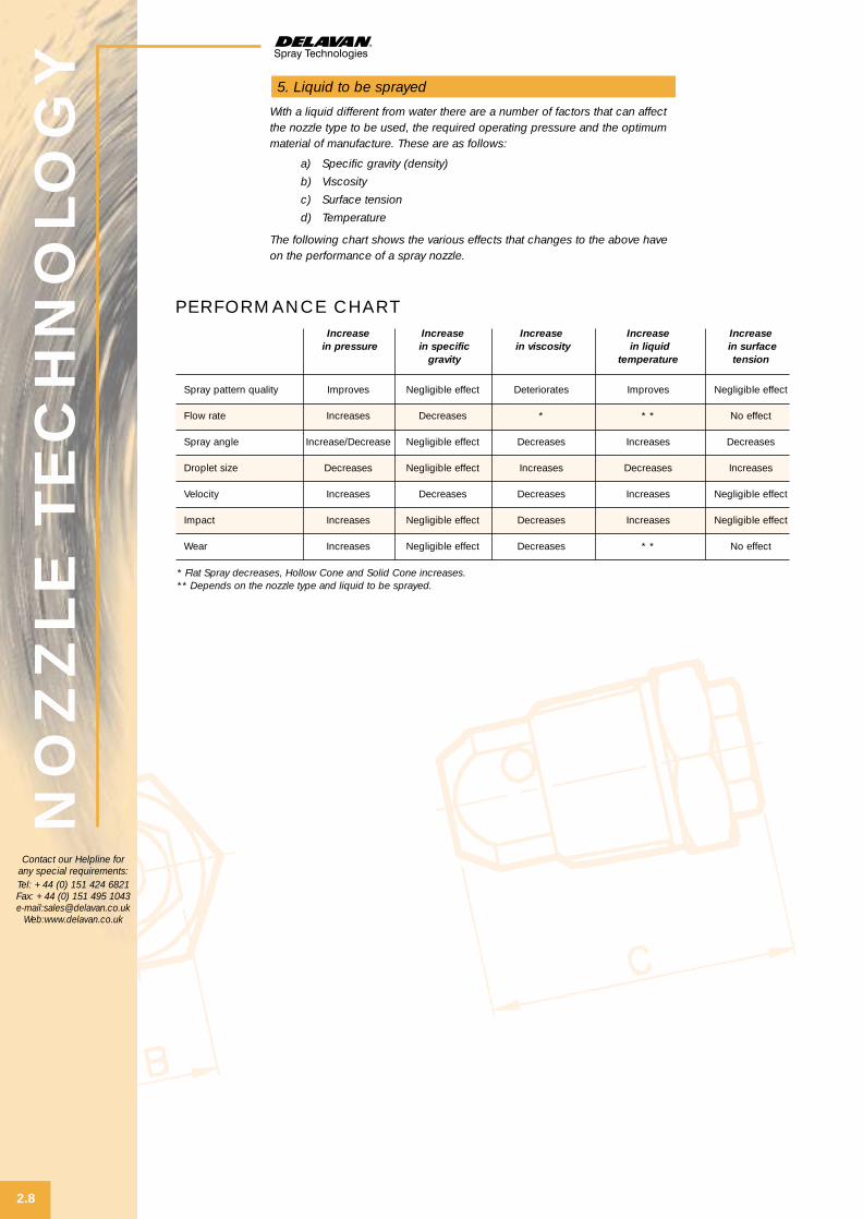
With a liquid different from water there are a number of factors that can affectthe nozzle type to be used, the required operating pressure and the optimummaterial of manufacture. These are as follows:
a) Specific gravity (density)
b) Viscosity
c) Surface tension
d) Temperature
The following chart shows the various effects that changes to the above haveon the performance of a spray nozzle.
5. Liquid to be sprayed
PERFORMANCE CHARTIncrease Increase Increase Increase Increase
in pressure in specific in viscosity in liquid in surfacegravity temperature tension
Spray pattern quality Improves Negligible effect Deteriorates Improves Negligible effect
Flow rate Increases Decreases * * * No effect
Spray angle Increase/Decrease Negligible effect Decreases Increases Decreases
Droplet size Decreases Negligible effect Increases Decreases Increases
Velocity Increases Decreases Decreases Increases Negligible effect
Impact Increases Negligible effect Decreases Increases Negligible effect
Wear Increases Negligible effect Decreases * * No effect
* Flat Spray decreases, Hollow Cone and Solid Cone increases.** Depends on the nozzle type and liquid to be sprayed.
Contact our Helpline forany special requirements:Tel: +44 (0) 151 424 6821Fax: +44 (0) 151 495 1043e-mail:[email protected]
Web:www.delavan.co.uk
NozzleTechSection 10/5/01 6:36 am Page 8
NO
ZZ
LE
TE
CH
NO
LO
GY
2.9
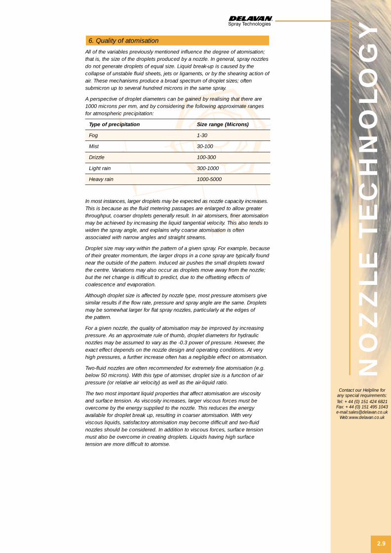
All of the variables previously mentioned influence the degree of atomisation;that is, the size of the droplets produced by a nozzle. In general, spray nozzlesdo not generate droplets of equal size. Liquid break-up is caused by thecollapse of unstable fluid sheets, jets or ligaments, or by the shearing action ofair. These mechanisms produce a broad spectrum of droplet sizes; oftensubmicron up to several hundred microns in the same spray.
A perspective of droplet diameters can be gained by realising that there are1000 microns per mm, and by considering the following approximate rangesfor atmospheric precipitation:
Type of precipitation Size range (Microns)
Fog 1-30
Mist 30-100
Drizzle 100-300
Light rain 300-1000
Heavy rain 1000-5000
In most instances, larger droplets may be expected as nozzle capacity increases.This is because as the fluid metering passages are enlarged to allow greaterthroughput, coarser droplets generally result. In air atomisers, finer atomisationmay be achieved by increasing the liquid tangential velocity. This also tends towiden the spray angle, and explains why coarse atomisation is oftenassociated with narrow angles and straight streams.
Droplet size may vary within the pattern of a given spray. For example, becauseof their greater momentum, the larger drops in a cone spray are typically foundnear the outside of the pattern. Induced air pushes the small droplets towardthe centre. Variations may also occur as droplets move away from the nozzle;but the net change is difficult to predict, due to the offsetting effects ofcoalescence and evaporation.
Although droplet size is affected by nozzle type, most pressure atomisers givesimilar results if the flow rate, pressure and spray angle are the same. Dropletsmay be somewhat larger for flat spray nozzles, particularly at the edges ofthe pattern.
For a given nozzle, the quality of atomisation may be improved by increasingpressure. As an approximate rule of thumb, droplet diameters for hydraulicnozzles may be assumed to vary as the -0.3 power of pressure. However, theexact effect depends on the nozzle design and operating conditions. At veryhigh pressures, a further increase often has a negligible effect on atomisation.
Two-fluid nozzles are often recommended for extremely fine atomisation (e.g.below 50 microns). With this type of atomiser, droplet size is a function of airpressure (or relative air velocity) as well as the air-liquid ratio.
The two most important liquid properties that affect atomisation are viscosityand surface tension. As viscosity increases, larger viscous forces must beovercome by the energy supplied to the nozzle. This reduces the energyavailable for droplet break up, resulting in coarser atomisation. With veryviscous liquids, satisfactory atomisation may become difficult and two-fluidnozzles should be considered. In addition to viscous forces, surface tensionmust also be overcome in creating droplets. Liquids having high surfacetension are more difficult to atomise.
6. Quality of atomisation
Contact our Helpline forany special requirements:Tel: +44 (0) 151 424 6821Fax: +44 (0) 151 495 1043e-mail:[email protected]
Web:www.delavan.co.uk
NozzleTechSection 10/5/01 6:36 am Page 9

NO
ZZ
LE
TE
CH
NO
LO
GY
2.10
The complete characterisation of spray quality requires information on thefrequency of all droplet diameters. This may be expressed as the numberof droplets or their corresponding volume in specified size ranges. Thoughcomplete distribution data is needed for certain applications, spray qualityor the consistency of droplet size is frequently described by a singleparameter, such as the mean or median droplet diameter.
If the cumulative percentage volume is plotted as a function of dropletdiameter, the 50% point corresponds to the volume median diameter, DVO.5.This divides the spray into two equal portions by volume. For processesinvolving evaporation, reactions or combustion, the Sauter mean diameter, D32is commonly used. This is a hypothetical droplet whose ratio of volume tosurface area is equal to that of the entire spray.
Delavan has been producing spray nozzles since 1946 and has developedspecialist nozzles for applications such as oil heating and specialised injectorsfor gas turbine engines. These have now been built into successful, specialistbusinesses in their own right within the Coltec Group and help provideDelavan with a wealth of knowledge and expertise to draw upon.
Delavan is a major supplier of spray nozzles and accessories for agriculturaland industrial applications worldwide. Thousands of nozzle designs have beendeveloped and research and development is constantly undertaken to optimiseflow, spray pattern and droplet size of nozzles for new applications.
Operating conditions cover wide ranges – flow rates from 0.1 GPH to 60000GPH, and pressures as high as 7000 psi. Delavan nozzles must also bedesigned for many types of liquids: light and heavy oils, abrasive and corrosivechemicals, and formulations containing suspended solids.
Optimum performance can be achieved only through intensive spray researchinvolving fluid dynamic theory, thorough testing and data analysis. This researchnot only aids product design, but is also essential for the proper application ofspray equipment and for the technical support of Delavan’s customers.
The work is carried out by an experienced staff of research engineers andtechnicians using modern laboratory facilities. The facilities include instrumentedtest stands designed for the accurate measurement of flow and spray patternswhen atomising fuel, water or other liquids. Test equipment is available for specialstudies of nozzle endurance, vibration analysis and fuel spray combustion. Thelaboratory also contains equipment for Schlieren and high-resolution photography.
Delavan’s research capabilities are further enhanced by the ANSYS finite-elementmodelling program for analysis of stress, vibration and heat transfer, the FLUENTcode for flowfield modelling, and other proprietary codes for predicting flowparameters, spray structure and particle size.
Of particular interest are Delavan’s unique systems for determining spraydroplet size. For many years laboratory data has been accumulated using atechnique involving droplet collection, photomicrography and high-speedimage analysis. In 1982 Delavan augmented its research facilities by procuringlaser spectrometer probes and custom software from Particle MeasuringSystems Inc. Also, the PMS light-scattering and imaging probes, used with adedicated computer, permit rapid spray analysis for a broad spectrum ofparticle diameters.
The laboratory is now equipped with still another diagnostic tool, the AerometricsPhase Doppler Particle Analyser which is capable of measuring not only thesize distribution of droplets, but also their velocity, flux and concentrationwithin the spray sampling volume. This non-intrusive instrument may beoperated with a computer-controlled nozzle traversing mechanism to provideglobal data or statistical information at designated locations within a three-dimensional region.
Interest in spray analysis has grown steadily in recent years, and manyorganisations are utilising droplet size information to improve their processesand products. If you would like to have additional information about dropletsize, please contact our Customer Service Team.
RESEARCH
REPRESENTATION OF DROPLET SIZE
6. Quality of atomisation (continued)
Contact our Helpline forany special requirements:Tel: +44 (0) 151 424 6821Fax: +44 (0) 151 495 1043e-mail:[email protected]
Web:www.delavan.co.uk
NozzleTechSection 10/5/01 6:36 am Page 10

NO
ZZ
LE
TE
CH
NO
LO
GY
2.11
Accurate sizing of spray droplets is difficult, and no single method is completelysatisfactory. However, by recognising the limitations of various instruments andexperimental techniques, useful and significant data can be obtained.
Delavan’s research laboratory is equipped with spectrometer probes fordroplet size measurement. Small droplets are detected by scattered light froma laser beam passing through the spray, whereas the larger droplets are sizedby an imaging system.
These research tools are a great asset in nozzle development and in supplyinguseful data to Delavan’s customers.
DROPLET SIZE MEASUREMENT
6. Quality of atomisation (continued)
The following charts show the estimated Sauter mean diameter of dropletsfor various flow rates of typical 80˚ hollow and solid cone spray patterns basedon water.
DROPLET ANALYSIS : 841106.BLW DATEFSSP INPUT FILE : 841106.BLW OAP INPUT FILE : 841106.BLWTEST REFERENCE : LO-AIR NOZZLE ATOMISER : 38977-8TEST LIQUID : WATER LIQUID PRESSURE : 24 PSIGLIQUID FLOW : 3 GPH ATOMISING GAS : AIRGAS PRESSURE : 30 PSIG GAS FLOW RATE : 5.32 SCFMFSSP PERIOD : 60 SEC OAP PERIOD : 60 SECOVERLAP REGION : 20 TO 80 UM MERGE DIAMETER : 50 UM
FSSP SAMPLING LOCATION: 12" HORIZONTAL TRAVERSEOAP SAMPLING LOCATION: 12" HORIZONTAL TRAVERSESUPPLEMENTAL INFORMATION: 10 MM DEPTH OF FIELDTEST ENGRS. SC & DT
• DISTRIBUTION PARAMETERS •LENGTH MEAN DIAMETER (D10): 21.11 UM NUMBER MEDIAN DIAM. (DN.5): 14.65 UMAREA MEAN DIAMETER (D20): 30.25 UM VOLUME MEDIAN DIAM. (DV.5): 119.37 UMVOLUME MEAN DIAMETER (D30): 42.43 UM 10% – VOLUME DIAMETER (DV.1): 42.70 UMSAUTER MEAN DIAMETER (D32): 83.48 UM 90% – VOLUME DIAMETER (DV.9): 200.07 UMSTANDARD DEVIATION (VOL): 59.20 UM MAXIMUM DIAMETER : 305.00 UMCOEFF. OF VARIATION (VOL): 0.483 UNIFORMITY INDEX (VOLUME) : 0.401_
Contact our Helpline forany special requirements:Tel: +44 (0) 151 424 6821Fax: +44 (0) 151 495 1043e-mail:[email protected]
Web:www.delavan.co.uk
TYPICAL DROPLET ANALYSIS
80° Hollow Cone pressureatomisers spraying water
80° Solid Cone pressureatomisers spraying water
NozzleTechSection 10/5/01 6:37 am Page 11
NO
ZZ
LE
TE
CH
NO
LO
GY
2.12
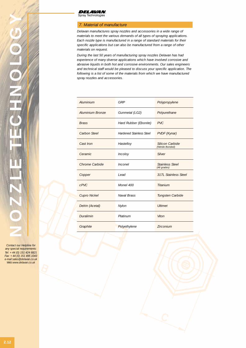
Delavan manufactures spray nozzles and accessories in a wide range ofmaterials to meet the various demands of all types of spraying applications.Each nozzle type is manufactured in a range of standard materials for theirspecific applications but can also be manufactured from a range of othermaterials on request.
During the last 50 years of manufacturing spray nozzles Delavan has hadexperience of many diverse applications which have involved corrosive andabrasive liquids in both hot and corrosive environments. Our sales engineersand technical staff would be pleased to discuss your specific application. Thefollowing is a list of some of the materials from which we have manufacturedspray nozzles and accessories.
7. Material of manufacture
Aluminium
Aluminium Bronze
Brass
Carbon Steel
Cast Iron
Ceramic
Chrome Carbide
Copper
cPVC
Cupro Nickel
Delrin (Acetal)
Duralimin
Graphite
GRP
Gunmetal (LG2)
Hard Rubber (Ebonite)
Hardened Stainless Steel
Hastelloy
Incoloy
Inconel
Lead
Monel 400
Naval Brass
Nylon
Platinum
Polyethylene
Polypropylene
Polyurethane
PVC
PVDF (Kynar)
Silicon Carbide
Silver
Stainless Steel
317L Stainless Steel
Titanium
Tungsten Carbide
Ultimet
Viton
Zirconium
Contact our Helpline forany special requirements:Tel: +44 (0) 151 424 6821Fax: +44 (0) 151 495 1043e-mail:[email protected]
Web:www.delavan.co.uk
(Nitride Bonded)
(All grades)
NozzleTechSection 10/5/01 6:37 am Page 12

NO
ZZ
LE
TE
CH
NO
LO
GY
2.13
8. Conversion factors
LIQUID PRESSURE EQUIVALENTS CHARTLIQUID Lb/In2 Ft Kg/Cm2 ATMOSPHERE BAR INCH kPa
PRESSURE (psi) WATER MERCURY (KILOPASCAL)
Lb/In2 (psi) * 2,31 0,070 0,068 0,069 2,04 6,895
Ft Water 0,433 * 0,030 0,029 0,030 0,882 2,99
Kg/Cm2 14,2 32,8 * 0,968 0,981 29,0 98
Atmosphere 14,7 33,9 1,03 * 1,01 29,9 101
Bar 14,5 33,5 1,02 0,987 * 29,5 100
Inch Mercury 0,491 1,13 0,035 0,033 0,034 * 3,4
kPa (Kilopascal) 0,145 0,335 0,01 0,009 0,01 0,296 *
VOLUMETRIC UNITS EQUIVALENTS CHARTVOLUMETRIC CUBIC FLUID POUND LITRE IMPERIAL CUBIC CUBIC
UNIT CENTIMETRE OUNCE OF WATER GALLON FOOT METRE
Cubic Centimetre * 0,034 2,2x10⁻³ 0,001 2,2x10⁻⁴ 3,53x10⁻⁵ 1,0x10⁻⁶
Fluid Ounce 29,4 * 0,065 0,030 6,51x10⁻³ 1,04x10⁻³ 2,96x10⁻⁵
Pound of Water 454 15,4 * 0,454 0,10 0,016 4,54x10⁻⁴
Litre 1000 33,8 2,2 * 0,22 0,035 0,001
Imperial Gallon 4546 154 10,0 4,546 * 0,161 4,55x10⁻³
Cubic Foot 28320 958 62,4 28,3 6,23 * 0,028
Cubic Metre 1,0x10⁶ 3,38x10⁴ 2202 1000 220 35,3 *
LINEAR UNITS EQUIVALENTS CHARTLINEAR MICRON MIL MILLIMETRE CENTIMETRE INCH FOOT METRE
UNIT
Micron * 0,039 0,001 1,0x10⁻⁴ 3,94x10⁻⁵
Mil 25,4 * 2,54x10-2 2,54x10⁻³ 0,001 8,33x10⁻⁵
Millimetre 1000 39,4 * 0,10 0,0394 3,28x10⁻³ 0,001
Centimetre 10000 394 10 * 0,394 0,033 0,01
Inch 2,54x10⁴ 1000 25,4 2,54 * 0,083 0,0254
Foot 3,05x10⁵ 1,2x10⁴ 305 30,5 12 * 0,305
Metre 1,0x10⁶ 3,94x10⁴ 1000 100 39,4 3,28 *
EQUIVALENTS CHART FORMULAE CHARTUNIT EQUIVALENT
Ounce 28,35 gr.
Pound 0,4536 Kg.
Horse-Power 0,746 KW.
B T U 0,2520 K Cal.
Square Inch 6,452 Sq. Cm.
Square Foot 0,09290 Sq. M.
Acre 0,4047 Hectare
Acre 43,560 Sq. Ft.
UNIT FORMULA
Fahrenheit (F˚) = 9/5 C˚+32
Celcius (C˚) = 5/9 (F˚-32)
Circumference of a Circle = 3,1416 x Diameter
Area of a Circle = ,7854 x Squareof the Diameter
Volume of a Sphere = ,5236 x Cubeof the Diameter
Area of a Sphere = 3,1416 x Squareof the Diameter
Contact our Helpline forany special requirements:Tel: +44 (0) 151 424 6821Fax: +44 (0) 151 495 1043e-mail:[email protected]
Web:www.delavan.co.uk
NozzleTechSection 10/5/01 6:37 am Page 13

NO
ZZ
LE
TE
CH
NO
LO
GY
2.14
9. Information tables
FLOW IN PRESSURE DROP IN BAR FOR VARIOUS PIPE SIZES (IN 10M LENGTH)L/MIN 1/8" 1/4" 3/8" 1/2" 3/4" 1" 11/4" 11/2" 2" 21/2" 3" 31/2" 4" 5" 6" 8"
1 0,07
1.5 0,16 0,04
2 0,26 0,06
2.5 0,40 0,08
3 0,56 0,12 0,03
4 0,96 0,21 0,05 0,02
6 2,0 0,45 0,10 0,03
8 3,5 0,74 0,17 0,05 0,01
10 1,2 0,25 0,08 0,02
12 1,7 0,35 0,11 0,03
15 2,6 0,54 0,17 0,04 0,01
20 0,92 0,28 0,07 0,02
25 1,2 0,45 0,11 0,03
30 2,1 0,62 0,15 0,04 0,01
40 1,1 0,25 0,08 0,02
60 0,54 0,16 0,04 0,02 0,006
80 0,93 0,28 0,07 0,03 0,009
100 0,43 0,12 0,05 0,010
115 0,58 0,14 0,06 0,015
130 0,72 0,18 0,08 0,02 0,010
150 0,23 0,10 0,03 0,012
170 0,29 0,13 0,04 0,016
190 0,36 0,16 0,05 0,02
230 0,50 0,23 0,07 0,03 0,009
260 0,32 0,09 0,04 0,01
300 0,38 0,11 0,04 0,02 0,007
340 0,50 0,14 0,06 0,02 0,009
380 0,61 0,18 0,07 0,03 0,01
470 0,28 0,11 0,04 0,02 0,009
570 0,39 0,15 0,05 0,03 0,01
750 0,64 0,26 0,09 0,04 0,02 0,007
950 0,14 0,06 0,03 0,01
1150 0,19 0,09 0,05 0,02
1500 0,16 0,08 0,03 0,01
1900 0,13 0,04 0,02
2800 0,09 0,03 0,009
3800 0,16 0,06 0,02
7500 0,23 0,06
PRESSURE LOSS TABLE
Recommended flow rate ranges are shown shaded.
FLOW OF WATER THROUGH SCHEDULE 40 STEEL PIPE
Contact our Helpline forany special requirements:Tel: +44 (0) 151 424 6821Fax: +44 (0) 151 495 1043e-mail:[email protected]
Web:www.delavan.co.uk
NozzleTechSection 10/5/01 6:38 am Page 14

NO
ZZ
LE
TE
CH
NO
LO
GY
2.15
9. Information tables (continued)
FRICTION LOSS TABLE
PIPE ACTUAL GATE GLOBE 45˚ RUN STD. STD. TEESIZE PIPE VALVE VALVE ELBOW OF ELBOW OR THROUGHSTD. BORE FULLY FULLY STD. RUN OF TEE SIDE SCH. (mm) OPEN OPEN TEE REDUCED 1/2 OUTLET
1/8" N.B. 6,8 0,05 2,4 0,11 0,12 0,23 0,43
1/4" N.B. 9,2 0,06 3,4 0,15 0,20 0,34 0,67
3/8" N.B. 12.5 0,08 4,4 0,19 0,26 0,42 0,80
1/2" N.B. 15,8 0,11 5,7 0,24 0,34 0,52 1,0
3/4" N.B. 21 0,13 7,0 0,30 0,43 0,64 1,3
1" N.B. 27 0,17 9,0 0,37 0,55 0,79 1,6
11/4" N.B. 35 0,23 11,8 0,49 0,70 1,1 2,1
11/2" N.B. 41 0,26 13,8 0,58 0,82 1,2 2,5
2" N.B. 53 0,34 17,7 0,73 1,1 1,6 3,2
21/2" N.B. 63 0,40 21 0,88 1,3 1,9 3,8
3" N.B. 78 0,49 26 1,1 1,6 2,3 4,7
4" N.B. 102 0,64 34 1,4 2,1 3,1 6,2
5" N.B. 128 0,82 43 1,8 2,6 3,9 7,7
6" N.B. 154 0,98 52 2,2 3,1 4,7 9,4
MESH SIZES
US AND ASTM STD.SIEVE NO. INCHES MICRONS
10 ,0787 2000
12 ,0661 1680
14 ,0555 1410
16 ,0469 1190
18 ,0394 1000
20 ,0331 840
25 ,0280 710
30 ,0232 590
35 ,0197 500
40 ,0165 420
45 ,0138 350
50 ,0117 297
60 ,0098 250
70 ,0083 210
80 ,0070 177
100 ,0059 149
120 ,0049 125
140 ,0041 105
170 ,0035 88
200 ,0029 74
APPROXIMATE FRICTION LOSS IN PIPE FITTINGS IN EQUIVALENT FEET OF STRAIGHT PIPE
Contact our Helpline forany special requirements:Tel: +44 (0) 151 424 6821Fax: +44 (0) 151 495 1043e-mail:[email protected]
Web:www.delavan.co.uk
NozzleTechSection 10/5/01 6:38 am Page 15

1) Spray Droplet Technology #678C:
This booklet was prepared to help clarify spray droplet technologyand answer questions often asked by our customers. It also describesDelavan’s spray droplet analysis system and explains the test data thatcan be provided.
2) Spray Drying Technology #1875:
This booklet describes the spray drying process and the nozzles designedfor this industry. It is intended as a guide for proper nozzle selection. Alsoincluded is an enquiry sheet requesting information needed for Delavanto make a nozzle recommendation for a specific application.
3) Spraying Droplets to Order:
This article explains the different types of nozzles and their spraypatterns. The author was Richard K. Cox. It is reprinted from Automation magazine.
4) Sprays and Spraying for Process Use:
This two-part article by Dr. Roger W. Tate is reprinted from ChemicalEngineering. It discusses atomiser types and principles, and describesthe selection of nozzles for specific industrial applications.
10. Other literature
If you need more detailed information or advice thenDelavan sales engineers and technical staff are alwaysavailable to answer your questions.
WE ARE HERE TO HELPNO
ZZ
LE
TE
CH
NO
LO
GY
2.16
Contact our Helpline forany special requirements:Tel: +44 (0) 151 424 6821Fax: +44 (0) 151 495 1043e-mail:[email protected]
Web:www.delavan.co.uk
NozzleTechSection 10/5/01 6:38 am Page 16

WELCOME TO DELAVAN
of newchallengesMeeting the
industriesand NEW markets
3Application GuideApplication GuideS P E C I F I E R S G U I D E
Del A4dividers pt1 A/W 21/6/01 4:24 pm Page 3

Section PageNo.
Introduction . . . . . . . . . . . . . . . . . . . . . . . . . . . . . . . . . . . . . . . . . . . . . . . . . . . . . . . . . . . . . . . . . . . . . . . . . . . . . . . . 3.1
Industry Applications . . . . . . . . . . . . . . . . . . . . . . . . . . . . . . . . . . . . . . . . . . . . . . . . . . . . . . . . . . 3.1
Nozzle Guide . . . . . . . . . . . . . . . . . . . . . . . . . . . . . . . . . . . . . . . . . . . . . . . . . . . . . . . . . . . . . . . . . . . . . . . . . . . . . 3.6
Notes . . . . . . . . . . . . . . . . . . . . . . . . . . . . . . . . . . . . . . . . . . . . . . . . . . . . . . . . . . . . . . . . . . . . . . . . . . . . . . . . . . . . . . . . . . . . 3.14
SE
CTIO
N IN
DE
X
Contact our Helpline forany special requirements:Tel: +44 (0) 151 424 6821Fax: +44 (0) 151 495 1043e-mail:[email protected]
Web:www.delavan.co.uk
Del A4dividers pt1 A/W 21/6/01 4:24 pm Page 4

AP
PLIC
ATIO
N G
UID
E
3.1
Contact our Helpline forany special requirements:Tel: +44 (0) 151 424 6821Fax: +44 (0) 151 495 1043e-mail:[email protected]
Web:www.delavan.co.uk
INDUSTRY APPLICATION SEE APPLICATION TYPES
Agriculture/Horticulture/Livestock Plant Protection / Watering / Irrigation Application 3 – Dust Suppression – Roads
Stubble Burning Application 26 – Oil Burning
Aerial Spraying Application 25 – Oil Pollution Control
Livestock Showering / Cooling Application 37 – Livestock Cooling
Automotive Industry Component or Body Washing Machines Application 15 – Component Washing
De-burring Application 16 – De-burring
Dip Tank Agitation Application 17 – Liquid Agitation
Leak Test Application 20 – Leak Testing
Foam Breaking Application 6 – Foam Breaking
Bottling and Canning Industries Conveyor Lubrication Application 7 – Roll Lubrication
Bottle & Can Cooling Application 15 – Component Washing
Washing – Trays etc. Application 10 – Phosphate Spraying
Drying Application 13 – Air Drying
Foam Breaking Application 6 – Foam Breaking
Brewing Industry Vessel Clean In Place Systems Application 30 – Cleaning In Place
Mash Tun Cleaning Application 30 – Cleaning In Place
Foam Breaking Application 6 – Foam Breaking
Bottle Washing Application 15 – Component Washing
Keg Washing Application 30 – Cleaning In Place
Conveyor Lubrication Application 7 – Roll Lubrication
Drying Application 13 – Air Drying
Trub Dispersal Application 14 – Coke / Slag Quenching
Carpet Industry Application of Stain Repellent Chemicals Application 7 – Roll Lubrication
SPRAYING APPLICATIONS
INDUSTRY APPLICATIONS
With more than 60 years of nozzle application experience Delavan has listedsome of the more common spray nozzle applications in the table below.Please use the Nozzle Technology section to calculate the desired flow rate,spray angle, operating pressure and material and then use the tables in thissection to find the nozzle you need.
The first table groups applications by industry and the second lists the nozzletypes suggested for each application. Certain installation sites will oftenpresent unique design constraints but the most common nozzles for particularapplications are presented in the next table on page 3.6.
If you need more detailed information or advice thenDelavan sales engineers and technical staff are alwaysavailable to answer your questions.
WE ARE HERE TO HELP
Application Guide 1 10/5/01 6:07 am Page 1

AP
PLIC
ATIO
N G
UID
E
3.2
Contact our Helpline forany special requirements:Tel: +44 (0) 151 424 6821Fax: +44 (0) 151 495 1043e-mail:[email protected]
Web:www.delavan.co.uk
INDUSTRY APPLICATION SEE APPLICATION TYPES
CHEMICAL & PETROCHEMICAL Dust Suppression Application 2 – Dust Suppression – Transfer Points Manufacturing
Storage Tank Cooling Application 23 – Fire Protection
Leaching Application 15 – Component Washing
Odour Control Application 22 – Odour Control
Vessel Clean In Place Systems Application 30 – Cleaning In Place
Container Washing – Internal Application 30 – Cleaning In Place
Container Washing – External Application 15 – Component Washing
Keg Washing Application 30 – Cleaning In Place
IBC Washing – Internal Application 30 – Cleaning In Place
IBC Washing – External Application 15 – Component Washing
Conveyor Washing Application 21 – Vehicle Washing
Conveyor Lubrication Application 7 – Roll Lubrication
Foam Breaking Application 6 – Foam Breaking
Oil Slick – Detergent Spraying Application 25 – Oil Pollution Control
Gas Scrubbing Application 35 – Gas Scrubbing
Steam Conditioning Application 36 – Steam Conditioning
Liquid Waste Incineration Application 26 – Oil Burning
Fire Protection Application 23 – Fire Protection
Safety Showers & Eye Baths Application 44 – Safety Showers
Coke or Slag Quenching Application 14 – Coke / Slag Quenching
Civil Engineering Dust Suppression Application 3 – Dust Suppression – Roads
Building Cleaning Application 9 – Descaling
Decorative Water Features Application 45 – Decorative Water Features
Wood Preservation Application 18 – Paint Spraying
Roof Cooling Application 23 – Fire Protection
Electronics Industry Etch and Wash Chemical Spraying Application 40 – Etch And Wash ChemicalSpraying – Electronics
Dip Tank Agitation Application 17 – Liquid Agitation
Drying Application 13 – Air Drying
Foam Breaking Application 6 – Foam Breaking
Environmental Dust Control – Roads Application 3 – Dust Suppression – Roads
Pollution Control – Oil Slick Spraying Application 25 – Oil Pollution Control
Effluent Treatment Application 28 – Effluent Treatment
Spray Ponds Application 29 – Spray Ponds
Odour Control Application 22 – Odour Control
Dust Suppression Application 2 – Dust Suppression – Transfer PointsApplication 3 – Dust Suppression – Roads
Wheel Wash Application 5 – Wheel Wash
Road Sweeping Application 24 – Weed Control
INDUSTRY APPLICATIONS
Application Guide 1 10/5/01 6:07 am Page 2

AP
PLIC
ATIO
N G
UID
E
3.3
Contact our Helpline forany special requirements:Tel: +44 (0) 151 424 6821Fax: +44 (0) 151 495 1043e-mail:[email protected]
Web:www.delavan.co.uk
INDUSTRY APPLICATION SEE APPLICATION TYPES
Environmental (continued) Weed Control Application 24 – Weed Control
Liquid Waste Incineration Application 26 – Oil Burning
Weir Wall Washing Application 16 – Oil De-burring
Food Processing Industry Container Washing - External Application 15 – Component Washing
Container Washing – Internal Application 30 – Cleaning In Place
Conveyor Washing Application 21 – Vehicle Washing
Drying Application 13 – Air Drying
Leaching Application 15 – Component Washing
Foam Breaking Application 6 – Foam Breaking
Fruit/Vegetable Washing Application 15 – Component Washing
Fruit/Vegetable Coating Application 7 – Roll Lubrication
Mould Cooling Application 31 – Mould Cooling
Release Agent Spraying Application 7 – Roll Lubrication
Disinfection – Spraying or Fogging Application 27 – Humidification
Spray Drying Application 32 – Spray Drying
Oven Humidity Control Application 27 – Humidification
HVAC Heating – Oil Burning Application 26 – Oil Burning
Humidification Application 27 – Humidification
Fogging Application 27 – Humidification
Fume Scrubbing Application 19 – Fume Scrubbing
Meat Processing Abattoir Cleaning Application 15 – Component Washing
Disinfection – Spraying or Fogging Application 27 – Humidification
Conveyor Washing Application 21 – Vehicle Washing
Foam Breaking Application 6 – Foam Breaking
Mechanical Engineering Tool Cooling Application 4 – Cutter Cooling
Mould Release Spraying Application 7 – Roll Lubrication
Lubricant & Grease Spraying Application 7 – Roll Lubrication
Metal Finishing Static, Rotary or Conveyor Component Application 15 – Component WashingWashing Machines
De-burring Application 16 – De-burring
Grinding Dust Removal Application 5 – Wheel Wash
Electroplating – Tank Agitation Application 17 – Liquid Agitation
Electroplating – Product Washing Application 10 – Phosphate Spraying
Pre-treatment Wash Application 15 – Component Washing
Pre-treatment PlatingApplication 10 – Phosphate SprayingIron or Zinc Phosphate
Protective Coating Spraying Application 7 – Roll Lubrication
Paint Spraying Application 18 – Paint Spraying
Drying Application 13 – Air Drying
Dip Tank Agitation Application 17 – Liquid Agitation
INDUSTRY APPLICATIONS
Application Guide 1 10/5/01 6:07 am Page 3

AP
PLIC
ATIO
N G
UID
E
3.4
Contact our Helpline forany special requirements:Tel: +44 (0) 151 424 6821Fax: +44 (0) 151 495 1043e-mail:[email protected]
Web:www.delavan.co.uk
INDUSTRY APPLICATION SEE APPLICATION TYPES
Metal Finishing (continued) Foam Breaking Application 6 – Foam Breaking
Safety Showers & Eyebaths Application 44 – Safety Showers
Fume Scrubbing Application 19 – Fume Scrubbing
Metal Heat Treatment Billet Quenching Application 11 – Continuous Casting Cooling
Strip Cooling Application 8 – Cooling Mill Rolls
Metal Production Industry Roll Lubrication Application 7 – Roll Lubrication
Roll Cooling Application 8 – Cooling Mill Rolls
Descaling Application 9 – Descaling
Dust Control – at Descaling Points Application 2 – Dust Suppression – Transfer Points
Pickling Application 10 – Phosphate Spraying
Continuous Casting – Cooling Application 11 – Continuous Casting
Wire Die Lubrication / Cooling Application 12 – Wire Die Lubrication
Sheet Washing Application 10 – Phosphate Spraying
Drying Application 13 – Air Drying
Sheet Oiling Application 7 – Roll Lubrication
Coke or Slag Quenching Application 14 – Coke Quenching
Mineral Extraction & Processing Gravel or Coal Washing Application 1 – Gravel / Coal Washing
Dust Control – Transfer Points Application 2 – Dust Suppression – Transfer Points
Dust Control – Roads Application 3 – Dust Suppression – Roads
Cutter Cooling Application 4 – Cutter Cooling
Wheel Wash Application 5 – Wheel Wash
Foam Breaking Application 6 – Foam Breaking
Paper Making Industry Bark Removal Application 16 – De-burring
Edge Trimming Application 42 – Edge Trimming
Pulp – Water Addition Application 43 – Pulp – Water Addition
Foam Breaking Application 6 – Foam Breaking
Filter / Screen Washing Application 11 – Continuous Casting Cooling
Pharmaceutical Industry Vessel Clean In Place Systems Application 30 – Cleaning In Place
Tablet Coating Application 33 – Tablet Coating
Bottle Washing Application 15 – Component Washing
Drying Application 13 – Air Drying
Conveyor Lubrication Application 7 – Roll Lubrication
Dust Suppression Application 2 – Dust Suppression – Transfer Points
Fume Scrubbing Application 19 – Fume Scrubbing
Centrifuge Cake Washing Application 34 – Centrifuge Cake Washing
Photographic Industry Film Processing Application 40 – Etch And Wash ChemicalSpraying – Electronics
Dip Tank Agitation Application 17 – Agitation
Drying Application 13 – Air Drying
INDUSTRY APPLICATIONS
Application Guide 1 10/5/01 6:08 am Page 4

AP
PLIC
ATIO
N G
UID
E
3.5
Contact our Helpline forany special requirements:Tel: +44 (0) 151 424 6821Fax: +44 (0) 151 495 1043e-mail:[email protected]
Web:www.delavan.co.uk
INDUSTRY APPLICATION SEE APPLICATION TYPES
Power Industry Flue Gas De-Sulphurisation Application 35 – Gas Scrubbing
Steam Conditioning Application 36 – Steam Conditioning
De-Superheating Application 36 – Steam Conditioning
Spray Ponds Application 29 – Spray Ponds
Cooling Towers Application 29 – Spray Ponds
Gravel / Coal Washing Application 1 – Gravel / Coal Washing
Dust Control – Transfer Points Application 2 – Dust Suppression – Transfer Points
Dust Control – Roads Application 3 – Dust Suppression – Roads
Flask Decontamination – Nuclear Application 38 – Flask Decontamination – Nuclear
Magnox Extinguishing Application 39 – Magnox Extinguishing – Nuclear
Safety Showers & Eyebaths Application 44 – Safety Showers
Pollution Control – Oil Slick Spraying Application 25 – Oil Pollution Control
Wheel Wash Application 5 – Wheel Wash
Insulator Washing Application 5 – Wheel Wash
Transformer Fire Protection Application 23 – Fire Protection
Coke or Slag Quenching Application 14 – Coke / Slag Quenching
Rubber Processing Industry Conveyor Lubrication Application 7 – Roll Lubrication
Belt Cooling Application 41 – Belt Cooling
Mould Release Agent Spraying Application 7 – Roll Lubrication
Foam Breaking Application 6 – Foam Breaking
Textile Industry Moistening of cloth or yarn Application 27 – Humidification
Spraying of Stain Repellent Chemicals Application 7 – Roll Lubrication
Transport Industry Vehicle Washing Application 21 – Vehicle Wash
Wheel Wash Application 5 – Wheel Wash
Odour Control – Ships Application 22 – Odour Control
Fire Protection – Ships Application 23 – Fire Protection
Weed Control – Railway Lines,Application 24 – Weed ControlRunways & Pavements
Oil Slick Detergent Spraying Application 25 – Oil Pollution Control
INDUSTRY APPLICATIONS
Application Guide 1 10/5/01 6:08 am Page 5

AP
PLIC
ATIO
N G
UID
E
3.6
Contact our Helpline forany special requirements:Tel: +44 (0) 151 424 6821Fax: +44 (0) 151 495 1043e-mail:[email protected]
Web:www.delavan.co.uk
NOZZLE GUIDE
APPLICATION 1 – GRAVEL/COAL WASHINGSPRAY TYPE ONE PIECE TIP TYPE DELA-FIT OTHER ACCESSORIES
THREADED
Flat Spray AC, TJ, AN DFAC, DFTJ, DFAN Eyelets, HNS
Hollow Cone Spray AE, AF, AH, AG DFAE, DFAF
Solid Cone Spray BI, BN DFBI, DFBN
Other Nozzles
Use Hollow Cone sprays when the wash water is re-circulated and is likely to contain debris.
APPLICATION 3 – DUST SUPPRESSION – ROADSSPRAY TYPE ONE PIECE TIP TYPE DELA-FIT OTHER ACCESSORIES
THREADED
Flat Spray AC, AN Eyelets, HNS
Hollow Cone Spray
Solid Cone Spray BI, CJ
Other Nozzles Sector Sprays
APPLICATION 4 – CUTTER COOLINGSPRAY TYPE ONE PIECE TIP TYPE DELA-FIT OTHER ACCESSORIES
THREADED
Flat Spray AC(0°) HNS
Hollow Cone Spray WM
Solid Cone Spray BL
Other Nozzles
APPLICATION 2 – DUST SUPPRESSION – TRANSFER POINTSSPRAY TYPE ONE PIECE TIP TYPE DELA-FIT OTHER ACCESSORIES
THREADED
Flat Spray Eyelets, HNS,
Hollow Cone Spray AE, AF, WR, WRW DC DFAE, DFAF Swivels
Solid Cone Spray BI, BN,BK,BL WL DFBI, DFBN
Other Nozzles
Having found the application number from the previous table, use this table todetermine the nozzle you require.
The various fitting options are:
One piece threaded – This type of nozzle screws onto or into amating part.
Tip Type – A flanged nozzle which requires a body and cap assembly.
Delafit – A quick release system which allows tool free replacement.
If you need more detailed information or advice thenDelavan sales engineers and technical staff are alwaysavailable to answer your questions.
WE ARE HERE TO HELP
Application Guide 1 10/5/01 6:08 am Page 6

AP
PLIC
ATIO
N G
UID
E
3.7
Contact our Helpline forany special requirements:Tel: +44 (0) 151 424 6821Fax: +44 (0) 151 495 1043e-mail:[email protected]
Web:www.delavan.co.uk
NOZZLE GUIDE
APPLICATION 5 – WHEEL WASHSPRAY TYPE ONE PIECE TIP TYPE DELA-FIT OTHER ACCESSORIES
THREADED
Flat Spray AC, TJ AD HNS
Hollow Cone Spray
Solid Cone Spray
Other Nozzles
APPLICATION 6 – FOAM BREAKINGSPRAY TYPE ONE PIECE TIP TYPE DELA-FIT OTHER ACCESSORIES
THREADED
Flat Spray AN D Tip Eyelets, HNS
Hollow Cone Spray RA
Solid Cone Spray BN, BY
Other Nozzles
Due to the complex nature and variation of different chemical foams please contact Delavan’s Customer Service Team for advice on this application.
APPLICATION 7 – ROLL LUBRICATIONSPRAY TYPE ONE PIECE TIP TYPE DELA-FIT OTHER ACCESSORIES
THREADED
Flat Spray LF, LK, D Tip AL15, AL60, Lo-Air HNS, Swivels
Hollow Cone Spray
Solid Cone Spray
Other Nozzles
APPLICATION 9 – DESCALINGSPRAY TYPE ONE PIECE TIP TYPE DELA-FIT OTHER ACCESSORIES
THREADED
Flat Spray AZ, BZ, 343, 344 DE, DQ, DD, LQ HNS
Hollow Cone Spray
Solid Cone Spray
Other Nozzles
APPLICATION 10 – PHOSPHATE SPRAYINGSPRAY TYPE ONE PIECE TIP TYPE DELA-FIT OTHER ACCESSORIES
THREADED
Flat Spray AC, TJ, AN DFAC, DFTJ, DFAN LD, AD Eyelets, Ball Swivel
Hollow Cone Spray AE, AF DFAE, DFAF Eyelets, HNS,
Solid Cone Spray BI, BN DFBI, DFBN
Adjustable Joints
Other Nozzles
APPLICATION 8 – COOLING MILL ROLLSSPRAY TYPE ONE PIECE TIP TYPE DELA-FIT OTHER ACCESSORIES
THREADED
Flat Spray AC, CAC LF DFAC LD, AD HNS
Hollow Cone Spray
Solid Cone Spray
Other Nozzles
Application Guide 1 10/5/01 6:09 am Page 7

AP
PLIC
ATIO
N G
UID
E
3.8
Contact our Helpline forany special requirements:Tel: +44 (0) 151 424 6821Fax: +44 (0) 151 495 1043e-mail:[email protected]
Web:www.delavan.co.uk
NOZZLE GUIDE
APPLICATION 13 – AIR DRYINGSPRAY TYPE ONE PIECE TIP TYPE DELA-FIT OTHER ACCESSORIES
THREADED
Flat Spray AC, DJ LF, SL, Blow Off DFAC, FB Cap & Body HNS, Swivels,
Hollow Cone SprayAdjustable Joints
Solid Cone Spray
Other Nozzles
APPLICATION 15 – COMPONENT WASHINGSPRAY TYPE ONE PIECE TIP TYPE DELA-FIT OTHER ACCESSORIES
THREADED
Flat Spray AC, CAC, TJ DFAC, DFTJ HNS, Ball Swivel
Hollow Cone Spray AE DFAEEyelets
Solid Cone Spray BI BFBI
Other Nozzles
APPLICATION 16 – DE-BURRINGSPRAY TYPE ONE PIECE TIP TYPE DELA-FIT OTHER ACCESSORIES
THREADED
Flat Spray AQ, AZ LQ HNS
Hollow Cone Spray
Solid Cone Spray
Other Nozzles
APPLICATION 14 – COKE QUENCHINGSPRAY TYPE ONE PIECE TIP TYPE DELA-FIT OTHER ACCESSORIES
THREADED
Flat Spray HNS
Hollow Cone Spray AE, AF, BE DFAE, DFAF
Solid Cone Spray BI, BN, CM, BY DFBI, DFBN
Other Nozzles
APPLICATION 12 – WIRE DIE LUBRICATION (AND COOLING)SPRAY TYPE ONE PIECE TIP TYPE DELA-FIT OTHER ACCESSORIES
THREADED
Flat Spray HNS
Hollow Cone Spray WM
Solid Cone Spray AL, AL45
Other Nozzles
APPLICATION 11 – CONTINUOUS CASTING COOLINGSPRAY TYPE ONE PIECE TIP TYPE DELA-FIT OTHER ACCESSORIES
THREADED
Flat Spray AC LF DFAC, FB Cap & Body LD, AD HNS
Hollow Cone Spray
Solid Cone Spray BI, BN, BQ, BT DFBI, DFBN, DFBQ, DFBT
Other Nozzles
Application Guide 1 10/5/01 6:09 am Page 8

AP
PLIC
ATIO
N G
UID
E
3.9
Contact our Helpline forany special requirements:Tel: +44 (0) 151 424 6821Fax: +44 (0) 151 495 1043e-mail:[email protected]
Web:www.delavan.co.uk
APPLICATION 17 – LIQUID AGITATIONSPRAY TYPE ONE PIECE TIP TYPE DELA-FIT OTHER ACCESSORIES
THREADED
Flat Spray AC HNS, Ball Swivel
Hollow Cone SprayEyelets, Adjustable
Solid Cone Spray
Joints
Other Nozzles BB Eductor
APPLICATION 18 – PAINT SPRAYINGSPRAY TYPE ONE PIECE TIP TYPE DELA-FIT OTHER ACCESSORIES
THREADED
Flat Spray LK, LQ Airless Tips Turnaflo
Hollow Cone Spray
Solid Cone Spray
Other Nozzles
NOZZLE GUIDE
APPLICATION 19 – FUME SCRUBBINGSPRAY TYPE ONE PIECE TIP TYPE DELA-FIT OTHER ACCESSORIES
THREADED
Flat Spray HNS, Ball Swivel
Hollow Cone Spray AE, AF, PJ DFAE, DFAFEyelets
Solid Cone Spray BN DFBN AL30
Other Nozzles
APPLICATION 21 – VECHICLE WASHINGSPRAY TYPE ONE PIECE TIP TYPE DELA-FIT OTHER ACCESSORIES
THREADED
Flat Spray AC, CAC, AN, LF DFAC, DFTJ, DFAN, HNS, Ball SwivelTJ, AZ FB Cap & Body Eyelets, Swivels
Hollow Cone Spray
Solid Cone Spray
Other Nozzles
APPLICATION 22 – ODOUR CONTROLSPRAY TYPE ONE PIECE TIP TYPE DELA-FIT OTHER ACCESSORIES
THREADED
Flat Spray AL60 HNS
Hollow Cone Spray WM WG FB Cap & Body
Solid Cone Spray GA, GC, AL, AL45
Other Nozzles
APPLICATION 20 – LEAK TESTINGSPRAY TYPE ONE PIECE TIP TYPE DELA-FIT OTHER ACCESSORIES
THREADED
Flat Spray HNS, Ball Swivel
Hollow Cone SprayEyelets
Solid Cone Spray BN, BI, CJ DFBN, DFBI
Other Nozzles
Application Guide 1 10/5/01 6:09 am Page 9

AP
PLIC
ATIO
N G
UID
E
3.10
Contact our Helpline forany special requirements:Tel: +44 (0) 151 424 6821Fax: +44 (0) 151 495 1043e-mail:[email protected]
Web:www.delavan.co.uk
NOZZLE GUIDE
APPLICATION 25 – OIL POLLUTION CONTROLSPRAY TYPE ONE PIECE TIP TYPE DELA-FIT OTHER ACCESSORIES
THREADED
Flat Spray AC QLD, FLD HNS, Swivels,
Hollow Cone Spray RAQuick Couplers
Solid Cone Spray
Other Nozzles
Note:- QLD and FLD are not featured in this catalogue. Please contact Delavan’s Customer Service Team for further details.
APPLICATION 27 – HUMIDIFICATIONSPRAY TYPE ONE PIECE TIP TYPE DELA-FIT OTHER ACCESSORIES
THREADED
Flat Spray AL60
Hollow Cone Spray WM WG FB Cap & Body Swirl-Air
Solid Cone Spray AL, AL30, AL45, SNA
Other Nozzles
APPLICATION 28 – EFFLUENT TREATMENTSPRAY TYPE ONE PIECE TIP TYPE DELA-FIT OTHER ACCESSORIES
THREADED
Flat Spray AN HNS, Quick
Hollow Cone Spray BE,WRA,WRA-RDCouplers
Solid Cone Spray CM
Other Nozzles
APPLICATION 26 – OIL BURNINGSPRAY TYPE ONE PIECE TIP TYPE DELA-FIT OTHER ACCESSORIES
THREADED
Flat Spray AC LF Protek
Hollow Cone Spray WDA Swirl-Air
Solid Cone Spray WDB SNA, AIRO.
Other Nozzles
Please contact Delavan’s Customer Service Team for further details of oil burning nozzles and our Oil Burner leaflet.
APPLICATION 24 – WEED CONTROLSPRAY TYPE ONE PIECE TIP TYPE DELA-FIT OTHER ACCESSORIES
THREADED
Flat Spray AN LF FB Cap & Body HNS, Swivels
Hollow Cone Spray RA
Solid Cone Spray BL WL FB Cap & Body
Other Nozzles
APPLICATION 23 – FIRE PROTECTIONSPRAY TYPE ONE PIECE TIP TYPE DELA-FIT OTHER ACCESSORIES
THREADED
Flat Spray AN HNS
Hollow Cone Spray
Solid Cone Spray BI, BN,CM, BY CL7
Other Nozzles
Application Guide 1 10/5/01 6:09 am Page 10

AP
PLIC
ATIO
N G
UID
E
3.11
Contact our Helpline forany special requirements:Tel: +44 (0) 151 424 6821Fax: +44 (0) 151 495 1043e-mail:[email protected]
Web:www.delavan.co.uk
APPLICATION 29 – SPRAY PONDSSPRAY TYPE ONE PIECE TIP TYPE DELA-FIT OTHER ACCESSORIES
THREADED
Flat Spray HNS, Quick
Hollow Cone Spray BE, RA, WRACouplers
Solid Cone Spray
Other Nozzles
APPLICATION 30 – CLEAN IN PLACESPRAY TYPE ONE PIECE TIP TYPE DELA-FIT OTHER ACCESSORIES
THREADED
Flat Spray HNS
Hollow Cone Spray PU, PJ
Solid Cone Spray BI, BN, CLFD 13 CIP21, DWN19, KN9
Other Nozzles
Note:- As vessels vary widely in shape and size, please contact Delavan’s Customer Service Team for advice on Clean In Place Systems.
NOZZLE GUIDE
APPLICATION 31 – MOULD COOLINGSPRAY TYPE ONE PIECE TIP TYPE DELA-FIT OTHER ACCESSORIES
THREADED
Flat Spray HNS, Swivels,
Hollow Cone SprayAdjustable Joints
Solid Cone Spray BI, BN, BL WL DFBI, DFBN, FB Cap & Body
Other Nozzles
APPLICATION 33 – TABLET COATINGSPRAY TYPE ONE PIECE TIP TYPE DELA-FIT OTHER ACCESSORIES
THREADED
Flat Spray AL15,AL60,AFAL, Airless Tip
Hollow Cone Spray
Solid Cone Spray
Other Nozzles
Note:- AFAL is a variable fan width, air atomising nozzle specifically designed for batch tablet coating and is not featured in this catalogue.Please contact Delavan’s Customer Service Team for further details.
APPLICATION 32 – SPRAY DRYINGSPRAY TYPE ONE PIECE TIP TYPE DELA-FIT OTHER ACCESSORIES
THREADED
Flat Spray Assembly Tools,
Hollow Cone Spray Mini SDX, SDX, Kwik-Chek Orifice
SDX III, Swirl-AirGauge
Solid Cone Spray
Other Nozzles
Delavan produce a complete range of Spray Drying nozzles and accessories. Please contact Delavan’s Customer Service Team for full details and acopy of our Spray Drying literature.
Application Guide 1 10/5/01 6:10 am Page 11

AP
PLIC
ATIO
N G
UID
E
3.12
Contact our Helpline forany special requirements:Tel: +44 (0) 151 424 6821Fax: +44 (0) 151 495 1043e-mail:[email protected]
Web:www.delavan.co.uk
NOZZLE GUIDE
APPLICATION 36 – STEAM CONDITIONINGSPRAY TYPE ONE PIECE TIP TYPE DELA-FIT OTHER ACCESSORIES
THREADED
Flat Spray HNS
Hollow Cone Spray AE
Solid Cone Spray BI, CJ
Other Nozzles
APPLICATION 38 – FLASK DE-CONTAMINATION – NUCLEARSPRAY TYPE ONE PIECE TIP TYPE DELA-FIT OTHER ACCESSORIES
THREADED
Flat Spray AZ, AQ LQ HNS
Hollow Cone Spray
Solid Cone Spray
Other Nozzles
APPLICATION 39 – MAGNOX EXTINGUISHING – NUCLEARSPRAY TYPE ONE PIECE TIP TYPE DELA-FIT OTHER ACCESSORIES
THREADED
Flat Spray HNS
Hollow Cone Spray
Solid Cone Spray CJ
Other Nozzles
APPLICATION 37 – LIVESTOCK COOLINGSPRAY TYPE ONE PIECE TIP TYPE DELA-FIT OTHER ACCESSORIES
THREADED
Flat Spray HNS, Swivels
Hollow Cone Spray WA, WR, WRW WG
Solid Cone Spray BL, BI, BN WL
Other Nozzles
APPLICATION 35 – GAS SCRUBBINGSPRAY TYPE ONE PIECE TIP TYPE DELA-FIT OTHER ACCESSORIES
THREADED
Flat Spray HNS
Hollow Cone Spray AF, BE, AE, UC
Solid Cone Spray BI,BN,CM,BY,CJ
Other Nozzles
Due to the complex nature and variation of the different chemicals and gas scrubber designs please contact Delavan’s Customer Service Team foradvice on this application.
APPLICATION 34 – CENTRIFUGE CAKE WASHINGSPRAY TYPE ONE PIECE TIP TYPE DELA-FIT OTHER ACCESSORIES
THREADED
Flat Spray AC, TJ LF DFAC, DFTJ, FB HNSCap & Body
Hollow Cone Spray
Solid Cone Spray
Other Nozzles
Application Guide 1 10/5/01 6:10 am Page 12

AP
PLIC
ATIO
N G
UID
E
3.13
Contact our Helpline forany special requirements:Tel: +44 (0) 151 424 6821Fax: +44 (0) 151 495 1043e-mail:[email protected]
Web:www.delavan.co.uk
APPLICATION 40 – ETCH AND WASH CHEMICAL SPRAYING – ELECTRONICSSPRAY TYPE ONE PIECE TIP TYPE DELA-FIT OTHER ACCESSORIES
THREADED
Flat Spray CAC LF, LD, LE HNS, Swivels,
Hollow Cone Spray WM WGAdjustable Joints
Solid Cone Spray BL WL
Other Nozzles
APPLICATION 41 – BELT COOLINGSPRAY TYPE ONE PIECE TIP TYPE DELA-FIT OTHER ACCESSORIES
THREADED
Flat Spray AC HNS
Hollow Cone Spray
Solid Cone Spray BT, BQ
Other Nozzles
NOZZLE GUIDE
APPLICATION 42 – EDGE TRIMMINGSPRAY TYPE ONE PIECE TIP TYPE DELA-FIT OTHER ACCESSORIES
THREADED
Flat Spray AC(0°), AQ(0°) HNS
Hollow Cone Spray
Solid Cone Spray
Other Nozzles
Note:- Delavan have manufactured many types of edge trimming nozzles for a wide range of industries. Please call Delavan’s Customer Service Team for further details.
APPLICATION 45 – DECORATIVE WATER FEATURESSPRAY TYPE ONE PIECE TIP TYPE DELA-FIT OTHER ACCESSORIES
THREADED
Flat Spray AC, AN, TJ
Hollow Cone Spray BE, WRA, WRS
Solid Cone Spray CM, BY
Other Nozzles
APPLICATION 43 – WATER ADDITIONSPRAY TYPE ONE PIECE TIP TYPE DELA-FIT OTHER ACCESSORIES
THREADED
Flat Spray HNS
Hollow Cone Spray AE, WR, RA
Solid Cone Spray
Other Nozzles
APPLICATION 44 – SAFETY SHOWERS AND EYEBATHS
Delavan produce a wide range of safety showers, Eyebaths and custom designed units for all applications. Pleasecontact Delavan’s Customer Service Team for further advice and a copy of the Safety Showers literature.
HNS = Header Nozzle Socket
If you need more detailed information or advice then Delavan sales engineers andtechnical staff are always available to answer your questions.
WE ARE HERE TO HELP
Application Guide 1 10/5/01 6:10 am Page 13

WELCOME TO DELAVAN
of newchallengesMeeting the
industriesand NEW markets
4NozzlesNozzlesS P E C I F I E R S G U I D E
Del A4dividers pt1 A/W 21/6/01 4:24 pm Page 5

WELCOME TO DELAVAN
of newchallengesMeeting the
industriesand NEW markets
A Flat Spray
Del Nozzle A4 dividers A/W 21/6/01 10:35 am Page 1

TYPICAL APPLICATIONSAsphalt or tar laying, bottle washing, coal and gravel washing, degreasing, dishwashing, foam control, industrial washers, metalcleaning-rinsing and washing, spray coating, vehicle washing, water misting and water fountains.
TYPE AC SPRAY PATTERN TYPE AN SPRAY PATTERN
Nozzle Spray Characteristics Spray Basic Features Flow Range. PageType Angles L/Min @ 3 Bar.G. No.AC 0° – 110° 0,80 – 237 A.1
CAC 0° – 110° 0,40 – 118,4 A.2
ACS 0° – 110° 0,80 – 3,93 A.3
LF 0° – 110° 0,16 – 19,7 A.4
LA 0° – 110° 3,93 – 79,07 A.5
LC 0° – 110° 1,0 – 20,0 A.6
LE 80° and 110° 0,39 – 5,9 A.7
LX 70° offset 0,79 – 6,32 A.8
WJ 70° offset 8,05 – 118 A.9
LK 15° – 110° 0,04 – 2,30 A.10
LD 0° – 110° 0,39 – 19,9 A.11
AD 0° – 110° 3,93 – 79,1 A.12
ED 45° – 90° 1,2 – 19,9 A.13
EF 45° – 90° 1,2 – 19,9 A.14
D 90° – 160° 0,39 – 23,6 A.15
AN 90° – 160° 0,39 – 23,4 A.16
TJ 15° – 50° 1,6 – 79 A.17
Blow-off 55° – 100° SEE CHARTS A.18
SL 80° – 115° 2,1 – 26 A.19
DJ 80° – 115° 2,1 – 26 A.20
Nozzle Spray Characteristics Spray Basic Features Flow Range. PageType Angles L/Min @ 70 Bar.G. No.
AZ 0° – 50° 7,6 – 95,4 A.21
BZ 30° 5,5 – 129,3 A.22
343 25° and 32° 19 – 114 A.23
344 25° and 32° 38,2 – 114 A.24
DD 25° and 32° 11,5 – 114 A.25
AQ 25° – 95° 0,94 – 21,6 A.26
LQ 25° – 95° 0,94 – 21,6 A.27
DQ 25° and 32° 11,5 – 132 A.28
DE 25° and 32° 38 – 132 A.29
Uniform spray pattern with tapered edges.
Uniform spray pattern with tapered edges.
Uniform spray pattern with tapered edges.
Uniform spray pattern with tapered edges.
Uniform spray pattern with tapered edges.
Relatively evenly distributed spray for concastcooling applications.
Evenly distributed spray pattern.
Asymmetric spray pattern with heavy leadingedge.
Asymmetric spray pattern with heavy leadingedge.
Uniform spray pattern with tapered edges.
Uniform spray pattern with tapered edges.
Uniform spray pattern with tapered edges.
Uniform spray pattern with tapered edges.
Uniform spray pattern with tapered edges.
Wide angle deflected spray pattern withrelatively uniform distribution.
Wide angle deflected spray pattern withrelatively uniform distribution.
Evenly distributed deflected spray pattern forlow pressure impact cleaning.
Wide angle, thin sheet of air or steam at lowpressures.
Wide angle, thin sheet of air, steam or water atlow pressures.
Wide angle, thin sheet of air, steam or water atlow pressures.
Uniform spray with hard hitting edges for highpressure cleaning.
Uniform spray with hard hitting edges for highpressure cleaning.
Uniform spray with hard hitting edges for highpressure cleaning/descaling.
Uniform spray with tapered edges for highpressure cleaning/descaling.
Uniform spray with hard hitting edges for highpressure cleaning/descaling.
Uniform spray with tapered edges for highpressure cleaning.
Uniform spray with tapered edges for highpressure cleaning.
Uniform spray pattern with hard hitting edgesfor descaling purposes.
Uniform spray pattern with hard hitting edgesfor descaling purposes.
1/8"-1" Male BSPT thread, 1/4" and 3/8" FemaleBSPP thread.1/16" NPT, 1/4" to 3/4" BSPP Male thread. Morecompact than AC type.1/8" and 1/4" Male BSPT thread.Supplied with optional strainer.
Flanged tip design for use with standard threadedbodies and caps.
Large flanged tip design for use withthreaded/welded bodies and cap.
Robust flanged tip design for use with standardthreaded bodies and caps.
Flanged tip design for use with standard threadedbodies and caps.
Flanged tip design for use with standard threadedbodies and caps.1/4"-1" Male BSPT thread.
Flanged tip design for use with standard threadedbodies and caps, ceramic orifice insert.
Flanged tip design with dovetail connection. Usesspecial bodies for positive alignment.
Flanged tip design with dovetail connection. Usesspecial bodies for positive alignment.
Flat disc with 5/8" UNF thread for direct fitting intopipe walls.
Flat disc as ED, but for use with standard bodiesand caps.
Flanged tip design for use with standard threadedbodies and caps.1/8"-1" Male BSPT thread.
1/4"-1/2" Male BSPT thread.
Flanged tip design for use with standard threadedbodies and caps.
Flanged tip design for use with standard threadedbodies and caps.1/4"-1/2" Male BSPT thread.
1/8"-1/4" Male BSPT thread.
1/4"-1/2" Male BSPT thread.
3/8" Male NPT thread.
3/8" Male NPT thread.
3/4" and 1" Male NPT thread and welding bodies.Dovetail connection for positive alignment of orifice.1/4" Male BSPT thread. Tungsten Carbide orificeinsert.
Flanged tip design with dovetail connection. Usesspecial bodies for positive alignment.3/4" and 1" Male NPT thread and welding bodies.Dovetail connection for positive alignment of orifice.Tungsten Carbide orifice insert.3/4" and 1" Male NPT thread. Unique connection forpositive alignment of orifice. Tungsten Carbide orifice insert.
HIG
H P
RE
SS
UR
ES
PE
CIA
LP
UR
PO
SE
SE
CTIO
N IN
DE
X
Contact our Helpline forany special requirements:Tel: +44 (0) 151 424 6821Fax: +44 (0) 151 495 1043e-mail:[email protected]
Web:www.delavan.co.uk
FL
AT
SP
RA
Y
Del Nozzle A4 dividers A/W 21/6/01 10:35 am Page 2

A.1
Contact our Helpline forany special requirements:Tel: +44 (0) 151 424 6821Fax: +44 (0) 151 495 1043e-mail:[email protected]
Web:www.delavan.co.uk
TYP
E A
C
CAPACITY CHART
Thread Nozzle Dimensions (mm) WeightSize Type A B Hex C (g)1/8 ACM 17,5 11,3 9,5 121/8 ACF 24,5 15,3 12,6 201/4 ACM 24,5 15,3 13,0 231/4 ACF 25,5 18,0 12,7 303/8 ACM 25,5 18,0 14,0 353/8 ACF 39,0 20,8 21,0 551/2 ACM 32,0 25,7 16,0 683/4 ACM 36,0 28,0 19,0 100
1 ACM 50,0 38,0 28,6 240
NOZZLE FLOW RATE IN LITRES/MIN AT Bar.G.NUMBER 0,7 1,0 2 3 4 5 7 10 0 15 25 40 50 65 80 90 100 110
2,0 0,9 0,38 0,46 0,65 0,80 0,89 0,99 1,24 1,43 * *3,0 1,10 0,57 0,68 0,97 1,18 1,36 1,53 1,81 2,23 * *4,0 1,25 0,75 0,90 1,27 1,56 1,83 2,03 2,38 2,86 *4,5 1,3 0,85 1,01 1,43 1,75 2,05 2,29 2,70 3,215,0 1,4 0,96 1,15 1,62 1,99 2,28 2,55 3,02 3,625,5 1,45 1,05 1,26 1,78 2,18 2,50 2,81 3,29 4,116,0 1,5 1,15 1,37 1,94 2,37 2,72 3,07 3,61 4,466,5 1,6 1,24 1,48 2,09 2,56 3,00 3,33 3,80 4,917,0 1,65 1,33 1,59 2,25 2,75 3,21 3,54 4,21 5,368,0 1,75 1,53 1,83 2,59 3,17 3,66 3,98 5,03 5,808,5 1,8 1,62 1,94 2,74 3,36 3,88 4,32 5,03 5,809,0 1,9 1,72 2,05 2,90 3,55 4,11 4,75 5,50 6,2510 2,0 1,90 2,27 3,21 3,93 4,46 5,19 5,95 7,14
12,5 2,2 2,40 2,90 4,02 4,97 5,69 6,38 7,55 9,0415 2,4 2,84 3,44 4,21 6,16 6,70 7,78 9,15 10,7120 2,8 3,80 4,46 6,25 8,05 9,37 9,94 12,35 14,7325 3,1 4,80 5,80 8,03 9,94 11,38 12,75 15,09 18,0830 3,6 5,95 6,70 9,82 11,84 13,84 15,13 17,84 21,4340 4,0 7,78 9,37 12,05 15,62 18,30 20,57 24,25 28,5750 4,4 9,61 11,61 16,07 19,89 22,77 25,50 30,19 36,1660 4,8 11,44 13,84 19,20 23,67 27,23 30,69 36,14 43,3070 5,2 13,27 16,07 22,77 27,46 32,14 35,88 42,54 50,4580 5,6 15,10 18,75 25,45 31,72 36,61 41,06 48,03 57,14100 6,4 19,21 22,77 31,70 39,30 45,53 51,00 60,38 72,32125 7,0 24,01 28,46 39,62 49,12 56,91 63,75 75,48 90,40150 7,5 28,82 34,37 48,21 59,19 68,31 76,50 90,10 108,0200 8,8 37,96 45,53 64,28 79,07 91,10 102,0 120,3 143,8250 9,8 45,57 58,84 80,36 98,50 113,4 127,5 150,0 179,9300 10,8 57,18 68,30 96,87 118,4 136,6 152,6 180,7 215,6400 12,5 76,39 90,60 128,6 157,7 182,1 204,0 241,1 287,9500 14,0 95,40 114,0 161,3 197,5 228,0 254,9 301,6 360,5600 15,0 114,4 136,8 193,5 237,0 273,7 306,0 362,1 432,8
BSPT THREAD SIZE1/8 1/4 3/8 1/2 3/4 1
EQUIV.ORIFICEDIA.(mm)
SPRAY CHARACTERISTICS● Produces a uniform, flat spray pattern without hard edges at pressure of
0.5 bar and up.● Tapered edges of pattern allow overlapping for even distribution.● Impact of spray is generally greater with narrower spray angles assuming
equal flow rates.● Available spray angles of 0°,15°,25°,40°,50°,65°,80°,90°,100° and 110°.
CONSTRUCTION AND MATERIALS● One piece Male BSPT thread design ( 1⁄4” and 3/8” Female BSPP threaded
body available to order).● Hexagon body with wrench flats avoid distortion when tightening.● Tapered inlet reduces wear and resists clogging.● Brass, Stainless Steel and Hardened Stainless Steel.● PVC, PVDF (1⁄8 ACM 6 and larger only).● Other materials available to special order.
ORDER EXAMPLE1⁄4” ACM (Male) 6.5-15° Brass.3⁄8” ACF (Female) 60-80° Stainless Steel.
* Brass Only
Maximum Recommended Pressure:100 Bar.G. (Metal) 7 Bar.G. (Plastic).
MALE
FEMALE
DIMENSIONS AND WEIGHTS
SPRAY ANGLES (°) @ 2.8 Bar.G.
FL
AT
SP
RA
Y
Flatspray 1 21/6/01 10:51 am Page 1

TYP
E C
AC
Thread Nozzle Dimensions (mm) WeightSize Type A B Hex C D Dia (g)
1/16 CAC 9,5 10,0 3,2 - 3
1/8 CAC 9,1 11,3 4,4 11,0 6
1/4 CAC 14,0 18,0 7,0 16,5 17
3/8 CAC 17,0 20,8 10,0 20,0 28
1/2 CAC 22,2 25,7 12,7 24,9 50
3/4 CAC 23,0 31,8 12,7 31,0 110
A.2
SPRAY CHARACTERISTICS● Produces a uniform, flat spray pattern without hard edges at pressure of
0.5 bar and up.● Tapered edges of pattern allow overlapping for even distribution.● Impact of spray is generally greater with narrower spray angles assuming
equal flow rates.● Available spray angles of 0°,15°,25°,40°,50°,65°,80°,90°,100° and 110°.
CONSTRUCTION AND MATERIALS● One piece Male BSPP thread design ( 1⁄16” size is NPT only).● Hexagon body with wrench flats avoid distortion when tightening.● Tapered inlet reduces wear and resists clogging.● Brass, Stainless Steel and Hardened Stainless Steel.● PVC, PVDF (1⁄8 CAC 6 and larger only).● Other materials available to special order.
ORDER EXAMPLE1⁄4” CAC 10-50° Brass.
Contact our Helpline forany special requirements:Tel: +44 (0) 151 424 6821Fax: +44 (0) 151 495 1043e-mail:[email protected]
Web:www.delavan.co.uk
CAPACITY CHARTNOZZLE FLOW RATE IN LITRES/MIN AT Bar.G. SPRAY ANGLES (°) @ 2.8 Bar.G.NUMBER 0,7 1,0 2 3 4 5 7 10 0 15 25 40 50 65 80 90 100 110
1,0 0,66 0,19 0,23 0,32 0,40 0,45 0,50 0,62 0,71 * * * * * * *1,5 0,76 0,28 0,34 0,49 0,59 0,68 0,76 0,90 1,12 * * * * * * *2,0 0,9 0,38 0,46 0,65 0,80 0,89 0,99 1,24 1,43 * *3,0 1,10 0,57 0,68 0,97 1,18 1,36 1,53 1,81 2,23 * *4,0 1,25 0,75 0,90 1,27 1,56 1,83 2,03 2,38 2,86 *4,5 1,3 0,85 1,01 1,43 1,75 2,05 2,29 2,70 3,215,0 1,4 0,96 1,15 1,62 1,99 2,28 2,55 3,02 3,625,5 1,45 1,05 1,26 1,78 2,18 2,50 2,81 3,29 4,116,0 1,5 1,15 1,37 1,94 2,37 2,72 3,07 3,61 4,466,5 1,6 1,24 1,48 2,09 2,56 3,00 3,33 3,80 4,917,0 1,65 1,33 1,59 2,25 2,75 3,21 3,54 4,21 5,368,0 1,75 1,53 1,83 2,59 3,17 3,66 3,98 5,03 5,808,5 1,8 1,62 1,94 2,74 3,36 3,88 4,32 5,03 5,809,0 1,9 1,72 2,05 2,90 3,55 4,11 4,75 5,50 6,2510 2,0 1,90 2,27 3,21 3,93 4,46 5,19 5,95 7,14
12,5 2,2 2,40 2,90 4,02 4,97 5,69 6,38 7,55 9,0415 2,4 2,84 3,44 4,21 6,16 6,70 7,78 9,15 10,7120 2,8 3,80 4,46 6,25 8,05 9,37 9,94 12,35 14,7325 3,1 4,80 5,80 8,03 9,94 11,38 12,75 15,09 18,0830 3,6 5,95 6,70 9,82 11,84 13,84 15,13 17,84 21,4340 4,0 7,78 9,37 12,05 15,62 18,30 20,57 24,25 28,5750 4,4 9,61 11,61 16,07 19,89 22,77 25,50 30,19 36,1660 4,8 11,44 13,84 19,20 23,67 27,23 30,69 36,14 43,3070 5,2 13,27 16,07 22,77 27,46 32,14 35,88 42,54 50,4580 5,6 15,10 18,75 25,45 31,72 36,61 41,06 48,03 57,14100 6,4 19,21 22,77 31,70 39,30 45,53 51,00 60,38 72,32125 7,0 24,01 28,46 39,62 49,12 56,91 63,75 75,48 90,40150 7,5 28,82 34,37 48,21 59,19 68,31 76,50 90,10 108,0200 8,8 37,96 45,53 64,28 79,07 91,10 102,0 120,3 143,8250 9,8 45,57 58,84 80,36 98,50 113,4 127,5 150,0 179,9300 10,8 57,18 68,30 96,87 118,4 136,6 152,6 180,7 215,6
THREAD SIZE(BSPP except 1/16 which is NPT)
1/16 1/8 1/4 3/8 1/2 3/4
EQUIV.ORIFICEDIA.(mm)
* Brass Only
Maximum Recommended Pressure:70 Bar.G. (Metal) 7 Bar.G. (Plastic).
DIMENSIONS AND WEIGHTS
FL
AT
SP
RA
Y
Flatspray 1 21/6/01 10:52 am Page 2

Suggested Mesh SizesNozzle ACS 2 TO ACS 5 TO ACS 8 TOSize & ACS 4 ACS 7 ACS 10
Material 200’s 100’s 50’s
1/8 Brass W11464-105 W11464-104 W11464-102
1/8 St. St. W11464-305 W11464-304 W11464-302
1/4 Brass W00089-103 W00089-102 W00089-101
1/4 St. St. W00089-303 W00089-302 W00089-301
TYP
E A
CS
CAPACITY CHART
NOZZLE FLOW RATE IN LITRES/MIN AT Bar.G. SPRAY ANGLES (°) @ 2.8 Bar.G.
NUMBER 0,7 1,0 2 3 4 5 7 10 0 15 25 40 50 65 80 90 100 110
2,0 0,9 0,38 0,46 0,65 0,80 0,89 0,99 1,24 1,43 * *
3,0 1,10 0,57 0,68 0,97 1,18 1,36 1,53 1,81 2,23 * *
4,0 1,25 0,75 0,90 1,27 1,56 1,83 2,03 2,38 2,86 *
4,5 1,3 0,85 1,01 1,43 1,75 2,05 2,29 2,70 3,21
5,0 1,4 0,96 1,15 1,62 1,99 2,28 2,55 3,02 3,62
5,5 1,45 1,05 1,26 1,78 2,18 2,50 2,81 3,29 4,11
6,0 1,5 1,15 1,37 1,94 2,37 2,72 3,07 3,61 4,46
6,5 1,6 1,24 1,48 2,09 2,56 3,00 3,33 3,80 4,91
7,0 1,65 1,33 1,59 2,25 2,75 3,21 3,54 4,21 5,36
8,0 1,75 1,53 1,83 2,59 3,17 3,66 3,98 5,03 5,80
8,5 1,8 1,62 1,94 2,74 3,36 3,88 4,32 5,03 5,80
9,0 1,9 1,72 2,05 2,90 3,55 4,11 4,75 5,50 6,25
10 2,0 1,90 2,27 3,21 3,93 4,46 5,19 5,95 7,14
A.3
OPTIONAL, STRAINER
BSPTTHREAD
SIZE1/8 1/4
SPRAY CHARACTERISTICS● Produces a uniform, flat spray pattern without hard edges at pressure of
0.5 bar and up.● Tapered edges of pattern allow overlapping for even distribution.● Impact of spray is generally greater with narrower spray angles assuming
equal flow rates.● Available spray angles of 0°,15°,25°,40°,50°,65°,80°,90°,100° and 110°.
CONSTRUCTION AND MATERIALS● One piece Male BSPT thread design.● Hexagon body with wrench flats avoid distortion when tightening.● Tapered inlet reduces wear and resists clogging.● Will accept optional strainer (see chart).● Brass, Stainless Steel and Hardened Stainless Steel.● Other materials available to special order.
ORDER EXAMPLE1⁄4” ACS 10-65° Stainless Steel.
Thread Nozzle Dimensions (mm) WeightSize Type A B Hex C D (g)
1/8 ACS 17,5 11,3 9,5 27,0 14
1/4 ACS 24,5 15,3 13,0 40,5 27
Contact our Helpline forany special requirements:Tel: +44 (0) 151 424 6821Fax: +44 (0) 151 495 1043e-mail:[email protected]
Web:www.delavan.co.uk
EQUIV.ORIFICE
DIA. (mm)
* Brass Only
Maximum RecommendedPressure: 100 Bar.G.
DIMENSIONS AND WEIGHTS FL
AT
SP
RA
Y
Flatspray 1 21/6/01 10:52 am Page 3

TYP
E L
F Thread Assembly Dimensions (mm) WeightSize Type A Hex B C Hex (g)
1/8 LFF 20,8 43,0 18 65
1/8 LFM 20,8 41,3 18 55
1/4 LFF 20,8 43,0 18 64
1/4 LFM 20,8 43,0 18 57
3/8 LFF 20,8 43,0 20,8 65
3/8 LFM 20,8 43,0 18 59
A.4
CAPACITY CHART
FLOW RATE IN LITRES/MIN AT Bar.G. SPRAY ANGLES (°) @ 2.8 Bar.G.0,7 1,0 2 3 4 5 7 10 20 35 0 15 25 40 50 65 80 90 110
0,08 0,09 0,13 0,16 0,18 0,20 0,24 0,29 0,41 0,54 * * *
0,10 0,11 0,16 0,20 0,23 0,25 0,30 0,36 0,51 0,67 * * *
0,13 0,16 0,22 0,27 0,31 0,35 0,41 0,49 0,69 0,91 * * *
0,19 0,23 0,32 0,39 0,45 0,51 0,60 0,72 1,0 1,3
0,29 0,34 0,48 0,59 0,68 0,76 0,9 1,1 1,6 2,1
0,38 0,46 0,64 0,78 0,9 1,0 1,2 1,4 2,0 2,6
0,57 0,68 0,97 1,2 1,4 1,5 1,8 2,2 3,1 4,1
0,76 0,91 1,3 1,6 1,8 2,0 2,4 2,9 4,1 5,4
0,95 1,1 1,6 2,0 2,3 2,5 3,0 3,6 5,1 6,7
1,1 1,4 1,9 2,3 2,7 3,1 3,7 4,3 6,1 8,1
1,5 1,8 2,6 3,2 3,7 4,1 4,9 5,8 8,2 10,8
1,9 2,3 3,2 3,9 4,5 5,1 6,0 7,2 10,2 13,5
2,9 3,4 4,8 5,9 6,8 7,6 9,0 10,8 15,3 20,2
3,8 4,6 6,4 7,8 9,0 10,2 12,1 14,4 20,4 27,0
4,8 5,7 8,1 9,9 11,4 12,7 15,0 18,0 25,5 33,7
5,7 6,8 9,7 11,9 13,7 15,3 18,1 21,6 30,5 40,3
7,6 9,1 12,9 15,8 18,2 20,4 24,1 28,8 40,7 53,9
9,5 11,4 16,1 19,7 22,7 25,4 30,0 35,9 50,8 67,2
LF 0,4 200 0,41
LF 0,5 200 0,46
LF 0,67 100 0,53
LF 1,0 100 0,66
LF 1,5 100 0,76
LF 2,0 50 0,9
LF 3,0 50 1,10
LF 4,0 50 1,25
LF 5,0 50 1,4
LF 6,0 50 1,5
LF 8,0 50 1,75
LF 10 50 2,0
LF 15 2,4
LF 20 2,8
LF 25 3,1
LF 30 3,6
LF 40 4,0
LF 50 4,4
EquivMax Orifice
NOZZLE Mesh DiaNUMBER Size (mm)
SPRAY CHARACTERISTICS● Produces a uniform flat, fan shaped pattern with tapering edges.● Requires overlapping for even distribution.
CONSTRUCTION AND MATERIALSFour part design is available in the following materials:● Nozzle cap - Brass and Stainless Steel.● Nozzle strainers - Brass and Stainless Steel.● Nozzle body - Brass and Stainless Steel.● Nozzle tip - Brass and Stainless Steel.● Other materials available to special order.● Thread sizes are Male BSPT and Female BSPP.
ORDER EXAMPLELF 1.5-80° Brass = Tip Only.1⁄4” LFM (Male) 1.5-80° Brass = Complete Assembly.
Contact our Helpline forany special requirements:Tel: +44 (0) 151 424 6821Fax: +44 (0) 151 495 1043e-mail:[email protected]
Web:www.delavan.co.uk
DIMENSIONS AND WEIGHTS
Maximum Recommended Pressure:70 Bar.G. (Metal) 7 Bar.G. (Plastic).
* Brass Only
LFM (MALE) ASSEMBLY
LFF (FEMALE) ASSEMBLY
FL
AT
SP
RA
Y
Flatspray 1 21/6/01 10:53 am Page 4

TYP
E L
A
A.5
CAPACITY CHART
FLOW RATE IN LITRES/MIN AT Bar.G. SPRAY ANGLES (°) @ 2.8 Bar.G.
0,7 1,0 2,0 3,0 5 7 10 15 20 0 15 25 40 50 65 80 90 100 110
1,92 2,28 3,22 3,93 5,1 6,0 7,2 8,84 10,2
2,30 2,90 4,00 4,97 6,5 7,55 9,15 11,15 12,8
2,84 3,44 4,92 6,16 7,9 9,2 10,7 13,20 15,2 *
3,80 4,47 6,26 8,05 10,2 12,4 14,7 17,70 20,4 *
4,60 5,80 8,00 9,94 13,0 15,1 18,3 22,30 25,5
6,00 6,70 9,80 11,84 15,3 17,9 21,4 26,50 30,4
7,80 9,40 13,00 15,62 20,8 24,3 28,6 35,40 41,1
9,60 11,60 16,10 19,89 25,4 30,2 36,2 44,10 51,0
11,40 13,90 19,20 23,67 30,5 36,2 43,4 52,90 61,2
13,30 16,10 22,80 27,46 36,1 42,6 50,5 61,80 71,5
15,10 18,80 25,50 31,72 41,2 48,1 57,2 70,60 81,3
19,20 22,80 31,70 39,30 50,9 60,5 72,4 88,40 102
22,90 27,30 38,90 47,40 61,1 72,4 86,3 106 122
28,80 34,40 48,30 59,19 76,8 90,2 108 132 153
38,00 48,70 64,40 79,07 102 120 144 175 204
SPRAY CHARACTERISTICS● Produces a uniform, flat spray without hard edges.● Tapered edges of pattern allow overlapping for even distribution.● Impact of spray is generally greater with narrower spray angles assuming
equal flow rates.
CONSTRUCTION AND MATERIALS● 3 piece design with Male BSPT thread or Welding Nipple body, available in:● Brass.● Stainless Steel. ● Mild Steel (Welding Nipple body only).● Other materials available to special order.
ORDER EXAMPLELA 80-65° Stainless Steel = Tip Only.1⁄2” LAM 60-80° Brass = Complete Assembly.LAW 100-90° Stainless Steel = Welding Assembly.
Contact our Helpline forany special requirements:Tel: +44 (0) 151 424 6821Fax: +44 (0) 151 495 1043e-mail:[email protected]
Web:www.delavan.co.uk
DIMENSIONS AND WEIGHTS
Maximum Recommended Pressure:100 Bar.G. (Metal) 7 Bar.G. (Plastic).
* Brass Only
LA 10 2,0
LA 12.5 2,2
LA 15 2,4
LA 20 2,8
LA 25 3,1
LA 30 3,6
LA 40 4,0
LA 50 4,4
LA 60 4,8
LA 70 5,2
LA 80 5,6
LA 100 6,4
LA 120 7,1
LA 150 7,5
LA 200 8,8
EquivOrifice
NOZZLE Dia.NUMBER (mm)
Assembly Dimensions (mm) WeightType A Hex B Hex C (g)
1/2” LAM 28,0 31,8 50,3 150
3/4” LAM 28,0 31,8 50,3 180
LAW 27,0 dia. 31,8 37,6 130
LAM (MALE) ASSEMBLY LAW WELDING ASSEMBLY
FL
AT
SP
RA
Y
Flatspray 1 21/6/01 10:53 am Page 5

TYP
E L
C
Thread Assembly Dimensions (mm) WeightSize Type A Hex B C Hex (g)
1/8 LCF 20,8 47,9 18,0 69
1/8 LCM 20,8 46,2 18,0 59
1/4 LCF 20,8 47,9 18,0 68
1/4 LCM 20,8 47,9 18,0 61
3/8 LCF 20,8 47,9 20,8 69
3/8 LCM 20,8 47,9 18,0 63
A.6
CAPACITY CHART
FLOW RATE IN LITRES/MIN AT Bar.G. SPRAY ANGLES (°) @ 2.8 Bar.G.1 2 3 4 5 6 7 10 15 20 35 0 15 25 40 50 65 80 90 110
0,58 0,82 1,00 1,15 1,29 1,40 1,80 2,14 2,23 2,55 3,35
0,87 1,23 1,50 1,72 1,93 2,11 2,69 3,20 3,34 3,78 5,02
1,10 1,60 2,00 2,30 2,58 2,80 3,58 4,26 4,46 5,04 6,70
1,44 2,04 2,50 2,87 3,22 3,52 4,49 5,34 5,57 6,30 8,37
1,73 2,45 3,00 3,45 3,87 4,24 5,48 6,52 6,68 7,56 10,0
2,20 3,20 4,00 4,60 5,16 5,63 7,19 8,55 8,92 10,0 13,4
2,89 4,08 5,00 5,75 6,45 7,05 8,99 10,6 11,1 12,6 16,7
3,46 4,90 6,00 6,90 7,74 8,44 10,7 12,7 13,3 15,1 20,1
4,62 6,40 8,00 9,20 10,3 11,3 14,4 17,1 17,8 20,1 26,8
5,70 8,10 10,0 11,4 12,7 14,1 15,0 18,0 22,3 25,5 33,7
7,22 10,2 12,5 14,3 16,1 17,6 22,4 26,6 27,8 31,5 41,9
8,66 12,2 15,0 17,2 19,3 21,2 26,9 32,0 33,5 37,8 50,2
11,4 16,2 20,0 22,9 25,5 28,2 30,2 35,9 44,7 50,9 67,3
LC 10 1,00
LC 15 1,30
LC 20 1,50
LC 25 1,60
LC 30 1,75
LC 40 2,00
LC 50 2,20
LC 60 2,40
LC 80 2,80
LC 100 3,20
LC 125 3,60
LC 150 3,95
LC 200 4,45
EquivOrifice
NOZZLE Dia.NUMBER (mm)
SPRAY CHARACTERISTICS● Produces a flat fan shaped pattern.● Requires minimal overlapping to produce even distribution when used in
multiple nozzle systems.● Purpose designed for continuous casting duties.
CONSTRUCTION AND MATERIALS● 3 piece construction. Body, tip and cap nut.● The tip carries two flats to facilitate alignment.● The orifice has been designed to provide a more even spray distribution
than conventional tips.● Manufactured in Brass and Stainless Steel as standard. Contact the
factory for other materials.● Optional body, cap and strainer available in a variety of thread sizes and
materials. Specialised bodies are also available.● Thread sizes are Male BSPT and Female BSPP.
ORDER EXAMPLELC 50-60° Brass = Tip Only.3⁄8” LCM (Male) 40-50° Brass = Complete Assembly.
Contact our Helpline forany special requirements:Tel: +44 (0) 151 424 6821Fax: +44 (0) 151 495 1043e-mail:[email protected]
Web:www.delavan.co.uk
Maximum RecommendedPressure: 70 Bar.G.
DIMENSIONS AND WEIGHTS
LCM (MALE) ASSEMBLY
LCF (FEMALE) ASSEMBLY
FL
AT
SP
RA
Y
Flatspray 1 21/6/01 10:54 am Page 6

TYP
E L
E
A.7
CAPACITY CHART
FLOW RATE IN LITRES/MIN AT Bar.G.
0,7 1,0 2 3 4 5 7 10 20 35
0,19 0,23 0,32 0,39 0,45 0,51 0,60 0,72 1,0 1,3
0,29 0,34 0,48 0,59 0,68 0,76 0,9 1,1 1,6 2,1
0,38 0,46 0,64 0,78 0,9 1,0 1,2 1,4 2,0 2,6
0,57 0,68 0,97 1,2 1,4 1,5 1,8 2,2 3,1 4,1
0,76 0,91 1,3 1,6 1,8 2,0 2,4 2,9 4,1 5,4
0,95 1,1 1,6 2,0 2,3 2,5 3,0 3,6 5,1 6,7
1,1 1,4 1,9 2,3 2,7 3,1 3,7 4,3 6,1 8,1
1,5 1,8 2,6 3,2 3,7 4,1 4,9 5,8 8,2 10,8
1,9 2,3 3,2 3,9 4,5 5,1 6,0 7,2 10,2 13,5
2,9 3,4 4,8 5,9 6,8 7,6 9,0 10,8 15,3 20,2
LE 1,0 0,66
LE 1,5 0,76
LE 2,0 0,9
LE 3,0 1,1
LE 4,0 1,25
LE 5,0 1,4
LE 6,0 1,5
LE 8,0 1,75
LE 10 2,0
LE 15 2,4
EquivOrifice
NOZZLE Dia.NUMBER (mm)
SPRAY CHARACTERISTICS● Produces a flat, fan shaped pattern with uniform distribution across the
entire spray width.● 80° spray angle only.
CONSTRUCTION AND MATERIALSFour part design is available in the following materials:● Nozzle cap - Brass and Stainless Steel.● Nozzle strainers - Brass and Stainless Steel.● Nozzle body - Brass and Stainless Steel.● Nozzle tip - Brass and Stainless Steel.● Thread sizes are Male BSPT and Female BSPP.
ORDER EXAMPLELE 1.5-80° Brass = Tip Only. 1⁄4” LEM (Male) 1.5-80° Brass = Complete Assembly.
Contact our Helpline forany special requirements:Tel: +44 (0) 151 424 6821Fax: +44 (0) 151 495 1043e-mail:[email protected]
Web:www.delavan.co.uk
Maximum RecommendedPressure: 70 Bar.G.
Thread Assembly Dimensions (mm) WeightSize Type A Hex B C Hex (g)
1/8 LEF 20,8 47,9 18,0 69
1/8 LEM 20,8 46,2 18,0 59
1/4 LEF 20,8 47,9 18,0 68
1/4 LEM 20,8 47,9 18,0 61
3/8 LEF 20,8 47,9 20,8 69
3/8 LEM 20,8 47,9 18,0 63
DIMENSIONS AND WEIGHTS
LEM (MALE) ASSEMBLY
LEF (FEMALE) ASSEMBLY
FL
AT
SP
RA
Y
Flatspray 1 21/6/01 10:54 am Page 7

A.8
TYP
E L
X
CAPACITY CHART
Thread Assembly Dimensions (mm) WeightSize Type A Hex B C Hex (g)
1/4 LXM 20,8 46,0 18,0 68
1/4 LXF 20,8 46,0 18,0 61
3/8 LXM 20,8 46,0 18,0 69
3/8 LXF 20,8 46,0 20,8 63
SPRAY CHARACTERISTICS● Asymmetric flat spray pattern with spray projected to the side.● Spray density decreasing from heavy upper edge to give uniform
ground contact.
CONSTRUCTION AND MATERIALS● Type LX is of 3 piece construction.● Straight through eliptical orifice with no internal vanes or cores.● Optional body, cap and strainer available in a variety of thread sizes.● Thread sizes are Male BSPT and Female BSPP.● Specialised bodies are also available.● Available in Brass and Stainless Steel.
ORDER EXAMPLELX 12 Brass = Tip Only. 3⁄8” LXF (Female) 10 Brass = Complete Assembly.
RECOMMENDEDTHREAD SIZE FLOW CAPACITY IN LITRES/MIN AT Bar.G.
1/4 3/8 1 2 3 4 5 7
LX 2 0,9 0,46 0,64 0,79 0,91 1,02 1,21
LX 3 1,1 0,69 0,97 1,18 1,37 1,52 1,80
LX 4 1,25 0,91 1,29 1,58 1,82 2,04 2,41
LX 6 1,5 1,37 1,93 2,37 2,73 3,06 3,62
LX 8 1,75 1,83 2,58 3,16 3,65 4,08 4,83
LX 12 2,15 2,74 3,87 4,74 5,47 6,12 7,24
LX 16 2,5 3,65 5,16 6,32 7,29 8,16 9,65
70°10
Contact our Helpline forany special requirements:Tel: +44 (0) 151 424 6821Fax: +44 (0) 151 495 1043e-mail:[email protected]
Web:www.delavan.co.uk
DIMENSIONS AND WEIGHTS
Maximum RecommendedPressure: 70 Bar.G.
TYPICAL SPRAY PATTERN @ 2.8 Bar.G.
NOZZLENUMBER
EquivOrifice
Dia.(mm)
LXM (MALE) ASSEMBLY
LXF (FEMALE) ASSEMBLY
FL
AT
SP
RA
Y
Flatspray 1 21/6/01 10:55 am Page 8

TYP
E W
J
A.9
CAPACITY CHART
SPRAY CHARACTERISTICS● Asymmetric flat spray pattern with spray projected to the side.● Spray density decreasing from heavy upper edge to give uniform
ground contact.
CONSTRUCTION AND MATERIALS● One piece construction with Male BSPT thread only.● Straight through eliptical orifice with no internal vanes or cores.● Brass and Stainless Steel standard.● Other materials available to special order.
ORDER EXAMPLE1⁄4” WJ 20 Brass.
FLOW CAPACITY IN LITRES/MIN AT Bar.G.0,7 1,5 2 3 4 5 7
WJ 20 2,8 3,80 5,41 6,25 8,05 9,37 9,94 12,4
WJ 30 3,6 5,95 8,50 9,82 11,8 13,8 15,1 17,8
WJ 40 4,0 7,78 10,5 12,1 15,6 18,3 20,6 24,3
WJ 50 4,4 9,61 13,9 16,1 19,9 22,8 25,5 30,2
WJ 60 4,8 11,4 16,6 19,2 23,7 27,2 30,7 36,1
WJ 70 5,2 13,3 19,7 22,8 27,5 32,1 35,9 42,5
WJ 80 5,6 15,1 22,1 25,5 31,7 36,6 41,1 48,0
WJ 100 6,4 19,2 27,5 31,7 39,3 45,5 51,0 60,4
WJ 125 7,0 22,9 33,5 38,7 47,4 54,7 61,2 72,4
WJ 150 7,5 28,8 41,7 48,2 59,2 68,3 76,5 90,1
WJ 200 8,8 38,0 55,7 64,3 79,1 91,1 102 120
WJ 250 9,8 47,6 69,6 80,4 98,5 113 128 150
WJ 300 10,8 57,2 83,9 96,9 118 137 153 181
NOZZLE
NUMBER
BSPT THREAD SIZE
1/4 3/8 1/2 3/4 1
Contact our Helpline forany special requirements:Tel: +44 (0) 151 424 6821Fax: +44 (0) 151 495 1043e-mail:[email protected]
Web:www.delavan.co.uk
Thread Nozzle Dimensions (mm) WeightSize Type A Hex B C (g)
1/4 WJ 15,3 30,2 19,0 43
3/8 WJ 18,0 40,0 25,4 85
1/2 WJ 25,7 46,0 31,8 114
3/4 WJ 28,0 50,0 29,3 170
1 WJ 38,0 62,7 39,7 380
DIMENSIONS AND WEIGHTS
70°10
TYPICAL SPRAY PATTERN @ 2.8 Bar.G.
Equiv.Orifice
Dia. (mm)
Maximum RecommendedPressure: 100 Bar.G.F
LA
T S
PR
AY
Flatspray 1 21/6/01 10:55 am Page 9

A.10
TYP
E L
K
CAPACITY CHART
FLOW RATE IN LITRES/MIN AT Bar.G. STANDARD SPRAY ANGLES (°)1 2 3 4 5 6 7 10 15 20 35 15 25 40 50 65 73 80 95 110
- - 0,04 0,05 0,06 0,07 0,075 0,08 0,10 0,12 0,15
- 0,05 0,07 0,08 0,09 0,10 0,11 0,12 0,15 0,17 0,23
- 0,07 0,09 0,10 0,12 0,13 0,14 0,16 0,20 0,23 0,31
- 0,08 0,10 0,11 0,13 0,14 0,15 0,18 0,22 0,25 0,33
- 0,11 0,13 0,15 0,17 0,18 0,20 0,24 0,29 0,34 0,44
- 0,16 0,20 0,23 0,25 0,28 0,30 0,36 0,44 0,51 0,67
- 0,21 0,26 0,30 0,34 0,37 0,40 0,48 0,59 0,68 0,90
- 0,32 0,39 0,45 0,50 0,55 0,60 0,71 0,88 1,00 1,30
0,34 0,48 0,59 0,68 0,76 0,83 0,90 1,00 1,30 1,50 2,00
0,45 0,64 0,78 0,90 1,00 1,10 1,20 1,40 1,80 2,00 2,70
0,68 0,96 1,20 1,40 1,50 1,70 1,80 2,10 2,60 3,00 4,00
0,90 1,30 1,60 1,80 2,00 2,20 2,40 2,90 3,50 4,00 5,30
1,40 1,90 2,30 2,70 3,00 3,30 3,60 4,30 5,30 6,10 8,00
LK ,11 0,23
LK ,17 0,28
LK ,23 0,31
LK ,25 0,33
LK ,33 0,38
LK ,50 0,46
LK ,67 0,53
LK 1,0 0,66
LK 1,5 0,80
LK 2,9 0,90
LK 3,0 1,10
LK 4,0 1,30
LK 6,0 1,60
Approx Equiv.
NOZZLE Orifice Dia.NUMBER (mm)
SPRAY CHARACTERISTICS● Produces a uniform, flat fan shaped pattern with tapering edges.● Requires overlapping to produce even distribution when used in multiple
nozzle systems.● Extremely low flow rates from the smaller capacities make the LK ideal for
chain and conveyor lubrication.
CONSTRUCTION AND MATERIALS● 3 piece construction, body, orifice insert and insert retainer.● The orifice insert is produced in Ceramic, with the body and retainer in
Stainless Steel.● The orifice insert is recessed in the body for maximum protection.● Optional body, cap and strainer available in a variety of thread sizes
and materials. ● Thread sizes are Male BSPT and Female BSPP.● Specialised mounting bodies are also available.
ORDER EXAMPLELK 0.33-65° = Tip Only.1⁄4” LKM (Male) 0,67-65° = Complete Assembly.
Contact our Helpline forany special requirements:Tel: +44 (0) 151 424 6821Fax: +44 (0) 151 495 1043e-mail:[email protected]
Web:www.delavan.co.uk
Thread Assembly Dimensions (mm) WeightSize Type A Hex B C Hex (g)
1/8 LKF 20,8 43,0 18,0 65
1/8 LKM 20,8 41,3 18,0 55
1/4 LKF 20,8 43,0 18,0 64
1/4 LKM 20,8 43,0 18,0 57
3/8 LKF 20,8 43,0 20,8 65
3/8 LKM 20,8 43,0 18,0 59
DIMENSIONS AND WEIGHTS
Maximum RecommendedPressure: 70 Bar.G.
LKM (MALE) ASSEMBLY
LKF (FEMALE) ASSEMBLY
FL
AT
SP
RA
Y
Flatspray 1 21/6/01 10:56 am Page 10

TYP
E L
D
A.11
CAPACITY CHART
FLOW RATE IN LITRES/MIN AT Bar.G. SPRAY ANGLES (°) @ 2.8 Bar.G.0,7 1,0 2,0 3,0 5 7 10 15 20 0 15 25 40 50 65 80 90 100 110
0,19 0,23 0,32 0,39 0,51 0,60 0,72 0,88 1,02 * * * * * * * *
0,38 0,45 0,63 0,80 1,02 1,24 1,47 1,77 1,51 * * * * *
0,60 0,67 0,98 1,18 1,53 1,79 2,14 2,65 2,04 * * * *
0,78 0,94 1,30 1,56 2,08 2,43 2,86 3,54 4,11 * *
0,96 1,16 1,61 1,99 2,54 3,02 3,62 4,41 5,10 *
1,14 1,39 1,92 2,37 3,05 3,62 4,34 5,29 6,12 *
1,51 1,88 2,55 3,17 4,12 4,81 5,72 7,06 8,13 *
1,92 2,28 3,22 3,93 5,10 6,05 7,24 8,84 10,20 *
2,84 3,44 4,92 6,16 7,90 9,20 10,70 13,20 15,20 *
3,80 4,47 6,26 8,05 10,20 12,40 14,70 17,70 20,40 *
4,60 5,80 8,00 9,94 13,00 15,10 18,30 22,30 25,50 *
7,80 9,40 13,00 15,62 20,80 24,30 28,60 35,40 41,10 *
9,60 11,60 16,10 19,89 25,40 30,20 36,20 44,10 51,00 *
LD 1 0,66
LD 2 0,9
LD 3 1,1
LD 4 1,25
LD 5 1,4
LD 6 1,5
LD 8 1,75
LD 10 2,0
LD 15 2,4
LD 20 2,8
LD 25 3,1
LD 40 4,0
LD 50 4,4
EquivOrifice
NOZZLE Dia.NUMBER (mm)
SPRAY CHARACTERISTICS● Produces a uniform, flat spray without hard edges.● Tapered edges of pattern allow overlapping for even distribution.● Impact of spray is generally greater with narrower spray angles assuming
equal flow rates.● Orifice is offset 5° to axis of dovetail.
CONSTRUCTION AND MATERIALS● Dovetail connection nozzle/body for positive alignment.● 3 piece design with male thread or Welding Nipple body, available in:● Brass.● Stainless Steel. ● Mild Steel (Welding Nipple body only).● Longer Welding Nipple bodies available to special order.● Thread sizes are Male BSPT and Female BSPP.● Other materials available to special order.
ORDER EXAMPLELD 15-65° Stainless Steel = Tip Only.1⁄4” LDM (Male) 6-65° Stainless Steel = Complete Assembly.LDW 6-65° Stainless Steel = Welding Assembly.
Contact our Helpline forany special requirements:Tel: +44 (0) 151 424 6821Fax: +44 (0) 151 495 1043e-mail:[email protected]
Web:www.delavan.co.uk
Thread Assembly Dimensions (mm) WeightSize Type A Hex B Hex C (g)
1/8 LDF 18,0 20,8 43,0 65
1/8 LDM 18,0 20,8 41,3 55
1/4 LDF 18,0 20,8 43,0 64
1/4 LDM 18,0 20,8 43,0 57
3/8 LDF 20,8 20,8 43,0 65
3/8 LDM 18,0 20,8 43,0 59
- LDW 17,5 dia. 20,8 29,2 46
DIMENSIONS AND WEIGHTS
* Brass Only
Maximum RecommendedPressure: 100 Bar.G.
LDM (MALE) ASSEMBLY
LDF (FEMALE) ASSEMBLY LDW WELDING ASSEMBLY
FL
AT
SP
RA
Y
Flatspray 1 21/6/01 10:56 am Page 11

A.12
TYP
E A
D
CAPACITY CHART
FLOW RATE IN LITRES/MIN AT Bar.G. SPRAY ANGLES (°) @ 2.8 Bar.G.0,7 1,0 2,0 3,0 5 7 10 15 20 0 15 25 40 50 65 80 90 100 110
1,92 2,28 3,22 3,93 5,1 6,0 7,2 8,84 10,2
2,30 2,90 4,00 4,97 6,5 7,55 9,15 11,15 12,8
2,84 3,44 4,92 6,16 7,9 9,2 10,7 13,20 15,2 *3,80 4,47 6,26 8,05 10,2 12,4 14,7 17,70 20,4 *4,60 5,80 8,00 9,94 13,0 15,1 18,3 22,30 25,5
6,00 6,70 9,80 11,84 15,3 17,9 21,4 26,50 30,4
7,80 9,40 13,00 15,62 20,8 24,3 28,6 35,40 41,1
9,60 11,60 16,10 19,89 25,4 30,2 36,2 44,10 51,0
11,40 13,90 19,20 23,67 30,5 36,2 43,4 52,90 61,2
13,30 16,10 22,80 27,46 36,1 42,6 50,5 61,80 71,5
15,10 18,80 25,50 31,72 41,2 48,1 57,2 70,60 81,3
19,20 22,80 31,70 39,30 50,9 60,5 72,4 88,40 102
22,90 27,30 38,90 47,40 61,1 72,4 86,3 106 122
28,80 34,40 48,30 59,19 76,8 90,2 108 132 153
38,00 48,70 64,40 79,07 102 120 144 175 204
AD 10 2,0
AD 12.5 2,2
AD 15 2,4
AD 20 2,8
AD 25 3,1
AD 30 3,6
AD 40 4,0
AD 50 4,4
AD 60 4,8
AD 70 5,2
AD 80 5,6
AD 100 6,4
AD 120 7,1
AD 150 7,5
AD 200 8,8
EquivOrifice
NOZZLE Dia.NUMBER (mm)
SPRAY CHARACTERISTICS● Produces a uniform, flat spray without hard edges.● Tapered edges of pattern allow overlapping for even distribution.● Impact of spray is generally greater with narrower spray angles assuming
equal flow rates.● Orifice is offset 15° to axis of dovetail.
CONSTRUCTION AND MATERIALS● Dovetail connection nozzle/body for positive alignment.● 3 piece design with Male BSPT thread or Welding Nipple body, available in:● Brass.● Stainless Steel. ● Mild Steel (Welding Nipple body only).● Longer Welding Nipple bodies available to special order.● Other materials available to special order.
ORDER EXAMPLEAD 80-65° Stainless Steel = Tip Only.1⁄2” ADM (Male) 60-80° Brass = Complete Assembly.ADW 100-90° Stainless Steel = Welding Assembly.
Contact our Helpline forany special requirements:Tel: +44 (0) 151 424 6821Fax: +44 (0) 151 495 1043e-mail:[email protected]
Web:www.delavan.co.uk
DIMENSIONS AND WEIGHTS
* Brass Only
Maximum Recommended Pressure:100 Bar.G. (Metal) 7 Bar.G. (Plastic).
ADM (MALE) ASSEMBLY WELDING ASSEMBLY
Assembly Dimensions (mm) WeightType A Hex B Hex C (g)
1/2” ADM 28,0 31,8 50,3 150
3/4” ADM 28,0 31,8 50,3 180
ADW 27,0 dia. 31,8 37,6 130
FL
AT
SP
RA
Y
Flatspray2 3/5/01 12:44 pm Page 1

TYP
E E
D
A.13
Contact our Helpline forany special requirements:Tel: +44 (0) 151 424 6821Fax: +44 (0) 151 495 1043e-mail:[email protected]
Web:www.delavan.co.uk
SPRAY CHARACTERISTICS● Self cleaning action assures constant spray force to kill foam in headbox
and moulds, to clean wires, cylinder moulds, rotary screens and to washfelts, clean grinding stones, etc.
● Produces a uniform flat, fan shaped pattern with tapering edges.● Requires overlapping for even distribution.
CONSTRUCTION AND MATERIALS● Inner surface of nozzle is grooved to give concentrated,
fan shaped spray.● These sprays should overlap sufficiently to cover the entire sprayed
surface, but without reducing each other’s impact.● Spray nozzle patterns should be offset by 15° to allow overlap without
impingement.● Stainless Steel and Brass. ● Standard spray angles are 45°, 60° and 90° @ 2.8 Bar.G.● Other materials available to special order.● Connecting thread is 5⁄8” UNF.
ORDER EXAMPLEED 4-60° Stainless Steel.
NOZZLE Approx. Orifice FLOW RATE IN LITRES/MIN AT Bar.GNUMBER Dia. (mm) 0,7 1,5 2 3 4 5 7
ED 1 1,2 0,44 0,73 0,96 1,2 1,4 1,5 1,7
ED 2 1,6 0,78 1,3 1,7 2,1 2,5 2,7 3,1
ED 3 2,0 1,7 2,5 3,0 3,7 4,4 4,9 5,8
ED 4 2,4 2,4 3,5 4,3 5,3 6,3 6,9 8,2
ED 5 2,8 3,3 4,9 5,8 7,2 8,4 9,5 11,1
ED 6 3,2 4,3 6,5 7,6 9,5 11,1 12,5 14,6
ED 7 3,6 4,9 7,5 9,1 11,2 13,2 14,9 16,4
ED 8 4,0 6,0 9,2 11,2 13,7 16,2 18,2 20,1
ED 9 4,4 8,1 11,8 14,0 16,8 19,3 21,9 26,7
ED 10 4,8 9,6 13,9 16,5 19,9 22,8 25,9 31,6
CAPACITY CHARTMaximum Recommended
Pressure: 35 Bar.G.
TYPICAL ED INSTALLATION
FRONT VIEW
REAR VIEW
Note: To assist in determining the correct nozzle for the application please specify dimensionsA, B and C together with the total flow rate requirement and operating pressure
FL
AT
SP
RA
Y
Flatspray2 3/5/01 12:44 pm Page 2

TYP
E E
F
A.14
Contact our Helpline forany special requirements:Tel: +44 (0) 151 424 6821Fax: +44 (0) 151 495 1043e-mail:[email protected]
Web:www.delavan.co.uk
SPRAY CHARACTERISTICS● Self cleaning action assures constant spray force to kill foam in headbox
and moulds, to clean wires, cylinder moulds, rotary screens and to washfelts, clean grinding stones, etc.
● Produces a uniform flat, fan shaped pattern with tapering edges.● Requires overlapping for even distribution.
CONSTRUCTION AND MATERIALS● Inner surface of nozzle is grooved to give concentrated,
fan shaped spray.● These sprays should overlap sufficiently to cover the entire sprayed
surface, but without reducing each other’s impact.● Spray nozzle patterns should be offset by 15° to allow overlap without
impingement.● Stainless Steel and Brass. ● Standard spray angles are 45°, 60° and 90° @ 2.8 Bar.G.● Other materials available to special order.● Nozzle will fit into standard nozzle bodies and cap.● Thread sizes are Male BSPT and Female BSPT.
ORDER EXAMPLEEF 4-60° Stainless Steel.
NOZZLE Approx. Orifice FLOW RATE IN LITRES/MIN AT Bar.GNUMBER Dia. (mm) 0,7 1,5 2 3 4 5 7
EF 1 1,2 0,44 0,73 0,96 1,2 1,4 1,5 1,7
EF 2 1,6 0,78 1,3 1,7 2,1 2,5 2,7 3,1
EF 3 2,0 1,7 2,5 3,0 3,7 4,4 4,9 5,8
EF 4 2,4 2,4 3,5 4,3 5,3 6,3 6,9 8,2
EF 5 2,8 3,3 4,9 5,8 7,2 8,4 9,5 11,1
EF 6 3,2 4,3 6,5 7,6 9,5 11,1 12,5 14,6
EF 7 3,6 4,9 7,5 9,1 11,2 13,2 14,9 16,4
EF 8 4,0 6,0 9,2 11,2 13,7 16,2 18,2 20,1
EF 9 4,4 8,1 11,8 14,0 16,8 19,3 21,9 26,7
EF 10 4,8 9,6 13,9 16,5 19,9 22,8 25,9 31,6
CAPACITY CHART
Maximum RecommendedPressure: 35 Bar.G.
FRONT VIEW
REAR VIEW
FL
AT
SP
RA
Y
Flatspray2 3/5/01 12:44 pm Page 3

CAPACITY CHART
TYP
E D
A.15
SPRAY CHARACTERISTICS● Produces a wide, flat spray pattern with uniform distribution.● Low impact spray with low atomization at lower pressures.● 120° nominal spray angle or more depending on size.
CONSTRUCTION AND MATERIALS● Simple deflector-type design producing spray at 75° spray angle from
inlet orifice. Wide angle coverage at low pressures.● Tips are interchangeable and replaceable.● Available in Brass and Stainless Steel.● Other materials available to special order.● Nozzle will fit into standard nozzle bodies and cap.● Thread sizes are Male BSPT and Female BSPT.
ORDER EXAMPLED 10 Stainless Steel = Tip Only.3⁄8” Female D 20 Brass = Complete Assembly.
FLOW RATE IN LITRES/MIN AT Bar.G.0,5 0,7 1,0 1,5 2,0 3,0 4,0
D 0,5 0,7 0,16 0,19 0,23 0,28 0,32 0,39 0,46 90
D 0,75 0,8 0,24 0,29 0,34 0,42 0,48 0,59 0,68 105
D 1 0,9 0,32 0,38 0,46 0,56 0,65 0,79 0,91 110
D 1,5 1,1 0,48 0,57 0,68 0,84 0,97 1,18 1,37 115
D 2 1,2 0,65 0,76 0,91 1,12 1,29 1,57 1,82 115
D 2,5 1,3 0,81 0,95 1,14 1,40 1,61 1,96 2,28 115
D 3 1,5 0,97 1,14 1,37 1,68 1,93 2,36 2,74 120
D 4 1,8 1,29 1,53 1,82 2,23 2,59 3,14 3,65 120
D 5 2,0 1,61 1,91 2,28 2,79 3,22 3,93 4,56 130
D 6 2,2 1,93 2,29 2,74 3,35 3,87 4,71 5,47 130
D 7,5 2,4 2,42 2,86 3,42 4,19 4,84 5,89 6,84 140
D 10 2,7 3,22 3,81 4,56 5,58 6,45 7,85 9,12 145
D 15 3,3 4,83 5,72 6,84 8,37 9,67 11,78 13,68 125
D 18 3,6 5,80 6,97 8,21 10,05 11,60 14,14 16,41 140
D 20 3,8 6,45 7,63 9,12 11,17 12,89 15,71 18,23 140
D 25 4,2 8,06 9,54 11,40 13,96 16,12 19,63 22,79 125
D 30 4,6 9,67 11,44 13,68 16,75 19,34 23,56 27,35 130
SprayAngle (°)
At1.5 Bar. G.
Appox.Orifice
Dia.(mm)
NOZZLENUMBER
Contact our Helpline forany special requirements:Tel: +44 (0) 151 424 6821Fax: +44 (0) 151 495 1043e-mail:[email protected]
Web:www.delavan.co.uk
Maximum RecommendedPressure: 35 Bar.G.
DIMENSIONS AND WEIGHTS
D (MALE) ASSEMBLY
D (FEMALE) ASSEMBLY D TIPF
LA
T S
PR
AY
Assembly Dimensions (mm) WeightType A Hex B C Hex (g)
1/8” Female 20,8 50,0 18,0 74
1/4” Male 20,8 50,0 18,0 66
1/4” Female 20,8 50,0 18,0 72
3/8” Male 20,8 50,0 18,0 68
3/8” Female 20,8 50,0 20,8 74
Tip 14,7 dia. 15,9 12,4 dia. 10
Flatspray2 3/5/01 12:44 pm Page 4

TYP
E A
N
A.16
Contact our Helpline forany special requirements:Tel: +44 (0) 151 424 6821Fax: +44 (0) 151 495 1043e-mail:[email protected]
Web:www.delavan.co.uk
Thread Nozzle Dimensions (mm) WeightSize Type A B Hex C (g)1/8 AN 0,5 to AN 7,5 25,4 11,3 16,0 141/8 AN 10 to AN 20 28,5 15,3 19,0 291/4 AN 2,5 to AN 20 29,9 15,3 19,0 301/4 AN 25 to AN 35 34,0 18,0 25,4 453/8 AN 20 to AN 35 40,0 18,0 25,4 553/8 AN 40 to AN 80 36,0 25,7 31,9 961/2 AN 20 to AN 80 46,1 25,7 31,9 1141/2 AN 90 to AN 120 44,5 28,0 29,7 1543/4 AN 100 to AN 120 50,0 28,0 29,7 1703/4 AN 150 to AN 210 58,7 38,0 39,7 340
1 AN 150 to AN 300 62,7 38,0 39,7 380
SPRAY CHARACTERISTICS● Produces a wide, flat spray pattern with uniform distribution.● Low impact spray with low atomization at low pressures.● 120° nominal spray angle or more depending on size.
CONSTRUCTION AND MATERIALS● Simple deflector-type design producing spray at 75° spray angle from
inlet orifice. Wide angle coverage at low pressures.● One piece Male BSPT thread design.● Resistant to clogging due to tapered inlet and circular orifice.● Hexagon body with wrench flats avoid distortion when tightening.● Stainless Steel and Brass.● Other materials available to special order.
ORDER EXAMPLE1⁄2” AN 40 Stainless Steel.
FLOW RATE IN LITRES/MIN AT Bar.G.0,35 0,5 0,7 1,0 1,5 2,0 3,0 4,0 0,5 1,5 4
AN 0,5 0,66 - - - 0,23 0,28 0,32 0,39 0,46 90 120
AN 0,75 0,81 - - 0,29 0,34 0,42 0,48 0,59 0,68 105 125
AN 1 0,91 - - 0,38 0,46 0,56 0,65 0,79 0,91 110 130
AN 1,5 1,1 - 0,48 0,57 0,68 0,84 0,97 1,18 1,37 85 115 135
AN 2 1,2 - 0,65 0,76 0,91 1,12 1,29 1,57 1,82 90 115 135
AN 2,5 1,3 - 0,81 0,95 1,14 1,40 1,61 1,96 2,28 90 115 135
AN 3 1,5 0,80 0,97 1,14 1,38 1,66 1,92 2,37 2,72 95 120 135
AN 5 2,0 1,33 1,61 1,92 2,28 2,79 3,21 3,94 4,42 115 130 150
AN 7,5 2,4 2,01 2,40 2,84 3,39 4,36 4,91 5,92 6,70 130 140 160
AN 10 2,7 2,70 3,23 3,81 4,46 5,49 6,29 7,91 9,38 135 145 160
AN 15 3,3 4,16 4,99 5,67 6,70 8,24 9,64 11,8 13,8 110 125 140
AN 18 3,6 5,03 5,70 6,86 8,17 9,94 11,6 14,2 16,4 130 140 160
AN 20 3,8 5,35 6,56 7,59 8,93 11,0 13,0 15,7 18,3 130 140 160
AN 25 4,2 6,86 8,09 9,61 11,6 13,8 16,1 16,1 22,8 115 140 140
AN 30 4,6 8,00 9,70 11,4 13,8 16,6 19,0 23,7 27,2 120 130 145
AN 35 5,0 9,60 16,6 13,3 15,6 19,4 22,7 27,5 32,1 125 135 150
AN 40 5,3 10,6 12,7 15,2 18,3 22,4 25,7 31,5 36,4 130 140 160
AN 45 5,6 12,1 14,5 17,1 20,4 25,0 28,9 35,4 40,9 130 140 150
AN 50 5,9 13,3 16,2 19,0 22,7 28,0 32,0 39,4 46,4 130 140 150
AN 60 6,5 16,0 19,2 22,9 27,2 33,6 38,7 47,3 54,6 130 140 160
AN 70 7,1 18,9 22,6 26,7 31,9 39,1 45,1 55,3 63,8 120 140 150
AN 75 7,4 20,2 24,2 28,6 34,2 41,8 48,3 59,2 68,4 130 140 150
AN 80 7,7 21,3 25,9 30,5 36,4 44,6 51,3 63,1 72,9 130 140 150
AN 90 8,1 24,3 29,0 34,3 41,0 50,2 58,0 71,0 82,0 120 140 150
AN 100 8,4 27,0 32,3 38,1 45,4 55,6 64,3 78,9 91,1 135 145 155
AN 108 8,7 29,1 34,8 41,2 49,2 60,3 69,6 85,3 98,5 130 140 150
AN 120 9,3 32,5 38,5 45,7 54,6 67,0 77,3 94,7 109 120 130 145
AN 150 10,5 40,4 48,5 57,2 68,4 83,6 96,7 118 137 125 135 145
AN 180 11,3 48,6 58,1 68,7 82,1 101 116 142 164 145 150 160
AN 200 11,9 54,1 64,7 76,2 90,7 111 129 158 182 125 140 160
AN 210 12,7 56,4 67,3 80,1 95,6 117 135 166 191 125 140 160
AN 250 13,3 66,5 79,4 94,0 112 138 159 195 225 130 145 160
AN 300 14,6 79,8 95,3 113 135 165 191 234 270 135 150 160
BSPT THREAD SIZE1/8 1/4 3/8 1/2 3/4 1
NOZZLENUMBER
SPRAY ANGLES(°) AT Bar.G.
CAPACITY CHART
DIMENSIONS AND WEIGHTS
Maximum Recommended Pressure:35 Bar.G. (Metal) 7 Bar.G. (Plastic).
Appox.Orifice
Dia.(mm)
FL
AT
SP
RA
Y
Flatspray2 3/5/01 12:45 pm Page 5
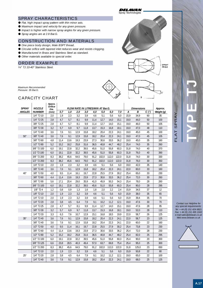
TYP
E T
J
A.17
SPRAY CHARACTERISTICS● Flat, high impact spray pattern with thin minor axis.● Maximum impact and velocity for any given pressure.● Impact is higher with narrow spray angles for any given pressure.● Spray angles are at 2.8 Bar.G.
CONSTRUCTION AND MATERIALS● One piece body design, Male BSPT thread.● Circular orifice with tapered inlet reduces wear and resists clogging.● Manufactured in Brass and Stainless Steel as standard.● Other materials available to special order.
ORDER EXAMPLE1⁄4” TJ 10-40° Stainless Steel.
CAPACITY CHART
SPRAY NOZZLE FLOW RATE IN LITRES/MIN AT Bar.G. Dimensions Approx.ANGLES NUMBER 0,7 1,0 2,0 3,0 4,0 5,0 6,0 7,0 A B C (°) Weight (g)
1/4” TJ 10 2,0 1,9 2,3 3,2 3,9 4,6 5,1 5,6 6,0 15,9 34,9 60 35
1/4” TJ 25 2,8 4,7 5,7 8,1 9,9 11,4 12,7 14,0 15,1 19,0 44,0 50 100
3/8” TJ 25 2,8 4,7 5,7 8,1 9,9 11,4 12,7 14,0 15,1 19,0 46,0 50 105
3/8” TJ 30 3,2 5,7 6,9 9,7 11,8 13,7 15,3 16,8 18,1 19,0 47,0 48 110
1/4” TJ 40 3,6 7,6 9,1 12,9 15,8 18,2 20,4 22,3 24,1 19,0 45,0 45 100
50° 3/8” TJ 40 3,6 7,6 9,1 12,9 15,8 18,2 20,4 22,3 24,1 19,0 47,0 45 105
3/8” TJ 60 4,8 11,4 13,6 19,3 23,9 27,3 30,6 33,5 36,2 19,0 45,0 35 160
1/2” TJ 80 5,2 15,2 18,2 25,8 31,6 36,5 40,8 44,7 48,2 25,4 74,0 35 260
3/8” TJ 100 6,0 19,1 22,8 32,2 39,5 45,6 51,0 55,8 60,3 31,8 74,0 40 370
1/2’ TJ 100 6,0 19,1 22,8 32,2 39,5 45,6 51,0 55,8 60,3 31,8 76,0 40 390
3/8” TJ 200 8,3 38,2 45,6 64,5 79,0 91,2 102,0 112,0 122,0 31,8 74,0 30 330
1/2” TJ 200 8,3 38,2 45,6 64,5 79,0 91,2 102,0 112,0 122,0 31,8 76,0 30 350
1/4” TJ 10 2,0 1,9 2,3 3,2 3,9 4,6 5,1 5,6 6,0 19,0 42,0 35 140
3/8” TJ 40 3,6 7,6 9,1 12,9 15,8 18,2 20,4 22,3 24,1 22,0 60,0 33 160
40° 3/8” TJ 50 4,0 9,5 11,4 16,1 19,7 22,8 25,5 27,9 30,2 25,4 65,0 33 230
3/8” TJ 60 4,4 11,4 13,6 19,3 23,9 27,3 30,6 33,5 36,2 25,4 72,0 30 260
3/8” TJ 90 5,6 17,1 20,4 29,0 35,9 41,0 45,9 50,3 54,3 25,4 78,0 28 260
3/8” TJ 100 6,0 19,1 22,8 32,2 39,5 45,6 51,0 55,8 60,3 25,4 90,0 28 295
1/8” TJ 4 1,2 0,8 0,9 1,3 1,6 1,8 2,0 2,2 2,4 15,9 34,5 37 12
1/8” TJ 10 2,0 1,9 2,3 3,2 3,9 4,6 5,1 5,6 6,0 15,9 38,0 35 65
1/4” TJ 10 2,0 1,9 2,3 3,2 3,9 4,6 5,1 5,6 6,0 15,9 39,4 35 70
1/4” TJ 20 2,8 3,8 4,5 6,4 7,9 9,1 10,2 11,2 12,1 19,0 47,6 30 70
1/4” TJ 25 2,8 4,7 5,7 8,1 9,9 11,4 12,7 14,0 15,1 19,0 47,6 28 95
3/8” TJ 30 3,2 5,7 6,9 9,7 11,8 13,7 15,3 16,8 18,1 19,0 52,0 28 110
1/4” TJ 33 3,3 6,3 7,6 10,7 12,9 15,1 16,8 18,5 19,9 22,0 58,7 26 125
35° 1/4” TJ 40 3,6 7,6 9,1 12,9 15,8 18,2 20,4 22,3 24,1 22,0 58,7 23 125
3/8” TJ 40 3,6 7,6 9,1 12,9 15,8 18,2 20,4 22,3 24,1 22,0 60,0 22 160
1/2” TJ 50 4,0 9,5 11,4 16,1 19,7 22,8 25,5 27,9 30,2 25,4 73,8 23 230
3/8” TJ 60 4,4 11,4 13,6 19,3 23,9 27,3 30,6 33,5 36,2 25,4 72,0 28 230
1/2” TJ 80 5,2 15,2 18,2 25,8 31,6 36,5 40,8 44,7 48,2 25,4 82,0 25 295
1/2” TJ 100 6,0 19,1 22,8 32,2 39,5 45,6 51,0 55,8 60,3 25,4 90,0 20 300
3/8” TJ 125 6,6 23,8 28,5 40,3 49,4 57,0 63,7 69,8 75,4 25,4 95,0 25 300
1/2” TJ 200 8,3 38,2 45,6 64,5 79,0 91,2 102,0 112,0 122,0 31,8 125,0 23 650
1/4” TJ 10 2,0 1,9 2,3 3,2 3,9 4,6 5,1 5,6 6,0 15,9 50,8 22 80
25° 1/4” TJ 20 2,8 3,8 4,5 6,4 7,9 9,1 10,2 11,2 12,1 19,0 65,0 22 100
1/4” TJ 40 3,6 7,6 9,1 12,9 15,8 18,2 20,4 22,3 24,1 19,0 68,0 25 125
Contact our Helpline forany special requirements:Tel: +44 (0) 151 424 6821Fax: +44 (0) 151 495 1043e-mail:[email protected]
Web:www.delavan.co.uk
Maximum RecommendedPressure: 35 Bar.G.
Appox.Orifice
Dia.(mm)
FL
AT
SP
RA
Y
Flatspray2 3/5/01 12:45 pm Page 6

SPRAY CHARACTERISTICS● Directs compressed air or steam in a wide, thin air sheet.● Designed with a relatively large slotted orifice.
CONSTRUCTION AND MATERIALS● Available in Brass and Stainless Steel (recommended for steam
applications).● 3 piece construction, body, tip and cap.● The tip has two flats to facilitate alignment.● Optional body is available in a variety of threads.● Thread sizes are Male BSPT and Female BSPP.● Other materials available to special order.
ORDER EXAMPLENo. 4 Blow-Off Brass = Tip Only.1⁄4” Male No. 3 Blow-Off Stainless Steel = Complete Assembly.
NOZZLE AIR FLOW IN M3/HOUR AT Bar.G.NUMBER 0,7 2 4 7
No. 1 1,1 2,4 4 6,4 75°
No. 2 2,1 4,6 7,5 11,6 55°
No. 3 6,2 12,2 19,5 28,4 60°
No. 4 10,0 20,1 32,3 47,6 100°
No. 5 22,4 46,7 72,2 105,5 60°
Thread Assembly Dimensions (mm) WeightType Type A Hex B C Hex (g)
1/8 Female 20,8 46,0 18,0 69
1/4 Male 20,8 46,0 18,0 61
1/4 Female 20,8 46,0 18,0 68
3/8 Male 20,8 46,0 18,0 63
3/8 Female 20,8 46,0 20,8 69
AIR CAPACITY CHART
DIMENSIONS AND WEIGHTS
Maximum RecommendedPressure: 14 Bar.G.
APPROX.SPRAY
ANGLES (°)
NOZZLE STEAM FLOW IN Kg/HOUR AT Bar.G.NUMBER 0,7 2 4 7
No. 1 0,54 1,27 2,08 3,72 75°
No. 2 1,27 2,35 4,08 7,26 55°
No. 3 3,5 6,12 10,3 17,2 60°
No. 4 5,76 10,2 17,2 29,3 100°
No. 5 12,7 22,9 38,6 64,9 60°
STEAM CAPACITY CHARTAPPROX.
SPRAYANGLES (°)
BLOW-OFF (MALE) ASSEMBLY
BLOW-OFF (FEMALE) ASSEMBLY
TYP
E B
LO
W-O
FF
A.18
Contact our Helpline forany special requirements:Tel: +44 (0) 151 424 6821Fax: +44 (0) 151 495 1043e-mail:[email protected]
Web:www.delavan.co.uk
SP
EC
IAL
PU
RP
OS
E

TYP
E S
L
A.19
Contact our Helpline forany special requirements:Tel: +44 (0) 151 424 6821Fax: +44 (0) 151 495 1043e-mail:[email protected]
Web:www.delavan.co.uk
SP
EC
IAL
PU
RP
OS
E
SPRAY CHARACTERISTICS● Wide flat spray of liquid with even distribution except for the edges which
have heavier deposit.● Wide spray angles with water, at low pressure. ● Useful with steam or air for blow-off application.
CONSTRUCTION AND MATERIALS● Straight through slot shaped orifice.● 3 piece construction, body, tip and cap nut.● The tip has two flats to facilitate alignment.● Optional body is available in a variety of threads.● Thread sizes are Male BSPT and Female BSPP.● Brass and Stainless Steel are standard.● Other materials available to special order.
ORDER EXAMPLESL 40 Stainless Steel = Tip Only.1⁄4” SLF (Female) 18 Brass = Complete Assembly.
WATER CAPACITY CHART
STEAM CAPACITY CHART
Maximum RecommendedPressure: 70 Bar.G.
Thread Assembly Dimensions (mm) WeightSize Type A Hex B C Hex (g)
1/8 SLF 20,8 46,0 18,0 69
1/4 SLM 20,8 46,0 18,0 61
1/4 SLF 20,8 46,0 18,0 68
3/8 SLM 20,8 46,0 18,0 63
3/8 SLF 20,8 46,0 20,8 69
DIMENSIONS AND WEIGHTS
SL (MALE) ASSEMBLY
SL (FEMALE) ASSEMBLY
AIR CAPACITY CHART
APPROX RECOMMENDEDSLOT THREAD SPRAY ANGLES (°)
NOZZLE WIDTH SIZE FLOW RATE IN Kg/HOUR AT Bar.G. AT Bar.G.NUMBER (mm) 1/8 1/4 3/8 0,7 1 2 3 4 5 7 1 3 7
SL 10 0,25 1,3 1,7 2,0 2,5 2,9 3,2 3,8 80 95 100
SL 14 0,35 1,4 1,8 2,4 2,8 3,1 3,6 4,2 80 95 100
SL 18 0,45 1,9 2,3 3,1 3,6 4,1 4,6 5,4 70 85 90
SL 24 0,60 2,5 3,0 4,2 4,8 5,5 6,1 7,2 75 85 95
SL 31 0,80 3,2 3,8 5,4 6,2 7,1 7,9 9,3 75 85 100
SL 40 1,00 4,4 5,2 7,2 10,5 12,1 13,5 15,9 85 90 115
SL 46 1,20 5,0 6,0 8,3 12,1 13,9 15,6 18,3 90 105 110
SL 93 2,40 14,9 17,8 24,0 31,0 37,0 42,0 49,0 75 80 85
APPROX RECOMMENDEDSLOT THREAD SPRAY ANGLES (°)
NOZZLE WIDTH SIZE FLOW RATE IN LITRE/MIN AT Bar.G. AT Bar.G.NUMBER (mm) 1/8 1/4 3/8 0,7 1 2 3 4 5 7 1 3 7
SL 10 0,25 35 46 56 69 78 88 105 80 95 100
SL 14 0,35 39 49 65 75 85 98 114 80 95 100
SL 18 0,45 52 62 85 98 111 124 147 70 85 90
SL 24 0,60 69 82 114 131 150 167 196 75 85 95
SL 31 0,80 88 105 147 170 193 216 255 75 85 100
SL 40 1,00 121 141 196 288 330 370 435 85 90 105
SL 46 1,20 137 164 226 330 379 425 500 90 105 110
SL 93 2,40 405 487 654 850 101 1145 1341 75 80 85
APPROX RECOMMENDEDSLOT THREAD SPRAY ANGLES (°)
NOZZLE WIDTH SIZE FLOW RATE IN LITRE/MIN AT Bar.G. AT Bar.G.NUMBER (mm) 1/8 1/4 3/8 0,7 1 2 3 4 5 7 1 3 7
SL 10 0,25 1,1 1,4 1,7 2,1 2,4 2,7 3,2 85 100 105
SL 14 0,35 1,2 1,5 2,0 2,3 2,6 3,0 3,5 85 100 105
SL 18 0,45 1,6 1,9 2,6 3,0 3,4 3,8 4,5 75 90 95
SL 24 0,60 2,1 2,5 3,5 4,0 4,6 5,1 6,0 90 90 100
SL 31 0,80 2,7 3,2 4,5 5,2 5,9 6,6 7,8 80 90 100
SL 40 1,00 3,7 4,3 6,0 8,8 10,1 11,3 13,3 90 95 110
SL 46 1,20 4,2 5,0 6,9 10,1 11,6 13,0 15,3 95 110 115
SL 93 2,40 12,4 14,9 20 26 31 35 41 80 85 90

SPRAY CHARACTERISTICS● Wide flat spray of liquid with even distribution except for the edges which
have heavier deposit.● Wide spray angles, on water, for low pressure. ● Useful with steam or air for blow-off application.
CONSTRUCTION AND MATERIALS● Straight through slot shaped orifice.● One piece Male BSPT thread only. ● Hexagon body with wrench flats avoid distortion when tightening.● Larger thread sizes are available on request.● Brass and Stainless Steel are standard.● Other materials available to special order.
ORDER EXAMPLE1⁄4” DJ 24 Brass.
APPROX BSPTNOZZLE SLOT THREAD SPRAY ANGLES (°)
NUMBER WIDTH SIZE FLOW RATE IN LITRE/MIN AT Bar.G. AT Bar.G.MALE (mm) 1/4 3/8 0,7 1 2 3 4 5 7 1 3 7DJ 10 0,25 1,1 1,4 1,7 2,1 2,4 2,7 3,2 85 100 105
DJ 14 0,35 1,2 1,5 2,0 2,3 2,6 3,0 3,5 85 100 105
DJ 18 0,45 1,6 1,9 2,6 3,0 3,4 3,8 4,5 75 90 95
DJ 24 0,60 2,1 2,5 3,5 4,0 4,6 5,1 6,0 90 90 100
DJ 31 0,80 2,7 3,2 4,5 5,2 5,9 6,6 7,8 80 90 100
DJ 40 1,00 3,7 4,3 6,0 8,8 10,1 11,3 13,3 90 95 110
DJ 46 1,20 4,2 5,0 6,9 10,1 11,6 13,0 15,3 95 110 115
DJ 93 2,40 12,4 14,9 20 26 31 35 41 80 85 90
APPROX BSPTNOZZLE SLOT THREAD SPRAY ANGLES (°)
NUMBER WIDTH SIZE FLOW RATE IN LITRE/MIN AT Bar.G. AT Bar.G.MALE (mm) 1/4 3/8 0,7 1 2 3 4 5 7 1 3 7DJ 10 0,25 35 46 56 69 78 88 105 80 95 100
DJ 14 0,35 39 49 65 75 85 98 114 80 95 100
DJ 18 0,45 52 62 85 98 111 124 147 70 85 90
DJ 24 0,60 69 82 114 131 150 167 196 75 85 95
DJ 31 0,80 88 105 147 170 193 216 255 75 85 100
DJ 40 1,00 121 141 196 288 330 370 435 85 90 105
DJ 46 1,20 137 164 226 330 379 425 500 90 105 110
DJM 93 2,40 405 487 654 850 101 1145 1341 75 80 85
APPROX BSPTNOZZLE SLOT THREAD SPRAY ANGLES (°)
NUMBER WIDTH SIZE FLOW RATE IN Kg/HOUR AT Bar.G. AT Bar.G.MALE (mm) 1/4 3/8 0,7 1 2 3 4 5 7 1 3 7DJ 10 0,25 1,3 1,7 2,0 2,5 2,9 3,2 3,8 80 95 100
DJ 14 0,35 1,4 1,8 2,4 2,8 3,1 3,6 4,2 80 95 100
DJ 18 0,45 1,9 2,3 3,1 3,6 4,1 4,6 5,4 70 85 90
DJ 24 0,60 2,5 3,0 4,2 4,8 5,5 6,1 7,2 75 85 95
DJ 31 0,80 3,2 3,8 5,4 6,2 7,1 7,9 9,3 75 85 100
DJ 40 1,00 4,4 5,2 7,2 10,5 12,1 13,5 15,9 85 90 115
DJ 46 1,20 5,0 6,0 8,3 12,1 13,9 15,6 18,3 90 105 110
DJ 93 2,40 14,9 17,8 24,0 31,0 37,0 42,0 49,0 75 80 85
TYP
E D
J
A.20
Thread Dimensions (mm) WeightSize A B Hex C (g)
1/4 30,0 15,3 10,3 28
3/8 35,0 18,0 14,3 45
WATER CAPACITY CHART
AIR CAPACITY CHART
STEAM CAPACITY CHART
Contact our Helpline forany special requirements:Tel: +44 (0) 151 424 6821Fax: +44 (0) 151 495 1043e-mail:[email protected]
Web:www.delavan.co.uk
DIMENSIONS AND WEIGHTS
Maximum Recommended Pressure:70 Bar.G. (Metal) 7 Bar.G. (Plastic)
SP
EC
IAL
PU
RP
OS
E

A.21
Contact our Helpline forany special requirements:Tel: +44 (0) 151 424 6821Fax: +44 (0) 151 495 1043e-mail:[email protected]
Web:www.delavan.co.uk
TYP
E A
Z
SPRAY CHARACTERISTICS● Uniform distribution of hard hitting flat spray with a minimum of
atomization.● No soft edges - no need for overlapping.● Minimum flow deviation at varying pressures.● Available spray angles of 0°, 15°, 25°, 40° and 50° @ 10 Bar.G.
CONSTRUCTION AND MATERIALS● One piece construction with no internal shoulders or ledges causing
unwanted liquid turbulence.● Available with Male BSPT pipe thread design only.● Hexagon body with wrench flats avoid distortion when tightening.● Circular shaped orifice reduces wear, no feather edges● Nozzle filter is not needed, orifice will pass small amounts of foreign
matter.● Manufactured in Stainless Steel and Hardened Stainless Steel as
standard.● Other materials available to special order.
ORDER EXAMPLE1⁄4” AZ 6-15° Stainless Steel.
Thread Nozzle Dimensions (mm) WeightSize Type A B Hex C (g)
1/8 AZ 17,5 11,3 9,5 12
1/4 AZ 24,5 15,3 13,0 23
1/4 AZ (HSS) 22,2 15,3 12,0 19
EQUIVNOZZLE ORIFICE BSPT THREAD SIZE FLOW RATE IN LITRES/MIN AT Bar.G.
NUMBER DIA. (mm) 1/8 1/4 15 20 25 35 40 50 60 70
AZ 4 1,25 3,5 4,1 4,6 5,4 5,8 6,5 7,1 7,6
AZ 4,5 1,30 4,0 4,6 5,1 6,1 6,5 7,3 8,0 8,6
AZ 5 1,40 4,4 5,1 5,7 6,7 7,2 8,1 8,8 9,5
AZ 5,5 1,45 4,9 5,6 6,3 7,4 7,9 8,9 9,7 10,5
AZ 6 1,50 5,3 6,1 6,8 8,1 8,7 9,7 10,6 11,4
AZ 6,5 1,60 5,7 6,6 7,4 8,8 9,4 10,5 11,5 12,4
AZ 7 1,65 6,2 7,1 8,0 9,4 10,1 11,3 12,4 13,4
AZ 7,5 1,70 6,6 7,6 8,6 10,1 10,8 12,1 13,2 14,3
AZ 8 1,75 7,1 8,2 9,1 10,8 11,5 12,9 14,1 15,3
AZ 8,5 1,8 7,5 8,7 9,7 11,5 12,3 13,7 15,0 16,2
AZ 9 1,9 8,0 9,2 10,3 12,1 13,0 14,5 16,0 17,2
AZ 10 2,0 8,8 10,2 11,4 13,5 14,4 16,1 17,7 19,1
AZ 15 2,4 13,2 15,3 17,1 20,2 21,6 24,2 26,5 28,6
AZ 20 2,8 17,7 20,4 22,8 27,0 28,8 32,2 35,3 38,1
AZ 30 3,6 24,5 30,6 34,2 40,5 43,3 48,4 53,0 57,2
AZ 40 4,0 35,3 40,8 45,6 54,0 57,7 64,5 70,6 76,3
AZ 50 4,4 44,1 51,0 57,0 67,4 72,0 80,6 88,3 95,4
CAPACITY CHARTMaximum Recommended
Pressure: 150 Bar.G.
DIMENSIONS AND WEIGHTS
AZ STAINLESS STEEL
AZ HARDENED STAINLESS STEEL
HIG
H P
RE
SS
UR
E
High Pres F/S 1 3/5/01 1:45 pm Page 1

TYP
E B
Z
A.22
CAPACITY CHART
Contact our Helpline forany special requirements:Tel: +44 (0) 151 424 6821Fax: +44 (0) 151 495 1043e-mail:[email protected]
Web:www.delavan.co.uk
EQUIV BSPT NOZZLE ORIFICE THREAD SIZE FLOW RATE IN LITRES/MIN AT Bar.G.NUMBER DIA. (mm) 1/4 3/8 1/2 20 25 30 35 40 50 60 70 80 90 100 110
BZ 5 1,2 2,97 3,30 3,61 3,88 4,16 4,69 5,14 5,50 5,88 6,24 6,57 6,93
BZ 8 1,45 5,14 5,74 6,24 6,75 7,21 8,08 8,81 8,54 10,20 10,81 11,31 11,92
BZ 13 1,85 8,12 9,04 9,87 10,61 11,41 12,83 14,04 15,15 16,16 17,17 18,08 18,99
BZ 15 2,0 9,74 10,91 11,82 12,73 13,64 15,25 16,67 18,08 19,29 20,40 21,61 22,62
BZ 20 2,3 12,93 14,44 15,76 16,97 18,18 20,30 22,32 24,04 25,76 27,17 28,79 30,20
BZ 25 2,5 16,36 18,28 19,90 21,41 22,93 25,65 27,98 30,30 32,32 34,24 36,26 38,08
BZ 36 3,0 23,63 26,36, 28,68 30,91 33,03 37,07 40,40 43,83 46,86 49,09 52,32 54,64
BZ 38 3,1 24,85 26,97 30,50 33,03 35,25 40,00 43,63 47,27 50,50 53,73 56,46 59,69
BZ 51 3,7 34,54 38,58 42,22 45,35 48,68 54,24 59,19 64,24 68,38 72,52 76,66 80,30
BZ 54 3,75 35,05 39.09 42,72 45,96 49,09 55,05 60,60 65,25 69,79 73,93 77,57 81,71
BZ 78 4,4 51,41 56,96 62,42 67,47 72,11 80,80 89,03 96,35 103,02 109,08 115,14 120,19
BZ 106 5,0 69,29 77,16 84,44 91,30 97,77 109,08 120,19 129,28 138,37 146,45 154,53 162,61
SPRAY CHARACTERISTICS● Uniform distribution of hard hitting flat spray with a minimum of
atomization.● No soft edges - no need for overlapping.● Minimum flow deviation at varying pressures.● Available only in 30° spray angle measured @ 10 Bar.G.
CONSTRUCTION AND MATERIALS● One piece construction with no internal shoulders or ledges causing
unwanted liquid turbulence.● Available as a Male BSPT pipe thread design only.● Hexagon body with wrench flats avoid distortion when tightening.● Circular shaped orifice reduces wear, no feather edges.● Nozzle filter is not needed, orifice will pass small amounts of foreign
matter.● Manufactured in Stainless Steel and Hardened Stainless Steel as
standard.● Other materials available to special order.
ORDER EXAMPLE3⁄8” BZ 15 Hardened Stainless Steel.
Thread Dimensions (mm) WeightSize A B Hex C (g)
1/4 29,9 15,3 19 35
3/8 40,0 18,0 25,4 65
1/2 46,1 25,7 31,9 120
Maximum RecommendedPressure: 200 Bar.G.
DIMENSIONS AND WEIGHTS
HIG
H P
RE
SS
UR
E
High Pres F/S 1 3/5/01 1:46 pm Page 2

TYP
E 3
43
A.23
SPRAY CHARACTERISTICS● Highly uniform and stable distribution across the complete spray pattern
with a knife-like cutting edge.● Maximum impinging force produced with a minimum loss of energy
resulting in higher efficiency.● Spray patterns do not require overlapping.● Nominal spray angles of 25° and 32°.
CONSTRUCTION AND MATERIALS● Available in type 440 Hardened Stainless Steel.● One piece constructionand with 3⁄8” Male NPT thread
ORDER EXAMPLENozzle Number 343-15.
Contact our Helpline forany special requirements:Tel: +44 (0) 151 424 6821Fax: +44 (0) 151 495 1043e-mail:[email protected]
Web:www.delavan.co.uk
CAPACITY CHARTNOZZLE Equiv.
NUMBER Orif.SPRAY ANGLE Dia. FLOW RATE IN LITRES/MIN AT Bar.G.
25° 32° (mm) 40 55 70 85 100 110 125 140 150 165 180 195 210 240 275
343-1 343-10 2,0 14,5 17,0 19,0 21,0 22,7 23,8 25,5 27,0 27,9 29,0 30,7 32,0 33,2 35,5 37,8
343-3 343-12 2,8 28,7 33,7 38,2 42,2 45,5 47,7 51,0 53,8 55,7 58,6 61,0 63,6 66,0 70,6 75,6
343-5 343-14 3,6 43,2 50,7 57,2 63,0 68,2 71,9 76,0 80,0 82,9 87,0 91,0 95,2 99,2 106 113
343-6 343-15 4,0 57,7 67,8 76,3 84,5 92,5 94,6 103 107 113 117 121 126 134 140 151
343-7 343-16 4,4 72,3 83,2 95,4 104 116 121 129 134 139 148 152 160 164 178 189
343-8 343-17 4,8 85,7 102 114 127 135 144 152 160 166 174 182 190 198 212 227
Dimensions (mm) WeightNozzle A B C (g)
343 31,8 17,5 17,4 35
DIMENSIONS AND WEIGHTS
Maximum RecommendedPressure: 275 Bar.G.
Nozzle Coverage (mm) atHeight 70 Bar.G.(mm) 25° 32°
200 127 152
225 146 165
250 156 181
275 168 194
300 181 210
325 188 222
350 200 238
400 222 264
450 245 289
500 260 305
550 273 318
600 286 324
HIG
H P
RE
SS
UR
E
High Pres F/S 1 3/5/01 1:46 pm Page 3

TYP
E 3
44
A.24
CAPACITY CHART
SPRAY CHARACTERISTICS● Highly uniform and stable distribution across the complete spray pattern
with a knife-like cutting edge.● Maximum impinging force produced with a minimum loss of energy
resulting in higher efficiency.● Tapered ends of the spray pattern make this the best suited to systems set
up for overlapping spray patterns.● Nominal spray angles of 25° and 32°.
CONSTRUCTION AND MATERIALS● Available in type 440 Hardened Stainless Steel.● One piece construction and with 3⁄8” Male NPT thread
ORDER EXAMPLENozzle Number 344 - 6.
Contact our Helpline forany special requirements:Tel: +44 (0) 151 424 6821Fax: +44 (0) 151 495 1043e-mail:[email protected]
Web:www.delavan.co.uk
NOZZLE Equiv.NUMBER Orif.
SPRAY ANGLE Dia. FLOW RATE IN LITRES/MIN AT Bar.G.25° 32° (mm) 40 55 70 85 100 110 125 140 150 165 180 190 200 245 275
344-3 344-12 2,8 28,7 33,7 38,2 42,2 45,5 47,7 51,0 53,8 55,7 58,6 61,0 63,6 66,0 70,6 75,6
344-5 344-14 3,6 43,2 50,7 57,2 63,0 68,2 71,9 76,0 80,0 82,9 87,0 91,0 95,2 99,2 106 113
344-6 344-15 4,0 57,7 67,8 76,3 84,5 92,5 94,6 103 107 113 117 121 126 134 140 151
344-7 344-16 4,4 72,3 83,2 95,4 104 116 121 129 134 139 148 152 160 164 178 189
344-8 344-17 4,8 85,7 102 114 127 135 144 152 160 166 174 182 190 198 212 227
Nozzle Coverage (mm) atHeight 70 Bar.G.(mm) 25° 32°
200 76 99
225 89 111
250 102 124
275 114 137
300 127 149
325 133 159
350 143 172
400 162 191
450 175 213
500 191 232
550 207 251
600 222 270Maximum RecommendedPressure: 275 Bar.G.
Dimensions (mm) WeightNozzle A B C (g)
344 31,8 17,5 17,4 35
DIMENSIONS AND WEIGHTS
HIG
H P
RE
SS
UR
E
High Pres F/S 1 3/5/01 1:46 pm Page 4

TYP
E D
D
A.25
Contact our Helpline forany special requirements:Tel: +44 (0) 151 424 6821Fax: +44 (0) 151 495 1043e-mail:[email protected]
Web:www.delavan.co.uk
HIG
H P
RE
SS
UR
E
SPRAY CHARACTERISTICS● Produces highly uniform flat spray at high pressures.● Maximum impinging force is produced with a minimum loss of energy
resulting in higher efficiency.● Spray pattern has a knife-like cutting edge.● Normal spray angles of 25° and 32°.● Orifice is offset 15° to axis of dovetail.
CONSTRUCTION AND MATERIALS● Dovetail connection nozzle/body for positive alignment.● 3 piece design with Male BSPT thread or Welding Nipple body, available in:● Stainless Steel bodies and cap.● Mild Steel (Welding Nipple body only.)● Longer welding nipple bodies available to special order.● Nozzle is 416 Hardened Stainless Steel.● Tips, bodies and cap can be ordered separately in different materials.● Threaded bodies are 3⁄4” or 1” Male BSPT only.● Other materials available to special order.
ORDER EXAMPLEDD 20-32° Hardened Stainless Steel = Tip Only.3⁄4” DDM (Male) 40-25° Stainless Steel = Complete Assembly.DDW 60-32° Stainless Steel = Welding Assembly.
CAPACITY CHARTEquiv.
NOZZLE Orifice FLOW RATE IN LITRES/MIN AT Bar.G. - FOR BOTH 25° AND 32°NUMBER Dia. (mm) 40 55 70 85 100 110 125 140 150 165 180 195 210 240 275
DD 6 1,5 8,7 10,2 11,5 12,6 13,7 14,4 15,3 16,2 16,8 17,6 18,4 19 20 21 23
DD 10 2,0 15 17 19 21 23 24 26 27 28 30 31 32 33 35 38
DD 12,5 2,2 18 21 24 26 29 30 32 34 35 37 38 40 41 44 47
DD 15 2,4 22 25 28 31 34 36 39 40 42 44 46 48 49 53 57
DD 20 2,8 29 34 38 42 45 48 51 54 56 59 61 64 66 71 76
DD 25 3,2 36 43 48 53 57 60 64 68 70 74 77 80 83 88 94
DD 30 3,6 43 51 57 63 68 72 78 81 84 88 92 95 99 106 113
DD 40 4,0 57 68 76 84 91 96 102 109 112 117 122 27 133 141 151
DD 50 4,4 72 85 95 105 114 119 127 135 140 147 153 159 166 177 189
DD 60 4,8 86 102 114 127 135 142 152 160 166 174 182 190 198 212 227
Assembly Dimensions (mm) WeightType A Hex B C Hex (g)
3/4” DDM 41,3 79,2 38,0 494
1” DDM 41,3 79,2 38,0 551
DDW 41,3 70,0 35,0 dia. 410
Nozzle Coverage (mm) atHeight 70 Bar.G.(mm) 25° 32°
200 125 150
225 135 165
250 155 180
275 165 190
300 180 205
325 185 220
350 195 235
400 220 250
450 240 285
500 255 300
550 270 315
600 280 320
DIMENSIONS AND WEIGHTS
Maximum RecommendedPressure: 275 Bar.G.
High Pres F/S 1 3/5/01 1:46 pm Page 5

SPRAY CHARACTERISTICS● Produces a uniform flat fan shaped pattern.● Requires minimal overlapping to produce an even distribution when used
in multiple nozzle system.● High pressure body design with replaceable insert.● A wide range of flow rates and spray angles.● 0° nozzle sizes available on request.
CONSTRUCTION AND MATERIALS● 3 piece construction. Body, insert and retaining screw.● The orifice insert is manufactured in Tungsten Carbide for maximum wear
resistance at higher pressures.● The insert is recessed for protection.● The high pressure body and retaining screw are manufactured in
Stainless Steel as standard.● Standard thread is 1⁄4” Male BSPT.● Special bodies can be made to order.
ORDER EXAMPLE1⁄4” AQ 4-65°.
TYP
E A
Q
A.26
CAPACITY CHART
Contact our Helpline forany special requirements:Tel: +44 (0) 151 424 6821Fax: +44 (0) 151 495 1043e-mail:[email protected]
Web:www.delavan.co.uk
Equiv.orifice
NOZZLE size FLOW RATE IN LITRES/MIN AT Bar.G. SPRAY ANGLES (°) @ 70 Bar.G.NUMBER (mm) 35 50 70 100 140 210 280 350 25 40 50 65 80 95
AQ 0,5 0,45 0,68 0,81 0,94 1,14 1,36 1,66 1,92 2,15
AQ 0,6 0,51 0,75 0,89 1,06 1,26 1,51 1,84 2,13 2,38
AQ 0,7 0,53 0,90 1,07 1,25 1,52 1,78 2,18 2,51 2,81
AQ 0,8 0,61 1,14 1,36 1,59 1,92 2,27 2,78 3,21 3,59
AQ 1,0 0,66 1,32 1,57 1,89 2,23 2,63 3,22 3,71 4,15
AQ 1,25 0,74 1,70 2,03 2,38 2,87 3,39 4,15 4,79 5,36
AQ 1,5 0,79 2,00 2,39 2,83 3,38 3,97 4,86 5,61 6,27
AQ 2,0 0,91 2,68 3,20 3,78 4,53 5,29 6,47 7,48 8,36
AQ 2,5 1,04 3,33 3,98 4,54 5,62 6,62 8,10 9,36 10,4
AQ 3,0 1,09 4,16 4,97 5,67 7,03 7,94 9,72 11,2 12,5
AQ 3,5 1,22 4,54 5,42 6,44 7,67 9,46 11,5 13,3 14,9
AQ 4,0 1,32 5,30 6,33 7,57 8,95 10,5 12,8 14,8 16,6
AQ 6,0 1,57 7,95 9,50 11,3 13,4 15,8 19,3 22,3 24,9
AQ 8,0 1,83 10,6 12,6 15,1 17,9 21,1 25,8 36,4 33,3
AQ 11,5 2,16 15,5 18,5 21,6 26,2 30,6 37,4 43,2 48,3
Maximum RecommendedPressure: 350 Bar.G.
Thread Dimensions (mm) WeightSize A B C (g)
1/4” 24,5 15,3 13,0 26
DIMENSIONS AND WEIGHTS
HIG
H P
RE
SS
UR
E
High Pres F/S 1 3/5/01 1:46 pm Page 6
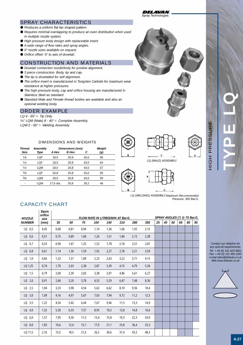
TYP
E L
Q
A.27
Contact our Helpline forany special requirements:Tel: +44 (0) 151 424 6821Fax: +44 (0) 151 495 1043e-mail:[email protected]
Web:www.delavan.co.uk
HIG
H P
RE
SS
UR
E
SPRAY CHARACTERISTICS● Produces a uniform flat fan shaped pattern.● Requires minimal overlapping to produce an even distribution when used
in multiple nozzle system.● High pressure body design with replaceable insert.● A wide range of flow rates and spray angles.● 0° nozzle sizes available on request.● Orifice offset -5° to axis of dovetail.
CONSTRUCTION AND MATERIALS● Dovetail connection nozzle/body for positive alignment.● 3 piece construction. Body, tip and cap.● The tip is dovetailed for self alignment.● The orifice insert is manufactured in Tungsten Carbide for maximum wear
resistance at higher pressures.● The high pressure body, cap and orifice housing are manufactured in
Stainless Steel as standard.● Standard Male and Female thread bodies are available and also an
optional welding body.
ORDER EXAMPLELQ 4 - 65° = Tip Only.1⁄4” LQM (Male) 8 - 40° = Complete Assembly.LQW 2 - 65° = Welding Assembly.
CAPACITY CHART
Maximum RecommendedPressure: 350 Bar.G.
Thread Assembly Dimensions (mm) WeightSize Type A Hex B Hex C (g)
1/8 LQF 18,0 20,8 43,0 65
1/4 LQF 18,0 20,8 43,0 64
1/4 LQM 18,0 20,8 43,0 57
3/8 LQF 20,8 20,8 43,0 65
3/8 LQM 18,0 20,8 43,0 59
- LQW 17,5 dia. 20,8 29,2 46
DIMENSIONS AND WEIGHTS
Equiv.orifice
NOZZLE size FLOW RATE IN LITRES/MIN AT Bar.G. SPRAY ANGLES (°) @ 70 Bar.G.NUMBER (mm) 35 50 70 100 140 210 280 350 25 40 50 65 80 95
LQ 0,5 0,45 0,68 0,81 0,94 1,14 1,36 1,66 1,92 2,15
LQ 0,6 0,51 0,75 0,89 1,06 1,26 1,51 1,84 2,13 2,38
LQ 0,7 0,53 0,90 1,07 1,25 1,52 1,78 2,18 2,51 2,81
LQ 0,8 0,61 1,14 1,36 1,59 1,92 2,27 2,78 3,21 3,59
LQ 1,0 0,66 1,32 1,57 1,89 2,23 2,63 3,22 3,71 4,15
LQ 1,25 0,74 1,70 2,03 2,38 2,87 3,39 4,15 4,79 5,36
LQ 1,5 0,79 2,00 2,39 2,83 3,38 3,97 4,86 5,61 6,27
LQ 2,0 0,91 2,68 3,20 3,78 4,53 5,29 6,47 7,48 8,36
LQ 2,5 1,04 3,33 3,98 4,54 5,62 6,62 8,10 9,36 10,4
LQ 3,0 1,09 4,16 4,97 5,67 7,03 7,94 9,72 11,2 12,5
LQ 3,5 1,22 4,54 5,42 6,44 7,67 9,46 11,5 13,3 14,9
LQ 4,0 1,32 5,30 6,33 7,57 8,95 10,5 12,8 14,8 16,6
LQ 6,0 1,57 7,95 9,50 11,3 13,4 15,8 19,3 22,3 24,9
LQ 8,0 1,83 10,6 12,6 15,1 17,9 21,1 25,8 36,4 33,3
LQ 11,5 2,16 15,5 18,5 21,6 26,2 30,6 37,4 43,2 48,3
LQ (MALE) ASSEMBLY
LQ (WELDING) ASSEMBLY
High Pres F/S 1 3/5/01 1:47 pm Page 7

SPRAY CHARACTERISTICS● Produces highly uniform flat spray at high pressures.● Maximum impinging force is produced with a minimum loss of energy
resulting in higher efficiency.● Spray pattern has knife-like cutting edge.● Normal spray angles of 25° and 32°.● Orifice insert is offset 15° to axis of dovetail.
CONSTRUCTION AND MATERIALS● Dovetail connection nozzle/body for positive alignment.● 3 piece design with Male NPT thread or Welding Nipple body, available in:● Stainless Steel bodies and cap.● Mild Steel (Welding Nipple body only.)● Longer Welding Nipple bodies available to special order.● Nozzle is Stainless Steel with Tungsten Carbide orifice insert.● Tips, bodies and cap can be ordered separately in different materials.● Threaded bodies are 3⁄4” or 1” Male NPT only.● Other materials available to special order.
ORDER EXAMPLEDQ 20-32° = Tip Only.3⁄4” DQM 40-25° Stainless Steel = Complete Assembly.DQW 60-32° Stainless Steel = Welding Assembly.
TYP
E D
Q
A.28
Contact our Helpline forany special requirements:Tel: +44 (0) 151 424 6821Fax: +44 (0) 151 495 1043e-mail:[email protected]
Web:www.delavan.co.uk
CAPACITY CHARTEquiva.
Nozzle Orifice FLOW RATE IN LITRES/MIN AT Bar.G. - FOR BOTH 25° AND 32°Number Dia. (mm) 40 55 70 85 100 110 125 140 150 165 180 195 210 240 275
DQ 6 1,5 8,7 10,2 11,5 12,6 13,7 14,4 15,3 16,2 16,8 17,6 18,4 19 20 21 23
DQ 10 2,0 15 17 19 21 23 24 26 27 28 30 31 32 33 35 38
DQ 12,5 2,2 18 21 24 26 29 30 32 34 35 37 38 40 41 44 47
DQ 15 2,4 22 25 28 31 34 36 39 40 42 44 46 48 49 53 57
DQ 20 2,8 29 34 38 42 45 48 51 54 56 59 61 64 66 71 76
DQ 30 3,6 43 51 57 63 68 72 78 81 84 88 92 95 99 106 113
DQ 40 4,0 57 68 76 84 91 96 102 109 112 117 122 127 133 141 151
DQ 50 4,4 72 85 95 105 114 119 127 135 140 147 153 159 166 177 189
DQ 60 4,8 86 102 114 127 135 142 152 160 166 174 182 190 198 212 227
DQ 70 5,2 102 117 132 144 155 167 178 189 197 204 212 219 231 246 265
Assembly Dimensions (mm) WeightType A Hex B C Hex (g)
3/4” DQM 41,3 79,2 38,0 504
1” DQM 41,3 79,2 38,0 561
DQW 41,3 70,0 35,0 dia. 420
Nozzle Coverage (mm) atHeight 70 Bar.G.(mm) 25° 32°
200 125 150
225 135 165
250 155 180
275 165 190
300 180 205
325 185 220
350 195 235
400 220 250
450 240 285
500 255 300
550 270 315
600 280 320
DIMENSIONS AND WEIGHTS
Maximum RecommendedPressure: 275 Bar.G.
HIG
H P
RE
SS
UR
E
Note:- This nozzle type is also availableas the DE type design with strainerand flow stabiliser.
High Pres F/S 1 3/5/01 1:47 pm Page 8

TYP
E D
E
A.29
Contact our Helpline forany special requirements:Tel: +44 (0) 151 424 6821Fax: +44 (0) 151 495 1043e-mail:[email protected]
Web:www.delavan.co.uk
HIG
H P
RE
SS
UR
E
SPRAY CHARACTERISTICS● Produces highly uniform flat spray at pressures up to 4000 PSIG
(275 Bar.G.).● Maximum impinging force is produced with a minimum loss of energy
resulting in higher efficiency.● Spray pattern has knife-like cutting edge.● Available spray angles of 25° and 32°.
CONSTRUCTION AND MATERIALS● Unique connection nozzle/body for positive alignment.● Cap, mild steel.● Orifice assembly, tungsten carbide orifice for maximum wear resistance.● Strainer available in several styles.● Body, mild steel with 3⁄4” - 14 NPTM threads and 1” - 11 - 1⁄2”
NPTM threads or welding nipple type.● Cap and body also available in 303 Stainless Steel by special order.
ORDER EXAMPLEDE 30-32° = Tip and Strainer Assembly Only.1” DEM 60-25° Stainless Steel = Complete Assembly.DEW 40-32° Stainless Steel = Welding Assembly
CAPACITY CHARTEquiv.
NOZZLE Orifice FLOW RATE IN LITRES/MIN AT Bar.G. - FOR BOTH 25° AND 32°NUMBER Dia. (mm) 40 55 70 85 100 110 125 140 150 165 180 195 210 240 275
DE 20 2,8 29 34 38 42 45 48 51 54 56 59 61 64 66 71 76
DE 30 3,6 43 51 57 63 68 72 78 81 84 88 92 95 99 106 113
DE 40 4,0 57 68 76 84 91 96 102 109 112 117 122 27 133 141 151
DE 50 4,4 72 85 95 105 114 119 127 135 140 147 153 159 166 177 189
DE 60 4,8 86 102 114 127 135 142 152 160 166 174 182 190 198 212 227
DE 70 5,2 102 117 132 144 155 167 178 189 197 204 212 219 231 246 265
Assembly Dimensions (mm) WeightType A Hex B C D dia (g)
3/4” DEM 41,3 79,2 114,3 - 553
1” DEM 41,3 79,2 114,3 - 624
DEW 41,3 79,2 114,3 33,4 624
Nozzle Coverage (mm) atHeight 70 Bar.G.(mm) 25° 32°
200 125 150
225 135 165
250 155 180
275 165 190
300 180 205
325 185 220
350 195 235
400 220 250
450 240 285
500 255 300
550 270 315
600 280 320
Maximum RecommendedPressure: 275 Bar.G.
DIMENSIONS AND WEIGHTS
DEM
DEW
High Pres F/S 1 3/5/01 1:47 pm Page 9

A.30
Contact our Helpline forany special requirements:Tel: +44 (0) 151 424 6821Fax: +44 (0) 151 495 1043e-mail:[email protected]
Web:www.delavan.co.uk
NO
TE
SNOTES
HIG
H P
RE
SS
UR
E
High Pres F/S 1 3/5/01 1:47 pm Page 10

WELCOME TO DELAVAN
of newchallengesMeeting the
industriesand NEW markets
B Hollow Cone
Del Nozzle A4 dividers A/W 21/6/01 10:35 am Page 3

TYPICAL APPLICATIONSAerating water, brine sprays, chemical processing, coil defrosting, dust control, evaporative condensers, evaporative coolers, industrialwashers, roof cooling, spray ponds, spray coating, gas scrubbing and washing, humidification, gas cooling, cooling towers, coal washing,degreasing, gravel washing, dishwashing, foam control, industrial washing and water fountains.
TYPICAL SPRAY PATTERN
Nozzle Spray Characteristics Spray Basic Features Flow Range. PageType Angles L/Min @ 3 Bar.G. No.WM 40°,60°,80° 0,04 – 1,97 B.1
WG 40°,60°,80° 0,04 – 1,97 B.2
WA 40°,60°,80° 0,04 – 1,97 B.3
WDA 30°,45°,60°, 0,019 – 1,3 B.470°,80°,90°
HC 45°,70°,80° 0,066 – 1,72 B.5
BJ 44° – 98° 0,94 – 46,86 B.6
DC 20° – 110° 0,32 – 9,86 B.7
AG 65° – 75° 1,6 – 39,5 B.8
AH 100° – 115° 1,6 – 39,5 B.9
WS 65°,70°,75° 0,8 – 39,5 B.10
CBJ 44° – 98° 0,94 – 46,86 B.11
PJ 90°,120°,150°, 8,05 – 59,19 B.12180°,210°
AE 65° – 95° 0,79 – 138 B.13
AF 100°,110°, 0,79 – 98,8 B.14115°,120°
WR 45° – 155° 4,7 – 39,5 B.15
WRW 110°,115°, 0,79 – 94,7 B.16140°
RA 120° – 140° 0,79 – 111,0 B.17
BE 55° – 90° 130 – 3500 B.18
* WRA- 50° – 100° 62 – 501* B.19WRS
WRA-RD 100° – 135° 65 – 414 B.20WRS-RD
Uniform distribution with very fine atomisation.
Uniform distribution with very fine atomisation.
Uniform distribution with very fine atomisation.
Uniform distribution with very fine atomisation.
Uniform distribution with very fine atomisation.
Uniform distribution with fine to coarseatomisation.
Uniform distribution with fine to mediumatomisation.
Uniform distribution with fine to coarseatomisation.
Uniform distribution with fine to coarseatomisation.
Uniform distribution with fine to coarseatomisation.
Uniform distribution with fine to coarseatomisation.
Relatively uniform distribution with fine tocoarse atomisation.
Uniform distribution with fine to coarseatomisation.
Uniform distribution with fine to coarseatomisation.
Uniform distribution with fine to coarseatomisation.
Uniform distribution with fine to coarseatomisation.
Uniform distribution of a 'Raindrop' type spray.
Uniform distribution with coarse atomisation.
Uniform distribution with coarse atomisation.
Uniform distribution of a 'Raindrop' type spray.
1/4" BSPT Male thread.
Flanged tip design for use with standard bodiesand caps.9/16" UNEF thread for use with special Male andFemale BSP threaded adaptors.9/16" UNEF thread for use with special Male andFemale BSP threaded adaptors.
Flanged tip design for use with standard bodiesand caps.1/8"-1" BSPT Male and BSPP Female threads.
Two piece nozzle design for use with standardbodies and caps.3/8"-3/4" BSPT Male thread.
3/8"-3/4" BSPT Male thread.
1/8"-3/4" NPT Male and Female threads.
1/8"-1" BSPP Male threads. More compact than BJtype.1/4"-3/4" BSPT Male threads.
1/8"-1" BSPT Male and BSPP Female threads.
1/8"-1" BSPT Male and BSPP Female threads.
3/8" NPT Male and Female threads.
1/4" and 3/4" NPT Male threads.
1/4" and 3/4" NPT Male threads.
11/4"-4" BSPT Female threads.
11/2" BSPT Male thread or Quick Coupler Adaptorconnection.
11/2" BSPT Male thread or Quick Coupler Adaptorconnection.
* Flow quoted at 2 Bar.G.
SE
CTIO
N IN
DE
X
Contact our Helpline forany special requirements:Tel: +44 (0) 151 424 6821Fax: +44 (0) 151 495 1043e-mail:[email protected]
Web:www.delavan.co.uk
HO
LLO
W C
ON
E
Del Nozzle A4 dividers A/W 21/6/01 10:35 am Page 4

B.1
Contact our Helpline forany special requirements:Tel: +44 (0) 151 424 6821Fax: +44 (0) 151 495 1043e-mail:[email protected]
Web:www.delavan.co.uk
TYP
E W
M
CAPACITY CHART
Dimensions (mm) WeightA Hex B C D (g)
15,9 27,8 16,7 44,5 14
SPRAY CHARACTERISTICS● Uniform distribution with finest possible atomisation using direct liquid
pressure alone.● The standard spray angles of 40°, 60° or 80° are the nominal angles close
to the nozzle orifice.● For small capacity tips up to say 8 litres/hour the angle falls off rapidly a
few inches from the tip. The larger the tip size the further the nominalangle projects before the spray begins to fall away.
● The nozzles produce a hollow cone spray but with the small capacity tipsthe spray rapidly merges into a “Solid” cone type.
CONSTRUCTION AND MATERIALS● Nozzle tips precision machined to ensure most perfect spray available at
low throughputs.● Internal distributor, screw pin and strainers are renewable in most sizes.● Available in Brass and 316 Stainless Steel as standard.● Nozzle has 1⁄4” Male BSPT thread as standard.● Other materials available to special order.
ORDER EXAMPLEWM 1408 Brass.
NOZZLE NUMBERS MAXSPRAY ANGLES AT 7 Bar.G. MESH FLOW RATE IN LITRES/HOUR AT Bar.G.
40° 60° 80° SIZE 1,5 2 3 3,5 4 6 7 8
WM 054 WM 056 WM 058 200 - - - - 1,47 2,04 2,29 2,46
WM 074 WM 076 WM 078 200 - - 2,22 2,42 2,59 3,12 3,20 3,48
WM 104 WM 106 WM 108 200 - - 3,08 3,25 3,53 4,36 4,57 5,04
WM 124 WM 126 WM 128 200 - - 3,74 4,03 4,20 5,21 5,49 5,80
WM 154 WM 156 WM 158 200 - - 4,97 5,03 5,36 6,39 6,86 7,23
WM 204 WM 206 WM 208 80 4,73 5,36 6,39 6,86 7,37 8,76 9,15 9,37
WM 254 WM 256 WM 258 80 5,92 6,47 7,91 8,32 8,93 10,7 11,4 12,1
WM 304 WM 306 WM 308 80 6,87 8,04 9,47 10,1 10,6 12,8 13,7 14,4
WM 354 WM 356 WM 358 80 8,05 9,15 10,9 11,5 12,3 14,9 16,0 17,0
WM 404 WM 406 WM 408 80 9,00 10,0 12,3 13,1 14,1 17,0 18,3 19,4
WM 454 WM 456 WM 458 80 10,27 11,5 13,7 14,6 15,6 18,9 20,6 21,9
WM 504 WM 506 WM 508 80 10,89 12,7 15,2 16,1 17,4 21,1 22,9 24,5
WM 554 WM 556 WM 558 80 12,31 13,8 16,8 17,8 19,2 23,2 25,2 26,9
WM 604 WM 606 WM 608 80 13,26 15,1 18,0 19,2 21,0 25,6 27,4 29,2
WM 704 WM 706 WM 708 80 15,62 17,9 21,3 22,8 24,6 29,8 32,0 34,4
WM 804 WM 806 WM 808 80 17,52 20,1 26,0 26,5 27,7 34,3 36,6 39,7
WM 1004 WM 1006 WM 1008 80 21,31 24,6 30,1 32,5 34,6 42,6 45,7 49,1
WM 1054 WM 1056 WM 1058 80 22,49 25,4 31,2 33,8 36,4 45,0 48,0 51,3
WM 1154 WM 1156 WM 1158 40 25,1 29,5 35,0 38,0 41,1 49,2 52,6 55,8
WM 1404 WM 1406 WM 1408 40 28,4 33,5 41,2 44,6 47,5 59,7 64,0 67,9
WM 1704 WM 1706 WM 1708 40 33,6 39,7 49,2 52,6 56,2 69,8 77,8 85,3
WM 2004 WM 2006 WM 2008 40 43,6 49,1 59,2 64,0 69,2 85,2 91,5 97,3
WM 2504 WM 2506 WM 2508 40 52,1 60,3 73,4 78,2 84,8 104,2 114,3 122,8
WM 3004 WM 3006 WM 3008 40 66,3 74,1 90,0 94,2 101,3 125,0 137,2 150,4
WM 3504 WM 3506 WM 3508 40 75,8 86,6 104,2 109,8 117,2 144,9 160,1 175,0
WM 4004 WM 4006 WM 4008 40 85,2 99,3 118,4 125,8 133,9 165,7 183,0 200,9
Maximum RecommendedPressure: 35 Bar.G.
DIMENSIONS AND WEIGHTS
HO
LLO
W C
ON
E S
PR
AY
Hollow cone spray 1 22/6/01 10:45 pm Page 1

TYP
E W
G
B.2
SPRAY CHARACTERISTICS● Uniform distribution with finest possible atomisation using direct liquid
pressure alone.● The standard spray angles of 40°, 60° or 80° are the nominal angles close
to the nozzle orifice.● For small capacity tips up to say 8 litres/hour the angle falls off rapidly a
few inches from the tip. The larger the tip size the further the nominalangle projects before the spray begins to fall away.
● The nozzles produce a hollow cone spray but with the small capacity tipsthe spray rapidly merges into a “Solid” cone type.
CONSTRUCTION AND MATERIALS● Nozzle tips precision machined to ensure most perfect spray available at
low throughputs.● Internal distributor, screw pin and strainers are renewable in most sizes.● Available in Brass and 316 Stainless Steel as standard.● Used with standard bodies and caps.● Body thread sizes are Male BSPT and Female BSPP.● Other materials available to special order.
ORDER EXAMPLEWG 154 Brass = Tip Only.1⁄8” WGF 2008 (Female) Brass = Complete Assembly.
Contact our Helpline forany special requirements:Tel: +44 (0) 151 424 6821Fax: +44 (0) 151 495 1043e-mail:[email protected]
Web:www.delavan.co.uk
Maximum RecommendedPressure: 35 Bar.G.
DIMENSIONS AND WEIGHTS
CAPACITY CHARTNOZZLE NUMBERS MAX
SPRAY ANGLES AT 7 Bar.G. MESH FLOW RATE IN LITRES/HOUR AT Bar.G.40° 60° 80° SIZE 1,5 2 3 3,5 4 6 7 8
WG 054 WG 056 WG 058 200 - - - - 1,47 2,04 2,29 2,46
WG 074 WG 076 WG 078 200 - - 2,22 2,42 2,59 3,12 3,20 3,48
WG 104 WG 106 WG 108 200 - - 3,08 3,25 3,53 4,36 4,57 5,04
WG 124 WG 126 WG 128 200 - - 3,74 4,03 4,20 5,21 5,49 5,80
WG 154 WG 156 WG 158 200 - - 4,97 5,03 5,36 6,39 6,86 7,23
WG 204 WG 206 WG 208 80 4,73 5,36 6,39 6,86 7,37 8,76 9,15 9,37
WG 254 WG 256 WG 258 80 5,92 6,47 7,91 8,32 8,93 10,7 11,4 12,1
WG 304 WG 306 WG 308 80 6,87 8,04 9,47 10,1 10,6 12,8 13,7 14,4
WG 354 WG 356 WG 358 80 8,05 9,15 10,9 11,5 12,3 14,9 16,0 17,0
WG 404 WG 406 WG 408 80 9,00 10,0 12,3 13,1 14,1 17,0 18,3 19,4
WG 454 WG 456 WG 458 80 10,27 11,5 13,7 14,6 15,6 18,9 20,6 21,9
WG 504 WG 506 WG 508 80 10,89 12,7 15,2 16,1 17,4 21,1 22,9 24,5
WG 554 WG 556 WG 558 80 12,31 13,8 16,8 17,8 19,2 23,2 25,2 26,9
WG 604 WG 606 WG 608 80 13,26 15,1 18,0 19,2 21,0 25,6 27,4 29,2
WG 704 WG 706 WG 708 80 15,62 17,9 21,3 22,8 24,6 29,8 32,0 34,4
WG 804 WG 806 WG 808 80 17,52 20,1 26,0 26,5 27,7 34,3 36,6 39,7
WG 1004 WG 1006 WG 1008 80 21,31 24,6 30,1 32,5 34,6 42,6 45,7 49,1
WG 1054 WG 1056 WG 1058 80 22,49 25,4 31,2 33,8 36,4 45,0 48,0 51,3
WG 1154 WG 1156 WG 1158 40 25,1 29,5 35,0 38,0 41,1 49,2 52,6 55,8
WG 1404 WG 1406 WG 1408 40 28,4 33,5 41,2 44,6 47,5 59,7 64,0 67,9
WG 1704 WG 1706 WG 1708 40 33,6 39,7 49,2 52,6 56,2 69,8 77,8 85,3
WG 2004 WG 2006 WG 2008 40 43,6 49,1 59,2 64,0 69,2 85,2 91,5 97,3
WG 2504 WG 2506 WG 2508 40 52,1 60,3 73,4 78,2 84,8 104,2 114,3 122,8
WG 3004 WG 3006 WG 3008 40 66,3 74,1 90,0 94,2 101,3 125,0 137,2 150,4
WG 3504 WG 3506 WG 3508 40 75,8 86,6 104,2 109,8 117,2 144,9 160,1 175,0
WG 4004 WG 4006 WG 4008 40 85,2 99,3 118,4 125,8 133,9 165,7 183,0 200,9
WGM (MALE) ASSEMBLY WGF (FEMALE) ASSEMBLY
HO
LLO
W C
ON
E S
PR
AY
Assembly Dimensions (mm) WeightType A Hex B Hex C in (g)
1/8 WGF 18 20,8 54 70
1/8 WGM 18 20,8 52.4 60
1/4 WGF 18 20,8 54 70
1/4 WGM 18 20,8 54 62
Hollow cone spray 1 22/6/01 10:45 pm Page 2

TYP
E W
A
B.3
Contact our Helpline forany special requirements:Tel: +44 (0) 151 424 6821Fax: +44 (0) 151 495 1043e-mail:[email protected]
Web:www.delavan.co.uk
CAPACITY CHART
Assembly Dimensions (mm) WeightType A Hex B C D E Hex (g)
1/8 Female 15,9 52,4 38,1 14,3 18,0 82
1/4 Male 15,9 52,4 38,1 14,3 18,0 78
1/4 Female 15,9 52,4 38,1 14,3 18,0 69
SPRAY CHARACTERISTICS● Uniform distribution with finest possible atomisation using direct liquid
pressure alone.● The standard spray angles of 40°, 60° or 80° are the nominal angles close
to the nozzle orifice.● For small capacity tips up to say 8 litres/hour the angle falls off rapidly a
few inches from the tip. The larger the tip size the further the nominalangle projects before the spray begins to fall away.
● The nozzles produce a hollow cone spray but with the small capacity tipsthe spray rapidly merges into a “Solid” cone type.
CONSTRUCTION AND MATERIALS● Nozzle tips precision machined to ensure most perfect spray available at
low throughputs.● Internal distributor, screw pin and strainers are renewable in most sizes.● Available in Brass and 316 Stainless Steel as standard.● Nozzle thread is 9⁄16” - 24 UNEF.● Adaptors are available with 1⁄4” Male BSPT and 1⁄8”/1⁄4” Female BSPP and
can be ordered separately.● Other materials available to special order.
ORDER EXAMPLEWA 1408 Stainless Steel = Tip Only.1⁄4” Male WA 808 Brass = Complete Assembly.
NOZZLE NUMBERS MAXSPRAY ANGLES AT 7 Bar.G. MESH FLOW RATE IN LITRES/HOUR AT Bar.G.
40° 60° 80° SIZE 1,5 2 3 3,5 4 6 7 8WA 054 WA 056 WA 058 200 - - - - 1,47 2,04 2,29 2,46
WA 074 WA 076 WA 078 200 - - 2,22 2,42 2,59 3,12 3,20 3,48
WA 104 WA 106 WA 108 200 - - 3,08 3,25 3,53 4,36 4,57 5,04
WA 124 WA 126 WA 128 200 - - 3,74 4,03 4,20 5,21 5,49 5,80
WA 154 WA 156 WA 158 200 - - 4,97 5,03 5,36 6,39 6,86 7,23
WA 204 WA 206 WA 208 80 4,73 5,36 6,39 6,86 7,37 8,76 9,15 9,37
WA 254 WA 256 WA 258 80 5,92 6,47 7,91 8,32 8,93 10,7 11,4 12,1
WA 304 WA 306 WA 308 80 6,87 8,04 9,47 10,1 10,6 12,8 13,7 14,4
WA 354 WA 356 WA 358 80 8,05 9,15 10,9 11,5 12,3 14,9 16,0 17,0
WA 404 WA 406 WA 408 80 9,00 10,0 12,3 13,1 14,1 17,0 18,3 19,4
WA 454 WA 456 WA 458 80 10,27 11,5 13,7 14,6 15,6 18,9 20,6 21,9
WA 504 WA 506 WA 508 80 10,89 12,7 15,2 16,1 17,4 21,1 22,9 24,5
WA 554 WA 556 WA 558 80 12,31 13,8 16,8 17,8 19,2 23,2 25,2 26,9
WA 604 WA 606 WA 608 80 13,26 15,1 18,0 19,2 21,0 25,6 27,4 29,2
WA 704 WA 706 WA 708 80 15,62 17,9 21,3 22,8 24,6 29,8 32,0 34,4
WA 804 WA 806 WA 808 80 17,52 20,1 26,0 26,5 27,7 34,3 36,6 39,7
WA 1004 WA 1006 WA 1008 80 21,31 24,6 30,1 32,5 34,6 42,6 45,7 49,1
WA 1054 WA 1056 WA 1058 80 22,49 25,4 31,2 33,8 36,4 45,0 48,0 51,3
WA 1154 WA 1156 WA 1158 40 25,1 29,5 35,0 38,0 41,1 49,2 52,6 55,8
WA 1404 WA 1406 WA 1408 40 28,4 33,5 41,2 44,6 47,5 59,7 64,0 67,9
WA 1704 WA 1706 WA 1708 40 33,6 39,7 49,2 52,6 56,2 69,8 77,8 85,3
WA 2004 WA 2006 WA 2008 40 43,6 49,1 59,2 64,0 69,2 85,2 91,5 97,3
WA 2504 WA 2506 WA 2508 40 52,1 60,3 73,4 78,2 84,8 104,2 114,3 122,8
WA 3004 WA 3006 WA 3008 40 66,3 74,1 90,0 94,2 101,3 125,0 137,2 150,4
WA 3504 WA 3506 WA 3508 40 75,8 86,6 104,2 109,8 117,2 144,9 160,1 175,0
WA 4004 WA 4006 WA 4008 40 85,2 99,3 118,4 125,8 133,9 165,7 183,0 200,9
DIMENSIONS AND WEIGHTS
Maximum RecommendedPressure: 35 Bar.G.
WA (MALE) ASSEMBLY WA (FEMALE) ASSEMBLY
HO
LLO
W C
ON
E S
PR
AY
Hollow cone spray 1 22/6/01 10:46 pm Page 3

TYP
E W
DA
CAPACITY CHART
B.4
SPRAY CHARACTERISTICS● Finely atomised hollow cone spray pattern.● Available spray angles of 30°, 45°, 60°, 70°, 80° and 90° at 8,6 Bar.G.
pressure.
CONSTRUCTION AND MATERIALSNozzle consists of five basic parts:● Nozzle body - Brass or 416 Stainless Steel.● Orifice Disc - 416 Stainless Steel.● Distributor - 416 Stainless Steel.● Retainer - Brass or 416 Stainless Steel.● Strainer - (used up to WDA 14).● Nozzle thread is 9⁄16” - 24 UNEF.● Adaptors are available with 1⁄4” Male BSPT and 1⁄8”/1⁄4” Female BSPP and
can be ordered separately.
ORDER EXAMPLEWDA 8,0-70° Stainless Steel = Tip Only.1⁄4” Female WDA 12,0-70° Brass = Complete Assembly.
Contact our Helpline forany special requirements:Tel: +44 (0) 151 424 6821Fax: +44 (0) 151 495 1043e-mail:[email protected]
Web:www.delavan.co.uk
APPROX.NOZZLE ORIFICE FLOW RATE IN LITRES/HOUR AT Bar.G.NUMBER DIA. (mm) 2 3 5 7 10 15 20 35
0,5 x 0,21 - - 1,45 1,72 2,05 2,51 2,87 3,82
0,75 x 0,23 - - 2,16 2,56 3,05 3,74 4,32 5,72
1,0 0,28 - - 2,87 3,40 4,10 5,02 5,77 7,63
1,5 0,33 - - 4,32 5,11 6,15 7,53 8,64 11,4
2,0 0,38 - - 5,77 6,83 8,19 10,0 11,6 15,3
2,5 0,41 - - 7,19 8,55 10,2 12,5 14,5 19,1
3,0 0,46 - - 8,64 10,2 12,3 15,1 17,3 22,9
4,0 0,64 - 8,69 11,5 13,7 16,4 20,1 23,1 30,5
5,0 0,64 - 11,1 14,5 17,2 20,5 25,1 28,7 38,2
6,0 0,74 - 14,2 17,5 20,6 24,6 30,1 34,6 45,8
8,0 0,81 - 17,8 23,1 27,5 33,1 40,6 46,2 61,1
10,0 0,89 17,9 22,1 28,7 34,0 41,0 50,2 57,7 76,3
12,0 1,02 21,6 26,9 34,6 40,8 49,2 60,2 69,3 91,6
14,0 1,02 25,3 31,2 40,2 47,7 57,0 69,8 80,8 107
16,0* 1,17 29,1 35,6 46,2 54,6 65,2 79,8 92,4 122
18,0* 1,32 32,8 39,9 51,8 61,4 73,4 89,9 104 137
20,0* 1,40 36,5 44,6 57,8 68,3 81,6 99,9 115 153
24,0* 1,52 45,8 53,3 69,3 82,1 98,0 120 139 183
30,0* 1,70 54,4 66,8 86,4 102 123 150 173 229
35,0* 1,78 64,1 78,2 101 120 143 175 202 267
Maximum RecommendedPressure: 35 Bar.G.
Assembly Dimensions (mm) WeightType A Hex B C D E Hex (g)
1/8 Female 15,9 52,4 38,1 14,3 18,0 82
1/4 Male 15,9 52,4 38,1 14,3 18,0 78
1/4 Female 15,9 52,4 38,1 14,3 18,0 69
DIMENSIONS AND WEIGHTS
WDA (MALE) ASSEMBLY WDA (FEMALE) ASSEMBLY
x Not available in 30° or 45°.* These sizes are supplied without strainers.
HO
LLO
W C
ON
E S
PR
AY
Hollow cone spray 1 22/6/01 10:46 pm Page 4

TYP
E H
C
B.5
Assembly Dimensions (mm) WeightType A Hex B C Hex (g)
1⁄8 Female 20,8 47,7 18,0 70
1⁄8 Male 20,8 46,0 18,0 60
1⁄4 Female 20,8 47,7 18,0 70
1⁄4 Male 20,8 47,7 18,0 62
Contact our Helpline forany special requirements:Tel: +44 (0) 151 424 6821Fax: +44 (0) 151 495 1043e-mail:[email protected]
Web:www.delavan.co.uk
CAPACITY CHART
SPRAY CHARACTERISTICS● Finely atomised hollow cone spray pattern.● Nominal spray angle of 70° (45° and 80° to special order).
CONSTRUCTION AND MATERIALS● Four part design - nozzle body, strainer, tip and cap.● Tip consists of body with orifice insert, distributor and screw pin.● Tips are interchangeable and replaceable. ● Body thread sizes are Male BSPT and Female BSPP.● 100 - mesh Stainless Steel strainers supplied on request.● Brass with 416 Stainless Steel metering parts.
ORDER EXAMPLEHC 5 = Tip Only.1⁄4” HC 5 (Male) = Complete Assembly.1⁄4” HC 10 (Female) = Complete Assembly.
NOZZLE FLOW RATE IN LITRES/HOUR AT Bar.G.NUMBER 2 3 4 5 6 7
HC 1,0 3,23 3,95 4,56 5,10 5,58 6,03
HC 1,25 4,03 4,93 5,70 6,37 6,98 7,54
HC 1,50 4,84 5,92 6,84 7,64 8,37 9,04
HC 2,0 6,45 7,89 9,12 10,2 11,2 12,1
HC 2,5 8,05 9,57 11,4 12,7 14,0 15,1
HC 3,0 9,65 11,8 13,7 15,3 16,7 18,0
HC 4,0 12,9 15,8 18,2 20,4 22,3 24,1
HC 5,0 16,1 19,7 22,8 25,5 27,9 30,1
HC 6,0 19,3 23,7 27,3 30,6 33,5 36,2
HC 8,0 25,8 31,6 36,5 40,8 44,7 48,3
HC 10,0 32,2 39,5 45,6 51,0 55,8 60,3
HC 12,0 38,6 47,4 54,7 61,1 67,0 72,4
HC 14,0 45,1 55,3 63,8 71,3 78,1 84,4
HC 18,0 58,0 71,0 82,0 91,7 100 108
HC 22,0 71,0 86,8 100 112 123 133
HC 26,0 84,0 103 119 132 145 157
DIMENSIONS AND WEIGHTS
Maximum RecommendedPressure: 35 Bar.G.
HC (MALE) ASSEMBLY
HC (FEMALE) ASSEMBLYH
OL
LO
W C
ON
E S
PR
AY
HC TYPE
Hollow cone spray 1 22/6/01 10:46 pm Page 5

TYP
E B
J
CAPACITY CHART
Thread Nozzle Dimensions (mm) WeightSize Type A Hex B C (g)
1/8 BJM 11,3 17,5 9,6 10
1/8 BJF 15,3 25,4 13,5 21
1/4 BJM 15,3 24,5 13,0 24
1/4 BJF 18,0 27,8 12,7 35
3/8 BJM 18,0 25,5 14,0 35
3/8 BJF 20,8 38,9 21,1 58
1/2 BJM 25,6 32,0 16,1 75
1/2 BJF 25,6 50,0 28,3 118
3/4 BJM 28,0 36,0 19,0 115
3/4 BJF 31,8 62,7 31,5 215
1 BJM 38,0 50,0 28,5 290
1 BJF 38,0 81,0 51,0 330
B.6
SPRAY CHARACTERISTICS● Uniform distribution of droplets in a hollow cone spray pattern.● For nozzles of the same capacity, the droplet size of hollow cone type
nozzles are smaller than droplets produced by solid cone nozzles.
CONSTRUCTION AND MATERIALS● One-piece body with removable spiral-type core.● Hexagon body for easy installation, eliminates distortion of orifice
during installation.● Available with Male BSPT or Female BSPP threads.● Brass and 316 Stainless Steel are standard.● Other materials available to special order.
ORDER EXAMPLE3⁄8” BJM 6 (Male) Brass.1” BJF 60 (Female) Stainless Steel.
Contact our Helpline forany special requirements:Tel: +44 (0) 151 424 6821Fax: +44 (0) 151 495 1043e-mail:[email protected]
Web:www.delavan.co.uk
APPROX. SPRAYORIFICE ANGLE (°)
NOZZLE DIA. BSPT THREAD SIZE FLOW RATE IN LITRES/MIN AT Bar.G. AT Bar.G.NUMBER (mm) 1/8 1/4 3/8 1/2 3/4 1 ,7 1 1,5 2 3 4 5 6 7 8 ,7 2 5
BJ 1 1,6 ,45 ,53 ,65 ,76 ,94 1,09 1,22 1,33 1,46 1,57 44 65 70
BJ 2 2,0 ,62 ,74 ,87 1,00 1,20 1,37 1,53 1,67 1,80 1,93 60 70 75
BJ 3 2,4 ,69 ,84 ,98 1,12 1,36 1,57 1,73 1,88 2,03 2,16 66 80 85
BJ 3 2,8 ,74 ,86 1,04 1,19 1,44 1,66 1,84 1,99 2,16 2,29 62 65 70
BJ 4 2,4 ,90 1,07 1,29 1,47 1,79 2,04 2,27 2,46 2,67 2,85 62 66 80
BJ 5 2,8 1,02 1,21 1,47 1,70 2,09 2,40 2,70 2,93 3,21 3,39 74 83 83
BJ 6 3,2 1,21 1,45 1,77 2,04 2,51 2,89 3,23 3,52 3,83 4,09 75 84 86
BJ 7 3,6 1,36 1,62 1,99 2,30 2,84 3,31 3,68 4,02 4,36 4,69 75 90 95
BJ 7 3,2 1,70 2,00 2,44 2,82 3,42 3,95 4,40 4,83 5,24 5,57 64 68 76
BJ 8 3,6 1,84 2,17 2,66 3,06 3,73 4,47 4,78 5,24 5,70 6,06 72 85 84
BJ 9 4,0 2,16 2,55 3,08 3,54 4,29 4,92 5,46 5,98 6,48 6,89 84 90 88
BJ 11 4,7 2,39 2,87 3,52 4,14 5,10 5,93 6,62 7,26 7,95 8,50 86 90 90
BJ 13 5,5 2,85 3,41 4,21 4,92 6,06 7,26 7,91 8,69 9,51 10,10 87 97 98
BJ 18 4,7 3,88 4,60 5,61 6,43 7,91 9,10 10,20 11,21 12,12 13,03 67 73 74
BJ 20 5,5 4,69 5,57 6,80 7,86 9,65 11,21 12,52 13,64 14,85 15,86 74 75 80
BJ 26 6,4 5,46 6,58 8,13 9,46 11,72 13,64 15,35 16,97 18,58 19,90 80 84 80
BJ 29 7,1 6,34 7,63 9,42 10,91 13,43 15,76 17,68 19,39 21,11 22,62 88 88 87
BJ 33 7,9 6,99 8,36 10,50 12,22 15,15 17,88 20,10 22,22 24,24 26,06 95 95 92
BJ 28 4,7 - 7,08 8,83 10,20 12,63 14,85 16,67 18,38 20,10 21,61 - 50 45
BJ 39 5,9 - 10,06 12,52 14,65 18,08 21,11 23,94 26,26 28,68 30,81 - 60 55
BJ 53 7,1 10,61 12,83 15,86 18,58 22,83 26,66 30,10 33,07 36,26 38,58 65 60 62
BJ 60 7,9 12,63 15,15 18,69 21,61 26,56 31,01 34,74 38,18 41,31 44,14 70 65 67
BJ 66 8,7 14,34 17,17 21,01 24,24 29,59 34,14 38,18 41,81 45,45 48,28 70 65 65
BJ 75 9,5 15,96 18,99 23,43 27,07 33,13 38,58 43,23 47,37 51,51 52,82 73 70 70
BJ 102 12,3 23,03 27,27 33,33 38,48 46,86 53,73 59,79 65,25 70,80 75,35 80 83 83
Maximum RecommendedPressure: 35 Bar.G.
DIMENSIONS AND WEIGHTS
BJM (MALE)
BJF (FEMALE)
HO
LLO
W C
ON
E S
PR
AY
Hollow cone spray 1 22/6/01 10:47 pm Page 6

TYP
E D
C
B.7
Assembly Dimensions (mm) WeightType A Hex B C Hex (g)
1⁄8 DCF 20,8 40,0 18,0 65
1⁄8 DCM 20,8 38,4 18,0 55
1⁄4 DCF 20,8 40,0 18,0 64
1⁄4 DCM 20,8 40,0 18,0 55
Contact our Helpline forany special requirements:Tel: +44 (0) 151 424 6821Fax: +44 (0) 151 495 1043e-mail:[email protected]
Web:www.delavan.co.uk
CAPACITY CHART
SPRAY CHARACTERISTICS● Hollow cone spray pattern with relatively large droplets at
lower pressures.● As pressure increases, the atomisation becomes finer.
CONSTRUCTION AND MATERIALS● Made up of five parts and available in these materials:● Body - Brass and 316 Stainless Steel.● Flanged Strainer - Brass, 316 Stainless Steel and Nylon.● Core - Nylon only (5 different sizes).● Disc - 302 Stainless Steel (12 different sizes).● Cap - Brass and 316 Stainless Steel.● Body thread sizes are Male BSPT and Female BSPP.
ORDER EXAMPLE1/4” DCF (Female) 7-25 Brass.1/8” DCM (Male) 6-23 Stainless Steel.No. 8 Disc, No. 45 Core (can be ordered separately).
NOZZLE NUMBER FLOW RATE IN LITRES/MIN AT Bar.G. SPRAY ANGLE (°) TYPE DISC-CORE 2,8 5 7 10 15 25 AT 2,8 Bar.G.
DC 2-13 0,31 0,41 0,48 0,58 0,71 0,91 70
DC 3-13 0,34 0,46 0,54 0,65 0,79 1,03 70
DC 2-23 0,38 0,51 0,60 0,72 0,88 1,14 65
DC 3-23 0,46 0,61 0,72 0,86 1,06 1,37 70
DC 4-13 0,46 0,61 0,72 0,86 1,06 1,37 80
DC 2-25 0,61 0,82 0,96 1,15 1,41 1,82 50
DC 5-23 0,69 0,92 1,09 1,30 1,59 2,05 90
DC 3-25 0,72 0,97 1,15 1,37 1,68 2,17 65
DC 6-23 0,80 1,07 1,27 1,51 1,85 2,39 95
DC 3-45 0,88 1,17 1,39 1,66 2,03 2,62 60
DC 4-25 1,11 1,48 1,75 2,09 2,56 3,30 75
DC 3-46 1,22 1,63 1,93 2,30 2,82 3,65 20
DC 5-25 1,33 1,78 2,11 2,52 3,09 3,99 80
DC 6-25 1,68 2,24 2,65 3,17 3,88 5,01 85
DC 5-45 1,72 2,29 2,71 3,24 3,97 5,13 75
DC 7-25 1,98 2,65 3,14 3,75 4,59 5,93 90
DC 6-45 2,21 2,96 3,50 4,18 5,12 6,61 80
DC 8-25 2,33 3,11 3,68 4,40 5,38 6,95 95
DC 7-45 2,59 3,47 4,10 4,90 6,00 7,75 85
DC 5-46 2,94 3,92 4,64 5,55 6,80 8,77 40
DC 8-45 3,05 4,28 5,07 6,05 7,41 9,57 90
DC 12-25 3,55 4,74 5,61 6,70 8,21 10,6 110
DC 14-25 3,81 5,10 6,03 7,21 8,83 11,4 110
DC 6-46 4,20 5,61 6,63 7,93 9,71 12,5 50
DC 10-45 4,20 5,61 6,63 7,93 9,71 12,5 90
DC 7-46 5,34 7,13 8,44 10,1 12,4 16,0 55
DC 12-45 5,34 7,13 8,44 10,1 12,4 16,0 100
DC 14-45 5,72 7,64 9,04 10,8 13,2 17,1 105
DC 8-46 6,86 9,17 10,9 13,0 15,9 20,5 60
DC 10-46 9,53 12,7 15,1 18,0 22,1 28,5 65
DIMENSIONS AND WEIGHTS
Maximum RecommendedPressure: 35 Bar.G.
DCM (MALE) ASSEMBLY
DISC
CORE
HO
LLO
W C
ON
E S
PR
AY
Hollow cone spray 1 22/6/01 10:47 pm Page 7

TYP
E A
G
CAPACITY CHART
Thread Dimensions (mm) WeightSize A Hex B Hex C (g)
3⁄8 18,0 11,3 32,0 60
1⁄2 25,6 15,3 37,0 90
3⁄4 28,0 18,0 44,5 140
B.8
SPRAY CHARACTERISTICS● Hollow cone spray pattern with uniform distribution of finely
atomised droplets.● Smaller droplets in spray pattern than full cone nozzles of the same
capacity at similar pressures.
CONSTRUCTION AND MATERIALS● One piece in-line body with removable orifice cap.● No internal vanes or cores for clog resistant performance.● Available with Male BSPT thread only.● Brass and Stainless Steel are standard.● Other materials available to special order.
ORDER EXAMPLE3⁄8” AG 20 Brass.
Contact our Helpline forany special requirements:Tel: +44 (0) 151 424 6821Fax: +44 (0) 151 495 1043e-mail:[email protected]
Web:www.delavan.co.uk
BSPT THREAD APPROX. ORIFICE SPRAYNOZZLE SIZE SIZE (mm) FLOW RATE IN LITRES/MIN AT Bar.G. ANGLE (°)NUMBER 3/8 1/2 3/4 Outlet Inlet 1 2 3 4 5 6 7 AT 3 Bar.G.
AG 4 2,0 2,4 0,92 1,3 1,6 1,8 2,0 2,2 2,4 65
AG 6 2,4 2,4 1,3 1,9 2,4 2,7 3,1 3,4 3,6 68
AG 10 3,2 2,8 2,3 3,2 3,9 4,6 5,1 5,6 6,0 70
AG 15 3,6 4,0 3,4 4,8 5,9 6,8 7,6 8,4 9,0 72
AG 20 4,4 4,0 4,5 6,4 7,9 9,1 10,2 11,2 12,1 75
AG 25 4,8 5,6 5,7 8,1 9,9 11,4 12,7 14,0 15,1 75
AG 15 4,0 4,0 3,4 4,8 5,9 6,8 7,6 8,4 9,0 65
AG 20 4,4 4,4 4,5 6,4 7,9 9,1 10,2 11,2 12,1 67
AG 25 4,8 4,4 5,7 8,1 9,9 11,4 12,7 14,0 15,1 70
AG 30 5,2 6,2 6,9 9,7 11,8 13,7 15,3 16,8 18,1 70
AG 40 6,0 6,8 9,1 12,9 15,8 18,2 20,4 22,3 24,1 73
AG 50 7,2 7,4 11,4 16,1 19,7 22,8 25,5 27,9 30,2 75
AG 30 5,6 6,4 6,9 9,7 11,8 13,7 15,3 16,8 18,1 65
AG 40 6,4 7,2 9,1 12,9 15,8 18,2 20,4 22,3 24,1 68
AG 50 7,5 7,2 11,4 16,1 19,7 22,8 25,5 27,9 30,2 70
AG 60 8,0 7,2 13,6 19,3 23,7 27,3 30,6 33,5 36,2 70
AG 80 8,8 10,0 18,2 25,8 31,6 36,5 40,8 44,7 48,2 72
AG 100 9,5 10,0 22,8 32,2 39,5 45,6 51,0 55,8 60,3 75
Maximum Recommended Pressure:14 Bar.G. (Metal), 7 Bar.G. (Plastic).
DIMENSIONS AND WEIGHTS
HO
LLO
W C
ON
E S
PR
AY
Hollow cone spray 1 22/6/01 10:47 pm Page 8

TYP
E A
H
B.9
Thread Dimensions (mm) WeightSize A Hex B Hex C (g)
3⁄8 18,0 11,3 32,0 60
1⁄2 25,6 15,3 37,0 90
3⁄4 28,0 18,0 44,5 140
SPRAY CHARACTERISTICS● Hollow cone wide angle spray pattern with uniform distribution of finely
atomised droplets.● Smaller droplets in spray pattern than full cone nozzles of the same
capacity at similar pressures.
CONSTRUCTION AND MATERIALS● One piece in-line body with removable orifice cap.● No internal vanes or cores for clog resistant performance.● Available with Male BSPT thread only.● Brass and Stainless Steel are standard.● Other materials available to special order.
ORDER EXAMPLE1⁄2” AH 30 Stainless Steel.
Contact our Helpline forany special requirements:Tel: +44 (0) 151 424 6821Fax: +44 (0) 151 495 1043e-mail:[email protected]
Web:www.delavan.co.uk
CAPACITY CHARTBSPT THREAD APPROX. ORIFICE SPRAY
NOZZLE SIZE SIZE (mm) FLOW RATE IN LITRES/MIN AT Bar.G. ANGLE (°)NUMBER 3/8 1/2 3/4 Outlet Inlet 1 2 3 4 5 6 7 AT 3 Bar.G.
AH 4 2,0 2,4 0,92 1,3 1,6 1,8 2,0 2,2 2,4 100
AH 5 2,4 2,4 1,1 1,6 2,0 2,3 2,5 2,8 3,0 100
AH 6 2,8 2,4 1,3 1,9 2,4 2,7 3,1 3,4 3,6 105
AH 10 3,6 2,8 2,3 3,2 3,9 4,6 5,1 5,6 6,0 105
AH 15 4,0 4,0 3,4 4,8 5,9 6,8 7,6 8,4 9,0 105
AH 15 4,4 4,0 3,4 4,8 5,9 6,8 7,6 8,4 9,0 110
AH 20 4,8 4,4 4,5 6,4 7,9 9,1 10,2 11,2 12,1 110
AH 25 5,2 4,4 5,7 8,1 9,9 11,4 12,7 14,0 15,1 110
AH 30 6,0 6,0 6,9 9,7 11,8 13,7 15,3 16,8 18,1 110
AH 50 8,0 7,2 11,4 16,1 19,7 22,8 26,5 27,9 30,2 115
AH 80 9,5 10,0 18,2 25,8 31,6 36,5 40,8 44,7 48,2 115
AH 100 10,0 10,0 22,8 32,2 39,5 45,6 51,0 55,8 60,3 115
DIMENSIONS AND WEIGHTS
Maximum Recommended Pressure:14 Bar.G. (Metal), 7 Bar.G. (Plastic).
HO
LLO
W C
ON
E S
PR
AY
Hollow cone spray 1 22/6/01 10:48 pm Page 9

TYP
E W
S
CAPACITY CHART
Thread Nozzle Dimensions (mm) WeightSize Type A Hex B (g)
1/8 WSF 15,9 27,8 28,4
1/8 WSM 15,9 31,0 28,4
1/4 WSF 15,9 29,4 28,4
1/4 WSM 15,9 32,5 28,4
3/8 WSF 19,0 34,1 57,0
3/8 WSM 19,0 34,1 57,0
1/2 WSF 25,4 43,7 113,0
1/2 WSM 25,4 45,2 113,0
3/4 WSF 31,8 57,9 255,0
3/4 WSM 31,8 58,7 255,0
B.10
SPRAY CHARACTERISTICS● Nominal spray angle of 75° as standard (measured at 3 Bar.G.).● Hollow cone spray pattern with fine atomisation.● Three piece construction with a removable internal distributor for ease
of cleaning.
CONSTRUCTION AND MATERIALS● Three part construction - nozzle body, core and nozzle adaptor.● Threads are NPT Male or Female.● Core imparts swirling motion to liquid producing a hollow cone pattern.● Resistant to clogging, but can be disassembled for easy cleaning.● Brass and 303 Stainless Steel are standard.● Other materials available to special order.
ORDER EXAMPLE1⁄2” WSF (Female) 40 Stainless Steel.3⁄8” WSM (Male) 10 Brass.
Contact our Helpline forany special requirements:Tel: +44 (0) 151 424 6821Fax: +44 (0) 151 495 1043e-mail:[email protected]
Web:www.delavan.co.uk
MAXIMUM SPRAYAPPROX. PASSAGE ANGLE (°)
NOZZLE ORIFICE SIZE NPT THREAD SIZE FLOW RATE IN LITRES/MIN AT Bar.G. AT Bar.G.NUMBER DIA. (mm) (mm) 1/8 1/4 3/8 1/2 3/4 0,35 0,7 1,5 3 4 7 10 0,35 3 6
WS 2 1,4 0,8 - 0,4 0,6 0,8 0,9 1,2 1,5 65 75 75
WS 4 2,8 0,8 0,5 0,8 1,1 1,6 1,8 2,4 2,9 65 75 75
WS 6 2,6 1,3 0,8 1,1 1,7 2,4 2,8 3,6 4,5 65 75 75
WS 8 3,0 1,6 1,1 1,5 2,2 3,2 3,6 4,8 6,0 65 75 75
WS 10 3,3 1,6 1,3 1,9 2,8 4,0 4,5 6,1 7,1 65 75 7
WS 12 3,5 1,6 1,6 2,3 3,3 4,7 5,6 7,3 8,9 65 75 75
WS 15 4,0 1,6 2,0 2,9 4,1 5,9 6,9 9,0 10,8 65 75 75
WS 20 4,7 2,0 2,7 3,8 5,5 7,9 8,9 12,2 14,5 70 75 75
WS 30 5,7 2,4 4,2 5,7 8,3 11,9 13,8 17,9 21,6 70 75 75
WS 40 6,9 3,2 5,3 7,6 11,1 15,8 17,9 24,4 29,0 70 75 75
WS 50 7,7 3,2 6,9 9,5 13,8 19,8 22,7 30,1 36,1 70 75 75
WS 60 8,2 3,2 8,4 11,4 16,6 23,7 27,6 35,9 43,2 70 75 75
WS 80 9,6 4,0 10,7 15,3 22,5 31,6 36,5 48,5 57,7 70 75 75
WS 100 10,5 4,0 13,7 19,1 27,7 39,5 45,4 60,3 72,3 70 75 75
Maximum Recommended Pressure: 34 Bar.G.
DIMENSIONS AND WEIGHTS
WSM (MALE) ASSEMBLY WSF (FEMALE) ASSEMBLY
HO
LLO
W C
ON
E S
PR
AY
Hollow cone spray 1 22/6/01 10:48 pm Page 10

TYP
E C
BJ
B.11
Contact our Helpline forany special requirements:Tel: +44 (0) 151 424 6821Fax: +44 (0) 151 495 1043e-mail:[email protected]
Web:www.delavan.co.uk
CAPACITY CHART
Thread Dimensions (mm) WeightSize A Hex B C D (Dia) (g)
1/8 14,0 10,7 6,4 12,7 10
1/4 18,0 14,0 7,0 16,5 20
3/8 20,8 20,0 10,0 20,0 32
1/2 25,7 25,4 12,7 24,9 63
3/4 31,8 33,3 15,9 31,0 105
1 38,0 47,6 19,1 38,0 210
SPRAY CHARACTERISTICS● Uniform distribution of spray droplets in a hollow cone shaped pattern.● For nozzles of the same capacity, the droplet size of hollow cone type
nozzles are smaller than droplets produced by solid cone nozzles.
CONSTRUCTION AND MATERIALS● One piece body with removable spiral type core.● Hex body for easy installation, eliminates distortion of orifice
during installation.● Available in Male BSPP thread design only.● Brass and 316 Stainless Steel are standard.● Other materials available to special order.
ORDER EXAMPLE3⁄8” CBJ 7 Stainless Steel.
APPROX. SPRAYORIFICE ANGLE (°)
NOZZLE DIA. BSPP THREAD SIZE FLOW RATE IN LITRES/MIN AT Bar.G. AT Bar.G.NUMBER (mm) ,7 1 1,5 2 3 4 5 6 7 8 ,7 2 5
CBJ 1 1,6 ,45 ,53 ,65 ,76 ,94 1,09 1,22 1,33 1,46 1,57 44 65 70
CBJ 2 2,0 ,62 ,74 ,87 1,00 1,20 1,37 1,53 1,67 1,80 1,93 60 70 75
CBJ 3 2,4 ,69 ,84 ,98 1,12 1,36 1,57 1,73 1,88 2,03 2,16 66 80 85
CBJ 3 2,8 ,74 ,86 1,04 1,19 1,44 1,66 1,84 1,99 2,16 2,29 62 65 70
CBJ 4 2,4 ,90 1,07 1,29 1,47 1,79 2,04 2,27 2,46 2,67 2,85 62 66 80
CBJ 5 2,8 1,02 1,21 1,47 1,70 2,09 2,40 2,70 2,93 3,21 3,39 74 83 83
CBJ 6 3,2 1,21 1,45 1,77 2,04 2,51 2,89 3,23 3,52 3,83 4,09 75 84 86
CBJ 7 3,6 1,36 1,62 1,99 2,30 2,84 3,31 3,68 4,02 4,36 4,69 75 90 95
CBJ 7 3,2 1,70 2,00 2,44 2,82 3,42 3,95 4,40 4,83 5,24 5,57 64 68 76
CBJ 8 3,6 1,84 2,17 2,66 3,06 3,73 4,47 4,78 5,24 5,70 6,06 72 85 84
CBJ 9 4,0 2,16 2,55 3,08 3,54 4,29 4,92 5,46 5,98 6,48 6,89 84 90 88
CBJ 11 4,7 2,39 2,87 3,52 4,14 5,10 5,93 6,62 7,26 7,95 8,50 86 90 90
CBJ 13 5,5 2,85 3,41 4,21 4,92 6,06 7,26 7,91 8,69 9,51 10,10 87 97 98
CBJ 18 4,7 3,88 4,60 5,61 6,43 7,91 9,10 10,20 11,21 12,12 13,03 67 73 74
CBJ 20 5,5 4,69 5,57 6,80 7,86 9,65 11,21 12,52 13,64 14,85 15,86 74 75 80
CBJ 26 6,4 5,46 6,58 8,13 9,46 11,72 13,64 15,35 16,97 18,58 19,90 80 84 80
CBJ 29 7,1 6,34 7,63 9,42 10,91 13,43 15,76 17,68 19,39 21,11 22,62 88 88 87
CBJ 33 7,9 6,99 8,36 10,50 12,22 15,15 17,88 20,10 22,22 24,24 26,06 95 95 92
CBJ 28 4,7 - 7,08 8,83 10,20 12,63 14,85 16,67 18,38 20,10 21,61 - 50 45
CBJ 39 5,9 - 10,06 12,52 14,65 18,08 21,11 23,94 26,26 28,68 30,81 - 60 55
CBJ 53 7,1 10,61 12,83 15,86 18,58 22,83 26,66 30,10 33,07 36,26 38,58 65 60 62
CBJ 60 7,9 12,63 15,15 18,69 21,61 26,56 31,01 34,74 38,18 41,31 44,14 70 65 67
CBJ 66 8,7 14,34 17,17 21,01 24,24 29,59 34,14 38,18 41,81 45,45 48,28 70 65 65
CBJ 75 9,5 15,96 18,99 23,43 27,07 33,13 38,58 43,23 47,37 51,51 52,82 73 70 70
CBJ 102 12,3 23,03 27,27 33,33 38,48 46,86 53,73 59,79 65,25 70,80 75,35 80 83 83
DIMENSIONS AND WEIGHTS
Maximum RecommendedPressure: 35 Bar.G.
HO
LLO
W C
ON
E S
PR
AY
1/8 1/4 3/8 1/2 3/4 1
Hollow cone spray 1 22/6/01 10:49 pm Page 11

TYP
E P
J Thread Dimensions (mm) WeightSize A Hex B C (g)
1/4 15,3 33,3 19,0 30
3/8 18,0 37,3 21,4 80
1/2 25,7 46,0 28,6 100
3/4 28,0 58,7 33,3 125
1 38,0 63,5 38,1 180
B.12
SPRAY CHARACTERISTICS● Produces a hollow cone spray pattern using an external ‘pintle’ deflector.● Relatively uniform distribution at low pressures.● Produces coarser droplets than a normal hollow cone spray.● Available in spray angles of 90°, 120°, 150°, 180° and 210°.
CONSTRUCTION AND MATERIALS● In-line design, manufactured in Male BSPT thread only.● The pintle design can be varied to allow for different spray angles.● Available in Brass and 316 Stainless Steel as standard.● Other materials available to special order.
ORDER EXAMPLE3⁄8” PJ 70-120° Stainless Steel.
Contact our Helpline forany special requirements:Tel: +44 (0) 151 424 6821Fax: +44 (0) 151 495 1043e-mail:[email protected]
Web:www.delavan.co.uk
NOZZLE BSPT THREAD SIZE FLOW RATE IN LITRES/MIN AT Bar.G.NUMBER 1/4 3/8 1/2 3/4 1 0,7 1,0 2,0 3,0 4,0 5,0 6,0 7,0
PJ 20 3,80 4,46 6,25 8,05 9,37 9,94 10,88 12,35
PJ 30 5,95 6,70 9,82 11,84 13,84 15,13 16,57 17,84
PJ 40 7,78 9,37 12,05 15,62 18,30 20,57 22,53 24,25
PJ 50 9,61 11,61 16,07 19,89 22,77 25,50 27,93 30,19
PJ 60 11,44 13,84 19,20 23,67 27,23 30,69 33,61 36,14
PJ 70 13,27 16,07 22,77 27,46 32,14 35,88 39,30 42,54
PJ 80 15,10 18,75 25,45 31,72 36,61 41,06 44,98 48,03
PJ 90 16,73 20,00 28,95 35,10 40,95 45,02 50,01 54,00
PJ 100 19,21 22,77 31,70 39,30 45,53 51,00 55,87 60,38
PJ 125 24,01 28,46 39,62 49,12 56,91 63,75 69,83 75,48
PJ 150 28,82 34,37 48,21 59,19 68,30 76,51 83,81 90,12
PJ 175 33,39 39,91 56,44 69,13 79,82 89,25 97,76 105,6
PJ 200 38,16 45,61 64,45 79,00 91,22 102,0 111,7 120,7
PJ 225 42,93 51,31 72,57 88,88 102,6 114,7 125,7 135,8
PJ 250 47,71 57,02 80,64 98,76 114,0 127,5 139,7 150,9
CAPACITY CHART
Maximum Recommended Pressure:14 Bar.G. (Metal) 7 Bar.G. (Plastic).
DIMENSIONS AND WEIGHTS
HO
LLO
W C
ON
E S
PR
AY
Hollow cone spray 2 3/5/01 3:06 pm Page 1

TYP
E A
E
B.13
Contact our Helpline forany special requirements:Tel: +44 (0) 151 424 6821Fax: +44 (0) 151 495 1043e-mail:[email protected]
Web:www.delavan.co.uk
SPRAY CHARACTERISTICS● Uniform hollow cone spray pattern.● Atomisation becomes finer at higher pressure and wider spray angles.
CONSTRUCTION AND MATERIALS● Right angle configuration.● Two piece design (body and cap) with no internal vanes.● Swirl chamber designed with counterbore for improved spray quality.● Thread sizes are Male BSPT and Female BSPP.● Brass and 316 Stainless Steel are standard.● Other materials available to special order.
ORDER EXAMPLE1⁄2” AEM (Male) 80 Stainless Steel.3⁄4” AEF (Female) 150 Brass.
Thread Nozzle Dimensions (mm) WeightSize Type A B Sq C D (g)
1⁄8 AEF 25,4 15,9 16,2 8,0 25
1⁄8 AEM 25,4 15,9 16,2 8,0 24
1⁄4 AEF 28,6 15,9 20,8 8,0 50
1⁄4 AEM 28,6 15,9 20,8 8,0 44
3⁄8 AEF 34,9 19,0 23,8 9,5 83
3⁄8 AEM 34,9 19,0 23,8 9,5 75
1⁄2 AEF 44,5 25,4 31,4 12,7 164
1⁄2 AEM 44,5 25,4 31,4 12,7 152
3⁄4 AEF 57,2 31,8 38,4 15,9 302
3⁄4 AEM 57,2 31,8 38,4 15,9 292
1 AEF 76,0 38,1 46,6 19,0 590
1 AEM 76,0 38,1 46,6 19,0 575
SPRAYAPPROX.ORIFICE ANGLE (°)
NOZZLE DIA. (mm) BSPT THREAD SIZE FLOW RATE IN LITRES/MIN AT Bar.G. ATNUMBER Outlet Inlet 1/8 1/4 3/8 1/2 3/4 1 1 2 3 4 5 6 7 3 Bar.G.
AE 2 1,7 1,6 0,46 0,64 0,79 0,91 1,0 1,1 1,2 70
AE 4 2,4 2,2 0,92 1,3 1,6 1,8 2,0 2,2 2,4 70
AE 6 2,9 2,6 1,3 1,9 2,4 2,7 3,1 3,4 3,6 70
AE 10 3,6 3,3 2,3 3,2 3,9 4,6 5,1 5,6 6,0 70
AE 15 4,3 3,9 3,4 4,8 5,9 6,8 7,6 8,4 9,0 70
AE 20 5,0 4,4 4,5 6,4 7,9 9,1 10,2 11,2 12,1 70
AE 25 5,6 4,9 5,7 8,1 9,9 11,4 12,7 14,0 15,1 70
AE 30 5,9 5,2 6,9 9,7 11,8 13,7 15,3 16,8 18,1 70
AE 40 5,6 9,1 9,1 12,9 15,8 18,2 20,4 22,3 24,1 65
AE 50 6,4 9,1 11,4 16,1 19,7 22,8 25,5 27,9 30,2 75
AE 60 7,5 9,1 13,6 19,3 23,7 27,3 30,6 33,5 36,2 75
AE 80 7,1 13,5 18,2 25,8 31,6 36,5 40,8 44,7 48,2 65
AE 100 8,3 13,5 22,8 32,2 39,5 45,6 41,0 55,8 60,3 75
AE 125 9,9 13,5 28,5 40,3 49,4 57,0 63,7 69,8 75,4 85
AE 150 11,5 13,5 34,2 48,3 59,2 68,4 76,4 83,7 90,5 95
AE 200 14,3 13,5 45,6 64,5 79,0 91,2 102 112 121 80
AE 250 15,5 17,5 57,0 80,7 98,8 114,1 128 140 151 70
AE 300 17,1 17,5 68,4 96,8 119 137 153 168 181 75
AE 350 20,0 17,5 79,8 113 138 160 179 196 211 80
CAPACITY CHART
DIMENSIONS AND WEIGHTS
Maximum Recommended Pressure:14 Bar.G. (Metal), 7 Bar.G. (Plastic).
HO
LLO
W C
ON
E S
PR
AY
MALE FEMALE
Hollow cone spray 2 3/5/01 3:07 pm Page 2

TYP
E A
F
B.14
Contact our Helpline forany special requirements:Tel: +44 (0) 151 424 6821Fax: +44 (0) 151 495 1043e-mail:[email protected]
Web:www.delavan.co.uk
SPRAY CHARACTERISTICS● Uniform hollow cone wide angle spray pattern.● Atomisation becomes finer at higher pressure and wider spray angles.
CONSTRUCTION AND MATERIALS● Right angle configuration.● Two piece design (body and cap) with no internal vanes.● Swirl chamber designed with counterbore for improved spray quality.● Thread sizes are Male BSPT and Female BSPP.● Brass and 316 Stainless Steel are standard.● Other materials available to special order.
ORDER EXAMPLE3⁄8” AFM (Male) 30 Stainless Steel.1⁄4” AFF (Female) 10 Brass.
Thread Nozzle Dimensions (mm) WeightSize Type A B Sq C D (g)1⁄8 AFF 25,4 15,9 16,2 8,0 251⁄8 AFM 25,4 15,9 16,2 8,0 241⁄4 AFF 28,6 15,9 20,8 8,0 501⁄4 AFM 28,6 15,9 20,8 8,0 443⁄8 AFF 34,9 19,0 23,8 9,5 833⁄8 AFM 34,9 19,0 23,8 9,5 751⁄2 AFF 44,5 25,4 31,4 12,7 1641⁄2 AFM 44,5 25,4 31,4 12,7 1523⁄4 AFF 57,2 31,8 38,4 15,9 3023⁄4 AFM 57,2 31,8 38,4 15,9 292
1 AFF 76,0 38,1 56,0 19,0 615
1 AFM 76,0 38,1 56,0 19,0 600
CAPACITY CHART
Maximum Recommended Pressure:14 Bar.G. (Metal), 7 Bar.G. (Plastic).
DIMENSIONS AND WEIGHTS
HO
LLO
W C
ON
E S
PR
AY
SPRAYAPPROX. ORIFICE ANGLE
NOZZLE DIA. (mm) BSPT THREAD SIZE FLOW RATE IN LITRES/MIN AT Bar.G. (°) ATNUMBER Outlet Inlet 1/8 1/4 3/8 1/2 3/4 1 1 2 3 4 5 6 7 3 Bar.G.
AF 2 1,7 1,6 0,46 0,64 0,79 0,91 1,0 1,1 1,2 100
AF 4 2,5 2,2 0,92 1,3 1,6 1,8 2,0 2,2 2,4 100
AF 5 2,5 2,6 1,1 1,6 2,0 2,3 2,5 2,8 3,0 100
AF 6 2,5 3,1 1,3 1,9 2,4 2,7 3,1 3,4 3,6 100
AF 10 3,4 3,8 2,3 3,2 3,9 4,6 5,1 5,6 6,0 100
AF 15 5,6 3,5 3,4 4,8 5,9 6,8 7,6 8,4 9,0 100
AF 20 6,4 4,3 4,5 6,4 7,9 9,1 10,2 11,2 12,1 100
AF 25 6,9 4,7 5,7 8,1 9,9 11,4 12,7 14,0 15,1 110
AF 30 7,5 5,1 6,9 9,7 11,8 13,7 15,3 16,8 18,1 110
AF 50 7,5 6,5 9,0 16,1 19,7 22,8 26,5 27,9 30,2 115
AF 80 9,9 7,5 18,2 25,8 31,6 36,5 40,8 44,7 48,2 115
AF 100 11,1 8,4 22,8 32,2 39,5 45,6 51,0 55,8 60,3 115
AF 150 14,3 10,5 34,2 48,3 59,2 68,4 76,4 83,7 90,5 115
AF 200 18,0 11,0 45,6 64,5 79,0 91,2 102 112 121 120
AF 250 19,5 14,0 57,0 80,7 98,8 114,1 128 140 151 120
MALE FEMALE
Hollow cone spray 2 3/5/01 3:07 pm Page 3

TYP
E W
R
B.15
Thread Nozzle Dimensions (mm) WeightSize Type A B (Dia) C (g)
3⁄8 NPT WRM or WRF 41,7 29,8 26,2 28,4
Contact our Helpline forany special requirements:Tel: +44 (0) 151 424 6821Fax: +44 (0) 151 495 1043e-mail:[email protected]
Web:www.delavan.co.uk
SPRAY CHARACTERISTICS● Uniform hollow-cone spray pattern.● Atomisation becomes finer at higher pressure and wider spray angles.
CONSTRUCTION AND MATERIALS● Right angle configuration.● Two piece design (body and cap) with no internal vanes.● Swirl chamber designed with counterbore for improved spray quality.● Available in Polypropylene and Nylon.● 3⁄8” NPT Male and Female only.● Tolerance on flow rates is ± 10%.
ORDER EXAMPLE29203-4 3⁄8” WRM Polypropylene.
NOZZLE PART NUMBERS APPROX. SPRAY ANGLEPolypropylene Nylon ORIFICE DIA. FLOW RATE IN LITRES/MIN AT Bar.G. (°) AT Bar.G.Male Female Male Female Outlet Inlet 0,7 1,5 3 4 5 6 7 0,7 3,0
29203-25 29204-25 29203-46 29204-46 3,5 3,7 2,3 3,4 4,7 5,5 6,1 6,7 7,3 70 75
29203-37 29204-37 29203-59 29204-59 3,5 4,9 2,7 3,9 5,5 6,4 7,1 7,8 8,5 75 80
29203-26 29204-26 29203-47 29204-47 5,3 3,7 3,1 4,3 6,3 7,3 8,2 9,0 9,7 85 90
29203-27 29204-27 29203-48 29204-48 3,5 8,3 3,8 5,5 7,6 9,5 10,2 11,2 12,1 65 70
292031-1 29204-1 29203-13 29204-12 5,3 4,9 4,6 6,7 9,5 10,9 12,2 13,4 14,5 90 95
29203-2 29204-2 29203-14 29204-13 5,3 6,7 5,7 8,3 11,8 13,7 15,3 16,8 18,1 85 90
29203-34 29204-34 29203-49 29204-49 12,3 3,7 5,7 8,3 11,8 13,7 15,3 16,8 18,1 155 155
29203-28 29204-28 29203-50 29204-50 8,7 4,9 6,5 9,5 13,8 16,0 17,8 19,6 21,1 100 105
29203-3 29204-3 29203-15 29204-14 5,3 8,3 6,9 9,9 14,2 16,4 18,3 20,1 21,7 80 85
29203-29 29204-29 29203-51 29204-51 5,5 9,3 7,6 11,1 15,2 19,0 21,4 22,4 24,2 55 60
29203-4 29204-4 29203-16 29204-15 7,1 6,7 8,4 12,2 17,4 20,1 22,4 24,6 26,5 70 80
29203-5 29204-5 29203-17 29204-16 10,3 4,9 8,4 12,2 17,4 20,1 22,4 24,6 26,5 85 95
29203-6 29204-6 29203-18 29204-17 7,1 8,3 9,5 13,8 19,7 22,8 25,7 24,9 30,2 65 70
29203-7 29204-7 29203-19 29204-18 12,3 4,9 9,5 13,8 19,7 22,8 25,5 27,9 30,2 140 130
29203-44 29204-44 29203-52 29204-52 7,0 9,3 10,7 15,4 22,0 25,5 28,6 31,2 33,8 45 50
29203-30 29204-30 29203-53 29204-53 8,7 6,7 11,1 15,8 22,5 26,0 29,0 31,8 34,4 85 90
29203-31 29204-31 29203-54 29204-54 7,1 9,3 11,4 16,6 23,6 27,4 30,6 33,5 36,2 60 60
29203-40 29204-40 None None 5,5 11,9 11,4 16,6 23,6 27,4 30,6 33,5 36,2 45 45
29203-32 29204-32 29203-55 29204-55 10,3 6,7 13,4 19,8 27,6 31,9 35,7 39,1 42,2 65 65
29203-8 29204-8 29203-20 29204-19 10,3 6,7 13,4 19,8 27,6 31,9 35,7 39,1 42,2 80 90
29203-33 29204-33 29203-56 29204-56 8,7 9,3 14,5 20,9 29,6 34,2 38,3 47,9 45,2 80 85
29203-9 29204-9 29203-21 29204-20 10,3 8,3 15,3 22,5 31,6 36,5 40,8 44,7 48,2 75 85
29203-10 29204-10 29203-22 29204-46 12,3 6,7 15,3 22,5 31,6 36,5 40,8 44,7 48,2 135 125
29203-35 29204-35 29203-57 29204-57 10,3 8,3 17,2 25,3 35,6 41,0 45,9 50,2 27,3 60 60
29203-45 29204-45 29203-58 29204-58 10,3 9,3 19,1 28,0 39,5 45,6 51,0 55,8 60,3 45 50
29203-12 29204-24 29203-24 29204-23 11,1 9,3 19,1 28,0 39,5 45,6 51,0 55,8 60,3 65 70
29203-11 29204-11 29203-23 29204-22 12,3 8,3 19,1 28,0 39,5 45,6 51,0 55,8 60,3 130 115
CAPACITY CHART
DIMENSIONS AND WEIGHTS
Maximum Recommended Pressure: 7 Bar.G.Maximum Recommended Temp.: 50°C (Nylon)
Maximum Recommended Temp.: 80°C (Poly)
HO
LLO
W C
ON
E S
PR
AY
WRM (MALE) WRF (FEMALE)
Hollow cone spray 2 3/5/01 3:07 pm Page 4

TYP
E W
RW
Thread Nozzle Dimensions (mm) WeightSize Type A B (Dia) C (g)
1⁄4 NPT WRW 33,3 19,1 24,6 6,5
3⁄4 NPT WRW 69,1 40,0 47,2 70,0
B.16
SPRAY CHARACTERISTICS● Uniform hollow-cone wide angle spray pattern.● Atomisation becomes finer at higher pressure and wider spray angles.
CONSTRUCTION AND MATERIALS● Right angle configuration.● Two piece design (body and cap) with no internal vanes.● Swirl chamber designed with counterbore for improved spray quality.● Available in Nylon only.● Available in 1⁄4” and 3⁄4” Male NPT thread only.● Tolerance on flow rates is ± 10%.
ORDER EXAMPLE1⁄4” WRW 10.3⁄4” WRW 200.
Contact our Helpline forany special requirements:Tel: +44 (0) 151 424 6821Fax: +44 (0) 151 495 1043e-mail:[email protected]
Web:www.delavan.co.uk
APPROX. ORIFICE NPT THREAD SPRAYNOZZLE DIA. (mm) SIZE FLOW RATE IN LITRES/MIN AT Bar.G. ANGLE (°)NUMBER Outlet Inlet 1/4 3/4 1 2 3 4 5 6 7 AT 3 Bar.G.
WRW 2 1,6 1,6 0,45 0,64 0,79 0,91 1,0 1,1 1,2 115
WRW 4 2,5 2,1 0,92 1,3 1,6 1,8 2,0 2,2 2,4 115
WRW 5 2,5 2,6 1,1 1,6 2,0 2,3 2,5 2,8 3,0 110
WRW 6 2,5 3,1 1,3 1,9 2,4 2,7 3,1 3,4 3,6 110
WRW 10 3,5 3,5 2,3 3,2 3,9 4,6 5,1 5,6 6,0 110
WRW 15 4,0 3,9 3,4 4,8 5,9 6,8 7,6 8,4 9,0 110
WRW 20 5,6 3,9 4,5 6,4 7,9 9,1 10,2 11,2 12,1 110
WRW 20 8,3 3,8 4,56 6,45 7,9 9,12 10,2 11,2 12,1 140
WRW 30 9,3 4,9 6,84 9,67 11,8 13,7 15,3 16,7 18,1 140
WRW 40 9,3 6,2 9,12 12,9 15,8 18,2 20,4 22,4 24,1 140
WRW 60 10,3 7,9 13,7 19,3 23,7 27,4 30,6 33,4 36,2 140
WRW 80 15,9 7,1 18,2 25,8 31,5 36,5 40,8 44,6 48,3 140
WRW 100 15,9 8,2 22,8 32,2 39,5 45,6 51,0 55,8 60,3 140
WRW 120 17,4 8,6 27,3 38,7 47,4 54,7 61,2 67,0 72,4 140
WRW 160 20,6 9,6 36,5 51,6 63,2 73,0 81,6 89,4 96,5 140
WRW 200 20,6 10,7 45,6 64,5 79,0 91,2 102 112 121 140
WRW 240 20,6 12,1 54,7 77,4 94,7 109 122 134 145 140
CAPACITY CHART
Maximum Recommended Pressure: 7 Bar.G.Maximum Recommended Temperature: 50°C.
DIMENSIONS AND WEIGHTS
HO
LLO
W C
ON
E S
PR
AY
Hollow cone spray 2 3/5/01 3:07 pm Page 5

TYP
E R
A
B.17
Thread Nozzle Dimensions (mm) WeightSize Number A B C (g)
1⁄4 2 29 16 21 43
1⁄4 4, 5, 6 29 16 26 45
1⁄4 8, 10 29 16 33 45
3⁄4 20 54 32 63 332
3⁄4 30 54 32 60 329
3⁄4 50 54 32 69 335
3⁄4 80, 100 54 32 85 690
3⁄4 160, 200, 280 54 38 107 850
Contact our Helpline forany special requirements:Tel: +44 (0) 151 424 6821Fax: +44 (0) 151 495 1043e-mail:[email protected]
Web:www.delavan.co.uk
SPRAY CHARACTERISTICS● Hollow cone spray producing uniform spray distribution.● Coarse atomisation with the elimination of finer droplets.● Nominal spray angle of 120°-140°.
CONSTRUCTION AND MATERIALS● Right angle configuration.● Two piece design (body and cap) with no internal vanes.● Patented dual swirl chamber to produce “RAINDROP” type spray.● Aerated droplets for the cleaning and purification of water.● Wide open passages for reduced clogging.● Available in 1⁄4” and 3⁄4” NPT Male thread only.● Available in Nylon and Stainless Steel only.
ORDER EXAMPLE3⁄4” RA 80 Nylon.
APPROX. ORIFICE NPT THREAD SPRAYNOZZLE DIA. (mm) SIZE FLOW RATE IN LITRES/MIN AT Bar.G. ANGLE (°)NUMBER Outlet Inlet 1/4 3/4 1,5 2 3 4 5 6 7 AT 3 Bar.G.
RA 2 1,2 2,0 0,55 0,64 0,79 0,91 1,0 1,1 1,2 120
RA 4 2,4 2,0 1,1 1,3 1,6 1,8 2,0 2,2 2,4 120
RA 5 2,4 2,8 1,4 1,6 2,0 2,3 2,5 2,8 3,0 120
RA 6 2,4 3,2 1,7 1,9 2,4 2,7 3,1 3,4 3,6 120
RA 8 4,0 2,4 2,3 2,6 3,2 3,6 4,1 4,5 4,8 120
RA 10 4,0 3,2 2,8 3,2 3,9 4,6 5,1 5,6 6,0 120
RA 20 6,0 5,6 5,5 6,4 7,9 9,1 10,2 11,2 12,1 140
RA 30 9,1 5,6 8,3 9,7 11,8 13,7 15,3 16,8 18,1 140
RA 50 10,3 7,1 13,8 16,1 19,7 22,8 25,5 27,9 30,2 140
RA 80 15,9 7,5 22,5 25,8 31,6 36,5 40,8 44,7 48,2 140
RA 100 15,9 8,3 28,0 32,2 39,5 45,6 51,0 55,8 60,3 140
RA 160 20,7 10,3 44,6 51,6 63,2 72,9 81,5 89,3 96,5 140
RA 200 20,7 11,5 55,7 64,5 79,0 91,2 102 112 121 140
RA 280 21,0 13,5 78,2 90,3 111 128 143 156 169 140
CAPACITY CHART
DIMENSIONS AND WEIGHTS - STAINLESS STEEL
Thread Nozzle Dimensions (mm) WeightSize Number A B C (g)
1⁄4 2 33 19 25 7
1⁄4 4, 5, 6 33 19 30 7
1⁄4 8, 10 33 19 38 7
3⁄4 20 69 42 70 70
3⁄4 30 69 42 70 70
3⁄4 50 69 42 70 70
3⁄4 80, 100 69 42 79 70
3⁄4 160, 200, 280 69 42 92 70
DIMENSIONS AND WEIGHTS - NYLON
Maximum Recommended Pressure:14 Bar.G. (Metal), 7 Bar.G. (Nylon).
Maximum RecommendedTemperature: 50°C (Nylon).
HO
LLO
W C
ON
E S
PR
AY
3/4” RA
NOTE: There are many other nozzle sizes between the 3/4” RA 20 and the 3/4” 280 and information is available from the factory.
1/4” RA
Hollow cone spray 2 3/5/01 3:07 pm Page 6

APPROX. SPRAYOUTLET ANGLE (°)
NOZZLE ORIFICE BSPT THREAD SIZE FLOW RATE IN LITRES/MIN AT Bar.G. AT Bar.G.NUMBER DIA. (mm) 11/4 11/2 2 3 4 ,15 ,3 ,5 ,7 1 1,5 2 3 4 ,15 ,7 2
BE 23 16 33,2 45,0 56,0 64,0 77,0 92,3 107 130 150 55 62 65
BE 28 19 37,9 52,1 65,6 75,5 91,5 109 128 152 175 60 65 70
BE 36 22 50,9 66,3 84,8 98,4 118 142 163 198 228 70 70 75
BE 43 25 59,2 79,5 101 117 140 168 192 237 268 75 78 83
BE 49 29 68,7 90,0 116 135 160 193 223 272 321 75 80 85
BE 54 32 75,8 102 128 149 180 213 254 313 353 75 87 90
BE 63 25 91,2 123 159 188 210 249 281 341 402 60 70 70
BE 75 29 104 152 200 226 243 296 339 417 504 75 80 82
BE 88 32 123 180 230 256 283 346 393 492 598 75 80 85
BE 100 35 156 208 262 274 324 393 442 549 661 80 80 85
BE 112 38 180 227 284 306 362 440 473 587 705 80 80 87
BE 122 41 199 246 306 332 402 483 554 682 813 80 80 80
BE 144 44 208 256 317 371 442 568 665 814 938 85 85 90
BE 109 38 161 213 268 302 357 431 513 - - 75 80 85
BE 140 44 199 260 334 384 455 554 625 - - 80 85 87
BE 169 51 232 308 394 462 558 672 768 - - 80 85 90
BE 186 56 256 336 437 512 607 734 848 - - 80 90 90
BE 228 51 308 421 547 650 759 900 991 - - 65 75 80
BE 276 57 365 502 634 755 875 1089 1259 - - 70 77 82
BE 326 64 426 582 749 878 1036 1288 1518 - - 77 82 85
BE 384 70 483 668 853 1002 1205 1515 1830 - - 75 85 87
BE 438 76 540 758 962 1144 1384 1728 2098 - - 77 85 87
BE 493 83 597 843 1061 1281 1545 1941 2366 - - 77 87 90
BE 540 89 672 919 1176 1423 1714 2131 2545 - - 80 90 90
BE 613 95 734 1027 1334 1578 1920 2415 2857 - - 83 90 90
TYP
E B
E
Thread Dimensions (mm) WeightSize A B C D E F (kg)
11⁄4-11⁄2 88,9 44,5 111 73,0 64 19,0 1,7
2 98,4 60,3 140 88,9 76 19,0 3,4
3 127 88,9 222 146 102 38,1 9,8
4 152 121 279 178 133 38,1 20,0
B.18
SPRAY CHARACTERISTICS● Uniform distribution of spray droplets in hollow cone pattern.● Droplet size is smaller than in full cone nozzles of equal capacity.● Low pressure down to 0,15 Bar applications.
CONSTRUCTION AND MATERIALS● One piece, cast body.● No internal vanes or cores.● One large, single inlet to swirl chamber allows excellent flow
characteristics.● Octagonal body inlet connection for easy installation eliminates distortion
of orifice during installation.● Thread sizes are Female BSPT.● Cast Iron, Gunmetal and 316 Stainless Steel are standard.● Other materials available to special order.
ORDER EXAMPLE2” BE 112 Cast Iron.
Contact our Helpline forany special requirements:Tel: +44 (0) 151 424 6821Fax: +44 (0) 151 495 1043e-mail:[email protected]
Web:www.delavan.co.uk
CAPACITY CHART
Maximum RecommendedPressure: 14 Bar.G.
DIMENSIONS AND WEIGHTS
HO
LLO
W C
ON
E S
PR
AY
Hollow cone spray 2 3/5/01 3:07 pm Page 7
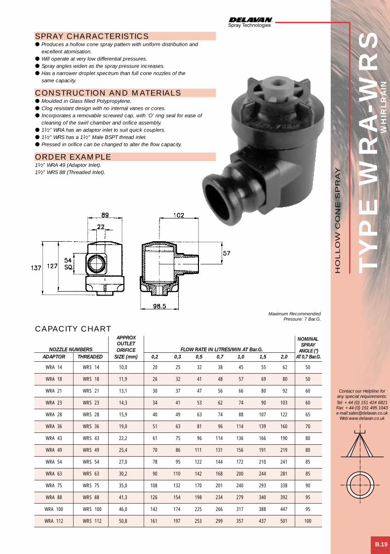
APPROX NOMINALOUTLET SPRAY
NOZZLE NUMBERS ORIFICE FLOW RATE IN LITRES/MIN AT Bar.G. ANGLE (°)ADAPTOR THREADED SIZE (mm) 0,2 0,3 0,5 0,7 1,0 1,5 2,0 AT 0,7 Bar.G.
WRA 14 WRS 14 10,0 20 25 32 38 45 55 62 50
WRA 18 WRS 18 11,9 26 32 41 48 57 69 80 50
WRA 21 WRS 21 13,1 30 37 47 56 66 80 92 60
WRA 23 WRS 23 14,3 34 41 53 62 74 90 103 60
WRA 28 WRS 28 15,9 40 49 63 74 88 107 122 65
WRA 36 WRS 36 19,0 51 63 81 96 114 139 160 70
WRA 43 WRS 43 22,2 61 75 96 114 136 166 190 80
WRA 49 WRS 49 25,4 70 86 111 131 156 191 219 80
WRA 54 WRS 54 27,0 78 95 122 144 172 210 241 85
WRA 63 WRS 63 30,2 90 110 142 168 200 244 281 85
WRA 75 WRS 75 35,0 108 132 170 201 240 293 338 90
WRA 88 WRS 88 41,3 126 154 198 234 279 340 392 95
WRA 100 WRS 100 46,0 142 174 225 266 317 388 447 95
WRA 112 WRS 112 50,8 161 197 253 299 357 437 501 100
TYP
E W
RA
-WR
SW
HIR
LR
AIN
B.19
SPRAY CHARACTERISTICS● Produces a hollow cone spray pattern with uniform distribution and
excellent atomisation.● Will operate at very low differential pressures.● Spray angles widen as the spray pressure increases.● Has a narrower droplet spectrum than full cone nozzles of the
same capacity.
CONSTRUCTION AND MATERIALS● Moulded in Glass filled Polypropylene.● Clog resistant design with no internal vanes or cores.● Incorporates a removable screwed cap, with ‘O’ ring seal for ease of
cleaning of the swirl chamber and orifice assembly.● 11⁄2” WRA has an adaptor inlet to suit quick couplers.● 11⁄2” WRS has a 11⁄2” Male BSPT thread inlet.● Pressed in orifice can be changed to alter the flow capacity.
ORDER EXAMPLE11⁄2” WRA 49 (Adaptor Inlet).11⁄2” WRS 88 (Threaded Inlet).
Contact our Helpline forany special requirements:Tel: +44 (0) 151 424 6821Fax: +44 (0) 151 495 1043e-mail:[email protected]
Web:www.delavan.co.uk
CAPACITY CHART
Maximum RecommendedPressure: 7 Bar.G.
HO
LLO
W C
ON
E S
PR
AY
Hollow cone spray 2 3/5/01 3:08 pm Page 8

TYP
E W
RA
-WR
S
B.20
Contact our Helpline forany special requirements:Tel: +44 (0) 151 424 6821Fax: +44 (0) 151 495 1043e-mail:[email protected]
Web:www.delavan.co.uk
RA
IND
RO
PSPRAY CHARACTERISTICS● Produces a a wide hollow cone spray pattern with uniform distribution of
large aerated droplets.● The “Raindrop” feature significantly reduces the amount of driftable
“fines” (under 100 microns).● Will operate at low differential pressures.● Spray angles widen as the spray pressure increases.
CONSTRUCTION AND MATERIALS● Moulded in Glass filled Polypropylene.● Clog resistant design with no internal vanes or cores.● Incorporates a removable screwed cap, with ‘O’ ring seal for ease
of cleaning of the swirl chamber and orifice assembly.● 11⁄2” WRA has an adaptor inlet to suit quick couplers.● 11⁄2” WRS has a 11⁄2” Male BSPT thread inlet.● Pressed in orifice and “Raindrop” cap can be changed to alter the
flow capacity.
ORDER EXAMPLE11⁄2” WRS 30-RD (Threaded Inlet).11⁄2” WRD 75-RD (Adaptor Inlet).
NOMINALMINIMUM SPRAY
NOZZLE NUMBERS ORIFICE “A” FLOW RATE IN LITRES/MIN AT Bar.G. ANGLE (°)ADAPTOR THREADED SIZE (mm) (mm) 0,5 0,7 1,0 1,5 2,0 2,5 3,0 AT 1,5 Bar.G.
WRA 12-RD WRS 12-RD 6,4 168 28 33 39 47 53 60 65 120
WRA 14-RD WRS 14-RD 9,1 168 32 38 45 55 62 71 77 125
WRA 16-RD WRS 16-RD 10,3 167 36 43 51 63 72 81 88 130
WRA 30-RD WRS 30-RD 15,9 177 68 81 96 118 136 152 166 130
WRA 32-RD WRS 32-RD 19,0 177 72 86 102 126 145 162 177 135
WRA 40-RD WRS 40-RD 20,7 190 91 108 129 158 182 203 222 135
WRA 49-RD WRS 49-RD 24,0 175 112 132 158 194 224 250 274 110
WRA 63-RD WRS 63-RD 26,0 175 144 170 203 249 287 321 352 110
WRA 75-RD WRS 75-RD 33,3 193 169 201 240 293 338 378 414 100
CAPACITY CHART
Maximum RecommendedPressure: 7 Bar.G.
HO
LLO
W C
ON
E S
PR
AY
Hollow cone spray 2 3/5/01 3:08 pm Page 9

WELCOME TO DELAVAN
of newchallengesMeeting the
industriesand NEW markets
C Solid Cone
Del Nozzle A4 dividers A/W 21/6/01 10:35 am Page 5

TYPICAL APPLICATIONSAerating water, brine sprays, chemical processing, coil defrosting, dust control, evaporative condensers, evaporative coolers, industrialwashers, roof cooling, spray coating, gas scrubbing and washing, cooling towers, coal washing, degreasing, gravel washing, dishwashing,foam control, industrial washing and water fountains.
TYPICAL SPRAY PATTERN
Nozzle Spray Characteristics Spray Basic Features Flow Range. PageType Angles L/Min @ 3 Bar.G. No.WDB 30°,45°,60°, 0,02 – 1,30 C.1
70°,80°,90°BL 45°,60°,90° 0,24 – 2,37 C.2
BP 45°,60°,90° 0,24 – 2,37 C.3
WL 45°,60°,90° 0,24 – 2,37 C.4
BF 30°,60°, 0,78 – 12,37 C.590°,120°
BI 35° – 100° 2,65 – 87,57 C.6
BN 85° – 130° 2,65 – 88,68 C.7
CT 45° – 90° 1,58 – 30,00 C.8
CU 45° – 80° 5,14 – 16,60 C.9
BK 20° – 105° 2,34 – 111,10 C.10
CJM 30° 1,18 – 158 C.11
CJF 30° 1,18 – 987 C.12
CM 45° – 110° 87,6 – 8040 C.13
BY 70° – 130° 90 – 1037* C.14
CA 45° – 98° 65,7 – 2495* C.15
CB 45° – 95° 53,73 – 1040,3** C.16
BC 50°,65°, 4,0 – 16,0 C.1780°,90°,120°
BX 50°,65°, 4,0 – 16,0 C.1880°,90°,120°
BQ 35° – 100° 2,65 – 87,57 C.19
BT 85° – 130° 2,65 – 88,68 C.20
CU/SQ 60° – 65° 7,51 – 22,91 C.21
CBI 35° – 100° 2,65 – 87,57 C.22
CBN 85° – 130° 2,65 – 88,68 C.23
CBQ 35° – 100° 2,65 – 87,57 C.24
CBT 85° – 130° 2,65 – 88,68 C.25
RBI 35° – 100° 2,65 – 87,57 C.26
RBN 85° – 130° 2,65 – 88,68 C.27
NBI 41° – 100° 4,87 – 87,57 C.28
NBN 110° – 128° 5,15 – 88,68 C.29
QI/QN/ 42° – 120° 21,11 – 46,26 C.30QQ/QT
Uniform distribution with very fine atomisation.
Uniform distribution with fine atomisation.
Uniform distribution with fine atomisation.
Uniform distribution with fine atomisation.
Uniform distribution with fine to mediumatomisation.
Uniform distribution with fine to coarseatomisation.
Uniform distribution with fine to coarseatomisation.
Uniform distribution with fine to coarseatomisation.
Uniform distribution with fine to coarseatomisation.
Uniform distribution with fine to coarseatomisation.
Uniform distribution with medium to coarseatomisation.
Uniform distribution with medium to coarseatomisation.
Uniform distribution with coarse atomisation.
Uniform distribution with coarse atomisation.
Uniform distribution with coarse atomisation.
Uniform distribution with coarse atomisation.
Uniform distribution with medium to coarseatomisation.
Uniform distribution with medium to coarseatomisation.
Uniform distribution with fine to coarseatomisation.
Uniform distribution with fine to coarseatomisation.
Uniform distribution with fine to coarseatomisation.
Uniform distribution with fine to coarseatomisation.
Uniform distribution with fine to coarseatomisation.
Uniform distribution with fine to coarseatomisation.
Uniform distribution with fine to coarseatomisation.
Uniform distribution with fine to coarseatomisation.
Uniform distribution with fine to coarseatomisation.
Uniform distribution with fine to coarseatomisation.
Uniform distribution with fine to coarseatomisation.
Uniform distribution with medium to coarseatomisation.
9/16" UNEF thread for use with special Male andFemale BSP threaded adaptors.1/8" BSPT Male thread.
1/8" BSPT Male thread.
Flanged tip design for use with standard bodiesand caps.
Flanged tip design for use with standard bodiesand caps.1/8"-1" BSPT Male and BSPP Female threads.
1/8"-1" BSPT Male and BSPP Female threads.
1/8"-1/2" NPT Male and Female threads.
1/4"-3/8" NPT Male threads.
1/8"-1" BSPT Male and BSPP Female threads.
1/8"-2" BSPT Male threads.
1/8"-1" BSPP Female and 11/4"-4" BSPT Femalethreads.
11/4"-8" BSPT Female threads.
11/4"-3" BSPT Female threads.
1"-4" BSPT Female threads.
1"-3" NB welded connection.
3/8" BSPP Female thread.
3/8" BSPP Female thread.
1/8"-1" BSPT Male and BSPP Female threads.
1/8"-1" BSPT Male and BSPP Female threads.
1/4"-1/2" NPT Male threads.
1/8"-1" BSPP Male threads. More compact than BItype.1/8"-1" BSPP Male threads. More compact than BNtype.1/8"-1" BSPP Male threads. More compact thanBQ type.1/8"-1" BSPP Male threads. More compact than BTtype.1/8"-1" BSPT Male and BSPP Female threads. Rightangle design.1/8"-1" BSPT Male and BSPP Female threads. Rightangle design.1/8"-1" BSPT Male and BSPP Female threads. Rightangle design.1/8"-1" BSPT Male and BSPP Female threads. Rightangle design.
Quick attach connection to 11/4" and 11/2"NB eyelets.
* Flow quoted at 1.5 Bar.G. ** Flow quoted at 2 Bar.G.
SE
CTIO
N IN
DE
X
Contact our Helpline forany special requirements:Tel: +44 (0) 151 424 6821Fax: +44 (0) 151 495 1043e-mail:[email protected]
Web:www.delavan.co.uk
SO
LID
CO
NE
Del Nozzle A4 dividers A/W 21/6/01 10:35 am Page 6

C.1
Contact our Helpline forany special requirements:Tel: +44 (0) 151 424 6821Fax: +44 (0) 151 495 1043e-mail:[email protected]
Web:www.delavan.co.uk
TYP
E W
DB
SPRAY CHARACTERISTICS● Finely atomised solid cone spray pattern.● Available spray angles of 30°, 45°, 60°, 70°, 80° and 90°.
CONSTRUCTION AND MATERIALSNozzle consists of 5 basic parts:● Nozzle Body - Brass or 416 Stainless Steel.● Orifice Disc - 416 Stainless Steel.● Distributor - 416 Stainless Steel.● Retainer - Brass or 416 Stainless Steel.● Strainer - (used up to WDB 14).● Nozzle thread is 9⁄16” - 24 UNEF.● Adaptors are available with 1⁄4” Male BSPT and 1⁄8”/1⁄4” Female BSPP and
can be ordered separately.
ORDER EXAMPLEWDB 6.0-80° Stainless Steel = Tip Only.1⁄4” Female WDB 12,0-60° Stainless Steel = Complete Assembly.
APPROX.NOZZLE ORIFICE FLOW RATE IN LITRES/HOUR AT Bar.G.NUMBER DIA. (mm) 2 3 5 7 10 15 20 35
0,5 x 0,21 - - 1,45 1,72 2,05 2,51 2,87 3,82
0,75 x 0,23 - - 2,16 2,56 3,05 3,74 4,32 5,72
1,0 0,28 - - 2,87 3,40 4,10 5,02 5,77 7,63
1,5 0,33 - - 4,32 5,11 6,15 7,53 8,64 11,4
2,0 0,38 - - 5,77 6,83 8,19 10,0 11,6 15,3
2,5 0,41 - - 7,19 8,55 10,2 12,5 14,5 19,1
3,0 0,46 - - 8,64 10,2 12,3 15,1 17,3 22,9
4,0 0,64 - 8,69 11,5 13,7 16,4 20,1 23,1 30,5
5,0 0,64 - 11,1 14,5 17,2 20,5 25,1 28,7 38,2
6,0 0,74 - 14,2 17,5 20,6 24,6 30,1 34,6 45,8
8,0 0,81 - 17,8 23,1 27,5 33,1 40,6 46,2 61,1
10,0 0,89 17,9 22,1 28,7 34,0 41,0 50,2 57,7 76,3
12,0 1,02 21,6 26,9 34,6 40,8 49,2 60,2 69,3 91,6
14,0 1,02 25,3 31,2 40,2 47,7 57,0 69,8 80,8 107
16,0 * 1,17 29,1 35,6 46,2 54,6 65,2 79,8 92,4 122
18,0 * 1,32 32,8 39,9 51,8 61,4 73,4 89,9 104 137
20,0 * 1,40 36,5 44,6 57,8 68,3 81,6 99,9 115 153
24,0 * 1,52 45,8 53,3 69,3 82,1 98,0 120 139 183
30,0 * 1,70 54,4 66,8 86,4 102 123 150 173 229
35,0 * 1,78 64,1 78,2 101 120 143 175 202 267
CAPACITY CHARTMaximum Recommended
Pressure: 35 Bar.G.
WDB (MALE) ASSEMBLY WDB (FEMALE) ASSEMBLY
Assembly Dimensions (mm) WeightType A Hex B C D E Hex (g)
1/8” Female 15,9 52,4 38,1 14,3 18,0 82
1/4” Male 15,9 52,4 38,1 14,3 18,0 78
1/4” Female 15,9 52,4 38,1 14,3 18,0 69
DIMENSIONS AND WEIGHTS
x Not available in 30° or 45°.* These sizes are supplied without strainers.
SO
LID
CO
NE
SP
RA
Y
Solid cone spray 1 3/5/01 3:29 pm Page 1

TYP
E B
L
Dimensions (mm) WeightA B Hex C D (g)
17,5 11,3 9,5 27,0 9
C.2
SPRAY CHARACTERISTICS● Precision, low capacity nozzle with uniform distribution in a solid cone
spray pattern.● Uniform distribution of finely atomised droplets.
CONSTRUCTION AND MATERIALS● One piece body with removable screwed core, using allen key.● Core is multi-slotted for uniform distribution.● Available only with 1⁄8” Male BSPT thread.● Standard spray angles are 45°,60° and 90°.● Other angles available to special order.● Threaded strainer is optional (see chart for mesh size).● Available in Brass or Stainless Steel as standard.● Other materials available on a special order.
ORDER EXAMPLE1⁄8” BL 4-90° Brass.
Contact our Helpline forany special requirements:Tel: +44 (0) 151 424 6821Fax: +44 (0) 151 495 1043e-mail:[email protected]
Web:www.delavan.co.uk
NOZZLE MESH FLOW RATE IN LITRES/HOUR AT Bar.G.NUMBER SIZE 0,7 1 1,5 2 3 4 6 7
3 200 7,4 8,7 10,4 11,9 14,2 16,2 18,9 20,7
4 200 9,9 11,6 13,9 16,0 19,0 21,7 25,3 27,7
5 200 12,3 14,4 17,3 19,9 23,7 27,0 31,5 34,6
6 100 14,8 17,3 20,7 23,9 28,4 32,4 37,8 41,5
7 100 17,3 20,3 24,2 27,9 33,2 37,8 44,2 48,5
8 100 19,7 23,1 27,7 31,8 37,9 43,2 50,4 55,3
9 100 22,2 26,0 31,2 35,9 42,7 48,7 56,8 62,3
10 100 24,6 28,9 34,6 39,8 47,4 54,0 63,0 69,2
12 100 29,6 34,7 41,5 47,8 56,9 64,9 75,7 83,1
14 100 34,5 40,5 48,5 55,8 66,4 75,7 88,3 97,0
16 50 39,5 46,3 55,4 63,8 75,9 86,5 101,0 111,0
18 50 44,4 52,0 62,3 71,7 85,3 97,2 113,4 125,0
20 50 49,3 57,8 69,2 79,6 94,8 108,0 126,0 138,0
25 50 61,9 72,6 86,9 100,0 119,0 136,0 158,0 174,0
30 50 73,8 86,6 104,0 119,0 142,0 162,0 189,0 207,0
CAPACITY CHART
DIMENSIONS AND WEIGHTS
Maximum RecommendedPressure: 35 Bar.G.
SO
LID
CO
NE
SP
RA
Y
Solid cone spray 1 3/5/01 3:29 pm Page 2

TYP
E B
P
C.3
Dimensions (mm) WeightA B Hex C D (g)
17,5 14,0 9,5 27,0 9
Contact our Helpline forany special requirements:Tel: +44 (0) 151 424 6821Fax: +44 (0) 151 495 1043e-mail:[email protected]
Web:www.delavan.co.uk
SPRAY CHARACTERISTICS● Precision, low capacity nozzle with uniform distribution in a solid cone
spray pattern.● Uniform distribution of finely atomised droplets.
CONSTRUCTION AND MATERIALS● One piece body with removable screwed core, using allen key.● Core is multi-slotted for uniform distribution.● Available only with 1⁄8” Male BSPT thread.● Standard spray angles are 45°,60° and 90°. Contact factory for
special angles.● Threaded strainer is optional (see chart for mesh size).● Available in Brass or Stainless Steel as standard.● Other materials available on a special order.
ORDER EXAMPLE1⁄8” BP 4-90° Brass.
NOZZLE MESH FLOW RATE IN LITRES/HOUR AT Bar.G.NUMBER SIZE 0,7 1 1,5 2 3 4 6 7
3 200 7,4 8,7 10,4 11,9 14,2 16,2 18,9 20,7
4 200 9,9 11,6 13,9 16,0 19,0 21,7 25,3 27,7
5 200 12,3 14,4 17,3 19,9 23,7 27,0 31,5 34,6
6 100 14,8 17,3 20,7 23,9 28,4 32,4 37,8 41,5
7 100 17,3 20,3 24,2 27,9 33,2 37,8 44,2 48,5
8 100 19,7 23,1 27,7 31,8 37,9 43,2 50,4 55,3
9 100 22,2 26,0 31,2 35,9 42,7 48,7 56,8 62,3
10 100 24,6 28,9 34,6 39,8 47,4 54,0 63,0 69,2
12 100 29,6 34,7 41,5 47,8 56,9 64,9 75,7 83,1
14 100 34,5 40,5 48,5 55,8 66,4 75,7 88,3 97,0
16 50 39,5 46,3 55,4 63,8 75,9 86,5 101,0 111,0
18 50 44,4 52,0 62,3 71,7 85,3 97,2 113,4 125,0
20 50 49,3 57,8 69,2 79,6 94,8 108,0 126,0 138,0
25 50 61,9 72,6 86,9 100,0 119,0 136,0 158,0 174,0
30 50 73,8 86,6 104,0 119,0 142,0 162,0 189,0 207,0
CAPACITY CHART
DIMENSIONS AND WEIGHTS
Maximum RecommendedPressure: 35 Bar.G.
SO
LID
CO
NE
SP
RA
Y
Solid cone spray 1 3/5/01 3:29 pm Page 3

TYP
E W
L
C.4
SPRAY CHARACTERISTICS● Precision, low capacity nozzle with uniform distribution in a solid cone
shaped pattern.● Uniform distribution of finely atomised droplets.
CONSTRUCTION AND MATERIALS● Used with standard bodies and caps.● Core is multi-slotted for uniform distribution.● Body thread sizes are Male BSPT and Female BSPP.● Standard spray angles are 45°,60° and 90°.● Other angles available to special order.● Threaded strainer is optional (see chart for mesh size).● Available in Brass or Stainless Steel as standard.● Other materials available on a special order.
ORDER EXAMPLEWL 6-45° Brass = Tip Only.1⁄4” WLM (Male) 12-60° Stainless Steel = Complete Assembly.
Contact our Helpline forany special requirements:Tel: +44 (0) 151 424 6821Fax: +44 (0) 151 495 1043e-mail:[email protected]
Web:www.delavan.co.uk
NOZZLE MESH FLOW RATE IN LITRES/HOUR AT Bar.G.NUMBER SIZE 0,7 1 1,5 2 3 4 6 7
3 200 7,4 8,7 10,4 11,9 14,2 16,2 18,9 20,7
4 200 9,9 11,6 13,9 16,0 19,0 21,7 25,3 27,7
5 200 12,3 14,4 17,3 19,9 23,7 27,0 31,5 34,6
6 100 14,8 17,3 20,7 23,9 28,4 32,4 37,8 41,5
7 100 17,3 20,3 24,2 27,9 33,2 37,8 44,2 48,5
8 100 19,7 23,1 27,7 31,8 37,9 43,2 50,4 55,3
9 100 22,2 26,0 31,2 35,9 42,7 48,7 56,8 62,3
10 100 24,6 28,9 34,6 39,8 47,4 54,0 63,0 69,2
12 100 29,6 34,7 41,5 47,8 56,9 64,9 75,7 83,1
14 100 34,5 40,5 48,5 55,8 66,4 75,7 88,3 97,0
16 50 39,5 46,3 55,4 63,8 75,9 86,5 101,0 111,0
18 50 44,4 52,0 62,3 71,7 85,3 97,2 113,4 125,0
20 50 49,3 57,8 69,2 79,6 94,8 108,0 126,0 138,0
25 50 61,9 72,6 86,9 100,0 119,0 136,0 158,0 174,0
30 50 73,8 86,6 104,0 119,0 142,0 162,0 189,0 207,0
CAPACITY CHART
Maximum RecommendedPressure: 35 Bar.G.
Assembly Dimensions (mm) WeightType A Hex B C Hex (g)
1/8” WLF 20,8 54,0 18,0 70
1/8” WLM 20,8 52,4 18,0 60
1/4” WLF 20,8 54,0 18,0 70
1/4” WLM 20,8 54,0 18,0 62
3/8” WLF 20,8 54,0 20,8 70
3/8” WLM 20,8 54,0 18,0 64
DIMENSIONS AND WEIGHTS
WLM (MALE) ASSEMBLY
WLF (FEMALE) ASSEMBLY
SO
LID
CO
NE
SP
RA
Y
Solid cone spray 1 3/5/01 3:30 pm Page 4

TYP
E B
F
C.5
Nozzle Dimensions (mm) WeightThread A B C (g)
1/8 BFF 18,0 20,8 54,0 70
1/8 BFM 18,0 20,8 52,4 60
1/4 BFF 18,0 20,8 54,0 70
1/4 BFM 18,0 20,8 54,0 62
3/8 BFF 20,8 20,8 54,0 70
3/8 BFM 18,0 20,8 54,0 64
Contact our Helpline forany special requirements:Tel: +44 (0) 151 424 6821Fax: +44 (0) 151 495 1043e-mail:[email protected]
Web:www.delavan.co.uk
SPRAY CHARACTERISTICS● Uniform distribution of droplets in a solid cone spray pattern.● Droplet size is larger than most hollow cone nozzles of equal capacity.● Impact of spray is generally greater with narrower spray angles, assuming
the same flow rate. Pressure increases affect spray angle.
CONSTRUCTION AND MATERIALS● One piece body with pressed in cross-milled core which is removable.● Core imparts the necessary swirl to produce a solid cone spray pattern.● Available in 30,° 60°, 90°, and 120° spray angles (see chart).● Flanged design for use with standard bodies and caps.● Body thread sizes are Male BSPT and Female BSPP.● Standard flanged filters can be used.● Available in Brass or Stainless Steel as standard.● Other materials available on a special order.
ORDER EXAMPLEBF 4-120° Brass = Tip Only.1⁄4” BFM (Male) 12-60° Stainless Steel = Complete Assembly.
CAPACITY CHART
DIMENSIONS AND WEIGHTS
Maximum RecommendedPressure: 35 Bar.G.
AVAILABLENOZZLE FLOW RATE IN LITRES/MIN AT Bar.G. SPRAY ANGLES (°)NUMBER 0,35 0,7 1,0 1,5 2 3 4 5 7 30 60 90 120
BF 1 - 0,38 0,45 0,56 0,64 0,78 0,86 0,94 1,14
BF 2 - 0,76 0,89 1,11 1,26 1,54 1,71 1,87 2,27
BF 3 0,8 1,14 1,34 1,67 1,90 2,32 2,57 2,81 3,41
BF 4 1,07 1,52 1,79 2,22 2,53 3,10 3,42 3,75 4,54 *
BF 5 1,33 1,90 2,23 2,78 3,15 3,86 4,28 4,68 5,68 *
BF 6 1,6 2,29 2,68 3,34 3,79 4,64 5,13 5,62 6,81 *
BF 8 2,13 3,05 3,57 4,44 6,28 6,18 6,84 7,49 9,08 *
BF 10 2,67 3,81 4,40 5,56 6,31 7,72 8,56 9,36 11,35 *
BF 12 3,20 4,57 5,36 6,67 7,58 9,28 10,27 11,24 13,62 *
BF 16 4,27 6,10 7,14 8,90 10,10 12,37 13,73 14,98 18,16 *
BFM (MALE) ASSEMBLY
BFF (FEMALE) ASSEMBLY
SO
LID
CO
NE
SP
RA
Y
* Brass Only.
Solid cone spray 1 3/5/01 3:30 pm Page 5

TYP
E B
I
C.6
SPRAY CHARACTERISTICS● Uniform distribution of droplets in a solid cone spray pattern.● Droplet size is larger than in hollow cone nozzles of equal capacity.● Impact of spray is generally greater with narrower spray angles, assuming
the same flow rate. Pressure increases affect spray angle.
CONSTRUCTION AND MATERIALS● One piece body with pressed in cross-milled core which is removable.● Core imparts the necessary swirl to produce a solid cone spray pattern.● Hexagon body for easy installation, eliminates distortion of orifice
during installation.● Available with Male BSPT and Female BSPP threads.● Brass and 316 Stainless Steel are standard.● Other materials available to special order.
ORDER EXAMPLE1⁄4” BIM (Male) 22 Brass.1⁄2” BIF (Female) 49 Stainless Steel.
Contact our Helpline forany special requirements:Tel: +44 (0) 151 424 6821Fax: +44 (0) 151 495 1043e-mail:[email protected]
Web:www.delavan.co.uk
SPRAYANGLES (°)
NOZZLE NUMBER BSPT THREAD SIZE FLOW RATE IN LITRES/MIN AT Bar.G. AT Bar.G.Female Male 1/8 1/4 3/8 1/2 3/4 1 ,35 ,7 1 1,5 2 3 4 6 7 8 ,7 2 6BIF 6 BIM 6 0,88 1,25 1,50 1,88 2,18 2,65 2,87 3,41 3,54 3,76 40 47 40
BIF 8 BIM 8 1,30 1,86 2,28 2,84 3,23 4,00 4,55 5,38 5,72 5,97 44 56 53
BIF 11 BIM 11 1,63 2,32 2,87 3,62 4,05 4,87 5,36 6,30 6,74 7,06 52 64 58
BIF 12 BIM 12 2,09 2,79 3,41 4,09 4,55 5,30 5,91 7,02 7,58 8,01 62 70 58
BIF 16 BIM 16 2,50 3,58 4,41 5,30 6,14 7,27 8,00 9,51 10,04 10,61 57 60 55
BIF 20 BIM 20 3,11 4,46 5,46 6,50 7,54 9,06 10,00 11,92 12,63 13,43 62 73 58
BIF 22 BIM 22 3,58 5,11 6,24 7,51 8,32 9,78 10,91 13,23 14,24 14,95 70 80 62
BIF 12 BIM 12 2,00 2,79 3,32 4,19 4,73 5,83 6,60 7,79 8,17 8,65 36 45 39
BIF 16 BIM 16 2,50 3,58 4,41 5,30 6,14 7,27 8,00 9,51 10,04 10,61 57 60 55
BIF 20 BIM 20 3,11 4,46 5,46 6,50 7,54 9,06 10,00 11,92 12,63 13,43 61 73 58
BIF 22 BIM 22 3,58 5,11 6,24 7,51 8,32 9,78 10,91 13,23 14,24 14,95 70 80 62
BIF 27 BIM 27 4,23 6,04 7,42 9,01 10,10 12,32 13,64 16,06 17,47 18,08 44 53 51
BIF 32 BIM 32 5,81 7,25 8,88 10,81 12,32 14,44 15,96 19,29 20,40 22,12 60 70 61
BIF 27 BIM 27 4,23 6,04 7,42 9,01 10,10 12,32 13,64 16,06 17,47 18,08 44 53 51
BIF 32 BIM 32 5,81 7,25 8,88 10,81 12,32 14,44 15,96 19,29 20,40 22,12 60 70 61
BIF 42 BIM 42 6,74 9,67 11,82 14,44 15,96 19,29 21,41 24,95 27,37 28,48 70 76 64
BIF 49 BIM 49 8,17 11,62 14,24 16,36 18,69 23,13 25,05 29,29 32,52 33,94 79 86 72
BIF 63 BIM 63 10,20 14,44 17,07 20,50 23,84 28,89 32,22 38,48 41,31 43,94 70 80 70
BIF 47 BIM 47 7,48 10,61 13,03 14,95 17,78 21,11 26,63 28,48 30,20 31,71 43 57 42
BIF 63 BIM 63 10,20 14,44 17,07 20,50 23,84 28,89 32,22 38,48 41,31 43,94 60 69 53
BIF 77 BIM 77 12,32 17,68 20,50 23,94 29,09 34,95 38,68 45,65 49,29 52,02 70 73 60
BIF 89 BIM 89 13,94 20,00 23,74 29,39 33,63 40,00 44,54 52,92 56,26 59,29 82 85 67
BIF 102 BIM 102 14,85 20,91 27,37 33,73 38,68 46,26 50,00 60,10 64,54 67,87 85 97 74
BIF 73 BIM 73 11,92 16,26 20,00 22,62 27,78 34,24 38,68 45,65 50,00 52,02 35 41 44
BIF 105 BIM 105 16,26 23,23 27,78 33,73 39,79 48,18 52,32 62,42 67,37 71,51 51 57 49
BIF 123 BIM 123 19,49 28,38 34,64 42,32 46,56 57,77 63,63 75,95 80,40 85,55 66 73 57
BIF 140 BIM 140 22,73 32,02 38,18 45,25 53,23 62,12 68,18 80,80 85,95 90,90 75 81 52
BIF 162 BIM 162 25,55 36,26 44,64 53,03 61,41 72,22 79,08 95,14 101,00 108,07 74 86 63
BIF 193 BIM 193 28,79 41,81 50,10 60,70 73,23 87,57 99,08 119,18 128,27 135,34 82 100 80
CAPACITY CHART
Maximum Recommended Pressure:70 Bar.G. (Metal), 7 Bar.G. (Plastic).
BIM (MALE)
BIF (FEMALE)
SO
LID
CO
NE
SP
RA
Y
Thread Nozzle Dimensions (mm) WeightSize Type A Hex B C (g)
1/8” BIM 11,3 17,5 9,6 10
1/8” BIF 15,3 25,4 13,5 21
1/4” BIM 15,3 24,5 13,0 24
1/4” BIF 18,0 27,8 12,7 35
3/8” BIM 18,0 25,5 14,0 35
3/8” BIF 20,8 38,9 21,1 58
1/2” BIM 25,6 32,0 16,1 75
1/2” BIF 25,6 50,0 28,3 118
3/4” BIM 28,0 36,0 19,0 115
3/4” BIF 31,8 62,7 31,5 215
1” BIM 38,0 50,0 28,5 290
1” BIF 38,0 81,0 51,0 330
DIMENSIONS AND WEIGHTS
Solid cone spray 1 3/5/01 3:30 pm Page 6

TYP
E B
N
C.7
Contact our Helpline forany special requirements:Tel: +44 (0) 151 424 6821Fax: +44 (0) 151 495 1043e-mail:[email protected]
Web:www.delavan.co.uk
SPRAY CHARACTERISTICS● Uniform distribution of droplets in a wide angle solid cone spray pattern.● Droplet size is larger than in hollow cone nozzles of equal capacity.● Impact of spray is generally lower than narrower spray angles, assuming
the same flow rate. Pressure increases affect spray angle.
CONSTRUCTION AND MATERIALS● One piece body with pressed in cross-milled core which is removable.● Core imparts the necessary swirl to produce a solid cone spray pattern.● Hexagon body for easy installation, eliminates distortion of orifice
during installation.● Brass and Stainless Steel are standard.● Other materials available to special order.
ORDER EXAMPLE3⁄8” BNM (Male) 22 Brass.1⁄2” BNF (Female) 59 Stainless Steel.
CAPACITY CHARTMaximum Recommended Pressure:35 Bar.G. (Metal), 7 Bar.G. (Plastic).
SPRAY ANGLES (°)
NOZZLE NUMBER BSPT THREAD SIZE FLOW RATE IN LITRES/MIN AT Bar.G. AT Bar.G.Female Male 1/8 1/4 3/8 1/2 3/4 1 ,35 ,7 1 1,5 2 3 4 6 7 8 ,7 2 6
BNF 6 BNM 6 0,88 1,25 1,50 1,88 2,18 2,65 2,87 3,41 3,54 3,76 110 100 90
BNF 8 BNM 8 1,30 1,86 2,28 2,84 3,23 4,00 4,55 5,38 5,72 5,97 125 120 100
BNF 11 BNM 11 1,86 2,79 3,23 3,86 4,31 5,15 5,45 6,73 7,43 7,70 115 120 95
BNF 15 BNM 15 2,60 3,67 4,50 5,26 5,59 6,64 7,24 8,70 9,16 9,70 115 110 90
BNF 18 BNM 18 3,10 4,40 5,39 6,30 6,70 7,96 8,68 10,43 10,98 11,63 120 120 95
BNF 22 BNM 22 3,95 5,58 6,84 8,0 8,50 10,10 11,01 13,23 13,94 14,75 113 110 90
BNF 25 BNM 25 4,27 6,04 7,24 8,43 9,32 11,01 12,32 14,65 15,76 16,26 120 120 100
BNF 32 BNM 32 5,90 7,70 9,15 10,80 11,92 14,30 15,78 18,90 19,90 21,26 115 110 85
BNF 39 BNM 39 7,20 9,40 11,15 13,14 14,52 17,40 19,20 23,00 24,25 25,90 120 120 90
BNF 46 BNM 46 8,13 11,62 13,64 15,86 17,27 19,29 22,32 25,45 27,88 29,39 125 112 90
BNF 48 BNM 48 8,33 12,52 15,25 16,87 18,18 23,13 24,54 29,80 32,52 34,34 125 120 90
BNF 59 BNM 59 9,29 13,23 15,96 19,29 22,32 26,06 28,18 34,64 37,67 40,70 130 128 100
BNF 65 BNM 65 12,00 15,65 18,60 21,92 24,21 29,00 32,05 38,37 40,40 43,20 115 110 85
BNF 73 BNM 73 13,50 17,60 20,88 24,50 27,19 32,60 36,00 43,10 45,40 48,50 115 120 90
BNF 82 BNM 82 15,35 20,0 23,74 27,98 30,91 37,07 40,91 48,99 51,61 55,15 115 112 90
BNF 94 BNM 94 16,77 22,32 26,87 32,72 35,45 41,92 45,96 56,26 59,89 63,33 119 120 91
BNF 98 BNM 98 18,08 23,23 27,78 34,24 37,27 44,34 50,00 59,59 64,54 67,87 112 120 90
BNF 136 BNM 136 24,14 35,25 42,32 48,18 51,41 60,20 67,77 81,20 86,86 91,41 118 115 75
BNF 153 BNM 153 27,88 38,08 46,97 53,93 57,97 67,47 76,36 91,30 98,07 108,07 125 120 85
BNF 200 BNM 200 29,69 42,32 51,41 62,62 75,95 88,68 99,59 120,19 130,29 139,38 118 125 90
BNM (MALE)
BNF (FEMALE)
SO
LID
CO
NE
SP
RA
Y
Thread Nozzle Dimensions (mm) WeightSize Type A Hex B C (g)
1/8” BNM 11,3 17,5 9,6 10
1/8” BNF 15,3 25,4 13,5 21
1/4” BNM 15,3 24,5 13,0 24
1/4” BNF 18,0 27,8 12,7 35
3/8” BNM 18,0 25,5 14,0 35
3/8” BNF 20,8 38,9 21,1 58
1/2” BNM 25,6 32,0 16,1 75
1/2” BNF 25,6 50,0 28,3 118
3/4” BNM 28,0 36,0 19,0 115
3/4” BNF 31,8 62,7 31,5 215
1” BNM 38,0 50,0 28,5 290
1” BNF 38,0 81,0 51,0 330
DIMENSIONS AND WEIGHTS
Solid cone spray 1 3/5/01 3:30 pm Page 7

TYP
E C
T
Thread Dimensions (mm) WeightType Size A Hex B (g)
1/8 14,3 31,8 28
CTF 1/4 15,9 34,2 43
(Female) 3/8 19,0 39,0 651/2 25,4 46,9 1281/8 14,3 28,6 28
CTM 1/4 15,9 36,5 43
(Male) 3/8 19,0 38,9 651/2 25,4 48,4 128
C.8
SPRAY CHARACTERISTICS● Uniform distribution of droplets in a solid cone spray pattern.● Droplet size is larger than in hollow cone nozzles of equal capacity.● Impact of spray is generally lower than narrower spray angles, assuming
the same flow rate. Pressure increases affect spray angle.
CONSTRUCTION AND MATERIALS● Manufactured with a two piece body design and removable core.● Core inparts the necessary swirl to produce a solid cone spray pattern.● Threads are Male and Female NPT.● Manufactured with a two piece body design.● Brass and 303 Stainless Steel are standard.● Other materials available to special order.
ORDER EXAMPLE1⁄8” CTM (Male) 4 Brass.1⁄2” CTF (Female) 25 Brass.
Contact our Helpline forany special requirements:Tel: +44 (0) 151 424 6821Fax: +44 (0) 151 495 1043e-mail:[email protected]
Web:www.delavan.co.uk
CAPACITY CHART
DIMENSIONS AND WEIGHTS
Maximum RecommendedPressure: 35 Bar.G.
NOZZLE APPROX. NPT THREAD SPRAYNUMBER ORIFICE SIZES FLOW RATE IN LITRES/MIN AT Bar.G. ANGLES (°)
FEMALE MALE DIA. (mm) 1/8 1/4 3/8 1/2 0,35 0,7 1,5 3 5 7 AT 0,7 Bar.G.
CTF 2 CTM 2 1,2 0,53 0,76 1,10 1,58 1,98 2,29 45°
CTF 3 CTM 3 1,5 0,84 1,14 1,70 2,37 2,88 3,43 55°
CTF 3.5 CTM 3.5 1,6 0,95 1,34 1,98 2,69 3,32 3,82 45°
CTF 4 CTM 4 1,7 1,07 1,53 2,21 3,16 3,97 4,77 50°
CTF 5 CTM 5 2,0 1,37 1,91 2,77 3,75 4,69 5,72 55°
CTF 6.5 CTM 6.5 2,25 1,79 2,48 3,56 5,14 6,13 7,25 45° *
CTF 6.5 CTM 6.5 2,4 1,79 2,48 3,56 5,14 6,13 7,25 60° *
CTF 9.5 CTM 9.5 2,7 2,63 3,63 5,14 7,11 9,02 10,69 45°
CTF 10 CTM 10 2,8 2,78 3,82 5,53 7,50 9,74 11,45 60°
CTF 15 CTM 15 3,5 4,20 5,72 8,30 11,45 14,42 16,79 65°
CTF 16 CTM 16 3,6 4,60 6,10 8,69 12,25 15,50 17,94 50°
CTF 22 CTM 22 4,6 6,10 8,40 11,85 16,60 20,92 24,42 80°
CTF 25 CTM 25 4,8 6,87 9,54 13,83 18,96 24,16 28,24 65°
CTF 32 CTM 32 5,2 8,78 12,20 17,38 24,10 30,65 35,87 75°
CTF 40 CTM 40 6,4 11,07 15,26 21,73 30,00 38,22 45,03 90°
* Specify either 45° or 60° spray angle for CT 6.5 nozzle when ordering.
CTM (MALE) ASSEMBLY
CTF (FEMALE) ASSEMBLY
SO
LID
CO
NE
SP
RA
Y
Solid cone spray 1 3/5/01 3:30 pm Page 8

TYP
E C
U
C.9
Contact our Helpline forany special requirements:Tel: +44 (0) 151 424 6821Fax: +44 (0) 151 495 1043e-mail:[email protected]
Web:www.delavan.co.uk
SPRAY CHARACTERISTICS● Uniform distribution of droplets in a solid cone spray pattern.● Droplet size is larger than in hollow cone nozzles of equal capacity.● Impact of spray is generally lower than narrower spray angles, assuming
the same flow rate. Pressure increases affect spray angle.
CONSTRUCTION AND MATERIALS● One piece body design with cross-milled core pressed into place which
is removable.● Core imparts the necessary swirl to produce a solid cone spray pattern.● Hexagon body for easy installation, eliminates distortion of orifice
during installation.● Brass and 303 Stainless Steel are standard.● Other materials available to special order.
ORDER EXAMPLE3⁄8” CUM 22 Brass.
CAPACITY CHART
DIMENSIONS AND WEIGHTS
Maximum RecommendedPressure: 35 Bar.G.
APPROX. NPT THREAD SPRAYNOZZLE ORIFICE SIZES FLOW RATE IN LITRES/MIN AT Bar.G. ANGLES ATNUMBER DIA. (mm) 1/4 3/8 0,35 0,7 1,5 3 5 7 0,7 Bar.G.
CUM 6,5 2,25 1,79 2,48 3,56 5,14 6,13 7,25 45°
CUM 7,5 2,5 2,02 2,86 4,35 5,93 7,57 9,16 70°
CUM 9,5 2,7 2,63 3,63 5,14 7,11 9,02 10,69 45°
CUM 10 2,8 2,78 3,82 5,53 7,50 9,74 11,45 60°
CUM 15 3,5 4,20 5,72 8,30 11,45 14,42 16,79 65°
CUM 22 4,6 6,10 8,40 11,85 16,60 20,92 24,42 80°
Thread Dimensions (mm) WeightSize A Hex B (g)1/4” 14,3 24,5 233/8” 17,5 25,5 28
CUM
SO
LID
CO
NE
SP
RA
Y
Solid cone spray 1 3/5/01 3:30 pm Page 9

TYP
E B
K
C.10
SPRAY CHARACTERISTICS● Uniform distribution of droplets in a solid cone spray pattern.● Impact of spray is greater with narrower spray angles, assuming the same
flow rate. Pressure increases spray angle which affects impact.
CONSTRUCTION AND MATERIALS● One piece body with removable spiral-type core.● Hexagon body for easy installation eliminates distortion of orifice
during installation.● Available with Male BSPT and Female BSPP threads.● Brass and Stainless Steel are standard.● Other materials available to special order.
ORDER EXAMPLE1⁄8” BKM (Male) 5 Brass.3⁄8” BKF (Female) 30 Stainless Steel.
Contact our Helpline forany special requirements:Tel: +44 (0) 151 424 6821Fax: +44 (0) 151 495 1043e-mail:[email protected]
Web:www.delavan.co.uk
CAPACITY CHART
Approx. SPRAYNOZZLE Orifice ANGLES (°)
NUMBER Dia. FLOW RATE IN LITRES/MIN AT Bar.G. AT Bar.G.Female Male (mm) 0,7 1 1,5 2 3 4 5 6 7 8 0,7 2 6
BKF 5 BKM 5 1,6 1,18 1,40 1,73 2,01 2,34 2,62 2,85 3,05 3,26 3,46 25 30 30
BKF 7 BKM 7 2,0 1,55 1,88 2,35 2,76 3,28 3,64 3,96 4,24 4,50 4,73 30 45 45
BKF 10 BKM 10 2,8 2,09 2,51 3,11 3,62 4,25 4,82 5,28 5,70 6,15 6,47 55 65 68
BKF 10 BKM 10 2,4 2,27 2,71 3,33 3,87 4,58 5,14 5,70 6,15 6,57 6,98 20 32 36
BKF 13 BKM 13 2,8 2,91 3,48 4,31 5,01 6,06 6,80 7,43 8,04 8,54 9,00 23 45 47
BKF 16 BKM 16 3,2 3,39 4,04 4,96 5,79 7,12 7,99 8,73 9,41 9,96 10,61 28 49 56
BKF 19 BKM 19 4,0 4,22 4,96 6,11 7,03 8,59 9,92 10,91 11,82 12,73 13,53 46 70 78
BKF 25 BKM 25 4,3 6,33 6,93 8,54 9,92 12,12 14,14 15,86 17,37 18,79 20,20 24 50 47
BKF 30 BKM 30 4,8 6,57 7,85 9,55 11,01 13,53 15,66 17,47 19,09 20,71 22,02 55 72 65
BKF 53 BKM 53 6,4 12,52 14,54 17,37 19,70 23,43 26,66 29,39 31,71 33,94 35,86 48 53 78
BKF 86 BKM 86 7,1 18,08 21,82 27,27 31,92 38,99 44,04 48,18 51,91 56,06 58,78 50 64 51
BKF 105 BKM 105 7,9 22,73 27,17 33,43 38,58 47,27 53,23 58,78 62,92 67,47 71,21 48 65 50
BKF 120 BKM 120 9,5 27,57 32,12 38,48 43,63 51,91 58,78 65,25 70,30 75,35 79,89 60 75 98
BKF 144 BKM 144 10,3 33,03 38,58 45,96 52,32 62,42 70,70 78,07 84,44 90,50 96,46 67 83 100
BKF 162 BKM 162 9,5 37,17 43,53 52,32 59,19 71,21 80,80 89,49 96,86 104,03 110,09 75 86 66
BKF 179 BKM 179 10,3 39,29 45,96 55,55 62,92 75,75 84,44 96,46 104,03 112,11 119,18 77 90 70
BKF 204 BKM 204 11,1 45,96 53,23 63,83 72,52 86,76 98,68 109,08 118,17 126,25 134,33 78 93 70
BKF 217 BKM 217 11,9 50,50 58,78 70,30 79,39 95,04 108,07 119,18 129,28 139,38 146,45 90 95 77
BKF 252 BKM 252 12,7 58,28 68,38 81,71 93,22 111,10 126,25 139,38 151,50 162,61 172,71 90 105 85
BSPT THREAD SIZE1/8 1/4 3/8 1/2 3/4 1
SO
LID
CO
NE
SP
RA
Y
Maximum Recommended Pressure:70 Bar.G. (Metal), 7 Bar.G. (Plastic).
BKM (MALE)
BKF (FEMALE)
Thread Nozzle Dimensions (mm) WeightSize Type A Hex B C (g)
1/8” BKM 11,3 17,5 9,6 10
1/8” BKF 15,3 25,4 13,5 21
1/4” BKM 15,3 24,5 13,0 24
1/4” BKF 18,0 27,8 12,7 35
3/8” BKM 18,0 25,5 14,0 35
3/8” BKF 20,8 38,9 21,1 58
1/2” BKM 25,6 32,0 16,1 75
1/2” BKF 25,6 50,0 28,3 118
3/4” BKM 28,0 36,0 19,0 115
3/4” BKF 31,8 62,7 31,5 215
1” BKM 38,0 50,0 28,5 290
1” BKF 38,0 81,0 51,0 330
DIMENSIONS AND WEIGHTS
Solid cone spray 1 3/5/01 3:31 pm Page 10
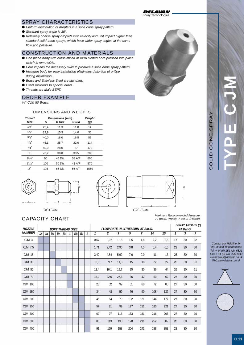
TYP
E C
JM
C.11
Thread Dimensions (mm) WeightSize A B Hex C Dia (g)
1/8” 25,4 11,3 11,0 14
1/4” 29,9 15,3 14,0 30
3/8” 40,0 18,0 16,5 55
1/2” 46,1 25,7 22,0 114
3/4” 50,0 28,0 27 170
1” 76,2 38,0 33,5 280
11/4” 90 45 Dia 38 A/F 600
11/2” 100 50 Dia 43 A/F 870
2” 125 65 Dia 56 A/F 1550
Contact our Helpline forany special requirements:Tel: +44 (0) 151 424 6821Fax: +44 (0) 151 495 1043e-mail:[email protected]
Web:www.delavan.co.uk
SPRAY CHARACTERISTICS● Uniform distribution of droplets in a solid cone spray pattern.● Standard spray angle is 30°.● Relatively coarse spray droplets with velocity and unit impact higher than
standard solid cone sprays, which have wider spray angles at the sameflow and pressure.
CONSTRUCTION AND MATERIALS● One piece body with cross-milled or multi slotted core pressed into place
which is removable.● Core imparts the necessary swirl to produce a solid cone spray pattern.● Hexagon body for easy installation eliminates distortion of orifice
during installation.● Brass and Stainless Steel are standard.● Other materials to special order.● Threads are Male BSPT.
ORDER EXAMPLE3⁄4” CJM 50 Brass.
CAPACITY CHART
DIMENSIONS AND WEIGHTS
Maximum Recommended Pressure:70 Bar.G. (Metal), 7 Bar.G. (Plastic).
SPRAY ANGLES (°)NOZZLE FLOW RATE IN LITRES/MIN AT Bar.G. AT Bar.G.NUMBER 1 2 3 5 7 10 15 1 3 7
CJM 3 0,67 0,97 1,18 1,5 1,8 2,2 2,6 17 30 32
CJM 7,5 1,71 2,42 2,96 3,8 4,5 5,4 6,6 23 30 30
CJM 15 3,42 4,84 5,92 7,6 9,0 11 13 25 30 30
CJM 30 6,9 9,7 11,8 15 18 22 27 26 30 31
CJM 50 11,4 16,1 19,7 25 30 36 44 26 30 31
CJM 70 16,0 22,6 27,6 36 42 50 62 27 30 30
CJM 100 23 32 39 51 60 72 88 27 30 30
CJM 150 34 48 59 76 90 108 132 27 30 30
CJM 200 45 64 79 102 121 144 177 27 30 30
CJM 250 57 81 99 127 151 180 221 27 30 30
CJM 300 69 97 118 153 181 216 265 27 30 30
CJM 300 80 113 138 178 211 252 309 28 30 30
CJM 400 91 129 158 204 241 288 353 28 30 30
BSPT THREAD SIZE1/8 1/4 3/8 1/2 3/4 1 11/4 11/2 2
11⁄4”-2”CJM1⁄8”-1”CJMS
OL
ID C
ON
E S
PR
AY
Solid cone spray 1 3/5/01 3:31 pm Page 11

TYP
E C
JF
C.12
Contact our Helpline forany special requirements:Tel: +44 (0) 151 424 6821Fax: +44 (0) 151 495 1043e-mail:[email protected]
Web:www.delavan.co.uk
Maximum Recommended Pressure:35 Bar.G. (Metal) 7 Bar.G. (Plastic).
SPRAY ANGLES (°)NOZZLE FLOW RATE IN LITRES/MIN AT Bar.G. AT Bar.G.NUMBER 1 2 3 5 7 10 15 1 3 7
CJF 3 0,67 0,97 1,18 1,5 1,8 2,2 2,6 17 30 32
CJF 7,5 1,71 2,42 2,96 3,8 4,5 5,4 6,6 23 30 30
CJF 15 3,42 4,84 5,92 7,6 9,0 11 13 25 30 30
CJF 30 6,9 9,7 11,8 15 18 22 27 26 30 31
CJF 50 11,4 16,1 19,7 25 30 36 44 26 30 31
CJF 70 16,0 22,6 27,6 36 42 50 62 27 30 30
CJF 100 23 32 39 51 60 72 88 27 30 30
CJF 150 34 48 59 76 90 108 132 27 30 30
CJF 200 45 64 79 102 121 144 177 27 30 30
CJF 250 57 81 99 127 151 180 221 27 30 30
CJF 300 69 97 118 153 181 216 265 27 30 30
CJF 350 80 113 138 178 211 252 309 28 30 30
CJF 400 91 129 158 204 241 288 353 28 30 30
CJF 500 114 161 197 255 302 360 442 28 30 30
CJF 750 171 242 296 382 452 541 662 28 30 30
CJF 1000 228 322 395 510 603 721 883 28 30 30
CJF 1500 342 484 592 765 905 1082 1325 28 30 30
CJF 2000 456 645 790 1020 1206 1442 1766 28 30 30
CJF 2500 570 806 987 1275 1508 1803 2208 28 30 30
BSPT THREAD SIZE1/8 1/4 3/8 1/2 3/4 1 11/4 11/2 2 3 4
Thread Dimensions (mm) WeightSize A B Hex C (g)1/8” 33.3 15.3 10.7 201/4” 42.8 18.0 13.8 313/8” 50.8 20.8 17.0 721/2” 63.5 25.7 21.0 1403/4” 82.6 31.8 26.5 260
1” 101.6 38.0 36.5 395
DIMENSIONS AND WEIGHTS Thread Dimensions (mm) Weight
Size A B Hex C (kg)
11/4” 95 48 48 0,6
11/2” 108 56 54 0,72” 136 73 67 1,63” 200 98 98 5,94” 250 127 121 7,5
SPRAY CHARACTERISTICS● Uniform distribution of spray droplets in a solid cone spray pattern.● 30° is the standard spray angle.● Relatively coarse spray droplets with velocity and unit impact higher than
standard solid cone sprays, which have wider spray angles at the sameflow and pressure.
CONSTRUCTION AND MATERIALS● One piece body with cross-milled or vane type core pressed into place
which is removable.● Core imparts the necessary swirl to produce a solid cone spray pattern.● Hexagon body for easy installation eliminates distortion of orifice
during installation.● Threads up to 1” are BSPP and above are BSPT.● 11⁄4” and larger are generally cast and are available in Gunmetal, Stainless
Steel and Cast Iron.● Brass and Stainless Steel are standard for hexagon barstock sizes.● Other materials to special order.
ORDER EXAMPLE11⁄4” CJF 150 Gunmetal.
CAPACITY CHART11⁄4” - 4”CJF
1⁄8” - 1”CJF
SO
LID
CO
NE
SP
RA
Y
B A
C
B A
C
Solid cone spray 2 3/5/01 3:43 pm Page 1

TYP
E C
M
C.13
Thread Dimensions (mm) Weight Size A Hex B C (Kg)11/4” 95 48 48 0,611/2” 108 56 54 0,7
2” 136 73 67 1,63” 200 98 98 5,94” 178 127 121 7,55” 191 165 152 11,66” 276 197 184 20,08” 318 241(Oct) 235 35,0
SPRAY CHARACTERISTICS● Uniform distribution of droplets in solid cone spray pattern.● Droplet size is larger than in hollow cone nozzles of equal capacity.● Spray droplet size increases as flow increases at the same pressure.
CONSTRUCTION AND MATERIALS● One piece, cast body with removable vane type core.● Core imparts the necessary swirl to produce a solid spray pattern.● Hexagon body for easy installation eliminates distortion of orifice
during installation.● Available in Cast Iron, Stainless Steel and Gunmetal as standard.● Threads are Female BSPT.● Other materials to special order.
ORDER EXAMPLE2” CM 105 Gunmetal.
Contact our Helpline forany special requirements:Tel: +44 (0) 151 424 6821Fax: +44 (0) 151 495 1043e-mail:[email protected]
Web:www.delavan.co.uk
CAPACITY CHART
DIMENSIONS AND WEIGHTS
SPRAY ANGLES (°)NOZZLE FLOW RATE IN LITRES/MIN AT BAR.G AT BAR.G
NUMBER 0,2 0,35 0,7 1 1,5 2 3 4 5 6 7 ,35 ,7 1,5 6
CM 16 25,9 33,3 45,7 53,6 64,4 72,3 87,6 99,6 110 119 127 55 60 65 45
CM 22 34,2 44,0 59,9 70,1 84,3 96,4 115 131 145 153 168 65 70 75 48
CM 27 43,4 55,8 76,4 89,3 106 121 146 166 184 200 213 65 70 75 50
CM 33 52,2 67,7 91,9 108 129 146 177 202 222 243 259 65 70 80 52
CM 29 45,1 57,6 79,6 94,2 112 128 154 177 197 212 229 55 60 60 50
CM 35 36,2 70,0 96,5 114 137 156 187 216 238 259 278 60 60 60 55
CM 42 66,1 86,0 117 137 168 191 229 261 289 317 339 70 70 70 60
CM 48 74,1 96,5 133 158 188 216 259 298 326 355 381 75 75 70 65
CM 54 83,5 108 148 175 211 241 288 330 367 398 427 80 85 80 70
CM 64 96,9 126 175 206 248 284 341 389 437 473 503 70 73 75 -
CM 71 109 142 195 231 279 321 335 440 488 536 572 71 77 79 -
CM 81 123 161 222 261 316 362 436 504 553 603 650 70 75 75 -
CM 90 137 181 250 294 353 408 492 558 618 679 723 85 85 85 -
CM 98 149 195 270 316 385 451 526 607 670 728 782 88 88 89 -
CM 105 160 209 288 339 413 473 568 652 718 781 833 94 94 94 -
CM 119 187 240 330 396 473 509 650 746 822 894 954 70 73 75 -
CM 155 245 306 430 518 573 594 788 905 996 1083 1155 80 83 85 -
CM 193 299 386 535 638 767 881 1055 1210 1333 1450 1547 85 87 90 -
CM 232 361 462 636 772 923 987 1269 1457 1604 1745 1861 90 93 95 -
CM 242 379 485 686 821 966 1040 1328 1525 1679 1826 1948 95 95 95 -
CM 156 254 311 424 513 620 719 853 979 1078 1172 1250 45 47 50 -
CM 230 361 467 631 768 919 1098 1264 1451 1598 1738 1852 50 55 55 -
CM 318 500 631 846 1040 1264 1491 1738 1995 2197 2390 2549 60 65 67 -
CM 432 661 832 1144 1388 1714 2080 2357 2706 2980 3241 3457 75 80 83 -
CM 628 924 1181 1633 2009 2500 2863 3438 3946 4346 4727 5042 90 95 96 -
CM 534 780 996 1378 1695 2110 2416 2901 3330 3668 3989 4255 70 73 75 -
CM 643 938 1199 1659 2040 2540 2908 3493 4008 4416 4802 5122 75 80 85 -
CM 720 1057 1350 1868 2298 2860 3275 3933 4514 4972 5407 5768 80 90 95 -
CM 815 1190 1520 2103 2587 3220 3687 4428 5082 5598 6087 6494 75 78 80 -
CM 960 1401 1790 2477 3047 3793 4343 5216 5986 6594 7170 7650 84 86 88 -
CM 1150 1679 2145 2968 3651 4544 5203 6248 7172 7900 8590 9164 90 92 95 -
CM 1480 2161 2762 3819 4698 5847 6695 8040 9228 10164 11054 11792 100 106 110 -
BSPT THREAD SIZE11/4 11/2 2 3 4 5 6 8
Maximum Recommended Pressure:14 Bar.G. (Metal), 7 Bar.G. (Plastic).
SO
LID
CO
NE
SP
RA
Y
B A
C
Solid cone spray 2 3/5/01 3:43 pm Page 2

TYP
E B
Y
Thread Dimensions (mm) WeightSize A Hex B C (Kg)
11/4” 95 48 48 0,6
11/2” 108 56 54 0,7
2” 136 73 67 1,6
3” 200 98 98 5,9
C.14
Contact our Helpline forany special requirements:Tel: +44 (0) 151 424 6821Fax: +44 (0) 151 495 1043e-mail:[email protected]
Web:www.delavan.co.uk
SPRAY CHARACTERISTICS● Uniform distribution of droplets in a wide angle solid cone spray pattern.● Droplet size is larger than in hollow cone nozzles of equal capacity.● Spray droplet size increases as flow increases at the same pressure.
CONSTRUCTION AND MATERIALS● One piece, cast body with removable vane type core.● Core imparts the necessary swirl to produce a solid spray pattern.● Hexagon body for easy installation eliminates distortion of orifice
during installation.● Available in Cast Iron, Stainless Steel and Gunmetal as standard.● Threads are Female BSPT.● Other materials to special order.
ORDER EXAMPLE11⁄2” BY 52 Cast Iron.
Maximum Recommended Pressure:14 Bar.G. (Metal) 7 Bar.G. (Plastic).
CAPACITY CHART
DIMENSIONS AND WEIGHTS
SPRAYBSPT THREAD ANGLES (°)
NOZZLE SIZE FLOW RATE IN LITRES/MIN AT Bar.G. AT Bar.G.NUMBER 11/4 11/2 2 3 0,2 0,35 0,7 1,0 1,5 2 3 4 5 6 7 ,35 ,7 1,5 6
BY 23 38,3 49,4 64,0 75,4 90 103 117 138 147 160 173 108 112 112 75
BY 28 46,4 59,5 78,2 91,5 108 118 145 163 179 192 206 100 108 105 75
BY 35 58,9 75,9 101,1 115 133 137 179 206 225 258 274 102 105 112 70
BY 37 62,9 80,5 106 125 146 166 199 216 252 274 294 116 116 120 70
BY 42 69,6 89,2 119 138 164 187 218 248 275 302 323 110 115 120 75
BY 47 76,3 98,8 133 154 184 210 254 292 319 348 373 107 110 110 70
BY 52 86,6 110 146 170 203 227 277 318 353 - - 112 117 120 -
BY 66 105 137 188 219 259 294 355 401 - - - 100 105 103 -
BY 73 116 149 204 240 286 325 390 452 - - - 110 120 130 -
BY 78 125 161 220 256 306 347 420 - - - - 110 120 120 -
BY 89 141 183 247 291 344 403 486 - - - - 115 110 110 -
BY 96 152 197 270 313 375 441 515 - - - - 105 105 110 -
BY 156 272 353 489 625 720 - - - - - - 110 112 112 -
BY 198 344 446 613 795 919 - - - - - - 105 110 105 -
BY 224 370 480 654 902 1037 - - - - - - 100 105 105 -
SO
LID
CO
NE
SP
RA
Y
B A
C
Solid cone spray 2 3/5/01 3:43 pm Page 3

TYP
E C
A
C.15
Contact our Helpline forany special requirements:Tel: +44 (0) 151 424 6821Fax: +44 (0) 151 495 1043e-mail:[email protected]
Web:www.delavan.co.uk
Maximum RecommendedPressure: 14 Bar.G.
Thread Dimensions (mm) WeightSize A B Dia. (kg)
1” 93,7 50,8 0,9
11/4” 93,7 50,8 0,9
11/2” 104,8 63,5 2,4
2” 127,0 76,2 4,3
3” 158,8 114,3 6,2
4” 244,5 149,2 9,0
SPRAY CHARACTERISTICS● Uniform distribution of droplets in solid cone spray pattern.● Droplet size is larger than in hollow cone nozzles of equal capacity.● Spray droplet size increases as flow increases at the same pressure.
CONSTRUCTION AND MATERIALS● Body housing and cap support the internal ceramic parts.● Ceramic internals are lining, orifice plate and multi-slotted core. The ceramic
resists corrosive and abrasive suspensions.● Body and cap are supplied in Stainless Steel as standard.● Cap is threaded Female BSPT.● Other materials are available on a special order.
ORDER EXAMPLE3” CA 140 Stainless Steel.
CAPACITY CHART
DIMENSIONS AND WEIGHTS
SPRAY ANGLES (°)NOZZLE FLOW RATE IN LITRES/MIN AT Bar.G. AT Bar.G.NUMBER 1 11/4 11/2 2 3 4 0,2 0,35 0,7 1 1,5 2 3 4 5,6 7 ,35 ,7 1,5 5,6
CA 12 24,0 35,5 4,7 54,6 65,7 74,8 86,9 94,8 106 115 55 60 65 45
CA 16 33,9 43,6 56,7 71,6 85,9 96,0 110 122 143 161 65 70 75 80
CA 20 43,6 56,1 78,1 96,4 113 126 145 162 188 213 65 70 75 50
CA 26 57,2 71,2 98,7 119,2 142 161 184 205 238 262 65 70 80 52
CA 22 46,0 59,7 83,8 102 123 138 162 178 207 225 55 60 60 50
CA 27 59,7 74,6 103 127 152 172 201 228 262 285 60 60 60 55
CA 32 71,9 89,5 124 150 180 202 228 260 294 319 70 70 70 60
CA 38 85,9 104 145 176 205 225 257 285 326 359 75 75 70 65
CA 43 91,8 115 166 200 232 255 291 330 373 404 80 85 80 70
CA 48 99,7 133 184 222 263 294 348 399 - - 70 73 75 -
CA 58 121 161 222 258 307 344 400 449 - - 71 77 79 -
CA 67 134 175 255 301 354 393 451 497 - - 70 75 75 -
CA 76 157 204 289 343 409 458 526 574 - - 85 85 85 -
CA 86 181 291 330 389 465 566 595 631 - - 88 88 89 -
CA 91 193 253 348 418 501 567 654 718 - - 94 94 94 -
CA 86 191 241 330 397 468 510 - - - - 70 73 75 -
CA 113 247 310 431 512 593 605 - - - - 80 83 85 -
CA 140 304 386 537 618 737 788 - - - - 85 87 90 -
CA 167 368 464 638 758 895 974 - - - - 90 93 95 -
CA 180 390 487 689 826 941 1030 - - - - 95 95 95 -
CA 111 255 312 425 527 621 707 - - - - 45 47 50 -
CA 166 368 469 633 758 919 1091 - - - - 55 55 55 -
CA 222 501 633 849 1040 1263 1535 - - - - 65 67 70 -
CA 300 675 835 1151 1364 1717 2020 - - - - 80 83 85 -
CA 430 927 1182 1646 2030 2495 2969 - - - - 95 96 98 -
BSPT THREAD SIZE SO
LID
CO
NE
SP
RA
Y
Solid cone spray 2 3/5/01 3:43 pm Page 4

TYP
E C
B
Nozzle Dimensions (mm) WeightSize A B Dia. (Kg)
1” 76 47,6 0,9
11/4” 76 54,0 1,25
11/2” 76 63,5 2,3
2” 102 76,2 4,1
3” 146 114,3 5,9
C.16
Contact our Helpline forany special requirements:Tel: +44 (0) 151 424 6821Fax: +44 (0) 151 495 1043e-mail:[email protected]
Web:www.delavan.co.uk
SPRAY CHARACTERISTICS● Uniform distribution of droplets in solid cone spray pattern.● Droplet size is larger than in hollow cone nozzles of equal capacity.● Spray droplet size increases as flow increases at the same pressure.
CONSTRUCTION AND MATERIALS● Support body is cast around the internal ceramic parts.● Ceramic internals are lining, orifice plate and multi-slotted core. The ceramic
resists corrosive and abrasive suspensions.● Support body is a hard antimony lead material.● Supply line should be welded to the outer lead casing when
being installed.
ORDER EXAMPLE3” CB 141.
CAPACITY CHART
DIMENSIONS AND WEIGHTS
SPRAY ANGLE (°)NOZZLE INLET SIZE (N.B.) FLOW RATE IN LITRES/MIN AT Bar.G. AT Bar.G.NUMBER 1 11/411/2 2 3 0,2 0,5 0,7 1 1,5 2 3 4 6 8 ,35 ,7 1,5 6
CB 8 - 27,88 32,06 38,68 47,27 53,73 65,15 77,16 85,45 96,46 - 80 85 88
CB 10 - 30,81 36,18 43,83 53,73 62,42 74,84 84,03 99,18 112,11 - 73 85 56
CB 11 - 34,24 41,22 48,68 60,10 70,20 84,03 94,54 112,11 127,26 - 76 89 62
CB 13 - 41,11 49,23 58,28 72,11 84,03 100,09 113,12 133,32 150,49 - 77 88 60
CB 14 - 45,65 53,81 64,74 79,39 91,91 111,10 124,23 146,45 165,64 - 73 84 60
CB 12 25,96 38,28 44,65 51,41 61,51 68,88 82,21 93,22 110,09 125,24 55 60 65 45
CB 16 34,85 51,91 59,54 70,30 84,03 95,04 114,13 129,28 153,52 175,74 65 70 75 48
CB 20 45,25 67,06 77,86 90,70 109,08 122,21 146,45 166,65 196,95 223,21 65 70 75 50
CB 26 57,87 85,45 98,47 115,14 137,36 153,52 183,82 208,06 246,44 279,77 65 70 80 52
CB 22 46,86 71,21 83,58 98,27 119,18 136,35 160,59 178,77 208,06 233,31 55 60 60 50
CB 27 56,96 89,49 103,05 124,23 151,50 173,72 205,03 228,26 267,65 296,94 60 60 60 55
CB 32 68,38 106,05 123,66 147,46 179,78 198,97 232,30 357,55 297,95 333,30 70 70 60 60
CB 38 81,71 125,24 145,18 172,71 202,00 224,22 261,59 288,86 335,32 371,68 75 75 70 65
CB 43 92,72 141,40 164,88 192,91 229,27 254,52 295,93 328,25 379,76 422,18 80 85 80 70
CB 48 104,03 157,56 183,20 216,14 260,58 297,95 352,49 390,87 - - 70 73 75 -
CB 58 119,18 183,82 222,13 252,50 305,02 348,45 406,02 448,44 - - 71 77 79 -
CB 67 135,34 208,06 154,19 287,85 348,45 399,96 457,53 505,00 - - 70 75 75 -
CB 76 156,55 240,38 258,54 333,30 406,02 468,64 523,18 569,64 - - 85 85 85 -
CB 86 130,79 275,73 329,76 376,73 456,52 519,14 587,82 633,27 - - 88 88 89 -
CB 91 197,96 301,99 348,08 415,11 500,96 569,64 638,21 688,82 - - 94 94 94 -
CB 86 186,35 289,82 329,76 394,91 468,64 510,05 - - - - 70 73 75 -
CB 113 239,37 368,65 430,52 514,09 606,00 661,55 - - - - 80 83 85 -
CB 141 300,98 456,52 535,86 629,23 743,36 813,05 - - - - 85 87 90 -
CB 167 364,61 550,45 636,62 762,55 904,96 986,77 - - - - 90 93 95 -
CB 180 379,76 587,82 687,0 813,05 964,55 1040,30 - - - - 95 95 95 -
Maximum RecommendedPressure: 14 Bar.G.
SO
LID
CO
NE
SP
RA
Y
Solid cone spray 2 3/5/01 3:44 pm Page 5

TYP
E B
C
C.17
Contact our Helpline forany special requirements:Tel: +44 (0) 151 424 6821Fax: +44 (0) 151 495 1043e-mail:[email protected]
Web:www.delavan.co.uk
Maximum RecommendedPressure: 35 Bar.G.
SPRAY CHARACTERISTICS● Uniform distribution of droplets in a solid cone spray pattern.● Droplet size is larger than in hollow cone nozzles of equal capacity.● Purpose designed for continuous casting applications.● Available spray angles of 50°, 65°, 80°, 90° and 120°.
CONSTRUCTION AND MATERIALS● The nozzle uses a multi-slotted core incorporating Delavan's ‘Star Slot’
swirl chamber bottom.● The core is a drive fit into the body and is not suitable for replacement.● Inlet thread is 3⁄8” BSPP Female.● Brass and Stainless Steel are standard.● Other materials are available on a special order.
ORDER EXAMPLE3⁄8” BC 55-65°, Brass.
NOZZLE FLOW RATE IN LITRES/MIN AT Bar.G.NUMBER 1,0 1,5 2,0 2,5 3,0 4,0 5,0 6,0 7,0
BC 40 2,31 2,38 3,27 3,65 4,0 4,62 5,10 5,62 6,11
BC 45 2,60 3,18 3,67 4,11 4,5 5,20 5,74 6,31 6,86
BC 50 2,89 3,54 4,08 4,56 5,0 5,77 6,37 7,05 7,61
BC 55 3,18 3,89 4,49 5,02 5,5 6,35 7,01 7,75 8,38
BC 60 3,46 4,24 4,90 5,48 6,0 6,93 7,65 8,46 9,15
BC 65 3,75 4,67 5,31 5,93 6,5 7,51 8,29 9,16 9,91
BC 70 4,04 4,95 5,71 6,93 7,0 8,08 8,92 9,87 10,66
BC 80 4,62 5,66 6,53 7,30 8,0 9,24 10,20 11,28 12,19
BC 90 5,20 6,36 7,35 8,22 9,0 10,39 11,47 12,69 13,71
BC 100 5,77 7,07 8,16 9,13 10,0 11,55 12,75 14,10 15,25
BC 110 6,35 7,80 8,98 10,04 11,0 12,70 14,02 15,51 16,78
BC 120 6,93 8,49 9,80 10,95 12,0 13,86 15,30 16,92 18,31
BC 140 8,08 9,90 11,42 12,78 14,0 16,16 17,84 19,74 21,32
BC 160 9,24 11,32 13,06 14,60 16,0 18,48 20,40 22,56 24,38
CAPACITY CHART
SO
LID
CO
NE
SP
RA
Y
Solid cone spray 2 3/5/01 3:44 pm Page 6

TYP
E B
X
C.18
Contact our Helpline forany special requirements:Tel: +44 (0) 151 424 6821Fax: +44 (0) 151 495 1043e-mail:[email protected]
Web:www.delavan.co.uk
SPRAY CHARACTERISTICS● Uniform distribution of spray droplets in a solid cone pattern.● Droplet size is larger than in hollow cone nozzles of equal capacity.● Purpose designed for continuous casting applications.● Available spray angles of 50°, 65°, 80°, 90° and 120°.
CONSTRUCTION AND MATERIALS● The nozzle uses a standard cross-milled core design.● The cross-milled core is pressed into place and is removable.● Inlet thread is 3⁄8” BSPP Female.● Brass and Stainless Steel are standard.● Other materials are available on a special order.
ORDER EXAMPLE3⁄8” BX 40-80°, Stainless Steel.
Maximum RecommendedPressure: 35 Bar.G.
Nozzle Dimensions (mm) WeightNumber A B Hex C (g)
BX40 - BX90 24,0 20,8 20,2 40
BX100 - BX160 35,0 20,8 20,2 55
DIMENSIONS AND WEIGHTS
NOZZLE FLOW RATE IN LITRES/MIN AT Bar.G.NUMBER 1,0 1,5 2,0 2,5 3,0 4,0 5,0 6,0 7,0
BX 40 2,31 2,38 3,27 3,65 4,0 4,62 5,10 5,62 6,11
BX 45 2,60 3,18 3,67 4,11 4,5 5,20 5,74 6,31 6,86
BX 50 2,89 3,54 4,08 4,56 5,0 5,77 6,37 7,05 7,61
BX 55 3,18 3,89 4,49 5,02 5,5 6,35 7,01 7,75 8,38
BX 60 3,46 4,24 4,90 5,48 6,0 6,93 7,65 8,46 9,15
BX 65 3,75 4,670 5,31 5,93 6,5 7,51 8,29 9,16 9,91
BX 70 4,04 4,95 5,71 6,93 7,0 8,08 8,92 9,87 10,66
BX 80 4,62 5,66 6,53 7,30 8,0 9,24 10,20 11,28 12,19
BX 90 5,20 6,36 7,35 8,22 9,0 10,39 11,47 12,69 13,71
BX 100 5,77 7,07 8,16 9,13 10,0 11,55 12,75 14,10 15,25
BX 110 6,35 7,80 8,98 10,04 11,0 12,70 14,02 15,51 16,78
BX 120 6,93 8,49 9,80 10,95 12,0 13,86 15,30 16,92 18,31
BX 140 8,08 9,90 11,42 12,78 14,0 16,16 17,84 19,74 21,32
BX 160 9,24 11,32 13,06 14,60 16,0 18,48 20,40 22,56 24,38
CAPACITY CHART
SO
LID
CO
NE
SP
RA
Y
Solid cone spray 2 3/5/01 3:44 pm Page 7

TYP
E B
Q
C.19
Contact our Helpline forany special requirements:Tel: +44 (0) 151 424 6821Fax: +44 (0) 151 495 1043e-mail:[email protected]
Web:www.delavan.co.uk
SPRAY CHARACTERISTICS● Uniform distribution of droplets in a solid cone square shaped spray pattern.● Droplet size is larger than in hollow cone nozzles of equal capacity.● Impact of spray is generally greater with narrower spray angles, assuming
the same flow rate. Pressure increases affect spray angle.
CONSTRUCTION AND MATERIALS● One piece body with pressed-in, cross-milled core which is removable.● Core imparts the necessary swirl to produce a solid cone spray pattern.● Hexagon body for easy installation eliminates distortion of orifice
during installation.● Available with Male BSPT and Female BSPP threads.● Brass and 316 Stainless Steel are standard.● Other materials available to special order.
ORDER EXAMPLE3⁄4” BQM (Male) 89 Brass.1⁄2” BQF (Female) 49 Stainless Steel.
SPRAYBSPT THREAD ANGLES (°)
NOZZLE NUMBER SIZE FLOW RATE IN LITRES/MIN AT Bar.G. AT Bar.G.Female Male 1/8 1/4 3/8 1/2 3/4 1 ,35 ,7 1 1,5 2 3 4 6 7 8 ,7 2 6
BQF 6 BQM 6 ,88 1,25 1,50 1,88 2,18 2,65 2,87 3,41 3,54 3,76 40 47 40
BQF 8 BQM 8 1,30 1,86 2,28 2,84 3,23 4,00 4,55 5,38 5,72 5,97 44 56 53
BQF 11 BQM 11 1,63 2,32 2,87 3,62 4,05 4,87 5,36 6,30 6,74 7,06 52 64 58
BQF 12 BQM 12 2,09 2,79 3,41 4,09 4,55 5,30 5,91 7,02 7,58 8,01 62 70 58
BQF 16 BQM 16 2,50 3,58 4,41 5,30 6,14 7,27 8,00 9,51 10,04 10,61 62 70 58
BQF 20 BQM 20 3,11 4,46 5,46 6,50 7,54 9,06 10,00 11,92 12,63 13,43 62 73 58
BQF 22 BQM 22 3,58 5,11 6,24 7,51 8,32 9,78 10,91 13,23 14,24 14,95 70 80 62
BQF 12 BQM 12 2,00 2,79 3,32 4,19 4,73 5,83 6,60 7,79 8,17 8,65 36 45 39
BQF 16 BQM 16 2,50 3,58 4,41 5,30 6,14 7,27 8,00 9,51 10,04 10,61 57 60 55
BQF 20 BQM 20 3,11 4,46 5,46 6,50 7,54 9,06 10,00 11,92 12,63 13,43 61 73 58
BQF 22 BQM 22 3,58 5,11 6,24 7,51 8,32 9,78 10,91 13,23 14,24 14,95 70 80 62
BQF 27 BQM 27 4,23 6,04 7,42 9,01 10,10 12,32 13,64 16,06 17,47 18,08 70 80 62
BQF 32 BQM 32 5,81 7,25 8,88 10,81 12,32 14,44 15,96 19,29 20,40 22,12 70 80 62
BQF 27 BQM 27 4,23 6,04 7,42 9,01 10,10 12,32 13,64 16,06 17,47 18,08 44 53 51
BQF 32 BQM 32 5,81 7,25 8,88 10,81 12,32 14,44 15,96 19,29 20,40 22,12 60 70 61
BQF 42 BQM 42 6,74 9,67 11,82 14,44 15,96 19,29 21,41 24,95 27,37 28,48 70 76 64
BQF 49 BQM 49 8,17 11,62 14,24 16,36 18,69 23,13 25,05 29,29 32,52 33,94 79 86 72
BQF 63 BQM 63 10,20 14,44 17,07 20,50 23,84 28,89 32,22 38,48 41,31 43,94 80 86 70
BQF 47 BQM 47 7,48 10,61 13,03 14,95 17,78 21,11 26,63 28,48 30,20 31,71 43 57 42
BQF 63 BQM 63 10,20 14,44 17,07 20,50 23,84 28,89 32,22 38,48 41,31 43,94 60 69 53
BQF 77 BQM 77 12,32 17,68 20,50 23,94 29,09 34,95 38,68 45,65 49,29 52,02 70 73 60
BQF 89 BQM 89 13,94 20,00 23,74 29,39 33,63 40,00 44,54 52,92 56,26 59,29 82 85 67
BQF 102 BQM 102 14,85 20,91 27,37 33,73 38,68 46,26 50,00 60,10 64,54 67,87 85 97 74
BQF 73 BQM 73 11,92 16,26 20,00 22,62 27,78 34,24 38,68 45,65 50,00 52,02 35 41 44
BQF 105 BQM 105 16,26 23,23 27,78 33,73 39,79 48,18 52,32 62,42 67,37 71,51 51 57 49
BQF 123 BQM 123 19,49 28,38 34,64 42,32 46,56 57,77 63,63 75,95 80,40 85,55 66 73 57
BQF 140 BQM 140 22,73 32,02 38,18 45,25 53,23 62,12 68,18 80,80 85,95 90,90 75 81 52
BQF 162 BQM 162 25,55 36,26 44,64 53,03 61,41 72,22 79,08 95,14 101,00 108,07 74 86 63
BQF 193 BQM 193 28,79 41,81 50,10 60,70 73,23 87,57 99,08 119,18 128,27 135,34 82 100 80
CAPACITY CHART
BQM (MALE)
BQF (FEMALE) SO
LID
CO
NE
SP
RA
Y
Thread Nozzle Dimensions (mm) WeightSize Type A B C Hex (g)1/8” BQM 17,5 9,6 11,3 101/8” BQF 25,4 13,5 15,3 211/4” BQM 24,5 13,0 15,3 241/4” BQF 27,8 12,7 18,0 353/8” BQM 25,5 14,0 18,0 353/8” BQF 38,9 21,1 20,8 581/2” BQM 32,0 16,1 25,6 751/2” BQF 50,0 28,3 25,6 1183/4” BQM 36,0 19,0 28,0 1153/4” BQF 62,7 31,5 31,8 2151” BQM 50,0 28,5 38,0 2901” BQF 81,0 51,0 38,0 330
DIMENSIONS AND WEIGHTS
Maximum RecommendedPressure: 35 Bar.G.
Solid cone spray 2 3/5/01 3:44 pm Page 8

TYP
E B
T
C.20
Contact our Helpline forany special requirements:Tel: +44 (0) 151 424 6821Fax: +44 (0) 151 495 1043e-mail:[email protected]
Web:www.delavan.co.uk
SPRAY CHARACTERISTICS● Uniform distribution of droplets in a wide angle solid cone square
shaped pattern.● Droplet size is larger than in hollow cone nozzles of equal capacity.● Impact of spray is generally greater with narrower spray angles, assuming
the same flow rate. Pressure increases affect spray angle.
CONSTRUCTION AND MATERIALS● One piece body with pressed-in, cross-milled core which is removable.● Core imparts the necessary swirl to produce a solid cone spray pattern.● Hexagon body for easy installation eliminates distortion of orifice
during installation.● Brass and Stainless Steel are standard.● Other materials available to special order.
ORDER EXAMPLE1⁄2” BTF (Female) 59 Brass.3⁄4” BTM (Male) 98 Stainless Steel.
Maximum RecommendedPressure: 35 Bar.G. CAPACITY CHART
SPRAY ANGLES (°)
NOZZLE NUMBER BSPT THREAD SIZE FLOW RATE IN LITRES/MIN AT Bar.G. AT Bar.G.Female Male 1/8 1/4 3/8 1/2 3/4 1 0,35 0,7 1 1,5 2 3 4 6 7 8 ,7 2 6
BTF 6 BTM 6 0,88 1,25 1,50 1,88 2,18 2,65 2,87 3,41 3,54 3,76 110 100 90
BTF 8 BTM 8 1,30 1,86 2,28 2,84 3,23 4,00 4,55 5,38 5,72 5,97 125 120 100
BTF 11 BTM 11 1,86 2,79 3,23 3,86 4,31 5,15 5,45 6,73 7,43 7,70 115 120 95
BTF 15 BTM 15 2,60 3,67 4,50 5,26 5,59 6,64 7,24 8,70 9,16 9,70 115 110 90
BTF 18 BTM 18 3,10 4,40 5,39 6,30 6,70 7,96 8,68 10,43 10,98 11,63 120 120 95
BTF 22 BTM 22 3,95 5,58 6,84 8,0 8,50 10,10 11,01 13,23 13,94 14,75 113 110 90
BTF 25 BTM 25 4,27 6,04 7,24 8,43 9,32 11,01 12,32 14,65 15,76 16,26 120 120 100
BTF 32 BTM 32 5,90 7,70 9,15 10,80 11,92 14,30 15,78 18,90 19,90 21,26 115 110 85
BTF 39 BTM 39 7,20 9,40 11,15 13,14 14,52 17,40 19,20 23,00 24,25 25,90 120 120 90
BTF 46 BTM 46 8,13 11,62 13,64 15,86 17,27 19,29 22,32 25,45 27,88 29,39 125 112 90
BTF 48 BTM 48 8,33 12,52 15,25 16,87 18,18 23,13 24,54 29,80 32,52 34,34 125 120 90
BTF 59 BTM 59 9,29 13,23 15,96 19,29 22,32 26,06 28,18 34,64 37,67 40,70 130 128 100
BTF 65 BTM 65 12,00 15,65 18,60 21,92 24,21 29,00 32,05 38,37 40,40 43,20 115 110 85
BTF 73 BTM 73 13,50 17,60 20,88 24,50 27,19 32,60 36,00 43,10 45,40 48,50 115 120 90
BTF 82 BTM 82 15,35 20,0 23,74 27,98 30,91 37,07 40,91 48,99 51,61 55,15 115 112 90
BTF 94 BTM 94 16,77 22,32 26,87 32,72 35,45 41,92 45,96 56,26 59,89 63,33 119 120 91
BTF 98 BTM 98 18,08 23,23 27,78 34,24 37,27 44,34 50,00 59,59 64,54 67,87 112 120 90
BTF 136 BTM 136 24,14 35,25 42,32 48,18 51,41 60,20 67,77 81,20 86,86 91,41 118 115 75
BTF 153 BTM 153 27,88 38,08 46,97 53,93 57,97 67,47 76,36 91,30 98,07 108,07 125 120 85
BTF 200 BTM 200 29,69 42,32 51,41 62,62 75,95 88,68 99,59 120,19 130,29 139,38 118 125 90
BTM (MALE)
BTF (FEMALE)
SO
LID
CO
NE
SP
RA
Y
Thread Nozzle Dimensions (mm) WeightSize Type A B C Hex (g)
1/8” BTM 17,5 9,6 11,3 10
1/8” BTF 25,4 13,5 15,3 21
1/4” BTM 24,5 13,0 15,3 24
1/4” BTF 27,8 12,7 18,0 35
3/8” BTM 25,5 14,0 18,0 35
3/8” BTF 38,9 21,1 20,8 58
1/2” BTM 32,0 16,1 25,6 75
1/2” BTF 50,0 28,3 25,6 118
3/4” BTM 36,0 19,0 28,0 115
3/4” BTF 62,7 31,5 31,8 215
1” BTM 50,0 28,5 38,0 290
1” BTF 81,0 51,0 38,0 330
DIMENSIONS AND WEIGHTS
Solid cone spray 2 3/5/01 3:44 pm Page 9

TYP
E C
U/S
Q
C.21
Contact our Helpline forany special requirements:Tel: +44 (0) 151 424 6821Fax: +44 (0) 151 495 1043e-mail:[email protected]
Web:www.delavan.co.uk
Maximum RecommendedPressure: 35 Bar.G.
CAPACITY CHARTApprox. AVAILABLEOrifice SPRAY
NOZZLE Dia. NPT THREAD SIZE FLOW RATE IN LITRES/MIN AT BAR.G. ANGLES (°)NUMBER (mm) 1/4 3/8 1/2 0,35 0,7 1,5 3 5 7 AT 0,7 BAR.G.
CU/SQ-10 2,2 2,79 3,82 5,53 7,51 9,74 11,45 60°
CU/SQ-18 3,9 4,69 6,87 9,88 14,22 18,39 21,75 65°
CU/SQ-29 5,3 8,01 11,07 16,20 22,91 29,57 35,11 65°
SPRAY CHARACTERISTICS● Uniform distribution of droplets in a solid cone square shaped spray pattern.● Droplet size is larger than in hollow cone nozzles of equal capacity.● Impact of spray is generally greater with narrower spray angles, assuming
the same flow rate. Pressure increases affect spray angle.
CONSTRUCTION AND MATERIALS● One piece body with pressed-in, cross-milled core which is removable.● Core imparts the necessary swirl to produce a solid cone spray pattern.● Hexagon body for easy installation eliminates distortion of orifice
during installation.● Available with Male NPT threads only.● Brass and 303 Stainless Steel are standard.● Other materials available to special order.
ORDER EXAMPLE1⁄2” CU/SQ 29 Brass.
Thread Dimensions (mm) WeightSize A Hex B (g)
1/4” 14,3 24,5 23
3/8” 17,5 25,5 28
1/2” 25,6 32,0 75
DIMENSIONS AND WEIGHTS
SQ (MALE)S
OL
ID C
ON
E S
PR
AY
Solid cone spray 2 3/5/01 3:44 pm Page 10

TYP
E C
BI
C.22
Contact our Helpline forany special requirements:Tel: +44 (0) 151 424 6821Fax: +44 (0) 151 495 1043e-mail:[email protected]
Web:www.delavan.co.uk
Maximum Recommended Pressure:35 Bar.G. (Metal), 7 Bar.G. (Plastic).
CAPACITY CHART SPRAYANGLES (°)
NOZZLE BSPP THREAD SIZE FLOW RATE IN LITRES/MIN AT Bar.G. AT Bar.G.NUMBER 1/8 1/4 3/8 1/2 3/4 1 0,35 0,7 1 1,5 2 3 4 6 7 8 ,7 2 6
CBI 6 0,88 1,25 1,50 1,88 2,18 2,65 2,87 3,41 3,54 3,76 40 47 40
CBI 8 1,30 1,86 2,28 2,84 3,23 4,00 4,55 5,38 5,72 5,97 44 56 53
CBI 11 1,63 2,32 2,87 3,62 4,05 4,87 5,36 6,30 6,74 7,06 52 64 58
CBI 12 2,09 2,79 3,41 4,09 4,55 5,30 5,91 7,02 7,58 8,01 62 70 58
CBI 16 2,50 3,58 4,41 5,30 6,14 7,27 8,00 9,51 10,04 10,61 57 60 55
CBI 20 3,11 4,46 5,46 6,50 7,54 9,06 10,00 11,92 12,63 13,43 62 73 58
CBI 22 3,58 5,11 6,24 7,51 8,32 9,78 10,91 13,23 14,24 14,95 70 80 62
CBI 12 2,00 2,79 3,32 4,19 4,73 5,83 6,60 7,79 8,17 8,65 36 45 39
CBI 16 2,50 3,58 4,41 5,30 6,14 7,27 8,00 9,51 10,04 10,61 57 60 55
CBI 20 3,11 4,46 5,46 6,50 7,54 9,06 10,00 11,92 12,63 13,43 61 73 58
CBI 22 3,58 5,11 6,24 7,51 8,32 9,78 10,91 13,23 14,24 14,95 70 80 62
CBI 27 4,23 6,04 7,42 9,01 10,10 12,32 13,64 16,06 17,47 18,08 44 53 51
CBI 32 5,81 7,25 8,88 10,81 12,32 14,44 15,96 19,29 20,40 22,12 60 70 61
CBI 27 4,23 6,04 7,42 9,01 10,10 12,32 13,64 16,06 17,47 18,08 44 53 51
CBI 32 5,81 7,25 8,88 10,81 12,32 14,44 15,96 19,29 20,40 22,12 60 70 61
CBI 42 6,74 9,67 11,82 14,44 15,96 19,29 21,41 24,95 27,37 28,48 70 76 64
CBI 49 8,17 11,62 14,24 16,36 18,69 23,13 15,05 29,29 32,52 33,94 79 86 72
CBI 63 10,20 14,44 17,07 20,50 23,84 28,89 32,22 38,48 41,31 43,94 80 86 70
CBI 47 7,48 10,61 13,03 14,95 17,78 21,11 26,63 28,48 30,20 31,71 43 57 42
CBI 63 10,20 14,44 17,07 20,50 23,84 28,89 32,22 38,48 41,31 43,94 60 69 53
CBI 77 12,32 17,68 20,50 23,94 29,09 34,95 38,68 45,65 49,29 52,02 70 73 60
CBI 89 13,94 20,00 23,74 29,39 33,63 40,00 44,54 52,92 56,26 59,29 82 85 67
CBI 102 14,85 20,91 27,37 33,73 38,68 46,26 50,00 60,10 64,54 67,87 85 97 74
CBI 73 11,92 16,26 20,00 22,62 27,78 34,24 38,68 45,65 50,00 52,02 35 41 44
CBI 105 16,26 23,23 27,78 33,73 39,79 48,18 52,32 62,42 67,37 71,51 51 57 49
CBI 123 19,49 28,38 34,64 42,32 46,56 57,77 63,63 75,95 80,40 85,55 66 73 57
CBI 140 22,73 32,02 38,18 45,25 53,23 62,12 68,18 80,80 85,95 90,90 75 81 52
CBI 162 25,55 36,26 44,64 53,03 61,41 72,22 79,08 95,14 101,00 108,07 74 86 63
CBI 193 28,79 41,81 50,10 60,70 73,23 87,57 99,08 119,18 128,27 135,34 82 100 80
SPRAY CHARACTERISTICS● Uniform distribution of droplets in a solid cone spray pattern.● Droplet size is larger than in hollow cone nozzles of equal capacity.● Impact of spray is generally greater with narrower spray angles, assuming
the same flow rate. Pressure increases affect spray angle.
CONSTRUCTION AND MATERIALS● One piece body with pressed-in, cross-milled core which is removable.● Core imparts the necessary swirl to produce a solid cone spray pattern.● Hexagon body for easy installation eliminates distortion of orifice
during installation.● Supplied with Male BSPP thread only.● Brass and 316 Stainless Steel are standard.● Other materials available to special order.
ORDER EXAMPLE1⁄2” CBI 42 Brass.
Thread Dimensions (mm) WeightSize A Hex B C D Dia (g)
1/8” 14,0 10,7 6,4 12,7 10
1/4” 18,0 14,0 7,0 16,5 20
3/8” 20,8 20,0 10,0 20,0 32
1/2” 25,7 25,4 12,7 24,9 63
3/4” 31,8 33,3 15,9 31,0 105
1” 38,0 47,6 19,1 38,0 210
DIMENSIONS AND WEIGHTS
SO
LID
CO
NE
SP
RA
Y
Solid cone spray 3 3/5/01 4:04 pm Page 1

TYP
E C
BN
C.23
Contact our Helpline forany special requirements:Tel: +44 (0) 151 424 6821Fax: +44 (0) 151 495 1043e-mail:[email protected]
Web:www.delavan.co.uk
CAPACITY CHARTSPRAY
ANGLES (°)NOZZLE BSPP THREAD SIZE FLOW RATE IN LITRES/MIN AT Bar.G. AT Bar.G.
NUMBER 1/8 1/4 3/8 1/2 3/4 1 0,35 0,7 1 1,5 2 3 4 6 7 8 ,7 2 6
CBN 6 0,88 1,25 1,50 1,88 2,18 2,65 2,87 3,41 3,54 3,76 110 100 90
CBN 8 1,30 1,86 2,28 2,84 3,23 4,00 4,55 5,38 5,72 5,97 125 120 100
CBN 11 1,86 2,79 3,23 3,86 4,31 5,15 5,45 6,73 7,43 7,70 115 120 95
CBN 15 2,60 3,67 4,50 5,26 5,59 6,64 7,24 8,70 9,16 9,70 115 110 90
CBN 18 3,10 4,40 5,39 6,30 6,70 7,96 8,68 10,43 10,98 11,63 120 120 95
CBN 22 3,95 5,58 6,84 8,0 8,50 10,10 11,01 13,23 13,94 14,75 113 110 90
CBN 25 4,27 6,04 7,24 8,43 9,32 11,01 12,32 14,65 15,76 16,26 120 120 100
CBN 32 5,90 7,70 9,15 10,80 11,92 14,30 15,78 18,90 19,90 21,26 115 110 85
CBN 39 7,20 9,40 11,15 13,14 14,52 17,40 19,20 23,00 24,25 25,90 120 120 90
CBN 46 8,13 11,62 13,64 15,86 17,27 19,29 22,32 25,45 27,88 29,39 125 112 90
CBN 48 8,33 12,52 15,25 16,87 18,18 23,13 24,54 29,80 32,52 34,34 125 120 90
CBN 59 9,29 13,23 15,96 19,29 22,32 26,06 28,18 34,64 37,67 40,70 130 128 100
CBN 65 12,00 15,65 18,60 21,92 24,21 29,00 32,05 38,37 40,40 43,20 115 110 85
CBN 73 13,50 17,60 20,88 24,50 27,19 32,60 36,00 43,10 45,40 48,50 115 120 90
CBN 82 15,35 20,0 23,74 27,98 30,91 37,07 40,91 48,99 51,61 55,15 115 112 90
CBN 94 16,77 22,32 26,87 32,72 35,45 41,92 45,96 56,26 59,89 63,33 119 120 91
CBN 98 18,08 23,23 27,78 34,24 37,27 44,34 50,00 59,59 64,54 67,87 112 120 90
CBN 136 24,14 35,25 42,32 48,18 51,41 60,20 67,77 81,20 86,86 91,41 118 115 75
CBN 153 27,88 38,08 46,97 53,93 57,97 67,47 76,36 91,30 98,07 108,07 125 120 85
CBN 200 29,69 42,32 51,41 62,62 75,95 88,68 99,59 120,19 130,29 139,38 118 125 90
SPRAY CHARACTERISTICS● Uniform distribution of droplets in a solid cone wide angle spray pattern.● Droplet size is larger than in hollow cone nozzles of equal capacity.● Impact of spray is generally greater with narrower spray angles, assuming
the same flow rate. Pressure increases affect spray angle.
CONSTRUCTION AND MATERIALS● One piece body with pressed-in, cross-milled core which is removable.● Core imparts the necessary swirl to produce a solid cone spray pattern.● Hexagon body for easy installation eliminates distortion of orifice
during installation.● Supplied with Male BSPP thread only.● Brass and 316 Stainless Steel are standard.● Other materials available to special order.
ORDER EXAMPLE3⁄8” CBN 22 Stainless Steel.
Maximum Recommended Pressure:35 Bar.G. (Metal), 7 Bar.G. (Plastic).
Thread Dimensions (mm) WeightSize A B Hex C D (g)
1/8” 10,7 14,0 6,4 12,7 10
1/4” 14,0 18,0 7,0 16,5 20
3/8” 20,0 20,8 10,0 20,0 32
1/2” 25,4 25,7 12,7 24,9 63
3/4” 33,3 31,8 15,9 31,0 105
1” 47,6 38,0 19,1 38,0 210
DIMENSIONS AND WEIGHTS
SO
LID
CO
NE
SP
RA
Y
Solid cone spray 3 3/5/01 4:04 pm Page 2
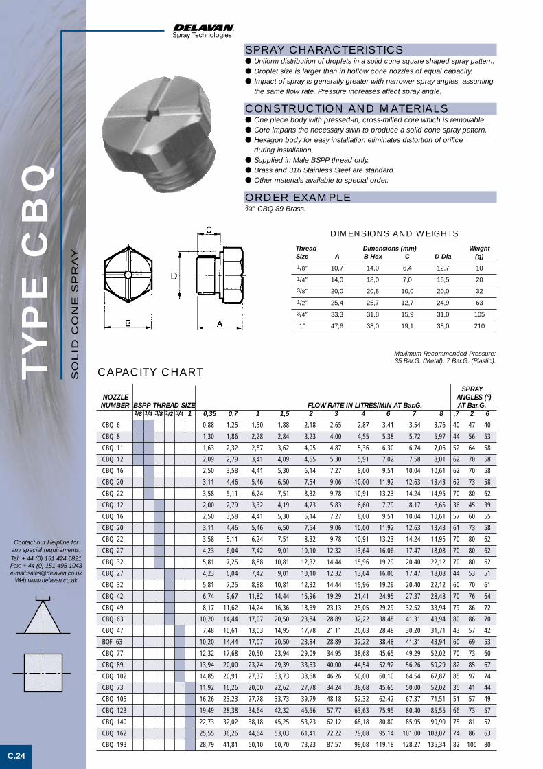
TYP
E C
BQ
C.24
Contact our Helpline forany special requirements:Tel: +44 (0) 151 424 6821Fax: +44 (0) 151 495 1043e-mail:[email protected]
Web:www.delavan.co.uk
Maximum Recommended Pressure:35 Bar.G. (Metal), 7 Bar.G. (Plastic).
CAPACITY CHARTSPRAY
NOZZLE ANGLES (°)NUMBER BSPP THREAD SIZE FLOW RATE IN LITRES/MIN AT Bar.G. AT Bar.G.
1/8 1/4 3/8 1/2 3/4 1 0,35 0,7 1 1,5 2 3 4 6 7 8 ,7 2 6
CBQ 6 0,88 1,25 1,50 1,88 2,18 2,65 2,87 3,41 3,54 3,76 40 47 40
CBQ 8 1,30 1,86 2,28 2,84 3,23 4,00 4,55 5,38 5,72 5,97 44 56 53
CBQ 11 1,63 2,32 2,87 3,62 4,05 4,87 5,36 6,30 6,74 7,06 52 64 58
CBQ 12 2,09 2,79 3,41 4,09 4,55 5,30 5,91 7,02 7,58 8,01 62 70 58
CBQ 16 2,50 3,58 4,41 5,30 6,14 7,27 8,00 9,51 10,04 10,61 62 70 58
CBQ 20 3,11 4,46 5,46 6,50 7,54 9,06 10,00 11,92 12,63 13,43 62 73 58
CBQ 22 3,58 5,11 6,24 7,51 8,32 9,78 10,91 13,23 14,24 14,95 70 80 62
CBQ 12 2,00 2,79 3,32 4,19 4,73 5,83 6,60 7,79 8,17 8,65 36 45 39
CBQ 16 2,50 3,58 4,41 5,30 6,14 7,27 8,00 9,51 10,04 10,61 57 60 55
CBQ 20 3,11 4,46 5,46 6,50 7,54 9,06 10,00 11,92 12,63 13,43 61 73 58
CBQ 22 3,58 5,11 6,24 7,51 8,32 9,78 10,91 13,23 14,24 14,95 70 80 62
CBQ 27 4,23 6,04 7,42 9,01 10,10 12,32 13,64 16,06 17,47 18,08 70 80 62
CBQ 32 5,81 7,25 8,88 10,81 12,32 14,44 15,96 19,29 20,40 22,12 70 80 62
CBQ 27 4,23 6,04 7,42 9,01 10,10 12,32 13,64 16,06 17,47 18,08 44 53 51
CBQ 32 5,81 7,25 8,88 10,81 12,32 14,44 15,96 19,29 20,40 22,12 60 70 61
CBQ 42 6,74 9,67 11,82 14,44 15,96 19,29 21,41 24,95 27,37 28,48 70 76 64
CBQ 49 8,17 11,62 14,24 16,36 18,69 23,13 25,05 29,29 32,52 33,94 79 86 72
CBQ 63 10,20 14,44 17,07 20,50 23,84 28,89 32,22 38,48 41,31 43,94 80 86 70
CBQ 47 7,48 10,61 13,03 14,95 17,78 21,11 26,63 28,48 30,20 31,71 43 57 42
BQF 63 10,20 14,44 17,07 20,50 23,84 28,89 32,22 38,48 41,31 43,94 60 69 53
CBQ 77 12,32 17,68 20,50 23,94 29,09 34,95 38,68 45,65 49,29 52,02 70 73 60
CBQ 89 13,94 20,00 23,74 29,39 33,63 40,00 44,54 52,92 56,26 59,29 82 85 67
CBQ 102 14,85 20,91 27,37 33,73 38,68 46,26 50,00 60,10 64,54 67,87 85 97 74
CBQ 73 11,92 16,26 20,00 22,62 27,78 34,24 38,68 45,65 50,00 52,02 35 41 44
CBQ 105 16,26 23,23 27,78 33,73 39,79 48,18 52,32 62,42 67,37 71,51 51 57 49
CBQ 123 19,49 28,38 34,64 42,32 46,56 57,77 63,63 75,95 80,40 85,55 66 73 57
CBQ 140 22,73 32,02 38,18 45,25 53,23 62,12 68,18 80,80 85,95 90,90 75 81 52
CBQ 162 25,55 36,26 44,64 53,03 61,41 72,22 79,08 95,14 101,00 108,07 74 86 63
CBQ 193 28,79 41,81 50,10 60,70 73,23 87,57 99,08 119,18 128,27 135,34 82 100 80
SPRAY CHARACTERISTICS● Uniform distribution of droplets in a solid cone square shaped spray pattern.● Droplet size is larger than in hollow cone nozzles of equal capacity.● Impact of spray is generally greater with narrower spray angles, assuming
the same flow rate. Pressure increases affect spray angle.
CONSTRUCTION AND MATERIALS● One piece body with pressed-in, cross-milled core which is removable.● Core imparts the necessary swirl to produce a solid cone spray pattern.● Hexagon body for easy installation eliminates distortion of orifice
during installation.● Supplied in Male BSPP thread only.● Brass and 316 Stainless Steel are standard.● Other materials available to special order.
ORDER EXAMPLE3⁄4” CBQ 89 Brass.
Thread Dimensions (mm) WeightSize A B Hex C D Dia (g)
1/8” 10,7 14,0 6,4 12,7 10
1/4” 14,0 18,0 7,0 16,5 20
3/8” 20,0 20,8 10,0 20,0 32
1/2” 25,4 25,7 12,7 24,9 63
3/4” 33,3 31,8 15,9 31,0 105
1” 47,6 38,0 19,1 38,0 210
DIMENSIONS AND WEIGHTS
SO
LID
CO
NE
SP
RA
Y
Solid cone spray 3 3/5/01 4:04 pm Page 3

TYP
E C
BT
C.25
Contact our Helpline forany special requirements:Tel: +44 (0) 151 424 6821Fax: +44 (0) 151 495 1043e-mail:[email protected]
Web:www.delavan.co.uk
SPRAY CHARACTERISTICS● Uniform distribution of spray droplets in a wide angle solid cone sqare
shaped pattern.● Droplet size is larger than in hollow cone nozzles of equal capacity.● Impact of spray is generally greater with narrower spray angles, assuming
the same flow rate. Pressure increases affect spray angle.
CONSTRUCTION AND MATERIALS● One piece body with pressed-in, cross-milled core which is removable.● Core imparts the necessary swirl to produce a solid cone spray pattern.● Hexagon body for easy installation eliminates distortion of orifice
during installation.● Supplied in Male BSPP thread only.● Brass and 316 Stainless Steel are standard.● Other materials available to special order.
ORDER EXAMPLE1⁄2” CBT 59 Brass.
CAPACITY CHARTSPRAY
ANGLES (°)NOZZLE BSPP THREAD SIZE FLOW RATE IN LITRES/MIN AT Bar.G. AT Bar.G.
NUMBER 1/8 1/4 3/8 1/2 3/4 1 0,35 0,7 1 1,5 2 3 4 6 7 8 ,7 2 6
CBT 6 0,88 1,25 1,50 1,88 2,18 2,65 2,87 3,41 3,54 3,76 110 100 90
CBT 8 1,30 1,86 2,28 2,84 3,23 4,00 4,55 5,38 5,72 5,97 125 120 100
CBT 11 1,86 2,79 3,23 3,86 4,31 5,15 5,45 6,73 7,43 7,70 115 120 95
CBT 15 2,60 3,67 4,50 5,26 5,59 6,64 7,24 8,70 9,16 9,70 115 110 90
CBT 18 3,10 4,40 5,39 6,30 6,70 7,96 8,68 10,43 10,98 11,63 120 120 95
CBT 22 3,95 5,58 6,84 8,0 8,50 10,10 11,01 13,23 13,94 14,75 113 110 90
CBT 25 4,27 6,04 7,24 8,43 9,32 11,01 12,32 14,65 15,76 16,26 120 120 100
CBT 32 5,90 7,70 9,15 10,80 11,92 14,30 15,78 18,90 19,90 21,26 115 110 85
CBT 39 7,20 9,40 11,15 13,14 14,52 17,40 19,20 23,00 24,25 25,90 120 120 90
CBT 46 8,13 11,62 13,64 15,86 17,27 19,29 22,32 25,45 27,88 29,39 125 112 90
CBT 48 8,33 12,52 15,25 16,87 18,18 23,13 24,54 29,80 32,52 34,34 125 120 90
CBT 59 9,29 13,23 15,96 19,29 22,32 26,06 28,18 34,64 37,67 40,70 130 128 100
CBT 65 12,00 15,65 18,60 21,92 24,21 29,00 32,05 38,37 40,40 43,20 115 110 85
CBT 73 13,50 17,60 20,88 24,50 27,19 32,60 36,00 43,10 45,40 48,50 115 120 90
CBT 82 15,35 20,0 23,74 27,98 30,91 37,07 40,91 48,99 51,61 55,15 115 112 90
CBT 94 16,77 22,32 26,87 32,72 35,45 41,92 45,96 56,26 59,89 63,33 119 120 91
CBT 98 18,08 23,23 27,78 34,24 37,27 44,34 50,00 59,59 64,54 67,87 112 120 90
CBT 136 24,14 35,25 42,32 48,18 51,41 60,20 67,77 81,20 86,86 91,41 118 115 75
CBT 153 27,88 38,08 46,97 53,93 57,97 67,47 76,36 91,30 98,07 108,07 125 120 85
CBT 200 29,69 42,32 51,41 62,62 75,95 88,68 99,59 120,19 130,29 139,38 118 125 90
Maximum Recommended Pressure:35 Bar.G. (Metal), 7 Bar.G. (Plastic).
Thread Dimensions (mm) WeightSize A B Hex C D (g)
1/8” 10,7 14,0 6,4 12,7 10
1/4” 14,0 18,0 7,0 16,5 20
3/8” 20,0 20,8 10,0 20,0 32
1/2” 25,4 25,7 12,7 24,9 63
3/4” 33,3 31,8 15,9 31,0 105
1” 47,6 38,0 19,1 38,0 210
DIMENSIONS AND WEIGHTS
SO
LID
CO
NE
SP
RA
Y
Solid cone spray 3 3/5/01 4:04 pm Page 4

TYP
E R
BI
C.26
Contact our Helpline forany special requirements:Tel: +44 (0) 151 424 6821Fax: +44 (0) 151 495 1043e-mail:[email protected]
Web:www.delavan.co.uk
Maximum Recommended Pressure: 35 Bar.G. (Metal) 7 Bar.G. (Plastic).
SPRAY ANGLE (°)NOZZLE NUMBER BSPT THREAD SIZE FLOW RATE IN LITRES/MIN AT Bar.G. AT Bar.G.Female Male 1/8 1/4 3/8 1/2 3/4 1 0,35 ,7 1 1,5 2 3 4 6 7 8 ,7 2 6RBIF 6 RBIM 6 0,88 1,25 1,50 1,88 2,18 2,65 2,87 3,41 3,54 3,76 40 47 40
RBIF 8 RBIM 8 1,30 1,86 2,28 2,84 3,23 4,00 4,55 5,38 5,72 5,97 44 56 53
RBIF 11 RBIM 11 1,63 2,32 2,87 3,62 4,05 4,87 5,36 6,30 6,74 7,06 52 64 58
RBIF 12 RBIM 12 2,09 2,79 3,41 4,09 4,55 5,30 5,91 7,02 7,58 8,01 62 70 58
RBIF 16 RBIM 16 2,50 3,58 4,41 5,30 6,14 7,27 8,00 9,51 10,04 10,61 57 60 55
RBIF 20 RBIM 20 3,11 4,46 5,46 6,50 7,54 9,06 10,00 11,92 12,63 13,43 62 73 58
RBIF 22 RBIM 22 3,58 5,11 6,24 7,51 8,32 9,78 10,91 13,23 14,24 14,95 70 80 62
RBIF 12 RBIM 12 2,00 2,79 3,32 4,19 4,73 5,83 6,60 7,79 8,17 8,65 36 45 39
RBIF 16 RBIM 16 2,50 3,58 4,41 5,30 6,14 7,27 8,00 9,51 10,04 10,61 57 60 55
RBIF 20 RBIM 20 3,11 4,46 5,46 6,50 7,54 9,06 10,00 11,92 12,63 13,43 61 73 58
RBIF 22 RBIM 22 3,58 5,11 6,24 7,51 8,32 9,78 10,91 13,23 14,24 14,95 70 80 62
RBIF 27 RBIM 27 4,23 6,04 7,42 9,01 10,10 12,32 13,64 16,06 17,47 18,08 70 80 62
RBIF 32 RBIM 32 5,81 7,25 8,88 10,81 12,32 14,44 15,96 19,29 20,40 22,12 70 80 62
RBIF 27 RBIM 27 4,23 6,04 7,42 9,01 10,10 12,32 13,64 16,06 17,47 18,08 44 53 51
RBIF 32 RBIM 32 5,81 7,25 8,88 10,81 12,32 14,44 15,96 19,29 20,40 22,12 60 70 61
RBIF 42 RBIM 42 6,74 9,67 11,82 14,44 15,96 19,29 21,41 24,95 27,37 28,48 70 76 64
RBIF 49 RBIM 49 8,17 11,62 14,24 16,36 18,69 23,13 25,05 29,29 32,52 33,94 79 86 72
RBIF 63 RBIM 63 10,20 14,44 17,07 20,50 23,84 28,89 32,22 38,48 41,31 43,94 80 86 70
RBIF 47 RBIM 47 7,48 10,61 13,03 14,95 17,78 21,11 26,63 28,48 30,20 31,71 43 57 42
RBIF 63 RBIM 63 10,20 14,44 17,07 20,50 23,84 28,89 32,22 38,48 41,31 43,94 60 69 53
RBIF 77 RBIM 77 12,32 17,68 20,50 23,94 29,09 34,95 38,68 45,65 49,29 52,02 70 73 60
RBIF 89 RBIM 89 13,94 20,00 23,74 29,39 33,63 40,00 44,54 52,92 56,26 59,29 82 85 67
RBIF 102 RBIM 102 14,85 20,91 27,37 33,73 38,68 46,26 50,00 60,10 64,54 67,87 85 97 74
RBIF 73 RBIM 73 11,92 16,26 20,00 22,62 27,78 34,24 38,68 45,65 50,00 52,02 35 41 44
RBIF 105 RBIM 105 16,26 23,23 27,78 33,73 39,79 48,18 52,32 62,42 67,37 71,51 51 57 49
RBIF 123 RBIM 123 19,49 28,38 34,64 42,32 46,56 57,77 63,63 75,95 80,40 85,55 66 73 57
RBIF 140 RBIM 140 22,73 32,02 38,18 45,25 53,23 62,12 68,18 80,80 85,95 90,90 75 81 52
RBIF 162 RBIM 162 25,55 36,26 44,64 53,03 61,41 72,22 79,08 95,14 101,00 108,07 74 86 63
RBIF 193 RBIM 193 28,79 41,81 50,10 60,70 73,23 87,57 99,08 119,18 128,27 135,34 82 100 80
CAPACITY CHART
SPRAY CHARACTERISTICS● Uniform distribution of droplets in a solid cone spray pattern.● Droplet size is larger than in hollow cone nozzles of equal capacity.● Impact of spray is generally greater with narrower spray angles, assuming
the same flow rate. Pressure increases affect spray angle.
CONSTRUCTION AND MATERIALS● One piece body with pressed-in, crossed-milled core, fitted into
a 90° adaptor.● Core imparts the necessary swirl to produce a solid cone spray pattern.● Available with Male BSPT and Female BSPP threads. ● Brass and 316 Stainless Steel are standard.● Other materials available to special order.
ORDER EXAMPLE1⁄2” RBIF (Female) 32 Brass.1⁄4” RBIM (Male) 11 Stainless Steel.
RBIM (MALE)
RBIF (FEMALE)
Thread Nozzle Dimensions (mm) WeightSize Type A B Sq C D (g)
1/8” RBIM 25,4 15,9 22,3 8,0 47
1/8” RBIF 25,4 15,9 22,3 8,0 60
1/4” RBIM 28,5 15,9 21,0 8,0 53
1/4” RBIF 28,5 15,9 21,0 8,0 66
3/8” RBIM 35,0 19,0 26,0 9,5 89
3/8” RBIF 35,0 19,0 26,0 9,5 100
1/2” RBIM 44,5 25,4 35,5 12,7 184
1/2” RBIF 44,5 25,4 35,5 12,7 200
3/4” RBIM 57,0 31,8 43,0 16,0 350
3/4” RBIF 57,0 31,8 43,0 16,0 370
1” RBIM 76,0 38,1 50,0 19,0 695
1” RBIF 76,0 38,1 50,0 19,0 715
DIMENSIONS AND WEIGHTS
SO
LID
CO
NE
SP
RA
Y
Solid cone spray 3 3/5/01 4:04 pm Page 5

TYP
E R
BN
C.27
Contact our Helpline forany special requirements:Tel: +44 (0) 151 424 6821Fax: +44 (0) 151 495 1043e-mail:[email protected]
Web:www.delavan.co.uk
Maximum Recommended Pressure: 35 Bar.G. (Metal), 7 Bar.G. (Plastic).
CAPACITY CHARTSPRAY
ANGLES (°)NOZZLE NUMBER BSPT THREAD SIZE FLOW RATE IN LITRES/MIN AT Bar.G. AT Bar.G.Female Male 1/8 1/4 3/8 1/2 3/4 1 0,35 0,7 1 1,5 2 3 4 6 7 8 ,7 2 6
RBNF 6 RBNM 6 0,88 1,25 1,50 1,88 2,18 2,65 2,87 3,41 3,54 3,76 110 100 90
RBNF 8 RBNM 8 1,30 1,86 2,28 2,84 3,23 4,00 4,55 5,38 5,72 5,97 125 120 100
RBNF 11 RBNM 11 1,86 2,79 3,23 3,86 4,31 5,15 5,45 6,73 7,43 7,70 115 120 95
RBNF 15 RBNM 15 2,60 3,67 4,50 5,26 5,59 6,64 7,24 8,70 9,16 9,70 115 110 90
RBNF 18 RBNM 18 3,10 4,40 5,39 6,30 6,70 7,96 8,68 10,43 10,98 11,63 120 120 95
RBNF 22 RBNM 22 3,95 5,58 6,84 8,0 8,50 10,10 11,01 13,23 13,94 14,75 113 110 90
RBNF 25 RBNM 25 4,27 6,04 7,24 8,43 9,32 11,01 12,32 14,65 15,76 16,26 120 120 100
RBNF 32 RBNM 32 5,90 7,70 9,15 10,80 11,92 14,30 15,78 18,90 19,90 21,26 115 110 85
RBNF 39 RBNM 39 7,20 9,40 11,15 13,14 14,52 17,40 19,20 23,00 24,25 25,90 120 120 90
RBNF 46 RBNM 46 8,13 11,62 13,64 15,86 17,27 19,29 22,32 25,45 27,88 29,39 125 112 90
RBNF 48 RBNM 48 8,33 12,52 15,25 16,87 18,18 23,13 24,54 29,80 32,52 34,34 125 120 90
RBNF 59 RBNM 59 9,29 13,23 15,96 19,29 22,32 26,06 28,18 34,64 37,67 40,70 130 128 100
RBNF 65 RBNM 65 12,00 15,65 18,60 21,92 24,21 29,00 32,05 38,37 40,40 43,20 115 110 85
RBNF 73 RBNM 73 13,50 17,60 20,88 24,50 27,19 32,60 36,00 43,10 45,40 48,50 115 120 90
RBNF 82 RBNM 82 15,35 20,0 23,74 27,98 30,91 37,07 40,91 48,99 51,61 55,15 115 112 90
RBNF 94 RBNM 94 16,77 22,32 26,87 32,72 35,45 41,92 45,96 56,26 59,89 63,33 119 120 91
RBNF 98 RBNM 98 18,08 23,23 27,78 34,24 37,27 44,34 50,00 59,59 64,54 67,87 112 120 90
RBNF 136 RBNM 136 24,14 35,25 42,32 48,18 51,41 60,20 67,77 81,20 86,86 91,41 118 115 75
RBNF 153 RBNM 153 27,88 38,08 46,97 53,93 57,97 67,47 76,36 91,30 98,07 108,07 125 120 85
RBNF 200 RBNM 200 29,69 42,32 51,41 62,62 75,95 88,68 99,59 120,19 130,29 139,38 118 125 90
SPRAY CHARACTERISTICS● Uniform distribution of droplets in a wide angle solid cone spray pattern.● Droplet size is larger than in hollow cone nozzles of equal capacity.● Impact of spray is generally lower than narrower spray angles, assuming
the same flow rate. Pressure increases affect spray angle.
CONSTRUCTION AND MATERIALS● One piece body with pressed-in, crossed-milled fitted into
a 90° adaptor.● Core imparts the necessary swirl to produce a solid cone spray pattern.● Available with Male BSPT and Female BSPP threads. ● Brass and 316 Stainless Steel are standard.● Other materials available to special order.
ORDER EXAMPLE3⁄4” RBNM (Male) 94 Stainless Steel.1⁄2” RBNF (Female) 59 Brass.
RBNM (MALE)
RBNF (FEMALE)
Thread Nozzle Dimensions (mm) WeightSize Type A B Sq C D (g)
1/8” RBNM 25,4 15,9 22,3 8,0 47
1/8” RBNF 25,4 15,9 22,3 8,0 60
1/4” RBNM 28,5 15,9 21,0 8,0 53
1/4” RBNF 28,5 15,9 21,0 8,0 66
3/8” RBNM 35,0 19,0 26,0 9,5 89
3/8” RBNF 35,0 19,0 26,0 9,5 100
1/2” RBNM 44,5 25,4 35,5 12,7 184
1/2” RBNF 44,5 25,4 35,5 12,7 200
3/4” RBNM 57,0 31,8 43,0 16,0 350
3/4” RBNF 57,0 31,8 43,0 16,0 370
1” RBNM 76,0 38,1 50,0 19,0 695
1” RBNF 76,0 38,1 50,0 19,0 715
DIMENSIONS AND WEIGHTS
SO
LID
CO
NE
SP
RA
Y
Solid cone spray 3 3/5/01 4:05 pm Page 6

TYP
E N
BI
C.28
SPRAY CHARACTERISTICS● Coarse solid cone spray pattern with a relatively uniform distribution.● Droplet sizes are generally larger than solid cone sprays with internal cores.● Impact of spray is generally greater with narrower spray angles, assuming
the same flow rate. Pressure increases affect spray angle.
CONSTRUCTION AND MATERIALS● Two piece assembly with no internal core.● Unrestricted internal flow passages for resistance to clogging.● Spray is projected at an axis of 90° from the nozzle inlet axis.● Available with Male BSPT thread or Female BSPP thread.● Brass and Stainless Steel are standard.● Other materials available to special order.
ORDER EXAMPLE1⁄4” NBIM (Male) 11 Brass.1⁄2” NBIF (Female) 63 Stainless Steel.
Contact our Helpline forany special requirements:Tel: +44 (0) 151 424 6821Fax: +44 (0) 151 495 1043e-mail:[email protected]
Web:www.delavan.co.uk
SPRAYNOZZLE NUMBER BSPT THREAD SIZE FLOW RATE IN LITRES/MIN AT Bar.G. ANGLES (°)Female Male 1/4 3/8 1/2 3/4 1 0,35 0,7 1 1,5 2 3 4 6 7 8 AT 2 Bar.G.
NBIF 11 NBIM 11 1,63 2,32 2,87 3,62 4,05 4,87 5,36 6,30 6,74 7,06 64
NBIF 12 NBIM 12 2,09 2,79 3,41 4,09 4,55 5,30 5,91 7,02 7,58 8,01 70
NBIF 16 NBIM 16 2,50 3,58 4,41 5,30 6,14 7,27 8,00 9,51 10,04 10,61 60
NBIF 20 NBIM 20 3,11 4,46 5,46 6,50 7,54 9,06 10,00 11,92 12,63 13,43 73
NBIF 22 NBIM 22 3,58 5,11 6,24 7,51 8,32 9,78 10,91 13,23 14,24 14,95 80
NBIF 12 NBIM 12 2,00 2,79 3,32 4,19 4,73 5,83 6,60 7,79 8,17 8,65 45
NBIF 16 NBIM 16 2,50 3,58 4,41 5,30 6,14 7,27 8,00 9,51 10,04 10,61 60
NBIF 20 NBIM 20 3,11 4,46 5,46 6,50 7,54 9,06 10,00 11,92 12,63 13,43 73
NBIF 22 NBIM 22 3,58 5,11 6,24 7,51 8,32 9,78 10,91 13,23 14,24 14,95 80
NBIF 27 NBIM 27 4,23 6,04 7,42 9,01 10,10 12,32 13,64 16,06 17,47 18,08 53
NBIF 32 NBIM 32 5,81 7,25 8,88 10,81 12,32 14,44 15,96 19,29 20,40 22,12 70
NBIF 27 NBIM 27 4,23 6,04 7,42 9,01 10,10 12,32 13,64 16,06 17,47 18,08 53
NBIF 32 NBIM 32 5,81 7,25 8,88 10,81 12,32 14,44 15,96 19,29 20,40 22,12 70
NBIF 42 NBIM 42 6,74 9,67 11,82 14,44 15,96 19,29 21,41 24,95 27,37 28,48 76
NBIF 49 NBIM 49 8,17 11,62 14,24 16,36 18,69 23,13 25,05 29,29 32,52 33,94 86
NBIF 63 NBIM 63 10,20 14,44 17,07 20,50 23,84 28,89 32,22 38,48 41,31 43,94 80
NBIF 47 NBIM 47 7,48 10,61 13,03 14,95 17,78 21,11 26,63 28,48 30,20 31,71 57
NBIF 63 NBIM 63 10,20 14,44 17,07 20,50 23,84 28,89 32,22 38,48 41,31 43,94 69
NBIF 77 NBIM 77 12,32 17,68 20,50 23,94 29,09 34,95 38,68 45,65 49,29 52,02 73
NBIF 89 NBIM 89 13,94 20,00 23,74 29,39 33,63 40,00 44,54 52,92 56,26 59,29 85
NBIF 102 NBIM 102 14,85 20,91 27,37 33,73 38,68 46,26 50,00 60,10 64,54 67,87 97
NBIF 73 NBIM 73 11,92 16,26 20,00 22,62 27,78 34,24 38,68 45,65 50,00 52,02 41
NBIF 105 NBIM 105 16,26 23,23 27,78 33,73 39,79 48,18 52,32 62,42 67,37 71,51 57
NBIF 123 NBIM 123 19,49 28,38 34,64 42,32 46,56 57,77 63,63 75,95 80,40 85,55 73
NBIF 140 NBIM 140 22,73 32,02 38,18 45,25 53,23 62,12 68,18 80,80 85,95 90,90 81
NBIF 162 NBIM 162 25,55 36,26 44,64 53,03 61,41 72,22 79,08 95,14 101,00 108,07 86
NBIF 193 NBIM 193 28,79 41,81 50,10 60,70 73,23 87,57 99,08 119,18 128,27 135,34 100
CAPACITY CHART
Maximum Recommended Pressure:35 Bar.G. (Metal), 7 Bar.G. (Plastic).
NBIM (MALE)
NBIF (FEMALE)
Nozzle Dimensions (mm) WeightSize A B Sq C D (g)
1/4” M 28,5 15,9 19,0 8,0 50
1/4” F 28,5 15,9 19,0 8,0 63
3/8” M 35,0 19,0 24,0 9,5 85
3/8” F 35,0 19,0 24,0 9,5 95
1/2” M 44,5 25,4 30,5 12,7 175
1/2” F 44,5 25,4 30,5 12,7 190
3/4” M 57,0 31,8 38,0 16,0 335
3/4” F 57,0 31,8 38,0 16,0 350
1” M 76,0 38,1 46,0 19,0 660
1” F 76,0 38,1 46,0 19,0 680
DIMENSIONS AND WEIGHTS
SO
LID
CO
NE
SP
RA
Y
Solid cone spray 3 3/5/01 4:05 pm Page 7

TYP
E N
BN
C.29
Contact our Helpline forany special requirements:Tel: +44 (0) 151 424 6821Fax: +44 (0) 151 495 1043e-mail:[email protected]
Web:www.delavan.co.uk
CAPACITY CHARTMaximum Recommended Pressure:35 Bar.G. (Metal), 7 Bar.G. (Plastic)
SPRAYNOZZLE NUMBER BSPT THREAD SIZE FLOW RATE IN LITRES/MIN AT Bar.G. ANGLES (°)Female Male 1/4 3/8 1/2 3/4 1 0,35 0,7 1 1,5 2 3 4 6 7 8 AT 2 Bar.G.
NBNF 11 NBNM 11 1,86 2,79 3,23 3,86 4,31 5,15 5,45 6,73 7,43 7,70 120
NBNF 15 NBNM 15 2,60 3,67 4,50 5,26 5,59 6,64 7,24 8,70 9,16 9,70 110
NBNF 18 NBNM 18 3,10 4,40 5,39 6,30 6,70 7,96 8,68 10,43 10,98 11,63 120
NBNF 22 NBNM 22 3,95 5,58 6,84 8,0 8,50 10,10 11,01 13,23 13,94 14,75 110
NBNF 25 NBNM 25 4,27 6,04 7,24 8,43 9,32 11,01 12,32 14,65 15,76 16,26 120
NBNF 32 NBNM 32 5,90 7,70 9,15 10,80 11,92 14,30 15,78 18,90 19,90 21,26 110
NBNF 39 NBNM 39 7,20 9,40 11,15 13,14 14,52 17,40 19,20 23,00 24,25 25,90 120
NBNF 46 NBNM 46 8,13 11,62 13,64 15,86 17,27 19,29 22,32 25,45 27,88 29,39 112
NBNF 48 NBNM 48 8,33 12,52 15,25 16,87 18,18 23,13 24,54 29,80 32,52 34,34 120
NBNF 59 NBNM 59 9,29 13,23 15,96 19,29 22,32 26,06 28,18 34,64 37,67 40,70 128
NBNF 65 NBNM 65 12,00 15,65 18,60 21,92 24,21 29,00 32,05 38,37 40,40 43,20 110
NBNF 73 NBNM 73 13,50 17,60 20,88 24,50 27,19 32,60 36,00 43,10 45,40 48,50 120
NBNF 82 NBNM 82 15,35 20,0 23,74 27,98 30,91 37,07 40,91 48,99 51,61 55,15 112
NBNF 94 NBNM 94 16,77 22,32 26,87 32,72 35,45 41,92 45,96 56,26 59,89 63,33 120
NBNF 98 NBNM 98 18,08 23,23 27,78 34,24 37,27 44,34 50,00 59,59 64,54 67,87 120
NBNF 136 NBNM 136 24,14 35,25 42,32 48,18 51,41 60,20 67,77 81,20 86,86 91,41 115
NBNF 153 NBNM 153 27,88 38,08 46,97 53,93 57,97 67,47 76,36 91,30 98,07 108,07 120
NBNF 200 NBNM 200 29,69 42,32 51,41 62,62 75,95 88,68 99,59 120,19 130,29 139,38 125
SPRAY CHARACTERISTICS● Coarse, solid cone, wide angle spray pattern with a relatively
uniform distribution.● Droplet sizes are generally larger than solid cone sprays with internal cores.● Impact of spray is generally greater with narrower spray angles, assuming
the same flow rate. Pressure increases affect spray angle.
CONSTRUCTION AND MATERIALS● Two piece assembly with no internal core.● Unrestricted internal flow passages for resistance to clogging.● Spray is projected at an axis of 90° from the nozzle inlet axis.● Available with Male BSPT thread or Female BSPP thread.● Brass and Stainless Steel are standard.● Other materials available to special order.
ORDER EXAMPLE3⁄8” NBNM (Male) 25 Brass.1⁄2” NBNF (Female) 82 Stainless Steel.
NBNM (MALE)
NBNF (FEMALE)
Nozzle Dimensions (mm) WeightSize A B Sq C D (g)
1/4” M 28,5 15,9 19,0 8,0 50
1/4” F 28,5 15,9 19,0 8,0 63
3/8” M 35,0 19,0 24,0 9,5 85
3/8” F 35,0 19,0 24,0 9,5 95
1/2” M 44,5 25,4 30,5 12,7 175
1/2” F 44,5 25,4 30,5 12,7 190
3/4” M 57,0 31,8 38,0 16,0 335
3/4” F 57,0 31,8 38,0 16,0 350
1” M 76,0 38,1 46,0 19,0 660
1” F 76,0 38,1 46,0 19,0 680
DIMENSIONS AND WEIGHTS
SO
LID
CO
NE
SP
RA
Y
Solid cone spray 3 3/5/01 4:05 pm Page 8

TYP
E Q
I/Q
N/Q
Q/Q
T
C.30
Contact our Helpline forany special requirements:Tel: +44 (0) 151 424 6821Fax: +44 (0) 151 495 1043e-mail:[email protected]
Web:www.delavan.co.uk
SPRAY CHARACTERISTICS● Uniform distribution of droplets in solid cone or square shaped
spray pattern.● Droplet size is larger than in hollow cone nozzles of equal capacity.● Impact of spray is generally greater with narrower spray angles, assuming
the same flow rate. Pressure increases affect spray angle.
CONSTRUCTION AND MATERIALS● The nozzles are designed to fit the QA eyelet which is available to suit
11⁄4” NB pipe (W12838) and 11⁄2” NB pipe (W12837).● No tools are required to change spray nozzles. Only a quarter turn is
needed to attach or remove the nozzles for ease of maintenance.● Large inlet connection allows high flow capacity with minimum pressure
drop. To fit the eyelet a 20mm diameter hole is required in the pipe.● Eyelets and nozzles are produced in glass filled polypropylene with other
parts being in Stainless Steel with Nitrile ‘O’ rings.
ORDER EXAMPLEQN 94 - Nozzle only. 11⁄4” NB QA Eyelet.
Maximum RecommendedPressure: 7 Bar.G.
CAPACITY CHARTNOZZLE TYPE SPRAY
ANGLES (°)SPRAY PATTERN FLOW RATE IN LITRES/MIN AT Bar.G. AT Bar.G.
Round Squared ,35 ,7 1 1,5 2 3 4 5 6 7 ,7 2 6
QI 47 QQ 47 7,48 10,61 13,03 14,95 17,78 21,11 26,63 27,77 28,38 30,20 43 57 42
QI 63 QQ 63 10,20 14,44 17,07 20,50 23,84 28,89 32,22 34,05 38,48 41,31 60 69 53
QI 77 QQ 77 12,32 17,68 20,50 23,94 29,09 34,95 38,68 41,66 45,65 49,29 70 73 60
QI 89 QQ 89 13,94 20,00 23,74 29,39 33,63 40,00 44,54 48,02 52,92 56,26 82 85 67
QI 102 QQ 102 14,85 20,91 27,37 33,73 38,68 46,26 50,00 55,02 60,10 64,54 85 97 74
CAPACITY CHARTNOZZLE TYPE SPRAY
ANGLES (°)SPRAY PATTERN FLOW RATE IN LITRES/MIN AT Bar.G. AT Bar.G.
Round Squared ,35 ,7 1 1,5 2 3 4 5 6 7 ,7 2 6
QN 82 QT 82 15,35 20,00 23,74 27,98 30,91 37,07 40,91 44,72 48,99 51,61 115 112 90
QN 94 QT 94 16,77 22,32 26,87 32,72 35,45 41,92 45,96 49,91 56,26 59,89 119 120 91
QN 98 QT 98 18,08 23,23 27,78 34,24 37,27 44,34 50,00 55,64 59,59 64,54 112 120 90
94
51
43
30,5
118
87,5
11/4” NB QA EYELET
QI NOZZLE
SO
LID
CO
NE
SP
RA
Y
Solid cone spray 3 3/5/01 4:05 pm Page 9

WELCOME TO DELAVAN
of newchallengesMeeting the
industriesand NEW markets
D Air Atomising
Del Nozzle A4 dividers A/W 21/6/01 10:36 am Page 7

TYPICAL APPLICATIONSChemical processing, continuous casting, cooling castings and moulds, curing concrete products, evaporative coolers, foam control,incineration, quenching, spray coating, spray drying, flue gas desulfurisation.
TYPICAL SPRAY PATTERN
Nozzle Spray Characteristics and Features Type of Spray Flow Range. PageType L/Hour No.
SWIRL- 1,0 – 6720 D.1-16AIRGA 0,82 – 47,7 D.17
GC 26 – 148 D.18
AIRO 18,9 – 604,8 D.19
AL – D.20-23
AL 1,36 – 315 D.24-25
AL15 1,36 – 280 D.26-27
AL 30 1,7 – 93 D.28
AL 45 1,4 – 250 D.29
AL 60 0,95 – 140 D.30
AL 75 5,7 – 26 D.31
AL 90 0,49 – 7,6 D.31
SN 0,1 – 10,3 D.32-33
LO-AIR 11,4 – 113,6 D.34-35
INTERNAL 113,6 – 2273 D.36-37MIX
EXTERNAL 193 – 1410 D.38-39MIX
Internal mix design with a range of flow and spray angles. High turndown ratio. Variation on degree of atomisation.
Siphon/gravity fed design with external mixing of air and liquid.
Pressure fed design with external mixing of air and liquid.
Pressure fed design with internal mixing of air and liquid.
Constructional options.
Siphon/gravity fed design with external mixing of air and liquid.
Siphon/pressure fed design with external mixing of air and liquid.
Pressure fed design with internal mixing of air and liquid.
Pressure fed design with internal mixing of air and liquid.
Pressure fed design with internal mixing of air and liquid.
Pressure fed design with internal mixing of air and liquid.
Siphon/gravity fed design with internal mixing of air and liquid.
Siphon/gravity fed design with internal mixing of air and liquid.
Pressure fed design with internal mixing of air and liquid.
Pressure fed design with internal mixing of air and liquid.
Pressure fed design with external mixing of air and liquid.
Narrow – Wide angle hollow cone.
Narrow angle cone spray.
Narrow angle cone spray.
Narrow angle cone spray.
–.
Narrow angle cone spray.
Medium angle flat spray.
Wide angle cone spray.
Narrow angle cone spray.
Wide angle flat spray.
Deflected flat spray.
Narrow angle cone spray.
Narrow angle cone spray.
Wide angle flat spray.
Narrow angle cone spray.
Wide angle cone spray.
SE
CTIO
N IN
DE
X
Contact our Helpline forany special requirements:Tel: +44 (0) 151 424 6821Fax: +44 (0) 151 495 1043e-mail:[email protected]
Web:www.delavan.co.uk
AIR
AT
OM
ISIN
G
Del Nozzle A4 dividers A/W 21/6/01 10:36 am Page 8

D.1
Contact our Helpline forany special requirements:Tel: +44 (0) 151 424 6821Fax: +44 (0) 151 495 1043e-mail:[email protected]
Web:www.delavan.co.uk
SW
IRL-A
IR®
● Two Swirl-Air nozzle versions are available: the right angle nozzle(atomising air enters the side, the liquid enters axially in back): and the in-line nozzle (concentric piping is used with the liquid in the centre andatomising air around the outside). Concentric pipe adaptors are optionaland not included with the nozzle assembly.
FEATURES● Large internal passages with no vanes or cores assure unrestricted flow
with little chance for clogging. ● No external struts or supports to interfere with spray pattern.● Nozzle design provides for vortex mixing, primary impingement, fluid
distortion and external impact for fine atomisation and relatively highnozzle efficiency.
● Spray angle can be adjusted through interchangeable nozzle capassemblies. This feature permits much wider spray patterns than arepossible with most types of two fluid atomisers.
● Air flow (M3/min) and power requirements are relatively low, permittingspecification of smaller air compressors.
● Good atomisation over wide turn-down ratios.● Droplet size is controlled by minor changes in air pressure.
SPRAY CHARACTERISTICS● Air is introduced tangentially into the nozzle chamber in low pressure
region of the swirling liquid, creating extreme turbulence and primaryatomisation. As liquid leaves the orifice, it impinges against the deflectorring which serves a dual purpose: close control of spray angle andbreakup of the spray into even finer droplets (secondary atomisation).
● Nominal spray angles of 50º, 75º, 100º can be attained by specification ofinterchangeable nozzle caps. Contact Delavan’s Customer Service Teamfor special spray angles up to 180º.
● Mean droplet diameters in the 50 to 100 micrometres range at modest airpressures and flow rates.
● Degree of atomisation is also variable by controlling the ratio of air toliquid.
● If air pressure is set initially, and it is necessary to modulate the liquid flow,the air pressure and flow rates will automatically respond in such a waythat the quality of atomisation remains nearly constant. In someapplications, this can result in savings through the elimination of airvalving and controls.
CONSTRUCTION AND MATERIALS● Two piece construction, the nozzle body plus integral deflector ring and
cap, easily removable without disturbing pipe connection.● For in-line nozzles the user can alter “C” dimension to any extended
length by providing two concentric pipes with a coupling on one end ofeach. Both made up pipe/coupling lengths should be equal. The length isthen the desired addition to “C” dimension.
● No external struts or supports to interfere with spray pattern.● Both in-line and right angle versions are available in 316L Stainless Steel
and 440 Stainless Steel. Other materials such as Hastelloy C276, Inconel600, Carpenter 20, Titanium and Carbide lined are available by specialorder. For other materials, contact Delavan’s Customer Service Team.
● Large internal passages with no vanes or cores assure unrestricted flowwith little chance for clogging.
Nozzle - Max. Design Pressure: 14 Bar.G.Max. Design Temperature: 540ºC.
Adaptor -Max. Design Pressure: 14 Bar.G.Max. Design Temperature: 150ºC.
Right AngleNozzle Assembly
In-Line Nozzle
AIR
AT
OM
ISIN
G
Adaptor
(Nipple and O-Ringincluded with Adaptor)
Air Atom 1 3/5/01 4:11 pm Page 1

SW
IRL-A
IR®
D.2
Contact our Helpline forany special requirements:Tel: +44 (0) 151 424 6821Fax: +44 (0) 151 495 1043e-mail:[email protected]
Web:www.delavan.co.uk
RIGHT ANGLE SWIRL-AIR NOZZLE ASSEMBLY DIMENSIONS (mm)RIGHT ANGLE NOZZLE ASSEMBLY DEMENSIONS (mm)
DIMENSION 45506 31618 31325 31693 31694 32163A 66,7 54,0 44,5 34,9 28,6 28,6
B 56,4 51,8 46,4 38,1 34,9 34,9
C 64,6 59,2 53,7 42,3 38,5 38,5
D 38,1 31,8 25,4 19,0 15,9 15,9
E 41,3 34,7 28,3 22,0 18,8 18,8
F (NPT) 3/8-18 1/4-18 1/4-18 1/8-27 1/8-27 1/8-27
G (NPT) 3/4-14 3/4-14 1/2-14 3/8-18 1/4-18 1/4-18
J 47,6 38,1 31,8 25,4 20,6 20,6
K 38,1 35,9 33,7 28,6 27,0 27,0
L 19,0 20,0 21,0 19,1 19,1 19,1
M 36,5 31,8 25,4 19,1 15,9 15,9
Approx. weight (g) 430 270 170 77 51 51
IN-LINE SWIRL-AIR NOZZLE ASSEMBLY DIMENSIONS (mm)IN-LINE NOZZLE/ADAPTOR DEMENSIONS (mm)
DIMENSION 32555/32614 32554/32618 32668/32695 32740/32742
A 127,0 120,7 120,7 90,2
B 22,2 15,9 15,9 12,7
C 152,4 146,1 142,8 108,0
D 44,5 39,6 39,6 32,6
E 44,5 58,4 58,4 38,1
F 50,8 41,3 41,3 28,6
L 38,1 31,8 31,8 19,1
M 59,7 53,9 54,0 38,1
N 34,7 28,3 22,0 18,8
O 31,8 25,4 19,0 15,9
P 42,2 33,4 26,7 21,3
R 34,9 28,6 22,2 19,0
G (NPTM) 11/4" - 111/2 1" - 111/2 3/4" - 14 1/2" - 14
H (NPTF) 1/2" - 14 1/4" - 18 1/4" - 18 1/8" - 27
J (NPTF) 1/2" - 14 1/2" - 14 1/2" - 14 1/4" - 18
Approx. weight (g) 1248 1120 1177 462
AIR
AT
OM
ISIN
G
Air Atom 1 3/5/01 4:12 pm Page 2

SW
IRL-A
IR®
NOZZLE SIZING CHARTS
D.3
Contact our Helpline forany special requirements:Tel: +44 (0) 151 424 6821Fax: +44 (0) 151 495 1043e-mail:[email protected]
Web:www.delavan.co.uk
Maximum RecommendedPressure: 100 Bar.G.
* Higher flow rates can be achieved by increasing pressure.
* Higher flow rates can be achieved by increasing pressure.
EVAPORATIVE COOLING WATER INJECTIONRATES VS. GAS INLET-OUTLET
TEMPERATURES
Dry Gas Outlet Temperature. °F
EXAMPLE: 1700°F dry inlet gas to be cooled to800°F outlet temperature requires 0,32 US GPMwater injection per 1000 CFM of inlet gas.
US
GP
M o
f Wat
er p
er 1
000
AC
FM (
Act
ual C
u. F
t./M
in)
Inle
t Gas
RIGHT ANGLE NOZZLESRIGHT DASH NUMBERS FOR MATERIAL CAP
NOMINAL ANGLE AND NOMINAL SPRAY ANGLE ASSEMBLYFLOW NOZZLE MIN.
(LITRES/ ASSEMBLY 316 440 ANGLE PASSAGE 316 440MIN) NUMBER SS HSS (º) (mm) SS HSS
-2 - 50 (40-60) 6,1 707-97 -
93 45506 -1 - 75 (65-85) 4,8 707-96 -
-3 - 100 (90-110) 3,8 707-98 -
-2 -5 50 (40-60) 4,3 707-11 707-26
56 31618 -1 -4 75 (65-85) 3,6 707-10 707-25
-3 -6 100 (90-110) 2,8 707-12 707-27
-2 -5 50 (40-60) 2,5 707-8 707-23
37 31325 -1 -4 75 (65-85) 2,1 707-7 707-22
-3 -6 100 (90-110) 1,6 707-9 707-24
-2 -5 50 (40-60) 1,7 707-5 707-20
15 31693 -1 -4 75 (65-85) 1,7 707-4 707-19
-3 -6 100 (90-110) 1,7 707-6 707-21
-2 -5 50 (40-60) 1,3 707-2 707-17
9,5 31694 -1 -4 75 (65-85) 1,3 707-1 707-16
-3 -6 100 (90-110) 1,3 707-3 707-18
-11 - 50 (40-60) 0,64 707-93 -
3,8 -2 - 75 (65-85) 0,64 707-13 -
32163-7 - 100 (90-110) 0,64 707-29 -
-10 - 50 (40-60) 0,64 707-93 -
,8 -1 - 75 (65-85) 0,64 707-13 -
-8 - 100 (90-110) 0,64 707-29 -
IN-LINE NOZZLESDASH NUMBERS FOR
MATERIAL AND NOMINAL CAPNOMINAL SPRAY ANGLE ASSEMBLY
FLOW NOZZLE MIN.(LITRES/ ASSEM. 316 ANGLE PASSAGE 316 440 OPTIONAL
MIN) NUMBER SS (º) (mm) SS HSS ADAPTOR
-2 50 (40-60) 4,3 707-11 707-26
56 32555 -1 75 (65-85) 3,6 707-10 707-25 32614
-3 100 (90-110) 2,8 707-12 707-27
-2 50 (40-60) 2,5 707-8 707-23
37 32554 -1 75 (65-85) 2,1 707-7 707-22 32618
-3 100 (90-110) 1,6 707-9 707-24
-2 50 (40-60) 1,7 707-5 707-20
15 32668 -1 75 (65-85) 1,7 707-4 707-19 32695
-3 100 (90-110) 1,7 707-6 707-21
-2 50 (40-60) 1,3 707-2 707-17
9,5 -1 75 (65-85) 1,3 707-1 707-16 32742
32740-3 100 (90-110) 1,3 707-3 707-18
-13 50 (40-60) 0,64 707-93 -
3,8 -4 75 (65-85) 0,64 707-13 - 32742
-5 100 (90-110) 0,64 707-29 -
AIR
AT
OM
ISIN
G
Dry
Gas
Out
let T
empe
ratu
re °
F
Air Atom 1 3/5/01 4:12 pm Page 3

SW
IRL-A
IR®
D.4
NOZZLE SIZING CHART
NOZZLE ASSEMBLY DIMENSIONS (mm)
CARBIDE-LINED IN-LINE SWIRL-AIR NOZZLES
Contact our Helpline forany special requirements:Tel: +44 (0) 151 424 6821Fax: +44 (0) 151 495 1043e-mail:[email protected]
Web:www.delavan.co.uk
* Higher flow rates can be achieved by increasing pressure.
NOTE: Nozzle consists of body and cap assembly. Adaptor with nipple must be ordered seperately.
IN-LINE NOZZLESNominal Nozzle Pintle & Sleeve Nominal Min. Cap Assembly Optional
Flow Asembly Tungsten Nickel Spray Passage Tungsten Nickel Adaptor (Litres/Min) No. Carbide Carbide Angle(°) (mm) Carbide Carbide Part No.
-2 -5 50 (40-60) 4,3
56 39144 -1 -4 75 (65-85) 3,6 39138-1 39138-2 32614
-3 -6 100 (90-110) 2,8
-2 -5 50 (40-60) 2,5
37 39185 -1 -4 75 (65-85) 2,1 39184-1 39184-2 32618
-3 -6 100 (90-110) 1,6
-2 -5 50 (40-60) 1,7
15 39195 -1 -4 75 (65-85) 1,7 39197-1 39197-2 32695
-3 -6 100 (90-110) 1,7
-2 -5 50 (40-60) 1,3
9,5 39225 -1 -4 75 (65-85) 1,3 39226-1 39226-2 32742
-3 -6 100 (90-110) 1,3
In-Line Swirl-Air Nozzle/Adaptor (mm)56 LPM 56 LPM 37 LPM 37 LPM 15 LPM 15 LPM 9,5 LPM39144 39144 39185 39185 39195 39195 39225
Dimension -1 thru -6 -7 -1 thru -6 -8, -9 & -10 -1 thru -6 -7 All dash Nos.32614 32614 32618 32618 32695 32695 32742
Adaptor Adaptor Adaptor Adaptor Adaptor Adaptor Adaptor
A 127,0 127,0 120,7 120,7 120,7 120,7 120,7
B 22,2 22,2 15,9 15,9 15,9 15,9 12,7
C 152,4 152,4 150,0 150,0 150,0 150,0 109,2
D 44,5 44,5 39,6 39,6 39,6 39,6 32,6
E 44,5 44,5 58,4 58,4 58,4 58,4 38,1
F 50,8 50,8 41,3 41,3 41,3 41,3 28,6
L 38,1 38,1 31,8 31,8 31,8 31,8 19,1
M 59,7 59,7 53,9 53,9 53,9 53,9 38,1
N 39,5 39,5 31,8 31,8 25,8 25,8 20,3
O 34,9 34,9 28,6 28,6 22,2 22,2 18,3
P 47,4 47,4 37,9 37,9 30,0 30,0 23,6
R 42,1 42,1 33,3 33,3 27,0 27,0 21,4
G (NPTM) 11/4" - 111/2 11/4" - 111/2 1" - 111/2 1" - 111/2 3/4" - 14 3/4" - 14 1/2" - 14
H (NPTF) 1/2" - 14 1/2" - 14 1/4" - 18 1/4" - 18 1/4" - 18 1/4" - 18 1/8" - 27
J (NPTF) 1/2" - 14 1/2" - 14 1/2" - 14 1/2" - 14 1/2" - 14 1/2" - 14 1/4" - 18
Approx. Weight (g) 1304 1134 1106 454
AIR
AT
OM
ISIN
G
Air Atom 1 3/5/01 4:12 pm Page 4

SW
IRL-A
IR®
D.5
Contact our Helpline forany special requirements:Tel: +44 (0) 151 424 6821Fax: +44 (0) 151 495 1043e-mail:[email protected]
Web:www.delavan.co.uk
TYPICAL NOZZLE INSTALLATIONS
RIGHT ANGLE SWIRL-AIR NOZZLE
1. Install nozzle as shown in schematic drawing above.Make certain both pressure gauges are located as closeto the nozzle as practical. Allow for pressure lossesbetween gauges and nozzle when establishing settings.Shut-off valves are included for convenience, allowingnozzle removal without shutting down system.
2. Always start air flow first, then liquid flow. On shut-down,stop liquid flow first, then air flow. Adjust air and liquidpressures simultaneously; each affects the other. Checkliquid flow rate after system reaches equilibrium.
3. In-Line Version: The adaptor shown may be purchasedfrom Delavan. It is not part of the nozzle.
4. In-Line Version: Concentric piping can be used betweenadaptor and nozzle, making it possible to position theadaptor in an ambient temperature area and the nozzlewithin the walls of a high temperature chamber. ContactDelavan for installation drawing SK6072.
NOTE: For gas cooling applications, it is recommendedthat the air flow continues through nozzles afterliquid flow is stopped.
AIR
AT
OM
ISIN
G
IN-LINE SWIRL-AIR NOZZLE
Air Atom 1 3/5/01 4:12 pm Page 5

SW
IRL-A
IR®
D.6
DROPLET SIZE DATA
Contact our Helpline forany special requirements:Tel: +44 (0) 151 424 6821Fax: +44 (0) 151 495 1043e-mail:[email protected]
Web:www.delavan.co.uk
The generation of small droplets by Swirl-Air nozzles is dueto the efficient utilisation of pneumatic energy. Although thespectrum of droplet diameters typically covers a ratherwide range, the Sauter mean diameter (D32) is commonlyused to compare and select nozzles for specific industrialprocesses such as evaporative cooling and spray drying.
In the graph D32 is shown as a function of the air/liquidmass ratio for a Swirl-Air nozzle tested at air pressurebetween 3 and 7 Bar.G. and water rates in the range of 0,37to 3,7 litres per minute.
This correlation can alternatively be expressed as:
D32 = 200 - 66 LOG (SCFM/GPM)
Similar correlations have been developed for other Swirl-Airnozzles and, in certain instances, include additional termsfor air pressure or velocity. The magnitude of D32 alsodepends on nozzle size and the liquid properties.
Another important consideration is the droplet-sizinginstrument and sampling technique. A number ofsophisticated optical systems have been developed inrecent years. Unfortunately, there may be seriousdiscrepancies between different types of instruments.Therefore droplet size data should be treated asapproximate when specifying nozzles and their operatingconditions. Please contact Delavan’s Customer ServiceTeam for further information about specific nozzles.
CAPACITY CHARTS
LIQUID PRESSURE (Bar.G.)93 LPM LIQUID FLOW at these Air Pressures (Bar.G.)
LPM LPH 1,4 2,0 2,8 3,5 4,1 4,9 5,5 6,2 7,019 1140 0,96 1,37 1,79 2,20 2,61 3,00 3,50 3,85 4,26
Right 37 2220 1,37 1,86 2,34 2,82 3,30 3,78 4,25 4,68 5,16
Angle 56 3360 1,86 2,41 2,96 3,51 4,06 4,61 5,16 5,71 6,19
78 4680 2,33 2,96 3,51 4,13 4,68 5,30 5,85 6,46 7,02
P/N 45506-1 93 5580 3,16 3,71 4,33 4,95 5,51 6,20 6,80 7,50 8,05
112 6720 3,58 4,26 4,96 5,64 6,33 7,00 7,70 8,40 9,08
*AIR FLOW (M3 PER MIN)93 LPM LIQUID FLOW at these Air Pressures (Bar.G.)
LPM LPH 1,4 2,0 2,8 3,5 4,1 4,9 5,5 6,2 7,019 1140 2,32 3,28 4,22 5,18 6,12 7,08 8,00 9,00 -
Right 37 2220 1,76 2,57 3,43 4,25 5,10 5,95 6,80 7,60 -
Angle 56 3360 1,19 1,93 2,63 3,40 4,10 4,84 5,60 6,30 7,10
78 4680 0,88 1,47 2,04 2,63 3,34 3,77 4,40 4,93 5,50
P/N 45506-1 93 5580 0,45 0,99 1,50 2,07 2,60 3,11 3,62 4,20 4,70
112 6720 - 0,48 0,96 1,44 1,93 2,40 2,90 3,34 3,90
AIR
AT
OM
ISIN
G
* Air flow rates are estimates only.
Air Atom 1 3/5/01 4:12 pm Page 6

SW
IRL-A
IR®
D.7
CAPACITY CHARTS (CONT.)
Contact our Helpline forany special requirements:Tel: +44 (0) 151 424 6821Fax: +44 (0) 151 495 1043e-mail:[email protected]
Web:www.delavan.co.uk
LIQUID PRESSURE (Bar.G.)56 LPM LIQUID FLOW at these Air Pressures (Bar.G.)
LPM LPH 1,4 2,0 2,8 3,5 4,1 4,9 5,5 6,2 7,019 1140 1,0 1,31 1,65 1,99 2,27 2,61 2,89 3,23 3,51
22 1320 1,24 1,58 1,93 2,27 2,61 2,96 3,30 3,65 3,99
26 1560 1,40 1,79 2,20 2,54 2,89 3,30 3,71 4,06 4,47
Right 30 1800 1,58 2,00 2,41 2,82 3,23 3,65 4,06 4,47 4,81
Angle 34 2040 1,72 2,20 2,68 3,09 3,51 3,92 4,40 4,81 5,23
37 2220 2,00 2,41 2,89 3,37 3,78 4,27 4,68 5,16 5,57
P/N 31618-1 41 2460 2,2 2,68 3,16 3,64 4,13 4,54 5,02 5,43 5,91
45 2700 2,48 2,96 3,44 3,92 4,40 4,81 5,30 5,78 6,26
49 2940 2,75 3,23 3,78 4,19 4,68 5,23 5,71 6,19 6,67
53 3180 3,03 3,51 4,06 4,54 5,02 5,57 6,05 6,60 7,08
56 3360 3,30 3,85 4,40 4,88 5,43 6,05 6,50 7,02 7,50
AIR FLOW (M3 PER MIN)56 LPM LIQUID FLOW at these Air Pressures (Bar.G.)
LPM LPH 1,4 2,0 2,8 3,5 4,1 4,9 5,5 6,2 7,019 1140 0,93 1,36 1,78 2,21 2,63 3,06 3,48 3,91 4,33
22 1320 0,85 1,27 1,70 2,10 2,52 2,92 3,34 3,77 4,16
26 1560 0,76 1,19 1,56 1,98 2,41 2,83 3,23 3,65 4,05
Right 30 1800 0,68 1,08 1,47 1,90 2,29 2,69 3,09 3,48 3,88
Angle 34 2040 0,59 1,12 1,39 1,76 2,12 2,52 2,89 3,28 3,65
37 2220 0,54 0,91 1,27 1,64 1,98 2,35 2,69 3,06 3,43
P/N 31618-1 41 2460 0,48 0,82 1,19 1,53 1,87 2,21 2,55 2,89 3,23
45 2700 0,42 0,76 1,10 1,42 1,76 2,07 2,41 2,75 3,06
49 2940 0,37 0,71 1,02 1,33 1,67 1,98 2,32 2,63 2,94
53 3180 0,31 0,63 0,96 1,27 1,56 1,90 2,21 2,52 2,86
56 3360 0,25 0,57 0,88 1,19 1,47 1,76 2,07 2,38 2,66
LIQUID PRESSURE (Bar.G.)56 LPM LIQUID FLOW at these Air Pressures (Bar.G.)
LPM LPH 1,4 2,0 2,8 3,5 4,1 4,9 5,5 6,2 7,019 1140 1,03 1,31 1,65 1,93 2,27 2,54 2,89 3,16 3,51
22 1320 1,24 1,58 1,93 2,20 2,54 2,82 3,16 3,51 3,78
26 1560 1,44 1,86 2,20 2,54 2,89 3,16 3,58 3,92 4,76
30 1800 1,65 2,07 2,48 2,82 3,23 3,51 3,99 4,33 4,68
In-Line 34 2040 1,86 2,27 2,75 3,16 3,51 3,85 4,33 4,68 5,16
37 2220 1,99 2,54 3,03 3,44 3,85 4,26 4,61 5,09 5,50
P/N 32555-1 41 2460 2,27 2,82 3,30 3,71 4,19 4,61 5,02 5,50 5,91
45 2700 2,48 3,09 3,58 4,06 4,54 4,95 5,64 6,12 6,6
49 2940 2,75 3,30 3,85 4,33 4,81 5,30 5,85 6,40 7,0
53 3180 3,03 3,58 4,13 4,68 5,16 5,64 6,26 6,74 7,30
56 3360 3,30 3,85 4,47 5,02 5,64 6,18 6,74 7,29 7,84
AIR FLOW (M3 PER MIN)56 LPM LIQUID FLOW at these Air Pressures (Bar.G.)
LPM LPH 1,4 2,0 2,8 3,5 4,1 4,9 5,5 6,2 7,019 1140 0,99 1,42 1,84 2,27 2,72 3,14 3,57 3,99 4,42
22 1320 0,91 1,36 1,78 2,21 2,66 3,11 3,48 3,94 4,36
26 1560 0,82 1,25 1,64 2,09 2,55 2,97 3,40 3,82 4,28
30 1800 0,74 1,16 1,56 1,98 2,41 2,80 3,23 3,62 4,05
In-Line 34 2040 0,65 1,08 1,47 1,87 2,27 2,66 3,06 3,45 3,88
37 2220 0,59 0,96 1,36 1,76 2,15 2,52 2,92 3,31 3,68
P/N 32555-1 41 2460 0,54 0,91 1,27 1,64 2,04 2,41 2,76 3,14 3,51
45 2700 0,48 0,82 1,19 1,56 1,90 2,27 2,63 2,97 3,34
49 2940 0,42 0,76 1,10 1,44 1,78 2,15 2,49 2,83 3,17
53 3180 0,37 0,68 1,02 1,36 1,70 2,04 2,38 2,69 2,03
56 3360 0,31 0,62 0,92 1,27 1,59 1,93 2,24 2,58 2,89
AIR
AT
OM
ISIN
G
Air Atom 1 3/5/01 4:12 pm Page 7

D.8
SW
IRL-A
IR®
Contact our Helpline forany special requirements:Tel: +44 (0) 151 424 6821Fax: +44 (0) 151 495 1043e-mail:[email protected]
Web:www.delavan.co.uk
CAPACITY CHARTS (CONT.)LIQUID PRESSURE (Bar.G.)
37 LPM LIQUID FLOW at these Air Pressures (Bar.G.)LPM LPH 1,4 2,0 2,8 3,5 4,1 4,9 5,5 6,2 7,07,6 454 ,70 1,0 1,3 1,6 1,9 2,1 2,5 2,8 3,011,3 681 1,0 1,4 1,7 2,0 2,4 2,7 3,0 3,4 3,715 900 1,3 1,7 2,1 2,5 2,9 3,2 3,6 4,0 4,4
Right 19 1140 1,65 2,1 2,5 3,0 3,4 3,8 4,2 4,6 5,0Angle 22 1320 2,0 2,5 3,0 3,5 3,9 4,3 4,7 5,2 5,6
26 1560 2,4 3,0 3,5 4,0 4,4 4,8 5,3 5,8 6,3P/N 31325-1 30 1800 2,9 3,5 4,0 4,5 5,0 5,4 6,0 6,5 7,0
34 2040 3,4 3,9 4,5 5,0 5,6 6,1 6,6 7,2 7,737 2220 3,9 4,5 5,0 5,6 6,1 6,7 7,2 7,8 8,3
AIR FLOW (M3 PER MIN)37 LPM LIQUID FLOW at these Air Pressures (Bar.G.)
LPM LPH 1,4 2,0 2,8 3,5 4,1 4,9 5,5 6,2 7,07,6 454 0,62 0,88 1,1 1,3 1,6 1.8 2,1 2,3 2,611,3 681 0,54 0,79 1,1 1,3 1,5 1.8 2,0 2,2 2,415 900 0,45 0,70 0,96 1,2 1,4 1.6 1,8 2,1 2,3
Right 19 1140 0,40 0,59 0,85 1,1 1,3 1.5 1,8 2,0 2,3Angle 22 1320 0,31 0,54 0,74 0,96 1,2 1,4 1,6 1,9 2,1
26 1560 0,25 0,45 0,68 0,88 1,1 1,3 1,5 1,7 1,9P/N 31325-1 30 1800 0,20 0,40 0,59 0,79 0,99 1,2 1,4 1,6 1,8
34 2040 0,14 0,31 0,51 0,71 0,91 1,1 1,3 1,5 1,737 2220 0,06 0,25 0,42 0,62 0,79 1,0 1,2 1,4 1,6
LIQUID PRESSURE (Bar.G.)37 LPM LIQUID FLOW at these Air Pressures (Bar.G.)
LPM LPH 1,4 2,0 2,8 3,5 4,1 4,9 5,5 6,2 7,07,6 454 0,7 0,97 1,2 1,5 1,8 2,0 2,3 2,5 2,8
11,3 681 1,0 1,4 1,7 2,0 2,3 2,6 2,9 3,2 3,515 900 1,4 1,8 2,1 2,5 2,9 3,2 3,6 4,0 4,319 1140 1,7 2,1 2,6 3,0 3,4 3,7 4,2 4,5 4,8
In-Line 22 1320 2,0 2,6 3,1 3,5 3,9 4,3 4,7 5,2 5,626 1560 2,5 3,0 3,5 4,1 4,5 4,9 5,4 5,8 6,3
P/N 32554-1 30 1800 3,0 3,5 4,1 4,6 5,1 5,5 6,0 6,5 7,034 2040 3,5 4,1 4,7 5,2 5,7 6,2 6,8 7,3 7,837 2220 4,0 4,7 5,2 5,8 6,3 6,8 7,4 7,9 8,5
AIR FLOW (M3 PER MIN)37 LPM LIQUID FLOW at these Air Pressures (Bar.G.)
LPM LPH 1,4 2,0 2,8 3,5 4,1 4,9 5,5 6,2 7,07,6 454 0,65 0,88 1,1 1,4 1,6 1,8 2,0 2,3 2,511,3 681 0,57 0,82 1,1 1,3 1,5 1,8 2,0 2,2 2,415 900 0,51 0,74 1,0 1,3 1,5 1,7 1,9 2,2 2,419 1140 0,42 0,68 0,93 1,2 1,4 1,6 1,9 2,1 2,4
In-Line 22 1320 0,37 0,59 0,82 1,1 1,3 1,5 1,8 2,0 2,326 1560 0,28 0,51 0,74 0,96 1,2 1,4 1,6 1,9 2,1
P/N 32554-1 30 1800 0,23 0,45 0,65 0,85 1,1 1,3 1,5 1,8 2,034 2040 0,17 0,37 0,57 0,76 0,99 1,2 1,4 1,6 1,837 2220 0,09 0,31 0,51 0,71 0,91 1,1 1,3 1,5 1,7
LIQUID PRESSURE (Bar.G.)15 LPM LIQUID FLOW at these Air Pressures (Bar.G.)
LPM LPH 1,4 2,0 2,8 3,5 4,1 4,9 5,5 6,2 7,01,25 75 0,6 1,0 1,4 1,8 2,2 2,5 3,0 3,4 3,81,93 114 0,7 1,1 1,6 2,0 2,4 2,8 3,2 3,7 4,1
Right 2,5 150 0,8 1,2 1,7 2,1 2,6 3,0 3,4 3,9 4,3Angle 3,8 228 1,0 1,4 1,9 2,4 2,9 3,4 3,9 4,3 4,8
7,6 454 1,4 1,9 2,5 3,1 3,7 4,1 4,7 5,3 5,9P/N 31693-1 11,3 681 1,7 2,3 2,9 3,5 4,1 4,7 5,4 6,0 6,5
13,25 795 1,9 2,5 3,1 3,7 4,3 5,0 5,6 6,2 6,815 900 2,0 2,7 3,3 3,9 4,6 5,2 5,8 6,5 7,1
AIR FLOW (M3 PER MIN)15 LPM LIQUID FLOW at these Air Pressures (Bar.G.)
LPM LPH 1,4 2,0 2,8 3,5 4,1 4,9 5,5 6,2 7,01,25 75 0,33 0,45 0,57 0,68 0,79 0,91 1,0 1,1 1,31,93 114 0,31 0,42 0,54 0,65 0,76 0,88 0,99 1,1 1,2
Right 2,5 150 0,28 0,40 0,51 0,62 0,74 0,85 0,96 1,1 1,2Angle 3,8 228 0,24 0,37 0,45 0,57 0,68 0,80 0,91 1,0 1,1
7,6 454 0,14 0,23 0,31 0,42 0,51 0,62 0,74 0,82 0,93P/N 31693-1 11,3 681 0,03 0,14 0,20 0,28 0,37 0,45 0,54 0,62 0,63
13,25 795 - 0,09 0,17 0,23 0,31 0,40 0,45 0,54 0,6215 900 - 0,06 0,14 0,20 0,25 0,34 0,40 0,48 0,54
AIR
AT
OM
ISIN
G
Air Atom 1 3/5/01 4:13 pm Page 8

SW
IRL-A
IR®
D.9
Contact our Helpline forany special requirements:Tel: +44 (0) 151 424 6821Fax: +44 (0) 151 495 1043e-mail:[email protected]
Web:www.delavan.co.uk
CAPACITY CHARTS (CONT.)LIQUID PRESSURE (Bar.G.)
15 LPM LIQUID FLOW at these Air Pressures (Bar.G.)LPM LPH 1,4 2,0 2,8 3,5 4,1 4,9 5,5 6,2 7,01,25 45 0,65 1,00 1,44 1,86 2,20 2,61 3,09 3,50 3,921,89 113 0,79 1,24 1,65 2,06 2,48 2,89 3,37 3,78 4,202,50 150 0,89 1,30 1,72 2,20 2,61 3,09 3,51 3,99 4,40
In-Line 3,78 227 1,17 1,65 2,20 2,61 3,09 3,68 4,06 4,54 5,027,57 455 1,92 2,48 3,09 3,65 4,20 4,75 5,30 5,84 6,40
P/N 32668-1 11,35 681 2,89 3,50 4,10 4,75 5,36 5,91 6,53 7,15 7,7713,24 795 3,50 4,10 4,75 5,40 5,98 6,60 7,22 7,91 8,5315,13 908 4,10 4,80 5,43 6,05 6,67 7,29 7,98 8,60 9,28
AIR FLOW (M3 PER MIN)15 LPM LIQUID FLOW at these Air Pressures (Bar.G.)
LPM LPH 1,4 2,0 2,8 3,5 4,1 4,9 5,5 6,2 7,01,25 75 0,34 0,45 0,59 0,71 0,82 0,96 1,08 1,19 1,331,89 113 0,31 0,44 0,57 0,68 0,79 0,93 1,05 1,16 1,302,50 150 0,30 0,41 0,54 0,65 0,76 0,91 1,02 1,13 1,27
In-Line 3,78 227 0,25 0,37 0,48 0,59 0,71 0,85 0,96 1,08 1,197,57 455 0,14 0,23 0,31 0,42 0,54 0,62 0,74 0,85 0,93
P/N 32668-1 11,35 681 0,028 0,14 0,20 0,28 0,37 0,45 0,54 0,62 0,7113,24 795 - 0,085 0,17 0,23 0,31 0,40 0,45 0,54 0,6215,13 908 - 0,028 0,14 0,20 0,25 0,34 0,40 0,48 0,57
LIQUID PRESSURE (Bar.G.)9,5 LPM LIQUID FLOW at these Air Pressures (Bar.G.)
LPM LPH 1,4 2,0 2,8 3,5 4,1 4,9 5,5 6,2 7,01,25 75 ,76 1,24 1,72 2,13 2,61 3,03 3,50 3,99 4,471,89 113 ,89 1,38 1,86 2,34 2,82 3,30 3,71 4,20 4,68
Right 2,50 150 ,96 1,51 1,99 2,48 2,96 3,44 3,92 4,40 5,09Angle 3,78 227 1,10 1,65 2,20 2,75 3,30 3,78 4,33 4,88 5,43
5,67 340 1,24 1,93 2,48 3,03 3,58 4,10 4,75 5,30 5,91P/N 31694-1 7,57 455 1,38 2,06 2,68 3,30 3,92 4,47 5,16 5,78 6,4
9,46 568 1,51 2,20 2,82 3,50 4,13 4,75 5,36 6,05 6,67
AIR FLOW (M3 PER MIN)9,5 LPM LIQUID FLOW at these Air Pressures (Bar.G.)
LPM LPH 1,4 2,0 2,8 3,5 4,1 4,9 5,5 6,2 7,01,25 75 ,18 ,25 ,33 ,40 ,47 ,54 ,61 ,68 ,751,89 113 ,17 ,23 ,30 ,37 ,44 ,52 ,58 ,65 ,72
Right 2,50 150 ,14 ,21 ,28 ,35 ,42 ,50 ,57 ,64 ,71Angle 3,78 227 ,11 ,18 ,24 ,31 ,37 ,44 ,51 ,57 ,64
5,67 340 ,07 ,13 ,18 ,25 ,31 ,37 ,42 ,50 ,55P/N 31694-1 7,57 455 - ,057 ,11 ,17 ,23 ,28 ,33 ,40 ,45
9,46 568 - ,042 ,085 ,13 ,17 ,20 ,25 ,31 ,34
LIQUID PRESSURE (Bar.G.)9,5 LPM LIQUID FLOW at these Air Pressures (Bar.G.)
LPM LPH 1,4 2,0 2,8 3,5 4,1 4,9 5,5 6,2 7,01,25 75 ,69 1,17 1,58 1,99 2,40 2,82 3,23 3,65 4,061,89 113 ,83 1,31 1,79 2,27 2,68 3,09 3,44 4,06 4,472,50 150 ,96 1,38 1,86 2,41 2,89 3,30 3,65 4,26 4,75
In-Line 3,78 227 1,10 1,65 2,70 2,68 3,23 3,71 4,19 4,75 5,235,67 340 1,31 1,93 2,48 3,09 3,65 4,13 4,8 5,36 5,92
P/N 32740-1 7,57 455 1,44 2,06 2,68 3,30 3,92 4,54 5,16 5,71 6,339,46 568 1,58 2,20 2,89 3,50 4,13 4,8 5,43 6,05 6,67
AIR FLOW (M3 PER MIN)9,5 LPM LIQUID FLOW at these Air Pressures (Bar.G.)
LPM LPH 1,4 2,0 2,8 3,5 4,1 4,9 5,5 6,2 7,01,25 75 ,17 ,24 ,31 ,37 ,44 ,51 ,58 ,65 ,711,89 113 ,14 ,21 ,28 ,35 ,42 ,48 ,55 ,62 ,682,50 150 ,13 ,20 ,27 ,33 ,40 ,47 ,54 ,59 ,65
In-Line 3,78 227 - ,16 ,21 ,28 ,35 ,41 ,48 ,54 ,595,67 340 - - ,16 ,21 ,28 ,33 ,40 ,45 ,51
P/N 32740-1 7,57 455 - - - ,16 ,21 ,27 ,31 ,37 ,429,46 568 - - - - ,16 ,21 ,23 ,28 ,34
AIR
AT
OM
ISIN
G
Air Atom 1 3/5/01 4:13 pm Page 9

D.10
SW
IRL-A
IR®
Contact our Helpline forany special requirements:Tel: +44 (0) 151 424 6821Fax: +44 (0) 151 495 1043e-mail:[email protected]
Web:www.delavan.co.uk
CAPACITY CHARTS (CONT.)LIQUID PRESSURE (Bar.G.)
3,8 LPM LIQUID FLOW at these Air Pressures (Bar.G.)LPM LPH 1,4 2,0 2,8 3,5 4,1 4,9 5,5 6,2 7,0,76 46 1,17 1,84 2,48 3,11 3,71 4,35 5,02 5,64 6,241,13 68 1,24 1,87 2,53 3,14 3,80 4,46 5,09 5,75 6,391,51 90 1,25 1,91 2,56 3,20 3,87 4,54 5,19 5,86 6,51
Right 1,89 113 1,27 1,93 2,60 3,26 3,92 4,57 5,23 5,90 6,55Angle 2,27 136 1,28 1,97 2,61 3,29 3,98 4,62 5,31 5,98 6,67
2,65 159 1,29 1,98 2,64 3,31 3,99 4,68 5,36 6,02 6,68P/N 32163-2 3,03 182 1,31 1,99 2,65 3,34 4,04 4,72 5,40 6,05 6,74
3,40 204 1,32 2,00 2,68 3,36 4,06 4,74 5,43 6,09 6,783,78 227 1,33 2,02 2,70 3,37 4,07 4,77 5,45 6,12 6,82
AIR FLOW (M3 PER MIN)3,8 LPM LIQUID FLOW at these Air Pressures (Bar.G.)
LPM LPH 1,4 2,0 2,8 3,5 4,1 4,9 5,5 6,2 7,0,76 46 ,085 ,113 ,140 ,170 ,198 ,230 ,255 ,300 ,3301,13 68 ,070 ,085 ,127 ,156 ,184 ,212 ,240 ,270 ,3001,51 90 ,057 ,080 ,113 ,127 ,156 ,184 ,212 ,240 ,270
Right 1,89 113 ,042 ,070 ,085 ,113 ,140 ,170 ,198 ,212 ,240Angle 2,27 136 ,028 ,057 ,070 ,099 ,127 ,140 ,170 ,198 ,212
2,65 159 - ,042 ,057 ,085 ,113 ,127 ,140 ,170 ,198P/N 32163-2 3,03 182 - ,034 ,051 ,070 ,085 ,113 ,127 ,140 ,170
3,40 204 - ,028 ,042 ,057 ,079 ,099 ,113 ,127 ,1563,78 227 - - ,034 ,051 ,070 ,085 ,099 ,113 ,140
LIQUID PRESSURE (Bar.G.)3,8 LPM LIQUID FLOW at these Air Pressures (Bar.G.)
LPM LPH 1,4 2,0 2,8 3,5 4,1 4,9 5,5 6,2 7,0,76 46 1,17 1,86 2,51 3,16 3,78 4,42 5,09 5,71 6,331,13 68 1,20 1,89 2,58 3,23 3,89 4,57 5,21 5,81 6,571,51 90 1,24 1,93 2,61 3,27 3,92 4,59 5,26 5,91 6,601,89 113 1,27 1,96 2,65 3,30 3,99 4,66 5,33 5,98 6,67
In-Line 2,27 136 1,31 1,99 2,68 3,34 4,00 4,68 5,36 6,02 6,712,65 159 1,32 2,00 2,70 3,36 4,02 4,71 5,40 6,07 6,74
P/N 32740-4 3,03 182 1,33 2,02 2,71 3,37 4,03 4,73 5,43 6,08 6,773,40 204 1,35 2,04 2,74 3,38 4,06 4,75 5,45 6,09 6,783,78 227 1,36 2,05 2,75 3,40 4,09 4,76 5,46 6,12 6,81
AIR FLOW (M3 PER MIN)3,8 LPM LIQUID FLOW at these Air Pressures (Bar.G.)
LPM LPH 1,4 2,0 2,8 3,5 4,1 4,9 5,5 6,2 7,0,76 46 ,085 ,099 ,130 ,155 ,169 ,212 ,240 ,270 ,2971,13 68 ,070 ,085 ,099 ,127 ,155 ,184 ,212 ,230 ,2501,51 90 ,057 ,070 ,085 ,113 ,142 ,155 ,184 ,198 ,2301,89 113 ,028 ,057 ,070 ,097 ,113 ,142 ,155 ,184 ,198
In-Line 2,27 136 ,022 ,042 ,057 .085 ,097 ,127 ,142 ,169 ,1922,65 159 - ,033 ,051 ,070 ,091 ,113 ,127 ,142 ,155
P/N 32740-4 3,03 182 - ,028 ,042 ,062 ,085 ,097 ,113 ,127 ,1423,40 204 - - ,033 ,057 ,070 ,085 ,097 ,113 ,1273,78 227 - - ,028 ,042 ,057 ,070 ,085 ,097 ,113
LIQUID PRESSURE (Bar.G.) AIR FLOW (M3 PER MIN)0,8 LPM LIQUID FLOW at these Air Pressures (Bar.G.) at these Air Pressures (Bar.G.)
LPM LPH 3,5 4,1 4,9 5,5 6,2 7,0 3,5 4,1 4,9 5,5 6,2 7,0,063 3,8 ,52 ,65 ,79 ,93 1,07 1,20 ,085 ,099 ,113 ,127 ,142 ,155,19 11 ,62 ,79 ,93 1,07 1,20 1,34 ,085 ,099 ,113 ,127 ,142 ,155,38 23 ,89 1,10 1,31 1,48 1,65 1,86 ,085 ,099 ,113 ,127 ,142 ,155
Right ,57 34 1,13 1,38 1,62 1,86 2,06 2,30 ,085 ,099 ,113 ,127 ,142 ,142Angle ,76 46 1,41 1,69 1,96 2,24 2,51 2,79 ,085 ,099 ,107 ,113 ,127 ,142
1,14 68 1,72 2,03 2,34 2,65 2,96 3,27 ,085 ,093 ,099 ,113 ,127 ,127P/N 32163-1 1,89 113 2,27 2,68 3,06 3,47 3,88 4,26 ,085 ,085 ,099 ,102 ,113 ,127
2,65 159 2,68 3,20 3,71 4,20 4,68 5,16 ,070 ,085 ,099 ,102 ,113 ,1273,40 204 3,23 3,85 4,40 4,95 5,50 6,12 ,070 ,079 ,085 ,099 ,102 ,1133,78 227 3,51 4,13 4,75 5,36 5,98 6,60 ,065 ,070 ,085 ,091 ,099 ,113
AIR
AT
OM
ISIN
G
Maximum Recommended Flow
Air Atom 1 3/5/01 4:13 pm Page 10

SW
IRL-A
IR®
D.11
Estimated Sauter Mean Droplet DiametersFlow/Droplet Diameters - US Measures
Swirl-Air Nozzle 31618 or 32555
Contact our Helpline forany special requirements:Tel: +44 (0) 151 424 6821Fax: +44 (0) 151 495 1043e-mail:[email protected]
Web:www.delavan.co.uk
50
75
100
125
150
175
200
225
250
275
300
325
350
25
SAUT
ER M
EAN
DIAM
ETER
(microns)
2 4 6 8 10 12 14flow rate (US gpm)
airpressure
(psi)
20
30
40
60
80100
Estimated Sauter Mean Droplet DiametersFlow/Droplet Diameters - Metric Measures
Swirl-Air Nozzle 31618 or 32555
50
75
100
125
150
175
200
225
250
275
300
325
350
25
SAUT
ER M
EAN
DIAM
ETER
(microns)
7,5 15,07 22,57 30,07 37,57 45,07 52,57flow rate (lpm)
airpressure
(Bar)
1,4
2,06
2,75
4,1
5,56,9
AIR
AT
OM
ISIN
G
Air Atom 1 3/5/01 4:13 pm Page 11

SW
IRL-A
IR®
D.12
Contact our Helpline forany special requirements:Tel: +44 (0) 151 424 6821Fax: +44 (0) 151 495 1043e-mail:[email protected]
Web:www.delavan.co.uk
Estimated Sauter Mean Droplet DiametersFlow/Droplet Diameters - US Measures
Swirl-Air Nozzle 31325 or 32554
75100
25
SAUT
ER M
EAN
DIAM
ETER
(microns)
2flow rate (US gpm)
airpressure
(psi)
20
30
40
60
80100
125150175200225250275300325350375400425450475500
4 6 8 10
Estimated Sauter Mean Droplet DiametersFlow/Droplet Diameters - Metric Measures
Swirl-Air Nozzle 31325 or 32554
75100
25
SAUT
ER M
EAN
DIAM
ETER
(microns)
7,75flow rate (lpm)
airpressure
(Bar)
1,4
2,06
2,74
4,1
5,56,9
125150175200225250275300325350375400425450475500
15,07 22,57 30,07 37,57
AIR
AT
OM
ISIN
G
Air Atom 2 4/5/01 5:19 pm Page 1

SW
IRL-A
IR®
D.13
Contact our Helpline forany special requirements:Tel: +44 (0) 151 424 6821Fax: +44 (0) 151 495 1043e-mail:[email protected]
Web:www.delavan.co.uk
Estimated Sauter Mean Droplet DiametersFlow/Droplet Diameters - US Measures
Swirl-Air Nozzle 31693 or 32668
50
75
25
SAUT
ER M
EAN
DIAM
ETER
(microns)
0,5 4flow rate (US gpm)
airpressure
(psi)
20
30
40
60
80100100
125
150
175
200
225
250
275
300
3,51 1,5 2 2,5 3
Estimated Sauter Mean Droplet DiametersFlow/Droplet Diameters - Metric Measures
Swirl-Air Nozzle 31693 or 32668
50
75
25
SAUT
ER M
EAN
DIAM
ETER
(microns)
1,9flow rate (lpm)
airpressure
(Bar)
1,4
2,06
2,75
4,1
5,56,9100
125
150
175
200
225
250
275
300
1513,33,8 5,7 7,6 9,5 11,4
AIR
AT
OM
ISIN
G
Air Atom 2 4/5/01 5:19 pm Page 2

SW
IRL-A
IR®
D.14
Contact our Helpline forany special requirements:Tel: +44 (0) 151 424 6821Fax: +44 (0) 151 495 1043e-mail:[email protected]
Web:www.delavan.co.uk
Estimated Sauter Mean Droplet DiametersFlow/Droplet Diameters - US Measures
Swirl-Air Nozzle 31694 or 32740-1
75
100
50
SAUT
ER M
EAN
DIAM
ETER
(microns)
0,5 2,5flow rate (US gpm)
airpressure
(psi)
20
30
40
60
80100
75
100
125
150
175
200
225
250
275
300
1 21,5
Estimated Sauter Mean Droplet DiametersFlow/Droplet Diameters - Metric Measures
Swirl-Air Nozzle 31694 or 32740-1
75
100
50
SAUT
ER M
EAN
DIAM
ETER
(microns)
1,9 9,5flow rate (lpm)
airpressure
(Bar)
1,4
2,06
2,75
4,1
5,56,9
75
100
125
150
175
200
225
250
275
300
3,8 7,65,7
AIR
AT
OM
ISIN
G
Air Atom 2 4/5/01 5:20 pm Page 3

SW
IRL-A
IR®
D.15
Contact our Helpline forany special requirements:Tel: +44 (0) 151 424 6821Fax: +44 (0) 151 495 1043e-mail:[email protected]
Web:www.delavan.co.uk
Estimated Sauter Mean Droplet DiametersFlow/Droplet Diameters - US Measures
Swirl-Air Nozzle 32740-4 or 32163-2
40
50
30
SAUT
ER M
EAN
DIAM
ETER
(microns)
0,2 1flow rate (US gpm)
airpressure
(psi)
20
30
40
60
80100
60
70
80
90
100
110
120
130
140
150
160
170
0,4 0,6 0,8
Estimated Sauter Mean Droplet DiametersFlow/Droplet Diameters - Metric Measures
Swirl-Air Nozzle 32740-4 or 32163-2
40
50
30
SAUT
ER M
EAN
DIAM
ETER
(microns)
0,8 3,8flow rate (lpm)
airpressure
(Bar)
1,4
2,06
2,75
4,1
5,56,9
60
70
80
90
100
110
120
130
140
150
160
170
1 1,2 1,4 1,6 1,8 2,0 2,2 2,4 2,6 2,8 3,0 3,2 3,4 3,6
AIR
AT
OM
ISIN
G
Air Atom 2 4/5/01 5:20 pm Page 4

SW
IRL-A
IR®
D.16
Contact our Helpline forany special requirements:Tel: +44 (0) 151 424 6821Fax: +44 (0) 151 495 1043e-mail:[email protected]
Web:www.delavan.co.uk
Estimated Sauter Mean Droplet DiametersFlow/Droplet Diameters - US Measures
Swirl-Air Nozzle 31325-22
75
100
50
SAUT
ER M
EAN
DIAM
ETER
(microns)
1 6flow rate (US gpm)
airpressure
(psi)
20
30
40
60
80
100
75
100
125
150
175
200
225
250
275
300
2 53 4
Estimated Sauter Mean Droplet DiametersFlow/Droplet Diameters - Metric Measures
Swirl-Air Nozzle 31325-22
75
100
50
SAUT
ER M
EAN
DIAM
ETER
(microns)
3,8 22,8flow rate (lpm)
airpressure
(Bar)
1,4
2,06
2,75
4,1
5,5
6,9
75
100
125
150
175
200
225
250
275
300
7,6 1911,4 15,2
AIR
AT
OM
ISIN
G
Air Atom 2 4/5/01 5:20 pm Page 5

TYP
E G
A
D.17
Contact our Helpline forany special requirements:Tel: +44 (0) 151 424 6821Fax: +44 (0) 151 495 1043e-mail:[email protected]
Web:www.delavan.co.uk
CAPACITY CHARTWATER FLOW RATE IN LITRES/HOUR AT Bar.G.
NOZZLE AIR FLOW RATE IN M3/MIN (Free air)NUMBER 0,35 0,7 1,0 1,4 1,7 2,1 2,8 4,2 5,5 6,9
L/Hr 0,82 1,9 2,3 2,7 3,2 3,3 3,7 3,8 3,9 4,1
GA 1m3 Air 0,010 0,016 0,019 0,021 0,023 0,025 0,027 0,033 0,037 0,039
A (º) 40 35 30 28 25 22 22 18 18 18
B (Mtr.) 1,8 1,8 1,8 1,8 1,8 1,8 2,1 2,1 2,1 2,7
L/Hr 4,1 6,4 8,2 9,1 11,4 12,0 13,6 15,9 17,7 18,6
GA 2m3 Air 0,022 0,033 0,040 0,045 0,048 0,052 0,057 0,068 0,076 0,084
A (º) 40 30 28 28 25 20 20 18 18 18
B (Mtr.) 1,8 1,8 1,8 1,8 1,8 1,8 2,1 2,1 2,4 2,7
L/Hr 5,0 9,1 13,6 14,5 17,3 19,1 20,9 25,9 28,2 29,5
GA 3m3 Air 0,028 0,045 0,052 0,057 0,063 0,065 0,073 0,086 0,097 0,110
A (º) 40 35 30 30 25 20 20 20 18 18
B (Mtr.) 1,8 1,8 1,8 1,8 2,1 2,1 2,4 2,7 3,7 3,7
L/Hr 7,7 14,8 19,3 21,1 25,9 26,3 30,0 38,6 40,0 41,8
GA 4m3 Air 0,032 0,052 0,057 0,063 0,070 0,076 0,086 0,104 0,131 0,136
A (º) 50 50 45 40 37 35 30 28 26 26
B (Mtr.) 2,1 2,1 2,1 2,4 2,4 2,4 2,7 3,4 3,7 4,0
L/Hr 8,2 17,3 22,7 26,3 30,0 32,7 36,3 45,4 46,5 47,7
GA 5m3 Air 0,052 0,060 0,065 0,070 0,076 0,081 0,089 0,115 0,128 0,141
A (º) 50 50 45 40 37 35 30 28 26 26
B (Mtr.) 2,1 2,1 2,1 2,4 2,4 2,4 2,7 3,4 3,7 4,0
SPRAY CHARACTERISTICS● Generally a long narrow cloud of finely atomised mist or fog. Will atomise
most liquids which can be made to flow under gravity head.● External mixing of air and liquid.● Full cone spray pattern.
CONSTRUCTION AND MATERIALS● This nozzle is precision made to ensure best possible atomisation using
compressed air or other gas or steam as the atomising medium. Thenozzle is a siphon type, i.e. the gas pressure exerts a negative pressureon the liquid orifice drawing up the liquid to be atomised. Liquid can alsobe supplied under slight pressure if required.
● Larger flowrates available to special order.● Brass and Stainless Steel are standard.● Other materials available to special order.
ORDER EXAMPLEGA 1 - Brass.
AIR
AT
OM
ISIN
G
Air Atom 2 4/5/01 5:21 pm Page 6

D.18
TYP
E G
C
Contact our Helpline forany special requirements:Tel: +44 (0) 151 424 6821Fax: +44 (0) 151 495 1043e-mail:[email protected]
Web:www.delavan.co.uk
CAPACITY CHARTWATER FLOW RATE IN LITRES/HOUR AT Bar.G.
NOZZLE AIR FLOW RATE IN M3/MIN (Free air)NUMBER 0,7 1,0 1,4 2,1 2,8 4,1
L/Hr 26 39 46 56 63 79
GC 1m3 Air 0,09 0,12 0,13 0,15 0,17 0,20
A (mm) 280 280 250 250 250 250
B (Mtr) 2,4 2,4 2,7 3,1 3,7 4,3
L/Hr 39 48 55 63 74 89
GC 2m3 Air 0,10 0,12 0,14 0,16 0,18 0,20
A (mm) 200 200 200 200 230 250
B (Mtr) 2,7 2,7 3,1 3,1 3,7 4,3
L/Hr 48 56 63 77 89 125
GC 3m3 Air 0,11 0,13 0,15 0,18 0,21 0,24
A (mm) 200 200 230 230 250 250
B (Mtr) 3,1 3,4 3,7 4,0 4,3 4,3
L/Hr 63 80 86 103 114 148
GC 4m3 Air 0,13 0,16 0,19 0,23 0,27 0,32
A (mm) 180 190 200 230 240 250
B (Mtr) 3,1 3,4 3,7 4,0 4,3 4,3
SPRAY CHARACTERISTICS● Generally a long narrow cloud of finely atomised mist or fog. Will atomise
most liquids which can be made to flow under gravity head.● External mixing of air and liquid.● Full cone spray pattern.
CONSTRUCTION AND MATERIALS● This nozzle is precision made to ensure best possible atomisation using
compressed air or other gas or steam as the atomising medium.● The GC nozzle is designed for atomising larger volumes of liquid.● Larger flowrates available to special order.● Brass and Stainless Steel are standard.● Other materials available to special order.
ORDER EXAMPLEGC 3 - Stainless Steel.
AIR
AT
OM
ISIN
G
Air Atom 2 4/5/01 5:21 pm Page 7

TYP
E A
IRO
®
D.19
Contact our Helpline forany special requirements:Tel: +44 (0) 151 424 6821Fax: +44 (0) 151 495 1043e-mail:[email protected]
Web:www.delavan.co.uk
CAPACITY CHART
SPRAY CHARACTERISTICS● Fine atomisation of many liquids that cannot be atomised by hydraulic
pressure alone.● Uniform solid cone. Spray angle varies with air pressure and flow. Separate
metering device, such as orifice, metering pump or valve required. ● Large flow passages greatly reduce clogging.
CONSTRUCTION AND MATERIALS● Three part construction:● Nozzle body - Brass or 303 Stainless Steel. Thread sizes:3/4”-20 UNEF on
No. 30615 and 11/8”-18 UNEF on No. 30616.● Distributor - Brass or 303 Stainless Steel.● Screw pin - Brass or 303 Stainless Steel.● Adaptors are available (refer to chart).
ORDER EXAMPLE30615-15 Brass (nozzle).23034-1 Brass (Adaptor).
Nozzle Material Dimensions Inlet SizesType Type A B Hex C D Hex Air Liquid
30615 with 15,5 22,2 76 32 1/4” 1/8”23034-1 Adap. Brass NPT NPT
30615 with Stainless 16,0 22,2 76 32 1/4” 1/8”23034-2 Adap. Steel NPT NPT
30616 with Stainless 20,0 31,8 93 32 1/2” 1/4”30678-2 Adap. Steel NPT NPT
DIMENSIONS (mm)
FLOWNOZZLE NUMBER RATE AIR FLOWRATE (M3/MIN) AND SPRAY ANGLE (º)
30615 - LITRES/ 1,4 Bar.G. 2,1 Bar.G. 2,8 Bar.G. 3,4 Bar.G. 4,1 Bar.G.BRASS SS HOUR (M3/MIN) (º) (M3/MIN) (º) (M3/MIN) (º) (M3/MIN) (º) (M3/MIN) (º)
18,9 0,048 45 0,068 35 0,088 30-1 -2 37,8 0,020 75 0,025 65 0,059 60
56,7 0,010 80 0,020 75 0,023 7037,8 0,065 50 0,012 40 0,133 3056,7 0,048 60 0,082 50 0,110 40
-15 -16 75,6 0,034 70 0,059 60 0,088 5094,5 0,020 80 0,048 70 0,068 60
113,4 0,011 90 0,028 80 0,048 70113,4 0,076 65 0,110 55 0,139 45132,3 0,062 65 0,093 55 0,119 45
-44 -45 151,2 0,051 70 0,079 60 0,105 50170,1 0,040 70 0,065 60 0,088 50189,0 0,028 75 0,054 65 0,076 55207,9 0,022 75 0,042 65 0,065 55
30616 -226,8 0,014 80 0,034 70 0,057 60226,8 0,150 60 0,218 50 0,283 40245,7 0,139 60 0,204 50 0,269 40
-8 264,6 0,125 65 0,193 55 0,252 45283,5 0,113 65 0,178 55 0,238 45302,4 0,105 65 0,164 55 0,221 45321,3 0,093 65 0,147 55 0,201 45340,2 0,085 70 0,130 60 0,173 50340,2 0,150 55 0,221 45 0,292 35
-14 359,1 0,139 60 0,204 50 0,269 40378,0 0,130 60 0,187 50 0,252 40396,9 0,119 65 0,173 55 0,235 45415,8 0,108 65 0,161 55 0,221 45434,7 0,099 70 0,153 60 0,212 50434,7 0,229 45 0,297 40 0,371 35453,6 0,218 50 0,292 45 0,365 40
-24 472,5 0,207 50 0,283 45 0,357 40491,4 0,198 55 0,272 50 0,346 45510,3 0,187 55 0,261 50 0,334 45529,2 0,176 60 0,241 55 0,306 50529,2 0,181 55 0,249 50 0,317 45548,1 0,173 60 0,241 55 0,309 50
-29 567,0 0,161 60 0,229 55 0,297 50585,9 0,147 65 0,215 60 0,280 55604,8 0,133 65 0,195 60 0,255 55
AIR
AT
OM
ISIN
G
Maximum Recommended Pressure: 7 Bar.G.Maximum Recommended Temperature: 82°C.
Air Atom 2 4/5/01 5:21 pm Page 8

D.20
TYP
E A
L
Contact our Helpline forany special requirements:Tel: +44 (0) 151 424 6821Fax: +44 (0) 151 495 1043e-mail:[email protected]
Web:www.delavan.co.uk
SPRAY CHARACTERISTICS● The Delavan AL air atomising series spray nozzles offer the user a wide
variety of spray patterns, flow rates and atomisation. Unlike hydraulic orpressurised nozzles where the energy from the pressure of the liquid isused to atomise, the AL series of nozzles use the energy of a pressurisedgas (typically air) to atomise the liquid. This allows the liquid to be fedunder lower pressure and still achieve fine atomisation. This is alsoadvantageous for abrasive or high viscosity liquids.
● The nozzles are so designed that flow rates from almost no flow, as in thesiphon-fed, to over four litres per minute can be achieved. (For higher flowrates in an air atomised spray, refer to Delavan’s Swirl-Air series.)
● The low flow rates and air atomisation combine to give the AL seriesextremely fine atomisation. Droplet sizes below 50 microns Sauter MeanDiameter can be expected. In the lower flow rates, droplet sizes below 20micron SMD are not uncommon.
● The mechanics of the atomisation in the AL series are of two types. Theinternal mix nozzle design provides for the gas and liquid to mix internallyin the nozzle. For a given liquid pressure an increase in gas pressure willresult in a decrease in liquid flow and a decrease in droplet size. Adecrease in gas pressure will do the reverse to the liquid.
● The external mix nozzle has the gas flow intersect the liquid flow at theface of the nozzle. The liquid flow can remain constant while theatomisation and spray pattern can be modified with adjustments in gaspressure. The liquid supply can be siphoned, gravity or pressure fed.
● The Delavan internal and external air atomising series provide excellentatomisation with a simpler and less expensive nozzle.
CONSTRUCTION AND MATERIALS● Standard materials of construction are 316 Stainless Steel and ENP Brass.● The seals between mating surfaces are in PTFE and the O-Ring seals are
in Viton although other materials can be supplied on request.● Standard inlet connections are 1/8” BSPP and 1/4” BSPP with other sizes
available to special order.
AIR
AT
OM
ISIN
G
Air Atom 2 4/5/01 5:22 pm Page 9

TYP
E A
L
D.21
Contact our Helpline forany special requirements:Tel: +44 (0) 151 424 6821Fax: +44 (0) 151 495 1043e-mail:[email protected]
Web:www.delavan.co.uk
1/8” - 1/4” AL BASIC NOZZLE
MOUNTING OPTIONS
This option has an alternative cap nutthat allows the nozzle to be plate orsocket mounted by the 3/4” MaleBSPT thread.
AIR
AT
OM
ISIN
G1. Cap Locknut
2. Air Cap
3. Liquid Tip
4. Liquid Tip Gasket
5. Nozzle Body
6. Plug Gasket
This option has an alternative cap nut thatallows the nozzle to be panel mountedand includes a locknut for tighteningpurposes.
Air Atom 2 4/5/01 5:22 pm Page 10

TYP
E A
L
D.22
Contact our Helpline forany special requirements:Tel: +44 (0) 151 424 6821Fax: +44 (0) 151 495 1043e-mail:[email protected]
Web:www.delavan.co.uk
Automatic Body Options
2C This body option has two inlets, one for the liquid and the other forthe atomising air which also opens the shut off needle. The needlehas a spring return for shut off.
3C This body option has three inlets for the liquid, atomising air andneedle operation. The needle has a spring return for shut off.
3D This body option is identical to 2C but the needle is returned to theshut off position with a seperate air inlet at the rear of the cylinder.
4D This body option is identical to 3C but the needle is returned to theshut off position with a seperate air inlet at the rear of the nozzle.
2E This body option is identical to 2C but is provided with a regulatingscrew at the rear of the nozzle to control the movement of the shutoff needle.
3E This body option is identical to 3C but is provided with a regulatingscrew at the rear of the nozzle to control the movement of the shutoff needle.
4F This body option is identical to 3D but is provided with a seperatebody port to allow re-circulation of the liquid through the nozzle.
5F This body option is identical to 4D but is provided with a seperatebody port to allow re-circulation of the liquid through the nozzle.
Type Description Schematic
NOTE: Add ‘x’ to the above types to signify that a clean out needle is required inaddition to shut off. This is not available with types 2E and 3E.
AIR
AT
OM
ISIN
G
LIQUID IN
LIQUID IN
LIQUID IN
SPRING
AIR
ATOMISING AIR/NEEDLE OPEN
ATOMISING AIR/NEEDLE OPEN
AIR
ATOMISING AIR/NEEDLE OPEN
LIQUID IN
LIQUID IN
SPRING
REGULATINGSCREW
REGULATINGSCREW
ATOMISING AIR/NEEDLE OPEN
ATOMISINGAIR
AIR TO OPENNEEDLE
LIQUID IN
AIR
AIR
ATOMISINGAIR
ATOMISINGAIR
LIQUIDOUT
AIR TO OPENNEEDLE
LIQUID IN
ATOMISINGAIR
AIR TO OPENNEEDLE
AIR TO OPENNEEDLE
LIQUIDIN
LIQUIDOUT
Air Atom 3 4/5/01 5:40 pm Page 1

TYP
E A
L
D.23
Contact our Helpline forany special requirements:Tel: +44 (0) 151 424 6821Fax: +44 (0) 151 495 1043e-mail:[email protected]
Web:www.delavan.co.uk
NOTE: All dimensions shown are in mm
NOZZLE BODY OPTIONS WITH DIMENSIONS
1/8” AL plugged
1/8” AL - A(Manual metering needle)
1/8” AL - B(Manual clean out needle)
1/8” AL - C(Manual clean out/shut off
needle)
1/8” AL body options2C, 3C, 3D, 4D and 4F
1/8” AL body option 5F
1/8” AL body options2E and 3E
AIR
AT
OM
ISIN
G
Air Atom 3 4/5/01 5:40 pm Page 2

TYP
E A
L
D.24
Contact our Helpline forany special requirements:Tel: +44 (0) 151 424 6821Fax: +44 (0) 151 495 1043e-mail:[email protected]
Web:www.delavan.co.uk
ORDERING INFORMATION
ORDERING EXAMPLES1) 1/8” AL 45 - 03 ENPB.2) 1/8” AL - 01 - A 316 S.S.3) 1/8” AL 60 - 04 - 2CX ENPB.4) 30 - 03 Metering Set 316 S.S. = Metering Set5) Liquid Tip W13154 - 316 S.S. = Liquid Tip only.6) Air Cap W01234 - 4 ENPB = Air Cap only.
Metering Sets - Each metering set provides a specific spray pattern with aspecific flow capacity and spray coverage rangeperformance. All of the metering sets are interchangeable,thereby providing flexibility for different spray performances.Each metering set consists of a liquid tip and air cap.
AIR
AT
OM
ISIN
GNozzle Number System
Nozzle Size - 1/8”- 1/4”
Nozzle Series
Metering Set - see pages D.25 to D.31
Basic Nozzle / Body Options - see pages D.21 and D.22
Optional Mounting - see page D.21
Material 316 S.S. = 316 Stainless SteelENPB = Electroless Nickel Plated Brass
AL 15-04 2C P 316 S.S.1/8”
If you need more detailed information or advice thenDelavan sales engineers and technical staff are alwaysavailable to answer your questions.
WE ARE HERE TO HELP
Air Atom 3 4/5/01 5:40 pm Page 3

TYP
E A
L
D.25
Contact our Helpline forany special requirements:Tel: +44 (0) 151 424 6821Fax: +44 (0) 151 495 1043e-mail:[email protected]
Web:www.delavan.co.uk
SPRAYMETERING LIQUID TIP & CAPACITIES AT SIPHON AIR PRESSURE IN Bar.G. ANGLE(°)SET NO. AIR CAP NUMBERS HEIGHT OF 15CM 0,35 0,7 1,0 1,5 1,75 2,0 3,0 4,0 6,0 7,0 @ 1.5 Bar
Liquid Tip W05736-1 Air Capacity Litres/Min 15 20 23 29 32 35 44 58 78 91
01 Liquid Capacity Litres/Hour 1,36 2,27 3,12 3,41 3,72 4,08 4,64 5,9 7,1 8,3 20
Air Cap W00003 Distance ‘D’ Metres 0,9 1,4 1,8 2,1 2,4 2,7 3,0 3,4 3,7 3,8
Liquid Tip W05736-2 Air Capacity Litres/Min 26 32 38 47 52 58 73 96 126 151
02 Liquid Capacity Litres/Hour 2,50 4,54 5,9 7,0 7,9 9,1 10,7 13,6 16,6 19,5 20
Air Cap W00009 Distance ‘D’ Metres 1,5 1,8 2,4 2,9 3,0 3,2 3,7 4,3 4,9 5,2
Liquid Tip W05736-3 Air Capacity Litres/Min 33 42 49 60 67 75 94 125 164 195
03 Liquid Capacity Litres/Hour 3,18 5,4 7,3 8,9 10,2 11,8 14,8 20,9 26,8 32,7 20
Air Cap W00011 Distance ‘D’ Metres 1,5 1,8 2,4 2,9 3,0 3,2 3,7 4,3 4,9 5,2
Liquid Tip W05736-4 Air Capacity Litres/Min 43 54 63 77 86 96 120 162 210 250
04 Liquid Capacity Litres/Hour 3,63 6,4 8,6 10,7 12,5 14,1 17,5 24,1 30,9 37,7 20
Air Cap W00013 Distance ‘D’ Metres 1,5 1,8 2,4 2,9 3,0 3,2 3,7 4,3 4,9 5,2
Liquid Tip W05736-5 Air Capacity Litres/Min 49 61 71 86 97 108 135 182 236 281
05 Liquid Capacity Litres/Hour 4,22 7,4 10,0 12,4 14,5 16,4 20,3 28,0 35,9 43,8 20
Air Cap W13155-5 Distance ‘D’ Metres 1,5 1,8 2,4 2,9 3,0 3,2 3,7 4,3 4,9 5,2
CAPACITY CHARTS
ATOMISING AIR LIQUID CAPACITY LITRES/HOURAir Air Gravity Head Siphon Height Air
METERING LIQUID TIP & Press. Flow 45 30 15 10 20 30 60 90 Press. B DSET NO. AIR CAP NUMBERS Bar.G. L/MIN cm cm cm cm cm cm cm cm Bar.G. cm M
Liquid Tip W13154 - 10,7 11,3 1,5 1,3 1,1 0,87 0,68 0,53 - - 0,7 18 28 1,8
061,5 17,0 1,8 1,7 1,5 1,3 1,2 1,1 0,62 1,5 18 28 1,9
Air Cap W13155 - 13,0 28 2,1 1,9 1,7 1,5 1,4 1,3 1,1 0,76 3,0 18 30 2,3
4,0 36 2,2 2,0 1,8 1,6 1,5 1,4 1,2 0,87 4,0 18 36 2,6
Liquid Tip W13154 - 20,7 13,3 2,4 2,1 1,7 1,5 1,2 0,79 - - 0,7 18 30 2,1
071,5 20 2,8 2,6 2,4 2,1 1,9 1,6 0,91 - 1,5 18 33 2,3
Air Cap W13155 - 13,0 32 3,4 3,1 2,9 2,8 2,6 2,4 1,7 1,1 3,0 18 38 2,6
4,0 41 3,7 3,4 3,3 3,1 2,9 2,7 2,1 1,5 4,0 19 43 3,0
Liquid Tip W13154 - 20,7 23 2,5 2,3 2,0 1,6 1,4 1,1 - - 0,7 18 30 2,4
081,5 36 2,9 2,8 2,5 2,2 2,0 1,7 0,89 - 1,5 18 33 2,7
Air Cap W13155 - 23,0 58 3,4 3,3 3,2 2,9 2,8 2,5 1,9 1,2 3,0 19 38 3,4
4,0 74 3,7 3,6 3,5 3,4 3,3 3,0 2,5 2,0 4,0 20 43 4,0
Liquid Tip W13154 - 30,7 19,3 4,5 4,0 3,4 2,1 1,8 1,4 - - 0,7 21 38 3,0
091,5 31 5,3 4,9 4,4 3,5 2,9 2,7 1,8 - 1,5 21 41 3,4
Air Cap W13155 - 23,0 50 6,0 5,6 5,0 4,4 4,0 3,4 2,4 1,2 3,0 21 46 4,0
4,0 65 5,7 5,4 5,0 4,2 3,9 3,5 2,8 1,9 4,0 22 51 4,6
Liquid Tip W13154 - 61,5 58 22 19,9 16,3 12,3 10,5 8,3 2,8 - 1,5 17 46 3,7
103,0 88 25 23 19,5 16,7 14,2 11,5 6,4 2,8 3,0 18 51 4,3
Air Cap W13155 - 34,0 111 26 24 21 18,4 15,7 12,9 7,9 4,5 4,0 18 53 4,9
5,6 147 26 24 22 19,7 17,0 14,6 9,8 6,1 5,6 19 58 5,5
Liquid Tip W13154 - 102,0 144 - - - 27 22 16,8 - - 2,0 20 51 6,7
113,0 190 - - - 30 26 21 - - 3,0 20 53 7,0
Air Cap W13155 - 44,0 240 - 43 40 31 28 23 11,0 - 4,0 21 58 7,6
5,6 315 44 42 39 31 28 24 16,7 8,3 5,6 22 63 8,2
SPRAY DIMENSIONS AT20 CM SIPHON HEIGHT
SprayAngleA (°)
AIR
AT
OM
ISIN
G
In the AL external mix nozzle the liquid can be provided by suction, gravityfeed, or pressurised. Flow rates can be extremely low by increasing suctionheight. For pressurised liquid, a flow regulator should be used. Nominalspray angle of 20-25°.
ALROUND SPRAY - EXTERNAL MIX
Air Atom 3 4/5/01 5:40 pm Page 4

TYP
E A
L 1
5
D.26
Contact our Helpline forany special requirements:Tel: +44 (0) 151 424 6821Fax: +44 (0) 151 495 1043e-mail:[email protected]
Web:www.delavan.co.uk
SPRAYMETERING LIQUID TIP & CAPACITIES AS SIPHON AIR PRESSURE IN Bar.G. ANGLE(°)SET NO. AIR CAP NUMBERS HEIGHT OF 15CM 0,35 0,7 1,0 1,5 1,75 2,0 3,0 4,0 6,0 7,0 @ 1.5 Bar
Liquid Tip W05736-1 Air Capacity Litres/Min 40 51 54 57 62 66 74 88 95 108
15-01 Liquid Capacity Litres/Hour 1,36 2,27 3,12 3,41 3,72 4,08 4,64 5,9 7,1 8,3 45
Air Cap W01234-1 Distance D Metres 0,9 1,4 1,8 2,1 2,4 2,7 3,0 3,4 3,7 3,8
Liquid Tip W05736-2 Air Capacity Litres/Min 44 57 64 71 75 79 89 105 113 122
15-02 Liquid Capacity Litres/Hour 2,50 4,54 5,9 7,0 7,9 9,1 10,7 13,6 16,6 19,5 50
Air Cap W01234-2 Distance D Metres 1,5 1,8 2,4 2,9 3,0 3,2 3,7 4,3 4,9 5,2
Liquid Tip W05736-3 Air Capacity Litres/Min 54 68 78 85 94 99 110 127 139 151
15-03 Liquid Capacity Litres/Hour 3,18 5,4 7,3 8,9 10,2 11,8 14,8 20,9 26,8 32,7 55
Air Cap W01234-3 Distance D Metres 1,5 1,8 2,4 2,9 3,0 3,2 3,7 4,3 4,9 5,2
Liquid Tip W05736-4 Air Capacity Litres/Min 57 78 89 99 108 116 127 153 163 177
15-04 Liquid Capacity Litres/Hour 3,63 6,4 8,6 10,7 12,5 14,1 17,5 24,1 30,9 37,7 60
Air Cap W01234-4 Distance D Metres 1,5 1,8 2,4 2,9 3,0 3,2 3,7 4,3 4,9 5,2
Liquid Tip W05736-5 Air Capacity Litres/Min 63 85 97 108 119 128 142 173 189 208
15-05 Liquid Capacity Litres/Hour 4,22 7,4 10,0 12,4 14,5 16,4 20,3 28,0 35,9 43,8 60
Air Cap W01234-5 Distance D Metres 1,5 1,8 2,4 2,9 3,0 3,2 3,7 4,3 4,9 5,2
LIQUID PRESSURE Bar.G.LIQUID 0,2 Bar 0,3 Bar 0,7 Bar 1,5 Bar 3 BarTIP AND Air Air Air Air Air
METERING AIR CAP Press. Air Liquid Press. Air Liquid Press. Air Liquid Press. Air Liquid Press. Air LiquidSET NO. NOS. Bar l/min l/h Bar l/min l/h Bar l/min l/h Bar l/min l/h Bar l/min l/h
0,2 25,2 0,35 26,3 0,7 31,2 1,4 45,3 2,8 73,6Liquid Tip 0,35 26,3 0,7 31,2 1,05 39,6 1,75 53,8 3,5 85,0W13154-1 0,7 31,2 1,05 39,6 1,4 45,3 2,1 59,5 4,2 102
15-06 1,05 39,6 2,8 1,4 45,3 3,5 1,75 53,8 5,3 2,8 73,6 7,8 4,9 119 11,0Air Cap 1,4 45,3 1,75 53,8 2,1 59,4 3,5 85,0 5,3 127,5
W13159-1 1,75 53,8 2,1 59,4 2,8 73,6 4,2 102 5,6 1392.1 59,4 2,8 73,6 3,5 85,0 5,6 139 6,3 159
Liquid Tip 0,35 22 0,35 22 0,4 25 0,6 28 0,7 34W13154-1 0,4 25 0,4 25 0,6 28 0,7 34 1,1 45
15-07 2,8 3,5 5,3 7,8 11,0Air Cap 0,5 27,5 0,6 28 0,7 34 1,1 45 1,8 62
W13159-2 0,6 28 0,7 34 0,85 40 1,4 54 2,5 79
0,35 26,3 0,7 31,2 1,05 39,6 1,75 53,8 3,15 82Liquid Tip 0,7 31,2 1,05 39,6 1,4 45,3 2,1 59,4 3,5 85W13154-2 1,05 39,6 1,4 45,3 1,75 53,8 2,8 73,6 4,2 102
15-08 1,4 45,3 4,5 1,75 53,8 5,5 2,1 59,4 8,3 3,5 85,0 12,2 4,9 119 16,6Air Cap 1,75 53,8 2,1 59,4 2,8 73,6 4,2 102 5,25 127
W13159-1 2,1 59,4 2,8 73,6 3,5 85,0 4,9 119 6,3 1592,8 73,6 3,5 85,0 4,2 102 6,3 159 6,7 164
Liquid Tip 0,35 22 0,35 22 0,6 28 0,7 34 1,1 45W13154-2 0,6 28 0,7 34 0,7 34 1,4 54 1,4 54
15-09 4,5 5,5 8,3 12,2 17,2Air Cap 0,7 34 1,1 45 1,4 54 2,1 71 2,1 71
W13159-2 1,1 45 1,4 54 2,1 71 2,5 79 2,5 79
CAPACITY CHARTS
SPRAY DIMENSIONSAir Liquid A B C DBar Bar cm cm cm M0,2 0,2 9 15 23 0,91,05 0,2 9 15 23 1,21,4 0,35 10 15 23 1,21,4 1,4 11,5 18 25 1,51,75 0,7 11,5 15 24 1,52,8 1,4 13 18 28 1,84,9 2,8 15 18 24 2,40,4 0,3 20 28 33 1,20,6 0,7 23 30 40 1,80,6 1,5 28 35 46 1,81,1 1,5 28 33 43 2,41,4 1,5 25 30 41 2,71,1 2,0 28 35 48 2,61,4 3,0 30 38 51 2,70,35 0,2 7,5 14 22 1,01,4 0,2 9 15 22 1,71,75 0,35 10 16,5 23 1,81,75 1,4 13 19 29 2,12,1 0,7 13 18 25 1,83,5 1,4 13 22 30 2,45,3 2,8 15 19 25 3,00,7 0,3 28 33 40 1,51,1 0,7 30 38 48 2,10,7 1,5 38 46 58 1,81,4 1,5 35 43 56 2,42,5 1,5 33 40 51 3,01,8 2,0 38 46 58 2,71,8 3,0 41 48 66 2,9
The AL 15 series is a pressure-fed external mix flat fan spray nozzle. Theexternal mix feature allows control of the atomisation without changing liquidflow. The lighter the air pressure, the higher the atomisation for a given liquidpressure (types 15-06 to 15-11). Types 15-01 to 15-05 are siphon type. Thespray pattern is a function of pressure. The higher the air pressure, thelonger the spray pattern (length D).
AIR
AT
OM
ISIN
G
AL 15FLAT SPRAY - EXTERNAL MIX
Air Atom 3 4/5/01 5:40 pm Page 5

TYP
E A
L 1
5
D.27
Contact our Helpline forany special requirements:Tel: +44 (0) 151 424 6821Fax: +44 (0) 151 495 1043e-mail:[email protected]
Web:www.delavan.co.uk
LIQUID PRESSURE Bar.G.LIQUID 0,2 Bar 0,3 Bar 0,7 Bar 1,5 Bar 3 BarTIP AND Air Air Air Air Air
METERING AIR CAP Press. Air Liquid Press. Air Liquid Press. Air Liquid Press. Air Liquid Press. Air LiquidSET NO. NOS. Bar l/min l/h Bar l/min l/h Bar l/min l/h Bar l/min l/h Bar l/min l/h
0,7 31,2 1,05 39,6 1,4 45,3 2,5 68 3,5 85Liquid Tip 1,05 39,6 1,4 45,3 1,75 53,8 2,8 73,6 4,2 102W13154-3 1,4 45,3 1,75 53,8 2,1 59,4 3,5 85 4,9 119
15-10 1,75 53,8 8,5 2,1 59,4 10,4 2,8 73,6 15,9 4,2 102 23 5,3 127 33Air Cap 2,1 59,4 2,8 73,6 3,5 85,0 4,9 119 5,6 139
W13159-1 2,8 73,6 3,5 85,0 4,2 102 5,6 139 6,3 1593,5 85,0 4,2 102 4,9 119 6,3 159 7,0 176
Liquid Tip 0,4 25 0,4 25 0,4 25 0,7 34 1,4 54W13154-3 0,5 27,5 0,6 28 0,6 28 0,85 40 1,8 62
15-11 8,5 10,4 15,9 23 33Air Cap 0,6 28 0,65 31 0,7 34 1,1 45 2,1 71
W13159-2 0,7 34 0,7 34 0,85 40 1,4 54 2,5 79
0,7 85 1,0 102 1,4 116 2,5 178 3,2 212Liquid Tip 1,0 102 1,4 116 1,8 139 2,8 195 3,5 232W13154-4 1,4 116 1,8 139 2,1 156 3,5 227 3,9 255
15-12 1,8 139 13,4 2,1 156 16,4 2,5 178 25 4,2 266 37 4,2 275 52Air Cap 2,1 156 2,8 195 2,8 195 4,9 312 4,9 314
W13159-3 2,8 195 3,5 227 3,7 227 5,6 360 5,6 3603,5 227 4,2 266 4,2 266 6,3 411 6,3 411
Liquid Tip 0,6 91 0,7 102 1,4 156 2,1 210 3,2 285W13154-4 0,7 102 1,1 130 2,1 210 2,8 260 4,2 360
15-13 13,4 16,4 25 37 52Air Cap 1,1 130 1,8 184 2,5 235 3,5 310 5,3 430
W13159-4 1,4 156 2,1 210 2,8 260 4,2 360 5,6 455
0,7 85 1,4 116 1,8 139 2,8 195 3,5 232Liquid Tip 1,0 102 1,8 139 2,1 156 3,2 212 4,2 275W13154-5 1,4 116 2,1 156 2,5 178 3,5 227 4,9 314
15-14 1,8 139 17,6 2,5 178 22 2,8 195 33 4,2 266 48 5,3 340 68Air Cap 2,1 156 2,8 195 3,5 227 4,9 312 5,6 360
W13159-3 2,8 195 3,5 227 4,2 226 5,6 360 6,3 4113,5 227 4,2 266 4,9 312 6,3 411 6,6 428
Liquid Tip 0,6 91 0,7 102 1,1 130 2,5 235 3,5 310W13154-5 1,1 130 1,4 156 1,8 184 3,2 285 4,6 380
15-15 17,6 22 33 48 68Air Cap 1,4 156 1,8 184 2,5 235 3,9 330 6,0 475
W13159-4 1,8 184 2,1 210 2,8 260 4,2 360 6,7 525
Liquid Tip 0,7 102 1,1 130 1,8 184 3,2 285 5,3 430W13154-6 1,1 130 1,4 156 2,1 210 3,5 310 6,0 475
15-16 36 45 68 100 141Air Cap 1,4 156 2,1 210 2,8 260 4,9 405 6,7 525
W13159-4 1,8 184 2,5 235 3,2 285 5,9 455 7,0 550
1,0 102 1,8 139 2,5 178 3,2 212 3,9 255Liquid Tip 1,4 116 2,1 156 2,8 195 3,5 227 4,2 275W13154-6 1,8 139 2,5 178 3,2 212 3,9 246 4,6 297
15-17 2,1 156 36 2,8 195 45 3,5 227 68 4,2 266 100 4,9 314 141Air Cap 2,5 178 3,2 212 4,2 266 4,9 312 5,6 360
W13159-3 2,8 195 3,5 227 4,9 312 5,6 360 6,3 4113,5 227 4,2 266 5,6 360 6,3 411 7,0 4531,8 235 1,8 235 2,5 300 3,9 410
Liquid Tip 2,1 260 2,1 260 2,8 330 4,2 445W13154-8 2,5 300 2,5 300 3,2 355 4,6 480
15-18 2,8 330 36 2,8 330 45 3,5 380 68 4,9 529 100Air Cap 3,2 355 3,2 355 3,9 410 5,3 565
W13159-5 3,5 380 3,5 380 4,2 445 5,6 6004,2 445 4,2 455 4,9 520 6,3 6852,1 260 2,8 330 3,9 410 4,9 520
Liquid Tip 2,5 300 3,2 355 4,2 445 5,3 565W13154-9 2,8 330 3,5 380 4,6 480 5,6 600
15-19 3,2 355 64 3,9 410 78 4,9 520 119 6,0 640 175Air Cap 3,5 380 4,2 445 5,3 565 6,3 685
W13159-5 4,2 445 4,9 520 5,6 6004,9 520 5,6 600 6,3 6852,8 330 3,5 380 4,6 480 5,6 600
Liquid Tip 3,2 355 3,9 410 4,9 520 6,0 640W13154-10 3,5 380 4,2 445 5,3 565 6,3 685
15-20 3,9 410 102 4,6 480 125 5,6 600 192 280Air Cap 4,2 445 4,9 520 6,0 640
W13159-5 4,6 480 5,3 565 6,3 6854,9 520 5,6 600
SPRAY DIMENSIONSAir Liquid A B C DBar Bar cm cm cm M0,7 0,2 13 16,5 25 1,21,75 0,2 13 16,5 25 1,82,1 0,35 13 18,0 24 1,82,5 1,4 14 20 32 1,82,8 0,7 14 19 30 2,34,2 1,4 14 20 36 3,05,3 2,8 16,5 20 30 4,00,6 0,3 35 48 61 1,80,6 0,7 35 48 63 1,50,7 1,5 38 48 63 1,81,1 1,5 41 51 66 2,11,4 1,5 43 53 66 2,41,8 2,0 41 51 69 2,72,1 3,0 41 51 69 2,90,7 0,2 13 19 25 1,71,8 0,2 13 19 25 2,72,1 0,35 15 19 28 3,02,5 0,7 15 22 28 3,52,5 1,4 16,5 23 36 3,74,2 1,4 16,5 23 36 4,34,9 2,8 16,5 22 32 4,91,4 0,3 33 38 48 3,82,1 0,7 33 40 56 4,32,1 1,5 35 46 58 4,03,2 1,5 38 48 66 4,64,2 1,5 38 48 64 5,23,9 2,0 41 51 69 4,64,2 3,0 38 51 71 4,90,7 0,35 15 19 27 2,11,8 0,7 15 19 27 3,02,5 1,4 15 22 33 3,42,8 1,4 15 22 36 3,82,8 1,4 16,5 25 37 4,04,2 2,1 16,5 25 37 4,95,3 2,8 18 23 36 5,81,1 0,2 33 38 51 3,51,8 0,7 35 48 64 3,02,5 1,5 38 46 64 3,83,2 1,5 33 43 61 4,34,2 1,5 30 43 58 4,94,2 2,0 33 43 61 5,24,9 3,0 33 43 61 4,02,1 0,3 40 56 76 3,02,8 0,7 46 58 81 4,03,2 1,5 48 58 79 4,34,6 1,5 43 53 76 4,95,6 1,5 38 51 66 5,83,9 2,0 48 64 84 4,36,3 3,0 41 56 79 5,81,0 0,2 15 20 25 2,72,1 0,2 15 22 29 3,02,8 0,35 18 24 36 3,53,2 1,4 20 28 39 3,73,5 0,7 19 27 38 4,04,2 1,4 20 28 39 4,35,6 2,8 18 24 38 5,91,8 0,2 15 20 29 3,02,8 0,2 15 20 30 3,42,8 0,3 15 20 30 4,03,5 0,7 17 22 32 4,33,9 1,5 17 22 34 4,64,2 1,0 17 23 33 4,74,9 1,5 17 23 34 5,52,1 0,2 17 24 34 3,53,2 0,2 18 24 36 4,33,9 0,3 18 25 36 4,94,9 0,7 18 25 36 5,54,9 1,5 20 25 38 5,55,3 1,0 18 25 38 5,85,6 1,5 20 25 38 6,12,8 0,2 19 25 36 4,63,9 0,2 20 25 37 4,94,6 0,3 20 25 37 5,25,3 0,7 22 27 38 5,55,6 1,0 22 27 41 5,55,6 1,5 22 27 41 5,86,0 1,5 22 27 41 6,1
AIR
AT
OM
ISIN
G
CAPACITY CHARTS (CONT.)
Air Atom 3 4/5/01 5:40 pm Page 6

D.28
TYP
E A
L 3
0
Contact our Helpline forany special requirements:Tel: +44 (0) 151 424 6821Fax: +44 (0) 151 495 1043e-mail:[email protected]
Web:www.delavan.co.uk
CAPACITY CHARTLIQUID PRESSURE Bar.G.
LIQUID 0,7 Bar 1,5 Bar 2 Bar 3 Bar 4 BarTIP AND Air Air Air Air Air
METERING AIR CAP Press. Liquid Air Press. Liquid Air Press. Liquid Air Press. Liquid Air Press. Liquid AirSET NO. NOS. Bar l/h l/min Bar l/h l/min Bar l/h l/min Bar l/h l/min Bar l/h l/min
0,6 5,3 10,2 1,1 8,1 13,3 1,5 8,1 16,4 2,4 8,9 22 3,1 10,5 24Liquid Tip 0,7 4,3 12,2 1,3 7,0 15,0 1,8 6,6 21 2,7 8,1 26 3,4 9,7 28W13154-2 0,85 3,0 14,2 1,4 6,4 17,0 2,1 4,9 25 3,0 6,4 30 3,9 7,8 36
30-01 1,0 1,7 17,0 1,5 5,5 19,0 2,4 3,2 29 3,2 4,9 34 4,2 6,1 42Air Cap 1,7 4,5 22 3,4 4,2 37 4,6 4,4 47
W13157-1 1,8 3,5 24 3,5 3,4 40 4,9 2,8 54
0,85 7,0 50 1,7 13,2 68 2,0 18,5 68 2,8 25 84 3,7 31 96Liquid Tip 1,0 2,1 62 1,8 9,8 79 2,1 15,1 76 3,0 22 92 3,8 28 105W13154-5 2,2 11,7 85 3,1 18,5 101 3,9 26 113
30-02 3,2 15,1 109 4,1 23 122Air Cap 3,4 12,1 119 4,2 20 130
W13157-3 3,5 9,1 130 4,6 13,6 1533,7 6,1 142 4,9 6,8 183
0,7 24 32 1,4 43 37 2,1 33 66 2,8 52 65 3,7 63 68Liquid Tip 0,85 13,6 44 1,5 35 49 2,2 26 78 3,0 46 76 3,8 58 79W13154-6 1,0 7,6 57 1,7 28 61 2,4 18,9 89 3,1 39 87 3,9 52 101
30-03 1,8 21 71 2,5 11,7 100 3,2 33 99 4,2 41 111Air Cap 3,4 26 110 4,6 27 138
W13157-3 3,5 19,5 122 4,9 16 1663,7 13,2 133
1,3 36 85 2,1 57 116 3,1 53 156 4,2 64 197 5,6 74 245Liquid Tip 1,5 29 102 2,4 51 130 3,2 50 163 4,9 51 230 6,0 68 260W13154-6 1,8 23 117 2,7 45 143 3,4 47 170 5,6 40 265 6,3 62 280
30-04 2,0 19,7 125 3,0 39 157 3,5 45 177 6,0 34 285 6,7 56 295Air Cap 2,1 16,7 133 3,2 33 170 3,9 38 194 6,3 28 300 7,0 51 315
W13157-4 2,3 14,0 142 3,5 28 185 4,6 25 230 6,7 22 3202,4 11,4 149 4,2 13,6 220 4,9 18,5 245 7,0 17,8 3351,1 12,3 40 2,2 16,3 62 2,7 21 69 4,2 19,3 100 5,6 22 130
Liquid Tip 1,3 9,9 45 2,5 12,1 71 3,0 16,3 78 4,6 14,6 113 6,0 17,6 142W13154-5 1,4 7,9 50 2,8 8,9 79 3,2 12,3 86 4,9 10,8 124 6,3 14,0 152
30-05 1,5 6,1 54 3,0 7,6 83 3,4 10,7 91 5,3 8,1 135 6,7 11,4 163Air Cap 1,7 4,9 58 3,1 6,4 87 3,5 9,3 94 5,6 6,2 146 7,0 9,1 174
W13157-2 1,8 3,9 62 3,2 5,5 91 3,9 6,4 105 6,0 4,9 1572,0 3,1 67 3,4 4,7 95 4,2 4,7 115 6,3 4,0 1671,7 25 156 3,0 39 230 3,4 50 250 4,6 62 320 6,0 93 395
Liquid Tip 1,8 19,7 167 3,1 33 240 3,5 43 260 4,9 47 345 6,3 77 425W13154-10 2,0 15,1 178 3,2 27 255 3,7 41 275 5,3 36 375 6,7 62 460
30-06 2,1 11,4 193 3,4 23 265 3,9 27 300 5,6 26 405 7,0 52 495Air Cap 2,3 7,6 205 3,5 18,5 280 4,1 23 310 6,0 18,9 435
W13157-5 3,7 14,8 290 4,2 18,9 320 6,3 13,6 4604,4 15,9 335
SPRAY DIMENSIONSAir Liquid A B C DBar Bar cm cm cm M0,7 0,7 14 18 23 1,51,4 1,5 15 19 24 1,81,8 2,0 16 20 25 2,13,0 3,0 16 20 26 2,73,9 4,0 19 23 30 4,0
0,85 0,7 18 24 31 1,81,7 1,5 19 25 33 2,42,1 2,0 19 25 33 3,23,2 3,0 20 26 34 4,14,1 4,0 21 28 37 5,9
0,85 0,7 19 25 36 2,11,5 1,5 20 27 37 3,22,4 2,0 20 27 37 4,13,2 3,0 20 28 38 5,03,9 4,0 20 28 39 6,8
2,0 0,7 20 25 33 5,53,0 1,5 22 27 34 6,43,9 2,0 22 28 37 8,26,0 3,0 23 29 38 9,16,3 4,0 24 32 41 10,4
1,5 0,7 15 19 23 2,73,0 1,5 16 20 24 4,63,4 2,0 16 20 24 5,55,3 3,0 18 22 25 7,36,3 4,0 19 24 30 9,4
2,0 0,7 24 33 46 5,53,2 1,5 25 34 47 6,43,9 2,0 28 37 51 7,35,3 3,0 29 38 53 7,96,3 4,0 33 42 58 9,8
The AL 30 series produces a wide, round spray pattern with a nominal angle of 70°. This is an internal mix nozzle, where a change in air or liquid pressure will result in a change of flow or atomisation. Increasing air pressure decreases flow and increases atomisation. Increasing liquidpressure increases flow and decreases atomisation.
AIR
AT
OM
ISIN
G
AL 30WIDE ROUND SPRAY -
INTERNAL MIX
Air Atom 3 4/5/01 5:41 pm Page 7

TYP
E A
L 4
5
D.29
Contact our Helpline forany special requirements:Tel: +44 (0) 151 424 6821Fax: +44 (0) 151 495 1043e-mail:[email protected]
Web:www.delavan.co.uk
CAPACITY CHARTLIQUID PRESSURE Bar.G.
LIQUID 0,7 Bar 1,5 Bar 2 Bar 3 Bar 4 BarMETERING TIP AND Air Air Air Air Air
SET AIR CAP Press. Liquid Air Press. Liquid Air Press. Liquid Air Press. Liquid Air Press. Liquid AirNUMBER NO. Bar l/h l/min Bar l/h l/min Bar l/h l/min Bar l/h l/min Bar l/h l/min
0,7 2,5 15,6 1,1 6,4 11,9 1,4 6,4 13,9 2,7 6,2 23 3,5 7,8 28Liquid Tip 0,85 1,8 19,0 1,4 5,0 15,0 1,7 5,5 16,7 2,8 5,7 25 3,7 7,3 29W13154-2 1,0 1,4 22 1,7 4,1 18,7 2,0 4,5 19,8 3,0 5,2 27 3,9 6,4 33
45-01 1,8 3,4 20 2,2 3,4 24 3,1 4,7 29 4,2 5,5 38Air Cap 2,0 3,0 23 2,4 3,0 26 3,2 4,3 31 4,5 4,5 43
W13156-1 2,1 2,6 25 2,5 2,5 28 3,4 3,9 33 4,6 4,1 452,2 2,0 27 2,7 2,3 31 3,7 3,0 38 4,8 3,7 47
0,7 2,5 18,7 1,4 5,7 27 1,7 6,7 29 2,2 9,2 34 2,8 11,9 39Liquid Tip 0,85 2,0 22 1,5 5,2 29 1,8 6,4 31 2,5 8,2 39 3,1 11,0 43W13154-2 1,0 1,6 26 1,7 4,8 32 2,0 5,9 34 2,8 7,2 44 3,4 10,1 47
45-02 1,8 4,3 35 2,1 5,2 37 3,0 6,7 47 3,7 9,2 52Air Cap 2,0 3,9 37 2,2 4,8 40 3,1 6,3 49 3,9 8,4 58
W13156-2 2,1 3,4 40 2,4 4,3 43 3,2 5,9 52 4,2 7,6 622,7 3,6 48 3,4 5,5 55 4,5 6,8 68
0,85 4,8 21 1,7 8,4 31 2,0 10,7 33 2,7 16,5 37 3,4 20 43Liquid Tip 1,1 4,1 27 1,8 7,5 35 2,1 9,8 37 2,8 15,4 38 3,7 18,4 47W13154-3 1,4 3,4 33 2,0 7,0 37 2,4 8,2 42 3,1 13,6 43 3,9 16,8 50
45-03 1,5 3,1 35 2,2 5,7 44 2,7 6,8 48 3,4 11,8 49 4,2 15,2 55Air Cap 1,7 3,0 39 2,5 4,8 49 3,0 5,9 55 3,7 10,4 55 4,5 13,8 60
W13156-2 1,8 2,9 41 2,8 4,1 54 3,2 5,0 59 3,9 9,1 61 4,8 12,4 652,0 2,8 44 3,1 3,6 59 3,5 4,1 65 4,2 7,9 65 4,9 11,8 681,1 13,0 76 2,2 17,8 116 2,8 20 136 3,4 32 149 4,6 37 193
Liquid Tip 1,4 8,9 91 2,5 13,1 130 3,1 16,3 149 3,9 25 170 5,3 29 220W13154-5 1,5 7,2 98 2,8 9,5 143 3,4 11,9 163 4,6 15,9 205 5,6 25 235
45-04 1,7 5,8 105 3,1 7,0 157 3,9 7,0 187 5,3 9,1 240 6,0 21 250Air Cap 1,8 4,7 112 3,4 4,9 171 4,2 4,7 205 5,6 6,8 255 6,3 17,4 270
W13156-3 2,0 3,6 119 3,5 4,2 178 4,6 3,0 220 6,0 5,0 275 6,7 14,0 2902,1 2,7 127 6,3 3,6 290 7,0 11,0 305
0,85 31 57 1,4 61 69 2,1 53 96 2,7 80 103 3,8 88 135Liquid Tip 1,0 25 66 1,5 54 76 2,4 41 112 3,0 69 117 4,2 73 156W13154-6 1,1 18,5 75 1,7 48 85 2,7 31 127 3,2 59 130 4,6 61 176
45-05 1,3 12,9 85 1,8 41 93 2,8 26 136 3,5 49 146 4,9 48 196Air Cap 2,0 35 102 3,0 22 144 3,7 44 154 5,3 39 215
W13156-3 2,1 30 110 3,8 37 161 5,6 31 2402,2 25 119 3,9 35 170 6,0 23 260
1,0 44 86 1,4 125 79 2,0 123 108 2,2 199 88 3,0 250 99Liquid Tip 1,1 32 102 1,5 106 91 2,1 108 119 2,5 174 110 3,2 225 120W13154-10 1,7 87 105 2,2 95 130 2,8 146 133 3,5 205 141
45-06 1,8 70 118 2,4 79 143 3,1 121 154 3,8 182 163Air Cap 2,0 55 130 2,5 64 155 3,2 108 166 4,1 159 184
W13156-4 2,7 52 166 3,4 95 176 4,6 121 2252,8 42 178 3,5 84 187 4,9 93 255
SPRAY DIMENSIONS
SprayAir Liquid Angle B CBar Bar A (°) cm M
0,85 0,7 13 30 2,71,7 1,5 13 33 3,02,5 2,0 13 36 3,43,1 3,0 14 39 3,84,5 4,0 15 44 4,4
0,85 0,7 12 43 3,71,5 1,5 13 46 4,02,4 2,0 13 48 4,33,0 3,0 13 51 4,63,9 4,0 15 56 5,2
1,5 0,7 12 48 4,02,5 1,5 13 51 4,33,0 2,0 13 53 4,63,4 3,0 14 56 4,94,2 4,0 15 60 5,3
1,7 0,7 18 66 4,92,8 1,5 20 76 6,13,9 2,0 20 81 6,75,3 3,0 21 91 7,96,0 4,0 21 97 9,1
1,0 0,7 17 61 4,91,8 1,5 18 69 5,82,8 2,0 20 76 6,73,5 3,0 20 79 7,04,9 4,0 21 91 8,5
1,0 0,7 19 89 6,11,7 1,5 20 99 7,02,4 2,0 21 104 7,63,1 3,0 21 107 7,93,8 4,0 22 117 9,1
The AL 45 series produces a narrow angle spray pattern with a nominal angle of 15°-20°. This is an internal mix nozzle, where a change in air orliquid pressure will result in a change of flow or atomisation. Increasing air pressure decreases flow and increases atomisation. Increasing liquidpressure increases flow and decreases atomisation.
AIR
AT
OM
ISIN
G
AL 45ROUND SPRAY - INTERNAL MIX
Air Atom 3 4/5/01 5:41 pm Page 8

D.30
TYP
E A
L 6
0
Contact our Helpline forany special requirements:Tel: +44 (0) 151 424 6821Fax: +44 (0) 151 495 1043e-mail:[email protected]
Web:www.delavan.co.uk
CAPACITY CHARTLIQUID PRESSURE Bar.G.
LIQUID 0,7 Bar 1,5 Bar 2 Bar 3 Bar 4 BarTIP AND Air Air Air Air Air
METERING AIR CAP Press. Liquid Air Press. Liquid Air Press. Liquid Air Press. Liquid Air Press. Liquid AirSET NO. NO.S Bar l/h l/min Bar l/h l/min Bar l/h l/min Bar l/h l/min Bar l/h l/min
0,7 5,5 24 1,3 9,1 31 2,0 8,6 42 2,7 11,2 52 3,9 12,0 69Liquid Tip 0,85 4,7 27 1,5 7,7 36 2,2 7,5 47 3,0 10,1 56 4,6 9,7 81W13154-2 1,0 4,1 31 1,8 6,5 42 2,5 6,2 52 3,2 9,1 62 5,3 7,5 93
60-01 1,1 3,5 34 2,1 5,4 47 2,8 5,2 57 3,5 8,1 66 6,0 5,3 104Air Cap 1,3 3,0 37 2,4 4,3 52 3,1 4,2 63 4,2 5,4 79 6,3 4,3 110
W13158-2 1,4 2,5 40 2,7 3,3 57 3,2 3,7 65 4,6 4,2 85 6,7 3,3 1161,5 2,0 44 2,8 2,8 60 3,4 3,2 68 4,9 3,1 91 7,0 2,4 122
0,85 8,2 19,8 1,4 14,4 27 2,1 13,5 36 2,7 19,1 42 4,6 16,1 69Liquid Tip 1,0 6,8 23 1,7 11,9 32 2,4 11,4 42 3,0 17,1 46 4,9 13,8 76W13154-3 1,1 5,5 27 2,0 9,5 37 2,7 9,2 47 3,2 15,1 52 5,3 11,5 83
60-02 1,3 4,1 30 2,1 8,3 40 3,0 7,1 53 3,5 13,1 57 5,6 9,3 90Air Cap 1,4 2,9 34 2,2 7,1 43 3,2 5,0 59 4,2 8,1 72 6,0 7,3 97
W13158-2 2,4 6,1 46 3,4 4,0 63 4,6 5,9 79 6,3 5,6 1042,5 5,1 49 3,5 3,3 66 4,9 4,0 86 6,7 4,3 112
1,0 9,0 25 2,0 10,4 41 2,4 11,6 48 3,1 15,6 56 4,2 17,1 73Liquid Tip 1,1 7,8 30 2,1 9,3 45 2,5 10,4 51 3,2 14,6 59 4,6 15,0 80W13154-3 1,3 6,6 32 2,2 8,2 48 2,7 9,4 54 3,4 13,7 62 4,9 12,8 87
60-03 1,4 5,2 36 2,5 6,1 55 3,0 7,3 61 3,8 10,8 71 5,3 11,0 94Air Cap 1,7 3,1 44 2,8 4,3 62 3,2 5,5 68 4,2 8,5 82 5,6 9,4 103
W13158-3 2,0 2,0 50 3,1 3,0 69 3,5 4,1 75 4,9 5,2 98 6,3 7,2 1192,2 1,1 56 3,4 2,0 75 3,8 2,9 81 6,0 2,3 120 7,0 6,1 1341,3 3,9 30 2,1 7,4 40 3,0 6,1 52 3,9 9,4 60 5,3 10,2 78
Liquid Tip 1,4 3,0 33 2,4 5,3 45 3,1 5,3 54 4,2 7,2 67 5,6 8,3 84W13154-3 1,5 2,3 35 2,5 4,4 47 3,2 4,5 57 4,6 5,3 73 6,0 6,6 89
60-04 1,7 1,8 38 2,7 3,7 50 3,4 3,8 59 4,9 3,8 80 6,3 5,1 98Air Cap 1,8 1,3 41 2,8 3,1 52 3,5 3,2 62
W13158-1 2,0 0,95 44 3,0 2,6 55 3,9 1,8 683,1 2,1 57
1,0, 17,0 23 2,0 24 44 2,4 28 51 3,4 38 72 3,9 65 75Liquid Tip 1,1 11,0 27 2,1 18,9 50 2,5 23 59 3,5 33 80 4,2 53 89W13154-6 1,3 7,6 33 2,2 14,4 56 2,7 18,9 66 3,7 28 89 4,6 40 108
60-05 1,4 3,2 40 2,4 10,6 63 2,8 15,1 74 3,8 23 97 4,9 30 127Air Cap 2,5 7,2 71 3,0 11,7 79 3,9 19,7 105 5,3 21 149
W13158-5 4,2 13,1 120 5,6 13,8 1734,6 7,2 138 6,3 3,2 225
1,1 11,2 54 2,1 18,0 79 2,7 19,6 93 3,5 27 112 4,6 33 137Liquid Tip 1,3 8,5 60 2,2 15,8 84 2,8 17,3 98 3,7 25 116 4,9 28 149W13154-5 1,4 6,5 65 2,4 13,6 89 3,0 15,2 103 3,8 23 121 5,3 24 161
60-06 1,5 5,0 71 2,5 11,6 95 3,1 13,2 109 3,9 21 126 5,6 19,7 174Air Cap 1,7 3,8 77 3,2 11,4 114 4,1 18,9 132 6,0 15,7 187
W13158-4 4,2 17,0 137 6,3 12,4 200
0,85 27 33 1,8 38 55 2,4 39 67 3,2 58 76 4,6 59 106Liquid Tip 1,0 20 38 2,1 28 66 2,7 30 77 3,5 47 87 5,3 40 132W13154-6 1,1 15,9 45 2,2 24 71 3,0 24 87 3,8 38 97 5,6 32 145
60-07 1,3 12,5 48 2,4 21 76 3,2 17,8 98 3,9 34 103 6,0 26 158Air Cap 1,4 10,2 56 2,5 17,8 82 3,4 15,1 103 4,2 27 113 6,3 20 172
W13158-4 1,5 7,6 62 2,7 15,1 87 3,5 12,9 109 4,6 20 126 6,7 15,9 1853,7 10,6 114 4,9 14,8 140 7,0 12,7 198
1,0, 29 90 1,8 56 117 2,1 100 119 3,0 126 140 4,1 140 181Liquid Tip 1,1 18,9 108 2,0 40 133 2,2 79 133 3,1 110 151 4,2 125 193W13154-10 2,4 62 147 3,2 95 163 4,6 89 225
60-08 2,5 48 162 3,4 78 184 4,9 58 265Air Cap 2,7 36 177 3,5 62 193 5,3 34 305
W13158-6 3,7 48 210 5,6 16,7 3403,8 37 225
SPRAY DIMENSIONSAir Liquid A B C DBar Bar cm cm cm M1,1 0,7 25 36 46 2,62,1 1,5 36 48 76 3,02,8 2,0 38 53 76 3,23,5 3,0 47 61 86 3,46,0 4,0 56 74 94 4,0
1,1 0,7 36 46 71 2,12,1 1,5 43 61 81 2,43,0 2,0 51 66 89 2,63,5 3,0 58 76 97 2,75,6 4,0 58 76 97 3,2
1,4 0,7 10 13 17 3,02,5 1,5 13 15 20 3,73,2 2,0 13 17 22 4,03,8 3,0 15 22 28 4,25,3 4,0 20 25 33 4,8
1,5 0,7 25 33 46 1,82,7 1,5 36 51 69 2,03,2 2,0 58 74 91 2,04,2 3,0 61 74 94 2,15,6 4,0 64 76 97 2,3
1,1 0,7 10 13 15 2,42,1 1,5 10 13 17 3,02,8 2,0 13 17 22 3,43,7 3,0 15 20 28 3,64,9 4,0 20 25 35 4,0
1,4 0,7 15 18 20 3,02,4 1,5 23 28 33 3,23,0 2,0 25 33 46 3,43,7 3,0 30 38 46 3,55,3 4,0 33 41 48 4,0
1,1 0,7 18 23 30 3,42,4 1,5 23 30 41 3,53,2 2,0 25 33 43 3,73,9 3,0 30 38 48 3,86,0 4,0 33 41 51 4,4
1,0 0,7 18 20 25 3,41,8 1,5 25 30 43 3,82,4 2,0 25 30 46 4,33,4 3,0 33 41 53 4,64,9 4,0 36 43 58 5,2
The AL 60 series produces a wide angle flat fan spray pattern with a nominalangle of 90°-110°. This is an internal mix nozzle, where a change in air or liquid pressure will result in a change of flow or atomisation. Increasing air pressure decreases flow and increases atomisation. Increasing liquidpressure increases flow and decreases atomisation.
AIR
AT
OM
ISIN
G
AL 60FLAT SPRAY - INTERNAL MIX
Air Atom 3 4/5/01 5:41 pm Page 9

TYP
E A
L 7
5 -
90
D.31
Contact our Helpline forany special requirements:Tel: +44 (0) 151 424 6821Fax: +44 (0) 151 495 1043e-mail:[email protected]
Web:www.delavan.co.uk
CAPACITY CHARTLIQUID PRESSURE Bar.G.
LIQUID 0,7 Bar 1,5 Bar 2 Bar 3 Bar 4 BarTIP AND Air Air Air Air Air
METERING AIR CAP Press. Liquid Air Press. Liquid Air Press. Liquid Air Press. Liquid Air Press. Liquid AirSET NO. NO.S Bar l/h l/min Bar l/h l/min Bar l/h l/min Bar l/h l/min Bar l/h l/min
Liquid Tip 0,4 11,0 45 1,1 14,5 79 1,5 15,7 96 2,1 20 114 2,7 26 133W13154-7 0,6 9,5 54 1,3 13,2 86 1,7 14,3 104 2,2 19,2 121 3,2 22 160
75-01 0,7 7,6 65 1,4 11,8 95 1,8 12,9 112 2,7 15,8 146 3,8 17,7 186Air Cap 0,8 5,7 77 1,5 10,0 103 2,1 9,8 130 3,1 11,8 173 4,4 13,1 230W13161 1,7 8,7 113 2,2 8,3 142 3,2 10,3 183 4,6 10,2 250
SPRAY PATTERN
The AL 75 series offers a right angle version of the flat spray. Spray pattern isthinner than that of the standard straight versions and can be directed into amore concentrated pattern. This is an internal mix nozzle, where a change inair or liquid pressure will result in a change of flow or atomisation. Increasing air pressure decreases flow and increases atomisation. Increasing liquidpressure increases flow and decreases atomisation.
The AL 90 series produces a flat fan spray pattern with siphoned or gravityfed liquid. Unlike other internal mix types the flow will remain relativelyconstant with an increase or decrease in air pressure. This allows the user tomaintain constant flow rates and adjust atomisation with air pressure.
ATOMISING AIR LIQUID CAPACITY LITRES/HOURAir Air Gravity Head Siphon Height
METERING LIQUID TIP & Press. Flow 45 30 15 10 20 30 60 90 AIR A B C DSET NO. AIR CAP NUMBERS Bar.G. L/MIN cm cm cm cm cm cm cm cm Bar.G. cm cm cm M
Liquid Tip W13154 - 3 0,7 28 1,3 1,2 1,1 1,0 0,95 0,83 0,64 0,49 0,7 20 26 38 2,1
90-01 1,5 43 1,2 1,1 1,0 0,90 0,86 0,78 0,66 0,54 1,5 21 29 38 2.1
Air Cap W13160 - 1 2,0 50 0,82 0,76 0,68 0,57 0,50 2,0 23 30 38 1,8
Liquid Tip W13154 - 41,5 56 3,7 3,5 3,3 2,9 2,8 2,5 2,3 2,1 1,5 23 32 38 2,7
90-022,0 65 3,4 3,3 3,1 2,8 2,7 2,6 2,4 2,2 2,0 24 34 42 2,7
Air Cap W13160 - 23,0 87 2,8 2,7 2,5 2,4 2,2 2,1 1,9 1,7 3,0 27 37 46 3,0
4,0 110 1,9 1,8 1,6 1,5 1,3 1,2 4,0 28 39 48 2,7
Liquid Tip W13154 - 51,5 68 5,1 4,8 4,5 3,8 3,7 3,5 3,0 2,4 1,5 19 23 27 3,4
90-032,0 78 4,9 4,7 4,4 3,6 3,4 3,2 2,9 2,3 2,0 20 25 28 3,4
Air Cap W13160 - 33,0 103 3,4 3,2 3,0 2,2 2,0 1,7 3,0 22 27 30 3,0
3,5 117 2,2 2,0 1,7
Liquid Tip W13154 - 51,5 63 7,6 7,2 6,6 5,7 5,4 5,1 4,6 3,7 1,5 17 22 27 3,4
90-042,0 73 7,6 7,3 6,8 5,9 5,7 5,5 5,0 4,2 2,0 18 23 29 3,4
Air Cap W13160 - 43,0 96 6,4 6,1 5,7 5,0 4,5 4,1 3,3 3,0 20 27 33 3,4
3,5 110 4,2 3,7 3,2 2,6
SPRAY DIMENSIONS AT20 CM SIPHON HEIGHT
AIR
AT
OM
ISIN
G
CAPACITY CHART
AL 75DEFLECTED FLAT SPRAY -
INTERNAL MIX
AL 90FLAT SPRAY - INTERNAL MIX
FLAT SPRAY PATTERN
Air Atom 3 4/5/01 5:41 pm Page 10

TYP
E S
N
D.32
Contact our Helpline forany special requirements:Tel: +44 (0) 151 424 6821Fax: +44 (0) 151 495 1043e-mail:[email protected]
Web:www.delavan.co.uk
SPRAY CHARACTERISTICS● Produces a solid cone pattern with extremely fine particle size.● Requires low pressure air and very low air flow.● Suction lift up to 1,2 metres. Will operate with positive head if a shut off in
liquid line is provided.● Flow rates, spray angles and droplet sizes can be modified, with limitation,
by variations in air, lift etc.● Clog free operation of low volume due to relatively large passages.
CONSTRUCTION AND MATERIALS● Five part construction:● Nozzle Body - Brass or 416 Stainless Steel (9⁄16”-24 UNEF thread).● Orifice Disc - 403F Stainless Steel, integral with body.● Distributor - 403F Stainless Steel.● Screw Pin - Brass or 416 Stainless Steel.● Seal - Viton - O-ring with Brass nozzle, or PTFE preformed seal with
Stainless Steel nozzle.● 30609 nozzles are produced in Brass with Stainless Steel metering parts.● 30610 nozzles are produced in Stainless Steel.
ORDER EXAMPLE30610-4 = Nozzle.29713-2 = Adaptor.
DIMENSIONS AND WEIGHTS
Nozzle Dimensions (mm) Inlet Sizes WeightType Material A B Hex C D Hex Air Liquid (g)
30610 with Stainless 1/4” 1/8”29713-2 Adaptor Steel 12,7 15,9 68,3 19,0 NPT NPT 227
30609 with 1/4” 1/8”17147-1 Adaptor Brass 12,7 15,9 68,3 19,0 NPT NPT 170
CAPACITY CHART
ATOMISING AIR FLOW RATE IN LITRES/HOUR AT Bar.G. SPRAY ANGLES (°)NOZZLE PRESSURE CAPACITY GRAVITY HEAD (m) SIPHON HEIGHT (m) AT 0,15 (m) AT 0,2 (m)
NUMBER Bar.G. m3/min 0,6 0,45 0,3 0,15 0,03 0,1 0,2 0,3 0,6 0,9 1,2 HEAD HEAD
0,21 0,010 2,1 1,9 1,5 1,2 0,8 0,6 0,6 0,4 0,2 0,1 - 40 40
0,35 0,013 2,0 1,9 1,6 1,4 1,0 0,9 0,8 0,6 0,4 0,3 0,2 40 35
30610-1 0,7 0,023 1,9 1,8 1,6 1,4 1,2 1,2 1,1 1,0 0,7 0,6 0,4 40 30
or 1,0 0,029 1,7 1,6 1,5 1,3 1,2 1,1 1,1 1,0 0,8 0,7 0,6 40 30
30609-2 1,4 0,036 1,4 1,4 1,2 1,2 1,1 1,0 0,9 0,9 0,8 0,6 0,6 35 30
2,1 0,048 0,9 0,9 0,8 0,7 0,7 0,6 0,6 0,6 0,5 0,4 0,3 30 30
2,8 0,059 - - - 0,3 0,4 0,3 0,2 0,2 0,1 - - 30 30
0,21 0,010 2,2 2,0 1,7 1,4 1,0 0,9 0,7 0,6 0,2 0,1 - 60 45
0,35 0,014 2,3 2,0 1,8 1,6 1,2 1,1 1,0 0,9 0,6 0,3 0,2 60 40
30610-2 0,7 0,024 2,3 2,1 1,9 1,8 1,5 1,4 1,4 1,3 1,1 0,8 0,6 40 30
or 1,0 0,031 2,2 2,0 1,9 1,9 1,7 1,6 1,6 1,5 1,3 1,0 0,8 35 30
30609-3 1,4 0,036 2,1 2,0 1,7 1,8 1,8 1,7 1,7 1,6 1,4 1,2 1,0 30 30
2,1 0,051 1,8 1,8 1,5 1,7 1,4 - - - - - - 30 -
2,8 0,063 1,3 1,2 1,0 1,0 - - - - - - - 30 -
0,21 0,010 - - - - 1,5 1,2 1,0 0,7 - - - 65 45
0,35 0,015 - 2,5 2,2 2,0 1,8 1,6 1,5 1,2 0,9 0,5 0,3 65 45
30610-3 0,7 0,026 2,8 2,7 2,5 2,3 2,2 2,1 2,0 1,9 ,16 - - 35 30
or 1,0 0,033 3,0 2,8 2,6 2,5 2,4 2,3 2,2 2,1 1,9 - - 30 30
30609-4 1,4 0,039 3,1 2,9 2,7 2,6 2,5 2,4 2,3 2,2 2,0 - - 30 30
2,1 0,053 3,0 2,8 2,6 2,5 2,4 2,3 2,3 2,2 2,1 - - 30 30
2,8 0,067 2,7 2,5 2,4 2,3 2,1 2,1 2,1 2,0 1,9 - - 30 30
AIR
AT
OM
ISIN
G
Air Atom 4 21/6/01 10:14 am Page 1

TYP
E S
N
D.33
Contact our Helpline forany special requirements:Tel: +44 (0) 151 424 6821Fax: +44 (0) 151 495 1043e-mail:[email protected]
Web:www.delavan.co.uk
AIR
AT
OM
ISIN
G
CAPACITY CHART (CONT.)
ATOMISING AIR FLOW RATE IN LITRES/HOUR AT Bar.G. SPRAY ANGLES (°)NOZZLE PRESSURE CAPACITY GRAVITY HEAD (m) SIPHON HEIGHT (m) AT 0,15 (m) AT 0,2 (m)
NUMBER Bar.G. m3/min 0,6 0,45 0,3 0,15 0,03 0,1 0,2 0,3 0,6 0,9 1,2 HEAD HEAD
0,21 0,012 4,3 3,7 3,1 2,6 1,9 1,5 1,3 0,9 - - - 65 50
0,35 0,017 3,9 3,5 2,9 2,6 2,1 1,9 1,6 1,3 0,8 0,4 - 40 45
30610-4 0,7 0,030 3,4 3,1 2,7 2,5 2,2 2,0 1,9 1,8 1,3 - - 35 35
or 1,0 0,039 3,1 2,9 2,6 2,5 2,2 2,0 - - - - - 30 -
30609-5 1,4 0,048 2,6 2,4 2,3 1,9 - - - - - - - 30 -
2,1 0,061 2,0 1,8 1,7 1,6 - - - - - - - 30 -
2,8 0,074 0,9 0,8 0,7 0,6 - - - - - - - 20 -
0,21 0,013 4,8 4,2 3,6 3,0 2,2 1,9 1,5 1,2 0,6 0,2 - 70 50
0,35 0,019 4,6 4,2 3,6 3,3 2,7 2,5 2,2 1,9 1,1 0,6 - 65 45
30610-5 0,7 0,033 4,6 4,2 3,9 3,6 3,3 3,1 2,9 2,7 2,2 - - 40 35
or 1,0 0,043 4,4 4,2 4,0 3,7 3,4 3,3 3,2 3,1 2,6 - - 35 30
30609-7 1,4 0,052 4,3 4,0 3,9 3,7 3,5 3,4 3,4 3,2 2,9 - - 30 30
2,1 0,072 4,0 3,9 3,6 3,5 3,6 3,6 3,4 3,3 2,9 - - 30 30
2,8 0,090 3,4 3,3 3,1 2,9 - - - - - - - 30 30
0,21 0,014 6,4 5,6 4,5 3,8 2,8 2,3 1,9 1,3 - - - 65 50
0,35 0,020 5,9 5,3 4,6 4,0 3,3 3,1 2,6 2,2 1,3 - - 65 45
30610-6 0,7 0,033 5,2 4,8 4,2 4,0 3,7 3,6 3,4 3,1 2,6 - - 40 35
or 1,0 0,043 4,8 4,6 4,2 4,0 3,8 3,7 3,5 3,3 2,7 - - 40 35
30609-8 1,4 0,054 4,5 4,3 4,1 3,8 3,7 3,6 3,5 3,3 2,9 - - 35 30
2,1 0,076 4,3 4,0 3,8 3,6 3,3 3,3 3,1 3,0 2,7 - - 30 30
2,8 0,087 3,5 3,4 3,2 2,8 2,8 2,7 2,6 2,6 2,4 - - 30 30
0,21 0,018 6,89 6,28 5,34 4,01 3,14 2,65 2,08 1,40 0,45 - - 95 85
0,35 0,024 6,74 6,09 5,41 4,50 3,79 3,44 3,03 2,54 1,40 0,53 - 85 80
30610-7 0,7 0,037 6,78 6,32 5,87 5,26 4,81 4,66 4,35 3,97 2,91 2,04 - 65 65
or 1,0 0,048 6,85 6,40 5,87 5,30 4,96 4,77 4,47 4,16 3,48 2,84 - 55 55
30609-9 1,4 0,061 6,66 6,21 5,9 5,41 5,07 4,84 4,58 4,24 3,63 3,10 - 45 45
2,1 0,081 7,15 6,81 6,55 5,98 5,56 5,53 5,22 5,15 4,43 3,71 - 35 35
2,8 0,102 8,02 7,49 7,19 6,93 6,32 6,25 6,09 5,90 5,11 4,62 - 35 35
0,21 0,018 10,3 8,40 7,57 5,15 3,79 2,91 1,85 0,30 - - - 95 90
0,35 0,024 9,77 8,55 7,65 5,87 4,77 4,24 3,41 2,50 - - - 95 90
30610-8 0,7 0,035 9,69 8,93 8,18 6,81 6,36 5,83 5,22 4,66 2,88 0,53 - 75 75
or 1,0 0,046 9,69 9,01 8,40 7,42 6,93 6,70 6,21 5,68 4,35 2,54 - 70 70
30609-11 1,4 0,058 9,27 8,67 8,18 7,46 7,08 6,93 6,32 6,02 5,41 3,48 - 65 60
2,1 0,077 8,48 7,65 7,19 6,66 6,32 6,21 5,72 5,49 3,90 3,29 - 55 55
2,8 0,094 8,63 8,14 7,68 7,00 6,55 6,36 6,09 5,79 4,96 3,86 - 50 50
Air Atom 4 21/6/01 10:14 am Page 2

TYP
E L
O-A
IR
D.34
Contact our Helpline forany special requirements:Tel: +44 (0) 151 424 6821Fax: +44 (0) 151 495 1043e-mail:[email protected]
Web:www.delavan.co.uk
CAPACITY CHART
AIR PRESSURE Bar.G.Nozzle Nozzle Nozzle 0,7 1,4 2,0 2,8 3,5Assy. Stem Tip Liquid Liquid Air Liquid Air Liquid Air Liquid Air Liquid AirPart Part Part Flow Press. Flow Press. Flow Press. Flow Press. Flow Press. Flow No. No. No. Mat. LPM LPH Bar. LPM Bar. LPM Bar. LPM Bar. LPM Bar. LPM
38977-1 38744-1 38882-1 Brass 0,19 11,4 0,62 72,5 1,07 115,5 1,62 155,7 2,07 192,5 2,55 225,1
0,31 18,8 0,86 65,7 1,38 108,2 1,83 149,0 2,43 181,2 2,86 213,8
45144-1 38744-21 38882-11 S.S. 0,44 26,6 1,08 64,5 1,55 103,1 2,12 141,0 2,69 176,7 3,19 208,1
0,63 37,9 - - 2,22 100,2 2,76 134,2 3,29 168,5 3,79 198,2
38977-2 38744-2 38882-1 Brass 0,19 11,4 0,48 71,4 0,95 114,1 1,46 126,6 1,95 186,3 2,45 222,3
0,37 18,8 0,56 64,5 1,08 103,6 1,56 145,8 2,12 178,4 2,12 213,8
0,44 26,6 0,66 59,5 1,14 99,7 1,66 137,3 2,39 172,2 2,72 202,5
45144-2 38744-22 38882-11 S.S. 0,63 37,9 - - 1,30 91,2 1,86 126,0 2,39 159,7 2,92 188,0
0,89 53,1 - - 1,48 86,6 2,05 117,5 2,59 148,9 3,17 178,4
1,14 68,1 - - - - 2,31 111,3 2,90 142,4 3,45 170,2
38977-3 38744-3 38882-2 Brass 0,63 37,9 0,66 47,0 1,23 81,0 1,79 114,4 2,35 143,8 2,92 175,6
0,95 56,5 0,76 38,8 1,35 68,8 1,95 97,4 2,55 127,4 3,12 155,7
1,25 74,9 - - 1,45 60,9 2,07 87,2 2,69 113,8 3,28 140,5
45144-3 38744-23 38882-12 S.S. 1,56 93,8 - - 1,62 54,4 2,22 79,3 2,85 103,6 3,45 128,3
1,89 113,6 - - 1,72 49,6 2,37 72,8 2,99 95,1 3,62 119,5
SPRAY CHARACTERISTICS● Produces a flat or fan spray pattern with extremely fine particle size
especially suited for applications such as humidification, poultry cooling,lubrication and oil coating.
● Low pressures (liquid and air) needed for fine atomisation at low volumesor flow rates of liquid (LPH) and air (m3/min).
● A two-fluid, internal mix, air atomising nozzle with large flow passageswhich greatly reduce clogging.
CONSTRUCTION AND MATERIALS● Five part construction: Body, Stem, O-Ring, Nozzle Cap and Tip.● Brass (38977) and 303 Stainless Steel (45144) are standard. O-Ring is
Buna-N.● Other materials available to special order.
ORDER EXAMPLE38977-3.
SPRAY DIMENSIONS
Nozzle Air Press.Liquid Press. DimensionsAssy. P/N @ Bar.G. @ Bar.G. A (mm) B (mm) C (mm) D (m)
38977-1 1,4 1,4 610 1016 1524 3,052,8 2,6 559 965 1524 3,35
45144-1 4,1 4,8 457 864 1321 3,96
38977-2 1,4 0,9 356 660 1118 3,6645144-2 2,8 2,1 356 711 1270 3,66
38977-3 2,1 2,1 660 1168 1829 3,0545144-3 3,4 2,4 660 1168 1930 3,66
38977-4 2,1 1,9 152 305 457 4,5745144-4 3,4 3,4 203 381 610 5,49
38977-5 2,1 2,1 508 991 1372 2,133,4 3,4 508 1016 1473 2,442,1 2,6 533 1067 1524 2,13
45144-5 3,4 5,0 635 1219 1702 2,44
38977-6 2,1 2,0 660 1016 1422 2,133,4 3,3 660 1118 1524 2,132,1 2,1 660 1067 1778 2,13
45144-6 3,4 3,4 660 1118 1880 2,13
AIR
AT
OM
ISIN
G
Air Atom 4 21/6/01 10:15 am Page 3

TYP
E L
O-A
IR
D.35
Contact our Helpline forany special requirements:Tel: +44 (0) 151 424 6821Fax: +44 (0) 151 495 1043e-mail:[email protected]
Web:www.delavan.co.uk
AIR
AT
OM
ISIN
G
CAPACITY CHART (CONT.)
AIR PRESSURE Bar.G.Nozzle Nozzle Nozzle 0,7 1,4 2,0 2,8 3,5Assy. Stem Tip Liquid Liquid Air Liquid Air Liquid Air Liquid Air Liquid AirPart Part Part Flow Press. Flow Press. Flow Press. Flow Press. Flow Press. Flow No. No. No. Mat. LPM LPH Bar. LPM Bar. LPM Bar. LPM Bar. LPM Bar. LPM
38977-4 38744-4 38882-4 Brass 0,19 11,4 0,66 43,9 1,24 71,4 1,86 97,4 - - - -
0,31 18,8 - - 1,33 63,4 1,97 87,5 2,55 111,0 2,45 133,9
45144-4 38744-22 38882-14 S.S. 0,44 26,6 - - 1,35 57,8 2,02 80,1 2,59 102,5 3,25 123,5
0,63 37,9 - - 1,54 49,8 2,17 71,4 2,79 90,0 3,38 111,3
0,95 56,8 - - 1,72 42,8 2,34 59,5 2,98 76,5 3,63 95,1
38977-5 38744-1 38882-3 Brass 0,19 11,4 - - 1,45 39,6 2,14 53,8 2,79 68,8 3,41 83,0
0,37 18,8 - - 1,69 35,1 2,33 46,4 3,02 60,0 3,61 74,8
45144-5 38744-21 38882-13 S.S. 0,44 26,6 - - 1,83 - 2,55 43,0 3,17 54,7 3,86 66,8
0,63 37,9 - - - - 3,17 36,8 3,83 47,6 4,48 62,0
38977-6 38744-2 38882-3 Brass 0,19 11,4 - - 1,43 38,2 2,02 52,1 2,68 65,1 - -
0,37 18,8 - - 1,41 - 2,10 42,8 2,76 55,2 3,28 68,5
45144-6 38744-22 38882-13 S.S. 0,44 26,6 - - 1,45 - 2,14 39,1 2.77 48,1 3,45 60,0
0,63 37,9 - - 1,59 - 2,25 - 2,91 42,5 3,57 52,1
38977-7 38744-1 38882-5 Brass 0,19 11,4 - - 1,14 79,3 1,68 107,6 2,27 135,9 2,85 169,9
0,37 18,8 - - 1,34 76,5 1,90 104,8 2,54 130,3 3,10 161,4
45144-7 38744-21 38882-15 S.S. 0,44 26,6 - - 1,53 73,6 2,07 101,9 2,71 124,6 3,27 152,9
0,63 37,9 - - 1,83 70,8 2,60 96,3 3,17 118,9 3,76 141,6
38977-8 38744-4 38882-2 Brass 0,19 11,4 0,55 68,0 1,00 107,6 1,66 150,1 2,21 189,7 2,90 229,4
0,31 18,8 0,59 59,5 1,17 99,1 1,83 138,8 2,40 178,4 3,03 215,2
0,44 26,6 0,66 53,8 1,28 90,6 1,97 130,3 2,55 169,9 3,14 203,9
45144-8 38744-24 38882-12 S.S. 0,63 37,9 - - 1,45 87,8 2,07 121,8 2,72 155,7 3,38 186,9
0,95 56,8 - - - - 2,45 110,4 3,10 138,8 3,76 169,9
Air Atom 4 21/6/01 10:15 am Page 4

INTE
RN
AL M
IX
D.36
Contact our Helpline forany special requirements:Tel: +44 (0) 151 424 6821Fax: +44 (0) 151 495 1043e-mail:[email protected]
Web:www.delavan.co.uk
SPRAY CHARACTERISTICS● Good turn down ratios.● Nominal 30° spray angle.● Produces plume of finely atomised particles.● Ideal for slurry atomisation.● More wear resistant than other internal mix nozzles.● Large internal passages reduce clogging.
CONSTRUCTION AND MATERIALS● Three piece construction: Nozzle Body, Distributor and Cap.● Right angle version has atomising air enter from the side of nozzle, and
liquid from the back.● In-line version allows for the nozzle to be placed on a lance for simple
plumbing. The length of the lance can vary by providing two concentricpipes and couplings. A Swirl-Air adaptor could also be used.
● 316L Stainless Steel is standard.● Other materials available to special order.
ORDER EXAMPLEP/N 50544-4 GPM Right Angle Internal Mix Nozzle.
TYPICAL INSTALLATIONInstall nozzle as shown in schematic drawing. Make certain both pressuregauges are located as close to the nozzle as practical. Allow for pressurelosses between gauges and nozzle when establishing settings. Shut off valves included for convenience, allowing nozzle removal without shuttingdown system.
AIR
AT
OM
ISIN
G
Maximum Recommended Pressure: 200 Psig (14 Bar.G.).Maximum Recommended Temperature: 1000°F (540°C).
4 GPM Right Angle Internal Mix Nozzle Assembly P/N 50544
10 GPM Right Angle Internal Mix Nozzle Assembly P/N 50545
4 GPM In-Line Internal Mix Nozzle Assembly P/N 50524
10 GPM In-Line Internal Mix Nozzle Assembly P/N 50529
Air Atom 4 21/6/01 10:15 am Page 5

INTE
RN
AL M
IX
D.37
Contact our Helpline forany special requirements:Tel: +44 (0) 151 424 6821Fax: +44 (0) 151 495 1043e-mail:[email protected]
Web:www.delavan.co.uk
AIR
AT
OM
ISIN
G
CAPACITY CHARTS
LIQUID PRESSURE (PSIG)4 GPM LIQUID FLOW at these Air Pressures (PSIG)
GPM GPH 30 40 50 60 70 80 90 100
0,5 30 25 35 46 57 66 76 82 90
1,0 60 28 39 49 60 69 79 85 94
Right 1,5 90 32 42 52 63 72 83 88 98
Angle 2,0 120 34 44 54 65 74 85 92 103
2,5 150 37 47 57 67 76,5 87 98 107
P/N 50544 3,0 180 40 49,5 60 69 80 90 100 110
3,5 210 43 52,5 63 73 83 93 103 113
4,0 240 46,5 57 67 77,5 87,5 97 107,5 117
AIR FLOW (SCFM)4 GPM LIQUID FLOW at these Air Pressures (PSIG)
GPM GPH 30 40 50 60 70 80 90 100
0,5 30 10,5 13 15,5 18 21 23 27 30
1,0 60 9,0 11 14 16 19 21 25 28
Right 1,5 90 6,0 8,5 12 14,5 18 18,5 23 25
Angle 2,0 120 4,5 7,0 9,5 13,5 16,5 18 20 22
2,5 150 3,5 5,0 7,0 10,0 11,5 14 16 19
P/N 50544 3,0 180 2,0 4,0 6,0 9,0 10,0 11,5 14 17
3,5 210 1,5 3,0 5,0 6,5 8,0 9,5 11 13
4,0 240 1,0 2,5 3,0 5,0 7,0 8,5 9,5 11
LIQUID PRESSURE (PSIG)10 GPM LIQUID FLOW at these Air Pressures (PSIG)
GPM GPH 30 40 50 60 70 80 90 100
2 120 28 37 45 54 62 70 77 84
3 180 30 39,5 47,5 57 65 73 80 88
Right 4 240 31,5 41 50 60 68 75 82 90
Angle 5 300 34 43 52 63 71 78 85 93
6 360 36 46 55 65 73 81 90 98
P/N 50529 7 420 39 49 58 68 77 85 93 101
8 480 42 52 62 71 80 88 97 106
9 540 46 55 65 75 85 94 104 113
10 600 49 60 69 80 88 99 108 118
AIR FLOW (SCFM)10 GPM LIQUID FLOW at these Air Pressures (PSIG)
GPM GPH 30 40 50 60 70 80 90 100
2 120 42,5 56 60 64 68 73 77 85
3 180 35 46 56 61 65 69 74 82
Right 4 240 32 43 50 57 61 66 72 80
Angle 5 300 27 33 45 54 57 63 70 78
6 360 24 34 42 50 54 60 68 76
P/N 50529 7 420 22 32 39 47 51 58 66 73
8 480 21 29 37 45 48 56 64 71
9 540 20 27 34 43 46 54 61 68
10 600 18 25 32 38 43 52 59 66
NOTE: The above capacity charts are all in US gallons liquid flow and SCFM air flow.
Air Atom 4 21/6/01 10:16 am Page 6
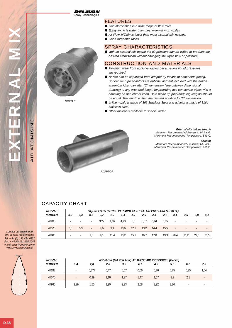
EXTE
RN
AL M
IX
D.38
Contact our Helpline forany special requirements:Tel: +44 (0) 151 424 6821Fax: +44 (0) 151 495 1043e-mail:[email protected]
Web:www.delavan.co.uk
FEATURES● Fine atomisation in a wide range of flow rates.● Spray angle is wider than most external mix nozzles.● Air Flow M3/Min is lower than most external mix nozzles.● Good turndown ratios.
SPRAY CHARACTERISTICS● With an external mix nozzle the air pressure can be varied to produce the
desired atomisation without changing the liquid flow or pressure.
CONSTRUCTION AND MATERIALS● Minimum wear from abrasive liquids because low liquid pressures
are required.● Nozzle can be separated from adaptor by means of concentric piping.
Concentric pipe adaptors are optional and not included with the nozzleassembly. User can alter “C” dimension (see cutaway dimensionaldrawing) to any extended length by providing two concentric pipes with acoupling on one end of each. Both made up pipe/coupling lengths shouldbe equal. The length is then the desired addition to “C” dimension.
● In-line nozzle is made of 303 Stainless Steel and adaptor is made of 316LStainless Steel.
● Other materials available to special order.
External Mix In-Line NozzleMaximum Recommended Pressure: 14 Bar.G.
Maximum Recommended Temperature: 540°C.
AdaptorMaximum Recommended Pressure: 14 Bar.G.
Maximum Recommended Temperature: 150°C.
NOZZLE AIR FLOW (M3 PER MIN) AT THESE AIR PRESSURES (Bar.G.)NUMBER 1,4 2,0 2,8 3,5 4,1 4,9 5,5 6,2 7,0
47283 - 0,377 0,47 0,57 0,66 0,76 0,85 0,95 1,04
47570 - 0,99 1,16 1,27 1,47 1,67 1,9 2,1 -
47980 3,99 1,55 1,90 2,23 2,58 2,92 3,26 - -
CAPACITY CHARTNOZZLE LIQUID FLOW (LITRES PER MIN) AT THESE AIR PRESSURES (Bar.G.)NUMBER 0,2 0,3 0,5 0,7 1,0 1,4 1,7 2,0 2,4 2,8 3,1 3,5 3,8 4,1
47283 - - - 3,22 4,16 4,73 5,3 5,67 5,94 6,05 - - - -
47570 3,8 5,3 - 7,6 9,1 10,6 12,1 13,2 14,4 15,5 - - - -
47980 - - 7,6 9,1 11,4 13,2 15,1 16,7 17,8 19,3 20,4 21,2 22,3 23,5
AIR
AT
OM
ISIN
G
NOZZLE
ADAPTOR
Air Atom 4 21/6/01 10:16 am Page 7

DIMENSIONS AND WEIGHTS
EXTERNAL MIX NOZZLE/ADAPTOR (mm)Dimensions 47980/32618 47570/32695 47283/32742
A 120,7 120,7 90,2
B 15,9 15,9 12,7
C 146,1 142,7 108
D 39,6 39,6 32,6
E 58,4 58,4 38,1
F 41,3 41,3 28,6
L 31,8 31,7 19,1
M 53,8 54 38,1
N 31,8 25,3 20,4
O 28,6 22,2 19,1
P 37,8 26,7 23,6
R 33,3 27 21,4
G NPT (M) 1” - 111/2 3/4” - 14 1/2” - 14
H NPT (F) 1/4” - 18 1/4” - 18 1/8” - 27
J NPT (F) 1” - 14 1/2” - 14 1/4” - 18
Approx. Weight (g) 1120 1176 462
EXTE
RN
AL M
IX
D.39
Contact our Helpline forany special requirements:Tel: +44 (0) 151 424 6821Fax: +44 (0) 151 495 1043e-mail:[email protected]
Web:www.delavan.co.uk
AIR
AT
OM
ISIN
G
1. Install nozzle as shown in schematic drawing. Makecertain both pressure gauges are located as close to thenozzle as practical. Allow for pressure losses betweengauges and nozzle when establishing settings. Shut-offvalves are included for convenience, allowing nozzleremoval without shutting down system.
2. The adaptor shown may be purchased from Delavan. It isnot part of the nozzle.
Air Atom 4 21/6/01 10:16 am Page 8

WELCOME TO DELAVAN
of newchallengesMeeting the
industriesand NEW markets
E Spray Drying
Del Nozzle A4 dividers A/W 21/6/01 10:36 am Page 9
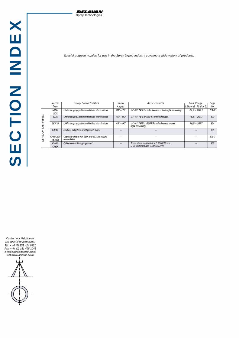
Special purpose nozzles for use in the Spray Drying industry covering a wide variety of products.
Nozzle Spray Characteristics Spray Basic Features Flow Range. PageType Angles L/Hour @ 70 Bar.G. No.MINI- 70° – 75° 24,2 – 208,1 E.1-2SDXSDX 45° – 90° 76,5 – 2677 E.3
SDX III 45° – 90° 76,5 – 2677 E.4
MISC. – – – E.5
CAPACITY – – – E.6-7CHARTKWIK- – – E.8CHEK
Uniform spray pattern with fine atomisation.
Uniform spray pattern with fine atomisation.
Uniform spray pattern with fine atomisation.
Bodies, Adaptors and Special Tools.
Capacity charts for SDX and SDX III nozzleassemblies.
Calibrated orifice gauge tool.
1/4"-3/8" NPT Female threads. Hand tight assembly.
1/4"-3/4" NPT or BSPT Female threads.
1/4"-3/4" NPT or BSPT Female threads. Handtight assembly.
Three sizes available for 0,25-0,70mm,0,60-3,30mm and 3,30-6,50mm
SP
RA
Y D
RY
ING
SE
CTIO
N IN
DE
X
Contact our Helpline forany special requirements:Tel: +44 (0) 151 424 6821Fax: +44 (0) 151 495 1043e-mail:[email protected]
Web:www.delavan.co.uk
Del Nozzle A4 dividers A/W 21/6/01 10:36 am Page 10

E.1
Contact our Helpline forany special requirements:Tel: +44 (0) 151 424 6821Fax: +44 (0) 151 495 1043e-mail:[email protected]
Web:www.delavan.co.uk
TYP
E M
INI-
SD
XDESCRIPTION PART NO. MATERIAL WEIGHT (g)
Orifice Disc 902-XX* Tungsten Carbide 8,5
Nozzle Body 32932 303 SS 62,4
Swirl Chamber 32933-X* Ceramic 7,1Swirl Chamber 50791-X* Tungsten Carbide 9,9
O-Ring Seal 31352-013 Viton 2,3
1⁄4” NPTF Adaptor 32931-1 303 SS 85,03⁄8” NPTF Adaptor 32931-2 303 SS 71,0
MATERIALS AND WEIGHTS
PART NO. DESCRIPTION MATERIAL
49109 Seal Kit Viton
SEAL KIT (24 SEALS)
Max. Design Pressure: 350 Bar.G.Max. Design Temperature: 150ºC.
FEATURESThe unique swirl chamber is the heart of Delavan’s Mini-SDX nozzle design.The single inlet spiral configuration produces a natural, free vortex pattern.Friction is minimised, permitting 10-20% lower operating pressure thanconventional slotted distributor nozzles. This lengthens both pump andnozzle life.
SPRAY CHARACTERISTICS● The Mini-SDX nozzle produces a hollow cone spray pattern with relatively
uniform droplet size and particle distribution.● Nominal spray angle is 70º-75º.● Flow rates on water at 69 Bar.G. range from as low as 24.2 litres/hour to
as high as 208 litres/hour, depending on nozzle size.
CONSTRUCTION AND MATERIALS● Five part construction (see part and material list below).● The orifice disc, a pressed fit insert, is recessed to protect against
damage if dropped or hit.● Wrench tighten only when replacing orifice disc by pressing into nozzle
body with assembly tool, otherwise no wrench tightening should be doneduring assembly. Wrench tightening may result in fracture of the swirlchamber.
● The patented single inlet swirl chamber minimises plugging andmaximises particle uniformity.
● The Viton O-ring seal allows assembly and disassembly without tools.● Only assembly tool (P/N 36386) is needed for changing the pressed fit
orifice disc.
ORDER EXAMPLEWhen ordering specify the following:
1) Assembly part number from capacity chartor 2) Part numbers of individual items.
* Refer to capacity chart for dash number.NOTE: - 50791-1 is equivalent to 32933-1.
SP
RA
Y D
RY
ING
BODY
ORIFICEDISC
SWIRLCHAMBERS
O-RING
ADAPTOR
UNIQUE SWIRL CHAMBER
Spray Drying 1 21/6/01 2:25 pm Page 1

TYP
E M
INI-
SD
X
E.2
Contact our Helpline forany special requirements:Tel: +44 (0) 151 424 6821Fax: +44 (0) 151 495 1043e-mail:[email protected]
Web:www.delavan.co.uk
CAPACITY CHART
ASSEMBLY INLET SWIRL ORIFICE FLOW RATE IN LITRES/HOUR AT BAR.G. APPROX. PART ADAPTOR THREAD CHAMBER DISC WEIGHT
NUMBER (NPTF) 34,5 69 138 207 276 345 (g)
32936-47 32931-1 1/4 32933-4 902-18 17,4 24,2 34 42 48,4 53,7 13332936-48 32931-2 3/8 119
32936-49 32931-1 1/4 32933-4 902-20 18,5 25,7 36,3 44,6 51,5 57,5 13332936-50 32931-2 3/8 119
32936-51 32931-1 1/4 32933-4 902-22 20,4 28,4 40,1 49,2 56,8 63,6 13332936-52 32931-2 3/8 119
32936-53 32931-1 1/4 32933-4 902-24 23,5 32,5 46,2 56,4 65,1 72,6 13332936-54 32931-2 3/8 119
32936-55 32931-1 1/4 32933-4 902-27 26,9 37,8 53,3 65,5 75,7 84,7 13332936-56 32931-2 3/8 119
32936-1 32931-1 1/4 32933-1 902-22 29,5 41,6 59,0 72,2 83,2 93,1 13332936-2 32931-2 3/8 119
32936-3 32931-1 1/4 32933-1 902-24 34 47,3 67 82 94,6 105,9 13332936-4 32931-2 3/8 119
32936-5 32931-1 1/4 32933-1 902-27 38,6 54,9 77,6 95 109,8 122,6 13332936-6 32931-2 3/8 119
32936-7 32931-1 1/4 32933-1 902-30 44,3 62,4 88,2 108,2 124,8 140,1 13332936-8 32931-2 3/8 119
32936-9 32931-1 1/4 32933-2 902-30 53,3 75,7 107,1 130,9 151,3 169,1 13332936-10 32931-2 3/8 119
32936-11 32931-1 1/4 32933-2 902-33 60,1 85,1 120,3 147,5 170,2 190,3 13332936-12 32931-2 3/8 119
32936-13 32931-1 1/4 32933-2 902-36 67 94,6 133,9 163,8 189,2 211,5 13332936-14 32931-2 3/8 119
32936-15 32931-1 1/4 32933-2 902-38 70,7 100,3 141,9 173,3 200,5 224,4 13332936-16 32931-2 3/8 119
32936-17 32931-1 1/4 32933-2 902-40 77,6 109,7 155,1 189,9 219,4 245,1 13332936-18 32931-2 3/8 119
32936-19 32931-1 1/4 32933-2 902-42 80,2 113,5 160,8 196,7 227 253,5 13332936-20 32931-2 3/8 119
32936-21 32931-1 1/4 32933-2 902-44 82,9 117,3 164,2 203,5 234,6 262,1 13332936-22 32931-2 3/8 119
32936-23 32931-1 1/4 32933-2 902-46 87 123 174 213 245,9 275 13332936-24 32931-2 3/8 119
32936-25 32931-1 1/4 32933-2 902-48 90,8 132,4 187,3 229,3 264,8 296,2 13332936-26 32931-2 3/8 119
32936-27 32931-1 1/4 32933-2 902-50 97,6 138,1 195,2 239,1 276 308,7 13332936-28 32931-2 3/8 119
32936-29 32931-1 1/4 32933-2 902-52 105,6 149,4 211,5 258,8 298,9 334,1 13332936-30 32931-2 3/8 119
32936-31 32931-1 1/4 32933-2 902-54 109,7 155,1 219,4 268,6 310,2 346,9 13332936-32 32931-2 3/8 119
32936-33 32931-1 1/4 32933-2 902-56 113,5 158,9 224,7 275,4 317,8 355,6 13332936-34 32931-2 3/8 119
32936-37 32931-1 1/4 32933-3 902-50 117,3 169,5 239,5 293,6 339,0 378,3 13332936-38 32931-2 3/8 119
32936-39 32931-1 1/4 32933-3 902-52 127,5 180,8 255,8 313,3 361,7 404,4 13332936-40 32931-2 3/8 119
32936-41 32931-1 1/4 32933-3 902-54 135,1 191,1 270,1 331 382,1 427,1 13332936-42 32931-2 3/8 119
32936-43 32931-1 1/4 32933-3 902-56 143,8 202,4 286,4 350,7 404,8 452,5 13332936-44 32931-2 3/8 119
32936-45 32931-1 1/4 32933-3 902-58 147,2 208,1 294,3 360,6 416,2 465,3 13332936-46 32931-2 3/8 119
All Spray Angles 70º-75º.
SP
RA
Y D
RY
ING
Spray Drying 1 21/6/01 2:25 pm Page 2

Description Part No. Material Weight(g)
Body 29776 316 SS 153,0
29772-1 Nylon –29772-3 Aluminium –
Orifice Seal 29772-6 PTFE –29772-7 Hard Fibre –29772-4 Copper –
703-XXX* Tungsten Carbide 11,4Orifice Disc 704-XXX Chrome Carbide 11,4
608-XXX Ceramic –
Swirl Chamber 29794-XX* Hardened SS 8,5Swirl Chamber 31212-XX Tungsten Carbide 17,0Swirl Chamber 30655-XX Ceramic –
Swirl Chamber with WO1380-XX Tungsten Carbide 28,4End Plate combined
W05366 Tungsten Carbide 11,4End Plate 29953 Chrome Carbide 11,4
34430 Ceramic –
Screw Pin 29777 316 Stainless Steel 91,0
29773-1 Nylon –29773-3 Aluminium –
Body Seal 29773-6 PTFE –29773-7 Hard Fibre –29773-4 Copper –
1⁄4” BSPT Female Adaptor 29775-93⁄8” BSPT Female Adaptor 29775-11 316 Stainless Steel 370,01⁄2” BSPT Female Adaptor 29775-133⁄4” BSPT Female Adaptor 29775-15
TYP
E S
DX
E.3
Contact our Helpline forany special requirements:Tel: +44 (0) 151 424 6821Fax: +44 (0) 151 495 1043e-mail:[email protected]
Web:www.delavan.co.uk
WEIGHTS
COMPONENT PARTS, MATERIALS AND WEIGHTS
SPRAY CHARACTERISTICS● The SDX series nozzles produce a hollow cone spray pattern with uniform
particle size distribution even at low operating pressures.● Flow rates are certified to be within ±5% of rated capacity at 69 Bar.G.
and within ±5º of rated spray angle when tested with water.● Unique, patented single inlet, spiral swirl chamber offers increased
nozzle life, improved product uniformity, density or solubility.● Minimal friction due to nozzle design permitting 10-20% lower operating
pressure than conventional slotted distributor nozzle for equivalentatomisation quality.
● Extended pump life due to lower operating pressure.● Reduction in fine particles is possible due to lower pressure requirements.
CONSTRUCTION AND MATERIALS● Eight part construction (see part and material list below).● Nozzle bodies, screw pins and adaptors are available in 316 Stainless
Steel. Other materials available on special request.● Orifice discs are easily removable and are available in Tungsten Carbide,
Chrome Carbide and Ceramic as standard.● Swirl chambers are standard in Tungsten Carbide, Hardened Stainless
Steel or Ceramic.● End plates are available in Tungsten Carbide, Chrome Carbide and Ceramic. ● Combined swirl chamber/end plate is available in Tungsten Carbide only.● Seals are available in Nylon, PTFE, Copper, Hard Fibre and Aluminium.
ORDER EXAMPLEPlease indicate all component parts and materials when ordering.
SP
RA
Y D
RY
ING
Max. Design Pressure: 500 Bar.G.Max. Design Temperature: 540ºC (Metal Seals),
150ºC (Other Seals).
Assembly Size Weight (g)
1/4” 680
3/8” 666
1/2” 640
3/4” 61238,1 A/F 72,6 38
45
* Specify orifice size and swirl chamber suffix from capacity chart.
NOZZLEASSEMBLY
BODY
ORIFICESEAL
BODY SEAL
ORIFICE DISC
END PLATE
SCREW PIN
SWIRLCHAMBERS
ADAPTOR
ADAPTOR
Spray Drying 1 21/6/01 2:26 pm Page 3

Description Part No. Material Weight(g)
Body W11300 316 Stainless Steel 276
Orifice O-Ring 31351-66 Silicone –31352-016 Viton –
Orifice Disc 703-XXX* Tungsten Carbide 11,4704-XXX Chrome Carbide 11,4608-XXX Ceramic –
Swirl Chamber 29794-XX* Hardened Stainless Steel 8,5Swirl Chamber 31212-XX Tungsten Carbide 17Swirl Chamber 30655-XX Ceramic –
Swirl Chamber with WO1380-XX Tungsten Carbide 28,4End Plate Combined
End Plate 38331** Tungsten Carbide 42,5W11430 Ceramic –
Adaptor O-Ring 31351-65 Silicone –31351-32 Viton –
1⁄4” BSPT Female Adaptor W11301-1 316 Stainless Steel 3693⁄8” BSPT Female Adaptor W11301-2 3541⁄2” BSPT Female Adaptor W11301-3 3403⁄4” BSPT Female Adaptor W11301-4 312
TYP
E S
DX
III
E.4
Contact our Helpline forany special requirements:Tel: +44 (0) 151 424 6821Fax: +44 (0) 151 495 1043e-mail:[email protected]
Web:www.delavan.co.uk
COMPONENT PARTS, MATERIALS AND WEIGHTS
SPRAY CHARACTERISTICS● The SDX series nozzles produce a hollow cone spray pattern with uniform
particle size distribution even at low operating pressures.● Flow rates are certified to be within ±5% of rated capacity at 65 Bar.G.
and within ±5º of rated spray angle when tested with water.● Unique, patented single inlet spiral swirl chamber offers increased nozzle
life, improved product uniformity, density or solubility.● Minimal friction due to nozzle design permitting 10-20% lower operating
pressure than conventional slotted distributor nozzle for equivalentatomisation quality.
● Extended pump life due to lower operating pressure.● Reduction in fine particles is possible due to lower pressure requirements.
CONSTRUCTION AND MATERIALS● Six part construction (see part and material list below).● O-ring seals allow assembly and disassembly without tools.● Body and adaptors are produced from hexagon barstock with other
materials in round bar with flats.● Nozzle bodies and adaptors are available in 316 Stainless Steel. Other
materials are available on special request.● Orifice discs are easily removable and are available in Tungsten Carbide,
Chrome Carbide and Ceramic.● Swirl chambers are standard in Tungsten Carbide, Hardened Stainless
Steel or Ceramic.● End plates are available in Tungsten Carbide and Ceramic. ● Combined swirl chamber/end plate is available in Tungsten Carbide only.● O-Rings are in Silicone or Viton.
ORDER EXAMPLEPlease indicate all component parts and materials when ordering.
SP
RA
Y D
RY
ING
* Specify orifice size and swirl chamber suffix from capacity chart.** End plate not required with W01380 swirl chamber.
BODY
ORIFICE SEAL
ADAPTOR SEAL
ORIFICE DISC
END PLATE
SWIRLCHAMBERS
ADAPTOR
WEIGHTS
Max. Design Pressure: 350 Bar.G.Max. Design Temperature: 150ºC.
Assembly Size Weight (g)
1/4” 743
3/8” 729
1/2” 714
3/4” 700
37,4
3895 (VARIES WITH SWIRL CHAMBER)
Spray Drying 1 21/6/01 2:26 pm Page 4

TYP
E S
DX
E.5
Contact our Helpline forany special requirements:Tel: +44 (0) 151 424 6821Fax: +44 (0) 151 495 1043e-mail:[email protected]
Web:www.delavan.co.uk
SP
RA
Y D
RY
ING
The following are various special bodies, adaptors and toolsthat are available for the SDX nozzle range.
CONE FACED BODIESThese are designed to prevent build up of sprayed product on the nozzle faceand are available with cone angles of 70°, 80° and 90°. Special angles areavailable on request.
MULTIPLE NOZZLE ADAPTORSWhere spray dryers permit, special adaptors are available to provide multiplenozzle installations. These have a 1” NPTF inlet with 3/8” NPTF outlets so thatnipples can be fitted on to which the nozzles will be mounted. The partnumbers are 95161-4 for the four nozzle adaptor and 95161-5 for the fivenozzle adaptor.
CONE FACED BODY PART NUMBERS
Nozzle Type 70° 80° 90°
SDX 20319-1 20319-2 20319-3
SDXIII W11882-1 W11882-2 W11882-3
THREAD GUARDSThese are designed to protect the threads and sealing surfaces duringcleaning of the SDX bodies and SDX III adaptors. The part numbers are 50519for the SDX and 50423 for the SDX III.
Part number 36386 for changing Mini-SDXorifice discs.
There is an additional tool number W15336 which is designed for removal oforifice discs which have become embedded with product.
Part number W15307 for insertion and removalof SDX and SDX III swirl chambers.
SDX III TYPE
95161-4 95161-5
50519 50423
36386W15307
ASSEMBLY TOOLS
Spray Drying 1 21/6/01 2:27 pm Page 5

SWIRL ORIFICE SPRAY ANGLE FLOW RATE IN LITRES/HOUR AT Bar.G.CHAMBER DISC AT 69 Bar.G.
SUFFIX 15 25 50 75 100 125 150 200 300 400 500
SB 703-33 70 37,5 47,7 65,8 79,2 89,9 99,5 108 123 149 171 188SA 703-38 80SC 703-34 60SB 703-40 75 45,9 58,1 81,8 98,3 112 124 135 156 187 216 240SA 703-48 85SD 703-35 60SC 703-39 70 54,6 70,0 98,3 118 135 150 164 189 228 264 293SA 703-59 85SE 703-35 50SD 703-39 65 63,4 81,5 115 136 159 179 193 225 271 312 347SB 703-54 80SA 703-69 90SE 703-38 55SD 703-48 65 71,9 92,9 131 158 181 202 220 253 307 358 394SC 703-50 75SB 703-62 85SF 703-38 50SE 703-41 60 80,7 106 146 178 205 227 248 285 347 401 439SC 703-54 75SB 703-69 85SF 703-40 50SE 703-44 60SD 703-52 70 89,1 116 164 199 229 257 279 321 390 451 508SC 703-60 80SB 703-77 90SF 703-43 50SE 703-48 60 97,5 126 179 216 248 279 303 351 428 497 554SD 703-56 70SC 703-66 80SG 703-40 45SF 703-45 55 106 138 196 237 275 307 332 384 474 546 612SE 703-51 65SC 703-71 80SG 703-45 45SF 703-51 55SE 703-58 65 124 160 229 277 321 360 390 451 559 646 722SD 703-69 75SC 703-83 85SG 703-49 50SF 703-56 60SE 703-64 70 141 182 260 315 364 404 439 512 627 722 811SD 703-76 80SC 703-94 90SG 703-53 50SF 703-60 60SE 703-70 70 158 205 293 356 409 459 505 585 711 811 929SD 703-83 80SC 703-107 90SG 703-57 55SF 703-65 65 176 228 327 394 454 514 559 646 795 921 1032SD 703-92 80SH 703-54 45SG 703-60 55 192 247 358 436 501 562 615 715 895 1013 1139SF 703-70 65SE 703-83 75 192 247 358 436 501 562 615 715 895 1013 1139SD 703-100 85SH 703-57 45SG 703-63 55SF 703-75 65 211 274 390 474 550 616 669 776 955 1101 1242SE 703-89 75SD 703-108 85
TYP
E S
DX
& S
DXIII
E.6
Contact our Helpline forany special requirements:Tel: +44 (0) 151 424 6821Fax: +44 (0) 151 495 1043e-mail:[email protected]
Web:www.delavan.co.uk
CAPACITY CHART - SDX & SDX III*
** Maximum Operating Pressure for SDX III = 350 Bar.G. (Available up to 500 Bar.G. on request)
SP
RA
Y D
RY
ING
Spray Drying 1 21/6/01 2:27 pm Page 6
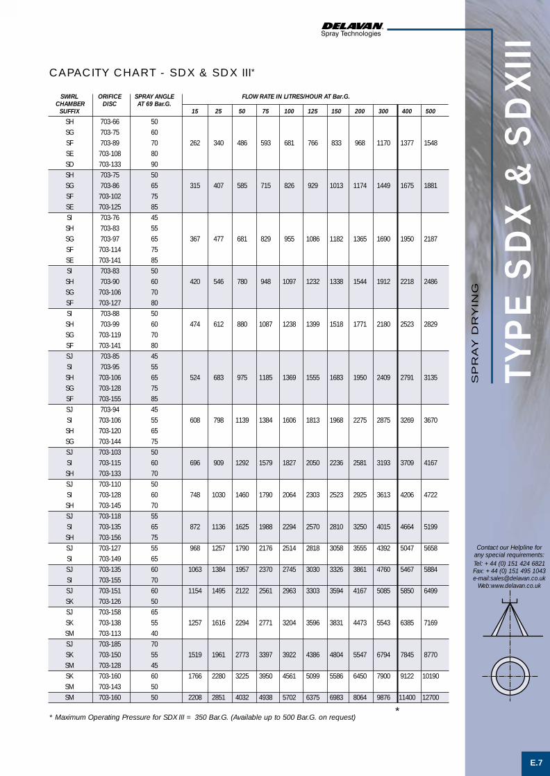
TYP
E S
DX
& S
DXIII
E.7
Contact our Helpline forany special requirements:Tel: +44 (0) 151 424 6821Fax: +44 (0) 151 495 1043e-mail:[email protected]
Web:www.delavan.co.uk
SP
RA
Y D
RY
ING
SWIRL ORIFICE SPRAY ANGLE FLOW RATE IN LITRES/HOUR AT Bar.G.CHAMBER DISC AT 69 Bar.G.
SUFFIX 15 25 50 75 100 125 150 200 300 400 500
SH 703-66 50SG 703-75 60SF 703-89 70 262 340 486 593 681 766 833 968 1170 1377 1548SE 703-108 80SD 703-133 90SH 703-75 50SG 703-86 65 315 407 585 715 826 929 1013 1174 1449 1675 1881SF 703-102 75SE 703-125 85SI 703-76 45SH 703-83 55SG 703-97 65 367 477 681 829 955 1086 1182 1365 1690 1950 2187SF 703-114 75SE 703-141 85SI 703-83 50SH 703-90 60 420 546 780 948 1097 1232 1338 1544 1912 2218 2486SG 703-106 70SF 703-127 80SI 703-88 50SH 703-99 60 474 612 880 1087 1238 1399 1518 1771 2180 2523 2829SG 703-119 70SF 703-141 80SJ 703-85 45SI 703-95 55SH 703-106 65 524 683 975 1185 1369 1555 1683 1950 2409 2791 3135SG 703-128 75SF 703-155 85SJ 703-94 45SI 703-106 55 608 798 1139 1384 1606 1813 1968 2275 2875 3269 3670SH 703-120 65SG 703-144 75SJ 703-103 50SI 703-115 60 696 909 1292 1579 1827 2050 2236 2581 3193 3709 4167SH 703-133 70SJ 703-110 50SI 703-128 60 748 1030 1460 1790 2064 2303 2523 2925 3613 4206 4722SH 703-145 70SJ 703-118 55SI 703-135 65 872 1136 1625 1988 2294 2570 2810 3250 4015 4664 5199SH 703-156 75SJ 703-127 55 968 1257 1790 2176 2514 2818 3058 3555 4392 5047 5658SI 703-149 65SJ 703-135 60 1063 1384 1957 2370 2745 3030 3326 3861 4760 5467 5884SI 703-155 70SJ 703-151 60 1154 1495 2122 2561 2963 3303 3594 4167 5085 5850 6499SK 703-126 50SJ 703-158 65SK 703-138 55 1257 1616 2294 2771 3204 3596 3831 4473 5543 6385 7169SM 703-113 40SJ 703-185 70SK 703-150 55 1519 1961 2773 3397 3922 4386 4804 5547 6794 7845 8770SM 703-128 45SK 703-160 60 1766 2280 3225 3950 4561 5099 5586 6450 7900 9122 10190SM 703-143 50SM 703-160 50 2208 2851 4032 4938 5702 6375 6983 8064 9876 11400 12700
CAPACITY CHART - SDX & SDX III*
** Maximum Operating Pressure for SDX III = 350 Bar.G. (Available up to 500 Bar.G. on request)
Spray Drying 1 21/6/01 2:27 pm Page 7

The Kwik-Chek orifice gauges are designed for the rapid measurement ofsmall hole diameters. Models are available to cover a range of holediameters from 0,010” to 0,255” (0,25mm-6,50mm).These gauges work on the principle of directly transferring diametermeasurements from a sliding, tapered needle to a linear scale readoutgraduated in 0,001” or 0,02mm.
FEATURES● No skill required. Untrained personnel can make fast and accurate
measurements.● Rapid and simple calibration. A setting master is provided with each
gauge. Permits rapid periodic check on calibration and fieldreadjustment, if necessary, by shop personnel.
● Magnified, direct reading scale permits easy reading of hole diametersto nearest 0,001” or 0,02mm.
● Precision ground tapered needle is made of 52-100 Steel and Chromeplated for maximum wear resistance.
● Positive Clutch which locks needle and scale at exact dimension of holebeing measured.
● Convenient pocket size and weight makes these gauges ideal for rovinginspectors and engineers.
ORDER EXAMPLEPlease specify the model number and Inch or Metric size when ordering.
Model Hole Size RangeNumber Inches Metric
10 0,010”-0,028” 0,25mm-0,70mm
20 0,025”-0,130” 0,60mm-3,30mm
30 0,130”-0,255” 3,30mm-6,50mm
INDIVIDUAL GAUGES
TYP
E K
WIK
-CH
EK
E.8
Note:- Kwik-Chek orifice gauge is not suitable for Mini-SDX.
Contact our Helpline forany special requirements:Tel: +44 (0) 151 424 6821Fax: +44 (0) 151 495 1043e-mail:[email protected]
Web:www.delavan.co.uk
SP
RA
Y D
RY
ING
Spray Drying 1 21/6/01 2:28 pm Page 8

WELCOME TO DELAVAN
of newchallengesMeeting the
industriesand NEW markets
F Cleaning InPlace
Del Nozzle A4 dividers A/W 21/6/01 10:36 am Page 11
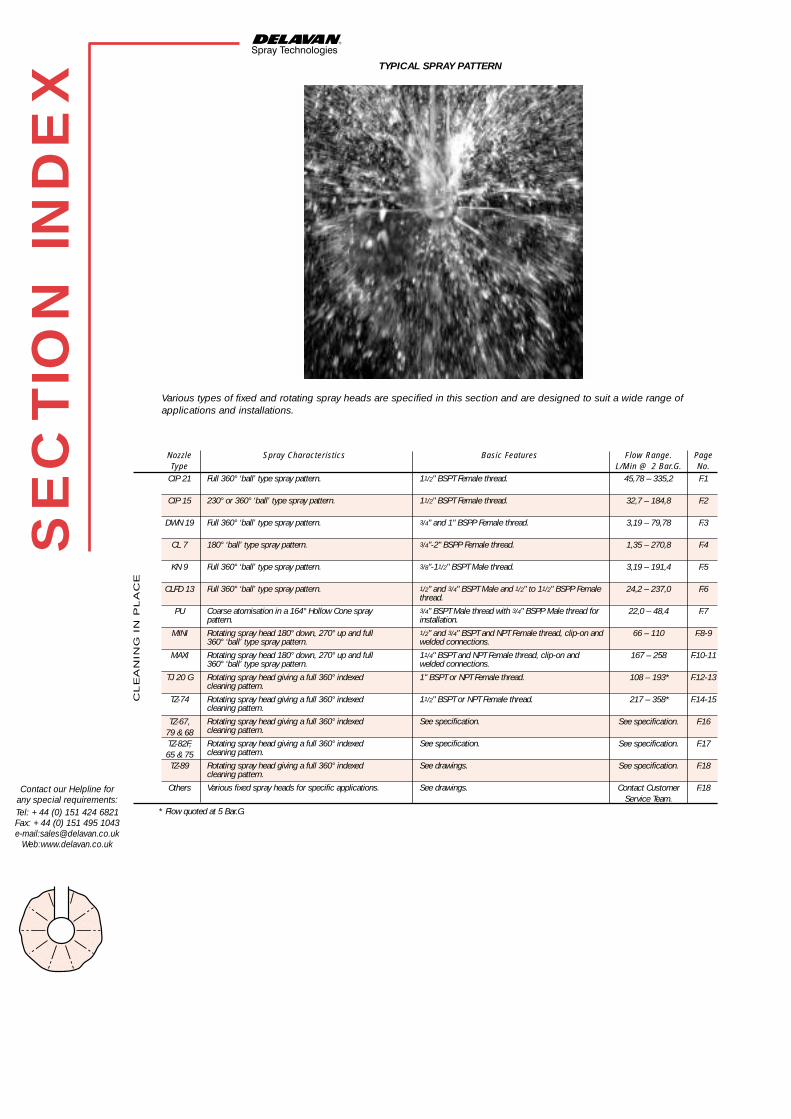
Various types of fixed and rotating spray heads are specified in this section and are designed to suit a wide range ofapplications and installations.
TYPICAL SPRAY PATTERN
Nozzle Spray Characteristics Basic Features Flow Range. PageType L/Min @ 2 Bar.G. No.
CIP 21 45,78 – 335,2 F.1
CIP 15 32,7 – 184,8 F.2
DWN 19 3,19 – 79,78 F.3
CL 7 1,35 – 270,8 F.4
KN 9 3,19 – 191,4 F.5
CLFD 13 24,2 – 237,0 F.6
PU 22,0 – 48,4 F.7
MINI 66 – 110 F.8-9
MAXI 167 – 258 F.10-11
TJ 20 G 108 – 193* F.12-13
TZ-74 217 – 358* F.14-15
TZ-67, See specification. F.1679 & 68TZ-82F, See specification. F.1765 & 75TZ-89 See specification. F.18
Others Contact Customer F.18Service Team.
Full 360° ‘ball’ type spray pattern.
230° or 360° ‘ball’ type spray pattern.
Full 360° ‘ball’ type spray pattern.
180° ‘ball’ type spray pattern.
Full 360° ‘ball’ type spray pattern.
Full 360° ‘ball’ type spray pattern.
Coarse atomisation in a 164° Hollow Cone spraypattern.
Rotating spray head 180° down, 270° up and full360° ‘ball’ type spray pattern.
Rotating spray head 180° down, 270° up and full360° ‘ball’ type spray pattern.
Rotating spray head giving a full 360° indexedcleaning pattern.
Rotating spray head giving a full 360° indexedcleaning pattern.
Rotating spray head giving a full 360° indexedcleaning pattern.
Rotating spray head giving a full 360° indexedcleaning pattern.
Rotating spray head giving a full 360° indexedcleaning pattern.
Various fixed spray heads for specific applications.
11/2" BSPT Female thread.
11/2" BSPT Female thread.
3/4" and 1" BSPP Female thread.
3/4"-2" BSPP Female thread.
3/8"-11/2" BSPT Male thread.
1/2" and 3/4" BSPT Male and 1/2" to 11/2" BSPP Femalethread.3/4" BSPT Male thread with 3/4" BSPP Male thread forinstallation.1/2" and 3/4" BSPT and NPT Female thread, clip-on andwelded connections.
11/4" BSPT and NPT Female thread, clip-on andwelded connections.
1" BSPT or NPT Female thread.
11/2" BSPT or NPT Female thread.
See specification.
See specification.
See drawings.
See drawings.
SE
CTIO
N IN
DE
X
Contact our Helpline forany special requirements:Tel: +44 (0) 151 424 6821Fax: +44 (0) 151 495 1043e-mail:[email protected]
Web:www.delavan.co.uk
* Flow quoted at 5 Bar.G.
CL
EA
NIN
G I
N P
LA
CE
Del Nozzle A4 dividers A/W 21/6/01 10:36 am Page 12

F.1
Contact our Helpline forany special requirements:Tel: +44 (0) 151 424 6821Fax: +44 (0) 151 495 1043e-mail:[email protected]
Web:www.delavan.co.uk
TYP
E C
IP 2
1CAPACITY CHART
SPRAY CHARACTERISTICS● Relatively uniform distribution at all pressures.● Available in a range of flow capacities.● Produces a full spray pattern from a multiple orifice body, with 360°
spherical cover for tanks up to 3 mtrs in diameter.
CONSTRUCTION AND MATERIALS● Manufactured with a 11⁄2” BSPT Female threaded body fitted with
21 removable solid cone spray nozzles.● Made in Stainless Steel, Gunmetal/Brass as standard.● Other nozzles can be fitted to give non-standard spray patterns.● Other materials available to special order.
ORDER EXAMPLE11⁄2” CIP21-500 Stainless Steel.
Assembly Pressure Bar. G.Number 1,0 3,0 5,0
CIP21-100/200 1000 1900 2000
CIP21-250/400 1200 2400 2500
CIP21-500/650 1500 2990 3100
CIP21-750/1000 1700 3300 3500
APPROX. DIAMETER OF COVERAGE (mm)
FLOW RATE IN LITRES/MIN AT Bar.G.
ASSEMBLY NUMBER NOZZLES 0,7 1,0 2,0 3,0 4,0 5,0 6,0 7,0
1.1⁄2” CIP21-150 1⁄4” BIM 6 - 31,50 45,78 55,64 60,26 67,37 71,61 74,34
1.1⁄2” CIP21-200 1⁄4” BIM 8 - 47,87 67,83 83,98 95,55 104,8 112,9 120,1
1.1⁄2” CIP21-250 1⁄4” BIM 12 - 71,61 95,54 111,2 124,1 138,7 147,4 159,1
1.1⁄2” CIP21-300 3⁄8” BIM 12 58,59 69,72 99,33 122,4 138,6 154,9 163,5 171,5
1.1⁄2” CIP21-400 3⁄8” BIM 16 75,18 92,61 128,9 152,6 167,9 187,7 199,7 210,8
1.1⁄2” CIP21-500 3⁄8” BIM 22 107,3 131,1 174,7 205,3 229,1 256,1 277,8 298,9
1.1⁄2” CIP21-650 3⁄8” BIM 27 126,8 155,8 211,9 258,7 286,4 320,1 337,2 366,6
1.1⁄2” CIP21-750 3⁄8” BIM 32 152,1 186,5 258,7 303,2 335,1 374,6 405,1 428,2
1.1⁄2” CIP21-1000 3⁄8” BIM 42 203,1 242,8 335,2 405,1 449,6 478,3 524,0 574,8
CL
EA
NIN
G I
N P
LA
CE
Approx. weight of assembly=1.5Kg
Maximum Recommended Pressure:35 Bar.G. (Metal), 7 Bar.G. (Plastic).
cluster spray 1 4/5/01 5:48 pm Page 1

TYP
E C
IP 1
5
F.2
SPRAY CHARACTERISTICS● Relatively uniform distribution at all pressures.● Available in a range of flow capacities.● The CIP15 is used in place of a standard full cone nozzle, where finer
atomisation than a single nozzle might normally provide is required.● Normal spray angle is 230°.● For full 360° coverage with type CIP15 the assembly is identified with the
suffix 'FC'.
CONSTRUCTION AND MATERIALS● Manufactured with a 11⁄2” BSPT Female threaded body fitted with
15 removable solid cone spray nozzles.● Made in Stainless Steel, Gunmetal/Brass as standard.● Other nozzles can be fitted to give non-standard spray patterns.● Other material available to special order.
ORDER EXAMPLE11⁄2” CIP15-150 Stainless Steel.11⁄2” CIP15-150-FC P.T.F.E.
Contact our Helpline forany special requirements:Tel: +44 (0) 151 424 6821Fax: +44 (0) 151 495 1043e-mail:[email protected]
Web:www.delavan.co.uk
Assembly Pressure Bar. G.Numbers 1,0 3,0 5,0
CIP 15-FC 100/190 800 1550 1750
CIP 15-FC 250/380 1000 1850 2100
CIP 15-FC 430/550 1200 2250 2600
CIP 15- 100/200 900 1600 1900
CIP 15- 275/380 1050 1900 2250
CIP 15- 470/550 1400 2500 2950
APPROX. DIAMETER OF COVERAGE (mm)
CAPACITY CHARTFLOW RATE IN LITRES/MIN AT Bar.G.
ASSEMBLY NUMBER NOZZLES 0,7 1,0 2,0 3,0 4,0 5,0 6,0 7,0
1.1⁄2” CIP 15 -100 1/4" BIM 6 18,75 22,50 28,20 32,70 39,75 44,44 51,15 53,10
1.1⁄2” CIP 15 -140 1/4" BIM 8 27,90 34,20 42,60 48,15 60,00 67,08 80,70 85,80
1.1⁄2” CIP 15 -200 1/4" BIM 12 41,85 51,15 61,35 68,25 79,95 89,39 105,30 113,70
1.1⁄2” CIP 15 -275 3/8" BIM 16 53,70 66,15 79,50 92,10 109,05 121,92 142,65 150,60
1.1⁄2” CIP 15 -350 3/8" BIM 20 66,90 81,90 97,50 113,10 135,90 151,94 178,80 189,45
1.1⁄2” CIP 15 -380 3/8" BIM 22 76,65 93,60 112,65 124,80 146,70 164,02 198,45 213,60
1.1⁄2” CIP 15 -470 3/8" BIM 27 90,60 111,30 135,15 151,50 184,80 206,61 240,90 262,05
1.1⁄2” CIP 15 -550 3/8" BIM 32 108,75 133,20 162,15 184,80 216,60 242,17 289,35 306,00
1.1⁄2” CIP 15 -100 FC 1/4" BNM 6 18,75 22,50 32,70 39,75 43,05 48,13 51,15 53,10
1.1⁄2” CIP 15 -140 FC 1/4" BNM 8 27,90 34,20 48,45 60,00 68,25 76,31 80,70 85,80
1.1⁄2” CIP 15 -190 FC 1/4" BNM 11 41,85 48,45 64,65 77,25 81,75 91,40 100,95 111,45
1.1⁄2” CIP 15 -250 FC 1/4" BNM 15 55,05 67,50 83,85 99,60 108,60 121,42 130,50 137,40
1.1⁄2” CIP 15 -300 FC 1/4" BNM 18 66,00 80,85 100,50 119,40 130,20 145,57 156,45 164,70
1.1⁄2” CIP 15 -380 FC 3/8" BNM 22 83,70 102,60 127,50 151,50 165,15 184,64 198,45 209,10
1.1⁄2” CIP 15 -430 FC 3/8" BNM 25 90,60 108,60 139,80 165,15 184,80 206,61 219,75 236,40
1.1⁄2” CIP 15 -550 FC 3/8" BNM 32 115,50 137,25 178,80 214,50 236,70 264,64 283,50 298,50
CL
EA
NIN
G I
N P
LA
CE
CIP 15 ASSEMBLY
CIP 15 - FC CIP 15
Approx. weight of assembly=1.34Kg
Maximum Recommended Pressure:35 Bar.G. (Metal), 7 Bar.G. (Plastic).
cluster spray 1 4/5/01 5:48 pm Page 2

TYP
E D
WN
19
F.3
SPRAY CHARACTERISTICS● Produces a solid cone type spray pattern from a multiple orifice body.● Relatively uniform distribution at all pressures.● Atomisation is finer than with a single nozzle of the same capacity.● Available in a range of flow capacities and thread sizes.● Produces a 360° 'Ball' shaped spray pattern.
CONSTRUCTION AND MATERIALS● The cluster consists of a body fitted with 19 removable solid cone
spray nozzles.● Available with 3⁄4” and 1” BSPP Female threads.● Different spray nozzles can be installed to give non-standard
spray patterns.● Available in Stainless Steel and Brass as standard.● Other materials available to special order.
ORDER EXAMPLE3⁄4” DWN19-25 Stainless Steel.1” DWN19-50 Brass.
Thread Dimensions (mm) WeightSize A B Dia (kg)3⁄4” 100 57,0 0,66
1” 100 57,0 0,63
Contact our Helpline forany special requirements:Tel: +44 (0) 151 424 6821Fax: +44 (0) 151 495 1043e-mail:[email protected]
Web:www.delavan.co.uk
DIMENSIONS AND WEIGHTS
CAPACITY CHART
FLOW RATE IN LITRES/MIN AT Bar.G.ASSEMBLY NUMBER NOZZLES 0,7 1,0 2,0 3,0 4,0 5,0 6,0 7,0
DWN19-10 1⁄8” BL 3 - 2,25 3,19 3,91 4,50 5,05 5,53 5,88
DWN19-15 1⁄8” BL 4 - 3,38 4,78 5,86 6,76 7,56 8,29 8,88
DWN19-20 1⁄8” BL 6 - 4,51 6,37 7,81 9,19 10,08 11,04 11,74
DWN19-25 1⁄8” BL 7 - 5,64 7,98 9,77 11,27 12,61 13,80 14,69
DWN19-50 1⁄8” BL 14 9,44 11,28 15,98 19,55 22,55 25,24 27,64 29,58
DWN19-100 1⁄8” BL 30 18,88 22,57 31,92 39,10 45,14 50,48 55,25 58,75
DWN19-125 1⁄8” BIM 6 23,60 28,21 39,89 48,86 56,41 63,08 69,07 73,42
DWN19-150 1⁄8” BIM 7 28,32 33,85 47,87 58,63 67,69 75,69 82,88 88,11
DWN19-200 1⁄8” BIM 8 37,76 45,14 63,83 78,18 90,27 100,9 110,2 117,9
DWN19-250 1⁄8” BIM 12 47,19 56,41 79,78 97,72 112,8 126,1 138,1 146,8
BSPPTHREAD
SIZE
3/4” 1”
CL
EA
NIN
G I
N P
LA
CE
Maximum RecommendedPressure: 35 Bar.G. (Metal) 7 Bar.G. (Plastic).
cluster spray 1 4/5/01 5:48 pm Page 3

TYP
E C
L7
F.4
Contact our Helpline forany special requirements:Tel: +44 (0) 151 424 6821Fax: +44 (0) 151 495 1043e-mail:[email protected]
Web:www.delavan.co.uk
Thread Dimensions (mm) WeightSize A B Dia (kg)3⁄4” 43,25 59,0 0,33
1” 55,00 67,5 0,66
11⁄4” 80,00 100,0 1,63
11⁄2” 80,00 110,0 1,66
2” 90,00 130,0 2,10
DIMENSIONS AND WEIGHTS
CAPACITY CHART
SPRAY CHARACTERISTICS● Produces a solid cone type spray pattern from a multiple orifice body.● Relatively uniform distribution at all pressures.● Atomisation is finer than with a single nozzle of the same capacity.● Available in a range of flow capacities.
CONSTRUCTION AND MATERIALS● The cluster consists of a body fitted with 7 removable solid cone
spray nozzles.● Available with 3⁄4”-2”, BSPP Female threads only.● Different spray nozzles can be installed to give non-standard
spray patterns.● Made in Brass and Stainless Steel as standard.● Other materials available to special order.
ORDER EXAMPLE3⁄4” CL7-135, Stainless Steel.11⁄2” CL7-350, Brass.
BSPP THREAD SIZE3/4” 1” 11/4” 11/2” 2”
ASSEMBLY FLOW RATE IN LITRES/MIN AT Bar.G.
NUMBER NOZZLES 0,7 1,0 2,0 3,0 4,0 5,0 6,0 7,0
CL7-4 1⁄8” BL 3 - 0,96 1,35 1,66 1,91 2,13 2,34 2,53
CL7-6 1⁄8” BL 4 - 1,27 1,81 2,22 2,55 2,85 3,13 3,38
CL7-8 1⁄8” BL 6 - 1,92 2,70 3,32 3,82 4,27 4,68 5,06
CL7-10 1⁄8” BL 7 - 2,23 3,16 3,87 4,47 5,00 5,47 5,91
CL7-20 1⁄8” BL 14 3,74 4,47 6,32 7,75 8,94 10,00 10,95 11,78
CL7-40 1⁄8” BL 30 7,76 9,27 12,48 15,48 18,51 19,62 21,05 22,76
CL7-50 1⁄8” BIM 6 8,75 10,50 15,26 18,55 20,09 22,46 23,87 24,78
CL7-75 1⁄8” BIM 8 13,02 15,96 22,61 28,00 31,85 35,60 37,66 40,04
CL7-100 1⁄4” BIM 12 19,53 23,87 31,85 37,10 41,37 46,25 49,14 53,06
CL7-135 1⁄4” BIM 16 25,06 30,87 42,98 50,89 56,00 62,61 66,57 70,28
CL7-160 1⁄4” BIM 20 31,22 38,22 52,78 63,42 70,00 78,26 83,44 88,41
CL7-200 1⁄4” BIM 25 39,03 47,78 65,98 79,28 87,50 97,83 104,3 110,5
CL7-250 3⁄8” BIM 32 50,57 62,16 86,24 101,9 111,7 124,9 135,0 140,3
CL7-300 3⁄8” BIM 37 58,67 71,86 99,69 117,3 129,1 144,3 156,0 162,2
CL7-350 1⁄2” BIM 42 67,69 82,74 111,7 135,0 150,0 167,7 174,6 191,6
CL7-400 1⁄2” BIM 49 81,34 99,68 130,8 161,9 175,3 196,0 205,0 227,6
CL7-500 1⁄2” BIM 63 101,1 119,5 166,9 202,2 225,5 252,1 269,4 289,1
CL7-600 1⁄2” BIM 77 113,2 135,4 191,4 234,4 270,6 302,6 331,4 325,4
CL7-700 3⁄4” BIM 89 140,0 166,2 235,4 280,0 311,8 338,0 370,4 393,8
CL7-825 3⁄4” BIM 102 146,4 171,6 270,8 323,8 350,0 384,0 420,7 451,8
CL
EA
NIN
G I
N P
LA
CE
Maximum RecommendedPressure: 35 Bar.G. (Metal), 7 Bar.G. (Plastic).
cluster spray 1 4/5/01 5:48 pm Page 4

TYP
E K
N9
F.5
SPRAY CHARACTERISTICS● Produces a solid cone type spray pattern from a multiple orifice body.● Relatively uniform distribution at all pressures, 360° coverage.● Atomisation is finer than with a single nozzle of the same capacity.● Available in a range of flow capacities and thread sizes.
CONSTRUCTION AND MATERIALS● The cluster consists of a body fitted with 9 removable solid cone
spray nozzles.● Available with 3⁄8” - 11⁄2” Male BSPT thread connection only.● Different spray nozzles can be installed to give non-standard
spray patterns.● Made in Brass and Stainless Steel as standard.● Other materials available to special order.
ORDER EXAMPLE3⁄4” KN9-30, Stainless Steel.11⁄2” KN9-300, Brass.
Thread Dimensions (mm) WeightSize A B Dia (kg)
3⁄8” 65,00 47,00 0,74
1⁄2” 91,00 69,00 0,97
3⁄4” 91,00 71,00 1,15
1” 87,00 85,00 1,50
11⁄4” 108,0 95,00 1,79
11⁄2” 146,0 112,0 2,00
Contact our Helpline forany special requirements:Tel: +44 (0) 151 424 6821Fax: +44 (0) 151 495 1043e-mail:[email protected]
Web:www.delavan.co.uk
DIMENSIONS AND WEIGHTS
BSPT THREAD SIZE3/8” 1/2” 3/4” 1” 11/4”11/2”
CAPACITY CHART
ASSEMBLY FLOW RATE IN LITRES/MIN AT Bar.G.
NUMBER NOZZLES 0,7 1,0 2,0 3,0 4,0 5,0 6,0 7,0
KN9-10 1⁄8” BL 6 - 2,25 3,19 3,91 4,50 5,05 5,53 5,88
KN9-15 1⁄8” BL 9 - 3,38 4,78 5,86 6,76 7,56 8,29 8,88
KN9-20 1⁄8” BL 12 - 4,51 6,37 7,81 9,19 10,08 11,04 11,74
KN9-25 1⁄8” BL 14 - 5,64 7,98 9,77 11,27 12,61 13,80 14,69
KN9-30 1⁄8” BL 18 5,66 6,76 9,56 11,72 13,52 15,12 16,58 17,76
KN9-40 1⁄8” BL 25 7,54 9,02 12,74 15,62 18,38 20,16 22,08 23,48
KN9-50 1⁄4” BNM 6 9,44 11,28 15,98 19,55 22,55 25,24 27,64 29,58
KN9-75 1⁄4” BNM 7 14,16 16,92 23,97 29,33 33,83 37,86 41,46 44,37
KN9-100 1⁄4” BNM 8 18,88 22,57 31,92 39,10 45,14 50,48 55,25 58,75
KN9-120 1⁄4” BNM 11 25,11 29,07 38,79 46,35 49,05 55,29 60,57 66,87
KN9-150 1⁄4” BNM 16 28,32 33,85 47,87 58,63 67,69 75,69 82,88 88,11
KN9-200 3⁄8” BNM 20 37,76 45,14 63,83 78,18 90,27 100,9 110,2 117,9
KN9-250 3⁄8” BNM 25 47,19 56,41 79,78 97,72 112,8 126,1 138,1 146,8
KN9-300 1⁄2” BNM 32 56,64 67,70 95,74 117,2 135,3 151,3 165,7 176,2
KN9-400 1⁄2” BNM 37 75,52 90,28 127,6 156,3 180,5 201,8 220,4 235,8
KN9-500 1⁄2” BNM 48 94,38 112,8 159,5 195,5 225,6 252,2 276,2 293,6
KN9-600 1⁄2” BNM 59 113,2 135,4 191,4 234,4 270,6 302,6 331,4 352,4
CL
EA
NIN
G I
N P
LA
CE
Maximum RecommendedPressure: 35 Bar.G. (Metal), 7 Bar.G. (Plastic).
cluster spray 1 4/5/01 5:48 pm Page 5

CAPACITY CHART
TYP
E C
LFD
13
F.6
Contact our Helpline forany special requirements:Tel: +44 (0) 151 424 6821Fax: +44 (0) 151 495 1043e-mail:[email protected]
Web:www.delavan.co.uk
CL
EA
NIN
G I
N P
LA
CE
SPRAY CHARACTERISTICS● Produces a solid cone type spray pattern from a multiple orifice body.● Relatively uniform distribution at all pressures, 360° coverage.● Atomisation is finer than with a single nozzle of the same capacity.● Available in a range of flow capacities and thread sizes.
CONSTRUCTION AND MATERIALS● The cluster body is fitted with 13 flush mounted nozzles that
are not removable.● The 1⁄2” and 3⁄4” sizes are ideal to fit through keg bung holes for
internal washing.● Useful in the food industry due to lack of sharp corners or threads where
foreign matter may collect.● Manufactured in 316 Stainless Steel as standard.● Other materials available to special order.● 1⁄2” and 3⁄4” are available in Male BSPT or Female BSPP threads. 1” and
11⁄2” are available in Female BSPP only.
ORDER EXAMPLE1” CLFD 13-300, Stainless Steel.
BSPT THREAD SIZE1/2” 3/4” 1” 11/2”
ASSEMBLY FLOW RATE IN LITRES/MIN AT Bar.G.
NUMBER 0,7 1,0 2,0 3,0 4,0 5,0 6,0 7,0
CLFD13 - 75 - 17,1 24,8 29,6 34,2 38,2 41,9 45,3
CLFD13 - 90 17,0 20,3 28,7 35,2 40,6 45,4 49,7 52,9
CLFD13 - 165 31,2 37,2 52,7 64,5 74,5 83,3 91,2 96,9
CLFD13 - 240 47,2 54,2 76,6 93,8 108,3 121,0 132,6 140,9
CLFD13 - 300 57,2 68,4 97,8 118,5 136,8 153,0 167,6 181,0
CLFD13 - 400 76,3 91,2 129,0 158,0 182,5 204,0 223,5 241,4
CLFD13 - 500 94,5 114,0 161,3 197,5 228,0 255,0 279,3 301,7
CLFD13 - 600 114,5 136,8 193,5 237,0 273,7 306,0 335,0 362,0
CLFD13 - 700 132,0 158,0 223,3 273,5 315,7 353,0 386,6 411,0
Thread Dimensions (mm)Size A B Dia
1” 105 57,2
11⁄2” 143 76,2
DIMENSIONS
Maximum RecommendedPressure: 7 Bar.G.
1"-11/2" CLFD 13
A
B159
35 DIA1/2"- 3/4" BSPT
1/2"- 3/4"CLFD 13
cluster spray 1 4/5/01 5:49 pm Page 6

TYP
E P
U
F.7
Contact our Helpline forany special requirements:Tel: +44 (0) 151 424 6821Fax: +44 (0) 151 495 1043e-mail:[email protected]
Web:www.delavan.co.uk
CL
EA
NIN
G I
N P
LA
CE
SPRAY CHARACTERISTICS● Produces a hollow cone spray pattern using an external
pintle deflector.● Relatively uniform distribution at low pressures.● Produces coarser droplets than a normal hollow-cone spray.● Standard spray angle is 164° but is available with other spray angles.● The pintle deflector is spring loaded and will “pop-up” under pressure to
produce the spray pattern. When the pressure reduces the pintle returnsto its seat to prevent ingress from the external process.
CONSTRUCTION AND MATERIALS● In line design, manufactured in 3⁄4” BSPT Male thread only.● The front of the nozzle is threaded 3⁄4” BSPP for socket or plate mounting
to allow installation through the floor of a vessel.● Pintle design can be varied to allow for different spray angles.● Manufactured in 316 Stainless Steel as standard with a 302
Stainless Steel spring.● Other materials to special order.
ORDER EXAMPLE● 3/4” PU 80 Stainless Steel.
NOZZLE FLOW RATE IN LITRES/MIN AT Bar.G.NUMBER 0,7 1,0 2,0 3,0 4,0 5,0 6,0 7,0
3⁄4” PU 50 9,61 11,61 16,07 19,89 22,77 25,50 27,93 30,19
3⁄4” PU 60 11,44 13,84 19,20 23,67 27,23 30,69 33,61 36,14
3⁄4” PU 70 13,27 16,07 22,77 27,46 32,14 35,88 39,30 42,54
3⁄4” PU 80 15,10 18,75 25,45 31,72 36,61 41,06 44,98 48,03
3⁄4” PU 90 16,73 20,00 28,95 35,10 40,95 45,02 50,01 54,00
3⁄4” PU 100 19,21 22,77 31,70 39,30 45,53 51,00 55,87 60,38
3⁄4” PU 125 24,01 28,46 39,62 49,12 56,91 63,75 69,83 75,48
3⁄4” PU 150 28,6 34,2 48,4 59,3 68,4 76,5 83,8 90,5
CAPACITY CHART
Maximum RecommendedPressure: 14 Bar.G.
cluster spray 1 4/5/01 5:49 pm Page 7

TYP
E M
INI
F.8
Contact our Helpline forany special requirements:Tel: +44 (0) 151 424 6821Fax: +44 (0) 151 495 1043e-mail:[email protected]
Web:www.delavan.co.uk
CL
EA
NIN
G I
N P
LA
CE
MaterialsHousing: SAF 2205 (UNS 31803)
Balls: AISI 316. Others: AISI 316L
WeightThread and clip-on: 0,30 kgs (0,66 lbs)
On pipe: 0,55/0,90 kg (1,21/1,98 lbs)
LubricantSelf-lubricating with the cleaning fluid
Working pressure1-3 Bar (14.5-44 psi)
Recommended pressure2 Bar (29 psi)
Max. working temperature95°C (203°F)
Max. ambient temperature140°C (284°F)
Wetting radiusMax. 3 m (10 ft.)
Impact cleaning radiusMax. effective 1,4 m (4,6 ft.)
Connection1⁄2” or 3⁄4” BSP or NPT thread, clip-on, or
welded on pipe
SPECIFICATIONS
The Mini rotary spray head provides a rotating fan cleaning action using lowvolumes of liquid at low pressure. It is an automatic device for cleaning smalltanks and represents a more efficient replacement for traditional fixedsprayballs or manual methods used in tank cleaning.
APPLICATIONSHygienic and non-hygienic industries can benefit from the use of the Mini intanks ranging from 0.1 to 10m3 (26 to 2 600 US gallons).
OPERATIONThe flow of the cleaning fluid causes the body of the cleaning head to rotateproviding a swirling impact. Three spray patterns 360°, 270° and 180° areavailable to suit various designs.
SPRAY CHARACTERISTICS
360°
270°
180° Down
ORDERING INFORMATIONPlease specify desired spray pattern and required connections.
cluster spray 1 4/5/01 5:49 pm Page 8

TYP
E M
INI
F.9
Contact our Helpline forany special requirements:Tel: +44 (0) 151 424 6821Fax: +44 (0) 151 495 1043e-mail:[email protected]
Web:www.delavan.co.uk
Thread Clip-on
FLOW RATE
DIMENSIONS
CLEANING RADIUS
Note:- For Clip-on models, the flow rate is increased by approx. 10%
A low flow version of the 360˚ model is available on request.
Welded on pipe
CL
EA
NIN
G I
N P
LA
CE
cluster spray 1 4/5/01 5:49 pm Page 9

TYP
E M
AXI
F.10
Contact our Helpline forany special requirements:Tel: +44 (0) 151 424 6821Fax: +44 (0) 151 495 1043e-mail:[email protected]
Web:www.delavan.co.uk
CL
EA
NIN
G I
N P
LA
CE
MaterialsHousing: SAF 2205 (UNS 31803)
Balls: AISI 316. Others: AISI 316L
WeightThread and clip-on: 0,76 kgs (1,48 lbs)
On pipe: 0,97/1,52 kg (2,14/3,35 lbs)
LubricantSelf-lubricating with the cleaning fluid
Working pressure1-3 Bar (14,5-44 psi)
Recommended pressure2 Bar (29 psi)
Max. working temperature95°C (203°F)
Max. ambient temperature140°C (284°F)
Wetting radiusMax. 3 m (10 ft.)
Impact cleaning radiusMax. effective 2 m (6,6 ft.)
Connection11⁄4” BSP or NPT thread, clip-on, or
welded on pipe
SPECIFICATIONS
The Maxi rotary spray head provides a rotating fan cleaning action using lowvolumes of liquid at low pressure. It is an automatic device for cleaningmedium size tanks and a more efficient replacement for traditional fixedsprayballs or manual methods used in tank cleaning.
APPLICATIONSHygienic and non-hygienic industries can benefit from the use of the Maxi intanks ranging from 5 to 50m3 (1 300 to 13 000 US gallons).
OPERATIONThe flow of the cleaning fluid causes the body of the cleaning head to rotateproviding a swirling impact. Three spray patterns 360°, 270° and 180° areavailable to suit various tank designs.
SPRAY CHARACTERISTICS
360°
270°
180° Down
ORDERING INFORMATIONPlease specify desired spray pattern and required connections.
cluster spray 1 4/5/01 5:49 pm Page 10

Thread Clip-on
FLOW RATE
DIMENSIONS
CLEANING RADIUS
For Clip-on models, the flow rate is increased by approx. 10%.
Welded on pipe
TYP
E M
AXI
F.11
Contact our Helpline forany special requirements:Tel: +44 (0) 151 424 6821Fax: +44 (0) 151 495 1043e-mail:[email protected]
Web:www.delavan.co.uk
CL
EA
NIN
G I
N P
LA
CE
cluster spray 1 4/5/01 5:49 pm Page 11

MaterialsAISI 316L, AISI 316, SAF 2205 (UNS
31803), PTFE, E-CTFE, PEEK, PVDF
Weight5,1 kgs (11,2 lbs)
LubricantSelf-lubricating with the cleaning fluid
Working pressure3-8 Bar (40-115 psi)
Recommended pressure4-7 Bar ( 58-100 psi)
Max. working temperature95°C (203°F)
Max. ambient temperature140°C (284°F)
Max. throw length9-14 m (29-46 ft.)
Effective throw length4-8 m (13-26 ft.). Impact in centre of jet250 mm water column (50 lbs/sq.ft.)
Standard thread1” BSP or NPT, Female
Min. tank openingSee dimension drawings
SPECIFICATIONS
The TJ 20G rotary jet head provides 360° indexed impact cleaning over adefined time period. It is automatic and represents a guaranteed means ofachieving quality assurance from cleaning tanks.
APPLICATIONSProcessing, storage and transportation tanks and vessels between 15 and150m3 (4 000 to 39 400 US gallons). Used in breweries, food and dairyprocesses, chemical and many other industries. The award winning designis particularly suitable for ultra hygienic industries demanding HygienicEquipment Design Group approval.
OPERATIONThe flow of the cleaning fluid makes the nozzles perform a geared rotationaround the vertical and horizontal axes. In the first cycle, the nozzles lay outa coarse pattern on the tank surface. The following cycles make the patterngradually more dense until a full pattern is reached after 8 cycles.
CYCLE CHARACTERISTICS
First Cycle
Full Cycle
The above drawings show the cleaning pattern achieved on a cylindricalhorizontal vessel. The difference between the first cycle and the full patternrepresents the number of additional cycles available to increase the densityof the clean.
OPTIONSThe choice of nozzle diameters can optimise jet impact length and flow rateat the desired pressure. An electronic rotation sensor to validate 360°coverage can also be included.
SYSTEM QUALITYThe TJ 20G is approved according to the EHEDG test procedure.
ORDERING INFORMATIONPlease specify nozzle size and required connections.
TYP
E T
J 2
0G
F.12
Contact our Helpline forany special requirements:Tel: +44 (0) 151 424 6821Fax: +44 (0) 151 495 1043e-mail:[email protected]
Web:www.delavan.co.uk
CL
EA
NIN
G I
N P
LA
CE
cluster spray 2 4/5/01 5:55 pm Page 1

TYP
E T
J 2
0G
F.13
Contact our Helpline forany special requirements:Tel: +44 (0) 151 424 6821Fax: +44 (0) 151 495 1043e-mail:[email protected]
Web:www.delavan.co.uk
CL
EA
NIN
G I
N P
LA
CE
Complete Pattern
Horizontal Throw Length at Static Condition
FLOW RATE
DIMENSIONS CLEANING TIME
THROW LENGTH
cluster spray 2 4/5/01 5:55 pm Page 2

TYP
E T
Z-7
4
F.14
Contact our Helpline forany special requirements:Tel: +44 (0) 151 424 6821Fax: +44 (0) 151 495 1043e-mail:[email protected]
Web:www.delavan.co.uk
MaterialsAISI 316L, AISI 316, PTFE, PEEK, Tefzel
Weight6,1 kgs (13,6 lbs)
LubricantSelf-lubricating with the cleaning fluid
Working pressure3-12 Bar (44-174 psi)
Recommended pressure3-8 Bar (44-116 psi)
Max. working temperature95°C (203°F)
Max. ambient temperature140°C (284°F)
Max. throw length, static7-24 m (23-79 ft.)
Effective throw length4-13 m (13-43 ft.). Impact in centre of jet250 mm water column (50 lbs/sq.ft.)
Standard thread11⁄2" BSP or NPT, Female
Min. tank openingSee dimension drawings
SPECIFICATIONS
The TZ-74 rotary jet head provides 360° indexed impact cleaning over adefined time period. It is automatic and represents a guaranteed means ofachieving quality assurance from cleaning tanks.
APPLICATIONSProcessing, storage and transportation tanks and vessels between 50 and500m3 (13 000 and 131 000 US gallons). Used in breweries, food and dairyprocesses, chemical and many other industries. The TZ-74 rotary jet headhas been particularly suitable and successful in the brewing industryworldwide.
OPERATIONThe flow of the cleaning fluid makes the nozzles perform a geared rotationaround the vertical and horizontal axis. In the first cycle, the nozzles lay out acoarse pattern on the tank surface. The following cycles make the patterngradually more dense until a full pattern is reached after 8 cycles.
CYCLE CHARACTERISTICS
First Cycle
Full Cycle
The above drawings show the cleaning pattern achieved on a cylindricalhorizontal vessel. The difference between the first cycle and the full patternrepresents the number of additional cycles available to increase the densityof the clean.
OPTIONSThe choice of nozzle diameters can optimise jet impact length and flow rateat the desired pressure. An electronic rotation sensor to validate 360°coverage can also be included.
ORDERING INFORMATIONPlease specify nozzle size and inlet/guide configuration connections.
CL
EA
NIN
G I
N P
LA
CE
cluster spray 2 4/5/01 5:55 pm Page 3

TYP
E T
Z-7
4
F.15
Contact our Helpline forany special requirements:Tel: +44 (0) 151 424 6821Fax: +44 (0) 151 495 1043e-mail:[email protected]
Web:www.delavan.co.uk
CL
EA
NIN
G I
N P
LA
CE
Complete Pattern
Horizontal Throw Length at Static Condition
FLOW RATE
DIMENSIONS CLEANING TIME
THROW LENGTH
cluster spray 2 4/5/01 5:55 pm Page 4

TY
PE T
Z-6
7/79/6
8
F.16
Contact our Helpline forany special requirements:Tel: +44 (0) 151 424 6821Fax: +44 (0) 151 495 1043e-mail:[email protected]
Web:www.delavan.co.uk
MaterialsAISI 316L, AISI 316, PTFE, PEEK, Tefzel
Weight6,0 kgs (13,3 lbs)
LubricantSelf-lubricating with the cleaning fluid
Working pressure3-12 Bar (44-174 psi)
Recommended pressure3-8 Bar (44-116 psi)
Max. working temperature95°C (203°F)
Max. ambient temperature140°C (284°F)
Max. throw length, static7-24 m (23-79 ft.)
Effective throw length4-13 m (13-43 ft.). Impact in centre of jet
250 mm water column (50 lbs/sq.ft.)
Standard thread11⁄2" BSP or NPT, Female
SPECIFICATIONS
MaterialsAISI 316L, AISI 316, PTFE, PVDF,
Carbon, Tefzel
Weight12,2 kgs (26,9 lbs)
LubricantSelf-lubricating with the cleaning fluid
Working pressure3-12 Bar (44-174 psi)
Recommended pressure3-8 Bar (44-116 psi)
Max. working temperature95°C (203°F)
Max. ambient temperature140°C (284°F)
Max. throw length9-29 m (29-95 ft.)
Effective throw length5-15 m (16-49 ft.). Impact in centre of jet
250 mm water column (50 lbs/sq.ft.)
Standard thread2" BSP or NPT, Female
SPECIFICATIONS
MaterialsBronze, AISI 316L, PTFE, Carbon, Tefzel
Weight6,5 kgs (14,3 lbs) portable model
8,5 kgs (18,7 lbs) fixed model
LubricantSelf-lubricating with the cleaning fluid
Working pressure2-12 Bar (30-174 psi)
Recommended pressure5-10 Bar (72-145 psi)
Max. working temperature95°C (203°F)
Max. throw length18-31 m (59-102 ft.)
InstallationFixed or portable
Standard thread11⁄2" BSP or NPT for portable installation
Flangeø127 - PC98.5 - 4 x ø11 mm (0,43”) holes
SPECIFICATIONS
TYPE TZ-67
TYPE TZ-79
TYPE TZ-68
CL
EA
NIN
G I
N P
LA
CE
Contact Delavan’s Customer Service Teamfor further details.
cluster spray 2 4/5/01 5:56 pm Page 5

TY
PE
TZ
-82F/6
5/7
5
F.17
Contact our Helpline forany special requirements:Tel: +44 (0) 151 424 6821Fax: +44 (0) 151 495 1043e-mail:[email protected]
Web:www.delavan.co.uk
CL
EA
NIN
G I
N P
LA
CE
Contact Delavan’s Customer Service Teamfor further details.
MaterialsAISI 316L, PTFE, Carbon, Tefzel
Weight8,5 kgs (18,7 lbs) fixed model
LubricantSelf-lubricating with the cleaning fluid
Working pressure2-12 Bar (30-174 psi)
Recommended pressure5-10 Bar (72-145 psi)
Max. working temperature95°C (203°F)
Max. throw length18-31 m (59-102 ft.)
InstallationFixed
Flangeø127 - PC98.5 - 4 ø11 mm (0,43”) holes
SPECIFICATIONS
MaterialsBronze, AISI 316L, PTFE, PVDF, Carbon
Weight15 kgs (33 lbs) portable model
16 kgs (35.3 lbs) fixed model
LubricantSelf-lubricating with the cleaning fluid
Working pressure2-12 Bar (30-174 psi)
Recommended pressure5-10 Bar (72-145 psi)
Max. working temperature95°C (203°F)
Max. throw length22-36 m (72-118 ft.)
InstallationFixed or portable
Standard thread2" NPT or 21⁄2" ASA for portable installation
Flangeø165 - PC125 - 4 x ø19 mm (0,75”) holes
SPECIFICATIONS
MaterialsAISI 316L, AISI 316, PTFE, Carbon,
PEEK, Tefzel
Weight13 kgs (28,7 lbs) portable model
16 kgs (35,3 lbs) fixed model
LubricantSelf-lubricating with the cleaning fluid
Working pressure2-12 Bar (30-174 psi)
Recommended pressure5-10 Bar (72-145 psi)
Max. working temperature95°C (203°F)
Max. throw length22-36 m (72-118 ft.)
InstallationFixed or portable
Standard thread2" NPT 21⁄2" ASA for portable installation
Flangeø127 - PC98.5 - 4 x ø11 mm (0,43”) holes
SPECIFICATIONS
TYPE TZ-82F
TYPE TZ-65
TYPE TZ-75
cluster spray 2 4/5/01 5:56 pm Page 6
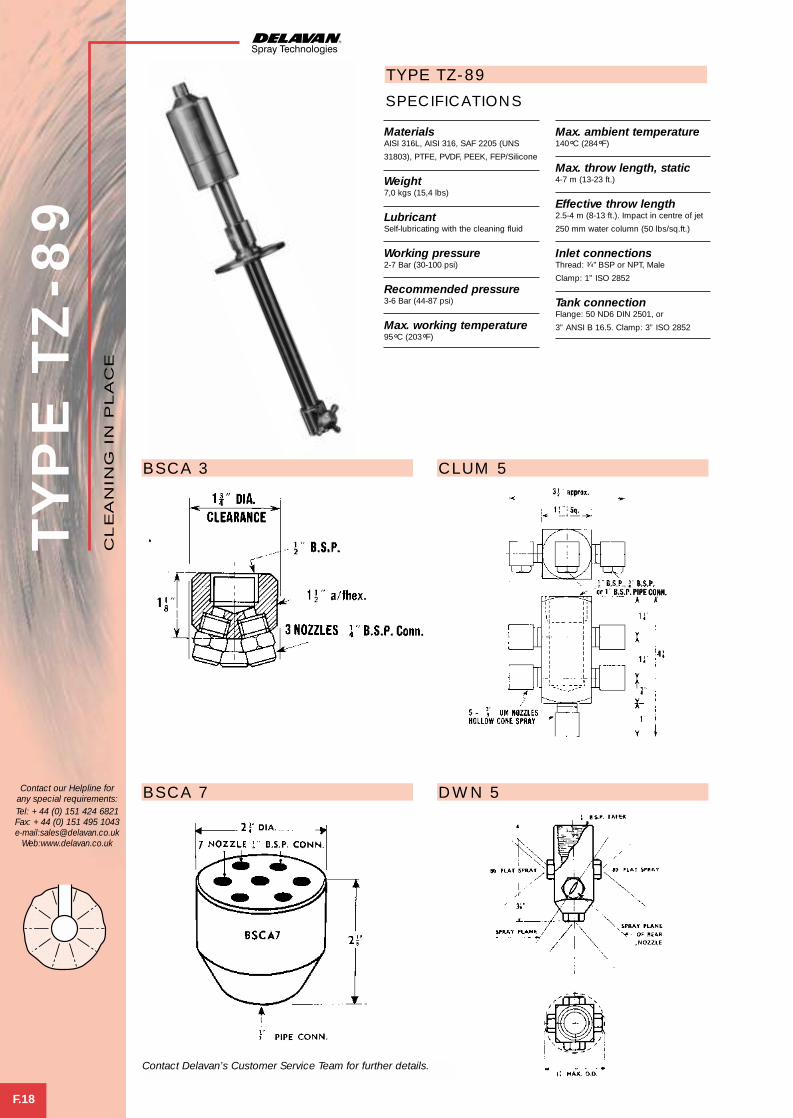
TYP
E T
Z-8
9
F.18
Contact our Helpline forany special requirements:Tel: +44 (0) 151 424 6821Fax: +44 (0) 151 495 1043e-mail:[email protected]
Web:www.delavan.co.uk
MaterialsAISI 316L, AISI 316, SAF 2205 (UNS
31803), PTFE, PVDF, PEEK, FEP/Silicone
Weight7,0 kgs (15,4 lbs)
LubricantSelf-lubricating with the cleaning fluid
Working pressure2-7 Bar (30-100 psi)
Recommended pressure3-6 Bar (44-87 psi)
Max. working temperature95°C (203°F)
Max. ambient temperature140°C (284°F)
Max. throw length, static4-7 m (13-23 ft.)
Effective throw length2.5-4 m (8-13 ft.). Impact in centre of jet
250 mm water column (50 lbs/sq.ft.)
Inlet connectionsThread: 3⁄4" BSP or NPT, Male
Clamp: 1” ISO 2852
Tank connectionFlange: 50 ND6 DIN 2501, or
3” ANSI B 16.5. Clamp: 3” ISO 2852
SPECIFICATIONS
TYPE TZ-89
BSCA 3 CLUM 5
BSCA 7 DWN 5
CL
EA
NIN
G I
N P
LA
CE
Contact Delavan’s Customer Service Team for further details.
cluster spray 2 4/5/01 5:56 pm Page 7

WELCOME TO DELAVAN
of newchallengesMeeting the
industriesand NEW markets
G Dela-Fit
DF
Del Nozzle A4 dividers A/W 21/6/01 10:37 am Page 13

Dela-Fit is a unique system of quick fitting nozzles of various spray types which allows connection to pipework without theuse of spanners.
Nozzle Spray Characteristics Spray Basic Features Flow Range. PageType Angles L/Min @ 3 Bar.G. No.DFAC 0° – 90° 3,93 – 79,07 G.1
DFAN 120° Nom. 3,94 – 78,9 G.2
DFAE 70° 2,4 – 79,0 G.3
DFAF 110° 2,4 – 79,0 G.4
DFTJ 35°,40°,50° 3,9 – 39 G.5
DFBI 47° – 86° 2,65 – 28,89 G.6
DFBN 85° – 128° 2,65 – 26,06 G.7
DFBQ 47° – 86° 2,65 – 28,89 G.8
DFBT 85° – 128° 2,65 – 26,06 G.9
DF – – G.10BODIES
AD – – G.10ADAPTORSFB CAPS – – G.11BODIESSEALS – – G.11
Uniform flat spray pattern with tapered edges.
Wide angle deflected flat spray with relativelyuniform distribution.
Uniformly distributed hollow cone spray withfine to coarse atomisation.
Uniformly distributed hollow cone spray withfine to coarse atomisation.
Evenly distributed deflected flat spray for lowpressure impact cleaning.
Uniformly distributed solid cone spray withfine to coarse atomisation.
Uniformly distributed solid cone spray withfine to coarse atomisation.
Uniformly distributed solid cone spray withfine to coarse atomisation.
Uniformly distributed solid cone spray withfine to coarse atomisation.
–
–
–
–
Standard and large nozzles with ‘chamfaloc’locking mechanism.
Standard and large nozzles with ‘chamfaloc’locking mechanism.
Standard and large nozzles with ‘chamfaloc’locking mechanism.
Standard and large nozzles with ‘chamfaloc’locking mechanism.
Standard and large nozzles with ‘chamfaloc’locking mechanism.
Standard and large nozzles with ‘chamfaloc’locking mechanism.
Standard and large nozzles with ‘chamfaloc’locking mechanism.
Standard and large nozzles with ‘chamfaloc’locking mechanism.
Standard and large nozzles with ‘chamfaloc’locking mechanism.
Standard and large mating bodies for nozzles with‘chamfaloc’ locking mechanism.
Standard and large adaptors to fit Dela-Fit bodiesto enable threaded nozzles to be used.
Mating bodies and caps with ‘chamfaloc’ lockingmechanism for use with standard flanged nozzles.
EPDM and Viton seals for standard and largeDela-Fit bodies and FB caps.
SE
CTIO
N IN
DE
X
Contact our Helpline forany special requirements:Tel: +44 (0) 151 424 6821Fax: +44 (0) 151 495 1043e-mail:[email protected]
Web:www.delavan.co.uk
DF
DE
LA
-FIT
Del Nozzle A4 dividers A/W 21/6/01 10:37 am Page 14

TYP
E D
FA
C
G.1
Contact our Helpline forany special requirements:Tel: +44 (0) 151 424 6821Fax: +44 (0) 151 495 1043e-mail:[email protected]
Web:www.delavan.co.uk
CAPACITY CHART
NOZZLE BODY SIZE* FLOW RATE IN LITRES/MIN AT Bar.G.NUMBER S L 0,7 1,0 2,0 3 5 7 10 15
DFAC 10 1,92 2,28 3,22 3,93 5,1 6,0 7,2 8,84
DFAC 15 2,84 3,44 4,92 6,16 7,9 9,2 10,7 13,2
DFAC 20 3,80 4,47 6,26 8,05 10,2 12,4 14,7 17,7
DFAC 25 4,60 5,80 8,00 9,95 13,0 15,1 18,3 22,3
DFAC 30 6,00 6,70 9,80 11,84 15,3 17,9 21,4 26,5
DFAC 40 7,80 9,40 13,00 15,62 20,8 24,3 28,6 35,4
DFAC 50 9,60 11,60 16,10 19,89 25,4 30,2 36,2 44,1
DFAC 60 11,40 13,90 19,20 23,67 30,5 36,2 43,4 52,9
DFAC 70 13,30 16,10 22,80 27,40 36,1 42,6 50,5 61,8
DFAC 80 15,10 18,80 25,50 31,72 41,2 48,1 57,2 70,6
DFAC 100 19,20 22,80 31,70 39,3 50,9 60,5 72,4 88,4
DFAC 120 22,90 27,30 38,90 47,34 61,1 72,4 86,3 106
DFAC 150 28,80 34,40 48,30 59,19 76,8 90,2 108 132
DFAC 200 38,00 48,70 64,40 79,07 102 120 144 175
SPRAY CHARACTERISTICS● Produces a uniform, flat spray pattern with soft tapered edges to allow
overlapping for even distribution.● Impact is generally greater with narrower spray angles assuming equal
flow rates.
CONSTRUCTION AND MATERIALS● Available spray angles of 0°, 15°, 25°, 40°, 50°, 65°, 80°, 90°.● Hexagonal one piece quick attach body.● Tapered inlet reduces wear and clogging.● Available in Brass and 316 Stainless Steel.
ORDER EXAMPLEDFAC 20-65° Brass.
*S = for use with 1⁄4” or 3⁄8” Dela-Fit Bodies. L = for use with 1⁄2” Dela-Fit Bodies.
DE
LA
-FIT
DFAC STANDARD DFAC LARGE
DIMENSIONS (mm)
Nozzle Size A B Hex
DFAC STANDARD 21,4 18,0
DFAC LARGE 25,6 25,7
DF
Delafit 1 4/5/01 6:40 pm Page 1
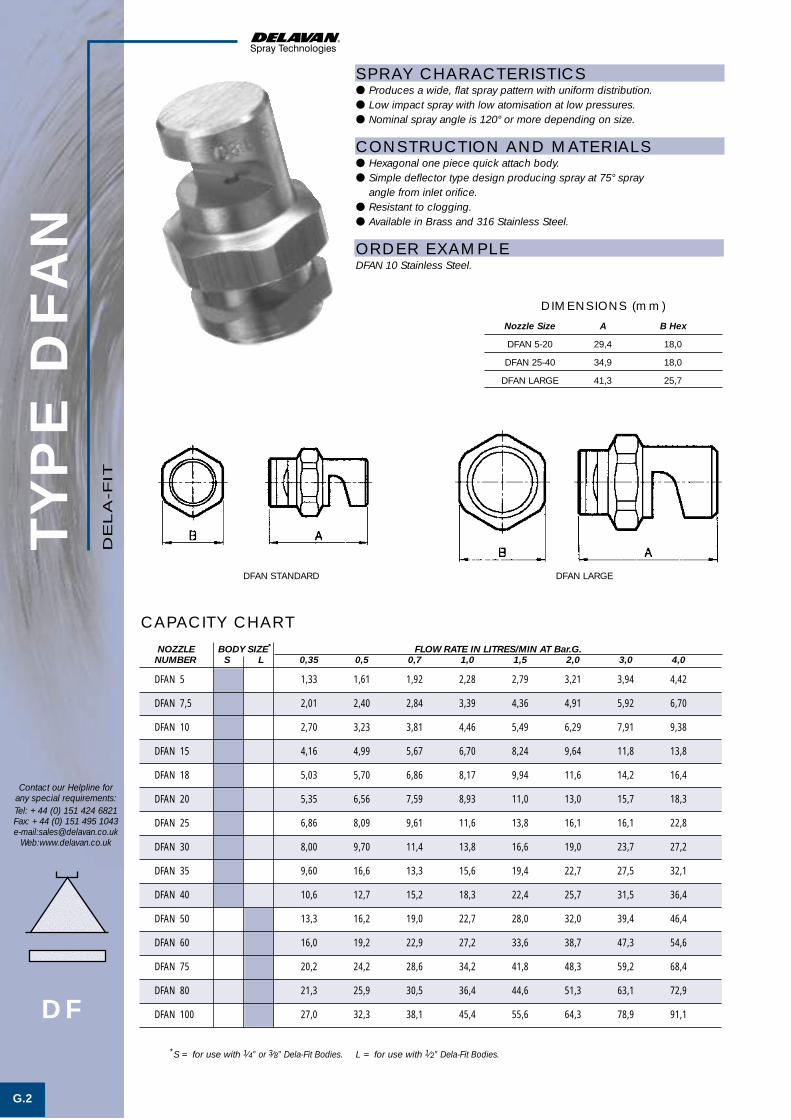
TYP
E D
FA
N
G.2
Contact our Helpline forany special requirements:Tel: +44 (0) 151 424 6821Fax: +44 (0) 151 495 1043e-mail:[email protected]
Web:www.delavan.co.uk
CAPACITY CHART
NOZZLE BODY SIZE* FLOW RATE IN LITRES/MIN AT Bar.G.NUMBER S L 0,35 0,5 0,7 1,0 1,5 2,0 3,0 4,0
DFAN 5 1,33 1,61 1,92 2,28 2,79 3,21 3,94 4,42
DFAN 7,5 2,01 2,40 2,84 3,39 4,36 4,91 5,92 6,70
DFAN 10 2,70 3,23 3,81 4,46 5,49 6,29 7,91 9,38
DFAN 15 4,16 4,99 5,67 6,70 8,24 9,64 11,8 13,8
DFAN 18 5,03 5,70 6,86 8,17 9,94 11,6 14,2 16,4
DFAN 20 5,35 6,56 7,59 8,93 11,0 13,0 15,7 18,3
DFAN 25 6,86 8,09 9,61 11,6 13,8 16,1 16,1 22,8
DFAN 30 8,00 9,70 11,4 13,8 16,6 19,0 23,7 27,2
DFAN 35 9,60 16,6 13,3 15,6 19,4 22,7 27,5 32,1
DFAN 40 10,6 12,7 15,2 18,3 22,4 25,7 31,5 36,4
DFAN 50 13,3 16,2 19,0 22,7 28,0 32,0 39,4 46,4
DFAN 60 16,0 19,2 22,9 27,2 33,6 38,7 47,3 54,6
DFAN 75 20,2 24,2 28,6 34,2 41,8 48,3 59,2 68,4
DFAN 80 21,3 25,9 30,5 36,4 44,6 51,3 63,1 72,9
DFAN 100 27,0 32,3 38,1 45,4 55,6 64,3 78,9 91,1
SPRAY CHARACTERISTICS● Produces a wide, flat spray pattern with uniform distribution.● Low impact spray with low atomisation at low pressures.● Nominal spray angle is 120° or more depending on size.
CONSTRUCTION AND MATERIALS● Hexagonal one piece quick attach body.● Simple deflector type design producing spray at 75° spray
angle from inlet orifice.● Resistant to clogging.● Available in Brass and 316 Stainless Steel.
ORDER EXAMPLEDFAN 10 Stainless Steel.
*S = for use with 1⁄4” or 3⁄8” Dela-Fit Bodies. L = for use with 1⁄2” Dela-Fit Bodies.
DE
LA
-FIT
DFAN LARGEDFAN STANDARD
DIMENSIONS (mm)
Nozzle Size A B Hex
DFAN 5-20 29,4 18,0
DFAN 25-40 34,9 18,0
DFAN LARGE 41,3 25,7
DF
Delafit 1 4/5/01 6:40 pm Page 2

TYP
E D
FA
E
G.3
Contact our Helpline forany special requirements:Tel: +44 (0) 151 424 6821Fax: +44 (0) 151 495 1043e-mail:[email protected]
Web:www.delavan.co.uk
CAPACITY CHARTNOZZLE BODY SIZE* FLOW RATE IN LITRES/MIN AT Bar.G.
NUMBER S L 0,7 1,0 2,0 3,0 4,0 5,0 6,0 7,0
DFAE 6 1,14 1,3 1,9 2,4 2,7 3,1 3,4 3,6
DFAE 10 1,92 2,3 3,2 3,9 4,6 5,1 5,6 6,0
DFAE 15 2,84 3,4 4,8 5,9 6,8 7,6 8,4 9,0
DFAE 20 3,80 4,5 6,4 7,9 9,1 10,2 11,2 12,1
DFAE 25 4,76 5,7 8,1 9,9 11,4 12,7 14,0 15,1
DFAE 30 5,72 6,9 9,7 11,8 13,7 15,3 16,8 18,1
DFAE 40 7,60 9,1 12,9 15,8 18,2 20,4 22,3 24,1
DFAE 50 9,51 11,4 16,1 19,7 22,8 25,5 27,9 30,2
DFAE 60 11,44 13,6 19,3 23,7 27,3 30,6 33,5 36,2
DFAE 80 15,23 18,2 25,8 31,6 36,5 40,8 44,7 48,2
DFAE 100 19,08 22,8 32,2 39,5 45,6 41,0 55,8 60,3
DFAE 125 23,84 28,5 40,3 49,4 57,0 63,7 69,8 75,4
DFAE 150 28,59 34,2 48,3 59,2 68,4 76,4 83,7 90,5
DFAE 200 38,16 45,6 64,5 79,0 91,2 102 112 122
*S = for use with 1⁄4” or 3⁄8” Dela-Fit Bodies. L = for use with 1⁄2” Dela-Fit Bodies.
SPRAY CHARACTERISTICS● Uniform hollow cone spray pattern.● Atomisation becomes finer at higher pressures.● Spray angle is 70°.
CONSTRUCTION AND MATERIALS● Right angle configuration, quick attach body with no internal vanes.● Unique swirl chamber with single inlet and large passageways to provide
a more uniform spray and to reduce chances of clogging.● Available in Brass and 316 Stainless Steel.
ORDER EXAMPLEDFAE 20 Brass.
DE
LA
-FIT
DFAE LARGEDFAE STANDARD
DIMENSIONS (mm)
Nozzle Size A B Sq
DFAE STANDARD 30,0 19,0
DFAE LARGE 36,5 25,4
DF
Delafit 1 4/5/01 6:40 pm Page 3

TYP
E D
FA
F
G.4
Contact our Helpline forany special requirements:Tel: +44 (0) 151 424 6821Fax: +44 (0) 151 495 1043e-mail:[email protected]
Web:www.delavan.co.uk
SPRAY CHARACTERISTICS● Uniform wide angle hollow cone spray pattern.● Atomisation becomes finer at higher pressures.● Spray angle is 110°.
CONSTRUCTION AND MATERIALS● Right angle configuration, quick attach body with no internal vanes.● Unique swirl chamber with single inlet and large passageways to provide
a more uniform spray and to reduce chances of clogging.● Available in Brass and 316 Stainless Steel.
ORDER EXAMPLEDFAF 50 Stainless Steel.
CAPACITY CHART
NOZZLE BODY SIZE* FLOW RATE IN LITRES/MIN AT Bar.G.NUMBER S L 0,7 1,0 2,0 3,0 4,0 5,0 6,0 7,0
DFAF 6 1,14 1,3 1,9 2,4 2,7 3,1 3,4 3,6
DFAF 10 1,92 2,3 3,2 3,9 4,6 5,1 5,6 6,0
DFAF 15 2,84 3,4 4,8 5,9 6,8 7,6 8,4 9,0
DFAF 20 3,80 4,5 6,4 7,9 9,1 10,2 11,2 12,1
DFAF 25 4,76 5,7 8,1 9,9 11,4 12,7 14,0 15,1
DFAF 30 5,72 6,9 9,7 11,8 13,7 15,3 16,8 18,1
DFAF 40 7,60 9,1 12,9 15,8 18,2 20,4 22,3 24,1
DFAF 50 9,51 11,4 16,1 19,7 22,8 25,5 27,9 30,2
DFAF 60 11,44 13,6 19,3 23,7 27,3 30,6 33,5 36,2
DFAF 80 15,23 18,2 25,8 31,6 36,5 40,8 44,7 48,2
DFAF 100 19,08 22,8 32,2 39,5 45,6 41,0 55,8 60,3
DFAF 125 23,84 28,5 40,3 49,4 57,0 63,7 69,8 75,4
DFAF 150 28,59 34,2 48,3 59,2 68,4 76,4 83,7 90,5
DFAF 200 38,16 45,6 64,5 79,0 91,2 102 112 122
*S = for use with 1⁄4” or 3⁄8” Dela-Fit Bodies. L = for use with 1⁄2” Dela-Fit Bodies.
DE
LA
-FIT
DFAF LARGEDFAF STANDARD
DIMENSIONS (mm)
Nozzle Size A B Sq
DFAF STANDARD 30,0 19,0
DFAF LARGE 36,5 25,4
DF
Delafit 1 4/5/01 6:41 pm Page 4

TYP
E D
FTJ
G.5
Contact our Helpline forany special requirements:Tel: +44 (0) 151 424 6821Fax: +44 (0) 151 495 1043e-mail:[email protected]
Web:www.delavan.co.uk
CAPACITY CHART
SPRAY CHARACTERISTICS● Flat, high impact spray pattern.
CONSTRUCTION AND MATERIALS● Circular orifice with tapered inlet to reduce plugging.● Maximum impact for any given pressure due to deflector design.● Available in Brass and 316 Stainless Steel.
ORDER EXAMPLEDFTJ 50-40° Brass.
NOZZLE BODY SIZE* SPRAY ANGLES (°) FLOW RATE IN LITRES/MIN AT Bar.G.NUMBER S L 35 40 50 1 1,5 2 3 4 5 7
DFTJ 10 2,3 2,25 3,2 3,9 4,5 5,0 6,00
DFTJ 20 4,5 5,5 6,4 7,8 9,0 10,0 11,9
DFTJ 25 5,6 6,9 8,0 9,8 11,3 12,6 14,9
DFTJ 30 6,8 8,30 9,6 11,7 13,5 15,1 17,9
DFTJ 40 9,0 11,0 12,8 15,6 18,0 20,0 24,0
DFTJ 50 11,3 14,0 16,0 19,5 23,0 25 30,0
DFTJ 60 13,5 16,5 19,2 23 27 30 36,00
DFTJ 80 18,1 22,0 26 31 36 40 48,00
DFTJ 100 23,0 27,5 32 39 45 50 60,00
*S = for use with 1⁄4” or 3⁄8” Dela-Fit Bodies. L = for use with 1⁄2” Dela-Fit Bodies.
DE
LA
-FIT
DFTJ LARGE
DFTJ STANDARD
DIMENSIONS (mm)
Nozzle Size A B Sq
DFTJ 10 31,0 15,9
DFTJ 20-40 73,0 25,4
DFTJ 50-60 72,2 25,4
DFTJ 80-100 88,9 31,8
DF
Delafit 1 4/5/01 6:41 pm Page 5
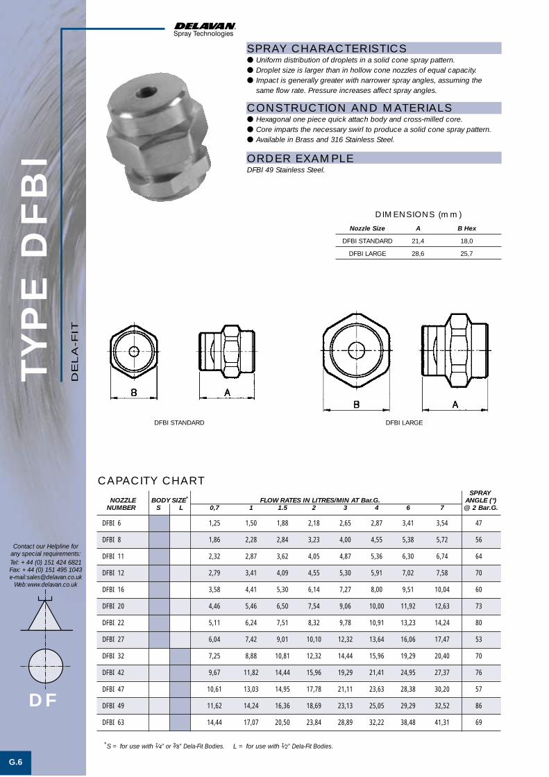
TYP
E D
FB
I
G.6
Contact our Helpline forany special requirements:Tel: +44 (0) 151 424 6821Fax: +44 (0) 151 495 1043e-mail:[email protected]
Web:www.delavan.co.uk
CAPACITY CHART
SPRAY CHARACTERISTICS● Uniform distribution of droplets in a solid cone spray pattern.● Droplet size is larger than in hollow cone nozzles of equal capacity.● Impact is generally greater with narrower spray angles, assuming the
same flow rate. Pressure increases affect spray angles.
CONSTRUCTION AND MATERIALS● Hexagonal one piece quick attach body and cross-milled core.● Core imparts the necessary swirl to produce a solid cone spray pattern.● Available in Brass and 316 Stainless Steel.
ORDER EXAMPLEDFBI 49 Stainless Steel.
SPRAYNOZZLE BODY SIZE* FLOW RATES IN LITRES/MIN AT Bar.G. ANGLE (°)
NUMBER S L 0,7 1 1.5 2 3 4 6 7 @ 2 Bar.G.
DFBI 6 1,25 1,50 1,88 2,18 2,65 2,87 3,41 3,54 47
DFBI 8 1,86 2,28 2,84 3,23 4,00 4,55 5,38 5,72 56
DFBI 11 2,32 2,87 3,62 4,05 4,87 5,36 6,30 6,74 64
DFBI 12 2,79 3,41 4,09 4,55 5,30 5,91 7,02 7,58 70
DFBI 16 3,58 4,41 5,30 6,14 7,27 8,00 9,51 10,04 60
DFBI 20 4,46 5,46 6,50 7,54 9,06 10,00 11,92 12,63 73
DFBI 22 5,11 6,24 7,51 8,32 9,78 10,91 13,23 14,24 80
DFBI 27 6,04 7,42 9,01 10,10 12,32 13,64 16,06 17,47 53
DFBI 32 7,25 8,88 10,81 12,32 14,44 15,96 19,29 20,40 70
DFBI 42 9,67 11,82 14,44 15,96 19,29 21,41 24,95 27,37 76
DFBI 47 10,61 13,03 14,95 17,78 21,11 23,63 28,38 30,20 57
DFBI 49 11,62 14,24 16,36 18,69 23,13 25,05 29,29 32,52 86
DFBI 63 14,44 17,07 20,50 23,84 28,89 32,22 38,48 41,31 69
*S = for use with 1⁄4” or 3⁄8” Dela-Fit Bodies. L = for use with 1⁄2” Dela-Fit Bodies.
DE
LA
-FIT
DF
DFBI LARGEDFBI STANDARD
DIMENSIONS (mm)
Nozzle Size A B Hex
DFBI STANDARD 21,4 18,0
DFBI LARGE 28,6 25,7
Delafit 1 4/5/01 6:41 pm Page 6

TYP
E D
FB
N
G.7
Contact our Helpline forany special requirements:Tel: +44 (0) 151 424 6821Fax: +44 (0) 151 495 1043e-mail:[email protected]
Web:www.delavan.co.uk
SPRAY CHARACTERISTICS● Uniform distribution of droplets in a wide angle solid cone spray pattern.● Droplet size is larger than in hollow cone nozzles of equal capacity.● Pressure increases affect spray angles.
CONSTRUCTION AND MATERIALS● Hexagonal one piece quick attach body and cross-milled core.● Core imparts the necessary swirl to produce a solid cone spray pattern.● Available in Brass and 316 Stainless Steel.
ORDER EXAMPLEDFBN 59 Stainless Steel.
CAPACITY CHARTSPRAY
NOZZLE BODY SIZE* FLOW RATE IN LITRES/MIN AT Bar.G. ANGLE (°)NUMBER S L 0,7 1 1,5 2 3 4 6 7 @ 2 Bar.G.
DFBN 6 1,25 1,50 1,88 2,18 2,65 2,87 3,41 3,54 85
DFBN 8 1,86 2,28 2,84 3,23 4,00 4,55 5,38 5,72 95
DFBN 11 2,79 3,23 3,86 4,31 5,15 5,45 6,73 7,34 120
DFBN 15 3,67 4,50 5,26 5,59 6,64 7,24 8,70 9,16 110
DFBN 18 4,40 5,39 6,30 6,70 7,96 8,68 10,43 10,98 120
DFBN 22 5,58 6,84 8,0 8,50 10,10 11,01 13,23 13,94 110
DFBN 25 6,04 7,24 8,43 9,32 11,01 12,32 14,65 15,76 120
DFBN 32 7,70 9,15 10,80 11,92 14,30 15,78 18,90 19,90 110
DFBN 39 9,40 11,15 13,14 14,52 17,40 19,20 23,00 24,25 120
DFBN 46 11,62 13,64 15,86 17,27 19,29 22,32 25,45 27,88 112
DFBN 48 12,52 15,25 16,87 18,18 23,13 24,54 29,80 32,52 120
DFBN 59 13,23 15,96 19,29 22,32 26,06 28,18 34,64 37,67 128
*S = for use with 1⁄4” or 3⁄8” Dela-Fit Bodies. L = for use with 1⁄2” Dela-Fit Bodies.
DE
LA
-FIT
DF
DFBN LARGEDFBN STANDARD
DIMENSIONS (mm)
Nozzle Size A B Hex
DFBN STANDARD 21,4 18,0
DFBN LARGE 28,6 25,7
Delafit 1 4/5/01 6:41 pm Page 7

TYP
E D
FB
Q
G.8
Contact our Helpline forany special requirements:Tel: +44 (0) 151 424 6821Fax: +44 (0) 151 495 1043e-mail:[email protected]
Web:www.delavan.co.uk
CAPACITY CHARTSPRAY
NOZZLE BODY SIZE* FLOW RATE IN LITRES/MIN AT Bar.G. ANGLE (°)NUMBER S L 0,7 1 1,5 2 3 4 6 7 @ 2 Bar.G.
DFBQ 6 1,25 1,50 1,88 2,18 2,65 2,87 3,41 3,54 47
DFBQ 8 1,86 2,28 2,84 3,23 4,00 4,55 5,38 5,72 56
DFBQ 11 2,32 2,87 3,62 4,05 4,87 5,36 6,30 6,74 64
DFBQ 12 2,79 3,41 4,09 4,55 5,30 5,91 7,02 7,58 70
DFBQ 16 3,58 4,41 5,30 6,14 7,27 8,00 9,51 10,04 60
DFBQ 20 4,46 5,46 6,50 7,54 9,06 10,00 11,92 12,63 73
DFBQ 22 5,11 6,24 7,51 8,32 9,78 10,91 13,23 14,24 80
DFBQ 27 6,04 7,42 9,01 10,10 12,32 13,64 16,06 17,47 53
DFBQ 32 7,25 8,88 10,81 12,32 14,44 15,96 19,29 20,40 70
DFBQ 42 9,67 11,82 14,44 15,96 19,29 21,41 24,95 27,37 76
DFBQ 47 10,61 13,03 14,95 17,78 21,11 23,63 28,38 30,20 57
DFBQ 49 11,62 14,24 16,36 18,69 23,13 25,05 29,29 32,52 86
DFBQ 63 14,44 17,07 20,50 23,84 28,89 32,22 38,48 41,31 69
*S = for use with 1⁄4” or 3⁄8” Dela-Fit Bodies. L = for use with 1⁄2” Dela-Fit Bodies.
SPRAY CHARACTERISTICS● Uniform distribution of droplets in a solid cone square shaped
spray pattern.● Droplet size is larger than in hollow cone nozzles of equal capacity.● Impact is generally greater with narrower spray angles, assuming the
same flow rate. Pressure increases affect spray angles.
CONSTRUCTION AND MATERIALS● Hexagonal one piece quick attach body and cross-milled core.● Core imparts the necessary swirl to produce a solid spray pattern.● Available in Brass and 316 Stainless Steel.
ORDER EXAMPLEDFBQ 16 Brass.
DE
LA
-FIT
DFBQ LARGEDFBQ STANDARD
DIMENSIONS (mm)
Nozzle Size A B Hex
DFBQ STANDARD 21,4 18,0
DFBQ LARGE 28,6 25,7
DF
Delafit 1 4/5/01 6:41 pm Page 8

TYP
E D
FB
T
G.9
Contact our Helpline forany special requirements:Tel: +44 (0) 151 424 6821Fax: +44 (0) 151 495 1043e-mail:[email protected]
Web:www.delavan.co.uk
SPRAY CHARACTERISTICS● Uniform distribution of droplets in a wide angle solid cone square
shaped spray pattern.● Droplet size is larger than in hollow cone nozzles of equal capacity.● Pressure increases affect spray angles.
CONSTRUCTION AND MATERIALS● Hexagonal one piece quick attach body and cross-milled core.● Core imparts the necessary swirl to produce a solid spray pattern.● Available in Brass and 316 Stainless Steel.
ORDER EXAMPLEDFBT 25 Brass.
CAPACITY CHARTSPRAY
NOZZLE BODY SIZE* FLOW RATE IN LITRES/MIN AT Bar.G. ANGLE (°)NUMBER S L 0,7 1 1.5 2 3 4 6 7 @ 2 Bar.G.
DFBT 6 1,25 1,50 1,88 2,18 2,65 2,87 3,41 3,54 85
DFBT 8 1,86 2,28 2,84 3,23 4,00 4,55 5,38 5,72 95
DFBT 11 2,79 3,23 3,86 4,31 5,15 5,45 6,73 7,34 120
DFBT 15 3,67 4,50 5,26 5,59 6,64 7,24 8,70 9,16 110
DFBT 18 4,40 5,39 6,30 6,70 7,96 8,68 10,43 10,98 120
DFBT 22 5,58 6,84 8,0 8,50 10,10 11,01 13,23 13,94 110
DFBT 25 6,04 7,24 8,43 9,32 11,01 12,32 14,65 15,76 120
DFBT 32 7,70 9,15 10,80 11,92 14,30 15,78 18,90 19,90 110
DFBT 39 9,40 11,15 13,14 14,52 17,40 19,20 23,00 24,25 120
DFBT 46 11,62 13,64 15,86 17,27 19,29 22,32 25,45 27,88 112
DFBT 48 12,52 15,25 16,87 18,18 23,13 24,54 29,80 32,52 120
DFBT 59 13,23 15,96 19,29 22,32 26,06 28,18 34,64 37,67 128
*S = for use with 1⁄4” or 3⁄8” Dela-Fit Bodies. L = for use with 1⁄2” Dela-Fit Bodies.
DE
LA
-FIT
DF
DFBT LARGEDFBT STANDARD
DIMENSIONS (mm)
Nozzle Size A B Hex
DFBT STANDARD 21,4 18,0
DFBT LARGE 28,6 25,7
Delafit 1 4/5/01 6:41 pm Page 9

TYP
E D
F / A
D
G.10
Contact our Helpline forany special requirements:Tel: +44 (0) 151 424 6821Fax: +44 (0) 151 495 1043e-mail:[email protected]
Web:www.delavan.co.uk
CHARACTERISTICS● Dela-Fit bodies are designed to accept any tip from the Dela-Fit range as
well as any of the threaded adaptors.
CONSTRUCTION AND MATERIALS● 1⁄4”, 3⁄8” and DFW Welding bodies are for nozzles designated ‘S’ in the
nozzle size chart. 1⁄2” bodies are for nozzles designated ‘L’.● EPDM Seals are Standard, Viton optional.● Threaded bodies available in Brass and 316 Stainless Steel.● Welding nipples available in 316 Stainless Steel and Mild Steel.● Thread sizes are Male BSPT and Female BSPP.
DF BODIES
Body Type A B Hex1⁄4” DFM (Male) 28,6 20,8
3⁄8” DFM (Male) 28,6 20,8
1⁄2” DFM (Male) 36,5 28,0
1⁄4” DFF (Female) 30,7 20,8
3⁄8” DFF (Female) 31,0 20,8
1⁄2” DFF (Female) 34,9 28,0
DFW (Welding) 19,0 20,8
1⁄2” DFF (Welding) 25,4 28,0
DIMENSIONS (mm)
CHARACTERISTICS● Adapts standard threaded nozzles, hose fittings or accessories to the
Dela-Fit system.● Can function as quick release couplings.
CONSTRUCTION AND MATERIALS● Available in Brass and 316 Stainless Steel.● Thread sizes are Male BSPT and Female BSPP.
AD ADAPTORS
Adaptor Type A B Hex
DF x 1⁄4” ADM (Male) 30,4 18,0
DF x 3⁄8” ADM (Male) 30,4 18,0
1⁄2” DF x 1⁄2” ADM (Male) 38,0 28,0
DF x 1⁄4” ADF (Female) 23,2 18,0
DF x 3⁄8” ADF (Female) 26,2 20,8
1⁄2” DF x 1⁄2” ADF (Female) 30,5 28,0
DIMENSIONS (mm)
DE
LA
-FIT
DF
DFM BODY DFF BODY DFW BODY
DFM ADAPTOR DFF ADAPTOR
Delafit 1 4/5/01 6:42 pm Page 10
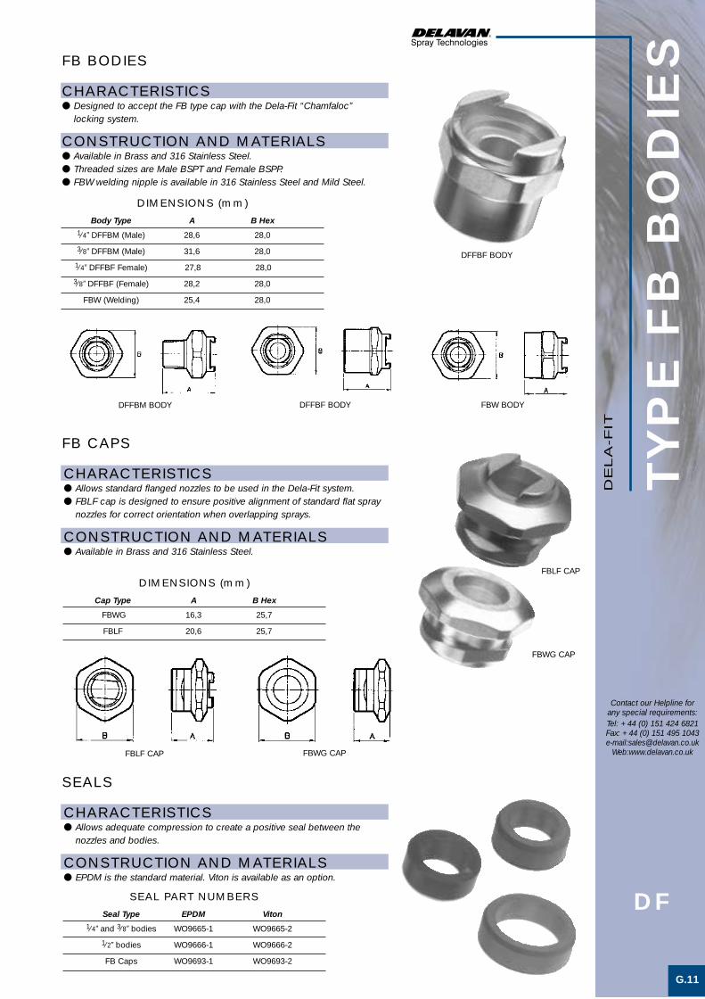
TYP
E F
B B
OD
IES
G.11
Contact our Helpline forany special requirements:Tel: +44 (0) 151 424 6821Fax: +44 (0) 151 495 1043e-mail:[email protected]
Web:www.delavan.co.uk
CHARACTERISTICS● Designed to accept the FB type cap with the Dela-Fit “Chamfaloc”
locking system.
CONSTRUCTION AND MATERIALS● Available in Brass and 316 Stainless Steel.● Threaded sizes are Male BSPT and Female BSPP.● FBW welding nipple is available in 316 Stainless Steel and Mild Steel.
FB BODIES
CHARACTERISTICS● Allows standard flanged nozzles to be used in the Dela-Fit system.● FBLF cap is designed to ensure positive alignment of standard flat spray
nozzles for correct orientation when overlapping sprays.
CONSTRUCTION AND MATERIALS● Available in Brass and 316 Stainless Steel.
FB CAPS
CHARACTERISTICS● Allows adequate compression to create a positive seal between the
nozzles and bodies.
CONSTRUCTION AND MATERIALS● EPDM is the standard material. Viton is available as an option.
SEALS
Body Type A B Hex1⁄4” DFFBM (Male) 28,6 28,0
3⁄8” DFFBM (Male) 31,6 28,0
1⁄4” DFFBF Female) 27,8 28,0
3⁄8” DFFBF (Female) 28,2 28,0
FBW (Welding) 25,4 28,0
DIMENSIONS (mm)
Cap Type A B Hex
FBWG 16,3 25,7
FBLF 20,6 25,7
DIMENSIONS (mm)
Seal Type EPDM Viton1⁄4” and 3⁄8” bodies WO9665-1 WO9665-2
1⁄2” bodies WO9666-1 WO9666-2
FB Caps WO9693-1 WO9693-2
SEAL PART NUMBERS
DE
LA
-FIT
DF
DFFBM BODY DFFBF BODY FBW BODY
FBLF CAP FBWG CAP
DFFBF BODY
FBLF CAP
FBWG CAP
Delafit 1 4/5/01 6:42 pm Page 11

WELCOME TO DELAVAN
of newchallengesMeeting the
industriesand NEW markets
H Airless
Del Nozzle A4 dividers A/W 21/6/01 10:37 am Page 15

Nozzle Spray Characteristics Spray Basic Features Flow Range. PageType Angles L/Min @ 70 Bar.G. No.
AIRLESS 15° – 110° 0,076 – 21,6 H.1TIP
PRE- 0° – H.2ORIFICE
TURNAFLO – – H.3
TURNATIP – 0,076 – 21,6 H.4KITAIR 15° – 110° 0,076 – 21,6 H.5
ASSISTED
Uniform flat spray pattern with tapered edgesand fine atomisation.
Metering orifice to improve spray quality ofairless tips.
–
Uniform flat spray pattern with tapered edgesand fine atomisation.
Uniform flat spray pattern with tapered edgesand fine atomisation.
Flanged tip design for use with standardhandguns.
Flat disc for use with airless tips and standardhandguns.
High pressure adaptor for use with Turnatips.Rotates through 180° for ease of tip cleaning.
Insert assembly designed to fit the Turnaflo unit.
Flanged tip designs for use with special airassisted handguns.
AIR
LE
SS
SE
CTIO
N IN
DE
X
Contact our Helpline forany special requirements:Tel: +44 (0) 151 424 6821Fax: +44 (0) 151 495 1043e-mail:[email protected]
Web:www.delavan.co.uk
These units are purposely designed items for use in paint spraying and coating applications. Additional specialpurpose air assisted tips are also shown for reference.
Del Nozzle A4 dividers A/W 21/6/01 10:37 am Page 16

H.1
Contact our Helpline forany special requirements:Tel: +44 (0) 151 424 6821Fax: +44 (0) 151 495 1043e-mail:[email protected]
Web:www.delavan.co.uk
AIR
LE
SS
TIP
S
CAPACITY CHART
FEATURES● Delavan Carbide Tips are specifically designed and tested for all airless
paint spraying applications.● Design and manufacturing techniques used on the Delavan Airless Tips
are based specifically on the industry’s need for high performancestandards using viscous materials etc.
● Carbide Tips are being used on all types of airless equipment andapplications. Continued research assures all users of quality unsurpassedin the industry.
● The Carbide Tip material selected for use is the highest quality, wearresistant material now available.
● Every Airless Tip is checked to ensure calibration, and all other designfeatures are achieved on every Tip before leaving the factory.
SELECTION GUIDE● Airless Tip orifices are elliptical in shape. The term “equivalent orifice
diameter” refers to a circular orifice diameter which will provide the sameflow rates as the elliptical orifice. The equivalent orifice diameter does notindicate the actual orifice dimensions.
● The flow rates of Delavan Airless Tips are given in US GPM based onwater at the pressures shown. Capacities would vary to some degree on other liquids.
● The pattern width dimension is the nominal pattern width of each AirlessTip when tested on a coating material of 20 seconds - # 4 Zahn cupviscosity at 1500 PSI at a distance of 12” from the Tip.
● Maximum design pressure is 500 Bar.G.
EQUIV. PATTERN FLOW RATE IN US GPM PRE-TIP ORIF. WIDTH AT PSIG PRESSURE ORIFICE
NUMBER (Inches) (Inches) 500 1000 1500 2000 DISC NO.
C515 3
C525 0,005 5 0,015 0,02 0,025 0,03 9
C540 7
C715 3
C725 0,007 5 0,03 0,04 0,05 0,06 9
C735 6
C740 7
C915 3
C925 5,5
C940 0,009 7 0,04 0,06 0,067 0,08 9
C950 8,5
C965 10
C1115 3
C1125 5,5
C1140 7 11
C1150 0,011 8,5 0,06 0,08 0,10 0,12 OR
C1165 10 13
C1180 11,5
C1315 3
C1325 5,5
C1340 8
C1350 0,013 9 0,09 0,12 0,15 0,18 16
C1365 11
C1380 13
C1395 14
C1515 4
C1525 6
C1540 8
C1550 0,15 10 0,12 0,16 0,20 0,23 16
C1565 12
C1580 14
C1595 15,5
EQUIV. PATTERN FLOW RATE IN US GPM PRE-TIP ORIF. WIDTH AT PSIG PRESSURE ORIFICE
NUMBER (Inches) (Inches) 500 1000 1500 2000 DISC NO.
C1615 4
C1625 6
C1640 8
C1650 0,016 10 0,14 0,19 0,24 0,28 20
C1665 12
C1673 14
C1680 15
C1695 17
C1825 6
C1840 8,5
C1850 0,018 10 0,18 0,25 0,30 0,36 20
C1865 13
C1880 15
C1895 17
C2025 6
C2040 8,5
C2050 10
C2060 0,020 12 0,20 0,28 0,35 0,40 25
C2065 14
C2080 16
C2095 18
C2125 6
C2140 8,5
C2150 0,021 11,5 0,24 0,33 0,41 0,47 25
C2165 15
C2180 17
C2195 19
C2425 7
C2440 9
C2450 12
C2465 0,024 15 0,30 0,42 0,52 0,60 25
C2473 17
C2480 18,5
C2495 21
AIR
LE
SS
Continued on page H.2
Airless 1 4/5/01 6:44 pm Page 1

AIR
LE
SS
TIP
S
H.2
Contact our Helpline forany special requirements:Tel: +44 (0) 151 424 6821Fax: +44 (0) 151 495 1043e-mail:[email protected]
Web:www.delavan.co.uk
CAPACITY CHART (CONT.)EQUIV. PATTERN FLOW RATE IN US GPM PRE-
TIP ORIF. WIDTH AT PSIG PRESSURE ORIFICENUMBER (Inches) (Inches) 500 1000 1500 2000 DISC NO.
C2625 7
C2640 9
C2650 0,026 12 0,35 0,50 0,61 0,71 28
C2665 15
C2680 18,5
C2695 21
C2925 7
C2940 9
C2950 12
C2965 0,029 15 0,45 0,63 0,80 0,90 31
C2973 17
C2980 18,5
C2995 21,5
C3140 9
C3150 12
C3165 0,031 15 0,53 0,75 0,92 1,1 39
C3180 18,5
C3195 21,5
EQUIV. PATTERN FLOW RATE IN US GPM PRETIP ORIF. WIDTH AT PSIG PRESSURE ORIFICE
NUMBER (Inches) (Inches) 500 1000 1500 2000 DISC NO.
C3640 9
C3650 12
C3665 0,036 15 0,71 1,0 1,2 1,4 39
C3680 18,5
C3695 21,5
C4195 0,041 21,5 0,88 1,2 1,5 1,8 45
C4340 9
C4350 12
C4365 0,043 15 1,1 1,5 1,8 2,1 45
C4380 18,5
C4395 21,5
C4880 0,048 18,5 1,2 1,7 2,1 2,5 55
C4895 22
C5240 0,052 9 1,4 2,0 2,4 2,8 55
C5265 15
C6240 0,062 9 2,1 3,0 3,7 4,2 65
C6265 15
C7265 0,072 15 2,8 4,0 4,9 5,7 76
C8565 0,085 15 4,1 5,7 6,7 8,1 76
PRE-ORIFICE DISCS● The spray quality of most airless tips can be improved with the use of a
Delavan Pre-Orifice Disc.● Applications previously considered impractical can now be handled by
adding a Delavan Pre-Orifice.● Substantially lower operating pressures can be used without sacrificing
spray quality.● Larger Airless Tip sizes may be used at lower pressures, resulting in low
flow rates without clogging.● The Pre-Orifice Disc, which is easily installed directly behind the Airless
Tip, also serves as a seal, eliminating the need for a separate gasket.● Pre-Orifice Discs are constructed with a Carbide insert mounted in a
Stainless Steel housing.● Refer to the above chart and that on page H.1 to obtain the recommended
Pre-Orifice Disc size.
AIR
LE
SS
DISC NO. 9 11 13 16 20 25 28 31 39 45 55 65 76
ORIFICE DIA. 0,009 0,011 0,013 0,016 0,020 0,025 0,028 0,031 0,039 0,045 0,055 0,065 0,076
(inches)
ORIFICE DIMENSIONS
Airless 1 4/5/01 6:44 pm Page 2

ITEM DESCRIPTION PART NUMBER
1 Nut W01744
2 Nut Washer W01741
3 Handle W01468
4 Handle Washer W01563
5 Body W01561
6 Drive Shank Washer W01564
7 Drive Shank W01560
8 Ball W01482
9 Ball Gasket W01086
10 Nu-lip Seal W00075
ITEM DESCRIPTION PART NUMBER
11 Locknut W00916
12 Seal-Retainer W00915
13 Cap See Table Below
14 Connecting Piece W00747
15 Gasket See Table Below
16 Turnatip Kit See Page H.4
17 Safety Guard W05758
18 Seal Kit 4600 SK*19 Ball and Seal Kit 4600 BSK*
TU
RN
AFLO
H.3
Parts List
Parts List
FEATURES● The Delavan Turnaflo adaptor provides a quick and easy method for
removal of particles blocking the spray tip during operation.● When spray tip is blocked, turn handle 180°. Flow then reverses through
spray tip and flushes out foreign matter.● Maximum recommended pressure is 4000 PSIG (275 Bar.G.)
Contact our Helpline forany special requirements:Tel: +44 (0) 151 424 6821Fax: +44 (0) 151 495 1043e-mail:[email protected]
Web:www.delavan.co.uk
TURNAFLO SREW CAP GUN SEALINGPART NUMBER TO FIT GUN TYPE SCREW CAP THREAD PART NUMBER GASKET
4500 - AG Speeflo 3/8” NPS W00056 W06428
4500 - AG Kremlin 3/8” NPS W00056 W06428
4500 - AG Nordson 3/8” NPS W00056 W06428
4500 - AG De Vilbiss 3/8” NPS W00056 W06428
4510 - AG Graco* 11/16” x 16 UN W00057 W06428
4510 - AG Alemite 11/16” x 16 UN W00057 W06428
4510 - AG S.S. Co. 24-A & 25A 11/16” x 16 UN W00057 W06428
4510 - AG Wagner Super G15 11/16” x 16 UN W00057 W06428
4510 - AG Rexson 11/16” x 16 UN W00057 W06428
4510 - AG Binks 43 11/16” x 16 UN W00057 W06428
4520 - AG Blinks 50 3/4” x 20 UNEF W00058 W01776
4530 - AG Graco** 7/8” x 14 NF W00059 W00064
4540 - AG S.S. Co. 44A 1” x 14 NF W00060 W00079
4550 - AG Atlas Copco M18 x 1 W01684 W06428
4550 - AG Bede M18 x 1 W01684 W06428
4550 - AG Kopperschmidt M18 x 1 W01684 W06428
4560 - AG Iwata M18 x 1 W01684 W00063
4570 - AG Aro 651-516 11/16” x 16 UN W00697 W06428
4580 - AG - 5/8” BSPP W01324 W00064
4590 - AG - M18 x 1,5 W15151 W06428
AIR
LE
SS
* Not illustrated.
TURNAFLO SELECTION GUIDE
* Attach Turnaflo after removing Airless Tip retaining nut only.** Attach Turnaflo after removing filter retainer.
1
2
3
417
6
7
5
8
9
16
1011 12 13
14 15
Airless 1 4/5/01 6:45 pm Page 3
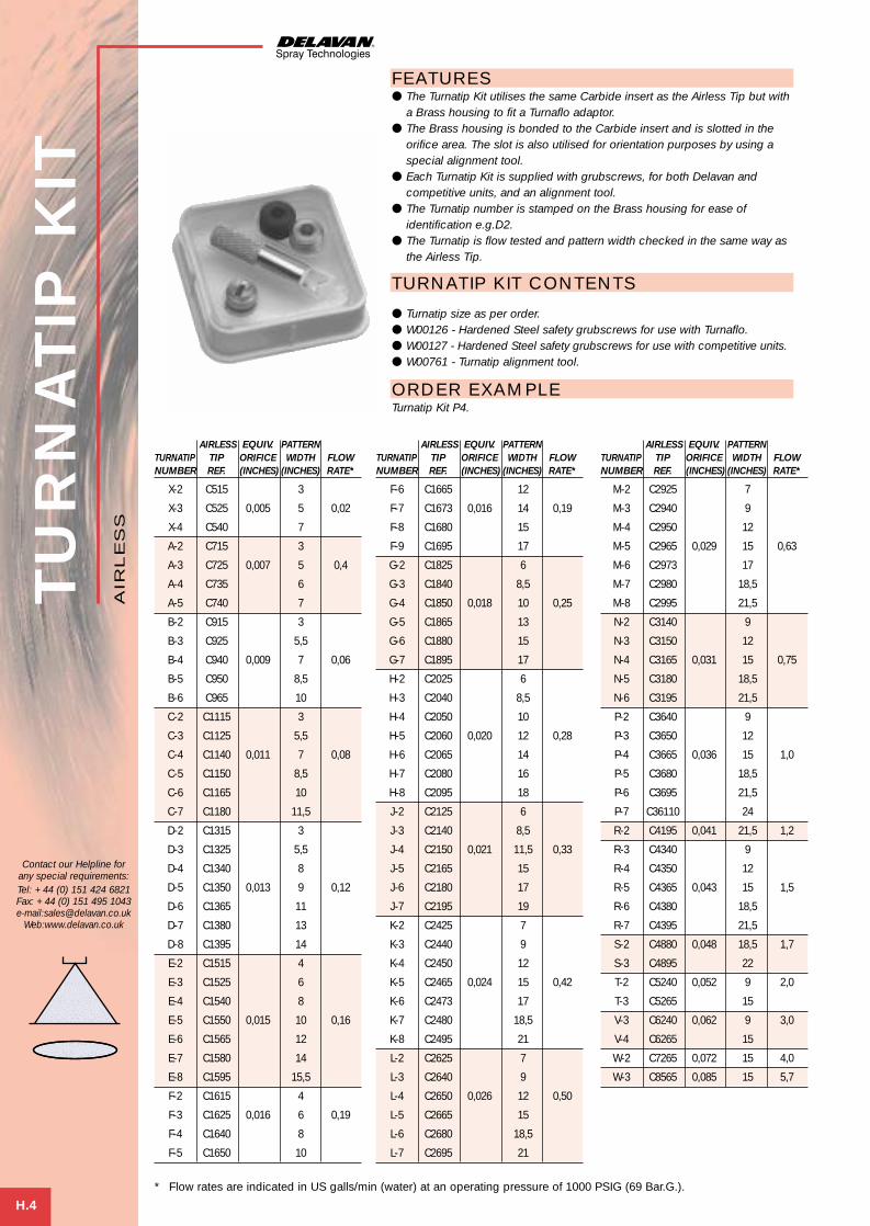
TU
RN
ATIP
KIT
H.4
FEATURES● The Turnatip Kit utilises the same Carbide insert as the Airless Tip but with
a Brass housing to fit a Turnaflo adaptor.● The Brass housing is bonded to the Carbide insert and is slotted in the
orifice area. The slot is also utilised for orientation purposes by using aspecial alignment tool.
● Each Turnatip Kit is supplied with grubscrews, for both Delavan andcompetitive units, and an alignment tool.
● The Turnatip number is stamped on the Brass housing for ease ofidentification e.g.D2.
● The Turnatip is flow tested and pattern width checked in the same way asthe Airless Tip.
TURNATIP KIT CONTENTS
● Turnatip size as per order.● W00126 - Hardened Steel safety grubscrews for use with Turnaflo.● W00127 - Hardened Steel safety grubscrews for use with competitive units.● W00761 - Turnatip alignment tool.
ORDER EXAMPLETurnatip Kit P4.
Contact our Helpline forany special requirements:Tel: +44 (0) 151 424 6821Fax: +44 (0) 151 495 1043e-mail:[email protected]
Web:www.delavan.co.uk
AIRLESS EQUIV. PATTERNTURNATIP TIP ORIFICE WIDTH FLOWNUMBER REF. (INCHES) (INCHES) RATE*
X-2 C515 3
X-3 C525 0,005 5 0,02
X-4 C540 7
A-2 C715 3
A-3 C725 0,007 5 0,4
A-4 C735 6
A-5 C740 7
B-2 C915 3
B-3 C925 5,5
B-4 C940 0,009 7 0,06
B-5 C950 8,5
B-6 C965 10
C-2 C1115 3
C-3 C1125 5,5
C-4 C1140 0,011 7 0,08
C-5 C1150 8,5
C-6 C1165 10
C-7 C1180 11,5
D-2 C1315 3
D-3 C1325 5,5
D-4 C1340 8
D-5 C1350 0,013 9 0,12
D-6 C1365 11
D-7 C1380 13
D-8 C1395 14
E-2 C1515 4
E-3 C1525 6
E-4 C1540 8
E-5 C1550 0,015 10 0,16
E-6 C1565 12
E-7 C1580 14
E-8 C1595 15,5
F-2 C1615 4
F-3 C1625 0,016 6 0,19
F-4 C1640 8
F-5 C1650 10
AIRLESS EQUIV. PATTERNTURNATIP TIP ORIFICE WIDTH FLOWNUMBER REF. (INCHES) (INCHES) RATE*
F-6 C1665 12
F-7 C1673 0,016 14 0,19
F-8 C1680 15
F-9 C1695 17
G-2 C1825 6
G-3 C1840 8,5
G-4 C1850 0,018 10 0,25
G-5 C1865 13
G-6 C1880 15
G-7 C1895 17
H-2 C2025 6
H-3 C2040 8,5
H-4 C2050 10
H-5 C2060 0,020 12 0,28
H-6 C2065 14
H-7 C2080 16
H-8 C2095 18
J-2 C2125 6
J-3 C2140 8,5
J-4 C2150 0,021 11,5 0,33
J-5 C2165 15
J-6 C2180 17
J-7 C2195 19
K-2 C2425 7
K-3 C2440 9
K-4 C2450 12
K-5 C2465 0,024 15 0,42
K-6 C2473 17
K-7 C2480 18,5
K-8 C2495 21
L-2 C2625 7
L-3 C2640 9
L-4 C2650 0,026 12 0,50
L-5 C2665 15
L-6 C2680 18,5
L-7 C2695 21
AIRLESS EQUIV. PATTERNTURNATIP TIP ORIFICE WIDTH FLOWNUMBER REF. (INCHES) (INCHES) RATE*
M-2 C2925 7
M-3 C2940 9
M-4 C2950 12
M-5 C2965 0,029 15 0,63
M-6 C2973 17
M-7 C2980 18,5
M-8 C2995 21,5
N-2 C3140 9
N-3 C3150 12
N-4 C3165 0,031 15 0,75
N-5 C3180 18,5
N-6 C3195 21,5
P-2 C3640 9
P-3 C3650 12
P-4 C3665 0,036 15 1,0
P-5 C3680 18,5
P-6 C3695 21,5
P-7 C36110 24
R-2 C4195 0,041 21,5 1,2
R-3 C4340 9
R-4 C4350 12
R-5 C4365 0,043 15 1,5
R-6 C4380 18,5
R-7 C4395 21,5
S-2 C4880 0,048 18,5 1,7
S-3 C4895 22
T-2 C5240 0,052 9 2,0
T-3 C5265 15
V-3 C6240 0,062 9 3,0
V-4 C6265 15
W-2 C7265 0,072 15 4,0
W-3 C8565 0,085 15 5,7
AIR
LE
SS
* Flow rates are indicated in US galls/min (water) at an operating pressure of 1000 PSIG (69 Bar.G.).
Airless 1 4/5/01 6:45 pm Page 4
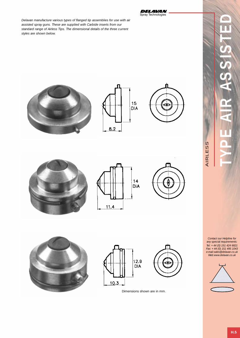
TYP
E A
IR A
SS
ISTE
D
H.5
Contact our Helpline forany special requirements:Tel: +44 (0) 151 424 6821Fax: +44 (0) 151 495 1043e-mail:[email protected]
Web:www.delavan.co.uk
AIR
LE
SS
Delavan manufacture various types of flanged tip assemblies for use with airassisted spray guns. These are supplied with Carbide inserts from ourstandard range of Airless Tips. The dimensional details of the three currentstyles are shown below.
Dimensions shown are in mm.
Airless 1 4/5/01 6:45 pm Page 5

WELCOME TO DELAVAN
of newchallengesMeeting the
industriesand NEW markets
I SpecialPurpose
Del Nozzle A4 dividers A/W 21/6/01 10:37 am Page 17

Nozzle Spray Characteristics Spray Basic Features Flow Range. PageType Angles L/Min @ 3 Bar.G. No.BB 0° 20 – 157 I.1
1505 0° 0,032 – 28,1 I.2
RO 0° As per order. I.2
UC 75° – 90° 334 – 3348 I.3
CON 0° As per order. I.4
BYPASS 75° – 85° See Charts. I.5
KIT ONE 115° – 130° 6,05 – 22,7* I.6
FN 180° 155 I.7
AJ 0° See charts I.8
3/8"-3/4" BSPT Male thread.
Flat disc for use with standard bodies and caps.
1/4"-1" BSPT Male thread.
2"-4" Flanged ANSI 150.
Flanged tip design for use with standard bodiesand caps.3/4"-1/2" NPT Male threads. Used with specialadaptors.3/4"-1" hosetail connections with 1/2 or 1 metrerisers.1/2" BSPP Female thread.
1/4" BSPT or 1/4" NPT Male thread
SP
EC
IAL
PU
RP
OS
E
High velocity straight jet to agitate and mixsolids in suspension.
Straight jet liquid stream or metering orifice.
Straight jet liquid stream or metering orifice.
Uniformly distributed hollow cone spray withcoarse atomisation.
Calibrated orifice for steam flows.
Uniformly distributed hollow cone spray withfine atomisation.
Uniformly distributed square shaped solid conespray with medium to coarse atomisation.
Wide angle solid cone - Filter Bed nozzle.
Flat pattern of high impact compressed airSE
CTIO
N IN
DE
X
Contact our Helpline forany special requirements:Tel: +44 (0) 151 424 6821Fax: +44 (0) 151 495 1043e-mail:[email protected]
Web:www.delavan.co.uk
These special purpose assemblies have been designed for particular applications but can be utilised for others when necessary. Other ‘specials’ can be designed for specific applications. Please contact Delavan’s Customer Service Teamfor further details.
* Flow quoted at 1 Bar.G. approx.
Del Nozzle A4 dividers A/W 21/6/01 10:37 am Page 18

NOZZLE APPROX. BSPT THREAD FLOW RATE IN LITRES/MIN AT Bar.G. Turnover NUMBER ORIFICE SIZE Ratio 1,5–
SIZE (mm) 3/8 1/2 3/4 ,7 1,0 1,5 2,0 3,0 4,0 5,0 7,0 8,0 4,0 Bar.G.
BB 50 4,4 9,61 11,61 14,2 16,4 20,00 23,1 25,8 30,19 32,2 3:1
BB 75 5,4 14,42 17,42 21,3 24,6 30,00 34,8 38,90 45,3 48,3 3:1
BB 100 6,4 19,1 22,8 27,94 32,24 40,00 45,6 51,0 60,38 64,4 3:1
BB 125 7,1 24,0 29,0 35,5 40,25 50,00 58,0 63,75 75,48 80,5 3:1
BB 150 7,8 28,8 34,4 41,67 48,6 60,00 68,8 76,5 90,12 96,4 3:1
BB 175 8,4 33,4 39,90 48,9 56,48 69,00 79,8 89,25 105,57 110,95 3:1
BB 200 8,8 38,0 45,5 55,70 64,3 78,80 91,0 102 120,31 128,6 3:1
BB 250 9,8 47,6 57,0 69,6 80,4 98,75 114,0 128 150 160,8 3:1
BB 300 11,0 57,2 68,3 83,33 96,9 118,30 136,6 153 180,7 197,8 3:1
BB 350 11,9 66,5 79,63 97,50 112,53 138,00 159,28 178,0 210,54 225,0 3:1
BB 400 12,7 76,0 90,6 111,96 129 157,00 181,2 202,5 241,1 258 3:1
TYP
E B
B
I.1
POLYGLASS 316 STAINLESS STEELTHREAD Weight Weight
Size A B C (g) A B C (g)3⁄8” 60,3 140 33,3 79 48,3 124 25 5251⁄2” 60,3 140 33,3 85 48,3 127 25 5403⁄4” 60,3 140 33,3 86 60,3 137 30 580
Contact our Helpline forany special requirements:Tel: +44 (0) 151 424 6821Fax: +44 (0) 151 495 1043e-mail:[email protected]
Web:www.delavan.co.uk
CAPACITY CHART
TANK HEATING CHART
DIMENSIONS AND WEIGHTS
Maximum Recommended Temperature:75˚C (Polyglass), 500˚C (Stainless Steel).
Maximum Recommended Pressure:10 Bar.G.(Polyglass), 35 Bar.G.(Stainless Steel).
APPLICATIONS● Agitation and mixing of liquids containing solid suspensions.● Cataphoresis plants.● Stainless Steel units ideal for steam heating of liquid in tanks where
uniform heat distribution over a large area is required.
FEATURES● High efficiency.● Wide range of flow capacities.● Outstanding resistance to erosion/corrosion.● Tapered inlet reduces wear and resists clogging.● High velocity jet stream for maximum agitation/mixing.● Typical turnover ratio of 3:1.
SPRAY CHARACTERISTICS● Produces a high velocity straight jet.● Induces the surrounding liquid into the jet stream.
CONSTRUCTION AND MATERIALS● One piece design with no internal components.● Available with 3⁄8”, 1⁄2” and 3⁄4” Male BSPT thread.● Available in 316 Stainless Steel or Glass filled Polypropylene (Polyglass).
ORDER EXAMPLE1⁄2” BB 100 Stainless Steel.3⁄4” BB 250 Polyglass.
TIME IN MINUTES TO HEAT 300 LITRES OF WATER AT VARIOUS STEAM PRESSURESSTEAM PRESSURE Bar.G. 0,35 0,7 1 2 3 4 5 6
5˚C 11 7 6 4 3 2 2 2
10˚C 22 13 11 7 5 4 4 3
20˚C 43 26 22 13 10 8 6 6
40˚C 86 52 43 26 19 15 12 10
60˚C 130 78 64 58 29 23 19 15
80˚C 173 103 86 51 38 30 25 20
100˚C 216 130 107 64 48 38 31 25
TEMPERATURERISE
This chart is based on using a single 1/2” BB 100 Stainless Steel nozzle with a 6,4mm orifice.
SP
EC
IAL
PU
RP
OS
E
MOULDED EDUCTOR
METAL EDUCTOR
LARGER SIZES ARE AVAILABLE - CONTACT OUR CUSTOMER SERVICES DEPARTMENT
SpecialPurpose 1 21/6/01 3:58 pm Page 1

TYP
E 1
505/R
O
I.2
Contact our Helpline forany special requirements:Tel: +44 (0) 151 424 6821Fax: +44 (0) 151 495 1043e-mail:[email protected]
Web:www.delavan.co.uk
CAPACITY CHART
TYPE 1505SPRAY CHARACTERISTICS● Calibrated metering orifice for regulating liquid fluids.● Straight stream jet with needle type spray.
CONSTRUCTION AND MATERIALS● Burr-free orifice to provide consistent flow with minimum deviation.● Available in 302 Stainless Steel only.● Used with Standard bodies and caps.
ORDER EXAMPLE1505-45.
FLOW RATE INNOZZLE DIA. LITRES/MIN AT Bar.G.NUMBER (mm) 1 2 3 4
1505-8 0,20 ,018 ,026 ,032 ,036
1505-10 0,25 ,030 ,042 ,051 ,059
1505-12 0,30 ,041 ,058 ,071 ,082
1505-14 0,36 ,057 ,081 ,099 ,114
1505-15 0,38 ,064 ,090 ,111 ,128
1505-16 0,41 ,073 ,103 ,126 ,146
1505-17 0,43 ,082 ,116 ,142 ,164
1505-18 0,46 ,091 ,129 ,158 ,182
1505-19 0,48 ,103 ,145 ,178 ,205
1505-20 0,51 ,112 ,158 ,193 ,223
1505-22 0,56 ,135 ,190 ,233 ,269
1505-24 0,61 ,169 ,239 ,292 ,337
1505-25 0,64 ,182 ,258 ,316 ,365
1505-26 0,66 ,198 ,280 ,344 ,397
1505-28 0,71 ,228 ,322 ,395 ,456
1505-29 0,74 ,246 ,348 ,426 ,492
1505-30 0,76 ,262 ,371 ,454 ,524
1505-32 0,81 ,285 ,403 ,494 ,570
1505-34 0,86 ,312 ,442 ,541 ,625
1505-35 0,89 ,328 ,464 ,569 ,657
1505-37 0,94 ,367 ,519 ,636 ,734
1505-39 0,99 ,413 ,584 ,715 ,825
FLOW RATE INNOZZLE DIA. LITRES/MIN AT Bar.G.NUMBER (mm) 1 2 3 4
1505-41 1,04 ,499 ,635 ,778 ,898
1505-43 1,09 ,492 ,696 ,853 ,985
1505-45 1,14 ,540 ,764 ,936 1,08
1505-46 1,17 ,565 ,800 ,979 1,13
1505-47 1,19 ,593 ,838 1,03 1,19
1505-48 1,22 ,616 ,870 1,07 1,23
1505-49 1,24 ,638 ,903 1,11 1,28
1505-51 1,30 ,684 ,967 1,18 1,37
1505-52 1,32 ,72 1,02 1,25 1,44
1505-54 1,37 ,775 1,1 1,34 1,55
1505-55 1,40 ,807 1,14 1,4 1,61
1505-57 1,45 ,866 1,23 1,5 1,73
1505-59 1,50 ,926 1,31 1,6 1,85
1505-61 1,55 1,0 1,42 1,74 2,01
1505-63 1,60 1,09 1,55 1,90 2,19
1505-65 1,65 1,16 1,64 2,01 2,33
1505-67 1,70 1,25 1,77 2,17 2,51
1505-68 1,73 1,28 1,81 2,21 2,55
1505-70 1,78 ,140 1,98 2,42 2,80
1505-72 1,83 1,46 2,06 2,53 2,92
1505-73 1,85 1,54 2,18 2,67 3,08
1505-75 1,91 1,60 2,26 2,76 3,19
FLOW RATE INNOZZLE DIA. LITRES/MIN AT Bar.G.NUMBER (mm) 1 2 3 4
1505-78 1,98 1,76 2,48 3,04 3,51
1505-80 2,03 1,85 2,61 3,20 3,69
1505-81 2,05 1,89 2,68 3,28 3,78
1505-83 2,11 1,98 2,81 3,44 3,97
1505-86 2,18 2,05 2,90 3,55 4,1
1505-89 2,26 2,2 3,11 3,31 4,4
1505-91 2,31 2,23 3,16 3,87 4,47
1505-93 2,36 2,3 3,26 3,99 4,61
1505-95 2,41 2,51 3,55 4,34 5,02
1505-98 2,49 2,67 3,77 4,62 5,34
1505-105 2,62 2,96 4,19 5,13 5,93
1505-107 2,72 3,19 4,51 5,53 6,38
1505-110 2,79 3,42 4,84 5,92 6,84
1505-115 2,92 3,88 5,48 6,71 7,75
1505-120 3,05 4,01 5,67 6,95 8,03
1505-125 3,18 4,74 6,71 8,21 9,48
1505-140 3,56 5,75 8,13 9,95 11,5
1505-156 3,96 7,25 10,3 12,6 14,5
1505-177 4,50 9,23 13,1 16,0 18,5
1505-196 4,98 11,2 15,9 19,5 22,5
1505-218 5,54 14,2 20,1 24,6 28,5
1505-234 5,94 16,2 23,0 28,1 32,5
DIMENSIONS AND WEIGHTS
BSPT ThreadSize Dimensions (mm) Weight
A B C D (g)
1/4” 25,4 9,5 6,4 28
3/8” 33,3 12,7 7,9 57
1/2” 38,1 12,7 12,7 99
3/4” 44,5 14,3 15,9 170
1” 57,2 20,6 15,9 184
TYPE ROSPRAY CHARACTERISTICS● Calibrated metering orifice for regulating liquid fluids.● Straight stream jet with needle type spray.
CONSTRUCTION AND MATERIALS● One piece construction with Male BSPT thread.● Burr-free orifice to provide consistent flow with minimum deviation.● Brass and Stainless Steel are standard.● Other materials are available to special order.
ORDER EXAMPLESpecify thread size required, together with orifice size and orifice length as follows:3/8” RO x 3.0mm x 10.0mm.
SP
EC
IAL
PU
RP
OS
E
SpecialPurpose 1 21/6/01 3:58 pm Page 2

TYP
E U
C
I.3
Size Weight(N.B.) A B C D E F G H (Kg)
2” 98,4 140 148 19 121 152 4 19 2,69
21⁄2” 98,4 190 148 22 140 178 4 19 4,66
3” 127 225 210 24 152 191 4 19 7,45
4” 152 269 252 24 191 229 8 19 13,4
Contact our Helpline forany special requirements:Tel: +44 (0) 151 424 6821Fax: +44 (0) 151 495 1043e-mail:[email protected]
Web:www.delavan.co.uk
CAPACITY CHART
DIMENSIONS AND WEIGHTS
SPRAY CHARACTERISTICS● Produces a hollow cone spray pattern with uniform distribution.● Has a narrower droplet spectrum than equivalent solid cone sprays.
CONSTRUCTION AND MATERIALS● Manufactured in Silicon Carbide, Nitride bonded (SiC).● Clog resistant design with no internal vanes or cones.● Uses ‘Canted Bottom’ design of swirl chamber for maximum
wear resistance.● Ideal for Gas washing and cooling where high temperatures, together with
corrosive and abrasive elements, are present.● Manufactured in flanged version only. ● Mounting flanges as per ANSI 150.
ORDER EXAMPLE3” UC 250-FL.
FLANGE NOZZLE FLOW RATE IN LITRES/MINUTE AT Bar.G. Nominal SpraySIZE (N.B.) NUMBER 0,3 0,5 0,7 1,0 1,5 2,0 3,0 Angle(°) at 1 Bar.G.
UC 60-FL 106 136 161 193 236 272 334 70
UC 75-FL 132 170 201 241 295 340 417 70
UC 90-FL 158 204 241 289 353 408 500 80
UC 100-FL 176 228 269 322 394 455 557 80
UC 110-FL 194 250 296 354 433 500 613 80
UC 120-FL 211 273 322 386 472 545 668 80
UC 135-FL 238 307 363 434 531 613 751 85
UC 150-FL 265 342 404 483 591 683 836 85
UC 90-FL 158 204 241 289 353 408 500 70
UC 100-FL 176 228 269 322 394 455 557 70
UC 110-FL 194 250 296 354 433 500 613 70
UC 120-FL 211 273 322 386 472 545 668 80
UC 135-FL 238 307 363 434 531 613 751 80
UC 150-FL 265 342 404 483 591 683 836 80
UC 165-FL 290 375 444 531 650 750 919 85
UC 135-FL 238 307 363 434 531 613 751 80
UC 150-FL 265 342 404 483 591 683 836 80
UC 175-FL 308 398 448 563 689 796 975 85
UC 200-FL 353 455 539 644 788 910 1115 85
UC 225-FL 396 512 606 724 886 1023 1254 90
UC 250-FL 441 569 673 805 985 1138 1394 90
UC 275-FL 485 625 740 885 1089 1251 1532 90
UC 225-FL 396 512 606 724 886 1023 1254 75
UC 250-FL 441 569 673 805 985 1138 1394 75
UC 275-FL 485 625 740 885 1089 1251 1532 75
UC 325-FL 573 740 875 1046 1281 1479 1811 80
UC 375-FL 662 854 1010 1208 1479 1708 2092 80
UC 450-FL 794 1025 1213 1450 1775 2050 2511 85
UC 500-FL 882 1138 1347 1610 1971 2276 2788 85
UC 550-FL 970 1252 1481 1771 2169 2504 3067 90
UC 600-FL 1059 1367 1617 1933 2367 2733 3348 90
2”
21/2”
3”
4”
SP
EC
IAL
PU
RP
OS
E
Maximum Recommended Pressure: 7 Bar.G.Maximum Recommended Temperature: 1650˚C.
SpecialPurpose 1 21/6/01 3:59 pm Page 3

TYP
E C
ON
I.4
Contact our Helpline forany special requirements:Tel: +44 (0) 151 424 6821Fax: +44 (0) 151 495 1043e-mail:[email protected]
Web:www.delavan.co.uk
SPRAY CHARACTERISTICS● Produces a straight jet of steam which subsequently opens up with
surrounding air resistance.
CONSTRUCTION AND MATERIALS● Nozzle tip has a precision machined orifice to provide accurate calibration
of steam flow.● Maximum orifice size available is 0,400” (10,2mm).● Supplied in a 3 piece design of nozzle tip, cap and threaded body.● Body thread sizes are Male BSPT and Female BSPP.● Available thread sizes are 1/8”, 1/4” and 3/8”.● Supplied in Brass and Stainless Steel as standard.● Other materials available to special order.
ORDER EXAMPLEAdvise the following: 1) Steam flow rate in kg/hr
2) Operating pressure in Bar.G.If the orifice is known:-1/4” CONM (Male) x 4,8mm (0,189”) Stainless Steel.3/8” CONF (Female) x 9,2mm (0,362”) Brass.
COP F is a calibrated orifice plate and is utilised for higher flow rates that theCON cannot handle. They are designed in accordance with the BritishStandard 1042 and typical profiles are shown in the drawing.
SP
EC
IAL
PU
RP
OS
E
CON (MALE)
CON (FEMALE)
COP
Thread Dimensions (mm) WeightSize A Hex B C Hex (g)
1⁄8” 20,8 40,0 18,0 65
1⁄8” 20,8 38,4 18,0 55
1⁄4” 20,8 40,0 18,0 64
1⁄4” 20,8 40,0 18,0 55
DIMENSIONS AND WEIGHTS
SpecialPurpose 1 21/6/01 3:59 pm Page 4

NOZZLE FLOW RATE IN LITRES/MIN TURNASSEMBLY ADAPTOR AT 42 Bar.G. DOWN SPRAY NOZZLE BODY NOZZLE CAP
PART NUMBER PART NUMBER MAXIMUM MINIMUM RATIO ANGLE (°) PART NUMBER PART NUMBER
35051-2 35054 26.5 2.19 12:1 80 35052-2 25053-235051-9 35054 26.5 2.65 10:1 85 35052-6 25053-7
35051-7 35054 18.9 1.21 15:1 80 37701-2 37702-235051-8 35054 18.9 1.89 10:1 85 37701-3 35053-6
38635-1 38640 11.3 .76 15:1 80 38636-1 38637-138635-3 38640 11.3 1.13 10:1 75 38636-3 38637-3
TYP
E B
YP
AS
S
I.5
Contact our Helpline forany special requirements:Tel: +44 (0) 151 424 6821Fax: +44 (0) 151 495 1043e-mail:[email protected]
Web:www.delavan.co.uk
Dimensions Nozzle and Adaptor
(mm) 35051/35054 38635/38640
A 120.6 90.1
B (Thds) 1/2” -14 NPTF 1/4” -18 NPTF
C 58.4 38.1
D 39.6 32.6
E(Flats) 22.2 19.1
F 26.7 21.3
G 19.1 15.9
H 21.9 18.8
I 54 38.1
J 142.7 105.8
K 41.3 28.6
L 31.7 19.1
M 1/2” -14 NPTF 1/4” -18 NPTF
DIMENSIONS
Part Part Number Weight (g)
Nozzle35051– 15038635– 79
Adaptor35054 99238640 360
WEIGHT
Delavan’s Bypass nozzle has won an Honours Award in the Vaaler Awardscompetition held by Chemical Processing magazine. The product wasjudged as a major contribution toward more efficient and effective operationof plants in chemical processing industries.
APPLICATION● Evaporative cooling, chemical processing.
FEATURES● Flow rate is changed by means of a bypass valve without varying the
supply pressure of using atomising air or gas. (See flow diagram.)● Reduces the number of nozzles needed when gas inlet temperatures vary.● In a bypass system, a portion of the input liquid may be diverted through a
return line by means of a bypass valve. As the valve is opened, the totalinput flow increases. Delavan’s Bypass nozzle’s patented designminimises this flow growth to avoid excessive pumping requirements andhydraulic power consumption. The input flow increase (when bypass valveis opened) can be as low as 15%.
● Nozzle can be located in high temperature zone and connected byconcentric piping to adaptor in cool area.
SPRAY CHARACTERISTICS● Hollow cone spray pattern.● “Turndown” refers to the ratio of the maximum discharge (bypass valve
closed) to the minimum flow (bypass valve open) while maintainingsatisfactory quality. Between these flow limits, there are no largefluctuations in spray angle or droplet size.
● The quality of atomisation depends on nozzle capacity, turndown rating,and specific operating conditions. For example, a nozzle will produce finerdroplets when the inlet pressure is higher than 42 Bar.G., and vice versa.
CONSTRUCTION AND MATERIALS● Large passages, to minimise restriction and to avoid clogging.● Nozzle cap and body easily removed from adaptor.● Available in 316 L Stainless Steel only.
ORDER EXAMPLERefer to capacity chart for part numbers.
CAPACITY CHART
Maximum Design Pressure: 56 Bar.G.
Maximum Design Temperature:540˚C (Bypass Nozzle), 150˚C (Adaptor).
SP
EC
IAL
PU
RP
OS
E
SpecialPurpose 1 21/6/01 3:59 pm Page 5

KIT
-ON
E
I.6
Contact our Helpline forany special requirements:Tel: +44 (0) 151 424 6821Fax: +44 (0) 151 495 1043e-mail:[email protected]
Web:www.delavan.co.uk
● A universal system, in kit form, for permanent or semi-permanent siting inpolythene-clad structures, under glass or on open ground.
● For interconnection and initial connection from the water supply, Hose-Tails are 3/4” or 1”, to suit length of run, diameter of orifice, width of coverand volume/pressure available on site.
● Each free standing member comprises a Ground-Spike, Heel Plate, Tee,Hose Connector and Clips, plus a Riser topped by a Brass Nozzle whichproduces a squared pattern. The nozzles are in our HL range and areavailable in 8 different flow-rates. Operating pressures are in the region of12 to 15 psi (0,8 to 1 Bar.G.). Standard heights are 1 metre, 1/2 metre and1/4 metre, though the nozzle can be used at low level directly from the teeif required.
● Droplet sizes from our HL range of nozzles are larger than the norm, solessening the problem of “Drift” on open ground.
● Though true evenness of watering from man-made sprinklers is a myth,the squared pattern produced by the HL nozzle helps to keep water ontarget, reduces variation in overlap and irrigates those areas in whichretarded growth rates have curbed profit.
● Materials used in the construction of Kit-One will, with reasonable care,provide a generation of nurserymen and growers with a sound system.Ideal for watering applications in Tunnels, Glasshouses, Production beds,Borders, Trial plots, Display areas, Container grounds etc.
SP
EC
IAL
PU
RP
OS
E
For horticultural irrigation use Kit-One units with H.L. nozzles.
HL HL HL HL HL HL HL HLNOZZLE TYPE 80-12 100-14 140-16 170-18 185-21 200-24 250-27 300-30
Aprox. flow Litres/Hour 363 454 636 772 840 908 1135 1362
Aprox. flow Gals/Hour 80 100 140 170 185 200 250 300
Maximum width of cover 3,95m 4,6m 5,3m 5,9m 6,3m 7,2m 8,1m 9,1m
at 1 Metre high 12ft 14ft 16ft 18ft 21ft 24ft 27ft 30ft
Maximum recommended 3,1m 3,8m 4,3m 4,8m 5,4m 6,3m 7,0m 7,8m
space in house run 91/2ft 111/2ft 13ft 141/2ft 161/2ft 19ft 23ft 26ft
INSTALLATION GUIDE
Typical Example 54ft x 16ft (17,8m x 5,3m).
Note: For larger installations contact Delavan’s Customer Service Team.
NOZZLEHL 170-18
NOZZLEHL 170-18
NOZZLEHL 170-18
SpecialPurpose 1 21/6/01 4:00 pm Page 6

TYP
E F
N
I.7
Contact our Helpline forany special requirements:Tel: +44 (0) 151 424 6821Fax: +44 (0) 151 495 1043e-mail:[email protected]
Web:www.delavan.co.uk
APPLICATIONS● Fluidised bed for sand reclamation in foundries.● Aeration and cooling nozzle.● Filter nozzle for cooling water reclamation in steel mills, etc.● Tertiary treatment in effluent plants.● Aeration of sludge.● Trub dispersal in breweries.
CONSTRUCTION AND MATERIALS● Moulded in black Polypropylene.● Available with 1/2” Female BSPP connection only.● Unit has 24 slots each 0,25mm wide in two positions.
SP
EC
IAL
PU
RP
OS
E
PRESSURE Bar.G. 0,7 1,4 2,1 2,8 3,5
FLOW RATE IN LITRES/MIN 68 100 123 150 173
DIAMETER OF COVERAGE (M) FROM5,5 7,0 7,9 8,8 9,1
A HEIGHT OF 600mm
CAPACITY CHART
SpecialPurpose 1 21/6/01 4:00 pm Page 7
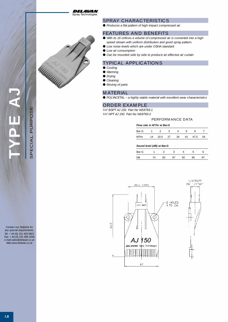
I.8
TYP
E A
J
Contact our Helpline forany special requirements:Tel: +44 (0) 151 424 6821Fax: +44 (0) 151 495 1043e-mail:[email protected]
Web:www.delavan.co.uk
SP
EC
IAL
PU
RP
OS
E
Flow rate in M3/hr at Bar.G
Bar G 1 2 3 4 5 6 7
M3/hr 14 20.5 27 34 41 47.5 54
PERFORMANCE DATA
SPRAY CHARACTERISTICS● Produces a flat pattern of high impact compressed air.
FEATURES AND BENEFITS● With its 16 orifices a volume of compressed air is converted into a high
speed stream with uniform distribution and good spray pattern.● Low noise levels which are under OSHA standard● Low air consumption● Can be mounted side by side to produce an effective air curtain
TYPICAL APPLICATIONS● Cooling● Warming● Drying● Cleaning● Moving of parts
MATERIAL● POLYACETAL – a highly stable material with excellent wear characteristics
ORDER EXAMPLE1/4" BSPT AJ 150 Part No W18783-11/4" NPT AJ 150 Part No W18783-2
Sound level (dB) at Bar.G
Bar G 1 2 3 4 5 6
DB 74 82 87 92 95 97
SpecialPurpose 1 21/6/01 4:01 pm Page 8

WELCOME TO DELAVAN
of newchallengesMeeting the
industriesand NEW markets
J Handguns &Accessories
Del Nozzle A4 dividers A/W 21/6/01 10:37 am Page 19

Item Type Basic Description PageNo.
HANDGUNS AND LANCES J.1
EYELETS J.2-3
STRAINERS J.4-5
BODIES J.6
CAPS J.6
FILTERS J.7
SWIVELS J.7
BALL CHECK J.8
ADAPTORS J.9
HNS J.9
ADJUSTABLE JOINTS J.10
Various high pressure handguns, lances and accessories.
1/2"-11/2" N.B. Eyelets with various outlet connections for nozzles.
3/4"-11/2" ‘Y’ line strainers with various mesh sizes. Polypropylene and Nylon.
1/8"-3/8" BSPT Male and BSPP Female threads for use with flanged type nozzles.
3/8" BSPP and 11/16"-16 UN threaded for use with the above bodies.
Flanged filters with various mesh sizes for use with the above.
1/8"-1/4" NPT Female and 1/4" NPT Male inlets with outlet for above caps with flanged type nozzles.
1/8"-1/4" NPT threaded check valves for use with threaded nozzles or flanged type nozzles.
1/8"-1" BSPT Male and BSPP Female x 90˚ adaptor for use with threaded nozzles.
1/8"-1" BSPP Female threaded sockets for use with threaded nozzles.
1/8"-1" Male/Female adjustable joint with various angles of inclination.
SE
CTIO
N IN
DE
X
Contact our Helpline forany special requirements:Tel: +44 (0) 151 424 6821Fax: +44 (0) 151 495 1043e-mail:[email protected]
Web:www.delavan.co.uk
HA
ND
GU
NS
&A
CC
ES
SO
RIE
S
Del Nozzle A4 dividers A/W 21/6/01 10:37 am Page 20

J.1
Contact our Helpline forany special requirements:Tel: +44 (0) 151 424 6821Fax: +44 (0) 151 495 1043e-mail:[email protected]
Web:www.delavan.co.uk
HA
ND
GU
NS
& L
AN
CE
SA
CC
ES
SO
RIE
S
PART DESCRIPTION TYPE MAX. MAX. MAX. INLET OUTLET LENGTHNUMBER FLOW PRESS. TEMP. CONN. CONN. OF
(LPM) (Bar.G.) (°C) (BSP) (BSP) LANCE (mm)
W09114* Handgun ST 2000 40 250 160 3/8” Fem 1/4” Fem
W09115 Handgun ST 601 40 250 160 3/8” Fem 1/4” Fem
W13063 Handgun ST 810 30 200 160 3/8” Fem 1/4” Fem
W13064* Handgun ST 1500 40 250 150 3/8” Fem 1/4” Fem
W13066 Handgun ST 3002 100 250 150 1/2” Male 1/2” Fem
W09116 Hand Lance ST 007 40 250 160 1/4” Male 1/4” Male 500
W09117 Hand Lance ST 007 40 250 160 1/4” Male 1/4” Male 800
W09118 Hand Lance ST 007 40 250 160 1/4” Male 1/4” Male 1000
W09119-1 Twin Lance ST 53 40 250 160 1/4” Male 1/4” Fem
W09119-2 Twin Lance ST 54 40 250 160 1/4” Male 1/4” Fem
W13067 H.P. Hand Lance ST 3001/ v 100 500 150 1/2” Male 1/4” Fem 500
W13068 H.P. Hand Lance ST 3001/ v 100 500 150 1/2” Male 1/4” Fem 1000
W09121 Adjustable Nozzle ST 51N 30 250 80 1/4” Fem 1/4” Fem
W09122 Rollover Nozzle ST 56 30 250 150 1/4” Fem 2 x 1/4” Fem
W13070-2 Turbo Nozzle ST 357 80 200 80 1/4” Fem Turbo
W13070-3 Turbo Nozzle ST 457 120 350 80 1/4” Fem Turbo
W13069 Suction Filter ST 35 - - - 1/2” – 3/4” -
Hosetail
W09120-1 Siphon Injector
(1,8mm) ST 60 8,5 250 150 3/8” Male 3/8” Fem
W09120-2 Siphon Injector
(2,1mm) ST 60 12,6 250 150 3/8” Male 3/8” Fem
W09120-3 Siphon Injector
(2,4mm) ST 60 18,9 250 150 3/8” Male 3/8” Fem
W09123-1 Coupling ST 40 250 150 22 x 1,5mm 1/4” Male
W09123-2 Coupling ST 40 250 150 22 x 1,5mm 1/4” Fem
W09123-3 Coupling ST 40 250 150 22 x 1,5mm 3/8” Male
W09123-4 Coupling ST 40 250 150 22 x 1,5mm 3/8” Fem
W09123-5 Coupling ST 40 250 150 22 x 1,5mm 1/2” Fem
W09124-1 Nipple ST 41 250 150 1/4” Fem 22 x 1,5mm
W09124-2 Nipple ST 41 250 150 1/4” Male 22 x 1,5mm
W09124-3 Nipple ST 41 250 150 3/8” Fem 22 x 1,5mm
W09124-4 Nipple ST 41 250 150 3/8” Male 22 x 1,5mm
W09124-5 Nipple ST 41 250 150 1/2” Male 22 x 1,5mm
FEATURES● Manufactured in a range of flows and pressures.● Various models in different styles.● Trigger lock-off for safety.● A range of compatible hand lances and accessories are available.
CONSTRUCTION AND MATERIALS● Body, handle and trigger in Glass Reinforced Polyamide.● Valve body in Brass. Some available in Stainless Steel.● Plunger and spring in Stainless Steel.● Liquid inlet integrated into handle in some models.
*Fitted with inlet swivel as standard.
W13068W09119
W09118
W09119-2
W09116
W09115
W13065
W09114
W09122
W13070
Accessories B 21/6/01 10:00 am Page 1

EYE
LE
TS
J.2
Contact our Helpline forany special requirements:Tel: +44 (0) 151 424 6821Fax: +44 (0) 151 495 1043e-mail:[email protected]
Web:www.delavan.co.uk
AC
CE
SS
OR
IES
FEATURES● Delavan threaded eyelets offer the most economical method of attaching
spray nozzles to pipe systems.● Can be used as a Tee piece with PVC or Poly. pipes in place of a solvent
welded or threaded unit.● 11/16"–16 and 3/8" BSP outlets will accept all standard flanged nozzle tips
and filters.● Ease of installation. Only a single hole is required in the pipe with a single
screw for attachment.● Light weight with excellent chemical resistance through materials of
construction.● The body design provides leak proof service, facilitating high flowrates
with minimum pressure drop.● Allows the use of thin wall tubing in pipe systems for reduced cost.
CONSTRUCTION AND MATERIALS● One piece design, hinged bridge and locking screw.● Twin outlet bodies are also available in 1/2” and 3/4”.● Polypropylene, Nylon and Steel are available as standard. (Steel eyelets
have plated Steel clamp with wetted outlet in Brass or Stainless Steel.)
ORDER EXAMPLE● W06046 ( 3/4” NB x 3/8” BSPPM – Poly. Eyelet).
Part Number SIZE (NB) MATERIAL OUTLET HOLE SEAL SCREW
36977 1/2” St/Br 11/16”-16 8,75 37052-2 26139
W11396-2 1/2” St/SS 11/16”-16 8,75 37052-2 26139
W11396-11 1/2” St/Br 1/8” NPTF 8,75 37052-2 26139
W11396-1 1/2” St/SS 1/8” NPTF 8,75 37052-2 26139
W11396-13 1/2” St/Br 1/8” BSPF 8,75 37052-2 26139
W11396-3 1/2” St/SS 1/8” BSPF 8,75 37052-2 26139
W11396-14 1/2” St/Br 1/4” BSPF 8,75 37052-2 26139
W11396-4 1/2” St/SS 1/4” BSPF 8,75 37052-2 26139
W11396-15 1/2” St/Br 1/8” NPTM 8,75 37052-2 26139
W11396-5 1/2” St/SS 1/8” NPTM 8,75 37052-2 26139
W11396-16 1/2” St/Br 1/4” NPTM 8,75 37052-2 26139
W11396-6 1/2” St/SS 1/4” NPTM 8,75 37052-2 26139
W11396-17 1/2” St/Br 1/8” BSPTM 8,75 37052-2 26139
W11396-7 1/2” St/SS 1/8” BSPTM 8,75 37052-2 26139
W11396-18 1/2” St/Br 1/4” BSPTM 8,75 37052-2 26139
W11396-8 1/2” St/SS 1/4” BSPTM 8,75 37052-2 26139
W11396-19 1/2” St/Br 3/8” BSPTM 8,75 37052-2 26139
W11396-9 1/2” St/SS 3/8” BSPTM 8,75 37052-2 26139
W11396-20 1/2” St/Br 3/8” BSPPM 8,75 37052-2 26139
W11396-10 1/2” St/SS 3/8” BSPPM 8,75 37052-2 26139
10001 1/2” Nylon 11/16” - 16 5,60 4010-1 45202
W06045 1/2” Poly. 11/16” - 16 10,3 W16250-310 45202-3
W10878-1 1/2” Poly. 1/8” NPTF x2 10,3 W16250-310 45202-3
W10878-2 1/2” Poly. 1/8” NPTF x2 10,3 W16250-310 45202-3
W12048-1 1/2” Poly. 3/8” BSPM x2 10,3 W16250-310 45202-3
W16901-2 1/2” Poly. 1/4” NPTM 10,3 W16250-310 45202-3
SELECTION CHART
Accessories B 21/6/01 10:01 am Page 2

EYE
LE
TS
J.3
Contact our Helpline forany special requirements:Tel: +44 (0) 151 424 6821Fax: +44 (0) 151 495 1043e-mail:[email protected]
Web:www.delavan.co.uk
AC
CE
SS
OR
IES
Part Number SIZE (NB) MATERIAL OUTLET HOLE SEAL SCREW
36977 3/4” St/Br 11/16”-16 8,75 37052-2 26139
W11473-2 3/4” St/SS 11/16”-16 8,75 37052-2 26139
W11473-11 3/4” St/Br 1/8” NPTF 8,75 37052-2 26139
W11473-1 3/4” St/SS 1/8” NPTF 8,75 37052-2 26139
W11473-13 3/4” St/Br 1/8” BSPF 8,75 37052-2 26139
W11473-3 3/4” St/SS 1/8” BSPF 8,75 37052-2 26139
W11473-14 3/4” St/Br 1/4” BSPF 8,75 37052-2 26139
W11473-4 3/4” St/SS 1/4” BSPF 8,75 37052-2 26139
W11473-15 3/4” St/Br 1/8” NPTM 8,75 37052-2 26139
W11473-5 3/4” St/SS 1/8” NPTM 8,75 37052-2 26139
W11473-16 3/4” St/Br 1/4” NPTM 8,75 37052-2 26139
W11473-6 3/4” St/SS 1/4” NPTM 8,75 37052-2 26139
W11473-17 3/4” St/Br 1/8” BSPTM 8,75 37052-2 26139
W11473-7 3/4” St/SS 1/8” BSPTM 8.75 37052-2 26139
W11473-18 3/4” St/Br 1/4” BSPTM 8,75 37052-2 26139
W11473-8 3/4” St/SS 1/4” BSPTM 8,75 37052-2 26139
W11473-19 3/4” St/Br 3/8” BSPTM 8,75 37052-2 26139
W11473-9 3/4” St/SS 3/8” BSPTM 8,75 37052-2 26139
W11473-20 3/4” St/Br 3/8” BSPPM 8,75 37052-2 26139
W11473-10 3/4” St/SS 3/8” BSPPM 8,75 37052-2 26139
10000-2 3/4” Nylon 11/16”-16 10,3 4010-2 45202
W06046 3/4” Poly. 3/8” BSPPM 10,3 W16250-310 45202-3
W10817-3 3/4” Poly. 1/4” NPTF x2 10,3 W16250-310 45202-3
W10817-4 3/4” Poly. 1/4” NPTF x2 10,3 W16250-310 45202-3
W10817-2 3/4” Poly. 3/8” BSPM x2 10,3 W16250-310 45202-3
W16901-1 3/4” Poly. 1/4” NPTM 10,3 W16250-310 45202-3
Part Number SIZE (NB) MATERIAL OUTLET HOLE SEAL SCREW
36979 1” St/Br 11/16”-16 8,75 37052-2 26139
W11474-2 1” St/SS 11/16”-16 8,75 37052-2 26139
W11474-11 1” St/Br 1/8” NPTF 8,75 37052-2 26139
W11474-1 1” St/SS 1/8” NPTF 8,75 37052-2 26139
W11474-13 1” St/Br 1/8” BSPF 8,75 37052-2 26139
W11474-3 1” St/SS 1/8” BSPF 8,75 37052-2 26139
W11474-14 1” St/Br 1/4” BSPF 8,75 37052-2 26139
W11474-4 1” St/SS 1/4” BSPF 8,75 37052-2 26139
W11474-15 1” St/Br 1/8” NPTM 8,75 37052-2 26139
W11474-5 1” St/SS 1/8” NPTM 8,75 37052-2 26139
W11474-16 1” St/Br 1/4” NPTM 8,75 37052-2 26139
W11474-6 1” St/SS 1/4” NPTM 8,75 37052-2 26139
W11474-17 1” St/Br 1/8” BSPTM 8,75 37052-2 26139
W11474-7 1” St/SS 1/8” BSPTM 8,75 37052-2 26139
W11474-18 1” St/Br 1/4” BSPTM 8,75 37052-2 26139
W11474-8 1” St/SS 1/4” BSPTM 8,75 37052-2 26139
W11474-19 1” St/Br 3/8” BSPTM 8,75 37052-2 26139
W11474-9 1” St/SS 3/8” BSPTM 8,75 37052-2 26139
W11474-20 1” St/Br 3/8” BSPPM 8,75 37052-2 26139
W11474-10 1” St/SS 3/8” BSPPM 8,75 37052-2 26139
W06043 1” Poly. 3/8” BSPPM 10,3 W16250-310 45202-3
W16807 1” Poly. 1/4” NPTM 10,3 W16250-310 45202-3
Part Number SIZE (NB) MATERIAL OUTLET HOLE SEAL SCREW
W10046-1 11/4” Poly. 3/8” BSPPM 20 W10371 W04091
W10046-2 11/4” Poly. 1/2” BSPPM 20 W10371 W04091
W10046-3 11/4” Poly. 3/4” BSPPM 20 W10371 W04091
W10046-4 11/4” Poly. 1” BSPPM 20 W10371 W04091
W10046-5 11/2” Poly. 3/8” BSPPM 20 W10371 W04091
W10046-6 11/2” Poly. 1/2” BSPPM 20 W10371 W04091
W10046-7 11/2” Poly. 3/4” BSPPM 20 W10371 W04091
W10046-8 11/2” Poly. 1” BSPPM 20 W10371 W04091
SELECTION CHARTS
Accessories B 21/6/01 10:01 am Page 3

CAPACITY CHARTScreen Information
INLET/OUTLETPART THREAD SIZE PART NUMBER MESH SIZE OF STRAINER EFFECTIVE
NUMBER NPTF OF SCREEN SIZE OPENINGS (mm) AREA (cm2) STRAINER AREA (cm2)
39908-3 3/4” 31500-3 20 0,84 145 66
39908-2 3/4” 31500-1 40 0,46 145 55
39908-1 3/4” 31500-4* 80 0,18 145 46
39908-7 3/4” 31500-8 100 0,13 145 39
39908-6 1” 31500-3 20 0,84 145 66
39908-5 1” 31500-1 40 0,46 145 55
39908-4 1” 31500-4* 80 0,18 145 46
39908-8 1” 31500-8 100 0,13 145 39
39911-4 1 1/4” 25157 20 0,84 145 152
39911-5 1 1/4” 25156 40 0,46 145 126
39911-6 1 1/4” 32876 10 1,96 145 195
39911-7 1 1/4” 50321-1 80 0,18 145 46
39911-8 1 1/4” 50321-2 100 0,13 145 46
39911-1 1 1/2” 25257 20 0,84 330 152
39911-2 1 1/2” 25156 40 0,46 330 126
39911-3 1 1/2” 32876 10 1,97 330 195
39911-9 1 1/2” 50321-2 80 0,18 145 46
39911-10 1 1/2” 50321-2 100 0,13 145 39
Maximum Recommended Pressure:39908 Strainer (3/4” and 1”): 10 Bar.G. (150 psig).
39911 Strainer (1 1/4” and 1 1/2”): 5 Bar.G. (75 psig).
39908 and 39911 Y-TYPE LINE STRAINERFEATURES● O-ring sits on a special chamber to seal against leaking and for easy
removal of cap for cleaning.● Body configuration turns the liquid flow, the strainer acts as a plumbing
elbow and plugs less due to internal flow design.● Cap can be removed with the help of a slot in the cap. Use a screwdriver,
etc. through the slot to loosen cap.
CONSTRUCTION AND MATERIALS● Made of Nylon with Stainless Steel screens and Viton O-rings.● A new coarse buttress thread is featured on the cap for ease of
installation and removal (two turns only).● Strainer 39908 weighs approx. 269g.● Strainer 39911 weighs approx. 666g.
REPLACEMENT SEALS● 31352-226 for 39908 Strainers.● 31352-234 for 39911 Strainers.
* 20-mesh outer and 80-mesh inner screen.
Y-LI
NE
STR
AIN
ER
S
Contact our Helpline forany special requirements:Tel: +44 (0) 151 424 6821Fax: +44 (0) 151 495 1043e-mail:[email protected]
Web:www.delavan.co.uk
AC
CE
SS
OR
IES
J.4
Accessories B 21/6/01 10:01 am Page 4

Y-LI
NE
STR
AIN
ER
S
J.5
Contact our Helpline forany special requirements:Tel: +44 (0) 151 424 6821Fax: +44 (0) 151 495 1043e-mail:[email protected]
Web:www.delavan.co.uk
AC
CE
SS
OR
IES
45946 and 45992 Y-TYPE LINE STRAINERFEATURES● Low cost strainer that removes contaminants from the line.● Easily flushed by removing cap.
CONSTRUCTION AND MATERIALS● Made of Glass-filled Polypropylene with Stainless Steel screens and
EPDM seals.● Strainer 45946 weighs approx. 211g.● Strainer 45992 weighs approx. 666g.● 45992 should be used only as a suction strainer.
REPLACEMENT SEALS● 45950 EPDM Seal for 45946.● 32627-237 EPDM O-ring for 45992.
Maximum Recommended Pressure: 3.5 Bar.G.* 20-mesh outer and 80-mesh inner screen.
CAPACITY CHARTScreen Information
INLET/OUTLETPART THREAD SIZE PART NUMBER MESH SIZE OF STRAINER EFFECTIVE
NUMBER NPTF OF SCREEN SIZE OPENINGS (mm) AREA (cm2) STRAINER AREA (cm2)
45946-3 3/4” 31500-3 20 0,84 145 66
45946-2 3/4” 31500-1 40 0,46 145 55
45946-1 3/4” 31500-4 * 80 0,18 145 46
45946-7 3/4” 31500-8 100 0,13 145 39
45946-6 1” 31500-3 20 0,84 145 66
45946-5 1” 31500-1 40 0,46 145 55
45946-4 1” 31500-4 * 80 0,18 145 46
45946-8 1” 31500-8 100 0,13 145 39
45992-1 (see caution) 1 1/2” 25157 20 0,84 330 152
45992-2 (see caution) 1 1/2” 25156 40 0,46 330 126
45992-3 (see caution) 1 1/2” 32876 10 1,97 330 195
45992-4 1 1/2” 50321-1 80 0,18 145 46
45992-5 1 1/2” 50321-2 100 0,13 145 46
Accessories B 21/6/01 10:02 am Page 5

BO
DIE
S &
CA
PS
J.6
Contact our Helpline forany special requirements:Tel: +44 (0) 151 424 6821Fax: +44 (0) 151 495 1043e-mail:[email protected]
Web:www.delavan.co.uk
AC
CE
SS
OR
IES
NOZZLE BODIESCHARACTERISTICS● These are designed to accept any standard flanged tip from the standard
nozzle range.● Will accept the caps from the list below.
CONSTRUCTION AND MATERIALS● Available in Brass and Stainless Steel as standard.● Thread sizes are Male BSPT, Female BSPP and NPT Male and Female.● Other materials available to special order.
NOZZLE CAPSCHARACTERISTICS● Designed to fit nozzle bodies, eyelets and swivels from the
standard range.
CONSTRUCTION AND MATERIALS● Available in Brass, Stainless Steel, Polypropylene and Nylon.● Refer to chart for thread sizes and part numbers.● Other materials available to special order.
NOZZLE BODIESTHREAD PART NUMBER
SIZE MATERIAL MALE FEMALE CAP THREAD
1/8” BSP Brass 32011-1 32012-1 3/8” BSPP1/8” BSP Stainless Steel 32011-3 32012-3 3/8” BSPP1/4” BSP Brass 32013-1 32014-1 3/8” BSPP1/4” BSP Stainless Steel 32013-3 32014-3 3/8” BSPP3/8” BSP Brass 32016-1 32017-1 3/8” BSPP3/8” BSP Stainless Steel 32016-3 32017-3 3/8” BSPP1/8” NPT Brass 1171-1 1173-1 11/16”-16 UN1/8” NPT Stainless Steel 1171-3 1173-3 11/16”-16 UN1/4” NPT Brass 1167-1 1169-1 11/16”-16 UN1/4” NPT Stainless Steel 1167-3 1169-3 11/16”-16 UN3/8” NPT Brass 50701-1 50702-1 11/16”-16 UN3/8” NPT Stainless Steel 50701-2 50702-2 11/16”-16 UN1/4” NPT Nylon 8474 - 11/16”-16 UN
NOZZLE CAPSPART THREAD
NUMBER SIZE MATERIAL
W00105-1 3/8” BSPP Stainless Steel
W00105-2 3/8” BSPP Brass
W01783 3/8” BSPP Polypropylene
1165-1 11/16”-16 UN Brass
1165-3 11/16”-16 UN Stainless Steel
8475 11/16”-16 UN Nylon
Accessories B 21/6/01 10:02 am Page 6

FILT
ER
S &
SW
IVE
LS
J.7
Contact our Helpline forany special requirements:Tel: +44 (0) 151 424 6821Fax: +44 (0) 151 495 1043e-mail:[email protected]
Web:www.delavan.co.uk
AC
CE
SS
OR
IES
THREADED FILTER (SC TYPE)● For use with WM, WG and WA nozzle range.
DOME FILTER (FC TYPE)● For use with standard flanged nozzles such as LF
and BF.
FLANGED FILTER● For use with standard flanged nozzles.
Part Number Mesh Material
W00091-1 50 Stainless Steel
W00091-3 80 Stainless Steel
W00091-2 50 Phosphor Bronze
W00091-4 80 Phosphor Bronze
SLOTTED FILTER (NYLAFIL)● Primarily for use with DC nozzle assemblies but can
be used with standard flanged nozzles.
Part Number Mesh Material Slot Width
19410-1 50 Glass-filled Nylon 0.36 (mm)
19410-2 25 Glass-filled Nylon 0.56 (mm)
19410-3 16 Glass-filled Nylon 0.84 (mm)
BALL CHECK STRAINER● For use with standard flanged nozzles to help stop
dripping after pressure shut off.
Part Number Spring Press. Mesh Material
35288-1 5 PSI 50 Brass
35288-2 5 PSI 100 Brass
35288-6 5 PSI 24 Brass
35288-7 5 PSI 50 Stainless Steel
35288-8 5 PSI 100 Stainless Steel
35288-9 5 PSI 24 Stainless Steel
35288-10 5 PSI 200 Stainless Steel
50136-1 5 PSI 50 Nylon
50136-2 5 PSI 100 Nylon
49420-1 10 PSI 50 Brass
49420-2 10 PSI 100 Brass
49420-3 10 PSI 200 Brass
49420-6 10 PSI 24 Brass
SWIVELS● These have single or double outlet connections for
use with standard flanged nozzles and filters toenable positioning of sprays.
PartNumber Type Material Inlet Outlet
33764-1 Single Brass 1/8” NPTF 11/16”-16 UN
33764-2 Single Brass 1/4” NPTF 11/16”-16 UN
33765-2 Double Brass 1/4” NPTF 11/16”-16 UN
33764-3 Single Brass 1/4” NPTM 11/16”-16 UN
33765-3 Double Brass 1/4” NPTM 11/16”-16 UN
30387-8 Single Nylon 1/8” NPTF 11/16”-16 UN
30384-7 Double Nylon 1/8” NPTF 11/16”-16 UN
30387-9 Single Nylon 1/4” NPTF 11/16”-16 UN
30384-8 Double Nylon 1/4” NPTF 11/16”-16 UN
30387-12 Single Nylon 1/4” NPTF 11/16”-16 UN
30384-11 Double Nylon 1/4” NPTF 11/16”-16 UN
Part Number Mesh Material
W00089-101 40 Brass
W00089-301 40 Stainless Steel
W00089-102 80 Brass
W00089-302 80 Stainless Steel
W00089-103 200 Brass
W00089-303 200 Stainless Steel
Part Number Mesh Material
28175-1 50 Stainless Steel
28175-2 100 Stainless Steel
28175-3 50 Brass
28175-4 100 Brass
28175-11 150 Brass
28175-7 200 Brass
28175-10 200 Stainless Steel
28175-13 24 Stainless Steel
28175-14 24 Brass
26642-1 50 Glass-filled Poly.
26642-2 100 Glass-filled Poly.
26642-3 150 Glass-filled Poly.
26642-4 200 Glass-filled Poly.
26642-7 24 Glass-filled Poly.
Accessories B 21/6/01 10:03 am Page 7

J.8
BA
LL C
HE
CK
Contact our Helpline forany special requirements:Tel: +44 (0) 151 424 6821Fax: +44 (0) 151 495 1043e-mail:[email protected]
Web:www.delavan.co.uk
AC
CE
SS
OR
IES
FEATURES● Especially designed to stop drooling or dripping in car washing or other
cleaning applications to prevent line from emptying during wash cycles.● The Ball Check Valve Assembly is for use with standard 1/8” and 1/4” NPT
Male threaded nozzles.● The Ball Check Nozzle Assembly is for use with standard flanged
type nozzles.● Available with spring pressures of 0,2, 0,35 and 0,7 Bar.G.
CONSTRUCTION AND MATERIALS● 1/8” or 1/4” NPT Male threaded inlets.● Available in Brass, Stainless Steel and Nylon.● Ball and spring are Stainless Steel.● Seal washer is Nylon.
AssemblySize A Hex B Hex C
1⁄8” 17,5 20,7 38,71⁄4” 17,5 20,7 39,5
DIMENSIONS (mm)
AssemblySize A Hex B Hex C
1⁄8” 17,5 20,7 43,71⁄4” 17,5 20,7 44,5
DIMENSIONS (mm)
BALL CHECK NOZZLE
BALL CHECK NOZZLE
BALL CHECK VALVE
BALL CHECK VALVE
ASSEMBLY NUMBER INLET SPRING SPRING BALL WASHERBRASS STAINLESS STEEL NYLON NPTM PRESSURE PART No. PART No. PART No.
29800-1 1/8” 0,7 Bar 27211 13809 37538
29800-13 29800-17 1/4” 0,35 Bar 27211 13809 37538
37444-3 1/4” 0,7 Bar 27211 13809 37538
ASSEMBLY NUMBER INLET OUTLET SPRING SPRING BALL WASHERBRASS STAINLESS STEEL NYLON NPTM NPTF PRESSURE PART No. PART No. PART No.
28800-1 28800-11 1/8” 1/8” 0,7 Bar 27211 13809 37538
28800-26 28800-36 1/4” 1/4” 0,35 Bar 27211 13809 37538
37444-1 1/4” 1/4” 0,7 Bar 27211 13809 37538
37444-4 1/4” 1/4” 0,2 Bar 50375 13809 37538
BALL CHECK NOZZLE ASSEMBLY
BALL CHECK VALVE ASSEMBLY
Accessories B 21/6/01 10:03 am Page 8
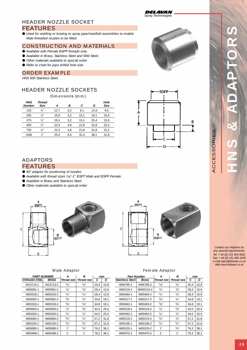
HN
S &
AD
AP
TO
RS
J.9
Contact our Helpline forany special requirements:Tel: +44 (0) 151 424 6821Fax: +44 (0) 151 495 1043e-mail:[email protected]
Web:www.delavan.co.uk
AC
CE
SS
OR
IES
HEADER NOZZLE SOCKETFEATURES● Used for welding or brazing to spray pipe/manifold assemblies to enable
Male threaded nozzles to be fitted.
CONSTRUCTION AND MATERIALS● Available with Female BSPP threads only.● Available in Brass, Stainless Steel and Mild Steel.● Other materials available to special order.● Refer to chart for pipe drilled hole size.
ORDER EXAMPLEHNS 500 Stainless Steel.
ADAPTORSFEATURES● 90° adaptor for positioning of nozzles.● Available with thread sizes 1/8”-1” BSPT Male and BSPP Female.● Available in Brass and Stainless Steel.● Other materials available to special order.
HNS Thread HoleNumber Size A B C D Size
125 1⁄8” 12,7 3,2 9,1 14,3 9,5
250 1⁄4” 15,9 3,2 15,1 19,1 15,9
375 3⁄8” 19,1 3,2 15,1 25,4 15,9
500 1⁄2” 22,3 4,8 21,8 31,8 22,2
750 3⁄4” 22,3 4,8 21,8 31,8 22,2
1000 1” 25,4 6,4 31,4 38,1 31,8
Dimensions (mm)
PART NUMBER A B mmSTAINLESS STEEL BRASS Thread size Thread size C D
W13713-1 W13713-2 1/8” 1/8” 25,4 15,9
W00081-1 W00081-2 1/4” 1/8” 28,4 15,9
W00318-1 W00318-2 1/4” 1/4” 28,4 15,9
W00082-1 W00082-2 3/8” 1/4” 34,8 19,1
W00319-1 W00319-2 3/8” 3/8” 34,8 19,1
W00083-1 W00083-2 1/2” 3/8” 44,5 25,4
W00320-1 W00320-2 1/2” 1/2” 44,5 25,4
W00084-1 W00084-2 3/4” 1/2” 57,2 31,8
W00194-1 W00194-2 3/4” 3/4” 57,2 31,8
W00085-1 W00085-2 1” 3/4” 76,2 38,1
W00468-1 W00468-2 1” 1” 76,2 38,1
Male Adaptor
Part Number A B mmStainless Steel Brass Thread size Thread size C D
W06785-1 W06785-2 1/8” 1/8” 25,4 15,9
W00216-1 W000216-2 1/4” 1/8” 28,4 15,9
W00464-1 W00464-2 1/4” 1/4” 28,4 15,9
W00217-1 W00217-2 3/8” 1/4” 34,8 19,1
W00463-1 W00463-2 3/8” 3/8” 34,8 19,1
W00218-1 W00218-2 1/2” 3/8” 44,5 25,4
W00462-1 W00462-2 1/2” 1/2” 44,5 25,4
W00219-1 W00219-2 3/4” 1/2” 57,2 31,8
W00196-1 W00196-2 3/4” 3/4” 57,2 31,8
W00220-1 W00220-2 1” 3/4” 76,2 38,1
W00470-1 W00470-2 1” 1” 76,2 38,1
Female Adaptor
HEADER NOZZLE SOCKETS
Accessories B 21/6/01 10:04 am Page 9

AD
JUS
TAB
LE J
OIN
T
J.10
Contact our Helpline forany special requirements:Tel: +44 (0) 151 424 6821Fax: +44 (0) 151 495 1043e-mail:[email protected]
Web:www.delavan.co.uk
CAPACITY CHARTASSEMBLY INLET SIZE OUTLET SIZE DIMENSIONS (mm) ANGULARNUMBER BSPT BSPP A B C Hex ADJUSTMENT (°)
WO9111-1 1⁄8” 1⁄8” 28,6 25,4 20,8 50
WO9111-2 1⁄4” 1⁄8” 28,6 25,4 20,8 50
WO9111-3 1⁄4” 1⁄4” 34,9 31,8 25,7 50
WO9111-4 3⁄8” 1⁄4” 34,9 31,8 25,7 50
WO9111-5 3⁄8” 3⁄8” 44,5 38,1 31,8 40
WO9111-6 1⁄2” 1⁄2” 55,6 44,5 31,8 40
WO9111-7 3⁄4” 3⁄4” 61,1 50,8 38,0 40
WO9111-8 1” 1” 75,0 70,0 60,0 40
FEATURES● Facilitates finger-tight nozzle adjustment without disturbing piping system.● No tools required for repositioning.● Positive O-ring seal handles pressures up to 35 Bar.G.● No internal obstructions.● Complete 360° radial adjustment.● Up to 50° angular adjustment.
CONSTRUCTION AND MATERIALS● Available with Male BSPT inlet connections and Female BSPP outlets.● Available in Brass and Stainless Steel.● Other materials available to special order.
ORDER EXAMPLEW09111-4 (3/8” x 1/4”) Stainless Steel.
AC
CE
SS
OR
IES
Accessories B 21/6/01 10:04 am Page 10

J.11
Contact our Helpline forany special requirements:Tel: +44 (0) 151 424 6821Fax: +44 (0) 151 495 1043e-mail:[email protected]
Web:www.delavan.co.uk
CU
STO
ME
R E
NQ
UIR
YFA
X B
AC
K
Spray Drying
Fax Back FormName: _______________________________________________________ Date: ______________________________________
Company:_________________________________________________________________________________________________
Address: __________________________________________________________________________________________________
___________________________________________________________________________________________________________
___________________________________________________________________________________________________________
Tel No:_______________________________________________________ Fax No:____________________________________
The Feed Material
Substance being sprayed: ___________________________________ % Solids: _________________________________
Specific gravity (or Density): _________________________________ Viscosity: _________________________________
Acidic or alkaline (pH): ______________________________________
The Nozzle
Nozzle type presently being used: ________________________________________________________________________
Manufacturer: _______________________________________________ Number of nozzles: _______________________
Rated flow and spray angle: _________________________________ Average wear life: _________________________
Pipe size: ___________________________________________________
The Dryer
Dryer manufacturer: _________________________________________ Inlet air temp: _____________________________
Cocurrent or countercurrent air: _____________________________ Outlet air temp: ___________________________
Dryer diameter at nozzle position: ___________________________ Maximum pump pressure: ________________
Pump manufacturer: ________________________________________ Operating pressure: _______________________
The Dry Product
% Moisture: _________________________________________________ Density: ___________________________________
Pounds per hour: ___________________________________________ Solubility: _________________________________
Comments: ______________________________________________________________________________________________
___________________________________________________________________________________________________________
___________________________________________________________________________________________________________
___________________________________________________________________________________________________________
Please fax back to:
+44 (0)151 495 1043Delavan Ltd.•Gorsey Lane•Widnes•Cheshire WA8 0RJ•England
Tel: +44 (0) 151 424 6821. E-mail: [email protected]. Web: www.delavan.co.uk
✁
Accessories B 21/6/01 10:04 am Page 11

CU
STO
ME
R E
NQ
UIR
Y
J.12
Contact our Helpline forany special requirements:Tel: +44 (0) 151 424 6821Fax: +44 (0) 151 495 1043e-mail:[email protected]
Web:www.delavan.co.uk
FA
X B
AC
KGas Cooling Information
Fax Back FormName: _______________________________________________________ Date: ______________________________________
Company:_________________________________________________________________________________________________
Address: __________________________________________________________________________________________________
___________________________________________________________________________________________________________
___________________________________________________________________________________________________________
Tel No:_______________________________________________________ Fax No:____________________________________
Inlet gas temperature: a) _________________ ˚C b) _________________ ˚F
Outlet gas temperature: a) _________________ ˚C b) _________________ ˚F
Volume of gas: a) _________________ SCFM b) ___________________ NM3/hr
Cooling chamber dimensions: a) Circular b) Rectangular
i __________________ Diameter i __________________ Height
ii __________________ Length ii __________________ Width
iii _________________ Length
Comments: _______________________________________________________________________________________________
___________________________________________________________________________________________________________
___________________________________________________________________________________________________________
___________________________________________________________________________________________________________
___________________________________________________________________________________________________________
Please fax back to:
+44 (0)151 495 1043Delavan Ltd.•Gorsey Lane•Widnes•Cheshire WA8 0RJ•England
Tel: +44 (0) 151 424 6821. E-mail: [email protected]. Web: www.delavan.co.uk
✁
Accessories B 21/6/01 10:05 am Page 12

CU
STO
ME
R E
NQ
UIR
Y
J.13
Contact our Helpline forany special requirements:Tel: +44 (0) 151 424 6821Fax: +44 (0) 151 495 1043e-mail:[email protected]
Web:www.delavan.co.uk
FA
X B
AC
K
Nozzle Specification Information
Fax Back FormName: ________________________________________________ Date: _____________________________________________
Company:_________________________________________________________________________________________________
Address: __________________________________________________________________________________________________
___________________________________________________________________________________________________________
___________________________________________________________________________________________________________
Tel No:________________________________________________ Fax No:___________________________________________
To specify any type of nozzle it is essential to provide several pieces of information:
Flow rate: ________________________________________________________________________________________________
which can be given in a variety of units such as:
● Litres per minute ● Gallons per minute (specify US or Imp)
● M3/hour ● Kg per hour (density will be required if different from water
Operating pressure: _____________________________________________________________________________________
which can be given in a variety of units such as:
● Bar.G. ● P.S.I.G.
● Kg/cm2 ● kPa (Kilo Pascals)
● Head in Metres or Feet
Spray angle: _____________________________________________________________________________________________
Type of spray pattern: ___________________________________________________________________________________
● Flat ● Solid Cone/Circular or Square
● Hollow Cone ● Air Atomising
Liquid being sprayed: ___________________________________________________________________________________
If different from water the following are required:
● Density: ____________________________ ● Viscosity: _______________________________________
● Surface Tension: ____________________ ● Solids Content : ______________________________________
Application or Purpose of Nozzle (not always necessary) e.g.
● Washing/Rinsing ● Cleaning in Place ● Humidification
● Gas Scrubbing ● Quenching
● Aeration of liquids ● De-Scaling
● Gas Cooling - Separate Enquiry Sheet required
● Spray Drying - Separate Enquiry Sheet required
___________________________________________________________________________________________________________
___________________________________________________________________________________________________________
Please fax back to:
+44 (0)151 495 1043Delavan Ltd.•Gorsey Lane•Widnes•Cheshire WA8 0RJ•England
Tel: +44 (0) 151 424 6821. E-mail: [email protected]. Web: www.delavan.co.uk
✁
Accessories B 21/6/01 10:05 am Page 13

Safety Showers& Accessories
Pulp and PaperGuide
Clean in PlaceProduct Guide
Other Specialist literature available
Availa
ble
Soon Availa
ble
Soon
Oil BurnerNozzles &
Accessories
VariableCoatingNozzle
Steel IndustryProduct Guide
Short FormBrochure
SDX SprayDrying
Availa
ble
Soon
Copyright © 2022 FDOKUMEN