ENGINE MECHANICAL
284
EM-1 ENGINE MECHANICAL B ENGINE CONTENTS C D E F G H I J K L M SECTION EM A EM ENGINE MECHANICAL VQ PRECAUTIONS ......................................................... 6 Precautions for Drain Engine Coolant ..................... 6 Precautions for Disconnecting Fuel Piping ............. 6 Precautions for Removal and Disassembly ............ 6 Precautions for Inspection, Repair and Replace- ment ........................................................................ 6 Precautions for Assembly and Installation .............. 6 Parts Requiring Angle Tightening ............................ 6 Precautions for Liquid Gasket ................................. 7 REMOVAL OF LIQUID GASKET SEALING ......... 7 LIQUID GASKET APPLICATION PROCEDURE ..... 7 PREPARATION .......................................................... 8 Special Service Tools .............................................. 8 Commercial Service Tools ....................................... 9 NOISE, VIBRATION AND HARSHNESS (NVH) TROUBLESHOOTING .............................................. 11 NVH Troubleshooting —Engine Noise ................... 11 Use the Chart Below to Help You Find the Cause of the Symptom. .................................................... 12 DRIVE BELTS .......................................................... 13 Checking Drive Belts ............................................. 13 Tension Adjustment ............................................... 13 Removal and Installation ....................................... 13 REMOVAL .......................................................... 13 INSTALLATION .................................................. 14 Drive Belt Auto Tensioner and Idler Pulley ............ 15 REMOVAL .......................................................... 15 INSTALLATION .................................................. 15 AIR CLEANER AND AIR DUCT .............................. 16 Components .......................................................... 16 Removal and Installation ....................................... 16 REMOVAL .......................................................... 16 INSPECTION AFTER REMOVAL ...................... 16 INSTALLATION .................................................. 16 Changing Air Cleaner Filter ................................... 16 REMOVAL .......................................................... 16 INSTALLATION .................................................. 16 INTAKE MANIFOLD COLLECTOR ......................... 17 Components .......................................................... 17 Removal and Installation ....................................... 17 REMOVAL .......................................................... 17 INSTALLATION .................................................. 18 INTAKE MANIFOLD ................................................ 20 Components .......................................................... 20 Removal and Installation ....................................... 20 REMOVAL .......................................................... 20 INSPECTION AFTER REMOVAL ...................... 21 INSTALLATION .................................................. 21 EXHAUST MANIFOLD AND THREE WAY CATA- LYST ......................................................................... 22 Components .......................................................... 22 Removal and Installation ....................................... 22 REMOVAL (LEFT BANK) ................................... 22 INSPECTION AFTER REMOVAL (LEFT BANK)...24 INSTALLATION (LEFT BANK) ........................... 24 REMOVAL (RIGHT BANK) ................................. 25 INSPECTION AFTER REMOVAL (RIGHT BANK) ................................................................ 25 INSTALLATION (RIGHT BANK) ......................... 25 OIL PAN AND OIL STRAINER ................................ 27 Components .......................................................... 27 Removal and Installation ....................................... 27 REMOVAL .......................................................... 27 INSPECTION AFTER REMOVAL ...................... 29 INSTALLATION .................................................. 29 INSPECTION AFTER INSTALLATION ............... 31 IGNITION COIL ........................................................ 32 Components .......................................................... 32 Removal and Installation ....................................... 32 REMOVAL (LEFT BANK) ................................... 32 INSTALLATION (LEFT BANK) ........................... 32 REMOVAL (RIGHT BANK) ................................. 32 INSTALLATION (RIGHT BANK) ......................... 32
-
Upload
khangminh22 -
Category
Documents
-
view
2 -
download
0
Transcript of ENGINE MECHANICAL
EM-1
ENGINE MECHANICAL
B ENGINE
CONTENTS
C
D
E
F
G
H
I
J
K
L
M
SECTIONEMA
EM
ENGINE MECHANICAL
VQ
PRECAUTIONS .......................................................... 6Precautions for Drain Engine Coolant ...................... 6Precautions for Disconnecting Fuel Piping .............. 6Precautions for Removal and Disassembly ............. 6Precautions for Inspection, Repair and Replace-ment ......................................................................... 6Precautions for Assembly and Installation ............... 6Parts Requiring Angle Tightening ............................. 6Precautions for Liquid Gasket .................................. 7
REMOVAL OF LIQUID GASKET SEALING .......... 7LIQUID GASKET APPLICATION PROCEDURE..... 7
PREPARATION ........................................................... 8Special Service Tools ............................................... 8Commercial Service Tools ........................................ 9
NOISE, VIBRATION AND HARSHNESS (NVH)TROUBLESHOOTING ...............................................11
NVH Troubleshooting —Engine Noise ....................11Use the Chart Below to Help You Find the Causeof the Symptom. ..................................................... 12
DRIVE BELTS ........................................................... 13Checking Drive Belts .............................................. 13Tension Adjustment ................................................ 13Removal and Installation ........................................ 13
REMOVAL ........................................................... 13INSTALLATION ................................................... 14
Drive Belt Auto Tensioner and Idler Pulley ............. 15REMOVAL ........................................................... 15INSTALLATION ................................................... 15
AIR CLEANER AND AIR DUCT ............................... 16Components ........................................................... 16Removal and Installation ........................................ 16
REMOVAL ........................................................... 16INSPECTION AFTER REMOVAL ....................... 16INSTALLATION ................................................... 16
Changing Air Cleaner Filter .................................... 16REMOVAL ........................................................... 16INSTALLATION ................................................... 16
INTAKE MANIFOLD COLLECTOR .......................... 17Components ........................................................... 17Removal and Installation ........................................ 17
REMOVAL ........................................................... 17INSTALLATION ................................................... 18
INTAKE MANIFOLD ................................................. 20Components ........................................................... 20Removal and Installation ........................................ 20
REMOVAL ........................................................... 20INSPECTION AFTER REMOVAL ....................... 21INSTALLATION ................................................... 21
EXHAUST MANIFOLD AND THREE WAY CATA-LYST .......................................................................... 22
Components ........................................................... 22Removal and Installation ........................................ 22
REMOVAL (LEFT BANK) .................................... 22INSPECTION AFTER REMOVAL (LEFT BANK)... 24INSTALLATION (LEFT BANK) ............................ 24REMOVAL (RIGHT BANK) .................................. 25INSPECTION AFTER REMOVAL (RIGHTBANK) ................................................................. 25INSTALLATION (RIGHT BANK) .......................... 25
OIL PAN AND OIL STRAINER ................................. 27Components ........................................................... 27Removal and Installation ........................................ 27
REMOVAL ........................................................... 27INSPECTION AFTER REMOVAL ....................... 29INSTALLATION ................................................... 29INSPECTION AFTER INSTALLATION ................ 31
IGNITION COIL ......................................................... 32Components ........................................................... 32Removal and Installation ........................................ 32
REMOVAL (LEFT BANK) .................................... 32INSTALLATION (LEFT BANK) ............................ 32REMOVAL (RIGHT BANK) .................................. 32INSTALLATION (RIGHT BANK) .......................... 32
EM-2
SPARK PLUG (PLATINUM-TIPPED TYPE) ............. 33Components ........................................................... 33Removal and Installation ........................................ 33
REMOVAL ........................................................... 33INSPECTION AFTER REMOVAL ........................ 33INSTALLATION .................................................... 34
FUEL INJECTOR AND FUEL TUBE ........................ 35Components ........................................................... 35Removal and Installation ........................................ 35
REMOVAL ........................................................... 35INSTALLATION .................................................... 38INSPECTION AFTER INSTALLATION ................ 39
ROCKER COVER ..................................................... 40Components ........................................................... 40Removal and Installation ........................................ 40
REMOVAL ........................................................... 40INSTALLATION .................................................... 41
FRONT TIMING CHAIN CASE ................................. 43Removal and Installation ........................................ 43
REMOVAL ........................................................... 43INSTALLATION .................................................... 47INSPECTION AFTER INSTALLATION ................ 51
TIMING CHAIN .......................................................... 52Components ........................................................... 52Removal and Installation ........................................ 53
REMOVAL ........................................................... 53INSPECTION AFTER REMOVAL ........................ 60INSTALLATION .................................................... 61INSPECTION AFTER INSTALLATION ................ 71
CAMSHAFT ............................................................... 72Components ........................................................... 72Removal and Installation ........................................ 73
REMOVAL ........................................................... 73INSPECTION AFTER REMOVAL ........................ 74INSTALLATION .................................................... 77INSPECTION AFTER INSTALLATION ................ 81
Valve Clearance ...................................................... 82INSPECTION ....................................................... 82ADJUSTMENT .................................................... 85
OIL SEAL .................................................................. 87Removal and Installation of Valve Oil Seal ............. 87
REMOVAL ........................................................... 87INSTALLATION .................................................... 87
Removal and Installation of Front Oil Seal ............. 88REMOVAL ........................................................... 88INSTALLATION .................................................... 88
Removal and Installation of Rear Oil Seal .............. 88REMOVAL ........................................................... 88INSTALLATION .................................................... 89
CYLINDER HEAD ..................................................... 90On-Vehicle Service ................................................. 90
CHECKING COMPRESSION PRESSURE ......... 90Components ........................................................... 91Removal and Installation ........................................ 91
REMOVAL ........................................................... 91INSPECTION AFTER REMOVAL ........................ 92INSTALLATION .................................................... 93INSPECTION AFTER INSTALLATION ................ 95
Components ........................................................... 95
Disassembly and Assembly ....................................96DISASSEMBLY ....................................................96ASSEMBLY ..........................................................96
Inspection After Disassembly ..................................98VALVE DIMENSIONS ..........................................98VALVE GUIDE CLEARANCE ..............................98VALVE GUIDE REPLACEMENT .........................98VALVE SEAT CONTACT ....................................100VALVE SEAT REPLACEMENT ..........................100VALVE SPRING SQUARENESS .......................101VALVE SPRING DIMENSIONS AND VALVESPRING PRESSURE LOAD ..............................101
ENGINE ASSEMBLY ...............................................102Components ..........................................................102Removal and Installation .......................................103
REMOVAL ..........................................................103INSTALLATION ..................................................104INSPECTION AFTER INSTALLATION ..............104
CYLINDER BLOCK .................................................105Components ..........................................................105Disassembly and Assembly ..................................106
DISASSEMBLY ..................................................106ASSEMBLY ........................................................109
How to Select Piston and Bearing ........................ 116DESCRIPTION .................................................. 116HOW TO SELECT PISTON ............................... 116HOW TO SELECT CONNECTING ROD BEAR-ING ..................................................................... 117HOW TO SELECT MAIN BEARING .................. 118
Inspection After Disassembly ................................121CRANKSHAFT END PLAY ................................121CONNECTING ROD SIDE CLEARANCE .........121PISTON TO PISTON PIN OIL CLEARANCE .....121PISTON RING SIDE CLEARANCE ...................122PISTON RING END GAP ..................................122CONNECTING ROD BEND AND TORSION .....123CONNECTING ROD BIG END DIAMETER ......123CONNECTING ROD BUSHING OIL CLEAR-ANCE .................................................................123CYLINDER BLOCK DISTORTION ....................124MAIN BEARING HOUSING INNER DIAMETER.125PISTON TO CYLINDER BORE CLEARANCE ..125CRANKSHAFT MAIN JOURNAL DIAMETER ...126CRANKSHAFT PIN JOURNAL DIAMETER ......127CRANKSHAFT OUT-OF-ROUND AND TAPER.127CRANKSHAFT RUNOUT ..................................127CONNECTING ROD BEARING OIL CLEAR-ANCE .................................................................127MAIN BEARING OIL CLEARANCE ...................128CRUSH HEIGHT OF MAIN BEARING ..............129CRUSH HEIGHT OF CONNECTING RODBEARING ...........................................................129LOWER CYLINDER BLOCK BOLT OUTERDIAMETER ........................................................129CONNECTING ROD BOLT OUTER DIAMETER.130DRIVE PLATE ....................................................130OIL JET ..............................................................130OIL JET RELIEF VALVE ....................................130
EM-3
C
D
E
F
G
H
I
J
K
L
M
EM
ASERVICE DATA AND SPECIFICATIONS (SDS) .... 131
Standard and Limit ............................................... 131GENERAL SPECIFICATIONS .......................... 131DRIVE BELT ..................................................... 132INTAKE MANIFOLD COLLECTOR, INTAKEMANIFOLD AND EXHAUST MANIFOLD ......... 132SPARK PLUG ................................................... 132CAMSHAFT AND CAMSHAFT BEARING ........ 133CYLINDER HEAD ............................................. 135CYLINDER BLOCK ........................................... 138PISTON, PISTON RING AND PISTON PIN ...... 139CONNECTING ROD ......................................... 140CRANKSHAFT .................................................. 141MAIN BEARING ................................................ 142CONNECTING ROD BEARING ........................ 143
YD
PRECAUTIONS ...................................................... 144Precautions for Draining Engine Coolant ............. 144Precautions for Disconnecting Fuel Piping .......... 144Precautions for Removal and Disassembly ......... 144Precautions for Inspection, Repair and Replace-ment ..................................................................... 144Precautions for Assembly and Installation ........... 144Parts Requiring Angle Tightening ......................... 144Precautions For Liquid Gasket ............................. 145
REMOVAL OF LIQUID GASKET ...................... 145LIQUID GASKET APPLICATION PROCEDURE. 145
PREPARATION ....................................................... 146Special Service Tools ........................................... 146Commercial Service Tools .................................... 148
NOISE, VIBRATION AND HARSHNESS (NVH)TROUBLESHOOTING ............................................ 150
NVH Troubleshooting — Engine Noise ................ 150Use the Chart Below to Help You Find the Causeof the Symptom. ................................................... 151
DRIVE BELTS ......................................................... 152Checking Drive Belts ............................................ 152Deflection Adjustment .......................................... 153
POWER STEERING OIL PUMP BELT ............. 153A/C COMPRESSOR, ALTERNATOR ANDWATER PUMP BELT ........................................ 154
Removal and Installation ...................................... 154REMOVAL ......................................................... 154INSTALLATION ................................................. 154
AIR CLEANER AND AIR DUCT ............................. 155Components ......................................................... 155Removal and Installation ...................................... 155
REMOVAL ......................................................... 155INSTALLATION ................................................. 156CHANGING AIR CLEANER FILTER ................. 157
CHARGE AIR COOLER ......................................... 158Components ......................................................... 158Removal and Installation ...................................... 158
REMOVAL ......................................................... 158INSPECTION AFTER REMOVAL ..................... 159INSTALLATION ................................................. 159
INTAKE MANIFOLD ............................................... 160Components ......................................................... 160Removal and Installation ...................................... 161
REMOVAL ......................................................... 161INSPECTION AFTER REMOVAL ..................... 162INSTALLATION ................................................. 162INSPECTION AFTER INSTALLATION .............. 165
CATALYST .............................................................. 166Components ......................................................... 166Removal and Installation ...................................... 166
REMOVAL ......................................................... 166INSTALLATION ................................................. 167
TURBO CHARGER ................................................. 168Components ......................................................... 168Removal and Installation ...................................... 168
REMOVAL ......................................................... 168INSPECTION AFTER REMOVAL ..................... 169TROUBLE DIAGNOSIS OF TURBOCHARGER. 170INSTALLATION ................................................. 171
EXHAUST MANIFOLD ........................................... 172Components ......................................................... 172Removal and Installation ...................................... 172
REMOVAL ......................................................... 172INSPECTION AFTER REMOVAL ..................... 173INSTALLATION ................................................. 173INSPECTION AFTER INSTALLATION .............. 173
OIL PAN AND OIL STRAINER ............................... 174Components ......................................................... 174Removal and Installation ...................................... 174
REMOVAL ......................................................... 174INSPECTION AFTER REMOVAL ..................... 176INSTALLATION ................................................. 176INSPECTION AFTER INSTALLATION .............. 178
GLOW PLUG .......................................................... 179Components ......................................................... 179Removal and Installation ...................................... 179
REMOVAL ......................................................... 179INSTALLATION ................................................. 179
VACUUM PUMP ...................................................... 180Components ......................................................... 180Removal and Installation ...................................... 180
INSPECTION BEFORE REMOVAL .................. 180REMOVAL ......................................................... 180INSTALLATION ................................................. 181
INJECTION TUBE AND FUEL INJECTOR ............ 182Components ......................................................... 182Removal and Installation ...................................... 182
REMOVAL ......................................................... 182INSTALLATION ................................................. 184INSPECTION AFTER INSTALLATION .............. 186
FUEL PUMP ............................................................ 187Components ......................................................... 187Removal and Installation ...................................... 187
REMOVAL ......................................................... 187INSPECTION AFTER REMOVAL ..................... 190INSTALLATION ................................................. 190
EM-4
ROCKER COVER ................................................... 194Components ......................................................... 194Removal and Installation ...................................... 194
REMOVAL ......................................................... 194INSTALLATION .................................................. 195INSPECTION AFTER INSTALLATION .............. 195
CAMSHAFT ............................................................. 197Components ......................................................... 197Removal and Installation ...................................... 197
REMOVAL ......................................................... 197INSPECTION AFTER REMOVAL ...................... 198INSTALLATION .................................................. 201INSPECTION AFTER INSTALLATION .............. 203
Valve Clearance .................................................... 204INSPECTION ..................................................... 204ADJUSTMENTS ................................................ 205
OIL SEAL ................................................................ 208Removal and Installation of Valve Oil Seal ........... 208
REMOVAL ......................................................... 208INSTALLATION .................................................. 208
Removal and Installation of Front Oil Seal ........... 209REMOVAL ......................................................... 209INSTALLATION .................................................. 209
Removal and Installation of Rear Oil Seal ............ 210REMOVAL ......................................................... 210INSTALLATION .................................................. 210
SECONDARY TIMING CHAIN ................................ 211Components ......................................................... 211Removal and Installation ...................................... 211
REMOVAL ......................................................... 211INSPECTION AFTER REMOVAL ...................... 213INSTALLATION .................................................. 213INSPECTION AFTER INSTALLATION .............. 215
PRIMARY TIMING CHAIN ...................................... 217Components ......................................................... 217Removal and Installation ...................................... 218
REMOVAL ......................................................... 218INSPECTION AFTER REMOVAL ...................... 222INSTALLATION .................................................. 223INSPECTION AFTER INSTALLATION .............. 229
CYLINDER HEAD ................................................... 230On-Vehicle Service ............................................... 230
CHECKING COMPRESSION PRESSURE ....... 230Components ......................................................... 231Removal and Installation ...................................... 232
REMOVAL ......................................................... 232INSPECTION AFTER REMOVAL ...................... 232INSTALLATION .................................................. 234INSPECTION AFTER INSTALLATION .............. 236
Components ......................................................... 237Disassembly and Assembly .................................. 237
DISASSEMBLY ................................................. 237ASSEMBLY ....................................................... 238INSPECTION AFTER DISASSEMBLY .............. 239
ENGINE ASSEMBLY ...............................................244Components ..........................................................244Removal and Installation .......................................245
REMOVAL ..........................................................245INSTALLATION ..................................................246INSPECTION AFTER INSTALLATION ..............246
CYLINDER BLOCK .................................................248Components ..........................................................248Disassembly and Assembly ..................................249
DISASSEMBLY ..................................................249ASSEMBLY ........................................................252
How to Select Piston and Bearing ........................259DESCRIPTION ..................................................259HOW TO SELECT PISTON ...............................259HOW TO SELECT CONNECTING ROD BEAR-ING .....................................................................260HOW TO SELECT MAIN BEARING ..................261
Inspection After Disassembly ................................262CRANKSHAFT END PLAY ................................262CONNECTING ROD SIDE CLEARANCE .........263PISTON TO PISTON PIN CLEARANCE ...........263PISTON RING SIDE CLEARANCE ...................264PISTON RING END GAP ..................................264CONNECTING ROD BEND AND TORSION .....265CONNECTING ROD BIG END INNER DIAME-TER ....................................................................265CONNECTING ROD BUSHING OIL CLEAR-ANCE .................................................................265CYLINDER BLOCK TOP SURFACE DISTOR-TION ..................................................................266MAIN BEARING HOUSING INNER DIAMETER.266PISTON TO CYLINDER BORE CLEARANCE ..267CRANKSHAFT JOURNAL OUTER DIAMETER.268CRANKSHAFT PIN OUTER DIAMETER ..........268CRANKSHAFT OUT-OF-ROUND AND TAPER.268CRANKSHAFT RUNOUT ..................................269CONNECTING ROD BEARING OIL CLEAR-ANCE .................................................................269MAIN BEARING OIL CLEARANCE ...................270CRUSH HEIGHT OF MAIN BEARING ..............270CRUSH HEIGHT OF CONNECTING RODBEARING ...........................................................270MAIN BEARING CAP BOLT DEFORMATION ...271CONNECTING ROD BOLT DEFORMATION ....271OIL JET ..............................................................271OIL JET RELIEF VALVE ....................................271FLYWHEEL DEFLECTION ................................272MOVEMENT AMOUNT OF FLYWHEEL ...........272DRIVE PLATE ....................................................272
SERVICE DATA AND SPECIFICATIONS (SDS) ....273Standard and Limit ................................................273
GENERAL SPECIFICATIONS ...........................273INTAKE MANIFOLD AND EXHAUST MANI-
EM-5
C
D
E
F
G
H
I
J
K
L
M
EM
AFOLD ................................................................. 273DRIVE BELTS ................................................... 273CYLINDER HEAD ............................................. 274VALVE ............................................................... 274CAMSHAFT ....................................................... 278CYLINDER BLOCK ........................................... 279PISTON, PISTON RING AND PISTON PIN ...... 279CONNECTING ROD ......................................... 281CRANKSHAFT .................................................. 281AVAILABLE MAIN BEARING ............................ 282AVAILABLE CONNECTING ROD BEARING .... 282MISCELLANEOUS COMPONENTS ................. 282

EM-6
[VQ]PRECAUTIONS
[VQ]PRECAUTIONS PFP:00001
Precautions for Drain Engine Coolant BBS00001
Drain engine coolant when engine is cooled.
Precautions for Disconnecting Fuel Piping BBS00002
● Before starting work, make sure no fire or spark producing items are in the work area.● Release fuel pressure before disconnecting and disassembly.● After disconnecting pipes, plug openings to stop fuel leakage.
Precautions for Removal and Disassembly BBS00003
● When instructed to use SST, use the specified tools. Always be careful to work safely, avoid forceful oruninstructed operations.
● Exercise maximum care to avoid damage to mating or sliding surfaces.● Cover openings of engine system with tape or the equivalent, if necessary, to seal out foreign materials.● Mark and arrange disassembly parts in an organized way for easy troubleshooting and re-assembly.● When loosening nuts and bolts, as a basic rule, start with the one furthest outside, then the one diagonally
opposite, and so on. If the order of loosening is specified, do exactly as specified.
Precautions for Inspection, Repair and Replacement BBS00004
Before repairing or replacing, thoroughly inspect parts. Inspect new replacement parts in the same way, andreplace if necessary.
Precautions for Assembly and Installation BBS00005
● Use torque wrench to tighten bolts or nuts to specification.● When tightening nuts and bolts, as a basic rule, equally tighten in several different steps starting with the
ones in center, then ones on inside and outside diagonally in this order. If the order of tightening is speci-fied, do exactly as specified.
● Replace with new gasket, packing, oil seal or O-ring.● Dowel pins are used for several parts alignment. When replacing and reassembling parts with dowel pins,
make sure that dowel pins are installed in the original position.● Thoroughly wash, clean, and air-blow each part. Carefully check engine oil or engine coolant passages for
any restriction and blockage.● Avoid damaging sliding or mating surfaces. Completely remove foreign materials such as cloth lint or dust.
Before assembly, oil sliding surfaces well.● Release air within route when refilling after draining engine coolant.● After repairing, start engine and increase engine speed to check engine coolant, fuel, engine oil, and
exhaust gasses for leakage.
Parts Requiring Angle Tightening BBS00006
● Use angle wrench [SST: KV10112100] for the final tightening of the following engine parts:– Cylinder head bolts– Lower cylinder block bolts– Connecting rod cap bolts– Crankshaft pulley bolt (The angle wrench is not required as bolt flange is provided with notches for angle
tightening)● Do not use a torque value for final tightening.● The torque value for these parts are for a preliminary step.● Ensure thread and seat surfaces are clean and coated with engine oil.

PRECAUTIONS
EM-7
[VQ]
C
D
E
F
G
H
I
J
K
L
M
A
EM
Precautions for Liquid Gasket BBS00007
REMOVAL OF LIQUID GASKET SEALING● After removing mounting nuts and bolts, separate the mating
surface using the seal cutter [SST] and remove the old liquidgasket sealing.CAUTION:Be careful not to damage the mating surfaces.
● Tap seal cutter to insert it, and then slide it by tapping on theside as shown in the figure.
● In areas where seal cutter [SST] is difficult to use, use plastichammer to lightly tap the parts, to remove it.CAUTION:If for some unavoidable reason tool such as screwdriver isused, be careful not to damage the mating surfaces.
LIQUID GASKET APPLICATION PROCEDURE1. Using a scraper, remove the old liquid gasket adhering to the liq-
uid gasket application surface and the mating surface.● Remove the liquid gasket completely from the groove of the
liquid gasket application surface, mounting bolts, and boltholes.
2. Wipe the liquid gasket application surface and the mating sur-face with white gasoline (lighting and heating use) to removeadhering moisture, grease and foreign materials.
3. Attach liquid gasket tube to tube presser [SST].Use Genuine Liquid Gasket or equivalent.
4. Apply the liquid gasket without breaks to the specified locationwith the specified dimensions.● If there is a groove for the liquid gasket application, apply the
liquid gasket to the groove.
● As for the bolt holes, normally apply the liquid gasket insidethe holes. If specified, it should be applied outside the holes.Make sure to read the text of this manual.
● Within five minutes of liquid gasket application, install the mat-ing component.
● If the liquid gasket protrudes, wipe it off immediately.● Do not retighten mounting bolts or nuts after the installation.● After 30 minutes or more have passed from the installation, fill
engine oil and engine coolant.CAUTION:If there are specific instructions in this manual, observethem.
PBIC0275E
PBIC0003E
PBIC2160E
SEM159F
EM-8
[VQ]PREPARATION
PREPARATION PFP:00002
Special Service Tools BBS00008
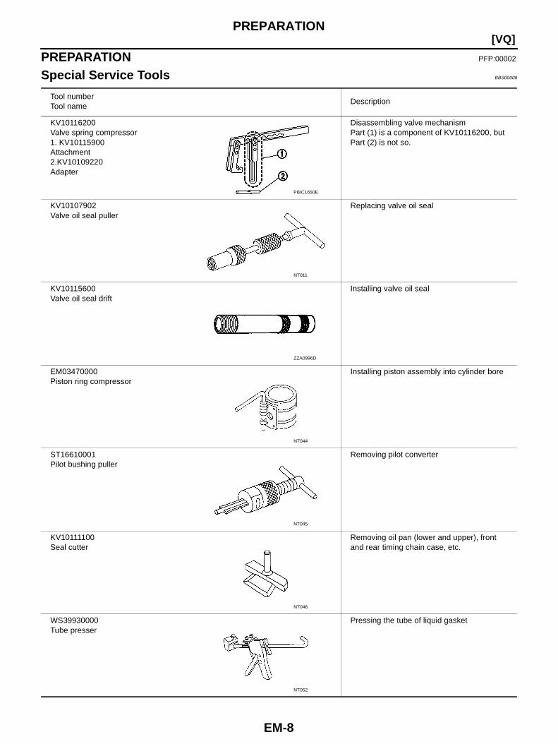
Tool numberTool name
Description
KV10116200Valve spring compressor1. KV10115900Attachment2.KV10109220Adapter
Disassembling valve mechanismPart (1) is a component of KV10116200, butPart (2) is not so.
KV10107902Valve oil seal puller
Replacing valve oil seal
KV10115600Valve oil seal drift
Installing valve oil seal
EM03470000Piston ring compressor
Installing piston assembly into cylinder bore
ST16610001Pilot bushing puller
Removing pilot converter
KV10111100Seal cutter
Removing oil pan (lower and upper), frontand rear timing chain case, etc.
WS39930000Tube presser
Pressing the tube of liquid gasket
PBIC1650E
NT011
ZZA0996D
NT044
NT045
NT046
NT052
PREPARATION
EM-9
[VQ]
C
D
E
F
G
H
I
J
K
L
M
A
EM
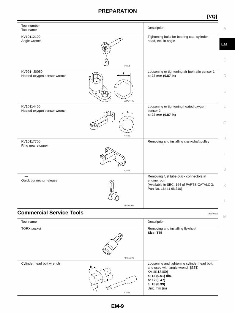
Commercial Service Tools BBS00009
KV10112100Angle wrench
Tightening bolts for bearing cap, cylinderhead, etc. in angle
KV991- J0050Heated oxygen sensor wrench
Loosening or tightening air fuel ratio sensor 1a: 22 mm (0.87 in)
KV10114400Heated oxygen sensor wrench
Loosening or tightening heated oxygensensor 2a: 22 mm (0.87 in)
KV10117700Ring gear stopper
Removing and installing crankshaft pulley
—Quick connector release
Removing fuel tube quick connectors inengine room(Available in SEC. 164 of PARTS CATALOG:Part No. 16441 6N210)
Tool numberTool name
Description
NT014
LBIA0444E
NT636
NT822
PBIC0198E
Tool name Description
TORX socket Removing and installing flywheelSize: T55
Cylinder head bolt wrench Loosening and tightening cylinder head bolt,and used with angle wrench [SST:KV10112100]a: 13 (0.51) dia.b: 12 (0.47)c: 10 (0.39)Unit: mm (in)
PBIC1113E
NT583
EM-10
[VQ]PREPARATION
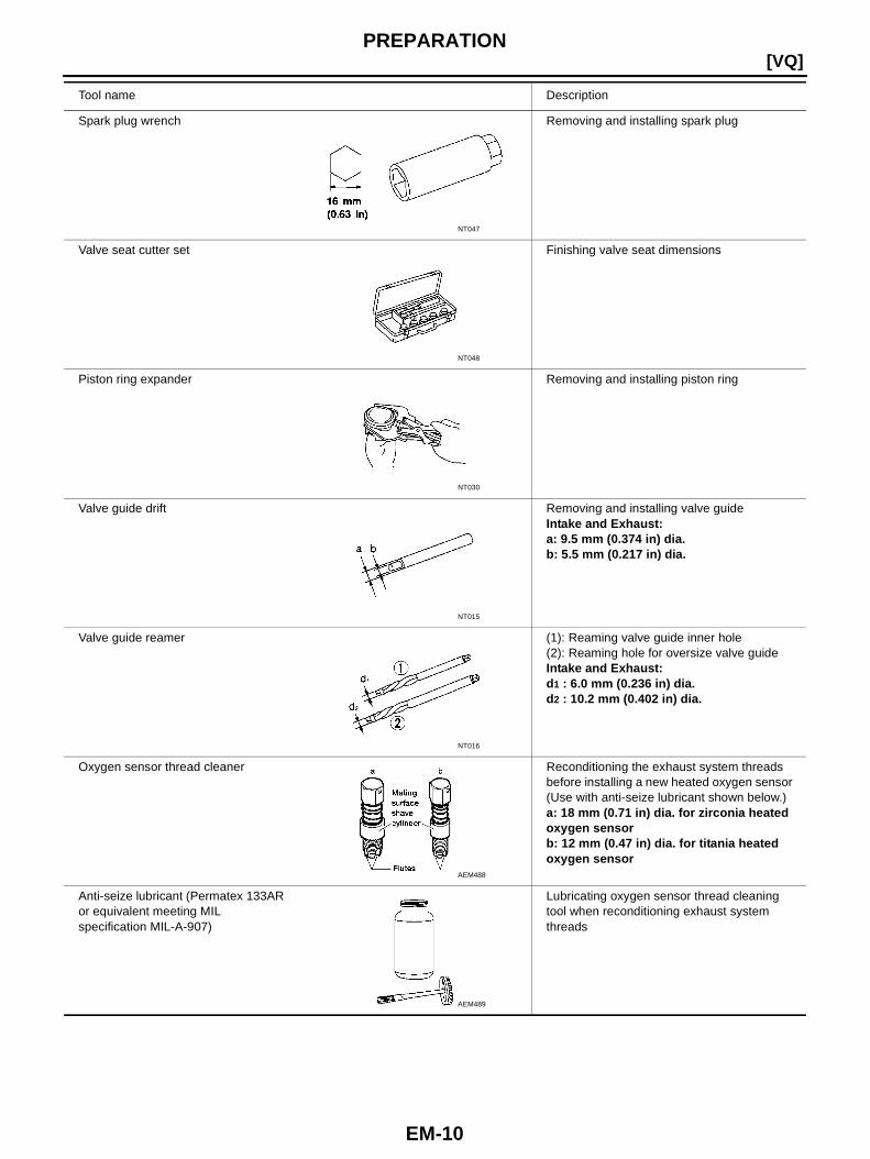
Spark plug wrench Removing and installing spark plug
Valve seat cutter set Finishing valve seat dimensions
Piston ring expander Removing and installing piston ring
Valve guide drift Removing and installing valve guideIntake and Exhaust:a: 9.5 mm (0.374 in) dia.b: 5.5 mm (0.217 in) dia.
Valve guide reamer (1): Reaming valve guide inner hole(2): Reaming hole for oversize valve guideIntake and Exhaust:d1 : 6.0 mm (0.236 in) dia.d2 : 10.2 mm (0.402 in) dia.
Oxygen sensor thread cleaner Reconditioning the exhaust system threadsbefore installing a new heated oxygen sensor(Use with anti-seize lubricant shown below.)a: 18 mm (0.71 in) dia. for zirconia heatedoxygen sensorb: 12 mm (0.47 in) dia. for titania heatedoxygen sensor
Anti-seize lubricant (Permatex 133ARor equivalent meeting MILspecification MIL-A-907)
Lubricating oxygen sensor thread cleaningtool when reconditioning exhaust systemthreads
Tool name Description
NT047
NT048
NT030
NT015
NT016
AEM488
AEM489
NOISE, VIBRATION AND HARSHNESS (NVH) TROUBLESHOOTING
EM-11
[VQ]
C
D
E
F
G
H
I
J
K
L
M
A
EM
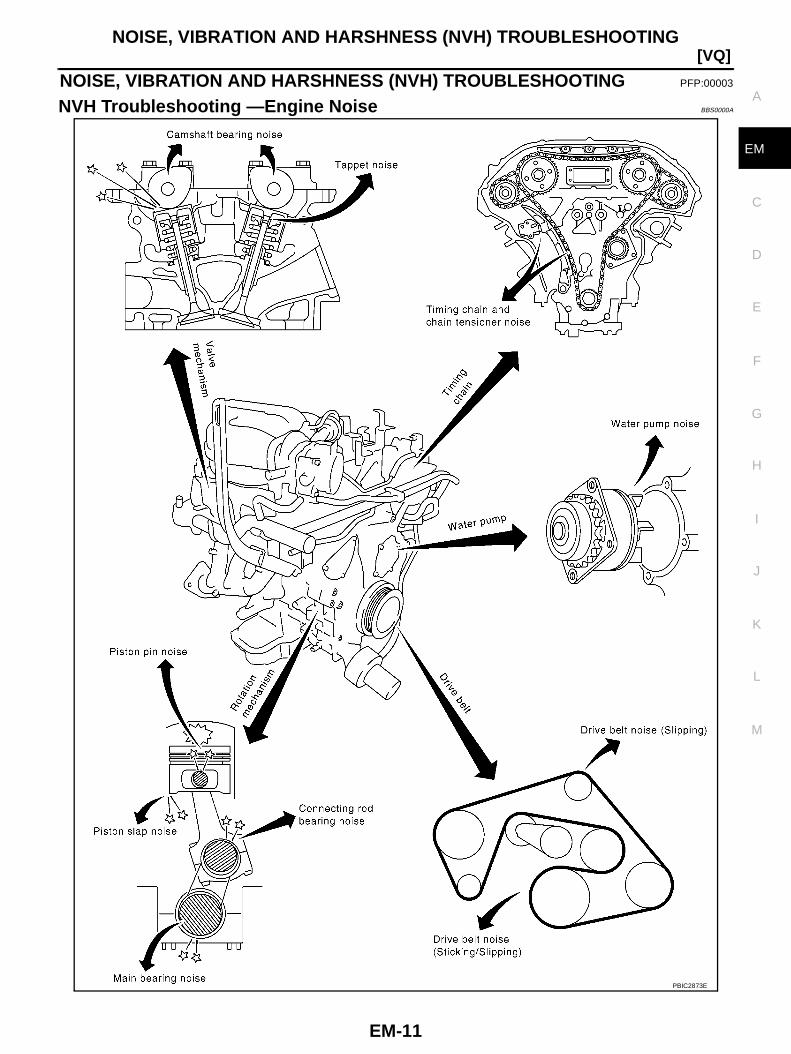
NOISE, VIBRATION AND HARSHNESS (NVH) TROUBLESHOOTING PFP:00003
NVH Troubleshooting —Engine Noise BBS0000A
PBIC2873E
EM-12
[VQ]NOISE, VIBRATION AND HARSHNESS (NVH) TROUBLESHOOTING
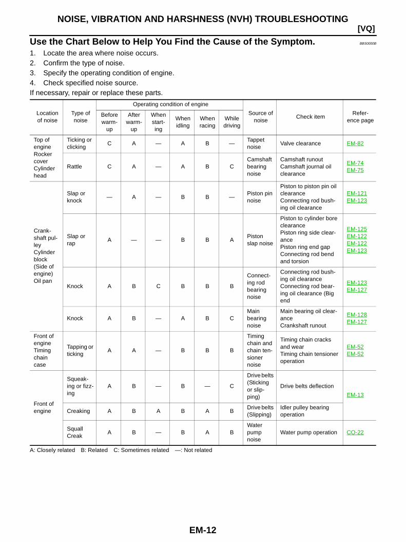
Use the Chart Below to Help You Find the Cause of the Symptom. BBS0000B
1. Locate the area where noise occurs.2. Confirm the type of noise.3. Specify the operating condition of engine.4. Check specified noise source.If necessary, repair or replace these parts.
A: Closely related B: Related C: Sometimes related —: Not related
Locationof noise
Type ofnoise
Operating condition of engine
Source ofnoise
Check itemRefer-
ence pageBeforewarm-
up
Afterwarm-
up
Whenstart-ing
Whenidling
Whenracing
Whiledriving
Top ofengineRockercoverCylinderhead
Ticking orclicking
C A — A B —Tappetnoise
Valve clearance EM-82
Rattle C A — A B CCamshaftbearingnoise
Camshaft runoutCamshaft journal oilclearance
EM-74EM-75
Crank-shaft pul-leyCylinderblock(Side ofengine)Oil pan
Slap orknock
— A — B B —Piston pinnoise
Piston to piston pin oilclearanceConnecting rod bush-ing oil clearance
EM-121EM-123
Slap orrap
A — — B B APistonslap noise
Piston to cylinder boreclearancePiston ring side clear-ancePiston ring end gapConnecting rod bendand torsion
EM-125EM-122EM-122EM-123
Knock A B C B B B
Connect-ing rodbearingnoise
Connecting rod bush-ing oil clearanceConnecting rod bear-ing oil clearance (Bigend
EM-123EM-127
Knock A B — A B CMainbearingnoise
Main bearing oil clear-anceCrankshaft runout
EM-128EM-127
Front ofengineTimingchaincase
Tapping orticking
A A — B B B
Timingchain andchain ten-sionernoise
Timing chain cracksand wearTiming chain tensioneroperation
EM-52EM-52
Front ofengine
Squeak-ing or fizz-ing
A B — B — C
Drive belts(Stickingor slip-ping)
Drive belts deflection
EM-13
Creaking A B A B A BDrive belts(Slipping)
Idler pulley bearingoperation
SquallCreak
A B — B A BWaterpumpnoise
Water pump operation CO-22
DRIVE BELTS
EM-13
[VQ]
C
D
E
F
G
H
I
J
K
L
M
A
EM
DRIVE BELTS PFP:02117
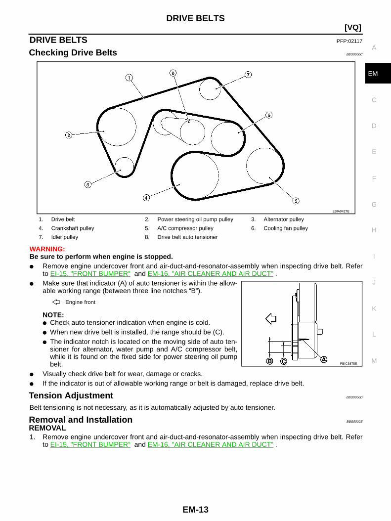
Checking Drive Belts BBS0000C
WARNING:Be sure to perform when engine is stopped.● Remove engine undercover front and air-duct-and-resonator-assembly when inspecting drive belt. Refer
to EI-15, "FRONT BUMPER" and EM-16, "AIR CLEANER AND AIR DUCT" .● Make sure that indicator (A) of auto tensioner is within the allow-
able working range (between three line notches “B”).
NOTE:● Check auto tensioner indication when engine is cold.● When new drive belt is installed, the range should be (C).● The indicator notch is located on the moving side of auto ten-
sioner for alternator, water pump and A/C compressor belt,while it is found on the fixed side for power steering oil pumpbelt.
● Visually check drive belt for wear, damage or cracks.● If the indicator is out of allowable working range or belt is damaged, replace drive belt.
Tension Adjustment BBS0000D
Belt tensioning is not necessary, as it is automatically adjusted by auto tensioner.
Removal and Installation BBS0000E
REMOVAL1. Remove engine undercover front and air-duct-and-resonator-assembly when inspecting drive belt. Refer
to EI-15, "FRONT BUMPER" and EM-16, "AIR CLEANER AND AIR DUCT" .
1. Drive belt 2. Power steering oil pump pulley 3. Alternator pulley
4. Crankshaft pulley 5. A/C compressor pulley 6. Cooling fan pulley
7. Idler pulley 8. Drive belt auto tensioner
Engine front
LBIA0427E
PBIC3875E
EM-14
[VQ]DRIVE BELTS
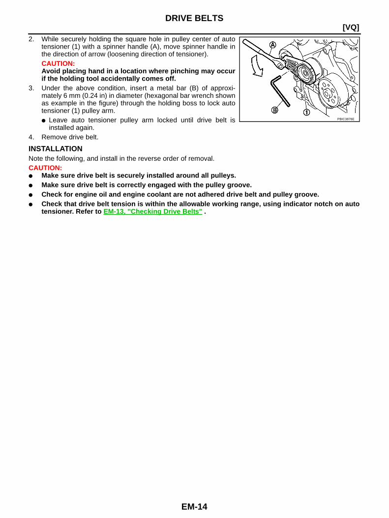
2. While securely holding the square hole in pulley center of autotensioner (1) with a spinner handle (A), move spinner handle inthe direction of arrow (loosening direction of tensioner).CAUTION:Avoid placing hand in a location where pinching may occurif the holding tool accidentally comes off.
3. Under the above condition, insert a metal bar (B) of approxi-mately 6 mm (0.24 in) in diameter (hexagonal bar wrench shownas example in the figure) through the holding boss to lock autotensioner (1) pulley arm.● Leave auto tensioner pulley arm locked until drive belt is
installed again.4. Remove drive belt.
INSTALLATIONNote the following, and install in the reverse order of removal.CAUTION:● Make sure drive belt is securely installed around all pulleys.● Make sure drive belt is correctly engaged with the pulley groove.● Check for engine oil and engine coolant are not adhered drive belt and pulley groove.● Check that drive belt tension is within the allowable working range, using indicator notch on auto
tensioner. Refer to EM-13, "Checking Drive Belts " .
PBIC3876E

DRIVE BELTS
EM-15
[VQ]
C
D
E
F
G
H
I
J
K
L
M
A
EM
Drive Belt Auto Tensioner and Idler Pulley BBS0000F
REMOVAL1. Remove engine undercover front and air-duct-and-resonator-assembly when inspecting drive belt. Refer
to EI-15, "FRONT BUMPER" and EM-16, "AIR CLEANER AND AIR DUCT" .2. Remove drive belt. Refer to EM-13, "Removal and Installation" .
● Keep auto tensioner pulley arm locked after belt is removed.3. Remove auto tensioner and idler pulley.
● Keep auto tensioner pulley arm locked to install or remove auto tensioner.
INSTALLATIONInstallation is the reverse order of removal.
1. Idler pulley 2. Drive belt auto tensioner
LBIA0429E
EM-16
[VQ]AIR CLEANER AND AIR DUCT
AIR CLEANER AND AIR DUCT PFP:16500
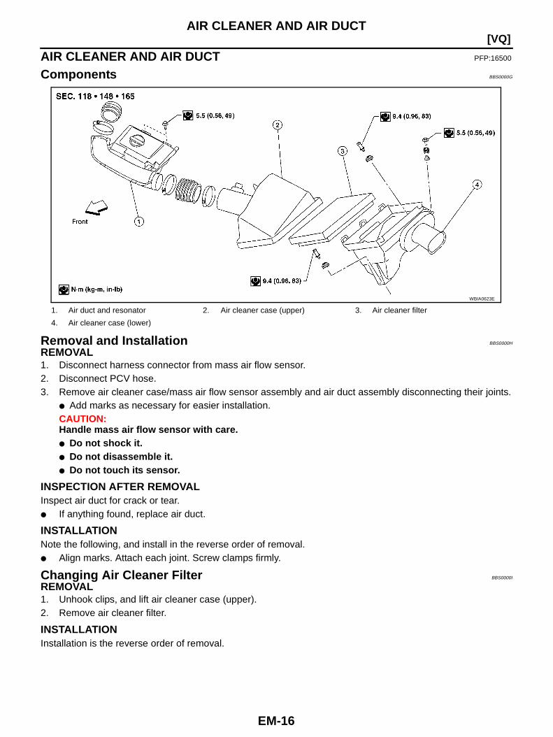
Components BBS0000G
Removal and Installation BBS0000H
REMOVAL1. Disconnect harness connector from mass air flow sensor.2. Disconnect PCV hose.3. Remove air cleaner case/mass air flow sensor assembly and air duct assembly disconnecting their joints.
● Add marks as necessary for easier installation.CAUTION:Handle mass air flow sensor with care.● Do not shock it.● Do not disassemble it.● Do not touch its sensor.
INSPECTION AFTER REMOVALInspect air duct for crack or tear.● If anything found, replace air duct.
INSTALLATIONNote the following, and install in the reverse order of removal.● Align marks. Attach each joint. Screw clamps firmly.
Changing Air Cleaner Filter BBS0000I
REMOVAL1. Unhook clips, and lift air cleaner case (upper).2. Remove air cleaner filter.
INSTALLATIONInstallation is the reverse order of removal.
1. Air duct and resonator 2. Air cleaner case (upper) 3. Air cleaner filter
4. Air cleaner case (lower)
WBIA0623E
INTAKE MANIFOLD COLLECTOR
EM-17
[VQ]
C
D
E
F
G
H
I
J
K
L
M
A
EM
INTAKE MANIFOLD COLLECTOR PFP:14003
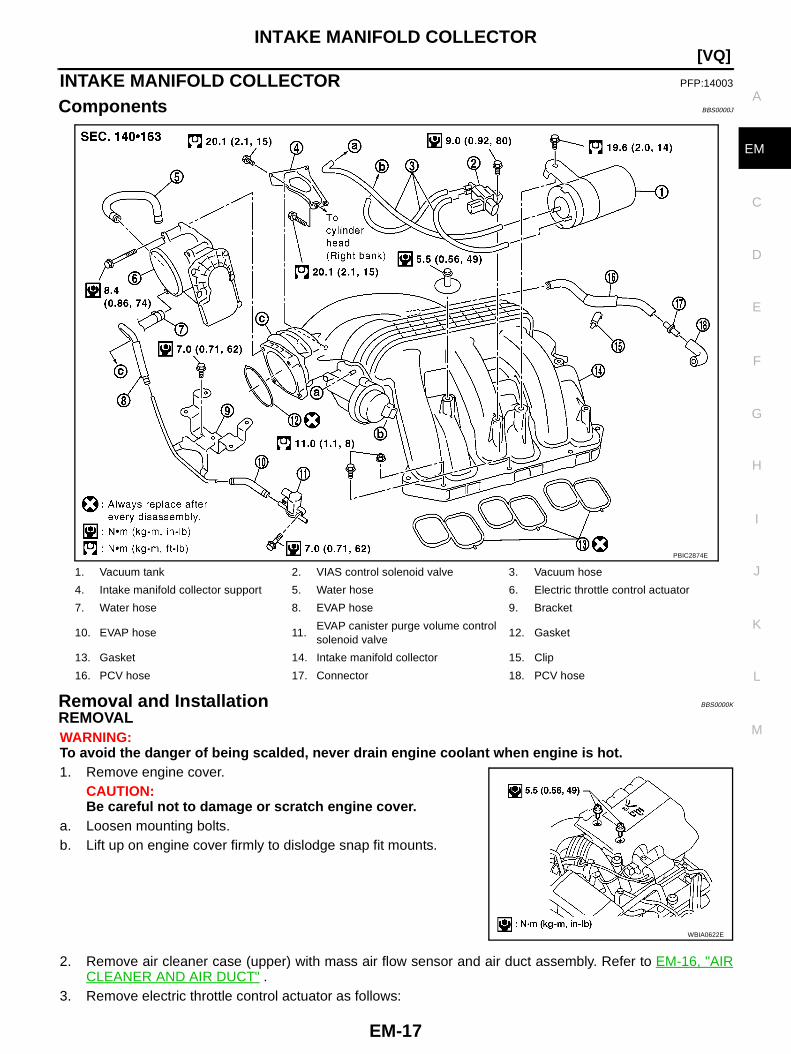
Components BBS0000J
Removal and Installation BBS0000K
REMOVALWARNING:To avoid the danger of being scalded, never drain engine coolant when engine is hot.1. Remove engine cover.
CAUTION:Be careful not to damage or scratch engine cover.
a. Loosen mounting bolts.b. Lift up on engine cover firmly to dislodge snap fit mounts.
2. Remove air cleaner case (upper) with mass air flow sensor and air duct assembly. Refer to EM-16, "AIRCLEANER AND AIR DUCT" .
3. Remove electric throttle control actuator as follows:
1. Vacuum tank 2. VIAS control solenoid valve 3. Vacuum hose
4. Intake manifold collector support 5. Water hose 6. Electric throttle control actuator
7. Water hose 8. EVAP hose 9. Bracket
10. EVAP hose 11.EVAP canister purge volume controlsolenoid valve
12. Gasket
13. Gasket 14. Intake manifold collector 15. Clip
16. PCV hose 17. Connector 18. PCV hose
PBIC2874E
WBIA0622E
EM-18
[VQ]INTAKE MANIFOLD COLLECTOR
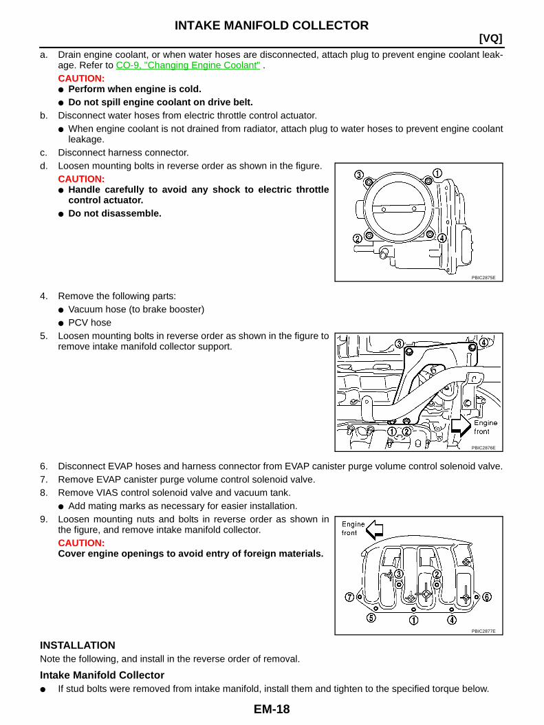
a. Drain engine coolant, or when water hoses are disconnected, attach plug to prevent engine coolant leak-age. Refer to CO-9, "Changing Engine Coolant" .CAUTION:● Perform when engine is cold.● Do not spill engine coolant on drive belt.
b. Disconnect water hoses from electric throttle control actuator.● When engine coolant is not drained from radiator, attach plug to water hoses to prevent engine coolant
leakage.c. Disconnect harness connector.d. Loosen mounting bolts in reverse order as shown in the figure.
CAUTION:● Handle carefully to avoid any shock to electric throttle
control actuator.● Do not disassemble.
4. Remove the following parts:● Vacuum hose (to brake booster)● PCV hose
5. Loosen mounting bolts in reverse order as shown in the figure toremove intake manifold collector support.
6. Disconnect EVAP hoses and harness connector from EVAP canister purge volume control solenoid valve.7. Remove EVAP canister purge volume control solenoid valve.8. Remove VIAS control solenoid valve and vacuum tank.
● Add mating marks as necessary for easier installation.9. Loosen mounting nuts and bolts in reverse order as shown in
the figure, and remove intake manifold collector.CAUTION:Cover engine openings to avoid entry of foreign materials.
INSTALLATIONNote the following, and install in the reverse order of removal.
Intake Manifold Collector● If stud bolts were removed from intake manifold, install them and tighten to the specified torque below.
PBIC2875E
PBIC2876E
PBIC2877E

INTAKE MANIFOLD COLLECTOR
EM-19
[VQ]
C
D
E
F
G
H
I
J
K
L
M
A
EM
● Tighten mounting nuts and bolts in numerical order as shown inthe figure.
Electric Throttle Control Actuator● Tighten mounting bolts in numerical order as shown in the fig-
ure.● Perform the “Throttle Valve Closed Position Learning” when har-
ness connector of electric throttle control actuator is discon-nected. Refer to EC-72, "Throttle Valve Closed PositionLearning" (WITH EURO-OBD) or EC-601, "Throttle ValveClosed Position Learning" (WITHOUT EURO-OBD).
● Perform the “Idle Air Volume Learning” and “Throttle ValveClosed Position Learning” when electric throttle control actuatoris replaced. Refer to EC-72, "Idle Air Volume Learning" (WITHEURO-OBD) or EC-601, "Idle Air Volume Learning" (WITHOUTEURO-OBD).
: 6.9 N·m (0.70 kg-m, 61 in-lb)
PBIC2877E
PBIC2875E
EM-20
[VQ]INTAKE MANIFOLD
INTAKE MANIFOLD PFP:14003
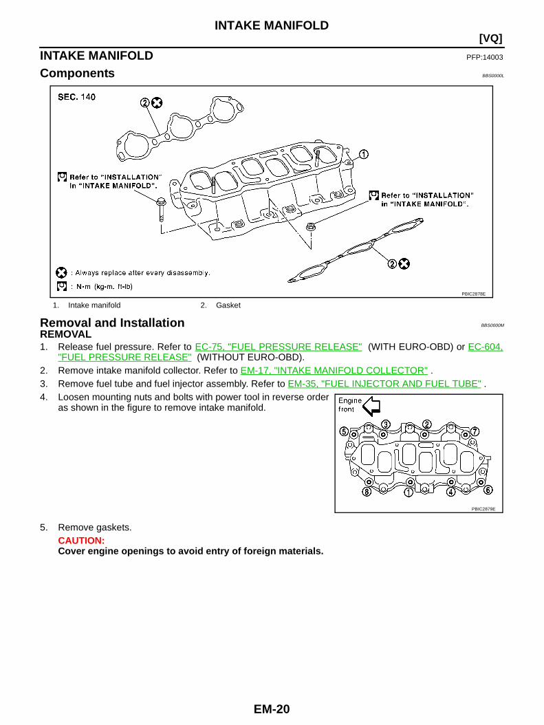
Components BBS0000L
Removal and Installation BBS0000M
REMOVAL1. Release fuel pressure. Refer to EC-75, "FUEL PRESSURE RELEASE" (WITH EURO-OBD) or EC-604,
"FUEL PRESSURE RELEASE" (WITHOUT EURO-OBD).2. Remove intake manifold collector. Refer to EM-17, "INTAKE MANIFOLD COLLECTOR" .3. Remove fuel tube and fuel injector assembly. Refer to EM-35, "FUEL INJECTOR AND FUEL TUBE" .4. Loosen mounting nuts and bolts with power tool in reverse order
as shown in the figure to remove intake manifold.
5. Remove gaskets.CAUTION:Cover engine openings to avoid entry of foreign materials.
1. Intake manifold 2. Gasket
PBIC2878E
PBIC2879E

INTAKE MANIFOLD
EM-21
[VQ]
C
D
E
F
G
H
I
J
K
L
M
A
EM
INSPECTION AFTER REMOVALSurface Distortion● Check the surface distortion of the intake manifold mating sur-
face with straightedge and feeler gauge.
● If it exceeds the limit, replace intake manifold.
INSTALLATIONNote the following, and install in the reverse order of removal.
Intake Manifold● If stud bolts were removed from cylinder head, install them and tighten to the specified torque below.
● Tighten all mounting nuts and bolts to the specified torque in twoor more steps in numerical order shown in the figure.
Limit : 0.1 mm (0.004 in)
PBIC0870E
: 10.8 N·m (1.1 kg-m, 8 ft-lb)
1st step: 7.4 N·m (0.75 kg-m, 5 ft-lb)
2nd step and after: 29.0 N·m (3.0 kg-m, 21 ft-lb)
PBIC2879E
EM-22
[VQ]EXHAUST MANIFOLD AND THREE WAY CATALYST
EXHAUST MANIFOLD AND THREE WAY CATALYST PFP:14004
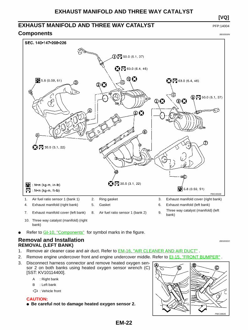
Components BBS0000N
● Refer to GI-10, "Components" for symbol marks in the figure.
Removal and Installation BBS0000O
REMOVAL (LEFT BANK)1. Remove air cleaner case and air duct. Refer to EM-16, "AIR CLEANER AND AIR DUCT" .2. Remove engine undercover front and engine undercover middle. Refer to EI-15, "FRONT BUMPER" .3. Disconnect harness connector and remove heated oxygen sen-
sor 2 on both banks using heated oxygen sensor wrench (C)[SST: KV10114400].
CAUTION:● Be careful not to damage heated oxygen sensor 2.
1. Air fuel ratio sensor 1 (bank 1) 2. Ring gasket 3. Exhaust manifold cover (right bank)
4. Exhaust manifold (right bank) 5. Gasket 6. Exhaust manifold (left bank)
7. Exhaust manifold cover (left bank) 8. Air fuel ratio sensor 1 (bank 2) 9.Three way catalyst (manifold) (leftbank)
10. Three way catalyst (manifold) (rightbank)
PBIC4063E
A : Right bank
B : Left bank
: Vehicle front
PBIC3882E
EXHAUST MANIFOLD AND THREE WAY CATALYST
EM-23
[VQ]
C
D
E
F
G
H
I
J
K
L
M
A
EM
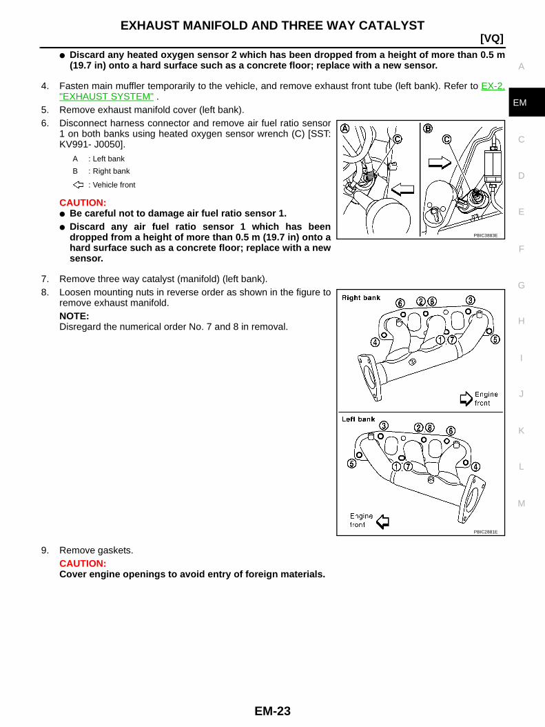
● Discard any heated oxygen sensor 2 which has been dropped from a height of more than 0.5 m(19.7 in) onto a hard surface such as a concrete floor; replace with a new sensor.
4. Fasten main muffler temporarily to the vehicle, and remove exhaust front tube (left bank). Refer to EX-2,"EXHAUST SYSTEM" .
5. Remove exhaust manifold cover (left bank).6. Disconnect harness connector and remove air fuel ratio sensor
1 on both banks using heated oxygen sensor wrench (C) [SST:KV991- J0050].
CAUTION:● Be careful not to damage air fuel ratio sensor 1.● Discard any air fuel ratio sensor 1 which has been
dropped from a height of more than 0.5 m (19.7 in) onto ahard surface such as a concrete floor; replace with a newsensor.
7. Remove three way catalyst (manifold) (left bank).8. Loosen mounting nuts in reverse order as shown in the figure to
remove exhaust manifold.NOTE:Disregard the numerical order No. 7 and 8 in removal.
9. Remove gaskets.CAUTION:Cover engine openings to avoid entry of foreign materials.
A : Left bank
B : Right bank
: Vehicle front
PBIC3883E
PBIC2881E
EM-24
[VQ]EXHAUST MANIFOLD AND THREE WAY CATALYST
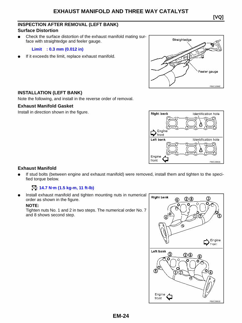
INSPECTION AFTER REMOVAL (LEFT BANK)Surface Distortion● Check the surface distortion of the exhaust manifold mating sur-
face with straightedge and feeler gauge.
● If it exceeds the limit, replace exhaust manifold.
INSTALLATION (LEFT BANK)Note the following, and install in the reverse order of removal.
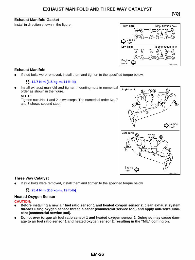
Exhaust Manifold GasketInstall in direction shown in the figure.
Exhaust Manifold● If stud bolts (between engine and exhaust manifold) were removed, install them and tighten to the speci-
fied torque below.
● Install exhaust manifold and tighten mounting nuts in numericalorder as shown in the figure.NOTE:Tighten nuts No. 1 and 2 in two steps. The numerical order No. 7and 8 shows second step.
Limit : 0.3 mm (0.012 in)
PBIC1096E
PBIC2882E
: 14.7 N·m (1.5 kg-m, 11 ft-lb)
PBIC2881E
EXHAUST MANIFOLD AND THREE WAY CATALYST
EM-25
[VQ]
C
D
E
F
G
H
I
J
K
L
M
A
EM
Three Way Catalyst● If stud bolts were removed, install them and tighten to the specified torque below.
Heated Oxygen SensorCAUTION:● Before installing a new air fuel ratio sensor 1 and heated oxygen sensor 2, clean exhaust system
threads using oxygen sensor thread cleaner (commercial service tool) and apply anti-seize lubri-cant (commercial service tool).
● Do not over torque air fuel ratio sensor 1 and heated oxygen sensor 2. Doing so may cause dam-age to air fuel ratio sensor 1 and heated oxygen sensor 2, resulting in the “MIL” coming on.
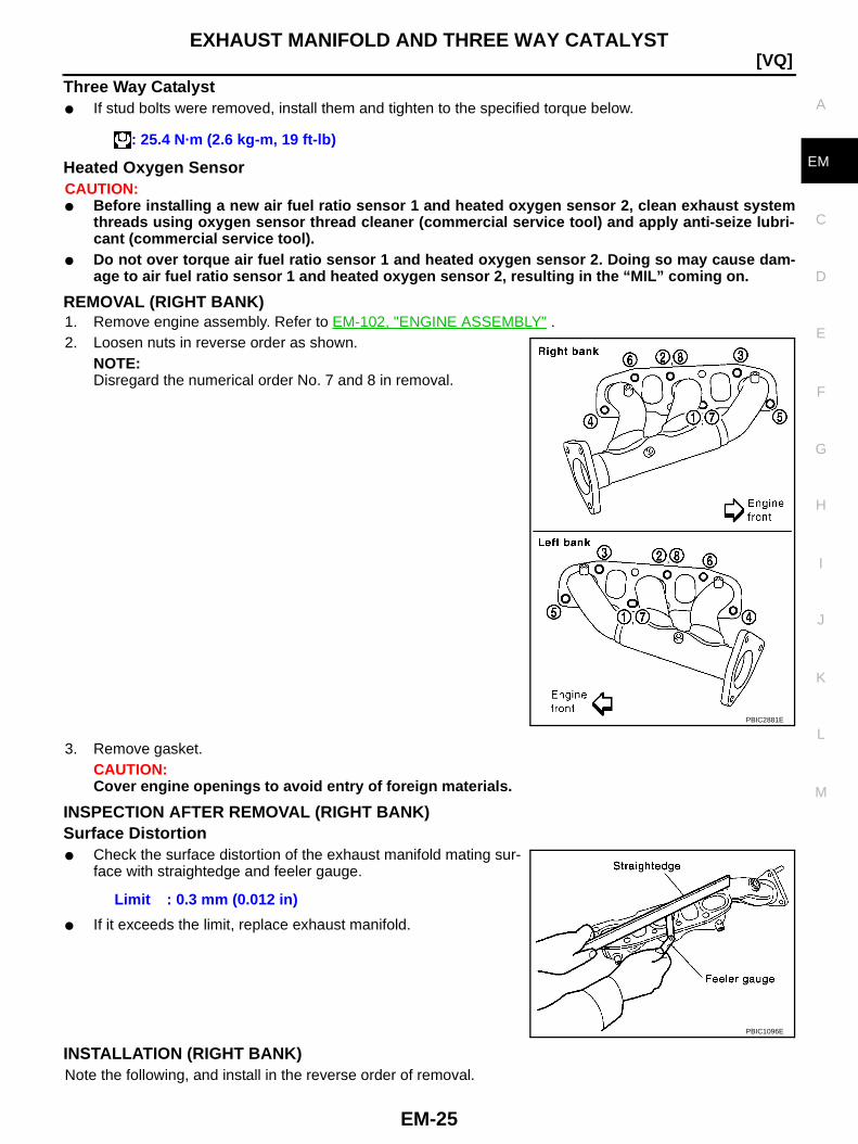
REMOVAL (RIGHT BANK)1. Remove engine assembly. Refer to EM-102, "ENGINE ASSEMBLY" .2. Loosen nuts in reverse order as shown.
NOTE:Disregard the numerical order No. 7 and 8 in removal.
3. Remove gasket.CAUTION:Cover engine openings to avoid entry of foreign materials.
INSPECTION AFTER REMOVAL (RIGHT BANK)Surface Distortion● Check the surface distortion of the exhaust manifold mating sur-
face with straightedge and feeler gauge.
● If it exceeds the limit, replace exhaust manifold.
INSTALLATION (RIGHT BANK)Note the following, and install in the reverse order of removal.
: 25.4 N·m (2.6 kg-m, 19 ft-lb)
PBIC2881E
Limit : 0.3 mm (0.012 in)
PBIC1096E
EM-26
[VQ]EXHAUST MANIFOLD AND THREE WAY CATALYST
Exhaust Manifold GasketInstall in direction shown in the figure.
Exhaust Manifold● If stud bolts were removed, install them and tighten to the specified torque below.
● Install exhaust manifold and tighten mounting nuts in numericalorder as shown in the figure.NOTE:Tighten nuts No. 1 and 2 in two steps. The numerical order No. 7and 8 shows second step.
Three Way Catalyst● If stud bolts were removed, install them and tighten to the specified torque below.
Heated Oxygen SensorCAUTION:● Before installing a new air fuel ratio sensor 1 and heated oxygen sensor 2, clean exhaust system
threads using oxygen sensor thread cleaner (commercial service tool) and apply anti-seize lubri-cant (commercial service tool).
● Do not over torque air fuel ratio sensor 1 and heated oxygen sensor 2. Doing so may cause dam-age to air fuel ratio sensor 1 and heated oxygen sensor 2, resulting in the “MIL” coming on.
PBIC2882E
: 14.7 N·m (1.5 kg-m, 11 ft-lb)
PBIC2881E
: 25.4 N·m (2.6 kg-m, 19 ft-lb)
OIL PAN AND OIL STRAINER
EM-27
[VQ]
C
D
E
F
G
H
I
J
K
L
M
A
EM
OIL PAN AND OIL STRAINER PFP:11110
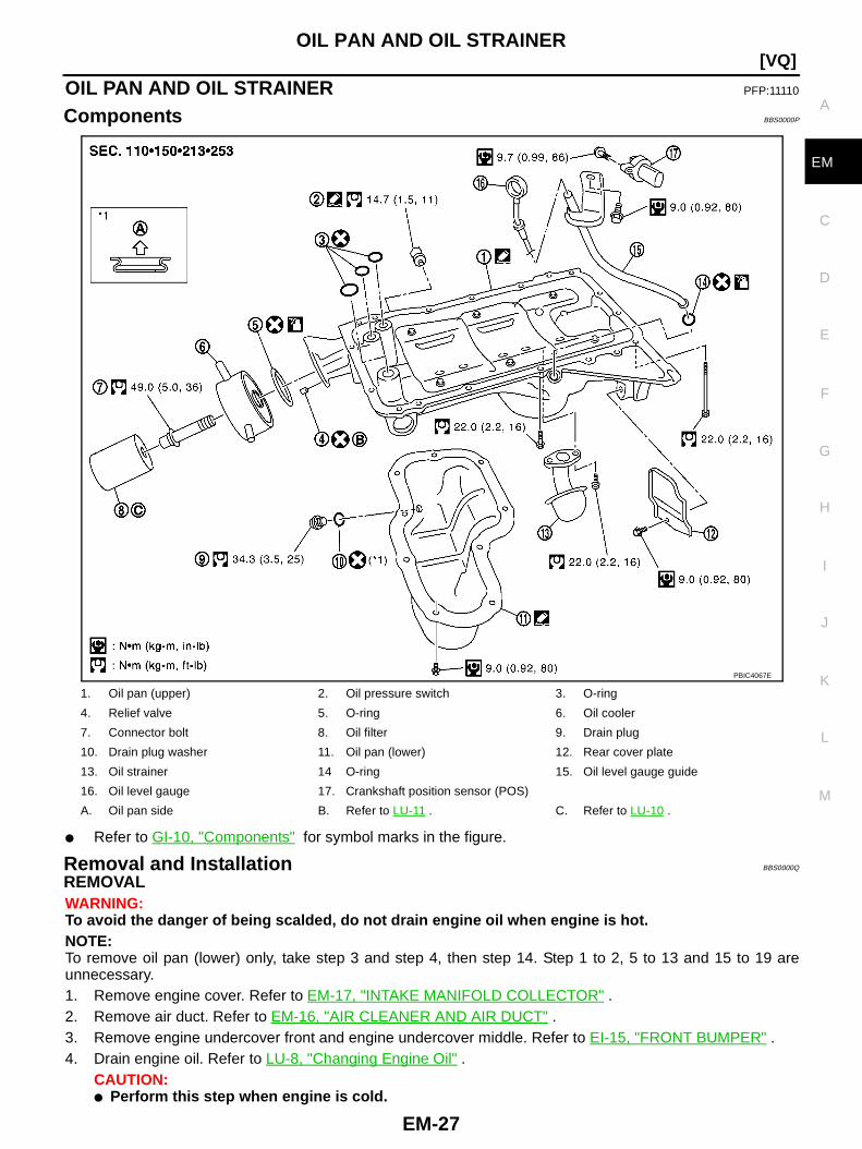
Components BBS0000P
● Refer to GI-10, "Components" for symbol marks in the figure.
Removal and Installation BBS0000Q
REMOVALWARNING:To avoid the danger of being scalded, do not drain engine oil when engine is hot.NOTE:To remove oil pan (lower) only, take step 3 and step 4, then step 14. Step 1 to 2, 5 to 13 and 15 to 19 areunnecessary.1. Remove engine cover. Refer to EM-17, "INTAKE MANIFOLD COLLECTOR" .2. Remove air duct. Refer to EM-16, "AIR CLEANER AND AIR DUCT" .3. Remove engine undercover front and engine undercover middle. Refer to EI-15, "FRONT BUMPER" .4. Drain engine oil. Refer to LU-8, "Changing Engine Oil" .
CAUTION:● Perform this step when engine is cold.
1. Oil pan (upper) 2. Oil pressure switch 3. O-ring
4. Relief valve 5. O-ring 6. Oil cooler
7. Connector bolt 8. Oil filter 9. Drain plug
10. Drain plug washer 11. Oil pan (lower) 12. Rear cover plate
13. Oil strainer 14 O-ring 15. Oil level gauge guide
16. Oil level gauge 17. Crankshaft position sensor (POS)
A. Oil pan side B. Refer to LU-11 . C. Refer to LU-10 .
PBIC4067E

EM-28
[VQ]OIL PAN AND OIL STRAINER
● Do not spill engine oil on drive belts.5. Drain engine coolant. Refer to CO-9, "Changing Engine Coolant" .
CAUTION:● Perform this step when engine is cold.● Do not spill engine coolant on drive belts.
6. Remove front final drive assembly. Refer to FFD-15, "FRONT FINAL DRIVE ASSEMBLY" .7. Disconnect steering gear lower joint shaft bolt and steering gear nuts and bolts, position out of the way.
Refer to PS-16, "POWER STEERING GEAR AND LINKAGE" .8. Remove starter motor. Refer to SC-35, "Removal and Installation" .9. Disconnect A/T fluid cooler tube brackets and position out of the way. Refer to AT-236, "A/T FLUID
COOLER" .10. Install engine slinger to sling engine assembly for positioning. Refer to EM-102, "ENGINE ASSEMBLY" .11. Disconnect oil cooler water hoses, and remove oil cooler water pipe mounting bolt. Refer to LU-11, "OIL
COOLER" .12. Remove oil filter. Refer to LU-10, "OIL FILTER" .13. Remove oil cooler. Refer to LU-11, "OIL COOLER" .14. Remove oil pan (lower) as follows:a. Loosen mounting bolts in reverse order as shown in the figure to
remove.
b. Insert seal cutter [SST] between oil pan (upper) and oil pan(lower).CAUTION:● Be careful not to damage the mating surfaces.● Do not insert screwdriver, this will damage the mating
surfaces.
c. Slide seal cutter by tapping on the side of the tool with hammer. Remove oil pan (lower).15. Remove oil strainer.16. Remove transmission joint bolts which pierce oil pan (upper). Refer to AT-239, "TRANSMISSION ASSEM-
BLY" .17. Remove rear cover plate.
PBIC2890E
SEM365ED
OIL PAN AND OIL STRAINER
EM-29
[VQ]
C
D
E
F
G
H
I
J
K
L
M
A
EM
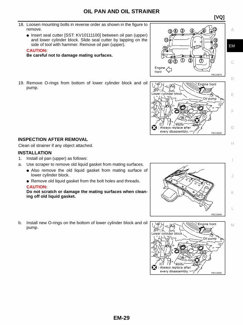
18. Loosen mounting bolts in reverse order as shown in the figure toremove.● Insert seal cutter [SST: KV10111100] between oil pan (upper)
and lower cylinder block. Slide seal cutter by tapping on theside of tool with hammer. Remove oil pan (upper).
CAUTION:Be careful not to damage mating surfaces.
19. Remove O-rings from bottom of lower cylinder block and oilpump.
INSPECTION AFTER REMOVALClean oil strainer if any object attached.
INSTALLATION1. Install oil pan (upper) as follows:a. Use scraper to remove old liquid gasket from mating surfaces.
● Also remove the old liquid gasket from mating surface oflower cylinder block.
● Remove old liquid gasket from the bolt holes and threads.CAUTION:Do not scratch or damage the mating surfaces when clean-ing off old liquid gasket.
b. Install new O-rings on the bottom of lower cylinder block and oilpump.
PBIC2887E
PBIC2885E
PBIC2884E
PBIC2885E

EM-30
[VQ]OIL PAN AND OIL STRAINER
c. Apply a continuous bead of liquid gasket with tube presser [SST:WS39930000] to the lower cylinder block mating surfaces of oilpan (upper) to a limited portion as shown in the figure.Use Genuine Liquid Gasket or equivalent.CAUTION:● For bolt holes with mark, apply liquid gasket outside
the hole.● Apply a bead of 4.5 to 5.5 mm (0.177 to 0.217 in) in diame-
ter to area “A”.● Attaching should be done within 5 minutes after coating.
d. Install oil pan (upper).CAUTION:Install avoiding misalignment of both oil pan gaskets and O-rings.● Tighten mounting bolts in numerical order as shown in the fig-
ure.● There are two types of mounting bolts. Refer to the following
for locating bolts.
e. Tighten transmission joint bolts. Refer to AT-239, "TRANSMISSION ASSEMBLY" .2. Install oil strainer to oil pan (upper).3. Install oil pan (lower) as follows:a. Use scraper to remove old liquid gasket from mating surfaces.
● Also remove old liquid gasket from mating surface of oil pan(upper).
● Remove old liquid gasket from the bolt holes and thread.CAUTION:Do not scratch or damage the mating surfaces when clean-ing off old liquid gasket.
b. Apply a continuous bead of liquid gasket with tube presser [SST:WS39930000] to the oil pan (lower) as shown in the figure.Use Genuine Liquid Gasket or equivalent.CAUTION:Attaching should be done within 5 minutes after coating.
c. Install oil pan (lower).
PBIC2886E
M8 × 100 mm (3.97 in) : 7, 11, 12, 13M8 × 25 mm (0.98 in) : Except the above
PBIC2887E
PBIC2888E
PBIC2889E
OIL PAN AND OIL STRAINER
EM-31
[VQ]
C
D
E
F
G
H
I
J
K
L
M
A
EM
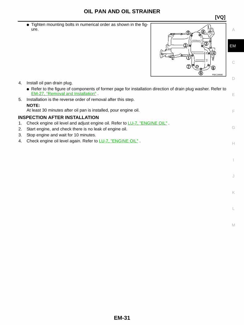
● Tighten mounting bolts in numerical order as shown in the fig-ure.
4. Install oil pan drain plug.● Refer to the figure of components of former page for installation direction of drain plug washer. Refer to
EM-27, "Removal and Installation" .5. Installation is the reverse order of removal after this step.
NOTE:At least 30 minutes after oil pan is installed, pour engine oil.
INSPECTION AFTER INSTALLATION1. Check engine oil level and adjust engine oil. Refer to LU-7, "ENGINE OIL" .2. Start engine, and check there is no leak of engine oil.3. Stop engine and wait for 10 minutes.4. Check engine oil level again. Refer to LU-7, "ENGINE OIL" .
PBIC2890E
EM-32
[VQ]IGNITION COIL
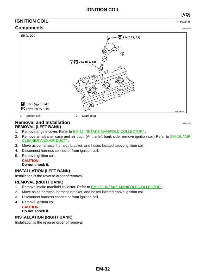
IGNITION COIL PFP:22448
Components BBS0000R
Removal and Installation BBS0000S
REMOVAL (LEFT BANK)1. Remove engine cover. Refer to EM-17, "INTAKE MANIFOLD COLLECTOR" .2. Remove air cleaner case and air duct. (At the left bank side, remove ignition coil) Refer to EM-16, "AIR
CLEANER AND AIR DUCT" .3. Move aside harness, harness bracket, and hoses located above ignition coil.4. Disconnect harness connector from ignition coil.5. Remove ignition coil.
CAUTION:Do not shock it.
INSTALLATION (LEFT BANK)Installation is the reverse order of removal.
REMOVAL (RIGHT BANK)1. Remove intake manifold collector. Refer to EM-17, "INTAKE MANIFOLD COLLECTOR" .2. Move aside harness, harness bracket, and hoses located above ignition coil.3. Disconnect harness connector from ignition coil.4. Remove ignition coil.
CAUTION:Do not shock it.
INSTALLATION (RIGHT BANK)Installation is the reverse order of removal.
1. Ignition coil 2. Spark plug
PBIC2901E
SPARK PLUG (PLATINUM-TIPPED TYPE)
EM-33
[VQ]
C
D
E
F
G
H
I
J
K
L
M
A
EM
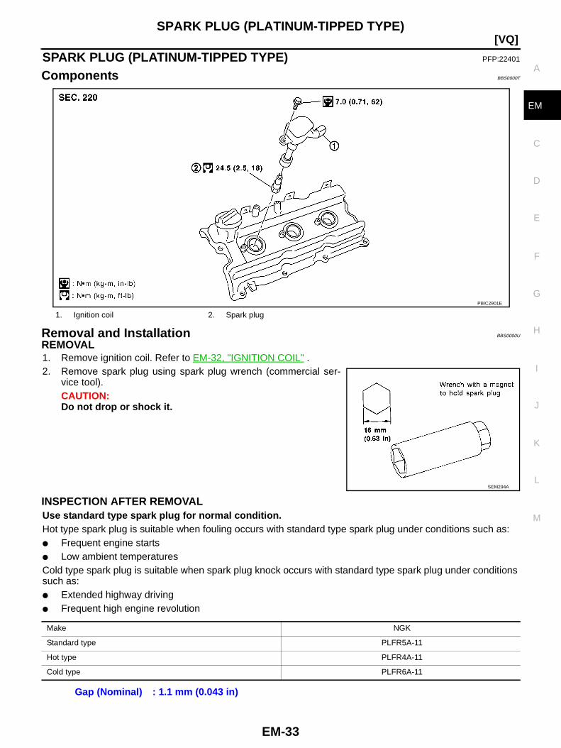
SPARK PLUG (PLATINUM-TIPPED TYPE) PFP:22401
Components BBS0000T
Removal and Installation BBS0000U
REMOVAL1. Remove ignition coil. Refer to EM-32, "IGNITION COIL" .2. Remove spark plug using spark plug wrench (commercial ser-
vice tool).CAUTION:Do not drop or shock it.
INSPECTION AFTER REMOVALUse standard type spark plug for normal condition.Hot type spark plug is suitable when fouling occurs with standard type spark plug under conditions such as:● Frequent engine starts● Low ambient temperaturesCold type spark plug is suitable when spark plug knock occurs with standard type spark plug under conditionssuch as:● Extended highway driving● Frequent high engine revolution
1. Ignition coil 2. Spark plug
PBIC2901E
SEM294A
Make NGK
Standard type PLFR5A-11
Hot type PLFR4A-11
Cold type PLFR6A-11
Gap (Nominal) : 1.1 mm (0.043 in)
EM-34
[VQ]SPARK PLUG (PLATINUM-TIPPED TYPE)
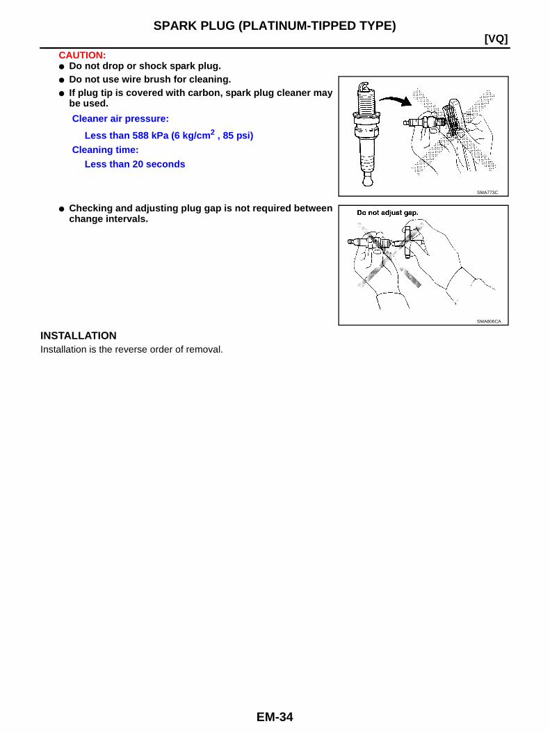
CAUTION:● Do not drop or shock spark plug.● Do not use wire brush for cleaning.● If plug tip is covered with carbon, spark plug cleaner may
be used.
● Checking and adjusting plug gap is not required betweenchange intervals.
INSTALLATIONInstallation is the reverse order of removal.
Cleaner air pressure:
Less than 588 kPa (6 kg/cm 2 , 85 psi)Cleaning time:
Less than 20 seconds
SMA773C
SMA806CA
FUEL INJECTOR AND FUEL TUBE
EM-35
[VQ]
C
D
E
F
G
H
I
J
K
L
M
A
EM
FUEL INJECTOR AND FUEL TUBE PFP:16600
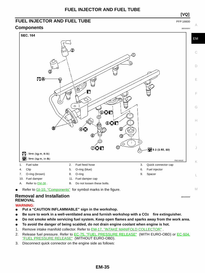
Components BBS0000V
● Refer to GI-10, "Components" for symbol marks in the figure.
Removal and Installation BBS0000W
REMOVALWARNING:● Put a “CAUTION INFLAMMABLE” sign in the workshop.● Be sure to work in a well-ventilated area and furnish workshop with a CO 2 fire extinguisher.● Do not smoke while servicing fuel system. Keep open flames and sparks away from the work area.● To avoid the danger of being scalded, do not drain engine coolant when engine is hot.1. Remove intake manifold collector. Refer to EM-17, "INTAKE MANIFOLD COLLECTOR" .2. Release fuel pressure. Refer to EC-75, "FUEL PRESSURE RELEASE" (WITH EURO-OBD) or EC-604,
"FUEL PRESSURE RELEASE" (WITHOUT EURO-OBD).3. Disconnect quick connector on the engine side as follows:
1. Fuel tube 2. Fuel feed hose 3. Quick connector cap
4. Clip 5. O-ring (blue) 6. Fuel injector
7. O-ring (brown) 8. O-ring 9. Spacer
10. Fuel damper 11. Fuel damper cap
A. Refer to EM-38 . B. Do not loosen these bolts.
PBIC4062E
EM-36
[VQ]FUEL INJECTOR AND FUEL TUBE
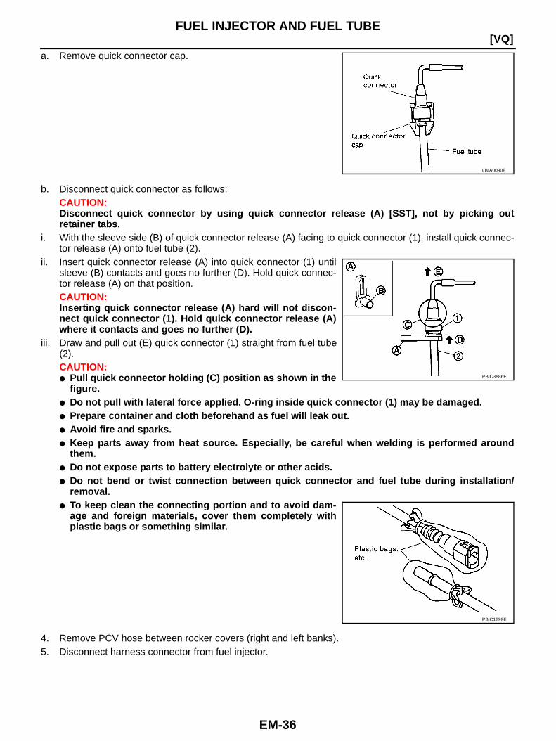
a. Remove quick connector cap.
b. Disconnect quick connector as follows:CAUTION:Disconnect quick connector by using quick connector release (A) [SST], not by picking outretainer tabs.
i. With the sleeve side (B) of quick connector release (A) facing to quick connector (1), install quick connec-tor release (A) onto fuel tube (2).
ii. Insert quick connector release (A) into quick connector (1) untilsleeve (B) contacts and goes no further (D). Hold quick connec-tor release (A) on that position.CAUTION:Inserting quick connector release (A) hard will not discon-nect quick connector (1). Hold quick connector release (A)where it contacts and goes no further (D).
iii. Draw and pull out (E) quick connector (1) straight from fuel tube(2).CAUTION:● Pull quick connector holding (C) position as shown in the
figure.● Do not pull with lateral force applied. O-ring inside quick connector (1) may be damaged.● Prepare container and cloth beforehand as fuel will leak out.● Avoid fire and sparks.● Keep parts away from heat source. Especially, be careful when welding is performed around
them.● Do not expose parts to battery electrolyte or other acids.● Do not bend or twist connection between quick connector and fuel tube during installation/
removal.● To keep clean the connecting portion and to avoid dam-
age and foreign materials, cover them completely withplastic bags or something similar.
4. Remove PCV hose between rocker covers (right and left banks).5. Disconnect harness connector from fuel injector.
LBIA0090E
PBIC3886E
PBIC1899E
FUEL INJECTOR AND FUEL TUBE
EM-37
[VQ]
C
D
E
F
G
H
I
J
K
L
M
A
EM
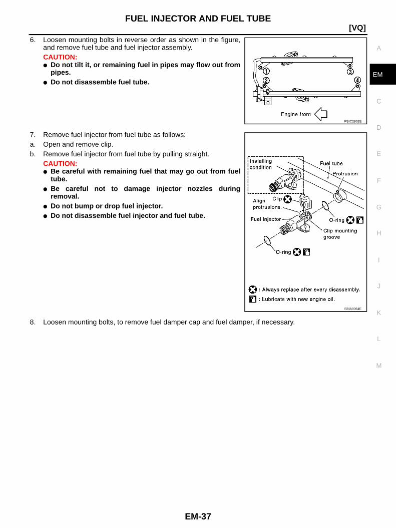
6. Loosen mounting bolts in reverse order as shown in the figure,and remove fuel tube and fuel injector assembly.CAUTION:● Do not tilt it, or remaining fuel in pipes may flow out from
pipes.● Do not disassemble fuel tube.
7. Remove fuel injector from fuel tube as follows:a. Open and remove clip.b. Remove fuel injector from fuel tube by pulling straight.
CAUTION:● Be careful with remaining fuel that may go out from fuel
tube.● Be careful not to damage injector nozzles during
removal.● Do not bump or drop fuel injector.● Do not disassemble fuel injector and fuel tube.
8. Loosen mounting bolts, to remove fuel damper cap and fuel damper, if necessary.
PBIC2902E
SBIA0364E
EM-38
[VQ]FUEL INJECTOR AND FUEL TUBE
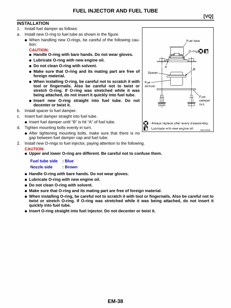
INSTALLATION1. Install fuel damper as follows:a. Install new O-ring to fuel tube as shown in the figure.
● When handling new O-rings, be careful of the following cau-tion:CAUTION:● Handle O-ring with bare hands. Do not wear gloves.● Lubricate O-ring with new engine oil.● Do not clean O-ring with solvent.● Make sure that O-ring and its mating part are free of
foreign material.● When installing O-ring, be careful not to scratch it with
tool or fingernails. Also be careful not to twist orstretch O-ring. If O-ring was stretched while it wasbeing attached, do not insert it quickly into fuel tube.
● Insert new O-ring straight into fuel tube. Do notdecenter or twist it.
b. Install spacer to fuel damper.c. Insert fuel damper straight into fuel tube.
● Insert fuel damper until “B” is hit “A” of fuel tube.d. Tighten mounting bolts evenly in turn.
● After tightening mounting bolts, make sure that there is nogap between fuel damper cap and fuel tube.
2. Install new O-rings to fuel injector, paying attention to the following.CAUTION:● Upper and lower O-ring are different. Be careful not to confuse them.
● Handle O-ring with bare hands. Do not wear gloves.● Lubricate O-ring with new engine oil.● Do not clean O-ring with solvent.● Make sure that O-ring and its mating part are free of foreign material.● When installing O-ring, be careful not to scratch it with tool or fingernails. Also be careful not to
twist or stretch O-ring. If O-ring was stretched while it was being attached, do not insert itquickly into fuel tube.
● Insert O-ring straight into fuel injector. Do not decenter or twist it.
Fuel tube side : BlueNozzle side : Brown
PBIC2903E

FUEL INJECTOR AND FUEL TUBE
EM-39
[VQ]
C
D
E
F
G
H
I
J
K
L
M
A
EM
3. Install fuel injector to fuel tube as follows:a. Insert clip into clip mounting groove on fuel injector.
● Insert clip so that protrusion “A” of fuel injector matches cutout“A” of clip.CAUTION:● Do not reuse clip. Replace it with a new one.● Be careful to keep clip from interfering with O-ring. If
interference occurs, replace O-ring.b. Insert fuel injector into fuel tube with clip attached.
● Insert it while matching it to the axial center.● Insert fuel injector so that protrusion “B” of fuel tube matches
cutout “B” of clip.● Make sure that fuel tube flange is securely fixed in flange fix-
ing groove on clip.c. Make sure that installation is complete by checking that fuel
injector does not rotate or come off.● Make sure that protrusions of fuel injectors are aligned with
cutouts of clips after installation.
4. Install fuel tube and fuel injector assembly to intake manifold.CAUTION:Be careful not to let tip of injector nozzle come in contact with other parts.● Tighten mounting bolts in two steps in numerical order as
shown in the figure.
5. Connect fuel injector harness connector.6. Install intake manifold collector. Refer to EM-17, "INTAKE MANIFOLD COLLECTOR" .7. Install in the reverse order of removal after this step.
INSPECTION AFTER INSTALLATIONCheck on Fuel Leakage1. Turn ignition switch “ON” (with engine stopped). With fuel pressure applied to fuel piping, check for fuel
leakage at connection points.NOTE:Use mirrors for checking at points out of clear sight.
2. Start engine. With engine speed increased, check again for fuel leakage at connection points.CAUTION:Do not touch engine immediately after stopped, as engine becomes extremely hot.
PBIC2545E
1st step: 10.1 N·m (1.0 kg-m, 7 ft-lb)
2nd step: 22.0 N·m (2.2 kg-m, 16 ft-lb)
PBIC2902E

EM-40
[VQ]ROCKER COVER
ROCKER COVER PFP:13264
Components BBS0000X
● Refer to GI-10, "Components" for symbol marks in the figure.
Removal and Installation BBS0000Y
REMOVAL1. Remove engine cover. Refer to EM-17, "INTAKE MANIFOLD COLLECTOR" .2. Drain engine coolant, or when water hoses are disconnected, attach plug to prevent engine coolant leak-
age. Refer to CO-9, "Changing Engine Coolant" and EM-17, "INTAKE MANIFOLD COLLECTOR" .CAUTION:Perform this step when engine is cold.
3. Remove intake manifold collector. Refer to EM-17, "INTAKE MANIFOLD COLLECTOR" .4. Separate engine harness removing their brackets from rocker covers.5. Remove harness bracket from cylinder head (right bank). Refer to EM-90, "CYLINDER HEAD" .6. Remove ignition coil. Refer to EM-32, "IGNITION COIL" .7. Remove PCV hoses from rocker covers.8. Remove PCV valve and O-ring from rocker cover (right bank), if necessary.9. Remove oil filler cap from rocker cover (left bank), if necessary.
1. Oil filler cap 2. PCV hose 3. PCV valve
4. O-ring 5. Rocker cover (right bank) 6. PCV hose
7. Rocker cover gasket (right bank) 8. Rocker cover gasket (left bank) 9. Rocker cover (left bank)
10. PCV hose
A. To intake manifold collector B. To air duct C. Refer to EM-41 .
D. Camshaft bracket side
PBIC4061E
ROCKER COVER
EM-41
[VQ]
C
D
E
F
G
H
I
J
K
L
M
A
EM
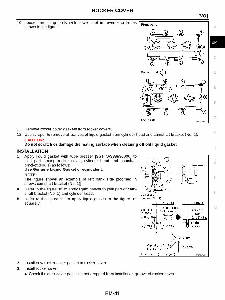
10. Loosen mounting bolts with power tool in reverse order asshown in the figure.
11. Remove rocker cover gaskets from rocker covers.12. Use scraper to remove all trances of liquid gasket from cylinder head and camshaft bracket (No. 1).
CAUTION:Do not scratch or damage the mating surface when cleaning off old liquid gasket.
INSTALLATION1. Apply liquid gasket with tube presser [SST: WS39930000] to
joint part among rocker cover, cylinder head and camshaftbracket (No. 1) as follows:Use Genuine Liquid Gasket or equivalent.NOTE:The figure shows an example of left bank side [zoomed inshows camshaft bracket (No. 1)].
a. Refer to the figure “a” to apply liquid gasket to joint part of cam-shaft bracket (No. 1) and cylinder head.
b. Refer to the figure “b” to apply liquid gasket to the figure “a”squarely.
2. Install new rocker cover gasket to rocker cover.3. Install rocker cover.
● Check if rocker cover gasket is not dropped from installation groove of rocker cover.
PBIC2906E
PBIC2474E
EM-42
[VQ]ROCKER COVER
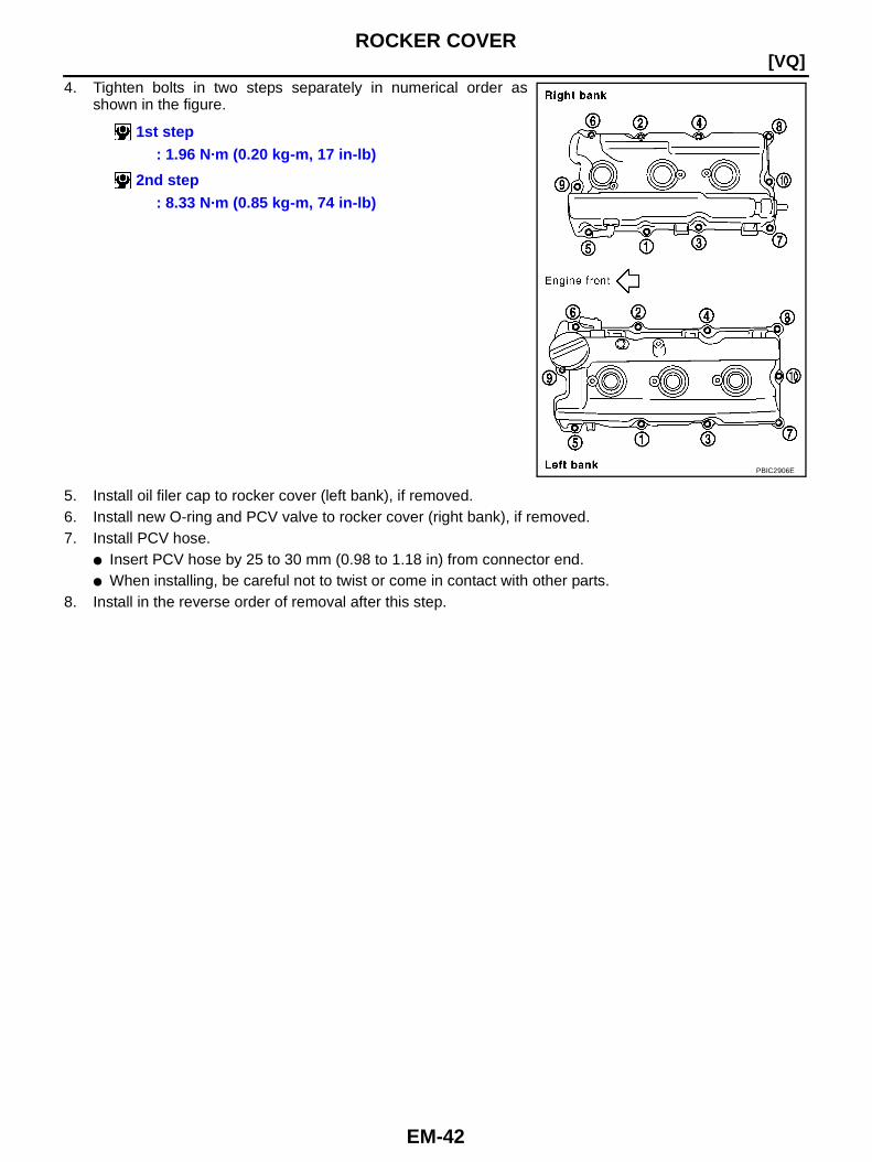
4. Tighten bolts in two steps separately in numerical order asshown in the figure.
5. Install oil filer cap to rocker cover (left bank), if removed.6. Install new O-ring and PCV valve to rocker cover (right bank), if removed.7. Install PCV hose.
● Insert PCV hose by 25 to 30 mm (0.98 to 1.18 in) from connector end.● When installing, be careful not to twist or come in contact with other parts.
8. Install in the reverse order of removal after this step.
1st step: 1.96 N·m (0.20 kg-m, 17 in-lb)
2nd step: 8.33 N·m (0.85 kg-m, 74 in-lb)
PBIC2906E

FRONT TIMING CHAIN CASE
EM-43
[VQ]
C
D
E
F
G
H
I
J
K
L
M
A
EM
FRONT TIMING CHAIN CASE PFP:13599
Removal and Installation BBS0000Z
NOTE:● This section describes removal/installation procedure of front timing chain case and timing chain related
parts without removing oil pan (upper) on vehicle.● When oil pan (upper) needs to be removed or installed, or when rear timing chain case is removed or
installed, remove oil pans (upper and lower) first. Then remove front timing chain case, timing chainrelated parts, and rear timing chain case in this order, and install in the reverse order of removal. Refer toEM-52, "TIMING CHAIN" .
● Refer to EM-52, "TIMING CHAIN" for component parts location.
REMOVAL1. Remove engine cover. Refer to EM-17, "INTAKE MANIFOLD COLLECTOR" .2. Remove engine undercover front and engine undercover middle. Refer to EI-15, "FRONT BUMPER" .3. Release the fuel pressure. Refer to EC-75, "FUEL PRESSURE RELEASE" (WITH EURO-OBD) or EC-
604, "FUEL PRESSURE RELEASE" (WITHOUT EURO-OBD).4. Drain engine oil. Refer to LU-8, "Changing Engine Oil" .
CAUTION:● Perform this step when engine is cold.● Do not spill engine oil on drive belts.
5. Drain engine coolant from radiator. Refer to CO-9, "Changing Engine Coolant" .CAUTION:● Perform this step when engine is cold.● Do not spill engine coolant on drive belts.
6. Remove radiator cooling fan assembly. Refer to CO-20, "COOLING FAN" .7. Separate engine harnesses removing their brackets from front timing chain case.8. Remove drive belt. Refer to EM-13, "DRIVE BELTS" .9. Remove power steering oil pump from bracket with piping connected, and temporarily secure it to aside.
Refer to PS-35, "POWER STEERING OIL PUMP" .10. Remove power steering oil pump bracket. Refer to PS-35, "POWER STEERING OIL PUMP" .11. Remove alternator. Refer to SC-14, "CHARGING SYSTEM" .12. Remove water bypass hose, water hose clamp and idler pulley bracket from front timing chain case.13. Remove right and left intake valve timing control covers.
● Loosen mounting bolts in reverse order as shown in the fig-ure.
● Use seal cutter [SST: KV10111100] to cut liquid gasket forremoval.
CAUTION:Shaft is internally jointed with camshaft sprocket (INT) cen-ter hole. When removing, keep it horizontal until it is com-pletely disconnected.
SEM728G
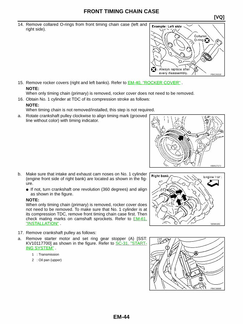
EM-44
[VQ]FRONT TIMING CHAIN CASE
14. Remove collared O-rings from front timing chain case (left andright side).
15. Remove rocker covers (right and left banks). Refer to EM-40, "ROCKER COVER" .NOTE:When only timing chain (primary) is removed, rocker cover does not need to be removed.
16. Obtain No. 1 cylinder at TDC of its compression stroke as follows:NOTE:When timing chain is not removed/installed, this step is not required.
a. Rotate crankshaft pulley clockwise to align timing mark (groovedline without color) with timing indicator.
b. Make sure that intake and exhaust cam noses on No. 1 cylinder(engine front side of right bank) are located as shown in the fig-ure.● If not, turn crankshaft one revolution (360 degrees) and align
as shown in the figure.NOTE:When only timing chain (primary) is removed, rocker cover doesnot need to be removed. To make sure that No. 1 cylinder is atits compression TDC, remove front timing chain case first. Thencheck mating marks on camshaft sprockets. Refer to EM-61,"INSTALLATION" .
17. Remove crankshaft pulley as follows:a. Remove starter motor and set ring gear stopper (A) [SST:
KV10117700] as shown in the figure. Refer to SC-31, "START-ING SYSTEM" .
PBIC2631E
KBIA1717J
SEM418G
1 : Transmission
2 : Oil pan (upper)
PBIC3889E

FRONT TIMING CHAIN CASE
EM-45
[VQ]
C
D
E
F
G
H
I
J
K
L
M
A
EM
b. Loosen crankshaft pulley bolt and locate bolt seating surface as10 mm (0.39 in) from its original position.CAUTION:Do not remove crankshaft pulley bolt. Keep loosenedcrankshaft pulley bolt in place to protect removed crank-shaft pulley from dropping.
c. Pull crankshaft pulley with both hands to remove it.18. Loosen two mounting bolts in front of oil pan (upper) in reverse
order as shown in the figure.
19. Remove front timing chain case as follows:a. Loosen mounting bolts in reverse order as shown in the figure.
b. Insert suitable tool into the notch at the top of the front timingchain case as shown (1).
c. Pry off case by moving tool as shown (2).● Use seal cutter [SST: KV10111100] to cut liquid gasket for
removal.CAUTION:● Do not use screwdriver or something similar.● After removal, handle front timing chain case carefully so
it does not tilt, cant, or warp under a load.
PBIC2918E
PBIC2907E
PBIC2908E
SEM156F
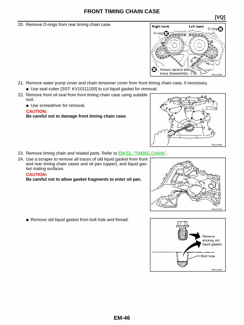
EM-46
[VQ]FRONT TIMING CHAIN CASE
20. Remove O-rings from rear timing chain case.
21. Remove water pump cover and chain tensioner cover from front timing chain case, if necessary.● Use seal cutter [SST: KV10111100] to cut liquid gasket for removal.
22. Remove front oil seal from front timing chain case using suitabletool.● Use screwdriver for removal.CAUTION:Be careful not to damage front timing chain case.
23. Remove timing chain and related parts. Refer to EM-52, "TIMING CHAIN" .24. Use a scraper to remove all traces of old liquid gasket from front
and rear timing chain cases and oil pan (upper), and liquid gas-ket mating surfaces.CAUTION:Be careful not to allow gasket fragments to enter oil pan.
● Remove old liquid gasket from bolt hole and thread.
PBIC2548E
PBIC2909E
PBIC2910E
PBIC2084E
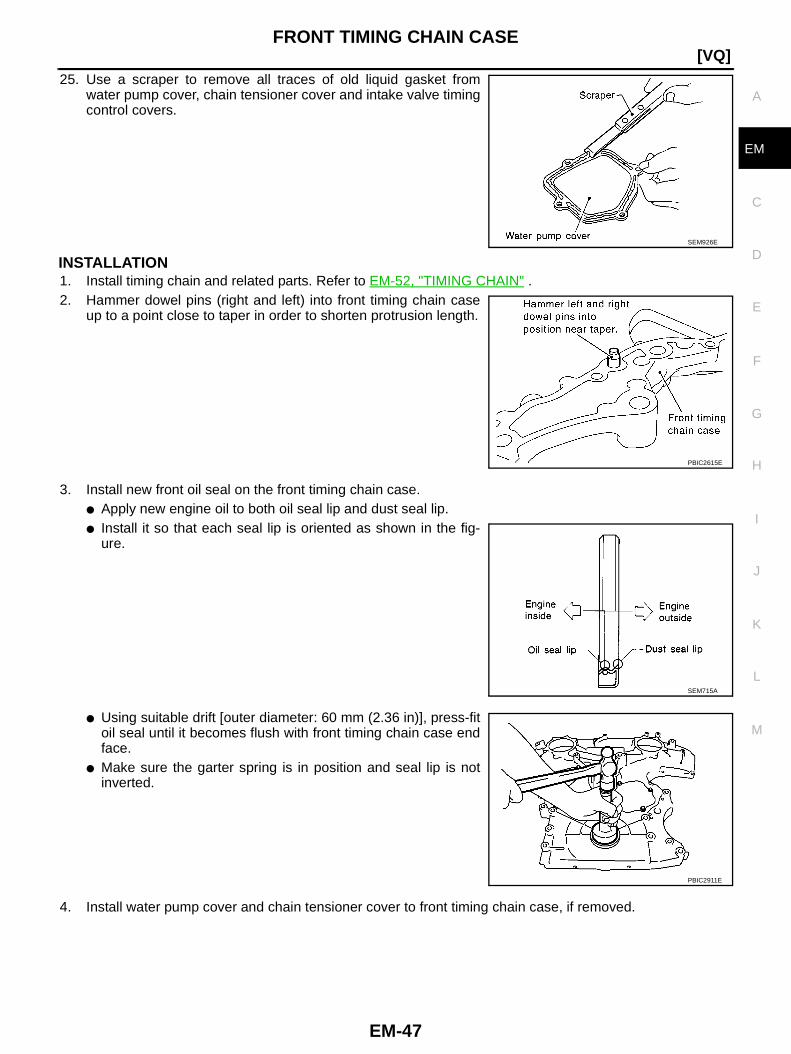
FRONT TIMING CHAIN CASE
EM-47
[VQ]
C
D
E
F
G
H
I
J
K
L
M
A
EM
25. Use a scraper to remove all traces of old liquid gasket fromwater pump cover, chain tensioner cover and intake valve timingcontrol covers.
INSTALLATION1. Install timing chain and related parts. Refer to EM-52, "TIMING CHAIN" .2. Hammer dowel pins (right and left) into front timing chain case
up to a point close to taper in order to shorten protrusion length.
3. Install new front oil seal on the front timing chain case.● Apply new engine oil to both oil seal lip and dust seal lip.● Install it so that each seal lip is oriented as shown in the fig-
ure.
● Using suitable drift [outer diameter: 60 mm (2.36 in)], press-fitoil seal until it becomes flush with front timing chain case endface.
● Make sure the garter spring is in position and seal lip is notinverted.
4. Install water pump cover and chain tensioner cover to front timing chain case, if removed.
SEM926E
PBIC2615E
SEM715A
PBIC2911E

EM-48
[VQ]FRONT TIMING CHAIN CASE
● Apply a continuous bead of liquid gasket with tube presser[SST: WS39930000] to front timing chain case as shown inthe figure.Use Genuine Liquid Gasket or equivalent.
5. Install front timing chain case as follows:a. Apply a continuous bead of liquid gasket with tube presser [SST:
WS39930000] to front timing chain case back side as shown inthe figure.
Use Genuine Liquid Gasket or equivalent.
b. Apply liquid gasket with tube presser [SST: WS39930000] to topsurface of oil pan (upper) as shown in the figure.Use Genuine Liquid Gasket or equivalent.
PBIC2912E
B : Protrusion
C : Both permissible
D : Bolt hole
PBIC3887E
PBIC2914E
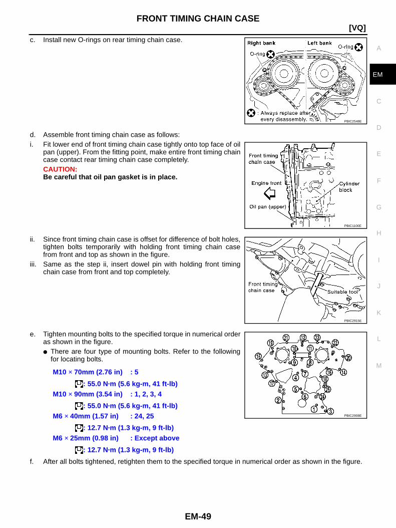
FRONT TIMING CHAIN CASE
EM-49
[VQ]
C
D
E
F
G
H
I
J
K
L
M
A
EM
c. Install new O-rings on rear timing chain case.
d. Assemble front timing chain case as follows:i. Fit lower end of front timing chain case tightly onto top face of oil
pan (upper). From the fitting point, make entire front timing chaincase contact rear timing chain case completely.CAUTION:Be careful that oil pan gasket is in place.
ii. Since front timing chain case is offset for difference of bolt holes,tighten bolts temporarily with holding front timing chain casefrom front and top as shown in the figure.
iii. Same as the step ii, insert dowel pin with holding front timingchain case from front and top completely.
e. Tighten mounting bolts to the specified torque in numerical orderas shown in the figure.● There are four type of mounting bolts. Refer to the following
for locating bolts.
f. After all bolts tightened, retighten them to the specified torque in numerical order as shown in the figure.
PBIC2548E
PBIC1100E
PBIC2915E
M10 × 70mm (2.76 in) : 5
: 55.0 N·m (5.6 kg-m, 41 ft-lb)M10 × 90mm (3.54 in) : 1, 2, 3, 4
: 55.0 N·m (5.6 kg-m, 41 ft-lb)M6 × 40mm (1.57 in) : 24, 25
: 12.7 N·m (1.3 kg-m, 9 ft-lb)M6 × 25mm (0.98 in) : Except above
: 12.7 N·m (1.3 kg-m, 9 ft-lb)
PBIC2908E
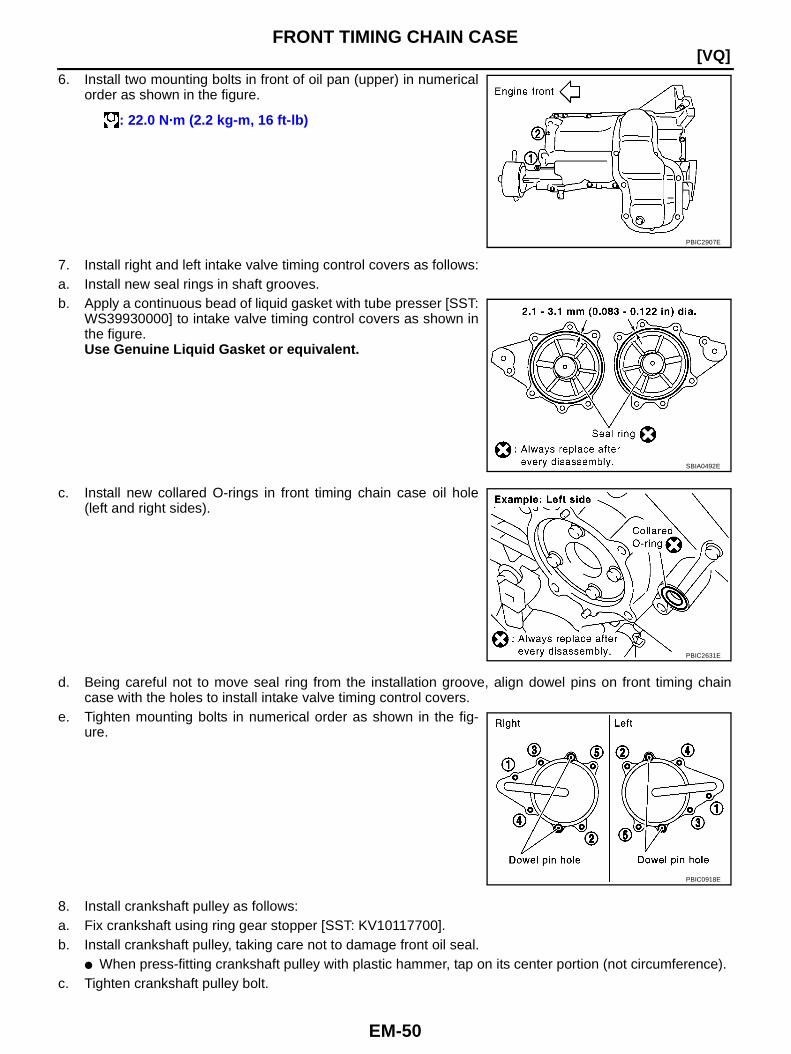
EM-50
[VQ]FRONT TIMING CHAIN CASE
6. Install two mounting bolts in front of oil pan (upper) in numericalorder as shown in the figure.
7. Install right and left intake valve timing control covers as follows:a. Install new seal rings in shaft grooves.b. Apply a continuous bead of liquid gasket with tube presser [SST:
WS39930000] to intake valve timing control covers as shown inthe figure.Use Genuine Liquid Gasket or equivalent.
c. Install new collared O-rings in front timing chain case oil hole(left and right sides).
d. Being careful not to move seal ring from the installation groove, align dowel pins on front timing chaincase with the holes to install intake valve timing control covers.
e. Tighten mounting bolts in numerical order as shown in the fig-ure.
8. Install crankshaft pulley as follows:a. Fix crankshaft using ring gear stopper [SST: KV10117700].b. Install crankshaft pulley, taking care not to damage front oil seal.
● When press-fitting crankshaft pulley with plastic hammer, tap on its center portion (not circumference).c. Tighten crankshaft pulley bolt.
: 22.0 N·m (2.2 kg-m, 16 ft-lb)
PBIC2907E
SBIA0492E
PBIC2631E
PBIC0918E
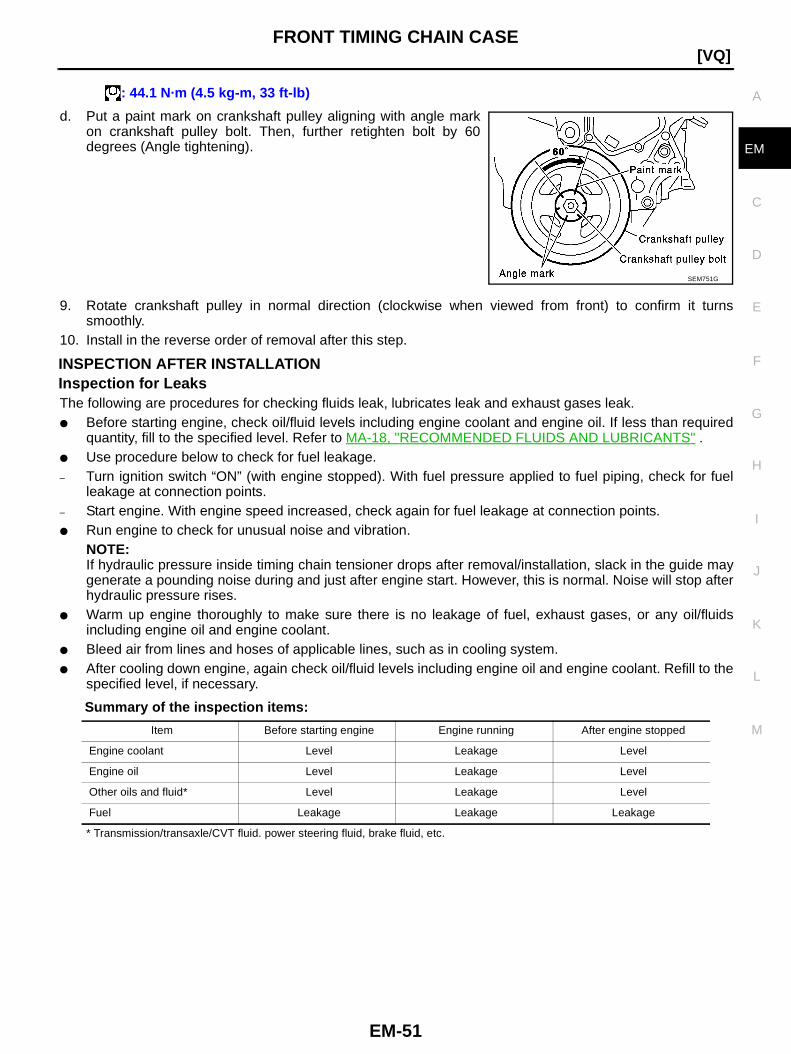
FRONT TIMING CHAIN CASE
EM-51
[VQ]
C
D
E
F
G
H
I
J
K
L
M
A
EM
d. Put a paint mark on crankshaft pulley aligning with angle markon crankshaft pulley bolt. Then, further retighten bolt by 60degrees (Angle tightening).
9. Rotate crankshaft pulley in normal direction (clockwise when viewed from front) to confirm it turnssmoothly.
10. Install in the reverse order of removal after this step.
INSPECTION AFTER INSTALLATIONInspection for LeaksThe following are procedures for checking fluids leak, lubricates leak and exhaust gases leak.● Before starting engine, check oil/fluid levels including engine coolant and engine oil. If less than required
quantity, fill to the specified level. Refer to MA-18, "RECOMMENDED FLUIDS AND LUBRICANTS" .● Use procedure below to check for fuel leakage.– Turn ignition switch “ON” (with engine stopped). With fuel pressure applied to fuel piping, check for fuel
leakage at connection points.– Start engine. With engine speed increased, check again for fuel leakage at connection points.● Run engine to check for unusual noise and vibration.
NOTE:If hydraulic pressure inside timing chain tensioner drops after removal/installation, slack in the guide maygenerate a pounding noise during and just after engine start. However, this is normal. Noise will stop afterhydraulic pressure rises.
● Warm up engine thoroughly to make sure there is no leakage of fuel, exhaust gases, or any oil/fluidsincluding engine oil and engine coolant.
● Bleed air from lines and hoses of applicable lines, such as in cooling system.● After cooling down engine, again check oil/fluid levels including engine oil and engine coolant. Refill to the
specified level, if necessary.
Summary of the inspection items:
* Transmission/transaxle/CVT fluid. power steering fluid, brake fluid, etc.
: 44.1 N·m (4.5 kg-m, 33 ft-lb)
SEM751G
Item Before starting engine Engine running After engine stopped
Engine coolant Level Leakage Level
Engine oil Level Leakage Level
Other oils and fluid* Level Leakage Level
Fuel Leakage Leakage Leakage

EM-52
[VQ]TIMING CHAIN
TIMING CHAIN PFP:13028
Components BBS00010
PBIC3888E
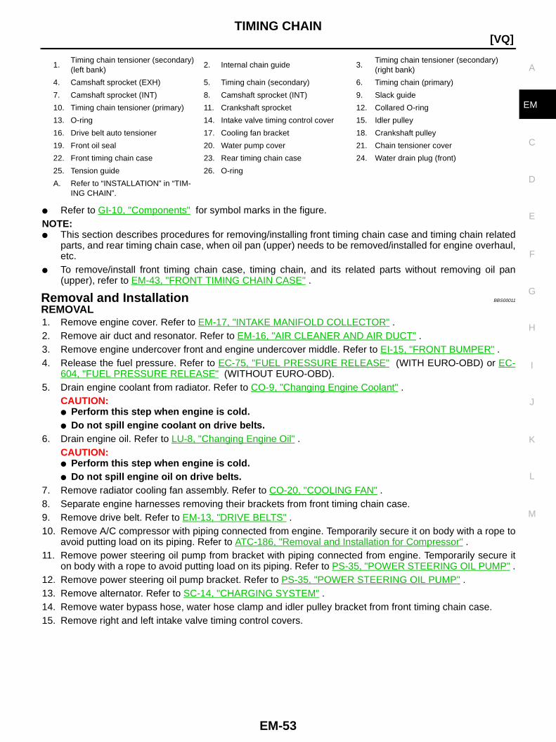
TIMING CHAIN
EM-53
[VQ]
C
D
E
F
G
H
I
J
K
L
M
A
EM
● Refer to GI-10, "Components" for symbol marks in the figure.NOTE:● This section describes procedures for removing/installing front timing chain case and timing chain related
parts, and rear timing chain case, when oil pan (upper) needs to be removed/installed for engine overhaul,etc.
● To remove/install front timing chain case, timing chain, and its related parts without removing oil pan(upper), refer to EM-43, "FRONT TIMING CHAIN CASE" .
Removal and Installation BBS00011
REMOVAL1. Remove engine cover. Refer to EM-17, "INTAKE MANIFOLD COLLECTOR" .2. Remove air duct and resonator. Refer to EM-16, "AIR CLEANER AND AIR DUCT" .3. Remove engine undercover front and engine undercover middle. Refer to EI-15, "FRONT BUMPER" .4. Release the fuel pressure. Refer to EC-75, "FUEL PRESSURE RELEASE" (WITH EURO-OBD) or EC-
604, "FUEL PRESSURE RELEASE" (WITHOUT EURO-OBD).5. Drain engine coolant from radiator. Refer to CO-9, "Changing Engine Coolant" .
CAUTION:● Perform this step when engine is cold.● Do not spill engine coolant on drive belts.
6. Drain engine oil. Refer to LU-8, "Changing Engine Oil" .CAUTION:● Perform this step when engine is cold.● Do not spill engine oil on drive belts.
7. Remove radiator cooling fan assembly. Refer to CO-20, "COOLING FAN" .8. Separate engine harnesses removing their brackets from front timing chain case.9. Remove drive belt. Refer to EM-13, "DRIVE BELTS" .10. Remove A/C compressor with piping connected from engine. Temporarily secure it on body with a rope to
avoid putting load on its piping. Refer to ATC-186, "Removal and Installation for Compressor" .11. Remove power steering oil pump from bracket with piping connected from engine. Temporarily secure it
on body with a rope to avoid putting load on its piping. Refer to PS-35, "POWER STEERING OIL PUMP" .12. Remove power steering oil pump bracket. Refer to PS-35, "POWER STEERING OIL PUMP" .13. Remove alternator. Refer to SC-14, "CHARGING SYSTEM" .14. Remove water bypass hose, water hose clamp and idler pulley bracket from front timing chain case.15. Remove right and left intake valve timing control covers.
1.Timing chain tensioner (secondary)(left bank)
2. Internal chain guide 3.Timing chain tensioner (secondary)(right bank)
4. Camshaft sprocket (EXH) 5. Timing chain (secondary) 6. Timing chain (primary)
7. Camshaft sprocket (INT) 8. Camshaft sprocket (INT) 9. Slack guide
10. Timing chain tensioner (primary) 11. Crankshaft sprocket 12. Collared O-ring
13. O-ring 14. Intake valve timing control cover 15. Idler pulley
16. Drive belt auto tensioner 17. Cooling fan bracket 18. Crankshaft pulley
19. Front oil seal 20. Water pump cover 21. Chain tensioner cover
22. Front timing chain case 23. Rear timing chain case 24. Water drain plug (front)
25. Tension guide 26. O-ring
A. Refer to “INSTALLATION” in “TIM-ING CHAIN”.
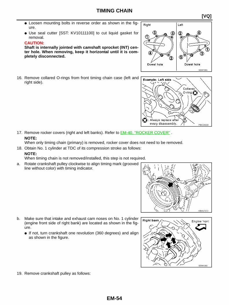
EM-54
[VQ]TIMING CHAIN
● Loosen mounting bolts in reverse order as shown in the fig-ure.
● Use seal cutter [SST: KV10111100] to cut liquid gasket forremoval.
CAUTION:Shaft is internally jointed with camshaft sprocket (INT) cen-ter hole. When removing, keep it horizontal until it is com-pletely disconnected.
16. Remove collared O-rings from front timing chain case (left andright side).
17. Remove rocker covers (right and left banks). Refer to EM-40, "ROCKER COVER" .NOTE:When only timing chain (primary) is removed, rocker cover does not need to be removed.
18. Obtain No. 1 cylinder at TDC of its compression stroke as follows:NOTE:When timing chain is not removed/installed, this step is not required.
a. Rotate crankshaft pulley clockwise to align timing mark (groovedline without color) with timing indicator.
b. Make sure that intake and exhaust cam noses on No. 1 cylinder(engine front side of right bank) are located as shown in the fig-ure.● If not, turn crankshaft one revolution (360 degrees) and align
as shown in the figure.
19. Remove crankshaft pulley as follows:
SEM728G
PBIC2631E
KBIA1717J
SEM418G

TIMING CHAIN
EM-55
[VQ]
C
D
E
F
G
H
I
J
K
L
M
A
EM
a. Remove starter motor and set ring gear stopper (A) [SST:KV10117700] as shown in the figure. Refer to SC-31, "START-ING SYSTEM" .
b. Loosen crankshaft pulley bolt and locate bolt seating surface as10 mm (0.39 in) from its original position.CAUTION:Do not remove crankshaft pulley bolt. Keep loosenedcrankshaft pulley bolt in place to protect removed crank-shaft pulley from dropping.
c. Pull crankshaft pulley with both hands to remove it.20. Remove oil pans (upper and lower). Refer to EM-27, "OIL PAN AND OIL STRAINER" .21. Remove front timing chain case as follows:a. Loosen mounting bolts in reverse order as shown in the figure.
b. Insert suitable tool into the notch at the top of the front timingchain case as shown (1).
c. Pry off case by moving the tool as shown (2).● Use seal cutter [SST: KV10111100] to cut liquid gasket for
removal.CAUTION:● Do not use screwdriver or something similar.● After removal, handle front timing chain case carefully so
it does not tilt, cant, or warp under a load.
1 : Transmission
2 : Oil pan (upper)
PBIC3889E
PBIC2918E
PBIC2908E
SEM156F

EM-56
[VQ]TIMING CHAIN
22. Remove O-rings from rear timing chain case.
23. Remove water pump cover and chain tensioner cover from front timing chain case.● Use seal cutter [SST: KV10111100] to cut liquid gasket for removal.
24. Remove front oil seal from front timing chain case using suitabletool.● Use screwdriver for removal.CAUTION:Be careful not to damage front timing chain case.
25. Remove timing chain tensioner (primary) as follows:a. Loosen clip of timing chain tensioner (primary), and release
plunger stopper. (1)b. Insert plunger into tensioner body by pressing slack guide. (2)c. Keep slack guide pressed and hold plunger in by pushing stop-
per pin through the tensioner body hole and plunger groove. (3)
d. Remove mounting bolts and remove timing chain tensioner (primary).
PBIC2548E
PBIC2909E
PBIC2919E
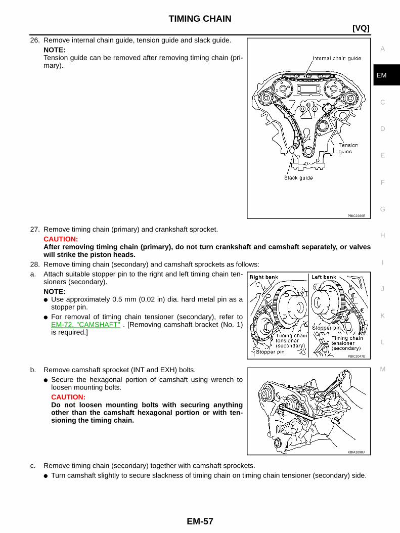
TIMING CHAIN
EM-57
[VQ]
C
D
E
F
G
H
I
J
K
L
M
A
EM
26. Remove internal chain guide, tension guide and slack guide.NOTE:Tension guide can be removed after removing timing chain (pri-mary).
27. Remove timing chain (primary) and crankshaft sprocket.CAUTION:After removing timing chain (primary), do not turn crankshaft and camshaft separately, or valveswill strike the piston heads.
28. Remove timing chain (secondary) and camshaft sprockets as follows:a. Attach suitable stopper pin to the right and left timing chain ten-
sioners (secondary).NOTE:● Use approximately 0.5 mm (0.02 in) dia. hard metal pin as a
stopper pin.● For removal of timing chain tensioner (secondary), refer to
EM-72, "CAMSHAFT" . [Removing camshaft bracket (No. 1)is required.]
b. Remove camshaft sprocket (INT and EXH) bolts.● Secure the hexagonal portion of camshaft using wrench to
loosen mounting bolts.CAUTION:Do not loosen mounting bolts with securing anythingother than the camshaft hexagonal portion or with ten-sioning the timing chain.
c. Remove timing chain (secondary) together with camshaft sprockets.● Turn camshaft slightly to secure slackness of timing chain on timing chain tensioner (secondary) side.
PBIC2266E
PBIC2047E
KBIA1698J
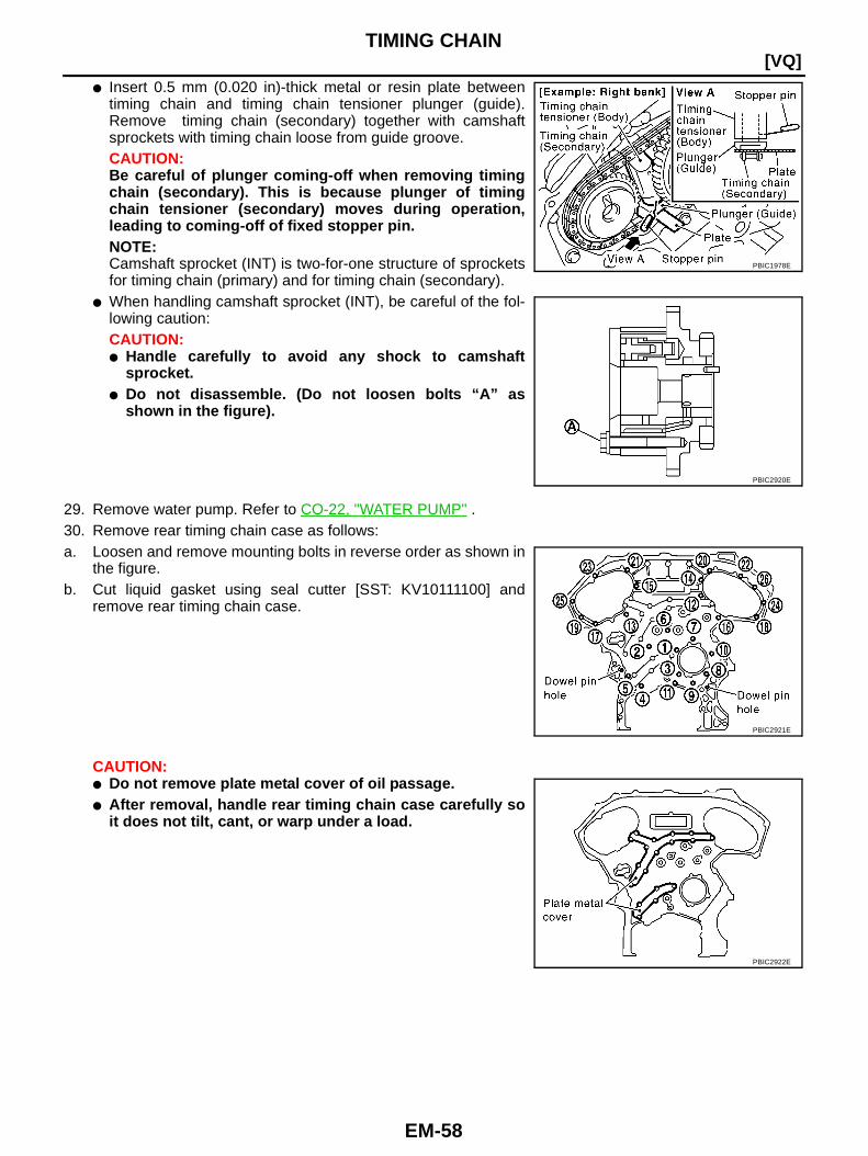
EM-58
[VQ]TIMING CHAIN
● Insert 0.5 mm (0.020 in)-thick metal or resin plate betweentiming chain and timing chain tensioner plunger (guide).Remove timing chain (secondary) together with camshaftsprockets with timing chain loose from guide groove.CAUTION:Be careful of plunger coming-off when removing timingchain (secondary). This is because plunger of timingchain tensioner (secondary) moves during operation,leading to coming-off of fixed stopper pin.NOTE:Camshaft sprocket (INT) is two-for-one structure of sprocketsfor timing chain (primary) and for timing chain (secondary).
● When handling camshaft sprocket (INT), be careful of the fol-lowing caution:CAUTION:● Handle carefully to avoid any shock to camshaft
sprocket.● Do not disassemble. (Do not loosen bolts “A” as
shown in the figure).
29. Remove water pump. Refer to CO-22, "WATER PUMP" .30. Remove rear timing chain case as follows:a. Loosen and remove mounting bolts in reverse order as shown in
the figure.b. Cut liquid gasket using seal cutter [SST: KV10111100] and
remove rear timing chain case.
CAUTION:● Do not remove plate metal cover of oil passage.● After removal, handle rear timing chain case carefully so
it does not tilt, cant, or warp under a load.
PBIC1978E
PBIC2920E
PBIC2921E
PBIC2922E
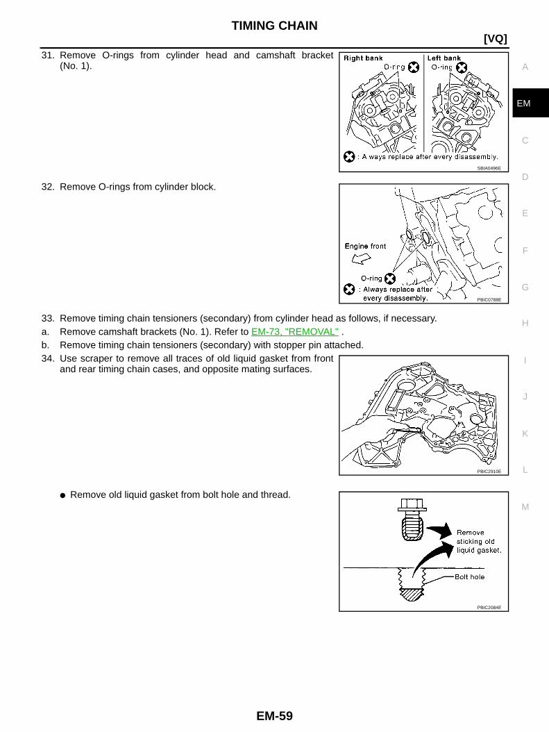
TIMING CHAIN
EM-59
[VQ]
C
D
E
F
G
H
I
J
K
L
M
A
EM
31. Remove O-rings from cylinder head and camshaft bracket(No. 1).
32. Remove O-rings from cylinder block.
33. Remove timing chain tensioners (secondary) from cylinder head as follows, if necessary.a. Remove camshaft brackets (No. 1). Refer to EM-73, "REMOVAL" .b. Remove timing chain tensioners (secondary) with stopper pin attached.34. Use scraper to remove all traces of old liquid gasket from front
and rear timing chain cases, and opposite mating surfaces.
● Remove old liquid gasket from bolt hole and thread.
SBIA0496E
PBIC0788E
PBIC2910E
PBIC2084E
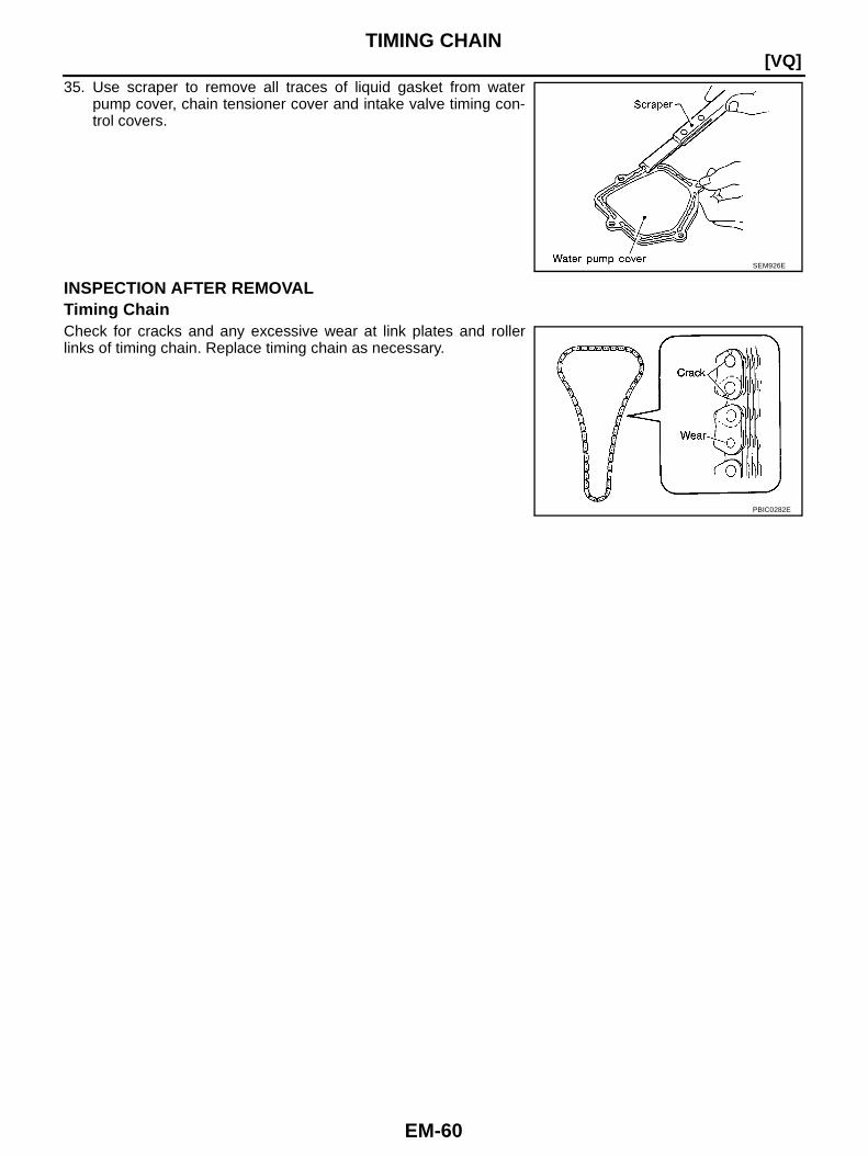
EM-60
[VQ]TIMING CHAIN
35. Use scraper to remove all traces of liquid gasket from waterpump cover, chain tensioner cover and intake valve timing con-trol covers.
INSPECTION AFTER REMOVALTiming ChainCheck for cracks and any excessive wear at link plates and rollerlinks of timing chain. Replace timing chain as necessary.
SEM926E
PBIC0282E
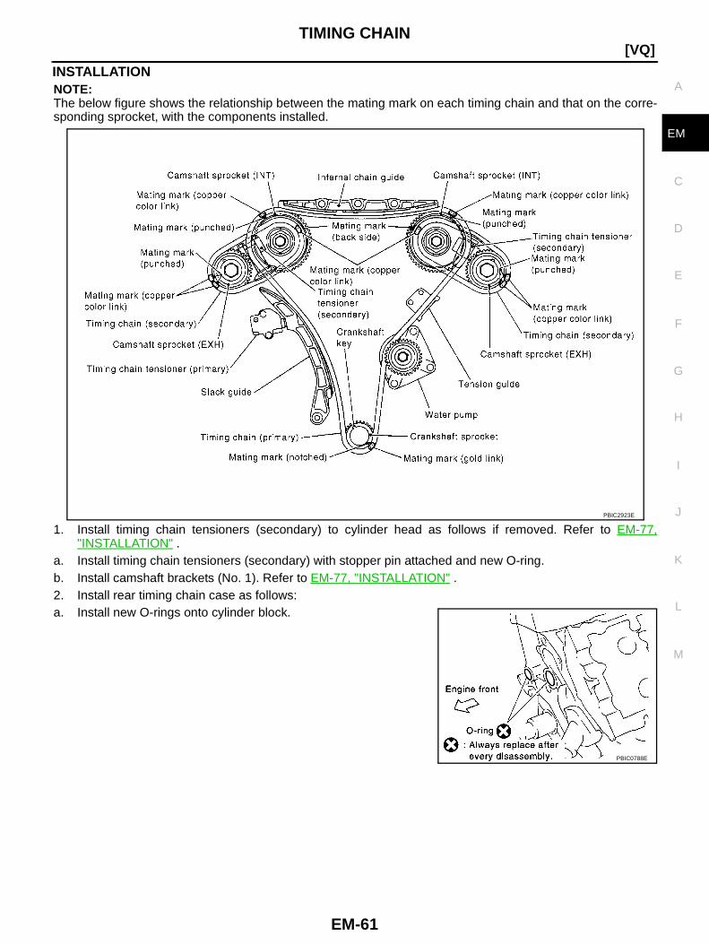
TIMING CHAIN
EM-61
[VQ]
C
D
E
F
G
H
I
J
K
L
M
A
EM
INSTALLATIONNOTE:The below figure shows the relationship between the mating mark on each timing chain and that on the corre-sponding sprocket, with the components installed.
1. Install timing chain tensioners (secondary) to cylinder head as follows if removed. Refer to EM-77,"INSTALLATION" .
a. Install timing chain tensioners (secondary) with stopper pin attached and new O-ring.b. Install camshaft brackets (No. 1). Refer to EM-77, "INSTALLATION" .2. Install rear timing chain case as follows:a. Install new O-rings onto cylinder block.
PBIC2923E
PBIC0788E

EM-62
[VQ]TIMING CHAIN
b. Install new O-rings to cylinder head and camshaft bracket(No. 1).
c. Apply liquid gasket with tube presser [SST: WS39930000] to rear timing chain case back side as shown inthe figure.Use Genuine Liquid Gasket or equivalent.CAUTION:● For “A” in the figure, completely wipe out liquid gasket extended on a portion touching at
engine coolant.● Apply liquid gasket on installation position of water pump and cylinder head very completely.
d. Align rear timing chain case with dowel pins (right and left) on cylinder block and install rear timing chaincase.● Make sure O-rings stay in place during installation to cylinder block, cylinder head and camshaft
bracket (No. 1).
SBIA0496E
PBIC3890E
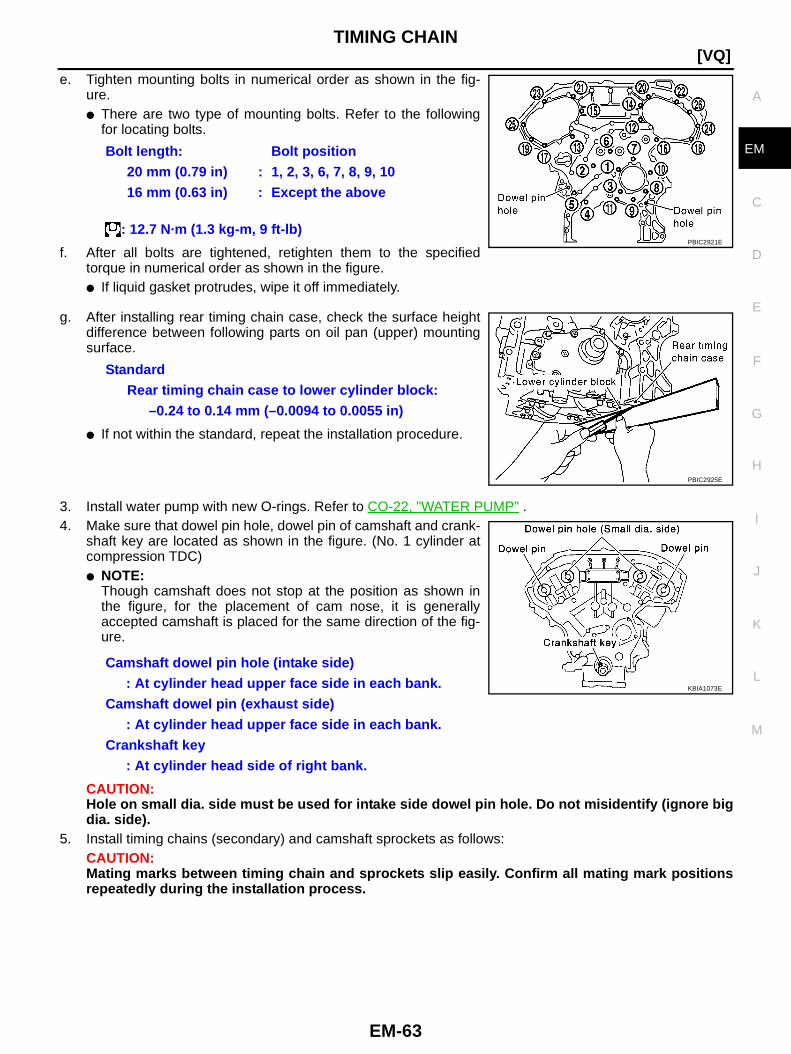
TIMING CHAIN
EM-63
[VQ]
C
D
E
F
G
H
I
J
K
L
M
A
EM
e. Tighten mounting bolts in numerical order as shown in the fig-ure.● There are two type of mounting bolts. Refer to the following
for locating bolts.
f. After all bolts are tightened, retighten them to the specifiedtorque in numerical order as shown in the figure.● If liquid gasket protrudes, wipe it off immediately.
g. After installing rear timing chain case, check the surface heightdifference between following parts on oil pan (upper) mountingsurface.
● If not within the standard, repeat the installation procedure.
3. Install water pump with new O-rings. Refer to CO-22, "WATER PUMP" .4. Make sure that dowel pin hole, dowel pin of camshaft and crank-
shaft key are located as shown in the figure. (No. 1 cylinder atcompression TDC)● NOTE:
Though camshaft does not stop at the position as shown inthe figure, for the placement of cam nose, it is generallyaccepted camshaft is placed for the same direction of the fig-ure.
CAUTION:Hole on small dia. side must be used for intake side dowel pin hole. Do not misidentify (ignore bigdia. side).
5. Install timing chains (secondary) and camshaft sprockets as follows:CAUTION:Mating marks between timing chain and sprockets slip easily. Confirm all mating mark positionsrepeatedly during the installation process.
Bolt length: Bolt position20 mm (0.79 in) : 1, 2, 3, 6, 7, 8, 9, 1016 mm (0.63 in) : Except the above
: 12.7 N·m (1.3 kg-m, 9 ft-lb)PBIC2921E
StandardRear timing chain case to lower cylinder block:
–0.24 to 0.14 mm (–0.0094 to 0.0055 in)
PBIC2925E
Camshaft dowel pin hole (intake side): At cylinder head upper face side in each bank.
Camshaft dowel pin (exhaust side): At cylinder head upper face side in each bank.
Crankshaft key: At cylinder head side of right bank.
KBIA1073E
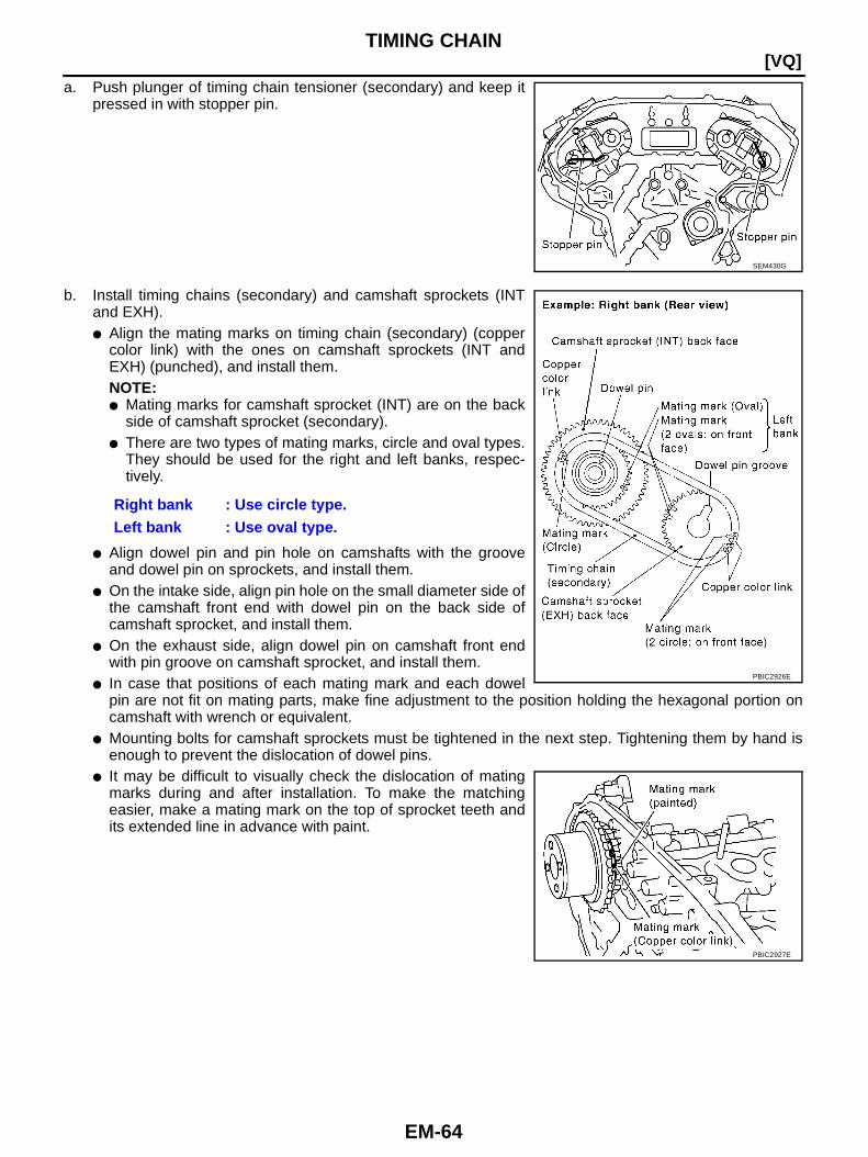
EM-64
[VQ]TIMING CHAIN
a. Push plunger of timing chain tensioner (secondary) and keep itpressed in with stopper pin.
b. Install timing chains (secondary) and camshaft sprockets (INTand EXH).● Align the mating marks on timing chain (secondary) (copper
color link) with the ones on camshaft sprockets (INT andEXH) (punched), and install them.NOTE:● Mating marks for camshaft sprocket (INT) are on the back
side of camshaft sprocket (secondary).● There are two types of mating marks, circle and oval types.
They should be used for the right and left banks, respec-tively.
● Align dowel pin and pin hole on camshafts with the grooveand dowel pin on sprockets, and install them.
● On the intake side, align pin hole on the small diameter side ofthe camshaft front end with dowel pin on the back side ofcamshaft sprocket, and install them.
● On the exhaust side, align dowel pin on camshaft front endwith pin groove on camshaft sprocket, and install them.
● In case that positions of each mating mark and each dowelpin are not fit on mating parts, make fine adjustment to the position holding the hexagonal portion oncamshaft with wrench or equivalent.
● Mounting bolts for camshaft sprockets must be tightened in the next step. Tightening them by hand isenough to prevent the dislocation of dowel pins.
● It may be difficult to visually check the dislocation of matingmarks during and after installation. To make the matchingeasier, make a mating mark on the top of sprocket teeth andits extended line in advance with paint.
SEM430G
Right bank : Use circle type.Left bank : Use oval type.
PBIC2926E
PBIC2927E
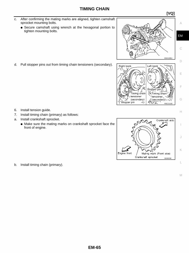
TIMING CHAIN
EM-65
[VQ]
C
D
E
F
G
H
I
J
K
L
M
A
EM
c. After confirming the mating marks are aligned, tighten camshaftsprocket mounting bolts.● Secure camshaft using wrench at the hexagonal portion to
tighten mounting bolts.
d. Pull stopper pins out from timing chain tensioners (secondary).
6. Install tension guide.7. Install timing chain (primary) as follows:a. Install crankshaft sprocket.
● Make sure the mating marks on crankshaft sprocket face thefront of engine.
b. Install timing chain (primary).
KBIA1698J
PBIC2110E
SEM929E

EM-66
[VQ]TIMING CHAIN
● Install timing chain (primary) so the mating mark (punched) oncamshaft sprocket is aligned with the copper color link on tim-ing chain, while the mating mark (notched) on crankshaftsprocket is aligned with the gold one on timing chain, asshown in the figure.
● When it is difficult to align mating marks of timing chain (pri-mary) with each sprocket, gradually turn camshaft usingwrench on the hexagonal portion to align it with the matingmarks.
● During alignment, be careful to prevent dislocation of matingmark alignments of timing chains (secondary).
8. Install internal chain guide, slack guide and timing chain ten-sioner (primary).
PBIC2928E
PBIC2109E

TIMING CHAIN
EM-67
[VQ]
C
D
E
F
G
H
I
J
K
L
M
A
EM
CAUTION:Do not overtighten slack guide mounting bolts. It is normalfor a gap to exist under the bolt seats when mounting boltare tightened to specification.
● When installing timing chain tensioner (primary), push in plunger and keep it pressed in with stopperpin.
● Remove any dirt and foreign materials completely from the back and the mounting surfaces of timingchain tensioner (primary).
● After installation, pull out stopper pin by pressing slack guide.
9. Make sure again that the mating marks on camshaft sprockets and timing chain have not slipped out ofalignment.
10. Install new front oil seal on front timing chain case.● Apply new engine oil to both oil seal lip and dust seal lip.● Install it so that each seal lip is oriented as shown in the fig-
ure.
● Using suitable drift [outer diameter: 60 mm (2.36 in)], press-fitoil seal until it becomes flush with front timing chain case endface.
● Make sure the garter spring is in position and seal lip is notinverted.
11. Install water pump cover and chain tensioner cover to front timing chain case.
PBIC2633E
SEM715A
PBIC2911E
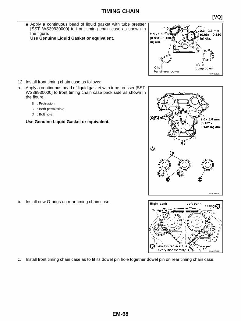
EM-68
[VQ]TIMING CHAIN
● Apply a continuous bead of liquid gasket with tube presser[SST: WS39930000] to front timing chain case as shown inthe figure.Use Genuine Liquid Gasket or equivalent.
12. Install front timing chain case as follows:a. Apply a continuous bead of liquid gasket with tube presser [SST:
WS39930000] to front timing chain case back side as shown inthe figure.
Use Genuine Liquid Gasket or equivalent.
b. Install new O-rings on rear timing chain case.
c. Install front timing chain case as to fit its dowel pin hole together dowel pin on rear timing chain case.
PBIC2912E
B : Protrusion
C : Both permissible
D : Bolt hole
PBIC3887E
PBIC2548E

TIMING CHAIN
EM-69
[VQ]
C
D
E
F
G
H
I
J
K
L
M
A
EM
d. Tighten mounting bolts to the specified torque in numerical orderas shown in the figure.● There are four type of mounting bolts. Refer to the following
for locating bolts.
e. After all bolts are tightened, retighten them to the specified torque in numerical order as shown in the fig-ure.CAUTION:Be sure to wipe off any excessive liquid gasket leaking on surface mating with oil pan (upper).
f. After installing front timing chain case, check surface height dif-ference between the following parts on the oil pan (upper)mounting surface.
● If not within the standard, repeat the installation procedure.
13. Install right and left intake valve timing control covers as follows:a. Install new seal rings in shaft grooves.b. Apply a continuous bead of liquid gasket with tube presser [SST:
WS39930000] to intake valve timing control covers as shown inthe figure.Use Genuine Liquid Gasket or equivalent.
c. Install new collared O-rings in front timing chain case oil hole(left and right sides).
M10 × 70 mm (2.76 in) : 5
: 55.0 N·m (5.6 kg-m, 41 ft-lb)M10 × 90 mm (3.54 in) : 1, 2, 3, 4
: 55.0 N·m (5.6 kg-m, 41 ft-lb)M6 × 40 mm (1.57 in) : 24, 25
: 12.7 N·m (1.3 kg-m, 9 ft-lb)M6 × 25 mm (0.98 in) : Except above
: 12.7 N·m (1.3 kg-m, 9 ft-lb)
PBIC2908E
StandardFront timing chain case to rear timing chain case:
–0.14 to 0.14 mm (–0.005 to 0.0055 in)
PBIC2929E
SBIA0492E
PBIC2631E

EM-70
[VQ]TIMING CHAIN
d. Being careful not to move seal ring from the installation groove, align dowel pins on front timing chaincase with holes to install intake valve timing control covers.
e. Tighten mounting bolts in numerical order as shown in the fig-ure.
14. Install oil pans (upper and lower). Refer to EM-27, "OIL PAN AND OIL STRAINER" .15. Install rocker covers (right and left banks). Refer to EM-40, "ROCKER COVER" .16. Install crankshaft pulley as follows:a. Fix crankshaft using ring gear stopper [SST: KV10117700].b. Install crankshaft pulley, taking care not to damage front oil seal.
● When press-fitting crankshaft pulley with plastic hammer, tap on its center portion (not circumference).c. Tighten crankshaft pulley bolt.
d. Put a paint mark on crankshaft pulley aligning with angle markon crankshaft pulley bolt. Then, further retighten bolt by 60degrees (Angle tightening).
17. Rotate crankshaft pulley in normal direction (clockwise when viewed from engine front) to confirm it turnssmoothly.
18. Install in the reverse order of removal after this step.
PBIC0918E
: 44.1 N·m (4.5 kg-m, 33 ft-lb)
SEM751G

TIMING CHAIN
EM-71
[VQ]
C
D
E
F
G
H
I
J
K
L
M
A
EM
INSPECTION AFTER INSTALLATIONInspection for LeaksThe following are procedures for checking fluids leak, lubricant leak and exhaust gases leak.● Before starting engine, check oil/fluid levels including engine coolant and engine oil. If less than required
quantity, fill to the specified level. Refer to MA-18, "RECOMMENDED FLUIDS AND LUBRICANTS" .● Use procedure below to check for fuel leakage.– Turn ignition switch “ON” (with engine stopped). With fuel pressure applied to fuel piping, check for fuel
leakage at connection points.– Start engine. With engine speed increased, check again for fuel leakage at connection points.● Run engine to check for unusual noise and vibration.
NOTE:If hydraulic pressure inside timing chain tensioner drops after removal/installation, slack in the guide maygenerate a pounding noise during and just after engine start. However, this is normal. Noise will stop afterhydraulic pressure rises.
● Warm up engine thoroughly to make sure there is no leakage of fuel, exhaust gases, or any oil/fluidsincluding engine oil and engine coolant.
● Bleed air from lines and hoses of applicable lines, such as in cooling system.● After cooling down engine, again check oil/fluid levels including engine oil and engine coolant. Refill to the
specified level, if necessary.
Summary of the inspection items:
* Transmission/transaxle/CVT fluid. power steering fluid, brake fluid, etc.
Item Before starting engine Engine running After engine stopped
Engine coolant Level Leakage Level
Engine oil Level Leakage Level
Other oils and fluid* Level Leakage Level
Fuel Leakage Leakage Leakage
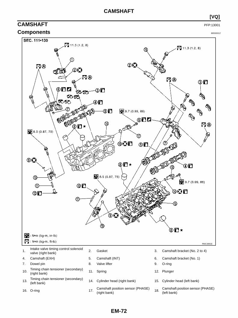
EM-72
[VQ]CAMSHAFT
CAMSHAFT PFP:13001
Components BBS00012
1.Intake valve timing control solenoidvalve (right bank)
2. Gasket 3. Camshaft bracket (No. 2 to 4)
4. Camshaft (EXH) 5. Camshaft (INT) 6. Camshaft bracket (No. 1)
7. Dowel pin 8. Valve lifter 9. O-ring
10.Timing chain tensioner (secondary)(right bank)
11. Spring 12. Plunger
13.Timing chain tensioner (secondary)(left bank)
14. Cylinder head (right bank) 15. Cylinder head (left bank)
16. O-ring 17.Camshaft position sensor (PHASE)(right bank)
18.Camshaft position sensor (PHASE)(left bank)
PBIC3891E
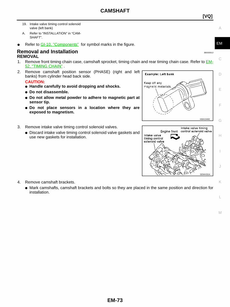
CAMSHAFT
EM-73
[VQ]
C
D
E
F
G
H
I
J
K
L
M
A
EM● Refer to GI-10, "Components" for symbol marks in the figure.
Removal and Installation BBS00013
REMOVAL1. Remove front timing chain case, camshaft sprocket, timing chain and rear timing chain case. Refer to EM-
52, "TIMING CHAIN" .2. Remove camshaft position sensor (PHASE) (right and left
banks) from cylinder head back side.CAUTION:● Handle carefully to avoid dropping and shocks.● Do not disassemble.● Do not allow metal powder to adhere to magnetic part at
sensor tip.● Do not place sensors in a location where they are
exposed to magnetism.
3. Remove intake valve timing control solenoid valves.● Discard intake valve timing control solenoid valve gaskets and
use new gaskets for installation.
4. Remove camshaft brackets.● Mark camshafts, camshaft brackets and bolts so they are placed in the same position and direction for
installation.
19. Intake valve timing control solenoidvalve (left bank)
A. Refer to “INSTALLATION” in “CAM-SHAFT”.
KBIA1046E
SEM443GA

EM-74
[VQ]CAMSHAFT
● Equally loosen camshaft bracket bolts in several steps inreverse order as shown in the figure.
5. Remove camshafts.6. Remove valve lifters.
● Identify installation positions, and store them without mixing them up.7. Remove timing chain tensioner (secondary) from cylinder head.
● Remove timing chain tensioner (secondary) with its stopperpin attached.
NOTE:Stopper pin was attached when timing chain (secondary) wasremoved.
INSPECTION AFTER REMOVALCamshaft Runout1. Put V-block on precise flat table, and support No. 2 and 4 journal
of camshaft.CAUTION:Do not support journal No. 1 (on the side of camshaftsprocket) because it has a different diameter from the otherthree locations.
2. Set dial indicator vertically to No. 3 journal.3. Turn camshaft to one direction with hands, and measure the
camshaft runout on dial indicator. (Total indicator reading)
4. If it exceeds the limit, replace camshaft.
PBIC2050E
PBIC2111E
Standard : Less than 0.02 mm (0.001 in)Limit : 0.05 mm (0.002 in)
PBIC0929E
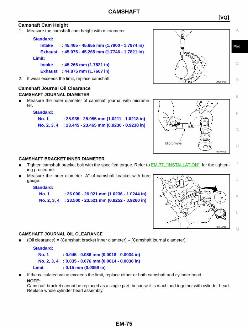
CAMSHAFT
EM-75
[VQ]
C
D
E
F
G
H
I
J
K
L
M
A
EM
Camshaft Cam Height1. Measure the camshaft cam height with micrometer.
2. If wear exceeds the limit, replace camshaft.
Camshaft Journal Oil ClearanceCAMSHAFT JOURNAL DIAMETER● Measure the outer diameter of camshaft journal with microme-
ter.
CAMSHAFT BRACKET INNER DIAMETER● Tighten camshaft bracket bolt with the specified torque. Refer to EM-77, "INSTALLATION" for the tighten-
ing procedure.● Measure the inner diameter “A” of camshaft bracket with bore
gauge.
CAMSHAFT JOURNAL OIL CLEARANCE● (Oil clearance) = (Camshaft bracket inner diameter) – (Camshaft journal diameter).
● If the calculated value exceeds the limit, replace either or both camshaft and cylinder head.NOTE:Camshaft bracket cannot be replaced as a single part, because it is machined together with cylinder head.Replace whole cylinder head assembly.
Standard:Intake : 45.465 - 45.655 mm (1.7900 - 1.7974 in)Exhaust : 45.075 - 45.265 mm (1.7746 - 1.7821 in)
Limit:Intake : 45.265 mm (1.7821 in)Exhaust : 44.875 mm (1.7667 in)
EMQ0072D
Standard:No. 1 : 25.935 - 25.955 mm (1.0211 - 1.0218 in)No. 2, 3, 4 : 23.445 - 23.465 mm (0.9230 - 0.9238 in)
PBIC0040E
Standard:No. 1 : 26.000 - 26.021 mm (1.0236 - 1.0244 in)No. 2, 3, 4 : 23.500 - 23.521 mm (0.9252 - 0.9260 in)
PBIC1645E
Standard:No. 1 : 0.045 - 0.086 mm (0.0018 - 0.0034 in)No. 2, 3, 4 : 0.035 - 0.076 mm (0.0014 - 0.0030 in)
Limit : 0.15 mm (0.0059 in)
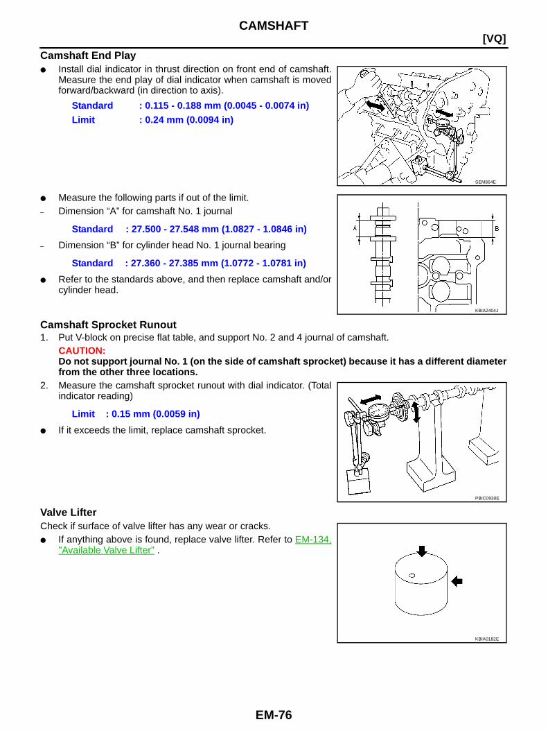
EM-76
[VQ]CAMSHAFT
Camshaft End Play● Install dial indicator in thrust direction on front end of camshaft.
Measure the end play of dial indicator when camshaft is movedforward/backward (in direction to axis).
● Measure the following parts if out of the limit.– Dimension “A” for camshaft No. 1 journal
– Dimension “B” for cylinder head No. 1 journal bearing
● Refer to the standards above, and then replace camshaft and/orcylinder head.
Camshaft Sprocket Runout1. Put V-block on precise flat table, and support No. 2 and 4 journal of camshaft.
CAUTION:Do not support journal No. 1 (on the side of camshaft sprocket) because it has a different diameterfrom the other three locations.
2. Measure the camshaft sprocket runout with dial indicator. (Totalindicator reading)
● If it exceeds the limit, replace camshaft sprocket.
Valve LifterCheck if surface of valve lifter has any wear or cracks.● If anything above is found, replace valve lifter. Refer to EM-134,
"Available Valve Lifter" .
Standard : 0.115 - 0.188 mm (0.0045 - 0.0074 in)Limit : 0.24 mm (0.0094 in)
SEM864E
Standard : 27.500 - 27.548 mm (1.0827 - 1.0846 in)
Standard : 27.360 - 27.385 mm (1.0772 - 1.0781 in)
KBIA2404J
Limit : 0.15 mm (0.0059 in)
PBIC0930E
KBIA0182E
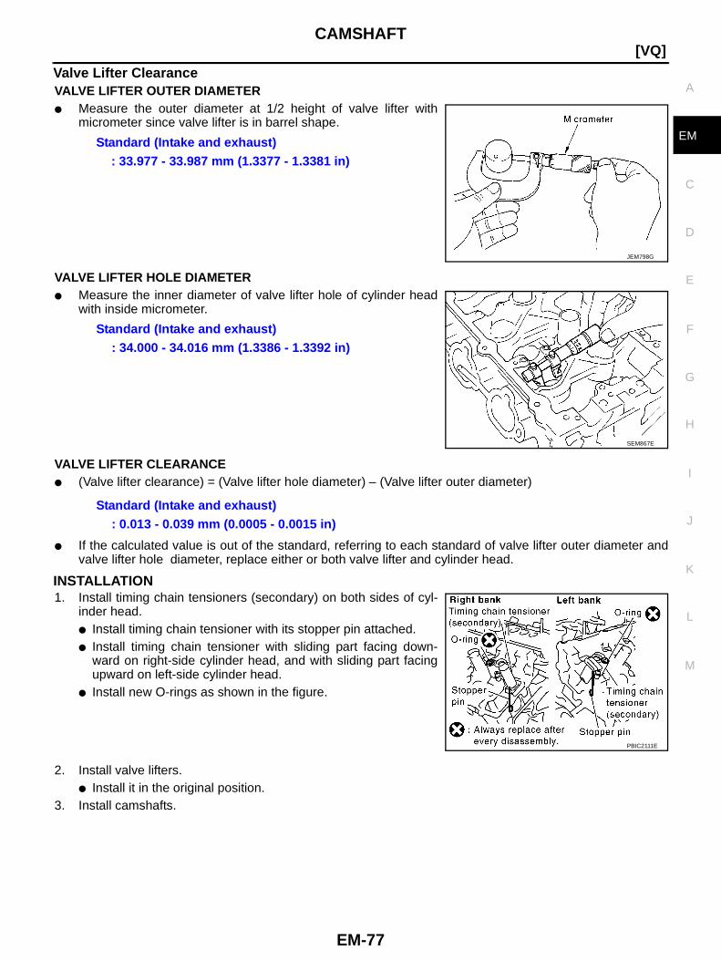
CAMSHAFT
EM-77
[VQ]
C
D
E
F
G
H
I
J
K
L
M
A
EM
Valve Lifter ClearanceVALVE LIFTER OUTER DIAMETER● Measure the outer diameter at 1/2 height of valve lifter with
micrometer since valve lifter is in barrel shape.
VALVE LIFTER HOLE DIAMETER● Measure the inner diameter of valve lifter hole of cylinder head
with inside micrometer.
VALVE LIFTER CLEARANCE● (Valve lifter clearance) = (Valve lifter hole diameter) – (Valve lifter outer diameter)
● If the calculated value is out of the standard, referring to each standard of valve lifter outer diameter andvalve lifter hole diameter, replace either or both valve lifter and cylinder head.
INSTALLATION1. Install timing chain tensioners (secondary) on both sides of cyl-
inder head.● Install timing chain tensioner with its stopper pin attached.● Install timing chain tensioner with sliding part facing down-
ward on right-side cylinder head, and with sliding part facingupward on left-side cylinder head.
● Install new O-rings as shown in the figure.
2. Install valve lifters.● Install it in the original position.
3. Install camshafts.
Standard (Intake and exhaust): 33.977 - 33.987 mm (1.3377 - 1.3381 in)
JEM798G
Standard (Intake and exhaust): 34.000 - 34.016 mm (1.3386 - 1.3392 in)
SEM867E
Standard (Intake and exhaust): 0.013 - 0.039 mm (0.0005 - 0.0015 in)
PBIC2111E

EM-78
[VQ]CAMSHAFT
● Install camshaft with dowel pin attached to its front end faceon the exhaust side.
● Follow your identification marks made during removal, or fol-low the identification marks that are present on new cam-shafts for proper placement and direction.
● Install camshaft so that dowel pin hole and dowel pin on frontend face are positioned as shown in the figure. (No. 1 cylinderTDC on its compression stroke)NOTE:● Large and small pin holes are located on front end face of
camshaft (INT), at intervals of 180 degrees. Face small dia.side pin hole upward (in cylinder head upper face direc-tion).
● Though camshaft does not stop at the portion as shown inthe figure, for the placement of cam nose, it is generallyaccepted camshaft is placed for the same direction of thefigure.
4. Install camshaft brackets.● Remove foreign material completely from camshaft bracket
backside and from cylinder head installation face.● Install camshaft bracket in original position and direction as
shown in the figure.
KBIA1071E
Bank INT/EXH Dowel pinPaint marks Identification
markM1 M2
RHINT No Green No RE
EXH Yes No White RE
LHINT No Green No LH
EXH Yes No White LH KBIA1009E
PBIC2478E
PBIC2051E

CAMSHAFT
EM-79
[VQ]
C
D
E
F
G
H
I
J
K
L
M
A
EM
● Install camshaft brackets (No. 2 to 4) aligning the stampmarks as shown in the figure.NOTE:There are no identification marks indicating left and right forcamshaft bracket (No. 1).
● Apply liquid gasket to mating surface of camshaft bracket (No.1) as shown on right and left banks.Use Genuine Liquid Gasket or equivalent.
5. Tighten camshaft bracket bolts in the following steps, in numeri-cal order as shown in the figure.
a. Tighten No. 7 to 10 in order as shown.
b. Tighten No. 1 to 6 in order as shown.
c. Tighten No. 1 to 10 in numerical order as shown.
d. Tighten No. 1 to 10 in numerical order as shown.
CAUTION:After tightening mounting bolts of camshaft brackets (No.1), be sure to wipe off excessive liquid gasket from theparts list below.● Mating surface of rocker cover● Mating surface of rear timing chain case
PBIC2052E
PBIC2617E
: 1.96 N·m (0.2 kg-m, 1 ft-lb)
: 1.96 N·m (0.2 kg-m, 1 ft-lb)
: 5.88 N·m (0.6 kg-m, 4 ft-lb)
: 10.4 N·m (1.1 kg-m, 8 ft-lb)
PBIC2050E
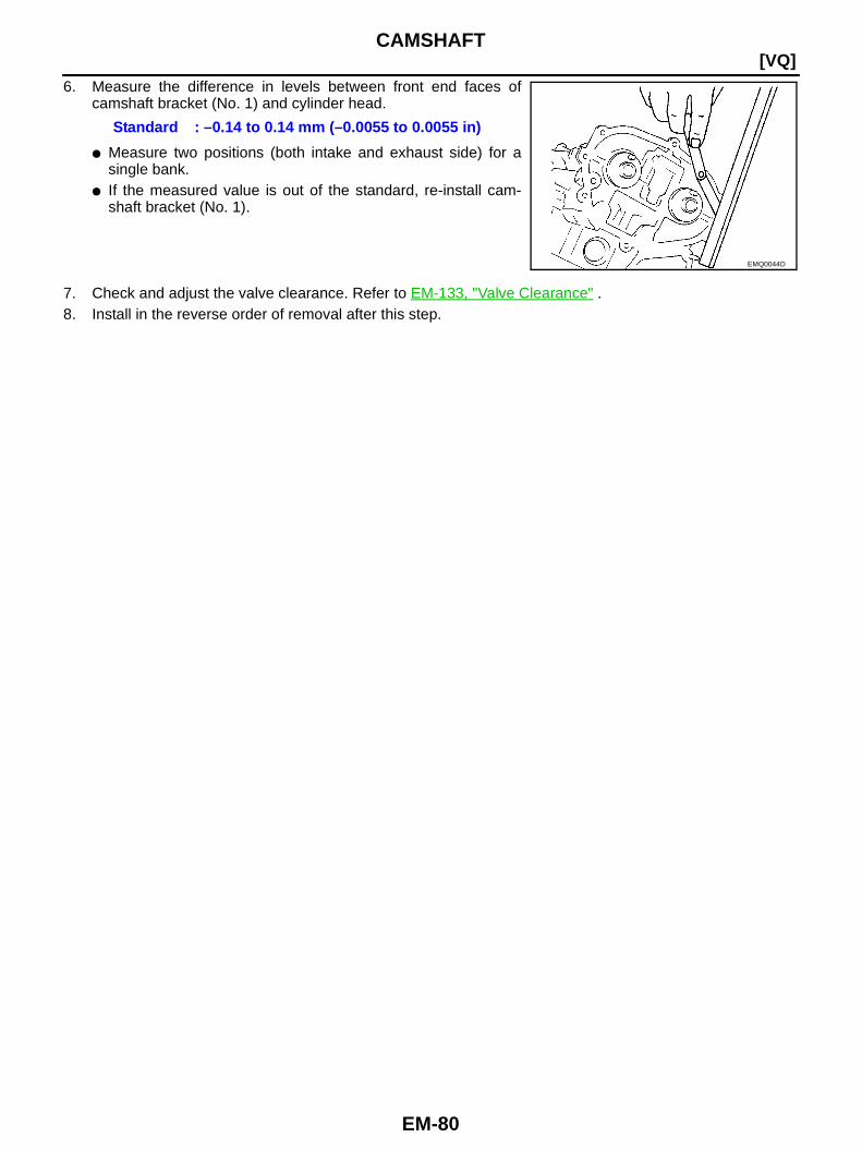
EM-80
[VQ]CAMSHAFT
6. Measure the difference in levels between front end faces ofcamshaft bracket (No. 1) and cylinder head.
● Measure two positions (both intake and exhaust side) for asingle bank.
● If the measured value is out of the standard, re-install cam-shaft bracket (No. 1).
7. Check and adjust the valve clearance. Refer to EM-133, "Valve Clearance" .8. Install in the reverse order of removal after this step.
Standard : –0.14 to 0.14 mm (–0.0055 to 0.0055 in)
EMQ0044D
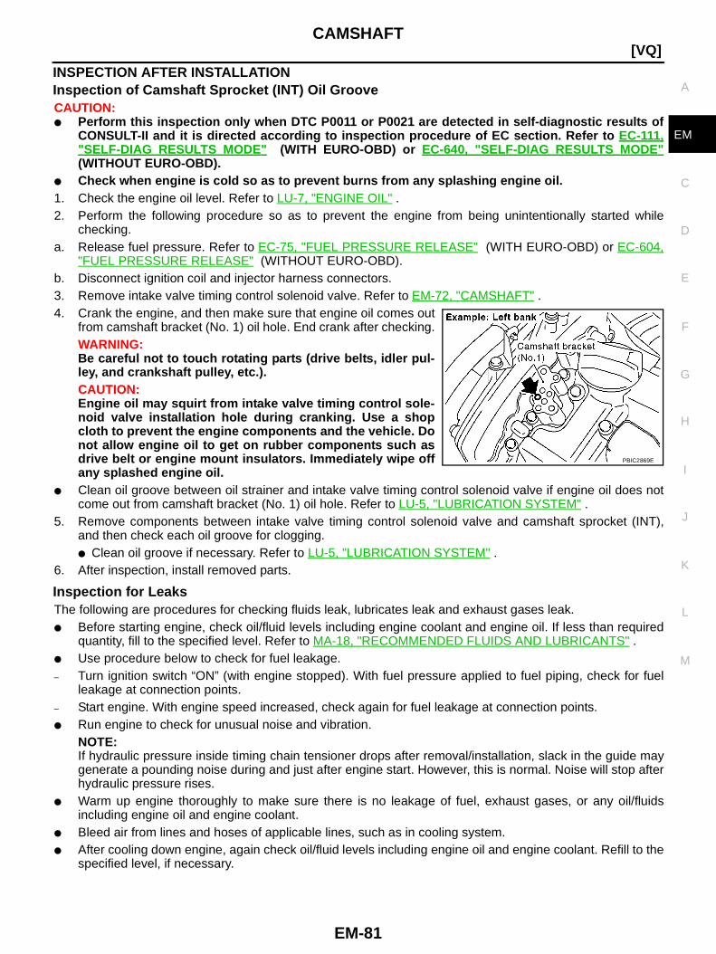
CAMSHAFT
EM-81
[VQ]
C
D
E
F
G
H
I
J
K
L
M
A
EM
INSPECTION AFTER INSTALLATIONInspection of Camshaft Sprocket (INT) Oil GrooveCAUTION:● Perform this inspection only when DTC P0011 or P0021 are detected in self-diagnostic results of
CONSULT-II and it is directed according to inspection procedure of EC section. Refer to EC-111,"SELF-DIAG RESULTS MODE " (WITH EURO-OBD) or EC-640, "SELF-DIAG RESULTS MODE "(WITHOUT EURO-OBD).
● Check when engine is cold so as to prevent burns from any splashing engine oil.1. Check the engine oil level. Refer to LU-7, "ENGINE OIL" .2. Perform the following procedure so as to prevent the engine from being unintentionally started while
checking.a. Release fuel pressure. Refer to EC-75, "FUEL PRESSURE RELEASE" (WITH EURO-OBD) or EC-604,
"FUEL PRESSURE RELEASE" (WITHOUT EURO-OBD).b. Disconnect ignition coil and injector harness connectors.3. Remove intake valve timing control solenoid valve. Refer to EM-72, "CAMSHAFT" .4. Crank the engine, and then make sure that engine oil comes out
from camshaft bracket (No. 1) oil hole. End crank after checking.WARNING:Be careful not to touch rotating parts (drive belts, idler pul-ley, and crankshaft pulley, etc.).CAUTION:Engine oil may squirt from intake valve timing control sole-noid valve installation hole during cranking. Use a shopcloth to prevent the engine components and the vehicle. Donot allow engine oil to get on rubber components such asdrive belt or engine mount insulators. Immediately wipe offany splashed engine oil.
● Clean oil groove between oil strainer and intake valve timing control solenoid valve if engine oil does notcome out from camshaft bracket (No. 1) oil hole. Refer to LU-5, "LUBRICATION SYSTEM" .
5. Remove components between intake valve timing control solenoid valve and camshaft sprocket (INT),and then check each oil groove for clogging.● Clean oil groove if necessary. Refer to LU-5, "LUBRICATION SYSTEM" .
6. After inspection, install removed parts.
Inspection for LeaksThe following are procedures for checking fluids leak, lubricates leak and exhaust gases leak.● Before starting engine, check oil/fluid levels including engine coolant and engine oil. If less than required
quantity, fill to the specified level. Refer to MA-18, "RECOMMENDED FLUIDS AND LUBRICANTS" .● Use procedure below to check for fuel leakage.– Turn ignition switch “ON” (with engine stopped). With fuel pressure applied to fuel piping, check for fuel
leakage at connection points.– Start engine. With engine speed increased, check again for fuel leakage at connection points.● Run engine to check for unusual noise and vibration.
NOTE:If hydraulic pressure inside timing chain tensioner drops after removal/installation, slack in the guide maygenerate a pounding noise during and just after engine start. However, this is normal. Noise will stop afterhydraulic pressure rises.
● Warm up engine thoroughly to make sure there is no leakage of fuel, exhaust gases, or any oil/fluidsincluding engine oil and engine coolant.
● Bleed air from lines and hoses of applicable lines, such as in cooling system.● After cooling down engine, again check oil/fluid levels including engine oil and engine coolant. Refill to the
specified level, if necessary.
PBIC2869E
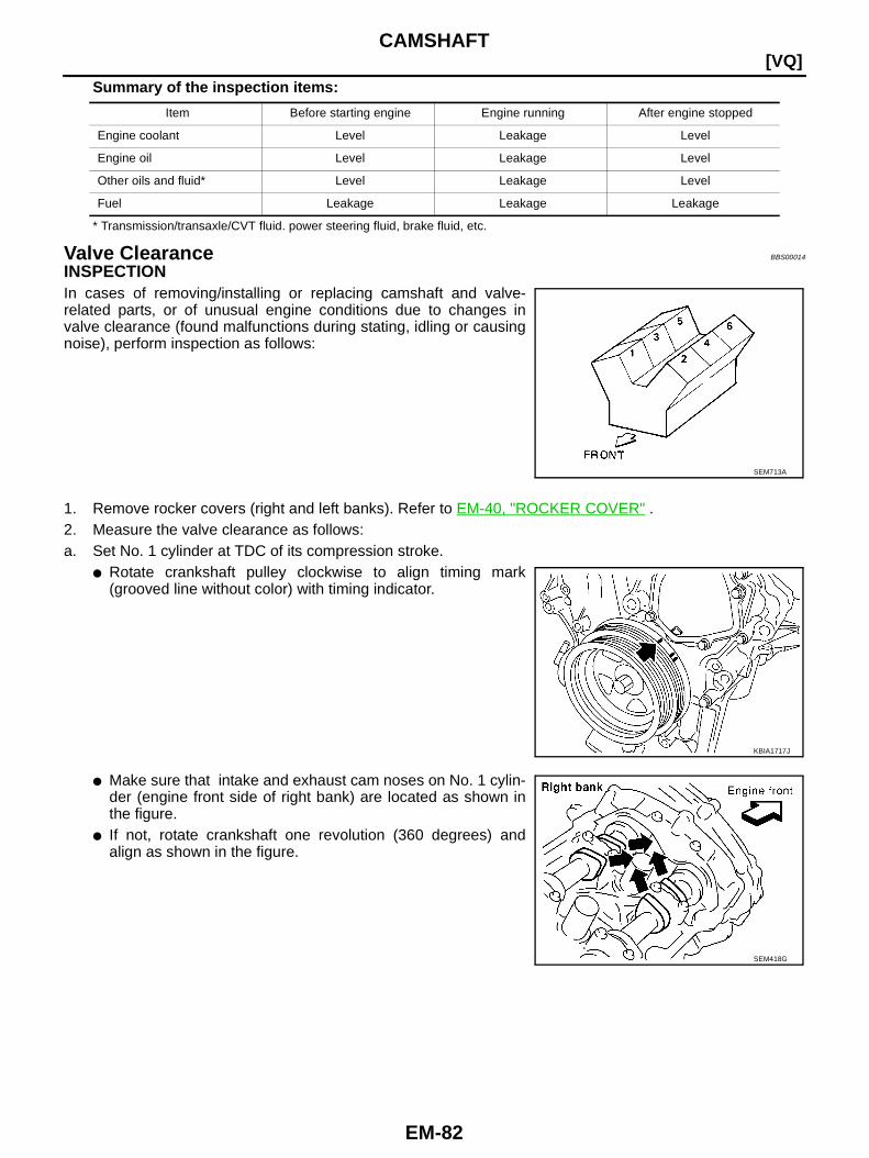
EM-82
[VQ]CAMSHAFT
Summary of the inspection items:
* Transmission/transaxle/CVT fluid. power steering fluid, brake fluid, etc.
Valve Clearance BBS00014
INSPECTIONIn cases of removing/installing or replacing camshaft and valve-related parts, or of unusual engine conditions due to changes invalve clearance (found malfunctions during stating, idling or causingnoise), perform inspection as follows:
1. Remove rocker covers (right and left banks). Refer to EM-40, "ROCKER COVER" .2. Measure the valve clearance as follows:a. Set No. 1 cylinder at TDC of its compression stroke.
● Rotate crankshaft pulley clockwise to align timing mark(grooved line without color) with timing indicator.
● Make sure that intake and exhaust cam noses on No. 1 cylin-der (engine front side of right bank) are located as shown inthe figure.
● If not, rotate crankshaft one revolution (360 degrees) andalign as shown in the figure.
Item Before starting engine Engine running After engine stopped
Engine coolant Level Leakage Level
Engine oil Level Leakage Level
Other oils and fluid* Level Leakage Level
Fuel Leakage Leakage Leakage
SEM713A
KBIA1717J
SEM418G
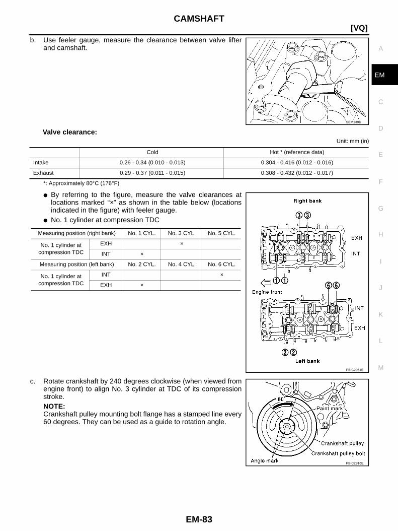
CAMSHAFT
EM-83
[VQ]
C
D
E
F
G
H
I
J
K
L
M
A
EM
b. Use feeler gauge, measure the clearance between valve lifterand camshaft.
Valve clearance:Unit: mm (in)
*: Approximately 80°C (176°F)
● By referring to the figure, measure the valve clearances atlocations marked “×” as shown in the table below (locationsindicated in the figure) with feeler gauge.
● No. 1 cylinder at compression TDC
c. Rotate crankshaft by 240 degrees clockwise (when viewed fromengine front) to align No. 3 cylinder at TDC of its compressionstroke.NOTE:Crankshaft pulley mounting bolt flange has a stamped line every60 degrees. They can be used as a guide to rotation angle.
SEM139D
Cold Hot * (reference data)
Intake 0.26 - 0.34 (0.010 - 0.013) 0.304 - 0.416 (0.012 - 0.016)
Exhaust 0.29 - 0.37 (0.011 - 0.015) 0.308 - 0.432 (0.012 - 0.017)
Measuring position (right bank) No. 1 CYL. No. 3 CYL. No. 5 CYL.
No. 1 cylinder atcompression TDC
EXH ×
INT ×
Measuring position (left bank) No. 2 CYL. No. 4 CYL. No. 6 CYL.
No. 1 cylinder atcompression TDC
INT ×
EXH ×
PBIC2054E
PBIC2916E
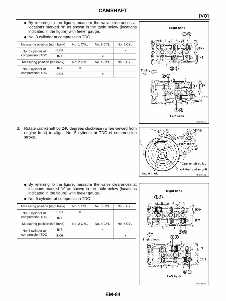
EM-84
[VQ]CAMSHAFT
● By referring to the figure, measure the valve clearances atlocations marked “×” as shown in the table below (locationsindicated in the figure) with feeler gauge.
● No. 3 cylinder at compression TDC
d. Rotate crankshaft by 240 degrees clockwise (when viewed fromengine front) to align No. 5 cylinder at TDC of compressionstroke.
● By referring to the figure, measure the valve clearances atlocations marked “×” as shown in the table below (locationsindicated in the figure) with feeler gauge.
● No. 5 cylinder at compression TDC
Measuring position (right bank) No. 1 CYL. No. 3 CYL. No. 5 CYL.
No. 3 cylinder atcompression TDC
EXH ×
INT ×
Measuring position (left bank) No. 2 CYL. No. 4 CYL. No. 6 CYL.
No. 3 cylinder atcompression TDC
INT ×
EXH ×
PBIC2055E
PBIC2916E
Measuring position (right bank) No. 1 CYL. No. 3 CYL. No. 5 CYL.
No. 5 cylinder atcompression TDC
EXH ×
INT ×
Measuring position (left bank) No. 2 CYL. No. 4 CYL. No. 6 CYL.
No. 5 cylinder atcompression TDC
INT ×
EXH ×
PBIC2056E
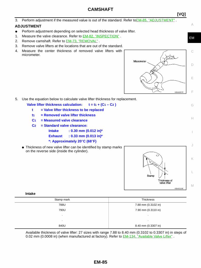
CAMSHAFT
EM-85
[VQ]
C
D
E
F
G
H
I
J
K
L
M
A
EM
3. Perform adjustment if the measured value is out of the standard. Refer toEM-85, "ADJUSTMENT" .
ADJUSTMENT● Perform adjustment depending on selected head thickness of valve lifter.1. Measure the valve clearance. Refer to EM-82, "INSPECTION" .2. Remove camshaft. Refer to EM-73, "REMOVAL" .3. Remove valve lifters at the locations that are out of the standard.4. Measure the center thickness of removed valve lifters with
micrometer.
5. Use the equation below to calculate valve lifter thickness for replacement.
● Thickness of new valve lifter can be identified by stamp markson the reverse side (inside the cylinder).
Intake
Available thickness of valve lifter: 27 sizes with range 7.88 to 8.40 mm (0.3102 to 0.3307 in) in steps of0.02 mm (0.0008 in) (when manufactured at factory). Refer to EM-134, "Available Valve Lifter" .
KBIA0057E
Valve lifter thickness calculation: t = t 1 + (C1 – C2 )t = Valve lifter thickness to be replacedt1 = Removed valve lifter thicknessC1 = Measured valve clearanceC2 = Standard valve clearance:
Intake : 0.30 mm (0.012 in)*Exhaust : 0.33 mm (0.013 in)**: Approximately 20 °C (68°F)
KBIA0119E
Stamp mark Thickness
788U 7.88 mm (0.3102 in)
790U 7.90 mm (0.3110 in)
· ·
· ·
840U 8.40 mm (0.3307 in)
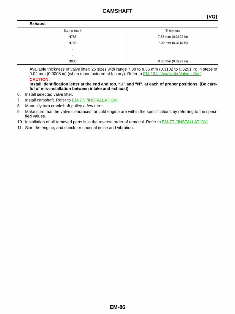
EM-86
[VQ]CAMSHAFT
Exhaust
Available thickness of valve lifter: 25 sizes with range 7.88 to 8.36 mm (0.3102 to 0.3291 in) in steps of0.02 mm (0.0008 in) (when manufactured at factory). Refer to EM-134, "Available Valve Lifter" .CAUTION:Install identification letter at the end and top, “U” and “N”, at each of proper positions. (Be care-ful of mis-installation between intake and exhaust)
6. Install selected valve lifter.7. Install camshaft. Refer to EM-77, "INSTALLATION" .8. Manually turn crankshaft pulley a few turns.9. Make sure that the valve clearances for cold engine are within the specifications by referring to the speci-
fied values.10. Installation of all removed parts is in the reverse order of removal. Refer to EM-77, "INSTALLATION" .11. Start the engine, and check for unusual noise and vibration.
Stamp mark Thickness
N788 7.88 mm (0.3102 in)
N790 7.90 mm (0.3110 in)
· ·
· ·
N836 8.36 mm (0.3291 in)

OIL SEAL
EM-87
[VQ]
C
D
E
F
G
H
I
J
K
L
M
A
EM
OIL SEAL PFP:00100
Removal and Installation of Valve Oil Seal BBS00015
REMOVAL1. Turn crankshaft until the cylinder requiring new valve oil seals is at TDC. This will prevent valve from drop-
ping into cylinder.2. Remove camshaft relating to valve oil seal to be removed. Refer to EM-72, "CAMSHAFT" .3. Remove valve lifters. Refer to EM-72, "CAMSHAFT" .4. Remove valve collet.
● Compress valve spring with valve spring compressor, attach-ment, adapter [SST]. Remove valve collet with magnet hand.CAUTION:When working, take care not to damage valve lifter holes.
5. Remove valve spring retainer and valve spring.6. Remove valve oil seal using valve oil seal puller [SST].
INSTALLATION1. Apply new engine oil on new valve oil seal joint and seal lip.2. Using valve oil seal drift [SST], press fit valve seal to height “H”
shown in the figure.NOTE:Dimension “H”: Height measured before valve spring seat instal-lation
3. Install in the reverse order of removal after this step.
PBIC1791E
PBIC1610E
Intake and exhaust : 14.3 - 14.9 mm (0.563 - 0.587 in)
PBIC1611E
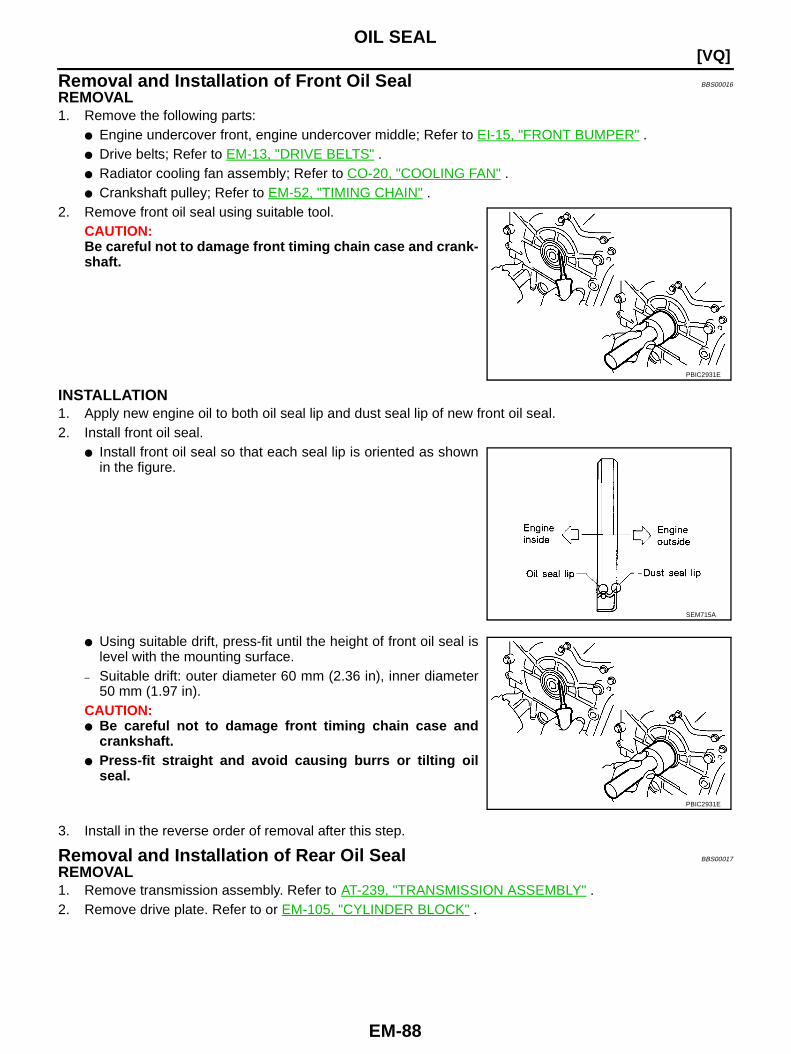
EM-88
[VQ]OIL SEAL
Removal and Installation of Front Oil Seal BBS00016
REMOVAL1. Remove the following parts:
● Engine undercover front, engine undercover middle; Refer to EI-15, "FRONT BUMPER" .● Drive belts; Refer to EM-13, "DRIVE BELTS" .● Radiator cooling fan assembly; Refer to CO-20, "COOLING FAN" .● Crankshaft pulley; Refer to EM-52, "TIMING CHAIN" .
2. Remove front oil seal using suitable tool.CAUTION:Be careful not to damage front timing chain case and crank-shaft.
INSTALLATION1. Apply new engine oil to both oil seal lip and dust seal lip of new front oil seal.2. Install front oil seal.
● Install front oil seal so that each seal lip is oriented as shownin the figure.
● Using suitable drift, press-fit until the height of front oil seal islevel with the mounting surface.
– Suitable drift: outer diameter 60 mm (2.36 in), inner diameter50 mm (1.97 in).
CAUTION:● Be careful not to damage front timing chain case and
crankshaft.● Press-fit straight and avoid causing burrs or tilting oil
seal.
3. Install in the reverse order of removal after this step.
Removal and Installation of Rear Oil Seal BBS00017
REMOVAL1. Remove transmission assembly. Refer to AT-239, "TRANSMISSION ASSEMBLY" .2. Remove drive plate. Refer to or EM-105, "CYLINDER BLOCK" .
PBIC2931E
SEM715A
PBIC2931E
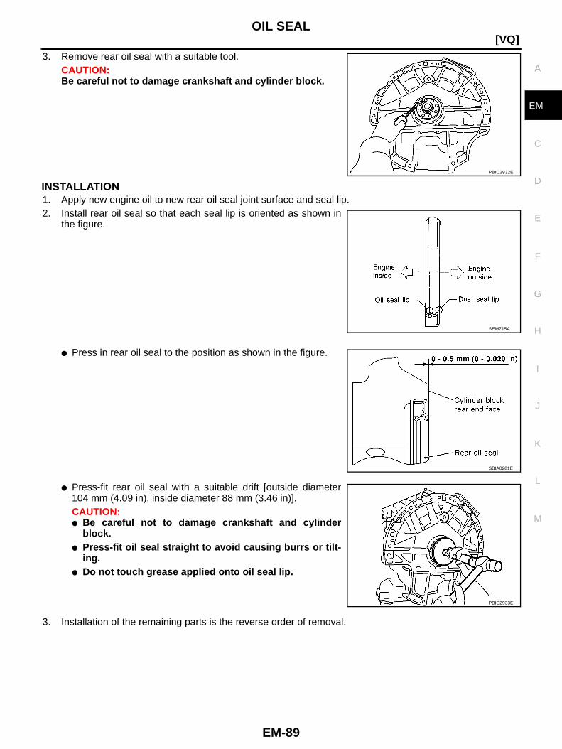
OIL SEAL
EM-89
[VQ]
C
D
E
F
G
H
I
J
K
L
M
A
EM
3. Remove rear oil seal with a suitable tool.CAUTION:Be careful not to damage crankshaft and cylinder block.
INSTALLATION1. Apply new engine oil to new rear oil seal joint surface and seal lip.2. Install rear oil seal so that each seal lip is oriented as shown in
the figure.
● Press in rear oil seal to the position as shown in the figure.
● Press-fit rear oil seal with a suitable drift [outside diameter104 mm (4.09 in), inside diameter 88 mm (3.46 in)].CAUTION:● Be careful not to damage crankshaft and cylinder
block.● Press-fit oil seal straight to avoid causing burrs or tilt-
ing.● Do not touch grease applied onto oil seal lip.
3. Installation of the remaining parts is the reverse order of removal.
PBIC2932E
SEM715A
SBIA0281E
PBIC2933E

EM-90
[VQ]CYLINDER HEAD
CYLINDER HEAD PFP:11041
On-Vehicle Service BBS00018
CHECKING COMPRESSION PRESSURE1. Warm up engine thoroughly. Then, stop it.2. Release fuel pressure. Refer to EC-75, "FUEL PRESSURE RELEASE" (models with EURO-OBD) or EC-
604, "FUEL PRESSURE RELEASE" (models without EURO-OBD).3. Disconnect fuel pump fuse to avoid fuel injection during mea-
surement.
4. Remove intake manifold collector. Refer to EM-17, "INTAKE MANIFOLD COLLECTOR" .5. Remove ignition coil and spark plug from each cylinder. Refer to EM-32, "IGNITION COIL" and EM-33,
"SPARK PLUG (PLATINUM-TIPPED TYPE)" .6. Connect engine tachometer (not required in use of CONSULT-ll).7. Install compression tester with adapter onto spark plug hole.
● Use compression gauge whose picking up end inserted tospark plug hole is smaller than 20 mm (0.79 in) in diameter.Otherwise, it may be caught by cylinder head during removal.
8. With accelerator pedal fully depressed, turn ignition switch to “START” for cranking. When the gaugepointer stabilizes, read the compression pressure and engine rpm. Perform these steps to check each cyl-inder.
Compression pressure:Unit: kPa (kg/cm2 , psi) /rpm
CAUTION:Always use a fully changed battery to obtain specified engine speed.
BBIA0534E
PBIC0900E
SBIA0533E
Standard Minimum Differential limit between cylinders
1,275 (13.0, 185) / 300 981 (10.0, 142) / 300 98 (1.0, 14) / 300

CYLINDER HEAD
EM-91
[VQ]
C
D
E
F
G
H
I
J
K
L
M
A
EM
● If the engine speed is out of specified range, check battery liquid for proper gravity. Check enginespeed again with normal battery gravity.
● If compression pressure is below minimum value, check valve clearances and parts associated withcombustion chamber (valve, valve seat, piston, piston ring, cylinder bore, cylinder head, cylinder headgasket). After the checking, measure compression pressure again.
● If some cylinders have low compression pressure, pour small amount of engine oil into the spark plughole of the cylinder to re-check it for compression.
– If the added engine oil improves the compression, piston rings may be worn out or damaged. Check thepiston rings and replace if necessary.
– If the compression pressure remains at low level despite the addition of engine oil, valves may be mal-functioning. Check valves for damage. Replace valve or valve seat accordingly.
● If two adjacent cylinders have respectively low compression pressure and their compression remainslow even after the addition of engine oil, cylinder head gaskets are leaking. In such a case, replace cyl-inder head gaskets.
9. After inspection is completed, install removed parts.10. Start engine, and make sure that engine runs smoothly.11. Perform trouble diagnosis. If DTC appears, erase it. Refer to EC-77, "TROUBLE DIAGNOSIS" (models
with EURO-OBD) or EC-606, "TROUBLE DIAGNOSIS" (models without EURO-OBD).
Components BBS00019
Removal and Installation BBS0001A
REMOVAL1. Remove camshaft. Refer to EM-72, "CAMSHAFT" .2. Release the hoist from hanging, then remove the engine slingers.3. Remove the following parts:
1. Rubber plug 2. Cylinder head (left bank) 3. Cylinder head bolt
4. Cylinder head (right bank) 5. Harness bracket 6. Cylinder head gasket (right bank)
7. Cylinder head gasket (left bank)
PBIC2934E

EM-92
[VQ]CYLINDER HEAD
● Intake manifold; Refer to EM-20, "INTAKE MANIFOLD" .● Exhaust manifold; Refer to EM-22, "EXHAUST MANIFOLD AND THREE WAY CATALYST" .● Water inlet and thermostat assembly; Refer to CO-26, "WATER INLET AND THERMOSTAT ASSEM-
BLY" .● Water outlet, water pipe and heater pipe; Refer to CO-28, "WATER OUTLET AND WATER PIPING" .
4. Remove cylinder head bolts in reverse order as shown in the fig-ure with cylinder head bolt wrench (commercial service tool) andpower tool to remove cylinder heads (right and left banks).
5. Remove cylinder head gaskets.
INSPECTION AFTER REMOVALCylinder Head Bolts Outer Diameter● Cylinder head bolts are tightened by plastic zone tightening
method. Whenever the size difference between “d1” and “d2”exceeds the limit, replace them with new one.
● If reduction of outer diameter appears in a position other than“d2”, use it as “d2” point.
Cylinder Head DistortionNOTE:When performing this inspection, cylinder block distortion should be also checking. Refer to EM-124, "CYLIN-DER BLOCK DISTORTION" .1. Using scraper, wipe off oil, scale, gasket, sealant and carbon deposits from surface of cylinder head.
CAUTION:Do not allow gasket fragments to enter engine oil or engine coolant passages.
PBIC2057E
Limit (“d1” – “d2”) : 0.11 mm (0.0043 in)
PBIC2480E
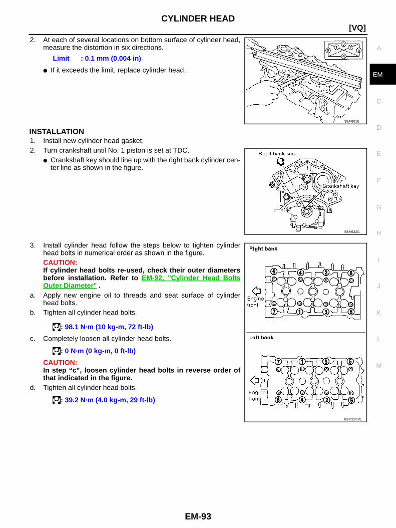
CYLINDER HEAD
EM-93
[VQ]
C
D
E
F
G
H
I
J
K
L
M
A
EM
2. At each of several locations on bottom surface of cylinder head,measure the distortion in six directions.
● If it exceeds the limit, replace cylinder head.
INSTALLATION1. Install new cylinder head gasket.2. Turn crankshaft until No. 1 piston is set at TDC.
● Crankshaft key should line up with the right bank cylinder cen-ter line as shown in the figure.
3. Install cylinder head follow the steps below to tighten cylinderhead bolts in numerical order as shown in the figure.CAUTION:If cylinder head bolts re-used, check their outer diametersbefore installation. Refer to EM-92, "Cylinder Head BoltsOuter Diameter " .
a. Apply new engine oil to threads and seat surface of cylinderhead bolts.
b. Tighten all cylinder head bolts.
c. Completely loosen all cylinder head bolts.
CAUTION:In step “c”, loosen cylinder head bolts in reverse order ofthat indicated in the figure.
d. Tighten all cylinder head bolts.
Limit : 0.1 mm (0.004 in)
SEM861E
SEM532G
: 98.1 N·m (10 kg-m, 72 ft-lb)
: 0 N·m (0 kg-m, 0 ft-lb)
: 39.2 N·m (4.0 kg-m, 29 ft-lb)
PBIC2057E

EM-94
[VQ]CYLINDER HEAD
e. Turn all cylinder head bolts 90 degrees clockwise (angle tighten-ing).CAUTION:Check the tightening angle by using angle wrench [SST].Avoid judgment by visual inspection without tool.● Check tightening angle indicated on angle wrench [SST] indi-
cator plate.f. Turn all cylinder head bolts 90 degrees clockwise again.
4. After installing cylinder head, measure distance between frontend faces of cylinder block and cylinder head (left and rightbanks).
● If the measured value is out of the standard, re-install cylinderhead.
5. Install in the reverse order of removal after this step.
PBIC1613E
Standard : 14.1 - 14.9 mm (0.555 - 0.587 in)
EMQ0662D
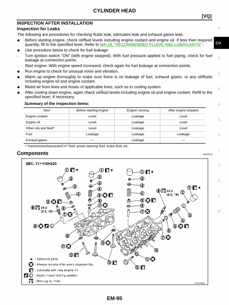
CYLINDER HEAD
EM-95
[VQ]
C
D
E
F
G
H
I
J
K
L
M
A
EM
INSPECTION AFTER INSTALLATIONInspection for LeaksThe following are procedures for checking fluids leak, lubricates leak and exhaust gases leak.● Before starting engine, check oil/fluid levels including engine coolant and engine oil. If less than required
quantity, fill to the specified level. Refer to MA-18, "RECOMMENDED FLUIDS AND LUBRICANTS" .● Use procedure below to check for fuel leakage.– Turn ignition switch “ON” (with engine stopped). With fuel pressure applied to fuel piping, check for fuel
leakage at connection points.– Start engine. With engine speed increased, check again for fuel leakage at connection points.● Run engine to check for unusual noise and vibration.● Warm up engine thoroughly to make sure there is no leakage of fuel, exhaust gases, or any oil/fluids
including engine oil and engine coolant.● Bleed air from lines and hoses of applicable lines, such as in cooling system.● After cooling down engine, again check oil/fluid levels including engine oil and engine coolant. Refill to the
specified level, if necessary.
Summary of the inspection items:
* Transmission/transaxle/CVT fluid. power steering fluid, brake fluid, etc.
Components BBS0001B
Item Before starting engine Engine running After engine stopped
Engine coolant Level Leakage Level
Engine oil Level Leakage Level
Other oils and fluid* Level Leakage Level
Fuel Leakage Leakage Leakage
Exhaust gases — Leakage —
PBIC2481E
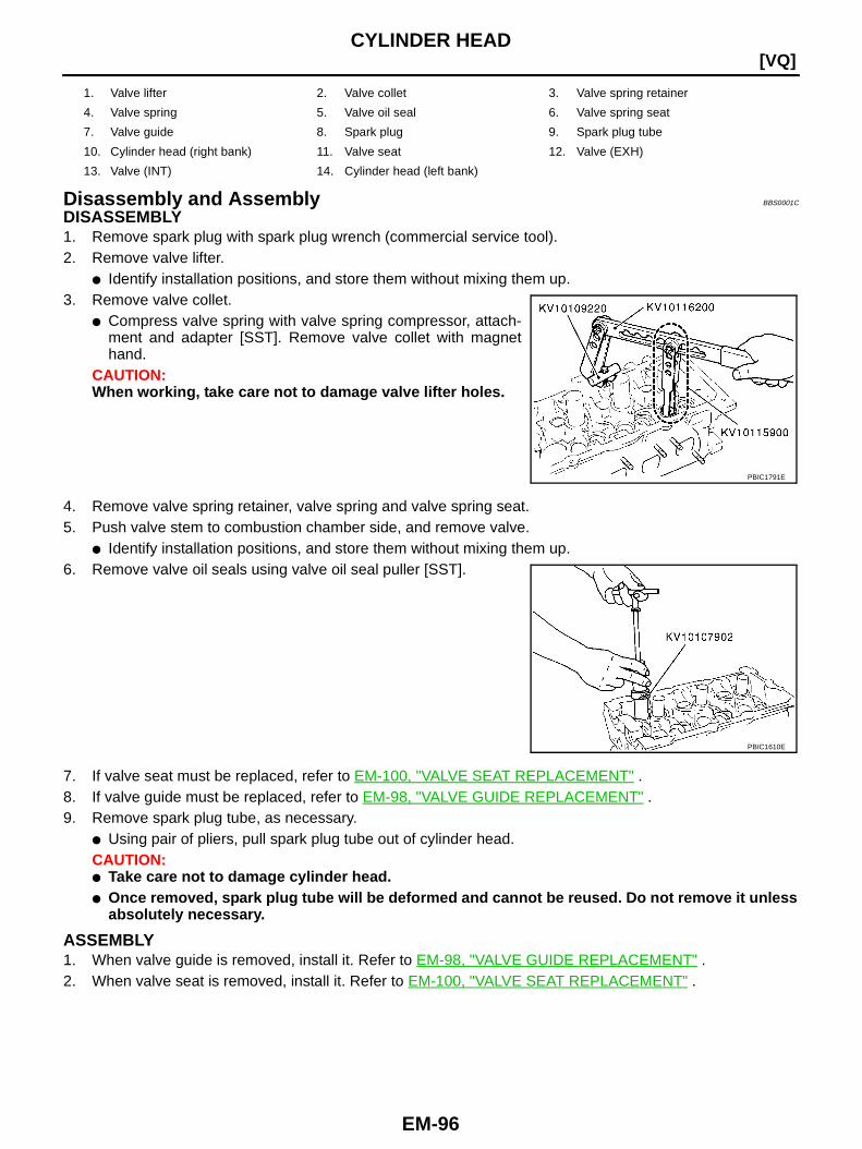
EM-96
[VQ]CYLINDER HEAD
Disassembly and Assembly BBS0001C
DISASSEMBLY1. Remove spark plug with spark plug wrench (commercial service tool).2. Remove valve lifter.
● Identify installation positions, and store them without mixing them up.3. Remove valve collet.
● Compress valve spring with valve spring compressor, attach-ment and adapter [SST]. Remove valve collet with magnethand.
CAUTION:When working, take care not to damage valve lifter holes.
4. Remove valve spring retainer, valve spring and valve spring seat.5. Push valve stem to combustion chamber side, and remove valve.
● Identify installation positions, and store them without mixing them up.6. Remove valve oil seals using valve oil seal puller [SST].
7. If valve seat must be replaced, refer to EM-100, "VALVE SEAT REPLACEMENT" .8. If valve guide must be replaced, refer to EM-98, "VALVE GUIDE REPLACEMENT" .9. Remove spark plug tube, as necessary.
● Using pair of pliers, pull spark plug tube out of cylinder head.CAUTION:● Take care not to damage cylinder head.● Once removed, spark plug tube will be deformed and cannot be reused. Do not remove it unless
absolutely necessary.
ASSEMBLY1. When valve guide is removed, install it. Refer to EM-98, "VALVE GUIDE REPLACEMENT" .2. When valve seat is removed, install it. Refer to EM-100, "VALVE SEAT REPLACEMENT" .
1. Valve lifter 2. Valve collet 3. Valve spring retainer
4. Valve spring 5. Valve oil seal 6. Valve spring seat
7. Valve guide 8. Spark plug 9. Spark plug tube
10. Cylinder head (right bank) 11. Valve seat 12. Valve (EXH)
13. Valve (INT) 14. Cylinder head (left bank)
PBIC1791E
PBIC1610E
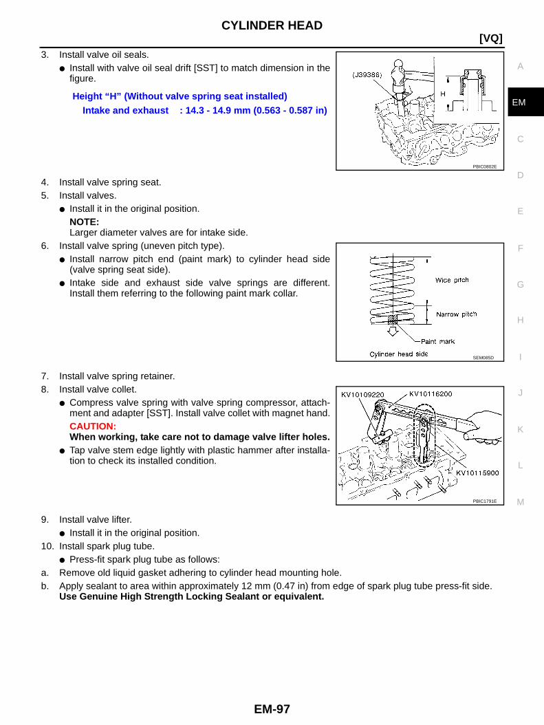
CYLINDER HEAD
EM-97
[VQ]
C
D
E
F
G
H
I
J
K
L
M
A
EM
3. Install valve oil seals.● Install with valve oil seal drift [SST] to match dimension in the
figure.
4. Install valve spring seat.5. Install valves.
● Install it in the original position.NOTE:Larger diameter valves are for intake side.
6. Install valve spring (uneven pitch type).● Install narrow pitch end (paint mark) to cylinder head side
(valve spring seat side).● Intake side and exhaust side valve springs are different.
Install them referring to the following paint mark collar.
7. Install valve spring retainer.8. Install valve collet.
● Compress valve spring with valve spring compressor, attach-ment and adapter [SST]. Install valve collet with magnet hand.CAUTION:When working, take care not to damage valve lifter holes.
● Tap valve stem edge lightly with plastic hammer after installa-tion to check its installed condition.
9. Install valve lifter.● Install it in the original position.
10. Install spark plug tube.● Press-fit spark plug tube as follows:
a. Remove old liquid gasket adhering to cylinder head mounting hole.b. Apply sealant to area within approximately 12 mm (0.47 in) from edge of spark plug tube press-fit side.
Use Genuine High Strength Locking Sealant or equivalent.
Height “H” (Without valve spring seat installed)Intake and exhaust : 14.3 - 14.9 mm (0.563 - 0.587 in)
PBIC0802E
SEM085D
PBIC1791E
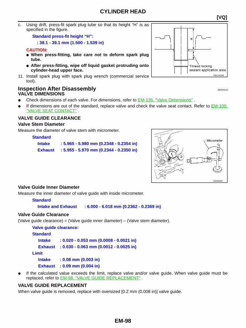
EM-98
[VQ]CYLINDER HEAD
c. Using drift, press-fit spark plug tube so that its height “H” is asspecified in the figure.
CAUTION:● When press-fitting, take care not to deform spark plug
tube.● After press-fitting, wipe off liquid gasket protruding onto
cylinder-head upper face.11. Install spark plug with spark plug wrench (commercial service
tool).
Inspection After Disassembly BBS0001D
VALVE DIMENSIONS● Check dimensions of each valve. For dimensions, refer to EM-135, "Valve Dimensions" .● If dimensions are out of the standard, replace valve and check the valve seat contact. Refer to EM-100,
"VALVE SEAT CONTACT" .
VALVE GUIDE CLEARANCEValve Stem DiameterMeasure the diameter of valve stem with micrometer.
Valve Guide Inner DiameterMeasure the inner diameter of valve guide with inside micrometer.
Valve Guide Clearance(Valve guide clearance) = (Valve guide inner diameter) – (Valve stem diameter).
● If the calculated value exceeds the limit, replace valve and/or valve guide. When valve guide must bereplaced, refer to EM-98, "VALVE GUIDE REPLACEMENT" .
VALVE GUIDE REPLACEMENTWhen valve guide is removed, replace with oversized [0.2 mm (0.008 in)] valve guide.
Standard press-fit height “H”:: 38.1 - 39.1 mm (1.500 - 1.539 in)
PBIC2634E
StandardIntake : 5.965 - 5.980 mm (0.2348 - 0.2354 in)Exhaust : 5.955 - 5.970 mm (0.2344 - 0.2350 in)
SEM938C
StandardIntake and Exhaust : 6.000 - 6.018 mm (0.2362 - 0.2369 in)
Valve guide clearance:Standard
Intake : 0.020 - 0.053 mm (0.0008 - 0.0021 in)Exhaust : 0.030 - 0.063 mm (0.0012 - 0.0025 in)
LimitIntake : 0.08 mm (0.003 in)Exhaust : 0.09 mm (0.004 in)
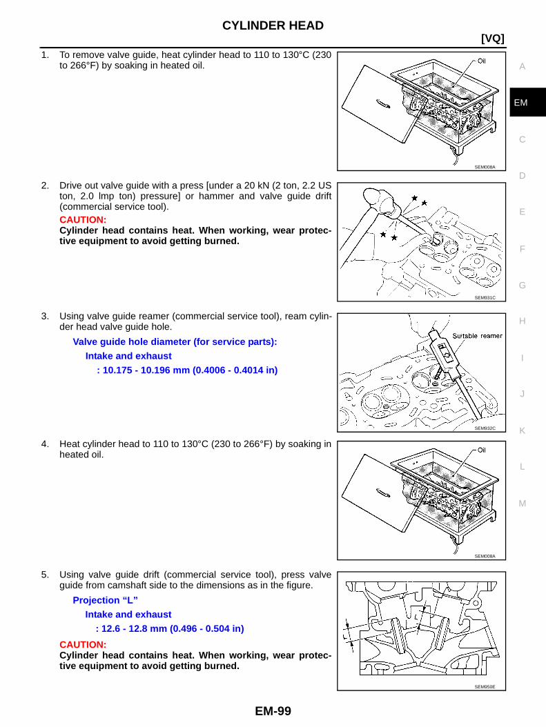
CYLINDER HEAD
EM-99
[VQ]
C
D
E
F
G
H
I
J
K
L
M
A
EM
1. To remove valve guide, heat cylinder head to 110 to 130°C (230to 266°F) by soaking in heated oil.
2. Drive out valve guide with a press [under a 20 kN (2 ton, 2.2 USton, 2.0 lmp ton) pressure] or hammer and valve guide drift(commercial service tool).CAUTION:Cylinder head contains heat. When working, wear protec-tive equipment to avoid getting burned.
3. Using valve guide reamer (commercial service tool), ream cylin-der head valve guide hole.
4. Heat cylinder head to 110 to 130°C (230 to 266°F) by soaking inheated oil.
5. Using valve guide drift (commercial service tool), press valveguide from camshaft side to the dimensions as in the figure.
CAUTION:Cylinder head contains heat. When working, wear protec-tive equipment to avoid getting burned.
SEM008A
SEM931C
Valve guide hole diameter (for service parts):Intake and exhaust
: 10.175 - 10.196 mm (0.4006 - 0.4014 in)
SEM932C
SEM008A
Projection “L”Intake and exhaust
: 12.6 - 12.8 mm (0.496 - 0.504 in)
SEM950E
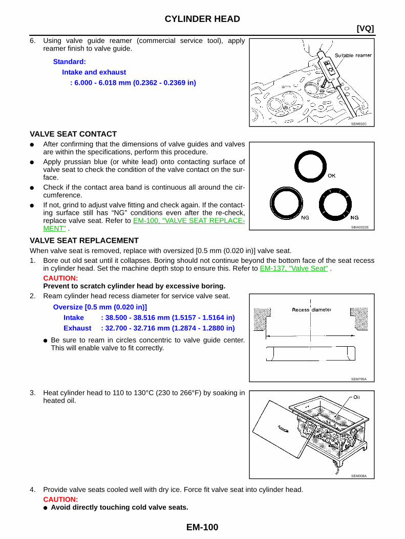
EM-100
[VQ]CYLINDER HEAD
6. Using valve guide reamer (commercial service tool), applyreamer finish to valve guide.
VALVE SEAT CONTACT● After confirming that the dimensions of valve guides and valves
are within the specifications, perform this procedure.● Apply prussian blue (or white lead) onto contacting surface of
valve seat to check the condition of the valve contact on the sur-face.
● Check if the contact area band is continuous all around the cir-cumference.
● If not, grind to adjust valve fitting and check again. If the contact-ing surface still has “NG” conditions even after the re-check,replace valve seat. Refer to EM-100, "VALVE SEAT REPLACE-MENT" .
VALVE SEAT REPLACEMENTWhen valve seat is removed, replace with oversized [0.5 mm (0.020 in)] valve seat.1. Bore out old seat until it collapses. Boring should not continue beyond the bottom face of the seat recess
in cylinder head. Set the machine depth stop to ensure this. Refer to EM-137, "Valve Seat" .CAUTION:Prevent to scratch cylinder head by excessive boring.
2. Ream cylinder head recess diameter for service valve seat.
● Be sure to ream in circles concentric to valve guide center.This will enable valve to fit correctly.
3. Heat cylinder head to 110 to 130°C (230 to 266°F) by soaking inheated oil.
4. Provide valve seats cooled well with dry ice. Force fit valve seat into cylinder head.CAUTION:● Avoid directly touching cold valve seats.
Standard:Intake and exhaust
: 6.000 - 6.018 mm (0.2362 - 0.2369 in)
SEM932C
SBIA0322E
Oversize [0.5 mm (0.020 in)]Intake : 38.500 - 38.516 mm (1.5157 - 1.5164 in)Exhaust : 32.700 - 32.716 mm (1.2874 - 1.2880 in)
SEM795A
SEM008A
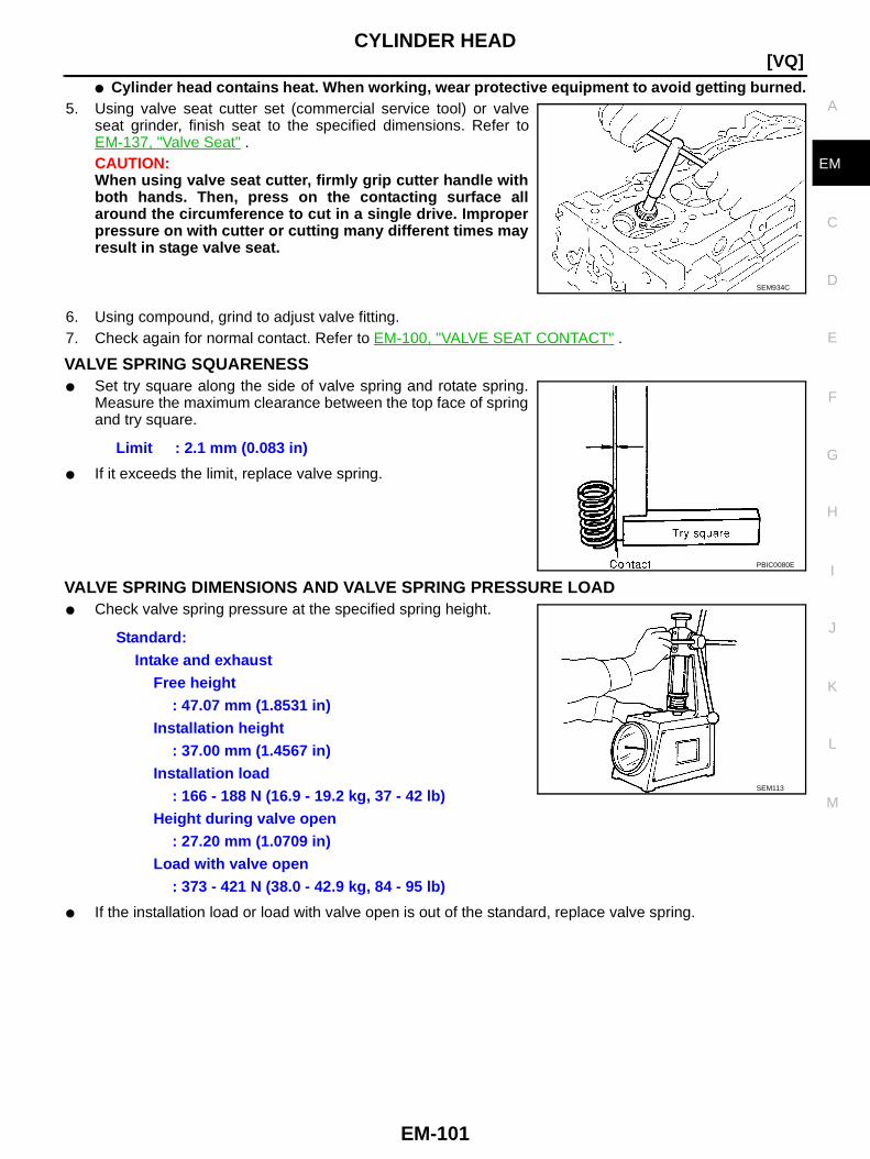
CYLINDER HEAD
EM-101
[VQ]
C
D
E
F
G
H
I
J
K
L
M
A
EM
● Cylinder head contains heat. When working, wear protective equipment to avoid getting burned.5. Using valve seat cutter set (commercial service tool) or valve
seat grinder, finish seat to the specified dimensions. Refer toEM-137, "Valve Seat" .CAUTION:When using valve seat cutter, firmly grip cutter handle withboth hands. Then, press on the contacting surface allaround the circumference to cut in a single drive. Improperpressure on with cutter or cutting many different times mayresult in stage valve seat.
6. Using compound, grind to adjust valve fitting.7. Check again for normal contact. Refer to EM-100, "VALVE SEAT CONTACT" .
VALVE SPRING SQUARENESS● Set try square along the side of valve spring and rotate spring.
Measure the maximum clearance between the top face of springand try square.
● If it exceeds the limit, replace valve spring.
VALVE SPRING DIMENSIONS AND VALVE SPRING PRESSURE LOAD● Check valve spring pressure at the specified spring height.
● If the installation load or load with valve open is out of the standard, replace valve spring.
SEM934C
Limit : 2.1 mm (0.083 in)
PBIC0080E
Standard:Intake and exhaust
Free height: 47.07 mm (1.8531 in)
Installation height: 37.00 mm (1.4567 in)
Installation load: 166 - 188 N (16.9 - 19.2 kg, 37 - 42 lb)
Height during valve open: 27.20 mm (1.0709 in)
Load with valve open: 373 - 421 N (38.0 - 42.9 kg, 84 - 95 lb)
SEM113

EM-102
[VQ]ENGINE ASSEMBLY
ENGINE ASSEMBLY PFP:10001
Components BBS0001E
WARNING:● Situate vehicle on a flat and solid surface.● Place chocks at front and back of rear wheels.● For engines not equipped with engine slingers, attach proper slingers and bolts described in
PARTS CATALOG.CAUTION:● Always be careful to work safely, avoid forceful or uninstructed operations.● Do not start working until exhaust system and engine coolant are cooled sufficiently.
1. RH engine mounting bracket (upper) 2. RH heat shield plate 3. RH engine mounting insulator
4. RH engine mounting bracket (lower) 5. LH engine mounting bracket (lower) 6. LH engine mounting insulator
7. LH heat shield plate 8. LH engine mounting bracket (upper) 9. Rear engine mounting insulator
PBIC4153E
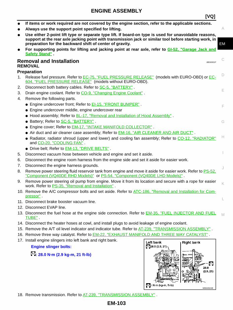
ENGINE ASSEMBLY
EM-103
[VQ]
C
D
E
F
G
H
I
J
K
L
M
A
EM
● If items or work required are not covered by the engine section, refer to the applicable sections.● Always use the support point specified for lifting.● Use either 2-point lift type or separate type lift. If board-on type is used for unavoidable reasons,
support at the rear axle jacking point with transmission jack or similar tool before starting work, inpreparation for the backward shift of center of gravity.
● For supporting points for lifting and jacking point at rear axle, refer to GI-52, "Garage Jack andSafety Stand " .
Removal and Installation BBS0001F
REMOVALPreparation1. Release fuel pressure. Refer to EC-75, "FUEL PRESSURE RELEASE" (models with EURO-OBD) or EC-
604, "FUEL PRESSURE RELEASE" (models without EURO-OBD).2. Disconnect both battery cables. Refer to SC-5, "BATTERY" .3. Drain engine coolant. Refer to CO-9, "Changing Engine Coolant" .4. Remove the following parts.
● Engine undercover front; Refer to EI-15, "FRONT BUMPER" .● Engine undercover middle, engine undercover rear● Hood assembly; Refer to BL-17, "Removal and Installation of Hood Assembly" .● Battery; Refer to SC-5, "BATTERY" .● Engine cover; Refer to EM-17, "INTAKE MANIFOLD COLLECTOR" .● Air duct and air cleaner case assembly; Refer to EM-16, "AIR CLEANER AND AIR DUCT" .● Radiator, radiator shroud (upper and lower) and cooling fan assembly; Refer to CO-12, "RADIATOR"
and CO-20, "COOLING FAN" .● Drive belt; Refer to EM-13, "DRIVE BELTS" .
5. Disconnect vacuum hose between vehicle and engine and set it aside.6. Disconnect the engine room harness from the engine side and set it aside for easier work.7. Disconnect the engine harness grounds.8. Remove power steering fluid reservoir tank from engine and move it aside for easier work. Refer to PS-52,
"Component (VQ40DE RHD Models)" or PS-54, "Component (VQ40DE LHD Models)" .9. Remove power steering oil pump from engine. Move it from its location and secure with a rope for easier
work. Refer to PS-35, "Removal and Installation" .10. Remove the A/C compressor bolts and set aside. Refer to ATC-186, "Removal and Installation for Com-
pressor" .11. Disconnect brake booster vacuum line.12. Disconnect EVAP line.13. Disconnect the fuel hose at the engine side connection. Refer to EM-35, "FUEL INJECTOR AND FUEL
TUBE" .14. Disconnect the heater hoses at cowl, and install plugs to avoid leakage of engine coolant.15. Remove the A/T oil level indicator and indicator tube. Refer to AT-239, "TRANSMISSION ASSEMBLY" .16. Remove three way catalyst. Refer to EM-22, "EXHAUST MANIFOLD AND THREE WAY CATALYST" .17. Install engine slingers into left bank and right bank.
18. Remove transmission. Refer to AT-239, "TRANSMISSION ASSEMBLY" .
Engine slinger bolts:
: 28.0 N·m (2.9 kg-m, 21 ft-lb)
WBIA0624E
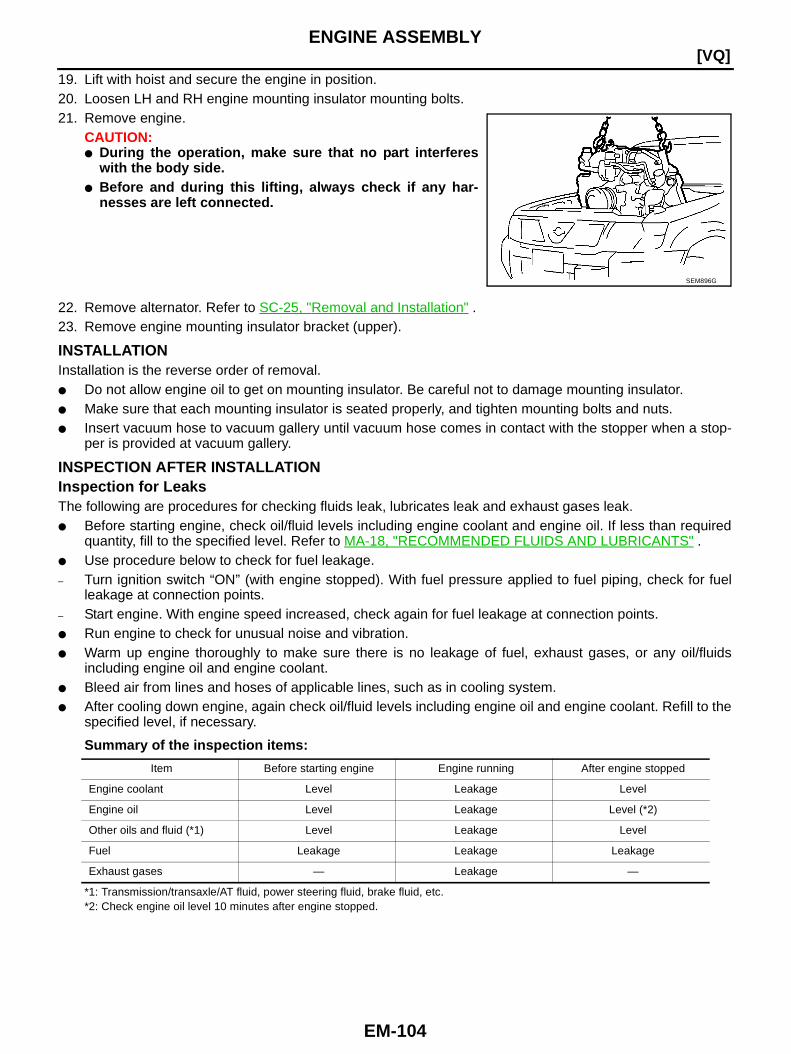
EM-104
[VQ]ENGINE ASSEMBLY
19. Lift with hoist and secure the engine in position.20. Loosen LH and RH engine mounting insulator mounting bolts.21. Remove engine.
CAUTION:● During the operation, make sure that no part interferes
with the body side.● Before and during this lifting, always check if any har-
nesses are left connected.
22. Remove alternator. Refer to SC-25, "Removal and Installation" .23. Remove engine mounting insulator bracket (upper).
INSTALLATIONInstallation is the reverse order of removal.● Do not allow engine oil to get on mounting insulator. Be careful not to damage mounting insulator.● Make sure that each mounting insulator is seated properly, and tighten mounting bolts and nuts.● Insert vacuum hose to vacuum gallery until vacuum hose comes in contact with the stopper when a stop-
per is provided at vacuum gallery.
INSPECTION AFTER INSTALLATIONInspection for LeaksThe following are procedures for checking fluids leak, lubricates leak and exhaust gases leak.● Before starting engine, check oil/fluid levels including engine coolant and engine oil. If less than required
quantity, fill to the specified level. Refer to MA-18, "RECOMMENDED FLUIDS AND LUBRICANTS" .● Use procedure below to check for fuel leakage.– Turn ignition switch “ON” (with engine stopped). With fuel pressure applied to fuel piping, check for fuel
leakage at connection points.– Start engine. With engine speed increased, check again for fuel leakage at connection points.● Run engine to check for unusual noise and vibration.● Warm up engine thoroughly to make sure there is no leakage of fuel, exhaust gases, or any oil/fluids
including engine oil and engine coolant.● Bleed air from lines and hoses of applicable lines, such as in cooling system.● After cooling down engine, again check oil/fluid levels including engine oil and engine coolant. Refill to the
specified level, if necessary.
Summary of the inspection items:
*1: Transmission/transaxle/AT fluid, power steering fluid, brake fluid, etc.*2: Check engine oil level 10 minutes after engine stopped.
SEM896G
Item Before starting engine Engine running After engine stopped
Engine coolant Level Leakage Level
Engine oil Level Leakage Level (*2)
Other oils and fluid (*1) Level Leakage Level
Fuel Leakage Leakage Leakage
Exhaust gases — Leakage —

CYLINDER BLOCK
EM-105
[VQ]
C
D
E
F
G
H
I
J
K
L
M
A
EM
CYLINDER BLOCK PFP:11010
Components BBS0001G
PBIC4154E
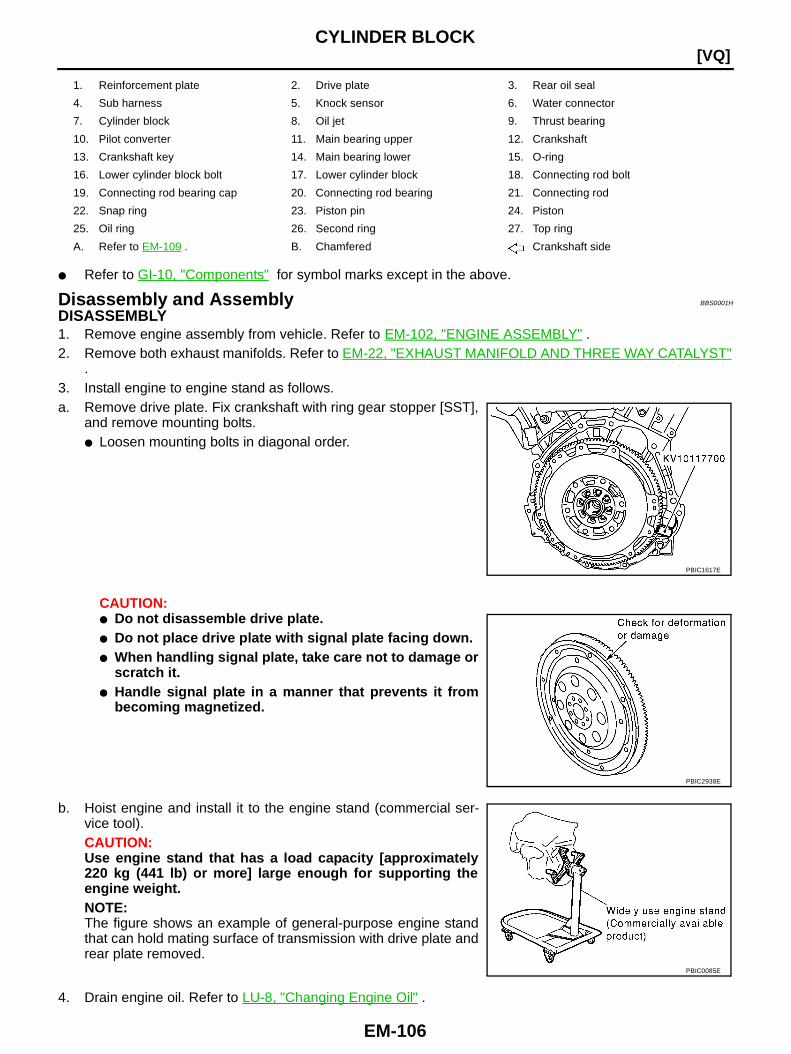
EM-106
[VQ]CYLINDER BLOCK
● Refer to GI-10, "Components" for symbol marks except in the above.
Disassembly and Assembly BBS0001H
DISASSEMBLY1. Remove engine assembly from vehicle. Refer to EM-102, "ENGINE ASSEMBLY" .2. Remove both exhaust manifolds. Refer to EM-22, "EXHAUST MANIFOLD AND THREE WAY CATALYST"
.3. Install engine to engine stand as follows.a. Remove drive plate. Fix crankshaft with ring gear stopper [SST],
and remove mounting bolts.● Loosen mounting bolts in diagonal order.
CAUTION:● Do not disassemble drive plate.● Do not place drive plate with signal plate facing down.● When handling signal plate, take care not to damage or
scratch it.● Handle signal plate in a manner that prevents it from
becoming magnetized.
b. Hoist engine and install it to the engine stand (commercial ser-vice tool).CAUTION:Use engine stand that has a load capacity [approximately220 kg (441 lb) or more] large enough for supporting theengine weight.NOTE:The figure shows an example of general-purpose engine standthat can hold mating surface of transmission with drive plate andrear plate removed.
4. Drain engine oil. Refer to LU-8, "Changing Engine Oil" .
1. Reinforcement plate 2. Drive plate 3. Rear oil seal
4. Sub harness 5. Knock sensor 6. Water connector
7. Cylinder block 8. Oil jet 9. Thrust bearing
10. Pilot converter 11. Main bearing upper 12. Crankshaft
13. Crankshaft key 14. Main bearing lower 15. O-ring
16. Lower cylinder block bolt 17. Lower cylinder block 18. Connecting rod bolt
19. Connecting rod bearing cap 20. Connecting rod bearing 21. Connecting rod
22. Snap ring 23. Piston pin 24. Piston
25. Oil ring 26. Second ring 27. Top ring
A. Refer to EM-109 . B. Chamfered Crankshaft side
PBIC1617E
PBIC2938E
PBIC0085E

CYLINDER BLOCK
EM-107
[VQ]
C
D
E
F
G
H
I
J
K
L
M
A
EM
5. Drain engine coolant by removing water drain plugs from cylin-der block left side at “A” and cylinder block front side at “B” asshown in the figure.
6. Remove cylinder head. Refer to EM-90, "CYLINDER HEAD" .7. Remove sub harness, and remove knock sensors.
CAUTION:Carefully handle sensor avoiding shocks.
8. Remove pilot converter using pilot bushing puller (A) [SST:16610001] as necessary.
9. Remove piston and connecting rod assembly as follows:● Before removing piston and connecting rod assembly, check the connecting rod side clearance. Refer
to EM-121, "CONNECTING ROD SIDE CLEARANCE" .CAUTION:Be careful not to drop connecting rod bearing, and to scratch the surface.
a. Position crankshaft pin corresponding to connecting rod to be removed onto the bottom dead center.b. Remove connecting rod bearing cap.c. Using hammer handle or similar tool, push piston and connect-
ing rod assembly out to the cylinder head side.CAUTION:Be careful not to damage the cylinder wall and crankshaftpin, resulting from an interference of the connecting rod bigend.
PBIC2937E
PBIC3893E
PBIC2940E

EM-108
[VQ]CYLINDER BLOCK
10. Remove connecting rod bearings from connecting rod and connecting rod bearing cap.CAUTION:Identify installation position, and store them without mixing them up.
11. Remove piston rings from piston.● Before removing piston rings, check the piston ring side clearance. Refer to EM-122, "PISTON RING
SIDE CLEARANCE" .● Use piston ring expander (commercial service tool).CAUTION:● When removing piston rings, be careful not to damage
piston.● Be careful not to damage piston rings by expanding them
excessively.
12. Remove piston from connecting rod as follows:a. Using snap ring pliers, remove snap rings.
b. Heat piston to 60 to 70°C (140 to 158°F) with industrial use drieror equivalent.
c. Push out piston pin with stick of outer diameter approximately 20mm (0.79 in).
13. Remove lower cylinder block bolts.● Before loosening lower cylinder block bolts, measure the crankshaft end play. Refer to EM-121,
"CRANKSHAFT END PLAY" .
PBIC0087E
PBIC1638E
PBIC1639E
PBIC0262E
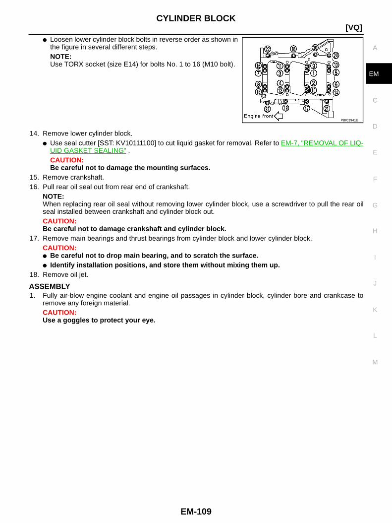
CYLINDER BLOCK
EM-109
[VQ]
C
D
E
F
G
H
I
J
K
L
M
A
EM
● Loosen lower cylinder block bolts in reverse order as shown inthe figure in several different steps.NOTE:Use TORX socket (size E14) for bolts No. 1 to 16 (M10 bolt).
14. Remove lower cylinder block.● Use seal cutter [SST: KV10111100] to cut liquid gasket for removal. Refer to EM-7, "REMOVAL OF LIQ-
UID GASKET SEALING" .CAUTION:Be careful not to damage the mounting surfaces.
15. Remove crankshaft.16. Pull rear oil seal out from rear end of crankshaft.
NOTE:When replacing rear oil seal without removing lower cylinder block, use a screwdriver to pull the rear oilseal installed between crankshaft and cylinder block out.CAUTION:Be careful not to damage crankshaft and cylinder block.
17. Remove main bearings and thrust bearings from cylinder block and lower cylinder block.CAUTION:● Be careful not to drop main bearing, and to scratch the surface.● Identify installation positions, and store them without mixing them up.
18. Remove oil jet.
ASSEMBLY1. Fully air-blow engine coolant and engine oil passages in cylinder block, cylinder bore and crankcase to
remove any foreign material.CAUTION:Use a goggles to protect your eye.
PBIC2941E
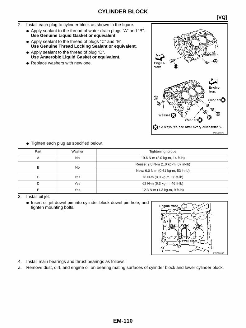
EM-110
[VQ]CYLINDER BLOCK
2. Install each plug to cylinder block as shown in the figure.● Apply sealant to the thread of water drain plugs “A” and “B”.
Use Genuine Liquid Gasket or equivalent.● Apply sealant to the thread of plugs “C” and “E”.
Use Genuine Thread Locking Sealant or equivalent.● Apply sealant to the thread of plug “D”.
Use Anaerobic Liquid Gasket or equivalent.● Replace washers with new one.
● Tighten each plug as specified below.
3. Install oil jet.● Insert oil jet dowel pin into cylinder block dowel pin hole, and
tighten mounting bolts.
4. Install main bearings and thrust bearings as follows:a. Remove dust, dirt, and engine oil on bearing mating surfaces of cylinder block and lower cylinder block.
PBIC2937E
Part Washer Tightening torque
A No 19.6 N·m (2.0 kg-m, 14 ft-lb)
B NoReuse: 9.8 N·m (1.0 kg-m, 87 in-lb)
New: 6.0 N·m (0.61 kg-m, 53 in-lb)
C Yes 78 N·m (8.0 kg-m, 58 ft-lb)
D Yes 62 N·m (6.3 kg-m, 46 ft-lb)
E Yes 12.3 N·m (1.3 kg-m, 9 ft-lb)
PBIC0898E

CYLINDER BLOCK
EM-111
[VQ]
C
D
E
F
G
H
I
J
K
L
M
A
EM
b. Install thrust bearings to the both sides of the No. 3 journal hous-ing on cylinder block.● Install thrust bearings with the oil groove facing crankshaft
arm (outside).● Install thrust bearing with a projection on one end on cylinder
block, and thrust bearing with a projection at center on lowercylinder block. Align each projection with mating notch.
c. Install main bearings paying attention to the direction.● Main bearing with oil hole and groove goes on cylinder block.
The one without them goes on lower cylinder block.● Before installing main bearings, apply engine oil to the bear-
ing surface (inside). Do not apply engine oil to the back sur-face, but thoroughly clean it.
● When installing, align main bearing stopper protrusion to cut-out of cylinder block and lower cylinder block.
● Ensure the oil holes on cylinder block and those on the corre-sponding bearing are aligned.
5. Install crankshaft to cylinder block.● While turning crankshaft by hand, check that it turns smoothly.
6. Inspect the outer diameter of lower cylinder block bolt. Refer to EM-129, "LOWER CYLINDER BLOCKBOLT OUTER DIAMETER" .
7. Install lower cylinder block as follows:NOTE:Lower cylinder block cannot be replaced as a single part, because it is machined together with cylinderblock.
a. Apply a continuous bead of liquid gasket with tube presser [SST:WS39930000] to lower cylinder block as shown in the figure.Use Genuine Liquid Gasket or equivalent.CAUTION:After liquid gasket is applied, rear oil seal installation mustbe finished within 5 minutes. Therefore, the following pro-cedure must be performed quickly.
b. Tighten lower cylinder block mounting bolt as follows:i. Apply new engine oil to threads and seat surfaces of the mount-
ing bolts.
ii. Tighten M8 bolts in numerical order from No. 17 to 24 in the fig-ure.
CAUTION:Wipe off completely any protruding liquid gasket on rear oilseal installation surface.NOTE:There are more processes to complete the tightening of mount-ing bolts. However stop procedure here to install rear oil seal.
c. Install rear oil seal. Refer to EM-88, "Removal and Installation of Rear Oil Seal" .d. Restart tightening of lower cylinder block bolts as follows:
PBIC2968E
PBIC2969E
: 22.1 N·m (2.3 kg-m, 16 ft-lb)
PBIC2942E
PBIC2941E
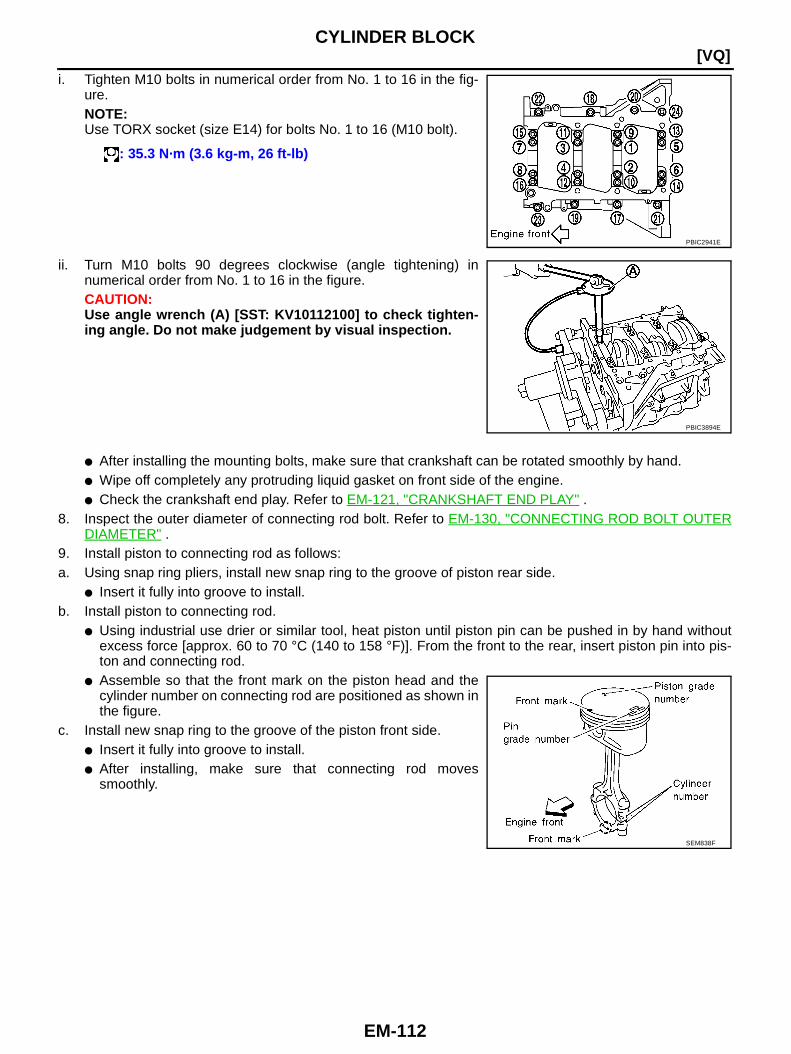
EM-112
[VQ]CYLINDER BLOCK
i. Tighten M10 bolts in numerical order from No. 1 to 16 in the fig-ure.NOTE:Use TORX socket (size E14) for bolts No. 1 to 16 (M10 bolt).
ii. Turn M10 bolts 90 degrees clockwise (angle tightening) innumerical order from No. 1 to 16 in the figure.CAUTION:Use angle wrench (A) [SST: KV10112100] to check tighten-ing angle. Do not make judgement by visual inspection.
● After installing the mounting bolts, make sure that crankshaft can be rotated smoothly by hand.● Wipe off completely any protruding liquid gasket on front side of the engine.● Check the crankshaft end play. Refer to EM-121, "CRANKSHAFT END PLAY" .
8. Inspect the outer diameter of connecting rod bolt. Refer to EM-130, "CONNECTING ROD BOLT OUTERDIAMETER" .
9. Install piston to connecting rod as follows:a. Using snap ring pliers, install new snap ring to the groove of piston rear side.
● Insert it fully into groove to install.b. Install piston to connecting rod.
● Using industrial use drier or similar tool, heat piston until piston pin can be pushed in by hand withoutexcess force [approx. 60 to 70 °C (140 to 158 °F)]. From the front to the rear, insert piston pin into pis-ton and connecting rod.
● Assemble so that the front mark on the piston head and thecylinder number on connecting rod are positioned as shown inthe figure.
c. Install new snap ring to the groove of the piston front side.● Insert it fully into groove to install.● After installing, make sure that connecting rod moves
smoothly.
: 35.3 N·m (3.6 kg-m, 26 ft-lb)
PBIC2941E
PBIC3894E
SEM838F
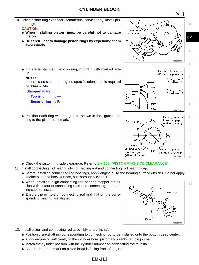
CYLINDER BLOCK
EM-113
[VQ]
C
D
E
F
G
H
I
J
K
L
M
A
EM
10. Using piston ring expander (commercial service tool), install pis-ton rings.CAUTION:● When installing piston rings, be careful not to damage
piston.● Be careful not to damage piston rings by expending them
excessively.
● If there is stamped mark on ring, mount it with marked sideup.NOTE:If there is no stamp on ring, no specific orientation is requiredfor installation.
● Position each ring with the gap as shown in the figure refer-ring to the piston front mark.
● Check the piston ring side clearance. Refer to EM-122, "PISTON RING SIDE CLEARANCE" .11. Install connecting rod bearings to connecting rod and connecting rod bearing cap.
● Before installing connecting rod bearings, apply engine oil to the bearing surface (inside). Do not applyengine oil to the back surface, but thoroughly clean it.
● When installing, align connecting rod bearing stopper protru-sion with cutout of connecting rods and connecting rod bear-ing caps to install.
● Ensure the oil hole on connecting rod and that on the corre-sponding bearing are aligned.
12. Install piston and connecting rod assembly to crankshaft.● Position crankshaft pin corresponding to connecting rod to be installed onto the bottom dead center.● Apply engine oil sufficiently to the cylinder bore, piston and crankshaft pin journal.● Match the cylinder position with the cylinder number on connecting rod to install.● Be sure that front mark on piston head is facing front of engine.
PBIC0087E
Stamped mark:Top ring : —Second ring : R
SEM757G
PBIC0808E
PBIC2067E
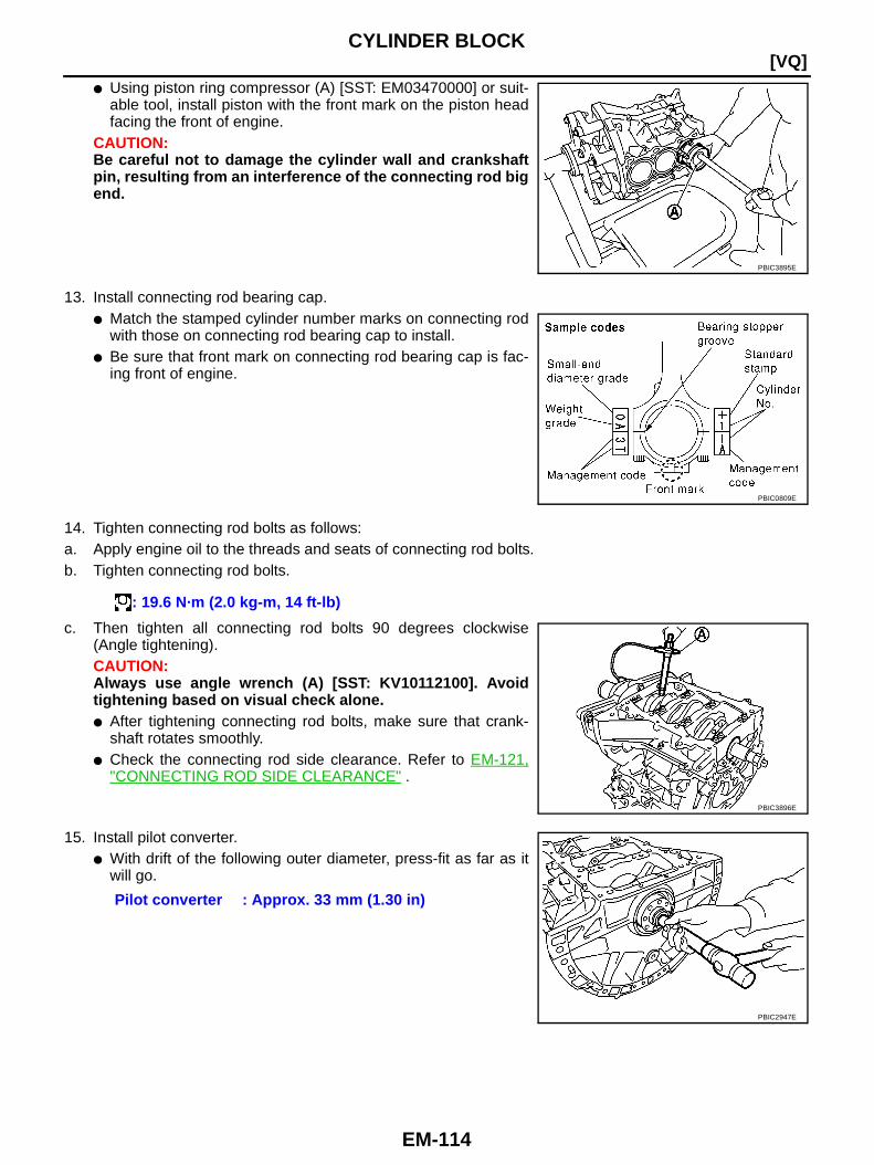
EM-114
[VQ]CYLINDER BLOCK
● Using piston ring compressor (A) [SST: EM03470000] or suit-able tool, install piston with the front mark on the piston headfacing the front of engine.
CAUTION:Be careful not to damage the cylinder wall and crankshaftpin, resulting from an interference of the connecting rod bigend.
13. Install connecting rod bearing cap.● Match the stamped cylinder number marks on connecting rod
with those on connecting rod bearing cap to install.● Be sure that front mark on connecting rod bearing cap is fac-
ing front of engine.
14. Tighten connecting rod bolts as follows:a. Apply engine oil to the threads and seats of connecting rod bolts.b. Tighten connecting rod bolts.
c. Then tighten all connecting rod bolts 90 degrees clockwise(Angle tightening).CAUTION:Always use angle wrench (A) [SST: KV10112100]. Avoidtightening based on visual check alone.● After tightening connecting rod bolts, make sure that crank-
shaft rotates smoothly.● Check the connecting rod side clearance. Refer to EM-121,
"CONNECTING ROD SIDE CLEARANCE" .
15. Install pilot converter.● With drift of the following outer diameter, press-fit as far as it
will go.
PBIC3895E
PBIC0809E
: 19.6 N·m (2.0 kg-m, 14 ft-lb)
PBIC3896E
Pilot converter : Approx. 33 mm (1.30 in)
PBIC2947E
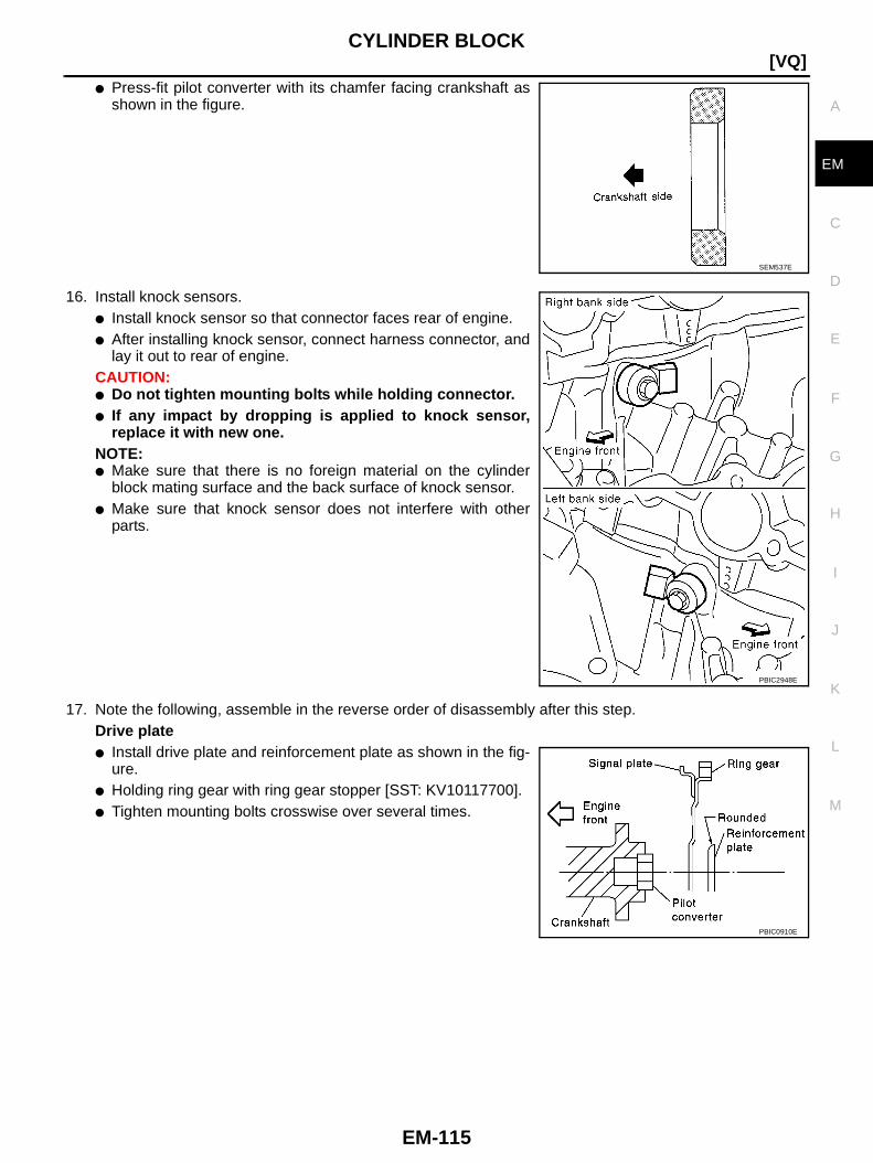
CYLINDER BLOCK
EM-115
[VQ]
C
D
E
F
G
H
I
J
K
L
M
A
EM
● Press-fit pilot converter with its chamfer facing crankshaft asshown in the figure.
16. Install knock sensors.● Install knock sensor so that connector faces rear of engine.● After installing knock sensor, connect harness connector, and
lay it out to rear of engine.CAUTION:● Do not tighten mounting bolts while holding connector.● If any impact by dropping is applied to knock sensor,
replace it with new one.NOTE:● Make sure that there is no foreign material on the cylinder
block mating surface and the back surface of knock sensor.● Make sure that knock sensor does not interfere with other
parts.
17. Note the following, assemble in the reverse order of disassembly after this step.Drive plate● Install drive plate and reinforcement plate as shown in the fig-
ure.● Holding ring gear with ring gear stopper [SST: KV10117700].● Tighten mounting bolts crosswise over several times.
SEM537E
PBIC2948E
PBIC0910E
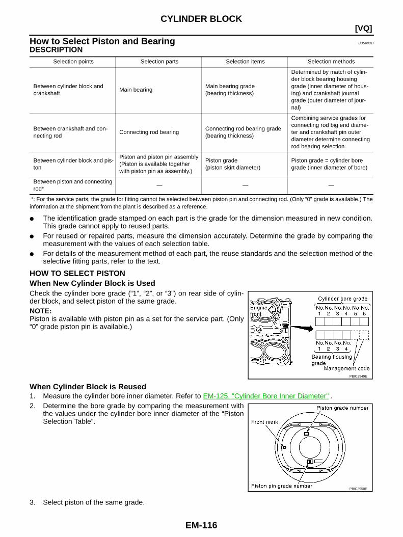
EM-116
[VQ]CYLINDER BLOCK
How to Select Piston and Bearing BBS0001I
DESCRIPTION
*: For the service parts, the grade for fitting cannot be selected between piston pin and connecting rod. (Only “0” grade is available.) Theinformation at the shipment from the plant is described as a reference.
● The identification grade stamped on each part is the grade for the dimension measured in new condition.This grade cannot apply to reused parts.
● For reused or repaired parts, measure the dimension accurately. Determine the grade by comparing themeasurement with the values of each selection table.
● For details of the measurement method of each part, the reuse standards and the selection method of theselective fitting parts, refer to the text.
HOW TO SELECT PISTONWhen New Cylinder Block is UsedCheck the cylinder bore grade (“1”, “2”, or “3”) on rear side of cylin-der block, and select piston of the same grade.NOTE:Piston is available with piston pin as a set for the service part. (Only“0” grade piston pin is available.)
When Cylinder Block is Reused1. Measure the cylinder bore inner diameter. Refer to EM-125, "Cylinder Bore Inner Diameter" .2. Determine the bore grade by comparing the measurement with
the values under the cylinder bore inner diameter of the “PistonSelection Table”.
3. Select piston of the same grade.
Selection points Selection parts Selection items Selection methods
Between cylinder block andcrankshaft
Main bearingMain bearing grade(bearing thickness)
Determined by match of cylin-der block bearing housinggrade (inner diameter of hous-ing) and crankshaft journalgrade (outer diameter of jour-nal)
Between crankshaft and con-necting rod
Connecting rod bearingConnecting rod bearing grade(bearing thickness)
Combining service grades forconnecting rod big end diame-ter and crankshaft pin outerdiameter determine connectingrod bearing selection.
Between cylinder block and pis-ton
Piston and piston pin assembly(Piston is available togetherwith piston pin as assembly.)
Piston grade(piston skirt diameter)
Piston grade = cylinder boregrade (inner diameter of bore)
Between piston and connectingrod*
— — —
PBIC2949E
PBIC2950E

CYLINDER BLOCK
EM-117
[VQ]
C
D
E
F
G
H
I
J
K
L
M
A
EM
Piston Selection TableUnit: mm (in)
NOTE:● Piston is available together with piston pin as assembly.● Piston pin (piston pin hole) grade is provided only for the parts installed at the plant. For service parts, no
piston pin grades can be selected. (Only “0” grade is available.)● No second grade mark is available on piston.
HOW TO SELECT CONNECTING ROD BEARINGWhen New Connecting Rod and Crankshaft are UsedCheck pin journal grade (“0”, “1”, or “2”) on front of crankshaft, andselect connecting rod bearing of the same grade.NOTE:There is no grading for connecting rod big end diameter.
When Crankshaft and Connecting Rod are Reused1. Measure the connecting rod big end diameter. Refer to EM-123, "CONNECTING ROD BIG END DIAME-
TER" .2. Make sure that the connecting rod big end diameter is within the standard value.3. Measure the crankshaft pin journal diameter. Refer to EM-127, "CRANKSHAFT PIN JOURNAL DIAME-
TER" .4. Determine the grade of crankshaft pin journal grade by corresponding to the measured dimension in
“Crankshaft pin journal diameter” column of “Connecting Rod Bearing Selection Table”.5. Select connecting rod bearing of the same grade.
Connecting Rod Bearing Selection TableUnit: mm (in)
Unit: mm (in)
Undersize Bearings Usage Guide● When the specified connecting rod bearing oil clearance is not obtained with standard size connecting rod
bearings, use undersize (US) bearings.● When using undersize (US) bearing, measure the connecting rod bearing inner diameter with bearing
installed, and grind crankshaft pin so that the connecting rod bearing oil clearance satisfies the standard.
Grade 1 2 (or no mark) 3
Cylinder bore inner diameter95.500 - 95.510
(3.7598 - 3.7602)95.510 - 95.520(3.7602 - 3.7606)
95.520 - 95.530(3.7606 - 3.7610)
Piston skirt diameter95.480 - 95.490
(3.7590 - 3.7594)95.490 - 95.500
(3.7594 - 3.7598)95.500 - 95.510
(3.7598 - 3.7602)
PBIC2951E
Connecting rod big end diameter 57.000 - 57.013 (2.2441 - 2.2446)
Crankshaft Connecting rod bearing
Crankshaft pin journal diameter Grade (Mark) Dimension (Bearing thickness range) Bearing grade No. Color
53.968 - 53.974 (2.1247 - 2.1250) 0 1.500 - 1.503 (0.0591 - 0.0592) STD 0 Black
53.962 - 53.968 (2.1245 - 2.1247) 1 1.503 - 1.506 (0.0592 - 0.0593) STD 1 Brown
53.956 - 53.962 (2.1242 - 2.1245) 2 1.506 - 1.509 (0.0593 - 0.0594) STD 2 Green

EM-118
[VQ]CYLINDER BLOCK
CAUTION:In grinding crankshaft pin to use undersize bearings, keepthe fillet R [1.5 - 1.7 mm (0.059 - 0.067 in)].
Bearing undersize tableUnit: mm (in)
HOW TO SELECT MAIN BEARINGWhen New Cylinder Block and Crankshaft are Used1. “Main Bearing Selection Table” rows correspond to bearing
housing grade on rear left side of cylinder block.
2. “Main Bearing Selection Table” columns correspond to journaldiameter grade on front side of crankshaft.
3. Select main bearing grade at the point where selected row and column meet in “Main Bearing SelectionTable”.
When Cylinder Block and Crankshaft are Reused1. Measure cylinder block main bearing housing inner diameter and crankshaft main journal diameter. Refer
to EM-125, "MAIN BEARING HOUSING INNER DIAMETER" and EM-126, "CRANKSHAFT MAIN JOUR-NAL DIAMETER" .
2. Correspond the measured dimension in “Cylinder block main bearing housing inner diameter” row of“Main Bearing Selection Table”.
3. Correspond the measured dimension in “Crankshaft main journal diameter” column of “Main BearingSelection Table”.
4. Select main bearing grade at the point where selected row and column meet in following selection table.
PBIC1908E
Size Thickness
US 0.25 (0.0098) 1.626 - 1.634 (0.0640 - 0.0643)
PBIC2949E
PBIC2951E

CYLINDER BLOCK
EM-119
[VQ]
C
D
E
F
G
H
I
J
K
L
M
A
EM
Main Bearing Selection Table
WBIA0625E
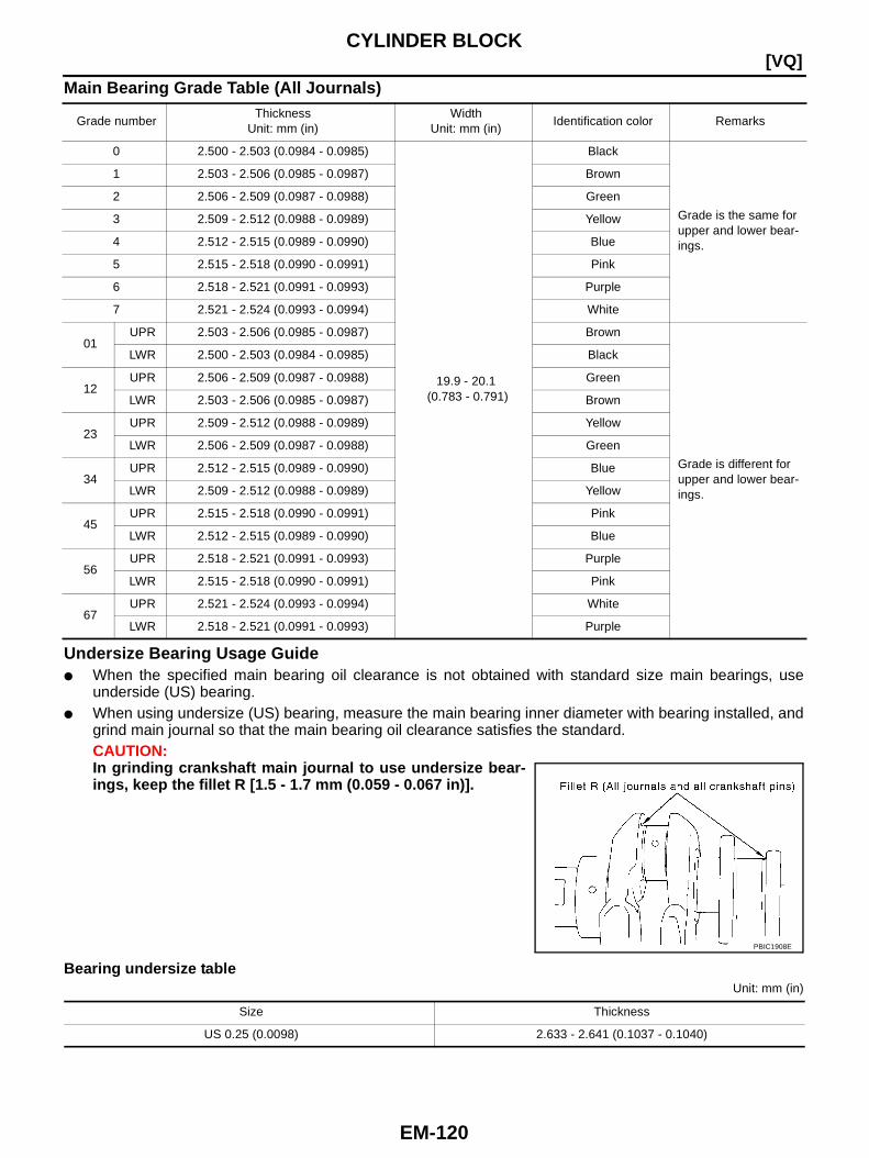
EM-120
[VQ]CYLINDER BLOCK
Main Bearing Grade Table (All Journals)
Undersize Bearing Usage Guide● When the specified main bearing oil clearance is not obtained with standard size main bearings, use
underside (US) bearing.● When using undersize (US) bearing, measure the main bearing inner diameter with bearing installed, and
grind main journal so that the main bearing oil clearance satisfies the standard.CAUTION:In grinding crankshaft main journal to use undersize bear-ings, keep the fillet R [1.5 - 1.7 mm (0.059 - 0.067 in)].
Bearing undersize tableUnit: mm (in)
Grade numberThickness
Unit: mm (in)Width
Unit: mm (in)Identification color Remarks
0 2.500 - 2.503 (0.0984 - 0.0985)
19.9 - 20.1(0.783 - 0.791)
Black
Grade is the same forupper and lower bear-ings.
1 2.503 - 2.506 (0.0985 - 0.0987) Brown
2 2.506 - 2.509 (0.0987 - 0.0988) Green
3 2.509 - 2.512 (0.0988 - 0.0989) Yellow
4 2.512 - 2.515 (0.0989 - 0.0990) Blue
5 2.515 - 2.518 (0.0990 - 0.0991) Pink
6 2.518 - 2.521 (0.0991 - 0.0993) Purple
7 2.521 - 2.524 (0.0993 - 0.0994) White
01UPR 2.503 - 2.506 (0.0985 - 0.0987) Brown
Grade is different forupper and lower bear-ings.
LWR 2.500 - 2.503 (0.0984 - 0.0985) Black
12UPR 2.506 - 2.509 (0.0987 - 0.0988) Green
LWR 2.503 - 2.506 (0.0985 - 0.0987) Brown
23UPR 2.509 - 2.512 (0.0988 - 0.0989) Yellow
LWR 2.506 - 2.509 (0.0987 - 0.0988) Green
34UPR 2.512 - 2.515 (0.0989 - 0.0990) Blue
LWR 2.509 - 2.512 (0.0988 - 0.0989) Yellow
45UPR 2.515 - 2.518 (0.0990 - 0.0991) Pink
LWR 2.512 - 2.515 (0.0989 - 0.0990) Blue
56UPR 2.518 - 2.521 (0.0991 - 0.0993) Purple
LWR 2.515 - 2.518 (0.0990 - 0.0991) Pink
67UPR 2.521 - 2.524 (0.0993 - 0.0994) White
LWR 2.518 - 2.521 (0.0991 - 0.0993) Purple
PBIC1908E
Size Thickness
US 0.25 (0.0098) 2.633 - 2.641 (0.1037 - 0.1040)

CYLINDER BLOCK
EM-121
[VQ]
C
D
E
F
G
H
I
J
K
L
M
A
EM
Inspection After Disassembly BBS0001J
CRANKSHAFT END PLAY● Measure the clearance between thrust bearings and crankshaft
arm when crankshaft is moved fully forward or backward withdial indicator.
● If the measured value exceeds the limit, replace thrust bearings,and measure again. If it still exceeds the limit, replace crank-shaft also.
CONNECTING ROD SIDE CLEARANCE● Measure the side clearance between connecting rod and crank-
shaft arm with feeler gauge.
● If the measured value exceeds the limit, replace connecting rod,and measure again. If it still exceeds the limit, replace crank-shaft also.
PISTON TO PISTON PIN OIL CLEARANCEPiston Pin Hole DiameterMeasure the inner diameter of piston pin hole with inside microme-ter.
Piston Pin Outer DiameterMeasure the outer diameter of piston pin with micrometer.
Piston to Piston Pin Oil Clearance(Piston to piston pin oil clearance) = (Piston pin hole diameter) – (Piston pin outer diameter)
● If the calculated value is out of the standard, replace piston and piston pin assembly.
Standard : 0.14 - 0.22 mm (0.0055 - 0.0087 in)Limit : 0.30 mm (0.0118 in)
PBIC2953E
Standard : 0.20 - 0.35 mm (0.0079 - 0.0138 in)Limit : 0.40 mm (0.0157 in)
PBIC2954E
Standard : 21.993 - 22.005 mm (0.8659 - 0.8663 in)
PBIC0116E
Standard : 21.989 - 22.001 mm (0.8657 - 0.8662 in)
PBIC0117E
Standard : 0.002 - 0.006 mm (0.0001 - 0.0002 in)
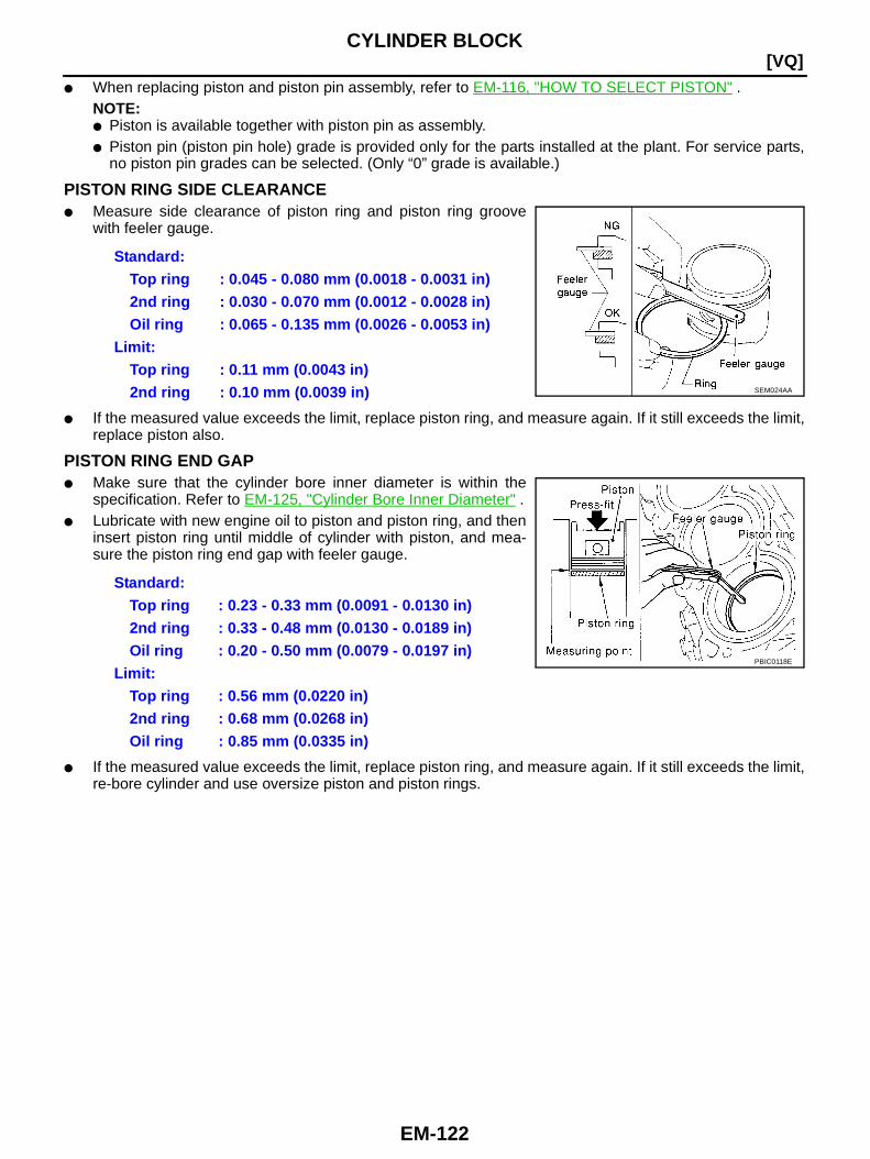
EM-122
[VQ]CYLINDER BLOCK
● When replacing piston and piston pin assembly, refer to EM-116, "HOW TO SELECT PISTON" .NOTE:● Piston is available together with piston pin as assembly.● Piston pin (piston pin hole) grade is provided only for the parts installed at the plant. For service parts,
no piston pin grades can be selected. (Only “0” grade is available.)
PISTON RING SIDE CLEARANCE● Measure side clearance of piston ring and piston ring groove
with feeler gauge.
● If the measured value exceeds the limit, replace piston ring, and measure again. If it still exceeds the limit,replace piston also.
PISTON RING END GAP● Make sure that the cylinder bore inner diameter is within the
specification. Refer to EM-125, "Cylinder Bore Inner Diameter" .● Lubricate with new engine oil to piston and piston ring, and then
insert piston ring until middle of cylinder with piston, and mea-sure the piston ring end gap with feeler gauge.
● If the measured value exceeds the limit, replace piston ring, and measure again. If it still exceeds the limit,re-bore cylinder and use oversize piston and piston rings.
Standard:Top ring : 0.045 - 0.080 mm (0.0018 - 0.0031 in)2nd ring : 0.030 - 0.070 mm (0.0012 - 0.0028 in)Oil ring : 0.065 - 0.135 mm (0.0026 - 0.0053 in)
Limit:Top ring : 0.11 mm (0.0043 in)2nd ring : 0.10 mm (0.0039 in) SEM024AA
Standard:Top ring : 0.23 - 0.33 mm (0.0091 - 0.0130 in)2nd ring : 0.33 - 0.48 mm (0.0130 - 0.0189 in)Oil ring : 0.20 - 0.50 mm (0.0079 - 0.0197 in)
Limit:Top ring : 0.56 mm (0.0220 in)2nd ring : 0.68 mm (0.0268 in)Oil ring : 0.85 mm (0.0335 in)
PBIC0118E
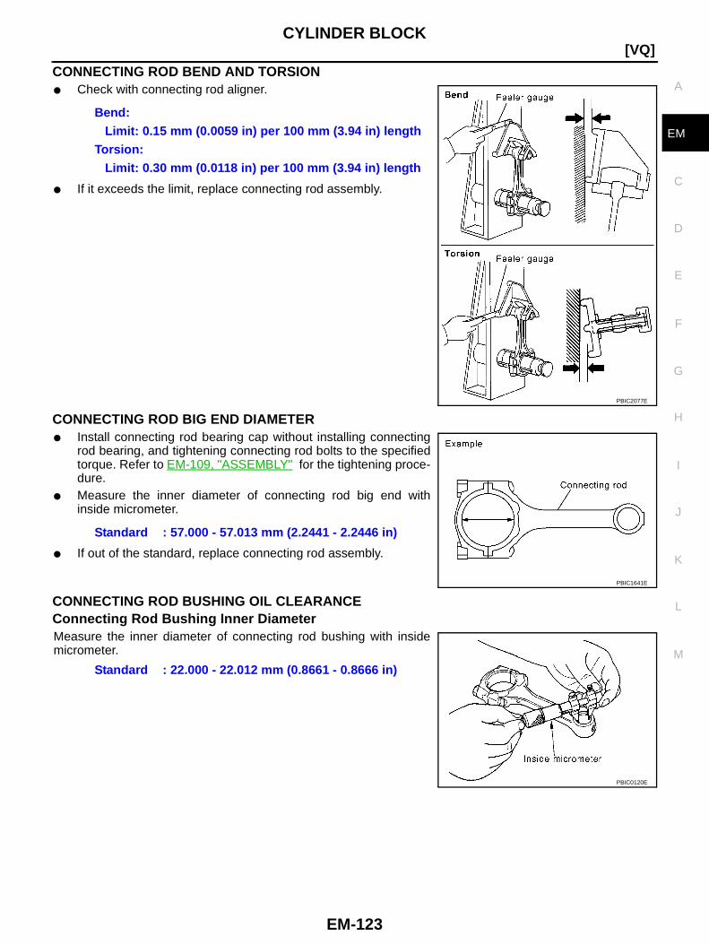
CYLINDER BLOCK
EM-123
[VQ]
C
D
E
F
G
H
I
J
K
L
M
A
EM
CONNECTING ROD BEND AND TORSION● Check with connecting rod aligner.
● If it exceeds the limit, replace connecting rod assembly.
CONNECTING ROD BIG END DIAMETER● Install connecting rod bearing cap without installing connecting
rod bearing, and tightening connecting rod bolts to the specifiedtorque. Refer to EM-109, "ASSEMBLY" for the tightening proce-dure.
● Measure the inner diameter of connecting rod big end withinside micrometer.
● If out of the standard, replace connecting rod assembly.
CONNECTING ROD BUSHING OIL CLEARANCEConnecting Rod Bushing Inner DiameterMeasure the inner diameter of connecting rod bushing with insidemicrometer.
Bend:Limit: 0.15 mm (0.0059 in) per 100 mm (3.94 in) length
Torsion:Limit: 0.30 mm (0.0118 in) per 100 mm (3.94 in) length
PBIC2077E
Standard : 57.000 - 57.013 mm (2.2441 - 2.2446 in)
PBIC1641E
Standard : 22.000 - 22.012 mm (0.8661 - 0.8666 in)
PBIC0120E
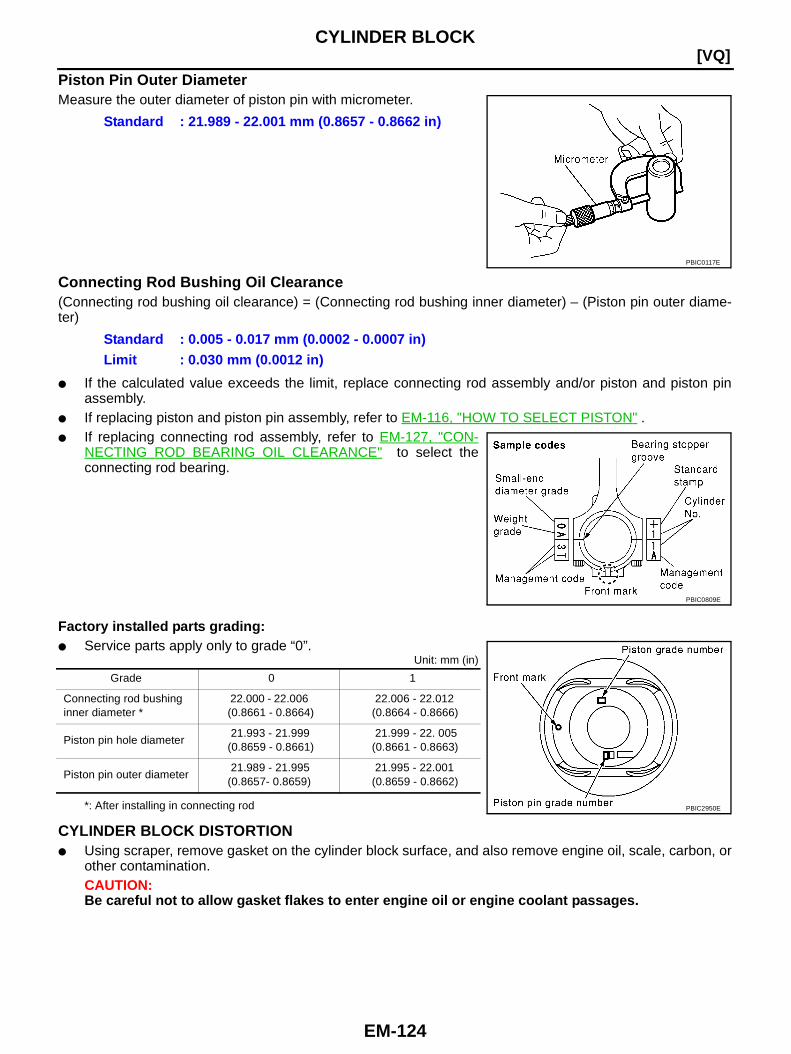
EM-124
[VQ]CYLINDER BLOCK
Piston Pin Outer DiameterMeasure the outer diameter of piston pin with micrometer.
Connecting Rod Bushing Oil Clearance(Connecting rod bushing oil clearance) = (Connecting rod bushing inner diameter) – (Piston pin outer diame-ter)
● If the calculated value exceeds the limit, replace connecting rod assembly and/or piston and piston pinassembly.
● If replacing piston and piston pin assembly, refer to EM-116, "HOW TO SELECT PISTON" .● If replacing connecting rod assembly, refer to EM-127, "CON-
NECTING ROD BEARING OIL CLEARANCE" to select theconnecting rod bearing.
Factory installed parts grading:● Service parts apply only to grade “0”.
Unit: mm (in)
*: After installing in connecting rod
CYLINDER BLOCK DISTORTION● Using scraper, remove gasket on the cylinder block surface, and also remove engine oil, scale, carbon, or
other contamination.CAUTION:Be careful not to allow gasket flakes to enter engine oil or engine coolant passages.
Standard : 21.989 - 22.001 mm (0.8657 - 0.8662 in)
PBIC0117E
Standard : 0.005 - 0.017 mm (0.0002 - 0.0007 in)Limit : 0.030 mm (0.0012 in)
PBIC0809E
Grade 0 1
Connecting rod bushinginner diameter *
22.000 - 22.006(0.8661 - 0.8664)
22.006 - 22.012(0.8664 - 0.8666)
Piston pin hole diameter21.993 - 21.999
(0.8659 - 0.8661)21.999 - 22. 005
(0.8661 - 0.8663)
Piston pin outer diameter21.989 - 21.995
(0.8657- 0.8659)21.995 - 22.001
(0.8659 - 0.8662)
PBIC2950E
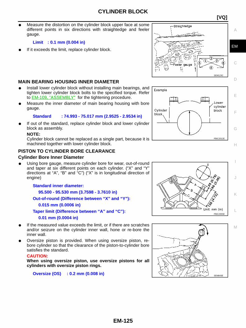
CYLINDER BLOCK
EM-125
[VQ]
C
D
E
F
G
H
I
J
K
L
M
A
EM
● Measure the distortion on the cylinder block upper face at somedifferent points in six directions with straightedge and feelergauge.
● If it exceeds the limit, replace cylinder block.
MAIN BEARING HOUSING INNER DIAMETER● Install lower cylinder block without installing main bearings, and
tighten lower cylinder block bolts to the specified torque. Referto EM-109, "ASSEMBLY" for the tightening procedure.
● Measure the inner diameter of main bearing housing with boregauge.
● If out of the standard, replace cylinder block and lower cylinderblock as assembly.NOTE:Cylinder block cannot be replaced as a single part, because it ismachined together with lower cylinder block.
PISTON TO CYLINDER BORE CLEARANCECylinder Bore Inner Diameter● Using bore gauge, measure cylinder bore for wear, out-of-round
and taper at six different points on each cylinder. (“X” and “Y”directions at “A”, “B” and “C”) (“X” is in longitudinal direction ofengine)
● If the measured value exceeds the limit, or if there are scratchesand/or seizure on the cylinder inner wall, hone or re-bore theinner wall.
● Oversize piston is provided. When using oversize piston, re-bore cylinder so that the clearance of the piston-to-cylinder boresatisfies the standard.CAUTION:When using oversize piston, use oversize pistons for allcylinders with oversize piston rings.
Limit : 0.1 mm (0.004 in)
SEM123C
Standard : 74.993 - 75.017 mm (2.9525 - 2.9534 in)
PBIC2012E
Standard inner diameter:95.500 - 95.530 mm (3.7598 - 3.7610 in)
Out-of-round (Difference between “X” and “Y”):0.015 mm (0.0006 in)
Taper limit (Difference between “A” and “C”):0.01 mm (0.0004 in)
Oversize (OS) : 0.2 mm (0.008 in)
PBIC2955E
SEM843E
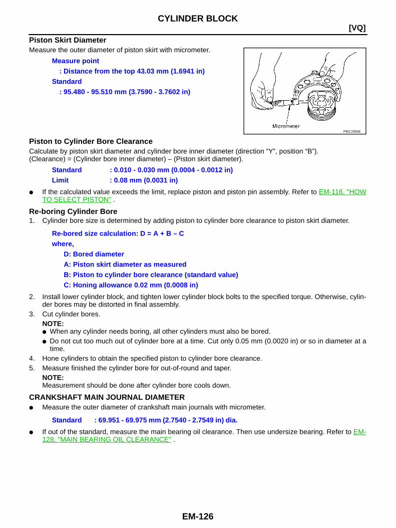
EM-126
[VQ]CYLINDER BLOCK
Piston Skirt DiameterMeasure the outer diameter of piston skirt with micrometer.
Piston to Cylinder Bore ClearanceCalculate by piston skirt diameter and cylinder bore inner diameter (direction “Y”, position “B”).(Clearance) = (Cylinder bore inner diameter) – (Piston skirt diameter).
● If the calculated value exceeds the limit, replace piston and piston pin assembly. Refer to EM-116, "HOWTO SELECT PISTON" .
Re-boring Cylinder Bore1. Cylinder bore size is determined by adding piston to cylinder bore clearance to piston skirt diameter.
2. Install lower cylinder block, and tighten lower cylinder block bolts to the specified torque. Otherwise, cylin-der bores may be distorted in final assembly.
3. Cut cylinder bores.NOTE:● When any cylinder needs boring, all other cylinders must also be bored.● Do not cut too much out of cylinder bore at a time. Cut only 0.05 mm (0.0020 in) or so in diameter at a
time.4. Hone cylinders to obtain the specified piston to cylinder bore clearance.5. Measure finished the cylinder bore for out-of-round and taper.
NOTE:Measurement should be done after cylinder bore cools down.
CRANKSHAFT MAIN JOURNAL DIAMETER● Measure the outer diameter of crankshaft main journals with micrometer.
● If out of the standard, measure the main bearing oil clearance. Then use undersize bearing. Refer to EM-128, "MAIN BEARING OIL CLEARANCE" .
Measure point: Distance from the top 43.03 mm (1.6941 in)
Standard: 95.480 - 95.510 mm (3.7590 - 3.7602 in)
PBIC2956E
Standard : 0.010 - 0.030 mm (0.0004 - 0.0012 in)Limit : 0.08 mm (0.0031 in)
Re-bored size calculation: D = A + B – Cwhere,
D: Bored diameterA: Piston skirt diameter as measuredB: Piston to cylinder bore clearance (standard value)C: Honing allowance 0.02 mm (0.0008 in)
Standard : 69.951 - 69.975 mm (2.7540 - 2.7549 in) dia.

CYLINDER BLOCK
EM-127
[VQ]
C
D
E
F
G
H
I
J
K
L
M
A
EM
CRANKSHAFT PIN JOURNAL DIAMETER● Measure the outer diameter of crankshaft pin journal with
micrometer.
● If out of the standard, measure the connecting rod bearing oilclearance. Then use undersize bearing. Refer to EM-127,"CONNECTING ROD BEARING OIL CLEARANCE" .
CRANKSHAFT OUT-OF-ROUND AND TAPER● Measure the dimensions at four different points as shown in the
figure on each main journal and pin journal with micrometer.● Out-of-round is indicated by the difference in the dimensions
between “X” and “Y” at “A” and “B”.● Taper is indicated by the difference in the dimensions between
“A” and “B” at “X” and “Y”.
● If the measured value exceeds the limit, correct or replace crankshaft.● If corrected, measure the bearing oil clearance of the corrected main journal and/or pin journal. Then
select the main bearing and/or connecting rod bearing. Refer to EM-128, "MAIN BEARING OIL CLEAR-ANCE" and/or EM-127, "CONNECTING ROD BEARING OIL CLEARANCE" .
CRANKSHAFT RUNOUT● Place V-block on precise flat table, and support the journals on
the both end of crankshaft.● Place dial indicator straight up on the No. 3 journal.● While rotating crankshaft, read the movement of the pointer on
dial indicator. (Total indicator reading)
● If it exceeds the limit, replace crankshaft.
CONNECTING ROD BEARING OIL CLEARANCEMethod by Calculation● Install connecting rod bearings to connecting rod and cap, and
tighten connecting rod bolts to the specified torque. Refer toEM-109, "ASSEMBLY" for the tightening procedure.
● Measure the inner diameter of connecting rod bearing withinside micrometer.
(Bearing oil clearance) = (Connecting rod bearing inner diameter) –(Crankshaft pin journal diameter)
Standard : 53.956 - 53.974 mm (2.1242 - 2.1250 in) dia.
PBIC0127E
Limit:Out-of-round (Difference between “X” and “Y”)
: 0.002 mm (0.0001 in)Taper (Difference between “A” and “B”)
: 0.002 mm (0.0001 in)
SBIA0535E
Standard : Less than 0.05 mm (0.0020 in)Limit : 0.10 mm (0.0039 in)
SEM346D
Standard : 0.034 - 0.059 mm (0.0013 - 0.0023 in)(actual clearance)
Limit : 0.070 mm (0.0028 in) PBIC1642E
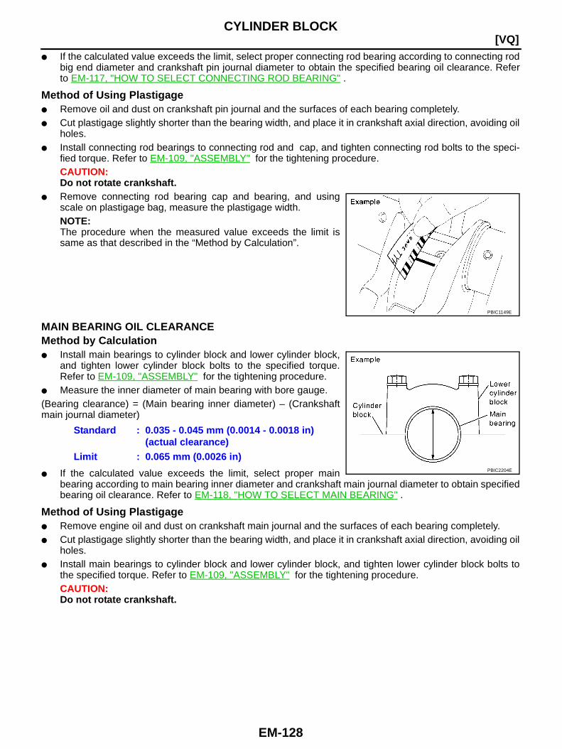
EM-128
[VQ]CYLINDER BLOCK
● If the calculated value exceeds the limit, select proper connecting rod bearing according to connecting rodbig end diameter and crankshaft pin journal diameter to obtain the specified bearing oil clearance. Referto EM-117, "HOW TO SELECT CONNECTING ROD BEARING" .
Method of Using Plastigage● Remove oil and dust on crankshaft pin journal and the surfaces of each bearing completely.● Cut plastigage slightly shorter than the bearing width, and place it in crankshaft axial direction, avoiding oil
holes.● Install connecting rod bearings to connecting rod and cap, and tighten connecting rod bolts to the speci-
fied torque. Refer to EM-109, "ASSEMBLY" for the tightening procedure.CAUTION:Do not rotate crankshaft.
● Remove connecting rod bearing cap and bearing, and usingscale on plastigage bag, measure the plastigage width.NOTE:The procedure when the measured value exceeds the limit issame as that described in the “Method by Calculation”.
MAIN BEARING OIL CLEARANCEMethod by Calculation● Install main bearings to cylinder block and lower cylinder block,
and tighten lower cylinder block bolts to the specified torque.Refer to EM-109, "ASSEMBLY" for the tightening procedure.
● Measure the inner diameter of main bearing with bore gauge.(Bearing clearance) = (Main bearing inner diameter) – (Crankshaftmain journal diameter)
● If the calculated value exceeds the limit, select proper mainbearing according to main bearing inner diameter and crankshaft main journal diameter to obtain specifiedbearing oil clearance. Refer to EM-118, "HOW TO SELECT MAIN BEARING" .
Method of Using Plastigage● Remove engine oil and dust on crankshaft main journal and the surfaces of each bearing completely.● Cut plastigage slightly shorter than the bearing width, and place it in crankshaft axial direction, avoiding oil
holes.● Install main bearings to cylinder block and lower cylinder block, and tighten lower cylinder block bolts to
the specified torque. Refer to EM-109, "ASSEMBLY" for the tightening procedure.CAUTION:Do not rotate crankshaft.
PBIC1149E
Standard : 0.035 - 0.045 mm (0.0014 - 0.0018 in)(actual clearance)
Limit : 0.065 mm (0.0026 in)PBIC2204E
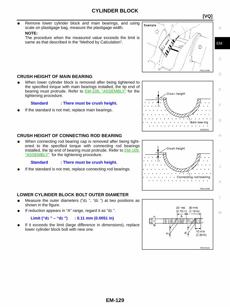
CYLINDER BLOCK
EM-129
[VQ]
C
D
E
F
G
H
I
J
K
L
M
A
EM
● Remove lower cylinder block and main bearings, and usingscale on plastigage bag, measure the plastigage width.NOTE:The procedure when the measured value exceeds the limit issame as that described in the “Method by Calculation”.
CRUSH HEIGHT OF MAIN BEARING● When lower cylinder block is removed after being tightened to
the specified torque with main bearings installed, the tip end ofbearing must protrude. Refer to EM-109, "ASSEMBLY" for thetightening procedure.
● If the standard is not met, replace main bearings.
CRUSH HEIGHT OF CONNECTING ROD BEARING● When connecting rod bearing cap is removed after being tight-
ened to the specified torque with connecting rod bearingsinstalled, the tip end of bearing must protrude. Refer to EM-109,"ASSEMBLY" for the tightening procedure.
● If the standard is not met, replace connecting rod bearings.
LOWER CYLINDER BLOCK BOLT OUTER DIAMETER● Measure the outer diameters (“d1 ”, “d2 ”) at two positions as
shown in the figure.● If reduction appears in “A” range, regard it as “d2 ”.
● If it exceeds the limit (large difference in dimensions), replacelower cylinder block bolt with new one.
PBIC1149E
Standard : There must be crush height.
SEM502G
Standard : There must be crush height.
PBIC1646E
Limit (“d 1 ” – “d 2 ”) : 0.11 mm (0.0051 in)
PBIC0911E
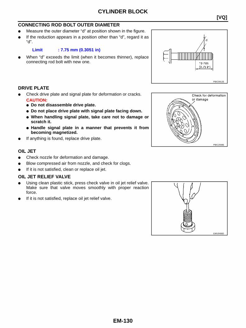
EM-130
[VQ]CYLINDER BLOCK
CONNECTING ROD BOLT OUTER DIAMETER● Measure the outer diameter “d” at position shown in the figure.● If the reduction appears in a position other than “d”, regard it as
“d”.
● When “d” exceeds the limit (when it becomes thinner), replaceconnecting rod bolt with new one.
DRIVE PLATE● Check drive plate and signal plate for deformation or cracks.
CAUTION:● Do not disassemble drive plate.● Do not place drive plate with signal plate facing down.● When handling signal plate, take care not to damage or
scratch it.● Handle signal plate in a manner that prevents it from
becoming magnetized.● If anything is found, replace drive plate.
OIL JET● Check nozzle for deformation and damage.● Blow compressed air from nozzle, and check for clogs.● If it is not satisfied, clean or replace oil jet.
OIL JET RELIEF VALVE● Using clean plastic stick, press check valve in oil jet relief valve.
Make sure that valve moves smoothly with proper reactionforce.
● If it is not satisfied, replace oil jet relief valve.
Limit : 7.75 mm (0.3051 in)
PBIC0912E
PBIC2938E
EMU0468D
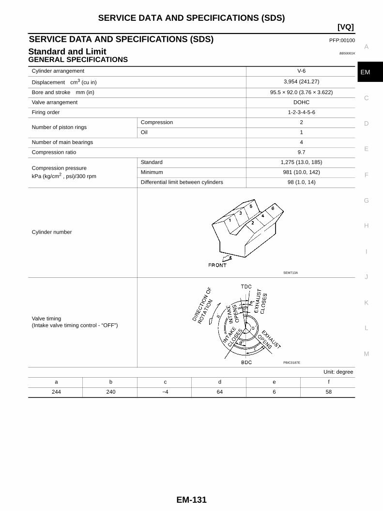
SERVICE DATA AND SPECIFICATIONS (SDS)
EM-131
[VQ]
C
D
E
F
G
H
I
J
K
L
M
A
EM
SERVICE DATA AND SPECIFICATIONS (SDS) PFP:00100
Standard and Limit BBS0001K
GENERAL SPECIFICATIONSCylinder arrangement V-6
Displacement cm3 (cu in) 3,954 (241.27)
Bore and stroke mm (in) 95.5 × 92.0 (3.76 × 3.622)
Valve arrangement DOHC
Firing order 1-2-3-4-5-6
Number of piston ringsCompression 2
Oil 1
Number of main bearings 4
Compression ratio 9.7
Compression pressure
kPa (kg/cm2 , psi)/300 rpm
Standard 1,275 (13.0, 185)
Minimum 981 (10.0, 142)
Differential limit between cylinders 98 (1.0, 14)
Cylinder number
Valve timing(Intake valve timing control - “OFF”)
Unit: degree
a b c d e f
244 240 −4 64 6 58
SEM713A
PBIC0187E

EM-132
[VQ]SERVICE DATA AND SPECIFICATIONS (SDS)
DRIVE BELT
INTAKE MANIFOLD COLLECTOR, INTAKE MANIFOLD AND EXHAUST MANIFOLDUnit: mm (in)
SPARK PLUG
Tension of drive belts Auto adjustment by auto tensioner
Items Limit
Surface distortionIntake manifold 0.1 (0.004)
Exhaust manifold 0.3 (0.012)
Make NGK
Standard type PLFR5A-11
Hot type PLFR4A-11
Cold type PLFR6A-11
Gap (nominal) 1.1 mm (0.043 in)
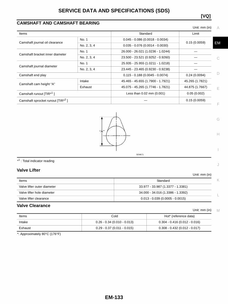
SERVICE DATA AND SPECIFICATIONS (SDS)
EM-133
[VQ]
C
D
E
F
G
H
I
J
K
L
M
A
EM
CAMSHAFT AND CAMSHAFT BEARINGUnit: mm (in)
*1 : Total indicator reading
Valve LifterUnit: mm (in)
Valve ClearanceUnit: mm (in)
*: Approximately 80°C (176°F)
Items Standard Limit
Camshaft journal oil clearanceNo. 1 0.045 - 0.086 (0.0018 - 0.0034)
0.15 (0.0059)No. 2, 3, 4 0.035 - 0.076 (0.0014 - 0.0030)
Camshaft bracket inner diameterNo. 1 26.000 - 26.021 (1.0236 - 1.0244) —
No. 2, 3, 4 23.500 - 23.521 (0.9252 - 0.9260) —
Camshaft journal diameterNo. 1 25.935 - 25.955 (1.0211 - 1.0218) —
No. 2, 3, 4 23.445 - 23.465 (0.9230 - 0.9238) —
Camshaft end play 0.115 - 0.188 (0.0045 - 0.0074) 0.24 (0.0094)
Camshaft cam height “A”Intake 45.465 - 45.655 (1.7900 - 1.7921) 45.265 (1.7821)
Exhaust 45.075 - 45.265 (1.7746 - 1.7821) 44.875 (1.7667)
Camshaft runout [TIR*1 ] Less than 0.02 mm (0.001) 0.05 (0.002)
Camshaft sprocket runout [TIR*2 ] — 0.15 (0.0059)
SEM671
Items Standard
Valve lifter outer diameter 33.977 - 33.987 (1.3377 - 1.3381)
Valve lifter hole diameter 34.000 - 34.016 (1.3386 - 1.3392)
Valve lifter clearance 0.013 - 0.039 (0.0005 - 0.0015)
Items Cold Hot* (reference data)
Intake 0.26 - 0.34 (0.010 - 0.013) 0.304 - 0.416 (0.012 - 0.016)
Exhaust 0.29 - 0.37 (0.011 - 0.015) 0.308 - 0.432 (0.012 - 0.017)
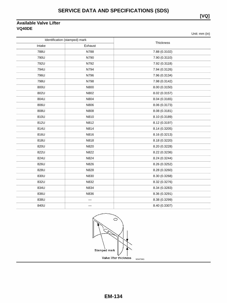
EM-134
[VQ]SERVICE DATA AND SPECIFICATIONS (SDS)
Available Valve LifterVQ40DE
Unit: mm (in)
Identification (stamped) markThickness
Intake Exhaust
788U N788 7.88 (0.3102)
790U N790 7.90 (0.3110)
792U N792 7.92 (0.3118)
794U N794 7.94 (0.3126)
796U N796 7.96 (0.3134)
798U N798 7.98 (0.3142)
800U N800 8.00 (0.3150)
802U N802 8.02 (0.3157)
804U N804 8.04 (0.3165)
806U N806 8.06 (0.3173)
808U N808 8.08 (0.3181)
810U N810 8.10 (0.3189)
812U N812 8.12 (0.3197)
814U N814 8.14 (0.3205)
816U N816 8.16 (0.3213)
818U N818 8.18 (0.3220)
820U N820 8.20 (0.3228)
822U N822 8.22 (0.3236)
824U N824 8.24 (0.3244)
826U N826 8.26 (0.3252)
828U N828 8.28 (0.3260)
830U N830 8.30 (0.3268)
832U N832 8.32 (0.3276)
834U N834 8.34 (0.3283)
836U N836 8.36 (0.3291)
838U — 8.38 (0.3299)
840U — 8.40 (0.3307)
SEM758G
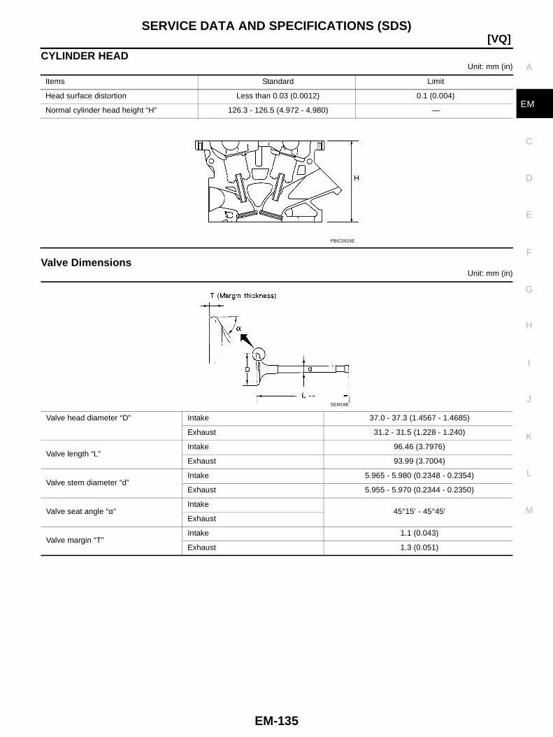
SERVICE DATA AND SPECIFICATIONS (SDS)
EM-135
[VQ]
C
D
E
F
G
H
I
J
K
L
M
A
EM
CYLINDER HEADUnit: mm (in)
Valve DimensionsUnit: mm (in)
Items Standard Limit
Head surface distortion Less than 0.03 (0.0012) 0.1 (0.004)
Normal cylinder head height “H” 126.3 - 126.5 (4.972 - 4.980) —
PBIC0924E
Valve head diameter “D” Intake 37.0 - 37.3 (1.4567 - 1.4685)
Exhaust 31.2 - 31.5 (1.228 - 1.240)
Valve length “L”Intake 96.46 (3.7976)
Exhaust 93.99 (3.7004)
Valve stem diameter “d”Intake 5.965 - 5.980 (0.2348 - 0.2354)
Exhaust 5.955 - 5.970 (0.2344 - 0.2350)
Valve seat angle “α”Intake
45°15′ - 45°45′Exhaust
Valve margin “T”Intake 1.1 (0.043)
Exhaust 1.3 (0.051)
SEM188
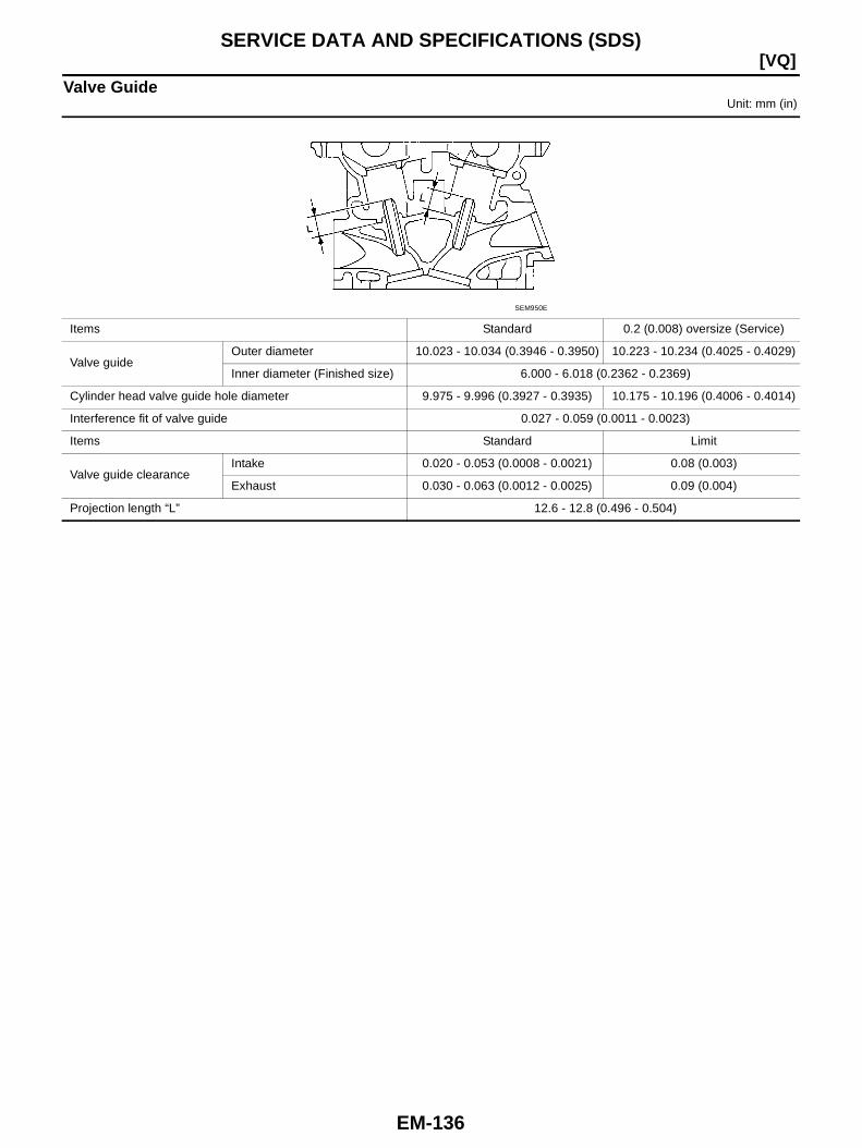
EM-136
[VQ]SERVICE DATA AND SPECIFICATIONS (SDS)
Valve GuideUnit: mm (in)
Items Standard 0.2 (0.008) oversize (Service)
Valve guideOuter diameter 10.023 - 10.034 (0.3946 - 0.3950) 10.223 - 10.234 (0.4025 - 0.4029)
Inner diameter (Finished size) 6.000 - 6.018 (0.2362 - 0.2369)
Cylinder head valve guide hole diameter 9.975 - 9.996 (0.3927 - 0.3935) 10.175 - 10.196 (0.4006 - 0.4014)
Interference fit of valve guide 0.027 - 0.059 (0.0011 - 0.0023)
Items Standard Limit
Valve guide clearanceIntake 0.020 - 0.053 (0.0008 - 0.0021) 0.08 (0.003)
Exhaust 0.030 - 0.063 (0.0012 - 0.0025) 0.09 (0.004)
Projection length “L” 12.6 - 12.8 (0.496 - 0.504)
SEM950E
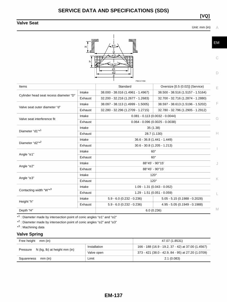
SERVICE DATA AND SPECIFICATIONS (SDS)
EM-137
[VQ]
C
D
E
F
G
H
I
J
K
L
M
A
EM
Valve SeatUnit: mm (in)
*1 : Diameter made by intersection point of conic angles “α1” and “α2”
*2 : Diameter made by intersection point of conic angles “α2” and “α3”
*3 : Machining data
Valve Spring
Items Standard Oversize [0.5 (0.02)] (Service)
Cylinder head seat recess diameter “D”Intake 38.000 - 38.016 (1.4961 - 1.4967) 38.500 - 38.516 (1.5157 - 1.5164)
Exhaust 32.200 - 32.216 (1.2677 - 1.2683) 32.700 - 32.716 (1.2874 - 1.2880)
Valve seat outer diameter “d”Intake 38.097 - 38.113 (1.4999 - 1.5005) 38.597 - 38.613 (1.5196 - 1.5202)
Exhaust 32.280 - 32.296 (1.2709 - 1.2715) 32.780 - 32.796 (1.2905 - 1.2912)
Valve seat interference fitIntake 0.081 - 0.113 (0.0032 - 0.0044)
Exhaust 0.064 - 0.096 (0.0025 - 0.0038)
Diameter “d1”*1Intake 35 (1.38)
Exhaust 28.7 (1.130)
Diameter “d2”*2Intake 36.6 - 36.8 (1.441 - 1.449)
Exhaust 30.6 - 30.8 (1.205 - 1.213)
Angle “α1”Intake 60°
Exhaust 60°
Angle “α2”Intake 88°45′ - 90°15′
Exhaust 88°45′ - 90°15′
Angle “α3”Intake 120°
Exhaust 120°
Contacting width “W”*3Intake 1.09 - 1.31 (0.043 - 0.052)
Exhaust 1.29 - 1.51 (0.051 - 0.059)
Height “h”Intake 5.9 - 6.0 (0.232 - 0.236) 5.05 - 5.15 (0.1988 - 0.2028)
Exhaust 5.9 - 6.0 (0.232 - 0.236) 4.95 - 5.05 (0.1949 - 0.1988)
Depth “H” 6.0 (0.236)
PBIC2745E
Free height mm (in) 47.07 (1.8531)
Pressure N (kg, lb) at height mm (in)Installation 166 - 188 (16.9 - 19.2, 37 - 42) at 37.00 (1.4567)
Valve open 373 - 421 (38.0 - 42.9, 84 - 95) at 27.20 (1.0709)
Squareness mm (in) Limit 2.1 (0.083)

EM-138
[VQ]SERVICE DATA AND SPECIFICATIONS (SDS)
CYLINDER BLOCKUnit: mm (in)
Surface flatnessStandard Less than 0.03 (0.0012)
Limit 0.1 (0.004)
Main bearing housing inner diameter Standard 74.993 - 75.017 (2.9525 - 2.9534)
Cylinder bore Inner diameter Standard
Grade No. 1 95.500 - 95.510 (3.7598 - 3.7602)
Grade No. 2 95.510 - 95.520 (3.7602 - 3.7606)
Grade No. 3 95.520 - 95.530 (3.7606 - 3.7610)
Out-of-round (Difference between “X” and “Y”)Limit
0.015 (0.0006)
Taper (Difference between “A” and “C”) 0.01 (0.0004)
Main bearing housing inner diameter (Without bearing)
Grade No. AGrade No. BGrade No. CGrade No. DGrade No. EGrade No. FGrade No. GGrade No. HGrade No. JGrade No. KGrade No. LGrade No. MGrade No. NGrade No. PGrade No. RGrade No. SGrade No. TGrade No. UGrade No. VGrade No. WGrade No. XGrade No. YGrade No. 4Grade No. 7
74.993 - 74.994 (2.9525 - 2.9525)74.994 - 74.995 (2.9525 - 2.9526)74.995 - 74.996 (2.9526 - 2.9526)74.996 - 74.997 (2.9526 - 2.9526)74.997 - 74.998 (2.9526 - 2.9527)74.998 - 74.999 (2.9527 - 2.9527)74.999 - 75.000 (2.9527 - 2.9528)75.000 - 75.001 (2.9528 - 2.9528)75.001 - 75.002 (2.9528 - 2.9528)75.002 - 75.003 (2.9528 - 2.9529)75.003 - 75.004 (2.9529 - 2.9529)75.004 - 75.005 (2.9529 - 2.9529)75.005 - 75.006 (2.9529 - 2.9530)75.006 - 75.007 (2.9530 - 2.9530)75.007 - 75.008 (2.9530 - 2.9531)75.008 - 75.009 (2.9530 - 2.9531)75.009 - 75.010 (2.9531 - 2.9531)75.010 - 75.011 (2.9531 - 2.9532)75.011 - 75.012 (2.9532 - 2.9532)75.012 - 75.013 (2.9532 - 2.9533)75.013 - 75.014 (2.9533 - 2.9533)75.014 - 75.015 (2.9533 - 2.9533)75.015 - 75.016 (2.9533 - 2.9534)75.016 - 75.017 (2.9534 - 2.9534)
Difference in inner diameter between cylinders Standard Less than 0.03 (0.0012)
PBIC2955E

SERVICE DATA AND SPECIFICATIONS (SDS)
EM-139
[VQ]
C
D
E
F
G
H
I
J
K
L
M
A
EM
PISTON, PISTON RING AND PISTON PINAvailable Piston
Unit: mm (in)
Piston RingUnit: mm (in)
Piston PinUnit: mm (in)
Items Standard 0.20 (0.0079) oversize
Piston skirt diameter “A”
Grade No. 1 95.480 - 95.490 (3.7590 - 3.7594) —
Grade No. 2 95.490 - 95.500 (3.7594 - 3.7598) —
Grade No. 3 95.500 - 95.510 (3.7598 - 3.7602) —
Service — 95.680 - 95.710 (3.7669 - 3.7681)
Items Standard Limit
“a” dimension 43.03 (1.6941) —
Piston pin hole diameterGrade No. 0 21.993 - 21.999 (0.8659 - 0.8661) —
Grade No. 1 21.999 - 22.005 (0.8661 - 0.8663) —
Piston to cylinder bore clearance 0.010 - 0.030 (0.0004 - 0.0012) 0.08 (0.0031)
SEM882E
Items Standard Limit
Side clearance
Top 0.045 - 0.080 (0.0018 - 0.0031) 0.11 (0.0043)
2nd 0.030 - 0.070 (0.0012 - 0.0028) 0.10 (0.0039)
Oil ring 0.065 - 0.135 (0.0026 - 0.0053) —
End gap
Top 0.23 - 0.33 (0.0091 - 0.0130) 0.56 (0.0220)
2nd 0.33 - 0.48 (0.0130 - 0.0189) 0.68 (0.0268)
Oil (rail ring) 0.20 - 0.50 (0.0079 - 0.0197) 0.85 (0.0335)
Items Standard Limit
Piston pin outer diameterGrade No. 0 21.989 - 21.995 (0.8657 - 0.8659) —
Grade No. 1 21.995 - 22.001 (0.8659 - 0.8662) —
Piston to piston pin oil clearance 0.002 - 0.006 (0.0001 - 0.0002) —
Connecting rod bushing oil clearance 0.005 - 0.017 (0.0002 - 0.0007) 0.030 (0.0012)
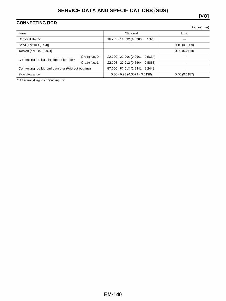
EM-140
[VQ]SERVICE DATA AND SPECIFICATIONS (SDS)
CONNECTING RODUnit: mm (in)
*: After installing in connecting rod
Items Standard Limit
Center distance 165.82 - 165.92 (6.5283 - 6.5323) —
Bend [per 100 (3.94)] — 0.15 (0.0059)
Torsion [per 100 (3.94)] — 0.30 (0.0118)
Connecting rod bushing inner diameter*Grade No. 0 22.000 - 22.006 (0.8661 - 0.8664) —
Grade No. 1 22.006 - 22.012 (0.8664 - 0.8666) —
Connecting rod big end diameter (Without bearing) 57.000 - 57.013 (2.2441 - 2.2446) —
Side clearance 0.20 - 0.35 (0.0079 - 0.0138) 0.40 (0.0157)

SERVICE DATA AND SPECIFICATIONS (SDS)
EM-141
[VQ]
C
D
E
F
G
H
I
J
K
L
M
A
EM
CRANKSHAFTUnit: mm (in)
*: Total indicator reading
Main journal diameter. “Dm” grade Standard
Grade No. AGrade No. BGrade No. CGrade No. DGrade No. EGrade No. FGrade No. GGrade No. HGrade No. JGrade No. KGrade No. LGrade No. MGrade No. NGrade No. PGrade No. RGrade No. SGrade No. TGrade No. UGrade No. VGrade No. WGrade No. XGrade No. YGrade No. 4Grade No. 7
69.975 - 69.974 (2.7549 - 2.7549)69.974 - 69.973 (2.7549 - 2.7548)69.973 - 69.972 (2.7548 - 2.7548)69.972 - 69.971 (2.7548 - 2.7548)69.971 - 69.970 (2.7548 - 2.7547)69.970 - 69.969 (2.7547 - 2.7547)69.969 - 69.968 (2.7547 - 2.7546)69.968 - 69.967 (2.7546 - 2.7546)69.967 - 69.966 (2.7546 - 2.7546)69.966 - 69.965 (2.7546 - 2.7545)69.965 - 69.964 (2.7545 - 2.7545)69.964 - 69.963 (2.7545 - 2.7544)69.963 - 69.962 (2.7544 - 2.7544)69.962 - 69.961 (2.7544 - 2.7544)69.961 - 69.960 (2.7544 - 2.7543)69.960 - 69.959 (2.7543 - 2.7543)69.959 - 69.958 (2.7543 - 2.7542)69.958 - 69.957 (2.7542 - 2.7542)69.957 - 69.956 (2.7542 - 2.7542)69.956 - 69.955 (2.7542 - 2.7541)69.955 - 69.954 (2.7541 - 2.7541)69.954 - 69.953 (2.7541 - 2.7540)69.953 - 69.952 (2.7540 - 2.7540)69.952 - 69.951 (2.7540 - 2.7540)
Pin journal diameter. “Dp” Standard
Grade No. 0 53.968 - 53.974 (2.1247 - 2.1250)
Grade No. 1 53.962 - 53.968 (2.1245 - 2.1247)
Grade No. 2 53.956 - 53.962 (2.1242 - 2.1245)
Center distance “r” 45.96 - 46.04 (1.8094 - 1.8126)
Taper (Difference between “A” and “B”)Limit
0.002 (0.0001)
Out-of-round (Difference between “X” and “Y”) 0.002 (0.0001)
Crankshaft runout [TIR*]Standard Less than 0.05 (0.002)
Limit 0.10 (0.0039)
Crankshaft end playStandard 0.14 - 0.22 (0.0055 - 0.0087)
Limit 0.30 (0.0118)
SEM645 SBIA0535E

EM-142
[VQ]SERVICE DATA AND SPECIFICATIONS (SDS)
MAIN BEARING
UndersizeUnit: mm (in)
Main Bearing Oil ClearanceUnit: mm (in)
*: Actual clearance
Grade number UPR/LWR Thickness mm (in) Width mm (in) Identification color Remarks
0 — 2.500 - 2.503 (0.0984 - 0.0985)
19.9 - 20.1(0.783 - 0.791)
Black
Grade is the samefor upper and lowerbearings.
1 — 2.503 - 2.506 (0.0985 - 0.0987) Brown
2 — 2.506 - 2.509 (0.0987 - 0.0988) Green
3 — 2.509 - 2.512 (0.0988 - 0.0989) Yellow
4 — 2.512 - 2.515 (0.0989 - 0.0990) Blue
5 — 2.515 - 2.518 (0.0990 - 0.0991) Pink
6 — 2.518 - 2.521 (0.0991 - 0.0993) Purple
7 — 2.521 - 2.524 (0.0993 - 0.0994) White
01UPR 2.503 - 2.506 (0.0985 - 0.0987) Brown
Grade is differentfor upper and lowerbearings.
LWR 2.500 - 2.503 (0.0984 - 0.0985) Black
12UPR 2.506 - 2.509 (0.0987 - 0.0988) Green
LWR 2.503 - 2.506 (0.0985 - 0.0987) Brown
23UPR 2.509 - 2.512 (0.0988 - 0.0989) Yellow
LWR 2.506 - 2.509 (0.0987 - 0.0988) Green
34UPR 2.512 - 2.515 (0.0989 - 0.0990) Blue
LWR 2.509 - 2.512 (0.0988 - 0.0989) Yellow
45UPR 2.515 - 2.518 (0.0990 - 0.0991) Pink
LWR 2.512 - 2.515 (0.0989 - 0.0990) Blue
56UPR 2.518 - 2.521 (0.0991 - 0.0993) Purple
LWR 2.515 - 2.518 (0.0990 - 0.0991) Pink
67UPR 2.521 - 2.524 (0.0993 - 0.0994) White
LWR 2.518 - 2.521 (0.0991 - 0.0993) Purple
PBIC2969E
Items Thickness Main journal diameter
0.25 (0.0098) 2.633 - 2.641 (0.1037 - 0.1040) Grind so that bearing clearance is the specified value.
Items Standard Limit
Main bearing oil clearance 0.035 - 0.045 (0.0014 - 0.0018)* 0.065 (0.0026)
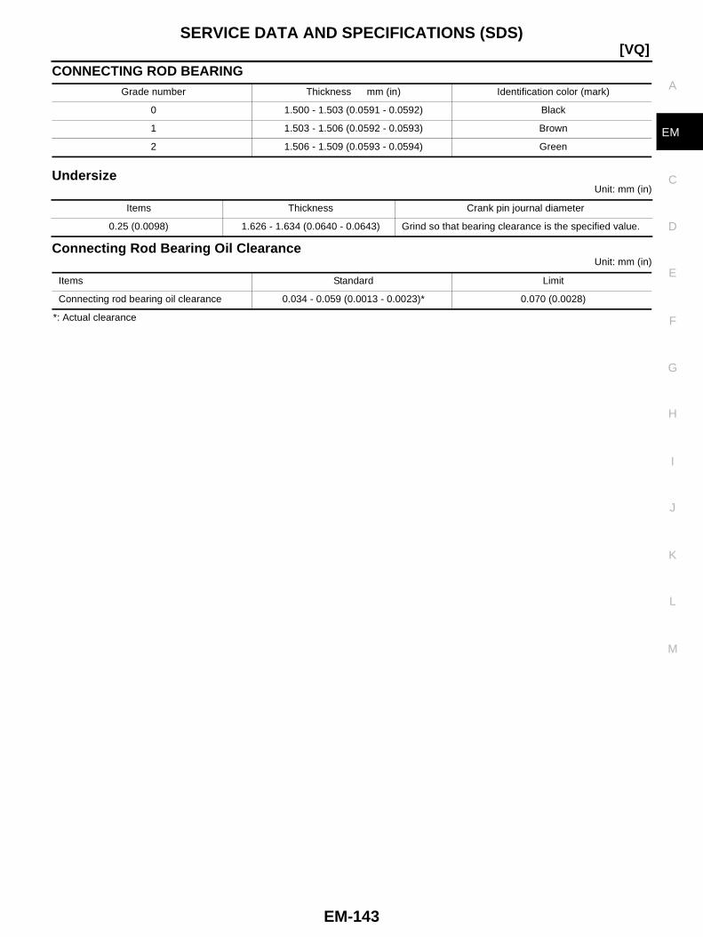
SERVICE DATA AND SPECIFICATIONS (SDS)
EM-143
[VQ]
C
D
E
F
G
H
I
J
K
L
M
A
EM
CONNECTING ROD BEARING
UndersizeUnit: mm (in)
Connecting Rod Bearing Oil ClearanceUnit: mm (in)
*: Actual clearance
Grade number Thickness mm (in) Identification color (mark)
0 1.500 - 1.503 (0.0591 - 0.0592) Black
1 1.503 - 1.506 (0.0592 - 0.0593) Brown
2 1.506 - 1.509 (0.0593 - 0.0594) Green
Items Thickness Crank pin journal diameter
0.25 (0.0098) 1.626 - 1.634 (0.0640 - 0.0643) Grind so that bearing clearance is the specified value.
Items Standard Limit
Connecting rod bearing oil clearance 0.034 - 0.059 (0.0013 - 0.0023)* 0.070 (0.0028)

EM-144
[YD]PRECAUTIONS
[YD]PRECAUTIONS PFP:00001
Precautions for Draining Engine Coolant BBS0001L
Drain engine coolant when engine is cooled.
Precautions for Disconnecting Fuel Piping BBS0001M
● Before starting work, make sure no fire or spark producing items are in the work area.● After disconnecting pipes, plug openings to stop fuel leakage.
Precautions for Removal and Disassembly BBS0001N
● When instructed to use special service tools, use the specified tools. Always be careful to work safely,avoid forceful or uninstructed operations.
● Exercise maximum care to avoid damage to mating or sliding surfaces.● Cover openings of engine system with tape or the equivalent, if necessary, to seal out foreign materials.● Mark and arrange disassembly parts in an organized way for easy troubleshooting and re-assembly.● When loosening nuts and bolts, as a basic rule, start with the one furthest outside, then the one diagonally
opposite, and so on. If the order of loosening is specified, do exactly as specified.
Precautions for Inspection, Repair and Replacement BBS0001O
Before repairing or replacing, thoroughly inspect parts. Inspect new replacement parts in the same way, andreplace if necessary.
Precautions for Assembly and Installation BBS0001P
● Use torque wrench to tighten bolts or nuts to specification.● When tightening nuts and bolts, as a basic rule, equally tighten in several different steps starting with the
ones in center, then ones on inside and outside diagonally in this order. If the order of tightening is speci-fied, do exactly as specified.
● Replace with new liquid gasket, packing, oil seal or O-ring.● Dowel pins are used for several parts alignment. When replacing and reassembling parts with dowel pins,
make sure that dowel pins are installed in the original position.● Thoroughly wash, clean, and air-blow each part. Carefully check engine oil or engine coolant passages for
any restriction and blockage.● Avoid damaging sliding or mating surfaces. Completely remove foreign materials such as cloth lint or dust.
Before assembly, engine oil sliding surfaces well.● Release air within route when refilling after draining engine coolant.● After repairing, start engine and increase engine speed to check engine coolant, fuel, engine oil, and
exhaust systems for leakage.
Parts Requiring Angle Tightening BBS0001Q
● Use an angle wrench [SST: KV10112100] for the final tightening of the following engine parts:– Cylinder head bolts– Main bearing cap bolts– Connecting rod cap nuts– Crankshaft pulley bolt (No angle wrench is required as the bolt flange is provided with notches for angle
tightening)● Do not use a torque value for final tightening.● The torque value for these parts are for a preliminary step.● Ensure thread and seat surfaces are clean and coated with engine oil.
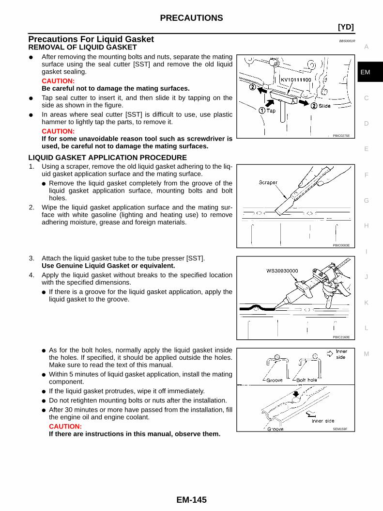
PRECAUTIONS
EM-145
[YD]
C
D
E
F
G
H
I
J
K
L
M
A
EM
Precautions For Liquid Gasket BBS0001R
REMOVAL OF LIQUID GASKET● After removing the mounting bolts and nuts, separate the mating
surface using the seal cutter [SST] and remove the old liquidgasket sealing.CAUTION:Be careful not to damage the mating surfaces.
● Tap seal cutter to insert it, and then slide it by tapping on theside as shown in the figure.
● In areas where seal cutter [SST] is difficult to use, use plastichammer to lightly tap the parts, to remove it.CAUTION:If for some unavoidable reason tool such as screwdriver isused, be careful not to damage the mating surfaces.
LIQUID GASKET APPLICATION PROCEDURE1. Using a scraper, remove the old liquid gasket adhering to the liq-
uid gasket application surface and the mating surface.● Remove the liquid gasket completely from the groove of the
liquid gasket application surface, mounting bolts and boltholes.
2. Wipe the liquid gasket application surface and the mating sur-face with white gasoline (lighting and heating use) to removeadhering moisture, grease and foreign materials.
3. Attach the liquid gasket tube to the tube presser [SST].Use Genuine Liquid Gasket or equivalent.
4. Apply the liquid gasket without breaks to the specified locationwith the specified dimensions.● If there is a groove for the liquid gasket application, apply the
liquid gasket to the groove.
● As for the bolt holes, normally apply the liquid gasket insidethe holes. If specified, it should be applied outside the holes.Make sure to read the text of this manual.
● Within 5 minutes of liquid gasket application, install the matingcomponent.
● If the liquid gasket protrudes, wipe it off immediately.● Do not retighten mounting bolts or nuts after the installation.● After 30 minutes or more have passed from the installation, fill
the engine oil and engine coolant.CAUTION:If there are instructions in this manual, observe them.
PBIC0275E
PBIC0003E
PBIC2160E
SEM159F
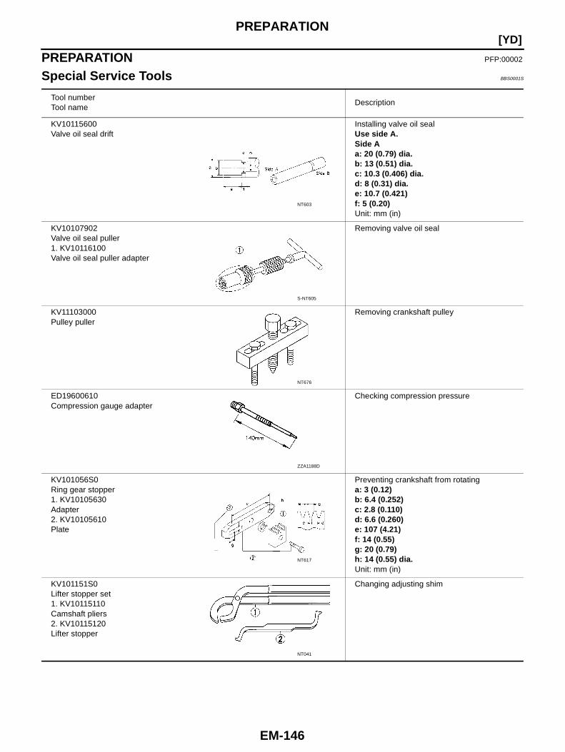
EM-146
[YD]PREPARATION
PREPARATION PFP:00002
Special Service Tools BBS0001S
Tool numberTool name
Description
KV10115600Valve oil seal drift
Installing valve oil sealUse side A.Side Aa: 20 (0.79) dia.b: 13 (0.51) dia.c: 10.3 (0.406) dia.d: 8 (0.31) dia.e: 10.7 (0.421)f: 5 (0.20)Unit: mm (in)
KV10107902Valve oil seal puller1. KV10116100Valve oil seal puller adapter
Removing valve oil seal
KV11103000Pulley puller
Removing crankshaft pulley
ED19600610Compression gauge adapter
Checking compression pressure
KV101056S0Ring gear stopper1. KV10105630Adapter2. KV10105610Plate
Preventing crankshaft from rotatinga: 3 (0.12)b: 6.4 (0.252)c: 2.8 (0.110)d: 6.6 (0.260)e: 107 (4.21)f: 14 (0.55)g: 20 (0.79)h: 14 (0.55) dia.Unit: mm (in)
KV101151S0Lifter stopper set1. KV10115110Camshaft pliers2. KV10115120Lifter stopper
Changing adjusting shim
NT603
S-NT605
NT676
ZZA1188D
NT617
NT041

PREPARATION
EM-147
[YD]
C
D
E
F
G
H
I
J
K
L
M
A
EM
KV10116200Valve spring compressor1. KV10115900Attachment2. KV10109220Adapter
Disassembling and assembling valvemechanismPart (1) is a component of KV10116200, butPart (2) is not so.
ST16610001Pilot bushing puller
Removing crankshaft pilot bush
KV10111100Seal cutter
Removing oil pan upper, oil pan lower andrear chain case, etc.
WS39930000Tube presser
Pressing the tube of liquid gasket
KV10112100Angle wrench
Tightening bolts for bearing cap, cylinderhead, etc.
EM03470000Piston ring compressor
Installing piston assembly into cylinder bore
KV11106010Hexagon wrench
Removing and installing chain tensionera: 5 mm (0.20 in) (Face to face)b: 20 mm (0.79 in)
Tool numberTool name
Description
PBIC1650E
NT045
NT046
NT052
NT014
NT044
NT801

EM-148
[YD]PREPARATION
Commercial Service Tools BBS0001T
KV11106020Hexagon wrench
Removing and installing slack guidea: 6 mm (0.24 in) (Face to face)b: 20 mm (0.79 in)
KV11106030Positioning stopper pin
Fixing fuel pump sprocketa: 6 mm (0.24 in) dia.b: 80 mm (3.15 in)
KV11106040TORX wrench
Removing and installing fuel pump sprocketnuta: T70b: 26 mm (1.02 in)
KV11106050Hexagonal wrench
Removing and installing fuel pump sprocketa: 6 mm (0.24 in) (Face to face)b: 42 mm (1.65 in)
KV11106060Sprocket holder
Holding fuel pump sprocket
Tool numberTool name
Description
NT803
NT804
NT805
SBIA0224E
SBIA0225E
Tool name Description
Valve seat cutter set Finishing valve seat dimensions
Piston ring expander Removing and installing piston ring
NT048
NT030

PREPARATION
EM-149
[YD]
C
D
E
F
G
H
I
J
K
L
M
A
EM
Valve guide reamer Reaming valve guide with (1) or hole foroversize valve guide with (2)Intake and Exhaust:d1 = 6.0 mm (0.236 in) dia.d2 = 10.2 mm (0.402 in) dia.
Valve guide drift Removing and installing valve guideIntake and Exhaust:a = 9.5 mm (0.374 in) dia.b = 5.5 mm (0.217 in) dia.
TORX socket Loosening and tightening fuel pump mountingboltSize: E10
Torx socket Loosening and tightening flywheel mountingboltSize: T55
Cylinder head bolt wrench Loosening and tightening cylinder head bolt,and used with angle wrench [SST:KV10112100]a: 13 (0.51) dia.b: 12 (0.47)c: 10 (0.39)Unit: mm (in)
TORX socket Loosening and tightening drive platemounting boltSize: E20
TORX socket Loosening and tightening main bearing capboltSize: E14
Tool name Description
NT016
NT015
NT807
PBIC1113E
NT583
NT807
NT807
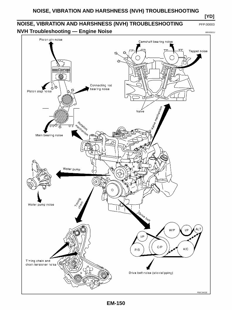
EM-150
[YD]NOISE, VIBRATION AND HARSHNESS (NVH) TROUBLESHOOTING
NOISE, VIBRATION AND HARSHNESS (NVH) TROUBLESHOOTING PFP:00003
NVH Troubleshooting — Engine Noise BBS0001U
PBIC3402E

NOISE, VIBRATION AND HARSHNESS (NVH) TROUBLESHOOTING
EM-151
[YD]
C
D
E
F
G
H
I
J
K
L
M
A
EM
Use the Chart Below to Help You Find the Cause of the Symptom. BBS0001V
1. Locate the area where noise occurs.2. Confirm the type of noise.3. Specify the operating condition of engine.4. Check specified noise source.If necessary, repair or replace these parts.
A: Closely related B: Related C: Sometimes related —: Not related
Locationof noise
Type ofnoise
Operating condition of engine
Source ofnoise
Check itemRefer-
ence pageBeforewarm-
up
Afterwarm-
up
Whenstart-ing
Whenidling
Whenracing
Whiledriving
Top ofengineRockercoverCylinderhead
Ticking orclicking
C A — A B —Tappetnoise
Valve clearance EM-204
Rattle C A — A B CCamshaftbearingnoise
Camshaft oil clearanceCamshaft runout
EM-199EM-199
Crank-shaft pul-leyCylinderblock(Side ofengine)Oil pan
Slap orknock
— A — B B —Piston pinnoise
Piston to piston pinclearanceConnecting rod bush-ing oil clearance
EM-263EM-265
Slap orrap
A — — B B APistonslap noise
Piston to cylinder boreclearancePiston ring side clear-ancePiston ring end gapConnecting rod bendand torsion
EM-267EM-264EM-264EM-265
Knock A B C B B B
Connect-ing rodbearingnoise
Connecting rod bush-ing oil clearanceConnecting rod bear-ing oil clearance (Bigend)
EM-265EM-269
Knock A B — A B CMainbearingnoise
Main bearing oil clear-anceCrankshaft runout
EM-270EM-269
Front ofengineTimingchaincase
Tapping orticking
A A — B B B
Timingchain andchain ten-sionernoise
Timing chain cracksand wearTiming chain tensioneroperation
EM-213EM-222EM-217
Front ofengine
Squeak-ing or fizz-ing
A B — B — C
Drive belts(Stickingor slip-ping)
Drive belts deflection
EM-152
Creaking A B A B A BDrive belts(Slipping)
Idler pulley bearingoperation
SquallCreak
A B — B A BWaterpumpnoise
Water pump operationCO-50,"WATERPUMP"
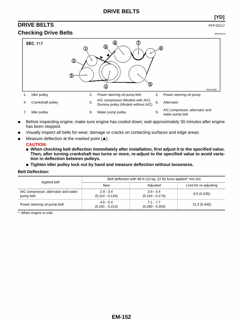
EM-152
[YD]DRIVE BELTS
DRIVE BELTS PFP:02117
Checking Drive Belts BBS0001W
● Before inspecting engine, make sure engine has cooled down; wait approximately 30 minutes after enginehas been stopped.
● Visually inspect all belts for wear, damage or cracks on contacting surfaces and edge areas.
● Measure deflection at the marked point ( ).CAUTION:● When checking belt deflection immediately after installation, first adjust it to the specified value.
Then, after turning crankshaft two turns or more, re-adjust to the specified value to avoid varia-tion in deflection between pulleys.
● Tighten idler pulley lock nut by hand and measure deflection without looseness.
Belt Deflection:
*: When engine is cold.
1. Idler pulley 2. Power steering oil pump belt 3. Power steering oil pump
4. Crankshaft pulley 5.A/C compressor (Models with A/C)Dummy pulley (Models without A/C)
6. Alternator
7. Idler pulley 8. Water pump pulley 9.A/C compressor, alternator andwater pump belt
PBIC4038E
Applied beltBelt deflection with 98 N (10 kg, 22 lb) force applied* mm (in)
New Adjusted Limit for re-adjusting
A/C compressor, alternator and waterpump belt
2.9 - 3.4(0.114 - 0.134)
3.9 - 4.4(0.154 - 0.173)
8.5 (0.335)
Power steering oil pump belt4.6 - 5.4
(0.181 - 0.213)7.1 - 7.7
(0.280 - 0.303)11.3 (0.445)
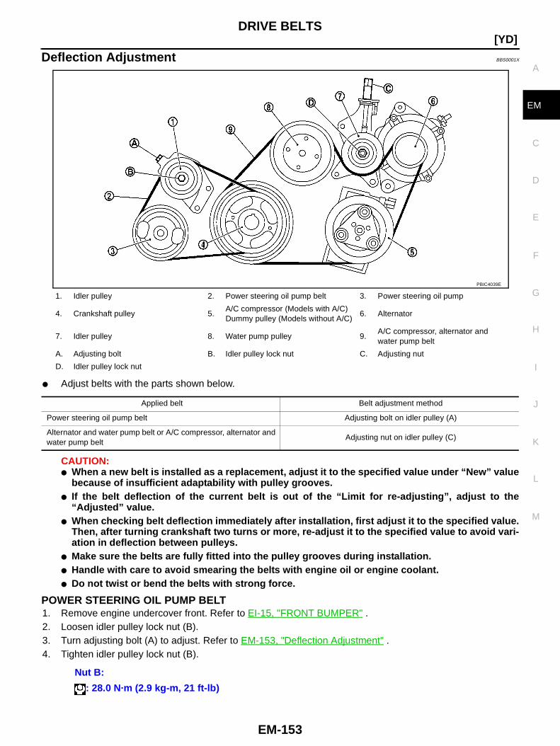
DRIVE BELTS
EM-153
[YD]
C
D
E
F
G
H
I
J
K
L
M
A
EM
Deflection Adjustment BBS0001X
● Adjust belts with the parts shown below.
CAUTION:● When a new belt is installed as a replacement, adjust it to the specified value under “New” value
because of insufficient adaptability with pulley grooves.● If the belt deflection of the current belt is out of the “Limit for re-adjusting”, adjust to the
“Adjusted” value.● When checking belt deflection immediately after installation, first adjust it to the specified value.
Then, after turning crankshaft two turns or more, re-adjust it to the specified value to avoid vari-ation in deflection between pulleys.
● Make sure the belts are fully fitted into the pulley grooves during installation.● Handle with care to avoid smearing the belts with engine oil or engine coolant.● Do not twist or bend the belts with strong force.
POWER STEERING OIL PUMP BELT1. Remove engine undercover front. Refer to EI-15, "FRONT BUMPER" .2. Loosen idler pulley lock nut (B).3. Turn adjusting bolt (A) to adjust. Refer to EM-153, "Deflection Adjustment" .4. Tighten idler pulley lock nut (B).
1. Idler pulley 2. Power steering oil pump belt 3. Power steering oil pump
4. Crankshaft pulley 5.A/C compressor (Models with A/C)Dummy pulley (Models without A/C)
6. Alternator
7. Idler pulley 8. Water pump pulley 9.A/C compressor, alternator andwater pump belt
A. Adjusting bolt B. Idler pulley lock nut C. Adjusting nut
D. Idler pulley lock nut
PBIC4039E
Applied belt Belt adjustment method
Power steering oil pump belt Adjusting bolt on idler pulley (A)
Alternator and water pump belt or A/C compressor, alternator andwater pump belt
Adjusting nut on idler pulley (C)
Nut B:
: 28.0 N·m (2.9 kg-m, 21 ft-lb)
EM-154
[YD]DRIVE BELTS
A/C COMPRESSOR, ALTERNATOR AND WATER PUMP BELT1. Loosen idler pulley lock nut (D).2. Turn adjusting nut (C) to adjust. Refer to EM-153, "Deflection Adjustment" .3. Tighten lock nut (D).
Removal and Installation BBS0001Y
REMOVAL1. Loosen each belt. Refer to EM-153, "Deflection Adjustment" .2. Remove power steering oil pump belt. Refer to EM-153, "POWER STEERING OIL PUMP BELT" .3. Remove A/C compressor, alternator and water pump belt. Refer to EM-154, "A/C COMPRESSOR,
ALTERNATOR AND WATER PUMP BELT" .
INSTALLATION1. Install each belt on pulley in the reverse order of removal.2. Adjust belt deflection. Refer to EM-153, "Deflection Adjustment" .3. Tighten nuts provided for adjustment to the specified torque.4. Make sure again that each belt deflection is as specified.
Nut D:
: 45.0 N·m (4.6 kg-m, 33 ft-lb)
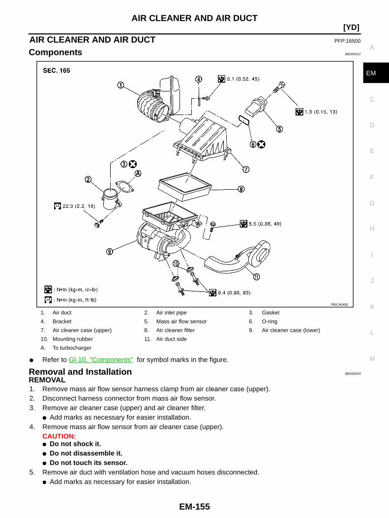
AIR CLEANER AND AIR DUCT
EM-155
[YD]
C
D
E
F
G
H
I
J
K
L
M
A
EM
AIR CLEANER AND AIR DUCT PFP:16500
Components BBS0001Z
● Refer to GI-10, "Components" for symbol marks in the figure.
Removal and Installation BBS00020
REMOVAL1. Remove mass air flow sensor harness clamp from air cleaner case (upper).2. Disconnect harness connector from mass air flow sensor.3. Remove air cleaner case (upper) and air cleaner filter.
● Add marks as necessary for easier installation.4. Remove mass air flow sensor from air cleaner case (upper).
CAUTION:● Do not shock it.● Do not disassemble it.● Do not touch its sensor.
5. Remove air duct with ventilation hose and vacuum hoses disconnected.● Add marks as necessary for easier installation.
1. Air duct 2. Air inlet pipe 3. Gasket
4. Bracket 5. Mass air flow sensor 6. O-ring
7. Air cleaner case (upper) 8. Air cleaner filter 9. Air cleaner case (lower)
10. Mounting rubber 11. Air duct side
A. To turbocharger
PBIC4040E
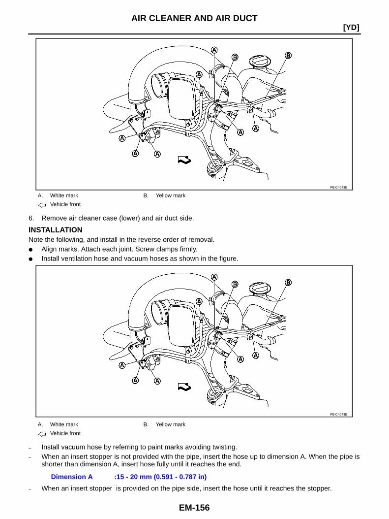
EM-156
[YD]AIR CLEANER AND AIR DUCT
6. Remove air cleaner case (lower) and air duct side.
INSTALLATIONNote the following, and install in the reverse order of removal.● Align marks. Attach each joint. Screw clamps firmly.● Install ventilation hose and vacuum hoses as shown in the figure.
– Install vacuum hose by referring to paint marks avoiding twisting.– When an insert stopper is not provided with the pipe, insert the hose up to dimension A. When the pipe is
shorter than dimension A, insert hose fully until it reaches the end.
– When an insert stopper is provided on the pipe side, insert the hose until it reaches the stopper.
A. White mark B. Yellow mark
Vehicle front
PBIC4043E
A. White mark B. Yellow mark
Vehicle front
Dimension A :15 - 20 mm (0.591 - 0.787 in)
PBIC4043E
AIR CLEANER AND AIR DUCT
EM-157
[YD]
C
D
E
F
G
H
I
J
K
L
M
A
EM
CHANGING AIR CLEANER FILTERRemoval1. Remove mass air flow sensor harness clamp from air cleaner case (upper).2. Disconnect harness connector from mass air flow sensor.3. Unfasten clips and lift up air cleaner case (upper).4. Remove air cleaner filter.
InstallationInstallation is the reverse order of removal.
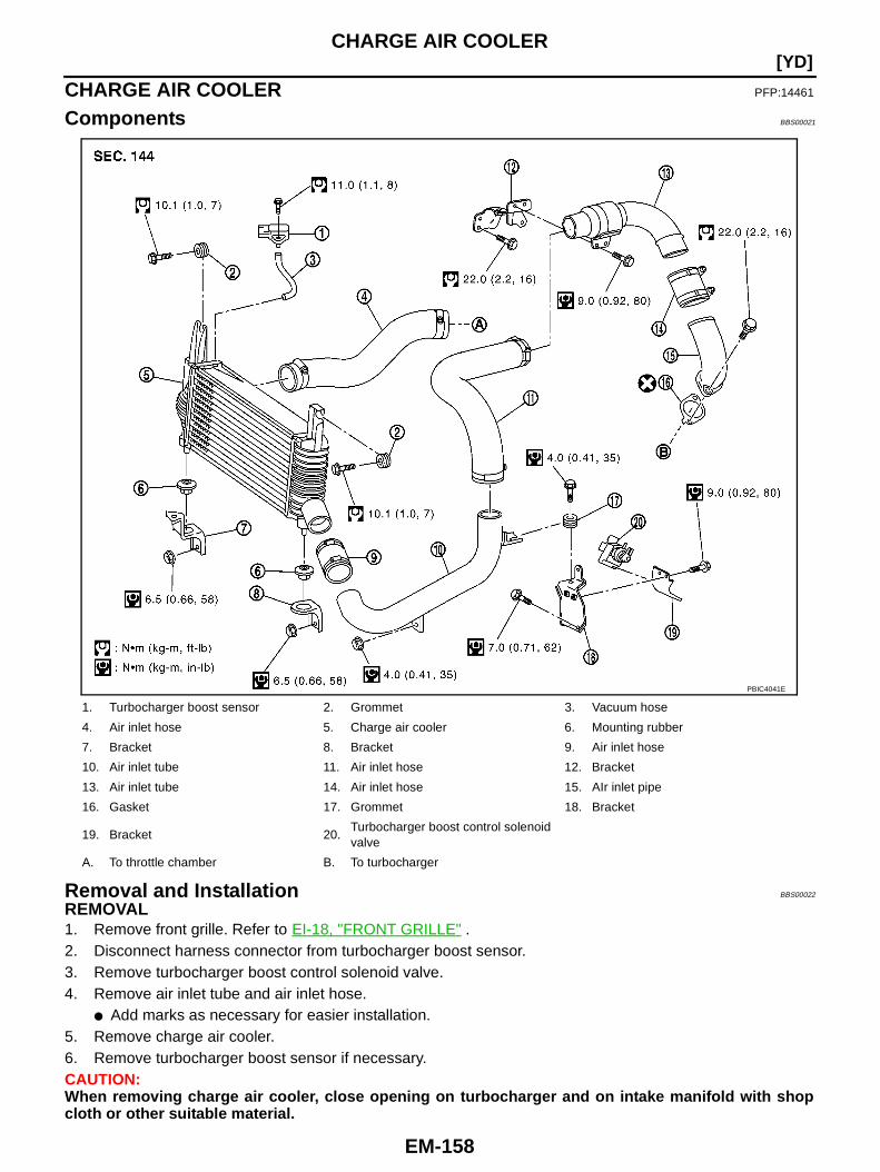
EM-158
[YD]CHARGE AIR COOLER
CHARGE AIR COOLER PFP:14461
Components BBS00021
Removal and Installation BBS00022
REMOVAL1. Remove front grille. Refer to EI-18, "FRONT GRILLE" .2. Disconnect harness connector from turbocharger boost sensor.3. Remove turbocharger boost control solenoid valve.4. Remove air inlet tube and air inlet hose.
● Add marks as necessary for easier installation.5. Remove charge air cooler.6. Remove turbocharger boost sensor if necessary.CAUTION:When removing charge air cooler, close opening on turbocharger and on intake manifold with shopcloth or other suitable material.
1. Turbocharger boost sensor 2. Grommet 3. Vacuum hose
4. Air inlet hose 5. Charge air cooler 6. Mounting rubber
7. Bracket 8. Bracket 9. Air inlet hose
10. Air inlet tube 11. Air inlet hose 12. Bracket
13. Air inlet tube 14. Air inlet hose 15. AIr inlet pipe
16. Gasket 17. Grommet 18. Bracket
19. Bracket 20.Turbocharger boost control solenoidvalve
A. To throttle chamber B. To turbocharger
PBIC4041E
CHARGE AIR COOLER
EM-159
[YD]
C
D
E
F
G
H
I
J
K
L
M
A
EM
INSPECTION AFTER REMOVALCheck air passages of charge air cooler core and fins for clogging, leaks or deformation. Clean or replacecharge air cooler if necessary.● Be careful not to deform core fins.● For cleaning procedure of charge air cooler core, refer to CO-42, "Checking Radiator " .
INSTALLATIONNote the following, and install in the reverse order of removal.● Pay attention to identification mark color and direction when installing air inlet hose.● Align marks. Attach each joint. Screw clamps firmly.

EM-160
[YD]INTAKE MANIFOLD
INTAKE MANIFOLD PFP:14003
Components BBS00023
PBIC4042E

INTAKE MANIFOLD
EM-161
[YD]
C
D
E
F
G
H
I
J
K
L
M
A
EM
● Refer to GI-10, "Components" for symbol marks except in the above.
Removal and Installation BBS00024
REMOVALWARNING:To avoid the danger of being scalded, do not drain engine coolant when engine is hot.1. Drain engine coolant. Refer to CO-36, "Changing Engine Coolant" .2. Remove engine cover (1).
CAUTION:Be careful not to damage engine cover surface.
3. Disconnect air inlet hose from throttle chamber. Refer to EM-158, "CHARGE AIR COOLER" .4. Remove fuel filter. Refer to FL-15, "FUEL FILTER" .5. Remove oil level gauge guide. Refer to EM-174, "OIL PAN AND OIL STRAINER" .6. Remove fuel hoses and fuel gallery. Refer to EM-182, "INJECTION TUBE AND FUEL INJECTOR" .
● To prevent fuel from flowing out, plug the opening of the hose with plug after disconnection.CAUTION:Be careful not to spill fuel in the engine component.
● Add marks as necessary for easier installation.7. Remove vacuum galleries and vacuum hoses.
● Add marks as necessary for easier installation.8. Disconnect EGR volume control valve water hoses and wiring harness.9. Disconnect heater feed hose, water hoses, and remove heater feed pipe.10. Remove EGR cooler (A/T models) or EGR tube (M/T models).11. Remove injection tube center. Refer to EM-182, "Removal and Installation" .
CAUTION:Be careful not to spill fuel in the engine component.
12. Remove water pipe.
1. Vacuum hose 2. Vacuum gallery 3. Vacuum hose
4. Bracket 5. Bracket 6. Gasket
7. Bracket 8. Intake manifold 9. Water hose
10. Heater feed pipe (M/T models) 11. O-ring 12. Vacuum hose
13. Vacuum gallery 14. Vacuum hose 15. Gasket
16. Throttle chamber 17. Gasket 18. Gasket
19. EGR passage 20. Gasket 21. Bracket
22. EGR volume control valve 23. Vacuum gallery 24. Bracket
25. Washer 26. Gasket 27. EGR tube (M/T models)
28. Water hose 29. Water hose 30. Clip (A/T models)
31. Water hose (A/T models) 32. Heater feed pipe (A/T models) 33. Water hose (A/T models)
34. EGR cooler (A/T models) 35. Gasket (A/T models) 36. EGR tube (A/T models)
37. Bracket (A/T models)
C. To heater return pipe E. To cylinder head F. To water outlet
G. To exhaust manifold H. To air inlet hose
Vehicle front
PBIC3409E
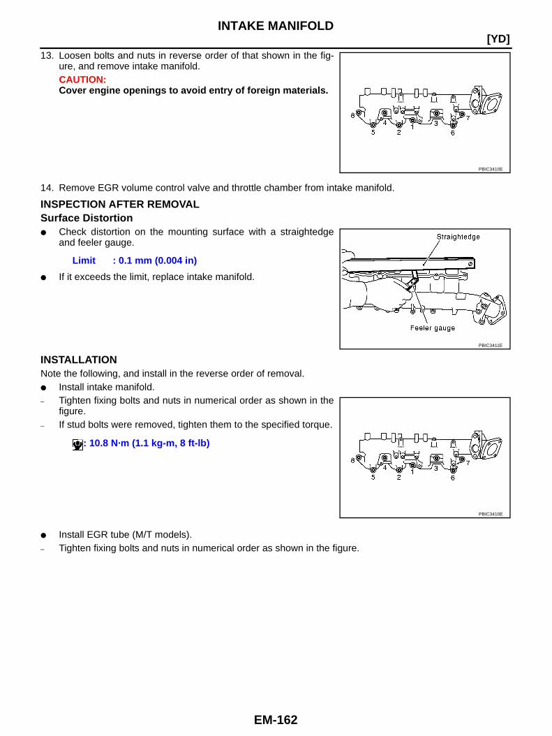
EM-162
[YD]INTAKE MANIFOLD
13. Loosen bolts and nuts in reverse order of that shown in the fig-ure, and remove intake manifold.CAUTION:Cover engine openings to avoid entry of foreign materials.
14. Remove EGR volume control valve and throttle chamber from intake manifold.
INSPECTION AFTER REMOVALSurface Distortion● Check distortion on the mounting surface with a straightedge
and feeler gauge.
● If it exceeds the limit, replace intake manifold.
INSTALLATIONNote the following, and install in the reverse order of removal.● Install intake manifold.– Tighten fixing bolts and nuts in numerical order as shown in the
figure.– If stud bolts were removed, tighten them to the specified torque.
● Install EGR tube (M/T models).– Tighten fixing bolts and nuts in numerical order as shown in the figure.
PBIC3410E
Limit : 0.1 mm (0.004 in)
PBIC3411E
: 10.8 N·m (1.1 kg-m, 8 ft-lb)
PBIC3410E
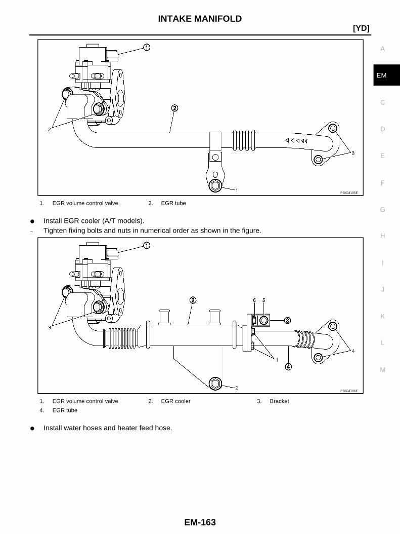
INTAKE MANIFOLD
EM-163
[YD]
C
D
E
F
G
H
I
J
K
L
M
A
EM
● Install EGR cooler (A/T models).– Tighten fixing bolts and nuts in numerical order as shown in the figure.
● Install water hoses and heater feed hose.
1. EGR volume control valve 2. EGR tube
PBIC4105E
1. EGR volume control valve 2. EGR cooler 3. Bracket
4. EGR tube
PBIC4106E

EM-164
[YD]INTAKE MANIFOLD
– Install water hose by referring to paint marks avoiding twisting.– When an insert stopper is not provided with the pipe, insert the hose up to dimension A. When the pipe is
shorter than dimension A, insert hose fully until it reaches the end.
– When an insert stopper is provided on the pipe side, insert the hose until it reaches the stopper.● Install vacuum hoses.
1. Heater return pipe 2. Heater feed pipe 3. EGR volume control valve
4.EGR cooler (A/T models)EGR tube (M/T models)
5. Water outlet
A. Paint mark B. A/T models only
Vehicle front
Dimension A : 27 - 32 mm (1.063 - 1.260 in)
1. EGR volume control valve 2. Throttle chamber 3. Intake shutter control solenoid valve
4.Engine mount control solenoid valve(models with electronic controlledengine mount)
A. Yellow paint B. White paint C. To brake booster
PBIC3412E
PBIC4044E
INTAKE MANIFOLD
EM-165
[YD]
C
D
E
F
G
H
I
J
K
L
M
A
EM– Install vacuum hose by referring to paint marks avoiding twisting.– When an insert stopper is not provided with the pipe, insert the hose up to dimension A. When the pipe is
shorter than dimension A, insert hose fully until it reaches the end.
– When an insert stopper is provided on the pipe side, insert the hose until it reaches the stopper.● Before starting engine, bleed air from fuel piping. Refer to FL-16, "Air Bleeding" .
INSPECTION AFTER INSTALLATIONStart engine and increase engine speed to check for fuel leak.CAUTION:Do not touch the engine immediately after stopped as engine becomes extremely hot.NOTE:Use mirrors for checking at points out of clear sight.
D. To vacuum pump E.To engine mounting insulator(models with electronic controlledengine mount)
Vehicle front
Dimension A : 15 – 20 mm (0.591 – 0.787 in)
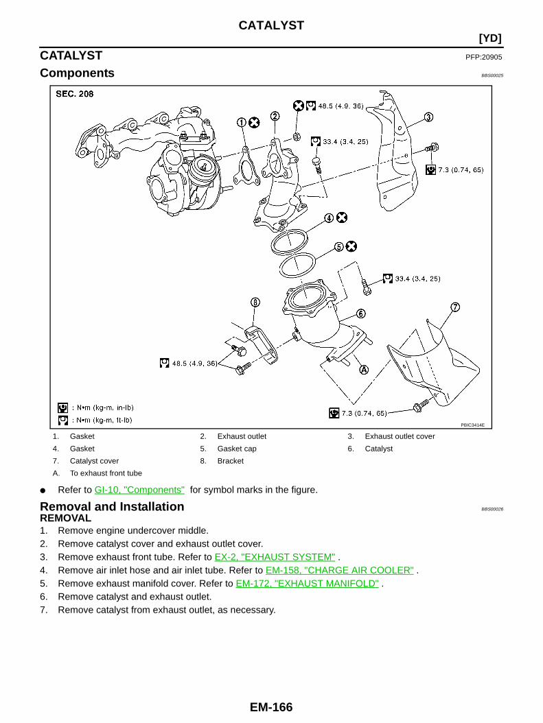
EM-166
[YD]CATALYST
CATALYST PFP:20905
Components BBS00025
● Refer to GI-10, "Components" for symbol marks in the figure.
Removal and Installation BBS00026
REMOVAL1. Remove engine undercover middle.2. Remove catalyst cover and exhaust outlet cover.3. Remove exhaust front tube. Refer to EX-2, "EXHAUST SYSTEM" .4. Remove air inlet hose and air inlet tube. Refer to EM-158, "CHARGE AIR COOLER" .5. Remove exhaust manifold cover. Refer to EM-172, "EXHAUST MANIFOLD" .6. Remove catalyst and exhaust outlet.7. Remove catalyst from exhaust outlet, as necessary.
1. Gasket 2. Exhaust outlet 3. Exhaust outlet cover
4. Gasket 5. Gasket cap 6. Catalyst
7. Catalyst cover 8. Bracket
A. To exhaust front tube
PBIC3414E
CATALYST
EM-167
[YD]
C
D
E
F
G
H
I
J
K
L
M
A
EM
INSTALLATIONNote the following, and install in the reverse order of removal.● If stud bolts of turbocharger were removed, tighten them to the specified torque.
● If stud bolts of catalyst were removed, tighten them to the specified torque.
● Pushing bracket against the cylinder block and the catalyst, temporarily tighten the mounting bolt. Andthen tighten it to the specified torque.
: 25.5 N·m (2.6 kg-m, 19 ft-lb)
: 45.0 N·m (4.6 kg-m, 33 ft-lb)
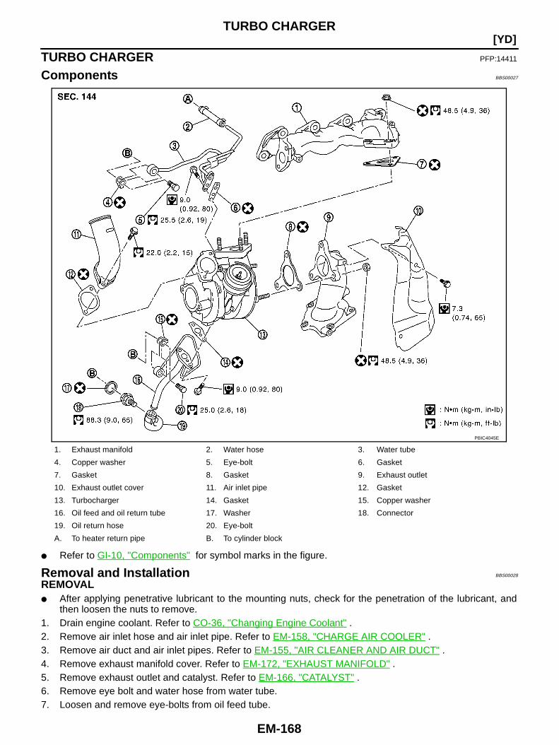
EM-168
[YD]TURBO CHARGER
TURBO CHARGER PFP:14411
Components BBS00027
● Refer to GI-10, "Components" for symbol marks in the figure.
Removal and Installation BBS00028
REMOVAL● After applying penetrative lubricant to the mounting nuts, check for the penetration of the lubricant, and
then loosen the nuts to remove.1. Drain engine coolant. Refer to CO-36, "Changing Engine Coolant" .2. Remove air inlet hose and air inlet pipe. Refer to EM-158, "CHARGE AIR COOLER" .3. Remove air duct and air inlet pipes. Refer to EM-155, "AIR CLEANER AND AIR DUCT" .4. Remove exhaust manifold cover. Refer to EM-172, "EXHAUST MANIFOLD" .5. Remove exhaust outlet and catalyst. Refer to EM-166, "CATALYST" .6. Remove eye bolt and water hose from water tube.7. Loosen and remove eye-bolts from oil feed tube.
1. Exhaust manifold 2. Water hose 3. Water tube
4. Copper washer 5. Eye-bolt 6. Gasket
7. Gasket 8. Gasket 9. Exhaust outlet
10. Exhaust outlet cover 11. Air inlet pipe 12. Gasket
13. Turbocharger 14. Gasket 15. Copper washer
16. Oil feed and oil return tube 17. Washer 18. Connector
19. Oil return hose 20. Eye-bolt
A. To heater return pipe B. To cylinder block
PBIC4045E
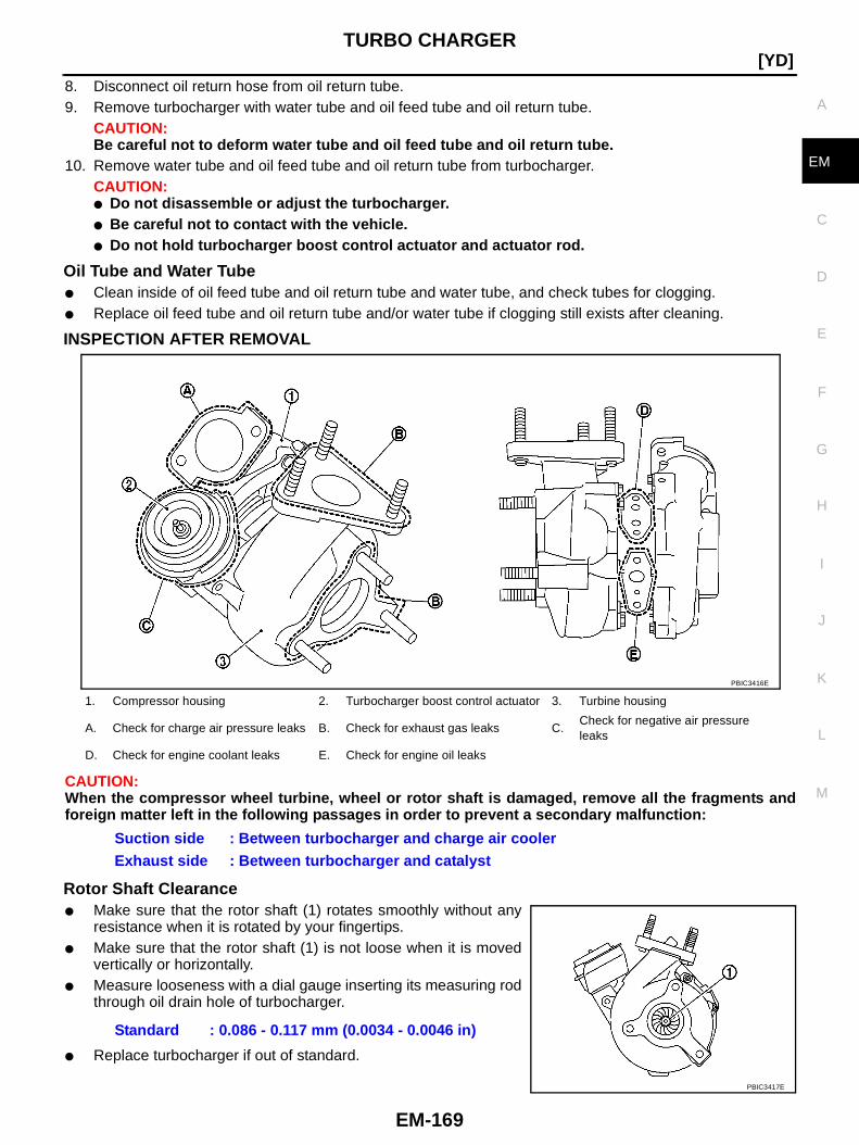
TURBO CHARGER
EM-169
[YD]
C
D
E
F
G
H
I
J
K
L
M
A
EM
8. Disconnect oil return hose from oil return tube.9. Remove turbocharger with water tube and oil feed tube and oil return tube.
CAUTION:Be careful not to deform water tube and oil feed tube and oil return tube.
10. Remove water tube and oil feed tube and oil return tube from turbocharger.CAUTION:● Do not disassemble or adjust the turbocharger.● Be careful not to contact with the vehicle.● Do not hold turbocharger boost control actuator and actuator rod.
Oil Tube and Water Tube● Clean inside of oil feed tube and oil return tube and water tube, and check tubes for clogging.● Replace oil feed tube and oil return tube and/or water tube if clogging still exists after cleaning.
INSPECTION AFTER REMOVAL
CAUTION:When the compressor wheel turbine, wheel or rotor shaft is damaged, remove all the fragments andforeign matter left in the following passages in order to prevent a secondary malfunction:
Rotor Shaft Clearance● Make sure that the rotor shaft (1) rotates smoothly without any
resistance when it is rotated by your fingertips.● Make sure that the rotor shaft (1) is not loose when it is moved
vertically or horizontally.● Measure looseness with a dial gauge inserting its measuring rod
through oil drain hole of turbocharger.
● Replace turbocharger if out of standard.
1. Compressor housing 2. Turbocharger boost control actuator 3. Turbine housing
A. Check for charge air pressure leaks B. Check for exhaust gas leaks C.Check for negative air pressureleaks
D. Check for engine coolant leaks E. Check for engine oil leaks
Suction side : Between turbocharger and charge air coolerExhaust side : Between turbocharger and catalyst
PBIC3416E
Standard : 0.086 - 0.117 mm (0.0034 - 0.0046 in)
PBIC3417E
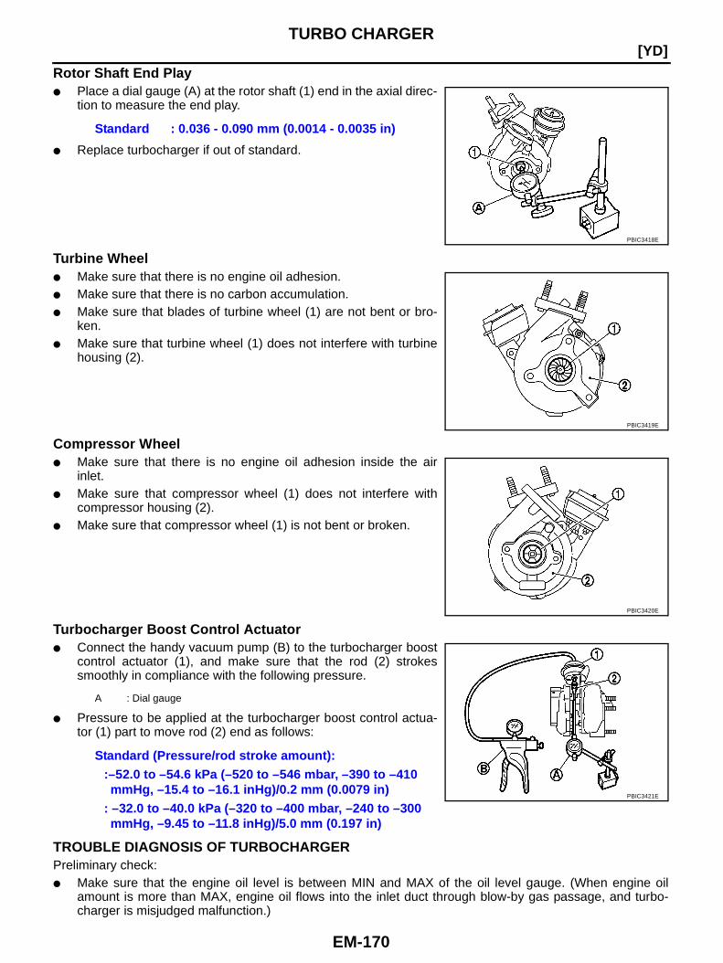
EM-170
[YD]TURBO CHARGER
Rotor Shaft End Play● Place a dial gauge (A) at the rotor shaft (1) end in the axial direc-
tion to measure the end play.
● Replace turbocharger if out of standard.
Turbine Wheel● Make sure that there is no engine oil adhesion.● Make sure that there is no carbon accumulation.● Make sure that blades of turbine wheel (1) are not bent or bro-
ken.● Make sure that turbine wheel (1) does not interfere with turbine
housing (2).
Compressor Wheel● Make sure that there is no engine oil adhesion inside the air
inlet.● Make sure that compressor wheel (1) does not interfere with
compressor housing (2).● Make sure that compressor wheel (1) is not bent or broken.
Turbocharger Boost Control Actuator● Connect the handy vacuum pump (B) to the turbocharger boost
control actuator (1), and make sure that the rod (2) strokessmoothly in compliance with the following pressure.
● Pressure to be applied at the turbocharger boost control actua-tor (1) part to move rod (2) end as follows:
TROUBLE DIAGNOSIS OF TURBOCHARGERPreliminary check:● Make sure that the engine oil level is between MIN and MAX of the oil level gauge. (When engine oil
amount is more than MAX, engine oil flows into the inlet duct through blow-by gas passage, and turbo-charger is misjudged malfunction.)
Standard : 0.036 - 0.090 mm (0.0014 - 0.0035 in)
PBIC3418E
PBIC3419E
PBIC3420E
A : Dial gauge
Standard (Pressure/rod stroke amount)::–52.0 to –54.6 kPa (–520 to –546 mbar, –390 to –410mmHg, –15.4 to –16.1 inHg)/0.2 mm (0.0079 in)
: –32.0 to –40.0 kPa (–320 to –400 mbar, –240 to –300mmHg, –9.45 to –11.8 inHg)/5.0 mm (0.197 in)
PBIC3421E

TURBO CHARGER
EM-171
[YD]
C
D
E
F
G
H
I
J
K
L
M
A
EM
● Ask the customer if he/she always runs the vehicle in idle engine speed to cool the engine oil down afterdriving.
● Replace the turbocharger assembly when any malfunction is found after unit inspections specified in thetable below.
● If no malfunction is found after the unit inspections, judge that the turbocharger body has no malfunction.Check the other parts again.
A: Large possibilityB: Medium possibilityC: Small possibility
INSTALLATION● When a stud bolt is pulled out, replace it with a new one and tighten it to the following torque.
Inspection item Inspection resultSymptom
(when each inspection item meets each inspection result)
Engine oilleakage
Smoke NoiseInsufficient power/accel-
eration malfunction
Turbine wheel
Engine oil leaks C A C C
Carbon is accumulated C A B B
Friction with housing C B A B
Blades are bent or broken — — A A
Compressor wheel
Inside the air inlet is seriously con-taminated by engine oil.
B B — —
Friction with housing C B A B
Blades are bent or broken — — A A
After checking both turbine andcompressor, inspect rotor shaftend play.
There is resistance when the rotorshaft is rotated by your fingertips.
— C C B
The rotor shaft sometimes does notrotate by your fingertips.
— — — A
There is too much play in the bear-ing.
C C B C
Oil return portCarbon or sludge is accumulated inthe waste oil hole.
C A C C
: 25.5 N·m (2.6 kg-m, 19 ft-lb)
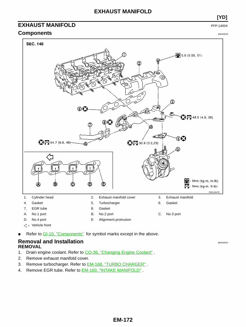
EM-172
[YD]EXHAUST MANIFOLD
EXHAUST MANIFOLD PFP:14004
Components BBS00029
● Refer to GI-10, "Components" for symbol marks except in the above.
Removal and Installation BBS0002A
REMOVAL1. Drain engine coolant. Refer to CO-36, "Changing Engine Coolant" .2. Remove exhaust manifold cover.3. Remove turbocharger. Refer to EM-168, "TURBO CHARGER" .4. Remove EGR tube. Refer to EM-160, "INTAKE MANIFOLD" .
1. Cylinder head 2. Exhaust manifold cover 3. Exhaust manifold
4. Gasket 5. Turbocharger 6. Gasket
7. EGR tube 8. Gasket
A. No.1 port B. No.2 port C. No.3 port
D. No.4 port E. Alignment protrusion
Vehicle front
PBIC4047E
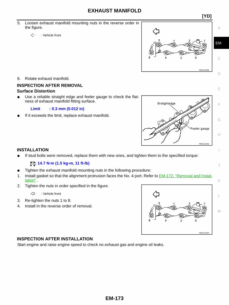
EXHAUST MANIFOLD
EM-173
[YD]
C
D
E
F
G
H
I
J
K
L
M
A
EM
5. Loosen exhaust manifold mounting nuts in the reverse order inthe figure.
6. Rotate exhaust manifold.
INSPECTION AFTER REMOVALSurface Distortion● Use a reliable straight edge and feeler gauge to check the flat-
ness of exhaust manifold fitting surface.
● If it exceeds the limit, replace exhaust manifold.
INSTALLATION● If stud bolts were removed, replace them with new ones, and tighten them to the specified torque:
● Tighten the exhaust manifold mounting nuts in the following procedure:1. Install gasket so that the alignment protrusion faces the No. 4 port. Refer to EM-172, "Removal and Instal-
lation" .2. Tighten the nuts in order specified in the figure.
3. Re-tighten the nuts 1 to 8.4. Install in the reverse order of removal.
INSPECTION AFTER INSTALLATIONStart engine and raise engine speed to check no exhaust gas and engine oil leaks.
: Vehicle front
PBIC3423E
Limit : 0.3 mm (0.012 in)
PBIC2210E
: 14.7 N·m (1.5 kg-m, 11 ft-lb)
: Vehicle front
PBIC3423E
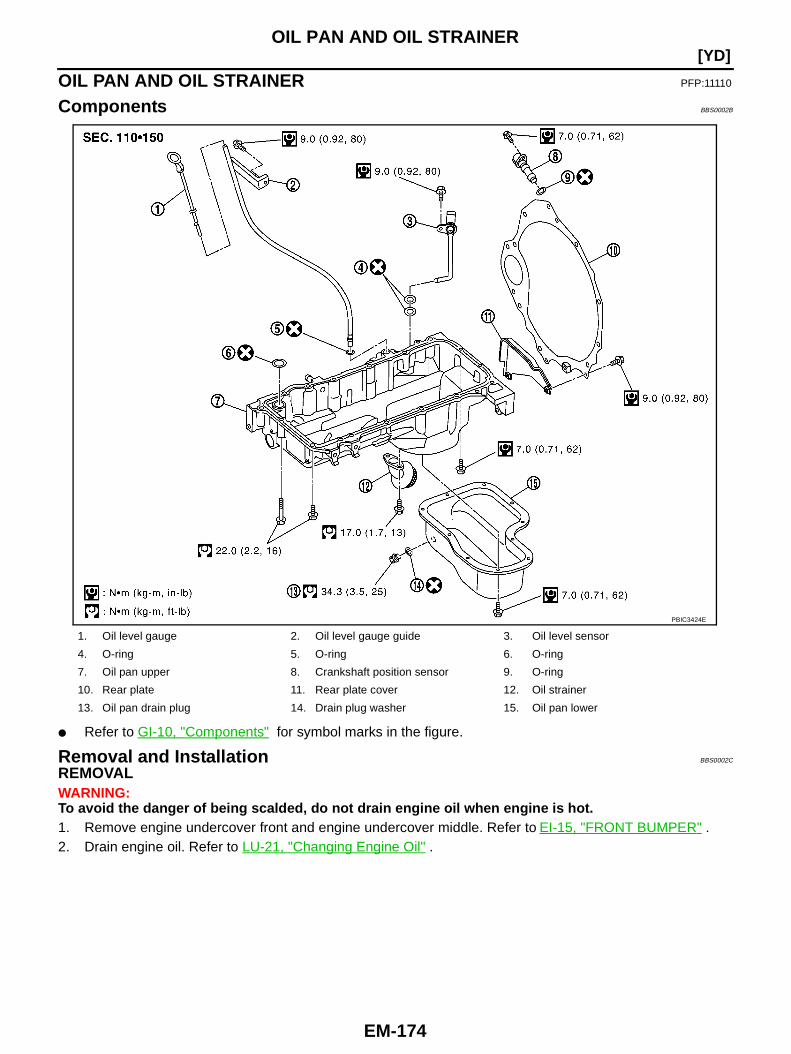
EM-174
[YD]OIL PAN AND OIL STRAINER
OIL PAN AND OIL STRAINER PFP:11110
Components BBS0002B
● Refer to GI-10, "Components" for symbol marks in the figure.
Removal and Installation BBS0002C
REMOVALWARNING:To avoid the danger of being scalded, do not drain engine oil when engine is hot.1. Remove engine undercover front and engine undercover middle. Refer to EI-15, "FRONT BUMPER" .2. Drain engine oil. Refer to LU-21, "Changing Engine Oil" .
1. Oil level gauge 2. Oil level gauge guide 3. Oil level sensor
4. O-ring 5. O-ring 6. O-ring
7. Oil pan upper 8. Crankshaft position sensor 9. O-ring
10. Rear plate 11. Rear plate cover 12. Oil strainer
13. Oil pan drain plug 14. Drain plug washer 15. Oil pan lower
PBIC3424E

OIL PAN AND OIL STRAINER
EM-175
[YD]
C
D
E
F
G
H
I
J
K
L
M
A
EM
3. Remove oil pan lower bolts, loosen bolts in reverse order of thatshown in the figure.
4. Remove oil pan lower.a. Insert the seal cutter [SST] between oil pan upper and oil pan
lower.CAUTION:● Be careful not to damage aluminum mating surface.● Do not insert screwdriver, or oil pan flange will be
deformed.b. Slide the seal cutter by tapping on the side of the seal cutter with
a hammer.c. Remove oil pan lower.
5. Remove oil strainer.6. Remove power steering oil pump belt. Refer to EM-152, "DRIVE BELTS" .7. Remove power steering oil pump bracket and move power steering oil pump aside with its piping con-
nected. Temporarily secure it on the vehicle side with a rope to avoid putting load on it. Refer to PS-35,"POWER STEERING OIL PUMP" .
8. Disconnect oil return hose (vacuum pump) from oil pan upper. Refer to EM-180, "VACUUM PUMP" .9. Remove vacuum tube mounting bolts (A). (models with electrical
engine mount) Refer to EM-244, "ENGINE ASSEMBLY" .
10. Remove A/C compressor bracket mounting bolts (A).
11. Remove crankshaft position sensor and oil level sensor.CAUTION:● Avoid impacts such as a dropping.
: Vehicle front
PBIC3425E
SEM365EA
1 : Vacuum tube
2 : Oil pan upper
PBIC3427E
1 : Oil pan upper
2 : A/C compressor bracket
: Vehicle front
PBIC3426E
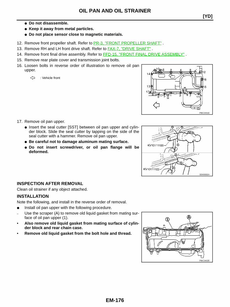
EM-176
[YD]OIL PAN AND OIL STRAINER
● Do not disassemble.● Keep it away from metal particles.● Do not place sensor close to magnetic materials.
12. Remove front propeller shaft. Refer to PR-3, "FRONT PROPELLER SHAFT" .13. Remove RH and LH front drive shaft. Refer to FAX-7, "DRIVE SHAFT" .14. Remove front final drive assembly. Refer to FFD-15, "FRONT FINAL DRIVE ASSEMBLY" .15. Remove rear plate cover and transmission joint bolts.16. Loosen bolts in reverse order of illustration to remove oil pan
upper.
17. Remove oil pan upper.● Insert the seal cutter [SST] between oil pan upper and cylin-
der block. Slide the seal cutter by tapping on the side of theseal cutter with a hammer. Remove oil pan upper.
● Be careful not to damage aluminum mating surface.● Do not insert screwdriver, or oil pan flange will be
deformed.
INSPECTION AFTER REMOVALClean oil strainer if any object attached.
INSTALLATIONNote the following, and install in the reverse order of removal.● Install oil pan upper with the following procedure.– Use the scraper (A) to remove old liquid gasket from mating sur-
face of oil pan upper (1).• Also remove old liquid gasket from mating surface of cylin-
der block and rear chain case.• Remove old liquid gasket from the bolt hole and thread.
: Vehicle front
PBIC3431E
SEM365EA
PBIC3432E
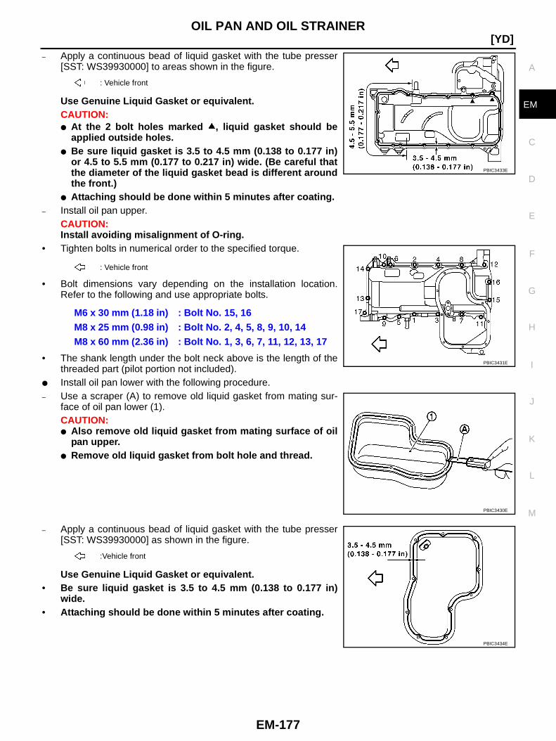
OIL PAN AND OIL STRAINER
EM-177
[YD]
C
D
E
F
G
H
I
J
K
L
M
A
EM
– Apply a continuous bead of liquid gasket with the tube presser[SST: WS39930000] to areas shown in the figure.
Use Genuine Liquid Gasket or equivalent.CAUTION:● At the 2 bolt holes marked , liquid gasket should be
applied outside holes.● Be sure liquid gasket is 3.5 to 4.5 mm (0.138 to 0.177 in)
or 4.5 to 5.5 mm (0.177 to 0.217 in) wide. (Be careful thatthe diameter of the liquid gasket bead is different aroundthe front.)
● Attaching should be done within 5 minutes after coating.– Install oil pan upper.
CAUTION:Install avoiding misalignment of O-ring.
• Tighten bolts in numerical order to the specified torque.
• Bolt dimensions vary depending on the installation location.Refer to the following and use appropriate bolts.
• The shank length under the bolt neck above is the length of thethreaded part (pilot portion not included).
● Install oil pan lower with the following procedure.– Use a scraper (A) to remove old liquid gasket from mating sur-
face of oil pan lower (1).CAUTION:● Also remove old liquid gasket from mating surface of oil
pan upper.● Remove old liquid gasket from bolt hole and thread.
– Apply a continuous bead of liquid gasket with the tube presser[SST: WS39930000] as shown in the figure.
Use Genuine Liquid Gasket or equivalent.• Be sure liquid gasket is 3.5 to 4.5 mm (0.138 to 0.177 in)
wide.• Attaching should be done within 5 minutes after coating.
: Vehicle front
: Vehicle front
M6 x 30 mm (1.18 in) : Bolt No. 15, 16M8 x 25 mm (0.98 in) : Bolt No. 2, 4, 5, 8, 9, 10, 14M8 x 60 mm (2.36 in) : Bolt No. 1, 3, 6, 7, 11, 12, 13, 17
PBIC3433E
PBIC3431E
PBIC3430E
:Vehicle front
PBIC3434E

EM-178
[YD]OIL PAN AND OIL STRAINER
– Install oil pan lower.• Tighten bolts in numerical order to the specified torque.
NOTE:Pour engine oil or start engine at least 30 minutes after oil pan isinstalled.
INSPECTION AFTER INSTALLATION1. Check engine oil level and add engine oil. Refer to LU-20, "ENGINE OIL" .2. Check for leakage of engine oil when engine is warmed.3. Stop engine and wait for 10 minutes.4. Check engine oil level again. Refer to LU-20, "ENGINE OIL" .
SEM159F
: Vehicle front
PBIC3425E

GLOW PLUG
EM-179
[YD]
C
D
E
F
G
H
I
J
K
L
M
A
EM
GLOW PLUG PFP:22401
Components BBS0002D
Removal and Installation BBS0002E
REMOVALCAUTION:Remove glow plug only if necessary. If carbon adheres, it may be stuck and broken.1. Disconnect glow harness from glow plate.2. Remove glow nut to remove glow plate.3. Remove glow plug.
CAUTION:● When removing or installing, do not use such tools as an air impact wrench.● Handle it carefully without giving any impact, even after removal. [As a guide, if it drops from
height of 10 cm (3.94 in) or higher, always replace it.]
INSTALLATION1. Remove adhered carbon from glow plug installation hole with a reamer.2. Install glow plug.3. Install remaining parts in the reverse order of removal.
1. Glow plate 2. Glow harness 3. Glow nut
4. Cap 5. Glow plug
PBIC2436E
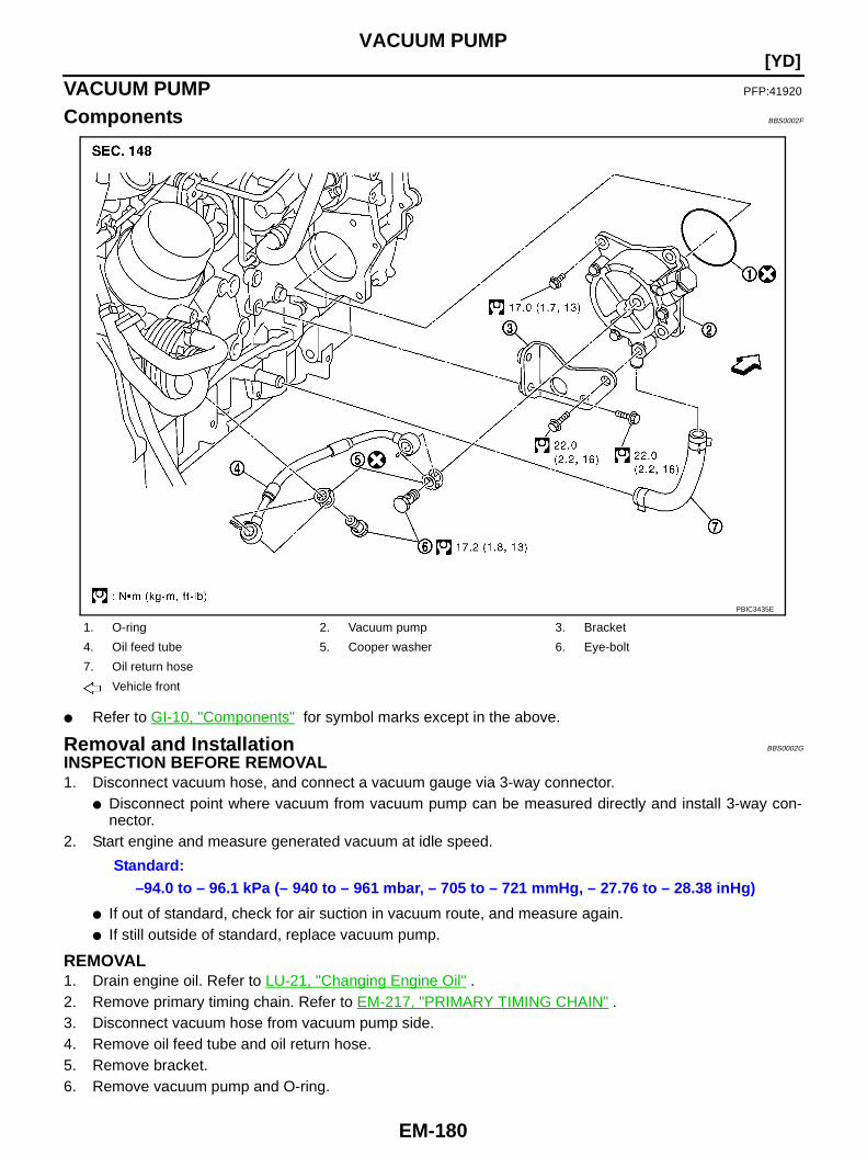
EM-180
[YD]VACUUM PUMP
VACUUM PUMP PFP:41920
Components BBS0002F
● Refer to GI-10, "Components" for symbol marks except in the above.
Removal and Installation BBS0002G
INSPECTION BEFORE REMOVAL1. Disconnect vacuum hose, and connect a vacuum gauge via 3-way connector.
● Disconnect point where vacuum from vacuum pump can be measured directly and install 3-way con-nector.
2. Start engine and measure generated vacuum at idle speed.
● If out of standard, check for air suction in vacuum route, and measure again.● If still outside of standard, replace vacuum pump.
REMOVAL1. Drain engine oil. Refer to LU-21, "Changing Engine Oil" .2. Remove primary timing chain. Refer to EM-217, "PRIMARY TIMING CHAIN" .3. Disconnect vacuum hose from vacuum pump side.4. Remove oil feed tube and oil return hose.5. Remove bracket.6. Remove vacuum pump and O-ring.
1. O-ring 2. Vacuum pump 3. Bracket
4. Oil feed tube 5. Cooper washer 6. Eye-bolt
7. Oil return hose
Vehicle front
PBIC3435E
Standard:–94.0 to – 96.1 kPa (– 940 to – 961 mbar, – 705 to – 721 mmHg, – 27.76 to – 28.38 inHg)
VACUUM PUMP
EM-181
[YD]
C
D
E
F
G
H
I
J
K
L
M
A
EM
INSTALLATIONInstallation is the reverse order of removal.
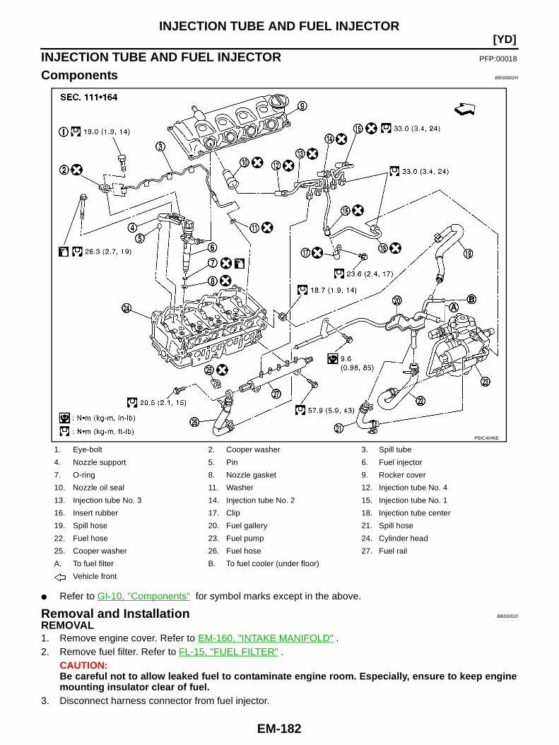
EM-182
[YD]INJECTION TUBE AND FUEL INJECTOR
INJECTION TUBE AND FUEL INJECTOR PFP:00018
Components BBS0002H
● Refer to GI-10, "Components" for symbol marks except in the above.
Removal and Installation BBS0002I
REMOVAL1. Remove engine cover. Refer to EM-160, "INTAKE MANIFOLD" .2. Remove fuel filter. Refer to FL-15, "FUEL FILTER" .
CAUTION:Be careful not to allow leaked fuel to contaminate engine room. Especially, ensure to keep enginemounting insulator clear of fuel.
3. Disconnect harness connector from fuel injector.
1. Eye-bolt 2. Cooper washer 3. Spill tube
4. Nozzle support 5. Pin 6. Fuel injector
7. O-ring 8. Nozzle gasket 9. Rocker cover
10. Nozzle oil seal 11. Washer 12. Injection tube No. 4
13. Injection tube No. 3 14. Injection tube No. 2 15. Injection tube No. 1
16. Insert rubber 17. Clip 18. Injection tube center
19. Spill hose 20. Fuel gallery 21. Spill hose
22. Fuel hose 23. Fuel pump 24. Cylinder head
25. Cooper washer 26. Fuel hose 27. Fuel rail
A. To fuel filter B. To fuel cooler (under floor)
Vehicle front
PBIC4046E
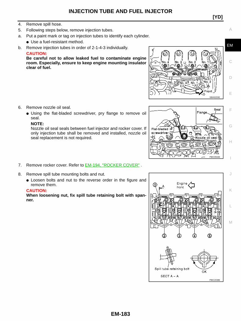
INJECTION TUBE AND FUEL INJECTOR
EM-183
[YD]
C
D
E
F
G
H
I
J
K
L
M
A
EM
4. Remove spill hose.5. Following steps below, remove injection tubes.a. Put a paint mark or tag on injection tubes to identify each cylinder.
● Use a fuel-resistant method.b. Remove injection tubes in order of 2-1-4-3 individually.
CAUTION:Be careful not to allow leaked fuel to contaminate engineroom. Especially, ensure to keep engine mounting insulatorclear of fuel.
6. Remove nozzle oil seal.● Using the flat-bladed screwdriver, pry flange to remove oil
seal.NOTE:Nozzle oil seal seals between fuel injector and rocker cover. Ifonly injection tube shall be removed and installed, nozzle oilseal replacement is not required.
7. Remove rocker cover. Refer to EM-194, "ROCKER COVER" .
8. Remove spill tube mounting bolts and nut.● Loosen bolts and nut to the reverse order in the figure and
remove them.CAUTION:When loosening nut, fix spill tube retaining bolt with span-ner.
SBIA0203E
PBIC0944E
PBIC2038E

EM-184
[YD]INJECTION TUBE AND FUEL INJECTOR
9. Following steps below, remove fuel injector.a. Remove nozzle support.b. Remove fuel injector. While rotating it to left and right, raise it to
remove.CAUTION:● Handle fuel injector carefully without giving any impact.● Do not disassemble fuel injector.
c. If nozzle gasket remains in cylinder head, hook it with tip of aflat-bladed screwdriver and pull it out.
d. Remove O-ring from fuel injector.
INSTALLATION1. Record “INJECTOR ADJUSTMENT VALUE” on the top surface when replacing fuel injector.
● Refer to EC-990, "Injector Adjustment Value Registration" for use of “INJECTOR ADJUSTMENTVALUE”.
Example: Injector Adjustment value = D021ABCD1A061234000000000000E62. Following steps below, install fuel injector.a. Install O-ring and nozzle gasket to fuel injector, and insert them into cylinder head.b. Tighten injection tubes temporarily in the order of 3-4-1-2.c. Be sure to fit nozzle support and pin without looseness.d. Tighten nozzle support bolts.e. Loosen injection tubes in the order of 2-1-4-3.3. Connect spill tube.
● Tighten fixing bolts and nut in numerical order shown in thefigure.CAUTION:When tightening nut, fix spill tube retaining bolt withspanner.NOTE:Connection of spill tube gasket may be broken, even if it istighten to the specified torque. It does not affect performance.
PBIC0759E
MBIB1251E
PBIC2038E

INJECTION TUBE AND FUEL INJECTOR
EM-185
[YD]
C
D
E
F
G
H
I
J
K
L
M
A
EM
4. Perform air tightness test for spill tube.● Connect a handy vacuum pump to spill connector. Make sure
that vacuum is retained while applying following vacuum.
● If outside of standard, reconnect spill tube. (Replace gasket inthis case.)
5. Install rocker cover. Refer to EM-194, "Removal and Installation".
6. Install nozzle oil seal.● Insert it straight until its flange fully contacts rocker cover.
CAUTION:● Check gutter spring in nozzle oil seal on fuel injector for missing.
7. Connect injection tubes individually to each cylinder in order of3-4-1-2.
8. Install fuel hoses, spill hose and fuel gallery as shown in the figure.
Standard:– 53.3 to – 66.7 kPa (– 533 to – 667 mbar, – 400 to– 500 mmHg, – 15.75 to – 19.69 inHg)
JEF250Z
SBIA0203E
PBIC3437E
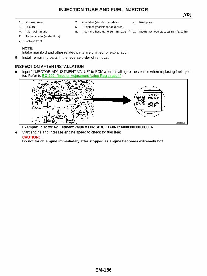
EM-186
[YD]INJECTION TUBE AND FUEL INJECTOR
NOTE:Intake manifold and other related parts are omitted for explanation.
9. Install remaining parts in the reverse order of removal.
INSPECTION AFTER INSTALLATION● Input “INJECTOR ADJUSTMENT VALUE” to ECM after installing to the vehicle when replacing fuel injec-
tor. Refer to EC-990, "Injector Adjustment Value Registration" .
Example: Injector Adjustment value = D021ABCD1A061234000000000000E6● Start engine and increase engine speed to check for fuel leak.
CAUTION:Do not touch engine immediately after stopped as engine becomes extremely hot.
1. Rocker cover 2. Fuel filter (standard models) 3. Fuel pump
4. Fuel rail 5. Fuel filter (models for cold area)
A. Align paint mark B. Insert the hose up to 26 mm (1.02 in) C. Insert the hose up to 28 mm (1.10 in)
D. To fuel cooler (under floor)
Vehicle front
MBIB1251E
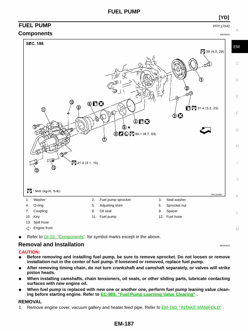
FUEL PUMP
EM-187
[YD]
C
D
E
F
G
H
I
J
K
L
M
A
EM
FUEL PUMP PFP:17042
Components BBS0002J
● Refer to GI-10, "Components" for symbol marks except in the above.
Removal and Installation BBS0002K
CAUTION:● Before removing and installing fuel pump, be sure to remove sprocket. Do not loosen or remove
installation nut in the center of fuel pump. If loosened or removed, replace fuel pump.● After removing timing chain, do not turn crankshaft and camshaft separately, or valves will strike
piston heads.● When installing camshafts, chain tensioners, oil seals, or other sliding parts, lubricate contacting
surfaces with new engine oil.● When fuel pump is replaced with new one or another one, perform fuel pump leaning value clean-
ing before starting engine. Refer to EC-989, "Fuel Pump Learning Value Clearing " .
REMOVAL1. Remove engine cover, vacuum gallery and heater feed pipe. Refer to EM-160, "INTAKE MANIFOLD" .
1. Washer 2. Fuel pump sprocket 3. Seal washer
4. O-ring 5. Adjusting shim 6. Sprocket nut
7. Coupling 8. Oil seal 9. Spacer
10. Key 11. Fuel pump 12. Fuel hose
13. Spill hose
Engine front
PBIC3438E
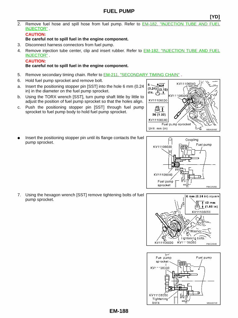
EM-188
[YD]FUEL PUMP
2. Remove fuel hose and spill hose from fuel pump. Refer to EM-182, "INJECTION TUBE AND FUELINJECTOR" .CAUTION:Be careful not to spill fuel in the engine component.
3. Disconnect harness connectors from fuel pump.4. Remove injection tube center, clip and insert rubber. Refer to EM-182, "INJECTION TUBE AND FUEL
INJECTOR" .CAUTION:Be careful not to spill fuel in the engine component.
5. Remove secondary timing chain. Refer to EM-211, "SECONDARY TIMING CHAIN" .6. Hold fuel pump sprocket and remove bolt.a. Insert the positioning stopper pin [SST] into the hole 6 mm (0.24
in) in the diameter on the fuel pump sprocket.b. Using the TORX wrench [SST], turn pump shaft little by little to
adjust the position of fuel pump sprocket so that the holes align.c. Push the positioning stopper pin [SST] through fuel pump
sprocket to fuel pump body to hold fuel pump sprocket.
● Insert the positioning stopper pin until its flange contacts the fuelpump sprocket.
7. Using the hexagon wrench [SST] remove tightening bolts of fuelpump sprocket.
MBIA0049E
PBIC2535E
PBIC2404E
MBIA0074E

FUEL PUMP
EM-189
[YD]
C
D
E
F
G
H
I
J
K
L
M
A
EM
8. Using the sprocket holder [SST], hold fuel pump sprocket to pre-vent falling.● For sprocket holder, use KV11106060 machined as shown in
the figure, because the previous bore is not fitting.
● When the sprocket holder is installed, if the positioning stop-per pin [SST] interferes, pull out the positioning stopper pinapproximately 10 mm (0.39 in), then install it.
● After the sprocket holder is installed temporarily, tighten thesprocket holder after making extension bar and TORX socket(size: E10) (commercial service tool) insert into the machinedbore.
● The length of the sprocket holder mounting bolts should beapproximately 15 mm (0.59 in) (M6 thread length).
● Make sure that the a- and b-faces of the sprocket holder con-tact the bottom side of the sprocket (small diameter side).CAUTION:Do not remove the sprocket holder [SST] until fuel pump is installed.
● After the sprocket holder is installed, pull out the positioningstopper pin from fuel pump sprocket.
9. Using the extension bar and the TORX socket (size: E10) (com-mercial service tool), remove the tightening bolts.CAUTION:Do not disassemble or adjust fuel pump.
10. Remove the fuel pump toward the rear of engine.CAUTION:For removal, be careful not to drop the seal washer into the engine.NOTE:The seal washer of the tightening bolts cannot be reused.
11. Remove adjusting shim.12. Attach a suitable tool in the M8 bolt hole on coupling.
SBIA0217E
PBIC2534E
MBIA0075E
PBIC2405E
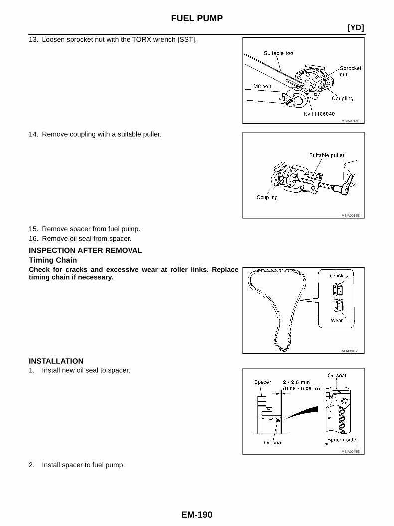
EM-190
[YD]FUEL PUMP
13. Loosen sprocket nut with the TORX wrench [SST].
14. Remove coupling with a suitable puller.
15. Remove spacer from fuel pump.16. Remove oil seal from spacer.
INSPECTION AFTER REMOVALTiming ChainCheck for cracks and excessive wear at roller links. Replacetiming chain if necessary.
INSTALLATION1. Install new oil seal to spacer.
2. Install spacer to fuel pump.
MBIA0013E
MBIA0014E
SEM984C
MBIA0045E
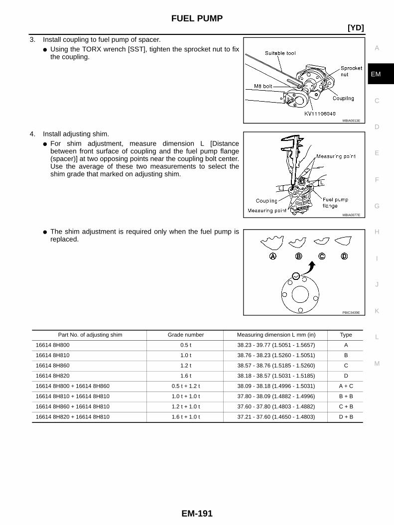
FUEL PUMP
EM-191
[YD]
C
D
E
F
G
H
I
J
K
L
M
A
EM
3. Install coupling to fuel pump of spacer.● Using the TORX wrench [SST], tighten the sprocket nut to fix
the coupling.
4. Install adjusting shim.● For shim adjustment, measure dimension L [Distance
between front surface of coupling and the fuel pump flange(spacer)] at two opposing points near the coupling bolt center.Use the average of these two measurements to select theshim grade that marked on adjusting shim.
● The shim adjustment is required only when the fuel pump isreplaced.
MBIA0013E
MBIA0077E
PBIC3439E
Part No. of adjusting shim Grade number Measuring dimension L mm (in) Type
16614 8H800 0.5 t 38.23 - 39.77 (1.5051 - 1.5657) A
16614 8H810 1.0 t 38.76 - 38.23 (1.5260 - 1.5051) B
16614 8H860 1.2 t 38.57 - 38.76 (1.5185 - 1.5260) C
16614 8H820 1.6 t 38.18 - 38.57 (1.5031 - 1.5185) D
16614 8H800 + 16614 8H860 0.5 t + 1.2 t 38.09 - 38.18 (1.4996 - 1.5031) A + C
16614 8H810 + 16614 8H810 1.0 t + 1.0 t 37.80 - 38.09 (1.4882 - 1.4996) B + B
16614 8H860 + 16614 8H810 1.2 t + 1.0 t 37.60 - 37.80 (1.4803 - 1.4882) C + B
16614 8H820 + 16614 8H810 1.6 t + 1.0 t 37.21 - 37.60 (1.4650 - 1.4803) D + B
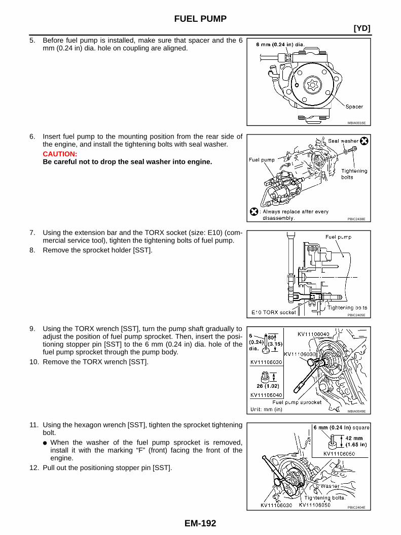
EM-192
[YD]FUEL PUMP
5. Before fuel pump is installed, make sure that spacer and the 6mm (0.24 in) dia. hole on coupling are aligned.
6. Insert fuel pump to the mounting position from the rear side ofthe engine, and install the tightening bolts with seal washer.CAUTION:Be careful not to drop the seal washer into engine.
7. Using the extension bar and the TORX socket (size: E10) (com-mercial service tool), tighten the tightening bolts of fuel pump.
8. Remove the sprocket holder [SST].
9. Using the TORX wrench [SST], turn the pump shaft gradually toadjust the position of fuel pump sprocket. Then, insert the posi-tioning stopper pin [SST] to the 6 mm (0.24 in) dia. hole of thefuel pump sprocket through the pump body.
10. Remove the TORX wrench [SST].
11. Using the hexagon wrench [SST], tighten the sprocket tighteningbolt.● When the washer of the fuel pump sprocket is removed,
install it with the marking “F” (front) facing the front of theengine.
12. Pull out the positioning stopper pin [SST].
MBIA0016E
PBIC2438E
PBIC2405E
MBIA0049E
PBIC2404E
FUEL PUMP
EM-193
[YD]
C
D
E
F
G
H
I
J
K
L
M
A
EM
13. Install secondary timing chain. Refer to EM-211, "SECONDARY TIMING CHAIN" .14. Following steps below, install injection tube center. Refer to EM-182, "INJECTION TUBE AND FUEL
INJECTOR" .a. Pre-set clip and insert rubber to injection tube center.b. Pre-tight nut of injection tube center to fuel pump and fuel rail by hand. (until seal surface touched)c. Adjust clip dimension and tight bolt for clip to intake manifold by tool.d. Tight nut of injection tube center to fuel pump by tool.e. Tight nut of injection tube center to fuel rail by tool.15. Connect the harness connector to fuel pump.16. Install fuel hoses. Refer to EM-182, "INJECTION TUBE AND FUEL INJECTOR" .17. Hereafter, install in the reverse order of removal.
CAUTION:When fuel pump is replaced with new one or another one, perform fuel pump leaning value clean-ing before starting engine. Refer to EC-989, "Fuel Pump Learning Value Clearing " .
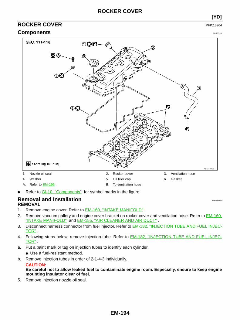
EM-194
[YD]ROCKER COVER
ROCKER COVER PFP:13264
Components BBS0002L
● Refer to GI-10, "Components" for symbol marks in the figure.
Removal and Installation BBS0002M
REMOVAL1. Remove engine cover. Refer to EM-160, "INTAKE MANIFOLD" .2. Remove vacuum gallery and engine cover bracket on rocker cover and ventilation hose. Refer to EM-160,
"INTAKE MANIFOLD" and EM-155, "AIR CLEANER AND AIR DUCT" .3. Disconnect harness connector from fuel injector. Refer to EM-182, "INJECTION TUBE AND FUEL INJEC-
TOR" .4. Following steps below, remove injection tube. Refer to EM-182, "INJECTION TUBE AND FUEL INJEC-
TOR" .a. Put a paint mark or tag on injection tubes to identify each cylinder.
● Use a fuel-resistant method.b. Remove injection tubes in order of 2-1-4-3 individually.
CAUTION:Be careful not to allow leaked fuel to contaminate engine room. Especially, ensure to keep enginemounting insulator clear of fuel.
5. Remove injection nozzle oil seal.
1. Nozzle oil seal 2. Rocker cover 3. Ventilation hose
4. Washer 5. Oil filler cap 6. Gasket
A. Refer to EM-195 . B. To ventilation hose
PBIC3440E

ROCKER COVER
EM-195
[YD]
C
D
E
F
G
H
I
J
K
L
M
A
EM
● Using the flat-bladed screwdriver, pry flange to remove nozzleoil seal.
6. Remove rocker cover.● Loosen holding bolts in reverse order of that shown in the fig-
ure and remove.
INSTALLATION1. Install new gasket to rocker cover.2. Apply liquid gasket with tube presser [SST: WS39930000] on
locations shown in the figure.● Use Genuine Liquid Gasket or equivalent.
3. Tighten holding bolts in numerical order shown in the figure.
Re-tighten to the same torque in the same order as above.
4. Install nozzle oil seal.● Insert it straight until flange fully contacts rocker cover.
5. Install remaining parts in the reverse order of removal.6. Before starting engine, bleed air from fuel piping. Refer to FL-16, "Air Bleeding" .
INSPECTION AFTER INSTALLATIONStart engine and increase engine speed to check for fuel leak and engine oil leak.
PBIC0944E
: Engine front
PBIC3441E
1 : Cylinder head
2 : Cylinder head rear cover
A : Liquid gasket application area
: Engine front
PBIC3442E
: Engine front
: 7.8 N·m (0.8 kg-m, 69 in-lb)
PBIC3441E
EM-196
[YD]ROCKER COVER
CAUTION:Do not touch the engine immediately after stopped as engine becomes extremely hot.
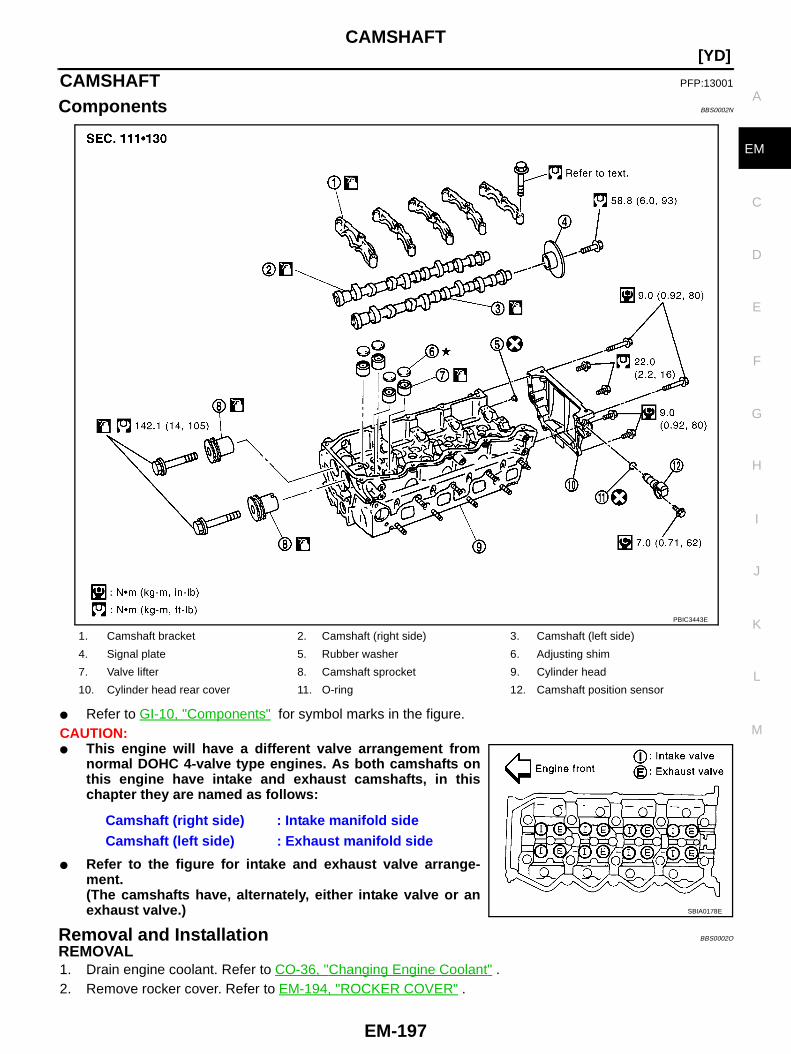
CAMSHAFT
EM-197
[YD]
C
D
E
F
G
H
I
J
K
L
M
A
EM
CAMSHAFT PFP:13001
Components BBS0002N
● Refer to GI-10, "Components" for symbol marks in the figure.CAUTION:● This engine will have a different valve arrangement from
normal DOHC 4-valve type engines. As both camshafts onthis engine have intake and exhaust camshafts, in thischapter they are named as follows:
● Refer to the figure for intake and exhaust valve arrange-ment.(The camshafts have, alternately, either intake valve or anexhaust valve.)
Removal and Installation BBS0002O
REMOVAL1. Drain engine coolant. Refer to CO-36, "Changing Engine Coolant" .2. Remove rocker cover. Refer to EM-194, "ROCKER COVER" .
1. Camshaft bracket 2. Camshaft (right side) 3. Camshaft (left side)
4. Signal plate 5. Rubber washer 6. Adjusting shim
7. Valve lifter 8. Camshaft sprocket 9. Cylinder head
10. Cylinder head rear cover 11. O-ring 12. Camshaft position sensor
Camshaft (right side) : Intake manifold sideCamshaft (left side) : Exhaust manifold side
PBIC3443E
SBIA0178E
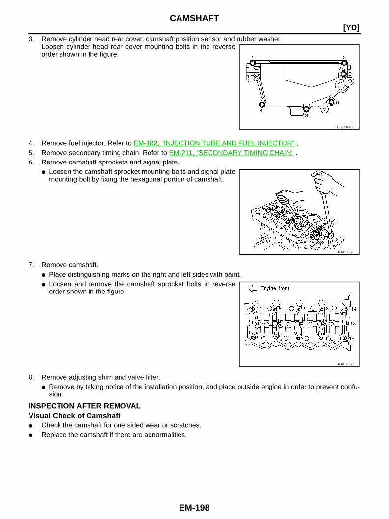
EM-198
[YD]CAMSHAFT
3. Remove cylinder head rear cover, camshaft position sensor and rubber washer.Loosen cylinder head rear cover mounting bolts in the reverseorder shown in the figure.
4. Remove fuel injector. Refer to EM-182, "INJECTION TUBE AND FUEL INJECTOR" .5. Remove secondary timing chain. Refer to EM-211, "SECONDARY TIMING CHAIN" .6. Remove camshaft sprockets and signal plate.
● Loosen the camshaft sprocket mounting bolts and signal platemounting bolt by fixing the hexagonal portion of camshaft.
7. Remove camshaft.● Place distinguishing marks on the right and left sides with paint.● Loosen and remove the camshaft sprocket bolts in reverse
order shown in the figure.
8. Remove adjusting shim and valve lifter.● Remove by taking notice of the installation position, and place outside engine in order to prevent confu-
sion.
INSPECTION AFTER REMOVALVisual Check of Camshaft● Check the camshaft for one sided wear or scratches.● Replace the camshaft if there are abnormalities.
PBIC3445E
JEM159G
JEM160G
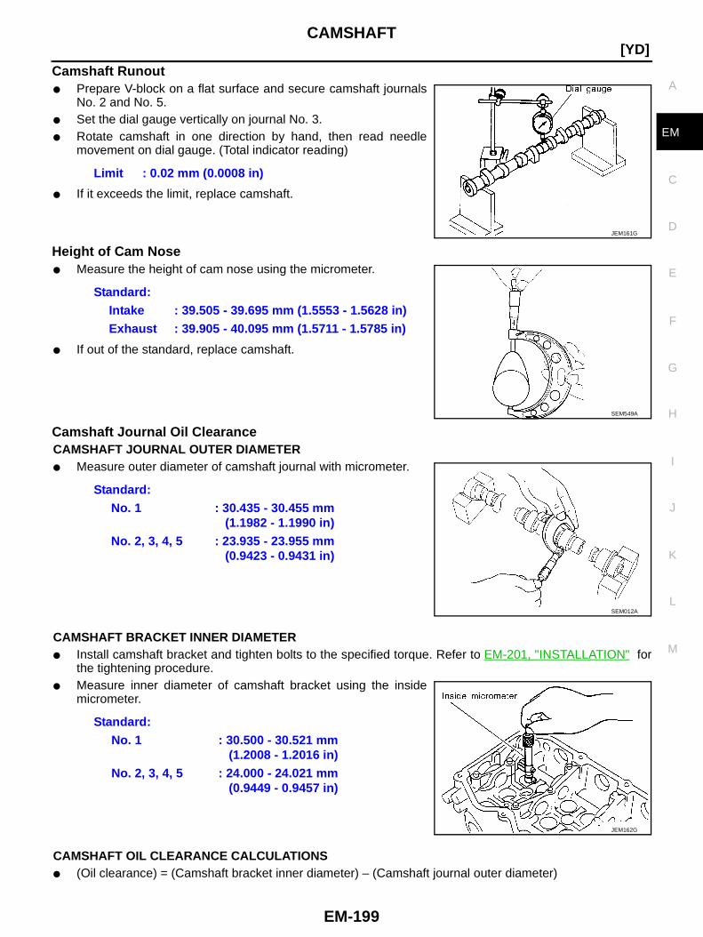
CAMSHAFT
EM-199
[YD]
C
D
E
F
G
H
I
J
K
L
M
A
EM
Camshaft Runout● Prepare V-block on a flat surface and secure camshaft journals
No. 2 and No. 5.● Set the dial gauge vertically on journal No. 3.● Rotate camshaft in one direction by hand, then read needle
movement on dial gauge. (Total indicator reading)
● If it exceeds the limit, replace camshaft.
Height of Cam Nose● Measure the height of cam nose using the micrometer.
● If out of the standard, replace camshaft.
Camshaft Journal Oil ClearanceCAMSHAFT JOURNAL OUTER DIAMETER● Measure outer diameter of camshaft journal with micrometer.
CAMSHAFT BRACKET INNER DIAMETER● Install camshaft bracket and tighten bolts to the specified torque. Refer to EM-201, "INSTALLATION" for
the tightening procedure.● Measure inner diameter of camshaft bracket using the inside
micrometer.
CAMSHAFT OIL CLEARANCE CALCULATIONS● (Oil clearance) = (Camshaft bracket inner diameter) – (Camshaft journal outer diameter)
Limit : 0.02 mm (0.0008 in)
JEM161G
Standard:Intake : 39.505 - 39.695 mm (1.5553 - 1.5628 in)Exhaust : 39.905 - 40.095 mm (1.5711 - 1.5785 in)
SEM549A
Standard:No. 1 : 30.435 - 30.455 mm
(1.1982 - 1.1990 in)No. 2, 3, 4, 5 : 23.935 - 23.955 mm
(0.9423 - 0.9431 in)
SEM012A
Standard:No. 1 : 30.500 - 30.521 mm
(1.2008 - 1.2016 in)No. 2, 3, 4, 5 : 24.000 - 24.021 mm
(0.9449 - 0.9457 in)
JEM162G
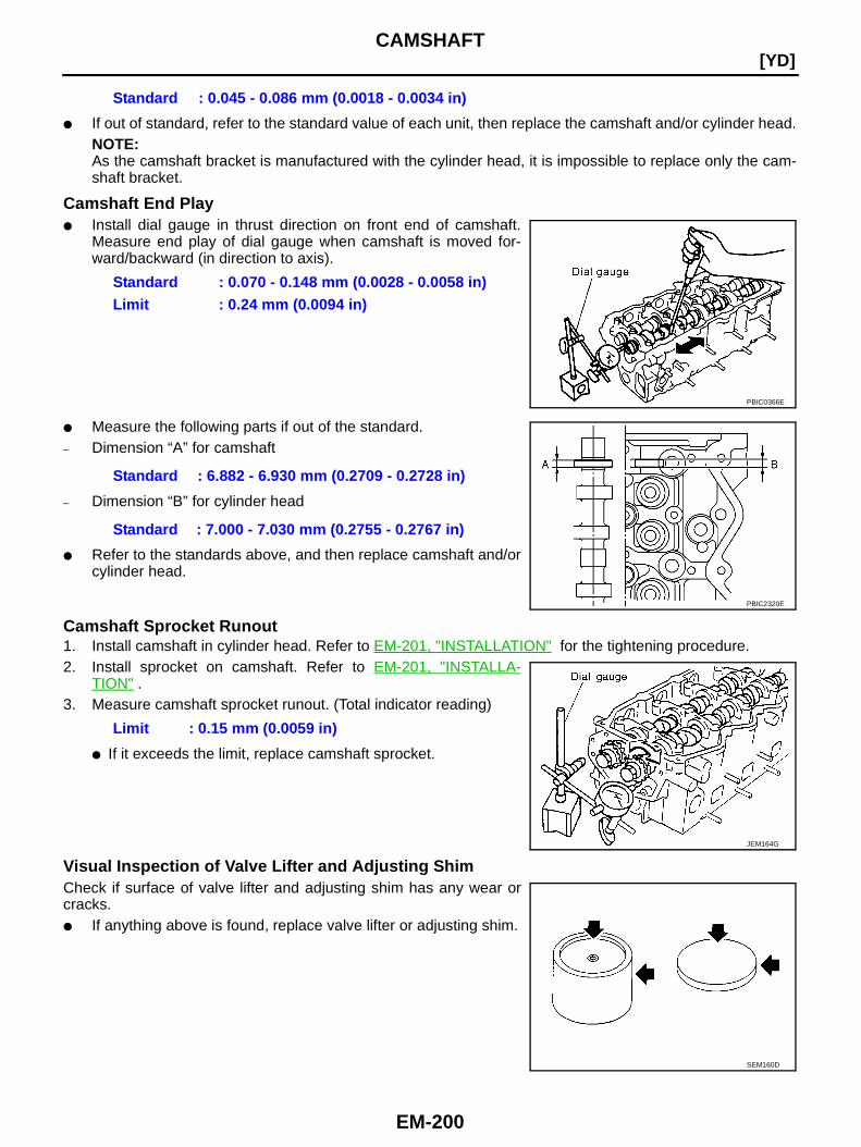
EM-200
[YD]CAMSHAFT
● If out of standard, refer to the standard value of each unit, then replace the camshaft and/or cylinder head.NOTE:As the camshaft bracket is manufactured with the cylinder head, it is impossible to replace only the cam-shaft bracket.
Camshaft End Play● Install dial gauge in thrust direction on front end of camshaft.
Measure end play of dial gauge when camshaft is moved for-ward/backward (in direction to axis).
● Measure the following parts if out of the standard.– Dimension “A” for camshaft
– Dimension “B” for cylinder head
● Refer to the standards above, and then replace camshaft and/orcylinder head.
Camshaft Sprocket Runout1. Install camshaft in cylinder head. Refer to EM-201, "INSTALLATION" for the tightening procedure.2. Install sprocket on camshaft. Refer to EM-201, "INSTALLA-
TION" .3. Measure camshaft sprocket runout. (Total indicator reading)
● If it exceeds the limit, replace camshaft sprocket.
Visual Inspection of Valve Lifter and Adjusting ShimCheck if surface of valve lifter and adjusting shim has any wear orcracks.● If anything above is found, replace valve lifter or adjusting shim.
Standard : 0.045 - 0.086 mm (0.0018 - 0.0034 in)
Standard : 0.070 - 0.148 mm (0.0028 - 0.0058 in)Limit : 0.24 mm (0.0094 in)
PBIC0366E
Standard : 6.882 - 6.930 mm (0.2709 - 0.2728 in)
Standard : 7.000 - 7.030 mm (0.2755 - 0.2767 in)
PBIC2320E
Limit : 0.15 mm (0.0059 in)
JEM164G
SEM160D
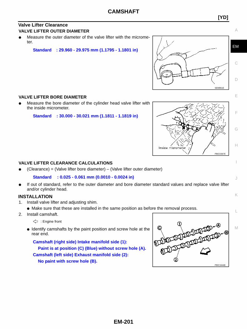
CAMSHAFT
EM-201
[YD]
C
D
E
F
G
H
I
J
K
L
M
A
EM
Valve Lifter ClearanceVALVE LIFTER OUTER DIAMETER● Measure the outer diameter of the valve lifter with the microme-
ter.
VALVE LIFTER BORE DIAMETER● Measure the bore diameter of the cylinder head valve lifter with
the inside micrometer.
VALVE LIFTER CLEARANCE CALCULATIONS● (Clearance) = (Valve lifter bore diameter) – (Valve lifter outer diameter)
● If out of standard, refer to the outer diameter and bore diameter standard values and replace valve lifterand/or cylinder head.
INSTALLATION1. Install valve lifter and adjusting shim.
● Make sure that these are installed in the same position as before the removal process.2. Install camshaft.
● Identify camshafts by the paint position and screw hole at therear end.
Standard : 29.960 - 29.975 mm (1.1795 - 1.1801 in)
SEM961E
Standard : 30.000 - 30.021 mm (1.1811 - 1.1819 in)
PBIC0367E
Standard : 0.025 - 0.061 mm (0.0010 - 0.0024 in)
: Engine front
Camshaft (right side) Intake manifold side (1):Paint is at position (C) (Blue) without screw hole (A).
Camshaft (left side) Exhaust manifold side (2):No paint with screw hole (B).
PBIC3444E
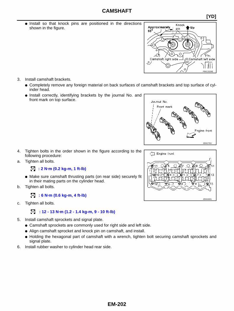
EM-202
[YD]CAMSHAFT
● Install so that knock pins are positioned in the directionsshown in the figure.
3. Install camshaft brackets.● Completely remove any foreign material on back surfaces of camshaft brackets and top surface of cyl-
inder head.● Install correctly, identifying brackets by the journal No. and
front mark on top surface.
4. Tighten bolts in the order shown in the figure according to thefollowing procedure:
a. Tighten all bolts.
● Make sure camshaft thrusting parts (on rear side) securely fitin their mating parts on the cylinder head.
b. Tighten all bolts.
c. Tighten all bolts.
5. Install camshaft sprockets and signal plate.● Camshaft sprockets are commonly used for right side and left side.● Align camshaft sprocket and knock pin on camshaft, and install.● Holding the hexagonal part of camshaft with a wrench, tighten bolt securing camshaft sprockets and
signal plate.6. Install rubber washer to cylinder head rear side.
PBIC2026E
JEM175G
: 2 N·m (0.2 kg-m, 1 ft-lb)
: 6 N·m (0.6 kg-m, 4 ft-lb)
: 12 - 13 N·m (1.2 - 1.4 kg-m, 9 - 10 ft-lb)
JEM160G
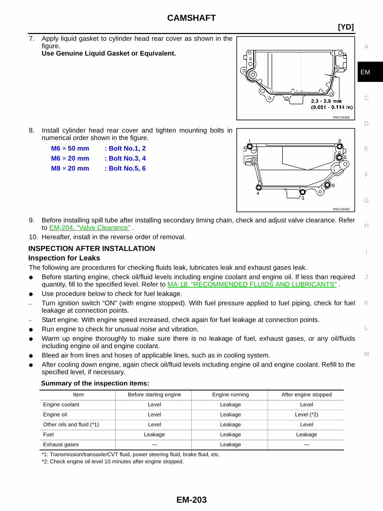
CAMSHAFT
EM-203
[YD]
C
D
E
F
G
H
I
J
K
L
M
A
EM
7. Apply liquid gasket to cylinder head rear cover as shown in thefigure.Use Genuine Liquid Gasket or Equivalent.
8. Install cylinder head rear cover and tighten mounting bolts innumerical order shown in the figure.
9. Before installing spill tube after installing secondary timing chain, check and adjust valve clearance. Referto EM-204, "Valve Clearance" .
10. Hereafter, install in the reverse order of removal.
INSPECTION AFTER INSTALLATIONInspection for LeaksThe following are procedures for checking fluids leak, lubricates leak and exhaust gases leak.● Before starting engine, check oil/fluid levels including engine coolant and engine oil. If less than required
quantity, fill to the specified level. Refer to MA-18, "RECOMMENDED FLUIDS AND LUBRICANTS" .● Use procedure below to check for fuel leakage.– Turn ignition switch “ON” (with engine stopped). With fuel pressure applied to fuel piping, check for fuel
leakage at connection points.– Start engine. With engine speed increased, check again for fuel leakage at connection points.● Run engine to check for unusual noise and vibration.● Warm up engine thoroughly to make sure there is no leakage of fuel, exhaust gases, or any oil/fluids
including engine oil and engine coolant.● Bleed air from lines and hoses of applicable lines, such as in cooling system.● After cooling down engine, again check oil/fluid levels including engine oil and engine coolant. Refill to the
specified level, if necessary.
Summary of the inspection items:
*1: Transmission/transaxle/CVT fluid, power steering fluid, brake fluid, etc.*2: Check engine oil level 10 minutes after engine stopped.
PBIC3446E
M6 × 50 mm : Bolt No.1, 2M6 × 20 mm : Bolt No.3, 4M8 × 20 mm : Bolt No.5, 6
PBIC3445E
Item Before starting engine Engine running After engine stopped
Engine coolant Level Leakage Level
Engine oil Level Leakage Level (*2)
Other oils and fluid (*1) Level Leakage Level
Fuel Leakage Leakage Leakage
Exhaust gases — Leakage —
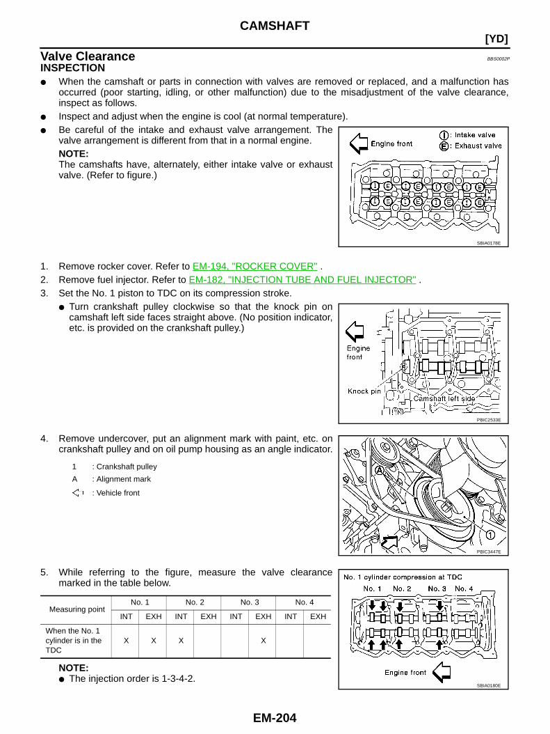
EM-204
[YD]CAMSHAFT
Valve Clearance BBS0002P
INSPECTION● When the camshaft or parts in connection with valves are removed or replaced, and a malfunction has
occurred (poor starting, idling, or other malfunction) due to the misadjustment of the valve clearance,inspect as follows.
● Inspect and adjust when the engine is cool (at normal temperature).● Be careful of the intake and exhaust valve arrangement. The
valve arrangement is different from that in a normal engine.NOTE:The camshafts have, alternately, either intake valve or exhaustvalve. (Refer to figure.)
1. Remove rocker cover. Refer to EM-194, "ROCKER COVER" .2. Remove fuel injector. Refer to EM-182, "INJECTION TUBE AND FUEL INJECTOR" .3. Set the No. 1 piston to TDC on its compression stroke.
● Turn crankshaft pulley clockwise so that the knock pin oncamshaft left side faces straight above. (No position indicator,etc. is provided on the crankshaft pulley.)
4. Remove undercover, put an alignment mark with paint, etc. oncrankshaft pulley and on oil pump housing as an angle indicator.
5. While referring to the figure, measure the valve clearancemarked in the table below.
NOTE:● The injection order is 1-3-4-2.
SBIA0178E
PBIC2533E
1 : Crankshaft pulley
A : Alignment mark
: Vehicle front
PBIC3447E
Measuring pointNo. 1 No. 2 No. 3 No. 4
INT EXH INT EXH INT EXH INT EXH
When the No. 1cylinder is in theTDC
X X X X
SBIA0180E
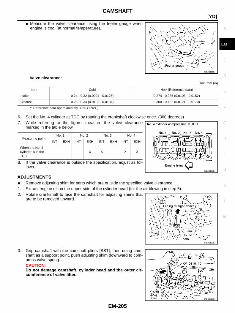
CAMSHAFT
EM-205
[YD]
C
D
E
F
G
H
I
J
K
L
M
A
EM
● Measure the valve clearance using the feeler gauge whenengine is cool (at normal temperature).
Valve clearance:Unit: mm (in)
*: Reference data approximately 80°C (176°F)
6. Set the No. 4 cylinder at TDC by rotating the crankshaft clockwise once. (360 degrees)7. While referring to the figure, measure the valve clearance
marked in the table below.
8. If the valve clearance is outside the specification, adjust as fol-lows.
ADJUSTMENTS● Remove adjusting shim for parts which are outside the specified valve clearance.1. Extract engine oil on the upper side of the cylinder head (for the air blowing in step 6).2. Rotate crankshaft to face the camshaft for adjusting shims that
are to be removed upward.
3. Grip camshaft with the camshaft pliers [SST], then using cam-shaft as a support point, push adjusting shim downward to com-press valve spring.CAUTION:Do not damage camshaft, cylinder head and the outer cir-cumference of valve lifter.
SBIA0181E
Item Cold Hot* (Reference data)
Intake 0.24 - 0.32 (0.0094 - 0.0126) 0.274 - 0.386 (0.0108 - 0.0152)
Exhaust 0.26 - 0.34 (0.0102 - 0.0134) 0.308 - 0.432 (0.0121 - 0.0170)
Measuring pointNo. 1 No. 2 No. 3 No. 4
INT EXH INT EXH INT EXH INT EXH
When the No. 4cylinder is in theTDC
X X X X
SBIA0182E
SBIA0183E
PBIC2321E
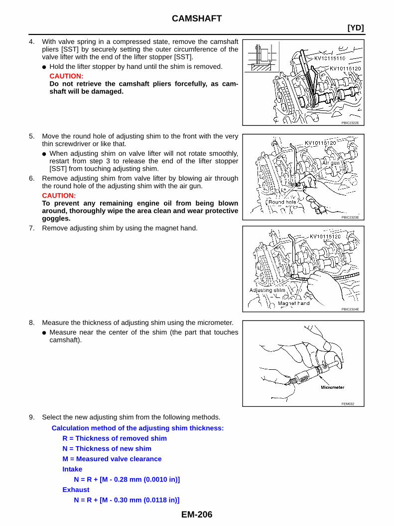
EM-206
[YD]CAMSHAFT
4. With valve spring in a compressed state, remove the camshaftpliers [SST] by securely setting the outer circumference of thevalve lifter with the end of the lifter stopper [SST].● Hold the lifter stopper by hand until the shim is removed.
CAUTION:Do not retrieve the camshaft pliers forcefully, as cam-shaft will be damaged.
5. Move the round hole of adjusting shim to the front with the verythin screwdriver or like that.● When adjusting shim on valve lifter will not rotate smoothly,
restart from step 3 to release the end of the lifter stopper[SST] from touching adjusting shim.
6. Remove adjusting shim from valve lifter by blowing air throughthe round hole of the adjusting shim with the air gun.CAUTION:To prevent any remaining engine oil from being blownaround, thoroughly wipe the area clean and wear protectivegoggles.
7. Remove adjusting shim by using the magnet hand.
8. Measure the thickness of adjusting shim using the micrometer.● Measure near the center of the shim (the part that touches
camshaft).
9. Select the new adjusting shim from the following methods.
PBIC2322E
PBIC2323E
PBIC2324E
FEM032
Calculation method of the adjusting shim thickness:R = Thickness of removed shimN = Thickness of new shimM = Measured valve clearanceIntake
N = R + [M - 0.28 mm (0.0010 in)]Exhaust
N = R + [M - 0.30 mm (0.0118 in)]

CAMSHAFT
EM-207
[YD]
C
D
E
F
G
H
I
J
K
L
M
A
EM
● New adjusting shims have the thickness stamped on the rearside.
● Shims are available in 33 size from 2.10 mm (0.0827 in) to2.74 mm (0.1079 in), in steps of 0.02 mm (0.0008 in). Refer toEM-275, "Available Shims" .
10. Fit the selected adjusting shim to valve lifter.CAUTION:Place the stamped side of adjusting shim to valve lifter.
11. Compress valve spring using the camshaft pliers [SST: KV10115110] and remove the lifter stopper [SST].12. Rotate crankshaft 2 to 3 turns by hand.13. Confirm that the valve clearance is within the specification. Refer to EM-204, "INSPECTION" .14. Install remaining parts in the reverse order of removal.15. Warm up engine, and check for unusual noise and vibration.
JEM184G
PBIC2325E

EM-208
[YD]OIL SEAL
OIL SEAL PFP:12279
Removal and Installation of Valve Oil Seal BBS0002Q
REMOVAL1. Turn crankshaft until the cylinder requiring new valve oil seals is at TDC. This will prevent valve from drop-
ping into cylinder.2. Remove camshafts. Refer to EM-197, "CAMSHAFT" .3. Remove adjusting shims and valve lifters. Refer to EM-197, "CAMSHAFT" .
● Check the installation positions, and keep them to avoid being confused.4. Rotate crankshaft, and set piston whose valve oil seal is to be removed to TDC. This will prevent valve
from dropping into cylinder.5. Remove valve collet.
● Compress the valve spring with valve spring compressor,attachment and adapter [SST]. Remove valve collet with amagnet hand.
CAUTION:When working, be careful not to damage valve lifter holes.
6. Remove valve spring retainer and valve spring.7. Remove valve oil seal with the valve oil seal puller [SST].
INSTALLATION1. Apply new engine oil to valve oil seal joint surface and seal lip.2. Using the valve oil seal drift [SST], install valve oil seals referring
to the dimension shown in the figure.
3. Install in the reverse order of removal.
PBIC2388E
JEM153G
JEM165G
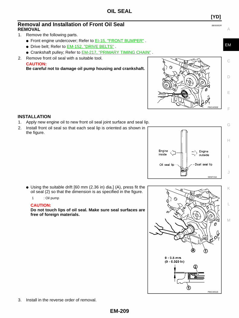
OIL SEAL
EM-209
[YD]
C
D
E
F
G
H
I
J
K
L
M
A
EM
Removal and Installation of Front Oil Seal BBS0002R
REMOVAL1. Remove the following parts.
● Front engine undercover; Refer to EI-15, "FRONT BUMPER" .● Drive belt; Refer to EM-152, "DRIVE BELTS" .● Crankshaft pulley; Refer to EM-217, "PRIMARY TIMING CHAIN" .
2. Remove front oil seal with a suitable tool.CAUTION:Be careful not to damage oil pump housing and crankshaft.
INSTALLATION1. Apply new engine oil to new front oil seal joint surface and seal lip.2. Install front oil seal so that each seal lip is oriented as shown in
the figure.
● Using the suitable drift [60 mm (2.36 in) dia.] (A), press fit theoil seal (2) so that the dimension is as specified in the figure.
CAUTION:Do not touch lips of oil seal. Make sure seal surfaces arefree of foreign materials.
3. Install in the reverse order of removal.
PBIC4050E
SEM715A
1 : Oil pump
PBIC4051E
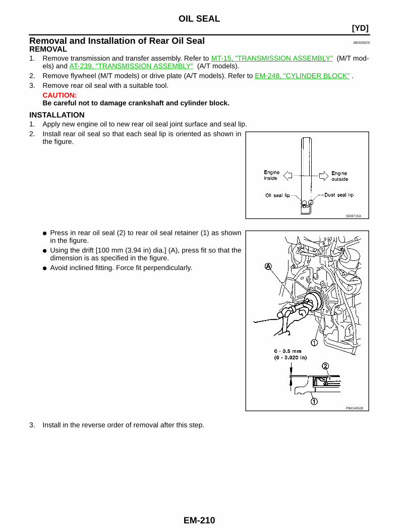
EM-210
[YD]OIL SEAL
Removal and Installation of Rear Oil Seal BBS0002S
REMOVAL1. Remove transmission and transfer assembly. Refer to MT-15, "TRANSMISSION ASSEMBLY" (M/T mod-
els) and AT-239, "TRANSMISSION ASSEMBLY" (A/T models).2. Remove flywheel (M/T models) or drive plate (A/T models). Refer to EM-248, "CYLINDER BLOCK" .3. Remove rear oil seal with a suitable tool.
CAUTION:Be careful not to damage crankshaft and cylinder block.
INSTALLATION1. Apply new engine oil to new rear oil seal joint surface and seal lip.2. Install rear oil seal so that each seal lip is oriented as shown in
the figure.
● Press in rear oil seal (2) to rear oil seal retainer (1) as shownin the figure.
● Using the drift [100 mm (3.94 in) dia.] (A), press fit so that thedimension is as specified in the figure.
● Avoid inclined fitting. Force fit perpendicularly.
3. Install in the reverse order of removal after this step.
SEM715A
PBIC4052E
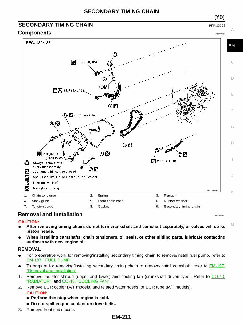
SECONDARY TIMING CHAIN
EM-211
[YD]
C
D
E
F
G
H
I
J
K
L
M
A
EM
SECONDARY TIMING CHAIN PFP:13028
Components BBS0002T
Removal and Installation BBS0002U
CAUTION:● After removing timing chain, do not turn crankshaft and camshaft separately, or valves will strike
piston heads.● When installing camshafts, chain tensioners, oil seals, or other sliding parts, lubricate contacting
surfaces with new engine oil.
REMOVAL● For preparative work for removing/installing secondary timing chain to remove/install fuel pump, refer to
EM-187, "FUEL PUMP" .● To prepare for removing/installing secondary timing chain to remove/install camshaft, refer to EM-197,
"Removal and Installation" .1. Remove radiator shroud (upper and lower) and cooling fan (crankshaft driven type). Refer to CO-40,
"RADIATOR" and CO-48, "COOLING FAN" .2. Remove EGR cooler (A/T models) and related water hoses, or EGR tube (M/T models).
CAUTION:● Perform this step when engine is cold.● Do not spill engine coolant on drive belts.
3. Remove front chain case.
1. Chain tensioner 2. Spring 3. Plunger
4. Slack guide 5. Front chain case 6. Rubber washer
7. Tension guide 8. Gasket 9. Secondary timing chain
PBIC2326E

EM-212
[YD]SECONDARY TIMING CHAIN
● Loosen fixing bolts in reverse order of that shown in the figureand remove them.CAUTION:● While front chain case is removed, cover openings to
prevent entry of foreign material into engine.
● Do not remove two mass dampers on the back ofcover.
4. Set the No. 1 piston to TDC on its compression stroke.● Turn crankshaft pulley clockwise so that the alignment mark
(punched mark) on each camshaft sprocket is positioned asshown in the figure.
● No position indicator is provided on crankshaft pulley.● When installing, color coded links on secondary timing
chain can be used as alignment marks. Marking may notbe necessary for removal; however, make alignmentmarks as required because the alignment mark on fuelpump sprocket may not be easy to see.
5. Remove chain tensioner.a. Push the plunger of chain tensioner and keep it pressed with a
push pin.
JEM121G
SBIA0189E
SEM515G
JEM124G
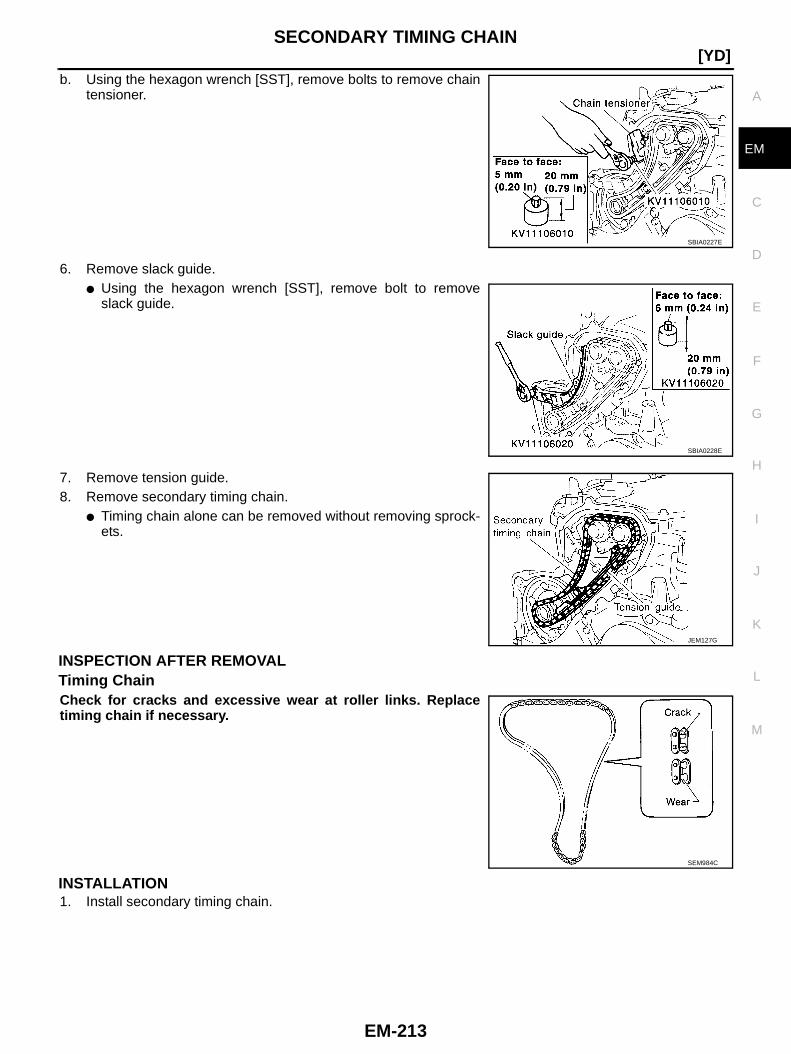
SECONDARY TIMING CHAIN
EM-213
[YD]
C
D
E
F
G
H
I
J
K
L
M
A
EM
b. Using the hexagon wrench [SST], remove bolts to remove chaintensioner.
6. Remove slack guide.● Using the hexagon wrench [SST], remove bolt to remove
slack guide.
7. Remove tension guide.8. Remove secondary timing chain.
● Timing chain alone can be removed without removing sprock-ets.
INSPECTION AFTER REMOVALTiming ChainCheck for cracks and excessive wear at roller links. Replacetiming chain if necessary.
INSTALLATION1. Install secondary timing chain.
SBIA0227E
SBIA0228E
JEM127G
SEM984C

EM-214
[YD]SECONDARY TIMING CHAIN
● When installing, match the alignment marks on sprockets withcolor coded alignment marks (colored links) on the timingchain.
2. Install tension guide (5).● The upper bolt has a longer shank than the lower bolt.
3. Using the hexagon wrench [SST], install slack guide.
4. Install chain tensioner.a. Push the plunger of chain tensioner. While holding it with a push
pin, install chain tensioner.b. Using the hexagon wrench [SST], tighten bolts.c. Pull out the push pin, etc. holding the plunger.
● Make sure again that the alignment marks on the sprock-ets and the colored alignment marks on the timing chainare aligned.
5. Install front chain case.
1 : Secondary timing chain
2 : Chain tensioner
3 : Slack guide
4 : Fuel pump sprocket
5 : Tension guide
6 : Camshaft sprocket
A : Alignment mark (silver link)
B : Alignment mark (punched mark)
C : Alignment mark (yellow link)
PBIC4048E
SBIA0228E
SBIA0227E
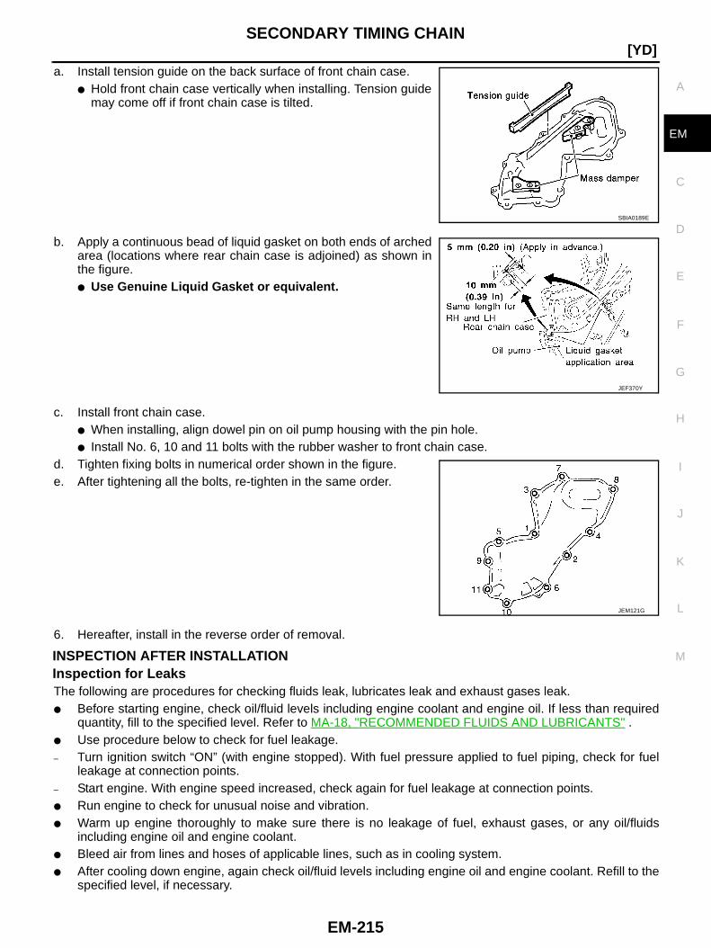
SECONDARY TIMING CHAIN
EM-215
[YD]
C
D
E
F
G
H
I
J
K
L
M
A
EM
a. Install tension guide on the back surface of front chain case.● Hold front chain case vertically when installing. Tension guide
may come off if front chain case is tilted.
b. Apply a continuous bead of liquid gasket on both ends of archedarea (locations where rear chain case is adjoined) as shown inthe figure.● Use Genuine Liquid Gasket or equivalent.
c. Install front chain case.● When installing, align dowel pin on oil pump housing with the pin hole.● Install No. 6, 10 and 11 bolts with the rubber washer to front chain case.
d. Tighten fixing bolts in numerical order shown in the figure.e. After tightening all the bolts, re-tighten in the same order.
6. Hereafter, install in the reverse order of removal.
INSPECTION AFTER INSTALLATIONInspection for LeaksThe following are procedures for checking fluids leak, lubricates leak and exhaust gases leak.● Before starting engine, check oil/fluid levels including engine coolant and engine oil. If less than required
quantity, fill to the specified level. Refer to MA-18, "RECOMMENDED FLUIDS AND LUBRICANTS" .● Use procedure below to check for fuel leakage.– Turn ignition switch “ON” (with engine stopped). With fuel pressure applied to fuel piping, check for fuel
leakage at connection points.– Start engine. With engine speed increased, check again for fuel leakage at connection points.● Run engine to check for unusual noise and vibration.● Warm up engine thoroughly to make sure there is no leakage of fuel, exhaust gases, or any oil/fluids
including engine oil and engine coolant.● Bleed air from lines and hoses of applicable lines, such as in cooling system.● After cooling down engine, again check oil/fluid levels including engine oil and engine coolant. Refill to the
specified level, if necessary.
SBIA0189E
JEF370Y
JEM121G
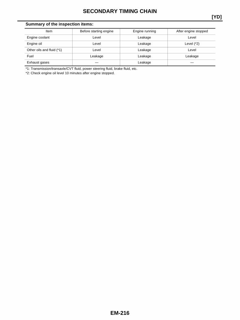
EM-216
[YD]SECONDARY TIMING CHAIN
Summary of the inspection items:
*1: Transmission/transaxle/CVT fluid, power steering fluid, brake fluid, etc.*2: Check engine oil level 10 minutes after engine stopped.
Item Before starting engine Engine running After engine stopped
Engine coolant Level Leakage Level
Engine oil Level Leakage Level (*2)
Other oils and fluid (*1) Level Leakage Level
Fuel Leakage Leakage Leakage
Exhaust gases — Leakage —
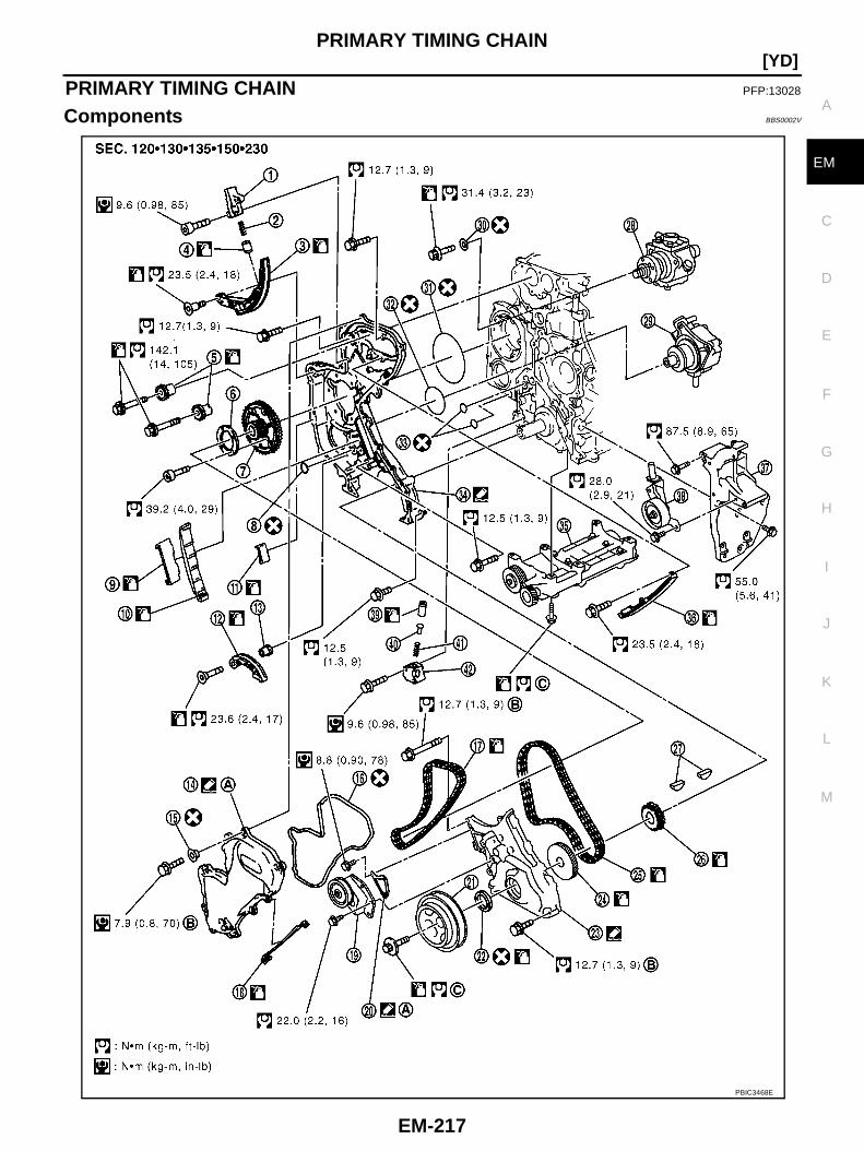
PRIMARY TIMING CHAIN
EM-217
[YD]
C
D
E
F
G
H
I
J
K
L
M
A
EM
PRIMARY TIMING CHAIN PFP:13028
Components BBS0002V
PBIC3468E
EM-218
[YD]PRIMARY TIMING CHAIN
● Refer to GI-10, "Components" for symbol marks in the figure.
Removal and Installation BBS0002W
CAUTION:● After removing timing chain, do not turn crankshaft and camshaft separately, or valves will strike
piston heads.● When installing camshafts, chain tensioners, oil seals or other sliding parts, lubricate contacting
surfaces with new engine oil.
REMOVAL1. Remove power steering oil pump and power steering oil pump bracket. Refer to PS-35, "POWER STEER-
ING OIL PUMP" .2. Remove idler pulleys.3. Remove rocker cover. Refer to EM-194, "ROCKER COVER" .4. Remove oil pan (upper and lower). Refer to EM-174, "OIL PAN AND OIL STRAINER" .5. Remove fuel injector. Refer to EM-182, "INJECTION TUBE AND FUEL INJECTOR" .6. Remove secondary timing chain and associated parts. Refer to EM-211, "SECONDARY TIMING CHAIN" .7. When removing rear chain case, remove camshaft sprockets. Refer to EM-197, "CAMSHAFT" .8. Remove crankshaft pulley.a. Hold crankshaft pulley with the pulley holder (commercial ser-
vice tool).b. Loosen crankshaft pulley fixing bolt and pull out the bolt approx-
imately 10 mm (0.39 in).
1. Chain tensioner 2. Spring 3. Slack guide
4. Plunger 5. Camshaft sprocket 6. Washer
7. Fuel pump sprocket 8. O-ring 9. Tension guide
10. Tension guide 11. Chain guide 12. Slack guide
13. Spacer 14. Front chain case 15. Rubber washer
16. Gasket 17. Secondary timing chain 18. Chain guide
19. Idler pulley 20. Vacuum pump cover 21. Crankshaft pulley
22. Front oil seal 23. Oil pump housing 24. Crankshaft gear
25. Primary timing chain 26. Crankshaft sprocket 27. Key
28. Fuel pump 29. Vacuum pump 30. Seal washer
31. O-ring 32. O-ring 33. O-ring
34. Rear chain case 35. Balancer unit 36. Tension guide
37. A/C compressor bracket 38. Idler pulley 39. Plunger
40. Plug 41. Spring 42. Chain tensioner
A. Oil pump side. B. Tighten twice. C. Refer to EM-223 .
PBIC3469E

PRIMARY TIMING CHAIN
EM-219
[YD]
C
D
E
F
G
H
I
J
K
L
M
A
EM
c. Using the pulley puller [SST], remove crankshaft pulley.● Use two M6 bolts with approx. 60 mm (2.36 in) shank length
for securing crankshaft pulley.
9. Remove oil pump housing.● Loosen bolts in reverse order of that shown in the figure and
remove them.● Use the seal cutter [SST: KV10111100] etc. for removal.
10. Remove crankshaft gear.● Remove crankshaft gear (1) with the following procedure.
a. Make sure that No.1 piston is TDC on its compression stroke.b. Turn the idler sub gear (3) counterclockwise with snap ring plier
(B) or suitable tool for aligning idler sub gear (3) and idler maingear (2).● If idler gear rotates, hold the flat faces on balancer drive shaft
front end (4).c. Install internal mechanism securing bolt and plate (Service part:
13012 EB30A and 13013 EB30A) (A) and tighten to the speci-fied torque.
CAUTION:● Do not loosen idler gear mounting bolt (5).● Only use the genuine internal mechanism securing bolt
and plate (A), or the idler gear (2) and (3) will be damaged.● Do not remove internal mechanism securing bolt and
plate (A) from idler gear (2) and (3) until crankshaft gear(1) and all of the parts in connection have been installed.
● If internal mechanism securing bolt and plate (A) is notinstalled, internal mechanism of idler gear (2) and (3) willdisengage after crankshaft gear (1) is removed. This willprohibit the balancer unit from being reusable.
d. Apply mating marks (C) to crankshaft gear (1) and idler sub gear (3).e. Remove crankshaft gear (1).11. Remove front oil seal from oil pump housing.
● Punch out the seal off from the back surface of the oil pump housing using a flat-bladed screwdriver.CAUTION:Be careful not to damage oil pump housing.
JEM132G
PBIC3470E
: 4.0 N·m (0.41 kg-m, 35 in-lb)
PBIC3471E
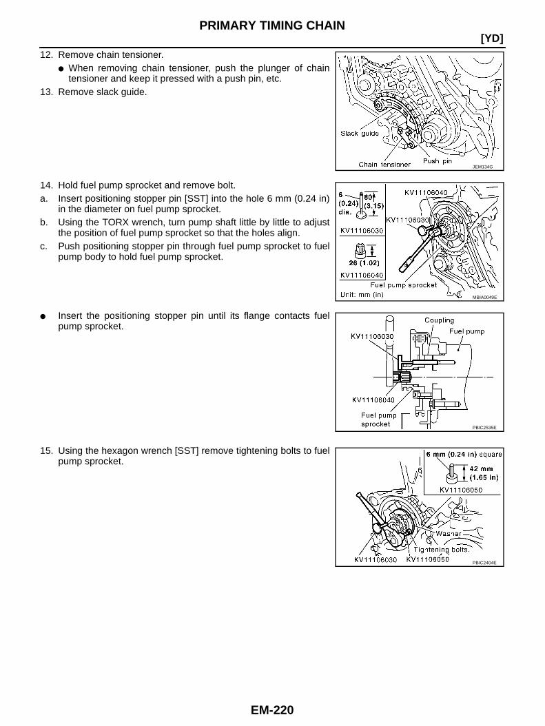
EM-220
[YD]PRIMARY TIMING CHAIN
12. Remove chain tensioner.● When removing chain tensioner, push the plunger of chain
tensioner and keep it pressed with a push pin, etc.13. Remove slack guide.
14. Hold fuel pump sprocket and remove bolt.a. Insert positioning stopper pin [SST] into the hole 6 mm (0.24 in)
in the diameter on fuel pump sprocket.b. Using the TORX wrench, turn pump shaft little by little to adjust
the position of fuel pump sprocket so that the holes align.c. Push positioning stopper pin through fuel pump sprocket to fuel
pump body to hold fuel pump sprocket.
● Insert the positioning stopper pin until its flange contacts fuelpump sprocket.
15. Using the hexagon wrench [SST] remove tightening bolts to fuelpump sprocket.
JEM134G
MBIA0049E
PBIC2535E
PBIC2404E
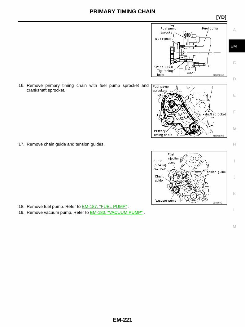
PRIMARY TIMING CHAIN
EM-221
[YD]
C
D
E
F
G
H
I
J
K
L
M
A
EM
16. Remove primary timing chain with fuel pump sprocket andcrankshaft sprocket.
17. Remove chain guide and tension guides.
18. Remove fuel pump. Refer to EM-187, "FUEL PUMP" .19. Remove vacuum pump. Refer to EM-180, "VACUUM PUMP" .
MBIA0074E
MBIA0079E
JEM885G
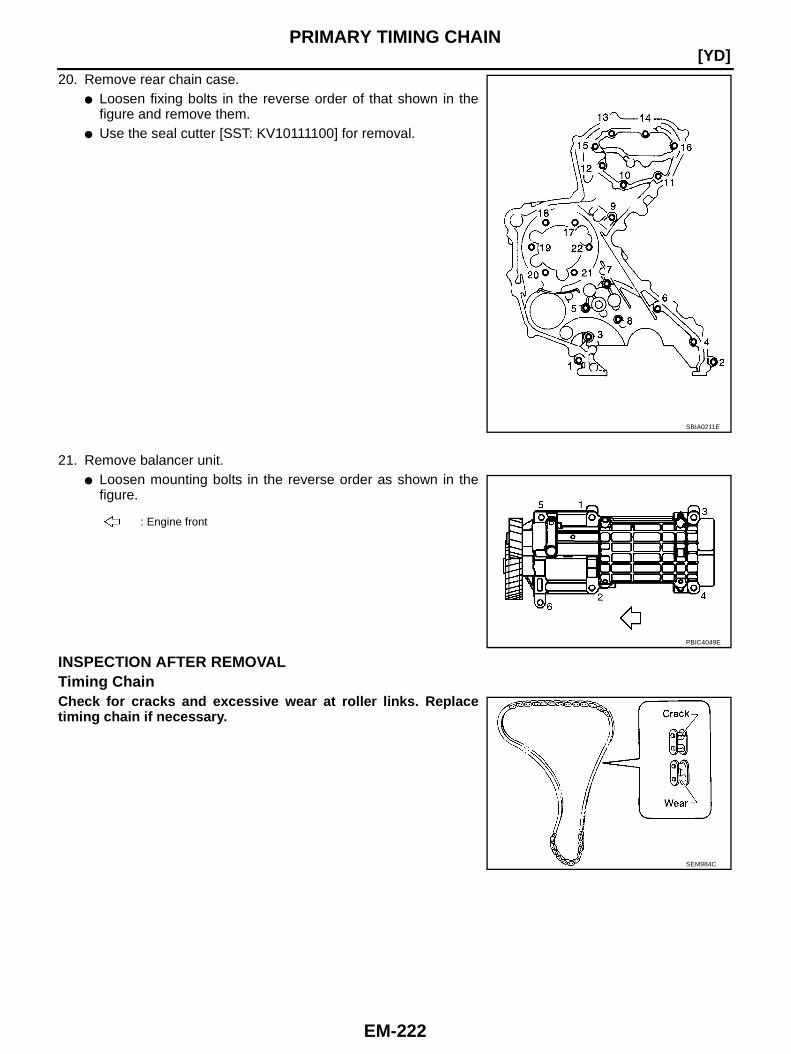
EM-222
[YD]PRIMARY TIMING CHAIN
20. Remove rear chain case.● Loosen fixing bolts in the reverse order of that shown in the
figure and remove them.● Use the seal cutter [SST: KV10111100] for removal.
21. Remove balancer unit.● Loosen mounting bolts in the reverse order as shown in the
figure.
INSPECTION AFTER REMOVALTiming ChainCheck for cracks and excessive wear at roller links. Replacetiming chain if necessary.
SBIA0211E
: Engine front
PBIC4049E
SEM984C
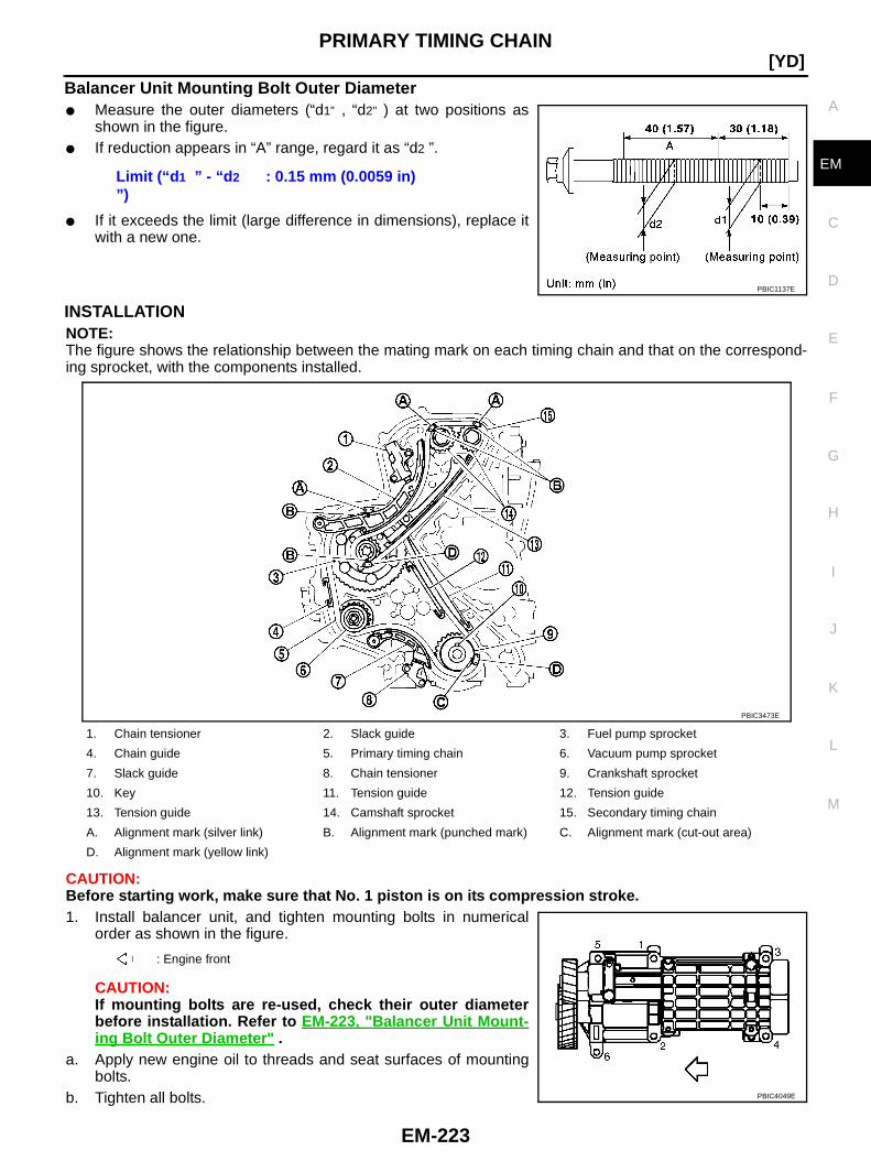
PRIMARY TIMING CHAIN
EM-223
[YD]
C
D
E
F
G
H
I
J
K
L
M
A
EM
Balancer Unit Mounting Bolt Outer Diameter● Measure the outer diameters (“d1” , “d2” ) at two positions as
shown in the figure.● If reduction appears in “A” range, regard it as “d2 ”.
● If it exceeds the limit (large difference in dimensions), replace itwith a new one.
INSTALLATIONNOTE:The figure shows the relationship between the mating mark on each timing chain and that on the correspond-ing sprocket, with the components installed.
CAUTION:Before starting work, make sure that No. 1 piston is on its compression stroke.1. Install balancer unit, and tighten mounting bolts in numerical
order as shown in the figure.
CAUTION:If mounting bolts are re-used, check their outer diameterbefore installation. Refer to EM-223, "Balancer Unit Mount-ing Bolt Outer Diameter " .
a. Apply new engine oil to threads and seat surfaces of mountingbolts.
b. Tighten all bolts.
Limit (“d 1 ” - “d 2
”): 0.15 mm (0.0059 in)
PBIC1137E
1. Chain tensioner 2. Slack guide 3. Fuel pump sprocket
4. Chain guide 5. Primary timing chain 6. Vacuum pump sprocket
7. Slack guide 8. Chain tensioner 9. Crankshaft sprocket
10. Key 11. Tension guide 12. Tension guide
13. Tension guide 14. Camshaft sprocket 15. Secondary timing chain
A. Alignment mark (silver link) B. Alignment mark (punched mark) C. Alignment mark (cut-out area)
D. Alignment mark (yellow link)
: Engine front
PBIC3473E
PBIC4049E

EM-224
[YD]PRIMARY TIMING CHAIN
c. Turn all bolts 65 degrees clockwise (angle tightening).
d. Completely loosen.
CAUTION:In this step, loosen bolts in reverse order as shown in thefigure.
e. Tighten all bolts.
f. Turn them another 65 degrees clockwise (angle tightening).CAUTION:Check tightening angle with an angle wrench [SST] (A) or a protractor. Do not make judgment byvisual check alone.
2. Install rear chain case.a. Apply a continuous bead of liquid gasket with the tube presser
[SST: WS39930000] on locations shown in the figure.Use Genuine Liquid Gasket or equivalent.A: Apply bead so that it does not protrude into the oil passage.B, C: Minimize overlapping area of bead, by starting and endingat areas of bead as shown in the figure. Apply so that the portionmarked * comes at an external location but cannot be viewedexternally after engine assembly.D: Leave the start and end areas of the bead slightly protrudingfrom the case surface.
b. Install four O-rings to the grooves of the cylinder block and fuelpump bracket.
c. Install rear chain case.● When installing, align the dowel pin with the pin hole.
: 29.4 N·m (3.0 kg-m, 22 ft-lb)
1 : Balancer unit
A : KV10112100
: 0 N·m (0 kg-m, 0 ft-lb)
: 29.4 N·m (3.0 kg-m, 22 ft-lb)
PBIC3474E
PBIC1255E
JEM141G
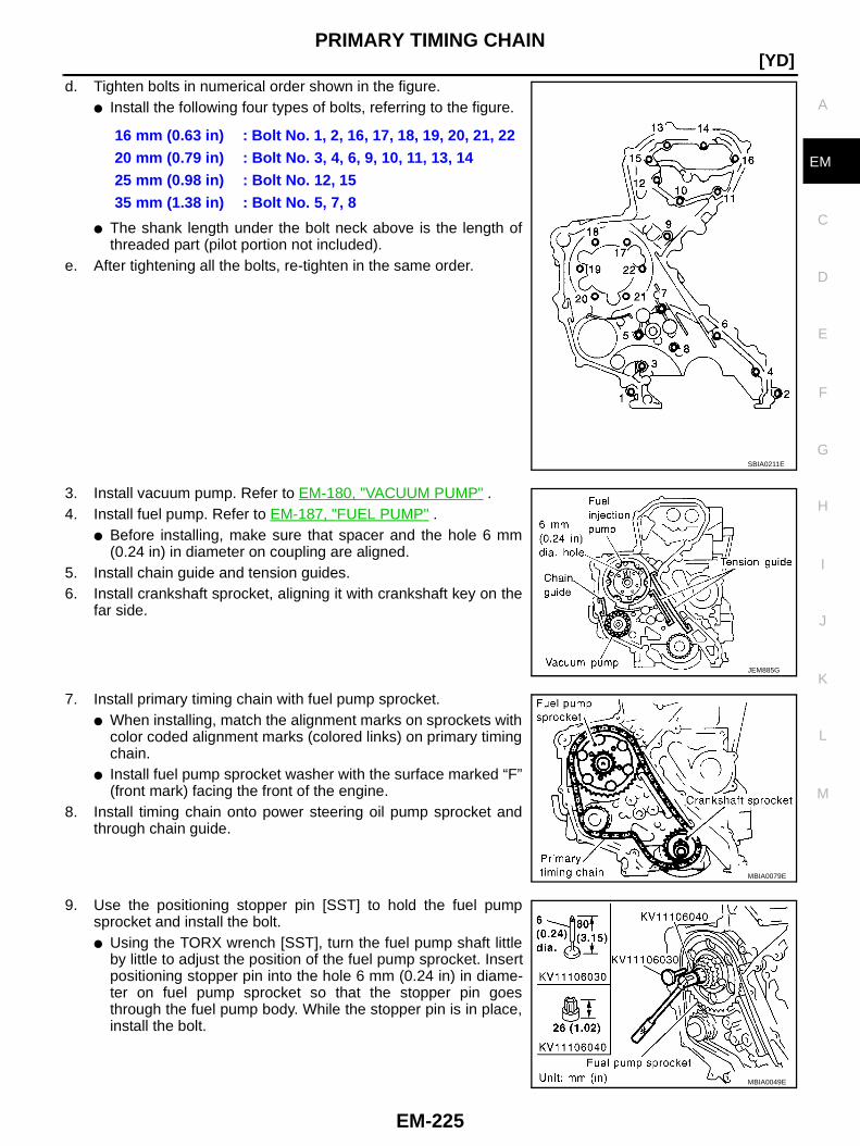
PRIMARY TIMING CHAIN
EM-225
[YD]
C
D
E
F
G
H
I
J
K
L
M
A
EM
d. Tighten bolts in numerical order shown in the figure.● Install the following four types of bolts, referring to the figure.
● The shank length under the bolt neck above is the length ofthreaded part (pilot portion not included).
e. After tightening all the bolts, re-tighten in the same order.
3. Install vacuum pump. Refer to EM-180, "VACUUM PUMP" .4. Install fuel pump. Refer to EM-187, "FUEL PUMP" .
● Before installing, make sure that spacer and the hole 6 mm(0.24 in) in diameter on coupling are aligned.
5. Install chain guide and tension guides.6. Install crankshaft sprocket, aligning it with crankshaft key on the
far side.
7. Install primary timing chain with fuel pump sprocket.● When installing, match the alignment marks on sprockets with
color coded alignment marks (colored links) on primary timingchain.
● Install fuel pump sprocket washer with the surface marked “F”(front mark) facing the front of the engine.
8. Install timing chain onto power steering oil pump sprocket andthrough chain guide.
9. Use the positioning stopper pin [SST] to hold the fuel pumpsprocket and install the bolt.● Using the TORX wrench [SST], turn the fuel pump shaft little
by little to adjust the position of the fuel pump sprocket. Insertpositioning stopper pin into the hole 6 mm (0.24 in) in diame-ter on fuel pump sprocket so that the stopper pin goesthrough the fuel pump body. While the stopper pin is in place,install the bolt.
16 mm (0.63 in) : Bolt No. 1, 2, 16, 17, 18, 19, 20, 21, 2220 mm (0.79 in) : Bolt No. 3, 4, 6, 9, 10, 11, 13, 1425 mm (0.98 in) : Bolt No. 12, 1535 mm (1.38 in) : Bolt No. 5, 7, 8
SBIA0211E
JEM885G
MBIA0079E
MBIA0049E

EM-226
[YD]PRIMARY TIMING CHAIN
10. Install timing chain slack guide.11. Install chain tensioner.
● Push the plunger of the chain tensioner. While keepingplunger pressed down with a push pin, etc., install chain ten-sioner.
● After installation, pull out the push pin holding the plunger.CAUTION:Make sure again that the alignment marks on sprockets andthe colored alignment marks on timing chain are aligned.
12. Install front oil seal (1) to oil pump housing (2).● Using the suitable drift (A) [62 mm (2.44 in) dia.], force fit the
seal until it hits the bottom.CAUTION:Do not touch lips of oil seal. Make sure seal surfaces arefree of foreign materials.
13. Install vacuum pump cover to oil pump housing.● Apply a continuous bead of liquid gasket with the tube presser
[SST: WS39930000] as shown in the figure.Use Genuine Liquid Gasket or equivalent.
● Apply liquid gasket on oil pump-side surface.
14. Install crankshaft gear.● Install crankshaft gear with the following procedure.
PBIC2404E
JEM134G
PBIC3448E
JEM143G

PRIMARY TIMING CHAIN
EM-227
[YD]
C
D
E
F
G
H
I
J
K
L
M
A
EM
– Align crankshaft gear (1) mating mark and idler sub gear (3)mating mark (C).
– Remove internal mechanism securing bolt and plate (Servicepart: 13012 EB30A and 13013 EB30A) (A).
– If new balancer unit (2) is used, align matching marks (B) ofeach gear as shown in the figure.
– Remove securing-bolt-and-plate (A) and securing pin (C) afterinstalling crankshaft gear (1).
15. Install oil pump housing.a. Apply a continuous bead of liquid gasket with the tube presser
[SST: WS39930000] as shown in the figure.A: Leave the start and end areas of the bead slightly protrudingfrom the surface.B: Apply liquid gasket along upper end surface of oil pump hous-ing.
2 : Idler main gear
4 : Balancer drive shaft front end
5 : Idler gear mounting bolt (do not loosen)
B : Snap ring plier
PBIC3471E
PBIC3475E
JEM144G
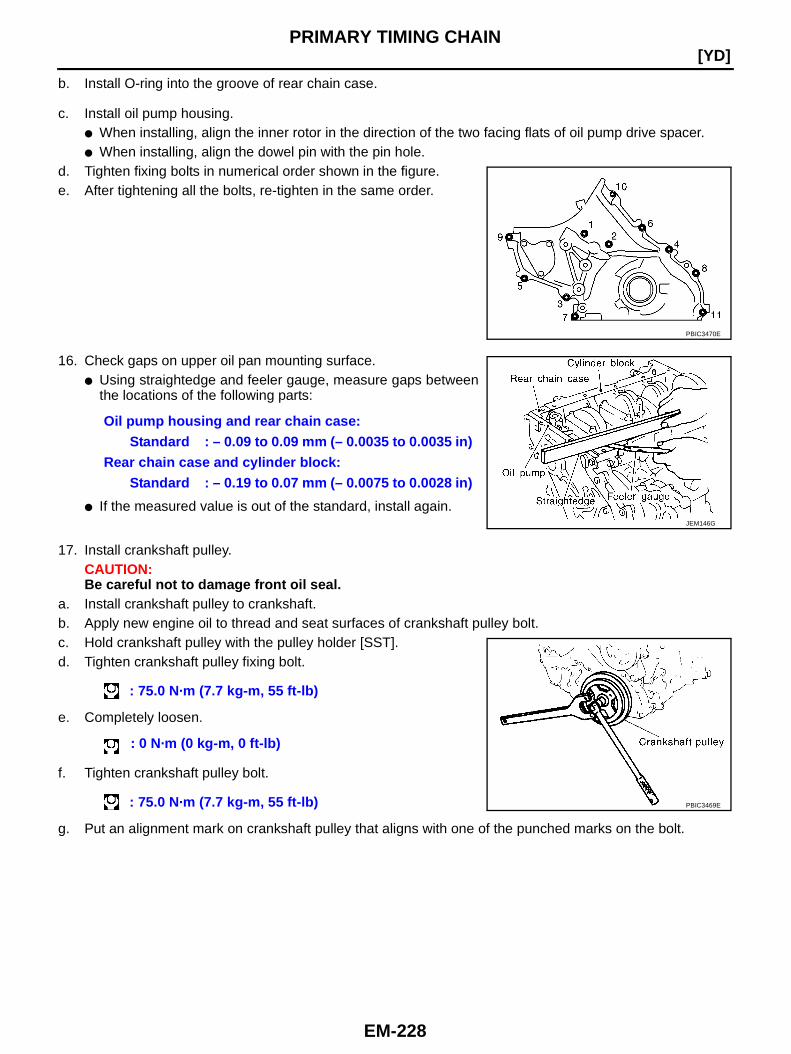
EM-228
[YD]PRIMARY TIMING CHAIN
b. Install O-ring into the groove of rear chain case.
c. Install oil pump housing.● When installing, align the inner rotor in the direction of the two facing flats of oil pump drive spacer.● When installing, align the dowel pin with the pin hole.
d. Tighten fixing bolts in numerical order shown in the figure.e. After tightening all the bolts, re-tighten in the same order.
16. Check gaps on upper oil pan mounting surface.● Using straightedge and feeler gauge, measure gaps between
the locations of the following parts:
● If the measured value is out of the standard, install again.
17. Install crankshaft pulley.CAUTION:Be careful not to damage front oil seal.
a. Install crankshaft pulley to crankshaft.b. Apply new engine oil to thread and seat surfaces of crankshaft pulley bolt.c. Hold crankshaft pulley with the pulley holder [SST].d. Tighten crankshaft pulley fixing bolt.
e. Completely loosen.
f. Tighten crankshaft pulley bolt.
g. Put an alignment mark on crankshaft pulley that aligns with one of the punched marks on the bolt.
PBIC3470E
Oil pump housing and rear chain case:Standard : – 0.09 to 0.09 mm (– 0.0035 to 0.0035 in)
Rear chain case and cylinder block:Standard : – 0.19 to 0.07 mm (– 0.0075 to 0.0028 in)
JEM146G
: 75.0 N·m (7.7 kg-m, 55 ft-lb)
: 0 N·m (0 kg-m, 0 ft-lb)
: 75.0 N·m (7.7 kg-m, 55 ft-lb) PBIC3469E

PRIMARY TIMING CHAIN
EM-229
[YD]
C
D
E
F
G
H
I
J
K
L
M
A
EM
h. Tighten fixing bolt another 120 degrees (angle tightening) (turnby 2 notch).
18. Install secondary timing chain and the associated parts.Refer to EM-213, "INSTALLATION" .
19. Install in the reverse order of removal.
INSPECTION AFTER INSTALLATIONInspection for LeaksThe following are procedures for checking fluids leak, lubricates leak and exhaust gases leak.● Before starting engine, check oil/fluid levels including engine coolant and engine oil. If less than required
quantity, fill to the specified level. Refer to MA-18, "RECOMMENDED FLUIDS AND LUBRICANTS" .● Use procedure below to check for fuel leakage.– Turn ignition switch “ON” (with engine stopped). With fuel pressure applied to fuel piping, check for fuel
leakage at connection points.– Start engine. With engine speed increased, check again for fuel leakage at connection points.● Run engine to check for unusual noise and vibration.● Warm up engine thoroughly to make sure there is no leakage of fuel, exhaust gases, or any oil/fluids
including engine oil and engine coolant.● Bleed air from lines and hoses of applicable lines, such as in cooling system.● After cooling down engine, again check oil/fluid levels including engine oil and engine coolant. Refill to the
specified level, if necessary.
Summary of the inspection items:
*1: Transmission/transaxle/CVT fluid, power steering fluid, brake fluid, etc.*2: Check engine oil level 10 minutes after engine stopped.
A : Indicate embossments
B : Alignment mark
PBIC3476E
Item Before starting engine Engine running After engine stopped
Engine coolant Level Leakage Level
Engine oil Level Leakage Level (*2)
Other oils and fluid (*1) Level Leakage Level
Fuel Leakage Leakage Leakage
Exhaust gases — Leakage —
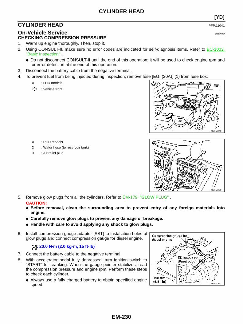
EM-230
[YD]CYLINDER HEAD
CYLINDER HEAD PFP:11041
On-Vehicle Service BBS0002X
CHECKING COMPRESSION PRESSURE1. Warm up engine thoroughly. Then, stop it.2. Using CONSULT-II, make sure no error codes are indicated for self-diagnosis items. Refer to EC-1003,
"Basic Inspection" .● Do not disconnect CONSULT-II until the end of this operation; it will be used to check engine rpm and
for error detection at the end of this operation.3. Disconnect the battery cable from the negative terminal.4. To prevent fuel from being injected during inspection, remove fuse [EGI (20A)] (1) from fuse box.
5. Remove glow plugs from all the cylinders. Refer to EM-179, "GLOW PLUG" .CAUTION:● Before removal, clean the surrounding area to prevent entry of any foreign materials into
engine.● Carefully remove glow plugs to prevent any damage or breakage.● Handle with care to avoid applying any shock to glow plugs.
6. Install compression gauge adapter [SST] to installation holes ofglow plugs and connect compression gauge for diesel engine.
7. Connect the battery cable to the negative terminal.8. With accelerator pedal fully depressed, turn ignition switch to
“START” for cranking. When the gauge pointer stabilizes, readthe compression pressure and engine rpm. Perform these stepsto check each cylinder.● Always use a fully-charged battery to obtain specified engine
speed.
A : LHD models
: Vehicle front
PBIC3623E
A : RHD models
2 : Water hose (to reservoir tank)
3 : Air relief plug
PBIC3624E
: 20.0 N·m (2.0 kg-m, 15 ft-lb)
SEM112G
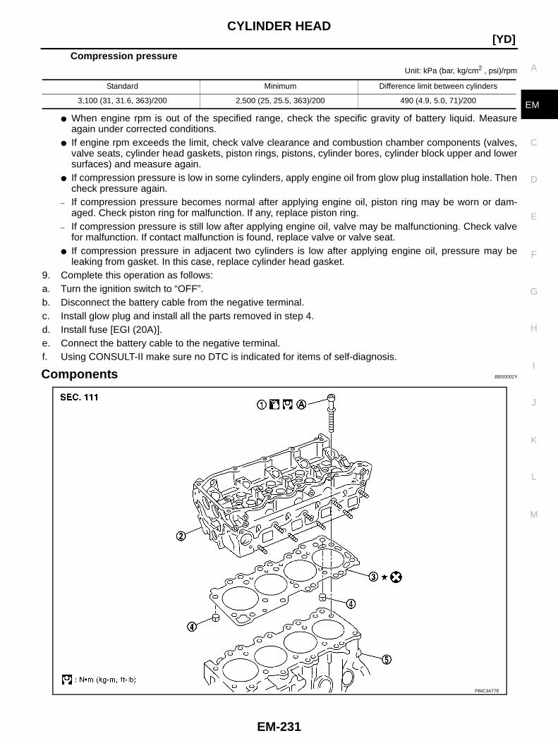
CYLINDER HEAD
EM-231
[YD]
C
D
E
F
G
H
I
J
K
L
M
A
EM
Compression pressureUnit: kPa (bar, kg/cm2 , psi)/rpm
● When engine rpm is out of the specified range, check the specific gravity of battery liquid. Measureagain under corrected conditions.
● If engine rpm exceeds the limit, check valve clearance and combustion chamber components (valves,valve seats, cylinder head gaskets, piston rings, pistons, cylinder bores, cylinder block upper and lowersurfaces) and measure again.
● If compression pressure is low in some cylinders, apply engine oil from glow plug installation hole. Thencheck pressure again.
– If compression pressure becomes normal after applying engine oil, piston ring may be worn or dam-aged. Check piston ring for malfunction. If any, replace piston ring.
– If compression pressure is still low after applying engine oil, valve may be malfunctioning. Check valvefor malfunction. If contact malfunction is found, replace valve or valve seat.
● If compression pressure in adjacent two cylinders is low after applying engine oil, pressure may beleaking from gasket. In this case, replace cylinder head gasket.
9. Complete this operation as follows:a. Turn the ignition switch to “OFF”.b. Disconnect the battery cable from the negative terminal.c. Install glow plug and install all the parts removed in step 4.d. Install fuse [EGI (20A)].e. Connect the battery cable to the negative terminal.f. Using CONSULT-II make sure no DTC is indicated for items of self-diagnosis.
Components BBS0002Y
Standard Minimum Difference limit between cylinders
3,100 (31, 31.6, 363)/200 2,500 (25, 25.5, 363)/200 490 (4.9, 5.0, 71)/200
PBIC3477E
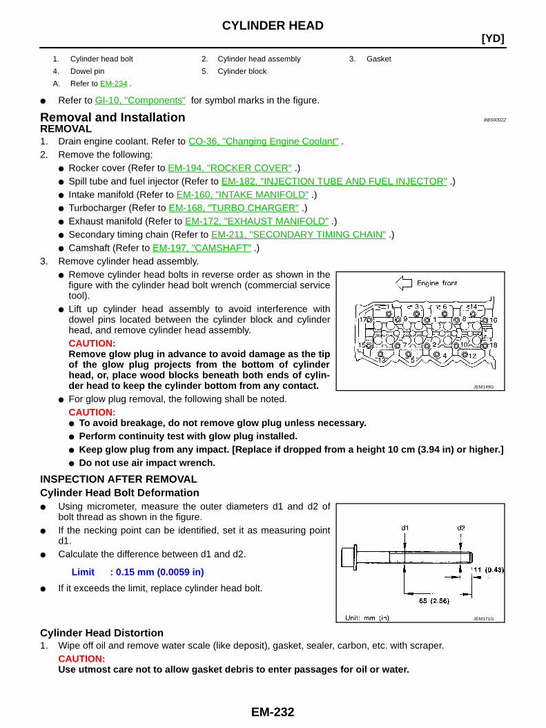
EM-232
[YD]CYLINDER HEAD
● Refer to GI-10, "Components" for symbol marks in the figure.
Removal and Installation BBS0002Z
REMOVAL1. Drain engine coolant. Refer to CO-36, "Changing Engine Coolant" .2. Remove the following:
● Rocker cover (Refer to EM-194, "ROCKER COVER" .)● Spill tube and fuel injector (Refer to EM-182, "INJECTION TUBE AND FUEL INJECTOR" .)● Intake manifold (Refer to EM-160, "INTAKE MANIFOLD" .)● Turbocharger (Refer to EM-168, "TURBO CHARGER" .)● Exhaust manifold (Refer to EM-172, "EXHAUST MANIFOLD" .)● Secondary timing chain (Refer to EM-211, "SECONDARY TIMING CHAIN" .)● Camshaft (Refer to EM-197, "CAMSHAFT" .)
3. Remove cylinder head assembly.● Remove cylinder head bolts in reverse order as shown in the
figure with the cylinder head bolt wrench (commercial servicetool).
● Lift up cylinder head assembly to avoid interference withdowel pins located between the cylinder block and cylinderhead, and remove cylinder head assembly.CAUTION:Remove glow plug in advance to avoid damage as the tipof the glow plug projects from the bottom of cylinderhead, or, place wood blocks beneath both ends of cylin-der head to keep the cylinder bottom from any contact.
● For glow plug removal, the following shall be noted.CAUTION:● To avoid breakage, do not remove glow plug unless necessary.● Perform continuity test with glow plug installed.● Keep glow plug from any impact. [Replace if dropped from a height 10 cm (3.94 in) or higher.]● Do not use air impact wrench.
INSPECTION AFTER REMOVALCylinder Head Bolt Deformation● Using micrometer, measure the outer diameters d1 and d2 of
bolt thread as shown in the figure.● If the necking point can be identified, set it as measuring point
d1.● Calculate the difference between d1 and d2.
● If it exceeds the limit, replace cylinder head bolt.
Cylinder Head Distortion1. Wipe off oil and remove water scale (like deposit), gasket, sealer, carbon, etc. with scraper.
CAUTION:Use utmost care not to allow gasket debris to enter passages for oil or water.
1. Cylinder head bolt 2. Cylinder head assembly 3. Gasket
4. Dowel pin 5. Cylinder block
A. Refer to EM-234 .
JEM149G
Limit : 0.15 mm (0.0059 in)
JEM171G
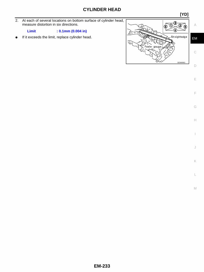
CYLINDER HEAD
EM-233
[YD]
C
D
E
F
G
H
I
J
K
L
M
A
EM
2. At each of several locations on bottom surface of cylinder head,measure distortion in six directions.
● If it exceeds the limit, replace cylinder head.
Limit : 0.1mm (0.004 in)
SEM496G
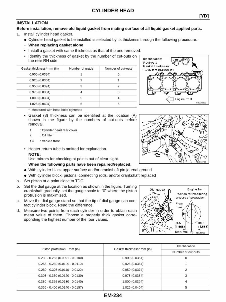
EM-234
[YD]CYLINDER HEAD
INSTALLATIONBefore installation, remove old liquid gasket from mating surface of all liquid gasket applied parts.1. Install cylinder head gasket.
● Cylinder head gasket to be installed is selected by its thickness through the following procedure.– When replacing gasket alone• Install a gasket with same thickness as that of the one removed.• Identify the thickness of gasket by the number of cut-outs on
the rear RH side.
*: Measured with head bolts tightened
• Gasket (3) thickness can be identified at the location (A)shown in the figure by the numbers of cut-outs beforeremoval.
• Heater return tube is omitted for explanation.NOTE:Use mirrors for checking at points out of clear sight.
– When the following parts have been repaired/replaced:● With cylinder block upper surface and/or crankshaft pin journal ground● With cylinder block, pistons, connecting rods, and/or crankshaft replaced
a. Set piston at a point close to TDC.b. Set the dial gauge at the location as shown in the figure. Turning
crankshaft gradually, set the gauge scale to “0” where the pistonprotrusion is maximized.
c. Move the dial gauge stand so that the tip of dial gauge can con-tact cylinder block. Read the difference.
d. Measure two points from each cylinder in order to obtain eachmean value of them. Choose a properly thick gasket corre-sponding the highest number of the four values.
Gasket thickness* mm (in) Number of grade Number of cut-outs
0.900 (0.0354) 1 0
0.925 (0.0364) 2 1
0.950 (0.0374) 3 2
0.975 (0.0384) 4 3
1.000 (0.0394) 5 4
1.025 (0.0404) 6 5
1 : Cylinder head rear cover
2 : Oil filter
: Vehicle front
MBIA0020E
PBIC3478E
SEM507G
Piston protrusion mm (in) Gasket thickness* mm (in)Identification
Number of cut-outs
0.230 - 0.255 (0.0091 - 0.0100) 0.900 (0.0354) 0
0.255 - 0.280 (0.0100 - 0.0110) 0.925 (0.0364) 1
0.280 - 0.305 (0.0110 - 0.0120) 0.950 (0.0374) 2
0.305 - 0.330 (0.0120 - 0.0130) 0.975 (0.0384) 3
0.330 - 0.355 (0.0130 - 0.0140) 1.000 (0.0394) 4
0.355 - 0.400 (0.0140 - 0.0157) 1.025 (0.0404) 5
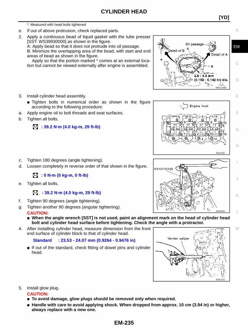
CYLINDER HEAD
EM-235
[YD]
C
D
E
F
G
H
I
J
K
L
M
A
EM
*: Measured with head bolts tightened
e. If out of above protrusion, check replaced parts.2. Apply a continuous bead of liquid gasket with the tube presser
[SST: WS39930000] as shown in the figure.A: Apply bead so that it does not protrude into oil passage.B: Minimize the overlapping area of the bead, with start and endareas of bead as shown in the figure.
Apply so that the portion marked * comes at an external loca-tion but cannot be viewed externally after engine is assembled.
3. Install cylinder head assembly.● Tighten bolts in numerical order as shown in the figure
according to the following procedure:a. Apply engine oil to bolt threads and seat surfaces.b. Tighten all bolts.
c. Tighten 180 degrees (angle tightening).d. Loosen completely in reverse order of that shown in the figure.
e. Tighten all bolts.
f. Tighten 90 degrees (angle tightening).g. Tighten another 90 degrees (angular tightening).
CAUTION:● When the angle wrench [SST] is not used, paint an alignment mark on the head of cylinder head
bolt and cylinder head surface before tightening. Check the angle with a protractor.4. After installing cylinder head, measure dimension from the front
end surface of cylinder block to that of cylinder head.
● If out of the standard, check fitting of dowel pins and cylinderhead.
5. Install glow plug.CAUTION:● To avoid damage, glow plugs should be removed only when required.● Handle with care to avoid applying shock. When dropped from approx. 10 cm (3.94 in) or higher,
always replace with a new one.
PBIC1256E
: 39.2 N·m (4.0 kg-m, 29 ft-lb)
JEM149G
: 0 N·m (0 kg-m, 0 ft-lb)
: 39.2 N·m (4.0 kg-m, 29 ft-lb)
Standard : 23.53 - 24.07 mm (0.9264 - 0.9476 in)
JEM166G
JEM172G
EM-236
[YD]CYLINDER HEAD
● Before installing, remove carbon depositing on mounting hole of glow plug with a reamer.6. Install in the reverse order of removal.
INSPECTION AFTER INSTALLATIONInspection for LeaksThe following are procedures for checking fluids leak, lubricates leak and exhaust gases leak.● Before starting engine, check oil/fluid levels including engine coolant and engine oil. If less than required
quantity, fill to the specified level. Refer to MA-18, "RECOMMENDED FLUIDS AND LUBRICANTS" .● Use procedure below to check for fuel leakage.– Turn ignition switch “ON” (with engine stopped). With fuel pressure applied to fuel piping, check for fuel
leakage at connection points.– Start engine. With engine speed increased, check again for fuel leakage at connection points.● Run engine to check for unusual noise and vibration.● Warm up engine thoroughly to make sure there is no leakage of fuel, exhaust gases, or any oil/fluids
including engine oil and engine coolant.● Bleed air from lines and hoses of applicable lines, such as in cooling system.● After cooling down engine, again check oil/fluid levels including engine oil and engine coolant. Refill to the
specified level, if necessary.
Summary of the inspection items:
*1: Transmission/transaxle/CVT fluid, power steering fluid, brake fluid, etc.*2: Check engine oil level 10 minutes after engine stopped.
Item Before starting engine Engine running After engine stopped
Engine coolant Level Leakage Level
Engine oil Level Leakage Level (*2)
Other oils and fluid (*1) Level Leakage Level
Fuel Leakage Leakage Leakage
Exhaust gases — Leakage —

CYLINDER HEAD
EM-237
[YD]
C
D
E
F
G
H
I
J
K
L
M
A
EM
Components BBS00030
Disassembly and Assembly BBS00031
DISASSEMBLY1. Remove adjusting shims and valve lifters.
● Check the installation positions, and keep them to avoid being confused.2. Remove valve collet.
● Using the valve spring compressor [SST], compress valvespring. Using magnet hand, remove valve collets.
3. Remove valve spring retainers and valve springs.4. Remove valves as pressing valve stems toward combustion chamber.
● Before removing valve, check the valve guide clearance. Refer to EM-239, "Valve Guide Clearance" .
1. Adjusting shim 2. Valve lifter 3. Valve collet
4. Valve spring retainer 5. Valve spring 6. Valve oil seal
7. Valve spring seat 8. Valve guide 9. Cylinder head
10. Valve seat 11. Valve (Exhaust) 12. Valve (Intake)
PBIC2328E
PBIC2388E
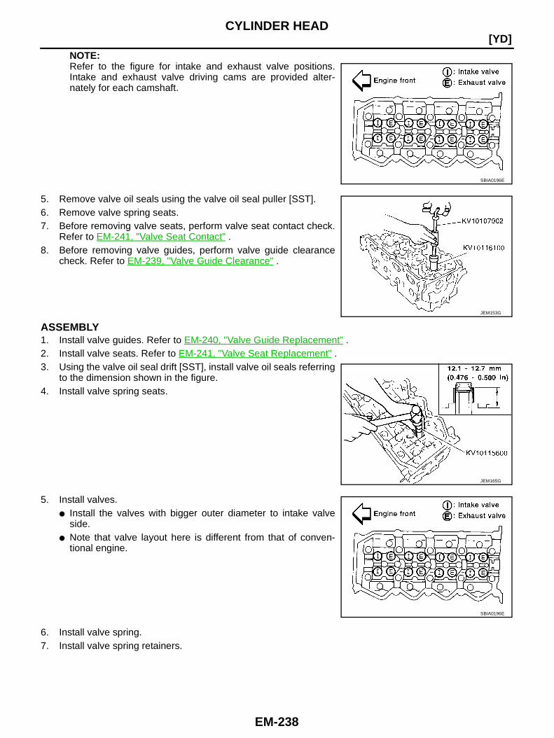
EM-238
[YD]CYLINDER HEAD
NOTE:Refer to the figure for intake and exhaust valve positions.Intake and exhaust valve driving cams are provided alter-nately for each camshaft.
5. Remove valve oil seals using the valve oil seal puller [SST].6. Remove valve spring seats.7. Before removing valve seats, perform valve seat contact check.
Refer to EM-241, "Valve Seat Contact" .8. Before removing valve guides, perform valve guide clearance
check. Refer to EM-239, "Valve Guide Clearance" .
ASSEMBLY1. Install valve guides. Refer to EM-240, "Valve Guide Replacement" .2. Install valve seats. Refer to EM-241, "Valve Seat Replacement" .3. Using the valve oil seal drift [SST], install valve oil seals referring
to the dimension shown in the figure.4. Install valve spring seats.
5. Install valves.● Install the valves with bigger outer diameter to intake valve
side.● Note that valve layout here is different from that of conven-
tional engine.
6. Install valve spring.7. Install valve spring retainers.
SBIA0196E
JEM153G
JEM165G
SBIA0196E
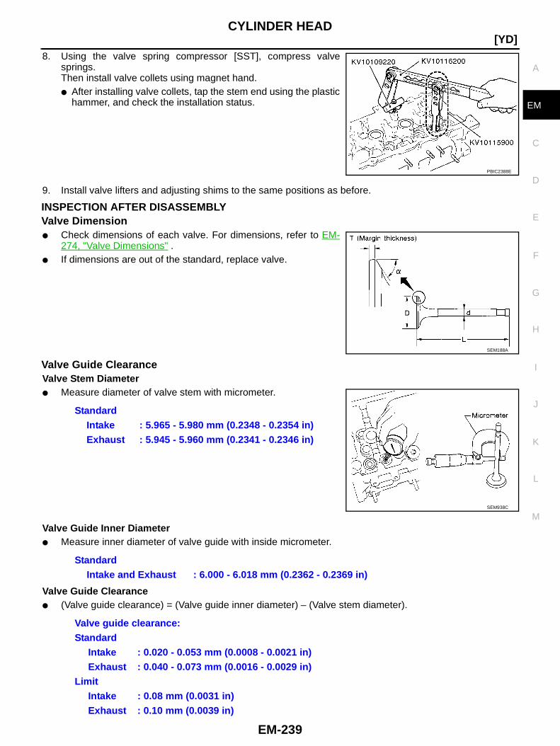
CYLINDER HEAD
EM-239
[YD]
C
D
E
F
G
H
I
J
K
L
M
A
EM
8. Using the valve spring compressor [SST], compress valvesprings.Then install valve collets using magnet hand.● After installing valve collets, tap the stem end using the plastic
hammer, and check the installation status.
9. Install valve lifters and adjusting shims to the same positions as before.
INSPECTION AFTER DISASSEMBLYValve Dimension● Check dimensions of each valve. For dimensions, refer to EM-
274, "Valve Dimensions" .● If dimensions are out of the standard, replace valve.
Valve Guide ClearanceValve Stem Diameter● Measure diameter of valve stem with micrometer.
Valve Guide Inner Diameter● Measure inner diameter of valve guide with inside micrometer.
Valve Guide Clearance● (Valve guide clearance) = (Valve guide inner diameter) – (Valve stem diameter).
PBIC2388E
SEM188A
StandardIntake : 5.965 - 5.980 mm (0.2348 - 0.2354 in)Exhaust : 5.945 - 5.960 mm (0.2341 - 0.2346 in)
SEM938C
StandardIntake and Exhaust : 6.000 - 6.018 mm (0.2362 - 0.2369 in)
Valve guide clearance:Standard
Intake : 0.020 - 0.053 mm (0.0008 - 0.0021 in)Exhaust : 0.040 - 0.073 mm (0.0016 - 0.0029 in)
LimitIntake : 0.08 mm (0.0031 in)Exhaust : 0.10 mm (0.0039 in)
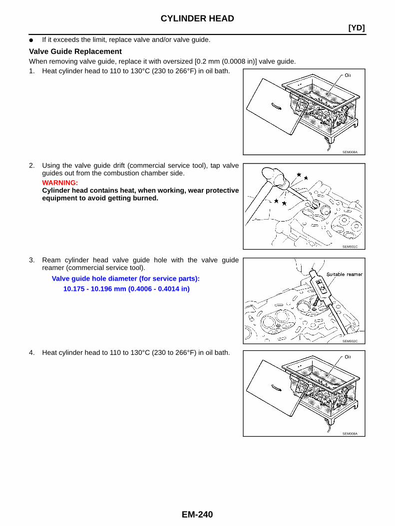
EM-240
[YD]CYLINDER HEAD
● If it exceeds the limit, replace valve and/or valve guide.
Valve Guide ReplacementWhen removing valve guide, replace it with oversized [0.2 mm (0.0008 in)] valve guide.1. Heat cylinder head to 110 to 130°C (230 to 266°F) in oil bath.
2. Using the valve guide drift (commercial service tool), tap valveguides out from the combustion chamber side.WARNING:Cylinder head contains heat, when working, wear protectiveequipment to avoid getting burned.
3. Ream cylinder head valve guide hole with the valve guidereamer (commercial service tool).
4. Heat cylinder head to 110 to 130°C (230 to 266°F) in oil bath.
SEM008A
SEM931C
Valve guide hole diameter (for service parts):10.175 - 10.196 mm (0.4006 - 0.4014 in)
SEM932C
SEM008A
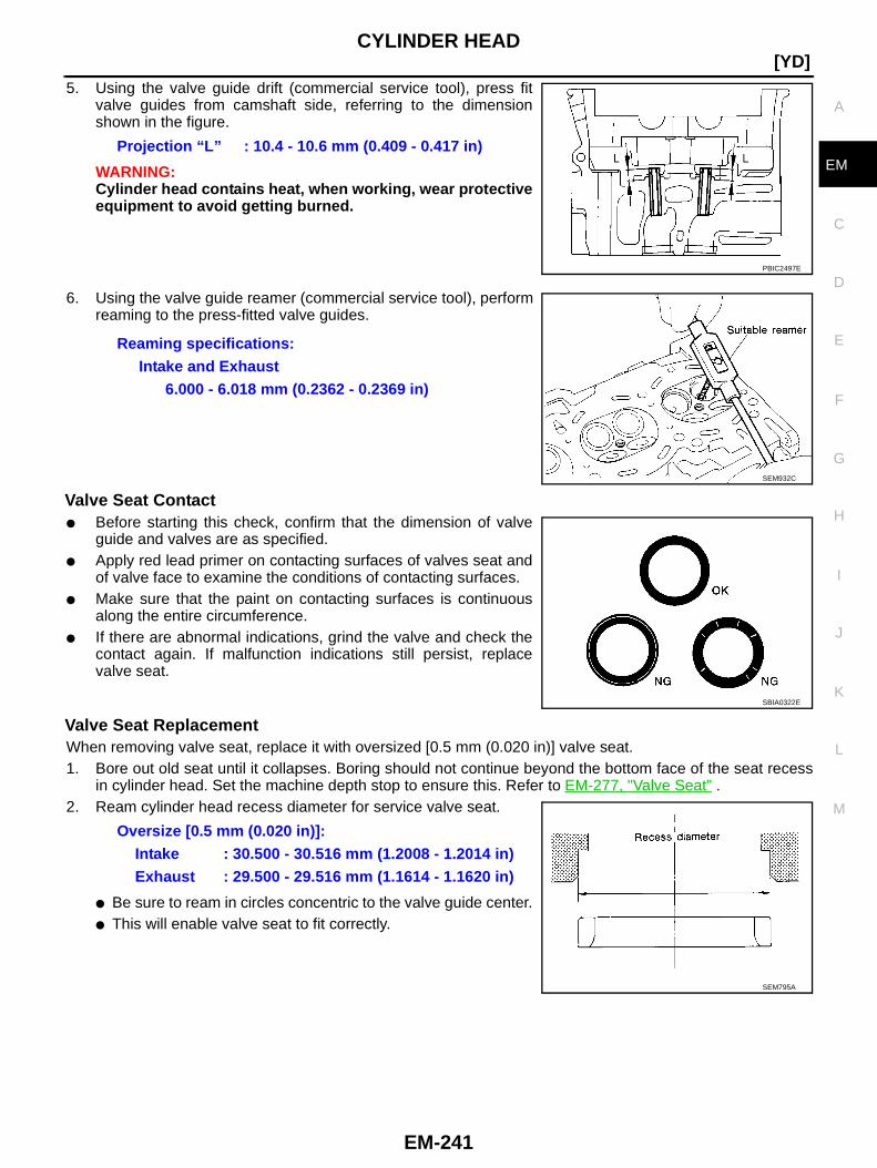
CYLINDER HEAD
EM-241
[YD]
C
D
E
F
G
H
I
J
K
L
M
A
EM
5. Using the valve guide drift (commercial service tool), press fitvalve guides from camshaft side, referring to the dimensionshown in the figure.
WARNING:Cylinder head contains heat, when working, wear protectiveequipment to avoid getting burned.
6. Using the valve guide reamer (commercial service tool), performreaming to the press-fitted valve guides.
Valve Seat Contact● Before starting this check, confirm that the dimension of valve
guide and valves are as specified.● Apply red lead primer on contacting surfaces of valves seat and
of valve face to examine the conditions of contacting surfaces.● Make sure that the paint on contacting surfaces is continuous
along the entire circumference.● If there are abnormal indications, grind the valve and check the
contact again. If malfunction indications still persist, replacevalve seat.
Valve Seat ReplacementWhen removing valve seat, replace it with oversized [0.5 mm (0.020 in)] valve seat.1. Bore out old seat until it collapses. Boring should not continue beyond the bottom face of the seat recess
in cylinder head. Set the machine depth stop to ensure this. Refer to EM-277, "Valve Seat" .2. Ream cylinder head recess diameter for service valve seat.
● Be sure to ream in circles concentric to the valve guide center.● This will enable valve seat to fit correctly.
Projection “L” : 10.4 - 10.6 mm (0.409 - 0.417 in)
PBIC2497E
Reaming specifications:Intake and Exhaust
6.000 - 6.018 mm (0.2362 - 0.2369 in)
SEM932C
SBIA0322E
Oversize [0.5 mm (0.020 in)]:Intake : 30.500 - 30.516 mm (1.2008 - 1.2014 in)Exhaust : 29.500 - 29.516 mm (1.1614 - 1.1620 in)
SEM795A

EM-242
[YD]CYLINDER HEAD
3. Heat cylinder head to approximately 110 to 130°C (230 to266°F) in oil bath.
4. After cooling valve seats sufficiently with dry ice, press fit it tocylinder head.WARNING:Cylinder head contains heat, when working, wear protectiveequipment to avoid getting burned.CAUTION:Do not touch the cooled valve seats directly by hand.
5. Using the valve seat cutter set (commercial service tool), finishprocessing referring to the dimensions shown in the figure.Refer to EM-277, "Valve Seat" .CAUTION:When using the valve seat cutter set, grasp cutter handlewith both hands, press cutter onto contacting face allaround, and cut thoroughly. If cutter is pressed unevenly orrepeatedly, the valve seat surface may be damaged.
6. Using compound, perform valve fitting.7. Check again to make sure that contacting status is satisfactory.
For details, Refer to EM-241, "Valve Seat Contact" .
8. Use the depth gauge to measure the distance between themounting surface of cylinder head spring seat and the valvestem end. If the distance is shorter than specified, repeat step 5above to adjust it. If it is longer, replace valve seat with a newone.
Valve Spring Square● Position the try square to valve spring, turn the spring, and mea-
sure the maximum clearance value between top surface ofspring and the try square.
● If it exceeds the limit, replace valve spring.
SEM008A
SEM934C
Valve seat resurface limit “L”:Intake : 36.53 - 36.98 mm (1.4382 - 1.4559 in)Exhaust : 36.53 - 37.01 mm (1.4382 - 1.4571 in)
JEM253G
Limit : 1.9 mm (0.075 in)
PBIC0080E

CYLINDER HEAD
EM-243
[YD]
C
D
E
F
G
H
I
J
K
L
M
A
EM
Valve Spring Dimensions and Valve Spring Pressure Load● Using valve spring tester, check the following.
● If out of the standard, replace the valve spring.
Standard:Free height : 44.74 mm (1.76 in)Installation height : 32.82 mm (1.2921 in)Installation load : 184 - 208 N
(18.77 - 21.22 kg, 41.4 - 46.8 lb)Height duringvalve open
: 24.82 mm (0.9772 in)
Load with valveopen
: 320 - 360 N(32.65 - 36.73 kg, 71.9 - 80.9 lb)
SEM113

EM-244
[YD]ENGINE ASSEMBLY
ENGINE ASSEMBLY PFP:10001
Components BBS00032
1. Vacuum hose 2. Vacuum gallery 3. Vacuum hose
4. Vacuum hose 5. RH engine mounting insulator 6. RH engine mounting bracket
7. Engine mount control solenoid valve 8. Vacuum gallery 9. LH engine mounting bracket
10. Heat insulator 11. Vacuum hose 12. LH engine mounting insulator
13. Transmission cross member 14. Engine mounting insulator (rear) 15. RH engine mounting insulator
16. RH engine mounting bracket 17. LH engine mounting bracket 18. Heat insulator
19. LH engine mounting insulator
A.Models with electronic controlledengine mount
B.Models without electronic controlledengine mount
PBIC4053E

ENGINE ASSEMBLY
EM-245
[YD]
C
D
E
F
G
H
I
J
K
L
M
A
EM
Removal and Installation BBS00033
WARNING:● Situate vehicle on a flat and solid surface.● Place chocks at front and back of rear wheels.● For engines not equipped with engine slingers, attach proper slingers and bolts described in
PARTS CATALOG.CAUTION:● Always be careful to work safely, avoid forceful or uninstructed operations.● Do not start working until exhaust system and engine coolant are cool enough.● If items or work required are not covered by the engine main body section, refer to the applicable
sections.● Always use the support point specified for lifting.● Use either 2-pole lift type or separate type lift as best you can. If board-on type is used for
unavoidable reasons, support at the rear axle jacking point with transmission jack or similar toolbefore starting work, in preparation for the backward shift of center of gravity.
● For supporting points for lifting and jacking point at rear axle, refer to GI-52, "Garage Jack andSafety Stand " .
REMOVALDescription of workRemove transmission assembly from vehicle downward. Then hoist the engine from vehicle upward.
Preparation1. Disconnect battery cable from negative terminal. Refer to SC-5, "BATTERY" .2. Drain engine coolant from radiator drain plug. Refer to CO-36, "Changing Engine Coolant" .3. Remove the following parts.
● Engine undercover front, engine undercover middle, engine undercover rear; Refer to EI-15, "FRONTBUMPER" .
● Hood assembly; Refer to BL-15, "HOOD" .● Engine cover; Refer to EM-160, "INTAKE MANIFOLD" .● Drive belts; Refer to EM-152, "DRIVE BELTS" .● Cooling fan, fan coupling and water pump pulley; Refer to CO-48, "COOLING FAN" .● Air duct and air cleaner case; Refer to EM-155, "AIR CLEANER AND AIR DUCT" .● Air inlet tube and air inlet hose; Refer to EM-158, "CHARGE AIR COOLER" .● Alternator; Refer to SC-25, "Removal and Installation" .● Radiator, radiator shroud (upper and lower) and cooling fan assembly; Refer to CO-40, "RADIATOR"
and CO-48, "COOLING FAN" .4. Disconnect engine room harness from the engine side and set it aside for easier work.5. Disconnect all the body-side vacuum hoses and air hoses at engine side.
Engine room RH1. Disconnect fuel feed hose and return hose, and plug it to prevent fuel from draining. Refer to EM-182,
"INJECTION TUBE AND FUEL INJECTOR" .2. Remove fuel filter. Refer to FL-15, "FUEL FILTER" .3. Disconnect heater hose, and install plug it to prevent engine coolant from draining. Refer to CO-52,
"THERMOSTAT AND WATER PIPING" .
Engine room LH1. Remove A/C compressor with piping connected from engine. Temporarily secure it on body with a rope to
avoid putting load on it. Refer to ATC-186, "Removal and Installation for Compressor" .
Vehicle underbody1. Remove exhaust front tube. Refer to EX-3, "Removal and Installation" .2. Remove front and rear propeller shaft. Refer to PR-3, "FRONT PROPELLER SHAFT" and PR-7, "REAR
PROPELLER SHAFT" .

EM-246
[YD]ENGINE ASSEMBLY
3. Remove clutch operating cylinder from transmission, and move it aside (M/T models). Refer to MT-15,"TRANSMISSION ASSEMBLY" and CL-11, "OPERATING CYLINDER" .
4. Disconnect power steering fluid piping at a point between body and engine. Refer to PS-44, "HYDRAULICLINE" .
5. Remove starter motor. Refer to SC-35, "Removal and Installation" .6. Remove transmission assembly. Refer to MT-15, "TRANSMISSION ASSEMBLY" (M/T models) or AT-
239, "TRANSMISSION ASSEMBLY" (A/T models).
Removal1. Install engine slingers into front right of cylinder head (A) and
rear left of cylinder head (B).
2. Lift with hoist and secure engine in position.3. Loosen LH and RH engine mounting insulator mounting nuts.4. Remove engine.
CAUTION:● During the operation, make sure that no part interferes
with body side.● Before and during this lifting, always check if any har-
nesses are left connected.
INSTALLATIONInstall in the reverse order of removal.● Do not allow engine oil to get on mounting insulator. Be careful not to damage mounting insulator.● When installation directions are specified, install parts according to the direction marks on them referring
to figure of components. Refer to EM-244, "ENGINE ASSEMBLY" .● Make sure that each mounting insulator is seated properly, and tighten mounting bolts and nuts.● Insert vacuum hose to vacuum gallery until vacuum hose comes in contact with the stopper when a stop-
per is provided at vacuum gallery.● Insert vacuum hose up to 15 mm (0. 59 in) when a stopper is not provided at vacuum gallery.
INSPECTION AFTER INSTALLATIONInspection for LeaksThe following are procedures for checking fluids leak, lubricates leak and exhaust gases leak.● Before starting engine, check oil/fluid levels including engine coolant and engine oil. If less than required
quantity, fill to the specified level. Refer to MA-18, "RECOMMENDED FLUIDS AND LUBRICANTS" .● Use procedure below to check for fuel leakage.– Before starting engine, check for fuel leakage at connection points.– Start engine. With engine speed increased, check again for fuel leakage at connection points.● Run engine to check for unusual noise and vibration.● Warm up engine thoroughly to make sure there is no leakage of fuel, exhaust gases, or any oil/fluids
including engine oil and engine coolant.
1 : Engine slinger (front)
2 : Engine slinger (rear)
: Engine front
Engine slinger bolts:
: 28.0 N·m (2.9 kg-m, 21 ft-lb)
PBIC3480E
SEM896G
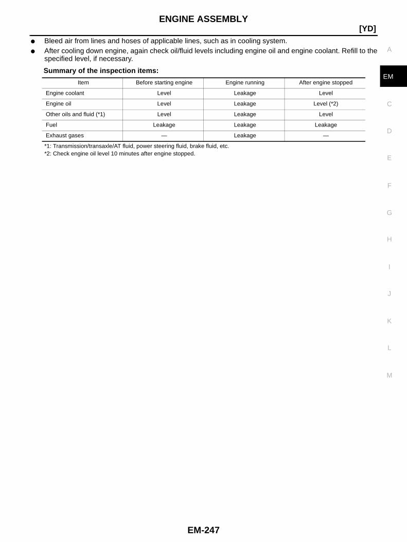
ENGINE ASSEMBLY
EM-247
[YD]
C
D
E
F
G
H
I
J
K
L
M
A
EM
● Bleed air from lines and hoses of applicable lines, such as in cooling system.● After cooling down engine, again check oil/fluid levels including engine oil and engine coolant. Refill to the
specified level, if necessary.
Summary of the inspection items:
*1: Transmission/transaxle/AT fluid, power steering fluid, brake fluid, etc.*2: Check engine oil level 10 minutes after engine stopped.
Item Before starting engine Engine running After engine stopped
Engine coolant Level Leakage Level
Engine oil Level Leakage Level (*2)
Other oils and fluid (*1) Level Leakage Level
Fuel Leakage Leakage Leakage
Exhaust gases — Leakage —

EM-248
[YD]CYLINDER BLOCK
CYLINDER BLOCK PFP:11010
Components BBS00034
PBIC3481E
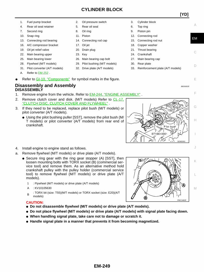
CYLINDER BLOCK
EM-249
[YD]
C
D
E
F
G
H
I
J
K
L
M
A
EM
● Refer to GI-10, "Components" for symbol marks in the figure.
Disassembly and Assembly BBS00035
DISASSEMBLY1. Remove engine from the vehicle. Refer to EM-244, "ENGINE ASSEMBLY" .2. Remove clutch cover and disk. (M/T models) Refer to CL-17,
"CLUTCH DISC, CLUTCH COVER AND FLYWHEEL" .3. If they need to be replaced, replace pilot bush (M/T models) or
pilot converter (A/T models).● Using the pilot bushing puller [SST], remove the pilot bush (M/
T models) or pilot converter (A/T models) from rear end ofcrankshaft.
4. Install engine to engine stand as follows.a. Remove flywheel (M/T models) or drive plate (A/T models).
● Secure ring gear with the ring gear stopper (A) [SST], thenloosen mounting bolts with TORX socket (B) (commercial ser-vice tool) and remove them. As an alternative method holdcrankshaft pulley with the pulley holder (commercial servicetool) to remove flywheel (M/T models) or drive plate (A/Tmodels).
CAUTION:● Do not disassemble flywheel (M/T models) or drive plate (A/T models).● Do not place flywheel (M/T models) or drive plate (A/T models) with signal plate facing down.● When handling signal plate, take care not to damage or scratch it.● Handle signal plate in a manner that prevents it from becoming magnetized.
1. Fuel pump bracket 2. Oil pressure switch 3. Cylinder block
4. Rear oil seal retainer 5. Rear oil seal 6. Top ring
7. Second ring 8. Oil ring 9. Piston pin
10. Snap ring 11. Piston 12. Connecting rod
13. Connecting rod bearing 14. Connecting rod cap 15. Connecting rod nut
16. A/C compressor bracket 17. Oil jet 18. Copper washer
19. Oil jet relief valve 20. Drain plug 21. Thrust bearing
22. Main bearing upper 23. Key 24. Crankshaft
25. Main bearing lower 26. Main bearing cap bolt 27. Main bearing cap
28. Flywheel (M/T models) 29. Pilot bushing (M/T models) 30. Rear plate
31. Pilot converter (A/T models) 32. Drive plate (A/T models) 33. Reinforcement plate (A/T models)
A. Refer to EM-252 .
SEM500G
1 : Flywheel (M/T models) or drive plate (A/T models)
A : KV10105630
B: TORX bit (size: T55)(M/T models) or TORX socket (size: E20)(A/Tmodels)
PBIC3482E
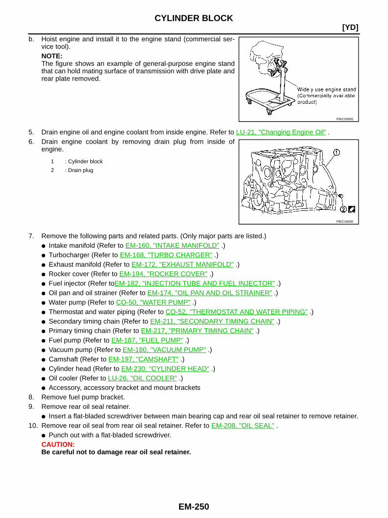
EM-250
[YD]CYLINDER BLOCK
b. Hoist engine and install it to the engine stand (commercial ser-vice tool).NOTE:The figure shows an example of general-purpose engine standthat can hold mating surface of transmission with drive plate andrear plate removed.
5. Drain engine oil and engine coolant from inside engine. Refer to LU-21, "Changing Engine Oil" .6. Drain engine coolant by removing drain plug from inside of
engine.
7. Remove the following parts and related parts. (Only major parts are listed.)● Intake manifold (Refer to EM-160, "INTAKE MANIFOLD" .)● Turbocharger (Refer to EM-168, "TURBO CHARGER" .)● Exhaust manifold (Refer to EM-172, "EXHAUST MANIFOLD" .)● Rocker cover (Refer to EM-194, "ROCKER COVER" .)● Fuel injector (Refer toEM-182, "INJECTION TUBE AND FUEL INJECTOR" .)● Oil pan and oil strainer (Refer to EM-174, "OIL PAN AND OIL STRAINER" .)● Water pump (Refer to CO-50, "WATER PUMP" .)● Thermostat and water piping (Refer to CO-52, "THERMOSTAT AND WATER PIPING" .)● Secondary timing chain (Refer to EM-211, "SECONDARY TIMING CHAIN" .)● Primary timing chain (Refer to EM-217, "PRIMARY TIMING CHAIN" .)● Fuel pump (Refer to EM-187, "FUEL PUMP" .)● Vacuum pump (Refer to EM-180, "VACUUM PUMP" .)● Camshaft (Refer to EM-197, "CAMSHAFT" .)● Cylinder head (Refer to EM-230, "CYLINDER HEAD" .)● Oil cooler (Refer to LU-26, "OIL COOLER" .)● Accessory, accessory bracket and mount brackets
8. Remove fuel pump bracket.9. Remove rear oil seal retainer.
● Insert a flat-bladed screwdriver between main bearing cap and rear oil seal retainer to remove retainer.10. Remove rear oil seal from rear oil seal retainer. Refer to EM-208, "OIL SEAL" .
● Punch out with a flat-bladed screwdriver.CAUTION:Be careful not to damage rear oil seal retainer.
PBIC0085E
1 : Cylinder block
2 : Drain plug
PBIC3483E
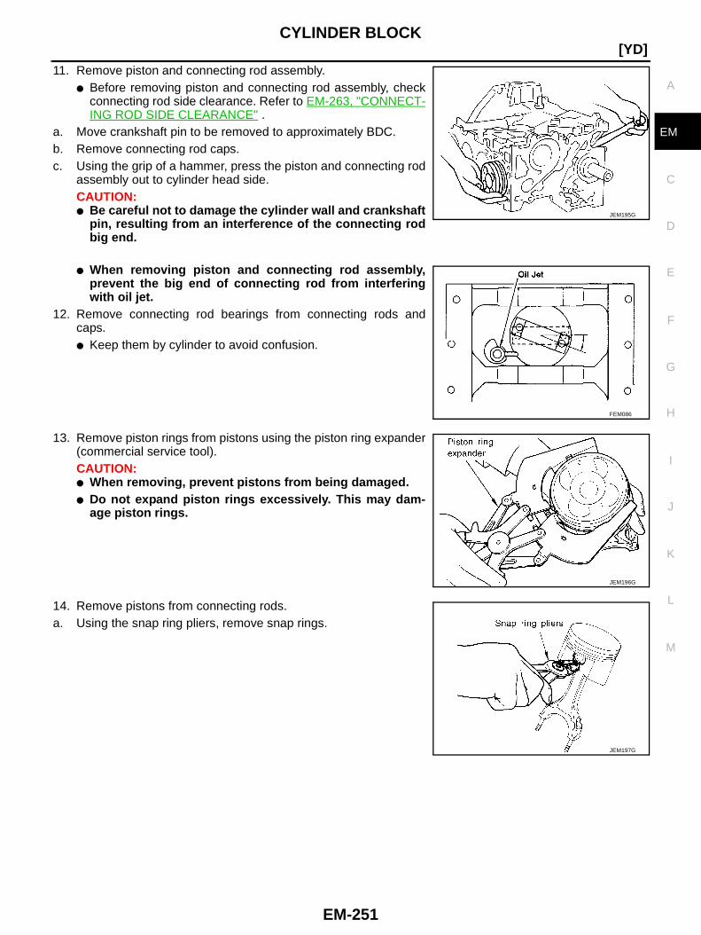
CYLINDER BLOCK
EM-251
[YD]
C
D
E
F
G
H
I
J
K
L
M
A
EM
11. Remove piston and connecting rod assembly.● Before removing piston and connecting rod assembly, check
connecting rod side clearance. Refer to EM-263, "CONNECT-ING ROD SIDE CLEARANCE" .
a. Move crankshaft pin to be removed to approximately BDC.b. Remove connecting rod caps.c. Using the grip of a hammer, press the piston and connecting rod
assembly out to cylinder head side.CAUTION:● Be careful not to damage the cylinder wall and crankshaft
pin, resulting from an interference of the connecting rodbig end.
● When removing piston and connecting rod assembly,prevent the big end of connecting rod from interferingwith oil jet.
12. Remove connecting rod bearings from connecting rods andcaps.● Keep them by cylinder to avoid confusion.
13. Remove piston rings from pistons using the piston ring expander(commercial service tool).CAUTION:● When removing, prevent pistons from being damaged.● Do not expand piston rings excessively. This may dam-
age piston rings.
14. Remove pistons from connecting rods.a. Using the snap ring pliers, remove snap rings.
JEM195G
FEM086
JEM196G
JEM197G
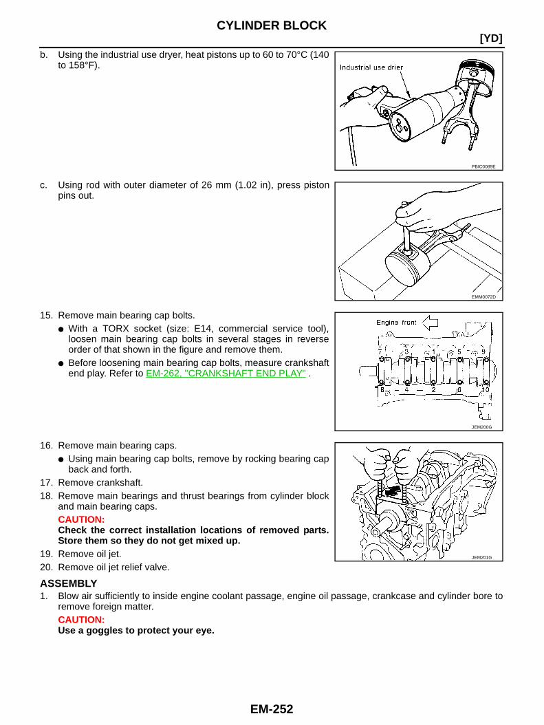
EM-252
[YD]CYLINDER BLOCK
b. Using the industrial use dryer, heat pistons up to 60 to 70°C (140to 158°F).
c. Using rod with outer diameter of 26 mm (1.02 in), press pistonpins out.
15. Remove main bearing cap bolts.● With a TORX socket (size: E14, commercial service tool),
loosen main bearing cap bolts in several stages in reverseorder of that shown in the figure and remove them.
● Before loosening main bearing cap bolts, measure crankshaftend play. Refer to EM-262, "CRANKSHAFT END PLAY" .
16. Remove main bearing caps.● Using main bearing cap bolts, remove by rocking bearing cap
back and forth.17. Remove crankshaft.18. Remove main bearings and thrust bearings from cylinder block
and main bearing caps.CAUTION:Check the correct installation locations of removed parts.Store them so they do not get mixed up.
19. Remove oil jet.20. Remove oil jet relief valve.
ASSEMBLY1. Blow air sufficiently to inside engine coolant passage, engine oil passage, crankcase and cylinder bore to
remove foreign matter.CAUTION:Use a goggles to protect your eye.
PBIC0089E
EMM0072D
JEM200G
JEM201G
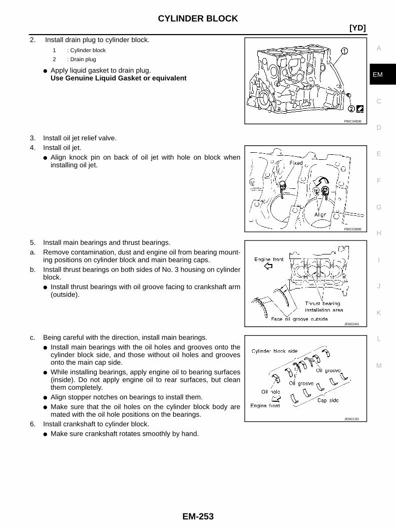
CYLINDER BLOCK
EM-253
[YD]
C
D
E
F
G
H
I
J
K
L
M
A
EM
2. Install drain plug to cylinder block.
● Apply liquid gasket to drain plug.Use Genuine Liquid Gasket or equivalent
3. Install oil jet relief valve.4. Install oil jet.
● Align knock pin on back of oil jet with hole on block wheninstalling oil jet.
5. Install main bearings and thrust bearings.a. Remove contamination, dust and engine oil from bearing mount-
ing positions on cylinder block and main bearing caps.b. Install thrust bearings on both sides of No. 3 housing on cylinder
block.● Install thrust bearings with oil groove facing to crankshaft arm
(outside).
c. Being careful with the direction, install main bearings.● Install main bearings with the oil holes and grooves onto the
cylinder block side, and those without oil holes and groovesonto the main cap side.
● While installing bearings, apply engine oil to bearing surfaces(inside). Do not apply engine oil to rear surfaces, but cleanthem completely.
● Align stopper notches on bearings to install them.● Make sure that the oil holes on the cylinder block body are
mated with the oil hole positions on the bearings.6. Install crankshaft to cylinder block.
● Make sure crankshaft rotates smoothly by hand.
1 : Cylinder block
2 : Drain plug
PBIC3483E
PBIC0389E
JEM224G
JEM213G
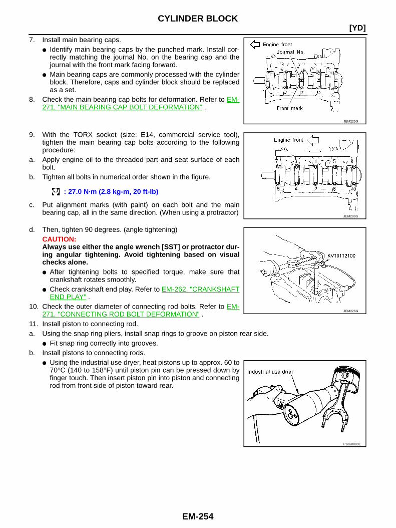
EM-254
[YD]CYLINDER BLOCK
7. Install main bearing caps.● Identify main bearing caps by the punched mark. Install cor-
rectly matching the journal No. on the bearing cap and thejournal with the front mark facing forward.
● Main bearing caps are commonly processed with the cylinderblock. Therefore, caps and cylinder block should be replacedas a set.
8. Check the main bearing cap bolts for deformation. Refer to EM-271, "MAIN BEARING CAP BOLT DEFORMATION" .
9. With the TORX socket (size: E14, commercial service tool),tighten the main bearing cap bolts according to the followingprocedure:
a. Apply engine oil to the threaded part and seat surface of eachbolt.
b. Tighten all bolts in numerical order shown in the figure.
c. Put alignment marks (with paint) on each bolt and the mainbearing cap, all in the same direction. (When using a protractor)
d. Then, tighten 90 degrees. (angle tightening)CAUTION:Always use either the angle wrench [SST] or protractor dur-ing angular tightening. Avoid tightening based on visualchecks alone.● After tightening bolts to specified torque, make sure that
crankshaft rotates smoothly.● Check crankshaft end play. Refer to EM-262, "CRANKSHAFT
END PLAY" .10. Check the outer diameter of connecting rod bolts. Refer to EM-
271, "CONNECTING ROD BOLT DEFORMATION" .11. Install piston to connecting rod.a. Using the snap ring pliers, install snap rings to groove on piston rear side.
● Fit snap ring correctly into grooves.b. Install pistons to connecting rods.
● Using the industrial use dryer, heat pistons up to approx. 60 to70°C (140 to 158°F) until piston pin can be pressed down byfinger touch. Then insert piston pin into piston and connectingrod from front side of piston toward rear.
JEM225G
: 27.0 N·m (2.8 kg-m, 20 ft-lb)
JEM200G
JEM226G
PBIC0089E

CYLINDER BLOCK
EM-255
[YD]
C
D
E
F
G
H
I
J
K
L
M
A
EM
● Assemble piston and connecting rod with front mark of pistonhead and cylinder No. stamped on connecting rod being posi-tioned as shown in the figure.
c. Install snap ring to front side of piston.● Refer to above step a for precaution on snap ring installation.● After installation, check connecting rods for smooth move-
ment.
12. Use the piston ring expander (commercial service tool) to install piston rings.CAUTION:When installing, prevent piston from being damaged.● Install top ring and second ring with punched mark surfaces
facing upward.
● Install rings so that three closed gap position 120 degreesapart one another.
● Closed gaps do not need to face in a specific directions, aslong as each are positioned 120 degrees apart.
13. Install connecting rod bearing to connecting rod and cap.● While installing connecting rod bearing, apply engine oil to
bearing surfaces (inside). Do not apply engine oil to rear sur-faces, but clean them completely.
● Align protrusions on connecting rod bearings with connectingrod cut-outs to install connecting rod bearings.
14. Install piston and connecting rod assembly to crankshaft.● Move crankshaft pin to be assembled to BDC.● Align cylinder position with cylinder No. on connecting rod to
install piston and connecting rod assembly.● Using the piston ring compressor [SST] or suitable tool, install
piston and connecting rod assembly with front mark on pistonhead facing toward the front side of engine.CAUTION:When installing piston and connecting rod assembly, pre-vent the big end of connecting rod from interfering withoil jet.
MBIA0024E
Punched mark:Top ring : RTOPSecond ring : R2ND
JEM228G
JEM229G
PBIC1619E

EM-256
[YD]CYLINDER BLOCK
15. Install connecting rod caps and mounting nuts.● Align cylinder No. stamped on connecting rod with that on cap
to install connecting rod cap.● Make sure that the front mark on connecting rod cap faces
towards the front of the engine.
16. Tighten connecting rod nuts according to the following procedure:a. Apply engine oil on bolt threads and seat surface of nuts.b. Tighten bolts.
c. Loosen completely.
d. Tighten bolts.
e. Tighten 120 degrees. (angle tightening)● Always use either the angle wrench [SST] or protractor
during angular tightening. Avoid tightening based onvisual checks alone.
● After tightening nuts, make sure that crankshaft rotatessmoothly.
● Check connecting rod side clearance. Refer to EM-263,"CONNECTING ROD SIDE CLEARANCE" .
17. Press fit rear oil seal into rear oil seal retainer.● Using the drift [105 mm (4.13 in) dia.], press fit so that the
dimension is as specified in the figure.● Avoid inclined fitting. Force fit perpendicularly.
MBIA0024E
: 29.4 N·m (3.0 kg-m, 22 ft-lb)
: 0 N·m (0 kg-m, 0 in-lb)
: 19.6 N·m (2.0 kg-m, 14 ft-lb)
JEM231G
JEM232G

CYLINDER BLOCK
EM-257
[YD]
C
D
E
F
G
H
I
J
K
L
M
A
EM
18. Install rear oil seal retainer to cylinder block.● Apply new engine oil to the oil and dust seal lips.● Apply liquid gasket to rear oil seal retainer using the tube
presser [SST: WS39930000] as shown in the figure.Use Genuine Liquid Gasket or equivalent.
19. Press fit pilot bushing into crankshaft (M/T models).● Using the drift with outer diameter of 19 mm (0.75 in), press fit
pilot bushing until it stops.
20. Press fit pilot converter into crankshaft (A/T models).● Using the drift with outer diameter of 33 mm (1.30 in), press fit pilot converter until it stops.● Press fit pilot converter with its chamfer facing crankshaft as
shown in the figure.
21. Install fuel pump bracket.● Align the bracket with the dowel pins on cylinder block to
install.● The two bolts used for dowel pins have a longer shanks than
the other two.
22. Install parts to engine in the reverse order of disassembly.23. Remove engine from engine stand in the reverse order of assembly.24. Install flywheel (M/T models).
JEM233G
JEM234G
SEM537E
PBIC2329E
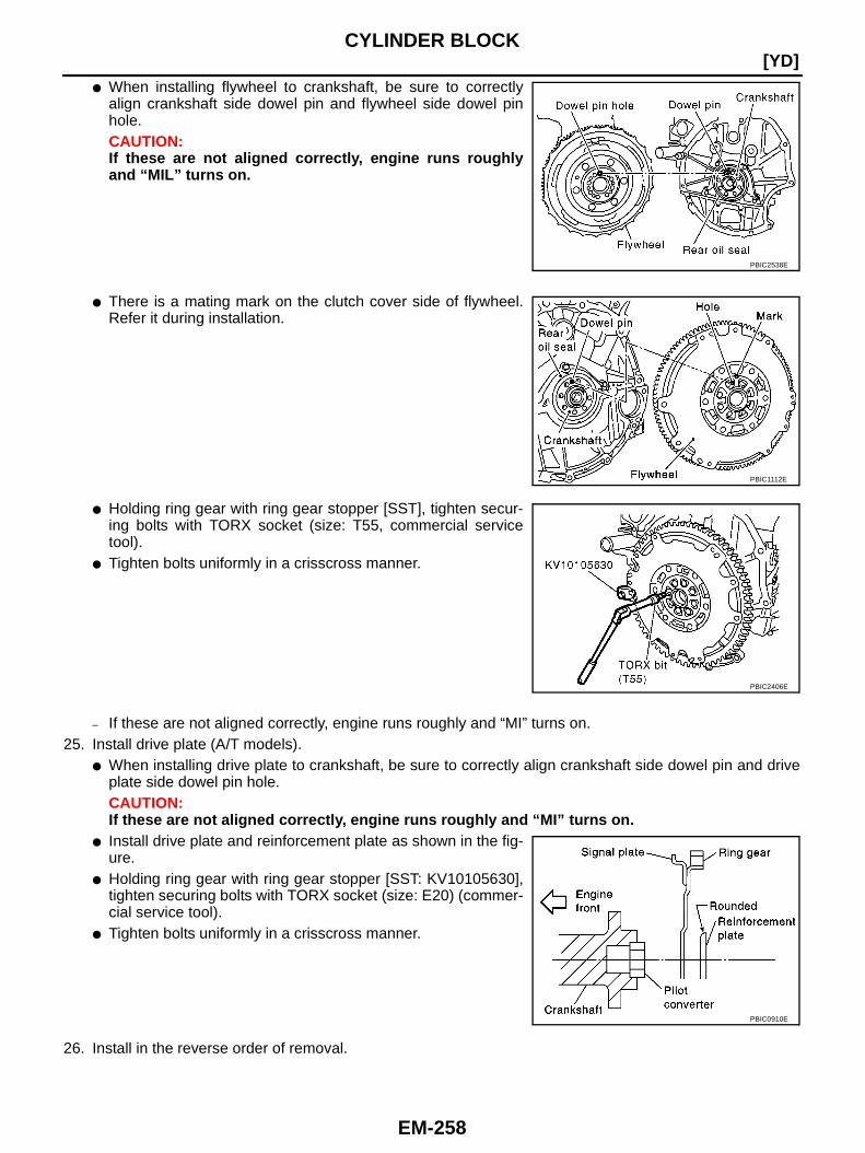
EM-258
[YD]CYLINDER BLOCK
● When installing flywheel to crankshaft, be sure to correctlyalign crankshaft side dowel pin and flywheel side dowel pinhole.CAUTION:If these are not aligned correctly, engine runs roughlyand “MIL” turns on.
● There is a mating mark on the clutch cover side of flywheel.Refer it during installation.
● Holding ring gear with ring gear stopper [SST], tighten secur-ing bolts with TORX socket (size: T55, commercial servicetool).
● Tighten bolts uniformly in a crisscross manner.
– If these are not aligned correctly, engine runs roughly and “MI” turns on.25. Install drive plate (A/T models).
● When installing drive plate to crankshaft, be sure to correctly align crankshaft side dowel pin and driveplate side dowel pin hole.CAUTION:If these are not aligned correctly, engine runs roughly and “MI” turns on.
● Install drive plate and reinforcement plate as shown in the fig-ure.
● Holding ring gear with ring gear stopper [SST: KV10105630],tighten securing bolts with TORX socket (size: E20) (commer-cial service tool).
● Tighten bolts uniformly in a crisscross manner.
26. Install in the reverse order of removal.
PBIC2538E
PBIC1112E
PBIC2406E
PBIC0910E
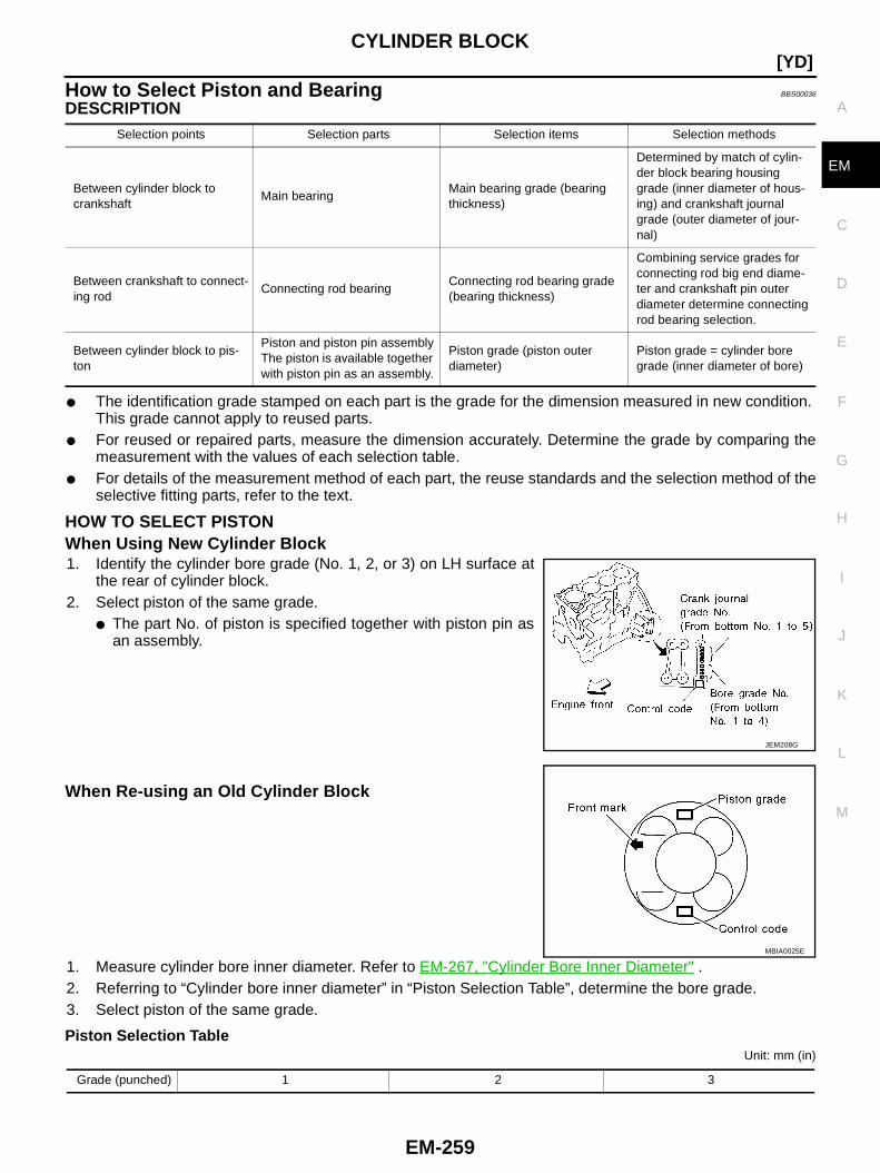
CYLINDER BLOCK
EM-259
[YD]
C
D
E
F
G
H
I
J
K
L
M
A
EM
How to Select Piston and Bearing BBS00036
DESCRIPTION
● The identification grade stamped on each part is the grade for the dimension measured in new condition.This grade cannot apply to reused parts.
● For reused or repaired parts, measure the dimension accurately. Determine the grade by comparing themeasurement with the values of each selection table.
● For details of the measurement method of each part, the reuse standards and the selection method of theselective fitting parts, refer to the text.
HOW TO SELECT PISTONWhen Using New Cylinder Block1. Identify the cylinder bore grade (No. 1, 2, or 3) on LH surface at
the rear of cylinder block.2. Select piston of the same grade.
● The part No. of piston is specified together with piston pin asan assembly.
When Re-using an Old Cylinder Block
1. Measure cylinder bore inner diameter. Refer to EM-267, "Cylinder Bore Inner Diameter" .2. Referring to “Cylinder bore inner diameter” in “Piston Selection Table”, determine the bore grade.3. Select piston of the same grade.
Piston Selection TableUnit: mm (in)
Selection points Selection parts Selection items Selection methods
Between cylinder block tocrankshaft
Main bearingMain bearing grade (bearingthickness)
Determined by match of cylin-der block bearing housinggrade (inner diameter of hous-ing) and crankshaft journalgrade (outer diameter of jour-nal)
Between crankshaft to connect-ing rod
Connecting rod bearingConnecting rod bearing grade(bearing thickness)
Combining service grades forconnecting rod big end diame-ter and crankshaft pin outerdiameter determine connectingrod bearing selection.
Between cylinder block to pis-ton
Piston and piston pin assemblyThe piston is available togetherwith piston pin as an assembly.
Piston grade (piston outerdiameter)
Piston grade = cylinder boregrade (inner diameter of bore)
JEM208G
MBIA0025E
Grade (punched) 1 2 3
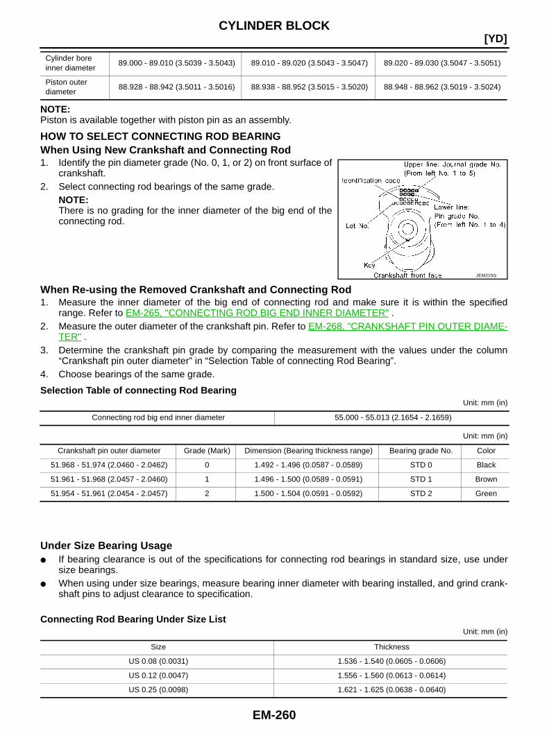
EM-260
[YD]CYLINDER BLOCK
NOTE:Piston is available together with piston pin as an assembly.
HOW TO SELECT CONNECTING ROD BEARINGWhen Using New Crankshaft and Connecting Rod1. Identify the pin diameter grade (No. 0, 1, or 2) on front surface of
crankshaft.2. Select connecting rod bearings of the same grade.
NOTE:There is no grading for the inner diameter of the big end of theconnecting rod.
When Re-using the Removed Crankshaft and Connecting Rod1. Measure the inner diameter of the big end of connecting rod and make sure it is within the specified
range. Refer to EM-265, "CONNECTING ROD BIG END INNER DIAMETER" .2. Measure the outer diameter of the crankshaft pin. Refer to EM-268, "CRANKSHAFT PIN OUTER DIAME-
TER" .3. Determine the crankshaft pin grade by comparing the measurement with the values under the column
“Crankshaft pin outer diameter” in “Selection Table of connecting Rod Bearing”.4. Choose bearings of the same grade.
Selection Table of connecting Rod BearingUnit: mm (in)
Unit: mm (in)
Under Size Bearing Usage● If bearing clearance is out of the specifications for connecting rod bearings in standard size, use under
size bearings.● When using under size bearings, measure bearing inner diameter with bearing installed, and grind crank-
shaft pins to adjust clearance to specification.
Connecting Rod Bearing Under Size ListUnit: mm (in)
Cylinder boreinner diameter
89.000 - 89.010 (3.5039 - 3.5043) 89.010 - 89.020 (3.5043 - 3.5047) 89.020 - 89.030 (3.5047 - 3.5051)
Piston outerdiameter
88.928 - 88.942 (3.5011 - 3.5016) 88.938 - 88.952 (3.5015 - 3.5020) 88.948 - 88.962 (3.5019 - 3.5024)
JEM215G
Connecting rod big end inner diameter 55.000 - 55.013 (2.1654 - 2.1659)
Crankshaft pin outer diameter Grade (Mark) Dimension (Bearing thickness range) Bearing grade No. Color
51.968 - 51.974 (2.0460 - 2.0462) 0 1.492 - 1.496 (0.0587 - 0.0589) STD 0 Black
51.961 - 51.968 (2.0457 - 2.0460) 1 1.496 - 1.500 (0.0589 - 0.0591) STD 1 Brown
51.954 - 51.961 (2.0454 - 2.0457) 2 1.500 - 1.504 (0.0591 - 0.0592) STD 2 Green
Size Thickness
US 0.08 (0.0031) 1.536 - 1.540 (0.0605 - 0.0606)
US 0.12 (0.0047) 1.556 - 1.560 (0.0613 - 0.0614)
US 0.25 (0.0098) 1.621 - 1.625 (0.0638 - 0.0640)
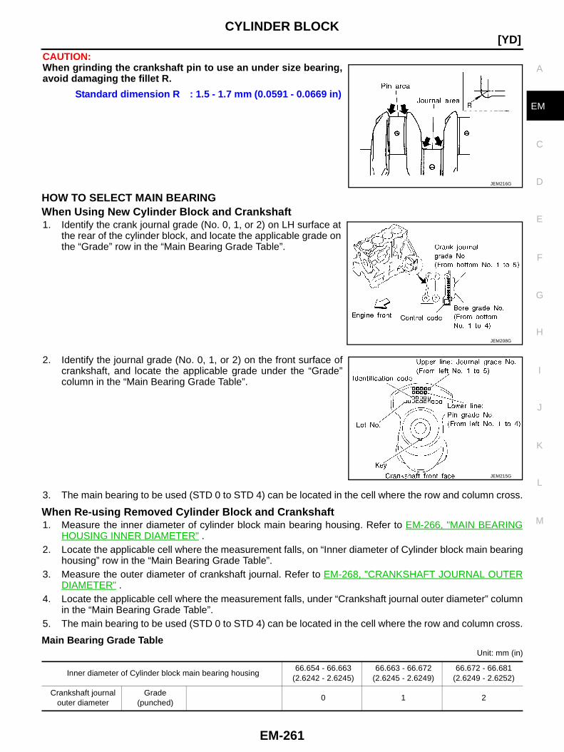
CYLINDER BLOCK
EM-261
[YD]
C
D
E
F
G
H
I
J
K
L
M
A
EM
CAUTION:When grinding the crankshaft pin to use an under size bearing,avoid damaging the fillet R.
HOW TO SELECT MAIN BEARINGWhen Using New Cylinder Block and Crankshaft1. Identify the crank journal grade (No. 0, 1, or 2) on LH surface at
the rear of the cylinder block, and locate the applicable grade onthe “Grade” row in the “Main Bearing Grade Table”.
2. Identify the journal grade (No. 0, 1, or 2) on the front surface ofcrankshaft, and locate the applicable grade under the “Grade”column in the “Main Bearing Grade Table”.
3. The main bearing to be used (STD 0 to STD 4) can be located in the cell where the row and column cross.
When Re-using Removed Cylinder Block and Crankshaft1. Measure the inner diameter of cylinder block main bearing housing. Refer to EM-266, "MAIN BEARING
HOUSING INNER DIAMETER" .2. Locate the applicable cell where the measurement falls, on “Inner diameter of Cylinder block main bearing
housing” row in the “Main Bearing Grade Table”.3. Measure the outer diameter of crankshaft journal. Refer to EM-268, "CRANKSHAFT JOURNAL OUTER
DIAMETER" .4. Locate the applicable cell where the measurement falls, under “Crankshaft journal outer diameter” column
in the “Main Bearing Grade Table”.5. The main bearing to be used (STD 0 to STD 4) can be located in the cell where the row and column cross.
Main Bearing Grade TableUnit: mm (in)
Standard dimension R : 1.5 - 1.7 mm (0.0591 - 0.0669 in)
JEM216G
JEM208G
JEM215G
Inner diameter of Cylinder block main bearing housing66.654 - 66.663
(2.6242 - 2.6245)66.663 - 66.672
(2.6245 - 2.6249)66.672 - 66.681
(2.6249 - 2.6252)
Crankshaft journalouter diameter
Grade(punched)
0 1 2

EM-262
[YD]CYLINDER BLOCK
Under Size Bearing Usage● If bearing clearance is out of the specifications for main bearings in standard size, use under size bear-
ings.● When using under size bearings, measure bearing inner diameter with bearing installed, and grind crank-
shaft journals to adjust clearance to the specification.
Main Bearing Under Size ListUnit: mm (in)
CAUTION:When grinding crank journals to use under size bearings, keepcorners radius of fillet R. (All journals)
Inspection After Disassembly BBS00037
CRANKSHAFT END PLAY● Using dial gauge, measure crankshaft travel amount by moving
the crankshaft forward or backward.
● If the value exceeds the limit, replace thrust bearings with newones and measure again.If the measurement exceeds the limit again, replace crankshaftwith a new one.
62.967 - 62.975(2.4790 - 2.4793)
0
● Bearing grade No.
● Bearing thickness
● Oil clearance
● Identification color
STD 01.816 - 1.820
(0.0715 - 0.0717)0.039 - 0.066
(0.0015 - 0.0026)Black
STD 11.820 - 1.824
(0.0717 - 0.0718)0.039 - 0.066
(0.0015 - 0.0026)Brown
STD 21.824 - 1.828
(0.0718 - 0.0720)0.039 - 0.066
(0.0015 - 0.0026)Green
62.959 - 62.967(2.4787 - 2.6790)
1
● Bearing grade No.
● Bearing thickness
● Oil clearance
● Identification color
STD 11.820 - 1.824
(0.0717 - 0.0718)0.039 - 0.066
(0.0015 - 0.0026)Brown
STD 21.824 - 1.828
(0.0718 - 0.0720)0.039 - 0.066
(0.0015 - 0.0026)Green
STD 31.828 - 1.832
(0.0720 - 0.0721)0.039 - 0.066
(0.0015 - 0.0026)Yellow
62.951 - 62.959(2.4784 - 2.4787)
2
● Bearing grade No.
● Bearing thickness
● Oil clearance
● Identification color
STD 21.824 - 1.828
(0.0718 - 0.0720)0.039 - 0.066
(0.0015 - 0.0026)Green
STD 31.828 - 1.832
(0.0720 - 0.0721)0.039 - 0.066
(0.0015 - 0.0026)Yellow
STD 41.832 - 1.836
(0.0721 - 0.0723)0.039 - 0.066
(0.0015 - 0.0026)Blue
Size Thickness
US 0.25(0.0098) 1.949 - 1.953 (0.0767 - 0.0769)
Standard dimension R : 1.5 - 1.7 mm (0.0591 - 0.0669 in)
JEM216G
Standard : 0.10 - 0.25 mm (0.0039 - 0.0098 in)Limit : 0.30 mm (0.0118 in)
JEM202G

CYLINDER BLOCK
EM-263
[YD]
C
D
E
F
G
H
I
J
K
L
M
A
EM
CONNECTING ROD SIDE CLEARANCE● Using feeler gauge, measure side clearance between connect-
ing rod and crankshaft arm.
● If measured value exceeds the limit, replace connecting rod andrepeat measurement.If measured value still exceeds the limit, replace crankshaft.
PISTON TO PISTON PIN CLEARANCEPiston Pin Bore DiameterUsing inside micrometer, measure piston pin bore diameter.
Piston Pin Outer DiameterUsing micrometer, measure piston pin outer diameter.
Calculation of Piston to Piston Pin Clearance(Piston pin clearance) = (Piston pin bore diameter) − (Piston pin outer diameter)
● If out of the standard, replace piston/piston pin assembly.NOTE:Piston is available together with piston pin as assembly.
Standard : 0.20 - 0.35 (0.0079 - 0.0138 in)Limit : 0.40 mm (0.0157 in)
JEM203G
Standard : 28.003 - 28.009 mm (1.1025 - 1.1027 in)
PBIC0116E
Standard : 27.995 - 28.000 mm (1.1022 - 1.1024 in)
PBIC0117E
Standard : 0.003 - 0.014 mm (0.0001 - 0.0006 in)

EM-264
[YD]CYLINDER BLOCK
PISTON RING SIDE CLEARANCE● Using feeler gauge, measure the side clearance between piston
ring and piston ring groove.Unit: mm (in)
● Align top ring and external surface of piston. Measure lower sideclearance of top ring with top ring pressed onto upper side ofring groove.
● If side clearance exceeds the limit, replace piston ring.● Check clearance again. If side clearance still exceeds the limit,
replace piston.
PISTON RING END GAP● Make sure that cylinder bore diameter is within the specifica-
tions. Refer to EM-267, "PISTON TO CYLINDER BORECLEARANCE" .
● Lubricate with new engine oil to piston and piston ring, and theninsert piston ring until middle of cylinder with piston, and mea-sure piston ring end gap with feeler gauge.
Unit: mm (in)
● If out of the limit, replace piston ring. If gap still exceeds the limit even with a new ring, re-bore cylinderand use oversized piston and piston ring. Refer to EM-267, "PISTON TO CYLINDER BORE CLEAR-ANCE" .
Item Standard Limit
Top ring 0.050 - 0.090 (0.0020 - 0.0035) 0.2 (0.008)
2nd ring 0.050 - 0.090 (0.0020 - 0.0035) 0.1 (0.004)
Oil ring 0.030 - 0.070 (0.0012 - 0.0028) —
SEM024AA
FEM100
Item Standard Limit
Top ring 0.21 - 0.28 (0.0083 - 0.0110)
1.0 (0.039)2nd ring 0.32 - 0.47 (0.0126 - 0.0185)
Oil ring 0.30 - 0.55 (0.0118 - 0.0217)
FEM101
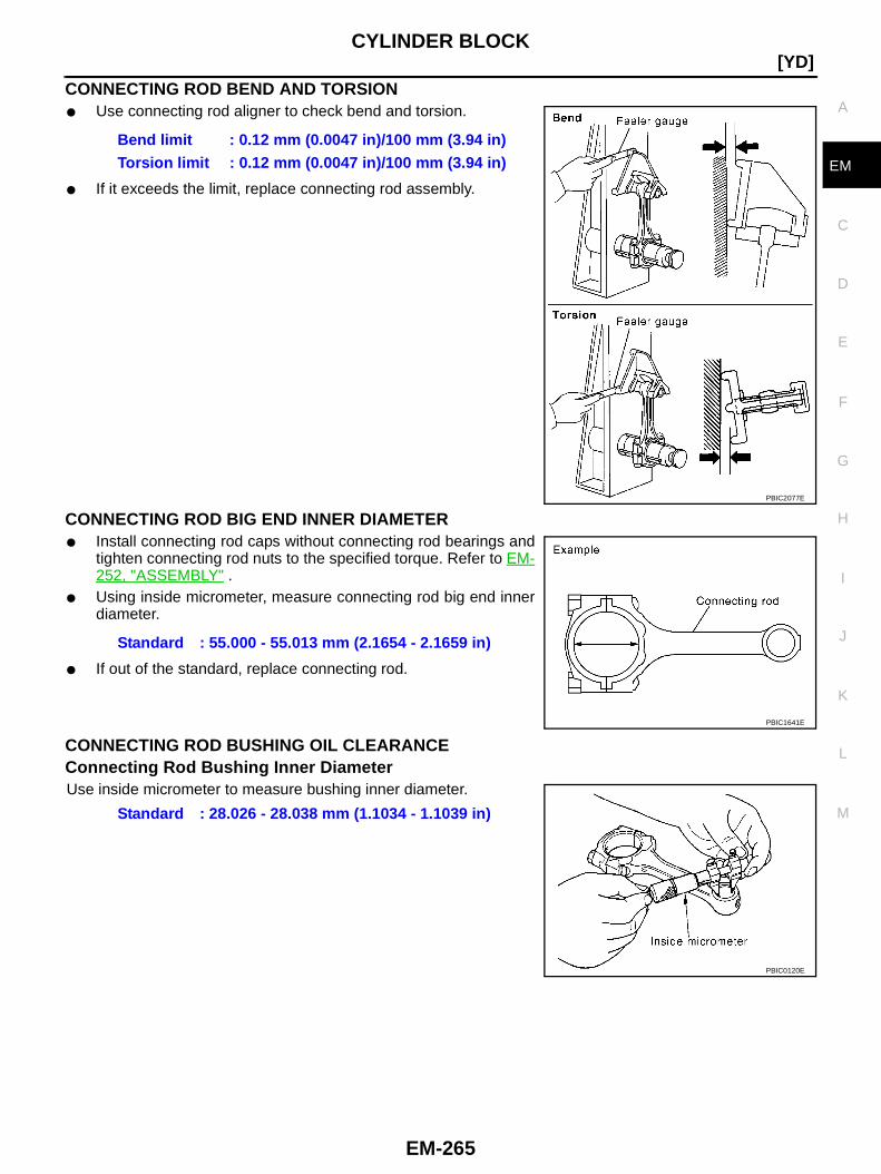
CYLINDER BLOCK
EM-265
[YD]
C
D
E
F
G
H
I
J
K
L
M
A
EM
CONNECTING ROD BEND AND TORSION● Use connecting rod aligner to check bend and torsion.
● If it exceeds the limit, replace connecting rod assembly.
CONNECTING ROD BIG END INNER DIAMETER● Install connecting rod caps without connecting rod bearings and
tighten connecting rod nuts to the specified torque. Refer to EM-252, "ASSEMBLY" .
● Using inside micrometer, measure connecting rod big end innerdiameter.
● If out of the standard, replace connecting rod.
CONNECTING ROD BUSHING OIL CLEARANCEConnecting Rod Bushing Inner DiameterUse inside micrometer to measure bushing inner diameter.
Bend limit : 0.12 mm (0.0047 in)/100 mm (3.94 in)Torsion limit : 0.12 mm (0.0047 in)/100 mm (3.94 in)
PBIC2077E
Standard : 55.000 - 55.013 mm (2.1654 - 2.1659 in)
PBIC1641E
Standard : 28.026 - 28.038 mm (1.1034 - 1.1039 in)
PBIC0120E
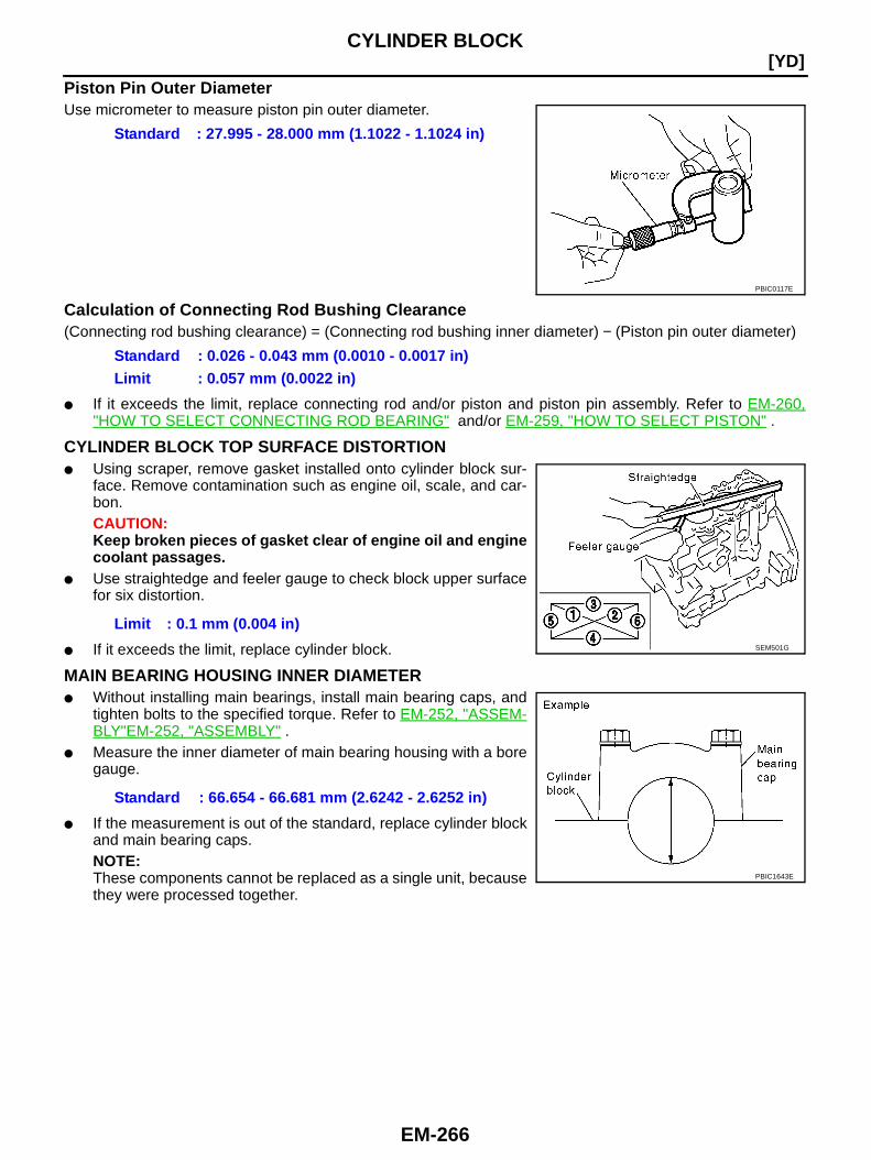
EM-266
[YD]CYLINDER BLOCK
Piston Pin Outer DiameterUse micrometer to measure piston pin outer diameter.
Calculation of Connecting Rod Bushing Clearance(Connecting rod bushing clearance) = (Connecting rod bushing inner diameter) − (Piston pin outer diameter)
● If it exceeds the limit, replace connecting rod and/or piston and piston pin assembly. Refer to EM-260,"HOW TO SELECT CONNECTING ROD BEARING" and/or EM-259, "HOW TO SELECT PISTON" .
CYLINDER BLOCK TOP SURFACE DISTORTION● Using scraper, remove gasket installed onto cylinder block sur-
face. Remove contamination such as engine oil, scale, and car-bon.CAUTION:Keep broken pieces of gasket clear of engine oil and enginecoolant passages.
● Use straightedge and feeler gauge to check block upper surfacefor six distortion.
● If it exceeds the limit, replace cylinder block.
MAIN BEARING HOUSING INNER DIAMETER● Without installing main bearings, install main bearing caps, and
tighten bolts to the specified torque. Refer to EM-252, "ASSEM-BLY"EM-252, "ASSEMBLY" .
● Measure the inner diameter of main bearing housing with a boregauge.
● If the measurement is out of the standard, replace cylinder blockand main bearing caps.NOTE:These components cannot be replaced as a single unit, becausethey were processed together.
Standard : 27.995 - 28.000 mm (1.1022 - 1.1024 in)
PBIC0117E
Standard : 0.026 - 0.043 mm (0.0010 - 0.0017 in)Limit : 0.057 mm (0.0022 in)
Limit : 0.1 mm (0.004 in)SEM501G
Standard : 66.654 - 66.681 mm (2.6242 - 2.6252 in)
PBIC1643E

CYLINDER BLOCK
EM-267
[YD]
C
D
E
F
G
H
I
J
K
L
M
A
EM
PISTON TO CYLINDER BORE CLEARANCECylinder Bore Inner Diameter● Using bore gauge, measure cylinder inner diameters at six posi-
tions; top, middle, and bottom (A, B, C) in 2 directions (X, Y).
● If the measured value exceeds the limit, or if there are scratchesand/or seizure on the cylinder inner wall, hone or bore the innerwall.
● Oversize piston is provided. When using oversize piston, honethe cylinder so that the clearance between piston and cylindersatisfies the standard.CAUTION:If oversize piston is used, use it for all cylinders with over-size piston rings.
Piston Outer DiameterUse micrometer to measure piston outer diameter.
Calculation of Piston to Cylinder Bore Clearance● Calculate using piston outer diameter and cylinder bore inner diameter (direction X, position B).
(Clearance) = (Cylinder bore inner diameter) − (Piston outer diameter)
● If it exceeds the limit, replace piston and piston pin assembly. Refer to EM-259, "HOW TO SELECT PIS-TON" .
Reboring Cylinder Bore1. Determine the cylinder bore size by adding piston-to-cylinder bore clearance to piston diameter.
Cylinder bore inner diameter: 89.000 – 89.030 mm (3.5039 – 3.5051 in)
Wear limit: 0.07 mm (0.028 in)
Out-of-round limit (Difference between X and y): 0.015 mm (0.0006 in)
Taper limit (Difference between A and C): 0.010 mm (0.0004 in)
SEM899G
Oversize (OS) : 0.25 mm (0.0098 in): 0.50 mm (0.0197 in)
FEM110
Piston outer diameterMeasurement position : 11.0 mm (0.43 in)
Distance from the bottomStandard : 88.928 – 88.962 mm
(3.5011 – 3.5024 in)0.25 (0.0098) O/S : 89.188 – 89.202
(3.5113 – 3.5119 in)0.50 (0.0197) O/S : 89.438 – 89.452
(3.5212 – 3.5217 in)PBIC0125E
Specifications at room temperature [20 °C (68°F)]:Standard : 0.058 - 0.082 mm (0.0023 - 0.0032 in)
Rebore size calculation:D = A + B – CWhere,D: Bored diameter
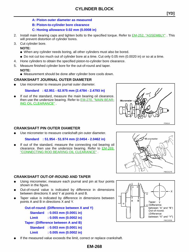
EM-268
[YD]CYLINDER BLOCK
2. Install main bearing caps and tighten bolts to the specified torque. Refer to EM-252, "ASSEMBLY" . Thiswill prevent distortion of cylinder bores.
3. Cut cylinder bore.NOTE:● When any cylinder needs boring, all other cylinders must also be bored.● Do not cut too much out of cylinder bore at a time. Cut only 0.05 mm (0.0020 in) or so at a time.
4. Hone cylinders to obtain the specified piston-to-cylinder bore clearance.5. Measure finished cylinder bore for the out-of-round and taper.
NOTE:● Measurement should be done after cylinder bore cools down.
CRANKSHAFT JOURNAL OUTER DIAMETER● Use micrometer to measure journal outer diameter.
● If out of the standard, measure the main bearing oil clearance.then use the undersize bearing. Refer to EM-270, "MAIN BEAR-ING OIL CLEARANCE" .
CRANKSHAFT PIN OUTER DIAMETER● Use micrometer to measure crankshaft pin outer diameter.
● If out of the standard, measure the connecting rod bearing oilclearance. then use the undersize bearing. Refer to EM-269,"CONNECTING ROD BEARING OIL CLEARANCE" .
CRANKSHAFT OUT-OF-ROUND AND TAPER● Using micrometer, measure each journal and pin at four points
shown in the figure.● Out-of-round value is indicated by difference in dimensions
between directions X and Y at points A and B.● Taper value is indicated by difference in dimensions between
points A and B in directions X and Y.
● If the measured value exceeds the limit, correct or replace crankshaft.
A: Piston outer diameter as measuredB: Piston-to-cylinder bore clearanceC: Honing allowance 0.02 mm (0.0008 in)
Standard : 62.951 - 62.975 mm (2.4784 - 2.4793 in)
FEM114
Standard : 51.954 - 51.974 mm (2.0454 - 2.0462 in)
PBIC0127E
Out-of-round: (Difference between X and Y)Standard : 0.003 mm (0.0001 in)Limit : 0.005 mm (0.0002 in)
Taper: (Difference between A and B)Standard : 0.003 mm (0.0001 in)Limit : 0.005 mm (0.0002 in)
PBIC2203E
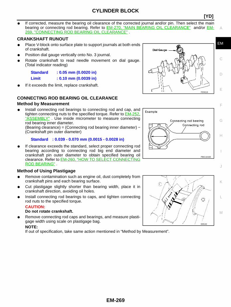
CYLINDER BLOCK
EM-269
[YD]
C
D
E
F
G
H
I
J
K
L
M
A
EM
● If corrected, measure the bearing oil clearance of the corrected journal and/or pin. Then select the mainbearing or connecting rod bearing. Refer to EM-270, "MAIN BEARING OIL CLEARANCE" and/or EM-269, "CONNECTING ROD BEARING OIL CLEARANCE" .
CRANKSHAFT RUNOUT● Place V-block onto surface plate to support journals at both ends
of crankshaft.● Position dial gauge vertically onto No. 3 journal.● Rotate crankshaft to read needle movement on dial gauge.
(Total indicator reading)
● If it exceeds the limit, replace crankshaft.
CONNECTING ROD BEARING OIL CLEARANCEMethod by Measurement● Install connecting rod bearings to connecting rod and cap, and
tighten connecting nuts to the specified torque. Refer to EM-252,"ASSEMBLY" . Use inside micrometer to measure connectingrod bearing inner diameter.(Bearing clearance) = (Connecting rod bearing inner diameter) −(Crankshaft pin outer diameter)
● If clearance exceeds the standard, select proper connecting rodbearing according to connecting rod big end diameter andcrankshaft pin outer diameter to obtain specified bearing oilclearance. Refer to EM-260, "HOW TO SELECT CONNECTINGROD BEARING" .
Method of Using Plastigage● Remove contamination such as engine oil, dust completely from
crankshaft pins and each bearing surface.● Cut plastigage slightly shorter than bearing width, place it in
crankshaft direction, avoiding oil holes.● Install connecting rod bearings to caps, and tighten connecting
rod nuts to the specified torque.CAUTION:Do not rotate crankshaft.
● Remove connecting rod caps and bearings, and measure plasti-gage width using scale on plastigage bag.NOTE:If out of specification, take same action mentioned in “Method by Measurement”.
Standard : 0.05 mm (0.0020 in)Limit : 0.10 mm (0.0039 in)
FEM116
Standard : 0.039 - 0.070 mm (0.0015 - 0.0028 in)
PBIC1642E
EM142
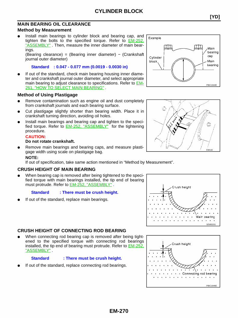
EM-270
[YD]CYLINDER BLOCK
MAIN BEARING OIL CLEARANCEMethod by Measurement● Install main bearings to cylinder block and bearing cap, and
tighten the bolts to the specified torque. Refer to EM-252,"ASSEMBLY" . Then, measure the inner diameter of main bear-ings.(Bearing clearance) = (Bearing inner diameter) − (Crankshaftjournal outer diameter)
● If out of the standard, check main bearing housing inner diame-ter and crankshaft journal outer diameter, and select appropriatemain bearing to adjust clearance to specifications. Refer to EM-261, "HOW TO SELECT MAIN BEARING" .
Method of Using Plastigage● Remove contamination such as engine oil and dust completely
from crankshaft journals and each bearing surface.● Cut plastigage slightly shorter than bearing width. Place it in
crankshaft turning direction, avoiding oil holes.● Install main bearings and bearing cap and tighten to the speci-
fied torque. Refer to EM-252, "ASSEMBLY" for the tighteningprocedure.CAUTION:Do not rotate crankshaft.
● Remove main bearings and bearing caps, and measure plasti-gage width using scale on plastigage bag.NOTE:If out of specification, take same action mentioned in “Method by Measurement”.
CRUSH HEIGHT OF MAIN BEARING● When bearing cap is removed after being tightened to the speci-
fied torque with main bearings installed, the tip end of bearingmust protrude. Refer to EM-252, "ASSEMBLY" .
● If out of the standard, replace main bearings.
CRUSH HEIGHT OF CONNECTING ROD BEARING● When connecting rod bearing cap is removed after being tight-
ened to the specified torque with connecting rod bearingsinstalled, the tip end of bearing must protrude. Refer to EM-252,"ASSEMBLY" .
● If out of the standard, replace connecting rod bearings.
Standard : 0.047 - 0.077 mm (0.0019 - 0.0030 in)
PBIC1644E
EM142
Standard : There must be crush height.
SEM502G
Standard : There must be crush height.
PBIC1646E
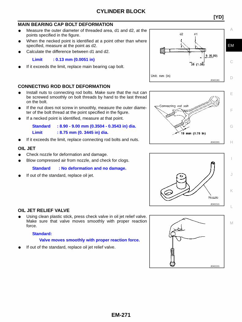
CYLINDER BLOCK
EM-271
[YD]
C
D
E
F
G
H
I
J
K
L
M
A
EM
MAIN BEARING CAP BOLT DEFORMATION● Measure the outer diameter of threaded area, d1 and d2, at the
points specified in the figure.● When the necked point is identified at a point other than where
specified, measure at the point as d2.● Calculate the difference between d1 and d2.
● If it exceeds the limit, replace main bearing cap bolt.
CONNECTING ROD BOLT DEFORMATION● Install nuts to connecting rod bolts. Make sure that the nut can
be screwed smoothly on bolt threads by hand to the last threadon the bolt.
● If the nut does not screw in smoothly, measure the outer diame-ter of the bolt thread at the point specified in the figure.
● If a necked point is identified, measure at that point.
● If it exceeds the limit, replace connecting rod bolts and nuts.
OIL JET● Check nozzle for deformation and damage.● Blow compressed air from nozzle, and check for clogs.
● If out of the standard, replace oil jet.
OIL JET RELIEF VALVE● Using clean plastic stick, press check valve in oil jet relief valve.
Make sure that valve moves smoothly with proper reactionforce.
● If out of the standard, replace oil jet relief valve.
Limit : 0.13 mm (0.0051 in)
JEM219G
Standard : 8.90 - 9.00 mm (0.3504 - 0.3543 in) dia.Limit : 8.75 mm (0. 3445 in) dia.
JEM220G
Standard : No deformation and no damage.
JEM221G
Standard:Valve moves smoothly with proper reaction force.
JEM222G
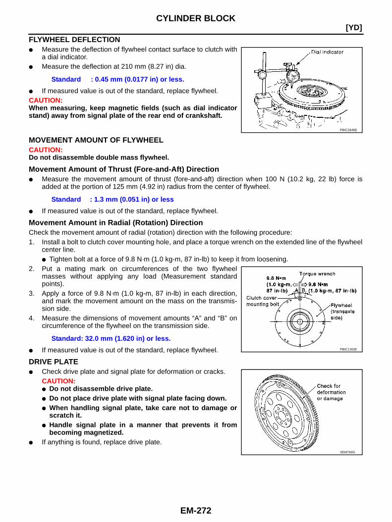
EM-272
[YD]CYLINDER BLOCK
FLYWHEEL DEFLECTION● Measure the deflection of flywheel contact surface to clutch with
a dial indicator.● Measure the deflection at 210 mm (8.27 in) dia.
● If measured value is out of the standard, replace flywheel.CAUTION:When measuring, keep magnetic fields (such as dial indicatorstand) away from signal plate of the rear end of crankshaft.
MOVEMENT AMOUNT OF FLYWHEELCAUTION:Do not disassemble double mass flywheel.
Movement Amount of Thrust (Fore-and-Aft) Direction● Measure the movement amount of thrust (fore-and-aft) direction when 100 N (10.2 kg, 22 lb) force is
added at the portion of 125 mm (4.92 in) radius from the center of flywheel.
● If measured value is out of the standard, replace flywheel.
Movement Amount in Radial (Rotation) DirectionCheck the movement amount of radial (rotation) direction with the following procedure:1. Install a bolt to clutch cover mounting hole, and place a torque wrench on the extended line of the flywheel
center line.● Tighten bolt at a force of 9.8 N·m (1.0 kg-m, 87 in-lb) to keep it from loosening.
2. Put a mating mark on circumferences of the two flywheelmasses without applying any load (Measurement standardpoints).
3. Apply a force of 9.8 N·m (1.0 kg-m, 87 in-lb) in each direction,and mark the movement amount on the mass on the transmis-sion side.
4. Measure the dimensions of movement amounts “A” and “B” oncircumference of the flywheel on the transmission side.
● If measured value is out of the standard, replace flywheel.
DRIVE PLATE● Check drive plate and signal plate for deformation or cracks.
CAUTION:● Do not disassemble drive plate.● Do not place drive plate with signal plate facing down.● When handling signal plate, take care not to damage or
scratch it.● Handle signal plate in a manner that prevents it from
becoming magnetized.● If anything is found, replace drive plate.
Standard : 0.45 mm (0.0177 in) or less.
PBIC2646E
Standard : 1.3 mm (0.051 in) or less
Standard: 32.0 mm (1.620 in) or less.PBIC1263E
SEM760G
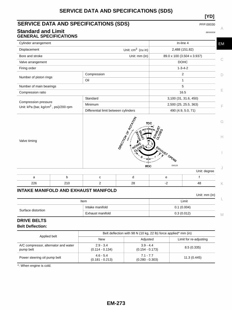
SERVICE DATA AND SPECIFICATIONS (SDS)
EM-273
[YD]
C
D
E
F
G
H
I
J
K
L
M
A
EM
SERVICE DATA AND SPECIFICATIONS (SDS) PFP:00030
Standard and Limit BBS00038
GENERAL SPECIFICATIONS
INTAKE MANIFOLD AND EXHAUST MANIFOLDUnit: mm (in)
DRIVE BELTSBelt Deflection:
*: When engine is cold.
Cylinder arrangement In-line 4
Displacement Unit: cm3 (cu in) 2,488 (151.82)
Bore and stroke Unit: mm (in) 89.0 x 100 (3.504 x 3.937)
Valve arrangement DOHC
Firing order 1-3-4-2
Number of piston ringsCompression 2
Oil 1
Number of main bearings 5
Compression ratio 16.5
Compression pressure
Unit: kPa (bar, kg/cm2 , psi)/200 rpm
Standard 3,100 (31, 31.6, 450)
Minimum 2,500 (25, 25.5, 363)
Differential limit between cylinders 490 (4.9, 5.0, 71)
Valve timing
Unit: degree
a b c d e f
226 210 2 28 -2 48
EM120
Item Limit
Surface distortionIntake manifold 0.1 (0.004)
Exhaust manifold 0.3 (0.012)
Applied beltBelt deflection with 98 N (10 kg, 22 lb) force applied* mm (in)
New Adjusted Limit for re-adjusting
A/C compressor, alternator and waterpump belt
2.9 - 3.4(0.114 - 0.134)
3.9 - 4.4(0.154 - 0.173)
8.5 (0.335)
Power steering oil pump belt4.6 - 5.4
(0.181 - 0.213)7.1 - 7.7
(0.280 - 0.303)11.3 (0.445)
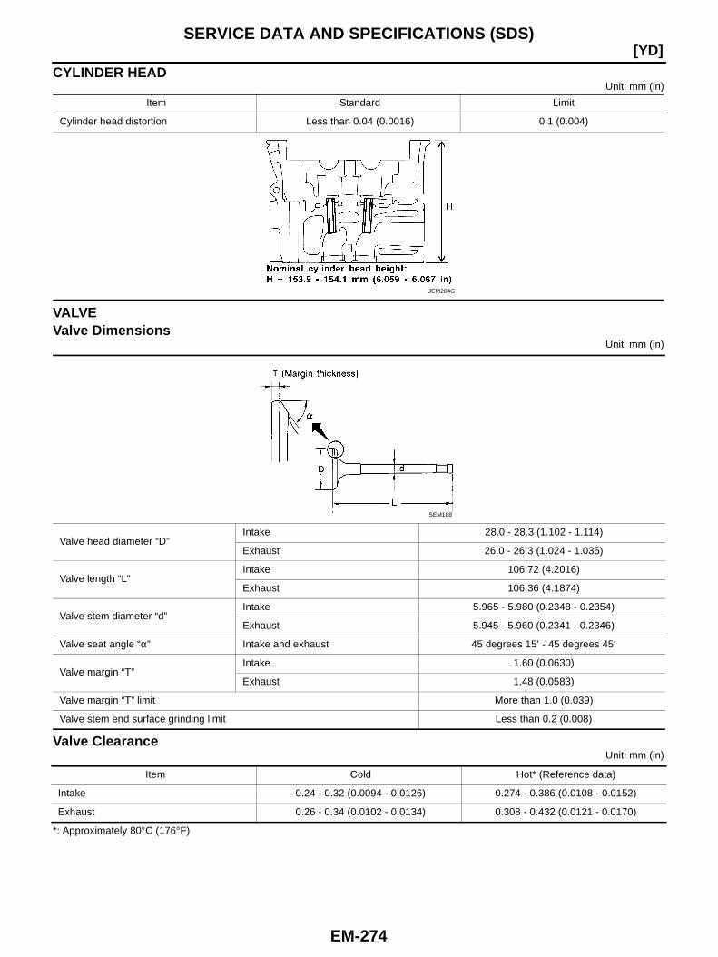
EM-274
[YD]SERVICE DATA AND SPECIFICATIONS (SDS)
CYLINDER HEADUnit: mm (in)
VALVEValve Dimensions
Unit: mm (in)
Valve ClearanceUnit: mm (in)
*: Approximately 80°C (176°F)
Item Standard Limit
Cylinder head distortion Less than 0.04 (0.0016) 0.1 (0.004)
JEM204G
Valve head diameter “D”Intake 28.0 - 28.3 (1.102 - 1.114)
Exhaust 26.0 - 26.3 (1.024 - 1.035)
Valve length “L”Intake 106.72 (4.2016)
Exhaust 106.36 (4.1874)
Valve stem diameter “d”Intake 5.965 - 5.980 (0.2348 - 0.2354)
Exhaust 5.945 - 5.960 (0.2341 - 0.2346)
Valve seat angle “α” Intake and exhaust 45 degrees 15′ - 45 degrees 45′
Valve margin “T”Intake 1.60 (0.0630)
Exhaust 1.48 (0.0583)
Valve margin “T” limit More than 1.0 (0.039)
Valve stem end surface grinding limit Less than 0.2 (0.008)
SEM188
Item Cold Hot* (Reference data)
Intake 0.24 - 0.32 (0.0094 - 0.0126) 0.274 - 0.386 (0.0108 - 0.0152)
Exhaust 0.26 - 0.34 (0.0102 - 0.0134) 0.308 - 0.432 (0.0121 - 0.0170)
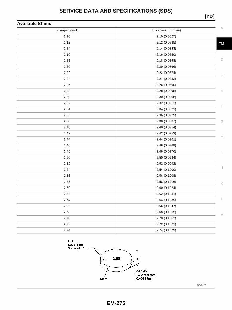
SERVICE DATA AND SPECIFICATIONS (SDS)
EM-275
[YD]
C
D
E
F
G
H
I
J
K
L
M
A
EM
Available ShimsStamped mark Thickness mm (in)
2.10 2.10 (0.0827)
2.12 2.12 (0.0835)
2.14 2.14 (0.0843)
2.16 2.16 (0.0850)
2.18 2.18 (0.0858)
2.20 2.20 (0.0866)
2.22 2.22 (0.0874)
2.24 2.24 (0.0882)
2.26 2.26 (0.0890)
2.28 2.28 (0.0898)
2.30 2.30 (0.0906)
2.32 2.32 (0.0913)
2.34 2.34 (0.0921)
2.36 2.36 (0.0929)
2.38 2.38 (0.0937)
2.40 2.40 (0.0954)
2.42 2.42 (0.0953)
2.44 2.44 (0.0961)
2.46 2.46 (0.0969)
2.48 2.48 (0.0976)
2.50 2.50 (0.0984)
2.52 2.52 (0.0992)
2.54 2.54 (0.1000)
2.56 2.56 (0.1008)
2.58 2.58 (0.1016)
2.60 2.60 (0.1024)
2.62 2.62 (0.1031)
2.64 2.64 (0.1039)
2.66 2.66 (0.1047)
2.68 2.68 (0.1055)
2.70 2.70 (0.1063)
2.72 2.72 (0.1071)
2.74 2.74 (0.1079)
SEM512G
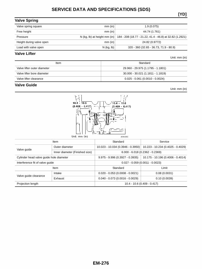
EM-276
[YD]SERVICE DATA AND SPECIFICATIONS (SDS)
Valve Spring
Valve LifterUnit: mm (in)
Valve GuideUnit: mm (in)
Valve spring square mm (in) 1.9 (0.075)
Free height mm (in) 44.74 (1.761)
Pressure N (kg, lb) at height mm (in) 184 - 208 (18.77 - 21.22, 41.4 - 46.8) at 32.82 (1.2921)
Height during valve open mm (in) 24.82 (0.9772)
Load with valve open N (kg, lb) 320 - 360 (32.65 - 36.73, 71.9 - 80.9)
Item Standard
Valve lifter outer diameter 29.960 - 29.975 (1.1795 - 1.1801)
Valve lifter bore diameter 30.000 - 30.021 (1.1811 - 1.1819)
Valve lifter clearance 0.025 - 0.061 (0.0010 - 0.0024)
Item Standard Service
Valve guideOuter diameter 10.023 - 10.034 (0.3946 - 0.3950) 10.223 - 10.234 (0.4025 - 0.4029)
Inner diameter (Finished size) 6.000 - 6.018 (0.2362 - 0.2369)
Cylinder head valve guide hole diameter 9.975 - 9.996 (0.3927 - 0.3935) 10.175 - 10.196 (0.4006 - 0.4014)
Interference fit of valve guide 0.027 - 0.059 (0.0011 - 0.0023)
Item Standard Limit
Valve guide clearanceIntake 0.020 - 0.053 (0.0008 - 0.0021) 0.08 (0.0031)
Exhaust 0.040 - 0.073 (0.0016 - 0.0029) 0.10 (0.0039)
Projection length 10.4 - 10.6 (0.409 - 0.417)
JEM156G

SERVICE DATA AND SPECIFICATIONS (SDS)
EM-277
[YD]
C
D
E
F
G
H
I
J
K
L
M
A
EM
Valve SeatUnit: mm (in)
Items Standard Oversize [0.5 (0.02)] (Service)
Cylinder head seat (1) recess diam-eter “D”
Intake 30.000 - 30.016 (1.1811 - 1.1817) 30.500 - 30.516 (1.2008 - 1.2014)
Exhaust 29.000 - 29.016 (1.1417 - 1.1424) 29.500 - 29.516 (1.1614 - 1.1620)
Valve seat outer diameter “d”Intake (A) 30.080 - 30.100 (1.1842 - 1.1850) 30.580 - 30.600 (1.2039 - 1.2047)
Exhaust (B) 29.080 - 29.096 (1.1449 - 1.1455) 29.580 - 29.596 (1.1646 - 1.1652)
Valve seat interference fitIntake (A) 0.064 - 0.100 (0.0025 - 0.0039)
Exhaust (B) 0.064 - 0.096 (0.0025 - 0.0038)
Diameter “d1”Intake (A) 27.15 - 27.65 (1.0689 - 1.0886) 26.05 - 26.55 (1.0256 - 1.0453)
Exhaust (B) 24.95 - 25.45 (0.9823 - 1.0020) 24.15 - 24.65 (0.9508 - 0.9705)
PBIC4054E
JEM253G
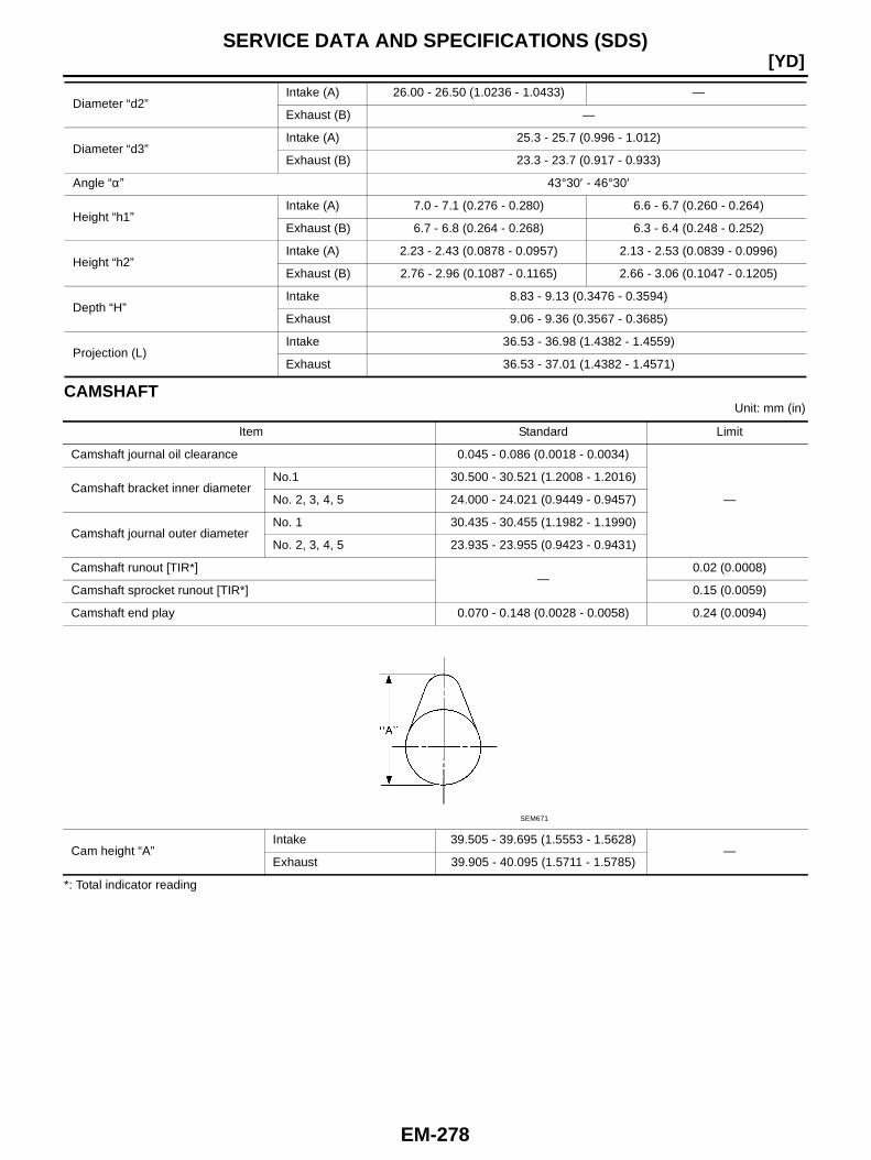
EM-278
[YD]SERVICE DATA AND SPECIFICATIONS (SDS)
CAMSHAFTUnit: mm (in)
*: Total indicator reading
Diameter “d2”Intake (A) 26.00 - 26.50 (1.0236 - 1.0433) —
Exhaust (B) —
Diameter “d3”Intake (A) 25.3 - 25.7 (0.996 - 1.012)
Exhaust (B) 23.3 - 23.7 (0.917 - 0.933)
Angle “α” 43°30′ - 46°30′
Height “h1”Intake (A) 7.0 - 7.1 (0.276 - 0.280) 6.6 - 6.7 (0.260 - 0.264)
Exhaust (B) 6.7 - 6.8 (0.264 - 0.268) 6.3 - 6.4 (0.248 - 0.252)
Height “h2”Intake (A) 2.23 - 2.43 (0.0878 - 0.0957) 2.13 - 2.53 (0.0839 - 0.0996)
Exhaust (B) 2.76 - 2.96 (0.1087 - 0.1165) 2.66 - 3.06 (0.1047 - 0.1205)
Depth “H”Intake 8.83 - 9.13 (0.3476 - 0.3594)
Exhaust 9.06 - 9.36 (0.3567 - 0.3685)
Projection (L)Intake 36.53 - 36.98 (1.4382 - 1.4559)
Exhaust 36.53 - 37.01 (1.4382 - 1.4571)
Item Standard Limit
Camshaft journal oil clearance 0.045 - 0.086 (0.0018 - 0.0034)
—Camshaft bracket inner diameter
No.1 30.500 - 30.521 (1.2008 - 1.2016)
No. 2, 3, 4, 5 24.000 - 24.021 (0.9449 - 0.9457)
Camshaft journal outer diameterNo. 1 30.435 - 30.455 (1.1982 - 1.1990)
No. 2, 3, 4, 5 23.935 - 23.955 (0.9423 - 0.9431)
Camshaft runout [TIR*]—
0.02 (0.0008)
Camshaft sprocket runout [TIR*] 0.15 (0.0059)
Camshaft end play 0.070 - 0.148 (0.0028 - 0.0058) 0.24 (0.0094)
Cam height “A”Intake 39.505 - 39.695 (1.5553 - 1.5628)
—Exhaust 39.905 - 40.095 (1.5711 - 1.5785)
SEM671
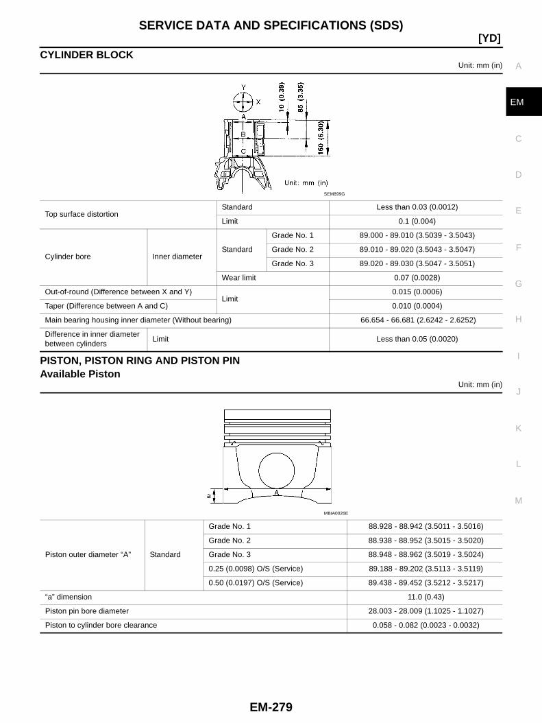
SERVICE DATA AND SPECIFICATIONS (SDS)
EM-279
[YD]
C
D
E
F
G
H
I
J
K
L
M
A
EM
CYLINDER BLOCKUnit: mm (in)
PISTON, PISTON RING AND PISTON PINAvailable Piston
Unit: mm (in)
Top surface distortionStandard Less than 0.03 (0.0012)
Limit 0.1 (0.004)
Cylinder bore Inner diameterStandard
Grade No. 1 89.000 - 89.010 (3.5039 - 3.5043)
Grade No. 2 89.010 - 89.020 (3.5043 - 3.5047)
Grade No. 3 89.020 - 89.030 (3.5047 - 3.5051)
Wear limit 0.07 (0.0028)
Out-of-round (Difference between X and Y)Limit
0.015 (0.0006)
Taper (Difference between A and C) 0.010 (0.0004)
Main bearing housing inner diameter (Without bearing) 66.654 - 66.681 (2.6242 - 2.6252)
Difference in inner diameterbetween cylinders
Limit Less than 0.05 (0.0020)
SEM899G
Piston outer diameter “A” Standard
Grade No. 1 88.928 - 88.942 (3.5011 - 3.5016)
Grade No. 2 88.938 - 88.952 (3.5015 - 3.5020)
Grade No. 3 88.948 - 88.962 (3.5019 - 3.5024)
0.25 (0.0098) O/S (Service) 89.188 - 89.202 (3.5113 - 3.5119)
0.50 (0.0197) O/S (Service) 89.438 - 89.452 (3.5212 - 3.5217)
“a” dimension 11.0 (0.43)
Piston pin bore diameter 28.003 - 28.009 (1.1025 - 1.1027)
Piston to cylinder bore clearance 0.058 - 0.082 (0.0023 - 0.0032)
MBIA0026E
EM-280
[YD]SERVICE DATA AND SPECIFICATIONS (SDS)
Piston RingUnit: mm (in)
Piston PinUnit: mm (in)
Item Standard Limit
Side clearance
Top 0.050 - 0.090 (0.0020 - 0.0035) 0.2 (0.008)
2nd 0.050 - 0.090 (0.0020 - 0.0035) 0.1 (0.004)
Oil ring 0.030 - 0.070 (0.0012 - 0.0028) —
End gap
Top 0.21 - 0.28 (0.0083 - 0.0110)
1.0 (0.039)2nd 0.32 - 0.47 (0.0126 - 0.0185)
Oil ring 0.30 - 0.55 (0.0118 - 0.0217)
Piston pin outer diameter 27.995 - 28.000 (1.1022 - 1.1024)
Piston to piston pin clearance 0.003 - 0.014 (0.0001 - 0.0006)
Connecting rod bushing clearanceStandard 0.026 - 0.043 (0.0010 - 0.0017)
Limit 0.057 (0.0022)
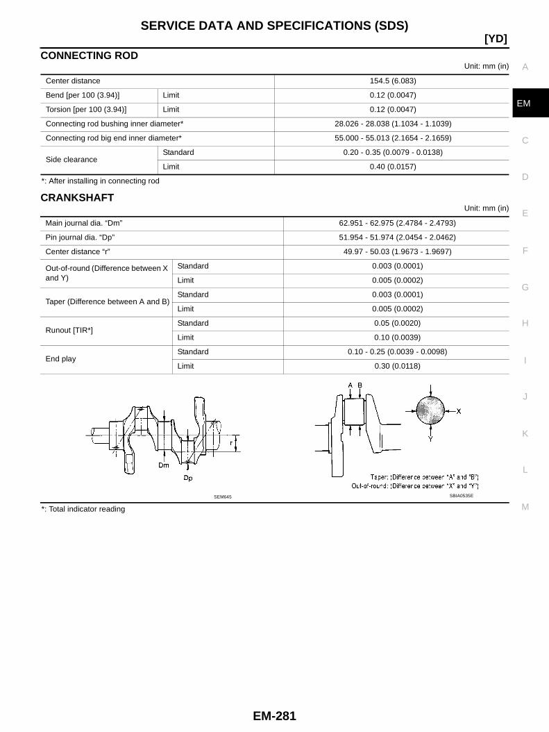
SERVICE DATA AND SPECIFICATIONS (SDS)
EM-281
[YD]
C
D
E
F
G
H
I
J
K
L
M
A
EM
CONNECTING RODUnit: mm (in)
*: After installing in connecting rod
CRANKSHAFTUnit: mm (in)
*: Total indicator reading
Center distance 154.5 (6.083)
Bend [per 100 (3.94)] Limit 0.12 (0.0047)
Torsion [per 100 (3.94)] Limit 0.12 (0.0047)
Connecting rod bushing inner diameter* 28.026 - 28.038 (1.1034 - 1.1039)
Connecting rod big end inner diameter* 55.000 - 55.013 (2.1654 - 2.1659)
Side clearanceStandard 0.20 - 0.35 (0.0079 - 0.0138)
Limit 0.40 (0.0157)
Main journal dia. “Dm” 62.951 - 62.975 (2.4784 - 2.4793)
Pin journal dia. “Dp” 51.954 - 51.974 (2.0454 - 2.0462)
Center distance “r” 49.97 - 50.03 (1.9673 - 1.9697)
Out-of-round (Difference between Xand Y)
Standard 0.003 (0.0001)
Limit 0.005 (0.0002)
Taper (Difference between A and B)Standard 0.003 (0.0001)
Limit 0.005 (0.0002)
Runout [TIR*]Standard 0.05 (0.0020)
Limit 0.10 (0.0039)
End playStandard 0.10 - 0.25 (0.0039 - 0.0098)
Limit 0.30 (0.0118)
SEM645 SBIA0535E
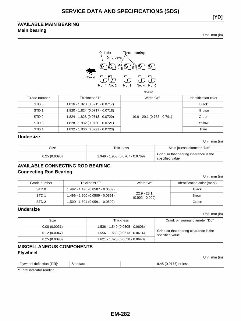
EM-282
[YD]SERVICE DATA AND SPECIFICATIONS (SDS)
AVAILABLE MAIN BEARINGMain bearing
Unit: mm (in)
UndersizeUnit: mm (in)
AVAILABLE CONNECTING ROD BEARINGConnecting Rod Bearing
Unit: mm (in)
UndersizeUnit: mm (in)
MISCELLANEOUS COMPONENTSFlywheel
Unit: mm (in)
*: Total indicator reading
Grade number Thickness “T” Width “W” Identification color
STD 0 1.816 - 1.820 (0.0715 - 0.0717)
19.9 - 20.1 (0.783 - 0.791)
Black
STD 1 1.820 - 1.824 (0.0717 - 0.0718) Brown
STD 2 1.824 - 1.828 (0.0718 - 0.0720) Green
STD 3 1.828 - 1.832 (0.0720 - 0.0721) Yellow
STD 4 1.832 - 1.836 (0.0721 - 0.0723) Blue
SEM255G
Size Thickness Main journal diameter “Dm”
0.25 (0.0098) 1.949 - 1.953 (0.0767 - 0.0769)Grind so that bearing clearance is thespecified value.
Grade number Thickness “T” Width “W” Identification color (mark)
STD 0 1.492 - 1.496 (0.0587 - 0.0589)22.9 - 23.1
(0.902 - 0.909)
Black
STD 1 1.496 - 1.500 (0.0589 - 0.0591) Brown
STD 2 1.500 - 1.504 (0.0591 - 0.0592) Green
Size Thickness Crank pin journal diameter “Dp”
0.08 (0.0031) 1.536 - 1.540 (0.0605 - 0.0606)Grind so that bearing clearance is thespecified value.
0.12 (0.0047) 1.556 - 1.560 (0.0613 - 0.0614)
0.25 (0.0098) 1.621 - 1.625 (0.0638 - 0.0640)
Flywheel deflection [TIR]* Standard 0.45 (0.0177) or less
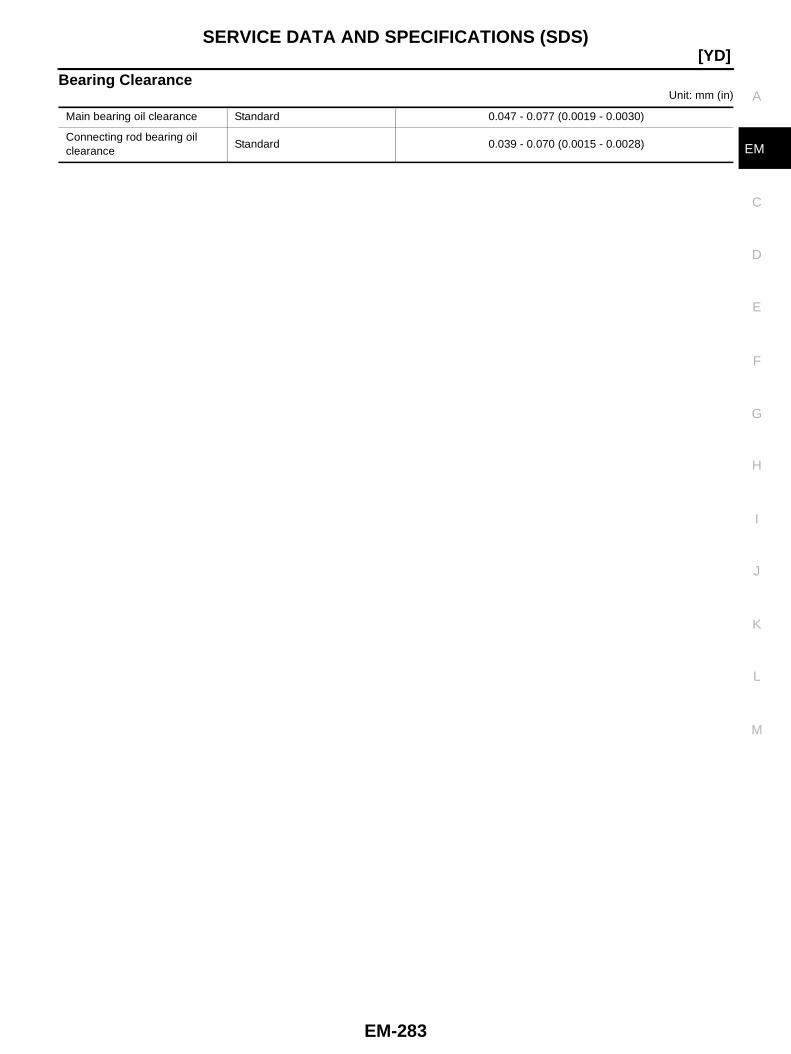
SERVICE DATA AND SPECIFICATIONS (SDS)
EM-283
[YD]
C
D
E
F
G
H
I
J
K
L
M
A
EM
Bearing ClearanceUnit: mm (in)
Main bearing oil clearance Standard 0.047 - 0.077 (0.0019 - 0.0030)
Connecting rod bearing oilclearance
Standard 0.039 - 0.070 (0.0015 - 0.0028)
EM-284
[YD]SERVICE DATA AND SPECIFICATIONS (SDS)