![PET imaging of demyelination and remyelination in the cuprizone mouse model for multiple sclerosis: A comparison between [11C]CIC and [11C]MeDAS](https://static.fdokumen.com/doc/165x107/63419d7d8768bcaafb01b673/pet-imaging-of-demyelination-and-remyelination-in-the-cuprizone-mouse-model-for.jpg)
group 11c - engine mechanical - Mirage Performance Online
36
11C-1 GROUP 11C ENGINE MECHANICAL <3.0L> CONTENTS GENERAL DESCRIPTION. . . . . . . . . 11C-2 ENGINE DIAGNOSIS . . . . . . . . . . . . . 11C-2 SPECIAL TOOLS . . . . . . . . . . . . . . . . 11C-3 ON VEHICLE SERVICE . . . . . . . . . . . 11C-5 DRIVE BELT TENSION CHECK AND ADJUSTMENT . . . . . . . . . . . . . . . . . . . . . . . . . . . . . . . . . . . . . . 11C-5 IGNITION TIMING CHECK . . . . . . . . . . . . . 11C-5 IDLE MIXTURE CHECK . . . . . . . . . . . . . . . 11C-6 CURB IDLE SPEED CHECK . . . . . . . . . . . 11C-7 COMPRESSION PRESSURE CHECK . . . . 11C-7 MANIFOLD VACUUM CHECK . . . . . . . . . . 11C-8 LASH ADJUSTER CHECK . . . . . . . . . . . . . 11C-9 ENGINE ASSEMBLY . . . . . . . . . . . . . 11C-11 REMOVAL AND INSTALLATION . . . . . . . . 11C-11 CAMSHAFT AND CAMSHAFT OIL SEAL . . . . . . . . . . . . . . . . . . . . . . . . . . . . . . . . . . . . . . . . . . . . . . . . . . . . . . . . . . . . . . . . . . . . . . . . . . . . . . . . . . . . . . . . . . . . . . . . . . . . . . . . . . . . . . . . . . . . . . . . . . . . . . . . . . . . 11C-16 REMOVAL AND INSTALLATION . . . . . . . . 11C-16 OIL PAN . . . . . . . . . . . . . . . . . . . . . . . 11C-21 REMOVAL AND INSTALLATION . . . . . . . . 11C-21 INSPECTION. . . . . . . . . . . . . . . . . . . . . . . . 11C-23 CRANKSHAFT FRONT OIL SEAL. . . 11C-24 REMOVAL AND INSTALLATION . . . . . . . . 11C-24 CRANKSHAFT REAR OIL SEAL . . . . 11C-25 REMOVAL AND INSTALLATION . . . . . . . . 11C-25 CYLINDER HEAD GASKET . . . . . . . . 11C-27 REMOVAL AND INSTALLATION . . . . . . . . 11C-27 TIMING BELT . . . . . . . . . . . . . . . . . . . 11C-29 REMOVAL AND INSTALLATION . . . . . . . . 11C-29 INSPECTION. . . . . . . . . . . . . . . . . . . . . . . . 11C-35 SPECIFICATIONS . . . . . . . . . . . . . . . 11C-35 FASTENER TIGHTENING SPECIFICATIONS . . . . . . . . . . . . . . . . . . . . . . . . . . . . . . . . . . . . . . 11C-35 SERVICE SPECIFICATIONS . . . . . . . . . . . 11C-36 SEALANT . . . . . . . . . . . . . . . . . . . . . . . . . . 11C-36
-
Upload
khangminh22 -
Category
Documents
-
view
3 -
download
0
Transcript of group 11c - engine mechanical - Mirage Performance Online

11C-1
GROUP 11C
ENGINE MECHANICAL
<3.0L>
CONTENTS
GENERAL DESCRIPTION. . . . . . . . . 11C-2
ENGINE DIAGNOSIS. . . . . . . . . . . . . 11C-2
SPECIAL TOOLS. . . . . . . . . . . . . . . . 11C-3
ON VEHICLE SERVICE. . . . . . . . . . . 11C-5DRIVE BELT TENSION CHECK AND ADJUSTMENT . . . . . . . . . . . . . . . . . . . . . . . . . . . . . . . . . . . . . . 11C-5
IGNITION TIMING CHECK. . . . . . . . . . . . . 11C-5
IDLE MIXTURE CHECK . . . . . . . . . . . . . . . 11C-6
CURB IDLE SPEED CHECK . . . . . . . . . . . 11C-7
COMPRESSION PRESSURE CHECK. . . . 11C-7
MANIFOLD VACUUM CHECK . . . . . . . . . . 11C-8
LASH ADJUSTER CHECK . . . . . . . . . . . . . 11C-9
ENGINE ASSEMBLY. . . . . . . . . . . . . 11C-11REMOVAL AND INSTALLATION . . . . . . . . 11C-11
CAMSHAFT AND CAMSHAFT OIL SEAL. . . . . . . . . . . . . . . . . . . . . . . . . . . . . . . . . . . . . . . . . . . . . . . . . . . . . . . . . . . . . . . . . . . . . . . . . . . . . . . . . . . . . . . . . . . . . . . . . . . . . . . . . . . . . . . . . . . . . . . . . . . . . . . . . . . . 11C-16
REMOVAL AND INSTALLATION . . . . . . . . 11C-16
OIL PAN . . . . . . . . . . . . . . . . . . . . . . . 11C-21REMOVAL AND INSTALLATION . . . . . . . . 11C-21
INSPECTION. . . . . . . . . . . . . . . . . . . . . . . . 11C-23
CRANKSHAFT FRONT OIL SEAL. . . 11C-24REMOVAL AND INSTALLATION . . . . . . . . 11C-24
CRANKSHAFT REAR OIL SEAL. . . . 11C-25REMOVAL AND INSTALLATION . . . . . . . . 11C-25
CYLINDER HEAD GASKET . . . . . . . . 11C-27REMOVAL AND INSTALLATION . . . . . . . . 11C-27
TIMING BELT . . . . . . . . . . . . . . . . . . . 11C-29REMOVAL AND INSTALLATION . . . . . . . . 11C-29
INSPECTION. . . . . . . . . . . . . . . . . . . . . . . . 11C-35
SPECIFICATIONS . . . . . . . . . . . . . . . 11C-35FASTENER TIGHTENING SPECIFICATIONS. . . . . . . . . . . . . . . . . . . . . . . . . . . . . . . . . . . . . . 11C-35
SERVICE SPECIFICATIONS . . . . . . . . . . . 11C-36
SEALANT . . . . . . . . . . . . . . . . . . . . . . . . . . 11C-36

GENERAL DESCRIPTIONENGINE MECHANICAL <3.0L>11C-2
.
GENERAL DESCRIPTIONM1111000100107
The 6G72 (3.0L) engine is a six-cylinder engine. The cylinder numbers are assigned as 1-3-5 for the right bank and 2-4-6 for the left bank from the front of the engine (timing belt side). This engine is fired in the order of the 1, 2, 3, 4, 5 and 6 cylinders.
ENGINE DIAGNOSISM1111000700080
ITEMS SPECIFICATIONS
Type V-type, overhead camshaft
Number of cylinders 6
Bore mm (in) 91.1 (3.59)
Stroke mm (in) 76.0 (2.99)
Piston displacement cm3 (cu in) 2,972 (181.4)
Compression ratio 9.0
Firing order 1-2-3-4-5-6
Valve timing Intake valve Opens (BTDC) 15°Closes (ABDC) 53°
Exhaust valve Opens (BBDC) 53°Closes (ATDC) 15°
SYMPTOMS PROBABLE CAUSE REMEDY
Compression is too low
Blown cylinder head gasket Replace the gasket.
Worn or damaged piston rings Replace the rings.
Worn piston or cylinder Repair or replace the piston and/or the cylinder block.
Worn or damaged valve seat Repair or replace the valve and/or the seat ring
Drop in oil pressure Engine oil level is too low Check the engine oil level.
Malfunction of oil pressure switch Replace the oil pressure switch.
Clogged oil filter Install a new filter.
Worn oil pump gears or cover Replace the gears and/or the cover.
Thin or diluted engine oil Change the engine oil to the correct viscosity.
Stuck (opened) oil relief valve Repair the relief valve.
Excessive bearing clearance Replace the bearings.
Oil pressure too high Stuck (closed) oil relief valve Repair the relief valve.
TSB Revision

SPECIAL TOOLSENGINE MECHANICAL <3.0L> 11C-3
SPECIAL TOOLSM1111000600124
Noisy valves Malfunction of lash adjuster (including entry of air into high pressure chamber)
Check the lash adjuster.
Thin or diluted engine oil (low oil pressure)
Change the engine oil.
Worn or damaged valve stem or valve guide
Replace the valve and/or the guide.
Connecting rod noise/main bearing noise
Insufficient oil supply Check the engine oil level.
Thin or diluted engine oil Change the engine oil.
Excessive bearing clearance Replace the bearings.
SYMPTOMS PROBABLE CAUSE REMEDY
TOOL TOOL NUMBER AND NAME
SUPERSESSION APPLICATION
MB991502Scan tool (MUT-II)
MB991496-OD • Ignition timing check• Idle speed check
MB991453Engine hanger assembly
MZ203827-01 Supporting the engine assembly during remove and installation of the tran-saxle
GENERAL SERVICE TOOLMZ203827Engine lifter
MZ203827-01
MD998443Lash adjuster holder (8)
MD998443-01 Supporting of the lash adjuster to prevent it from falling when rocker shaft assembly is removed or installed
B991502
MB991453
MZ203827
D998443
TSB Revision
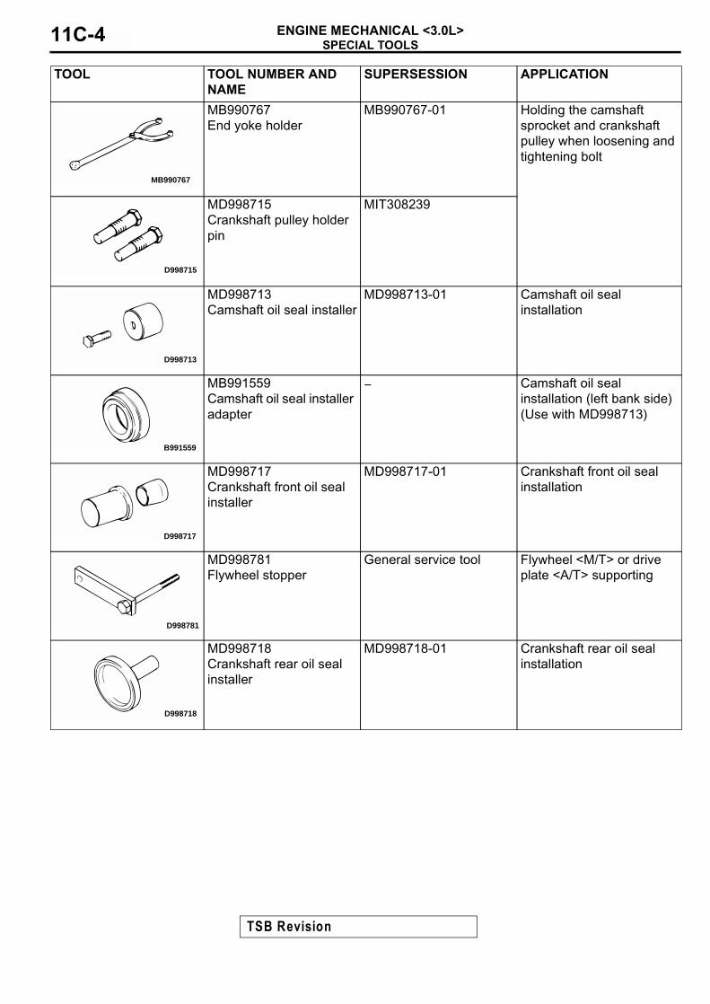
SPECIAL TOOLSENGINE MECHANICAL <3.0L>11C-4
MB990767End yoke holder
MB990767-01 Holding the camshaft sprocket and crankshaft pulley when loosening and tightening bolt
MD998715Crankshaft pulley holder pin
MIT308239
MD998713Camshaft oil seal installer
MD998713-01 Camshaft oil seal installation
MB991559Camshaft oil seal installer adapter
− Camshaft oil seal installation (left bank side)(Use with MD998713)
MD998717Crankshaft front oil seal installer
MD998717-01 Crankshaft front oil seal installation
MD998781Flywheel stopper
General service tool Flywheel <M/T> or drive plate <A/T> supporting
MD998718Crankshaft rear oil seal installer
MD998718-01 Crankshaft rear oil seal installation
TOOL TOOL NUMBER AND NAME
SUPERSESSION APPLICATION
MB990767
D998715
D998713
B991559
D998717
D998781
D998718
TSB Revision
ON VEHICLE SERVICEENGINE MECHANICAL <3.0L> 11C-5
ON VEHICLE SERVICE
DRIVE BELT TENSION CHECK AND ADJUSTMENT
M1111003100128
Refer to GROUP 00, Maintenance Service − Drive Belts (Check Condition) P.00-39
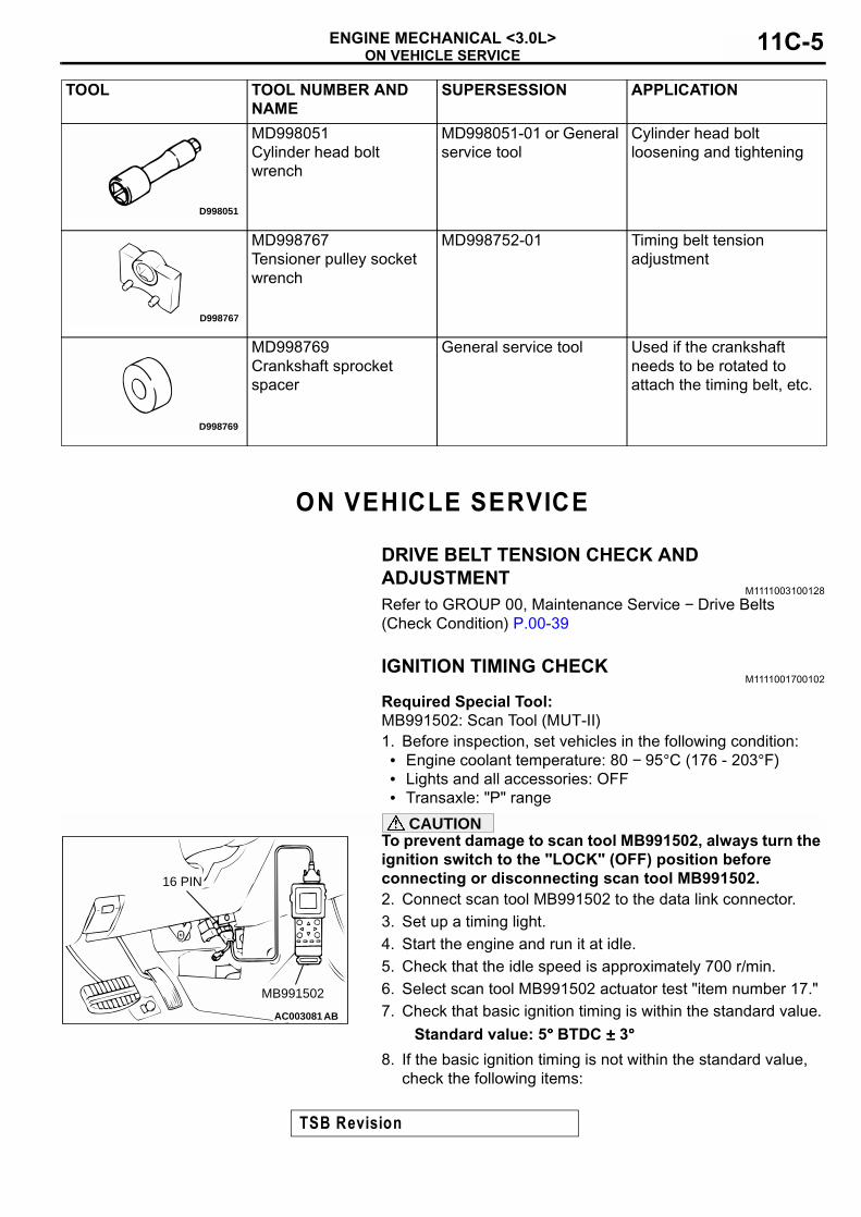
IGNITION TIMING CHECKM1111001700102
Required Special Tool:MB991502: Scan Tool (MUT-II)1. Before inspection, set vehicles in the following condition:• Engine coolant temperature: 80 − 95°C (176 - 203°F)• Lights and all accessories: OFF• Transaxle: "P" range
CAUTIONTo prevent damage to scan tool MB991502, always turn the ignition switch to the "LOCK" (OFF) position before connecting or disconnecting scan tool MB991502.2. Connect scan tool MB991502 to the data link connector.3. Set up a timing light.4. Start the engine and run it at idle.5. Check that the idle speed is approximately 700 r/min.6. Select scan tool MB991502 actuator test "item number 17."7. Check that basic ignition timing is within the standard value.
Standard value: 5°°°° BTDC ±±±± 3°°°°8. If the basic ignition timing is not within the standard value,
check the following items:
MD998051Cylinder head bolt wrench
MD998051-01 or General service tool
Cylinder head bolt loosening and tightening
MD998767Tensioner pulley socket wrench
MD998752-01 Timing belt tension adjustment
MD998769Crankshaft sprocket spacer
General service tool Used if the crankshaft needs to be rotated to attach the timing belt, etc.
TOOL TOOL NUMBER AND NAME
SUPERSESSION APPLICATION
D998051
D998767
D998769
AC003081 AB
16 PIN
MB991502
TSB Revision

ON VEHICLE SERVICEENGINE MECHANICAL <3.0L>11C-6
• Diagnosis output• Timing belt cover and crankshaft position sensor installation
conditions• Crankshaft sensing blade condition
CAUTIONIf the actuator test is not canceled, the forced drive will continue for 27 minutes. Driving in this state could lead to engine failure.9. Press the clear key on scan tool MB991502 (select forced
drive stop mode), and cancel the actuator test.10.Check that the actual ignition timing is at the standard value.
Standard value: Approximately 15°°°° BTDCNOTE: Ignition timing fluctuates about ± 7° Before Top Dead Center, even under normal operating condition.NOTE: It is automatically further advanced by about 5° to 10° Before Top Dead Center at higher altitudes.
IDLE MIXTURE CHECKM1111002100103
Required Special Tool:MB991502: Scan Tool (MUT-II)1. Before inspection, set vehicles in the following condition:• Engine coolant temperature: 80 − 95°C (176 - 203°F)• Lights and all accessories: OFF• Transaxle: "P" range
CAUTIONTo prevent damage to scan tool MB991502, always turn the ignition switch to the "LOCK" (OFF) position before connecting or disconnecting scan tool MB991502.2. Connect scan tool MB991502 to the data link connector.3. Check that the basic ignition timing is within the standard
value. Standard value: 5°°°° BTDC ±±±± 3°°°°
4. Start the engine and increase the engine speed to 2,500 r/min for 2 minutes.
5. Set the CO, HC tester.6. Check the CO contents and the HC contents at idle.
Standard value:CO contents: 0.5% or lessHC contents: 100 ppm or less
7. If the CO and HC contents do not remain inside the standard value, check the following items:NOTE: Replace the catalytic converter when the CO and HC contents do not remain inside the standard value, even though the result of the inspection is normal for all items.
• Diagnosis output• Closed-loop control (When the closed-loop control is carried
out normally, the output signal of the heated oxygen sensor changes between 0 − 400 mV and 600 − 1,000 mV at idle.)
• Fuel pressures
AC003081 AB
16 PIN
MB991502
TSB Revision

ON VEHICLE SERVICEENGINE MECHANICAL <3.0L> 11C-7
• Injector• Ignition coil, spark plug cable, spark plug• EGR system and EGR valve leak• Evaporative emission control system• Compression pressure
CURB IDLE SPEED CHECKM1111003500115
Required Special Tool:MB991502: Scan Tool (MUT-II)1. Before inspection and adjustment set vehicles in the
following condition.• Engine coolant temperature: 80 − 95°C (176 - 203°F)• Lights and all accessories: OFF• Transaxle: "P" range
CAUTIONTo prevent damage to scan tool MB991502, always turn the ignition switch to the "LOCK" (OFF) position before connecting or disconnecting scan tool MB991502.2. Connect scan tool MB991502 to the data link connector.3. Check the basic ignition timing.
Standard value: 5°°°° BTDC ±±±± 3°°°°4. Start the engine.5. Run the engine at idle for 2 minutes.6. Check the idle speed. Select item number 22 and take a
reading of the idle speed.
Curb idle speed: 700 ±±±± 100 r/minNOTE: The idle speed is controlled automatically by the idle air control system.
7. If the idle speed is outside the standard value, refer to GROUP 13B, Diagnosis − Symptom Chart P.13B-22.
COMPRESSION PRESSURE CHECKM1111002600090
1. Before inspection, check that the engine oil, starter and battery are normal. Also, set the vehicle in the following condition:
• Engine coolant temperature: 80 − 95°C (176 - 203°F)• Lights, and all accessories: OFF• Transaxle: "P" range
2. Disconnect the spark plug cables.3. Remove all of the spark plugs.
AC003081 AB
16 PIN
MB991502
TSB Revision

ON VEHICLE SERVICEENGINE MECHANICAL <3.0L>11C-8
4. Disconnect the crankshaft position sensor connector.NOTE: Doing this will prevent the engine control module from carrying out ignition and fuel injection.
WARNINGKeep your distance from the spark plug hole when cranking. Oil, fuel, etc., may spray out from the spark plug hole and may cause serious injury.5. Cover the spark plug hole with a shop towel etc., during
cranking. After the engine has been cranked, check for foreign material adhering to the shop towel.
6. Set compression gauge to one of the spark plug holes.7. Crank the engine with the throttle valve fully open and
measure the compression pressure.
Standard value (at engine speed of 250 −−−− 400 r/min):824 kPa (119 psi)Minimum limit (at engine speed of 250 −−−− 400 r/min):575 kPa (83 psi)
8. Measure the compression pressure for all the cylinders, and check that the pressure differences of the cylinders are below the limit.
Limit: 98 kPa (14 psi)
9. If there is a cylinder with compression or a compression difference that is outside the limit, pour a small amount of engine oil through the spark plug hole, and repeat the operations in steps 6 to 8.(1) If the compression increases after oil is added, the cause
of the malfunction is a worn or damaged piston ring and/or cylinder inner surface.
(2) If the compression does not rise after oil is added, the cause is a burnt or defective valve seat, or pressure is leaking from the gasket.
10.Connect the crankshaft position sensor connector.11.Install the spark plugs and spark plug cables.12.Use the scan tool to erase the diagnostic trouble codes.
NOTE: This will erase the diagnostic trouble code resulting from the distributor connector being disconnected.
MANIFOLD VACUUM CHECKM1111002700105
1. Before inspection, set vehicles in the following condition:• Engine coolant temperature: 80 − 95°C (176 - 203°F)• Lights and all accessories: OFF• Transmission: "P" range
2. Connect a tachometer.
AKX01198
CRANKSHAFT POSITIONSENSOR CONNECTOR
AB
AKX01199
COMPRESSIONGAUGE
AB
TSB Revision

ON VEHICLE SERVICEENGINE MECHANICAL <3.0L> 11C-9
3. Attach a Tee-fitting union to the vacuum hose between the fuel pressure regulator and the intake manifold plenum, and connect a vacuum gauge.
4. Start the engine and check that idle speed is within specification. Then check the vacuum gauge reading.
Idle speed:700 ±±±± 100 r/minMinimum limit:60 kPa (18 in Hg)
LASH ADJUSTER CHECKM1111002900110
If an abnormal noise (chattering noise) suspected to be caused by malfunction of the lash adjuster is produced immediately after starting the engine and does not disappear, perform the following check.NOTE: An abnormal noise due to malfunction of the lash adjuster is produced immediately after starting the engine and changes with the engine speed, irrespective of the engine load.If, the abnormal noise is not produced immediately after starting the engine or does not change with the engine speed, or it changes with the engine load, the lash adjuster is not the cause for the abnormal noise.NOTE: When the lash adjuster is malfunctioning, the abnormal noise is rarely eliminated by continuing the warming-up of the engine at idle speed.However, the abnormal noise may disappear only when seizure is caused by oil sludge in the engine whose oil is not maintained properly.1. Start the engine.2. Check if the abnormal noise produced immediately after
starting the engine, changes with the change in the engine speed.If the abnormal noise is not produced immediately after starting the engine or it does not change with the engine speed, the lash adjuster is not the cause for the noise. Therefore, investigate other causes. The abnormal noise is probably caused by some other parts than the engine proper if it does not change with the engine speed. (In this case, the lash adjuster is in good condition.)
3. With the engine idling, change the engine load (shift from N to D range, for example) to make sure that there is no change in the level of abnormal noise.If there is a change in the level of abnormal noise, suspect a tapping noise due to worn crankshaft bearing or connecting rod bearing. (In this case, the lash adjuster is in good condition.)
4. After completion of warm-up, run the engine at idle to check for abnormal noise.
AKX01200
VACUUM GAUGE
AB
TSB Revision

ON VEHICLE SERVICEENGINE MECHANICAL <3.0L>11C-10
If the noise is reduced or disappears, clean the lash adjuster (Refer to GROUP 11D-Engine overhaul − Rocker Arms and Camshaft − Inspection P.11D-25.) As it is suspected that the noise is due to seizure of the lash adjuster. If there is no change in the level of the abnormal noise, proceed to step 5.
5. Run the engine to bleed the lash adjuster system. (Refer to P.11C-10.)
6. If the abnormal noise does not disappear after air bleeding operation, clean the lash adjuster (Refer to GROUP 11D-Engine overhaul − Rocker Arms and Camshaft − Inspection P.11D-25.)
Bleeding lash adjuster systemNOTE: Parking the vehicle on a grade for a long time may decrease oil in the lash adjuster, causing air to enter the high pressure chamber when starting the engine.NOTE: After parking for many hours, oil may run out from the oil passage and take time before oil is supplied to the lash adjuster, causing air to enter the high pressure chamber.NOTE: In the above cases, abnormal noise can be eliminated by bleeding the lash adjuster system.1. Check engine oil and add or change oil if required.
NOTE: If the engine oil level is low, air is sucked from the oil screen, causing air to enter the oil passage.NOTE: If the engine oil level is higher than specification, oil may be stirred by the crankshaft, causing oil to be mixed with a large quantity of air.NOTE: If oil is deteriorated, air is not easily separated from oil, increasing the quantity of air contained in oil.
NOTE: If air mixed with oil enters the high pressure chamber inside the lash adjuster from the above causes, air in the high pressure chamber is compressed excessively while the valve is opened, resulting in an abnormal noise when the valve closes.This is the same phenomenon as that observed when the valve clearance has become excessive. The lash adjuster can resume normal function when air entered the lash adjuster is removed.
2. Idle the engine for one to three minutes to warm it up.
3. Repeat the operation pattern, shown in left figure, at no load to check for abnormal noise. (Usually the abnormal noise is eliminated after repetition of the operation 10 to 30 times. If, however, no change is observed in the level of abnormal noise after repeating the operation more than 30 times, suspect that the abnormal noise is due to some other factors.)
4. After elimination of abnormal noise, repeat the operation shown in left figure five more times.
AKX00328
GOOD
MINIMUM
MAXIMUM
AB
AKX00329
HIGH-PRESSURECHAMBER
AB
AKX00330
OPEN THROTTLEVALVE GRADUALLY
CLOSETHROTTLE VALVE
APPROXI-MATELY3,000 r/min
IDLINGOPERATION
ONCE
15s 15s
AIR BLEEDING OPERATION PATTERN
AB
TSB Revision

ENGINE ASSEMBLYENGINE MECHANICAL <3.0L> 11C-11
5. Run the engine at idle for one to three minutes to make sure that the abnormal noise has been eliminated.
ENGINE ASSEMBLYREMOVAL AND INSTALLATION
M1112001000151
CAUTION*: Indicates parts which should be temporarily tightened, and then fully tightened after placing the vehicle horizontally and loading the full weight of the engine on the vehicle body.
Pre-removal Operation• Hood Removal (Refer to GROUP 42, Hood P.42-5.)• Fuel Line Pressure Reduction [Refer to GROUP 13B,
On-vehicle Service − Fuel Pump Relay Disconnection (How to Reduce Pressurized Fuel Lines) P.13B-523.]
• Engine Coolant Draining [Refer to GROUP 00, Maintenance Service − Engine Coolant (Change)P.00-50.]
• Air Cleaner Removal (Refer to GROUP 15, Air Cleaner P.15-4.)
• Reserve Tank and Radiator Removal (Refer to GROUP 14, Radiator P.14-15.)
• Front Exhaust Pipe Removal (Refer to GROUP 15, Exhaust Pipe and Main Muffler P.15-19.)
Post-installation Operation• Front Exhaust Pipe Installation (Refer to GROUP 15,
Exhaust Pipe and Main MufflerP.15-19.)• Reserve Tank and Radiator Installation (Refer to GROUP
14, Radiator P.14-15.)• Air Cleaner Installation (Refer to GROUP 15, Air Cleaner
P.15-4.)• Drive Belt Tension Adjustment [Refer to GROUP 00
Maintenance Service − Drive Belts (Check Condition) P.00-39.]
• Engine Coolant Refilling [Refer to GROUP 00, Maintenance Service − Engine Coolant (Change) P.00-50.]
• Accelerator Cable Adjustment (Refer to GROUP 17, On-vehicle Service − Accelerator Cable Check and Adjustment P.17-4.)
• Hood Installation (Refer to GROUP 42, Hood P.42-5.)
AC004714
4.9 N·m43 in-lb
8.9 N·m78 in-lb1
2
3
4
56
8
9
1011
12
13
14
15
16
17
18
AB
7
4.9 N·m43 in-lb
19
8.9 N·m78 in-lb
20 21
22
4.9 N·m43 in-lb
23
23
24
TSB Revision

ENGINE ASSEMBLYENGINE MECHANICAL <3.0L>11C-12
REMOVAL STEPS1. ACCELERATOR CABLE
CONNECTION2. MANIFOLD DIFFERENTIAL
PRESSURE SENSOR CONNECTOR
3. CONTROL WIRING HARNESS AND POWER STEERING WIRING HARNESS COMBINATION CONNECTOR
4. EGR SOLENOID VALVE CONNECTOR
5. EVAPORATIVE EMISSION PURGE SOLENOID VALVE CONNECTOR
6. KNOCK SENSOR CONNECTOR7. CRANKSHAFT POSITION
SENSOR CONNECTOR8. RIGHT BANK HEATED OXYGEN
SENSOR CONNECTOR 9. INJECTOR CONNECTOR10. DISTRIBUTOR CONNECTOR11. CONTROL WIRING HARNESS
AND INJECTOR WIRING HARNESS COMBINATION CONNECTOR
12. THROTTLE POSITION SENSOR CONNECTOR
13. IDLE AIR CONTROL MOTOR CONNECTOR
14. GROUND WIRE CONNECTION15. ENGINE COOLANT
TEMPERATURE GAUGE UNIT CONNECTOR
16. ENGINE COOLANT TEMPERATURE SENSOR CONNECTOR
17. LEFT BANK HEATED OXYGEN SENSOR CONNECTOR
18. STARTER CONNECTOR19. GROUND WIRE CONNECTION20. GENERATOR CONNECTOR21. OIL PRESSURE SWITCH
CONNECTOR22. A/C COMPRESSOR
CONNECTOR23. VACUUM HOSE CONNECTION24. BRAKE BOOSTER VACUUM
HOSE CONNECTION
REMOVAL STEPS (Continued)
TSB Revision

ENGINE ASSEMBLYENGINE MECHANICAL <3.0L> 11C-13
Required Special Tools:• MB991453: Engine Hanger Assembly
• MZ203827: Engine Lifter
REMOVAL SERVICE POINTS<<A>> A/C COMPRESSOR REMOVALRemove the A/C compressor from the compressor bracket with the hose attached.
NOTE: Place the removed A/C compressor where it will not be a hindrance when removing and installing the engine assembly, and secure it with a cord or wire.
AC005055
25N
26
4.9 N·m43 ft-lb
27
28
29
30
31
3233
42 N·m31 ft-lb
ENGINE OIL
FUEL RAILO-RING
25
34
36
36
35
37
35 N·m26 ft-lb
86 N·m63 ft-lb
81 N·m*60 ft-lb*
AB
>>D<< 25. HIGH-PRESSURE FUEL HOSE CONNECTION
26. FUEL RETURN HOSE CONNECTION
27. HEATER HOSE CONNECTION28. SUCTION HOSE CONNECTION29. DRIVE BELT (GENERATOR AND
A/C COMPRESSOR)30. DRIVE BELT (POWER STEERING
OIL PUMP)<<A>> 31. A/C COMPRESSOR
32. POWER STEERING PRESSURE SWITCH CONNECTOR
<<B>> 33. POWER STEERING OIL PUMP34. ENGINE MOUNT STAY• TRANSAXLE ASSEMBLY
(REFER TO GROUP 23A, TRANSAXLE ASSEMBLY P.23A-290.)
<<C>> >>C<< 35. ENGINE MOUNT BRACKET>>B<< 36. ENGINE MOUNT STOPPER
<<D>> >>A<< 37. ENGINE ASSEMBLY
TSB Revision

ENGINE ASSEMBLYENGINE MECHANICAL <3.0L>11C-14
<<B>> POWER STEERING OIL PUMP REMOVALRemove the power steering oil pump from the engine with the hose attached.
NOTE: Place the removed power steering oil pump in a place where it will not be a hindrance when removing and installing the engine assembly, and secure it with a cord or wire.
<<C>> ENGINE MOUNT BRACKET REMOVAL1. Support the engine with a garage jack.2. Remove special tools MB991453 and MZ203827 which
were attached when the transaxle assembly was removed.3. Hold the engine assembly with a chain block or similar tool.4. Place a garage jack against the engine oil pan with a piece
of wood in between, jack up the engine so that the weight of the engine is no longer being applied to the engine mount bracket, and then remove the engine mount bracket.
<<D>> ENGINE ASSEMBLY REMOVALAfter checking that all cables, hoses and harness connectors, etc., are disconnected from the engine, lift the chain block slowly to remove the engine assembly upward from the engine compartment.
INSTALLATION SERVICE POINTS>>A<< ENGINE ASSEMBLY INSTALLATIONInstall the engine assembly, checking that the cables, hoses, and harness connectors are not clamped.
>>B<< ENGINE MOUNT STOPPER INSTALLATIONClamp the engine mount stopper so that the arrow points in the direction as shown in the diagram.
>>C<< ENGINE MOUNT BRACKET INSTALLATION1. Place a garage jack against the engine oil pan with a piece
of wood in between, and install the engine mount bracket while adjusting the position of the engine.
2. Support the engine with the garage jack.
AC000127
MZ203827
MB991453
AB
AC001714AB
ENGINE SIDE
ENGINE MOUNTSTOPPER
ENGINE MOUNT BRACKET
ARROW
TSB Revision
ENGINE ASSEMBLYENGINE MECHANICAL <3.0L> 11C-15
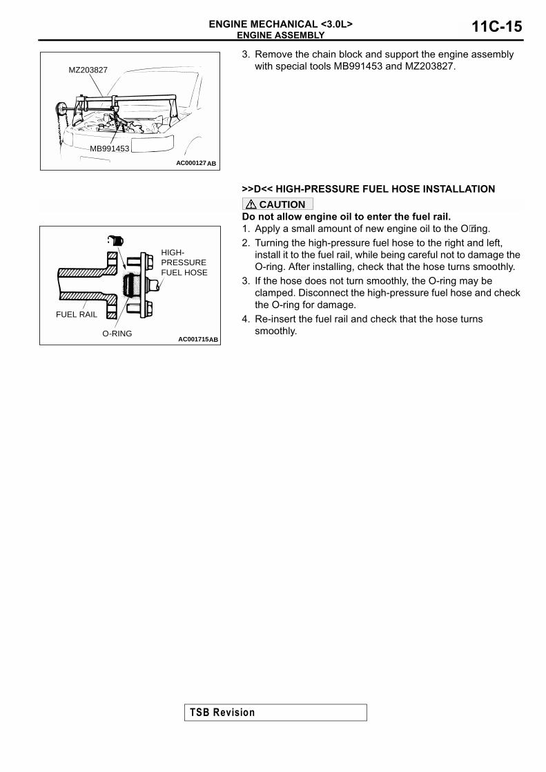
3. Remove the chain block and support the engine assembly with special tools MB991453 and MZ203827.
>>D<< HIGH-PRESSURE FUEL HOSE INSTALLATION
CAUTIONDo not allow engine oil to enter the fuel rail.1. Apply a small amount of new engine oil to the O⋅ring.2. Turning the high-pressure fuel hose to the right and left,
install it to the fuel rail, while being careful not to damage the O-ring. After installing, check that the hose turns smoothly.
3. If the hose does not turn smoothly, the O-ring may be clamped. Disconnect the high-pressure fuel hose and check the O-ring for damage.
4. Re-insert the fuel rail and check that the hose turns smoothly.
AC000127
MZ203827
MB991453
AB
AC001715
HIGH-PRESSUREFUEL HOSE
O-RING
FUEL RAIL
AB
TSB Revision

CAMSHAFT AND CAMSHAFT OIL SEALENGINE MECHANICAL <3.0L>11C-16
CAMSHAFT AND CAMSHAFT OIL SEALREMOVAL AND INSTALLATION
M1112001900121
<LEFT BANK>
Required Special Tools:• MB990767: End Yoke Holder• MB991559: Camshaft Oil Seal Adapter
• MD998443: Auto-lash Adjuster Holder• MD998713: Camshaft Oil Seal Installer• MD998715: Crankshaft Pulley Holder Pin
Pre-removal and Post-installation Operation• Timing Belt Removal and Installation (Refer to P.11C-29.)• Thermostat Housing Assembly Removal and Installation
(Refer to GROUP 14, Water Hose and Water Pipe P.14-23.)
AC004834
APPLY ENGINE OIL TOALL THE MOVING PARTSWHEN INSTALLING
(ENGINE OIL)
3.4 N·m30 in-lb
13 N·m115 in-lb
88 N·m65 ft-lb
28 – 34 N·m21 – 25 ft-lb
1
2
3
5
6
7
8
10
11
AB
4
N
9
N
CAMSHAFT REMOVAL STEPS1. BLOW-BY HOSE CONNECTION2. PCV HOSE CONNECTION3. SPARK PLUG CABLE4. BATTERY CABLE CONNECTION5. ROCKER COVER
<<A>> >>D<< 6. ROCKER ARM AND SHAFT ASSEMBLY
<<B>> >>B<< 7. CAMSHAFT SPROCKET
9. BATTERY CABLE AND HARNESS BRACKET
10. THRUST CASE11. CAMSHAFT
CAMSHAFT OIL SEAL REMOVAL STEPS
<<B>> >>B<< 7. CAMSHAFT SPROCKET>>A<< 8. CAMSHAFT OIL SEAL
CAMSHAFT REMOVAL STEPS
TSB Revision

CAMSHAFT AND CAMSHAFT OIL SEALENGINE MECHANICAL <3.0L> 11C-17
<RIGHT BANK>
Required Special Tools:• MB990767: End Yoke Holder• MD998443: Auto-lash Adjuster Holder
• MD998713: Camshaft Oil Seal Installer• MD998715: Crankshaft Pulley Holder Pin
Pre-removal and Post-installation Operation• Timing Belt Removal and Installation (Refer to P.11C-29.)• Intake Manifold Plenum Removal and Installation (Refer
to GROUP 15, Intake Manifold Plenum P.15-5)
AC001717AC
3.4 N·m30 in-lb
13 N·m115 in-lb
28 – 34 N·m21 – 25 ft-lb
88 N·m65 ft-lb
APPLY ENGINE OIL TOALL THE MOVING PARTSWHEN INSTALLING
1
2
3
4
5
6
78
9
CAMSHAFT REMOVAL STEPS1. BREATHER HOSE
CONNECTION2. BLOW-BY HOSE CONNECTION3. SPARK PLUG CABLE4. ROCKER COVER
<<A>> >>D<< 5. ROCKER ARM AND SHAFT ASSEMBLY
>>C<< 6. DISTRIBUTOR
<<B>> >>B<< 7. CAMSHAFT SPROCKET9. CAMSHAFT
CAMSHAFT OIL SEAL REMOVAL STEPS
<<B>> >>B<< 7. CAMSHAFT SPROCKET>>A<< 8. CAMSHAFT OIL SEAL
CAMSHAFT REMOVAL STEPS
TSB Revision

CAMSHAFT AND CAMSHAFT OIL SEALENGINE MECHANICAL <3.0L>11C-18
REMOVAL SERVICE POINTS<<A>> ROCKER ARM AND SHAFT ASSEMBLY REMOVAL1. Install special tool MD998443 as shown in the illustration so
that the lash adjusters will not fall out.
CAUTIONNever disassemble the rocker arm and shaft assembly.2. Loosen the rocker arm and shaft assembly mounting bolts,
then remove the rocker arm and shaft assembly with the bolts still attached.
<<B>> CAMSHAFT SPROCKET REMOVAL1. Use special tools MB990767 and MD998715 to loosen the
camshaft sprocket mounting bolt.2. Remove the camshaft sprocket.
INSTALLATION SERVICE POINTS>>A<< CAMSHAFT OIL SEAL INSTALLATION1. Apply engine oil to the camshaft oil seal lip.2. Use special tools MB991559 and MD998713 to press-fit the
camshaft oil seal.
>>B<< CAMSHAFT SPROCKET INSTALLATION1. Install the camshaft sprocket.2. Use special tools MB990767 and MD998715 to tighten the
camshaft sprocket mounting bolt to the specified torque.Tightening torque: 88 N⋅⋅⋅⋅m (65 ft-lb)
AC001718
MD998443AB
ACX00301AB
MB990767
MD998715
AC001719AB
MD998713MB991559 MD998713
LEFT RANK RIGHT BANK
ACX00301AB
MB990767
MD998715
TSB Revision

CAMSHAFT AND CAMSHAFT OIL SEALENGINE MECHANICAL <3.0L> 11C-19
>>C<< DISTRIBUTOR INSTALLATION1. Align the timing mark of the camshaft sprocket (right bank)
with that of the cylinder head.
2. Align the mating marks on the distributor housing and coupling, then install the distributor to the engine.
>>D<< ROCKER ARM AND SHAFT ASSEMBLY INSTALLATION1. Rotate the camshaft until the dowel pin on its front end is
located as shown in the illustration.
NOTE: Placing the camshaft in the illustrated position minimizes the amount of cam lift, making it easier to install the rocker arm and shaft assembly.
2. Temporarily tighten the rocker shaft with the bolts so that all rocker arms on the inlet valve side do not push the valves.
AC001720
TIMINGMARKS
CAMSHAFT SPROCKET(RIGHT BANK)
AB
AC001721AB
MATING MARKS
AC001722
APPROXIMATELY 60˚APPROXIMATELY 70˚
RIGHT BANK LEFT BANK
AB
TSB Revision

CAMSHAFT AND CAMSHAFT OIL SEALENGINE MECHANICAL <3.0L>11C-20
3. Position the rocker shaft spring so that it takes a right angle against the plug guide.NOTE: Set the rocker shaft spring before installing the rocker arm and shaft assembly on the exhaust side.
4. Tighten the rocker arm and shaft assembly mounting bolts to the specified torque.
Tightening torque: 28 −−−− 34 N⋅⋅⋅⋅m (21 −−−− 25 ft-lb)
5. Remove special tool MD998443.
ACX00378
PLUG GUIDE
ROCKER SHAFT SPRING
ROCKER SHAFT SPRING PLUG GUIDE
AB
TSB Revision

OIL PANENGINE MECHANICAL <3.0L> 11C-21
OIL PANREMOVAL AND INSTALLATION
M1112002800086
REMOVAL SERVICE POINTS<<A>> LOWER OIL PAN REMOVAL1. Remove the oil pan, lower mounting bolts.
Pre-removal and Post-installation operation• Engine Oil Draining and Refilling (Refer to GROUP 12,
On-vehicle Service − Engine Oil Replacement P.12-3.)• Front Exhaust Pipe Removal and Installation (Refer to
GROUP 15, Exhaust Pipe and Main Muffler P.15-19.)
AC001723AC
48 N·m35 ft-lb
26 – 33 N·m19 – 24 ft-lb
26 – 33 N·m19 – 24 ft-lb
35 N·m26 ft-lb
5.9 N·m52 in-lb
9.8 – 12 N·m87 – 106 in-lb
39 N·m29 ft-lb
12
34
5
6
7
8
9
7
9
SEALANT:MITSUBISHI GENUINE PARTNO. MD970389 OREQUIVALENT
(ENGINE OIL)
GROOVE BOLT HOLE
Ø 4 mm(0.2 in)
LOWER OIL PAN REMOVAL STEPS
1. DRAIN PLUG>>C<< 2. DRAIN PLUG GASKET
<<A>> >>B<< 7. LOWER OIL PANUPPER OIL PAN REMOVAL STEPS
1. DRAIN PLUG>>C<< 2. DRAIN PLUG GASKET
3. STARTER CONNECTOR
4. STARTER5. OIL DIPSTICK AND DIPSTICK
GUIDE6. O-RING
<<A>> >>B<< 7. LOWER OIL PAN8. COVER
<<B>> >>A<< 9. UPPER OIL PAN
UPPER OIL PAN REMOVAL STEPS (Continued)
TSB Revision

OIL PANENGINE MECHANICAL <3.0L>11C-22
CAUTIONDo not use the oil pan remover (MD998727). It will damage the upper oil pan.2. Place a wooden block against the lower oil pan as shown in
the illustration and remove by tapping with a hammer.
<<B>> UPPER OIL PAN REMOVAL1. Remove the upper oil pan mounting bolts.2. Screw the bolts (M10) securing the upper oil pan to the
transaxle assembly in the illustrated bolt holes, then remove the upper oil pan.
INSTALLATION SERVICE POINTS>>A<< UPPER OIL PAN INSTALLATION
CAUTIONThe bolt holes for bolts 13 and 14 in the illustration are cut away on the transaxle side. Be careful not to insert these bolts at an angle.Tighten the oil pan, upper mounting bolts in the order shown.
AC001724
LOWER OIL PAN
AB
AC001725
AC001726AB
148 512 9
23711 6 10
16
15
13
14
UPPER OIL PAN
REAR OILSEAL CASE
TRANSAXLE SIDE
TSB Revision

OIL PANENGINE MECHANICAL <3.0L> 11C-23
>>B<< LOWER OIL PAN INSTALLATIONTighten the lower oil pan mounting bolts in the order shown.
>>C<< DRAIN PLUG GASKET INSTALLATIONReplace the gasket with a new gasket. Install the new gasket in the direction shown in the illustration.
INSPECTIONM1112002900083
• Check the oil pan for cracks.• Check the oil pan sealant-coated surface for damage and
deformation.
AC0017271
2
3
4
5
6
78
9
10
AB
ACX00364
DRAIN PLUGGASKET
OIL PANSIDE
AB
TSB Revision

CRANKSHAFT FRONT OIL SEALENGINE MECHANICAL <3.0L>11C-24
CRANKSHAFT FRONT OIL SEALREMOVAL AND INSTALLATION
M1112003400111
Required Special Tool:• MD998717: Crankshaft Front Oil Seal Installer
INSTALLATION SERVICE POINTS>>A<< CRANKSHAFT FRONT OIL SEAL INSTALLATION1. Apply a small amount of engine oil to the oil seal lip and then
insert.2. Using special tool MD998717, tap the oil seal into the front
case.
Pre-removal and Post-installation Operation• Timing Belt Removal and Installation (Refer to P.11C-29.)
AC001728 AC
8.8 N·m78 in-lb
1
2
34
5
6
6
ENGINE OIL
REMOVAL STEPS>>B<< 1. CRANKSHAFT SPROCKET
2. CRANKSHAFT POSITION SENSOR
>>B<< 3. CRANKSHAFT SENSING BLADE
>>B<< 4. CRANKSHAFT SPACER5. KEY
>>A<< 6. CRANKSHAFT FRONT OIL SEAL
REMOVAL STEPS (Continued)
ACX00363 ABOIL SEALMD998717
CRANKSHAFT
MD998717
TSB Revision
CRANKSHAFT REAR OIL SEALENGINE MECHANICAL <3.0L> 11C-25
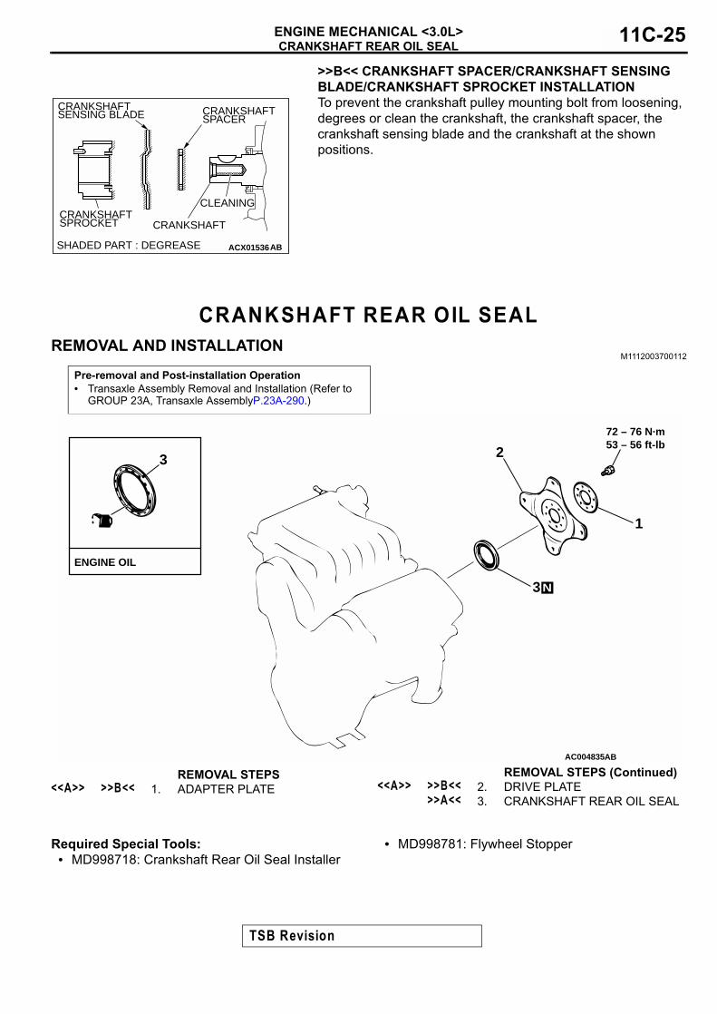
>>B<< CRANKSHAFT SPACER/CRANKSHAFT SENSING BLADE/CRANKSHAFT SPROCKET INSTALLATIONTo prevent the crankshaft pulley mounting bolt from loosening, degrees or clean the crankshaft, the crankshaft spacer, the crankshaft sensing blade and the crankshaft at the shown positions.
CRANKSHAFT REAR OIL SEALREMOVAL AND INSTALLATION
M1112003700112
Required Special Tools:• MD998718: Crankshaft Rear Oil Seal Installer
• MD998781: Flywheel Stopper
ACX01536AB
CRANKSHAFT
CRANKSHAFTSPACER
CRANKSHAFTSENSING BLADE
CRANKSHAFTSPROCKET
SHADED PART : DEGREASE
CLEANING
Pre-removal and Post-installation Operation• Transaxle Assembly Removal and Installation (Refer to
GROUP 23A, Transaxle AssemblyP.23A-290.)
AC004835
3
ENGINE OIL
72 – 76 N·m53 – 56 ft-lb
1
2
3 N
AB
REMOVAL STEPS<<A>> >>B<< 1. ADAPTER PLATE <<A>> >>B<< 2. DRIVE PLATE
>>A<< 3. CRANKSHAFT REAR OIL SEAL
REMOVAL STEPS (Continued)
TSB Revision

CRANKSHAFT REAR OIL SEALENGINE MECHANICAL <3.0L>11C-26
REMOVAL SERVICE POINT<<A>> ADAPTER PLATE/DRIVE PLATE REMOVALUse special tool MB998781 to secure the drive plate, and remove the bolts.
INSTALLATION SERVICE POINTS>>A<< CRANKSHAFT REAR OIL SEAL INSTALLATION1. Apply a small amount of engine oil to the entire
circumference of the oil seal lip.2. Use special tool MD998718 to tap in the oil seal as shown in
the illustration.
>>B<< DRIVE PLATE/ADAPTER PLATE INSTALLATIONUse special tool MD998781 to hold the drive plate in the same manner as removal. Then install the bolts.
ACX00296 AB
MD998781
ACX00356AB
MD998718
ACX00296 AB
MD998781
TSB Revision

CYLINDER HEAD GASKETENGINE MECHANICAL <3.0L> 11C-27
CYLINDER HEAD GASKETREMOVAL AND INSTALLATION
M1112004000116
Pre-removal and Post-installation Operation• Engine Coolant Draining and Refilling [Refer to GROUP
00, Maintenance Service − Engine Coolant (Change) P.00-50.]
• Timing Belt Removal and installation (Refer to P.11C-29.)• Generator Removal and Installation (Refer to GROUP16,
Generator P.16-14.)• Intake Manifold Removal and installation (Refer to
GROUP 15, Intake Manifold P.15-10.)• Exhaust Manifold Removal and Installation (Refer to
GROUP 15, Exhaust Manifold P.15-16.)• Water Inlet Pipe Removal and Installation (Refer to
GROUP 14, Water Hose and Water Pipe P.14-23.)
AC004838AB
12 – 15 N·m106 – 133 in-lb
3.4 N·m30 in-lb
3.4 N·m30 in-lb
<COLD ENGINE>103 – 113 N·m → 0 N·m → 103 – 113 N·m76 – 83 ft-lb → 0 in-lb → 76 – 83 ft-lb
1
2
2
3
4
6
4
6
7
9
9
10 N
<COLD ENGINE>103 – 113 N·m → 0 N·m → 103 – 113 N·m76 – 83 ft-lb → 0 in-lb → 76 – 83 ft-lb
5
8
REMOVAL STEPS1. BREATHER HOSE2. BLOW-BY HOSE3. PCV HOSE
4. SPARK PLUG CABLE5. BATTERY CABLE
CONNECTION
REMOVAL STEPS (Continued)
TSB Revision

CYLINDER HEAD GASKETENGINE MECHANICAL <3.0L>11C-28
Required Special Tool:• MD998051: Cylinder Head Bolt Wrench
REMOVAL SERVICE POINT<<A>> CYLINDER HEAD ASSEMBLY REMOVALUsing special tool MD998051, loosen the cylinder head bolts in two or three steps in the order of the numbers shown in the illustration, then remove the cylinder head assembly.
INSTALLATION SERVICE POINTS>>A<< CYLINDER HEAD GASKET INSTALLATION1. Wipe off all oil and grease from the gasket mounting
surface.2. Match the shapes of the cylinder head holes with their
respective cylinder head gasket holes.
>>B<< CYLINDER HEAD ASSEMBLY INSTALLATION
CAUTIONBe careful that no foreign material gets into the cylinder, coolant passages or oil passages. Engine damage may result.1. Use a scraper to clean the gasket surface of the cylinder
head assembly.
6. ROCKER COVER7. TIMING BELT REAR COVER8. BATTERY CABLE
CONNECTION<<A>> >>B<< 9. CYLINDER HEAD ASSEMBLY
>>A<< 10. CYLINDER HEAD GASKET
REMOVAL STEPS (Continued)
AC001732
73 6 2
54 8 1
51 8 4
762 3
EXHAUST SIDE
EXHAUST SIDE
INTAKE SIDE
FRONT OF ENGINE
MD998051
AB
TSB Revision

TIMING BELTENGINE MECHANICAL <3.0L> 11C-29
CAUTIONAttach the cylinder head bolt washer in the direction shown in the illustration.2. Using special tool MD998051 and a torque wrench, tighten
the bolts to the specified torque in the order shown in the illustration. (in two or three steps)
Tightening torque: 103 −−−− 113 N⋅⋅⋅⋅m (76 −−−− 83 ft-lb)
3. Loosen the mounting bolts in the reverse sequence to that shown.
4. Tighten the mounting bolts progressively in the shown sequence to the specified torque again.
Tightening torque: 103 −−−− 113 N⋅⋅⋅⋅m (76 −−−− 83 ft-lb)
TIMING BELTREMOVAL AND INSTALLATION
M1112004300117
AC001733
2 3 76
15 4 8
148 5
237 6
EXHAUST SIDE
EXHAUST SIDE
INTAKE SIDE
FRONT OF ENGINE
AB
MD998051
CYLINDERHEAD BOLTWASHER
CYLINDER HEAD BOLT
ROUNDEDSHOULDER
CYLINDERHEAD
Pre-removal Operation• Generator Removal (Refer to GROUP 16, Generator
P.16-14.)• Engine Mount Bracket Removal (Refer to GROUP 32,
Engine Mounting P.32-5.)
Post-installation Operation• Engine Mount Bracket Installation (Refer to GROUP 32,
Engine Mounting P.32-5.)• Generator Installation (Refer to GROUP 16, Generator
P.16-14.)• Drive Belt Tension Adjustment [Refer to GROUP 00,
Maintenance Service − Drive Belts (Check Condi-tion).P.00-39]
TSB Revision

TIMING BELTENGINE MECHANICAL <3.0L>11C-30
Required Special Tools:MB990767: End Yoke HolderMD998715: Crankshaft Pulley Holder Pin
MD998767: Tensioner WrenchMD998769: Crankshaft Pulley Spacer
AC001734 AC177 – 186 N·m131 – 137 ft-lb
44 N·m32 ft-lb44 N·m
32 ft-lb
48 N·m35 ft-lb
44 N·m32 ft-lb
24 N·m18 ft-lb
12 – 15 N·m106 – 133 in-lb
9.8 – 12 N·m87 – 106 in-lb
45
8
9
11
6
310
21
7(ENGINE OIL)
12 – 15 N·m106 – 133 in-lb
REMOVAL STEPS1. DRIVE BELT (POWER STEERING
OIL PUMP)<<A>> >>D<< 2. CRANKSHAFT PULLEY
3. TENSIONER PULLEY ASSEMBLY (POWER STEERING OIL PUMP)
4. TIMING BELT FRONT UPPER COVER, RIGHT
5. TIMING BELT FRONT UPPER COVER, LEFT
6. TIMING BELT FRONT LOWER COVER
>>C<< 7. ENGINE SUPPORT BRACKET, RIGHT
<<B>> >>B<< 8. TIMING BELT>>A<< 9. AUTO-TENSIONER
10. TENSIONER PULLEY11. TENSIONER ARM
REMOVAL STEPS (Continued)
TSB Revision

TIMING BELTENGINE MECHANICAL <3.0L> 11C-31
REMOVAL SERVICE POINTS<<A>> CRANKSHAFT PULLEY REMOVAL
CAUTIONUse only the specified special tools, or a damaged pulley damper could result.Use special tools MB990767 and MD998715 to remove the crankshaft pulley from the crankshaft.
<<B>> TIMING BELT REMOVAL
CAUTIONNever turn the crankshaft counterclockwise.1. Turn the crankshaft clockwise to align each timing mark and
to set the number 1 cylinder to compression top dead center.2. If the timing belt is to be reused, chalk an arrow on the flat
side of the belt, indicating the clockwise direction.3. Loosen the center bolt of the tensioner pulley, then remove
the timing belt.
AC001735
MD998715
MB990767
AB
AC001736AB
TIMING MARKS
TIMINGMARKS
TIMINGMARKS
CAMSHAFTSPROCKET(LEFT BANK)
CAMSHAFTSPROCKET(RIGHT BANK)
CRANKSHAFTSPROCKET
TENSIONERPULLEY
CENTERBOLT
TSB Revision

TIMING BELTENGINE MECHANICAL <3.0L>11C-32
INSTALLATION SERVICE POINTS>>A<< AUTO-TENSIONER INSTALLATION1. While holding the auto-tensioner with your hand, press the
end of the pushrod against a metal surface (such as the cylinder block) with a force of 98 − 196 N (22 − 44 pound) and measure how far the pushrod is pushed in.
Standard value: Within 1 mm (0.04 inch)A: Length when no force is appliedB: Length when force is appliedA −−−− B: Amount pushed in
2. If it is not within the standard value range, replace the auto-tensioner.
CAUTION• Place the auto-tensioner perpendicular to the jaws of
the vice.• If there is a plug at the base of the auto-tensioner, insert
a plain washer onto the end of the auto-tensioner to protect the plug.
3. Place two blocks in a vice as shown in the illustration, and then place the auto-tensioner in the vice.
CAUTIONNever compress the pushrod too fast, or it may be damaged.4. Slowly compress the pushrod of the auto-tensioner until pin
hole A in the pushrod is aligned with pin hole B in the cylinder.
5. Insert the setting pin into the pin holes once they are aligned.NOTE: If replacing the auto-tensioner, the pin will already be inserted into the pin holes of the new part.
CAUTIONDo not remove the setting pin from the auto-tensioner.6. Install the auto-tensioner to the engine.
ACX00306AC
A B
AUTO-TENSIONER
AMOUNT PUSHED IN
PUSHROD
98 – 196 N(22 – 44 lb)
ACX00333
PLUG
PLAIN WASHER
DOLLY BLOCKS AB
ACX00334AB
PIN HOLE A
PIN HOLE B
TSB Revision

TIMING BELTENGINE MECHANICAL <3.0L> 11C-33
>>B<< TIMING BELT INSTALLATION1. Align the timing marks on the camshaft sprockets with those
on the rocker cover and the timing mark on the crankshaft sprocket with that on the engine block as shown in the illustration.
CAUTIONThe camshaft sprocket (right bank) can turn easily due to the spring force applied, so be careful not to get your fingers caught.2. Install the timing belt by the following procedure so that
there is no deflection in the timing belt between each sprocket and pulley.(1) Crankshaft sprocket(2) Idler pulley(3) Camshaft sprocket (Left bank)(4) Water pump pulley(5) Camshaft sprocket (Right bank)(6) Tensioner pulley
3. Turn the camshaft sprocket (Right bank) counterclockwise until the tension side of the timing belt is firmly stretched. Check all the timing marks again.
4. Use special tool MD998767 to push the tensioner pulley into the timing belt, then temporarily tighten the center bolt.
5. Use special tool MD998769 to turn the crankshaft 1/4 turn counterclockwise, then turn it again clockwise until the timing marks are aligned.
AC001737
CRANKSHAFT SPROCKET
TENSIONERPULLEY TIMING MARKS
CENTERBOLT
TIMINGMARKS
TIMINGMARKS
CAMSHAFTSPROCKET(LEFT BANK)
CAMSHAFTSPROCKET(RIGHT BANK)
WATERPUMPPULLEY
IDLERPULLEY
: BELT TENSION SIDEAB
ACX00335AB
MD998767
ACX00336 AB
MD998769
TIMING MARK
TSB Revision
TIMING BELTENGINE MECHANICAL <3.0L>11C-34
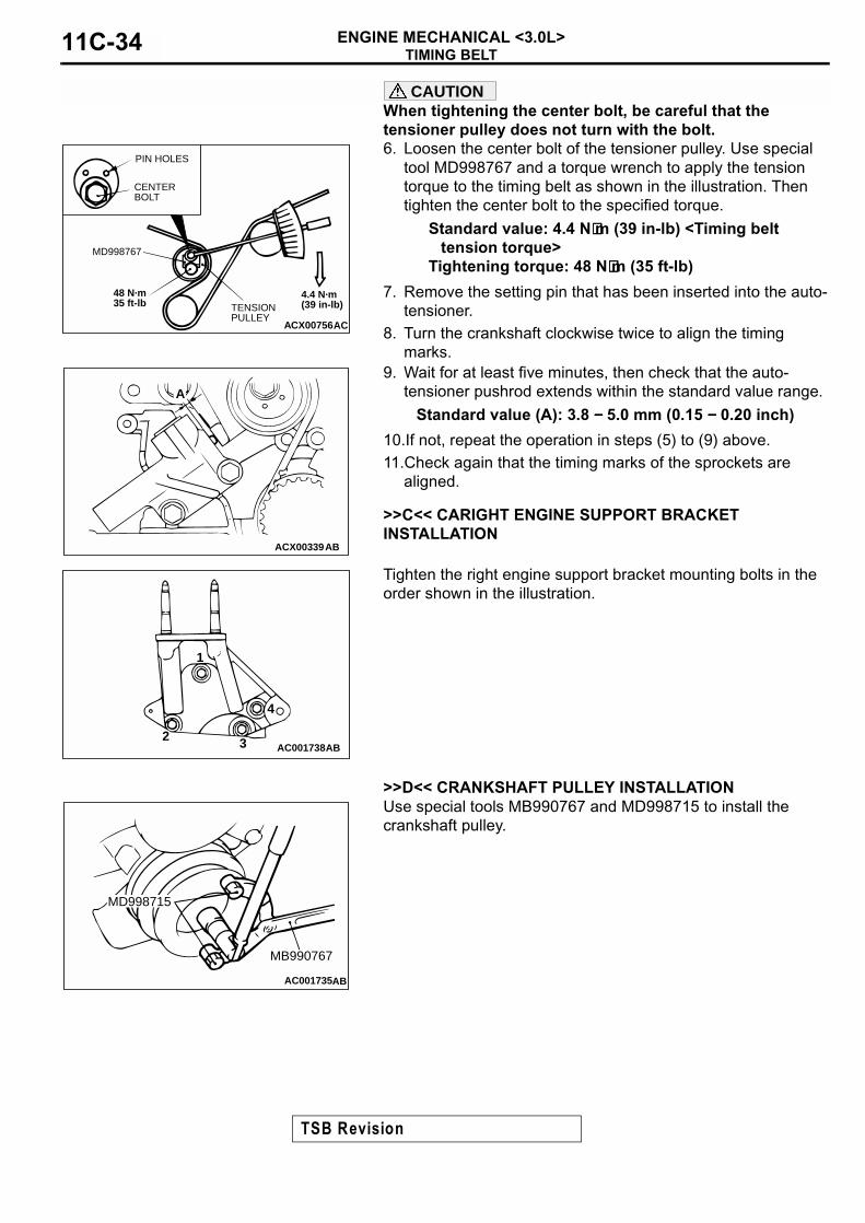
CAUTIONWhen tightening the center bolt, be careful that the tensioner pulley does not turn with the bolt.6. Loosen the center bolt of the tensioner pulley. Use special
tool MD998767 and a torque wrench to apply the tension torque to the timing belt as shown in the illustration. Then tighten the center bolt to the specified torque.
Standard value: 4.4 N⋅⋅⋅⋅m (39 in-lb) <Timing belt tension torque>
Tightening torque: 48 N⋅⋅⋅⋅m (35 ft-lb)
7. Remove the setting pin that has been inserted into the auto-tensioner.
8. Turn the crankshaft clockwise twice to align the timing marks.
9. Wait for at least five minutes, then check that the auto-tensioner pushrod extends within the standard value range.
Standard value (A): 3.8 −−−− 5.0 mm (0.15 −−−− 0.20 inch)
10.If not, repeat the operation in steps (5) to (9) above.11.Check again that the timing marks of the sprockets are
aligned.
>>C<< CARIGHT ENGINE SUPPORT BRACKET INSTALLATION
Tighten the right engine support bracket mounting bolts in the order shown in the illustration.
>>D<< CRANKSHAFT PULLEY INSTALLATIONUse special tools MB990767 and MD998715 to install the crankshaft pulley.
ACX00756AC
CENTER BOLT
PIN HOLES
48 N·m35 ft-lb
MD998767
TENSION PULLEY
4.4 N·m (39 in-lb)
ACX00339
A
AB
AC001738AB
1
2 3
4
AC001735
MD998715
MB990767
AB
TSB Revision

SPECIFICATIONSENGINE MECHANICAL <3.0L> 11C-35
INSPECTIONM1112004400084
AUTO-TENSIONER• Check the auto-tensioner for possible leaks.• Check the pushrod for cracks.
SPECIFICATIONSFASTENER TIGHTENING SPECIFICATIONS
M1111003800138
AC001740AB
PUSHROD
SPRINGAUTO-TENSIONER
ITEMS SPECIFICATIONS
Auto-tensioner attaching bolt 24 N⋅m (18 ft-lb)
Camshaft sprocket attaching bolt 88 N⋅m (65 ft-lb)
Camshaft thrust case attaching bolt 13 N⋅m (115 in-lb)
Control wiring harness protector attaching bolt 4.9 N⋅m (43 in-lb)
Crankshaft bolt 177 − 186 N⋅m (131 − 137 ft-lb)
Crankshaft position sensor attaching bolt 8.8 N⋅m (78 in-lb)
Cylinder head bolt <cold engine> 103 − 113 N⋅m → 0 N⋅m → 103 − 113 N⋅m(76 − 83 ft-lb → 0 ft-lb → 76 − 83 ft-lb)
Distributor attaching bolt 13 N⋅m (115 in-lb)
Drive plate bolt 72 − 76 N⋅m (53 − 56 ft-lb)
Engine mount bracket attaching bolt M10 86 N⋅m (63 ft-lb)
M12 81 N⋅m (60 ft-lb)
Engine mount bracket attaching nut 86 N⋅m (63 ft-lb)
Engine mount stay attaching nut 35 N⋅m (26 ft-lb)
Engine support bracket right attaching nut 44 N⋅m (32 ft-lb)
Ground wire attaching bolt 8.9 N⋅m (78 in-lb)
High-pressure fuel hose attaching bolt 4.9 N⋅m (43 in-lb)
Lower oil pan attaching bolt 9.8 − 12 N⋅m (87 − 106 in-lb)
Oil dipstick guide attaching bolt 48 N⋅m (35 ft-lb)
Oil pan cover attaching bolt 9.8 − 12 N⋅m (87 − 106 in-lb)
Oil pan drain plug 39 N⋅m (29 ft-lb)
Power steering oil pump attaching bolt 42 N⋅m (31 ft-lb)
Rocker arm and shaft assembly attaching bolt 28 − 34 N⋅m (21 − 25 ft-lb)
Rocker cover attaching bolt 3.4 N⋅m (30 in-lb)
Starter attaching bolt 26 − 33 N⋅m (19 − 24 ft-lb)
TSB Revision

SPECIFICATIONSENGINE MECHANICAL <3.0L>11C-36
SERVICE SPECIFICATIONSM1111000300145
SEALANTM1111000500172
Tensioner pulley attaching bolt 44 N⋅m (32 ft-lb)
Timing belt front lower cover attaching bolt 9.8 − 12 N⋅m (87 − 106 in-lb)
Timing belt front upper cover attaching bolt M6 9.8 − 12 N⋅m (87 − 106 in-lb)
M8 12 − 15 N⋅m (106 − 133 in-lb)
Timing belt rear cover attaching bolt 12 − 15 N⋅m (106 − 133 in-lb)
Timing belt tensioner arm attaching bolt 44 N⋅m (32 ft-lb)
Timing belt tensioner pulley attaching bolt 48 N⋅m (35 ft-lb)
Upper oil pan attaching bolt M6 5.9 N⋅m (52 in-lb)
M10 35 N⋅m (26 ft-lb)
ITEMS SPECIFICATIONS
ITEMS STANDARD VALUE LIMIT
Basic ignition timing at idle 5°BTDC ± 3° −Actual ignition timing at idle Approximately 15° BTDC −CO content % 0.5 or less −HC contents ppm 100 or less −Curb idle speed r/min 700 ± 100 −Compression pressure (250 − 400 r/min) kPa (psi) 824 (119) Minimum 575 (83)
Compression pressure difference of all cylinder kPa (psi) − 98 (14)
Intake manifold vacuum at curb idle kPa (in Hg) − Minimum 60 (18)
Auto-tensioner pushrod movement mm (in) Within 1.0 (0.04) −Auto-tensioner rod protrusion mm (in) 3.8 − 5.0 (0.15 − 0.20) −
ITEM SPECIFIED SEALANT
Oil pan MITSUBISHI GENUINE Sealant Part No. MD970389 or equivalent
TSB Revision

![Intracellular reactions affecting 2-amino-4-([11C]methylthio)butyric acid ([11C]methionine) response to carbon ion radiotherapy in C10 glioma cells](https://static.fdokumen.com/doc/165x107/6343c86b88adeae9b9061aee/intracellular-reactions-affecting-2-amino-4-11cmethylthiobutyric-acid-11cmethionine.jpg)


![Synthesis of oncological [11C]radiopharmaceuticals for clinical PET](https://static.fdokumen.com/doc/165x107/633497dee9e768a27a101d8b/synthesis-of-oncological-11cradiopharmaceuticals-for-clinical-pet.jpg)


![Astrocytic tracer dynamics estimated from [1-11C]-acetate PET measurements](https://static.fdokumen.com/doc/165x107/6334cca03e69168eaf070c95/astrocytic-tracer-dynamics-estimated-from-1-11c-acetate-pet-measurements.jpg)