12OBDG09 Engine Diagnostics.pdf
491
Section 1 : S1-12OBDG09 Contains information that is common to all applications within 12OBDG09 GMT911 - Chevrolet Silverado HD GMT610 - Chevrolet Express GMT912 - GMC Sierra HD Section 2 : S2-12OBDG09_Glow Plug Module Contains diagnostic information that is performed within the Glow Plug Control Module and common to all applications within 12OBDG09 The diagnostic algorithms are contained within the Glow Plug Control Module, but the Fault Code storage handling and MIL Illumination are performed within the ECM Section 3 : S3-12OBDG09-LGH_Specific Contains information that is specific to the LGH applications within 12OBDG09 GMT911 - Chevrolet Silverado HD GMT610 - Chevrolet Express GMT912 - GMC Sierra HD Parameter Definition Contains definitions of secondary parameters which are used in the parameter document. These secondary parameters conditions are shown in the respective physical parameters which define each condition. Calibration Look-Up Tables Contains the calibration look-up tables from both the Section 1, Section 3, and the Parameter Definitions Inhibit Tables Contains the matrix of diagnostics which are inhibited from being executed if an active DTC is stored in the ECM Enable Tables Contains the matrix of additional enable conditions which need to be satisfied for each diagnotic to be enabled 12 OBDG09 Engine Diagnostics Page 1 of 491
-
Upload
khangminh22 -
Category
Documents
-
view
3 -
download
0
Transcript of 12OBDG09 Engine Diagnostics.pdf

Section 1 : S1-12OBDG09Contains information that is common to all applications within 12OBDG09
GMT911 - Chevrolet Silverado HD GMT610 - Chevrolet ExpressGMT912 - GMC Sierra HD
Section 2 : S2-12OBDG09_Glow Plug ModuleContains diagnostic information that is performed within the Glow Plug Control Module
and common to all applications within 12OBDG09 The diagnostic algorithms are contained within the Glow Plug Control Module,
but the Fault Code storage handling and MIL Illumination are performed within the ECM
Section 3 : S3-12OBDG09-LGH_SpecificContains information that is specific to the LGH applications within 12OBDG09
GMT911 - Chevrolet Silverado HD GMT610 - Chevrolet ExpressGMT912 - GMC Sierra HD
Parameter Definition Contains definitions of secondary parameters which are used in the parameter document.
These secondary parameters conditions are shown in the respective physical parameters which define each condition.
Calibration Look-Up Tables Contains the calibration look-up tables from both the Section 1, Section 3, and the Parameter Definitions
Inhibit TablesContains the matrix of diagnostics which are inhibited from being executed if an active DTC is stored in the ECM
Enable TablesContains the matrix of additional enable conditions which need to be satisfied for each diagnotic to be enabled
12 OBDG09 Engine Diagnostics
Page 1 of 491
Component / Fault Monitor Strategy Primary Malfunction Secondary Time MILSystem Code Description Criteria Parameters Required Illum.
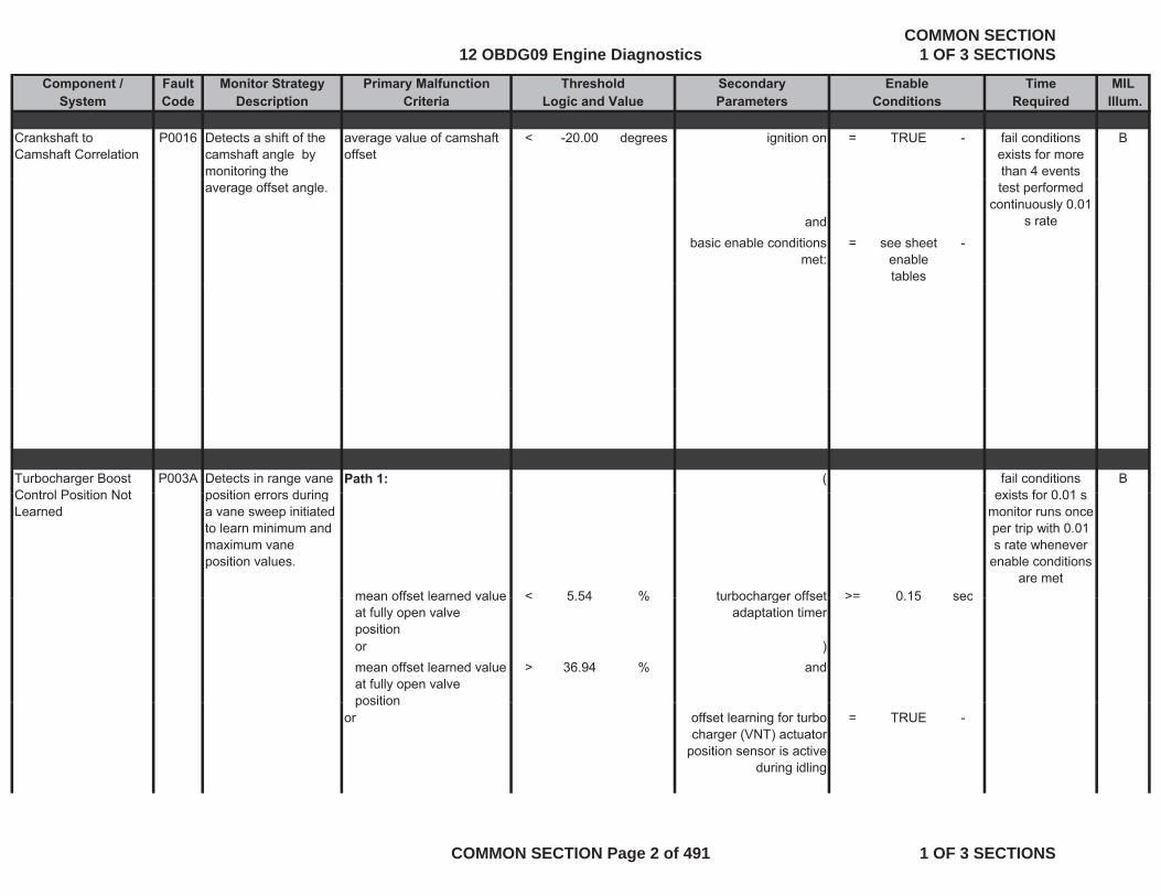
Crankshaft to Camshaft Correlation
P0016 Detects a shift of the camshaft angle by monitoring the
average value of camshaft offset
< -20.00 degrees ignition on = TRUE - B
Threshold EnableLogic and Value Conditions
fail conditions exists for more than 4 events
average offset angle.
andbasic enable conditions
met:= see sheet
enable tables
-
test performed continuously 0.01
s rate
Turbocharger Boost Control Position Not
P003A Detects in range vane position errors during
Path 1: ( Bfail conditions exists for 0 01 sControl Position Not
Learnedposition errors during a vane sweep initiated to learn minimum and maximum vane position values.
mean offset learned value < 5 54 % turbocharger offset >= 0 15 sec
exists for 0.01 smonitor runs once per trip with 0.01 s rate whenever
enable conditions are met
mean offset learned value at fully open valve position
< 5.54 % turbocharger offset adaptation timer
>= 0.15 sec
or )mean offset learned value at fully open valve position
> 36.94 % and
positionor offset learning for turbo
charger (VNT) actuator position sensor is active
during idling
= TRUE -
12 OBDG09 Engine DiagnosticsCOMMON SECTION
1 OF 3 SECTIONS
COMMON SECTION Page 2 of 491 1 OF 3 SECTIONS
Component / Fault Monitor Strategy Primary Malfunction Secondary Time MILSystem Code Description Criteria Parameters Required Illum.
Threshold EnableLogic and Value Conditions
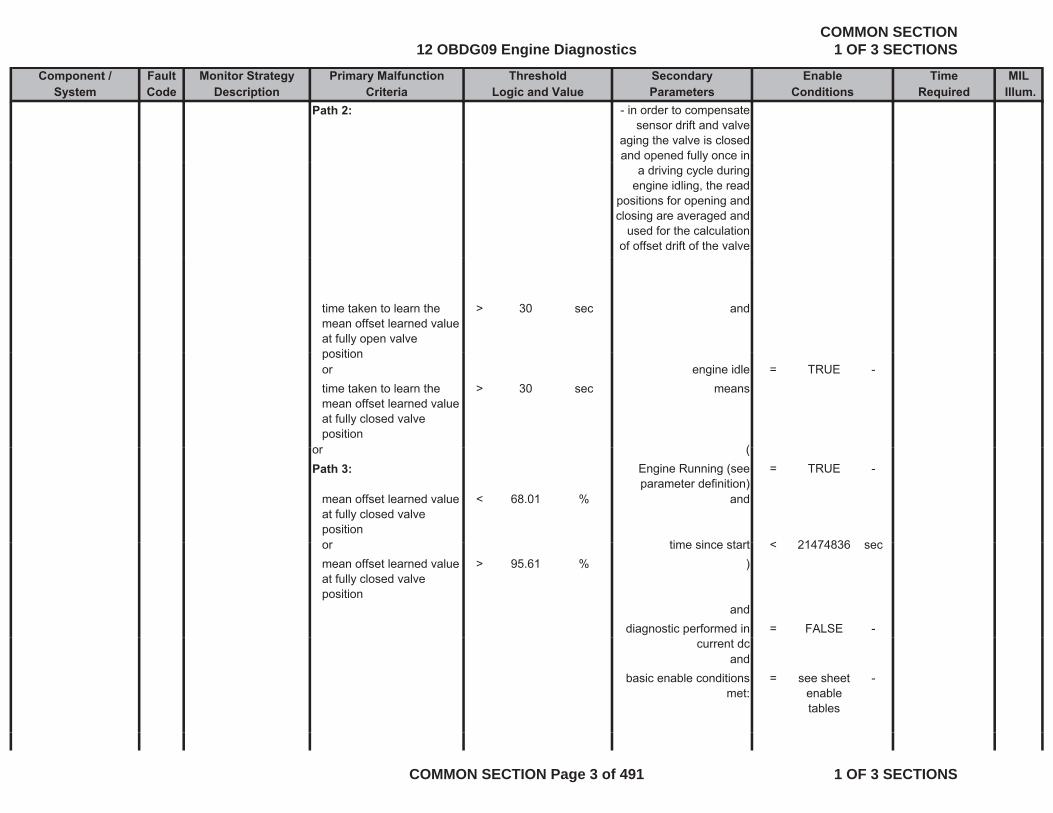
Path 2: - in order to compensate sensor drift and valve
aging the valve is closed and opened fully once in
a driving cycle during engine idling, the read
positions for opening and closing are averaged and
used for the calculation of offset drift of the valve
time taken to learn the mean offset learned value at fully open valve position
> 30 sec and
positionor engine idle = TRUE -time taken to learn the mean offset learned value at fully closed valve position
> 30 sec means
or (or (Path 3: Engine Running (see
parameter definition)= TRUE -
mean offset learned value at fully closed valve position
< 68.01 % and
ti i t t < 21474836or time since start < 21474836 secmean offset learned value at fully closed valve position
> 95.61 % )
anddiagnostic performed in = FALSE -
current dcand
basic enable conditions met:
= see sheet enable tables
-
12 OBDG09 Engine DiagnosticsCOMMON SECTION
1 OF 3 SECTIONS
COMMON SECTION Page 3 of 491 1 OF 3 SECTIONS
Component / Fault Monitor Strategy Primary Malfunction Secondary Time MILSystem Code Description Criteria Parameters Required Illum.
Threshold EnableLogic and Value Conditions
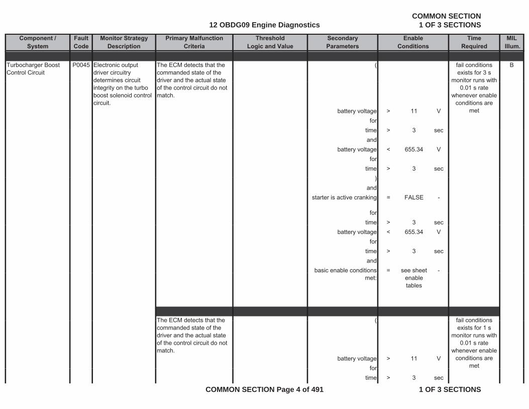
Turbocharger Boost Control Circuit
P0045 Electronic output driver circuitry determines circuit
The ECM detects that the commanded state of the driver and the actual state
( Bfail conditions exists for 3 s
monitor runs withdetermines circuit integrity on the turbo boost solenoid control circuit.
driver and the actual state of the control circuit do not match.
battery voltage > 11 Vfor
time > 3 sec
monitor runs with 0.01 s rate
whenever enable conditions are
met
time > 3 secand
battery voltage < 655.34 Vfor
time > 3 sec))
andstarter is active cranking = FALSE -
fortime > 3 sec
battery voltage < 655.34 Vfor
time > 3 secand
basic enable conditions = see sheet -met: enable
tables
The ECM detects that the ( fail conditionsThe ECM detects that the commanded state of the driver and the actual state of the control circuit do not match.
(
battery voltage > 11 Vfor
fail conditions exists for 1 s
monitor runs with 0.01 s rate
whenever enable conditions are
metfortime > 3 sec
12 OBDG09 Engine DiagnosticsCOMMON SECTION
1 OF 3 SECTIONS
COMMON SECTION Page 4 of 491 1 OF 3 SECTIONS

Component / Fault Monitor Strategy Primary Malfunction Secondary Time MILSystem Code Description Criteria Parameters Required Illum.
Threshold EnableLogic and Value Conditions
andbattery voltage < 655.34 V
fortime > 3 sec
)and
starter is active cranking = FALSE -
forfortime > 3 sec
battery voltage < 655.34 Vfor
time > 3 secandand
basic enable conditions met:
= see sheet enable tables
-
Turbocharger Boost Control Circuit Low Voltage
P0047 Electronic out-put driver circuitry determines circuit integrity on the turbo
The ECM detects that the commanded state of the driver and the actual state of the control circuit do not
( Bfail conditions exists for 3 s
monitor runs with 0.01 s rate
boost solenoid control circuit.
match.
battery voltage > 11 Vfor
time > 3 secand
whenever enable conditions are
met
andbattery voltage < 655.34 V
fortime > 3 sec
)andand
12 OBDG09 Engine DiagnosticsCOMMON SECTION
1 OF 3 SECTIONS
COMMON SECTION Page 5 of 491 1 OF 3 SECTIONS

Component / Fault Monitor Strategy Primary Malfunction Secondary Time MILSystem Code Description Criteria Parameters Required Illum.
Threshold EnableLogic and Value Conditions
starter is active cranking = FALSE -
fortime > 3 sectime > 3 sec
battery voltage < 655.34 Vfor
time > 3 secand
basic enable conditions = see sheet -basic enable conditions met:
see sheet enable tables
Turbocharger Boost Control Circuit High Voltage
P0048 Electronic out-put driver circuitry determines circuit integrity on the turbo boost solenoid control circuit
The ECM detects that the commanded state of the driver and the actual state of the control circuit do not match.
( Bfail conditions exists for 1 s
monitor runs with 0.01 s rate
whenever enable conditions arecircuit.
battery voltage > 11 Vfor
time > 3 secand
battery voltage < 655 34 V
conditions are met
battery voltage < 655.34 Vfor
time > 3 sec)
andstarter is active cranking = FALSE -starter is active cranking = FALSE -
fortime > 3 sec
battery voltage < 655.34 Vfor
time > 3 sec
12 OBDG09 Engine DiagnosticsCOMMON SECTION
1 OF 3 SECTIONS
COMMON SECTION Page 6 of 491 1 OF 3 SECTIONS
Component / Fault Monitor Strategy Primary Malfunction Secondary Time MILSystem Code Description Criteria Parameters Required Illum.
Threshold EnableLogic and Value Conditions
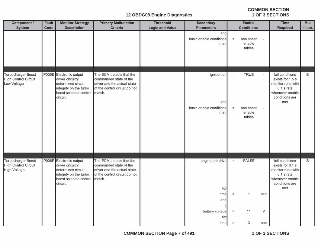
andbasic enable conditions
met:= see sheet
enable tables
-
tables
Turbocharger Boost P006E Electronic output The ECM detects that the ignition on = TRUE - Bfail conditions High Control Circuit Low Voltage
driver circuitry determines circuit integrity on the turbo boost solenoid control circuit.
commanded state of the driver and the actual state of the control circuit do not match.
and
exists for 1.5 smonitor runs with
0.1 s rate whenever enable
conditions are met
basic enable conditions met:
= see sheet enable tables
-
Turbocharger Boost P006F Electronic output The ECM detects that the engine pre drive = FALSE - Bfail conditions High Control Circuit High Voltage
driver circuitry determines circuit integrity on the turbo boost solenoid control circuit.
commanded state of the driver and the actual state of the control circuit do not match.
for
exists for 0.1 smonitor runs with
0.1 s rate whenever enable
conditions are met
time > 1 secand
(battery voltage > 11 V
fortime > 3 sec
12 OBDG09 Engine DiagnosticsCOMMON SECTION
1 OF 3 SECTIONS
COMMON SECTION Page 7 of 491 1 OF 3 SECTIONS
Component / Fault Monitor Strategy Primary Malfunction Secondary Time MILSystem Code Description Criteria Parameters Required Illum.
Threshold EnableLogic and Value Conditions
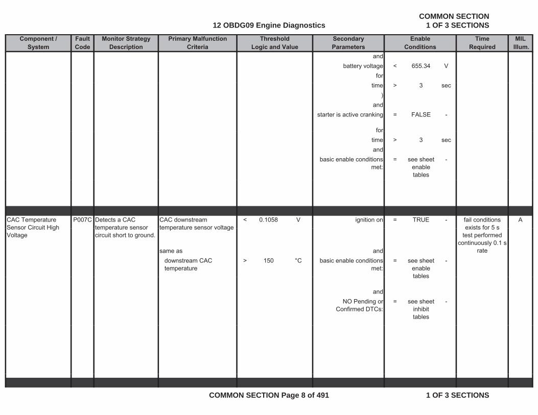
andbattery voltage < 655.34 V
fortime > 3 sec
)and
starter is active cranking = FALSE -
forfortime > 3 secand
basic enable conditions met:
= see sheet enable tables
-
CAC Temperature Sensor Circuit High
P007C Detects a CAC temperature sensor
CAC downstream temperature sensor voltage
< 0.1058 V ignition on = TRUE - Afail conditions exists for 5 sSensor Circuit High
Voltage temperature sensor circuit short to ground.
temperature sensor voltage
same as anddownstream CAC temperature
> 150 °C basic enable conditions met:
= see sheet enable tables
-
exists for 5 s test performed
continuously 0.1 s rate
tables
andNO Pending or
Confirmed DTCs:= see sheet
inhibit tables
-
12 OBDG09 Engine DiagnosticsCOMMON SECTION
1 OF 3 SECTIONS
COMMON SECTION Page 8 of 491 1 OF 3 SECTIONS
Component / Fault Monitor Strategy Primary Malfunction Secondary Time MILSystem Code Description Criteria Parameters Required Illum.
Threshold EnableLogic and Value Conditions
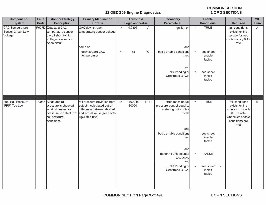
CAC Temperature Sensor Circuit Low Voltage
P007D Detects a CAC temperature sensor circuit short to high voltage or a sensor
CAC downstream temperature sensor voltage
> 4.9306 V ignition on = TRUE - Afail conditions exists for 5 s
test performed continuously 0.1 s
open circuitsame as and
downstream CAC temperature
< -53 °C basic enable conditions met:
= see sheet enable tables
-
rate
andNO Pending or
Confirmed DTCs:= see sheet
inhibit tables
-
Fuel Rail Pressure [FRP] Too Low
P0087 Measured rail pressure is checked against desired rail pressure to detect low
rail pressure deviation from setpoint calculated out of difference between desired and actual value (see Look
> 11000 to 80000
kPa state machine rail pressure control equal to
metering unit control mode
= TRUE - B fail conditions exists for 8 s
monitor runs with 0 02 s ratepressure to detect low
rail pressure conditions.
and actual value (see Look-Up-Table #58)
mode
andbasic enable conditions
t= see sheet
bl-
0.02 s rate whenever enable
conditions are met
met: enable tables
andmetering unit actuator
test active= FALSE -
dandNO Pending or
Confirmed DTCs:= see sheet
inhibit tables
-
12 OBDG09 Engine DiagnosticsCOMMON SECTION
1 OF 3 SECTIONS
COMMON SECTION Page 9 of 491 1 OF 3 SECTIONS
Component / Fault Monitor Strategy Primary Malfunction Secondary Time MILSystem Code Description Criteria Parameters Required Illum.
Threshold EnableLogic and Value Conditions
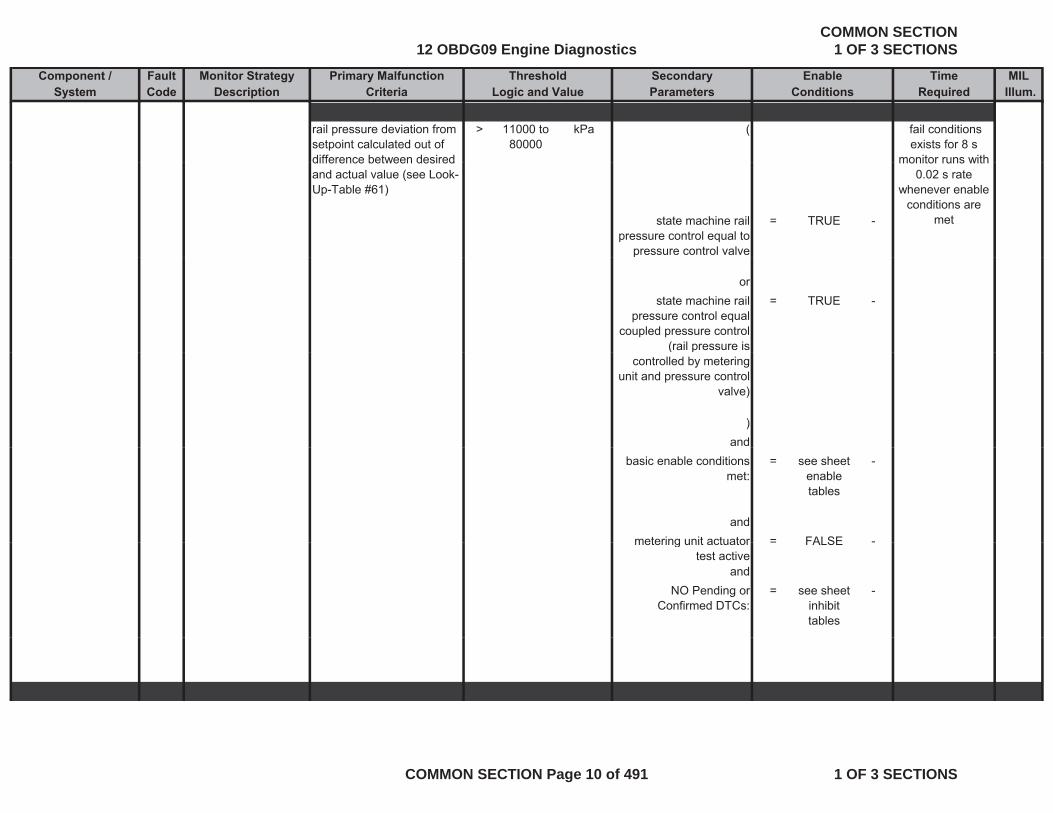
rail pressure deviation from setpoint calculated out of difference between desired
> 11000 to 80000
kPa ( fail conditions exists for 8 s
monitor runs withdifference between desired and actual value (see Look-Up-Table #61)
state machine rail pressure control equal to
pressure control valve
= TRUE -
monitor runs with 0.02 s rate
whenever enable conditions are
met
p
orstate machine rail
pressure control equal coupled pressure control
(rail pressure is
= TRUE -
( pcontrolled by metering
unit and pressure control valve)
)and
basic enable conditions met:
= see sheet enable tables
-
andmetering unit actuator = FALSE -metering unit actuator
test active= FALSE -
andNO Pending or
Confirmed DTCs:= see sheet
inhibit tables
-
12 OBDG09 Engine DiagnosticsCOMMON SECTION
1 OF 3 SECTIONS
COMMON SECTION Page 10 of 491 1 OF 3 SECTIONS

Component / Fault Monitor Strategy Primary Malfunction Secondary Time MILSystem Code Description Criteria Parameters Required Illum.
Threshold EnableLogic and Value Conditions
Fuel Rail Pressure [FRP] Too High
P0088 Measured rail pressure is checked against desired rail pressure to detect high
rail pressure deviation from setpoint calculated out of difference between desired and actual value (see Look-
< -80000 to -20000
kPa Path 1: B fail conditions exists for 8 s
monitor runs with 0.02 s rate
rail pressure conditions.
Up-Table #59)
current injection quantity > 8 mm^3/rev
and
whenever enable conditions are
met
state machine rail pressure control equal to
metering unit control mode
= TRUE -
andbasic enable conditions = see sheet -
met: enable tables
andmetering unit actuator
test active= FALSE -
andNO Pending or
Confirmed DTCs:= see sheet
inhibit tables
-
rail pressure deviation from setpoint calculated out of difference between desired and act al al e
< -20000 kPa ( fail conditions exists for 8 s
monitor runs with 0 02 s rateand actual value
state machine rail pressure control equal to
pressure control valve
= TRUE -
or
0.02 s rate whenever enable
conditions are met
or
12 OBDG09 Engine DiagnosticsCOMMON SECTION
1 OF 3 SECTIONS
COMMON SECTION Page 11 of 491 1 OF 3 SECTIONS
Component / Fault Monitor Strategy Primary Malfunction Secondary Time MILSystem Code Description Criteria Parameters Required Illum.
Threshold EnableLogic and Value Conditions
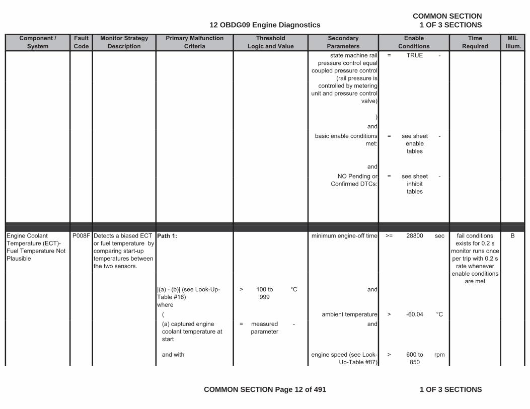
state machine rail pressure control equal
coupled pressure control (rail pressure is
= TRUE -
controlled by metering unit and pressure control
valve)
)and
basic enable conditions met:
= see sheet enable tables
-
andNO Pending or = see sheet -NO Pending or
Confirmed DTCs:see sheet
inhibit tables
Engine Coolant Temperature (ECT)-Fuel Temperature Not Plausible
P008F Detects a biased ECT or fuel temperature by comparing start-up temperatures between the two sensors.
Path 1: minimum engine-off time >= 28800 sec Bfail conditions exists for 0.2 s
monitor runs once per trip with 0.2 s
rate whenever enable conditions
|(a) - (b)| (see Look-Up-Table #16)
> 100 to 999
°C and
where( ambient temperature > -60.04 °C
enable conditions are met
(a) captured engine coolant temperature at start
= measured parameter
- and
and with engine speed (see Look-Up-Table #87)
> 600 to 850
rpm
12 OBDG09 Engine DiagnosticsCOMMON SECTION
1 OF 3 SECTIONS
COMMON SECTION Page 12 of 491 1 OF 3 SECTIONS
Component / Fault Monitor Strategy Primary Malfunction Secondary Time MILSystem Code Description Criteria Parameters Required Illum.
Threshold EnableLogic and Value Conditions
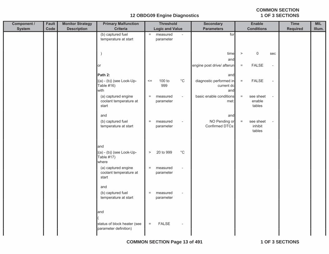
(b) captured fuel temperature at start
= measured parameter
- for
) time > 0 secand
or engine post drive/ afterun = FALSE -
Path 2: and|(a) (b)| (see Look Up <= 100 to °C diagnostic performed in = FALSE|(a) - (b)| (see Look-Up-Table #16)
<= 100 to 999
°C diagnostic performed in current dc
= FALSE -
with and(a) captured engine coolant temperature at start
= measured parameter
- basic enable conditions met:
= see sheet enable tables
-
and and(b) captured fuel temperature at start
= measured parameter
- NO Pending or Confirmed DTCs:
= see sheet inhibit tables
-
and|(a) - (b)| (see Look-Up-Table #17)
> 20 to 999 °C
where(a) captured engine = measured -( ) p gcoolant temperature at start
parameter
and(b) captured fuel temperature at start
= measured parameter
-p p
and(status of block heater (see parameter definition)
= FALSE -parameter definition)
12 OBDG09 Engine DiagnosticsCOMMON SECTION
1 OF 3 SECTIONS
COMMON SECTION Page 13 of 491 1 OF 3 SECTIONS
Component / Fault Monitor Strategy Primary Malfunction Secondary Time MILSystem Code Description Criteria Parameters Required Illum.
Threshold EnableLogic and Value Conditions
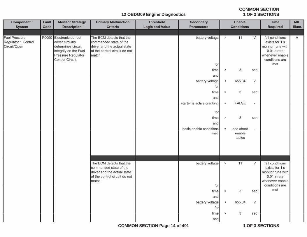
Fuel Pressure Regulator 1 Control Circuit/Open
P0090 Electronic out-put driver circuitry determines circuit
The ECM detects that the commanded state of the driver and the actual state
battery voltage > 11 V Afail conditions exists for 1 s
monitor runs withCircuit/Open determines circuit integrity on the Fuel Pressure Regulator Control Circuit.
driver and the actual state of the control circuit do not match.
fortime > 3 secand
monitor runs with 0.01 s rate
whenever enable conditions are
met
andbattery voltage < 655.34 V
fortime > 3 secand
starter is active cranking FALSEstarter is active cranking = FALSE -
fortime > 3 secand
basic enable conditions = see sheet -met: enable
tables
The ECM detects that the commanded state of the driver and the actual state of the control circuit do not match.
battery voltage > 11 V
for
fail conditions exists for 1 s
monitor runs with 0.01 s rate
whenever enable conditions arefor
time > 3 secand
battery voltage < 655.34 Vfor
time > 3 sec
conditions are met
time > 3 secand
12 OBDG09 Engine DiagnosticsCOMMON SECTION
1 OF 3 SECTIONS
COMMON SECTION Page 14 of 491 1 OF 3 SECTIONS
Component / Fault Monitor Strategy Primary Malfunction Secondary Time MILSystem Code Description Criteria Parameters Required Illum.
Threshold EnableLogic and Value Conditions
starter is active cranking = FALSE -
fortime > 3 sectime > 3 secand
basic enable conditions met:
= see sheet enable tables
-
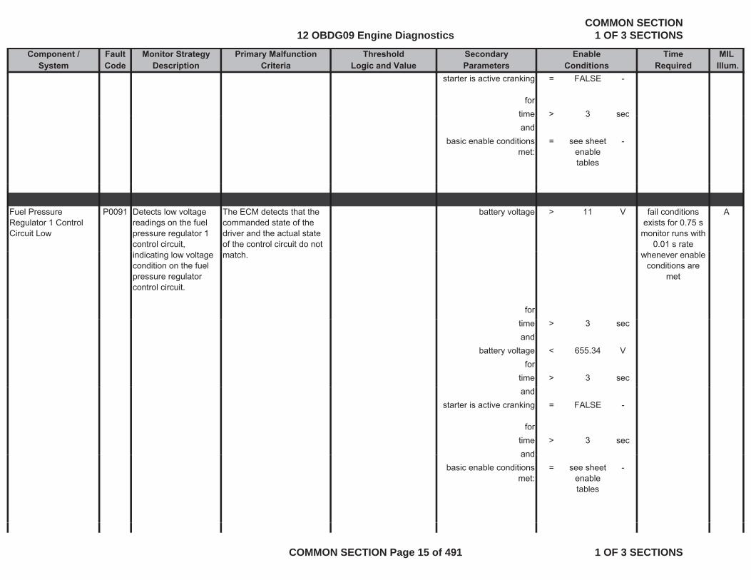
Fuel Pressure Regulator 1 Control Circuit Low
P0091 Detects low voltage readings on the fuel pressure regulator 1 control circuit,
The ECM detects that the commanded state of the driver and the actual state of the control circuit do not
battery voltage > 11 V Afail conditions exists for 0.75 s
monitor runs with 0.01 s rate
indicating low voltage condition on the fuel pressure regulator control circuit.
match.
for
whenever enable conditions are
met
time > 3 secand
battery voltage < 655.34 Vfor
time > 3 secand
starter is active cranking = FALSE -
fortime > 3 secandand
basic enable conditions met:
= see sheet enable tables
-
12 OBDG09 Engine DiagnosticsCOMMON SECTION
1 OF 3 SECTIONS
COMMON SECTION Page 15 of 491 1 OF 3 SECTIONS

Component / Fault Monitor Strategy Primary Malfunction Secondary Time MILSystem Code Description Criteria Parameters Required Illum.
Threshold EnableLogic and Value Conditions
Fuel Pressure Regulator 1 Control Circuit High
P0092 Detects high voltage readings on the fuel pressure regulator 1
The ECM detects that the commanded state of the driver and the actual state
battery voltage > 11 V Afail conditions exists for 1 s
monitor runs withCircuit High pressure regulator 1 control circuit, indicating high voltage condition on the fuel pressure regulator 1 control circuit.
driver and the actual state of the control circuit do not match.
monitor runs with 0.01 s rate
whenever enable conditions are
met
fortime > 3 secand
battery voltage < 655.34 Vfor
time > 3 secand
starter is active cranking = FALSE -
forti > 3time > 3 secand
basic enable conditions met:
= see sheet enable tables
-
Intake Air Temperature Sensor 2 Circuit Low Voltage
P0097 Detects low voltage readings on the intake air temperature sensor
intake air temperature sensor 2 voltage
< 0.0326 V ignition on = TRUE - Bfail conditions exists for 5 s
test performedVoltage air temperature sensor 2 circuit, indicating an OOR low condition.
same as and
test performed continuously 0.1 s
rate
12 OBDG09 Engine DiagnosticsCOMMON SECTION
1 OF 3 SECTIONS
COMMON SECTION Page 16 of 491 1 OF 3 SECTIONS
Component / Fault Monitor Strategy Primary Malfunction Secondary Time MILSystem Code Description Criteria Parameters Required Illum.
Threshold EnableLogic and Value Conditions
temperature of intake air temperature sensor 2
> 250 deg basic enable conditions met:
= see sheet enable tables
-
andNO Pending or
Confirmed DTCs:= see sheet
inhibit tables
-
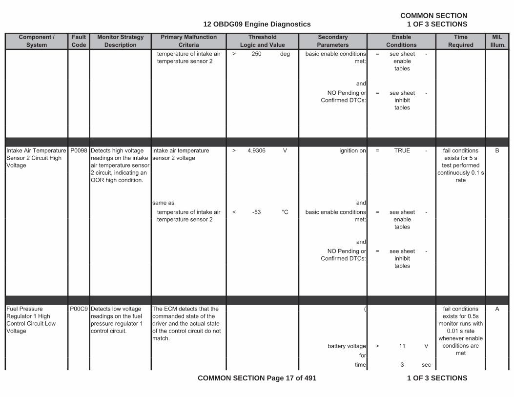
Intake Air Temperature Sensor 2 Circuit High Voltage
P0098 Detects high voltage readings on the intake air temperature sensor 2 circuit indicating an
intake air temperature sensor 2 voltage
> 4.9306 V ignition on = TRUE - Bfail conditions exists for 5 s
test performed continuously 0 1 s2 circuit, indicating an
OOR high condition.
same as andtemperature of intake air temperature sensor 2
< -53 °C basic enable conditions met:
= see sheet enable
-
continuously 0.1 s rate
temperature sensor 2 met: enable tables
andNO Pending or
Confirmed DTCs:= see sheet
inhibit tables
-
tables
Fuel Pressure P00C9 Detects low voltage The ECM detects that the ( Afail conditions Regulator 1 High Control Circuit Low Voltage
greadings on the fuel pressure regulator 1 control circuit.
commanded state of the driver and the actual state of the control circuit do not match.
(
battery voltage > 11 Vfor
exists for 0.5smonitor runs with
0.01 s rate whenever enable
conditions are met
time 3 sec
12 OBDG09 Engine DiagnosticsCOMMON SECTION
1 OF 3 SECTIONS
COMMON SECTION Page 17 of 491 1 OF 3 SECTIONS
Component / Fault Monitor Strategy Primary Malfunction Secondary Time MILSystem Code Description Criteria Parameters Required Illum.
Threshold EnableLogic and Value Conditions
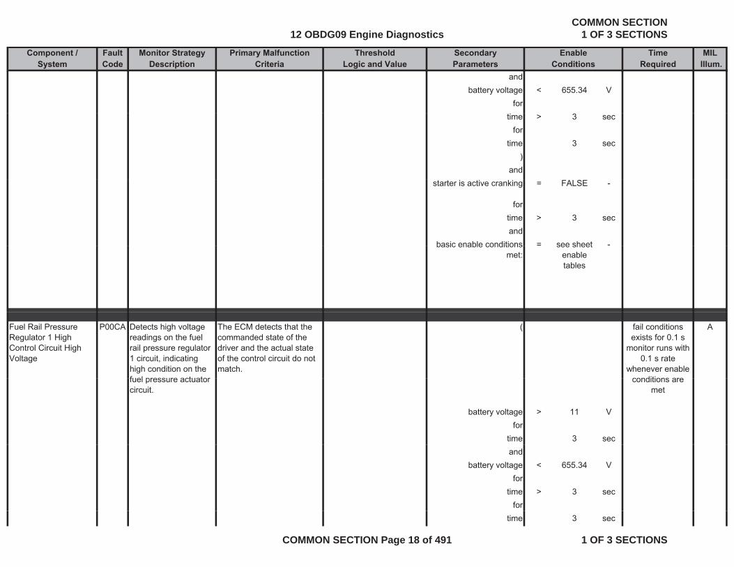
andbattery voltage < 655.34 V
fortime > 3 sec
fortime 3 sec
)and
starter is active cranking = FALSE -
fortime > 3 secand
basic enable conditions = see sheet -basic enable conditions met:
see sheet enable tables
Fuel Rail Pressure Regulator 1 High Control Circuit High Voltage
P00CA Detects high voltage readings on the fuel rail pressure regulator 1 circuit, indicating high condition on the fuel pressure actuator
The ECM detects that the commanded state of the driver and the actual state of the control circuit do not match.
( Afail conditions exists for 0.1 s
monitor runs with 0.1 s rate
whenever enable conditions arefuel pressure actuator
circuit.
battery voltage > 11 Vfor
time 3 sec
conditions are met
andbattery voltage < 655.34 V
fortime > 3 sec
fortime 3 sec
12 OBDG09 Engine DiagnosticsCOMMON SECTION
1 OF 3 SECTIONS
COMMON SECTION Page 18 of 491 1 OF 3 SECTIONS

Component / Fault Monitor Strategy Primary Malfunction Secondary Time MILSystem Code Description Criteria Parameters Required Illum.
Threshold EnableLogic and Value Conditions
)and
starter is active cranking = FALSE -
fortime > 3 secand
basic enable conditions met:
= see sheet enable
-
tables
Mass Air Flow (MAF) P0101 Detects skewed MAF ( ambient pressure > 74 8 kPa Bfail conditionsMass Air Flow (MAF) Sensor Performance
P0101 Detects skewed MAF sensor by comparing measured MAF to calculated expected MAF based on volumetric efficiency of the engine
( ambient pressure > 74.8 kPa Bfail conditions exists for 10 s
monitor runs with 0.01 s rate
whenever enable conditions are
metthe engine
measured air mass flow signal
< (a) - (b) - and
with ((a) engine load dependent MAP for calculating lower
= 0.75 to 0 8
- engine coolant temperature
>= -20.04 °C
met
MAP for calculating lower threshold (see Look-Up-Table #2)
0.8 temperature
and with and(b) air temperature dependent correction
= 0 to 0.05 - engine coolant temperature
<= 122.96 °Cdependent correction factor curve (see Look-Up-Table #1)
temperature
or )measured air mass flow signal
> (c) + (b) - and
with (with (
12 OBDG09 Engine DiagnosticsCOMMON SECTION
1 OF 3 SECTIONS
COMMON SECTION Page 19 of 491 1 OF 3 SECTIONS

Component / Fault Monitor Strategy Primary Malfunction Secondary Time MILSystem Code Description Criteria Parameters Required Illum.
Threshold EnableLogic and Value Conditions
(c) Engine load dependent MAP for calculating higher threshold
= 1.2 - gradient of the charge-air temperature
>= -2 °C/s
and with and(b) air temperature dependent correction factor curve (see Look-Up-Table #1)
= 0 to 0.05 - gradient of the charge-air temperature
<= 2 °C/s
) )) )and
(engine speed (see Look-
Up-Table #87)> 600 to
850rpm
fortime since start > 90 sec
)and
control value of the throttle valve
>= -400 %
andandcontrol value of the
throttle valve<= 5.00 %
and((
setpoint valve position of exhaust-gas recirculation
>= -400 %
andsetpoint valve position of exhaust-gas recirculation
<= 2.00 %g
)for
time > 3 secand
injection quantity <= 300 mm^3/rev
12 OBDG09 Engine DiagnosticsCOMMON SECTION
1 OF 3 SECTIONS
COMMON SECTION Page 20 of 491 1 OF 3 SECTIONS
Component / Fault Monitor Strategy Primary Malfunction Secondary Time MILSystem Code Description Criteria Parameters Required Illum.
Threshold EnableLogic and Value Conditions
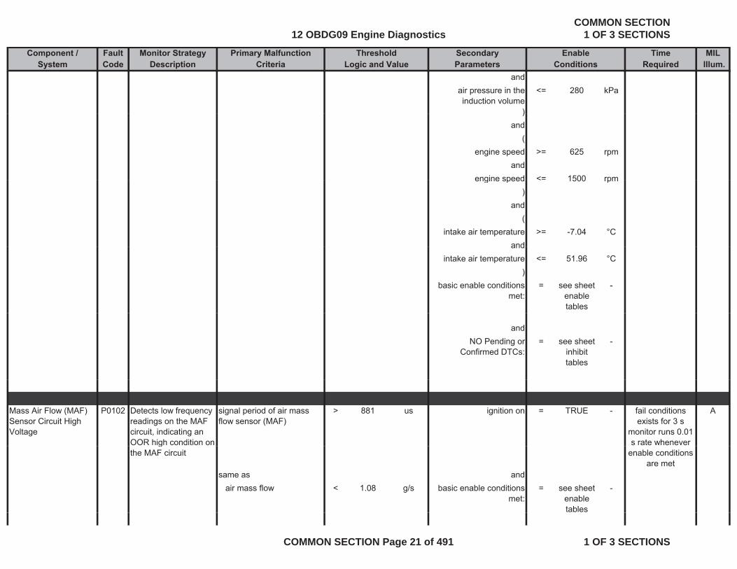
andair pressure in the induction volume
<= 280 kPa
))and
(engine speed >= 625 rpm
andengine speed <= 1500 rpmengine speed < 1500 rpm
)and
(intake air temperature >= -7.04 °C
andandintake air temperature <= 51.96 °C
)basic enable conditions
met:= see sheet
enable tables
-
andNO Pending or
Confirmed DTCs:= see sheet
inhibit tables
-
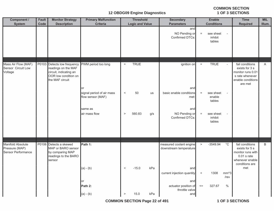
Mass Air Flow (MAF) Sensor Circuit High Voltage
P0102 Detects low frequency readings on the MAF circuit, indicating an OOR high condition on
signal period of air mass flow sensor (MAF)
> 881 us ignition on = TRUE - Afail conditions exists for 3 s
monitor runs 0.01 s rate whenever g
the MAF circuit
same as andair mass flow < 1.08 g/s basic enable conditions
met:= see sheet
enable tables
-
enable conditions are met
12 OBDG09 Engine DiagnosticsCOMMON SECTION
1 OF 3 SECTIONS
COMMON SECTION Page 21 of 491 1 OF 3 SECTIONS
Component / Fault Monitor Strategy Primary Malfunction Secondary Time MILSystem Code Description Criteria Parameters Required Illum.
Threshold EnableLogic and Value Conditions
andNO Pending or
Confirmed DTCs:= see sheet
inhibit tables
-
tables
Mass Air Flow (MAF) P0103 Detects low frequency PWM period too long = TRUE ignition on = TRUE - Afail conditions Sensor Circuit Low Voltage
readings on the MAF circuit, indicating an OOR low condition on the MAF circuit
or and
exists for 3 s monitor runs 0.01 s rate whenever
enable conditions are met
signal period of air mass flow sensor (MAF)
< 50 us basic enable conditions met:
= see sheet enable tables
-
same as andair mass flow > 560.83 g/s NO Pending or = see sheet -
Confirmed DTCs: inhibit tables
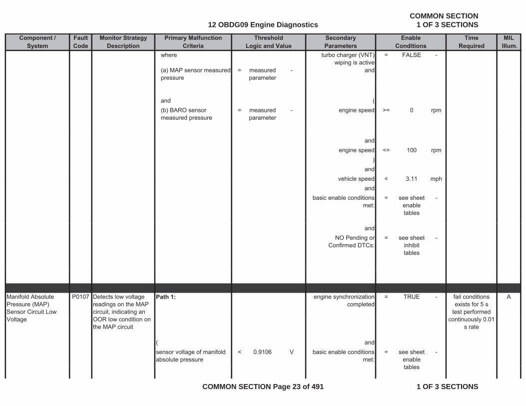
Manifold Absolute Pressure (MAP) Sensor Performance
P0106 Detects a skewed MAP or BARO sensor by comparing MAP readings to the BARO sensor
Path 1: measured coolant engine downstream temperature
> -3549.94 °C Bfail conditions exists for 5 s
monitor runs with 0.01 s rate
whenever enable conditions are
(a) - (b) < -15.0 kPa andcurrent injection quantity < 1308 mm^3
/revor andPath 2: actuator position of
throttle valve<= 327.67 %
met
throttle valve(a) - (b) > 15.0 kPa and
12 OBDG09 Engine DiagnosticsCOMMON SECTION
1 OF 3 SECTIONS
COMMON SECTION Page 22 of 491 1 OF 3 SECTIONS
Component / Fault Monitor Strategy Primary Malfunction Secondary Time MILSystem Code Description Criteria Parameters Required Illum.
Threshold EnableLogic and Value Conditions
where turbo charger (VNT) wiping is active
= FALSE -
(a) MAP sensor measured pressure
= measured parameter
- and
and ((b) BARO sensor measured pressure
= measured parameter
- engine speed >= 0 rpm
andengine speed <= 100 rpm
)and
vehicle speed < 3.11 mphand
basic enable conditions met:
= see sheet enable tables
-
andNO Pending or
Confirmed DTCs:= see sheet
inhibit tables
-
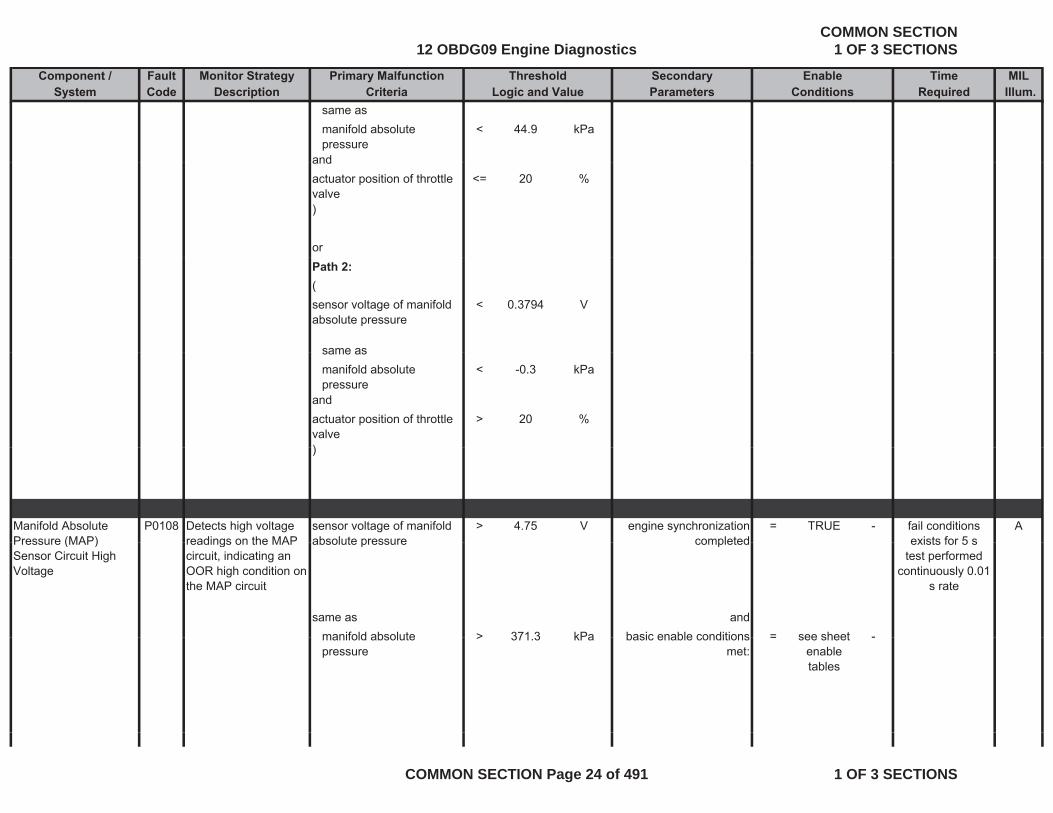
Manifold Absolute Pressure (MAP) Sensor Circuit Low Voltage
P0107 Detects low voltage readings on the MAP circuit, indicating an OOR lo condition on
Path 1: engine synchronization completed
= TRUE - Afail conditions exists for 5 s
test performed contin o sl 0 01Voltage OOR low condition on
the MAP circuit
( andsensor voltage of manifold absolute pressure
< 0.9106 V basic enable conditions met:
= see sheet enable t bl
-
continuously 0.01 s rate
tables
12 OBDG09 Engine DiagnosticsCOMMON SECTION
1 OF 3 SECTIONS
COMMON SECTION Page 23 of 491 1 OF 3 SECTIONS
Component / Fault Monitor Strategy Primary Malfunction Secondary Time MILSystem Code Description Criteria Parameters Required Illum.
Threshold EnableLogic and Value Conditions
same asmanifold absolute pressure
< 44.9 kPa
andandactuator position of throttle valve
<= 20 %
)
orPath 2:(sensor voltage of manifold absolute pressure
< 0.3794 V
same assame asmanifold absolute pressure
< -0.3 kPa
andactuator position of throttle valve
> 20 %
))
Manifold Absolute Pressure (MAP)
P0108 Detects high voltage readings on the MAP
sensor voltage of manifold absolute pressure
> 4.75 V engine synchronization completed
= TRUE - Afail conditions exists for 5 sPressure (MAP)
Sensor Circuit High Voltage
readings on the MAP circuit, indicating an OOR high condition on the MAP circuit
absolute pressure completed
same as andmanifold absolute > 371 3 kPa basic enable conditions = see sheet -
exists for 5 s test performed
continuously 0.01 s rate
manifold absolute pressure
> 371.3 kPa basic enable conditions met:
= see sheet enable tables
-
12 OBDG09 Engine DiagnosticsCOMMON SECTION
1 OF 3 SECTIONS
COMMON SECTION Page 24 of 491 1 OF 3 SECTIONS
Component / Fault Monitor Strategy Primary Malfunction Secondary Time MILSystem Code Description Criteria Parameters Required Illum.
Threshold EnableLogic and Value Conditions
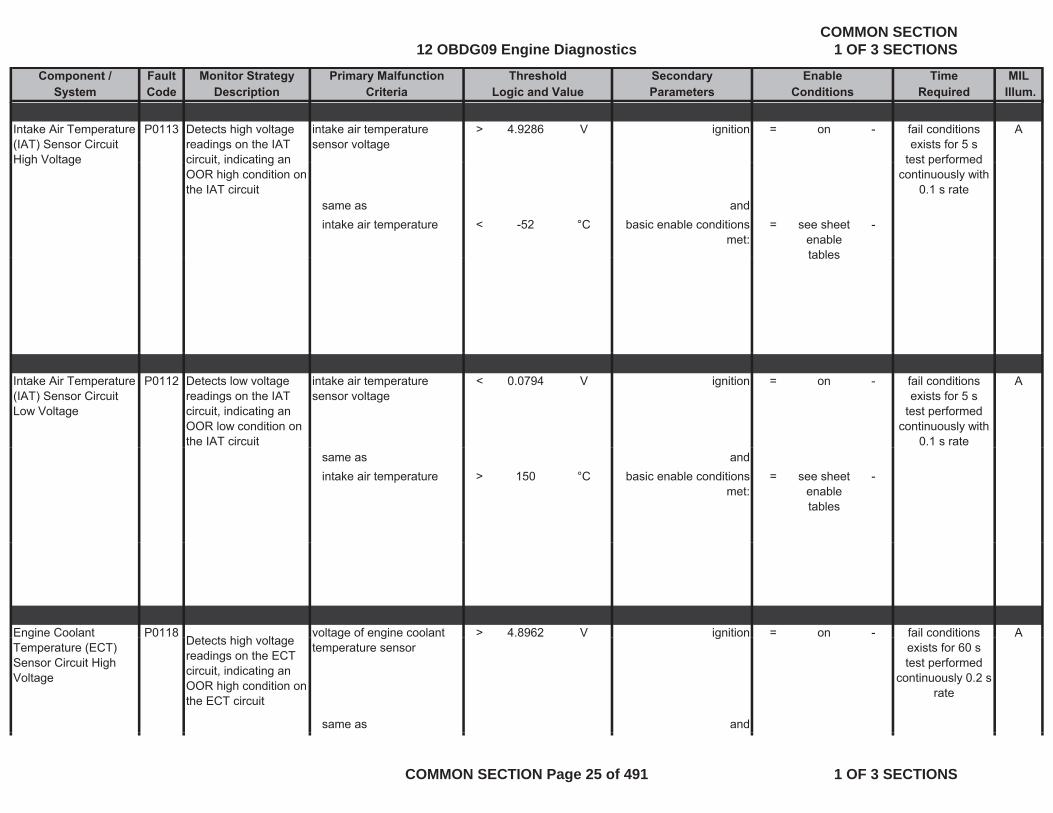
Intake Air Temperature (IAT) Sensor Circuit High Voltage
P0113 Detects high voltage readings on the IAT circuit indicating an
intake air temperature sensor voltage
> 4.9286 V ignition = on - Afail conditions exists for 5 s
test performedHigh Voltage circuit, indicating an OOR high condition on the IAT circuit
same as andintake air temperature < -52 °C basic enable conditions
met:= see sheet
enable tables
-
test performed continuously with
0.1 s rate
tables
Intake Air Temperature (IAT) Sensor Circuit Low Voltage
P0112 Detects low voltage readings on the IAT circuit, indicating an OOR low condition on the IAT circuit
intake air temperature sensor voltage
< 0.0794 V ignition = on - Afail conditions exists for 5 s
test performed continuously with
0.1 s ratesame as andintake air temperature > 150 °C basic enable conditions
met:= see sheet
enable tables
-
Engine Coolant P0118D t t hi h lt
voltage of engine coolant > 4.8962 V ignition = on - Afail conditions gTemperature (ECT) Sensor Circuit High Voltage
Detects high voltage readings on the ECT circuit, indicating an OOR high condition on the ECT circuit
g gtemperature sensor
g
same as and
exists for 60 s test performed
continuously 0.2 s rate
12 OBDG09 Engine DiagnosticsCOMMON SECTION
1 OF 3 SECTIONS
COMMON SECTION Page 25 of 491 1 OF 3 SECTIONS
Component / Fault Monitor Strategy Primary Malfunction Secondary Time MILSystem Code Description Criteria Parameters Required Illum.
Threshold EnableLogic and Value Conditions
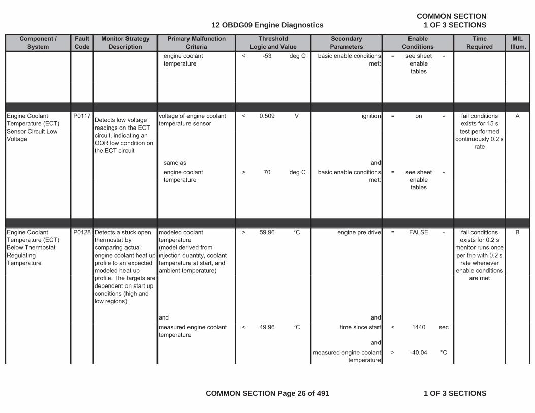
engine coolant temperature
< -53 deg C basic enable conditions met:
= see sheet enable tables
-
Engine Coolant Temperature (ECT) Sensor Circuit Low
P0117Detects low voltage readings on the ECT
voltage of engine coolant temperature sensor
< 0.509 V ignition = on - Afail conditions exists for 15 s test performedSensor Circuit Low
Voltage
gcircuit, indicating an OOR low condition on the ECT circuit
same as andengine coolant temperature
> 70 deg C basic enable conditions met:
= see sheet enable
-
test performed continuously 0.2 s
rate
temperature met: enable tables
Engine Coolant Temperature (ECT) Below Thermostat Regulating Temperature
P0128 Detects a stuck open thermostat by comparing actual engine coolant heat up profile to an expected modeled heat up
modeled coolant temperature(model derived from injection quantity, coolant temperature at start, and ambient temperature)
> 59.96 °C engine pre drive = FALSE - Bfail conditions exists for 0.2 s
monitor runs once per trip with 0.2 s
rate whenever enable conditions
profile. The targets are dependent on start up conditions (high and low regions)
and and
are met
measured engine coolant temperature
< 49.96 °C time since start < 1440 sec
andmeasured engine coolant
temperature> -40.04 °C
12 OBDG09 Engine DiagnosticsCOMMON SECTION
1 OF 3 SECTIONS
COMMON SECTION Page 26 of 491 1 OF 3 SECTIONS

Component / Fault Monitor Strategy Primary Malfunction Secondary Time MILSystem Code Description Criteria Parameters Required Illum.
Threshold EnableLogic and Value Conditions
Low Region Engine Temperature at start < 31 °C AND ambient air
and
temperature <= 10 °C.
captured value of coolant temperature during start
< 30.96 °C
and(
ambient temperature > -7.04 °Cand
ambient temperature < 59.96 °C)
andambient temperature (used for low region
determination)
< 9.96 °C
andengine idle time ratio < 0.50 %
which is defined by the following conditions:
(l t d l l < 10 01 %accelerator pedal value <= 10.01 %
andvehicle speed <= 9.94 mph
andengine speed <= 750 rpmg p p
)and
diagnostic performed in current dc
= FALSE -
and
12 OBDG09 Engine DiagnosticsCOMMON SECTION
1 OF 3 SECTIONS
COMMON SECTION Page 27 of 491 1 OF 3 SECTIONS
Component / Fault Monitor Strategy Primary Malfunction Secondary Time MILSystem Code Description Criteria Parameters Required Illum.
Threshold EnableLogic and Value Conditions
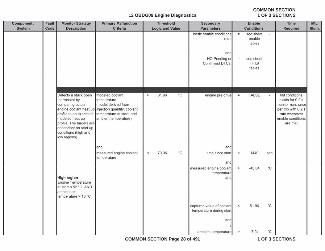
basic enable conditions met:
= see sheet enable tables
-
andNO Pending or
Confirmed DTCs:= see sheet
inhibit tables
-
Detects a stuck open thermostat by comparing actual engine coolant heat up
modeled coolant temperature(model derived from injection quantity coolant
> 81.96 °C engine pre drive = FALSE - fail conditions exists for 0.2 s
monitor runs once per trip with 0 2 sengine coolant heat up
profile to an expected modeled heat up profile. The targets are dependant on start up conditions (high and low regions)
injection quantity, coolant temperature at start, and ambient temperature)
per trip with 0.2 s rate whenever
enable conditions are met
low regions)
and andmeasured engine coolant temperature
< 70.96 °C time since start < 1440 sec
andd i l t > 40 04 °Cmeasured engine coolant
temperature> -40.04 °C
High regionEngine Temperature at start < 52 °C AND ambient air temperature > 10 °C
and
temperature > 10 C
captured value of coolant temperature during start
< 51.96 °C
and((
ambient temperature > -7.04 °C
12 OBDG09 Engine DiagnosticsCOMMON SECTION
1 OF 3 SECTIONS
COMMON SECTION Page 28 of 491 1 OF 3 SECTIONS
Component / Fault Monitor Strategy Primary Malfunction Secondary Time MILSystem Code Description Criteria Parameters Required Illum.
Threshold EnableLogic and Value Conditions
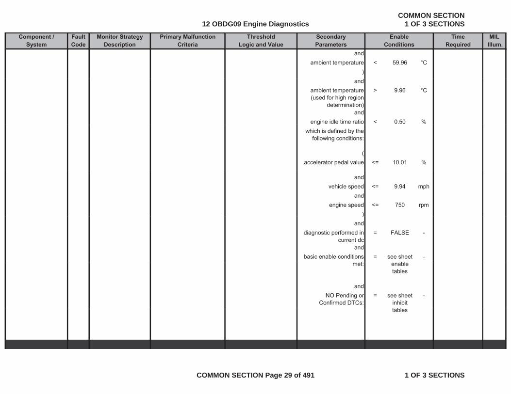
andambient temperature < 59.96 °C
)and
ambient temperature (used for high region
determination)
> 9.96 °C
andengine idle time ratio < 0.50 %g
which is defined by the following conditions:
(accelerator pedal value <= 10.01 %
andvehicle speed <= 9.94 mph
andengine speed <= 750 rpm
))and
diagnostic performed in current dc
= FALSE -
andbasic enable conditions
t= see sheet
bl-
met: enable tables
andNO Pending or
Confirmed DTCs:= see sheet
inhibit t bl
-
tables
12 OBDG09 Engine DiagnosticsCOMMON SECTION
1 OF 3 SECTIONS
COMMON SECTION Page 29 of 491 1 OF 3 SECTIONS
Component / Fault Monitor Strategy Primary Malfunction Secondary Time MILSystem Code Description Criteria Parameters Required Illum.
Threshold EnableLogic and Value Conditions
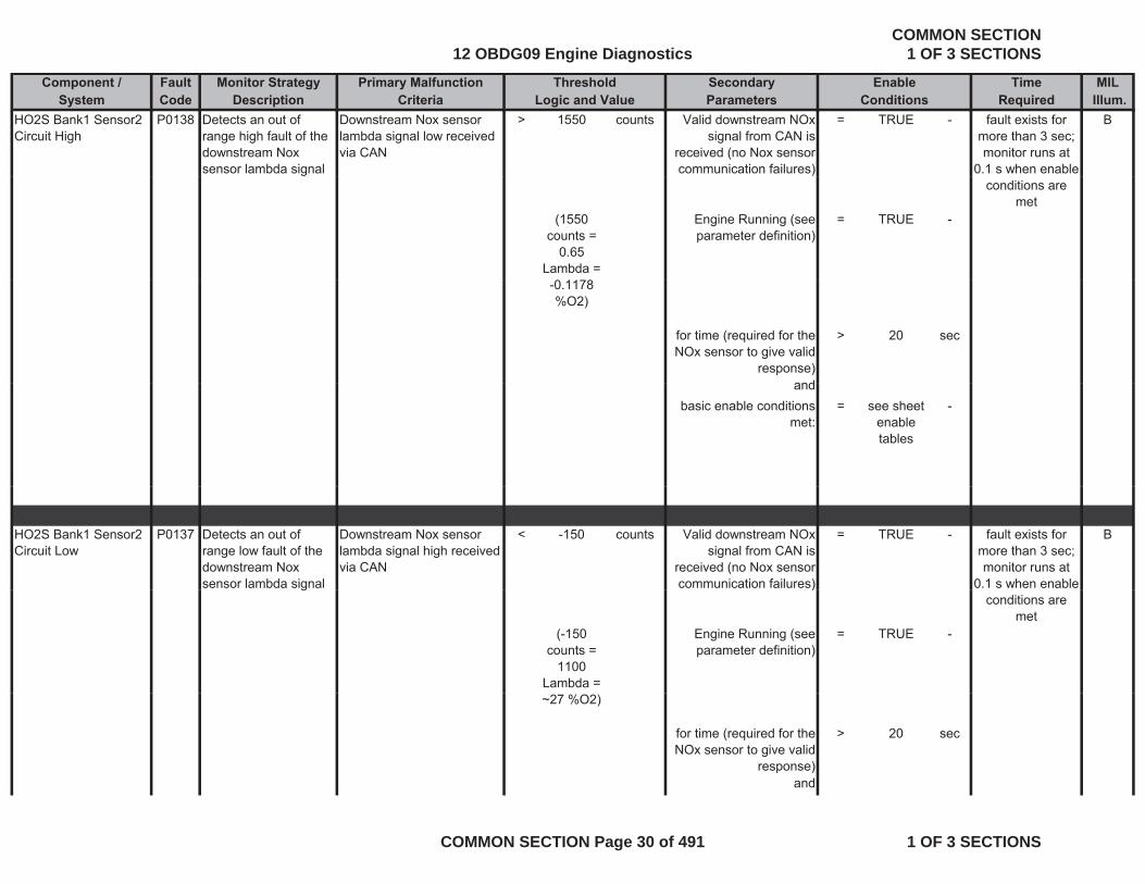
HO2S Bank1 Sensor2 Circuit High
P0138 Detects an out of range high fault of the downstream Nox sensor lambda signal
Downstream Nox sensor lambda signal low received via CAN
> 1550 counts Valid downstream NOx signal from CAN is
received (no Nox sensor communication failures)
= TRUE - Bfault exists for more than 3 sec; monitor runs at
0.1 s when enable
(1550 counts =
0.65 Lambda =
Engine Running (see parameter definition)
= TRUE -
conditions are met
-0.1178 %O2)
for time (required for the NOx sensor to give valid
response)
> 20 sec
andandbasic enable conditions
met:= see sheet
enable tables
-
HO2S Bank1 Sensor2 Circuit Low
P0137 Detects an out of range low fault of the downstream Nox sensor lambda signal
Downstream Nox sensor lambda signal high received via CAN
< -150 counts Valid downstream NOx signal from CAN is
received (no Nox sensor communication failures)
= TRUE - Bfault exists for more than 3 sec; monitor runs at
0.1 s when enable g )
(-150 counts =
1100 Lambda =
Engine Running (see parameter definition)
= TRUE -
conditions are met
~27 %O2)
for time (required for the NOx sensor to give valid
response)
> 20 sec
and
12 OBDG09 Engine DiagnosticsCOMMON SECTION
1 OF 3 SECTIONS
COMMON SECTION Page 30 of 491 1 OF 3 SECTIONS

Component / Fault Monitor Strategy Primary Malfunction Secondary Time MILSystem Code Description Criteria Parameters Required Illum.
Threshold EnableLogic and Value Conditions
basic enable conditions met:
= see sheet enable tables
-
Fuel Temperature Sensor 1 Circuit High
P0183 Detects high voltage readings in the fuel pump temperature
voltage of fuel temperature sensor 1
> 4.7132 V ignition on = TRUE - Bfail conditions exists for 5 s
test performedpump temperature sensor 1 circuit, indicating an OOR high condition on the fuel pump temperature sensor 1 circuit
test performed continuously 0.2 s
rate
same as andfuel temperature < - 50 degC basic enable conditions
met:= see sheet
enable tables
-
Fuel Temperature Sensor 1 Circuit Low
P0182 Detects low voltage readings in the fuel
voltage of fuel temperature sensor 1
< 0.599 V ignition on = TRUE - Bfail conditions exists for 5 s g
pump temperature sensor 1 circuit, indicating an OOR low condition on the fuel pump temperature sensor 1 circuit
test performed continuously 0.2 s
rate
or same as andfuel temperature > 60 deg C basic enable conditions
met:= see sheet
enable tables
-
12 OBDG09 Engine DiagnosticsCOMMON SECTION
1 OF 3 SECTIONS
COMMON SECTION Page 31 of 491 1 OF 3 SECTIONS
Component / Fault Monitor Strategy Primary Malfunction Secondary Time MILSystem Code Description Criteria Parameters Required Illum.
Threshold EnableLogic and Value Conditions
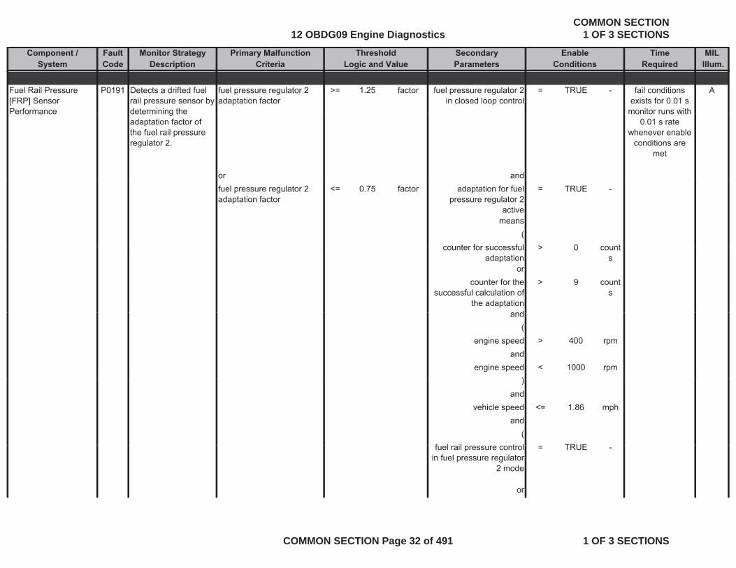
Fuel Rail Pressure [FRP] Sensor Performance
P0191 Detects a drifted fuel rail pressure sensor by determining the
fuel pressure regulator 2 adaptation factor
>= 1.25 factor fuel pressure regulator 2 in closed loop control
= TRUE - Afail conditions exists for 0.01 s
monitor runs withPerformance determining the adaptation factor of the fuel rail pressure regulator 2.
or and
monitor runs with 0.01 s rate
whenever enable conditions are
met
fuel pressure regulator 2 adaptation factor
<= 0.75 factor adaptation for fuel pressure regulator 2
active
= TRUE -
means(
counter for successful > 0 countcounter for successful adaptation
> 0 counts
orcounter for the
successful calculation of the adaptation
> 9 counts
andand(
engine speed > 400 rpmand
engine speed < 1000 rpm))
andvehicle speed <= 1.86 mph
and(
f l il t l TRUEfuel rail pressure control in fuel pressure regulator
2 mode
= TRUE -
or
12 OBDG09 Engine DiagnosticsCOMMON SECTION
1 OF 3 SECTIONS
COMMON SECTION Page 32 of 491 1 OF 3 SECTIONS
Component / Fault Monitor Strategy Primary Malfunction Secondary Time MILSystem Code Description Criteria Parameters Required Illum.
Threshold EnableLogic and Value Conditions
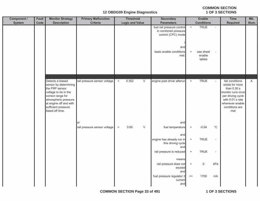
fuel rail pressure control in combined pressure
control (CPC) mode
= TRUE -
)and
basic enable conditions met:
= see sheet enable tables
-
Detects a biased sensor by determining
rail pressure sensor voltage < 0.352 V engine post drive/ afterun = TRUE - Afail conditions exists for more
the FRP sensor voltage to be in the correct range for atmospheric pressure at engine off and with sufficient pressure bleed off time
than 0.30 smonitor runs once per driving cycle with 0.01 s rate
whenever enable conditions are
metbleed-off time.
or andrail pressure sensor voltage > 0.65 V fuel temperature > -0.04 °C
d
met
andengine has already run in
this driving cycle= TRUE -
andrail pressure is reduced = TRUE -
meansrail pressure does not
exceed< 0 kPa
andfuel pressure regulator 2
current <= 1700 mA
and
12 OBDG09 Engine DiagnosticsCOMMON SECTION
1 OF 3 SECTIONS
COMMON SECTION Page 33 of 491 1 OF 3 SECTIONS

Component / Fault Monitor Strategy Primary Malfunction Secondary Time MILSystem Code Description Criteria Parameters Required Illum.
Threshold EnableLogic and Value Conditions
time since engine off > 30.08 secand
number of measurements during
> 10 countsmeasurements during
engine postdrive/ afteruns
andbasic enable conditions
met:= see sheet
enable tables
-
tables
andNO Pending or
Confirmed DTCs:see sheet
inhibit tables
-
Fuel Rail Pressure [FRP] Sensor Circuit
P0192 Detects low voltage readings on the FRP
rail pressure sensor voltage < 0.189 V ignition on = TRUE - A[ ]Low
gcircuit, indicating an OOR low condition on the FRP circuit
same as andrail pressure < 0 kPa basic enable conditions = see sheet -
fail conditions exists for 0.14 s
monitor runs with 0 01 s ratep
met: enable tables
andNO Pending or
Confirmed DTCs:= see sheet
inhibit -
0.01 s rate whenever enable
conditions are met
tables
12 OBDG09 Engine DiagnosticsCOMMON SECTION
1 OF 3 SECTIONS
COMMON SECTION Page 34 of 491 1 OF 3 SECTIONS
Component / Fault Monitor Strategy Primary Malfunction Secondary Time MILSystem Code Description Criteria Parameters Required Illum.
Threshold EnableLogic and Value Conditions
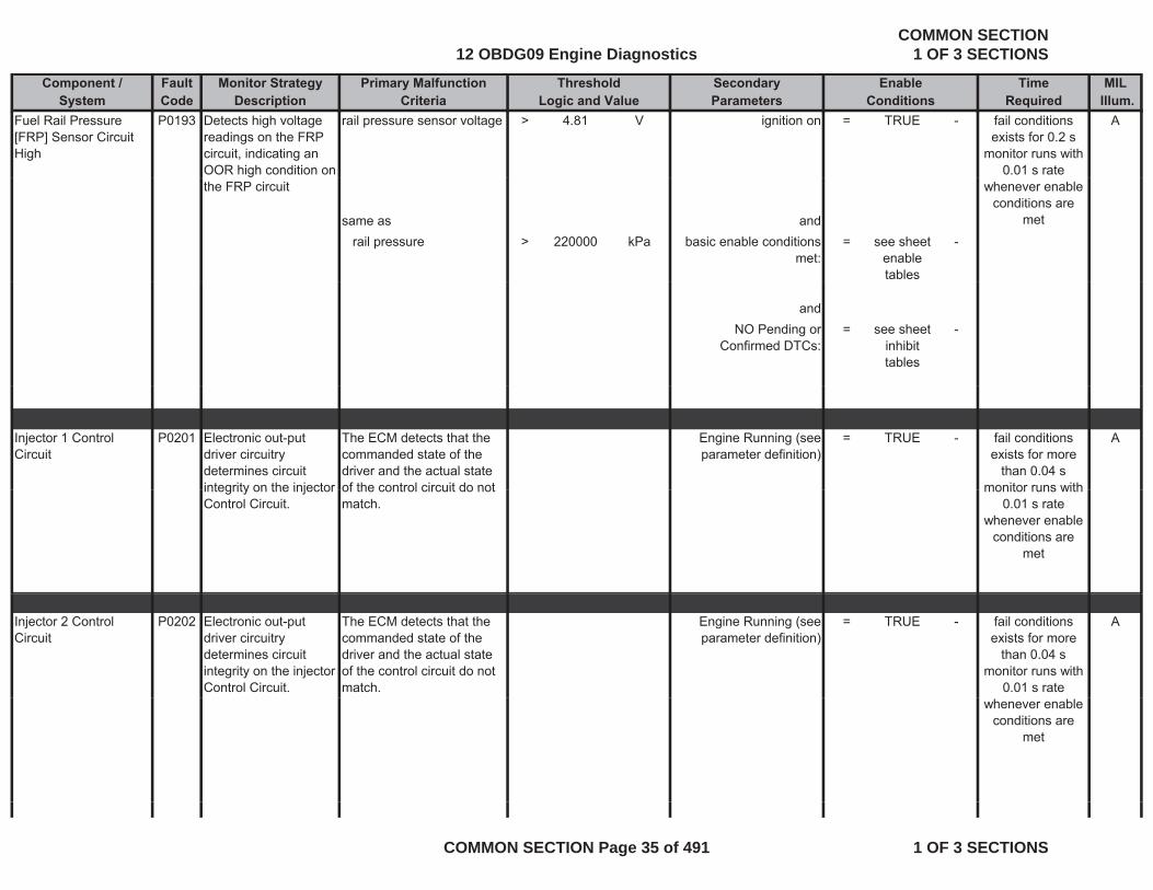
Fuel Rail Pressure [FRP] Sensor Circuit High
P0193 Detects high voltage readings on the FRP circuit, indicating an OOR high condition on
rail pressure sensor voltage > 4.81 V ignition on = TRUE - Afail conditions exists for 0.2 s
monitor runs with 0.01 s rate
the FRP circuit
same as andrail pressure > 220000 kPa basic enable conditions
met:= see sheet
enable tables
-
whenever enable conditions are
met
andNO Pending or
Confirmed DTCs:= see sheet
inhibit tables
-
Injector 1 Control Circuit
P0201 Electronic out-put driver circuitry determines circuit integrity on the injector
The ECM detects that the commanded state of the driver and the actual state of the control circuit do not
Engine Running (see parameter definition)
= TRUE - Afail conditions exists for more
than 0.04 smonitor runs withintegrity on the injector
Control Circuit.of the control circuit do not match.
monitor runs with 0.01 s rate
whenever enable conditions are
met
Injector 2 Control Circuit
P0202 Electronic out-put driver circuitry determines circuit integrity on the injector Control Circuit.
The ECM detects that the commanded state of the driver and the actual state of the control circuit do not match.
Engine Running (see parameter definition)
= TRUE - Afail conditions exists for more
than 0.04 smonitor runs with
0.01 s rate whenever enable
conditions are met
12 OBDG09 Engine DiagnosticsCOMMON SECTION
1 OF 3 SECTIONS
COMMON SECTION Page 35 of 491 1 OF 3 SECTIONS

Component / Fault Monitor Strategy Primary Malfunction Secondary Time MILSystem Code Description Criteria Parameters Required Illum.
Threshold EnableLogic and Value Conditions
Injector 3 Control Circuit
P0203 Electronic out-put driver circuitry determines circuit
The ECM detects that the commanded state of the driver and the actual state
Engine Running (see parameter definition)
= TRUE - A
determines circuit integrity on the injector Control Circuit.
driver and the actual state of the control circuit do not match.
fail conditions exists for more
than 0.04 smonitor runs with
0.01 s rate whenever enable
di i
Injector 4 Control P0204 Electronic out put The ECM detects that the Engine Running (see TRUE A
conditions are met
Injector 4 Control Circuit
P0204 Electronic out-put driver circuitry determines circuit integrity on the injector Control Circuit.
The ECM detects that the commanded state of the driver and the actual state of the control circuit do not match.
Engine Running (see parameter definition)
= TRUE - A
fail conditions exists for more
than 0.04 smonitor runs with
0.01 s rate whenever enable
conditions are met
Injector 5 Control Circuit
P0205 Electronic out-put driver circuitry determines circuit integrity on the injector Control Circ it
The ECM detects that the commanded state of the driver and the actual state of the control circuit do not match
Engine Running (see parameter definition)
= TRUE - A
fail conditions exists for more
Control Circuit. match. than 0.04 smonitor runs with
0.01 s rate whenever enable
conditions are met
12 OBDG09 Engine DiagnosticsCOMMON SECTION
1 OF 3 SECTIONS
COMMON SECTION Page 36 of 491 1 OF 3 SECTIONS
Component / Fault Monitor Strategy Primary Malfunction Secondary Time MILSystem Code Description Criteria Parameters Required Illum.
Threshold EnableLogic and Value Conditions
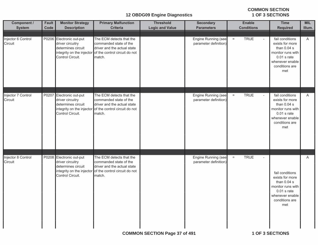
Injector 6 Control Circuit
P0206 Electronic out-put driver circuitry determines circuit
The ECM detects that the commanded state of the driver and the actual state
Engine Running (see parameter definition)
= TRUE - Afail conditions exists for more
than 0 04 sdetermines circuit integrity on the injector Control Circuit.
driver and the actual state of the control circuit do not match.
than 0.04 smonitor runs with
0.01 s rate whenever enable
conditions are met
Injector 7 Control Circuit
P0207 Electronic out-put driver circuitry determines circuit
The ECM detects that the commanded state of the driver and the actual state
Engine Running (see parameter definition)
= TRUE - Afail conditions exists for more
than 0.04 sintegrity on the injector Control Circuit.
of the control circuit do not match.
monitor runs with 0.01 s rate
whenever enable conditions are
met
Injector 8 Control Circuit
P0208 Electronic out-put driver circuitry
The ECM detects that the commanded state of the
Engine Running (see parameter definition)
= TRUE - Ay
determines circuit integrity on the injector Control Circuit.
driver and the actual state of the control circuit do not match.
p )
fail conditions exists for more
than 0.04 smonitor runs with
0.01 s rate0.01 s rate whenever enable
conditions are met
12 OBDG09 Engine DiagnosticsCOMMON SECTION
1 OF 3 SECTIONS
COMMON SECTION Page 37 of 491 1 OF 3 SECTIONS
Component / Fault Monitor Strategy Primary Malfunction Secondary Time MILSystem Code Description Criteria Parameters Required Illum.
Threshold EnableLogic and Value Conditions
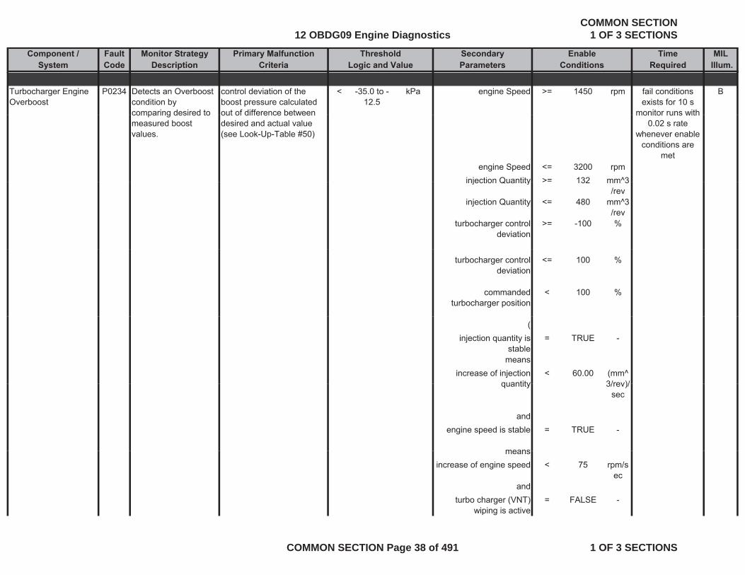
Turbocharger Engine Overboost
P0234 Detects an Overboost condition by comparing desired to
control deviation of the boost pressure calculated out of difference between
< -35.0 to -12.5
kPa engine Speed >= 1450 rpm Bfail conditions exists for 10 s
monitor runs withcomparing desired to measured boost values.
out of difference between desired and actual value (see Look-Up-Table #50)
engine Speed <= 3200 rpminjection Quantity >= 132 mm^3
monitor runs with 0.02 s rate
whenever enable conditions are
met
injection Quantity > 132 mm 3/rev
injection Quantity <= 480 mm^3/rev
turbocharger control deviation
>= -100 %
turbocharger control deviation
<= 100 %
commanded turbocharger position
< 100 %
(injection quantity is
stable= TRUE -
meansincrease of injection
quantity< 60.00 (mm^
3/rev)/quantity 3/rev)/sec
andengine speed is stable = TRUE -
meansmeansincrease of engine speed < 75 rpm/s
ecand
turbo charger (VNT) wiping is active
= FALSE -
12 OBDG09 Engine DiagnosticsCOMMON SECTION
1 OF 3 SECTIONS
COMMON SECTION Page 38 of 491 1 OF 3 SECTIONS
Component / Fault Monitor Strategy Primary Malfunction Secondary Time MILSystem Code Description Criteria Parameters Required Illum.
Threshold EnableLogic and Value Conditions
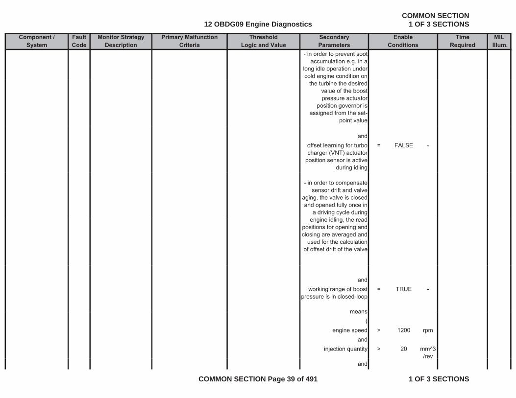
- in order to prevent soot accumulation e.g. in a
long idle operation under cold engine condition on
the turbine the desired value of the boost pressure actuator
position governor is assigned from the set-
point value
andoffset learning for turbo charger (VNT) actuator
position sensor is active during idling
= FALSE -
- in order to compensate sensor drift and valve
aging, the valve is closed and opened fully once in
a driving cycle during engine idling the readengine idling, the read
positions for opening and closing are averaged and
used for the calculation of offset drift of the valve
andworking range of boost
pressure is in closed-loop= TRUE -
meansmeans(
engine speed > 1200 rpmand
injection quantity > 20 mm^3/rev
and
12 OBDG09 Engine DiagnosticsCOMMON SECTION
1 OF 3 SECTIONS
COMMON SECTION Page 39 of 491 1 OF 3 SECTIONS
Component / Fault Monitor Strategy Primary Malfunction Secondary Time MILSystem Code Description Criteria Parameters Required Illum.
Threshold EnableLogic and Value Conditions
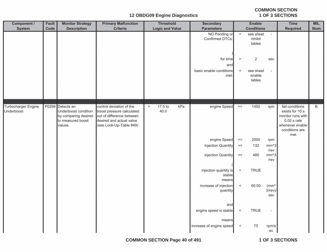
NO Pending or Confirmed DTCs:
= see sheet inhibit tables
-
)for time > 2 sec
andbasic enable conditions
met:= see sheet
enable tables
-
tables
Turbocharger Engine P0299 Detects an control deviation of the > 17.5 to kPa engine Speed >= 1450 rpm Bfail conditions Underboost Underboost condition
by comparing desired to measured boost values.
boost pressure calculated out of difference between desired and actual value (see Look-Up-Table #49)
40.0
i S d 2000
exists for 10 s monitor runs with
0.02 s rate whenever enable
conditions are met
engine Speed <= 2000 rpminjection Quantity >= 132 mm^3
/revinjection Quantity <= 480 mm^3
/rev(
injection quantity is stable
= TRUE
meansincrease of injection
quantity< 60.00 (mm^
3/rev)/sec
andengine speed is stable = TRUE -
meansincrease of engine speed < 75 rpm/sincrease of engine speed 75 rpm/s
ec
12 OBDG09 Engine DiagnosticsCOMMON SECTION
1 OF 3 SECTIONS
COMMON SECTION Page 40 of 491 1 OF 3 SECTIONS
Component / Fault Monitor Strategy Primary Malfunction Secondary Time MILSystem Code Description Criteria Parameters Required Illum.
Threshold EnableLogic and Value Conditions
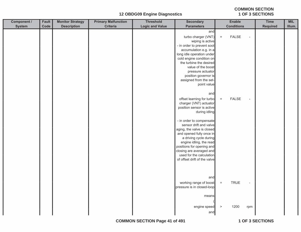
andturbo charger (VNT)
wiping is active = FALSE -
- in order to prevent soot in order to prevent soot accumulation e.g. in a
long idle operation under cold engine condition on
the turbine the desired value of the boost pressure actuator
position governor is assigned from the set-
point value
andoffset learning for turbo = FALSE -gcharger (VNT) actuator
position sensor is active during idling
- in order to compensate sensor drift and valve
aging, the valve is closed and opened fully once in
a driving cycle during engine idling, the read
positions for opening and closing are averaged and
used for the calculationused for the calculation of offset drift of the valve
andki f b t TRUEworking range of boost
pressure is in closed-loop= TRUE -
means(
engine speed > 1200 rpmand
12 OBDG09 Engine DiagnosticsCOMMON SECTION
1 OF 3 SECTIONS
COMMON SECTION Page 41 of 491 1 OF 3 SECTIONS
Component / Fault Monitor Strategy Primary Malfunction Secondary Time MILSystem Code Description Criteria Parameters Required Illum.
Threshold EnableLogic and Value Conditions
injection quantity > 20 mm^3/rev
andNO Pending or = see sheet -NO Pending or
Confirmed DTCs:see sheet
inhibit tables
)for time > 2 sec
andandbasic enable conditions
met:= see sheet
enable tables
-
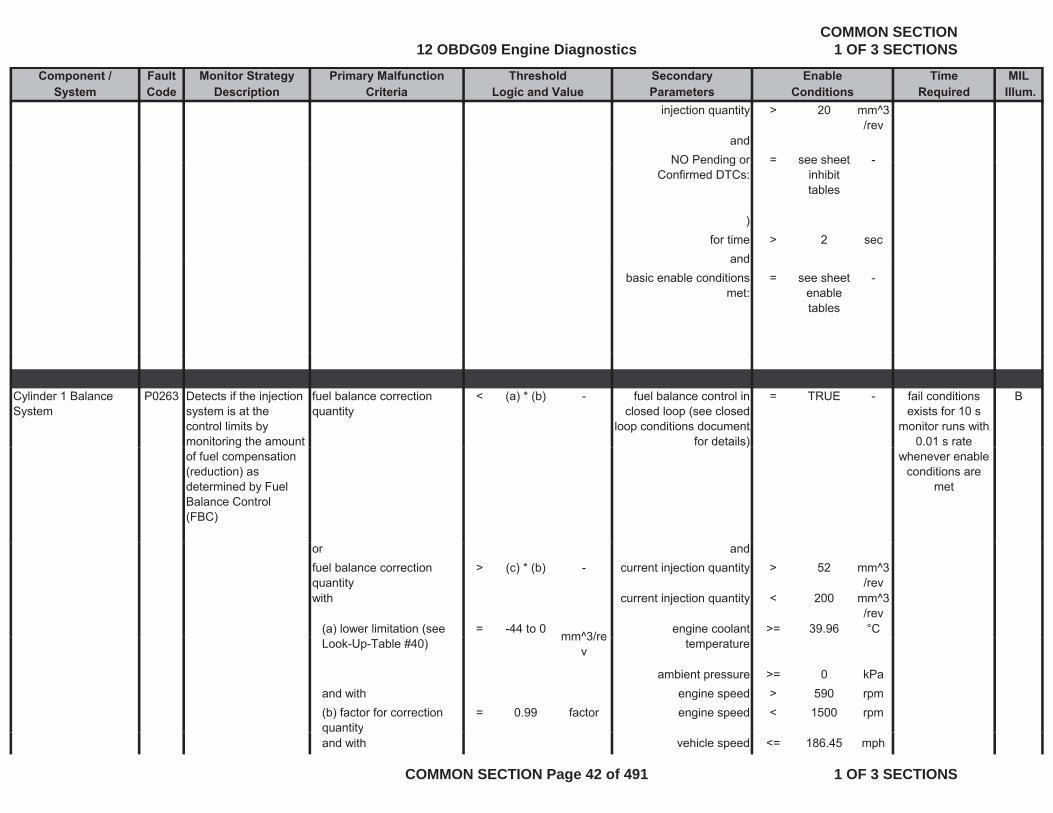
Cylinder 1 Balance System
P0263 Detects if the injection system is at the control limits by monitoring the amount
fuel balance correction quantity
< (a) * (b) - fuel balance control in closed loop (see closed
loop conditions document for details)
= TRUE - Bfail conditions exists for 10 s
monitor runs with 0.01 s rate g
of fuel compensation (reduction) as determined by Fuel Balance Control (FBC)
)whenever enable
conditions are met
or andfuel balance correction quantity
> (c) * (b) - current injection quantity > 52 mm^3/rev
with current injection quantity < 200 mm^3/rev
(a) lower limitation (see = -44 to 0 mm^3/re engine coolant >= 39.96 °CLook-Up-Table #40) mm 3/re
v temperature
ambient pressure >= 0 kPaand with engine speed > 590 rpm(b) factor for correction quantity
= 0.99 factor engine speed < 1500 rpmq yand with vehicle speed <= 186.45 mph
12 OBDG09 Engine DiagnosticsCOMMON SECTION
1 OF 3 SECTIONS
COMMON SECTION Page 42 of 491 1 OF 3 SECTIONS

Component / Fault Monitor Strategy Primary Malfunction Secondary Time MILSystem Code Description Criteria Parameters Required Illum.
Threshold EnableLogic and Value Conditions
(c) upper limitation (see Look-Up-Table #41)
= 0 to 44 mm^3/rev
and
basic enable conditions = see sheet -met: enable
tables
andNO Pending or
Confirmed DTCs:= see sheet
inhibit -
tables
Cylinder 2 Balance P0266 Detects if the injection fuel balance correction < (a) * (b) fuel balance control in = TRUE Bfail conditionsCylinder 2 Balance System
P0266 Detects if the injection system is at the control limits by monitoring the amount of fuel compensation (reduction) as determined by Fuel
fuel balance correction quantity
< (a) * (b) - fuel balance control in closed loop (see closed
loop conditions document for details)
= TRUE - Bfail conditions exists for 10 s
monitor runs with 0.01 s rate
whenever enable conditions are
metdetermined by Fuel Balance Control (FBC)
or andfuel balance correction quantity
> (c) * (b) - current injection quantity > 52 mm^3/rev
met
quantity /revwith current injection quantity < 200 mm^3
/rev(a) lower limitation (see Look-Up-Table #40)
= -44 to 0 mm^3/rev
engine coolant temperature
>= 39.96 °C
ambient pressure >= 0 kPapand with engine speed > 590 rpm(b) factor for correction quantity
= 0.99 factor engine speed < 1500 rpm
and with vehicle speed <= 186.45 mph(c) upper limitation (see L k U T bl #41)
= 0 to 44 mm^3/re andLook-Up-Table #41) v
12 OBDG09 Engine DiagnosticsCOMMON SECTION
1 OF 3 SECTIONS
COMMON SECTION Page 43 of 491 1 OF 3 SECTIONS
Component / Fault Monitor Strategy Primary Malfunction Secondary Time MILSystem Code Description Criteria Parameters Required Illum.
Threshold EnableLogic and Value Conditions
basic enable conditions met:
= see sheet enable tables
-
andNO Pending or
Confirmed DTCs:= see sheet
inhibit tables
-
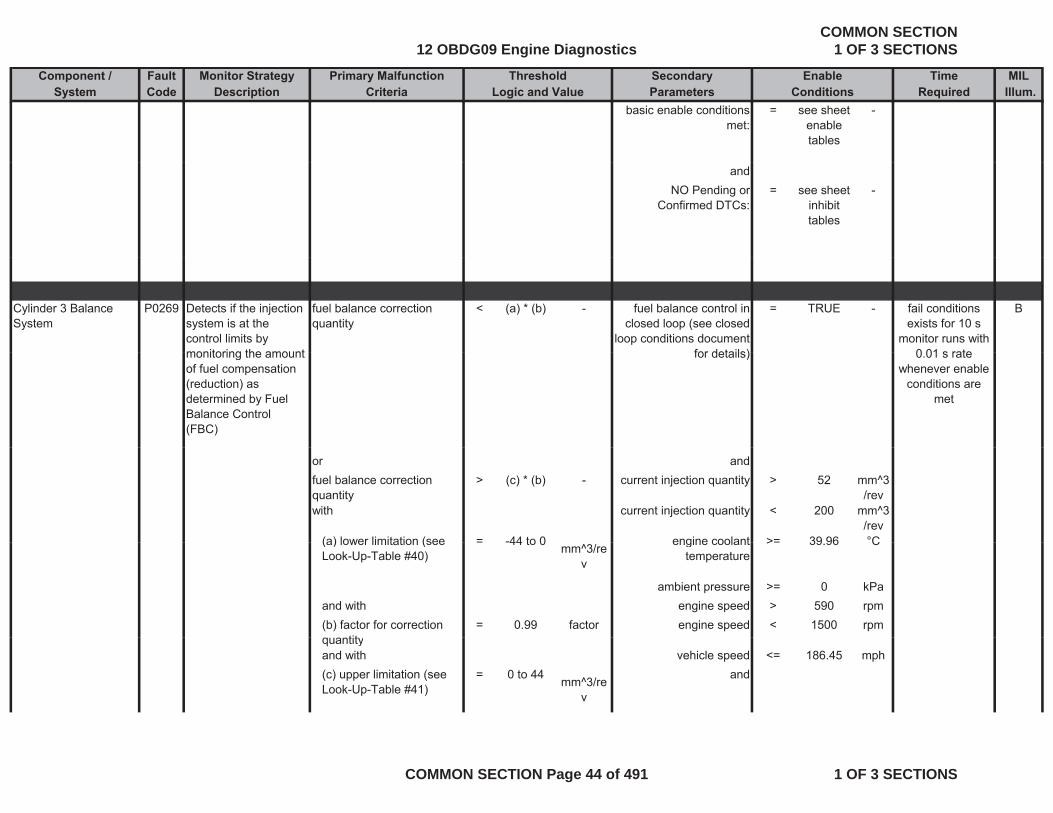
Cylinder 3 Balance System
P0269 Detects if the injection system is at the control limits by monitoring the amount
fuel balance correction quantity
< (a) * (b) - fuel balance control in closed loop (see closed
loop conditions document for details)
= TRUE - Bfail conditions exists for 10 s
monitor runs with 0 01 s ratemonitoring the amount
of fuel compensation (reduction) as determined by Fuel Balance Control (FBC)
for details) 0.01 s rate whenever enable
conditions are met
or andfuel balance correction quantity
> (c) * (b) - current injection quantity > 52 mm^3/rev
with current injection quantity < 200 mm^3/rev
(a) lower limitation (see = -44 to 0 engine coolant >= 39 96 °C(a) lower limitation (see Look-Up-Table #40)
= -44 to 0 mm^3/rev
engine coolant temperature
>= 39.96 C
ambient pressure >= 0 kPaand with engine speed > 590 rpm(b) factor for correction
tit= 0.99 factor engine speed < 1500 rpm
quantityand with vehicle speed <= 186.45 mph(c) upper limitation (see Look-Up-Table #41)
= 0 to 44 mm^3/rev
and
12 OBDG09 Engine DiagnosticsCOMMON SECTION
1 OF 3 SECTIONS
COMMON SECTION Page 44 of 491 1 OF 3 SECTIONS
Component / Fault Monitor Strategy Primary Malfunction Secondary Time MILSystem Code Description Criteria Parameters Required Illum.
Threshold EnableLogic and Value Conditions
basic enable conditions met:
= see sheet enable tables
-
andNO Pending or
Confirmed DTCs:= see sheet
inhibit tables
-
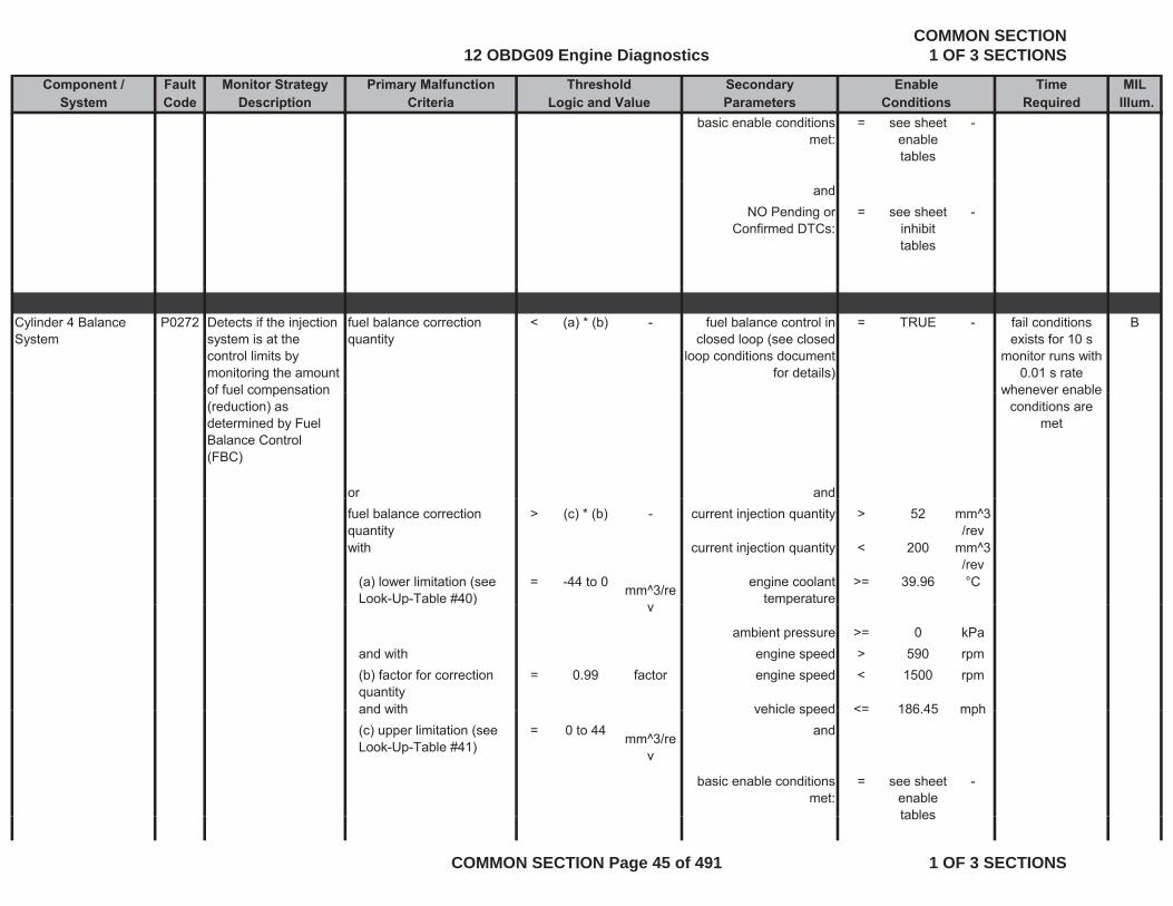
Cylinder 4 Balance System
P0272 Detects if the injection system is at the control limits by monitoring the amount of fuel compensation
fuel balance correction quantity
< (a) * (b) - fuel balance control in closed loop (see closed
loop conditions document for details)
= TRUE - Bfail conditions exists for 10 s
monitor runs with 0.01 s rate
whenever enableof fuel compensation (reduction) as determined by Fuel Balance Control (FBC)
or and
whenever enable conditions are
met
fuel balance correction quantity
> (c) * (b) - current injection quantity > 52 mm^3/rev
with current injection quantity < 200 mm^3/rev
(a) lower limitation (see Look-Up-Table #40)
= -44 to 0 mm^3/re engine coolant temperature
>= 39.96 °Cp ) v p
ambient pressure >= 0 kPaand with engine speed > 590 rpm(b) factor for correction quantity
= 0.99 factor engine speed < 1500 rpm
and with vehicle speed <= 186 45 mphand with vehicle speed <= 186.45 mph(c) upper limitation (see Look-Up-Table #41)
= 0 to 44 mm^3/rev
and
basic enable conditions met:
= see sheet enable tables
-
tables
12 OBDG09 Engine DiagnosticsCOMMON SECTION
1 OF 3 SECTIONS
COMMON SECTION Page 45 of 491 1 OF 3 SECTIONS
Component / Fault Monitor Strategy Primary Malfunction Secondary Time MILSystem Code Description Criteria Parameters Required Illum.
Threshold EnableLogic and Value Conditions
andNO Pending or
Confirmed DTCs:= see sheet
inhibit tables
-
tables
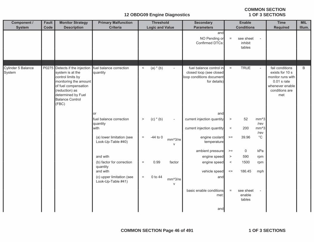
Cylinder 5 Balance System
P0275 Detects if the injection system is at the control limits by
fuel balance correction quantity
< (a) * (b) - fuel balance control in closed loop (see closed
loop conditions document
= TRUE - Bfail conditions exists for 10 s
monitor runs withcontrol limits by monitoring the amount of fuel compensation (reduction) as determined by Fuel Balance Control (FBC)
loop conditions document for details)
monitor runs with 0.01 s rate
whenever enable conditions are
met
(FBC)
or andfuel balance correction quantity
> (c) * (b) - current injection quantity > 52 mm^3/rev
with current injection quantity < 200 mm^3/rev/rev
(a) lower limitation (see Look-Up-Table #40)
= -44 to 0 mm^3/rev
engine coolant temperature
>= 39.96 °C
ambient pressure >= 0 kPaand with engine speed > 590 rpm(b) f t f ti 0 99 f t i d < 1500(b) factor for correction quantity
= 0.99 factor engine speed < 1500 rpm
and with vehicle speed <= 186.45 mph(c) upper limitation (see Look-Up-Table #41)
= 0 to 44 mm^3/rev
and
b i bl diti h tbasic enable conditions met:
= see sheet enable tables
-
and
12 OBDG09 Engine DiagnosticsCOMMON SECTION
1 OF 3 SECTIONS
COMMON SECTION Page 46 of 491 1 OF 3 SECTIONS
Component / Fault Monitor Strategy Primary Malfunction Secondary Time MILSystem Code Description Criteria Parameters Required Illum.
Threshold EnableLogic and Value Conditions
NO Pending or Confirmed DTCs:
= see sheet inhibit tables
-
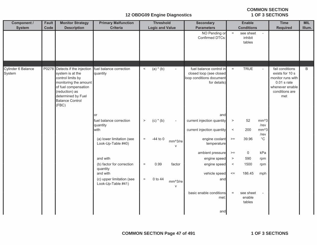
Cylinder 6 Balance System
P0278 Detects if the injection system is at the control limits by
fuel balance correction quantity
< (a) * (b) - fuel balance control in closed loop (see closed
loop conditions document
= TRUE - Bfail conditions exists for 10 s
monitor runs withcontrol limits by monitoring the amount of fuel compensation (reduction) as determined by Fuel Balance Control (FBC)
loop conditions document for details)
monitor runs with 0.01 s rate
whenever enable conditions are
met
(FBC)
or andfuel balance correction quantity
> (c) * (b) - current injection quantity > 52 mm^3/rev
with current injection quantity < 200 mm^3/rev/rev
(a) lower limitation (see Look-Up-Table #40)
= -44 to 0 mm^3/rev
engine coolant temperature
>= 39.96 °C
ambient pressure >= 0 kPaand with engine speed > 590 rpm(b) f t f ti 0 99 f t i d < 1500(b) factor for correction quantity
= 0.99 factor engine speed < 1500 rpm
and with vehicle speed <= 186.45 mph(c) upper limitation (see Look-Up-Table #41)
= 0 to 44 mm^3/rev
and
b i bl diti h tbasic enable conditions met:
= see sheet enable tables
-
and
12 OBDG09 Engine DiagnosticsCOMMON SECTION
1 OF 3 SECTIONS
COMMON SECTION Page 47 of 491 1 OF 3 SECTIONS

Component / Fault Monitor Strategy Primary Malfunction Secondary Time MILSystem Code Description Criteria Parameters Required Illum.
Threshold EnableLogic and Value Conditions
NO Pending or Confirmed DTCs:
= see sheet inhibit tables
-
Cylinder 7 Balance System
P0281 Detects if the injection system is at the control limits by
fuel balance correction quantity
< (a) * (b) - fuel balance control in closed loop (see closed
loop conditions document
= TRUE - Bfail conditions exists for 10 s
monitor runs withcontrol limits by monitoring the amount of fuel compensation (reduction) as determined by Fuel Balance Control (FBC)
loop conditions document for details)
monitor runs with 0.01 s rate
whenever enable conditions are
met
(FBC)
or andfuel balance correction quantity
> (c) * (b) - current injection quantity > 52 mm^3/rev
with current injection quantity < 200 mm^3/rev/rev
(a) lower limitation (see Look-Up-Table #40)
= -44 to 0 mm^3/rev
engine coolant temperature
>= 39.96 °C
ambient pressure >= 0 kPaand with engine speed > 590 rpm(b) f t f ti 0 99 f t i d < 1500(b) factor for correction quantity
= 0.99 factor engine speed < 1500 rpm
and with vehicle speed <= 186.45 mph(c) upper limitation (see Look-Up-Table #41)
= 0 to 44 mm^3/rev
and
b i bl diti h tbasic enable conditions met:
= see sheet enable tables
-
and
12 OBDG09 Engine DiagnosticsCOMMON SECTION
1 OF 3 SECTIONS
COMMON SECTION Page 48 of 491 1 OF 3 SECTIONS

Component / Fault Monitor Strategy Primary Malfunction Secondary Time MILSystem Code Description Criteria Parameters Required Illum.
Threshold EnableLogic and Value Conditions
NO Pending or Confirmed DTCs:
= see sheet inhibit tables
-
Cylinder 8 Balance System
P0284 Detects if the injection system is at the control limits by
fuel balance correction quantity
< (a) * (b) - fuel balance control in closed loop (see closed
loop conditions document
= TRUE - Bfail conditions exists for 10 s
monitor runs withcontrol limits by monitoring the amount of fuel compensation (reduction) as determined by Fuel Balance Control (FBC)
loop conditions document for details)
monitor runs with 0.01 s rate
whenever enable conditions are
met
(FBC)
or andfuel balance correction quantity
> (c) * (b) - current injection quantity > 52 mm^3/rev
with current injection quantity < 200 mm^3/rev/rev
(a) lower limitation (see Look-Up-Table #40)
= -44 to 0 mm^3/rev
engine coolant temperature
>= 39.96 °C
ambient pressure >= 0 kPaand with engine speed > 590 rpm(b) f t f ti 0 99 f t i d < 1500(b) factor for correction quantity
= 0.99 factor engine speed < 1500 rpm
and with vehicle speed <= 186.45 mph(c) upper limitation (see Look-Up-Table #41)
= 0 to 44 mm^3/rev
and
b i bl diti h tbasic enable conditions met:
= see sheet enable tables
-
and
12 OBDG09 Engine DiagnosticsCOMMON SECTION
1 OF 3 SECTIONS
COMMON SECTION Page 49 of 491 1 OF 3 SECTIONS
Component / Fault Monitor Strategy Primary Malfunction Secondary Time MILSystem Code Description Criteria Parameters Required Illum.
Threshold EnableLogic and Value Conditions
NO Pending or Confirmed DTCs:
= see sheet inhibit tables
-
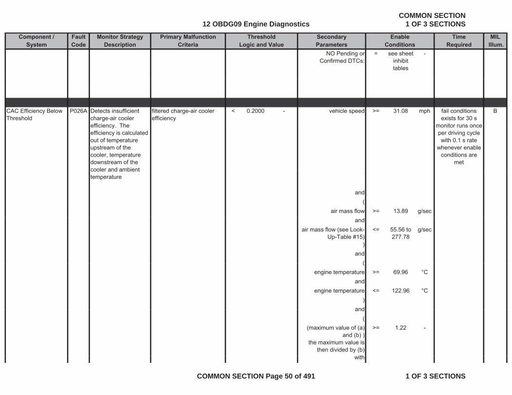
CAC Efficiency Below Threshold
P026A Detects insufficient charge-air cooler efficiency The
filtered charge-air cooler efficiency
< 0.2000 - vehicle speed >= 31.08 mph Bfail conditions exists for 30 s
monitor runs onceefficiency. The efficiency is calculated out of temperature upstream of the cooler, temperature downstream of the cooler and ambient
monitor runs once per driving cycle with 0.1 s rate
whenever enable conditions are
metcooler and ambient temperature
and(
air mass flow >= 13.89 g/secand
air mass flow (see Look-Up-Table #15)
<= 55.56 to 277.78
g/sec
)and
((engine temperature >= 69.96 °C
andengine temperature <= 122.96 °C
)andand
((maximum value of (a)
and (b) ) the maximum value is
then divided by (b)
>= 1.22 -
ithwith
12 OBDG09 Engine DiagnosticsCOMMON SECTION
1 OF 3 SECTIONS
COMMON SECTION Page 50 of 491 1 OF 3 SECTIONS
Component / Fault Monitor Strategy Primary Malfunction Secondary Time MILSystem Code Description Criteria Parameters Required Illum.
Threshold EnableLogic and Value Conditions
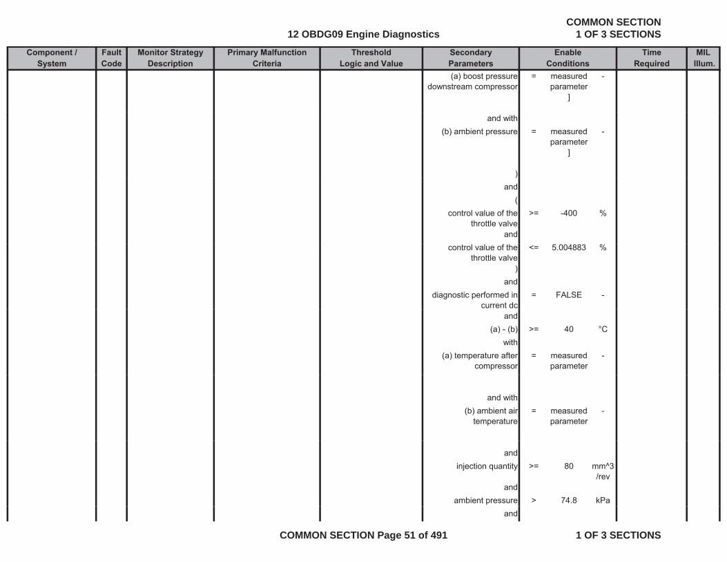
(a) boost pressure downstream compressor
= measured parameter
]
-
and with(b) ambient pressure = measured
parameter]
-
))and
(control value of the
throttle valve>= -400 %
andcontrol value of the
throttle valve<= 5.004883 %
)and
diagnostic performed in current dc
= FALSE -
and(a) - (b) >= 40 °C
with(a) temperature after
compressor= measured
parameter-
and with(b) ambient air
temperature= measured
parameter-
andinjection quantity >= 80 mm^3
/revand
ambient pressure > 74.8 kPaand
12 OBDG09 Engine DiagnosticsCOMMON SECTION
1 OF 3 SECTIONS
COMMON SECTION Page 51 of 491 1 OF 3 SECTIONS
Component / Fault Monitor Strategy Primary Malfunction Secondary Time MILSystem Code Description Criteria Parameters Required Illum.
Threshold EnableLogic and Value Conditions
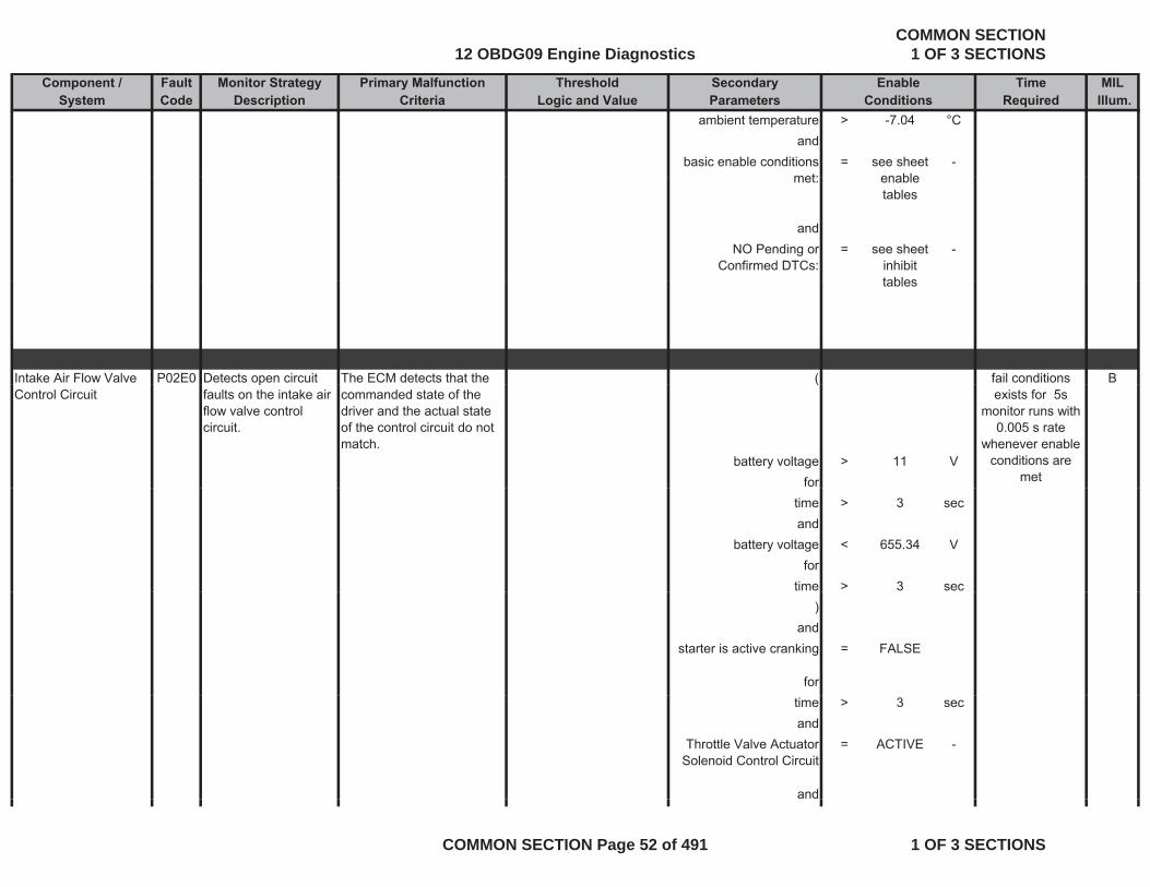
ambient temperature > -7.04 °Cand
basic enable conditions met:
= see sheet enable
-met: enable
tables
andNO Pending or
Confirmed DTCs:= see sheet
inhibit tables
-
tables
Intake Air Flow Valve P02E0 Detects open circuit The ECM detects that the ( Bfail conditions Control Circuit
pfaults on the intake air flow valve control circuit.
commanded state of the driver and the actual state of the control circuit do not match.
(
battery voltage > 11 Vfor
exists for 5s monitor runs with
0.005 s rate whenever enable
conditions are met
time > 3 secand
battery voltage < 655.34 Vfor
time > 3 sec)
andstarter is active cranking = FALSE
fortime > 3 secand
Throttle Valve Actuator Solenoid Control Circuit
= ACTIVE -
and
12 OBDG09 Engine DiagnosticsCOMMON SECTION
1 OF 3 SECTIONS
COMMON SECTION Page 52 of 491 1 OF 3 SECTIONS
Component / Fault Monitor Strategy Primary Malfunction Secondary Time MILSystem Code Description Criteria Parameters Required Illum.
Threshold EnableLogic and Value Conditions
basic enable conditions met:
= see sheet enable tables
-
andNO Pending or
Confirmed DTCs:= see sheet
inhibit tables
-
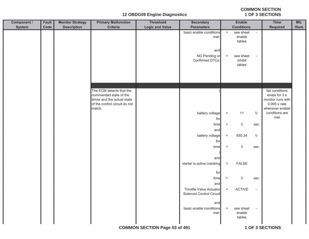
The ECM detects that the commanded state of the driver and the actual state of the control circuit do not
( fail conditions exists for 3 s
monitor runs with 0 005 s rateof the control circuit do not
match.battery voltage > 11 V
fortime > 3 secand
0.005 s rate whenever enable
conditions are met
battery voltage < 655.34 Vfor
time > 3 sec)
andstarter is active cranking = FALSE
fortime > 3 secand
Throttle Valve Actuator Solenoid Control Circuit
= ACTIVE -
andbasic enable conditions
met:= see sheet
enable -
tables
12 OBDG09 Engine DiagnosticsCOMMON SECTION
1 OF 3 SECTIONS
COMMON SECTION Page 53 of 491 1 OF 3 SECTIONS

Component / Fault Monitor Strategy Primary Malfunction Secondary Time MILSystem Code Description Criteria Parameters Required Illum.
Threshold EnableLogic and Value Conditions
andNO Pending or
Confirmed DTCs:= see sheet
inhibit tables
-
tables
The ECM detects that the ( fail conditions commanded state of the driver and the actual state of the control circuit do not match.
battery voltage > 11 Vfor
exists for 3 smonitor runs with
0.005 s rate whenever enable
conditions are met
time > 3 secand
battery voltage < 655.34 Vfor
time > 3 sec)
andstarter is active cranking = FALSE
forti > 3time > 3 secand
Throttle Valve Actuator Solenoid Control Circuit
= ACTIVE -
andbasic enable conditions
met:= see sheet
enable tables
-
and
12 OBDG09 Engine DiagnosticsCOMMON SECTION
1 OF 3 SECTIONS
COMMON SECTION Page 54 of 491 1 OF 3 SECTIONS
Component / Fault Monitor Strategy Primary Malfunction Secondary Time MILSystem Code Description Criteria Parameters Required Illum.
Threshold EnableLogic and Value Conditions
NO Pending or Confirmed DTCs:
= see sheet inhibit tables
-
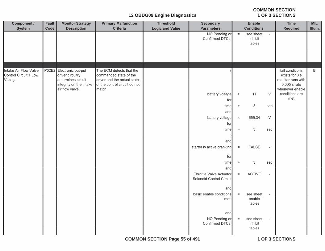
Intake Air Flow Valve Control Circuit 1 Low Voltage
P02E2 Electronic out-put driver circuitry determines circuit
The ECM detects that the commanded state of the driver and the actual state
( Bfail conditions exists for 3 s
monitor runs withVoltage determines circuit integrity on the intake air flow valve.
driver and the actual state of the control circuit do not match.
battery voltage > 11 Vfor
time > 3 sec
monitor runs with 0.005 s rate
whenever enable conditions are
met
andbattery voltage < 655.34 V
fortime > 3 sec
)and
starter is active cranking = FALSE -
fortime > 3 sec
dandThrottle Valve Actuator
Solenoid Control Circuit= ACTIVE -
andbasic enable conditions = see sheet -
met: enable tables
andNO Pending or
Confirmed DTCs:= see sheet
inhibit -
tables
12 OBDG09 Engine DiagnosticsCOMMON SECTION
1 OF 3 SECTIONS
COMMON SECTION Page 55 of 491 1 OF 3 SECTIONS
Component / Fault Monitor Strategy Primary Malfunction Secondary Time MILSystem Code Description Criteria Parameters Required Illum.
Threshold EnableLogic and Value Conditions
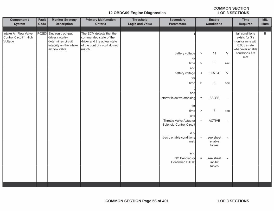
Intake Air Flow Valve Control Circuit 1 High Voltage
P02E3 Electronic out-put driver circuitry determines circuit
The ECM detects that the commanded state of the driver and the actual state
( Bfail conditions exists for 3 s
monitor runs withVoltage determines circuit integrity on the intake air flow valve.
driver and the actual state of the control circuit do not match.
battery voltage > 11 Vfor
time > 3 sec
monitor runs with 0.005 s rate
whenever enable conditions are
met
andbattery voltage < 655.34 V
fortime > 3 sec
)and
starter is active cranking = FALSE -
fortime > 3 secandand
Throttle Valve Actuator Solenoid Control Circuit
= ACTIVE -
andbasic enable conditions
t= see sheet
bl-
met: enable tables
andNO Pending or
Confirmed DTCs:= see sheet
inhibit t bl
-
tables
12 OBDG09 Engine DiagnosticsCOMMON SECTION
1 OF 3 SECTIONS
COMMON SECTION Page 56 of 491 1 OF 3 SECTIONS
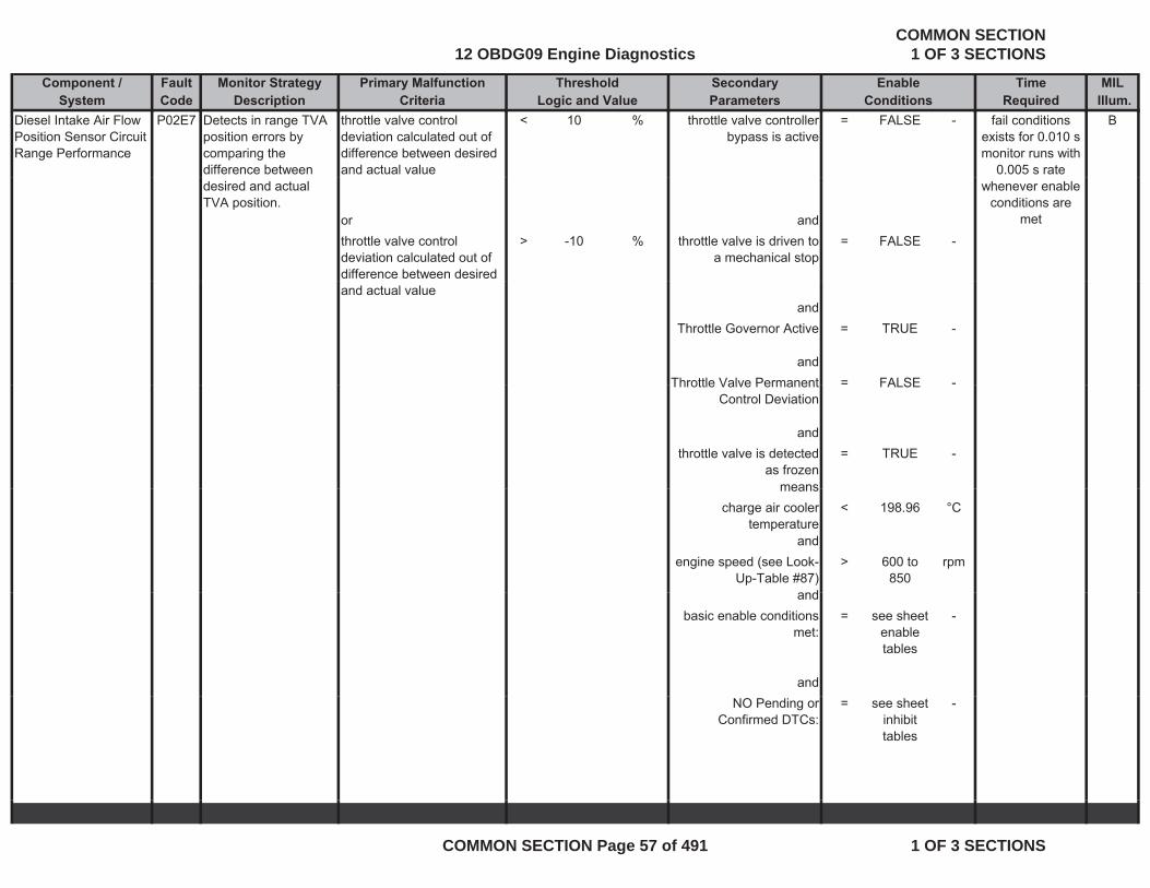
Component / Fault Monitor Strategy Primary Malfunction Secondary Time MILSystem Code Description Criteria Parameters Required Illum.
Threshold EnableLogic and Value Conditions
Diesel Intake Air Flow Position Sensor Circuit Range Performance
P02E7 Detects in range TVA position errors by comparing the difference between
throttle valve control deviation calculated out of difference between desired and actual value
< 10 % throttle valve controller bypass is active
= FALSE - fail conditions exists for 0.010 s monitor runs with
0.005 s rate
B
desired and actual TVA position.
or andthrottle valve control deviation calculated out of difference between desired
> -10 % throttle valve is driven to a mechanical stop
= FALSE -
whenever enable conditions are
met
and actual valueand
Throttle Governor Active = TRUE -
andThrottle Valve Permanent = FALSE -Throttle Valve Permanent
Control DeviationFALSE
andthrottle valve is detected
as frozen= TRUE -
meansmeanscharge air cooler
temperature< 198.96 °C
andengine speed (see Look-
Up-Table #87)> 600 to
850rpm
dandbasic enable conditions
met:= see sheet
enable tables
-
andNO Pending or
Confirmed DTCs:= see sheet
inhibit tables
-
12 OBDG09 Engine DiagnosticsCOMMON SECTION
1 OF 3 SECTIONS
COMMON SECTION Page 57 of 491 1 OF 3 SECTIONS
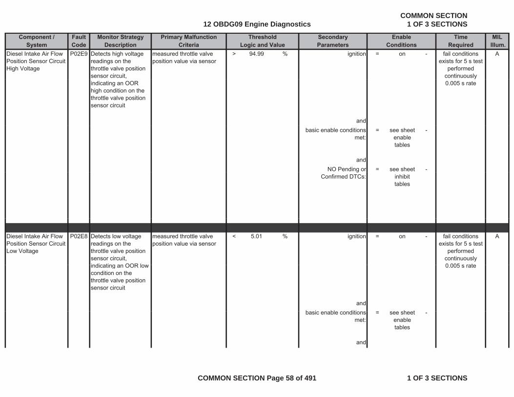
Component / Fault Monitor Strategy Primary Malfunction Secondary Time MILSystem Code Description Criteria Parameters Required Illum.
Threshold EnableLogic and Value Conditions
Diesel Intake Air Flow Position Sensor Circuit High Voltage
P02E9 Detects high voltage readings on the throttle valve position sensor circuit,
measured throttle valve position value via sensor
> 94.99 % ignition = on - Afail conditions exists for 5 s test
performed continuously
indicating an OOR high condition on the throttle valve position sensor circuit
and
0.005 s rate
basic enable conditions met:
= see sheet enable tables
-
andNO Pending or = see sheet -g
Confirmed DTCs: inhibit tables
Diesel Intake Air Flow Position Sensor Circuit Low Voltage
P02E8 Detects low voltage readings on the throttle valve position sensor circuit, indicating an OOR low
measured throttle valve position value via sensor
< 5.01 % ignition = on - Afail conditions exists for 5 s test
performed continuously 0 005 s rateindicating an OOR low
condition on the throttle valve position sensor circuit
andb i bl diti h t
0.005 s rate
basic enable conditions met:
= see sheet enable tables
-
and
12 OBDG09 Engine DiagnosticsCOMMON SECTION
1 OF 3 SECTIONS
COMMON SECTION Page 58 of 491 1 OF 3 SECTIONS
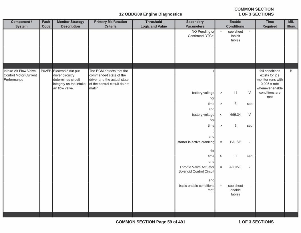
Component / Fault Monitor Strategy Primary Malfunction Secondary Time MILSystem Code Description Criteria Parameters Required Illum.
Threshold EnableLogic and Value Conditions
NO Pending or Confirmed DTCs:
= see sheet inhibit tables
-
Intake Air Flow Valve P02EB Electronic out-put The ECM detects that the ( Bfail conditions Control Motor Current Performance
driver circuitry determines circuit integrity on the intake air flow valve.
commanded state of the driver and the actual state of the control circuit do not match.
battery voltage > 11 Vfor
exists for 2 smonitor runs with
0.005 s rate whenever enable
conditions are met
time > 3 secand
battery voltage < 655.34 Vfor
time > 3 sec)
andstarter is active cranking = FALSE -
forti > 3time > 3 secand
Throttle Valve Actuator Solenoid Control Circuit
= ACTIVE -
andbasic enable conditions
met:= see sheet
enable tables
-
12 OBDG09 Engine DiagnosticsCOMMON SECTION
1 OF 3 SECTIONS
COMMON SECTION Page 59 of 491 1 OF 3 SECTIONS

Component / Fault Monitor Strategy Primary Malfunction Secondary Time MILSystem Code Description Criteria Parameters Required Illum.
Threshold EnableLogic and Value Conditions
Engine Misfire Detected
P0300 Indicates engine has experienced more than one cylinder misfiring
angular acceleration of the crankshaft
< -1.3999 - ( Bfail conditions exists for 0.02 s
monitor runs with 0.02 s rate
and Engine Running (see parameter definition)
= TRUE -
evaluated crankshaft revolutions
>= (a) * (b) - and
with engine speed > 400 rpm(a) number of crankshaft = 20 revs and
whenever enable conditions are
met
( )revolutions per block
and with engine speed < 1300 rpm(b) number of test blocks = 20 counts )
and andmisfires exist on more than one cylinder
= TRUE - |(a) - (b)| < 200 rpm
with(a) actual desired idle
speed= calculated
parameter-
and with(b) engine speed = measured
parameter-
and(
current injection quantity > 20 mm^3/rev
andcurrent injection quantity < 400 mm^3
/rev )
andengine coolant
temperature>= 39.96 °C
pand
12 OBDG09 Engine DiagnosticsCOMMON SECTION
1 OF 3 SECTIONS
COMMON SECTION Page 60 of 491 1 OF 3 SECTIONS
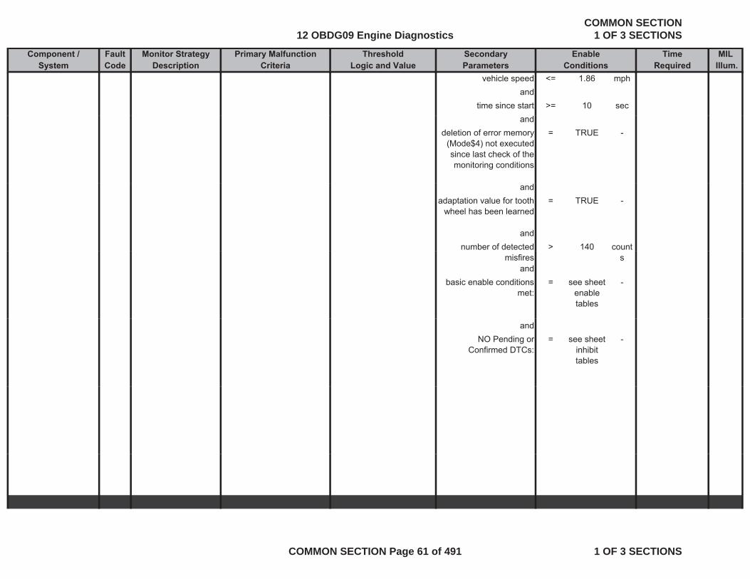
Component / Fault Monitor Strategy Primary Malfunction Secondary Time MILSystem Code Description Criteria Parameters Required Illum.
Threshold EnableLogic and Value Conditions
vehicle speed <= 1.86 mphand
time since start >= 10 secand
deletion of error memory (Mode$4) not executed since last check of the monitoring conditions
= TRUE -
andadaptation value for tooth
wheel has been learned= TRUE -
andnumber of detected > 140 count
misfires sand
basic enable conditions met:
= see sheet enable tables
-
andNO Pending or
Confirmed DTCs:= see sheet
inhibit tables
-
12 OBDG09 Engine DiagnosticsCOMMON SECTION
1 OF 3 SECTIONS
COMMON SECTION Page 61 of 491 1 OF 3 SECTIONS
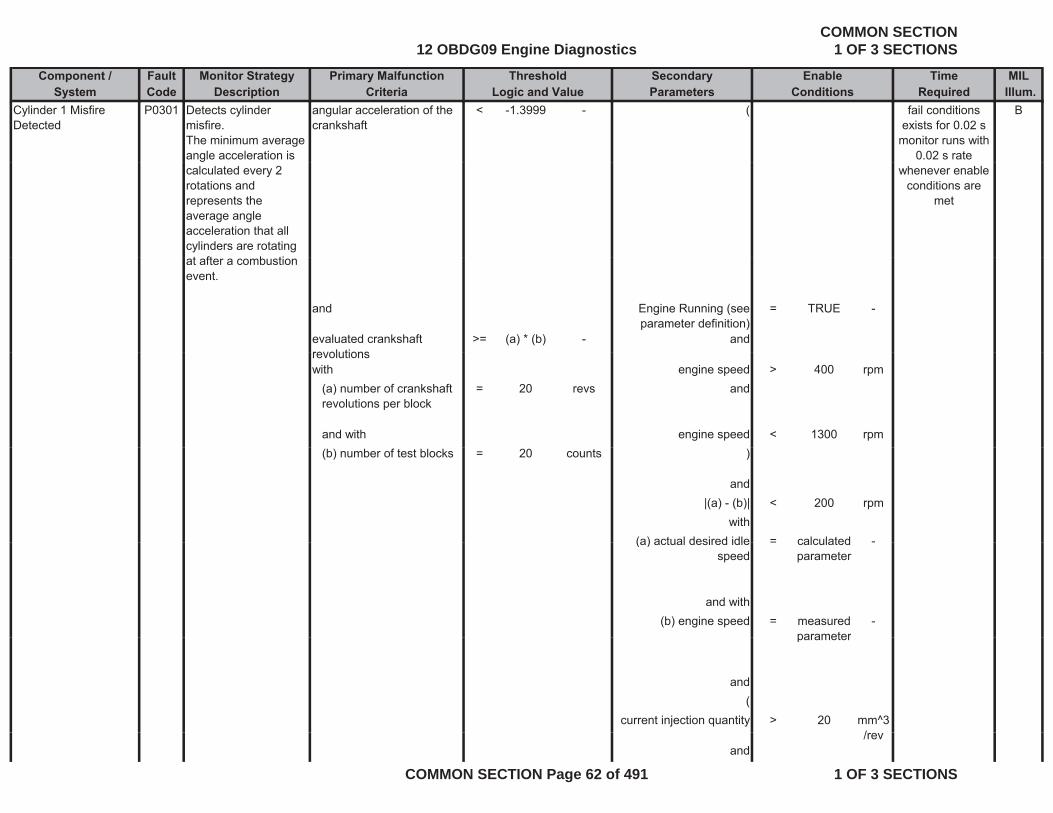
Component / Fault Monitor Strategy Primary Malfunction Secondary Time MILSystem Code Description Criteria Parameters Required Illum.
Threshold EnableLogic and Value Conditions
Cylinder 1 Misfire Detected
P0301 Detects cylinder misfire.The minimum average angle acceleration is
angular acceleration of the crankshaft
< -1.3999 - ( Bfail conditions exists for 0.02 s
monitor runs with 0.02 s rate
calculated every 2 rotations and represents the average angle acceleration that all cylinders are rotating t ft b ti
whenever enable conditions are
met
at after a combustion event.
and Engine Running (see parameter definition)
= TRUE -
evaluated crankshaft revolutions
>= (a) * (b) - andrevolutionswith engine speed > 400 rpm
(a) number of crankshaft revolutions per block
= 20 revs and
and with engine speed < 1300 rpm(b) number of test blocks = 20 counts )
and|(a) - (b)| < 200 rpm
with(a) actual desired idle = calculated -(a) actual desired idle
speed= calculated
parameter-
and with(b) engine speed = measured
parameter-
parameter
and(
current injection quantity > 20 mm^3//rev
and
12 OBDG09 Engine DiagnosticsCOMMON SECTION
1 OF 3 SECTIONS
COMMON SECTION Page 62 of 491 1 OF 3 SECTIONS
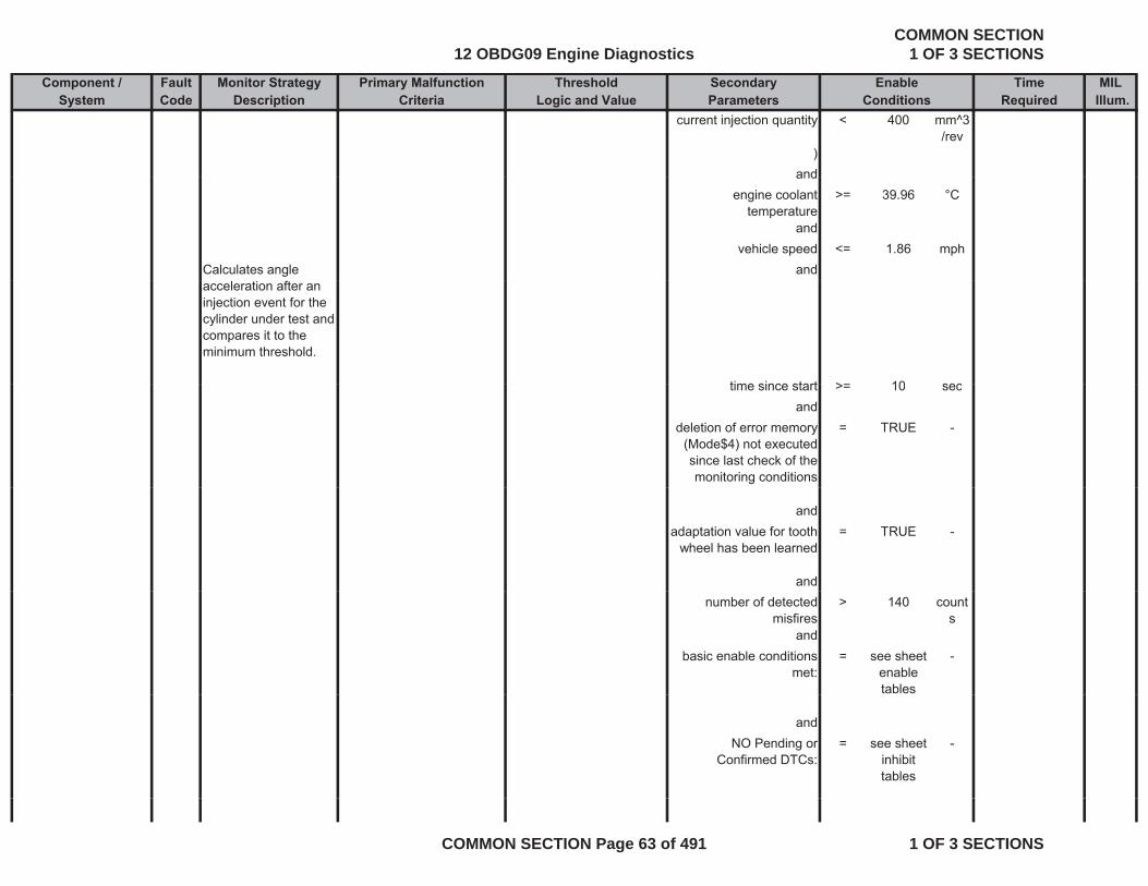
Component / Fault Monitor Strategy Primary Malfunction Secondary Time MILSystem Code Description Criteria Parameters Required Illum.
Threshold EnableLogic and Value Conditions
current injection quantity < 400 mm^3/rev
)andand
engine coolant temperature
>= 39.96 °C
andvehicle speed <= 1.86 mph
Calculates angle andacceleration after an injection event for the cylinder under test and compares it to the minimum threshold.
time since start >= 10 sectime since start >= 10 secand
deletion of error memory (Mode$4) not executed since last check of the monitoring conditions
= TRUE -
andadaptation value for tooth
wheel has been learned= TRUE -
andnumber of detected
misfires> 140 count
sand
basic enable conditions met:
= see sheet enable tables
-
andNO Pending or
Confirmed DTCs:= see sheet
inhibit tables
-
12 OBDG09 Engine DiagnosticsCOMMON SECTION
1 OF 3 SECTIONS
COMMON SECTION Page 63 of 491 1 OF 3 SECTIONS

Component / Fault Monitor Strategy Primary Malfunction Secondary Time MILSystem Code Description Criteria Parameters Required Illum.
Threshold EnableLogic and Value Conditions
Cylinder 2 Misfire Detected
P0302 Detects cylinder misfire.The minimum average
angular acceleration of the crankshaft
< -1.3999 - ( Bfail conditions exists for 0.02 s
monitor runs withThe minimum average angle acceleration is calculated every 2 rotations and represents the average angle acceleration that all
monitor runs with 0.02 s rate
whenever enable conditions are
met
cylinders are rotating at after a combustion event.
and Engine Running (see parameter definition)
= TRUE -
evaluated crankshaft revolutions
>= (a) * (b) - and
with engine speed > 400 rpm(a) number of crankshaft revolutions per block
= 20 revs and
and with engine speed < 1300 rpm(b) number of test blocks = 20 counts )
and|(a) - (b)| < 200 rpm
withwith(a) actual desired idle
speed= calculated
parameter-
and with(b) i d d(b) engine speed = measured
parameter-
and(
current injection quantity > 20 mm^3/rev
12 OBDG09 Engine DiagnosticsCOMMON SECTION
1 OF 3 SECTIONS
COMMON SECTION Page 64 of 491 1 OF 3 SECTIONS

Component / Fault Monitor Strategy Primary Malfunction Secondary Time MILSystem Code Description Criteria Parameters Required Illum.
Threshold EnableLogic and Value Conditions
andcurrent injection quantity < 400 mm^3
/rev ))
andengine coolant
temperature>= 39.96 °C
andvehicle speed <= 1.86 mph
Calculates angle acceleration after an injection event for the cylinder under test and compares it to the minimum threshold.
and
time since start >= 10 secand
deletion of error memory (Mode$4) not executed since last check of the
= TRUE -
monitoring conditions
andadaptation value for tooth
wheel has been learned= TRUE -
andnumber of detected
misfires> 140 count
sand
basic enable conditions met:
= see sheet enable
-met: enable
tables
andNO Pending or
Confirmed DTCs:= see sheet
inhibit tables
-
tables
12 OBDG09 Engine DiagnosticsCOMMON SECTION
1 OF 3 SECTIONS
COMMON SECTION Page 65 of 491 1 OF 3 SECTIONS

Component / Fault Monitor Strategy Primary Malfunction Secondary Time MILSystem Code Description Criteria Parameters Required Illum.
Threshold EnableLogic and Value Conditions
Cylinder 7 Misfire Detected
P0307 Detects cylinder misfire.The minimum average
angular acceleration of the crankshaft
< -1.3999 - ( Bfail conditions exists for 0.02 s
monitor runs withThe minimum average angle acceleration is calculated every 2 rotations and represents the average angle acceleration that all
monitor runs with 0.02 s rate
whenever enable conditions are
met
cylinders are rotating at after a combustion event.
and Engine Running (see parameter definition)
= TRUE -
evaluated crankshaft revolutions
>= (a) * (b) - and
with engine speed > 400 rpm(a) number of crankshaft revolutions per block
= 20 revs and
and with engine speed < 1300 rpm(b) number of test blocks = 20 counts )
and|(a) - (b)| < 200 rpm
withwith(a) actual desired idle
speed= calculated
parameter-
and with(b) i d d(b) engine speed = measured
parameter-
and(
current injection quantity > 20 mm^3/rev
12 OBDG09 Engine DiagnosticsCOMMON SECTION
1 OF 3 SECTIONS
COMMON SECTION Page 66 of 491 1 OF 3 SECTIONS

Component / Fault Monitor Strategy Primary Malfunction Secondary Time MILSystem Code Description Criteria Parameters Required Illum.
Threshold EnableLogic and Value Conditions
andcurrent injection quantity < 400 mm^3
/rev ))
andengine coolant
temperature>= 39.96 °C
andvehicle speed <= 1.86 mph
Calculates angle acceleration after an injection event for the cylinder under test and compares it to the minimum threshold.
and
time since start >= 10 secand
deletion of error memory (Mode$4) not executed since last check of the
= TRUE -
monitoring conditions
andadaptation value for tooth
wheel has been learned= TRUE -
andnumber of detected
misfires> 140 count
sand
basic enable conditions met:
= see sheet enable
-met: enable
tables
andNO Pending or
Confirmed DTCs:= see sheet
inhibit tables
-
tables
12 OBDG09 Engine DiagnosticsCOMMON SECTION
1 OF 3 SECTIONS
COMMON SECTION Page 67 of 491 1 OF 3 SECTIONS

Component / Fault Monitor Strategy Primary Malfunction Secondary Time MILSystem Code Description Criteria Parameters Required Illum.
Threshold EnableLogic and Value Conditions
Cylinder 8 Misfire Detected
P0308 Detects cylinder misfire.The minimum average
angular acceleration of the crankshaft
< -1.3999 - ( Bfail conditions exists for 0.02 s
monitor runs withThe minimum average angle acceleration is calculated every 2 rotations and represents the average angle acceleration that all
monitor runs with 0.02 s rate
whenever enable conditions are
met
cylinders are rotating at after a combustion event.
and Engine Running (see parameter definition)
= TRUE -
evaluated crankshaft revolutions
>= (a) * (b) - and
with engine speed > 400 rpm(a) number of crankshaft revolutions per block
= 20 revs and
and with engine speed < 1300 rpm(b) number of test blocks = 20 counts )
and|(a) - (b)| < 200 rpm
withwith(a) actual desired idle
speed= calculated
parameter-
and with(b) i d d(b) engine speed = measured
parameter-
and(
current injection quantity > 20 mm^3/rev
12 OBDG09 Engine DiagnosticsCOMMON SECTION
1 OF 3 SECTIONS
COMMON SECTION Page 68 of 491 1 OF 3 SECTIONS

Component / Fault Monitor Strategy Primary Malfunction Secondary Time MILSystem Code Description Criteria Parameters Required Illum.
Threshold EnableLogic and Value Conditions
andcurrent injection quantity < 400 mm^3
/rev ))
andengine coolant
temperature>= 39.96 °C
andvehicle speed <= 1.86 mph
Calculates angle acceleration after an injection event for the cylinder under test and compares it to the minimum threshold.
and
time since start >= 10 secand
deletion of error memory (Mode$4) not executed since last check of the
= TRUE -
monitoring conditions
andadaptation value for tooth
wheel has been learned= TRUE -
andnumber of detected
misfires> 140 count
sand
basic enable conditions met:
= see sheet enable
-met: enable
tables
andNO Pending or
Confirmed DTCs:= see sheet
inhibit tables
-
tables
12 OBDG09 Engine DiagnosticsCOMMON SECTION
1 OF 3 SECTIONS
COMMON SECTION Page 69 of 491 1 OF 3 SECTIONS
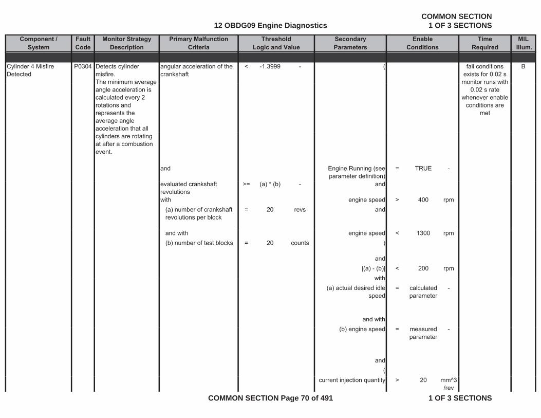
Component / Fault Monitor Strategy Primary Malfunction Secondary Time MILSystem Code Description Criteria Parameters Required Illum.
Threshold EnableLogic and Value Conditions
Cylinder 4 Misfire Detected
P0304 Detects cylinder misfire.The minimum average
angular acceleration of the crankshaft
< -1.3999 - ( Bfail conditions exists for 0.02 s
monitor runs withThe minimum average angle acceleration is calculated every 2 rotations and represents the average angle acceleration that all
monitor runs with 0.02 s rate
whenever enable conditions are
met
cylinders are rotating at after a combustion event.
and Engine Running (see parameter definition)
= TRUE -
evaluated crankshaft revolutions
>= (a) * (b) - and
with engine speed > 400 rpm(a) number of crankshaft revolutions per block
= 20 revs and
and with engine speed < 1300 rpm(b) number of test blocks = 20 counts )
and|(a) - (b)| < 200 rpm
withwith(a) actual desired idle
speed= calculated
parameter-
and with(b) i d d(b) engine speed = measured
parameter-
and(
current injection quantity > 20 mm^3/rev
12 OBDG09 Engine DiagnosticsCOMMON SECTION
1 OF 3 SECTIONS
COMMON SECTION Page 70 of 491 1 OF 3 SECTIONS

Component / Fault Monitor Strategy Primary Malfunction Secondary Time MILSystem Code Description Criteria Parameters Required Illum.
Threshold EnableLogic and Value Conditions
andcurrent injection quantity < 400 mm^3
/rev ))
andengine coolant
temperature>= 39.96 °C
andvehicle speed <= 1.86 mph
Calculates angle acceleration after an injection event for the cylinder under test and compares it to the minimum threshold.
and
time since start >= 10 secand
deletion of error memory (Mode$4) not executed since last check of the
= TRUE -
monitoring conditions
andadaptation value for tooth
wheel has been learned= TRUE -
andnumber of detected
misfires> 140 count
sand
basic enable conditions met:
= see sheet enable
-met: enable
tables
andNO Pending or
Confirmed DTCs:= see sheet
inhibit tables
-
tables
12 OBDG09 Engine DiagnosticsCOMMON SECTION
1 OF 3 SECTIONS
COMMON SECTION Page 71 of 491 1 OF 3 SECTIONS

Component / Fault Monitor Strategy Primary Malfunction Secondary Time MILSystem Code Description Criteria Parameters Required Illum.
Threshold EnableLogic and Value Conditions
Cylinder 5 Misfire Detected
P0305 Detects cylinder misfire.The minimum average
angular acceleration of the crankshaft
< -1.3999 - ( Bfail conditions exists for 0.02 s
monitor runs withThe minimum average angle acceleration is calculated every 2 rotations and represents the average angle acceleration that all
monitor runs with 0.02 s rate
whenever enable conditions are
met
cylinders are rotating at after a combustion event.
and Engine Running (see parameter definition)
= TRUE -
evaluated crankshaft revolutions
>= (a) * (b) - and
with engine speed > 400 rpm(a) number of crankshaft revolutions per block
= 20 revs and
and with engine speed < 1300 rpm(b) number of test blocks = 20 counts )
and|(a) - (b)| < 200 rpm
withwith(a) actual desired idle
speed= calculated
parameter-
and with(b) i d d(b) engine speed = measured
parameter-
and(
current injection quantity > 20 mm^3/rev
12 OBDG09 Engine DiagnosticsCOMMON SECTION
1 OF 3 SECTIONS
COMMON SECTION Page 72 of 491 1 OF 3 SECTIONS
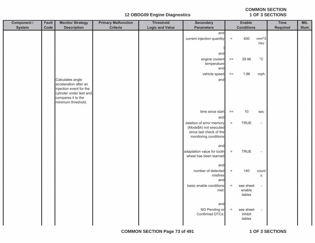
Component / Fault Monitor Strategy Primary Malfunction Secondary Time MILSystem Code Description Criteria Parameters Required Illum.
Threshold EnableLogic and Value Conditions
andcurrent injection quantity < 400 mm^3
/rev ))
andengine coolant
temperature>= 39.96 °C
andvehicle speed <= 1.86 mph
Calculates angle acceleration after an injection event for the cylinder under test and compares it to the minimum threshold.
and
time since start >= 10 secand
deletion of error memory (Mode$4) not executed since last check of the
= TRUE -
monitoring conditions
andadaptation value for tooth
wheel has been learned= TRUE -
andnumber of detected
misfires> 140 count
sand
basic enable conditions met:
= see sheet enable
-met: enable
tables
andNO Pending or
Confirmed DTCs:= see sheet
inhibit tables
-
tables
12 OBDG09 Engine DiagnosticsCOMMON SECTION
1 OF 3 SECTIONS
COMMON SECTION Page 73 of 491 1 OF 3 SECTIONS

Component / Fault Monitor Strategy Primary Malfunction Secondary Time MILSystem Code Description Criteria Parameters Required Illum.
Threshold EnableLogic and Value Conditions
Cylinder 6 Misfire Detected
P0306 Detects cylinder misfire.The minimum average
angular acceleration of the crankshaft
< -1.3999 - ( Bfail conditions exists for 0.02 s
monitor runs withThe minimum average angle acceleration is calculated every 2 rotations and represents the average angle acceleration that all
monitor runs with 0.02 s rate
whenever enable conditions are
met
cylinders are rotating at after a combustion event.
and Engine Running (see parameter definition)
= TRUE -
evaluated crankshaft revolutions
>= (a) * (b) - and
with engine speed > 400 rpm(a) number of crankshaft revolutions per block
= 20 revs and
and with engine speed < 1300 rpm(b) number of test blocks = 20 counts )
and|(a) - (b)| < 200 rpm
withwith(a) actual desired idle
speed= calculated
parameter-
and with(b) i d d(b) engine speed = measured
parameter-
and(
current injection quantity > 20 mm^3/rev
12 OBDG09 Engine DiagnosticsCOMMON SECTION
1 OF 3 SECTIONS
COMMON SECTION Page 74 of 491 1 OF 3 SECTIONS

Component / Fault Monitor Strategy Primary Malfunction Secondary Time MILSystem Code Description Criteria Parameters Required Illum.
Threshold EnableLogic and Value Conditions
andcurrent injection quantity < 400 mm^3
/rev ))
andengine coolant
temperature>= 39.96 °C
andvehicle speed <= 1.86 mph
Calculates angle acceleration after an injection event for the cylinder under test and compares it to the minimum threshold.
and
time since start >= 10 secand
deletion of error memory (Mode$4) not executed since last check of the
= TRUE -
monitoring conditions
andadaptation value for tooth
wheel has been learned= TRUE -
andnumber of detected
misfires> 140 count
sand
basic enable conditions met:
= see sheet enable
-met: enable
tables
andNO Pending or
Confirmed DTCs:= see sheet
inhibit tables
-
tables
12 OBDG09 Engine DiagnosticsCOMMON SECTION
1 OF 3 SECTIONS
COMMON SECTION Page 75 of 491 1 OF 3 SECTIONS

Component / Fault Monitor Strategy Primary Malfunction Secondary Time MILSystem Code Description Criteria Parameters Required Illum.
Threshold EnableLogic and Value Conditions
Cylinder 3 Misfire Detected
P0303 Detects cylinder misfire.The minimum average
angular acceleration of the crankshaft
< -1.3999 - ( Bfail conditions exists for 0.02 s
monitor runs withThe minimum average angle acceleration is calculated every 2 rotations and represents the average angle acceleration that all
monitor runs with 0.02 s rate
whenever enable conditions are
met
cylinders are rotating at after a combustion event.
and Engine Running (see parameter definition)
= TRUE -
evaluated crankshaft revolutions
>= (a) * (b) - and
with engine speed > 400 rpm(a) number of crankshaft revolutions per block
= 20 revs and
and with engine speed < 1300 rpm(b) number of test blocks = 20 counts )
and|(a) - (b)| < 200 rpm
withwith(a) actual desired idle
speed= calculated
parameter-
and with(b) i d d(b) engine speed = measured
parameter-
and(
current injection quantity > 20 mm^3/rev
12 OBDG09 Engine DiagnosticsCOMMON SECTION
1 OF 3 SECTIONS
COMMON SECTION Page 76 of 491 1 OF 3 SECTIONS

Component / Fault Monitor Strategy Primary Malfunction Secondary Time MILSystem Code Description Criteria Parameters Required Illum.
Threshold EnableLogic and Value Conditions
andcurrent injection quantity < 400 mm^3
/rev ))
andengine coolant
temperature>= 39.96 °C
andvehicle speed <= 1.86 mph
Calculates angle acceleration after an injection event for the cylinder under test and compares it to the minimum threshold.
and
time since start >= 10 secand
deletion of error memory (Mode$4) not executed since last check of the
= TRUE -
monitoring conditions
andadaptation value for tooth
wheel has been learned= TRUE -
andnumber of detected
misfires> 140 count
sand
basic enable conditions met:
= see sheet enable
-met: enable
tables
andNO Pending or
Confirmed DTCs:= see sheet
inhibit tables
-
tables
12 OBDG09 Engine DiagnosticsCOMMON SECTION
1 OF 3 SECTIONS
COMMON SECTION Page 77 of 491 1 OF 3 SECTIONS
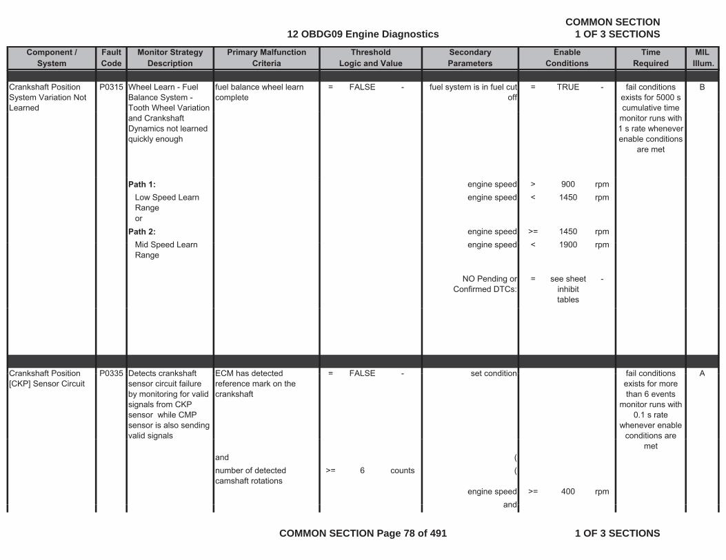
Component / Fault Monitor Strategy Primary Malfunction Secondary Time MILSystem Code Description Criteria Parameters Required Illum.
Threshold EnableLogic and Value Conditions
Crankshaft Position System Variation Not Learned
P0315 Wheel Learn - Fuel Balance System - Tooth Wheel Variation
fuel balance wheel learn complete
= FALSE - fuel system is in fuel cut off
= TRUE - Bfail conditions exists for 5000 s cumulative time
and Crankshaft Dynamics not learned quickly enough
monitor runs with 1 s rate whenever enable conditions
are met
Path 1: engine speed > 900 rpmLow Speed Learn Range
engine speed < 1450 rpm
orPath 2: engine speed >= 1450 rpm
Mid S d L i d < 1900Mid Speed Learn Range
engine speed < 1900 rpm
NO Pending or Confirmed DTCs:
= see sheet inhibit tables
-
Crankshaft Position P0335 Detects crankshaft ECM has detected = FALSE set condition Afail conditionsCrankshaft Position [CKP] Sensor Circuit
P0335 Detects crankshaft sensor circuit failure by monitoring for valid signals from CKP sensor while CMP sensor is also sending valid signals
ECM has detected reference mark on the crankshaft
= FALSE - set condition Afail conditions exists for more than 6 events
monitor runs with 0.1 s rate
whenever enable conditions are g
and (number of detected camshaft rotations
>= 6 counts (
engine speed >= 400 rpmand
met
and
12 OBDG09 Engine DiagnosticsCOMMON SECTION
1 OF 3 SECTIONS
COMMON SECTION Page 78 of 491 1 OF 3 SECTIONS
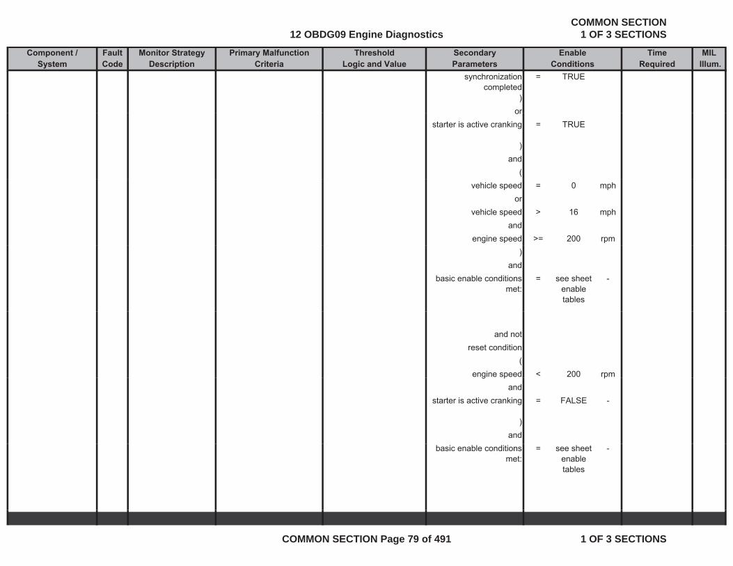
Component / Fault Monitor Strategy Primary Malfunction Secondary Time MILSystem Code Description Criteria Parameters Required Illum.
Threshold EnableLogic and Value Conditions
synchronization completed
= TRUE
)oror
starter is active cranking = TRUE
)and
(vehicle speed = 0 mph
orvehicle speed > 16 mph
andengine speed >= 200 rpm
)and
basic enable conditions met:
= see sheet enable tables
-
and notreset condition
(engine speed < 200 rpmg p p
andstarter is active cranking = FALSE -
)and
basic enable conditions met:
= see sheet enable tables
-
12 OBDG09 Engine DiagnosticsCOMMON SECTION
1 OF 3 SECTIONS
COMMON SECTION Page 79 of 491 1 OF 3 SECTIONS
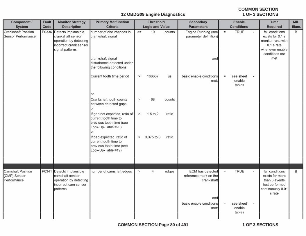
Component / Fault Monitor Strategy Primary Malfunction Secondary Time MILSystem Code Description Criteria Parameters Required Illum.
Threshold EnableLogic and Value Conditions
Crankshaft Position Sensor Performance
P0336 Detects implausible crankshaft sensor operation by detecting incorrect crank sensor
number of disturbances in crankshaft signal
>= 10 counts Engine Running (see parameter definition)
= TRUE - Bfail conditions exists for 0.1 s
monitor runs with 0.1 s rate
signal patterns.
crankshaft signal disturbance detected under the following conditions:
and
whenever enable conditions are
met
Current tooth time period > 166667 us basic enable conditions met:
= see sheet enable tables
-
orCrankshaft tooth counts > 68 countsbetween detected gapsorIf gap not expected, ratio of current tooth time to previous tooth time (see Look-Up-Table #20)
> 1.5 to 2 ratio
orIf gap expected, ratio of current tooth time to previous tooth time (see Look-Up-Table #19)
> 3.375 to 8 ratio
Camshaft Position [CMP] Sensor Performance
P0341 Detects implausible camshaft sensor operation by detecting incorrect cam sensor
number of camshaft edges > 4 edges ECM has detected reference mark on the
crankshaft
= TRUE - Bfail conditions exists for more than 6 eventstest performedincorrect cam sensor
patterns
andbasic enable conditions
met:= see sheet
enable tables
-
test performed continuously 0.01
s rate
tables
12 OBDG09 Engine DiagnosticsCOMMON SECTION
1 OF 3 SECTIONS
COMMON SECTION Page 80 of 491 1 OF 3 SECTIONS
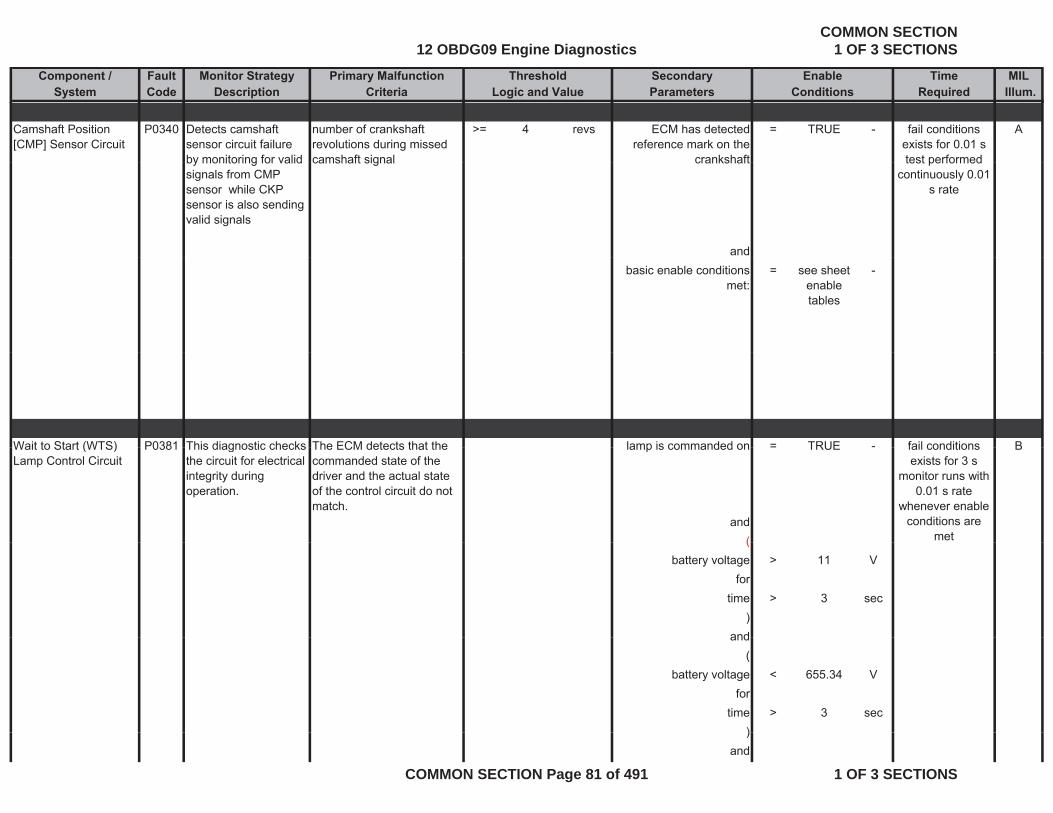
Component / Fault Monitor Strategy Primary Malfunction Secondary Time MILSystem Code Description Criteria Parameters Required Illum.
Threshold EnableLogic and Value Conditions
Camshaft Position [CMP] Sensor Circuit
P0340 Detects camshaft sensor circuit failure by monitoring for valid
number of crankshaft revolutions during missed camshaft signal
>= 4 revs ECM has detected reference mark on the
crankshaft
= TRUE - Afail conditions exists for 0.01 s test performedby monitoring for valid
signals from CMP sensor while CKP sensor is also sending valid signals
camshaft signal crankshaft
and
test performed continuously 0.01
s rate
basic enable conditions met:
= see sheet enable tables
-
Wait to Start (WTS) P0381 This diagnostic checks The ECM detects that the lamp is commanded on = TRUE - Bfail conditionsWait to Start (WTS) Lamp Control Circuit
P0381 This diagnostic checks the circuit for electrical integrity during operation.
The ECM detects that the commanded state of the driver and the actual state of the control circuit do not match.
lamp is commanded on = TRUE B
and(
fail conditions exists for 3 s
monitor runs with 0.01 s rate
whenever enable conditions are
met(battery voltage > 11 V
fortime > 3 sec
)andand
(battery voltage < 655.34 V
fortime > 3 sec
))and
12 OBDG09 Engine DiagnosticsCOMMON SECTION
1 OF 3 SECTIONS
COMMON SECTION Page 81 of 491 1 OF 3 SECTIONS
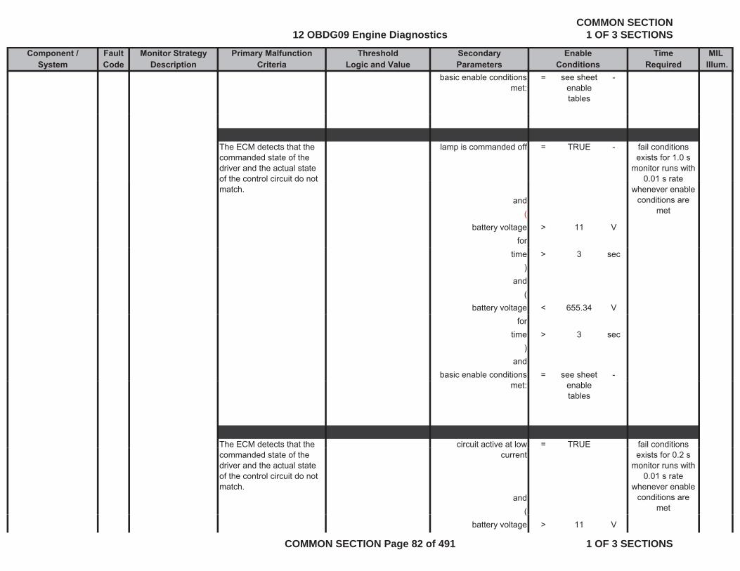
Component / Fault Monitor Strategy Primary Malfunction Secondary Time MILSystem Code Description Criteria Parameters Required Illum.
Threshold EnableLogic and Value Conditions
basic enable conditions met:
= see sheet enable tables
-
The ECM detects that the commanded state of the driver and the actual state of the control circuit do not
lamp is commanded off = TRUE - fail conditions exists for 1.0 s
monitor runs with 0 01 s rateof the control circuit do not
match.and
(battery voltage > 11 V
for
0.01 s rate whenever enable
conditions are met
time > 3 sec)
and(
battery voltage < 655.34 Vfor
time > 3 sec)
andbasic enable conditions = see sheet -
met: enable tables
The ECM detects that the circuit active at low = TRUE fail conditions commanded state of the driver and the actual state of the control circuit do not match.
current
and(
exists for 0.2 smonitor runs with
0.01 s rate whenever enable
conditions are met(
battery voltage > 11 V
12 OBDG09 Engine DiagnosticsCOMMON SECTION
1 OF 3 SECTIONS
COMMON SECTION Page 82 of 491 1 OF 3 SECTIONS
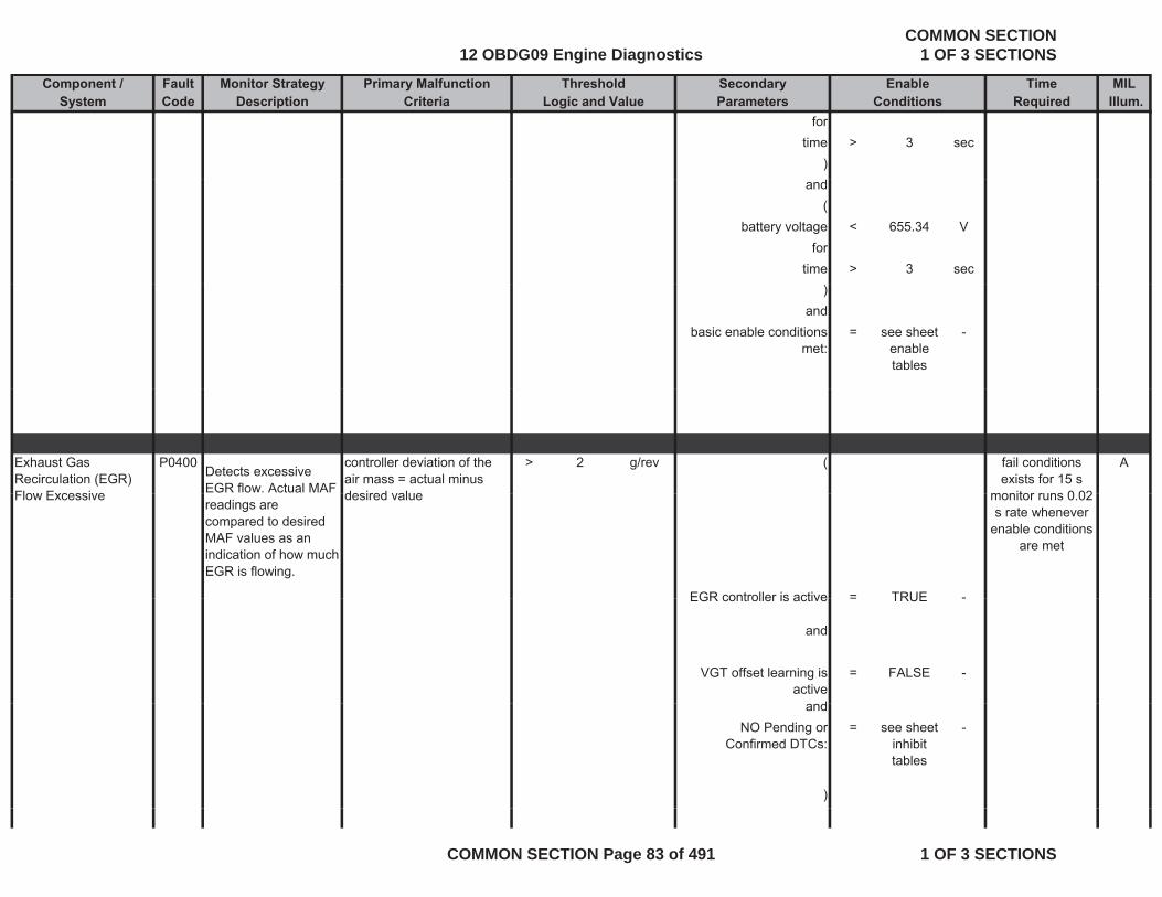
Component / Fault Monitor Strategy Primary Malfunction Secondary Time MILSystem Code Description Criteria Parameters Required Illum.
Threshold EnableLogic and Value Conditions
fortime > 3 sec
)and
(battery voltage < 655.34 V
fortime > 3 sec
)and
basic enable conditions met:
= see sheet enable tables
-
Exhaust Gas Recirculation (EGR) Flow Excessive
P0400Detects excessive EGR flow. Actual MAF
controller deviation of the air mass = actual minus desired value
> 2 g/rev ( Afail conditions exists for 15 s
monitor runs 0 02Flow Excessivereadings are compared to desired MAF values as an indication of how much EGR is flowing.
desired value
EGR controller is active = TRUE -
monitor runs 0.02 s rate whenever
enable conditions are met
EGR controller is active = TRUE -
and
VGT offset learning is active
= FALSE -
dandNO Pending or
Confirmed DTCs:= see sheet
inhibit tables
-
)
12 OBDG09 Engine DiagnosticsCOMMON SECTION
1 OF 3 SECTIONS
COMMON SECTION Page 83 of 491 1 OF 3 SECTIONS
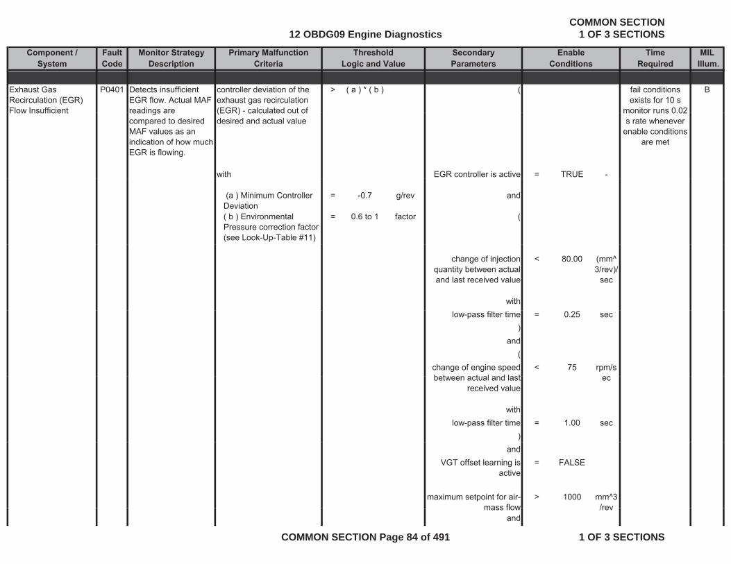
Component / Fault Monitor Strategy Primary Malfunction Secondary Time MILSystem Code Description Criteria Parameters Required Illum.
Threshold EnableLogic and Value Conditions
Exhaust Gas Recirculation (EGR) Flow Insufficient
P0401 Detects insufficient EGR flow. Actual MAF readings are
controller deviation of the exhaust gas recirculation (EGR) - calculated out of
> ( a ) * ( b ) ( Bfail conditions exists for 10 s
monitor runs 0 02Flow Insufficient readings are compared to desired MAF values as an indication of how much EGR is flowing.
(EGR) calculated out of desired and actual value
with EGR controller is active = TRUE -
monitor runs 0.02 s rate whenever
enable conditions are met
(a ) Minimum Controller Deviation
= -0.7 g/rev and
( b ) Environmental Pressure correction factor (see Look-Up-Table #11)
= 0.6 to 1 factor (
change of injection quantity between actual and last received value
< 80.00 (mm^3/rev)/
sec
withlow-pass filter time = 0.25 sec
)and
(change of engine speed b t t l d l t
< 75 rpm/sbetween actual and last
received valueec
withlow-pass filter time = 1.00 sec
)and
VGT offset learning is active
= FALSE
maximum setpoint for air-mass flow
> 1000 mm^3/revmass flow /rev
and
12 OBDG09 Engine DiagnosticsCOMMON SECTION
1 OF 3 SECTIONS
COMMON SECTION Page 84 of 491 1 OF 3 SECTIONS
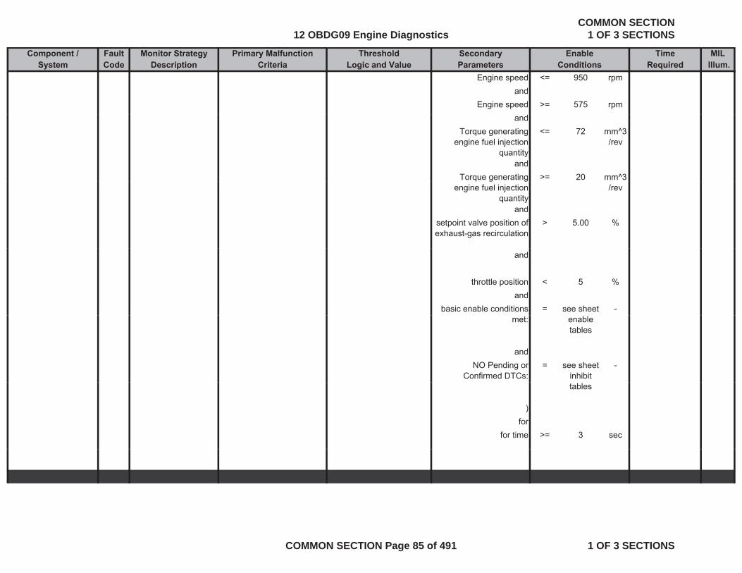
Component / Fault Monitor Strategy Primary Malfunction Secondary Time MILSystem Code Description Criteria Parameters Required Illum.
Threshold EnableLogic and Value Conditions
Engine speed <= 950 rpmand
Engine speed >= 575 rpmand
Torque generating engine fuel injection
quantity
<= 72 mm^3/rev
andTorque generating >= 20 mm^3q g g
engine fuel injection quantity
/rev
andsetpoint valve position of exhaust-gas recirculation
> 5.00 %
and
throttle position < 5 %and
basic enable conditions = see sheet -met: enable
tables
andNO Pending or
Confirmed DTCs:= see sheet
inhibit -
tables
)for
for time >= 3 sec
12 OBDG09 Engine DiagnosticsCOMMON SECTION
1 OF 3 SECTIONS
COMMON SECTION Page 85 of 491 1 OF 3 SECTIONS
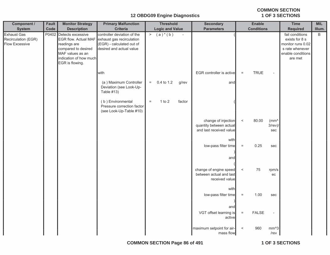
Component / Fault Monitor Strategy Primary Malfunction Secondary Time MILSystem Code Description Criteria Parameters Required Illum.
Threshold EnableLogic and Value Conditions
Exhaust Gas Recirculation (EGR) Flow Excessive
P0402 Detects excessive EGR flow. Actual MAF readings are compared to desired
controller deviation of the exhaust gas recirculation (EGR) - calculated out of desired and actual value
> ( a ) * ( b ) - ( Bfail conditions exists for 8 s
monitor runs 0.02 s rate whenever
MAF values as an indication of how much EGR is flowing.
with EGR controller is active = TRUE -
enable conditions are met
(a ) Maximum Controller Deviation (see Look-Up-Table #13)
= 0.4 to 1.2 g/rev and
( b ) Environmental Pressure correction factor (see Look Up Table #10)
= 1 to 2 factor (
(see Look-Up-Table #10)
change of injection quantity between actual and last received value
< 80.00 (mm^3/rev)/
sec
withwithlow-pass filter time = 0.25 sec
)and
(change of engine speed < 75 rpm/schange of engine speed between actual and last
received value
< 75 rpm/sec
withlow-pass filter time = 1.00 sec
))and
VGT offset learning is active
= FALSE -
maximum setpoint for air- < 960 mm^3pmass flow /rev
12 OBDG09 Engine DiagnosticsCOMMON SECTION
1 OF 3 SECTIONS
COMMON SECTION Page 86 of 491 1 OF 3 SECTIONS

Component / Fault Monitor Strategy Primary Malfunction Secondary Time MILSystem Code Description Criteria Parameters Required Illum.
Threshold EnableLogic and Value Conditions
andEngine speed <= 1700 rpm
andEngine speed >= 1150 rpm
andTorque generating
engine fuel injection quantity
<= 480 mm^3/rev
andTorque generating
engine fuel injection quantity
>= 160 mm^3/rev
andbasic enable conditions
met:= see sheet
enable-
met: enable tables
andNO Pending or
Confirmed DTCs:= see sheet
inhibit tables
-
tables
)for
for time >= 1.5 sec
Exhaust Gas Recirculation (EGR) Motor Control Circuit
P0403 Electronic out-put driver circuitry determines circuit integrity on the EGR
The ECM detects that the commanded state of the driver and the actual state of the control circuit do not
EGR Solenoid Control Circuit
= ACTIVE - Bfail conditions exists for 5 s
monitor runs with 0 005 s rateintegrity on the EGR
solenoid.of the control circuit do not match.
andoffset learning for EGR
valve is completed= TRUE -
and
0.005 s rate whenever enable
conditions are met
andengine pre drive = FALSE -
12 OBDG09 Engine DiagnosticsCOMMON SECTION
1 OF 3 SECTIONS
COMMON SECTION Page 87 of 491 1 OF 3 SECTIONS
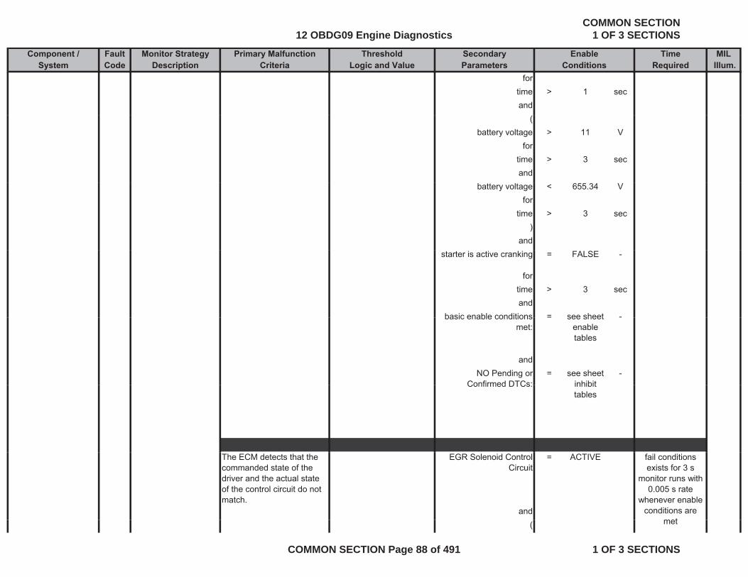
Component / Fault Monitor Strategy Primary Malfunction Secondary Time MILSystem Code Description Criteria Parameters Required Illum.
Threshold EnableLogic and Value Conditions
fortime > 1 secand
(battery voltage > 11 V
fortime > 3 secand
battery voltage < 655.34 Vfor
time > 3 sec)
andstarter is active cranking = FALSE -
fortime > 3 secand
basic enable conditions = see sheet -basic enable conditions met:
= see sheet enable tables
-
andNO Pending or
Confirmed DTCs:= see sheet
inhibit-
Confirmed DTCs: inhibit tables
The ECM detects that the commanded state of the driver and the actual state of the control circuit do not match.
EGR Solenoid Control Circuit
= ACTIVE
and
fail conditions exists for 3 s
monitor runs with 0.005 s rate
whenever enable conditions are
met( met
12 OBDG09 Engine DiagnosticsCOMMON SECTION
1 OF 3 SECTIONS
COMMON SECTION Page 88 of 491 1 OF 3 SECTIONS
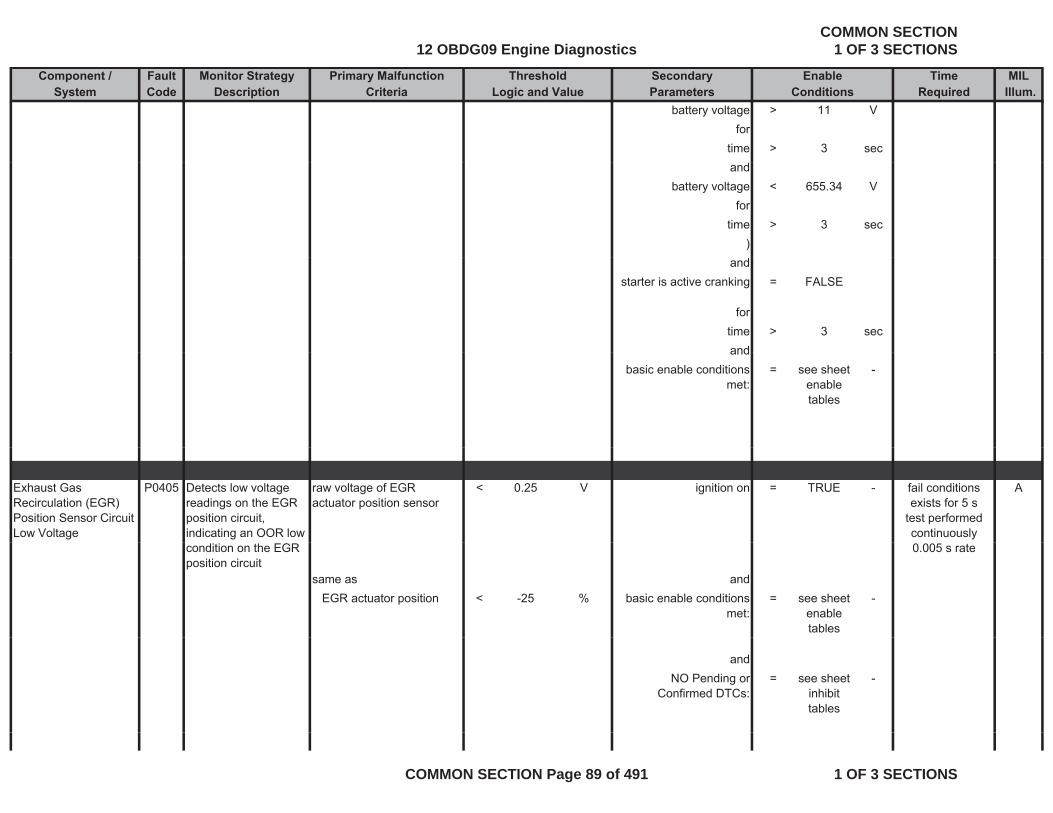
Component / Fault Monitor Strategy Primary Malfunction Secondary Time MILSystem Code Description Criteria Parameters Required Illum.
Threshold EnableLogic and Value Conditions
battery voltage > 11 Vfor
time > 3 secand
battery voltage < 655.34 Vfor
time > 3 sec)
andstarter is active cranking = FALSE
fortime > 3 secandand
basic enable conditions met:
= see sheet enable tables
-
Exhaust Gas Recirculation (EGR) Position Sensor Circuit Low Voltage
P0405 Detects low voltage readings on the EGR position circuit, indicating an OOR low
raw voltage of EGR actuator position sensor
< 0.25 V ignition on = TRUE - Afail conditions exists for 5 s
test performed continuously
condition on the EGR position circuit
same as andEGR actuator position < -25 % basic enable conditions
met:= see sheet
enable tables
-
0.005 s rate
andNO Pending or
Confirmed DTCs:= see sheet
inhibit tables
-
12 OBDG09 Engine DiagnosticsCOMMON SECTION
1 OF 3 SECTIONS
COMMON SECTION Page 89 of 491 1 OF 3 SECTIONS
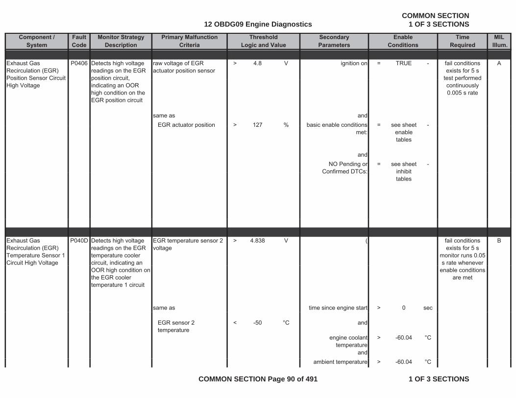
Component / Fault Monitor Strategy Primary Malfunction Secondary Time MILSystem Code Description Criteria Parameters Required Illum.
Threshold EnableLogic and Value Conditions
Exhaust Gas Recirculation (EGR) Position Sensor Circuit
P0406 Detects high voltage readings on the EGR position circuit
raw voltage of EGR actuator position sensor
> 4.8 V ignition on = TRUE - Afail conditions exists for 5 s
test performedPosition Sensor Circuit High Voltage
position circuit, indicating an OOR high condition on the EGR position circuit
same as andEGR actuator position > 127 % basic enable conditions = see sheet -
test performed continuously 0.005 s rate
EGR actuator position > 127 % basic enable conditions met:
see sheet enable tables
andNO Pending or
Confirmed DTCs:= see sheet
inhibit-
Confirmed DTCs: inhibit tables
Exhaust Gas Recirculation (EGR) Temperature Sensor 1 Circuit High Voltage
P040D Detects high voltage readings on the EGR temperature cooler circuit, indicating an
EGR temperature sensor 2 voltage
> 4.838 V ( Bfail conditions exists for 5 s
monitor runs 0.05 s rate whenever g g , g
OOR high condition on the EGR cooler temperature 1 circuit
same as time since engine start > 0 sec
enable conditions are met
EGR sensor 2 temperature
< -50 °C and
engine coolant temperature
> -60.04 °C
andambient temperature > -60.04 °C
12 OBDG09 Engine DiagnosticsCOMMON SECTION
1 OF 3 SECTIONS
COMMON SECTION Page 90 of 491 1 OF 3 SECTIONS
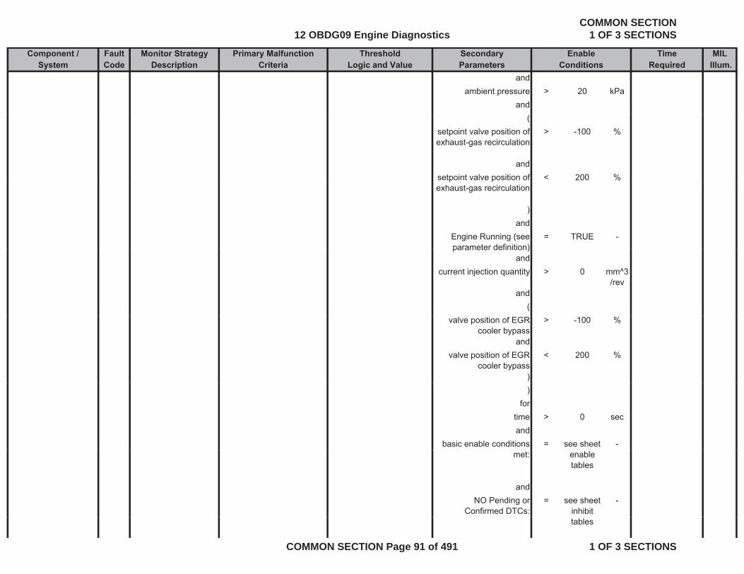
Component / Fault Monitor Strategy Primary Malfunction Secondary Time MILSystem Code Description Criteria Parameters Required Illum.
Threshold EnableLogic and Value Conditions
andambient pressure > 20 kPa
and(
setpoint valve position of exhaust-gas recirculation
> -100 %
andsetpoint valve position of < 200 %p pexhaust-gas recirculation
)and
Engine Running (see parameter definition)
= TRUE -parameter definition)
andcurrent injection quantity > 0 mm^3
/revand
(valve position of EGR
cooler bypass> -100 %
andvalve position of EGR
cooler bypass< 200 %
))
fortime > 0 secand
basic enable conditions = see sheet -met: enable
tables
andNO Pending or
Confirmed DTCs:= see sheet
inhibit -
tables
12 OBDG09 Engine DiagnosticsCOMMON SECTION
1 OF 3 SECTIONS
COMMON SECTION Page 91 of 491 1 OF 3 SECTIONS
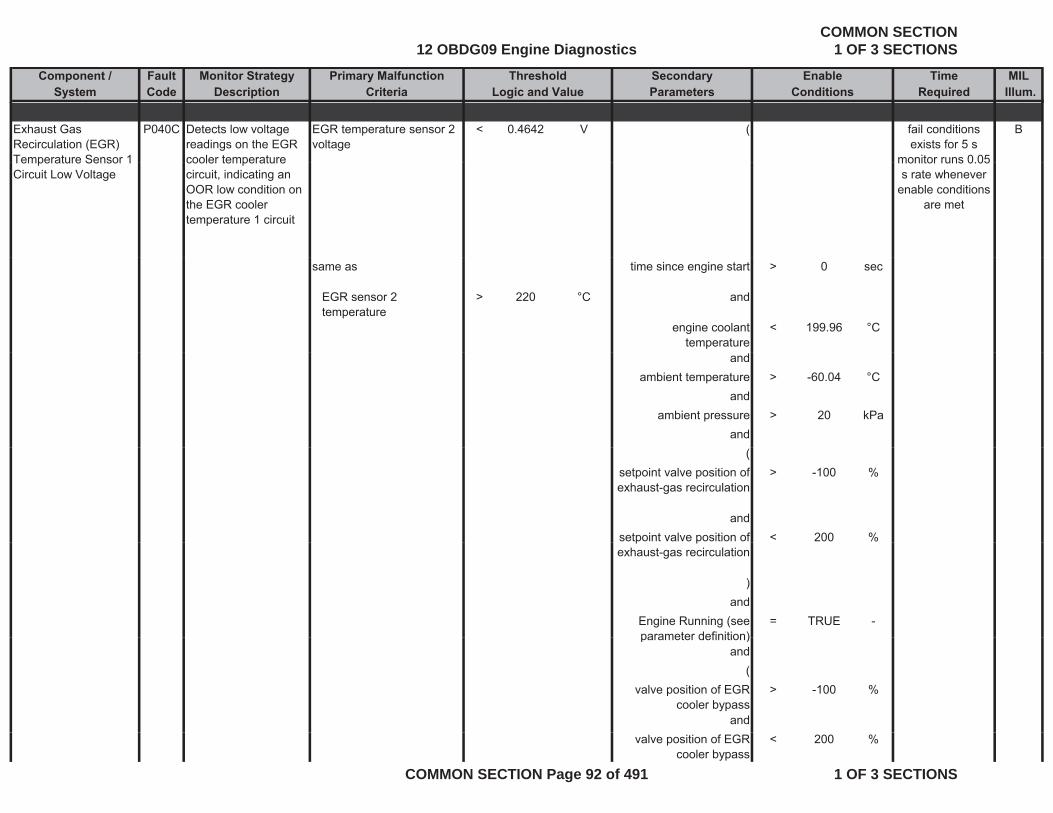
Component / Fault Monitor Strategy Primary Malfunction Secondary Time MILSystem Code Description Criteria Parameters Required Illum.
Threshold EnableLogic and Value Conditions
Exhaust Gas Recirculation (EGR) Temperature Sensor 1
P040C Detects low voltage readings on the EGR cooler temperature
EGR temperature sensor 2 voltage
< 0.4642 V ( Bfail conditions exists for 5 s
monitor runs 0 05Temperature Sensor 1 Circuit Low Voltage
cooler temperature circuit, indicating an OOR low condition on the EGR cooler temperature 1 circuit
monitor runs 0.05 s rate whenever
enable conditions are met
same as time since engine start > 0 sec
EGR sensor 2 temperature
> 220 °C and
engine coolant temperature
< 199.96 °C
andambient temperature > -60.04 °C
andambient pressure > 20 kPa
and(
setpoint valve position of exhaust-gas recirculation
> -100 %
andsetpoint valve position of < 200 %p pexhaust-gas recirculation
)and
Engine Running (see parameter definition)
= TRUE -parameter definition)
and(
valve position of EGR cooler bypass
> -100 %
andvalve position of EGR
cooler bypass< 200 %
12 OBDG09 Engine DiagnosticsCOMMON SECTION
1 OF 3 SECTIONS
COMMON SECTION Page 92 of 491 1 OF 3 SECTIONS
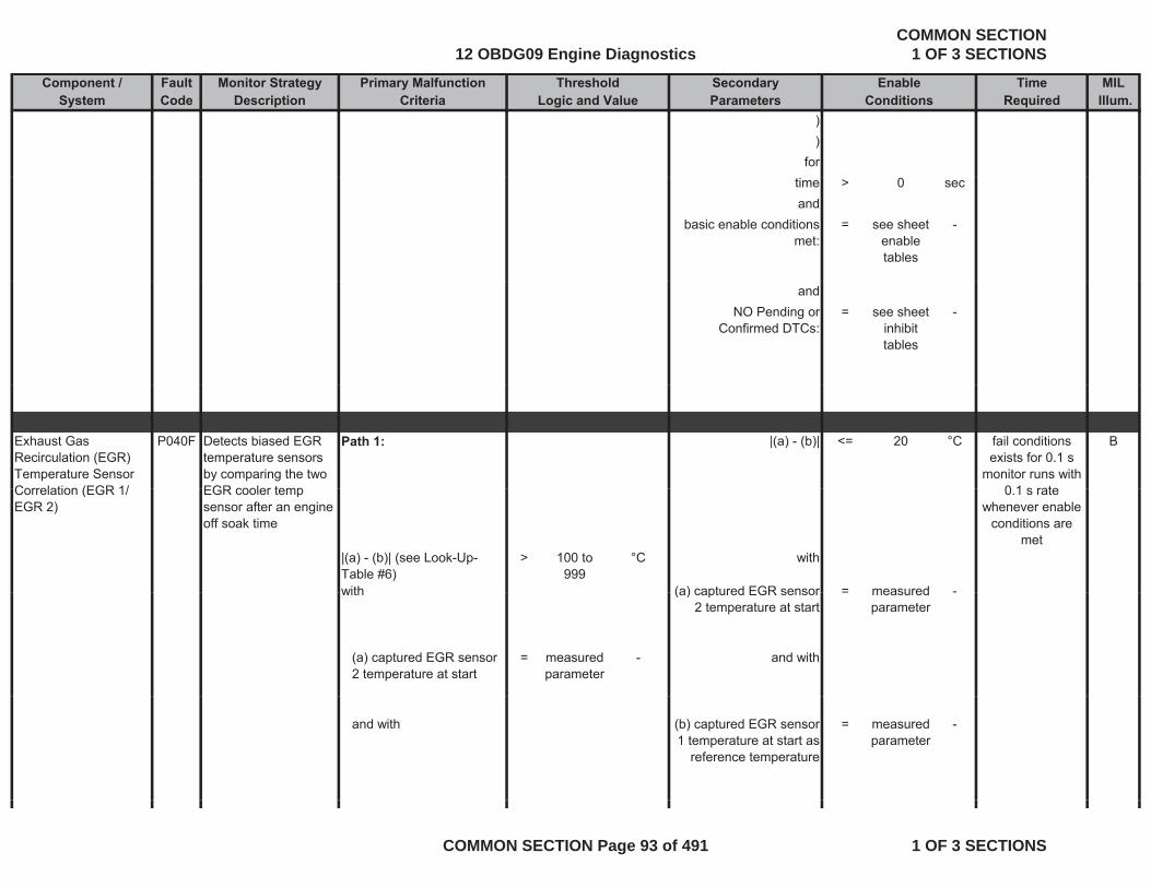
Component / Fault Monitor Strategy Primary Malfunction Secondary Time MILSystem Code Description Criteria Parameters Required Illum.
Threshold EnableLogic and Value Conditions
))
fortime > 0 secand
basic enable conditions met:
= see sheet enable tables
-
andNO Pending or
Confirmed DTCs:= see sheet
inhibit tables
-
Exhaust Gas Recirculation (EGR) Temperature Sensor Correlation (EGR 1/
P040F Detects biased EGR temperature sensors by comparing the two EGR cooler temp
Path 1: |(a) - (b)| <= 20 °C Bfail conditions exists for 0.1 s
monitor runs with 0 1 s rateCorrelation (EGR 1/
EGR 2)EGR cooler temp sensor after an engine off soak time
|(a) - (b)| (see Look-Up-Table #6)
> 100 to 999
°C with
with (a) captured EGR sensor = measured -
0.1 s rate whenever enable
conditions are met
with (a) captured EGR sensor 2 temperature at start
= measured parameter
-
(a) captured EGR sensor 2 temperature at start
= measured parameter
- and with
and with (b) captured EGR sensor 1 temperature at start as
reference temperature
= measured parameter
-
12 OBDG09 Engine DiagnosticsCOMMON SECTION
1 OF 3 SECTIONS
COMMON SECTION Page 93 of 491 1 OF 3 SECTIONS
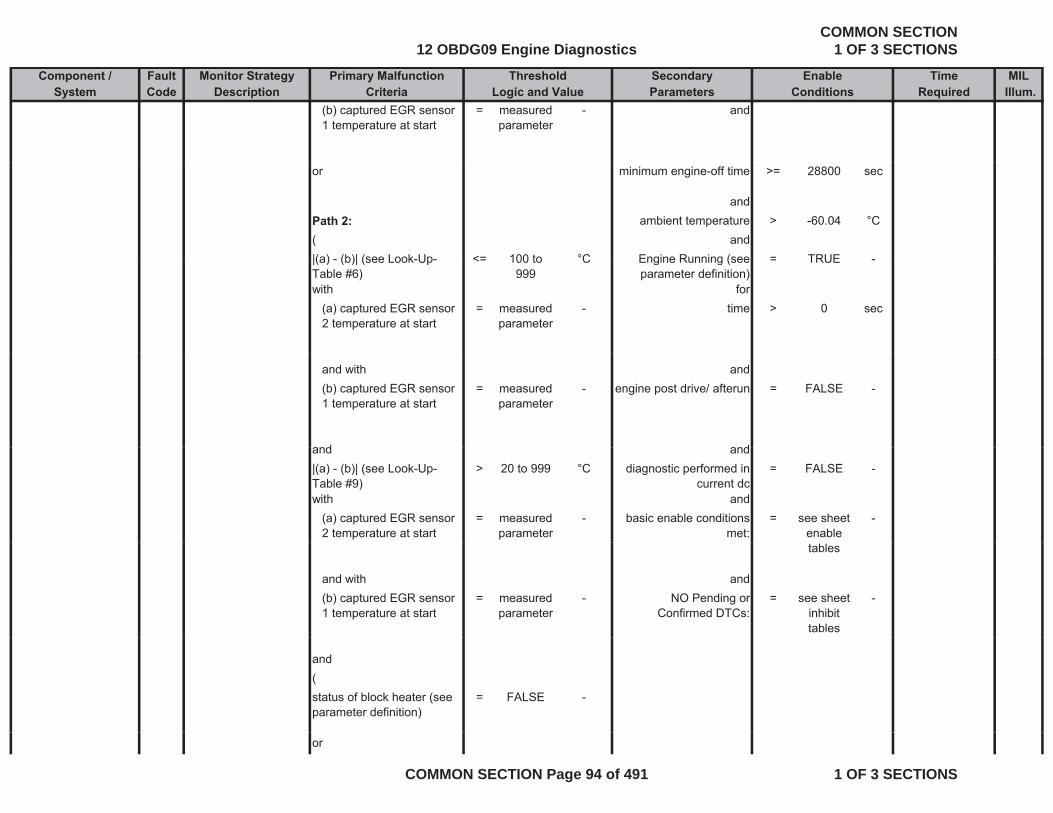
Component / Fault Monitor Strategy Primary Malfunction Secondary Time MILSystem Code Description Criteria Parameters Required Illum.
Threshold EnableLogic and Value Conditions
(b) captured EGR sensor 1 temperature at start
= measured parameter
- and
or minimum engine-off time >= 28800 sec
andPath 2: ambient temperature > -60.04 °C( and|(a) (b)| (see Look Up <= 100 to °C Engine Running (see = TRUE|(a) - (b)| (see Look-Up-Table #6)
<= 100 to 999
°C Engine Running (see parameter definition)
= TRUE -
with for(a) captured EGR sensor 2 temperature at start
= measured parameter
- time > 0 sec
and with and(b) captured EGR sensor 1 temperature at start
= measured parameter
- engine post drive/ afterun = FALSE -
and andand and|(a) - (b)| (see Look-Up-Table #9)
> 20 to 999 °C diagnostic performed in current dc
= FALSE -
with and(a) captured EGR sensor 2 temperature at start
= measured parameter
- basic enable conditions met:
= see sheet enable
-
tables
and with and(b) captured EGR sensor 1 temperature at start
= measured parameter
- NO Pending or Confirmed DTCs:
= see sheet inhibit tables
-
and(status of block heater (see parameter definition)
= FALSE -
or
12 OBDG09 Engine DiagnosticsCOMMON SECTION
1 OF 3 SECTIONS
COMMON SECTION Page 94 of 491 1 OF 3 SECTIONS
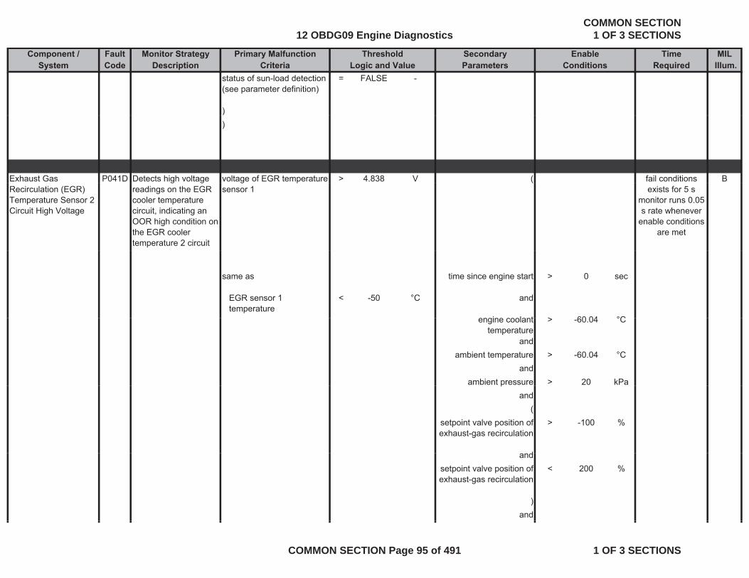
Component / Fault Monitor Strategy Primary Malfunction Secondary Time MILSystem Code Description Criteria Parameters Required Illum.
Threshold EnableLogic and Value Conditions
status of sun-load detection (see parameter definition)
= FALSE -
)))
Exhaust Gas P041D Detects high voltage voltage of EGR temperature > 4.838 V ( Bfail conditions Recirculation (EGR) Temperature Sensor 2 Circuit High Voltage
g greadings on the EGR cooler temperature circuit, indicating an OOR high condition on the EGR cooler temperature 2 circuit
g psensor 1
(exists for 5 s
monitor runs 0.05 s rate whenever
enable conditions are met
same as time since engine start > 0 sec
EGR sensor 1 temperature
< -50 °C and
engine coolant > 60 04 °Cengine coolant temperature
> -60.04 °C
andambient temperature > -60.04 °C
andambient pressure > 20 kPap
and(
setpoint valve position of exhaust-gas recirculation
> -100 %
dandsetpoint valve position of exhaust-gas recirculation
< 200 %
)and
12 OBDG09 Engine DiagnosticsCOMMON SECTION
1 OF 3 SECTIONS
COMMON SECTION Page 95 of 491 1 OF 3 SECTIONS
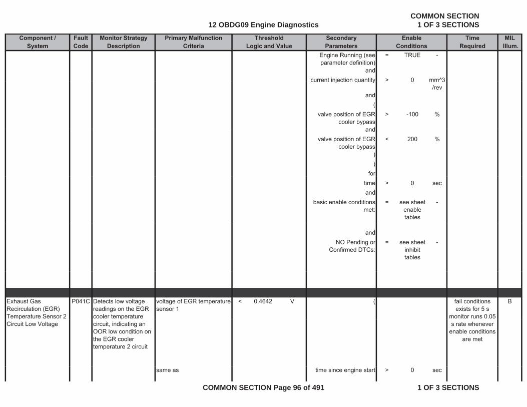
Component / Fault Monitor Strategy Primary Malfunction Secondary Time MILSystem Code Description Criteria Parameters Required Illum.
Threshold EnableLogic and Value Conditions
Engine Running (see parameter definition)
= TRUE -
andcurrent injection quantity > 0 mm^3current injection quantity > 0 mm 3
/revand
(valve position of EGR
cooler bypass> -100 %
andandvalve position of EGR
cooler bypass< 200 %
))
fortime > 0 secand
basic enable conditions met:
= see sheet enable tables
-
andNO Pending or
Confirmed DTCs:= see sheet
inhibit tables
-
Exhaust Gas Recirculation (EGR) Temperature Sensor 2
P041C Detects low voltage readings on the EGR cooler temperature
voltage of EGR temperature sensor 1
< 0.4642 V ( Bfail conditions exists for 5 s
monitor runs 0.05 pCircuit Low Voltage
pcircuit, indicating an OOR low condition on the EGR cooler temperature 2 circuit
s rate whenever enable conditions
are met
same as time since engine start > 0 sec
12 OBDG09 Engine DiagnosticsCOMMON SECTION
1 OF 3 SECTIONS
COMMON SECTION Page 96 of 491 1 OF 3 SECTIONS
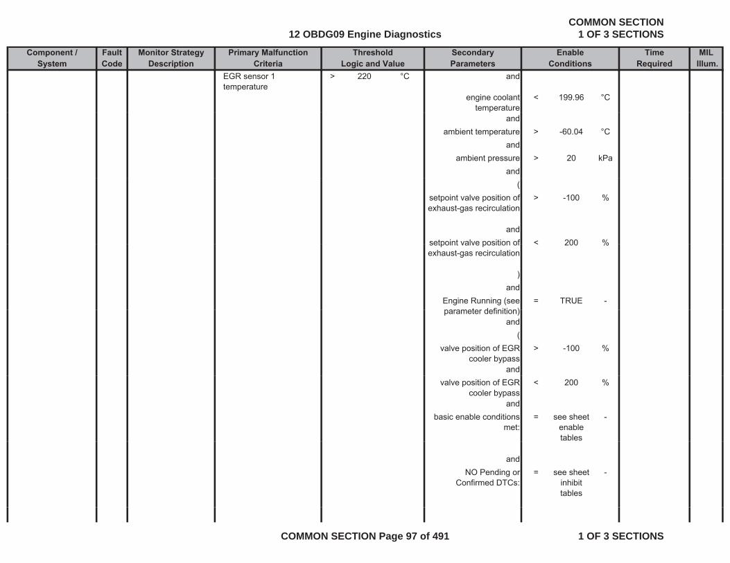
Component / Fault Monitor Strategy Primary Malfunction Secondary Time MILSystem Code Description Criteria Parameters Required Illum.
Threshold EnableLogic and Value Conditions
EGR sensor 1 temperature
> 220 °C and
engine coolant temperature
< 199.96 °C
andambient temperature > -60.04 °C
andambient pressure > 20 kPa
and(
setpoint valve position of exhaust-gas recirculation
> -100 %
andsetpoint valve position of < 200 %setpoint valve position of exhaust-gas recirculation
< 200 %
)and
Engine Running (see parameter definition)
= TRUE -parameter definition)
and(
valve position of EGR cooler bypass
> -100 %
andvalve position of EGR
cooler bypass< 200 %
andbasic enable conditions
met:= see sheet
enable tables
-
andNO Pending or
Confirmed DTCs:= see sheet
inhibit tables
-
12 OBDG09 Engine DiagnosticsCOMMON SECTION
1 OF 3 SECTIONS
COMMON SECTION Page 97 of 491 1 OF 3 SECTIONS
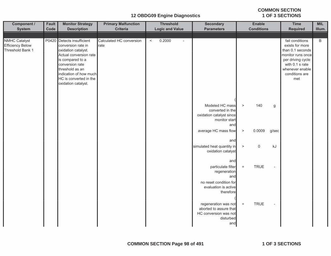
Component / Fault Monitor Strategy Primary Malfunction Secondary Time MILSystem Code Description Criteria Parameters Required Illum.
Threshold EnableLogic and Value Conditions
NMHC Catalyst Efficiency Below Threshold Bank 1
P0420 Detects insufficient conversion rate in oxidation catalyst
Calculated HC conversion rate
< 0.2000 - Bfail conditions exists for more
than 0 1 secondsThreshold Bank 1 oxidation catalyst. Actual conversion rate is compared to a conversion rate threshold as an indication of how much HC is converted in the
than 0.1 secondsmonitor runs once per driving cycle with 0.1 s rate
whenever enable conditions are
metoxidation catalyst.
(Modeled HC mass
converted in the> 140 g
converted in the oxidation catalyst since
monitor startand
average HC mass flow > 0.0009 g/sec
andandsimulated heat quantity in
oxidation catalyst> 0 kJ
andparticulate filter
ti= TRUE -
regenerationand
no reset condition for evaluation is active
therefore(
regeneration was not aborted to assure that
HC conversion was not disturbed
= TRUE -
and
12 OBDG09 Engine DiagnosticsCOMMON SECTION
1 OF 3 SECTIONS
COMMON SECTION Page 98 of 491 1 OF 3 SECTIONS
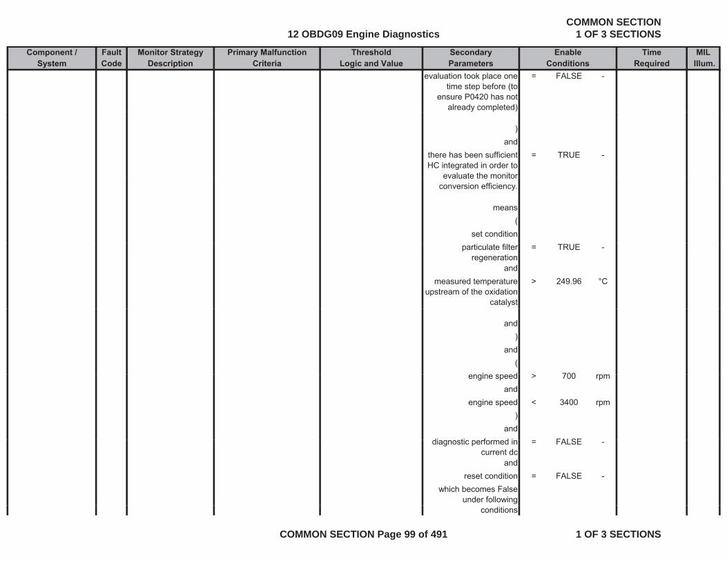
Component / Fault Monitor Strategy Primary Malfunction Secondary Time MILSystem Code Description Criteria Parameters Required Illum.
Threshold EnableLogic and Value Conditions
evaluation took place one time step before (to
ensure P0420 has not already completed)
= FALSE -
)and
there has been sufficient HC integrated in order to
evaluate the monitor
= TRUE -
evaluate the monitor conversion efficiency.
means(
set conditionparticulate filter
regeneration= TRUE -
andmeasured temperature
upstream of the oxidation catalyst
> 249.96 °C
and)
and(
i d > 700engine speed > 700 rpmand
engine speed < 3400 rpm)
anddi ti f d i FALSEdiagnostic performed in
current dc= FALSE -
andreset condition = FALSE -
which becomes False under following
conditions
12 OBDG09 Engine DiagnosticsCOMMON SECTION
1 OF 3 SECTIONS
COMMON SECTION Page 99 of 491 1 OF 3 SECTIONS
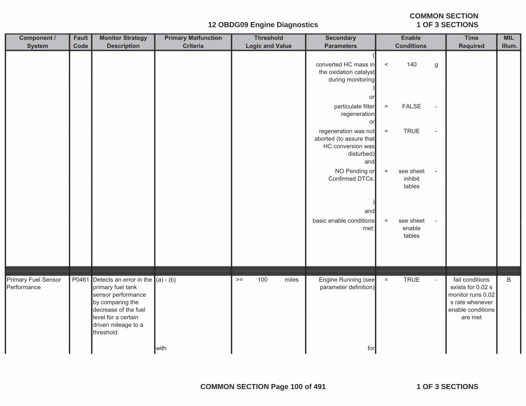
Component / Fault Monitor Strategy Primary Malfunction Secondary Time MILSystem Code Description Criteria Parameters Required Illum.
Threshold EnableLogic and Value Conditions
(converted HC mass in the oxidation catalyst
during monitoring
< 140 g
during monitoring)
orparticulate filter
regeneration= FALSE -
orregeneration was not
aborted (to assure that HC conversion was
disturbed)
= TRUE -
andNO Pending or = see sheet -
Confirmed DTCs: inhibit tables
)and
basic enable conditions = see sheet -met: enable
tables
Primary Fuel Sensor Performance
P0461 Detects an error in the primary fuel tank sensor performance by comparing the decrease of the fuel level for a certain
(a) - (b) >= 100 miles Engine Running (see parameter definition)
= TRUE - Bfail conditions exists for 0.02 s
monitor runs 0.02 s rate whenever
enable conditions are metlevel for a certain
driven mileage to a threshold.
with for
are met
12 OBDG09 Engine DiagnosticsCOMMON SECTION
1 OF 3 SECTIONS
COMMON SECTION Page 100 of 491 1 OF 3 SECTIONS
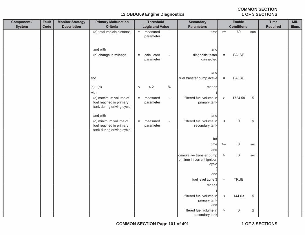
Component / Fault Monitor Strategy Primary Malfunction Secondary Time MILSystem Code Description Criteria Parameters Required Illum.
Threshold EnableLogic and Value Conditions
(a) total vehicle distance = measured parameter
- time >= 60 sec
and with and(b) change in mileage = calculated
parameter- diagnosis tester
connected= FALSE
andand fuel transfer pump active = FALSE
(c) - (d) < 4.21 % meanswith (
(c) maximum volume of fuel reached in primary
= measured parameter
- filtered fuel volume in primary tank
> 1724.58 %fuel reached in primary tank during driving cycle
parameter primary tank
and with and(c) minimum volume of fuel reached in primary tank during driving cycle
= measured parameter
- filtered fuel volume in secondary tank
< 0 %
tank during driving cycle
fortime >= 0 secand
cumulative transfer pump > 0 secp pon time in current ignition
cycle)
andfuel level zone 3 = TRUE
means(
filtered fuel volume in primary tank
< 144.63 %
andfiltered fuel volume in > 0 %
secondary tank
12 OBDG09 Engine DiagnosticsCOMMON SECTION
1 OF 3 SECTIONS
COMMON SECTION Page 101 of 491 1 OF 3 SECTIONS

Component / Fault Monitor Strategy Primary Malfunction Secondary Time MILSystem Code Description Criteria Parameters Required Illum.
Threshold EnableLogic and Value Conditions
)or
fuel level zone 4 = TRUEmeans
(filtered fuel volume in
primary tank< 144.63 %
andfiltered fuel volume in <= 0 %filtered fuel volume in
secondary tank< 0 %
)and
basic enable conditions met:
= see sheet enable tables
-
tables
andNO Pending or
Confirmed DTCs:= see sheet
inhibit tables
-
Fuel Level Sensor 1 Circuit High
P0463 Detects high voltage readings in the fuel
voltage of fuel level sensor 1
> 4.8 V ignition on = TRUE - Bfail conditions exists for 24 s
level sensor circuit, indicating an OOR high condition on the fuel level sensor circuit
same as and
test performed continuously 0.1 s
rate
fuel level < 0 % basic enable conditions met:
= see sheet enable tables
-
12 OBDG09 Engine DiagnosticsCOMMON SECTION
1 OF 3 SECTIONS
COMMON SECTION Page 102 of 491 1 OF 3 SECTIONS

Component / Fault Monitor Strategy Primary Malfunction Secondary Time MILSystem Code Description Criteria Parameters Required Illum.
Threshold EnableLogic and Value Conditions
Fuel Level Sensor 1 Circuit Low
P0462 Detects low voltage readings in the fuel level sensor circuit
voltage of fuel level sensor 1
< 0.2 V ignition on = TRUE - Bfail conditions exists for 24 s test performedlevel sensor circuit,
indicating an OOR low condition on the fuel level sensor circuit
same as andfuel level > 100 % basic enable conditions = see sheet -
test performed continuously 0.1 s
rate
fuel level > 100 % basic enable conditions met:
see sheet enable tables
Exhaust Gas Recirculation (EGR)
P046C Detects in range EGR valve position errors
controller deviation of EGR valve calculated out of
> 5.00 % offset learning of EGR actuator active
= FALSE Bfail conditions exists for 8 sRecirculation (EGR)
Position Sensor Performance
valve position errors by comparing desired EGR position to actual EGR valve position
valve calculated out of difference between desired and actual value
actuator active
or andcontroller deviation of EGR < -5 00 % offset learning in the = TRUE
exists for 8 s monitor runs with
0.02 s rate whenever enable
conditions are met
controller deviation of EGR valve calculated out of difference between desired and actual value
< -5.00 % offset learning in the previous driving cycle
was complete
= TRUE
andengine speed (see Look-
Up-Table #87)> 600 to
850rpm
Up-Table #87) 850and
duty cycle of the Intake Air Heater output
< 5 %
andbattery voltage >= 11 V
and
12 OBDG09 Engine DiagnosticsCOMMON SECTION
1 OF 3 SECTIONS
COMMON SECTION Page 103 of 491 1 OF 3 SECTIONS
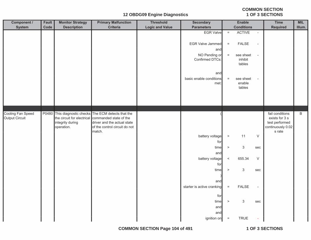
Component / Fault Monitor Strategy Primary Malfunction Secondary Time MILSystem Code Description Criteria Parameters Required Illum.
Threshold EnableLogic and Value Conditions
EGR Valve = ACTIVE -
EGR Valve Jammed = FALSE -and
NO Pending or Confirmed DTCs:
= see sheet inhibit tables
-
andbasic enable conditions
met:= see sheet
enable tables
-
Cooling Fan Speed Output Circuit
P0480 This diagnostic checks the circuit for electrical integrity during operation.
The ECM detects that the commanded state of the driver and the actual state of the control circuit do not match
( Bfail conditions exists for 3 s
test performed continuously 0.02
s ratematch.battery voltage > 11 V
fortime > 3 secand
battery voltage < 655.34 V
s rate
y gfor
time > 3 sec)
andstarter is active cranking = FALSE -g
fortime > 3 secandand
ignition on = TRUE -
12 OBDG09 Engine DiagnosticsCOMMON SECTION
1 OF 3 SECTIONS
COMMON SECTION Page 104 of 491 1 OF 3 SECTIONS
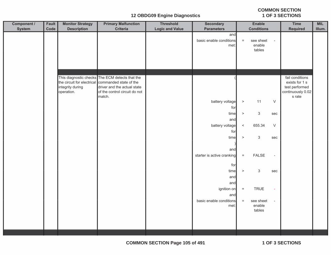
Component / Fault Monitor Strategy Primary Malfunction Secondary Time MILSystem Code Description Criteria Parameters Required Illum.
Threshold EnableLogic and Value Conditions
andbasic enable conditions
met:= see sheet
enable tables
-
tables
This diagnostic checks The ECM detects that the ( fail conditions the circuit for electrical integrity during operation.
commanded state of the driver and the actual state of the control circuit do not match.
battery voltage > 11 Vfor
exists for 1 s test performed
continuously 0.02 s rate
time > 3 secand
battery voltage < 655.34 Vfor
time > 3 sec)
andstarter is active cranking = FALSE -
forti > 3time > 3 secandand
ignition on = TRUE -and
b i bl diti h tbasic enable conditions met:
= see sheet enable tables
-
12 OBDG09 Engine DiagnosticsCOMMON SECTION
1 OF 3 SECTIONS
COMMON SECTION Page 105 of 491 1 OF 3 SECTIONS
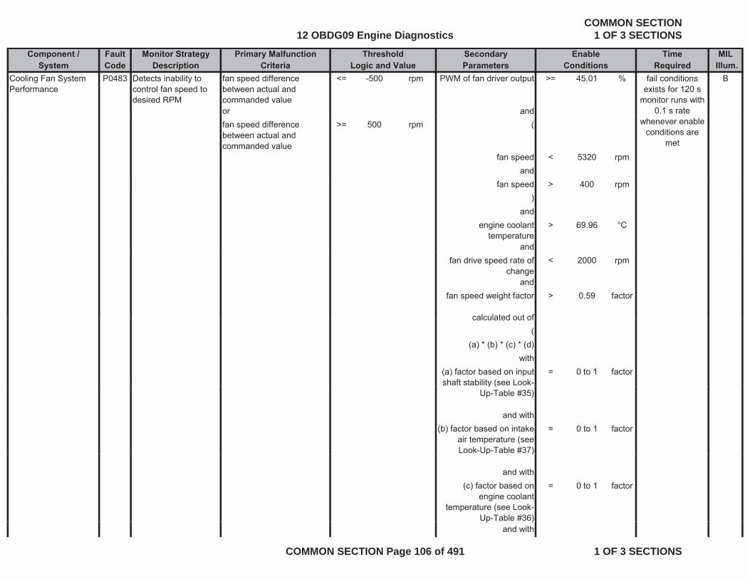
Component / Fault Monitor Strategy Primary Malfunction Secondary Time MILSystem Code Description Criteria Parameters Required Illum.
Threshold EnableLogic and Value Conditions
Cooling Fan System Performance
P0483 Detects inability to control fan speed to desired RPM
fan speed difference between actual and commanded value
<= -500 rpm PWM of fan driver output >= 45.01 % B
or and
fail conditions exists for 120 s
monitor runs with 0.1 s rate
fan speed difference between actual and commanded value
>= 500 rpm (
fan speed < 5320 rpmand
fan speed > 400 rpm
whenever enable conditions are
met
fan speed > 400 rpm)
andengine coolant
temperature> 69.96 °C
andfan drive speed rate of
change< 2000 rpm
andfan speed weight factor > 0.59 factor
calculated out ofcalculated out of(
(a) * (b) * (c) * (d)with
(a) factor based on input shaft stability (see Look-
= 0 to 1 factory (
Up-Table #35)
and with(b) factor based on intake
air temperature (see Look-Up-Table #37)
= 0 to 1 factor
p )
and with(c) factor based on
engine coolant temperature (see Look-
Up-Table #36)
= 0 to 1 factor
p )and with
12 OBDG09 Engine DiagnosticsCOMMON SECTION
1 OF 3 SECTIONS
COMMON SECTION Page 106 of 491 1 OF 3 SECTIONS
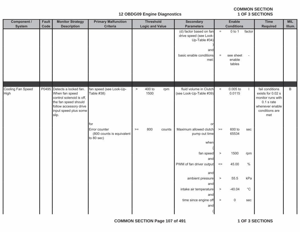
Component / Fault Monitor Strategy Primary Malfunction Secondary Time MILSystem Code Description Criteria Parameters Required Illum.
Threshold EnableLogic and Value Conditions
(d) factor based on fan drive speed (see Look-
Up-Table #34)
= 0 to 1 factor
))and
basic enable conditions met:
= see sheet enable tables
-
Cooling Fan Speed High
P0495 Detects a locked fan. When fan speed control solenoid is off,
fan speed (see Look-Up-Table #38)
> 400 to 1500
rpm fluid volume in Clutch (see Look-Up-Table #39)
< 0.005 to 0.0115
l Bfail conditions exists for 0.02 s
monitor runs with the fan speed should follow accessory drive input speed plus some slip.
for or
0.1 s rate whenever enable
conditions are met
Error counter (800 counts is equivalent to 80 sec)
>= 800 counts Maximum allowed clutch pump out time
>= 600 to 65534
sec
when{
fan speed > 1500 rpmp pand
PWM of fan driver output <= 45.00 %
andambient pressure > 55.5 kPa
andintake air temperature > -40.04 °C
andtime since engine off > 0 sec
and(
12 OBDG09 Engine DiagnosticsCOMMON SECTION
1 OF 3 SECTIONS
COMMON SECTION Page 107 of 491 1 OF 3 SECTIONS
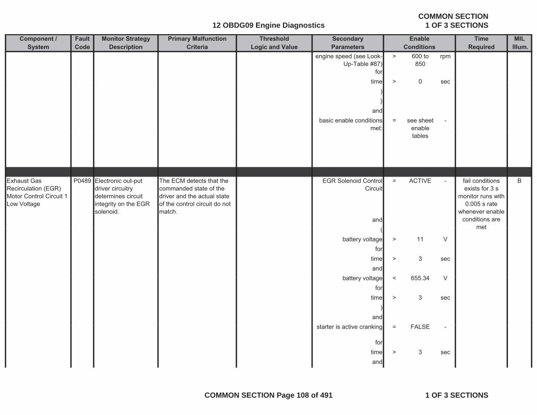
Component / Fault Monitor Strategy Primary Malfunction Secondary Time MILSystem Code Description Criteria Parameters Required Illum.
Threshold EnableLogic and Value Conditions
engine speed (see Look-Up-Table #87)
> 600 to 850
rpm
fortime > 0 sectime > 0 sec
)}
andbasic enable conditions
met:= see sheet
enable -
tables
Exhaust Gas P0489 Electronic out put The ECM detects that the EGR Solenoid Control = ACTIVE Bfail conditionsExhaust Gas Recirculation (EGR) Motor Control Circuit 1 Low Voltage
P0489 Electronic out-put driver circuitry determines circuit integrity on the EGR solenoid.
The ECM detects that the commanded state of the driver and the actual state of the control circuit do not match.
EGR Solenoid Control Circuit
= ACTIVE - B
and(
fail conditions exists for 3 s
monitor runs with 0.005 s rate
whenever enable conditions are
met(battery voltage > 11 V
fortime > 3 secand
b tt lt < 655 34 V
met
battery voltage < 655.34 Vfor
time > 3 sec)
andt t i ti ki FALSEstarter is active cranking = FALSE -
fortime > 3 secand
12 OBDG09 Engine DiagnosticsCOMMON SECTION
1 OF 3 SECTIONS
COMMON SECTION Page 108 of 491 1 OF 3 SECTIONS
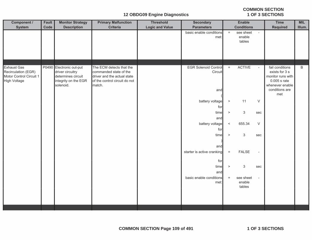
Component / Fault Monitor Strategy Primary Malfunction Secondary Time MILSystem Code Description Criteria Parameters Required Illum.
Threshold EnableLogic and Value Conditions
basic enable conditions met:
= see sheet enable tables
-
Exhaust Gas Recirculation (EGR) Motor Control Circuit 1
P0490 Electronic out-put driver circuitry determines circuit
The ECM detects that the commanded state of the driver and the actual state
EGR Solenoid Control Circuit
= ACTIVE - Bfail conditions exists for 3 s
monitor runs withMotor Control Circuit 1 High Voltage
determines circuit integrity on the EGR solenoid.
driver and the actual state of the control circuit do not match.
and(
battery voltage > 11 V
monitor runs with 0.005 s rate
whenever enable conditions are
met
fortime > 3 secand
battery voltage < 655.34 Vfor
time > 3 sec)
andstarter is active cranking = FALSE -
ffortime > 3 secand
basic enable conditions met:
= see sheet enable tables
-
12 OBDG09 Engine DiagnosticsCOMMON SECTION
1 OF 3 SECTIONS
COMMON SECTION Page 109 of 491 1 OF 3 SECTIONS
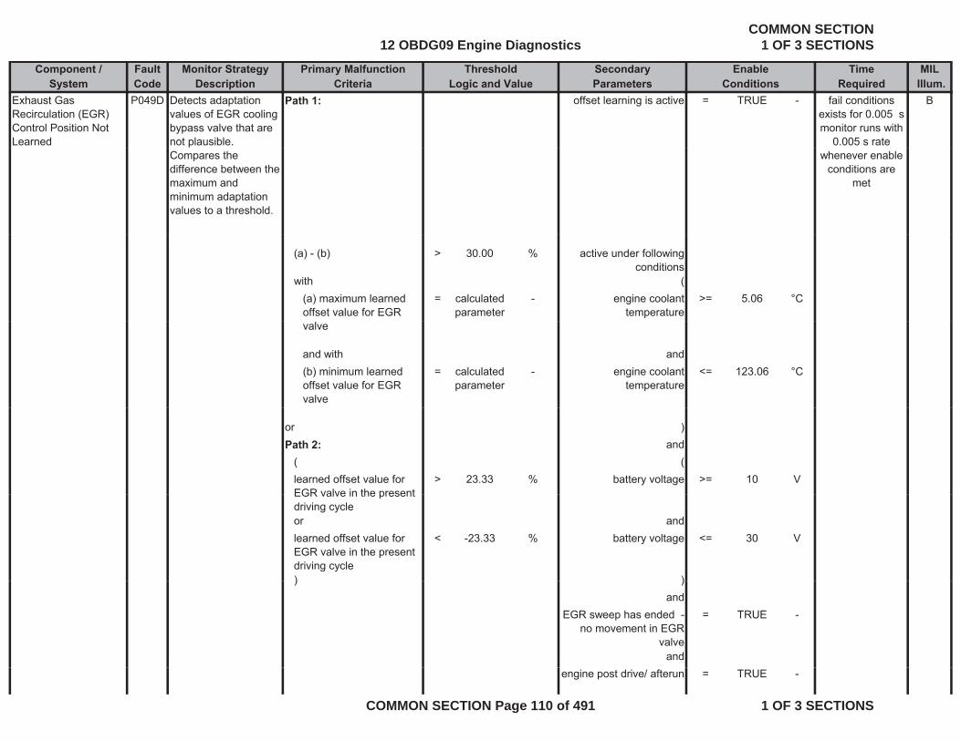
Component / Fault Monitor Strategy Primary Malfunction Secondary Time MILSystem Code Description Criteria Parameters Required Illum.
Threshold EnableLogic and Value Conditions
Exhaust Gas Recirculation (EGR) Control Position Not Learned
P049D Detects adaptation values of EGR cooling bypass valve that are not plausible.
Path 1: offset learning is active = TRUE - Bfail conditions exists for 0.005 smonitor runs with
0.005 s rate Compares the difference between the maximum and minimum adaptation values to a threshold.
whenever enable conditions are
met
(a) - (b) > 30.00 % active under following conditions
with ((a) maximum learned offset value for EGR
= calculated parameter
- engine coolant temperature
>= 5.06 °C
valve
and with and(b) minimum learned offset value for EGR valve
= calculated parameter
- engine coolant temperature
<= 123.06 °C
or )Path 2: and
( (learned offset value for EGR valve in the present
> 23.33 % battery voltage >= 10 VEGR valve in the present driving cycleor andlearned offset value for EGR valve in the present driving cycle
< -23.33 % battery voltage <= 30 V
) )) )and
EGR sweep has ended - no movement in EGR
valve
= TRUE -
andengine post drive/ afterun = TRUE -
12 OBDG09 Engine DiagnosticsCOMMON SECTION
1 OF 3 SECTIONS
COMMON SECTION Page 110 of 491 1 OF 3 SECTIONS
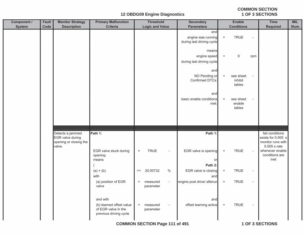
Component / Fault Monitor Strategy Primary Malfunction Secondary Time MILSystem Code Description Criteria Parameters Required Illum.
Threshold EnableLogic and Value Conditions
andengine was running
during last driving cycle= TRUE -
meansengine speed = 0 rpm
during last driving cycle
andNO Pending or
Confirmed DTCs:= see sheet
inhibit tables
-
andbasic enable conditions = see sheet -
met: enable tables
Detects a jammed EGR valve during opening or closing the valve.
Path 1: Path 1:
EGR valve stuck during opening
= TRUE - EGR valve is opening = TRUE -
fail conditions exists for 0.005 smonitor runs with
0.005 s rate whenever enable
conditions are p gmeans or( Path 2:(a) + (b) >= 20.00732 % EGR valve is closing = TRUE -with and
(a) position of EGR = measured - engine post drive/ afterun = TRUE -
met
valve parameter
and with and(b) learned offset value of EGR valve in the
= measured parameter
- offset learning active = TRUE -
previous driving cycle
12 OBDG09 Engine DiagnosticsCOMMON SECTION
1 OF 3 SECTIONS
COMMON SECTION Page 111 of 491 1 OF 3 SECTIONS
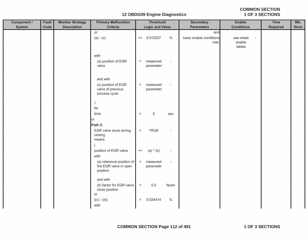
Component / Fault Monitor Strategy Primary Malfunction Secondary Time MILSystem Code Description Criteria Parameters Required Illum.
Threshold EnableLogic and Value Conditions
or and(a) - (c) <= 0.012207 % basic enable conditions
met:see sheet
enable tables
-
tables
with(a) position of EGR valve
= measured parameter
-
and with(c) position of EGR valve of previous process cycle
= measured parameter
-
))fortime > 5 sec
orPath 2:
EGR valve stuck during = TRUE -EGR valve stuck during closing
= TRUE
means(position of EGR valve <= (a) * (b) -with
(a) reference position of the EGR valve in open position
= measured parameter
-
and with(b) factor for EGR valve = 0.5 factor( )close position
or|(c) - (d)| > 0.024414 %with
12 OBDG09 Engine DiagnosticsCOMMON SECTION
1 OF 3 SECTIONS
COMMON SECTION Page 112 of 491 1 OF 3 SECTIONS
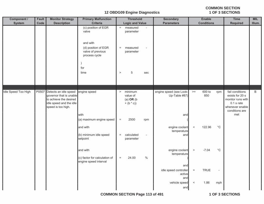
Component / Fault Monitor Strategy Primary Malfunction Secondary Time MILSystem Code Description Criteria Parameters Required Illum.
Threshold EnableLogic and Value Conditions
(c) position of EGR valve
= measured parameter
-
and with(d) position of EGR valve of previous process cycle
= measured parameter
-
))fortime > 5 sec
Idle Speed Too High P0507 Detects an idle speed governor that is unable to achieve the desired idle speed and the idle speed is too high.
engine speed > minimum value of (a) OR (b + (b * c))
engine speed (see Look-Up-Table #87)
>= 600 to 850
rpm Bfail conditions exists for 20 s
monitor runs with 0.1 s rate
whenever enable conditions are
with and(a) maximum engine speed = 2500 rpm (
and with engine coolant temperature
< 122.96 °C
(b) minimum idle speed = calculated - and
met
( ) psetpoint parameter
and with engine coolant temperature
> -7.04 °C
(c) factor for calculation of = 24.00 % )engine speed interval
andidle speed controller
active= TRUE -
andvehicle speed < 1.86 mphp p
and
12 OBDG09 Engine DiagnosticsCOMMON SECTION
1 OF 3 SECTIONS
COMMON SECTION Page 113 of 491 1 OF 3 SECTIONS
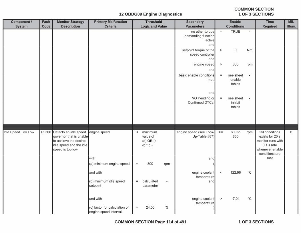
Component / Fault Monitor Strategy Primary Malfunction Secondary Time MILSystem Code Description Criteria Parameters Required Illum.
Threshold EnableLogic and Value Conditions
no other torque demanding function
active
= TRUE -
andsetpoint torque of the
speed controller> 0 Nm
andengine speed > 300 rpm
andbasic enable conditions
met:= see sheet
enable tables
-
andNO Pending or = see sheet -
Confirmed DTCs: inhibit tables
Idle Speed Too Low P0506 Detects an idle speed governor that is unable to achieve the desired idle speed and the idle speed is too low
engine speed < maximum value of (a) OR (b - (b * c))
engine speed (see Look-Up-Table #87)
>= 600 to 850
rpm Bfail conditions exists for 20 s
monitor runs with 0.1 s rate
whenever enable conditions are
with and(a) minimum engine speed = 300 rpm (
and with engine coolant temperature
< 122.96 °C
(b) minimum idle speed = calculated - and
met
( ) psetpoint parameter
and with engine coolant temperature
> -7.04 °C
(c) factor for calculation of = 24.00 % )engine speed interval
12 OBDG09 Engine DiagnosticsCOMMON SECTION
1 OF 3 SECTIONS
COMMON SECTION Page 114 of 491 1 OF 3 SECTIONS
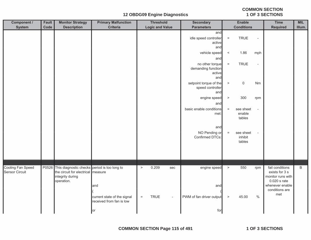
Component / Fault Monitor Strategy Primary Malfunction Secondary Time MILSystem Code Description Criteria Parameters Required Illum.
Threshold EnableLogic and Value Conditions
andidle speed controller
active= TRUE -
andandvehicle speed < 1.86 mph
andno other torque
demanding function active
= TRUE -
andsetpoint torque of the
speed controller> 0 Nm
andengine speed > 300 rpm
andandbasic enable conditions
met:= see sheet
enable tables
-
andNO Pending or see sheetNO Pending or
Confirmed DTCs:= see sheet
inhibit tables
-
Cooling Fan Speed Sensor Circuit
P0526 This diagnostic checks the circuit for electrical integrity during operation.
period is too long to measure
> 0.209 sec engine speed > 550 rpm B
and and
fail conditions exists for 3 s
monitor runs with 0.020 s rate
whenever enable ( (current state of the signal received from fan is low
= TRUE - PWM of fan driver output > 45.00 %
or for
conditions are met
12 OBDG09 Engine DiagnosticsCOMMON SECTION
1 OF 3 SECTIONS
COMMON SECTION Page 115 of 491 1 OF 3 SECTIONS
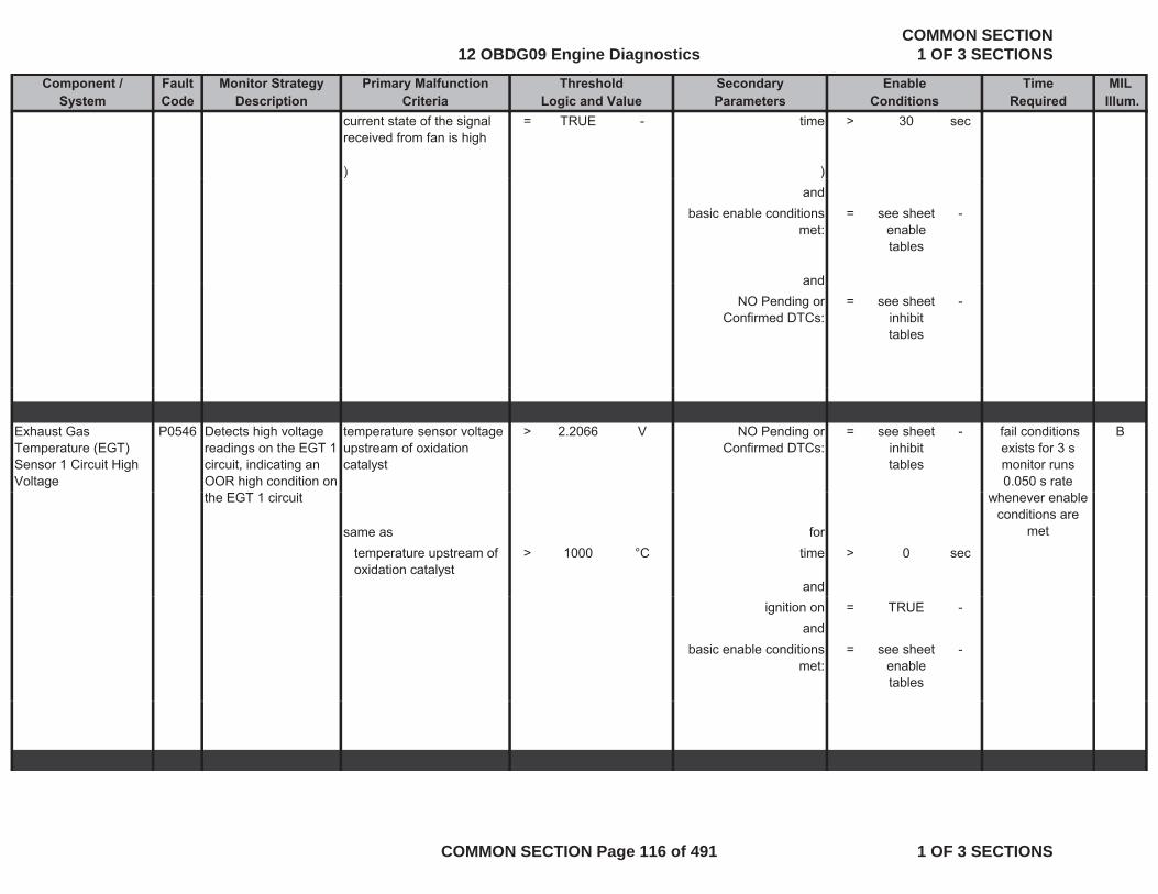
Component / Fault Monitor Strategy Primary Malfunction Secondary Time MILSystem Code Description Criteria Parameters Required Illum.
Threshold EnableLogic and Value Conditions
current state of the signal received from fan is high
= TRUE - time > 30 sec
) )) )and
basic enable conditions met:
= see sheet enable tables
-
andandNO Pending or
Confirmed DTCs:= see sheet
inhibit tables
-
Exhaust Gas Temperature (EGT) Sensor 1 Circuit High Voltage
P0546 Detects high voltage readings on the EGT 1 circuit, indicating an OOR high condition on
temperature sensor voltage upstream of oxidation catalyst
> 2.2066 V NO Pending or Confirmed DTCs:
= see sheet inhibit tables
- B fail conditions exists for 3 s monitor runs 0.050 s rate
the EGT 1 circuit
same as fortemperature upstream of oxidation catalyst
> 1000 °C time > 0 sec
and
whenever enable conditions are
met
ignition on = TRUE -and
basic enable conditions met:
= see sheet enable tables
-
12 OBDG09 Engine DiagnosticsCOMMON SECTION
1 OF 3 SECTIONS
COMMON SECTION Page 116 of 491 1 OF 3 SECTIONS
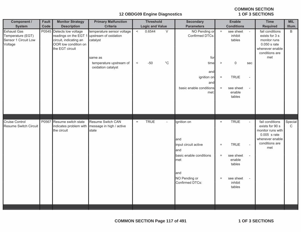
Component / Fault Monitor Strategy Primary Malfunction Secondary Time MILSystem Code Description Criteria Parameters Required Illum.
Threshold EnableLogic and Value Conditions
Exhaust Gas Temperature (EGT) Sensor 1 Circuit Low Voltage
P0545 Detects low voltage readings on the EGT 1 circuit, indicating an OOR low condition on
temperature sensor voltage upstream of oxidation catalyst
< 0.6544 V NO Pending or Confirmed DTCs:
= see sheet inhibit tables
- B fail conditions exists for 3 s monitor runs 0.050 s rate
the EGT circuit
same as fortemperature upstream of oxidation catalyst
< -50 °C time > 0 sec
and
whenever enable conditions are
met
ignition on = TRUE -and
basic enable conditions met:
= see sheet enable tables
-
Cruise Control Resume Switch Circuit
P0567 Resume switch state indicates problem with
Resume Switch CAN message in high / active
= TRUE - ignition on = TRUE - Special C
fail conditions exists for 90 s p
the circuitg g
state
andinput circuit active = TRUE -andb i bl diti h t
monitor runs with 0.005 s rate
whenever enable conditions are
met
basic enable conditions met
= see sheet enable tables
-
andNO Pending or C fi d DTC
= see sheet i hibit
-Confirmed DTCs: inhibit
tables
12 OBDG09 Engine DiagnosticsCOMMON SECTION
1 OF 3 SECTIONS
COMMON SECTION Page 117 of 491 1 OF 3 SECTIONS
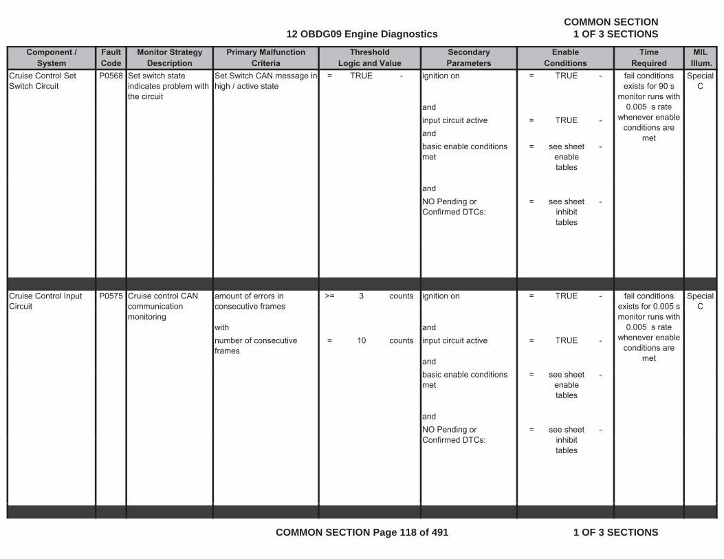
Component / Fault Monitor Strategy Primary Malfunction Secondary Time MILSystem Code Description Criteria Parameters Required Illum.
Threshold EnableLogic and Value Conditions
Cruise Control Set Switch Circuit
P0568 Set switch state indicates problem with the circuit
Set Switch CAN message in high / active state
= TRUE - ignition on = TRUE - Special C
and
fail conditions exists for 90 s
monitor runs with 0.005 s rate
input circuit active = TRUE -andbasic enable conditions met
= see sheet enable tables
-
whenever enable conditions are
met
andNO Pending or Confirmed DTCs:
= see sheet inhibit tables
-
Cruise Control Input Circuit
P0575 Cruise control CAN communication
amount of errors in consecutive frames
>= 3 counts ignition on = TRUE - Special C
fail conditions exists for 0 005 sCircuit communication
monitoringconsecutive frames C
with andnumber of consecutive frames
= 10 counts input circuit active = TRUE -
andb i bl diti h t
exists for 0.005 s monitor runs with
0.005 s rate whenever enable
conditions are met
basic enable conditions met
= see sheet enable tables
-
andNO Pending or C fi d DTC
= see sheet i hibit
-Confirmed DTCs: inhibit
tables
12 OBDG09 Engine DiagnosticsCOMMON SECTION
1 OF 3 SECTIONS
COMMON SECTION Page 118 of 491 1 OF 3 SECTIONS
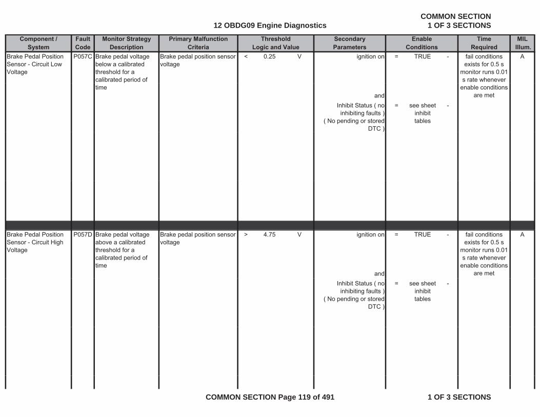
Component / Fault Monitor Strategy Primary Malfunction Secondary Time MILSystem Code Description Criteria Parameters Required Illum.
Threshold EnableLogic and Value Conditions
Brake Pedal Position Sensor - Circuit Low Voltage
P057C Brake pedal voltage below a calibrated threshold for a calibrated period of
Brake pedal position sensor voltage
< 0.25 V ignition on = TRUE - Afail conditions exists for 0.5 s
monitor runs 0.01 s rate whenever
timeand
Inhibit Status ( no inhibiting faults )
( No pending or stored DTC )
= see sheet inhibit tables
-
enable conditions are met
)
Brake Pedal Position Sensor - Circuit High Voltage
P057D Brake pedal voltage above a calibrated threshold for a calibrated period of time
Brake pedal position sensor voltage
> 4.75 V ignition on = TRUE - A
and
fail conditions exists for 0.5 s
monitor runs 0.01 s rate whenever
enable conditions are met
Inhibit Status ( no inhibiting faults )
( No pending or stored DTC )
= see sheet inhibit tables
-
12 OBDG09 Engine DiagnosticsCOMMON SECTION
1 OF 3 SECTIONS
COMMON SECTION Page 119 of 491 1 OF 3 SECTIONS
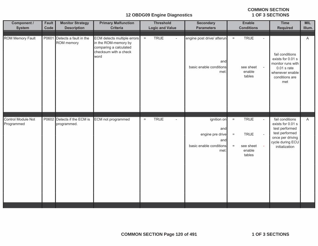
Component / Fault Monitor Strategy Primary Malfunction Secondary Time MILSystem Code Description Criteria Parameters Required Illum.
Threshold EnableLogic and Value Conditions
ROM Memory Fault P0601 Detects a fault in the ROM memory
ECM detects multiple errors in the ROM-memory by comparing a calculated
= TRUE - engine post drive/ afterun = TRUE - A
p gchecksum with a check word
andbasic enable conditions
met:see sheet
enable tables
-
fail conditions exists for 0.01 s
monitor runs with 0.01 s rate
whenever enable conditions areconditions are
met
Control Module Not Programmed
P0602 Detects if the ECM is programmed.
ECM not programmed = TRUE - ignition on = TRUE - A
andengine pre drive = TRUE -
fail conditions exists for 0.01 s test performedtest performed engine pre drive TRUE
andbasic enable conditions
met:= see sheet
enable tables
-
once per driving cycle during ECU
initialization
12 OBDG09 Engine DiagnosticsCOMMON SECTION
1 OF 3 SECTIONS
COMMON SECTION Page 120 of 491 1 OF 3 SECTIONS

Component / Fault Monitor Strategy Primary Malfunction Secondary Time MILSystem Code Description Criteria Parameters Required Illum.
Threshold EnableLogic and Value Conditions
Control Module Internal Performance
P0606 Monitors that ECM is operating correctly at proper voltage. All internal hardware
SPI communication, data transfer lost
= TRUE - ignition on = TRUE - Afail conditions exists for 0.5 s test performed
continuously with modules are communicating correctly.
andbasic enable conditions
met:= see sheet
enable -
0.01 s rate
tables
faults detected in the SPI communication
> 184 counts ignition on = TRUE -communicationIC internal and
basic enable conditions met:
- see sheet enable tables
-
andfail conditions
exists for at leastandNO Pending or
Confirmed DTCs:- see sheet
inhibit tables
-exists for at least
0.64 smonitor runs once per trip during pre
drive at least twice every 0.08s
rate whenever enable conditions
are met
12 OBDG09 Engine DiagnosticsCOMMON SECTION
1 OF 3 SECTIONS
COMMON SECTION Page 121 of 491 1 OF 3 SECTIONS

Component / Fault Monitor Strategy Primary Malfunction Secondary Time MILSystem Code Description Criteria Parameters Required Illum.
Threshold EnableLogic and Value Conditions
internal supply voltage < 4.2 V ignition on = TRUE -or andinternal supply voltage > 5.25 V counter of reactivation
attempt of power output>= 2 count
sattempt of power output stage
s
andbasic enable conditions
met:= see sheet
enable tables
- fail conditions exists for 0.08s
monitor runs once per trip during pre
andNO Pending or
Confirmed DTCs:= see sheet
inhibit tables
-
per trip during pre drive at least
twice every 0.08s rate whenever
enable conditions are met
|(a) - (b)| > 50 us programmed energizing time for fuel injection has
been read back
= TRUE - fail conditions exists for at least
0.15 s
with means(a) measured energizing time for fuel injection
= measured parameter
- programmed energizing time for fuel injection
>= 0 -
monitor runs with 0.01 s rate
whenever enable conditions are
met
and with and(b) programmed energizing time for fuel injection
= measured parameter
- measured energizing time for fuel injection has
been read back
= TRUE -
means
12 OBDG09 Engine DiagnosticsCOMMON SECTION
1 OF 3 SECTIONS
COMMON SECTION Page 122 of 491 1 OF 3 SECTIONS
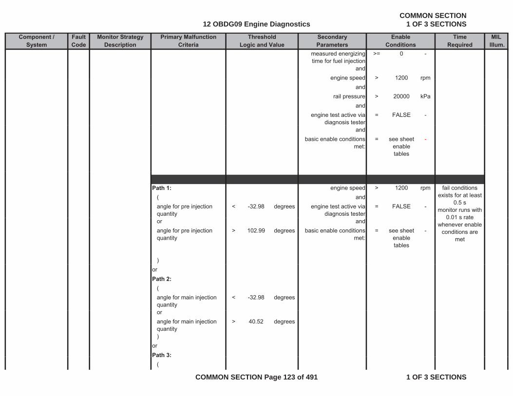
Component / Fault Monitor Strategy Primary Malfunction Secondary Time MILSystem Code Description Criteria Parameters Required Illum.
Threshold EnableLogic and Value Conditions
measured energizing time for fuel injection
>= 0 -
andengine speed > 1200 rpmengine speed > 1200 rpm
andrail pressure > 20000 kPa
andengine test active via
diagnosis tester= FALSE -
gand
basic enable conditions met:
= see sheet enable tables
-
Path 1: engine speed > 1200 rpm( andangle for pre injection quantity
< -32.98 degrees engine test active via diagnosis tester
= FALSE -
fail conditions exists for at least
0.5 smonitor runs with
0 01 s rateor andangle for pre injection quantity
> 102.99 degrees basic enable conditions met:
= see sheet enable tables
-
)
0.01 s rate whenever enable
conditions are met
orPath 2:
(angle for main injection quantity
< -32.98 degrees
orangle for main injection quantity
> 40.52 degrees
)orPath 3:Path 3:
(
12 OBDG09 Engine DiagnosticsCOMMON SECTION
1 OF 3 SECTIONS
COMMON SECTION Page 123 of 491 1 OF 3 SECTIONS
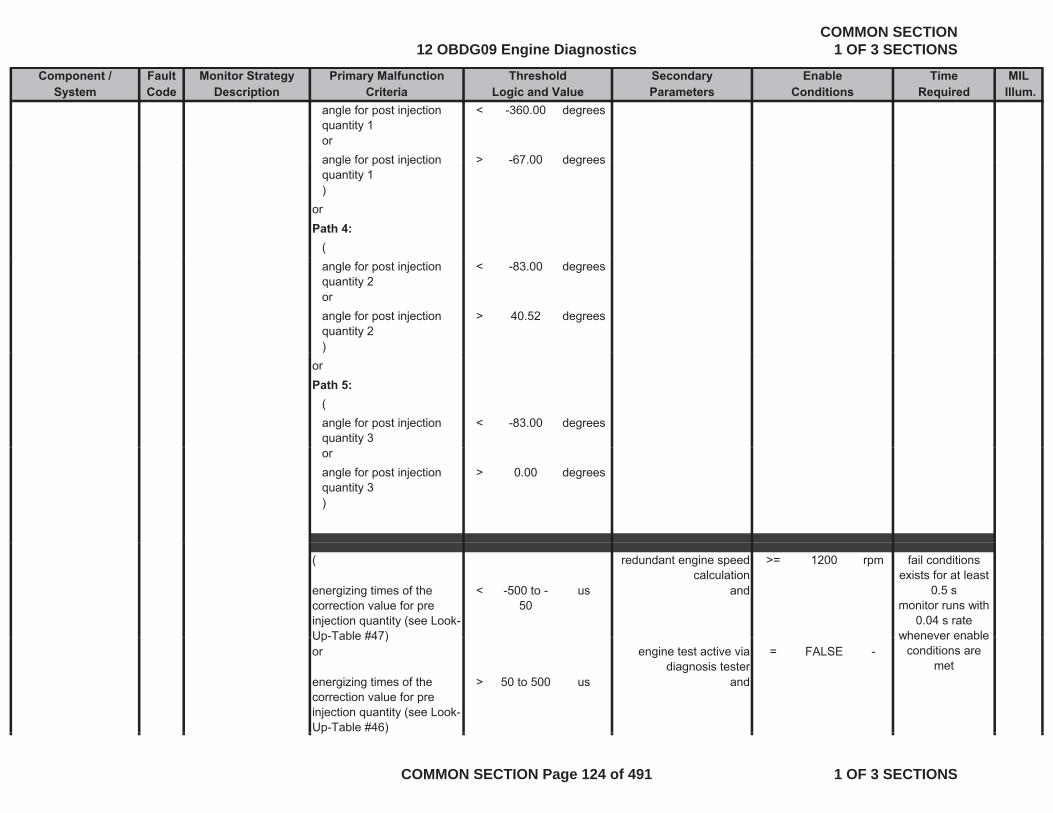
Component / Fault Monitor Strategy Primary Malfunction Secondary Time MILSystem Code Description Criteria Parameters Required Illum.
Threshold EnableLogic and Value Conditions
angle for post injection quantity 1
< -360.00 degrees
orangle for post injection > -67 00 degreesangle for post injection quantity 1
> 67.00 degrees
)orPath 4:
(angle for post injection quantity 2
< -83.00 degrees
orangle for post injection quantity 2
> 40.52 degrees
))orPath 5:
(angle for post injection quantity 3
< -83.00 degrees
orangle for post injection quantity 3
> 0.00 degrees
)
( redundant engine speed calculation
>= 1200 rpm
energizing times of the correction value for pre injection quantity (see Look-Up-Table #47)
< -500 to -50
us and
fail conditions exists for at least
0.5 smonitor runs with
0.04 s rate whenever enableUp Table #47)
or engine test active via diagnosis tester
= FALSE -
energizing times of the correction value for pre injection quantity (see Look-Up-Table #46)
> 50 to 500 us and
whenever enable conditions are
met
p )
12 OBDG09 Engine DiagnosticsCOMMON SECTION
1 OF 3 SECTIONS
COMMON SECTION Page 124 of 491 1 OF 3 SECTIONS
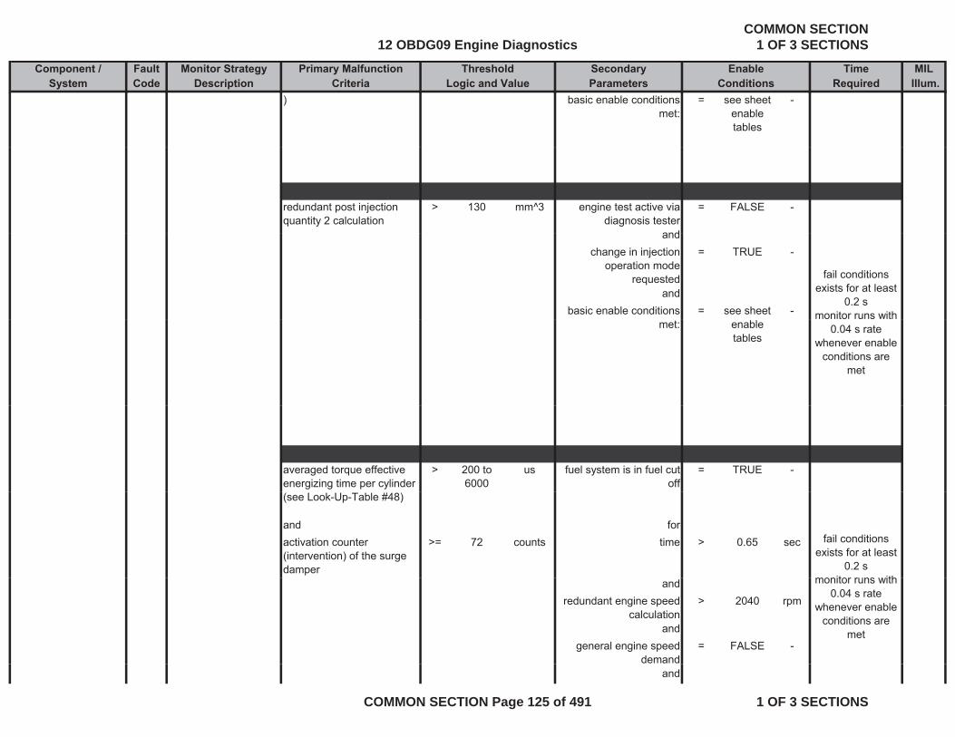
Component / Fault Monitor Strategy Primary Malfunction Secondary Time MILSystem Code Description Criteria Parameters Required Illum.
Threshold EnableLogic and Value Conditions
) basic enable conditions met:
= see sheet enable tables
-
redundant post injection quantity 2 calculation
> 130 mm^3 engine test active via diagnosis tester
= FALSE -
andandchange in injection
operation mode requested
= TRUE -
andbasic enable conditions = see sheet -
fail conditions exists for at least
0.2 smonitor runs with
met: enable tables
0.04 s rate whenever enable
conditions are met
averaged torque effective energizing time per cylinder
> 200 to 6000
us fuel system is in fuel cut off
= TRUE -
(see Look-Up-Table #48)
and foractivation counter (intervention) of the surge damper
>= 72 counts time > 0.65 sec fail conditions exists for at least
0.2 smonitor r ns ithand
redundant engine speed calculation
> 2040 rpm
andgeneral engine speed
demand= FALSE -
monitor runs with 0.04 s rate
whenever enable conditions are
met
and
12 OBDG09 Engine DiagnosticsCOMMON SECTION
1 OF 3 SECTIONS
COMMON SECTION Page 125 of 491 1 OF 3 SECTIONS
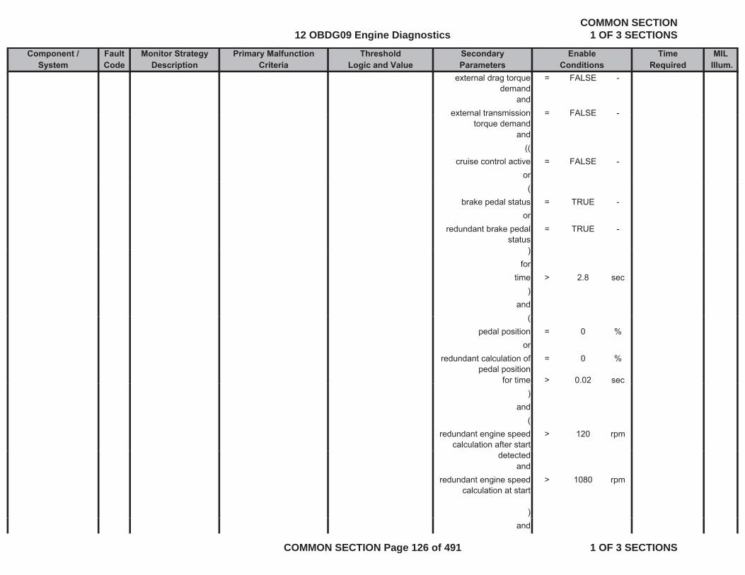
Component / Fault Monitor Strategy Primary Malfunction Secondary Time MILSystem Code Description Criteria Parameters Required Illum.
Threshold EnableLogic and Value Conditions
external drag torque demand
= FALSE -
andexternal transmission = FALSE -external transmission
torque demandFALSE
and((
cruise control active = FALSE -or(
brake pedal status = TRUE -or
redundant brake pedal status
= TRUE -
))for
time > 2.8 sec)
and((
pedal position = 0 %or
redundant calculation of pedal position
= 0 %
for time > 0.02 sec)
and(
redundant engine speed calculation after start
> 120 rpm
detectedand
redundant engine speed calculation at start
> 1080 rpm
)and
12 OBDG09 Engine DiagnosticsCOMMON SECTION
1 OF 3 SECTIONS
COMMON SECTION Page 126 of 491 1 OF 3 SECTIONS
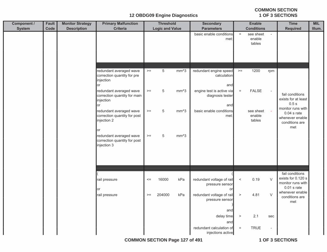
Component / Fault Monitor Strategy Primary Malfunction Secondary Time MILSystem Code Description Criteria Parameters Required Illum.
Threshold EnableLogic and Value Conditions
basic enable conditions met:
= see sheet enable tables
-
redundant averaged wave correction quantity for pre injection
>= 5 mm^3 redundant engine speed calculation
>= 1200 rpm
injectionor andredundant averaged wave correction quantity for main injection
>= 5 mm^3 engine test is active via diagnosis tester
= FALSE -
or and
fail conditions exists for at least
0.5 s monitor runs with
redundant averaged wave correction quantity for post injection 2
>= 5 mm^3 basic enable conditions met:
see sheet enable tables
-
orredundant averaged wave >= 5 mm^3
monitor runs with 0.04 s rate
whenever enable conditions are
met
correction quantity for post injection 3
( (rail pressure <= 16000 kPa redundant voltage of rail
pressure sensor< 0.19 V
or orrail pressure >= 204000 kPa redundant voltage of rail > 4.81 V
fail conditions exists for 0.120 s monitor runs with
0.01 s rate whenever enable
conditions arepressure sensor
)and
delay time > 2.1 secand
d d t l l ti f TRUE
conditions are met
redundant calculation of injections active
= TRUE -
12 OBDG09 Engine DiagnosticsCOMMON SECTION
1 OF 3 SECTIONS
COMMON SECTION Page 127 of 491 1 OF 3 SECTIONS
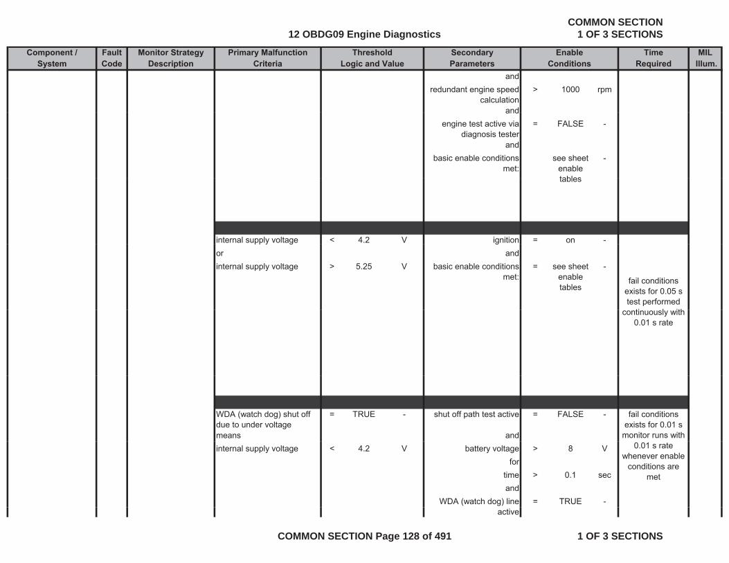
Component / Fault Monitor Strategy Primary Malfunction Secondary Time MILSystem Code Description Criteria Parameters Required Illum.
Threshold EnableLogic and Value Conditions
andredundant engine speed
calculation> 1000 rpm
andandengine test active via
diagnosis tester= FALSE -
andbasic enable conditions
met:see sheet
enable tables
-
tables
internal supply voltage < 4.2 V ignition = on -pp y g gor andinternal supply voltage > 5.25 V basic enable conditions
met:= see sheet
enable tables
-
fail conditions exists for 0.05 s test performed
ti l ithcontinuously with 0.01 s rate
WDA (watch dog) shut off due to under voltage
= TRUE - shut off path test active = FALSE -
means and
fail conditions exists for 0.01 s
monitor runs with internal supply voltage < 4.2 V battery voltage > 8 V
fortime > 0.1 secand
WDA (watch dog) line = TRUE -
0.01 s rate whenever enable
conditions are met
active
12 OBDG09 Engine DiagnosticsCOMMON SECTION
1 OF 3 SECTIONS
COMMON SECTION Page 128 of 491 1 OF 3 SECTIONS
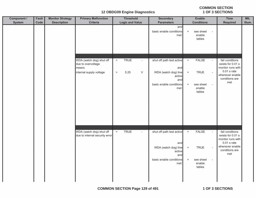
Component / Fault Monitor Strategy Primary Malfunction Secondary Time MILSystem Code Description Criteria Parameters Required Illum.
Threshold EnableLogic and Value Conditions
andbasic enable conditions
met:= see sheet
enable tables
-
tables
WDA (watch dog) shut off = TRUE - shut off path test active = FALSE - fail conditions due to overvoltagemeans andinternal supply voltage > 5.25 V WDA (watch dog) line
active= TRUE -
andbasic enable conditions = see sheet -
exists for 0.01 s monitor runs with
0.01 s rate whenever enable
conditions are met
met: enable tables
WDA (watch dog) shut off = TRUE - shut off path test active = FALSE - fail conditionsWDA (watch dog) shut off due to internal security error
= TRUE - shut off path test active = FALSE -
andWDA (watch dog) line
active= TRUE -
and
fail conditions exists for 0.01 s
monitor runs with 0.01 s rate
whenever enable conditions are
metandbasic enable conditions
met:= see sheet
enable tables
-
12 OBDG09 Engine DiagnosticsCOMMON SECTION
1 OF 3 SECTIONS
COMMON SECTION Page 129 of 491 1 OF 3 SECTIONS

Component / Fault Monitor Strategy Primary Malfunction Secondary Time MILSystem Code Description Criteria Parameters Required Illum.
Threshold EnableLogic and Value Conditions
WDA (watch dog) shut off because of corrupt question-and-answer communication
= TRUE - ignition = on - fail conditions exists for 0.01 s
monitor runs withand answer communication
andWDA (watch dog) line
active= TRUE -
andshut off path test active = FALSE
monitor runs with 0.01 s rate
whenever enable conditions are
met
shut off path test active = FALSE -
andbasic enable conditions
met:= see sheet
enable tables
-
the actual response time from processor is not equal to the requested response-time
= TRUE - ignition = on -
andb i bl diti h t
fail conditions exists for morebasic enable conditions
met:= see sheet
enable tables
-
andNO Pending or
C fi d DTC= see sheet
i hibit-
exists for more than 0.16 s
monitor runs at least twice every
0.08 s rate whenever enable
conditions are Confirmed DTCs: inhibit
tablesmet
12 OBDG09 Engine DiagnosticsCOMMON SECTION
1 OF 3 SECTIONS
COMMON SECTION Page 130 of 491 1 OF 3 SECTIONS
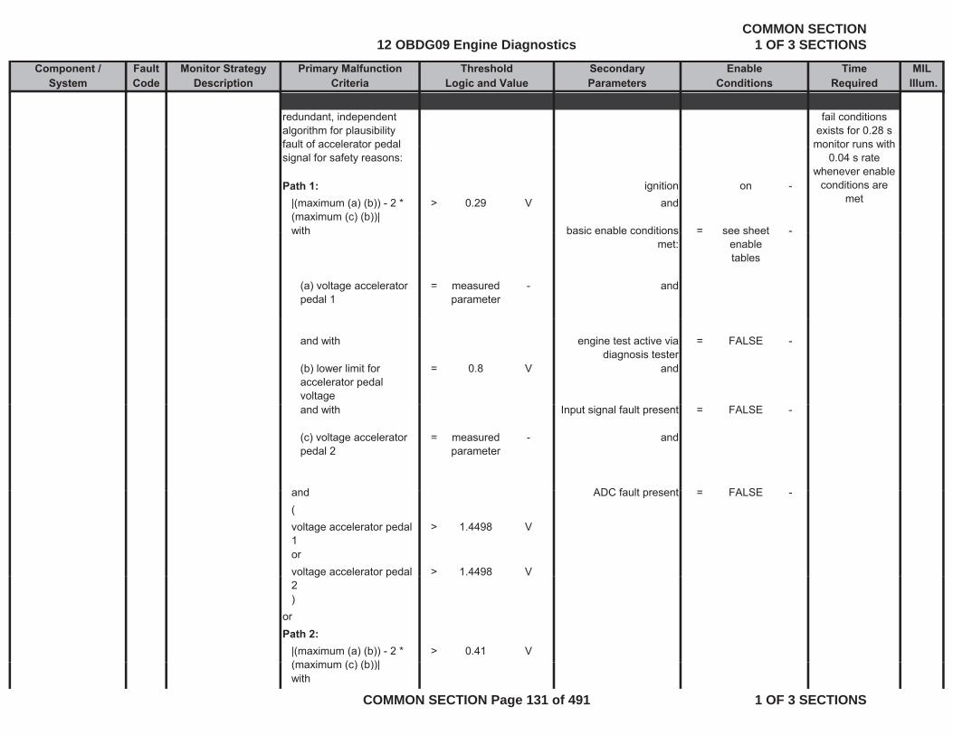
Component / Fault Monitor Strategy Primary Malfunction Secondary Time MILSystem Code Description Criteria Parameters Required Illum.
Threshold EnableLogic and Value Conditions
redundant, independent algorithm for plausibility fault of accelerator pedal
fail conditions exists for 0.28 s
monitor runs withfault of accelerator pedal signal for safety reasons:
Path 1: ignition on -|(maximum (a) (b)) - 2 * (maximum (c) (b))|
> 0.29 V and
with basic enable conditions = see sheet -
monitor runs with 0.04 s rate
whenever enable conditions are
met
with basic enable conditions met:
see sheet enable tables
(a) voltage accelerator pedal 1
= measured parameter
- and
and with engine test active via diagnosis tester
= FALSE -
(b) lower limit for accelerator pedal voltage
= 0.8 V and
and with Input signal fault present = FALSE -
(c) voltage accelerator pedal 2
= measured parameter
- and
d ADC f lt t FALSEand ADC fault present = FALSE -(voltage accelerator pedal 1
> 1.4498 V
orvoltage accelerator pedal > 1.4498 Vg p2)
orPath 2:
|(maximum (a) (b)) - 2 * ( i ( ) (b))|
> 0.41 V(maximum (c) (b))|with
12 OBDG09 Engine DiagnosticsCOMMON SECTION
1 OF 3 SECTIONS
COMMON SECTION Page 131 of 491 1 OF 3 SECTIONS
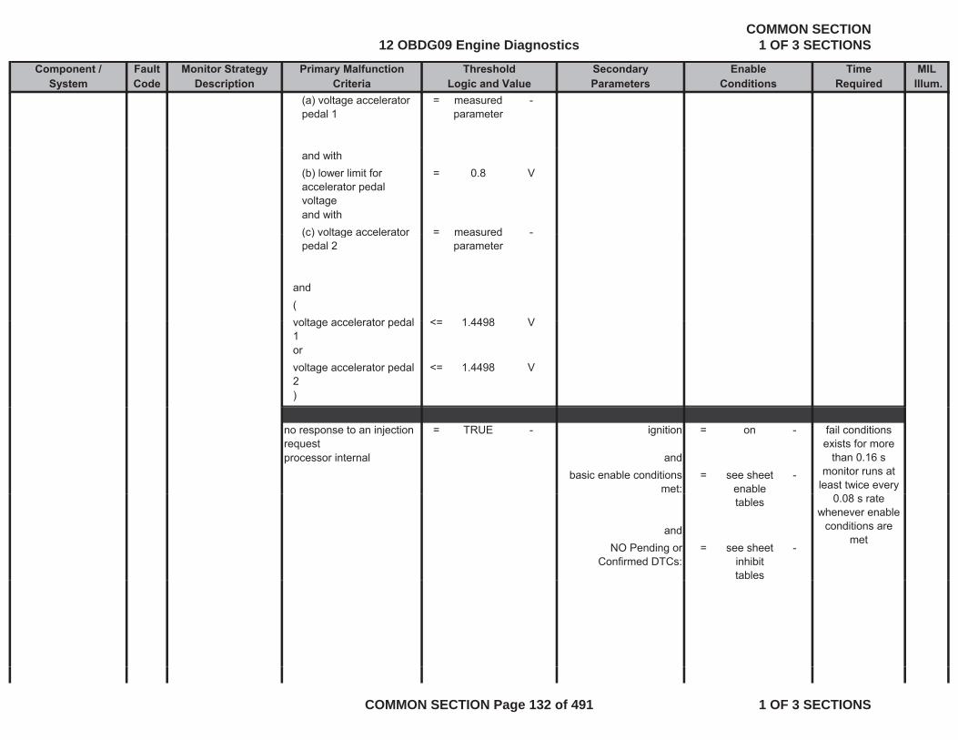
Component / Fault Monitor Strategy Primary Malfunction Secondary Time MILSystem Code Description Criteria Parameters Required Illum.
Threshold EnableLogic and Value Conditions
(a) voltage accelerator pedal 1
= measured parameter
-
and with(b) lower limit for accelerator pedal voltage
= 0.8 V
and with(c) voltage accelerator = measured -(c) voltage accelerator pedal 2
measured parameter
and(voltage accelerator pedal <= 1 4498 Vvoltage accelerator pedal 1
<= 1.4498 V
orvoltage accelerator pedal 2
<= 1.4498 V
)
no response to an injection request
= TRUE - ignition = on -
processor internal andbasic enable conditions
met:= see sheet
enable -
fail conditions exists for more
than 0.16 smonitor runs at
least twice every tables
andNO Pending or
Confirmed DTCs:= see sheet
inhibit tables
-
0.08 s rate whenever enable
conditions are met
12 OBDG09 Engine DiagnosticsCOMMON SECTION
1 OF 3 SECTIONS
COMMON SECTION Page 132 of 491 1 OF 3 SECTIONS

Component / Fault Monitor Strategy Primary Malfunction Secondary Time MILSystem Code Description Criteria Parameters Required Illum.
Threshold EnableLogic and Value Conditions
no response to shut-off path test
= TRUE - ignition = on -
processor internal andprocessor internal andbasic enable conditions
met:= see sheet
enable tables
-
andNO Pending or = see sheet
fail conditions exists for more
than 184 eventsmonitor runs atNO Pending or
Confirmed DTCs:= see sheet
inhibit tables
- monitor runs at least twice every
0.08 s rate whenever enable
conditions are met
no response to hardware activation request
= TRUE - ignition = on -
processor internal and
fail conditions exists for more than 98 eventsmonitor runs at p
basic enable conditions met:
= see sheet enable tables
-
andNO Pending or = see sheet -
least twice every 0.08 s rate
whenever enable conditions are
met
NO Pending or Confirmed DTCs:
= see sheet inhibit tables
-
12 OBDG09 Engine DiagnosticsCOMMON SECTION
1 OF 3 SECTIONS
COMMON SECTION Page 133 of 491 1 OF 3 SECTIONS
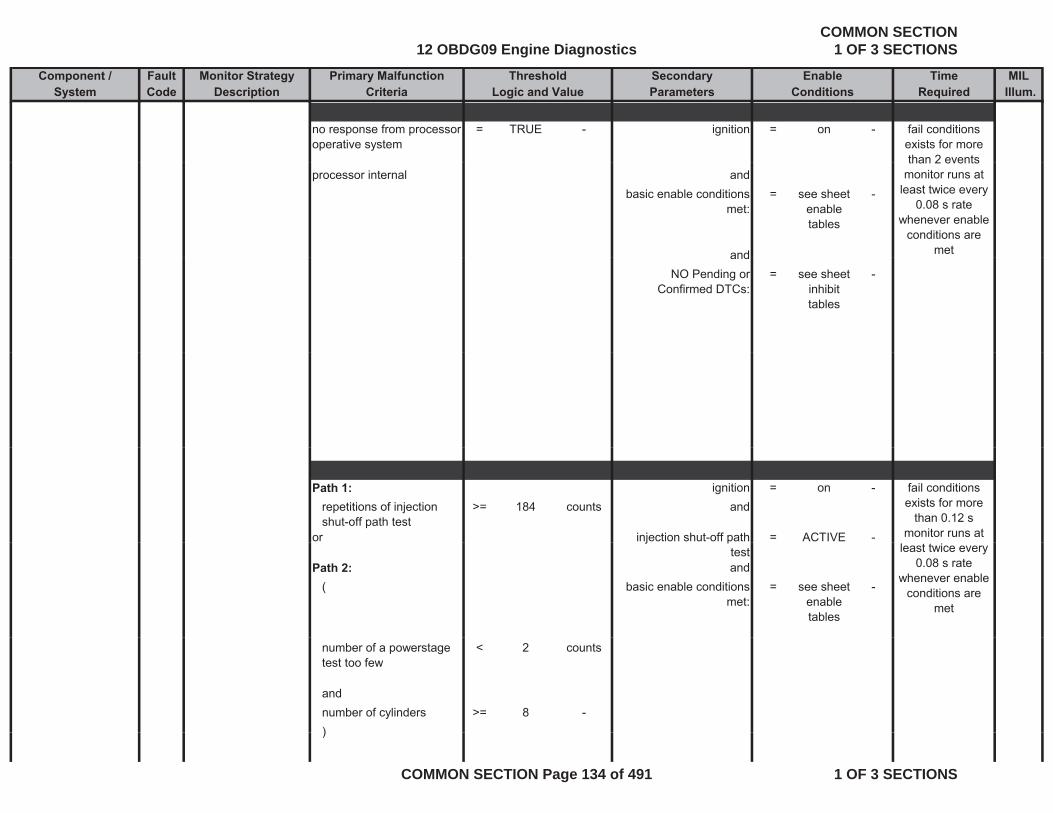
Component / Fault Monitor Strategy Primary Malfunction Secondary Time MILSystem Code Description Criteria Parameters Required Illum.
Threshold EnableLogic and Value Conditions
no response from processor operative system
= TRUE - ignition = on - fail conditions exists for more than 2 events
processor internal andbasic enable conditions
met:= see sheet
enable tables
-
and
than 2 eventsmonitor runs at
least twice every 0.08 s rate
whenever enable conditions are
metandNO Pending or
Confirmed DTCs:= see sheet
inhibit tables
-
Path 1: ignition = on -repetitions of injection shut-off path test
>= 184 counts and
or injection shut-off path = ACTIVE -
fail conditions exists for more
than 0.12 smonitor runs at j p
testPath 2: and
( basic enable conditions met:
= see sheet enable tables
-
least twice every 0.08 s rate
whenever enable conditions are
met
number of a powerstage test too few
< 2 counts
andnumber of cylinders >= 8 -))
12 OBDG09 Engine DiagnosticsCOMMON SECTION
1 OF 3 SECTIONS
COMMON SECTION Page 134 of 491 1 OF 3 SECTIONS
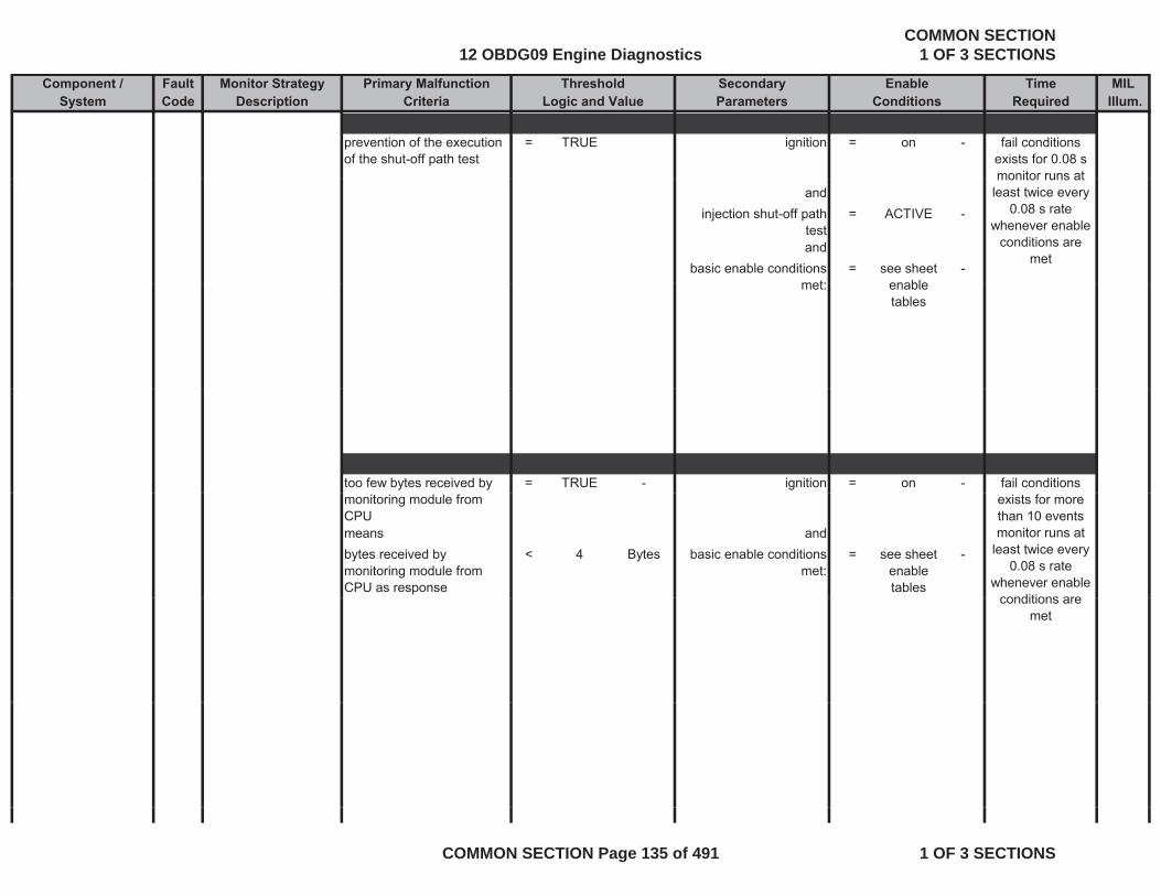
Component / Fault Monitor Strategy Primary Malfunction Secondary Time MILSystem Code Description Criteria Parameters Required Illum.
Threshold EnableLogic and Value Conditions
prevention of the execution of the shut-off path test
= TRUE ignition = on - fail conditions exists for 0.08 s monitor runs at
andinjection shut-off path
test= ACTIVE -
andbasic enable conditions
met:= see sheet
enable-
monitor runs at least twice every
0.08 s rate whenever enable
conditions are met
met: enable tables
too few bytes received by = TRUE - ignition = on - fail conditions monitoring module from CPUmeans andbytes received by monitoring module from CPU as response
< 4 Bytes basic enable conditions met:
= see sheet enable tables
-
exists for more than 10 eventsmonitor runs at
least twice every 0.08 s rate
whenever enable conditions areconditions are
met
12 OBDG09 Engine DiagnosticsCOMMON SECTION
1 OF 3 SECTIONS
COMMON SECTION Page 135 of 491 1 OF 3 SECTIONS
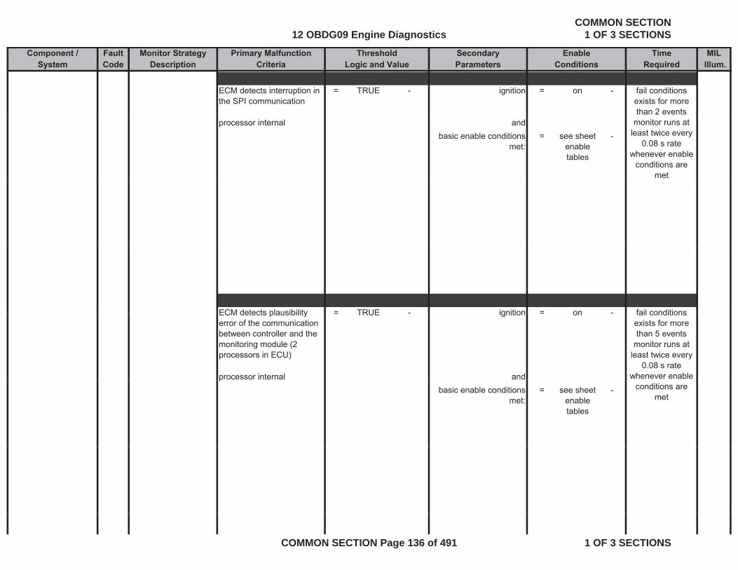
Component / Fault Monitor Strategy Primary Malfunction Secondary Time MILSystem Code Description Criteria Parameters Required Illum.
Threshold EnableLogic and Value Conditions
ECM detects interruption in the SPI communication
= TRUE - ignition = on - fail conditions exists for more than 2 events
processor internal andbasic enable conditions
met:= see sheet
enable tables
-
than 2 eventsmonitor runs at
least twice every 0.08 s rate
whenever enable conditions are
met
ECM detects plausibility = TRUE - ignition = on - fail conditionsECM detects plausibility error of the communication between controller and the monitoring module (2 processors in ECU)
= TRUE ignition = on
processor internal and
fail conditions exists for more than 5 events
monitor runs at least twice every
0.08 s rate whenever enable p
basic enable conditions met:
= see sheet enable tables
- conditions are met
12 OBDG09 Engine DiagnosticsCOMMON SECTION
1 OF 3 SECTIONS
COMMON SECTION Page 136 of 491 1 OF 3 SECTIONS
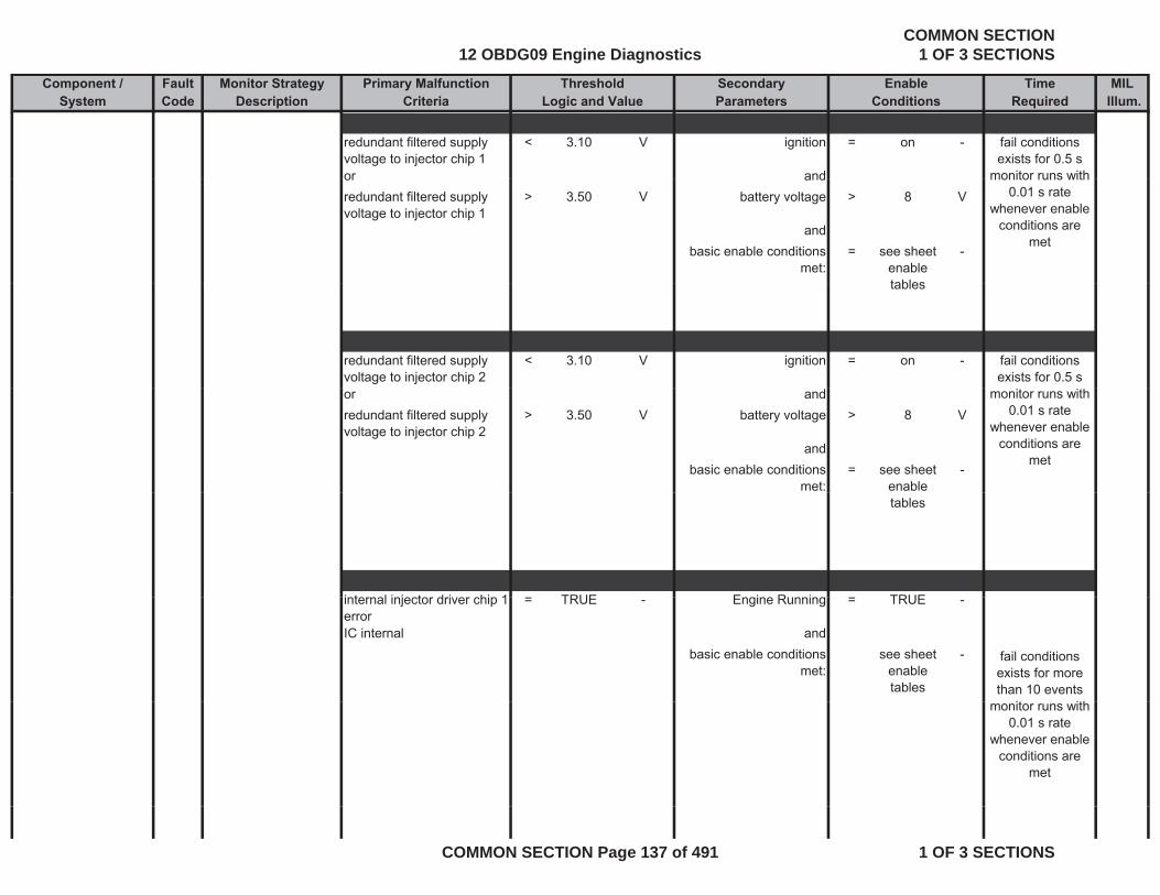
Component / Fault Monitor Strategy Primary Malfunction Secondary Time MILSystem Code Description Criteria Parameters Required Illum.
Threshold EnableLogic and Value Conditions
redundant filtered supply voltage to injector chip 1
< 3.10 V ignition = on -
or and
fail conditions exists for 0.5 s
monitor runs withor andredundant filtered supply voltage to injector chip 1
> 3.50 V battery voltage > 8 V
andbasic enable conditions
met:= see sheet
enable tables
-
monitor runs with 0.01 s rate
whenever enable conditions are
met
tables
redundant filtered supply voltage to injector chip 2
< 3.10 V ignition = on - fail conditions exists for 0.5 s
or andredundant filtered supply voltage to injector chip 2
> 3.50 V battery voltage > 8 V
andbasic enable conditions
met:= see sheet
enable -
monitor runs with 0.01 s rate
whenever enable conditions are
met
tables
i t l i j t d i hi 1 TRUE E i R i TRUEinternal injector driver chip 1 error
= TRUE - Engine Running = TRUE -
IC internal andbasic enable conditions
met:see sheet
enable tables
- fail conditions exists for more than 10 events
it ithmonitor runs with 0.01 s rate
whenever enable conditions are
met
12 OBDG09 Engine DiagnosticsCOMMON SECTION
1 OF 3 SECTIONS
COMMON SECTION Page 137 of 491 1 OF 3 SECTIONS
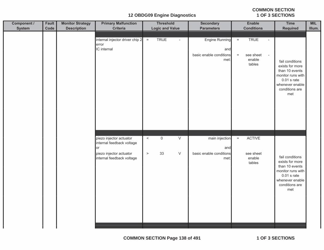
Component / Fault Monitor Strategy Primary Malfunction Secondary Time MILSystem Code Description Criteria Parameters Required Illum.
Threshold EnableLogic and Value Conditions
internal injector driver chip 2 error
= TRUE - Engine Running = TRUE -
IC internal andIC internal andbasic enable conditions
met:= see sheet
enable tables
-
fail conditions exists for more than 10 events
monitor runs with 0 01 t0.01 s rate
whenever enable conditions are
met
i i j t t t < 0 V i i j ti ACTIVEpiezo injector actuator internal feedback voltage
< 0 V main injection = ACTIVE
or andpiezo injector actuator internal feedback voltage
> 33 V basic enable conditions met:
see sheet enable tables
fail conditions exists for more than 10 eventsthan 10 events
monitor runs with 0.01 s rate
whenever enable conditions are
met
12 OBDG09 Engine DiagnosticsCOMMON SECTION
1 OF 3 SECTIONS
COMMON SECTION Page 138 of 491 1 OF 3 SECTIONS
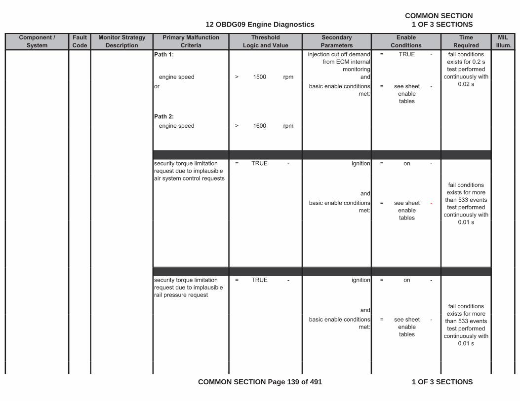
Component / Fault Monitor Strategy Primary Malfunction Secondary Time MILSystem Code Description Criteria Parameters Required Illum.
Threshold EnableLogic and Value Conditions
Path 1: injection cut off demand from ECM internal
monitoring
= TRUE -
engine speed > 1500 rpm and
fail conditions exists for 0.2 s test performed
continuously with g p por basic enable conditions
met:= see sheet
enable tables
-
Path 2:engine speed > 1600 rpm
0.02 s
engine speed > 1600 rpm
security torque limitation request due to implausible
= TRUE - ignition = on -q p
air system control requests
andbasic enable conditions
met:= see sheet
enable tables
-
fail conditions exists for more than 533 eventstest performed
continuously with 0 010.01 s
security torque limitation request due to implausible rail pressure request
= TRUE - ignition = on -
and fail conditions exists for more
basic enable conditions met:
= see sheet enable tables
-exists for more than 533 eventstest performed
continuously with 0.01 s
12 OBDG09 Engine DiagnosticsCOMMON SECTION
1 OF 3 SECTIONS
COMMON SECTION Page 139 of 491 1 OF 3 SECTIONS
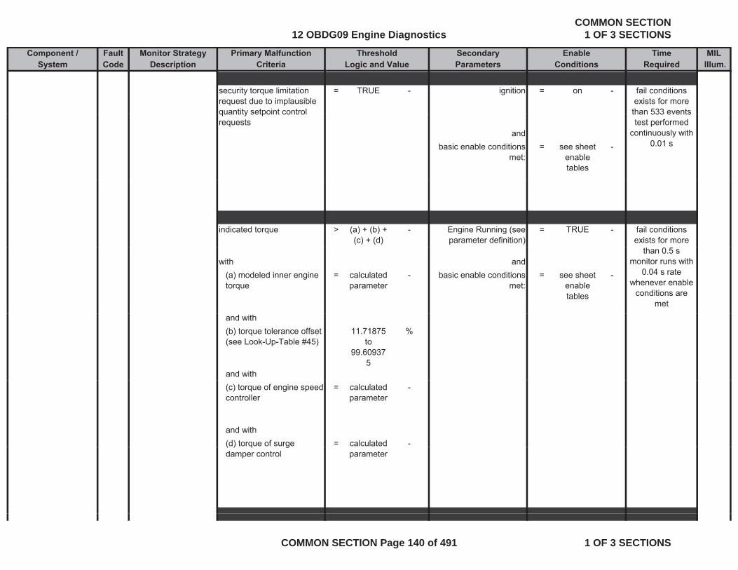
Component / Fault Monitor Strategy Primary Malfunction Secondary Time MILSystem Code Description Criteria Parameters Required Illum.
Threshold EnableLogic and Value Conditions
security torque limitation request due to implausible quantity setpoint control
= TRUE - ignition = on - fail conditions exists for more than 533 eventsquantity setpoint control
requestsand
basic enable conditions met:
= see sheet enable tables
-
than 533 eventstest performed
continuously with 0.01 s
indicated torque > (a) + (b) + (c) + (d)
- Engine Running (see parameter definition)
= TRUE - fail conditions exists for more
with and(a) modeled inner engine torque
= calculated parameter
- basic enable conditions met:
= see sheet enable tables
-
than 0.5 smonitor runs with
0.04 s rate whenever enable
conditions are met
and with(b) torque tolerance offset (see Look-Up-Table #45)
11.71875 to
99.609375
%
and with(c) torque of engine speed controller
= calculated parameter
-
and with(d) torque of surge = calculated -( ) q gdamper control parameter
12 OBDG09 Engine DiagnosticsCOMMON SECTION
1 OF 3 SECTIONS
COMMON SECTION Page 140 of 491 1 OF 3 SECTIONS
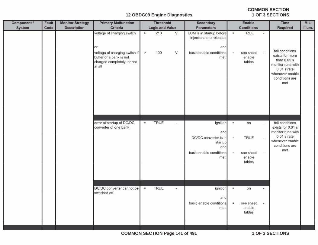
Component / Fault Monitor Strategy Primary Malfunction Secondary Time MILSystem Code Description Criteria Parameters Required Illum.
Threshold EnableLogic and Value Conditions
voltage of charging switch > 210 V ECM is in startup before injections are released
= TRUE -
or andvoltage of charging switch if buffer of a bank is not charged completely, or not at all
> 100 V basic enable conditions met:
= see sheet enable tables
- fail conditions exists for more
than 0.05 smonitor runs with
0.01 s rate whenever enable
diticonditions are met
error at startup of DC/DC converter of one bank
= TRUE - ignition = on -
and
fail conditions exists for 0.01 s
monitor runs with DC/DC converter is in
startup= TRUE -
andbasic enable conditions
met:= see sheet
enable tables
-
0.01 s rate whenever enable
conditions are met
DC/DC converter cannot be it h d ff
= TRUE - ignition = on -switched off.
andbasic enable conditions
met:= see sheet
enable tables
-
12 OBDG09 Engine DiagnosticsCOMMON SECTION
1 OF 3 SECTIONS
COMMON SECTION Page 141 of 491 1 OF 3 SECTIONS
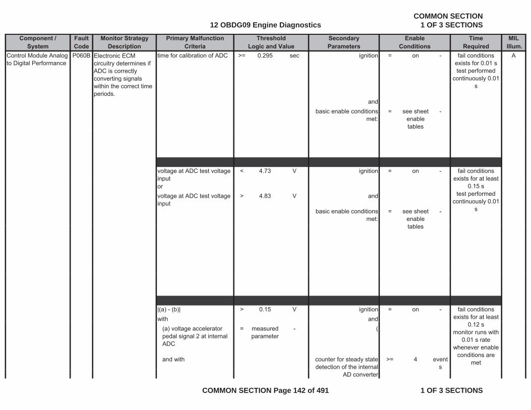
Component / Fault Monitor Strategy Primary Malfunction Secondary Time MILSystem Code Description Criteria Parameters Required Illum.
Threshold EnableLogic and Value Conditions
Control Module Analog to Digital Performance
P060B Electronic ECM circuitry determines if ADC is correctly converting signals
time for calibration of ADC >= 0.295 sec ignition = on - Afail conditions exists for 0.01 s test performed
continuously 0.01 g gwithin the correct time periods.
andbasic enable conditions
met:= see sheet
enable tables
-
s
voltage at ADC test voltage input
< 4.73 V ignition = on - fail conditions exists for at leastinput
orvoltage at ADC test voltage input
> 4.83 V and
basic enable conditions met:
= see sheet enable tables
-
exists for at least 0.15 s
test performed continuously 0.01
s
tables
|(a) - (b)| > 0.15 V ignition = on -with and
fail conditions exists for at least
(a) voltage accelerator pedal signal 2 at internal ADC
= measured parameter
- (
and with counter for steady state detection of the internal
>= 4 events
0.12 smonitor runs with
0.01 s rate whenever enable
conditions are met
AD converter
12 OBDG09 Engine DiagnosticsCOMMON SECTION
1 OF 3 SECTIONS
COMMON SECTION Page 142 of 491 1 OF 3 SECTIONS
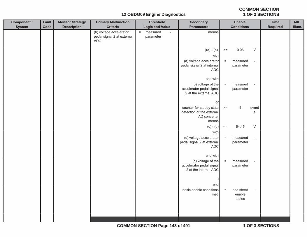
Component / Fault Monitor Strategy Primary Malfunction Secondary Time MILSystem Code Description Criteria Parameters Required Illum.
Threshold EnableLogic and Value Conditions
(b) voltage accelerator pedal signal 2 at external ADC
= measured parameter
- means
|(a) - (b)| <= 0.06 Vwith
(a) voltage accelerator pedal signal 2 at internal
ADC
= measured parameter
-
and with(b) voltage of the
accelerator pedal signal 2 at the external ADC
= measured parameter
-
ororcounter for steady state detection of the external
AD converter
>= 4 events
means(c) - (d) <= 64.45 V
with(c) voltage accelerator
pedal signal 2 at external ADC
= measured parameter
-
and with(d) voltage of the
accelerator pedal signal 2 at the internal ADC
= measured parameter
-
)and
basic enable conditions met:
= see sheet enable tables
-
12 OBDG09 Engine DiagnosticsCOMMON SECTION
1 OF 3 SECTIONS
COMMON SECTION Page 143 of 491 1 OF 3 SECTIONS
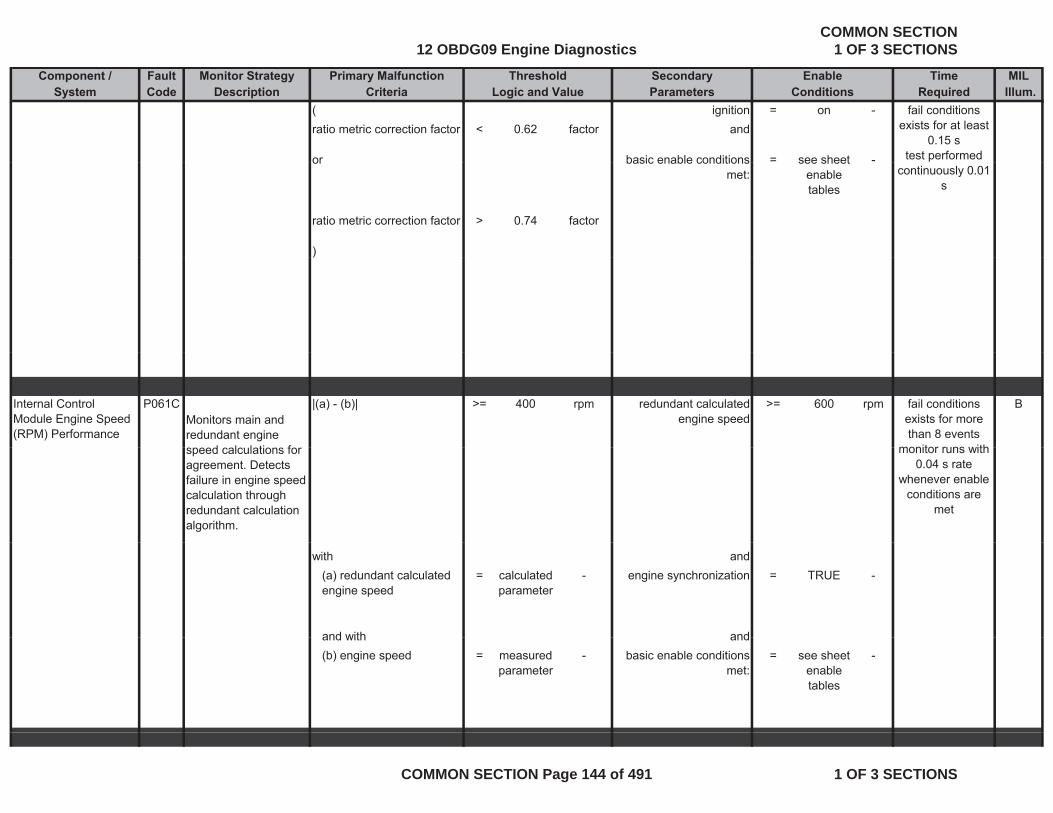
Component / Fault Monitor Strategy Primary Malfunction Secondary Time MILSystem Code Description Criteria Parameters Required Illum.
Threshold EnableLogic and Value Conditions
( ignition = on -ratio metric correction factor < 0.62 factor and
or basic enable conditions = see sheet -
fail conditions exists for at least
0.15 stest performed or basic enable conditions
met:see sheet
enable tables
ratio metric correction factor > 0.74 factor
)
continuously 0.01 s
)
Internal Control Module Engine Speed (RPM) Performance
P061CMonitors main and redundant engine
d l l ti f
|(a) - (b)| >= 400 rpm redundant calculated engine speed
>= 600 rpm Bfail conditions exists for more than 8 events
monitor runs withspeed calculations for agreement. Detects failure in engine speed calculation through redundant calculation algorithm.
monitor runs with 0.04 s rate
whenever enable conditions are
met
with and(a) redundant calculated engine speed
= calculated parameter
- engine synchronization = TRUE -
and with andand with and(b) engine speed = measured
parameter- basic enable conditions
met:= see sheet
enable tables
-
12 OBDG09 Engine DiagnosticsCOMMON SECTION
1 OF 3 SECTIONS
COMMON SECTION Page 144 of 491 1 OF 3 SECTIONS
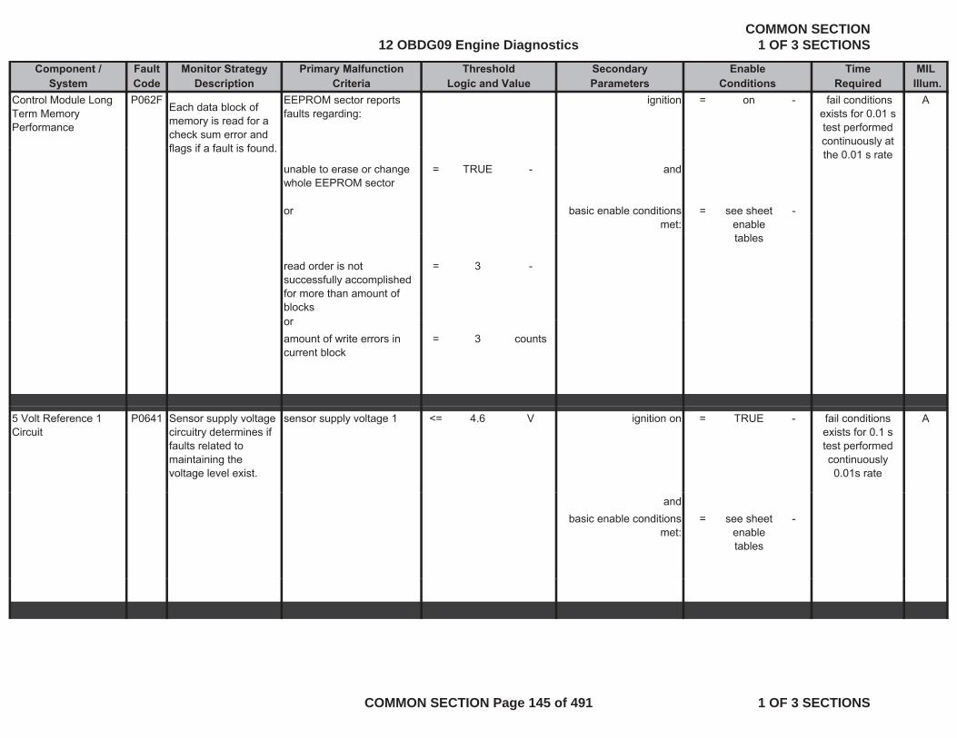
Component / Fault Monitor Strategy Primary Malfunction Secondary Time MILSystem Code Description Criteria Parameters Required Illum.
Threshold EnableLogic and Value Conditions
Control Module Long Term Memory Performance
P062FEach data block of memory is read for a check sum error and flags if a fault is found
EEPROM sector reports faults regarding:
ignition = on - A fail conditions exists for 0.01 s test performed continuously at
flags if a fault is found.
unable to erase or change whole EEPROM sector
= TRUE - and
or basic enable conditions met:
= see sheet enable
-
the 0.01 s rate
tables
read order is not successfully accomplished for more than amount of blocks
= 3 -
ororamount of write errors in current block
= 3 counts
5 Volt Reference 1 Circuit
P0641 Sensor supply voltage circuitry determines if faults related to maintaining the voltage level exist.
sensor supply voltage 1 <= 4.6 V ignition on = TRUE - Afail conditions exists for 0.1 s test performed continuously 0.01s rate
andbasic enable conditions
met:= see sheet
enable tables
-
12 OBDG09 Engine DiagnosticsCOMMON SECTION
1 OF 3 SECTIONS
COMMON SECTION Page 145 of 491 1 OF 3 SECTIONS
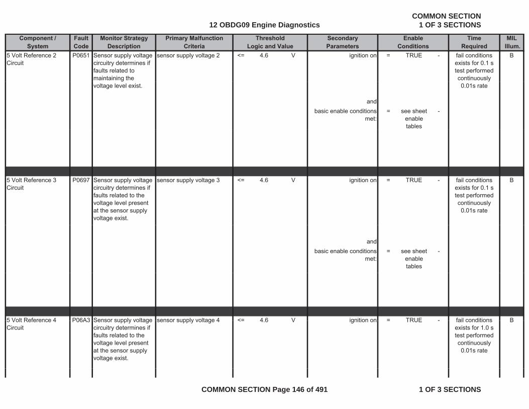
Component / Fault Monitor Strategy Primary Malfunction Secondary Time MILSystem Code Description Criteria Parameters Required Illum.
Threshold EnableLogic and Value Conditions
5 Volt Reference 2 Circuit
P0651 Sensor supply voltage circuitry determines if faults related to maintaining the
sensor supply voltage 2 <= 4.6 V ignition on = TRUE - Bfail conditions exists for 0.1 s test performed continuously
voltage level exist.
andbasic enable conditions
met:= see sheet
enable tables
-
0.01s rate
5 Volt Reference 3 Circuit
P0697 Sensor supply voltage circuitry determines if faults related to the voltage level present at the sensor supply voltage exist.
sensor supply voltage 3 <= 4.6 V ignition on = TRUE - Bfail conditions exists for 0.1 s test performed continuously 0.01s rate
andbasic enable conditions
met:= see sheet
enable tables
-
5 Volt Reference 4 P06A3 Sensor supply voltage sensor supply voltage 4 <= 4 6 V ignition on = TRUE - Bfail conditions5 Volt Reference 4 Circuit
P06A3 Sensor supply voltage circuitry determines if faults related to the voltage level present at the sensor supply voltage exist.
sensor supply voltage 4 <= 4.6 V ignition on = TRUE - Bfail conditions exists for 1.0 s test performed continuously 0.01s rate
12 OBDG09 Engine DiagnosticsCOMMON SECTION
1 OF 3 SECTIONS
COMMON SECTION Page 146 of 491 1 OF 3 SECTIONS

Component / Fault Monitor Strategy Primary Malfunction Secondary Time MILSystem Code Description Criteria Parameters Required Illum.
Threshold EnableLogic and Value Conditions
andbasic enable conditions
met:= see sheet
enable tables
-
tables
5 Volt Reference 5 Circuit
P06D2 Sensor supply voltage circuitry determines if faults related to the voltage level present at the sensor supply voltage exist.
sensor supply voltage 5 <= 4.6 V ignition on = TRUE - Bfail conditions exists for 0.1 s test performed continuously 0.01s rate
andbasic enable conditions
met:= see sheet
enable tables
-
M lf ti I di t P0650 Thi di ti h k Th ECM d t t th t th l i d d TRUE A (f il ditiMalfunction Indicator Lamp (MIL) Control Circuit
P0650 This diagnostic checks the MIL circuit for electrical integrity during operation.
The ECM detects that the commanded state of the driver and the actual state of the control circuit do not match.
lamp is commanded on = TRUE - A (no MIL)
andi iti
fail conditions exists for 3 s
monitor runs with 0.01 s rate
whenever enable conditions are
metignition = on -and
(battery voltage > 11 V
forti 3
met
time > 3 sec
12 OBDG09 Engine DiagnosticsCOMMON SECTION
1 OF 3 SECTIONS
COMMON SECTION Page 147 of 491 1 OF 3 SECTIONS
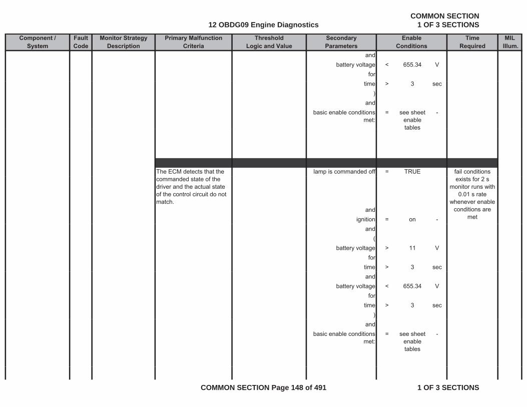
Component / Fault Monitor Strategy Primary Malfunction Secondary Time MILSystem Code Description Criteria Parameters Required Illum.
Threshold EnableLogic and Value Conditions
andbattery voltage < 655.34 V
fortime > 3 sec
)and
basic enable conditions met:
= see sheet enable tables
-
tables
The ECM detects that the lamp is commanded off = TRUE fail conditions commanded state of the driver and the actual state of the control circuit do not match.
andignition = on -
exists for 2 smonitor runs with
0.01 s rate whenever enable
conditions are met
and(
battery voltage > 11 Vfor
time > 3 secand
battery voltage < 655.34 Vfor
time > 3 sec)
andbasic enable conditions
met:= see sheet
enable tables
-
12 OBDG09 Engine DiagnosticsCOMMON SECTION
1 OF 3 SECTIONS
COMMON SECTION Page 148 of 491 1 OF 3 SECTIONS
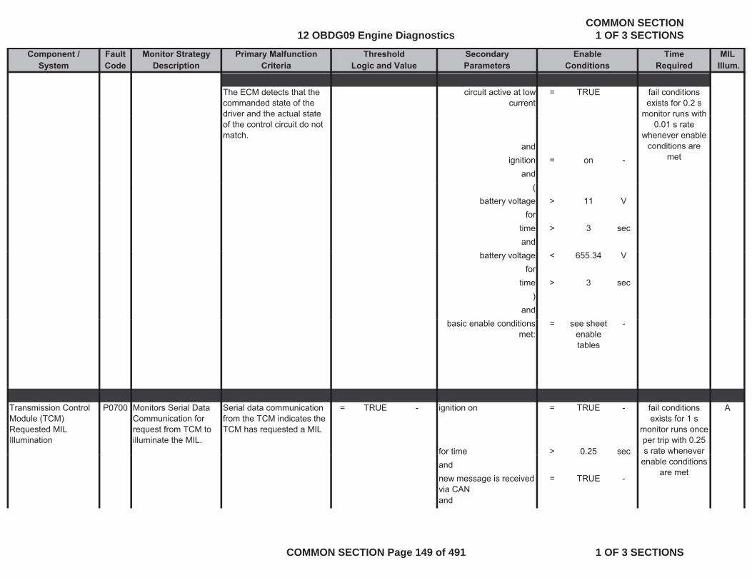
Component / Fault Monitor Strategy Primary Malfunction Secondary Time MILSystem Code Description Criteria Parameters Required Illum.
Threshold EnableLogic and Value Conditions
The ECM detects that the commanded state of the driver and the actual state
circuit active at low current
= TRUE fail conditions exists for 0.2 s
monitor runs withdriver and the actual state of the control circuit do not match.
andignition = on -
and
monitor runs with 0.01 s rate
whenever enable conditions are
met
(battery voltage > 11 V
fortime > 3 secand
battery voltage < 655.34 Vfor
time > 3 sec)
andbasic enable conditions
met:= see sheet
enable tables
-
Transmission Control Module (TCM) Requested MIL Illumination
P0700 Monitors Serial Data Communication for request from TCM to illuminate the MIL.
Serial data communication from the TCM indicates the TCM has requested a MIL
= TRUE - ignition on = TRUE - A
for time > 0.25 sec
fail conditions exists for 1 s
monitor runs once per trip with 0.25 s rate whenever
andnew message is received via CAN
= TRUE -
and
enable conditions are met
12 OBDG09 Engine DiagnosticsCOMMON SECTION
1 OF 3 SECTIONS
COMMON SECTION Page 149 of 491 1 OF 3 SECTIONS
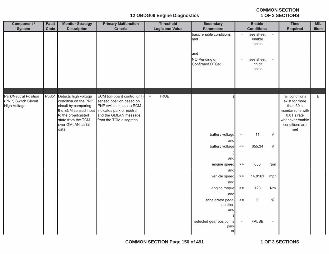
Component / Fault Monitor Strategy Primary Malfunction Secondary Time MILSystem Code Description Criteria Parameters Required Illum.
Threshold EnableLogic and Value Conditions
basic enable conditions met
= see sheet enable tables
-
andNO Pending or Confirmed DTCs:
= see sheet inhibit tables
-
Park/Neutral Position (PNP) Switch Circuit High Voltage
P0851 Detects high voltage condition on the PNP circuit by comparing the ECM sensed input
ECM (on-board control unit) sensed position based on PNP switch inputs to ECM indicates park or neutral
= TRUE ( Bfail conditions exist for more
than 30 smonitor runs withthe ECM sensed input
to the broadcasted state from the TCM over GMLAN serial data
indicates park or neutral and the GMLAN message from the TCM disagrees
battery voltage >= 11 Vand
monitor runs with 0.01 s rate
whenever enable conditions are
met
andbattery voltage <= 655.34 V
)and
engine speed >= 650 rpmdand
vehicle speed >= 14.9161 mphand
engine torque >= 120 Nmand
l t d l > 0 %accelerator pedal position
>= 0 %
and(
selected gear position is park
= FALSE -
or
12 OBDG09 Engine DiagnosticsCOMMON SECTION
1 OF 3 SECTIONS
COMMON SECTION Page 150 of 491 1 OF 3 SECTIONS
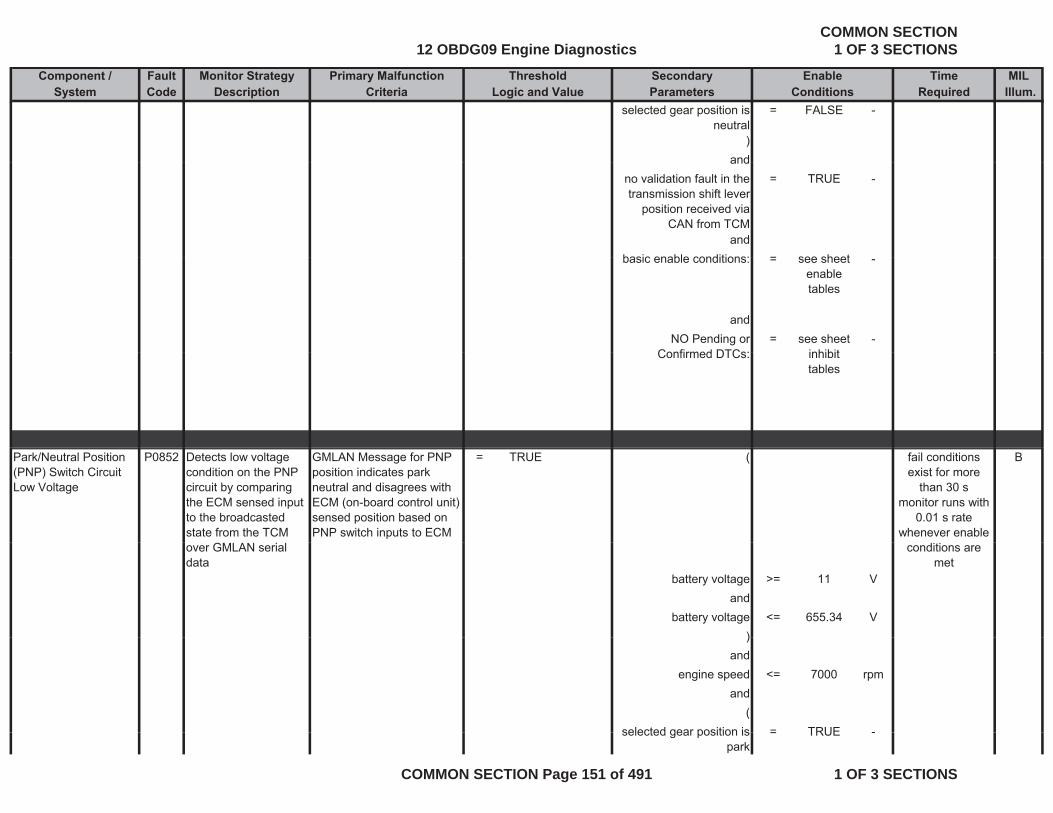
Component / Fault Monitor Strategy Primary Malfunction Secondary Time MILSystem Code Description Criteria Parameters Required Illum.
Threshold EnableLogic and Value Conditions
selected gear position is neutral
= FALSE -
)andand
no validation fault in the transmission shift lever
position received via CAN from TCM
= TRUE -
andbasic enable conditions: = see sheetbasic enable conditions: = see sheet
enable tables
-
andNO Pending or
Confirmed DTCs:= see sheet
inhibit-
Confirmed DTCs: inhibit tables
Park/Neutral Position (PNP) Switch Circuit Low Voltage
P0852 Detects low voltage condition on the PNP circuit by comparing the ECM sensed input to the broadcasted state from the TCM
GMLAN Message for PNP position indicates park neutral and disagrees with ECM (on-board control unit) sensed position based on PNP switch inputs to ECM
= TRUE ( Bfail conditions exist for more
than 30 smonitor runs with
0.01 s rate whenever enable
over GMLAN serial data
battery voltage >= 11 Vand
battery voltage <= 655.34 V)
conditions are met
)and
engine speed <= 7000 rpmand
(selected gear position is = TRUE -selected gear position is
park= TRUE -
12 OBDG09 Engine DiagnosticsCOMMON SECTION
1 OF 3 SECTIONS
COMMON SECTION Page 151 of 491 1 OF 3 SECTIONS
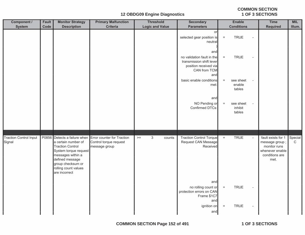
Component / Fault Monitor Strategy Primary Malfunction Secondary Time MILSystem Code Description Criteria Parameters Required Illum.
Threshold EnableLogic and Value Conditions
orselected gear position is
neutral= TRUE -
))and
no validation fault in the transmission shift lever
position received via CAN from TCM
= TRUE -
andandbasic enable conditions
met:= see sheet
enable tables
-
andNO Pending or
Confirmed DTCs:= see sheet
inhibit tables
-
Traction Control Input Signal
P0856 Detects a failure when a certain number of Traction Control System torque request messages within a
Error counter for Traction Control torque request message group
>= 3 counts Traction Control Torque Request CAN Message
Received
= TRUE - Special C
fault exists for 1 message group ;
monitor runs whenever enable
conditions are gdefined message group checksum or rolling count values are incorrect
and
met.
no rolling count or protection errors on CAN
Frame $1C7
= TRUE -
andignition on = TRUE -
andand
12 OBDG09 Engine DiagnosticsCOMMON SECTION
1 OF 3 SECTIONS
COMMON SECTION Page 152 of 491 1 OF 3 SECTIONS
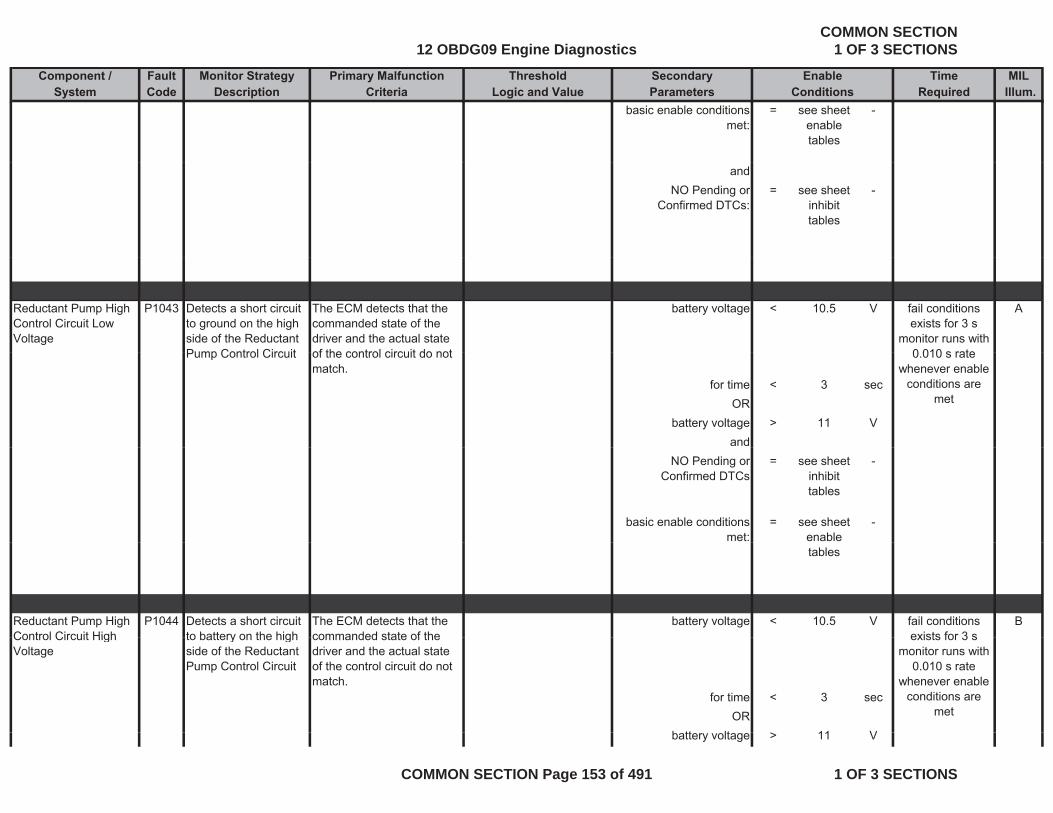
Component / Fault Monitor Strategy Primary Malfunction Secondary Time MILSystem Code Description Criteria Parameters Required Illum.
Threshold EnableLogic and Value Conditions
basic enable conditions met:
= see sheet enable tables
-
andNO Pending or
Confirmed DTCs:= see sheet
inhibit tables
-
Reductant Pump High Control Circuit Low Voltage
P1043 Detects a short circuit to ground on the high side of the Reductant Pump Control Circuit
The ECM detects that the commanded state of the driver and the actual state of the control circuit do not
battery voltage < 10.5 V Afail conditions exists for 3 s
monitor runs with 0 010 s ratePump Control Circuit of the control circuit do not
match.for time < 3 sec
ORbattery voltage > 11 V
and
0.010 s rate whenever enable
conditions are met
NO Pending or Confirmed DTCs
= see sheet inhibit tables
-
basic enable conditions met:
= see sheet enable
-
tables
Reductant Pump High Control Circuit High
P1044 Detects a short circuit to battery on the high
The ECM detects that the commanded state of the
battery voltage < 10.5 V Bfail conditions exists for 3 sControl Circuit High
Voltageto battery on the high side of the Reductant Pump Control Circuit
commanded state of the driver and the actual state of the control circuit do not match.
for time < 3 secOR
b tt lt > 11 V
exists for 3 smonitor runs with
0.010 s rate whenever enable
conditions are met
battery voltage > 11 V
12 OBDG09 Engine DiagnosticsCOMMON SECTION
1 OF 3 SECTIONS
COMMON SECTION Page 153 of 491 1 OF 3 SECTIONS
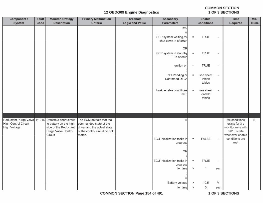
Component / Fault Monitor Strategy Primary Malfunction Secondary Time MILSystem Code Description Criteria Parameters Required Illum.
Threshold EnableLogic and Value Conditions
and((
SCR system waiting for shut down in afterrun
= TRUE -shut down in afterrun
ORSCR system in standby
in afterun= TRUE -
)ignition on = TRUE -
)NO Pending or
Confirmed DTCs= see sheet
inhibit tables
-
basic enable conditions met:
= see sheet enable tables
-
Reductant Purge Valve High Control Circuit High Voltage
P1046 Detects a short circuit to battery on the high side of the Reductant Purge Valve Control Circuit
The ECM detects that the commanded state of the driver and the actual state of the control circuit do not match
(( Bfail conditions exists for 3 s
monitor runs with 0.010 s rate
whenever enableCircuit match.ECU Initialization tasks in
progress= FALSE -
)OR
(
whenever enable conditions are
met
ECU Initialization tasks in progress
= TRUE -
for time > 1 sec)
((Battery voltage > 10 5 VBattery voltage > 10.5 V
for time > 3 sec
12 OBDG09 Engine DiagnosticsCOMMON SECTION
1 OF 3 SECTIONS
COMMON SECTION Page 154 of 491 1 OF 3 SECTIONS
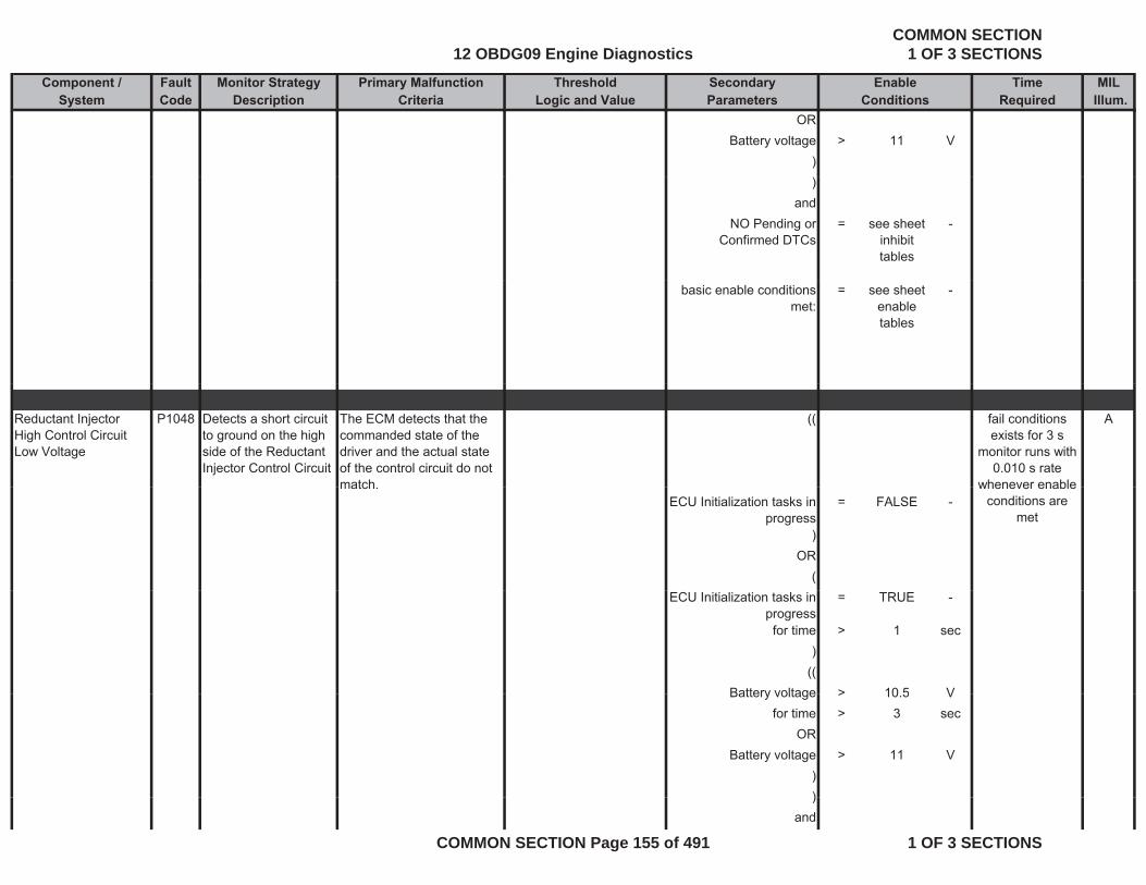
Component / Fault Monitor Strategy Primary Malfunction Secondary Time MILSystem Code Description Criteria Parameters Required Illum.
Threshold EnableLogic and Value Conditions
ORBattery voltage > 11 V
))
andNO Pending or
Confirmed DTCs= see sheet
inhibit tables
-
basic enable conditions met:
= see sheet enable tables
-
Reductant Injector High Control Circuit Low Voltage
P1048 Detects a short circuit to ground on the high side of the Reductant Injector Control Circuit
The ECM detects that the commanded state of the driver and the actual state of the control circuit do not match
(( Afail conditions exists for 3 s
monitor runs with 0.010 s rate
whenever enablematch.ECU Initialization tasks in
progress= FALSE -
)OR
(
whenever enable conditions are
met
ECU Initialization tasks in progress
= TRUE -
for time > 1 sec)
((Battery voltage > 10 5 VBattery voltage > 10.5 V
for time > 3 secOR
Battery voltage > 11 V)))
and
12 OBDG09 Engine DiagnosticsCOMMON SECTION
1 OF 3 SECTIONS
COMMON SECTION Page 155 of 491 1 OF 3 SECTIONS
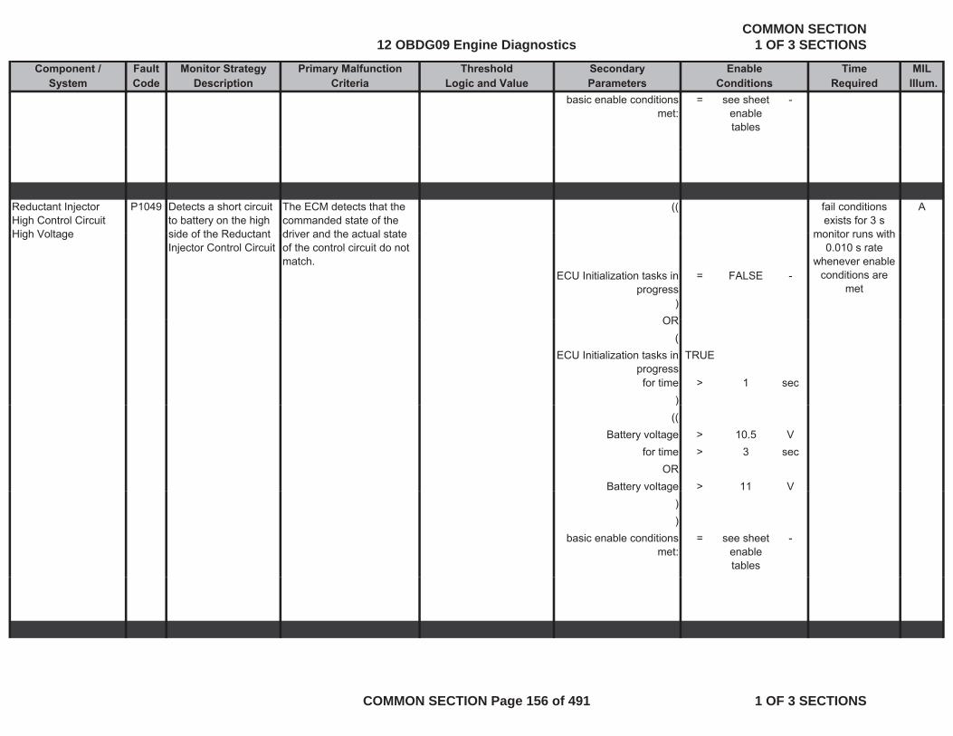
Component / Fault Monitor Strategy Primary Malfunction Secondary Time MILSystem Code Description Criteria Parameters Required Illum.
Threshold EnableLogic and Value Conditions
basic enable conditions met:
= see sheet enable tables
-
Reductant Injector High Control Circuit High Voltage
P1049 Detects a short circuit to battery on the high side of the Reductant
The ECM detects that the commanded state of the driver and the actual state
(( Afail conditions exists for 3 s
monitor runs withHigh Voltage side of the Reductant Injector Control Circuit
driver and the actual state of the control circuit do not match.
ECU Initialization tasks in progress
= FALSE -
)OR
monitor runs with 0.010 s rate
whenever enable conditions are
met
OR(
ECU Initialization tasks in progress
TRUE
for time > 1 sec))
((Battery voltage > 10.5 V
for time > 3 secOR
Battery voltage > 11 Vy g))
basic enable conditions met:
= see sheet enable tables
-
12 OBDG09 Engine DiagnosticsCOMMON SECTION
1 OF 3 SECTIONS
COMMON SECTION Page 156 of 491 1 OF 3 SECTIONS

Component / Fault Monitor Strategy Primary Malfunction Secondary Time MILSystem Code Description Criteria Parameters Required Illum.
Threshold EnableLogic and Value Conditions
Exhaust Aftertreatment Fuel Injector Control Circuit Shorted
P10CC Electronic out-put driver circuitry determines circuit integrity on the diesel
The ECM detects that the commanded state of the driver and the actual state of the control circuit do not
engine pre drive = FALSE - Bfail conditions exists for more
than 0.5 smonitor runs with
dosing valve control circuit.
match.
fortime > 1 secand
battery voltage > 11 V
0.1 s rate whenever enable
conditions are met
battery voltage > 11 Vfor
time > 3 secand
battery voltage < 655.34 Vforfor
time > 3 secand
starter is active cranking = FALSE -
for time > 3 secand
basic enable conditions met:
= see sheet enable tables
-
Exhaust Aftertreatment Fuel Injector High
P10CD Electronic out-put driver circuitry
The ECM detects that the commanded state of the
engine pre drive = FALSE - Bfail conditions exists for more j g
Control Circuit Low Voltage
ydetermines circuit integrity on the diesel dosing valve control circuit.
driver and the actual state of the control circuit do not match.
fortime > 1 sec
than 3.0 smonitor runs with
0.1 s rate whenever enable
conditions are met
and
12 OBDG09 Engine DiagnosticsCOMMON SECTION
1 OF 3 SECTIONS
COMMON SECTION Page 157 of 491 1 OF 3 SECTIONS
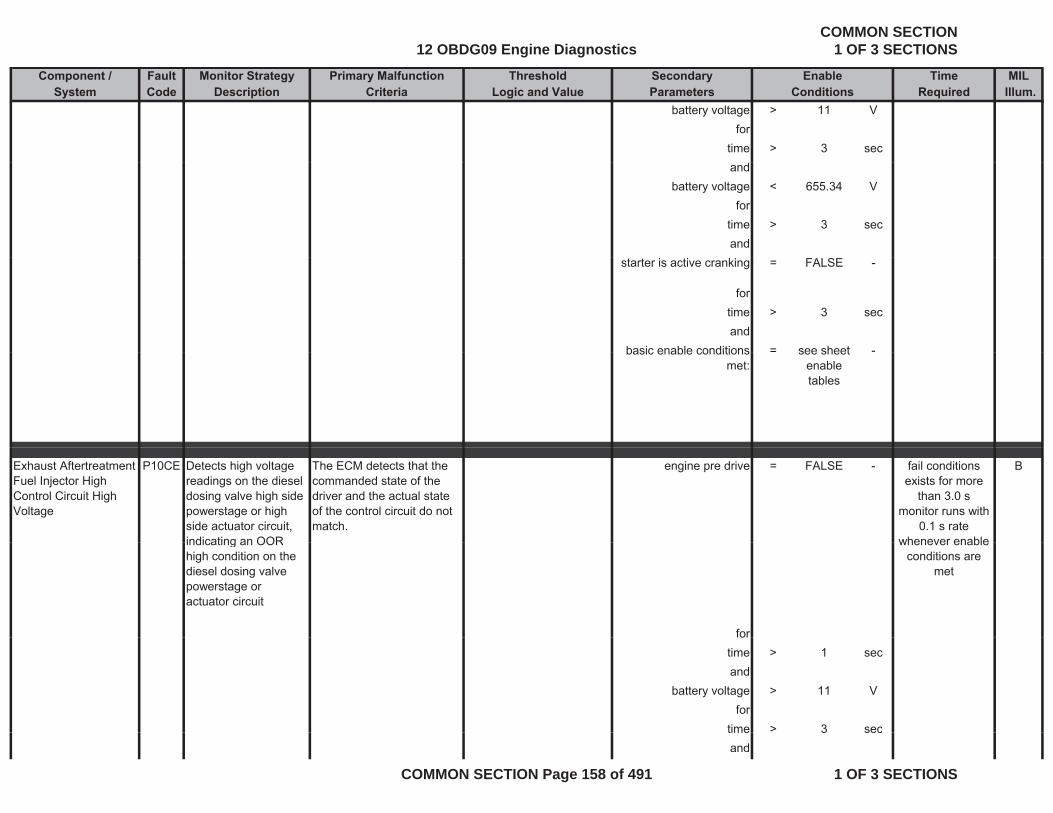
Component / Fault Monitor Strategy Primary Malfunction Secondary Time MILSystem Code Description Criteria Parameters Required Illum.
Threshold EnableLogic and Value Conditions
battery voltage > 11 Vfor
time > 3 secand
battery voltage < 655.34 Vfor
time > 3 secand
starter is active cranking = FALSE -
for time > 3 secand
basic enable conditions = see sheet -basic enable conditions met:
see sheet enable tables
Exhaust Aftertreatment Fuel Injector High Control Circuit High Voltage
P10CE Detects high voltage readings on the diesel dosing valve high side powerstage or high side actuator circuit, indicating an OOR
The ECM detects that the commanded state of the driver and the actual state of the control circuit do not match.
engine pre drive = FALSE - Bfail conditions exists for more
than 3.0 smonitor runs with
0.1 s rate whenever enableindicating an OOR
high condition on the diesel dosing valve powerstage or actuator circuit
for
whenever enable conditions are
met
fortime > 1 secand
battery voltage > 11 Vfor
time > 3 sectime 3 secand
12 OBDG09 Engine DiagnosticsCOMMON SECTION
1 OF 3 SECTIONS
COMMON SECTION Page 158 of 491 1 OF 3 SECTIONS
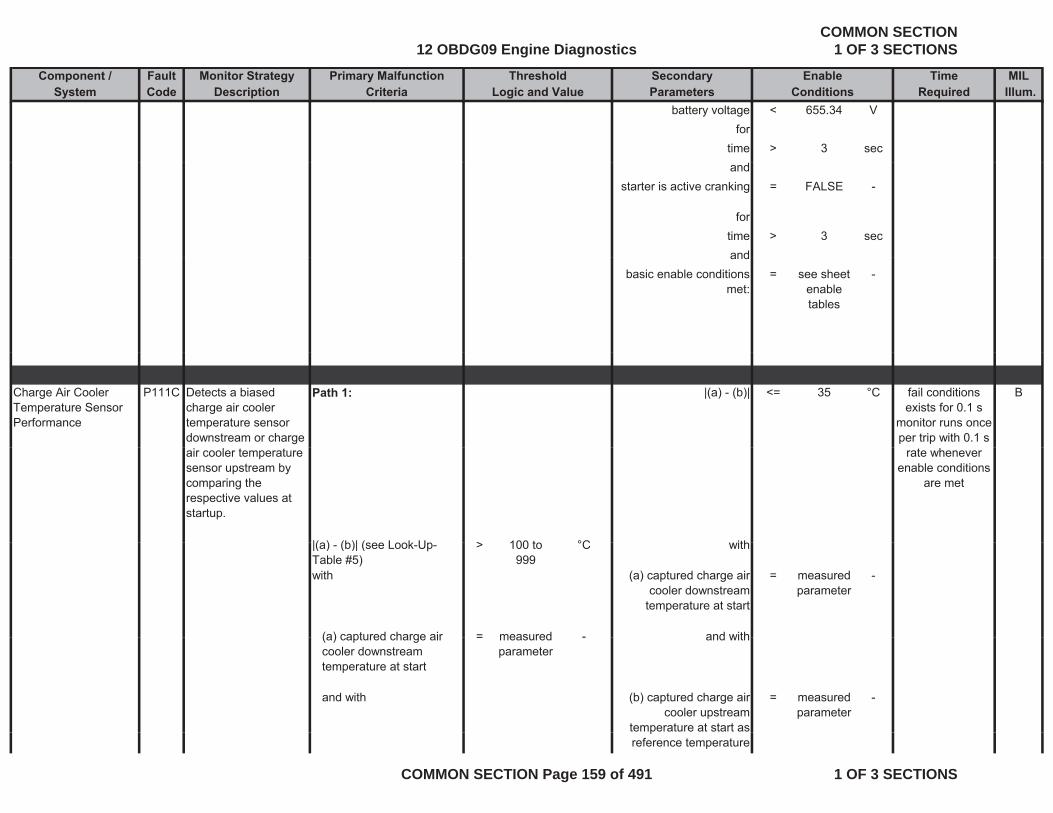
Component / Fault Monitor Strategy Primary Malfunction Secondary Time MILSystem Code Description Criteria Parameters Required Illum.
Threshold EnableLogic and Value Conditions
battery voltage < 655.34 Vfor
time > 3 secand
starter is active cranking = FALSE -
for time > 3 secandand
basic enable conditions met:
= see sheet enable tables
-
Charge Air Cooler Temperature Sensor Performance
P111C Detects a biased charge air cooler temperature sensor downstream or charge
Path 1: |(a) - (b)| <= 35 °C Bfail conditions exists for 0.1 s
monitor runs once per trip with 0.1 s
air cooler temperature sensor upstream by comparing the respective values at startup.
|( ) (b)| ( L k U > 100 t °C ith
rate whenever enable conditions
are met
|(a) - (b)| (see Look-Up-Table #5)
> 100 to 999
°C with
with (a) captured charge air cooler downstream
temperature at start
= measured parameter
-
(a) captured charge air = measured - and with(a) captured charge air cooler downstream temperature at start
= measured parameter
- and with
and with (b) captured charge air cooler upstream
temperature at start as
= measured parameter
-
preference temperature
12 OBDG09 Engine DiagnosticsCOMMON SECTION
1 OF 3 SECTIONS
COMMON SECTION Page 159 of 491 1 OF 3 SECTIONS
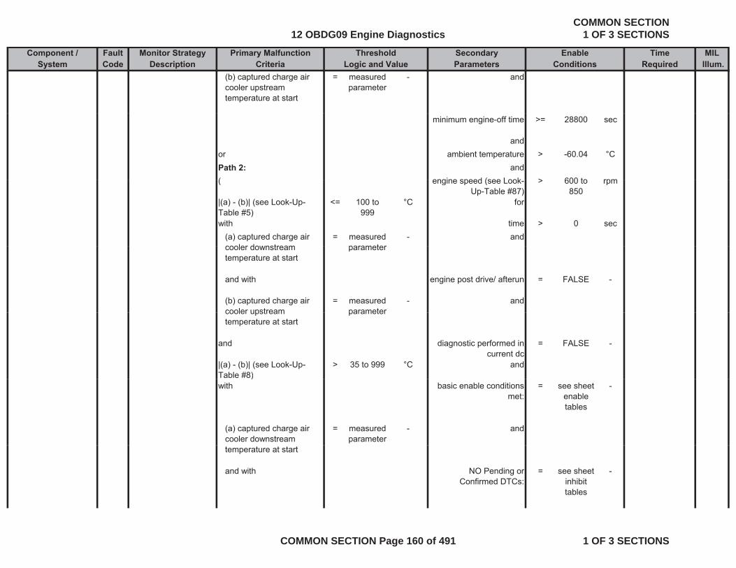
Component / Fault Monitor Strategy Primary Malfunction Secondary Time MILSystem Code Description Criteria Parameters Required Illum.
Threshold EnableLogic and Value Conditions
(b) captured charge air cooler upstream temperature at start
= measured parameter
- and
minimum engine-off time >= 28800 sec
andor ambient temperature > -60.04 °CPath 2: and( engine speed (see Look > 600 to rpm( engine speed (see Look-
Up-Table #87)> 600 to
850rpm
|(a) - (b)| (see Look-Up-Table #5)
<= 100 to 999
°C for
with time > 0 sec(a) captured charge air cooler downstream
= measured parameter
- andcooler downstream temperature at start
parameter
and with engine post drive/ afterun = FALSE -
(b) captured charge air cooler upstream
= measured parameter
- andcooler upstream temperature at start
parameter
and diagnostic performed in current dc
= FALSE -
|(a) - (b)| (see Look-Up-Table #8)
> 35 to 999 °C and)
with basic enable conditions met:
= see sheet enable tables
-
(a) captured charge air cooler downstream
= measured parameter
- and
temperature at start
and with NO Pending or Confirmed DTCs:
= see sheet inhibit tables
-
12 OBDG09 Engine DiagnosticsCOMMON SECTION
1 OF 3 SECTIONS
COMMON SECTION Page 160 of 491 1 OF 3 SECTIONS
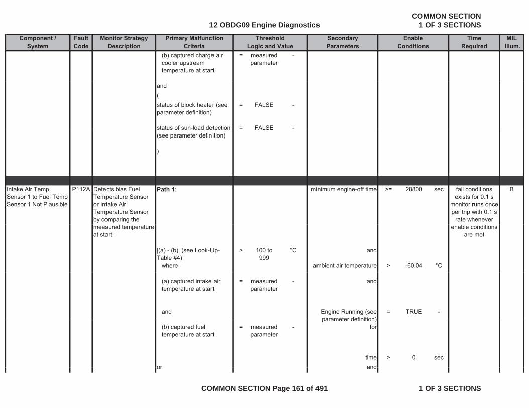
Component / Fault Monitor Strategy Primary Malfunction Secondary Time MILSystem Code Description Criteria Parameters Required Illum.
Threshold EnableLogic and Value Conditions
(b) captured charge air cooler upstream temperature at start
= measured parameter
-
and(status of block heater (see parameter definition)
= FALSE -
status of sun-load detection = FALSE -status of sun load detection (see parameter definition)
FALSE
)
Intake Air Temp Sensor 1 to Fuel Temp Sensor 1 Not Plausible
P112A Detects bias Fuel Temperature Sensor or Intake Air Temperature Sensor by comparing the
Path 1: minimum engine-off time >= 28800 sec Bfail conditions exists for 0.1 s
monitor runs once per trip with 0.1 s
rate whenever measured temperature at start.
|(a) - (b)| (see Look-Up-Table #4)
> 100 to 999
°C and
where ambient air temperature > -60.04 °C
enable conditions are met
(a) captured intake air temperature at start
= measured parameter
- and
and Engine Running (see parameter definition)
= TRUE -parameter definition)
(b) captured fuel temperature at start
= measured parameter
- for
time > 0 secor andor and
12 OBDG09 Engine DiagnosticsCOMMON SECTION
1 OF 3 SECTIONS
COMMON SECTION Page 161 of 491 1 OF 3 SECTIONS
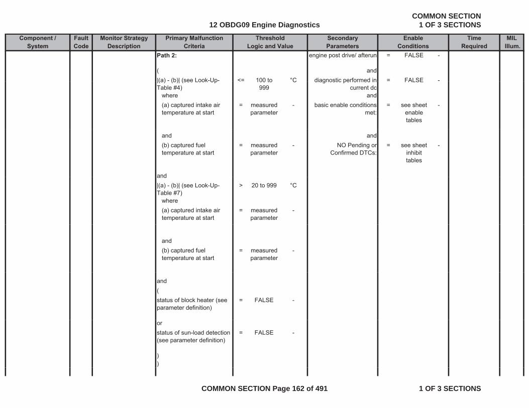
Component / Fault Monitor Strategy Primary Malfunction Secondary Time MILSystem Code Description Criteria Parameters Required Illum.
Threshold EnableLogic and Value Conditions
Path 2: engine post drive/ afterun = FALSE -
( and|(a) - (b)| (see Look-Up- <= 100 to °C diagnostic performed in = FALSE -|(a) (b)| (see Look UpTable #4)
< 100 to 999
C diagnostic performed in current dc
FALSE
where and(a) captured intake air temperature at start
= measured parameter
- basic enable conditions met:
= see sheet enable tables
-
and and(b) captured fuel temperature at start
= measured parameter
- NO Pending or Confirmed DTCs:
= see sheet inhibit tables
-
andand|(a) - (b)| (see Look-Up-Table #7)
> 20 to 999 °C
where(a) captured intake air temperature at start
= measured parameter
-
and(b) captured fuel temperature at start
= measured parameter
-
and(status of block heater (see parameter definition)
= FALSE -
orstatus of sun-load detection (see parameter definition)
= FALSE -
))
12 OBDG09 Engine DiagnosticsCOMMON SECTION
1 OF 3 SECTIONS
COMMON SECTION Page 162 of 491 1 OF 3 SECTIONS
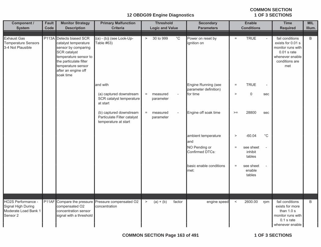
Component / Fault Monitor Strategy Primary Malfunction Secondary Time MILSystem Code Description Criteria Parameters Required Illum.
Threshold EnableLogic and Value Conditions
Exhaust Gas Temperature Sensors 3-4 Not Plausible
P113A Detects biased SCR catalyst temperature sensor by comparing
|(a) - (b)| (see Look-Up-Table #63)
> 30 to 999 °C Power on reset by ignition on
= TRUE - Bfail conditions exists for 0.01 s
monitor runs with y p gSCR catalyst temperature sensor to the particulate filter temperature sensor after an engine off soak time
0.01 s rate whenever enable
conditions are met
and with Engine Running (see parameter definition)
= TRUE -
(a) captured downstream SCR catalyst temperature at start
= measured parameter
- for time > 0 sec
(b) captured downstream Particulate Filter catalyst temperature at start
= measured parameter
- Engine off soak time >= 28800 sec
ambient temperature > -60 04 °Cambient temperature > -60.04 CandNO Pending or Confirmed DTCs:
= see sheet inhibit tables
-
b i bl diti h tbasic enable conditions met:
= see sheet enable tables
-
HO2S Performance - Signal High During Moderate Load Bank 1 Sensor 2
P11AF Compare the pressure compensated O2 concentration sensor signal with a threshold
Pressure compensated O2 concentration
> (a) + (b) factor engine speed < 2600.00 rpm Bfail conditions exists for more
than 1.0 smonitor runs with
0.1 s rate whenever enable
12 OBDG09 Engine DiagnosticsCOMMON SECTION
1 OF 3 SECTIONS
COMMON SECTION Page 163 of 491 1 OF 3 SECTIONS
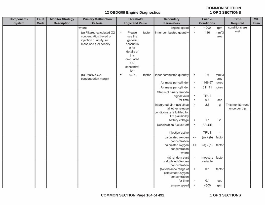
Component / Fault Monitor Strategy Primary Malfunction Secondary Time MILSystem Code Description Criteria Parameters Required Illum.
Threshold EnableLogic and Value Conditions
where engine speed > 1200 rpm(a) Filtered calculated O2 concentration based on injection quantity air
= Please see the general
factor Inner combusted quantity < 180 mm^3/rev
conditions are met
injection quantity, air mass and fuel density
general descriptio
n for details of
this calculated
O2 concentrat
ion(b) Positive O2 concentration margin
= 0.05 factor Inner combusted quantity > 36 mm^3/rev
Air mass per cylinder < 1166.67 g/revAir mass per cylinder > 611.11 g/revp y g
Status of binary lambda signal valid = TRUE -
for time > 0.5 secintegrated air mass since
all other release conditions are fulfilled for
> 2.5 g This monitor runs once per trip
conditions are fulfilled for O2 plausibility
battery voltage > 1.1 VDeceleration fuel cut-off = FALSE -
Injection active = TRUE -l l t d < ( ) + (b) f tcalculated oxygen
concentration<= (a) + (b) factor
calculated oxygen concentration
>= (a) - (b) factor
where(a) random start l l t d O
= measure i bl
factorcalculated Oxygen
concentrationvariable
(b) tolerance range of calculated Oxygen
concentration
= 0.1 factor
for time > 0.1 seci d < 4500engine speed < 4500 rpm
12 OBDG09 Engine DiagnosticsCOMMON SECTION
1 OF 3 SECTIONS
COMMON SECTION Page 164 of 491 1 OF 3 SECTIONS

Component / Fault Monitor Strategy Primary Malfunction Secondary Time MILSystem Code Description Criteria Parameters Required Illum.
Threshold EnableLogic and Value Conditions
engine speed > 600 rpmambient temperature < 122.96 °Cambient temperature > -45.04 °C
ambient pressure < 110 kPaambient pressure > 50 kPa
NO Pending or Confirmed DTCs:
= see sheet inhibit table
-
basic enable conditions met:
= see sheet enable tables
-
HO2S Performance - Signal Low During Moderate Load Bank 1
P11B2 Compare the pressure compensated O2 concentration sensor signal with a threshold
Pressure compensated O2 concentration
< (a) - (b) factor engine speed < 2600.00 rpm fail conditions exists for more
than 1.0 smonitor runs with
0 1 s rateModerate Load Bank 1 Sensor 2
where engine speed > 1200 rpm(a) Filtered calculated O2 concentration based on injection quantity, air mass and fuel density
= Please see the general
descriptio
factor Inner combusted quantity < 180 mm^3/rev
0.1 s rate whenever enable
conditions are met
mass and fuel density description for
details of this
calculated O2
concentration
(b) Negative O2 concentration margin
= 0.1 factor Inner combusted quantity > 36 mm^3/rev
Air mass per cylinder < 1166.67 g/revAir mass per cylinder > 611.11 g/rev
12 OBDG09 Engine DiagnosticsCOMMON SECTION
1 OF 3 SECTIONS
COMMON SECTION Page 165 of 491 1 OF 3 SECTIONS
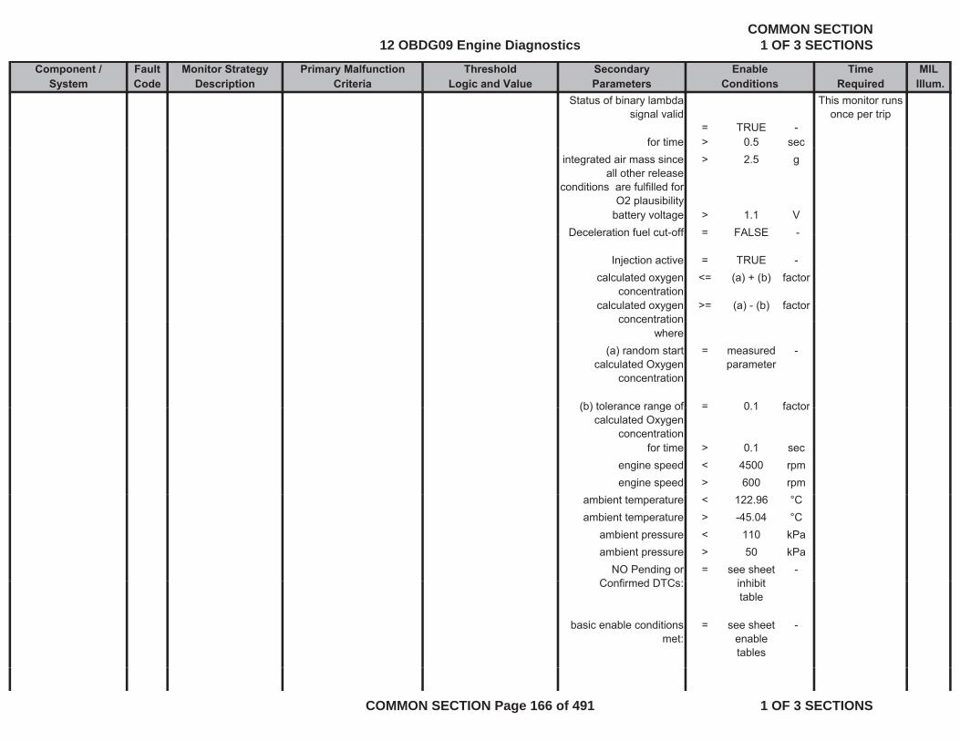
Component / Fault Monitor Strategy Primary Malfunction Secondary Time MILSystem Code Description Criteria Parameters Required Illum.
Threshold EnableLogic and Value Conditions
Status of binary lambda signal valid
= TRUE -
This monitor runs once per trip
for time > 0.5 secintegrated air mass since
all other release conditions are fulfilled for
O2 plausibility
> 2.5 g
battery voltage > 1.1 VDeceleration fuel cut-off = FALSE -Deceleration fuel cut off FALSE
Injection active = TRUE -calculated oxygen
concentration<= (a) + (b) factor
calculated oxygen concentration
>= (a) - (b) factorconcentration
where(a) random start
calculated Oxygen concentration
= measured parameter
-
(b) tolerance range of = 0 1 factor(b) tolerance range of calculated Oxygen
concentration
0.1 factor
for time > 0.1 secengine speed < 4500 rpmengine speed > 600 rpm
ambient temperature < 122.96 °Cambient temperature > -45.04 °C
ambient pressure < 110 kPaambient pressure > 50 kPa
NO Pending or C fi d DTC
= see sheet i hibit
-Confirmed DTCs: inhibit
table
basic enable conditions met:
= see sheet enable tables
-
12 OBDG09 Engine DiagnosticsCOMMON SECTION
1 OF 3 SECTIONS
COMMON SECTION Page 166 of 491 1 OF 3 SECTIONS

Component / Fault Monitor Strategy Primary Malfunction Secondary Time MILSystem Code Description Criteria Parameters Required Illum.
Threshold EnableLogic and Value Conditions
HO2S Current Performance Bank 1 Sensor 2
P11B5 Compares the ratio of valid lambda signal time to total time with
ratio of valid lambda signal time to total time: (a) / (b)
< 0.1 ratio NOx sensor’s heater temperature has reached
the set point
= TRUE - Bfail conditions exists for more
than 20 sSensor 2 time to total time with a threshold
the set point
where for time > 120 sec(a) time for which valid lambda signal received over CAN
= measured parameter
- Enabling Downstream NOx sensor heater
diagnosis (please see the
= TRUE -
than 20 smonitor runs with
0.02 s rate whenever enable
conditions are met
over CAN diagnosis (please see the definition)
(b) total time for which diagnosis is enabled
= calculated parameter
- Reciprocal lambda change : | (a) - (b) | (see
Look-Up-Table #42)
<= 0.1 to 22 factor
where(a) Reciprocal lambda = measured
parameter-
(b) Filtered reciprocal lambda
= calculated parameter
-p
for time > 5 sectime for which diagnosis
is enabled>= 20 sec
NO Pending or = see sheet -gConfirmed DTCs: inhibit
tables
basic enable conditions met:
= see sheet enable tables
-
12 OBDG09 Engine DiagnosticsCOMMON SECTION
1 OF 3 SECTIONS
COMMON SECTION Page 167 of 491 1 OF 3 SECTIONS

Component / Fault Monitor Strategy Primary Malfunction Secondary Time MILSystem Code Description Criteria Parameters Required Illum.
Threshold EnableLogic and Value Conditions
NOx Sensor Performance - Signal High Bank 1 Sensor 1
P11CB Detects a high deviation of the measured NOx sensor concentration from the
Filtered NOx concentration deviation from model
> 0.70 - The signal of the NOx sensor is ready
= TRUE - Bfault exists for more than 10 s; monitor runs at
0.1 s once per tripmodeled Nox concentration
Normal Mode (Particulate Filter Regeneration not
active)
= TRUE -
for time 15 secambient pressure >= 75.0 kPaambient pressure <= 106 kPa
ambient temperature >= -7.04 °Cambient temperature <= 37 96 °Cambient temperature <= 37.96 °C
filtered modeled Nox concentration percent positive deviation (see
Look-Up-Table #68)
<= 0.050 to 0.075
-
filtered modeled Nox concentration percent
negative deviation (see Look-Up-Table #69)
>= 0.050 to 0.075
-
for time > 2 sectime since start > 30 secengine coolant
temperature>= 68.96 °C
engine coolant <= 123 06 °Cengine coolant temperature
<= 123.06 C
12 OBDG09 Engine DiagnosticsCOMMON SECTION
1 OF 3 SECTIONS
COMMON SECTION Page 168 of 491 1 OF 3 SECTIONS

Component / Fault Monitor Strategy Primary Malfunction Secondary Time MILSystem Code Description Criteria Parameters Required Illum.
Threshold EnableLogic and Value Conditions
Exhaust gas temperature enable range for the
plausibility check of the NOx sensor upstream
>0 0 to 1 -
from the SCR (see Look-Up-Table #80)
Fuel Injection pattern (see Look-Up-Table #81)
= 0 to 58 -
24 = pilot 1 main
56 = pilot 2, pilot 1,
mainmain
58 = pilot 2, pilot 1,
main, post 2
26 = pilot 1 main, post 2
0 = all off (overrun)( )
vehicle speed >= 37.29 mphfor time > 1 sec
Engine speed and injection quantity enable range for the plausibility
check of the NOx sensor
0 0 to 1 -
check of the NOx sensor upstream from the SCR
(see Look-Up-Table #71)
for time > 0.5 sec
12 OBDG09 Engine DiagnosticsCOMMON SECTION
1 OF 3 SECTIONS
COMMON SECTION Page 169 of 491 1 OF 3 SECTIONS
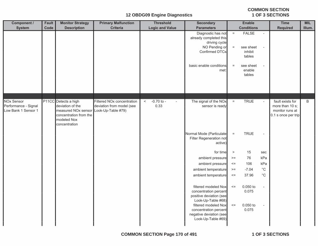
Component / Fault Monitor Strategy Primary Malfunction Secondary Time MILSystem Code Description Criteria Parameters Required Illum.
Threshold EnableLogic and Value Conditions
Diagnostic has not already completed this
driving cycle
= FALSE -
NO Pending or = see sheet -gConfirmed DTCs inhibit
tables
basic enable conditions met:
= see sheet enable tables
-
NOx Sensor Performance - Signal
P11CC Detects a high deviation of the
Filtered NOx concentration deviation from model (see
< -0.70 to -0 33
- The signal of the NOx sensor is ready
= TRUE - Bfault exists for more than 10 s;Performance Signal
Low Bank 1 Sensor 1deviation of the measured NOx sensor concentration from the modeled Nox concentration
deviation from model (see Look-Up-Table #79)
0.33 sensor is ready
Normal Mode (Particulate = TRUE -
more than 10 s; monitor runs at
0.1 s once per trip
(Filter Regeneration not
active)
for time > 15 secambient pressure >= 76 kPaambient pressure <= 106 kPaambient pressure <= 106 kPa
ambient temperature >= -7.04 °Cambient temperature <= 37.96 °C
filtered modeled Nox concentration percent
<= 0.050 to 0.075
-p
positive deviation (see Look-Up-Table #68)filtered modeled Nox
concentration percent negative deviation (see
Look-Up-Table #69)
<= 0.050 to 0.075
-
12 OBDG09 Engine DiagnosticsCOMMON SECTION
1 OF 3 SECTIONS
COMMON SECTION Page 170 of 491 1 OF 3 SECTIONS
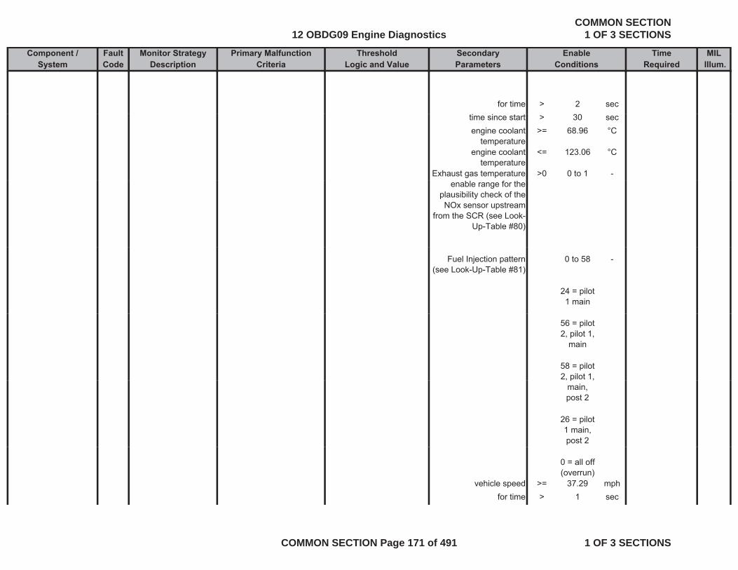
Component / Fault Monitor Strategy Primary Malfunction Secondary Time MILSystem Code Description Criteria Parameters Required Illum.
Threshold EnableLogic and Value Conditions
for time > 2 sectime since start > 30 secengine coolant
temperature>= 68.96 °C
engine coolant temperature
<= 123.06 °C
Exhaust gas temperature >0 0 to 1 -enable range for the
plausibility check of the NOx sensor upstream
from the SCR (see Look-Up-Table #80)
Fuel Injection pattern (see Look-Up-Table #81)
0 to 58 -
24 = pilot 1 main
56 = pilot 2, pilot 1,
main
58 = pilot 2, pilot 1, , p ,
main, post 2
26 = pilot 1 main, post 2
0 = all off (overrun)
vehicle speed >= 37.29 mphfor time > 1 sec
12 OBDG09 Engine DiagnosticsCOMMON SECTION
1 OF 3 SECTIONS
COMMON SECTION Page 171 of 491 1 OF 3 SECTIONS
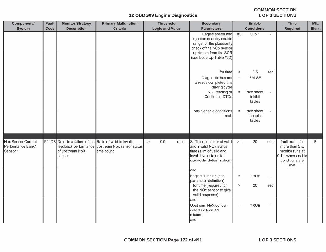
Component / Fault Monitor Strategy Primary Malfunction Secondary Time MILSystem Code Description Criteria Parameters Required Illum.
Threshold EnableLogic and Value Conditions
Engine speed and injection quantity enable range for the plausibility
check of the NOx sensor
0 0 to 1 -
upstream from the SCR (see Look-Up-Table #72)
for time > 0.5 secDiagnostic has not = FALSE -g
already completed this driving cycle
NO Pending or Confirmed DTCs
= see sheet inhibit tables
-
basic enable conditions met:
= see sheet enable tables
-
Nox Sensor Current Performance Bank1 Sensor 1
P11DB Detects a failure of the feedback performance of upstream NoX sensor
Ratio of valid to invalid upstream Nox sensor status time count
> 0.9 ratio Sufficient number of valid and invalid NOx status time (sum of valid and invalid Nox status for diagnostic determination)
>= 20 sec Bfault exists for more than 5 s; monitor runs at
0.1 s when enable conditions are
metandEngine Running (see parameter definition)
= TRUE -
for time (required for the NOx sensor to give valid response)
> 20 sec
andUpstream NoX sensor detects a lean A/F mixture
= TRUE -
and
12 OBDG09 Engine DiagnosticsCOMMON SECTION
1 OF 3 SECTIONS
COMMON SECTION Page 172 of 491 1 OF 3 SECTIONS
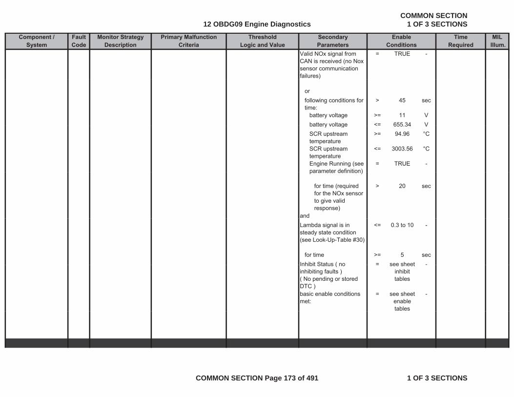
Component / Fault Monitor Strategy Primary Malfunction Secondary Time MILSystem Code Description Criteria Parameters Required Illum.
Threshold EnableLogic and Value Conditions
Valid NOx signal from CAN is received (no Nox sensor communication failures)
= TRUE -
orfollowing conditions for time:
> 45 sec
battery voltage >= 11 Vbattery voltage <= 655 34 Vbattery voltage < 655.34 VSCR upstream temperature
>= 94.96 °C
SCR upstream temperature
<= 3003.56 °C
Engine Running (see parameter definition)
= TRUE -parameter definition)
for time (required for the NOx sensor to give valid response)
> 20 sec
andLambda signal is in steady state condition (see Look-Up-Table #30)
<= 0.3 to 10 -
for time >= 5 secInhibit Status ( no = see sheet -Inhibit Status ( no inhibiting faults )( No pending or stored DTC )
= see sheet inhibit tables
-
basic enable conditions met:
= see sheet enable tables
-
12 OBDG09 Engine DiagnosticsCOMMON SECTION
1 OF 3 SECTIONS
COMMON SECTION Page 173 of 491 1 OF 3 SECTIONS
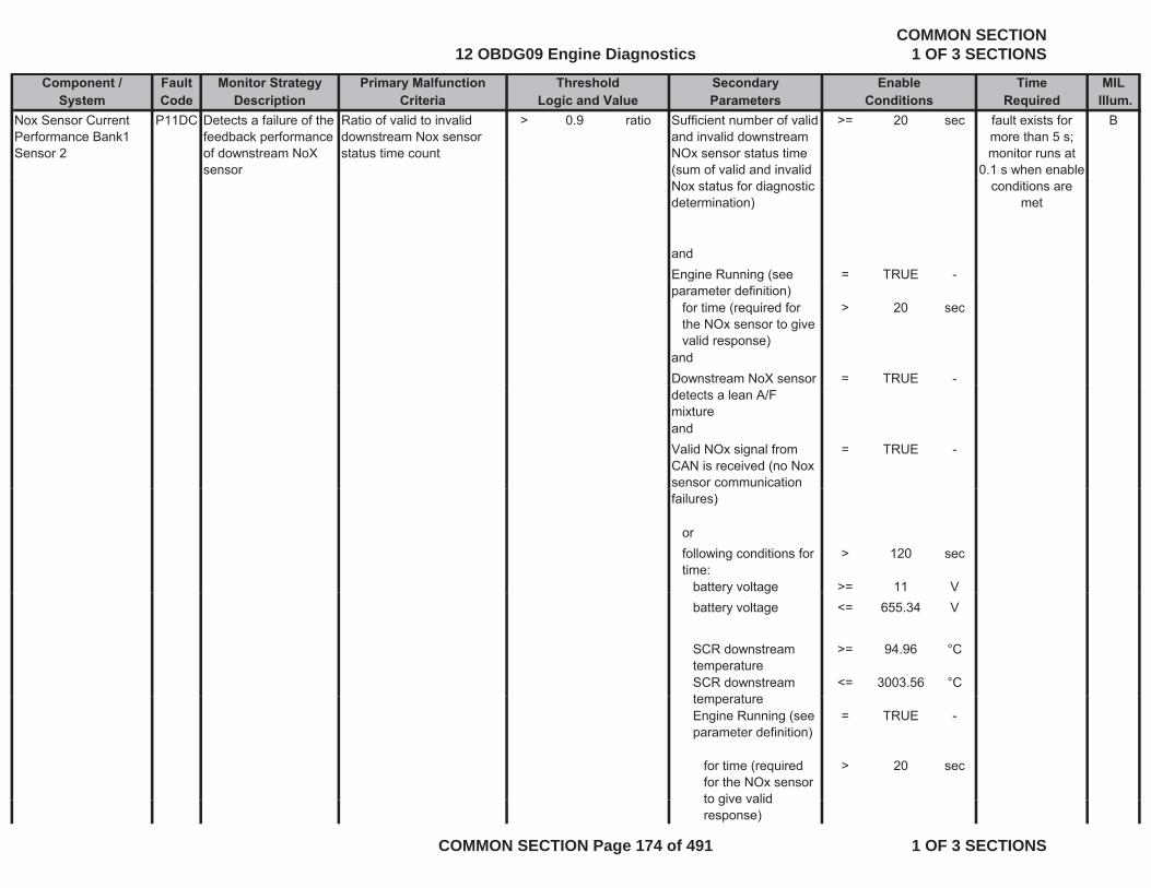
Component / Fault Monitor Strategy Primary Malfunction Secondary Time MILSystem Code Description Criteria Parameters Required Illum.
Threshold EnableLogic and Value Conditions
Nox Sensor Current Performance Bank1 Sensor 2
P11DC Detects a failure of the feedback performance of downstream NoX sensor
Ratio of valid to invalid downstream Nox sensor status time count
> 0.9 ratio Sufficient number of valid and invalid downstream NOx sensor status time (sum of valid and invalid
>= 20 sec Bfault exists for more than 5 s; monitor runs at
0.1 s when enable Nox status for diagnostic determination)
andEngine Running (see = TRUE -
conditions are met
g g (parameter definition)
for time (required for the NOx sensor to give valid response)
> 20 sec
andDownstream NoX sensor = TRUE -detects a lean A/F mixtureandValid NOx signal from CAN is received (no Nox sensor communication
= TRUE -
failures)
orfollowing conditions for time:
> 120 sec
battery voltage >= 11 Vy gbattery voltage <= 655.34 V
SCR downstream temperature
>= 94.96 °C
SCR downstream t t
<= 3003.56 °CtemperatureEngine Running (see parameter definition)
= TRUE -
for time (required for the NOx sensor to give valid
> 20 sec
to give valid response)
12 OBDG09 Engine DiagnosticsCOMMON SECTION
1 OF 3 SECTIONS
COMMON SECTION Page 174 of 491 1 OF 3 SECTIONS

Component / Fault Monitor Strategy Primary Malfunction Secondary Time MILSystem Code Description Criteria Parameters Required Illum.
Threshold EnableLogic and Value Conditions
andDownstream Lambda signal is in steady state condition ( | measured
<= 0.2 to 3.2 -
condition ( | measured lambda signal - filtered lambda signal | ) (see Look-Up-Table #29)
for time >= 5 secInhibit Status ( no = see sheet -Inhibit Status ( no inhibiting faults )( No pending or stored DTC )
see sheet inhibit tables
basic enable conditions met:
= see sheet enable tables
-
Injector 1 Control Circuit Shorted
P1224 Electronic out-put driver circuitry
The ECM detects that the commanded state of the
Engine Running (see parameter definition)
= TRUE - Afail conditions exists for moreCircuit Shorted driver circuitry
determines that the injector circuit is shorted.
commanded state of the driver and the actual state of the control circuit do not match.
parameter definition) exists for more than 0.5 s
monitor runs with 0.01 s rate
whenever enable conditions are
met
Injector 2 Control Circuit Shorted
P1227 Electronic out-put driver circuitry determines that the
The ECM detects that the commanded state of the driver and the actual state
Engine Running (see parameter definition)
= TRUE - A
met
fail conditions exists for more
than 0 5 sdetermines that the injector circuit is shorted.
driver and the actual state of the control circuit do not match.
than 0.5 smonitor runs with
0.01 s rate whenever enable
conditions are met
12 OBDG09 Engine DiagnosticsCOMMON SECTION
1 OF 3 SECTIONS
COMMON SECTION Page 175 of 491 1 OF 3 SECTIONS
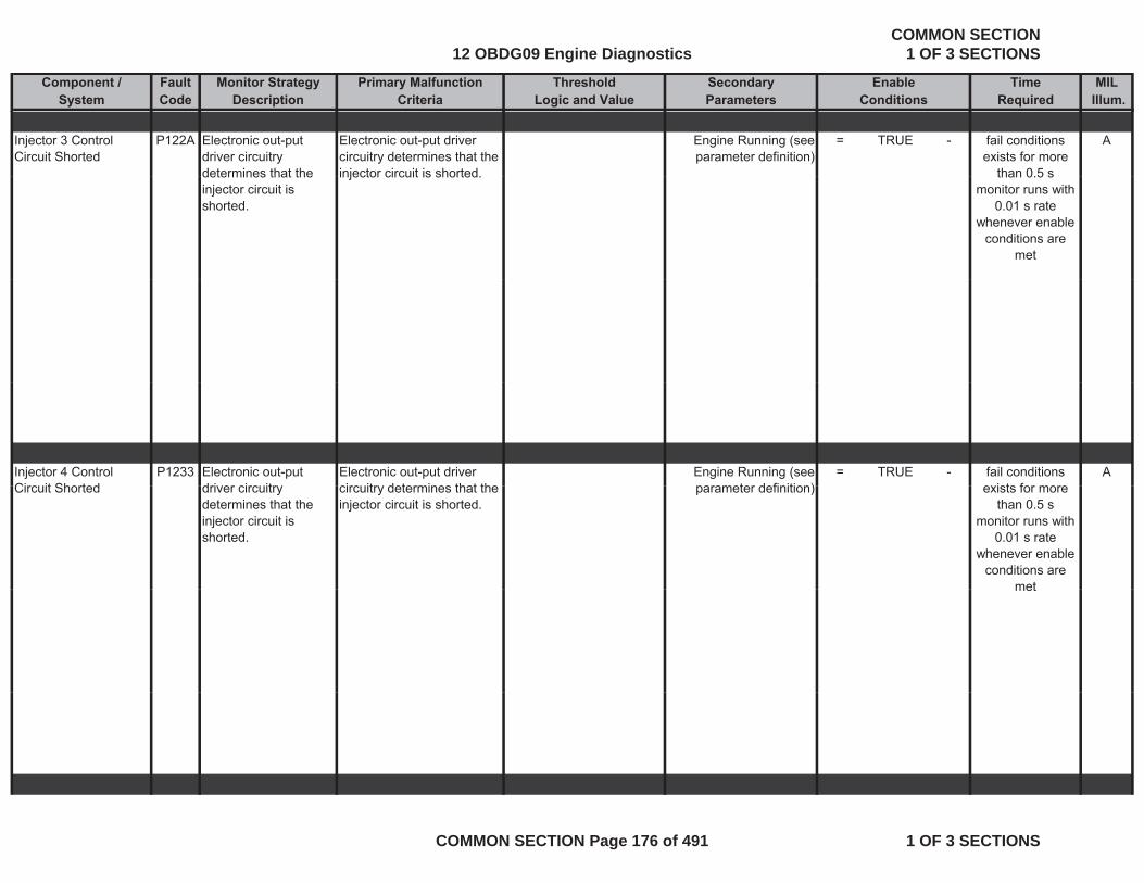
Component / Fault Monitor Strategy Primary Malfunction Secondary Time MILSystem Code Description Criteria Parameters Required Illum.
Threshold EnableLogic and Value Conditions
Injector 3 Control Circuit Shorted
P122A Electronic out-put driver circuitry determines that the
Electronic out-put driver circuitry determines that the injector circuit is shorted
Engine Running (see parameter definition)
= TRUE - Afail conditions exists for more
than 0 5 sdetermines that the injector circuit is shorted.
injector circuit is shorted. than 0.5 smonitor runs with
0.01 s rate whenever enable
conditions are met
Injector 4 Control Circ it Shorted
P1233 Electronic out-put dri er circ itr
Electronic out-put driver circ itr determines that the
Engine Running (see parameter definition)
= TRUE - Afail conditions e ists for moreCircuit Shorted driver circuitry
determines that the injector circuit is shorted.
circuitry determines that the injector circuit is shorted.
parameter definition) exists for more than 0.5 s
monitor runs with 0.01 s rate
whenever enable conditions are
metmet
12 OBDG09 Engine DiagnosticsCOMMON SECTION
1 OF 3 SECTIONS
COMMON SECTION Page 176 of 491 1 OF 3 SECTIONS
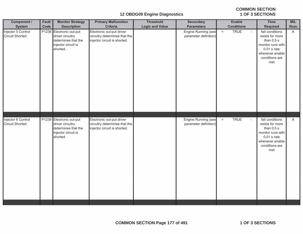
Component / Fault Monitor Strategy Primary Malfunction Secondary Time MILSystem Code Description Criteria Parameters Required Illum.
Threshold EnableLogic and Value Conditions
Injector 5 Control Circuit Shorted
P1236 Electronic out-put driver circuitry determines that the injector circuit is
Electronic out-put driver circuitry determines that the injector circuit is shorted.
Engine Running (see parameter definition)
= TRUE - Afail conditions exists for more
than 0.5 smonitor runs with
shorted. 0.01 s rate whenever enable
conditions are met
Injector 6 Control Circuit Shorted
P1239 Electronic out-put driver circuitry determines that the
Electronic out-put driver circuitry determines that the injector circuit is shorted
Engine Running (see parameter definition)
= TRUE - Afail conditions exists for more
than 0 5 sdetermines that the injector circuit is shorted.
injector circuit is shorted. than 0.5 smonitor runs with
0.01 s rate whenever enable
conditions are met
12 OBDG09 Engine DiagnosticsCOMMON SECTION
1 OF 3 SECTIONS
COMMON SECTION Page 177 of 491 1 OF 3 SECTIONS

Component / Fault Monitor Strategy Primary Malfunction Secondary Time MILSystem Code Description Criteria Parameters Required Illum.
Threshold EnableLogic and Value Conditions
Injector 7 Control Circuit Shorted
P1242 Electronic out-put driver circuitry determines that the injector circuit is
Electronic out-put driver circuitry determines that the injector circuit is shorted.
Engine Running (see parameter definition)
= TRUE - Afail conditions exists for more
than 0.5 smonitor runs with
shorted. 0.01 s rate whenever enable
conditions are met
Injector 8 Control Circuit Shorted
P1247 Electronic out-put driver circuitry determines that the injector circuit is shorted.
Electronic out-put driver circuitry determines that the injector circuit is shorted.
Engine Running (see parameter definition)
= TRUE - Afail conditions exists for more
than 0.5 smonitor runs with
0.01 s rate whenever enable
conditions areconditions are met
Intake Air Flow Valve Control Circuit Shorted
P122C Electronic out-put driver circuitry determines circuit
The ECM detects that the commanded state of the driver and the actual state
( Bfail conditions exists for 3 s
monitor runs withdetermines circuit integrity on the intake air flow valve.
driver and the actual state of the control circuit do not match.
battery voltage > 11 Vfor
time > 3 sec
monitor runs with 0.005 s rate
whenever enable conditions are
met
and
12 OBDG09 Engine DiagnosticsCOMMON SECTION
1 OF 3 SECTIONS
COMMON SECTION Page 178 of 491 1 OF 3 SECTIONS
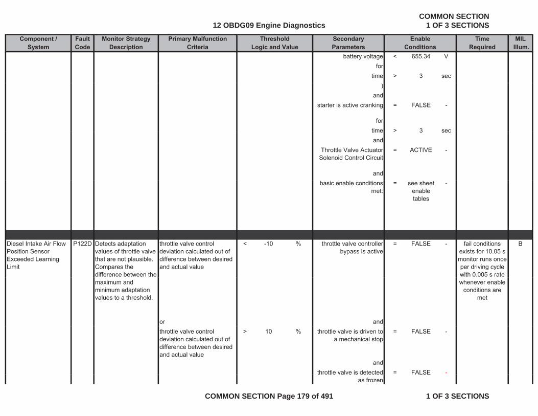
Component / Fault Monitor Strategy Primary Malfunction Secondary Time MILSystem Code Description Criteria Parameters Required Illum.
Threshold EnableLogic and Value Conditions
battery voltage < 655.34 Vfor
time > 3 sec)
andstarter is active cranking = FALSE -
fortime > 3 sectime > 3 secand
Throttle Valve Actuator Solenoid Control Circuit
= ACTIVE -
andbasic enable conditions
met:= see sheet
enable tables
-
Diesel Intake Air Flow Position Sensor Exceeded Learning Limit
P122D Detects adaptation values of throttle valve that are not plausible. Compares the difference between the
throttle valve control deviation calculated out of difference between desired and actual value
< -10 % throttle valve controller bypass is active
= FALSE - Bfail conditions exists for 10.05 smonitor runs once per driving cycle with 0.005 s rate
maximum and minimum adaptation values to a threshold.
or and
whenever enable conditions are
met
throttle valve control deviation calculated out of difference between desired and actual value
> 10 % throttle valve is driven to a mechanical stop
= FALSE -
andthrottle valve is detected = FALSE -
as frozen
12 OBDG09 Engine DiagnosticsCOMMON SECTION
1 OF 3 SECTIONS
COMMON SECTION Page 179 of 491 1 OF 3 SECTIONS
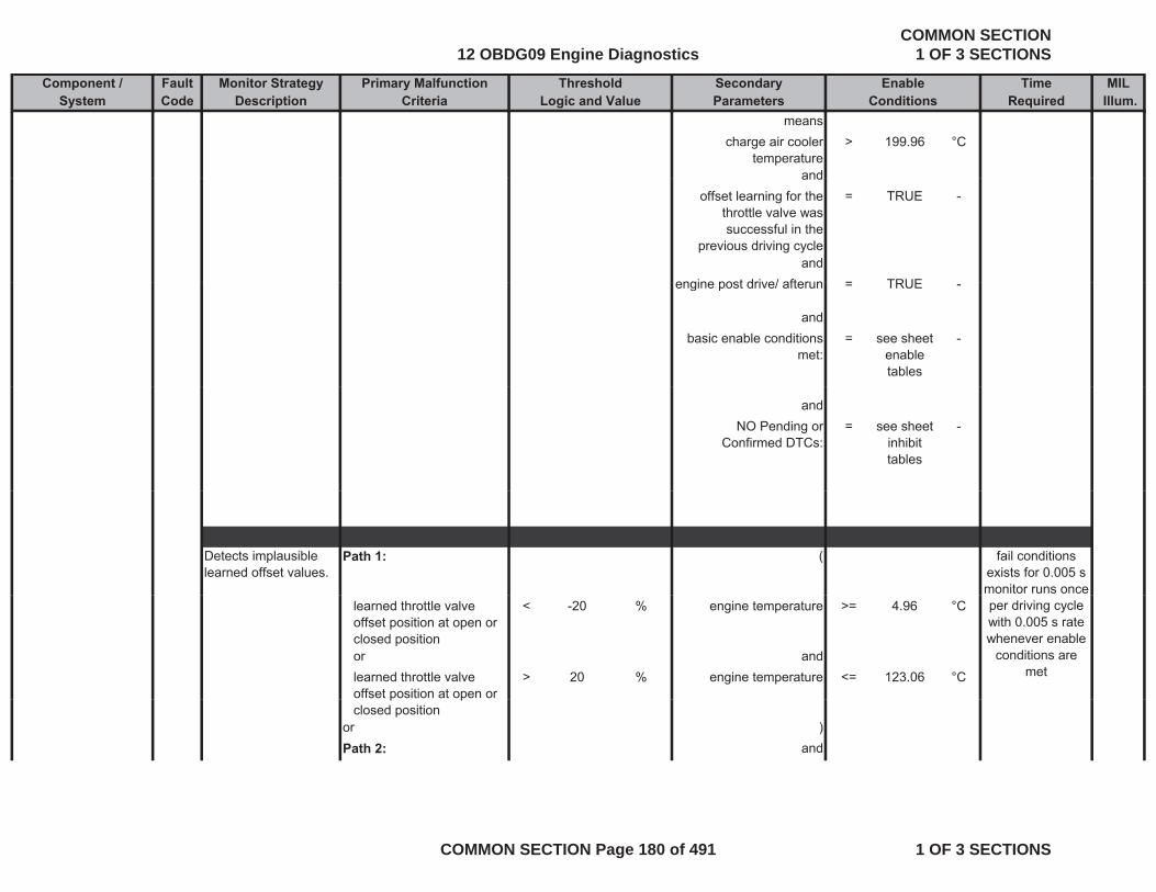
Component / Fault Monitor Strategy Primary Malfunction Secondary Time MILSystem Code Description Criteria Parameters Required Illum.
Threshold EnableLogic and Value Conditions
meanscharge air cooler
temperature> 199.96 °C
andandoffset learning for the
throttle valve was successful in the
previous driving cycle
= TRUE -
andengine post drive/ afterun = TRUEengine post drive/ afterun = TRUE -
andbasic enable conditions
met:= see sheet
enable tables
-
andNO Pending or
Confirmed DTCs:= see sheet
inhibit tables
-
Detects implausible learned offset values.
Path 1: ( fail conditions exists for 0.005 smonitor runs once
learned throttle valve offset position at open or closed position
< -20 % engine temperature >= 4.96 °C
or andlearned throttle valve offset position at open or
> 20 % engine temperature <= 123.06 °C
per driving cycle with 0.005 s rate whenever enable
conditions are met
p pclosed position
or )Path 2: and
12 OBDG09 Engine DiagnosticsCOMMON SECTION
1 OF 3 SECTIONS
COMMON SECTION Page 180 of 491 1 OF 3 SECTIONS
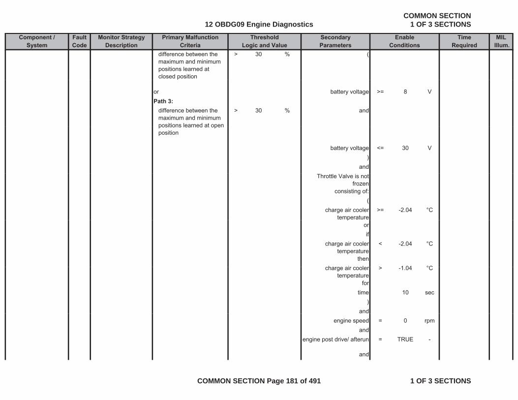
Component / Fault Monitor Strategy Primary Malfunction Secondary Time MILSystem Code Description Criteria Parameters Required Illum.
Threshold EnableLogic and Value Conditions
difference between the maximum and minimum positions learned at closed position
> 30 % (
or battery voltage >= 8 VPath 3:
difference between the maximum and minimum positions learned at open
> 30 % and
positions learned at open position
battery voltage <= 30 V)
andThrottle Valve is not
frozenconsisting of:
(charge air cooler
temperature>= -2.04 °C
porif
charge air cooler temperature
< -2.04 °C
thenh i l > 1 04 °Ccharge air cooler
temperature> -1.04 °C
fortime 10 sec
)and
engine speed = 0 rpmand
engine post drive/ afterun = TRUE -
and
12 OBDG09 Engine DiagnosticsCOMMON SECTION
1 OF 3 SECTIONS
COMMON SECTION Page 181 of 491 1 OF 3 SECTIONS
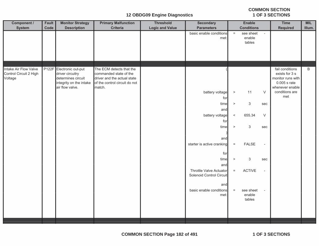
Component / Fault Monitor Strategy Primary Malfunction Secondary Time MILSystem Code Description Criteria Parameters Required Illum.
Threshold EnableLogic and Value Conditions
basic enable conditions met:
= see sheet enable tables
-
Intake Air Flow Valve Control Circuit 2 High Voltage
P122F Electronic out-put driver circuitry determines circuit
The ECM detects that the commanded state of the driver and the actual state
( Bfail conditions exists for 3 s
monitor runs withVoltage determines circuit integrity on the intake air flow valve.
driver and the actual state of the control circuit do not match.
battery voltage > 11 Vfor
time > 3 sec
monitor runs with 0.005 s rate
whenever enable conditions are
met
andbattery voltage < 655.34 V
fortime > 3 sec
)and
starter is active cranking = FALSE -
fortime > 3 sec
dandThrottle Valve Actuator
Solenoid Control Circuit= ACTIVE -
andbasic enable conditions = see sheet -
met: enable tables
12 OBDG09 Engine DiagnosticsCOMMON SECTION
1 OF 3 SECTIONS
COMMON SECTION Page 182 of 491 1 OF 3 SECTIONS
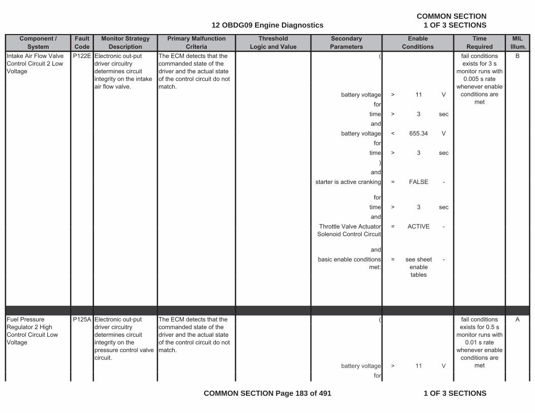
Component / Fault Monitor Strategy Primary Malfunction Secondary Time MILSystem Code Description Criteria Parameters Required Illum.
Threshold EnableLogic and Value Conditions
Intake Air Flow Valve Control Circuit 2 Low Voltage
P122E Electronic out-put driver circuitry determines circuit integrity on the intake
The ECM detects that the commanded state of the driver and the actual state of the control circuit do not
( Bfail conditions exists for 3 s
monitor runs with 0.005 s rate
air flow valve. match.battery voltage > 11 V
fortime > 3 secand
whenever enable conditions are
met
battery voltage < 655.34 Vfor
time > 3 sec)
andstarter is active cranking = FALSE -
fortime > 3 secand
Throttle Valve Actuator = ACTIVE -Throttle Valve Actuator Solenoid Control Circuit
= ACTIVE -
andbasic enable conditions
met:= see sheet
enable tables
-
tables
Fuel Pressure P125A Electronic out-put The ECM detects that the ( Afail conditions Regulator 2 High Control Circuit Low Voltage
driver circuitry determines circuit integrity on the pressure control valve circuit.
commanded state of the driver and the actual state of the control circuit do not match.
battery voltage > 11 V
exists for 0.5 s monitor runs with
0.01 s rate whenever enable
conditions are met
for
12 OBDG09 Engine DiagnosticsCOMMON SECTION
1 OF 3 SECTIONS
COMMON SECTION Page 183 of 491 1 OF 3 SECTIONS
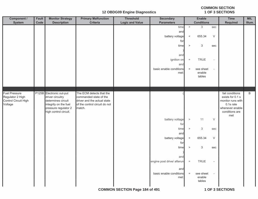
Component / Fault Monitor Strategy Primary Malfunction Secondary Time MILSystem Code Description Criteria Parameters Required Illum.
Threshold EnableLogic and Value Conditions
time > 3 secand
battery voltage < 655.34 Vfor
time > 3 sec)
andignition on = TRUE -
andbasic enable conditions
met:= see sheet
enable tables
-
Fuel Pressure Regulator 2 High Control Circuit High Voltage
P125B Electronic out-put driver circuitry determines circuit integrity on the fuel pressure regulator 2
The ECM detects that the commanded state of the driver and the actual state of the control circuit do not match.
( Bfail conditions exists for 0.1 s
monitor runs with 0.1s rate
whenever enable p ghigh control circuit.
battery voltage > 11 Vfor
time > 3 secd
conditions are met
andbattery voltage < 655.34 V
fortime > 3 sec
)dand
engine post drive/ afterun = TRUE -
andbasic enable conditions
met:= see sheet
enable -
tables
12 OBDG09 Engine DiagnosticsCOMMON SECTION
1 OF 3 SECTIONS
COMMON SECTION Page 184 of 491 1 OF 3 SECTIONS
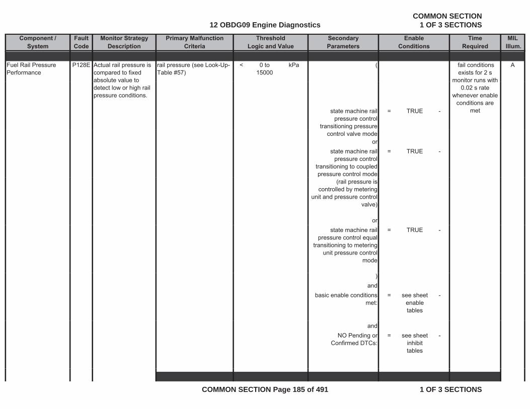
Component / Fault Monitor Strategy Primary Malfunction Secondary Time MILSystem Code Description Criteria Parameters Required Illum.
Threshold EnableLogic and Value Conditions
Fuel Rail Pressure Performance
P128E Actual rail pressure is compared to fixed absolute value to
rail pressure (see Look-Up-Table #57)
< 0 to 15000
kPa ( A fail conditions exists for 2 s
monitor runs withabsolute value to detect low or high rail pressure conditions.
state machine rail pressure control
transitioning pressure
= TRUE -
monitor runs with 0.02 s rate
whenever enable conditions are
met
g pcontrol valve mode
orstate machine rail
pressure control transitioning to coupled pressure control mode
= TRUE -
p(rail pressure is
controlled by metering unit and pressure control
valve)
orstate machine rail
pressure control equal transitioning to metering
unit pressure control mode
= TRUE -
)and
basic enable conditions met:
= see sheet enable tables
-
andNO Pending or
Confirmed DTCs:= see sheet
inhibit tables
-
12 OBDG09 Engine DiagnosticsCOMMON SECTION
1 OF 3 SECTIONS
COMMON SECTION Page 185 of 491 1 OF 3 SECTIONS
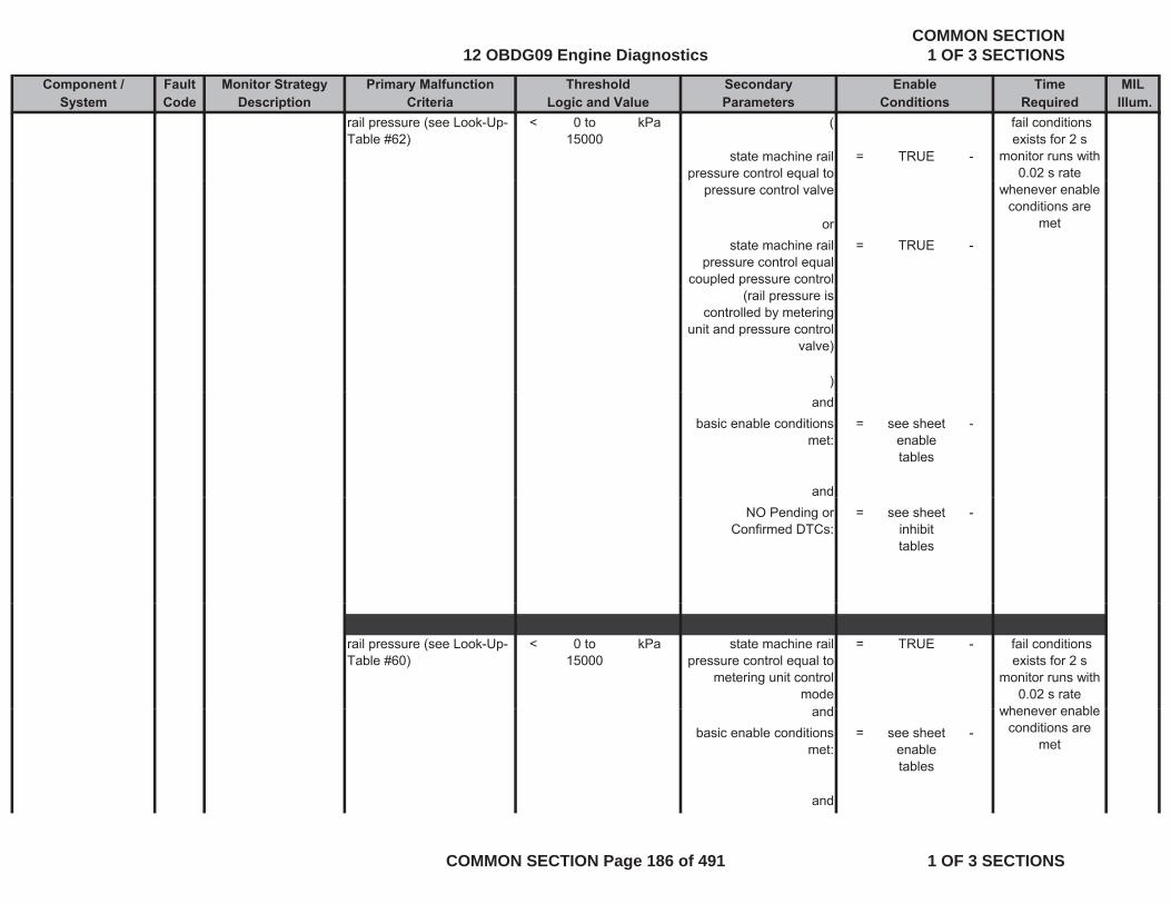
Component / Fault Monitor Strategy Primary Malfunction Secondary Time MILSystem Code Description Criteria Parameters Required Illum.
Threshold EnableLogic and Value Conditions
rail pressure (see Look-Up-Table #62)
< 0 to 15000
kPa (
state machine rail pressure control equal to
= TRUE -
fail conditions exists for 2 s
monitor runs with 0.02 s rate
pressure control valve
orstate machine rail
pressure control equal coupled pressure control
= TRUE -
whenever enable conditions are
met
p p(rail pressure is
controlled by metering unit and pressure control
valve)
)and
basic enable conditions met:
= see sheet enable tables
-
andNO Pending or
Confirmed DTCs:= see sheet
inhibit tables
-
rail pressure (see Look-Up-Table #60)
< 0 to 15000
kPa state machine rail pressure control equal to
metering unit control mode
= TRUE -
d
fail conditions exists for 2 s
monitor runs with 0.02 s rate
whenever enableandbasic enable conditions
met:= see sheet
enable tables
-
and
whenever enable conditions are
met
12 OBDG09 Engine DiagnosticsCOMMON SECTION
1 OF 3 SECTIONS
COMMON SECTION Page 186 of 491 1 OF 3 SECTIONS
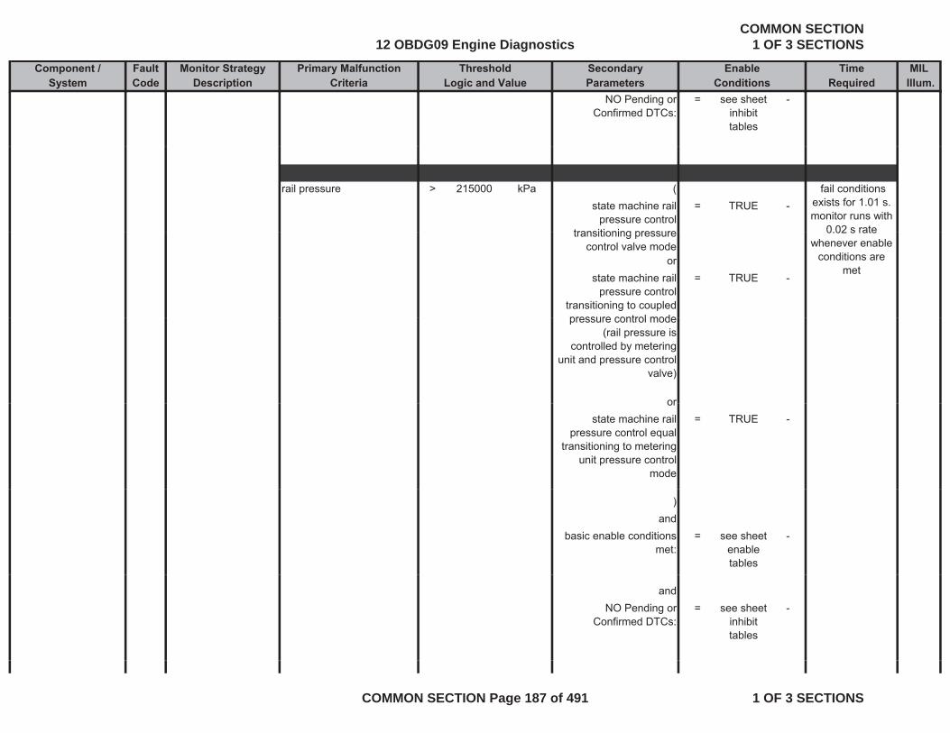
Component / Fault Monitor Strategy Primary Malfunction Secondary Time MILSystem Code Description Criteria Parameters Required Illum.
Threshold EnableLogic and Value Conditions
NO Pending or Confirmed DTCs:
= see sheet inhibit tables
-
rail pressure > 215000 kPa (state machine rail
pressure control transitioning pressure
= TRUE - fail conditions
exists for 1.01 s. monitor runs with
0 02 s ratetransitioning pressure control valve mode
orstate machine rail
pressure control transitioning to coupled pressure control mode
= TRUE -
0.02 s rate whenever enable
conditions are met
pressure control mode (rail pressure is
controlled by metering unit and pressure control
valve)
ororstate machine rail
pressure control equal transitioning to metering
unit pressure control mode
= TRUE -
)and
basic enable conditions met:
= see sheet enable tables
-
andNO Pending or
Confirmed DTCs:= see sheet
inhibit tables
-
12 OBDG09 Engine DiagnosticsCOMMON SECTION
1 OF 3 SECTIONS
COMMON SECTION Page 187 of 491 1 OF 3 SECTIONS
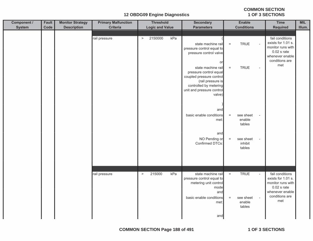
Component / Fault Monitor Strategy Primary Malfunction Secondary Time MILSystem Code Description Criteria Parameters Required Illum.
Threshold EnableLogic and Value Conditions
rail pressure > 2150000 kPa (state machine rail
pressure control equal to= TRUE -
fail conditions exists for 1.01 s. monitor runs withpressure control equal to
pressure control valve
orstate machine rail
pressure control equal coupled pressure control
= TRUE -
monitor runs with 0.02 s rate
whenever enable conditions are
met
coupled pressure control (rail pressure is
controlled by metering unit and pressure control
valve)
))and
basic enable conditions met:
= see sheet enable tables
-
andandNO Pending or
Confirmed DTCs:= see sheet
inhibit tables
-
rail pressure > 215000 kPa state machine rail pressure control equal to
metering unit control mode
= TRUE - fail conditions exists for 1.01 s. monitor runs with
0.02 s rate and
basic enable conditions met:
= see sheet enable tables
-
and
whenever enable conditions are
met
12 OBDG09 Engine DiagnosticsCOMMON SECTION
1 OF 3 SECTIONS
COMMON SECTION Page 188 of 491 1 OF 3 SECTIONS
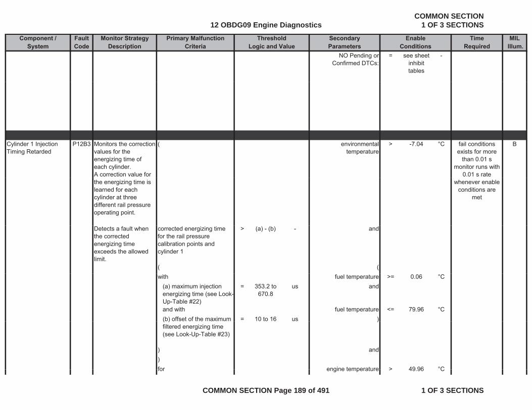
Component / Fault Monitor Strategy Primary Malfunction Secondary Time MILSystem Code Description Criteria Parameters Required Illum.
Threshold EnableLogic and Value Conditions
NO Pending or Confirmed DTCs:
= see sheet inhibit tables
-
Cylinder 1 Injection Timing Retarded
P12B3 Monitors the correction values for the energizing time of each cylinder. A correction value for
( environmental temperature
> -7.04 °C Bfail conditions exists for more
than 0.01 smonitor runs with
0.01 s rate the energizing time is learned for each cylinder at three different rail pressure operating point.
whenever enable conditions are
met
Detects a fault when the corrected energizing time exceeds the allowed limit.
corrected energizing time for the rail pressure calibration points and cylinder 1
> (a) - (b) - and
( (with fuel temperature >= 0.06 °C
(a) maximum injection energizing time (see Look-Up-Table #22)
= 353.2 to 670.8
us and
and with fuel temperature <= 79.96 °C(b) offset of the maximum = 10 to 16 us )( )filtered energizing time (see Look-Up-Table #23)
)
) and)for engine temperature > 49 96 °Cfor engine temperature > 49.96 C
12 OBDG09 Engine DiagnosticsCOMMON SECTION
1 OF 3 SECTIONS
COMMON SECTION Page 189 of 491 1 OF 3 SECTIONS
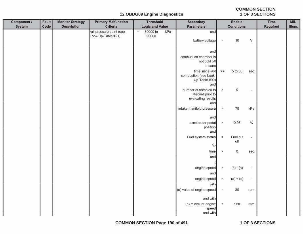
Component / Fault Monitor Strategy Primary Malfunction Secondary Time MILSystem Code Description Criteria Parameters Required Illum.
Threshold EnableLogic and Value Conditions
rail pressure point (see Look-Up-Table #21)
= 30000 to 90000
kPa and
battery voltage > 10 V
andcombustion chamber is
not cold offmeans
time since last >= 5 to 30 seccombustion (see Look-
Up-Table #90)and
number of samples to discard prior to
evaluating results
> 0 -
andintake manifold pressure > 75 kPa
andaccelerator pedal
position< 0.05 %
pand
Fuel system status = Fuel cut off
-
fortime > 0 sec
dand(
engine speed > (b) - (a) -and
engine speed < (a) + (c) -ithwith
(a) value of engine speed = 30 rpm
and with(b) minimum engine
speed= 950 rpm
and with
12 OBDG09 Engine DiagnosticsCOMMON SECTION
1 OF 3 SECTIONS
COMMON SECTION Page 190 of 491 1 OF 3 SECTIONS
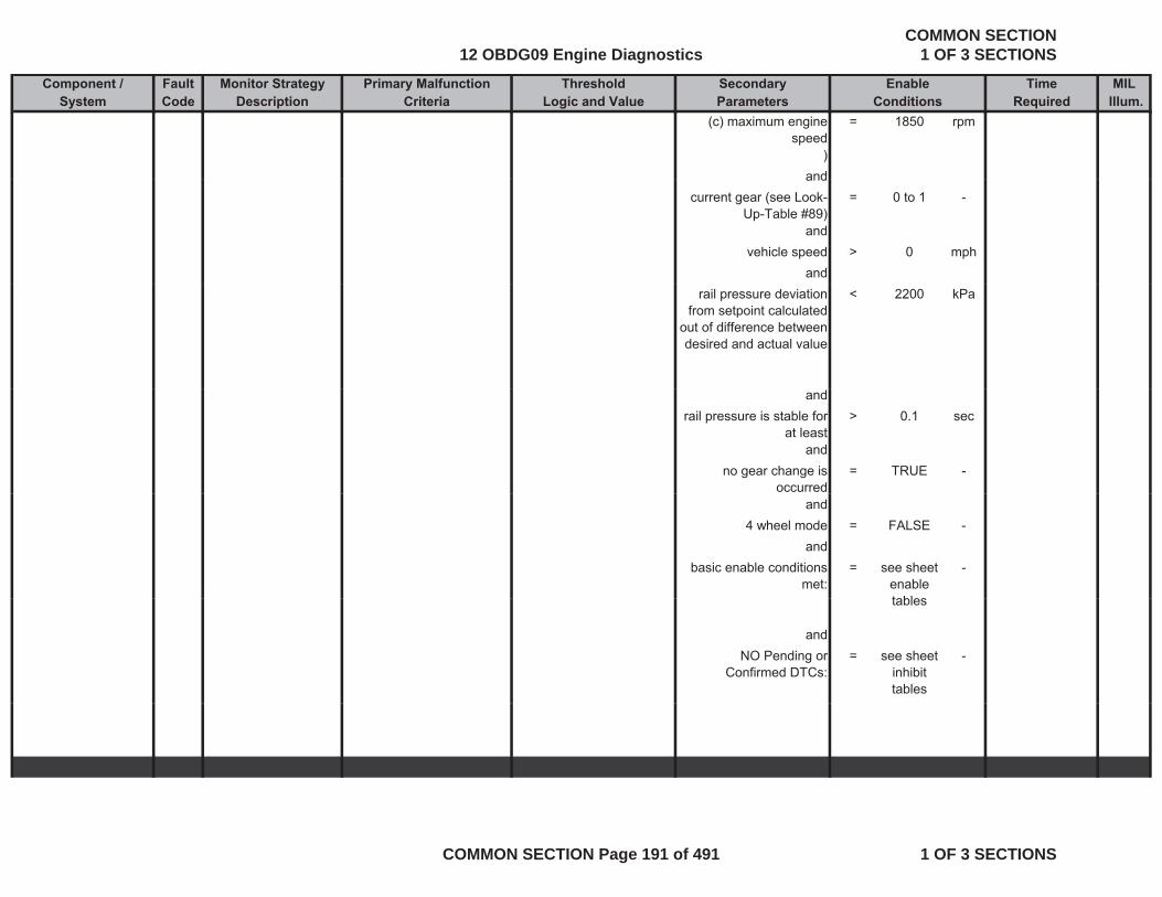
Component / Fault Monitor Strategy Primary Malfunction Secondary Time MILSystem Code Description Criteria Parameters Required Illum.
Threshold EnableLogic and Value Conditions
(c) maximum engine speed
= 1850 rpm
)andand
current gear (see Look-Up-Table #89)
= 0 to 1 -
andvehicle speed > 0 mph
andrail pressure deviation
from setpoint calculated out of difference between desired and actual value
< 2200 kPa
andrail pressure is stable for
at least> 0.1 sec
andno gear change is
occurred= TRUE -
and4 wheel mode = FALSE -
andbasic enable conditions
met:= see sheet
enable tables
-
tables
andNO Pending or
Confirmed DTCs:= see sheet
inhibit tables
-
12 OBDG09 Engine DiagnosticsCOMMON SECTION
1 OF 3 SECTIONS
COMMON SECTION Page 191 of 491 1 OF 3 SECTIONS

Component / Fault Monitor Strategy Primary Malfunction Secondary Time MILSystem Code Description Criteria Parameters Required Illum.
Threshold EnableLogic and Value Conditions
Cylinder 2 Injection Timing Retarded
P12B5 Monitors the correction values for the energizing time of each cylinder.
( environmental temperature
> -7.04 °C Bfail conditions exists for more
than 0.01 smonitor runs with
A correction value for the energizing time is learned for each cylinder at three different rail pressure operating point.
0.01 s rate whenever enable
conditions are met
Detects a fault when the corrected energizing time exceeds the allowed limit.
corrected energizing time for the rail pressure calibration points and cylinder 2
> (a) - (b) - and
( (( (with fuel temperature >= 0.06 °C
(a) maximum injection energizing time (see Look-Up-Table #22)
= 353.2 to 670.8
us and
and with fuel temperature <= 79.96 °C(b) offset of the maximum filtered energizing time (see Look-Up-Table #23)
= 10 to 16 us )
) and))for engine temperature > 49.96 °Crail pressure point (see Look-Up-Table #21)
= 30000 to 90000
kPa and
battery voltage > 10 V
andcombustion chamber is
not cold offmeans
time since last combustion (see Look-
>= 5 to 30 sec(
Up-Table #90)
12 OBDG09 Engine DiagnosticsCOMMON SECTION
1 OF 3 SECTIONS
COMMON SECTION Page 192 of 491 1 OF 3 SECTIONS
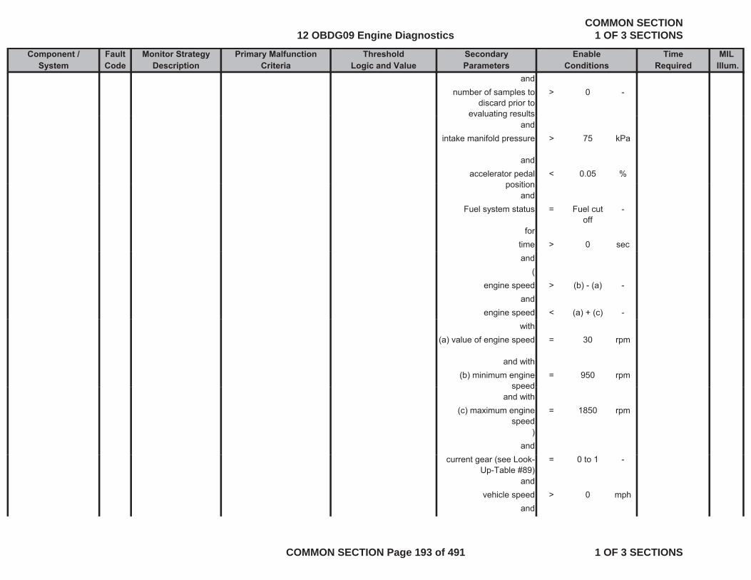
Component / Fault Monitor Strategy Primary Malfunction Secondary Time MILSystem Code Description Criteria Parameters Required Illum.
Threshold EnableLogic and Value Conditions
andnumber of samples to
discard prior to evaluating results
> 0 -
evaluating resultsand
intake manifold pressure > 75 kPa
andaccelerator pedal
position< 0.05 %
positionand
Fuel system status = Fuel cut off
-
fortime > 0 secand
(engine speed > (b) - (a) -
andengine speed < (a) + (c) -
with(a) value of engine speed = 30 rpm
and with(b) minimum engine
speed= 950 rpm
speedand with
(c) maximum engine speed
= 1850 rpm
)and
current gear (see Look-Up-Table #89)
= 0 to 1 -
andvehicle speed > 0 mph
and
12 OBDG09 Engine DiagnosticsCOMMON SECTION
1 OF 3 SECTIONS
COMMON SECTION Page 193 of 491 1 OF 3 SECTIONS
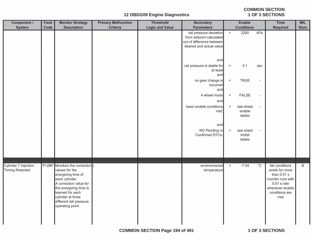
Component / Fault Monitor Strategy Primary Malfunction Secondary Time MILSystem Code Description Criteria Parameters Required Illum.
Threshold EnableLogic and Value Conditions
rail pressure deviation from setpoint calculated
out of difference between desired and actual value
< 2200 kPa
andrail pressure is stable for
at least> 0.1 sec
andno gear change is
occurred= TRUE -
and4 wheel mode = FALSE -
andbasic enable conditions
met:= see sheet
enable tables
-
andNO Pending or = see sheet -
Confirmed DTCs: inhibit tables
Cylinder 7 Injection Timing Retarded
P12BF Monitors the correction values for the energizing time of each cylinder. A correction value for the energizing time is
( environmental temperature
> -7.04 °C Bfail conditions exists for more
than 0.01 smonitor runs with
0.01 s rate whenever enable g g
learned for each cylinder at three different rail pressure operating point.
conditions are met
12 OBDG09 Engine DiagnosticsCOMMON SECTION
1 OF 3 SECTIONS
COMMON SECTION Page 194 of 491 1 OF 3 SECTIONS
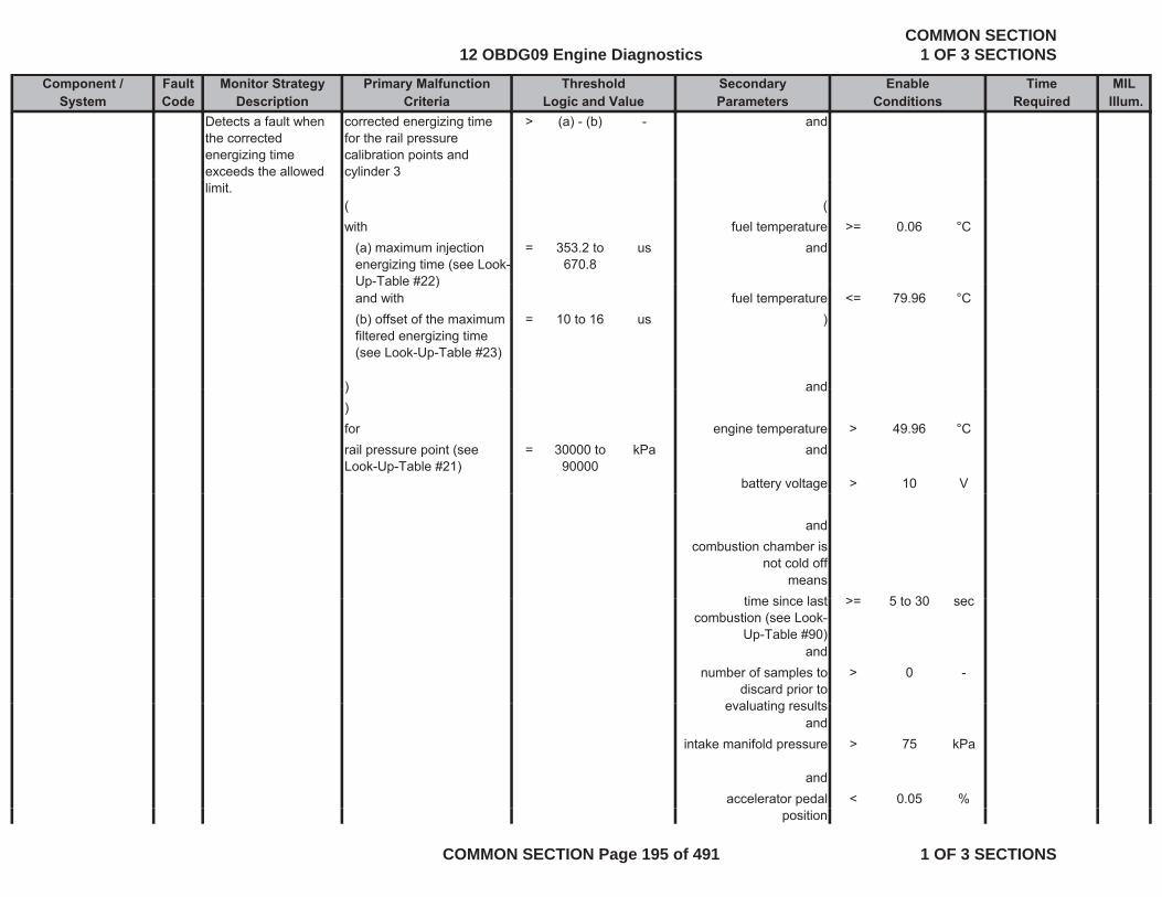
Component / Fault Monitor Strategy Primary Malfunction Secondary Time MILSystem Code Description Criteria Parameters Required Illum.
Threshold EnableLogic and Value Conditions
Detects a fault when the corrected energizing time exceeds the allowed
corrected energizing time for the rail pressure calibration points and cylinder 3
> (a) - (b) - and
limit.( (with fuel temperature >= 0.06 °C
(a) maximum injection energizing time (see Look-Up-Table #22)
= 353.2 to 670.8
us and
Up Table #22)and with fuel temperature <= 79.96 °C(b) offset of the maximum filtered energizing time (see Look-Up-Table #23)
= 10 to 16 us )
) and) and)for engine temperature > 49.96 °Crail pressure point (see Look-Up-Table #21)
= 30000 to 90000
kPa and
battery voltage > 10 V
andcombustion chamber is
not cold offmeans
ti i l t > 5 t 30time since last combustion (see Look-
Up-Table #90)
>= 5 to 30 sec
andnumber of samples to
discard prior to l ti lt
> 0 -
evaluating resultsand
intake manifold pressure > 75 kPa
andaccelerator pedal < 0.05 %
position
12 OBDG09 Engine DiagnosticsCOMMON SECTION
1 OF 3 SECTIONS
COMMON SECTION Page 195 of 491 1 OF 3 SECTIONS

Component / Fault Monitor Strategy Primary Malfunction Secondary Time MILSystem Code Description Criteria Parameters Required Illum.
Threshold EnableLogic and Value Conditions
andFuel system status = Fuel cut
off-
forfortime > 0 secand
(engine speed > (b) - (a) -
andandengine speed < (a) + (c) -
with(a) value of engine speed = 30 rpm
and with(b) minimum engine
speed= 950 rpm
and with(c) maximum engine
speed= 1850 rpm
))and
current gear (see Look-Up-Table #89)
= 0 to 1 -
andvehicle speed > 0 mph
andrail pressure deviation
from setpoint calculated out of difference between desired and actual value
< 2200 kPa
andrail pressure is stable for
at least> 0.1 sec
andno gear change is = TRUE -g g
occurred
12 OBDG09 Engine DiagnosticsCOMMON SECTION
1 OF 3 SECTIONS
COMMON SECTION Page 196 of 491 1 OF 3 SECTIONS
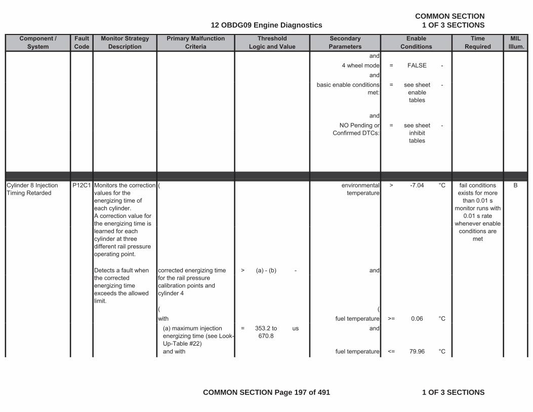
Component / Fault Monitor Strategy Primary Malfunction Secondary Time MILSystem Code Description Criteria Parameters Required Illum.
Threshold EnableLogic and Value Conditions
and4 wheel mode = FALSE -
andbasic enable conditions
met:= see sheet
enable tables
-
andNO Pending or = see sheet -
Confirmed DTCs: inhibit tables
Cylinder 8 Injection Timing Retarded
P12C1 Monitors the correction values for the energizing time of each cylinder. A correction value for the energizing time is
( environmental temperature
> -7.04 °C Bfail conditions exists for more
than 0.01 smonitor runs with
0.01 s rate whenever enable g g
learned for each cylinder at three different rail pressure operating point.
Detects a fault when corrected energizing time > (a) - (b) - and
conditions are met
the corrected energizing time exceeds the allowed limit.
for the rail pressure calibration points and cylinder 4
( (with fuel temperature >= 0.06 °C
(a) maximum injection energizing time (see Look-Up-Table #22)
= 353.2 to 670.8
us and
and with fuel temperature <= 79.96 °C
12 OBDG09 Engine DiagnosticsCOMMON SECTION
1 OF 3 SECTIONS
COMMON SECTION Page 197 of 491 1 OF 3 SECTIONS

Component / Fault Monitor Strategy Primary Malfunction Secondary Time MILSystem Code Description Criteria Parameters Required Illum.
Threshold EnableLogic and Value Conditions
(b) offset of the maximum filtered energizing time (see Look-Up-Table #23)
= 10 to 16 us )
) and)for engine temperature > 49.96 °Crail pressure point (see Look-Up-Table #21)
= 30000 to 90000
kPa and
battery voltage > 10 Vbattery voltage > 10 V
andcombustion chamber is
not cold offmeans
time since last combustion (see Look-
Up-Table #90)
>= 5 to 30 sec
andnumber of samples to
discard prior to> 0 -
discard prior to evaluating results
andintake manifold pressure > 75 kPa
andl t d l < 0 05 %accelerator pedal
position< 0.05 %
andFuel system status = Fuel cut
off-
fortime > 0 secand
(engine speed > (b) - (a) -
andengine speed < (a) + (c) -
12 OBDG09 Engine DiagnosticsCOMMON SECTION
1 OF 3 SECTIONS
COMMON SECTION Page 198 of 491 1 OF 3 SECTIONS

Component / Fault Monitor Strategy Primary Malfunction Secondary Time MILSystem Code Description Criteria Parameters Required Illum.
Threshold EnableLogic and Value Conditions
with(a) value of engine speed = 30 rpm
and withand with(b) minimum engine
speed= 950 rpm
and with(c) maximum engine
speed= 1850 rpm
))and
current gear (see Look-Up-Table #89)
= 0 to 1 -
andvehicle speed > 0 mphp p
andrail pressure deviation
from setpoint calculated out of difference between desired and actual value
< 2200 kPa
andrail pressure is stable for
at least> 0.1 sec
andh i TRUEno gear change is occurred
= TRUE -
and4 wheel mode = FALSE -
andbasic enable conditions = see sheet -
met: enable tables
and
12 OBDG09 Engine DiagnosticsCOMMON SECTION
1 OF 3 SECTIONS
COMMON SECTION Page 199 of 491 1 OF 3 SECTIONS

Component / Fault Monitor Strategy Primary Malfunction Secondary Time MILSystem Code Description Criteria Parameters Required Illum.
Threshold EnableLogic and Value Conditions
NO Pending or Confirmed DTCs:
= see sheet inhibit tables
-
Cylinder 4 Injection Timing Retarded
P12B9 Monitors the correction values for the energizing time of
( environmental temperature
> -7.04 °C Bfail conditions exists for more
than 0 01 senergizing time of each cylinder. A correction value for the energizing time is learned for each cylinder at three different rail pressure
than 0.01 smonitor runs with
0.01 s rate whenever enable
conditions are met
different rail pressure operating point.
Detects a fault when the corrected energizing time exceeds the allowed
corrected energizing time for the rail pressure calibration points and cylinder 5
> (a) - (b) - and
limit.y
( (with fuel temperature >= 0.06 °C
(a) maximum injection energizing time (see Look-Up-Table #22)
= 353.2 to 670.8
us and
Up Table #22)and with fuel temperature <= 79.96 °C(b) offset of the maximum filtered energizing time (see Look-Up-Table #23)
= 10 to 16 us )
) and) and)for engine temperature > 49.96 °Crail pressure point (see Look-Up-Table #21)
= 30000 to 90000
kPa and
battery voltage > 10 V
12 OBDG09 Engine DiagnosticsCOMMON SECTION
1 OF 3 SECTIONS
COMMON SECTION Page 200 of 491 1 OF 3 SECTIONS
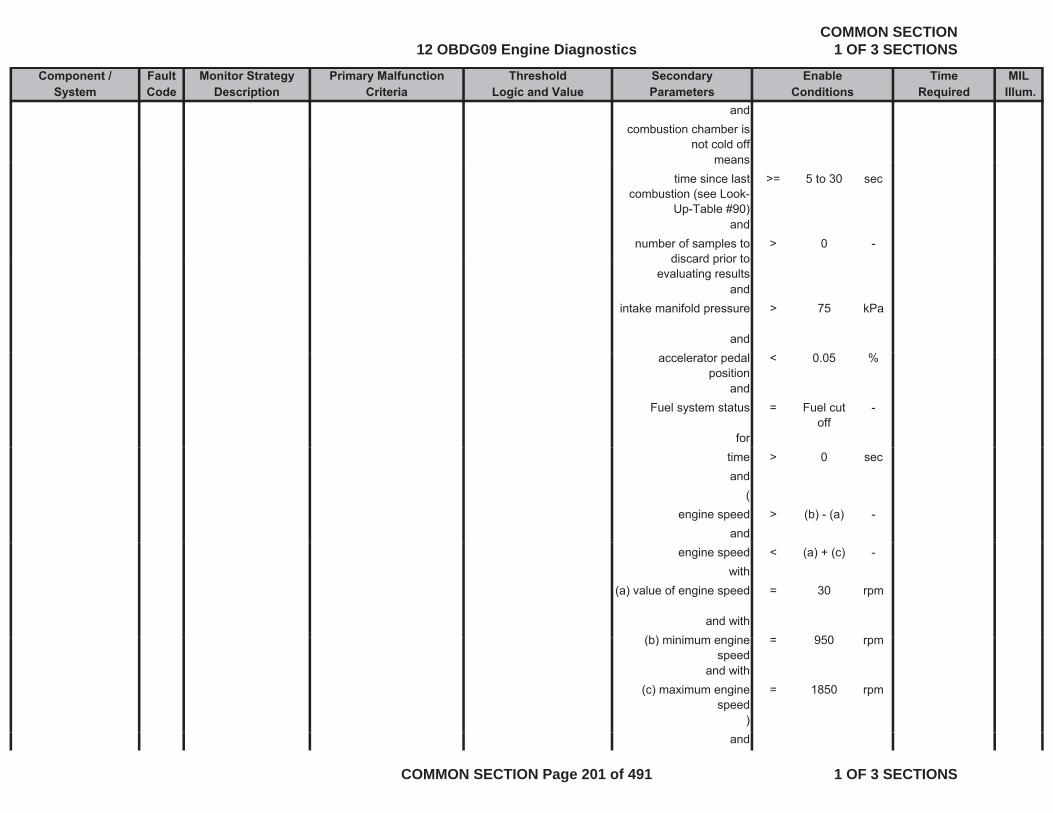
Component / Fault Monitor Strategy Primary Malfunction Secondary Time MILSystem Code Description Criteria Parameters Required Illum.
Threshold EnableLogic and Value Conditions
andcombustion chamber is
not cold offmeansmeans
time since last combustion (see Look-
Up-Table #90)
>= 5 to 30 sec
andnumber of samples to
discard prior to> 0 -
discard prior to evaluating results
andintake manifold pressure > 75 kPa
andaccelerator pedal
position< 0.05 %
andFuel system status = Fuel cut
off-
fortime > 0 secand
(engine speed > (b) - (a) -
andengine speed < (a) + (c) -
with(a) value of engine speed = 30 rpm
and with(b) i i i 950(b) minimum engine
speed= 950 rpm
and with(c) maximum engine
speed= 1850 rpm
)and
12 OBDG09 Engine DiagnosticsCOMMON SECTION
1 OF 3 SECTIONS
COMMON SECTION Page 201 of 491 1 OF 3 SECTIONS

Component / Fault Monitor Strategy Primary Malfunction Secondary Time MILSystem Code Description Criteria Parameters Required Illum.
Threshold EnableLogic and Value Conditions
current gear (see Look-Up-Table #89)
= 0 to 1 -
andvehicle speed > 0 mphvehicle speed > 0 mph
andrail pressure deviation
from setpoint calculated out of difference between desired and actual value
< 2200 kPa
andrail pressure is stable for
at least> 0.1 sec
andno gear change is
occurred= TRUE -
and4 wheel mode = FALSE -
andbasic enable conditions = see sheet -basic enable conditions
met:= see sheet
enable tables
andNO Pending or
Confirmed DTCs:= see sheet
inhibit-
Confirmed DTCs: inhibit tables
12 OBDG09 Engine DiagnosticsCOMMON SECTION
1 OF 3 SECTIONS
COMMON SECTION Page 202 of 491 1 OF 3 SECTIONS
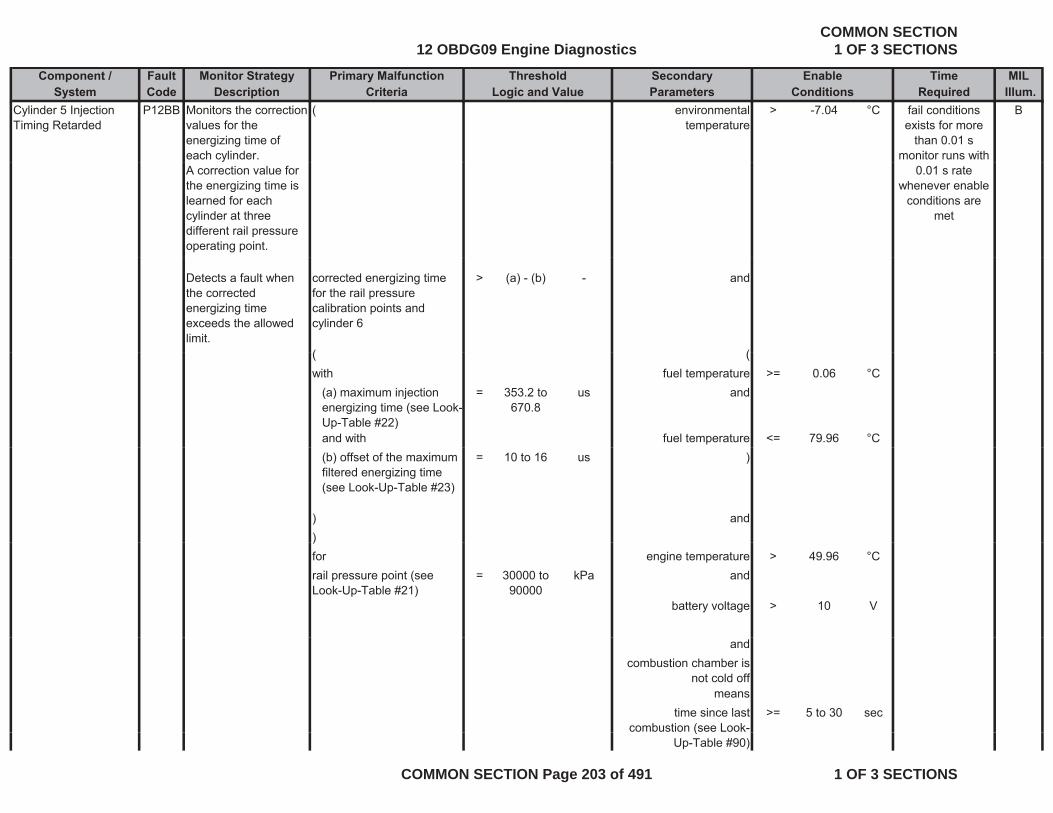
Component / Fault Monitor Strategy Primary Malfunction Secondary Time MILSystem Code Description Criteria Parameters Required Illum.
Threshold EnableLogic and Value Conditions
Cylinder 5 Injection Timing Retarded
P12BB Monitors the correction values for the energizing time of each cylinder.
( environmental temperature
> -7.04 °C Bfail conditions exists for more
than 0.01 smonitor runs with
A correction value for the energizing time is learned for each cylinder at three different rail pressure operating point.
0.01 s rate whenever enable
conditions are met
Detects a fault when the corrected energizing time exceeds the allowed limit.
corrected energizing time for the rail pressure calibration points and cylinder 6
> (a) - (b) - and
( (( (with fuel temperature >= 0.06 °C
(a) maximum injection energizing time (see Look-Up-Table #22)
= 353.2 to 670.8
us and
and with fuel temperature <= 79.96 °C(b) offset of the maximum filtered energizing time (see Look-Up-Table #23)
= 10 to 16 us )
) and))for engine temperature > 49.96 °Crail pressure point (see Look-Up-Table #21)
= 30000 to 90000
kPa and
battery voltage > 10 V
andcombustion chamber is
not cold offmeans
time since last combustion (see Look-
>= 5 to 30 sec(
Up-Table #90)
12 OBDG09 Engine DiagnosticsCOMMON SECTION
1 OF 3 SECTIONS
COMMON SECTION Page 203 of 491 1 OF 3 SECTIONS

Component / Fault Monitor Strategy Primary Malfunction Secondary Time MILSystem Code Description Criteria Parameters Required Illum.
Threshold EnableLogic and Value Conditions
andnumber of samples to
discard prior to evaluating results
> 0 -
evaluating resultsand
intake manifold pressure > 75 kPa
andaccelerator pedal
position< 0.05 %
positionand
Fuel system status = Fuel cut off
-
fortime > 0 secand
(engine speed > (b) - (a) -
andengine speed < (a) + (c) -
with(a) value of engine speed = 30 rpm
and with(b) minimum engine
speed= 950 rpm
speedand with
(c) maximum engine speed
= 1850 rpm
)and
current gear (see Look-Up-Table #89)
= 0 to 1 -
andvehicle speed > 0 mph
and
12 OBDG09 Engine DiagnosticsCOMMON SECTION
1 OF 3 SECTIONS
COMMON SECTION Page 204 of 491 1 OF 3 SECTIONS

Component / Fault Monitor Strategy Primary Malfunction Secondary Time MILSystem Code Description Criteria Parameters Required Illum.
Threshold EnableLogic and Value Conditions
rail pressure deviation from setpoint calculated
out of difference between desired and actual value
< 2200 kPa
andrail pressure is stable for
at least> 0.1 sec
andno gear change is
occurred= TRUE -
and4 wheel mode = FALSE -
andbasic enable conditions
met:= see sheet
enable tables
-
andNO Pending or = see sheet -
Confirmed DTCs: inhibit tables
Cylinder 6 Injection Timing Retarded
P12BD Monitors the correction values for the energizing time of each cylinder. A correction value for the energizing time is
( environmental temperature
> -7.04 °C Bfail conditions exists for more
than 0.01 smonitor runs with
0.01 s rate whenever enable g g
learned for each cylinder at three different rail pressure operating point.
conditions are met
12 OBDG09 Engine DiagnosticsCOMMON SECTION
1 OF 3 SECTIONS
COMMON SECTION Page 205 of 491 1 OF 3 SECTIONS

Component / Fault Monitor Strategy Primary Malfunction Secondary Time MILSystem Code Description Criteria Parameters Required Illum.
Threshold EnableLogic and Value Conditions
Detects a fault when the corrected energizing time exceeds the allowed
corrected energizing time for the rail pressure calibration points and cylinder 7
> (a) - (b) - and
limit.( (with fuel temperature >= 0.06 °C
(a) maximum injection energizing time (see Look-Up-Table #22)
= 353.2 to 670.8
us and
Up Table #22)and with fuel temperature <= 79.96 °C(b) offset of the maximum filtered energizing time (see Look-Up-Table #23)
= 10 to 16 us )
) and) and)for engine temperature > 49.96 °Crail pressure point (see Look-Up-Table #21)
= 30000 to 90000
kPa and
battery voltage > 10 V
andcombustion chamber is
not cold offmeans
ti i l t > 5 t 30time since last combustion (see Look-
Up-Table #90)
>= 5 to 30 sec
andnumber of samples to
discard prior to l ti lt
> 0 -
evaluating resultsand
intake manifold pressure > 75 kPa
andaccelerator pedal < 0.05 %
position
12 OBDG09 Engine DiagnosticsCOMMON SECTION
1 OF 3 SECTIONS
COMMON SECTION Page 206 of 491 1 OF 3 SECTIONS
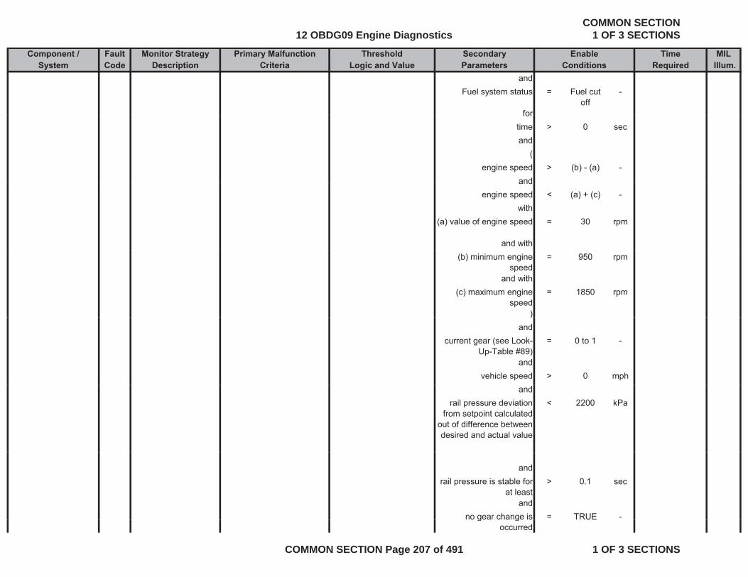
Component / Fault Monitor Strategy Primary Malfunction Secondary Time MILSystem Code Description Criteria Parameters Required Illum.
Threshold EnableLogic and Value Conditions
andFuel system status = Fuel cut
off-
forfortime > 0 secand
(engine speed > (b) - (a) -
andandengine speed < (a) + (c) -
with(a) value of engine speed = 30 rpm
and with(b) minimum engine
speed= 950 rpm
and with(c) maximum engine
speed= 1850 rpm
))and
current gear (see Look-Up-Table #89)
= 0 to 1 -
andvehicle speed > 0 mph
andrail pressure deviation
from setpoint calculated out of difference between desired and actual value
< 2200 kPa
andrail pressure is stable for
at least> 0.1 sec
andno gear change is = TRUE -g g
occurred
12 OBDG09 Engine DiagnosticsCOMMON SECTION
1 OF 3 SECTIONS
COMMON SECTION Page 207 of 491 1 OF 3 SECTIONS
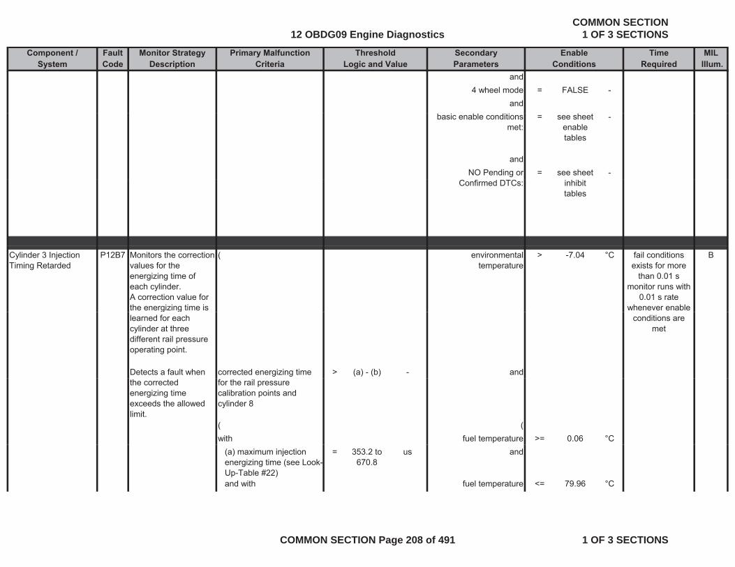
Component / Fault Monitor Strategy Primary Malfunction Secondary Time MILSystem Code Description Criteria Parameters Required Illum.
Threshold EnableLogic and Value Conditions
and4 wheel mode = FALSE -
andbasic enable conditions
met:= see sheet
enable tables
-
andNO Pending or = see sheet -
Confirmed DTCs: inhibit tables
Cylinder 3 Injection Timing Retarded
P12B7 Monitors the correction values for the energizing time of each cylinder. A correction value for the energizing time is
( environmental temperature
> -7.04 °C Bfail conditions exists for more
than 0.01 smonitor runs with
0.01 s rate whenever enable g g
learned for each cylinder at three different rail pressure operating point.
Detects a fault when corrected energizing time > (a) - (b) - and
conditions are met
the corrected energizing time exceeds the allowed limit.
for the rail pressure calibration points and cylinder 8
( (with fuel temperature >= 0.06 °C
(a) maximum injection energizing time (see Look-Up-Table #22)
= 353.2 to 670.8
us and
and with fuel temperature <= 79.96 °C
12 OBDG09 Engine DiagnosticsCOMMON SECTION
1 OF 3 SECTIONS
COMMON SECTION Page 208 of 491 1 OF 3 SECTIONS
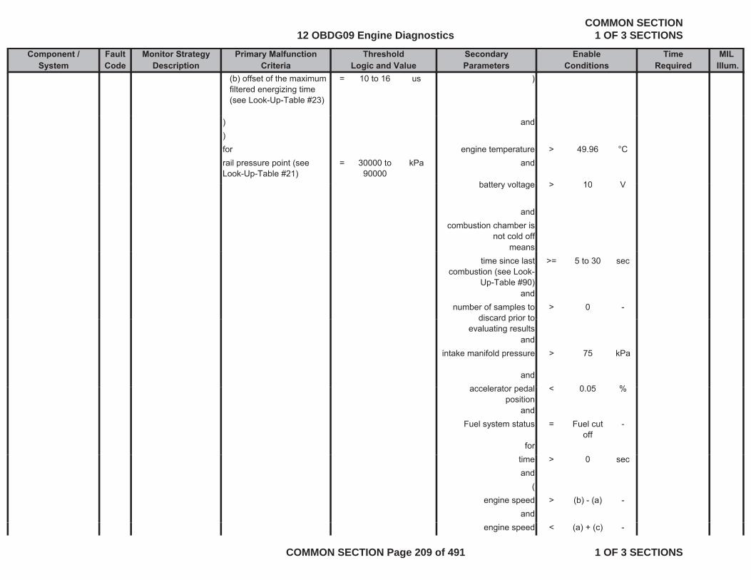
Component / Fault Monitor Strategy Primary Malfunction Secondary Time MILSystem Code Description Criteria Parameters Required Illum.
Threshold EnableLogic and Value Conditions
(b) offset of the maximum filtered energizing time (see Look-Up-Table #23)
= 10 to 16 us )
) and)for engine temperature > 49.96 °Crail pressure point (see Look-Up-Table #21)
= 30000 to 90000
kPa and
battery voltage > 10 Vbattery voltage > 10 V
andcombustion chamber is
not cold offmeans
time since last combustion (see Look-
Up-Table #90)
>= 5 to 30 sec
andnumber of samples to
discard prior to> 0 -
discard prior to evaluating results
andintake manifold pressure > 75 kPa
andl t d l < 0 05 %accelerator pedal
position< 0.05 %
andFuel system status = Fuel cut
off-
fortime > 0 secand
(engine speed > (b) - (a) -
andengine speed < (a) + (c) -
12 OBDG09 Engine DiagnosticsCOMMON SECTION
1 OF 3 SECTIONS
COMMON SECTION Page 209 of 491 1 OF 3 SECTIONS
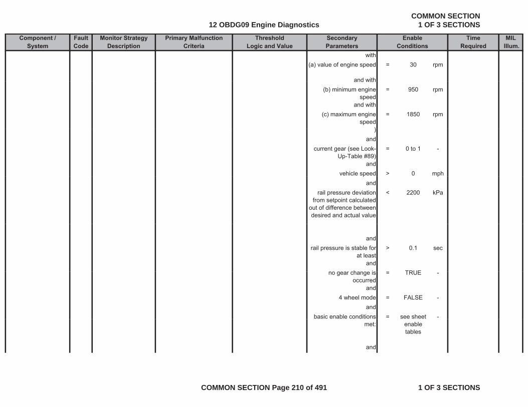
Component / Fault Monitor Strategy Primary Malfunction Secondary Time MILSystem Code Description Criteria Parameters Required Illum.
Threshold EnableLogic and Value Conditions
with(a) value of engine speed = 30 rpm
and withand with(b) minimum engine
speed= 950 rpm
and with(c) maximum engine
speed= 1850 rpm
))and
current gear (see Look-Up-Table #89)
= 0 to 1 -
andvehicle speed > 0 mphp p
andrail pressure deviation
from setpoint calculated out of difference between desired and actual value
< 2200 kPa
andrail pressure is stable for
at least> 0.1 sec
andh i TRUEno gear change is occurred
= TRUE -
and4 wheel mode = FALSE -
andbasic enable conditions = see sheet -
met: enable tables
and
12 OBDG09 Engine DiagnosticsCOMMON SECTION
1 OF 3 SECTIONS
COMMON SECTION Page 210 of 491 1 OF 3 SECTIONS
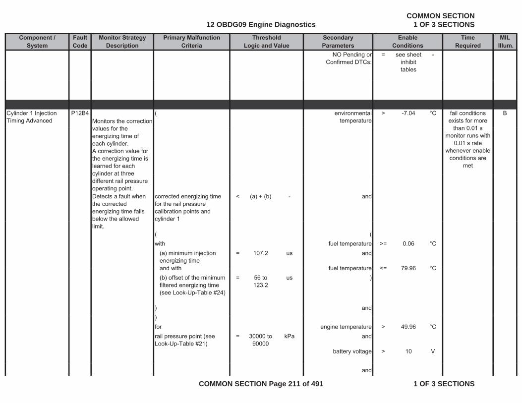
Component / Fault Monitor Strategy Primary Malfunction Secondary Time MILSystem Code Description Criteria Parameters Required Illum.
Threshold EnableLogic and Value Conditions
NO Pending or Confirmed DTCs:
= see sheet inhibit tables
-
Cylinder 1 Injection Timing Advanced
P12B4Monitors the correction al es for the
( environmental temperature
> -7.04 °C Bfail conditions exists for more
than 0 01 svalues for the energizing time of each cylinder. A correction value for the energizing time is learned for each cylinder at three
than 0.01 smonitor runs with
0.01 s rate whenever enable
conditions are met
cylinder at three different rail pressure operating point. Detects a fault when the corrected energizing time falls below the allowed
corrected energizing time for the rail pressure calibration points and cylinder 1
< (a) + (b) - and
limit.y
( (with fuel temperature >= 0.06 °C
(a) minimum injection energizing time
= 107.2 us and
and with fuel temperature <= 79 96 °Cand with fuel temperature <= 79.96 C(b) offset of the minimum filtered energizing time (see Look-Up-Table #24)
= 56 to 123.2
us )
) and))for engine temperature > 49.96 °Crail pressure point (see Look-Up-Table #21)
= 30000 to 90000
kPa and
battery voltage > 10 V
and
12 OBDG09 Engine DiagnosticsCOMMON SECTION
1 OF 3 SECTIONS
COMMON SECTION Page 211 of 491 1 OF 3 SECTIONS
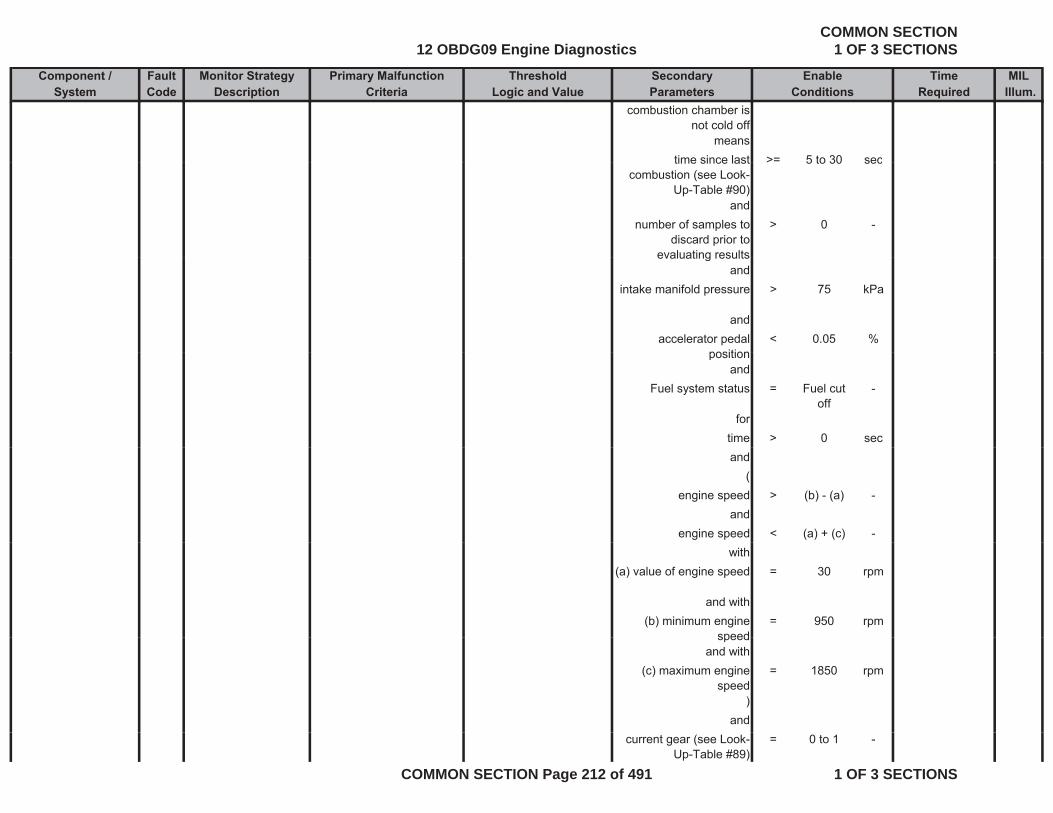
Component / Fault Monitor Strategy Primary Malfunction Secondary Time MILSystem Code Description Criteria Parameters Required Illum.
Threshold EnableLogic and Value Conditions
combustion chamber is not cold off
meanstime since last >= 5 to 30 sectime since last
combustion (see Look-Up-Table #90)
> 5 to 30 sec
andnumber of samples to
discard prior to evaluating results
> 0 -
evaluating resultsand
intake manifold pressure > 75 kPa
andaccelerator pedal
position< 0.05 %
positionand
Fuel system status = Fuel cut off
-
fortime > 0 secand
(engine speed > (b) - (a) -
andengine speed < (a) + (c) -
with(a) value of engine speed = 30 rpm
and with(b) minimum engine
speed= 950 rpm
speedand with
(c) maximum engine speed
= 1850 rpm
)and
current gear (see Look-Up-Table #89)
= 0 to 1 -
12 OBDG09 Engine DiagnosticsCOMMON SECTION
1 OF 3 SECTIONS
COMMON SECTION Page 212 of 491 1 OF 3 SECTIONS
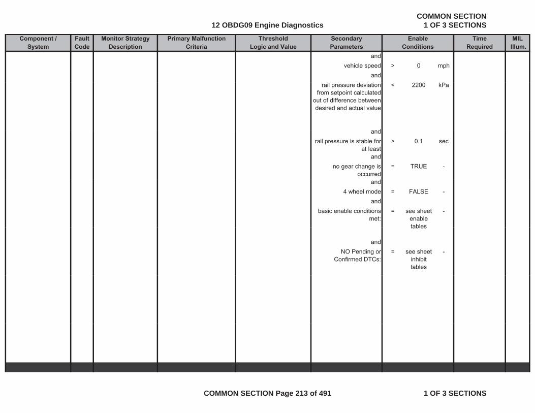
Component / Fault Monitor Strategy Primary Malfunction Secondary Time MILSystem Code Description Criteria Parameters Required Illum.
Threshold EnableLogic and Value Conditions
andvehicle speed > 0 mph
andrail pressure deviation
from setpoint calculated out of difference between desired and actual value
< 2200 kPa
andandrail pressure is stable for
at least> 0.1 sec
andno gear change is
occurred= TRUE -
and4 wheel mode = FALSE -
andbasic enable conditions
met:= see sheet
enable tables
-
tables
andNO Pending or
Confirmed DTCs:= see sheet
inhibit tables
-
12 OBDG09 Engine DiagnosticsCOMMON SECTION
1 OF 3 SECTIONS
COMMON SECTION Page 213 of 491 1 OF 3 SECTIONS
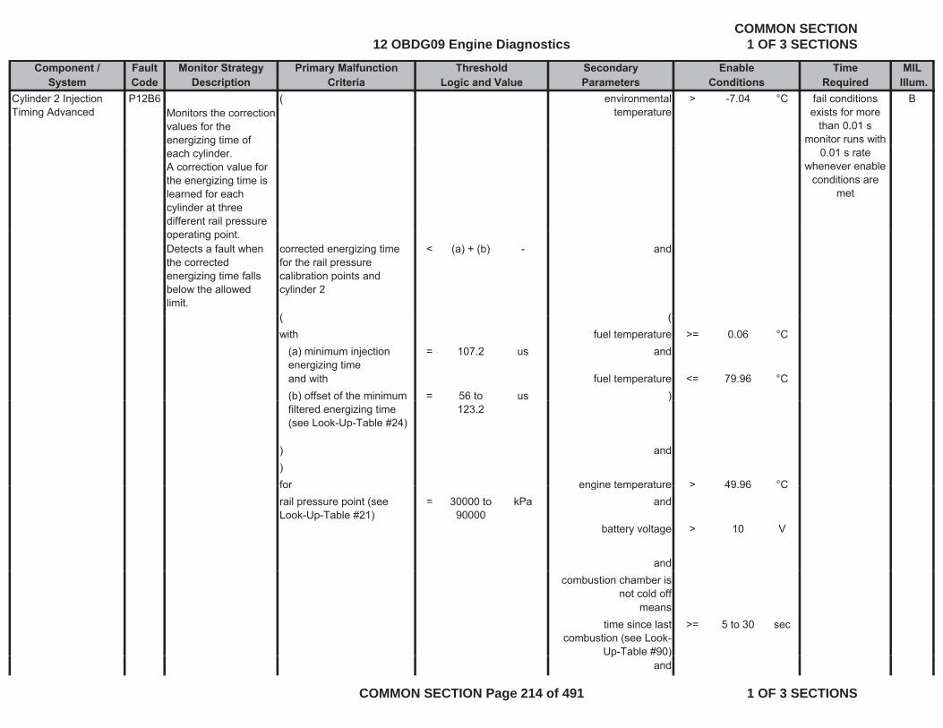
Component / Fault Monitor Strategy Primary Malfunction Secondary Time MILSystem Code Description Criteria Parameters Required Illum.
Threshold EnableLogic and Value Conditions
Cylinder 2 Injection Timing Advanced
P12B6Monitors the correction values for the energizing time of
( environmental temperature
> -7.04 °C Bfail conditions exists for more
than 0.01 smonitor runs with g g
each cylinder. A correction value for the energizing time is learned for each cylinder at three different rail pressure
0.01 s rate whenever enable
conditions are met
operating point. Detects a fault when the corrected energizing time falls below the allowed limit.
corrected energizing time for the rail pressure calibration points and cylinder 2
< (a) + (b) - and
( (( (with fuel temperature >= 0.06 °C
(a) minimum injection energizing time
= 107.2 us and
and with fuel temperature <= 79.96 °C(b) offset of the minimum = 56 to us )( )filtered energizing time (see Look-Up-Table #24)
123.2)
) and)for engine temperature > 49 96 °Cfor engine temperature > 49.96 Crail pressure point (see Look-Up-Table #21)
= 30000 to 90000
kPa and
battery voltage > 10 V
andcombustion chamber is
not cold offmeans
time since last combustion (see Look-
Up-Table #90)
>= 5 to 30 sec
p )and
12 OBDG09 Engine DiagnosticsCOMMON SECTION
1 OF 3 SECTIONS
COMMON SECTION Page 214 of 491 1 OF 3 SECTIONS
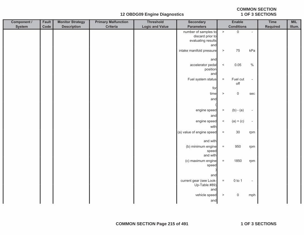
Component / Fault Monitor Strategy Primary Malfunction Secondary Time MILSystem Code Description Criteria Parameters Required Illum.
Threshold EnableLogic and Value Conditions
number of samples to discard prior to
evaluating results
> 0 -
andintake manifold pressure > 75 kPa
andaccelerator pedal
position< 0.05 %
andandFuel system status = Fuel cut
off-
fortime > 0 secand
(engine speed > (b) - (a) -
andengine speed < (a) + (c) -
with(a) value of engine speed = 30 rpm
and with(b) minimum engine
speed= 950 rpm
and with(c) maximum engine
speed= 1850 rpm
)and
current gear (see Look-U T bl #89)
= 0 to 1 -Up-Table #89)
andvehicle speed > 0 mph
and
12 OBDG09 Engine DiagnosticsCOMMON SECTION
1 OF 3 SECTIONS
COMMON SECTION Page 215 of 491 1 OF 3 SECTIONS

Component / Fault Monitor Strategy Primary Malfunction Secondary Time MILSystem Code Description Criteria Parameters Required Illum.
Threshold EnableLogic and Value Conditions
rail pressure deviation from setpoint calculated
out of difference between desired and actual value
< 2200 kPa
andrail pressure is stable for
at least> 0.1 sec
andno gear change is
occurred= TRUE -
and4 wheel mode = FALSE -
andbasic enable conditions
met:= see sheet
enable tables
-
andNO Pending or = see sheet -
Confirmed DTCs: inhibit tables
Cylinder 7 Injection Timing Advanced
P12C0Monitors the correction values for the energizing time of each cylinder. A correction value for
( environmental temperature
> -7.04 °C Bfail conditions exists for more
than 0.01 smonitor runs with
0.01 s rate whenever enable
the energizing time is learned for each cylinder at three different rail pressure operating point.
conditions are met
12 OBDG09 Engine DiagnosticsCOMMON SECTION
1 OF 3 SECTIONS
COMMON SECTION Page 216 of 491 1 OF 3 SECTIONS
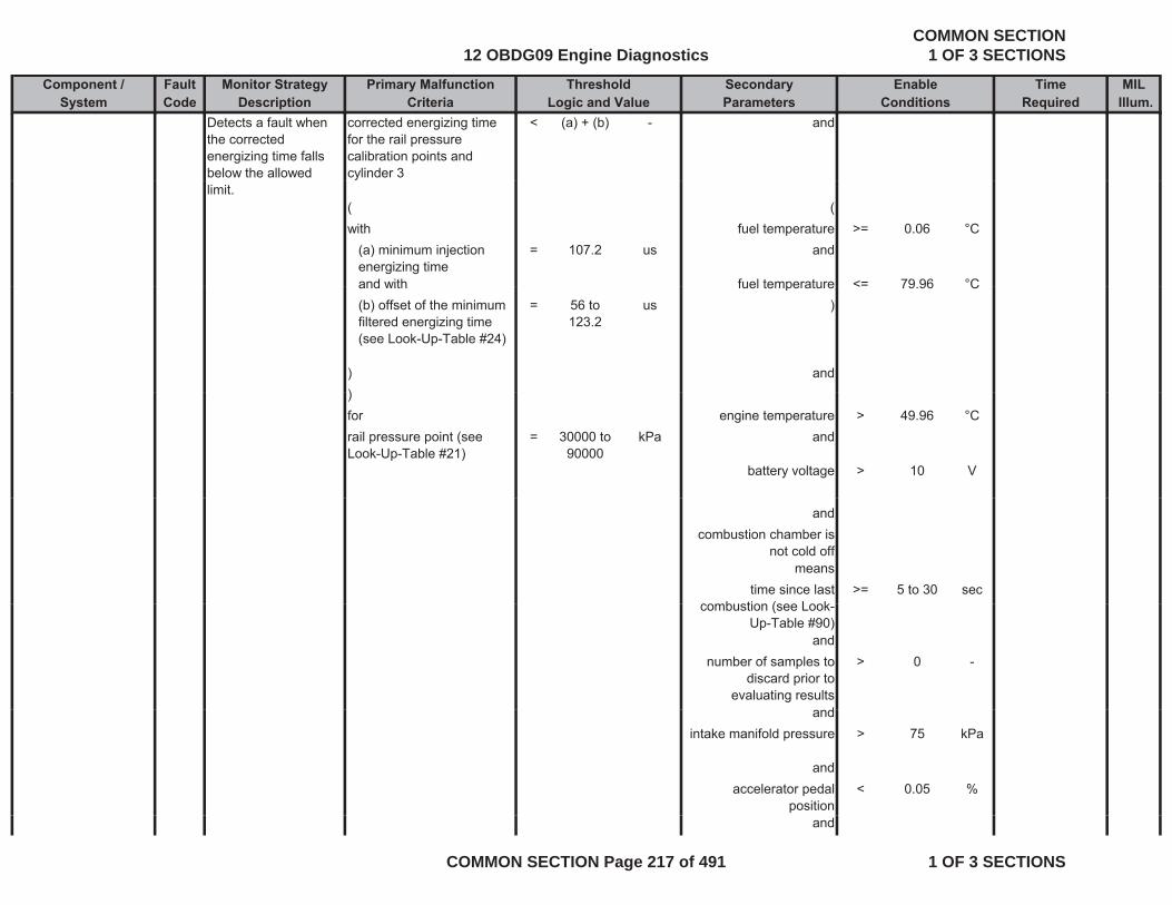
Component / Fault Monitor Strategy Primary Malfunction Secondary Time MILSystem Code Description Criteria Parameters Required Illum.
Threshold EnableLogic and Value Conditions
Detects a fault when the corrected energizing time falls below the allowed
corrected energizing time for the rail pressure calibration points and cylinder 3
< (a) + (b) - and
limit.( (with fuel temperature >= 0.06 °C
(a) minimum injection energizing time
= 107.2 us and
and with fuel temperature <= 79 96 °Cand with fuel temperature < 79.96 C(b) offset of the minimum filtered energizing time (see Look-Up-Table #24)
= 56 to 123.2
us )
) and))for engine temperature > 49.96 °Crail pressure point (see Look-Up-Table #21)
= 30000 to 90000
kPa and
battery voltage > 10 V
andcombustion chamber is
not cold offmeans
time since last b ti ( L k
>= 5 to 30 seccombustion (see Look-
Up-Table #90)and
number of samples to discard prior to
evaluating results
> 0 -
dandintake manifold pressure > 75 kPa
andaccelerator pedal
position< 0.05 %
and
12 OBDG09 Engine DiagnosticsCOMMON SECTION
1 OF 3 SECTIONS
COMMON SECTION Page 217 of 491 1 OF 3 SECTIONS

Component / Fault Monitor Strategy Primary Malfunction Secondary Time MILSystem Code Description Criteria Parameters Required Illum.
Threshold EnableLogic and Value Conditions
Fuel system status = Fuel cut off
-
fortime > 0 sectime > 0 secand
(engine speed > (b) - (a) -
andengine speed < (a) + (c) -engine speed < (a) + (c)
with(a) value of engine speed = 30 rpm
and with(b) minimum engine = 950 rpm
speedand with
(c) maximum engine speed
= 1850 rpm
)and
current gear (see Look-Up-Table #89)
= 0 to 1 -
andvehicle speed > 0 mph
andrail pressure deviation
from setpoint calculated out of difference between desired and actual value
< 2200 kPa
dandrail pressure is stable for
at least> 0.1 sec
andno gear change is
occurred= TRUE -
and
12 OBDG09 Engine DiagnosticsCOMMON SECTION
1 OF 3 SECTIONS
COMMON SECTION Page 218 of 491 1 OF 3 SECTIONS
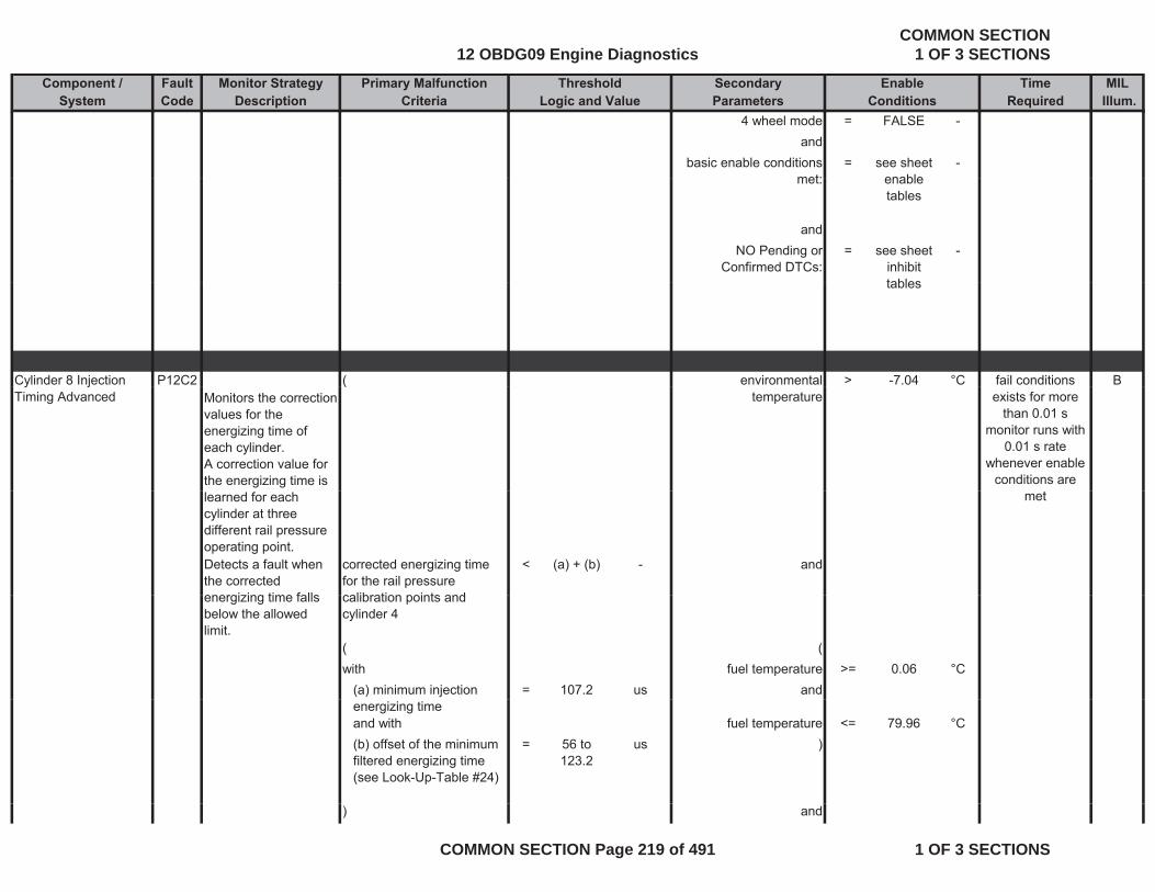
Component / Fault Monitor Strategy Primary Malfunction Secondary Time MILSystem Code Description Criteria Parameters Required Illum.
Threshold EnableLogic and Value Conditions
4 wheel mode = FALSE -and
basic enable conditions met:
= see sheet enable
-met: enable
tables
andNO Pending or
Confirmed DTCs:= see sheet
inhibit tables
-
tables
Cylinder 8 Injection P12C2 ( environmental > -7.04 °C Bfail conditions y jTiming Advanced Monitors the correction
values for the energizing time of each cylinder. A correction value for the energizing time is
(temperature exists for more
than 0.01 smonitor runs with
0.01 s rate whenever enable
conditions are learned for each cylinder at three different rail pressure operating point. Detects a fault when the corrected energi ing time falls
corrected energizing time for the rail pressure calibration points and
< (a) + (b) - and
met
energizing time falls below the allowed limit.
calibration points and cylinder 4
( (with fuel temperature >= 0.06 °C
(a) minimum injection = 107.2 us andenergizing timeand with fuel temperature <= 79.96 °C(b) offset of the minimum filtered energizing time (see Look-Up-Table #24)
= 56 to 123.2
us )
) and
12 OBDG09 Engine DiagnosticsCOMMON SECTION
1 OF 3 SECTIONS
COMMON SECTION Page 219 of 491 1 OF 3 SECTIONS

Component / Fault Monitor Strategy Primary Malfunction Secondary Time MILSystem Code Description Criteria Parameters Required Illum.
Threshold EnableLogic and Value Conditions
)for engine temperature > 49.96 °Crail pressure point (see Look Up Table #21)
= 30000 to 90000
kPa andLook-Up-Table #21) 90000
battery voltage > 10 V
andcombustion chamber is
not cold offmeans
time since last combustion (see Look-
Up-Table #90)
>= 5 to 30 sec
andnumber of samples to > 0 -number of samples to
discard prior to evaluating results
> 0
andintake manifold pressure > 75 kPa
andandaccelerator pedal
position< 0.05 %
andFuel system status = Fuel cut
off-
ffortime > 0 secand
(engine speed > (b) - (a) -
dandengine speed < (a) + (c) -
with(a) value of engine speed = 30 rpm
and with
12 OBDG09 Engine DiagnosticsCOMMON SECTION
1 OF 3 SECTIONS
COMMON SECTION Page 220 of 491 1 OF 3 SECTIONS

Component / Fault Monitor Strategy Primary Malfunction Secondary Time MILSystem Code Description Criteria Parameters Required Illum.
Threshold EnableLogic and Value Conditions
(b) minimum engine speed
= 950 rpm
and with(c) maximum engine = 1850 rpm(c) maximum engine
speed1850 rpm
)and
current gear (see Look-Up-Table #89)
= 0 to 1 -
andandvehicle speed > 0 mph
andrail pressure deviation
from setpoint calculated out of difference between
< 2200 kPa
desired and actual value
andrail pressure is stable for
at least> 0.1 sec
andno gear change is
occurred= TRUE -
and4 wheel mode = FALSE -
dandbasic enable conditions
met:= see sheet
enable tables
-
andNO Pending or
Confirmed DTCs:= see sheet
inhibit tables
-
12 OBDG09 Engine DiagnosticsCOMMON SECTION
1 OF 3 SECTIONS
COMMON SECTION Page 221 of 491 1 OF 3 SECTIONS

Component / Fault Monitor Strategy Primary Malfunction Secondary Time MILSystem Code Description Criteria Parameters Required Illum.
Threshold EnableLogic and Value Conditions
Cylinder 4 Injection Timing Advanced
P12BAMonitors the correction values for the energizing time of
( environmental temperature
> -7.04 °C Bfail conditions exists for more
than 0.01 smonitor runs with g g
each cylinder. A correction value for the energizing time is learned for each cylinder at three different rail pressure
0.01 s rate whenever enable
conditions are met
operating point. Detects a fault when the corrected energizing time falls below the allowed limit.
corrected energizing time for the rail pressure calibration points and cylinder 5
< (a) + (b) - and
( (( (with fuel temperature >= 0.06 °C
(a) minimum injection energizing time
= 107.2 us and
and with fuel temperature <= 79.96 °C(b) offset of the minimum = 56 to us )( )filtered energizing time (see Look-Up-Table #24)
123.2)
) and)for engine temperature > 49 96 °Cfor engine temperature > 49.96 Crail pressure point (see Look-Up-Table #21)
= 30000 to 90000
kPa and
battery voltage > 10 V
andcombustion chamber is
not cold offmeans
time since last combustion (see Look-
Up-Table #90)
>= 5 to 30 sec
p )and
12 OBDG09 Engine DiagnosticsCOMMON SECTION
1 OF 3 SECTIONS
COMMON SECTION Page 222 of 491 1 OF 3 SECTIONS

Component / Fault Monitor Strategy Primary Malfunction Secondary Time MILSystem Code Description Criteria Parameters Required Illum.
Threshold EnableLogic and Value Conditions
number of samples to discard prior to
evaluating results
> 0 -
andintake manifold pressure > 75 kPa
andaccelerator pedal
position< 0.05 %
andandFuel system status = Fuel cut
off-
fortime > 0 secand
(engine speed > (b) - (a) -
andengine speed < (a) + (c) -
with(a) value of engine speed = 30 rpm
and with(b) minimum engine
speed= 950 rpm
and with(c) maximum engine
speed= 1850 rpm
)and
current gear (see Look-U T bl #89)
= 0 to 1 -Up-Table #89)
andvehicle speed > 0 mph
and
12 OBDG09 Engine DiagnosticsCOMMON SECTION
1 OF 3 SECTIONS
COMMON SECTION Page 223 of 491 1 OF 3 SECTIONS
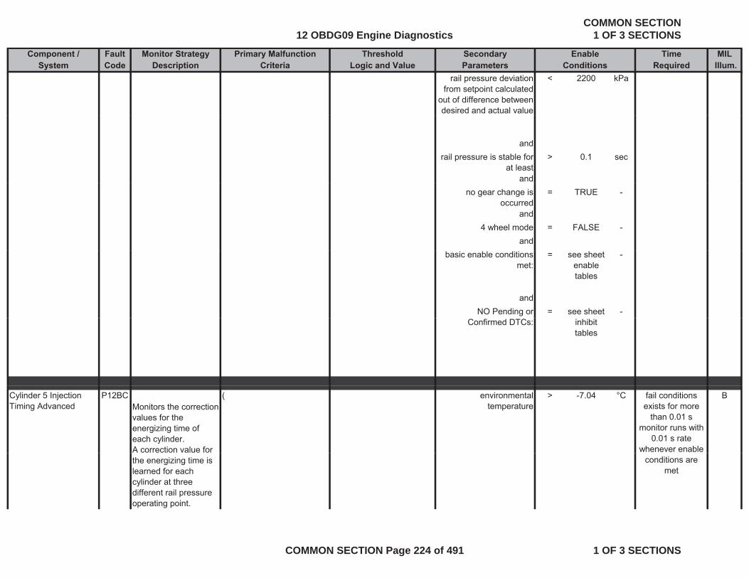
Component / Fault Monitor Strategy Primary Malfunction Secondary Time MILSystem Code Description Criteria Parameters Required Illum.
Threshold EnableLogic and Value Conditions
rail pressure deviation from setpoint calculated
out of difference between desired and actual value
< 2200 kPa
andrail pressure is stable for
at least> 0.1 sec
andno gear change is
occurred= TRUE -
and4 wheel mode = FALSE -
andbasic enable conditions
met:= see sheet
enable tables
-
andNO Pending or = see sheet -
Confirmed DTCs: inhibit tables
Cylinder 5 Injection Timing Advanced
P12BCMonitors the correction values for the energizing time of each cylinder. A correction value for
( environmental temperature
> -7.04 °C Bfail conditions exists for more
than 0.01 smonitor runs with
0.01 s rate whenever enable
the energizing time is learned for each cylinder at three different rail pressure operating point.
conditions are met
12 OBDG09 Engine DiagnosticsCOMMON SECTION
1 OF 3 SECTIONS
COMMON SECTION Page 224 of 491 1 OF 3 SECTIONS

Component / Fault Monitor Strategy Primary Malfunction Secondary Time MILSystem Code Description Criteria Parameters Required Illum.
Threshold EnableLogic and Value Conditions
Detects a fault when the corrected energizing time falls below the allowed
corrected energizing time for the rail pressure calibration points and cylinder 6
< (a) + (b) - and
limit.( (with fuel temperature >= 0.06 °C(a) minimum injection energizing time
= 107.2 us and
and with fuel temperature <= 79 96 °Cand with fuel temperature < 79.96 C(b) offset of the minimum filtered energizing time (see Look-Up-Table #24)
= 56 to 123.2
us )
) and))for engine temperature > 49.96 °Crail pressure point (see Look-Up-Table #21)
= 30000 to 90000
kPa and
battery voltage > 10 V
andcombustion chamber is
not cold offmeans
time since last b ti ( L k
>= 5 to 30 seccombustion (see Look-
Up-Table #90)and
number of samples to discard prior to
evaluating results
> 0 -
dandintake manifold pressure > 75 kPa
andaccelerator pedal
position< 0.05 %
and
12 OBDG09 Engine DiagnosticsCOMMON SECTION
1 OF 3 SECTIONS
COMMON SECTION Page 225 of 491 1 OF 3 SECTIONS
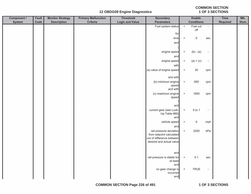
Component / Fault Monitor Strategy Primary Malfunction Secondary Time MILSystem Code Description Criteria Parameters Required Illum.
Threshold EnableLogic and Value Conditions
Fuel system status = Fuel cut off
-
fortime > 0 sectime > 0 secand
(engine speed > (b) - (a) -
andengine speed < (a) + (c) -engine speed < (a) + (c)
with(a) value of engine speed = 30 rpm
and with(b) minimum engine = 950 rpm
speedand with
(c) maximum engine speed
= 1850 rpm
)and
current gear (see Look-Up-Table #89)
= 0 to 1 -
andvehicle speed > 0 mph
andrail pressure deviation
from setpoint calculated out of difference between desired and actual value
< 2200 kPa
dandrail pressure is stable for
at least> 0.1 sec
andno gear change is
occurred= TRUE -
and
12 OBDG09 Engine DiagnosticsCOMMON SECTION
1 OF 3 SECTIONS
COMMON SECTION Page 226 of 491 1 OF 3 SECTIONS

Component / Fault Monitor Strategy Primary Malfunction Secondary Time MILSystem Code Description Criteria Parameters Required Illum.
Threshold EnableLogic and Value Conditions
4 wheel mode = FALSE -and
basic enable conditions met:
= see sheet enable
-met: enable
tables
andNO Pending or
Confirmed DTCs:= see sheet
inhibit tables
-
tables
Cylinder 6 Injection P12BE ( environmental > -7.04 °C Bfail conditions y jTiming Advanced Monitors the correction
values for the energizing time of each cylinder. A correction value for the energizing time is
(temperature exists for more
than 0.01 smonitor runs with
0.01 s rate whenever enable
conditions are learned for each cylinder at three different rail pressure operating point. Detects a fault when the corrected energi ing time falls
corrected energizing time for the rail pressure calibration points and
< (a) + (b) - and
met
energizing time falls below the allowed limit.
calibration points and cylinder 7
( (with fuel temperature >= 0.06 °C
(a) minimum injection = 107.2 us andenergizing timeand with fuel temperature <= 79.96 °C(b) offset of the minimum filtered energizing time (see Look-Up-Table #24)
= 56 to 123.2
us )
) and
12 OBDG09 Engine DiagnosticsCOMMON SECTION
1 OF 3 SECTIONS
COMMON SECTION Page 227 of 491 1 OF 3 SECTIONS
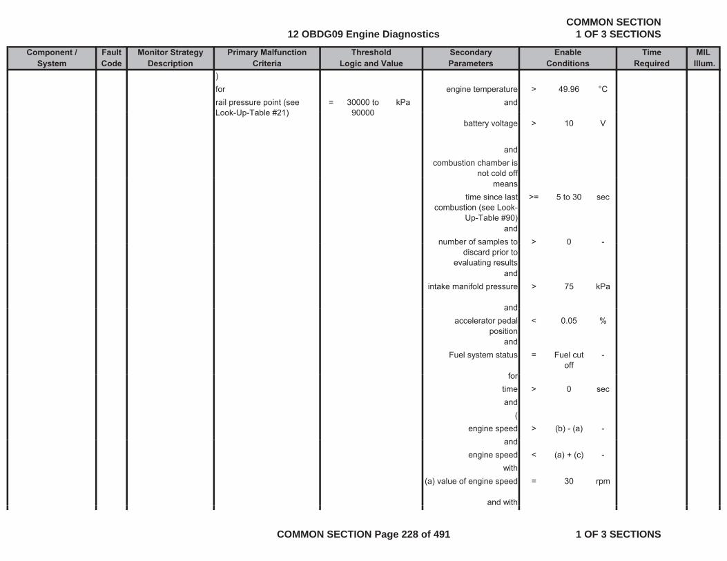
Component / Fault Monitor Strategy Primary Malfunction Secondary Time MILSystem Code Description Criteria Parameters Required Illum.
Threshold EnableLogic and Value Conditions
)for engine temperature > 49.96 °Crail pressure point (see Look Up Table #21)
= 30000 to 90000
kPa andLook-Up-Table #21) 90000
battery voltage > 10 V
andcombustion chamber is
not cold offmeans
time since last combustion (see Look-
Up-Table #90)
>= 5 to 30 sec
andnumber of samples to > 0 -number of samples to
discard prior to evaluating results
> 0
andintake manifold pressure > 75 kPa
andandaccelerator pedal
position< 0.05 %
andFuel system status = Fuel cut
off-
ffortime > 0 secand
(engine speed > (b) - (a) -
dandengine speed < (a) + (c) -
with(a) value of engine speed = 30 rpm
and with
12 OBDG09 Engine DiagnosticsCOMMON SECTION
1 OF 3 SECTIONS
COMMON SECTION Page 228 of 491 1 OF 3 SECTIONS
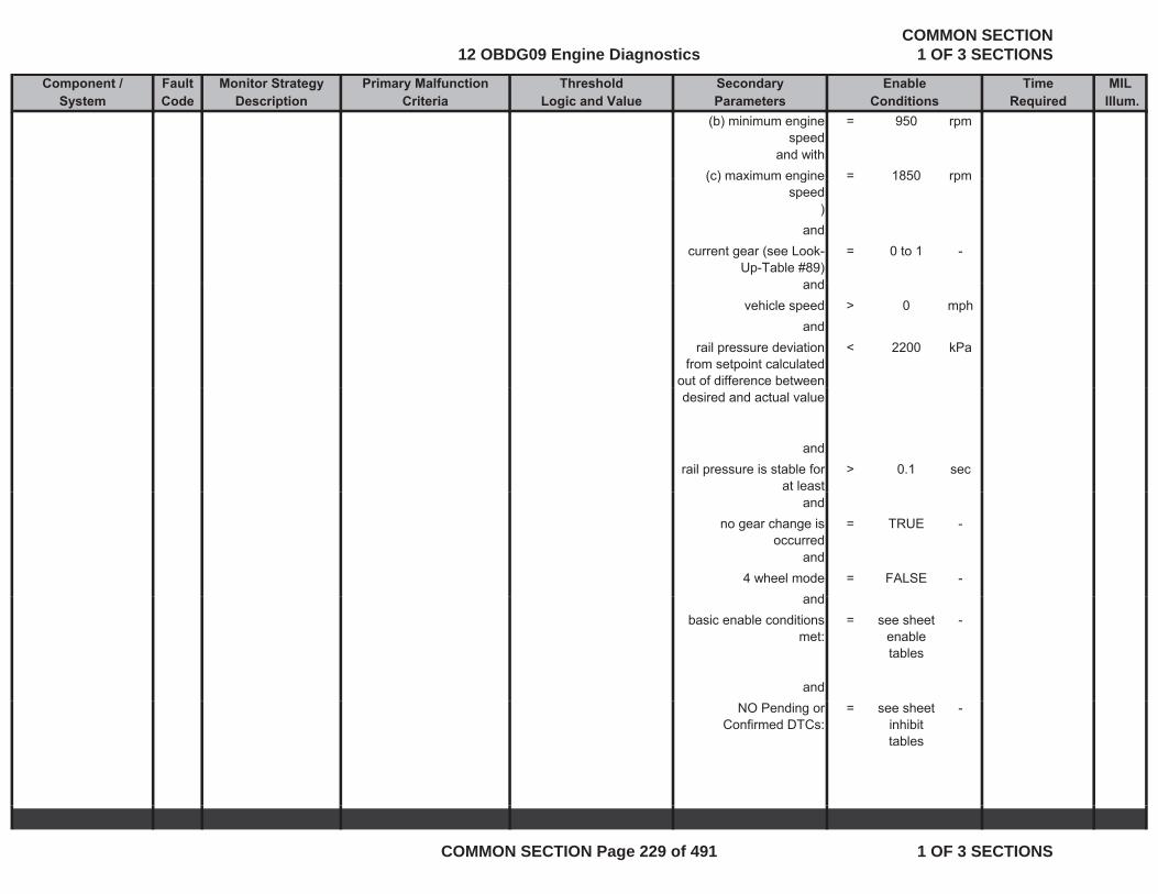
Component / Fault Monitor Strategy Primary Malfunction Secondary Time MILSystem Code Description Criteria Parameters Required Illum.
Threshold EnableLogic and Value Conditions
(b) minimum engine speed
= 950 rpm
and with(c) maximum engine = 1850 rpm(c) maximum engine
speed1850 rpm
)and
current gear (see Look-Up-Table #89)
= 0 to 1 -
andandvehicle speed > 0 mph
andrail pressure deviation
from setpoint calculated out of difference between
< 2200 kPa
desired and actual value
andrail pressure is stable for
at least> 0.1 sec
andno gear change is
occurred= TRUE -
and4 wheel mode = FALSE -
dandbasic enable conditions
met:= see sheet
enable tables
-
andNO Pending or
Confirmed DTCs:= see sheet
inhibit tables
-
12 OBDG09 Engine DiagnosticsCOMMON SECTION
1 OF 3 SECTIONS
COMMON SECTION Page 229 of 491 1 OF 3 SECTIONS

Component / Fault Monitor Strategy Primary Malfunction Secondary Time MILSystem Code Description Criteria Parameters Required Illum.
Threshold EnableLogic and Value Conditions
Cylinder 3 Injection Timing Advanced
P12B8Monitors the correction values for the energizing time of
( environmental temperature
> -7.04 °C Bfail conditions exists for more
than 0.01 smonitor runs with g g
each cylinder. A correction value for the energizing time is learned for each cylinder at three different rail pressure
0.01 s rate whenever enable
conditions are met
operating point. Detects a fault when the corrected energizing time falls below the allowed limit.
corrected energizing time for the rail pressure calibration points and cylinder 8
< (a) + (b) - and
( (( (with fuel temperature >= 0.06 °C
(a) minimum injection energizing time
= 107.2 us and
and with fuel temperature <= 79.96 °C(b) offset of the minimum = 56 to us )( )filtered energizing time (see Look-Up-Table #24)
123.2)
) and)for engine temperature > 49 96 °Cfor engine temperature > 49.96 Crail pressure point (see Look-Up-Table #21)
= 30000 to 90000
kPa and
battery voltage > 10 V
andcombustion chamber is
not cold offmeans
time since last combustion (see Look-
Up-Table #90)
>= 5 to 30 sec
p )and
12 OBDG09 Engine DiagnosticsCOMMON SECTION
1 OF 3 SECTIONS
COMMON SECTION Page 230 of 491 1 OF 3 SECTIONS
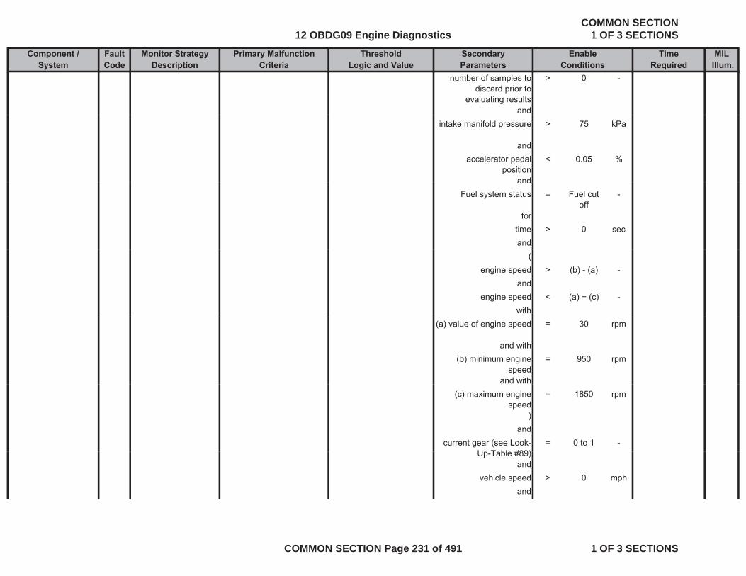
Component / Fault Monitor Strategy Primary Malfunction Secondary Time MILSystem Code Description Criteria Parameters Required Illum.
Threshold EnableLogic and Value Conditions
number of samples to discard prior to
evaluating results
> 0 -
andintake manifold pressure > 75 kPa
andaccelerator pedal
position< 0.05 %
andandFuel system status = Fuel cut
off-
fortime > 0 secand
(engine speed > (b) - (a) -
andengine speed < (a) + (c) -
with(a) value of engine speed = 30 rpm
and with(b) minimum engine
speed= 950 rpm
and with(c) maximum engine
speed= 1850 rpm
)and
current gear (see Look-U T bl #89)
= 0 to 1 -Up-Table #89)
andvehicle speed > 0 mph
and
12 OBDG09 Engine DiagnosticsCOMMON SECTION
1 OF 3 SECTIONS
COMMON SECTION Page 231 of 491 1 OF 3 SECTIONS
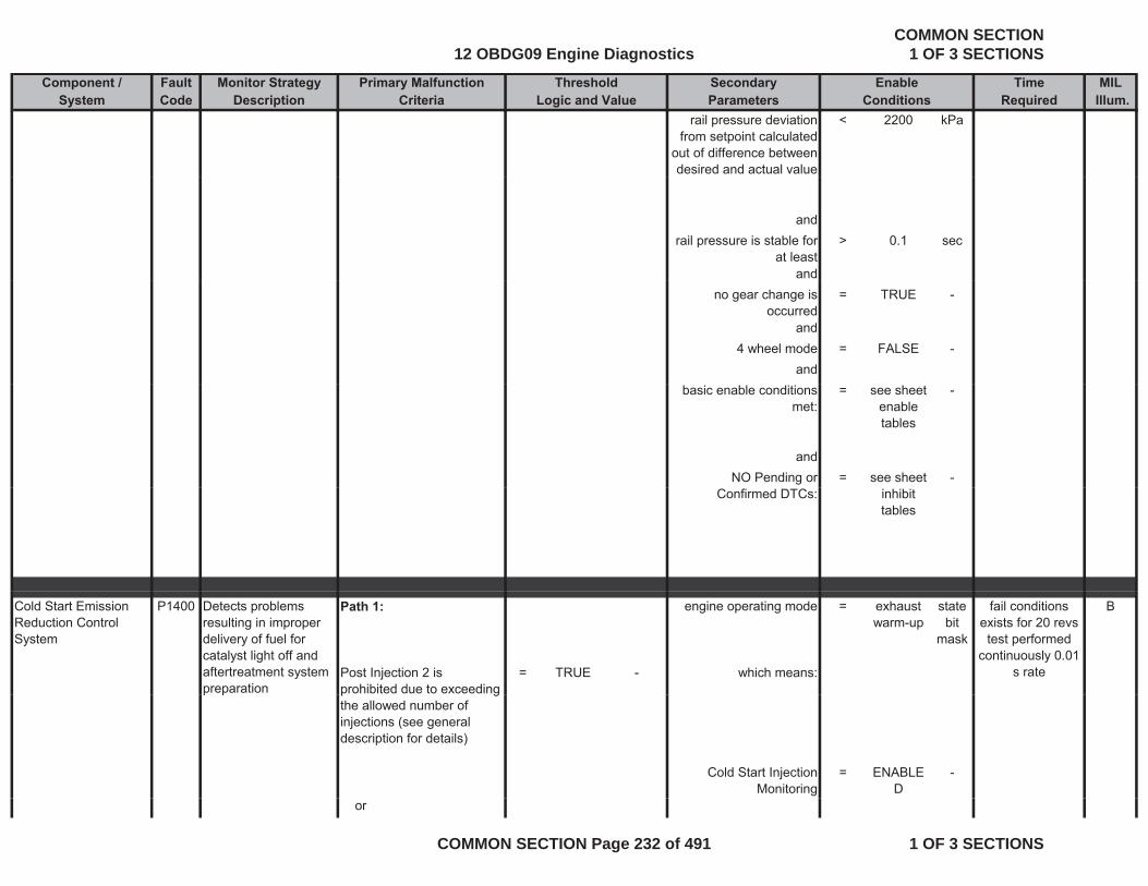
Component / Fault Monitor Strategy Primary Malfunction Secondary Time MILSystem Code Description Criteria Parameters Required Illum.
Threshold EnableLogic and Value Conditions
rail pressure deviation from setpoint calculated
out of difference between desired and actual value
< 2200 kPa
andrail pressure is stable for
at least> 0.1 sec
andno gear change is
occurred= TRUE -
and4 wheel mode = FALSE -
andbasic enable conditions
met:= see sheet
enable tables
-
andNO Pending or = see sheet -
Confirmed DTCs: inhibit tables
P1400 Path 1: engine operating mode = exhaust warm-up
state bit
mask
B
Post Injection 2 is prohibited due to exceeding
= TRUE - which means:
Cold Start Emission Reduction Control System
Detects problems resulting in improper delivery of fuel for catalyst light off and aftertreatment system preparation
fail conditions exists for 20 revs test performed
continuously 0.01 s rate
p gthe allowed number of injections (see general description for details)
Cold Start Injection Monitoring
= ENABLED
-
p p
or
12 OBDG09 Engine DiagnosticsCOMMON SECTION
1 OF 3 SECTIONS
COMMON SECTION Page 232 of 491 1 OF 3 SECTIONS
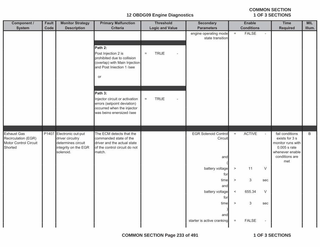
Component / Fault Monitor Strategy Primary Malfunction Secondary Time MILSystem Code Description Criteria Parameters Required Illum.
Threshold EnableLogic and Value Conditions
engine operating mode state transition
= FALSE -
Path 2:= TRUE -
or
Post Injection 2 is prohibited due to collision (overlap) with Main Injection and Post Injection 1 (see
Path 3:= TRUE -Injector circuit or activation
errors (setpoint deviation) d h th i j t
Exhaust Gas P1407 Electronic out-put The ECM detects that the EGR Solenoid Control = ACTIVE - B
occurred when the injector was being energized (see
fail conditions Recirculation (EGR) Motor Control Circuit Shorted
driver circuitry determines circuit integrity on the EGR solenoid.
commanded state of the driver and the actual state of the control circuit do not match.
Circuit
and(
exists for 3 s monitor runs with
0.005 s rate whenever enable
conditions are met
battery voltage > 11 Vfor
time > 3 secand
battery voltage < 655.34 Vfor
time > 3 sec)
andstarter is active cranking = FALSE -g
12 OBDG09 Engine DiagnosticsCOMMON SECTION
1 OF 3 SECTIONS
COMMON SECTION Page 233 of 491 1 OF 3 SECTIONS
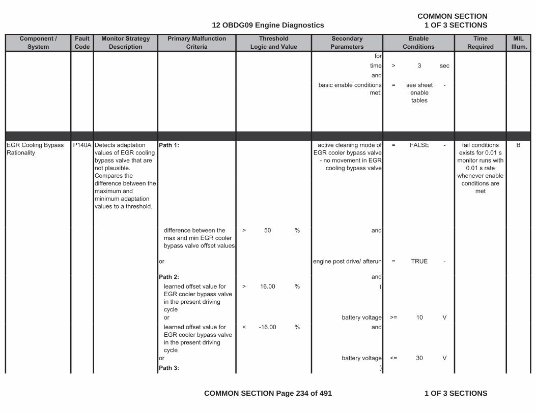
Component / Fault Monitor Strategy Primary Malfunction Secondary Time MILSystem Code Description Criteria Parameters Required Illum.
Threshold EnableLogic and Value Conditions
fortime > 3 secand
basic enable conditions met:
= see sheet enable tables
-
EGR Cooling Bypass Rationality
P140A Detects adaptation values of EGR cooling bypass valve that are not plausible. Compares the
Path 1: active cleaning mode of EGR cooler bypass valve
- no movement in EGR cooling bypass valve
= FALSE - Bfail conditions exists for 0.01 s
monitor runs with 0.01 s rate
whenever enable pdifference between the maximum and minimum adaptation values to a threshold.
conditions are met
difference between the max and min EGR cooler bypass valve offset values
> 50 % and
or engine post drive/ afterun = TRUE -
P th 2 dPath 2: andlearned offset value for EGR cooler bypass valve in the present driving cycle
> 16.00 % (
or battery voltage >= 10 Vlearned offset value for EGR cooler bypass valve in the present driving cycle
< -16.00 % and
or battery voltage <= 30 VPath 3: )
12 OBDG09 Engine DiagnosticsCOMMON SECTION
1 OF 3 SECTIONS
COMMON SECTION Page 234 of 491 1 OF 3 SECTIONS
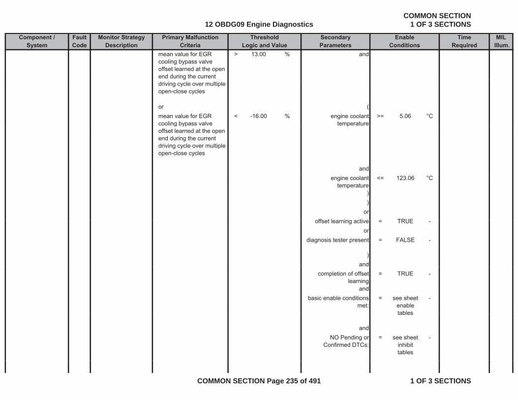
Component / Fault Monitor Strategy Primary Malfunction Secondary Time MILSystem Code Description Criteria Parameters Required Illum.
Threshold EnableLogic and Value Conditions
mean value for EGR cooling bypass valve offset learned at the open end during the current
> 13.00 % and
driving cycle over multiple open-close cycles
or (mean value for EGR cooling bypass valve
< -16.00 % engine coolant temperature
>= 5.06 °Cg yp
offset learned at the open end during the current driving cycle over multiple open-close cycles
p
andengine coolant
temperature<= 123.06 °C
))
orff t l i ti TRUEoffset learning active = TRUE -
ordiagnosis tester present = FALSE -
)and
completion of offset learning
= TRUE -
andbasic enable conditions
met:= see sheet
enable tables
-
tables
andNO Pending or
Confirmed DTCs:= see sheet
inhibit tables
-
12 OBDG09 Engine DiagnosticsCOMMON SECTION
1 OF 3 SECTIONS
COMMON SECTION Page 235 of 491 1 OF 3 SECTIONS
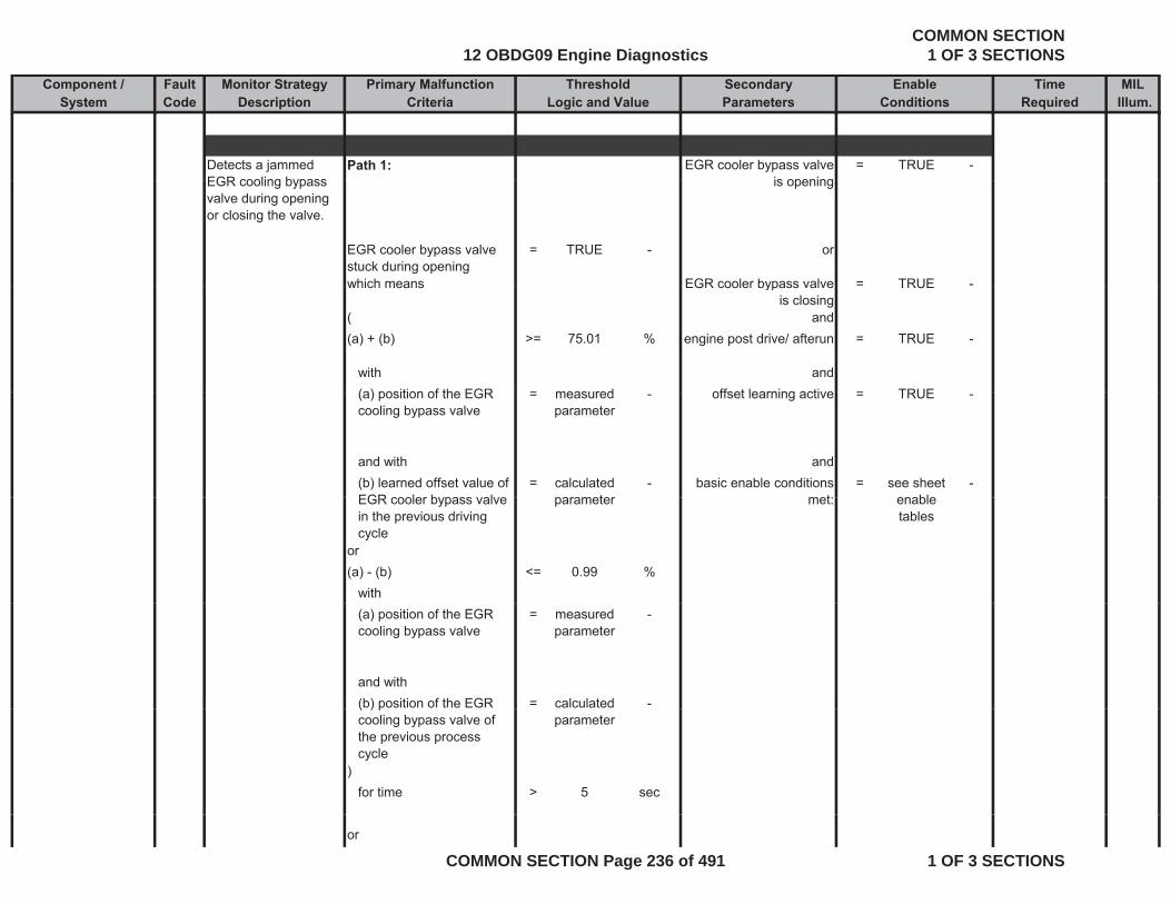
Component / Fault Monitor Strategy Primary Malfunction Secondary Time MILSystem Code Description Criteria Parameters Required Illum.
Threshold EnableLogic and Value Conditions
Detects a jammed EGR cooling bypass
Path 1: EGR cooler bypass valve is opening
= TRUE -EGR cooling bypass valve during opening or closing the valve.
is opening
EGR cooler bypass valve stuck during opening
= TRUE - or
which means EGR cooler bypass valve = TRUE -which means EGR cooler bypass valve is closing
TRUE
( and(a) + (b) >= 75.01 % engine post drive/ afterun = TRUE -
with and(a) position of the EGR = measured offset learning active = TRUE(a) position of the EGR cooling bypass valve
= measured parameter
- offset learning active = TRUE -
and with and(b) learned offset value of EGR cooler bypass valve
= calculated parameter
- basic enable conditions met:
= see sheet enable
-EGR cooler bypass valve in the previous driving cycle
parameter met: enable tables
or(a) - (b) <= 0.99 %
with(a) position of the EGR cooling bypass valve
= measured parameter
-
and with(b) position of the EGR = calculated -( ) pcooling bypass valve of the previous process cycle
parameter
)for time > 5 sec
or
12 OBDG09 Engine DiagnosticsCOMMON SECTION
1 OF 3 SECTIONS
COMMON SECTION Page 236 of 491 1 OF 3 SECTIONS
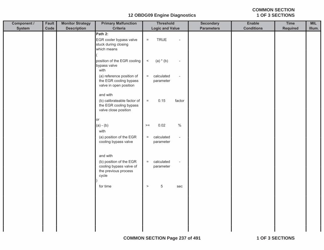
Component / Fault Monitor Strategy Primary Malfunction Secondary Time MILSystem Code Description Criteria Parameters Required Illum.
Threshold EnableLogic and Value Conditions
Path 2:EGR cooler bypass valve stuck during closing
= TRUE -
which meanswhich means(position of the EGR cooling bypass valve
< (a) * (b) -
with(a) reference position of = calculated -the EGR cooling bypass valve in open position
parameter
and with(b) calibrateable factor of the EGR cooling bypass
= 0.15 factor
valve close position
or(a) - (b) >= 0.02 %
with(a) position of the EGR = calculated -(a) position of the EGR cooling bypass valve
= calculated parameter
and with(b) position of the EGR cooling bypass valve of
= calculated parameter
-cooling bypass valve of the previous process cycle
parameter
)for time > 5 sec
12 OBDG09 Engine DiagnosticsCOMMON SECTION
1 OF 3 SECTIONS
COMMON SECTION Page 237 of 491 1 OF 3 SECTIONS
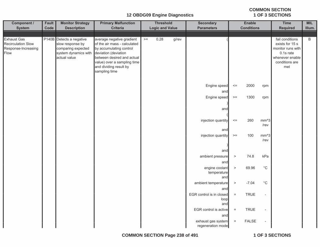
Component / Fault Monitor Strategy Primary Malfunction Secondary Time MILSystem Code Description Criteria Parameters Required Illum.
Threshold EnableLogic and Value Conditions
Exhaust Gas Recirculation Slow Response-Increasing
P140B Detects a negative slow response by comparing expected
average negative gradient of the air mass - calculated by accumulating control
>= 0.28 g/rev ( Bfail conditions exists for 15 s
monitor runs withResponse Increasing Flow
comparing expected system dynamics with actual value
by accumulating control deviation (deviation between desired and actual value) over a sampling time and dividing result by sampling time
monitor runs with 0.1s rate
whenever enable conditions are
met
Engine speed <= 2000 rpmand
Engine speed >= 1300 rpm)
and(
injection quantity <= 260 mm^3/rev
andinjection quantity >= 100 mm^3injection quantity >= 100 mm 3
/rev )
andambient pressure > 74.8 kPa
andengine coolant
temperature> 69.96 °C
andambient temperature > -7.04 °C
andEGR t l i i l d TRUEEGR control is in closed
loop= TRUE -
andEGR control is active = TRUE -
andexhaust gas system = FALSE -g yregeneration mode
12 OBDG09 Engine DiagnosticsCOMMON SECTION
1 OF 3 SECTIONS
COMMON SECTION Page 238 of 491 1 OF 3 SECTIONS
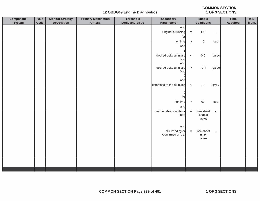
Component / Fault Monitor Strategy Primary Malfunction Secondary Time MILSystem Code Description Criteria Parameters Required Illum.
Threshold EnableLogic and Value Conditions
andEngine is running = TRUE -
forfor time > 0 sec
and(
desired delta air mass flow
< -0.01 g/sec
andanddesired delta air mass
flow> -0.1 g/sec
)and
difference of the air mass < 0 g/rev
)for
for time > 0.1 secand
b i bl diti h tbasic enable conditions met:
= see sheet enable tables
-
andNO Pending or
C fi d DTC= see sheet
i hibit-
Confirmed DTCs: inhibit tables
12 OBDG09 Engine DiagnosticsCOMMON SECTION
1 OF 3 SECTIONS
COMMON SECTION Page 239 of 491 1 OF 3 SECTIONS
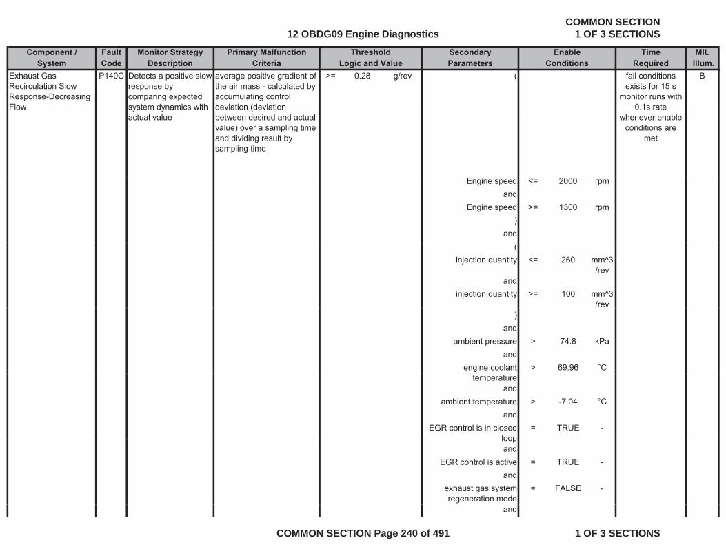
Component / Fault Monitor Strategy Primary Malfunction Secondary Time MILSystem Code Description Criteria Parameters Required Illum.
Threshold EnableLogic and Value Conditions
Exhaust Gas Recirculation Slow Response-Decreasing Flow
P140C Detects a positive slow response by comparing expected system dynamics with
average positive gradient of the air mass - calculated by accumulating control deviation (deviation
>= 0.28 g/rev ( Bfail conditions exists for 15 s
monitor runs with 0.1s rate
actual value between desired and actual value) over a sampling time and dividing result by sampling time
whenever enable conditions are
met
Engine speed <= 2000 rpmand
Engine speed >= 1300 rpm)
and(
injection quantity <= 260 mm^3/rev
andinjection quantity >= 100 mm^3
/rev )
andambient pressure > 74.8 kPa
andengine coolant > 69.96 °C
temperatureand
ambient temperature > -7.04 °Cand
EGR control is in closed loop
= TRUE -loopand
EGR control is active = TRUE -and
exhaust gas system regeneration mode
= FALSE -
and
12 OBDG09 Engine DiagnosticsCOMMON SECTION
1 OF 3 SECTIONS
COMMON SECTION Page 240 of 491 1 OF 3 SECTIONS

Component / Fault Monitor Strategy Primary Malfunction Secondary Time MILSystem Code Description Criteria Parameters Required Illum.
Threshold EnableLogic and Value Conditions
Engine is running = TRUE -for
for time 0 secand
(desired delta air mass
flow< 0.1 g/sec
anddesired delta air mass > 0 01 g/secdesired delta air mass
flow> 0.01 g/sec
)and
difference of the air mass < 0 g/rev
))for
for time > 0.2 secand
basic enable conditions met:
= see sheet enable
-met: enable
tables
andNO Pending or
Confirmed DTCs:= see sheet
inhibit tables
-
tables
Exhaust Gas P140E Electronic out-put The ECM detects that the EGR Solenoid Control = ACTIVE - Bfail conditions Recirculation (EGR) Motor Control Circuit 2 High Voltage
driver circuitry determines circuit integrity on the EGR solenoid.
commanded state of the driver and the actual state of the control circuit do not match.
Circuit
and(
exists for 3 s monitor runs with
0.005 s rate whenever enable
conditions are met
battery voltage > 11 V
12 OBDG09 Engine DiagnosticsCOMMON SECTION
1 OF 3 SECTIONS
COMMON SECTION Page 241 of 491 1 OF 3 SECTIONS

Component / Fault Monitor Strategy Primary Malfunction Secondary Time MILSystem Code Description Criteria Parameters Required Illum.
Threshold EnableLogic and Value Conditions
fortime > 3 secand
battery voltage < 655.34 Vfor
time > 3 sec)
andstarter is active cranking = FALSE -
fortime > 3 secand
basic enable conditions = see sheet -basic enable conditions met:
see sheet enable tables
Exhaust Gas Recirculation (EGR) Motor Control Circuit 2 Low Voltage
P140D Electronic out-put driver circuitry determines circuit integrity on the EGR solenoid.
The ECM detects that the commanded state of the driver and the actual state of the control circuit do not match.
EGR Solenoid Control Circuit
= ACTIVE - B
d
fail conditions exists for 3 s
monitor runs with 0.005 s rate
whenever enable conditions areand
(battery voltage > 11 V
fortime > 3 sec
d
conditions are met
andbattery voltage < 655.34 V
fortime > 3 sec
)dand
12 OBDG09 Engine DiagnosticsCOMMON SECTION
1 OF 3 SECTIONS
COMMON SECTION Page 242 of 491 1 OF 3 SECTIONS
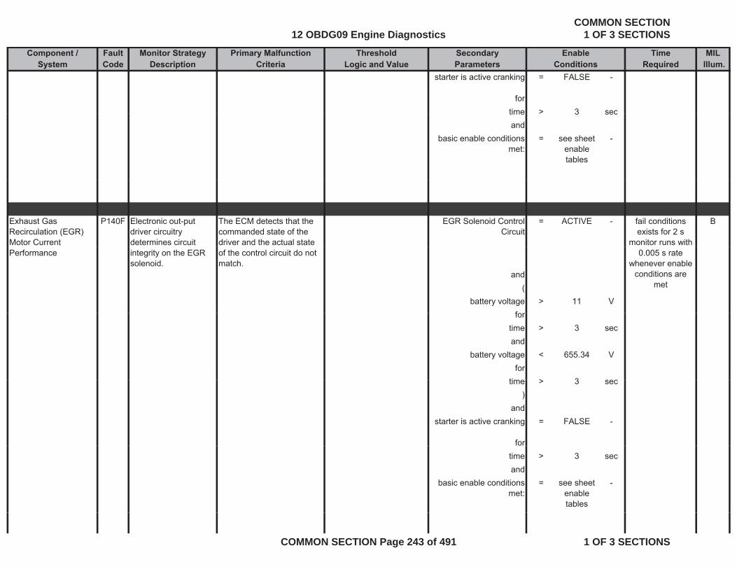
Component / Fault Monitor Strategy Primary Malfunction Secondary Time MILSystem Code Description Criteria Parameters Required Illum.
Threshold EnableLogic and Value Conditions
starter is active cranking = FALSE -
fortime > 3 sectime > 3 secand
basic enable conditions met:
= see sheet enable tables
-
Exhaust Gas Recirculation (EGR) Motor Current
P140F Electronic out-put driver circuitry determines circuit
The ECM detects that the commanded state of the driver and the actual state
EGR Solenoid Control Circuit
= ACTIVE - Bfail conditions exists for 2 s
monitor runs with Performance integrity on the EGR
solenoid.of the control circuit do not match.
and(
battery voltage > 11 Vf
0.005 s rate whenever enable
conditions are met
fortime > 3 secand
battery voltage < 655.34 Vfor
ti > 3time > 3 sec)
andstarter is active cranking = FALSE -
fortime > 3 secand
basic enable conditions met:
= see sheet enable tables
-
12 OBDG09 Engine DiagnosticsCOMMON SECTION
1 OF 3 SECTIONS
COMMON SECTION Page 243 of 491 1 OF 3 SECTIONS
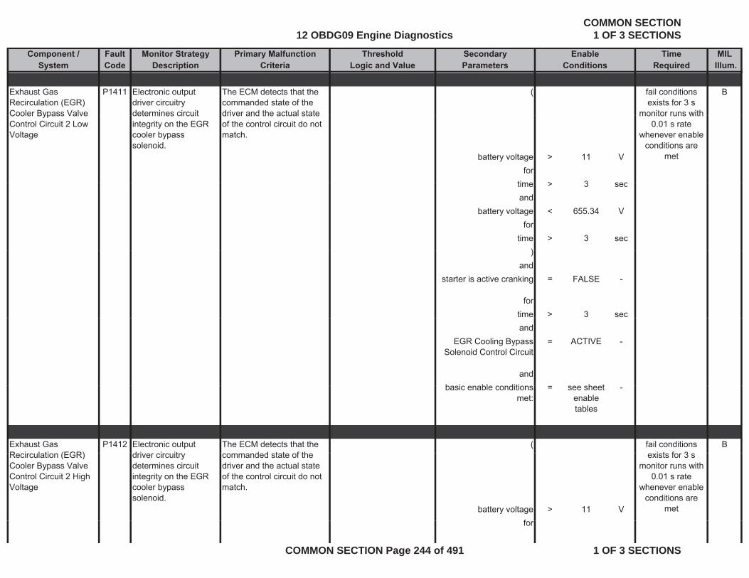
Component / Fault Monitor Strategy Primary Malfunction Secondary Time MILSystem Code Description Criteria Parameters Required Illum.
Threshold EnableLogic and Value Conditions
Exhaust Gas Recirculation (EGR) Cooler Bypass Valve
P1411 Electronic output driver circuitry determines circuit
The ECM detects that the commanded state of the driver and the actual state
( Bfail conditions exists for 3 s
monitor runs withCooler Bypass Valve Control Circuit 2 Low Voltage
determines circuit integrity on the EGR cooler bypass solenoid.
driver and the actual state of the control circuit do not match.
battery voltage > 11 Vfor
time > 3 sec
monitor runs with 0.01 s rate
whenever enable conditions are
met
time > 3 secand
battery voltage < 655.34 Vfor
time > 3 sec))
andstarter is active cranking = FALSE -
fortime > 3 secand
EGR Cooling Bypass Solenoid Control Circuit
= ACTIVE -
andb i bl diti h tbasic enable conditions
met:= see sheet
enable tables
-
Exhaust Gas R i l ti (EGR)
P1412 Electronic output d i i it
The ECM detects that the d d t t f th
( Bfail conditions i t f 3Recirculation (EGR)
Cooler Bypass Valve Control Circuit 2 High Voltage
driver circuitry determines circuit integrity on the EGR cooler bypass solenoid.
commanded state of the driver and the actual state of the control circuit do not match.
battery voltage > 11 Vf
exists for 3 smonitor runs with
0.01 s rate whenever enable
conditions are met
for
12 OBDG09 Engine DiagnosticsCOMMON SECTION
1 OF 3 SECTIONS
COMMON SECTION Page 244 of 491 1 OF 3 SECTIONS

Component / Fault Monitor Strategy Primary Malfunction Secondary Time MILSystem Code Description Criteria Parameters Required Illum.
Threshold EnableLogic and Value Conditions
time > 3 secand
battery voltage < 655.34 Vfor
time > 3 sec)
andstarter is active cranking = FALSE -
fortime > 3 secand
EGR Cooling Bypass Solenoid Control Circuit
= ACTIVE -
andbasic enable conditions
met:= see sheet
enable tables
-
Exhaust Gas Recirculation (EGR) Cooler B pass Val e
P1413 Electronic output driver circuitry determines circ it
The ECM detects that the commanded state of the dri er and the act al state
( Bfail conditions exists for 3 s
monitor r ns ithCooler Bypass Valve Control Circuit Shorted
determines circuit integrity on the EGR cooler bypass solenoid.
driver and the actual state of the control circuit do not match.
battery voltage > 11 VThis failure detects a h t b t th t
for
monitor runs with 0.01 s rate
whenever enable conditions are
met
short between the two output circuits
time > 3 secand
battery voltage < 655.34 Vfor
time > 3 sec
12 OBDG09 Engine DiagnosticsCOMMON SECTION
1 OF 3 SECTIONS
COMMON SECTION Page 245 of 491 1 OF 3 SECTIONS
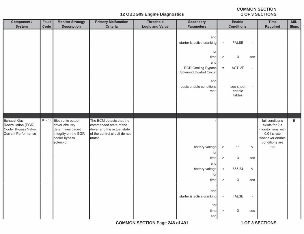
Component / Fault Monitor Strategy Primary Malfunction Secondary Time MILSystem Code Description Criteria Parameters Required Illum.
Threshold EnableLogic and Value Conditions
)and
starter is active cranking = FALSE -
fortime > 3 secand
EGR Cooling Bypass Solenoid Control Circuit
= ACTIVE -
andbasic enable conditions
met:= see sheet
enable tables
-
Exhaust Gas Recirculation (EGR) Cooler Bypass Valve
P1414 Electronic output driver circuitry determines circuit
The ECM detects that the commanded state of the driver and the actual state
( Bfail conditions exists for 2 s
monitor runs withCooler Bypass Valve Current Performance
determines circuit integrity on the EGR cooler bypass solenoid.
driver and the actual state of the control circuit do not match.
battery voltage > 11 Vfor
monitor runs with 0.01 s rate
whenever enable conditions are
met
time > 3 secand
battery voltage < 655.34 Vfor
time > 3 sec)
andstarter is active cranking = FALSE -
fortime > 3 sectime > 3 secand
12 OBDG09 Engine DiagnosticsCOMMON SECTION
1 OF 3 SECTIONS
COMMON SECTION Page 246 of 491 1 OF 3 SECTIONS

Component / Fault Monitor Strategy Primary Malfunction Secondary Time MILSystem Code Description Criteria Parameters Required Illum.
Threshold EnableLogic and Value Conditions
EGR Cooling Bypass Solenoid Control Circuit
= ACTIVE -
andbasic enable conditions
met:= see sheet
enable tables
-
Closed Loop Diesel Particulate Filter (DPF) Regeneration Control At Limit - Stage 1 Temperature Too Low
P144B Detects insufficient exhaust temperature. Actual inner controller ratio and temperature readings are
commanded control value of the inner control loop of the temperature controller
>= 0.99 - current engine operating point is suitable for
monitoring deviation of exhaust gas temperature
control depending on
= 0 to 1 - Bfail conditions exists for 300 s
monitor runs with 0.1 s rate
whenever enableTemperature Too Low readings are compared to desired controller ratio and temperature values as an indication of an insufficient exhaust gas temperature.
control - depending on engine speed and
injection quantity (see Look-Up-Table #25)
whenever enable conditions are
met
gas temperature.
and fordeviation from the temperature setpoint for
> maximum of (a) and
- time > 0 sectemperature setpoint for inner control loop
of (a) and (b+(c-d))
( andwith release of the exhaust
gas temperature outer loop control monitoring
= TRUE -
loop control monitoring
(a) limitation of the temperature threshold
= 100 °C means
and with ((b) temperature threshold value for maximum
= 100 °C active operation mode of the inner control loop
= TRUE -value for maximum deviation
the inner control loop
12 OBDG09 Engine DiagnosticsCOMMON SECTION
1 OF 3 SECTIONS
COMMON SECTION Page 247 of 491 1 OF 3 SECTIONS
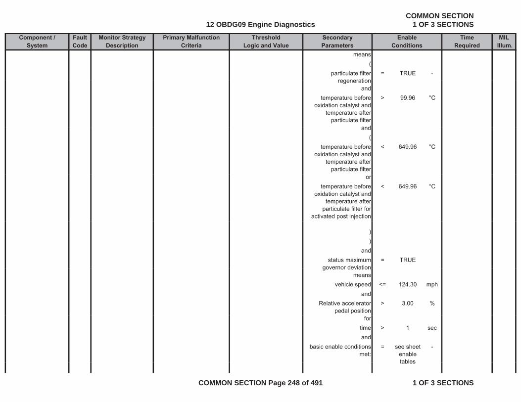
Component / Fault Monitor Strategy Primary Malfunction Secondary Time MILSystem Code Description Criteria Parameters Required Illum.
Threshold EnableLogic and Value Conditions
means(
particulate filter regeneration
= TRUE -regeneration
andtemperature before
oxidation catalyst and temperature after
particulate filter
> 99.96 °C
andand(
temperature before oxidation catalyst and
temperature after particulate filter
< 649.96 °C
ortemperature before
oxidation catalyst and temperature after
particulate filter for activated post injection
< 649.96 °C
))
andstatus maximum
governor deviation= TRUE
governor deviationmeans
vehicle speed <= 124.30 mphand
Relative accelerator pedal position
> 3.00 %
fortime > 1 secand
basic enable conditions met:
= see sheet enable tables
-
tables
12 OBDG09 Engine DiagnosticsCOMMON SECTION
1 OF 3 SECTIONS
COMMON SECTION Page 248 of 491 1 OF 3 SECTIONS
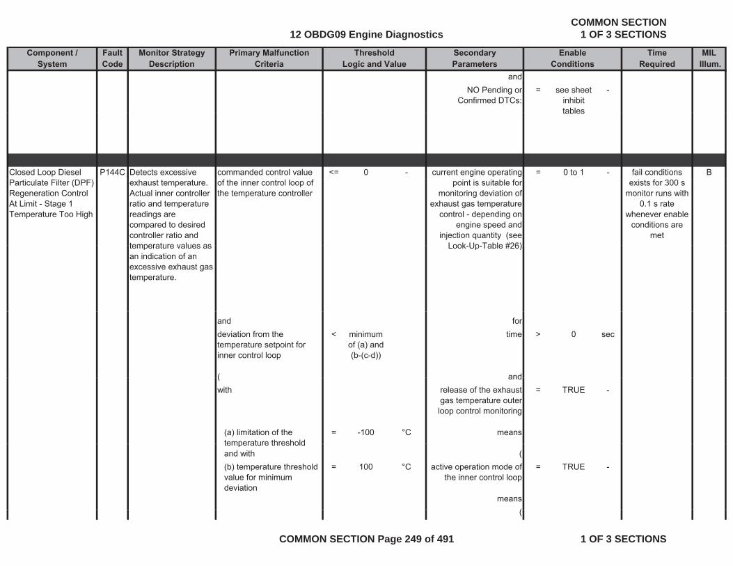
Component / Fault Monitor Strategy Primary Malfunction Secondary Time MILSystem Code Description Criteria Parameters Required Illum.
Threshold EnableLogic and Value Conditions
andNO Pending or
Confirmed DTCs:= see sheet
inhibit tables
-
tables
Closed Loop Diesel P144C Detects excessive commanded control value <= 0 - current engine operating = 0 to 1 - Bfail conditions Particulate Filter (DPF) Regeneration Control At Limit - Stage 1 Temperature Too High
exhaust temperature. Actual inner controller ratio and temperature readings are compared to desired controller ratio and temperature values as
of the inner control loop of the temperature controller
point is suitable for monitoring deviation of
exhaust gas temperature control - depending on
engine speed and injection quantity (see
Look Up Table #26)
exists for 300 s monitor runs with
0.1 s rate whenever enable
conditions are met
temperature values as an indication of an excessive exhaust gas temperature.
Look-Up-Table #26)
and fordeviation from the temperature setpoint for inner control loop
< minimum of (a) and (b-(c-d))
time > 0 sec
( and( andwith release of the exhaust
gas temperature outer loop control monitoring
= TRUE -
(a) limitation of the temperature threshold
= -100 °C meanstemperature thresholdand with ((b) temperature threshold value for minimum deviation
= 100 °C active operation mode of the inner control loop
= TRUE -
means((
12 OBDG09 Engine DiagnosticsCOMMON SECTION
1 OF 3 SECTIONS
COMMON SECTION Page 249 of 491 1 OF 3 SECTIONS
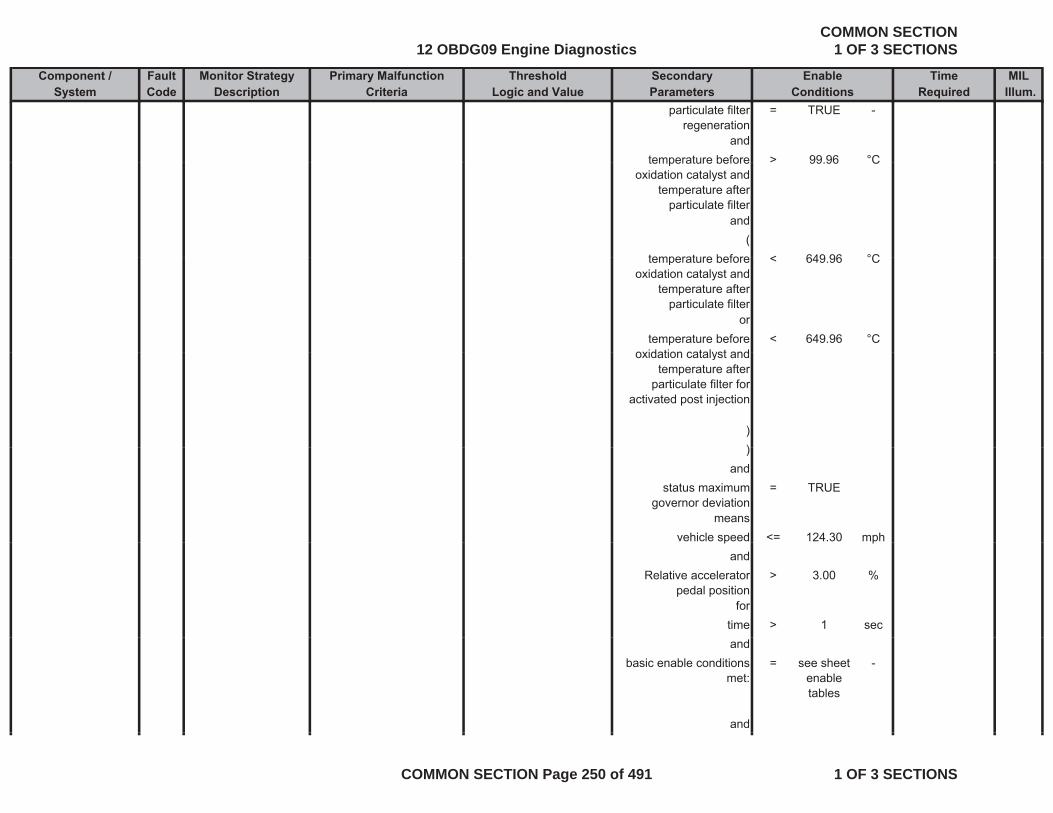
Component / Fault Monitor Strategy Primary Malfunction Secondary Time MILSystem Code Description Criteria Parameters Required Illum.
Threshold EnableLogic and Value Conditions
particulate filter regeneration
= TRUE -
andtemperature before > 99 96 °Ctemperature before
oxidation catalyst and temperature after
particulate filter
> 99.96 C
and(
temperature before < 649 96 °Ctemperature before oxidation catalyst and
temperature after particulate filter
< 649.96 °C
ortemperature before
oxidation catalyst and< 649.96 °C
oxidation catalyst and temperature after
particulate filter for activated post injection
)))
andstatus maximum
governor deviation= TRUE
meansvehicle speed <= 124.30 mphp p
andRelative accelerator
pedal position> 3.00 %
fortime > 1 secand
basic enable conditions met:
= see sheet enable tables
-
and
12 OBDG09 Engine DiagnosticsCOMMON SECTION
1 OF 3 SECTIONS
COMMON SECTION Page 250 of 491 1 OF 3 SECTIONS
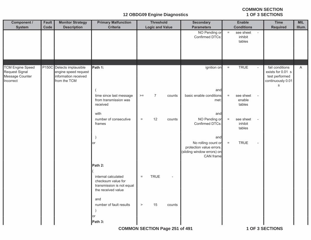
Component / Fault Monitor Strategy Primary Malfunction Secondary Time MILSystem Code Description Criteria Parameters Required Illum.
Threshold EnableLogic and Value Conditions
NO Pending or Confirmed DTCs:
= see sheet inhibit tables
-
TCM Engine Speed Request Signal Message Counter
P150C Detects implausible engine speed request information received
Path 1: ignition on = TRUE - Afail conditions exists for 0.01 stest performedMessage Counter
Incorrectinformation received from the TCM
( andtime since last message from transmission was received
>= 7 counts basic enable conditions met:
= see sheet enable tables
-
test performed continuously 0.01
s
received tables
with andnumber of consecutive frames
= 12 counts NO Pending or Confirmed DTCs:
= see sheet inhibit tables
-
) andor No rolling count or
protection value errors. (sliding window errors) on
CAN frame
= TRUE -
Path 2:(
internal calculated checksum value for transmission is not equal
= TRUE -
the received value
andnumber of fault results > 15 counts)
ororPath 3:
12 OBDG09 Engine DiagnosticsCOMMON SECTION
1 OF 3 SECTIONS
COMMON SECTION Page 251 of 491 1 OF 3 SECTIONS
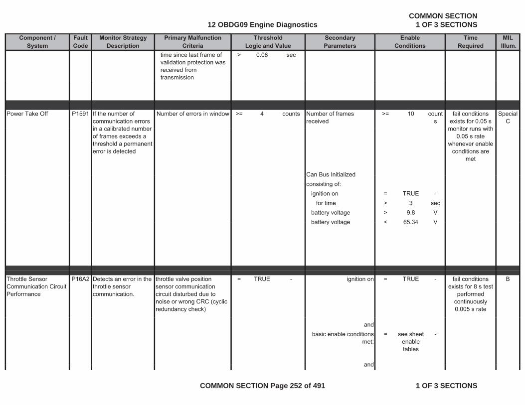
Component / Fault Monitor Strategy Primary Malfunction Secondary Time MILSystem Code Description Criteria Parameters Required Illum.
Threshold EnableLogic and Value Conditions
time since last frame of validation protection was received from transmission
> 0.08 sec
Power Take Off P1591 If the number of communication errors in a calibrated number
Number of errors in window >= 4 counts Number of frames received
>= 10 counts
Special C
fail conditions exists for 0.05 s
monitor runs within a calibrated number of frames exceeds a threshold a permanent error is detected
Can Bus Initialized
monitor runs with 0.05 s rate
whenever enable conditions are
met
Can Bus Initializedconsisting of:
ignition on = TRUE -for time > 3 sec
battery voltage > 9.8 Vbattery voltage < 65 34 Vbattery voltage < 65.34 V
Throttle Sensor Communication Circuit Performance
P16A2 Detects an error in the throttle sensor communication.
throttle valve position sensor communication circuit disturbed due to noise or wrong CRC (cyclic redundancy check)
= TRUE - ignition on = TRUE - Bfail conditions exists for 8 s test
performed continuously 0.005 s rate
andbasic enable conditions
met:= see sheet
enable tables
-
andand
12 OBDG09 Engine DiagnosticsCOMMON SECTION
1 OF 3 SECTIONS
COMMON SECTION Page 252 of 491 1 OF 3 SECTIONS
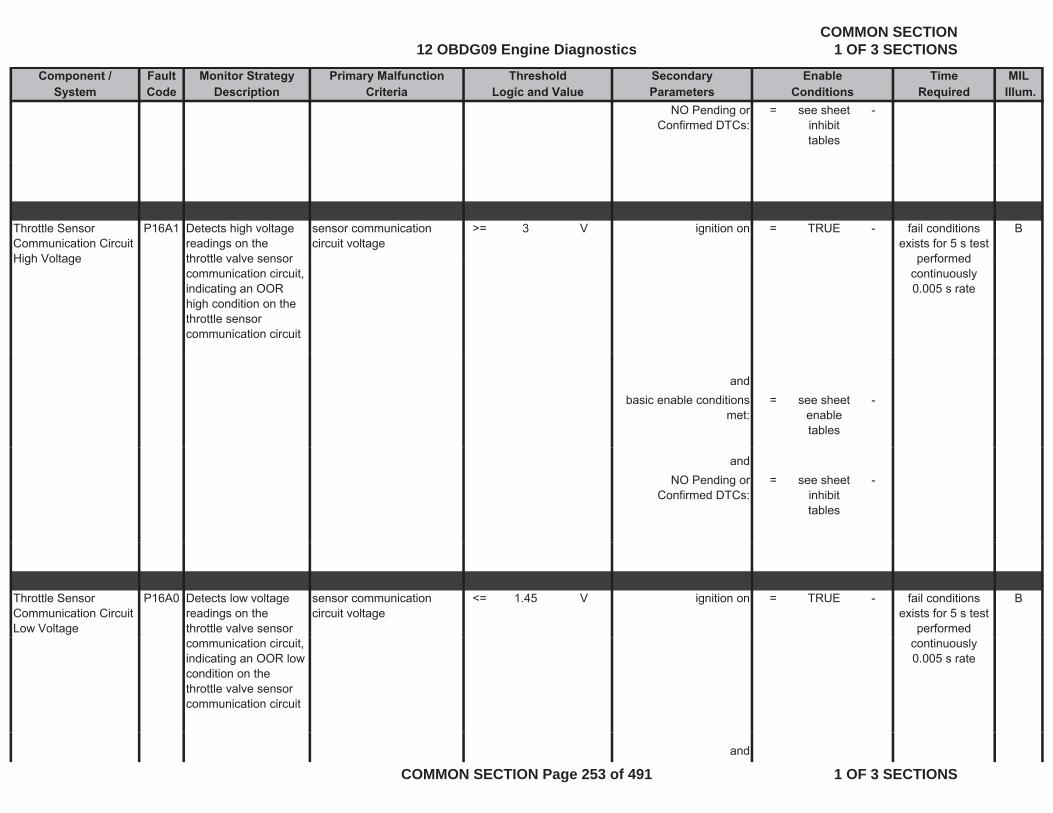
Component / Fault Monitor Strategy Primary Malfunction Secondary Time MILSystem Code Description Criteria Parameters Required Illum.
Threshold EnableLogic and Value Conditions
NO Pending or Confirmed DTCs:
= see sheet inhibit tables
-
Throttle Sensor Communication Circuit High Voltage
P16A1 Detects high voltage readings on the throttle valve sensor
sensor communication circuit voltage
>= 3 V ignition on = TRUE - Bfail conditions exists for 5 s test
performedHigh Voltage throttle valve sensor communication circuit, indicating an OOR high condition on the throttle sensor communication circuit
performed continuously 0.005 s rate
andbasic enable conditions
met:= see sheet
enable tables
-
andNO Pending or
Confirmed DTCs:= see sheet
inhibit tables
-
Throttle Sensor Communication Circuit Low Voltage
P16A0 Detects low voltage readings on the throttle valve sensor
sensor communication circuit voltage
<= 1.45 V ignition on = TRUE - Bfail conditions exists for 5 s test
performed communication circuit, indicating an OOR low condition on the throttle valve sensor communication circuit
continuously 0.005 s rate
and
12 OBDG09 Engine DiagnosticsCOMMON SECTION
1 OF 3 SECTIONS
COMMON SECTION Page 253 of 491 1 OF 3 SECTIONS

Component / Fault Monitor Strategy Primary Malfunction Secondary Time MILSystem Code Description Criteria Parameters Required Illum.
Threshold EnableLogic and Value Conditions
basic enable conditions met:
= see sheet enable tables
-
andNO Pending or
Confirmed DTCs:= see sheet
inhibit tables
-
Diesel Particulate Filter (DPF) Low Efficiency
P2002 Detects a DPF that is leaking particulates means it exceeds a PM threshold
differential pressure of particulate filter (see Look-Up-Table #52)
< 0.8 to 10.7
kPa particulate filter regeneration
= TRUE - Bfail conditions exists for 20 s
monitor runs 0.1 s rate wheneverPM threshold.
and(
particulate filter surface temperature
>= 99.96 °C
rate whenever enable conditions
are met
andparticulate filter surface
temperature<= 399.96 °C
)and
exhaust-gas volume flow > 500 m^3/hexhaust-gas volume flow in the particulate filter
> 500 m 3/h
andtime since last successful
regeneration<= 1200 sec
anddistance since last
regeneration of particulate trap
<= 30.175 miles
and
12 OBDG09 Engine DiagnosticsCOMMON SECTION
1 OF 3 SECTIONS
COMMON SECTION Page 254 of 491 1 OF 3 SECTIONS

Component / Fault Monitor Strategy Primary Malfunction Secondary Time MILSystem Code Description Criteria Parameters Required Illum.
Threshold EnableLogic and Value Conditions
basic enable conditions met:
= see sheet enable tables
-
andNO Pending or
Confirmed DTCs:= see sheet
inhibit tables
-
Reductant Injector Performance
P202E This diagnostic checks the Reductant Injector performance during operation
Number of times the ECM detects that the commanded state of the Reductant Injector driver
> 10 counts Flag for successful measurement of current
in opening phase of Reductant Injector
= TRUE - Afault exists for more than 80
injection events;monitor runs withoperation. Reductant Injector driver
and the actual state of the control circuit do not match.
Reductant Injector
(Reductant Dosing
System Metering control= TRUE -
monitor runs with 0.100 s rate
whenever enable conditions are
met
System Metering control substate of Pressure
control state (see definition)
(Calculated Reductant
I j t il t t>= -6.64 °C
Injector coil temperature
Calculated Reductant Injector coil temperature
<= 99.96 °C
)((
battery voltage >= 11 Vbattery voltage <= 655.34 V
)(
12 OBDG09 Engine DiagnosticsCOMMON SECTION
1 OF 3 SECTIONS
COMMON SECTION Page 255 of 491 1 OF 3 SECTIONS
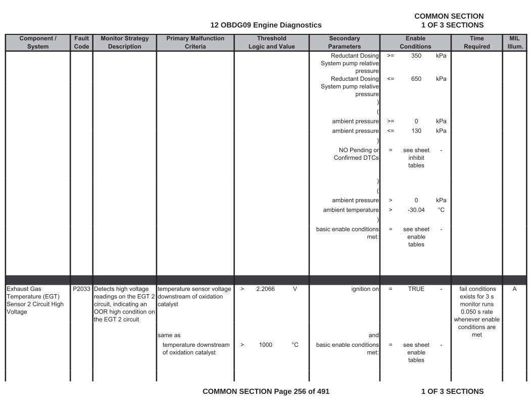
Component / Fault Monitor Strategy Primary Malfunction Secondary Time MILSystem Code Description Criteria Parameters Required Illum.
Threshold EnableLogic and Value Conditions
Reductant Dosing System pump relative
pressure
>= 350 kPa
Reductant Dosing <= 650 kPagSystem pump relative
pressure)(
ambient pressure >= 0 kPaambient pressure <= 130 kPaambient pressure <= 130 kPa
)NO Pending or
Confirmed DTCs= see sheet
inhibit tables
-
)(
ambient pressure > 0 kPaambient temperature > -30.04 °C
)basic enable conditions
met:= see sheet
enable tables
-
Exhaust Gas Temperature (EGT) Sensor 2 Circuit High Voltage
P2033 Detects high voltage readings on the EGT 2 circuit, indicating an OOR high condition on the EGT 2 circuit
temperature sensor voltage downstream of oxidation catalyst
> 2.2066 V ignition on = TRUE - A fail conditions exists for 3 s monitor runs 0.050 s rate
whenever enable
same as andtemperature downstream of oxidation catalyst
> 1000 °C basic enable conditions met:
= see sheet enable tables
-
conditions are met
12 OBDG09 Engine DiagnosticsCOMMON SECTION
1 OF 3 SECTIONS
COMMON SECTION Page 256 of 491 1 OF 3 SECTIONS
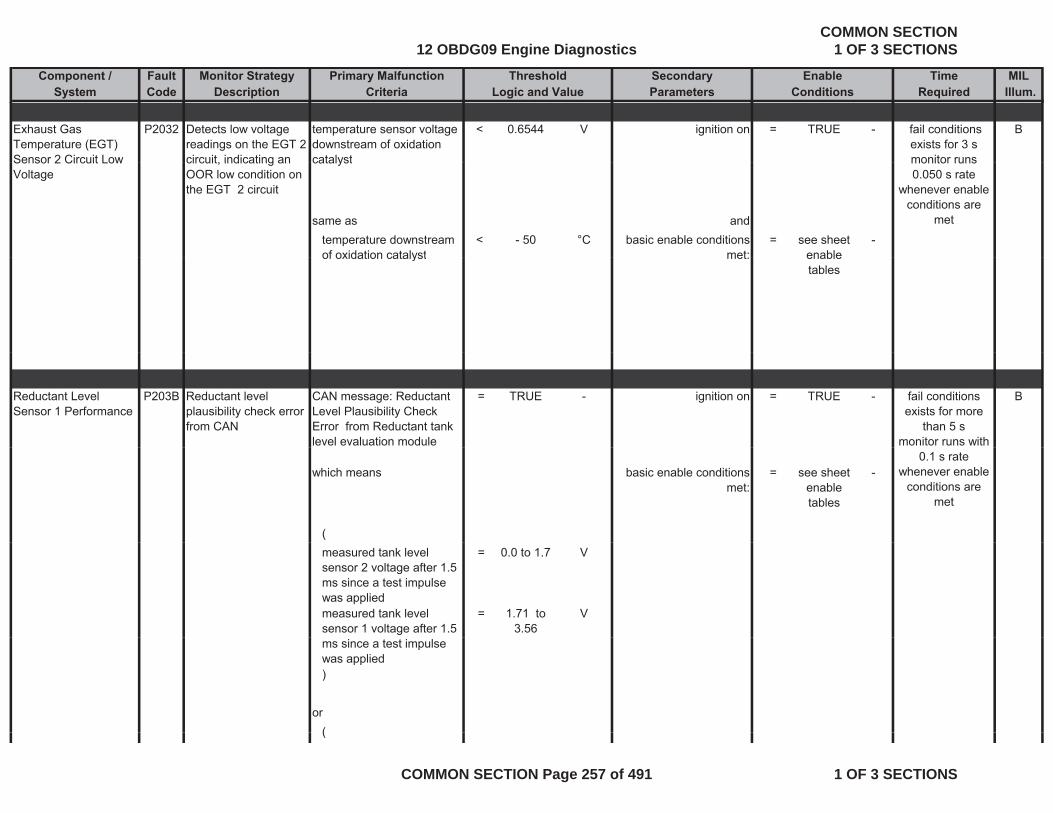
Component / Fault Monitor Strategy Primary Malfunction Secondary Time MILSystem Code Description Criteria Parameters Required Illum.
Threshold EnableLogic and Value Conditions
Exhaust Gas Temperature (EGT) Sensor 2 Circuit Low
P2032 Detects low voltage readings on the EGT 2 circuit indicating an
temperature sensor voltage downstream of oxidation catalyst
< 0.6544 V ignition on = TRUE - B fail conditions exists for 3 s monitor runsSensor 2 Circuit Low
Voltagecircuit, indicating an OOR low condition on the EGT 2 circuit
catalyst
same as andtemperature downstream of oxidation catalyst
< - 50 °C basic enable conditions met:
= see sheet enable
-
monitor runs 0.050 s rate
whenever enable conditions are
met
of oxidation catalyst met: enable tables
Reductant Level Sensor 1 Performance
P203B Reductant level plausibility check error from CAN
CAN message: Reductant Level Plausibility Check Error from Reductant tank level evaluation module
= TRUE - ignition on = TRUE - Bfail conditions exists for more
than 5 smonitor runs with
which means basic enable conditions met:
= see sheet enable tables
-
(
0.1 s rate whenever enable
conditions are met
measured tank level sensor 2 voltage after 1.5 ms since a test impulse was applied
= 0.0 to 1.7 V
measured tank level sensor 1 voltage after 1.5
= 1.71 to 3.56
V
ms since a test impulse was applied)
or((
12 OBDG09 Engine DiagnosticsCOMMON SECTION
1 OF 3 SECTIONS
COMMON SECTION Page 257 of 491 1 OF 3 SECTIONS
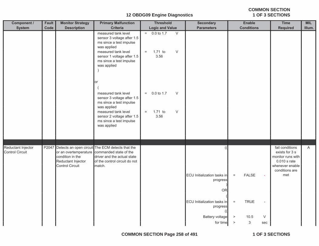
Component / Fault Monitor Strategy Primary Malfunction Secondary Time MILSystem Code Description Criteria Parameters Required Illum.
Threshold EnableLogic and Value Conditions
measured tank level sensor 3 voltage after 1.5 ms since a test impulse was applied
= 0.0 to 1.7 V
measured tank level sensor 1 voltage after 1.5 ms since a test impulse was applied
= 1.71 to 3.56
V
)
or(measured tank level sensor 3 voltage after 1.5 ms since a test impulse was applied
= 0.0 to 1.7 V
was appliedmeasured tank level sensor 2 voltage after 1.5 ms since a test impulse was applied
= 1.71 to 3.56
V
Reductant Injector Control Circuit
P2047 Detects an open circuit or an overtemperature condition in the Reductant Injector
The ECM detects that the commanded state of the driver and the actual state of the control circuit do not
(( Afail conditions exists for 3 s
monitor runs with 0.010 s rate
Control Circuit match.
ECU Initialization tasks in progress
= FALSE -
)OR
whenever enable conditions are
met
(ECU Initialization tasks in
progress= TRUE -
((Battery voltage > 10.5 V
f ti > 3for time > 3 sec
12 OBDG09 Engine DiagnosticsCOMMON SECTION
1 OF 3 SECTIONS
COMMON SECTION Page 258 of 491 1 OF 3 SECTIONS

Component / Fault Monitor Strategy Primary Malfunction Secondary Time MILSystem Code Description Criteria Parameters Required Illum.
Threshold EnableLogic and Value Conditions
ORBattery voltage > 11 V
))
basic enable conditions met:
= see sheet enable tables
-
Reductant Injector Control Circuit Low Voltage
P2048 Detects a short circuit to ground in the Reductant Injector Control Circuit
The ECM detects that the commanded state of the driver and the actual state of the control circuit do not
(( Afail conditions exists for 2 s
monitor runs with 0 010 s rateControl Circuit of the control circuit do not
match.ECU Initialization tasks in
progress= FALSE -
)OR
(
0.010 s rate whenever enable
conditions are met
(ECU Initialization tasks in
progress= TRUE -
((Battery voltage > 10.5 V
for time > 3 secOR
Battery voltage > 11 V))
basic enable conditions = see sheet -met: enable
tables
12 OBDG09 Engine DiagnosticsCOMMON SECTION
1 OF 3 SECTIONS
COMMON SECTION Page 259 of 491 1 OF 3 SECTIONS
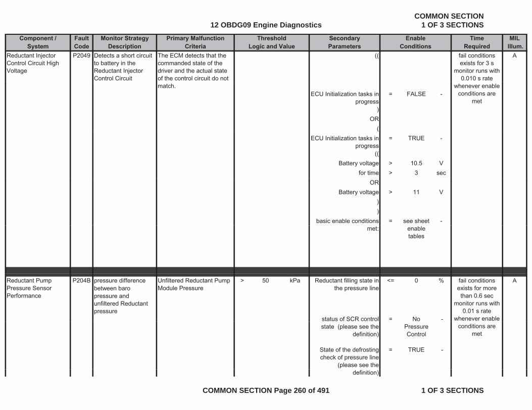
Component / Fault Monitor Strategy Primary Malfunction Secondary Time MILSystem Code Description Criteria Parameters Required Illum.
Threshold EnableLogic and Value Conditions
Reductant Injector Control Circuit High Voltage
P2049 Detects a short circuit to battery in the Reductant Injector Control Circuit
The ECM detects that the commanded state of the driver and the actual state of the control circuit do not
(( Afail conditions exists for 3 s
monitor runs with 0.010 s rate
match.ECU Initialization tasks in
progress= FALSE -
)OR
(
whenever enable conditions are
met
(ECU Initialization tasks in
progress= TRUE -
((Battery voltage > 10.5 V
for time > 3 secOR
Battery voltage > 11 V))
basic enable conditions = see sheet -met: enable
tables
Reductant Pump Pressure Sensor Performance
P204B pressure difference between baro pressure and unfiltered Reductant pressure
Unfiltered Reductant Pump Module Pressure
> 50 kPa Reductant filling state in the pressure line
<= 0 % A
status of SCR control = No -
fail conditions exists for more than 0.6 sec
monitor runs with 0.01 s rate
whenever enable state (please see the
definition)Pressure Control
State of the defrosting check of pressure line
(please see the
= TRUE -
conditions are met
definition)
12 OBDG09 Engine DiagnosticsCOMMON SECTION
1 OF 3 SECTIONS
COMMON SECTION Page 260 of 491 1 OF 3 SECTIONS
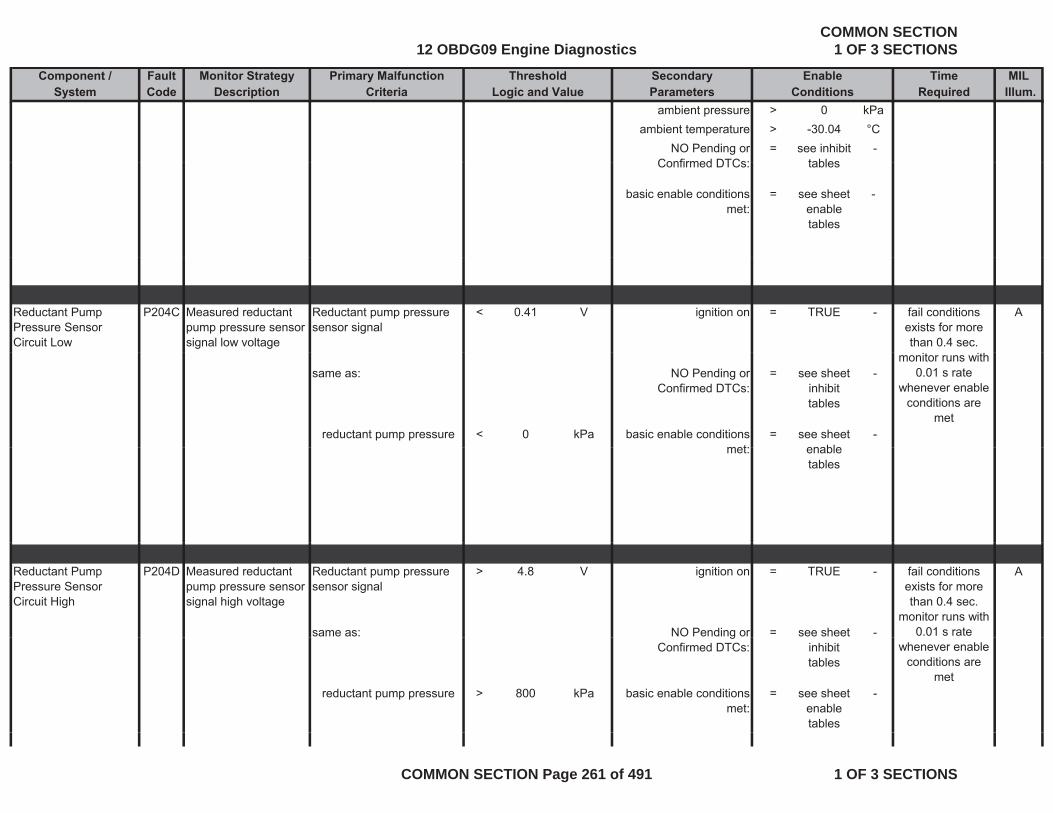
Component / Fault Monitor Strategy Primary Malfunction Secondary Time MILSystem Code Description Criteria Parameters Required Illum.
Threshold EnableLogic and Value Conditions
ambient pressure > 0 kPaambient temperature > -30.04 °C
NO Pending or Confirmed DTCs:
= see inhibit tables
-Confirmed DTCs: tables
basic enable conditions met:
= see sheet enable tables
-
Reductant Pump Pressure Sensor Circuit Low
P204C Measured reductant pump pressure sensor signal low voltage
Reductant pump pressure sensor signal
< 0.41 V ignition on = TRUE - Afail conditions exists for more than 0.4 sec.
same as: NO Pending or Confirmed DTCs:
= see sheet inhibit tables
-
reductant pump pressure < 0 kPa basic enable conditions met:
= see sheet enable
-
monitor runs with 0.01 s rate
whenever enable conditions are
met
met: enable tables
Reductant Pump Pressure Sensor Circuit High
P204D Measured reductant pump pressure sensor signal high voltage
Reductant pump pressure sensor signal
> 4.8 V ignition on = TRUE - A
same as: NO Pending or = see sheet -
fail conditions exists for more than 0.4 sec.
monitor runs with 0.01 s rate g
Confirmed DTCs: inhibit tables
reductant pump pressure > 800 kPa basic enable conditions met:
= see sheet enable tables
-
whenever enable conditions are
met
12 OBDG09 Engine DiagnosticsCOMMON SECTION
1 OF 3 SECTIONS
COMMON SECTION Page 261 of 491 1 OF 3 SECTIONS
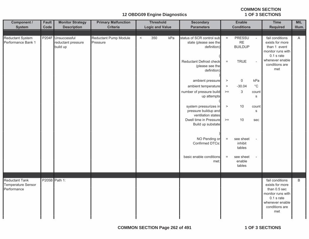
Component / Fault Monitor Strategy Primary Malfunction Secondary Time MILSystem Code Description Criteria Parameters Required Illum.
Threshold EnableLogic and Value Conditions
Reductant System Performance Bank 1
P204F Unsuccessful reductant pressure build up
Reductant Pump Module Pressure
< 350 kPa status of SCR control sub state (please see the
definition)
= PRESSURE
BUILDUP
- Afail conditions exists for more than 1 eventbuild up definition) BUILDUP
( Reductant Defrost check
(please see the definition)
= TRUE -
)
than 1 eventmonitor runs with
0.1 s rate whenever enable
conditions are met
)ambient pressure > 0 kPa
ambient temperature > -30.04 °Cnumber of pressure build-
up attempts>= 3 count
s(
system pressurizes in pressure buildup and
ventilation states
> 10 counts
Dwell time in Pressure Build up substate
>= 10 sec
)NO Pending or
Confirmed DTCs:= see sheet
inhibit tables
-
basic enable conditions = see sheet -met: enable
tables
Reductant Tank Temperature Sensor
P205B Path 1: Bfail conditions exists for more
Performance than 0.5 secmonitor runs with
0.1 s rate whenever enable
conditions are met
12 OBDG09 Engine DiagnosticsCOMMON SECTION
1 OF 3 SECTIONS
COMMON SECTION Page 262 of 491 1 OF 3 SECTIONS
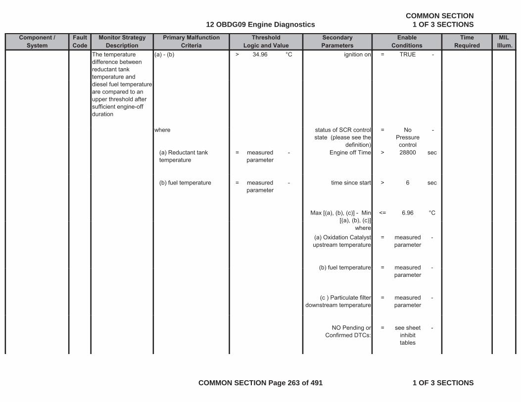
Component / Fault Monitor Strategy Primary Malfunction Secondary Time MILSystem Code Description Criteria Parameters Required Illum.
Threshold EnableLogic and Value Conditions
The temperature difference between reductant tank temperature and
(a) - (b) > 34.96 °C ignition on = TRUE -
diesel fuel temperature are compared to an upper threshold after sufficient engine-off duration
where status of SCR control state (please see the
definition)
= No Pressure control
-
(a) Reductant tank temperature
= measured parameter
- Engine off Time > 28800 sec
(b) fuel temperature = measured parameter
- time since start > 6 sec
Max [(a), (b), (c)] - Min [(a) (b) (c)]
<= 6.96 °C[(a), (b), (c)]
where(a) Oxidation Catalyst upstream temperature
= measured parameter
-
(b) fuel temperature = measured -(b) fuel temperature = measured parameter
-
(c ) Particulate filter downstream temperature
= measured parameter
-
NO Pending or Confirmed DTCs:
= see sheet inhibit tables
-
12 OBDG09 Engine DiagnosticsCOMMON SECTION
1 OF 3 SECTIONS
COMMON SECTION Page 263 of 491 1 OF 3 SECTIONS
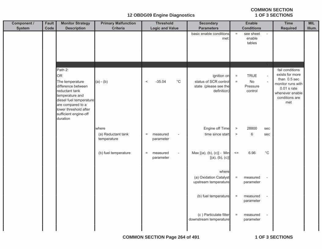
Component / Fault Monitor Strategy Primary Malfunction Secondary Time MILSystem Code Description Criteria Parameters Required Illum.
Threshold EnableLogic and Value Conditions
basic enable conditions met:
= see sheet enable tables
-
\Path 2:OR ignition on = TRUE -
fail conditions exists for more than 0 5 sec
The temperature difference between reductant tank temperature and diesel fuel temperature are compared to a
(a) - (b) < -35.04 °C status of SCR control state (please see the
definition)
= No Pressure control
-than 0.5 sec
monitor runs with 0.01 s rate
whenever enable conditions are
met
lower threshold after sufficient engine-off duration
where Engine off Time > 28800 sec(a) Reductant tank = measured - time since start > 6 sectemperature parameter
(b) fuel temperature = measured parameter
- Max [(a), (b), (c)] - Min [(a), (b), (c)]
<= 6.96 °C
where(a) Oxidation Catalyst upstream temperature
= measured parameter
-
(b) f l t t d(b) fuel temperature = measured parameter
-
(c ) Particulate filter downstream temperature
= measured parameter
-
12 OBDG09 Engine DiagnosticsCOMMON SECTION
1 OF 3 SECTIONS
COMMON SECTION Page 264 of 491 1 OF 3 SECTIONS
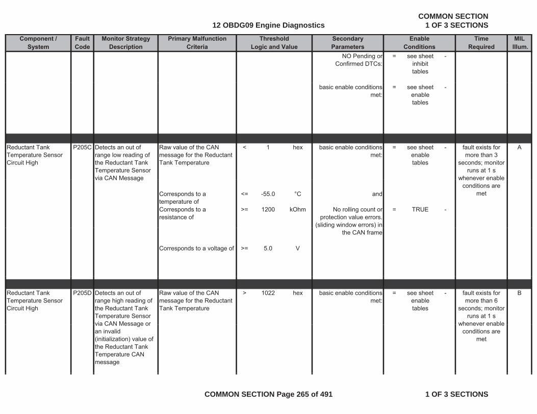
Component / Fault Monitor Strategy Primary Malfunction Secondary Time MILSystem Code Description Criteria Parameters Required Illum.
Threshold EnableLogic and Value Conditions
NO Pending or Confirmed DTCs:
= see sheet inhibit tables
-
basic enable conditions met:
= see sheet enable tables
-
Reductant Tank Temperature Sensor Circuit High
P205C Detects an out of range low reading of the Reductant Tank Temperature Sensor via CAN Message
Raw value of the CAN message for the Reductant Tank Temperature
< 1 hex basic enable conditions met:
= see sheet enable tables
- Afault exists for more than 3
seconds; monitor runs at 1 s
whenever enablevia CAN Message
Corresponds to a temperature of
<= -55.0 °C and
Corresponds to a resistance of
>= 1200 kOhm No rolling count or protection value errors.
(sliding window errors) in
= TRUE -
whenever enable conditions are
met
( g )the CAN frame
Corresponds to a voltage of >= 5.0 V
Reductant Tank Temperature Sensor Circuit High
P205D Detects an out of range high reading of the Reductant Tank Temperature Sensor via CAN Message or
Raw value of the CAN message for the Reductant Tank Temperature
> 1022 hex basic enable conditions met:
= see sheet enable tables
- Bfault exists for more than 6
seconds; monitor runs at 1 s
whenever enablevia CAN Message or an invalid (initialization) value of the Reductant Tank Temperature CAN message
whenever enable conditions are
met
12 OBDG09 Engine DiagnosticsCOMMON SECTION
1 OF 3 SECTIONS
COMMON SECTION Page 265 of 491 1 OF 3 SECTIONS
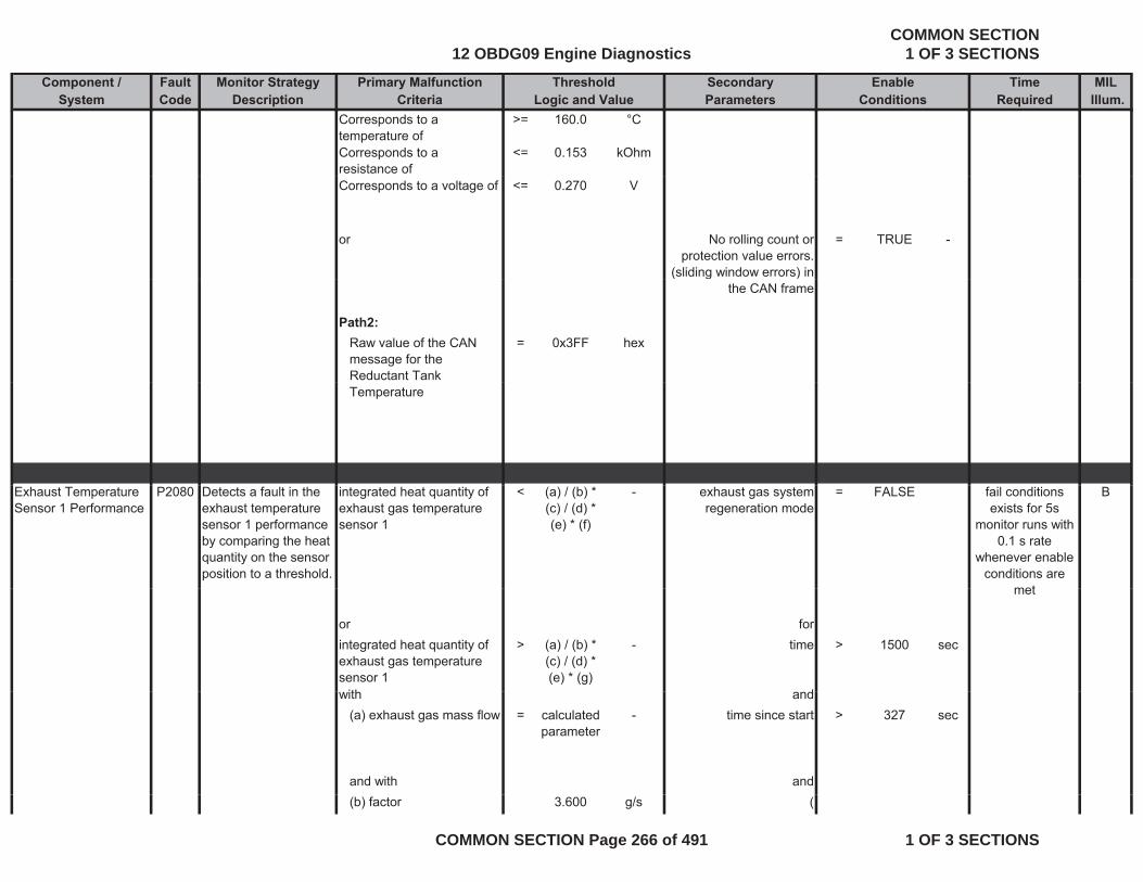
Component / Fault Monitor Strategy Primary Malfunction Secondary Time MILSystem Code Description Criteria Parameters Required Illum.
Threshold EnableLogic and Value Conditions
Corresponds to a temperature of
>= 160.0 °C
Corresponds to a resistance of
<= 0.153 kOhm
Corresponds to a voltage of <= 0.270 V
or No rolling count or protection value errors.
(sliding window errors) in
= TRUE -
( g )the CAN frame
Path2:Raw value of the CAN message for the Reductant Tank
= 0x3FF hex
Temperature
Exhaust Temperature Sensor 1 Performance
P2080 Detects a fault in the exhaust temperature sensor 1 performance by comparing the heat quantity on the sensor position to a threshold.
integrated heat quantity of exhaust gas temperature sensor 1
< (a) / (b) * (c) / (d) * (e) * (f)
- exhaust gas system regeneration mode
= FALSE Bfail conditions exists for 5s
monitor runs with 0.1 s rate
whenever enable conditions are
met
or forintegrated heat quantity of exhaust gas temperature sensor 1
> (a) / (b) * (c) / (d) * (e) * (g)
- time > 1500 sec
ith d
met
with and(a) exhaust gas mass flow = calculated
parameter- time since start > 327 sec
and with and(b) factor 3.600 g/s (
12 OBDG09 Engine DiagnosticsCOMMON SECTION
1 OF 3 SECTIONS
COMMON SECTION Page 266 of 491 1 OF 3 SECTIONS
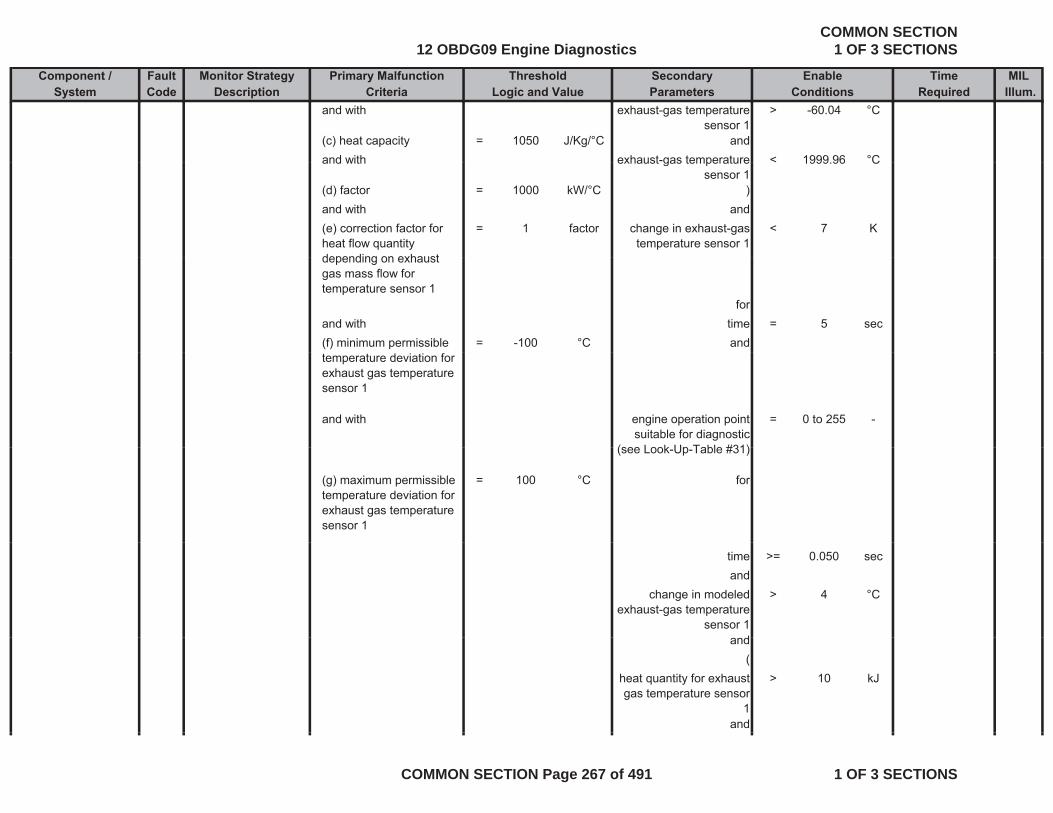
Component / Fault Monitor Strategy Primary Malfunction Secondary Time MILSystem Code Description Criteria Parameters Required Illum.
Threshold EnableLogic and Value Conditions
and with exhaust-gas temperature sensor 1
> -60.04 °C
(c) heat capacity = 1050 J/Kg/°C andand with exhaust-gas temperature < 1999 96 °Cand with exhaust gas temperature
sensor 1< 1999.96 C
(d) factor = 1000 kW/°C )and with and(e) correction factor for heat flow quantity depending on exhaust
= 1 factor change in exhaust-gas temperature sensor 1
< 7 K
depending on exhaust gas mass flow for temperature sensor 1
forand with time = 5 sec(f) minimum permissible = -100 °C andtemperature deviation for exhaust gas temperature sensor 1
and with engine operation point suitable for diagnostic
(see Look Up Table #31)
= 0 to 255 -
(see Look-Up-Table #31)
(g) maximum permissible temperature deviation for exhaust gas temperature sensor 1
= 100 °C for
time >= 0.050 secand
change in modeled exhaust-gas temperature
sensor 1
> 4 °C
dand(
heat quantity for exhaust gas temperature sensor
1
> 10 kJ
and
12 OBDG09 Engine DiagnosticsCOMMON SECTION
1 OF 3 SECTIONS
COMMON SECTION Page 267 of 491 1 OF 3 SECTIONS
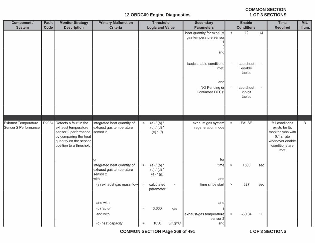
Component / Fault Monitor Strategy Primary Malfunction Secondary Time MILSystem Code Description Criteria Parameters Required Illum.
Threshold EnableLogic and Value Conditions
heat quantity for exhaust gas temperature sensor
1
< 12 kJ
))and
basic enable conditions met:
= see sheet enable tables
-
andNO Pending or
Confirmed DTCs:= see sheet
inhibit tables
-
Exhaust Temperature Sensor 2 Performance
P2084 Detects a fault in the exhaust temperature sensor 2 performance
integrated heat quantity of exhaust gas temperature sensor 2
< (a) / (b) * (c) / (d) * (e) * (f)
exhaust gas system regeneration mode
= FALSE Bfail conditions exists for 5s
monitor runs with pby comparing the heat quantity on the sensor position to a threshold.
( ) ( )
or for
0.1 s rate whenever enable
conditions are met
integrated heat quantity of exhaust gas temperature sensor 2
> (a) / (b) * (c) / (d) * (e) * (g)
time > 1500 sec
with and(a) exhaust gas mass flow = calculated
parameter- time since start > 327 sec
p
and with and(b) factor = 3.600 g/s (and with exhaust-gas temperature
sensor 2> -60.04 °C
sensor 2(c) heat capacity = 1050 J/Kg/°C and
12 OBDG09 Engine DiagnosticsCOMMON SECTION
1 OF 3 SECTIONS
COMMON SECTION Page 268 of 491 1 OF 3 SECTIONS
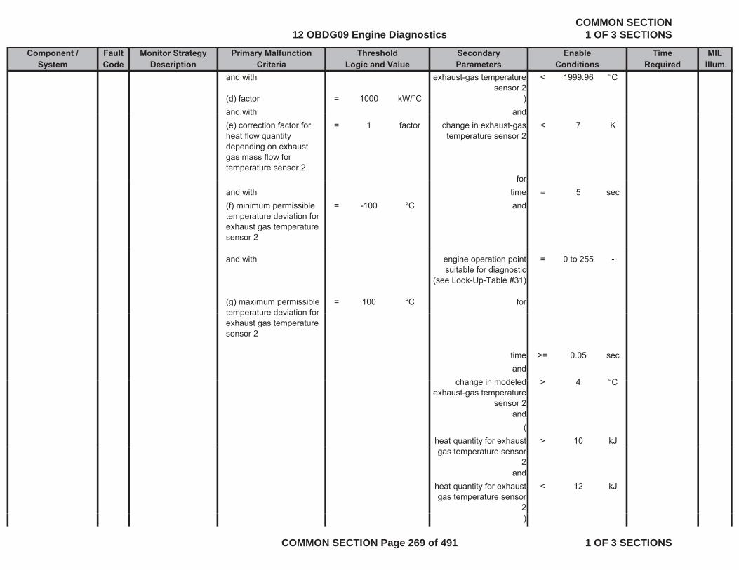
Component / Fault Monitor Strategy Primary Malfunction Secondary Time MILSystem Code Description Criteria Parameters Required Illum.
Threshold EnableLogic and Value Conditions
and with exhaust-gas temperature sensor 2
< 1999.96 °C
(d) factor = 1000 kW/°C )and with andand with and(e) correction factor for heat flow quantity depending on exhaust gas mass flow for temperature sensor 2
= 1 factor change in exhaust-gas temperature sensor 2
< 7 K
forforand with time = 5 sec(f) minimum permissible temperature deviation for exhaust gas temperature sensor 2
= -100 °C and
and with engine operation point suitable for diagnostic
(see Look-Up-Table #31)
= 0 to 255 -
(g) maximum permissible temperature deviation for
= 100 °C fortemperature deviation for exhaust gas temperature sensor 2
time >= 0.05 secand
h i d l d > 4 °Cchange in modeled exhaust-gas temperature
sensor 2
> 4 °C
and(
heat quantity for exhaust > 10 kJgas temperature sensor
2and
heat quantity for exhaust gas temperature sensor
2
< 12 kJ
)
12 OBDG09 Engine DiagnosticsCOMMON SECTION
1 OF 3 SECTIONS
COMMON SECTION Page 269 of 491 1 OF 3 SECTIONS
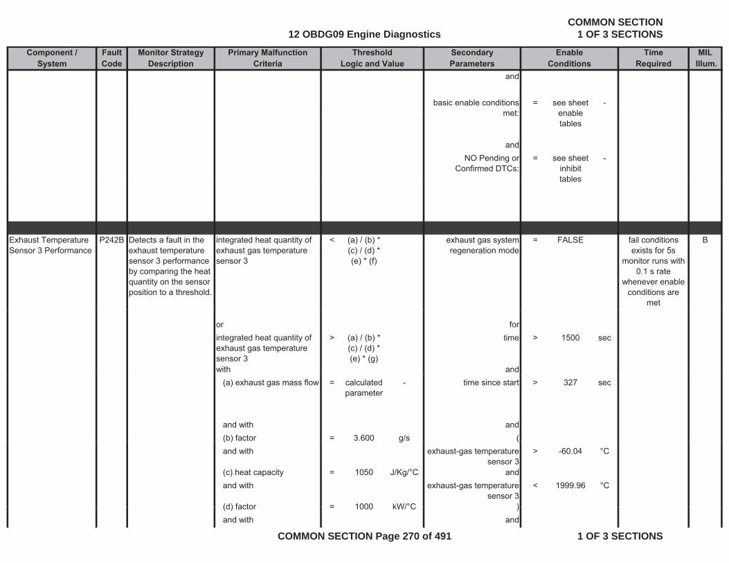
Component / Fault Monitor Strategy Primary Malfunction Secondary Time MILSystem Code Description Criteria Parameters Required Illum.
Threshold EnableLogic and Value Conditions
and
basic enable conditions met:
= see sheet enable
-met: enable
tables
andNO Pending or
Confirmed DTCs:= see sheet
inhibit tables
-
tables
Exhaust Temperature P242B Detects a fault in the integrated heat quantity of < (a) / (b) * exhaust gas system = FALSE Bfail conditions pSensor 3 Performance exhaust temperature
sensor 3 performance by comparing the heat quantity on the sensor position to a threshold.
g q yexhaust gas temperature sensor 3
( ) ( )(c) / (d) * (e) * (f)
g yregeneration mode exists for 5s
monitor runs with 0.1 s rate
whenever enable conditions are
met
or forintegrated heat quantity of exhaust gas temperature sensor 3
> (a) / (b) * (c) / (d) * (e) * (g)
time > 1500 sec
with and(a) exhaust gas mass flow = calculated
parameter- time since start > 327 sec
and with and(b) factor = 3.600 g/s (( ) g (and with exhaust-gas temperature
sensor 3> -60.04 °C
(c) heat capacity = 1050 J/Kg/°C andand with exhaust-gas temperature
sensor 3< 1999.96 °C
(d) factor = 1000 kW/°C )(d) factor = 1000 kW/ C )and with and
12 OBDG09 Engine DiagnosticsCOMMON SECTION
1 OF 3 SECTIONS
COMMON SECTION Page 270 of 491 1 OF 3 SECTIONS
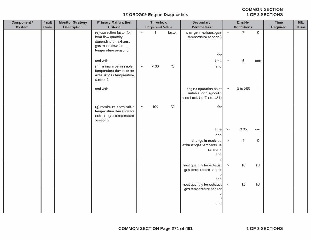
Component / Fault Monitor Strategy Primary Malfunction Secondary Time MILSystem Code Description Criteria Parameters Required Illum.
Threshold EnableLogic and Value Conditions
(e) correction factor for heat flow quantity depending on exhaust gas mass flow for
= 1 factor change in exhaust-gas temperature sensor 3
< 7 K
temperature sensor 3for
and with time = 5 sec(f) minimum permissible temperature deviation for exhaust gas temperature
= -100 °C and
exhaust gas temperature sensor 3
and with engine operation point suitable for diagnostic
(see Look-Up-Table #31)
= 0 to 255 -
(g) maximum permissible temperature deviation for exhaust gas temperature sensor 3
= 100 °C for
time >= 0.05 secand
change in modeled exhaust-gas temperature
sensor 3
> 4 K
and((
heat quantity for exhaust gas temperature sensor
3
> 10 kJ
andheat quantity for exhaust
t t< 12 kJ
gas temperature sensor 3)
and
12 OBDG09 Engine DiagnosticsCOMMON SECTION
1 OF 3 SECTIONS
COMMON SECTION Page 271 of 491 1 OF 3 SECTIONS
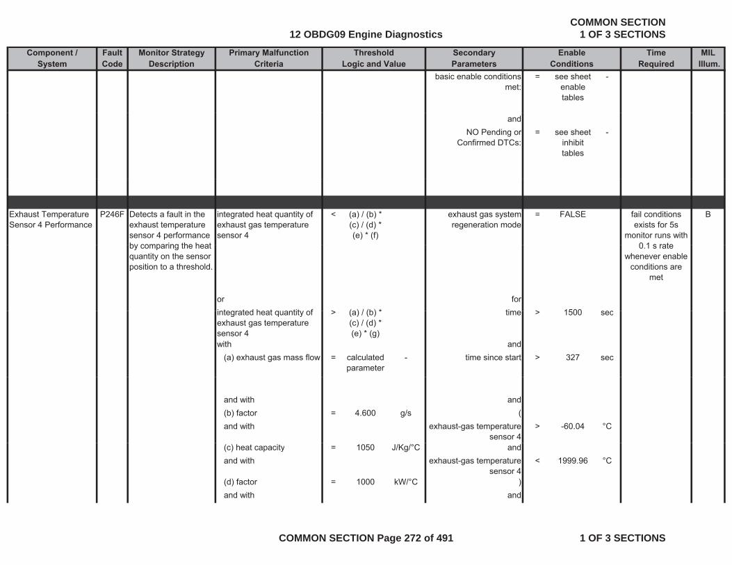
Component / Fault Monitor Strategy Primary Malfunction Secondary Time MILSystem Code Description Criteria Parameters Required Illum.
Threshold EnableLogic and Value Conditions
basic enable conditions met:
= see sheet enable tables
-
andNO Pending or
Confirmed DTCs:= see sheet
inhibit tables
-
Exhaust Temperature Sensor 4 Performance
P246F Detects a fault in the exhaust temperature sensor 4 performance by comparing the heat
integrated heat quantity of exhaust gas temperature sensor 4
< (a) / (b) * (c) / (d) * (e) * (f)
exhaust gas system regeneration mode
= FALSE Bfail conditions exists for 5s
monitor runs with 0 1 s rateby comparing the heat
quantity on the sensor position to a threshold.
or forintegrated heat q antit of > (a) / (b) * time > 1500 sec
0.1 s rate whenever enable
conditions are met
integrated heat quantity of exhaust gas temperature sensor 4
> (a) / (b) * (c) / (d) * (e) * (g)
time > 1500 sec
with and(a) exhaust gas mass flow = calculated
parameter- time since start > 327 sec
and with and(b) factor = 4.600 g/s (and with exhaust-gas temperature
sensor 4> -60.04 °C
(c) heat capacity = 1050 J/Kg/°C andand with exhaust-gas temperature
sensor 4< 1999.96 °C
(d) factor = 1000 kW/°C )and with and
12 OBDG09 Engine DiagnosticsCOMMON SECTION
1 OF 3 SECTIONS
COMMON SECTION Page 272 of 491 1 OF 3 SECTIONS

Component / Fault Monitor Strategy Primary Malfunction Secondary Time MILSystem Code Description Criteria Parameters Required Illum.
Threshold EnableLogic and Value Conditions
(e) correction factor for heat flow quantity depending on exhaust gas mass flow for
= 1 factor change in exhaust-gas temperature sensor 4
< 7 K
temperature sensor 4for
and with time = 5 sec(f) minimum permissible temperature deviation for exhaust gas temperature
= -100 °C and
exhaust gas temperature sensor 4
and with engine operation point suitable for diagnostic
(see Look-Up-Table #31)
= 0 to 255 -
(g) maximum permissible temperature deviation for exhaust gas temperature sensor 4
= 100 °C for
time >= 0.05 secand
change in modeled exhaust-gas temperature
sensor 4
> 4 °C
and((
heat quantity for exhaust gas temperature sensor
4
> 10 kJ
andheat quantity for exhaust
t t< 12 kJ
gas temperature sensor 4)
and
12 OBDG09 Engine DiagnosticsCOMMON SECTION
1 OF 3 SECTIONS
COMMON SECTION Page 273 of 491 1 OF 3 SECTIONS
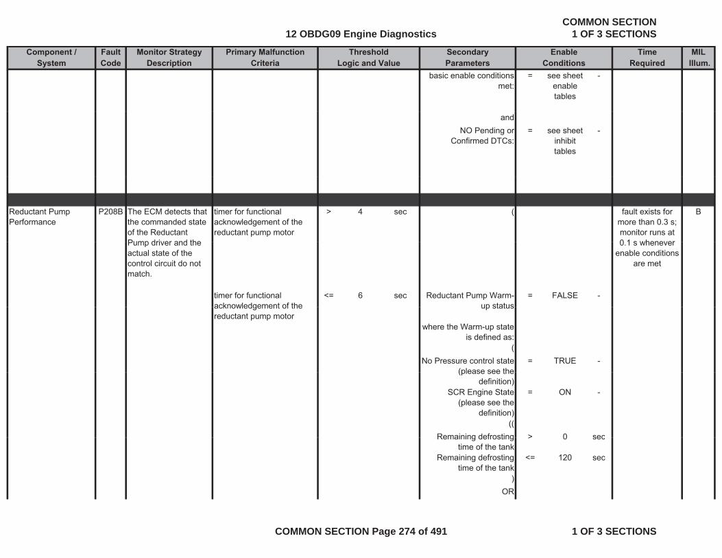
Component / Fault Monitor Strategy Primary Malfunction Secondary Time MILSystem Code Description Criteria Parameters Required Illum.
Threshold EnableLogic and Value Conditions
basic enable conditions met:
= see sheet enable tables
-
andNO Pending or
Confirmed DTCs:= see sheet
inhibit tables
-
Reductant Pump Performance
P208B The ECM detects that the commanded state of the Reductant Pump driver and the
timer for functional acknowledgement of the reductant pump motor
> 4 sec ( Bfault exists for more than 0.3 s;monitor runs at 0 1 s wheneverPump driver and the
actual state of the control circuit do not match.
timer for functional acknowledgement of the
<= 6 sec Reductant Pump Warm-up status
= FALSE -
0.1 s whenever enable conditions
are met
acknowledgement of the reductant pump motor
up status
where the Warm-up state is defined as:
(No Pressure control state
(please see the= TRUE -
(please see the definition)
SCR Engine State (please see the
definition)
= ON -
((Remaining defrosting > 0 secRemaining defrosting
time of the tank> 0 sec
Remaining defrosting time of the tank
<= 120 sec
)OR
12 OBDG09 Engine DiagnosticsCOMMON SECTION
1 OF 3 SECTIONS
COMMON SECTION Page 274 of 491 1 OF 3 SECTIONS

Component / Fault Monitor Strategy Primary Malfunction Secondary Time MILSystem Code Description Criteria Parameters Required Illum.
Threshold EnableLogic and Value Conditions
Reductant Defrost check (please see the
definition)
= TRUE -
))))ambient temperature > -6.64 °C
)basic enable conditions
met:= see sheet
enable tables
-
Reductant Pump Control Circuit
P208A Detects an open circuit or an overtemperature
The ECM detects that the commanded state of the
(( Bfail conditions exists for 6.2 sp
condition in the Reductant Pump Control Circuit
driver and the actual state of the control circuit do not match.
Battery voltage < 10.5 Vfor time < 3 sec
monitor runs with 0.010 s rate
whenever enable conditions are
met
ORBattery voltage > 11 V
))
((((SCR system waiting for
shut down in afterrun= TRUE -
ORSCR system in standby
in afterun= TRUE -
in afterun)
ignition = FALSE -)
NO Pending or Confirmed DTCs
= see sheet inhibit
-
tables
12 OBDG09 Engine DiagnosticsCOMMON SECTION
1 OF 3 SECTIONS
COMMON SECTION Page 275 of 491 1 OF 3 SECTIONS
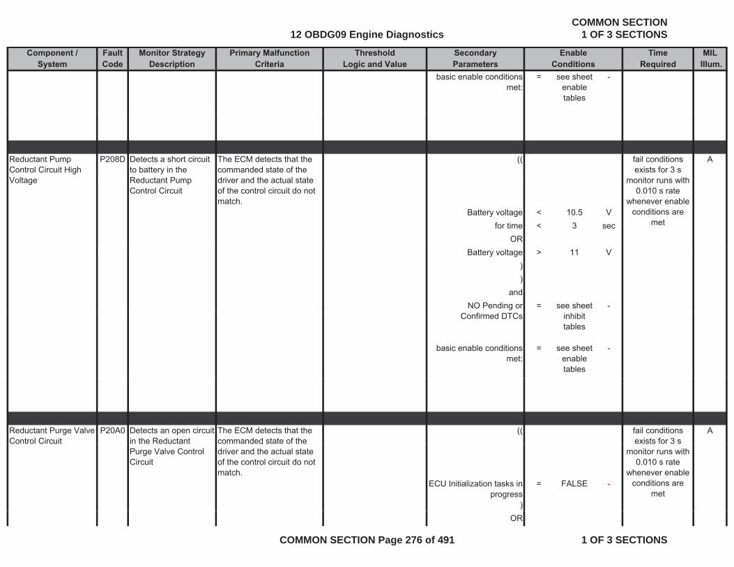
Component / Fault Monitor Strategy Primary Malfunction Secondary Time MILSystem Code Description Criteria Parameters Required Illum.
Threshold EnableLogic and Value Conditions
basic enable conditions met:
= see sheet enable tables
-
Reductant Pump Control Circuit High Voltage
P208D Detects a short circuit to battery in the Reductant Pump
The ECM detects that the commanded state of the driver and the actual state
(( Afail conditions exists for 3 s
monitor runs withVoltage Reductant Pump Control Circuit
driver and the actual state of the control circuit do not match.
Battery voltage < 10.5 Vfor time < 3 sec
OR
monitor runs with 0.010 s rate
whenever enable conditions are
met
Battery voltage > 11 V))
andNO Pending or = see sheet -
Confirmed DTCs inhibit tables
basic enable conditions met:
= see sheet enable tables
-
Reductant Purge Valve Control Circuit
P20A0 Detects an open circuit in the Reductant
The ECM detects that the commanded state of the
(( Afail conditions exists for 3 s
Purge Valve Control Circuit
driver and the actual state of the control circuit do not match.
ECU Initialization tasks in progress
= FALSE -
)
monitor runs with 0.010 s rate
whenever enable conditions are
met
OR
12 OBDG09 Engine DiagnosticsCOMMON SECTION
1 OF 3 SECTIONS
COMMON SECTION Page 276 of 491 1 OF 3 SECTIONS

Component / Fault Monitor Strategy Primary Malfunction Secondary Time MILSystem Code Description Criteria Parameters Required Illum.
Threshold EnableLogic and Value Conditions
(ECU Initialization tasks in
progress= TRUE -
for time > 1 secfor time > 1 sec)
((Battery voltage > 10.5 V
for time > 3 secOROR
Battery voltage > 11 V))
andNO Pending or = see sheet -NO Pending or
Confirmed DTCssee sheet
inhibit tables
basic enable conditions met:
= see sheet enable tables
-
Reductant Purge Valve P f
P20A1 This diagnostic checks th R d t t P
Difference between d t t t
< 50 kPa ( Afault exists for th 1Performance the Reductant Purge
valve performance during operation by detecting a lack of reduction of reductant pressure
reductant pump pressure at beginning and end of pressure reduction phase
more than 1 s monitor runs with
0.100 s rate whenever enable
conditions are met
Reductant Dosing System state pressure
reduction
= TRUE -
Reductant Dosing System pump relative
pressure to initiate test
>= 350 kPa
p
12 OBDG09 Engine DiagnosticsCOMMON SECTION
1 OF 3 SECTIONS
COMMON SECTION Page 277 of 491 1 OF 3 SECTIONS
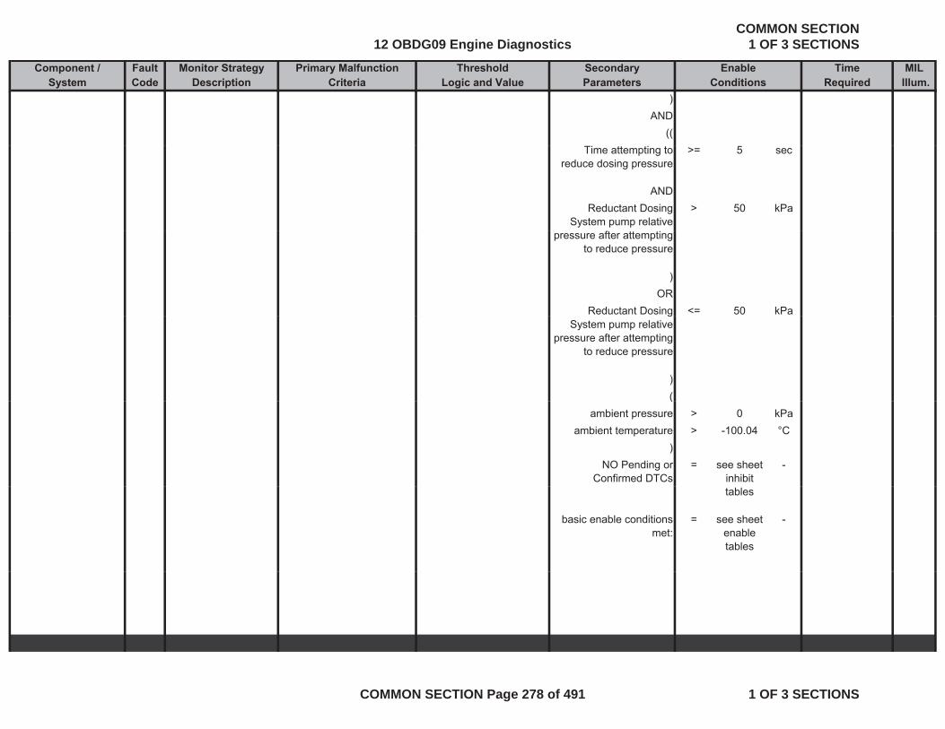
Component / Fault Monitor Strategy Primary Malfunction Secondary Time MILSystem Code Description Criteria Parameters Required Illum.
Threshold EnableLogic and Value Conditions
)AND
((Time attempting to
reduce dosing pressure>= 5 sec
ANDReductant Dosing
System pump relative > 50 kPa
pressure after attempting to reduce pressure
)OR
Reductant Dosing <= 50 kPagSystem pump relative
pressure after attempting to reduce pressure
)((
ambient pressure > 0 kPaambient temperature > -100.04 °C
)NO Pending or
Confirmed DTCs= see sheet
inhibit -
tables
basic enable conditions met:
= see sheet enable tables
-
12 OBDG09 Engine DiagnosticsCOMMON SECTION
1 OF 3 SECTIONS
COMMON SECTION Page 278 of 491 1 OF 3 SECTIONS
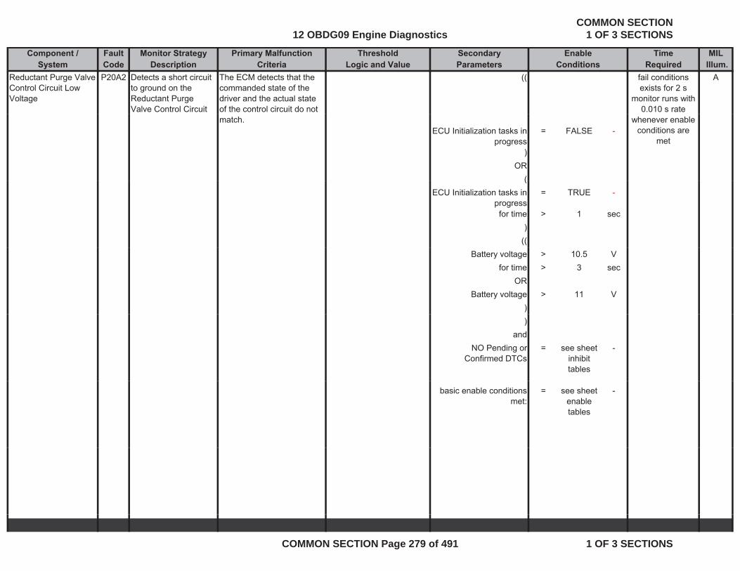
Component / Fault Monitor Strategy Primary Malfunction Secondary Time MILSystem Code Description Criteria Parameters Required Illum.
Threshold EnableLogic and Value Conditions
Reductant Purge Valve Control Circuit Low Voltage
P20A2 Detects a short circuit to ground on the Reductant Purge Valve Control Circuit
The ECM detects that the commanded state of the driver and the actual state of the control circuit do not
(( Afail conditions exists for 2 s
monitor runs with 0.010 s rate
match.ECU Initialization tasks in
progress= FALSE -
)OR
(
whenever enable conditions are
met
(ECU Initialization tasks in
progress= TRUE -
for time > 1 sec)
((Battery voltage > 10.5 V
for time > 3 secOR
Battery voltage > 11 V))
andNO Pending or
Confirmed DTCs= see sheet
inhibit tables
-
basic enable conditions met:
= see sheet enable tables
-
12 OBDG09 Engine DiagnosticsCOMMON SECTION
1 OF 3 SECTIONS
COMMON SECTION Page 279 of 491 1 OF 3 SECTIONS

Component / Fault Monitor Strategy Primary Malfunction Secondary Time MILSystem Code Description Criteria Parameters Required Illum.
Threshold EnableLogic and Value Conditions
Reductant Purge Valve Control Circuit High Voltage
P20A3 Detects a short circuit to battery on the Reductant Purge Valve Control Circuit
The ECM detects that the commanded state of the driver and the actual state of the control circuit do not
(( Afail conditions exists for 3 s
monitor runs with 0.010 s rate
match.ECU Initialization tasks in
progress= FALSE -
)OR
(
whenever enable conditions are
met
(ECU Initialization tasks in
progress= TRUE -
for time > 1 sec)
((Battery voltage > 10.5 V
for time > 3 secOR
Battery voltage > 11 V))
andNO Pending or
Confirmed DTCs= see sheet
inhibit tables
-
basic enable conditions met:
= see sheet enable tables
-
12 OBDG09 Engine DiagnosticsCOMMON SECTION
1 OF 3 SECTIONS
COMMON SECTION Page 280 of 491 1 OF 3 SECTIONS
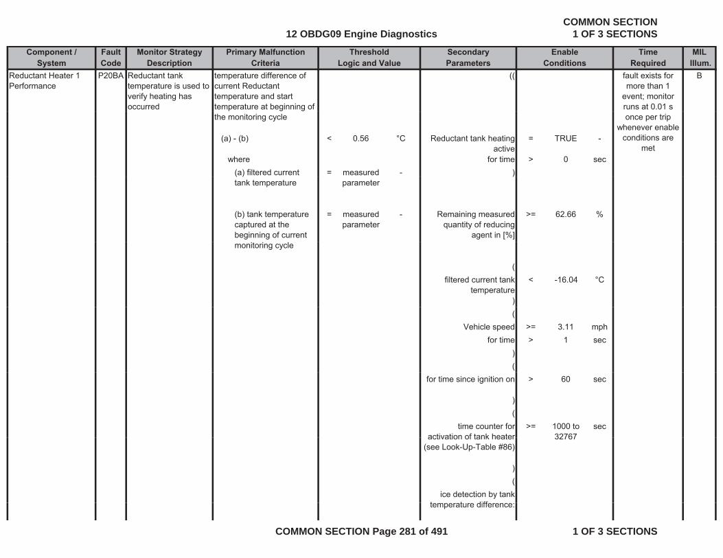
Component / Fault Monitor Strategy Primary Malfunction Secondary Time MILSystem Code Description Criteria Parameters Required Illum.
Threshold EnableLogic and Value Conditions
Reductant Heater 1 Performance
P20BA Reductant tank temperature is used to verify heating has occurred
temperature difference of current Reductant temperature and start temperature at beginning of
(( Bfault exists for more than 1
event; monitor runs at 0.01 s
the monitoring cycle
(a) - (b) < 0.56 °C Reductant tank heating active
= TRUE -
where for time > 0 sec(a) filtered current = measured - )
once per trip whenever enable
conditions are met
( )tank temperature parameter
)
(b) tank temperature captured at the beginning of current
= measured parameter
- Remaining measured quantity of reducing
agent in [%]
>= 62.66 %
monitoring cycle
(filtered current tank
temperature< -16.04 °C
)(
Vehicle speed >= 3.11 mphfor time > 1 sec
)(
for time since ignition on > 60 sec
)(
time counter for activation of tank heater
>= 1000 to 32767
secactivation of tank heater
(see Look-Up-Table #86)32767
)(
ice detection by tank t t difftemperature difference:
12 OBDG09 Engine DiagnosticsCOMMON SECTION
1 OF 3 SECTIONS
COMMON SECTION Page 281 of 491 1 OF 3 SECTIONS
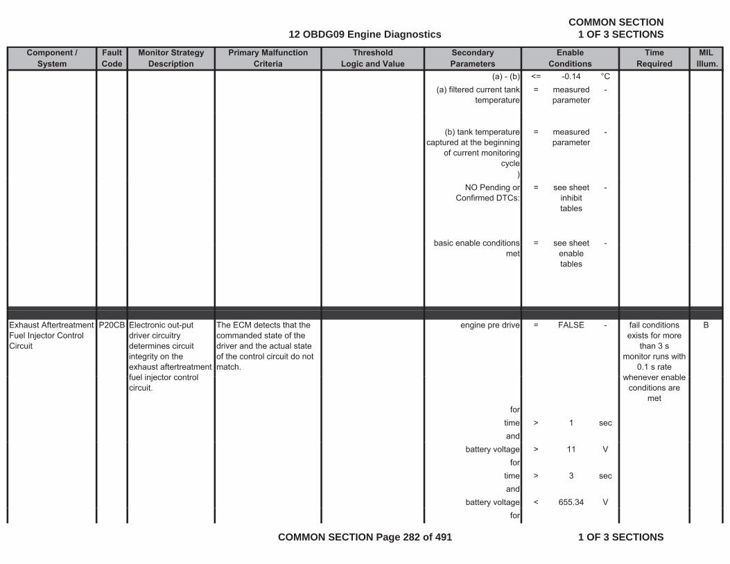
Component / Fault Monitor Strategy Primary Malfunction Secondary Time MILSystem Code Description Criteria Parameters Required Illum.
Threshold EnableLogic and Value Conditions
(a) - (b) <= -0.14 °C(a) filtered current tank
temperature= measured
parameter-
(b) tank temperature captured at the beginning
of current monitoring cycle
= measured parameter
-
))NO Pending or
Confirmed DTCs:= see sheet
inhibit tables
-
basic enable conditions = see sheet -basic enable conditions met
see sheet enable tables
Exhaust Aftertreatment Fuel Injector Control Circuit
P20CB Electronic out-put driver circuitry determines circuit integrity on the exhaust aftertreatment fuel injector control
The ECM detects that the commanded state of the driver and the actual state of the control circuit do not match.
engine pre drive = FALSE - Bfail conditions exists for more
than 3 smonitor runs with
0.1 s rate whenever enablefuel injector control
circuit.
fortime > 1 secand
whenever enable conditions are
met
battery voltage > 11 Vfor
time > 3 secand
battery voltage < 655.34 Vfor
12 OBDG09 Engine DiagnosticsCOMMON SECTION
1 OF 3 SECTIONS
COMMON SECTION Page 282 of 491 1 OF 3 SECTIONS
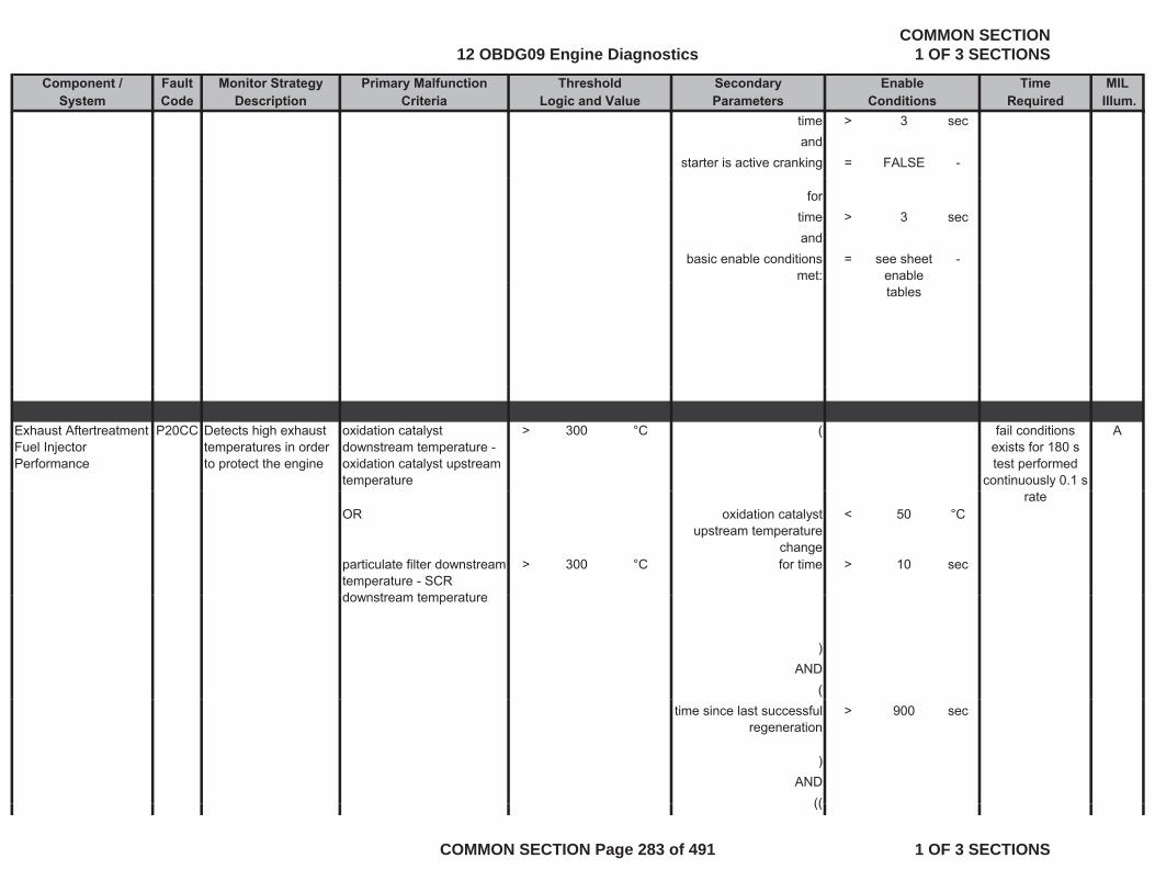
Component / Fault Monitor Strategy Primary Malfunction Secondary Time MILSystem Code Description Criteria Parameters Required Illum.
Threshold EnableLogic and Value Conditions
time > 3 secand
starter is active cranking = FALSE -
for time > 3 secand
basic enable conditions met:
= see sheet enable
-
tables
Exhaust Aftertreatment Fuel Injector Performance
P20CC Detects high exhaust temperatures in order to protect the engine
oxidation catalyst downstream temperature - oxidation catalyst upstream temperature
> 300 °C ( Afail conditions exists for 180 s test performed
continuously 0.1 s
OR oxidation catalyst upstream temperature
change
< 50 °C
particulate filter downstream temperature - SCR do nstream temperat re
> 300 °C for time > 10 sec
rate
downstream temperature
)AND
(time since last successful
regeneration> 900 sec
)AND
((((
12 OBDG09 Engine DiagnosticsCOMMON SECTION
1 OF 3 SECTIONS
COMMON SECTION Page 283 of 491 1 OF 3 SECTIONS
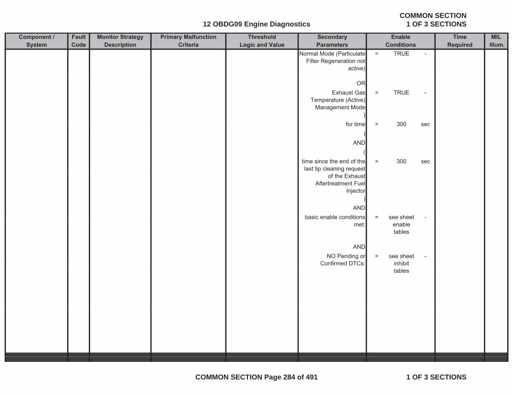
Component / Fault Monitor Strategy Primary Malfunction Secondary Time MILSystem Code Description Criteria Parameters Required Illum.
Threshold EnableLogic and Value Conditions
Normal Mode (Particulate Filter Regeneration not
active)
= TRUE -
ORExhaust Gas
Temperature (Active) Management Mode
= TRUE -
)for time > 300 secfor time > 300 sec
)AND
(time since the end of the last tip cleaning request
> 300 secp g q
of the Exhaust Aftertreatment Fuel
Injector)
ANDbasic enable conditions = see sheet -basic enable conditions
met:= see sheet
enable tables
ANDNO Pending or
Confirmed DTCs:= see sheet
inhibit-
Confirmed DTCs: inhibit tables
12 OBDG09 Engine DiagnosticsCOMMON SECTION
1 OF 3 SECTIONS
COMMON SECTION Page 284 of 491 1 OF 3 SECTIONS
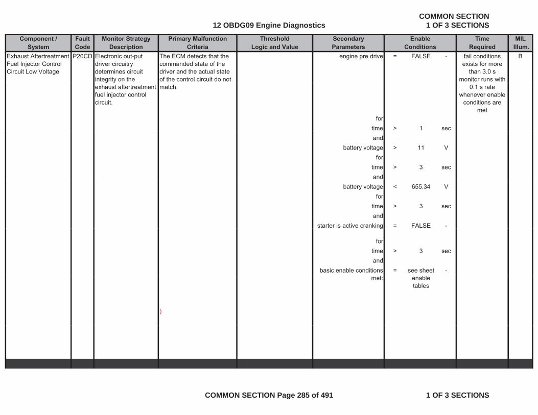
Component / Fault Monitor Strategy Primary Malfunction Secondary Time MILSystem Code Description Criteria Parameters Required Illum.
Threshold EnableLogic and Value Conditions
Exhaust Aftertreatment Fuel Injector Control Circuit Low Voltage
P20CD Electronic out-put driver circuitry determines circuit integrity on the
The ECM detects that the commanded state of the driver and the actual state of the control circuit do not
engine pre drive = FALSE - Bfail conditions exists for more
than 3.0 smonitor runs with
exhaust aftertreatment fuel injector control circuit.
match.
fortime > 1 sec
0.1 s rate whenever enable
conditions are met
andbattery voltage > 11 V
fortime > 3 secand
battery voltage < 655.34 Vfor
time > 3 secand
starter is active cranking = FALSE -g
for time > 3 secand
basic enable conditions t
= see sheet bl
-met: enable
tables
)
12 OBDG09 Engine DiagnosticsCOMMON SECTION
1 OF 3 SECTIONS
COMMON SECTION Page 285 of 491 1 OF 3 SECTIONS
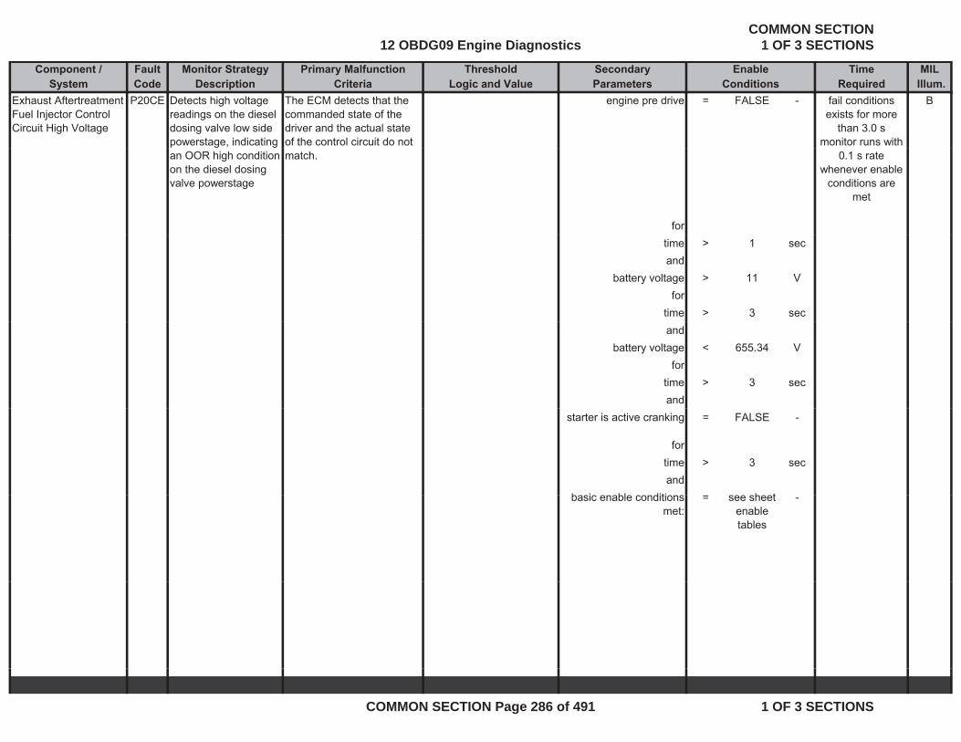
Component / Fault Monitor Strategy Primary Malfunction Secondary Time MILSystem Code Description Criteria Parameters Required Illum.
Threshold EnableLogic and Value Conditions
Exhaust Aftertreatment Fuel Injector Control Circuit High Voltage
P20CE Detects high voltage readings on the diesel dosing valve low side powerstage, indicating
The ECM detects that the commanded state of the driver and the actual state of the control circuit do not
engine pre drive = FALSE - Bfail conditions exists for more
than 3.0 smonitor runs with
an OOR high condition on the diesel dosing valve powerstage
match.
for
0.1 s rate whenever enable
conditions are met
time > 1 secand
battery voltage > 11 Vfor
time > 3 secand
battery voltage < 655.34 Vfor
time > 3 secand
starter is active cranking = FALSE -
for time > 3 secand
b i bl diti h tbasic enable conditions met:
= see sheet enable tables
-
12 OBDG09 Engine DiagnosticsCOMMON SECTION
1 OF 3 SECTIONS
COMMON SECTION Page 286 of 491 1 OF 3 SECTIONS
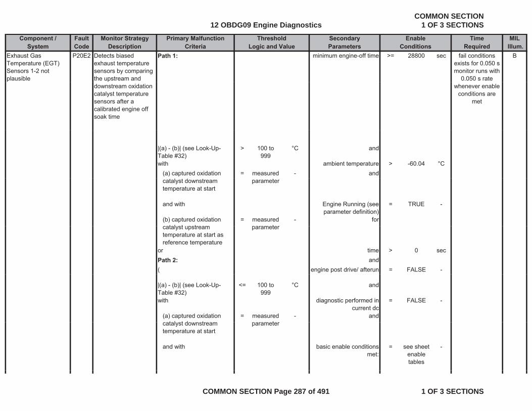
Component / Fault Monitor Strategy Primary Malfunction Secondary Time MILSystem Code Description Criteria Parameters Required Illum.
Threshold EnableLogic and Value Conditions
Exhaust Gas Temperature (EGT) Sensors 1-2 not plausible
P20E2 Detects biased exhaust temperature sensors by comparing the upstream and
Path 1: minimum engine-off time >= 28800 sec Bfail conditions exists for 0.050 s monitor runs with
0.050 s rate downstream oxidation catalyst temperature sensors after a calibrated engine off soak time
whenever enable conditions are
met
|(a) - (b)| (see Look-Up-Table #32)
> 100 to 999
°C and
with ambient temperature > -60.04 °C(a) captured oxidation = measured - andcatalyst downstream temperature at start
parameter
and with Engine Running (see parameter definition)
= TRUE -
(b) captured oxidation catalyst upstream
= measured parameter
- forcatalyst upstream temperature at start as reference temperature
parameter
or time > 0 secPath 2: and( engine post drive/ afterun = FALSE -
|(a) - (b)| (see Look-Up-Table #32)
<= 100 to 999
°C and
with diagnostic performed in current dc
= FALSE -
(a) captured oxidation t l t d t
= measured t
- andcatalyst downstream temperature at start
parameter
and with basic enable conditions met:
= see sheet enable tables
-
12 OBDG09 Engine DiagnosticsCOMMON SECTION
1 OF 3 SECTIONS
COMMON SECTION Page 287 of 491 1 OF 3 SECTIONS
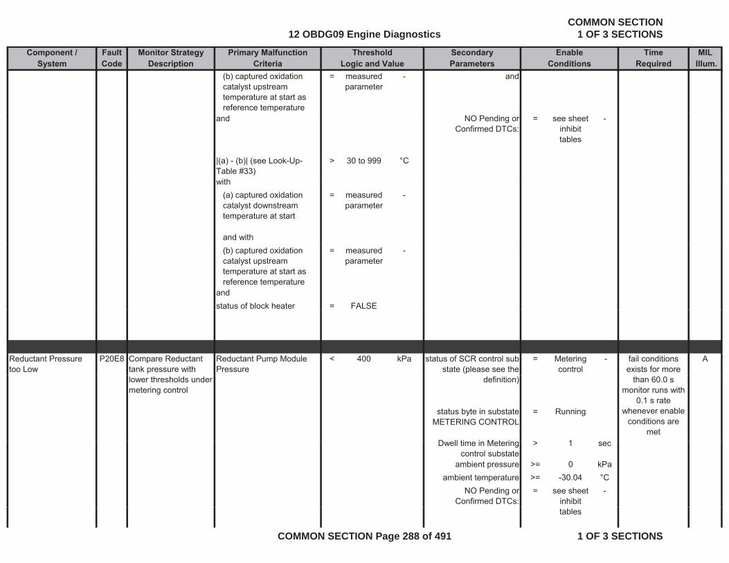
Component / Fault Monitor Strategy Primary Malfunction Secondary Time MILSystem Code Description Criteria Parameters Required Illum.
Threshold EnableLogic and Value Conditions
(b) captured oxidation catalyst upstream temperature at start as reference temperature
= measured parameter
- and
and NO Pending or Confirmed DTCs:
= see sheet inhibit tables
-
|(a) - (b)| (see Look-Up-Table #33)
> 30 to 999 °C
with(a) captured oxidation catalyst downstream temperature at start
= measured parameter
-
and with(b) captured oxidation catalyst upstream temperature at start as reference temperature
= measured parameter
-
andstatus of block heater = FALSE
Reductant Pressure too Low
P20E8 Compare Reductant tank pressure with
Reductant Pump Module Pressure
< 400 kPa status of SCR control sub state (please see the
= Metering control
- Afail conditions exists for more
lower thresholds under metering control
definition)
status byte in substate METERING CONTROL
= Running
D ll ti i M t i > 1
than 60.0 smonitor runs with
0.1 s rate whenever enable
conditions are met
Dwell time in Metering control substate
> 1 sec
ambient pressure >= 0 kPaambient temperature >= -30.04 °C
NO Pending or Confirmed DTCs:
= see sheet inhibit
-
tables
12 OBDG09 Engine DiagnosticsCOMMON SECTION
1 OF 3 SECTIONS
COMMON SECTION Page 288 of 491 1 OF 3 SECTIONS

Component / Fault Monitor Strategy Primary Malfunction Secondary Time MILSystem Code Description Criteria Parameters Required Illum.
Threshold EnableLogic and Value Conditions
basic enable conditions met:
= see sheet enable tables
-
Path 1:Reductant Pressure P20E9 Compare Reductant Reductant Pump Module > 650 kPa status of SCR control sub = Metering - A
fail conditions exists for more
than 10 stoo High tank pressure with upper threshold under metering control
Pressure state (please see the definition)
control
status byte in substate METERING CONTROL
= Running -
than 10 smonitor runs with
0.1 s rate whenever enable
conditions are met
Dwell time in Metering control substate
> 1 sec
ambient pressure >= 0 kPaambient temperature >= -30.04 °C
NO Pending or Confirmed DTCs:
= see inhibit tables
-
basic enable conditions met:
= see sheet enable tables
-
Path 2:O
fail conditions exists for moreOr
Reductant tank pressure high
Unfiltered Reductant Pump Module Pressure
> 795 kPa ambient pressure > 0 kPa
ambient temperature > -30.04 °Cbasic enable conditions
met:= see sheet
enable -
exists for more than 1 s
monitor runs with 0.1 s rate
whenever enable conditions are
mettables
12 OBDG09 Engine DiagnosticsCOMMON SECTION
1 OF 3 SECTIONS
COMMON SECTION Page 289 of 491 1 OF 3 SECTIONS

Component / Fault Monitor Strategy Primary Malfunction Secondary Time MILSystem Code Description Criteria Parameters Required Illum.
Threshold EnableLogic and Value Conditions
SCR Nox Catalyst Efficiency Below Threshold Bank 1
P20EE Compare EWMA filtered NOx conversion efficiency
EWMA filtered delta SCR catalyst efficiency of (a) - (b)
< 0 factor NO Pending or Confirmed DTCs:
= see sheetinhibit tables
- Afail conditions exists for more than 1 eventThreshold Bank 1 conversion efficiency
of SCR catalyst with a threshold value
(b) tables
where for time > 300 sec(a) measured SCR catalyst efficiency
= calculated parameter
-
than 1 eventmonitor runs with
0.01 s rate whenever enable
conditions are met
catalyst efficiency parameter
(b) offset-corrected modeled SCR catalyst efficiency (please see the general description for
= calculated parameter
- Status of NOx signal of upstream NOx sensor
(please see the definition)
= Active -
g pdetails)
)
for time > 60 secStatus of NOx signal of
downstream NOx sensor (please see the
definition)
= Active -
)for time > 60 sec
(Release of dosing
strategy (please see the definition)
= TRUE -
definition)for time >= (a) + (b) sec
(a) Turn on delay time 1 of status metering
strategy
= 330 sec
(b) Turn on delay time 2 f t t t i
= 20 secof status metering
strategy)
(
12 OBDG09 Engine DiagnosticsCOMMON SECTION
1 OF 3 SECTIONS
COMMON SECTION Page 290 of 491 1 OF 3 SECTIONS
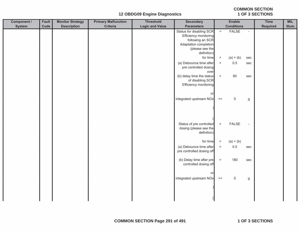
Component / Fault Monitor Strategy Primary Malfunction Secondary Time MILSystem Code Description Criteria Parameters Required Illum.
Threshold EnableLogic and Value Conditions
Status for disabling SCR Efficiency monitoring
following an SCR Adaptation completion
= FALSE -
(please see the definition)
for time > (a) + (b) sec(a) Debounce time after
pre controlled dosing over
> 0.5 sec
(b) delay time the status of disabling SCR
Efficiency monitoring
> 80 sec
orintegrated upstream NOx >= 0 gg p g
)
(Status of pre controlled dosing (please see the
= FALSE -dosing (please see the
definition)
for time > (a) + (b)(a) Debounce time after pre controlled dosing off
= 0.5 sec
(b) Delay time after pre controlled dosing off
= 180 sec
orintegrated upstream NOx >= 0 g
)
(
12 OBDG09 Engine DiagnosticsCOMMON SECTION
1 OF 3 SECTIONS
COMMON SECTION Page 291 of 491 1 OF 3 SECTIONS
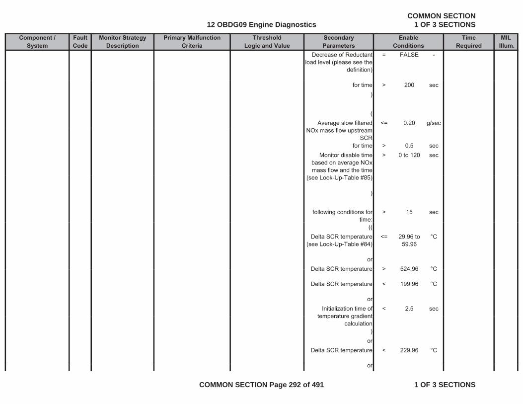
Component / Fault Monitor Strategy Primary Malfunction Secondary Time MILSystem Code Description Criteria Parameters Required Illum.
Threshold EnableLogic and Value Conditions
Decrease of Reductant load level (please see the
definition)
= FALSE -
for time > 200 sec)
(Average slow filtered <= 0.20 g/sec
NOx mass flow upstream SCR
for time > 0.5 secMonitor disable time
based on average NOx mass flow and the time
> 0 to 120 sec
(see Look-Up-Table #85)
)
following conditions for time:
> 15 sec
((Delta SCR temperature
(see Look-Up-Table #84)<= 29.96 to
59.96°C
orDelta SCR temperature > 524 96 °CDelta SCR temperature > 524.96 C
Delta SCR temperature < 199.96 °C
orInitialization time of
temperature gradient< 2.5 sec
temperature gradient calculation
)or
Delta SCR temperature < 229.96 °C
or
12 OBDG09 Engine DiagnosticsCOMMON SECTION
1 OF 3 SECTIONS
COMMON SECTION Page 292 of 491 1 OF 3 SECTIONS
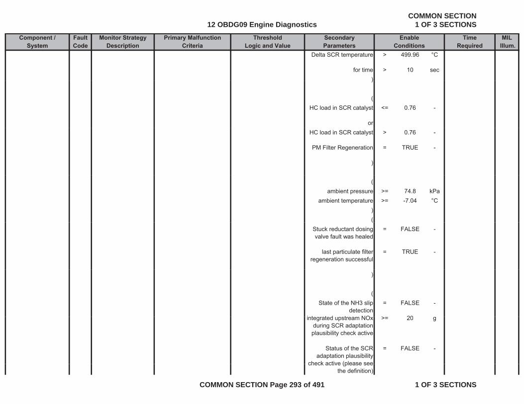
Component / Fault Monitor Strategy Primary Malfunction Secondary Time MILSystem Code Description Criteria Parameters Required Illum.
Threshold EnableLogic and Value Conditions
Delta SCR temperature > 499.96 °C
for time > 10 sec))
(HC load in SCR catalyst <= 0.76 -
orHC load in SCR catalyst > 0.76 -
PM Filter Regeneration = TRUE -
)
(ambient pressure >= 74.8 kPa
ambient temperature >= -7.04 °C)((
Stuck reductant dosing valve fault was healed
= FALSE -
last particulate filter regeneration successful
= TRUE -
)
(State of the NH3 slip
detection= FALSE -
i t t d t NO > 20integrated upstream NOx during SCR adaptation plausibility check active
>= 20 g
Status of the SCR adaptation plausibility
check active (please see
= FALSE -
check active (please see the definition)
12 OBDG09 Engine DiagnosticsCOMMON SECTION
1 OF 3 SECTIONS
COMMON SECTION Page 293 of 491 1 OF 3 SECTIONS
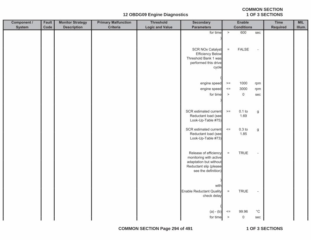
Component / Fault Monitor Strategy Primary Malfunction Secondary Time MILSystem Code Description Criteria Parameters Required Illum.
Threshold EnableLogic and Value Conditions
for time > 600 sec)
SCR NOx Catalyst Efficiency Below
Threshold Bank 1 was performed this drive
cycle
= FALSE -
(engine speed >= 1000 rpmengine speed <= 3000 rpm
for time > 0 sec)
SCR estimated current Reductant load (see Look-Up-Table #75)
>= 0.1 to 1.69
g
SCR estimated current <= 0.3 to gReductant load (see Look-Up-Table #73)
1.85
Release of efficiency monitoring with active
= TRUE -
adaptation but without Reductant slip (please
see the definition)
)with
Enable Reductant Quality check delay
= TRUE -
((a) - (b) <= 99.96 °Cf ti 0for time > 0 sec
12 OBDG09 Engine DiagnosticsCOMMON SECTION
1 OF 3 SECTIONS
COMMON SECTION Page 294 of 491 1 OF 3 SECTIONS
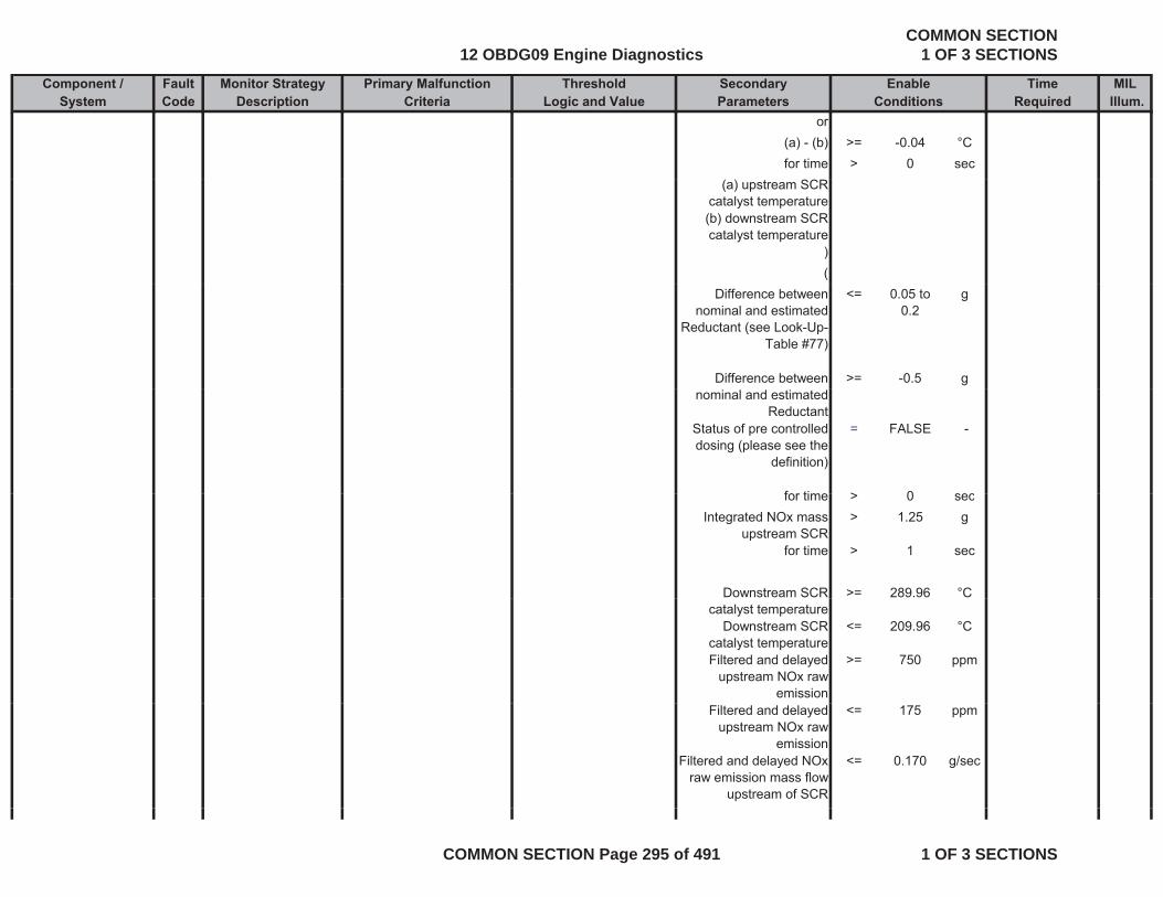
Component / Fault Monitor Strategy Primary Malfunction Secondary Time MILSystem Code Description Criteria Parameters Required Illum.
Threshold EnableLogic and Value Conditions
or(a) - (b) >= -0.04 °Cfor time > 0 sec
(a) upstream SCR catalyst temperature(b) downstream SCR catalyst temperature
)(
Difference between nominal and estimated
Reductant (see Look-Up-Table #77)
<= 0.05 to 0.2
g
Difference between >= -0.5 gnominal and estimated
ReductantStatus of pre controlled dosing (please see the
definition)
= FALSE -
for time > 0 secfor time > 0 secIntegrated NOx mass
upstream SCR> 1.25 g
for time > 1 sec
Downstream SCR >= 289.96 °Ccatalyst temperature
Downstream SCR catalyst temperature
<= 209.96 °C
Filtered and delayed upstream NOx raw
emission
>= 750 ppm
Filtered and delayed upstream NOx raw
emission
<= 175 ppm
Filtered and delayed NOx raw emission mass flow
upstream of SCR
<= 0.170 g/sec
12 OBDG09 Engine DiagnosticsCOMMON SECTION
1 OF 3 SECTIONS
COMMON SECTION Page 295 of 491 1 OF 3 SECTIONS
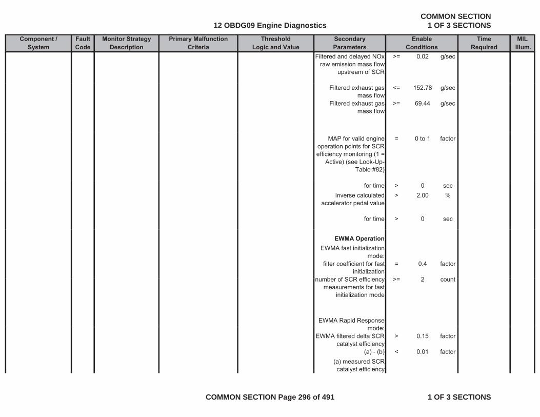
Component / Fault Monitor Strategy Primary Malfunction Secondary Time MILSystem Code Description Criteria Parameters Required Illum.
Threshold EnableLogic and Value Conditions
Filtered and delayed NOx raw emission mass flow
upstream of SCR
>= 0.02 g/sec
Filtered exhaust gas mass flow
<= 152.78 g/sec
Filtered exhaust gas mass flow
>= 69.44 g/sec
MAP for valid engine operation points for SCR efficiency monitoring (1 =
Active) (see Look-Up-Table #82)
= 0 to 1 factor
for time > 0 secInverse calculated
accelerator pedal value> 2.00 %
for time > 0 sec
EWMA OperationEWMA fast initialization
mode:filter coefficient for fast
initialization= 0.4 factor
b f SCR ffi i > 2 tnumber of SCR efficiency measurements for fast
initialization mode
>= 2 count
EWMA Rapid Response
dmode:EWMA filtered delta SCR
catalyst efficiency> 0.15 factor
(a) - (b) < 0.01 factor(a) measured SCR catalyst efficiency
12 OBDG09 Engine DiagnosticsCOMMON SECTION
1 OF 3 SECTIONS
COMMON SECTION Page 296 of 491 1 OF 3 SECTIONS
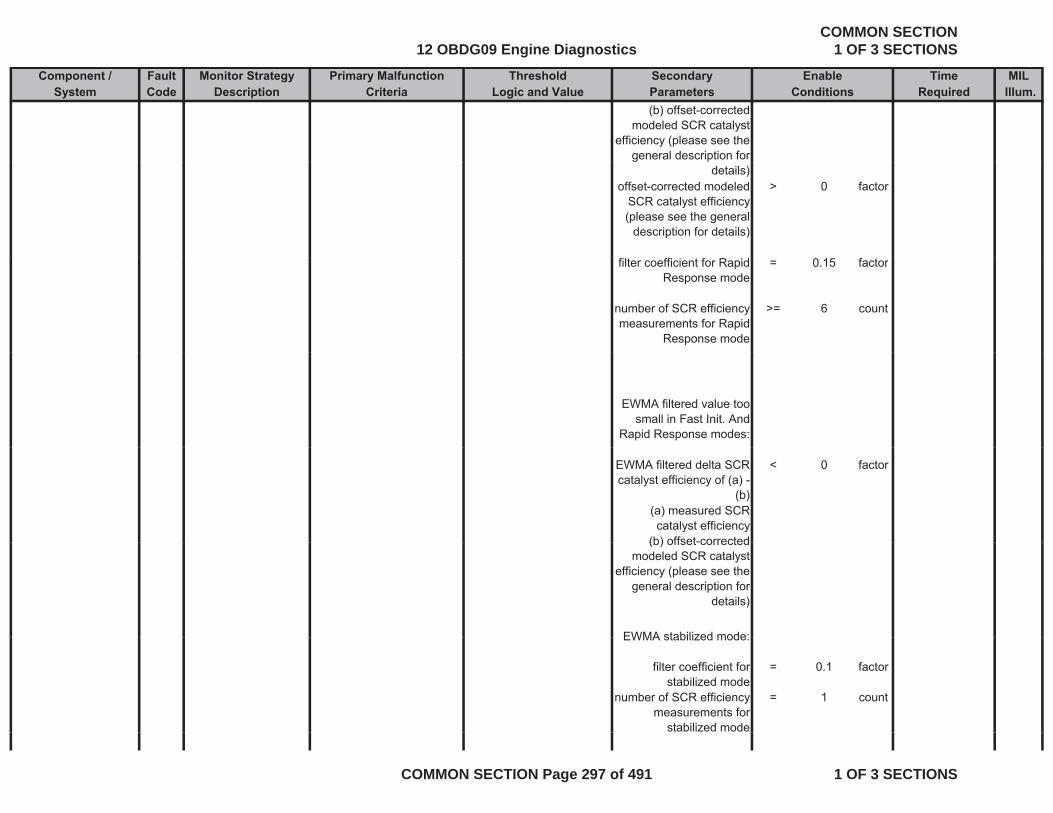
Component / Fault Monitor Strategy Primary Malfunction Secondary Time MILSystem Code Description Criteria Parameters Required Illum.
Threshold EnableLogic and Value Conditions
(b) offset-corrected modeled SCR catalyst
efficiency (please see the general description for
details)offset-corrected modeled
SCR catalyst efficiency (please see the general
description for details)
> 0 factor
filter coefficient for Rapid Response mode
= 0.15 factor
number of SCR efficiency measurements for Rapid
Response mode
>= 6 count
EWMA filtered value too small in Fast Init. And
Rapid Response modes:
EWMA filtered delta SCR catalyst efficiency of (a) -
(b)
< 0 factor
(a) measured SCR catalyst efficiency
(b) offset-corrected(b) offset-corrected modeled SCR catalyst
efficiency (please see the general description for
details)
EWMA stabilized mode:EWMA stabilized mode:
filter coefficient for stabilized mode
= 0.1 factor
number of SCR efficiency measurements for
stabilized mode
= 1 count
12 OBDG09 Engine DiagnosticsCOMMON SECTION
1 OF 3 SECTIONS
COMMON SECTION Page 297 of 491 1 OF 3 SECTIONS
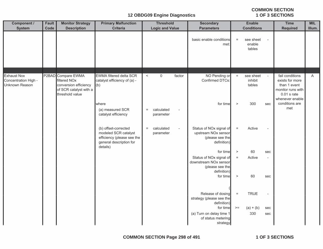
Component / Fault Monitor Strategy Primary Malfunction Secondary Time MILSystem Code Description Criteria Parameters Required Illum.
Threshold EnableLogic and Value Conditions
basic enable conditions met:
= see sheet enable tables
-
tables
Exhaust Nox P2BAD Compare EWMA EWMA filtered delta SCR < 0 factor NO Pending or = see sheet - Afail conditions Concentration High - Unknown Reason
filtered NOx conversion efficiency of SCR catalyst with a threshold value
catalyst efficiency of (a) - (b)
Confirmed DTCs: inhibit tables
where for time > 300 sec
exists for more than 1 event
monitor runs with 0.01 s rate
whenever enable conditions are
met(a) measured SCR catalyst efficiency
= calculated parameter
-
(b) offset-corrected modeled SCR catalyst efficiency (please see the
= calculated parameter
- Status of NOx signal of upstream NOx sensor
(please see the
= Active -
met
efficiency (please see the general description for details)
(please see the definition)
for time > 60 secStatus of NOx signal of
downstream NOx sensor (please see the
= Active -
(please see the definition)
for time > 60 sec
(Release of dosing = TRUE -g
strategy (please see the definition)
for time >= (a) + (b) sec(a) Turn on delay time 1
of status metering strategy
330 sec
gy
12 OBDG09 Engine DiagnosticsCOMMON SECTION
1 OF 3 SECTIONS
COMMON SECTION Page 298 of 491 1 OF 3 SECTIONS
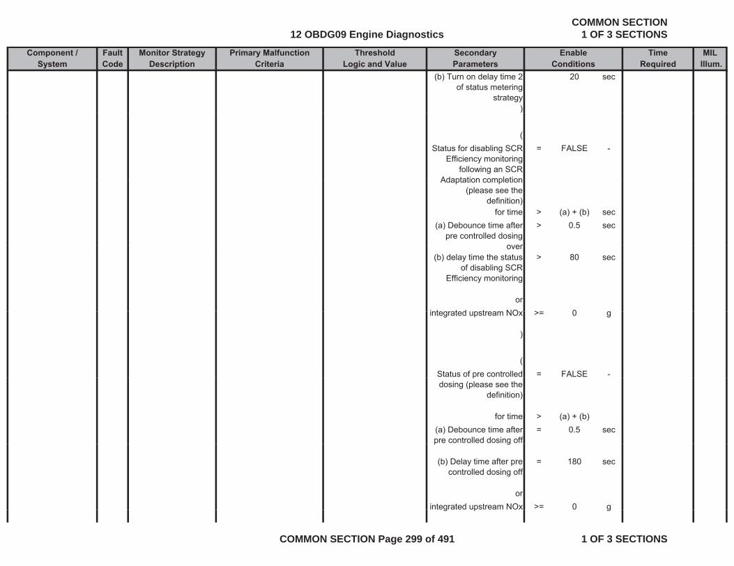
Component / Fault Monitor Strategy Primary Malfunction Secondary Time MILSystem Code Description Criteria Parameters Required Illum.
Threshold EnableLogic and Value Conditions
(b) Turn on delay time 2 of status metering
strategy
20 sec
))
(Status for disabling SCR
Efficiency monitoring following an SCR
Adaptation completion
= FALSE -
Adaptation completion (please see the
definition)for time > (a) + (b) sec
(a) Debounce time after pre controlled dosing
over
> 0.5 sec
over(b) delay time the status
of disabling SCR Efficiency monitoring
> 80 sec
orintegrated pstream NO > 0 gintegrated upstream NOx >= 0 g
)
(Status of pre controlled = FALSE -pdosing (please see the
definition)
for time > (a) + (b)(a) Debounce time after pre controlled dosing off
= 0.5 secp g
(b) Delay time after pre controlled dosing off
= 180 sec
orintegrated upstream NOx >= 0 gg p g
12 OBDG09 Engine DiagnosticsCOMMON SECTION
1 OF 3 SECTIONS
COMMON SECTION Page 299 of 491 1 OF 3 SECTIONS
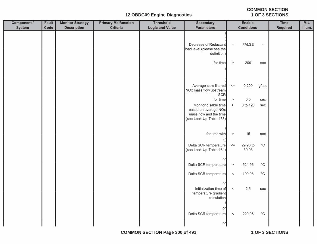
Component / Fault Monitor Strategy Primary Malfunction Secondary Time MILSystem Code Description Criteria Parameters Required Illum.
Threshold EnableLogic and Value Conditions
)(
Decrease of Reductant load level (please see the
= FALSE -load level (please see the
definition)
for time > 200 sec)
(Average slow filtered
NOx mass flow upstream SCR
<= 0.200 g/sec
for time > 0.5 secMonitor disable time > 0 to 120 secMonitor disable time
based on average NOx mass flow and the time
(see Look-Up-Table #85)
> 0 to 120 sec
)for time with > 15 secfor time with > 15 sec
((Delta SCR temperature
(see Look-Up-Table #84)<= 29.96 to
59.96°C
orDelta SCR temperature > 524.96 °C
Delta SCR temperature < 199.96 °C
orInitialization time of < 2.5 sec
temperature gradient calculation
)or
Delta SCR temperature < 229.96 °C
or
12 OBDG09 Engine DiagnosticsCOMMON SECTION
1 OF 3 SECTIONS
COMMON SECTION Page 300 of 491 1 OF 3 SECTIONS
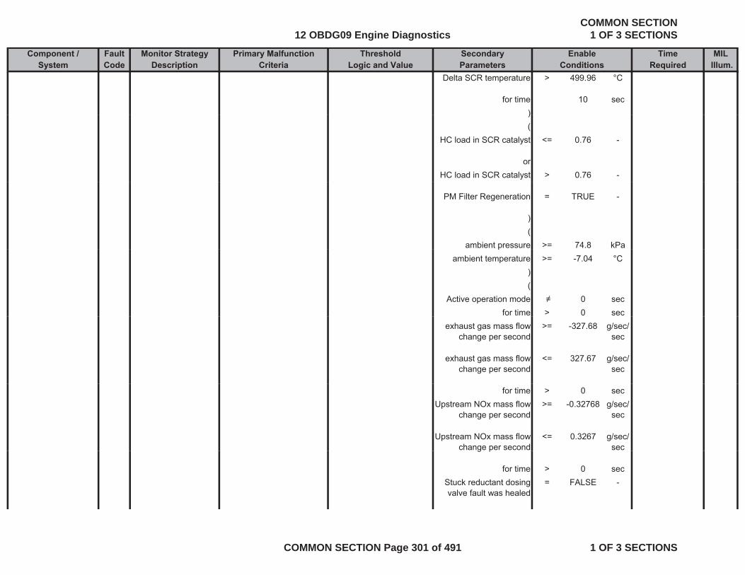
Component / Fault Monitor Strategy Primary Malfunction Secondary Time MILSystem Code Description Criteria Parameters Required Illum.
Threshold EnableLogic and Value Conditions
Delta SCR temperature > 499.96 °C
for time 10 sec))(
HC load in SCR catalyst <= 0.76 -
orHC load in SCR catalyst > 0.76 -
PM Filter Regeneration = TRUE -
)(
ambient pressure >= 74.8 kPapambient temperature >= -7.04 °C
)(
Active operation mode 0 secfor time > 0 sec
exhaust gas mass flow change per second
>= -327.68 g/sec/sec
exhaust gas mass flow change per second
<= 327.67 g/sec/sec
for time > 0 secUpstream NOx mass flow
change per second>= -0.32768 g/sec/
sec
Upstream NOx mass flow change per second
<= 0.3267 g/sec/secg p
for time > 0 secStuck reductant dosing valve fault was healed
= FALSE -
12 OBDG09 Engine DiagnosticsCOMMON SECTION
1 OF 3 SECTIONS
COMMON SECTION Page 301 of 491 1 OF 3 SECTIONS
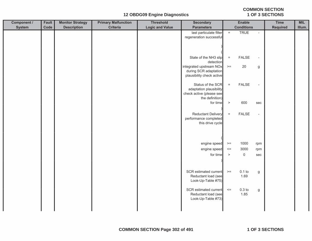
Component / Fault Monitor Strategy Primary Malfunction Secondary Time MILSystem Code Description Criteria Parameters Required Illum.
Threshold EnableLogic and Value Conditions
last particulate filter regeneration successful
= TRUE -
))(
State of the NH3 slip detection
= FALSE -
integrated upstream NOx during SCR adaptation plausibility check active
>= 20 g
plausibility check active
Status of the SCR adaptation plausibility
check active (please see the definition)
= FALSE -
for time > 600 sec)
Reductant Delivery performance completed
this drive cycle
= FALSE -
(engine speed >= 1000 rpmengine speed <= 3000 rpm
for time > 0 sec))
SCR estimated current Reductant load (see Look-Up-Table #75)
>= 0.1 to 1.69
g
SCR ti t d t < 0 3 tSCR estimated current Reductant load (see Look-Up-Table #73)
<= 0.3 to 1.85
g
12 OBDG09 Engine DiagnosticsCOMMON SECTION
1 OF 3 SECTIONS
COMMON SECTION Page 302 of 491 1 OF 3 SECTIONS
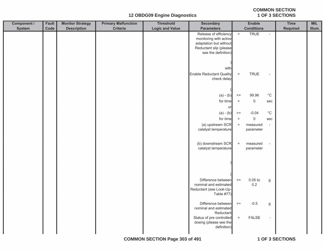
Component / Fault Monitor Strategy Primary Malfunction Secondary Time MILSystem Code Description Criteria Parameters Required Illum.
Threshold EnableLogic and Value Conditions
Release of efficiency monitoring with active adaptation but without Reductant slip (please
= TRUE -
see the definition)
)with
Enable Reductant Quality check delay
= TRUE -check delay
((a) - (b) <= 99.96 °Cfor time > 0 sec
or(a) - (b) >= -0.04 °Cfor time > 0 sec
(a) upstream SCR catalyst temperature
= measured parameter
-
(b) downstream SCR catalyst temperature
= measured parameter
-
)
(Difference between
nominal and estimated Reductant (see Look-Up-
Table #77)
<= 0.05 to 0.2
g
Difference between nominal and estimated
Reductant
>= -0.5 g
Status of pre controlled dosing (please see the
d fi iti )
= FALSE -
definition)
12 OBDG09 Engine DiagnosticsCOMMON SECTION
1 OF 3 SECTIONS
COMMON SECTION Page 303 of 491 1 OF 3 SECTIONS
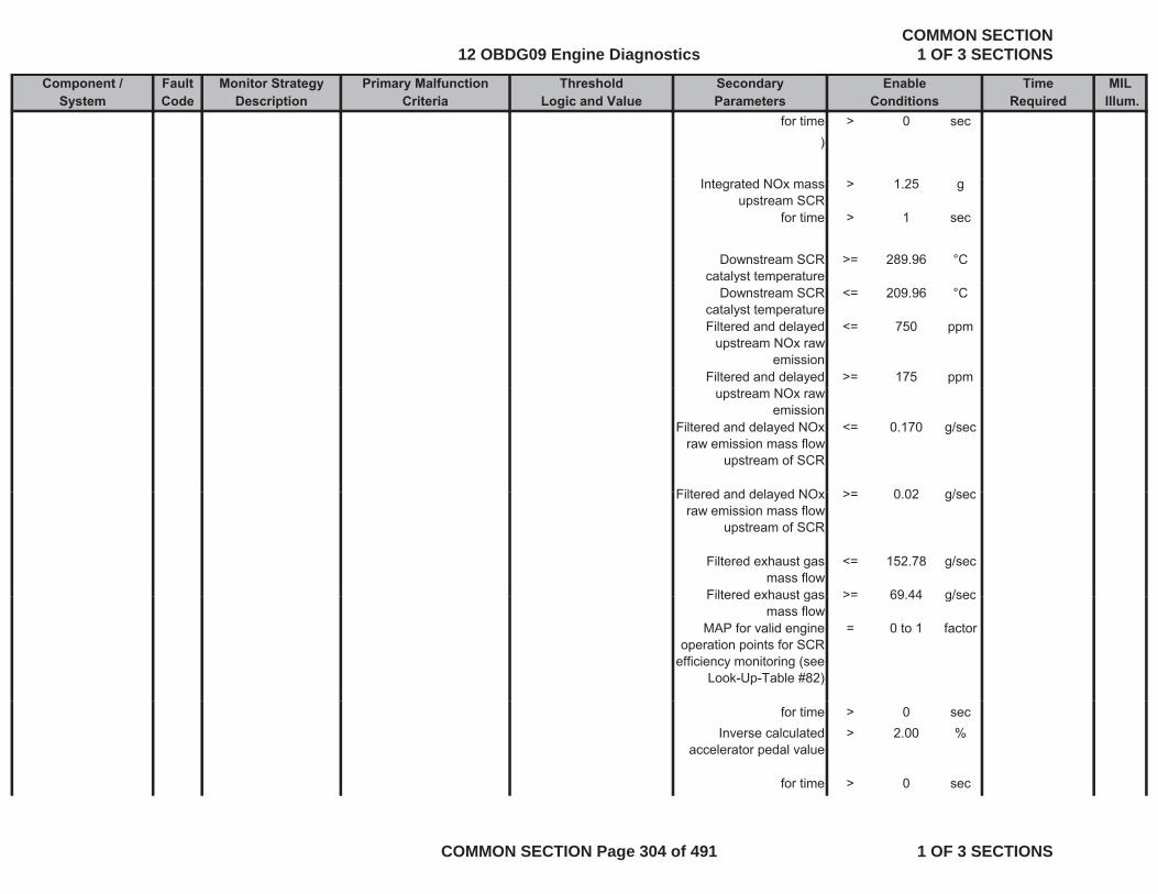
Component / Fault Monitor Strategy Primary Malfunction Secondary Time MILSystem Code Description Criteria Parameters Required Illum.
Threshold EnableLogic and Value Conditions
for time > 0 sec)
Integrated NOx mass upstream SCR
> 1.25 g
for time > 1 sec
Downstream SCR catalyst temperature
>= 289.96 °Cy p
Downstream SCR catalyst temperature
<= 209.96 °C
Filtered and delayed upstream NOx raw
emission
<= 750 ppm
Filtered and delayed >= 175 ppmupstream NOx raw
emissionFiltered and delayed NOx
raw emission mass flow upstream of SCR
<= 0.170 g/sec
Filtered and dela ed NO > 0 02 g/secFiltered and delayed NOx raw emission mass flow
upstream of SCR
>= 0.02 g/sec
Filtered exhaust gas mass flow
<= 152.78 g/sec
Filtered exhaust gas >= 69 44 g/secFiltered exhaust gas mass flow
>= 69.44 g/sec
MAP for valid engine operation points for SCR
efficiency monitoring (see Look-Up-Table #82)
= 0 to 1 factor
for time > 0 secInverse calculated
accelerator pedal value> 2.00 %
for time > 0 sec
12 OBDG09 Engine DiagnosticsCOMMON SECTION
1 OF 3 SECTIONS
COMMON SECTION Page 304 of 491 1 OF 3 SECTIONS

Component / Fault Monitor Strategy Primary Malfunction Secondary Time MILSystem Code Description Criteria Parameters Required Illum.
Threshold EnableLogic and Value Conditions
basic enable conditions met:
= see sheet enable tables
-
Accelerator Pedal P2122 Detects low voltage voltage of acceleration <= 0.785 V ignition on = TRUE - A fail conditions Position (APP) Sensor 1 Circuit Low Voltage
readings on the APP circuit, indicating an OOR low condition on the APP 1 circuit
pedal sensor 1
same as and
exists for 0.19 s monitor runs with
0.01 s rate whenever enable
conditions are met
acceleration pedal position
<= -3.3 % basic enable conditions met:
= see sheet enable tables
-
andNO Pending or = see sheet -
Confirmed DTCs: inhibit tables
Accelerator Pedal Position (APP) Sensor 1 Circuit High Voltage
P2123 Detects high voltage readings on the APP circuit, indicating an OOR high condition on the APP 1 circuit
voltage of acceleration pedal sensor 1
>= 4.75 V ignition on = TRUE - A fail conditions exists for 0.19 s
monitor runs with 0.01 s rate
whenever enablethe APP 1 circuit
same as andacceleration pedal position
>= 103.3 % basic enable conditions met:
= see sheet enable tables
-
whenever enable conditions are
met
and
12 OBDG09 Engine DiagnosticsCOMMON SECTION
1 OF 3 SECTIONS
COMMON SECTION Page 305 of 491 1 OF 3 SECTIONS
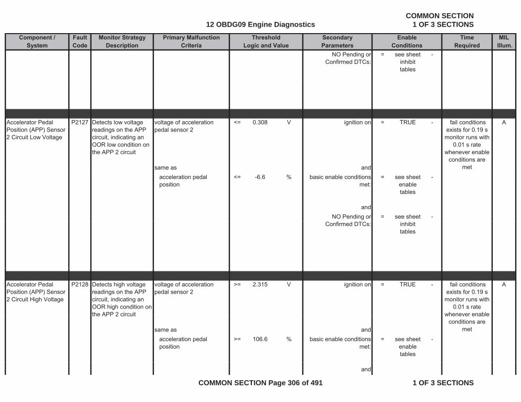
Component / Fault Monitor Strategy Primary Malfunction Secondary Time MILSystem Code Description Criteria Parameters Required Illum.
Threshold EnableLogic and Value Conditions
NO Pending or Confirmed DTCs:
= see sheet inhibit tables
-
Accelerator Pedal P2127 Detects low voltage voltage of acceleration <= 0.308 V ignition on = TRUE - A fail conditions Position (APP) Sensor 2 Circuit Low Voltage
readings on the APP circuit, indicating an OOR low condition on the APP 2 circuit
pedal sensor 2
same as and
exists for 0.19 s monitor runs with
0.01 s rate whenever enable
conditions are met
acceleration pedal position
<= -6.6 % basic enable conditions met:
= see sheet enable tables
-
andNO Pending or = see sheet -
Confirmed DTCs: inhibit tables
Accelerator Pedal Position (APP) Sensor 2 Circuit High Voltage
P2128 Detects high voltage readings on the APP circuit, indicating an OOR high condition on the APP 2 circuit
voltage of acceleration pedal sensor 2
>= 2.315 V ignition on = TRUE - A fail conditions exists for 0.19 s
monitor runs with 0.01 s rate
whenever enablethe APP 2 circuit
same as andacceleration pedal position
>= 106.6 % basic enable conditions met:
= see sheet enable tables
-
whenever enable conditions are
met
and
12 OBDG09 Engine DiagnosticsCOMMON SECTION
1 OF 3 SECTIONS
COMMON SECTION Page 306 of 491 1 OF 3 SECTIONS
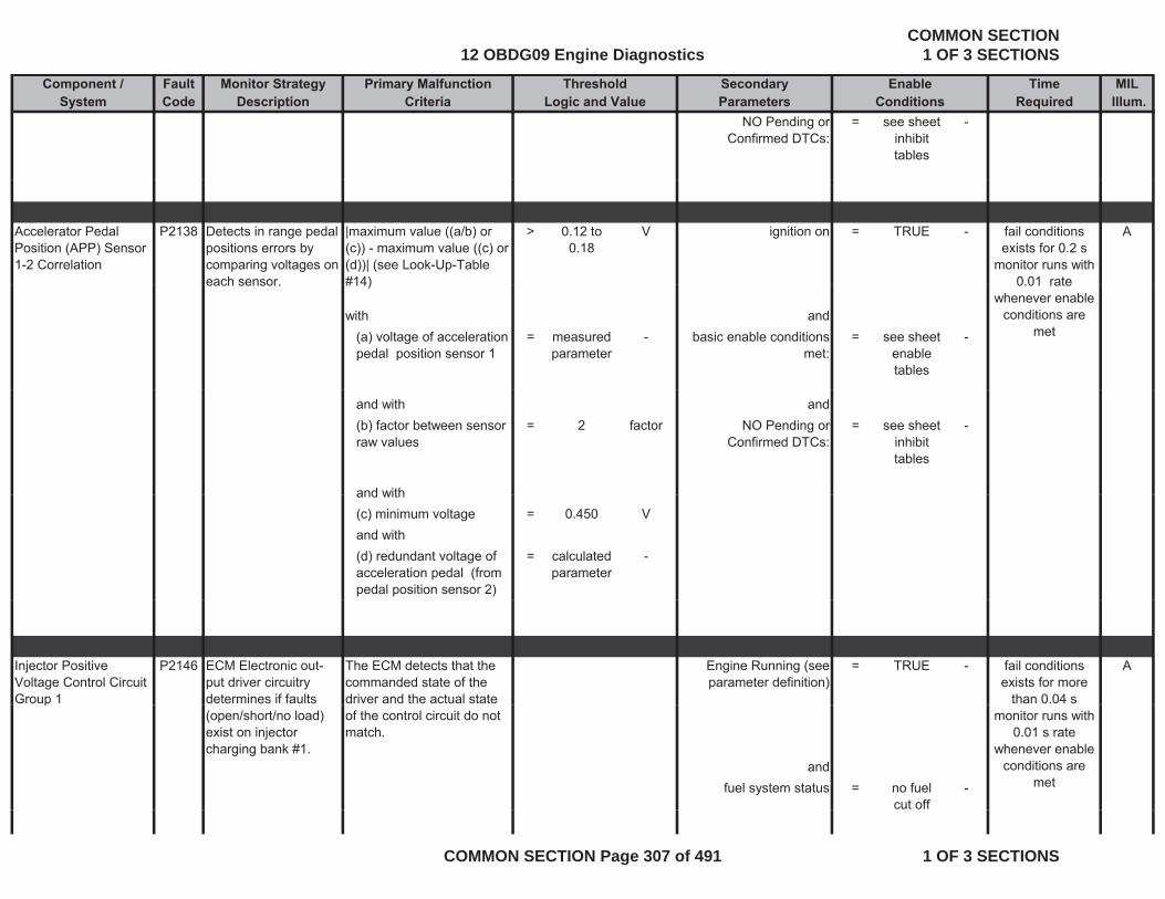
Component / Fault Monitor Strategy Primary Malfunction Secondary Time MILSystem Code Description Criteria Parameters Required Illum.
Threshold EnableLogic and Value Conditions
NO Pending or Confirmed DTCs:
= see sheet inhibit tables
-
Accelerator Pedal Position (APP) Sensor 1-2 Correlation
P2138 Detects in range pedal positions errors by comparing voltages on each sensor
|maximum value ((a/b) or (c)) - maximum value ((c) or (d))| (see Look-Up-Table #14)
> 0.12 to 0.18
V ignition on = TRUE - Afail conditions exists for 0.2 s
monitor runs with 0 01 rateeach sensor. #14)
with and(a) voltage of acceleration pedal position sensor 1
= measured parameter
- basic enable conditions met:
= see sheet enable tables
-
0.01 rate whenever enable
conditions are met
and with and(b) factor between sensor raw values
= 2 factor NO Pending or Confirmed DTCs:
= see sheet inhibit tables
-
and withand with(c) minimum voltage = 0.450 Vand with(d) redundant voltage of acceleration pedal (from pedal position sensor 2)
= calculated parameter
-
Injector Positive Voltage Control Circuit Group 1
P2146 ECM Electronic out-put driver circuitry determines if faults
The ECM detects that the commanded state of the driver and the actual state
Engine Running (see parameter definition)
= TRUE - Afail conditions exists for more
than 0.04 sp(open/short/no load) exist on injector charging bank #1.
of the control circuit do not match.
andfuel system status = no fuel
cut off-
monitor runs with 0.01 s rate
whenever enable conditions are
met
12 OBDG09 Engine DiagnosticsCOMMON SECTION
1 OF 3 SECTIONS
COMMON SECTION Page 307 of 491 1 OF 3 SECTIONS
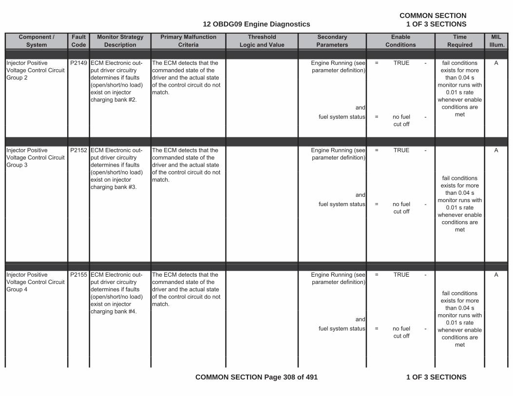
Component / Fault Monitor Strategy Primary Malfunction Secondary Time MILSystem Code Description Criteria Parameters Required Illum.
Threshold EnableLogic and Value Conditions
Injector Positive Voltage Control Circuit Group 2
P2149 ECM Electronic out-put driver circuitry determines if faults
The ECM detects that the commanded state of the driver and the actual state
Engine Running (see parameter definition)
= TRUE - Afail conditions exists for more
than 0 04 sGroup 2 determines if faults (open/short/no load) exist on injector charging bank #2.
driver and the actual state of the control circuit do not match.
andfuel system status = no fuel
cut off-
than 0.04 smonitor runs with
0.01 s rate whenever enable
conditions are met
cut off
Injector Positive Voltage Control Circuit Group 3
P2152 ECM Electronic out-put driver circuitry determines if faults (open/short/no load)
The ECM detects that the commanded state of the driver and the actual state of the control circuit do not
Engine Running (see parameter definition)
= TRUE - A
(open/short/no load) exist on injector charging bank #3.
of the control circuit do not match.
andfuel system status = no fuel
cut off-
fail conditions exists for more
than 0.04 smonitor runs with
0.01 s rate whenever enable
conditions are met
Injector Positive Voltage Control Circuit Group 4
P2155 ECM Electronic out-put driver circuitry determines if faults (open/short/no load) exist on injector charging bank #4
The ECM detects that the commanded state of the driver and the actual state of the control circuit do not match.
Engine Running (see parameter definition)
= TRUE - A
fail conditions exists for more
than 0.04 scharging bank #4.and
fuel system status = no fuel cut off
-
monitor runs with 0.01 s rate
whenever enable conditions are
met
12 OBDG09 Engine DiagnosticsCOMMON SECTION
1 OF 3 SECTIONS
COMMON SECTION Page 308 of 491 1 OF 3 SECTIONS
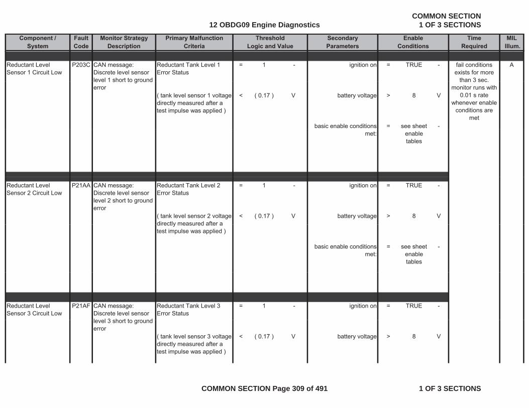
Component / Fault Monitor Strategy Primary Malfunction Secondary Time MILSystem Code Description Criteria Parameters Required Illum.
Threshold EnableLogic and Value Conditions
Reductant Level Sensor 1 Circuit Low
P203C CAN message: Discrete level sensor level 1 short to ground
Reductant Tank Level 1 Error Status
= 1 - ignition on = TRUE - Afail conditions exists for more
than 3 seclevel 1 short to ground error
( tank level sensor 1 voltage directly measured after a test impulse was applied )
< ( 0.17 ) V battery voltage > 8 V
basic enable conditions = see sheet -
than 3 sec.monitor runs with
0.01 s rate whenever enable
conditions are met
met: enable tables
Reductant Level Sensor 2 Circuit Low
P21AA CAN message: Discrete level sensor level 2 short to ground error
Reductant Tank Level 2 Error Status
= 1 - ignition on = TRUE -
( tank level sensor 2 voltage directly measured after a
< ( 0.17 ) V battery voltage > 8 Vdirectly measured after a test impulse was applied )
basic enable conditions met:
= see sheet enable tables
-
Reductant Level Sensor 3 Circuit Low
P21AF CAN message: Discrete level sensor le el 3 short to gro nd
Reductant Tank Level 3 Error Status
= 1 - ignition on = TRUE -
level 3 short to ground error
( tank level sensor 3 voltage directly measured after a test impulse was applied )
< ( 0.17 ) V battery voltage > 8 V
12 OBDG09 Engine DiagnosticsCOMMON SECTION
1 OF 3 SECTIONS
COMMON SECTION Page 309 of 491 1 OF 3 SECTIONS
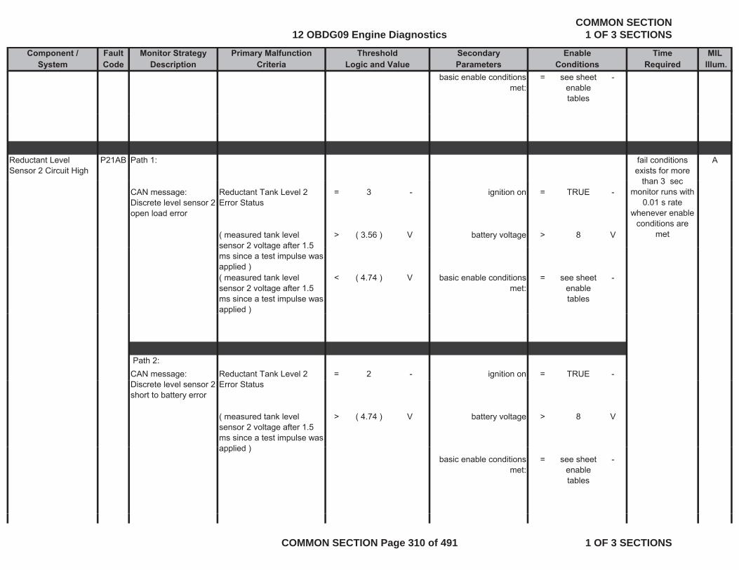
Component / Fault Monitor Strategy Primary Malfunction Secondary Time MILSystem Code Description Criteria Parameters Required Illum.
Threshold EnableLogic and Value Conditions
basic enable conditions met:
= see sheet enable tables
-
Reductant Level Sensor 2 Circuit High
P21AB Path 1: Afail conditions exists for more
than 3 secCAN message: Discrete level sensor 2 open load error
Reductant Tank Level 2 Error Status
= 3 - ignition on = TRUE -
( measured tank level sensor 2 voltage after 1 5
> ( 3.56 ) V battery voltage > 8 V
than 3 sec monitor runs with
0.01 s rate whenever enable
conditions are met
sensor 2 voltage after 1.5 ms since a test impulse was applied )( measured tank level sensor 2 voltage after 1.5 ms since a test impulse was applied )
< ( 4.74 ) V basic enable conditions met:
= see sheet enable tables
-
pp )
Path 2:CAN message: Reductant Tank Level 2 = 2 - ignition on = TRUE -Discrete level sensor 2 short to battery error
Error Status
( measured tank level sensor 2 voltage after 1.5 ms since a test impulse was applied )
> ( 4.74 ) V battery voltage > 8 V
applied )basic enable conditions
met:= see sheet
enable tables
-
12 OBDG09 Engine DiagnosticsCOMMON SECTION
1 OF 3 SECTIONS
COMMON SECTION Page 310 of 491 1 OF 3 SECTIONS
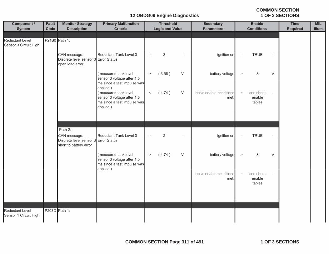
Component / Fault Monitor Strategy Primary Malfunction Secondary Time MILSystem Code Description Criteria Parameters Required Illum.
Threshold EnableLogic and Value Conditions
Reductant Level Sensor 3 Circuit High
P21B0 Path 1:
CAN message: Discrete level sensor 3 open load error
Reductant Tank Level 3 Error Status
= 3 - ignition on = TRUE -
( measured tank level sensor 3 voltage after 1.5
> ( 3.56 ) V battery voltage > 8 Vg
ms since a test impulse was applied )( measured tank level sensor 3 voltage after 1.5 ms since a test impulse was applied )
< ( 4.74 ) V basic enable conditions met:
= see sheet enable tables
-
Path 2:CAN message: Discrete level sensor 3
Reductant Tank Level 3 Error Status
= 2 - ignition on = TRUE -Discrete level sensor 3 short to battery error
Error Status
( measured tank level sensor 3 voltage after 1.5 ms since a test impulse was applied )
> ( 4.74 ) V battery voltage > 8 V
applied )basic enable conditions
met:= see sheet
enable tables
-
Reductant Level Sensor 1 Circuit High
P203D Path 1:
12 OBDG09 Engine DiagnosticsCOMMON SECTION
1 OF 3 SECTIONS
COMMON SECTION Page 311 of 491 1 OF 3 SECTIONS
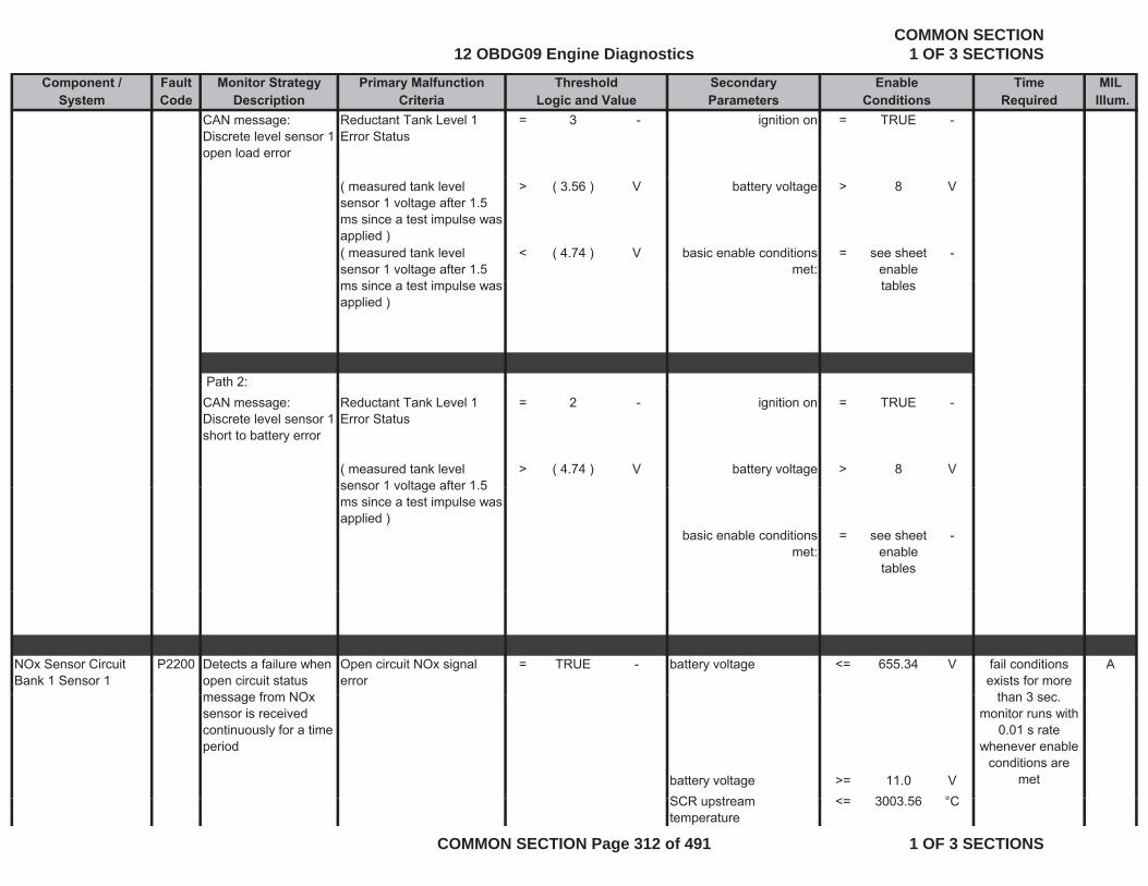
Component / Fault Monitor Strategy Primary Malfunction Secondary Time MILSystem Code Description Criteria Parameters Required Illum.
Threshold EnableLogic and Value Conditions
CAN message: Discrete level sensor 1 open load error
Reductant Tank Level 1 Error Status
= 3 - ignition on = TRUE -
( measured tank level sensor 1 voltage after 1.5 ms since a test impulse was applied )
> ( 3.56 ) V battery voltage > 8 V
( measured tank level sensor 1 voltage after 1.5
< ( 4.74 ) V basic enable conditions met:
= see sheet enable
-
ms since a test impulse was applied )
tables
Path 2: Path 2:CAN message: Discrete level sensor 1 short to battery error
Reductant Tank Level 1 Error Status
= 2 - ignition on = TRUE -
( measured tank level sensor 1 voltage after 1 5
> ( 4.74 ) V battery voltage > 8 Vsensor 1 voltage after 1.5 ms since a test impulse was applied )
basic enable conditions met:
= see sheet enable tables
-
NOx Sensor Circuit Bank 1 Sensor 1
P2200 Detects a failure when open circuit status message from NO
Open circuit NOx signal error
= TRUE - battery voltage <= 655.34 V Afail conditions exists for more
than 3 secmessage from NOx sensor is received continuously for a time period
battery voltage >= 11.0 VSCR t < 3003 56 °C
than 3 sec.monitor runs with
0.01 s rate whenever enable
conditions are met
SCR upstream temperature
<= 3003.56 °C
12 OBDG09 Engine DiagnosticsCOMMON SECTION
1 OF 3 SECTIONS
COMMON SECTION Page 312 of 491 1 OF 3 SECTIONS
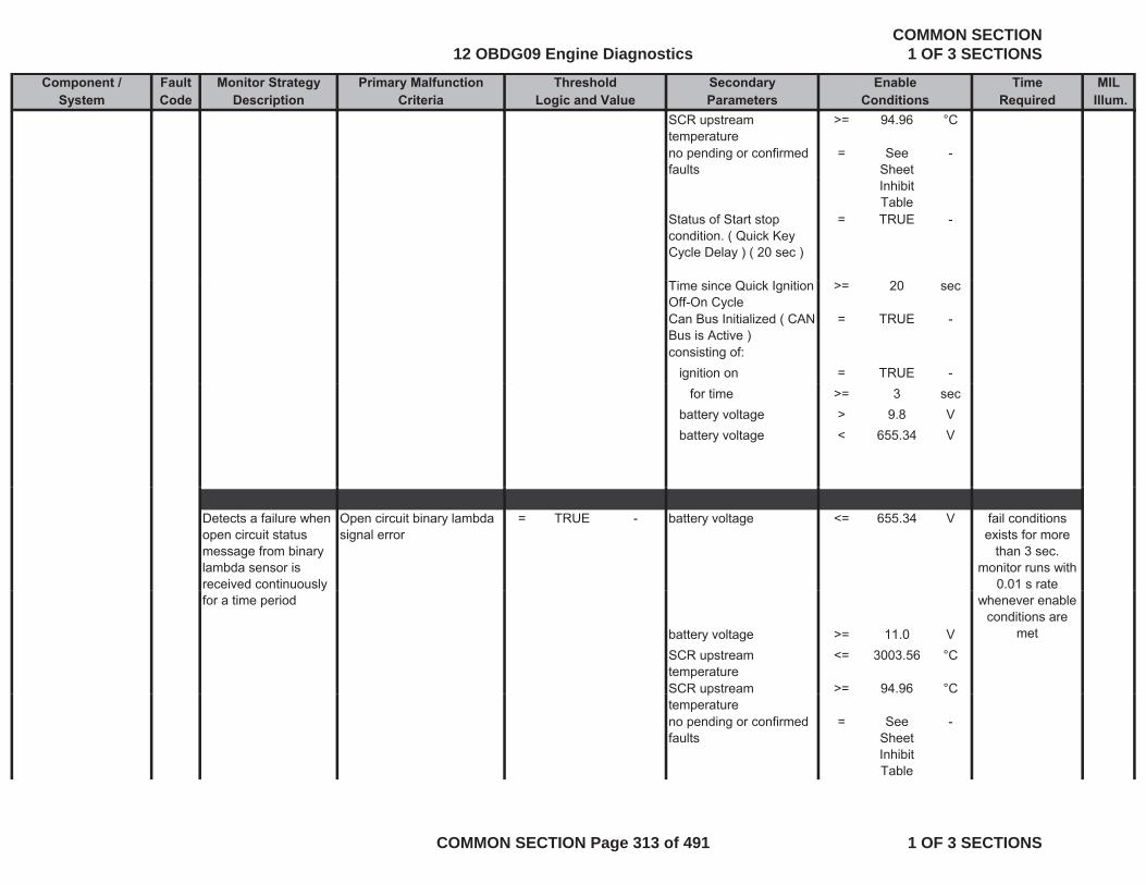
Component / Fault Monitor Strategy Primary Malfunction Secondary Time MILSystem Code Description Criteria Parameters Required Illum.
Threshold EnableLogic and Value Conditions
SCR upstream temperature
>= 94.96 °C
no pending or confirmed faults
= See Sheet
-
Inhibit Table
Status of Start stop condition. ( Quick Key Cycle Delay ) ( 20 sec )
= TRUE -
Time since Quick Ignition Off-On Cycle
>= 20 sec
Can Bus Initialized ( CAN Bus is Active )
= TRUE -
consisting of:ignition on = TRUE -
for time >= 3 secbattery voltage > 9.8 Vbattery voltage < 655.34 V
Detects a failure when open circuit status message from binary lambda sensor is received continuously
Open circuit binary lambda signal error
= TRUE - battery voltage <= 655.34 V fail conditions exists for more
than 3 sec.monitor runs with
0.01 s rate yfor a time period
battery voltage >= 11.0 VSCR upstream temperature
<= 3003.56 °C
SCR upstream >= 94.96 °C
whenever enable conditions are
met
ptemperatureno pending or confirmed faults
= See Sheet Inhibit Table
-
12 OBDG09 Engine DiagnosticsCOMMON SECTION
1 OF 3 SECTIONS
COMMON SECTION Page 313 of 491 1 OF 3 SECTIONS
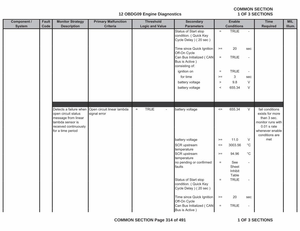
Component / Fault Monitor Strategy Primary Malfunction Secondary Time MILSystem Code Description Criteria Parameters Required Illum.
Threshold EnableLogic and Value Conditions
Status of Start stop condition. ( Quick Key Cycle Delay ) ( 20 sec )
= TRUE -
Time since Quick Ignition Off-On Cycle
>= 20 sec
Can Bus Initialized ( CAN Bus is Active )
= TRUE -
consisting of:ignition on = TRUE -g
for time >= 3 secbattery voltage > 9.8 Vbattery voltage < 655.34 V
Detects a failure when open circuit status message from linear lambda sensor is received continuously
Open circuit linear lambda signal error
= TRUE - battery voltage <= 655.34 V fail conditions exists for more
than 3 sec.monitor runs with
0 01 s ratereceived continuously for a time period
battery voltage >= 11.0 VSCR upstream temperature
<= 3003.56 °C
SCR upstream >= 94 96 °C
0.01 s rate whenever enable
conditions are met
SCR upstream temperature
>= 94.96 C
no pending or confirmed faults
= See Sheet Inhibit Table
-
Status of Start stop = TRUE -pcondition. ( Quick Key Cycle Delay ) ( 20 sec )
Time since Quick Ignition Off-On Cycle
>= 20 sec
Can Bus Initialized ( CAN = TRUE -Bus is Active )
12 OBDG09 Engine DiagnosticsCOMMON SECTION
1 OF 3 SECTIONS
COMMON SECTION Page 314 of 491 1 OF 3 SECTIONS

Component / Fault Monitor Strategy Primary Malfunction Secondary Time MILSystem Code Description Criteria Parameters Required Illum.
Threshold EnableLogic and Value Conditions
consisting of:ignition on = TRUE -
for time >= 3 secbattery voltage > 9.8 Vbattery voltage < 655.34 V
Detects a failure when short circuit status message from NOx sensor is received continuously for a time period
Short Circuit Nox signal error
= TRUE - battery voltage >= 11.0 V fail conditions exists for more
than 3 sec.monitor runs with
0.01 s rate whenever enable
conditions areSCR upstream temperature
<= 3003.56 °C
SCR upstream temperature
>= 94.96 °C
no pending or confirmed faults
= See Sheet
-
conditions are met
faults Sheet Inhibit Table
Status of Start stop condition. ( Quick Key Cycle Delay ) ( 20 sec )
= TRUE -
Time since Quick Ignition Off-On Cycle
>= 20 sec
Can Bus Initialized ( CAN Bus is Active )
= TRUE -
consisting of:ignition on = TRUE -g
for time >= 3 secbattery voltage > 9.8 Vbattery voltage < 655.34 V
12 OBDG09 Engine DiagnosticsCOMMON SECTION
1 OF 3 SECTIONS
COMMON SECTION Page 315 of 491 1 OF 3 SECTIONS
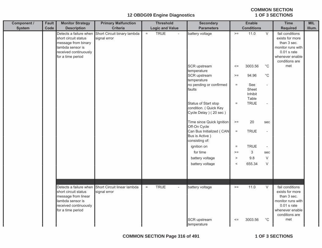
Component / Fault Monitor Strategy Primary Malfunction Secondary Time MILSystem Code Description Criteria Parameters Required Illum.
Threshold EnableLogic and Value Conditions
Detects a failure when short circuit status message from binary lambda sensor is
Short Circuit binary lambda signal error
= TRUE - battery voltage >= 11.0 V fail conditions exists for more
than 3 sec.monitor runs with
received continuously for a time period
SCR upstream temperature
<= 3003.56 °C
SCR upstream >= 94.96 °C
0.01 s rate whenever enable
conditions are met
temperatureno pending or confirmed faults
= See Sheet Inhibit Table
-
Status of Start stop condition ( Quick Key
= TRUE -condition. ( Quick Key Cycle Delay ) ( 20 sec )
Time since Quick Ignition Off-On Cycle
>= 20 sec
Can Bus Initialized ( CAN Bus is Active )
= TRUE -Bus is Active )consisting of:
ignition on = TRUE -for time >= 3 sec
battery voltage > 9.8 Vbattery voltage < 655.34 Vy g
Detects a failure when short circuit status
Short Circuit linear lambda signal error
= TRUE - battery voltage >= 11.0 V fail conditions exists for more
message from linear lambda sensor is received continuously for a time period
SCR upstream t t
<= 3003.56 °C
than 3 sec.monitor runs with
0.01 s rate whenever enable
conditions are met
temperature
12 OBDG09 Engine DiagnosticsCOMMON SECTION
1 OF 3 SECTIONS
COMMON SECTION Page 316 of 491 1 OF 3 SECTIONS
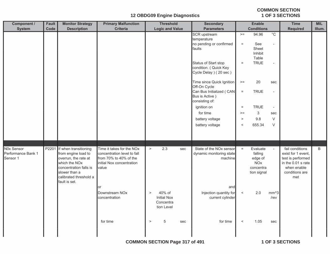
Component / Fault Monitor Strategy Primary Malfunction Secondary Time MILSystem Code Description Criteria Parameters Required Illum.
Threshold EnableLogic and Value Conditions
SCR upstream temperature
>= 94.96 °C
no pending or confirmed faults
= See Sheet
-
Inhibit Table
Status of Start stop condition. ( Quick Key Cycle Delay ) ( 20 sec )
= TRUE -
Time since Quick Ignition Off-On Cycle
>= 20 sec
Can Bus Initialized ( CAN Bus is Active )
= TRUE -
consisting of:ignition on = TRUE -
for time >= 3 secbattery voltage > 9.8 Vbattery voltage < 655.34 V
N0x Sensor Performance Bank 1 Sensor 1
P2201 If when transitioning from engine load to overrun, the rate at which the NOx concentration falls is
Time it takes for the NOx concentration level to fall from 70% to 40% of the initial Nox concentration value
> 2.3 sec State of the NOx sensor dynamic monitoring state
machine
= Evaluate falling
edge of NOx
concentra
- Bfail conditions exist for 1 event, test is performed in the 0.01 s rate
when enable slower than a calibrated threshold a fault is set.
tion signal
or andDownstream NOx concentration
> 40% of Initial Nox
Injection quantity for current cylinder
< 2.0 mm^3/rev
conditions are met
Concentration Level
y
for time > 5 sec for time < 1.05 sec
12 OBDG09 Engine DiagnosticsCOMMON SECTION
1 OF 3 SECTIONS
COMMON SECTION Page 317 of 491 1 OF 3 SECTIONS
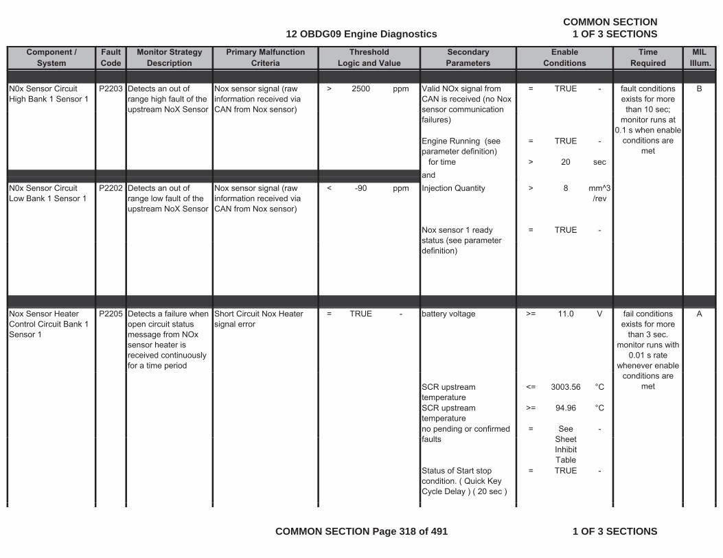
Component / Fault Monitor Strategy Primary Malfunction Secondary Time MILSystem Code Description Criteria Parameters Required Illum.
Threshold EnableLogic and Value Conditions
N0x Sensor Circuit High Bank 1 Sensor 1
P2203 Detects an out of range high fault of the upstream NoX Sensor
Nox sensor signal (raw information received via CAN from Nox sensor)
> 2500 ppm Valid NOx signal from CAN is received (no Nox sensor communication
= TRUE - Bfault conditions exists for more than 10 sec;upstream NoX Sensor CAN from Nox sensor) sensor communication
failures)
Engine Running (see parameter definition)
= TRUE -
for time > 20 secand
than 10 sec; monitor runs at
0.1 s when enable conditions are
met
andN0x Sensor Circuit Low Bank 1 Sensor 1
P2202 Detects an out of range low fault of the upstream NoX Sensor
Nox sensor signal (raw information received via CAN from Nox sensor)
< -90 ppm Injection Quantity > 8 mm^3/rev
Nox sensor 1 ready status (see parameter
= TRUE -status (see parameter definition)
Nox Sensor Heater Control Circuit Bank 1 Sensor 1
P2205 Detects a failure when open circuit status message from NOx sensor heater is received continuously for a time period
Short Circuit Nox Heater signal error
= TRUE - battery voltage >= 11.0 V Afail conditions exists for more
than 3 sec.monitor runs with
0.01 s rate whenever enable
SCR upstream temperature
<= 3003.56 °C
SCR upstream temperature
>= 94.96 °C
no pending or confirmed f lt
= See Sh t
-
conditions are met
faults Sheet Inhibit Table
Status of Start stop condition. ( Quick Key Cycle Delay ) ( 20 sec )
= TRUE -
12 OBDG09 Engine DiagnosticsCOMMON SECTION
1 OF 3 SECTIONS
COMMON SECTION Page 318 of 491 1 OF 3 SECTIONS

Component / Fault Monitor Strategy Primary Malfunction Secondary Time MILSystem Code Description Criteria Parameters Required Illum.
Threshold EnableLogic and Value Conditions
Time since Quick Ignition Off-On Cycle
>= 20 sec
Can Bus Initialized ( CAN Bus is Active )
= TRUE -)
consisting of:ignition on = TRUE -
for time >= 3 secbattery voltage > 9.8 Vbattery voltage < 655.34 V
Detects a failure when short circuit status message from NOx
Short Circuit Nox heater lambda signal error
= TRUE - battery voltage >= 11.0 V fail conditions exists for more
than 3 secmessage from NOx sensor heater is received continuously for a time period
SCR upstream temperature
<= 3003.56 °C
than 3 sec.monitor runs with
0.01 s rate whenever enable
conditions are met
temperatureSCR upstream temperature
>= 94.96 °C
no pending or confirmed faults
= See Sheet Inhibit Table
-
Status of Start stop condition. ( Quick Key Cycle Delay ) ( 20 sec )
= TRUE -
Time since Quick Ignition Off-On Cycle
>= 20 sec
Can Bus Initialized ( CAN Bus is Active )
= TRUE -
consisting of:ignition on = TRUE -
for time >= 3 secbattery voltage > 9 8 Vbattery voltage > 9.8 Vbattery voltage < 655.34 V
12 OBDG09 Engine DiagnosticsCOMMON SECTION
1 OF 3 SECTIONS
COMMON SECTION Page 319 of 491 1 OF 3 SECTIONS
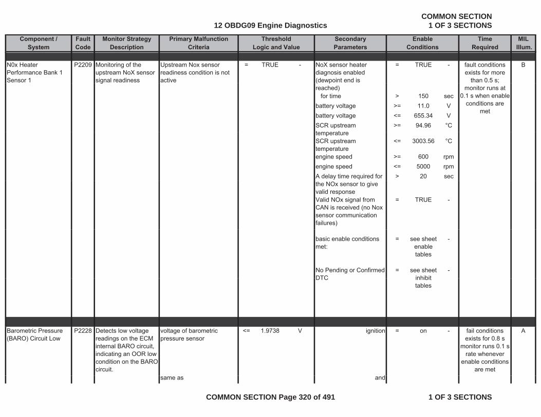
Component / Fault Monitor Strategy Primary Malfunction Secondary Time MILSystem Code Description Criteria Parameters Required Illum.
Threshold EnableLogic and Value Conditions
N0x Heater Performance Bank 1 Sensor 1
P2209 Monitoring of the upstream NoX sensor signal readiness
Upstream Nox sensor readiness condition is not active
= TRUE - NoX sensor heater diagnosis enabled (dewpoint end is
= TRUE - Bfault conditions exists for more
than 0.5 s; g ( preached)
for time > 150 secbattery voltage >= 11.0 Vbattery voltage <= 655.34 VSCR upstream t t
>= 94.96 °C
;monitor runs at
0.1 s when enable conditions are
met
temperatureSCR upstream temperature
<= 3003.56 °C
engine speed >= 600 rpmengine speed <= 5000 rpmA delay time required for > 20 secthe NOx sensor to give valid responseValid NOx signal from CAN is received (no Nox sensor communication failures)
= TRUE -
basic enable conditions met:
= see sheet enable tables
-
No Pending or Confirmed DTC
= see sheet inhibit
-DTC inhibit
tables
Barometric Pressure (BARO) Circuit Low
P2228 Detects low voltage readings on the ECM internal BARO circuit, indicating an OOR low condition on the BARO circuit.
voltage of barometric pressure sensor
<= 1.9738 V ignition = on - A
d
fail conditions exists for 0.8 s
monitor runs 0.1 s rate whenever
enable conditions are met
same as and
12 OBDG09 Engine DiagnosticsCOMMON SECTION
1 OF 3 SECTIONS
COMMON SECTION Page 320 of 491 1 OF 3 SECTIONS
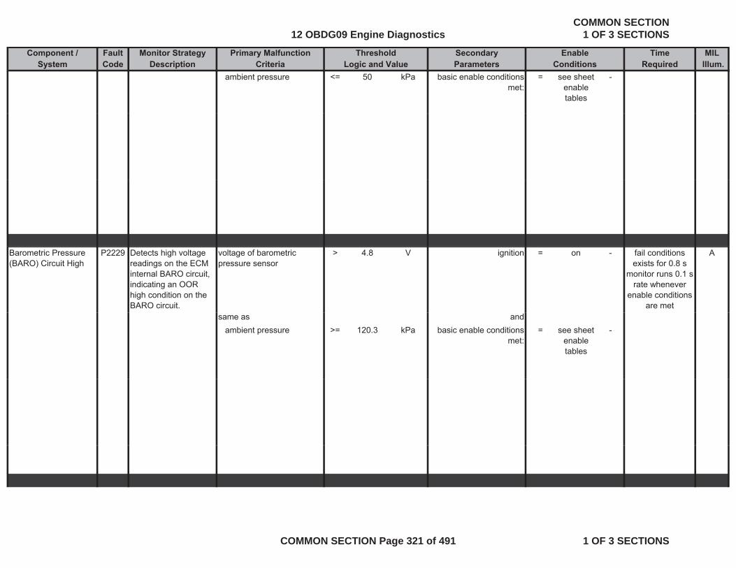
Component / Fault Monitor Strategy Primary Malfunction Secondary Time MILSystem Code Description Criteria Parameters Required Illum.
Threshold EnableLogic and Value Conditions
ambient pressure <= 50 kPa basic enable conditions met:
= see sheet enable tables
-
Barometric Pressure (BARO) Circuit High
P2229 Detects high voltage readings on the ECM internal BARO circuit, indicating an OOR high condition on the BARO circuit.
voltage of barometric pressure sensor
> 4.8 V ignition = on - Afail conditions exists for 0.8 s
monitor runs 0.1 s rate whenever
enable conditions are met
same as andambient pressure >= 120.3 kPa basic enable conditions
met:= see sheet
enable tables
-
12 OBDG09 Engine DiagnosticsCOMMON SECTION
1 OF 3 SECTIONS
COMMON SECTION Page 321 of 491 1 OF 3 SECTIONS
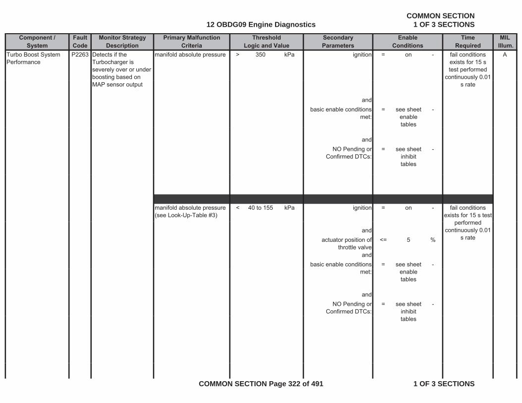
Component / Fault Monitor Strategy Primary Malfunction Secondary Time MILSystem Code Description Criteria Parameters Required Illum.
Threshold EnableLogic and Value Conditions
Turbo Boost System Performance
P2263 Detects if the Turbocharger is severely over or under boosting based on
manifold absolute pressure > 350 kPa ignition = on - Afail conditions exists for 15 s test performed
continuously 0.01 MAP sensor output
andbasic enable conditions
met:= see sheet
enable tables
-
s rate
andNO Pending or
Confirmed DTCs:= see sheet
inhibit tables
-
manifold absolute pressure (see Look-Up-Table #3)
< 40 to 155 kPa ignition = on - fail conditions exists for 15 s test
performedand
actuator position of throttle valve
<= 5 %
andbasic enable conditions = see sheet -
performed continuously 0.01
s rate
met: enable tables
andNO Pending or
Confirmed DTCs:= see sheet
inhibit -
tables
12 OBDG09 Engine DiagnosticsCOMMON SECTION
1 OF 3 SECTIONS
COMMON SECTION Page 322 of 491 1 OF 3 SECTIONS
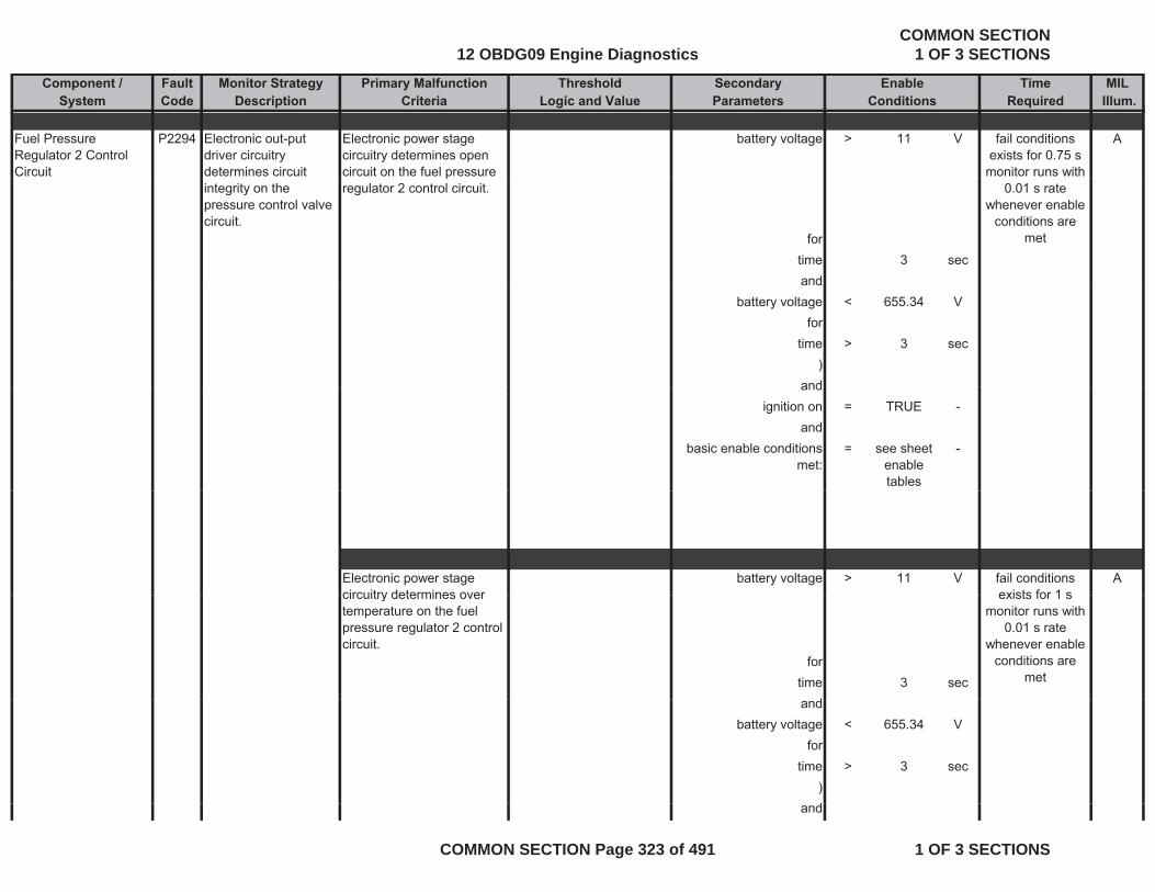
Component / Fault Monitor Strategy Primary Malfunction Secondary Time MILSystem Code Description Criteria Parameters Required Illum.
Threshold EnableLogic and Value Conditions
Fuel Pressure Regulator 2 Control Circuit
P2294 Electronic out-put driver circuitry determines circuit
Electronic power stage circuitry determines open circuit on the fuel pressure
battery voltage > 11 V Afail conditions exists for 0.75 s
monitor runs with integrity on the pressure control valve circuit.
pregulator 2 control circuit.
fortime 3 secand
0.01 s rate whenever enable
conditions are met
andbattery voltage < 655.34 V
fortime > 3 sec
)andand
ignition on = TRUE -and
basic enable conditions met:
= see sheet enable tables
-
Electronic power stage circuitry determines over
battery voltage > 11 V Afail conditions exists for 1 scircuitry determines over
temperature on the fuel pressure regulator 2 control circuit.
fortime 3 sec
d
exists for 1 s monitor runs with
0.01 s rate whenever enable
conditions are met
andbattery voltage < 655.34 V
fortime > 3 sec
)dand
12 OBDG09 Engine DiagnosticsCOMMON SECTION
1 OF 3 SECTIONS
COMMON SECTION Page 323 of 491 1 OF 3 SECTIONS
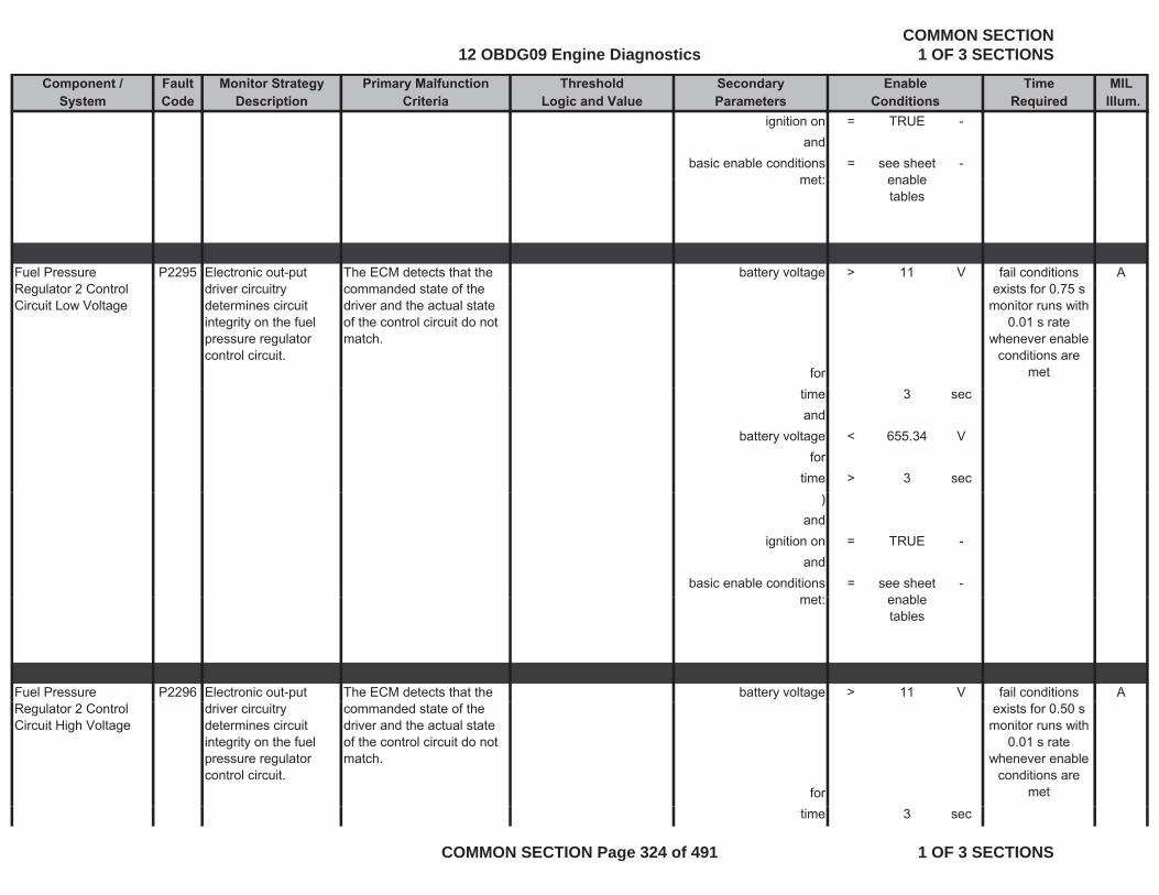
Component / Fault Monitor Strategy Primary Malfunction Secondary Time MILSystem Code Description Criteria Parameters Required Illum.
Threshold EnableLogic and Value Conditions
ignition on = TRUE -and
basic enable conditions met:
= see sheet enable
-met: enable
tables
Fuel Pressure P2295 Electronic out-put The ECM detects that the battery voltage > 11 V Afail conditions Regulator 2 Control Circuit Low Voltage
driver circuitry determines circuit integrity on the fuel pressure regulator control circuit.
commanded state of the driver and the actual state of the control circuit do not match.
for
exists for 0.75 s monitor runs with
0.01 s rate whenever enable
conditions are met
time 3 secand
battery voltage < 655.34 Vfor
time > 3 sec)
andignition on = TRUE -
andbasic enable conditions
t= see sheet
bl-
met: enable tables
Fuel Pressure P2296 Electronic out-put The ECM detects that the battery voltage > 11 V Afail conditions Regulator 2 Control Circuit High Voltage
driver circuitry determines circuit integrity on the fuel pressure regulator control circuit.
commanded state of the driver and the actual state of the control circuit do not match.
for
exists for 0.50 s monitor runs with
0.01 s rate whenever enable
conditions are met
time 3 sec
12 OBDG09 Engine DiagnosticsCOMMON SECTION
1 OF 3 SECTIONS
COMMON SECTION Page 324 of 491 1 OF 3 SECTIONS
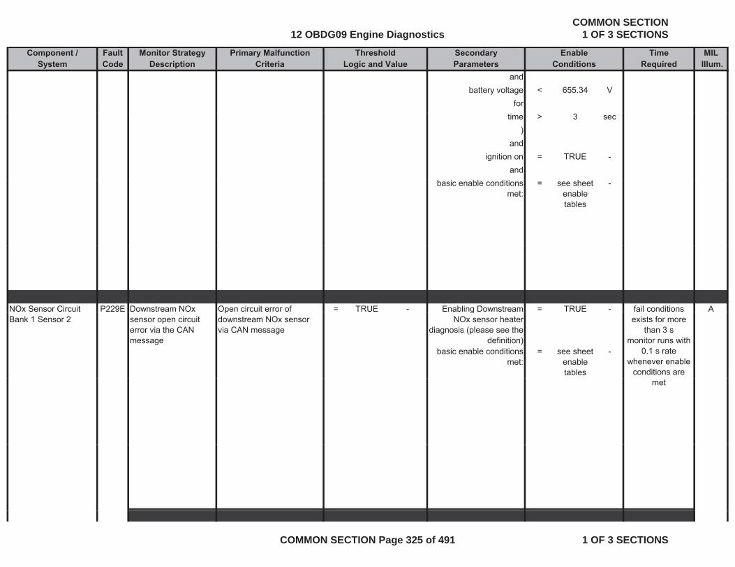
Component / Fault Monitor Strategy Primary Malfunction Secondary Time MILSystem Code Description Criteria Parameters Required Illum.
Threshold EnableLogic and Value Conditions
andbattery voltage < 655.34 V
fortime > 3 sec
)and
ignition on = TRUE -and
basic enable conditions met:
= see sheet enable tables
-
NOx Sensor Circuit P229E Downstream NOx Open circuit error of = TRUE - Enabling Downstream = TRUE - Afail conditions Bank 1 Sensor 2 sensor open circuit
error via the CAN message
pdownstream NOx sensor via CAN message
gNOx sensor heater
diagnosis (please see the definition)
basic enable conditions met:
= see sheet enable tables
-
exists for more than 3 s
monitor runs with 0.1 s rate
whenever enable conditions are
met
12 OBDG09 Engine DiagnosticsCOMMON SECTION
1 OF 3 SECTIONS
COMMON SECTION Page 325 of 491 1 OF 3 SECTIONS
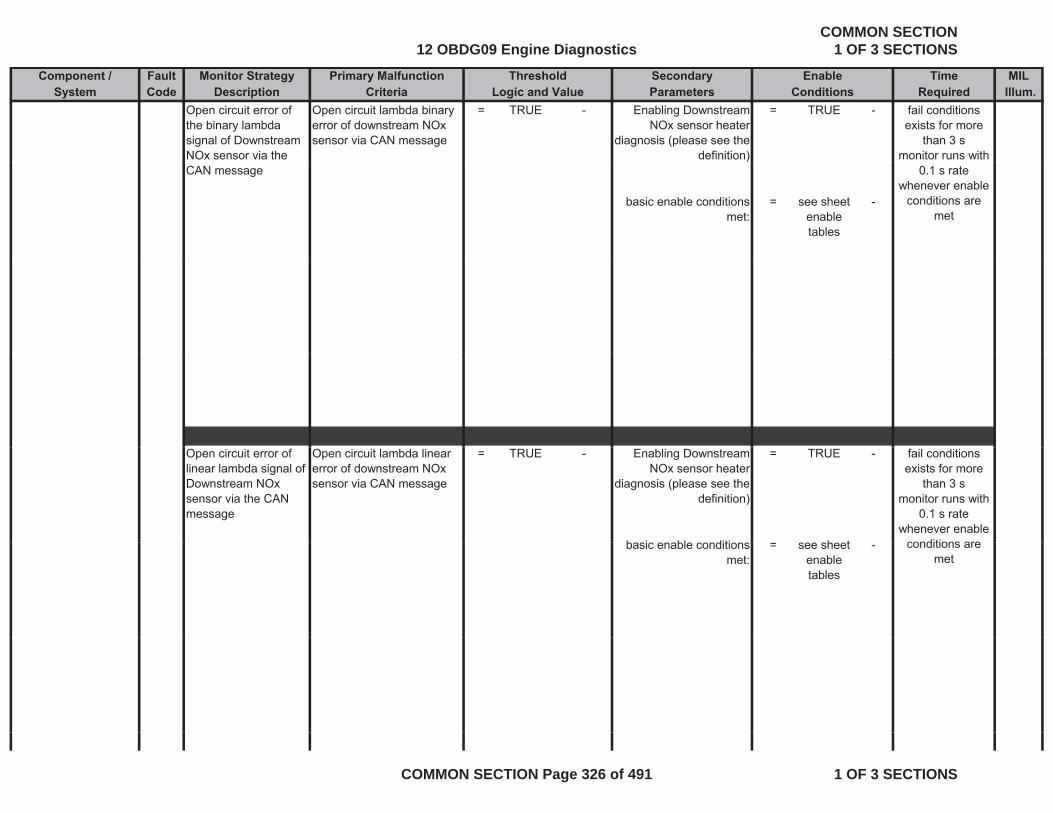
Component / Fault Monitor Strategy Primary Malfunction Secondary Time MILSystem Code Description Criteria Parameters Required Illum.
Threshold EnableLogic and Value Conditions
Open circuit error of the binary lambda signal of Downstream NOx sensor via the
Open circuit lambda binary error of downstream NOx sensor via CAN message
= TRUE - Enabling Downstream NOx sensor heater
diagnosis (please see the definition)
= TRUE - fail conditions exists for more
than 3 smonitor runs with
CAN message
basic enable conditions met:
= see sheet enable tables
-
0.1 s rate whenever enable
conditions are met
Open circuit error of linear lambda signal of Downstream NOx sensor via the CAN message
Open circuit lambda linear error of downstream NOx sensor via CAN message
= TRUE - Enabling Downstream NOx sensor heater
diagnosis (please see the definition)
= TRUE -
b i bl diti h t
fail conditions exists for more
than 3 smonitor runs with
0.1 s rate whenever enable
conditions arebasic enable conditions met:
= see sheet enable tables
- conditions are met
12 OBDG09 Engine DiagnosticsCOMMON SECTION
1 OF 3 SECTIONS
COMMON SECTION Page 326 of 491 1 OF 3 SECTIONS

Component / Fault Monitor Strategy Primary Malfunction Secondary Time MILSystem Code Description Criteria Parameters Required Illum.
Threshold EnableLogic and Value Conditions
Downstream NOx sensor short circuit error via the CAN
Short circuit NOx signal error of downstream NOx sensor via CAN message
= TRUE - Enabling Downstream NOx sensor heater
diagnosis (please see the
= TRUE - fail conditions exists for more
than 3 serror via the CAN message
sensor via CAN message diagnosis (please see the definition)
basic enable conditions met:
= see sheet enable tables
-
than 3 smonitor runs with
0.1 s rate whenever enable
conditions are met
Short circuit error of Short circuit lambda binary = TRUE - Enabling Downstream = TRUE - fail conditions binary lambda signal of Downstream NOx sensor via the CAN message
yerror of downstream NOx sensor via CAN message
gNOx sensor heater
diagnosis (please see the definition)
basic enable conditions = see sheet -
exists for more than 3 s
monitor runs with 0.1 s rate
whenever enable conditions are
met: enable tables
met
12 OBDG09 Engine DiagnosticsCOMMON SECTION
1 OF 3 SECTIONS
COMMON SECTION Page 327 of 491 1 OF 3 SECTIONS
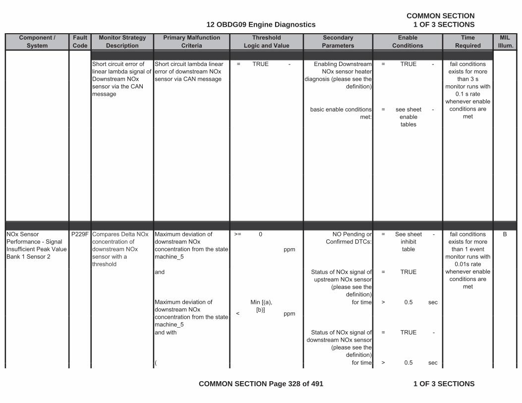
Component / Fault Monitor Strategy Primary Malfunction Secondary Time MILSystem Code Description Criteria Parameters Required Illum.
Threshold EnableLogic and Value Conditions
Short circuit error of linear lambda signal of Downstream NOx
Short circuit lambda linear error of downstream NOx sensor via CAN message
= TRUE - Enabling Downstream NOx sensor heater
diagnosis (please see the
= TRUE - fail conditions exists for more
than 3 sDownstream NOx sensor via the CAN message
sensor via CAN message diagnosis (please see the definition)
basic enable conditions met:
= see sheet enable tables
-
than 3 smonitor runs with
0.1 s rate whenever enable
conditions are met
NOx Sensor Performance - Signal Insufficient Peak Value Bank 1 Sensor 2
P229F Compares Delta NOx concentration of downstream NOx sensor with a threshold
Maximum deviation of downstream NOx concentration from the state machine_5
>= 0
ppm
NO Pending or Confirmed DTCs:
= See sheetinhibit table
- Bfail conditions exists for more than 1 event
monitor runs with 0.01s rate
and Status of NOx signal of upstream NOx sensor
(please see the definition)
= TRUE
Maximum deviation of downstream NOx concentration from the state <
Min [(a), [b)] ppm
for time > 0.5 sec
whenever enable conditions are
met
concentration from the state machine_5
pp
and with Status of NOx signal of downstream NOx sensor
(please see the definition)
= TRUE -
( for time > 0 5 sec( for time > 0.5 sec
12 OBDG09 Engine DiagnosticsCOMMON SECTION
1 OF 3 SECTIONS
COMMON SECTION Page 328 of 491 1 OF 3 SECTIONS
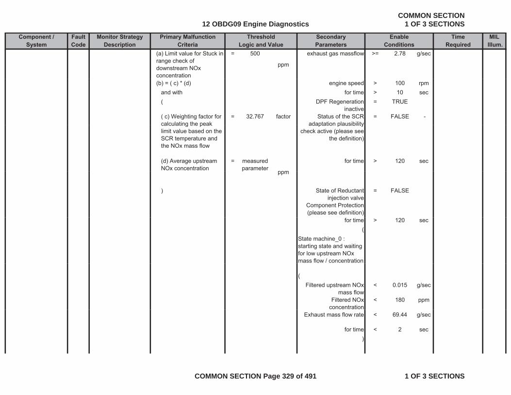
Component / Fault Monitor Strategy Primary Malfunction Secondary Time MILSystem Code Description Criteria Parameters Required Illum.
Threshold EnableLogic and Value Conditions
(a) Limit value for Stuck in range check of downstream NOx concentration
= 500
ppm
exhaust gas massflow >= 2.78 g/sec
(b) = ( c) * (d) engine speed > 100 rpmand with for time > 10 sec( DPF Regeneration
inactive= TRUE
( c) Weighting factor for calculating the peak
= 32.767 factor Status of the SCR adaptation plausibility
= FALSE -calculating the peak limit value based on the SCR temperature and the NOx mass flow
adaptation plausibility check active (please see
the definition)
(d) Average upstream NOx concentration
= measured parameter ppm
for time > 120 secp ppm
) State of Reductant injection valve
Component Protection (please see definition)
= FALSE
for time > 120 sec(
State machine_0 : starting state and waiting for low upstream NOx mass flow / concentration
(Filtered upstream NOx
mass flow< 0.015 g/sec
Filtered NOx concentration
< 180 ppm
Exhaust mass flow rate < 69.44 g/sec
for time < 2 sec)
12 OBDG09 Engine DiagnosticsCOMMON SECTION
1 OF 3 SECTIONS
COMMON SECTION Page 329 of 491 1 OF 3 SECTIONS
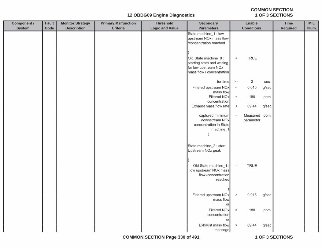
Component / Fault Monitor Strategy Primary Malfunction Secondary Time MILSystem Code Description Criteria Parameters Required Illum.
Threshold EnableLogic and Value Conditions
State machine_1 : low upstream NOx mass flow /concentration reached
(Old State machine_0 : starting state and waiting for low upstream NOx mass flow / concentration
= TRUE
for time >= 2 secFiltered upstream NOx
mass flow< 0.015 g/sec
Filtered NOx concentration
< 180 ppm
Exhaust mass flow rate < 69.44 g/secg
captured minimum downstream NOx
concentration in State machine_1
= Measured parameter
ppm
)
State machine_2 : start Upstream NOx peak
(Old State machine 1 : = TRUE -Old State machine_1 :
low upstream NOx mass flow /concentration
reached
= TRUE -
(Filtered upstream NOx > 0 015 g/secFiltered upstream NOx
mass flow> 0.015 g/sec
orFiltered NOx
concentration> 180 ppm
orE h t fl > 69 44 /Exhaust mass flow
message> 69.44 g/sec
12 OBDG09 Engine DiagnosticsCOMMON SECTION
1 OF 3 SECTIONS
COMMON SECTION Page 330 of 491 1 OF 3 SECTIONS
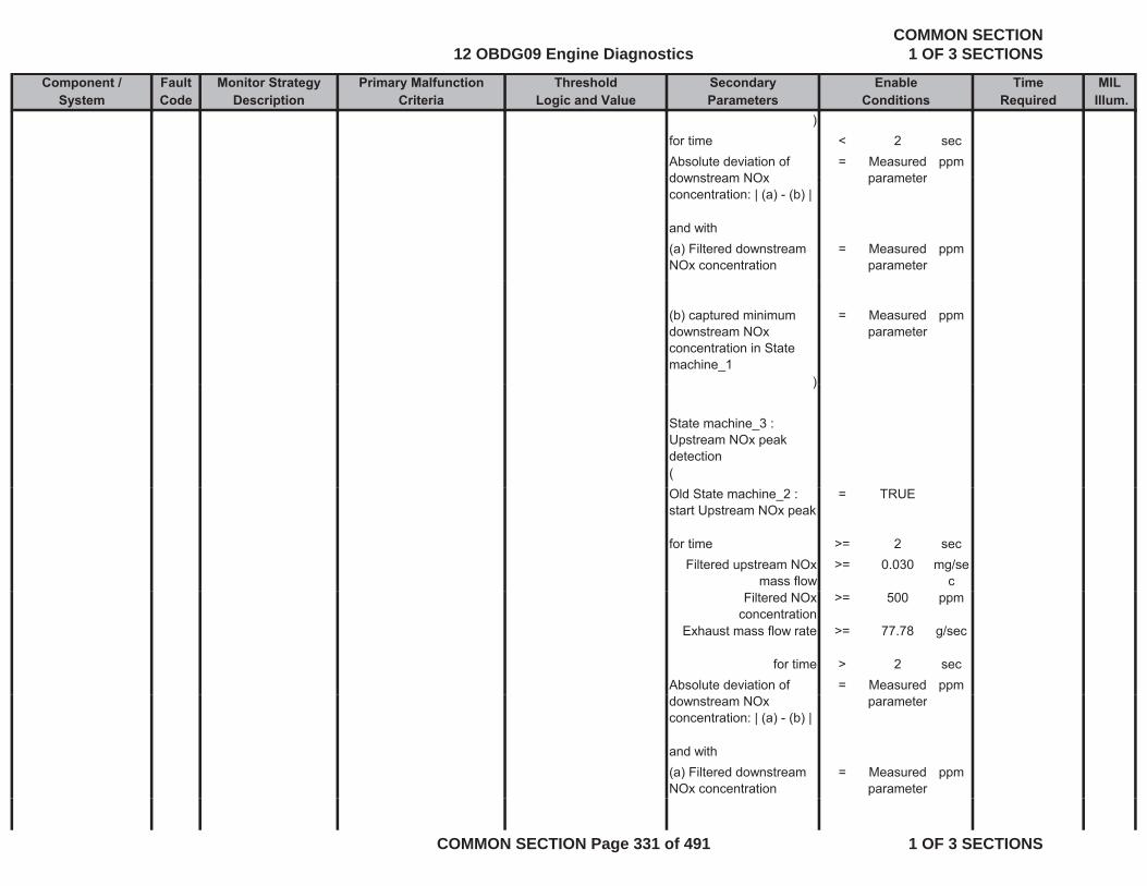
Component / Fault Monitor Strategy Primary Malfunction Secondary Time MILSystem Code Description Criteria Parameters Required Illum.
Threshold EnableLogic and Value Conditions
)for time < 2 secAbsolute deviation of downstream NOx
= Measured parameter
ppmdownstream NOx concentration: | (a) - (b) |
parameter
and with(a) Filtered downstream NOx concentration
= Measured parameter
ppm
(b) captured minimum downstream NOx concentration in State machine_1
= Measured parameter
ppm
))
State machine_3 : Upstream NOx peak detection(Old State machine_2 : start Upstream NOx peak
= TRUE
for time >= 2 secFiltered upstream NOx
mass flow>= 0.030 mg/se
cFiltered NOx
concentration>= 500 ppm
Exhaust mass flow rate >= 77.78 g/sec
for time > 2 secAbsolute deviation of = Measured ppmdownstream NOx concentration: | (a) - (b) |
parameter
and with(a) Filtered downstream NOx concentration
= Measured parameter
ppm
12 OBDG09 Engine DiagnosticsCOMMON SECTION
1 OF 3 SECTIONS
COMMON SECTION Page 331 of 491 1 OF 3 SECTIONS

Component / Fault Monitor Strategy Primary Malfunction Secondary Time MILSystem Code Description Criteria Parameters Required Illum.
Threshold EnableLogic and Value Conditions
(b) captured minimum downstream NOx concentration in State machine_1
= Measured parameter
ppm
)
State machine_4 : delay for downstream NOx peak evaluation((Old State machine_3 : Upstream NOx peak detection
= TRUE
for time >= 2 secFiltered and estimated NOx conversion
<= 0.8 factorNOx conversion efficiency of SCR catalyst
Absolute deviation of downstream NOx concentration: | (a) - (b) |
= Measured parameter
ppm
and with(a) Filtered downstream NOx concentration
= Measured parameter
ppm
(b) captured minimum = Measured ppm(b) captured minimum downstream NOx concentration in State machine_1
= Measured parameter
ppm
for time > 2 sec)
State machine_5 : end of downstream NOx peak and evaluation(
Old State machine_4 : = TRUE -delay for downstream NOx peak evaluation
12 OBDG09 Engine DiagnosticsCOMMON SECTION
1 OF 3 SECTIONS
COMMON SECTION Page 332 of 491 1 OF 3 SECTIONS
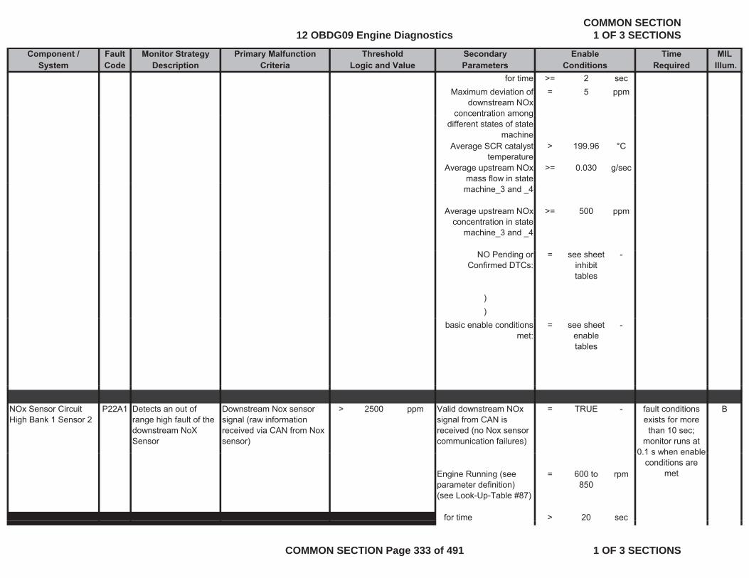
Component / Fault Monitor Strategy Primary Malfunction Secondary Time MILSystem Code Description Criteria Parameters Required Illum.
Threshold EnableLogic and Value Conditions
for time >= 2 secMaximum deviation of
downstream NOx concentration among
= 5 ppm
concentration among different states of state
machineAverage SCR catalyst
temperature> 199.96 °C
Average upstream NOx mass flow in state
>= 0.030 g/sec
machine_3 and _4
Average upstream NOx concentration in state
machine_3 and _4
>= 500 ppm
NO Pending or Confirmed DTCs:
= see sheet inhibit tables
-
))
basic enable conditions met:
= see sheet enable tables
-
NOx Sensor Circuit High Bank 1 Sensor 2
P22A1 Detects an out of range high fault of the downstream NoX Sensor
Downstream Nox sensor signal (raw information received via CAN from Nox sensor)
> 2500 ppm Valid downstream NOx signal from CAN is received (no Nox sensor communication failures)
= TRUE - Bfault conditions exists for more than 10 sec;
monitor runs at 0 1 s when enable
Engine Running (see parameter definition) (see Look-Up-Table #87)
= 600 to 850
rpm
for time > 20 sec
0.1 s when enable conditions are
met
12 OBDG09 Engine DiagnosticsCOMMON SECTION
1 OF 3 SECTIONS
COMMON SECTION Page 333 of 491 1 OF 3 SECTIONS
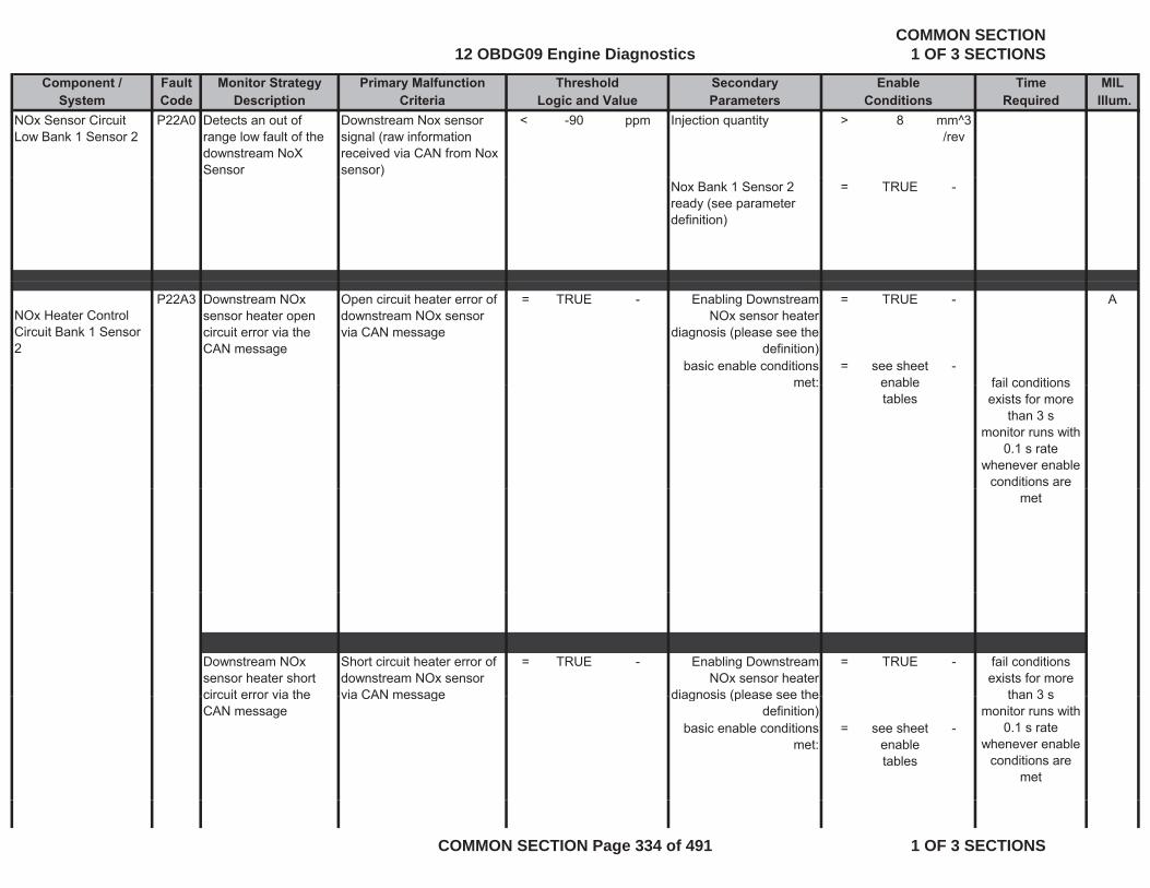
Component / Fault Monitor Strategy Primary Malfunction Secondary Time MILSystem Code Description Criteria Parameters Required Illum.
Threshold EnableLogic and Value Conditions
NOx Sensor Circuit Low Bank 1 Sensor 2
P22A0 Detects an out of range low fault of the downstream NoX Sensor
Downstream Nox sensor signal (raw information received via CAN from Nox sensor)
< -90 ppm Injection quantity > 8 mm^3/rev
Nox Bank 1 Sensor 2 ready (see parameter definition)
= TRUE -
NOx Heater Control Circuit Bank 1 Sensor 2
P22A3 Downstream NOx sensor heater open circuit error via the CAN message
Open circuit heater error of downstream NOx sensor via CAN message
= TRUE - Enabling Downstream NOx sensor heater
diagnosis (please see the definition)
= TRUE - A
basic enable conditions met:
= see sheet enable
-fail conditionsmet: enable
tablesfail conditions exists for more
than 3 smonitor runs with
0.1 s rate whenever enable
conditions are met
Downstream NOx sensor heater short circuit error via the
Short circuit heater error of downstream NOx sensor via CAN message
= TRUE - Enabling Downstream NOx sensor heater
diagnosis (please see the
= TRUE - fail conditions exists for more
than 3 scircuit error via the CAN message
via CAN message diagnosis (please see the definition)
basic enable conditions met:
= see sheet enable tables
-
than 3 smonitor runs with
0.1 s rate whenever enable
conditions are met
12 OBDG09 Engine DiagnosticsCOMMON SECTION
1 OF 3 SECTIONS
COMMON SECTION Page 334 of 491 1 OF 3 SECTIONS
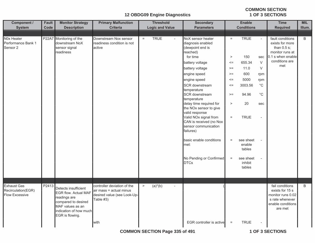
Component / Fault Monitor Strategy Primary Malfunction Secondary Time MILSystem Code Description Criteria Parameters Required Illum.
Threshold EnableLogic and Value Conditions
N0x Heater Performance Bank 1 Sensor 2
P22A7 Monitoring of the downstream NoX sensor signal
Downstream Nox sensor readiness condition is not active
= TRUE - NoX sensor heater diagnosis enabled (dewpoint end is
= TRUE - Bfault conditions exists for more
than 0 5 s;Sensor 2 sensor signal readiness
active (dewpoint end is reached)
for time > 150 secbattery voltage <= 655.34 Vbattery voltage >= 11.0 Vengine speed >= 600 rpm
than 0.5 s; monitor runs at
0.1 s when enable conditions are
met
engine speed <= 5000 rpmSCR downstream temperature
<= 3003.56 °C
SCR downstream temperature
>= 94.96 °C
delay time required for > 20 secy qthe NOx sensor to give valid responseValid NOx signal from CAN is received (no Nox sensor communication failures)
= TRUE -
basic enable conditions met:
= see sheet enable tables
-
No Pending or Confirmed DTC
= see sheet i hibit
-DTCs inhibit
tables
Exhaust Gas Recirculation(EGR)
P2413Detects insufficient
controller deviation of the air mass = actual minus
> (a)*(b) - ( Bfail conditions exists for 15 sRecirculation(EGR)
Flow Excessive EGR flow. Actual MAF readings are compared to desired MAF values as an indication of how much EGR is flowing.
air mass = actual minus desired value (see Look-Up-Table #3)
exists for 15 s monitor runs 0.02 s rate whenever
enable conditions are met
with EGR controller is active = TRUE -
12 OBDG09 Engine DiagnosticsCOMMON SECTION
1 OF 3 SECTIONS
COMMON SECTION Page 335 of 491 1 OF 3 SECTIONS
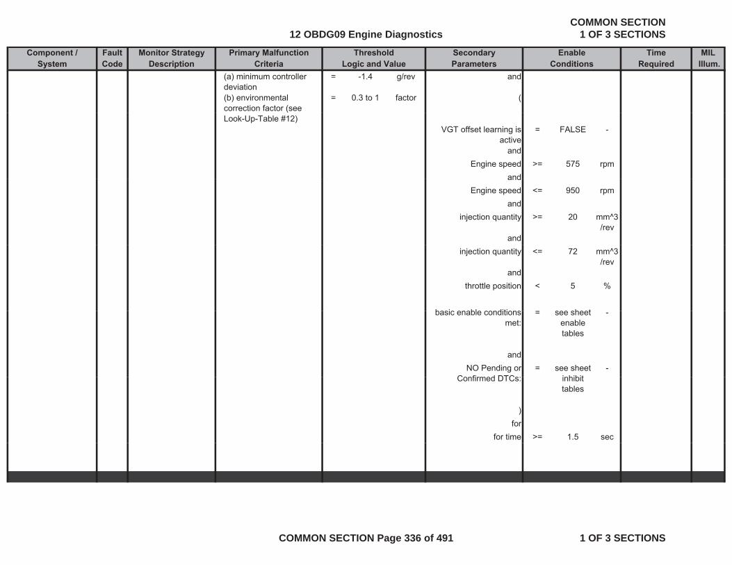
Component / Fault Monitor Strategy Primary Malfunction Secondary Time MILSystem Code Description Criteria Parameters Required Illum.
Threshold EnableLogic and Value Conditions
(a) minimum controller deviation
= -1.4 g/rev and
(b) environmental correction factor (see
= 0.3 to 1 factor ((
Look-Up-Table #12)VGT offset learning is
active= FALSE -
andEngine speed >= 575 rpm
andandEngine speed <= 950 rpm
andinjection quantity >= 20 mm^3
/revand
injection quantity <= 72 mm^3/rev
andthrottle position < 5 %
basic enable conditions see sheetbasic enable conditions met:
= see sheet enable tables
-
andNO Pending or
C fi d DTC= see sheet
i hibit-
Confirmed DTCs: inhibit tables
)for
for time >= 1.5 sec
12 OBDG09 Engine DiagnosticsCOMMON SECTION
1 OF 3 SECTIONS
COMMON SECTION Page 336 of 491 1 OF 3 SECTIONS
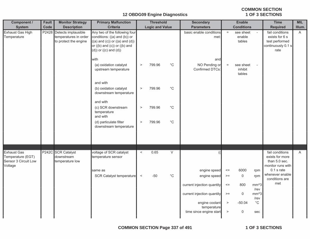
Component / Fault Monitor Strategy Primary Malfunction Secondary Time MILSystem Code Description Criteria Parameters Required Illum.
Threshold EnableLogic and Value Conditions
Exhaust Gas High Temperature
P2428 Detects implausible temperatures in order to protect the engine
Any two of the following four conditions: ((a) and (b)) or ((a) and (c)) or ((a) and (d)) or ((b) and (c)) or ((b) and
basic enable conditions met:
= see sheet enable tables
- Afail conditions exists for 6 s
test performed continuously 0.1 s
(d)) or ((c) and (d))
with and(a) oxidation catalyst upstream temperature
> 799.96 °C NO Pending or Confirmed DTCs:
= see sheet inhibit tables
-
rate
and with(b) oxidation catalyst downstream temperature
> 799.96 °C
and with(c) SCR downstream temperature
> 799.96 °C
and with(d) particulate filter downstream temperature
> 799.96 °C
Exhaust Gas Temperature (EGT)
P242C SCR Catalyst downstream
voltage of SCR catalyst temperature sensor
< 0.65 V (( Afail conditions exists for more
Sensor 3 Circuit Low Voltage
temperature low
same as engine speed <= 6000 rpmSCR Catalyst temperature < -50 °C engine speed >= 0 rpm
current injection quantity <= 800 mm^3
than 5.0 sec.monitor runs with
0.1 s rate whenever enable
conditions are met
/revcurrent injection quantity >= 0 mm^3
/revengine coolant
temperature> -50.04 °C
time since engine start > 0 sec
12 OBDG09 Engine DiagnosticsCOMMON SECTION
1 OF 3 SECTIONS
COMMON SECTION Page 337 of 491 1 OF 3 SECTIONS
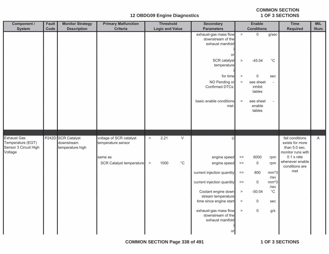
Component / Fault Monitor Strategy Primary Malfunction Secondary Time MILSystem Code Description Criteria Parameters Required Illum.
Threshold EnableLogic and Value Conditions
exhaust-gas mass flow downstream of the
exhaust manifold
> 0 g/sec
))or
SCR catalyst temperature
> -45.04 °C
)for time > 0 sec
NO Pending or Confirmed DTCs:
= see sheet inhibit tables
-
basic enable conditions met:
= see sheet enable tables
-
tables
Exhaust Gas P242D SCR Catalyst voltage of SCR catalyst > 2.21 V (( Afail conditions Temperature (EGT) Sensor 3 Circuit High Voltage
ydownstream temperature high
g ytemperature sensor
((
same as engine speed <= 6000 rpmSCR Catalyst temperature > 1000 °C engine speed >= 0 rpm
exists for more than 5.0 sec.
monitor runs with 0.1 s rate
whenever enable conditions are
current injection quantity <= 800 mm^3/rev
current injection quantity >= 0 mm^3/rev
Coolant engine down stream temperature
> -50.04 °C
met
time since engine start > 0 sec
exhaust-gas mass flow downstream of the
exhaust manifold
> 0 g/s
)or
12 OBDG09 Engine DiagnosticsCOMMON SECTION
1 OF 3 SECTIONS
COMMON SECTION Page 338 of 491 1 OF 3 SECTIONS
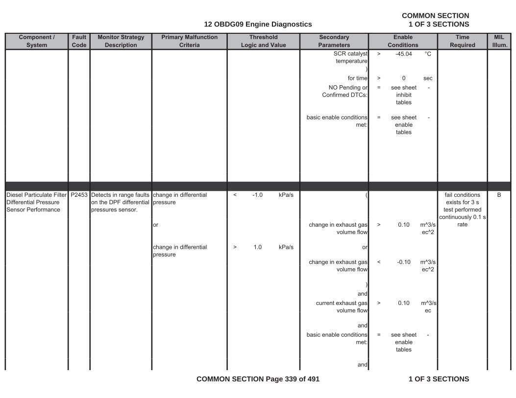
Component / Fault Monitor Strategy Primary Malfunction Secondary Time MILSystem Code Description Criteria Parameters Required Illum.
Threshold EnableLogic and Value Conditions
SCR catalyst temperature
> -45.04 °C
)for time > 0 secfor time > 0 sec
NO Pending or Confirmed DTCs:
= see sheet inhibit tables
-
basic enable conditions met:
= see sheet enable
-met: enable
tables
Diesel Particulate Filter Differential Pressure Sensor Performance
P2453 Detects in range faults on the DPF differential pressures sensor.
change in differential pressure
< -1.0 kPa/s ( Bfail conditions exists for 3 s
test performed continuously 0.1 s
or change in exhaust gas volume flow
> 0.10 m^3/sec^2
change in differential pressure
> 1.0 kPa/s or
change in exhaust gas < -0.10 m^3/s
continuously 0.1 s rate
volume flow ec^2
)and
current exhaust gas volume flow
> 0.10 m^3/s ecvolume flow ec
andbasic enable conditions
met:= see sheet
enable tables
-
and
12 OBDG09 Engine DiagnosticsCOMMON SECTION
1 OF 3 SECTIONS
COMMON SECTION Page 339 of 491 1 OF 3 SECTIONS

Component / Fault Monitor Strategy Primary Malfunction Secondary Time MILSystem Code Description Criteria Parameters Required Illum.
Threshold EnableLogic and Value Conditions
NO Pending or Confirmed DTCs:
= see sheet inhibit tables
-
Path 1: Engine State = After Run -
differential pressure > 3 2 kPa for time > 35 sec
fail conditions exists for 0.5 s
monitor runs withdifferential pressure sensor
> 3.2 kPa for time > 35 sec
andbasic enable conditions
met:= see sheet
enable tables
-
monitor runs with 0.1 s rate
whenever enable conditions are
met
andNO Pending or
Confirmed DTCs:= see sheet
inhibit tables
-
Diesel Particulate Filter Differential Pressure Sensor Circuit High Voltage
P2455 Detects high voltage readings on the DPF differential pressure sensor circuit,
voltage of differential pressure sensor
> 4.6664 V ignition on = TRUE - Bfail conditions exists for 3 s
test performed continuously
indicating an OOR high condition on the circuit
same as anddifferential pressure > 91.7 kPa basic enable conditions
met:= see sheet
enable -
0.020 s rate
tables
12 OBDG09 Engine DiagnosticsCOMMON SECTION
1 OF 3 SECTIONS
COMMON SECTION Page 340 of 491 1 OF 3 SECTIONS
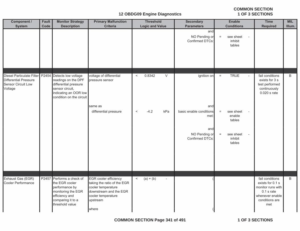
Component / Fault Monitor Strategy Primary Malfunction Secondary Time MILSystem Code Description Criteria Parameters Required Illum.
Threshold EnableLogic and Value Conditions
andNO Pending or
Confirmed DTCs:= see sheet
inhibit tables
-
tables
Diesel Particulate Filter Differential Pressure Sensor Circuit Low Voltage
P2454 Detects low voltage readings on the DPF differential pressure sensor circuit, indicating an OOR low condition on the circuit
voltage of differential pressure sensor
< 0.8342 V ignition on = TRUE - Bfail conditions exists for 3 s
test performed continuously 0.020 s rate
same as anddifferential pressure < -4.2 kPa basic enable conditions
met:= see sheet
enable tables
-
andNO Pending or
Confirmed DTCs:= see sheet
inhibit tables
-
Exhaust Gas (EGR) P2457 Performs a check of EGR cooler efficiency < (a) + (b) - ( Bfail conditions Cooler Performance the EGR cooler
performance by monitoring the EGR efficiency and comparing it to a threshold value
taking the ratio of the EGR cooler temperature downstream and the EGR cooler temperature upstream
h (
exists for 0.1 s monitor runs with
0.1 s rate whenever enable
conditions are met
where (
12 OBDG09 Engine DiagnosticsCOMMON SECTION
1 OF 3 SECTIONS
COMMON SECTION Page 341 of 491 1 OF 3 SECTIONS

Component / Fault Monitor Strategy Primary Malfunction Secondary Time MILSystem Code Description Criteria Parameters Required Illum.
Threshold EnableLogic and Value Conditions
(a) = 0.63 engine speed >= 1100 rpmand and(b) (see Look-Up-Table #18)
= -0.12 to 0 engine speed <= 1800 rpm#18)
)and
(injection quantity >= 20 mm^3
/revand
injection quantity <= 240 mm^3/rev
)and
((recirculated exhaust-gas
mass flow downstream of the EGR cooler
>= 16.67 g/sec
andrecirculated exhaust-gas
mass flow downstream of the EGR cooler
<= 40.28 g/sec
)and
EGR controller is active and DPF is not in
regeneration mode
= TRUE
and(
engine temperature >= 69 96 °Cengine temperature >= 69.96 Cand
engine temperature <= 122.96 °C)
and((
(a) - (b) >= 210 °C
12 OBDG09 Engine DiagnosticsCOMMON SECTION
1 OF 3 SECTIONS
COMMON SECTION Page 342 of 491 1 OF 3 SECTIONS
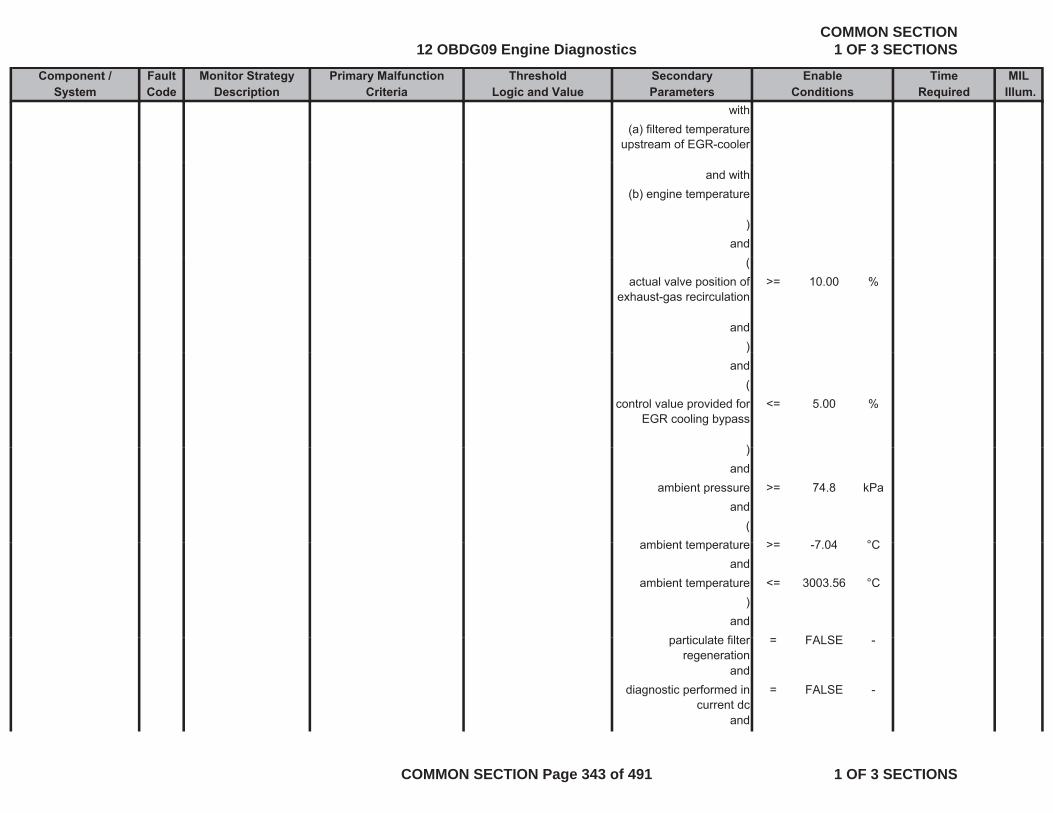
Component / Fault Monitor Strategy Primary Malfunction Secondary Time MILSystem Code Description Criteria Parameters Required Illum.
Threshold EnableLogic and Value Conditions
with(a) filtered temperature
upstream of EGR-cooler
and with(b) engine temperature
)and
(actual valve position of
exhaust-gas recirculation>= 10.00 %
and))
and(
control value provided for EGR cooling bypass
<= 5.00 %
))and
ambient pressure >= 74.8 kPaand
(bi t t t > 7 04 °Cambient temperature >= -7.04 °C
andambient temperature <= 3003.56 °C
)and
ti l t filt FALSEparticulate filter regeneration
= FALSE -
anddiagnostic performed in
current dc= FALSE -
and
12 OBDG09 Engine DiagnosticsCOMMON SECTION
1 OF 3 SECTIONS
COMMON SECTION Page 343 of 491 1 OF 3 SECTIONS
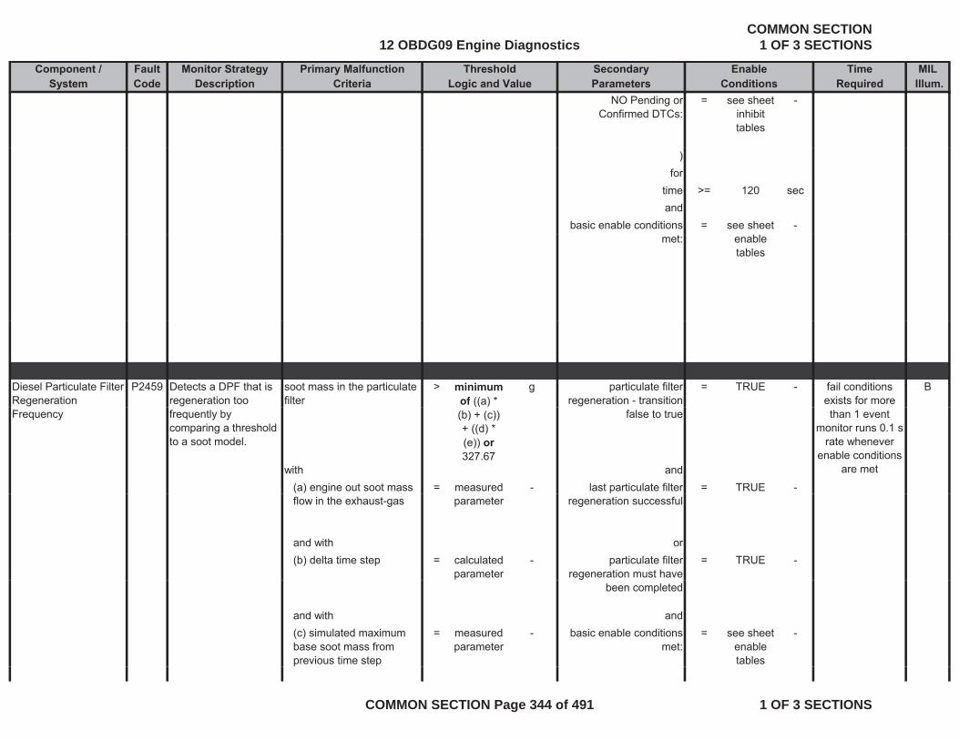
Component / Fault Monitor Strategy Primary Malfunction Secondary Time MILSystem Code Description Criteria Parameters Required Illum.
Threshold EnableLogic and Value Conditions
NO Pending or Confirmed DTCs:
= see sheet inhibit tables
-
)for
time >= 120 secand
basic enable conditions = see sheet -met: enable
tables
Diesel Particulate Filter Regeneration
P2459 Detects a DPF that is regeneration too
soot mass in the particulate filter
> minimum of ((a) *
g particulate filter regeneration - transition
= TRUE - Bfail conditions exists for more
Frequency frequently by comparing a threshold to a soot model.
(b) + (c)) + ((d) * (e)) or 327.67
false to true
with and(a) engine out soot mass = measured - last particulate filter = TRUE -
than 1 eventmonitor runs 0.1 s
rate whenever enable conditions
are met
flow in the exhaust-gas parameter regeneration successful
and with or(b) delta time step = calculated
parameter- particulate filter
regeneration must have = TRUE -
been completed
and with and(c) simulated maximum base soot mass from previous time step
= measured parameter
- basic enable conditions met:
= see sheet enable tables
-
12 OBDG09 Engine DiagnosticsCOMMON SECTION
1 OF 3 SECTIONS
COMMON SECTION Page 344 of 491 1 OF 3 SECTIONS

Component / Fault Monitor Strategy Primary Malfunction Secondary Time MILSystem Code Description Criteria Parameters Required Illum.
Threshold EnableLogic and Value Conditions
and with and(d) factor for calculation of a soot mass value offset depending on the
= 0 to 531 g NO Pending or Confirmed DTCs:
= see sheet inhibit tables
-
depending on the simulated maximal base soot mass (see Look-Up-Table #51)
tables
and with(e) factor for determination of
= 1 factordetermination of correction factor for ash in the particulate filter
Exhaust Gas Recirculation (EGR) Cooler Bypass Valve Control Circuit
P245A Electronic output driver circuitry determines circuit integrity on the EGR cooler bypass solenoid
The ECM detects that the commanded state of the driver and the actual state of the control circuit do not match.
( Bfail conditions exists for 3 s
monitor runs with 0.01 s rate
whenever enable conditions aresolenoid.
battery voltage > 11 Vfor
The faults of the output circuit, that are detected with this di i
time > 3 sec
conditions are met
diagnosis, are an open circuit or an overtemperature of the integrated circuit within the ECM.
andb tt lt 655 34 Vbattery voltage < 655.34 V
fortime > 3 sec
)and
t t i ti ki FALSEstarter is active cranking = FALSE
12 OBDG09 Engine DiagnosticsCOMMON SECTION
1 OF 3 SECTIONS
COMMON SECTION Page 345 of 491 1 OF 3 SECTIONS

Component / Fault Monitor Strategy Primary Malfunction Secondary Time MILSystem Code Description Criteria Parameters Required Illum.
Threshold EnableLogic and Value Conditions
fortime > 3 secand
EGR Cooling Bypass Solenoid Control Circuit
= ACTIVE
and(
open load diagnostics is p gtriggered after offset
learning of valve is completed
ortested for open load if the
valve is jammed = see sheet
inhibit -
jindicated by DTC's tables
)and
basic enable conditions met:
= see sheet enable
-met: enable
tables
Exhaust Gas Recirculation (EGR) Cooler Bypass Valve Control Circuit 1 Low Voltage
P245C Electronic output driver circuitry determines circuit integrity on the EGR cooler bypass solenoid.
The ECM detects that the commanded state of the driver and the actual state of the control circuit do not match.
( B
b tt lt > 11 V
fail conditions exists for 3 s
monitor runs with 0.01 s rate
whenever enable conditions are
metbattery voltage > 11 Vfor
time > 3 secand
battery voltage < 655.34 Vf
met
for
12 OBDG09 Engine DiagnosticsCOMMON SECTION
1 OF 3 SECTIONS
COMMON SECTION Page 346 of 491 1 OF 3 SECTIONS
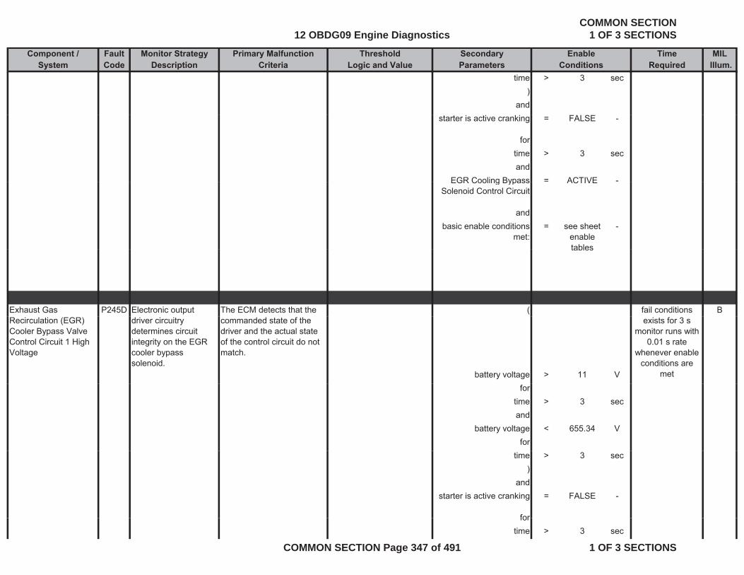
Component / Fault Monitor Strategy Primary Malfunction Secondary Time MILSystem Code Description Criteria Parameters Required Illum.
Threshold EnableLogic and Value Conditions
time > 3 sec)
andstarter is active cranking = FALSE -
fortime > 3 secand
EGR Cooling Bypass = ACTIVE -EGR Cooling Bypass Solenoid Control Circuit
ACTIVE
andbasic enable conditions
met:= see sheet
enable tables
-
tables
Exhaust Gas P245D Electronic output The ECM detects that the ( Bfail conditions Recirculation (EGR) Cooler Bypass Valve Control Circuit 1 High Voltage
driver circuitry determines circuit integrity on the EGR cooler bypass solenoid.
commanded state of the driver and the actual state of the control circuit do not match.
battery voltage > 11 V
exists for 3 smonitor runs with
0.01 s rate whenever enable
conditions are met
fortime > 3 secand
battery voltage < 655.34 Vfor
time > 3 sec)
andstarter is active cranking = FALSE -
forfortime > 3 sec
12 OBDG09 Engine DiagnosticsCOMMON SECTION
1 OF 3 SECTIONS
COMMON SECTION Page 347 of 491 1 OF 3 SECTIONS
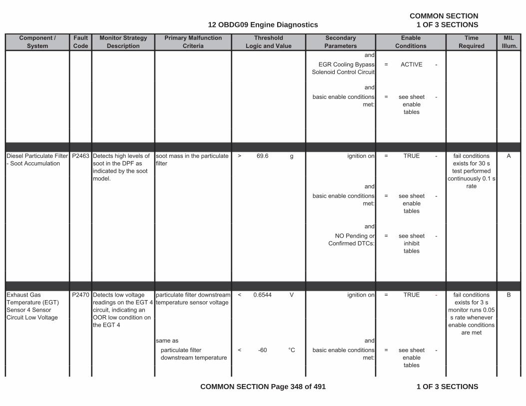
Component / Fault Monitor Strategy Primary Malfunction Secondary Time MILSystem Code Description Criteria Parameters Required Illum.
Threshold EnableLogic and Value Conditions
andEGR Cooling Bypass
Solenoid Control Circuit= ACTIVE -
andbasic enable conditions
met:= see sheet
enable tables
-
Diesel Particulate Filter - Soot Accumulation
P2463 Detects high levels of soot in the DPF as indicated by the soot
soot mass in the particulate filter
> 69.6 g ignition on = TRUE - Afail conditions exists for 30 s test performed
model.and
basic enable conditions met:
= see sheet enable tables
-
continuously 0.1 s rate
andNO Pending or
Confirmed DTCs:= see sheet
inhibit tables
-
Exhaust Gas Temperature (EGT) Sensor 4 Sensor Circuit Low Voltage
P2470 Detects low voltage readings on the EGT 4 circuit, indicating an OOR low condition on
particulate filter downstream temperature sensor voltage
< 0.6544 V ignition on = TRUE - Bfail conditions exists for 3 s
monitor runs 0.05 s rate wheneverCircuit Low Voltage OOR low condition on
the EGT 4
same as andparticulate filter downstream temperature
< -60 °C basic enable conditions met:
= see sheet enable tables
-
s rate whenever enable conditions
are met
tables
12 OBDG09 Engine DiagnosticsCOMMON SECTION
1 OF 3 SECTIONS
COMMON SECTION Page 348 of 491 1 OF 3 SECTIONS
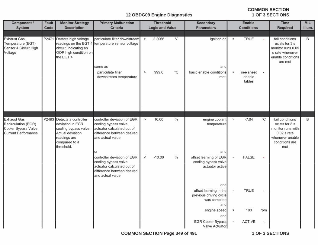
Component / Fault Monitor Strategy Primary Malfunction Secondary Time MILSystem Code Description Criteria Parameters Required Illum.
Threshold EnableLogic and Value Conditions
Exhaust Gas Temperature (EGT) Sensor 4 Circuit High
P2471 Detects high voltage readings on the EGT 4 circuit indicating an
particulate filter downstream temperature sensor voltage
> 2.2066 V ignition on = TRUE - Bfail conditions exists for 3 s
monitor runs 0 05Sensor 4 Circuit High Voltage
circuit, indicating an OOR high condition on the EGT 4
same as andparticulate filter downstream temperature
> 999.6 °C basic enable conditions met:
= see sheet enable
-
monitor runs 0.05 s rate whenever
enable conditions are met
downstream temperature met: enable tables
Exhaust Gas Recirculation (EGR) Cooler Bypass Valve Current Performance
P2493 Detects a controller deviation in EGR cooling bypass valve. Actual deviation
controller deviation of EGR cooling bypass valve actuator calculated out of difference between desired
> 10.00 % engine coolant temperature
> -7.04 °C Bfail conditions exists for 8 s
monitor runs with 0.02 s rate
readings are compared to a threshold.
and actual value
or andcontroller deviation of EGR cooling bypass valve
< -10.00 % offset learning of EGR cooling bypass valve
= FALSE -
whenever enable conditions are
met
g ypactuator calculated out of difference between desired and actual value
g ypactuator active
andoffset learning in the = TRUE -g
previous driving cycle was complete
andengine speed > 100 rpm
andEGR C l B ACTIVEEGR Cooler Bypass
Valve Actuator= ACTIVE -
12 OBDG09 Engine DiagnosticsCOMMON SECTION
1 OF 3 SECTIONS
COMMON SECTION Page 349 of 491 1 OF 3 SECTIONS

Component / Fault Monitor Strategy Primary Malfunction Secondary Time MILSystem Code Description Criteria Parameters Required Illum.
Threshold EnableLogic and Value Conditions
andbasic enable conditions
met:= see sheet
enable tables
-
tables
andNO Pending or
Confirmed DTCs:= see sheet
inhibit tables
-
EGR Cooling Bypass Position Sensor Circuit Low Voltage
P2494 Detects low voltage readings on the EGR cooling bypass
voltage of EGR cooling bypass actuator position sensor
< 0.25 V ignition on = TRUE - Afail conditions exists for 5 s
test performedLow Voltage cooling bypass position circuit, indicating an OOR low condition on the EGR position circuit
sensor
same as and
test performed continuously 0.01
s rate when enable conditions
are met
same as andEGR cooling bypass actuator position
< -22.5 % NO Pending or Confirmed DTCs:
= see sheet inhibit tables
-
andbasic enable conditions = see sheetbasic enable conditions
met:= see sheet
enable tables
-
12 OBDG09 Engine DiagnosticsCOMMON SECTION
1 OF 3 SECTIONS
COMMON SECTION Page 350 of 491 1 OF 3 SECTIONS
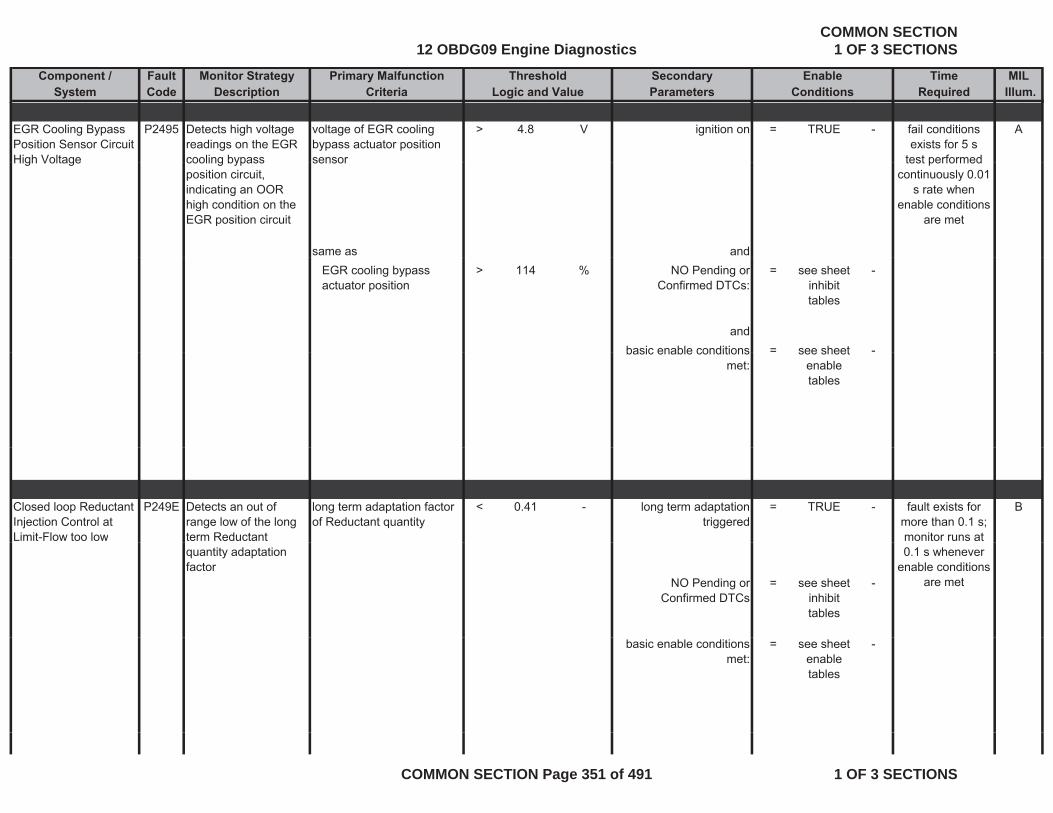
Component / Fault Monitor Strategy Primary Malfunction Secondary Time MILSystem Code Description Criteria Parameters Required Illum.
Threshold EnableLogic and Value Conditions
EGR Cooling Bypass Position Sensor Circuit High Voltage
P2495 Detects high voltage readings on the EGR cooling bypass
voltage of EGR cooling bypass actuator position sensor
> 4.8 V ignition on = TRUE - Afail conditions exists for 5 s
test performedHigh Voltage cooling bypass position circuit, indicating an OOR high condition on the EGR position circuit
sensor
same as and
test performed continuously 0.01
s rate when enable conditions
are met
EGR cooling bypass actuator position
> 114 % NO Pending or Confirmed DTCs:
= see sheet inhibit tables
-
andbasic enable conditions = see sheet -basic enable conditions
met:see sheet
enable tables
Closed loop Reductant Injection Control at Limit-Flow too low
P249E Detects an out of range low of the long term Reductant
long term adaptation factor of Reductant quantity
< 0.41 - long term adaptation triggered
= TRUE - Bfault exists for more than 0.1 s;monitor runs at
quantity adaptation factor
NO Pending or Confirmed DTCs
= see sheet inhibit tables
-
0.1 s whenever enable conditions
are met
basic enable conditions met:
= see sheet enable tables
-
12 OBDG09 Engine DiagnosticsCOMMON SECTION
1 OF 3 SECTIONS
COMMON SECTION Page 351 of 491 1 OF 3 SECTIONS
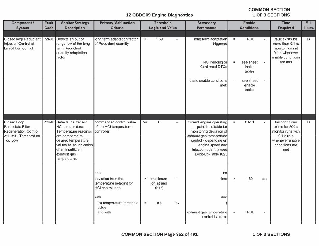
Component / Fault Monitor Strategy Primary Malfunction Secondary Time MILSystem Code Description Criteria Parameters Required Illum.
Threshold EnableLogic and Value Conditions
Closed loop Reductant Injection Control at Limit-Flow too high
P249D Detects an out of range low of the long term Reductant
long term adaptation factor of Reductant quantity
> 1.69 - long term adaptation triggered
= TRUE - Bfault exists for more than 0.1 s; monitor runs atLimit Flow too high term Reductant
quantity adaptation factor
NO Pending or Confirmed DTCs
= see sheet inhibit tables
-
monitor runs at 0.1 s whenever
enable conditions are met
basic enable conditions met:
= see sheet enable tables
-
Closed Loop Particulate Filter Regeneration Control At Limit Temperature
P24A0 Detects insufficient HCI temperature. Temperature readings are compared to
commanded control value of the HCI temperature controller
>= 0 - current engine operating point is suitable for
monitoring deviation of exhaust gas temperature
= 0 to 1 - Bfail conditions exists for 300 s
monitor runs with 0 1 s rateAt Limit - Temperature
Too Low are compared to desired temperature values as an indication of an insufficient exhaust gas temperature.
exhaust gas temperature control - depending on
engine speed and injection quantity (see
Look-Up-Table #27)
0.1 s rate whenever enable
conditions are met
and fordeviation from the temperature setpoint for HCI control loop
> maximum of (a) and
(b+c)
- time > 180 sec
with and(a) temperature threshold value
= 100 °C (
and with exhaust gas temperature control is active
= TRUE -
12 OBDG09 Engine DiagnosticsCOMMON SECTION
1 OF 3 SECTIONS
COMMON SECTION Page 352 of 491 1 OF 3 SECTIONS
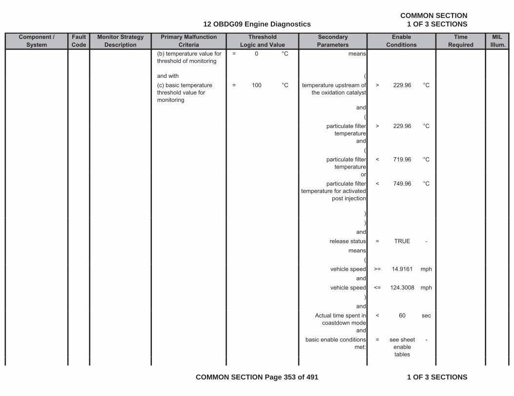
Component / Fault Monitor Strategy Primary Malfunction Secondary Time MILSystem Code Description Criteria Parameters Required Illum.
Threshold EnableLogic and Value Conditions
(b) temperature value for threshold of monitoring
= 0 °C means
and with (((c) basic temperature threshold value for monitoring
= 100 °C temperature upstream of the oxidation catalyst
> 229.96 °C
and(
particulate filter > 229 96 °Cparticulate filter temperature
> 229.96 °C
and(
particulate filter temperature
< 719.96 °C
orparticulate filter
temperature for activated post injection
< 749.96 °C
))
andrelease status = TRUE -
means(
vehicle speed >= 14.9161 mphand
vehicle speed <= 124.3008 mph)
andActual time spent in
coastdown mode< 60 sec
andbasic enable conditions
met:= see sheet
enable tables
-
12 OBDG09 Engine DiagnosticsCOMMON SECTION
1 OF 3 SECTIONS
COMMON SECTION Page 353 of 491 1 OF 3 SECTIONS
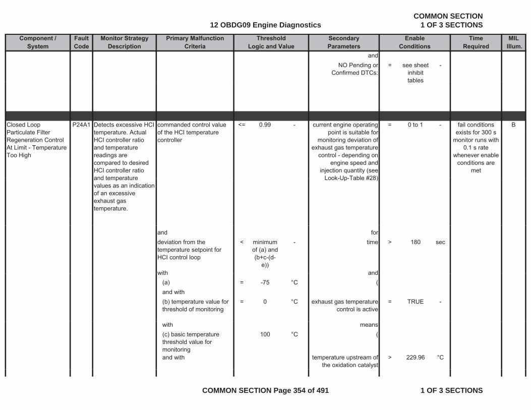
Component / Fault Monitor Strategy Primary Malfunction Secondary Time MILSystem Code Description Criteria Parameters Required Illum.
Threshold EnableLogic and Value Conditions
andNO Pending or
Confirmed DTCs:= see sheet
inhibit tables
-
tables
Closed Loop P24A1 Detects excessive HCI commanded control value <= 0.99 - current engine operating = 0 to 1 - Bfail conditions Particulate Filter Regeneration Control At Limit - Temperature Too High
temperature. Actual HCI controller ratio and temperature readings are compared to desired HCI controller ratio and temperature
of the HCI temperature controller
point is suitable for monitoring deviation of
exhaust gas temperature control - depending on
engine speed and injection quantity (see
Look Up Table #28)
exists for 300 s monitor runs with
0.1 s rate whenever enable
conditions are met
and temperature values as an indication of an excessive exhaust gas temperature.
Look-Up-Table #28)
and fordeviation from the temperature setpoint for HCI control loop
< minimum of (a) and (b+c-(d-
e))
- time > 180 sec
with andwith and(a) = -75 °C (and with(b) temperature value for threshold of monitoring
= 0 °C exhaust gas temperature control is active
= TRUE -
with means(c) basic temperature threshold value for monitoring
100 °C (
and with temperature upstream of the oxidation catalyst
> 229.96 °C
12 OBDG09 Engine DiagnosticsCOMMON SECTION
1 OF 3 SECTIONS
COMMON SECTION Page 354 of 491 1 OF 3 SECTIONS
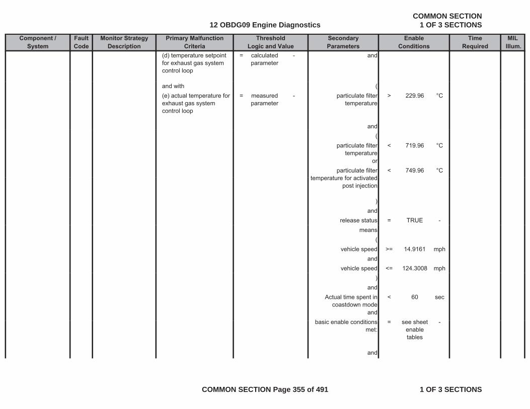
Component / Fault Monitor Strategy Primary Malfunction Secondary Time MILSystem Code Description Criteria Parameters Required Illum.
Threshold EnableLogic and Value Conditions
(d) temperature setpoint for exhaust gas system control loop
= calculated parameter
- and
and with ((e) actual temperature for exhaust gas system control loop
= measured parameter
- particulate filter temperature
> 229.96 °C
and(
particulate filter temperature
< 719.96 °C
orparticulate filter
temperature for activated< 749.96 °C
temperature for activated post injection
)and
release status = TRUE -means
(vehicle speed >= 14.9161 mph
andvehicle speed <= 124.3008 mph
)and
Actual time spent in coastdown mode
< 60 sec
andb i bl diti h tbasic enable conditions
met:= see sheet
enable tables
-
and
12 OBDG09 Engine DiagnosticsCOMMON SECTION
1 OF 3 SECTIONS
COMMON SECTION Page 355 of 491 1 OF 3 SECTIONS

Component / Fault Monitor Strategy Primary Malfunction Secondary Time MILSystem Code Description Criteria Parameters Required Illum.
Threshold EnableLogic and Value Conditions
NO Pending or Confirmed DTCs:
= see sheet inhibit tables
-
ECM Power Relay Circuit Performance
P2510 Detects stuck power relay that is not responding to ECM
counter value out of EEPROM for open the main relay
> 1 counts ignition on = TRUE - Bfail conditions exists for 0.02 s
monitor runs onceresponding to ECM commands to power down or a relay that is opening too early in power down. Stuck on is determined by timer values longer than
relay monitor runs once per driving cycle during predrive with 0.02 s rate
whenever enable conditions are
metvalues longer than possible if relay opened at end of after run.
andengine pre drive = TRUE -
met
engine pre drive = TRUEand
basic enable conditions met:
= see sheet enable
conditions
-
12 OBDG09 Engine DiagnosticsCOMMON SECTION
1 OF 3 SECTIONS
COMMON SECTION Page 356 of 491 1 OF 3 SECTIONS
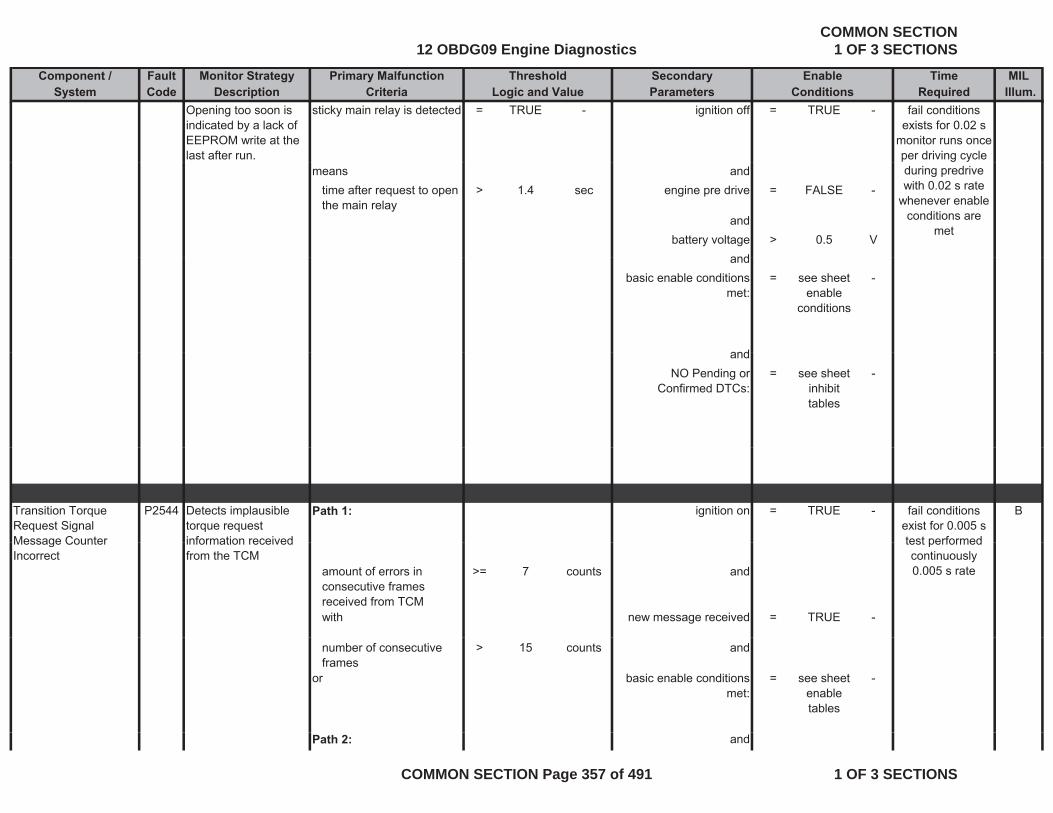
Component / Fault Monitor Strategy Primary Malfunction Secondary Time MILSystem Code Description Criteria Parameters Required Illum.
Threshold EnableLogic and Value Conditions
Opening too soon is indicated by a lack of EEPROM write at the last after run.
sticky main relay is detected = TRUE - ignition off = TRUE - fail conditions exists for 0.02 s
monitor runs once per driving cycle
means andtime after request to open the main relay
> 1.4 sec engine pre drive = FALSE -
andbattery voltage > 0.5 V
and
during predrive with 0.02 s rate
whenever enable conditions are
met
andbasic enable conditions
met:= see sheet
enable conditions
-
andandNO Pending or
Confirmed DTCs:= see sheet
inhibit tables
-
Transition Torque Request Signal Message Counter
P2544 Detects implausible torque request information received
Path 1: ignition on = TRUE - Bfail conditions exist for 0.005 stest performedMessage Counter
Incorrectinformation received from the TCM
amount of errors in consecutive frames received from TCM
>= 7 counts and
with new message received = TRUE -
test performed continuously 0.005 s rate
number of consecutive frames
> 15 counts and
or basic enable conditions met:
= see sheet enable tables
-
Path 2: and
12 OBDG09 Engine DiagnosticsCOMMON SECTION
1 OF 3 SECTIONS
COMMON SECTION Page 357 of 491 1 OF 3 SECTIONS
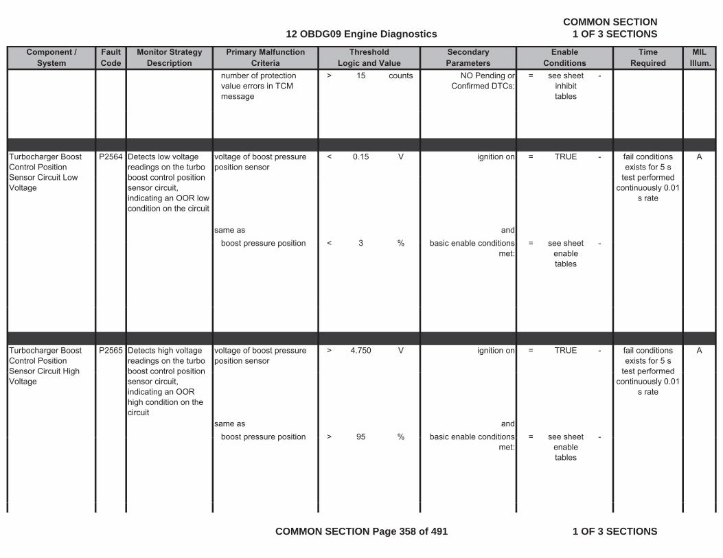
Component / Fault Monitor Strategy Primary Malfunction Secondary Time MILSystem Code Description Criteria Parameters Required Illum.
Threshold EnableLogic and Value Conditions
number of protection value errors in TCM message
> 15 counts NO Pending or Confirmed DTCs:
= see sheet inhibit tables
-
Turbocharger Boost Control Position Sensor Circuit Low
P2564 Detects low voltage readings on the turbo boost control position
voltage of boost pressure position sensor
< 0.15 V ignition on = TRUE - Afail conditions exists for 5 s
test performedSensor Circuit Low Voltage
boost control position sensor circuit, indicating an OOR low condition on the circuit
same as andboost pressure position < 3 % basic enable conditions = see sheet
test performed continuously 0.01
s rate
boost pressure position < 3 % basic enable conditions met:
= see sheet enable tables
-
Turbocharger Boost Control Position Sensor Circuit High
P2565 Detects high voltage readings on the turbo boost control position
voltage of boost pressure position sensor
> 4.750 V ignition on = TRUE - Afail conditions exists for 5 s
test performedSensor Circuit High Voltage
boost control position sensor circuit, indicating an OOR high condition on the circuit
same as andboost pressure position > 95 % basic enable conditions = see sheet -
test performed continuously 0.01
s rate
boost pressure position > 95 % basic enable conditions met:
= see sheet enable tables
-
12 OBDG09 Engine DiagnosticsCOMMON SECTION
1 OF 3 SECTIONS
COMMON SECTION Page 358 of 491 1 OF 3 SECTIONS
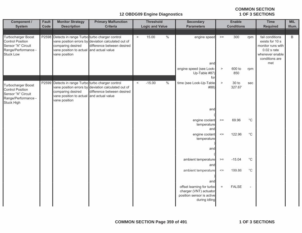
Component / Fault Monitor Strategy Primary Malfunction Secondary Time MILSystem Code Description Criteria Parameters Required Illum.
Threshold EnableLogic and Value Conditions
Turbocharger Boost Control Position Sensor "A" Circuit
P2598 Detects in range Turbo vane position errors by comparing desired
turbo charger control deviation calculated out of difference between desired
> 15.00 % engine speed >= 300 rpm Bfail conditions exists for 10 s
monitor runs withSensor A Circuit Range/Performance - Stuck Low
comparing desired vane position to actual vane position
difference between desired and actual value
andengine speed (see Look-
Up-Table #87)> 600 to
850rpm
monitor runs with 0.02 s rate
whenever enable conditions are
met
Up Table #87) 850for
Turbocharger Boost Control Position Sensor "A" Circuit Range/Performance -
P2599 Detects in range Turbo vane position errors by comparing desired vane position to actual vane position
turbo charger control deviation calculated out of difference between desired and actual value
< -15.00 % time (see Look-Up-Table #88)
> 30 to 327.67
sec
Stuck Highvane position
and(
engine coolant temperature
>= 69.96 °C
dandengine coolant
temperature<= 122.96 °C
)and
((ambient temperature >= -15.04 °C
andambient temperature <= 199.86 °C
)and
offset learning for turbo charger (VNT) actuator
position sensor is active during idling
= FALSE -
12 OBDG09 Engine DiagnosticsCOMMON SECTION
1 OF 3 SECTIONS
COMMON SECTION Page 359 of 491 1 OF 3 SECTIONS
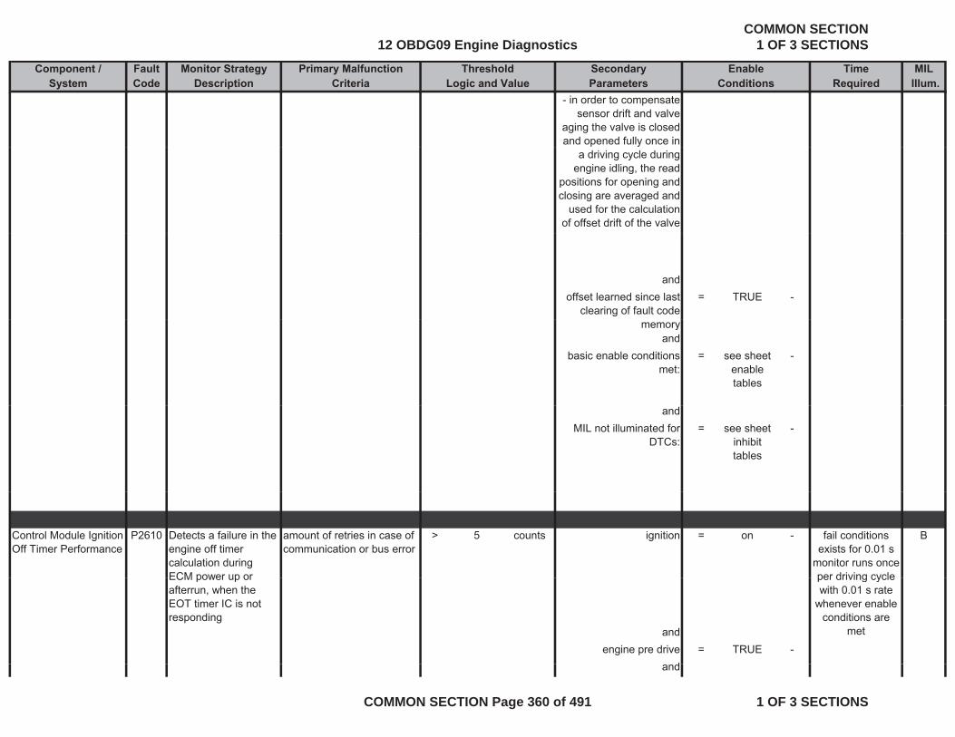
Component / Fault Monitor Strategy Primary Malfunction Secondary Time MILSystem Code Description Criteria Parameters Required Illum.
Threshold EnableLogic and Value Conditions
- in order to compensate sensor drift and valve
aging the valve is closed and opened fully once in
a driving cycle during engine idling, the read
positions for opening and closing are averaged and
used for the calculation of offset drift of the valve
andoffset learned since last
clearing of fault code = TRUE -
memoryand
basic enable conditions met:
= see sheet enable tables
-
andMIL not illuminated for
DTCs:= see sheet
inhibit tables
-
Control Module Ignition Off Timer Performance
P2610 Detects a failure in the engine off timer calculation during ECM power up or
amount of retries in case of communication or bus error
> 5 counts ignition = on - Bfail conditions exists for 0.01 s
monitor runs once per driving cycleECM power up or
afterrun, when the EOT timer IC is not responding
andengine pre drive = TRUE -
d
per driving cycle with 0.01 s rate
whenever enable conditions are
met
and
12 OBDG09 Engine DiagnosticsCOMMON SECTION
1 OF 3 SECTIONS
COMMON SECTION Page 360 of 491 1 OF 3 SECTIONS
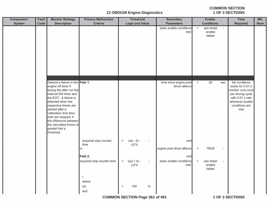
Component / Fault Monitor Strategy Primary Malfunction Secondary Time MILSystem Code Description Criteria Parameters Required Illum.
Threshold EnableLogic and Value Conditions
basic enable conditions met:
= see sheet enable tables
-
Detects a failure in the engine off timer if during the after run the
Path 1: time since engine post drive/ afterun
< 20 sec fail conditions exists for 0.01 s
monitor runs onceduring the after run the internal SW timer and the EOT. A failure is detected when the respective timers are started after a calibration time then
monitor runs once per driving cycle with 0.01 s rate
whenever enable conditions are
metcalibration time then both are stopped, if the difference between the calculated timers is greatet that a threshold
acquired stop counter time
< ((a) - (b - c))*d
- and
or engine post drive/ afterun = TRUE -
Path 2: andacquired stop counter time > ((a) + (b - - basic enable conditions = see sheet -q p (( ) (
c))*d met: enable tables
(where(a) = 100 %(a) = 100 %and
12 OBDG09 Engine DiagnosticsCOMMON SECTION
1 OF 3 SECTIONS
COMMON SECTION Page 361 of 491 1 OF 3 SECTIONS
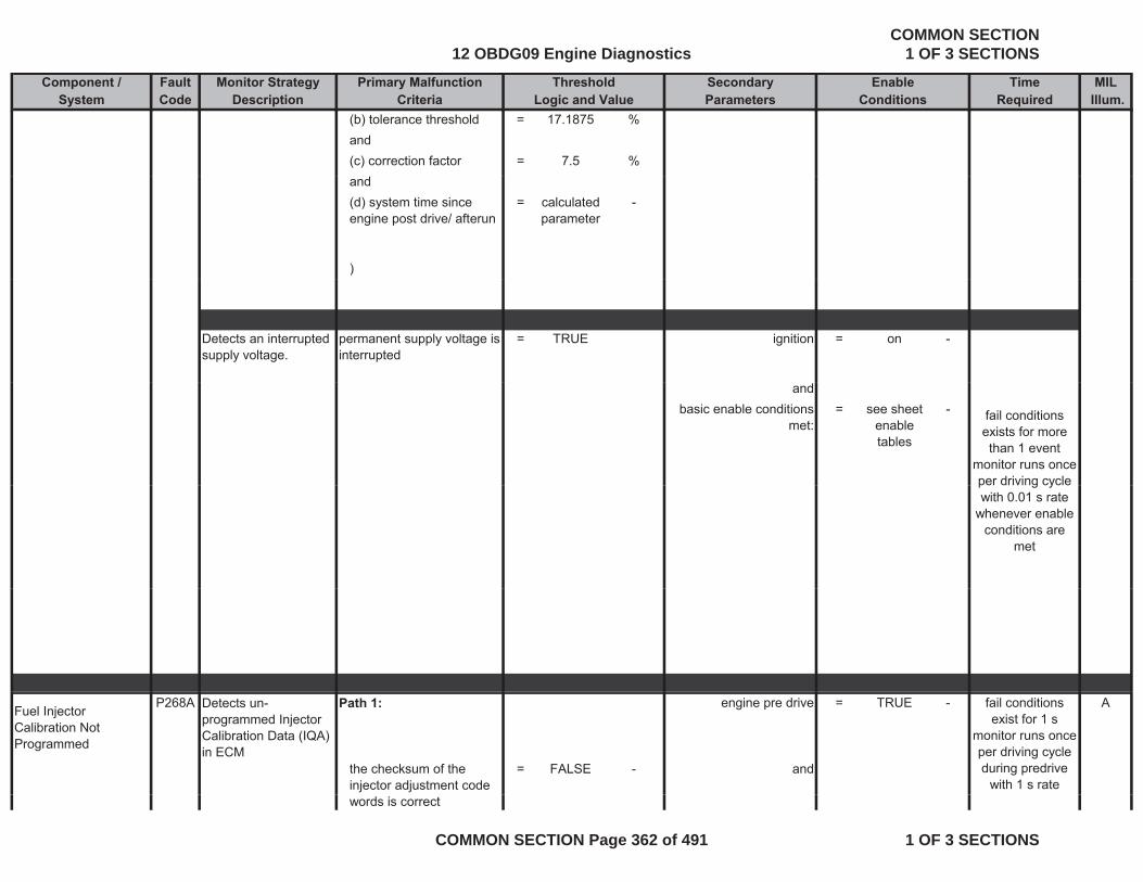
Component / Fault Monitor Strategy Primary Malfunction Secondary Time MILSystem Code Description Criteria Parameters Required Illum.
Threshold EnableLogic and Value Conditions
(b) tolerance threshold = 17.1875 %and(c) correction factor = 7.5 %and(d) system time since engine post drive/ afterun
= calculated parameter
-
)
Detects an interrupted supply voltage.
permanent supply voltage is interrupted
= TRUE ignition = on -
andbasic enable conditions
met:= see sheet
enable tables
- fail conditions exists for more than 1 event
monitor runs once per driving cycle pe d g cyc ewith 0.01 s rate
whenever enable conditions are
met
Fuel Injector Calibration Not Programmed
P268A Detects un-programmed Injector Calibration Data (IQA) in ECM
Path 1: engine pre drive = TRUE - A
the checksum of the injector adjustment code
= FALSE - and
fail conditions exist for 1 s
monitor runs once per driving cycle during predrive
with 1 s ratewords is correct
12 OBDG09 Engine DiagnosticsCOMMON SECTION
1 OF 3 SECTIONS
COMMON SECTION Page 362 of 491 1 OF 3 SECTIONS
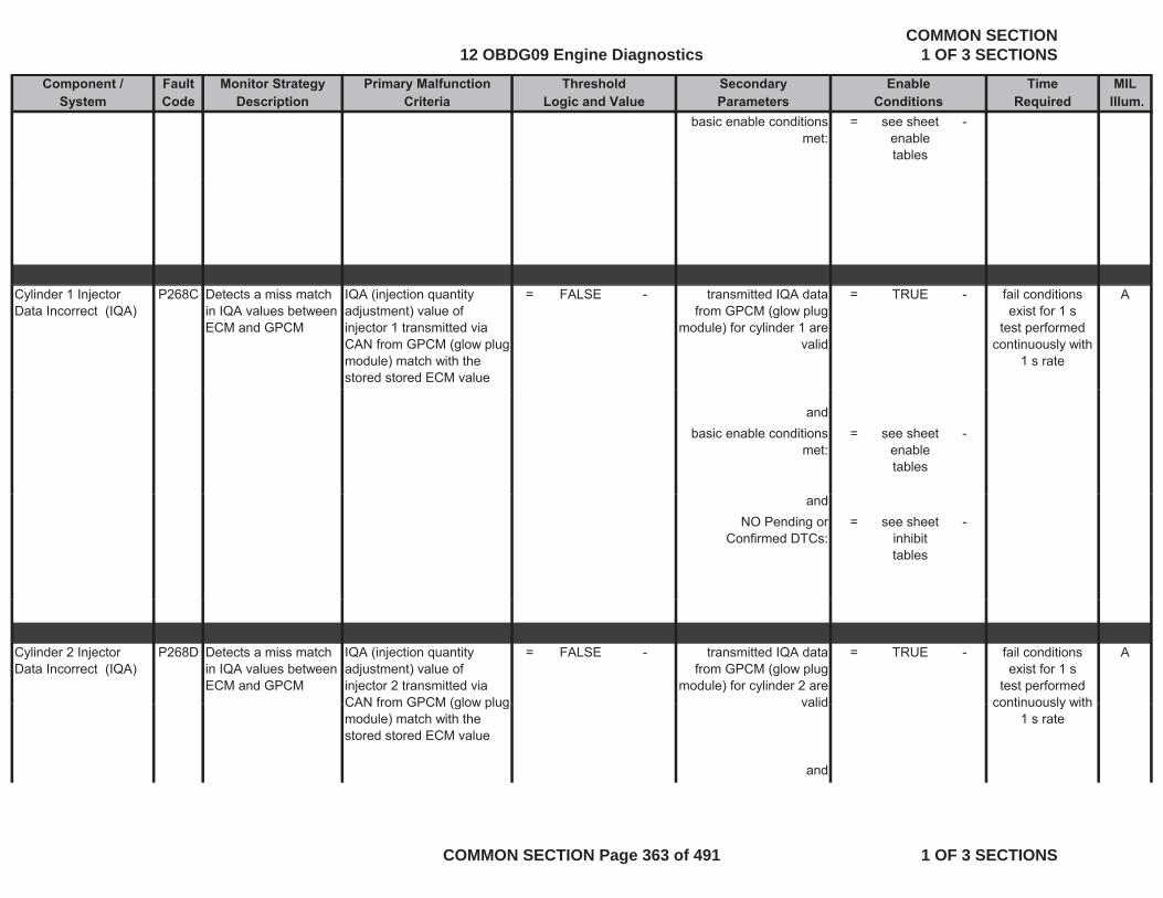
Component / Fault Monitor Strategy Primary Malfunction Secondary Time MILSystem Code Description Criteria Parameters Required Illum.
Threshold EnableLogic and Value Conditions
basic enable conditions met:
= see sheet enable tables
-
Cylinder 1 Injector Data Incorrect (IQA)
P268C Detects a miss match in IQA values between ECM and GPCM
IQA (injection quantity adjustment) value of injector 1 transmitted via CAN from GPCM (glow plug module) match with the stored stored ECM value
= FALSE - transmitted IQA data from GPCM (glow plug
module) for cylinder 1 are valid
= TRUE - Afail conditions exist for 1 s
test performed continuously with
1 s rate
andbasic enable conditions
met:= see sheet
enable tables
-
andNO Pending or
Confirmed DTCs:= see sheet
inhibit tables
-
Cylinder 2 Injector Data Incorrect (IQA)
P268D Detects a miss match in IQA values between ECM and GPCM
IQA (injection quantity adjustment) value of injector 2 transmitted via CAN from GPCM (glow plug
= FALSE - transmitted IQA data from GPCM (glow plug
module) for cylinder 2 are valid
= TRUE - Afail conditions exist for 1 s
test performed continuously withCAN from GPCM (glow plug
module) match with the stored stored ECM value
valid
and
continuously with 1 s rate
12 OBDG09 Engine DiagnosticsCOMMON SECTION
1 OF 3 SECTIONS
COMMON SECTION Page 363 of 491 1 OF 3 SECTIONS

Component / Fault Monitor Strategy Primary Malfunction Secondary Time MILSystem Code Description Criteria Parameters Required Illum.
Threshold EnableLogic and Value Conditions
basic enable conditions met:
see sheet enable tables
-
andNO Pending or
Confirmed DTCs:see sheet
inhibit tables
-
Cylinder 3 Injector Data Incorrect (IQA)
P268E Detects a miss match in IQA values between ECM and GPCM
IQA (injection quantity adjustment) value of injector 3 transmitted via CAN from GPCM (glow plug
= FALSE - transmitted IQA data from GPCM (glow plug
module) for cylinder 3 are valid
= TRUE - Afail conditions exist for 1 s
test performed continuously withCAN from GPCM (glow plug
module) match with the stored stored ECM value
valid
andbasic enable conditions
met:= see sheet
enable-
continuously with 1 s rate
met: enable tables
andNO Pending or
Confirmed DTCs:= see sheet
inhibit tables
-
tables
Cylinder 4 Injector P268F Detects a miss match IQA (injection quantity = FALSE - transmitted IQA data = TRUE - Afail conditions y jData Incorrect (IQA) in IQA values between
ECM and GPCM
( j q yadjustment) value of injector 4 transmitted via CAN from GPCM (glow plug module) match with the stored stored ECM value
from GPCM (glow plug module) for cylinder 4 are
valid
exist for 1 stest performed
continuously with 1 s rate
and
12 OBDG09 Engine DiagnosticsCOMMON SECTION
1 OF 3 SECTIONS
COMMON SECTION Page 364 of 491 1 OF 3 SECTIONS
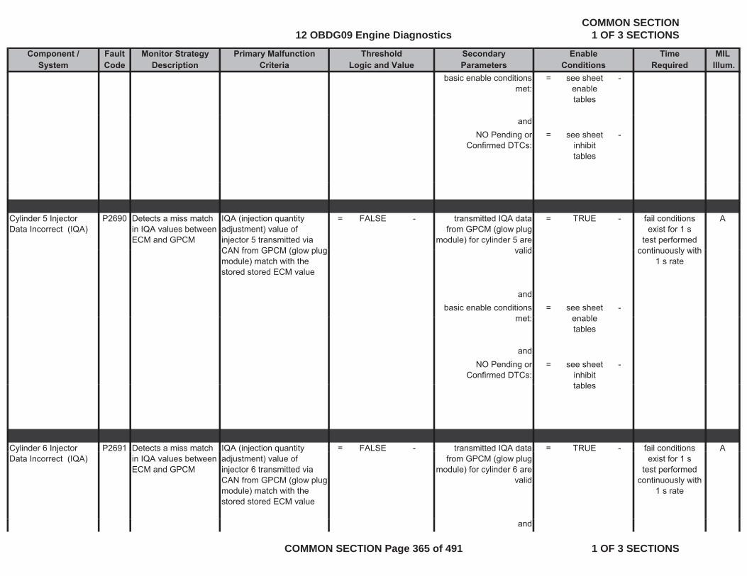
Component / Fault Monitor Strategy Primary Malfunction Secondary Time MILSystem Code Description Criteria Parameters Required Illum.
Threshold EnableLogic and Value Conditions
basic enable conditions met:
= see sheet enable tables
-
andNO Pending or
Confirmed DTCs:= see sheet
inhibit tables
-
Cylinder 5 Injector Data Incorrect (IQA)
P2690 Detects a miss match in IQA values between ECM and GPCM
IQA (injection quantity adjustment) value of injector 5 transmitted via CAN from GPCM (glow plug
= FALSE - transmitted IQA data from GPCM (glow plug
module) for cylinder 5 are valid
= TRUE - Afail conditions exist for 1 s
test performed continuously withCAN from GPCM (glow plug
module) match with the stored stored ECM value
valid
andbasic enable conditions
met:= see sheet
enable-
continuously with 1 s rate
met: enable tables
andNO Pending or
Confirmed DTCs:= see sheet
inhibit tables
-
tables
Cylinder 6 Injector P2691 Detects a miss match IQA (injection quantity = FALSE - transmitted IQA data = TRUE - Afail conditions y jData Incorrect (IQA) in IQA values between
ECM and GPCM
( j q yadjustment) value of injector 6 transmitted via CAN from GPCM (glow plug module) match with the stored stored ECM value
from GPCM (glow plug module) for cylinder 6 are
valid
exist for 1 stest performed
continuously with 1 s rate
and
12 OBDG09 Engine DiagnosticsCOMMON SECTION
1 OF 3 SECTIONS
COMMON SECTION Page 365 of 491 1 OF 3 SECTIONS

Component / Fault Monitor Strategy Primary Malfunction Secondary Time MILSystem Code Description Criteria Parameters Required Illum.
Threshold EnableLogic and Value Conditions
basic enable conditions met:
= see sheet enable tables
-
andNO Pending or
Confirmed DTCs:= see sheet
inhibit tables
-
Cylinder 7 Injector Data Incorrect (IQA)
P2692 Detects a miss match in IQA values between ECM and GPCM
IQA (injection quantity adjustment) value of injector 7 transmitted via CAN from GPCM (glow plug
= FALSE - transmitted IQA data from GPCM (glow plug
module) for cylinder 7 are valid
= TRUE - Afail conditions exist for 1 s
test performed continuously withCAN from GPCM (glow plug
module) match with the stored stored ECM value
valid
andbasic enable conditions
met:= see sheet
enable-
continuously with 1 s rate
met: enable tables
andNO Pending or
Confirmed DTCs:= see sheet
inhibit tables
-
tables
Cylinder 8 Injector P2693 Detects a miss match IQA (injection quantity = FALSE - transmitted IQA data = TRUE Afail conditions y jData Incorrect (IQA) in IQA values between
ECM and GPCM
( j q yadjustment) value of injector 8 transmitted via CAN from GPCM (glow plug module) match with the stored stored ECM value
from GPCM (glow plug module) for cylinder 8 are
valid
exist for 1 stest performed
continuously with 1 s rate
and
12 OBDG09 Engine DiagnosticsCOMMON SECTION
1 OF 3 SECTIONS
COMMON SECTION Page 366 of 491 1 OF 3 SECTIONS
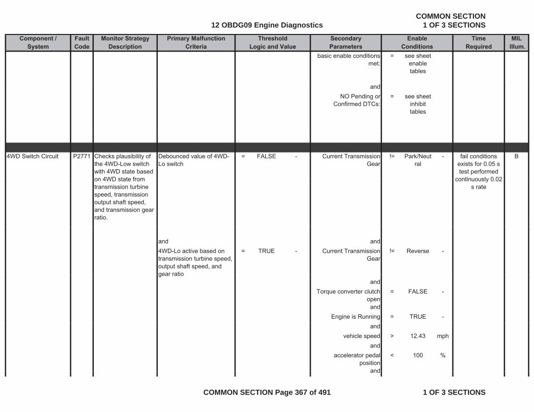
Component / Fault Monitor Strategy Primary Malfunction Secondary Time MILSystem Code Description Criteria Parameters Required Illum.
Threshold EnableLogic and Value Conditions
basic enable conditions met:
= see sheet enable tables
andNO Pending or
Confirmed DTCs:= see sheet
inhibit tables
4WD Switch Circuit P2771 Checks plausibility of the 4WD-Low switch with 4WD state based on 4WD state from
Debounced value of 4WD-Lo switch
= FALSE - Current Transmission Gear
!= Park/Neutral
- Bfail conditions exists for 0.05 s test performed
continuously 0 02on 4WD state from transmission turbine speed, transmission output shaft speed, and transmission gear ratio.
continuously 0.02 s rate
and and4WD-Lo active based on transmission turbine speed, output shaft speed, and gear ratio
= TRUE - Current Transmission Gear
!= Reverse -
gear ratioand
Torque converter clutch open
= FALSE -
andEngine is Running = TRUE -
andvehicle speed > 12.43 mph
andaccelerator pedal
position< 100 %
andand
12 OBDG09 Engine DiagnosticsCOMMON SECTION
1 OF 3 SECTIONS
COMMON SECTION Page 367 of 491 1 OF 3 SECTIONS
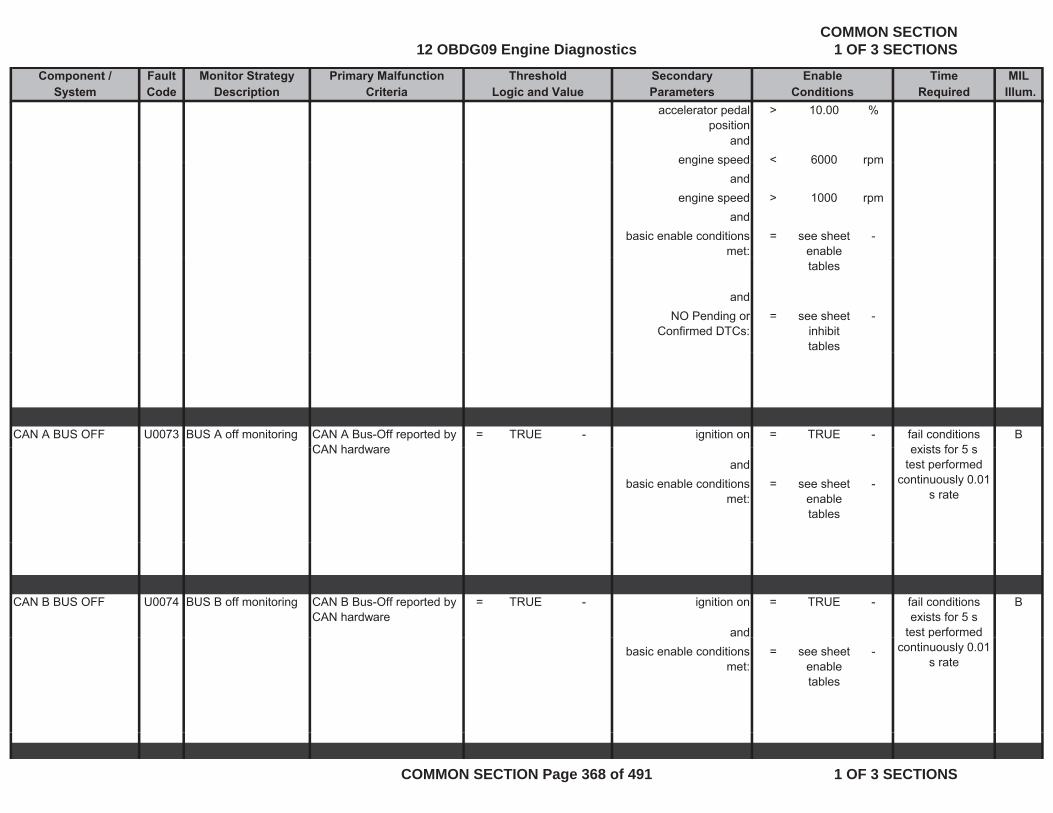
Component / Fault Monitor Strategy Primary Malfunction Secondary Time MILSystem Code Description Criteria Parameters Required Illum.
Threshold EnableLogic and Value Conditions
accelerator pedal position
> 10.00 %
andengine speed < 6000 rpmengine speed < 6000 rpm
andengine speed > 1000 rpm
andbasic enable conditions
met:= see sheet
enable -
tables
andNO Pending or
Confirmed DTCs:= see sheet
inhibit tables
-
CAN A BUS OFF U0073 BUS A off monitoring CAN A Bus-Off reported by CAN hardware
= TRUE - ignition on = TRUE - Bfail conditions exists for 5 sCAN hardware
andbasic enable conditions
met:= see sheet
enable tables
-
exists for 5 s test performed
continuously 0.01 s rate
CAN B BUS OFF U0074 BUS B off monitoring CAN B Bus-Off reported by CAN hardware
= TRUE - ignition on = TRUE - B
and
fail conditions exists for 5 s
test performed basic enable conditions
met:= see sheet
enable tables
-p
continuously 0.01 s rate
12 OBDG09 Engine DiagnosticsCOMMON SECTION
1 OF 3 SECTIONS
COMMON SECTION Page 368 of 491 1 OF 3 SECTIONS
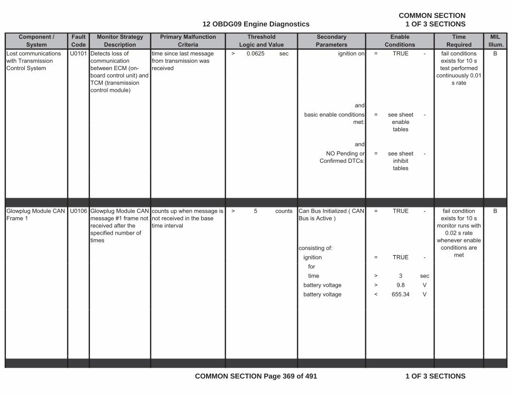
Component / Fault Monitor Strategy Primary Malfunction Secondary Time MILSystem Code Description Criteria Parameters Required Illum.
Threshold EnableLogic and Value Conditions
Lost communications with Transmission Control System
U0101 Detects loss of communication between ECM (on-board control unit) and
time since last message from transmission was received
> 0.0625 sec ignition on = TRUE - Bfail conditions exists for 10 s test performed
continuously 0.01 TCM (transmission control module)
andbasic enable conditions
met:= see sheet
enable -
s rate
tables
andNO Pending or
Confirmed DTCs:= see sheet
inhibit tables
-
Glowplug Module CAN Frame 1
U0106 Glowplug Module CAN message #1 frame not
counts up when message is not received in the base
> 5 counts Can Bus Initialized ( CAN Bus is Active )
= TRUE - Bfail condition exists for 10 sFrame 1 message #1 frame not
received after the specified number of times
not received in the base time interval
Bus is Active )
consisting of:ignition = TRUE -
exists for 10 s monitor runs with
0.02 s rate whenever enable
conditions are met
fortime > 3 sec
battery voltage > 9.8 Vbattery voltage < 655.34 V
12 OBDG09 Engine DiagnosticsCOMMON SECTION
1 OF 3 SECTIONS
COMMON SECTION Page 369 of 491 1 OF 3 SECTIONS

Component / Fault Monitor Strategy Primary Malfunction Secondary Time MILSystem Code Description Criteria Parameters Required Illum.
Threshold EnableLogic and Value Conditions
U010E CAN frame not received after the specified number of times
counts up when message is not received in the base time interval (1.0 sec)
> 40 counts CAN Bus is Active = TRUE - ALost Communication with Reductant Control Module
fail conditions exists for more
than 5 seconds ; monitor runs
Can Bus Initialized ( CAN Bus is Active )
consisting of:ignition = TRUE -
fortime > 5 sec
every 0.02 s whenever enable
conditions are met.
time > 5 secbattery voltage < 16 Vbattery voltage > 9 V
CAN message sliding DLS1 Sliding Window error >= 8 counts CAN Bus is Active = TRUECAN message sliding window detection
DLS1 Sliding Window error counter
>= 8 counts CAN Bus is Active = TRUE -
Check of level sensor within a number of message frames
= 9 counts Can Bus Initialized ( CAN Bus is Active )
consisting of:ignition TRUEignition = TRUE -
fortime > 5 sec
battery voltage < 16 Vbattery voltage > 9 V
CAN message sliding window detection
DLS2 Sliding Window error counter
>= 8 counts CAN Bus is Active = TRUE -
Check of temperature sensor
within a number of message frames
= 9 counts Can Bus Initialized ( CAN Bus is Active )
consisting of:ignition = TRUE -
forti > 5time > 5 sec
12 OBDG09 Engine DiagnosticsCOMMON SECTION
1 OF 3 SECTIONS
COMMON SECTION Page 370 of 491 1 OF 3 SECTIONS
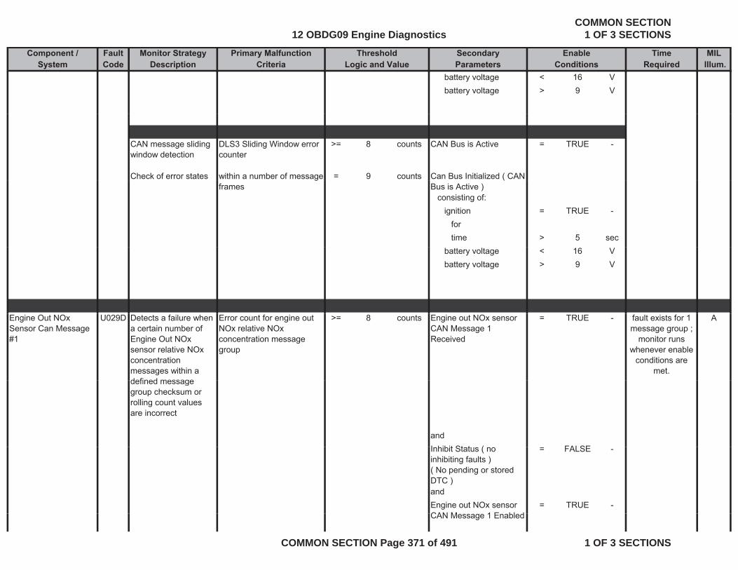
Component / Fault Monitor Strategy Primary Malfunction Secondary Time MILSystem Code Description Criteria Parameters Required Illum.
Threshold EnableLogic and Value Conditions
battery voltage < 16 Vbattery voltage > 9 V
CAN message sliding window detection
DLS3 Sliding Window error counter
>= 8 counts CAN Bus is Active = TRUE -
Check of error states within a number of message = 9 counts Can Bus Initialized ( CAN gframes
(Bus is Active )
consisting of:ignition = TRUE -
fortime > 5 sec
battery voltage < 16 Vbattery voltage > 9 V
Engine Out NOx Sensor Can Message #1
U029D Detects a failure when a certain number of Engine Out NOx sensor relative NOx concentration messages within a defined message
Error count for engine out NOx relative NOx concentration message group
>= 8 counts Engine out NOx sensor CAN Message 1 Received
= TRUE - Afault exists for 1 message group ;
monitor runs whenever enable
conditions are met.
defined message group checksum or rolling count values are incorrect
andI hibit St t ( FALSEInhibit Status ( no inhibiting faults )( No pending or stored DTC )
= FALSE -
andEngine out NOx sensor CAN M 1 E bl d
= TRUE -CAN Message 1 Enabled
12 OBDG09 Engine DiagnosticsCOMMON SECTION
1 OF 3 SECTIONS
COMMON SECTION Page 371 of 491 1 OF 3 SECTIONS
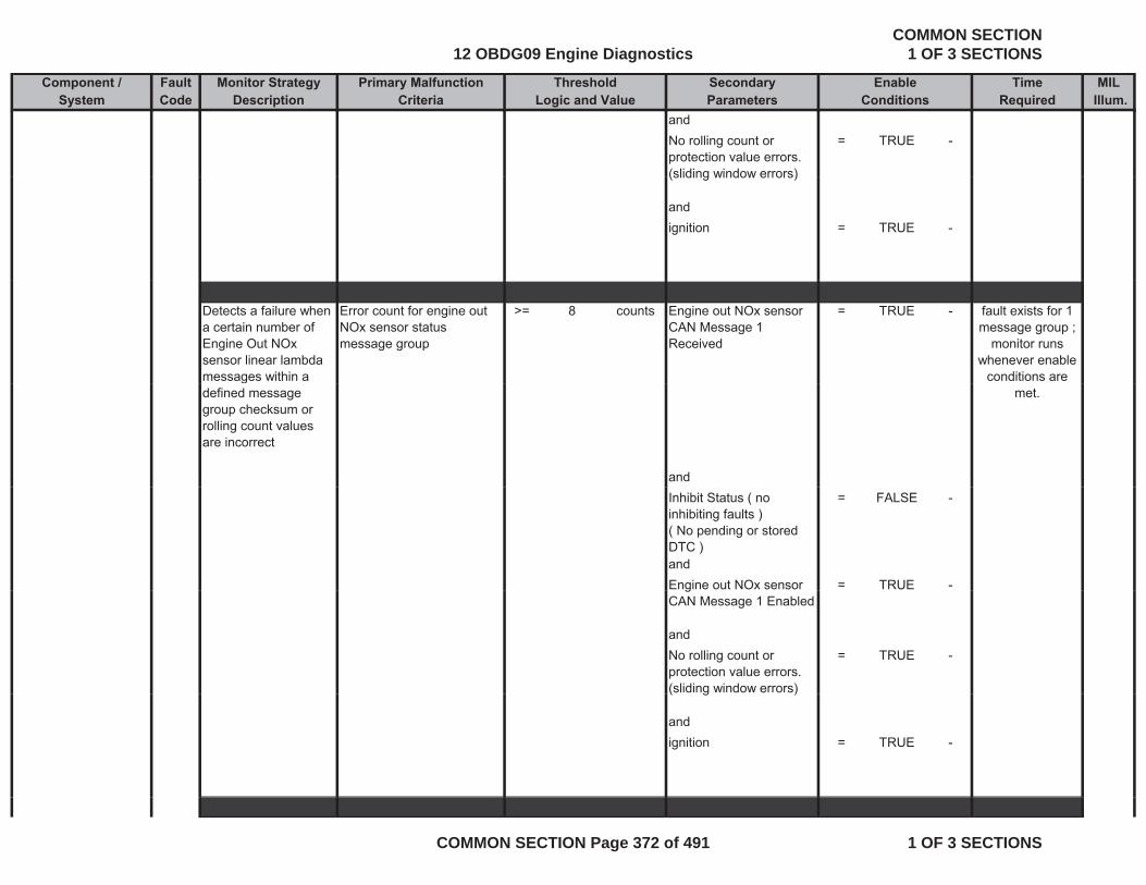
Component / Fault Monitor Strategy Primary Malfunction Secondary Time MILSystem Code Description Criteria Parameters Required Illum.
Threshold EnableLogic and Value Conditions
andNo rolling count or protection value errors. (sliding window errors)
= TRUE -
(sliding window errors)
andignition = TRUE -
Detects a failure when a certain number of Engine Out NOx sensor linear lambda messages within a
Error count for engine out NOx sensor status message group
>= 8 counts Engine out NOx sensor CAN Message 1 Received
= TRUE - fault exists for 1 message group ;
monitor runs whenever enable
conditions are gdefined message group checksum or rolling count values are incorrect
and
met.
Inhibit Status ( no inhibiting faults )( No pending or stored DTC )
= FALSE -
andEngine out NOx sensor = TRUE -gCAN Message 1 Enabled
andNo rolling count or protection value errors. (sliding window errors)
= TRUE -
( g )
andignition = TRUE -
12 OBDG09 Engine DiagnosticsCOMMON SECTION
1 OF 3 SECTIONS
COMMON SECTION Page 372 of 491 1 OF 3 SECTIONS

Component / Fault Monitor Strategy Primary Malfunction Secondary Time MILSystem Code Description Criteria Parameters Required Illum.
Threshold EnableLogic and Value Conditions
Engine out NOx sensor CAN message #1 frame not received after the specified
counts up when message is not received in the base time interval
> 5 counts Can Bus Initialized ( CAN Bus is Active )
= TRUE - fault exists for more than 20
seconds ; monitor runs every 0.05 s
number of times
consisting of:ignition = TRUEfortime > 3 sec
whenever enable conditions are
met.
time > 3 secbattery voltage > 9.8 Vbattery voltage < 18.1 V
Engine out NOx Detects a failure when Error count for engine out > 8 counts Engine out NOx sensor TRUE fault exists for 1Engine out NOx Sensor CAN Message #2
Detects a failure when a certain number of Engine Out NOx sensor error messages within a defined message group checksum or
Error count for engine out NOx sensor error status message group
>= 8 counts Engine out NOx sensor CAN Message 2 Received
= TRUE - fault exists for 1 message group ;
monitor runs whenever enable
conditions are met.
group checksum or rolling count values are incorrect
andInhibit Status ( no inhibiting faults )
= FALSE -inhibiting faults )( No pending or stored DTC )andEngine out NOx sensor CAN Message 2 Enabled
= TRUE -
andNo rolling count or protection value errors. (sliding window errors)
= TRUE -
andandignition = TRUE -
12 OBDG09 Engine DiagnosticsCOMMON SECTION
1 OF 3 SECTIONS
COMMON SECTION Page 373 of 491 1 OF 3 SECTIONS
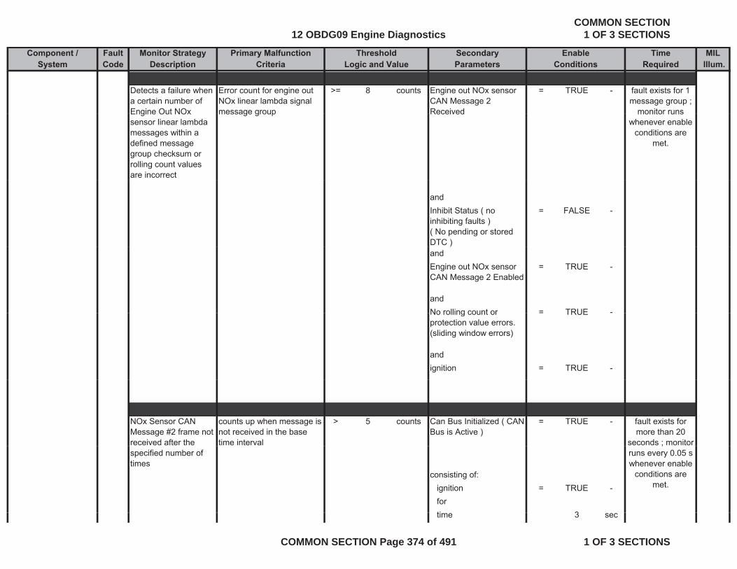
Component / Fault Monitor Strategy Primary Malfunction Secondary Time MILSystem Code Description Criteria Parameters Required Illum.
Threshold EnableLogic and Value Conditions
Detects a failure when a certain number of Engine Out NOx
Error count for engine out NOx linear lambda signal message group
>= 8 counts Engine out NOx sensor CAN Message 2 Received
= TRUE - fault exists for 1 message group ;
monitor runsEngine Out NOx sensor linear lambda messages within a defined message group checksum or rolling count values are incorrect
message group Received monitor runs whenever enable
conditions are met.
andInhibit Status ( no inhibiting faults )( No pending or stored DTC )
= FALSE -
)andEngine out NOx sensor CAN Message 2 Enabled
= TRUE -
andNo rolling count or = TRUE -No rolling count or protection value errors. (sliding window errors)
= TRUE
andignition = TRUE -
NOx Sensor CAN Message #2 frame not received after the
counts up when message is not received in the base time interval
> 5 counts Can Bus Initialized ( CAN Bus is Active )
= TRUE - fault exists for more than 20
seconds ; monitor specified number of times
consisting of:ignition = TRUE -forti 3
;runs every 0.05 s whenever enable
conditions are met.
time 3 sec
12 OBDG09 Engine DiagnosticsCOMMON SECTION
1 OF 3 SECTIONS
COMMON SECTION Page 374 of 491 1 OF 3 SECTIONS

Component / Fault Monitor Strategy Primary Malfunction Secondary Time MILSystem Code Description Criteria Parameters Required Illum.
Threshold EnableLogic and Value Conditions
battery voltage > 9.8 Vbattery voltage < 18.1 V
Engine out Nox Sensor CAN Message #3
Engine out NOx sensor CAN message #3 frame not received after the specified
counts up when message is not received in the base time interval
> 5 counts Can Bus Initialized ( CAN Bus is Active )
= TRUE - fault exists for more than 20
seconds ; monitor runs every 0.05 s
number of times
consisting of:ignition = TRUE -fortime 3 sec
ywhenever enable
conditions are met.
time 3 secbattery voltage > 9.8 Vbattery voltage < 18.1 V
Detects a failure when a certain number of Engine Out NOx sensor oxygen concentration messages within a
Error count for engine out NOx oxygen concentration signal message group
>= 8 counts Engine out NOx sensor CAN Message 3 Received
= TRUE - fault exists for 1 message group ;
monitor runs whenever enable
conditions are metmessages within a
defined message group checksum or rolling count values are incorrect
and
met.
andInhibit Status ( no inhibiting faults )( No pending or stored DTC )
= FALSE -
and
12 OBDG09 Engine DiagnosticsCOMMON SECTION
1 OF 3 SECTIONS
COMMON SECTION Page 375 of 491 1 OF 3 SECTIONS
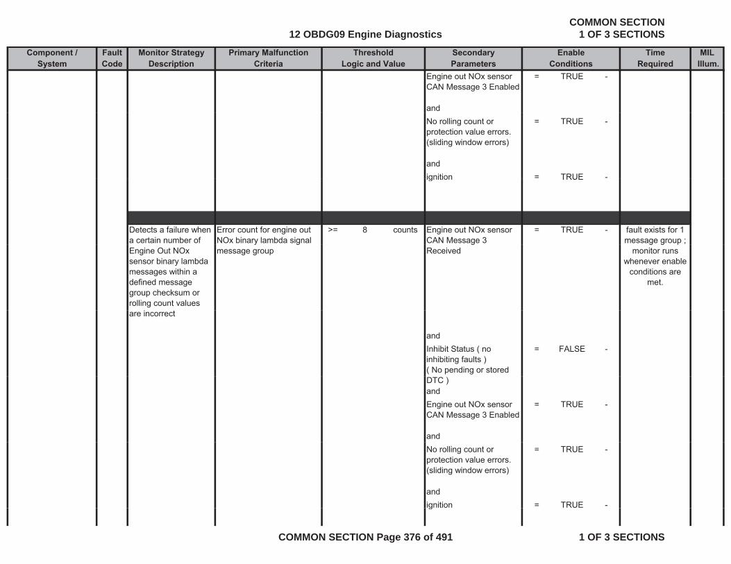
Component / Fault Monitor Strategy Primary Malfunction Secondary Time MILSystem Code Description Criteria Parameters Required Illum.
Threshold EnableLogic and Value Conditions
Engine out NOx sensor CAN Message 3 Enabled
= TRUE -
andNo rolling count or protection value errors. (sliding window errors)
= TRUE -
andignition = TRUE -ignition TRUE
Detects a failure when a certain number of
Error count for engine out NOx binary lambda signal
>= 8 counts Engine out NOx sensor CAN Message 3
= TRUE - fault exists for 1 message group ;
Engine Out NOx sensor binary lambda messages within a defined message group checksum or rolling count values
y gmessage group
gReceived
g g pmonitor runs
whenever enable conditions are
met.
are incorrect
andInhibit Status ( no inhibiting faults )( No pending or stored
= FALSE -
DTC )andEngine out NOx sensor CAN Message 3 Enabled
= TRUE -
andNo rolling count or protection value errors. (sliding window errors)
= TRUE -
andignition = TRUE -g
12 OBDG09 Engine DiagnosticsCOMMON SECTION
1 OF 3 SECTIONS
COMMON SECTION Page 376 of 491 1 OF 3 SECTIONS
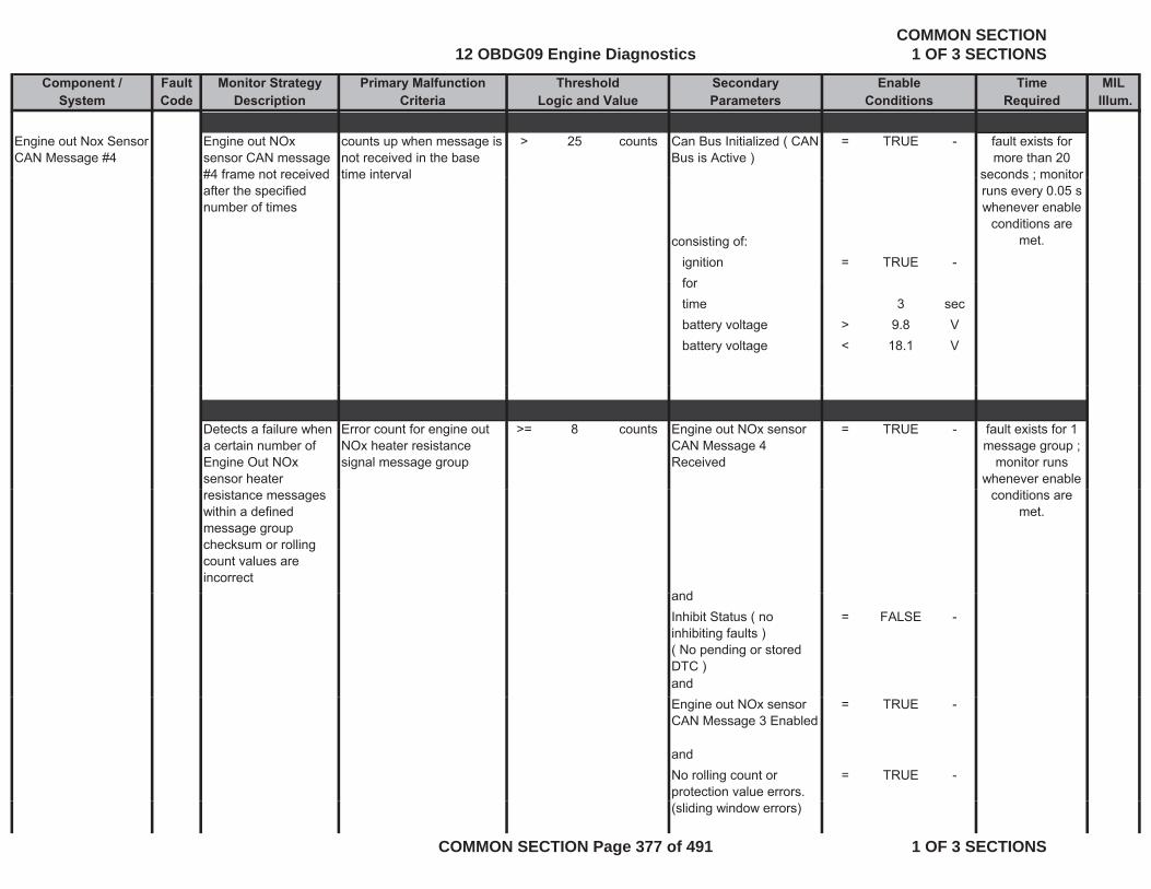
Component / Fault Monitor Strategy Primary Malfunction Secondary Time MILSystem Code Description Criteria Parameters Required Illum.
Threshold EnableLogic and Value Conditions
Engine out Nox Sensor CAN Message #4
Engine out NOx sensor CAN message #4 frame not received
counts up when message is not received in the base time interval
> 25 counts Can Bus Initialized ( CAN Bus is Active )
= TRUE - fault exists for more than 20
seconds ; monitor#4 frame not received after the specified number of times
time interval
consisting of:ignition = TRUE -for
seconds ; monitor runs every 0.05 s whenever enable
conditions are met.
fortime 3 secbattery voltage > 9.8 Vbattery voltage < 18.1 V
Detects a failure when a certain number of Engine Out NOx sensor heater
Error count for engine out NOx heater resistance signal message group
>= 8 counts Engine out NOx sensor CAN Message 4 Received
= TRUE - fault exists for 1 message group ;
monitor runs whenever enable
resistance messages within a defined message group checksum or rolling count values are incorrect
d
conditions are met.
andInhibit Status ( no inhibiting faults )( No pending or stored DTC )
= FALSE -
andEngine out NOx sensor CAN Message 3 Enabled
= TRUE -
andNo rolling count or protection value errors.
= TRUE -
(sliding window errors)
12 OBDG09 Engine DiagnosticsCOMMON SECTION
1 OF 3 SECTIONS
COMMON SECTION Page 377 of 491 1 OF 3 SECTIONS
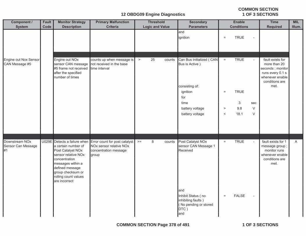
Component / Fault Monitor Strategy Primary Malfunction Secondary Time MILSystem Code Description Criteria Parameters Required Illum.
Threshold EnableLogic and Value Conditions
andignition = TRUE -
Engine out Nox Sensor CAN Message #5
Engine out NOx sensor CAN message #5 frame not received after the specified
counts up when message is not received in the base time interval
> 25 counts Can Bus Initialized ( CAN Bus is Active )
= TRUE - fault exists for more than 20
seconds ; monitor runs every 0.1 s
number of times
consisting of:ignition = TRUEfortime 3 sec
ywhenever enable
conditions are met.
time 3 secbattery voltage > 9.8 Vbattery voltage < 18.1 V
Downstream NOx Sensor Can Message #1
U029E Detects a failure when a certain number of Post Catalyst NOx sensor relative NOx
Error count for post catalyst NOx sensor relative NOx concentration message group
>= 8 counts Post Catalyst NOx sensor CAN Message 1 Received
= TRUE - Afault exists for 1 message group ;
monitor runs whenever enable
concentration messages within a defined message group checksum or rolling count values are incorrect
conditions are met.
andInhibit Status ( no inhibiting faults )( No pending or stored DTC )
= FALSE -
dand
12 OBDG09 Engine DiagnosticsCOMMON SECTION
1 OF 3 SECTIONS
COMMON SECTION Page 378 of 491 1 OF 3 SECTIONS

Component / Fault Monitor Strategy Primary Malfunction Secondary Time MILSystem Code Description Criteria Parameters Required Illum.
Threshold EnableLogic and Value Conditions
NOx sensor CAN Message 1 Enabled
= TRUE -
andNo rolling count or = TRUE -No rolling count or protection value errors. (sliding window errors)
TRUE
andignition = TRUE -
Detects a failure when a certain number of Post Catalyst NOx
Error count for post catalyst NOx sensor status message group
>= 8 counts Post Catalyst NOx sensor CAN Message 1 Received
= TRUE - fault exists for 1 message group ;
monitor runs ysensor linear lambda messages within a defined message group checksum or rolling count values are incorrect
g g pwhenever enable
conditions are met.
andInhibit Status ( no inhibiting faults )( No pending or stored
= FALSE -
DTC )andNOx sensor CAN Message 1 Enabled
= TRUE -
andNo rolling count or = TRUE -gprotection value errors. (sliding window errors)
andignition = TRUE -
12 OBDG09 Engine DiagnosticsCOMMON SECTION
1 OF 3 SECTIONS
COMMON SECTION Page 379 of 491 1 OF 3 SECTIONS
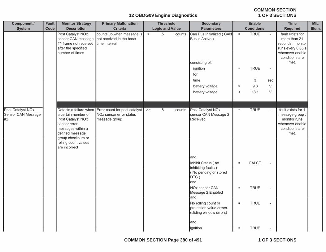
Component / Fault Monitor Strategy Primary Malfunction Secondary Time MILSystem Code Description Criteria Parameters Required Illum.
Threshold EnableLogic and Value Conditions
Post Catalyst NOx sensor CAN message #1 frame not received after the specified
counts up when message is not received in the base time interval
> 5 counts Can Bus Initialized ( CAN Bus is Active )
= TRUE - fault exists for more than 21
seconds ; monitor runs every 0.05 s
number of times
consisting of:ignition = TRUE -fortime 3 sec
whenever enable conditions are
met.
time 3 secbattery voltage > 9.8 Vbattery voltage < 18.1 V
Post Catalyst NOx Detects a failure when Error count for post catalyst > 8 counts Post Catalyst NOx TRUE fault exists for 1Post Catalyst NOx Sensor CAN Message #2
Detects a failure when a certain number of Post Catalyst NOx sensor error messages within a defined message group checksum or
Error count for post catalyst NOx sensor error status message group
>= 8 counts Post Catalyst NOx sensor CAN Message 2 Received
= TRUE - fault exists for 1 message group ;
monitor runs whenever enable
conditions are met.
group checksum or rolling count values are incorrect
andInhibit Status ( no inhibiting faults )
= FALSE -inhibiting faults )( No pending or stored DTC )andNOx sensor CAN Message 2 Enabled
= TRUE -
andandNo rolling count or protection value errors. (sliding window errors)
= TRUE -
andi iti TRUEignition = TRUE -
12 OBDG09 Engine DiagnosticsCOMMON SECTION
1 OF 3 SECTIONS
COMMON SECTION Page 380 of 491 1 OF 3 SECTIONS

Component / Fault Monitor Strategy Primary Malfunction Secondary Time MILSystem Code Description Criteria Parameters Required Illum.
Threshold EnableLogic and Value Conditions
Detects a failure when a certain number of Post Catalyst NOx
Error count for post catalyst NOx linear lambda signal message group
>= 8 counts Post Catalyst NOx sensor CAN Message 2 Received
= TRUE - fault exists for 1 message group ;
monitor runsPost Catalyst NOx sensor linear lambda messages within a defined message group checksum or rolling count values are incorrect
message group Received monitor runs whenever enable
conditions are met.
andInhibit Status ( no inhibiting faults )( No pending or stored
= FALSE -
( p gDTC )andNOx sensor CAN Message 2 Enabled
= TRUE -
andNo rolling count or = TRUE -No rolling count or protection value errors. (sliding window errors)
= TRUE
andignition = TRUE -
NOx Sensor CAN Message #2 frame not received after the
counts up when message is not received in the base time interval
> 5 counts Can Bus Initialized ( CAN Bus is Active )
= TRUE - fault exists for more than
21seconds ; specified number of times
consisting of:ignition = TRUE -forti 3
;monitor runs every 0.05 s
whenever enable conditions are
met.
time 3 sec
12 OBDG09 Engine DiagnosticsCOMMON SECTION
1 OF 3 SECTIONS
COMMON SECTION Page 381 of 491 1 OF 3 SECTIONS
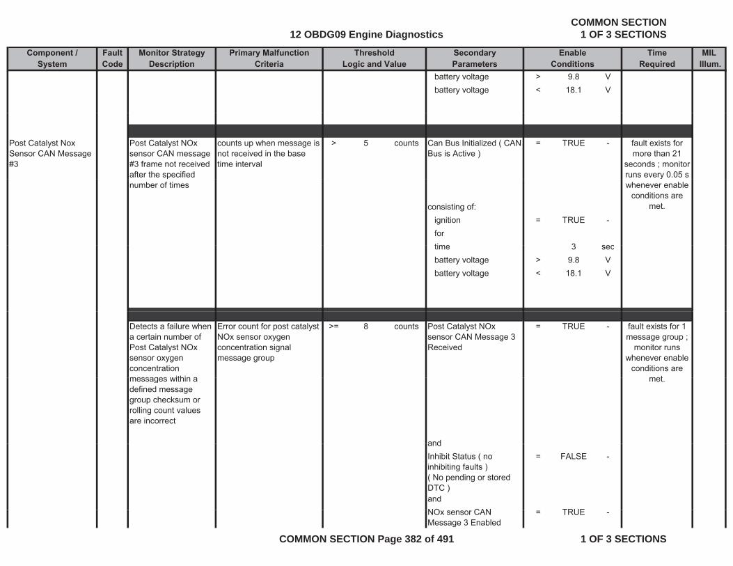
Component / Fault Monitor Strategy Primary Malfunction Secondary Time MILSystem Code Description Criteria Parameters Required Illum.
Threshold EnableLogic and Value Conditions
battery voltage > 9.8 Vbattery voltage < 18.1 V
Post Catalyst Nox Sensor CAN Message #3
Post Catalyst NOx sensor CAN message #3 frame not received after the specified
counts up when message is not received in the base time interval
> 5 counts Can Bus Initialized ( CAN Bus is Active )
= TRUE - fault exists for more than 21
seconds ; monitor runs every 0.05 s
number of times
consisting of:ignition = TRUE -fortime 3 sec
ywhenever enable
conditions are met.
time 3 secbattery voltage > 9.8 Vbattery voltage < 18.1 V
Detects a failure when a certain number of Post Catalyst NOx sensor oxygen concentration messages within a
Error count for post catalyst NOx sensor oxygen concentration signal message group
>= 8 counts Post Catalyst NOx sensor CAN Message 3 Received
= TRUE - fault exists for 1 message group ;
monitor runs whenever enable
conditions are metmessages within a
defined message group checksum or rolling count values are incorrect
and
met.
andInhibit Status ( no inhibiting faults )( No pending or stored DTC )
= FALSE -
andNO CAN TRUENOx sensor CAN Message 3 Enabled
= TRUE -
12 OBDG09 Engine DiagnosticsCOMMON SECTION
1 OF 3 SECTIONS
COMMON SECTION Page 382 of 491 1 OF 3 SECTIONS

Component / Fault Monitor Strategy Primary Malfunction Secondary Time MILSystem Code Description Criteria Parameters Required Illum.
Threshold EnableLogic and Value Conditions
andNo rolling count or protection value errors. (sliding window errors)
= TRUE -
(sliding window errors)
andignition = TRUE -
Detects a failure when a certain number of Post Catalyst NOx sensor binary lambda messages within a
Error count for post catalyst NOx sensor binary lambda signal message group
>= 8 counts Post Catalyst NOx sensor CAN Message 3 Received
= TRUE - fault exists for 1 message group ;
monitor runs whenever enable
conditions are gdefined message group checksum or rolling count values are incorrect
met.
andInhibit Status ( no inhibiting faults )( No pending or stored DTC )
= FALSE -
andNOx sensor CAN Message 3 Enabled
= TRUE -
andNo rolling count or protection value errors. (sliding window errors)
= TRUE -
( g )
andignition = TRUE -
12 OBDG09 Engine DiagnosticsCOMMON SECTION
1 OF 3 SECTIONS
COMMON SECTION Page 383 of 491 1 OF 3 SECTIONS
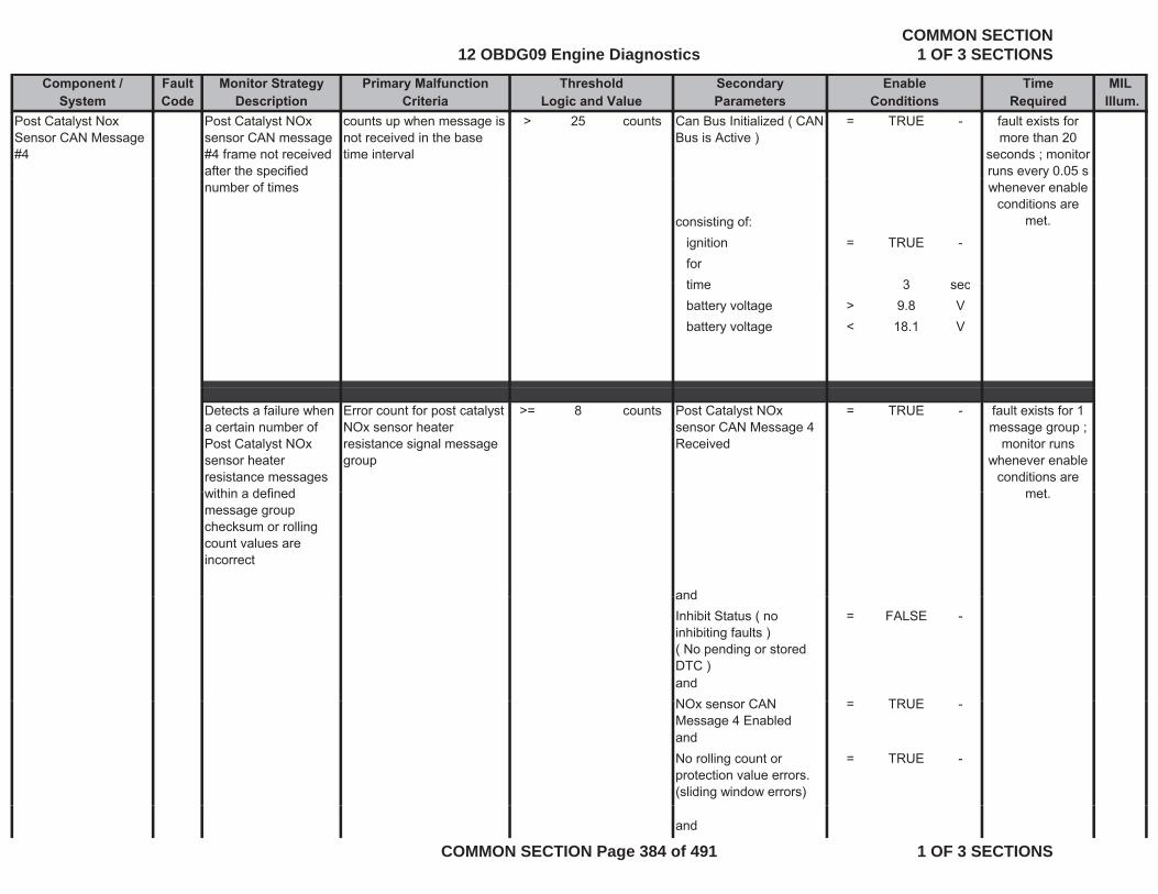
Component / Fault Monitor Strategy Primary Malfunction Secondary Time MILSystem Code Description Criteria Parameters Required Illum.
Threshold EnableLogic and Value Conditions
Post Catalyst Nox Sensor CAN Message #4
Post Catalyst NOx sensor CAN message #4 frame not received after the specified
counts up when message is not received in the base time interval
> 25 counts Can Bus Initialized ( CAN Bus is Active )
= TRUE - fault exists for more than 20
seconds ; monitor runs every 0.05 s
number of times
consisting of:ignition = TRUE -fortime 3 sec
whenever enable conditions are
met.
time 3 secbattery voltage > 9.8 Vbattery voltage < 18.1 V
Detects a failure when a certain number of Post Catalyst NOx sensor heater resistance messages within a defined
Error count for post catalyst NOx sensor heater resistance signal message group
>= 8 counts Post Catalyst NOx sensor CAN Message 4 Received
= TRUE - fault exists for 1 message group ;
monitor runs whenever enable
conditions are metwithin a defined
message group checksum or rolling count values are incorrect
and
met.
andInhibit Status ( no inhibiting faults )( No pending or stored DTC )
= FALSE -
andNO CAN TRUENOx sensor CAN Message 4 Enabled
= TRUE -
andNo rolling count or protection value errors. (sliding window errors)
= TRUE -
and
12 OBDG09 Engine DiagnosticsCOMMON SECTION
1 OF 3 SECTIONS
COMMON SECTION Page 384 of 491 1 OF 3 SECTIONS
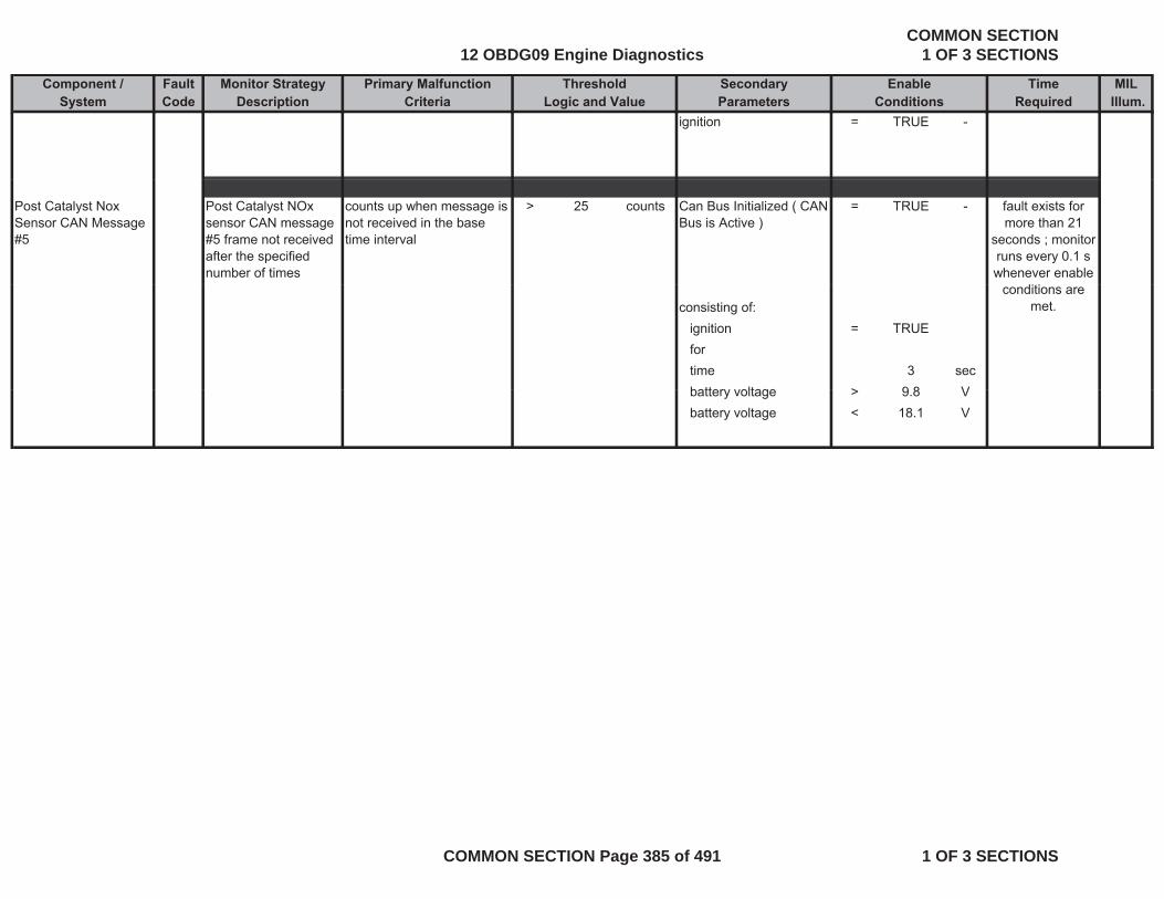
Component / Fault Monitor Strategy Primary Malfunction Secondary Time MILSystem Code Description Criteria Parameters Required Illum.
Threshold EnableLogic and Value Conditions
ignition = TRUE -
Post Catalyst Nox Sensor CAN Message #5
Post Catalyst NOx sensor CAN message #5 frame not received after the specified number of times
counts up when message is not received in the base time interval
> 25 counts Can Bus Initialized ( CAN Bus is Active )
= TRUE - fault exists for more than 21
seconds ; monitor runs every 0.1 s whenever enable
consisting of:ignition = TRUEfortime 3 secbattery voltage > 9 8 V
conditions are met.
battery voltage > 9.8 Vbattery voltage < 18.1 V
12 OBDG09 Engine DiagnosticsCOMMON SECTION
1 OF 3 SECTIONS
COMMON SECTION Page 385 of 491 1 OF 3 SECTIONS
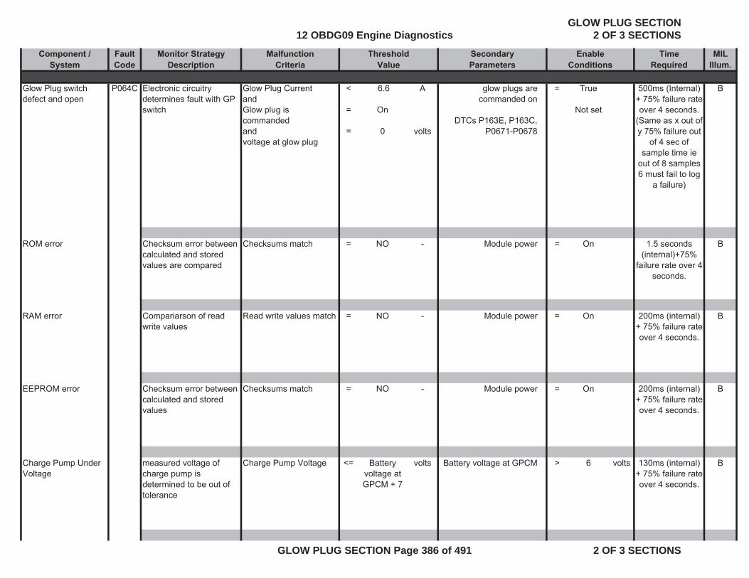
Component / Fault Monitor Strategy Malfunction Secondary Time MIL System Code Description Criteria Parameters Required Illum.
Glow Plug switch defect and open
P064C Electronic circuitry determines fault with GP switch
Glow Plug CurrentandGlow plug is commandedand voltage at glow plug
<
=
=
6.6
On
0
A
volts
glow plugs are commanded on
DTCs P163E, P163C, P0671-P0678
= True
Not set
500ms (Internal) + 75% failure rate over 4 seconds.
(Same as x out of y 75% failure out
of 4 sec of sample time ie
out of 8 samples 6 must fail to log
a failure)
B
ROM error Checksum error between calculated and stored values are compared
Checksums match = NO - Module power = On 1.5 seconds (internal)+75%
failure rate over 4 seconds.
B
RAM error Compariarson of read write values
Read write values match = NO - Module power = On 200ms (internal) + 75% failure rate over 4 seconds.
B
EEPROM error Checksum error between calculated and stored values
Checksums match = NO - Module power = On 200ms (internal) + 75% failure rate over 4 seconds.
B
Charge Pump Under Voltage
measured voltage of charge pump is determined to be out of tolerance
Charge Pump Voltage <= Battery voltage at GPCM + 7
volts Battery voltage at GPCM > 6 volts 130ms (internal) + 75% failure rate over 4 seconds.
B
ThresholdValue
EnableConditions
12 OBDG09 Engine DiagnosticsGLOW PLUG SECTION
2 OF 3 SECTIONS
GLOW PLUG SECTION Page 386 of 491 2 OF 3 SECTIONS
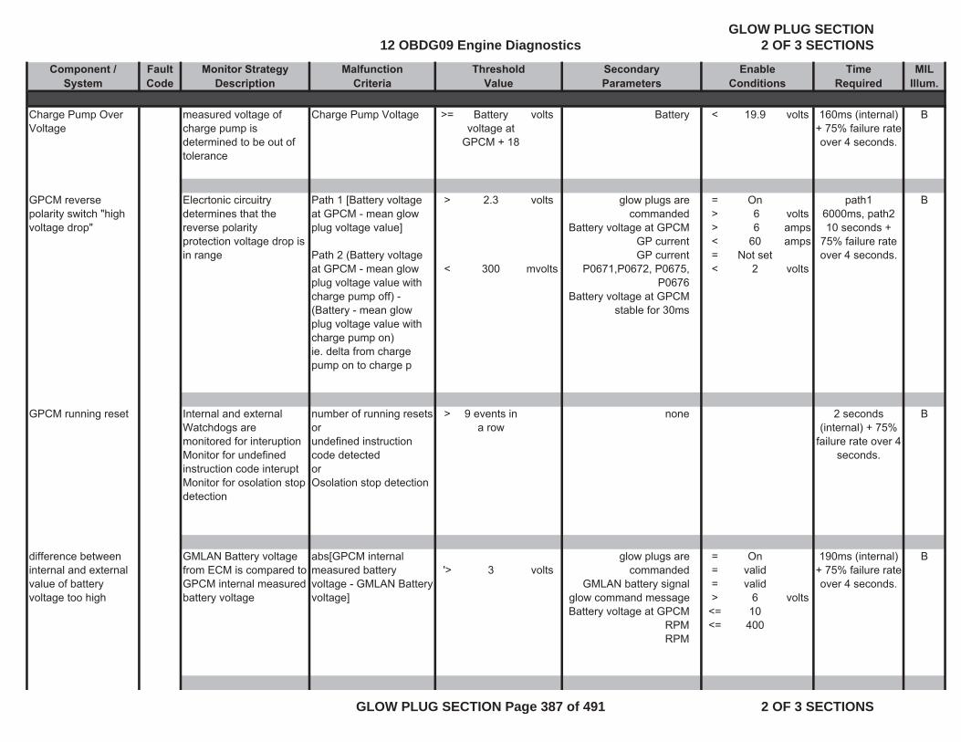
Component / Fault Monitor Strategy Malfunction Secondary Time MIL System Code Description Criteria Parameters Required Illum.
ThresholdValue
EnableConditions
Charge Pump Over Voltage
measured voltage of charge pump is determined to be out of tolerance
Charge Pump Voltage >= Battery voltage at
GPCM + 18
volts Battery < 19.9 volts 160ms (internal) + 75% failure rate over 4 seconds.
B
GPCM reverse polarity switch "high voltage drop"
Elecrtonic circuitry determines that the reverse polarity protection voltage drop is in range
Path 1 [Battery voltage at GPCM - mean glow plug voltage value]
Path 2 (Battery voltage at GPCM - mean glow plug voltage value with charge pump off) - (Battery - mean glow plug voltage value with charge pump on) ie. delta from charge pump on to charge p
>
<
2.3
300
volts
mvolts
glow plugs are commanded
Battery voltage at GPCMGP currentGP current
P0671,P0672, P0675, P0676
Battery voltage at GPCM stable for 30ms
=>>< =<
On 6 660
Not set2
voltsampsamps
volts
path16000ms, path2 10 seconds +
75% failure rate over 4 seconds.
B
GPCM running reset Internal and external Watchdogs are monitored for interuptionMonitor for undefined instruction code interuptMonitor for osolation stop detection
number of running resetsor undefined instruction code detectedorOsolation stop detection
> 9 events in a row
none 2 seconds (internal) + 75%
failure rate over 4 seconds.
B
difference between internal and external value of battery voltage too high
GMLAN Battery voltage from ECM is compared to GPCM internal measured battery voltage
abs[GPCM internal measured battery voltage - GMLAN Battery voltage]
'> 3 voltsglow plugs are
commandedGMLAN battery signal
glow command messageBattery voltage at GPCM
RPMRPM
===>
<=<=
Onvalidvalid
610
400
volts
190ms (internal) + 75% failure rate over 4 seconds.
B
12 OBDG09 Engine DiagnosticsGLOW PLUG SECTION
2 OF 3 SECTIONS
GLOW PLUG SECTION Page 387 of 491 2 OF 3 SECTIONS
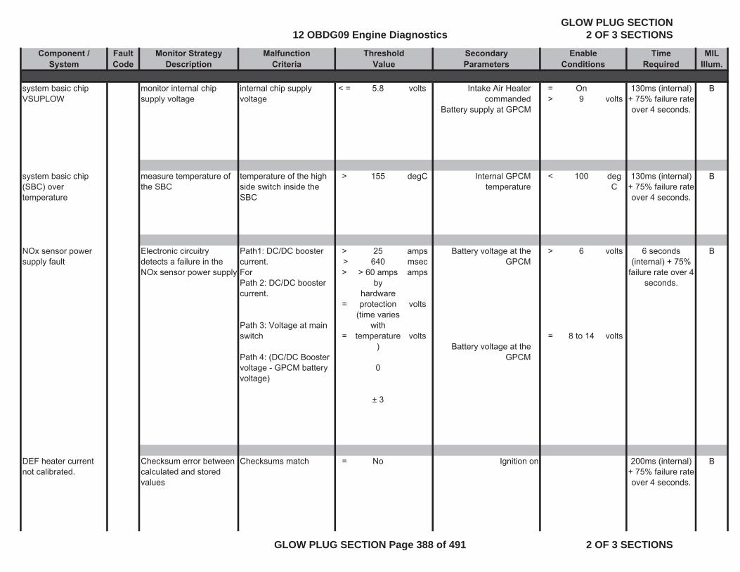
Component / Fault Monitor Strategy Malfunction Secondary Time MIL System Code Description Criteria Parameters Required Illum.
ThresholdValue
EnableConditions
system basic chip VSUPLOW
monitor internal chip supply voltage
internal chip supply voltage
< = 5.8 volts Intake Air Heater commanded
Battery supply at GPCM
=>
On9 volts
130ms (internal) + 75% failure rate over 4 seconds.
B
system basic chip (SBC) over temperature
measure temperature of the SBC
temperature of the high side switch inside the SBC
> 155 degC Internal GPCM temperature
< 100 deg C
130ms (internal) + 75% failure rate over 4 seconds.
B
NOx sensor power supply fault
Electronic circuitry detects a failure in the NOx sensor power supply
Path1: DC/DC booster current.For Path 2: DC/DC booster current.
Path 3: Voltage at main switch
Path 4: (DC/DC Booster voltage - GPCM battery voltage)
> > >
=
=
25640
> 60 amps by
hardware protection
(time varies with
temperature)
0
± 3
amps msecamps
volts
volts
Battery voltage at the GPCM
Battery voltage at the GPCM
>
=
6
8 to 14
volts
volts
6 seconds (internal) + 75%
failure rate over 4 seconds.
B
DEF heater current not calibrated.
Checksum error between calculated and stored values
Checksums match = No Ignition on 200ms (internal) + 75% failure rate over 4 seconds.
B
12 OBDG09 Engine DiagnosticsGLOW PLUG SECTION
2 OF 3 SECTIONS
GLOW PLUG SECTION Page 388 of 491 2 OF 3 SECTIONS
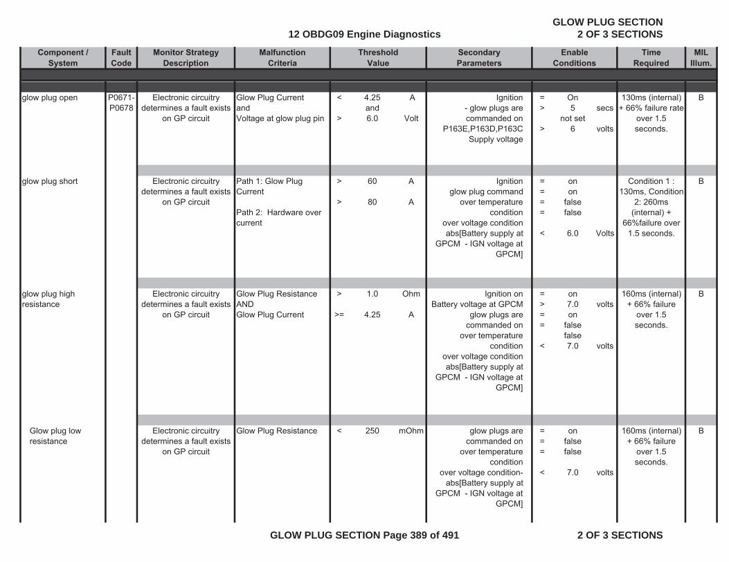
Component / Fault Monitor Strategy Malfunction Secondary Time MIL System Code Description Criteria Parameters Required Illum.
ThresholdValue
EnableConditions
glow plug open P0671-P0678
Electronic circuitry determines a fault exists
on GP circuit
Glow Plug Current andVoltage at glow plug pin
<
>
4.25and6.0
A
Volt
Ignition- glow plugs are commanded on
P163E,P163D,P163C Supply voltage
=>
>
On5
not set6
secs
volts
130ms (internal) + 66% failure rate
over 1.5 seconds.
B
glow plug short Electronic circuitry determines a fault exists
on GP circuit
Path 1: Glow Plug Current
Path 2: Hardware over current
>
>
60
80
A
A
Ignitionglow plug command
over temperature condition
over voltage conditionabs[Battery supply at
GPCM - IGN voltage at GPCM]
====
<
onon
falsefalse
6.0 Volts
Condition 1 : 130ms, Condition
2: 260ms (internal) +
66%failure over 1.5 seconds.
B
glow plug high resistance
Electronic circuitry determines a fault exists
on GP circuit
Glow Plug Resistance ANDGlow Plug Current
>
>=
1.0
4.25
Ohm
A
Ignition on Battery voltage at GPCM
glow plugs are commanded on
over temperature condition
over voltage conditionabs[Battery supply at
GPCM - IGN voltage at GPCM]
=>==
<
on7.0on
falsefalse7.0
volts
volts
160ms (internal) + 66% failure
over 1.5 seconds.
B
Glow plug low resistance
Electronic circuitry determines a fault exists
on GP circuit
Glow Plug Resistance < 250 mOhm glow plugs are commanded on
over temperature condition
over voltage condition- abs[Battery supply at
GPCM - IGN voltage at GPCM]
===
<
onfalsefalse
7.0 volts
160ms (internal) + 66% failure
over 1.5 seconds.
B
12 OBDG09 Engine DiagnosticsGLOW PLUG SECTION
2 OF 3 SECTIONS
GLOW PLUG SECTION Page 389 of 491 2 OF 3 SECTIONS
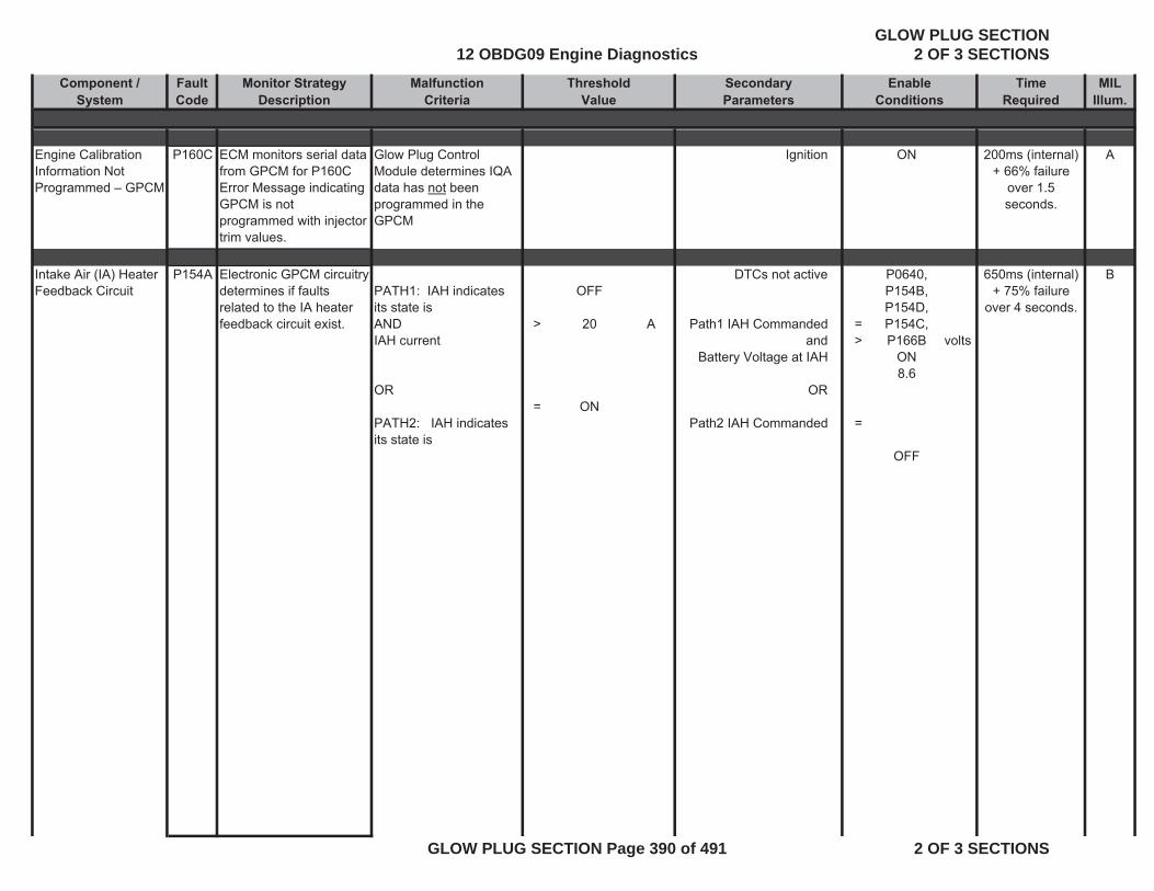
Component / Fault Monitor Strategy Malfunction Secondary Time MIL System Code Description Criteria Parameters Required Illum.
ThresholdValue
EnableConditions
Engine Calibration Information Not Programmed – GPCM
P160C ECM monitors serial data from GPCM for P160C Error Message indicating GPCM is not programmed with injector trim values.
Glow Plug Control Module determines IQA data has not been programmed in the GPCM
Ignition ON 200ms (internal) + 66% failure
over 1.5 seconds.
A
Intake Air (IA) Heater Feedback Circuit
P154A Electronic GPCM circuitry determines if faults related to the IA heater feedback circuit exist.
PATH1: IAH indicates its state is ANDIAH current
OR
PATH2: IAH indicates its state is
>
=
OFF
20
ON
A
DTCs not active
Path1 IAH Commanded
and Battery Voltage at IAH
OR
Path2 IAH Commanded
=>
=
P0640, P154B, P154D, P154C, P166B
ON8.6
OFF
volts
650ms (internal) + 75% failure
over 4 seconds.
B
12 OBDG09 Engine DiagnosticsGLOW PLUG SECTION
2 OF 3 SECTIONS
GLOW PLUG SECTION Page 390 of 491 2 OF 3 SECTIONS
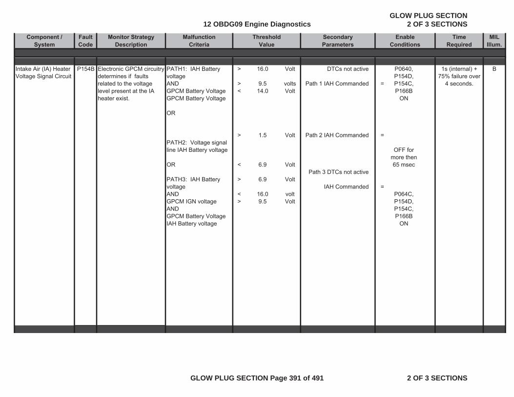
Component / Fault Monitor Strategy Malfunction Secondary Time MIL System Code Description Criteria Parameters Required Illum.
ThresholdValue
EnableConditions
Intake Air (IA) Heater Voltage Signal Circuit
P154B Electronic GPCM circuitry determines if faults related to the voltage level present at the IA heater exist.
PATH1: IAH Battery voltageANDGPCM Battery Voltage GPCM Battery Voltage
OR
PATH2: Voltage signal line IAH Battery voltage
OR
PATH3: IAH Battery voltageANDGPCM IGN voltageANDGPCM Battery VoltageIAH Battery voltage
>
> <
>
<
>
<>
16.0
9.5 14.0
1.5
6.9
6.9
16.09.5
Volt
volts Volt
Volt
Volt
Volt
voltVolt
DTCs not active
Path 1 IAH Commanded
Path 2 IAH Commanded
Path 3 DTCs not active
IAH Commanded
=
=
=
P0640, P154D, P154C, P166B
ON
OFF for more then 65 msec
P064C, P154D, P154C, P166B
ON
1s (internal) + 75% failure over
4 seconds.
B
12 OBDG09 Engine DiagnosticsGLOW PLUG SECTION
2 OF 3 SECTIONS
GLOW PLUG SECTION Page 391 of 491 2 OF 3 SECTIONS
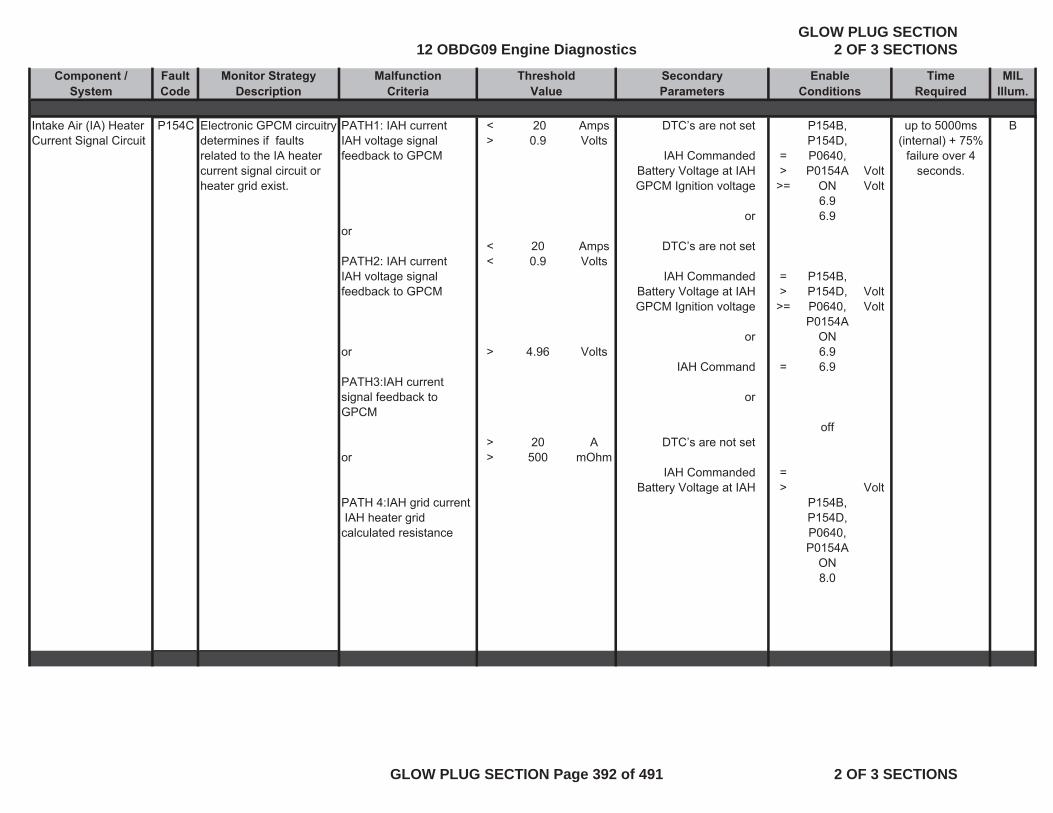
Component / Fault Monitor Strategy Malfunction Secondary Time MIL System Code Description Criteria Parameters Required Illum.
ThresholdValue
EnableConditions
Intake Air (IA) Heater Current Signal Circuit
P154C Electronic GPCM circuitry determines if faults related to the IA heater current signal circuit or heater grid exist.
PATH1: IAH current IAH voltage signal feedback to GPCM
or
PATH2: IAH currentIAH voltage signal feedback to GPCM
or
PATH3:IAH current signal feedback to GPCM
or
PATH 4:IAH grid current IAH heater grid calculated resistance
< >
<<
>
>>
200.9
200.9
4.96
20500
AmpsVolts
AmpsVolts
Volts
AmOhm
DTC’s are not set
IAH Commanded Battery Voltage at IAHGPCM Ignition voltage
or
DTC’s are not set
IAH Commanded Battery Voltage at IAHGPCM Ignition voltage
or
IAH Command
or
DTC’s are not set
IAH Commanded Battery Voltage at IAH
=>
>=
=>
>=
=
=>
P154B, P154D, P0640, P0154A
ON6.96.9
P154B, P154D, P0640, P0154A
ON6.96.9
off
P154B, P154D, P0640, P0154A
ON8.0
VoltVolt
VoltVolt
Volt
up to 5000ms (internal) + 75%
failure over 4 seconds.
B
12 OBDG09 Engine DiagnosticsGLOW PLUG SECTION
2 OF 3 SECTIONS
GLOW PLUG SECTION Page 392 of 491 2 OF 3 SECTIONS
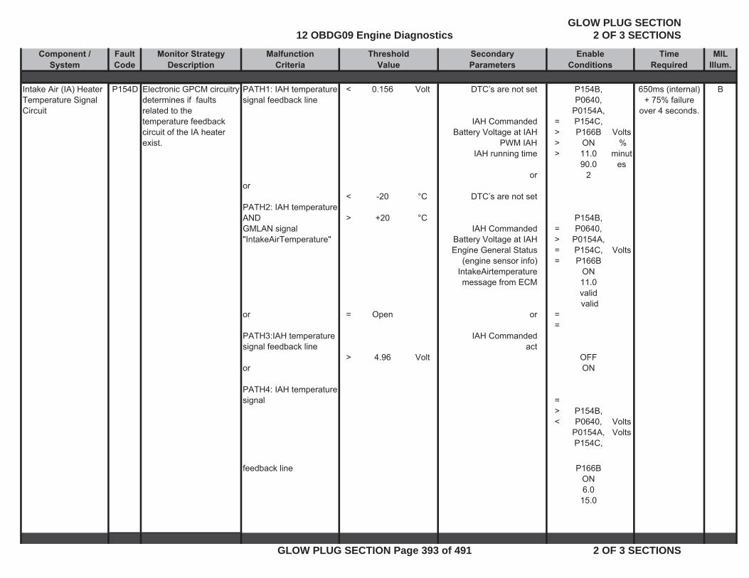
Component / Fault Monitor Strategy Malfunction Secondary Time MIL System Code Description Criteria Parameters Required Illum.
ThresholdValue
EnableConditions
Intake Air (IA) Heater Temperature Signal Circuit
P154D Electronic GPCM circuitry determines if faults related to the temperature feedback circuit of the IA heater exist.
PATH1: IAH temperature signal feedback line
or
PATH2: IAH temperatureANDGMLAN signal "IntakeAirTemperature"
or
PATH3:IAH temperature signal feedback line
or
PATH4: IAH temperature signal
<
<
>
=
>
0.156
-20
+20
Open
4.96
Volt
°C
°C
Volt
DTC’s are not set
IAH Commanded Battery Voltage at IAH
PWM IAH IAH running time
or
DTC’s are not set
IAH Commanded Battery Voltage at IAH Engine General Status
(engine sensor info)IntakeAirtemperature message from ECM
or
IAH Commandedact
=>>>
=>==
==
=><
P154B, P0640,
P0154A, P154C, P166B
ON11.090.0
2
P154B, P0640,
P0154A, P154C, P166B
ON11.0valid valid
OFFON
P154B, P0640,
P0154A, P154C,
Volts %
minutes
Volts
VoltsVolts
650ms (internal) + 75% failure
over 4 seconds.
B
feedback line P166BON6.0
15.0
12 OBDG09 Engine DiagnosticsGLOW PLUG SECTION
2 OF 3 SECTIONS
GLOW PLUG SECTION Page 393 of 491 2 OF 3 SECTIONS
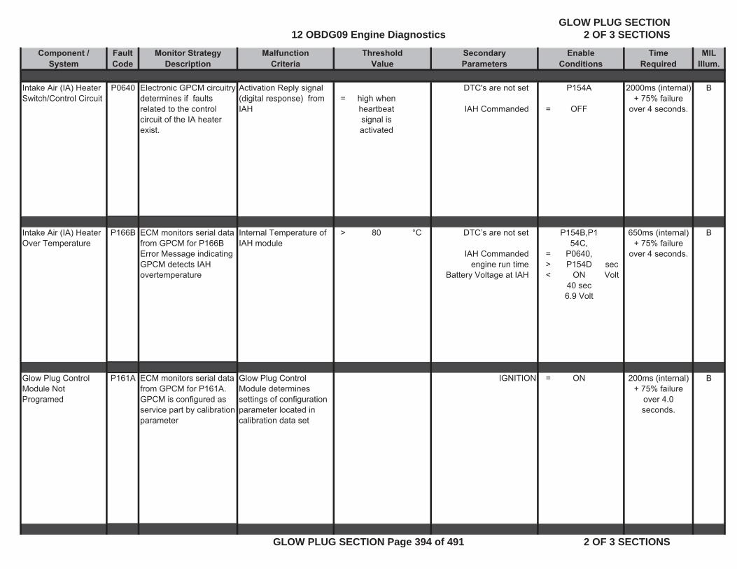
Component / Fault Monitor Strategy Malfunction Secondary Time MIL System Code Description Criteria Parameters Required Illum.
ThresholdValue
EnableConditions
Intake Air (IA) Heater Switch/Control Circuit
P0640 Electronic GPCM circuitry determines if faults related to the control circuit of the IA heater exist.
Activation Reply signal (digital response) from IAH
= high when heartbeat signal is activated
DTC's are not set
IAH Commanded =
P154A
OFF
2000ms (internal) + 75% failure
over 4 seconds.
B
Intake Air (IA) Heater Over Temperature
P166B ECM monitors serial data from GPCM for P166B Error Message indicating GPCM detects IAH overtemperature
Internal Temperature of IAH module
> 80 °C DTC’s are not set
IAH Commanded engine run time
Battery Voltage at IAH
=><
P154B,P154C,
P0640, P154D
ON40 sec6.9 Volt
secVolt
650ms (internal) + 75% failure
over 4 seconds.
B
Glow Plug Control Module Not Programed
P161A ECM monitors serial data from GPCM for P161A. GPCM is configured as service part by calibration parameter
Glow Plug Control Module determines settings of configuration parameter located in calibration data set
IGNITION = ON 200ms (internal) + 75% failure
over 4.0 seconds.
B
12 OBDG09 Engine DiagnosticsGLOW PLUG SECTION
2 OF 3 SECTIONS
GLOW PLUG SECTION Page 394 of 491 2 OF 3 SECTIONS
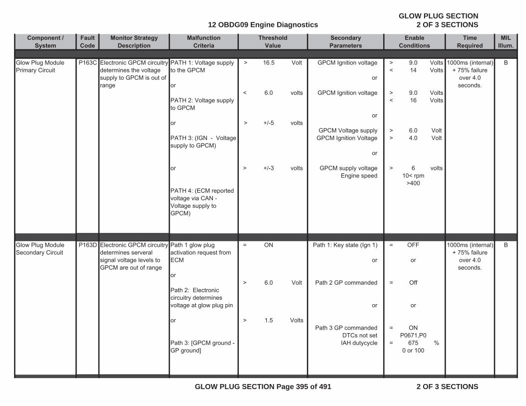
Component / Fault Monitor Strategy Malfunction Secondary Time MIL System Code Description Criteria Parameters Required Illum.
ThresholdValue
EnableConditions
Glow Plug Module Primary Circuit
P163C Electronic GPCM circuitry determines the voltage supply to GPCM is out of range
PATH 1: Voltage supply to the GPCM
or
PATH 2: Voltage supply to GPCM
or
PATH 3: (IGN - Voltage supply to GPCM)
or
PATH 4: (ECM reported voltage via CAN - Voltage supply to GPCM)
>
<
>
>
16.5
6.0
+/-5
+/-3
Volt
volts
volts
volts
GPCM Ignition voltage
or
GPCM Ignition voltage
or
GPCM Voltage supplyGPCM Ignition Voltage
or
GPCM supply voltage Engine speed
> <
> <
>>
>
9.0 14
9.0 16
6.04.0
610< rpm
>400
Volts Volts
Volts Volts
VoltVolt
volts
1000ms (internal) + 75% failure
over 4.0 seconds.
B
Glow Plug Module Secondary Circuit
P163D Electronic GPCM circuitry determines serveral signal voltage levels to GPCM are out of range
Path 1 glow plug activation request from ECM
or
Path 2: Electronic circuitry determines voltage at glow plug pin
or
Path 3: [GPCM ground - GP ground]
=
>
>
ON
6.0
1.5
Volt
Volts
Path 1: Key state (Ign 1)
or
Path 2 GP commanded
or
Path 3 GP commanded DTCs not set IAH dutycycle
=
=
=
=
OFF
or
Off
or
ONP0671,P0
6750 or 100
%
1000ms (internal) + 75% failure
over 4.0 seconds.
B
12 OBDG09 Engine DiagnosticsGLOW PLUG SECTION
2 OF 3 SECTIONS
GLOW PLUG SECTION Page 395 of 491 2 OF 3 SECTIONS
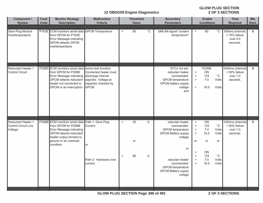
Component / Fault Monitor Strategy Malfunction Secondary Time MIL System Code Description Criteria Parameters Required Illum.
ThresholdValue
EnableConditions
Glow Plug Module Overtemperature
P163E ECM monitors serial data from GPCM for P163E Error Message indicating GPCM detects GPCM overtemperature
GPCM Temperature > 85 °C GMLAN signal "coolant temperature"
< 60 °C 650ms (internal) + 75% failure
over 4.0 seconds.
B
Reductant Heater 1 Control Circuit
P20B9 ECM monitors serial data from GPCM for P20B9Error Message indicating GPCM detects reductant heater not connected to GPCM or an interruption
Active test function; Connected heater must discharge internal capicitor. Voltage at capacitor checked by GPCM
DTCs not set:reductan heater
commanded:GPCM temperature
GPCM battery supply voltage
and
=<>
<
P220BON1237.0
16.0
°CVolts
Volts
3440ms (internal) + 50% failure
over 1.0 seconds.
B
Reductant Heater 1 Control Circuit Low Voltage
P20BB ECM monitors serial data from GPCM for P20BB Error Message indicating GPCM detects reductant heater output shorted to ground or an overload condition
Path 1: Glow Plug Current
or
Path 2: Hardware over current
>
>
25
or
80
A
A
reductan heater commanded:
GPCM temperature GPCM Battery supply
voltage
or
reductan heater commanded:
GPCM temperature GPCM Battery supply
voltage
=<> <
or
=<> <
ON1237.0
16.5
or
ON1237.0
16.5
°CVolts Volts
or
°CVolts Volts
1000ms (internal) + 50% failure
over 1.0 seconds.
B
12 OBDG09 Engine DiagnosticsGLOW PLUG SECTION
2 OF 3 SECTIONS
GLOW PLUG SECTION Page 396 of 491 2 OF 3 SECTIONS
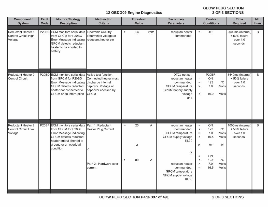
Component / Fault Monitor Strategy Malfunction Secondary Time MIL System Code Description Criteria Parameters Required Illum.
ThresholdValue
EnableConditions
Reductant Heater 1 Control Circuit High Voltage
P20BC ECM monitors serial data from GPCM for P20BCError Message indicating GPCM detects reductant heater to be shorted to battery
Electronic circuitry determines voltage at reductant heater pin
> 3.5 volts reductan heater commanded:
= OFF 2000ms (internal) + 50% failure
over 1.0 seconds.
B
Reductant Heater 2 Control Circuit
P20BD ECM monitors serial data from GPCM for P20BD Error Message indicating GPCM detects reductant heater not connected to GPCM or an interruption
Active test function; Connected heater must discharge internal capicitor. Voltage at capacitor checked by GPCM
DTCs not set:reductan heater
commanded:GPCM temperature
GPCM battery supply voltage
and
=<>
<
P20BFON1237.0
16.0
°CVolts
Volts
3440ms (internal) + 50% failure
over 1.0 seconds.
B
Reductant Heater 2 Control Circuit Low Voltage
P20BF ECM monitors serial data from GPCM for P20BF Error Message indicating GPCM detects reductant heater output shorted to ground or an overload condition
Path 1: Reductant Heater Plug Current
or
Path 2: Hardware over current
>
>
25
or
80
A
A
reductan heater commanded:
GPCM temperature GPCM supply voltage
KL30
or
reductan heater commanded:
GPCM temperature GPCM supply voltage
KL30
=<> <
or
=<> <
ON1237.0
16.5
or
ON1237.0
16.5
°CVolts Volts
or
°CVolts Volts
1000ms (internal) + 50% failure
over 1.0 seconds.
B
12 OBDG09 Engine DiagnosticsGLOW PLUG SECTION
2 OF 3 SECTIONS
GLOW PLUG SECTION Page 397 of 491 2 OF 3 SECTIONS
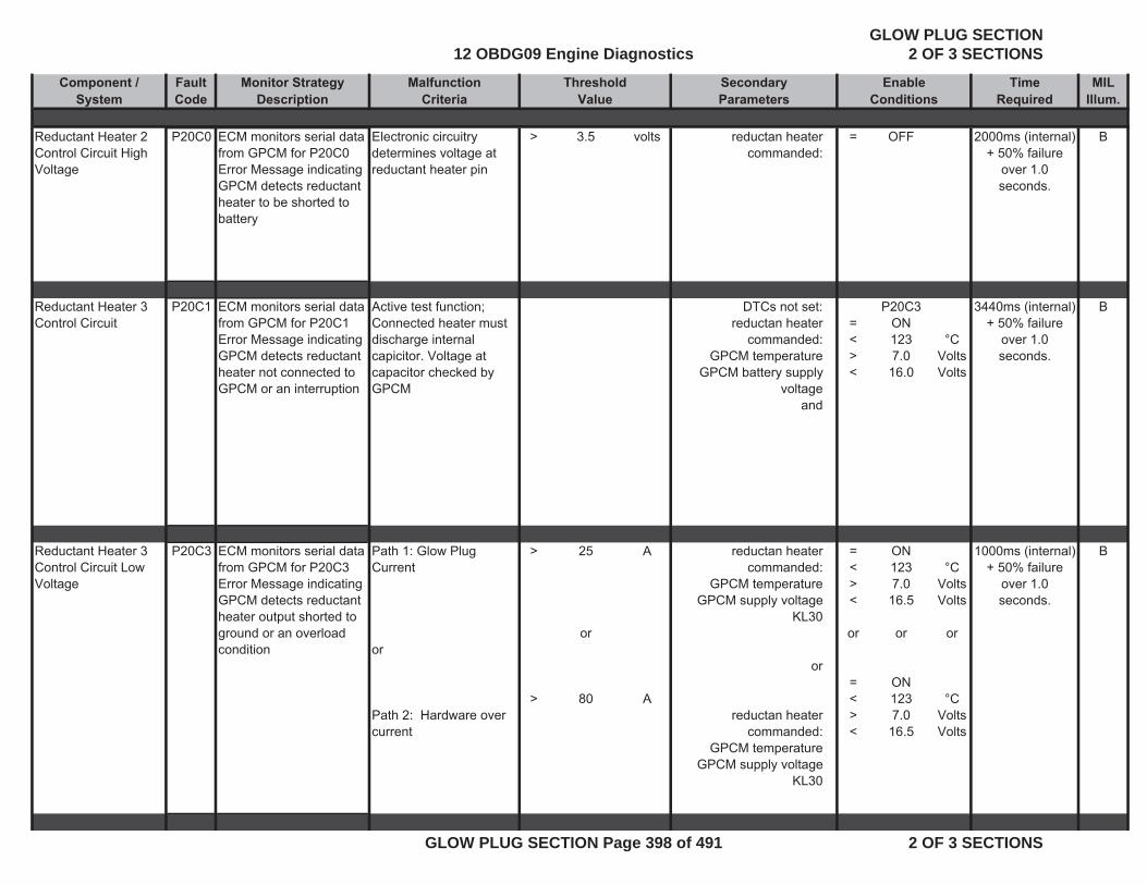
Component / Fault Monitor Strategy Malfunction Secondary Time MIL System Code Description Criteria Parameters Required Illum.
ThresholdValue
EnableConditions
Reductant Heater 2 Control Circuit High Voltage
P20C0 ECM monitors serial data from GPCM for P20C0Error Message indicating GPCM detects reductant heater to be shorted to battery
Electronic circuitry determines voltage at reductant heater pin
> 3.5 volts reductan heater commanded:
= OFF 2000ms (internal) + 50% failure
over 1.0 seconds.
B
Reductant Heater 3 Control Circuit
P20C1 ECM monitors serial data from GPCM for P20C1 Error Message indicating GPCM detects reductant heater not connected to GPCM or an interruption
Active test function; Connected heater must discharge internal capicitor. Voltage at capacitor checked by GPCM
DTCs not set:reductan heater
commanded:GPCM temperature
GPCM battery supply voltage
and
=<><
P20C3ON1237.0
16.0
°CVolts Volts
3440ms (internal) + 50% failure
over 1.0 seconds.
B
Reductant Heater 3 Control Circuit Low Voltage
P20C3 ECM monitors serial data from GPCM for P20C3 Error Message indicating GPCM detects reductant heater output shorted to ground or an overload condition
Path 1: Glow Plug Current
or
Path 2: Hardware over current
>
>
25
or
80
A
A
reductan heater commanded:
GPCM temperature GPCM supply voltage
KL30
or
reductan heater commanded:
GPCM temperature GPCM supply voltage
KL30
=<> <
or
=<> <
ON1237.0
16.5
or
ON1237.0
16.5
°CVolts Volts
or
°CVolts Volts
1000ms (internal) + 50% failure
over 1.0 seconds.
B
12 OBDG09 Engine DiagnosticsGLOW PLUG SECTION
2 OF 3 SECTIONS
GLOW PLUG SECTION Page 398 of 491 2 OF 3 SECTIONS
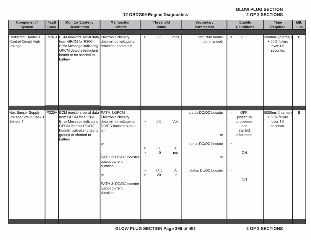
Component / Fault Monitor Strategy Malfunction Secondary Time MIL System Code Description Criteria Parameters Required Illum.
ThresholdValue
EnableConditions
Reductant Heater 3 Control Circuit High Voltage
P20C4 ECM monitors serial data from GPCM for P20C4Error Message indicating GPCM detects reductant heater to be shorted to battery
Electronic circuitry determines voltage at reductant heater pin
> 3.5 volts reductan heater commanded:
= OFF 2000ms (internal) + 50% failure
over 1.0 seconds.
B
Nox Sensor Supply Voltage Circuit Bank 1 Sensor 1
P220A ECM monitors serial data from GPCM for P220A Error Message indicating GPCM detects DC/DC booster output shorted to ground or shorted to battery
PATH 1:GPCM Electronic circuitry determines voltage at DC/DC booster output pin
or
PATH 2: DC/DC booster output currentduration
or
PATH 3: DC/DC booster output currentduration
>
> >
>>
5.0
5.010
37.520
Volt
Ams
Aμs
status DC/DC booster
or
status DC/DC booster
or
status Dc/DC booster
=
=
=
OFF, power up procedure
has started
after reset
ON
ON
5000ms (internal) + 50% failure
over 1.0 seconds.
B
12 OBDG09 Engine DiagnosticsGLOW PLUG SECTION
2 OF 3 SECTIONS
GLOW PLUG SECTION Page 399 of 491 2 OF 3 SECTIONS
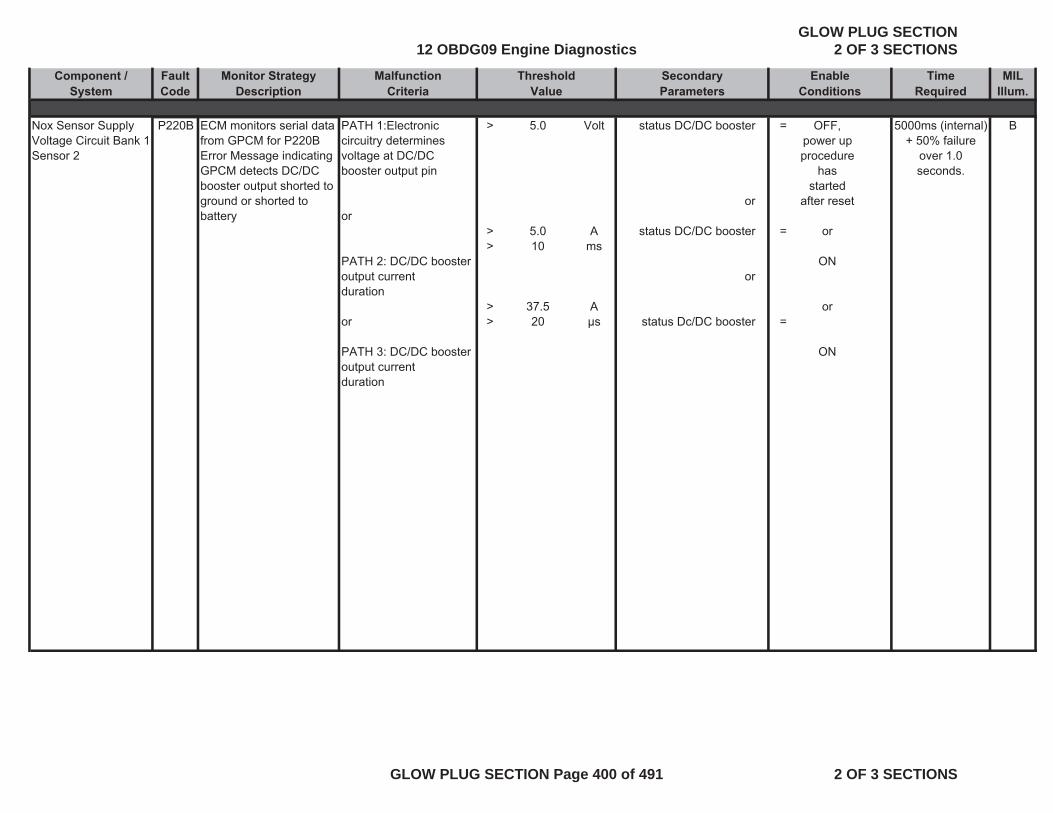
Component / Fault Monitor Strategy Malfunction Secondary Time MIL System Code Description Criteria Parameters Required Illum.
ThresholdValue
EnableConditions
Nox Sensor Supply Voltage Circuit Bank 1 Sensor 2
P220B ECM monitors serial data from GPCM for P220B Error Message indicating GPCM detects DC/DC booster output shorted to ground or shorted to battery
PATH 1:Electronic circuitry determines voltage at DC/DC booster output pin
or
PATH 2: DC/DC booster output currentduration
or
PATH 3: DC/DC booster output currentduration
>
>>
>>
5.0
5.010
37.520
Volt
Ams
Aμs
status DC/DC booster
or
status DC/DC booster
or
status Dc/DC booster
=
=
=
OFF, power up procedure
has started
after reset
or
ON
or
ON
5000ms (internal) + 50% failure
over 1.0 seconds.
B
12 OBDG09 Engine DiagnosticsGLOW PLUG SECTION
2 OF 3 SECTIONS
GLOW PLUG SECTION Page 400 of 491 2 OF 3 SECTIONS
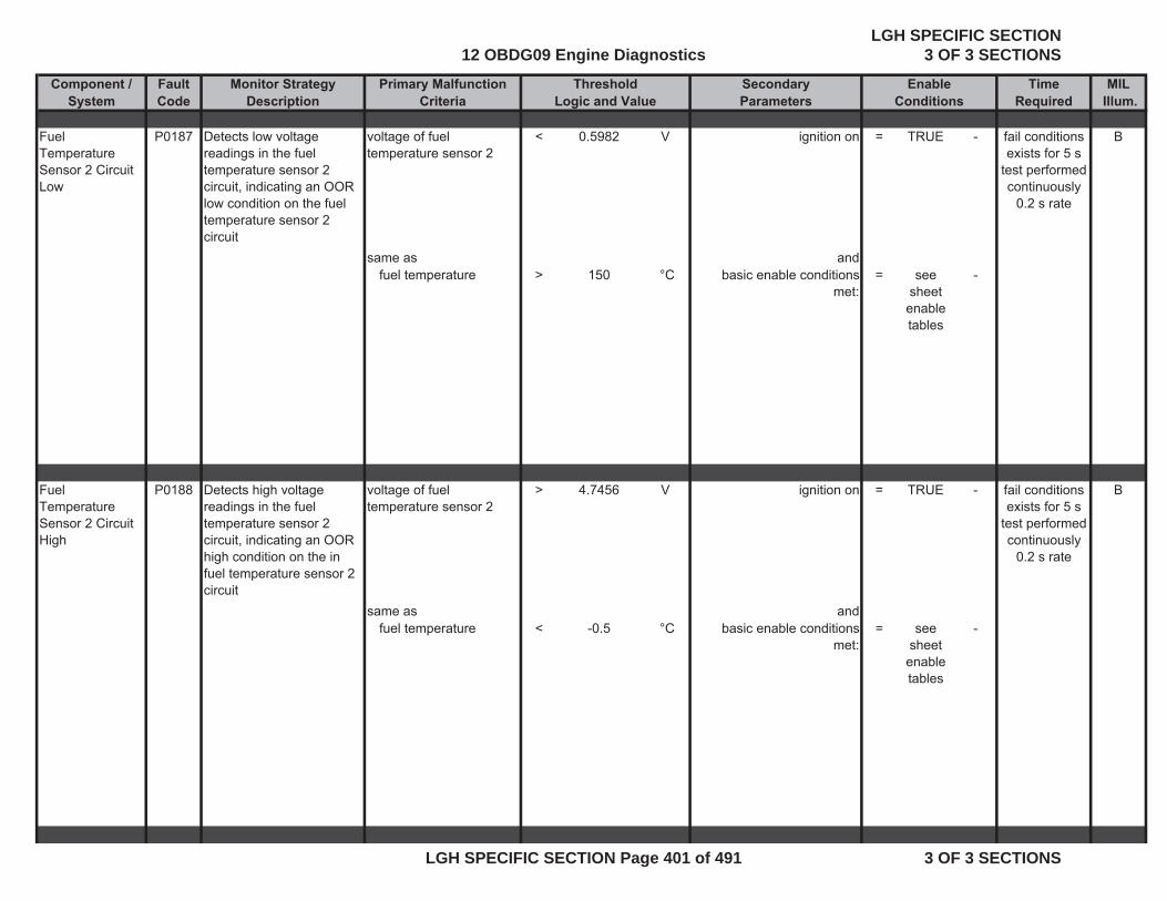
Component / Fault Monitor Strategy Primary Malfunction Secondary Time MILSystem Code Description Criteria Parameters Required Illum.
Fuel Temperature Sensor 2 Circuit Low
P0187 Detects low voltage readings in the fuel temperature sensor 2 circuit, indicating an OOR low condition on the fuel temperature sensor 2 circuit
voltage of fuel temperature sensor 2
< 0.5982 V ignition on = TRUE - B
same as andfuel temperature > 150 °C basic enable conditions
met:= see
sheet enable tables
-
Fuel Temperature Sensor 2 Circuit High
P0188 Detects high voltage readings in the fuel temperature sensor 2 circuit, indicating an OOR high condition on the in fuel temperature sensor 2 circuit
voltage of fuel temperature sensor 2
> 4.7456 V ignition on = TRUE - B
same as andfuel temperature < -0.5 °C basic enable conditions
met:= see
sheet enable tables
-
fail conditions exists for 5 s
test performed continuously
0.2 s rate
fail conditions exists for 5 s
test performed continuously
0.2 s rate
Threshold EnableLogic and Value Conditions
12 OBDG09 Engine DiagnosticsLGH SPECIFIC SECTION
3 OF 3 SECTIONS
LGH SPECIFIC SECTION Page 401 of 491 3 OF 3 SECTIONS

Component / Fault Monitor Strategy Primary Malfunction Secondary Time MILSystem Code Description Criteria Parameters Required Illum.
Threshold EnableLogic and Value Conditions
Fuel Level Sensor 1 Circuit High
P0463Detects high voltage readings in the fuel level sensor circuit, indicating an OOR high condition on the fuel level sensor circuit
voltage of fuel level sensor 1
> 4.8 V ignition on = TRUE - B
same as andfuel level < 0 % basic enable conditions
met:= see
sheet enable tables
-
Fuel Level Sensor 1 Circuit Low
P0462Detects low voltage readings in the fuel level sensor circuit, indicating an OOR low condition on the fuel level sensor circuit
voltage of fuel level sensor 1
< 0.2 V ignition on = TRUE - B
same as andfuel level > 100 % basic enable conditions
met:= see
sheet enable tables
-
Primary Fuel Sensor Performance
P0461 Detects an error in the primary fuel tank sensor performance by comparing the decrease of the fuel level for a certain driven mileage to a threshold.
(a) - (b) >= 100 miles Engine Running (see parameter definition)
= TRUE - B
with for(a) total vehicle distance
= measured parameter
- time >= 60 sec
fail conditions exists for 24 s test performed continuously
0.1 s rate
fail conditions exists for 24 s test performed continuously
0.1 s rate
fail conditions exists for 0.02
smonitor runs 0.02 s rate whenever
enable conditions are
met
12 OBDG09 Engine DiagnosticsLGH SPECIFIC SECTION
3 OF 3 SECTIONS
LGH SPECIFIC SECTION Page 402 of 491 3 OF 3 SECTIONS
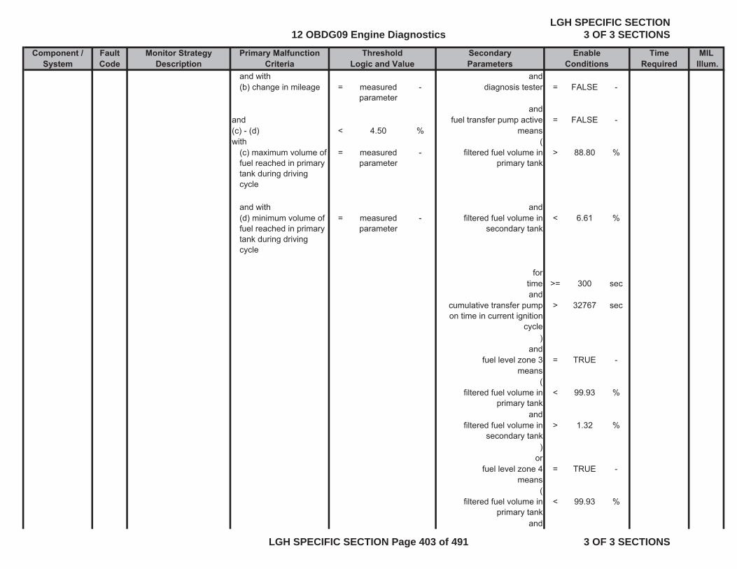
Component / Fault Monitor Strategy Primary Malfunction Secondary Time MILSystem Code Description Criteria Parameters Required Illum.
Threshold EnableLogic and Value Conditions
and with and(b) change in mileage = measured
parameter- diagnosis tester = FALSE -
andand fuel transfer pump active = FALSE -(c) - (d) < 4.50 % meanswith (
(c) maximum volume of fuel reached in primary tank during driving cycle
= measured parameter
- filtered fuel volume in primary tank
> 88.80 %
and with and(d) minimum volume of fuel reached in primary tank during driving cycle
= measured parameter
- filtered fuel volume in secondary tank
< 6.61 %
fortime >= 300 secand
cumulative transfer pump on time in current ignition
cycle
> 32767 sec
)and
fuel level zone 3 = TRUE -means
(filtered fuel volume in
primary tank< 99.93 %
andfiltered fuel volume in
secondary tank> 1.32 %
)or
fuel level zone 4 = TRUE -means
(filtered fuel volume in
primary tank< 99.93 %
and
12 OBDG09 Engine DiagnosticsLGH SPECIFIC SECTION
3 OF 3 SECTIONS
LGH SPECIFIC SECTION Page 403 of 491 3 OF 3 SECTIONS
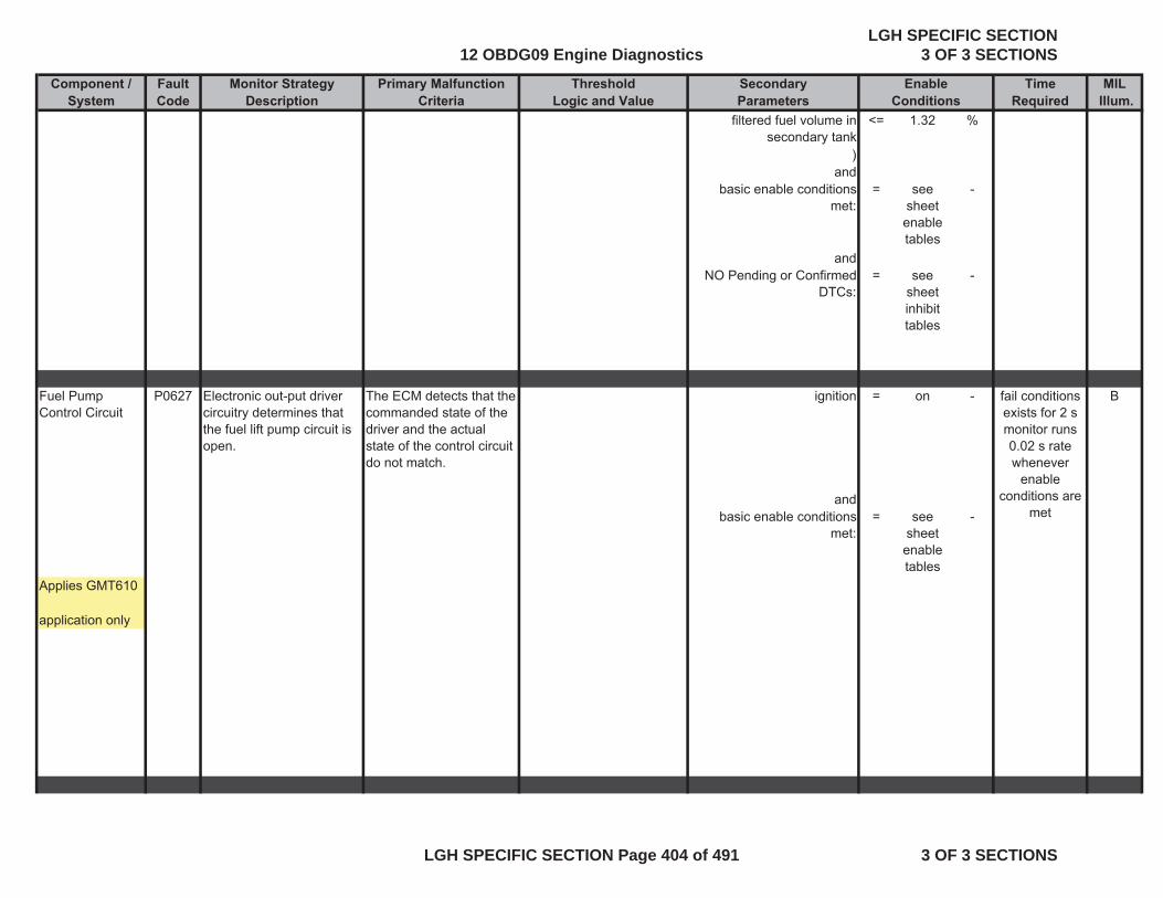
Component / Fault Monitor Strategy Primary Malfunction Secondary Time MILSystem Code Description Criteria Parameters Required Illum.
Threshold EnableLogic and Value Conditions
filtered fuel volume in secondary tank
<= 1.32 %
)and
basic enable conditions met:
= see sheet enable tables
-
andNO Pending or Confirmed
DTCs:= see
sheet inhibit tables
-
Fuel Pump Control Circuit
P0627 Electronic out-put driver circuitry determines that the fuel lift pump circuit is open.
The ECM detects that the commanded state of the driver and the actual state of the control circuit do not match.
ignition = on - B
andbasic enable conditions
met:= see
sheet enable tables
-
Applies GMT610
application only
fail conditions exists for 2 smonitor runs 0.02 s rate whenever
enable conditions are
met
12 OBDG09 Engine DiagnosticsLGH SPECIFIC SECTION
3 OF 3 SECTIONS
LGH SPECIFIC SECTION Page 404 of 491 3 OF 3 SECTIONS

Component / Fault Monitor Strategy Primary Malfunction Secondary Time MILSystem Code Description Criteria Parameters Required Illum.
Threshold EnableLogic and Value Conditions
Fuel Pump Control Circuit Low
P0628 Electronic out-put driver circuitry determines that the fuel lift pump circuit is shorted to ground.
The ECM detects that the commanded state of the driver and the actual state of the control circuit do not match.
ignition = on - B
andbasic enable conditions
met:= see
sheet enable tables
-
Applies GMT610
application only
Fuel Pump Control Circuit High
P0629 Electronic out-put driver circuitry determines that the fuel lift pump circuit is shorted to voltage.
The ECM detects that the commanded state of the driver and the actual state of the control circuit do not match.
ignition = on - B
andbasic enable conditions
met:= see
sheet enable tables
-
Applies GMT610
application only
fail conditions exists for 0.5smonitor runs 0.02 s rate whenever
enable conditions are
met
fail conditions exists for 1 smonitor runs 0.02 s rate whenever
enable conditions are
met
12 OBDG09 Engine DiagnosticsLGH SPECIFIC SECTION
3 OF 3 SECTIONS
LGH SPECIFIC SECTION Page 405 of 491 3 OF 3 SECTIONS
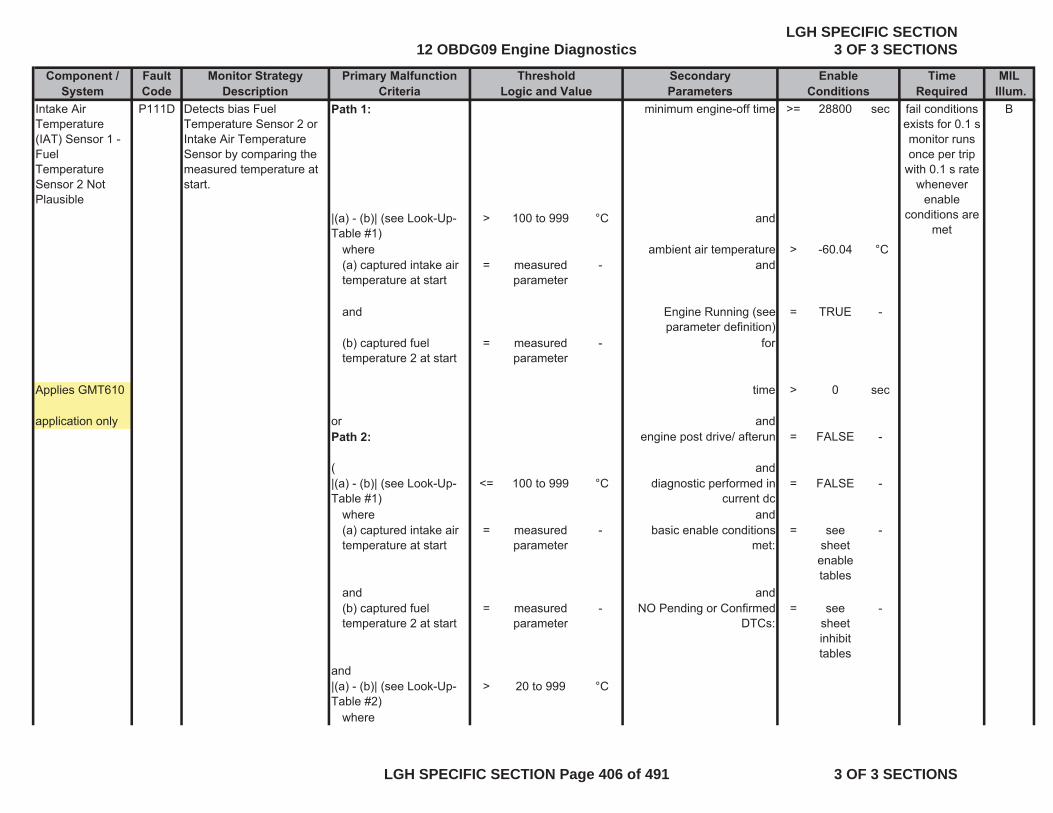
Component / Fault Monitor Strategy Primary Malfunction Secondary Time MILSystem Code Description Criteria Parameters Required Illum.
Threshold EnableLogic and Value Conditions
Intake Air Temperature (IAT) Sensor 1 - Fuel Temperature Sensor 2 Not Plausible
P111D Detects bias Fuel Temperature Sensor 2 or Intake Air Temperature Sensor by comparing the measured temperature at start.
Path 1: minimum engine-off time >= 28800 sec B
|(a) - (b)| (see Look-Up-Table #1)
> 100 to 999 °C and
where ambient air temperature > -60.04 °C(a) captured intake air temperature at start
= measured parameter
- and
and Engine Running (see parameter definition)
= TRUE -
(b) captured fuel temperature 2 at start
= measured parameter
- for
Applies GMT610 time > 0 sec
application only or andPath 2: engine post drive/ afterun = FALSE -
( and|(a) - (b)| (see Look-Up-Table #1)
<= 100 to 999 °C diagnostic performed in current dc
= FALSE -
where and(a) captured intake air temperature at start
= measured parameter
- basic enable conditions met:
= see sheet enable tables
-
and and(b) captured fuel temperature 2 at start
= measured parameter
- NO Pending or Confirmed DTCs:
= see sheet inhibit tables
-
and|(a) - (b)| (see Look-Up-Table #2)
> 20 to 999 °C
where
fail conditions exists for 0.1 smonitor runs once per trip
with 0.1 s rate whenever
enable conditions are
met
12 OBDG09 Engine DiagnosticsLGH SPECIFIC SECTION
3 OF 3 SECTIONS
LGH SPECIFIC SECTION Page 406 of 491 3 OF 3 SECTIONS
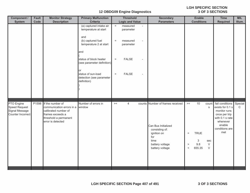
Component / Fault Monitor Strategy Primary Malfunction Secondary Time MILSystem Code Description Criteria Parameters Required Illum.
Threshold EnableLogic and Value Conditions
(a) captured intake air temperature at start
= measured parameter
-
and(b) captured fuel temperature 2 at start
= measured parameter
-
and(status of block heater (see parameter definition)
= FALSE -
orstatus of sun-load detection (see parameter definition)
= FALSE -
))
PTO Engine Speed Request Signal Message Counter Incorrect
P1598 If the number of communication errors in a calibrated number of frames exceeds a threshold a permanent error is detected
Number of errors in window
>= 4 counts Number of frames received >= 10 counts
Special C
Can Bus Initializedconsisting of:ignition on = TRUEfortime 3 secbattery voltage > 9.8 Vbattery voltage < 655.35 V
fail conditions exists for 0.1 smonitor runs once per trip
with 0.1 s rate whenever
enable conditions are
met
12 OBDG09 Engine DiagnosticsLGH SPECIFIC SECTION
3 OF 3 SECTIONS
LGH SPECIFIC SECTION Page 407 of 491 3 OF 3 SECTIONS

Component / Fault Monitor Strategy Primary Malfunction Secondary Time MILSystem Code Description Criteria Parameters Required Illum.
Threshold EnableLogic and Value Conditions
Turbocharger Vane Position Slow Response - Decreasing Position
P168C Detects slow responding turbo charger vanes. Actual positional readings are compared to desired values.
average positive gradient of the turbocharger vane commanded position - calculated by accumulating deviation between desired and actual value of vane position over a calibrated sampling time
>= 9.99755859 % ( B
turbocharger vane desired position gradient
> 0.61035 %/sec
andturbocharger vane desired
position gradient< 29.9072 %/sec
)and
control deviation of turbocharger vane position calculated out of difference between desired and actual
value
> 0 %
))
fortime > 0.2 secand
(engine speed >= 1000 rpm
andengine speed <= 3000 rpm
)and
ambient pressure > 74.8 kPaand
engine temperature > 69.96 °Cand
ambient air temperature > -7.04 °Cand
fail conditions exists for 15 s monitor runs
with 0.1 s rate whenever
enable conditions are
met
12 OBDG09 Engine DiagnosticsLGH SPECIFIC SECTION
3 OF 3 SECTIONS
LGH SPECIFIC SECTION Page 408 of 491 3 OF 3 SECTIONS
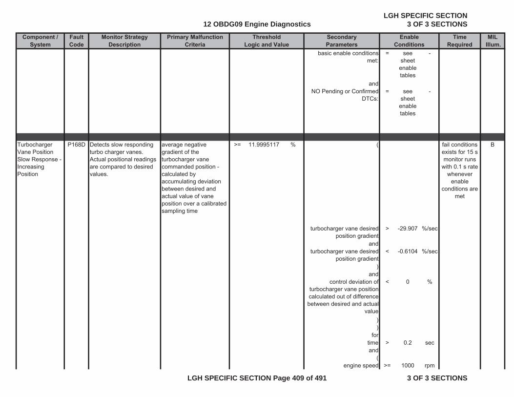
Component / Fault Monitor Strategy Primary Malfunction Secondary Time MILSystem Code Description Criteria Parameters Required Illum.
Threshold EnableLogic and Value Conditions
basic enable conditions met:
= see sheet enable tables
-
andNO Pending or Confirmed
DTCs:= see
sheet enable tables
-
Turbocharger Vane Position Slow Response - Increasing Position
P168D Detects slow responding turbo charger vanes. Actual positional readings are compared to desired values.
average negative gradient of the turbocharger vane commanded position - calculated by accumulating deviation between desired and actual value of vane position over a calibrated sampling time
>= 11.9995117 % ( B
turbocharger vane desired position gradient
> -29.907 %/sec
andturbocharger vane desired
position gradient< -0.6104 %/sec
)and
control deviation of turbocharger vane position calculated out of difference between desired and actual
value
< 0 %
))
fortime > 0.2 secand
(engine speed >= 1000 rpm
fail conditions exists for 15 s monitor runs
with 0.1 s rate whenever
enable conditions are
met
12 OBDG09 Engine DiagnosticsLGH SPECIFIC SECTION
3 OF 3 SECTIONS
LGH SPECIFIC SECTION Page 409 of 491 3 OF 3 SECTIONS

Component / Fault Monitor Strategy Primary Malfunction Secondary Time MILSystem Code Description Criteria Parameters Required Illum.
Threshold EnableLogic and Value Conditions
andengine speed <= 3000 rpm
)and
ambient pressure > 74.8 kPaand
engine temperature > 69.96 °Cand
ambient air temperature > -7.04 °Cand
basic enable conditions met:
= see sheet enable tables
-
andNO Pending or Confirmed
DTCs:= see
sheet enable tables
-
Secondary Fuel Sensor Performance
P2066 Detects an error in the secondary fuel tank sensor performance by comparing the decrease of the fuel level for a certain driven mileage to a threshold.
(a) - (b) < 100 miles Engine Running (see parameter definition)
= TRUE - B
with for(a) total vehicle distance
= measured parameter
- time >= 60 sec
and with and(b) change in mileage = measured
parameter- diagnosis tester connected = FALSE -
and and(c) - (d) < 2.64 % fuel transfer pump active = FALSE -with means
fail conditions exists for 0.02s
monitor runs 0.02 s rate whenever
enable conditions are
met
12 OBDG09 Engine DiagnosticsLGH SPECIFIC SECTION
3 OF 3 SECTIONS
LGH SPECIFIC SECTION Page 410 of 491 3 OF 3 SECTIONS
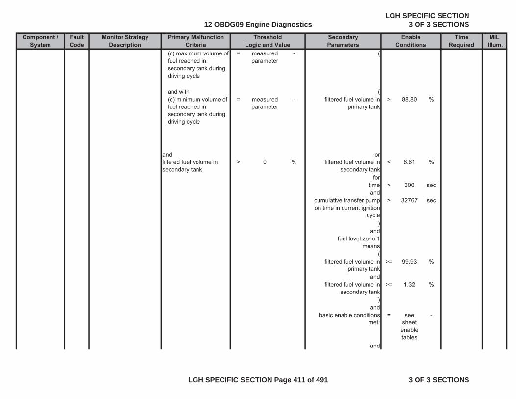
Component / Fault Monitor Strategy Primary Malfunction Secondary Time MILSystem Code Description Criteria Parameters Required Illum.
Threshold EnableLogic and Value Conditions
(c) maximum volume of fuel reached in secondary tank during driving cycle
= measured parameter
- (
and with ((d) minimum volume of fuel reached in secondary tank during driving cycle
= measured parameter
- filtered fuel volume in primary tank
> 88.80 %
and orfiltered fuel volume in secondary tank
> 0 % filtered fuel volume in secondary tank
< 6.61 %
fortime > 300 secand
cumulative transfer pump on time in current ignition
cycle
> 32767 sec
)and
fuel level zone 1means
(filtered fuel volume in
primary tank>= 99.93 %
andfiltered fuel volume in
secondary tank>= 1.32 %
)and
basic enable conditions met:
= see sheet enable tables
-
and
12 OBDG09 Engine DiagnosticsLGH SPECIFIC SECTION
3 OF 3 SECTIONS
LGH SPECIFIC SECTION Page 411 of 491 3 OF 3 SECTIONS

Component / Fault Monitor Strategy Primary Malfunction Secondary Time MILSystem Code Description Criteria Parameters Required Illum.
Threshold EnableLogic and Value Conditions
NO Pending or Confirmed DTCs:
= see sheet inhibit tables
-
Fuel Level Sensor 2 Circuit Low
P2067Detects low voltage readings in the fuel level sensor circuit, indicating an OOR low condition on the fuel level sensor circuit
voltage of fuel level sensor 2
< 0.2 V ignition on = TRUE - B
same as andfuel level > 100 % basic enable conditions
met:= see
sheet enable tables
-
Fuel Level Sensor 2 Circuit High
P2068Detects high voltage readings in the fuel level sensor circuit, indicating an OOR high condition on the fuel level sensor circuit
voltage of fuel level sensor 2
> 4.8 V ignition on = TRUE - B
same as andfuel level < 0 % basic enable conditions
met:= see
sheet enable tables
-
fail conditions exists for 24 s test performed continuously
0.1 s rate
fail conditions exists for 24 s test performed continuously
0.1 s rate
12 OBDG09 Engine DiagnosticsLGH SPECIFIC SECTION
3 OF 3 SECTIONS
LGH SPECIFIC SECTION Page 412 of 491 3 OF 3 SECTIONS

Component / Fault Monitor Strategy Primary Malfunction Secondary Time MILSystem Code Description Criteria Parameters Required Illum.
Threshold EnableLogic and Value Conditions
Fuel Transfer Pump Relay Control Circuit
P2632 Electronic out-put driver circuitry determines that the tank transfer pump circuit is open.
The ECM detects that the commanded state of the driver and the actual state of the control circuit do not match.
ignition on = TRUE - B
andbasic enable conditions
met:= see
sheet enable tables
-
Fuel Transfer Pump Relay Control Circuit Low
P2633 Electronic out-put driver circuitry determines that the tank transfer pump circuit is shorted to ground.
The ECM detects that the commanded state of the driver and the actual state of the control circuit do not match.
ignition on = TRUE - B
andbasic enable conditions
met:= see
sheet enable tables
-
fail conditions exists for 3 smonitor runs 0.02 s rate whenever
enable conditions are
met
fail conditions exists for 3 smonitor runs 0.02 s rate whenever
enable conditions are
met
12 OBDG09 Engine DiagnosticsLGH SPECIFIC SECTION
3 OF 3 SECTIONS
LGH SPECIFIC SECTION Page 413 of 491 3 OF 3 SECTIONS
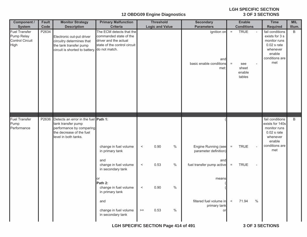
Component / Fault Monitor Strategy Primary Malfunction Secondary Time MILSystem Code Description Criteria Parameters Required Illum.
Threshold EnableLogic and Value Conditions
Fuel Transfer Pump Relay Control Circuit High
P2634Electronic out-put driver circuitry determines that the tank transfer pump circuit is shorted to battery.
The ECM detects that the commanded state of the driver and the actual state of the control circuit do not match.
ignition on = TRUE - B
andbasic enable conditions
met:= see
sheet enable tables
-
Fuel Transfer Pump Performance
P2636 Detects an error in the fuel tank transfer pump performance by comparing the decrease of the fuel level in both tanks.
Path 1: ( B
change in fuel volume in primary tank
< 0.90 % Engine Running (see parameter definition)
= TRUE -
and andchange in fuel volume in secondary tank
< 0.53 % fuel transfer pump active = TRUE -
or meansPath 2: (
change in fuel volume in primary tank
< 0.90 % (
and filtered fuel volume in primary tank
< 71.94 %
change in fuel volume in secondary tank
>= 0.53 % or
fail conditions exists for 3 smonitor runs 0.02 s rate whenever
enable conditions are
met
fail conditions exists for 140smonitor runs 0.02 s rate whenever
enable conditions are
met
12 OBDG09 Engine DiagnosticsLGH SPECIFIC SECTION
3 OF 3 SECTIONS
LGH SPECIFIC SECTION Page 414 of 491 3 OF 3 SECTIONS
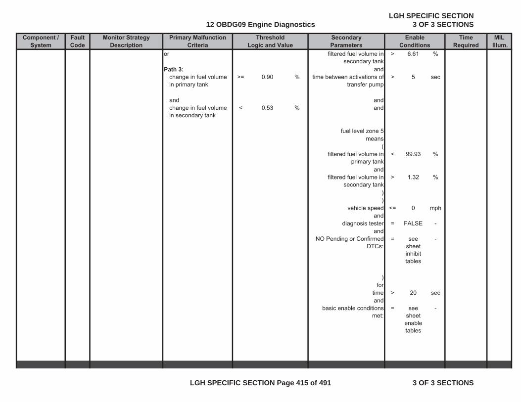
Component / Fault Monitor Strategy Primary Malfunction Secondary Time MILSystem Code Description Criteria Parameters Required Illum.
Threshold EnableLogic and Value Conditions
or filtered fuel volume in secondary tank
> 6.61 %
Path 3: andchange in fuel volume in primary tank
>= 0.90 % time between activations of transfer pump
> 5 sec
and andchange in fuel volume in secondary tank
< 0.53 % and
fuel level zone 5means
(filtered fuel volume in
primary tank< 99.93 %
andfiltered fuel volume in
secondary tank> 1.32 %
))
vehicle speed <= 0 mphand
diagnosis tester = FALSE -and
NO Pending or Confirmed DTCs:
= see sheet inhibit tables
-
)for
time > 20 secand
basic enable conditions met:
= see sheet enable tables
-
12 OBDG09 Engine DiagnosticsLGH SPECIFIC SECTION
3 OF 3 SECTIONS
LGH SPECIFIC SECTION Page 415 of 491 3 OF 3 SECTIONS
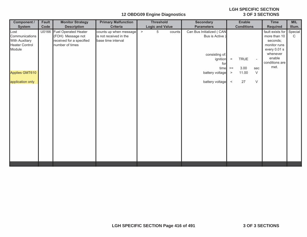
Component / Fault Monitor Strategy Primary Malfunction Secondary Time MILSystem Code Description Criteria Parameters Required Illum.
Threshold EnableLogic and Value Conditions
Lost Communications With Auxiliary Heater Control Module
U0166 counts up when message is not received in the base time interval
> 5 counts Can Bus Initialized ( CAN Bus is Active )
Special C
consisting of:ignition = TRUE -
fortime >= 3.00 sec
Applies GMT610 battery voltage > 11.00 V
application only battery voltage < 27 V
Fuel Operated Heater (FOH) Message not received for a specified number of times
fault exists for more than 10
seconds; monitor runs every 0.01 s
whenever enable
conditions are met.
12 OBDG09 Engine DiagnosticsLGH SPECIFIC SECTION
3 OF 3 SECTIONS
LGH SPECIFIC SECTION Page 416 of 491 3 OF 3 SECTIONS
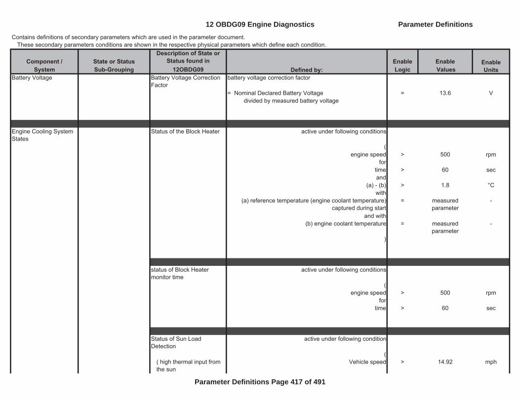
Contains definitions of secondary parameters which are used in the parameter document. These secondary parameters conditions are shown in the respective physical parameters which define each condition.
Component / State or Status Description of State or
Status found in Enable EnableSystem Sub-Grouping 12OBDG09 Logic Values
Battery Voltage Battery Voltage Correction Factor
battery voltage correction factor
= Nominal Declared Battery Voltage = 13.6 Vdivided by measured battery voltage
Engine Cooling System States
Status of the Block Heater active under following conditions
(engine speed > 500 rpm
fortime > 60 secand
(a) - (b) > 1.8 °Cwith
(a) reference temperature (engine coolant temperature) captured during start
= measured parameter
-
and with(b) engine coolant temperature = measured
parameter-
)
status of Block Heater monitor time
active under following conditions
(engine speed > 500 rpm
fortime > 60 sec
Status of Sun Load Detection
active under following condition
(( high thermal input from the sun
Vehicle speed > 14.92 mph
Enable UnitsDefined by:
12 OBDG09 Engine Diagnostics Parameter Definitions
Parameter Definitions Page 417 of 491
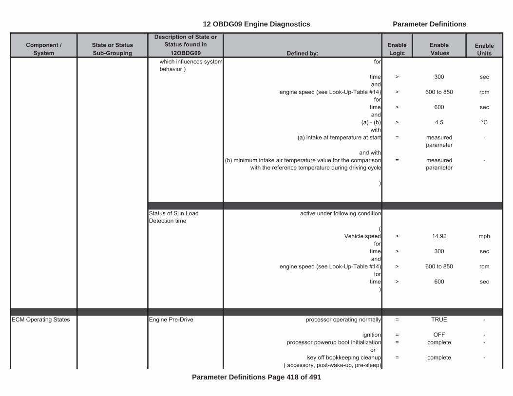
Component / State or Status Description of State or
Status found in Enable EnableSystem Sub-Grouping 12OBDG09 Logic Values
Enable UnitsDefined by:
which influences system behavior )
for
time > 300 secand
engine speed (see Look-Up-Table #14) > 600 to 850 rpmfor
time > 600 secand
(a) - (b) > 4.5 °Cwith
(a) intake at temperature at start = measured parameter
-
and with(b) minimum intake air temperature value for the comparison
with the reference temperature during driving cycle= measured
parameter-
)
Status of Sun Load Detection time
active under following condition
( Vehicle speed > 14.92 mph
fortime > 300 secand
engine speed (see Look-Up-Table #14) > 600 to 850 rpmfor
time > 600 sec)
ECM Operating States Engine Pre-Drive processor operating normally = TRUE -
ignition = OFF -processor powerup boot initialization = complete -
orkey off bookkeeping cleanup = complete -
( accessory, post-wake-up, pre-sleep)
12 OBDG09 Engine Diagnostics Parameter Definitions
Parameter Definitions Page 418 of 491
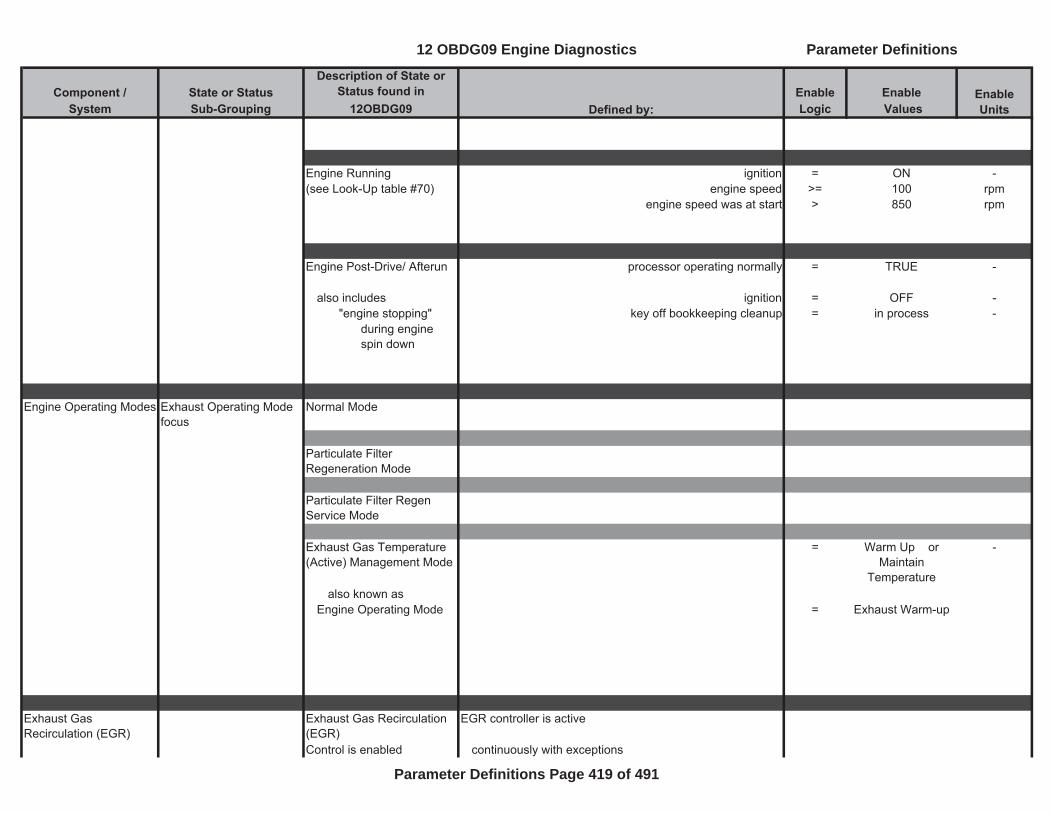
Component / State or Status Description of State or
Status found in Enable EnableSystem Sub-Grouping 12OBDG09 Logic Values
Enable UnitsDefined by:
Engine Running ignition = ON -(see Look-Up table #70) engine speed >= 100 rpm
engine speed was at start > 850 rpm
Engine Post-Drive/ Afterun processor operating normally = TRUE -
also includes ignition = OFF -"engine stopping" key off bookkeeping cleanup = in process -
during engine spin down
Engine Operating Modes Exhaust Operating Mode focus
Normal Mode
Particulate Filter Regeneration Mode
Particulate Filter Regen Service Mode
Exhaust Gas Temperature (Active) Management Mode
= Warm Up orMaintain
Temperature
-
also known asEngine Operating Mode = Exhaust Warm-up
Exhaust Gas Recirculation (EGR)
Exhaust Gas Recirculation (EGR)
EGR controller is active
Control is enabled continuously with exceptions
12 OBDG09 Engine Diagnostics Parameter Definitions
Parameter Definitions Page 419 of 491
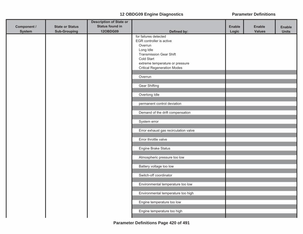
Component / State or Status Description of State or
Status found in Enable EnableSystem Sub-Grouping 12OBDG09 Logic Values
Enable UnitsDefined by:
for failures detectedEGR controller is active
OverrunLong IdleTransmission Gear ShiftCold Startextreme temperature or pressureCritical Regeneration Modes
Overrun
Gear Shifting
Overlong Idle
permanent control deviation
Demand of the drift compensation
System error
Error exhaust gas recirculation valve
Error throttle valve
Engine Brake Status
Atmospheric pressure too low
Battery voltage too low
Switch-off coordinator
Environmental temperature too low
Environmental temperature too high
Engine temperature too low
Engine temperature too high
12 OBDG09 Engine Diagnostics Parameter Definitions
Parameter Definitions Page 420 of 491
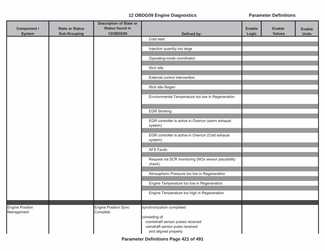
Component / State or Status Description of State or
Status found in Enable EnableSystem Sub-Grouping 12OBDG09 Logic Values
Enable UnitsDefined by:
Cold start
Injection quantity too large
Operating-mode coordinator
Rich Idle
External control intervention
Rich Idle Regen
Environmental Temperature too low in Regeneration
EGR Stroking
EGR controller is active in Overrun (warm exhaust system)
EGR controller is active in Overrun (Cold exhaust system)
AFS Faults
Request via SCR monitoring (NOx sensor plausibility check)
Atmospheric Pressure too low in Regeneration
Engine Temperature too low in Regeneration
Engine Temperature too high in Regeneration
Engine Position Management
Engine Position Sync Complete
synchronization completed
consisting of:crankshaft sensor pulses receivedcamshaft sensor pulse received
and aligned properly
12 OBDG09 Engine Diagnostics Parameter Definitions
Parameter Definitions Page 421 of 491
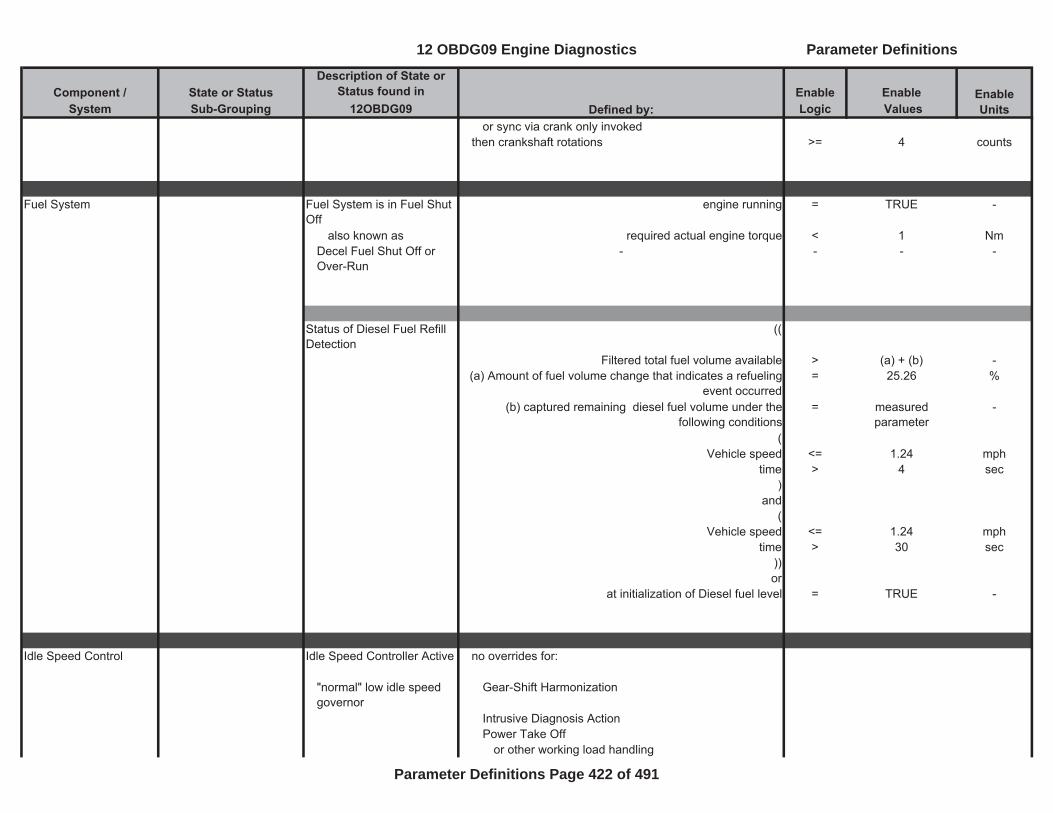
Component / State or Status Description of State or
Status found in Enable EnableSystem Sub-Grouping 12OBDG09 Logic Values
Enable UnitsDefined by:
or sync via crank only invokedthen crankshaft rotations >= 4 counts
Fuel System Fuel System is in Fuel Shut Off
engine running = TRUE -
also known as required actual engine torque < 1 NmDecel Fuel Shut Off or Over-Run
- - - -
Status of Diesel Fuel Refill Detection
((
Filtered total fuel volume available > (a) + (b) -(a) Amount of fuel volume change that indicates a refueling
event occurred= 25.26 %
(b) captured remaining diesel fuel volume under the following conditions
= measured parameter
-
(Vehicle speed <= 1.24 mph
time > 4 sec)
and(
Vehicle speed <= 1.24 mphtime > 30 sec
))or
at initialization of Diesel fuel level = TRUE -
Idle Speed Control Idle Speed Controller Active no overrides for:
"normal" low idle speed governor
Gear-Shift Harmonization
Intrusive Diagnosis ActionPower Take Off
or other working load handling
12 OBDG09 Engine Diagnostics Parameter Definitions
Parameter Definitions Page 422 of 491

Component / State or Status Description of State or
Status found in Enable EnableSystem Sub-Grouping 12OBDG09 Logic Values
Enable UnitsDefined by:
Engine Idling Time Ratio = ( time accumulated at idledivided by time since engine start )
NOx Sensor Status of NOx signal of upstream NOx sensor
(following condition met for time: > 30 sec
(Integrated heat quantity (see Look-Up-Table #1) >= 375 to 500 kJ
NOx status signal received via CAN message (Please see the definition)
= TRUE -
for time > 0.5 seccalculated lambda value based on air mass flow and
injection quantity> 0.9 -
for time > 0.5 secengine speed > 100 rpm
for time > 20 secNO Pending or Confirmed DTCs: = see sheet inhibit
tables-
))
Status of NOx signal of downstream NOx sensor
(following condition met for time: > 30 sec
(Integrated heat quantity (see Look-Up-Table #2) >= 0 to 350 kJ
NOx status signal received via CAN message (Please see the definition)
= TRUE -
for time > 0.5 seccalculated lambda value based on air mass flow and
injection quantity> 0.9 -
12 OBDG09 Engine Diagnostics Parameter Definitions
Parameter Definitions Page 423 of 491
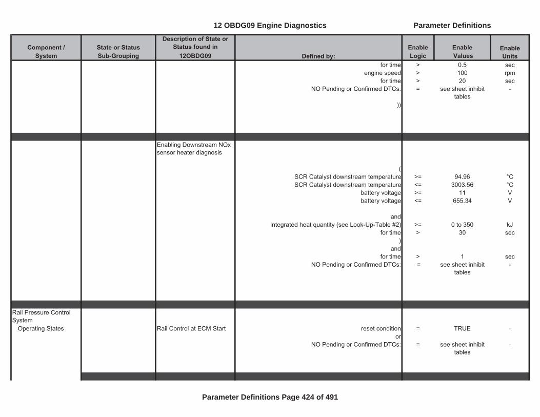
Component / State or Status Description of State or
Status found in Enable EnableSystem Sub-Grouping 12OBDG09 Logic Values
Enable UnitsDefined by:
for time > 0.5 secengine speed > 100 rpm
for time > 20 secNO Pending or Confirmed DTCs: = see sheet inhibit
tables-
))
Enabling Downstream NOx sensor heater diagnosis
( SCR Catalyst downstream temperature >= 94.96 °CSCR Catalyst downstream temperature <= 3003.56 °C
battery voltage >= 11 Vbattery voltage <= 655.34 V
andIntegrated heat quantity (see Look-Up-Table #2) >= 0 to 350 kJ
for time > 30 sec)
and for time > 1 sec
NO Pending or Confirmed DTCs: = see sheet inhibit tables
-
Rail Pressure Control System
Operating States Rail Control at ECM Start reset condition = TRUE -or
NO Pending or Confirmed DTCs: = see sheet inhibit tables
-
12 OBDG09 Engine Diagnostics Parameter Definitions
Parameter Definitions Page 424 of 491
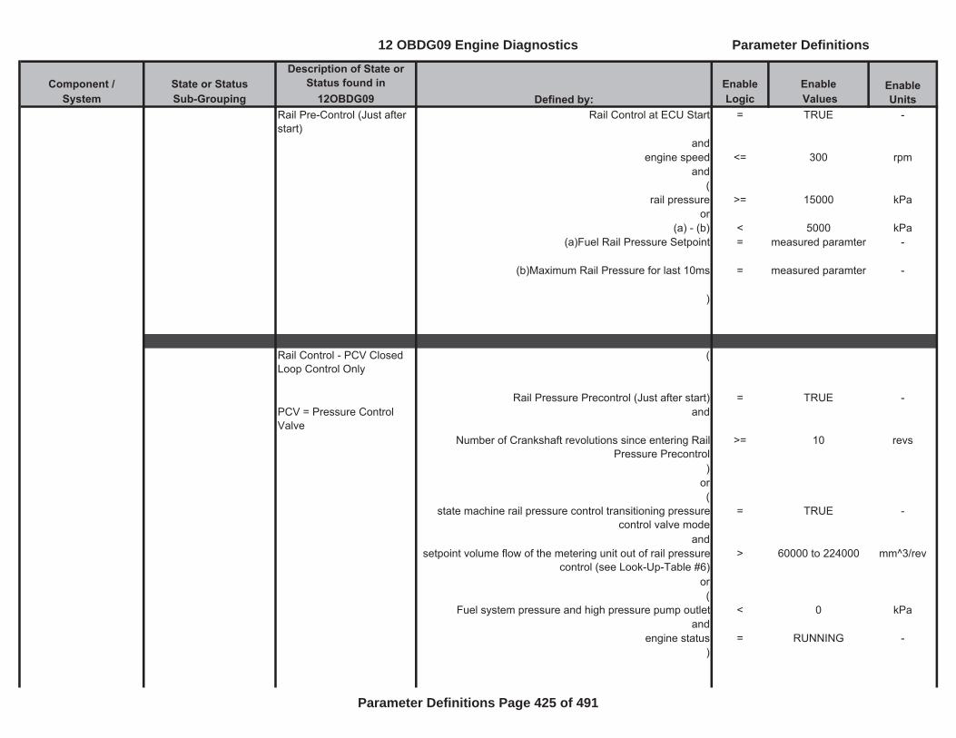
Component / State or Status Description of State or
Status found in Enable EnableSystem Sub-Grouping 12OBDG09 Logic Values
Enable UnitsDefined by:
Rail Pre-Control (Just after start)
Rail Control at ECU Start = TRUE -
andengine speed <= 300 rpm
and(
rail pressure >= 15000 kPaor
(a) - (b) < 5000 kPa(a)Fuel Rail Pressure Setpoint = measured paramter -
(b)Maximum Rail Pressure for last 10ms = measured paramter -
)
Rail Control - PCV Closed Loop Control Only
(
Rail Pressure Precontrol (Just after start) = TRUE -PCV = Pressure Control Valve
and
Number of Crankshaft revolutions since entering Rail Pressure Precontrol
>= 10 revs
)or(
state machine rail pressure control transitioning pressure control valve mode
= TRUE -
andsetpoint volume flow of the metering unit out of rail pressure
control (see Look-Up-Table #6)> 60000 to 224000 mm^3/rev
or(
Fuel system pressure and high pressure pump outlet < 0 kPaand
engine status = RUNNING -)
12 OBDG09 Engine Diagnostics Parameter Definitions
Parameter Definitions Page 425 of 491

Component / State or Status Description of State or
Status found in Enable EnableSystem Sub-Grouping 12OBDG09 Logic Values
Enable UnitsDefined by:
Rail Control - Metering Unit Closed Loop Control
state machine rail pressure control equal transitioning to metering unit pressure control mode
= TRUE -
andController for PCV not wound-up (large corrective control) = TRUE -
Rail Control - Metering Unit + PCV Closed Loop Control
state machine rail pressure control transitioning to coupled pressure control mode (rail pressure is controlled by
metering unit and pressure control valve)
= TRUE -
and(a) + (b) (see Look-Up-Table #7) < 12 to 400 mm^3/rev
(a)Torque Generating fuel injection quantity = calculated parametet
-
(b)Non-Torque generating fuel injection quantity = calculated parametet
-
Switchover Between Metering Unit + PCV Closed Loop Control to Metering Unit Closed Loop Control only
(
state machine rail pressure control equal to pressure control valve
orstate machine rail pressure control transitioning pressure
control valve mode)
and(a) + (b) < (c) + (d) -
(a)Torque Generating fuel injection quantity = calculated parameter
-
(b)Non-Torque generating fuel injection quantity = calculated parameter
-
12 OBDG09 Engine Diagnostics Parameter Definitions
Parameter Definitions Page 426 of 491
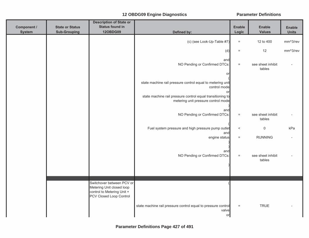
Component / State or Status Description of State or
Status found in Enable EnableSystem Sub-Grouping 12OBDG09 Logic Values
Enable UnitsDefined by:
(c) (see Look-Up-Table #7) = 12 to 400 mm^3/rev
(d) = 12 mm^3/rev
andNO Pending or Confirmed DTCs: = see sheet inhibit
tables-
or(
state machine rail pressure control equal to metering unit control mode
orstate machine rail pressure control equal transitioning to
metering unit pressure control mode)
andNO Pending or Confirmed DTCs: = see sheet inhibit
tables-
(Fuel system pressure and high pressure pump outlet < 0 kPa
andengine status = RUNNING -
))
andNO Pending or Confirmed DTCs: = see sheet inhibit
tables-
)
Switchover between PCV or Metering Unit closed loop control to Metering Unit + PCV Closed Loop Control
(
state machine rail pressure control equal to pressure control valve
= TRUE -
or
12 OBDG09 Engine Diagnostics Parameter Definitions
Parameter Definitions Page 427 of 491
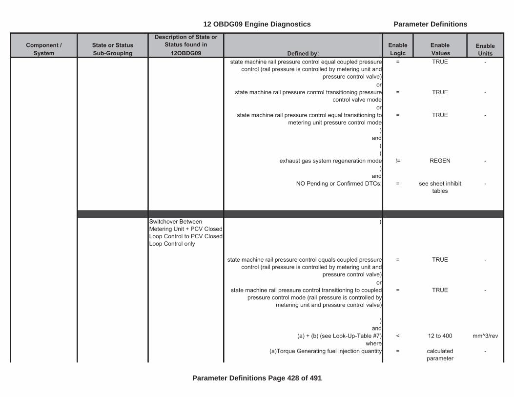
Component / State or Status Description of State or
Status found in Enable EnableSystem Sub-Grouping 12OBDG09 Logic Values
Enable UnitsDefined by:
state machine rail pressure control equal coupled pressure control (rail pressure is controlled by metering unit and
pressure control valve)
= TRUE -
orstate machine rail pressure control transitioning pressure
control valve mode= TRUE -
orstate machine rail pressure control equal transitioning to
metering unit pressure control mode= TRUE -
)and
((
exhaust gas system regeneration mode != REGEN -)
andNO Pending or Confirmed DTCs: = see sheet inhibit
tables-
Switchover Between Metering Unit + PCV Closed Loop Control to PCV Closed Loop Control only
(
state machine rail pressure control equals coupled pressure control (rail pressure is controlled by metering unit and
pressure control valve)
= TRUE -
orstate machine rail pressure control transitioning to coupled
pressure control mode (rail pressure is controlled by metering unit and pressure control valve)
= TRUE -
)and
(a) + (b) (see Look-Up-Table #7) < 12 to 400 mm^3/revwhere
(a)Torque Generating fuel injection quantity = calculated parameter
-
12 OBDG09 Engine Diagnostics Parameter Definitions
Parameter Definitions Page 428 of 491
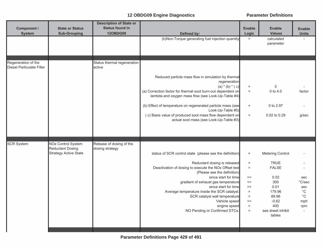
Component / State or Status Description of State or
Status found in Enable EnableSystem Sub-Grouping 12OBDG09 Logic Values
Enable UnitsDefined by:
(b)Non-Torque generating fuel injection quantity = calculated parameter
-
Regeneration of the Diesel Particulate Filter
Status thermal regeneration active
Reduced particle mass flow in simulation by thermal regeneration(a) * (b) * ( c) > 0 -
(a) Correction factor for thermal soot burn-out dependent on lambda and oxygen mass flow (see Look-Up-Table #4)
= 0 to 4.0 factor
(b) Effect of temperature on regenerated particle mass (see Look-Up-Table #5)
= 0 to 2.97 -
( c) Basis value of produced soot mass flow dependent on actual soot mass (see Look-Up-Table #3)
= 0.02 to 0.29 g/sec
Release of dosing of the dosing strategy
status of SCR control state (please see the definition) = Metering Control -
Reductant dosing is released = TRUE -Deactivation of dosing to execute the NOx Offset test
(Please see the definition)= FALSE -
since start for time >= 0.02 secgradient of exhaust gas temperature <= 300 °C/sec
since start for time >= 0.01 secAverage temperature inside the SCR catalyst: > 179.96 °C
SCR catalyst wall temperature > 89.96 °CVehicle speed >= -0.62 mphengine speed > 400 rpm
NO Pending or Confirmed DTCs: = see sheet inhibit tables
-
SCR System NOx Control System Reductant Dosing Strategy Active State
12 OBDG09 Engine Diagnostics Parameter Definitions
Parameter Definitions Page 429 of 491
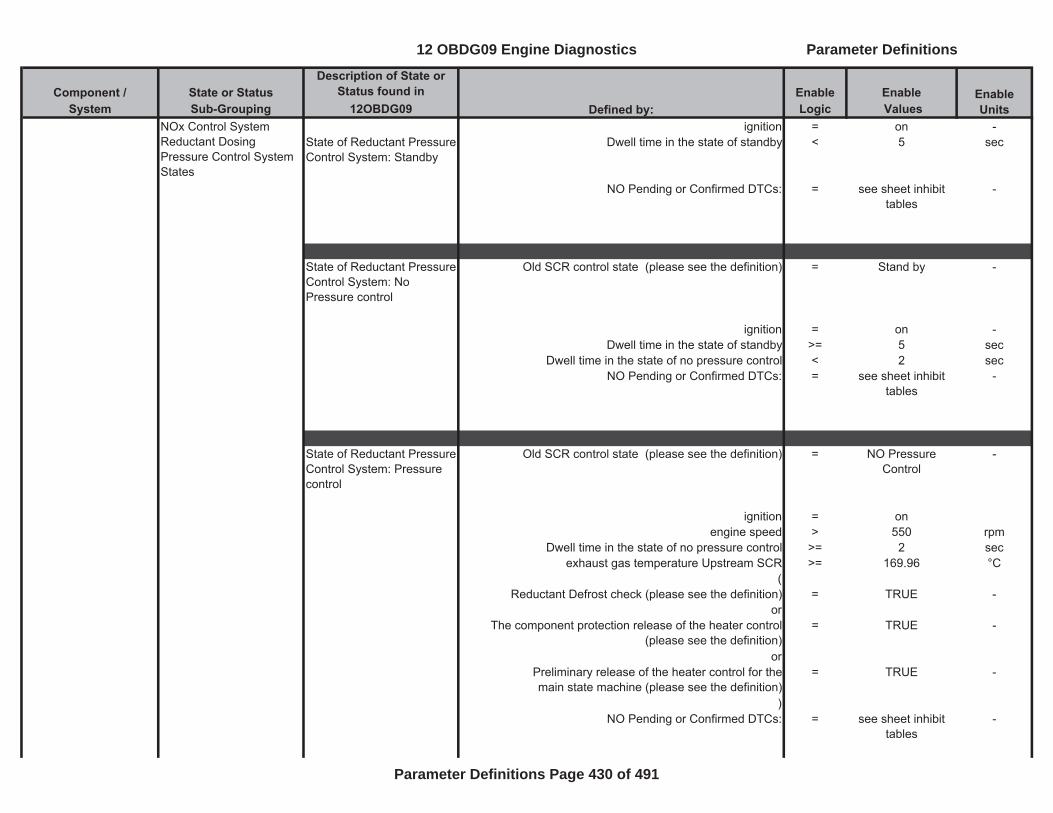
Component / State or Status Description of State or
Status found in Enable EnableSystem Sub-Grouping 12OBDG09 Logic Values
Enable UnitsDefined by:
ignition = on -State of Reductant Pressure Control System: Standby
Dwell time in the state of standby < 5 sec
NO Pending or Confirmed DTCs: = see sheet inhibit tables
-
State of Reductant Pressure Control System: No Pressure control
Old SCR control state (please see the definition) = Stand by -
ignition = on -Dwell time in the state of standby >= 5 sec
Dwell time in the state of no pressure control < 2 secNO Pending or Confirmed DTCs: = see sheet inhibit
tables-
State of Reductant Pressure Control System: Pressure control
Old SCR control state (please see the definition) = NO Pressure Control
-
ignition = on engine speed > 550 rpm
Dwell time in the state of no pressure control >= 2 secexhaust gas temperature Upstream SCR >= 169.96 °C
( Reductant Defrost check (please see the definition) = TRUE -
or The component protection release of the heater control
(please see the definition)= TRUE -
or Preliminary release of the heater control for themain state machine (please see the definition)
= TRUE -
) NO Pending or Confirmed DTCs: = see sheet inhibit
tables-
NOx Control System Reductant Dosing Pressure Control System States
12 OBDG09 Engine Diagnostics Parameter Definitions
Parameter Definitions Page 430 of 491
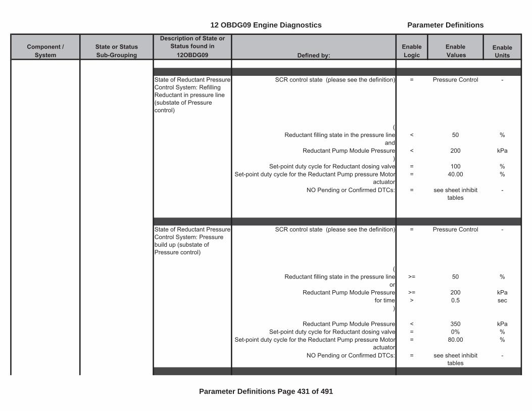
Component / State or Status Description of State or
Status found in Enable EnableSystem Sub-Grouping 12OBDG09 Logic Values
Enable UnitsDefined by:
State of Reductant Pressure Control System: Refilling Reductant in pressure line (substate of Pressure control)
SCR control state (please see the definition) = Pressure Control -
(Reductant filling state in the pressure line < 50 %
andReductant Pump Module Pressure < 200 kPa
)Set-point duty cycle for Reductant dosing valve = 100 %
Set-point duty cycle for the Reductant Pump pressure Motor actuator
= 40.00 %
NO Pending or Confirmed DTCs: = see sheet inhibit tables
-
State of Reductant Pressure Control System: Pressure build up (substate of Pressure control)
SCR control state (please see the definition) = Pressure Control -
(Reductant filling state in the pressure line >= 50 %
orReductant Pump Module Pressure >= 200 kPa
for time > 0.5 sec)
Reductant Pump Module Pressure < 350 kPaSet-point duty cycle for Reductant dosing valve = 0% %
Set-point duty cycle for the Reductant Pump pressure Motor actuator
= 80.00 %
NO Pending or Confirmed DTCs: = see sheet inhibit tables
-
12 OBDG09 Engine Diagnostics Parameter Definitions
Parameter Definitions Page 431 of 491
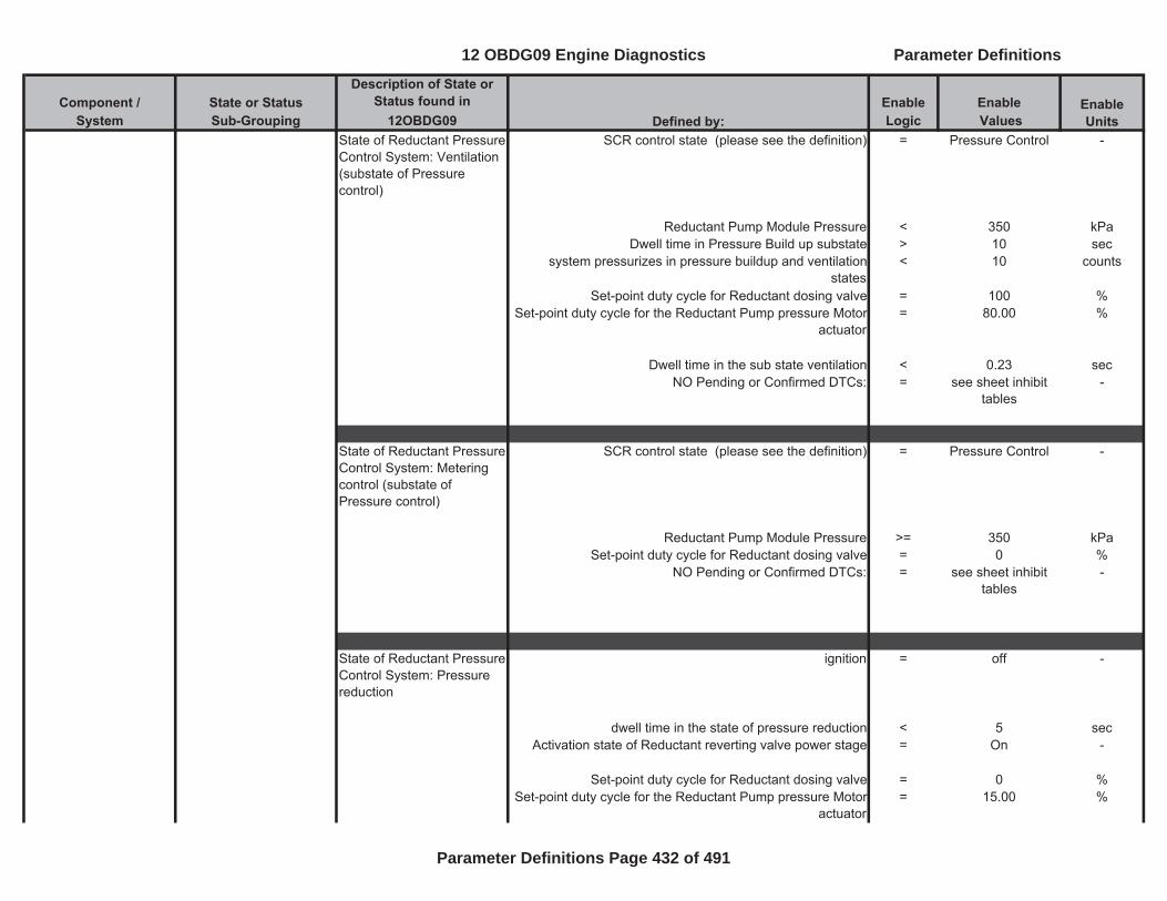
Component / State or Status Description of State or
Status found in Enable EnableSystem Sub-Grouping 12OBDG09 Logic Values
Enable UnitsDefined by:
State of Reductant Pressure Control System: Ventilation (substate of Pressure control)
SCR control state (please see the definition) = Pressure Control -
Reductant Pump Module Pressure < 350 kPaDwell time in Pressure Build up substate > 10 sec
system pressurizes in pressure buildup and ventilation states
< 10 counts
Set-point duty cycle for Reductant dosing valve = 100 %Set-point duty cycle for the Reductant Pump pressure Motor
actuator= 80.00 %
Dwell time in the sub state ventilation < 0.23 secNO Pending or Confirmed DTCs: = see sheet inhibit
tables-
State of Reductant Pressure Control System: Metering control (substate of Pressure control)
SCR control state (please see the definition) = Pressure Control -
Reductant Pump Module Pressure >= 350 kPaSet-point duty cycle for Reductant dosing valve = 0 %
NO Pending or Confirmed DTCs: = see sheet inhibit tables
-
State of Reductant Pressure Control System: Pressure reduction
ignition = off -
dwell time in the state of pressure reduction < 5 secActivation state of Reductant reverting valve power stage = On -
Set-point duty cycle for Reductant dosing valve = 0 %Set-point duty cycle for the Reductant Pump pressure Motor
actuator= 15.00 %
12 OBDG09 Engine Diagnostics Parameter Definitions
Parameter Definitions Page 432 of 491
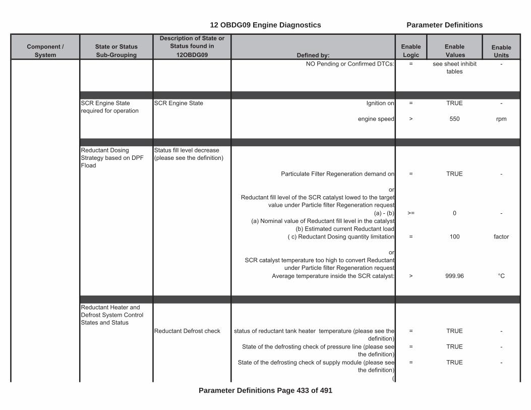
Component / State or Status Description of State or
Status found in Enable EnableSystem Sub-Grouping 12OBDG09 Logic Values
Enable UnitsDefined by:
NO Pending or Confirmed DTCs: = see sheet inhibit tables
-
SCR Engine State required for operation
SCR Engine State Ignition on = TRUE -
engine speed > 550 rpm
Reductant Dosing Strategy based on DPF Fload
Status fill level decrease (please see the definition)
Particulate Filter Regeneration demand on = TRUE -
orReductant fill level of the SCR catalyst lowed to the target
value under Particle filter Regeneration request(a) - (b) >= 0 -
(a) Nominal value of Reductant fill level in the catalyst(b) Estimated current Reductant load
( c) Reductant Dosing quantity limitation = 100 factor
orSCR catalyst temperature too high to convert Reductant
under Particle filter Regeneration requestAverage temperature inside the SCR catalyst: > 999.96 °C
Reductant Heater and Defrost System Control States and Status
Reductant Defrost check status of reductant tank heater temperature (please see the definition)
= TRUE -
State of the defrosting check of pressure line (please see the definition)
= TRUE -
State of the defrosting check of supply module (please see the definition)
= TRUE -
(
12 OBDG09 Engine Diagnostics Parameter Definitions
Parameter Definitions Page 433 of 491
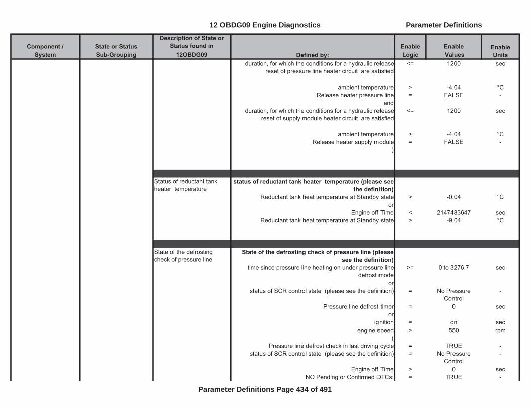
Component / State or Status Description of State or
Status found in Enable EnableSystem Sub-Grouping 12OBDG09 Logic Values
Enable UnitsDefined by:
duration, for which the conditions for a hydraulic release reset of pressure line heater circuit are satisfied
<= 1200 sec
ambient temperature > -4.04 °CRelease heater pressure line = FALSE -
andduration, for which the conditions for a hydraulic release
reset of supply module heater circuit are satisfied<= 1200 sec
ambient temperature > -4.04 °CRelease heater supply module = FALSE -
)
Status of reductant tank heater temperature
status of reductant tank heater temperature (please see the definition)
Reductant tank heat temperature at Standby state > -0.04 °Cor
Engine off Time < 2147483647 secReductant tank heat temperature at Standby state > -9.04 °C
State of the defrosting check of pressure line
State of the defrosting check of pressure line (please see the definition)
time since pressure line heating on under pressure line defrost mode
>= 0 to 3276.7 sec
orstatus of SCR control state (please see the definition) = No Pressure
Control-
Pressure line defrost timer = 0 secor
ignition = on secengine speed > 550 rpm
(Pressure line defrost check in last driving cycle = TRUE -
status of SCR control state (please see the definition) = No Pressure Control
-
Engine off Time > 0 secNO Pending or Confirmed DTCs: = TRUE -
12 OBDG09 Engine Diagnostics Parameter Definitions
Parameter Definitions Page 434 of 491
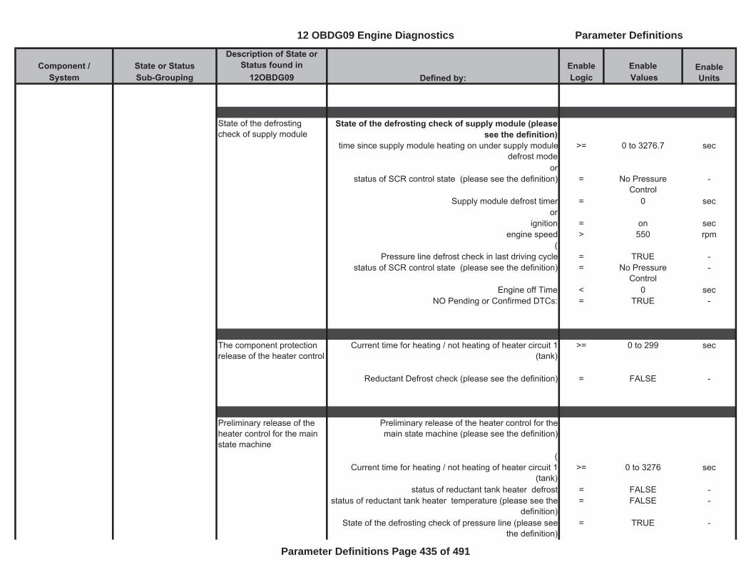
Component / State or Status Description of State or
Status found in Enable EnableSystem Sub-Grouping 12OBDG09 Logic Values
Enable UnitsDefined by:
State of the defrosting check of supply module
State of the defrosting check of supply module (please see the definition)
time since supply module heating on under supply module defrost mode
>= 0 to 3276.7 sec
orstatus of SCR control state (please see the definition) = No Pressure
Control-
Supply module defrost timer = 0 secor
ignition = on secengine speed > 550 rpm
(Pressure line defrost check in last driving cycle = TRUE -
status of SCR control state (please see the definition) = No Pressure Control
-
Engine off Time < 0 secNO Pending or Confirmed DTCs: = TRUE -
The component protection release of the heater control
Current time for heating / not heating of heater circuit 1 (tank)
>= 0 to 299 sec
Reductant Defrost check (please see the definition) = FALSE -
Preliminary release of the heater control for the main state machine
Preliminary release of the heater control for themain state machine (please see the definition)
(Current time for heating / not heating of heater circuit 1
(tank)>= 0 to 3276 sec
status of reductant tank heater defrost = FALSE -status of reductant tank heater temperature (please see the
definition)= FALSE -
State of the defrosting check of pressure line (please see the definition)
= TRUE -
12 OBDG09 Engine Diagnostics Parameter Definitions
Parameter Definitions Page 435 of 491
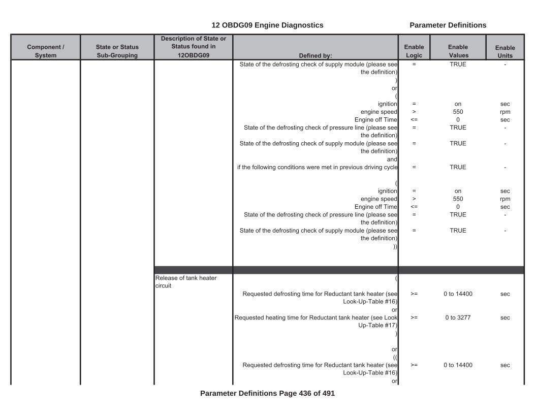
Component / State or Status Description of State or
Status found in Enable EnableSystem Sub-Grouping 12OBDG09 Logic Values
Enable UnitsDefined by:
State of the defrosting check of supply module (please see the definition)
= TRUE -
)or(
ignition = on secengine speed > 550 rpm
Engine off Time <= 0 secState of the defrosting check of pressure line (please see
the definition)= TRUE -
State of the defrosting check of supply module (please see the definition)
= TRUE -
andif the following conditions were met in previous driving cycle = TRUE -
(ignition = on sec
engine speed > 550 rpmEngine off Time <= 0 sec
State of the defrosting check of pressure line (please see the definition)
= TRUE -
State of the defrosting check of supply module (please see the definition)
= TRUE -
))
Release of tank heater circuit
(
Requested defrosting time for Reductant tank heater (see Look-Up-Table #16)
>= 0 to 14400 sec
orRequested heating time for Reductant tank heater (see Look-
Up-Table #17)>= 0 to 3277 sec
)
or((
Requested defrosting time for Reductant tank heater (see Look-Up-Table #16)
>= 0 to 14400 sec
or
12 OBDG09 Engine Diagnostics Parameter Definitions
Parameter Definitions Page 436 of 491
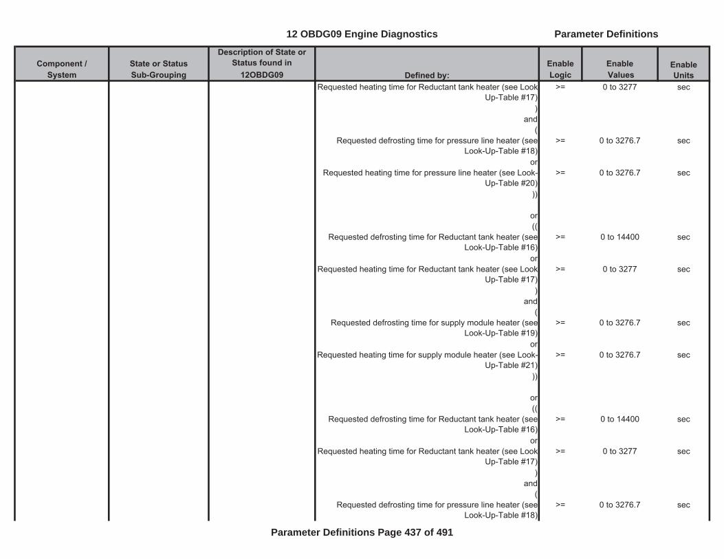
Component / State or Status Description of State or
Status found in Enable EnableSystem Sub-Grouping 12OBDG09 Logic Values
Enable UnitsDefined by:
Requested heating time for Reductant tank heater (see Look-Up-Table #17)
>= 0 to 3277 sec
)and
(Requested defrosting time for pressure line heater (see
Look-Up-Table #18)>= 0 to 3276.7 sec
orRequested heating time for pressure line heater (see Look-
Up-Table #20)>= 0 to 3276.7 sec
))
or((
Requested defrosting time for Reductant tank heater (see Look-Up-Table #16)
>= 0 to 14400 sec
orRequested heating time for Reductant tank heater (see Look-
Up-Table #17)>= 0 to 3277 sec
)and
(Requested defrosting time for supply module heater (see
Look-Up-Table #19)>= 0 to 3276.7 sec
orRequested heating time for supply module heater (see Look-
Up-Table #21)>= 0 to 3276.7 sec
))
or((
Requested defrosting time for Reductant tank heater (see Look-Up-Table #16)
>= 0 to 14400 sec
orRequested heating time for Reductant tank heater (see Look-
Up-Table #17)>= 0 to 3277 sec
)and
(Requested defrosting time for pressure line heater (see
Look-Up-Table #18)>= 0 to 3276.7 sec
12 OBDG09 Engine Diagnostics Parameter Definitions
Parameter Definitions Page 437 of 491
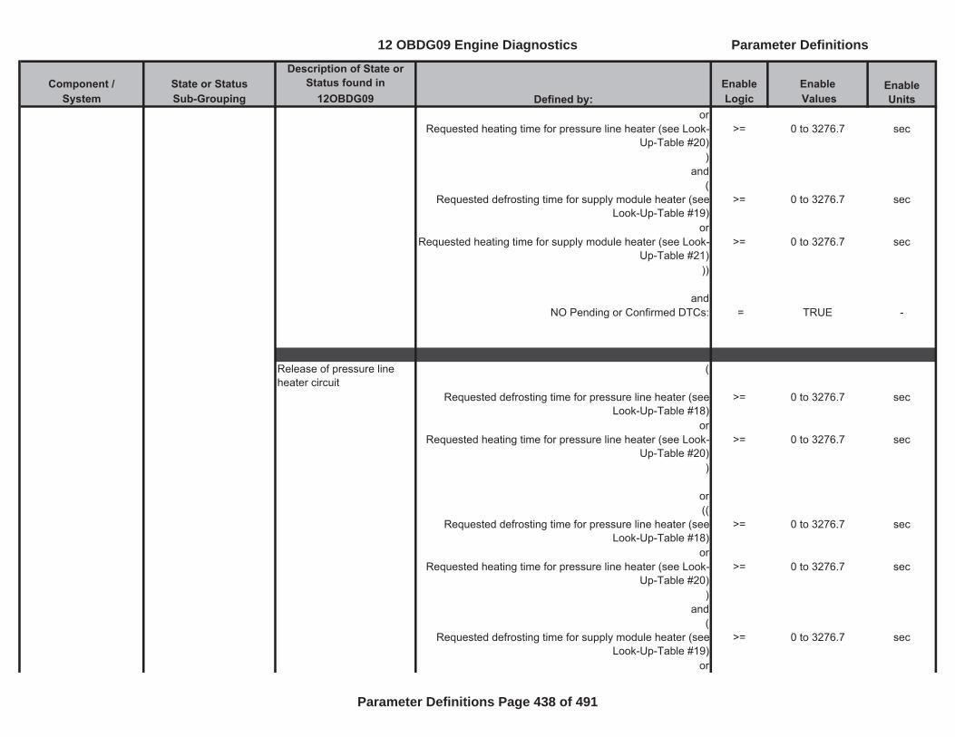
Component / State or Status Description of State or
Status found in Enable EnableSystem Sub-Grouping 12OBDG09 Logic Values
Enable UnitsDefined by:
orRequested heating time for pressure line heater (see Look-
Up-Table #20)>= 0 to 3276.7 sec
)and
(Requested defrosting time for supply module heater (see
Look-Up-Table #19)>= 0 to 3276.7 sec
orRequested heating time for supply module heater (see Look-
Up-Table #21)>= 0 to 3276.7 sec
))
andNO Pending or Confirmed DTCs: = TRUE -
Release of pressure line heater circuit
(
Requested defrosting time for pressure line heater (see Look-Up-Table #18)
>= 0 to 3276.7 sec
orRequested heating time for pressure line heater (see Look-
Up-Table #20)>= 0 to 3276.7 sec
)
or((
Requested defrosting time for pressure line heater (see Look-Up-Table #18)
>= 0 to 3276.7 sec
orRequested heating time for pressure line heater (see Look-
Up-Table #20)>= 0 to 3276.7 sec
)and
(Requested defrosting time for supply module heater (see
Look-Up-Table #19)>= 0 to 3276.7 sec
or
12 OBDG09 Engine Diagnostics Parameter Definitions
Parameter Definitions Page 438 of 491
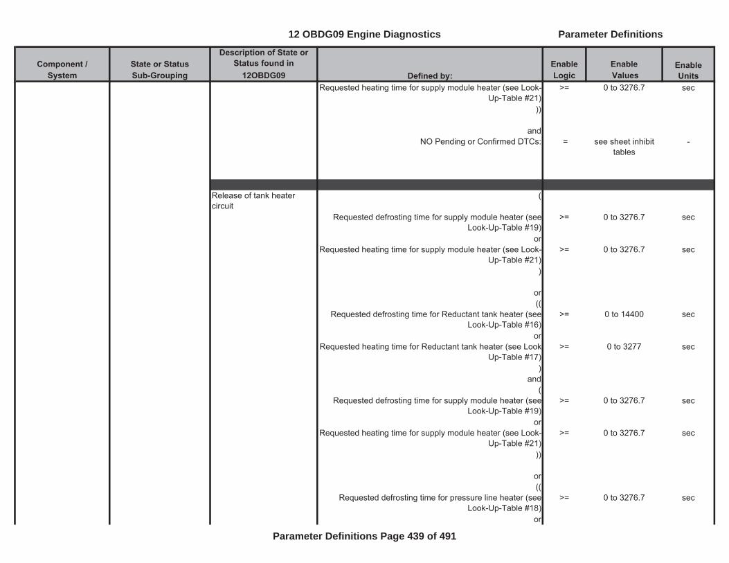
Component / State or Status Description of State or
Status found in Enable EnableSystem Sub-Grouping 12OBDG09 Logic Values
Enable UnitsDefined by:
Requested heating time for supply module heater (see Look-Up-Table #21)
>= 0 to 3276.7 sec
))
andNO Pending or Confirmed DTCs: = see sheet inhibit
tables-
Release of tank heater circuit
(
Requested defrosting time for supply module heater (see Look-Up-Table #19)
>= 0 to 3276.7 sec
orRequested heating time for supply module heater (see Look-
Up-Table #21)>= 0 to 3276.7 sec
)
or((
Requested defrosting time for Reductant tank heater (see Look-Up-Table #16)
>= 0 to 14400 sec
orRequested heating time for Reductant tank heater (see Look-
Up-Table #17)>= 0 to 3277 sec
)and
(Requested defrosting time for supply module heater (see
Look-Up-Table #19)>= 0 to 3276.7 sec
orRequested heating time for supply module heater (see Look-
Up-Table #21)>= 0 to 3276.7 sec
))
or((
Requested defrosting time for pressure line heater (see Look-Up-Table #18)
>= 0 to 3276.7 sec
or
12 OBDG09 Engine Diagnostics Parameter Definitions
Parameter Definitions Page 439 of 491
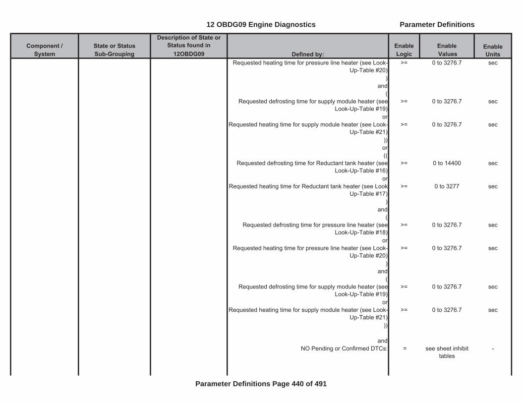
Component / State or Status Description of State or
Status found in Enable EnableSystem Sub-Grouping 12OBDG09 Logic Values
Enable UnitsDefined by:
Requested heating time for pressure line heater (see Look-Up-Table #20)
>= 0 to 3276.7 sec
)and
(Requested defrosting time for supply module heater (see
Look-Up-Table #19)>= 0 to 3276.7 sec
orRequested heating time for supply module heater (see Look-
Up-Table #21)>= 0 to 3276.7 sec
))or((
Requested defrosting time for Reductant tank heater (see Look-Up-Table #16)
>= 0 to 14400 sec
orRequested heating time for Reductant tank heater (see Look-
Up-Table #17)>= 0 to 3277 sec
)and
(Requested defrosting time for pressure line heater (see
Look-Up-Table #18)>= 0 to 3276.7 sec
orRequested heating time for pressure line heater (see Look-
Up-Table #20)>= 0 to 3276.7 sec
)and
(Requested defrosting time for supply module heater (see
Look-Up-Table #19)>= 0 to 3276.7 sec
orRequested heating time for supply module heater (see Look-
Up-Table #21)>= 0 to 3276.7 sec
))
andNO Pending or Confirmed DTCs: = see sheet inhibit
tables-
12 OBDG09 Engine Diagnostics Parameter Definitions
Parameter Definitions Page 440 of 491
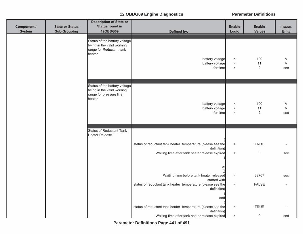
Component / State or Status Description of State or
Status found in Enable EnableSystem Sub-Grouping 12OBDG09 Logic Values
Enable UnitsDefined by:
Status of the battery voltage being in the valid working range for Reductant tank heater
battery voltage < 100 Vbattery voltage > 11 V
for time > 2 sec
Status of the battery voltage being in the valid working range for pressure line heater
battery voltage < 100 Vbattery voltage > 11 V
for time > 2 sec
Status of Reductant Tank Heater Release
(status of reductant tank heater temperature (please see the
definition)= TRUE -
Waiting time after tank heater release expired > 0 sec)
or((
Waiting time before tank heater released < 32767 secstarted with
status of reductant tank heater temperature (please see the definition)
= FALSE -
)and
(status of reductant tank heater temperature (please see the
definition)= TRUE -
Waiting time after tank heater release expired > 0 sec
12 OBDG09 Engine Diagnostics Parameter Definitions
Parameter Definitions Page 441 of 491

Component / State or Status Description of State or
Status found in Enable EnableSystem Sub-Grouping 12OBDG09 Logic Values
Enable UnitsDefined by:
))
or((
Waiting time before tank heater released > 32767 secstarted with
status of reductant tank heater temperature (please see the definition)
= FALSE -
)and
(status of reductant tank heater temperature (please see the
definition)= TRUE -
Waiting time after tank heater release expired > 0 sec))
Reductant Tank Level System States and Status
status of Reductant tank level
Tank level > full (100%) = Full -
Warning (66.67%) < tank level < full (100%) = OK -Restriction (33.33%) < tank level < Warning (66.67%) = Warning -
Empty < tank level < Restriction (33.33%) = Restriction -Tank level < = 0.1% = Empty -
Status of Reductant tank level reset when refilling is detected (please see the definition)
(
time since potential Reductant refill detection is set >= 12 secand with
(Derivation of the PT1 filtered level signal (DT1) >= 1.00 %/sec
ignition on = TRUE -engine speed > 550 rpm
Vehicle speed >= 6.22 mphtime since engine started <= (a) * (b)
(a) Time period for a positive slope to detect refueling = 12 sec
12 OBDG09 Engine Diagnostics Parameter Definitions
Parameter Definitions Page 442 of 491
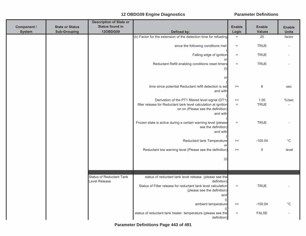
Component / State or Status Description of State or
Status found in Enable EnableSystem Sub-Grouping 12OBDG09 Logic Values
Enable UnitsDefined by:
(b) Factor for the extension of the detection time for refueling = 20 factor
since the following conditions met: = TRUE -(
Falling edge of ignition = TRUE -or
Reductant Refill enabling conditions reset timers = TRUE -)))
or(
time since potential Reductant refill detection is set >= 8 secand with
(Derivation of the PT1 filtered level signal (DT1) >= 1.00 %/sec
filter release for Reductant tank level calculation at ignition on on (Please see the definition)
= TRUE -
and with(
Frozen state is active during a certain warning level (please see the definition)
= TRUE -
and with(
Reductant tank Temperature >= -100.04 °Cor
Reductant low warning level (Please see the definition) >= 0 level
)))
Status of Reductant Tank Level Release
status of reductant tank level release (please see the definition)
Status of Filter release for reductant tank level calculation (please see the definition)
= TRUE -
and((
ambient temperature >= -100.04 °C((
status of reductant tank heater temperature (please see the definition)
= FALSE -
12 OBDG09 Engine Diagnostics Parameter Definitions
Parameter Definitions Page 443 of 491
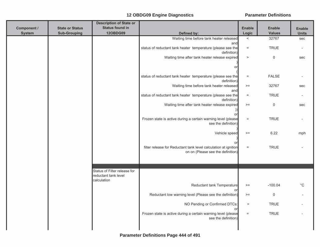
Component / State or Status Description of State or
Status found in Enable EnableSystem Sub-Grouping 12OBDG09 Logic Values
Enable UnitsDefined by:
Waiting time before tank heater released < 32767 secand
status of reductant tank heater temperature (please see the definition)
= TRUE -
Waiting time after tank heater release expired > 0 sec)
or(
status of reductant tank heater temperature (please see the definition)
= FALSE -
Waiting time before tank heater released >= 32767 secand
status of reductant tank heater temperature (please see the definition)
= TRUE -
Waiting time after tank heater release expired >= 0 sec))or
Frozen state is active during a certain warning level (please see the definition)
= TRUE -
)Vehicle speed >= 6.22 mph
)or
filter release for Reductant tank level calculation at ignition on on (Please see the definition)
= TRUE -
Status of Filter release for reductant tank level calculation
Reductant tank Temperature >= -100.04 °Cor
Reductant low warning level (Please see the definition) >= 0 -
NO Pending or Confirmed DTCs: = TRUE -or
Frozen state is active during a certain warning level (please see the definition)
= TRUE -
12 OBDG09 Engine Diagnostics Parameter Definitions
Parameter Definitions Page 444 of 491
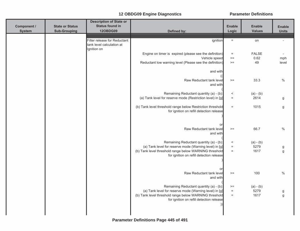
Component / State or Status Description of State or
Status found in Enable EnableSystem Sub-Grouping 12OBDG09 Logic Values
Enable UnitsDefined by:
Filter release for Reductant tank level calculation at Ignition on
ignition = on -
Engine on timer is expired (please see the definition) = FALSE -Vehicle speed >= 0.62 mph
Reductant low warning level (Please see the definition) >= 49 level
and with((
Raw Reductant tank level >= 33.3 %and with
(Remaining Reductant quantity (a) - (b): < (a) - (b)
(a) Tank level for reserve mode (Restriction level) in [g] = 2614 g
(b) Tank level threshold range below Restriction threshold for ignition on refill detection release
= 1015 g
)
orRaw Reductant tank level >= 66.7 %
and with(
Remaining Reductant quantity (a) - (b): < (a) - (b)(a) Tank level for reserve mode (Warning level) in [g] = 5279 g
(b) Tank level threshold range below WARNING threshold for ignition on refill detection release
= 1617 g
)
orRaw Reductant tank level >= 100 %
and with(
Remaining Reductant quantity (a) - (b): >= (a) - (b)(a) Tank level for reserve mode (Warning level) in [g] = 5279 g
(b) Tank level threshold range below WARNING threshold for ignition on refill detection release
= 1617 g
))
12 OBDG09 Engine Diagnostics Parameter Definitions
Parameter Definitions Page 445 of 491

Component / State or Status Description of State or
Status found in Enable EnableSystem Sub-Grouping 12OBDG09 Logic Values
Enable UnitsDefined by:
Status of Refill detection of Reductant tank
Status of Refill detection of Reductant tank (please see the definition)
Reductant tank level changed = TRUE -((
Captured Reductant tank level at last tank level change = Empty -
orCaptured Reductant tank level at last tank level change = Restriction -
)
and(
one or more of following conditions are metstatus of Reductant tank level (please see the definition) = Warning -
orstatus of Reductant tank level (please see the definition) = OK -
orstatus of Reductant tank level (please see the definition) = Full -
))or((
Captured Reductant tank level at last tank level change = Warning -
orCaptured Reductant tank level at last tank level change = OK -
)
and(
status of Reductant tank level (please see the definition) = Full -
)or(
12 OBDG09 Engine Diagnostics Parameter Definitions
Parameter Definitions Page 446 of 491
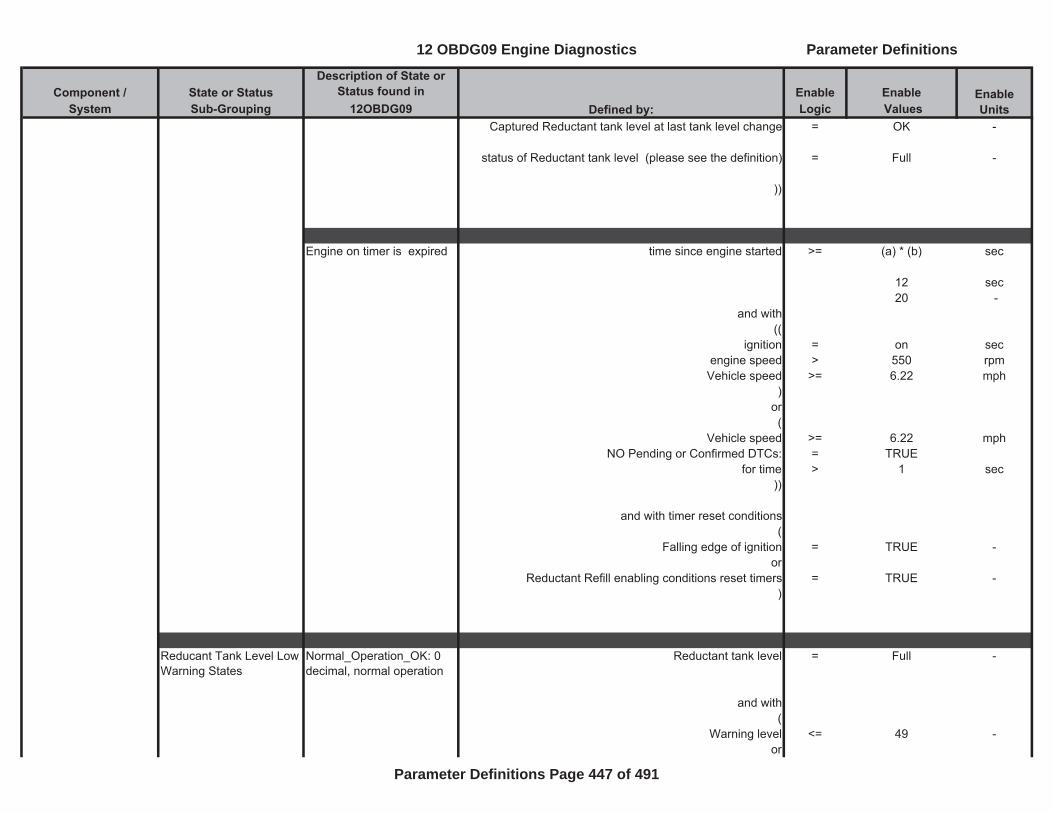
Component / State or Status Description of State or
Status found in Enable EnableSystem Sub-Grouping 12OBDG09 Logic Values
Enable UnitsDefined by:
Captured Reductant tank level at last tank level change = OK -
status of Reductant tank level (please see the definition) = Full -
))
Engine on timer is expired time since engine started >= (a) * (b) sec
12 sec20 -
and with((
ignition = on secengine speed > 550 rpm
Vehicle speed >= 6.22 mph)
or(
Vehicle speed >= 6.22 mphNO Pending or Confirmed DTCs: = TRUE
for time > 1 sec))
and with timer reset conditions(
Falling edge of ignition = TRUE -or
Reductant Refill enabling conditions reset timers = TRUE -)
Reducant Tank Level Low Warning States
Normal_Operation_OK: 0 decimal, normal operation
Reductant tank level = Full -
and with (
Warning level <= 49 -or
12 OBDG09 Engine Diagnostics Parameter Definitions
Parameter Definitions Page 447 of 491
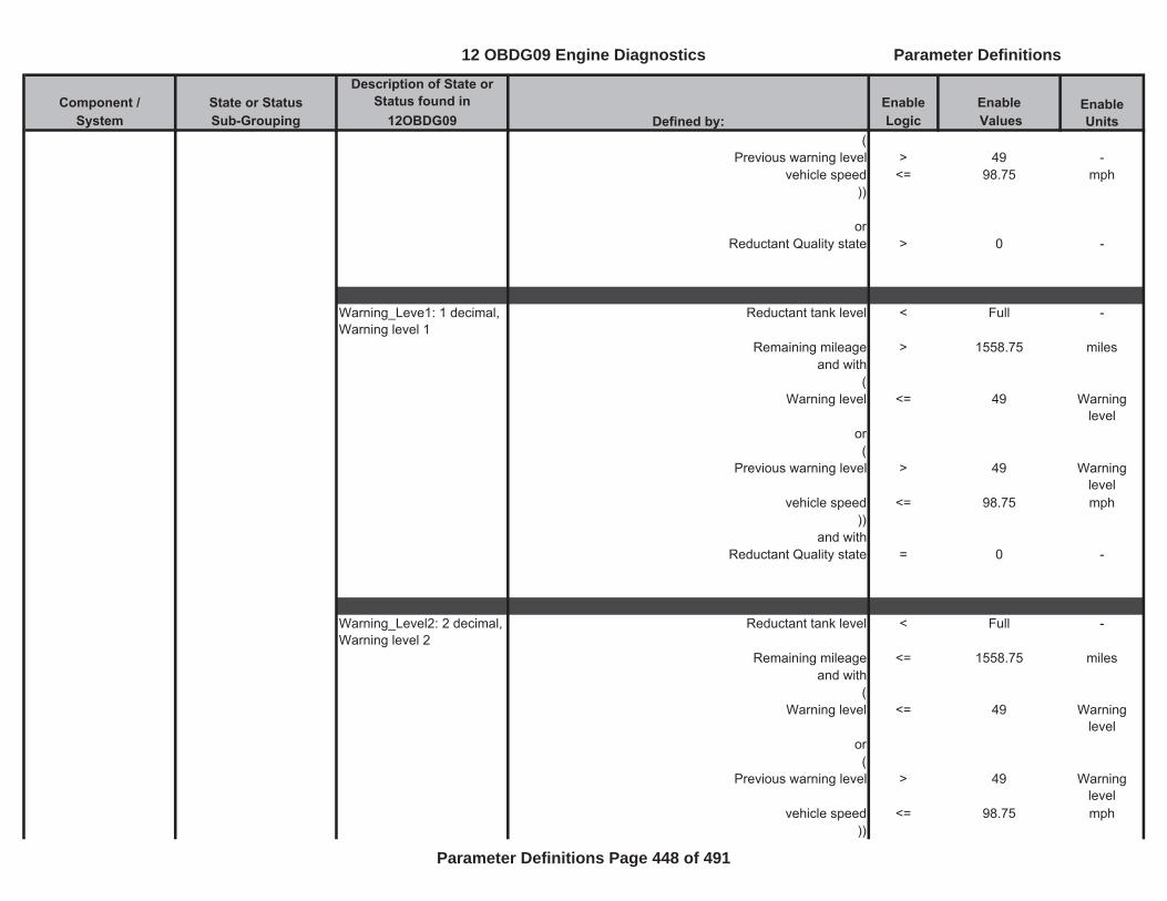
Component / State or Status Description of State or
Status found in Enable EnableSystem Sub-Grouping 12OBDG09 Logic Values
Enable UnitsDefined by:
(Previous warning level > 49 -
vehicle speed <= 98.75 mph))
orReductant Quality state > 0 -
Warning_Leve1: 1 decimal, Warning level 1
Reductant tank level < Full -
Remaining mileage > 1558.75 milesand with
( Warning level <= 49 Warning
levelor(
Previous warning level > 49 Warning level
vehicle speed <= 98.75 mph))
and withReductant Quality state = 0 -
Warning_Level2: 2 decimal, Warning level 2
Reductant tank level < Full -
Remaining mileage <= 1558.75 milesand with
( Warning level <= 49 Warning
levelor(
Previous warning level > 49 Warning level
vehicle speed <= 98.75 mph))
12 OBDG09 Engine Diagnostics Parameter Definitions
Parameter Definitions Page 448 of 491
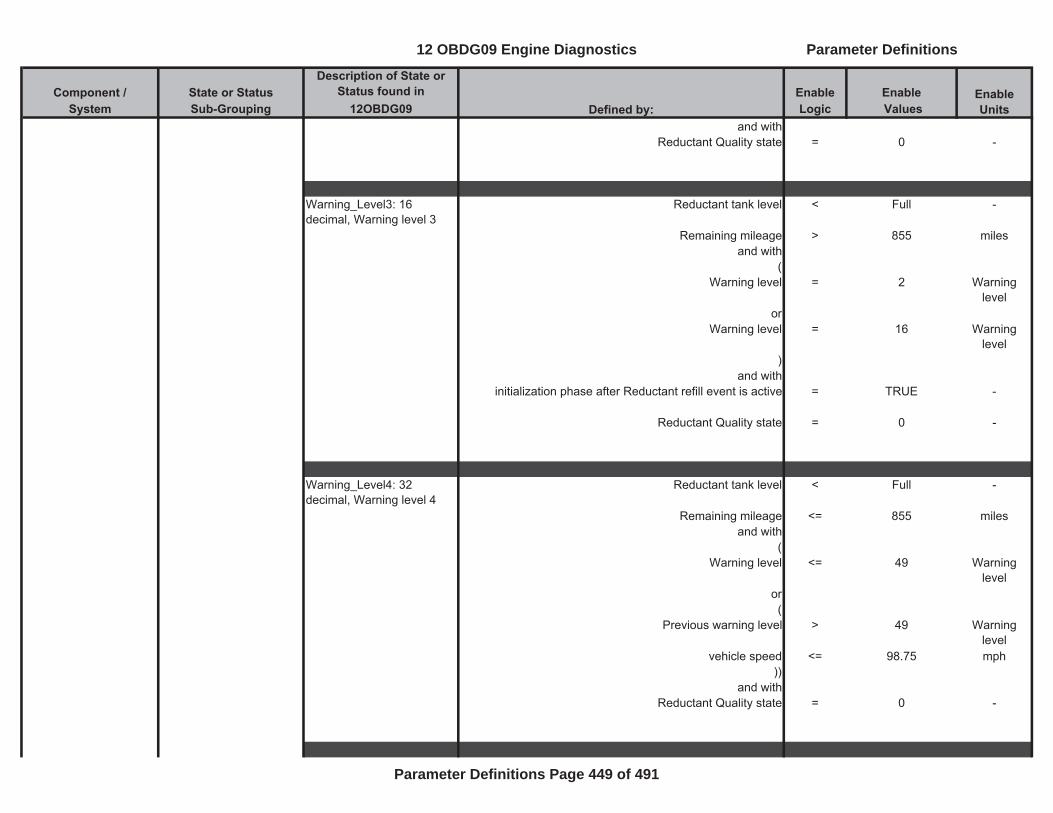
Component / State or Status Description of State or
Status found in Enable EnableSystem Sub-Grouping 12OBDG09 Logic Values
Enable UnitsDefined by:
and withReductant Quality state = 0 -
Warning_Level3: 16 decimal, Warning level 3
Reductant tank level < Full -
Remaining mileage > 855 milesand with
( Warning level = 2 Warning
levelor
Warning level = 16 Warning level
)and with
initialization phase after Reductant refill event is active = TRUE -
Reductant Quality state = 0 -
Warning_Level4: 32 decimal, Warning level 4
Reductant tank level < Full -
Remaining mileage <= 855 milesand with
( Warning level <= 49 Warning
levelor(
Previous warning level > 49 Warning level
vehicle speed <= 98.75 mph))
and withReductant Quality state = 0 -
12 OBDG09 Engine Diagnostics Parameter Definitions
Parameter Definitions Page 449 of 491
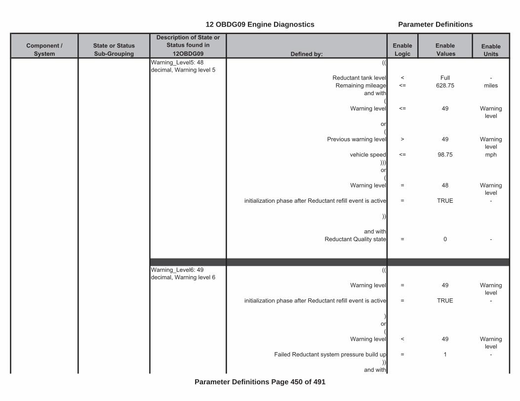
Component / State or Status Description of State or
Status found in Enable EnableSystem Sub-Grouping 12OBDG09 Logic Values
Enable UnitsDefined by:
Warning_Level5: 48 decimal, Warning level 5
((
Reductant tank level < Full -Remaining mileage <= 628.75 miles
and with (
Warning level <= 49 Warning level
or(
Previous warning level > 49 Warning level
vehicle speed <= 98.75 mph)))or(
Warning level = 48 Warning level
initialization phase after Reductant refill event is active = TRUE -
))
and withReductant Quality state = 0 -
Warning_Level6: 49 decimal, Warning level 6
((
Warning level = 49 Warning level
initialization phase after Reductant refill event is active = TRUE -
)or(
Warning level < 49 Warning level
Failed Reductant system pressure build up = 1 -))
and with
12 OBDG09 Engine Diagnostics Parameter Definitions
Parameter Definitions Page 450 of 491
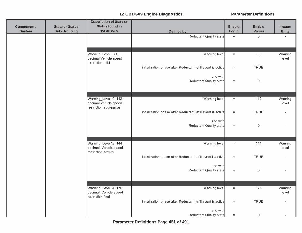
Component / State or Status Description of State or
Status found in Enable EnableSystem Sub-Grouping 12OBDG09 Logic Values
Enable UnitsDefined by:
Reductant Quality state = 0 -
Warning_Level8: 80 decimal,Vehicle speed restriction mild
Warning level = 80 Warning level
initialization phase after Reductant refill event is active = TRUE
and withReductant Quality state = 0
Warning_Level10: 112 decimal,Vehicle speed restriction aggressive
Warning level = 112 Warning level
initialization phase after Reductant refill event is active = TRUE -
and withReductant Quality state = 0 -
Warning_Level12: 144 decimal, Vehicle speed restriction severe
Warning level = 144 Warning level
initialization phase after Reductant refill event is active = TRUE -
and withReductant Quality state = 0 -
Warning_Level14: 176 decimal, Vehicle speed restriction final
Warning level = 176 Warning level
initialization phase after Reductant refill event is active = TRUE -
and withReductant Quality state = 0 -
12 OBDG09 Engine Diagnostics Parameter Definitions
Parameter Definitions Page 451 of 491
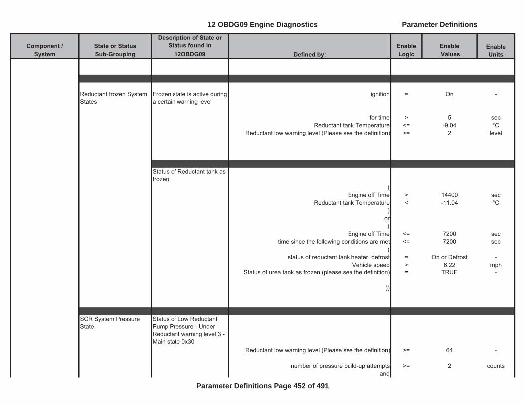
Component / State or Status Description of State or
Status found in Enable EnableSystem Sub-Grouping 12OBDG09 Logic Values
Enable UnitsDefined by:
Reductant frozen System States
Frozen state is active during a certain warning level
ignition = On -
for time > 5 secReductant tank Temperature <= -9.04 °C
Reductant low warning level (Please see the definition) >= 2 level
Status of Reductant tank as frozen
(Engine off Time > 14400 sec
Reductant tank Temperature < -11.04 °C)
or(
Engine off Time <= 7200 sectime since the following conditions are met <= 7200 sec
(status of reductant tank heater defrost = On or Defrost -
Vehicle speed > 6.22 mphStatus of urea tank as frozen (please see the definition) = TRUE -
))
SCR System Pressure State
Status of Low Reductant Pump Pressure - Under Reductant warning level 3 - Main state 0x30
Reductant low warning level (Please see the definition) >= 64 -
number of pressure build-up attempts >= 2 countsand
12 OBDG09 Engine Diagnostics Parameter Definitions
Parameter Definitions Page 452 of 491
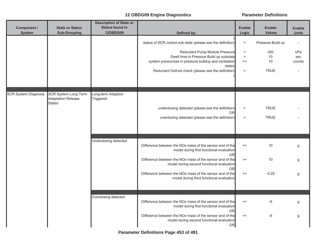
Component / State or Status Description of State or
Status found in Enable EnableSystem Sub-Grouping 12OBDG09 Logic Values
Enable UnitsDefined by:
(status of SCR control sub state (please see the definition) = Pressure Build up -
Reductant Pump Module Pressure < 350 kPaDwell time in Pressure Build up substate > 10 sec
system pressurizes in pressure buildup and ventilation states
>= 10 counts
Reductant Defrost check (please see the definition) = TRUE -)
SCR System Diagnosis SCR System Long Term Adaptation Release States
Long-term Adaption Triggered
underdosing detected (please see the definition) = TRUE -OR
overdosing detected (please see the definition) = TRUE -
Underdosing detectedDifference between the NOx mass of the sensor and of the
model during first functional evaluation >= 10 g
ORDifference between the NOx mass of the sensor and of the
model during second functional evaluation>= 10 g
ORDifference between the NOx mass of the sensor and of the
model during third functional evaluation>= -0.25 g
Overdosing detectedDifference between the NOx mass of the sensor and of the
model during first functional evaluation<= -6 g
ORDifference between the NOx mass of the sensor and of the
model during second functional evaluation<= -6 g
OR
12 OBDG09 Engine Diagnostics Parameter Definitions
Parameter Definitions Page 453 of 491
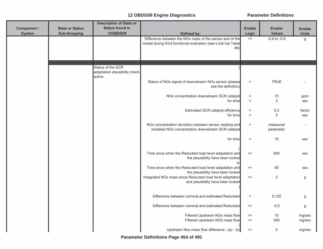
Component / State or Status Description of State or
Status found in Enable EnableSystem Sub-Grouping 12OBDG09 Logic Values
Enable UnitsDefined by:
Difference between the NOx mass of the sensor and of the model during third functional evaluation (see Look-Up-Table
#9)
<= -0.8 to -0.6 g
Status of the SCR adaptation plausibility check active
(
Status of NOx signal of downstream NOx sensor (please see the definition)
= TRUE -
NOx concentration downstream SCR catalyst > 15 ppmfor time > 3 sec
Estimated SCR catalyst efficiency > 0.3 factorfor time > 3 sec
NOx concentration deviation between sensor reading and modeled NOx concentration downstream SCR catalyst
> measured parameter
-
for time > 10 sec
(Time since when the Reductant load level adaptation and
the plausibility have been locked>= 600 sec
orTime since when the Reductant load level adaptation and
the plausibility have been locked>= 50 sec
Integrated NOx mass since Reductant load level adaptation and plausibility have been locked
>= 2 g
)
Difference between nominal and estimated Reductant < 0.125 g
Difference between nominal and estimated Reductant >= -0.5 g
Filtered Upstream NOx mass flow >= 10 mg/secFiltered Upstream NOx mass flow <= 500 mg/sec
(Upstream Nox mass flow difference : (a) - (b) >= 0 mg/sec
12 OBDG09 Engine Diagnostics Parameter Definitions
Parameter Definitions Page 454 of 491
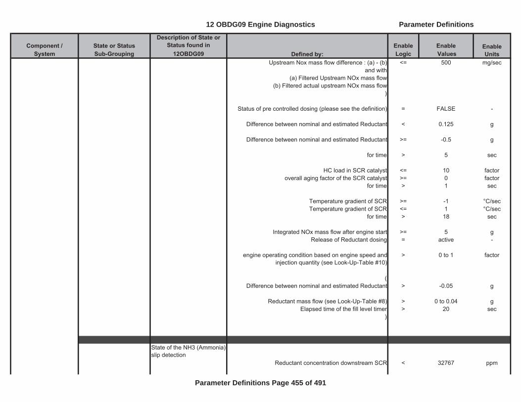
Component / State or Status Description of State or
Status found in Enable EnableSystem Sub-Grouping 12OBDG09 Logic Values
Enable UnitsDefined by:
Upstream Nox mass flow difference : (a) - (b) <= 500 mg/secand with
(a) Filtered Upstream NOx mass flow(b) Filtered actual upstream NOx mass flow
)
Status of pre controlled dosing (please see the definition) = FALSE -
Difference between nominal and estimated Reductant < 0.125 g
Difference between nominal and estimated Reductant >= -0.5 g
for time > 5 sec
HC load in SCR catalyst <= 10 factoroverall aging factor of the SCR catalyst >= 0 factor
for time > 1 sec
Temperature gradient of SCR >= -1 °C/secTemperature gradient of SCR <= 1 °C/sec
for time > 18 sec
Integrated NOx mass flow after engine start >= 5 gRelease of Reductant dosing = active -
engine operating condition based on engine speed and injection quantity (see Look-Up-Table #10)
> 0 to 1 factor
(Difference between nominal and estimated Reductant > -0.05 g
Reductant mass flow (see Look-Up-Table #8) > 0 to 0.04 gElapsed time of the fill level timer > 20 sec
)
State of the NH3 (Ammonia) slip detection
Reductant concentration downstream SCR < 32767 ppm
12 OBDG09 Engine Diagnostics Parameter Definitions
Parameter Definitions Page 455 of 491
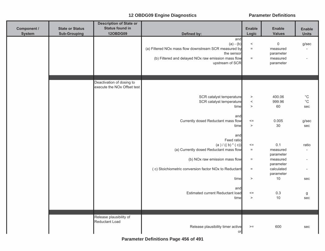
Component / State or Status Description of State or
Status found in Enable EnableSystem Sub-Grouping 12OBDG09 Logic Values
Enable UnitsDefined by:
and(a) - (b) < 0 g/sec
(a) Filtered NOx mass flow downstream SCR measured by the sensor
= measured parameter
-
(b) Filtered and delayed NOx raw emission mass flow upstream of SCR
= measured parameter
-
Deactivation of dosing to execute the NOx Offset test
SCR catalyst temperature > 400.06 °CSCR catalyst temperature < 999.96 °C
time > 60 sec
andCurrently dosed Reductant mass flow <= 0.005 g/sec
time > 30 sec
andFeed ratio
(a ) / (( b) * ( c)) <= 0.1 ratio(a) Currently dosed Reductant mass flow = measured
parameter-
(b) NOx raw emission mass flow = measured parameter
-
( c) Stoichiometric conversion factor NOx to Reductant = calculated parameter
-
time > 10 sec
andEstimated current Reductant load <= 0.3 g
time > 10 sec
Release plausibility of Reductant Load
Release plausibility timer active >= 600 secor
12 OBDG09 Engine Diagnostics Parameter Definitions
Parameter Definitions Page 456 of 491
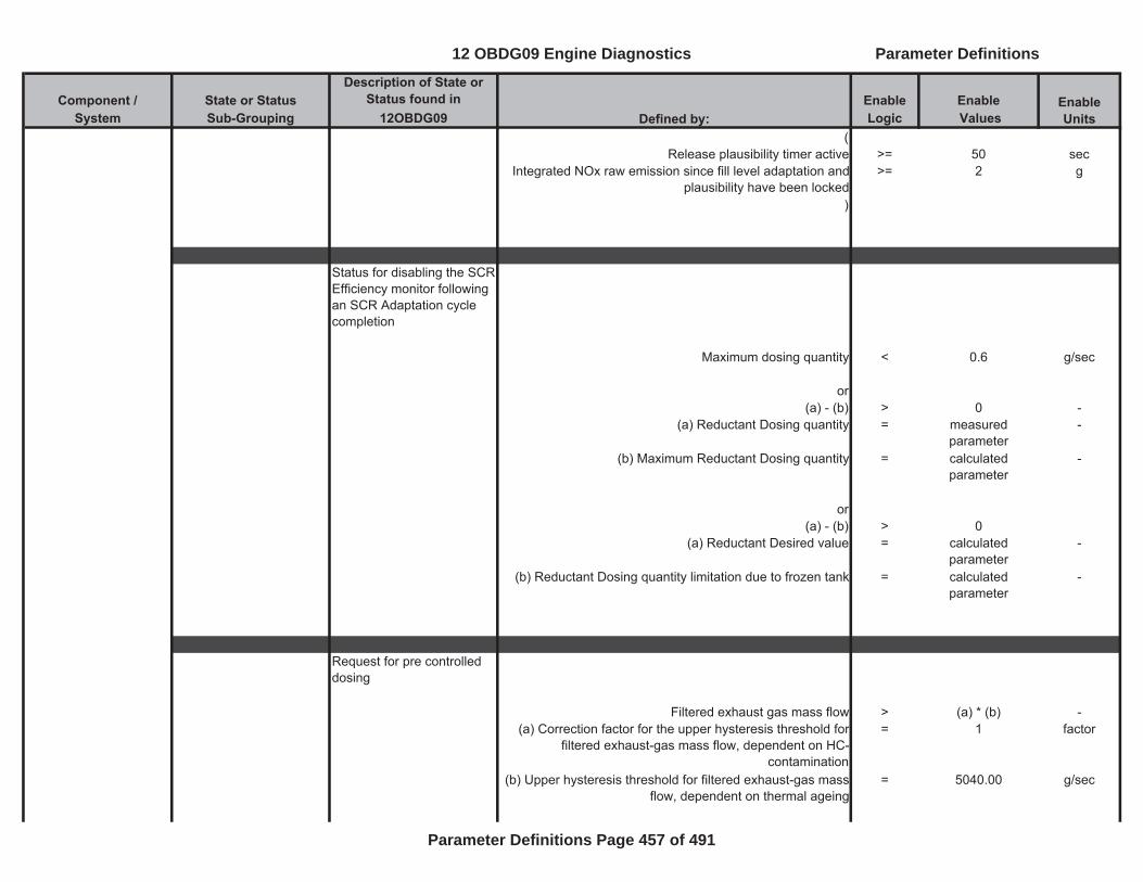
Component / State or Status Description of State or
Status found in Enable EnableSystem Sub-Grouping 12OBDG09 Logic Values
Enable UnitsDefined by:
(Release plausibility timer active >= 50 sec
Integrated NOx raw emission since fill level adaptation and plausibility have been locked
>= 2 g
)
Status for disabling the SCR Efficiency monitor following an SCR Adaptation cycle completion
Maximum dosing quantity < 0.6 g/sec
or(a) - (b) > 0 -
(a) Reductant Dosing quantity = measured parameter
-
(b) Maximum Reductant Dosing quantity = calculated parameter
-
or(a) - (b) > 0
(a) Reductant Desired value = calculated parameter
-
(b) Reductant Dosing quantity limitation due to frozen tank = calculated parameter
-
Request for pre controlled dosing
Filtered exhaust gas mass flow > (a) * (b) -(a) Correction factor for the upper hysteresis threshold for
filtered exhaust-gas mass flow, dependent on HC- contamination
= 1 factor
(b) Upper hysteresis threshold for filtered exhaust-gas mass flow, dependent on thermal ageing
= 5040.00 g/sec
12 OBDG09 Engine Diagnostics Parameter Definitions
Parameter Definitions Page 457 of 491
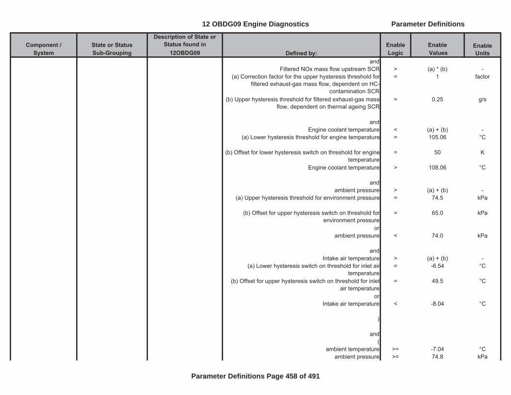
Component / State or Status Description of State or
Status found in Enable EnableSystem Sub-Grouping 12OBDG09 Logic Values
Enable UnitsDefined by:
andFiltered NOx mass flow upstream SCR > (a) * (b) -
(a) Correction factor for the upper hysteresis threshold for filtered exhaust-gas mass flow, dependent on HC-
contamination SCR
= 1 factor
(b) Upper hysteresis threshold for filtered exhaust-gas mass flow, dependent on thermal ageing SCR
= 0.25 g/s
andEngine coolant temperature < (a) + (b) -
(a) Lower hysteresis threshold for engine temperature = 105.06 °C
(b) Offset for lower hysteresis switch on threshold for engine temperature
= 50 K
Engine coolant temperature > 108.06 °C
andambient pressure > (a) + (b) -
(a) Upper hysteresis threshold for environment pressure = 74.5 kPa
(b) Offset for upper hysteresis switch on threshold for environment pressure
= 65.0 kPa
orambient pressure < 74.0 kPa
andIntake air temperature > (a) + (b) -
(a) Lower hysteresis switch on threshold for inlet air temperature
= -6.54 °C
(b) Offset for upper hysteresis switch on threshold for inlet air temperature
= 49.5 °C
orIntake air temperature < -8.04 °C
)
and(
ambient temperature >= -7.04 °Cambient pressure >= 74.8 kPa
12 OBDG09 Engine Diagnostics Parameter Definitions
Parameter Definitions Page 458 of 491
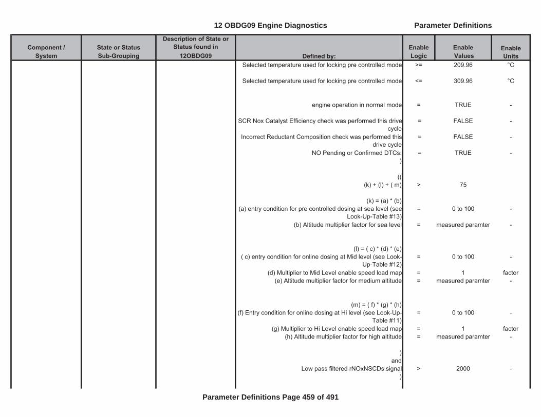
Component / State or Status Description of State or
Status found in Enable EnableSystem Sub-Grouping 12OBDG09 Logic Values
Enable UnitsDefined by:
Selected temperature used for locking pre controlled mode >= 209.96 °C
Selected temperature used for locking pre controlled mode <= 309.96 °C
engine operation in normal mode = TRUE -
SCR Nox Catalyst Efficiency check was performed this drive cycle
= FALSE -
Incorrect Reductant Composition check was performed this drive cycle
= FALSE -
NO Pending or Confirmed DTCs: = TRUE -)
(( (k) + (l) + ( m) > 75
(k) = (a) * (b)(a) entry condition for pre controlled dosing at sea level (see
Look-Up-Table #13)= 0 to 100 -
(b) Altitude multiplier factor for sea level = measured paramter -
(l) = ( c) * (d) * (e)( c) entry condition for online dosing at Mid level (see Look-
Up-Table #12)= 0 to 100 -
(d) Multiplier to Mid Level enable speed load map = 1 factor(e) Altitude multiplier factor for medium altitude = measured paramter -
(m) = ( f) * (g) * (h)(f) Entry condition for online dosing at Hi level (see Look-Up-
Table #11)= 0 to 100 -
(g) Multiplier to Hi Level enable speed load map = 1 factor(h) Altitude multiplier factor for high altitude = measured paramter -
)and
Low pass filtered rNOxNSCDs signal > 2000 -)
12 OBDG09 Engine Diagnostics Parameter Definitions
Parameter Definitions Page 459 of 491
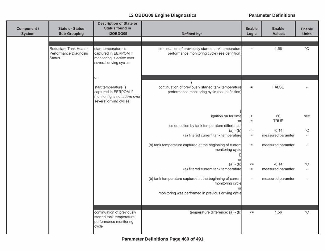
Component / State or Status Description of State or
Status found in Enable EnableSystem Sub-Grouping 12OBDG09 Logic Values
Enable UnitsDefined by:
Reductant Tank Heater Performance Diagnosis Status
start temperature is captured in EERPOM if monitoring is active over several driving cycles
continuation of previously started tank temperature performance monitoring cycle (see definition)
= 1.56 °C
or(
start temperature is captured in EERPOM if monitoring is not active over several driving cycles
continuation of previously started tank temperature performance monitoring cycle (see definition)
= FALSE -
(ignition on for time > 60 sec
or = TRUEice detection by tank temperature difference:
(a) - (b) <= -0.14 °C(a) filtered current tank temperature = measured paramter -
(b) tank temperature captured at the beginning of current monitoring cycle
= measured paramter -
))or
(a) - (b) <= -0.14 °C(a) filtered current tank temperature = measured paramter -
(b) tank temperature captured at the beginning of current monitoring cycle
= measured paramter -
ormonitoring was performed in previous driving cycle
continuation of previously started tank temperature performance monitoring cycle
temperature difference: (a) - (b) <= 1.56 °C
12 OBDG09 Engine Diagnostics Parameter Definitions
Parameter Definitions Page 460 of 491
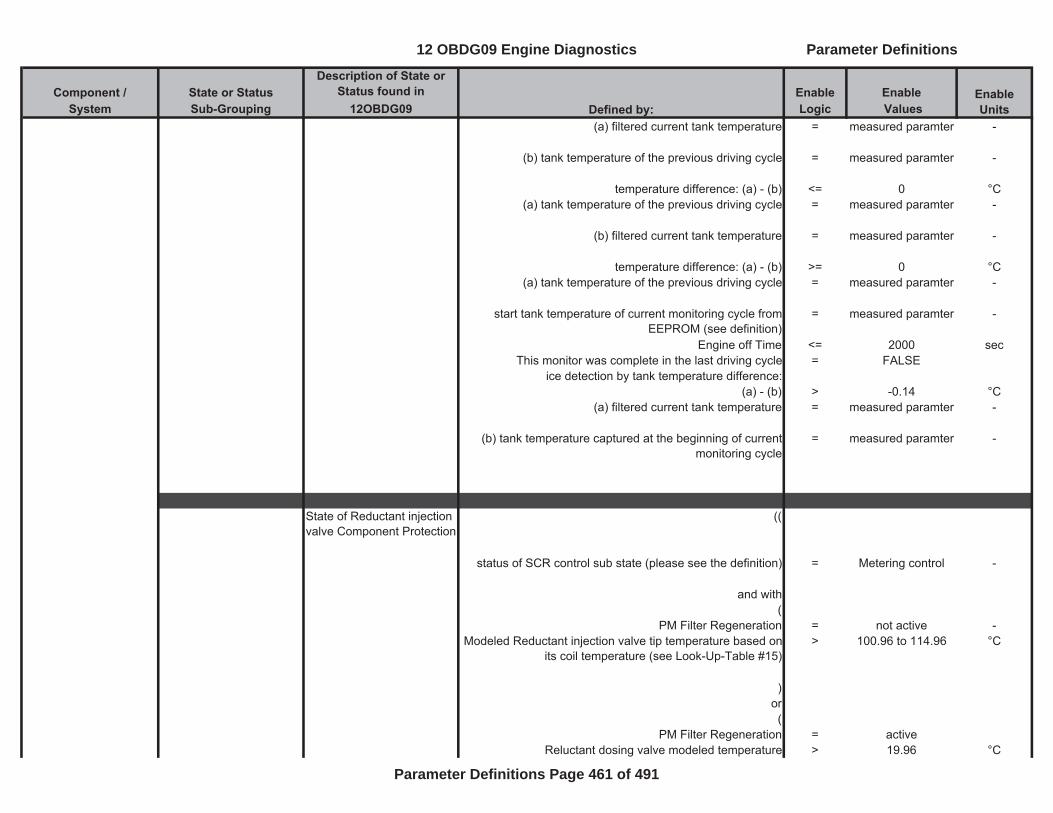
Component / State or Status Description of State or
Status found in Enable EnableSystem Sub-Grouping 12OBDG09 Logic Values
Enable UnitsDefined by:
(a) filtered current tank temperature = measured paramter -
(b) tank temperature of the previous driving cycle = measured paramter -
temperature difference: (a) - (b) <= 0 °C(a) tank temperature of the previous driving cycle = measured paramter -
(b) filtered current tank temperature = measured paramter -
temperature difference: (a) - (b) >= 0 °C(a) tank temperature of the previous driving cycle = measured paramter -
start tank temperature of current monitoring cycle from EEPROM (see definition)
= measured paramter -
Engine off Time <= 2000 secThis monitor was complete in the last driving cycle = FALSE
ice detection by tank temperature difference:(a) - (b) > -0.14 °C
(a) filtered current tank temperature = measured paramter -
(b) tank temperature captured at the beginning of current monitoring cycle
= measured paramter -
State of Reductant injection valve Component Protection
((
status of SCR control sub state (please see the definition) = Metering control -
and with(
PM Filter Regeneration = not active -Modeled Reductant injection valve tip temperature based on
its coil temperature (see Look-Up-Table #15)> 100.96 to 114.96 °C
)or(
PM Filter Regeneration = activeReluctant dosing valve modeled temperature > 19.96 °C
12 OBDG09 Engine Diagnostics Parameter Definitions
Parameter Definitions Page 461 of 491
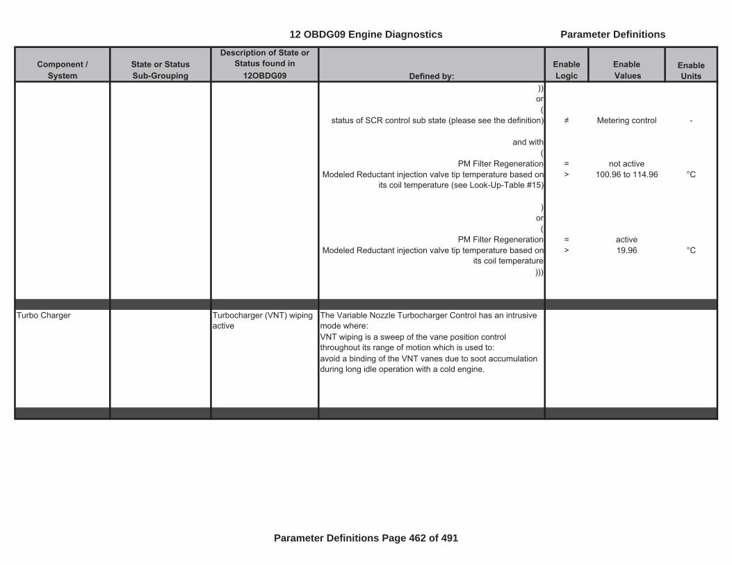
Component / State or Status Description of State or
Status found in Enable EnableSystem Sub-Grouping 12OBDG09 Logic Values
Enable UnitsDefined by:
))or(
status of SCR control sub state (please see the definition) Metering control -
and with(
PM Filter Regeneration = not activeModeled Reductant injection valve tip temperature based on
its coil temperature (see Look-Up-Table #15)> 100.96 to 114.96 °C
)or(
PM Filter Regeneration = activeModeled Reductant injection valve tip temperature based on
its coil temperature> 19.96 °C
)))
Turbo Charger Turbocharger (VNT) wiping active
The Variable Nozzle Turbocharger Control has an intrusive mode where:VNT wiping is a sweep of the vane position control throughout its range of motion which is used to:avoid a binding of the VNT vanes due to soot accumulation during long idle operation with a cold engine.
12 OBDG09 Engine Diagnostics Parameter Definitions
Parameter Definitions Page 462 of 491
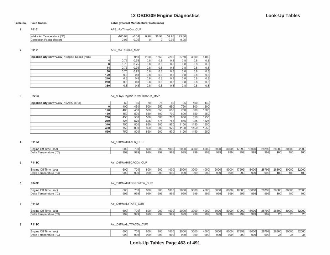
Table no. Fault Codes Label (Internal Manufacturer Reference)
1 P0101 AFS_rAirThresCor_CUR
Intake Air Temperature (°C) -100.04 -0.04 0.96 38.96 39.96 125.86Correction Factor (factor) 0.05 0.05 0 0 0.05 0.05
2 P0101 AFS_rAirThresLo_MAP
Injection Qty (mm^3/rev) / Engine Speed (rpm) 0 950 1100 1650 2200 2750 3300 44004 0.75 0.75 0.8 0.8 0.8 0.8 0.8 0.88 0.75 0.75 0.8 0.8 0.8 0.8 0.8 0.8
14 0.75 0.75 0.8 0.8 0.8 0.8 0.8 0.880 0.75 0.75 0.8 0.8 0.8 0.8 0.8 0.8
120 0.8 0.8 0.8 0.8 0.8 0.8 0.8 0.8240 0.8 0.8 0.8 0.8 0.8 0.8 0.8 0.8280 0.8 0.8 0.8 0.8 0.8 0.8 0.8 0.8380 0.8 0.8 0.8 0.8 0.8 0.8 0.8 0.8
3 P2263 Air_pPhysRngMinThresPIntkVUs_MAP
Injection Qty (mm^3/rev) / BARO (kPa) 60 65 70 75 82 95 100 1400 400 450 500 550 650 750 800 1200
120 400 450 500 550 650 750 800 1200160 450 500 550 600 700 800 850 1250260 450 500 550 600 700 800 850 1250280 525 575 625 675 768 875 925 1325340 750 800 850 900 970 1100 1150 1550480 750 800 850 900 970 1100 1150 1550560 750 800 850 900 970 1100 1150 1550
4 P112A Air_tDiffMaxHiTAFS_CUR
Engine Off Time (sec) 600 700 800 900 1000 2000 3000 4000 5000 8000 17999 18000 28799 28800 30000 32000Delta Temperature (°C) 999 999 999 999 999 999 999 999 999 999 999 999 999 100 100 100
5 P111C Air_tDiffMaxHiTCACDs_CUR
Engine Off Time (sec) 600 700 800 900 1000 2000 3000 4000 5000 8000 17999 18000 28799 28800 30000 32000Delta Temperature (°C) 999 999 999 999 999 999 999 999 999 999 999 999 999 100 100 100
6 P040F Air_tDiffMaxHiTEGRClr2Ds_CUR
Engine Off Time (sec) 600 700 800 900 1000 2000 3000 4000 5000 8000 10000 18000 28799 28800 30000 32000Delta Temperature (°C) 999 999 999 999 999 999 999 999 999 999 999 999 999 100 100 100
7 P112A Air_tDiffMaxLoTAFS_CUR
Engine Off Time (sec) 600 700 800 900 1000 2000 3000 4000 5000 8000 17999 18000 28799 28800 30000 32000Delta Temperature (°C) 999 999 999 999 999 999 999 999 999 999 999 999 999 20 20 20
8 P111C Air_tDiffMaxLoTCACDs_CUR
Engine Off Time (sec) 600 700 800 900 1000 2000 3000 4000 5000 8000 17999 18000 28799 28800 30000 32000Delta Temperature (°C) 999 999 999 999 999 999 999 999 999 999 999 999 999 35 35 35
12 OBDG09 Engine Diagnostics Look-Up Tables
Look-Up Tables Page 463 of 491
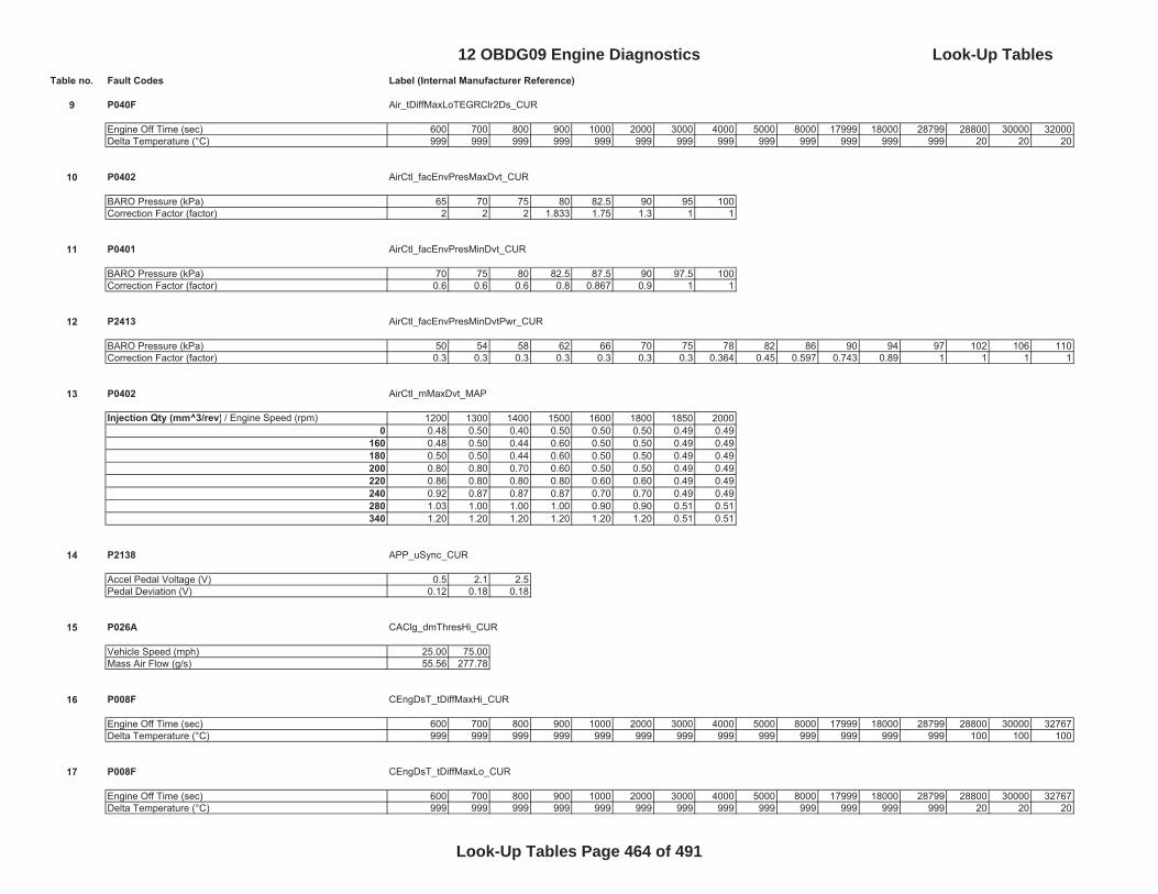
Table no. Fault Codes Label (Internal Manufacturer Reference)
9 P040F Air_tDiffMaxLoTEGRClr2Ds_CUR
Engine Off Time (sec) 600 700 800 900 1000 2000 3000 4000 5000 8000 17999 18000 28799 28800 30000 32000Delta Temperature (°C) 999 999 999 999 999 999 999 999 999 999 999 999 999 20 20 20
10 P0402 AirCtl_facEnvPresMaxDvt_CUR
BARO Pressure (kPa) 65 70 75 80 82.5 90 95 100Correction Factor (factor) 2 2 2 1.833 1.75 1.3 1 1
11 P0401 AirCtl_facEnvPresMinDvt_CUR
BARO Pressure (kPa) 70 75 80 82.5 87.5 90 97.5 100Correction Factor (factor) 0.6 0.6 0.6 0.8 0.867 0.9 1 1
12 P2413 AirCtl_facEnvPresMinDvtPwr_CUR
BARO Pressure (kPa) 50 54 58 62 66 70 75 78 82 86 90 94 97 102 106 110Correction Factor (factor) 0.3 0.3 0.3 0.3 0.3 0.3 0.3 0.364 0.45 0.597 0.743 0.89 1 1 1 1
13 P0402 AirCtl_mMaxDvt_MAP
Injection Qty (mm^3/rev) / Engine Speed (rpm) 1200 1300 1400 1500 1600 1800 1850 20000 0.48 0.50 0.40 0.50 0.50 0.50 0.49 0.49
160 0.48 0.50 0.44 0.60 0.50 0.50 0.49 0.49180 0.50 0.50 0.44 0.60 0.50 0.50 0.49 0.49200 0.80 0.80 0.70 0.60 0.50 0.50 0.49 0.49220 0.86 0.80 0.80 0.80 0.60 0.60 0.49 0.49240 0.92 0.87 0.87 0.87 0.70 0.70 0.49 0.49280 1.03 1.00 1.00 1.00 0.90 0.90 0.51 0.51340 1.20 1.20 1.20 1.20 1.20 1.20 0.51 0.51
14 P2138 APP_uSync_CUR
Accel Pedal Voltage (V) 0.5 2.1 2.5Pedal Deviation (V) 0.12 0.18 0.18
15 P026A CAClg_dmThresHi_CUR
Vehicle Speed (mph) 25.00 75.00Mass Air Flow (g/s) 55.56 277.78
16 P008F CEngDsT_tDiffMaxHi_CUR
Engine Off Time (sec) 600 700 800 900 1000 2000 3000 4000 5000 8000 17999 18000 28799 28800 30000 32767Delta Temperature (°C) 999 999 999 999 999 999 999 999 999 999 999 999 999 100 100 100
17 P008F CEngDsT_tDiffMaxLo_CUR
Engine Off Time (sec) 600 700 800 900 1000 2000 3000 4000 5000 8000 17999 18000 28799 28800 30000 32767Delta Temperature (°C) 999 999 999 999 999 999 999 999 999 999 999 999 999 20 20 20
12 OBDG09 Engine Diagnostics Look-Up Tables
Look-Up Tables Page 464 of 491
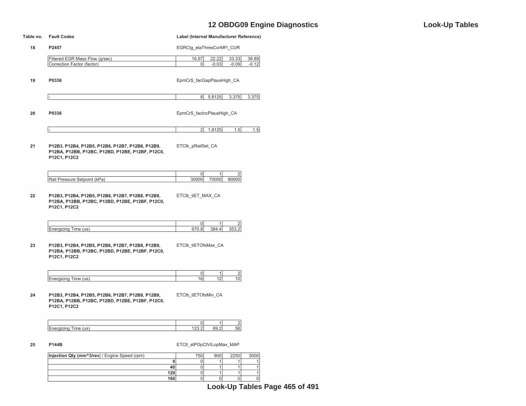
Table no. Fault Codes Label (Internal Manufacturer Reference)
18 P2457 EGRClg_etaThresCorMFl_CUR
Filtered EGR Mass Flow (g/sec) 16.67 22.22 33.33 38.89Correction Factor (factor) 0 -0.03 -0.09 -0.12
19 P0336 EpmCrS_facGapPlausHigh_CA
- 8 5.8125 3.375 3.375
20 P0336 EpmCrS_facIncPlausHigh_CA
- 2 1.8125 1.5 1.5
21 P12B3, P12B4, P12B5, P12B6, P12B7, P12B8, P12B9, P12BA, P12BB, P12BC, P12BD, P12BE, P12BF, P12C0, P12C1, P12C2
ETClb_pRailSet_CA
0 1 2Rail Pressure Setpoint (kPa) 30000 70000 90000
22 P12B3, P12B4, P12B5, P12B6, P12B7, P12B8, P12B9, P12BA, P12BB, P12BC, P12BD, P12BE, P12BF, P12C0, P12C1, P12C2
ETClb_tiET_MAX_CA
0 1 2Energizing Time (us) 670.8 384.4 353.2
23 P12B3, P12B4, P12B5, P12B6, P12B7, P12B8, P12B9, P12BA, P12BB, P12BC, P12BD, P12BE, P12BF, P12C0, P12C1, P12C2
ETClb_tiETOfsMax_CA
0 1 2Energizing Time (us) 16 12 10
24 P12B3, P12B4, P12B5, P12B6, P12B7, P12B8, P12B9, P12BA, P12BB, P12BC, P12BD, P12BE, P12BF, P12C0, P12C1, P12C2
ETClb_tiETOfsMin_CA
0 1 2Energizing Time (us) 123.2 69.2 56
25 P144B ETCtl_stPOpCtVILopMax_MAP
Injection Qty (mm^3/rev) / Engine Speed (rpm) 750 900 2250 30000 0 1 1 1
40 0 1 1 1120 0 1 1 1160 0 0 0 0
12 OBDG09 Engine Diagnostics Look-Up Tables
Look-Up Tables Page 465 of 491
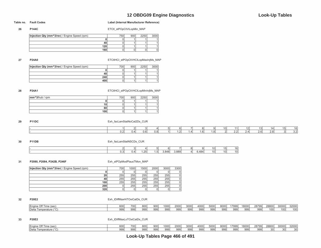
Table no. Fault Codes Label (Internal Manufacturer Reference)
26 P144C ETCtl_stPOpCtVILopMin_MAP
Injection Qty (mm^3/rev) / Engine Speed (rpm) 750 900 2250 30000 0 1 1 1
40 0 1 1 1120 0 1 1 1160 0 0 0 0
27 P24A0 ETCtlHCI_stPOpCtVHCILopMaxInjMs_MAP
Injection Qty (mm^3/rev) / Engine Speed (rpm) 700 900 2250 30000 0 1 1 1
40 0 1 1 1240 0 1 1 1400 0 1 1 1
28 P24A1 ETCtlHCI_stPOpCtVHCILopMinInjMs_MAP
mm^3/hub / rpm 700 900 2250 30000 0 1 1 1
10 0 1 1 160 0 1 1 1
100 0 1 1 1
29 P11DC Exh_facLamStatNoCat2Ds_CUR
- 1 2 3 4 5 6 7 8 9 10 11 12 13 14 15 16- 0.2 0.4 0.6 0.8 1 1.2 1.4 1.6 1.8 2 2.2 2.4 2.6 2.8 3 3.2
30 P11DB Exh_facLamStatNSCDs_CUR
- 2 3 4 5 6 7 8 9 10 15 16- 0.3 0.4 1.25 1.5 3.848 3.889 4 6.484 10 10 10
31 P2080, P2084, P242B, P246F Exh_stPOpModPlausTMon_MAP
Injection Qty (mm^3/rev) / Engine Speed (rpm) 700 1000 1500 2000 3000 33000 0 0 0 0 0 0
20 255 255 255 255 255 040 255 255 255 255 255 0
100 255 255 255 255 255 0200 0 255 255 255 255 0320 0 0 0 0 0 0
32 P20E2 Exh_tDiffMaxHiTOxiCatDs_CUR
Engine Off Time (sec) 600 700 800 900 1000 2000 3000 4000 5000 8000 17999 18000 28799 28800 30000 32000Delta Temperature (°C) 999 999 999 999 999 999 999 999 999 999 999 999 999 100 100 100
33 P20E2 Exh_tDiffMaxLoTOxiCatDs_CUR
Engine Off Time (sec) 600 700 800 900 1000 2000 3000 4000 5000 8000 17999 18000 28799 28800 30000 32000Delta Temperature (°C) 999 999 999 999 999 999 999 999 999 999 999 999 999 30 30 30
12 OBDG09 Engine Diagnostics Look-Up Tables
Look-Up Tables Page 466 of 491
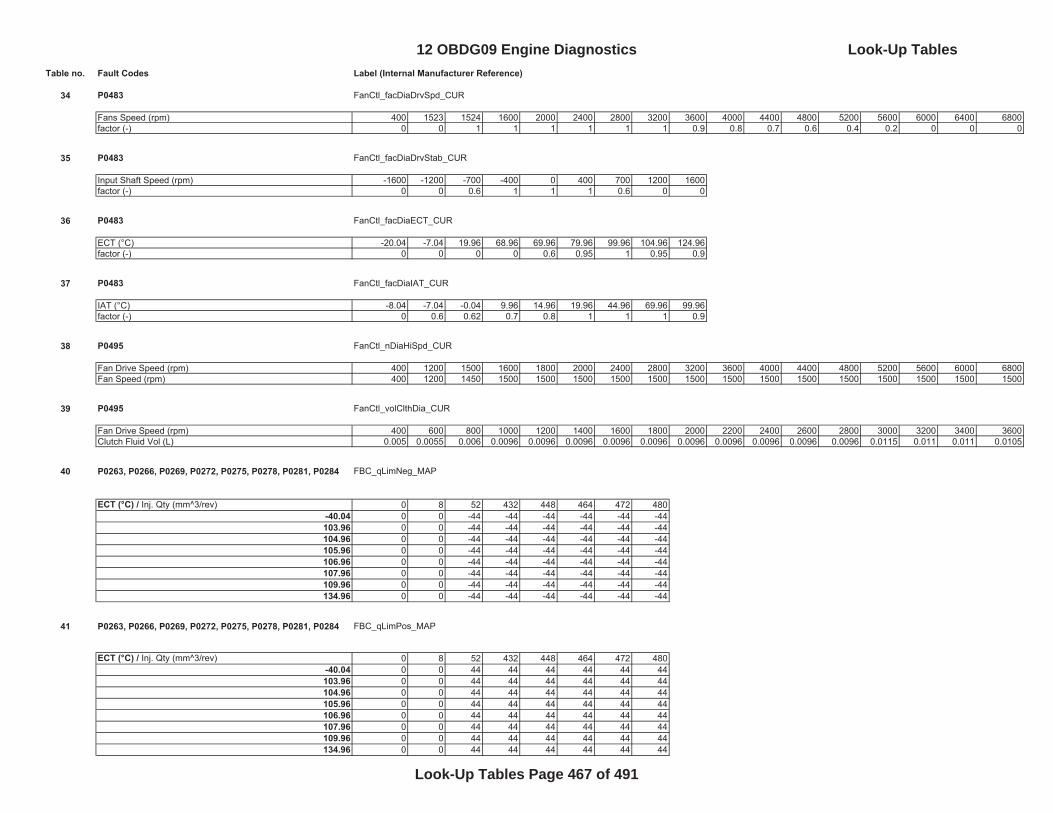
Table no. Fault Codes Label (Internal Manufacturer Reference)
34 P0483 FanCtl_facDiaDrvSpd_CUR
Fans Speed (rpm) 400 1523 1524 1600 2000 2400 2800 3200 3600 4000 4400 4800 5200 5600 6000 6400 6800factor (-) 0 0 1 1 1 1 1 1 0.9 0.8 0.7 0.6 0.4 0.2 0 0 0
35 P0483 FanCtl_facDiaDrvStab_CUR
Input Shaft Speed (rpm) -1600 -1200 -700 -400 0 400 700 1200 1600factor (-) 0 0 0.6 1 1 1 0.6 0 0
36 P0483 FanCtl_facDiaECT_CUR
ECT (°C) -20.04 -7.04 19.96 68.96 69.96 79.96 99.96 104.96 124.96factor (-) 0 0 0 0 0.6 0.95 1 0.95 0.9
37 P0483 FanCtl_facDiaIAT_CUR
IAT (°C) -8.04 -7.04 -0.04 9.96 14.96 19.96 44.96 69.96 99.96factor (-) 0 0.6 0.62 0.7 0.8 1 1 1 0.9
38 P0495 FanCtl_nDiaHiSpd_CUR
Fan Drive Speed (rpm) 400 1200 1500 1600 1800 2000 2400 2800 3200 3600 4000 4400 4800 5200 5600 6000 6800Fan Speed (rpm) 400 1200 1450 1500 1500 1500 1500 1500 1500 1500 1500 1500 1500 1500 1500 1500 1500
39 P0495 FanCtl_volClthDia_CUR
Fan Drive Speed (rpm) 400 600 800 1000 1200 1400 1600 1800 2000 2200 2400 2600 2800 3000 3200 3400 3600Clutch Fluid Vol (L) 0.005 0.0055 0.006 0.0096 0.0096 0.0096 0.0096 0.0096 0.0096 0.0096 0.0096 0.0096 0.0096 0.0115 0.011 0.011 0.0105
40 P0263, P0266, P0269, P0272, P0275, P0278, P0281, P0284 FBC_qLimNeg_MAP
ECT (°C) / Inj. Qty (mm^3/rev) 0 8 52 432 448 464 472 480-40.04 0 0 -44 -44 -44 -44 -44 -44103.96 0 0 -44 -44 -44 -44 -44 -44104.96 0 0 -44 -44 -44 -44 -44 -44105.96 0 0 -44 -44 -44 -44 -44 -44106.96 0 0 -44 -44 -44 -44 -44 -44107.96 0 0 -44 -44 -44 -44 -44 -44109.96 0 0 -44 -44 -44 -44 -44 -44134.96 0 0 -44 -44 -44 -44 -44 -44
41 P0263, P0266, P0269, P0272, P0275, P0278, P0281, P0284 FBC_qLimPos_MAP
ECT (°C) / Inj. Qty (mm^3/rev) 0 8 52 432 448 464 472 480-40.04 0 0 44 44 44 44 44 44103.96 0 0 44 44 44 44 44 44104.96 0 0 44 44 44 44 44 44105.96 0 0 44 44 44 44 44 44106.96 0 0 44 44 44 44 44 44107.96 0 0 44 44 44 44 44 44109.96 0 0 44 44 44 44 44 44134.96 0 0 44 44 44 44 44 44
12 OBDG09 Engine Diagnostics Look-Up Tables
Look-Up Tables Page 467 of 491
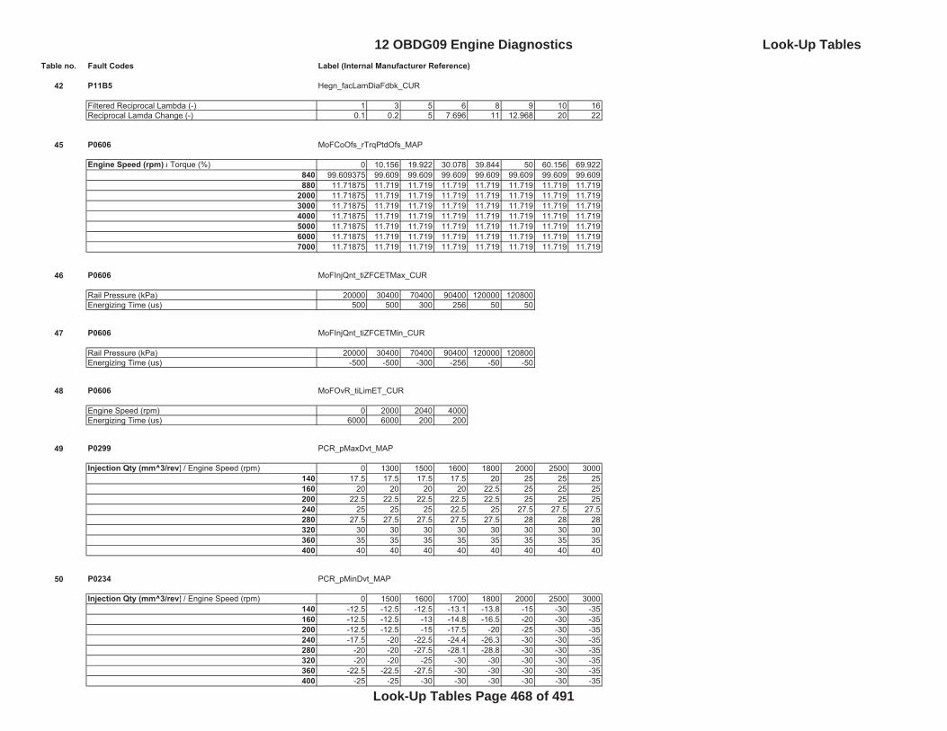
Table no. Fault Codes Label (Internal Manufacturer Reference)
42 P11B5 Hegn_facLamDiaFdbk_CUR
Filtered Reciprocal Lambda (-) 1 3 5 6 8 9 10 16Reciprocal Lamda Change (-) 0.1 0.2 5 7.696 11 12.968 20 22
45 P0606 MoFCoOfs_rTrqPtdOfs_MAP
Engine Speed (rpm) / Torque (%) 0 10.156 19.922 30.078 39.844 50 60.156 69.922840 99.609375 99.609 99.609 99.609 99.609 99.609 99.609 99.609880 11.71875 11.719 11.719 11.719 11.719 11.719 11.719 11.719
2000 11.71875 11.719 11.719 11.719 11.719 11.719 11.719 11.7193000 11.71875 11.719 11.719 11.719 11.719 11.719 11.719 11.7194000 11.71875 11.719 11.719 11.719 11.719 11.719 11.719 11.7195000 11.71875 11.719 11.719 11.719 11.719 11.719 11.719 11.7196000 11.71875 11.719 11.719 11.719 11.719 11.719 11.719 11.7197000 11.71875 11.719 11.719 11.719 11.719 11.719 11.719 11.719
46 P0606 MoFInjQnt_tiZFCETMax_CUR
Rail Pressure (kPa) 20000 30400 70400 90400 120000 120800Energizing Time (us) 500 500 300 256 50 50
47 P0606 MoFInjQnt_tiZFCETMin_CUR
Rail Pressure (kPa) 20000 30400 70400 90400 120000 120800Energizing Time (us) -500 -500 -300 -256 -50 -50
48 P0606 MoFOvR_tiLimET_CUR
Engine Speed (rpm) 0 2000 2040 4000Energizing Time (us) 6000 6000 200 200
49 P0299 PCR_pMaxDvt_MAP
Injection Qty (mm^3/rev) / Engine Speed (rpm) 0 1300 1500 1600 1800 2000 2500 3000140 17.5 17.5 17.5 17.5 20 25 25 25160 20 20 20 20 22.5 25 25 25200 22.5 22.5 22.5 22.5 22.5 25 25 25240 25 25 25 22.5 25 27.5 27.5 27.5280 27.5 27.5 27.5 27.5 27.5 28 28 28320 30 30 30 30 30 30 30 30360 35 35 35 35 35 35 35 35400 40 40 40 40 40 40 40 40
50 P0234 PCR_pMinDvt_MAP
Injection Qty (mm^3/rev) / Engine Speed (rpm) 0 1500 1600 1700 1800 2000 2500 3000140 -12.5 -12.5 -12.5 -13.1 -13.8 -15 -30 -35160 -12.5 -12.5 -13 -14.8 -16.5 -20 -30 -35200 -12.5 -12.5 -15 -17.5 -20 -25 -30 -35240 -17.5 -20 -22.5 -24.4 -26.3 -30 -30 -35280 -20 -20 -27.5 -28.1 -28.8 -30 -30 -35320 -20 -20 -25 -30 -30 -30 -30 -35360 -22.5 -22.5 -27.5 -30 -30 -30 -30 -35400 -25 -25 -30 -30 -30 -30 -30 -35
12 OBDG09 Engine Diagnostics Look-Up Tables
Look-Up Tables Page 468 of 491
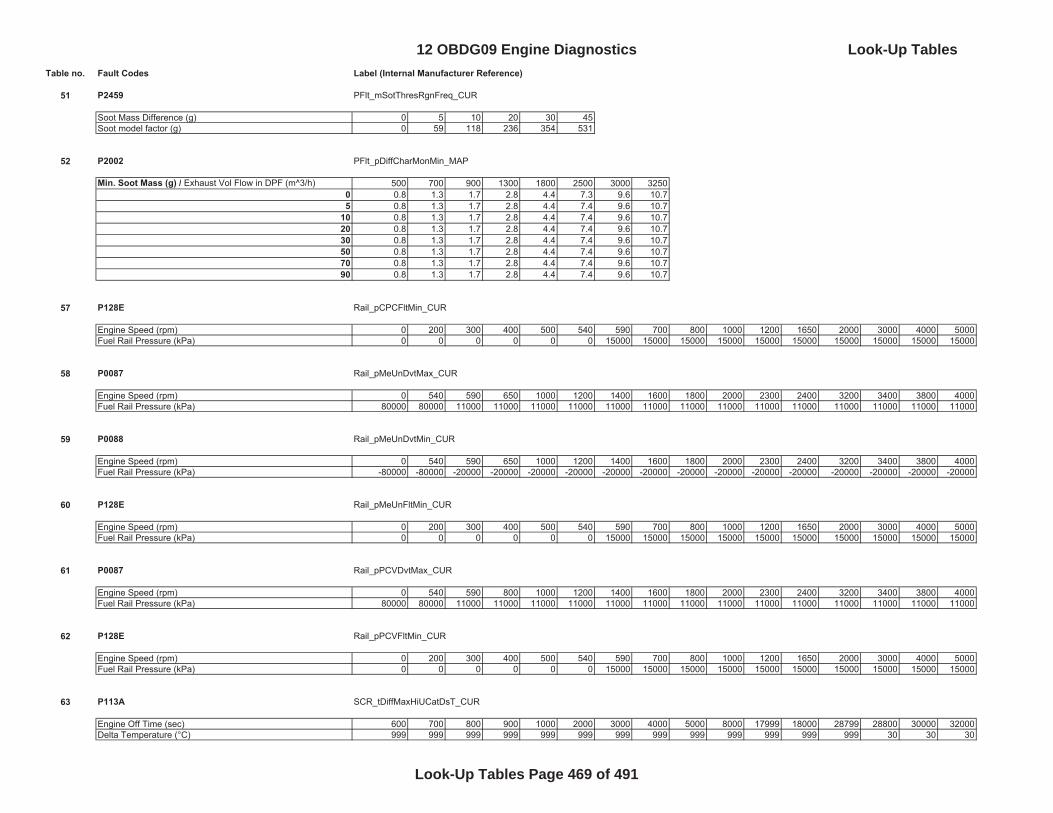
Table no. Fault Codes Label (Internal Manufacturer Reference)
51 P2459 PFlt_mSotThresRgnFreq_CUR
Soot Mass Difference (g) 0 5 10 20 30 45Soot model factor (g) 0 59 118 236 354 531
52 P2002 PFlt_pDiffCharMonMin_MAP
Min. Soot Mass (g) / Exhaust Vol Flow in DPF (m^3/h) 500 700 900 1300 1800 2500 3000 32500 0.8 1.3 1.7 2.8 4.4 7.3 9.6 10.75 0.8 1.3 1.7 2.8 4.4 7.4 9.6 10.7
10 0.8 1.3 1.7 2.8 4.4 7.4 9.6 10.720 0.8 1.3 1.7 2.8 4.4 7.4 9.6 10.730 0.8 1.3 1.7 2.8 4.4 7.4 9.6 10.750 0.8 1.3 1.7 2.8 4.4 7.4 9.6 10.770 0.8 1.3 1.7 2.8 4.4 7.4 9.6 10.790 0.8 1.3 1.7 2.8 4.4 7.4 9.6 10.7
57 P128E Rail_pCPCFltMin_CUR
Engine Speed (rpm) 0 200 300 400 500 540 590 700 800 1000 1200 1650 2000 3000 4000 5000Fuel Rail Pressure (kPa) 0 0 0 0 0 0 15000 15000 15000 15000 15000 15000 15000 15000 15000 15000
58 P0087 Rail_pMeUnDvtMax_CUR
Engine Speed (rpm) 0 540 590 650 1000 1200 1400 1600 1800 2000 2300 2400 3200 3400 3800 4000Fuel Rail Pressure (kPa) 80000 80000 11000 11000 11000 11000 11000 11000 11000 11000 11000 11000 11000 11000 11000 11000
59 P0088 Rail_pMeUnDvtMin_CUR
Engine Speed (rpm) 0 540 590 650 1000 1200 1400 1600 1800 2000 2300 2400 3200 3400 3800 4000Fuel Rail Pressure (kPa) -80000 -80000 -20000 -20000 -20000 -20000 -20000 -20000 -20000 -20000 -20000 -20000 -20000 -20000 -20000 -20000
60 P128E Rail_pMeUnFltMin_CUR
Engine Speed (rpm) 0 200 300 400 500 540 590 700 800 1000 1200 1650 2000 3000 4000 5000Fuel Rail Pressure (kPa) 0 0 0 0 0 0 15000 15000 15000 15000 15000 15000 15000 15000 15000 15000
61 P0087 Rail_pPCVDvtMax_CUR
Engine Speed (rpm) 0 540 590 800 1000 1200 1400 1600 1800 2000 2300 2400 3200 3400 3800 4000Fuel Rail Pressure (kPa) 80000 80000 11000 11000 11000 11000 11000 11000 11000 11000 11000 11000 11000 11000 11000 11000
62 P128E Rail_pPCVFltMin_CUR
Engine Speed (rpm) 0 200 300 400 500 540 590 700 800 1000 1200 1650 2000 3000 4000 5000Fuel Rail Pressure (kPa) 0 0 0 0 0 0 15000 15000 15000 15000 15000 15000 15000 15000 15000 15000
63 P113A SCR_tDiffMaxHiUCatDsT_CUR
Engine Off Time (sec) 600 700 800 900 1000 2000 3000 4000 5000 8000 17999 18000 28799 28800 30000 32000Delta Temperature (°C) 999 999 999 999 999 999 999 999 999 999 999 999 999 30 30 30
12 OBDG09 Engine Diagnostics Look-Up Tables
Look-Up Tables Page 469 of 491
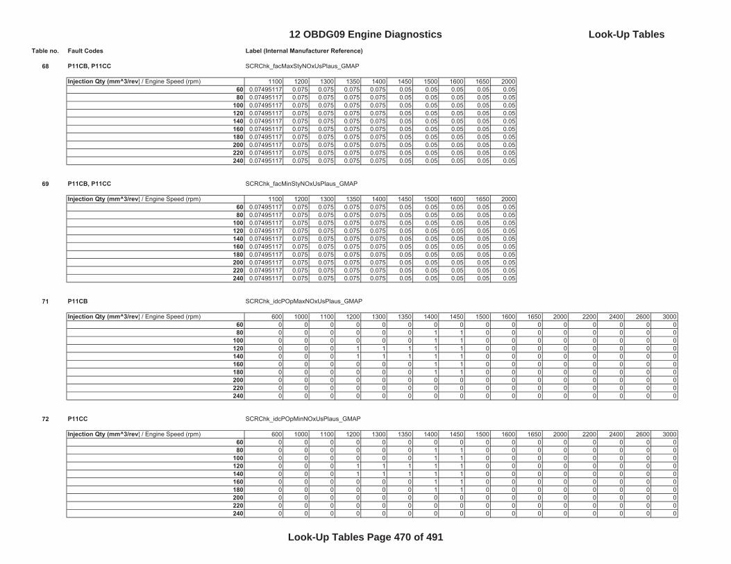
Table no. Fault Codes Label (Internal Manufacturer Reference)
68 P11CB, P11CC SCRChk_facMaxStyNOxUsPlaus_GMAP
Injection Qty (mm^3/rev) / Engine Speed (rpm) 1100 1200 1300 1350 1400 1450 1500 1600 1650 200060 0.07495117 0.075 0.075 0.075 0.075 0.05 0.05 0.05 0.05 0.0580 0.07495117 0.075 0.075 0.075 0.075 0.05 0.05 0.05 0.05 0.05
100 0.07495117 0.075 0.075 0.075 0.075 0.05 0.05 0.05 0.05 0.05120 0.07495117 0.075 0.075 0.075 0.075 0.05 0.05 0.05 0.05 0.05140 0.07495117 0.075 0.075 0.075 0.075 0.05 0.05 0.05 0.05 0.05160 0.07495117 0.075 0.075 0.075 0.075 0.05 0.05 0.05 0.05 0.05180 0.07495117 0.075 0.075 0.075 0.075 0.05 0.05 0.05 0.05 0.05200 0.07495117 0.075 0.075 0.075 0.075 0.05 0.05 0.05 0.05 0.05220 0.07495117 0.075 0.075 0.075 0.075 0.05 0.05 0.05 0.05 0.05240 0.07495117 0.075 0.075 0.075 0.075 0.05 0.05 0.05 0.05 0.05
69 P11CB, P11CC SCRChk_facMinStyNOxUsPlaus_GMAP
Injection Qty (mm^3/rev) / Engine Speed (rpm) 1100 1200 1300 1350 1400 1450 1500 1600 1650 200060 0.07495117 0.075 0.075 0.075 0.075 0.05 0.05 0.05 0.05 0.0580 0.07495117 0.075 0.075 0.075 0.075 0.05 0.05 0.05 0.05 0.05
100 0.07495117 0.075 0.075 0.075 0.075 0.05 0.05 0.05 0.05 0.05120 0.07495117 0.075 0.075 0.075 0.075 0.05 0.05 0.05 0.05 0.05140 0.07495117 0.075 0.075 0.075 0.075 0.05 0.05 0.05 0.05 0.05160 0.07495117 0.075 0.075 0.075 0.075 0.05 0.05 0.05 0.05 0.05180 0.07495117 0.075 0.075 0.075 0.075 0.05 0.05 0.05 0.05 0.05200 0.07495117 0.075 0.075 0.075 0.075 0.05 0.05 0.05 0.05 0.05220 0.07495117 0.075 0.075 0.075 0.075 0.05 0.05 0.05 0.05 0.05240 0.07495117 0.075 0.075 0.075 0.075 0.05 0.05 0.05 0.05 0.05
71 P11CB SCRChk_idcPOpMaxNOxUsPlaus_GMAP
Injection Qty (mm^3/rev) / Engine Speed (rpm) 600 1000 1100 1200 1300 1350 1400 1450 1500 1600 1650 2000 2200 2400 2600 300060 0 0 0 0 0 0 0 0 0 0 0 0 0 0 0 080 0 0 0 0 0 0 1 1 0 0 0 0 0 0 0 0
100 0 0 0 0 0 0 1 1 0 0 0 0 0 0 0 0120 0 0 0 1 1 1 1 1 0 0 0 0 0 0 0 0140 0 0 0 1 1 1 1 1 0 0 0 0 0 0 0 0160 0 0 0 0 0 0 1 1 0 0 0 0 0 0 0 0180 0 0 0 0 0 0 1 1 0 0 0 0 0 0 0 0200 0 0 0 0 0 0 0 0 0 0 0 0 0 0 0 0220 0 0 0 0 0 0 0 0 0 0 0 0 0 0 0 0240 0 0 0 0 0 0 0 0 0 0 0 0 0 0 0 0
72 P11CC SCRChk_idcPOpMinNOxUsPlaus_GMAP
Injection Qty (mm^3/rev) / Engine Speed (rpm) 600 1000 1100 1200 1300 1350 1400 1450 1500 1600 1650 2000 2200 2400 2600 300060 0 0 0 0 0 0 0 0 0 0 0 0 0 0 0 080 0 0 0 0 0 0 1 1 0 0 0 0 0 0 0 0
100 0 0 0 0 0 0 1 1 0 0 0 0 0 0 0 0120 0 0 0 1 1 1 1 1 0 0 0 0 0 0 0 0140 0 0 0 1 1 1 1 1 0 0 0 0 0 0 0 0160 0 0 0 0 0 0 1 1 0 0 0 0 0 0 0 0180 0 0 0 0 0 0 1 1 0 0 0 0 0 0 0 0200 0 0 0 0 0 0 0 0 0 0 0 0 0 0 0 0220 0 0 0 0 0 0 0 0 0 0 0 0 0 0 0 0240 0 0 0 0 0 0 0 0 0 0 0 0 0 0 0 0
12 OBDG09 Engine Diagnostics Look-Up Tables
Look-Up Tables Page 470 of 491
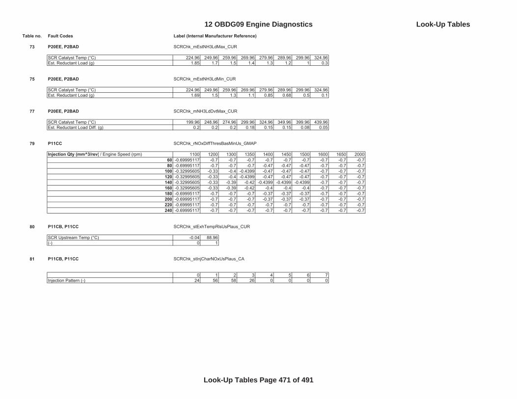
Table no. Fault Codes Label (Internal Manufacturer Reference)
73 P20EE, P2BAD SCRChk_mEstNH3LdMax_CUR
SCR Catalyst Temp (°C) 224.96 249.96 259.96 269.96 279.96 289.96 299.96 324.96Est. Reductant Load (g) 1.85 1.7 1.5 1.4 1.3 1.2 1 0.3
75 P20EE, P2BAD SCRChk_mEstNH3LdMin_CUR
SCR Catalyst Temp (°C) 224.96 249.96 259.96 269.96 279.96 289.96 299.96 324.96Est. Reductant Load (g) 1.69 1.5 1.3 1.1 0.85 0.68 0.5 0.1
77 P20EE, P2BAD SCRChk_mNH3LdDvtMax_CUR
SCR Catalyst Temp (°C) 199.96 248.96 274.96 299.96 324.96 349.96 399.96 439.96Est. Reductant Load Diff. (g) 0.2 0.2 0.2 0.18 0.15 0.15 0.08 0.05
79 P11CC SCRChk_rNOxDiffThresBasMinUs_GMAP
Injection Qty (mm^3/rev) / Engine Speed (rpm) 1100 1200 1300 1350 1400 1450 1500 1600 1650 200060 -0.69995117 -0.7 -0.7 -0.7 -0.7 -0.7 -0.7 -0.7 -0.7 -0.780 -0.69995117 -0.7 -0.7 -0.7 -0.47 -0.47 -0.47 -0.7 -0.7 -0.7
100 -0.32995605 -0.33 -0.4 -0.4399 -0.47 -0.47 -0.47 -0.7 -0.7 -0.7120 -0.32995605 -0.33 -0.4 -0.4399 -0.47 -0.47 -0.47 -0.7 -0.7 -0.7140 -0.32995605 -0.33 -0.39 -0.42 -0.4399 -0.4399 -0.4399 -0.7 -0.7 -0.7160 -0.32995605 -0.33 -0.39 -0.42 -0.4 -0.4 -0.4 -0.7 -0.7 -0.7180 -0.69995117 -0.7 -0.7 -0.7 -0.37 -0.37 -0.37 -0.7 -0.7 -0.7200 -0.69995117 -0.7 -0.7 -0.7 -0.37 -0.37 -0.37 -0.7 -0.7 -0.7220 -0.69995117 -0.7 -0.7 -0.7 -0.7 -0.7 -0.7 -0.7 -0.7 -0.7240 -0.69995117 -0.7 -0.7 -0.7 -0.7 -0.7 -0.7 -0.7 -0.7 -0.7
80 P11CB, P11CC SCRChk_stExhTempRlsUsPlaus_CUR
SCR Upstream Temp (°C) -0.04 88.96(-) 0 1
81 P11CB, P11CC SCRChk_stInjCharNOxUsPlaus_CA
0 1 2 3 4 5 6 7Injection Pattern (-) 24 56 58 26 0 0 0 0
12 OBDG09 Engine Diagnostics Look-Up Tables
Look-Up Tables Page 471 of 491
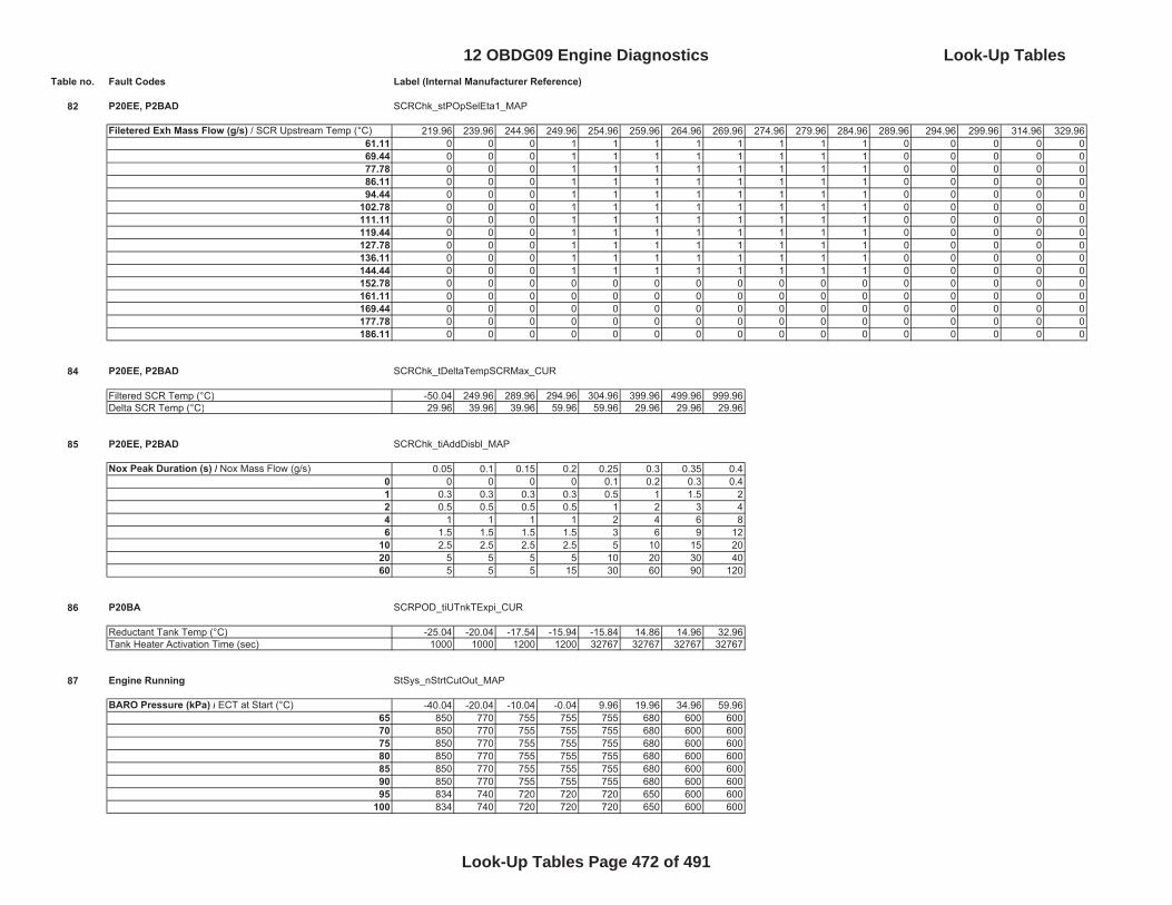
Table no. Fault Codes Label (Internal Manufacturer Reference)
82 P20EE, P2BAD SCRChk_stPOpSelEta1_MAP
Filetered Exh Mass Flow (g/s) / SCR Upstream Temp (°C) 219.96 239.96 244.96 249.96 254.96 259.96 264.96 269.96 274.96 279.96 284.96 289.96 294.96 299.96 314.96 329.9661.11 0 0 0 1 1 1 1 1 1 1 1 0 0 0 0 069.44 0 0 0 1 1 1 1 1 1 1 1 0 0 0 0 077.78 0 0 0 1 1 1 1 1 1 1 1 0 0 0 0 086.11 0 0 0 1 1 1 1 1 1 1 1 0 0 0 0 094.44 0 0 0 1 1 1 1 1 1 1 1 0 0 0 0 0
102.78 0 0 0 1 1 1 1 1 1 1 1 0 0 0 0 0111.11 0 0 0 1 1 1 1 1 1 1 1 0 0 0 0 0119.44 0 0 0 1 1 1 1 1 1 1 1 0 0 0 0 0127.78 0 0 0 1 1 1 1 1 1 1 1 0 0 0 0 0136.11 0 0 0 1 1 1 1 1 1 1 1 0 0 0 0 0144.44 0 0 0 1 1 1 1 1 1 1 1 0 0 0 0 0152.78 0 0 0 0 0 0 0 0 0 0 0 0 0 0 0 0161.11 0 0 0 0 0 0 0 0 0 0 0 0 0 0 0 0169.44 0 0 0 0 0 0 0 0 0 0 0 0 0 0 0 0177.78 0 0 0 0 0 0 0 0 0 0 0 0 0 0 0 0186.11 0 0 0 0 0 0 0 0 0 0 0 0 0 0 0 0
84 P20EE, P2BAD SCRChk_tDeltaTempSCRMax_CUR
Filtered SCR Temp (°C) -50.04 249.96 289.96 294.96 304.96 399.96 499.96 999.96Delta SCR Temp (°C) 29.96 39.96 39.96 59.96 59.96 29.96 29.96 29.96
85 P20EE, P2BAD SCRChk_tiAddDisbl_MAP
Nox Peak Duration (s) / Nox Mass Flow (g/s) 0.05 0.1 0.15 0.2 0.25 0.3 0.35 0.40 0 0 0 0 0.1 0.2 0.3 0.41 0.3 0.3 0.3 0.3 0.5 1 1.5 22 0.5 0.5 0.5 0.5 1 2 3 44 1 1 1 1 2 4 6 86 1.5 1.5 1.5 1.5 3 6 9 12
10 2.5 2.5 2.5 2.5 5 10 15 2020 5 5 5 5 10 20 30 4060 5 5 5 15 30 60 90 120
86 P20BA SCRPOD_tiUTnkTExpi_CUR
Reductant Tank Temp (°C) -25.04 -20.04 -17.54 -15.94 -15.84 14.86 14.96 32.96Tank Heater Activation Time (sec) 1000 1000 1200 1200 32767 32767 32767 32767
87 Engine Running StSys_nStrtCutOut_MAP
BARO Pressure (kPa) / ECT at Start (°C) -40.04 -20.04 -10.04 -0.04 9.96 19.96 34.96 59.9665 850 770 755 755 755 680 600 60070 850 770 755 755 755 680 600 60075 850 770 755 755 755 680 600 60080 850 770 755 755 755 680 600 60085 850 770 755 755 755 680 600 60090 850 770 755 755 755 680 600 60095 834 740 720 720 720 650 600 600
100 834 740 720 720 720 650 600 600
12 OBDG09 Engine Diagnostics Look-Up Tables
Look-Up Tables Page 472 of 491

Table no. Fault Codes Label (Internal Manufacturer Reference)
88 P2598, P2599 TrbCh_tiDiaEnblDly_CUR
ECT (°C) -30.04 -20.04 -0.04 9.96 19.96 39.96 59.96 79.96Run-Time Delay (sec) 327.67 210 120 100 60 50 30 30
89 P12B3, P12B4, P12B5, P12B6, P12B7, P12B8, P12B9, P12BA, P12BB, P12BC, P12BD, P12BE, P12BF, P12C0, P12C1, P12C2
ZFC_stGearRls_CA
Gear (-) 0 1 2 3 4 5 6 7 8- 0 0 0 1 1 1 1 0 0
90 P12B3, P12B4, P12B5, P12B6, P12B7, P12B8, P12B9, P12BA, P12BB, P12BC, P12BD, P12BE, P12BF, P12C0, P12C1, P12C2
ZFC_tiCldCham_CUR
IAT (°C) 0.06 9.96 16.86 26.86 36.86 46.86 56.86 66.86 76.86 86.86 96.86 106.86Time (sec) 5 15 20 27 30 30 30 30 30 30 30 30
12 OBDG09 Engine Diagnostics Look-Up Tables
Look-Up Tables Page 473 of 491
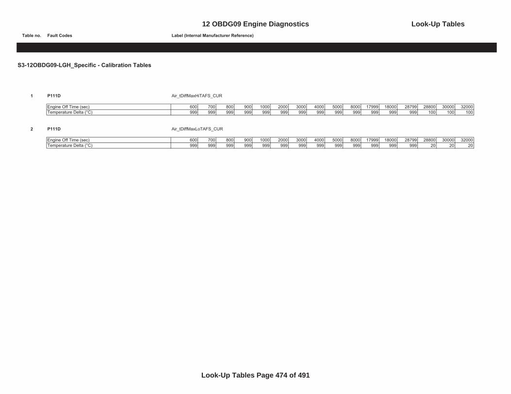
Table no. Fault Codes Label (Internal Manufacturer Reference)
S3-12OBDG09-LGH_Specific - Calibration Tables
1 P111D Air_tDiffMaxHiTAFS_CUR
Engine Off Time (sec) 600 700 800 900 1000 2000 3000 4000 5000 8000 17999 18000 28799 28800 30000 32000Temperature Delta (°C) 999 999 999 999 999 999 999 999 999 999 999 999 999 100 100 100
2 P111D Air_tDiffMaxLoTAFS_CUR
Engine Off Time (sec) 600 700 800 900 1000 2000 3000 4000 5000 8000 17999 18000 28799 28800 30000 32000Temperature Delta (°C) 999 999 999 999 999 999 999 999 999 999 999 999 999 20 20 20
12 OBDG09 Engine Diagnostics Look-Up Tables
Look-Up Tables Page 474 of 491
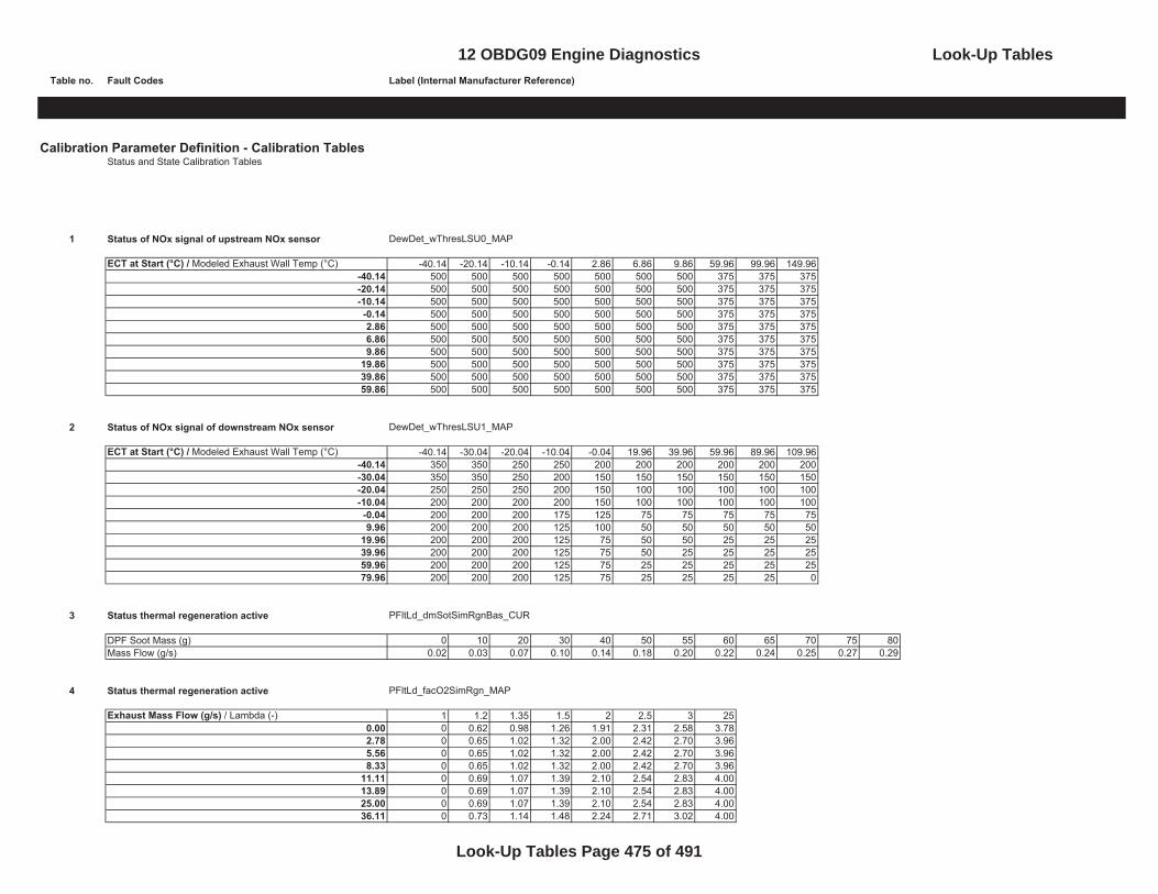
Table no. Fault Codes Label (Internal Manufacturer Reference)
Calibration Parameter Definition - Calibration TablesStatus and State Calibration Tables
1 Status of NOx signal of upstream NOx sensor DewDet_wThresLSU0_MAP
ECT at Start (°C) / Modeled Exhaust Wall Temp (°C) -40.14 -20.14 -10.14 -0.14 2.86 6.86 9.86 59.96 99.96 149.96-40.14 500 500 500 500 500 500 500 375 375 375-20.14 500 500 500 500 500 500 500 375 375 375-10.14 500 500 500 500 500 500 500 375 375 375-0.14 500 500 500 500 500 500 500 375 375 3752.86 500 500 500 500 500 500 500 375 375 3756.86 500 500 500 500 500 500 500 375 375 3759.86 500 500 500 500 500 500 500 375 375 375
19.86 500 500 500 500 500 500 500 375 375 37539.86 500 500 500 500 500 500 500 375 375 37559.86 500 500 500 500 500 500 500 375 375 375
2 Status of NOx signal of downstream NOx sensor DewDet_wThresLSU1_MAP
ECT at Start (°C) / Modeled Exhaust Wall Temp (°C) -40.14 -30.04 -20.04 -10.04 -0.04 19.96 39.96 59.96 89.96 109.96-40.14 350 350 250 250 200 200 200 200 200 200-30.04 350 350 250 200 150 150 150 150 150 150-20.04 250 250 250 200 150 100 100 100 100 100-10.04 200 200 200 200 150 100 100 100 100 100-0.04 200 200 200 175 125 75 75 75 75 759.96 200 200 200 125 100 50 50 50 50 50
19.96 200 200 200 125 75 50 50 25 25 2539.96 200 200 200 125 75 50 25 25 25 2559.96 200 200 200 125 75 25 25 25 25 2579.96 200 200 200 125 75 25 25 25 25 0
3 Status thermal regeneration active PFltLd_dmSotSimRgnBas_CUR
DPF Soot Mass (g) 0 10 20 30 40 50 55 60 65 70 75 80Mass Flow (g/s) 0.02 0.03 0.07 0.10 0.14 0.18 0.20 0.22 0.24 0.25 0.27 0.29
4 Status thermal regeneration active PFltLd_facO2SimRgn_MAP
Exhaust Mass Flow (g/s) / Lambda (-) 1 1.2 1.35 1.5 2 2.5 3 250.00 0 0.62 0.98 1.26 1.91 2.31 2.58 3.782.78 0 0.65 1.02 1.32 2.00 2.42 2.70 3.965.56 0 0.65 1.02 1.32 2.00 2.42 2.70 3.968.33 0 0.65 1.02 1.32 2.00 2.42 2.70 3.96
11.11 0 0.69 1.07 1.39 2.10 2.54 2.83 4.0013.89 0 0.69 1.07 1.39 2.10 2.54 2.83 4.0025.00 0 0.69 1.07 1.39 2.10 2.54 2.83 4.0036.11 0 0.73 1.14 1.48 2.24 2.71 3.02 4.00
12 OBDG09 Engine Diagnostics Look-Up Tables
Look-Up Tables Page 475 of 491

Table no. Fault Codes Label (Internal Manufacturer Reference)
5 Status thermal regeneration active PFltLd_facTempSimRgn_CUR
Particulate Filter Surface Temp (°C) 49.96 199.96 299.96 499.96 524.96 549.96 574.96 599.96 624.96 649.96 674.96 699.96Temperature Factor (-) 0 0 0 0.02 0.06 0.11 0.21 0.35 0.63 1.09 1.82 2.97
6 Rail Control - PCV Closed Loop Control Only Rail_dvolMeUnCtlUpLim_CUR
Engine Speed (rpm) 0 480 2250 5000 5005 5010 5015 5020 5025 5030 5035 5040 5045 5050 5055 5060Rail Volume Flow (mm^3/sec) 15000 15000 56000 56000 56000 56000 56000 56000 56000 56000 56000 56000 56000 56000 56000 56000
7 Rail Control - Metering Unit + PCV Closed Loop Control Rail_qMeUnCtlType_CUR
Engine Speed (rpm) 900 901 1200 1400 1600 1800 2000 4800Injection Qty (mm^3/rev) 400 60 60 60 12 12 12 12
8 Status of the SCR adaptation plausibility check active SCRAd_mNH3MinTrg_MAP
SCR Modeled Efficieny (- )/ SCR Temp (°C) 249.96 299.96 349.96 399.96 449.96 499.960 0 0 0 0.04 0.04 0.04
0.2 0 0 0 0.04 0.04 0.040.4 0 0 0 0.04 0.04 0.040.6 0 0 0 0.04 0.04 0.040.8 0 0 0 0.04 0.04 0.04
1 0 0 0 0.04 0.04 0.04
9 Overdosing detected SCRAd_mNOxOvrMetPh3_CUR
SCR Avg. Temp (°C) 254.96 299.96 349.96 424.96Nox Mass (g) -0.6 -0.65 -0.8 -0.8
10 Status of the SCR adaptation plausibility check active SCRAd_stSpdLd_MAP
Engine Speed (rpm) / Injection Qty. (mm^3/rev) 0 80 100 120 160 200 240 280 320 360 400 480600 0 0 0 1 1 1 1 1 1 1 1 1800 0 0 0 1 1 1 1 1 1 1 1 1900 1 1 1 1 1 1 1 1 1 1 1 1
1200 1 1 1 1 1 1 1 1 1 1 1 11400 1 1 1 1 1 1 1 1 1 1 1 11600 1 1 1 1 1 1 1 1 1 1 1 11800 1 1 1 1 1 1 1 1 1 1 1 12000 1 1 1 1 1 1 1 1 1 1 1 12200 1 1 1 1 1 1 1 1 1 1 1 12400 1 1 1 1 1 1 1 1 1 1 1 12800 1 1 1 1 1 1 1 1 1 1 1 13100 1 1 1 1 1 1 1 1 1 1 1 1
12 OBDG09 Engine Diagnostics Look-Up Tables
Look-Up Tables Page 476 of 491
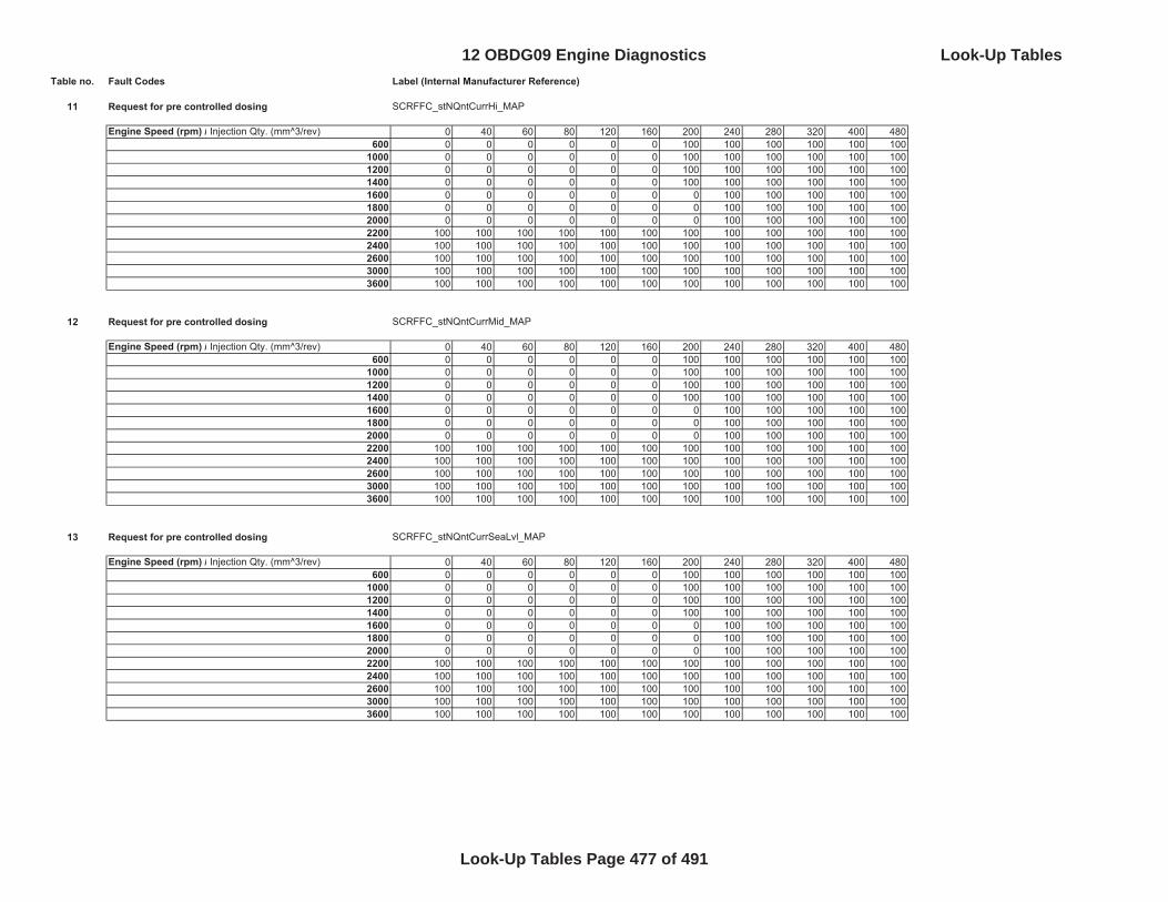
Table no. Fault Codes Label (Internal Manufacturer Reference)
11 Request for pre controlled dosing SCRFFC_stNQntCurrHi_MAP
Engine Speed (rpm) / Injection Qty. (mm^3/rev) 0 40 60 80 120 160 200 240 280 320 400 480600 0 0 0 0 0 0 100 100 100 100 100 100
1000 0 0 0 0 0 0 100 100 100 100 100 1001200 0 0 0 0 0 0 100 100 100 100 100 1001400 0 0 0 0 0 0 100 100 100 100 100 1001600 0 0 0 0 0 0 0 100 100 100 100 1001800 0 0 0 0 0 0 0 100 100 100 100 1002000 0 0 0 0 0 0 0 100 100 100 100 1002200 100 100 100 100 100 100 100 100 100 100 100 1002400 100 100 100 100 100 100 100 100 100 100 100 1002600 100 100 100 100 100 100 100 100 100 100 100 1003000 100 100 100 100 100 100 100 100 100 100 100 1003600 100 100 100 100 100 100 100 100 100 100 100 100
12 Request for pre controlled dosing SCRFFC_stNQntCurrMid_MAP
Engine Speed (rpm) / Injection Qty. (mm^3/rev) 0 40 60 80 120 160 200 240 280 320 400 480600 0 0 0 0 0 0 100 100 100 100 100 100
1000 0 0 0 0 0 0 100 100 100 100 100 1001200 0 0 0 0 0 0 100 100 100 100 100 1001400 0 0 0 0 0 0 100 100 100 100 100 1001600 0 0 0 0 0 0 0 100 100 100 100 1001800 0 0 0 0 0 0 0 100 100 100 100 1002000 0 0 0 0 0 0 0 100 100 100 100 1002200 100 100 100 100 100 100 100 100 100 100 100 1002400 100 100 100 100 100 100 100 100 100 100 100 1002600 100 100 100 100 100 100 100 100 100 100 100 1003000 100 100 100 100 100 100 100 100 100 100 100 1003600 100 100 100 100 100 100 100 100 100 100 100 100
13 Request for pre controlled dosing SCRFFC_stNQntCurrSeaLvl_MAP
Engine Speed (rpm) / Injection Qty. (mm^3/rev) 0 40 60 80 120 160 200 240 280 320 400 480600 0 0 0 0 0 0 100 100 100 100 100 100
1000 0 0 0 0 0 0 100 100 100 100 100 1001200 0 0 0 0 0 0 100 100 100 100 100 1001400 0 0 0 0 0 0 100 100 100 100 100 1001600 0 0 0 0 0 0 0 100 100 100 100 1001800 0 0 0 0 0 0 0 100 100 100 100 1002000 0 0 0 0 0 0 0 100 100 100 100 1002200 100 100 100 100 100 100 100 100 100 100 100 1002400 100 100 100 100 100 100 100 100 100 100 100 1002600 100 100 100 100 100 100 100 100 100 100 100 1003000 100 100 100 100 100 100 100 100 100 100 100 1003600 100 100 100 100 100 100 100 100 100 100 100 100
12 OBDG09 Engine Diagnostics Look-Up Tables
Look-Up Tables Page 477 of 491
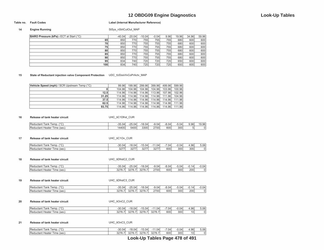
Table no. Fault Codes Label (Internal Manufacturer Reference)
14 Engine Running StSys_nStrtCutOut_MAP
BARO Pressure (kPa) / ECT at Start (°C) -40.04 -20.04 -10.04 -0.04 9.96 19.96 34.96 59.9665 850 770 755 755 755 680 600 60070 850 770 755 755 755 680 600 60075 850 770 755 755 755 680 600 60080 850 770 755 755 755 680 600 60085 850 770 755 755 755 680 600 60090 850 770 755 755 755 680 600 60095 834 740 720 720 720 650 600 600
100 834 740 720 720 720 650 600 600
15 State of Reductant injection valve Component Protection UDC_tUDosVlvCoPrActv_MAP
Vehicle Speed (mph) / SCR Upstream Temp (°C) 99.96 199.96 299.96 399.96 499.96 599.960 104.96 104.96 104.96 104.96 103.96 100.96
12.5 114.96 114.96 114.96 113.96 107.96 102.9631.25 114.96 114.96 114.96 114.96 111.96 104.9637.5 114.96 114.96 114.96 114.96 114.96 111.9662.5 114.96 114.96 114.96 114.96 114.96 111.96
93.75 114.96 114.96 114.96 114.96 114.96 111.96
16 Release of tank heater circuit UHC_tiC1Dfrst_CUR
Reductant Tank Temp. (°C) -35.04 -25.04 -18.04 -9.04 -8.04 -5.04 9.96 19.96Reductant Heater Time (sec) 14400 5400 3300 2700 600 300 5 0
17 Release of tank heater circuit UHC_tiC1On_CUR
Reductant Tank Temp. (°C) -30.04 -18.04 -15.04 -11.04 -7.04 -0.04 4.96 5.06Reductant Heater Time (sec) 3277 3277 3277 3277 600 300 300 0
18 Release of tank heater circuit UHC_tiDfrstC2_CUR
Reductant Tank Temp. (°C) -35.04 -25.04 -18.04 -9.04 -8.04 -5.04 -0.14 -0.04Reductant Heater Time (sec) 3276.7 3276.7 3276.7 2700 600 300 200 0
19 Release of tank heater circuit UHC_tiDfrstC3_CUR
Reductant Tank Temp. (°C) -35.04 -25.04 -18.04 -9.04 -8.04 -5.04 -0.14 -0.04Reductant Heater Time (sec) 3276.7 3276.7 3276.7 2700 600 300 200 0
20 Release of tank heater circuit UHC_tiOnC2_CUR
Reductant Tank Temp. (°C) -30.04 -18.04 -15.04 -11.04 -7.04 -0.04 4.96 5.06Reductant Heater Time (sec) 3276.7 3276.7 3276.7 3276.7 600 300 10 0
21 Release of tank heater circuit UHC_tiOnC3_CUR
Reductant Tank Temp. (°C) -30.04 -18.04 -15.04 -11.04 -7.04 -0.04 4.96 5.06Reductant Heater Time (sec) 3276.7 3276.7 3276.7 3276.7 600 300 10 0
12 OBDG09 Engine Diagnostics Look-Up Tables
Look-Up Tables Page 478 of 491
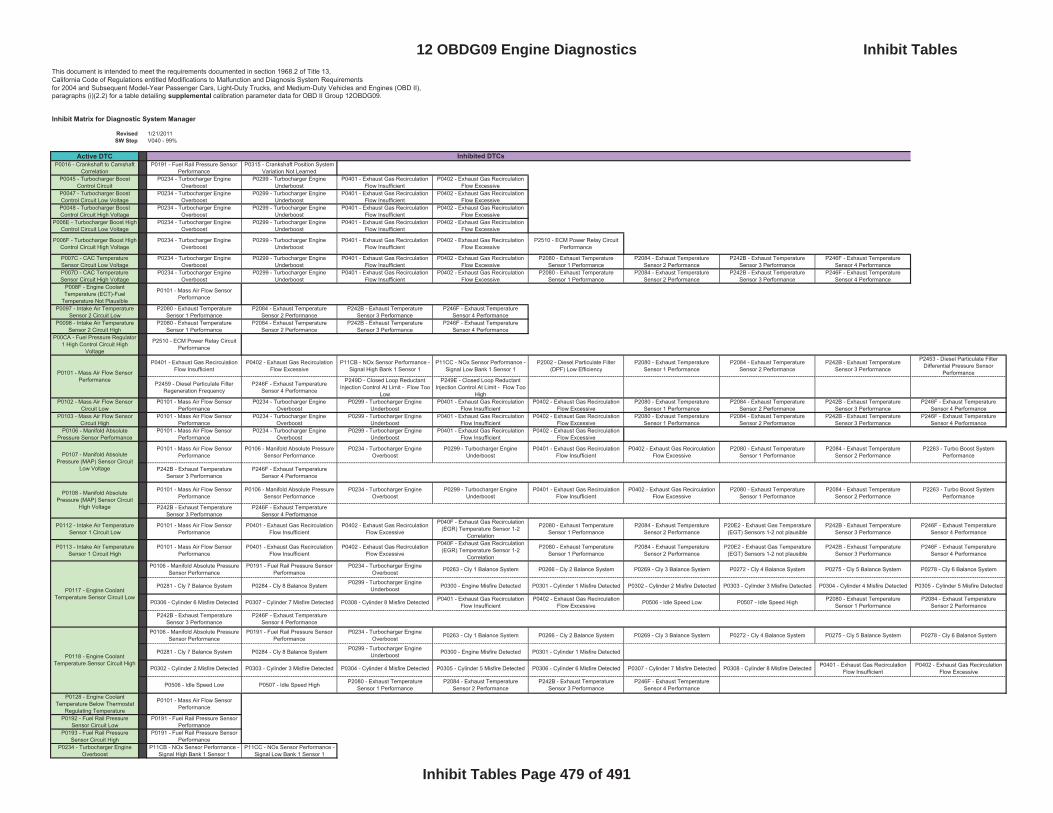
This document is intended to meet the requirements documented in section 1968.2 of Title 13, California Code of Regulations entitled Modifications to Malfunction and Diagnosis System Requirementsfor 2004 and Subsequent Model-Year Passenger Cars, Light-Duty Trucks, and Medium-Duty Vehicles and Engines (OBD II),paragraphs (i)(2.2) for a table detailing supplemental calibration parameter data for OBD II Group 12OBDG09.
Inhibit Matrix for Diagnostic System Manager
Revised 1/21/2011SW Step V040 - 99%
Active DTCP0016 - Crankshaft to Camshaft
CorrelationP0191 - Fuel Rail Pressure Sensor
PerformanceP0315 - Crankshaft Position System
Variation Not LearnedP0045 - Turbocharger Boost
Control CircuitP0234 - Turbocharger Engine
Overboost P0299 - Turbocharger Engine
UnderboostP0401 - Exhaust Gas Recirculation
Flow InsufficientP0402 - Exhaust Gas Recirculation
Flow ExcessiveP0047 - Turbocharger Boost Control Circuit Low Voltage
P0234 - Turbocharger Engine Overboost
P0299 - Turbocharger Engine Underboost
P0401 - Exhaust Gas Recirculation Flow Insufficient
P0402 - Exhaust Gas Recirculation Flow Excessive
P0048 - Turbocharger Boost Control Circuit High Voltage
P0234 - Turbocharger Engine Overboost
P0299 - Turbocharger Engine Underboost
P0401 - Exhaust Gas Recirculation Flow Insufficient
P0402 - Exhaust Gas Recirculation Flow Excessive
P006E - Turbocharger Boost High Control Circuit Low Voltage
P0234 - Turbocharger Engine Overboost
P0299 - Turbocharger Engine Underboost
P0401 - Exhaust Gas Recirculation Flow Insufficient
P0402 - Exhaust Gas Recirculation Flow Excessive
P006F - Turbocharger Boost High Control Circuit High Voltage
P0234 - Turbocharger Engine Overboost
P0299 - Turbocharger Engine Underboost
P0401 - Exhaust Gas Recirculation Flow Insufficient
P0402 - Exhaust Gas Recirculation Flow Excessive
P2510 - ECM Power Relay Circuit Performance
P007C - CAC Temperature Sensor Circuit Low Voltage
P0234 - Turbocharger Engine Overboost
P0299 - Turbocharger Engine Underboost
P0401 - Exhaust Gas Recirculation Flow Insufficient
P0402 - Exhaust Gas Recirculation Flow Excessive
P2080 - Exhaust Temperature Sensor 1 Performance
P2084 - Exhaust Temperature Sensor 2 Performance
P242B - Exhaust Temperature Sensor 3 Performance
P246F - Exhaust Temperature Sensor 4 Performance
P007D - CAC Temperature Sensor Circuit High Voltage
P0234 - Turbocharger Engine Overboost
P0299 - Turbocharger Engine Underboost
P0401 - Exhaust Gas Recirculation Flow Insufficient
P0402 - Exhaust Gas Recirculation Flow Excessive
P2080 - Exhaust Temperature Sensor 1 Performance
P2084 - Exhaust Temperature Sensor 2 Performance
P242B - Exhaust Temperature Sensor 3 Performance
P246F - Exhaust Temperature Sensor 4 Performance
P008F - Engine Coolant Temperature (ECT)-Fuel
Temperature Not Plausible
P0101 - Mass Air Flow Sensor Performance
P0097 - Intake Air Temperature Sensor 2 Circuit Low
P2080 - Exhaust Temperature Sensor 1 Performance
P2084 - Exhaust Temperature Sensor 2 Performance
P242B - Exhaust Temperature Sensor 3 Performance
P246F - Exhaust Temperature Sensor 4 Performance
P0098 - Intake Air Temperature Sensor 2 Circuit High
P2080 - Exhaust Temperature Sensor 1 Performance
P2084 - Exhaust Temperature Sensor 2 Performance
P242B - Exhaust Temperature Sensor 3 Performance
P246F - Exhaust Temperature Sensor 4 Performance
P00CA - Fuel Pressure Regulator 1 High Control Circuit High
Voltage
P2510 - ECM Power Relay Circuit Performance
P0401 - Exhaust Gas Recirculation Flow Insufficient
P0402 - Exhaust Gas Recirculation Flow Excessive
P11CB - NOx Sensor Performance - Signal High Bank 1 Sensor 1
P11CC - NOx Sensor Performance - Signal Low Bank 1 Sensor 1
P2002 - Diesel Particulate Filter (DPF) Low Efficiency
P2080 - Exhaust Temperature Sensor 1 Performance
P2084 - Exhaust Temperature Sensor 2 Performance
P242B - Exhaust Temperature Sensor 3 Performance
P2453 - Diesel Particulate Filter Differential Pressure Sensor
Performance
P2459 - Diesel Particulate Filter Regeneration Frequency
P246F - Exhaust Temperature Sensor 4 Performance
P249D - Closed Loop Reductant Injection Control At Limit - Flow Too
Low
P249E - Closed Loop Reductant Injection Control At Limit - Flow Too
HighP0102 - Mass Air Flow Sensor
Circuit LowP0101 - Mass Air Flow Sensor
PerformanceP0234 - Turbocharger Engine
Overboost P0299 - Turbocharger Engine
UnderboostP0401 - Exhaust Gas Recirculation
Flow InsufficientP0402 - Exhaust Gas Recirculation
Flow ExcessiveP2080 - Exhaust Temperature
Sensor 1 PerformanceP2084 - Exhaust Temperature
Sensor 2 PerformanceP242B - Exhaust Temperature
Sensor 3 PerformanceP246F - Exhaust Temperature
Sensor 4 PerformanceP0103 - Mass Air Flow Sensor
Circuit HighP0101 - Mass Air Flow Sensor
PerformanceP0234 - Turbocharger Engine
Overboost P0299 - Turbocharger Engine
UnderboostP0401 - Exhaust Gas Recirculation
Flow InsufficientP0402 - Exhaust Gas Recirculation
Flow ExcessiveP2080 - Exhaust Temperature
Sensor 1 PerformanceP2084 - Exhaust Temperature
Sensor 2 PerformanceP242B - Exhaust Temperature
Sensor 3 PerformanceP246F - Exhaust Temperature
Sensor 4 PerformanceP0106 - Manifold Absolute
Pressure Sensor PerformanceP0101 - Mass Air Flow Sensor
PerformanceP0234 - Turbocharger Engine
Overboost P0299 - Turbocharger Engine
UnderboostP0401 - Exhaust Gas Recirculation
Flow InsufficientP0402 - Exhaust Gas Recirculation
Flow Excessive
P0101 - Mass Air Flow Sensor Performance
P0106 - Manifold Absolute Pressure Sensor Performance
P0234 - Turbocharger Engine Overboost
P0299 - Turbocharger Engine Underboost
P0401 - Exhaust Gas Recirculation Flow Insufficient
P0402 - Exhaust Gas Recirculation Flow Excessive
P2080 - Exhaust Temperature Sensor 1 Performance
P2084 - Exhaust Temperature Sensor 2 Performance
P2263 - Turbo Boost System Performance
P242B - Exhaust Temperature Sensor 3 Performance
P246F - Exhaust Temperature Sensor 4 Performance
P0112 - Intake Air Temperature Sensor 1 Circuit Low
P0101 - Mass Air Flow Sensor Performance
P0401 - Exhaust Gas Recirculation Flow Insufficient
P0402 - Exhaust Gas Recirculation Flow Excessive
P040F - Exhaust Gas Recirculation (EGR) Temperature Sensor 1-2
Correlation
P2080 - Exhaust Temperature Sensor 1 Performance
P2084 - Exhaust Temperature Sensor 2 Performance
P20E2 - Exhaust Gas Temperature (EGT) Sensors 1-2 not plausible
P242B - Exhaust Temperature Sensor 3 Performance
P246F - Exhaust Temperature Sensor 4 Performance
P0113 - Intake Air Temperature Sensor 1 Circuit High
P0101 - Mass Air Flow Sensor Performance
P0401 - Exhaust Gas Recirculation Flow Insufficient
P0402 - Exhaust Gas Recirculation Flow Excessive
P040F - Exhaust Gas Recirculation (EGR) Temperature Sensor 1-2
Correlation
P2080 - Exhaust Temperature Sensor 1 Performance
P2084 - Exhaust Temperature Sensor 2 Performance
P20E2 - Exhaust Gas Temperature (EGT) Sensors 1-2 not plausible
P242B - Exhaust Temperature Sensor 3 Performance
P246F - Exhaust Temperature Sensor 4 Performance
P0106 - Manifold Absolute Pressure Sensor Performance
P0191 - Fuel Rail Pressure Sensor Performance
P0234 - Turbocharger Engine Overboost P0263 - Cly 1 Balance System P0266 - Cly 2 Balance System P0269 - Cly 3 Balance System P0272 - Cly 4 Balance System P0275 - Cly 5 Balance System P0278 - Cly 6 Balance System
P0281 - Cly 7 Balance System P0284 - Cly 8 Balance System P0299 - Turbocharger Engine Underboost P0300 - Engine Misfire Detected P0301 - Cylinder 1 Misfire Detected P0302 - Cylinder 2 Misfire Detected P0303 - Cylinder 3 Misfire Detected P0304 - Cylinder 4 Misfire Detected P0305 - Cylinder 5 Misfire Detected
P0306 - Cylinder 6 Misfire Detected P0307 - Cylinder 7 Misfire Detected P0308 - Cylinder 8 Misfire Detected P0401 - Exhaust Gas Recirculation Flow Insufficient
P0402 - Exhaust Gas Recirculation Flow Excessive P0506 - Idle Speed Low P0507 - Idle Speed High P2080 - Exhaust Temperature
Sensor 1 PerformanceP2084 - Exhaust Temperature
Sensor 2 Performance
P242B - Exhaust Temperature Sensor 3 Performance
P246F - Exhaust Temperature Sensor 4 Performance
P0106 - Manifold Absolute Pressure Sensor Performance
P0191 - Fuel Rail Pressure Sensor Performance
P0234 - Turbocharger Engine Overboost P0263 - Cly 1 Balance System P0266 - Cly 2 Balance System P0269 - Cly 3 Balance System P0272 - Cly 4 Balance System P0275 - Cly 5 Balance System P0278 - Cly 6 Balance System
P0281 - Cly 7 Balance System P0284 - Cly 8 Balance System P0299 - Turbocharger Engine Underboost P0300 - Engine Misfire Detected P0301 - Cylinder 1 Misfire Detected
P0302 - Cylinder 2 Misfire Detected P0303 - Cylinder 3 Misfire Detected P0304 - Cylinder 4 Misfire Detected P0305 - Cylinder 5 Misfire Detected P0306 - Cylinder 6 Misfire Detected P0307 - Cylinder 7 Misfire Detected P0308 - Cylinder 8 Misfire Detected P0401 - Exhaust Gas Recirculation Flow Insufficient
P0402 - Exhaust Gas Recirculation Flow Excessive
P0506 - Idle Speed Low P0507 - Idle Speed High P2080 - Exhaust Temperature Sensor 1 Performance
P2084 - Exhaust Temperature Sensor 2 Performance
P242B - Exhaust Temperature Sensor 3 Performance
P246F - Exhaust Temperature Sensor 4 Performance
P0128 - Engine Coolant Temperature Below Thermostat
Regulating Temperature
P0101 - Mass Air Flow Sensor Performance
P0192 - Fuel Rail Pressure Sensor Circuit Low
P0191 - Fuel Rail Pressure Sensor Performance
P0193 - Fuel Rail Pressure Sensor Circuit High
P0191 - Fuel Rail Pressure Sensor Performance
P0234 - Turbocharger Engine Overboost
P11CB - NOx Sensor Performance - Signal High Bank 1 Sensor 1
P11CC - NOx Sensor Performance - Signal Low Bank 1 Sensor 1
Inhibited DTCs
P0101 - Mass Air Flow Sensor Performance
P0118 - Engine Coolant Temperature Sensor Circuit High
P0107 - Manifold Absolute Pressure (MAP) Sensor Circuit
Low Voltage
P0108 - Manifold Absolute Pressure (MAP) Sensor Circuit
High Voltage
P0117 - Engine Coolant Temperature Sensor Circuit Low
12 OBDG09 Engine Diagnostics Inhibit Tables
Inhibit Tables Page 479 of 491
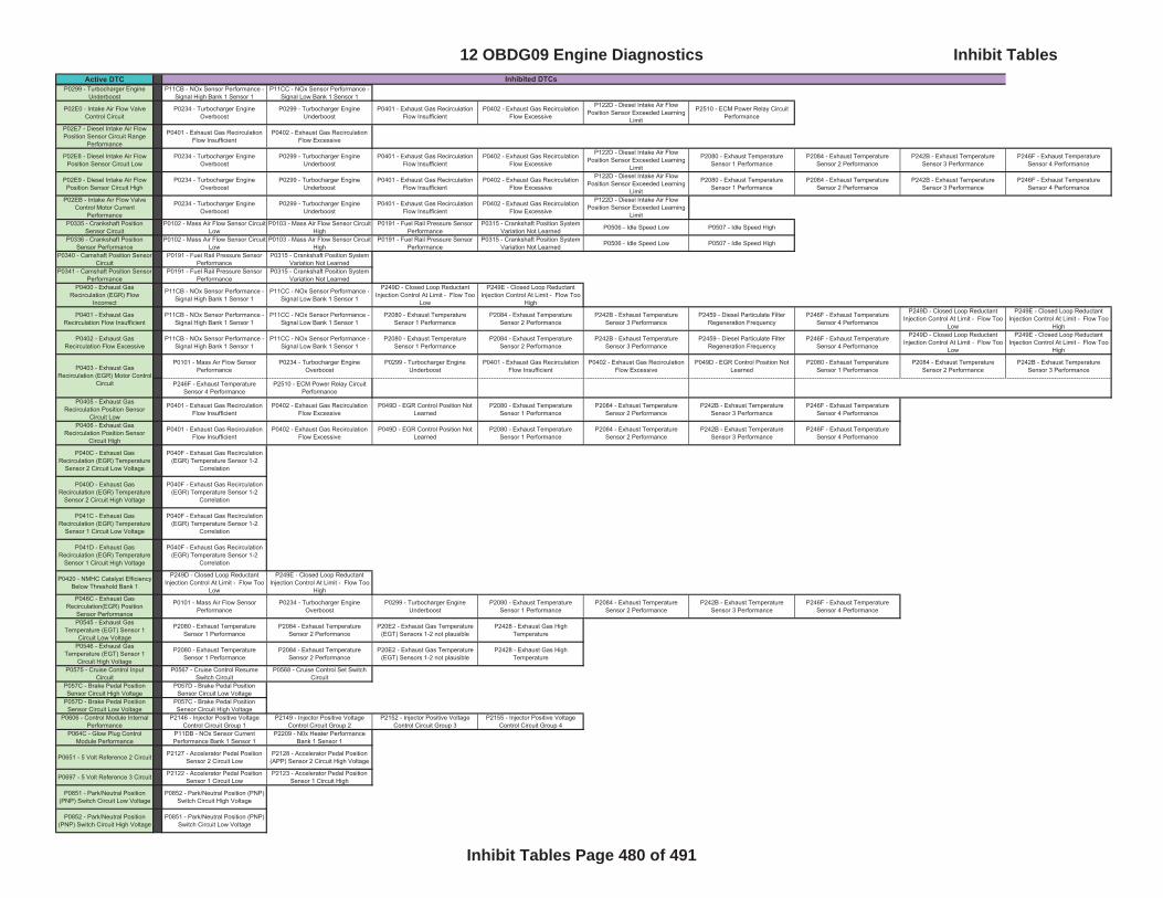
Active DTC Inhibited DTCsP0299 - Turbocharger Engine
UnderboostP11CB - NOx Sensor Performance -
Signal High Bank 1 Sensor 1P11CC - NOx Sensor Performance -
Signal Low Bank 1 Sensor 1
P02E0 - Intake Air Flow Valve Control Circuit
P0234 - Turbocharger Engine Overboost
P0299 - Turbocharger Engine Underboost
P0401 - Exhaust Gas Recirculation Flow Insufficient
P0402 - Exhaust Gas Recirculation Flow Excessive
P122D - Diesel Intake Air Flow Position Sensor Exceeded Learning
Limit
P2510 - ECM Power Relay Circuit Performance
P02E7 - Diesel Intake Air Flow Position Sensor Circuit Range
Performance
P0401 - Exhaust Gas Recirculation Flow Insufficient
P0402 - Exhaust Gas Recirculation Flow Excessive
P02E8 - Diesel Intake Air Flow Position Sensor Circuit Low
P0234 - Turbocharger Engine Overboost
P0299 - Turbocharger Engine Underboost
P0401 - Exhaust Gas Recirculation Flow Insufficient
P0402 - Exhaust Gas Recirculation Flow Excessive
P122D - Diesel Intake Air Flow Position Sensor Exceeded Learning
Limit
P2080 - Exhaust Temperature Sensor 1 Performance
P2084 - Exhaust Temperature Sensor 2 Performance
P242B - Exhaust Temperature Sensor 3 Performance
P246F - Exhaust Temperature Sensor 4 Performance
P02E9 - Diesel Intake Air Flow Position Sensor Circuit High
P0234 - Turbocharger Engine Overboost
P0299 - Turbocharger Engine Underboost
P0401 - Exhaust Gas Recirculation Flow Insufficient
P0402 - Exhaust Gas Recirculation Flow Excessive
P122D - Diesel Intake Air Flow Position Sensor Exceeded Learning
Limit
P2080 - Exhaust Temperature Sensor 1 Performance
P2084 - Exhaust Temperature Sensor 2 Performance
P242B - Exhaust Temperature Sensor 3 Performance
P246F - Exhaust Temperature Sensor 4 Performance
P02EB - Intake Air Flow Valve Control Motor Current
Performance
P0234 - Turbocharger Engine Overboost
P0299 - Turbocharger Engine Underboost
P0401 - Exhaust Gas Recirculation Flow Insufficient
P0402 - Exhaust Gas Recirculation Flow Excessive
P122D - Diesel Intake Air Flow Position Sensor Exceeded Learning
LimitP0335 - Crankshaft Position
Sensor CircuitP0102 - Mass Air Flow Sensor Circuit
LowP0103 - Mass Air Flow Sensor Circuit
HighP0191 - Fuel Rail Pressure Sensor
PerformanceP0315 - Crankshaft Position System
Variation Not Learned P0506 - Idle Speed Low P0507 - Idle Speed High
P0336 - Crankshaft Position Sensor Performance
P0102 - Mass Air Flow Sensor Circuit Low
P0103 - Mass Air Flow Sensor Circuit High
P0191 - Fuel Rail Pressure Sensor Performance
P0315 - Crankshaft Position System Variation Not Learned P0506 - Idle Speed Low P0507 - Idle Speed High
P0340 - Camshaft Position Sensor Circuit
P0191 - Fuel Rail Pressure Sensor Performance
P0315 - Crankshaft Position System Variation Not Learned
P0341 - Camshaft Position Sensor Performance
P0191 - Fuel Rail Pressure Sensor Performance
P0315 - Crankshaft Position System Variation Not Learned
P0400 - Exhaust Gas Recirculation (EGR) Flow
Incorrect
P11CB - NOx Sensor Performance - Signal High Bank 1 Sensor 1
P11CC - NOx Sensor Performance - Signal Low Bank 1 Sensor 1
P249D - Closed Loop Reductant Injection Control At Limit - Flow Too
Low
P249E - Closed Loop Reductant Injection Control At Limit - Flow Too
High
P0401 - Exhaust Gas Recirculation Flow Insufficient
P11CB - NOx Sensor Performance - Signal High Bank 1 Sensor 1
P11CC - NOx Sensor Performance - Signal Low Bank 1 Sensor 1
P2080 - Exhaust Temperature Sensor 1 Performance
P2084 - Exhaust Temperature Sensor 2 Performance
P242B - Exhaust Temperature Sensor 3 Performance
P2459 - Diesel Particulate Filter Regeneration Frequency
P246F - Exhaust Temperature Sensor 4 Performance
P249D - Closed Loop Reductant Injection Control At Limit - Flow Too
Low
P249E - Closed Loop Reductant Injection Control At Limit - Flow Too
High
P0402 - Exhaust Gas Recirculation Flow Excessive
P11CB - NOx Sensor Performance - Signal High Bank 1 Sensor 1
P11CC - NOx Sensor Performance - Signal Low Bank 1 Sensor 1
P2080 - Exhaust Temperature Sensor 1 Performance
P2084 - Exhaust Temperature Sensor 2 Performance
P242B - Exhaust Temperature Sensor 3 Performance
P2459 - Diesel Particulate Filter Regeneration Frequency
P246F - Exhaust Temperature Sensor 4 Performance
P249D - Closed Loop Reductant Injection Control At Limit - Flow Too
Low
P249E - Closed Loop Reductant Injection Control At Limit - Flow Too
High
P0101 - Mass Air Flow Sensor Performance
P0234 - Turbocharger Engine Overboost
P0299 - Turbocharger Engine Underboost
P0401 - Exhaust Gas Recirculation Flow Insufficient
P0402 - Exhaust Gas Recirculation Flow Excessive
P049D - EGR Control Position Not Learned
P2080 - Exhaust Temperature Sensor 1 Performance
P2084 - Exhaust Temperature Sensor 2 Performance
P242B - Exhaust Temperature Sensor 3 Performance
P246F - Exhaust Temperature Sensor 4 Performance
P2510 - ECM Power Relay Circuit Performance
P0405 - Exhaust Gas Recirculation Position Sensor
Circuit Low
P0401 - Exhaust Gas Recirculation Flow Insufficient
P0402 - Exhaust Gas Recirculation Flow Excessive
P049D - EGR Control Position Not Learned
P2080 - Exhaust Temperature Sensor 1 Performance
P2084 - Exhaust Temperature Sensor 2 Performance
P242B - Exhaust Temperature Sensor 3 Performance
P246F - Exhaust Temperature Sensor 4 Performance
P0406 - Exhaust Gas Recirculation Position Sensor
Circuit High
P0401 - Exhaust Gas Recirculation Flow Insufficient
P0402 - Exhaust Gas Recirculation Flow Excessive
P049D - EGR Control Position Not Learned
P2080 - Exhaust Temperature Sensor 1 Performance
P2084 - Exhaust Temperature Sensor 2 Performance
P242B - Exhaust Temperature Sensor 3 Performance
P246F - Exhaust Temperature Sensor 4 Performance
P040C - Exhaust Gas Recirculation (EGR) Temperature
Sensor 2 Circuit Low Voltage
P040F - Exhaust Gas Recirculation (EGR) Temperature Sensor 1-2
Correlation
P040D - Exhaust Gas Recirculation (EGR) Temperature
Sensor 2 Circuit High Voltage
P040F - Exhaust Gas Recirculation (EGR) Temperature Sensor 1-2
Correlation
P041C - Exhaust Gas Recirculation (EGR) Temperature
Sensor 1 Circuit Low Voltage
P040F - Exhaust Gas Recirculation (EGR) Temperature Sensor 1-2
Correlation
P041D - Exhaust Gas Recirculation (EGR) Temperature
Sensor 1 Circuit High Voltage
P040F - Exhaust Gas Recirculation (EGR) Temperature Sensor 1-2
Correlation
P0420 - NMHC Catalyst Efficiency Below Threshold Bank 1
P249D - Closed Loop Reductant Injection Control At Limit - Flow Too
Low
P249E - Closed Loop Reductant Injection Control At Limit - Flow Too
HighP046C - Exhaust Gas
Recirculation(EGR) Position Sensor Performance
P0101 - Mass Air Flow Sensor Performance
P0234 - Turbocharger Engine Overboost
P0299 - Turbocharger Engine Underboost
P2080 - Exhaust Temperature Sensor 1 Performance
P2084 - Exhaust Temperature Sensor 2 Performance
P242B - Exhaust Temperature Sensor 3 Performance
P246F - Exhaust Temperature Sensor 4 Performance
P0545 - Exhaust Gas Temperature (EGT) Sensor 1
Circuit Low Voltage
P2080 - Exhaust Temperature Sensor 1 Performance
P2084 - Exhaust Temperature Sensor 2 Performance
P20E2 - Exhaust Gas Temperature (EGT) Sensors 1-2 not plausible
P2428 - Exhaust Gas High Temperature
P0546 - Exhaust Gas Temperature (EGT) Sensor 1
Circuit High Voltage
P2080 - Exhaust Temperature Sensor 1 Performance
P2084 - Exhaust Temperature Sensor 2 Performance
P20E2 - Exhaust Gas Temperature (EGT) Sensors 1-2 not plausible
P2428 - Exhaust Gas High Temperature
P0575 - Cruise Control Input Circuit
P0567 - Cruise Control Resume Switch Circuit
P0568 - Cruise Control Set Switch Circuit
P057C - Brake Pedal Position Sensor Circuit High Voltage
P057D - Brake Pedal Position Sensor Circuit Low Voltage
P057D - Brake Pedal Position Sensor Circuit Low Voltage
P057C - Brake Pedal Position Sensor Circuit High Voltage
P0606 - Control Module Internal Performance
P2146 - Injector Positive Voltage Control Circuit Group 1
P2149 - Injector Positive Voltage Control Circuit Group 2
P2152 - Injector Positive Voltage Control Circuit Group 3
P2155 - Injector Positive Voltage Control Circuit Group 4
P064C - Glow Plug Control Module Performance
P11DB - NOx Sensor Current Performance Bank 1 Sensor 1
P2209 - N0x Heater Performance Bank 1 Sensor 1
P0651 - 5 Volt Reference 2 Circuit P2127 - Accelerator Pedal Position Sensor 2 Circuit Low
P2128 - Accelerator Pedal Position (APP) Sensor 2 Circuit High Voltage
P0697 - 5 Volt Reference 3 Circuit P2122 - Accelerator Pedal Position Sensor 1 Circuit Low
P2123 - Accelerator Pedal Position Sensor 1 Circuit High
P0851 - Park/Neutral Position (PNP) Switch Circuit Low Voltage
P0852 - Park/Neutral Position (PNP) Switch Circuit High Voltage
P0852 - Park/Neutral Position (PNP) Switch Circuit High Voltage
P0851 - Park/Neutral Position (PNP) Switch Circuit Low Voltage
P0403 - Exhaust Gas Recirculation (EGR) Motor Control
Circuit
12 OBDG09 Engine Diagnostics Inhibit Tables
Inhibit Tables Page 480 of 491

Active DTC Inhibited DTCsP1044 - Reductant Pump High
Control Circuit High VoltageP2510 - ECM Power Relay Circuit
Performance
P1046 - Reductant Purge Valve High Control Circuit High Voltage
P2510 - ECM Power Relay Circuit Performance
P1048 - Reductant Injector High Control Circuit Low Voltage
P202E - Reductant Injector Performance
P1049 - Reductant Injector High Control Circuit High Voltage
P202E - Reductant Injector Performance
P2510 - ECM Power Relay Circuit Performance
P10CE - Exhaust Aftertreatment Fuel Injector High Control Circuit
High Voltage
P2510 - ECM Power Relay Circuit Performance
P111C - Charge Air Cooler Temperature-Intake Air
Temperature (IAT) Sensor 2 Not Plausible
P0101 - Mass Air Flow Sensor Performance
P2080 - Exhaust Temperature Sensor 1 Performance
P2084 - Exhaust Temperature Sensor 2 Performance
P242B - Exhaust Temperature Sensor 3 Performance
P246F - Exhaust Temperature Sensor 4 Performance
P112A - Intake Air Temperature (IAT) Sensor 1 - Fuel Temperature
Sensor 1 Not Plausible
P0101 - Mass Air Flow Sensor Performance
P2080 - Exhaust Temperature Sensor 1 Performance
P2084 - Exhaust Temperature Sensor 2 Performance
P242B - Exhaust Temperature Sensor 3 Performance
P246F - Exhaust Temperature Sensor 4 Performance
P113A - Exhaust Gas Temperature Sensors 3-4 Not
Plausible
P242B - Exhaust Temperature Sensor 3 Performance
P246F - Exhaust Temperature Sensor 4 Performance
P11DB - NOx Sensor Current Performance Bank 1 Sensor 1
P249D - Closed Loop Reductant Injection Control At Limit - Flow Too
Low
P249E - Closed Loop Reductant Injection Control At Limit - Flow Too
High
P11DC - NOx Sensor Current Performance Bank 1 Sensor 2
P249D - Closed Loop Reductant Injection Control At Limit - Flow Too
Low
P249E - Closed Loop Reductant Injection Control At Limit - Flow Too
HighP1224 - Injector 1 Control Circuit
Shorted P0201 - Injector 1 Control Circuit P0606 - Control Module Internal Performance
P2146 - Injector Positive Voltage Control Circuit Group 1
P1227 - Injector 2 Control Circuit Shorted P0202 - Injector 2 Control Circuit P0606 - Control Module Internal
PerformanceP2152 - Injector Positive Voltage
Control Circuit Group 3P122A - Injector 3 Control Circuit
Shorted P0203 - Injector 3 Control Circuit P0606 - Control Module Internal Performance
P2155 - Injector Positive Voltage Control Circuit Group 4
P122D - Diesel Intake Air Flow Position Sensor Exceeded
Learning Limit
P0234 - Turbocharger Engine Overboost
P0299 - Turbocharger Engine Underboost
P0401 - Exhaust Gas Recirculation Flow Insufficient
P0402 - Exhaust Gas Recirculation Flow Excessive
P1233 - Injector 4 Control Circuit Shorted P0204 - Injector 4 Control Circuit P0606 - Control Module Internal
PerformanceP2146 - Injector Positive Voltage
Control Circuit Group 1P1236 - Injector 5 Control Circuit
Shorted P0205 - Injector 5 Control Circuit P0606 - Control Module Internal Performance
P2152 - Injector Positive Voltage Control Circuit Group 3
P1239 - Injector 6 Control Circuit Shorted P0206 - Injector 6 Control Circuit P0606 - Control Module Internal
PerformanceP2149 - Injector Positive Voltage
Control Circuit Group 2P1242 - Injector 7 Control Circuit
Shorted P0207 - Injector 7 Control Circuit P0606 - Control Module Internal Performance
P2149 - Injector Positive Voltage Control Circuit Group 2
P1247 - Injector 8 Control Circuit Shorted P0208 - Injector 8 Control Circuit P0606 - Control Module Internal
PerformanceP2155 - Injector Positive Voltage
Control Circuit Group 4P125B - Fuel Pressure Regulator
2 High Control Circuit High Voltage
P2510 - ECM Power Relay Circuit Performance
P140B - Exhaust Gas Recirculation Slow Response-
Increasing Flow
P11CB - NOx Sensor Performance - Signal High Bank 1 Sensor 1
P11CC - NOx Sensor Performance - Signal Low Bank 1 Sensor 1
P249D - Closed Loop Reductant Injection Control At Limit - Flow Too
Low
P249E - Closed Loop Reductant Injection Control At Limit - Flow Too
HighP140C - Exhaust Gas
Recirculation Slow Response-Decreasing Flow
P11CB - NOx Sensor Performance - Signal High Bank 1 Sensor 1
P11CC - NOx Sensor Performance - Signal Low Bank 1 Sensor 1
P249D - Closed Loop Reductant Injection Control At Limit - Flow Too
Low
P249E - Closed Loop Reductant Injection Control At Limit - Flow Too
HighP140F - Exhaust Gas
Recirculation (EGR) Motor Current Performance
P0101 - Mass Air Flow Sensor Performance
P0234 - Turbocharger Engine Overboost
P0299 - Turbocharger Engine Underboost
P0401 - Exhaust Gas Recirculation Flow Insufficient
P0402 - Exhaust Gas Recirculation Flow Excessive
P049D - EGR Control Position Not Learned
P1414 - Exhaust Gas Recirculation (EGR) Cooler
Bypass Valve Current Performance
P0401 - Exhaust Gas Recirculation Flow Insufficient
P0402 - Exhaust Gas Recirculation Flow Excessive
P140A - EGR Cooler BY Pass Position Sensor Exceded Learning
Limit
P163C - Glow Plug Control Module Primary Circuit
P11DB - NOx Sensor Current Performance Bank 1 Sensor 1
P2209 - N0x Heater Performance Bank 1 Sensor 1
P16A0 - Throttle Sensor Communication Circuit Low
Voltage
P0401 - Exhaust Gas Recirculation Flow Insufficient
P0402 - Exhaust Gas Recirculation Flow Excessive
P122D - Diesel Intake Air Flow Position Sensor Exceeded Learning
LimitP16A1 - Throttle Sensor
Communication Circuit High Voltage
P0401 - Exhaust Gas Recirculation Flow Insufficient
P0402 - Exhaust Gas Recirculation Flow Excessive
P122D - Diesel Intake Air Flow Position Sensor Exceeded Learning
LimitP16A2 - Throttle Sensor Communication Circuit
Performance
P0401 - Exhaust Gas Recirculation Flow Insufficient
P0402 - Exhaust Gas Recirculation Flow Excessive
P122D - Diesel Intake Air Flow Position Sensor Exceeded Learning
LimitP2002 - Diesel Particulate Filter
(DPF) Low EfficiencyP2459 - Diesel Particulate Filter
Regeneration Frequency P2032 - Exhaust Gas
Temperature (EGT) Sensor 2 Circuit Low Voltage
P2080 - Exhaust Temperature Sensor 1 Performance
P2084 - Exhaust Temperature Sensor 2 Performance
P20E2 - Exhaust Gas Temperature (EGT) Sensors 1-2 not plausible
P2428 - Exhaust Gas High Temperature
P242B - Exhaust Temperature Sensor 3 Performance
P2033 - Exhaust Gas Temperature (EGT) Sensor 2
Circuit High Voltage
P2080 - Exhaust Temperature Sensor 1 Performance
P2084 - Exhaust Temperature Sensor 2 Performance
P20E2 - Exhaust Gas Temperature (EGT) Sensors 1-2 not plausible
P2428 - Exhaust Gas High Temperature
P242B - Exhaust Temperature Sensor 3 Performance
P2047 - Reductant Injector Control Circuit
P202E - Reductant Injector Performance
P2048 - Reductant Injector Control Circuit Low Voltage
P202E - Reductant Injector Performance
P2049 - Reductant Injector Control Circuit High Voltage
P202E - Reductant Injector Performance
P2510 - ECM Power Relay Circuit Performance
P204B - Reductant Pump Pressure Sensor Performance
P204F - Reductant System Performance Bank 1 (cannot build
pump pressure)
P20E8 - Reductant Pressure Too Low
P20E9 - Reductant Pressure Too High
P204C - Reductant Pump Pressure Sensor Circuit Low
P204B - Reductant Pump Pressure Sensor Performance
P20A1 - Reductant Purge Valve Performance
P204D - Reductant Pump Pressure Sensor Circuit High
P204B - Reductant Pump Pressure Sensor Performance
P20A1 - Reductant Purge Valve Performance
12 OBDG09 Engine Diagnostics Inhibit Tables
Inhibit Tables Page 481 of 491
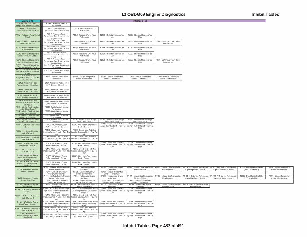
Active DTC Inhibited DTCsP205C - Reductant Tank
Temperature Sensor Circuit LowP20BA - Reductant Heater 1
Performance
P205D - Reductant Tank Temperature Sensor Circuit High
P205B - Reductant Tank Temperature Sensor Performance
P20BA - Reductant Heater 1 Performance
P208A - Reductant Pump Control Circuit
P204F - Reductant System Performance Bank 1 (cannot build
pump pressure)
P20A1 - Reductant Purge Valve Performance
P20E8 - Reductant Pressure Too Low
P20E9 - Reductant Pressure Too High
P208D - Reductant Pump Control Circuit High Voltage
P204F - Reductant System Performance Bank 1 (cannot build
pump pressure)
P20A1 - Reductant Purge Valve Performance
P20E8 - Reductant Pressure Too Low
P20E9 - Reductant Pressure Too High
P2510 - ECM Power Relay Circuit Performance
P20A0 - Reductant Purge Valve Control Circuit
P204F - Reductant System Performance Bank 1 (cannot build
pump pressure)
P20A1 - Reductant Purge Valve Performance
P20E8 - Reductant Pressure Too Low
P20E9 - Reductant Pressure Too High
P20A2 - Reductant Purge Valve Control Circuit Low Voltage
P204F - Reductant System Performance Bank 1 (cannot build
pump pressure)
P20A1 - Reductant Purge Valve Performance
P20E8 - Reductant Pressure Too Low
P20E9 - Reductant Pressure Too High
P20A3 - Reductant Purge Valve Control Circuit High Voltage
P204F - Reductant System Performance Bank 1 (cannot build
pump pressure)
P20A1 - Reductant Purge Valve Performance
P20E8 - Reductant Pressure Too Low
P20E9 - Reductant Pressure Too High
P2510 - ECM Power Relay Circuit Performance
P20CB - Exhaust Aftertreatment Fuel Injector Control Circuit
P2510 - ECM Power Relay Circuit Performance
P20CE - Exhaust Aftertreatment Fuel Injector Control Circuit High
Voltage
P2510 - ECM Power Relay Circuit Performance
P20E2 - Exhaust Gas Temperature (EGT) Sensors 1-2
not plausible
P0101 - Mass Air Flow Sensor Performance
P2080 - Exhaust Temperature Sensor 1 Performance
P2084 - Exhaust Temperature Sensor 2 Performance
P242B - Exhaust Temperature Sensor 3 Performance
P246F - Exhaust Temperature Sensor 4 Performance
P2122 - Accelerator Pedal Position Sensor 1 Circuit Low
P2138 - Accelerator Pedal Position (APP) Sensor 1-2 Correlation
P2123 - Accelerator Pedal Position Sensor 1 Circuit High
P2138 - Accelerator Pedal Position (APP) Sensor 1-2 Correlation
P2127 - Accelerator Pedal Position Sensor 2 Circuit Low
P2138 - Accelerator Pedal Position (APP) Sensor 1-2 Correlation
P2128 - Accelerator Pedal Position (APP) Sensor 2 Circuit
High Voltage
P2138 - Accelerator Pedal Position (APP) Sensor 1-2 Correlation
P2146 - Injector Positive Voltage Control Circuit Group 1
P0606 - Control Module Internal Performance
P2149 - Injector Positive Voltage Control Circuit Group 2
P0606 - Control Module Internal Performance
P2152 - Injector Positive Voltage Control Circuit Group 3
P0606 - Control Module Internal Performance
P2155 - Injector Positive Voltage Control Circuit Group 4
P0606 - Control Module Internal Performance
P2146 - Injector Positive Voltage Control Circuit Group 1
P2149 - Injector Positive Voltage Control Circuit Group 2
P2152 - Injector Positive Voltage Control Circuit Group 3
P2200 - N0x Sensor Circuit Bank 1 Sensor 1
P11DB - NOx Sensor Current Performance Bank 1 Sensor 1
P2209 - N0x Heater Performance Bank 1 Sensor 1
P249D - Closed Loop Reductant Injection Control At Limit - Flow Too
Low
P249E - Closed Loop Reductant Injection Control At Limit - Flow Too
High
P2202 - N0x Sensor Circuit Low Bank 1 Sensor 1
P249D - Closed Loop Reductant Injection Control At Limit - Flow Too
Low
P249E - Closed Loop Reductant Injection Control At Limit - Flow Too
High
P2203 - N0x Sensor Circuit High Bank 1 Sensor 1
P249D - Closed Loop Reductant Injection Control At Limit - Flow Too
Low
P249E - Closed Loop Reductant Injection Control At Limit - Flow Too
High
P2205 - N0x Heater Control Circuit Bank 1 Sensor 1
P11DB - NOx Sensor Current Performance Bank 1 Sensor 1
P2209 - N0x Heater Performance Bank 1 Sensor 1
P249D - Closed Loop Reductant Injection Control At Limit - Flow Too
Low
P249E - Closed Loop Reductant Injection Control At Limit - Flow Too
High
P2209 - N0x Heater Performance Bank 1 Sensor 1
P249D - Closed Loop Reductant Injection Control At Limit - Flow Too
Low
P249E - Closed Loop Reductant Injection Control At Limit - Flow Too
HighP220A - N0x Sensor Supply
Voltage Out Of Range Bank 1 Sensor 1
P11DB - NOx Sensor Current Performance Bank 1 Sensor 1
P2209 - N0x Heater Performance Bank 1 Sensor 1
P220B - N0x Sensor Supply Voltage Out Of Range Bank 1
Sensor 2
P11DB - NOx Sensor Current Performance Bank 1 Sensor 1
P2209 - N0x Heater Performance Bank 1 Sensor 1
P0106 - Manifold Absolute Pressure Sensor Performance
P0234 - Turbocharger Engine Overboost
P0299 - Turbocharger Engine Underboost
P0401 - Exhaust Gas Recirculation Flow Insufficient
P0402 - Exhaust Gas Recirculation Flow Excessive
P11CB - NOx Sensor Performance - Signal High Bank 1 Sensor 1
P11CC - NOx Sensor Performance - Signal Low Bank 1 Sensor 1
P2002 - Diesel Particulate Filter (DPF) Low Efficiency
P2080 - Exhaust Temperature Sensor 1 Performance
P2084 - Exhaust Temperature Sensor 2 Performance
P242B - Exhaust Temperature Sensor 3 Performance
P246F - Exhaust Temperature Sensor 4 Performance
P0106 - Manifold Absolute Pressure Sensor Performance
P0234 - Turbocharger Engine Overboost
P0299 - Turbocharger Engine Underboost
P0401 - Exhaust Gas Recirculation Flow Insufficient
P0402 - Exhaust Gas Recirculation Flow Excessive
P11CB - NOx Sensor Performance - Signal High Bank 1 Sensor 1
P11CC - NOx Sensor Performance - Signal Low Bank 1 Sensor 1
P2002 - Diesel Particulate Filter (DPF) Low Efficiency
P2080 - Exhaust Temperature Sensor 1 Performance
P2084 - Exhaust Temperature Sensor 2 Performance
P242B - Exhaust Temperature Sensor 3 Performance
P2459 - Diesel Particulate Filter Regeneration Frequency
P246F - Exhaust Temperature Sensor 4 Performance
P2263 - Turbo Boost System Performance
P0101 - Mass Air Flow Sensor Performance
P0106 - Manifold Absolute Pressure Sensor Performance
P0234 - Turbocharger Engine Overboost
P0299 - Turbocharger Engine Underboost
P0401 - Exhaust Gas Recirculation Flow Insufficient
P0402 - Exhaust Gas Recirculation Flow Excessive
P229E - NOx Sensor Circuit Bank 1 Sensor 2
P11AF - HO2S Performance - Signal High During Moderate Load Bank 1
Sensor 2
P11B2 - HO2S Performance - Signal Low During Moderate Load Bank 1
Sensor 2
P249D - Closed Loop Reductant Injection Control At Limit - Flow Too
Low
P249E - Closed Loop Reductant Injection Control At Limit - Flow Too
High
P229F - NOx Sensor Performance Bank 1 Sensor 2
P249D - Closed Loop Reductant Injection Control At Limit - Flow Too
Low
P249E - Closed Loop Reductant Injection Control At Limit - Flow Too
High
P22A3 - NOx Heater Control Circuit Bank 1 Sensor 2
P11AF - HO2S Performance - Signal High During Moderate Load Bank 1
Sensor 2
P11B2 - HO2S Performance - Signal Low During Moderate Load Bank 1
Sensor 2
P249D - Closed Loop Reductant Injection Control At Limit - Flow Too
Low
P249E - Closed Loop Reductant Injection Control At Limit - Flow Too
High
P22A7 - NOx Heater Performance Bank 1 Sensor 2
P249D - Closed Loop Reductant Injection Control At Limit - Flow Too
Low
P249E - Closed Loop Reductant Injection Control At Limit - Flow Too
HighP2413 - Exhaust Gas
Recirculation (EGR) System Performance
P11CB - NOx Sensor Performance - Signal High Bank 1 Sensor 1
P11CC - NOx Sensor Performance - Signal Low Bank 1 Sensor 1
P249D - Closed Loop Reductant Injection Control At Limit - Flow Too
Low
P249E - Closed Loop Reductant Injection Control At Limit - Flow Too
High
P2228 - Barometric Pressure Sensor Circuit Low
P2229 - Barometric Pressure Sensor Circuit High
12 OBDG09 Engine Diagnostics Inhibit Tables
Inhibit Tables Page 482 of 491
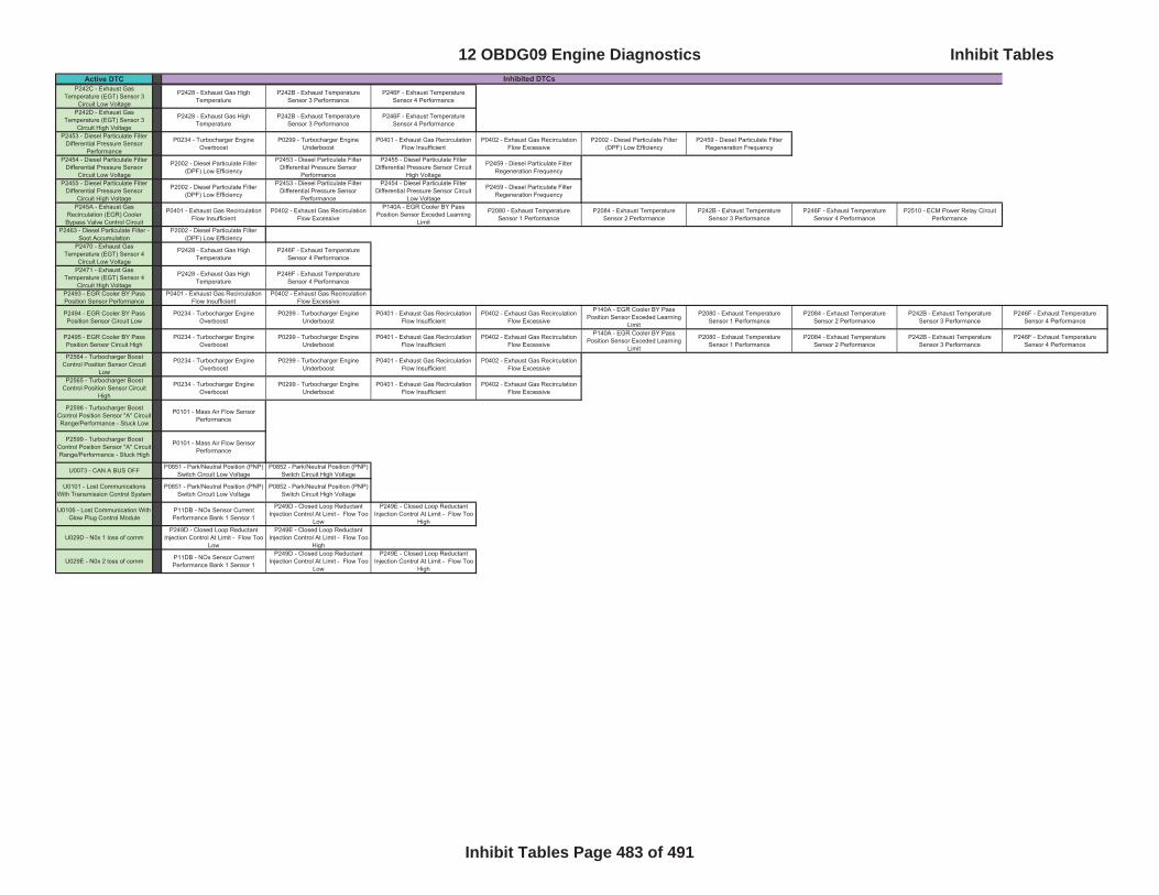
Active DTC Inhibited DTCsP242C - Exhaust Gas
Temperature (EGT) Sensor 3 Circuit Low Voltage
P2428 - Exhaust Gas High Temperature
P242B - Exhaust Temperature Sensor 3 Performance
P246F - Exhaust Temperature Sensor 4 Performance
P242D - Exhaust Gas Temperature (EGT) Sensor 3
Circuit High Voltage
P2428 - Exhaust Gas High Temperature
P242B - Exhaust Temperature Sensor 3 Performance
P246F - Exhaust Temperature Sensor 4 Performance
P2453 - Diesel Particulate Filter Differential Pressure Sensor
Performance
P0234 - Turbocharger Engine Overboost
P0299 - Turbocharger Engine Underboost
P0401 - Exhaust Gas Recirculation Flow Insufficient
P0402 - Exhaust Gas Recirculation Flow Excessive
P2002 - Diesel Particulate Filter (DPF) Low Efficiency
P2459 - Diesel Particulate Filter Regeneration Frequency
P2454 - Diesel Particulate Filter Differential Pressure Sensor
Circuit Low Voltage
P2002 - Diesel Particulate Filter (DPF) Low Efficiency
P2453 - Diesel Particulate Filter Differential Pressure Sensor
Performance
P2455 - Diesel Particulate Filter Differential Pressure Sensor Circuit
High Voltage
P2459 - Diesel Particulate Filter Regeneration Frequency
P2455 - Diesel Particulate Filter Differential Pressure Sensor
Circuit High Voltage
P2002 - Diesel Particulate Filter (DPF) Low Efficiency
P2453 - Diesel Particulate Filter Differential Pressure Sensor
Performance
P2454 - Diesel Particulate Filter Differential Pressure Sensor Circuit
Low Voltage
P2459 - Diesel Particulate Filter Regeneration Frequency
P245A - Exhaust Gas Recirculation (EGR) Cooler Bypass Valve Control Circuit
P0401 - Exhaust Gas Recirculation Flow Insufficient
P0402 - Exhaust Gas Recirculation Flow Excessive
P140A - EGR Cooler BY Pass Position Sensor Exceded Learning
Limit
P2080 - Exhaust Temperature Sensor 1 Performance
P2084 - Exhaust Temperature Sensor 2 Performance
P242B - Exhaust Temperature Sensor 3 Performance
P246F - Exhaust Temperature Sensor 4 Performance
P2510 - ECM Power Relay Circuit Performance
P2463 - Diesel Particulate Filter - Soot Accumulation
P2002 - Diesel Particulate Filter (DPF) Low Efficiency
P2470 - Exhaust Gas Temperature (EGT) Sensor 4
Circuit Low Voltage
P2428 - Exhaust Gas High Temperature
P246F - Exhaust Temperature Sensor 4 Performance
P2471 - Exhaust Gas Temperature (EGT) Sensor 4
Circuit High Voltage
P2428 - Exhaust Gas High Temperature
P246F - Exhaust Temperature Sensor 4 Performance
P2493 - EGR Cooler BY Pass Position Sensor Performance
P0401 - Exhaust Gas Recirculation Flow Insufficient
P0402 - Exhaust Gas Recirculation Flow Excessive
P2494 - EGR Cooler BY Pass Position Sensor Circuit Low
P0234 - Turbocharger Engine Overboost
P0299 - Turbocharger Engine Underboost
P0401 - Exhaust Gas Recirculation Flow Insufficient
P0402 - Exhaust Gas Recirculation Flow Excessive
P140A - EGR Cooler BY Pass Position Sensor Exceded Learning
Limit
P2080 - Exhaust Temperature Sensor 1 Performance
P2084 - Exhaust Temperature Sensor 2 Performance
P242B - Exhaust Temperature Sensor 3 Performance
P246F - Exhaust Temperature Sensor 4 Performance
P2495 - EGR Cooler BY Pass Position Sensor Circuit High
P0234 - Turbocharger Engine Overboost
P0299 - Turbocharger Engine Underboost
P0401 - Exhaust Gas Recirculation Flow Insufficient
P0402 - Exhaust Gas Recirculation Flow Excessive
P140A - EGR Cooler BY Pass Position Sensor Exceded Learning
Limit
P2080 - Exhaust Temperature Sensor 1 Performance
P2084 - Exhaust Temperature Sensor 2 Performance
P242B - Exhaust Temperature Sensor 3 Performance
P246F - Exhaust Temperature Sensor 4 Performance
P2564 - Turbocharger Boost Control Position Sensor Circuit
Low
P0234 - Turbocharger Engine Overboost
P0299 - Turbocharger Engine Underboost
P0401 - Exhaust Gas Recirculation Flow Insufficient
P0402 - Exhaust Gas Recirculation Flow Excessive
P2565 - Turbocharger Boost Control Position Sensor Circuit
High
P0234 - Turbocharger Engine Overboost
P0299 - Turbocharger Engine Underboost
P0401 - Exhaust Gas Recirculation Flow Insufficient
P0402 - Exhaust Gas Recirculation Flow Excessive
P2598 - Turbocharger Boost Control Position Sensor "A" Circuit Range/Performance - Stuck Low
P0101 - Mass Air Flow Sensor Performance
P2599 - Turbocharger Boost Control Position Sensor "A" Circuit Range/Performance - Stuck High
P0101 - Mass Air Flow Sensor Performance
U0073 - CAN A BUS OFF P0851 - Park/Neutral Position (PNP) Switch Circuit Low Voltage
P0852 - Park/Neutral Position (PNP) Switch Circuit High Voltage
U0101 - Lost Communications With Transmission Control System
P0851 - Park/Neutral Position (PNP) Switch Circuit Low Voltage
P0852 - Park/Neutral Position (PNP) Switch Circuit High Voltage
U0106 - Lost Communication With Glow Plug Control Module
P11DB - NOx Sensor Current Performance Bank 1 Sensor 1
P249D - Closed Loop Reductant Injection Control At Limit - Flow Too
Low
P249E - Closed Loop Reductant Injection Control At Limit - Flow Too
High
U029D - N0x 1 loss of comm P249D - Closed Loop Reductant
Injection Control At Limit - Flow Too Low
P249E - Closed Loop Reductant Injection Control At Limit - Flow Too
High
U029E - N0x 2 loss of comm P11DB - NOx Sensor Current Performance Bank 1 Sensor 1
P249D - Closed Loop Reductant Injection Control At Limit - Flow Too
Low
P249E - Closed Loop Reductant Injection Control At Limit - Flow Too
High
12 OBDG09 Engine Diagnostics Inhibit Tables
Inhibit Tables Page 483 of 491
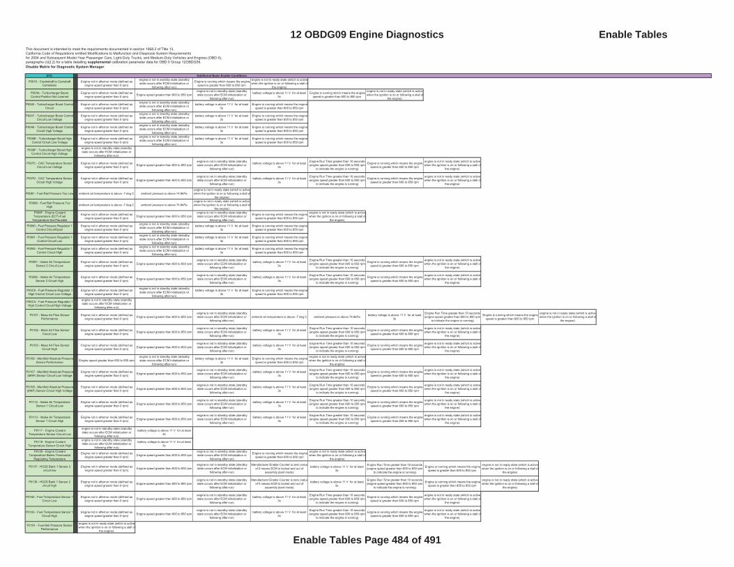
This document is intended to meet the requirements documented in section 1968.2 of Title 13, California Code of Regulations entitled Modifications to Malfunction and Diagnosis System Requirementsfor 2004 and Subsequent Model-Year Passenger Cars, Light-Duty Trucks, and Medium-Duty Vehicles and Engines (OBD II),paragraphs (i)(2.2) for a table detailing supplemental calibration parameter data for OBD II Group 12OBDG09.Disable Matrix for Diagnostic System Manager
DTC
P0016 - Crankshaft to Camshaft Correlation
Engine not in afterrun mode (defined as engine speed greater than 0 rpm)
engine is not in standby state (standby state occurs after ECM initialization or
following after-run)
Engine is running which means the engine speed is greater than 600 to 850 rpm
engine is not in ready state (which is active when the ignition is on or following a stall of
the engine)
P003A - Turbocharger Boost Control Position Not Learned
Engine not in afterrun mode (defined as engine speed greater than 0 rpm) Engine speed greater than 600 to 850 rpm
engine is not in standby state (standby state occurs after ECM initialization or
following after-run)
battery voltage is above 11 V for at least 3s
Engine is running which means the engine speed is greater than 600 to 850 rpm
engine is not in ready state (which is active when the ignition is on or following a stall of
the engine)
P0045 - Turbocharger Boost Control Circuit
Engine not in afterrun mode (defined as engine speed greater than 0 rpm)
engine is not in standby state (standby state occurs after ECM initialization or
following after-run)
battery voltage is above 11 V for at least 3s
Engine is running which means the engine speed is greater than 600 to 850 rpm
P0047 - Turbocharger Boost Control Circuit Low Voltage
Engine not in afterrun mode (defined as engine speed greater than 0 rpm)
engine is not in standby state (standby state occurs after ECM initialization or
following after-run)
battery voltage is above 11 V for at least 3s
Engine is running which means the engine speed is greater than 600 to 850 rpm
P0048 - Turbocharger Boost Control Circuit High Voltage
Engine not in afterrun mode (defined as engine speed greater than 0 rpm)
engine is not in standby state (standby state occurs after ECM initialization or
following after-run)
battery voltage is above 11 V for at least 3s
Engine is running which means the engine speed is greater than 600 to 850 rpm
P006E - Turbocharger Boost High Control Circuit Low Voltage
Engine not in afterrun mode (defined as engine speed greater than 0 rpm)
engine is not in standby state (standby state occurs after ECM initialization or
following after-run)
battery voltage is above 11 V for at least 3s
Engine is running which means the engine speed is greater than 600 to 850 rpm
P006F - Turbocharger Boost High Control Circuit High Voltage
engine is not in standby state (standby state occurs after ECM initialization or
following after-run)
P007C - CAC Temperature Sensor Circuit Low Voltage
Engine not in afterrun mode (defined as engine speed greater than 0 rpm) Engine speed greater than 600 to 850 rpm
engine is not in standby state (standby state occurs after ECM initialization or
following after-run)
battery voltage is above 11 V for at least 3s
Engine Run Time greater than 10 seconds (engine speed greater than 600 to 850 rpm
to indicate the engine is running)
Engine is running which means the engine speed is greater than 600 to 850 rpm
engine is not in ready state (which is active when the ignition is on or following a stall of
the engine)
P007D - CAC Temperature Sensor Circuit High Voltage
Engine not in afterrun mode (defined as engine speed greater than 0 rpm) Engine speed greater than 600 to 850 rpm
engine is not in standby state (standby state occurs after ECM initialization or
following after-run)
battery voltage is above 11 V for at least 3s
Engine Run Time greater than 10 seconds (engine speed greater than 600 to 850 rpm
to indicate the engine is running)
Engine is running which means the engine speed is greater than 600 to 850 rpm
engine is not in ready state (which is active when the ignition is on or following a stall of
the engine)
P0087 - Fuel Rail Pressure Too Low ambient air temperature is above -7 deg C ambient pressure is above 74.8kPa engine is not in ready state (which is active when the ignition is on or following a stall of
the engine)
P0088 - Fuel Rail Pressure Too High ambient air temperature is above -7 deg C ambient pressure is above 74.8kPa
engine is not in ready state (which is active when the ignition is on or following a stall of
the engine)P008F - Engine Coolant Temperature (ECT)-Fuel
Temperature Not Plausible
Engine not in afterrun mode (defined as engine speed greater than 0 rpm) Engine speed greater than 600 to 850 rpm
engine is not in standby state (standby state occurs after ECM initialization or
following after-run)
Engine is running which means the engine speed is greater than 600 to 850 rpm
engine is not in ready state (which is active when the ignition is on or following a stall of
the engine)
P0090 - Fuel Pressure Regulator 1 Control Circuit/Open
Engine not in afterrun mode (defined as engine speed greater than 0 rpm)
engine is not in standby state (standby state occurs after ECM initialization or
following after-run)
battery voltage is above 11 V for at least 3s
Engine is running which means the engine speed is greater than 600 to 850 rpm
P0091 - Fuel Pressure Regulator 1 Control Circuit Low
Engine not in afterrun mode (defined as engine speed greater than 0 rpm)
engine is not in standby state (standby state occurs after ECM initialization or
following after-run)
battery voltage is above 11 V for at least 3s
Engine is running which means the engine speed is greater than 600 to 850 rpm
P0092 - Fuel Pressure Regulator 1 Control Circuit High
Engine not in afterrun mode (defined as engine speed greater than 0 rpm)
engine is not in standby state (standby state occurs after ECM initialization or
following after-run)
battery voltage is above 11 V for at least 3s
Engine is running which means the engine speed is greater than 600 to 850 rpm
P0097 - Intake Air Temperature Sensor 2 Circuit Low
Engine not in afterrun mode (defined as engine speed greater than 0 rpm) Engine speed greater than 600 to 850 rpm
engine is not in standby state (standby state occurs after ECM initialization or
following after-run)
battery voltage is above 11 V for at least 3s
Engine Run Time greater than 10 seconds (engine speed greater than 600 to 850 rpm
to indicate the engine is running)
Engine is running which means the engine speed is greater than 600 to 850 rpm
engine is not in ready state (which is active when the ignition is on or following a stall of
the engine)
P0098 - Intake Air Temperature Sensor 2 Circuit High
Engine not in afterrun mode (defined as engine speed greater than 0 rpm) Engine speed greater than 600 to 850 rpm
engine is not in standby state (standby state occurs after ECM initialization or
following after-run)
battery voltage is above 11 V for at least 3s
Engine Run Time greater than 10 seconds (engine speed greater than 600 to 850 rpm
to indicate the engine is running)
Engine is running which means the engine speed is greater than 600 to 850 rpm
engine is not in ready state (which is active when the ignition is on or following a stall of
the engine)
P00C9 - Fuel Pressure Regulator 1 High Control Circuit Low Voltage
Engine not in afterrun mode (defined as engine speed greater than 0 rpm)
engine is not in standby state (standby state occurs after ECM initialization or
following after-run)
battery voltage is above 11 V for at least 3s
Engine is running which means the engine speed is greater than 600 to 850 rpm
P00CA - Fuel Pressure Regulator 1 High Control Circuit High Voltage
engine is not in standby state (standby state occurs after ECM initialization or
following after-run)
P0101 - Mass Air Flow Sensor Performance
Engine not in afterrun mode (defined as engine speed greater than 0 rpm) Engine speed greater than 600 to 850 rpm
engine is not in standby state (standby state occurs after ECM initialization or
following after-run)ambient air temperature is above -7 deg C ambient pressure is above 74.8kPa battery voltage is above 11 V for at least
3s
Engine Run Time greater than 10 seconds (engine speed greater than 600 to 850 rpm
to indicate the engine is running)
Engine is running which means the engine speed is greater than 600 to 850 rpm
engine is not in ready state (which is active when the ignition is on or following a stall of
the engine)
P0102 - Mass Air Flow Sensor Circuit Low
Engine not in afterrun mode (defined as engine speed greater than 0 rpm) Engine speed greater than 600 to 850 rpm
engine is not in standby state (standby state occurs after ECM initialization or
following after-run)
battery voltage is above 11 V for at least 3s
Engine Run Time greater than 10 seconds (engine speed greater than 600 to 850 rpm
to indicate the engine is running)
Engine is running which means the engine speed is greater than 600 to 850 rpm
engine is not in ready state (which is active when the ignition is on or following a stall of
the engine)
P0103 - Mass Air Flow Sensor Circuit High
Engine not in afterrun mode (defined as engine speed greater than 0 rpm) Engine speed greater than 600 to 850 rpm
engine is not in standby state (standby state occurs after ECM initialization or
following after-run)
battery voltage is above 11 V for at least 3s
Engine Run Time greater than 10 seconds (engine speed greater than 600 to 850 rpm
to indicate the engine is running)
Engine is running which means the engine speed is greater than 600 to 850 rpm
engine is not in ready state (which is active when the ignition is on or following a stall of
the engine)
P0106 - Manifold Absolute Pressure Sensor Performance Engine speed greater than 600 to 850 rpm
engine is not in standby state (standby state occurs after ECM initialization or
following after-run)
battery voltage is above 11 V for at least 3s
Engine is running which means the engine speed is greater than 600 to 850 rpm
engine is not in ready state (which is active when the ignition is on or following a stall of
the engine)
P0107 - Manifold Absolute Pressure (MAP) Sensor Circuit Low Voltage
Engine not in afterrun mode (defined as engine speed greater than 0 rpm) Engine speed greater than 600 to 850 rpm
engine is not in standby state (standby state occurs after ECM initialization or
following after-run)
battery voltage is above 11 V for at least 3s
Engine Run Time greater than 10 seconds (engine speed greater than 600 to 850 rpm
to indicate the engine is running)
Engine is running which means the engine speed is greater than 600 to 850 rpm
engine is not in ready state (which is active when the ignition is on or following a stall of
the engine)
P0108 - Manifold Absolute Pressure (MAP) Sensor Circuit High Voltage
Engine not in afterrun mode (defined as engine speed greater than 0 rpm) Engine speed greater than 600 to 850 rpm
engine is not in standby state (standby state occurs after ECM initialization or
following after-run)
battery voltage is above 11 V for at least 3s
Engine Run Time greater than 10 seconds (engine speed greater than 600 to 850 rpm
to indicate the engine is running)
Engine is running which means the engine speed is greater than 600 to 850 rpm
engine is not in ready state (which is active when the ignition is on or following a stall of
the engine)
P0112 - Intake Air Temperature Sensor 1 Circuit Low
Engine not in afterrun mode (defined as engine speed greater than 0 rpm) Engine speed greater than 600 to 850 rpm
engine is not in standby state (standby state occurs after ECM initialization or
following after-run)
battery voltage is above 11 V for at least 3s
Engine Run Time greater than 10 seconds (engine speed greater than 600 to 850 rpm
to indicate the engine is running)
Engine is running which means the engine speed is greater than 600 to 850 rpm
engine is not in ready state (which is active when the ignition is on or following a stall of
the engine)
P0113 - Intake Air Temperature Sensor 1 Circuit High
Engine not in afterrun mode (defined as engine speed greater than 0 rpm) Engine speed greater than 600 to 850 rpm
engine is not in standby state (standby state occurs after ECM initialization or
following after-run)
battery voltage is above 11 V for at least 3s
Engine Run Time greater than 10 seconds (engine speed greater than 600 to 850 rpm
to indicate the engine is running)
Engine is running which means the engine speed is greater than 600 to 850 rpm
engine is not in ready state (which is active when the ignition is on or following a stall of
the engine)
P0117 - Engine Coolant Temperature Sensor Circuit Low
engine is not in standby state (standby state occurs after ECM initialization or
following after-run)
battery voltage is above 11 V for at least 3s
P0118 - Engine Coolant Temperature Sensor Circuit High
engine is not in standby state (standby state occurs after ECM initialization or
following after-run)
battery voltage is above 11 V for at least 3s
P0128 - Engine Coolant Temperature Below Thermostat
Regulating Temperature
Engine not in afterrun mode (defined as engine speed greater than 0 rpm) Engine speed greater than 600 to 850 rpm
engine is not in standby state (standby state occurs after ECM initialization or
following after-run)
Engine is running which means the engine speed is greater than 600 to 850 rpm
engine is not in ready state (which is active when the ignition is on or following a stall of
the engine)
P0137 - HO2S Bank 1 Sensor 2 circuit low
Engine not in afterrun mode (defined as engine speed greater than 0 rpm) Engine speed greater than 600 to 850 rpm
engine is not in standby state (standby state occurs after ECM initialization or
following after-run)
Manufacturer Enable Counter is zero (valueof 0 means ECM is locked and out of
assembly plant mode)
battery voltage is above 11 V for at least 3s
Engine Run Time greater than 10 seconds (engine speed greater than 600 to 850 rpm
to indicate the engine is running)
Engine is running which means the engine speed is greater than 600 to 850 rpm
engine is not in ready state (which is active when the ignition is on or following a stall of
the engine)
P0138 - HO2S Bank 1 Sensor 2 circuit high
Engine not in afterrun mode (defined as engine speed greater than 0 rpm) Engine speed greater than 600 to 850 rpm
engine is not in standby state (standby state occurs after ECM initialization or
following after-run)
Manufacturer Enable Counter is zero (valueof 0 means ECM is locked and out of
assembly plant mode)
battery voltage is above 11 V for at least 3s
Engine Run Time greater than 10 seconds (engine speed greater than 600 to 850 rpm
to indicate the engine is running)
Engine is running which means the engine speed is greater than 600 to 850 rpm
engine is not in ready state (which is active when the ignition is on or following a stall of
the engine)
P0182 - Fuel Temperature Sensor 1 Circuit Low
Engine not in afterrun mode (defined as engine speed greater than 0 rpm) Engine speed greater than 600 to 850 rpm
engine is not in standby state (standby state occurs after ECM initialization or
following after-run)
battery voltage is above 11 V for at least 3s
Engine Run Time greater than 10 seconds (engine speed greater than 600 to 850 rpm
to indicate the engine is running)
Engine is running which means the engine speed is greater than 600 to 850 rpm
engine is not in ready state (which is active when the ignition is on or following a stall of
the engine)
P0183 - Fuel Temperature Sensor 1 Circuit High
Engine not in afterrun mode (defined as engine speed greater than 0 rpm) Engine speed greater than 600 to 850 rpm
engine is not in standby state (standby state occurs after ECM initialization or
following after-run)
battery voltage is above 11 V for at least 3s
Engine Run Time greater than 10 seconds (engine speed greater than 600 to 850 rpm
to indicate the engine is running)
Engine is running which means the engine speed is greater than 600 to 850 rpm
engine is not in ready state (which is active when the ignition is on or following a stall of
the engine)
P0191 - Fuel Rail Pressure Sensor Performance
engine is not in ready state (which is active when the ignition is on or following a stall of
the engine)
Additional Basic Enable Conditions
12 OBDG09 Engine Diagnostics Enable Tables
Enable Tables Page 484 of 491
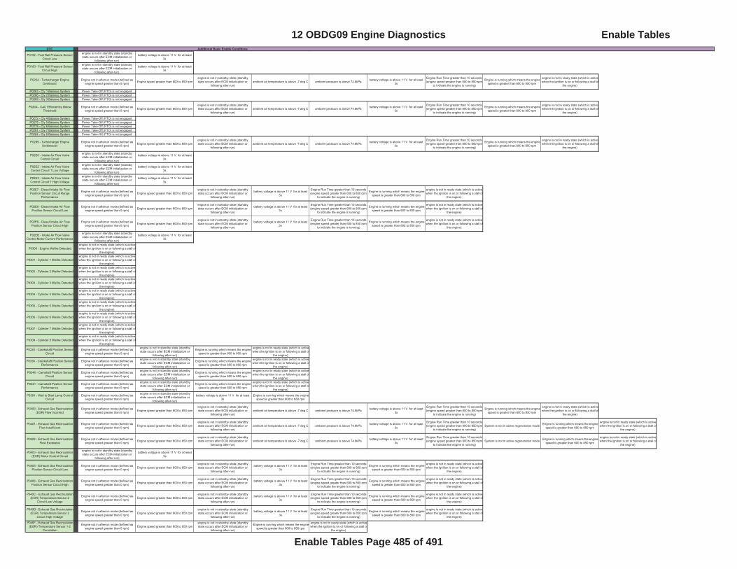
DTC Additional Basic Enable Conditions
P0192 - Fuel Rail Pressure Sensor Circuit Low
engine is not in standby state (standby state occurs after ECM initialization or
following after-run)
battery voltage is above 11 V for at least 3s
P0193 - Fuel Rail Pressure Sensor Circuit High
engine is not in standby state (standby state occurs after ECM initialization or
following after-run)
battery voltage is above 11 V for at least 3s
P0234 - Turbocharger Engine Overboost
Engine not in afterrun mode (defined as engine speed greater than 0 rpm) Engine speed greater than 600 to 850 rpm
engine is not in standby state (standby state occurs after ECM initialization or
following after-run)ambient air temperature is above -7 deg C ambient pressure is above 74.8kPa battery voltage is above 11 V for at least
3s
Engine Run Time greater than 10 seconds (engine speed greater than 600 to 850 rpm
to indicate the engine is running)
Engine is running which means the engine speed is greater than 600 to 850 rpm
engine is not in ready state (which is active when the ignition is on or following a stall of
the engine)
P0263 - Cly 1 Balance System Power Take-Off (PTO) is not engagedP0266 - Cly 2 Balance System Power Take-Off (PTO) is not engagedP0269 - Cly 3 Balance System Power Take-Off (PTO) is not engaged
P026A - CAC Effiecientcy Below Threshold
Engine not in afterrun mode (defined as engine speed greater than 0 rpm) Engine speed greater than 600 to 850 rpm
engine is not in standby state (standby state occurs after ECM initialization or
following after-run)ambient air temperature is above -7 deg C ambient pressure is above 74.8kPa battery voltage is above 11 V for at least
3s
Engine Run Time greater than 10 seconds (engine speed greater than 600 to 850 rpm
to indicate the engine is running)
Engine is running which means the engine speed is greater than 600 to 850 rpm
engine is not in ready state (which is active when the ignition is on or following a stall of
the engine)
P0272 - Cly 4 Balance System Power Take-Off (PTO) is not engagedP0275 - Cly 5 Balance System Power Take-Off (PTO) is not engagedP0278 - Cly 6 Balance System Power Take-Off (PTO) is not engagedP0281 - Cly 7 Balance System Power Take-Off (PTO) is not engagedP0284 - Cly 8 Balance System Power Take-Off (PTO) is not engaged
P0299 - Turbocharger Engine Underboost
Engine not in afterrun mode (defined as engine speed greater than 0 rpm) Engine speed greater than 600 to 850 rpm
engine is not in standby state (standby state occurs after ECM initialization or
following after-run)ambient air temperature is above -7 deg C ambient pressure is above 74.8kPa battery voltage is above 11 V for at least
3s
Engine Run Time greater than 10 seconds (engine speed greater than 600 to 850 rpm
to indicate the engine is running)
Engine is running which means the engine speed is greater than 600 to 850 rpm
engine is not in ready state (which is active when the ignition is on or following a stall of
the engine)
P02E0 - Intake Air Flow Valve Control Circuit
engine is not in standby state (standby state occurs after ECM initialization or
following after-run)
battery voltage is above 11 V for at least 3s
P02E2 - Intake Air Flow Valve Control Circuit 1 Low Voltage
engine is not in standby state (standby state occurs after ECM initialization or
following after-run)
battery voltage is above 11 V for at least 3s
P02E3 - Intake Air Flow Valve Control Circuit 1 High Voltage
engine is not in standby state (standby state occurs after ECM initialization or
following after-run)
battery voltage is above 11 V for at least 3s
P02E7 - Diesel Intake Air Flow Position Sensor Circuit Range
Performance
Engine not in afterrun mode (defined as engine speed greater than 0 rpm) Engine speed greater than 600 to 850 rpm
engine is not in standby state (standby state occurs after ECM initialization or
following after-run)
battery voltage is above 11 V for at least 3s
Engine Run Time greater than 10 seconds (engine speed greater than 600 to 850 rpm
to indicate the engine is running)
Engine is running which means the engine speed is greater than 600 to 850 rpm
engine is not in ready state (which is active when the ignition is on or following a stall of
the engine)
P02E8 - Diesel Intake Air Flow Position Sensor Circuit Low
Engine not in afterrun mode (defined as engine speed greater than 0 rpm) Engine speed greater than 600 to 850 rpm
engine is not in standby state (standby state occurs after ECM initialization or
following after-run)
battery voltage is above 11 V for at least 3s
Engine Run Time greater than 10 seconds (engine speed greater than 600 to 850 rpm
to indicate the engine is running)
Engine is running which means the engine speed is greater than 600 to 850 rpm
engine is not in ready state (which is active when the ignition is on or following a stall of
the engine)
P02E9 - Diesel Intake Air Flow Position Sensor Circuit High
Engine not in afterrun mode (defined as engine speed greater than 0 rpm) Engine speed greater than 600 to 850 rpm
engine is not in standby state (standby state occurs after ECM initialization or
following after-run)
battery voltage is above 11 V for at least 3s
Engine Run Time greater than 10 seconds (engine speed greater than 600 to 850 rpm
to indicate the engine is running)
Engine is running which means the engine speed is greater than 600 to 850 rpm
engine is not in ready state (which is active when the ignition is on or following a stall of
the engine)
P02EB - Intake Air Flow Valve Control Motor Current Performance
engine is not in standby state (standby state occurs after ECM initialization or
following after-run)
battery voltage is above 11 V for at least 3s
P0300 - Engine Misfire Detected engine is not in ready state (which is active when the ignition is on or following a stall of
the engine)
P0301 - Cylinder 1 Misfire Detected engine is not in ready state (which is active when the ignition is on or following a stall of
the engine)
P0302 - Cylinder 2 Misfire Detected engine is not in ready state (which is active when the ignition is on or following a stall of
the engine)
P0303 - Cylinder 3 Misfire Detected engine is not in ready state (which is active when the ignition is on or following a stall of
the engine)
P0304 - Cylinder 4 Misfire Detected engine is not in ready state (which is active when the ignition is on or following a stall of
the engine)
P0305 - Cylinder 5 Misfire Detected engine is not in ready state (which is active when the ignition is on or following a stall of
the engine)
P0306 - Cylinder 6 Misfire Detected engine is not in ready state (which is active when the ignition is on or following a stall of
the engine)
P0307 - Cylinder 7 Misfire Detected engine is not in ready state (which is active when the ignition is on or following a stall of
the engine)
P0308 - Cylinder 8 Misfire Detected engine is not in ready state (which is active when the ignition is on or following a stall of
the engine)
P0335 - Crankshaft Position Sensor Circuit
Engine not in afterrun mode (defined as engine speed greater than 0 rpm)
engine is not in standby state (standby state occurs after ECM initialization or
following after-run)
Engine is running which means the engine speed is greater than 600 to 850 rpm
engine is not in ready state (which is active when the ignition is on or following a stall of
the engine)
P0336 - Crankshaft Position Sensor Performance
Engine not in afterrun mode (defined as engine speed greater than 0 rpm)
engine is not in standby state (standby state occurs after ECM initialization or
following after-run)
Engine is running which means the engine speed is greater than 600 to 850 rpm
engine is not in ready state (which is active when the ignition is on or following a stall of
the engine)
P0340 - Camshaft Position Sensor Circuit
Engine not in afterrun mode (defined as engine speed greater than 0 rpm)
engine is not in standby state (standby state occurs after ECM initialization or
following after-run)
Engine is running which means the engine speed is greater than 600 to 850 rpm
engine is not in ready state (which is active when the ignition is on or following a stall of
the engine)
P0341 - Camshaft Position Sensor Performance
Engine not in afterrun mode (defined as engine speed greater than 0 rpm)
engine is not in standby state (standby state occurs after ECM initialization or
following after-run)
Engine is running which means the engine speed is greater than 600 to 850 rpm
engine is not in ready state (which is active when the ignition is on or following a stall of
the engine)
P0381 - Wait to Start Lamp Control Circuit
Engine not in afterrun mode (defined as engine speed greater than 0 rpm)
engine is not in standby state (standby state occurs after ECM initialization or
following after-run)
battery voltage is above 11 V for at least 3s
Engine is running which means the engine speed is greater than 600 to 850 rpm
P0400 - Exhaust Gas Recirculation (EGR) Flow Incorrect
Engine not in afterrun mode (defined as engine speed greater than 0 rpm) Engine speed greater than 600 to 850 rpm
engine is not in standby state (standby state occurs after ECM initialization or
following after-run)ambient air temperature is above -7 deg C ambient pressure is above 74.8kPa battery voltage is above 11 V for at least
3s
Engine Run Time greater than 10 seconds (engine speed greater than 600 to 850 rpm
to indicate the engine is running)
Engine is running which means the engine speed is greater than 600 to 850 rpm
engine is not in ready state (which is active when the ignition is on or following a stall of
the engine)
P0401 - Exhaust Gas Recirculation Flow Insufficient
Engine not in afterrun mode (defined as engine speed greater than 0 rpm) Engine speed greater than 600 to 850 rpm
engine is not in standby state (standby state occurs after ECM initialization or
following after-run)ambient air temperature is above -7 deg C ambient pressure is above 74.8kPa battery voltage is above 11 V for at least
3s
Engine Run Time greater than 10 seconds (engine speed greater than 600 to 850 rpm
to indicate the engine is running)System is not in active regeneration mode Engine is running which means the engine
speed is greater than 600 to 850 rpm
engine is not in ready state (which is active when the ignition is on or following a stall of
the engine)
P0402 - Exhaust Gas Recirculation Flow Excessive
Engine not in afterrun mode (defined as engine speed greater than 0 rpm) Engine speed greater than 600 to 850 rpm
engine is not in standby state (standby state occurs after ECM initialization or
following after-run)ambient air temperature is above -7 deg C ambient pressure is above 74.8kPa battery voltage is above 11 V for at least
3s
Engine Run Time greater than 10 seconds (engine speed greater than 600 to 850 rpm
to indicate the engine is running)System is not in active regeneration mode Engine is running which means the engine
speed is greater than 600 to 850 rpm
engine is not in ready state (which is active when the ignition is on or following a stall of
the engine)
P0403 - Exhaust Gas Recirculation (EGR) Motor Control Circuit
engine is not in standby state (standby state occurs after ECM initialization or
following after-run)
battery voltage is above 11 V for at least 3s
P0405 - Exhaust Gas Recirculation Position Sensor Circuit Low
Engine not in afterrun mode (defined as engine speed greater than 0 rpm) Engine speed greater than 600 to 850 rpm
engine is not in standby state (standby state occurs after ECM initialization or
following after-run)
battery voltage is above 11 V for at least 3s
Engine Run Time greater than 10 seconds (engine speed greater than 600 to 850 rpm
to indicate the engine is running)
Engine is running which means the engine speed is greater than 600 to 850 rpm
engine is not in ready state (which is active when the ignition is on or following a stall of
the engine)
P0406 - Exhaust Gas Recirculation Position Sensor Circuit High
Engine not in afterrun mode (defined as engine speed greater than 0 rpm) Engine speed greater than 600 to 850 rpm
engine is not in standby state (standby state occurs after ECM initialization or
following after-run)
battery voltage is above 11 V for at least 3s
Engine Run Time greater than 10 seconds (engine speed greater than 600 to 850 rpm
to indicate the engine is running)
Engine is running which means the engine speed is greater than 600 to 850 rpm
engine is not in ready state (which is active when the ignition is on or following a stall of
the engine)
P040C - Exhaust Gas Recirculation (EGR) Temperature Sensor 2
Circuit Low Voltage
Engine not in afterrun mode (defined as engine speed greater than 0 rpm) Engine speed greater than 600 to 850 rpm
engine is not in standby state (standby state occurs after ECM initialization or
following after-run)
battery voltage is above 11 V for at least 3s
Engine Run Time greater than 10 seconds (engine speed greater than 600 to 850 rpm
to indicate the engine is running)
Engine is running which means the engine speed is greater than 600 to 850 rpm
engine is not in ready state (which is active when the ignition is on or following a stall of
the engine)
P040D - Exhaust Gas Recirculation (EGR) Temperature Sensor 2
Circuit High Voltage
Engine not in afterrun mode (defined as engine speed greater than 0 rpm) Engine speed greater than 600 to 850 rpm
engine is not in standby state (standby state occurs after ECM initialization or
following after-run)
battery voltage is above 11 V for at least 3s
Engine Run Time greater than 10 seconds (engine speed greater than 600 to 850 rpm
to indicate the engine is running)
Engine is running which means the engine speed is greater than 600 to 850 rpm
engine is not in ready state (which is active when the ignition is on or following a stall of
the engine)
P040F - Exhaust Gas Recirculation (EGR) Temperature Sensor 1-2
Correlation
Engine not in afterrun mode (defined as engine speed greater than 0 rpm) Engine speed greater than 600 to 850 rpm
engine is not in standby state (standby state occurs after ECM initialization or
following after-run)
Engine is running which means the engine speed is greater than 600 to 850 rpm
engine is not in ready state (which is active when the ignition is on or following a stall of
the engine)
12 OBDG09 Engine Diagnostics Enable Tables
Enable Tables Page 485 of 491
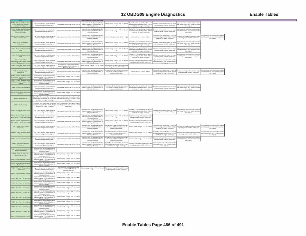
DTC Additional Basic Enable Conditions
P041C - Exhaust Gas Recirculation (EGR) Temperature Sensor 1
Circuit Low Voltage
Engine not in afterrun mode (defined as engine speed greater than 0 rpm) Engine speed greater than 600 to 850 rpm
engine is not in standby state (standby state occurs after ECM initialization or
following after-run)
battery voltage is above 11 V for at least 3s
Engine Run Time greater than 10 seconds (engine speed greater than 600 to 850 rpm
to indicate the engine is running)
Engine is running which means the engine speed is greater than 600 to 850 rpm
engine is not in ready state (which is active when the ignition is on or following a stall of
the engine)
P041D - Exhaust Gas Recirculation (EGR) Temperature Sensor 1
Circuit High Voltage
Engine not in afterrun mode (defined as engine speed greater than 0 rpm) Engine speed greater than 600 to 850 rpm
engine is not in standby state (standby state occurs after ECM initialization or
following after-run)
battery voltage is above 11 V for at least 3s
Engine Run Time greater than 10 seconds (engine speed greater than 600 to 850 rpm
to indicate the engine is running)
Engine is running which means the engine speed is greater than 600 to 850 rpm
engine is not in ready state (which is active when the ignition is on or following a stall of
the engine)
P0420 - NMHC Catalyst Efficiency Below Threshold Bank 1
Engine not in afterrun mode (defined as engine speed greater than 0 rpm) Engine speed greater than 600 to 850 rpm
engine is not in standby state (standby state occurs after ECM initialization or
following after-run)ambient air temperature is above -7 deg C ambient pressure is above 74.8kPa
Engine Run Time greater than 10 seconds (engine speed greater than 600 to 850 rpm
to indicate the engine is running)
Engine is running which means the engine speed is greater than 600 to 850 rpm
engine is not in ready state (which is active when the ignition is on or following a stall of
the engine)
P0461 - Fuel Level Sensor Performance
Engine not in afterrun mode (defined as engine speed greater than 0 rpm) Engine speed greater than 600 to 850 rpm
engine is not in standby state (standby state occurs after ECM initialization or
following after-run)
battery voltage is above 11 V for at least 3s
Engine Run Time greater than 10 seconds (engine speed greater than 600 to 850 rpm
to indicate the engine is running)
Engine is running which means the engine speed is greater than 600 to 850 rpm
engine is not in ready state (which is active when the ignition is on or following a stall of
the engine)
P0462 - Fuel Level Sensor Circuit Low
Engine not in afterrun mode (defined as engine speed greater than 0 rpm) Engine speed greater than 600 to 850 rpm
engine is not in standby state (standby state occurs after ECM initialization or
following after-run)
battery voltage is above 11 V for at least 3s
Engine Run Time greater than 10 seconds (engine speed greater than 600 to 850 rpm
to indicate the engine is running)
Engine is running which means the engine speed is greater than 600 to 850 rpm
engine is not in ready state (which is active when the ignition is on or following a stall of
the engine)
P0463 - Fuel Level Sensor Circuit High
Engine not in afterrun mode (defined as engine speed greater than 0 rpm) Engine speed greater than 600 to 850 rpm
engine is not in standby state (standby state occurs after ECM initialization or
following after-run)
battery voltage is above 11 V for at least 3s
Engine Run Time greater than 10 seconds (engine speed greater than 600 to 850 rpm
to indicate the engine is running)
Engine is running which means the engine speed is greater than 600 to 850 rpm
engine is not in ready state (which is active when the ignition is on or following a stall of
the engine)
P046C - Exhaust Gas Recirculation(EGR) Position Sensor
Performance
Engine not in afterrun mode (defined as engine speed greater than 0 rpm) Engine speed greater than 600 to 850 rpm
engine is not in standby state (standby state occurs after ECM initialization or
following after-run)
battery voltage is above 11 V for at least 3s
Engine is running which means the engine speed is greater than 600 to 850 rpm
engine is not in ready state (which is active when the ignition is on or following a stall of
the engine)
P0480 - Cooling Fan Speed Output Circuit
Engine not in afterrun mode (defined as engine speed greater than 0 rpm)
engine is not in standby state (standby state occurs after ECM initialization or
following after-run)
battery voltage is above 11 V for at least 3s
Engine is running which means the engine speed is greater than 600 to 850 rpm
P0483 - Cooling Fan System Performance
Engine not in afterrun mode (defined as engine speed greater than 0 rpm) Engine speed greater than 600 to 850 rpm
engine is not in standby state (standby state occurs after ECM initialization or
following after-run)
Manufacturer Enable Counter is zero (valueof 0 means ECM is locked and out of
assembly plant mode)ambient pressure is above 74.8kPa
Engine Run Time greater than 10 seconds (engine speed greater than 600 to 850 rpm
to indicate the engine is running)
Engine is running which means the engine speed is greater than 600 to 850 rpm
engine is not in ready state (which is active when the ignition is on or following a stall of
the engine)
P0489 - Exhaust Gas Recirculation (EGR) Motor Control Circuit 1 Low
Voltage
engine is not in standby state (standby state occurs after ECM initialization or
following after-run)
battery voltage is above 11 V for at least 3s
P0490 - Exhaust Gas Recirculation (EGR) Motor Control Circuit 1 High
Voltage
engine is not in standby state (standby state occurs after ECM initialization or
following after-run)
battery voltage is above 11 V for at least 3s
P0495 - Cooling Fan Speed High Engine not in afterrun mode (defined as engine speed greater than 0 rpm) Engine speed greater than 600 to 850 rpm
engine is not in standby state (standby state occurs after ECM initialization or
following after-run)
Manufacturer Enable Counter is zero (valueof 0 means ECM is locked and out of
assembly plant mode)
Engine Run Time greater than 10 seconds (engine speed greater than 600 to 850 rpm
to indicate the engine is running)
Engine is running which means the engine speed is greater than 600 to 850 rpm
engine is not in ready state (which is active when the ignition is on or following a stall of
the engine)
P049D - EGR Control Position Not Learned
engine is not in standby state (standby state occurs after ECM initialization or
following after-run)
battery voltage is above 11 V for at least 3s
P0506 - Idle Speed LowEngine Run Time greater than 10 seconds (engine speed greater than 600 to 850 rpm
to indicate the engine is running)
engine is not in ready state (which is active when the ignition is on or following a stall of
the engine)
P0507 - Idle Speed HighEngine Run Time greater than 10 seconds (engine speed greater than 600 to 850 rpm
to indicate the engine is running)
engine is not in ready state (which is active when the ignition is on or following a stall of
the engine)
P0526 - Cooling Fan Speed Sensor Circuit
Engine not in afterrun mode (defined as engine speed greater than 0 rpm) Engine speed greater than 600 to 850 rpm
engine is not in standby state (standby state occurs after ECM initialization or
following after-run)
battery voltage is above 11 V for at least 3s
Engine Run Time greater than 10 seconds (engine speed greater than 600 to 850 rpm
to indicate the engine is running)
Engine is running which means the engine speed is greater than 600 to 850 rpm
engine is not in ready state (which is active when the ignition is on or following a stall of
the engine)
P0545 - Exhaust Gas Temperature (EGT) Sensor 1 Circuit Low Voltage
Engine not in afterrun mode (defined as engine speed greater than 0 rpm) Engine speed greater than 600 to 850 rpm
engine is not in standby state (standby state occurs after ECM initialization or
following after-run)
battery voltage is above 11 V for at least 3s
Engine is running which means the engine speed is greater than 600 to 850 rpm
P0546 - Exhaust Gas Temperature (EGT) Sensor 1 Circuit High Voltage
Engine not in afterrun mode (defined as engine speed greater than 0 rpm) Engine speed greater than 600 to 850 rpm
engine is not in standby state (standby state occurs after ECM initialization or
following after-run)
battery voltage is above 11 V for at least 3s
Engine is running which means the engine speed is greater than 600 to 850 rpm
P0567 - Cruise Control Resume Switch Circuit
Engine not in afterrun mode (defined as engine speed greater than 0 rpm) Engine speed greater than 600 to 850 rpm
engine is not in standby state (standby state occurs after ECM initialization or
following after-run)
Manufacturer Enable Counter is zero (valueof 0 means ECM is locked and out of
assembly plant mode)
battery voltage is above 11 V for at least 3s
Engine Run Time greater than 10 seconds (engine speed greater than 600 to 850 rpm
to indicate the engine is running)
Engine is running which means the engine speed is greater than 600 to 850 rpm
engine is not in ready state (which is active when the ignition is on or following a stall of
the engine)
P0568 - Cruise Control Set Switch Circuit
Engine not in afterrun mode (defined as engine speed greater than 0 rpm) Engine speed greater than 600 to 850 rpm
engine is not in standby state (standby state occurs after ECM initialization or
following after-run)
Manufacturer Enable Counter is zero (valueof 0 means ECM is locked and out of
assembly plant mode)
battery voltage is above 11 V for at least 3s
Engine Run Time greater than 10 seconds (engine speed greater than 600 to 850 rpm
to indicate the engine is running)
Engine is running which means the engine speed is greater than 600 to 850 rpm
engine is not in ready state (which is active when the ignition is on or following a stall of
the engine)
P0575 - Cruise Control Input Circuit Engine not in afterrun mode (defined as engine speed greater than 0 rpm) Engine speed greater than 600 to 850 rpm
engine is not in standby state (standby state occurs after ECM initialization or
following after-run)
Manufacturer Enable Counter is zero (valueof 0 means ECM is locked and out of
assembly plant mode)
battery voltage is above 11 V for at least 3s
Engine is running which means the engine speed is greater than 600 to 850 rpm
engine is not in ready state (which is active when the ignition is on or following a stall of
the engine)
P0606 - Control Module Internal Performance
Engine not in afterrun mode (defined as engine speed greater than 0 rpm) Engine speed greater than 600 to 850 rpm
engine is not in standby state (standby state occurs after ECM initialization or
following after-run)
Engine Run Time greater than 10 seconds (engine speed greater than 600 to 850 rpm
to indicate the engine is running)
Engine is running which means the engine speed is greater than 600 to 850 rpm
engine is not in ready state (which is active when the ignition is on or following a stall of
the engine)
P062F - Control Module Long Term Memory Performance
engine is not in standby state (standby state occurs after ECM initialization or
following after-run)
P0640 - Intake Air (IA) Heater Switch/Control Circuit
engine is not in standby state (standby state occurs after ECM initialization or
following after-run)
battery voltage is above 11 V for at least 3s
P0641 - 5 Volt Reference 1 Circuitengine is not in standby state (standby state occurs after ECM initialization or
following after-run)
battery voltage is above 11 V for at least 3s
P064C - Glow Plug Control Module Performance
engine is not in standby state (standby state occurs after ECM initialization or
following after-run)
battery voltage is above 11 V for at least 3s
P0650 - Malfunction Indicator Lamp Control Circuit
Engine not in afterrun mode (defined as engine speed greater than 0 rpm)
engine is not in standby state (standby state occurs after ECM initialization or
following after-run)
battery voltage is above 11 V for at least 3s
Engine is running which means the engine speed is greater than 600 to 850 rpm
P0651 - 5 Volt Reference 2 Circuitengine is not in standby state (standby state occurs after ECM initialization or
following after-run)
battery voltage is above 11 V for at least 3s
P0671 - Glow Plug 1 Control Circuitengine is not in standby state (standby state occurs after ECM initialization or
following after-run)
battery voltage is above 11 V for at least 3s
P0672 - Glow Plug 2 Control Circuitengine is not in standby state (standby state occurs after ECM initialization or
following after-run)
battery voltage is above 11 V for at least 3s
P0673 - Glow Plug 3 Control Circuitengine is not in standby state (standby state occurs after ECM initialization or
following after-run)
battery voltage is above 11 V for at least 3s
P0674 - Glow Plug 4 Control Circuitengine is not in standby state (standby state occurs after ECM initialization or
following after-run)
battery voltage is above 11 V for at least 3s
P0675 - Glow Plug 5 Control Circuitengine is not in standby state (standby state occurs after ECM initialization or
following after-run)
battery voltage is above 11 V for at least 3s
P0676 - Glow Plug 6 Control Circuitengine is not in standby state (standby state occurs after ECM initialization or
following after-run)
battery voltage is above 11 V for at least 3s
P0677 - Glow Plug 7 Control Circuitengine is not in standby state (standby state occurs after ECM initialization or
following after-run)
battery voltage is above 11 V for at least 3s
P0678 - Glow Plug 8 Control Circuitengine is not in standby state (standby state occurs after ECM initialization or
following after-run)
battery voltage is above 11 V for at least 3s
P0697 - 5 Volt Reference 3 Circuitengine is not in standby state (standby state occurs after ECM initialization or
following after-run)
battery voltage is above 11 V for at least 3s
12 OBDG09 Engine Diagnostics Enable Tables
Enable Tables Page 486 of 491
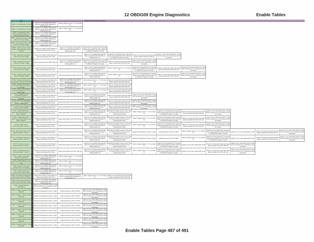
DTC Additional Basic Enable Conditions
P06A3 - 5 Volt Reference 4 Circuitengine is not in standby state (standby state occurs after ECM initialization or
following after-run)
battery voltage is above 11 V for at least 3s
P06D2 - 5 Volt Reference 5 Circuitengine is not in standby state (standby state occurs after ECM initialization or
following after-run)
battery voltage is above 11 V for at least 3s
P0700 - Transmission Control Module Requested Malfunction
Indicator Lamp Illumination
engine is not in standby state (standby state occurs after ECM initialization or
following after-run)
P0851 - Park/Neutral Position (PNP)Switch Circuit Low Voltage
engine is not in standby state (standby state occurs after ECM initialization or
following after-run)
P0852 - Park/Neutral Position (PNP)Switch Circuit High Voltage
engine is not in standby state (standby state occurs after ECM initialization or
following after-run)
P0856 - Traction Control Torque Request Signal Message Counter
Incorrect
Engine not in afterrun mode (defined as engine speed greater than 0 rpm)
engine is not in standby state (standby state occurs after ECM initialization or
following after-run)
Engine Run Time greater than 10 seconds (engine speed greater than 600 to 850 rpm
to indicate the engine is running)
P1043 - Reductant Pump High Control Circuit Low Voltage
Engine not in afterrun mode (defined as engine speed greater than 0 rpm) Engine speed greater than 600 to 850 rpm
engine is not in standby state (standby state occurs after ECM initialization or
following after-run)
Engine Run Time greater than 10 seconds (engine speed greater than 600 to 850 rpm
to indicate the engine is running)
Engine is running which means the engine speed is greater than 600 to 850 rpm
engine is not in ready state (which is active when the ignition is on or following a stall of
the engine)
P1044 - Reductant Pump High Control Circuit High Voltage Engine speed greater than 600 to 850 rpm
engine is not in standby state (standby state occurs after ECM initialization or
following after-run)
Engine Run Time greater than 10 seconds (engine speed greater than 600 to 850 rpm
to indicate the engine is running)
Engine is running which means the engine speed is greater than 600 to 850 rpm
engine is not in ready state (which is active when the ignition is on or following a stall of
the engine)
P1048 - Reductant Injector High Control Circuit Low Voltage
Engine not in afterrun mode (defined as engine speed greater than 0 rpm) Engine speed greater than 600 to 850 rpm
engine is not in standby state (standby state occurs after ECM initialization or
following after-run)
battery voltage is above 11 V for at least 3s
Engine Run Time greater than 10 seconds (engine speed greater than 600 to 850 rpm
to indicate the engine is running)
Engine is running which means the engine speed is greater than 600 to 850 rpm
engine is not in ready state (which is active when the ignition is on or following a stall of
the engine)
P1049 - Reductant Injector High Control Circuit High Voltage
Engine not in afterrun mode (defined as engine speed greater than 0 rpm) Engine speed greater than 600 to 850 rpm
engine is not in standby state (standby state occurs after ECM initialization or
following after-run)
battery voltage is above 11 V for at least 3s
Engine Run Time greater than 10 seconds (engine speed greater than 600 to 850 rpm
to indicate the engine is running)
Engine is running which means the engine speed is greater than 600 to 850 rpm
engine is not in ready state (which is active when the ignition is on or following a stall of
the engine)
P10CC - Exhaust Aftertreatment Fuel Injector Control Circuit Shorted
Engine not in afterrun mode (defined as engine speed greater than 0 rpm)
engine is not in standby state (standby state occurs after ECM initialization or
following after-run)
battery voltage is above 11 V for at least 3s
Engine is running which means the engine speed is greater than 600 to 850 rpm
P10CD - Exhaust Aftertreatment Fuel Injector High Control Circuit
Low Voltage
Engine not in afterrun mode (defined as engine speed greater than 0 rpm)
engine is not in standby state (standby state occurs after ECM initialization or
following after-run)
battery voltage is above 11 V for at least 3s
Engine is running which means the engine speed is greater than 600 to 850 rpm
P10CE - Exhaust Aftertreatment Fuel Injector High Control Circuit
High Voltage
Engine not in afterrun mode (defined as engine speed greater than 0 rpm)
engine is not in standby state (standby state occurs after ECM initialization or
following after-run)
battery voltage is above 11 V for at least 3s
Engine is running which means the engine speed is greater than 600 to 850 rpm
P111C - Charge Air Cooler Temperature-Intake Air
Temperature (IAT) Sensor 2 Not Plausible
Engine not in afterrun mode (defined as engine speed greater than 0 rpm) Engine speed greater than 600 to 850 rpm
engine is not in standby state (standby state occurs after ECM initialization or
following after-run)
Engine is running which means the engine speed is greater than 600 to 850 rpm
engine is not in ready state (which is active when the ignition is on or following a stall of
the engine)
P111D - Intake Air Temperature (IAT) Sensor 1 - Fuel Temperature
Sensor 2 Not Plausible
Engine not in afterrun mode (defined as engine speed greater than 0 rpm) Engine speed greater than 600 to 850 rpm
engine is not in standby state (standby state occurs after ECM initialization or
following after-run)
Engine is running which means the engine speed is greater than 600 to 850 rpm
engine is not in ready state (which is active when the ignition is on or following a stall of
the engine)
P113A - Exhaust Gas Temperature Sensors 3-4 Not Plausible
Engine not in afterrun mode (defined as engine speed greater than 0 rpm) Engine speed greater than 600 to 850 rpm
engine is not in standby state (standby state occurs after ECM initialization or
following after-run)
Engine is running which means the engine speed is greater than 600 to 850 rpm
engine is not in ready state (which is active when the ignition is on or following a stall of
the engine)
P11AF - HO2S Performance - Signal High During Moderate Load
Bank 1 Sensor 2
Engine not in afterrun mode (defined as engine speed greater than 0 rpm) Engine speed greater than 600 to 850 rpm
engine is not in standby state (standby state occurs after ECM initialization or
following after-run)
Manufacturer Enable Counter is zero (valueof 0 means ECM is locked and out of
assembly plant mode)
battery voltage is above 11 V for at least 3s
Engine Run Time greater than 10 seconds (engine speed greater than 600 to 850 rpm
to indicate the engine is running)
Engine is running which means the engine speed is greater than 600 to 850 rpm
engine is not in ready state (which is active when the ignition is on or following a stall of
the engine)
P11B2 - HO2S Performance - Signal Low During Moderate Load
Bank 1 Sensor 2
Engine not in afterrun mode (defined as engine speed greater than 0 rpm) Engine speed greater than 600 to 850 rpm
engine is not in standby state (standby state occurs after ECM initialization or
following after-run)
Manufacturer Enable Counter is zero (valueof 0 means ECM is locked and out of
assembly plant mode)
battery voltage is above 11 V for at least 3s
Engine Run Time greater than 10 seconds (engine speed greater than 600 to 850 rpm
to indicate the engine is running)
Engine is running which means the engine speed is greater than 600 to 850 rpm
engine is not in ready state (which is active when the ignition is on or following a stall of
the engine)
P11B5 - HO2S Current Performance Bank 1 Sensor 2
Engine not in afterrun mode (defined as engine speed greater than 0 rpm) Engine speed greater than 600 to 850 rpm
engine is not in standby state (standby state occurs after ECM initialization or
following after-run)
Manufacturer Enable Counter is zero (valueof 0 means ECM is locked and out of
assembly plant mode)
battery voltage is above 11 V for at least 3s
Engine Run Time greater than 10 seconds (engine speed greater than 600 to 850 rpm
to indicate the engine is running)
Engine is running which means the engine speed is greater than 600 to 850 rpm
engine is not in ready state (which is active when the ignition is on or following a stall of
the engine)
P11CB - NOx Sensor Performance - Signal High Bank 1 Sensor 1
Engine not in afterrun mode (defined as engine speed greater than 0 rpm) Engine speed greater than 600 to 850 rpm
engine is not in standby state (standby state occurs after ECM initialization or
following after-run)
Manufacturer Enable Counter is zero (valueof 0 means ECM is locked and out of
assembly plant mode)ambient air temperature is above -7 deg C ambient pressure is above 74.8kPa battery voltage is above 11 V for at least
3s
Engine Run Time greater than 10 seconds (engine speed greater than 600 to 850 rpm
to indicate the engine is running)System is not in active regeneration mode Engine is running which means the engine
speed is greater than 600 to 850 rpm
engine is not in ready state (which is active when the ignition is on or following a stall of
the engine)
P11CC - NOx Sensor Performance -Signal Low Bank 1 Sensor 1
Engine not in afterrun mode (defined as engine speed greater than 0 rpm) Engine speed greater than 600 to 850 rpm
engine is not in standby state (standby state occurs after ECM initialization or
following after-run)
Manufacturer Enable Counter is zero (valueof 0 means ECM is locked and out of
assembly plant mode)ambient air temperature is above -7 deg C ambient pressure is above 74.8kPa battery voltage is above 11 V for at least
3s
Engine Run Time greater than 10 seconds (engine speed greater than 600 to 850 rpm
to indicate the engine is running)System is not in active regeneration mode Engine is running which means the engine
speed is greater than 600 to 850 rpm
engine is not in ready state (which is active when the ignition is on or following a stall of
the engine)
P11DB - NOx Sensor Current Performance Bank 1 Sensor 1
Engine not in afterrun mode (defined as engine speed greater than 0 rpm) Engine speed greater than 600 to 850 rpm
engine is not in standby state (standby state occurs after ECM initialization or
following after-run)
Manufacturer Enable Counter is zero (valueof 0 means ECM is locked and out of
assembly plant mode)
battery voltage is above 11 V for at least 3s
Engine Run Time greater than 10 seconds (engine speed greater than 600 to 850 rpm
to indicate the engine is running)System is not in active regeneration mode Engine is running which means the engine
speed is greater than 600 to 850 rpm
engine is not in ready state (which is active when the ignition is on or following a stall of
the engine)
P11DC - NOx Sensor Current Performance Bank 1 Sensor 2
Engine not in afterrun mode (defined as engine speed greater than 0 rpm) Engine speed greater than 600 to 850 rpm
engine is not in standby state (standby state occurs after ECM initialization or
following after-run)
Manufacturer Enable Counter is zero (valueof 0 means ECM is locked and out of
assembly plant mode)
battery voltage is above 11 V for at least 3s
Engine Run Time greater than 10 seconds (engine speed greater than 600 to 850 rpm
to indicate the engine is running)System is not in active regeneration mode Engine is running which means the engine
speed is greater than 600 to 850 rpm
engine is not in ready state (which is active when the ignition is on or following a stall of
the engine)
P122C - Intake Air Flow Valve Control Circuit Shorted
engine is not in standby state (standby state occurs after ECM initialization or
following after-run)
battery voltage is above 11 V for at least 3s
P122D - Diesel Intake Air Flow Position Sensor Exceeded Learning
Limit
engine is not in standby state (standby state occurs after ECM initialization or
following after-run)
battery voltage is above 11 V for at least 3s
P122E - Intake Air Flow Valve Control Circuit 2 Low Voltage
engine is not in standby state (standby state occurs after ECM initialization or
following after-run)
battery voltage is above 11 V for at least 3s
P122F - Intake Air Flow Valve Control Circuit 2 High Voltage
engine is not in standby state (standby state occurs after ECM initialization or
following after-run)
battery voltage is above 11 V for at least 3s
P125A - Fuel Pressure Regulator 2 High Control Circuit Low Voltage
Engine not in afterrun mode (defined as engine speed greater than 0 rpm)
engine is not in standby state (standby state occurs after ECM initialization or
following after-run)
battery voltage is above 11 V for at least 3s
Engine is running which means the engine speed is greater than 600 to 850 rpm
P125B - Fuel Pressure Regulator 2 High Control Circuit High Voltage
engine is not in standby state (standby state occurs after ECM initialization or
following after-run)
P128E - Fuel Rail Pressure Performance
engine is not in ready state (which is active when the ignition is on or following a stall of
the engine)
P12B3 - Cylinder 1 Injection Timing Retarded ambient air temperature is above -7 deg C ambient pressure is above 74.8kPa
engine is not in ready state (which is active when the ignition is on or following a stall of
the engine)
P12B4 - Cylinder 1 Injection Timing Advanced ambient air temperature is above -7 deg C ambient pressure is above 74.8kPa
engine is not in ready state (which is active when the ignition is on or following a stall of
the engine)
P12B5 - Cylinder 2 Injection Timing Retarded ambient air temperature is above -7 deg C ambient pressure is above 74.8kPa
engine is not in ready state (which is active when the ignition is on or following a stall of
the engine)
P12B6 - Cylinder 2 Injection Timing Advanced ambient air temperature is above -7 deg C ambient pressure is above 74.8kPa
engine is not in ready state (which is active when the ignition is on or following a stall of
the engine)
P12B7 - Cylinder 3 Injection Timing Retarded ambient air temperature is above -7 deg C ambient pressure is above 74.8kPa
engine is not in ready state (which is active when the ignition is on or following a stall of
the engine)
P12B8 - Cylinder 3 Injection Timing Advanced ambient air temperature is above -7 deg C ambient pressure is above 74.8kPa
engine is not in ready state (which is active when the ignition is on or following a stall of
the engine)
P12B9 - Cylinder 4 Injection Timing Retarded ambient air temperature is above -7 deg C ambient pressure is above 74.8kPa
engine is not in ready state (which is active when the ignition is on or following a stall of
the engine)
P12BA - Cylinder 4 Injection Timing Advanced ambient air temperature is above -7 deg C ambient pressure is above 74.8kPa
engine is not in ready state (which is active when the ignition is on or following a stall of
the engine)
12 OBDG09 Engine Diagnostics Enable Tables
Enable Tables Page 487 of 491

DTC Additional Basic Enable Conditions
P12BB - Cylinder 5 Injection Timing Retarded ambient air temperature is above -7 deg C ambient pressure is above 74.8kPa
engine is not in ready state (which is active when the ignition is on or following a stall of
the engine)
P12BC - Cylinder 5 Injection Timing Advanced ambient air temperature is above -7 deg C ambient pressure is above 74.8kPa
engine is not in ready state (which is active when the ignition is on or following a stall of
the engine)
P12BD - Cylinder 6 Injection Timing Retarded ambient air temperature is above -7 deg C ambient pressure is above 74.8kPa
engine is not in ready state (which is active when the ignition is on or following a stall of
the engine)
P12BE - Cylinder 6 Injection Timing Advanced ambient air temperature is above -7 deg C ambient pressure is above 74.8kPa
engine is not in ready state (which is active when the ignition is on or following a stall of
the engine)
P12BF - Cylinder 7 Injection Timing Retarded ambient air temperature is above -7 deg C ambient pressure is above 74.8kPa
engine is not in ready state (which is active when the ignition is on or following a stall of
the engine)
P12C0 - Cylinder 7 Injection Timing Advanced ambient air temperature is above -7 deg C ambient pressure is above 74.8kPa
engine is not in ready state (which is active when the ignition is on or following a stall of
the engine)
P12C1 - Cylinder 8 Injection Timing Retarded ambient air temperature is above -7 deg C ambient pressure is above 74.8kPa
engine is not in ready state (which is active when the ignition is on or following a stall of
the engine)
P12C2 - Cylinder 8 Injection Timing Advanced ambient air temperature is above -7 deg C ambient pressure is above 74.8kPa
engine is not in ready state (which is active when the ignition is on or following a stall of
the engine)
P1407 - Exhaust Gas Recirculation (EGR) Motor Control Circuit Shorted
engine is not in standby state (standby state occurs after ECM initialization or
following after-run)
battery voltage is above 11 V for at least 3s
P140A - EGR Cooler BY Pass Position Sensor Exceded Learning
Limit
engine is not in standby state (standby state occurs after ECM initialization or
following after-run)
battery voltage is above 11 V for at least 3s
P140B - Exhaust Gas Recirculation Slow Response-Increasing Flow
Engine not in afterrun mode (defined as engine speed greater than 0 rpm) Engine speed greater than 600 to 850 rpm
engine is not in standby state (standby state occurs after ECM initialization or
following after-run)ambient air temperature is above -7 deg C ambient pressure is above 74.8kPa battery voltage is above 11 V for at least
3s
Engine Run Time greater than 10 seconds (engine speed greater than 600 to 850 rpm
to indicate the engine is running)System is not in active regeneration mode Engine is running which means the engine
speed is greater than 600 to 850 rpm
engine is not in ready state (which is active when the ignition is on or following a stall of
the engine)
P140C - Exhaust Gas Recirculation Slow Response-Decreasing Flow
Engine not in afterrun mode (defined as engine speed greater than 0 rpm) Engine speed greater than 600 to 850 rpm
engine is not in standby state (standby state occurs after ECM initialization or
following after-run)ambient air temperature is above -7 deg C ambient pressure is above 74.8kPa battery voltage is above 11 V for at least
3s
Engine Run Time greater than 10 seconds (engine speed greater than 600 to 850 rpm
to indicate the engine is running)System is not in active regeneration mode Engine is running which means the engine
speed is greater than 600 to 850 rpm
engine is not in ready state (which is active when the ignition is on or following a stall of
the engine)
P140D - Exhaust Gas Recirculation (EGR) Motor Control Circuit 2 Low
Voltage
engine is not in standby state (standby state occurs after ECM initialization or
following after-run)
battery voltage is above 11 V for at least 3s
P140E - Exhaust Gas Recirculation (EGR) Motor Control Circuit 2 High
Voltage
engine is not in standby state (standby state occurs after ECM initialization or
following after-run)
battery voltage is above 11 V for at least 3s
P140F - Exhaust Gas Recirculation (EGR) Motor Current Performance
engine is not in standby state (standby state occurs after ECM initialization or
following after-run)
battery voltage is above 11 V for at least 3s
P1411 - Exhaust Gas Recirculation (EGR) Cooler Bypass Valve Control
Circuit 2 Low Voltage
engine is not in standby state (standby state occurs after ECM initialization or
following after-run)
battery voltage is above 11 V for at least 3s
P1412 - Exhaust Gas Recirculation (EGR) Cooler Bypass Valve Control
Circuit 2 High Voltage
engine is not in standby state (standby state occurs after ECM initialization or
following after-run)
battery voltage is above 11 V for at least 3s
P1413 - Exhaust Gas Recirculation (EGR) Cooler Bypass Valve Control
Circuit Shorted
engine is not in standby state (standby state occurs after ECM initialization or
following after-run)
battery voltage is above 11 V for at least 3s
P1414 - Exhaust Gas Recirculation (EGR) Cooler Bypass Valve Current
Performance
engine is not in standby state (standby state occurs after ECM initialization or
following after-run)
battery voltage is above 11 V for at least 3s
P144B - Closed Loop Diesel Particulate Filter (DPF)
Regeneration Control At Limit - Stage 1 Temperature Too Low
Engine not in afterrun mode (defined as engine speed greater than 0 rpm) Engine speed greater than 600 to 850 rpm
engine is not in standby state (standby state occurs after ECM initialization or
following after-run)
Engine Run Time greater than 10 seconds (engine speed greater than 600 to 850 rpm
to indicate the engine is running)
Engine is running which means the engine speed is greater than 600 to 850 rpm
engine is not in ready state (which is active when the ignition is on or following a stall of
the engine)
P144C - Closed Loop Diesel Particulate Filter (DPF)
Regeneration Control At Limit - Stage 1 Temperature Too High
Engine not in afterrun mode (defined as engine speed greater than 0 rpm) Engine speed greater than 600 to 850 rpm
engine is not in standby state (standby state occurs after ECM initialization or
following after-run)
Engine Run Time greater than 10 seconds (engine speed greater than 600 to 850 rpm
to indicate the engine is running)
Engine is running which means the engine speed is greater than 600 to 850 rpm
engine is not in ready state (which is active when the ignition is on or following a stall of
the engine)
P150C - TCM Engine Speed Request Signal Message Counter
Incorrect
engine is not in standby state (standby state occurs after ECM initialization or
following after-run)P1591 - Body Control Module Engine Speed Request Signal
Message Counter Incorrect
Engine not in afterrun mode (defined as engine speed greater than 0 rpm)
engine is not in standby state (standby state occurs after ECM initialization or
following after-run)
battery voltage is above 11 V for at least 3s
P160C - Engine Calibration Information Not Programed In The
Control Module
Manufacturer Enable Counter is zero (valueof 0 means ECM is locked and out of
assembly plant mode)
battery voltage is above 11 V for at least 3s
P161A - Glow Plug Control Module Not Programed
engine is not in standby state (standby state occurs after ECM initialization or
following after-run)
battery voltage is above 11 V for at least 3s
P163C - Glow Plug Control Module Primary Circuit
engine is not in standby state (standby state occurs after ECM initialization or
following after-run)
battery voltage is above 11 V for at least 3s
P163D - Glow Plug Control Module Secondary Circuit
Engine not in afterrun mode (defined as engine speed greater than 0 rpm)
engine is not in standby state (standby state occurs after ECM initialization or
following after-run)
battery voltage is above 11 V for at least 3s
P163E - Glow Plug Control ModuleOvertemperature
engine is not in standby state (standby state occurs after ECM initialization or
following after-run)
battery voltage is above 11 V for at least 3s
P166B - Intake Air (IA) Heater Over Temperature
engine is not in standby state (standby state occurs after ECM initialization or
following after-run)
battery voltage is above 11 V for at least 3s
P16A0 - Throttle Sensor Communication Circuit Low Voltage
Engine not in afterrun mode (defined as engine speed greater than 0 rpm) Engine speed greater than 600 to 850 rpm
engine is not in standby state (standby state occurs after ECM initialization or
following after-run)
battery voltage is above 11 V for at least 3s
Engine Run Time greater than 10 seconds (engine speed greater than 600 to 850 rpm
to indicate the engine is running)
Engine is running which means the engine speed is greater than 600 to 850 rpm
engine is not in ready state (which is active when the ignition is on or following a stall of
the engine)
P16A1 - Throttle Sensor Communication Circuit High Voltage
Engine not in afterrun mode (defined as engine speed greater than 0 rpm) Engine speed greater than 600 to 850 rpm
engine is not in standby state (standby state occurs after ECM initialization or
following after-run)
battery voltage is above 11 V for at least 3s
Engine Run Time greater than 10 seconds (engine speed greater than 600 to 850 rpm
to indicate the engine is running)
Engine is running which means the engine speed is greater than 600 to 850 rpm
engine is not in ready state (which is active when the ignition is on or following a stall of
the engine)
P16A2 - Throttle Sensor Communication Circuit Performance
Engine not in afterrun mode (defined as engine speed greater than 0 rpm) Engine speed greater than 600 to 850 rpm
engine is not in standby state (standby state occurs after ECM initialization or
following after-run)
battery voltage is above 11 V for at least 3s
Engine Run Time greater than 10 seconds (engine speed greater than 600 to 850 rpm
to indicate the engine is running)
Engine is running which means the engine speed is greater than 600 to 850 rpm
engine is not in ready state (which is active when the ignition is on or following a stall of
the engine)
P2002 - Diesel Particulate Filter (DPF) Low Efficiency
Engine not in afterrun mode (defined as engine speed greater than 0 rpm) Engine speed greater than 600 to 850 rpm
engine is not in standby state (standby state occurs after ECM initialization or
following after-run)ambient air temperature is above -7 deg C ambient pressure is above 74.8kPa
Engine Run Time greater than 10 seconds (engine speed greater than 600 to 850 rpm
to indicate the engine is running)
Engine is running which means the engine speed is greater than 600 to 850 rpm
engine is not in ready state (which is active when the ignition is on or following a stall of
the engine)
P202E - Reductant Injector Performance
SCR Reductant Level not in restriction or empty level state (see reductant level
warning definition)
Engine not in afterrun mode (defined as engine speed greater than 0 rpm) Engine speed greater than 600 to 850 rpm
engine is not in standby state (standby state occurs after ECM initialization or
following after-run)
battery voltage is above 11 V for at least 3s
Engine Run Time greater than 10 seconds (engine speed greater than 600 to 850 rpm
to indicate the engine is running)
Engine is running which means the engine speed is greater than 600 to 850 rpm
engine is not in ready state (which is active when the ignition is on or following a stall of
the engine)
P2032 - Exhaust Gas Temperature (EGT) Sensor 2 Circuit Low Voltage
Engine not in afterrun mode (defined as engine speed greater than 0 rpm) Engine speed greater than 600 to 850 rpm
engine is not in standby state (standby state occurs after ECM initialization or
following after-run)
battery voltage is above 11 V for at least 3s
Engine is running which means the engine speed is greater than 600 to 850 rpm
P2033 - Exhaust Gas Temperature (EGT) Sensor 2 Circuit High Voltage
Engine not in afterrun mode (defined as engine speed greater than 0 rpm) Engine speed greater than 600 to 850 rpm
engine is not in standby state (standby state occurs after ECM initialization or
following after-run)
battery voltage is above 11 V for at least 3s
Engine is running which means the engine speed is greater than 600 to 850 rpm
P203B - Reductant Level Sensor 1 Performance
Engine not in afterrun mode (defined as engine speed greater than 0 rpm) Engine speed greater than 600 to 850 rpm
engine is not in standby state (standby state occurs after ECM initialization or
following after-run)
battery voltage is above 11 V for at least 3s
Status of the Reductant Tank is not Frozen which means ambient air temperature is >= -7°C and the reductatn tank temperature is
>= -7°C
Engine Run Time greater than 10 seconds (engine speed greater than 600 to 850 rpm
to indicate the engine is running)
Engine is running which means the engine speed is greater than 600 to 850 rpm
engine is not in ready state (which is active when the ignition is on or following a stall of
the engine)
12 OBDG09 Engine Diagnostics Enable Tables
Enable Tables Page 488 of 491
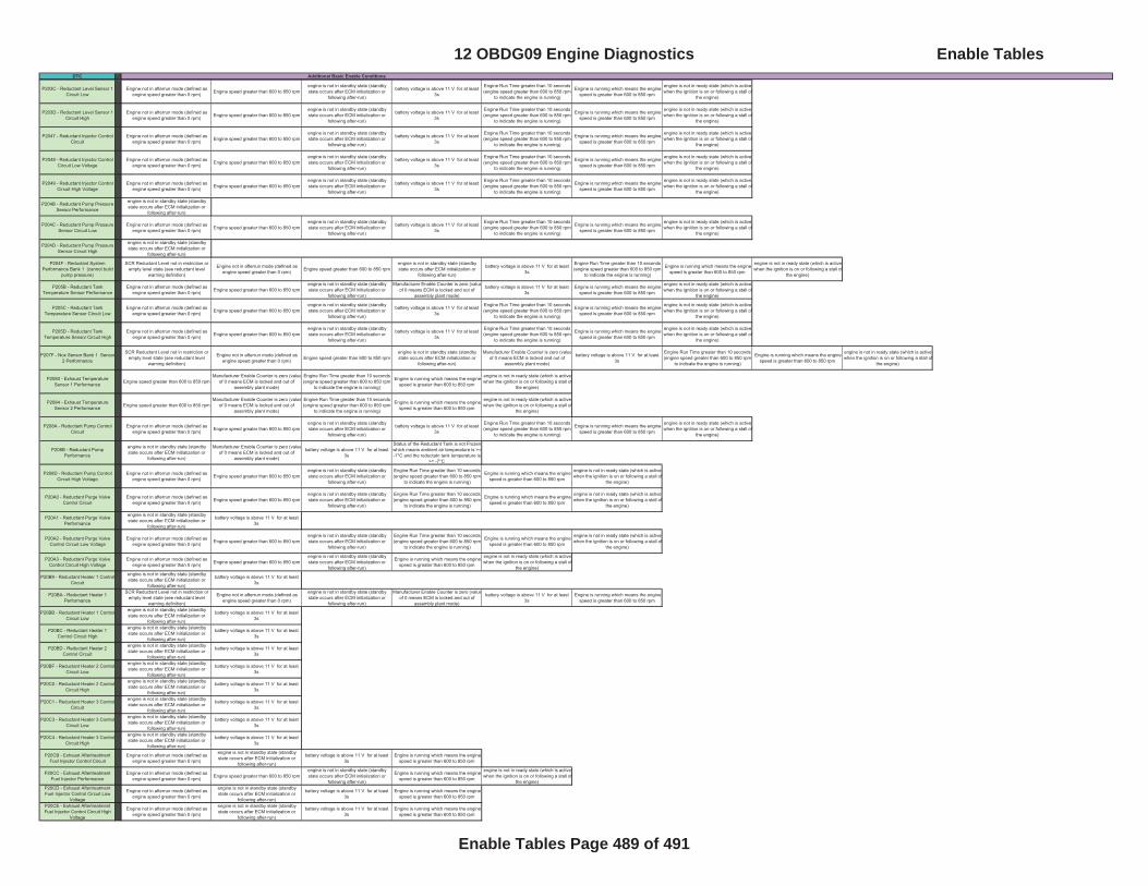
DTC Additional Basic Enable Conditions
P203C - Reductant Level Sensor 1 Circuit Low
Engine not in afterrun mode (defined as engine speed greater than 0 rpm) Engine speed greater than 600 to 850 rpm
engine is not in standby state (standby state occurs after ECM initialization or
following after-run)
battery voltage is above 11 V for at least 3s
Engine Run Time greater than 10 seconds (engine speed greater than 600 to 850 rpm
to indicate the engine is running)
Engine is running which means the engine speed is greater than 600 to 850 rpm
engine is not in ready state (which is active when the ignition is on or following a stall of
the engine)
P203D - Reductant Level Sensor 1 Circuit High
Engine not in afterrun mode (defined as engine speed greater than 0 rpm) Engine speed greater than 600 to 850 rpm
engine is not in standby state (standby state occurs after ECM initialization or
following after-run)
battery voltage is above 11 V for at least 3s
Engine Run Time greater than 10 seconds (engine speed greater than 600 to 850 rpm
to indicate the engine is running)
Engine is running which means the engine speed is greater than 600 to 850 rpm
engine is not in ready state (which is active when the ignition is on or following a stall of
the engine)
P2047 - Reductant Injector Control Circuit
Engine not in afterrun mode (defined as engine speed greater than 0 rpm) Engine speed greater than 600 to 850 rpm
engine is not in standby state (standby state occurs after ECM initialization or
following after-run)
battery voltage is above 11 V for at least 3s
Engine Run Time greater than 10 seconds (engine speed greater than 600 to 850 rpm
to indicate the engine is running)
Engine is running which means the engine speed is greater than 600 to 850 rpm
engine is not in ready state (which is active when the ignition is on or following a stall of
the engine)
P2048 - Reductant Injector Control Circuit Low Voltage
Engine not in afterrun mode (defined as engine speed greater than 0 rpm) Engine speed greater than 600 to 850 rpm
engine is not in standby state (standby state occurs after ECM initialization or
following after-run)
battery voltage is above 11 V for at least 3s
Engine Run Time greater than 10 seconds (engine speed greater than 600 to 850 rpm
to indicate the engine is running)
Engine is running which means the engine speed is greater than 600 to 850 rpm
engine is not in ready state (which is active when the ignition is on or following a stall of
the engine)
P2049 - Reductant Injector Control Circuit High Voltage
Engine not in afterrun mode (defined as engine speed greater than 0 rpm) Engine speed greater than 600 to 850 rpm
engine is not in standby state (standby state occurs after ECM initialization or
following after-run)
battery voltage is above 11 V for at least 3s
Engine Run Time greater than 10 seconds (engine speed greater than 600 to 850 rpm
to indicate the engine is running)
Engine is running which means the engine speed is greater than 600 to 850 rpm
engine is not in ready state (which is active when the ignition is on or following a stall of
the engine)
P204B - Reductant Pump Pressure Sensor Performance
engine is not in standby state (standby state occurs after ECM initialization or
following after-run)
P204C - Reductant Pump Pressure Sensor Circuit Low
Engine not in afterrun mode (defined as engine speed greater than 0 rpm) Engine speed greater than 600 to 850 rpm
engine is not in standby state (standby state occurs after ECM initialization or
following after-run)
battery voltage is above 11 V for at least 3s
Engine Run Time greater than 10 seconds (engine speed greater than 600 to 850 rpm
to indicate the engine is running)
Engine is running which means the engine speed is greater than 600 to 850 rpm
engine is not in ready state (which is active when the ignition is on or following a stall of
the engine)
P204D - Reductant Pump Pressure Sensor Circuit High
engine is not in standby state (standby state occurs after ECM initialization or
following after-run)
P204F - Reductant System Performance Bank 1 (cannot build
pump pressure)
SCR Reductant Level not in restriction or empty level state (see reductant level
warning definition)
Engine not in afterrun mode (defined as engine speed greater than 0 rpm) Engine speed greater than 600 to 850 rpm
engine is not in standby state (standby state occurs after ECM initialization or
following after-run)
battery voltage is above 11 V for at least 3s
Engine Run Time greater than 10 seconds (engine speed greater than 600 to 850 rpm
to indicate the engine is running)
Engine is running which means the engine speed is greater than 600 to 850 rpm
engine is not in ready state (which is active when the ignition is on or following a stall of
the engine)
P205B - Reductant Tank Temperature Sensor Performance
Engine not in afterrun mode (defined as engine speed greater than 0 rpm) Engine speed greater than 600 to 850 rpm
engine is not in standby state (standby state occurs after ECM initialization or
following after-run)
Manufacturer Enable Counter is zero (valueof 0 means ECM is locked and out of
assembly plant mode)
battery voltage is above 11 V for at least 3s
Engine is running which means the engine speed is greater than 600 to 850 rpm
engine is not in ready state (which is active when the ignition is on or following a stall of
the engine)
P205C - Reductant Tank Temperature Sensor Circuit Low
Engine not in afterrun mode (defined as engine speed greater than 0 rpm) Engine speed greater than 600 to 850 rpm
engine is not in standby state (standby state occurs after ECM initialization or
following after-run)
battery voltage is above 11 V for at least 3s
Engine Run Time greater than 10 seconds (engine speed greater than 600 to 850 rpm
to indicate the engine is running)
Engine is running which means the engine speed is greater than 600 to 850 rpm
engine is not in ready state (which is active when the ignition is on or following a stall of
the engine)
P205D - Reductant Tank Temperature Sensor Circuit High
Engine not in afterrun mode (defined as engine speed greater than 0 rpm) Engine speed greater than 600 to 850 rpm
engine is not in standby state (standby state occurs after ECM initialization or
following after-run)
battery voltage is above 11 V for at least 3s
Engine Run Time greater than 10 seconds (engine speed greater than 600 to 850 rpm
to indicate the engine is running)
Engine is running which means the engine speed is greater than 600 to 850 rpm
engine is not in ready state (which is active when the ignition is on or following a stall of
the engine)
P207F - Nox Sensor Bank 1 Sensor2 Performance
SCR Reductant Level not in restriction or empty level state (see reductant level
warning definition)
Engine not in afterrun mode (defined as engine speed greater than 0 rpm) Engine speed greater than 600 to 850 rpm
engine is not in standby state (standby state occurs after ECM initialization or
following after-run)
Manufacturer Enable Counter is zero (valueof 0 means ECM is locked and out of
assembly plant mode)
battery voltage is above 11 V for at least 3s
Engine Run Time greater than 10 seconds (engine speed greater than 600 to 850 rpm
to indicate the engine is running)
Engine is running which means the engine speed is greater than 600 to 850 rpm
engine is not in ready state (which is active when the ignition is on or following a stall of
the engine)
P2080 - Exhaust Temperature Sensor 1 Performance Engine speed greater than 600 to 850 rpm
Manufacturer Enable Counter is zero (valueof 0 means ECM is locked and out of
assembly plant mode)
Engine Run Time greater than 10 seconds (engine speed greater than 600 to 850 rpm
to indicate the engine is running)
Engine is running which means the engine speed is greater than 600 to 850 rpm
engine is not in ready state (which is active when the ignition is on or following a stall of
the engine)
P2084 - Exhaust Temperature Sensor 2 Performance Engine speed greater than 600 to 850 rpm
Manufacturer Enable Counter is zero (valueof 0 means ECM is locked and out of
assembly plant mode)
Engine Run Time greater than 10 seconds (engine speed greater than 600 to 850 rpm
to indicate the engine is running)
Engine is running which means the engine speed is greater than 600 to 850 rpm
engine is not in ready state (which is active when the ignition is on or following a stall of
the engine)
P208A - Reductant Pump Control Circuit
Engine not in afterrun mode (defined as engine speed greater than 0 rpm) Engine speed greater than 600 to 850 rpm
engine is not in standby state (standby state occurs after ECM initialization or
following after-run)
battery voltage is above 11 V for at least 3s
Engine Run Time greater than 10 seconds (engine speed greater than 600 to 850 rpm
to indicate the engine is running)
Engine is running which means the engine speed is greater than 600 to 850 rpm
engine is not in ready state (which is active when the ignition is on or following a stall of
the engine)
P208B - Reductant Pump Performance
engine is not in standby state (standby state occurs after ECM initialization or
following after-run)
Manufacturer Enable Counter is zero (valueof 0 means ECM is locked and out of
assembly plant mode)
battery voltage is above 11 V for at least 3s
Status of the Reductant Tank is not Frozen which means ambient air temperature is >= -7°C and the reductatn tank temperature is
>= -7°C
P208D - Reductant Pump Control Circuit High Voltage
Engine not in afterrun mode (defined as engine speed greater than 0 rpm) Engine speed greater than 600 to 850 rpm
engine is not in standby state (standby state occurs after ECM initialization or
following after-run)
Engine Run Time greater than 10 seconds (engine speed greater than 600 to 850 rpm
to indicate the engine is running)
Engine is running which means the engine speed is greater than 600 to 850 rpm
engine is not in ready state (which is active when the ignition is on or following a stall of
the engine)
P20A0 - Reductant Purge Valve Control Circuit
Engine not in afterrun mode (defined as engine speed greater than 0 rpm) Engine speed greater than 600 to 850 rpm
engine is not in standby state (standby state occurs after ECM initialization or
following after-run)
Engine Run Time greater than 10 seconds (engine speed greater than 600 to 850 rpm
to indicate the engine is running)
Engine is running which means the engine speed is greater than 600 to 850 rpm
engine is not in ready state (which is active when the ignition is on or following a stall of
the engine)
P20A1 - Reductant Purge Valve Performance
engine is not in standby state (standby state occurs after ECM initialization or
following after-run)
battery voltage is above 11 V for at least 3s
P20A2 - Reductant Purge Valve Control Circuit Low Voltage
Engine not in afterrun mode (defined as engine speed greater than 0 rpm) Engine speed greater than 600 to 850 rpm
engine is not in standby state (standby state occurs after ECM initialization or
following after-run)
Engine Run Time greater than 10 seconds (engine speed greater than 600 to 850 rpm
to indicate the engine is running)
Engine is running which means the engine speed is greater than 600 to 850 rpm
engine is not in ready state (which is active when the ignition is on or following a stall of
the engine)
P20A3 - Reductant Purge Valve Control Circuit High Voltage
Engine not in afterrun mode (defined as engine speed greater than 0 rpm) Engine speed greater than 600 to 850 rpm
engine is not in standby state (standby state occurs after ECM initialization or
following after-run)
Engine is running which means the engine speed is greater than 600 to 850 rpm
engine is not in ready state (which is active when the ignition is on or following a stall of
the engine)
P20B9 - Reductant Heater 1 Control Circuit
engine is not in standby state (standby state occurs after ECM initialization or
following after-run)
battery voltage is above 11 V for at least 3s
P20BA - Reductant Heater 1 Performance
SCR Reductant Level not in restriction or empty level state (see reductant level
warning definition)
Engine not in afterrun mode (defined as engine speed greater than 0 rpm)
engine is not in standby state (standby state occurs after ECM initialization or
following after-run)
Manufacturer Enable Counter is zero (valueof 0 means ECM is locked and out of
assembly plant mode)
battery voltage is above 11 V for at least 3s
Engine is running which means the engine speed is greater than 600 to 850 rpm
P20BB - Reductant Heater 1 ControlCircuit Low
engine is not in standby state (standby state occurs after ECM initialization or
following after-run)
battery voltage is above 11 V for at least 3s
P20BC - Reductant Heater 1 Control Circuit High
engine is not in standby state (standby state occurs after ECM initialization or
following after-run)
battery voltage is above 11 V for at least 3s
P20BD - Reductant Heater 2 Control Circuit
engine is not in standby state (standby state occurs after ECM initialization or
following after-run)
battery voltage is above 11 V for at least 3s
P20BF - Reductant Heater 2 Control Circuit Low
engine is not in standby state (standby state occurs after ECM initialization or
following after-run)
battery voltage is above 11 V for at least 3s
P20C0 - Reductant Heater 2 Control Circuit High
engine is not in standby state (standby state occurs after ECM initialization or
following after-run)
battery voltage is above 11 V for at least 3s
P20C1 - Reductant Heater 3 Control Circuit
engine is not in standby state (standby state occurs after ECM initialization or
following after-run)
battery voltage is above 11 V for at least 3s
P20C3 - Reductant Heater 3 Control Circuit Low
engine is not in standby state (standby state occurs after ECM initialization or
following after-run)
battery voltage is above 11 V for at least 3s
P20C4 - Reductant Heater 3 Control Circuit High
engine is not in standby state (standby state occurs after ECM initialization or
following after-run)
battery voltage is above 11 V for at least 3s
P20CB - Exhaust Aftertreatment Fuel Injector Control Circuit
Engine not in afterrun mode (defined as engine speed greater than 0 rpm)
engine is not in standby state (standby state occurs after ECM initialization or
following after-run)
battery voltage is above 11 V for at least 3s
Engine is running which means the engine speed is greater than 600 to 850 rpm
P20CC - Exhaust Aftertreatment Fuel Injector Performance
Engine not in afterrun mode (defined as engine speed greater than 0 rpm) Engine speed greater than 600 to 850 rpm
engine is not in standby state (standby state occurs after ECM initialization or
following after-run)
Engine is running which means the engine speed is greater than 600 to 850 rpm
engine is not in ready state (which is active when the ignition is on or following a stall of
the engine)P20CD - Exhaust Aftertreatment Fuel Injector Control Circuit Low
Voltage
Engine not in afterrun mode (defined as engine speed greater than 0 rpm)
engine is not in standby state (standby state occurs after ECM initialization or
following after-run)
battery voltage is above 11 V for at least 3s
Engine is running which means the engine speed is greater than 600 to 850 rpm
P20CE - Exhaust Aftertreatment Fuel Injector Control Circuit High
Voltage
Engine not in afterrun mode (defined as engine speed greater than 0 rpm)
engine is not in standby state (standby state occurs after ECM initialization or
following after-run)
battery voltage is above 11 V for at least 3s
Engine is running which means the engine speed is greater than 600 to 850 rpm
12 OBDG09 Engine Diagnostics Enable Tables
Enable Tables Page 489 of 491
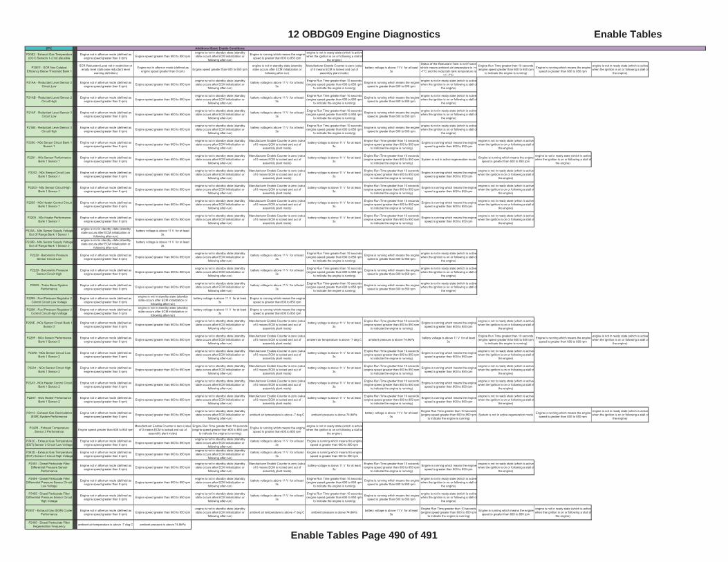
DTC Additional Basic Enable Conditions
P20E2 - Exhaust Gas Temperature (EGT) Sensors 1-2 not plausible
Engine not in afterrun mode (defined as engine speed greater than 0 rpm) Engine speed greater than 600 to 850 rpm
engine is not in standby state (standby state occurs after ECM initialization or
following after-run)
Engine is running which means the engine speed is greater than 600 to 850 rpm
engine is not in ready state (which is active when the ignition is on or following a stall of
the engine)
P20EE - SCR Nox Catalyst Efficiency Below Threshold Bank 1
SCR Reductant Level not in restriction or empty level state (see reductant level
warning definition)
Engine not in afterrun mode (defined as engine speed greater than 0 rpm) Engine speed greater than 600 to 850 rpm
engine is not in standby state (standby state occurs after ECM initialization or
following after-run)
Manufacturer Enable Counter is zero (valueof 0 means ECM is locked and out of
assembly plant mode)
battery voltage is above 11 V for at least 3s
Status of the Reductant Tank is not Frozen which means ambient air temperature is >= -7°C and the reductatn tank temperature is
>= -7°C
Engine Run Time greater than 10 seconds (engine speed greater than 600 to 850 rpm
to indicate the engine is running)
Engine is running which means the engine speed is greater than 600 to 850 rpm
engine is not in ready state (which is active when the ignition is on or following a stall of
the engine)
P21AA - Reductant Level Sensor 2 Circuit Low
Engine not in afterrun mode (defined as engine speed greater than 0 rpm) Engine speed greater than 600 to 850 rpm
engine is not in standby state (standby state occurs after ECM initialization or
following after-run)
battery voltage is above 11 V for at least 3s
Engine Run Time greater than 10 seconds (engine speed greater than 600 to 850 rpm
to indicate the engine is running)
Engine is running which means the engine speed is greater than 600 to 850 rpm
engine is not in ready state (which is active when the ignition is on or following a stall of
the engine)
P21AB - Reductant Level Sensor 2 Circuit High
Engine not in afterrun mode (defined as engine speed greater than 0 rpm) Engine speed greater than 600 to 850 rpm
engine is not in standby state (standby state occurs after ECM initialization or
following after-run)
battery voltage is above 11 V for at least 3s
Engine Run Time greater than 10 seconds (engine speed greater than 600 to 850 rpm
to indicate the engine is running)
Engine is running which means the engine speed is greater than 600 to 850 rpm
engine is not in ready state (which is active when the ignition is on or following a stall of
the engine)
P21AF - Reductant Level Sensor 3 Circuit Low
Engine not in afterrun mode (defined as engine speed greater than 0 rpm) Engine speed greater than 600 to 850 rpm
engine is not in standby state (standby state occurs after ECM initialization or
following after-run)
battery voltage is above 11 V for at least 3s
Engine Run Time greater than 10 seconds (engine speed greater than 600 to 850 rpm
to indicate the engine is running)
Engine is running which means the engine speed is greater than 600 to 850 rpm
engine is not in ready state (which is active when the ignition is on or following a stall of
the engine)
P21B0 - Reductant Level Sensor 3 Circuit High
Engine not in afterrun mode (defined as engine speed greater than 0 rpm) Engine speed greater than 600 to 850 rpm
engine is not in standby state (standby state occurs after ECM initialization or
following after-run)
battery voltage is above 11 V for at least 3s
Engine Run Time greater than 10 seconds (engine speed greater than 600 to 850 rpm
to indicate the engine is running)
Engine is running which means the engine speed is greater than 600 to 850 rpm
engine is not in ready state (which is active when the ignition is on or following a stall of
the engine)
P2200 - N0x Sensor Circuit Bank 1 Sensor 1
Engine not in afterrun mode (defined as engine speed greater than 0 rpm) Engine speed greater than 600 to 850 rpm
engine is not in standby state (standby state occurs after ECM initialization or
following after-run)
Manufacturer Enable Counter is zero (valueof 0 means ECM is locked and out of
assembly plant mode)
battery voltage is above 11 V for at least 3s
Engine Run Time greater than 10 seconds (engine speed greater than 600 to 850 rpm
to indicate the engine is running)
Engine is running which means the engine speed is greater than 600 to 850 rpm
engine is not in ready state (which is active when the ignition is on or following a stall of
the engine)
P2201 - N0x Sensor Performance Bank 1 Sensor 1
Engine not in afterrun mode (defined as engine speed greater than 0 rpm) Engine speed greater than 600 to 850 rpm
engine is not in standby state (standby state occurs after ECM initialization or
following after-run)
Manufacturer Enable Counter is zero (valueof 0 means ECM is locked and out of
assembly plant mode)
battery voltage is above 11 V for at least 3s
Engine Run Time greater than 10 seconds (engine speed greater than 600 to 850 rpm
to indicate the engine is running)System is not in active regeneration mode Engine is running which means the engine
speed is greater than 600 to 850 rpm
engine is not in ready state (which is active when the ignition is on or following a stall of
the engine)
P2202 - N0x Sensor Circuit Low Bank 1 Sensor 1
Engine not in afterrun mode (defined as engine speed greater than 0 rpm) Engine speed greater than 600 to 850 rpm
engine is not in standby state (standby state occurs after ECM initialization or
following after-run)
Manufacturer Enable Counter is zero (valueof 0 means ECM is locked and out of
assembly plant mode)
battery voltage is above 11 V for at least 3s
Engine Run Time greater than 10 seconds (engine speed greater than 600 to 850 rpm
to indicate the engine is running)
Engine is running which means the engine speed is greater than 600 to 850 rpm
engine is not in ready state (which is active when the ignition is on or following a stall of
the engine)
P2203 - N0x Sensor Circuit High Bank 1 Sensor 1
Engine not in afterrun mode (defined as engine speed greater than 0 rpm) Engine speed greater than 600 to 850 rpm
engine is not in standby state (standby state occurs after ECM initialization or
following after-run)
Manufacturer Enable Counter is zero (valueof 0 means ECM is locked and out of
assembly plant mode)
battery voltage is above 11 V for at least 3s
Engine Run Time greater than 10 seconds (engine speed greater than 600 to 850 rpm
to indicate the engine is running)
Engine is running which means the engine speed is greater than 600 to 850 rpm
engine is not in ready state (which is active when the ignition is on or following a stall of
the engine)
P2205 - N0x Heater Control Circuit Bank 1 Sensor 1
Engine not in afterrun mode (defined as engine speed greater than 0 rpm) Engine speed greater than 600 to 850 rpm
engine is not in standby state (standby state occurs after ECM initialization or
following after-run)
Manufacturer Enable Counter is zero (valueof 0 means ECM is locked and out of
assembly plant mode)
battery voltage is above 11 V for at least 3s
Engine Run Time greater than 10 seconds (engine speed greater than 600 to 850 rpm
to indicate the engine is running)
Engine is running which means the engine speed is greater than 600 to 850 rpm
engine is not in ready state (which is active when the ignition is on or following a stall of
the engine)
P2209 - N0x Heater Performance Bank 1 Sensor 1
Engine not in afterrun mode (defined as engine speed greater than 0 rpm) Engine speed greater than 600 to 850 rpm
engine is not in standby state (standby state occurs after ECM initialization or
following after-run)
Manufacturer Enable Counter is zero (valueof 0 means ECM is locked and out of
assembly plant mode)
battery voltage is above 11 V for at least 3s
Engine Run Time greater than 10 seconds (engine speed greater than 600 to 850 rpm
to indicate the engine is running)
Engine is running which means the engine speed is greater than 600 to 850 rpm
engine is not in ready state (which is active when the ignition is on or following a stall of
the engine)
P220A - N0x Sensor Supply VoltageOut Of Range Bank 1 Sensor 1
engine is not in standby state (standby state occurs after ECM initialization or
following after-run)
battery voltage is above 11 V for at least 3s
P220B - N0x Sensor Supply VoltageOut Of Range Bank 1 Sensor 2
engine is not in standby state (standby state occurs after ECM initialization or
following after-run)
battery voltage is above 11 V for at least 3s
P2228 - Barometric Pressure Sensor Circuit Low
Engine not in afterrun mode (defined as engine speed greater than 0 rpm) Engine speed greater than 600 to 850 rpm
engine is not in standby state (standby state occurs after ECM initialization or
following after-run)
battery voltage is above 11 V for at least 3s
Engine Run Time greater than 10 seconds (engine speed greater than 600 to 850 rpm
to indicate the engine is running)
Engine is running which means the engine speed is greater than 600 to 850 rpm
engine is not in ready state (which is active when the ignition is on or following a stall of
the engine)
P2229 - Barometric Pressure Sensor Circuit High
Engine not in afterrun mode (defined as engine speed greater than 0 rpm) Engine speed greater than 600 to 850 rpm
engine is not in standby state (standby state occurs after ECM initialization or
following after-run)
battery voltage is above 11 V for at least 3s
Engine Run Time greater than 10 seconds (engine speed greater than 600 to 850 rpm
to indicate the engine is running)
Engine is running which means the engine speed is greater than 600 to 850 rpm
engine is not in ready state (which is active when the ignition is on or following a stall of
the engine)
P2263 - Turbo Boost System Performance
Engine not in afterrun mode (defined as engine speed greater than 0 rpm) Engine speed greater than 600 to 850 rpm
engine is not in standby state (standby state occurs after ECM initialization or
following after-run)
battery voltage is above 11 V for at least 3s
Engine Run Time greater than 10 seconds (engine speed greater than 600 to 850 rpm
to indicate the engine is running)
Engine is running which means the engine speed is greater than 600 to 850 rpm
engine is not in ready state (which is active when the ignition is on or following a stall of
the engine)
P2295 - Fuel Pressure Regulator 2 Control Circuit Low Voltage
Engine not in afterrun mode (defined as engine speed greater than 0 rpm)
engine is not in standby state (standby state occurs after ECM initialization or
following after-run)
battery voltage is above 11 V for at least 3s
Engine is running which means the engine speed is greater than 600 to 850 rpm
P2296 - Fuel Pressure Regulator 2 Control Circuit High Voltage
Engine not in afterrun mode (defined as engine speed greater than 0 rpm)
engine is not in standby state (standby state occurs after ECM initialization or
following after-run)
battery voltage is above 11 V for at least 3s
Engine is running which means the engine speed is greater than 600 to 850 rpm
P229E - NOx Sensor Circuit Bank 1 Sensor 2
Engine not in afterrun mode (defined as engine speed greater than 0 rpm) Engine speed greater than 600 to 850 rpm
engine is not in standby state (standby state occurs after ECM initialization or
following after-run)
Manufacturer Enable Counter is zero (valueof 0 means ECM is locked and out of
assembly plant mode)
battery voltage is above 11 V for at least 3s
Engine Run Time greater than 10 seconds (engine speed greater than 600 to 850 rpm
to indicate the engine is running)
Engine is running which means the engine speed is greater than 600 to 850 rpm
engine is not in ready state (which is active when the ignition is on or following a stall of
the engine)
P229F - NOx Sensor Performance Bank 1 Sensor 2
Engine not in afterrun mode (defined as engine speed greater than 0 rpm) Engine speed greater than 600 to 850 rpm
engine is not in standby state (standby state occurs after ECM initialization or
following after-run)
Manufacturer Enable Counter is zero (valueof 0 means ECM is locked and out of
assembly plant mode)ambient air temperature is above -7 deg C ambient pressure is above 74.8kPa battery voltage is above 11 V for at least
3s
Engine Run Time greater than 10 seconds (engine speed greater than 600 to 850 rpm
to indicate the engine is running)
Engine is running which means the engine speed is greater than 600 to 850 rpm
engine is not in ready state (which is active when the ignition is on or following a stall of
the engine)
P22A0 - NOx Sensor Circuit Low Bank 1 Sensor 2
Engine not in afterrun mode (defined as engine speed greater than 0 rpm) Engine speed greater than 600 to 850 rpm
engine is not in standby state (standby state occurs after ECM initialization or
following after-run)
Manufacturer Enable Counter is zero (valueof 0 means ECM is locked and out of
assembly plant mode)
battery voltage is above 11 V for at least 3s
Engine Run Time greater than 10 seconds (engine speed greater than 600 to 850 rpm
to indicate the engine is running)
Engine is running which means the engine speed is greater than 600 to 850 rpm
engine is not in ready state (which is active when the ignition is on or following a stall of
the engine)
P22A1 - NOx Sensor Circuit High Bank 1 Sensor 2
Engine not in afterrun mode (defined as engine speed greater than 0 rpm) Engine speed greater than 600 to 850 rpm
engine is not in standby state (standby state occurs after ECM initialization or
following after-run)
Manufacturer Enable Counter is zero (valueof 0 means ECM is locked and out of
assembly plant mode)
battery voltage is above 11 V for at least 3s
Engine Run Time greater than 10 seconds (engine speed greater than 600 to 850 rpm
to indicate the engine is running)
Engine is running which means the engine speed is greater than 600 to 850 rpm
engine is not in ready state (which is active when the ignition is on or following a stall of
the engine)
P22A3 - NOx Heater Control Circuit Bank 1 Sensor 2
Engine not in afterrun mode (defined as engine speed greater than 0 rpm) Engine speed greater than 600 to 850 rpm
engine is not in standby state (standby state occurs after ECM initialization or
following after-run)
Manufacturer Enable Counter is zero (valueof 0 means ECM is locked and out of
assembly plant mode)
battery voltage is above 11 V for at least 3s
Engine Run Time greater than 10 seconds (engine speed greater than 600 to 850 rpm
to indicate the engine is running)
Engine is running which means the engine speed is greater than 600 to 850 rpm
engine is not in ready state (which is active when the ignition is on or following a stall of
the engine)
P22A7 - NOx Heater Performance Bank 1 Sensor 2
Engine not in afterrun mode (defined as engine speed greater than 0 rpm) Engine speed greater than 600 to 850 rpm
engine is not in standby state (standby state occurs after ECM initialization or
following after-run)
Manufacturer Enable Counter is zero (valueof 0 means ECM is locked and out of
assembly plant mode)
battery voltage is above 11 V for at least 3s
Engine Run Time greater than 10 seconds (engine speed greater than 600 to 850 rpm
to indicate the engine is running)
Engine is running which means the engine speed is greater than 600 to 850 rpm
engine is not in ready state (which is active when the ignition is on or following a stall of
the engine)
P2413 - Exhaust Gas Recirculation (EGR) System Performance
Engine not in afterrun mode (defined as engine speed greater than 0 rpm) Engine speed greater than 600 to 850 rpm
engine is not in standby state (standby state occurs after ECM initialization or
following after-run)ambient air temperature is above -7 deg C ambient pressure is above 74.8kPa battery voltage is above 11 V for at least
3s
Engine Run Time greater than 10 seconds (engine speed greater than 600 to 850 rpm
to indicate the engine is running)System is not in active regeneration mode Engine is running which means the engine
speed is greater than 600 to 850 rpm
engine is not in ready state (which is active when the ignition is on or following a stall of
the engine)
P242B - Exhaust Temperature Sensor 3 Performance Engine speed greater than 600 to 850 rpm
Manufacturer Enable Counter is zero (valueof 0 means ECM is locked and out of
assembly plant mode)
Engine Run Time greater than 10 seconds (engine speed greater than 600 to 850 rpm
to indicate the engine is running)
Engine is running which means the engine speed is greater than 600 to 850 rpm
engine is not in ready state (which is active when the ignition is on or following a stall of
the engine)
P242C - Exhaust Gas Temperature (EGT) Sensor 3 Circuit Low Voltage
Engine not in afterrun mode (defined as engine speed greater than 0 rpm) Engine speed greater than 600 to 850 rpm
engine is not in standby state (standby state occurs after ECM initialization or
following after-run)
battery voltage is above 11 V for at least 3s
Engine is running which means the engine speed is greater than 600 to 850 rpm
P242D - Exhaust Gas Temperature (EGT) Sensor 3 Circuit High Voltage
Engine not in afterrun mode (defined as engine speed greater than 0 rpm) Engine speed greater than 600 to 850 rpm
engine is not in standby state (standby state occurs after ECM initialization or
following after-run)
battery voltage is above 11 V for at least 3s
Engine is running which means the engine speed is greater than 600 to 850 rpm
P2453 - Diesel Particulate Filter Differential Pressure Sensor
Performance
Engine not in afterrun mode (defined as engine speed greater than 0 rpm) Engine speed greater than 600 to 850 rpm
engine is not in standby state (standby state occurs after ECM initialization or
following after-run)
Manufacturer Enable Counter is zero (valueof 0 means ECM is locked and out of
assembly plant mode)
battery voltage is above 11 V for at least 3s
Engine Run Time greater than 10 seconds (engine speed greater than 600 to 850 rpm
to indicate the engine is running)
Engine is running which means the engine speed is greater than 600 to 850 rpm
engine is not in ready state (which is active when the ignition is on or following a stall of
the engine)
P2454 - Diesel Particulate Filter Differential Pressure Sensor Circuit
Low Voltage
Engine not in afterrun mode (defined as engine speed greater than 0 rpm) Engine speed greater than 600 to 850 rpm
engine is not in standby state (standby state occurs after ECM initialization or
following after-run)
battery voltage is above 11 V for at least 3s
Engine Run Time greater than 10 seconds (engine speed greater than 600 to 850 rpm
to indicate the engine is running)
Engine is running which means the engine speed is greater than 600 to 850 rpm
engine is not in ready state (which is active when the ignition is on or following a stall of
the engine)
P2455 - Diesel Particulate Filter Differential Pressure Sensor Circuit
High Voltage
Engine not in afterrun mode (defined as engine speed greater than 0 rpm) Engine speed greater than 600 to 850 rpm
engine is not in standby state (standby state occurs after ECM initialization or
following after-run)
battery voltage is above 11 V for at least 3s
Engine Run Time greater than 10 seconds (engine speed greater than 600 to 850 rpm
to indicate the engine is running)
Engine is running which means the engine speed is greater than 600 to 850 rpm
engine is not in ready state (which is active when the ignition is on or following a stall of
the engine)
P2457 - Exhaust Gas (EGR) Cooler Performance
Engine not in afterrun mode (defined as engine speed greater than 0 rpm) Engine speed greater than 600 to 850 rpm
engine is not in standby state (standby state occurs after ECM initialization or
following after-run)ambient air temperature is above -7 deg C ambient pressure is above 74.8kPa battery voltage is above 11 V for at least
3s
Engine Run Time greater than 10 seconds (engine speed greater than 600 to 850 rpm
to indicate the engine is running)
Engine is running which means the engine speed is greater than 600 to 850 rpm
engine is not in ready state (which is active when the ignition is on or following a stall of
the engine)
P2459 - Diesel Particulate Filter Regeneration Frequency ambient air temperature is above -7 deg C ambient pressure is above 74.8kPa
12 OBDG09 Engine Diagnostics Enable Tables
Enable Tables Page 490 of 491
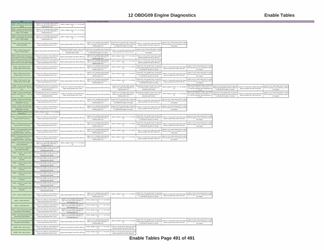
DTC Additional Basic Enable ConditionsP245A - Exhaust Gas Recirculation (EGR) Cooler Bypass Valve Control
Circuit
engine is not in standby state (standby state occurs after ECM initialization or
following after-run)
battery voltage is above 11 V for at least 3s
P245C - Exhaust Gas Recirculation (EGR) Cooler Bypass Valve Control
Circuit 1 Low Voltage
engine is not in standby state (standby state occurs after ECM initialization or
following after-run)
battery voltage is above 11 V for at least 3s
P245D - Exhaust Gas Recirculation (EGR) Cooler Bypass Valve Control
Circuit 1 High Voltage
engine is not in standby state (standby state occurs after ECM initialization or
following after-run)
battery voltage is above 11 V for at least 3s
P2463 - Diesel Particulate Filter - Soot Accumulation
Engine not in afterrun mode (defined as engine speed greater than 0 rpm) Engine speed greater than 600 to 850 rpm
engine is not in standby state (standby state occurs after ECM initialization or
following after-run)
Engine Run Time greater than 10 seconds (engine speed greater than 600 to 850 rpm
to indicate the engine is running)
Engine is running which means the engine speed is greater than 600 to 850 rpm
engine is not in ready state (which is active when the ignition is on or following a stall of
the engine)
P246F - Exhaust Temperature Sensor 4 Performance Engine speed greater than 600 to 850 rpm
Manufacturer Enable Counter is zero (valueof 0 means ECM is locked and out of
assembly plant mode)
Engine Run Time greater than 10 seconds (engine speed greater than 600 to 850 rpm
to indicate the engine is running)
Engine is running which means the engine speed is greater than 600 to 850 rpm
engine is not in ready state (which is active when the ignition is on or following a stall of
the engine)
P2470 - Exhaust Gas Temperature (EGT) Sensor 4 Circuit Low Voltage
Engine not in afterrun mode (defined as engine speed greater than 0 rpm) Engine speed greater than 600 to 850 rpm
engine is not in standby state (standby state occurs after ECM initialization or
following after-run)
battery voltage is above 11 V for at least 3s
Engine is running which means the engine speed is greater than 600 to 850 rpm
P2471 - Exhaust Gas Temperature (EGT) Sensor 4 Circuit High Voltage
Engine not in afterrun mode (defined as engine speed greater than 0 rpm) Engine speed greater than 600 to 850 rpm
engine is not in standby state (standby state occurs after ECM initialization or
following after-run)
battery voltage is above 11 V for at least 3s
Engine is running which means the engine speed is greater than 600 to 850 rpm
P2493 - EGR Cooler BY Pass Position Sensor Performance
Engine not in afterrun mode (defined as engine speed greater than 0 rpm) Engine speed greater than 600 to 850 rpm
engine is not in standby state (standby state occurs after ECM initialization or
following after-run)
battery voltage is above 11 V for at least 3s
Engine Run Time greater than 10 seconds (engine speed greater than 600 to 850 rpm
to indicate the engine is running)
Engine is running which means the engine speed is greater than 600 to 850 rpm
engine is not in ready state (which is active when the ignition is on or following a stall of
the engine)
P2494 - EGR Cooler BY Pass Position Sensor Circuit Low
Engine not in afterrun mode (defined as engine speed greater than 0 rpm) Engine speed greater than 600 to 850 rpm
engine is not in standby state (standby state occurs after ECM initialization or
following after-run)
battery voltage is above 11 V for at least 3s
Engine Run Time greater than 10 seconds (engine speed greater than 600 to 850 rpm
to indicate the engine is running)
Engine is running which means the engine speed is greater than 600 to 850 rpm
engine is not in ready state (which is active when the ignition is on or following a stall of
the engine)
P2495 - EGR Cooler BY Pass Position Sensor Circuit High
Engine not in afterrun mode (defined as engine speed greater than 0 rpm) Engine speed greater than 600 to 850 rpm
engine is not in standby state (standby state occurs after ECM initialization or
following after-run)
battery voltage is above 11 V for at least 3s
Engine Run Time greater than 10 seconds (engine speed greater than 600 to 850 rpm
to indicate the engine is running)
Engine is running which means the engine speed is greater than 600 to 850 rpm
engine is not in ready state (which is active when the ignition is on or following a stall of
the engine)
P249D - Closed Loop Reductant Injection Control At Limit - Flow Too
Low
SCR Reductant Level not in restriction or empty level state (see reductant level
warning definition)
Engine not in afterrun mode (defined as engine speed greater than 0 rpm) Engine speed greater than 600 to 850 rpm
engine is not in standby state (standby state occurs after ECM initialization or
following after-run)
Manufacturer Enable Counter is zero (valueof 0 means ECM is locked and out of
assembly plant mode)
battery voltage is above 11 V for at least 3s
Status of the Reductant Tank is not Frozen which means ambient air temperature is >= -7°C and the reductatn tank temperature is
>= -7°C
Engine Run Time greater than 10 seconds (engine speed greater than 600 to 850 rpm
to indicate the engine is running)
Engine is running which means the engine speed is greater than 600 to 850 rpm
engine is not in ready state (which is active when the ignition is on or following a stall of
the engine)
P249E - Closed Loop Reductant Injection Control At Limit - Flow Too
High
SCR Reductant Level not in restriction or empty level state (see reductant level
warning definition)
Engine not in afterrun mode (defined as engine speed greater than 0 rpm) Engine speed greater than 600 to 850 rpm
engine is not in standby state (standby state occurs after ECM initialization or
following after-run)
Manufacturer Enable Counter is zero (valueof 0 means ECM is locked and out of
assembly plant mode)
battery voltage is above 11 V for at least 3s
Status of the Reductant Tank is not Frozen which means ambient air temperature is >= -7°C and the reductatn tank temperature is
>= -7°C
Engine Run Time greater than 10 seconds (engine speed greater than 600 to 850 rpm
to indicate the engine is running)
Engine is running which means the engine speed is greater than 600 to 850 rpm
engine is not in ready state (which is active when the ignition is on or following a stall of
the engine)
P24A0 - Closed Loop Particulate Filter Regeneration Control At Limit -
Temperature Too Low
Engine not in afterrun mode (defined as engine speed greater than 0 rpm) Engine speed greater than 600 to 850 rpm
engine is not in standby state (standby state occurs after ECM initialization or
following after-run)
Engine Run Time greater than 10 seconds (engine speed greater than 600 to 850 rpm
to indicate the engine is running)
Engine is running which means the engine speed is greater than 600 to 850 rpm
engine is not in ready state (which is active when the ignition is on or following a stall of
the engine)
P24A1 - Closed Loop Particulate Filter Regeneration Control At Limit -
Temperature Too High
Engine not in afterrun mode (defined as engine speed greater than 0 rpm) Engine speed greater than 600 to 850 rpm
engine is not in standby state (standby state occurs after ECM initialization or
following after-run)
Engine Run Time greater than 10 seconds (engine speed greater than 600 to 850 rpm
to indicate the engine is running)
Engine is running which means the engine speed is greater than 600 to 850 rpm
engine is not in ready state (which is active when the ignition is on or following a stall of
the engine)
P2510 - ECM Power Relay Circuit Performance
battery voltage is above 11 V for at least 3s
P2564 - Turbocharger Boost Control Position Sensor Circuit Low
Engine not in afterrun mode (defined as engine speed greater than 0 rpm) Engine speed greater than 600 to 850 rpm
engine is not in standby state (standby state occurs after ECM initialization or
following after-run)
battery voltage is above 11 V for at least 3s
Engine Run Time greater than 10 seconds (engine speed greater than 600 to 850 rpm
to indicate the engine is running)
Engine is running which means the engine speed is greater than 600 to 850 rpm
engine is not in ready state (which is active when the ignition is on or following a stall of
the engine)
P2565 - Turbocharger Boost Control Position Sensor Circuit High
Engine not in afterrun mode (defined as engine speed greater than 0 rpm) Engine speed greater than 600 to 850 rpm
engine is not in standby state (standby state occurs after ECM initialization or
following after-run)
battery voltage is above 11 V for at least 3s
Engine Run Time greater than 10 seconds (engine speed greater than 600 to 850 rpm
to indicate the engine is running)
Engine is running which means the engine speed is greater than 600 to 850 rpm
engine is not in ready state (which is active when the ignition is on or following a stall of
the engine)
P2598 - Turbocharger Boost Control Position Sensor "A" Circuit
Range/Performance - Stuck Low
Engine not in afterrun mode (defined as engine speed greater than 0 rpm) Engine speed greater than 600 to 850 rpm
engine is not in standby state (standby state occurs after ECM initialization or
following after-run)
battery voltage is above 11 V for at least 3s
Engine is running which means the engine speed is greater than 600 to 850 rpm
engine is not in ready state (which is active when the ignition is on or following a stall of
the engine)
P2599 - Turbocharger Boost Control Position Sensor "A" Circuit
Range/Performance - Stuck High
Engine not in afterrun mode (defined as engine speed greater than 0 rpm) Engine speed greater than 600 to 850 rpm
engine is not in standby state (standby state occurs after ECM initialization or
following after-run)
battery voltage is above 11 V for at least 3s
Engine is running which means the engine speed is greater than 600 to 850 rpm
engine is not in ready state (which is active when the ignition is on or following a stall of
the engine)
P2610 - Control Module Ignition Off Timer Performance
engine is not in standby state (standby state occurs after ECM initialization or
following after-run)
battery voltage is above 11 V for at least 3s
P268A - Fuel Injector Calibration Not Programmed ECM
Manufacturer Enable Counter is zero (valueof 0 means ECM is locked and out of
assembly plant mode)
P268C - Cylinder 1 Injector Data Incorrect
Manufacturer Enable Counter is zero (valueof 0 means ECM is locked and out of
assembly plant mode)
P268D - Cylinder 2 Injector Data Incorrect
Manufacturer Enable Counter is zero (valueof 0 means ECM is locked and out of
assembly plant mode)
P268E - Cylinder 3 Injector Data Incorrect
Manufacturer Enable Counter is zero (valueof 0 means ECM is locked and out of
assembly plant mode)
P268F - Cylinder 4 Injector Data Incorrect
Manufacturer Enable Counter is zero (valueof 0 means ECM is locked and out of
assembly plant mode)
P2690 - Cylinder 5 Injector Data Incorrect
Manufacturer Enable Counter is zero (valueof 0 means ECM is locked and out of
assembly plant mode)
P2691 - Cylinder 6 Injector Data Incorrect
Manufacturer Enable Counter is zero (valueof 0 means ECM is locked and out of
assembly plant mode)
P2692 - Cylinder 7 Injector Data Incorrect
Manufacturer Enable Counter is zero (valueof 0 means ECM is locked and out of
assembly plant mode)
P2693 - Cylinder 8 Injector Data Incorrect
Manufacturer Enable Counter is zero (valueof 0 means ECM is locked and out of
assembly plant mode)
P2771 - 4wd Low Switch Circuit Engine not in afterrun mode (defined as engine speed greater than 0 rpm) Engine speed greater than 600 to 850 rpm
engine is not in standby state (standby state occurs after ECM initialization or
following after-run)
battery voltage is above 11 V for at least 3s
Engine Run Time greater than 10 seconds (engine speed greater than 600 to 850 rpm
to indicate the engine is running)
Engine is running which means the engine speed is greater than 600 to 850 rpm
engine is not in ready state (which is active when the ignition is on or following a stall of
the engine)
U0073 - CAN A BUS OFF Engine not in afterrun mode (defined as engine speed greater than 0 rpm)
engine is not in standby state (standby state occurs after ECM initialization or
following after-run)
battery voltage is above 11 V for at least 3s
U0074 - CAN B BUS OFF Engine not in afterrun mode (defined as engine speed greater than 0 rpm)
engine is not in standby state (standby state occurs after ECM initialization or
following after-run)
battery voltage is above 11 V for at least 3s
U0101 - Lost Communications With Transmission Control System
Engine not in afterrun mode (defined as engine speed greater than 0 rpm)
engine is not in standby state (standby state occurs after ECM initialization or
following after-run)
battery voltage is above 11 V for at least 3s
U0106 - Lost Communication With Glow Plug Control Module
Engine not in afterrun mode (defined as engine speed greater than 0 rpm)
engine is not in standby state (standby state occurs after ECM initialization or
following after-run)
battery voltage is above 11 V for at least 3s
U010E - Lost Communications With Reductant Control Module
Engine not in afterrun mode (defined as engine speed greater than 0 rpm) Engine speed greater than 600 to 850 rpm
engine is not in standby state (standby state occurs after ECM initialization or
following after-run)
battery voltage is above 11 V for at least 3s
Engine Run Time greater than 10 seconds (engine speed greater than 600 to 850 rpm
to indicate the engine is running)
Engine is running which means the engine speed is greater than 600 to 850 rpm
engine is not in ready state (which is active when the ignition is on or following a stall of
the engine)
U029D - N0x 1 loss of comm Engine not in afterrun mode (defined as engine speed greater than 0 rpm) Engine speed greater than 600 to 850 rpm battery voltage is above 11 V for at least
3s Engine is running which means the engine
speed is greater than 600 to 850 rpm
U029E - N0x 2 loss of comm Engine not in afterrun mode (defined as engine speed greater than 0 rpm) Engine speed greater than 600 to 850 rpm battery voltage is above 11 V for at least
3s Engine is running which means the engine
speed is greater than 600 to 850 rpm
12 OBDG09 Engine Diagnostics Enable Tables
Enable Tables Page 491 of 491