An adaptive multi-grid chemistry (AMC) model for efficient simulation of HCCI and DI engine...
32
University of Wisconsin– Engine Research Center 1 An adaptive multi-grid chemistry (AMC) model for efficient simulation of HCCI and DI engine combustion Yu Shi and Rolf D. Reitz Sponsor: Department of Energy
Transcript of An adaptive multi-grid chemistry (AMC) model for efficient simulation of HCCI and DI engine...
University of Wisconsin– Engine Research Center 1
An adaptive multi-grid chemistry (AMC) model for efficient
simulation of HCCI and DI engine combustion
Yu Shi and Rolf D. ReitzSponsor: Department of Energy

Engine Research Center 2
Outline
• Background and model description• Parametric study of the AMC model• Application in HCCI engine combustion• Application in DI engine combustion• Conclusions

Engine Research Center 3
Part 1
• Background and model description• Parametric study of the AMC model• Application in HCCI engine combustion• Application in DI engine combustion• Conclusions

Engine Research Center 4
Background
• There is a need to reduce the computational expense of practical multidimensional combustion simulationsa) Simulation of HCCI engine requires detailed chemistry, although the grid resolution can be relatively coarse.b) Simulation of DI engine requires fine meshes to achieve the resolution required by the spray and mixing models.c) The increasing application of CFD for engine design optimization is pushing the demand to reduce computation time.

Engine Research Center 5
Background
• For the current version of KIVA3v2-Chemkin, most of computing time is spent on the chemistry solver.
• Efforts of reducing computing time need to be placed on reducing the calling frequency to the chemkin solver. This can be achieved by multi-grid technique.

Engine Research Center 6
Model Description – Global MappingMapping cells to a group(2-D illustration)
Chemkin Solver
Remapping back to individual cells
Center cell
Thermodynamicallysimilar cells
Computingdomain

Engine Research Center 7
Model Description – Adaptive Neighbor MappingCenter cell
First level neighbors
Second level neighbors
Third level neighbors
Fourth level neighbors
A maximum 129 cells canbe grouped in 3-D meshes
Mapping cells to a group(2-D illustration)
Chemkin Solver
Remapping back to Individual cells
Search level is adaptively determined by temperatureinhomogeneity
Engine Research Center 8
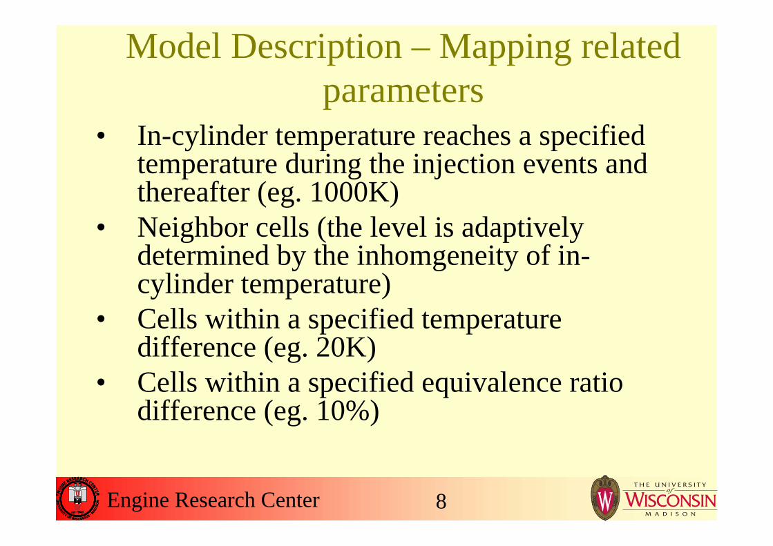
Model Description – Mapping related parameters
• In-cylinder temperature reaches a specified temperature during the injection events and thereafter (eg. 1000K)
• Neighbor cells (the level is adaptively determined by the inhomgeneity of in-cylinder temperature)
• Cells within a specified temperature difference (eg. 20K)
• Cells within a specified equivalence ratio difference (eg. 10%)

Engine Research Center 9
Model Description – Remapping Techniques
• Averaged remappingRemap group information to individual cells
• Gradient-preserving remapping *
Based on C, H numbers of cells
* Adopted from Babajimopoulos et al. International Journal of Engine Research 2005

Engine Research Center 10
Part 2
• Background and model description• Parametric study of the AMC model• Application in HCCI engine combustion• Application in DI engine combustion• Conclusions
Engine Research Center 11
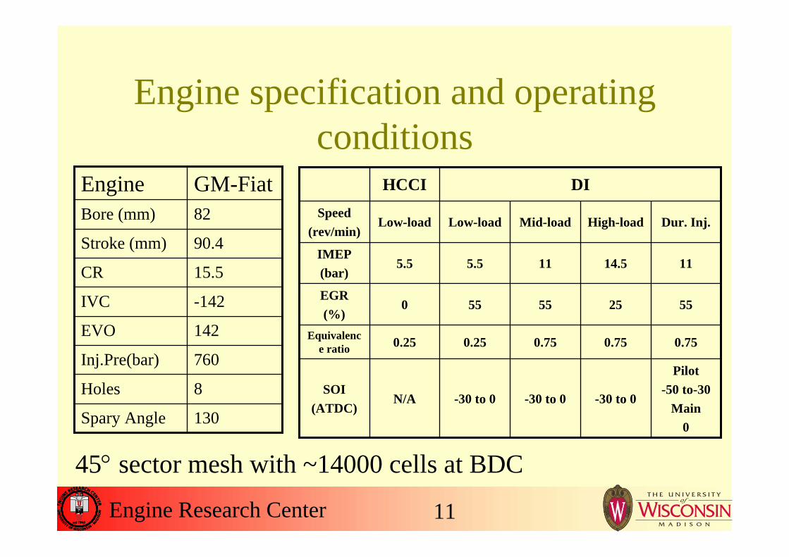
Engine specification and operating conditions
130Spary Angle
8Holes
760Inj.Pre(bar)
142EVO
-142IVC
15.5CR
90.4Stroke (mm)
82Bore (mm)
GM-FiatEngine
Pilot-50 to-30
Main0
-30 to 0-30 to 0-30 to 0N/ASOI
(ATDC)
0.750.750.750.250.25Equivalence ratio
552555550EGR(%)
1114.5115.55.5IMEP(bar)
Dur. Inj.High-loadMid-loadLow-loadLow-loadSpeed
(rev/min)
DIHCCI
45° sector mesh with ~14000 cells at BDC

Engine Research Center 12
Global Mapping VS Neighbor Mapping - HCCI
-50 -40 -30 -20 -10 0 10 20 30 40 500
2
4
6
8
10
12
14
HR
R(J
/CA
)
Pre
ssur
e(M
Pa)
Crank Angle
Full Chemistry Group - Neighbor Mapping Group - Global Mapping
0
50
100
150
200
250
300
350
400
0 50 100 15010
100
1000
10000
Global Mapping
Neighbor Mapping
Num
ber o
f Cel
ls (g
roup
s)
Crank Angle
Full Chemistry
1.530E-021.270E-021.470E-02CO (g/kg.fuel)2.899E-022.951E-023.015E-02NOx (g/kg.fuel)3.677E-053.603E-053.645E-05Soot (g/kg.fuel)2.021.519.59Comp. Time (hr)NeighborGlobalFull Chem.Methods

Engine Research Center 13
Global Mapping VS Neighbor Mapping - DI
-30 -20 -10 04
6
8
10
12
14
16
18
Full Chemistry Global Mapping
Com
puta
tiona
l Tim
e (h
r)
SOI
Adaptive Mapping Fixed 1 level Mapping Fixed 2 level Mapping Fixed 3 level Mapping Fixed 4 level Mapping
-30 -20 -10 00.2
0.3
0.4
0.5
0.6
0.7
0.8
0.9
1.0
Soo
t (g/
kg.fu
el)
SOI
-30 -20 -10 00.0
0.5
1.0
1.5
2.0
NO
x (g
/kg.
fuel
)
SOI-30 -20 -10 0
195
200
205
210
215
220
225
230
GIS
FC (g
/kW
.hr)
SOI
Computational time Soot
NOx GISFC

Engine Research Center 14
Averaged Remapping VS Gradient-preserving Remapping HCCI
-50 -40 -30 -20 -10 0 10 20 30 40 500
2
4
6
8
10
12
14 Full Chemistry Group - Gradient-preserving Remapping Group - Averaged Remapping
Pre
ssur
e (M
Pa)
Crank Angle0
50
100
150
200
250
300
350
400
1.530E-020.998E-021.470E-02CO (g/kg.fuel)2.899E-022.916E-023.015E-02NOx (g/kg.fuel)3.677E-053.602E-053.645E-05Soot (g/kg.fuel)2.021.799.59Comp. Time (hr)Gradient-pre.AveragedFull Chem.Methods

Engine Research Center 15
Averaged Remapping VS Gradient-preserving Remapping DI
-30 -20 -10 00.3
0.4
0.5
0.6
0.7
0.8
0.9
1.0
Soo
t (g/
kg.fu
el)
SOI
-30 -20 -10 00.0
0.5
1.0
1.5
2.0
NO
x (g
/kg.
fuel
))
SOI-30 -20 -10 0
180
185
190
195
200
205
210
215
220
225
230
GIS
FC (g
/kW
.hr)
SOI
-30 -20 -10 06
8
10
12
14
16
18
Com
puta
tiona
l Tim
e (h
r)
SOI
Full Chemistry Gradient-preserving remapping Averaged remapping

Engine Research Center 16
Parametric study ∆T and ∆φ
-30 -20 -10 00.3
0.4
0.5
0.6
0.7
0.8
0.9
1.0
Soot
(g/k
g.fu
el)
SOI
-30 -20 -10 00.0
0.5
1.0
1.5
2.0
NO
x (g
/kg.
fuel
)
SOI-30 -20 -10 0
195
200
205
210
215
220
225
230
GIS
FC (g
/kW
.hr)
SOI
-30 -20 -10 06
8
10
12
14
16
18
Full Chemistry Group ∆T = 30 K, ∆φ = 15% Group ∆T = 20 K, ∆φ = 10% Group ∆T = 10 K, ∆φ = 10% Group ∆T = 20 K, ∆φ = 5% Group ∆T = 10 K, ∆φ = 5%
Com
puta
tiona
l Tim
e (h
r)
SOI
Engine Research Center 17
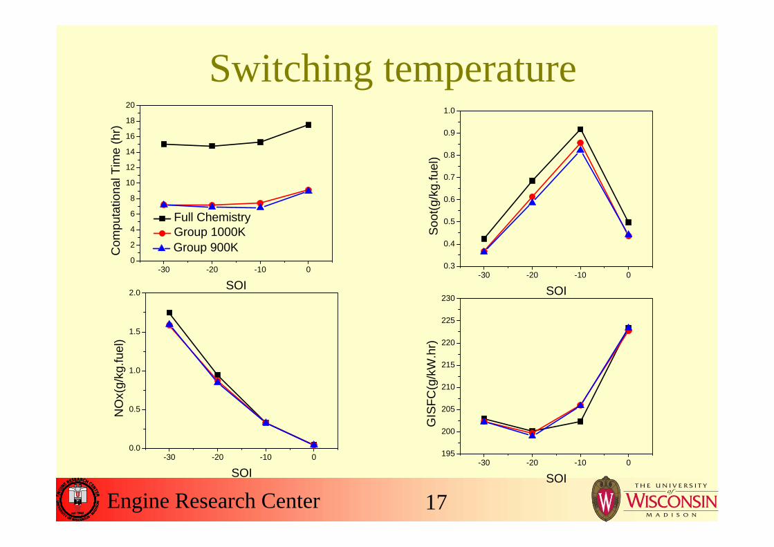
Switching temperature
-30 -20 -10 00
2
4
6
8
10
12
14
16
18
20C
ompu
tatio
nal T
ime
(hr)
SOI
Full Chemistry Group 1000K Group 900K
-30 -20 -10 00.3
0.4
0.5
0.6
0.7
0.8
0.9
1.0
Soot
(g/k
g.fu
el)
SOI
-30 -20 -10 00.0
0.5
1.0
1.5
2.0
NO
x(g/
kg.fu
el)
SOI-30 -20 -10 0
195
200
205
210
215
220
225
230
GIS
FC(g
/kW
.hr)
SOI

Engine Research Center 18
DI simulations – low load
-30 -20 -10 05
6
7
8
9
10
11
12
Full Chemistry Group
Com
puta
tiona
l Tim
e (h
r)
SOI-30 -20 -10 0
0.0000
0.0005
0.0010
0.0015
0.0020
0.0025
0.0030
0.0035
Soot
(g/k
g.fu
el)
SOI
-30 -20 -10 0
10
15
20
25
30
35
40
45
50
NO
x(g/
kg.fu
el)
SOI-30 -20 -10 0
160
165
170
175
180
185
GIS
FC(g
/kW
.hr)
SOI

Engine Research Center 19
DI simulations – high load
-30 -20 -10 05
10
15
20
25C
ompu
tatio
nal T
ime
(hr)
SOI
Full Chemistry Group
-30 -20 -10 00.0
0.5
1.0
1.5
2.0
Soot
(g/k
g.fu
el)
SOI
-30 -20 -10 00
5
10
15
20
25
NO
x(g/
kg.fu
el)
SOI-30 -20 -10 0
200
205
210
215
220
225
230
235
240
GIS
FC(g
/kW
.hr)
SOI

Engine Research Center 20
DI simulations – medium load, double injection
-50 -40 -300
5
10
15
20
Com
puta
tiona
l Tim
e (h
r)
Pilot injection SOI
Full Chemistry Group
-50 -40 -300.0
0.5
1.0
1.5
2.0
Soot
(g/k
g.fu
el)
Pilot injection SOI
-50 -40 -300.0
0.5
1.0
1.5
2.0
NO
x(g/
kg.fu
el)
Pilot injection SOI-50 -40 -30
150155160165170175180185190195200205210215220225230
GIS
FC(g
/kW
.hr)
Pilot injection SOI

Engine Research Center 21
Part 3
• Background and model description• Parametric study of the AMC model• Application in HCCI engine combustion• Application in DI engine combustion• Conclusions

Engine Research Center 22
Engine specification and experimental setup
153EVO
n-heptaneFuel
-158IVC
8.9CR
86Stroke (mm)
86Bore (mm)
HondaEngine
512459IVC Temp. (K)
42.736.7A/F
00EGR (%)
2.5972.503IMEP (bar)
1500600Speed (rev/min)
High-speedLow-speedOperatingconditions
FTIR (Fourier transform infrared spectroscopy ) measurementCell averaged temperature and H2Oconcentration are available

Engine Research Center 23
Comparison of experimental and simulated results – 1500 rev/min
-50 -40 -30 -20 -10 0 10 20 30 40 500.0
0.5
1.0
1.5
2.0
2.5
3.0 Experiment Simulation-AMC Simulation-Full Chemistry
Pres
sure
(MP
a)
Crank Angle
-100 -80 -60 -40 -20 0 20 40 60 80 1000.00
0.02
0.04
0.06
0.08
0.10 Experiment Simulation-AMC (laser path) Simulation-Full Chemistry (laser path)
H2O
(mol
e fra
ctio
n)
Crank Angle
-100 -80 -60 -40 -20 0 20 40 60 80 100400
600
800
1000
1200
1400
1600
1800
2000
Experiment Simulation-AMC
(cyl. avg.) Simulation-AMC
(laser path) Simulation-FULL
(cyl. avg.) Simulation-FULL
(laser path)
Tem
pera
ture
(K)
Crank Angle
Computer time was reduced by anorder of magnitude using AMC model with the global mapping method (50 hours to 5 hours)
ERC Primary Reference Fuel (PRF) Mech.(Ra et al. Combustion and Flame)
Cyl. avg.
laser pathlaser pathlaser path

Engine Research Center 24
Comparison of experimental and simulated results – 600 rev/min
-50 -40 -30 -20 -10 0 10 20 30 40 500.0
0.5
1.0
1.5
2.0
2.5
3.0
Pres
sure
(MP
a)
Crank Angle
Experiment Simulation-AMC Simulation-Full Chemistry
-100 -80 -60 -40 -20 0 20 40 60 80 100
400
600
800
1000
1200
1400
1600
1800
2000
2200
Tem
pera
ture
(K)
Crank Angle
Experiment Simulation-AMC
(cyl. avg.) Simulation-AMC
(laser path) Simulation-FULL
(cyl. avg.) Simulation-FULL
(laser path)
-100 -80 -60 -40 -20 0 20 40 60 80 1000.00
0.02
0.04
0.06
0.08
0.10
0.12 Experiment Simulation-AMC (laser path) Simulation-Full Chemistry (laser path)
H2O
(mol
e fra
ctio
n)
Crank Angle
Cyl. avg.
laser path

Engine Research Center 25
Boundary layer development
-100 -80 -60 -40 -20 0 20 40 60 80 100
400
600
800
1000
1200
1400
1600
1800
2000
2200
Tem
pera
ture
(K)
Crank Angle
Experiment Simulation-AMC
(cyl. avg.) Simulation-AMC
(laser path) Simulation-FULL
(cyl. avg.) Simulation-FULL
(laser path)
Courtesy of Honda R&D Co., Ltd,Prof. Sanders, Andrew Caswell

Engine Research Center 26
Part 4
• Background and model description• Parametric study of the AMC model• Application in HCCI engine combustion• Application in DI engine combustion• Conclusions
Engine Research Center 27
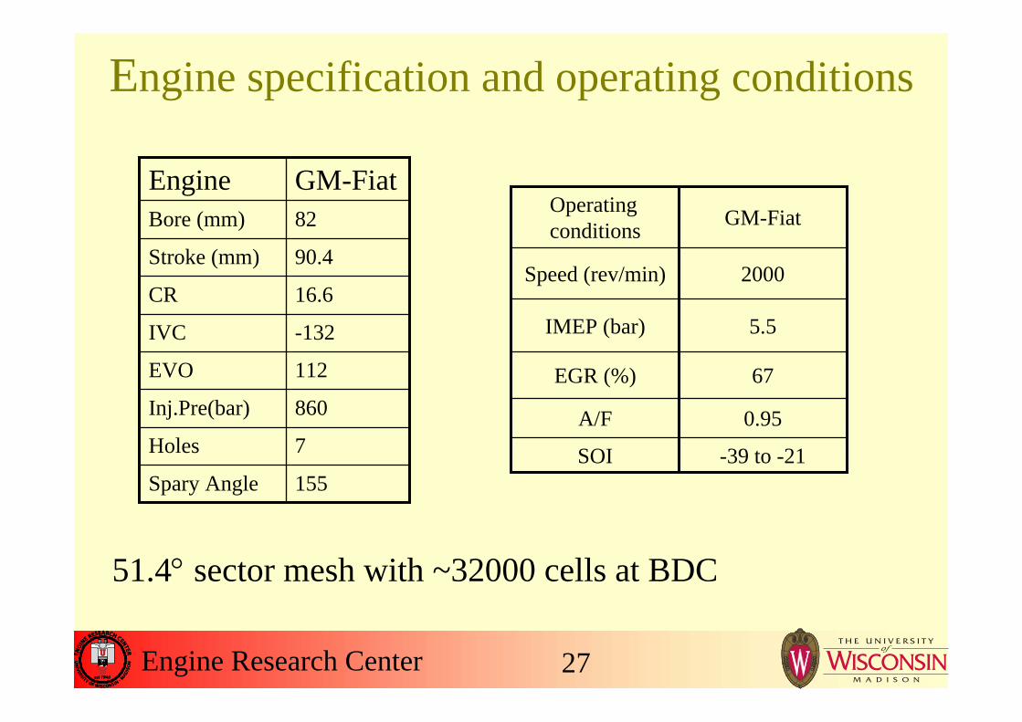
Engine specification and operating conditions
155Spary Angle
7Holes
860Inj.Pre(bar)
112EVO
-132IVC
16.6CR
90.4Stroke (mm)
82Bore (mm)
GM-FiatEngine
SOI
A/F
EGR (%)
IMEP (bar)
Speed (rev/min)
Operatingconditions
-39 to -21
0.95
67
5.5
2000
GM-Fiat
51.4° sector mesh with ~32000 cells at BDC
Engine Research Center 28
Comparison of experimental and simulated results
-40 -36 -32 -28 -24 -20
0.00
0.02
0.04
0.06
0.08
0.10
0.12
0.14 Experiment Simulation-AMC Simulation-Full Chemistry
Soot
(g/k
g/fu
el)
Crank Angle-40 -36 -32 -28 -24 -20
0.02
0.03
0.04
0.05
0.06
0.07
0.08
NO
x (g
/kg/
fuel
)
Crank Angle
-40 -36 -32 -28 -24 -205
10
15
20
25
30
35
40
45
Unb
urne
d H
C (g
/kg.
fuel
)
Crank Angle-40 -36 -32 -28 -24 -20
100
150
200
250
300
CO
(g/k
g.fu
el)
Crank Angle
Opat et al.SAE Paper2007-01-0193CO ‘sweet spot’
Computer timewas reduced from 40 hours to 14.5 hours
Soot NOx
UHC CO
Engine Research Center 29
Part 5
• Background and model description• Parametric study of the AMC model• Application in HCCI engine combustion• Application in DI engine combustion• Conclusions

Engine Research Center 30
Conclusions• The AMC model is able to reduce computer
time by a factor of ten for HCCI cases and two to three for DI cases without losing prediction accuracy.
• Both global and neighbor grouping methods were satisfactory to predict HCCI engine combustion, but the simpler global grouping method led to inaccuracies in the predicted emissions for DI cases.

Engine Research Center 31
Conclusions (cont.)• An averaged remapping method was
explored but not suggested in the AMC model due to increased numerical diffusion. Instead, a gradient-preserving method was found to be applicable for both HCCI and DI cases.
• The present AMC model predictions were shown to be fairly insensitive to convergence tolerance parameters in parametric studies.
Engine Research Center 32