Numerical investigation on the application of catalytic combustion to HCCI engines
13
Chemical Engineering Journal 127 (2007) 81–93 Numerical investigation on the application of catalytic combustion to HCCI engines Wen Zeng ∗ , Maozhao Xie, Ming Jia Department of Power Engineering, Dalian University of Technology, Dalian 116024, PR China Received 23 March 2006; received in revised form 25 August 2006; accepted 3 October 2006 Abstract The combustion processes of homogeneous charge compression ignition (HCCI) engines whose piston surfaces were coated with catalyst (platinum) are numerically investigated. The detailed reaction mechanism of methane oxidation on platinum catalyst is adopted. Mathematical models of three different levels, namely, a single-zone model, a multi-zone model, and a multidimensional one are developed. The effects of catalytic combustion on the ignition timing, the emissions of hydrocarbon (HC), carbon monoxide (CO) and nitrogen oxide (NO x ), and the combustion characteristics of HCCI engines are analyzed through the single- and the multi-zone models. The results show that due to the catalytic coating the ignition timing is advanced, the emissions of HC and CO are decreased, while the emissions of NO x are elevated, and that the indicated fuel conversion rate and the combustion efficiency are increased. Furthermore, through the multidimensional model, the inhomogeneity of the temperature and species concentration fields as well as the turbulence effect are considered. It is shown that the temperature and HC, CO concentration fields in the cylinder are more homogeneous because of the effects of catalytic combustion. Finally, a brief comparison of the above three models is presented. Advantages, drawbacks and applicabilities of each model are discussed. © 2006 Elsevier B.V. All rights reserved. Keywords: Catalytic combustion; HCCI; Single-zone model; Multi-zone model; Multidimensional model; Methane 1. Introduction With the rapid development of world economy, the problems of energy resource crisis and environment pollution become more and more serious. As one of the main energy con- sumers and the main source of environment pollution, the automobile receives comprehensive attentions of worldwide researchers. Because of its high efficiency, very low nitrogen oxide (NO x ) and particulate matter emissions, the homoge- neous charge compression ignition (HCCI) engine has recently become the focus of engine research. However, the HCCI engine still fronts some challenges including higher hydro- carbon (HC) and carbon monoxide (CO) emissions, control of ignition timing and limited operating range [1–7]. Fur- thermore, because of the lower exhaust temperature, dealing with the emissions by after-treatment (that is a conventional approach to decrease emissions of internal combustion engines) becomes difficult. So we must find new means to resolve these ∗ Corresponding author. Tel.: +86 41184704541; fax: +86 41184708460. E-mail address: [email protected] (W. Zeng). problems before the HCCI engine can be put into practical applications. Compared with the traditional combustion mode, catalytic combustion is a different process in which exist complicated interactions between homogeneous and heterogeneous reactions and, there is no flame propagation, and its ignition temperature is lower. For this reason, catalyst coatings on the internal cylin- der head, pre-combustion chamber, piston surface and piston crown, can be used to modify the engine combustion process and the combustion characteristics, decrease HC, CO, NO x emis- sions and extend the operating range of the internal combustion engine. Gaffney et al. [8] reported that Pt coatings decreased soot emission from a diesel engine by 40%, although the coatings were lost within 8 h of engine operation presumably because of poor adhesion caused by carbon and iron oxide deposits on the piston surface. A “catalytic engine” was described by Thring [9] which consisted of a methanol-burning, modified indirect injection diesel engine where the pre-combustion cham- ber was fitted with both a glow-plug and Pt mesh catalyst. The results showed that this engine had light-load fuel economy as good as a diesel, and the HC emissions were lower than either petrol or diesel engine. Hu and Ladommatos [10] and Hu [11] 1385-8947/$ – see front matter © 2006 Elsevier B.V. All rights reserved. doi:10.1016/j.cej.2006.10.018
-
Upload
independent -
Category
Documents
-
view
1 -
download
0
Transcript of Numerical investigation on the application of catalytic combustion to HCCI engines

A
(mcccioct©
K
1
omsaronbecotwab
1d
Chemical Engineering Journal 127 (2007) 81–93
Numerical investigation on the applicationof catalytic combustion to HCCI engines
Wen Zeng ∗, Maozhao Xie, Ming JiaDepartment of Power Engineering, Dalian University of Technology, Dalian 116024, PR China
Received 23 March 2006; received in revised form 25 August 2006; accepted 3 October 2006
bstract
The combustion processes of homogeneous charge compression ignition (HCCI) engines whose piston surfaces were coated with catalystplatinum) are numerically investigated. The detailed reaction mechanism of methane oxidation on platinum catalyst is adopted. Mathematicalodels of three different levels, namely, a single-zone model, a multi-zone model, and a multidimensional one are developed. The effects of
atalytic combustion on the ignition timing, the emissions of hydrocarbon (HC), carbon monoxide (CO) and nitrogen oxide (NOx), and theombustion characteristics of HCCI engines are analyzed through the single- and the multi-zone models. The results show that due to the catalyticoating the ignition timing is advanced, the emissions of HC and CO are decreased, while the emissions of NOx are elevated, and that thendicated fuel conversion rate and the combustion efficiency are increased. Furthermore, through the multidimensional model, the inhomogeneity
f the temperature and species concentration fields as well as the turbulence effect are considered. It is shown that the temperature and HC, COoncentration fields in the cylinder are more homogeneous because of the effects of catalytic combustion. Finally, a brief comparison of the abovehree models is presented. Advantages, drawbacks and applicabilities of each model are discussed.2006 Elsevier B.V. All rights reserved.
l; Mu
pa
ciaidcaseewo
eywords: Catalytic combustion; HCCI; Single-zone model; Multi-zone mode
. Introduction
With the rapid development of world economy, the problemsf energy resource crisis and environment pollution becomeore and more serious. As one of the main energy con-
umers and the main source of environment pollution, theutomobile receives comprehensive attentions of worldwideesearchers. Because of its high efficiency, very low nitrogenxide (NOx) and particulate matter emissions, the homoge-eous charge compression ignition (HCCI) engine has recentlyecome the focus of engine research. However, the HCCIngine still fronts some challenges including higher hydro-arbon (HC) and carbon monoxide (CO) emissions, controlf ignition timing and limited operating range [1–7]. Fur-hermore, because of the lower exhaust temperature, dealing
ith the emissions by after-treatment (that is a conventionalpproach to decrease emissions of internal combustion engines)ecomes difficult. So we must find new means to resolve these
∗ Corresponding author. Tel.: +86 41184704541; fax: +86 41184708460.E-mail address: [email protected] (W. Zeng).
oTibrgp
385-8947/$ – see front matter © 2006 Elsevier B.V. All rights reserved.oi:10.1016/j.cej.2006.10.018
ltidimensional model; Methane
roblems before the HCCI engine can be put into practicalpplications.
Compared with the traditional combustion mode, catalyticombustion is a different process in which exist complicatednteractions between homogeneous and heterogeneous reactionsnd, there is no flame propagation, and its ignition temperatures lower. For this reason, catalyst coatings on the internal cylin-er head, pre-combustion chamber, piston surface and pistonrown, can be used to modify the engine combustion processnd the combustion characteristics, decrease HC, CO, NOx emis-ions and extend the operating range of the internal combustionngine. Gaffney et al. [8] reported that Pt coatings decreased sootmission from a diesel engine by 40%, although the coatingsere lost within 8 h of engine operation presumably becausef poor adhesion caused by carbon and iron oxide depositsn the piston surface. A “catalytic engine” was described byhring [9] which consisted of a methanol-burning, modified
ndirect injection diesel engine where the pre-combustion cham-
er was fitted with both a glow-plug and Pt mesh catalyst. Theesults showed that this engine had light-load fuel economy asood as a diesel, and the HC emissions were lower than eitheretrol or diesel engine. Hu and Ladommatos [10] and Hu [11]
82 W. Zeng et al. / Chemical Engineeri
Nomenclature
A pre-exponential factorAs area of piston surfaceAw surface area of cylinder wallB diameter of borecp constant pressure specific heat averaged over all
speciescv constant volume specific heatCj concentration of species jDm Fick’s Law diffusion coefficientEa activation energyhj specific enthalpy of species jI unit dyadicm massp fluid pressurepcyl pressure in the cylinderqloss heat loss of the combustion chamber averaged
over the mass in the cylinderR gas constantR gas constant averaged over all speciess surface reaction rateS sticking coefficientSp average speed of pistont timeT temperatureTw temperature of cylinder wallu fluid velocityuj internal energy of species jv specific volumevst Stefan velocityVcyl volume of cylinderw gas reaction rateW molecular weight averaged over all speciesWj molecular weight of species jYj mass fraction of species j
Greek lettersδ Diract delta functionλ second coefficients of viscosityμ first coefficients of viscosityρ total mass densityρj mass density of species j
Subscriptsi index of zonesj index of speciest − 1 previous time step
rtsio
qn
tnriobTprcItitr
om(caafitodictfcefim
ibtsscoeiaoeBo
T transpose of matrix2 zone 2
eported that unburned HC emissions were reduced by 20% by
he deposition of a catalytic Pt-Rh coatings on the top and sideurfaces of the piston in an SI laboratory engine. However, theres another view that catalytic coatings have a negative effectn unburned HC emissions through so-called “catalytic flameeati
ng Journal 127 (2007) 81–93
uenching” [12]. To clarify this issue, deeper investigations areecessary.
All the above researches concerned only experiments forhe application of catalytic combustion to conventional inter-al combustion engines. Due to the lack of detailed surfaceeaction mechanism and the limitation of computer capabil-ty, numerical simulation of the effects of catalytic combustionn the combustion characteristics of conventional internal com-ustion engines has not been reported in the open literature.his might attributed to that catalytic combustion is a com-licated physical and chemical process which includes surfaceeaction kinetics, gas reaction kinetics as well as compli-ated transport phenomena of mass, momentum and energy.n fact, the flow and combustion processes in the conven-ional internal combustion engine themselves are also highlyntricate. Simulation of this combustion process needs sophis-icated physical and chemical submodels and vast computeresources.
Recently, with the computer capability advancing, new meth-ds of mathematical simulation developed, detailed reactionechanisms built, and specially new modes of combustion
such as HCCI) provided, mathematical simulation of this pro-ess has become possible and considerable progress has beenchieved in this area, from which research work by the groupst Wisconsin, Lund and Sandia are representative [13–15]. Dif-ering from the conventional CI and SI combustion modes,gnition in the HCCI engine occurs at multiple sites simul-aneously across the combustion chamber. Once the ignitionccurs, the gas mixture is consumed quickly even withoutiscernable flame propagation, so detailed chemical kineticss usually used to simulate HCCI combustion. Based on thisonsideration, in modeling the effects of catalytic coatings onhe combustion characteristics of the HCCI engine we canocus our attention on the aspect of chemical kinetics pro-ess, while the complicated transport phenomena and turbulenceffect are not taken into account or treated in a much simpli-ed manner. In this way, the whole problem becomes moreaneuverable.The objectives of this paper are two-fold. The first is to exam-
ne the applicability of catalytic combustion to the HCCI enginey numerical modeling. The second is to carry out a compara-ive study, in which three levels of combustion models, i.e. theingle-zone, multi-zone and multidimensional models are usedeparately to simulate the HCCI combustion under the action ofatalyst. In this way, advantages and drawbacks of the three kindsf combustion models concerning their applicabilities to HCCIngines might be clarified. This paper is organized as follows:n the next section, the detailed chemical reaction mechanismsdopted in this work are presented. In Section 3, the effectsf catalytic combustion on the ignition timing of the HCCIngine are analyzed based on single-zone model simulations.ecause the single-zone model cannot predict the emissionsf HC and CO, in Section 4, a multi-zone model is built. The
ffects of catalytic combustion on HC, CO and NOx emissionsre discussed through this model. In Section 5, through the mul-idimensional CFD model, the in-cylinder flow field, and thenhomogeneity of temperature and species concentration fields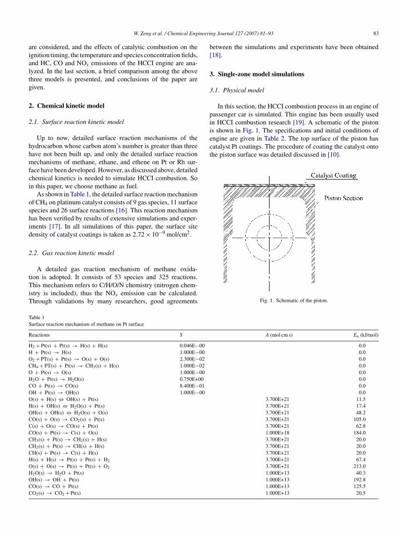
ineeri
aialtg
2
2
hhmfci
oshid
2
tTiT
b[
3
3
piis shown in Fig. 1. The specifications and initial conditions ofengine are given in Table 2. The top surface of the piston hascatalyst Pt coatings. The procedure of coating the catalyst ontothe piston surface was detailed discussed in [10].
TS
R
HHOCOHCOOHOCCCCCCHOHOCC
W. Zeng et al. / Chemical Eng
re considered, and the effects of catalytic combustion on thegnition timing, the temperature and species concentration fields,nd HC, CO and NOx emissions of the HCCI engine are ana-yzed. In the last section, a brief comparison among the abovehree models is presented, and conclusions of the paper areiven.
. Chemical kinetic model
.1. Surface reaction kinetic model
Up to now, detailed surface reaction mechanisms of theydrocarbon whose carbon atom’s number is greater than threeave not been built up, and only the detailed surface reactionechanisms of methane, ethane, and ethene on Pt or Rh sur-
ace have been developed. However, as discussed above, detailedhemical kinetics is needed to simulate HCCI combustion. Son this paper, we choose methane as fuel.
As shown in Table 1, the detailed surface reaction mechanismf CH4 on platinum catalyst consists of 9 gas species, 11 surfacepecies and 26 surface reactions [16]. This reaction mechanismas been verified by results of extensive simulations and exper-ments [17]. In all simulations of this paper, the surface siteensity of catalyst coatings is taken as 2.72 × 10⁻⁹ mol/cm2.
.2. Gas reaction kinetic model
A detailed gas reaction mechanism of methane oxida-
ion is adopted. It consists of 53 species and 325 reactions.his mechanism refers to C/H/O/N chemistry (nitrogen chem-stry is included), thus the NOx emission can be calculated.hrough validations by many researchers, good agreements
able 1urface reaction mechanism of methane on Pt surface
eactions S
2 + Pt(s) + Pt(s) → H(s) + H(s) 0.046E−00+ Pt(s) → H(s) 1.000E−00
2 + PT(s) + Pt(s) → O(s) + O(s) 2.300E−02H4 + PT(s) + Pt(s) → CH3(s) + H(s) 1.000E−02+ Pt(s) → O(s) 1.000E−00
2O + Pt(s) → H2O(s) 0.750E+00O + Pt(s) → CO(s) 8.400E−01H + Pt(s) → OH(s) 1.000E−00(s) + H(s) ⇔ OH(s) + Pt(s)(s) + OH(s) ⇔ H2O(s) + Pt(s)H(s) + OH(s) ⇔ H2O(s) + O(s)O(s) + O(s) → CO2(s) + Pt(s)(s) + O(s) → CO(s) + Pt(s)O(s) + Pt(s) → C(s) + O(s)H3(s) + Pt(s) → CH2(s) + H(s)H2(s) + Pt(s) → CH(s) + H(s)H(s) + Pt(s) → C(s) + H(s)(s) + H(s) → Pt(s) + Pt(s) + H2
(s) + O(s) → Pt(s) + Pt(s) + O2
2O(s) → H2O + Pt(s)H(s) → OH + Pt(s)O(s) → CO + Pt(s)O2(s) → CO2 + Pt(s)
ng Journal 127 (2007) 81–93 83
etween the simulations and experiments have been obtained18].
. Single-zone model simulations
.1. Physical model
In this section, the HCCI combustion process in an engine ofassenger car is simulated. This engine has been usually usedn HCCI combustion research [19]. A schematic of the piston
Fig. 1. Schematic of the piston.
A (mol cm s) Ea (kJ/mol)
0.00.00.00.00.00.00.00.0
3.700E+21 11.53.700E+21 17.43.700E+21 48.23.700E+21 105.03.700E+21 62.81.000E+18 184.03.700E+21 20.03.700E+21 20.03.700E+21 20.03.700E+21 67.43.700E+21 213.01.000E+13 40.31.000E+13 192.81.000E+13 125.51.000E+13 20.5
84 W. Zeng et al. / Chemical Engineering Journal 127 (2007) 81–93
Table 2Specifications and initial conditions of the engine
Bore (mm) Stroke (mm) Connecting rod Engine speed Compressiono
Initial temperature (K) Initial pressure (bar) λ Fuel
8 0
3
aItI
jWj
wtsTa
b
q
T
h
T
w
wv3
3
3o
c3ciew
o3
tsahbsI
kstwcitis
4
ipcharge is homogeneous and therefore greatly over predicts thecombustion rate and the emission of NOx. In an effort to describethe physical processes occurring in the cylinder more detailedlyand predict the emissions more accurately, a multi-zone model
length (mm) (rpm) rati
9 105.8 169.1 2500 15.
.2. Computational model
The single-zone model is used to analyze the effects of cat-lytic combustion on the ignition timing of the HCCI engine.n this model, thermodynamic properties are assumed uniformhroughout the chamber volume. The computation starts fromVC.
The basic equations of this model are as follows:
Conservation of energy
dT
dt= qloss − (RT/vW) dv/dt − v
∑Kj=1ujWjwj − ∑K
j=1ujs
cv
Conservation of species
dYj
dt= vWjwj + As
msjWj (2)
here K is the total number of gas phase species, the gas reac-ion rate is computed by CHEMKTN package [20], while theurface reaction rate is computed by DETCHEM package [21].he specific cylinder volume is specified as a function of crankngle (◦) [22].
The heat loss from the combustion chamber can be computedy the Woschni [23] heat transfer model given as:
˙loss = hAw(T − Tw)
m(3)
he heat transfer coefficient h can be calculated by
= 129.8B−0.2p0.8cylT
−0.55w0.8 (4)
he average gas velocity w can be calculated by
= C1Sp + C2VcylTr
prVr(pcyl − pmot) (5)
here Tr, pr and Vr are referenced temperature, pressure andolume, respectively. C1 is 2.28. C2 is 0 for compression and.34 × 10−3 for combustion and expansion.
.3. Computational results
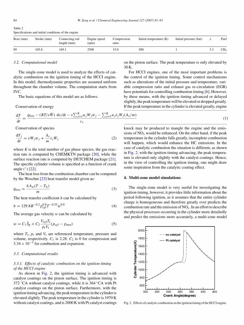
.3.1. Effects of catalytic combustion on the ignition timingf the HCCI engine
As shown in Fig. 2, the ignition timing is advanced withatalyst coatings on the piston surface. The ignition timing is72 ◦CA without catalyst coatings, while it is 364 ◦CA with Pt
atalyst coatings on the piston surface. Furthermore, with thegnition timing advancing, the peak temperature in the cylinder islevated slightly. The peak temperature in the cylinder is 1970 Kithout catalyst coatings, and is 2000 K with Pt catalyst coatings F500 1 3.3 CH4
(As/m)(1)
n the piston surface. The peak temperature is only elevated by0 K.
For HCCI engines, one of the most important problems ishe control of the ignition timing. Some control mechanismsuch as alterations of the initial pressure and temperature, vari-ble compression ratio and exhaust gas re-circulation (EGR)ave potentials for controlling combustion timing [6]. However,y these means, with the ignition timing advanced or delayedlightly, the peak temperature will be elevated or dropped greatly.f the peak temperature in the cylinder is elevated greatly, engine
nock may be produced to mangle the engine and the emis-ions of NOx would be enhanced. On the other hand, if the peakemperature in the cylinder falls greatly, incomplete combustionill happen, which would enhance the HC emissions. In the
ase of catalytic combustion the situation is different, as shownn Fig. 2, with the ignition timing advancing, the peak tempera-ure is elevated only slightly with the catalyst coatings. Hence,n the view of controlling the ignition timing, one might drawome inspiration from the catalytic coating effect.
. Multi-zone model simulations
The single-zone model is very useful for investigating thegnition timing, however, it provides little information about theeriod following ignition, as it assumes that the entire cylinder
ig. 2. Effects of catalytic combustion on the ignition timing of the HCCI engine.

W. Zeng et al. / Chemical Engineering Journal 127 (2007) 81–93 85
Table 3Specifications and initial conditions of the engine
Bore (mm) 89Connecting rod length (mm) 169.1Stroke (mm) 105.8Compression ratio 15:1Engine speed (rpm) 2500Crevice volume (cm2) 1.65Quench layer thickness (mm) 1Wall temperature (K) 390AI
ittcmsi
4
pstiw
sc
4
bdatltctrft
TT
Z
123456
cwtaltp
ir excess ratio 3.3nitial pressure (bar) 1
s developed to simulate the effects of catalytic combustion onhe emissions of CO, HC and NOx. Although it is not intendedo be a “predictive” model of HCCI ignition and emissions, theomputation times are relatively short in comparison with theultidimensional model (which will be discussed in the next
ection) while still providing valuable information about HCCIgnition and combustion processes.
.1. Physical model
The main specifications of the HCCI engine simulated in thisaper are listed in Table 3.The engine used in this section is theame one as used in the single-zone model. Initial conditions ofhe multi-zone model are listed in Table 4. The principle of thenitial mass and temperature distributions throughout the zonesas detailedly discussed in [24].A schematic of the engine cylinder and zone definitions is
hown in Fig. 3. Note that only the piston top surface has Ptatalyst coatings.
.2. Computational model
In this paper, six zones are used to provide some details,ut without extraordinarily long running times. The zones areefined such that they are representative of the crevice, bound-ry layer, outer core, and inner core regions, respectively. Thehree inner core regions are considered to be adiabatic. Heatoss to the walls from the boundary layer zone is modeled usinghe Woschni correlation and the temperature of crevice zone isonsidered to remain constant and equal to the wall temperature
hroughout the cycle. The outer core, boundary layer, and creviceegion are allowed to exchange mass in order to maintain a uni-orm pressure throughout the combustion chamber. The innerhree core zones are assumed to be of constant mass so that whenable 4he initial mass and temperature distributions of zones
ones Mass fraction Temperature (K)
0.3 3906.6 435
52.2 45514.5 47016.4 49510.0 520
wott
ocwfia
Fig. 3. Multi-zone model schematic showing the layout of the zones.
ombustion started these regions simply expand without mixingith other zones. Mass that flows from the outer core must pass
hrough the boundary layer before entering the crevice regionnd that leaving the crevice must also flow through the boundaryayer before entering the outer core. Mass transferred betweenhese zones is considered to instantly mix with the mass alreadyresent in the zone it is entering.
The basic equations of this model are as follows:
Conservation of energy
cp,i
dTi
dt− RiTi
∑Ni=1miRi dTi/dt∑N
i=1miRiTi
= qi − RiTi
1
Vcyl
dVcyl
dt(6)
Conservation of species
dYj,i
dt= viWj,iwj,i + As
m2sj,2Wj,2 (7)
Ideal gas law
pcyl =∑N
i=1mi,t−1RiTi
Vcyl(8)
here N is the total number of elementary reactions, qi the sumf the chemical heat release and the heat transfer to the wall ofhe unit mass in zone i, the chemical heat release consists ofhose from gas reactions and surface reactions.
Because the volumes of the crevice, boundary layer, anduter core zone have been adjusted to fit our definitions withoutonsidering mass transfer between them, pressure differences
ill exist between these zones. Therefore mass must be trans-erred between these zones, the pressure in each of the zoness calculated using the ideal gas law, and the directions of flowre determined from the pressure differences. Mass flows from

8 ineering Journal 127 (2007) 81–93
zmtca
Pata
4
4h
tozam2azc3bii
ioerc
4
a
otszitecasrscP
4
t
6 W. Zeng et al. / Chemical Eng
ones of higher pressure to those of lower pressure and in thisanner the pressure in each of the three zones equalizes to
he overall cylinder pressure. The mass flowing between zonesontains energy and does work in moving across the zone bound-ries.
At each time step the pressure in each zone keeps unchanged.ressure differences in the zones only exist during the intermedi-te step of solving for the conditions at time t. Since very smallime step are taken, the solution will closely approximate thectual solution.
.3. Computational results
.3.1. Effects of catalytic combustion on temperature andeat release in the cylinder
As shown in Fig. 4, catalytic combustion has little effect onhe temperatures of zones 1 and 4–6, but has effects on thosef zones 2 and 3. The main reason is that the temperature ofone 1 is considered to equal constantly to the wall temperature,nd zones 4–6 are the inner core zones, which do not exchangeass with other zones. In our simulations, because only in zonethat has Pt catalyst coatings, the chemical reaction is acceler-
ted by the catalytic effect, consequently, the temperature of thisone is higher than that when the piston surface has no catalystoatings. Because of the mass exchange between zones 2 and, the temperature of zone 3 is also affected by catalytic com-ustion. Comparing with the case without catalyst coatings, thegnition timing of zone 3 is advanced, and the peak temperatures remarkably elevated.
As shown in Fig. 5, because in zone 2 the gas mixture is nevergnited throughout the whole process, the catalytic coating cannly induce a marginal increase in the temperature but has noffect on the heat release of zone 2. On the other hand, the heatelease of zone 3 is much higher compared with the case withoutatalyst coatings.
.3.2. Effects of catalytic combustion on HC emissionsZones 4–6 are inner core zones, there are no mass exchange
mong these three zones and other zones, and the temperatures
Fig. 4. Effects on temperatures of all zones.
twat
Fig. 5. Effects on heat releases of all zones.
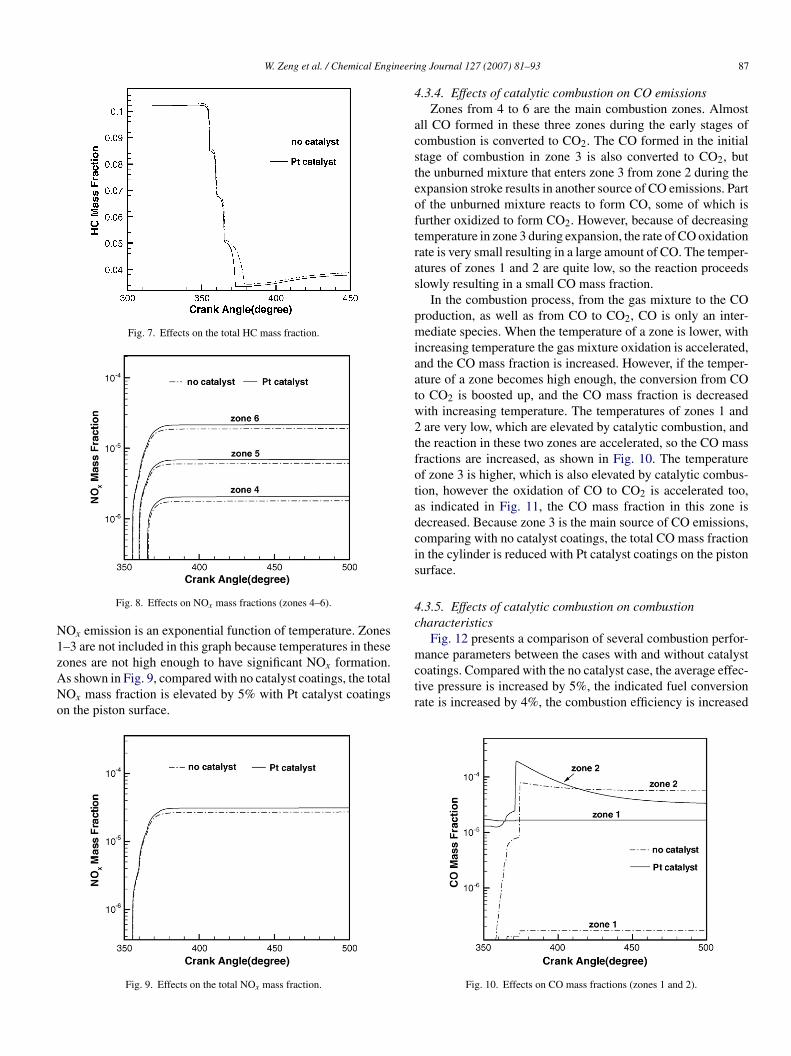
f these three zones are the highest among all the six zones,hus the unburned HC mass fractions in these three zones arelight. The expansion leads to unburned mixture flowing fromone 2 into zone 3, because of the low temperature, the reactionn zone 3 is slow, resulting in a small quantity of HC here. Theemperatures of zones 1 and 2 are much lower, thus plenty of HCxists in these two zones. On the other hand, with the catalystoatings on the piston surface, the reaction rate of zone 2 isccelerated, and the temperatures of this zone is elevated, ashown in Fig. 6, so the HC mass fraction of this zone is slightlyeduced. As shown in Fig. 7, because zones 1–3 are the mainource of HC production, compared with the case of no catalystoatings, the HC total mass fraction is reduced by about 5% witht catalyst coatings on the piston surface.
.3.3. Effects of catalytic combustion on NOx emissionsIn zones 4–6, complete combustion takes place, hence, the
emperatures of these three zones are very high, consequently,
hey are the main sources of the NOx emissions. Fig. 8 shows thatith Pt catalyst coatings on the piston surface, the reaction ratesre accelerated and the temperatures of zones 4–6 are elevated,he NOx mass fractions of zones 4–6 are increased because the
Fig. 6. Effects on HC mass fractions (zones 1–3).
W. Zeng et al. / Chemical Engineeri
Fig. 7. Effects on the total HC mass fraction.
N1zANo
4
acsteoftras
pmiaatw2tfotadcis
4c
mance parameters between the cases with and without catalyst
Fig. 8. Effects on NOx mass fractions (zones 4–6).
Ox emission is an exponential function of temperature. Zones–3 are not included in this graph because temperatures in these
ones are not high enough to have significant NOx formation.s shown in Fig. 9, compared with no catalyst coatings, the totalOx mass fraction is elevated by 5% with Pt catalyst coatingsn the piston surface.Fig. 9. Effects on the total NOx mass fraction.
ctr
ng Journal 127 (2007) 81–93 87
.3.4. Effects of catalytic combustion on CO emissionsZones from 4 to 6 are the main combustion zones. Almost
ll CO formed in these three zones during the early stages ofombustion is converted to CO2. The CO formed in the initialtage of combustion in zone 3 is also converted to CO2, buthe unburned mixture that enters zone 3 from zone 2 during thexpansion stroke results in another source of CO emissions. Partf the unburned mixture reacts to form CO, some of which isurther oxidized to form CO2. However, because of decreasingemperature in zone 3 during expansion, the rate of CO oxidationate is very small resulting in a large amount of CO. The temper-tures of zones 1 and 2 are quite low, so the reaction proceedslowly resulting in a small CO mass fraction.
In the combustion process, from the gas mixture to the COroduction, as well as from CO to CO2, CO is only an inter-ediate species. When the temperature of a zone is lower, with
ncreasing temperature the gas mixture oxidation is accelerated,nd the CO mass fraction is increased. However, if the temper-ture of a zone becomes high enough, the conversion from COo CO2 is boosted up, and the CO mass fraction is decreasedith increasing temperature. The temperatures of zones 1 andare very low, which are elevated by catalytic combustion, and
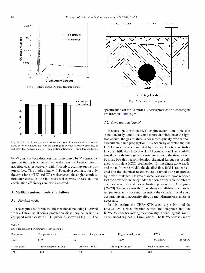
he reaction in these two zones are accelerated, so the CO massractions are increased, as shown in Fig. 10. The temperaturef zone 3 is higher, which is also elevated by catalytic combus-ion, however the oxidation of CO to CO2 is accelerated too,s indicated in Fig. 11, the CO mass fraction in this zone isecreased. Because zone 3 is the main source of CO emissions,omparing with no catalyst coatings, the total CO mass fractionn the cylinder is reduced with Pt catalyst coatings on the pistonurface.
.3.5. Effects of catalytic combustion on combustionharacteristics
Fig. 12 presents a comparison of several combustion perfor-
oatings. Compared with the no catalyst case, the average effec-ive pressure is increased by 5%, the indicated fuel conversionate is increased by 4%, the combustion efficiency is increased
Fig. 10. Effects on CO mass fractions (zones 1 and 2).
88 W. Zeng et al. / Chemical Engineering Journal 127 (2007) 81–93
Fig. 11. Effects on the CO mass fraction (zone 3).
Fii
bintttc
5
5
fe
sa
5
stdHltbuaebtc[tan
TS
B
1
S
1
ig. 12. Effects of catalytic combustion on combustion capabilities (compar-sons between without and with Pt coatings 1: average effective pressure, 2:ndicated fuel conversion rate, 3: combustion efficiency, 4: burn duration time).
y 7%, and the burn duration time is increased by 9% (since thegnition timing is advanced while the later combustion time isot effected), respectively, with Pt catalyst coatings on the pis-on surface. This implies that, with Pt catalyst coatings, not onlyhe emissions of HC and CO are decreased, the engine combus-ion characteristics (the indicated fuel conversion rate and theombustion efficiency) are also improved.
. Multidimensional model simulations
.1. Physical model
The engine used for the multidimensional modeling is derivedrom a Cummins B-series production diesel engine, which isquipped with a custom HCCI piston as shown in Fig. 13. The
DKd
able 5pecifications of the Cummins B-series engine
ore (mm) Compression ratio Connecting rod length (mm)
02 17.0 192
troke (mm) Intake temperature (K) Air excess ratio
20 470 3.0
Fig. 13. Schematic of the piston.
pecifications of the Cummins B-series production diesel enginere listed in Table 5 [25].
.2. Computational model
Because ignition in the HCCI engine occurs at multiple sitesimultaneously across the combustion chamber, once the igni-ion occurs, the gas mixture is consumed quickly even withoutiscernable flame propagation. It is generally accepted that theCCI combustion is dominated by chemical kinetics and turbu-
ence has little direct effect on HCCI combustion. This would berue if a strictly homogeneous mixture exists at the time of com-ustion. For this reason, detailed chemical kinetics is usuallysed to simulate HCCI combustion. In the single-zone modelnd the multi-zone model, the detailed flow field is not consid-red and the chemical reactions are assumed to be unaffectedy flow turbulence. However, some researchers have reportedhat the flow field in the cylinder had some effects on the rates ofhemical reactions and the combustion process of HCCI engines26–28]. This is because there are always small differences in theemperature and concentration inside the cylinder. To take intoccount this inhomogeneity effect, a multidimensional model isecessary.
In this section, the CHEMKTN chemistry solver and theETCHEM surface reaction solver are integrated into theIVA-3V code for solving the chemistry in coupling with multi-imensional engine CFD simulations. The KIVA code is used to
Engine speed (rpm) EVO IVC
1200 60 BBDC 25 ABDC
Intake pressure (bar) Wall temperature (K) Fuel
1 400 CH4
ineeri
ctgr
t
ws
tcs
s
w
j
wtiitv
�
wera
J
p
i
wPe
tsmnifcpsit�a
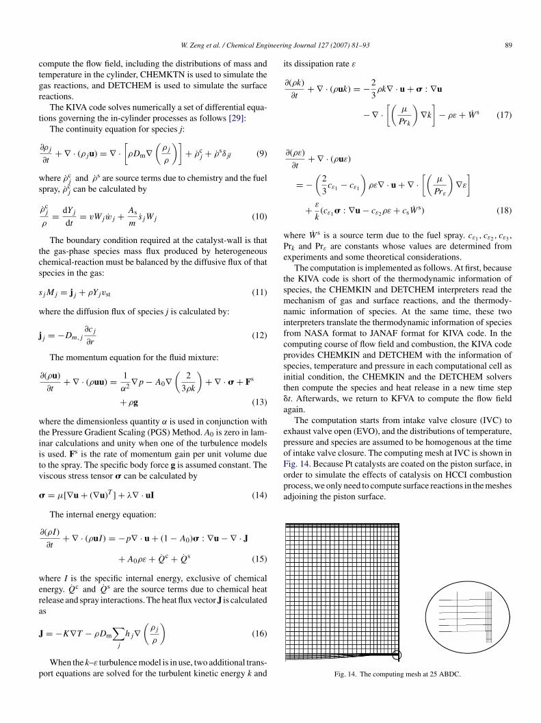
epoForder to simulate the effects of catalysis on HCCI combustionprocess, we only need to compute surface reactions in the meshesadjoining the piston surface.
W. Zeng et al. / Chemical Eng
ompute the flow field, including the distributions of mass andemperature in the cylinder, CHEMKTN is used to simulate theas reactions, and DETCHEM is used to simulate the surfaceeactions.
The KIVA code solves numerically a set of differential equa-ions governing the in-cylinder processes as follows [29]:
The continuity equation for species j:
∂ρj
∂t+ ∇ · (ρju) = ∇ ·
[ρDm∇
(ρj
ρ
)]+ ρc
j + ρsδjl (9)
here ρcj and ρs are source terms due to chemistry and the fuel
pray, ρcj can be calculated by
ρcj
ρ= dYj
dt= vWjwj + As
msjWj (10)
The boundary condition required at the catalyst-wall is thathe gas-phase species mass flux produced by heterogeneoushemical-reaction must be balanced by the diffusive flux of thatpecies in the gas:
jMj = jj + ρYjvst (11)
here the diffusion flux of species j is calculated by:
j = −Dm,j
∂cj
∂r(12)
The momentum equation for the fluid mixture:
∂(ρu)
∂t+ ∇ · (ρuu) = 1
α2 ∇p − A0∇(
2
3ρk
)+ ∇ · � + Fs
+ ρg (13)
here the dimensionless quantity α is used in conjunction withhe Pressure Gradient Scaling (PGS) Method. A0 is zero in lam-nar calculations and unity when one of the turbulence modelss used. Fs is the rate of momentum gain per unit volume dueo the spray. The specific body force g is assumed constant. Theiscous stress tensor � can be calculated by
= μ[∇u + (∇u)T ] + λ∇ · uI (14)
The internal energy equation:
∂(ρI)
∂t+ ∇ · (ρuI) = −p∇ · u + (1 − A0)� : ∇u − ∇ · J
+ A0ρε + Qc + Qs (15)
here I is the specific internal energy, exclusive of chemicalnergy. Qc and Qs are the source terms due to chemical heat
elease and spray interactions. The heat flux vector J is calculateds= −K∇T − ρDm
∑j
hj∇(
ρj
ρ
)(16)
When the k–ε turbulence model is in use, two additional trans-ort equations are solved for the turbulent kinetic energy k and
ng Journal 127 (2007) 81–93 89
ts dissipation rate ε
∂(ρk)
∂t+ ∇ · (ρuk) = −2
3ρk∇ · u + � : ∇u
− ∇ ·[(
μ
Prk
)∇k
]− ρε + W s (17)
∂(ρε)
∂t+ ∇ · (ρuε)
= −(
2
3cε1 − cε1
)ρε∇ · u + ∇ ·
[(μ
Prε
)∇ε
]
+ ε
k(cε1 � : ∇u − cε2ρε + csW
s) (18)
here W s is a source term due to the fuel spray. cε1 , cε2 , cε3 ,rk and Prε are constants whose values are determined fromxperiments and some theoretical considerations.
The computation is implemented as follows. At first, becausehe KIVA code is short of the thermodynamic information ofpecies, the CHEMKIN and DETCHEM interpreters read theechanism of gas and surface reactions, and the thermody-
amic information of species. At the same time, these twonterpreters translate the thermodynamic information of speciesrom NASA format to JANAF format for KIVA code. In theomputing course of flow field and combustion, the KIVA coderovides CHEMKIN and DETCHEM with the information ofpecies, temperature and pressure in each computational cell asnitial condition, the CHEMKIN and the DETCHEM solvershen compute the species and heat release in a new time stept. Afterwards, we return to KFVA to compute the flow fieldgain.
The computation starts from intake valve closure (IVC) toxhaust valve open (EVO), and the distributions of temperature,ressure and species are assumed to be homogenous at the timef intake valve closure. The computing mesh at IVC is shown inig. 14. Because Pt catalysts are coated on the piston surface, in
Fig. 14. The computing mesh at 25 ABDC.

90 W. Zeng et al. / Chemical Engineeri
5
5o
wiwsicft
5fi
gpsltastim
tisc
astFtphsod
5c
safgiaCacpttfilbtci
5c
F(
Fig. 15. Effects of catalytic combustion on pressure and heat release.
.3. Computational results
.3.1. Effects of catalytic combustion on the ignition timingf the HCCI engine
From Fig. 15 it is clear that the ignition timing is advancedith Pt catalyst coatings on the piston surface. The ignition tim-
ng is 1 ◦CA before top dead center (BTDC) without catalyst,hile it is 3 ◦CA BTDC with Pt catalyst coatings on the piston
urface. With the ignition timing advancing, the peak pressuren the cylinder is elevated, which is 7.1 and 7.2 MPa for theases without and with Pt catalyst coatings on the piston sur-ace, respectively. The peak pressure is elevated by 0.1 MPa dueo the catalytic effect.
.3.2. Effects of catalytic combustion on the temperatureeld of the HCCI engine
As shown in Fig. 16a1 and a2, at 5 ◦CA BTDC, the mixedas in the whole cylinder cannot be ignited for both cases of theiston surface without and with Pt catalyst coatings. However, ithould be noted when the piston surface is coated with Pt cata-yst, both the peak temperature of the core region and the lowestemperature in crevice region are elevated. At 0 ◦CA BTDC,s shown in Fig. 16b1, in the case without catalyst, there is a
ignificant temperature gradient in the cylinder, which meanshat a high temperature region exists in the core region, whilen the crevice region and the boundary layer, temperatures areuch lower. On the other hand, as shown in Fig. 16b2, when
pfc
ig. 16. Effects of catalytic combustion on the temperature (K) field in the cylinder. (b1 and b2) Without and with Pt catalyst on the piston surface at 0 ◦CA BTDC.
ng Journal 127 (2007) 81–93
he piston surface coated with Pt catalyst, the temperature fieldn the cylinder has become essentially homogeneous with con-iderably elevated temperatures in the boundary layer and therevice region.
Compared with the conventional SI engine, one of the maindvantages of the HCCI engine is that the gas mixture is ignitedimultaneously at multiple locations inside the cylinder and theemperature field is overall homogeneous. However, as shown inig. 16b1, due to the turbulence effect, there is still a substantial
emperature gradient in the cylinder. On the other hand, when theiston surface coated with Pt catalyst, as shown in Fig. 16b2, theomogeneity of temperature field is facilitated by the catalysis,o the feasibility of engine knock is diminished and the emissionsf HC and CO could be decreased (which will be detailedlyiscussed in the next section).
.3.3. Effects of catalytic combustion on the COoncentration field of the HCCI engine
As shown in Fig. 17a1, at 0 ◦CA BTDC, when the pistonurface has no catalyst, the core temperatures are rather high,nd most of the mixed gas in the core region is consumed toorm CO2. Because of low temperature in the crevices, the mixedas cannot be ignited. Consequently, there only unburned HCs produced. Thus the CO concentrations in these two regionsre low. The temperature in the boundary layer is not very high,O produced by the oxidation of mixed gas cannot be oxidizednd converted completely to CO2, and hence, there is a large COoncentration in the boundary layer. Fig. 17a2 shows that for theiston surface coated with Pt catalyst, the CO concentration inhe whole cylinder is higher and more homogeneous because ofhe higher temperature level and the homogeneity of temperatureeld. At 120 ◦CA ATDC, as shown in Fig. 17b1 and b2, although
ittle difference in the CO concentration fields can be observedetween the above two cases, there is still some difference inhe peak and the lowest CO concentrations. Comparing with noatalyst, the peak and the lowest CO concentrations are lowedn the case with Pt catalyst coatings on the piston surface.
.3.4. Effects of catalytic combustion on the HConcentration field of the HCCI engine
The calculated HC concentration fields in the cylinder areresented in Fig. 18. As shown in Fig. 18a1, at 0 ◦CA BTDC,or the case without catalyst, because of high temperature in theore region, there the HC concentration is slight. However, the
a1 and a2) Without and with Pt catalyst on the piston surface at 5 ◦CA BTDC.

W. Zeng et al. / Chemical Engineering Journal 127 (2007) 81–93 91
F inder.( C.
tooCwlaAcs
tHieuc
F(
ig. 17. Effects of catalytic combustion on the CO concentration field in the cylb1 and b2) Without and with Pt catalyst on the piston surface at 120 ◦CA ATD
emperatures are low in the regions adjacent to the head and wallf the cylinder as well as to the crevices, the mixtures cannot bexidized entirely, so there exists a large amount of unburned HC.ontrastively, Fig. 18a2 shows that for the piston surface coatedith Pt catalyst, the HC concentrations in the whole cylinder is
ow and distributed homogeneously because of the high temper-
ture and its homogeneity throughout the combustion chamber.t 120 ◦CA ATDC, as shown in Fig. 18b, although the HC con-entration fields in the above two cases seem similar, there istill certain difference in the peak and the lowest HC concentra-
eHmt
ig. 18. Effects of catalytic combustion on the HC concentration field in the cylinder.b1 and b2) Without and with Pt catalyst on the piston surface at 120 ◦CA ATDC.
(a1 and a2) Without and with Pt catalyst on the piston surface at 0 ◦CA BTDC.
ions. Comparing with no catalyst, both the peak and the lowestC concentrations are lower in the case with Pt catalyst coat-
ngs on the piston surface. Differing from our results, Hultqvistt al. [12] reported that the catalytic coatings give rise to morenburned HC. The observed HC rising is attributed to the so-alled catalytic flame quenching, the mechanism of which is
xplained as follows. The catalyst coatings have two effects onC emissions. On one hand, the catalyst coatings affect the ther-al boundary layer. The pores in the catalyst coatings enlargehe area of heat transfer and change the heat transfer coefficient.
(a1 and a2) Without and with Pt catalyst on the piston surface at 0 ◦CA BTDC.

92 W. Zeng et al. / Chemical Engineering Journal 127 (2007) 81–93
Table 6Comparisons of the three models
Model Application range Compute time
S te), emM and NM ission
TsdigtpetattceMrftwb
5t
ccpdtbmPttt
Fw
mee
6
btbfpiiPpitoNc
iaasvsflts
ingle-zone Ignition timing (accuraulti-zone Emissions of HC, CO,ulti-dimension Ignition timing and em
hus, heat transfer in the regions with catalyst coatings becomestranger and if the heat loss to the walls is greater than the pro-uction and convection of heat, the catalytic flame quenchings happened. On the other hand, the catalyst coatings affect theas reactions confined to it. As discussed in the above section,he catalysis can accelerate the gas reaction rate, so the tem-erature in the regions adjoining to the catalyst coatings can belevated. In [12], the upper part of the cylinder liner, the pistonop including the top land, the valves and the cylinder head werell coated with Pt catalyst. Hence, from the above mentionedwo effects, the first one is dominated. However, in our study,he catalyst is coated only on the piston top surface, but not in therevice zone, as in the experiment by Hultqvist et al. Thus, theffect of flame quenching should be much weaker than in [12].oreover, in our simulation the heat transfer equations and cor-
esponding boundary conditions were not modified to accountor the effect of heat transfer enhancement by the porous struc-ure of the catalytic coatings. This would further weaken theall quenching. For these reasons, the HC emissions predictedy our computation are lower.
.3.5. Summary of catalytic coating effects on emissions ofhe HCCI engine
Fig. 19 presents a general comparison of total emissionharacteristics between the engines with and without catalystoatings. It can be seen that at the same working conditions, com-ared with the no catalyst case, the emissions of HC and CO areecreased by 4 and 9%, respectively, with Pt catalyst coatings onhe piston surface, while the NOx emissions increased roughlyy 8%. As we know, the NOx emissions of the HCCI engine areuch lower than that of ordinary CI and SI engines, thus with
t catalyst coatings on the piston surface, a slight increase inhe NOx emissions seems not to deteriorate the advantages ofhe HCCI engine. Moreover, with catalyst coatings on the pis-on surface, the emissions of HC and CO are decreased, so the
ig. 19. The emissions of HC, CO and NOx (comparisons between without andith Pt catalyst coatings).
m
fiptl
7
awSasmct
issions of NOx (higher) 2 minOx (not very accurate) 4 hs of HC, CO, and NOx 67 h
ain disadvantage that the HCCI engine has higher HC and COmissions than conventional engines can be alleviated to somextent.
. Comparisons of the three models
In the single-zone model simulations, the combustion cham-er is assumed to be a well-stirred reactor with uniformemperature, pressure and compositions. This model is applica-le to the HCCI engine because here mixing is not a controllingactor. As shown in Table 6, the single-zone model analyses canredict the effects of catalytic combustion on the ignition tim-ng of HCCI engine with good accuracy, and the computing times shortest among the three models (all computations are on aentium 4, 2.8 GHz PC). However, because the in-cylinder tem-erature is actually non-uniform and the high temperature regionn the center of the chamber is more responsible for the igni-ion, the single-zone model inevitably over-predicts the effectsf catalytic combustion on the peak cylinder pressure and theOx emissions, and is not able to predict the effects of catalytic
ombustion on the emissions of HC and CO.Because the multi-zone model accounts for the temperature
nhomogeneity and thermal boundary layers, as well as the inter-ctions between zones such as heat transfer and work, it has thebility to predict the effects of catalytic combustion on the emis-ions of HC, CO, and NOx, and the computing time needed is notery long. But in this model, the detailed flow field is not con-idered, the chemical reactions are assumed to be unaffected byow turbulence, and the initial mass and temperature distribu-
ions in zones have to be presumed including some uncertainties,o comparing with multidimensional model, the precision of theulti-zone model simulations is not very satisfactory.In the multidimensional model simulations, the detailed flow
eld and the detailed chemical reactions are coupled, so it canredict the effects of catalytic combustion on the ignition timing,he emissions of HC, CO, and NOx accurately, but it need theongest computing time among the three models.
. Conclusions
In this paper, the combustion processes and emission char-cteristics of HCCI engines whose piston surfaces are coatedith Pt catalyst are simulated systematically by modifying theENKTN code of CHEMKTN chemical kinetics package, anddopting a detailed chemical kinetics mechanism that consists of
urface reactions and gas reactions mechanisms. A single-zoneodel and a multi-zone model are built. The effects of catalyticombustion on the ignition timing, the combustion characteris-ics and the unburned HC, CO and NOx emissions of a HCCI

ineeri
emaCifiaaf
(
(
(
A
R
R
[
[
[
[
[
[
[[
[
[
[
[
[
[
[
[
[
[
W. Zeng et al. / Chemical Eng
ngine are studied through these two models separately. Further-ore, by coupling the KTVA-3V package with the CHEMKIN
nd DETCHEM chemical kinetics packages, a multidimensionalFD model is built, and the effects of catalytic combustion on the
gnition timing, the temperature field, the CO, HC concentrationelds and the HC, CO and NOx emissions of the HCCI engine arenalyzed taking into account the inhomogeneity of temperaturend species concentrations in the cylinder. The study producesollowing results:
1) With the piston surface having Pt catalyst coatings, the igni-tion timing is advanced, and the peak temperature and thepeak pressure in the cylinder are elevated slightly.
2) With Pt catalyst coated on the piston surface, the HC andCO emissions are decreased but the NOx emissions areincreased.
3) Compared with the case without catalyst coatings, the tem-perature and CO, HC concentration fields in the cylinder aremore homogeneous when the piston surface has Pt catalystcoatings.
cknowledgments
This research is supported by the National Key Basicesearch Project of China (No. 2001CB209201).
eferences
[1] R.H. Stanglmaier, C.E. Robert. Homogeneous charge compression ignition(HCCI): benefits, compromises, and future engine applications, SAE Paper1999-01-3682, 1999.
[2] B.F. Scott, N.A. Dennis, Development of a two-zone HCCI combustionmodel accounting for boundary layer effects, SAE Paper 2001-01-1028,2001.
[3] B.F. Scott, N.A. Dennis, A four-stroke homogeneous charge compressionignition engine simulation for combustion and performance studies, SAEPaper 2000-01-0332, 2000.
[4] S.M. Aceves, D.L. Flowers, C.K. Westbrook, J.R. Smith, R.W. Dibble, M.Christensen, W.J. Pitz, B. Johansson, A multi-zone model for prediction ofHCCI combustion and emission, SAE Paper 2000-01-0327, 2000.
[5] S.C. Kong, R.D. Reitz, M. Christensen, Modeling and experiments of HCCIengine combustion using detailed chemical kinetics with multidimensionalCFD, SAE Paper 2001-01-1026, 2001.
[6] S. Seref, Examination of combustion characteristics and phasing strate-gies of a natural gas HCCI engine, Energy Convers. Manage. 46 (2005)101–119.
[7] M. Christensen, P. Einewall, B. Johansson, Homogeneous charge com-pression ignition (HCCI) using isooctane, ethanol and natural gas—acomparison with spark-ignition operation, SAE Paper 972874, 1997.
[8] J. Gaffney, R. Sapienza, T. Butcher, C. Krishna, W. Marlow, T.O. Hare, Sootreduction in diesel engines: a chemical approach, Combust. Sci. Technol.24 (1980) 89.
[9] R.H. Thring, Platium improves economy and reduces pollutants from arange of fuels, Catal. Engine 24 (1980) 126–133.
[
[
ng Journal 127 (2007) 81–93 93
10] Z. Hu, N. Ladommatos, In-cylinder catalysts—a novel approach to reducehydrocarbon emissions from spark-ignition engines, SAE Paper 952419,1995.
11] Z. Hu. A mathematical model for in-cylinder catalytic oxidation of hydro-carbons in spark-ignition engines, SAE Paper 961196, 1996.
12] A. Hultqvist, M. Christiensen, B. Johansson. The application of ceramicand catalytic coatings to reduce the unburned hydrocarbon emissions froma homogeneous charge compression ignition engine, SAE Paper 2000-01-1833, 2000.
13] S.C. Kong, R.D. Reitz, Numerical study of premixed HCCI engine com-bustion and its sensitivity to computation mesh and model uncertainties,Combust. Theory Model. 7 (2003) 417–433.
14] J. Bengtsson, P. Strandh, R. Johansson, P. Tunestal, B. Johansson, Closed-loop combustion control of homogeneous charge compression ignition(HCCI) engine dynamics, Int. J. Adaptive Control Signal Process. 18 (2004)167–179.
15] M. Sjoberg, J.E. Dec, An investigation into lowest acceptable combustiontemperature for hydrocarbon fuels in HCCI engines, Proc. Comb. Inst. 30(2005) 2719–2726.
16] O. Deutschmann, http://detchem.com/mechanisms.17] R. Schwiedernoch, S. Tischer, O. Deutschmann, J. Warnatz, Experiment
and numerical investigation of the ignition of methane combustion ina platinum-coated honeycomb monolith, Proc. Comb. Inst. 29 (2002)1005–1011.
18] M. Frenklach, T. Bowman, G. Smith, B. Gardiner, Gri-Mech 3.0,http://www.me.berkelev.edu/grimech/.
19] L.E. William, A. Apoorva, A.L. George, Modeling of HCCI combustionand emissions using detailed chemistry, SAE Paper 2001-01-1029, 2001.
20] R.J. Kee, F.M. Rupley, E. Meeks, J.A. Miller, CHEMKIN-III: A FortranChemical Kinetics Package for the Analysis of Gas-Phase Chemical andPlasma Kinetics, Sandia National Laboratories, Livermore, CA 94551-0969, 1996.
21] O. Deutschmann, S. Tischer, S. Kleditzsch, C. Correa, D. Chatter-jee, J. Wamatz, DETCHEM-Packagel.5.4. Steinbeis-Transferzentrum-Simulation Reaktiver Stromungen, Heidelberg, Germany, 2003.
22] J.B. Heywood, Internal Combustion Engine Fundamentals, McGraw-HillBook Company, 1988.
23] G. Woschni, Universally applicable equation of the instantaneous heattransfer coefficient in the internal combustion engine, SAE Paper 670931,1967.
24] S.M. Aceves, D.L. Flowers, J. Martinez-Frias, J.R. Smith, C.K. Westbrook,W.J. Pitz, R.W. Dibble, J.F. Wright, W.C. Akinyemi, R.P. Hessel, A sequen-tial fluid-mechanic chemical-kinetic model of propane HCCI Combustion,SAE Paper 2001-01-1027, 2001.
25] S.M. Aceves, D.L. Flowers, E.L. Francisco, J. Martinez-Frias, J.E. Dec, M.Sjoberg, R.W. Dibble, R.P. Hessel, Spatial analysis of emissions sourcesfor HCCI combustion at low loads using a multi-zone model, SAE Paper2004-01-1910, 2004.
26] S.C. Kong, R.D. Reitz, M. Christensen, Modeling the effects of geometrygenerated turbulence on HCCI engine combustion, SAE Paper 2003-01-1088, 2003.
27] S.C. Kong, R.D. Reitz, Use of detailed chemical kinetics to study HCCIengine combustion with consideration of turbulent mixing effects, J. Eng.Gas Turbines Power 124 (2002) 702–707.
28] S.C. Kong, M. Christensen, C.J. Runtland, Experiments and CFD modelingof direct injection gasoline HCCI engine combustion, SAE Paper 2002-01-1925, 2002.
29] L. Alamos, KIVA-3V: a block-structured KTVA program for engines withvertical or canted values, LA-18818-MS, 1997.