
Experimental study of the HCCI combustion through the use of ...
297
HAL Id: tel-01431037 https://tel.archives-ouvertes.fr/tel-01431037 Submitted on 10 Jan 2017 HAL is a multi-disciplinary open access archive for the deposit and dissemination of sci- entific research documents, whether they are pub- lished or not. The documents may come from teaching and research institutions in France or abroad, or from public or private research centers. L’archive ouverte pluridisciplinaire HAL, est destinée au dépôt et à la diffusion de documents scientifiques de niveau recherche, publiés ou non, émanant des établissements d’enseignement et de recherche français ou étrangers, des laboratoires publics ou privés. Experimental study of the HCCI combustion through the use of minor oxidizing chemical species Jean-Baptiste Masurier To cite this version: Jean-Baptiste Masurier. Experimental study of the HCCI combustion through the use of minor oxidizing chemical species. Other. Université d’Orléans, 2016. English. NNT : 2016ORLE2014. tel-01431037
-
Upload
khangminh22 -
Category
Documents
-
view
0 -
download
0
Transcript of Experimental study of the HCCI combustion through the use of ...
HAL Id: tel-01431037https://tel.archives-ouvertes.fr/tel-01431037
Submitted on 10 Jan 2017
HAL is a multi-disciplinary open accessarchive for the deposit and dissemination of sci-entific research documents, whether they are pub-lished or not. The documents may come fromteaching and research institutions in France orabroad, or from public or private research centers.
L’archive ouverte pluridisciplinaire HAL, estdestinée au dépôt et à la diffusion de documentsscientifiques de niveau recherche, publiés ou non,émanant des établissements d’enseignement et derecherche français ou étrangers, des laboratoirespublics ou privés.
Experimental study of the HCCI combustion throughthe use of minor oxidizing chemical species
Jean-Baptiste Masurier
To cite this version:Jean-Baptiste Masurier. Experimental study of the HCCI combustion through the use of minoroxidizing chemical species. Other. Université d’Orléans, 2016. English. �NNT : 2016ORLE2014�.�tel-01431037�
UNIVERSITÉ D’ORLÉANS
ÉCOLE DOCTORALE ENERGIE, MATERIAUX, SCIENCES DE LA TERRE ET DE L’UNIVERS
LABORATOIRE PRISME – Université d’Orléans
ICARE – CNRS
THÈSE présentée par :
Jean-Baptiste MASURIER
soutenue le : 8 Juin 2016
pour obtenir le grade de : Docteur de l’Université d’Orléans
Discipline/ Spécialité : Mécanique et Energétique
Etude expérimentale de la combustion HCCI
par l’ajout d’espèces chimiques oxydantes
minoritaires
THÈSE dirigée par : Fabrice FOUCHER Professeur, PRISME - Université d’Orléans Guillaume DAYMA Professeur, ICARE - CNRS
RAPPORTEURS :
António PIRES DA CRUZ Directeur de Département, IFPEN Luis LEMOYNE Professeur, DRIVE - Université de Bourgogne
____________________________________________________________________ JURY :
António PIRES DA CRUZ Directeur de Département, IFPEN Luis LEMOYNE Professeur, DRIVE - Université de Bourgogne Martin TUNÉR Maître de Conférences, Université de Lund Robert DIBBLE Professeur, CCRC - KAUST Francesco CONTINO Maître de Conférences, VUB Fabrice FOUCHER Professeur, PRISME - Université d’Orléans Philippe DAGAUT Directeur de Recherche, ICARE - CNRS

UNIVERSITÉ D’ORLÉANS
ÉCOLE DOCTORALE ENERGIE, MATERIAUX, SCIENCES DE LA TERRE ET DE L’UNIVERS
LABORATOIRE PRISME – University of Orléans
ICARE – CNRS
THESIS presented by:
Jean-Baptiste MASURIER
defended on: 8 June 2016]
for the degree of : PhD from the University of Orléans
Specialty: Mechanics and Energetics
Experimental study of the HCCI combustion
through the use of minor oxidizing chemical
species
THESIS supervised by: Fabrice FOUCHER Professor, PRISME - University of Orléans Guillaume DAYMA Professor, ICARE - CNRS
REVIEWERS:
António PIRES DA CRUZ Section Head, IFPEN Luis LEMOYNE Professor, DRIVE - University of Bourgogne
____________________________________________________________________ JURY:
António PIRES DA CRUZ Section Head, IFPEN Luis LEMOYNE Professor, DRIVE - University of Bourgogne Martin TUNÉR Associate Professor, Lund University Robert DIBBLE Professor, CCRC - KAUST Francesco CONTINO Associate Professor, VUB Fabrice FOUCHER Professor, PRISME - University of Orléans Philippe DAGAUT Research Director, ICARE - CNRS

Remerciements
Ces recherches ont été financées par le Projet Européen ERC 2G-CSafe.
Les travaux qui ont conduits à ces résultats se sont déroulés au sein du Laboratoire
Pluridisciplinaire de Recherche en Ingénierie des Systèmes, Mécanique et Energétique
(PRISME) de l’Université d’Orléans et de l’Institut de Combustion Aérothermique Réactivité
et Environnement (ICARE) du CNRS-INSIS.
Je tiens à remercier en premier lieu Fabrice FOUCHER, Professeur de l’Université
d’Orléans et Animateur de l’axe Energie, Combustion, Moteur du Laboratoire PRISME, et
Guillaume DAYMA, Professeur de l’Université d’Orléans et Chercheur à ICARE, pour leur
encadrement durant ces travaux de recherche. Ils m’ont permis, par leurs conseils et leurs
compétences techniques et scientifiques, de développer et accroître mes connaissances
dans le domaine de la combustion, respectivement au sein des moteurs à combustion
interne et de l’oxydation des carburants.
Je souhaite également exprimer ma profonde gratitude à Philippe DAGAUT, Directeur
de Recherche à ICARE et Porteur du Projet Européen ERC 2G-CSafe, pour m’avoir offert
l’opportunité d’effectuer cette thèse. Le temps qu’il a consacré à nos réunions de travail
ainsi que ses analyses critiques, vis-à-vis de mes interrogations et de mes propositions de
recherche au cours de la thèse, ont profondément contribué à l’aboutissement de ces
résultats de recherche. De plus, j’ai été honoré qu’il ait accepté de présider mon jury de
thèse.
Je tiens enfin à remercier Christine MOUNAÏM-ROUSSELLE, Professeure de
l’Université d’Orléans, qui a contribué selon sa disponibilité à quelques uns de mes travaux.
Sa rigueur, sa simplicité, son soutien et sa jovialité ont été une aide précieuse.
J’adresse également mes remerciements à António PIRES DA CRUZ, Directeur de
Département à l’IFP Energies Nouvelles, et Luis LEMOYNE, Professeur à l’Université de

Bourgogne, pour avoir accepté d’être les rapporteurs de mon mémoire et avoir évalué ces
résultats de recherche.
Je remercie aussi vivement Martin TUNÉR, Maître de Conférences à l’Université de
Lund (Suède), Robert DIBBLE, Professeur au KAUST (Arabie Saoudite), et Francesco
CONTINO, Maître de Conférences à VUB (Belgique), d’avoir accepté de faire le déplacement
de leur pays respectif pour compléter mon jury de thèse en tant qu’examinateurs. Leurs
questions et commentaires lors de la soutenance joints à ceux des rapporteurs ont
fortement apporté au rendu final de ce manuscrit.
Un grand merci également à l’équipe technique du laboratoire PRISME, en particulier
de l’axe ECM : Bruno MOREAU, Julien LEMAIRE, Benoît BELLICAUD, Yahia HAIDOUS. Cette
thèse n’aurait pas abouti sans leur contribution. Sans eux, il n’y aurait pas d’expériences,
donc pas de recherches, donc pas de science et encore moins de thèse. Je leur évoque donc
ce merci pour l’apport de connaissance qu’ils ont partagé avec moi, leurs conseils, les
échanges que nous avons eu et enfin pour leur collaboration vis-à-vis de mes idées quelques
fois loufoques.
Je souhaite enfin adresser mes remerciements aux autres membres du laboratoire
(anciens et présents) pour leur soutien de près ou de loin, leur conseil, pour avoir supporté
mon caractère de « Normand », leur amitié, pour la bonne ambiance, les moments de
rigolade et les différentes activités partagées à la fois au sein du laboratoire mais aussi en
dehors : Arnaud, Audrey, Jérémie, Amine, Pierre B, Charles, Haïfa, Antonio, Mehdi, Ricardo,
Padipan, Ob, Sokratis, Antoine, Salim, Alexandre, Florian, Ida, Vincent, Kévin, Yann, Sophie,
Francesco, Guillaume, Dominique, Sandrine, Annie, Azzedine, Sylvie, Kristan, Muriel,
Delphine, Pierre A, Benoît C et toutes les personnes que j’ai pu oublier.
Je terminerai finalement par remercier très chaleureusement ma famille et mes amis
qui m’ont fait part de leur soutien, leur encouragement et leur compréhension face à ces
années de thèse. Enfin, je dédie ce mémoire à mon père et lui exprime une pérenne
gratitude. Bien que son absence soit pesante, l’éducation qu’il m’a prodiguée, les valeurs
qu’il m’a transmises, ses conseils passés et le désir de le rendre fier m’ont conféré l’énergie,
la volonté et la ténacité pour finaliser chacun des travaux entrepris.
Acknowledgements
The research leading to these results has received funding from the European
Research Council under the European Community’s Seventh Framework Programme
(FP7/2007 – 2013)/ERC grant agreement n° 291049 – 2G – CSafe.
The research works were carried out at the Laboratory PRISME of the University of
Orléans and at ICARE, CNRS-INSIS.
Firstly, I would like to thank Fabrice FOUCHER, Professor of the University of
Orléans and Animator of the ECM axis at Laboratory PRISME, and Guillaume DAYMA,
Professor of the University of Orléans and Researcher at ICARE, for their guidance during
these research studies. They allowed me, by their advices and their technical and scientific
skills, to develop and grow my knowledge in the field of the combustion, respectively, in the
internal combustion engines and the oxidation of fuels.
I also wish to express my deep gratitude to Philippe DAGAUT, Research Director at
ICARE and Leader of the European Project ERC 2G-CSafe, for giving me the opportunity to
make this thesis. The time he spent at our meetings as well as its critical analysis, concerning
my queries and my research proposals, have profoundly contributed to the success of these
results. Also, I was honored that he has agreed to chair my thesis committee.
Finally, I would like to thank Christine MOUNAÏM-ROUSSELLE, Professor of the
University of Orléans, who contributed according to its availability to some of my work. Her
rigor, simplicity, support and cheerfulness were a precious help.
I extend my thanks to António PIRES DA CRUZ, Department Director at IFP Energies
Nouvelles, and Luis LEMOYNE, Professor at the University of Bourgogne, for accepting to be
the reviewers of my manuscript and evaluating these results of research.

I also warmly thank Martin TUNÉR, Associate Professor at the University of Lund
(Sweden), Robert DIBBLE, Professor at KAUST (Saudi Arabia), and Francesco CONTINO,
Associate Professor at VUB (Belgium), for accepting to move from their respective country
and completing my thesis committee. Their queries and comments at the defense together
with those of the reviewers have greatly help me improving the last version of my
manuscript.
Many thanks to the technical staff of the ECM axis: Bruno MOREAU, Julien LEMAIRE,
Benoît BELLICAUD, Yahia HAIDOUS. This thesis would have not succeeded without their
contribution. Without them, there would be no experiment, so no research, so no science
and even fewer theses. Therefore, I would like to thank them for sharing their knowledge
with me, giving me advice, our exchanges and their collaborations on my ideas sometimes
crazy.
I also wish to thank the other members of the laboratory (past and present) for
their support in one way or another, their advice, for accepting my character of “Normand”,
for their friendship, the good atmosphere, the moments of fun and the different activities
shared both inside the laboratory but also outside: Arnaud, Audrey, Jérémie, Amine, Pierre
B, Charles, Haïfa, Antonio, Mehdi, Ricardo, Padipan, Ob, Sokratis, Antoine, Salim, Alexandre,
Florian, Ida, Vincent, Kévin, Yann, Sophie, Francesco, Guillaume, Dominique, Sandrine,
Annie, Azzedine, Sylvie, Kristan, Muriel, Delphine, Pierre A, Benoît C and all the people I have
forgotten.
I will finally end by warmly thanking my family and my friends who gave me their
support, encouragement and understanding for these years of thesis. Finally, I dedicated this
work to my father and expresses him a long-lasting gratitude. Even though its absence is
painful, the education he provided me, the values he forwarded to me, his past advices and
the desire to make him proud have bring me the energy, the willingness and the tenacity to
complete each of the work undertaken.
Table des matières / Table of contents
Publications ...................................................................................................... 15
Abbreviations ................................................................................................... 17
Introduction ..................................................................................................... 23
1. Contexte ........................................................................................................................ 23
1.1. Contexte énergétique ............................................................................................. 23
1.2. Contexte environnemental ..................................................................................... 26
2. Objectifs ......................................................................................................................... 29
3. Plan du mémoire ........................................................................................................... 31
Introduction ..................................................................................................... 35
1. Context .......................................................................................................................... 35
1.1. Energetic context .................................................................................................... 35
1.2. Environmental context ........................................................................................... 38
2. Objectives ...................................................................................................................... 41
3. Organization of the manuscript ..................................................................................... 43
Chapitre 1 / Chapter 1 ...................................................................................... 45
1. Internal combustion engines ......................................................................................... 48
1.1. Conventional combustion engines ......................................................................... 48
1.1.1. Spark ignition engines ...................................................................................... 48
1.1.2. Compression ignition engines .......................................................................... 49
1.2. Advances combustion engines ............................................................................... 50
1.2.1. Premixed Charge Compression Ignition (PCCI) ................................................ 51
1.2.2. Reactivity Controlled Compression Ignition (RCCI) .......................................... 52
1.2.3. Homogeneous Charge Compression Ignition (HCCI) ....................................... 52
1.2.4. State on advanced combustion engines .......................................................... 52
2. The HCCI combustion process ....................................................................................... 53
2.1. Principle of the HCCI combustion ........................................................................... 53
2.2. Advantages and challenges of the HCCI combustion ............................................. 56
2.2.1. Advantages ....................................................................................................... 56
2.2.1.1. Low fuel consumption ............................................................................... 56
2.2.1.2. High efficiency ........................................................................................... 56
2.2.1.3. Low levels of NOx and particulate matters ................................................ 56
2.2.1.4. Fuel flexibility ............................................................................................. 56
2.2.2. Challenges ........................................................................................................ 57
2.2.2.1. Combustion timing control ........................................................................ 57
2.2.2.2. Operating range ......................................................................................... 57
2.2.2.3. Unburned hydrocarbons and carbon monoxide emissions ...................... 57
2.2.2.4. Level of noise ............................................................................................. 58
2.2.2.5. Mixture preparation .................................................................................. 58
2.2.2.6. Cold start ................................................................................................... 58
2.3. Kinetics of the HCCI combustion............................................................................. 59
2.3.1. Low-temperature range ................................................................................... 59
2.3.2. Negative temperature coefficient range ......................................................... 60
2.3.3. High temperature range ................................................................................... 61
3. Control of the HCCI combustion process ...................................................................... 62
3.1. Intake temperature ................................................................................................. 62
3.2. Fuel .......................................................................................................................... 63
3.3. Equivalence ratio .................................................................................................... 64
3.4. Intake pressure ....................................................................................................... 66
3.5. Rotation speed ........................................................................................................ 67
3.6. Geometry of the piston bowl .................................................................................. 69
3.7. Compression ratio ................................................................................................... 70
3.8. Variable valve actuation ......................................................................................... 71
3.9. Exhaust gas recirculation ........................................................................................ 72
3.10. Oxidizing chemical species ................................................................................... 74
3.10.1. Fuel peroxides ................................................................................................ 74
3.10.2. Hydrogen peroxide ........................................................................................ 75
3.10.3. Nitrogen oxides .............................................................................................. 76
3.10.3.1. Nitric oxide .............................................................................................. 76
3.10.3.2. Nitrogen dioxide ...................................................................................... 78
3.10.3.3. Nitrous oxide ........................................................................................... 79
3.10.4. Ozone ............................................................................................................. 79
4. Conclusion ..................................................................................................................... 81
Chapitre 2 / Chapter 2 ...................................................................................... 83
1. Experimental setup ........................................................................................................ 86
1.1. The HCCI engine bench ........................................................................................... 86
1.2. Controllers and sensors .......................................................................................... 87
1.3. Fuels selected .......................................................................................................... 89
1.4. Oxidizing chemical species selected ....................................................................... 91
1.4.1. Ozone ............................................................................................................... 91
1.4.1.1. Ozone generator ........................................................................................ 91
1.4.1.2. Ozone analyzer .......................................................................................... 92
1.4.2. Nitric oxides ...................................................................................................... 93
1.4.3. Seeding of the oxidizing chemical species ....................................................... 94
2. Analysis of the experimental data ................................................................................. 95
2.1. Loading of the engine parameters .......................................................................... 95
2.2. Loading of the experimental data ........................................................................... 95
2.2.1. Loading of the quick file ................................................................................... 96
2.2.2. Loading of the slow file .................................................................................... 97
2.3. Post-treatment of the experimental data .............................................................. 98
2.3.1. Motoring analysis ............................................................................................. 99
2.3.2. Combustion analysis....................................................................................... 102
2.4. Engine results ........................................................................................................ 106
2.4.1. In-cylinder pressure analysis .......................................................................... 106
2.4.2. In-cylinder temperature analysis ................................................................... 108
2.4.3. Heat release rate analysis .............................................................................. 109
2.5. Discussion about the post treatment approach ................................................... 110
3. Computations .............................................................................................................. 112
3.1. The Senkin program .............................................................................................. 112
3.1.1. System of equations ....................................................................................... 113
3.1.2. Structure of the program ............................................................................... 115
3.2. Kinetics schemes used .......................................................................................... 116
3.2.1. Fuel oxidation mechanisms ............................................................................ 116
3.2.2. Oxidizing chemical species sub-mechanisms ................................................. 117
3.2.2.1. Ozone sub-mechanism ............................................................................ 117
3.2.2.2. Nitric oxides sub-mechanism .................................................................. 117
3.3. Methodology ......................................................................................................... 117
4. Conclusion ................................................................................................................... 119
Chapitre 3 / Chapter 3 .................................................................................... 121
1. Introduction on Primary Reference Fuels (Article I) .................................................... 129
2. Combustion of the Primary Reference Fuels ............................................................... 130
3. Experimental results on the effect of ozone ............................................................... 132
3.1. In-cylinder pressure and heat release rates trends .............................................. 132
3.2. Combustion phasing ............................................................................................. 133
1.1.1 Cool and main flame phasing ............................................................................. 133
3.2.1. CA05 and CA50 ............................................................................................... 139
3.2.2. Cool flame energy .......................................................................................... 140
3.3. Kinetics results on the effect of ozone ................................................................. 141
3.3.1. Assessment of the kinetic scheme ................................................................. 141
3.3.2. Interaction between ozone and the intake conditions .................................. 142
3.3.3. Ignition delays computations ......................................................................... 144
3.3.4. Chemical analysis on PRFs .............................................................................. 145
3.3.4.1. Pure n-heptane and pure isooctane ........................................................ 145
3.3.4.2. Mixtures of n-heptane and isooctane ..................................................... 150
4. Ozone seeding with intake temperature variation (Article II) .................................... 152
4.1. Combustion under unfavorable intake conditions ............................................... 152
4.2. Combination of intake temperature with ozone .................................................. 153
4.3. Cool flame occurrence .......................................................................................... 155
5. Ozone, nitric oxide and nitrogen dioxide seeding (Article III) ..................................... 157
5.1. Comparison between ozone, nitric oxide and nitrogen dioxide .......................... 157
5.1.1. Experimental results ...................................................................................... 157
5.1.2. Kinetics results ............................................................................................... 161
5.2. Simultaneous seeding of ozone and nitric oxide .................................................. 164
5.2.1. Experimental results ...................................................................................... 164
5.2.2. Kinetics results ............................................................................................... 168
6. Application case (Article IV) ......................................................................................... 174
6.1. Ozone calibration .................................................................................................. 174
6.2. Comparison of the gas supply ............................................................................... 176
6.3. Comparison of the injection position ................................................................... 180
6.4. Experimental results ............................................................................................. 181
6.4.1. Engine outputs ............................................................................................... 181
6.4.1.1. Combustion phasing ................................................................................ 181
6.4.1.2. Indicated mean effective pressure .......................................................... 182
6.4.1.3. Maximum pressure rise rate ................................................................... 183
6.4.2. Pollutants emissions ....................................................................................... 184
6.4.2.1. Carbon monoxide emissions ................................................................... 184
6.4.2.2. Unburned hydrocarbons emissions......................................................... 185
6.4.2.3. Nitrogen oxides emissions ....................................................................... 186
6.5. Towards a cycle-to-cycle control .......................................................................... 187
6.5.1. Cycle-to-cycle approach ................................................................................. 188
6.5.2. Dynamic control ............................................................................................. 190
6.5.2.1. Open-loop control ................................................................................... 190
6.5.2.2. Closed-loop control ................................................................................. 191
7. Conclusion on Primary Reference Fuels ...................................................................... 193
Chapitre 4 / Chapter 4 .................................................................................... 197
1. Introduction on gaseous fuels (Article V) .................................................................... 202
2. Combustion of gaseous fuels ....................................................................................... 203
3. Effect of ozone on gaseous fuels ................................................................................. 205
3.1. Combustion of methane/propane surrogate ....................................................... 206
3.1.1. Experimental results ...................................................................................... 206
3.1.1.1. In-cylinder pressure, temperature and heat release rate trends ........... 207
3.1.1.2. Combustion characteristics under intake pressure variation ................. 208
3.1.1.3. Pollutants under intake pressure variation ............................................. 211
3.1.1.3.1. Carbon monoxide and unburned hydrocarbons .............................. 211
3.1.1.3.2. Nitric oxides ...................................................................................... 211
3.1.1.4. Combustion characteristics under intake temperature variation........... 212
3.1.1.5. Pollutants under intake temperature variation ...................................... 214
3.1.1.5.1. Carbon monoxides and unburned hydrocarbons ............................. 214
3.1.1.5.2. Nitric oxides ...................................................................................... 215
3.1.2. Kinetics interpretation ................................................................................... 216
3.1.2.1. Assessment of the kinetic scheme .......................................................... 216
3.1.2.2. Ignition delays.......................................................................................... 216
3.1.2.3. Rates of consumption .............................................................................. 222
3.2. Combustion of methane/hydrogen surrogate ..................................................... 224
3.2.1. Experimental results ...................................................................................... 224
3.2.1.1. In-cylinder pressure, temperature and heat release rate trends ........... 224
3.2.1.2. Combustion characteristics ..................................................................... 226
3.2.1.3. Pollutants ................................................................................................. 228
3.2.1.3.1. Carbon monoxides and unburned hydrocarbons ............................. 228
3.2.1.3.2. Nitric oxides ...................................................................................... 228
3.2.2. Kinetics interpretation ................................................................................... 229
3.2.2.1. Ignition delays.......................................................................................... 229
3.2.2.2. Rates of consumption .............................................................................. 231
4. Conclusion on gaseous fuels ........................................................................................ 236
Chapitre 5 / Chapter 5 .................................................................................... 237
1. Introduction on alcohol fuels (Article VI) .................................................................... 240
2. Combustion of alcohol fuels ........................................................................................ 241
3. Effect of ozone ............................................................................................................. 243
3.1. Experimental results ............................................................................................. 243
3.1.1. In-cylinder pressure and heat release rate traces ......................................... 243
3.1.2. Engine outputs ............................................................................................... 250
3.1.2.1. Combustion phasing ................................................................................ 250
3.1.2.2. Indicated mean effective pressure .......................................................... 253
3.1.2.3. Combustion duration ............................................................................... 254
3.2. Kinetics results ...................................................................................................... 254
3.2.1. Assessment of the kinetic scheme ................................................................. 255
3.2.2. Ignition delays ................................................................................................ 256
3.2.3. Kinetic analysis ............................................................................................... 258
4. Conclusion on alcohol fuels ......................................................................................... 259
Conclusion ...................................................................................................... 261
Conclusion ...................................................................................................... 267
Futures recherches ......................................................................................... 271
Future research .............................................................................................. 275
References ..................................................................................................... 277
Publications
Articles de journal / Journal articles
J-B. Masurier, F. Foucher, G. Dayma, P. Dagaut, Homogeneous Charge Compression
Ignition Combustion of Primary Reference Fuels Influenced by Ozone Addition, Energy
and Fuels, 2013.
J-B. Masurier, F. Foucher, G. Dayma, P. Dagaut, Investigation of iso-octane
combustion in a homogeneous charge compression ignition engine seeded by ozone,
nitric oxide and nitrogen dioxide, Proceedings of the Combustion Institute, 2014.
Presented at the 35th International Symposium on Combustion.
F. Contino, J-B. Masurier, F. Foucher, T. Lucchini, G. D’Errico, P. Dagaut, CFD
simulations using the TDAC method to model iso-octane combustion for a large range
of ozone seeding and temeprature conditions in a single cylinder HCCI engine, Fuel,
2014.
J-B. Masurier, F. Foucher, G. Dayma, P. Dagaut, Ozone Applied to the Homogeneous
Charge Compresssion Ignition Engine to Control Alcohol Fuels Combustion, Applied
Energy, 2015. Presented at the 21 ISAF.
Papiers de conférence / Conference papers
J-B. Masurier, F. Foucher, G. Dayma, C. Mounaïm-Rousselle, P. Dagaut, Towards HCCI
Control by Ozone Seeding, SAE Paper 2013-24-0049, 2013, doi: 10.4271/2013-24-
0049. Presented at the SAE Capri 2013.
J-B. Masurier, F. Foucher, G. Dayma, P. Dagaut, Effect of Additives on Combustion
Characteristics of a Natural Gas Fueled HCCI Engine, SAE Technical Paper 2014-01-
2662, 2014, doi: 10.4271/2014-01-2662.Presented at the SAE PFL Conference,
Birmingham.
J-B. Masurier, F. Foucher, G. Dayma, C. Mounaïm-Rousselle, P. Dagaut, Application of
an Ozone Generator to Control the Homogeneous Charge Compression Ignition
Combustion Process, SAE Technical Paper 2015-24-2456, 2015, doi : 10.4271/2015-
24-2456. Presented at the SAE Capri 2015.
P. Pinazzi, J-B. Masurier, G. Dayma, P. Dagaut, F. Foucher, Towards Stoichiometric
Combustion in HCCI Engines: Effect of Ozone Seeding and Dilution, SAE Technical
Paper 2015-24-2450, 2015, doi: 10.4271/2015-24-2450. Presented at the SAE Capri
2015.
Posters
J-B. Masurier, F. Foucher, G. Dayma, C. Mounaïm-Rousselle, P. Dagaut, Experimental
study of the control of HCCI combustion by ozone addition, ECM 2013.
J-B. Masurier, P. Pinazzi, S. Sayssouk, F. Foucher, G. Dayma, C ; Caillol, D. Gruel-
Nelson, Y. Chamaillard, P. Higelin, C. Mounaïm-Rousselle, P. Dagaut, Application des
Générateurs d’Ozone sur les Nouveaux Modes de Combustion Automobile,
Innovatives Voiture du Futur 2015.
Présentations orales / Oral presentations
J-B. Masurier, F. Foucher, G. Dayma, P. Dagaut , Etude du contrôle de la combustion
HCCI par l’ajout d’espèces chimiques oxydantes, Journée François Lacas, Journée des
Doctorants en Combustion, PPRIME Poitiers, 2013.
J-B. Masurier, F. Foucher, G. Dayma, P. Dagaut, A Study of the HCCI Isooctane
Combustion With Ozone Seeding Under Various Intake Temperatures, 23rd “Journées
d’Etudes” of the Belgian Section of the Combustion Institute, Brussels, 2014.
Abbreviations
𝐶𝑝 Heat capacity at constant pressure
𝐶𝑣 Heat capacity at constant volume
𝐸𝑐𝑓 Energy released through the cool flame
𝐸𝑚𝑓 Energy released through the main flame
𝐸𝑡 Total energy released
𝐿𝑏 Rod length
𝑃𝐼𝑉𝐶 Pressure at the intake valve closure
𝑃𝑐𝑦𝑙 In-cylinder pressure
𝑃𝑚𝑎𝑥 Maximum in-cylinder pressure
𝑄ℎ𝑡 Heat transfer heat release
𝑄𝑐𝑟𝑒𝑣𝑖𝑐𝑒 Heat release due to crevices
𝑄𝑔𝑟𝑜𝑠𝑠 Gross heat release
𝑄𝑛𝑒𝑡 Net heat release
𝑄𝑤𝑎𝑙𝑙 Wall heat release
𝑅𝑣 Crankshaft radius
𝑆𝑐𝑦𝑙𝑖𝑛𝑑𝑒𝑟 ℎ𝑒𝑎𝑑 Cylinder head surface
𝑆𝑒𝑥𝑐ℎ Exchange surface
𝑆𝑙𝑖𝑛𝑒𝑟 Liner chamber surface
𝑆𝑝𝑖𝑠𝑡𝑜𝑛 Piston surface
𝑇𝐼𝑉𝐶 Temperature at the intake valve closure
𝑇𝑐𝑦𝑙 In-cylinder temperature
𝑇𝑚𝑎𝑥 Maximum in-cylinder temperature
𝑇𝑤𝑎𝑙𝑙 Wall temperature
𝑉𝐼𝑉𝐶 Volume at the intake valve closure
𝑉𝑐𝑦𝑙 Displaced volume
𝑉𝑑 Clearance volume
𝑉𝑚𝑝 Mean piston speed
𝛼𝑃𝑚𝑎𝑥 Maximum pressure phasing
𝛼𝑇𝑚𝑎𝑥 Maximum temperature phasing
𝜃𝐻𝑇𝐻𝑅 Phasing of the main flame
𝜃𝐿𝑇𝐻𝑅 Phasing of the cool flame
𝜃𝑜𝑓𝑓𝑠𝑒𝑡 Offset on the crank angle degree
𝜎𝐼𝑀𝐸𝑃 Standard deviation of the IMEP
CR Compression ratio
CRm Modified compression ratio
�̇� Molar production
°C Celsius degree
°CA Crank Angle
2EHN 2-ethyl-hexyl-nitrate
A/F Air/Fuel ratio
ABDC After Bottom Dead Center
ATDC After Top Dead Center
Atm Atmosphere (pressure unit)
Bar Bar (pressure unit)
BDC Bottom Dead Center
BTDC Before Top Dead Center
Btu British Thermal Unit
BuOH Butanol
C3H8 Propane
C7H16 n-heptane
C8H18 Isooctane
CA05 Crank angle where 5 % of the fuel has burnt
CA10 Crank Angle where 10 % of the fuel has burnt
CA50 Crank angle where 50 % of the fuel has burnt
CA90 Crank angle where 90 % of the fuel has burnt
CAD Crank Angle Degrees
Cc Cubic centimeter
CDC Conventional Diesel Combustion
CFR Cooperative Research Engine
CH2O Formaldehyde
CH3 Methyl radical
CH4 Methane
CI Compression Ignition
CN Cetane Number
CO Carbon monoxide
CO2 Carbon dioxide
COV Covariance
CSP Complete Stoichiometric Products
DBD Dielectric Barrier Discharge
Dc Disc
deg Degrees
DTBP di-tertiary-butyl-peroxide
EG End Gases
EGR Exhaust Gas Recirculation
EIA U.S. Energy Information Administration
ERC European Research Council
EtOH Ethanol
EVC Exhaust Valve Closure
EVO Exhaust Valve Open
g/km Gram per kilometer
g/mol Gram per mole
Gt Gigatonnes
ℎ Convective heat transfer coefficient
H2 Hydrogen
H2O Water
H2O2 Hydrogen peroxide
HC Unburned hydrocarbon
HCCI Homogeneous Charge Compression Igniton
HO2 Hydroperoxyl radical
HONO Nitrous acid
HRR Heat Release Rate
HTHR High Temperature Heat Release
HTRA High Temperature Reaction Appearance
HTRE High Temperature Reaction End
Hz Hertz
IEA International Energy Agency
IGR Internal Gas Recirculation
IK Ignition kernel
IMEP Indicated Mean Effective Pressure
IVC Intake Valve Closure
IVO Intake Valve Open
J Joule
J/°CA Joule per Crank Angle
J/CAD Joule per Crank Angle Degrees
J/deg. Joule per degrees
J/K Joule per Kelvin
K Kelvin
kg/m3 Kilogram per cubic meter
kJ/kg Kilojoule per kilogram
kV Kilovolt
LHV Lower Heat Value
LTC Low Temperature Combustion
LTHR Low Temperature Heat Release
LTRA Low Temperature Reaction Appearance
LTRE Low Temperature Reaction End
MeOH Methanol
MFC Mass Flow Controller
mm Millimeter
Mol/cm3/s Mole per cubic centimeter per second
MON Motor Octane Number
MPa Mega Pascal
MPRR Maximum Pressure Rise Rate
N2O Nitrous oxide
NA Naturally Aspirated
NEDC New European Driving Cycle
NL/h Liter per hour under normal conditions
NL/min Liter per minute under normal conditions
NO Nitric oxide
NO2 Nitrogen dioxide
NOx Nitrogen oxides
NPF Non-Premixed Flame
NVO Negative Valve Overlap
O/N Oxygen to nitrogen ratio
O2 Oxygen
O3 Ozone
OECD Organisation for Economic Cooperation and Development
OH Hydroxyl radical
OI Octane Index
ON Octane Number
OOQOOH Peroxyhydroperoxyalkyl radical
OPO Oxygenated hydrocarbon radical
PCCI Premixed Charge Compression Ignition
Pin Intake Pressure
PLC Programmable Logic Controller
PM Particulate matter
ppm Parts per million
PRF Primary Reference Fuel
PTF Premixed Turbulent Flame
QOOH Hydroperoxyalkyl radical
R Alkyl radical
RCCI Reactivity Controlled Compression Ignition
RH Alkane fuel
RHO/ROH Alcohol radical
RHOH Alcohol fuel
RO2 Alkylperoxyl radical
ROC Rate of consumption
RON Research Octane Number
rpm Revolutions per minute
SC Supercharged
SI Spark Ignition
SOI Start of Ignition
Sq Square
TDC Top Dead Center
Tin Intake temperature
TRF Toluene Reference Fuel
T-S Temperature – Entropy
UV Ultraviolet
VCR Variable Compression Ratio
Vol % Volume fraction
𝐴 Pre-exponential coefficient
𝐵 Bore
𝐶 Stroke
𝐸 Activation energy
𝑀 Molar mass
𝑄 Quantity of heat
𝑆 Entropy
𝑉 Instantaneous volume
𝑋 Piston position
𝑋 Molar fraction
𝑌 Mass fraction
𝑎 JANAF coefficient
𝑒 Internal energy per mass
𝑘 Rate constant
𝑚 Mass
𝑝 Pressure
𝑡 Time
𝛽 Temperature exponent
𝛾 Ratio of the heat capacities
𝜃 Crank Angle Degree
𝜆 Air/Fuel ratio
𝜈 Specific volume
𝜏 Combustion phasing

𝜑 Equivalence ratio
𝜔 Rotation speed
𝜙 Equivalence ratio
𝜀 Molar absorptivity
𝐿 Length of the measurement cell
𝐼0 Reference light intensity
𝐼 Light intensity measured
Introduction Version française / French version
1. Contexte
1.1. Contexte énergétique
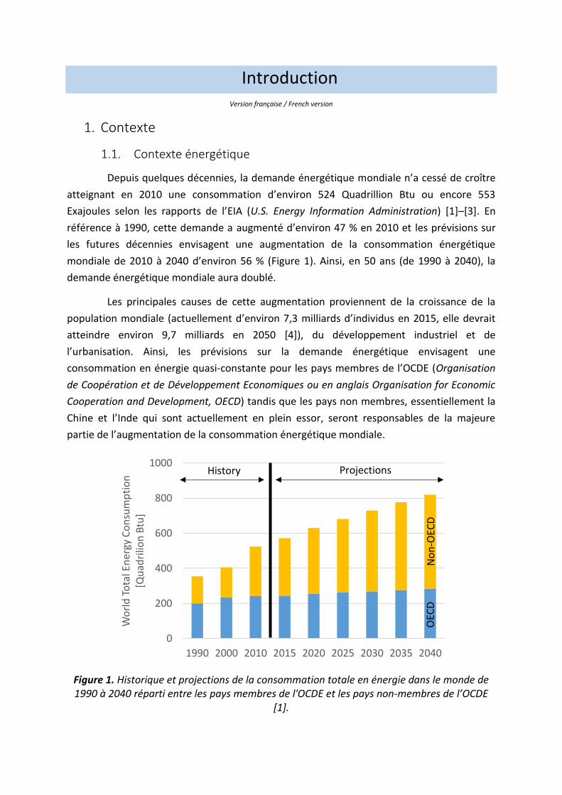
Depuis quelques décennies, la demande énergétique mondiale n’a cessé de croître
atteignant en 2010 une consommation d’environ 524 Quadrillion Btu ou encore 553
Exajoules selon les rapports de l’EIA (U.S. Energy Information Administration) [1]–[3]. En
référence à 1990, cette demande a augmenté d’environ 47 % en 2010 et les prévisions sur
les futures décennies envisagent une augmentation de la consommation énergétique
mondiale de 2010 à 2040 d’environ 56 % (Figure 1). Ainsi, en 50 ans (de 1990 à 2040), la
demande énergétique mondiale aura doublé.
Les principales causes de cette augmentation proviennent de la croissance de la
population mondiale (actuellement d’environ 7,3 milliards d’individus en 2015, elle devrait
atteindre environ 9,7 milliards en 2050 [4]), du développement industriel et de
l’urbanisation. Ainsi, les prévisions sur la demande énergétique envisagent une
consommation en énergie quasi-constante pour les pays membres de l’OCDE (Organisation
de Coopération et de Développement Economiques ou en anglais Organisation for Economic
Cooperation and Development, OECD) tandis que les pays non membres, essentiellement la
Chine et l’Inde qui sont actuellement en plein essor, seront responsables de la majeure
partie de l’augmentation de la consommation énergétique mondiale.
Figure 1. Historique et projections de la consommation totale en énergie dans le monde de 1990 à 2040 réparti entre les pays membres de l'OCDE et les pays non-membres de l’OCDE
[1].
0
200
400
600
800
1000
1990 2000 2010 2015 2020 2025 2030 2035 2040
Wo
rld
To
tal E
ner
gy C
on
sum
pti
on
[Q
uad
rilio
n B
tu]
History Projections
No
n-O
ECD
OEC
D
Introduction
24
Cette demande énergétique mondiale est répartie autour de deux grandes familles
d’énergie : les énergies renouvelables et les énergies non-renouvelables. Cette première
famille est composée de l’énergie solaire, éolienne, hydraulique, géothermique et enfin la
biomasse. La seconde famille est quant à elle composée de l’énergie nucléaire et des
énergies fossiles, ces dernières étant essentiellement le pétrole, le charbon et le gaz naturel.
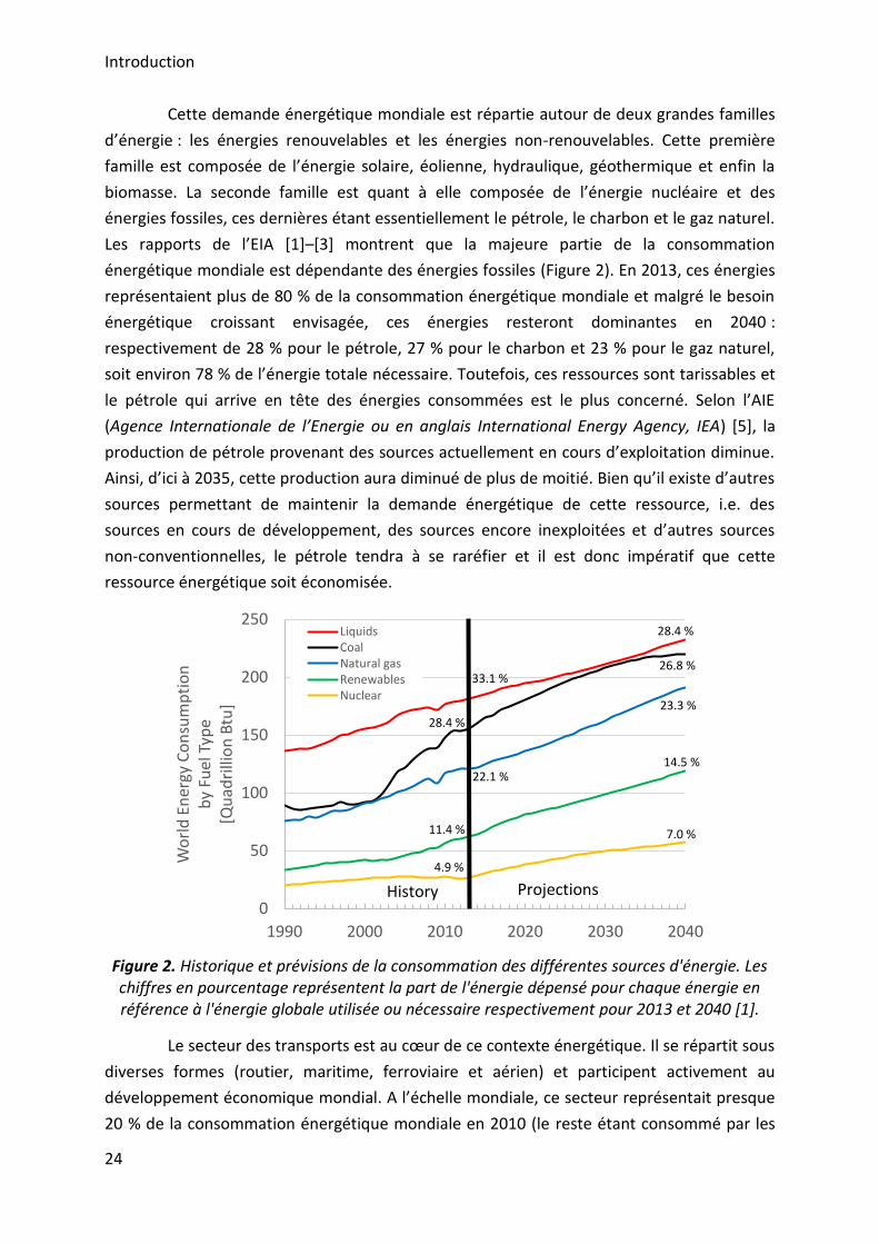
Les rapports de l’EIA [1]–[3] montrent que la majeure partie de la consommation
énergétique mondiale est dépendante des énergies fossiles (Figure 2). En 2013, ces énergies
représentaient plus de 80 % de la consommation énergétique mondiale et malgré le besoin
énergétique croissant envisagée, ces énergies resteront dominantes en 2040 :
respectivement de 28 % pour le pétrole, 27 % pour le charbon et 23 % pour le gaz naturel,
soit environ 78 % de l’énergie totale nécessaire. Toutefois, ces ressources sont tarissables et
le pétrole qui arrive en tête des énergies consommées est le plus concerné. Selon l’AIE
(Agence Internationale de l’Energie ou en anglais International Energy Agency, IEA) [5], la
production de pétrole provenant des sources actuellement en cours d’exploitation diminue.
Ainsi, d’ici à 2035, cette production aura diminué de plus de moitié. Bien qu’il existe d’autres
sources permettant de maintenir la demande énergétique de cette ressource, i.e. des
sources en cours de développement, des sources encore inexploitées et d’autres sources
non-conventionnelles, le pétrole tendra à se raréfier et il est donc impératif que cette
ressource énergétique soit économisée.
Figure 2. Historique et prévisions de la consommation des différentes sources d'énergie. Les chiffres en pourcentage représentent la part de l'énergie dépensé pour chaque énergie en référence à l'énergie globale utilisée ou nécessaire respectivement pour 2013 et 2040 [1].
Le secteur des transports est au cœur de ce contexte énergétique. Il se répartit sous
diverses formes (routier, maritime, ferroviaire et aérien) et participent activement au
développement économique mondial. A l’échelle mondiale, ce secteur représentait presque
20 % de la consommation énergétique mondiale en 2010 (le reste étant consommé par les
0
50
100
150
200
250
1990 2000 2010 2020 2030 2040
Wo
rld
En
ergy
Co
nsu
mp
tio
nb
y Fu
el T
ype
[Qu
adri
llio
n B
tu]
LiquidsCoalNatural gasRenewablesNuclear
History Projections
4.9 %
11.4 %
22.1 %
28.4 %
33.1 %
7.0 %
14.5 %
23.3 %
26.8 %
28.4 %
Introduction
25
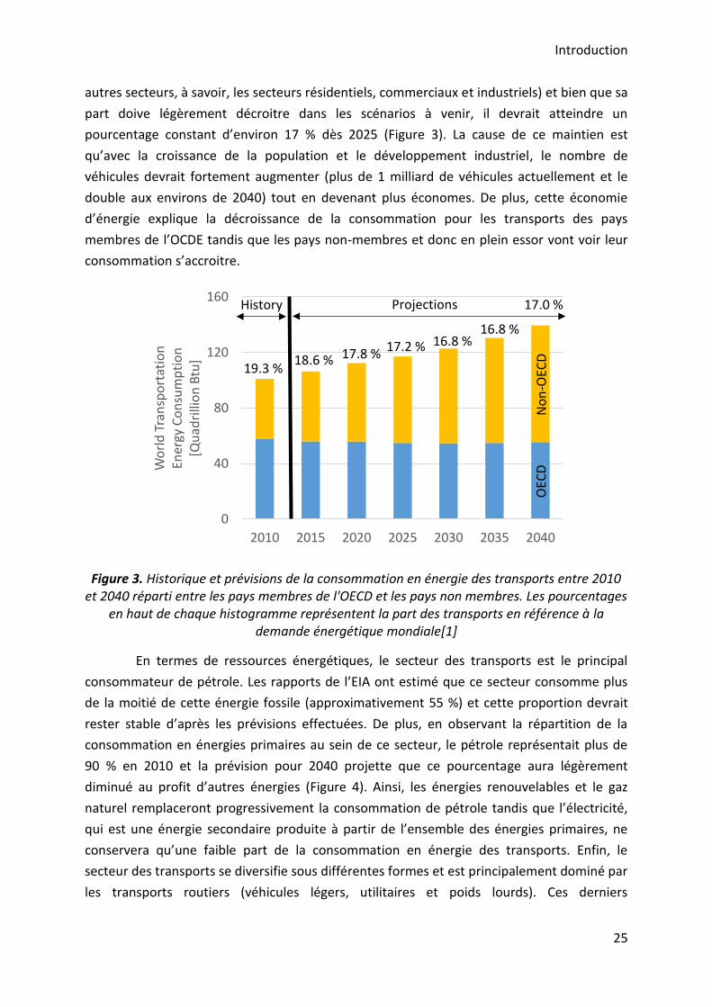
autres secteurs, à savoir, les secteurs résidentiels, commerciaux et industriels) et bien que sa
part doive légèrement décroitre dans les scénarios à venir, il devrait atteindre un
pourcentage constant d’environ 17 % dès 2025 (Figure 3). La cause de ce maintien est
qu’avec la croissance de la population et le développement industriel, le nombre de
véhicules devrait fortement augmenter (plus de 1 milliard de véhicules actuellement et le
double aux environs de 2040) tout en devenant plus économes. De plus, cette économie
d’énergie explique la décroissance de la consommation pour les transports des pays
membres de l’OCDE tandis que les pays non-membres et donc en plein essor vont voir leur
consommation s’accroitre.
Figure 3. Historique et prévisions de la consommation en énergie des transports entre 2010 et 2040 réparti entre les pays membres de l'OECD et les pays non membres. Les pourcentages
en haut de chaque histogramme représentent la part des transports en référence à la demande énergétique mondiale[1]
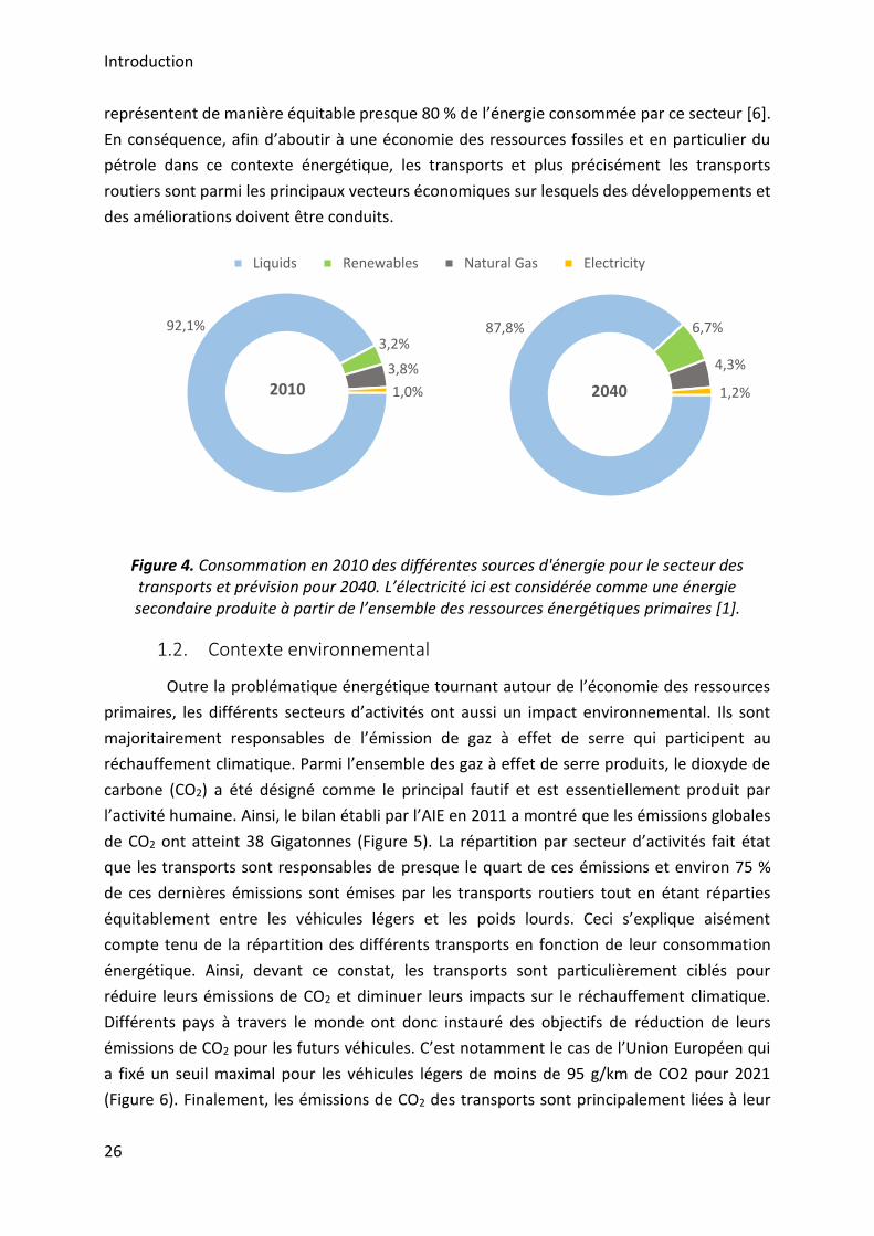
En termes de ressources énergétiques, le secteur des transports est le principal
consommateur de pétrole. Les rapports de l’EIA ont estimé que ce secteur consomme plus
de la moitié de cette énergie fossile (approximativement 55 %) et cette proportion devrait
rester stable d’après les prévisions effectuées. De plus, en observant la répartition de la
consommation en énergies primaires au sein de ce secteur, le pétrole représentait plus de
90 % en 2010 et la prévision pour 2040 projette que ce pourcentage aura légèrement
diminué au profit d’autres énergies (Figure 4). Ainsi, les énergies renouvelables et le gaz
naturel remplaceront progressivement la consommation de pétrole tandis que l’électricité,
qui est une énergie secondaire produite à partir de l’ensemble des énergies primaires, ne
conservera qu’une faible part de la consommation en énergie des transports. Enfin, le
secteur des transports se diversifie sous différentes formes et est principalement dominé par
les transports routiers (véhicules légers, utilitaires et poids lourds). Ces derniers
0
40
80
120
160
2010 2015 2020 2025 2030 2035 2040
Wo
rld
Tra
nsp
ort
atio
n
Ener
gy C
on
sum
pti
on
[Qu
adri
llio
n B
tu]
History Projections
No
n-O
ECD
OEC
D
19.3 %18.6 % 17.8 %
17.2 % 16.8 %16.8 %
17.0 %
Introduction
26
représentent de manière équitable presque 80 % de l’énergie consommée par ce secteur [6].
En conséquence, afin d’aboutir à une économie des ressources fossiles et en particulier du
pétrole dans ce contexte énergétique, les transports et plus précisément les transports
routiers sont parmi les principaux vecteurs économiques sur lesquels des développements et
des améliorations doivent être conduits.
Figure 4. Consommation en 2010 des différentes sources d'énergie pour le secteur des transports et prévision pour 2040. L’électricité ici est considérée comme une énergie secondaire produite à partir de l’ensemble des ressources énergétiques primaires [1].
1.2. Contexte environnemental
Outre la problématique énergétique tournant autour de l’économie des ressources
primaires, les différents secteurs d’activités ont aussi un impact environnemental. Ils sont
majoritairement responsables de l’émission de gaz à effet de serre qui participent au
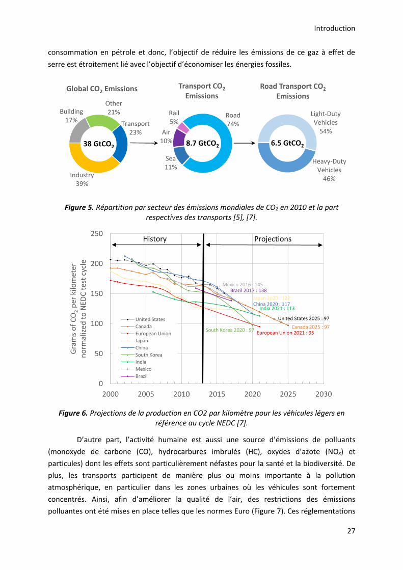
réchauffement climatique. Parmi l’ensemble des gaz à effet de serre produits, le dioxyde de
carbone (CO2) a été désigné comme le principal fautif et est essentiellement produit par
l’activité humaine. Ainsi, le bilan établi par l’AIE en 2011 a montré que les émissions globales
de CO2 ont atteint 38 Gigatonnes (Figure 5). La répartition par secteur d’activités fait état
que les transports sont responsables de presque le quart de ces émissions et environ 75 %
de ces dernières émissions sont émises par les transports routiers tout en étant réparties
équitablement entre les véhicules légers et les poids lourds. Ceci s’explique aisément
compte tenu de la répartition des différents transports en fonction de leur consommation
énergétique. Ainsi, devant ce constat, les transports sont particulièrement ciblés pour
réduire leurs émissions de CO2 et diminuer leurs impacts sur le réchauffement climatique.
Différents pays à travers le monde ont donc instauré des objectifs de réduction de leurs
émissions de CO2 pour les futurs véhicules. C’est notamment le cas de l’Union Européen qui
a fixé un seuil maximal pour les véhicules légers de moins de 95 g/km de CO2 pour 2021
(Figure 6). Finalement, les émissions de CO2 des transports sont principalement liées à leur
92,1%3,2%
3,8%
1,0%2010
Liquids Renewables Natural Gas Electricity
87,8% 6,7%
4,3%
1,2%2040
Introduction
27
consommation en pétrole et donc, l’objectif de réduire les émissions de ce gaz à effet de
serre est étroitement lié avec l’objectif d’économiser les énergies fossiles.
Figure 5. Répartition par secteur des émissions mondiales de CO2 en 2010 et la part
respectives des transports [5], [7].
Figure 6. Projections de la production en CO2 par kilomètre pour les véhicules légers en référence au cycle NEDC [7].
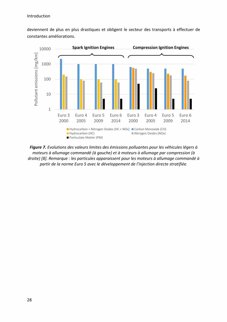
D’autre part, l’activité humaine est aussi une source d’émissions de polluants
(monoxyde de carbone (CO), hydrocarbures imbrulés (HC), oxydes d’azote (NOx) et
particules) dont les effets sont particulièrement néfastes pour la santé et la biodiversité. De
plus, les transports participent de manière plus ou moins importante à la pollution
atmosphérique, en particulier dans les zones urbaines où les véhicules sont fortement
concentrés. Ainsi, afin d’améliorer la qualité de l’air, des restrictions des émissions
polluantes ont été mises en place telles que les normes Euro (Figure 7). Ces réglementations
Transport23%
Industry39%
Building17%
Other21%
Global CO2 Emissions
38 GtCO2
Air10%
Rail5%
Road74%
Sea11%
Transport CO2
Emissions
8.7 GtCO2
Heavy-Duty Vehicles
46%
Light-Duty Vehicles
54%
Road Transport CO2
Emissions
6.5 GtCO2
0
50
100
150
200
250
2000 2005 2010 2015 2020 2025 2030
Gra
ms
of
CO
2p
er k
ilom
eter
n
orm
aliz
ed t
o N
EDC
tes
t cy
cle
United States
Canada
European Union
Japan
China
South Korea
India
Mexico
Brazil
ProjectionsHistory
European Union 2021 : 95
India 2021 : 113
South Korea 2020 : 97
United States 2025 : 97
Canada 2025 : 97
Japan 2020 : 122China 2020 : 117
Brazil 2017 : 138Mexico 2016 : 145
Introduction
28
deviennent de plus en plus drastiques et obligent le secteur des transports à effectuer de
constantes améliorations.
Figure 7. Evolutions des valeurs limites des émissions polluantes pour les véhicules légers à moteurs à allumage commandé (à gauche) et à moteurs à allumage par compression (à
droite) [8]. Remarque : les particules apparaissent pour les moteurs à allumage commandé à partir de la norme Euro 5 avec le développement de l’injection directe stratifiée.
1
10
100
1000
10000
Euro 32000
Euro 42005
Euro 52009
Euro 62014
Euro 32000
Euro 42005
Euro 52009
Euro 62014
Po
lluta
nt
em
issi
on
s [m
g/k
m]
Hydrocarbon + Nitrogen Oxides (HC + NOx) Carbon Monoxide (CO)Hydrocarbon (HC) Nitrogen Oxides (NOx)Particulate Matter (PM)
Spark Ignition Engines Compression Ignition Engines
Introduction
29
2. Objectifs
Face à ce contexte énergétique et environnemental, le secteur des transports a
donc pour objectifs d’économiser les énergies fossiles utilisées, participant également à
réduire les émissions de CO2 des véhicules, et de participer à l’amélioration de la qualité de
l’air. De plus, le secteur doit également continuer d’améliorer les rendements des véhicules.
Actuellement, la propulsion des véhicules est essentiellement réalisée aux moyens
des moteurs à combustion interne. Néanmoins, les contraintes énergétiques et
environnementales ont permis l’émergence d’autres types de propulsion telle que la
propulsion électrique ou encore la propulsion hybride. La première semble être la solution
idéale car les véhicules n’émettraient plus aucuns polluants (véhicules zéro émission) mais il
faut aussi prendre en considération la production d’électricité. Cette énergie est
majoritairement produite à partir des ressources primaires et est elle-même une source
importante d’émissions. De plus, ces véhicules sont soumis à deux problèmes majeurs : les
réseaux de distribution pour la recharge des batteries ne sont pas suffisamment développés
et la densité énergétique des batteries, médiocre en comparaison avec les carburants
conventionnels utilisés, pose un problème d’autonomie. L’hybridation, qui consiste à
combiner la propulsion au moyen d’un moteur à combustion interne et la propulsion
électrique, semble avoir de fortes possibilités d’aboutir à une large utilisation au sein des
véhicules mais nécessitera le maintien d’un moteur thermique. Ainsi, le moteur à
combustion interne continuera à propulser des véhicules au cours des futures décennies.
Le moteur à combustion interne est essentiellement dominé par deux types de
modes de combustion : le moteur à allumage commandé et le moteur à allumage par
compression. De nombreuses innovations et améliorations ont été implantées pour chacun
d’entre eux afin de répondre au contexte énergétique et environnemental mais face à des
réglementations de plus en plus drastiques, de nouveaux modes de combustion ont émergés
comme alternatives aux modes de combustion conventionnels. Ces modes de combustion
alternatifs, regroupés sous l’acronyme LTC (Low Temperature Combustion), permettent
potentiellement de réduire la consommation en carburants des moteurs, et donc leurs
émissions de CO2. Ces moteurs conduisent aussi à des émissions de particules et d’oxydes
d’azote (NOx) très faibles en raison des basses températures de combustion et maintiennent
de hauts rendements grâce à l’emploi de fort taux de compression. De plus, leur intérêt est
renforcé par leur possibilité d’utiliser un large choix de carburants (conventionnels et
alternatifs) dont certains sont actuellement en pleine émergence.
Parmi ces nouveaux modes de combustion, le mode HCCI (Homogeneous Charge
Compression Ignition), dont le principe consiste en une combinaison des modes de
combustion conventionnels, i.e. la préparation d’un mélange homogène entre l’air et le
Introduction
30
carburant comme pour le moteur à allumage commandé puis ce mélange est auto-inflammé
comme pour le moteur à allumage par compression, fait l’objet de nombreuses recherches.
En effet, il participe activement à la compréhension des phénomènes de combustion
homogènes intervenant dans la plupart des nouveaux modes de combustion ainsi qu’à leur
développement. Néanmoins, à la différence des moteurs conventionnels, le mode HCCI ne
possède pas de dispositifs permettant de contrôler efficacement l’ensemble du processus de
combustion. L’initiation de la combustion, entièrement contrôlée par les mécanismes de
cinétique chimique, est donc le principal challenge à surmonter. De nombreuses méthodes
ont fait l’objet d’investigations et d’applications et les études les plus récentes s’intéressent
à l’impact de différentes espèces chimiques oxydantes. Parmi le large panel d’espèces
chimiques oxydantes, plusieurs études ont été menées sur l’utilisation de l’ozone et ont
démontré que cette molécule a un fort potentiel [9]–[13]. L’ozone est essentiellement formé
à l’aide de générateurs à décharges plasma alimentés par un gaz contenant de l’oxygène tel
que l’air, ainsi, l’utilisation de tels appareils pourrait susciter un réel intérêt pour de futures
applications automobiles intégrant les nouveaux modes de combustion.
Dans le cadre du projet ERC Advanced Grant 2G-CSafe (Combustion of Sustainable
Alternative Fuels for Engines used in aeronautics and automotives), un des objectifs est
d’étudier l’impact d’espèces chimiques réactives sur le déroulement de la combustion au
sein de moteurs tel que le HCCI afin d’apporter de nouvelles stratégies de contrôle de la
combustion et éventuellement de nouvelles possibilités technologiques. La présente thèse
porte ainsi sur l’effet de l’ensemencement à l’admission d’un moteur HCCI par des espèces
chimiques minoritaires oxydantes produites au moyen d’un générateur à décharges plasma
et les possibilités applicatives de tels dispositifs au sein d’un véhicule conventionnel. Le
travail est majoritairement centré sur la compréhension de l’impact de ces espèces
chimiques et s’étend jusqu’à une première approche applicative de ce type de dispositif.
Puis, compte tenu de la flexibilité en carburant des nouveaux modes de combustion, une
seconde approche s’intéresse à l’effet de l’ozone sur divers carburants alternatifs.
Introduction
31
3. Plan du mémoire
La présente thèse traite d’une étude expérimentale couplée à des simulations de
cinétique chimique avec pour objectif principal d’étudier l’impact de diverses espèces
chimiques oxydantes minoritaires issues des générateurs à décharges plasma sur la
combustion HCCI. Les recherches menées considèrent aussi le potentiel applicatif de ces
dispositifs ainsi que l’utilisation de différentes familles de carburant. Ces travaux de thèse
ont été menés dans le cadre d’un contrat européen et ce manuscrit est basé sur les articles
de journaux et papiers de conférence publiés. Il est donc divisé en cinq chapitres distincts
intégralement rédigés en anglais. Chaque début de chapitre comporte un résumé en français
et en anglais mettant en évidence les principales informations et résultats retenues. Ce
mémoire s’organise donc comme ci-après.
Le premier chapitre consiste en une étude bibliographique sur la combustion HCCI.
Dans une première partie, un bilan des différents modes de combustion conventionnels sera
tout d’abord effectué et introduira les nouveaux modes de combustion dont fait partie le
mode HCCI. L’importance des recherches effectuées et en cours sur ce dernier sera mise en
avant et permettra de décrire son principe ainsi que ses différentes caractéristiques.
Finalement, les avantages et les inconvénients de ce mode de combustion alternatif
entièrement gouverné par les mécanismes de cinétique chimique seront exposés pour
mettre en évidence les enjeux qui limitent son développement et son application au sein
d’un véhicule conventionnel. Parmi les nombreux challenges à surmonter, des méthodes
originales ont été proposées afin de contrôler efficacement l’ensemble du processus de
combustion. Ce dernier étant fortement influencé par de nombreux paramètres, un état de
l’art sur la plupart d’entre eux et leurs impacts respectifs sera présenté.
Le deuxième chapitre fera l’objet d’une description des différents moyens
expérimentaux et outils numériques utilisés pour ces travaux de thèse. Le banc moteur
utilisé pour les essais expérimentaux HCCI sera entièrement détaillé ainsi que son
instrumentation et l’acquisition des données. Ce banc expérimental a permis d’étudier
différents types de carburant, un tableau récapitulatif des carburants retenus et de leurs
propriétés respectives sera donc dressé. Finalement, dans le cadre de ces recherches, les
méthodologies et les dispositifs nécessaires afin d’étudier l’impact des espèces chimiques
oxydantes seront également mis en évidence. Suite à cette description, la procédure de
post-traitement des données enregistrées mise en place conduisant aux résultats finaux sera
décrite. Enfin, ce chapitre se terminera par une description des simulations de cinétique
chimique conduites. Le modèle utilisé sera présenté et accompagné des schémas et sous-
Introduction
32
schémas cinétiques retenus pour la compréhension de l’impact des différentes espèces
chimiques sélectionnées.
Finalement, les chapitres suivants de ce manuscrit seront entièrement consacrés
aux résultats obtenus au cours de ces travaux de thèse et valorisés par des publications. Ces
chapitres s’organisent donc suivant le fil conducteur décrit ci-après.
La première partie des résultats est consacrée à une large étude sur la combustion
des « Primary Reference Fuels (PRFs) », i.e. l’isooctane et le n-heptane ainsi que les
mélanges de ces deux carburants. Tout d’abord, les recherches conduites sur la combustion
des PRFs sans ensemencement d’espèces chimiques oxydantes seront présentées dans
l’objectif d’appréhender les différentes conditions nécessaires à l’auto-inflammation de ces
carburants. Suite à ces résultats, l’étude se concentrera sur l’impact de l’ozone sur la
combustion des PRFs au moyen d’expériences effectuées à l’aide du banc moteur HCCI ainsi
qu’au moyen de simulations numériques. Face aux observations réalisées, un travail
expérimental plus approfondi sur l’impact de l’ozone sur la combustion de l’isooctane sera
présenté en vue de démontrer le potentiel de l’utilisation de cette molécule chimique
oxydante. Finalement, en considérant une probable application d’un générateur à décharges
plasma dans un véhicule, d’autres espèces chimiques oxydantes doivent être prises en
compte comme le monoxyde d’azote et le dioxyde d’azote, aussi présent dans les gaz
résiduels ou la recirculation des gaz d’échappement. Une étude comparative entre ces deux
espèces et l’ozone sur la combustion de l’isooctane sera donc également présentée ainsi que
l’effet de l’interaction entre l’ozone et le monoxyde d’azote. Enfin, un premier cas
d’application en vue de contrôler le processus de la combustion HCCI sera démontré et
analysé.
Les deux chapitres de résultats suivants s’intéresseront à la combustion HCCI de
carburants alternatifs et une comparaison avec les précédents résultats obtenus sur les PRFs
pourra être effectuée. Tout d’abord, les résultats seront focalisés sur les carburants gazeux,
en particulier le méthane et des mélanges contenant majoritairement du méthane. Les
résultats de ce chapitre suivront le même cheminement que les résultats obtenus avec les
PRFs en partant d’une étude de l’auto-inflammation de carburants gazeux purs puis l’impact
de l’ozone sera interprété à partir d’essais expérimentaux couplés à des simulations de
cinétique chimique. Finalement, le dernier chapitre des résultats se concentrera sur la
combustion des carburants de seconde génération et plus précisément sur les carburants de
la famille des alcools. L’étude se focalisera sur trois alcools : le méthanol, l’éthanol et le
butanol, et s’orientera elle aussi de manière similaire à l’étude conduite sur les PRFs.

Introduction
33
Ce mémoire se terminera finalement par un bilan de l’ensemble des expériences et
simulations conduites ainsi que sur l’apport des résultats obtenus pour la communauté
scientifique et le développement des nouveaux modes de combustion. De plus, compte tenu
de l’aspect émergent et innovant de ces recherches, de nombreuses perspectives seront
évoquées.

Introduction Version anglaise / English version
1. Context
1.1. Energetic context
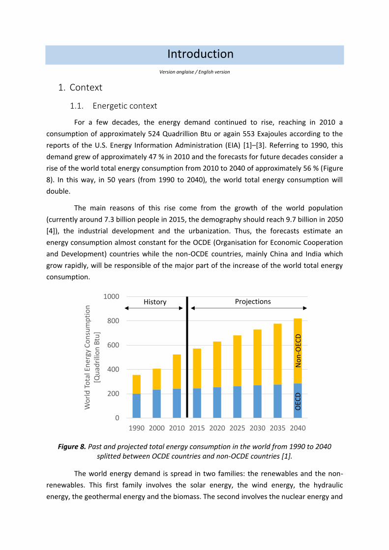
For a few decades, the energy demand continued to rise, reaching in 2010 a
consumption of approximately 524 Quadrillion Btu or again 553 Exajoules according to the
reports of the U.S. Energy Information Administration (EIA) [1]–[3]. Referring to 1990, this
demand grew of approximately 47 % in 2010 and the forecasts for future decades consider a
rise of the world total energy consumption from 2010 to 2040 of approximately 56 % (Figure
8). In this way, in 50 years (from 1990 to 2040), the world total energy consumption will
double.
The main reasons of this rise come from the growth of the world population
(currently around 7.3 billion people in 2015, the demography should reach 9.7 billion in 2050
[4]), the industrial development and the urbanization. Thus, the forecasts estimate an
energy consumption almost constant for the OCDE (Organisation for Economic Cooperation
and Development) countries while the non-OCDE countries, mainly China and India which
grow rapidly, will be responsible of the major part of the increase of the world total energy
consumption.
Figure 8. Past and projected total energy consumption in the world from 1990 to 2040 splitted between OCDE countries and non-OCDE countries [1].
The world energy demand is spread in two families: the renewables and the non-
renewables. This first family involves the solar energy, the wind energy, the hydraulic
energy, the geothermal energy and the biomass. The second involves the nuclear energy and
0
200
400
600
800
1000
1990 2000 2010 2015 2020 2025 2030 2035 2040
Wo
rld
To
tal E
ner
gy C
on
sum
pti
on
[Q
uad
rilio
n B
tu]
History ProjectionsN
on
-OEC
DO
ECD
Introduction
36
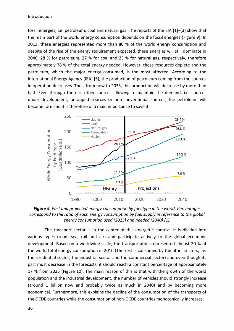
fossil energies, i.e. petroleum, coal and natural gas. The reports of the EIA [1]–[3] show that
the main part of the world energy consumption depends on the fossil energies (Figure 9). In
2013, these energies represented more than 80 % of the world energy consumption and
despite of the rise of the energy requirement expected, these energies will still dominate in
2040: 28 % for petroleum, 27 % for coal and 23 % for natural gas, respectively, therefore
approximately 78 % of the total energy needed. However, these resources deplete and the
petroleum, which the major energy consumed, is the most affected. According to the
International Energy Agency (IEA) [5], the production of petroleum coming from the sources
in operation decreases. Thus, from now to 2035, this production will decrease by more than
half. Even through there is other sources allowing to maintain the demand, i.e. sources
under development, untapped sources or non-conventional sources, the petroleum will
become rare and it is therefore of a main importance to save it.
Figure 9. Past and projected energy consumption by fuel type in the world. Percentages correspond to the ratio of each energy consumption by fuel supply in reference to the global
energy consumption used (2013) and needed (2040) [1].
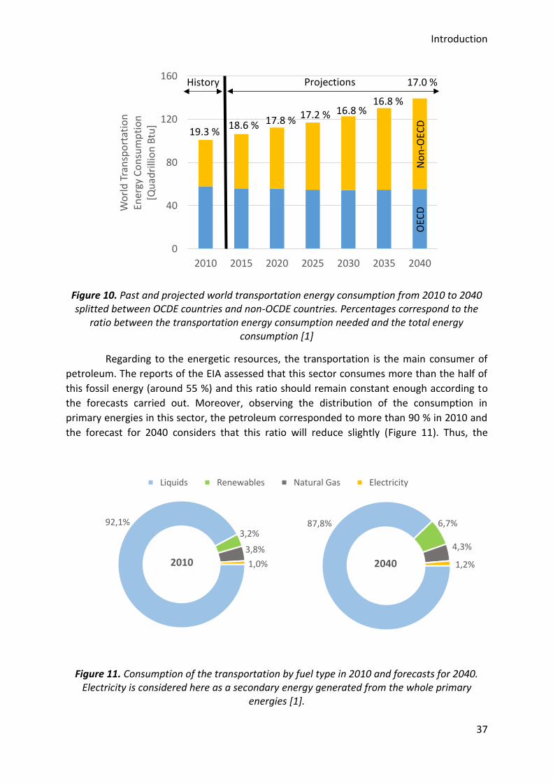
The transport sector is in the center of this energetic context. It is divided into
various types (road, sea, rail and air) and participate actively to the global economic
development. Based on a worldwide scale, the transportation represented almost 20 % of
the world total energy consumption in 2010 (The rest is consumed by the other sectors, i.e.
the residential sector, the industrial sector and the commercial sector) and even though its
part must decrease in the forecasts, it should reach a constant percentage of approximately
17 % from 2025 (Figure 10). The main reason of this is that with the growth of the world
population and the industrial development, the number of vehicles should strongly increase
(around 1 billion now and probably twice as much in 2040) and by becoming more
economical. Furthermore, this explains the decline of the consumption of the transports of
the OCDE countries while the consumption of non-OCDE countries monotonically increases.
0
50
100
150
200
250
1990 2000 2010 2020 2030 2040
Wo
rld
En
erg
y C
on
sum
pti
on
by
Fuel
Typ
e[Q
uad
rilli
on
Btu
]
LiquidsCoalNatural gasRenewablesNuclear
History Projections
4.9 %
11.4 %
22.1 %
28.4 %
33.1 %
7.0 %
14.5 %
23.3 %
26.8 %
28.4 %
Introduction
37
Figure 10. Past and projected world transportation energy consumption from 2010 to 2040 splitted between OCDE countries and non-OCDE countries. Percentages correspond to the
ratio between the transportation energy consumption needed and the total energy consumption [1]
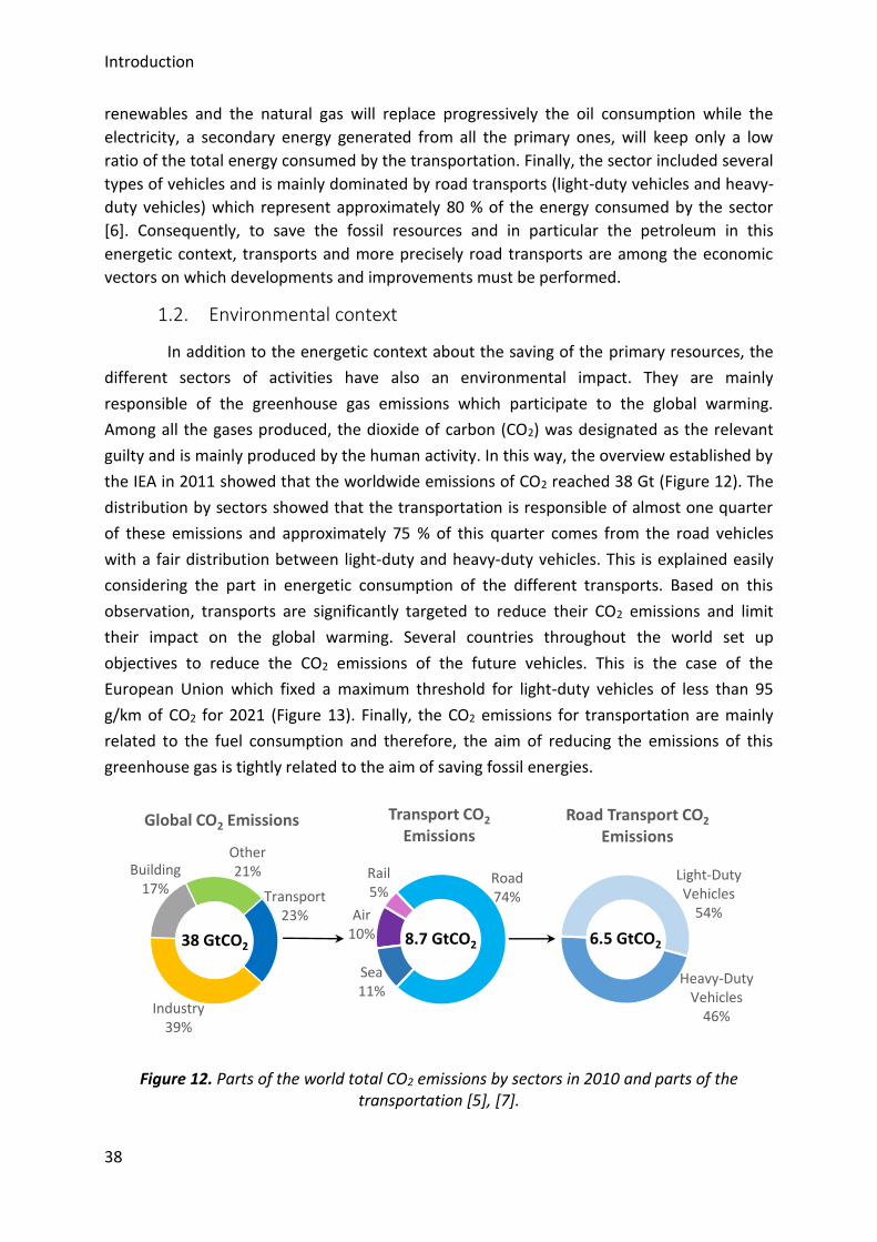
Regarding to the energetic resources, the transportation is the main consumer of
petroleum. The reports of the EIA assessed that this sector consumes more than the half of
this fossil energy (around 55 %) and this ratio should remain constant enough according to
the forecasts carried out. Moreover, observing the distribution of the consumption in
primary energies in this sector, the petroleum corresponded to more than 90 % in 2010 and
the forecast for 2040 considers that this ratio will reduce slightly (Figure 11). Thus, the
Figure 11. Consumption of the transportation by fuel type in 2010 and forecasts for 2040. Electricity is considered here as a secondary energy generated from the whole primary
energies [1].
0
40
80
120
160
2010 2015 2020 2025 2030 2035 2040
Wo
rld
Tra
nsp
ort
atio
n
Ener
gy C
on
sum
pti
on
[Qu
adri
llio
n B
tu]
History Projections
No
n-O
ECD
OEC
D
19.3 %18.6 % 17.8 %
17.2 % 16.8 %16.8 %
17.0 %
92,1%3,2%
3,8%
1,0%2010
Liquids Renewables Natural Gas Electricity
87,8% 6,7%
4,3%
1,2%2040
Introduction
38
renewables and the natural gas will replace progressively the oil consumption while the
electricity, a secondary energy generated from all the primary ones, will keep only a low
ratio of the total energy consumed by the transportation. Finally, the sector included several
types of vehicles and is mainly dominated by road transports (light-duty vehicles and heavy-
duty vehicles) which represent approximately 80 % of the energy consumed by the sector
[6]. Consequently, to save the fossil resources and in particular the petroleum in this
energetic context, transports and more precisely road transports are among the economic
vectors on which developments and improvements must be performed.
1.2. Environmental context
In addition to the energetic context about the saving of the primary resources, the
different sectors of activities have also an environmental impact. They are mainly
responsible of the greenhouse gas emissions which participate to the global warming.
Among all the gases produced, the dioxide of carbon (CO2) was designated as the relevant
guilty and is mainly produced by the human activity. In this way, the overview established by
the IEA in 2011 showed that the worldwide emissions of CO2 reached 38 Gt (Figure 12). The
distribution by sectors showed that the transportation is responsible of almost one quarter
of these emissions and approximately 75 % of this quarter comes from the road vehicles
with a fair distribution between light-duty and heavy-duty vehicles. This is explained easily
considering the part in energetic consumption of the different transports. Based on this
observation, transports are significantly targeted to reduce their CO2 emissions and limit
their impact on the global warming. Several countries throughout the world set up
objectives to reduce the CO2 emissions of the future vehicles. This is the case of the
European Union which fixed a maximum threshold for light-duty vehicles of less than 95
g/km of CO2 for 2021 (Figure 13). Finally, the CO2 emissions for transportation are mainly
related to the fuel consumption and therefore, the aim of reducing the emissions of this
greenhouse gas is tightly related to the aim of saving fossil energies.
Figure 12. Parts of the world total CO2 emissions by sectors in 2010 and parts of the
transportation [5], [7].
Transport23%
Industry39%
Building17%
Other21%
Global CO2 Emissions
38 GtCO2
Air10%
Rail5%
Road74%
Sea11%
Transport CO2
Emissions
8.7 GtCO2
Heavy-Duty Vehicles
46%
Light-Duty Vehicles
54%
Road Transport CO2
Emissions
6.5 GtCO2
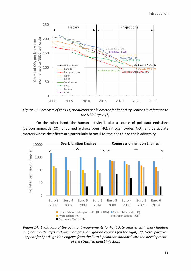
Introduction
39
Figure 13. Forecasts of the CO2 production per kilometer for light duty vehicles in reference to the NEDC cycle [7].
On the other hand, the human activity is also a source of pollutant emissions
(carbon monoxide (CO), unburned hydrocarbons (HC), nitrogen oxides (NOX) and particulate
matter) whose the effects are particularly harmful for the health and the biodiversity.
Figure 14. Evolutions of the pollutant requirements for light duty vehicles with Spark Ignition engines (on the left) and with Compression Ignition engines (on the right) [8]. Note: particles appear for Spark Ignition engines from the Euro 5 pollutant standard with the development
of the stratified direct injection.
0
50
100
150
200
250
2000 2005 2010 2015 2020 2025 2030
Gra
ms
of
CO
2p
er k
ilom
eter
n
orm
aliz
ed t
o N
EDC
tes
t cy
cle
United States
Canada
European Union
Japan
China
South Korea
India
Mexico
Brazil
ProjectionsHistory
European Union 2021 : 95
India 2021 : 113
South Korea 2020 : 97
United States 2025 : 97
Canada 2025 : 97
Japan 2020 : 122China 2020 : 117
Brazil 2017 : 138Mexico 2016 : 145
1
10
100
1000
10000
Euro 32000
Euro 42005
Euro 52009
Euro 62014
Euro 32000
Euro 42005
Euro 52009
Euro 62014
Pollu
tan
t em
issi
on
s [m
g/k
m]
Hydrocarbon + Nitrogen Oxides (HC + NOx) Carbon Monoxide (CO)Hydrocarbon (HC) Nitrogen Oxides (NOx)Particulate Matter (PM)
Spark Ignition Engines Compression Ignition Engines

Introduction
40
Moreover, the transportation participates more or less significantly to the atmospheric
pollution, in particular in the urban areas where vehicles are highly concentrated. Thus, in
order to improve the air quality, pollutant limitations were established such as the Euro
standards (Figure 14). These requirements become increasingly drastic and force the sector
to perform improvements continuously.
Introduction
41
2. Objectives
Based on this energetic and environmental context, the transports sector has
therefore for objectives to save fossil resources used, participating also to the reduction of
CO2 emissions coming from the vehicles, and to enhance the air quality. Moreover, the
sector must also continue to improve the efficiencies of the vehicles.
Currently, vehicles propulsion is essentially performed with the help of internal
combustion engines. Nevertheless, the energetic and environmental constraints allowed the
emergence of other kinds of propulsion such as the electric propulsion or again the hybrid
propulsion. The first seems to be the best solution because vehicles do not emit pollutants
(zero emission vehicles) but it is necessary to consider the electricity production. This energy
is largely produced from primary resources and it is itself a significant source of pollutant
emissions. Moreover, these type of vehicles are submitted to two main problems: the
distribution networks the battery regeneration are not developed enough and the density of
the batteries which is very weak compared to conventional fuels used limits the autonomy.
The hybridization, which consists in merging the propulsion coming from an internal
combustion engine and the electrical propulsion, seems to have strong possibilities for a
wide use into vehicles but maintaining an internal combustion engine is needed. In
conclusion, the internal combustion engine still continues to power vehicles in the future
decades.
The internal combustion engine is dominated by two kinds of combustion modes:
the spark ignition engine and the compression ignition engine. Lots of innovations and
improvements were implemented for each of them to answer to the energetic and
environmental context. However, in front of the more and more stringent requirements,
new combustion modes emerged as alternatives to the conventional ones. Potentially, these
advanced combustion modes, gather under the acronym LTC (Low Temperature
Combustion), allow to reduce fuel consumption of the engines, and therefore their CO2
emissions. These engines also allow to achieve low emissions of NOx and particulate matter
due to the low temperatures of combustion and allow to keep high efficiencies thanks to the
use of high compression ratios. Finally, their interest is strengthened with the possibility of
using a wide range of fuel (conventional and alternative) whose some of them are in full
expansion.
Among all the advanced combustion engines, the HCCI (Homogeneous Charge
Compression Ignition) mode is of a main interest and many studies focused on. Its principle
consists in a combination of the two conventional combustion modes, i.e. the air/fuel
mixture is prepared in front of the combustion chamber as in spark ignition engines and this
mixture is autoignited with the compression stroke as in compression ignition engines.
Therefore, it mainly participates to the understanding of the homogeneous combustion
Introduction
42
phenomena observed in all the advanced combustion engines as well as to their
development. Moreover, it could be itself implemented into vehicles for real applications.
Nevertheless, unlike both conventional combustion modes, HCCI mode does not have
system to control efficiently the whole combustion process. The HCCI combustion, which is
entirely governed by the kinetics mechanisms, is therefore the main issue to overcome.
Plenty of methods were investigated and implemented and the most recent studies focus on
the impact of oxidizing chemical species. In particular, several studies were performed on
the use of ozone and showed that this molecule has a strong potential [9]–[13]. Ozone is
essentially produced with the help of devices generating plasma discharges supplied by a gas
containing oxygen such as air. Moreover, these devices tend to become increasingly small.
As a result, their use onboard a vehicle could elevate interest for future applications with
advanced combustion engines.
Under the ERC Advanced Grant 2G-CSafe (Combustion of Sustainable Alternative
Fuels for Engines used in aeronautics and automotives) framework, one of the objectives is
to study the impact of oxidizing chemical species on the combustion process into engines
such as the HCCI one in order to propose innovative strategies for controlling the
combustion and help in the development of new technologies. The aim of the present Thesis
is to investigate the impact of seeding the intake of an HCCI engine with minor oxidizing
chemical species created by devices generating plasma discharges and to study the potential
application of such a device into a real vehicle. This work will mainly focus on the
understanding of the impact of these oxidizing chemical species and will extend up to a first
application of such a device. Then, considering the fuel flexibility of the advanced
combustion engines, a second part will observe the impact of ozone on various alternative
fuels.
Introduction
43
3. Organization of the manuscript
The present Thesis is about an experimental study on the HCCI combustion coupled
to kinetics computations with the aim to investigate the impact of various minor oxidizing
chemical species coming from devices generating plasma discharges. Research conducted
also considers the potential application of such a device as well as the use of different fuels.
This work was performed under a European framework and this memory is based on the
journal articles and conference papers published. It is therefore split into five separate
chapters entirely written in English. The beginning of each chapter includes an abstract in
French and in English to highlight the main discussions and results retained. The manuscript
is therefore organized as follows.
The first chapter consists in a review on the HCCI combustion. First, a review on the
different conventional combustion modes will be performed and will introduce the
advanced combustion modes, in particular, the HCCI combustion. The research conducted
and ongoing on this combustion mode will be highlighted and will allow introducing its
principle as well as its main features. Finally, advantages and drawbacks of this alternative
combustion mode totally governed by kinetics mechanisms will be outlined to show the
challenges which limit its development and its implementation into a conventional vehicle.
Among the numerous issues to overcome, original methods were proposed to control
efficiently the overall combustion process. The HCCI combustion process is strongly
influenced by plenty of parameters and a state of the art on most of them and their
respective impact will be introduced.
The second chapter consists of a description of the experimental setup and
numerical tools used for this work. The engine bench used for the experiments will be
described entirely as well as its instrumentation and the data acquisition. This experimental
setup allowed studying various kinds of fuel and a table summarizes their main
characteristics. Then, for these researches, the methods and the devices needed to
investigate the impact of the oxidizing chemical species will be highlighted. Following this,
the post-process of the data recorded developed for obtaining the final outputs will be
described. Finally, this chapter will end by a description of the kinetics computations
performed. The model used will be introduced as well as the main mechanisms and sub-
mechanisms retained for understanding the impact of the different oxidizing chemical
species selected.
Finally, the next chapters of this memory will focus on the results obtained and the
articles published. They are organized according the following main thread.
The first chapter of the results consists in a wide study on the combustion of
Primary Reference Fuels (PRFs), i.e. isooctane and n-heptane as well as mixtures of these
two fuels. First, the research conducted on the combustion of PRFs without any seeding with
Introduction
44
the aim to determine the conditions needed to autoignite the fuels selected. Following these
results, the study will focus on the effect of ozone on the combustion of the PRFs through
experiments performed on the engine bench and computations. Based on these prior
observations, a deeper experimental investigation on the impact of ozone on the HCCI
combustion for isooctane as fuel will be presented to highlight the potential of this oxidizing
chemical species. Then, considering a potential application of the device generating plasma
discharges onboard a vehicle, others oxidizing chemical species must be taken into account
such as nitric oxide and nitrogen dioxide, also found into residuals or exhaust gas
recirculation. A comparison between both species and ozone on the isooctane combustion
will be also introduced as well as the interaction between ozone and nitric oxide. Finally, a
first application case for controlling dynamically the HCCI combustion process has been
implemented and analyzed.
The two following chapters of results will consider the HCCI combustion of
alternative fuels and a comparison with previous results obtained with PRFs could be carried
out. First, the results will focus on gaseous fuels, in particular methane and blend with high
fractions of methane. A similar analysis of the outputs obtained for these fuels than for PRFs
will be conducted, i.e. a study on the autoignition of each fuel without any seeding and a
study of the ozone effect through experiments and computations. Then, the last chapter of
results will focus on the combustion of second-generation fuels and more precisely on
alcohol fuels. Three fuels were selected: methanol, ethanol and n-butanol and a similar
approach than that already carries out for PRFs will be performed.
This manuscript will end by a summary of all the experiments and computations
performed as well as the contribution brings to the scientific community and to the
development of advanced combustion engines. Moreover, according to the innovative and
emerging aspect of these research, lots of prospects will be discussed.
Chapitre 1 / Chapter 1
Etat de l’art sur la combustion HCCI
Review on the HCCI combustion
Chapter 1
46
Résumé
Le premier chapitre de ce mémoire est consacré à une étude bibliographique sur la
combustion HCCI (Homogeneous Charge Compression Ignition). Cette étude débute par une
introduction des différents moteurs conventionnels, à savoir le moteur à allumage
commandé et le moteur à allumage par compression. Les principes de ces deux modes de
combustion sont énoncés et permettent d’introduire les modes de combustion alternatifs.
Compte tenu du grand nombre de nouveaux modes existants, seul les plus pertinents et
répandus pour répondre au contexte énergétique et environnemental du secteur des
transports ont été présentés.
La combustion HCCI étant un contexte d’étude obligatoire pour la compréhension
des phénomènes d’auto-inflammation dans les moteurs, elle a été l’objet d’une attention
particulière. Son principe de combustion a été comparé à ceux des modes de combustion
conventionnels puis ses avantages et inconvénients ont été mis en évidence. Toutefois, il
existe un frein au développement applicatif de la combustion HCCI. La totalité du processus
de combustion est gouvernée par les mécanismes d’auto-inflammation qui peuvent être
décrit à l’aide de la cinétique chimique et doit être contrôlé. En conséquence, le principal
challenge à surmonter est donc de trouver des techniques pour contrôler efficacement le
processus de la combustion HCCI sur un large domaine d’opérations du moteur, en termes
de charge et de vitesse de rotation.
L’étude bibliographique s’est donc porté par la suite sur le contrôle du processus de
la combustion HCCI au moyen de différents paramètres. Chacun d’entre eux a ses propres
avantages et inconvénients pour aboutir à un contrôle dynamique et efficace. En
conséquence, le potentiel développement d’un moteur HCCI dans les années à venir
emploiera certainement plusieurs d’entre eux pour atteindre un phasage idéal sur un large
domaine d’utilisation. Parmi ces nombreux paramètres, l’impact de l’ajout d’espèces
chimiques à fort potentiel oxydant a fait l’objet de récentes études et celui de l’ozone est
particulièrement intéressant puisque de très faibles concentrations, de l’ordre du ppm,
permettent d’avancer considérablement le phasage de la combustion [9], [11]–[13]. Sa
production étant basée sur une technologie qui tend à se miniaturiser, une potentielle
application de ces dispositifs pourrait donc être développée pour l’automobile.
Cette étude préliminaire permet ainsi d’introduire les deux objectifs principaux de
ces travaux de thèse :
□ Premièrement, évaluer le potentiel applicatif des générateurs d’ozone pour
contrôler la combustion HCCI.
□ Deuxièmement, étudier l’influence de l’ozone sur des carburants conventionnels
et alternatifs.
Chapter 1
47
Abstract
The first chapter of this manuscript focuses on a review on the HCCI (Homogeneous
Charge Compression Ignition) combustion. This study starts with an introduction of both
conventional engines: the spark ignition engine and the compression ignition engine. Their
respective principle was outlined and this allowed introducing the advanced combustion
engines. As there are lots of new combustion modes, only the most relevant and widespread
to address the energetic and environmental context of the sector of transports were
presented.
The HCCI combustion is of a considerable importance for understanding the
autoignition phenomena occurring into engines and was of a particular attention. Its
principle was compared to both conventional combustion modes and its advantages and
drawbacks were highlighted. Nevertheless, there are limits in the application of the HCCI
combustion. The whole combustion process is governed by the mechanisms of auto-ignition
which are described with the help of kinetics and must be controlled. Consequently, the
main challenge to overcome is therefore to find techniques for controlling efficiently the
overall HCCI combustion process on a wide range of operations, in term of charge and
speed.
The bibliography was therefore focused on the control of the HCCI combustion with
the help of different means. Each of them has its own advantages and drawbacks to achieve
an efficient and dynamic control. As a result, the potential development of a HCCI engine for
the future years will use certainly several of them to achieve an ideal phasing on a wide
operating range. Among these parameters, the addition of chemical species with a strong
oxidizing potential was the topic of recent studies and that of ozone is particularly
interesting since very low concentrations, a few ppm, allow to advance significantly the
combustion phasing [9], [11]–[13]. Its production is based on a technology which becomes
increasingly small and therefore, a potential application of these devices could be developed
for automotive.
This prior study allows introducing the two main objectives of this Thesis:
□ First, assess the potential application of ozone generators to control the HCCI
combustion.
□ Second, study the influence of ozone on conventional and alternative fuels.
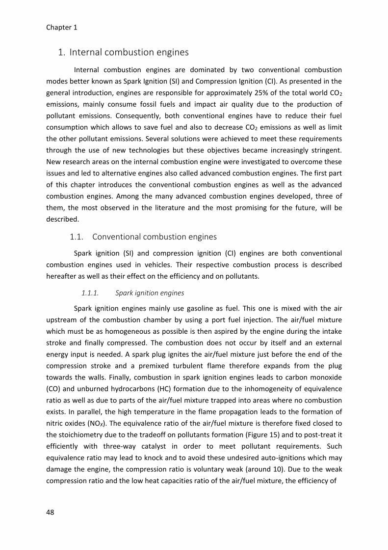
Chapter 1
48
1. Internal combustion engines
Internal combustion engines are dominated by two conventional combustion
modes better known as Spark Ignition (SI) and Compression Ignition (CI). As presented in the
general introduction, engines are responsible for approximately 25% of the total world CO2
emissions, mainly consume fossil fuels and impact air quality due to the production of
pollutant emissions. Consequently, both conventional engines have to reduce their fuel
consumption which allows to save fuel and also to decrease CO2 emissions as well as limit
the other pollutant emissions. Several solutions were achieved to meet these requirements
through the use of new technologies but these objectives became increasingly stringent.
New research areas on the internal combustion engine were investigated to overcome these
issues and led to alternative engines also called advanced combustion engines. The first part
of this chapter introduces the conventional combustion engines as well as the advanced
combustion engines. Among the many advanced combustion engines developed, three of
them, the most observed in the literature and the most promising for the future, will be
described.
1.1. Conventional combustion engines
Spark ignition (SI) and compression ignition (CI) engines are both conventional
combustion engines used in vehicles. Their respective combustion process is described
hereafter as well as their effect on the efficiency and on pollutants.
1.1.1. Spark ignition engines
Spark ignition engines mainly use gasoline as fuel. This one is mixed with the air
upstream of the combustion chamber by using a port fuel injection. The air/fuel mixture
which must be as homogeneous as possible is then aspired by the engine during the intake
stroke and finally compressed. The combustion does not occur by itself and an external
energy input is needed. A spark plug ignites the air/fuel mixture just before the end of the
compression stroke and a premixed turbulent flame therefore expands from the plug
towards the walls. Finally, combustion in spark ignition engines leads to carbon monoxide
(CO) and unburned hydrocarbons (HC) formation due to the inhomogeneity of equivalence
ratio as well as due to parts of the air/fuel mixture trapped into areas where no combustion
exists. In parallel, the high temperature in the flame propagation leads to the formation of
nitric oxides (NOX). The equivalence ratio of the air/fuel mixture is therefore fixed closed to
the stoichiometry due to the tradeoff on pollutants formation (Figure 15) and to post-treat it
efficiently with three-way catalyst in order to meet pollutant requirements. Such
equivalence ratio may lead to knock and to avoid these undesired auto-ignitions which may
damage the engine, the compression ratio is voluntary weak (around 10). Due to the weak
compression ratio and the low heat capacities ratio of the air/fuel mixture, the efficiency of
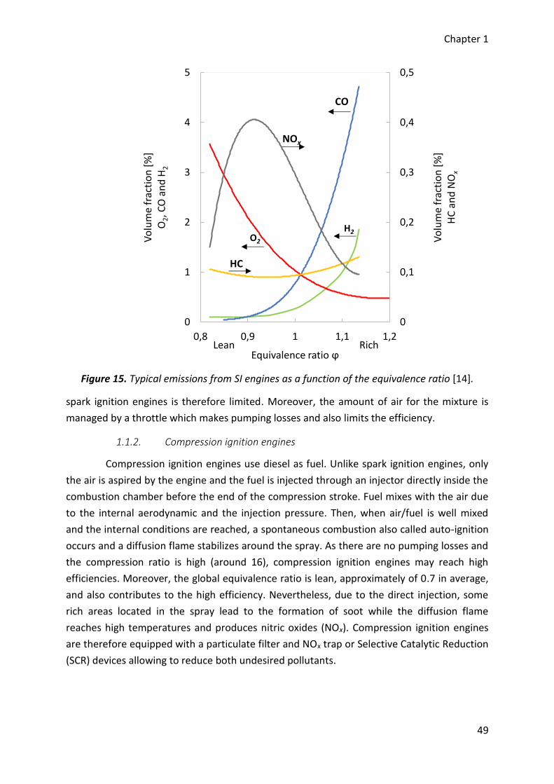
Chapter 1
49
Figure 15. Typical emissions from SI engines as a function of the equivalence ratio [14].
spark ignition engines is therefore limited. Moreover, the amount of air for the mixture is
managed by a throttle which makes pumping losses and also limits the efficiency.
1.1.2. Compression ignition engines
Compression ignition engines use diesel as fuel. Unlike spark ignition engines, only
the air is aspired by the engine and the fuel is injected through an injector directly inside the
combustion chamber before the end of the compression stroke. Fuel mixes with the air due
to the internal aerodynamic and the injection pressure. Then, when air/fuel is well mixed
and the internal conditions are reached, a spontaneous combustion also called auto-ignition
occurs and a diffusion flame stabilizes around the spray. As there are no pumping losses and
the compression ratio is high (around 16), compression ignition engines may reach high
efficiencies. Moreover, the global equivalence ratio is lean, approximately of 0.7 in average,
and also contributes to the high efficiency. Nevertheless, due to the direct injection, some
rich areas located in the spray lead to the formation of soot while the diffusion flame
reaches high temperatures and produces nitric oxides (NOx). Compression ignition engines
are therefore equipped with a particulate filter and NOx trap or Selective Catalytic Reduction
(SCR) devices allowing to reduce both undesired pollutants.
0
0,1
0,2
0,3
0,4
0,5
0
1
2
3
4
5
0,8 0,9 1 1,1 1,2
Vo
lum
e fr
acti
on
[%
]H
C a
nd
NO
x
Vo
lum
e fr
acti
on
[%
]O
2, C
O a
nd
H2
Equivalence ratio ϕ
CO
NOx
O2
HC
H2
Lean Rich
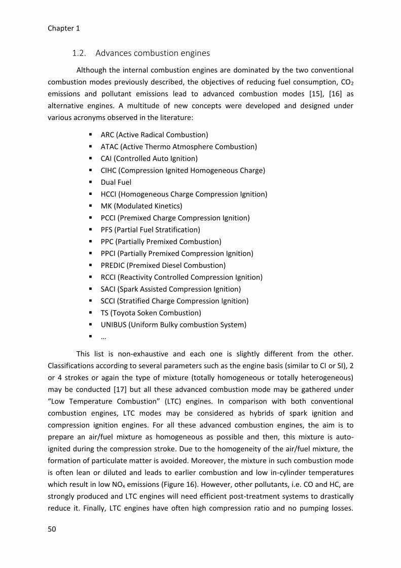
Chapter 1
50
1.2. Advances combustion engines
Although the internal combustion engines are dominated by the two conventional
combustion modes previously described, the objectives of reducing fuel consumption, CO2
emissions and pollutant emissions lead to advanced combustion modes [15], [16] as
alternative engines. A multitude of new concepts were developed and designed under
various acronyms observed in the literature:
ARC (Active Radical Combustion)
ATAC (Active Thermo Atmosphere Combustion)
CAI (Controlled Auto Ignition)
CIHC (Compression Ignited Homogeneous Charge)
Dual Fuel
HCCI (Homogeneous Charge Compression Ignition)
MK (Modulated Kinetics)
PCCI (Premixed Charge Compression Ignition)
PFS (Partial Fuel Stratification)
PPC (Partially Premixed Combustion)
PPCI (Partially Premixed Compression Ignition)
PREDIC (Premixed Diesel Combustion)
RCCI (Reactivity Controlled Compression Ignition)
SACI (Spark Assisted Compression Ignition)
SCCI (Stratified Charge Compression Ignition)
TS (Toyota Soken Combustion)
UNIBUS (Uniform Bulky combustion System)
…
This list is non-exhaustive and each one is slightly different from the other.
Classifications according to several parameters such as the engine basis (similar to CI or SI), 2
or 4 strokes or again the type of mixture (totally homogeneous or totally heterogeneous)
may be conducted [17] but all these advanced combustion mode may be gathered under
“Low Temperature Combustion” (LTC) engines. In comparison with both conventional
combustion engines, LTC modes may be considered as hybrids of spark ignition and
compression ignition engines. For all these advanced combustion engines, the aim is to
prepare an air/fuel mixture as homogeneous as possible and then, this mixture is auto-
ignited during the compression stroke. Due to the homogeneity of the air/fuel mixture, the
formation of particulate matter is avoided. Moreover, the mixture in such combustion mode
is often lean or diluted and leads to earlier combustion and low in-cylinder temperatures
which result in low NOx emissions (Figure 16). However, other pollutants, i.e. CO and HC, are
strongly produced and LTC engines will need efficient post-treatment systems to drastically
reduce it. Finally, LTC engines have often high compression ratio and no pumping losses.
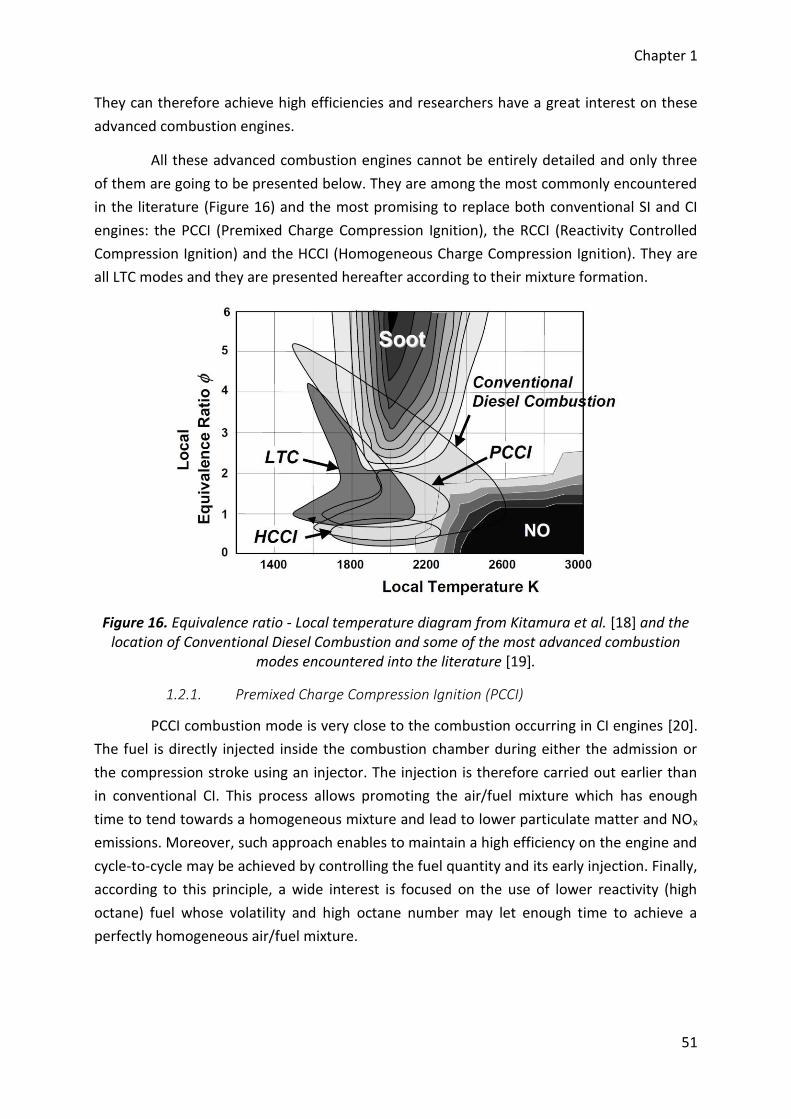
Chapter 1
51
They can therefore achieve high efficiencies and researchers have a great interest on these
advanced combustion engines.
All these advanced combustion engines cannot be entirely detailed and only three
of them are going to be presented below. They are among the most commonly encountered
in the literature (Figure 16) and the most promising to replace both conventional SI and CI
engines: the PCCI (Premixed Charge Compression Ignition), the RCCI (Reactivity Controlled
Compression Ignition) and the HCCI (Homogeneous Charge Compression Ignition). They are
all LTC modes and they are presented hereafter according to their mixture formation.
Figure 16. Equivalence ratio - Local temperature diagram from Kitamura et al. [18] and the location of Conventional Diesel Combustion and some of the most advanced combustion
modes encountered into the literature [19].
1.2.1. Premixed Charge Compression Ignition (PCCI)
PCCI combustion mode is very close to the combustion occurring in CI engines [20].
The fuel is directly injected inside the combustion chamber during either the admission or
the compression stroke using an injector. The injection is therefore carried out earlier than
in conventional CI. This process allows promoting the air/fuel mixture which has enough
time to tend towards a homogeneous mixture and lead to lower particulate matter and NOx
emissions. Moreover, such approach enables to maintain a high efficiency on the engine and
cycle-to-cycle may be achieved by controlling the fuel quantity and its early injection. Finally,
according to this principle, a wide interest is focused on the use of lower reactivity (high
octane) fuel whose volatility and high octane number may let enough time to achieve a
perfectly homogeneous air/fuel mixture.
Chapter 1
52
1.2.2. Reactivity Controlled Compression Ignition (RCCI)
RCCI is a recent combustion concept applied to the internal combustion engine [21],
[22]. It consists of controlling the reactivity of the air/fuel mixture inside the combustion
chamber by separately injecting two different fuels with their own reactivity. A lower
reactivity fuel is injected using a port fuel injection while a higher reactivity fuel, which is the
pilot of the combustion, is early injected through an injector. The total reactivity (which can
be assimilated to a cetane number or an octane number) is therefore modulated by
adjusting the amounts of each fuel injected depending on the engine work conditions.
Finally, this strategy demonstrated that cycle-to-cycle control, optimal engine outputs and
low emissions of particulate matter and NOx may be achieved by managing the ratio
between the two fuels applied and their injection time.
1.2.3. Homogeneous Charge Compression Ignition (HCCI)
Unlike the two previous combustion modes, the air/fuel mixture in HCCI engines is
fully premixed [23]–[25]. Most of the time, the mixture is prepared upstream of the
combustion chamber as in SI engines, then the mixture is compressed and finally auto-
ignites as in CI engines. In theory, HCCI combustion takes place in the overall volume at the
same time but in reality, the combustion occurs in several hot spots due to temperature and
equivalence ratio stratification. Finally, such strategy allows avoiding particulate matter
formation as well as NOx emissions or at least maintaining it near zero. However, HCCI
combustion is violent and therefore, cycle-to-cycle approaches are limited to lower engine
speeds and reduce its operating range.
1.2.4. State on advanced combustion engines
Among all the advanced combustion modes which emerged, the three concept
described above are the most promising modes for replacing both conventional engines.
Compare to the two others, HCCI combustion mode will have probably more difficulties than
PCCI and RCCI modes to be integrated due to its limited operating range. Nevertheless, some
applications could be possible with the emergence of hybridization for instance or in
combination with these other combustion modes. On the other hand, there is some
common characteristics between these three combustion modes. In particular, the air/fuel
mixture is fully premixed for HCCI and both PCCI and RCCI have a part of their mixture quite
homogeneous. As a consequence, HCCI investigations are essential for increasing the
knowledge on homogeneous auto-ignitions occurring in these advanced combustion modes
and are also intermediate studies for their future development. Moreover, HCCI combustion
may help in the understanding of knocking as well as pollutants formation. For the rest of
this investigation, the researches will be focused on the HCCI combustion. Further details of
this combustion mode will be given. Note that the observation made for HCCI could be
extend to all the advanced combustion modes demonstrating a part of homogeneous
combustion.
Chapter 1
53
2. The HCCI combustion process
The homogeneous charge compression ignition is one of the most investigating
advanced combustion mode. In this part, its principle and its main characteristics will be fully
described. Advantages will be highlighted and the main challenges to overcome before a
potential application will be argued. As this combustion mode is entirely governed by
kinetics, the combustion process will be described according to this kind of approach.
2.1. Principle of the HCCI combustion
The HCCI combustion is defined as a combination of the spark ignition combustion
and the compression ignition combustion [23]–[25]. The aim of such mode is to take the
advantages of conventional engines without their drawbacks. Most of the time, the air/fuel
mixture is prepared upstream the combustion chamber, often in the intake like in SI engines,
to be the most homogeneous as possible. Then, this mixture is auto-ignited inside the
combustion chamber during the compression stroke like in CI engines. Moreover, the HCCI
combustion mode has a high thermodynamic interest. Such engines operate without
throttling losses, with high compression ratio, with a globally lean mixture and fast
combustion. Therefore, HCCI engines achieve high efficiencies quite similar to those of CI
engines. Although it appears very attractive, controlling this kind of combustion is not
obvious. SI and CI engines respectively use spark plug whose the timing is managed and an
injector which controls the injection timing. For HCCI engine, none of them is available. The
heat release rate is therefore not controlled either by the rate of fuel injected or by the
flame propagation but according to chemical kinetics which is depending on the conditions
of temperature and pressure within the combustion chamber as well as the air/fuel mixture.
HCCI combustion therefore occurs throughout the combustion chamber when self-ignition
conditions are achieved and results in high heat release rates and high pressure rise rates.
This leads to ringing which may damage the engine and as a consequence, it is necessary to
limit such phenomenon, the power output of the engine is also limited. Globally, the HCCI
combustion well occurs in the overall combustion chamber but according to optical
diagnostics, this combustion takes place in several hot sites randomly distributed. This is
mainly due to fuel and temperature stratification. Moreover, as the mixture is lean and with
a high reactivity, flame propagation does not have enough time for taking place and
consequently, the HCCI combustion process is well entirely governed by chemical kinetics.
Figure 17 shows a scheme of the combustion for both conventional engines and the HCCI
engine.
According to emissions, particulate matter emissions are drastically reduced and
research zero due to the homogeneity of the air/fuel mixture and its lean equivalence ratio.
Moreover, the in-cylinder temperatures are quite uniform during the combustion the HCCI
combustion and do not exceed the critical temperature correspond to the formation of NOx.
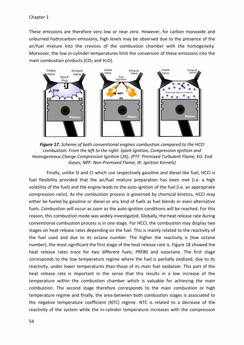
Chapter 1
54
These emissions are therefore very low or near zero. However, for carbon monoxide and
unburned hydrocarbon emissions, high levels may be observed due to the presence of the
air/fuel mixture into the crevices of the combustion chamber with the homogeneity.
Moreover, the low in-cylinder temperatures limit the conversion of these emissions into the
main combustion products (CO2 and H2O).
Figure 17. Scheme of both conventional engines combustion compared to the HCCI combustion. From the left to the right: Spark Ignition, Compression Ignition and
Homogeneous Charge Compression Ignition [26]. (PTF: Premixed Turbulent Flame; EG: End Gases; NPF: Non-Premixed Flame; IK: Ignition Kernels)
Finally, unlike SI and CI which use respectively gasoline and diesel like fuel, HCCI is
fuel flexibility provided that the air/fuel mixture preparation has been met (i.e. a high
volatility of the fuel) and the engine leads to the auto-ignition of the fuel (i.e. an appropriate
compression ratio). As the combustion process is governed by chemical kinetics, HCCI may
either be fueled by gasoline or diesel or any kind of fuels as fuel blends or even alternative
fuels. Combustion will occur as soon as the auto-ignition conditions will be reached. For this
reason, this combustion mode was widely investigated. Globally, the heat release rate during
conventional combustion process is in one stage. For HCCI, the combustion may display two
stages on heat release rates depending on the fuel. This is mainly related to the reactivity of
the fuel used and due to its octane number. The higher the reactivity is (low octane
number), the most significant the first stage of the heat release rate is. Figure 18 showed the
heat release rates trace for two different fuels, PRF80 and isooctane. The first stage
corresponds to the low temperature regime where the fuel is partially oxidized, due to its
reactivity, under lower temperatures than those of its main fuel oxidation. This part of the
heat release rate is important in the sense that this results in a low increase of the
temperature within the combustion chamber which is valuable for achieving the main
combustion. The second stage therefore corresponds to the main combustion or high
temperature regime and finally, the area between both combustion stages is associated to
the negative temperature coefficient (NTC) regime. NTC is related to a decrease of the
reactivity of the system while the in-cylinder temperature increases with the compression
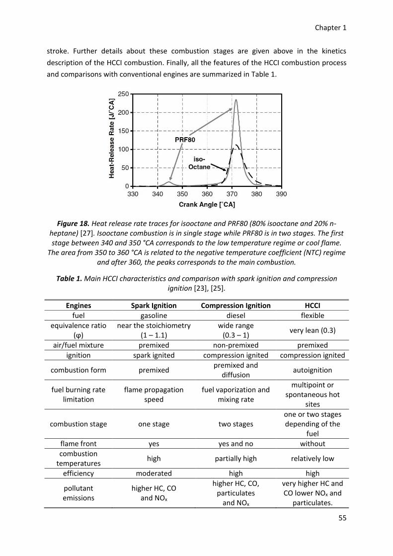
Chapter 1
55
stroke. Further details about these combustion stages are given above in the kinetics
description of the HCCI combustion. Finally, all the features of the HCCI combustion process
and comparisons with conventional engines are summarized in Table 1.
Figure 18. Heat release rate traces for isooctane and PRF80 (80% isooctane and 20% n-heptane) [27]. Isooctane combustion is in single stage while PRF80 is in two stages. The first stage between 340 and 350 °CA corresponds to the low temperature regime or cool flame.
The area from 350 to 360 °CA is related to the negative temperature coefficient (NTC) regime and after 360, the peaks corresponds to the main combustion.
Table 1. Main HCCI characteristics and comparison with spark ignition and compression ignition [23], [25].
Engines Spark Ignition Compression Ignition HCCI
fuel gasoline diesel flexible
equivalence ratio (ϕ)
near the stoichiometry (1 – 1.1)
wide range (0.3 – 1)
very lean (0.3)
air/fuel mixture premixed non-premixed premixed
ignition spark ignited compression ignited compression ignited
combustion form premixed premixed and
diffusion autoignition
fuel burning rate limitation
flame propagation speed
fuel vaporization and mixing rate
multipoint or spontaneous hot
sites
combustion stage one stage two stages one or two stages depending of the
fuel
flame front yes yes and no without
combustion temperatures
high partially high relatively low
efficiency moderated high high
pollutant emissions
higher HC, CO and NOx
higher HC, CO, particulates
and NOx
very higher HC and CO lower NOx and
particulates.
Chapter 1
56
2.2. Advantages and challenges of the HCCI combustion
According to the principle of the HCCI combustion previously described, the
advantages and the drawbacks of this combustion mode may be established [24], [25], [28].
The benefits are firstly presented above and then, the challenges mainly related to the
combustion process are highlighted.
2.2.1. Advantages
2.2.1.1. Low fuel consumption
HCCI combustion is based on the use of very lean air/fuel mixture, such engine may
potentially minimize their fuel consumption when the combustion efficiency is high enough.
This gives to HCCI engines a first advantage which is strengthened by the fact that
perspectives for the automotive field needs to reduce the fuel consumption in the aim to
save fossil resources and limit CO2 emissions.
2.2.1.2. High efficiency
HCCI engines mainly use lean air/fuel mixture and high compression ratio to reach
the auto-ignition conditions. This participates to the achievement of a high efficiency. The
efficiency is also improved by the fact that there are no throttle losses in front of the intake.
Furthermore, as the combustion of the lean mixture is very fast and the in-cylinder
temperatures reach reasonable values, HCCI engine may therefore achieve very high
efficiency.
2.2.1.3. Low levels of NOx and particulate matters
NOx and particulate matters are mainly produced due to excessive temperature and
rich area within the combustion chamber. For HCCI engine, the homogeneity of the lean
air/fuel mixture allows to avoid particulate matters formation. Moreover, in-cylinder
temperature is quite uniform and does not exceed the critical temperature corresponding to
the NOx formation. Consequently, levels of both particulate matters and NOx are very low,
even near zero, in such combustion mode.
2.2.1.4. Fuel flexibility
The occurrence of the combustion for HCCI engine is based on the chemical kinetics
which depends on the conditions inside the combustion chamber, i.e. pressure and
temperature evolutions as well as the air/fuel mixture. According to this, HCCI is not
dedicated to a single fuel and may therefore be supplied by a wide range of fuels. This
flexibility provides it a very interesting advantage as conventional fuels, which mainly come
from fossil resources, will be progressively replaced by alternative ones.
Chapter 1
57
2.2.2. Challenges
Although HCCI combustion looks ideal for replacing conventional combustion
modes, there are several issues which limit its use for practical applications. Therefore,
before such engines are suitable for integration into vehicles and a commercial
development, several challenges must be addressed.
2.2.2.1. Combustion timing control
Controlling the HCCI combustion process is the most important challenge to
overcome. To obtain the full benefits of such combustion, the combustion must occur near
the top dead center over a wide range of working conditions, i.e. in term of speed and load.
Unlike conventional engines, there is not a direct method for controlling the HCCI
combustion process. Instead the combustion timing is entirely governed by kinetics. The
auto-ignition therefore depends on the physical and chemical properties of the air/fuel
mixture as well as the thermodynamic conditions history into the combustion chamber. As a
consequence, the combustion process may be managed indirectly by a lot of parameters
with more or less sensitivity as for example: intake temperature, intake pressure, fuel
properties, equivalence ratio, exhaust gas recirculation or mixture composition, engine
speed, heat transfer or other parameters.
2.2.2.2. Operating range
As important as the control of the combustion phasing, HCCI engines operate in a
narrow window and must extend their operating range. Unlike conventional engines, HCCI is
limited to medium operating range and needs to cover low and high loads. Under low loads,
there is a lack of energy for allowing the auto-ignition. In-cylinder temperatures are too
weak to convert emissions and HCCI engines achieve less efficiency in particular near idle
operations. Moreover, this is a main drawback according to emissions requirements. In the
opposite, at high loads, the heat release rate is very intense due to the fast combustion
occurring. This provides a rapid increase of the pressure rate which may damage the engine.
Moreover, unacceptable levels of NOx emissions can be formed due to elevated
temperatures. Strategies have to be developed to overcome this issue.
2.2.2.3. Unburned hydrocarbons and carbon monoxide emissions
During the compression stroke, a part of the air/fuel mixture is trapped into the
crevices of the combustion chamber and is not consumed during the combustion. This
results in high levels of HC and CO emissions and decreases the combustion efficiency.
Moreover, this drawback is more important under low loads and near idles due to the low
temperatures within the combustion chamber. It is therefore essential to develop emissions
control devices to limit levels of HC and CO as well as increase the temperatures during the
expansion stroke to enable the conversion of these emissions into combustion products.
Chapter 1
58
However, too elevated temperatures may result in NOx formation. There is a tradeoff to find
in order to keep the benefit of HCCI combustion.
2.2.2.4. Level of noise
With the homogeneous air/fuel mixture, the combustion occurs throughout the
combustion chamber. Such a combustion leads to high heat release rates with short
combustion durations and is finally responsible of a high pressure rise rate. Rapid rise of the
in-cylinder pressure is related to intense ringing or noise and may therefore damage the
engine. Moreover, in case of high equivalence ratios or when the engine works under high
loads, the level of noise becomes too strong and is totally unacceptable for the engine.
Therefore, it is crucial to avoid, or at least limit, too rapid and high combustion.
2.2.2.5. Mixture preparation
Preparation of the air/fuel mixture is also an important challenge in HCCI engines.
The aim is to improve the fuel vaporization and mixing which lead to a charge the most
homogeneous as possible. A main parameter is therefore the fuel and its properties, in
particular its evaporating temperature and its volatility. Moreover, inhomogeneity may lead
to auto-ignition alteration as well as unfavorable particulate matter (rich area) and NOx
formation (very high temperatures). On the other hand, the homogeneous mixture
unfortunately results in wall impingement causing oil dilution and HC formation which in
turn decrease the combustion efficiency. Finally, the mixture preparation is challenging as
the aim is to easily auto-ignite it and avoid unacceptable levels of pollutants.
2.2.2.6. Cold start
Auto-ignition may easily be altered by temperatures. During cold start, the initial
temperatures are very weak to make combustion possible and this results in misfires.
Moreover, this is all the more important that there is no preheating of the charge into the
intake manifold and there are significant heat transfers to the walls. This challenge is as
important as the objective of achieve an ideal combustion at low loads.
All the challenges previously described are mainly focused on the auto-ignition of
the air/fuel mixture and the pollutants formation. Obviously, there are other challenges to
address before integrating HCCI engines in a real vehicle such as, the engine control
(feedbacks and close loop control), the response of transient cycle which has to be as fast as
possible, the cylinder to cylinder interaction or others. However, the control of the
combustion phasing is the main challenge to overcome for HCCI engines and is central to the
present work. The effect of various parameters will be therefore fully analyzed on the
combustion phasing in the next part.
Chapter 1
59
2.3. Kinetics of the HCCI combustion
Usually, the combustion process is described according to a unique reaction where
the reagents are consumed to give products of combustion. Typically, in the case of a
stoichiometric reaction, the reagents are the fuel and the oxygen contained in the air, while
the products are mainly carbon dioxide and water. However, a combustion process is more
complex and involves numerous chemical species and reactions. Furthermore, the amount
of species and reactions increases with the complexity of the fuel composition.
HCCI combustion is totally governed by chemical kinetics and its combustion
process may be described by a kinetics approach. In the present part, the main reactions
involved during this kind of combustion are going to be highlighted. In particular, the
reactions which lead to each heat release part, i.e. the low temperature regime, the NTC and
the high temperature regime. These different regimes occur in various temperature ranges
depending of the fuel properties. Generally, they are respectively estimated in the following
range: below 800 K, 800 to 1000 K and above 1000 K. The reactions involved presented
hereafter are those established for alkane fuels, more precisely primary reference fuels (n-
heptane and isooctane) and are based on the works of Curran et al. [29], [30] and Dagaut et
al. [31], [32].
2.3.1. Low-temperature range
The low temperature regime starts by an initiation reaction for temperatures below
800 K. It mainly involves a 𝐻-atom abstraction from the fuel considered (𝑅𝐻) through a
bimolecular reaction with an oxygen molecule (𝑂2). This leads to the formation of a
hydroperoxyl radical (𝐻𝑂2) and an alkyl radical (𝑅).
𝑅𝐻 + 𝑂2 → 𝑅 + 𝐻𝑂2 R-1
The alkyl radical then reacts with another molecular oxygen to produce an
alkylperoxyl radical (𝑅𝑂2). It contributes to the beginning of a chain branching which may
release a part of the energy contained into the fuel.
𝑅 + 𝑂2 → 𝑅𝑂2 R-2
The alkylperoxyl radical finally isomerizes into hydroperoxyalkyl radical (𝑄𝑂𝑂𝐻), i.e.
that an H atom is transferred from a carbon atom to the 𝑂2.
𝑅𝑂2 → 𝑄𝑂𝑂𝐻 R-3
Depending on its structure and its size, the 𝑄𝑂𝑂𝐻 radical is consumed through four
distinct propagation reactions leading to the production of stable species (olefin, carbonyl or
Chapter 1
60
cyclic ether) and hydroperoxyl (𝐻𝑂2), hydroxyl (𝑂𝐻) or peroxyhydroperoxyalkyl (𝑂𝑂𝑄𝑂𝑂𝐻)
radicals.
𝑄𝑂𝑂𝐻 → 𝑜𝑙𝑒𝑓𝑖𝑛 + 𝐻𝑂2 R-4
𝑄𝑂𝑂𝐻 → 𝑜𝑙𝑒𝑓𝑖𝑛 + 𝑐𝑎𝑟𝑏𝑜𝑛𝑦𝑙 + 𝑂𝐻 R-5
𝑄𝑂𝑂𝐻 → 𝑐𝑦𝑐𝑙𝑖𝑐 𝑒𝑡ℎ𝑒𝑟 + 𝑂𝐻 R-6
𝑄𝑂𝑂𝐻 + 𝑂2 → 𝑂𝑂𝑄𝑂𝑂𝐻 R-7
This last propagation reaction is similar to the reaction R-2 and is responsible of the
cool flame chain branching reactions. The 𝑂𝑂𝑄𝑂𝑂𝐻 species isomerizes and finally releases
three radicals, an oxygenated hydrocarbon radical (𝑂𝑃𝑂) and in particular two hydroxyl
radicals (𝑂𝐻).
𝑂𝑂𝑄𝑂𝑂𝐻 → 𝐻𝑂𝑂𝑃𝑂𝑂𝐻 → 𝑂𝑃𝑂 + 2 𝑂𝐻 R-8
𝑂𝐻 is then responsible for the fuel consumption through 𝐻-abstractions reactions
R-9 where 𝑋 is a radical (mainly 𝑂𝐻 and 𝐻𝑂2) and 𝑋𝐻 a stable species (𝐻2𝑂 and 𝐻2𝑂2)
under this temperature range. This leads to an increase of the overall reactivity determining
for the auto-ignition of the main temperature regime.
𝑅𝐻 + 𝑋 → 𝑅 + 𝑋𝐻 R-9
2.3.2. Negative temperature coefficient range
The low temperature regime is followed by a negative temperature coefficient
(NTC) regime. During the NTC, the chemical reactivity decreases while the temperature
continues to rise due to the compression. The reaction rates of the cool flame are altered
due to the temperature and the system is governed by linear chain reactions. In particular,
the propagation reaction R-4 dominates reaction R-7 to form olefins and 𝐻𝑂2 radicals.
Moreover, the reaction pathway that led to the production of 𝑄𝑂𝑂𝐻 from alkyl
radicals is modified (R-2 and R-3). There is therefore less 𝑄𝑂𝑂𝐻 species produced and the
chain branching which leads to a heat release is broken. Instead of the recombination which
leads to the formation of 𝑅𝑂2the reaction with an alkyl radical and molecular oxygen
produces an olefin and a 𝐻𝑂2radical.
𝑅 + 𝑂2 → 𝑜𝑙𝑒𝑓𝑖𝑛 + 𝐻𝑂2 R-10
Chapter 1
61
Finally, the NTC regime is dominated by a significant production of 𝐻𝑂2 radicals
while 𝑂𝐻 radicals are entirely consumed by the fuel through reaction R-9. Consequently, the
formation of 𝑂𝐻 is stopped while 𝐻𝑂2 radicals, which are less reactive than 𝑂𝐻 radicals and
do not lead to exothermic reactions, mainly react together and with the fuel (R-9) to form
hydrogen peroxide (𝐻2𝑂2). Under these temperatures, 𝐻2𝑂2 is a stable species and limit
strongly the reactivity of the system.
𝐻𝑂2 + 𝐻𝑂2 → 𝐻2𝑂2 + 𝑂2 R-11
2.3.3. High temperature range
The high temperature regime is initiated by the increase of the temperature due to
the compression and a new modification of the reaction rates. The hydrogen peroxide is
broken down into two hydroxyl radicals which lead to a strong rise of the global reactivity of
the system.
𝐻2𝑂2 + 𝑀 → 𝑂𝐻 + 𝑂𝐻 + 𝑀 R-12
This last reaction shows the impact of both previous regimes on the main
combustion stage. The NTC regime is responsible of the high production of 𝐻2𝑂2 from the
𝐻𝑂2 radicals and the low temperature regime allows to achieve earlier the 𝐻2𝑂2
decomposition and therefore the main combustion due to a slight increase of the
temperature.
The 𝑂𝐻 radicals produce through the previous chain branching reaction oxidize the
fuel and lead to the production of other 𝑂𝐻 radicals according to the pathway composed of
the reactions R-9, R-10, R-11 and R-12. With the formation of 𝑂𝐻 and the chain branching
which takes place, the reactivity and the temperature of the system exponentially grow.
Finally, as soon as the temperature is important enough, a high amount of 𝑂𝐻 radicals is
formed from the reactions R-13, R-14 and R-15 while the fuel and the other species
decompose into smaller species.
𝐻 + 𝑂2 → 𝑂 + 𝑂𝐻 R-13
𝑂 + 𝐻2 → 𝐻 + 𝑂𝐻 R-14
𝑂 + 𝐻2𝑂 → 𝑂𝐻 + 𝑂𝐻 R-15
Finally, all the fuel mainly reacts with 𝑂𝐻 radicals through reaction R-9 and as soon
as it is totally consumed, 𝑂𝐻 radicals participates to the production of final species.
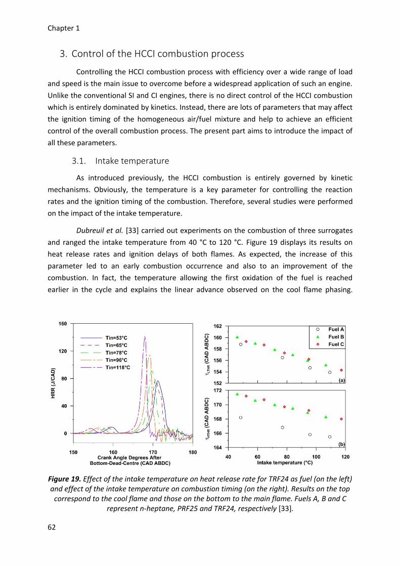
Chapter 1
62
3. Control of the HCCI combustion process
Controlling the HCCI combustion process with efficiency over a wide range of load
and speed is the main issue to overcome before a widespread application of such an engine.
Unlike the conventional SI and CI engines, there is no direct control of the HCCI combustion
which is entirely dominated by kinetics. Instead, there are lots of parameters that may affect
the ignition timing of the homogeneous air/fuel mixture and help to achieve an efficient
control of the overall combustion process. The present part aims to introduce the impact of
all these parameters.
3.1. Intake temperature
As introduced previously, the HCCI combustion is entirely governed by kinetic
mechanisms. Obviously, the temperature is a key parameter for controlling the reaction
rates and the ignition timing of the combustion. Therefore, several studies were performed
on the impact of the intake temperature.
Dubreuil et al. [33] carried out experiments on the combustion of three surrogates
and ranged the intake temperature from 40 °C to 120 °C. Figure 19 displays its results on
heat release rates and ignition delays of both flames. As expected, the increase of this
parameter led to an early combustion occurrence and also to an improvement of the
combustion. In fact, the temperature allowing the first oxidation of the fuel is reached
earlier in the cycle and explains the linear advance observed on the cool flame phasing.
Figure 19. Effect of the intake temperature on heat release rate for TRF24 as fuel (on the left) and effect of the intake temperature on combustion timing (on the right). Results on the top
correspond to the cool flame and those on the bottom to the main flame. Fuels A, B and C represent n-heptane, PRF25 and TRF24, respectively [33].
Chapter 1
63
Moreover, the cool flame brings a weak rise on the in-cylinder temperature and therefore,
an advance of the main flame may also be observed. Finally, as the combustion starts earlier,
a fast consumption of the fuel takes place, increases the whole reactivity and leads to higher
heat release rates.
Lu et al. [34] also investigated for three different PRFs the impact of the intake
temperature but on a smaller range. He observed also an advance of the combustion timing
but fuels present different sensitivities to this thermodynamic parameter due to the heat
capacity of the air/fuel mixture. Finally, many authors reached the same conclusion with
other fuels [35]–[41]. Additionally, even if the intake temperature is of a significant
importance, further experiments investigates the thermal stratification inside the
combustion chamber [42]–[44]. Results showed that there are some inhomogeneities inside
the combustion chamber due to heat transfers, the motion of the mixture and the motion of
the piston. The combustion occurs therefore into several hot spots. Finally, controlling the
combustion timing with efficiency by ranging the intake temperature was investigated by
Haraldsson et al. [45]. He proposed to warm up one part of the intake air into a second pipe
with the help of the temperature of the exhaust gases and manage the intake temperature
with two throttles.
3.2. Fuel
The second most obvious parameter which can influenced the autoignition is the
fuel and it is of a main importance. HCCI engines offer fuel flexibility and may therefore use a
wide range of fuels. Many studies were performed on the impact of the fuel on the HCCI
combustion process and nowadays, it still remains a main topic. The aim is to find a fuel
whose the properties allow combustion on a wide operating range for the engine. As a
result, fuel must have autoignition indexes as low as possible to easily burn and a high
volatility to rapidly achieve a homogeneous mixture [46].
Lots of fuels were investigated in the literature [10], [47], [48]. Results included
studies on pure fuels such as Primary Reference Fuels (PRFs) [37], [49]; n-heptane, isooctane
and mixtures of both fuels; gaseous fuels [50],[41]; natural gas and/or hydrogen; alcohol
fuels [51], [52] or even other alternative fuels [13], [53], [54]. In general, the results showed
that autoignition of pure fuels mainly depends on their own chemistry and their respective
properties of RON (Research Octane Number), MON (Motor Octane Number), ON (Octane
Number); i.e. the average between the RON and the MON; and CN (Cetane Number), which
is inversely proportional to RON and MON. For instance, many experiments were performed
with PRFs and showed that lower the ON of the fuel is, easier its autoignition is and inversely
[37], [49] (Figure 20). Unfortunately, all the experiments conducted with pure fuels indicated
that only a few part of the engine operations may be covered. As a result, studies were
carried out with mixture of fuels. Most of the time, these surrogates included only a few
pure fuels to keep the possibility of coupling the results with computations [55]–[57].
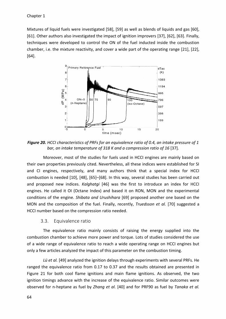
Chapter 1
64
Mixtures of liquid fuels were investigated [58], [59] as well as blends of liquids and gas [60],
[61]. Other authors also investigated the impact of ignition improvers [37], [62], [63]. Finally,
techniques were developed to control the ON of the fuel inducted inside the combustion
chamber, i.e. the mixture reactivity, and cover a wide part of the operating range [21], [22],
[64].
Figure 20. HCCI characteristics of PRFs for an equivalence ratio of 0.4, an intake pressure of 1 bar, an intake temperature of 318 K and a compression ratio of 16 [37].
Moreover, most of the studies for fuels used in HCCI engines are mainly based on
their own properties previously cited. Nevertheless, all these indices were established for SI
and CI engines, respectively, and many authors think that a special index for HCCI
combustion is needed [10], [48], [65]–[68]. In this way, several studies has been carried out
and proposed new indices. Kalghatgi [46] was the first to introduce an index for HCCI
engines. He called it OI (Octane Index) and based it on RON, MON and the experimental
conditions of the engine. Shibata and Urushihara [69] proposed another one based on the
MON and the composition of the fuel. Finally, recently, Truedsson et al. [70] suggested a
HCCI number based on the compression ratio needed.
3.3. Equivalence ratio
The equivalence ratio mainly consists of raising the energy supplied into the
combustion chamber to achieve more power and torque. Lots of studies considered the use
of a wide range of equivalence ratio to reach a wide operating range on HCCI engines but
only a few articles analyzed the impact of this parameter on the combustion timing.
Lü et al. [49] analyzed the ignition delays through experiments with several PRFs. He
ranged the equivalence ratio from 0.17 to 0.37 and the results obtained are presented in
Figure 21 for both cool flame ignitions and main flame ignitions. As observed, the two
ignition timings advance with the increase of the equivalence ratio. Similar outcomes were
observed for n-heptane as fuel by Zhang et al. [40] and for PRF90 as fuel by Tanaka et al.
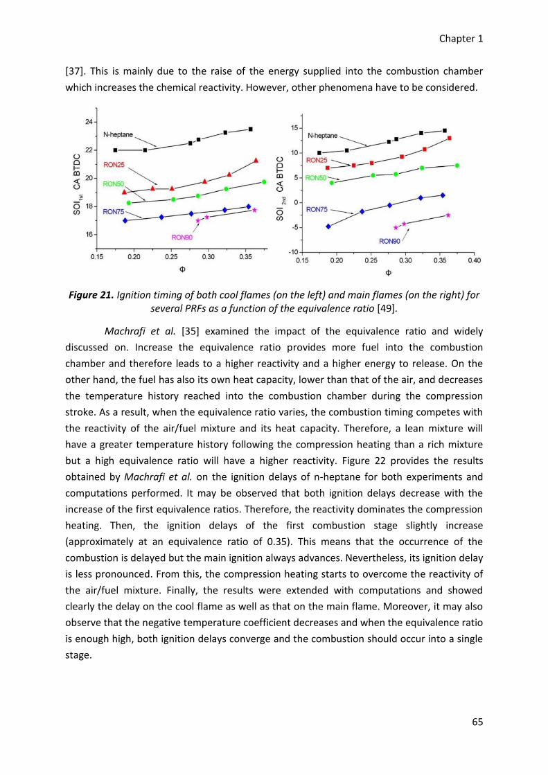
Chapter 1
65
[37]. This is mainly due to the raise of the energy supplied into the combustion chamber
which increases the chemical reactivity. However, other phenomena have to be considered.
Figure 21. Ignition timing of both cool flames (on the left) and main flames (on the right) for several PRFs as a function of the equivalence ratio [49].
Machrafi et al. [35] examined the impact of the equivalence ratio and widely
discussed on. Increase the equivalence ratio provides more fuel into the combustion
chamber and therefore leads to a higher reactivity and a higher energy to release. On the
other hand, the fuel has also its own heat capacity, lower than that of the air, and decreases
the temperature history reached into the combustion chamber during the compression
stroke. As a result, when the equivalence ratio varies, the combustion timing competes with
the reactivity of the air/fuel mixture and its heat capacity. Therefore, a lean mixture will
have a greater temperature history following the compression heating than a rich mixture
but a high equivalence ratio will have a higher reactivity. Figure 22 provides the results
obtained by Machrafi et al. on the ignition delays of n-heptane for both experiments and
computations performed. It may be observed that both ignition delays decrease with the
increase of the first equivalence ratios. Therefore, the reactivity dominates the compression
heating. Then, the ignition delays of the first combustion stage slightly increase
(approximately at an equivalence ratio of 0.35). This means that the occurrence of the
combustion is delayed but the main ignition always advances. Nevertheless, its ignition delay
is less pronounced. From this, the compression heating starts to overcome the reactivity of
the air/fuel mixture. Finally, the results were extended with computations and showed
clearly the delay on the cool flame as well as that on the main flame. Moreover, it may also
observe that the negative temperature coefficient decreases and when the equivalence ratio
is enough high, both ignition delays converge and the combustion should occur into a single
stage.
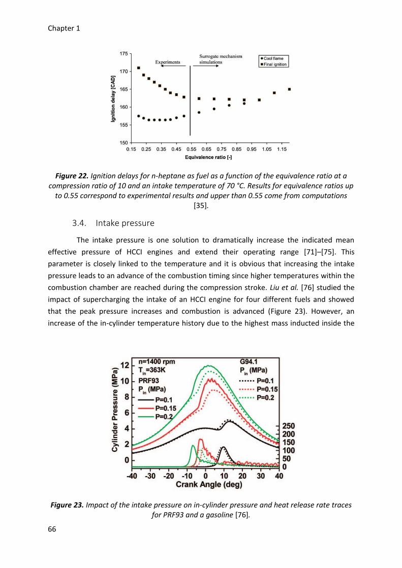
Chapter 1
66
Figure 22. Ignition delays for n-heptane as fuel as a function of the equivalence ratio at a compression ratio of 10 and an intake temperature of 70 °C. Results for equivalence ratios up
to 0.55 correspond to experimental results and upper than 0.55 come from computations [35].
3.4. Intake pressure
The intake pressure is one solution to dramatically increase the indicated mean
effective pressure of HCCI engines and extend their operating range [71]–[75]. This
parameter is closely linked to the temperature and it is obvious that increasing the intake
pressure leads to an advance of the combustion timing since higher temperatures within the
combustion chamber are reached during the compression stroke. Liu et al. [76] studied the
impact of supercharging the intake of an HCCI engine for four different fuels and showed
that the peak pressure increases and combustion is advanced (Figure 23). However, an
increase of the in-cylinder temperature history due to the highest mass inducted inside the
Figure 23. Impact of the intake pressure on in-cylinder pressure and heat release rate traces for PRF93 and a gasoline [76].
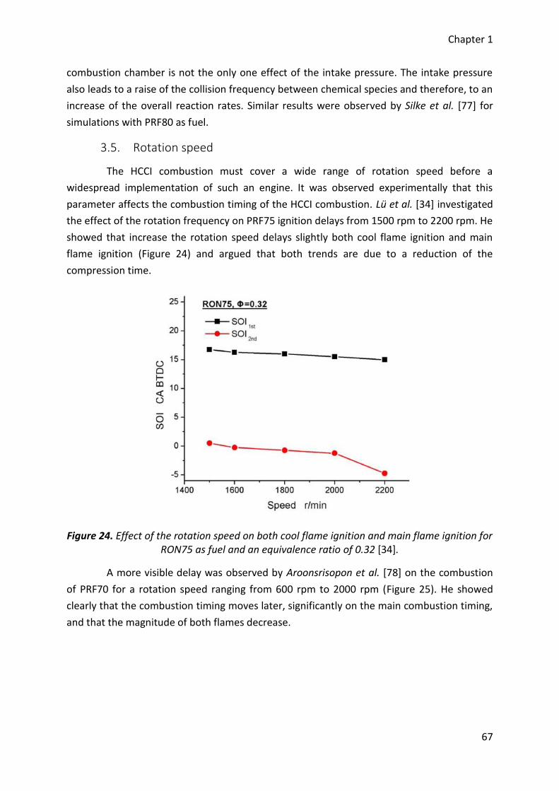
Chapter 1
67
combustion chamber is not the only one effect of the intake pressure. The intake pressure
also leads to a raise of the collision frequency between chemical species and therefore, to an
increase of the overall reaction rates. Similar results were observed by Silke et al. [77] for
simulations with PRF80 as fuel.
3.5. Rotation speed
The HCCI combustion must cover a wide range of rotation speed before a
widespread implementation of such an engine. It was observed experimentally that this
parameter affects the combustion timing of the HCCI combustion. Lü et al. [34] investigated
the effect of the rotation frequency on PRF75 ignition delays from 1500 rpm to 2200 rpm. He
showed that increase the rotation speed delays slightly both cool flame ignition and main
flame ignition (Figure 24) and argued that both trends are due to a reduction of the
compression time.
Figure 24. Effect of the rotation speed on both cool flame ignition and main flame ignition for RON75 as fuel and an equivalence ratio of 0.32 [34].
A more visible delay was observed by Aroonsrisopon et al. [78] on the combustion
of PRF70 for a rotation speed ranging from 600 rpm to 2000 rpm (Figure 25). He showed
clearly that the combustion timing moves later, significantly on the main combustion timing,
and that the magnitude of both flames decrease.
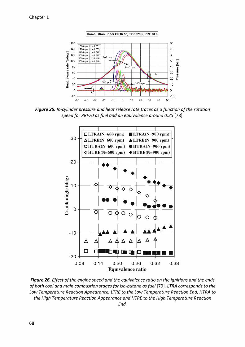
Chapter 1
68
Figure 25. In-cylinder pressure and heat release rate traces as a function of the rotation speed for PRF70 as fuel and an equivalence around 0.25 [78].
Figure 26. Effect of the engine speed and the equivalence ratio on the ignitions and the ends of both cool and main combustion stages for iso-butane as fuel [79]. LTRA corresponds to the Low Temperature Reaction Appearance, LTRE to the Low Temperature Reaction End, HTRA to
the High Temperature Reaction Appearance and HTRE to the High Temperature Reaction End.
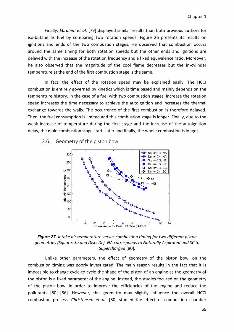
Chapter 1
69
Finally, Ebrahim et al. [79] displayed similar results than both previous authors for
iso-butane as fuel by comparing two rotation speeds. Figure 26 presents its results on
ignitions and ends of the two combustion stages. He observed that combustion occurs
around the same timing for both rotation speeds but the other ends and ignitions are
delayed with the increase of the rotation frequency and a fixed equivalence ratio. Moreover,
he also observed that the magnitude of the cool flame decreases but the in-cylinder
temperature at the end of the first combustion stage is the same.
In fact, the effect of the rotation speed may be explained easily. The HCCI
combustion is entirely governed by kinetics which is time based and mainly depends on the
temperature history. In the case of a fuel with two combustion stages, increase the rotation
speed increases the time necessary to achieve the autoignition and increases the thermal
exchange towards the walls. The occurrence of the first combustion is therefore delayed.
Then, the fuel consumption is limited and this combustion stage is longer. Finally, due to the
weak increase of temperature during the first stage and the increase of the autoignition
delay, the main combustion stage starts later and finally, the whole combustion is longer.
3.6. Geometry of the piston bowl
Figure 27. Intake air temperature versus combustion timing for two different piston geometries (Square: Sq and Disc: Dc). NA corresponds to Naturally Aspirated and SC to
Supercharged [80].
Unlike other parameters, the effect of geometry of the piston bowl on the
combustion timing was poorly investigated. The main reason results in the fact that it is
impossible to change cycle-to-cycle the shape of the piston of an engine as the geometry of
the piston is a fixed parameter of the engine. Instead, the studies focused on the geometry
of the piston bowl in order to improve the efficiencies of the engine and reduce the
pollutants [80]–[86]. However, the geometry may slightly influence the overall HCCI
combustion process. Christensen et al. [80] studied the effect of combustion chamber
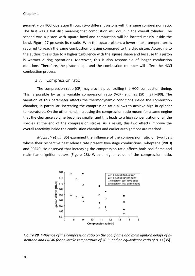
Chapter 1
70
geometry on HCCI operation through two different pistons with the same compression ratio.
The first was a flat disc meaning that combustion will occur in the overall cylinder. The
second was a piston with square bowl and combustion will be located mainly inside the
bowl. Figure 27 presents its results. With the square piston, a lower intake temperature is
required to reach the same combustion phasing compared to the disc piston. According to
the author, this is due to a higher turbulence with the square shape and because this piston
is warmer during operations. Moreover, this is also responsible of longer combustion
durations. Therefore, the piston shape and the combustion chamber will affect the HCCI
combustion process.
3.7. Compression ratio
The compression ratio (CR) may also help controlling the HCCI combustion timing.
This is possible by using variable compression ratio (VCR) engines [50], [87]–[90]. The
variation of this parameter affects the thermodynamic conditions inside the combustion
chamber, in particular, increasing the compression ratio allows to achieve high in-cylinder
temperatures. On the other hand, increasing the compression ratio means for a same engine
that the clearance volume becomes smaller and this leads to a high concentration of all the
species at the end of the compression stroke. As a result, this two effects improve the
overall reactivity inside the combustion chamber and earlier autoignitions are reached.
Machrafi et al. [35] examined the influence of the compression ratio on two fuels
whose their respective heat release rate present two-stage combustions: n-heptane (PRF0)
and PRF40. He observed that increasing the compression ratio affects both cool flame and
main flame ignition delays (Figure 28). With a higher value of the compression ratio,
Figure 28. Influence of the compression ratio on the cool flame and main ignition delays of n-heptane and PRF40 for an intake temperature of 70 °C and an equivalence ratio of 0.33 [35].
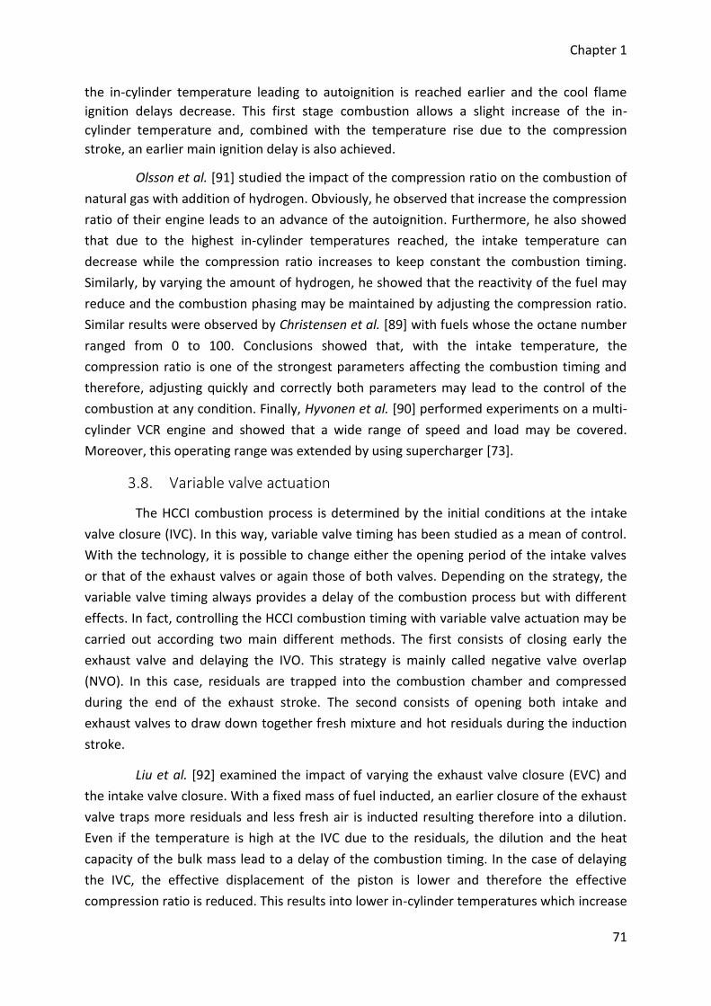
Chapter 1
71
the in-cylinder temperature leading to autoignition is reached earlier and the cool flame
ignition delays decrease. This first stage combustion allows a slight increase of the in-
cylinder temperature and, combined with the temperature rise due to the compression
stroke, an earlier main ignition delay is also achieved.
Olsson et al. [91] studied the impact of the compression ratio on the combustion of
natural gas with addition of hydrogen. Obviously, he observed that increase the compression
ratio of their engine leads to an advance of the autoignition. Furthermore, he also showed
that due to the highest in-cylinder temperatures reached, the intake temperature can
decrease while the compression ratio increases to keep constant the combustion timing.
Similarly, by varying the amount of hydrogen, he showed that the reactivity of the fuel may
reduce and the combustion phasing may be maintained by adjusting the compression ratio.
Similar results were observed by Christensen et al. [89] with fuels whose the octane number
ranged from 0 to 100. Conclusions showed that, with the intake temperature, the
compression ratio is one of the strongest parameters affecting the combustion timing and
therefore, adjusting quickly and correctly both parameters may lead to the control of the
combustion at any condition. Finally, Hyvonen et al. [90] performed experiments on a multi-
cylinder VCR engine and showed that a wide range of speed and load may be covered.
Moreover, this operating range was extended by using supercharger [73].
3.8. Variable valve actuation
The HCCI combustion process is determined by the initial conditions at the intake
valve closure (IVC). In this way, variable valve timing has been studied as a mean of control.
With the technology, it is possible to change either the opening period of the intake valves
or that of the exhaust valves or again those of both valves. Depending on the strategy, the
variable valve timing always provides a delay of the combustion process but with different
effects. In fact, controlling the HCCI combustion timing with variable valve actuation may be
carried out according two main different methods. The first consists of closing early the
exhaust valve and delaying the IVO. This strategy is mainly called negative valve overlap
(NVO). In this case, residuals are trapped into the combustion chamber and compressed
during the end of the exhaust stroke. The second consists of opening both intake and
exhaust valves to draw down together fresh mixture and hot residuals during the induction
stroke.
Liu et al. [92] examined the impact of varying the exhaust valve closure (EVC) and
the intake valve closure. With a fixed mass of fuel inducted, an earlier closure of the exhaust
valve traps more residuals and less fresh air is inducted resulting therefore into a dilution.
Even if the temperature is high at the IVC due to the residuals, the dilution and the heat
capacity of the bulk mass lead to a delay of the combustion timing. In the case of delaying
the IVC, the effective displacement of the piston is lower and therefore the effective
compression ratio is reduced. This results into lower in-cylinder temperatures which increase
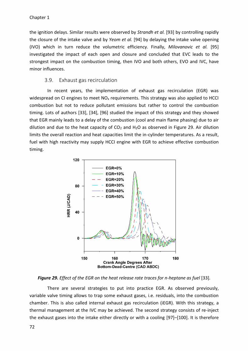
Chapter 1
72
the ignition delays. Similar results were observed by Strandh et al. [93] by controlling rapidly
the closure of the intake valve and by Yeom et al. [94] by delaying the intake valve opening
(IVO) which in turn reduce the volumetric efficiency. Finally, Milovanovic et al. [95]
investigated the impact of each open and closure and concluded that EVC leads to the
strongest impact on the combustion timing, then IVO and both others, EVO and IVC, have
minor influences.
3.9. Exhaust gas recirculation
In recent years, the implementation of exhaust gas recirculation (EGR) was
widespread on CI engines to meet NOx requirements. This strategy was also applied to HCCI
combustion but not to reduce pollutant emissions but rather to control the combustion
timing. Lots of authors [33], [34], [96] studied the impact of this strategy and they showed
that EGR mainly leads to a delay of the combustion (cool and main flame phasing) due to air
dilution and due to the heat capacity of CO2 and H2O as observed in Figure 29. Air dilution
limits the overall reaction and heat capacities limit the in-cylinder temperatures. As a result,
fuel with high reactivity may supply HCCI engine with EGR to achieve effective combustion
timing.
Figure 29. Effect of the EGR on the heat release rate traces for n-heptane as fuel [33].
There are several strategies to put into practice EGR. As observed previously,
variable valve timing allows to trap some exhaust gases, i.e. residuals, into the combustion
chamber. This is also called internal exhaust gas recirculation (iEGR). With this strategy, a
thermal management at the IVC may be achieved. The second strategy consists of re-inject
the exhaust gases into the intake either directly or with a cooling [97]–[100]. It is therefore
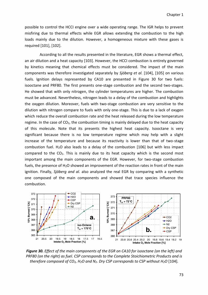
Chapter 1
73
possible to control the HCCI engine over a wide operating range. The IGR helps to prevent
misfiring due to thermal effects while EGR allows extending the combustion to the high
loads mainly due to the dilution. However, a homogeneous mixture with these gases is
required [101], [102].
According to all the results presented in the literature, EGR shows a thermal effect,
an air dilution and a heat capacity [103]. However, the HCCI combustion is entirely governed
by kinetics meaning that chemical effects must be considered. The impact of the main
components was therefore investigated separately by Sjöberg et al. [104], [105] on various
fuels. Ignition delays represented by CA10 are presented in Figure 30 for two fuels:
isooctane and PRF80. The first presents one-stage combustion and the second two-stages.
He showed that with only nitrogen, the cylinder temperatures are higher. The combustion
must be advanced. Nevertheless, nitrogen leads to a delay of the combustion and highlights
the oxygen dilution. Moreover, fuels with two-stage combustion are very sensitive to the
dilution with nitrogen compare to fuels with only one-stage. This is due to a lack of oxygen
which reduce the overall combustion rate and the heat released during the low temperature
regime. In the case of CO2, the combustion timing is mainly delayed due to the heat capacity
of this molecule. Note that its presents the highest heat capacity. Isooctane is very
significant because there is no low temperature regime which may help with a slight
increase of the temperature and because its reactivity is lower than that of two-stage
combustion fuel. H2O also leads to a delay of the combustion [106] but with less impact
compared to the CO2. This is mainly due to its heat capacity which is the second most
important among the main components of the EGR. However, for two-stage combustion
fuels, the presence of H2O showed an improvement of the reaction rates in front of the main
ignition. Finally, Sjöberg and al. also analyzed the real EGR by comparing with a synthetic
one composed of the main components and showed that trace species influence the
combustion.
Figure 30. Effect of the main components of the EGR on CA10 for isooctane (on the left) and PRF80 (on the right) as fuel. CSP corresponds to the Complete Stoichiometric Products and is
therefore composed of CO2, H2O and N2. Dry CSP corresponds to CSP without H2O [104].
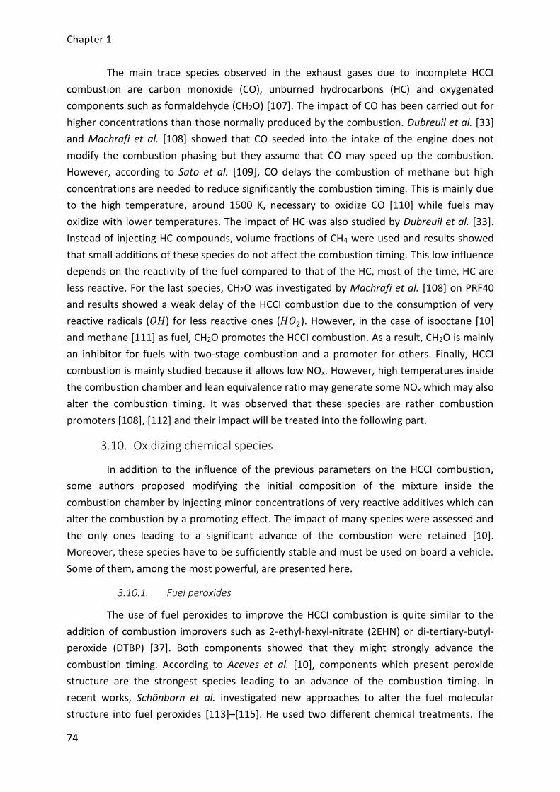
Chapter 1
74
The main trace species observed in the exhaust gases due to incomplete HCCI
combustion are carbon monoxide (CO), unburned hydrocarbons (HC) and oxygenated
components such as formaldehyde (CH2O) [107]. The impact of CO has been carried out for
higher concentrations than those normally produced by the combustion. Dubreuil et al. [33]
and Machrafi et al. [108] showed that CO seeded into the intake of the engine does not
modify the combustion phasing but they assume that CO may speed up the combustion.
However, according to Sato et al. [109], CO delays the combustion of methane but high
concentrations are needed to reduce significantly the combustion timing. This is mainly due
to the high temperature, around 1500 K, necessary to oxidize CO [110] while fuels may
oxidize with lower temperatures. The impact of HC was also studied by Dubreuil et al. [33].
Instead of injecting HC compounds, volume fractions of CH4 were used and results showed
that small additions of these species do not affect the combustion timing. This low influence
depends on the reactivity of the fuel compared to that of the HC, most of the time, HC are
less reactive. For the last species, CH2O was investigated by Machrafi et al. [108] on PRF40
and results showed a weak delay of the HCCI combustion due to the consumption of very
reactive radicals (𝑂𝐻) for less reactive ones (𝐻𝑂2). However, in the case of isooctane [10]
and methane [111] as fuel, CH2O promotes the HCCI combustion. As a result, CH2O is mainly
an inhibitor for fuels with two-stage combustion and a promoter for others. Finally, HCCI
combustion is mainly studied because it allows low NOx. However, high temperatures inside
the combustion chamber and lean equivalence ratio may generate some NOx which may also
alter the combustion timing. It was observed that these species are rather combustion
promoters [108], [112] and their impact will be treated into the following part.
3.10. Oxidizing chemical species
In addition to the influence of the previous parameters on the HCCI combustion,
some authors proposed modifying the initial composition of the mixture inside the
combustion chamber by injecting minor concentrations of very reactive additives which can
alter the combustion by a promoting effect. The impact of many species were assessed and
the only ones leading to a significant advance of the combustion were retained [10].
Moreover, these species have to be sufficiently stable and must be used on board a vehicle.
Some of them, among the most powerful, are presented here.
3.10.1. Fuel peroxides
The use of fuel peroxides to improve the HCCI combustion is quite similar to the
addition of combustion improvers such as 2-ethyl-hexyl-nitrate (2EHN) or di-tertiary-butyl-
peroxide (DTBP) [37]. Both components showed that they might strongly advance the
combustion timing. According to Aceves et al. [10], components which present peroxide
structure are the strongest species leading to an advance of the combustion timing. In
recent works, Schönborn et al. investigated new approaches to alter the fuel molecular
structure into fuel peroxides [113]–[115]. He used two different chemical treatments. The
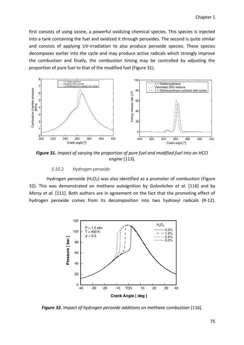
Chapter 1
75
first consists of using ozone, a powerful oxidizing chemical species. This species is injected
into a tank containing the fuel and oxidized it through peroxides. The second is quite similar
and consists of applying UV-irradiation to also produce peroxide species. These species
decomposes earlier into the cycle and may produce active radicals which strongly improve
the combustion and finally, the combustion timing may be controlled by adjusting the
proportion of pure fuel to that of the modified fuel (Figure 31).
Figure 31. Impact of varying the proportion of pure fuel and modified fuel into an HCCI engine [113].
3.10.2. Hydrogen peroxide
Hydrogen peroxide (H2O2) was also identified as a promoter of combustion (Figure
32). This was demonstrated on methane autoignition by Golovitchev et al. [116] and by
Morsy et al. [111]. Both authors are in agreement on the fact that the promoting effect of
hydrogen peroxide comes from its decomposition into two hydroxyl radicals (R-12).
Figure 32. Impact of hydrogen peroxide additions on methane combustion [116].
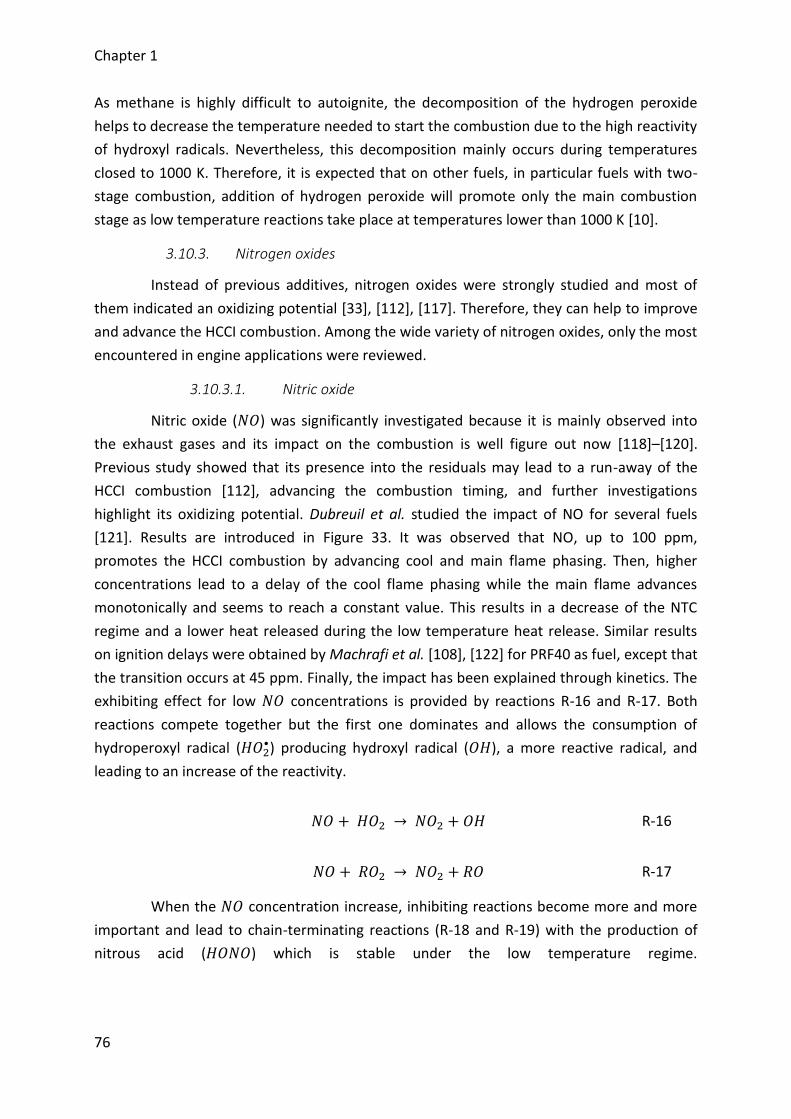
Chapter 1
76
As methane is highly difficult to autoignite, the decomposition of the hydrogen peroxide
helps to decrease the temperature needed to start the combustion due to the high reactivity
of hydroxyl radicals. Nevertheless, this decomposition mainly occurs during temperatures
closed to 1000 K. Therefore, it is expected that on other fuels, in particular fuels with two-
stage combustion, addition of hydrogen peroxide will promote only the main combustion
stage as low temperature reactions take place at temperatures lower than 1000 K [10].
3.10.3. Nitrogen oxides
Instead of previous additives, nitrogen oxides were strongly studied and most of
them indicated an oxidizing potential [33], [112], [117]. Therefore, they can help to improve
and advance the HCCI combustion. Among the wide variety of nitrogen oxides, only the most
encountered in engine applications were reviewed.
3.10.3.1. Nitric oxide
Nitric oxide (𝑁𝑂) was significantly investigated because it is mainly observed into
the exhaust gases and its impact on the combustion is well figure out now [118]–[120].
Previous study showed that its presence into the residuals may lead to a run-away of the
HCCI combustion [112], advancing the combustion timing, and further investigations
highlight its oxidizing potential. Dubreuil et al. studied the impact of NO for several fuels
[121]. Results are introduced in Figure 33. It was observed that NO, up to 100 ppm,
promotes the HCCI combustion by advancing cool and main flame phasing. Then, higher
concentrations lead to a delay of the cool flame phasing while the main flame advances
monotonically and seems to reach a constant value. This results in a decrease of the NTC
regime and a lower heat released during the low temperature heat release. Similar results
on ignition delays were obtained by Machrafi et al. [108], [122] for PRF40 as fuel, except that
the transition occurs at 45 ppm. Finally, the impact has been explained through kinetics. The
exhibiting effect for low 𝑁𝑂 concentrations is provided by reactions R-16 and R-17. Both
reactions compete together but the first one dominates and allows the consumption of
hydroperoxyl radical (𝐻𝑂2•) producing hydroxyl radical (𝑂𝐻), a more reactive radical, and
leading to an increase of the reactivity.
𝑁𝑂 + 𝐻𝑂2 → 𝑁𝑂2 + 𝑂𝐻 R-16
𝑁𝑂 + 𝑅𝑂2 → 𝑁𝑂2 + 𝑅𝑂 R-17
When the 𝑁𝑂 concentration increase, inhibiting reactions become more and more
important and lead to chain-terminating reactions (R-18 and R-19) with the production of
nitrous acid (𝐻𝑂𝑁𝑂) which is stable under the low temperature regime.
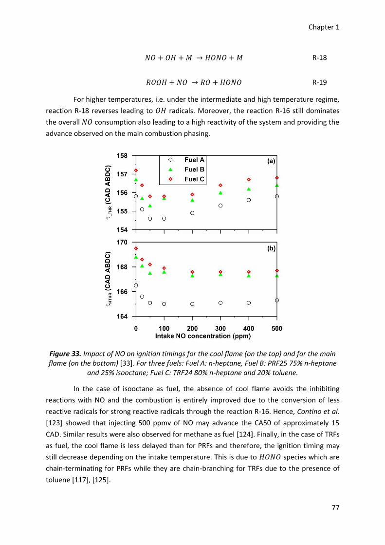
Chapter 1
77
𝑁𝑂 + 𝑂𝐻 + 𝑀 → 𝐻𝑂𝑁𝑂 + 𝑀 R-18
𝑅𝑂𝑂𝐻 + 𝑁𝑂 → 𝑅𝑂 + 𝐻𝑂𝑁𝑂 R-19
For higher temperatures, i.e. under the intermediate and high temperature regime,
reaction R-18 reverses leading to 𝑂𝐻 radicals. Moreover, the reaction R-16 still dominates
the overall 𝑁𝑂 consumption also leading to a high reactivity of the system and providing the
advance observed on the main combustion phasing.
Figure 33. Impact of NO on ignition timings for the cool flame (on the top) and for the main flame (on the bottom) [33]. For three fuels: Fuel A: n-heptane, Fuel B: PRF25 75% n-heptane
and 25% isooctane; Fuel C: TRF24 80% n-heptane and 20% toluene.
In the case of isooctane as fuel, the absence of cool flame avoids the inhibiting
reactions with NO and the combustion is entirely improved due to the conversion of less
reactive radicals for strong reactive radicals through the reaction R-16. Hence, Contino et al.
[123] showed that injecting 500 ppmv of NO may advance the CA50 of approximately 15
CAD. Similar results were also observed for methane as fuel [124]. Finally, in the case of TRFs
as fuel, the cool flame is less delayed than for PRFs and therefore, the ignition timing may
still decrease depending on the intake temperature. This is due to 𝐻𝑂𝑁𝑂 species which are
chain-terminating for PRFs while they are chain-branching for TRFs due to the presence of
toluene [117], [125].
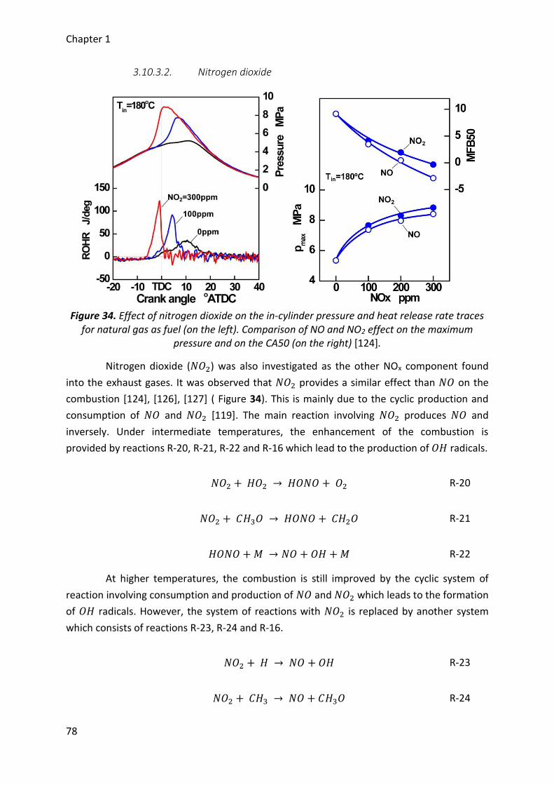
Chapter 1
78
3.10.3.2. Nitrogen dioxide
Figure 34. Effect of nitrogen dioxide on the in-cylinder pressure and heat release rate traces
for natural gas as fuel (on the left). Comparison of NO and NO2 effect on the maximum pressure and on the CA50 (on the right) [124].
Nitrogen dioxide (𝑁𝑂2) was also investigated as the other NOx component found
into the exhaust gases. It was observed that 𝑁𝑂2 provides a similar effect than 𝑁𝑂 on the
combustion [124], [126], [127] ( Figure 34). This is mainly due to the cyclic production and
consumption of 𝑁𝑂 and 𝑁𝑂2 [119]. The main reaction involving 𝑁𝑂2 produces 𝑁𝑂 and
inversely. Under intermediate temperatures, the enhancement of the combustion is
provided by reactions R-20, R-21, R-22 and R-16 which lead to the production of 𝑂𝐻 radicals.
𝑁𝑂2 + 𝐻𝑂2 → 𝐻𝑂𝑁𝑂 + 𝑂2 R-20
𝑁𝑂2 + 𝐶𝐻3𝑂 → 𝐻𝑂𝑁𝑂 + 𝐶𝐻2𝑂 R-21
𝐻𝑂𝑁𝑂 + 𝑀 → 𝑁𝑂 + 𝑂𝐻 + 𝑀 R-22
At higher temperatures, the combustion is still improved by the cyclic system of
reaction involving consumption and production of 𝑁𝑂 and 𝑁𝑂2 which leads to the formation
of 𝑂𝐻 radicals. However, the system of reactions with 𝑁𝑂2 is replaced by another system
which consists of reactions R-23, R-24 and R-16.
𝑁𝑂2 + 𝐻 → 𝑁𝑂 + 𝑂𝐻 R-23
𝑁𝑂2 + 𝐶𝐻3 → 𝑁𝑂 + 𝐶𝐻3𝑂 R-24
Chapter 1
79
3.10.3.3. Nitrous oxide
Recently, the impact of nitrous oxide (𝑁2𝑂) on the ignition delays has been carried
out for methane as fuel [128]–[130] and becomes of a main interest. All the authors
indicated that this species allows promoting the autoignition by reducing the ignition delays.
The advance of the ignition timing is due to reactions R-25 and R-26, the first being the main
responsible and the most reactive but both reactions lead to the formation of the main
radicals allowing a rapid fuel consumption, i.e. 𝑂-atoms and 𝑂𝐻 radicals.
𝑁2𝑂 + 𝑀 → 𝑁2 + 𝑂 + 𝑀 R-25
𝑁2𝑂 + 𝐻 → 𝑁2 + 𝑂𝐻 R-26
3.10.4. Ozone
Ozone (𝑂3) was largely studied on flame velocity [131]–[137] and indicated that
ozone may strongly increase the combustion reactivity or initiate the combustion under
lower temperatures than those necessary normally [138]. Ozone is therefore an excellent
promoter of combustion and is among the most powerful for potential HCCI application by
Aceves et al. [10]. Instead of Schönborn et al. who used ozone to alter the molecular
structure of the fuel [113], [114], some studies were performed by seeding directly the
intake of an HCCI engine with this oxidizing chemical species. Tachibana et al. [139] studied
the impact of ozone on fuels with different cetane number (CN) into a Cooperative Fuel
Research (CFR) engine. He observed that ozone allows increasing the CN, meaning that the
fuel may auto-ignite more easily and finally lead to a reduction of the ignition delays.
Moreover, easily the fuel auto-ignite without ozone, higher the impact of ozone is.
Therefore, the compression ratio of the engine can also be reduced with the use of ozone.
Reduction of the ignition delays were also observed by Mangus et al. [140] with a Diesel
engine with a mechanical injection system from low to middle loads. By comparison with a
common rail injection, results showed that ozone has a stronger impact with a mechanical
injection due to lots of heterogeneity of the air/fuel mixture within the combustion chamber
while common rail injection which is largely premixed rapidly reaches the diffusion flame.
Foucher et al. [9] seeded the intake of an HCCI engine with ozone for n-heptane as fuel. Its
results showed that ozone advance the combustion phasing of both cool and main flame
with the same trends (Figure 35), i.e. a strong decrease of the combustion phasing under low
concentrations and then, the impact is less pronounced. Similar results were observed for
other authors with other fuels [11]–[13]. Through kinetics interpretations, it was showed
that ozone improves the combustion due to an earlier production of 𝑂𝐻 radicals through a
direct oxidation of the fuel (R-27) from species coming from the breakdown of ozone (R-28).
Finally, managing the ozone concentration at the intake of the engine may easily control the
HCCI combustion timing.
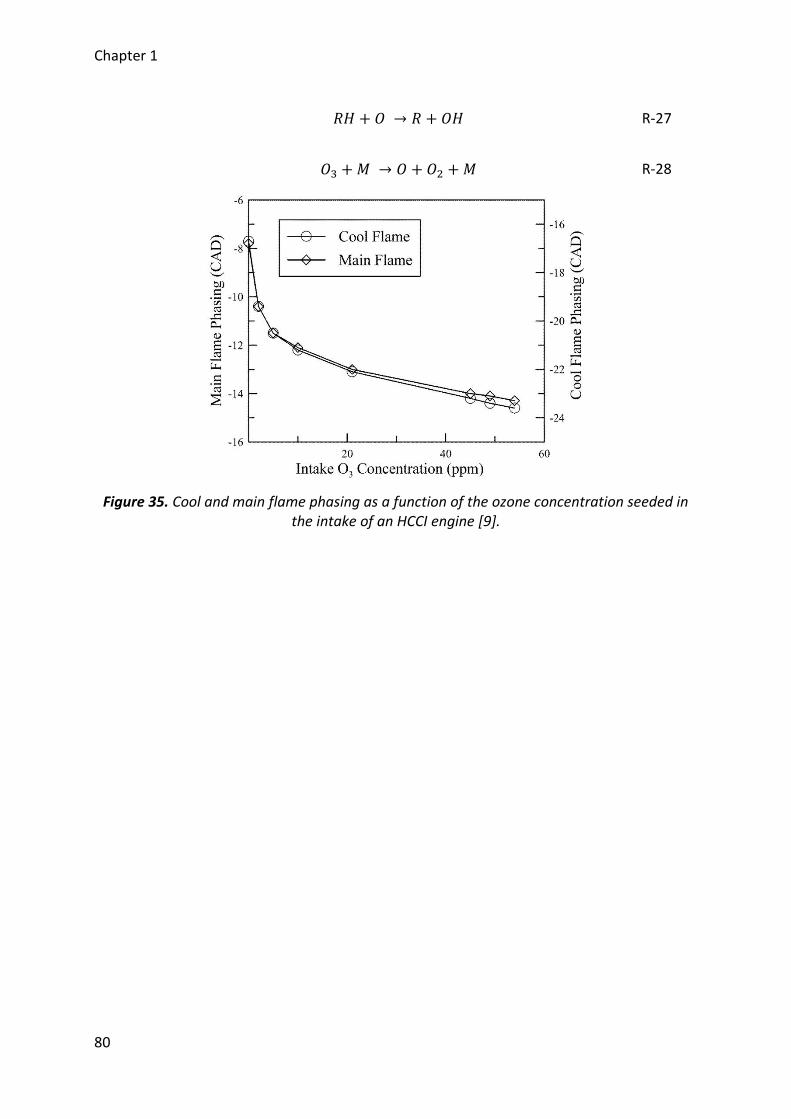
Chapter 1
80
𝑅𝐻 + 𝑂 → 𝑅 + 𝑂𝐻 R-27
𝑂3 + 𝑀 → 𝑂 + 𝑂2 + 𝑀 R-28
Figure 35. Cool and main flame phasing as a function of the ozone concentration seeded in the intake of an HCCI engine [9].
Chapter 1
81
4. Conclusion
This first chapter focused on a review on the HCCI combustion. The two
conventional engines, i.e. Spark Ignition and Compression Ignition engines were introduced
and defined according to their own principles. With the more and more stringent
requirements on these two engines, many advanced combustion modes were investigated
and are very promising since they allow keeping high efficiencies and low NOx and
particulate matter emissions. PCCI, RCCI and HCCI are considered as the most interesting
modes for automotive applications and were described. The respective principle of PCCI,
RCCI and HCCI showed that all these combustion modes present homogeneous auto-
ignitions and figure out perfectly the autoignition is needed for a widespread development
of advanced combustion modes.
Consequently, this study further investigated the HCCI combustion. HCCI was
compared to both conventional combustion modes and prior investigations showed that the
whole combustion process is dominated by kinetics instead of an element such as a spark
plug or an injector. Therefore, the HCCI combustion was also defined according to a kinetic
interpretation and the main reactions dominating the different combustion phases.
Additionally, the advantages and drawbacks were introduced and finally, a widespread
development of an HCCI engine will be considered once the main challenge for such an
engine will be overcome, i.e. once an efficient control of the entire combustion process over
a wide operating range (in term of loads and speeds) could be implemented.
A literature review revealed that many parameters may help controlling the HCCI
combustion. Each of them have its own pros and cons and a future HCCI engine will probably
use several of them for efficiently controlling the HCCI combustion. Among all the
parameters introduced, a recent interest was made on oxidizing chemical species, in
particular, that of ozone (𝑂3) which is among the most powerful oxidizing species. Indeed,
few ppm of ozone indicated that the combustion timing may be significantly advanced.
Moreover, its production is based on the use of ozone generator whose the size tends to
becoming increasingly small and means that a potential application may be developed on a
vehicle.
From this prior investigation on HCCI combustion, two objectives were drawn:
□ First, assess the potential of applying an ozone generator for controlling the HCCI
combustion process. Basically, ozone generators produce ozone from pure
oxygen but considering an implementation on-board a vehicle, use air will be
more suitable. Unfortunately, supply the ozone generator with air could produce
other reactive species such as nitrogen oxides which may alter the combustion.
Moreover, ozone mainly breaks down due to the temperature, the influence of
temperature must therefore be also considered.

Chapter 1
82
□ Second, conventional engines are associated to a unique fuel while HCCI engines
are flexible, depending on the conditions of pressure, temperature, equivalence
ratio and dilution. A wide range of fuel may be used and therefore, the influence
of ozone on the combustion of various fuels selected have to be performed and
compared.

Chapitre 2 / Chapter 2
Dispositif expérimental et moyens numériques
Experimental setup and numerical tools
Chapter 2
84
Résumé
Le second chapitre de ce manuscrit décrit le dispositif expérimental ainsi que les
outils numériques utilisés. Les études conduites ont été réalisées au moyen d’un banc
d’essai moteur et la première partie de ce chapitre décrit l’ensemble de l’installation
expérimentale. Le moteur utilisé est un moteur monocylindre dont l’admission a été
modifiée afin de permettre un fonctionnement HCCI, c’est-à-dire avec un mélange
air/carburant le plus homogène possible. De plus, l’intégralité des paramètres de
fonctionnement sont pilotables. Compte tenu des objectifs, un générateur d’ozone
commercial a été installé et est décrit ainsi que le matériel associé tel que l’analyseur
d’ozone.
L’acquisition des résultats se fait au moyen du banc expérimental qui enregistre le
signal de pression cylindre. Ces essais sont ensuite traités suivant un programme d’analyse
développé au cours de ces travaux de thèse. La méthodologie consiste en une étude
thermodynamique basée sur une analyse de la pression cylindre et des différentes
conditions d’essais. L’ensemble des calculs effectués est décrit et finalement, l’ensemble des
paramètres qui seront analysés dans les chapitres de résultats sont définis.
La combustion HCCI étant entièrement gouvernée par la cinétique chimique, des
simulations sont effectuées en complément des essais expérimentaux à l’aide de Chemkin II
et de l’exécutable Senkin. Le modèle sélectionné est décrit ainsi que les mécanismes et sous-
mécanismes retenus. Enfin, la méthodologie mise en place pour effectuer ces simulations est
finalement définie.
Chapter 2
85
Abstract
This second chapter of this Thesis describes the experimental setup as well as the
numerical tools used. The investigations conducted were carried out with the help of an
engine bench and the first part of this chapter introduces the whole experimental setup. The
engine used is a single cylinder engine whose the intake has been adapted to enable HCCI
operations, i.e. with an air/fuel mixture as homogeneous as possible. Moreover, all the
working parameters are controllable. According to our objectives, a commercial ozone
generator has been set up and is described as well as the associated devices such as the
ozone analyzer.
The acquisition of the results is performed by the use of the experimental bench
which records the in-cylinder pressure signal. The experiments are then post-treated with
the help of a program developed during the Thesis. The methodology consists of a
thermodynamic study based on an analysis of the in-cylinder pressure signal and the test
conditions. All the calculations performed are introduced and finally, all the parameters
which will be analyzed in the chapters presenting the results are defined.
The HCCI combustion is entirely governed by kinetics, computations are carried out
to complete the experiments with the help of Chemkin II and the Senkin executable code.
The model selected is described as well as the mechanisms and sub-mechanisms chosen.
Finally, the methodology considered to perform these computations is defined.
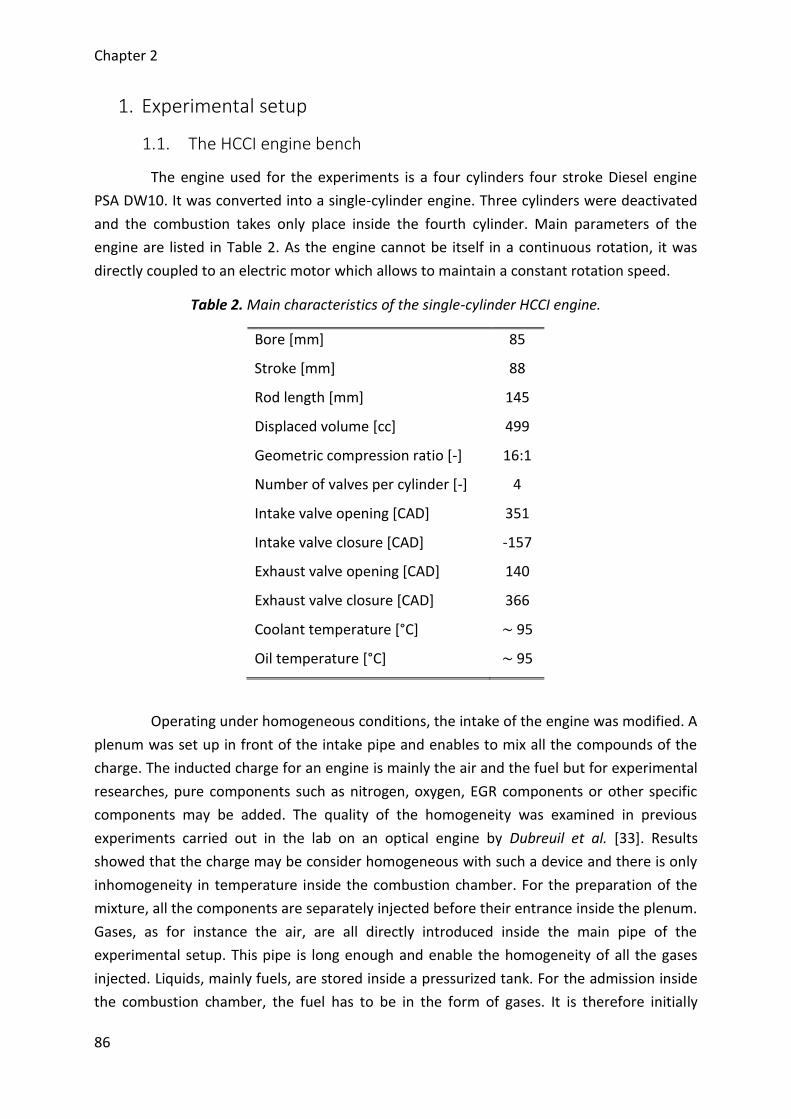
Chapter 2
86
1. Experimental setup
1.1. The HCCI engine bench
The engine used for the experiments is a four cylinders four stroke Diesel engine
PSA DW10. It was converted into a single-cylinder engine. Three cylinders were deactivated
and the combustion takes only place inside the fourth cylinder. Main parameters of the
engine are listed in Table 2. As the engine cannot be itself in a continuous rotation, it was
directly coupled to an electric motor which allows to maintain a constant rotation speed.
Table 2. Main characteristics of the single-cylinder HCCI engine.
Bore [mm] 85
Stroke [mm] 88
Rod length [mm] 145
Displaced volume [cc] 499
Geometric compression ratio [-] 16:1
Number of valves per cylinder [-] 4
Intake valve opening [CAD] 351
Intake valve closure [CAD] -157
Exhaust valve opening [CAD] 140
Exhaust valve closure [CAD] 366
Coolant temperature [°C] ~ 95
Oil temperature [°C] ~ 95
Operating under homogeneous conditions, the intake of the engine was modified. A
plenum was set up in front of the intake pipe and enables to mix all the compounds of the
charge. The inducted charge for an engine is mainly the air and the fuel but for experimental
researches, pure components such as nitrogen, oxygen, EGR components or other specific
components may be added. The quality of the homogeneity was examined in previous
experiments carried out in the lab on an optical engine by Dubreuil et al. [33]. Results
showed that the charge may be consider homogeneous with such a device and there is only
inhomogeneity in temperature inside the combustion chamber. For the preparation of the
mixture, all the components are separately injected before their entrance inside the plenum.
Gases, as for instance the air, are all directly introduced inside the main pipe of the
experimental setup. This pipe is long enough and enable the homogeneity of all the gases
injected. Liquids, mainly fuels, are stored inside a pressurized tank. For the admission inside
the combustion chamber, the fuel has to be in the form of gases. It is therefore initially
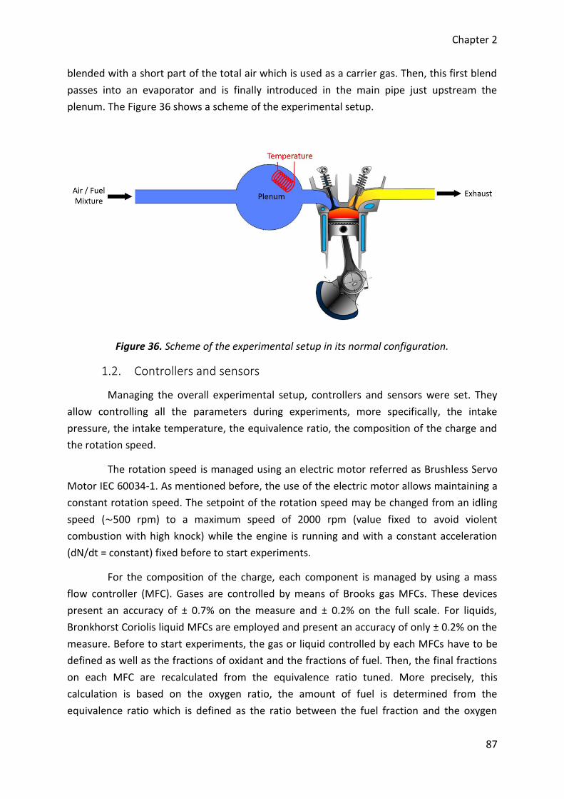
Chapter 2
87
blended with a short part of the total air which is used as a carrier gas. Then, this first blend
passes into an evaporator and is finally introduced in the main pipe just upstream the
plenum. The Figure 36 shows a scheme of the experimental setup.
Figure 36. Scheme of the experimental setup in its normal configuration.
1.2. Controllers and sensors
Managing the overall experimental setup, controllers and sensors were set. They
allow controlling all the parameters during experiments, more specifically, the intake
pressure, the intake temperature, the equivalence ratio, the composition of the charge and
the rotation speed.
The rotation speed is managed using an electric motor referred as Brushless Servo
Motor IEC 60034-1. As mentioned before, the use of the electric motor allows maintaining a
constant rotation speed. The setpoint of the rotation speed may be changed from an idling
speed (~500 rpm) to a maximum speed of 2000 rpm (value fixed to avoid violent
combustion with high knock) while the engine is running and with a constant acceleration
(dN/dt = constant) fixed before to start experiments.
For the composition of the charge, each component is managed by using a mass
flow controller (MFC). Gases are controlled by means of Brooks gas MFCs. These devices
present an accuracy of ± 0.7% on the measure and ± 0.2% on the full scale. For liquids,
Bronkhorst Coriolis liquid MFCs are employed and present an accuracy of only ± 0.2% on the
measure. Before to start experiments, the gas or liquid controlled by each MFCs have to be
defined as well as the fractions of oxidant and the fractions of fuel. Then, the final fractions
on each MFC are recalculated from the equivalence ratio tuned. More precisely, this
calculation is based on the oxygen ratio, the amount of fuel is determined from the
equivalence ratio which is defined as the ratio between the fuel fraction and the oxygen
Chapter 2
88
fraction measured in reference to the same ratio in the stoichiometric case (whether
𝑋𝑓𝑢𝑒𝑙 = 𝜑 × 𝑋𝑂2× (𝑋𝑓𝑢𝑒𝑙 𝑋𝑂2
⁄ )𝑠𝑡
). Finally, the flow on each MFC is automatically adjusted
in agreement with the fraction and the equivalence ratio defined with the aim to reach the
intake pressure setpoint. A Keller PAA-33X/80794 absolute pressure sensor measures this
last parameter with an accuracy of 0.1% on its measuring range. In conclusion, the present
approach is for a pressure regulation inside the plenum or again, for controlling the pressure
at the intake of the engine. Another approach is available to substitute the control of the
intake pressure and consists in managing independently the flow of each MFC by setting a
constant value on each of them. Therefore, the flows are fixed and in consequence, the
intake pressure is measured but not controlled. Finally, it is important to state that both
approaches may be combined. It is possible to control some MFCs with a constant flow and
adjust the other to achieve the intake pressure setpoint and the composition of the charge.
This combination will be particularly useful as part of the experiments performed during the
present work.
The intake temperature, the last parameter to tune, is controlled using several
heating resistance. The first heater is located inside the main pipe in front of the plenum and
upstream the fuel injection. As the temperature around the resistance can be very high, this
strategy enables to avoid ignition of the air/fuel mixture as there is no fuel near this heating
element and the gases inside the main pipe may be warm up to regulated temperatures
near 240 °C. The second heating resistance is a heater band positioned all around the
plenum. The aim of this element is not to warm up the air/fuel mixture but to limit heat
losses and maintain a high temperature of the charge before it is admitted inside the
combustion chamber. Most of the time, this heater band regulates a temperature similar to
that of the main heater. The last element influencing the intake temperature is the
evaporator. It is not use to control the temperature at the entrance of the engine but to
ensure that liquids, mainly fuels, will be well evaporated. However, as it warms up a part of
the flow up to 200 °C, it can slightly affect the intake temperature. Finally, the intake
temperature is a parameter measured when all the regulated temperature of all previous
element are well stabilized. Two K thermocouples, one in each pipe of the engine intake, are
used to determine the intake temperature. Each of them presents an accuracy of ± 2K and
the final intake temperature retained is the average of both measures.
All the parameters previously discussed; i.e. the intake conditions, the equivalence
ratio, the flow rates and the engine speed; are measured and recorded inside one file called
“Slow Acquisition File”. This file contains the average based on 40 measurements for each
parameter of the experimental setup. Then, these data will be used for a thermodynamic
analysis of the results described in the next part. Moreover, additional data on the exhaust
of the engine are also recorded inside this file. It consists of the exhaust pressure, the
exhaust temperature as well as pollutant emissions. The exhaust pressure is also measured
Chapter 2
89
with a Keller absolute pressure sensor, the same kind than that for the intake pressure. The
exhaust temperature is given from a K thermocouple similar to those used for the intake
temperature. Finally, emissions are examined using a HORIBA gas analyzer bay referred as
MEXA-7100HEGR. It collects a sample with a constant flow in the plenum located
downstream of the engine. A backpressure valve was set up to maintain a constant pressure
and avoid any perturbation on the exhaust of the engine. Then, the sample is separately
injected in the four different analyzers which quantified the following species: carbon
monoxide (CO), carbon dioxide (CO2), nitric oxide (NO), nitrogen oxides (NOx), oxygen (O2)
and unburned hydrocarbons (HC).
For the experimental results, the analyses are based on the evolutions of the in-
cylinder pressure. A Kistler 6043A piezo-electric relative pressure sensor measures this
pressure with an accuracy of ± 2%. Measurements are carried out every 0.1 crank angle
degree through the use of an optical encoder positioned on the crankshaft of the engine.
Therefore, 7200 points are recorded per cycle and each cycle starts at -180 CAD. In parallel
to the measurements of the in-cylinder pressure, pressure evolutions inside the manifolds,
i.e. intake and exhaust, are also measured with the same discretization. The intake pressure
is measured by a Kistler 4075A piezo-resistive absolute pressure sensor positioned on one of
the intake pipe. This sensor presents an accuracy of ± 0.3% of the full scale. The exhaust
pressure is also measured by the same kind of sensor except that an additional cooling
adapter has been mounted to remain inside the operating range of the pressure sensor.
Finally, all these pressures traces are recorded inside another file named “Quick Acquisition
File” which contains the data of 100 cycles.
1.3. Fuels selected
HCCI engines may use a wide range of fuels. More details were given in the first
chapter of the manuscript. The present experimental is suitable for testing different fuels
and according to the objectives, several fuels were selected among three fuel families, i.e.
Primary Reference Fuels (PRF), gaseous fuels and alcohol fuels. PRFs were chosen because
they are representative of conventional fuels already employed, n-heptane for diesel and
isooctane for gasoline. Moreover, they were widely studied as references for fuel
investigations. For the two other families, they are less employed than conventional fuels.
Nevertheless, regarding the forecasts, gaseous and alcohol fuels will grow in importance and
were therefore included in the present work. All the fuels selected are listed in Table 3 with
their respective properties.
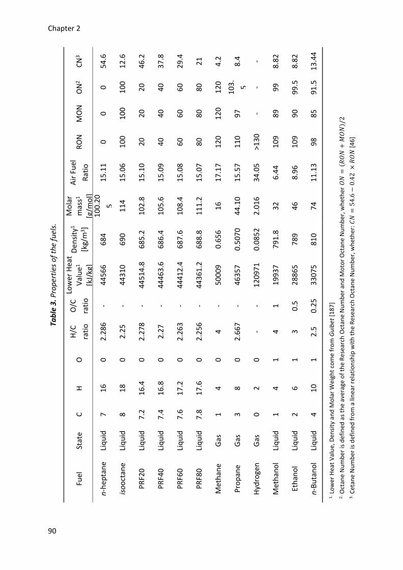
Chapter 2
90
Tab
le 3
. Pro
per
ties
of
the
fuel
s.
CN
3
54
.6
12
.6
46
.2
37
.8
29
.4
21
4.2
8.4
-
8.8
2
8.8
2
13
.44
1. L
ow
er H
eat
Val
ue,
Den
sity
an
d M
ola
r W
eigh
t co
me
fro
m G
uib
et [
18
7]
2. O
ctan
e N
um
ber
is d
efi
ned
as
the
aver
age
of
the
Re
sear
ch O
ctan
e N
um
ber
an
d M
oto
r O
ctan
e N
um
ber
, wh
eth
er 𝑂
𝑁=
( 𝑅𝑂
𝑁+
𝑀𝑂
𝑁) /
2
3. C
etan
e N
um
ber
is d
efin
ed f
rom
a li
nea
r re
lati
on
ship
wit
h t
he
Res
earc
h O
ctan
e N
um
be
r, w
het
her
: 𝐶
𝑁=
54
.6−
0.4
2 ×
𝑅𝑂
𝑁 [
46
]
ON
2
0
10
0
20
40
60
80
12
0
10
3.
5 - 9
9
99
.5
91
.5
MO
N
0
10
0
20
40
60
80
12
0
97 - 89
90
85
RO
N
0
10
0
20
40
60
80
12
0
11
0
>13
0
10
9
10
9
98
Air
Fu
el
Rat
io
15
.11
15
.06
15
.10
15
.09
15
.08
15
.07
17
.17
15
.57
34
.05
6.4
4
8.9
6
11
.13
Mo
lar
mas
s1
[g/m
ol]
1
00
.20
5
11
4
10
2.8
10
5.6
10
8.4
11
1.2
16
44
.10
2.0
16
32
46
74
Den
sity
1 [k
g/m
3]
68
4
69
0
68
5.2
68
6.4
68
7.6
68
8.8
0.6
56
0.5
07
0
0.0
85
2
79
1.8
78
9
81
0
Low
er H
eat
Val
ue
1
[kJ/
kg]
44
56
6
44
31
0
44
51
4.8
44
46
3.6
44
41
2.4
44
36
1.2
50
00
9
46
35
7
12
09
71
19
93
7
28
86
5
33
07
5
O/C
rati
o
- - - - - - - - - 1
0.5
0.2
5
H/C
rati
o
2.2
86
2.2
5
2.2
78
2.2
7
2.2
63
2.2
56
4
2.6
67
- 4
3
2.5
O
0
0
0
0
0
0
0
0
0
1
1
1
H
16
18
16
.4
16
.8
17
.2
17
.6
4
8
2
4
6
10
C
7
8
7.2
7.4
7.6
7.8
1
3
0
1
2
4
Stat
e
Liq
uid
Liq
uid
Liq
uid
Liq
uid
Liq
uid
Liq
uid
Gas
Gas
Gas
Liq
uid
Liq
uid
Liq
uid
Fuel
n-h
epta
ne
iso
oct
ane
PR
F20
PR
F40
PR
F60
PR
F80
Met
han
e
Pro
pan
e
Hyd
roge
n
Met
han
ol
Eth
ano
l
n-B
uta
no
l
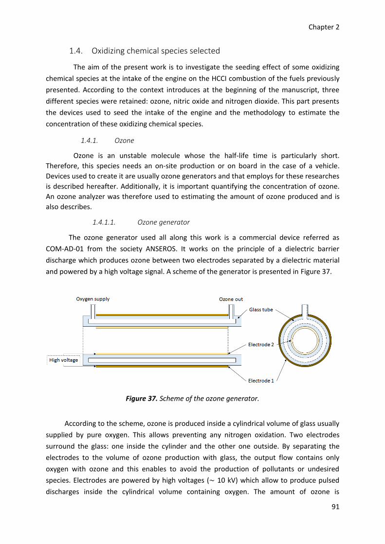
Chapter 2
91
1.4. Oxidizing chemical species selected
The aim of the present work is to investigate the seeding effect of some oxidizing
chemical species at the intake of the engine on the HCCI combustion of the fuels previously
presented. According to the context introduces at the beginning of the manuscript, three
different species were retained: ozone, nitric oxide and nitrogen dioxide. This part presents
the devices used to seed the intake of the engine and the methodology to estimate the
concentration of these oxidizing chemical species.
1.4.1. Ozone
Ozone is an unstable molecule whose the half-life time is particularly short.
Therefore, this species needs an on-site production or on board in the case of a vehicle.
Devices used to create it are usually ozone generators and that employs for these researches
is described hereafter. Additionally, it is important quantifying the concentration of ozone.
An ozone analyzer was therefore used to estimating the amount of ozone produced and is
also describes.
1.4.1.1. Ozone generator
The ozone generator used all along this work is a commercial device referred as
COM-AD-01 from the society ANSEROS. It works on the principle of a dielectric barrier
discharge which produces ozone between two electrodes separated by a dielectric material
and powered by a high voltage signal. A scheme of the generator is presented in Figure 37.
Figure 37. Scheme of the ozone generator.
According to the scheme, ozone is produced inside a cylindrical volume of glass usually
supplied by pure oxygen. This allows preventing any nitrogen oxidation. Two electrodes
surround the glass: one inside the cylinder and the other one outside. By separating the
electrodes to the volume of ozone production with glass, the output flow contains only
oxygen with ozone and this enables to avoid the production of pollutants or undesired
species. Electrodes are powered by high voltages (~ 10 kV) which allow to produce pulsed
discharges inside the cylindrical volume containing oxygen. The amount of ozone is
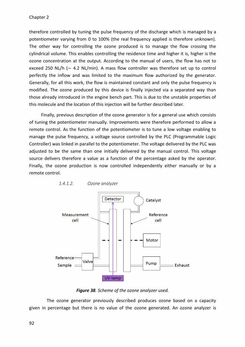
Chapter 2
92
therefore controlled by tuning the pulse frequency of the discharge which is managed by a
potentiometer varying from 0 to 100% (the real frequency applied is therefore unknown).
The other way for controlling the ozone produced is to manage the flow crossing the
cylindrical volume. This enables controlling the residence time and higher it is, higher is the
ozone concentration at the output. According to the manual of users, the flow has not to
exceed 250 NL/h (~ 4.2 NL/min). A mass flow controller was therefore set up to control
perfectly the inflow and was limited to the maximum flow authorized by the generator.
Generally, for all this work, the flow is maintained constant and only the pulse frequency is
modified. The ozone produced by this device is finally injected via a separated way than
those already introduced in the engine bench part. This is due to the unstable properties of
this molecule and the location of this injection will be further described later.
Finally, previous description of the ozone generator is for a general use which consists
of tuning the potentiometer manually. Improvements were therefore performed to allow a
remote control. As the function of the potentiometer is to tune a low voltage enabling to
manage the pulse frequency, a voltage source controlled by the PLC (Programmable Logic
Controller) was linked in parallel to the potentiometer. The voltage delivered by the PLC was
adjusted to be the same than one initially delivered by the manual control. This voltage
source delivers therefore a value as a function of the percentage asked by the operator.
Finally, the ozone production is now controlled independently either manually or by a
remote control.
1.4.1.2. Ozone analyzer
Figure 38. Scheme of the ozone analyzer used.
The ozone generator previously described produces ozone based on a capacity
given in percentage but there is no value of the ozone generated. An ozone analyzer is
Chapter 2
93
therefore used to measuring the concentrations which seed the intake of the engine. The
device used is also a commercial one coming from the society ANSEROS. It is referred as an
Ozomat MP analyzer. The determination of the ozone concentration is based on the
absorption of UV radiation by ozone and it has been set to measure concentrations up to
200 ppm. Concentrations are then recorded with other data in the slow acquisition file. A
scheme of the measurement system is presented in Figure 38.
As the measure is based on the UV absorption, the device is fitted of one UV lamp.
The UV light swept the measurement cell where a constant flow of the sample passes
through and the light intensity is determined by a detector. Then, the ozone concentration is
estimated from a Beer-Lambert law (Equation 1) where 𝐼 is the light intensity measured, 𝐿 is
the length of the measurement cell, 𝜀 is the molar absorptivity; which depends on the
wavelength, the temperature and the chemical entity; and finally 𝐼0 is the reference light
intensity. Parameters 𝐿 and 𝜀 are internal settings defined by ANSEROS while 𝐼0 must be
determined before a series of measures. This last parameter is established by using a
reference cell. This volume has the same characteristics than the measurement cell and may
be positioned in the UV light field with the help of a motor. When the device is under its
calibration step, the valve replaces the flow crossing the reference cell by ambient air
instead of the sample. Finally, before to pass through the reference cell, the flow, either the
sample or the ambient air, crosses a catalyst (2 O3 + catalyst → 3 O2). This allows avoiding
ozone concentration for determining the reference light intensity and to ensure no ozone in
the exhaust. Moreover, as the sample flow passes through the measurement cell and then
the reference cell, this methodology enables avoiding wrong measurements due to
pollutants. Finally, as for the ozone generator, the location of this materiel on the
experimental bench will be further described after.
1.4.2. Nitric oxides
Unlike ozone, nitric oxide and nitrogen dioxide are both stable chemical species.
They do not need any device to generate it and may be stored inside gas bottles. For
experiments, both molecules were separately available inside such materiel, diluted with
nitrogen to avoid any reaction and presented concentrations of 5000 ppm. Gas is injected
directly inside the main pipe of the experimental setup by using mass flow controller and
after being relaxed. Finally, the amount of these oxidizing chemical species seeded at the
intake of the engine is entirely controlled and quantified knowing the volume fraction on this
mass flow controller and the total flow.
[𝑂3] = −1
𝜀𝐿log
𝐼
𝐼0 (1)
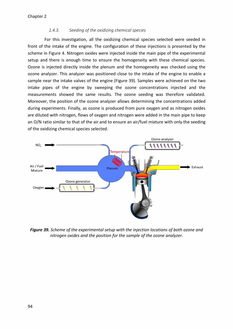
Chapter 2
94
1.4.3. Seeding of the oxidizing chemical species
For this investigation, all the oxidizing chemical species selected were seeded in
front of the intake of the engine. The configuration of these injections is presented by the
scheme in Figure 4. Nitrogen oxides were injected inside the main pipe of the experimental
setup and there is enough time to ensure the homogeneity with these chemical species.
Ozone is injected directly inside the plenum and the homogeneity was checked using the
ozone analyzer. This analyzer was positioned close to the intake of the engine to enable a
sample near the intake valves of the engine (Figure 39). Samples were achieved on the two
intake pipes of the engine by sweeping the ozone concentrations injected and the
measurements showed the same results. The ozone seeding was therefore validated.
Moreover, the position of the ozone analyzer allows determining the concentrations added
during experiments. Finally, as ozone is produced from pure oxygen and as nitrogen oxides
are diluted with nitrogen, flows of oxygen and nitrogen were added in the main pipe to keep
an O/N ratio similar to that of the air and to ensure an air/fuel mixture with only the seeding
of the oxidizing chemical species selected.
Figure 39. Scheme of the experimental setup with the injection locations of both ozone and nitrogen oxides and the position for the sample of the ozone analyzer.
Chapter 2
95
2. Analysis of the experimental data
The previous part introduced the experimental setup as well as fuels and additional
devices used for the present work. Measurements performed were recorded under two files
simply called “slow acquisition file” and “quick acquisition file”. The “quick acquisition file”
contains the pressure data recorded every 0.1 CAD for 100 cycles while the “slow acquisition
file” contains the average values of every sensor mounted on the experimental setup. Then,
these data must be post-treated and analyzed. Several approaches may be found in the
literature [141]–[144] depending of several parameters such as the engine, the type of
combustion or others. Based on the different post-treatments observed, the present part
describes the post-treatment methodology developed and implemented for analyzing the
acquired data and obtaining the engine outputs.
2.1. Loading of the engine parameters
Initially, the engine used must be configured in the post-treatment program.
Features of the engine given by Table 2 are therefore input and the program calculates the
other engine parameters needed for the analysis of the data recorded.
The first parameter determined from the features of the engine is the displaced
volume (𝑉𝑐𝑦𝑙). It is defined in Equation 2 as a function of the stroke (𝐶) and the bore (𝐵). In
parallel, the crankshaft radius (𝑅𝑣) may be calculated and correspond to the half of the
stroke (Equation 3). Then, the geometric clearance volume may be determined from the
displaced volume and knowing the compression ratio (CR) (Equation 4). Three last
parameters have to be found out. It is the rod length (𝐿𝑏), a modified compression ratio
(CRm) and an offset for the crank angle degree (𝜃𝑜𝑓𝑓𝑠𝑒𝑡). Their use will be defined in the
following parts.
𝑉𝑐𝑦𝑙 = 𝐶 × 𝐵2𝜋
4 (2)
𝑅𝑣 = 𝐶
2 (3)
𝑉𝑑 =𝑉𝑐𝑦𝑙
𝜏𝑐 − 1 (4)
2.2. Loading of the experimental data
Experimental data are recorded in two files: the quick acquisition file and the slow
acquisition file. The first contains the data of the pressures acquired every 0.1 crank angle
Chapter 2
96
degree while the second contains the average data of the other parameters. Details about
both files are given hereafter.
2.2.1. Loading of the quick file
As describe previously in the experimental setup, the quick acquisition file contains
the data records from the pressure sensors, i.e. the intake pressure, the in-cylinder pressure
and the exhaust pressure. Data were acquired for 100 cycles every 0.1 crank angle degree
and for each sensor. This is a good tradeoff for achieving an excellent statistical analysis and
avoid too much data [143]. Intake and exhaust pressure sensors are both absolute pressure
sensors while in-cylinder pressure sensor is a relative one. Therefore, the in-cylinder
pressure must be reset under absolute conditions by using either the intake pressure or the
exhaust pressure. In the present case, the reset is performed from the intake pressure
evolution according to the Equation 5 because this pressure is more stable than the exhaust
one (Figure 40).
To achieve a good reset of the in-cylinder pressure, it is necessary to select a range
between 𝐶𝐴𝐷𝑙𝑜𝑤 and 𝐶𝐴𝐷ℎ𝑖𝑔ℎ where the intake pressure is assumed equal to the pressure
inside the combustion chamber. The area chosen starts to 530 CAD and finishes to 540 CAD,
whether around the bottom dead center and before the intake valve closing.
Then, the 100 cycles of the in-cylinder pressure are all filtered. The overall analysis
may be led by an average of the 100 cycles but a filtering approach allows if necessary
providing statistical analysis of the results determined from the pressure traces. Moreover,
both approaches do not change a lot the final results. It is therefore most interesting
conducting an analysis by keeping the 100 cycles. In the present post-treatment analysis, the
filter used consists of a low pass “Butterworth” filter whose the cutting frequency was fixed
at 3000 Hz. The frequency selected allows limiting the information loss on the in-cylinder
pressure signal (less than 1%) and to well fit the in-cylinder pressure trace for the following
assessment.
In parallel to the loading of the pressure evolutions, the crank angle degree (𝜃) must
be rebuilt with the same accurate than the optical encoder allowing the data record. This
device has been positioned manually on the crankshaft and starts the acquisition from the
top dead center (-180 CAD). The crank angle degree is therefore defined from -180 to 540 by
step of 0.1 CAD. However, it may be a lag with the position of the optical encoder, an offset
is therefore added to the definition of the crank angle degree. The determination of this
offset is introduced in the part 2.3.1.
𝑃𝑐𝑦𝑙 = 𝑃𝑐𝑦𝑙 𝑔𝑟𝑜𝑠𝑠 + ∫ 𝑃𝑚𝑎𝑛𝑖𝑓𝑜𝑙𝑑 − ∫ 𝑃𝑐𝑦𝑙 𝑔𝑟𝑜𝑠𝑠
𝐶𝐴𝐷ℎ𝑖𝑔ℎ
𝐶𝐴𝐷𝑙𝑜𝑤
𝐶𝐴𝐷ℎ𝑖𝑔ℎ
𝐶𝐴𝐷𝑙𝑜𝑤
(5)
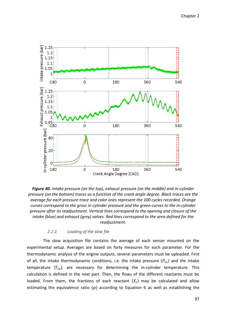
Chapter 2
97
Figure 40. Intake pressure (on the top), exhaust pressure (on the middle) and in-cylinder pressure (on the bottom) traces as a function of the crank angle degree. Black traces are the
average for each pressure trace and color ones represent the 100 cycles recorded. Orange curves correspond to the gross in-cylinder pressure and the green curves to the in-cylinder pressure after its readjustment. Vertical lines correspond to the opening and closure of the
intake (blue) and exhaust (grey) valves. Red lines correspond to the area defined for the readjustment.
2.2.2. Loading of the slow file
The slow acquisition file contains the average of each sensor mounted on the
experimental setup. Averages are based on forty measures for each parameter. For the
thermodynamic analysis of the engine outputs, several parameters must be uploaded. First
of all, the intake thermodynamic conditions, i.e. the intake pressure (𝑃𝑖𝑛) and the intake
temperature (𝑇𝑖𝑛), are necessary for determining the in-cylinder temperature. This
calculation is defined in the next part. Then, the flows of the different reactants must be
loaded. From them, the fractions of each reactant (𝑋𝑖) may be calculated and allow
estimating the equivalence ratio (𝜑) according to Equation 6 as well as establishing the
Chapter 2
98
combustion equation. The combustion equation enables finally evaluating the products of
combustion and their respective fractions (𝑋𝑗). Moreover, pollutants measurements may be
uploaded when they are available and the equivalence ratio previously calculated can be
compared with one obtained from a pollutants analysis. Finally, a last parameter must be
load from the slow acquisition file, it is the rotation speed (𝜔) whose use will be described
below.
𝜑 =
(𝑋𝑓𝑢𝑒𝑙
𝑋𝑂2
)𝑟𝑒𝑎𝑙
(𝑋𝑓𝑢𝑒𝑙
𝑋𝑂2
)𝑠𝑡
(6)
2.3. Post-treatment of the experimental data
From now on, all the parameters needed to achieve the analysis of the
experimental data were uploaded and the thermodynamic analysis may be run. The aim is to
obtain the evolutions of some thermodynamic parameter during the combustion process in
order to assess by some of its features. As the moment, only the in-cylinder pressure trace is
available and for conduct such analysis, it is of prime importance to know the instantaneous
volume as well as the in-cylinder temperature. The approach for achieving these results is
described hereafter.
The instantaneous volume of the combustion chamber must be rebuilt from the
geometry of the engine. As the volume changes with the piston motion, the calculation of
the volume must be expressed as a function of the piston position (𝑋) which depends on the
crank angle (𝜃) and is defined in Equation 7. 𝑅𝑣 and 𝐿𝑏 are respectively the crankshaft radius
and the rod length provided with the definition of the engine (part 2.1). Finally, the
instantaneous volume (𝑉) is expressed by the slider-crank equation (Equation 8) [141].
𝑋 = 𝑅𝑣 × cos (𝜃 ×
𝜋
180) + √𝐿𝑏
2 − (𝑅𝑣 × sin (𝜃 ×𝜋
180))
2
(7)
𝑉 =
𝜋 × 𝐵2 × (𝐿𝑏 + 𝑅𝑣 − 𝑋)
4+ 𝑉𝑑
(8)
Then, the in-cylinder temperature may be calculated from the in-cylinder pressure
and the instantaneous volume of the combustion chamber. At the start of the admission of
the homogeneous air/fuel mixture, it is possible to consider a perfect gas. Therefore, the
ideal gas law may be applied to the combustion chamber (Equation 9). The unknown
parameter in this equation is 𝑛𝑅. It is supposed a constant and it has to be determined. This
equation is also valid at the beginning of the compression stroke or more precisely at the
Chapter 2
99
intake valve closing. 𝑛𝑅 can therefore be expressed as in Equation 10 and by replacing the
term in Equation 9, the in-cylinder temperature may be finally rewritten as in Equation 11.
For the analysis, the initial volume 𝑉𝐼𝑉𝐶 is taken at the crank angle degree of the intake valve
closing (Table 2) according to Equations 7 and 8. For the initial thermodynamic conditions,
i.e. 𝑃𝐼𝑉𝐶 and 𝑇𝐼𝑉𝐶, these parameters are respectively taken as the pressure and the
temperature at the intake, i.e. 𝑃𝑖𝑛 and 𝑇𝑖𝑛, uploaded from the slow file acquisition.
𝑃𝑐𝑦𝑙𝑉 = 𝑛𝑅𝑇𝑐𝑦𝑙 (9)
𝑛𝑅 = 𝑃𝐼𝑉𝐶𝑉𝐼𝑉𝐶
𝑇𝐼𝑉𝐶 (10)
𝑇𝑐𝑦𝑙 = 𝑃𝑐𝑦𝑙𝑉𝑇𝐼𝑉𝐶
𝑃𝐼𝑉𝐶𝑉𝐼𝑉𝐶 (11)
For the rest of the post-treatment, the analysis is separated into two parts: a
motoring analysis and a combustion analysis. Both of them are separately described below.
2.3.1. Motoring analysis
The motoring analysis used in the present post-treatment program was developed
to adjust some parameters and therefore, improve the final results. Parameters, which need
to be corrected, are the position of the top dead center, or rather the crank angle (𝜃), and
the compression ratio (CR). The first alters the phasing of the volume with the in-cylinder
pressure trace while the second alters the calculation of the volume. A wrong phasing of the
crank angle is due to the optical encoder. This element mounted on the experimental setup
has been positioned to start the record from the bottom dead center but its position can be
shifted due to its manual positioning. An offset (𝜃𝑜𝑓𝑓𝑠𝑒𝑡) on the crank angle definition has
been therefore integrated to correct the phasing. A wrong compression ratio is due to a
wrong determination of the clearance volume which is used to calculate the instantaneous
volume. For the present engine, this volume has been estimated by determining the volume
of the piston bowl but the real clearance volume must consider the small volume between
the piston and the cylinder head. Therefore, a new compression ratio (CRm) has been
integrated for the analysis and replaced the geometric compression ratio defined with the
engine characteristics.
The determination of both parameters is based on a thermodynamic analysis of an
experimental motoring. The methodology was proposed by Tazerout et al. [145], [146] and
consists of examining the temperature-entropy (T-S) diagram of the data record. Ideally, this
diagram must look like a symmetrical evolution at the maximum in-cylinder temperature on
the compression and expansion strokes. If not, it is interpreted with no thermodynamic
Chapter 2
100
sense and this means that either the top dead center position or the compression ratio or
both parameters are not well calibrated. Calibrations needed are identified as a function of
the shape of the T-S diagram (Figure 41 and Figure 42).
The in-cylinder temperature is already calculated and it is necessary to estimate the
entropy (𝑆). This thermodynamic characteristic is determined according to Equations 12 and
13 from 𝜃𝑚𝑖𝑛 to 𝜃𝑚𝑎𝑥. Values of these two crank angles are respectively taken as -30 and +
30 to cover the parts of the compression and expansion strokes where the in-cylinder
temperature is the highest. For calculating the entropy, the heat capacity at constant
pressure (𝐶𝑝) and the molar mass (𝑀) of the mixture are needed. 𝐶𝑝 is defined as the sum of
the product of the molar fraction of each component of the mixture by their respective heat
capacity (𝐶𝑝𝑖) (Equation 14) and where each 𝐶𝑝𝑖
is obtained from the in-cylinder
temperature and the JANAF coefficients (𝑎𝑖,𝑘) found in the table of Burcat [147] (Equation
15). Finally, the molar mass (𝑀) is defined like a constant because no reactions are
considered during a motoring and is expressed as the sum of the products of the molar
fractions of each chemical species by their respective molar mass (Equation 16).
𝑑𝑆
𝑑𝜃=
𝐶𝑝
𝑀×
1
𝑇𝑐𝑦𝑙×
𝑑𝑇𝑐𝑦𝑙
𝑑𝜃−
𝑅
𝑀×
1
𝑃𝑐𝑦𝑙×
𝑑𝑃𝑐𝑦𝑙
𝑑𝜃 (12)
𝑆(𝜃) = ∫𝑑𝑆
𝑑𝜃
𝜃𝑚𝑎𝑥
𝜃𝑚𝑖𝑛
(13)
𝐶𝑝(𝜃) = ∑ 𝑋𝑖 ×
𝑖
𝐶𝑝𝑖(𝜃) (14)
𝐶𝑝𝑖(𝜃) = 𝑅 × ∑ 𝑎𝑖,𝑘 × 𝑇𝑐𝑦𝑙(𝜃)𝑘−1
5
𝑘=1
(15)
𝑀 = ∑ 𝑋𝑖 × 𝑀𝑖
𝑖
(16)
Once the entropy is calculated, the T-S diagram may be plotted and the adjustment
on the crank angle (𝜃𝑜𝑓𝑓𝑠𝑒𝑡) as well as the new compression ratio (CRm) have to be
determined. According to the shape observed, it is necessary to modify progressively one by
one either the compression ratio or the offset on the crank angle up to obtain the symmetry
explained above. Final results normally observed for a motoring analysis are represented by
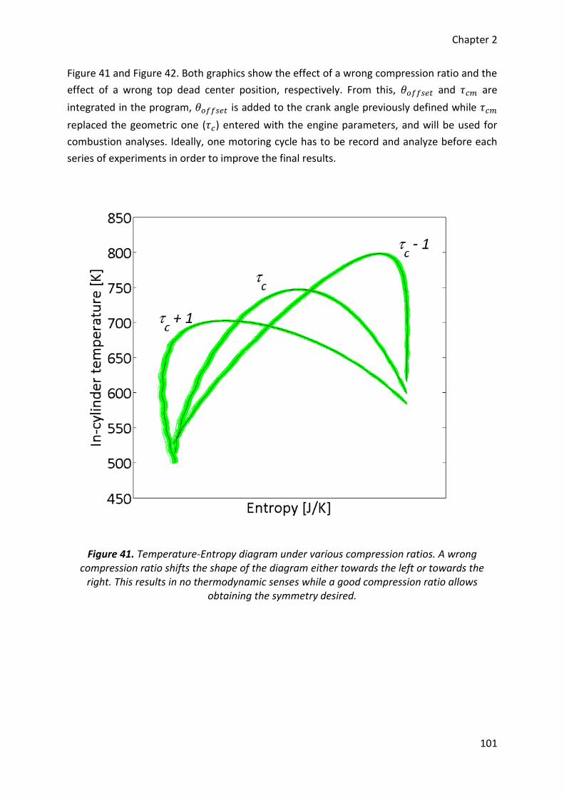
Chapter 2
101
Figure 41 and Figure 42. Both graphics show the effect of a wrong compression ratio and the
effect of a wrong top dead center position, respectively. From this, 𝜃𝑜𝑓𝑓𝑠𝑒𝑡 and 𝜏𝑐𝑚 are
integrated in the program, 𝜃𝑜𝑓𝑓𝑠𝑒𝑡 is added to the crank angle previously defined while 𝜏𝑐𝑚
replaced the geometric one (𝜏𝑐) entered with the engine parameters, and will be used for
combustion analyses. Ideally, one motoring cycle has to be record and analyze before each
series of experiments in order to improve the final results.
Figure 41. Temperature-Entropy diagram under various compression ratios. A wrong compression ratio shifts the shape of the diagram either towards the left or towards the
right. This results in no thermodynamic senses while a good compression ratio allows obtaining the symmetry desired.
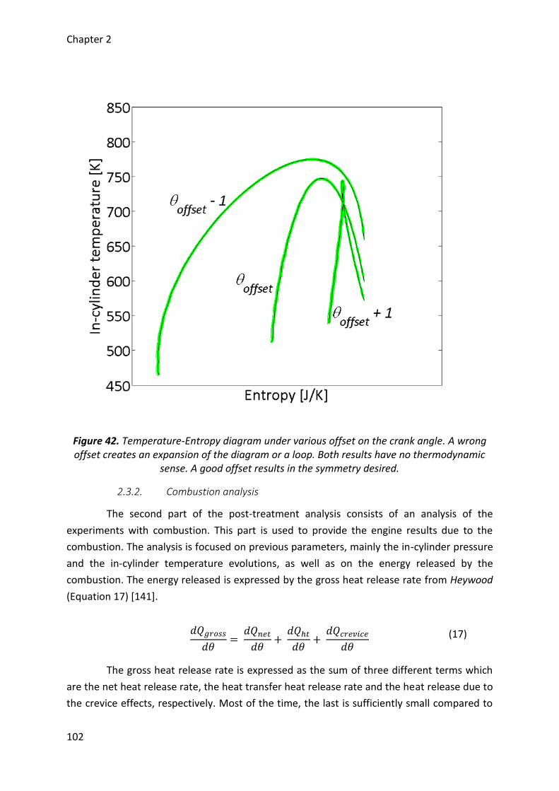
Chapter 2
102
Figure 42. Temperature-Entropy diagram under various offset on the crank angle. A wrong offset creates an expansion of the diagram or a loop. Both results have no thermodynamic
sense. A good offset results in the symmetry desired.
2.3.2. Combustion analysis
The second part of the post-treatment analysis consists of an analysis of the
experiments with combustion. This part is used to provide the engine results due to the
combustion. The analysis is focused on previous parameters, mainly the in-cylinder pressure
and the in-cylinder temperature evolutions, as well as on the energy released by the
combustion. The energy released is expressed by the gross heat release rate from Heywood
(Equation 17) [141].
𝑑𝑄𝑔𝑟𝑜𝑠𝑠
𝑑𝜃=
𝑑𝑄𝑛𝑒𝑡
𝑑𝜃+
𝑑𝑄ℎ𝑡
𝑑𝜃+
𝑑𝑄𝑐𝑟𝑒𝑣𝑖𝑐𝑒
𝑑𝜃 (17)
The gross heat release rate is expressed as the sum of three different terms which
are the net heat release rate, the heat transfer heat release rate and the heat release due to
the crevice effects, respectively. Most of the time, the last is sufficiently small compared to
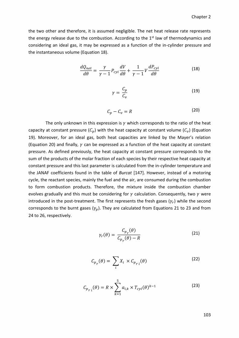
Chapter 2
103
the two other and therefore, it is assumed negligible. The net heat release rate represents
the energy release due to the combustion. According to the 1st law of thermodynamics and
considering an ideal gas, it may be expressed as a function of the in-cylinder pressure and
the instantaneous volume (Equation 18).
𝑑𝑄𝑛𝑒𝑡
𝑑𝜃=
𝛾
𝛾 − 1𝑃𝑐𝑦𝑙
𝑑𝑉
𝑑𝜃+
1
𝛾 − 1𝑉
𝑑𝑃𝑐𝑦𝑙
𝑑𝜃 (18)
𝛾 = 𝐶𝑝
𝐶𝑣 (19)
𝐶𝑝 − 𝐶𝑣 = 𝑅 (20)
The only unknown in this expression is 𝛾 which corresponds to the ratio of the heat
capacity at constant pressure (𝐶𝑝) with the heat capacity at constant volume (𝐶𝑣) (Equation
19). Moreover, for an ideal gas, both heat capacities are linked by the Mayer’s relation
(Equation 20) and finally, 𝛾 can be expressed as a function of the heat capacity at constant
pressure. As defined previously, the heat capacity at constant pressure corresponds to the
sum of the products of the molar fraction of each species by their respective heat capacity at
constant pressure and this last parameter is calculated from the in-cylinder temperature and
the JANAF coefficients found in the table of Burcat [147]. However, instead of a motoring
cycle, the reactant species, mainly the fuel and the air, are consumed during the combustion
to form combustion products. Therefore, the mixture inside the combustion chamber
evolves gradually and this must be considering for 𝛾 calculation. Consequently, two 𝛾 were
introduced in the post-treatment. The first represents the fresh gases (𝛾𝑟) while the second
corresponds to the burnt gases (𝛾𝑝). They are calculated from Equations 21 to 23 and from
24 to 26, respectively.
𝛾𝑟(𝜃) = 𝐶𝑝𝑟
(𝜃)
𝐶𝑝𝑟(𝜃) − 𝑅
(21)
𝐶𝑝𝑟(𝜃) = ∑ 𝑋𝑖 × 𝐶𝑝𝑟 𝑖
(𝜃)
𝑖
(22)
𝐶𝑝𝑟 𝑖(𝜃) = 𝑅 × ∑ 𝑎𝑖,𝑘 × 𝑇𝑐𝑦𝑙(𝜃)𝑘−1
5
𝑘=1
(23)
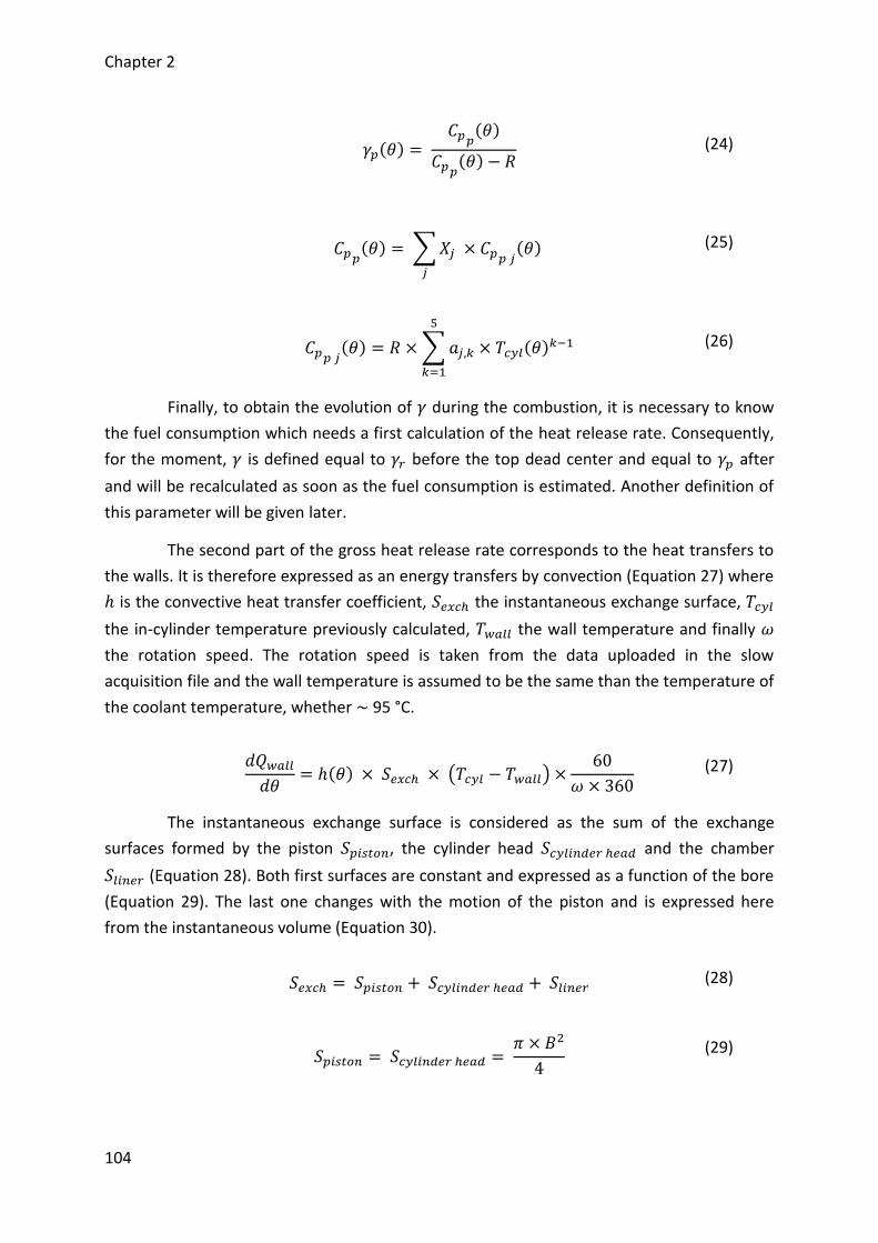
Chapter 2
104
𝛾𝑝(𝜃) = 𝐶𝑝𝑝
(𝜃)
𝐶𝑝𝑝(𝜃) − 𝑅
(24)
𝐶𝑝𝑝(𝜃) = ∑ 𝑋𝑗 × 𝐶𝑝𝑝 𝑗
(𝜃)
𝑗
(25)
𝐶𝑝𝑝 𝑗(𝜃) = 𝑅 × ∑ 𝑎𝑗,𝑘 × 𝑇𝑐𝑦𝑙(𝜃)𝑘−1
5
𝑘=1
(26)
Finally, to obtain the evolution of 𝛾 during the combustion, it is necessary to know
the fuel consumption which needs a first calculation of the heat release rate. Consequently,
for the moment, 𝛾 is defined equal to 𝛾𝑟 before the top dead center and equal to 𝛾𝑝 after
and will be recalculated as soon as the fuel consumption is estimated. Another definition of
this parameter will be given later.
The second part of the gross heat release rate corresponds to the heat transfers to
the walls. It is therefore expressed as an energy transfers by convection (Equation 27) where
ℎ is the convective heat transfer coefficient, 𝑆𝑒𝑥𝑐ℎ the instantaneous exchange surface, 𝑇𝑐𝑦𝑙
the in-cylinder temperature previously calculated, 𝑇𝑤𝑎𝑙𝑙 the wall temperature and finally 𝜔
the rotation speed. The rotation speed is taken from the data uploaded in the slow
acquisition file and the wall temperature is assumed to be the same than the temperature of
the coolant temperature, whether ~ 95 °C.
𝑑𝑄𝑤𝑎𝑙𝑙
𝑑𝜃= ℎ(𝜃) × 𝑆𝑒𝑥𝑐ℎ × (𝑇𝑐𝑦𝑙 − 𝑇𝑤𝑎𝑙𝑙) ×
60
𝜔 × 360 (27)
The instantaneous exchange surface is considered as the sum of the exchange
surfaces formed by the piston 𝑆𝑝𝑖𝑠𝑡𝑜𝑛, the cylinder head 𝑆𝑐𝑦𝑙𝑖𝑛𝑑𝑒𝑟 ℎ𝑒𝑎𝑑 and the chamber
𝑆𝑙𝑖𝑛𝑒𝑟 (Equation 28). Both first surfaces are constant and expressed as a function of the bore
(Equation 29). The last one changes with the motion of the piston and is expressed here
from the instantaneous volume (Equation 30).
𝑆𝑒𝑥𝑐ℎ = 𝑆𝑝𝑖𝑠𝑡𝑜𝑛 + 𝑆𝑐𝑦𝑙𝑖𝑛𝑑𝑒𝑟 ℎ𝑒𝑎𝑑 + 𝑆𝑙𝑖𝑛𝑒𝑟 (28)
𝑆𝑝𝑖𝑠𝑡𝑜𝑛 = 𝑆𝑐𝑦𝑙𝑖𝑛𝑑𝑒𝑟 ℎ𝑒𝑎𝑑 =
𝜋 × 𝐵2
4
(29)
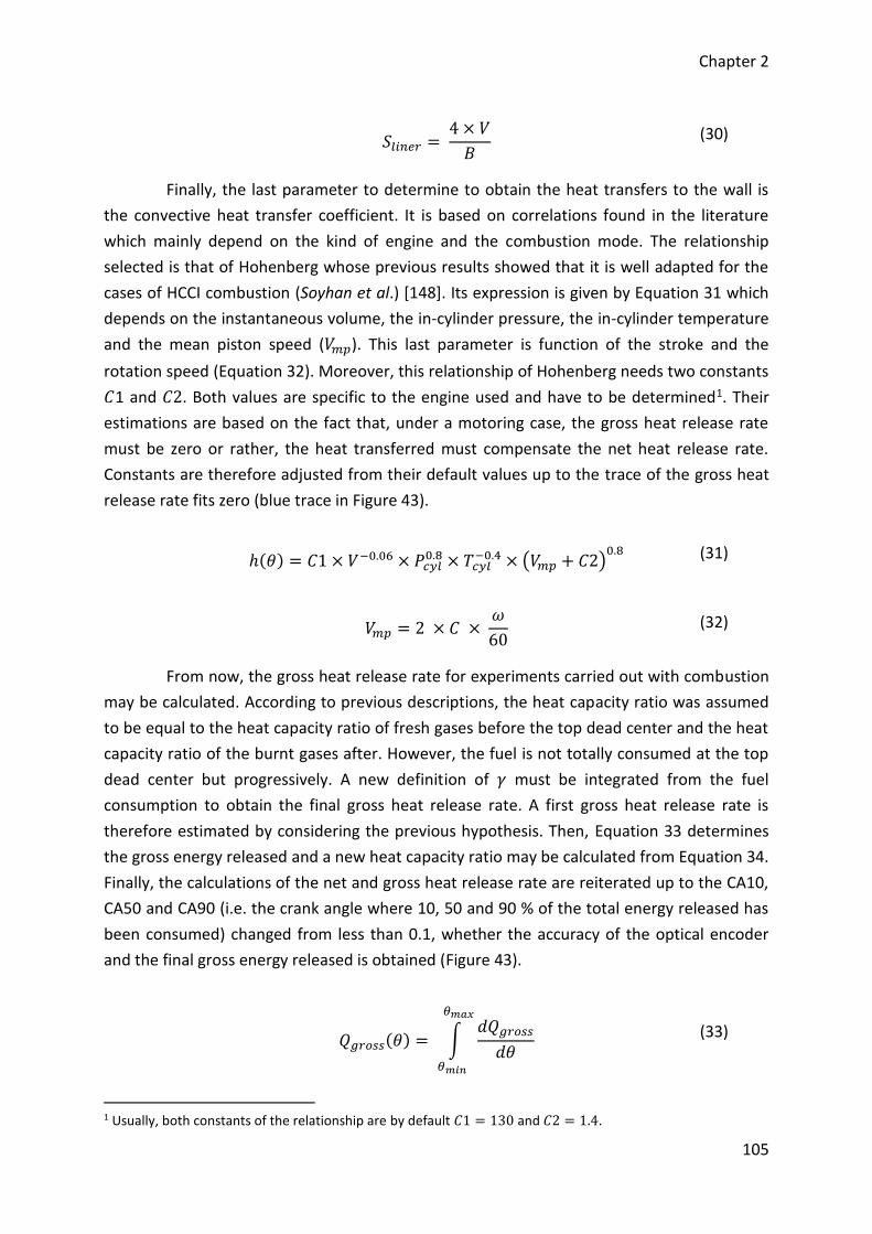
Chapter 2
105
𝑆𝑙𝑖𝑛𝑒𝑟 = 4 × 𝑉
𝐵 (30)
Finally, the last parameter to determine to obtain the heat transfers to the wall is
the convective heat transfer coefficient. It is based on correlations found in the literature
which mainly depend on the kind of engine and the combustion mode. The relationship
selected is that of Hohenberg whose previous results showed that it is well adapted for the
cases of HCCI combustion (Soyhan et al.) [148]. Its expression is given by Equation 31 which
depends on the instantaneous volume, the in-cylinder pressure, the in-cylinder temperature
and the mean piston speed (𝑉𝑚𝑝). This last parameter is function of the stroke and the
rotation speed (Equation 32). Moreover, this relationship of Hohenberg needs two constants
𝐶1 and 𝐶2. Both values are specific to the engine used and have to be determined1. Their
estimations are based on the fact that, under a motoring case, the gross heat release rate
must be zero or rather, the heat transferred must compensate the net heat release rate.
Constants are therefore adjusted from their default values up to the trace of the gross heat
release rate fits zero (blue trace in Figure 43).
ℎ(𝜃) = 𝐶1 × 𝑉−0.06 × 𝑃𝑐𝑦𝑙0.8 × 𝑇𝑐𝑦𝑙
−0.4 × (𝑉𝑚𝑝 + 𝐶2)0.8
(31)
𝑉𝑚𝑝 = 2 × 𝐶 × 𝜔
60 (32)
From now, the gross heat release rate for experiments carried out with combustion
may be calculated. According to previous descriptions, the heat capacity ratio was assumed
to be equal to the heat capacity ratio of fresh gases before the top dead center and the heat
capacity ratio of the burnt gases after. However, the fuel is not totally consumed at the top
dead center but progressively. A new definition of 𝛾 must be integrated from the fuel
consumption to obtain the final gross heat release rate. A first gross heat release rate is
therefore estimated by considering the previous hypothesis. Then, Equation 33 determines
the gross energy released and a new heat capacity ratio may be calculated from Equation 34.
Finally, the calculations of the net and gross heat release rate are reiterated up to the CA10,
CA50 and CA90 (i.e. the crank angle where 10, 50 and 90 % of the total energy released has
been consumed) changed from less than 0.1, whether the accuracy of the optical encoder
and the final gross energy released is obtained (Figure 43).
𝑄𝑔𝑟𝑜𝑠𝑠(𝜃) = ∫
𝑑𝑄𝑔𝑟𝑜𝑠𝑠
𝑑𝜃
𝜃𝑚𝑎𝑥
𝜃𝑚𝑖𝑛
(33)
1 Usually, both constants of the relationship are by default 𝐶1 = 130 and 𝐶2 = 1.4.
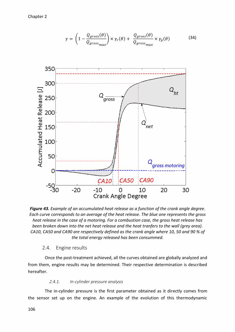
Chapter 2
106
𝛾 = (1 −𝑄𝑔𝑟𝑜𝑠𝑠(𝜃)
𝑄𝑔𝑟𝑜𝑠𝑠𝑚𝑎𝑥
) × 𝛾𝑟(𝜃) + 𝑄𝑔𝑟𝑜𝑠𝑠(𝜃)
𝑄𝑔𝑟𝑜𝑠𝑠𝑚𝑎𝑥
× 𝛾𝑝(𝜃) (34)
Figure 43. Example of an accumulated heat release as a function of the crank angle degree. Each curve corresponds to an average of the heat release. The blue one represents the gross
heat release in the case of a motoring. For a combustion case, the gross heat release has been broken down into the net heat release and the heat tranfers to the wall (grey area).
CA10, CA50 and CA90 are respectively defined as the crank angle where 10, 50 and 90 % of the total energy released has been consummed.
2.4. Engine results
Once the post-treatment achieved, all the curves obtained are globally analyzed and
from them, engine results may be determined. Their respective determination is described
hereafter.
2.4.1. In-cylinder pressure analysis
The in-cylinder pressure is the first parameter obtained as it directly comes from
the sensor set up on the engine. An example of the evolution of this thermodynamic
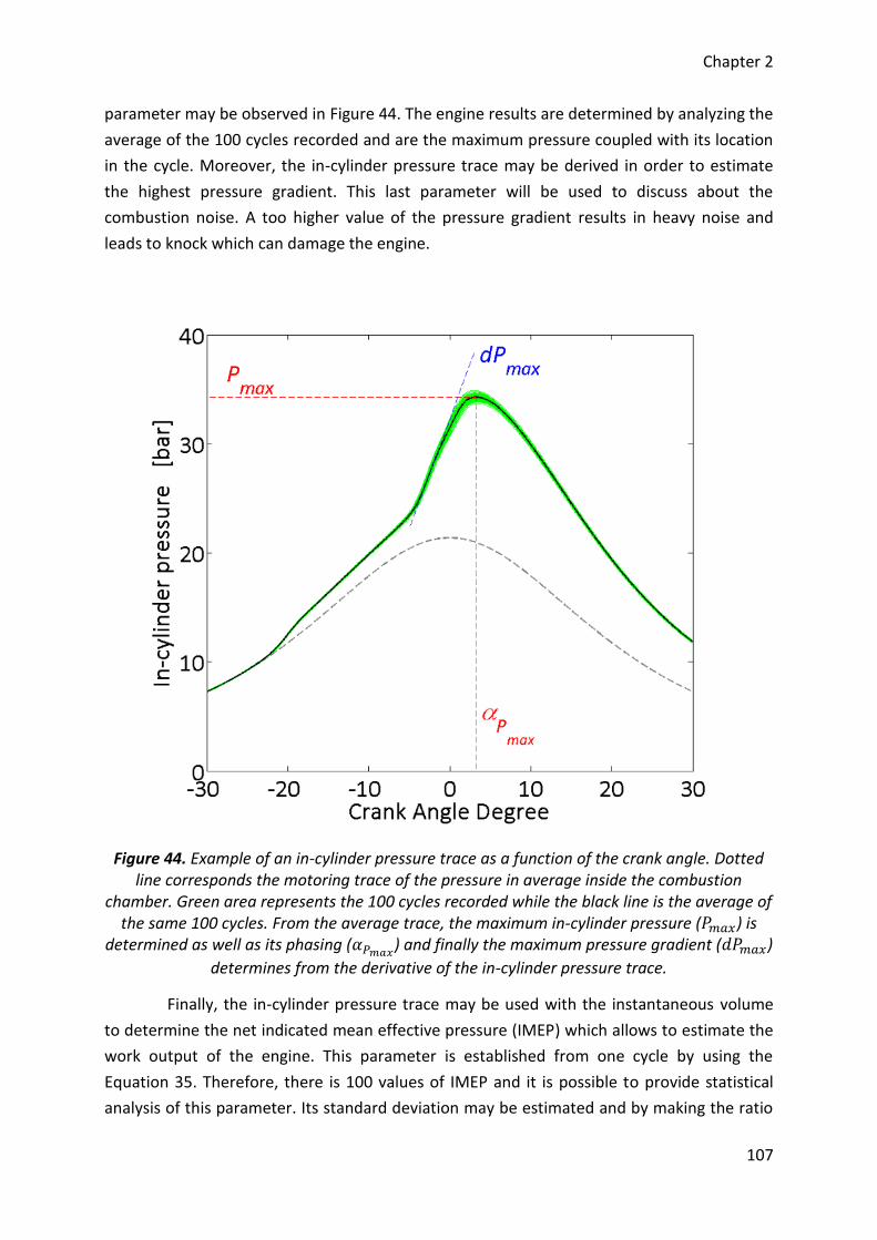
Chapter 2
107
parameter may be observed in Figure 44. The engine results are determined by analyzing the
average of the 100 cycles recorded and are the maximum pressure coupled with its location
in the cycle. Moreover, the in-cylinder pressure trace may be derived in order to estimate
the highest pressure gradient. This last parameter will be used to discuss about the
combustion noise. A too higher value of the pressure gradient results in heavy noise and
leads to knock which can damage the engine.
Figure 44. Example of an in-cylinder pressure trace as a function of the crank angle. Dotted line corresponds the motoring trace of the pressure in average inside the combustion
chamber. Green area represents the 100 cycles recorded while the black line is the average of the same 100 cycles. From the average trace, the maximum in-cylinder pressure (𝑃𝑚𝑎𝑥) is
determined as well as its phasing (𝛼𝑃𝑚𝑎𝑥) and finally the maximum pressure gradient (𝑑𝑃𝑚𝑎𝑥)
determines from the derivative of the in-cylinder pressure trace.
Finally, the in-cylinder pressure trace may be used with the instantaneous volume
to determine the net indicated mean effective pressure (IMEP) which allows to estimate the
work output of the engine. This parameter is established from one cycle by using the
Equation 35. Therefore, there is 100 values of IMEP and it is possible to provide statistical
analysis of this parameter. Its standard deviation may be estimated and by making the ratio
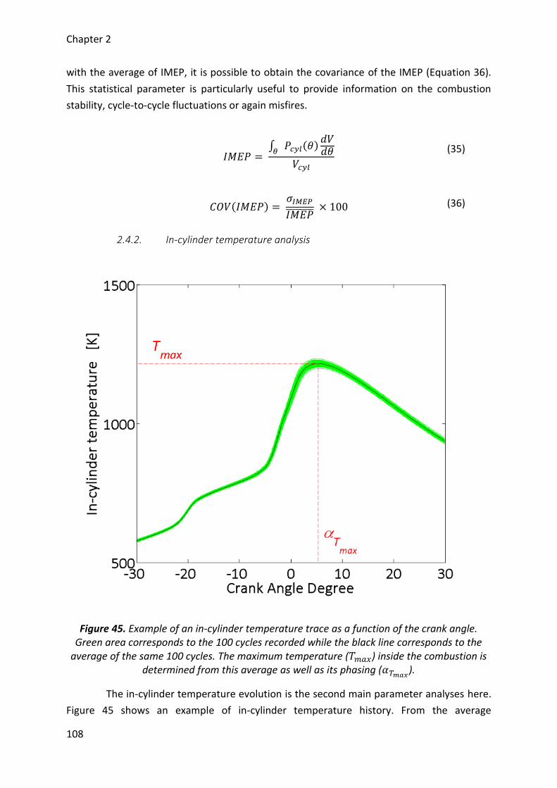
Chapter 2
108
with the average of IMEP, it is possible to obtain the covariance of the IMEP (Equation 36).
This statistical parameter is particularly useful to provide information on the combustion
stability, cycle-to-cycle fluctuations or again misfires.
𝐼𝑀𝐸𝑃 =
∫ 𝑃𝑐𝑦𝑙(𝜃)𝑑𝑉𝑑𝜃𝜃
𝑉𝑐𝑦𝑙
(35)
𝐶𝑂𝑉(𝐼𝑀𝐸𝑃) = 𝜎𝐼𝑀𝐸𝑃
𝐼𝑀𝐸𝑃̅̅ ̅̅ ̅̅ ̅̅ × 100 (36)
2.4.2. In-cylinder temperature analysis
Figure 45. Example of an in-cylinder temperature trace as a function of the crank angle. Green area corresponds to the 100 cycles recorded while the black line corresponds to the
average of the same 100 cycles. The maximum temperature (𝑇𝑚𝑎𝑥) inside the combustion is determined from this average as well as its phasing (𝛼𝑇𝑚𝑎𝑥
).
The in-cylinder temperature evolution is the second main parameter analyses here.
Figure 45 shows an example of in-cylinder temperature history. From the average
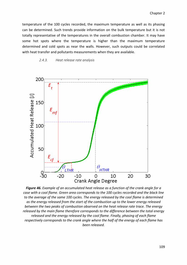
Chapter 2
109
temperature of the 100 cycles recorded, the maximum temperature as well as its phasing
can be determined. Such trends provide information on the bulk temperature but it is not
totally representative of the temperatures in the overall combustion chamber. It may have
some hot spots where the temperature is higher than the maximum temperature
determined and cold spots as near the walls. However, such outputs could be correlated
with heat transfer and pollutants measurements when they are available.
2.4.3. Heat release rate analysis
Figure 46. Example of an accumulated heat release as a function of the crank angle for a
case with a cool flame. Green area corresponds to the 100 cycles recorded and the black line to the average of the same 100 cycles. The energy released by the cool flame is determined
as the energy released from the start of the combustion up to the lower energy released between the two peaks of combustion observed on the heat release rate trace. The energy
released by the main flame therefore corresponds to the difference between the total energy released and the energy released by the cool flame. Finally, phasing of each flame
respectively corresponds to the crank angle where the half of the energy of each flame has been released.
Chapter 2
110
The heat release rates are the final results analyzed. Quality of the combustion may
be observed either from the gross heat release rate previously estimated or from the
accumulated heat release. Examples of the accumulated heat release are shown in Figure 43
and Figure 46. Globally, these curves are used to determine the combustion phasing mainly
represented by CA10, CA50 and CA90. The CA10 corresponds to the beginning of the
combustion while the CA90 corresponds to the end. The combustion duration is therefore
determined as the difference of both parameters (Equation 37). Finally, the CA50 represents
the crank angle where 50% of the combustion occurred. All these parameters are obtained
here from the accumulated heat release and are defined as the crank angle where 10, 50
and 90 % of the total energy released has been consumed, respectively (Figure 43).
𝑐𝑜𝑚𝑏𝑢𝑠𝑡𝑖𝑜𝑛 𝑑𝑢𝑟𝑎𝑡𝑖𝑜𝑛 = 𝐶𝐴90 – CA10 (37)
The previous analysis is applied to all the results obtained but in the case of HCCI
combustion, the heat release rate may involve cool flame as observed in Figure 46. For such
curves, further analysis is conducted and consists of determining the phasing of each flame
as well as their respective energy released. The energy produced by the cool flame
corresponds to the accumulated heat release from the occurring of the combustion up to
the minimal energy released between the peaks of the flame on the heat release rate trace.
The energy provided by the main flame is therefore the difference between the total energy
released and the cool flame energy. Finally, both flame phasing are determined as the crank
angle where 50 % of the energy of each flame has been released.
2.5. Discussion about the post treatment approach
It is possible to bring some improvements on the post-treatment used. For instance,
before to make any calculations, the in-cylinder pressure trace is filtered with the same kind
of filter on the overall cycle. It could be better to apply another kind of filter which enables
to strongly reduce the noise without information losses such as a filter per part on the cycle.
Another improvement possible is about the methodology to calculate the in-
cylinder temperature. For the moment, it involves the intake measurements as initial
conditions. However, the initial temperature to consider is the internal temperature just
before the closure of the intake valve [149], [150]. The in-cylinder temperature within the
combustion chamber at the bottom dead center may be higher or lower than the intake
temperature due to heat transfer and due to the presence of burned gases. On the other
hand, this methodology may also be replaced by considering the mass admitted (fresh gases)
and the mass of residuals (burnt gases) inside the combustion chamber instead of using the
initial conditions [151]–[153]. This is therefore another way which could be easily take place
as the flows of each components of the charge, the intake conditions and the exhaust
conditions are known
Chapter 2
111
Then, the gross heat release rate is decomposed in two parts: the net one and the
heat transfer one. The first is mostly dependent on the previous parameters calculated while
the second involves the use of a correlation. Instead of the Hohenberg correlation, another
ones may be replaced it such as Woschni correlation mainly used in the literature [141].
Moreover, the heat transfer also needs to know the wall temperature, which is here taken as
the coolant temperature, but it can be higher and different depending on the surface
considered.
Finally, the post-treatment approach here employed needs to tune some
parameters through motoring experimental data and to select intake conditions before to
run analysis of the combustion data. It may be very interesting to perform a parametric
investigation by involving an error on tuned parameters to observe the errors on final
results. Moreover, such investigation may also lead to incertitude analysis which is not really
used on engine experiments due to the lot of calculations carried out. This is among the
perspectives of developing a robust post-treatment analysis for combustion experiments
performed on internal combustion engines
Chapter 2
112
3. Computations
The best computations for simulating the HCCI combustion will be CFD
computations with a variable volume divided into lots of areas for considering all the
complexity of a combustion chamber (temperature stratification, aerodynamics, heat
exchange). Such a computation costs time for running calculations and configuring the
model in agreement with experimental results. The main goal here is to interpret the results
obtained in a sound scientific way. A simpler model has therefore been selected for giving
kinetics analyses in parallel to the experiments performed by using the Chemkin II package.
This program allows solving complex kinetics problems and it is used here to further analyze
the effect of the chemical oxidizing species investigated on the oxidations of the fuel
selected. In particular, the program selected to lead these analyses is the Senkin program
[154]. The present part will bring details about this program as well as the model chosen to
provide the kinetics analyses in agreement with the experiments conducted. Finally, the fuel
oxidation scheme will be given as well as the sub-mechanisms used to compute the effect of
the chemical oxidizing species.
3.1. The Senkin program
Senkin is a Fortran program which enables to compute in zero-dimension complex
kinetics problems of homogeneous reacting gas mixture in closed systems. It is particularly
adapted to solve problems which needs detailed kinetics schemes. Moreover, it also allows
performing sensitivity analysis of the kinetics scheme. Among the wide kinds of kinetics
applications existing, the Senkin program may compute six different problems that are
function of the conditions chosen:
Adiabatic system with constant pressure
Adiabatic system with constant volume
Adiabatic system with the volume a specified function of time
Pressure and temperature constant
Volume and temperature constant
Pressure and temperature are function of the time
For computing the HCCI combustion taking place in the engine, the best model
should be the third where the volume is variable. However, such a model does not consider
all the complexity of an engine problem as the aerodynamic or the heat transfer or even the
temperature stratification. Moreover, the objective with the present computations is to
provide kinetics analysis of the effect of the oxidizing chemical species. In order to isolate
the analysis to only kinetics and as, in theory, the HCCI combustion occurs very quickly in the
overall combustion chamber, the second model was selected. Further details of the Senkin
program are given hereafter.
Chapter 2
113
3.1.1. System of equations
The present part describes the equations considered to solve the problem of an
adiabatic system with constant volume. The model is a closed homogeneous reactor which
means that there is no leakages and the mass is assumed to be constant. This can be
summed up as:
𝑚 = ∑ 𝑚𝑘 and
𝐾
1
𝑑𝑚
𝑑𝑡= 0 (38)
where 𝑚𝑘 is the mass of the kth species and 𝐾 the total of species in the scheme selected.
Observing individually the species, the variation of their mass as a function of the time is:
𝑑𝑚𝑘
𝑑𝑡= 𝑉 × �̇�𝑘 × 𝑀𝑘 (39)
where 𝑉 is the volume, �̇�𝑘 the molar production of the kth species and 𝑀𝑘 the molecular
weight of the kth species.
However, as the mass is assumed to be constant, Equation 39 may be rewritten in terms of
the mass fractions:
𝑑𝑌𝑘
𝑑𝑡= 𝑣 × �̇�𝑘 × 𝑀𝑘 (40)
where 𝑌𝑘 = 𝑚𝑘
𝑚 is the mass fraction of the kth species and 𝑣 =
𝑉
𝑚 is the specific volume.
To solve the problem, the energy equation is necessary because the temperature is an
unknown parameter. From the first law of thermodynamics, it is assumed that:
𝑑𝑒
𝑑𝑡=
𝑑𝑄
𝑑𝑡− 𝑝
𝑑𝑣
𝑑𝑡 (41)
where 𝑒 is the internal energy per mass, 𝑄 the quantity of heat and 𝑝 is the pressure.
The model selected is assumed to be adiabatic and with a constant volume. Therefore, the
terms of the quantity of heat and the variation of volume are respectively zero and Equation
41 becomes:
𝑑𝑒
𝑑𝑡= 0 (42)
Chapter 2
114
Considering an ideal mixture of gases, the internal energy may be expressed as the sum of
the internal energy of each species multiplied by their respective mass fraction (Equation
43).
𝑒 = ∑ 𝑒𝑘 × 𝑌𝑘
𝐾
1
(43)
This expression can be derivate and the energy equation becomes:
∑ 𝑌𝑘
𝑑𝑒𝑘
𝑑𝑡
𝐾
1
+ ∑ 𝑒𝑘
𝑑𝑌𝑘
𝑑𝑡
𝐾
1
= 0 (44)
Assuming a calorific perfect mixture of gases, the derivative of the internal energy per
species may be write:
𝑑𝑒𝑘
𝑑𝑡= 𝐶𝑣𝑘
𝑑𝑇
𝑑𝑡 (45)
where 𝐶𝑣𝑘 is the specific heat capacity at constant volume of the kth species and 𝑇 is the
temperature.
Moreover, the mean specific heat capacity at constant volume is defined as follow:
𝐶𝑣 = ∑ 𝐶𝑣𝑘× 𝑌𝑘
𝐾
1
(46)
Finally, by injecting Equations 40, 45 and 46 in Equation 44 and by rearranging, the final
energy equation becomes:
𝐶𝑣
𝑑𝑇
𝑑𝑡+ 𝑣 ∑ 𝑒𝑘 × �̇�𝑘 × 𝑀𝑘
𝐾
1
(47)
To solve the problem, the last parameter needed is the chemical production rate. It is
expressed as the sum of the rate of progress variables for all reactions (𝐼) involving the kth
species:
�̇�𝑘 = ∑ 𝜈𝑘,𝑖 × 𝑞𝑖
𝐼
1
(48)
where
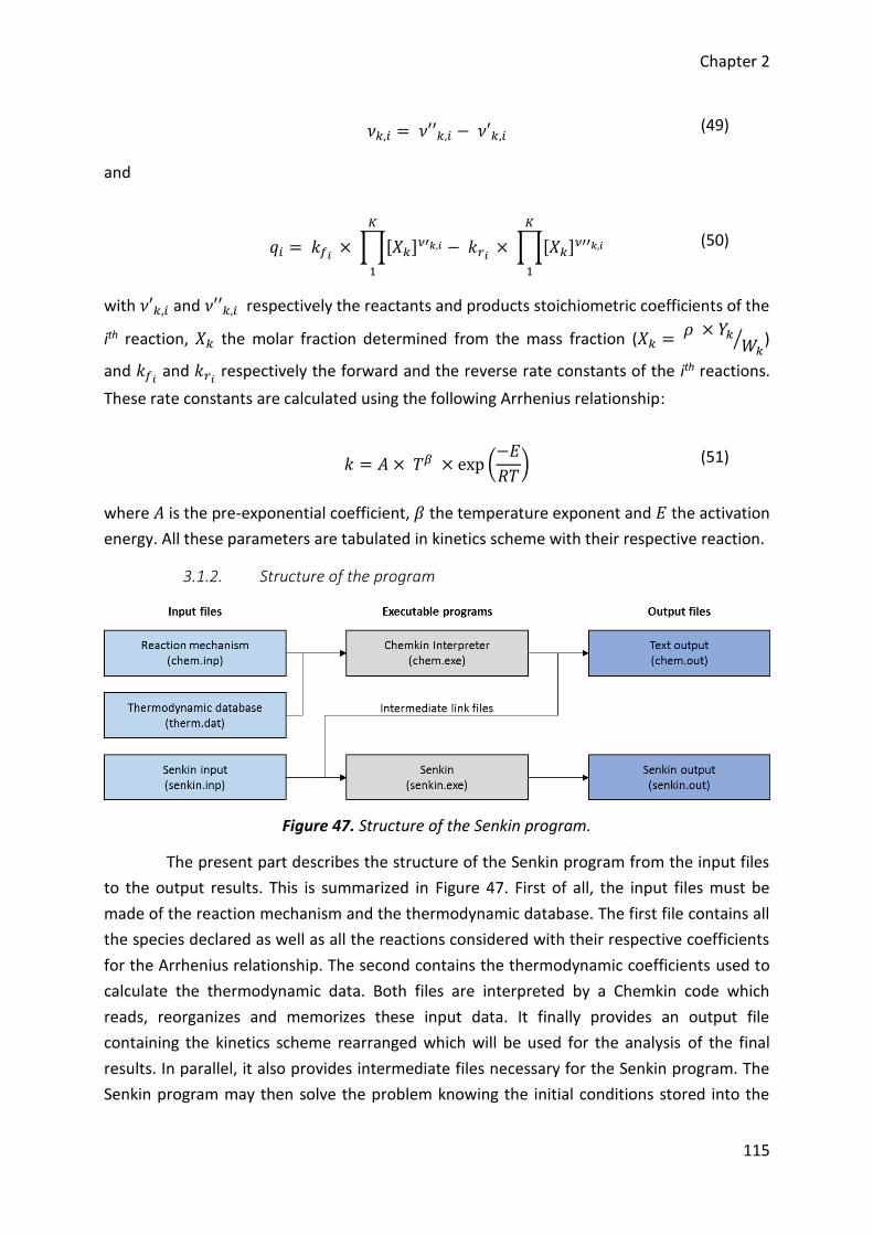
Chapter 2
115
𝜈𝑘,𝑖 = 𝜈′′𝑘,𝑖 − 𝜈′𝑘,𝑖 (49)
and
𝑞𝑖 = 𝑘𝑓𝑖 × ∏[𝑋𝑘]𝜈′𝑘,𝑖
𝐾
1
− 𝑘𝑟𝑖 × ∏[𝑋𝑘]𝜈′′𝑘,𝑖
𝐾
1
(50)
with 𝜈′𝑘,𝑖 and 𝜈′′𝑘,𝑖 respectively the reactants and products stoichiometric coefficients of the
ith reaction, 𝑋𝑘 the molar fraction determined from the mass fraction (𝑋𝑘 = 𝜌 × 𝑌𝑘
𝑊𝑘⁄ )
and 𝑘𝑓𝑖 and 𝑘𝑟𝑖
respectively the forward and the reverse rate constants of the ith reactions.
These rate constants are calculated using the following Arrhenius relationship:
𝑘 = 𝐴 × 𝑇𝛽 × exp (−𝐸
𝑅𝑇) (51)
where 𝐴 is the pre-exponential coefficient, 𝛽 the temperature exponent and 𝐸 the activation
energy. All these parameters are tabulated in kinetics scheme with their respective reaction.
3.1.2. Structure of the program
Figure 47. Structure of the Senkin program.
The present part describes the structure of the Senkin program from the input files
to the output results. This is summarized in Figure 47. First of all, the input files must be
made of the reaction mechanism and the thermodynamic database. The first file contains all
the species declared as well as all the reactions considered with their respective coefficients
for the Arrhenius relationship. The second contains the thermodynamic coefficients used to
calculate the thermodynamic data. Both files are interpreted by a Chemkin code which
reads, reorganizes and memorizes these input data. It finally provides an output file
containing the kinetics scheme rearranged which will be used for the analysis of the final
results. In parallel, it also provides intermediate files necessary for the Senkin program. The
Senkin program may then solve the problem knowing the initial conditions stored into the
Chapter 2
116
Senkin input file. All the results are computed as a function of the time, more precisely, the
thermodynamic parameters such as the pressure and the temperature as well as the
concentrations of the species. They are finally tabulated in an output file whose the reading
enables the kinetics analysis.
3.2. Kinetics schemes used
To complete with the experimental results, different kinetics schemes were run
with the Senkin program according to the fuels selected and the oxidizing chemical species
studied. The present part put forward the features of the schemes retained to compute the
oxidation of the fuel, the sub-mechanisms to analyze the effect of the oxidizing species and
finally the methodology applied.
3.2.1. Fuel oxidation mechanisms
In the present work, three different families of fuels have been selected and
represent a dozen of fuels. To perform kinetics analysis in agreement with the experiments,
three different detailed schemes, one for each fuel family, were selected. Table 4 provides
the main features of these schemes.
Table 4. Features of the kinetics schemes selected.
Fuels Species Reactions Reference
n-heptane/isooctane 1033 4238 Curran et al. [30]
H2/CO/C1-C4 111 784 Wang et al. [155]
MeOH/EtOH/BuOH 431 2336 Sarathy et al. [156]
Analyses on the oxidation of the PRFs, i.e. n-heptane, isooctane and blends of both
fuels, are carried out from the detailed mechanism proposed by Curran et al. [30] for the
oxidation of isooctane. This kinetics scheme is based on the oxidation of n-heptane [29] and
therefore allows to compute the oxidation of all the PRFs. Moreover, it was validated on a
wide type of applications as well as a wide range of conditions.
For the oxidation of the gaseous fuels, i.e. hydrogen, methane and propane, the
detailed chemical kinetics mechanism proposed by Wang et al. [155] has been used. The
scheme is based on several mechanisms and was updated. It finally allows considering a
wide variety of combustion applications supplying by hydrogen, carbon monoxide and
hydrocarbons from C1 to C4.
Finally, investigation on the oxidation of alcohol fuels is an ongoing topic of intense
research [157]. Recently, numerous studies on these fuels were conducted, in particular for
fuels composed of four carbons or less. The kinetics mechanism retained for the present
investigation is the scheme proposed by Sarathy et al. on the four isomers of the butanol
Chapter 2
117
[156]. It was built on previous schemes with alcohol fuels containing less than four carbons
in their structure and validated on several types of combustion devices. It can therefore be
used to examine the oxidation of fuels such as methanol, ethanol and n-butanol as in the
present work.
3.2.2. Oxidizing chemical species sub-mechanisms
According to the objective of studying the impact of oxidizing chemical species on
the oxidation of the fuels previously enumerated, sub-mechanisms involving these species
were selected to supplement the three schemes described above. There are two sub-
mechanisms, one for investigate the effect of ozone and one for studying the effect of nitric
oxides, and they are further described hereafter.
3.2.2.1. Ozone sub-mechanism
The ozone sub-mechanism selected in the present work is that proposed by Halter
et al. [132]. It consists of 17 reactions that involve ozone consumption and production
reactions mainly coming from the atmospheric studies. In the publication, the scheme has
been only validated on laminar burning velocity and provides similar results than those
already reported in the literature. Note that reactions often considered in the literature are
similar and were applied on various combustion systems. Moreover, this sub-mechanism has
been recently used in the case of the combustion of n-heptane by Foucher et al. [9] to
explain the influence of ozone.
3.2.2.2. Nitric oxides sub-mechanism
The other sub-mechanism used in the present work is a nitric oxides sub-
mechanism. It was proposed by Dagaut and Dayma [158]. The results obtained in a jet
stirred reactor were satisfactory but the mechanism needed further validations. Finally, it
was recently combined by Contino et al. [123] with the kinetics scheme of PRFs previously
described to investigate the effect of nitric oxide in the case of engine modeling. Final results
showed that modeling results well fitted with experimental results and helped to explain the
influence of nitric oxide on isooctane oxidation. This sub-mechanism may also be used under
various combustion systems.
3.3. Methodology
The present part describes the methodology used to observe the impact of the
oxidizing chemical species on the oxidation of the fuels selected. From the previous kinetics
mechanisms and sub-mechanisms presented, new schemes were built. They consist of
combining one or both sub-mechanisms with the fuel mechanisms. For the present work,
four new schemes were prepared and are summed up in Table 5.
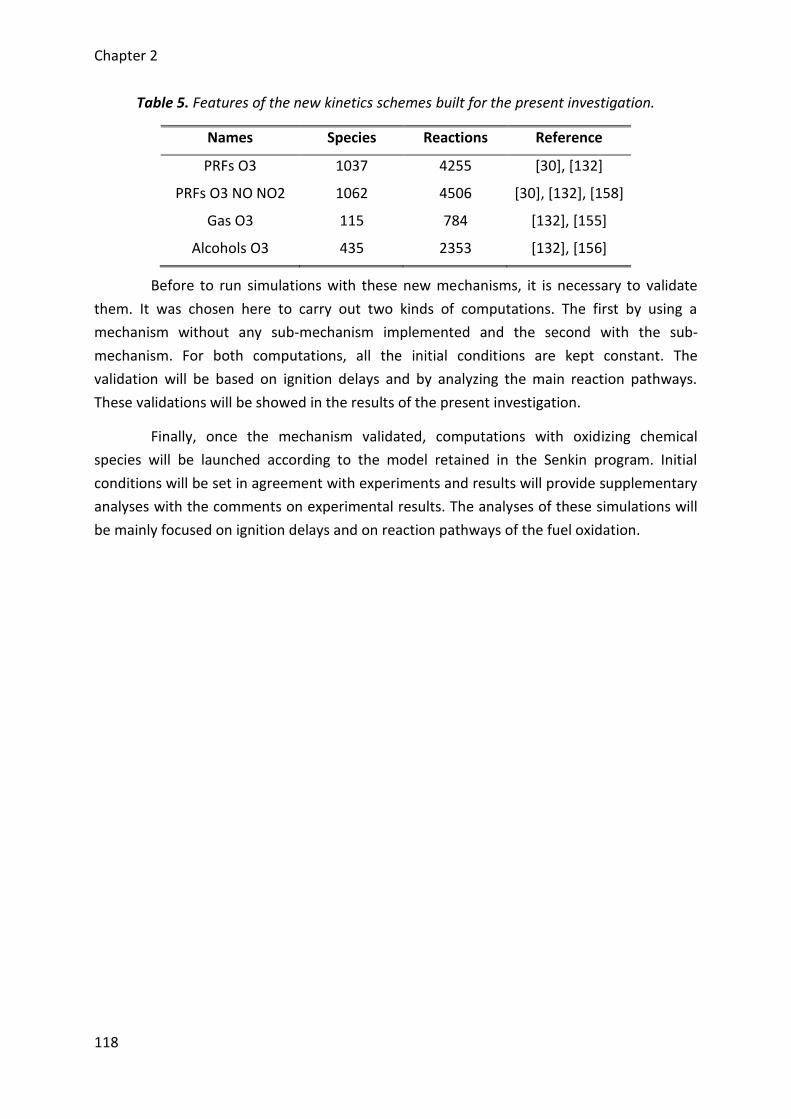
Chapter 2
118
Table 5. Features of the new kinetics schemes built for the present investigation.
Names Species Reactions Reference
PRFs O3 1037 4255 [30], [132]
PRFs O3 NO NO2 1062 4506 [30], [132], [158]
Gas O3 115 784 [132], [155]
Alcohols O3 435 2353 [132], [156]
Before to run simulations with these new mechanisms, it is necessary to validate
them. It was chosen here to carry out two kinds of computations. The first by using a
mechanism without any sub-mechanism implemented and the second with the sub-
mechanism. For both computations, all the initial conditions are kept constant. The
validation will be based on ignition delays and by analyzing the main reaction pathways.
These validations will be showed in the results of the present investigation.
Finally, once the mechanism validated, computations with oxidizing chemical
species will be launched according to the model retained in the Senkin program. Initial
conditions will be set in agreement with experiments and results will provide supplementary
analyses with the comments on experimental results. The analyses of these simulations will
be mainly focused on ignition delays and on reaction pathways of the fuel oxidation.
Chapter 2
119
4. Conclusion
The present chapter 2 introduced the experimental setup and the numerical tools
used all along this work. The first part of the second chapter was about the engine bench
which was widely described. In particular, the properties of the engine, the methodology
and the devices used to prepare a mixture at the intake of the engine the most
homogeneous as possible have been introduced. Then, the sensors mounted and the control
of each part of the experimental setup were described up to the record of the experimental
data. The fuels considered for this investigation were also introduced in this part as well as
the oxidizing chemical species selected. Finally, the methodologies to produce these
oxidizing chemical species, when it is necessary, control it and seed it were described.
The second part considers the analysis of the experimental data recorded. The post-
treatment applied and developed all along this work was fully described step by step from
the gross data to the final results. The approach is based on a common approach widely
observed in the literature which consists of analyzing the in-cylinder pressure recorded.
From the in-cylinder pressure traces, evolutions of the thermodynamic parameters inside
the combustion chamber may be calculated according to the relationships given to finally
provide engine outputs.
Finally, the last part of the chapter 2 exposed the computation approach
implemented into this work. Simulations were based on the use of the Senkin program
which is linked with Chemkin II software. In this program, the model selected was the
constant volume. The structure of the program and the calculations solved in this particular
case were described. Finally, the schemes and sub-mechanisms retained to further analyze
experimental results were introduced as well as the procedure to build the new ones. The
new schemes need validation which will be showed in the next chapters and will be finally
used to describe the impact of the different oxidizing chemical species selected.

Chapitre 3 / Chapter 3
Résultats sur la combustion des
« Primary Reference Fuels »
Results on the combustion
of Primary Reference Fuels
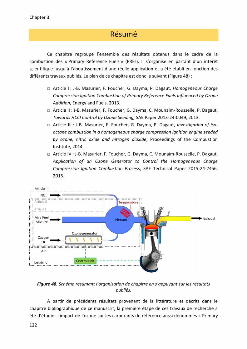
Chapter 3
122
Résumé
Ce chapitre regroupe l’ensemble des résultats obtenus dans le cadre de la
combustion des « Primary Reference Fuels » (PRFs). Il s’organise en partant d’un intérêt
scientifique jusqu’à l’aboutissement d’une réelle application et a été établi en fonction des
différents travaux publiés. Le plan de ce chapitre est donc le suivant (Figure 48) :
□ Article I : J-B. Masurier, F. Foucher, G. Dayma, P. Dagaut, Homogeneous Charge
Compression Ignition Combustion of Primary Reference Fuels Influenced by Ozone
Addition, Energy and Fuels, 2013.
□ Article II : J-B. Masurier, F. Foucher, G. Dayma, C. Mounaïm-Rousselle, P. Dagaut,
Towards HCCI Control by Ozone Seeding, SAE Paper 2013-24-0049, 2013.
□ Article III : J-B. Masurier, F. Foucher, G. Dayma, P. Dagaut, Investigation of iso-
octane combustion in a homogeneous charge compression ignition engine seeded
by ozone, nitric oxide and nitrogen dioxide, Proceedings of the Combustion
Institute, 2014.
□ Article IV : J-B. Masurier, F. Foucher, G. Dayma, C. Mounaïm-Rousselle, P. Dagaut,
Application of an Ozone Generator to Control the Homogeneous Charge
Compression Ignition Combustion Process, SAE Technical Paper 2015-24-2456,
2015.
Figure 48. Schéma résumant l’organisation de chapitre en s’appuyant sur les résultats publiés.
A partir de précédents résultats provenant de la littérature et décrits dans le
chapitre bibliographique de ce manuscrit, la première étape de ces travaux de recherche a
été d’étudier l’impact de l’ozone sur les carburants de référence aussi dénommés « Primary
Chapter 3
123
Reference Fuels ». Au moyen d’une étude préliminaire où les domaines de combustion
idéals du n-heptane, de l’isooctane et de mélanges préalablement choisis de ces deux
carburants ont été déterminés, l’impact de l’ozone a été démontré (Article I). Les résultats
regroupent des essais expérimentaux sur banc moteur et ont été couplés à des simulations
de cinétique chimique. Il a ainsi été mis en évidence, grâce à son effet promoteur, que
l’ozone améliore très rapidement la combustion moyennant de faibles concentrations tout
en permettant d’avancer le phasage de la combustion. Cet effet intervient très tôt dans le
processus de combustion puisque les résultats ont montré que l’ozone altère le début de la
combustion (CA05) ainsi que le phasage de la flamme froide. De plus, les études de cinétique
chimique conduites sur les délais d’autoinflammation et les chemins de réactions ont permis
de mettre en exergue que l’ozone est en réalité un promoteur indirect de la combustion
HCCI. L’effet promoteur provient de l’atome d’oxygène issu de la décomposition de l’ozone
qui oxyde directement le carburant bien plus rapidement que par les voies habituelles et
donne finalement lieu à une avance de l’autoinflammation. En fonction des carburants
retenus, il a été observé que l’ozone procure un effet similaire sur le phasage de la
combustion du n-heptane et des mélanges PRFs sélectionnés. Cela est principalement dû au
n-heptane présent en différentes proportions selon les mélanges et qui réagit facilement
avec l’ozone. Dans le cas de l’isooctane, celui-ci a montré qu’il était plus sensible à cette
espèce chimique oxydante. L’impact significatif est principalement dû à la température
d’admission réglée qui était bien supérieure à celle des essais avec les autres carburants et
est responsable d’une accélération de la décomposition de l’ozone.
A la suite de ces premiers résultats, des essais supplémentaires ont été menés sur la
combustion de l’isooctane (Article II). La température d’admission nécessaire à son
autoinflammation étant relativement élevée comparée à celles rencontrées dans un moteur
à combustion interne conventionnel (démarrage à froid et lors du fonctionnement normal
du moteur), des essais ont été effectués en diminuant la température d’admission et en
utilisant l’effet promoteur de l’ozone pour maintenir la combustion. Les résultats ont
démontré que l’ozone permet clairement de maintenir la combustion de l’isooctane sous
des conditions où celle-ci ne se produit pas habituellement. De plus, la température
d’admission diminuant, l’ozone se décompose moins rapidement et le phasage de la
combustion est moins sensible. En conséquence, l’ozone est une espèce chimique qui
permet de contrôler le déroulement de la combustion HCCI sous différentes conditions
moteur et un réel cas d’application pourrait être développé. Finalement, ces résultats ont
aussi révélé l’existence d’une flamme froide lors de la combustion HCCI de l’isooctane et
ainsi justifient que cette molécule oxydante réagit dès le début de l’oxydation du carburant.
Considérant que l’ozone est un atout majeur pour le contrôle de la combustion
HCCI et étant donné que les dispositifs permettant sa production tendent à devenir de plus
en plus petits, l’hypothèse d’une intégration véhicule a donc été posée. Idéalement, un tel
Chapter 3
124
dispositif devrait fonctionner avec de l’air mais il en résulte qu’en plus d’une production
d’ozone, des espèces azotées tel que les oxydes d’azote (NOx) peuvent être formées et les
précédentes études ont montré qu’il existe une forte interaction entre l’ozone et les NOx. De
plus, ces dernières peuvent aussi être présentes dans les résiduels de combustion au sein de
la chambre de combustion (IGR) ou encore dans les produits de combustion réinjectés (EGR).
Il a donc été indispensable d’évaluer l’impact des NOx et de l’ozone sur la combustion HCCI.
Une étude comparative entre l’ozone, le monoxyde d’azote et le dioxyde d’azote a donc été
effectuée avec l’isooctane (Article III). Les résultats ont montré que ces trois espèces
chimiques oxydantes accélèrent la combustion en raison de leur effet promoteur. De plus,
l’ozone est responsable de la meilleure amélioration de la combustion tandis que le dioxyde
d’azote fournit une avance bien moins importante. L’impact de chaque espèce a été
démontré au moyen de la cinétique chimique. L’ozone permet d’agir directement sur
l’oxydation du carburant tandis que les oxydes d’azote nécessitent la formation des premiers
radicaux résultant de l’oxydation normale de l’isooctane avant de promouvoir la
combustion. Finalement, le monoxyde d’azote est l’oxyde d’azote le plus présent dans les
gaz d’échappement et peut se retrouver dans des proportions minoritaires dans les résiduels
de la chambre de combustion ou avec l’utilisation de l’EGR. Par ailleurs, il pourrait aussi être
formé préalablement dans les générateurs d’ozone dans certains cas de fonctionnement.
L’interaction de cette espèce chimique avec l’ozone a donc été étudiée lorsque ces deux
molécules oxydantes sont simultanément injectées avec le mélange air/carburant. Il a ainsi
été mis en évidence que ces deux espèces réagissent ensemble pour former du dioxyde
d’azote. Bien que ce type d’ensemencement permette de continuer à avancer le phasage de
la combustion, leur impact reste toutefois modéré comparé aux résultats obtenus
lorsqu’elles sont injectées séparément. De plus, il a été démontré expérimentalement et à
l’aide une analyse de cinétique chimique que la réaction entre l’ozone et le monoxyde
d’azote intervient bien avant que ces deux espèces soient introduites dans la chambre de
combustion du moteur.
Enfin, l’ensemble de ces résultats a été complété par la mise en place d’un contrôle
dynamique de la combustion HCCI au moyen d’un générateur d’ozone afin de démontrer le
potentiel applicatif de ces dispositifs (Article IV). Des essais préalables avec le générateur ont
montré qu’en réalité le générateur produisait uniquement de l’ozone et ce dans des
proportions suffisantes pour permettre le contrôle. Cependant, le générateur d’ozone utilisé
lors cette étude est adaptée à une production d’ozone seul tandis que des cas non
favorables pourrait éventuellement être rencontré lors de réelles applications automobiles.
Un complément d’essais par rapport à l’ensemble des résultats déjà établis a démontré que
l’ajout d’ozone à l’admission du moteur permet de contrôler les paramètres du moteur ainsi
que les polluants. Enfin, deux types de contrôle ont été appliqués : un contrôle basé sur une
cartographie préalablement dressée et un contrôle en boucle fermée. Le premier a montré
un temps de réponse relativement court mais avec un manque de précision tandis que le

Chapter 3
125
second a montré l’inverse. Finalement, les voies d’amélioration pour tendre vers une
application réelle ont été identifiées.
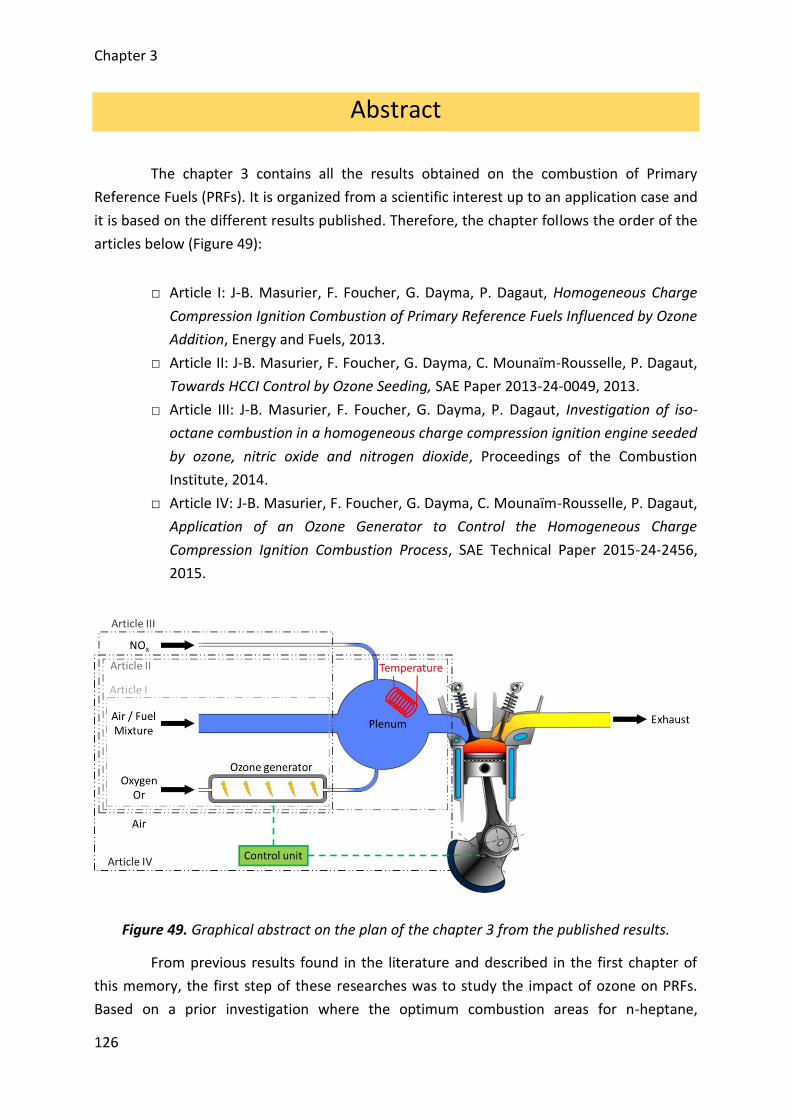
Chapter 3
126
Abstract
The chapter 3 contains all the results obtained on the combustion of Primary
Reference Fuels (PRFs). It is organized from a scientific interest up to an application case and
it is based on the different results published. Therefore, the chapter follows the order of the
articles below (Figure 49):
□ Article I: J-B. Masurier, F. Foucher, G. Dayma, P. Dagaut, Homogeneous Charge
Compression Ignition Combustion of Primary Reference Fuels Influenced by Ozone
Addition, Energy and Fuels, 2013.
□ Article II: J-B. Masurier, F. Foucher, G. Dayma, C. Mounaïm-Rousselle, P. Dagaut,
Towards HCCI Control by Ozone Seeding, SAE Paper 2013-24-0049, 2013.
□ Article III: J-B. Masurier, F. Foucher, G. Dayma, P. Dagaut, Investigation of iso-
octane combustion in a homogeneous charge compression ignition engine seeded
by ozone, nitric oxide and nitrogen dioxide, Proceedings of the Combustion
Institute, 2014.
□ Article IV: J-B. Masurier, F. Foucher, G. Dayma, C. Mounaïm-Rousselle, P. Dagaut,
Application of an Ozone Generator to Control the Homogeneous Charge
Compression Ignition Combustion Process, SAE Technical Paper 2015-24-2456,
2015.
Figure 49. Graphical abstract on the plan of the chapter 3 from the published results.
From previous results found in the literature and described in the first chapter of
this memory, the first step of these researches was to study the impact of ozone on PRFs.
Based on a prior investigation where the optimum combustion areas for n-heptane,
Chapter 3
127
isooctane and blends of both fuels selected were determined, the impact of ozone has been
showed (Article 1). Outputs gather experiments on engine bench coupled to computations
of kinetics. It was highlighted, due to its promoting effect, that ozone improves very rapidly
the combustion with low concentrations while the combustion phasing advances. This effect
occurs very early in the combustion process since the results showed that ozone alters the
beginning of the combustion as well as the cool flame phasing. Moreover, kinetics studies
conducted on ignition delays and reaction pathways allow highlighting that ozone is in reality
an indirect promoter of the HCCI combustion. The promoting effect is provided by the O-
atom coming from the ozone break down which oxidizes directly the fuel faster than by the
normal pathways and finally leads to an advance of the autoignition. According to the fuels
selected, it was observed that ozone leads to a similar effect on the phasing of n-heptane
and PRFs selected. The similar impact is mainly due to the presence in different ratios of n-
heptane into the blends selected which reacts easily with ozone. In the case of pure
isooctane, results showed that this fuel was more sensitive to ozone. The significant impact
is mainly due to the intake temperature set which was upper than that for experiments with
the other fuels and speed up the ozone break down.
Following these first results, further experiments were performed on isooctane
combustion (Article II). The intake temperature needed to achieve its autoignition is very
high compared to those encountered into conventional internal combustion engine (cold
start and during the normal operations of the engine), experiments were therefore carried
out by reducing the intake temperature and by using the promoting effect of ozone to
maintain the combustion. Outputs showed that ozone allows clearly achieving combustion
of isooctane under intake conditions where the combustion does not occur usually.
Moreover, as the intake temperature decreases, ozone breaks down less rapidly and the
phasing of the combustion is less sensitive. Consequently, ozone is an oxidizing chemical
species which allows controlling the HCCI combustion process under a wide range of engine
conditions. Moreover, a real application could be developed. Finally, these results also
showed the occurrence of the isooctane cool flame and justified that ozone modifies the
beginning of the oxidation of isooctane.
Considering that ozone is major asset for controlling the HCCI combustion and as
ozone generators become increasingly small, the assumption of implementing such a device
into a vehicle has been made. Ideally, such a device should work with air but additionally to
the production of ozone, NOx could be generated and previous investigations highlighted
that there is a strong interaction between ozone and NOx. Moreover, NOx can also be found
into residuals of the engine or again into the exhaust products with the use of EGR. It is
therefore essential to assess the impact of NOx and ozone on the HCCI combustion.
Consequently, a comparison between ozone, nitric oxide and nitrogen dioxide has been
performed for isooctane as fuel (Article III). Results showed that the three oxidizing chemical
species speed up the combustion due to their respective promoting effect. Moreover, ozone
Chapter 3
128
is responsible of the best improvement of the combustion while nitrogen dioxide provides a
less significant advance. Additionally, the impact of each species has been displayed with
kinetics. Ozone allows oxidizing directly the fuel while the NOx need the presence of the first
radicals coming from the normal oxidation of isooctane before promoting the combustion.
Finally, nitric oxide (NO) is the NOx the most encountered into the combustion products and
can be found into minor concentrations into hot residuals or with the use of EGR. On the
other hand, it could be produce preliminarily into ozone generators in case of malfunctions.
The interaction between NO and ozone was therefore studied when both oxidizing
molecules are injected simultaneously with the air/fuel mixture. It was highlighted that both
species react together resulting in the production of nitrogen dioxide (NO + O3 NO2 +
O2). Even if this seeding allows to continue to advance the combustion phasing, their impact
remains quite moderated compare to the results observed when they seed separately the
intake of the engine. Moreover, it was showed through experiments and computations that
the reaction between ozone and nitric oxide takes place in front of the entrance of both
species into the combustion chamber of the engine.
Finally, all these results were completed by the implementation of a dynamic
control of the HCCI combustion with the use of an ozone generator in order to show the
potential of these devices (Article IV). Prior experiments with the generator showed that this
device generates only ozone and with suitable concentrations to achieve the control.
However, the ozone generator used for this study is adapted to only an ozone production
while it could not be the case with real automotive applications. Referring to all the results
obtained, extra experiments were performed and showed that ozone added in the intake of
the engine enables to control all the engine parameters as well as pollutants. Two kinds of
control were then applied: 1) based on “look up table” built in advance and 2) a closed-loop
control. The first displayed a response time very short but with a lack of accuracy while the
second showed the inverse. Finally, the ways of improvement for achieving a real application
were identified.
Chapter 3
129
1. Introduction on Primary Reference Fuels (Article I)
Primary Reference Fuels (PRFs) were first investigated. This fuel family brings
together n-heptane and isooctane as well as blends of both fuels. PRFs are widely used as
representative fuels of conventional fuels such as gasoline or diesel and were employed into
numerous studies because PRFs are easy to apply for researches [34], [37], [46]. A set of six
PRFs was selected to start these investigations. It includes pure n-heptane (PRF0) and pure
isooctane (PRF100) and four surrogates from the mixture of both fuels, more precisely
PRF20, PRF40, PRF60 and PRF80 where the number corresponds to the volume fraction of
isooctane and the complement to 100 corresponds to the volume fraction of n-heptane.
Moreover, according to the definition of PRFs, this number also represents RON and MON
indexes and therefore the octane number (ON) of the fuel. More properties of these fuels
are available in the table of the chapter 2.
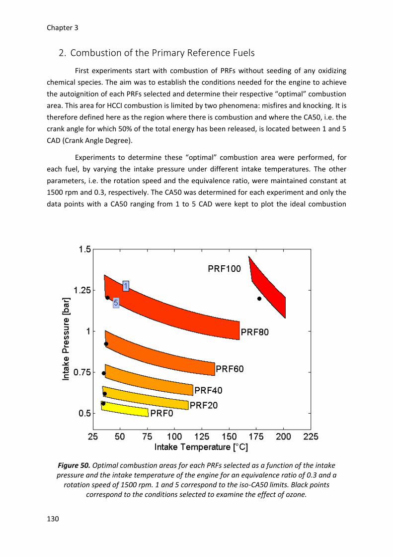
Chapter 3
130
2. Combustion of the Primary Reference Fuels
First experiments start with combustion of PRFs without seeding of any oxidizing
chemical species. The aim was to establish the conditions needed for the engine to achieve
the autoignition of each PRFs selected and determine their respective “optimal” combustion
area. This area for HCCI combustion is limited by two phenomena: misfires and knocking. It is
therefore defined here as the region where there is combustion and where the CA50, i.e. the
crank angle for which 50% of the total energy has been released, is located between 1 and 5
CAD (Crank Angle Degree).
Experiments to determine these “optimal” combustion area were performed, for
each fuel, by varying the intake pressure under different intake temperatures. The other
parameters, i.e. the rotation speed and the equivalence ratio, were maintained constant at
1500 rpm and 0.3, respectively. The CA50 was determined for each experiment and only the
data points with a CA50 ranging from 1 to 5 CAD were kept to plot the ideal combustion
Figure 50. Optimal combustion areas for each PRFs selected as a function of the intake pressure and the intake temperature of the engine for an equivalence ratio of 0.3 and a
rotation speed of 1500 rpm. 1 and 5 correspond to the iso-CA50 limits. Black points correspond to the conditions selected to examine the effect of ozone.

Chapter 3
131
region of each fuel. The final results obtained for each PRFs selected are presented into the
intake pressure – intake temperature diagram in Figure 50. For each fuel, the upper limit
corresponds to an iso-CA50 of 1 CAD, then, there is risk of knocking beyond this limit, while
the lower limit represents an iso-CA50 of 5 CAD and below, there is risk of misfires.
Results show that n-heptane (PRF0) burns with the lowest intake conditions on the
engine while isooctane (PRF100) is the most difficult to autoignite. For intermediate PRFs,
their combustion correlates with their respective ON. Therefore, lower is the ON, easily the
autoignition occurs and needs low intake pressure and temperature. Reversely, higher is the
ON, difficult the autoignition is and high thermodynamic intake conditions are necessary.
Moreover, it may be observed that each blend of isooctane and n-heptane burn at ambient
temperature but the intake pressure must be increasingly high depending on the ON. This
comes from the presence of n-heptane into the surrogates and was already observed in
previous researches [37], [46].
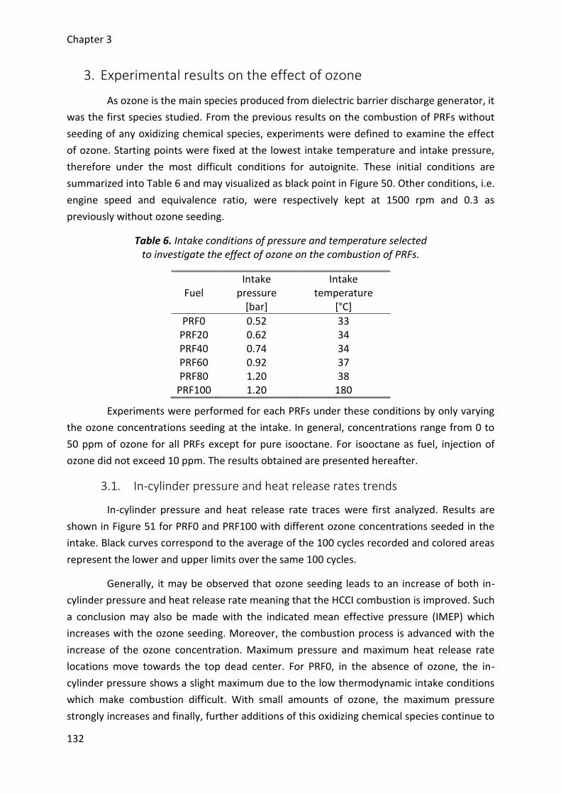
Chapter 3
132
3. Experimental results on the effect of ozone
As ozone is the main species produced from dielectric barrier discharge generator, it
was the first species studied. From the previous results on the combustion of PRFs without
seeding of any oxidizing chemical species, experiments were defined to examine the effect
of ozone. Starting points were fixed at the lowest intake temperature and intake pressure,
therefore under the most difficult conditions for autoignite. These initial conditions are
summarized into Table 6 and may visualized as black point in Figure 50. Other conditions, i.e.
engine speed and equivalence ratio, were respectively kept at 1500 rpm and 0.3 as
previously without ozone seeding.
Table 6. Intake conditions of pressure and temperature selected to investigate the effect of ozone on the combustion of PRFs.
Fuel Intake
pressure [bar]
Intake temperature
[°C]
PRF0 0.52 33 PRF20 0.62 34 PRF40 0.74 34 PRF60 0.92 37 PRF80 1.20 38
PRF100 1.20 180
Experiments were performed for each PRFs under these conditions by only varying
the ozone concentrations seeding at the intake. In general, concentrations range from 0 to
50 ppm of ozone for all PRFs except for pure isooctane. For isooctane as fuel, injection of
ozone did not exceed 10 ppm. The results obtained are presented hereafter.
3.1. In-cylinder pressure and heat release rates trends
In-cylinder pressure and heat release rate traces were first analyzed. Results are
shown in Figure 51 for PRF0 and PRF100 with different ozone concentrations seeded in the
intake. Black curves correspond to the average of the 100 cycles recorded and colored areas
represent the lower and upper limits over the same 100 cycles.
Generally, it may be observed that ozone seeding leads to an increase of both in-
cylinder pressure and heat release rate meaning that the HCCI combustion is improved. Such
a conclusion may also be made with the indicated mean effective pressure (IMEP) which
increases with the ozone seeding. Moreover, the combustion process is advanced with the
increase of the ozone concentration. Maximum pressure and maximum heat release rate
locations move towards the top dead center. For PRF0, in the absence of ozone, the in-
cylinder pressure shows a slight maximum due to the low thermodynamic intake conditions
which make combustion difficult. With small amounts of ozone, the maximum pressure
strongly increases and finally, further additions of this oxidizing chemical species continue to
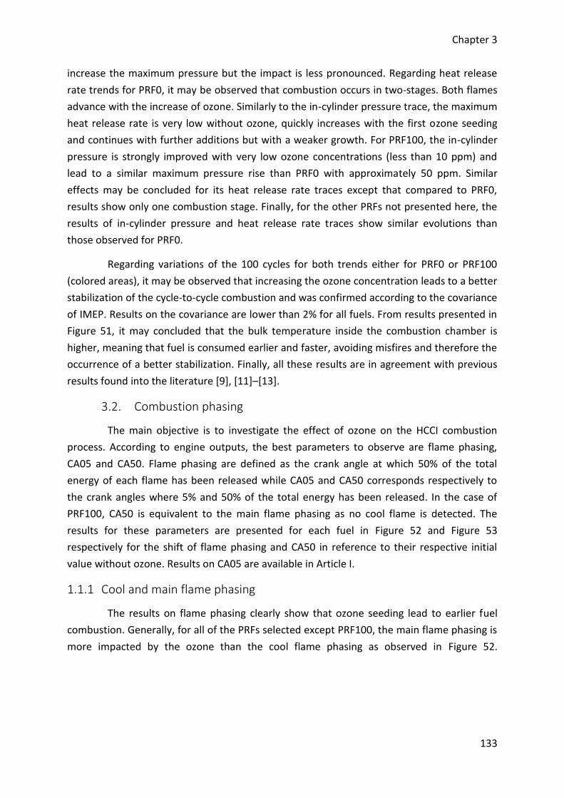
Chapter 3
133
increase the maximum pressure but the impact is less pronounced. Regarding heat release
rate trends for PRF0, it may be observed that combustion occurs in two-stages. Both flames
advance with the increase of ozone. Similarly to the in-cylinder pressure trace, the maximum
heat release rate is very low without ozone, quickly increases with the first ozone seeding
and continues with further additions but with a weaker growth. For PRF100, the in-cylinder
pressure is strongly improved with very low ozone concentrations (less than 10 ppm) and
lead to a similar maximum pressure rise than PRF0 with approximately 50 ppm. Similar
effects may be concluded for its heat release rate traces except that compared to PRF0,
results show only one combustion stage. Finally, for the other PRFs not presented here, the
results of in-cylinder pressure and heat release rate traces show similar evolutions than
those observed for PRF0.
Regarding variations of the 100 cycles for both trends either for PRF0 or PRF100
(colored areas), it may be observed that increasing the ozone concentration leads to a better
stabilization of the cycle-to-cycle combustion and was confirmed according to the covariance
of IMEP. Results on the covariance are lower than 2% for all fuels. From results presented in
Figure 51, it may concluded that the bulk temperature inside the combustion chamber is
higher, meaning that fuel is consumed earlier and faster, avoiding misfires and therefore the
occurrence of a better stabilization. Finally, all these results are in agreement with previous
results found into the literature [9], [11]–[13].
3.2. Combustion phasing
The main objective is to investigate the effect of ozone on the HCCI combustion
process. According to engine outputs, the best parameters to observe are flame phasing,
CA05 and CA50. Flame phasing are defined as the crank angle at which 50% of the total
energy of each flame has been released while CA05 and CA50 corresponds respectively to
the crank angles where 5% and 50% of the total energy has been released. In the case of
PRF100, CA50 is equivalent to the main flame phasing as no cool flame is detected. The
results for these parameters are presented for each fuel in Figure 52 and Figure 53
respectively for the shift of flame phasing and CA50 in reference to their respective initial
value without ozone. Results on CA05 are available in Article I.
1.1.1 Cool and main flame phasing
The results on flame phasing clearly show that ozone seeding lead to earlier fuel
combustion. Generally, for all of the PRFs selected except PRF100, the main flame phasing is
more impacted by the ozone than the cool flame phasing as observed in Figure 52.
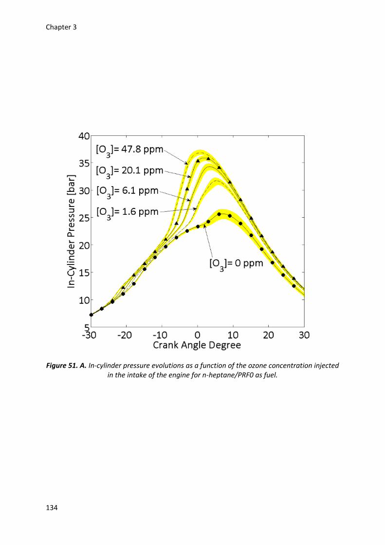
Chapter 3
134
Figure 51. A. In-cylinder pressure evolutions as a function of the ozone concentration injected in the intake of the engine for n-heptane/PRF0 as fuel.
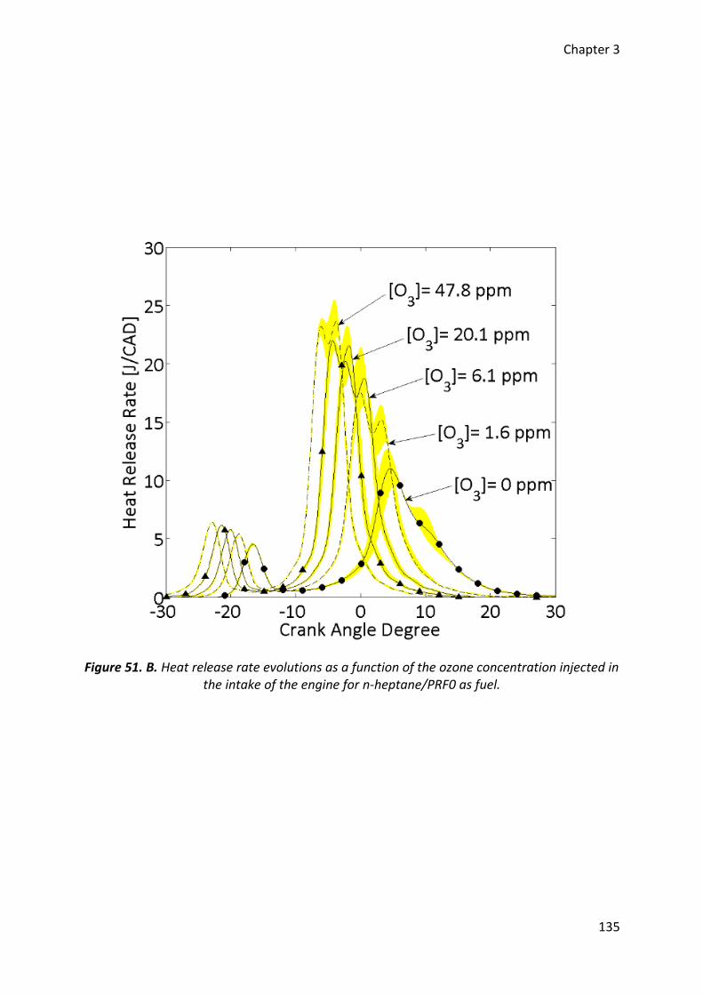
Chapter 3
135
Figure 51. B. Heat release rate evolutions as a function of the ozone concentration injected in the intake of the engine for n-heptane/PRF0 as fuel.
Chapter 3
136
Figure 51. C. In-cylinder pressure evolutions as a function of the ozone concentration injected in the intake of the engine for isooctane/PRF100 as fuel.
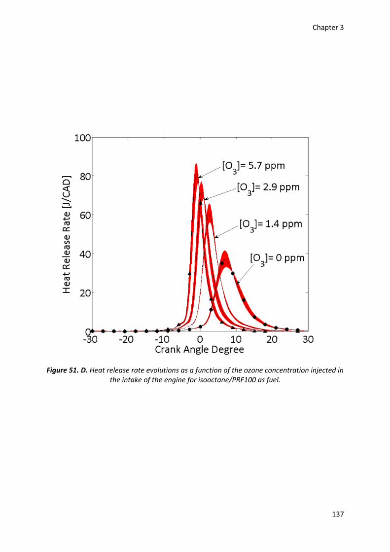
Chapter 3
137
Figure 51. D. Heat release rate evolutions as a function of the ozone concentration injected in the intake of the engine for isooctane/PRF100 as fuel.
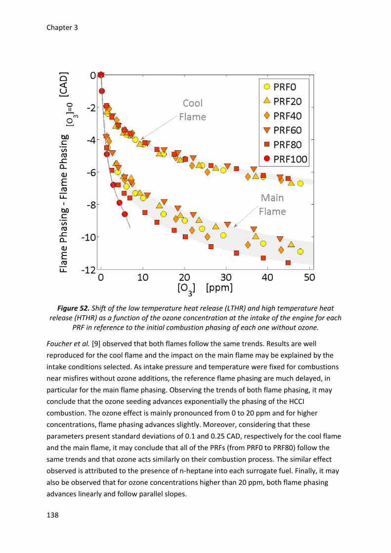
Chapter 3
138
Figure 52. Shift of the low temperature heat release (LTHR) and high temperature heat release (HTHR) as a function of the ozone concentration at the intake of the engine for each
PRF in reference to the initial combustion phasing of each one without ozone.
Foucher et al. [9] observed that both flames follow the same trends. Results are well
reproduced for the cool flame and the impact on the main flame may be explained by the
intake conditions selected. As intake pressure and temperature were fixed for combustions
near misfires without ozone additions, the reference flame phasing are much delayed, in
particular for the main flame phasing. Observing the trends of both flame phasing, it may
conclude that the ozone seeding advances exponentially the phasing of the HCCI
combustion. The ozone effect is mainly pronounced from 0 to 20 ppm and for higher
concentrations, flame phasing advances slightly. Moreover, considering that these
parameters present standard deviations of 0.1 and 0.25 CAD, respectively for the cool flame
and the main flame, it may conclude that all of the PRFs (from PRF0 to PRF80) follow the
same trends and that ozone acts similarly on their combustion process. The similar effect
observed is attributed to the presence of n-heptane into each surrogate fuel. Finally, it may
also be observed that for ozone concentrations higher than 20 ppm, both flame phasing
advances linearly and follow parallel slopes.
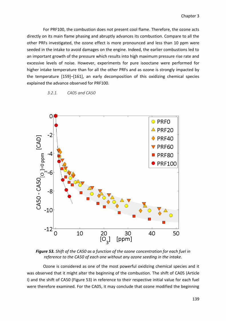
Chapter 3
139
For PRF100, the combustion does not present cool flame. Therefore, the ozone acts
directly on its main flame phasing and abruptly advances its combustion. Compare to all the
other PRFs investigated, the ozone effect is more pronounced and less than 10 ppm were
seeded in the intake to avoid damages on the engine. Indeed, the earlier combustions led to
an important growth of the pressure which results into high maximum pressure rise rate and
excessive levels of noise. However, experiments for pure isooctane were performed for
higher intake temperature than for all the other PRFs and as ozone is strongly impacted by
the temperature [159]–[161], an early decomposition of this oxidizing chemical species
explained the advance observed for PRF100.
3.2.1. CA05 and CA50
Figure 53. Shift of the CA50 as a function of the ozone concentration for each fuel in reference to the CA50 of each one without any ozone seeding in the intake.
Ozone is considered as one of the most powerful oxidizing chemical species and it
was observed that it might alter the beginning of the combustion. The shift of CA05 (Article
I) and the shift of CA50 (Figure 53) in reference to their respective initial value for each fuel
were therefore examined. For the CA05, it may conclude that ozone modified the beginning
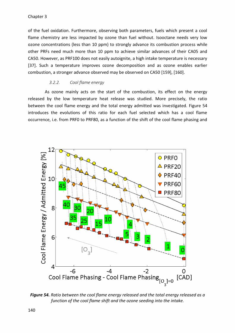
Chapter 3
140
of the fuel oxidation. Furthermore, observing both parameters, fuels which present a cool
flame chemistry are less impacted by ozone than fuel without. Isooctane needs very low
ozone concentrations (less than 10 ppm) to strongly advance its combustion process while
other PRFs need much more than 10 ppm to achieve similar advances of their CA05 and
CA50. However, as PRF100 does not easily autoignite, a high intake temperature is necessary
[37]. Such a temperature improves ozone decomposition and as ozone enables earlier
combustion, a stronger advance observed may be observed on CA50 [159], [160].
3.2.2. Cool flame energy
As ozone mainly acts on the start of the combustion, its effect on the energy
released by the low temperature heat release was studied. More precisely, the ratio
between the cool flame energy and the total energy admitted was investigated. Figure 54
introduces the evolutions of this ratio for each fuel selected which has a cool flame
occurrence, i.e. from PRF0 to PRF80, as a function of the shift of the cool flame phasing and
Figure 54. Ratio between the cool flame energy released and the total energy released as a function of the cool flame shift and the ozone seeding into the intake.
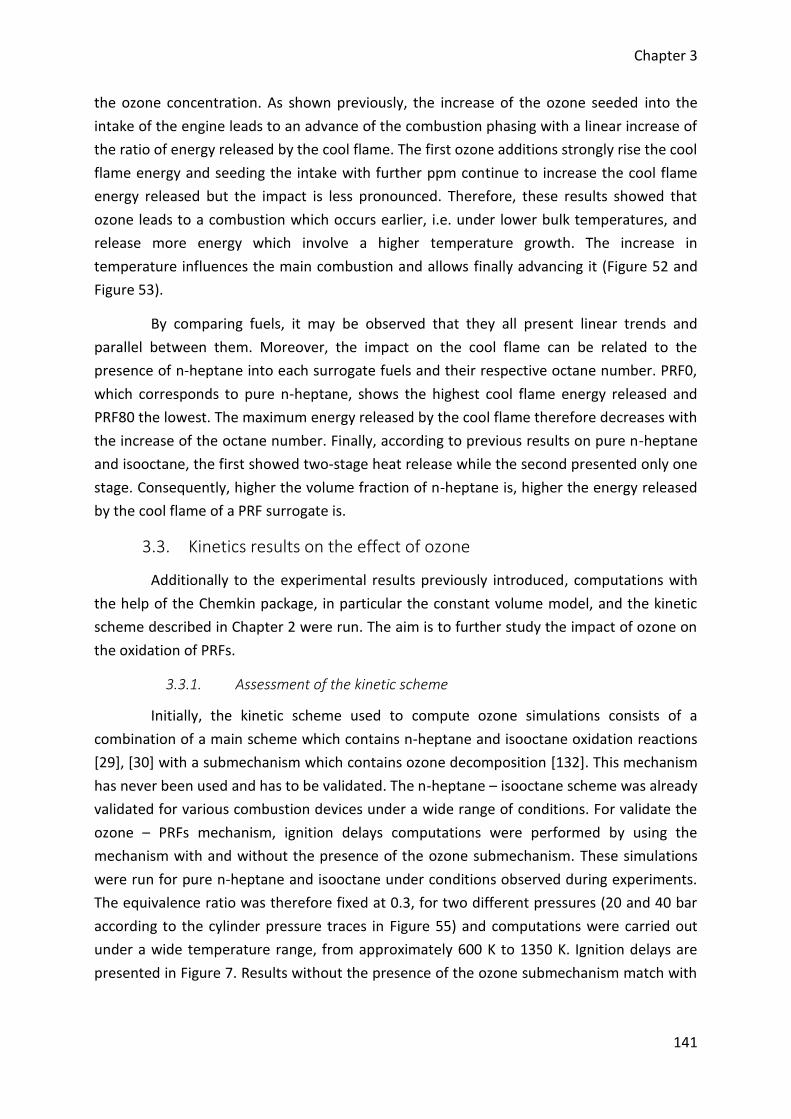
Chapter 3
141
the ozone concentration. As shown previously, the increase of the ozone seeded into the
intake of the engine leads to an advance of the combustion phasing with a linear increase of
the ratio of energy released by the cool flame. The first ozone additions strongly rise the cool
flame energy and seeding the intake with further ppm continue to increase the cool flame
energy released but the impact is less pronounced. Therefore, these results showed that
ozone leads to a combustion which occurs earlier, i.e. under lower bulk temperatures, and
release more energy which involve a higher temperature growth. The increase in
temperature influences the main combustion and allows finally advancing it (Figure 52 and
Figure 53).
By comparing fuels, it may be observed that they all present linear trends and
parallel between them. Moreover, the impact on the cool flame can be related to the
presence of n-heptane into each surrogate fuels and their respective octane number. PRF0,
which corresponds to pure n-heptane, shows the highest cool flame energy released and
PRF80 the lowest. The maximum energy released by the cool flame therefore decreases with
the increase of the octane number. Finally, according to previous results on pure n-heptane
and isooctane, the first showed two-stage heat release while the second presented only one
stage. Consequently, higher the volume fraction of n-heptane is, higher the energy released
by the cool flame of a PRF surrogate is.
3.3. Kinetics results on the effect of ozone
Additionally to the experimental results previously introduced, computations with
the help of the Chemkin package, in particular the constant volume model, and the kinetic
scheme described in Chapter 2 were run. The aim is to further study the impact of ozone on
the oxidation of PRFs.
3.3.1. Assessment of the kinetic scheme
Initially, the kinetic scheme used to compute ozone simulations consists of a
combination of a main scheme which contains n-heptane and isooctane oxidation reactions
[29], [30] with a submechanism which contains ozone decomposition [132]. This mechanism
has never been used and has to be validated. The n-heptane – isooctane scheme was already
validated for various combustion devices under a wide range of conditions. For validate the
ozone – PRFs mechanism, ignition delays computations were performed by using the
mechanism with and without the presence of the ozone submechanism. These simulations
were run for pure n-heptane and isooctane under conditions observed during experiments.
The equivalence ratio was therefore fixed at 0.3, for two different pressures (20 and 40 bar
according to the cylinder pressure traces in Figure 55) and computations were carried out
under a wide temperature range, from approximately 600 K to 1350 K. Ignition delays are
presented in Figure 7. Results without the presence of the ozone submechanism match with
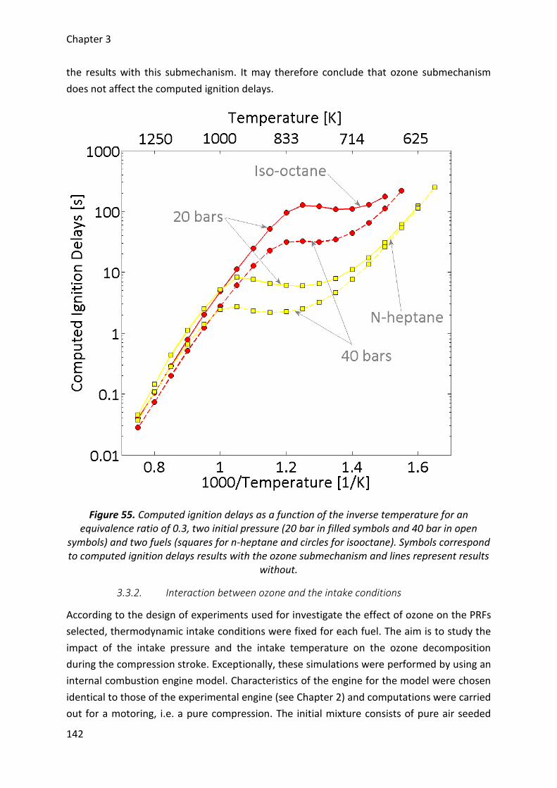
Chapter 3
142
the results with this submechanism. It may therefore conclude that ozone submechanism
does not affect the computed ignition delays.
Figure 55. Computed ignition delays as a function of the inverse temperature for an equivalence ratio of 0.3, two initial pressure (20 bar in filled symbols and 40 bar in open
symbols) and two fuels (squares for n-heptane and circles for isooctane). Symbols correspond to computed ignition delays results with the ozone submechanism and lines represent results
without.
3.3.2. Interaction between ozone and the intake conditions
According to the design of experiments used for investigate the effect of ozone on the PRFs
selected, thermodynamic intake conditions were fixed for each fuel. The aim is to study the
impact of the intake pressure and the intake temperature on the ozone decomposition
during the compression stroke. Exceptionally, these simulations were performed by using an
internal combustion engine model. Characteristics of the engine for the model were chosen
identical to those of the experimental engine (see Chapter 2) and computations were carried
out for a motoring, i.e. a pure compression. The initial mixture consists of pure air seeded
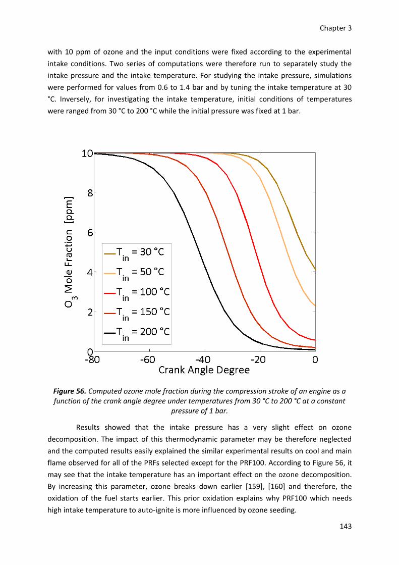
Chapter 3
143
with 10 ppm of ozone and the input conditions were fixed according to the experimental
intake conditions. Two series of computations were therefore run to separately study the
intake pressure and the intake temperature. For studying the intake pressure, simulations
were performed for values from 0.6 to 1.4 bar and by tuning the intake temperature at 30
°C. Inversely, for investigating the intake temperature, initial conditions of temperatures
were ranged from 30 °C to 200 °C while the initial pressure was fixed at 1 bar.
Figure 56. Computed ozone mole fraction during the compression stroke of an engine as a function of the crank angle degree under temperatures from 30 °C to 200 °C at a constant
pressure of 1 bar.
Results showed that the intake pressure has a very slight effect on ozone
decomposition. The impact of this thermodynamic parameter may be therefore neglected
and the computed results easily explained the similar experimental results on cool and main
flame observed for all of the PRFs selected except for the PRF100. According to Figure 56, it
may see that the intake temperature has an important effect on the ozone decomposition.
By increasing this parameter, ozone breaks down earlier [159], [160] and therefore, the
oxidation of the fuel starts earlier. This prior oxidation explains why PRF100 which needs
high intake temperature to auto-ignite is more influenced by ozone seeding.
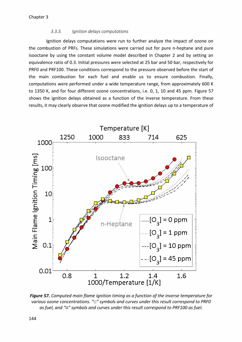
Chapter 3
144
3.3.3. Ignition delays computations
Ignition delays computations were run to further analyze the impact of ozone on
the combustion of PRFs. These simulations were carried out for pure n-heptane and pure
isooctane by using the constant volume model described in Chapter 2 and by setting an
equivalence ratio of 0.3. Initial pressures were selected at 25 bar and 50 bar, respectively for
PRF0 and PRF100. These conditions correspond to the pressure observed before the start of
the main combustion for each fuel and enable us to ensure combustion. Finally,
computations were performed under a wide temperature range, from approximately 600 K
to 1350 K, and for four different ozone concentrations, i.e. 0, 1, 10 and 45 ppm. Figure 57
shows the ignition delays obtained as a function of the inverse temperature. From these
results, it may clearly observe that ozone modified the ignition delays up to a temperature of
Figure 57. Computed main flame ignition timing as a function of the inverse temperature for various ozone concentrations. “□” symbols and curves under this result correspond to PRF0
as fuel, and “○” symbols and curves under this result correspond to PRF100 as fuel.
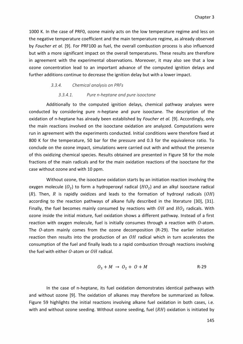
Chapter 3
145
1000 K. In the case of PRF0, ozone mainly acts on the low temperature regime and less on
the negative temperature coefficient and the main temperature regime, as already observed
by Foucher et al. [9]. For PRF100 as fuel, the overall combustion process is also influenced
but with a more significant impact on the overall temperatures. These results are therefore
in agreement with the experimental observations. Moreover, it may also see that a low
ozone concentration lead to an important advance of the computed ignition delays and
further additions continue to decrease the ignition delay but with a lower impact.
3.3.4. Chemical analysis on PRFs
3.3.4.1. Pure n-heptane and pure isooctane
Additionally to the computed ignition delays, chemical pathway analyses were
conducted by considering pure n-heptane and pure isooctane. The description of the
oxidation of n-heptane has already been established by Foucher et al. [9]. Accordingly, only
the main reactions involved on the isooctane oxidation are analyzed. Computations were
run in agreement with the experiments conducted. Initial conditions were therefore fixed at
800 K for the temperature, 50 bar for the pressure and 0.3 for the equivalence ratio. To
conclude on the ozone impact, simulations were carried out with and without the presence
of this oxidizing chemical species. Results obtained are presented in Figure 58 for the mole
fractions of the main radicals and for the main oxidation reactions of the isooctane for the
case without ozone and with 10 ppm.
Without ozone, the isooctane oxidation starts by an initiation reaction involving the
oxygen molecule (𝑂2) to form a hydroperoxyl radical (𝐻𝑂2) and an alkyl isooctane radical
(𝑅). Then, 𝑅 is rapidly oxidizes and leads to the formation of hydroxyl radicals (𝑂𝐻)
according to the reaction pathways of alkane fully described in the literature [30], [31].
Finally, the fuel becomes mainly consumed by reactions with 𝑂𝐻 and 𝐻𝑂2 radicals. With
ozone inside the initial mixture, fuel oxidation shows a different pathway. Instead of a first
reaction with oxygen molecule, fuel is initially consumes through a reaction with 𝑂-atom.
The 𝑂-atom mainly comes from the ozone decomposition (R-29). The earlier initiation
reaction then results into the production of an 𝑂𝐻 radical which in turn accelerates the
consumption of the fuel and finally leads to a rapid combustion through reactions involving
the fuel with either 𝑂-atom or 𝑂𝐻 radical.
𝑂3 + 𝑀 → 𝑂2 + 𝑂 + 𝑀 R-29
In the case of n-heptane, its fuel oxidation demonstrates identical pathways with
and without ozone [9]. The oxidation of alkanes may therefore be summarized as follow.
Figure 59 highlights the initial reactions involving alkane fuel oxidation in both cases, i.e.
with and without ozone seeding. Without ozone seeding, fuel (𝑅𝐻) oxidation is initiated by
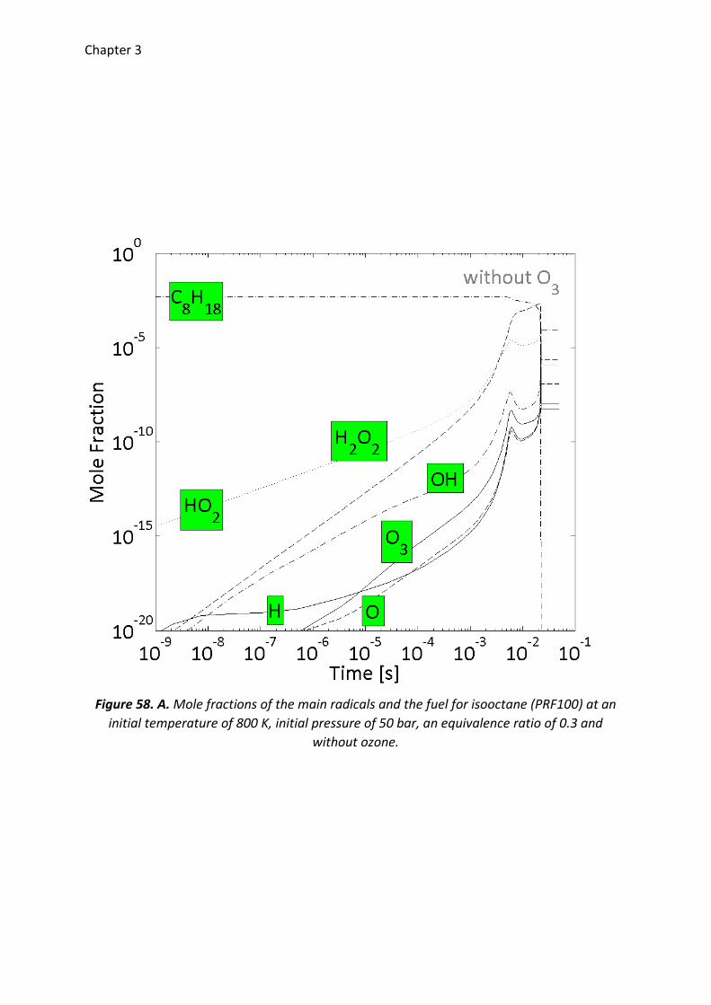
Chapter 3
Figure 58. A. Mole fractions of the main radicals and the fuel for isooctane (PRF100) at an
initial temperature of 800 K, initial pressure of 50 bar, an equivalence ratio of 0.3 and
without ozone.
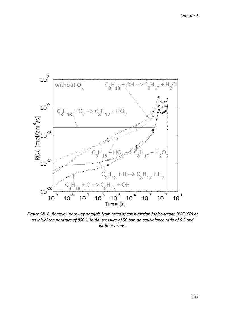
Chapter 3
147
Figure 58. B. Reaction pathway analysis from rates of consumption for isooctane (PRF100) at
an initial temperature of 800 K, initial pressure of 50 bar, an equivalence ratio of 0.3 and
without ozone.
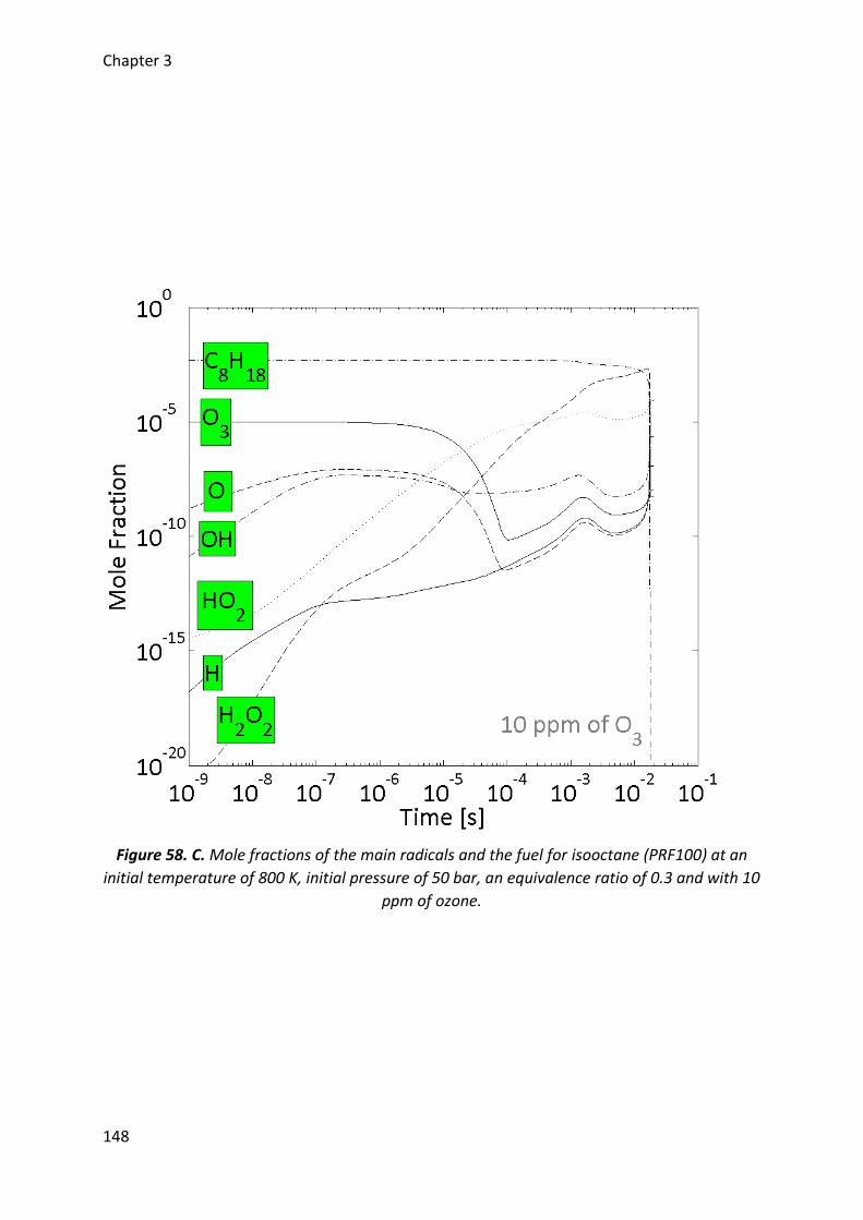
Chapter 3
148
Figure 58. C. Mole fractions of the main radicals and the fuel for isooctane (PRF100) at an
initial temperature of 800 K, initial pressure of 50 bar, an equivalence ratio of 0.3 and with 10
ppm of ozone.
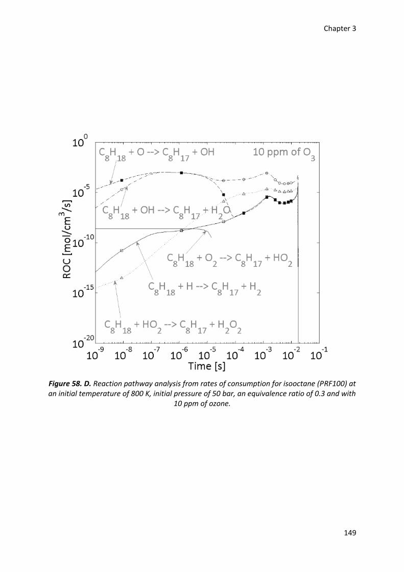
Chapter 3
149
Figure 58. D. Reaction pathway analysis from rates of consumption for isooctane (PRF100) at an initial temperature of 800 K, initial pressure of 50 bar, an equivalence ratio of 0.3 and with
10 ppm of ozone.
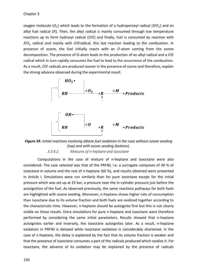
Chapter 3
150
oxygen molecule (𝑂2) which leads to the formation of a hydroperoxyl radical (𝐻𝑂2) and an
alkyl fuel radical (𝑅). Then, the alkyl radical is mainly consumed through low temperature
reactions up to form hydroxyl radical (𝑂𝐻) and finally, fuel is consumed by reaction with
𝐻𝑂2 radical and mainly with 𝑂𝐻radical, this last reaction leading to the combustion. In
presence of ozone, the fuel initially reacts with an 𝑂-atom coming from the ozone
decomposition. The presence of O-atom leads to the production of an alkyl radical and a 𝑂𝐻
radical which in turn rapidly consumes the fuel to lead to the occurrence of the combustion.
As a result, 𝑂𝐻 radicals are produced sooner in the presence of ozone and therefore, explain
the strong advance observed during the experimental result.
Figure 59. Initial reactions involving alkane fuel oxidation in the case without ozone seeding (top) and with ozone seeding (bottom).
3.3.4.2. Mixtures of n-heptane and isooctane
Computations in the case of mixture of n-heptane and isooctane were also
considered. The case selected was that of the PRF40, i.e. a surrogate composes of 40 % of
isooctane in volume and the rest of n-heptane (60 %), and results obtained were presented
in Article I. Simulations were run similarly than for pure isooctane except for the initial
pressure which was set up at 25 bar, a pressure near the in-cylinder pressure just before the
autoignition of the fuel. As observed previously, the same reactions pathways for both fuels
are highlighted with ozone seeding. Moreover, n-heptane shows higher rate of consumption
than isooctane due to its volume fraction and both fuels are oxidized together according to
the characteristic time. However, n-heptane should be autoignite first but this is not clearly
visible on these results. Extra simulations for pure n-heptane and isooctane were therefore
performed by considering the same initial parameters. Results showed that n-heptane
autoignites earlier and inversely, the isooctane autoignites later. As a result, n-heptane
oxidation in PRF40 is delayed while isooctane oxidation is considerably shortened. In the
case of n-heptane, the delay is explained by the fact that its volume fraction is weaker and
that the presence of isooctane consumes a part of the radicals produced which oxidize it. For
isooctane, the advance of its oxidation may be explained by the presence of radicals

Chapter 3
151
released from n-heptane oxidation and due to a slight increase of the temperature with n-
heptane consumption [32].
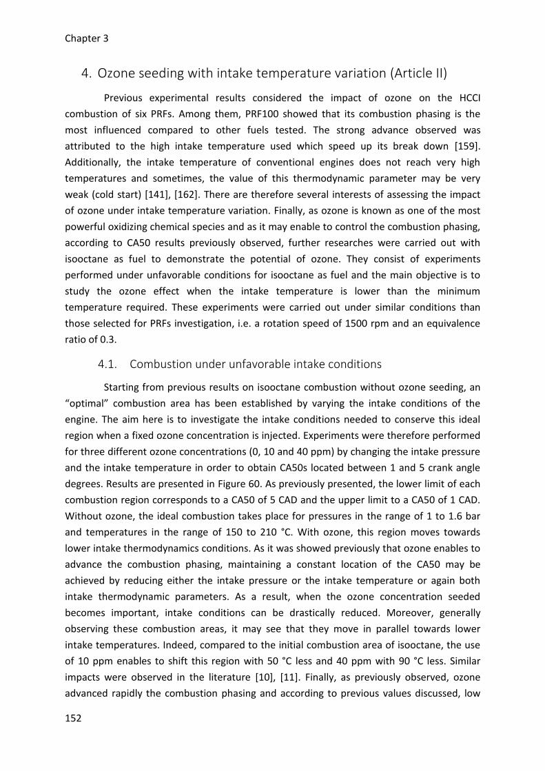
Chapter 3
152
4. Ozone seeding with intake temperature variation (Article II)
Previous experimental results considered the impact of ozone on the HCCI
combustion of six PRFs. Among them, PRF100 showed that its combustion phasing is the
most influenced compared to other fuels tested. The strong advance observed was
attributed to the high intake temperature used which speed up its break down [159].
Additionally, the intake temperature of conventional engines does not reach very high
temperatures and sometimes, the value of this thermodynamic parameter may be very
weak (cold start) [141], [162]. There are therefore several interests of assessing the impact
of ozone under intake temperature variation. Finally, as ozone is known as one of the most
powerful oxidizing chemical species and as it may enable to control the combustion phasing,
according to CA50 results previously observed, further researches were carried out with
isooctane as fuel to demonstrate the potential of ozone. They consist of experiments
performed under unfavorable conditions for isooctane as fuel and the main objective is to
study the ozone effect when the intake temperature is lower than the minimum
temperature required. These experiments were carried out under similar conditions than
those selected for PRFs investigation, i.e. a rotation speed of 1500 rpm and an equivalence
ratio of 0.3.
4.1. Combustion under unfavorable intake conditions
Starting from previous results on isooctane combustion without ozone seeding, an
“optimal” combustion area has been established by varying the intake conditions of the
engine. The aim here is to investigate the intake conditions needed to conserve this ideal
region when a fixed ozone concentration is injected. Experiments were therefore performed
for three different ozone concentrations (0, 10 and 40 ppm) by changing the intake pressure
and the intake temperature in order to obtain CA50s located between 1 and 5 crank angle
degrees. Results are presented in Figure 60. As previously presented, the lower limit of each
combustion region corresponds to a CA50 of 5 CAD and the upper limit to a CA50 of 1 CAD.
Without ozone, the ideal combustion takes place for pressures in the range of 1 to 1.6 bar
and temperatures in the range of 150 to 210 °C. With ozone, this region moves towards
lower intake thermodynamics conditions. As it was showed previously that ozone enables to
advance the combustion phasing, maintaining a constant location of the CA50 may be
achieved by reducing either the intake pressure or the intake temperature or again both
intake thermodynamic parameters. As a result, when the ozone concentration seeded
becomes important, intake conditions can be drastically reduced. Moreover, generally
observing these combustion areas, it may see that they move in parallel towards lower
intake temperatures. Indeed, compared to the initial combustion area of isooctane, the use
of 10 ppm enables to shift this region with 50 °C less and 40 ppm with 90 °C less. Similar
impacts were observed in the literature [10], [11]. Finally, as previously observed, ozone
advanced rapidly the combustion phasing and according to previous values discussed, low
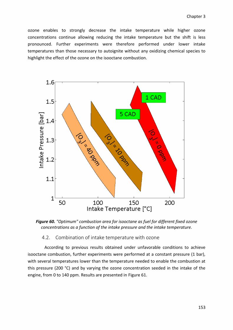
Chapter 3
153
ozone enables to strongly decrease the intake temperature while higher ozone
concentrations continue allowing reducing the intake temperature but the shift is less
pronounced. Further experiments were therefore performed under lower intake
temperatures than those necessary to autoignite without any oxidizing chemical species to
highlight the effect of the ozone on the isooctane combustion.
Figure 60. "Optimum" combustion area for isooctane as fuel for different fixed ozone concentrations as a function of the intake pressure and the intake temperature.
4.2. Combination of intake temperature with ozone
According to previous results obtained under unfavorable conditions to achieve
isooctane combustion, further experiments were performed at a constant pressure (1 bar),
with several temperatures lower than the temperature needed to enable the combustion at
this pressure (200 °C) and by varying the ozone concentration seeded in the intake of the
engine, from 0 to 140 ppm. Results are presented in Figure 61.
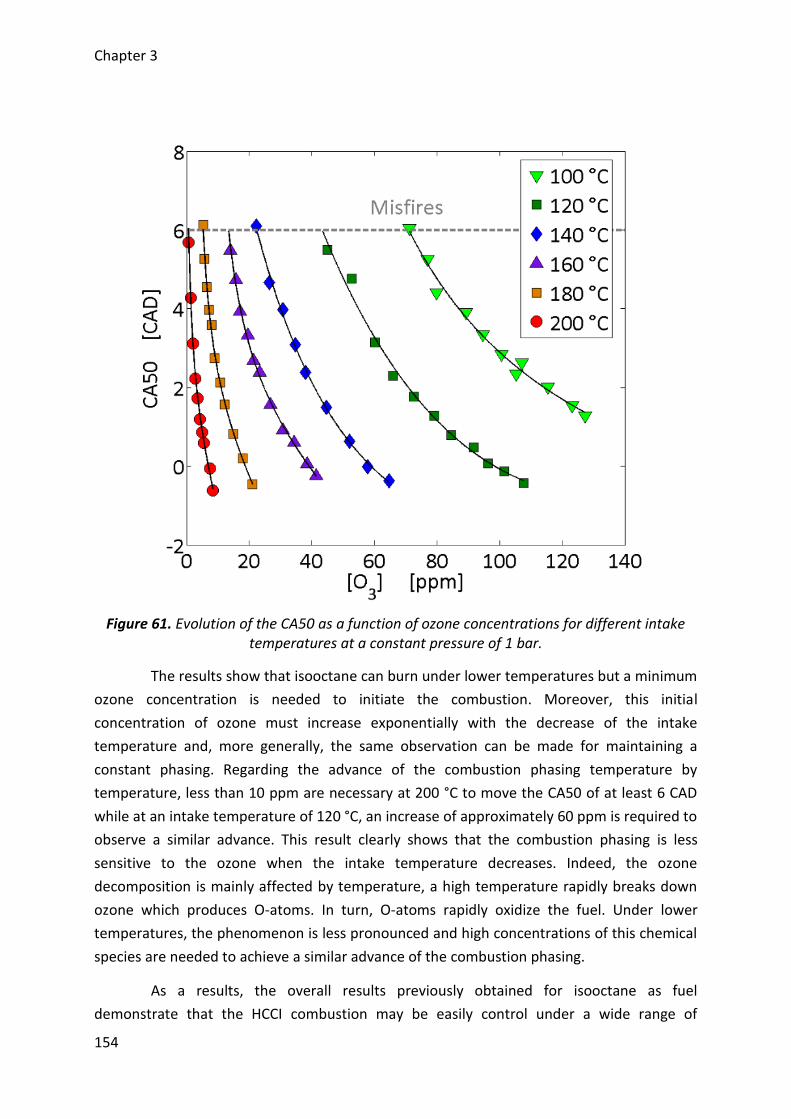
Chapter 3
154
Figure 61. Evolution of the CA50 as a function of ozone concentrations for different intake temperatures at a constant pressure of 1 bar.
The results show that isooctane can burn under lower temperatures but a minimum
ozone concentration is needed to initiate the combustion. Moreover, this initial
concentration of ozone must increase exponentially with the decrease of the intake
temperature and, more generally, the same observation can be made for maintaining a
constant phasing. Regarding the advance of the combustion phasing temperature by
temperature, less than 10 ppm are necessary at 200 °C to move the CA50 of at least 6 CAD
while at an intake temperature of 120 °C, an increase of approximately 60 ppm is required to
observe a similar advance. This result clearly shows that the combustion phasing is less
sensitive to the ozone when the intake temperature decreases. Indeed, the ozone
decomposition is mainly affected by temperature, a high temperature rapidly breaks down
ozone which produces O-atoms. In turn, O-atoms rapidly oxidize the fuel. Under lower
temperatures, the phenomenon is less pronounced and high concentrations of this chemical
species are needed to achieve a similar advance of the combustion phasing.
As a results, the overall results previously obtained for isooctane as fuel
demonstrate that the HCCI combustion may be easily control under a wide range of

Chapter 3
155
conditions and in particular, with temperatures variations. Moreover, as the CA50 is less
sensitive under lower temperatures, a better control of the combustion phasing can be
considered.
4.3. Cool flame occurrence
Most of the time, the HCCI combustion of isooctane into internal combustion
engines presents a single stage ignition [27]. However, previous studies showed that
isooctane is affected by a cool flame oxidation [37]. According to previous results with ozone
seeding, no cool flame appears on heat release rate traces and it was considered that this
oxidizing chemical species directly acts on the main combustion stage. Nevertheless, in the
case of combustion assisted by ozone seeding under lower intake temperature than one
necessary to achieve the combustion without ozone, isooctane may show two-stage ignition
Figure 62. Heat release rate evolutions for different ozone concentrations at a constant intake pressure of 1.3 bar and a constant CA50 of 5 CAD.

Chapter 3
156
as observed in Figure 62. These results are presented for heat release rate traces with a
constant CA50 around 5 CAD, a constant intake pressure of 1.3 bar and for three ozone
concentrations of 0, 10 and 40 ppm (therefore with intake temperatures of 167 °C, 105 °C
and 66 °C, respectively).
Without ozone, heat release rate shows only one ignition stage while under lower
intake temperature and with ozone addition, a cool flame ignition occurs progressively. As
the intake temperature is weaker, the cool flame reactions have enough time to establish
and demonstrate experimentally that ozone modifies the start of the combustion since the
energy released during the cool flame increases. Moreover, such results are confirmed
through kinetics computations. By using the same methodology than one previously
presented, ignition timing of the cool flame was computed. Simulations showed that ignition
timing are in agreement with the experimental results observed. When the temperature
decreases, the ignition timing is delayed but increasing the amount of ozone leads strongly
to a shortened ignition timing. Therefore, the ozone effect is higher than the temperature
effect. Finally, according to experimental results and computational results, reduce the
temperature and inject ozone enable to achieve cool flame occurrence.
As a conclusion, these results on isooctane combustion showed that the use of
ozone might help controlling the HCCI combustion phasing under a wide range of conditions.
Moreover, last results demonstrate that the combination of using low intake temperatures
with ozone injections clearly showed that ozone influences the beginning of the fuel
oxidation. It could therefore enable to examine the onset of the cool flame and its effect on
the overall HCCI combustion into internal combustion engines.
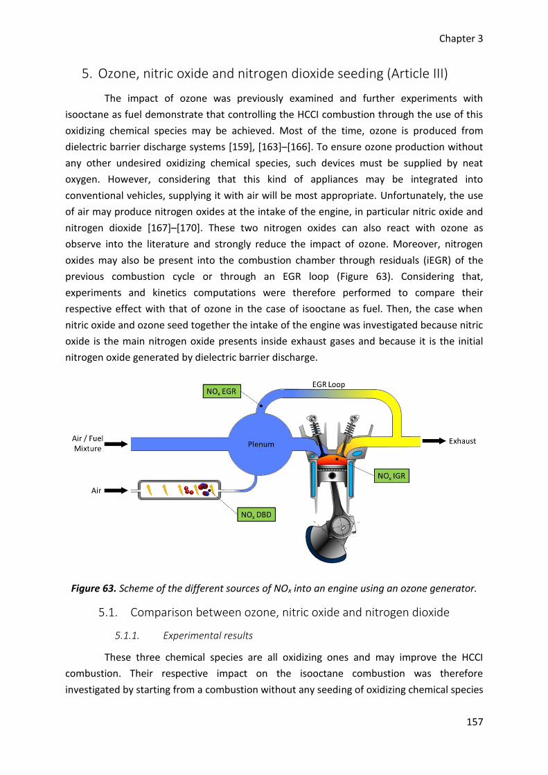
Chapter 3
157
5. Ozone, nitric oxide and nitrogen dioxide seeding (Article III)
The impact of ozone was previously examined and further experiments with
isooctane as fuel demonstrate that controlling the HCCI combustion through the use of this
oxidizing chemical species may be achieved. Most of the time, ozone is produced from
dielectric barrier discharge systems [159], [163]–[166]. To ensure ozone production without
any other undesired oxidizing chemical species, such devices must be supplied by neat
oxygen. However, considering that this kind of appliances may be integrated into
conventional vehicles, supplying it with air will be most appropriate. Unfortunately, the use
of air may produce nitrogen oxides at the intake of the engine, in particular nitric oxide and
nitrogen dioxide [167]–[170]. These two nitrogen oxides can also react with ozone as
observe into the literature and strongly reduce the impact of ozone. Moreover, nitrogen
oxides may also be present into the combustion chamber through residuals (iEGR) of the
previous combustion cycle or through an EGR loop (Figure 63). Considering that,
experiments and kinetics computations were therefore performed to compare their
respective effect with that of ozone in the case of isooctane as fuel. Then, the case when
nitric oxide and ozone seed together the intake of the engine was investigated because nitric
oxide is the main nitrogen oxide presents inside exhaust gases and because it is the initial
nitrogen oxide generated by dielectric barrier discharge.
Figure 63. Scheme of the different sources of NOx into an engine using an ozone generator.
5.1. Comparison between ozone, nitric oxide and nitrogen dioxide
5.1.1. Experimental results
These three chemical species are all oxidizing ones and may improve the HCCI
combustion. Their respective impact on the isooctane combustion was therefore
investigated by starting from a combustion without any seeding of oxidizing chemical species
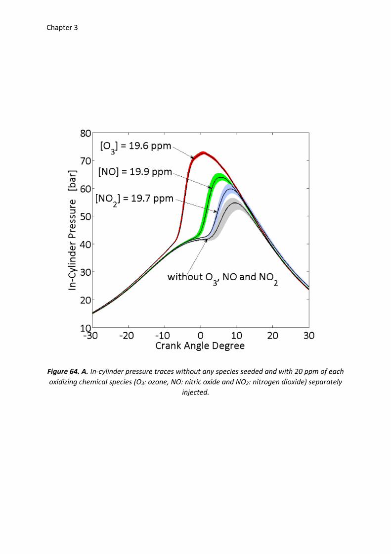
Chapter 3
Figure 64. A. In-cylinder pressure traces without any species seeded and with 20 ppm of each
oxidizing chemical species (O3: ozone, NO: nitric oxide and NO2: nitrogen dioxide) separately
injected.
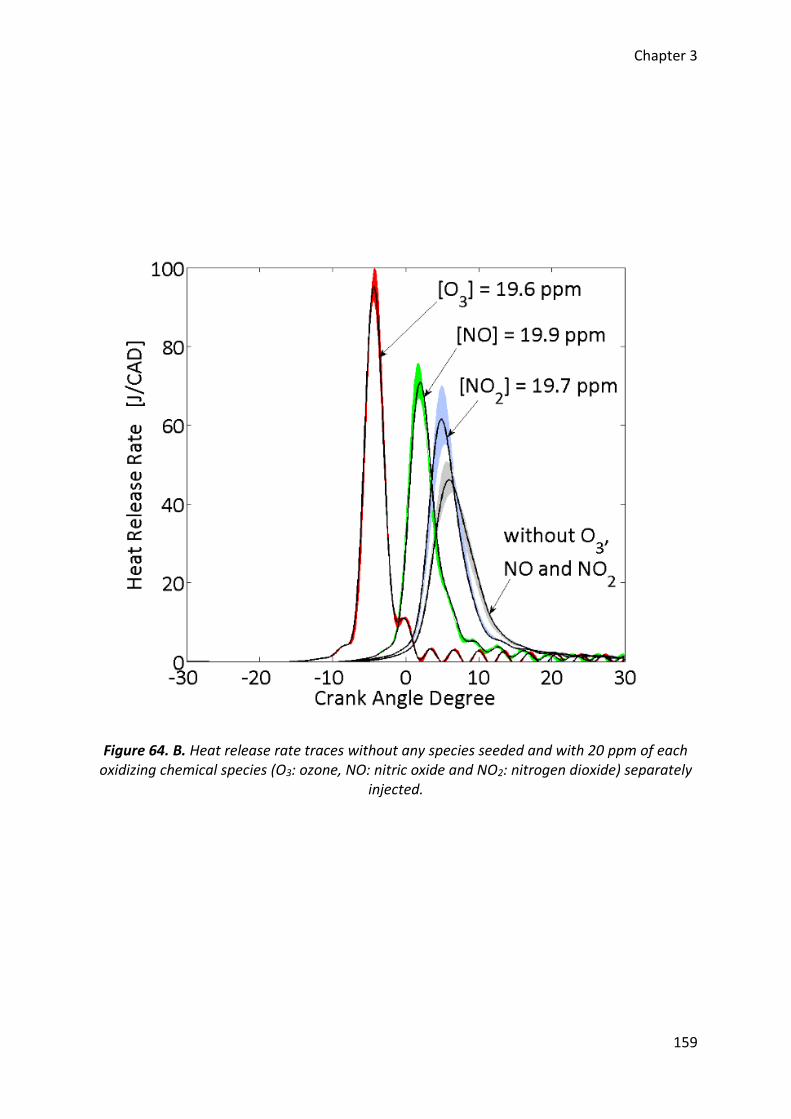
Chapter 3
159
Figure 64. B. Heat release rate traces without any species seeded and with 20 ppm of each oxidizing chemical species (O3: ozone, NO: nitric oxide and NO2: nitrogen dioxide) separately
injected.
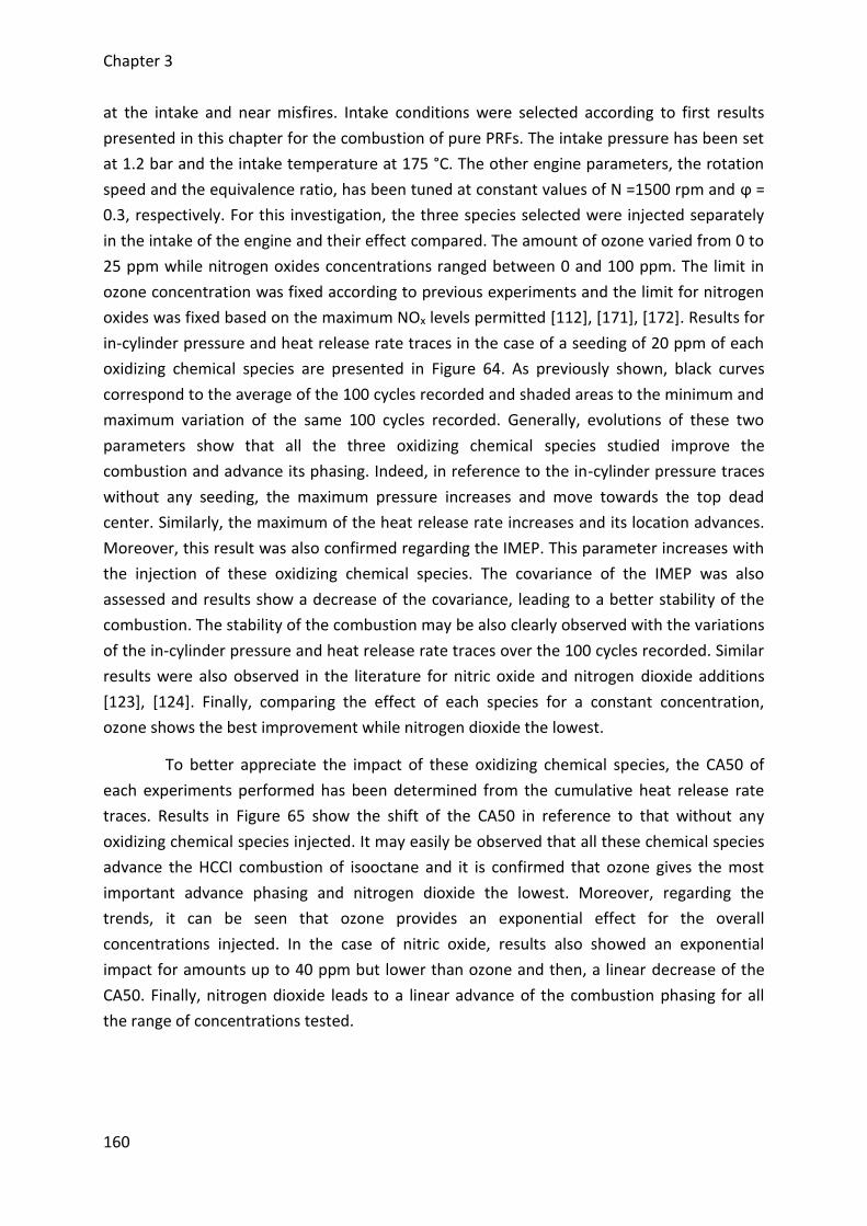
Chapter 3
160
at the intake and near misfires. Intake conditions were selected according to first results
presented in this chapter for the combustion of pure PRFs. The intake pressure has been set
at 1.2 bar and the intake temperature at 175 °C. The other engine parameters, the rotation
speed and the equivalence ratio, has been tuned at constant values of N =1500 rpm and ϕ =
0.3, respectively. For this investigation, the three species selected were injected separately
in the intake of the engine and their effect compared. The amount of ozone varied from 0 to
25 ppm while nitrogen oxides concentrations ranged between 0 and 100 ppm. The limit in
ozone concentration was fixed according to previous experiments and the limit for nitrogen
oxides was fixed based on the maximum NOx levels permitted [112], [171], [172]. Results for
in-cylinder pressure and heat release rate traces in the case of a seeding of 20 ppm of each
oxidizing chemical species are presented in Figure 64. As previously shown, black curves
correspond to the average of the 100 cycles recorded and shaded areas to the minimum and
maximum variation of the same 100 cycles recorded. Generally, evolutions of these two
parameters show that all the three oxidizing chemical species studied improve the
combustion and advance its phasing. Indeed, in reference to the in-cylinder pressure traces
without any seeding, the maximum pressure increases and move towards the top dead
center. Similarly, the maximum of the heat release rate increases and its location advances.
Moreover, this result was also confirmed regarding the IMEP. This parameter increases with
the injection of these oxidizing chemical species. The covariance of the IMEP was also
assessed and results show a decrease of the covariance, leading to a better stability of the
combustion. The stability of the combustion may be also clearly observed with the variations
of the in-cylinder pressure and heat release rate traces over the 100 cycles recorded. Similar
results were also observed in the literature for nitric oxide and nitrogen dioxide additions
[123], [124]. Finally, comparing the effect of each species for a constant concentration,
ozone shows the best improvement while nitrogen dioxide the lowest.
To better appreciate the impact of these oxidizing chemical species, the CA50 of
each experiments performed has been determined from the cumulative heat release rate
traces. Results in Figure 65 show the shift of the CA50 in reference to that without any
oxidizing chemical species injected. It may easily be observed that all these chemical species
advance the HCCI combustion of isooctane and it is confirmed that ozone gives the most
important advance phasing and nitrogen dioxide the lowest. Moreover, regarding the
trends, it can be seen that ozone provides an exponential effect for the overall
concentrations injected. In the case of nitric oxide, results also showed an exponential
impact for amounts up to 40 ppm but lower than ozone and then, a linear decrease of the
CA50. Finally, nitrogen dioxide leads to a linear advance of the combustion phasing for all
the range of concentrations tested.
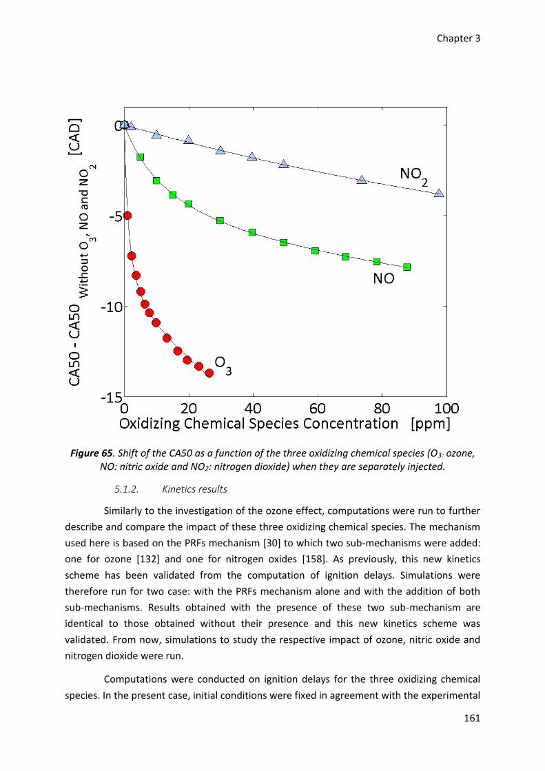
Chapter 3
161
Figure 65. Shift of the CA50 as a function of the three oxidizing chemical species (O3: ozone, NO: nitric oxide and NO2: nitrogen dioxide) when they are separately injected.
5.1.2. Kinetics results
Similarly to the investigation of the ozone effect, computations were run to further
describe and compare the impact of these three oxidizing chemical species. The mechanism
used here is based on the PRFs mechanism [30] to which two sub-mechanisms were added:
one for ozone [132] and one for nitrogen oxides [158]. As previously, this new kinetics
scheme has been validated from the computation of ignition delays. Simulations were
therefore run for two case: with the PRFs mechanism alone and with the addition of both
sub-mechanisms. Results obtained with the presence of these two sub-mechanism are
identical to those obtained without their presence and this new kinetics scheme was
validated. From now, simulations to study the respective impact of ozone, nitric oxide and
nitrogen dioxide were run.
Computations were conducted on ignition delays for the three oxidizing chemical
species. In the present case, initial conditions were fixed in agreement with the experimental
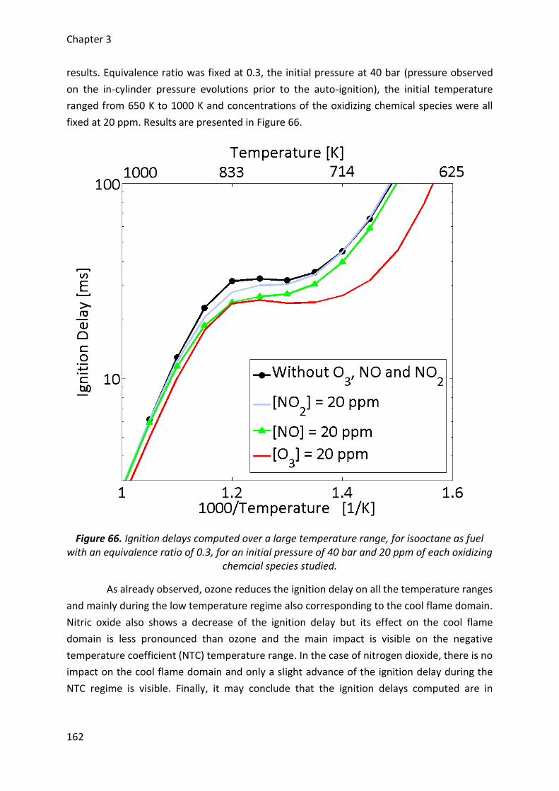
Chapter 3
162
results. Equivalence ratio was fixed at 0.3, the initial pressure at 40 bar (pressure observed
on the in-cylinder pressure evolutions prior to the auto-ignition), the initial temperature
ranged from 650 K to 1000 K and concentrations of the oxidizing chemical species were all
fixed at 20 ppm. Results are presented in Figure 66.
Figure 66. Ignition delays computed over a large temperature range, for isooctane as fuel with an equivalence ratio of 0.3, for an initial pressure of 40 bar and 20 ppm of each oxidizing
chemcial species studied.
As already observed, ozone reduces the ignition delay on all the temperature ranges
and mainly during the low temperature regime also corresponding to the cool flame domain.
Nitric oxide also shows a decrease of the ignition delay but its effect on the cool flame
domain is less pronounced than ozone and the main impact is visible on the negative
temperature coefficient (NTC) temperature range. In the case of nitrogen dioxide, there is no
impact on the cool flame domain and only a slight advance of the ignition delay during the
NTC regime is visible. Finally, it may conclude that the ignition delays computed are in

Chapter 3
163
agreement with experimental observations. Ozone well leads to the ignition delays the most
shortened and nitrogen dioxide to the lowest.
Regarding the rates of consumption (ROC) for each oxidizing chemical species
according to the previous computations, the impact of ozone previously described is not
modified. Indeed, ozone mainly decomposes into oxygen molecules and 𝑂-atoms (R-29)
which in turn directly oxidize the fuel and lead to the formation of 𝑂𝐻 radicals (R-30). Then,
𝑂𝐻 radicals rapidly consume the fuel (R-31) and the combustion occurs.
𝐶8𝐻18 + 𝑂 → 𝐶8𝐻17 + 𝑂𝐻 R-30
𝐶8𝐻18 + 𝑂𝐻 → 𝐶8𝐻17 + 𝐻2𝑂 R-31
In the case of nitric oxide, this oxidizing chemical species does not react with the
fuel but with 𝐻𝑂2 radicals (R-32) resulting from the first oxidation of the fuel (R-33). This
reaction leads to the formation of 𝑂𝐻 radicals which finally react with the fuel through
reaction R-31. Instead of ozone which enables a fast consumption of the fuel through 𝑂-
atoms prior to any reactions with the fuel, nitric oxide needs to wait for a first oxidation with
molecular oxygen and the availability of a 𝐻𝑂2 radical. As a result, the earlier formation of
OH radicals which enhance the fuel oxidation and the advance of the ignition timing is
postpones.
𝑁𝑂 + 𝐻𝑂2 → 𝑁𝑂2 + 𝑂𝐻 R-32
𝐶8𝐻18 + 𝑂2 → 𝐶8𝐻17 + 𝐻𝑂2 R-33
Similarly to nitric oxide, nitrogen dioxide does not react directly with the fuel and
also needs the presence of 𝐻𝑂2 radicals coming from the reaction R-33 or the presence of
methyl radicals (𝐶𝐻3) to improve the combustion. As a result, the improvement of the
combustion with nitrogen dioxide seeding comes from the following reaction system. The
nitrogen dioxide which reacts with a 𝐶𝐻3 radical produces a nitric oxide (R-34) and then,
nitric oxide leads to a 𝑂𝐻 radical through reaction R-32. However, the main pathway leading
to the formation of 𝑂𝐻 radicals and to the combustion enhancement comes from reactions
R-35 and R-36 with an intermediate radical. As a result, the need of a 𝐻𝑂2 radical explains
that nitrogen dioxide has less impact than ozone on the HCCI combustion of isooctane and
the presence of intermediate species explains that combustion improvement is lower than
nitric oxide one. Indeed, further analyses on the rate of consumption showed that reactions
R-35 and R-36 take place later than reaction R-32.
𝑁𝑂2 + 𝐶𝐻3 → 𝑁𝑂 + 𝐶𝐻3𝑂 R-34
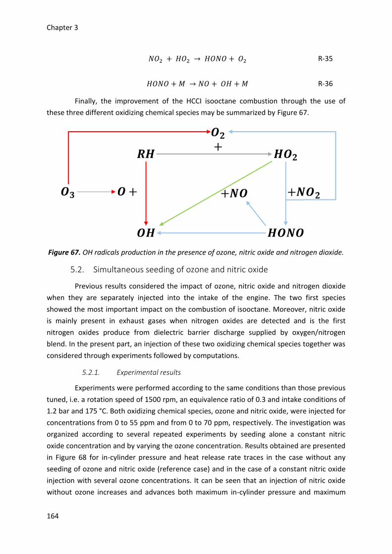
Chapter 3
164
𝑁𝑂2 + 𝐻𝑂2 → 𝐻𝑂𝑁𝑂 + 𝑂2 R-35
𝐻𝑂𝑁𝑂 + 𝑀 → 𝑁𝑂 + 𝑂𝐻 + 𝑀 R-36
Finally, the improvement of the HCCI isooctane combustion through the use of
these three different oxidizing chemical species may be summarized by Figure 67.
Figure 67. OH radicals production in the presence of ozone, nitric oxide and nitrogen dioxide.
5.2. Simultaneous seeding of ozone and nitric oxide
Previous results considered the impact of ozone, nitric oxide and nitrogen dioxide
when they are separately injected into the intake of the engine. The two first species
showed the most important impact on the combustion of isooctane. Moreover, nitric oxide
is mainly present in exhaust gases when nitrogen oxides are detected and is the first
nitrogen oxides produce from dielectric barrier discharge supplied by oxygen/nitrogen
blend. In the present part, an injection of these two oxidizing chemical species together was
considered through experiments followed by computations.
5.2.1. Experimental results
Experiments were performed according to the same conditions than those previous
tuned, i.e. a rotation speed of 1500 rpm, an equivalence ratio of 0.3 and intake conditions of
1.2 bar and 175 °C. Both oxidizing chemical species, ozone and nitric oxide, were injected for
concentrations from 0 to 55 ppm and from 0 to 70 ppm, respectively. The investigation was
organized according to several repeated experiments by seeding alone a constant nitric
oxide concentration and by varying the ozone concentration. Results obtained are presented
in Figure 68 for in-cylinder pressure and heat release rate traces in the case without any
seeding of ozone and nitric oxide (reference case) and in the case of a constant nitric oxide
injection with several ozone concentrations. It can be seen that an injection of nitric oxide
without ozone increases and advances both maximum in-cylinder pressure and maximum
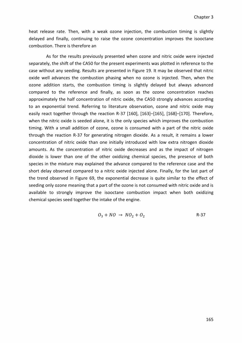
Chapter 3
165
heat release rate. Then, with a weak ozone injection, the combustion timing is slightly
delayed and finally, continuing to raise the ozone concentration improves the isooctane
combustion. There is therefore an
As for the results previously presented when ozone and nitric oxide were injected
separately, the shift of the CA50 for the present experiments was plotted in reference to the
case without any seeding. Results are presented in Figure 19. It may be observed that nitric
oxide well advances the combustion phasing when no ozone is injected. Then, when the
ozone addition starts, the combustion timing is slightly delayed but always advanced
compared to the reference and finally, as soon as the ozone concentration reaches
approximately the half concentration of nitric oxide, the CA50 strongly advances according
to an exponential trend. Referring to literature observation, ozone and nitric oxide may
easily react together through the reaction R-37 [160], [163]–[165], [168]–[170]. Therefore,
when the nitric oxide is seeded alone, it is the only species which improves the combustion
timing. With a small addition of ozone, ozone is consumed with a part of the nitric oxide
through the reaction R-37 for generating nitrogen dioxide. As a result, it remains a lower
concentration of nitric oxide than one initially introduced with low extra nitrogen dioxide
amounts. As the concentration of nitric oxide decreases and as the impact of nitrogen
dioxide is lower than one of the other oxidizing chemical species, the presence of both
species in the mixture may explained the advance compared to the reference case and the
short delay observed compared to a nitric oxide injected alone. Finally, for the last part of
the trend observed in Figure 69, the exponential decrease is quite similar to the effect of
seeding only ozone meaning that a part of the ozone is not consumed with nitric oxide and is
available to strongly improve the isooctane combustion impact when both oxidizing
chemical species seed together the intake of the engine.
𝑂3 + 𝑁𝑂 → 𝑁𝑂2 + 𝑂2 R-37
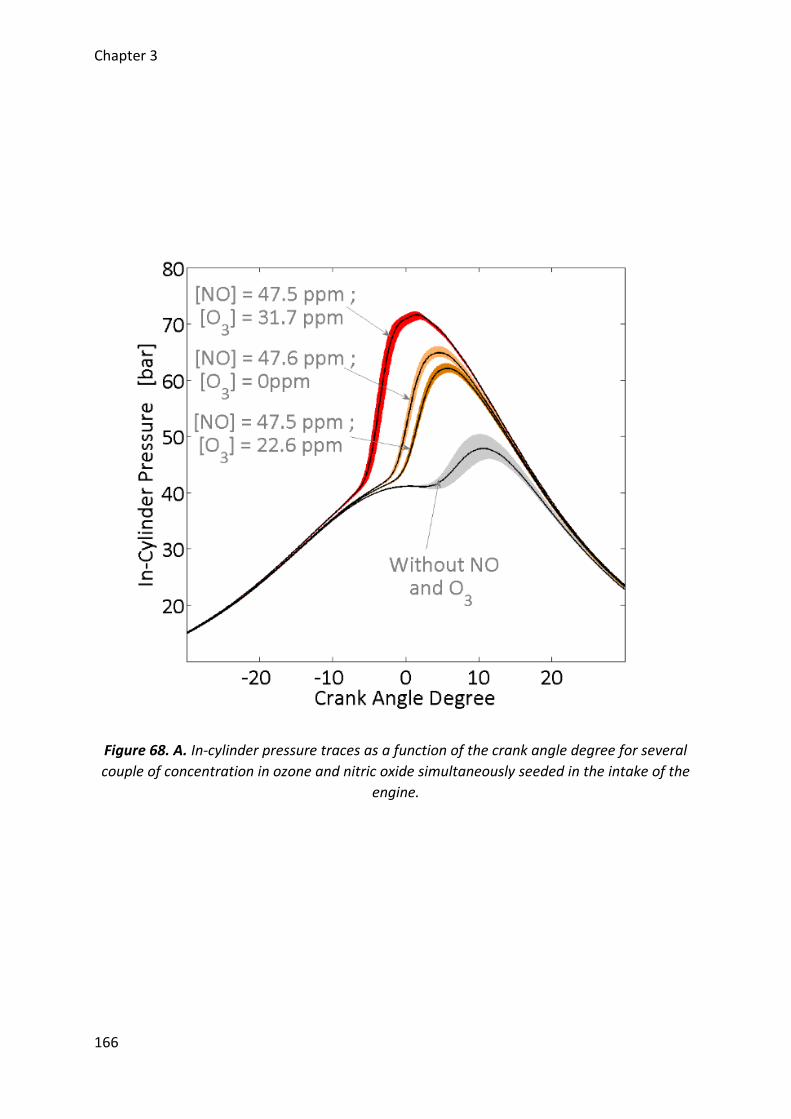
Chapter 3
166
Figure 68. A. In-cylinder pressure traces as a function of the crank angle degree for several
couple of concentration in ozone and nitric oxide simultaneously seeded in the intake of the
engine.
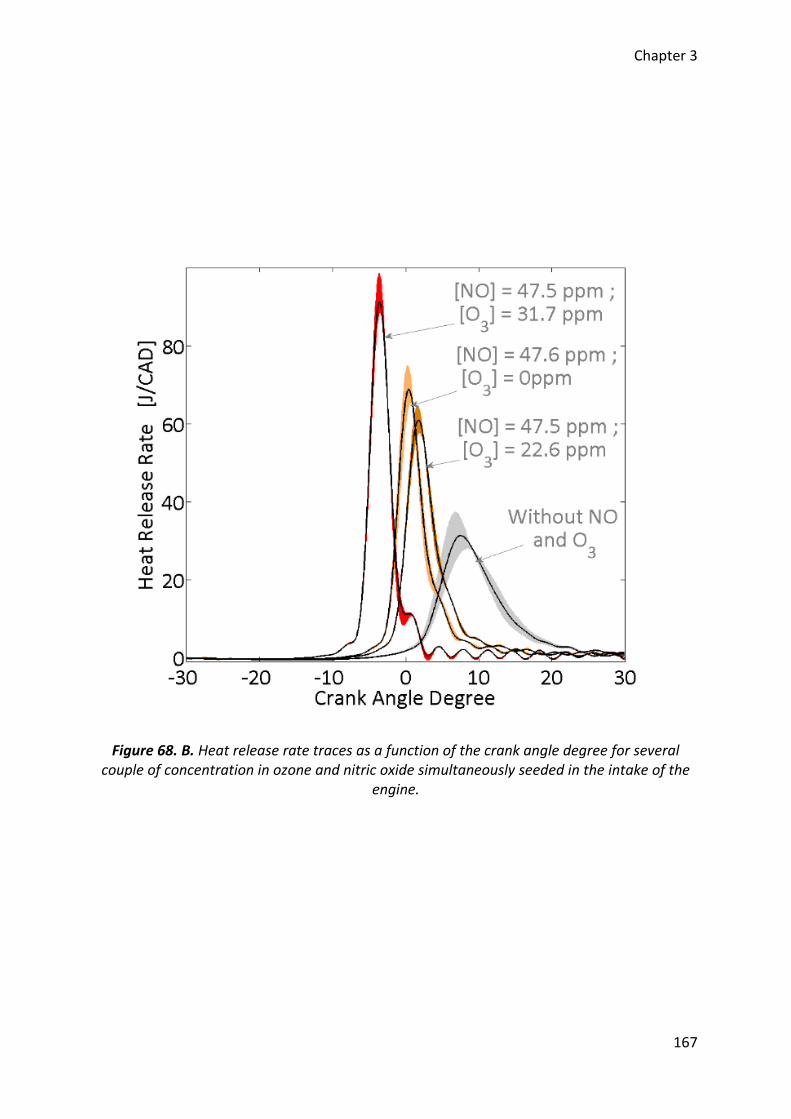
Chapter 3
167
Figure 68. B. Heat release rate traces as a function of the crank angle degree for several couple of concentration in ozone and nitric oxide simultaneously seeded in the intake of the
engine.
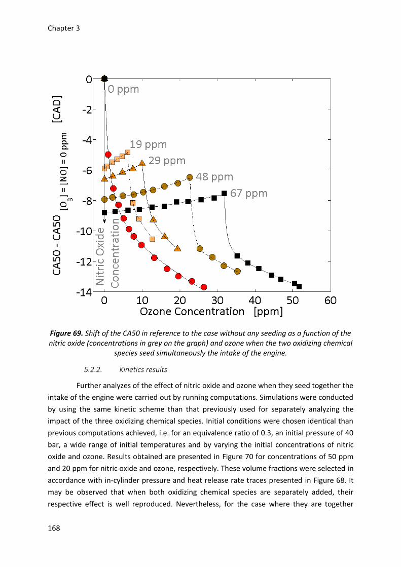
Chapter 3
168
Figure 69. Shift of the CA50 in reference to the case without any seeding as a function of the nitric oxide (concentrations in grey on the graph) and ozone when the two oxidizing chemical
species seed simultaneously the intake of the engine.
5.2.2. Kinetics results
Further analyzes of the effect of nitric oxide and ozone when they seed together the
intake of the engine were carried out by running computations. Simulations were conducted
by using the same kinetic scheme than that previously used for separately analyzing the
impact of the three oxidizing chemical species. Initial conditions were chosen identical than
previous computations achieved, i.e. for an equivalence ratio of 0.3, an initial pressure of 40
bar, a wide range of initial temperatures and by varying the initial concentrations of nitric
oxide and ozone. Results obtained are presented in Figure 70 for concentrations of 50 ppm
and 20 ppm for nitric oxide and ozone, respectively. These volume fractions were selected in
accordance with in-cylinder pressure and heat release rate traces presented in Figure 68. It
may be observed that when both oxidizing chemical species are separately added, their
respective effect is well reproduced. Nevertheless, for the case where they are together
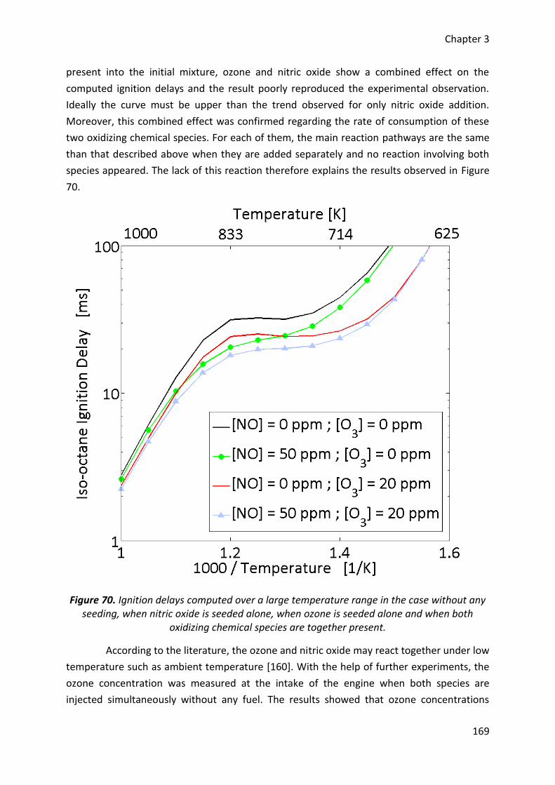
Chapter 3
169
present into the initial mixture, ozone and nitric oxide show a combined effect on the
computed ignition delays and the result poorly reproduced the experimental observation.
Ideally the curve must be upper than the trend observed for only nitric oxide addition.
Moreover, this combined effect was confirmed regarding the rate of consumption of these
two oxidizing chemical species. For each of them, the main reaction pathways are the same
than that described above when they are added separately and no reaction involving both
species appeared. The lack of this reaction therefore explains the results observed in Figure
70.
Figure 70. Ignition delays computed over a large temperature range in the case without any seeding, when nitric oxide is seeded alone, when ozone is seeded alone and when both
oxidizing chemical species are together present.
According to the literature, the ozone and nitric oxide may react together under low
temperature such as ambient temperature [160]. With the help of further experiments, the
ozone concentration was measured at the intake of the engine when both species are
injected simultaneously without any fuel. The results showed that ozone concentrations
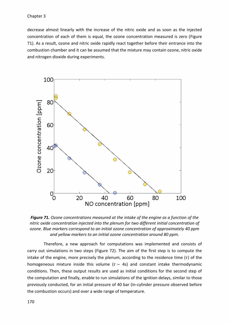
Chapter 3
170
decrease almost linearly with the increase of the nitric oxide and as soon as the injected
concentration of each of them is equal, the ozone concentration measured is zero (Figure
71). As a result, ozone and nitric oxide rapidly react together before their entrance into the
combustion chamber and it can be assumed that the mixture may contain ozone, nitric oxide
and nitrogen dioxide during experiments.
Figure 71. Ozone concentrations measured at the intake of the engine as a function of the nitric oxide concentration injected into the plenum for two different initial concentration of ozone. Blue markers correspond to an initial ozone concentration of approximately 40 ppm
and yellow markers to an initial ozone concentration around 80 ppm.
Therefore, a new approach for computations was implemented and consists of
carry out simulations in two steps (Figure 72). The aim of the first step is to compute the
intake of the engine, more precisely the plenum, according to the residence time (𝜏) of the
homogeneous mixture inside this volume (𝜏 ~ 4s) and constant intake thermodynamic
conditions. Then, these output results are used as initial conditions for the second step of
the computation and finally, enable to run simulations of the ignition delays, similar to those
previously conducted, for an initial pressure of 40 bar (in-cylinder pressure observed before
the combustion occurs) and over a wide range of temperature.
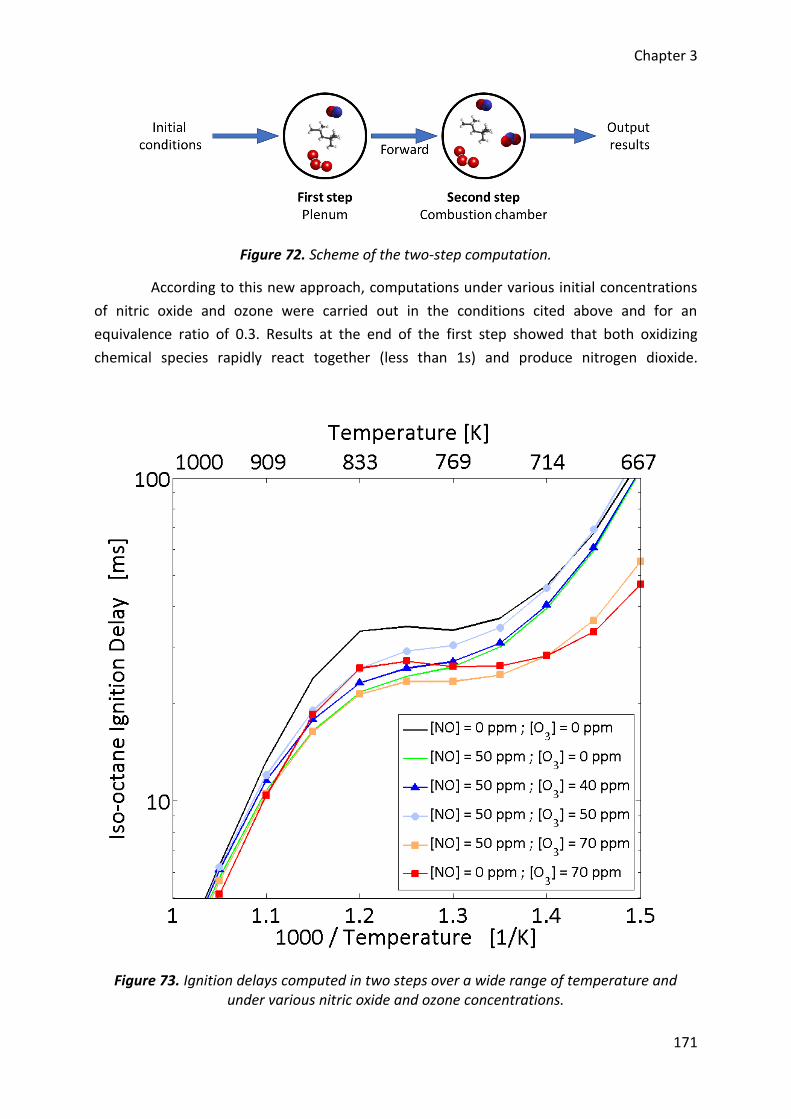
Chapter 3
171
Figure 72. Scheme of the two-step computation.
According to this new approach, computations under various initial concentrations
of nitric oxide and ozone were carried out in the conditions cited above and for an
equivalence ratio of 0.3. Results at the end of the first step showed that both oxidizing
chemical species rapidly react together (less than 1s) and produce nitrogen dioxide.
Figure 73. Ignition delays computed in two steps over a wide range of temperature and under various nitric oxide and ozone concentrations.

Chapter 3
172
Depending of the initial concentrations, several cases take place. If the concentration in
nitric oxide is greater than that of ozone, ozone is fully consumed and replaced by nitrogen
dioxide according to the reaction R-37 (𝑂3 + 𝑁𝑂 → 𝑁𝑂2 + 𝑂2). The second step of the
computation therefore starts with amounts of nitrogen dioxide (𝑁𝑂2) and a part of the nitric
oxide 𝑁𝑂 which did not react during the first step. Inversely, when ozone concentration is
greater than that of nitric oxide, 𝑁𝑂 is entirely consumed to generate 𝑁𝑂2 and some ppm of
ozone remain. However, after the total consumption of nitric oxide, ozone decomposes by
itself due to the temperature but this effect stays moderated and a part of this chemical
species remains for the second step of the computation. Finally, ignition delays are obtained
after the second step of the computations. Results are presented in Figure 73. It may
observe that when nitric oxide is seeded alone, the ignition delay is well advance compared
to the reference without seeding. Then, with an ozone concentration lower than the
concentration of nitric oxide, the ignition delays computed are slightly delayed but always in
advance compared to the reference and finally, when ozone amount becomes greater than
that of nitric oxide, the ignition delays strongly decreases. In the case where nitric oxide and
ozone are with the same initial concentration, there is only nitrogen dioxide during the
second step of the computation. These last results were compared with a simulation with
only nitrogen dioxide and for the same initial concentration. Outputs show a weak variation
which can be neglected.
Finally, the results obtained according to this two-step computation satisfactorily
explain the experimental observations. However, during experiments, the transition on
CA50s with the increase of the ozone and a constant concentration of nitric oxide has been
observed when the ozone amount is approximately the half of nitric oxide amount while
during computations, the transition occurs when the ratio between these two species is
about 1. This effect was attributed to a partial stratification which may take place inside the
plenum during the injection of the oxidizing chemical species and before the entrance of the
fresh gases into the combustion chamber. As a result, there is less nitrogen dioxide produce
experimentally than during computations. However, it was also observed that nitrogen
dioxide may consumed ozone into the plenum (Figure 74). A reaction between ozone and
nitrogen dioxide could compete with the reaction between ozone and nitric oxide leading to
a higher nitric oxide concentration into the combustion chamber. This assessment may
considered when the CA50 is delayed with a nitric oxide injection and a small ozone
concentration (Figure 69) but does not explain the strong advance observed on the CA50
when a higher ozone concentration seeds the intake of the engine. According to the trend
observed with our experimental results, it may assume that the impact comes from chemical
interactions between ozone and isooctane. Under these intake temperatures, fuels may be
partially oxidized [113], [114], [173] and may lead to the advance observed. Therefore, there
is probably a competition between ozone consumed by nitric oxide and ozone which breaks
down to O-atom which finally oxidizes the fuel. This assumption on a competition between
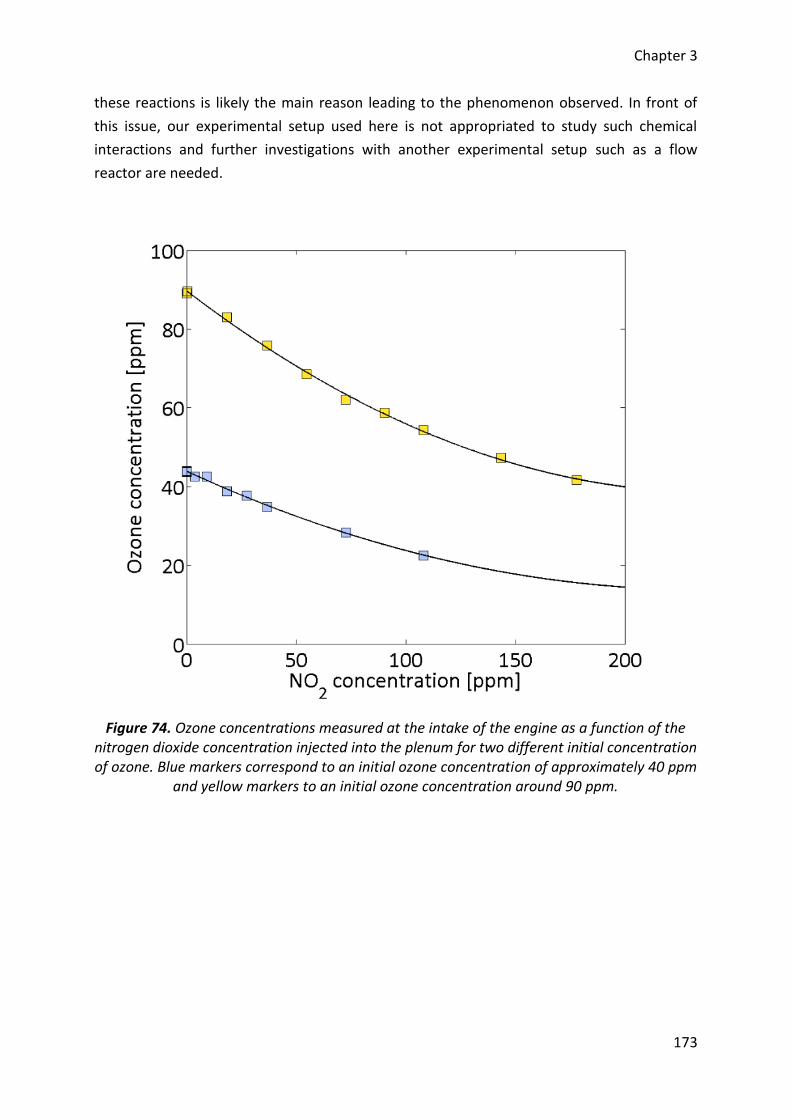
Chapter 3
173
these reactions is likely the main reason leading to the phenomenon observed. In front of
this issue, our experimental setup used here is not appropriated to study such chemical
interactions and further investigations with another experimental setup such as a flow
reactor are needed.
Figure 74. Ozone concentrations measured at the intake of the engine as a function of the nitrogen dioxide concentration injected into the plenum for two different initial concentration of ozone. Blue markers correspond to an initial ozone concentration of approximately 40 ppm
and yellow markers to an initial ozone concentration around 90 ppm.
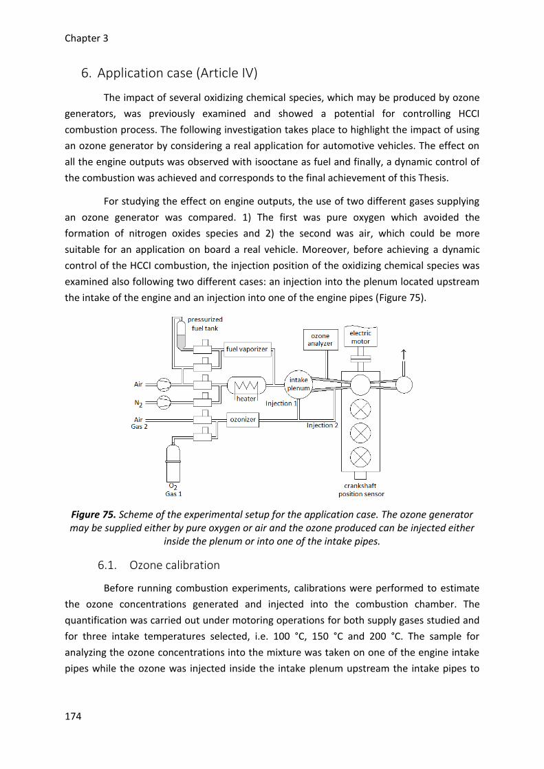
Chapter 3
174
6. Application case (Article IV)
The impact of several oxidizing chemical species, which may be produced by ozone
generators, was previously examined and showed a potential for controlling HCCI
combustion process. The following investigation takes place to highlight the impact of using
an ozone generator by considering a real application for automotive vehicles. The effect on
all the engine outputs was observed with isooctane as fuel and finally, a dynamic control of
the combustion was achieved and corresponds to the final achievement of this Thesis.
For studying the effect on engine outputs, the use of two different gases supplying
an ozone generator was compared. 1) The first was pure oxygen which avoided the
formation of nitrogen oxides species and 2) the second was air, which could be more
suitable for an application on board a real vehicle. Moreover, before achieving a dynamic
control of the HCCI combustion, the injection position of the oxidizing chemical species was
examined also following two different cases: an injection into the plenum located upstream
the intake of the engine and an injection into one of the engine pipes (Figure 75).
Figure 75. Scheme of the experimental setup for the application case. The ozone generator may be supplied either by pure oxygen or air and the ozone produced can be injected either
inside the plenum or into one of the intake pipes.
6.1. Ozone calibration
Before running combustion experiments, calibrations were performed to estimate
the ozone concentrations generated and injected into the combustion chamber. The
quantification was carried out under motoring operations for both supply gases studied and
for three intake temperatures selected, i.e. 100 °C, 150 °C and 200 °C. The sample for
analyzing the ozone concentrations into the mixture was taken on one of the engine intake
pipes while the ozone was injected inside the intake plenum upstream the intake pipes to
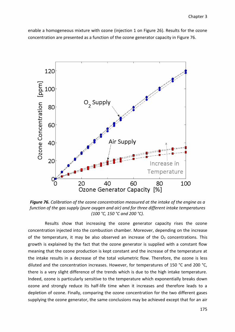
Chapter 3
175
enable a homogeneous mixture with ozone (injection 1 on Figure 26). Results for the ozone
concentration are presented as a function of the ozone generator capacity in Figure 76.
Figure 76. Calibration of the ozone concentration measured at the intake of the engine as a function of the gas supply (pure oxygen and air) and for three different intake temperatures
(100 °C, 150 °C and 200 °C).
Results show that increasing the ozone generator capacity rises the ozone
concentration injected into the combustion chamber. Moreover, depending on the increase
of the temperature, it may be also observed an increase of the O3 concentrations. This
growth is explained by the fact that the ozone generator is supplied with a constant flow
meaning that the ozone production is kept constant and the increase of the temperature at
the intake results in a decrease of the total volumetric flow. Therefore, the ozone is less
diluted and the concentration increases. However, for temperatures of 150 °C and 200 °C,
there is a very slight difference of the trends which is due to the high intake temperature.
Indeed, ozone is particularly sensitive to the temperature which exponentially breaks down
ozone and strongly reduce its half-life time when it increases and therefore leads to a
depletion of ozone. Finally, comparing the ozone concentration for the two different gases
supplying the ozone generator, the same conclusions may be achieved except that for an air
Chapter 3
176
supply, the ozone concentration is lower than for a pure oxygen supply. Indeed, it is normal
to observe a lower ozone concentration as the oxygen fraction is approximately 21% in the
air. However, even if there is a ratio of five in oxygen between both gases selected, the
concentration of ozone is not five times lower but between three and four times lower.
Similar results were already observed in ozone generation studies [160], [163], [173], [174].
As a result, the ozone production strongly depends on the ozone generator but also on the
intake temperature of the engine and the nature of the gas supply.
For the case of the injection near the intake valve (injection 2 on the Figure 26),
measurements of the ozone concentration were not available as the ozone has not enough
time to be well mixed with the main flow and it was impossible to carry out a sample.
Therefore, results as a function of ozone concentrations will be presented from the
calibration performed with the first injection. Only the study on the impact of the gas supply
will use the ozone concentration and, most of the time, the ozone generator capacity will be
used instead.
6.2. Comparison of the gas supply
According to the results on the calibration of the ozone generator, the most
efficient gas supply is the pure oxygen but for an automotive application, air will be more
appropriated. The aim here is to compare the impact of the gas supply on the combustion
results, more precisely on the combustion phasing from the observation of the maximum
pressure location. Experiments were conducted for isooctane as fuel, under a constant
intake pressure of 1 bar and for three intake temperature of 100 °C, 150 °C and 200 °C,
respectively. Ozone was injected inside the plenum and was respectively produced from
pure oxygen in a first time and then from air. Results for an increase of the ozone generator
capacity on the combustion phasing can be observed in Figure 77.
Results are presented for both gas supply selected and were plotted referring to the
ozone generator capacity tuned and then from the ozone concentration estimated
previously. As previously observed in previous experiments, ozone allows advancing the
maximum pressure location towards the top dead center according to an exponential trend.
Applying a low capacity on the ozone generator results in a significant advance of the
combustion phasing while with a high capacity, the combustion phasing moves slightly.
Moreover, this effect is particularly pronounced for high temperatures. For lower
temperatures, a minimum ozone concentration is required and the exponential trend is kept
but with less impact. Depending on the nature of the gas supply, it may see that air has a
lower impact for a same ozone generator capacity due to the lower ozone concentration
generated and injected. The tuned capacity must be therefore strongly increased with air as
gas supply to achieve a similar phasing than with oxygen as gas supply. Nevertheless, air can
be used to ensure the HCCI combustion of isooctane.
Chapter 3
177
Finally, observing the maximum pressure location trends according to the ozone
concentration estimated previously, it might conclude that there is no dependence of the
gas supply. It is also possible to conclude that the use of air with the present ozone
generator leads to only an ozone production and avoids the formation of nitrogen oxides.
Measurements of nitric oxide and nitrogen dioxide were conducted at the intake of the
engine and did not exceed 1 ppm. Their presence has been neglected. However, it is
important to note that the ozone generator used for this study was designed to avoid the
production of such unfavorable species but their formations could not be omitted in the case
of an ozone generator with malfunctions or for an onboard automotive ozone generator.
Therefore, the ozone generator which will be implemented into a vehicle must be developed
to suit such an application. Moreover, as the maximum ozone concentration achieved for an
air supply is less than 40 ppm, no results are available at 100 °C. Indeed, ozone
concentration needed to start the combustion is approximately of 50 ppm and the ozone
generated is insufficient. Moreover, the limit for maintaining the isooctane combustion near
misfires with the ozone capacity tuned to the maximum was established experimentally at
120 °C.
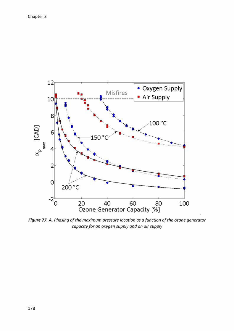
Chapter 3
178
.
Figure 77. A. Phasing of the maximum pressure location as a function of the ozone generator
capacity for an oxygen supply and an air supply
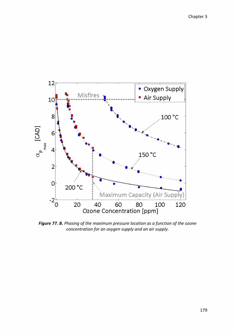
Chapter 3
179
Figure 77. B. Phasing of the maximum pressure location as a function of the ozone concentration for an oxygen supply and an air supply.
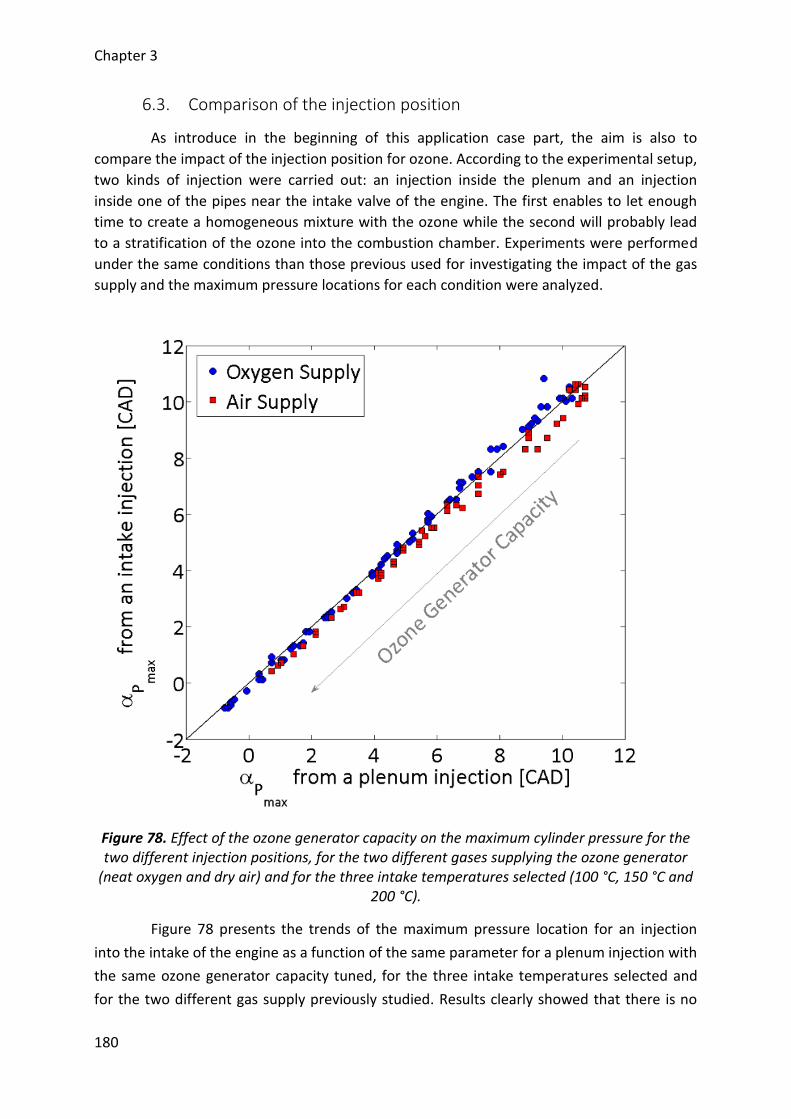
Chapter 3
180
6.3. Comparison of the injection position
As introduce in the beginning of this application case part, the aim is also to
compare the impact of the injection position for ozone. According to the experimental setup,
two kinds of injection were carried out: an injection inside the plenum and an injection
inside one of the pipes near the intake valve of the engine. The first enables to let enough
time to create a homogeneous mixture with the ozone while the second will probably lead
to a stratification of the ozone into the combustion chamber. Experiments were performed
under the same conditions than those previous used for investigating the impact of the gas
supply and the maximum pressure locations for each condition were analyzed.
Figure 78. Effect of the ozone generator capacity on the maximum cylinder pressure for the two different injection positions, for the two different gases supplying the ozone generator
(neat oxygen and dry air) and for the three intake temperatures selected (100 °C, 150 °C and 200 °C).
Figure 78 presents the trends of the maximum pressure location for an injection
into the intake of the engine as a function of the same parameter for a plenum injection with
the same ozone generator capacity tuned, for the three intake temperatures selected and
for the two different gas supply previously studied. Results clearly showed that there is no
Chapter 3
181
difference between the two injection positions and there is also no difference by changing
the gas supplying the ozone generator. The results mean that the ozone is efficiently mixed
with the air/fuel mixture inside the combustion chamber. As a consequence, these results
are particularly interesting for a future dynamic control of the HCCI combustion with such a
technique. Indeed, by injecting the ozone very near the intake valve of the engine, the
residence time between the ozone production and its injection inside the combustion
chamber is strongly reduced. Controlling cycle-to-cycle the HCCI combustion is therefore
possible.
6.4. Experimental results
Previous results showed that the HCCI combustion process of isooctane may be
controlled efficiently by using an ozone generator. Moreover, air may supply such a device
and leads to ozone concentrations without any nitrogen oxides and finally, the injection may
be performed near the intake valve of the engine to achieve a cycle-to-cycle control of the
combustion. Considering this injection position, the other engine outputs were analyzed for
both kind of gas supply chosen. The goal here is to go further in our investigations, as there
is no impact on the results in term of ozone concentrations by using either pure oxygen or
air. All these results are presented as a function of the maximum pressure location since
varying the ozone generator capacity may control this parameter.
6.4.1. Engine outputs
6.4.1.1. Combustion phasing
Combustion phasing is here represented from CA10, CA50 and CA90 determined
from the cumulative heat release rate traces. As a function of the maximum cylinder
pressure location (Figure 79), all the parameters showed a linear decrease with the increase
of the ozone generator capacity, especially for a maximum pressure crank angle located
between the top dead center and 10 CAD after this position. Beyond 10 CAD, the deviation
observed is related to the occurrence of misfires over the 100 cycles recorded, i.e. that some
cycles present a negative IMEP. Prior to the top dead center, the other deviation is related to
an advance of the auto-ignition of the isooctane while the maximum pressure location
cannot advance more due to the motion of the piston. Similar results were already observed
into the literature and it was assumed that this curve followed third order polynomial trends
[52]. Moreover, it can also be noted that there is no dependence to the intake temperatures
on the evolution of these combustion phasing as well as no effect of the gas supplying the
ozone generator. Finally, as the CA10 and CA90 evolve linearly with two different slopes, it
may conclude that the combustion duration also evolves linearly and it declines with the
increase of the ozone concentration injected.
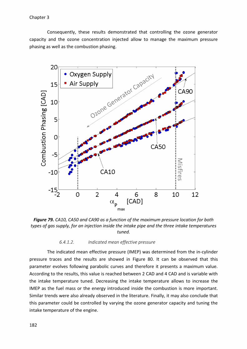
Chapter 3
182
Consequently, these results demonstrated that controlling the ozone generator
capacity and the ozone concentration injected allow to manage the maximum pressure
phasing as well as the combustion phasing.
Figure 79. CA10, CA50 and CA90 as a function of the maximum pressure location for both types of gas supply, for an injection inside the intake pipe and the three intake temperatures
tuned.
6.4.1.2. Indicated mean effective pressure
The indicated mean effective pressure (IMEP) was determined from the in-cylinder
pressure traces and the results are showed in Figure 80. It can be observed that this
parameter evolves following parabolic curves and therefore it presents a maximum value.
According to the results, this value is reached between 2 CAD and 4 CAD and is variable with
the intake temperature tuned. Decreasing the intake temperature allows to increase the
IMEP as the fuel mass or the energy introduced inside the combustion is more important.
Similar trends were also already observed in the literature. Finally, it may also conclude that
this parameter could be controlled by varying the ozone generator capacity and tuning the
intake temperature of the engine.
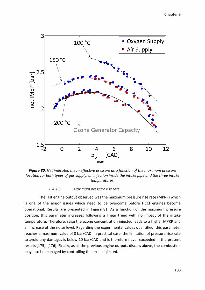
Chapter 3
183
Figure 80. Net indicated mean effective pressure as a function of the maximum pressure location for both types of gas supply, an injection inside the intake pipe and the three intake
temperatures.
6.4.1.3. Maximum pressure rise rate
The last engine output observed was the maximum pressure rise rate (MPRR) which
is one of the major issues which need to be overcome before HCCI engines become
operational. Results are presented in Figure 81. As a function of the maximum pressure
position, this parameter increases following a linear trend with no impact of the intake
temperature. Therefore, raise the ozone concentration injected leads to a higher MPRR and
an increase of the noise level. Regarding the experimental values quantified, this parameter
reaches a maximum value of 8 bar/CAD. In practical case, the limitation of pressure rise rate
to avoid any damages is below 10 bar/CAD and is therefore never exceeded in the present
results [175], [176]. Finally, as all the previous engine outputs discuss above, the combustion
may also be managed by controlling the ozone injected.
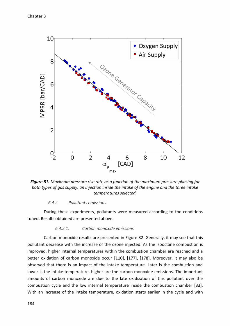
Chapter 3
184
Figure 81. Maximum pressure rise rate as a function of the maximum pressure phasing for both types of gas supply, an injection inside the intake of the engine and the three intake
temperatures selected.
6.4.2. Pollutants emissions
During these experiments, pollutants were measured according to the conditions
tuned. Results obtained are presented above.
6.4.2.1. Carbon monoxide emissions
Carbon monoxide results are presented in Figure 82. Generally, it may see that this
pollutant decrease with the increase of the ozone injected. As the isooctane combustion is
improved, higher internal temperatures within the combustion chamber are reached and a
better oxidation of carbon monoxide occur [110], [177], [178]. Moreover, it may also be
observed that there is an impact of the intake temperature. Later is the combustion and
lower is the intake temperature, higher are the carbon monoxide emissions. The important
amounts of carbon monoxide are due to the late oxidization of this pollutant over the
combustion cycle and the low internal temperature inside the combustion chamber [33].
With an increase of the intake temperature, oxidation starts earlier in the cycle and with
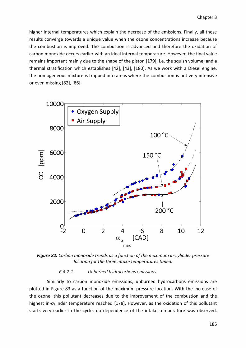
Chapter 3
185
higher internal temperatures which explain the decrease of the emissions. Finally, all these
results converge towards a unique value when the ozone concentrations increase because
the combustion is improved. The combustion is advanced and therefore the oxidation of
carbon monoxide occurs earlier with an ideal internal temperature. However, the final value
remains important mainly due to the shape of the piston [179], i.e. the squish volume, and a
thermal stratification which establishes [42], [43], [180]. As we work with a Diesel engine,
the homogeneous mixture is trapped into areas where the combustion is not very intensive
or even missing [82], [86].
Figure 82. Carbon monoxide trends as a function of the maximum in-cylinder pressure location for the three intake temperatures tuned.
6.4.2.2. Unburned hydrocarbons emissions
Similarly to carbon monoxide emissions, unburned hydrocarbons emissions are
plotted in Figure 83 as a function of the maximum pressure location. With the increase of
the ozone, this pollutant decreases due to the improvement of the combustion and the
highest in-cylinder temperature reached [178]. However, as the oxidation of this pollutant
starts very earlier in the cycle, no dependence of the intake temperature was observed.
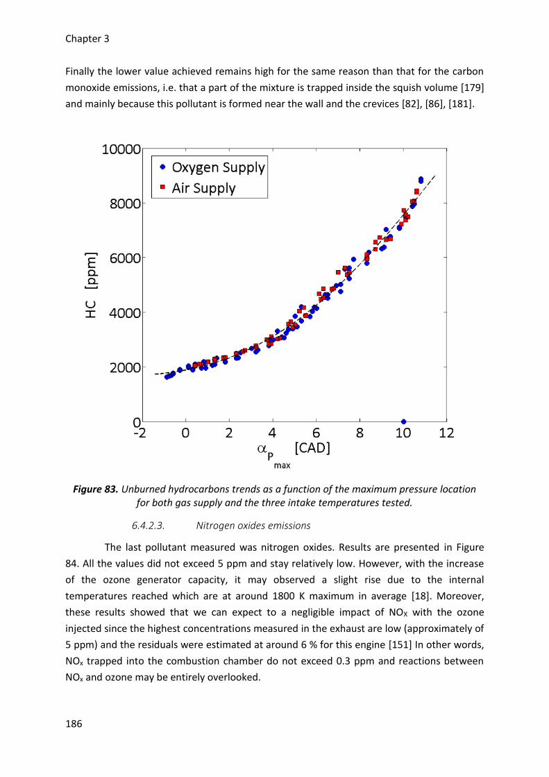
Chapter 3
186
Finally the lower value achieved remains high for the same reason than that for the carbon
monoxide emissions, i.e. that a part of the mixture is trapped inside the squish volume [179]
and mainly because this pollutant is formed near the wall and the crevices [82], [86], [181].
Figure 83. Unburned hydrocarbons trends as a function of the maximum pressure location for both gas supply and the three intake temperatures tested.
6.4.2.3. Nitrogen oxides emissions
The last pollutant measured was nitrogen oxides. Results are presented in Figure
84. All the values did not exceed 5 ppm and stay relatively low. However, with the increase
of the ozone generator capacity, it may observed a slight rise due to the internal
temperatures reached which are at around 1800 K maximum in average [18]. Moreover,
these results showed that we can expect to a negligible impact of NOX with the ozone
injected since the highest concentrations measured in the exhaust are low (approximately of
5 ppm) and the residuals were estimated at around 6 % for this engine [151] In other words,
NOx trapped into the combustion chamber do not exceed 0.3 ppm and reactions between
NOx and ozone may be entirely overlooked.
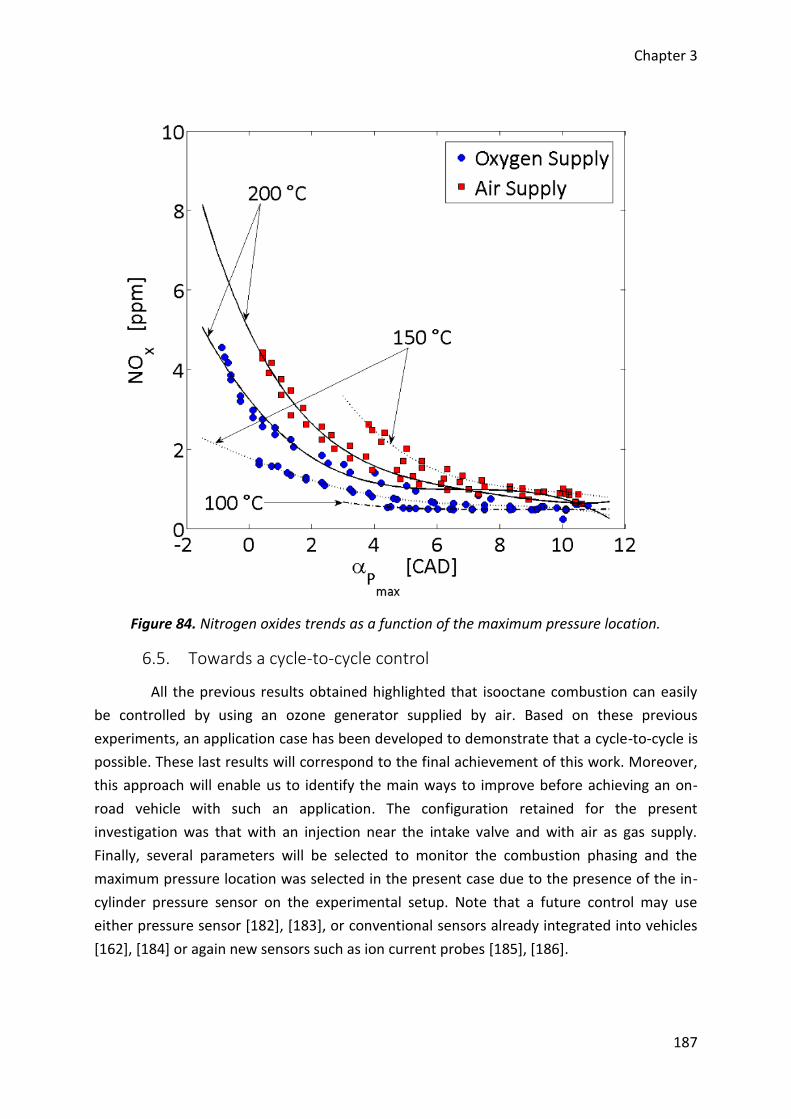
Chapter 3
187
Figure 84. Nitrogen oxides trends as a function of the maximum pressure location.
6.5. Towards a cycle-to-cycle control
All the previous results obtained highlighted that isooctane combustion can easily
be controlled by using an ozone generator supplied by air. Based on these previous
experiments, an application case has been developed to demonstrate that a cycle-to-cycle is
possible. These last results will correspond to the final achievement of this work. Moreover,
this approach will enable us to identify the main ways to improve before achieving an on-
road vehicle with such an application. The configuration retained for the present
investigation was that with an injection near the intake valve and with air as gas supply.
Finally, several parameters will be selected to monitor the combustion phasing and the
maximum pressure location was selected in the present case due to the presence of the in-
cylinder pressure sensor on the experimental setup. Note that a future control may use
either pressure sensor [182], [183], or conventional sensors already integrated into vehicles
[162], [184] or again new sensors such as ion current probes [185], [186].
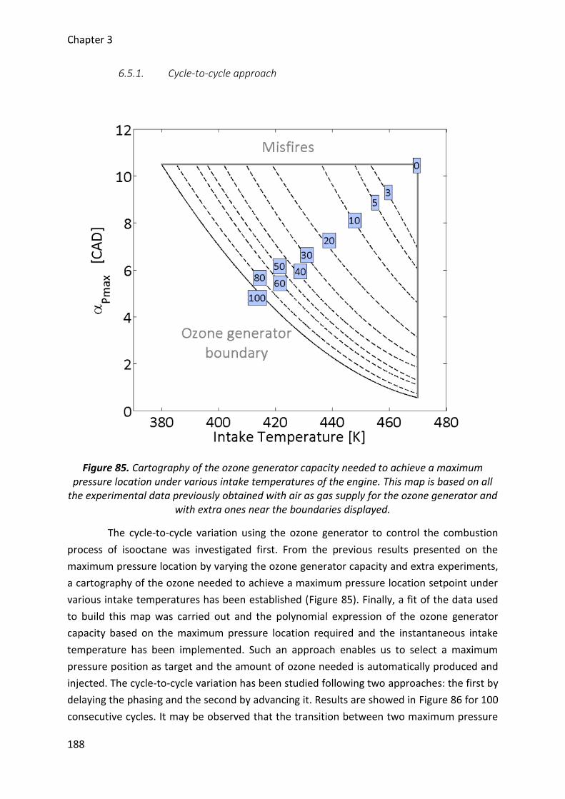
Chapter 3
188
6.5.1. Cycle-to-cycle approach
Figure 85. Cartography of the ozone generator capacity needed to achieve a maximum pressure location under various intake temperatures of the engine. This map is based on all
the experimental data previously obtained with air as gas supply for the ozone generator and with extra ones near the boundaries displayed.
The cycle-to-cycle variation using the ozone generator to control the combustion
process of isooctane was investigated first. From the previous results presented on the
maximum pressure location by varying the ozone generator capacity and extra experiments,
a cartography of the ozone needed to achieve a maximum pressure location setpoint under
various intake temperatures has been established (Figure 85). Finally, a fit of the data used
to build this map was carried out and the polynomial expression of the ozone generator
capacity based on the maximum pressure location required and the instantaneous intake
temperature has been implemented. Such an approach enables us to select a maximum
pressure position as target and the amount of ozone needed is automatically produced and
injected. The cycle-to-cycle variation has been studied following two approaches: the first by
delaying the phasing and the second by advancing it. Results are showed in Figure 86 for 100
consecutive cycles. It may be observed that the transition between two maximum pressure
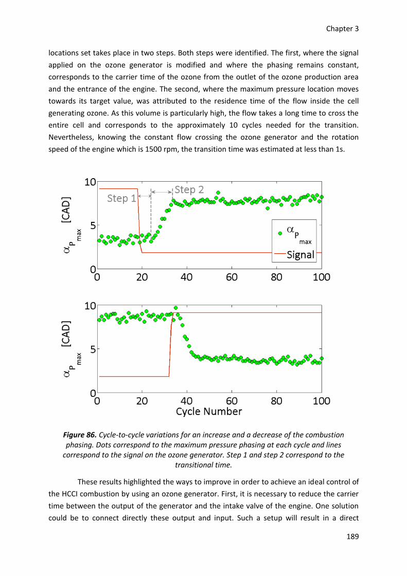
Chapter 3
189
locations set takes place in two steps. Both steps were identified. The first, where the signal
applied on the ozone generator is modified and where the phasing remains constant,
corresponds to the carrier time of the ozone from the outlet of the ozone production area
and the entrance of the engine. The second, where the maximum pressure location moves
towards its target value, was attributed to the residence time of the flow inside the cell
generating ozone. As this volume is particularly high, the flow takes a long time to cross the
entire cell and corresponds to the approximately 10 cycles needed for the transition.
Nevertheless, knowing the constant flow crossing the ozone generator and the rotation
speed of the engine which is 1500 rpm, the transition time was estimated at less than 1s.
Figure 86. Cycle-to-cycle variations for an increase and a decrease of the combustion phasing. Dots correspond to the maximum pressure phasing at each cycle and lines
correspond to the signal on the ozone generator. Step 1 and step 2 correspond to the transitional time.
These results highlighted the ways to improve in order to achieve an ideal control of
the HCCI combustion by using an ozone generator. First, it is necessary to reduce the carrier
time between the output of the generator and the intake valve of the engine. One solution
could be to connect directly these output and input. Such a setup will result in a direct
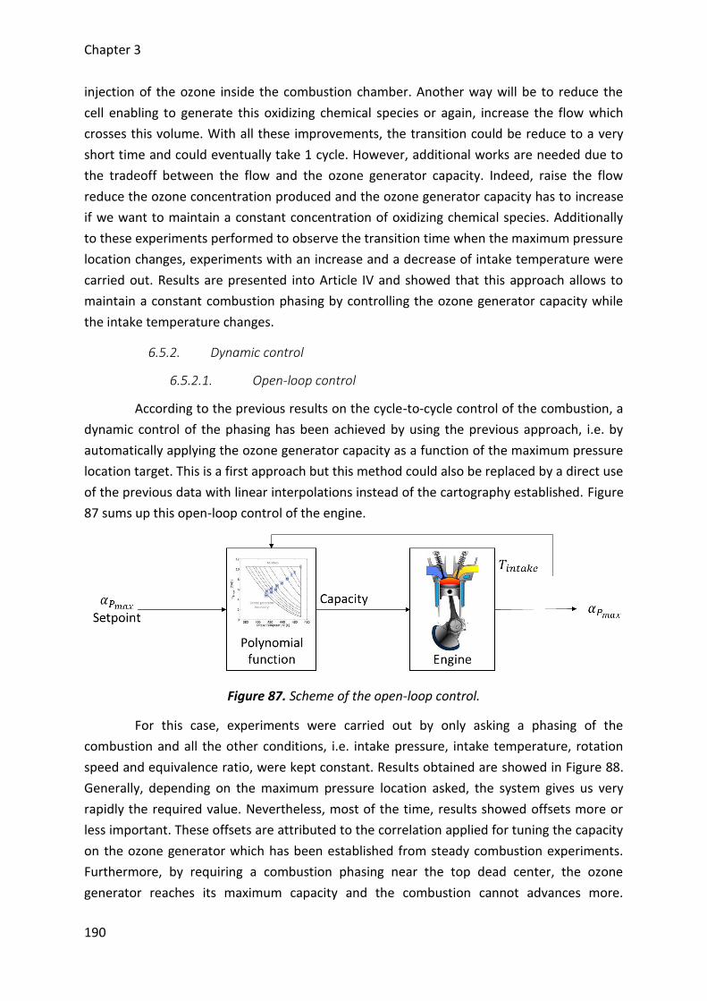
Chapter 3
190
injection of the ozone inside the combustion chamber. Another way will be to reduce the
cell enabling to generate this oxidizing chemical species or again, increase the flow which
crosses this volume. With all these improvements, the transition could be reduce to a very
short time and could eventually take 1 cycle. However, additional works are needed due to
the tradeoff between the flow and the ozone generator capacity. Indeed, raise the flow
reduce the ozone concentration produced and the ozone generator capacity has to increase
if we want to maintain a constant concentration of oxidizing chemical species. Additionally
to these experiments performed to observe the transition time when the maximum pressure
location changes, experiments with an increase and a decrease of intake temperature were
carried out. Results are presented into Article IV and showed that this approach allows to
maintain a constant combustion phasing by controlling the ozone generator capacity while
the intake temperature changes.
6.5.2. Dynamic control
6.5.2.1. Open-loop control
According to the previous results on the cycle-to-cycle control of the combustion, a
dynamic control of the phasing has been achieved by using the previous approach, i.e. by
automatically applying the ozone generator capacity as a function of the maximum pressure
location target. This is a first approach but this method could also be replaced by a direct use
of the previous data with linear interpolations instead of the cartography established. Figure
87 sums up this open-loop control of the engine.
Figure 87. Scheme of the open-loop control.
For this case, experiments were carried out by only asking a phasing of the
combustion and all the other conditions, i.e. intake pressure, intake temperature, rotation
speed and equivalence ratio, were kept constant. Results obtained are showed in Figure 88.
Generally, depending on the maximum pressure location asked, the system gives us very
rapidly the required value. Nevertheless, most of the time, results showed offsets more or
less important. These offsets are attributed to the correlation applied for tuning the capacity
on the ozone generator which has been established from steady combustion experiments.
Furthermore, by requiring a combustion phasing near the top dead center, the ozone
generator reaches its maximum capacity and the combustion cannot advances more.
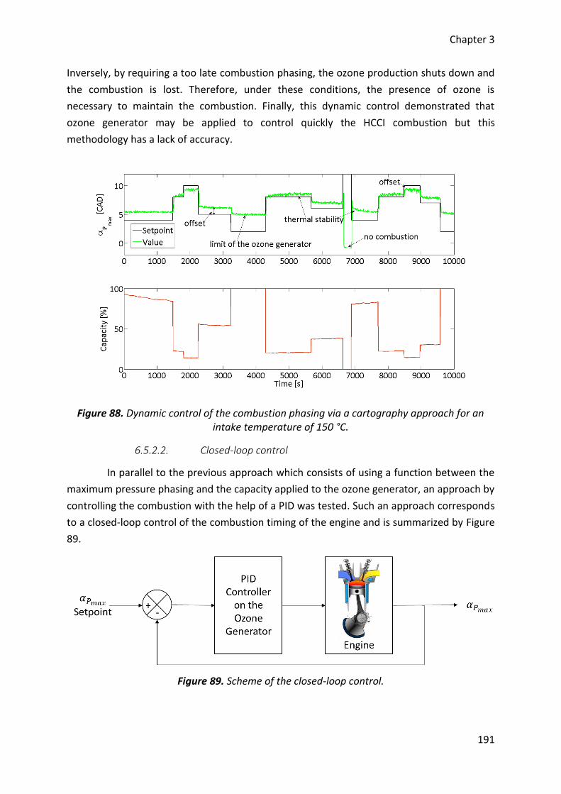
Chapter 3
191
Inversely, by requiring a too late combustion phasing, the ozone production shuts down and
the combustion is lost. Therefore, under these conditions, the presence of ozone is
necessary to maintain the combustion. Finally, this dynamic control demonstrated that
ozone generator may be applied to control quickly the HCCI combustion but this
methodology has a lack of accuracy.
Figure 88. Dynamic control of the combustion phasing via a cartography approach for an intake temperature of 150 °C.
6.5.2.2. Closed-loop control
In parallel to the previous approach which consists of using a function between the
maximum pressure phasing and the capacity applied to the ozone generator, an approach by
controlling the combustion with the help of a PID was tested. Such an approach corresponds
to a closed-loop control of the combustion timing of the engine and is summarized by Figure
89.
Figure 89. Scheme of the closed-loop control.
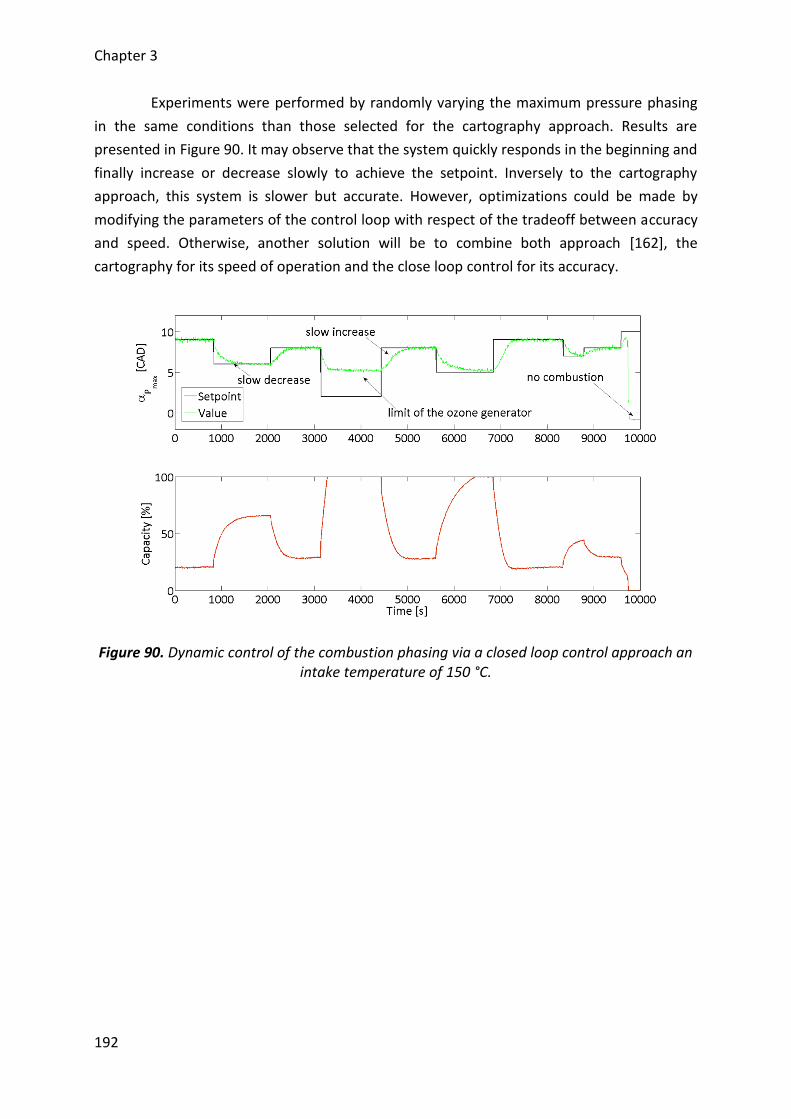
Chapter 3
192
Experiments were performed by randomly varying the maximum pressure phasing
in the same conditions than those selected for the cartography approach. Results are
presented in Figure 90. It may observe that the system quickly responds in the beginning and
finally increase or decrease slowly to achieve the setpoint. Inversely to the cartography
approach, this system is slower but accurate. However, optimizations could be made by
modifying the parameters of the control loop with respect of the tradeoff between accuracy
and speed. Otherwise, another solution will be to combine both approach [162], the
cartography for its speed of operation and the close loop control for its accuracy.
Figure 90. Dynamic control of the combustion phasing via a closed loop control approach an intake temperature of 150 °C.
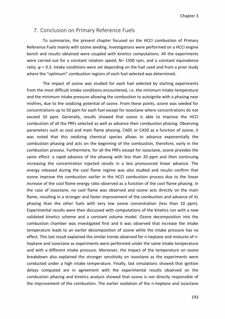
Chapter 3
193
7. Conclusion on Primary Reference Fuels
To summarize, the present chapter focused on the HCCI combustion of Primary
Reference Fuels mainly with ozone seeding. Investigations were performed on a HCCI engine
bench and results obtained were coupled with kinetics computations. All the experiments
were carried out for a constant rotation speed, N= 1500 rpm, and a constant equivalence
ratio, ϕ = 0.3. Intake conditions were set depending on the fuel used and from a prior study
where the “optimum” combustion regions of each fuel selected was determined.
The impact of ozone was studied for each fuel selected by starting experiments
from the most difficult intake conditions encountered, i.e. the minimum intake temperature
and the minimum intake pressure allowing the combustion to autoignite with a phasing near
misfires, due to the oxidizing potential of ozone. From these points, ozone was seeded for
concentrations up to 50 ppm for each fuel except for isooctane where concentrations do not
exceed 10 ppm. Generally, results showed that ozone is able to improve the HCCI
combustion of all the PRFs selected as well as advance their combustion phasing. Observing
parameters such as cool and main flame phasing, CA05 or CA50 as a function of ozone, it
was noted that this oxidizing chemical species allows to advance exponentially the
combustion phasing and acts on the beginning of the combustion, therefore, early in the
combustion process. Furthermore, for all the PRFs except for isooctane, ozone provides the
same effect: a rapid advance of the phasing with less than 20 ppm and then continuing
increasing the concentration injected results in a less pronounced linear advance. The
energy released during the cool flame regime was also studied and results confirm that
ozone improve the combustion earlier in the HCCI combustion process due to the linear
increase of the cool flame energy ratio observed as a function of the cool flame phasing. In
the case of isooctane, no cool flame was observed and ozone acts directly on the main
flame, resulting in a stronger and faster improvement of the combustion and advance of its
phasing than the other fuels with very low ozone concentration (less than 10 ppm).
Experimental results were then discussed with computations of the kinetics run with a new
validated kinetics scheme and a constant volume model. Ozone decomposition into the
combustion chamber was investigated first and it was observed that increase the intake
temperature leads to an earlier decomposition of ozone while the intake pressure has no
effect. This last result explained the similar trends observed for n-heptane and mixtures of n-
heptane and isooctane as experiments were performed under the same intake temperature
and with a different intake pressure. Moreover, the impact of the temperature on ozone
breakdown also explained the stronger sensitivity on isooctane as the experiments were
conducted under a high intake temperature. Finally, last simulations showed that ignition
delays computed are in agreement with the experimental results observed on the
combustion phasing and kinetics analysis showed that ozone is not directly responsible of
the improvement of the combustion. The earlier oxidation of the n-heptane and isooctane
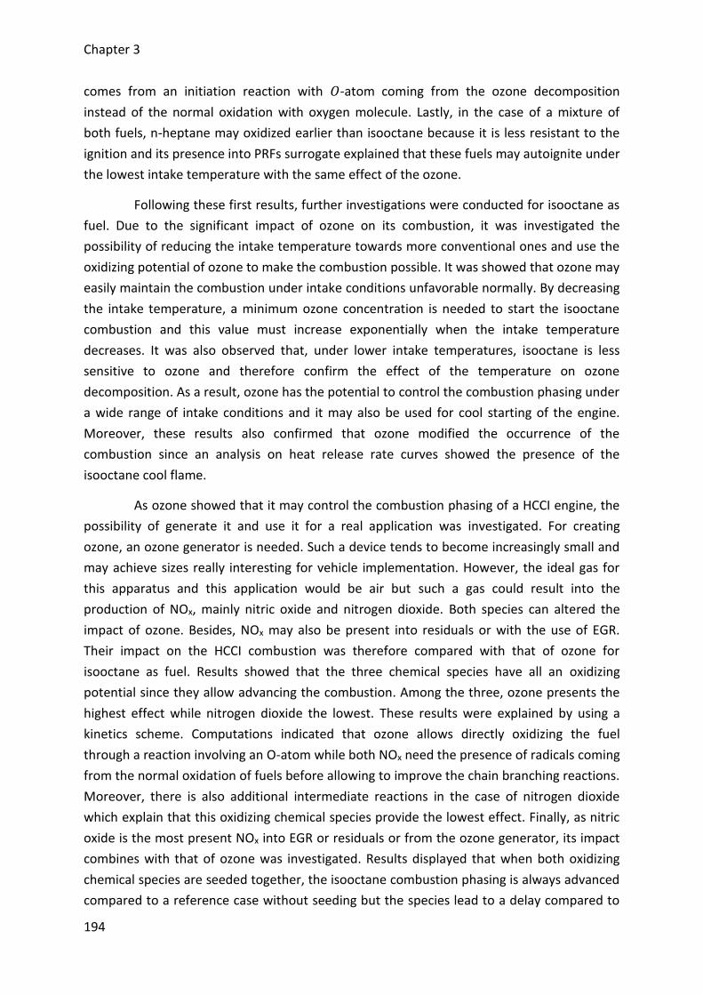
Chapter 3
194
comes from an initiation reaction with 𝑂-atom coming from the ozone decomposition
instead of the normal oxidation with oxygen molecule. Lastly, in the case of a mixture of
both fuels, n-heptane may oxidized earlier than isooctane because it is less resistant to the
ignition and its presence into PRFs surrogate explained that these fuels may autoignite under
the lowest intake temperature with the same effect of the ozone.
Following these first results, further investigations were conducted for isooctane as
fuel. Due to the significant impact of ozone on its combustion, it was investigated the
possibility of reducing the intake temperature towards more conventional ones and use the
oxidizing potential of ozone to make the combustion possible. It was showed that ozone may
easily maintain the combustion under intake conditions unfavorable normally. By decreasing
the intake temperature, a minimum ozone concentration is needed to start the isooctane
combustion and this value must increase exponentially when the intake temperature
decreases. It was also observed that, under lower intake temperatures, isooctane is less
sensitive to ozone and therefore confirm the effect of the temperature on ozone
decomposition. As a result, ozone has the potential to control the combustion phasing under
a wide range of intake conditions and it may also be used for cool starting of the engine.
Moreover, these results also confirmed that ozone modified the occurrence of the
combustion since an analysis on heat release rate curves showed the presence of the
isooctane cool flame.
As ozone showed that it may control the combustion phasing of a HCCI engine, the
possibility of generate it and use it for a real application was investigated. For creating
ozone, an ozone generator is needed. Such a device tends to become increasingly small and
may achieve sizes really interesting for vehicle implementation. However, the ideal gas for
this apparatus and this application would be air but such a gas could result into the
production of NOx, mainly nitric oxide and nitrogen dioxide. Both species can altered the
impact of ozone. Besides, NOx may also be present into residuals or with the use of EGR.
Their impact on the HCCI combustion was therefore compared with that of ozone for
isooctane as fuel. Results showed that the three chemical species have all an oxidizing
potential since they allow advancing the combustion. Among the three, ozone presents the
highest effect while nitrogen dioxide the lowest. These results were explained by using a
kinetics scheme. Computations indicated that ozone allows directly oxidizing the fuel
through a reaction involving an O-atom while both NOx need the presence of radicals coming
from the normal oxidation of fuels before allowing to improve the chain branching reactions.
Moreover, there is also additional intermediate reactions in the case of nitrogen dioxide
which explain that this oxidizing chemical species provide the lowest effect. Finally, as nitric
oxide is the most present NOx into EGR or residuals or from the ozone generator, its impact
combines with that of ozone was investigated. Results displayed that when both oxidizing
chemical species are seeded together, the isooctane combustion phasing is always advanced
compared to a reference case without seeding but the species lead to a delay compared to
Chapter 3
195
the case when they are injected separately. The delay occurs due to a significant reaction
involving both ozone and nitric oxide in front of the combustion chamber. This reaction leads
to nitrogen dioxide species which in turn advance the combustion but has less effect on the
combustion phasing than both others.
Finally, a real application case was considered using an ozone generator supplied
with air. Prior experiments consisted of measuring the concentration of ozone at the
entrance of the engine and showed that such a device may achieve suitable levels of ozone
for applications. Furthermore, NOx concentrations were also quantified and the level
remained negligible. However, it is important to note that the ozone generator used is a
commercial one configured to produce only ozone. There is not ozone generator developed
for automotive application from now and the interaction between ozone and NOx should be
considered for implementing such device into a vehicle. New experiments similar to those
previously performed were then carried out and indicated that such a device can be used to
control the combustion phasing as well as other engine outputs and levels of pollutants.
Moreover, based on the results obtained, a dynamic control was developed through an
open-loop control approach and through a closed-loop control approach. The first allows a
rapid control but with a lack of accuracy while the second presents the inverse and finally,
the improvements which can lead to an on-board application of such device were identified.
From now, the investigation focused only on PRFs but HCCI engines may consider
the use of other fuels. The impact of ozone was therefore investigated on alternative fuels
for automotive and results are presented in the next chapters.

Chapitre 4 / Chapter 4
Résultats sur la combustion de
carburants gazeux
Results on the combustion of
gaseous fuels
Chapter 4
198
Résumé
Ce quatrième chapitre est ciblé sur la combustion des carburants gazeux. Suite aux
précédents résultats obtenus sur la combustion des PRFs, une approche scientifique
similaire a été mise en place et consiste à étudier l’impact de l’ozone sur ces autres
carburants, en particulier sur des carburants relativement proches du gaz naturel. Les
résultats présentés font référence à un travail publié :
□ Article V : J-B. Masurier, F. Foucher, G. Dayma, P. Dagaut, Effect of Additives on
Combustion Characteristics of a Natural Gas Fueled HCCI Engine, SAE Technical Paper
2014-01-2662, 2014.
Les carburants gazeux sélectionnés pour cette étude ont été le méthane, le propane
et l’hydrogène. Grâce à son potentiel oxydant, l’ozone a démontré une aptitude à
autoinflammer l’isooctane alors que les conditions appliquées au moteur ne l’auraient pas
permis en temps normal. Le méthane a donc été sélectionné en raison de sa très forte
résistance à l’autoinflammation et dans le but de voir si cette espèce chimique sera capable
d’améliorer la combustion de ce carburant. Le propane a quant à lui été retenu en raison de
ses propriétés d’auto-inflammation relativement proches de celles de l’isooctane. Enfin,
l’hydrogène est lui aussi un carburant difficile à autoinflammer et est considéré comme un
carburant n’émettant pas de CO2.
De manière analogue à l’étude menée sur les PRFs, des essais expérimentaux sans
ensemencement ont été effectués. Les résultats ont montré que le propane présente des
tendances similaires à celles de l’isooctane. Dans le cas de l’hydrogène, ses propriétés le
décrivent comme étant difficile à autoinflammer mais en réalité, dans le cadre de sa
combustion en moteur HCCI, ce gaz peut s’autoinflammer bien plus facilement que
l’isooctane. Finalement, des essais ont aussi été tentés jusqu’aux limites des conditions
d’admission du moteur avec le méthane mais malheureusement, ce carburant nécessite des
conditions encore bien plus importantes. Compte tenu de l’absence de combustion dans le
cas du méthane, une injection d’ozone a été effectuée afin de réduire sa résistance à
l’autoinflammation. Cependant, malgré la présence d’une quantité significative de cette
espèce oxydante, la combustion du méthane reste inexistante. En conséquence et en
considérant que le méthane n’est jamais employé pur, l’étude s’est finalement portée sur
des mélanges essentiellement composés de méthane avec propane ou hydrogène.
D’une manière générale, les résultats ont montré des tendances similaires à celles
déjà obtenues lors de la combustion des PRFs : une amélioration de la combustion avec une
avance de son phasage. Dans le cadre des expériences menées avec un mélange méthane-
propane, les résultats ont montré qu’il est bien possible de réduire les conditions de
pression et de température à l’admission du moteur tout en maintenant le contrôle de la
Chapter 4
199
combustion par l’ozone. Ainsi, il est possible de contrôler les paramètres du moteur tel que
la pression moyenne indiquée, le niveau de bruit ou encore le déroulement de la
combustion. De plus, les niveaux de polluants ont aussi été évalués et leurs tendances ont
confirmé une amélioration de la combustion. Toutefois, en raison des fortes conditions
d’admission, d’importants niveaux de NOx ont été relevés. Dans le cas des expériences avec
les mélanges méthane-hydrogène, la variation des fractions volumiques de chaque
carburant a démontré des résultats similaires à ceux obtenus en dégradant les conditions
d’admission du moteur. Ainsi, l’ozone a donc le potentiel de maintenir le contrôle d’un
carburant malgré des conditions d’admission non favorables à son autoinflammation en
l’absence de cette espèce chimique oxydante. De plus, il donne aussi la possibilité d’adapter
le carburant, d’utiliser des mélanges avec des fractions volumiques variables, en fonction de
l’objectif à atteindre sur le moteur. Finalement, ces expériences ont été couplées avec des
simulations de cinétique chimique où l’impact de l’ozone sur chaque carburant pure a été
analysé. Les résultats ont indiqué que ces carburants sont oxydés d’une manière identique à
celle observé pour les PRFs.
Chapter 4
200
Abstract
The fourth chapter is centering on the combustion of gaseous fuels. Following the
previous results obtained on the combustion of PRFs, a similar scientific approach was made
and consists in studying the impact of ozone on these fuels, in particular on fuels closed to
the natural gas. Results introduced refer to the following article:
□ Article V: J-B. Masurier, F. Foucher, G. Dayma, P. Dagaut, Effect of Additives on
Combustion Characteristics of a Natural Gas Fueled HCCI Engine, SAE Technical Paper
2014-01-2662, 2014.
Gaseous fuels selected for this study was methane, propane and hydrogen. Thanks
to its oxidizing potential, ozone showed it was able to autoignite isooctane while the
conditions applied to the engine do not enable normally. Methane was therefore selected
due to its high resistance to the autoignition and in the aim to see if ozone will be able to
improve the combustion of this fuel with its promoting effect. Propane was selected due to
its autoignition properties closed to those of isooctane. Finally, hydrogen is also a fuel
difficult to autoignite and is considered as a clean fuel.
Similarly to the study conducted on PRFs, experiments without seeding were
performed. Results showed that propane has trends similar to those of isooctane. In the case
of hydrogen, its properties described it as a fuel difficult to autoignite, but in the case of
HCCI combustion, this gas may autoignite more easily than isooctane. Finally, experiments
were carried out up to the limits of the intake conditions of the engine with methane as fuel
but unfortunately, this fuel needs more important intake conditions. As there is no
combustion for methane, an ozone injection was performed to reduce its resistance to the
autoignition. However, despite the significant amount of this oxidizing species, methane
combustion does not exist. Consequently and by considering that methane is never used
pure, the study was made on fuel blends with high ratios of methane and complemented
with propane or hydrogen.
Generally, results showed similar trends than those obtained for the combustion of
PRFs: an improvement of the combustion coupled to an advance of its phasing. For
experiments performed with methane/propane as fuel, results showed that it was possible
to reduce either the intake pressure or the intake temperature or these two parameters
while keeping the control of the combustion by using ozone. As a result, it is possible to
control engine outputs such the indicated mean effective pressure, the noise level or again
the combustion process. Moreover, pollutants were also measured and their trends
confirmed the improvement of the combustion. However, due to the too high intake
conditions, significant levels of NOx were measured. In the case of methane/hydrogen as
fuel, ranging the ratios of each fuel showed similar results than those obtained by reducing

Chapter 4
201
the intake conditions of the engine. Ozone has therefore the potential to maintain the
control of a fuel despite unfavorable intake conditions for the autoignition when ozone is
missing. Moreover, it gives also the possibility to adapt the fuel, to use blends with variable
ratios, as a function of the aim to achieve on the engine. Finally, experiments were coupled
with computations of kinetics where the impact of ozone for each fuel used pure was
analyzed. Results indicated that fuels are oxidized similarly to PRFs.
Chapter 4
202
1. Introduction on gaseous fuels (Article V)
Previous chapter discussed about the impact of using ozone generators to control
the combustion of primary reference fuels. In particular, a wide part was focused on the
impact of the oxidizing chemical species generated by such devices on the combustion of
isooctane. Last results showed that the ozone generator used produces only ozone and
achieving a dynamic control is possible with an ozone generator. Considering these prior
results and the possibility that HCCI engines and future advanced combustion engines can
use other fuels than the conventional ones, the impact of ozone has been investigated on
alternative fuels such as gaseous fuels. This study was also reinforced by the fact that ozone
may auto-ignite fuels under unfavorable conditions. Therefore, as gaseous fuels are often
more resistant to the self-ignition than isooctane, the use of ozone could help to achieve the
combustion of such fuels.
The aim of the present part is to investigate the effect of ozone on gaseous fuels.
Fuels retained were methane because it is the most difficult fuel to auto-ignite, propane due
to its properties similar to those of isooctane and hydrogen due to its ability to be a clean
fuel and normally also difficult to auto-ignite.
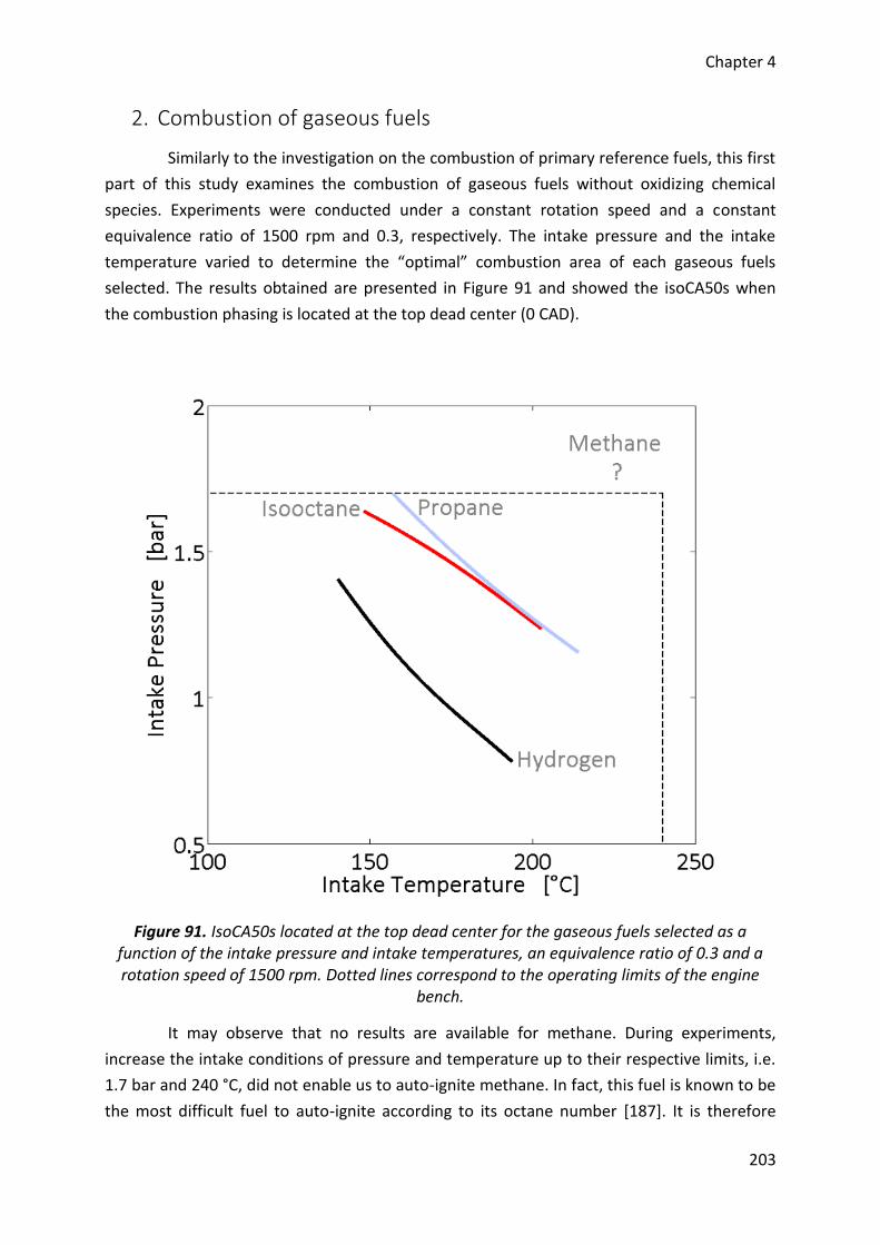
Chapter 4
203
2. Combustion of gaseous fuels
Similarly to the investigation on the combustion of primary reference fuels, this first
part of this study examines the combustion of gaseous fuels without oxidizing chemical
species. Experiments were conducted under a constant rotation speed and a constant
equivalence ratio of 1500 rpm and 0.3, respectively. The intake pressure and the intake
temperature varied to determine the “optimal” combustion area of each gaseous fuels
selected. The results obtained are presented in Figure 91 and showed the isoCA50s when
the combustion phasing is located at the top dead center (0 CAD).
Figure 91. IsoCA50s located at the top dead center for the gaseous fuels selected as a function of the intake pressure and intake temperatures, an equivalence ratio of 0.3 and a rotation speed of 1500 rpm. Dotted lines correspond to the operating limits of the engine
bench.
It may observe that no results are available for methane. During experiments,
increase the intake conditions of pressure and temperature up to their respective limits, i.e.
1.7 bar and 240 °C, did not enable us to auto-ignite methane. In fact, this fuel is known to be
the most difficult fuel to auto-ignite according to its octane number [187]. It is therefore
Chapter 4
204
normal that no combustion appears. Propane has an octane number similar to that of
isooctane and is mainly assimilated to this PRF but under gaseous phase. Regarding the
results, it may observe that the isoCA50 for propane is really closed to that of isooctane.
Finally, the last gaseous fuel selected, hydrogen, presents an octane number higher than
100. Therefore, from the results on the same diagram observed for PRFs and from the other
gaseous fuels tested, hydrogen must present an isoCA50 line upper than that of isooctane.
Unfortunately, results obtained showed that the isoCA50 line for hydrogen is lower than one
for isooctane by the fact that hydrogen is more reactive than other gaseous fuels tested.
Indeed, RON and MON are mainly defined for spark ignition engines [188], [189] and studies
showed that the burning velocities of this fuel are very significant [190], resulting in high
indexes. For HCCI combustion, there is no flame velocity, instead, the kinetics allows a quite
homogeneous mixture and as a consequence, octane number is not the only parameter to
consider to conclude on the combustion of fuels into HCCI engines [46], [47], [70].
According to previous results on isooctane combustion under HCCI conditions
assisted by ozone injections, it was observed that the presence of ozone may help to auto-
ignite fuels under conditions where the combustion does not exist. It was therefore decided
to focus on the possibility of using ozone to enable the HCCI combustion of methane.
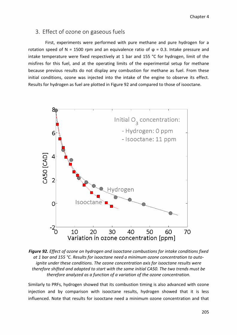
Chapter 4
205
3. Effect of ozone on gaseous fuels
First, experiments were performed with pure methane and pure hydrogen for a
rotation speed of N = 1500 rpm and an equivalence ratio of ϕ = 0.3. Intake pressure and
intake temperature were fixed respectively at 1 bar and 155 °C for hydrogen, limit of the
misfires for this fuel, and at the operating limits of the experimental setup for methane
because previous results do not display any combustion for methane as fuel. From these
initial conditions, ozone was injected into the intake of the engine to observe its effect.
Results for hydrogen as fuel are plotted in Figure 92 and compared to those of isooctane.
Figure 92. Effect of ozone on hydrogen and isooctane combustions for intake conditions fixed at 1 bar and 155 °C. Results for isooctane need a minimum ozone concentration to auto-
ignite under these conditions. The ozone concentration axis for isooctane results were therefore shifted and adapted to start with the same initial CA50. The two trends must be
therefore analyzed as a function of a variation of the ozone concentration.
Similarly to PRFs, hydrogen showed that its combustion timing is also advanced with ozone
injection and by comparison with isooctane results, hydrogen showed that it is less
influenced. Note that results for isooctane need a minimum ozone concentration and that
Chapter 4
206
these results were shifted. Its trend is therefore displayed according to a variation of the
ozone added. The highest impact on isooctane comes from its chemical structure which
enables an easier oxidation by oxygen atom resulting from the breakdown of ozone. This
result means that the chemical structure of the fuel is of main importance for applying ozone
and observing a significant impact.
For methane, the initial conditions do not permit the autoignition of this fuel but
previous results on PRFs and in particular on isooctane combustion showed that the fuel
oxidation may occur under lower temperatures than those necessary by seeding ozone into
the intake of the engine. Ozone was therefore directly applied under these conditions and
unfortunately, no results were available, even by pushing the ozone generator to its
maximum capacity. The main issue comes from the ozone seeding which was limited to a
very low concentration while previous results in the literature showed that at least 600 ppm
of ozone is needed to initiate natural gas combustion [12]. Moreover, experiments were also
performed by increasing the equivalence ratio but here again, no combustion occurs.
Referring to practical case using methane, this fuel is always blended with other compounds.
For instance, natural gas is mainly composed of methane but depending of its source in the
world, it is mixed with other small fuel fractions of ethane, propane or again butane [191].
Another example is hythane which is referred as a blend of 80 % of natural gas with 20 % of
hydrogen [192]. Finally, there is also biogas which mainly consists of methane and carbon
dioxide [193], [194]. Therefore, the present investigation on the impact of ozone did not
consider pure methane as fuel but blends of methane with propane and methane with
hydrogen.
3.1. Combustion of methane/propane surrogate
Combustion of a mixture of methane and propane in the volume fraction of 95 %
and 5 %, respectively, was investigated first. These respective amounts of fuels were
selected to be representative of a synthetic natural gas. The study was conducted with
combustion experiments on the engine bench and then, with computations using a detailed
kinetics scheme.
3.1.1. Experimental results
Experiments were performed on the engine bench for a fixed mixture of methane
and propane with an equivalence ratio remained constant at ϕ = 0.4 and a constant rotation
speed of N = 1500 rpm. The impact of ozone on such a fuel is first studied under constant
intake conditions and then by separately varying the intake pressure and the intake
temperature.
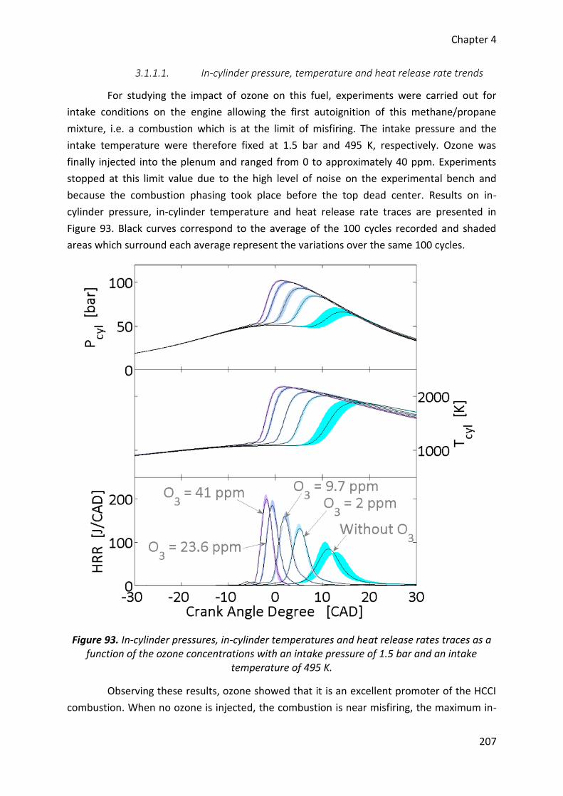
Chapter 4
207
3.1.1.1. In-cylinder pressure, temperature and heat release rate trends
For studying the impact of ozone on this fuel, experiments were carried out for
intake conditions on the engine allowing the first autoignition of this methane/propane
mixture, i.e. a combustion which is at the limit of misfiring. The intake pressure and the
intake temperature were therefore fixed at 1.5 bar and 495 K, respectively. Ozone was
finally injected into the plenum and ranged from 0 to approximately 40 ppm. Experiments
stopped at this limit value due to the high level of noise on the experimental bench and
because the combustion phasing took place before the top dead center. Results on in-
cylinder pressure, in-cylinder temperature and heat release rate traces are presented in
Figure 93. Black curves correspond to the average of the 100 cycles recorded and shaded
areas which surround each average represent the variations over the same 100 cycles.
Figure 93. In-cylinder pressures, in-cylinder temperatures and heat release rates traces as a function of the ozone concentrations with an intake pressure of 1.5 bar and an intake
temperature of 495 K.
Observing these results, ozone showed that it is an excellent promoter of the HCCI
combustion. When no ozone is injected, the combustion is near misfiring, the maximum in-
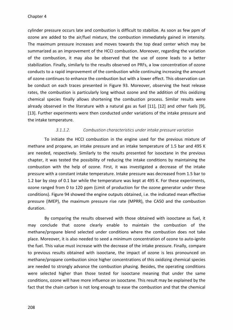
Chapter 4
208
cylinder pressure occurs late and combustion is difficult to stabilize. As soon as few ppm of
ozone are added to the air/fuel mixture, the combustion immediately gained in intensity.
The maximum pressure increases and moves towards the top dead center which may be
summarized as an improvement of the HCCI combustion. Moreover, regarding the variation
of the combustion, it may also be observed that the use of ozone leads to a better
stabilization. Finally, similarly to the results observed on PRFs, a low concentration of ozone
conducts to a rapid improvement of the combustion while continuing increasing the amount
of ozone continues to enhance the combustion but with a lower effect. This observation can
be conduct on each traces presented in Figure 93. Moreover, observing the heat release
rates, the combustion is particularly long without ozone and the addition of this oxidizing
chemical species finally allows shortening the combustion process. Similar results were
already observed in the literature with a natural gas as fuel [11], [12] and other fuels [9],
[13]. Further experiments were then conducted under variations of the intake pressure and
the intake temperature.
3.1.1.2. Combustion characteristics under intake pressure variation
To initiate the HCCI combustion in the engine used for the previous mixture of
methane and propane, an intake pressure and an intake temperature of 1.5 bar and 495 K
are needed, respectively. Similarly to the results presented for isooctane in the previous
chapter, it was tested the possibility of reducing the intake conditions by maintaining the
combustion with the help of ozone. First, it was investigated a decrease of the intake
pressure with a constant intake temperature. Intake pressure was decreased from 1.5 bar to
1.2 bar by step of 0.1 bar while the temperature was kept at 495 K. For these experiments,
ozone ranged from 0 to 120 ppm (Limit of production for the ozone generator under these
conditions). Figure 94 showed the engine outputs obtained, i.e. the indicated mean effective
pressure (IMEP), the maximum pressure rise rate (MPRR), the CA50 and the combustion
duration.
By comparing the results observed with those obtained with isooctane as fuel, it
may conclude that ozone clearly enable to maintain the combustion of the
methane/propane blend selected under conditions where the combustion does not take
place. Moreover, it is also needed to seed a minimum concentration of ozone to auto-ignite
the fuel. This value must increase with the decrease of the intake pressure. Finally, compare
to previous results obtained with isooctane, the impact of ozone is less pronounced on
methane/propane combustion since higher concentrations of this oxidizing chemical species
are needed to strongly advance the combustion phasing. Besides, the operating conditions
were selected higher than those tested for isooctane meaning that under the same
conditions, ozone will have more influence on isooctane. This result may be explained by the
fact that the chain carbon is not long enough to ease the combustion and that the chemical
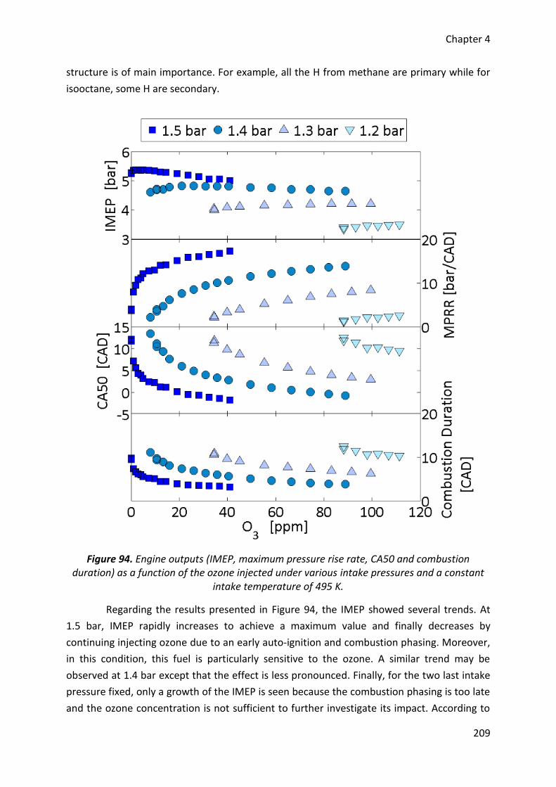
Chapter 4
209
structure is of main importance. For example, all the H from methane are primary while for
isooctane, some H are secondary.
Figure 94. Engine outputs (IMEP, maximum pressure rise rate, CA50 and combustion duration) as a function of the ozone injected under various intake pressures and a constant
intake temperature of 495 K.
Regarding the results presented in Figure 94, the IMEP showed several trends. At
1.5 bar, IMEP rapidly increases to achieve a maximum value and finally decreases by
continuing injecting ozone due to an early auto-ignition and combustion phasing. Moreover,
in this condition, this fuel is particularly sensitive to the ozone. A similar trend may be
observed at 1.4 bar except that the effect is less pronounced. Finally, for the two last intake
pressure fixed, only a growth of the IMEP is seen because the combustion phasing is too late
and the ozone concentration is not sufficient to further investigate its impact. According to
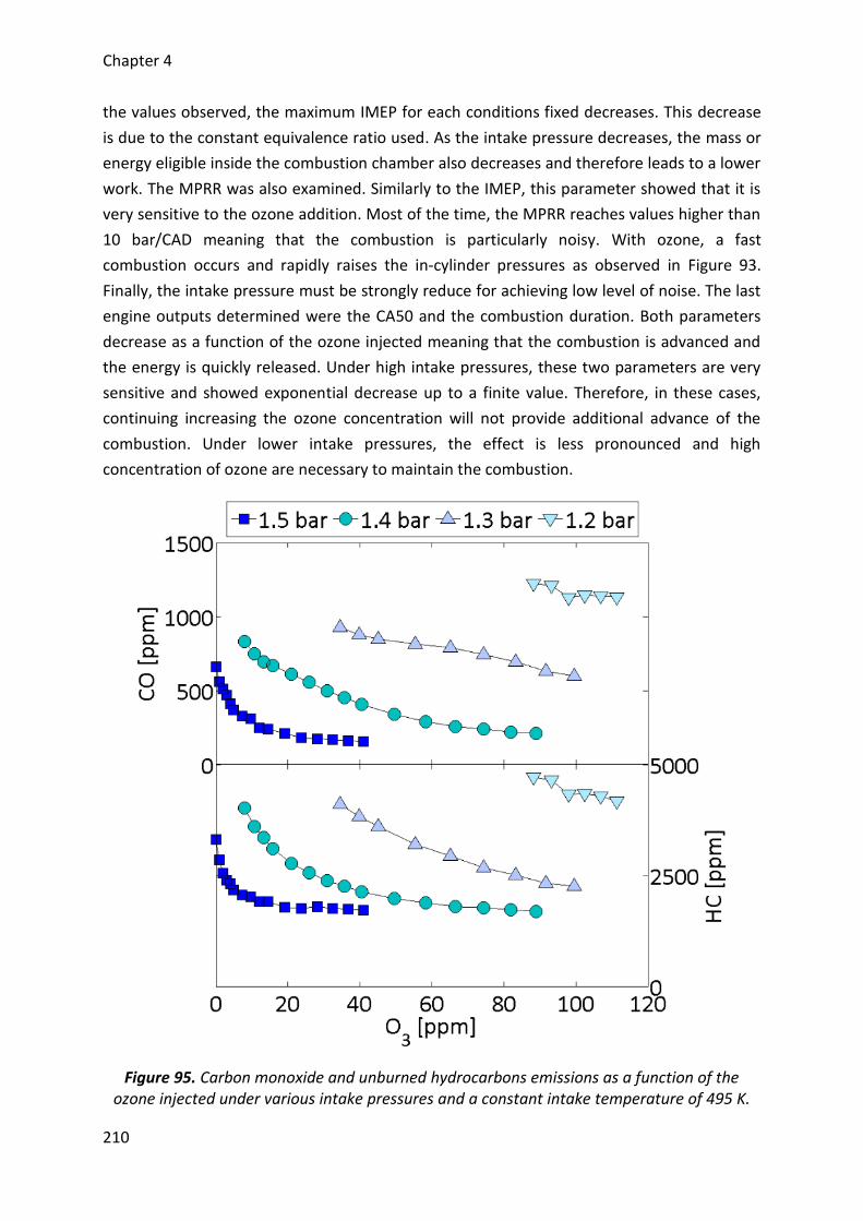
Chapter 4
210
the values observed, the maximum IMEP for each conditions fixed decreases. This decrease
is due to the constant equivalence ratio used. As the intake pressure decreases, the mass or
energy eligible inside the combustion chamber also decreases and therefore leads to a lower
work. The MPRR was also examined. Similarly to the IMEP, this parameter showed that it is
very sensitive to the ozone addition. Most of the time, the MPRR reaches values higher than
10 bar/CAD meaning that the combustion is particularly noisy. With ozone, a fast
combustion occurs and rapidly raises the in-cylinder pressures as observed in Figure 93.
Finally, the intake pressure must be strongly reduce for achieving low level of noise. The last
engine outputs determined were the CA50 and the combustion duration. Both parameters
decrease as a function of the ozone injected meaning that the combustion is advanced and
the energy is quickly released. Under high intake pressures, these two parameters are very
sensitive and showed exponential decrease up to a finite value. Therefore, in these cases,
continuing increasing the ozone concentration will not provide additional advance of the
combustion. Under lower intake pressures, the effect is less pronounced and high
concentration of ozone are necessary to maintain the combustion.
Figure 95. Carbon monoxide and unburned hydrocarbons emissions as a function of the ozone injected under various intake pressures and a constant intake temperature of 495 K.
Chapter 4
211
3.1.1.1. Pollutants under intake pressure variation
Additionally to the engine outputs, pollutants (carbon monoxide (CO), unburned
hydrocarbons (HC) and nitrogen oxides (NOx)) were also measured and are analyzed above.
3.1.1.1.1. Carbon monoxide and unburned hydrocarbons
Generally, it may be observed that the ozone seeding results in a decrease of the CO
and HC levels (Figure 95). These two pollutants present a similar decrease except that the
quantified values are different and they finally finish to achieve a minimum and finite value.
These high levels are due to the intake conditions fixed (closed to misfiring cycle) which are
not favorable for achieving ideal cylinder temperatures and combustion timing of this fuel
[178], [181]. Moreover, the high levels of CO and HC are also due to the shape of the piston
which is a diesel one. Such a shape leads to a squish volume [179] and crevices [82] which
traps part of the fresh gases and avoid their combustion. Finally, both trends demonstrate
that ozone is responsible of an improvement of the combustion since lower are these
pollutants, higher is the combustion efficiency.
3.1.1.1.2. Nitric oxides
For NOx, results showed an increase of this pollutant. Levels are quite low under
unfavorable conditions while with the enhancement of the combustion, high level may be
achieved (Figure 96). Such a level is due to the in-cylinder temperatures which may reach
temperatures closed to 2200 K and are particularly high due to the intake conditions
selected [18]. However, under the lowest intake pressure tested (1.2 bar), NOx are strongly
reduced and we find all the benefits of using homogeneous combustion.
Compare to isooctane combustion in the previous chapter where the levels of NOx
can be neglected, the high amount measured with methane/propane blend must be
discussed. According to Figure 96, NOx range from 0 to 1000 ppm and means that NOx
trapped into the clearance volume of the engine may be estimated up to 60 ppm [151]. In
this case, the intake pressure was fixed at 1.5 bar and the ozone ranged from 0 to 40 ppm.
As the NOx concentration is higher than ozone one, it could be assumed that all the ozone
should be consumed by reaction between these oxidizing species. Nevertheless, such an
assumption does not allow us to explain the promoting effect on the combustion since
oxidizing species produced from reactions between ozone and NOx have less effect than
ozone alone. The main reason of these results comes from the difference of pressure
between the intake and the exhaust which are respectively of 1.5 bar and 1.0 bar. As a
result, there is a swept of the hot residuals and therefore of the residuals NO meaning that
the reaction between O3 and NO during the induction stroke can still be neglected in the
present case. However, the possibility of ozone breakdown in front of the intake pipe with
the elevated intake temperature have not to be neglected [159], [160]. Such a prior
decomposition could lead to prior oxidation of the fuel and there will also be no time for
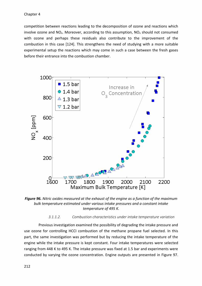
Chapter 4
212
competition between reactions leading to the decomposition of ozone and reactions which
involve ozone and NOx. Moreover, according to this assumption, NOx should not consumed
with ozone and perhaps these residuals also contribute to the improvement of the
combustion in this case [124]. This strengthens the need of studying with a more suitable
experimental setup the reactions which may come in such a case between the fresh gases
before their entrance into the combustion chamber.
Figure 96. Nitric oxides measured at the exhaust of the engine as a function of the maximum bulk temperature estimated under various intake pressures and a constant intake
temperature of 495 K.
3.1.1.2. Combustion characteristics under intake temperature variation
Previous investigation examined the possibility of degrading the intake pressure and
use ozone for controlling HCCI combustion of the methane propane fuel selected. In this
part, the same investigation was performed but by reducing the intake temperature of the
engine while the intake pressure is kept constant. Four intake temperatures were selected
ranging from 448 K to 495 K. The intake pressure was fixed at 1.5 bar and experiments were
conducted by varying the ozone concentration. Engine outputs are presented in Figure 97.
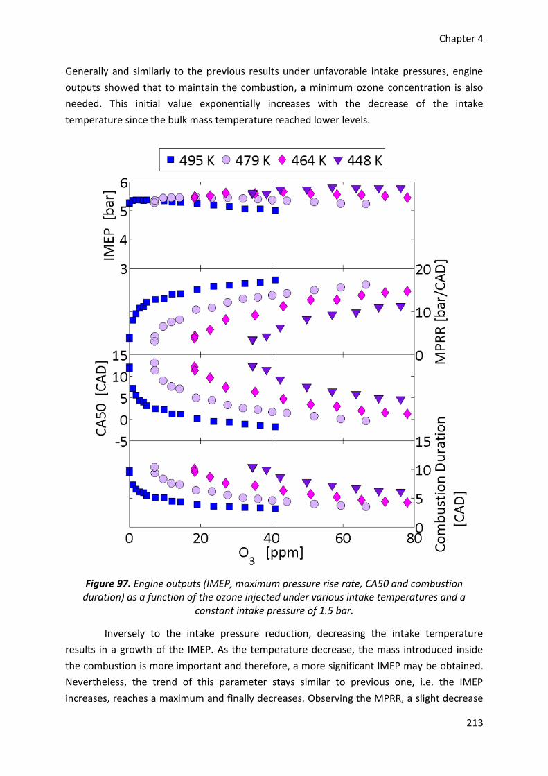
Chapter 4
213
Generally and similarly to the previous results under unfavorable intake pressures, engine
outputs showed that to maintain the combustion, a minimum ozone concentration is also
needed. This initial value exponentially increases with the decrease of the intake
temperature since the bulk mass temperature reached lower levels.
Figure 97. Engine outputs (IMEP, maximum pressure rise rate, CA50 and combustion duration) as a function of the ozone injected under various intake temperatures and a
constant intake pressure of 1.5 bar.
Inversely to the intake pressure reduction, decreasing the intake temperature
results in a growth of the IMEP. As the temperature decrease, the mass introduced inside
the combustion is more important and therefore, a more significant IMEP may be obtained.
Nevertheless, the trend of this parameter stays similar to previous one, i.e. the IMEP
increases, reaches a maximum and finally decreases. Observing the MPRR, a slight decrease
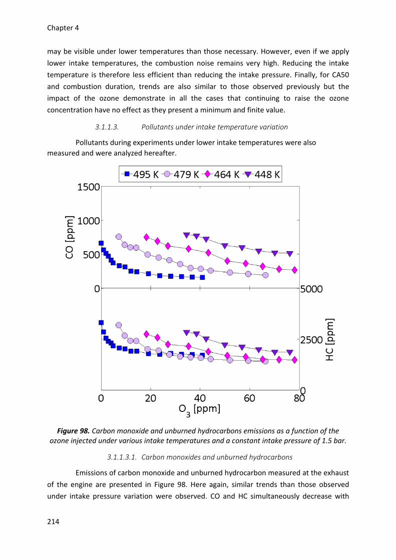
Chapter 4
214
may be visible under lower temperatures than those necessary. However, even if we apply
lower intake temperatures, the combustion noise remains very high. Reducing the intake
temperature is therefore less efficient than reducing the intake pressure. Finally, for CA50
and combustion duration, trends are also similar to those observed previously but the
impact of the ozone demonstrate in all the cases that continuing to raise the ozone
concentration have no effect as they present a minimum and finite value.
3.1.1.3. Pollutants under intake temperature variation
Pollutants during experiments under lower intake temperatures were also
measured and were analyzed hereafter.
Figure 98. Carbon monoxide and unburned hydrocarbons emissions as a function of the ozone injected under various intake temperatures and a constant intake pressure of 1.5 bar.
3.1.1.3.1. Carbon monoxides and unburned hydrocarbons
Emissions of carbon monoxide and unburned hydrocarbon measured at the exhaust
of the engine are presented in Figure 98. Here again, similar trends than those observed
under intake pressure variation were observed. CO and HC simultaneously decrease with
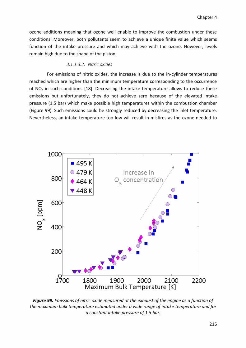
Chapter 4
215
ozone additions meaning that ozone well enable to improve the combustion under these
conditions. Moreover, both pollutants seem to achieve a unique finite value which seems
function of the intake pressure and which may achieve with the ozone. However, levels
remain high due to the shape of the piston.
3.1.1.3.2. Nitric oxides
For emissions of nitric oxides, the increase is due to the in-cylinder temperatures
reached which are higher than the minimum temperature corresponding to the occurrence
of NOx in such conditions [18]. Decreasing the intake temperature allows to reduce these
emissions but unfortunately, they do not achieve zero because of the elevated intake
pressure (1.5 bar) which make possible high temperatures within the combustion chamber
(Figure 99). Such emissions could be strongly reduced by decreasing the inlet temperature.
Nevertheless, an intake temperature too low will result in misfires as the ozone needed to
Figure 99. Emissions of nitric oxide measured at the exhaust of the engine as a function of the maximum bulk temperature estimated under a wide range of intake temperature and for
a constant intake pressure of 1.5 bar.
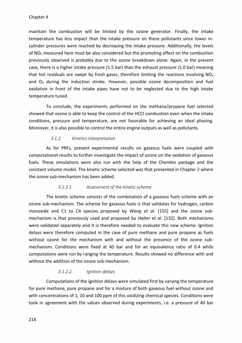
Chapter 4
216
maintain the combustion will be limited by the ozone generator. Finally, the intake
temperature has less impact than the intake pressure on these pollutants since lower in-
cylinder pressures were reached by decreasing the intake pressure. Additionally, the levels
of NOx measured here must be also considered but the promoting effect on the combustion
previously observed is probably due to the ozone breakdown alone. Again, in the present
case, there is a higher intake pressure (1.5 bar) than the exhaust pressure (1.0 bar) meaning
that hot residuals are swept by fresh gases, therefore limiting the reactions involving NOx
and O3 during the induction stroke. However, possible ozone decomposition and fuel
oxidation in front of the intake pipes have not to be neglected due to the high intake
temperature tuned.
To conclude, the experiments performed on the methane/propane fuel selected
showed that ozone is able to keep the control of the HCCI combustion even when the intake
conditions, pressure and temperature, are not favorable for achieving an ideal phasing.
Moreover, it is also possible to control the entire engine outputs as well as pollutants.
3.1.2. Kinetics interpretation
As for PRFs, present experimental results on gaseous fuels were coupled with
computational results to further investigate the impact of ozone on the oxidation of gaseous
fuels. These simulations were also run with the help of the Chemkin package and the
constant volume model. The kinetic scheme selected was that presented in Chapter 2 where
the ozone sub-mechanism has been added.
3.1.2.1. Assessment of the kinetic scheme
The kinetic scheme consists of the combination of a gaseous fuels scheme with an
ozone sub-mechanism. The scheme for gaseous fuels is that validates for hydrogen, carbon
monoxide and C1 to C4 species proposed by Wang et al. [155] and the ozone sub-
mechanism is that previously used and proposed by Halter et al. [132]. Both mechanisms
were validated separately and it is therefore needed to evaluate this new scheme. Ignition
delays were therefore computed in the case of pure methane and pure propane as fuels
without ozone for the mechanism with and without the presence of the ozone sub-
mechanism. Conditions were fixed at 40 bar and for an equivalence ratio of 0.4 while
computations were run by ranging the temperature. Results showed no difference with and
without the addition of the ozone sub-mechanism.
3.1.2.2. Ignition delays
Computations of the ignition delays were simulated first by varying the temperature
for pure methane, pure propane and for a mixture of both gaseous fuel without ozone and
with concentrations of 1, 10 and 100 ppm of this oxidizing chemical species. Conditions were
took in agreement with the values observed during experiments, i.e. a pressure of 40 bar
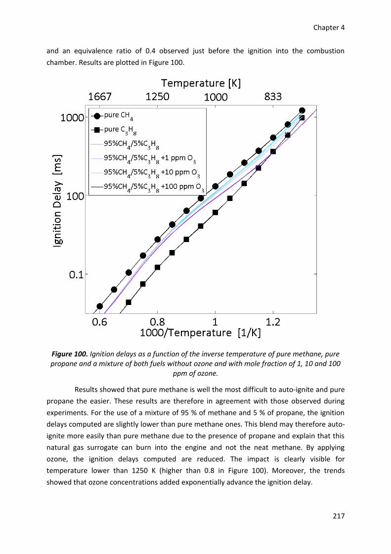
Chapter 4
217
and an equivalence ratio of 0.4 observed just before the ignition into the combustion
chamber. Results are plotted in Figure 100.
Figure 100. Ignition delays as a function of the inverse temperature of pure methane, pure propane and a mixture of both fuels without ozone and with mole fraction of 1, 10 and 100
ppm of ozone.
Results showed that pure methane is well the most difficult to auto-ignite and pure
propane the easier. These results are therefore in agreement with those observed during
experiments. For the use of a mixture of 95 % of methane and 5 % of propane, the ignition
delays computed are slightly lower than pure methane ones. This blend may therefore auto-
ignite more easily than pure methane due to the presence of propane and explain that this
natural gas surrogate can burn into the engine and not the neat methane. By applying
ozone, the ignition delays computed are reduced. The impact is clearly visible for
temperature lower than 1250 K (higher than 0.8 in Figure 100). Moreover, the trends
showed that ozone concentrations added exponentially advance the ignition delay.
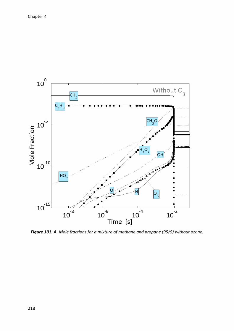
Chapter 4
218
Figure 101. A. Mole fractions for a mixture of methane and propane (95/5) without ozone.
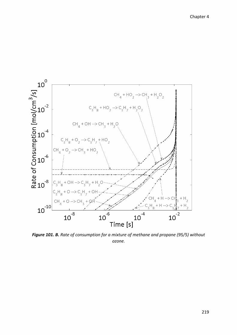
Chapter 4
219
Figure 101. B. Rate of consumption for a mixture of methane and propane (95/5) without
ozone.
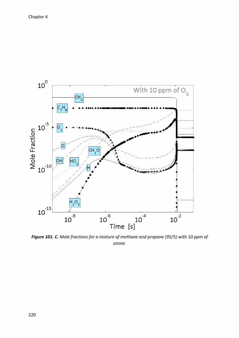
Chapter 4
220
Figure 101. C. Mole fractions for a mixture of methane and propane (95/5) with 10 ppm of
ozone.
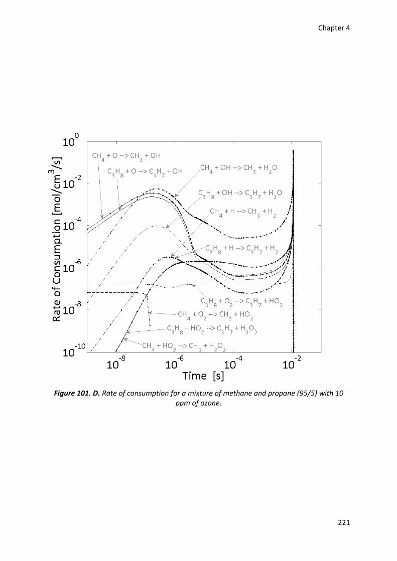
Chapter 4
221
Figure 101. D. Rate of consumption for a mixture of methane and propane (95/5) with 10 ppm of ozone.
Chapter 4
222
3.1.2.1. Rates of consumption
Following the computations of ignition delays, the oxidation pathways of methane
propane fuel selected were studied in two conditions: without ozone and for a
concentration of 10 ppm. Results for mole fractions of the main radicals and rate of
consumption for methane and propane are showed in Figure 101.
The impact of ozone on methane and propane was separately investigated. Without
ozone, it may be observed that the oxidation of methane starts by a reaction involving the
oxygen molecule (R-38). This reaction leads to the formation of a methyl radical (𝐶𝐻3) and a
hydroperoxyl radical (𝐻𝑂2).
𝐶𝐻4 + 𝑂2 → 𝐶𝐻3 + 𝐻𝑂2 R-38
Following this initiation reaction, methane is mainly consumed through reactions
with hydroxyl radicals (𝑂𝐻) (R-39) and 𝐻𝑂2 radicals (R-40). The first one dominates and
leads to the combustion.
𝐶𝐻4 + 𝑂𝐻 → 𝐶𝐻3 + 𝐻2𝑂 R-39
𝐶𝐻4 + 𝐻𝑂2 → 𝐶𝐻3 + 𝐻2𝑂2 R-40
According to the analysis of the reactions, 𝑂𝐻 radicals are produced from the
following reaction system (R-41 to R-45).
𝐻2𝑂2 → 𝑂𝐻 + 𝑂𝐻 R-41
𝐶𝐻3 + 𝑂2 → 𝐶𝐻2𝑂 + 𝑂𝐻 R-42
𝐶𝐻3 + 𝐻𝑂2 → 𝐶𝐻3𝑂 + 𝑂𝐻 R-43
𝐻 + 𝑂2 → 𝑂 + 𝑂𝐻 R-44
𝐻 + 𝐻𝑂2 → 𝑂𝐻 + 𝑂𝐻 R-45
In this system, the 𝐻2𝑂2 radical is produced from two 𝐻𝑂2 radicals via reaction R-
46.
𝐻𝑂2 + 𝐻𝑂2 → 𝐻2𝑂2 + 𝑂2 R-46
while 𝐻 comes from the reactions R-47 and R-48.
Chapter 4
223
𝐻2 + 𝑂 → 𝑂𝐻 + 𝐻 R-47
𝐻2 + 𝑂𝐻 → 𝐻2𝑂 + 𝐻 R-48
On the other hand, the oxidation of propane also starts with an initiation reaction
involving an oxygen molecule and results in the production of an alkyl radical of the propane
and a 𝐻𝑂2 radical (R-49).
𝐶3𝐻8 + 𝑂2 → 𝐶3𝐻7 + 𝐻𝑂2 R-49
Then, propane is mostly consumed by 𝑂𝐻 and 𝐻𝑂2 radicals through the following
reactions which lead to the combustion.
𝐶3𝐻8 + 𝑂𝐻 → 𝐶3𝐻7 + 𝐻2𝑂 R-50
𝐶3𝐻8 + 𝐻𝑂2 → 𝐶3𝐻7 + 𝐻2𝑂2 R-51
Similarly to the methane, 𝑂𝐻 radicals in the case of propane come from the system
involving the reactions R-41, R-42, R-42 and R-52.
𝑎𝐶3𝐻5 + 𝐻𝑂2 → 𝑂𝐻 + 𝐶2𝐻3 + 𝐶𝐻2𝑂 R-52
where 𝐻2𝑂2 comes from the reaction R-46 as previously determined and the other
radicals, i.e. 𝐶𝐻3 and 𝑎𝐶3𝐻5, come from direct and indirect decompositions of propane.
Finally, when we consider the surrogate of natural gas, the oxidation starts with an
initiation reaction of the propane which reacts more easily than the oxidation of methane
with the oxygen molecule. Then, the low concentration of radicals produced allows
consuming both fuels with chain branching reaction up to the occurrence of the combustion.
When ozone is injected, the oxidation pathway is modified. Instead of reacting with
oxygen molecule, these two fuels react with 𝑂-atoms through reactions R-53 and R-54 and
results into a direct formation of 𝑂𝐻 radicals.
𝐶𝐻4 + 𝑂 → 𝐶𝐻3 + 𝑂𝐻 R-53
𝐶3𝐻8 + 𝑂 → 𝐶3𝐻7 + 𝑂𝐻 R-54
These O-atoms comes from ozone decomposition which occurs earlier than usual
oxidation of the fuels through reaction R-55.
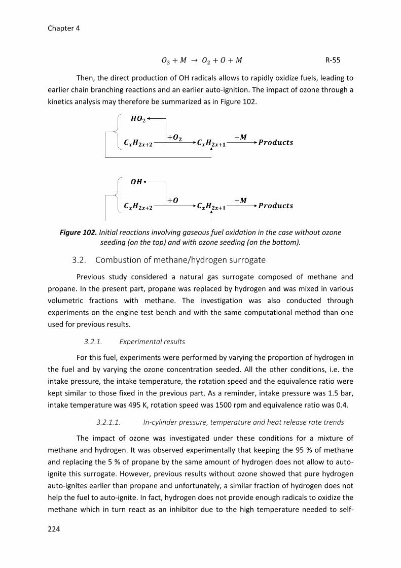
Chapter 4
224
𝑂3 + 𝑀 → 𝑂2 + 𝑂 + 𝑀 R-55
Then, the direct production of OH radicals allows to rapidly oxidize fuels, leading to
earlier chain branching reactions and an earlier auto-ignition. The impact of ozone through a
kinetics analysis may therefore be summarized as in Figure 102.
Figure 102. Initial reactions involving gaseous fuel oxidation in the case without ozone seeding (on the top) and with ozone seeding (on the bottom).
3.2. Combustion of methane/hydrogen surrogate
Previous study considered a natural gas surrogate composed of methane and
propane. In the present part, propane was replaced by hydrogen and was mixed in various
volumetric fractions with methane. The investigation was also conducted through
experiments on the engine test bench and with the same computational method than one
used for previous results.
3.2.1. Experimental results
For this fuel, experiments were performed by varying the proportion of hydrogen in
the fuel and by varying the ozone concentration seeded. All the other conditions, i.e. the
intake pressure, the intake temperature, the rotation speed and the equivalence ratio were
kept similar to those fixed in the previous part. As a reminder, intake pressure was 1.5 bar,
intake temperature was 495 K, rotation speed was 1500 rpm and equivalence ratio was 0.4.
3.2.1.1. In-cylinder pressure, temperature and heat release rate trends
The impact of ozone was investigated under these conditions for a mixture of
methane and hydrogen. It was observed experimentally that keeping the 95 % of methane
and replacing the 5 % of propane by the same amount of hydrogen does not allow to auto-
ignite this surrogate. However, previous results without ozone showed that pure hydrogen
auto-ignites earlier than propane and unfortunately, a similar fraction of hydrogen does not
help the fuel to auto-ignite. In fact, hydrogen does not provide enough radicals to oxidize the
methane which in turn react as an inhibitor due to the high temperature needed to self-
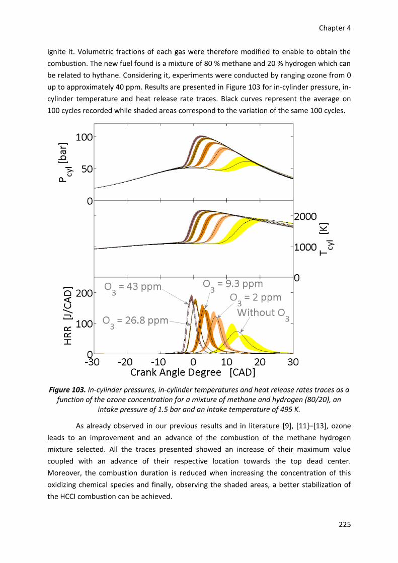
Chapter 4
225
ignite it. Volumetric fractions of each gas were therefore modified to enable to obtain the
combustion. The new fuel found is a mixture of 80 % methane and 20 % hydrogen which can
be related to hythane. Considering it, experiments were conducted by ranging ozone from 0
up to approximately 40 ppm. Results are presented in Figure 103 for in-cylinder pressure, in-
cylinder temperature and heat release rate traces. Black curves represent the average on
100 cycles recorded while shaded areas correspond to the variation of the same 100 cycles.
Figure 103. In-cylinder pressures, in-cylinder temperatures and heat release rates traces as a function of the ozone concentration for a mixture of methane and hydrogen (80/20), an
intake pressure of 1.5 bar and an intake temperature of 495 K.
As already observed in our previous results and in literature [9], [11]–[13], ozone
leads to an improvement and an advance of the combustion of the methane hydrogen
mixture selected. All the traces presented showed an increase of their maximum value
coupled with an advance of their respective location towards the top dead center.
Moreover, the combustion duration is reduced when increasing the concentration of this
oxidizing chemical species and finally, observing the shaded areas, a better stabilization of
the HCCI combustion can be achieved.
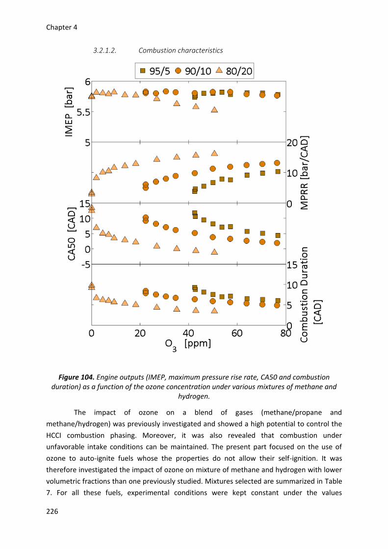
Chapter 4
226
3.2.1.2. Combustion characteristics
Figure 104. Engine outputs (IMEP, maximum pressure rise rate, CA50 and combustion duration) as a function of the ozone concentration under various mixtures of methane and
hydrogen.
The impact of ozone on a blend of gases (methane/propane and
methane/hydrogen) was previously investigated and showed a high potential to control the
HCCI combustion phasing. Moreover, it was also revealed that combustion under
unfavorable intake conditions can be maintained. The present part focused on the use of
ozone to auto-ignite fuels whose the properties do not allow their self-ignition. It was
therefore investigated the impact of ozone on mixture of methane and hydrogen with lower
volumetric fractions than one previously studied. Mixtures selected are summarized in Table
7. For all these fuels, experimental conditions were kept constant under the values
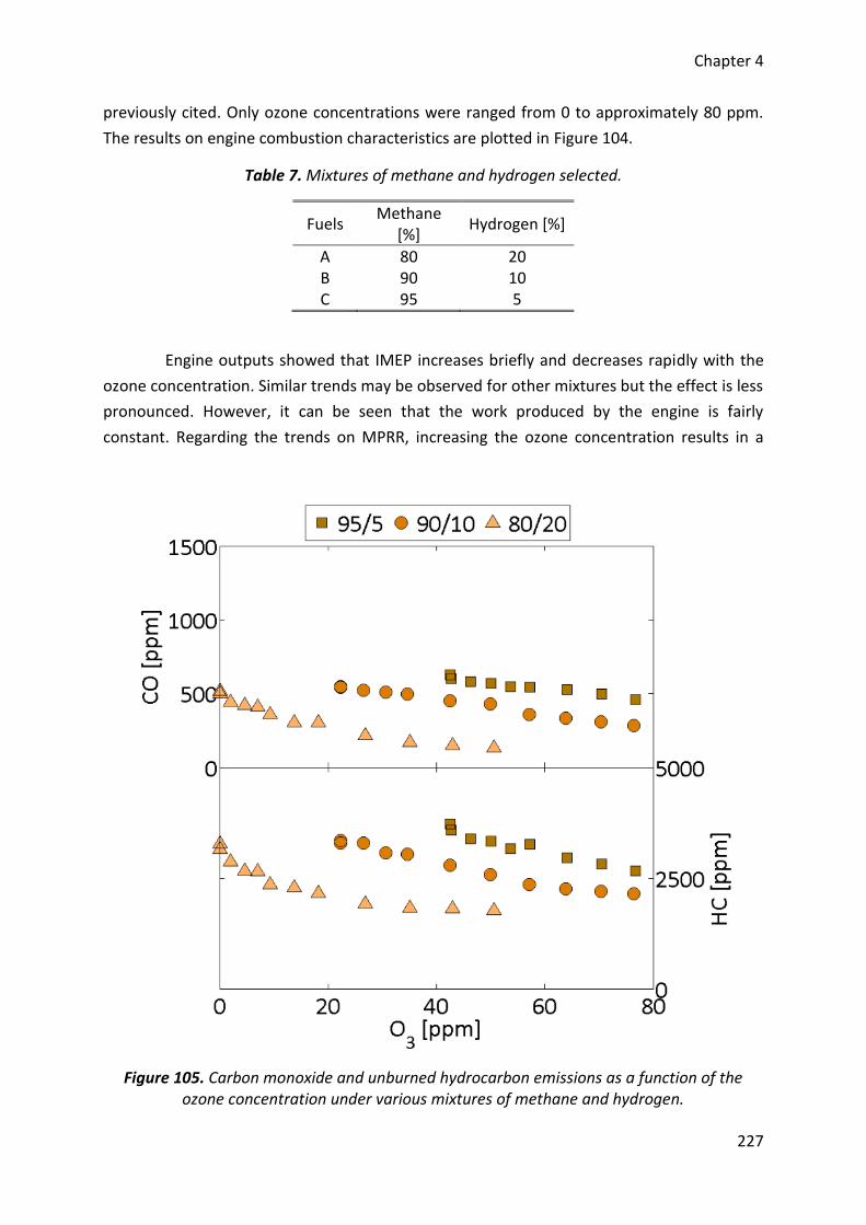
Chapter 4
227
previously cited. Only ozone concentrations were ranged from 0 to approximately 80 ppm.
The results on engine combustion characteristics are plotted in Figure 104.
Table 7. Mixtures of methane and hydrogen selected.
Fuels Methane
[%] Hydrogen [%]
A 80 20 B 90 10 C 95 5
Engine outputs showed that IMEP increases briefly and decreases rapidly with the
ozone concentration. Similar trends may be observed for other mixtures but the effect is less
pronounced. However, it can be seen that the work produced by the engine is fairly
constant. Regarding the trends on MPRR, increasing the ozone concentration results in a
Figure 105. Carbon monoxide and unburned hydrocarbon emissions as a function of the ozone concentration under various mixtures of methane and hydrogen.
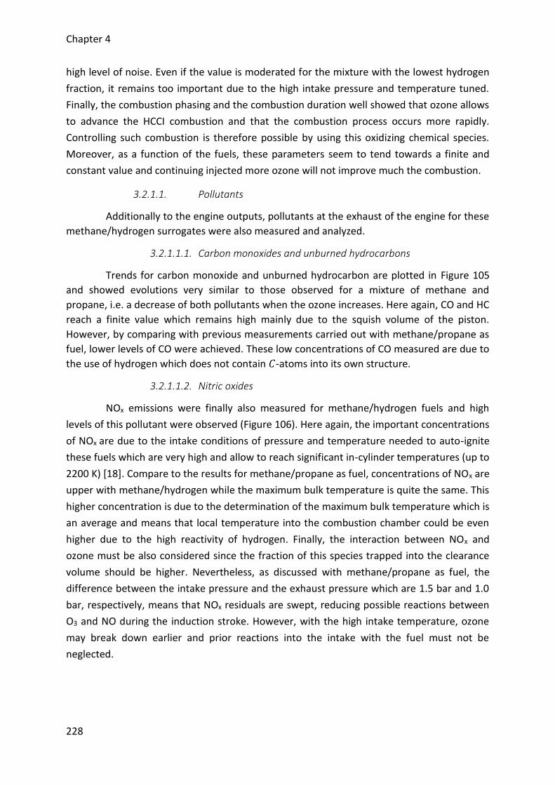
Chapter 4
228
high level of noise. Even if the value is moderated for the mixture with the lowest hydrogen
fraction, it remains too important due to the high intake pressure and temperature tuned.
Finally, the combustion phasing and the combustion duration well showed that ozone allows
to advance the HCCI combustion and that the combustion process occurs more rapidly.
Controlling such combustion is therefore possible by using this oxidizing chemical species.
Moreover, as a function of the fuels, these parameters seem to tend towards a finite and
constant value and continuing injected more ozone will not improve much the combustion.
3.2.1.1. Pollutants
Additionally to the engine outputs, pollutants at the exhaust of the engine for these
methane/hydrogen surrogates were also measured and analyzed.
3.2.1.1.1. Carbon monoxides and unburned hydrocarbons
Trends for carbon monoxide and unburned hydrocarbon are plotted in Figure 105
and showed evolutions very similar to those observed for a mixture of methane and
propane, i.e. a decrease of both pollutants when the ozone increases. Here again, CO and HC
reach a finite value which remains high mainly due to the squish volume of the piston.
However, by comparing with previous measurements carried out with methane/propane as
fuel, lower levels of CO were achieved. These low concentrations of CO measured are due to
the use of hydrogen which does not contain 𝐶-atoms into its own structure.
3.2.1.1.2. Nitric oxides
NOx emissions were finally also measured for methane/hydrogen fuels and high
levels of this pollutant were observed (Figure 106). Here again, the important concentrations
of NOx are due to the intake conditions of pressure and temperature needed to auto-ignite
these fuels which are very high and allow to reach significant in-cylinder temperatures (up to
2200 K) [18]. Compare to the results for methane/propane as fuel, concentrations of NOx are
upper with methane/hydrogen while the maximum bulk temperature is quite the same. This
higher concentration is due to the determination of the maximum bulk temperature which is
an average and means that local temperature into the combustion chamber could be even
higher due to the high reactivity of hydrogen. Finally, the interaction between NOx and
ozone must be also considered since the fraction of this species trapped into the clearance
volume should be higher. Nevertheless, as discussed with methane/propane as fuel, the
difference between the intake pressure and the exhaust pressure which are 1.5 bar and 1.0
bar, respectively, means that NOx residuals are swept, reducing possible reactions between
O3 and NO during the induction stroke. However, with the high intake temperature, ozone
may break down earlier and prior reactions into the intake with the fuel must not be
neglected.
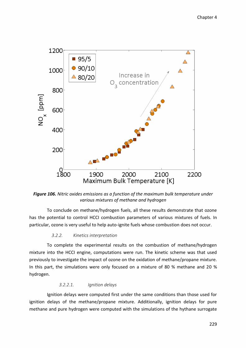
Chapter 4
229
Figure 106. Nitric oxides emissions as a function of the maximum bulk temperature under various mixtures of methane and hydrogen
To conclude on methane/hydrogen fuels, all these results demonstrate that ozone
has the potential to control HCCI combustion parameters of various mixtures of fuels. In
particular, ozone is very useful to help auto-ignite fuels whose combustion does not occur.
3.2.2. Kinetics interpretation
To complete the experimental results on the combustion of methane/hydrogen
mixture into the HCCI engine, computations were run. The kinetic scheme was that used
previously to investigate the impact of ozone on the oxidation of methane/propane mixture.
In this part, the simulations were only focused on a mixture of 80 % methane and 20 %
hydrogen.
3.2.2.1. Ignition delays
Ignition delays were computed first under the same conditions than those used for
ignition delays of the methane/propane mixture. Additionally, ignition delays for pure
methane and pure hydrogen were computed with the simulations of the hythane surrogate
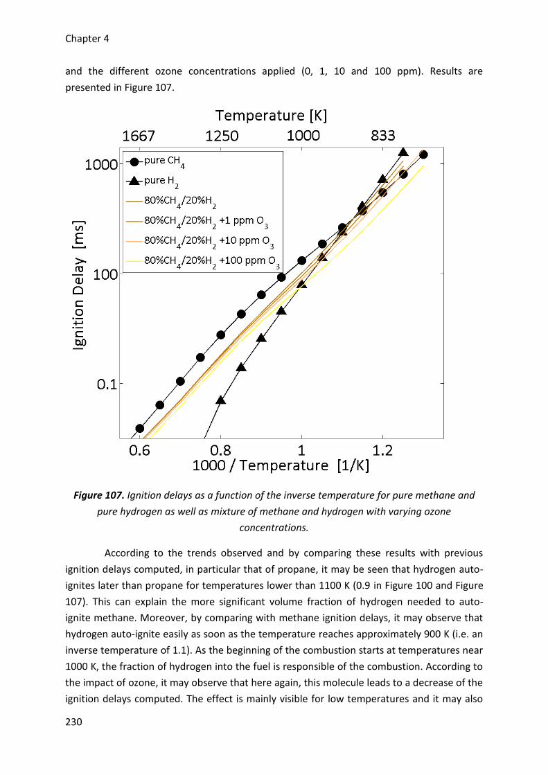
Chapter 4
230
and the different ozone concentrations applied (0, 1, 10 and 100 ppm). Results are
presented in Figure 107.
Figure 107. Ignition delays as a function of the inverse temperature for pure methane and
pure hydrogen as well as mixture of methane and hydrogen with varying ozone
concentrations.
According to the trends observed and by comparing these results with previous
ignition delays computed, in particular that of propane, it may be seen that hydrogen auto-
ignites later than propane for temperatures lower than 1100 K (0.9 in Figure 100 and Figure
107). This can explain the more significant volume fraction of hydrogen needed to auto-
ignite methane. Moreover, by comparing with methane ignition delays, it may observe that
hydrogen auto-ignite easily as soon as the temperature reaches approximately 900 K (i.e. an
inverse temperature of 1.1). As the beginning of the combustion starts at temperatures near
1000 K, the fraction of hydrogen into the fuel is responsible of the combustion. According to
the impact of ozone, it may observe that here again, this molecule leads to a decrease of the
ignition delays computed. The effect is mainly visible for low temperatures and it may also
Chapter 4
231
conclude that a low concentration of this species strongly improve the autoignition while
higher concentrations continue to advance this parameter but with an effect less
pronounced.
3.2.2.2. Rates of consumption
To further investigate the impact of ozone on the methane/hydrogen mixture
selected, an analysis of the main pathways leading to the combustion was conducted. Two
cases were studied: without ozone added and with 10 ppm of ozone. Results on the mole
fractions of the fuels and the main radicals as well as the main rate of consumption of the
fuels are presented in Figure 108. The impact on methane was previously studied and do not
change by replacing propane by hydrogen. Therefore, only the pathways for hydrogen were
analyzed. Its oxidation starts with an initiation reaction with the help of the oxygen molecule
(R-56).
𝐻2 + 𝑂2 → 𝐻 + 𝐻𝑂2 R-56
Then, the combustion is achieved through the reactions R-57 and R-58 and mainly
by the reaction involving 𝑂𝐻 radicals.
𝐻2 + 𝑂𝐻 → 𝐻 + 𝐻2𝑂 R-57
𝐻2 + 𝐻𝑂2 → 𝐻 + 𝐻2𝑂2 R-58
𝑂𝐻 and 𝐻𝑂2 radicals are mainly produced from the system including reactions R-7,
R-8 and R-10. Finally, as hydrogen has a better reactivity than methane, it promotes the
entire combustion with a production of 𝑂𝐻 radicals. In the case of the presence of ozone,
the initiation reactions of each fuel start with an 𝑂-atom instead of the oxygen molecule (R-
47 and R-53) where this atom comes from the ozone decomposition. 𝑂-atom allows creating
earlier and directly 𝑂𝐻 radicals which therefore lead to an advance of the combustion.
Finally, the impact of ozone on the methane/hydrogen fuel may also be summarized
according to the pathways in Figure 102.
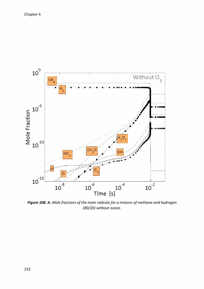
Chapter 4
232
Figure 108. A. Mole fractions of the main radicals for a mixture of methane and hydrogen
(80/20) without ozone.
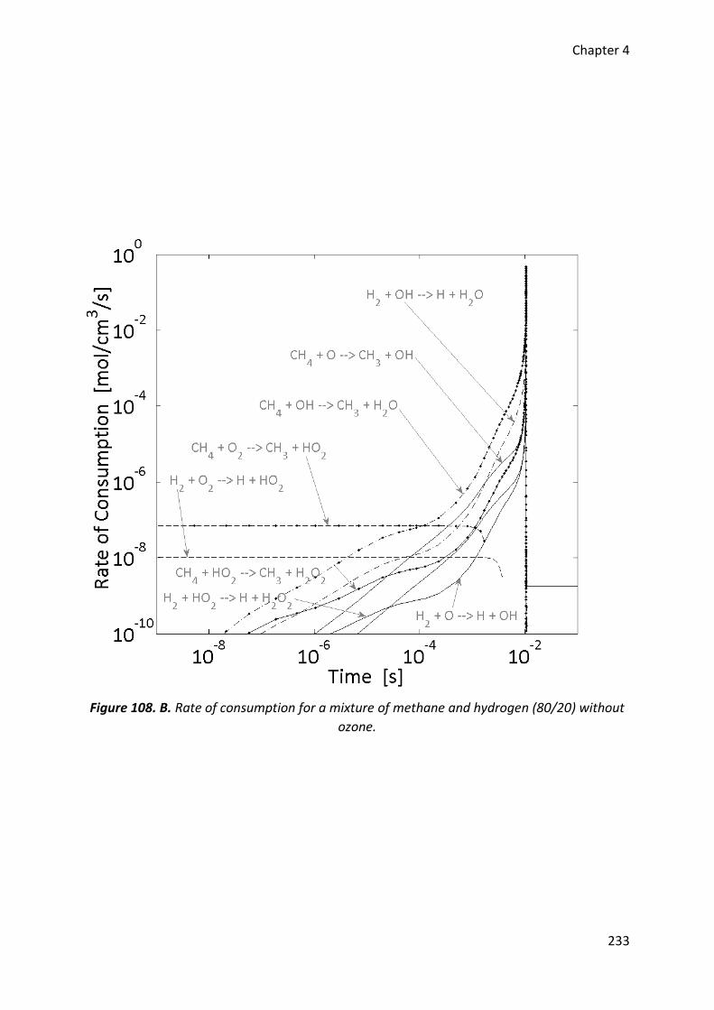
Chapter 4
233
Figure 108. B. Rate of consumption for a mixture of methane and hydrogen (80/20) without
ozone.
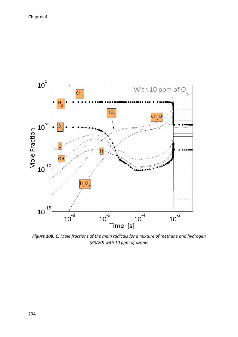
Chapter 4
234
Figure 108. C. Mole fractions of the main radicals for a mixture of methane and hydrogen
(80/20) with 10 ppm of ozone.
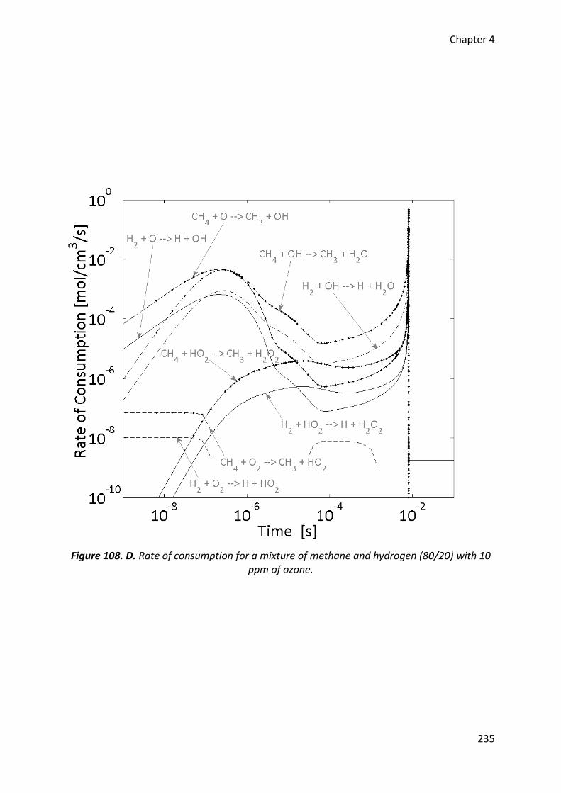
Chapter 4
235
Figure 108. D. Rate of consumption for a mixture of methane and hydrogen (80/20) with 10 ppm of ozone.
Chapter 4
236
4. Conclusion on gaseous fuels
In the present chapter, the combustion of gaseous fuels with ozone seeding was
investigated. A prior series of experiments without this oxidizing chemical species showed
that propane leads to similar trends than isooctane due to its properties near than those of
the reference fuel. Hydrogen, despite its high octane number, indicated that it can self-ignite
easily than isooctane due to its high reactivity. Finally, methane as fuel for HCCI engines was
studied but unfortunately, no results were obtained due to the very high autoignition
resistance. Extra experiments were performed at the limit of the engine intake conditions
but even with ozone addition, methane does not burn. As a result, the study focused on the
combustion of a methane-propane mixture and methane-hydrogen mixtures with ozone
additions.
The first part with a methane-propane mixture demonstrated that ozone leads to
an enhancement of the combustion of this fuel as well as an advance of its phasing.
Additionally, experiments conducted by decreasing either the intake pressure or the intake
temperature confirmed that this oxidizing chemical species can be used to manage the HCCI
combustion. Therefore, parameters such as IMEP, combustion process, efficiencies, level of
noise and pollutants can be controlled by monitoring the ozone concentration injected. In
the second part, experiments with methane-hydrogen mixtures were performed also by
varying the ozone concentration but instead of reducing the intake conditions, three
different volumetric ratios of both fuels were selected. Similar conclusions were achieved
meaning that it is possible to choose a fuel adapted to the engine and control its combustion
process by setting the ozone seeded. Finally, computations carried out to complete
experiments displayed the same results than PRFs. Fuels, either methane or propane or
hydrogen, are all oxidized first by the 𝑂-atom coming from the ozone decomposition which
results in an earlier ignition providing the improvement of the overall combustion.
Chapitre 5 / Chapter 5
Résultats sur la combustion des
carburants de la famille des
alcools
Results on the combustion of
alcohol fuels
Chapter 5
238
Résumé
Ce dernier chapitre sur les résultats obtenus au cours de la thèse traite des
carburants de faisant partis de la famille des alcools. Comme dans le chapitre précédent,
seul l’impact de l’ozone sur ces carburants a été étudié et les résultats présentés font
référence à un travail déjà publié :
□ Article VI : J-B. Masurier, F. Foucher, G. Dayma, P. Dagaut, Ozone Applied to the
Homogeneous Charge Compresssion Ignition Engine to Control Alcohol Fuels
Combustion, Applied Energy, 2015.
De manière similaire aux études précédentes, l’effet de l’ozone a aussi été étudié
sur la combustion des carburants de type alcool. Trois carburants ont été sélectionnés : le
méthanol, l’éthanol et enfin le butanol. Une étude préliminaire sans ensemencement a été
effectuée afin de déterminer les conditions d’admission idéales à imposer pour obtenir un
phasage optimum de la combustion de chacun de ces carburants. Les résultats ayant
montrés une convergence de leurs phasages respectifs, un couple unique pression-
température d’admission a été retenu pour analyser expérimentalement l’impact de l’ozone.
Comme dans le cas des PRFs, il a été observé que l’ozone permet d’améliorer la combustion
des alcools et d’avancer leur phasage. Par comparaison entre eux, le butanol est le carburant
le plus impacté par l’ozone et le méthanol le moins en raison de leur structure chimique.
Cependant, par rapport aux PRFs, malgré des tendances similaires en fonction de la
concentration d’ozone, les alcools sont beaucoup plus résistants à son potentiel oxydant
étant donné que des concentrations bien supérieures sont nécessaires pour obtenir une
même avance sur le phasage. De plus, ces carburants ont eux aussi démontré la possibilité
de contrôler le phasage de leur combustion, ainsi que l’ensemble des paramètres moteur
(pression moyenne indiquée, durée de la combustion) moyennant le contrôle de la quantité
d’ozone injectée. Toutefois, afin d’aboutir à un phasage optimal permettant l’optimisation
sur un maximum de paramètres du moteur, un mélange de ces trois carburants de la famille
des alcools serait probablement idéale. Finalement, en complément des résultats
expérimentaux, des simulations de cinétique chimique à l’aide d’un nouveau schéma basé
sur l’oxydation des alcools auquel a été ajouté le sous mécanisme de l’ozone ont été
réalisées et ont permis d’aboutir aux mêmes conclusions que celles pour les PRFs et les
carburants gazeux. D’une manière générale, l’oxydation des alcools commence par une
réaction d’initiation avec la molécule d’oxygène tandis que dans le cas où l’ozone est injecté,
les alcools sont consommés via une réaction impliquant l’oxygène atomique résultant de la
décomposition de l’ozone. Cette première réaction qui prend place bien plus tôt que les
voies d’oxydation normales permet finalement d’aboutir aux avances observées lors des
expériences.
Chapter 5
239
Abstract
This last chapter of results is about alcohol fuels. As in the previous chapter, only
the impact of ozone on these fuels was investigated and the results presented are referred
to the following article:
□ Article VI : J-B. Masurier, F. Foucher, G. Dayma, P. Dagaut, Ozone Applied to the
Homogeneous Charge Compresssion Ignition Engine to Control Alcohol Fuels
Combustion, Applied Energy, 2015.
Similarly to the previous studies, the effect of ozone was also study on the
combustion of alcohol fuels. Three different fuels were selected: methanol, ethanol and
finally n-butanol. A prior study without seeding was carried out to determine the optimum
conditions to set in order to obtain an ideal phasing of their respective combustion. Results
showed a convergence of their respective phasing and therefore, a unique couple of intake
pressure and temperature was chosen for analyzing through experiments the impact of
ozone on these fuels. As for PRFs, it was observed that ozone enables to improve the
combustion of alcohols and advance their phasing. By comparing them, n-butanol is the
most affected by ozone and methanol the least due to their chemical structure. However,
compare to PRFs, despite the similar trends observed as a function of the ozone
concentration, alcohols are more resistant to the oxidizing potential of ozone since higher
concentrations were needed to achieve the same combustion phasing. Moreover, these
fuels also showed the possibility to control the combustion phasing as well as all the engine
outputs (indicated mean effective pressure, combustion duration) by managing the amount
of ozone injected. However, to achieve an optimal phasing and an optimization of the engine
outputs, a blend of these three alcohol fuels will be probably ideal. Finally, to complement
the experimental results, computations were carried out with a scheme based on the
oxidation of alcohol fuels where it was added the ozone sub-mechanism. Results allowed to
achieve the same conclusions than those for PRFs and gaseous fuels. Generally, alcohol
oxidation starts with an initiation reaction involving the oxygen molecule while in the case of
an ozone injection, alcohol fuels are consumed through reaction involving the oxygen atom
coming from the ozone break down. This reaction occurs very earlier than by the normal
oxidation pathways and finally lead to the advances of the combustion observed during the
experiments.
Chapter 5
240
1. Introduction on alcohol fuels (Article VI)
In previous chapters, experimental and numerical results showed that ozone has
the potential to control the HCCI combustion phasing of different kinds of fuels, in particular
PRFs and gaseous fuels. Moreover, it was also observed that this oxidizing chemical species
provide the same initial pathways on these fuels. Currently, other fuels present a wide
interest for engine applications and may use as alternative fuels. Alcohol fuels are good
candidates and were widely investigated [157], [195]. They already showed that they may
replace conventional automotive fuels as for instance ethanol. These fuels have for
properties to include an oxygen atom in their respective structure which may alter the
impact of ozone.
Ozone was already applied on fuel with oxygen atom in its structure [13] but never
on alcohol fuels. The aim of the present part is therefore to study the impact of ozone on the
combustion of alcohol fuels into a HCCI engine. Similarly to previous investigations carried
out, the effect of this oxidizing chemical species was studied through experiments on the
engine bench coupled with computations. Fuels selected were methanol (MeOH), ethanol
(EtOH) and n-butanol (BuOH) because they present properties closed to that of isooctane.
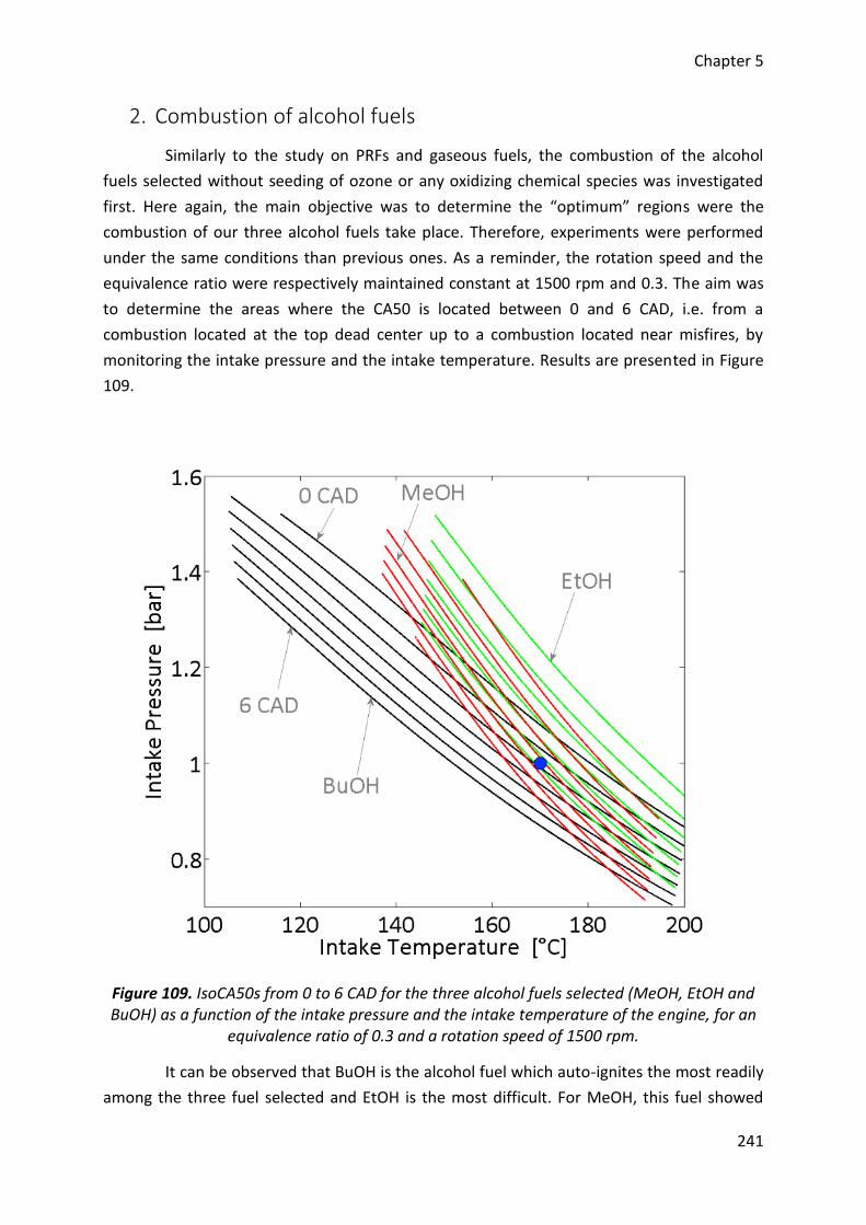
Chapter 5
241
2. Combustion of alcohol fuels
Similarly to the study on PRFs and gaseous fuels, the combustion of the alcohol
fuels selected without seeding of ozone or any oxidizing chemical species was investigated
first. Here again, the main objective was to determine the “optimum” regions were the
combustion of our three alcohol fuels take place. Therefore, experiments were performed
under the same conditions than previous ones. As a reminder, the rotation speed and the
equivalence ratio were respectively maintained constant at 1500 rpm and 0.3. The aim was
to determine the areas where the CA50 is located between 0 and 6 CAD, i.e. from a
combustion located at the top dead center up to a combustion located near misfires, by
monitoring the intake pressure and the intake temperature. Results are presented in Figure
109.
Figure 109. IsoCA50s from 0 to 6 CAD for the three alcohol fuels selected (MeOH, EtOH and BuOH) as a function of the intake pressure and the intake temperature of the engine, for an
equivalence ratio of 0.3 and a rotation speed of 1500 rpm.
It can be observed that BuOH is the alcohol fuel which auto-ignites the most readily
among the three fuel selected and EtOH is the most difficult. For MeOH, this fuel showed
Chapter 5
242
that it has a behavior similar to that of EtOH. This trend may be interpreted according to the
respective RON, MON and ON of each fuel [187]. BuOH has an ON of 91.5, the lowest of the
alcohol fuels selected, MeOH and EtOH holding ON of 99 and 99.5, respectively. The ON
therefore explains that BuOH is the most easily fuel to auto-ignite and as both other fuels
have ON rather similar, it was normal to see that combustion area of MeOH is very close to
that of EtOH. However, there is a slight difference which results in a later combustion
phasing for EtOH. Similar results were already observed for both fuels in the literature [52]
and are in agreement with our results. Finally, it can also be noted that in the case of high
intake temperatures, isoCA50s converge for all the fuels studied. This convergence was
attributed to the sensitivity of each fuel which is defined as the difference between the RON
and the MON of each fuel [46]. Fuels have respectively a sensitivity of 20 for MeOH, 19 for
EtOH and 13 for BuOH. The closed sensitivity of MeOH and EtOH explain both fuels present
similar trends, even parallel. Moreover, by observing a unique isoCA50 with an increase of
the intake temperature, both fuels present a higher slope than BuOH due to their higher
values on this parameter.
Chapter 5
243
3. Effect of ozone
Starting from the previous results on the HCCI combustion of alcohol fuels without
oxidizing chemical species seeding, the effect of ozone was studied by performing
experiments and computations.
3.1. Experimental results
3.1.1. In-cylinder pressure and heat release rate traces
Results in Figure 1 showed that without ozone injection and by varying the intake
conditions of the engine, the respective MeOH, EtOH and BuOH “optimum” combustion
regions converge. Therefore, the experiments with ozone were performed for a unique
couple of intake pressure and intake temperature to compare the impact of this oxidizing
chemical species on these three fuels. The intake pressure was fixed at 1 bar and
consequently, the intake temperature was monitored at 170 °C. This temperature
corresponds to the minimum intake temperature needed to allow the combustion of the
most difficult fuel to autoignite, i.e. EtOH at a combustion timing of 6 CAD. From this point,
experiments were performed by ranging the ozone concentration from 0 to approximately
130 ppm (upper limit with the ozone generator). Moreover, data were recorded by
increasing the ozone concentration from the minimum up to the maximum and then, by
decreasing the concentration. The objective was to show the good stability and repeatability
of the results. The evolutions of the in-cylinder pressures recorded and the heat release
rates calculated are presented in Figure 110 as a function of the ozone concentrations. Here
again, black curves represent the average of the 100 cycles recorded and colored envelopes
correspond to the maximum variations, upper and lower limits, of the same 100 cycles.
Generally, we may observe that results are quite similar to those obtained for ozone
seeding with PRFs and gaseous fuels. They are also in agreement with prior results observed
in the literature [9], [11]–[13]. Regarding the in-cylinder pressure traces, increasing the
ozone concentration at the intake of the engine allow to increase the maximum pressure
and the combustion is advanced for all the alcohol fuels selected. In the same way, the heat
release rate traces also showed an increase of their maximum values meaning that ozone
allows to improve the combustion of alcohol fuels and advance its phasing. Moreover, this
result was confirmed observing the value of the IMEP. This parameter raises from 2.40 to
2.55 bar, from 2.10 to 2.36 bar and 2.30 to 2.39 bar for MeOH, EtOH and BuOH, respectively.
Finally, it may also be observed from the colored areas and the covariance of the IMEP that
ozone enables to stabilize the combustion.
Additionally to the observations provide by in-cylinder pressure and heat release
rate traces as a function of ozone, it is possible to give a first comparison of the impact of
this oxidizing chemical species on the three alcohol fuels selected. Thus, from the difference
between the maximum in-cylinder pressure without ozone seeding and the maximum
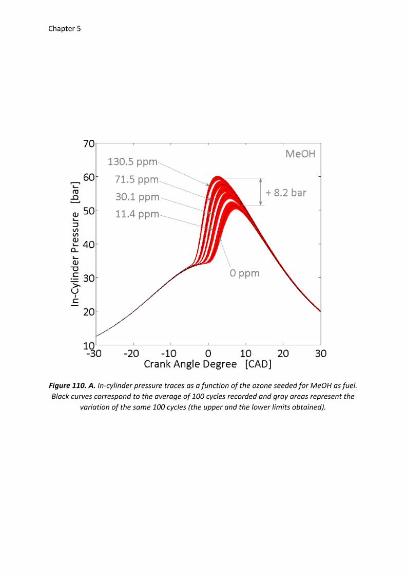
Chapter 5
Figure 110. A. In-cylinder pressure traces as a function of the ozone seeded for MeOH as fuel.
Black curves correspond to the average of 100 cycles recorded and gray areas represent the
variation of the same 100 cycles (the upper and the lower limits obtained).
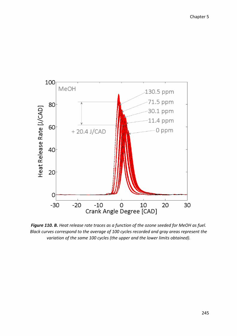
Chapter 5
245
Figure 110. B. Heat release rate traces as a function of the ozone seeded for MeOH as fuel.
Black curves correspond to the average of 100 cycles recorded and gray areas represent the
variation of the same 100 cycles (the upper and the lower limits obtained).
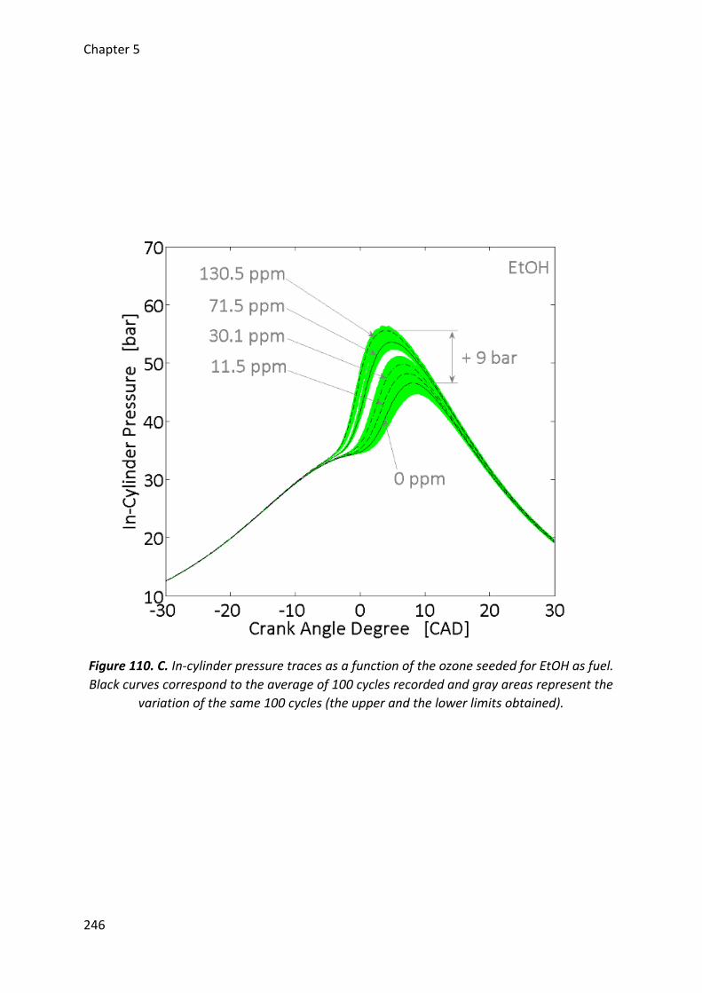
Chapter 5
246
Figure 110. C. In-cylinder pressure traces as a function of the ozone seeded for EtOH as fuel.
Black curves correspond to the average of 100 cycles recorded and gray areas represent the
variation of the same 100 cycles (the upper and the lower limits obtained).
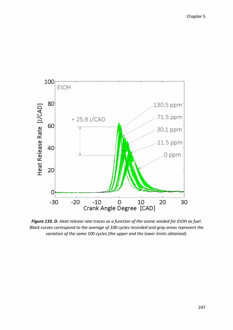
Chapter 5
247
Figure 110. D. Heat release rate traces as a function of the ozone seeded for EtOH as fuel.
Black curves correspond to the average of 100 cycles recorded and gray areas represent the
variation of the same 100 cycles (the upper and the lower limits obtained).
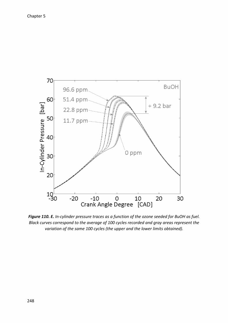
Chapter 5
248
Figure 110. E. In-cylinder pressure traces as a function of the ozone seeded for BuOH as fuel.
Black curves correspond to the average of 100 cycles recorded and gray areas represent the
variation of the same 100 cycles (the upper and the lower limits obtained).
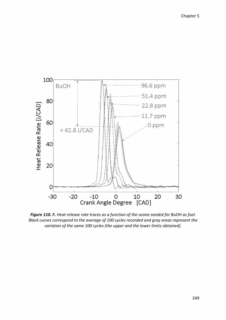
Chapter 5
249
Figure 110. F. Heat release rate traces as a function of the ozone seeded for BuOH as fuel. Black curves correspond to the average of 100 cycles recorded and gray areas represent the
variation of the same 100 cycles (the upper and the lower limits obtained).
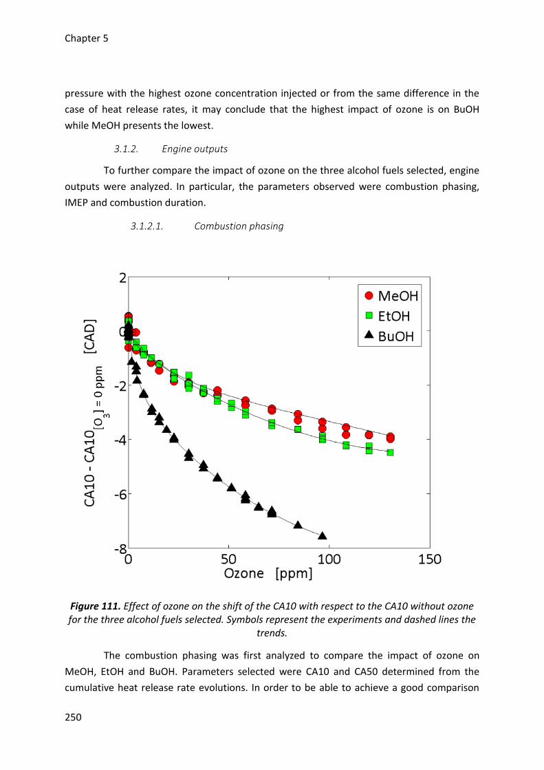
Chapter 5
250
pressure with the highest ozone concentration injected or from the same difference in the
case of heat release rates, it may conclude that the highest impact of ozone is on BuOH
while MeOH presents the lowest.
3.1.2. Engine outputs
To further compare the impact of ozone on the three alcohol fuels selected, engine
outputs were analyzed. In particular, the parameters observed were combustion phasing,
IMEP and combustion duration.
3.1.2.1. Combustion phasing
Figure 111. Effect of ozone on the shift of the CA10 with respect to the CA10 without ozone for the three alcohol fuels selected. Symbols represent the experiments and dashed lines the
trends.
The combustion phasing was first analyzed to compare the impact of ozone on
MeOH, EtOH and BuOH. Parameters selected were CA10 and CA50 determined from the
cumulative heat release rate evolutions. In order to be able to achieve a good comparison
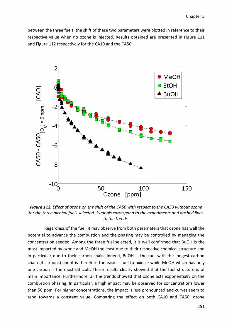
Chapter 5
251
between the three fuels, the shift of these two parameters were plotted in reference to their
respective value when no ozone is injected. Results obtained are presented in Figure 111
and Figure 112 respectively for the CA10 and the CA50.
Figure 112. Effect of ozone on the shift of the CA50 with respect to the CA50 without ozone for the three alcohol fuels selected. Symbols correspond to the experiments and dashed lines
to the trends.
Regardless of the fuel, it may observe from both parameters that ozone has well the
potential to advance the combustion and the phasing may be controlled by managing the
concentration seeded. Among the three fuel selected, it is well confirmed that BuOH is the
most impacted by ozone and MeOH the least due to their respective chemical structure and
in particular due to their carbon chain. Indeed, BuOH is the fuel with the longest carbon
chain (4 carbons) and it is therefore the easiest fuel to oxidize while MeOH which has only
one carbon is the most difficult. These results clearly showed that the fuel structure is of
main importance. Furthermore, all the trends showed that ozone acts exponentially on the
combustion phasing. In particular, a high impact may be observed for concentrations lower
than 50 ppm. For higher concentrations, the impact is less pronounced and curves seem to
tend towards a constant value. Comparing the effect on both CA10 and CA50, ozone
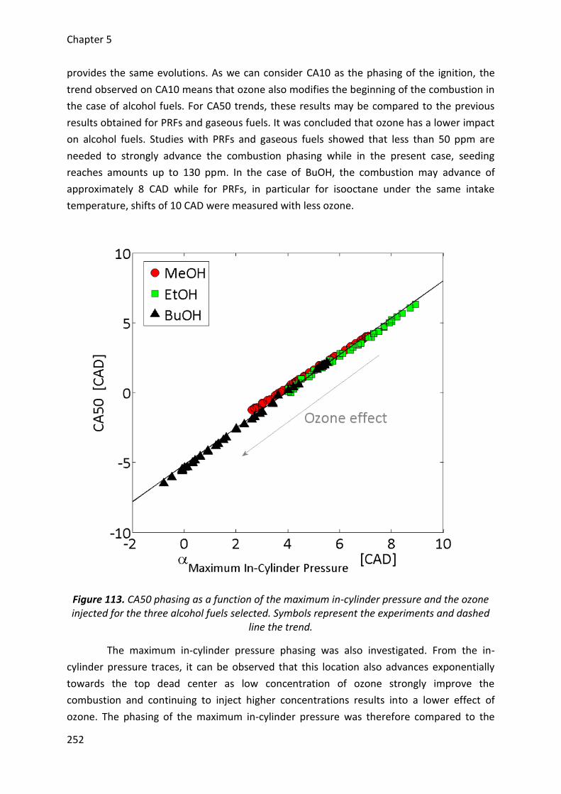
Chapter 5
252
provides the same evolutions. As we can consider CA10 as the phasing of the ignition, the
trend observed on CA10 means that ozone also modifies the beginning of the combustion in
the case of alcohol fuels. For CA50 trends, these results may be compared to the previous
results obtained for PRFs and gaseous fuels. It was concluded that ozone has a lower impact
on alcohol fuels. Studies with PRFs and gaseous fuels showed that less than 50 ppm are
needed to strongly advance the combustion phasing while in the present case, seeding
reaches amounts up to 130 ppm. In the case of BuOH, the combustion may advance of
approximately 8 CAD while for PRFs, in particular for isooctane under the same intake
temperature, shifts of 10 CAD were measured with less ozone.
Figure 113. CA50 phasing as a function of the maximum in-cylinder pressure and the ozone injected for the three alcohol fuels selected. Symbols represent the experiments and dashed
line the trend.
The maximum in-cylinder pressure phasing was also investigated. From the in-
cylinder pressure traces, it can be observed that this location also advances exponentially
towards the top dead center as low concentration of ozone strongly improve the
combustion and continuing to inject higher concentrations results into a lower effect of
ozone. The phasing of the maximum in-cylinder pressure was therefore compared to the
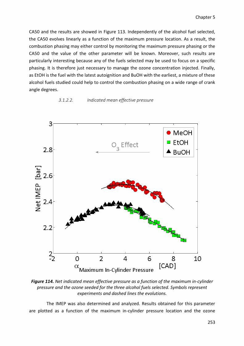
Chapter 5
253
CA50 and the results are showed in Figure 113. Independently of the alcohol fuel selected,
the CA50 evolves linearly as a function of the maximum pressure location. As a result, the
combustion phasing may either control by monitoring the maximum pressure phasing or the
CA50 and the value of the other parameter will be known. Moreover, such results are
particularly interesting because any of the fuels selected may be used to focus on a specific
phasing. It is therefore just necessary to manage the ozone concentration injected. Finally,
as EtOH is the fuel with the latest autoignition and BuOH with the earliest, a mixture of these
alcohol fuels studied could help to control the combustion phasing on a wide range of crank
angle degrees.
3.1.2.2. Indicated mean effective pressure
Figure 114. Net indicated mean effective pressure as a function of the maximum in-cylinder pressure and the ozone seeded for the three alcohol fuels selected. Symbols represent
experiments and dashed lines the evolutions.
The IMEP was also determined and analyzed. Results obtained for this parameter
are plotted as a function of the maximum in-cylinder pressure location and the ozone
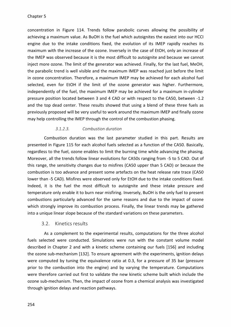
Chapter 5
254
concentration in Figure 114. Trends follow parabolic curves allowing the possibility of
achieving a maximum value. As BuOH is the fuel which autoignites the easiest into our HCCI
engine due to the intake conditions fixed, the evolution of its IMEP rapidly reaches its
maximum with the increase of the ozone. Inversely in the case of EtOH, only an increase of
the IMEP was observed because it is the most difficult to autoignite and because we cannot
inject more ozone. The limit of the generator was achieved. Finally, for the last fuel, MeOH,
the parabolic trend is well visible and the maximum IMEP was reached just before the limit
in ozone concentration. Therefore, a maximum IMEP may be achieved for each alcohol fuel
selected, even for EtOH if the limit of the ozone generator was higher. Furthermore,
independently of the fuel, the maximum IMEP may be achieved for a maximum in-cylinder
pressure position located between 3 and 4 CAD or with respect to the CA50, between -1.2
and the top dead center. These results showed that using a blend of these three fuels as
previously proposed will be very useful to work around the maximum IMEP and finally ozone
may help controlling the IMEP through the control of the combustion phasing.
3.1.2.3. Combustion duration
Combustion duration was the last parameter studied in this part. Results are
presented in Figure 115 for each alcohol fuels selected as a function of the CA50. Basically,
regardless to the fuel, ozone enables to limit the burning time while advancing the phasing.
Moreover, all the trends follow linear evolutions for CA50s ranging from -5 to 5 CAD. Out of
this range, the sensitivity changes due to misfires (CA50 upper than 5 CAD) or because the
combustion is too advance and present some artefacts on the heat release rate trace (CA50
lower than -5 CAD). Misfires were observed only for EtOH due to the intake conditions fixed.
Indeed, it is the fuel the most difficult to autoignite and these intake pressure and
temperature only enable it to burn near misfiring. Inversely, BuOH is the only fuel to present
combustions particularly advanced for the same reasons and due to the impact of ozone
which strongly improve its combustion process. Finally, the linear trends may be gathered
into a unique linear slope because of the standard variations on these parameters.
3.2. Kinetics results
As a complement to the experimental results, computations for the three alcohol
fuels selected were conducted. Simulations were run with the constant volume model
described in Chapter 2 and with a kinetic scheme containing our fuels [156] and including
the ozone sub-mechanism [132]. To ensure agreement with the experiments, ignition delays
were computed by tuning the equivalence ratio at 0.3, for a pressure of 35 bar (pressure
prior to the combustion into the engine) and by varying the temperature. Computations
were therefore carried out first to validate the new kinetic scheme built which include the
ozone sub-mechanism. Then, the impact of ozone from a chemical analysis was investigated
through ignition delays and reaction pathways.
Chapter 5
255
Figure 115. Combustion duration as a function of the CA50 and the ozone seeded for the three alcohol fuels selected. Symbols correspond to the experiments and dashed lines to the
trends.
3.2.1. Assessment of the kinetic scheme
The kinetic scheme built to study the impact of ozone on the combustion of alcohol
fuels consists of an alcohol fuel scheme and an ozone sub-mechanism. Both mechanisms
were separately validated and their combination must be also assessed before investigating
the impact of this oxidizing chemical species through a kinetic interpretation. Computations
were therefore performed for ignition delays for two cases, with the presence of the ozone
sub-mechanism and without. Results obtained are presented in Figure 116.
As observe, results with and without the use of the ozone sub-mechanism are in
good agreement. The presence of the ozone does not affect the ignition delays computed of
the three alcohol fuels meaning that it is validated and can be used for our study.
Additionally, it may see that computational results well match with the first experimental
results presented without ozone seeding. Before 950 K, i.e. for temperatures similar than
those observed at the ignition of the fuels into the engine when the intake temperature is
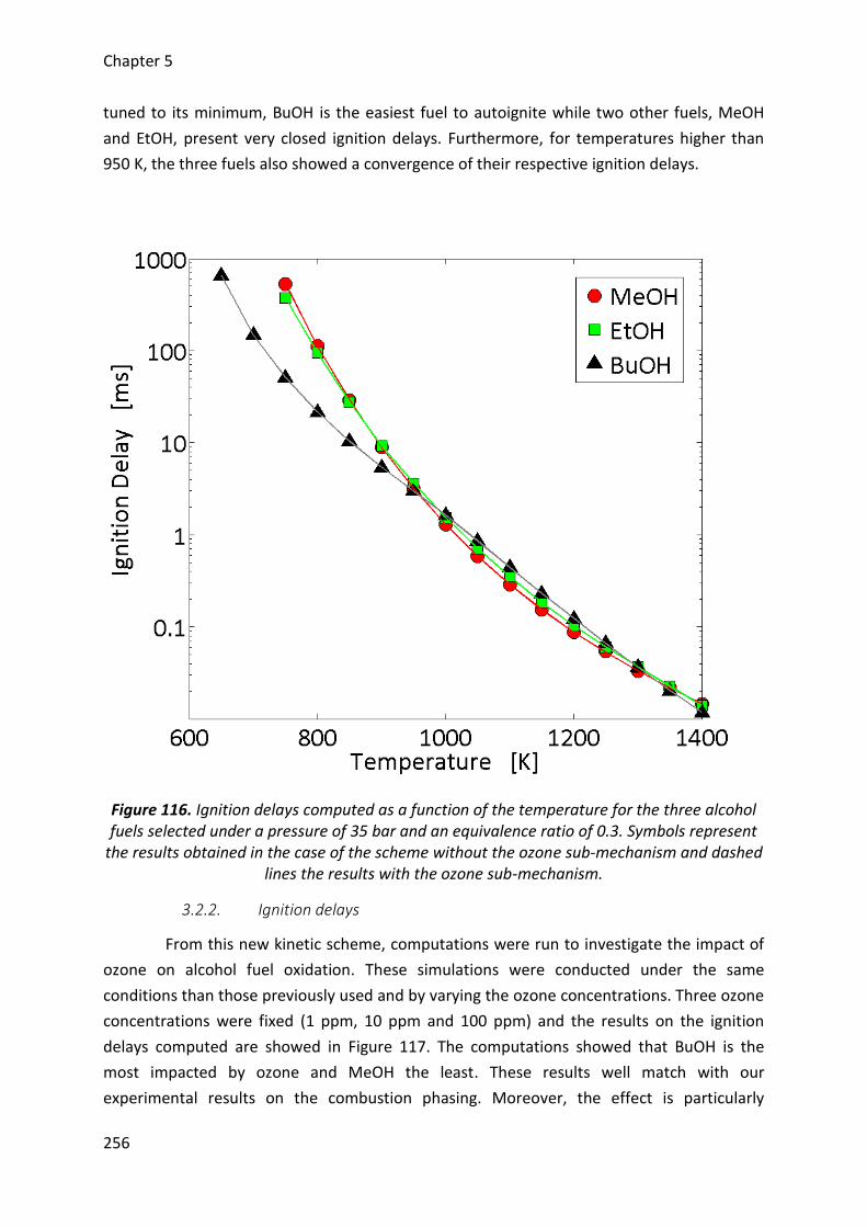
Chapter 5
256
tuned to its minimum, BuOH is the easiest fuel to autoignite while two other fuels, MeOH
and EtOH, present very closed ignition delays. Furthermore, for temperatures higher than
950 K, the three fuels also showed a convergence of their respective ignition delays.
Figure 116. Ignition delays computed as a function of the temperature for the three alcohol fuels selected under a pressure of 35 bar and an equivalence ratio of 0.3. Symbols represent
the results obtained in the case of the scheme without the ozone sub-mechanism and dashed lines the results with the ozone sub-mechanism.
3.2.2. Ignition delays
From this new kinetic scheme, computations were run to investigate the impact of
ozone on alcohol fuel oxidation. These simulations were conducted under the same
conditions than those previously used and by varying the ozone concentrations. Three ozone
concentrations were fixed (1 ppm, 10 ppm and 100 ppm) and the results on the ignition
delays computed are showed in Figure 117. The computations showed that BuOH is the
most impacted by ozone and MeOH the least. These results well match with our
experimental results on the combustion phasing. Moreover, the effect is particularly
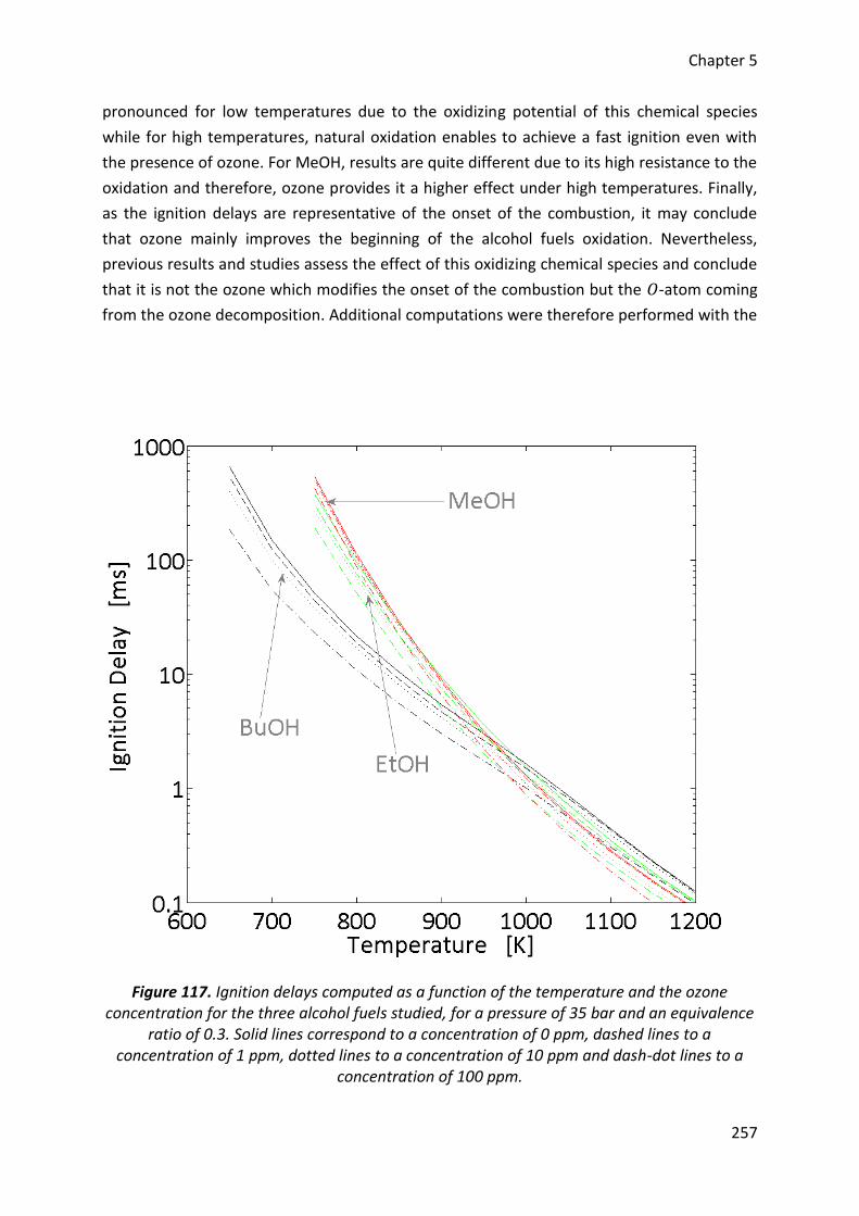
Chapter 5
257
pronounced for low temperatures due to the oxidizing potential of this chemical species
while for high temperatures, natural oxidation enables to achieve a fast ignition even with
the presence of ozone. For MeOH, results are quite different due to its high resistance to the
oxidation and therefore, ozone provides it a higher effect under high temperatures. Finally,
as the ignition delays are representative of the onset of the combustion, it may conclude
that ozone mainly improves the beginning of the alcohol fuels oxidation. Nevertheless,
previous results and studies assess the effect of this oxidizing chemical species and conclude
that it is not the ozone which modifies the onset of the combustion but the 𝑂-atom coming
from the ozone decomposition. Additional computations were therefore performed with the
Figure 117. Ignition delays computed as a function of the temperature and the ozone concentration for the three alcohol fuels studied, for a pressure of 35 bar and an equivalence
ratio of 0.3. Solid lines correspond to a concentration of 0 ppm, dashed lines to a concentration of 1 ppm, dotted lines to a concentration of 10 ppm and dash-dot lines to a
concentration of 100 ppm.
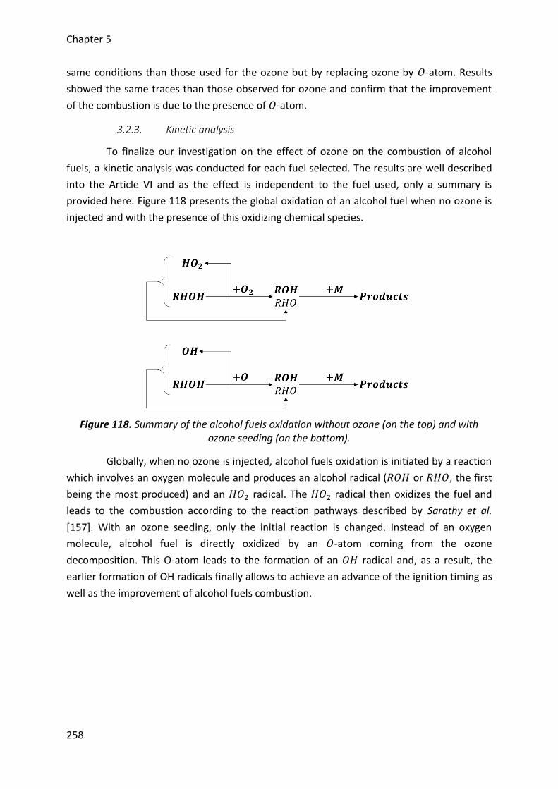
Chapter 5
258
same conditions than those used for the ozone but by replacing ozone by 𝑂-atom. Results
showed the same traces than those observed for ozone and confirm that the improvement
of the combustion is due to the presence of 𝑂-atom.
3.2.3. Kinetic analysis
To finalize our investigation on the effect of ozone on the combustion of alcohol
fuels, a kinetic analysis was conducted for each fuel selected. The results are well described
into the Article VI and as the effect is independent to the fuel used, only a summary is
provided here. Figure 118 presents the global oxidation of an alcohol fuel when no ozone is
injected and with the presence of this oxidizing chemical species.
Figure 118. Summary of the alcohol fuels oxidation without ozone (on the top) and with ozone seeding (on the bottom).
Globally, when no ozone is injected, alcohol fuels oxidation is initiated by a reaction
which involves an oxygen molecule and produces an alcohol radical (𝑅𝑂𝐻 or 𝑅𝐻𝑂, the first
being the most produced) and an 𝐻𝑂2 radical. The 𝐻𝑂2 radical then oxidizes the fuel and
leads to the combustion according to the reaction pathways described by Sarathy et al.
[157]. With an ozone seeding, only the initial reaction is changed. Instead of an oxygen
molecule, alcohol fuel is directly oxidized by an 𝑂-atom coming from the ozone
decomposition. This O-atom leads to the formation of an 𝑂𝐻 radical and, as a result, the
earlier formation of OH radicals finally allows to achieve an advance of the ignition timing as
well as the improvement of alcohol fuels combustion.
Chapter 5
259
4. Conclusion on alcohol fuels
This last chapter considered the use of alternative alcohol fuels for HCCI engines
and the impact of ozone on their respective combustion was examined. Similarly to previous
chapter, the study was conducted through experiments coupled with kinetics computations.
All the experiments were performed for a constant rotation speed of N = 1500 rpm
and an equivalence ratio fixed at ϕ = 0.3. A prior study without ozone seeding allowed
determining the optimum combustion regions of each alcohol fuel. The results were
consistent with the properties of the fuels, octane number and sensitivity. Moreover, these
first results showed a convergence of the regions and therefore, a unique couple of intake
pressure and intake temperature was held for observing the impact of ozone.
Concentrations of ozone were ranged up to 130 ppm and results showed that increase the
ozone seeding leads to an improvement of the combustion and an advance of their
respective phasing. By comparing them, it was displayed that butanol is the most impacted
by ozone and methanol the least due to their chemical structure. Moreover, these results
matched with PRFs results for the trends but ozone concentrations must be significant to
achieve a similar advance in alcohol fuels phasing. Finally, engine outputs were also
observed and showed that ozone has a good potential for controlling HCCI combustion of
these alcohol fuels (CA50, maximum pressure location, IMEP, combustion duration) or a
mixture of the three fuels selected.
Additionally to the experiments, computations were performed with a new kinetics
scheme based on a validated alcohol fuels mechanism and an ozone sub-mechanism. Results
on ignition delays are in agreement with experimental observations and an analysis of the
reaction pathways showed that ozone oxidizes indirectly alcohol fuels as in the case of PRFs.
Instead, the earlier oxidation of the fuel is due to 𝑂-atom coming from the ozone
breakdown.

Conclusion Version française / French version
Les principaux objectifs dans le domaine de l’automobile sont de réduire la
consommation en carburants des véhicules, réduire les émissions de CO2 ainsi que les
polluants tout en maintenant de hauts rendements. Ces dernières années ont vu
l’émergence de nouveaux modes de combustion automobiles qui pourrait dans un avenir
proche remplacé les modes de combustion conventionnels, à savoir le moteur à allumage
commandé et le moteur à allumage par compression, afin de mieux répondre à ces objectifs.
Parmi eux, de nombreuses études se sont portées sur le mode de combustion
« Homogeneous Charge Compression Ignition ». En dépit de son fort potentiel, le
développement de ce nouveau mode de combustion est encore très limité du fait que
plusieurs défis restent à surmonter. Le problème majeur est de trouver un moyen efficace
de contrôler son processus de combustion, entièrement gouverné par la cinétique chimique,
sur un large domaine d’utilisation, en termes de charges et de régimes.
Dans le cadre du projet ERC 2G-CSafe, un des objectifs scientifiques est d’étudier
l’impact de l’injection d’espèces chimiques oxydantes sur le déroulement de la combustion
au sein des moteurs tel que les nouveaux modes de combustion et en particulier, la
combustion HCCI. Cela permettra d’apporter à la communauté scientifique de nouvelles
données et analyses sur l’impact chimique de diverses espèces oxydantes en vue de
participer à la compréhension des phénomènes observés lors de combustions homogènes.
Finalement, ces travaux participeront aussi à dresser de nouvelles stratégies de contrôle
pour l’automobile et participeront à la création de technologies innovantes. Les présents
travaux de thèse portent ainsi sur l’effet d’un ensemencement à l’admission d’un moteur
HCCI par des espèces chimiques minoritaires oxydantes provenant de générateurs à
décharges plasma et les possibilités applicatives de tels dispositifs pour un véhicule
automobile.
La première partie de ce manuscrit s’est donc intéressée en détail à la combustion
HCCI et a permis de mettre en évidence les avantages et inconvénients de ce mode de
combustion. Il en résulte que le problème majeur de ce type de combustion est que le
manque d’un moyen efficace pour contrôler l’intégralité de son processus de combustion sur
une large plage d’utilisation est le facteur limitant de son développement. Une étude
bibliographique a démontré qu’il existe de nombreuses possibilités et paramètres à
contrôler qui pourrait permettre de lever ce verrou. D’une manière générale, chacun de ces
leviers ont leurs propres avantages et inconvénients et il est fort à parier que le
développement de futurs moteurs fonctionnant sur le mode de combustion HCCI intégrera
plusieurs d’entre eux. Compte tenu que ce mode de combustion est entièrement régit par la
Conclusion
262
cinétique de la combustion, des études récentes se sont portées sur l’impact de l’ajout de
diverses espèces chimiques oxydantes. Bon nombre d’entre elles influencent clairement le
processus de combustion mais toutes ne peuvent pas aboutir à de réels cas d’applications.
Finalement, il en résulte que l’ozone, qui est par ailleurs une des espèces les plus oxydantes,
sera probablement la plus à même à contrôler efficacement le processus de combustion
HCCI et pourrait être produite au sein de réels véhicules puisque les dispositifs la générant
deviennent de plus en plus petit. Jusqu’à présent, les études avaient seulement démontré
son impact sans pour autant considérer de vrais cas d’applications. Ainsi, deux objectifs
principaux ont été définis :
1. Evaluer le potentiel applicatif des générateurs d’ozone pour contrôler la
combustion HCCI. Ces dispositifs produisent majoritairement de l’ozone mais
d’autres espèces telles que les oxydes d’azote peuvent aussi être formés compte
tenu des conditions d’utilisation. Il était donc important de caractériser leur
impact respectif et leurs interactions. De plus, puisque l’ozone dispose de temps
de vie assez limité, l’influence de la température a aussi été considérée.
2. Etudier l’impact de l’ozone sur la combustion d’une grande variété de
carburants. Puisque les moteurs HCCI ont la particularité d’être flexible sur
l’utilisation des carburants, divers carburants référencés comme conventionnels
et alternatifs et leur oxydation en présence d’ozone doit faire l’objet de
recherche et pourra ces résultats pourront être comparé.
Afin de répondre concrètement à ce double objectif, les différents moyens
expérimentaux et outils de simulation utilisés tout au long de ces travaux de thèse ont été
définis dans la deuxième partie de ce manuscrit. Les études ont principalement été
conduites sur un banc moteur monocylindre expérimental adapté pour un fonctionnement
HCCI. Celui-ci a été décrit dans sa totalité ainsi que la méthodologie d’acquisition des
données. De plus, un nouveau programme a été développé tout au long de la thèse pour
permettre l’analyse des résultats et a été entièrement présentée. Finalement, en plus des
résultats expérimentaux, des simulations de cinétique chimique ont été effectuées au
moyen du package Chemkin II et de l’exécutable Senkin en vue d’appréhender les
phénomènes relatifs à l’ajout d’ozone dans le moteur. Le modèle retenu a été présenté ainsi
que les différents mécanismes et sous-mécanismes sélectionnés pour ces travaux.
Une importante partie des essais a été réalisé avec pour carburant les « Primary
Reference Fuels » et en particulier l’isooctane en vue de répondre au premier objectif de ces
travaux. Initialement, l’impact de l’ozone sur la combustion de plusieurs PRFs a été
déterminé, permettant une comparaison avec des résultats issus de la littérature et
d’étendre l’analyse de l’ozone sur leur combustion. Les résultats ont clairement mis en
évidence l’effet promoteur de cette espèce chimique oxydante. D’une manière générale,
l’ozone a démontré qu’il permet d’améliorer la combustion, de la rendre plus stable ainsi
Conclusion
263
que d’avancer son phasage. Une analyse approfondie des résultats sur le phasage de la
combustion a aussi mis en évidence que l’ozone a un effet promoteur exponentiel sur la
combustion HCCI des PRFs. De très faibles concentrations injectées à l’admission permettent
d’avancer considérablement le phasage de l’ensemble du processus de combustion tandis
que de plus importantes concentrations continuent de promouvoir la combustion mais avec
une influence moins prononcée. Par comparaison entre les différents PRFs sélectionnés,
l’ozone conduit à un effet similaire pour l’ensemble d’entre eux excepté pour l’isooctane.
Cela est dû à la présence de n-heptane dans ces carburants qui permet l’autoinflammation à
des températures d’admission ambiantes. Pour l’isooctane, la principale raison vient de sa
difficulté à s’autoinflammer qui nécessite l’emploi d’une température d’admission
significative. Ce paramètre a une forte influence sur la durée de vie de l’ozone et résulte en
une décomposition prématurée de cette espèce chimique oxydante. Cela permet ainsi
d’oxyder le carburant bien plus tôt et donc d’augmenter brutalement le phasage de la
combustion. Par ailleurs, ces essais expérimentaux ont montré que l’ozone agissait sur
l’intégralité du processus de combustion et particulièrement au début. Les analyses ont
montré que le phasage de la flamme froide des PRFs avance dans le cycle et que l’énergie
libérée pendant cette étape augmente conduisant à une augmentation de températures
dans le cycle et donc aussi à une avance de la combustion principale. Néanmoins, dans le cas
de l’isooctane qui ne présente pas de flamme froide, l’ozone influence directement le début
de la combustion principale. Cet effet promoteur de l’ozone a aussi été mis en évidence à
l’aide de simulations de cinétique chimique sur l’isooctane. Les résultats ont démontré que
l’ozone influence bien l’initiation de la combustion mais de manière indirecte. C’est en
réalité l’atome d’oxygène issu de la décomposition de l’ozone qui permet l’oxydation directe
du carburant et la formation de radicaux hautement réactifs menant très rapidement à la
combustion.
Etant donné que les premiers résultats ont montré que l’ozone permet d’avancer le
phasage de la combustion en initiant l’oxydation des carburants à de plus faibles
températures et étant donné que sa décomposition est fortement influencée par la
température, une étude supplémentaire a été effectuée avec l’isooctane. Les résultats ont
clairement démontré que l’ozone a le potentiel de contrôler la combustion HCCI moyennant
des variations des conditions d’admission du moteur. L’emploi de cette molécule oxydante
serait donc bénéfique pour résoudre une autre problématique de la combustion HCCI, à
savoir, le démarrage à froid. De plus, cette étude a aussi permis de confirmer que l’ozone
agit sur le début de la combustion puisqu’une apparition de la flamme froide a été observée.
L’ozone a ainsi démontré son potentiel d’utilisation pour une application
automobile. Néanmoins, l’intégration des dispositifs le générant peut amener d’autres
problématiques. Ceux-ci nécessitent l’utilisation d’oxygène pour assurer la production
d’ozone mais dans le cadre d’une application automobile, employer l’oxygène contenu dans
l’air sera plus adapté. Toutefois, d’autres espèces oxydantes telles que les oxydes d’azote
Conclusion
264
pourraient aussi être produites. De plus, ces espèces peuvent être présentes dans les
résiduels ou avec l’EGR et pourraient interagir avec l’utilisation d’un générateur d’ozone,
renforçant ainsi l’intérêt d’une telle étude. L’impact de ces différentes espèces a donc été
comparé et il a été mis en évidence que toutes ces espèces chimiques améliorent la
combustion et avancent le phasage de la combustion. Par comparaison de leur influence
respective, l’ozone est le plus oxydant et le dioxygène d’azote le moins. Cela a été justifié à
l’aide de la cinétique chimique et par une analyse de la production des espèces les plus
réactives et conduisant à la combustion. Finalement, l’ajout simultané de l’ozone et du
monoxyde d’azote, l’oxyde d’azote le plus présent dans les gaz d’échappement, a été étudié.
Les résultats ont ainsi montré qu’il existe des interactions résultant en un retard de la
combustion. Ces réactions prennent place à l’admission du moteur bien avant l’admission
des gaz frais dans la chambre de combustion. Toutefois, ces phénomènes ont été expliqués à
l’aide de la cinétique chimique mais le problème reste assez complexe. D’autres études
basées sur l’utilisation de dispositifs expérimentaux mieux adaptés seraient nécessaires pour
approfondir la compréhension des phénomènes prenant place dans l’admission du moteur.
Finalement, une dernière étude a permis de finaliser l’évaluation du potentiel
applicatif des générateurs d’ozone à l’aide de la mise en place d’un contrôle dynamique dans
de réelles conditions d’utilisation. Tout d’abord, il a été observé que le générateur d’ozone
employé produit uniquement de l’ozone et aucunes espèces chimiques indésirables. Cela est
dû au générateur d’ozone utilisé pour notre étude qui a été conçu pour se focaliser sur une
production d’ozone tandis que dans le cas d’une potentielle application automobile,
l’hypothèse de possibles interactions entre l’ozone et les oxydes d’azote n’est pas à mettre
de côté. Finalement, il a été démontré qu’il est possible de contrôler le phasage de la
combustion ainsi que l’ensemble des paramètres moteur moyennant la gestion du
générateur d’ozone et la gestion de la température d’admission. En conséquence, deux
types de contrôle dynamiques ont été testés, permettant clairement de montrer qu’un
générateur d’ozone peut être employé pour un contrôle efficace de la combustion HCCI.
Suite à l’ensemble de ces résultats prouvant le potentiel applicatif des générateurs
d’ozone, plusieurs séries d’expériences ont été conduites en utilisant des carburants autres
que les carburants conventionnels et en considérant uniquement l’ozone comme espèce
oxydante. Face au potentiel oxydant de cette molécule permettant de réduire les
températures de début d’oxydation des carburants, son influence sur des carburants très
difficiles à autoinflammer a été effectuée. Le meilleur candidat pour une telle étude était
bien évidemment le méthane. Malheureusement, les concentrations injectées étant faibles,
seul des mélanges à fortes teneurs en méthane ont pu être étudiés. Par comparaison avec
les précédents résultats et en particulier ceux de l’isooctane, l’impact de l’ozone reste
identique toutefois, des concentrations bien plus importantes sont nécessaires pour
atteindre des avances significatives de la combustion malgré que la température d’admission
était bien plus importante. La principale raison vient donc de la structure du carburant et de
Conclusion
265
la longueur de sa chaîne carbonée. Plus cette dernière est longue et plus l’oxydation du
carburant par l’oxygène atomique est facile. Le carburant a sélectionné pour une
combinaison avec l’ozone est donc crucial afin de couvrir une large plage d’utilisation.
En plus de carburants à hautes teneurs en méthane, d’autres carburants alternatifs
possédant une structure chimique différente ont été sélectionnés pour étudier l’impact de
l’ozone. Le choix s’est porté sur trois carburants de la famille des alcools, le méthanol,
l’éthanol et le n-butanol. Etant donné que ces carburants peuvent s’autoinflammer
moyennant les mêmes conditions moteur, une étude comparative a pu être établit. L’ozone
a montré une influence similaire aux carburants précédemment sélectionnés, pour rappel,
une avance et une amélioration de la combustion. Toutefois, il a été observé que le n-
butanol était bien plus impacté par l’ozone que le méthanol. Cela a ainsi mis en évidence
que la structure chimique du carburant est importante si l’on souhaite obtenir une influence
plus ou moins importante de l’ozone. De plus, par comparaison avec l’isooctane, ce dernier
est bien plus influencé pour des conditions similaires moteur du fait que sa chaine carbonée
la plus importante contient plus d’atomes de carbone que le n-butanol mais aussi en raison
de l’absence de la structure alcool. Finalement, l’ensemble de ces résultats a permis de
mettre en évidence l’impact de l’ozone sur la combustion HCCI de différents carburants et
que la structure du carburant est un facteur important a considéré.

Conclusion Version anglaise / English version
The main objectives in the automotive field are reducing fuel consumption of
vehicles, reducing CO2 emissions as well as pollutants while maintaining high efficiencies. In
recent years, advanced combustion modes emerged and may replace in the near future
conventional combustion modes, i.e. spark ignition and compression ignition engines, in
order to meet these requirements. Among them, lots of investigations were made on the
Homogeneous Charge Compression Ignition mode. In spite of its strong potential, the
development of this new combustion mode is still very limited as there are many challenges
to address. The main problem is finding an effective means for controlling the combustion
process, entirely governed by kinetics, on a wide operating range, in terms of rotation
speeds (N) and loads (ϕ, P, T).
One scientific aim of the ERC 2G-CSafe project is investigating the impact of minor
oxidizing chemical species on the combustion process into engines such as the advanced
combustion engines and in particular, the HCCI combustion. This investigation will allow
bringing the scientific community new data and analysis on the chemical impact of various
oxidizing species in order to participate to the understanding of the phenomena observed
during homogeneous combustions. Finally, these works will also participate to the built of
new control strategies for automotive and to the design of innovative technologies. The
present Thesis consists in investigating the effect of seeding the intake of a HCCI engine with
minor oxidizing chemical species coming from devices generating plasma discharges and
showing the possible applications of such a device onboard a vehicle.
The first part of the Thesis consisted in a review on the HCCI combustion which
allows us highlighting the advantages and drawbacks of this combustion mode. It was
therefore observed that the main issue of the HCCI combustion is that an efficient means for
controlling the whole combustion process is needed and therefore limits the development of
such an engine. A state of the art on the HCCI combustion showed that there is many
possibilities and parameters to control in order to overcome this problem. Generally, each of
them has its own pros and cons and the development of future HCCI engines will probably
use several of them. As this combustion mode is entirely governed by kinetics, recent
investigations were made on the impact of the addition of different oxidizing chemical
species. Many of them influence clearly the combustion process but only some of these
species may be consider for real applications. Finally, ozone, one of the strongest oxidizing
species, will be probably the most powerful species used for controlling the overall HCCI
combustion process. Moreover, it could be generated onboard a vehicle since devices
generating it become increasingly small. Up to now, studies only observed the impact of
Conclusion
268
ozone without considering real application cases. As a result, two main objectives were
drawn:
1. Assess the potential of applying ozone generators to control the HCCI
combustion. These devices mainly generate ozone but other species could be
produced such as nitrogen oxides depending in the conditions of use. It was
therefore important to characterize their respective impact and their
interactions. Moreover, since ozone has a short life time which decreases with
the temperature, the influence of temperature was also considered.
2. Investigate the impact of ozone on the combustion of a wide range of fuels. Since
HCCI engine is fuel flexibility, many fuels referred as conventional and alternative
fuels were studied as well as their own oxidation in the presence of ozone.
Finally, these results are compared.
In order to meet these objectives, the experimental setup and the numerical tools
used during these works were defined in the second chapter of the Thesis. The
investigations were mainly carried out on a single cylinder engine adapted to work under
HCCI conditions. It was entirely described as well as the methodology to acquire the data.
Moreover, a new program has been developed all along the Thesis to allow the
determination and analysis of the results and was introduced. Finally, in complement to the
experimental results, kinetics computations were performed with the help of the Chemkin II
package and the Senkin executable to bring the understanding of the phenomena observed
due to the ozone seeding at the intake of the engine. The model retained was introduced as
well as the mechanism and sub-mechanisms selected.
A major part of the experiments was performed with Primary Reference Fuels
(PRFs) and in particular isooctane to meet the first objective of these works. First, the impact
of ozone on the combustion of several PRFs was determined, allowing a comparison with
results found in the literature and to extend the analysis of ozone on the combustion.
Results clearly highlighted the promoting effect of ozone. Generally, ozone showed that it
allows to improve the combustion, to stabilize it as well as advance its phasing. A deeper
analysis of the results on the combustion phasing also highlighted that ozone leads to an
exponential effect on the HCCI combustion of PRFs. Low concentrations injected at the
intake allow to strongly advance the phasing of the overall combustion process while higher
concentrations continue to promote the combustion but the influence is less pronounced.
By comparing the PRFs selected, ozone leads to a similar effect for all of them except for
isooctane as fuel. The similar impact observed is due to the presence of n-heptane in all the
PRFs which allows the autoignition under ambient temperatures. For isooctane as fuel, the
main reason comes from its difficulty to autoignite which need the use of a significant intake
temperature. The temperature strongly influences the ozone lifetime and results in an
earlier breakdown of ozone which finally allows to oxidize very earlier the fuel and therefore
Conclusion
269
to increase rapidly the combustion phasing. Furthermore, these experimental results
showed that ozone modified the overall combustion process and in particular the beginning.
Analysis showed that the phasing of the PRFs cool flame advance in the cycle and that the
energy released during this step increases, leading to an increase of the in-cylinder
temperatures into the cycle and therefore, also to the advance of the main combustion step.
Nevertheless, in the case of isooctane where no cool flame occurs, ozone influences directly
the beginning of the main combustion. The promoting effect of ozone was also highlighted
through the help of kinetics computations with isooctane as fuel. These last results showed
that ozone impacts the start of the combustion but not directly. The improvement is due to
the oxygen atom coming from the ozone breakdown (𝑂3 𝑂𝑎𝑡𝑜𝑚 + 𝑂2) which enables a
direct oxidation of the fuel and the formation of highly reactive radicals leading very rapidly
to the combustion.
As the first results showed that ozone allows advancing the combustion phasing by
starting the oxidation of fuels under lower temperatures and as the breakdown of ozone is
strongly influenced by the temperature, an extra study has been carried out with isooctane.
Results displayed that ozone has the potential to manage the HCCI combustion with
variations of the intake conditions of the engine. The use of this oxidizing species will be also
useful to solve another issue of the HCCI combustion: the cold start. Moreover, this study
also allowed confirming that ozone acts on the beginning of the combustion as a cool flame
occurred.
Ozone therefore showed its potential for an automotive application. Nevertheless,
the implementation of devices generating ozone may bring other problems. These
generators need the use of pure oxygen to ensure a high production of ozone but for
automotive applications, use oxygen contained in the air will be more suitable. However,
other species such as nitrogen oxides could also be produced in the ozone generator.
Moreover, these species could also be present into residuals or with the use of EGR and may
react with the use of an ozone generator, supporting such an investigation. The impact of all
these different species was therefore compared and it was highlighted that each of them
improve the combustion and advance the combustion phasing. Ozone showed that it is the
species which influences the most the combustion and nitrogen dioxide (𝑁𝑂2) the least.
These results were justified through kinetics computations and by an analysis of the more
reactive radicals produced leading to the combustion. Finally, the simultaneous injection of
ozone (𝑂3) and nitric oxide (𝑁𝑂), the nitrogen oxide the most encountered into the
combustion products, was studied. Results showed that there are interactions which lead to
a delay of the combustion. These reactions take place in front of the combustion chamber
before the entrance of the fresh gases into the combustion chamber. These phenomena
were explained through kinetics but the problem remains complex. Other studies based on
the use of other experimental setups more appropriate will be needed to examine deeply
the understanding of these phenomena into the intake of the engine.
Conclusion
270
Finally, a last study with isooctane allowed assessing the possible application of
ozone generators through a dynamic control in real conditions of use. First, it was observed
that the ozone generator used, only produced ozone, and no undesirable chemical species.
In fact, the ozone generator used, which is a commercial device, focuses only on an ozone
production while in the case of an automotive application, the assumption of possible
interactions between ozone and nitrogen dioxide are not forgotten. Finally, it was showed
that it is possible to control the combustion phasing as well as all the engine parameters by
managing 1) the ozone generator capacity and 2) the intake temperature. Consequently, two
kinds of dynamic controls were performed, showing that ozone generator could be
implemented for efficiently controlling the HCCI combustion.
Following all these results showing the potential application of ozone generators,
lots of experiments were performed by using other fuels than conventional ones and by
considering only ozone as oxidizing chemical species. As ozone allows to reduce
temperatures of the start of the oxidation of fuels, it influence on fuels highly difficult to
autoignite was carried out. The best fuel for such a study is obviously methane.
Unfortunately, the concentrations injected were low and only mixtures of fuels with high
fractions of methane have been studied. By comparing with previous results and in
particular with isooctane ones, the impact of ozone is similar. However, higher
concentrations are needed to achieve significant advances of the combustion in spite of the
highest intake temperatures set. The main reason comes from the structure of the fuel.
Longer the carbon chain is, easier the fuel oxidation is. The fuel selected for a use with ozone
is therefore crucial and must enable to cover a wide operating range.
Additionally to the fuels with high ratios of methane, other alternative fuels with a
different chemical structure were selected for investigating the ozone impact. Three alcohol
fuels were selected: methanol, ethanol and n-butanol. As these fuels may autoignite through
the same intake conditions, a comparative study was established. Ozone showed a similar
influence than with previous fuels selected, an advance and an improvement of the
combustion. However, it was observed that n-butanol is the most impacted by ozone and
methanol the least. It was highlighted that the fuel structure is of main importance if we
want to obtain an influence more or less important with the use of ozone. Moreover, by
comparing with prior results, isooctane is more influenced by ozone under the same engine
conditions due to its carbon chain, which is longer than that of n-butanol, but also due to the
absence of the alcohol structure. Finally, all these results allowed highlighting that the
impact of ozone on the combustion of a wide range of fuels and that the structure of the
fuel is a significant parameter to consider.
Futures recherches Version française / French version
Jusqu’à présent, les études sur la combustion HCCI avec l’ozone avaient considéré
seulement son effet promoteur pour contrôler le phasage de la combustion. La présente
étude a considéré le potentiel applicatif de l’utilisation de l’ozone et a permis une
comparaison de l’impact de cette molécule chimique oxydante sur divers carburants. Bien
évidemment, ces résultats participent à la communauté scientifique en apportant de
nouvelles données et analyses pour le développement de tels dispositifs dans le cadre
d’applications automobiles pouvant intégrer divers nouveaux modes de combustion. Ces
approches étant innovantes, de nombreuses recherches restent encore à effectuer et font
partis des perspectives de la présente thèse.
L’ozone a démontré aisément qu’il est possible de contrôler le phasage de la
combustion HCCI en ajustant les concentrations injectées. Néanmoins, les essais menés au
cours de la présente étude se sont limités à un seul régime moteur et une seule richesse
pour les mélanges air/carburant. Afin de pouvoir remplacer les moteurs conventionnels, le
mode de combustion HCCI doit pouvoir être contrôlé efficacement sur un large domaine
d’opérations. Des recherches supplémentaires sont donc nécessaires afin de déterminer si
l’ozone peut être utilisé sur un large domaine de régimes et de charges et finalement
déterminer les limites applicatives du dispositif générant cette espèce chimique oxydante.
Afin d’étendre le domaine d’utilisation de la combustion HCCI, de forts taux d’EGR
sont employés. Les résultats ont montré que des espèces minoritaires comme les oxydes
d’azote présents en très faibles concentrations peuvent altérer le phasage de la combustion
HCCI par des réactions avec l’ozone intervenant bien avant l’admission du mélange
homogène dans la chambre de combustion. L’EGR est composé de bien d’autres espèces
chimiques dont les fractions sont plus ou moins importantes et qui pourrait réagir avec
l’ozone, annihilant son potentiel oxydant. Il est donc important de considérer les différentes
interactions pouvant survenir lors d’une combinaison entre l’utilisation d’importants niveaux
d’EGR et de l’ozone.
Certaines réactions pouvant intervenir dans l’admission du moteur, il est crucial
d’étudier la décomposition de l’ozone et les différentes réactions pouvant intervenir entre
les différents composés. Cela permettra de caractériser les éventuelles oxydations entre
l’ozone et les espèces majoritaires et minoritaires issues de l’EGR ainsi que les hypothétiques
réactions de pré-oxydation du carburant. Cependant, de telles études ne peuvent pas utiliser
un banc moteur. A la place, un nouveau réacteur chimique est nécessaire et de nombreuses
études pourraient être menées pour apporter une meilleure compréhension de ces
Futures recherches
272
différents phénomènes et éventuellement participer au développement d’un nouveau
mécanisme de combustion avec l’ozone. De manière additionnelle, ce type d’expérience
pourrait permettre de caractériser l’intégralité des réactions en amont de la chambre de
combustion mais la majeure partie des réactions conduisant à la combustion prennent place
au sein du moteur. Des études en moteurs optiques sont donc nécessaires afin d’évaluer la
décomposition de l’ozone dans la chambre de combustion. Cela demeure néanmoins un réel
challenge compte tenu que les fractions de cette espèce chimique sont extrêmement faibles
pour être détectées par des techniques optiques. D’autres essais optiques pourraient
permettre d’observer la formation prématurée des radicaux hydroxyles mais il pourrait être
difficile de distinguer ceux produits par l’oxydation directe du carburant avec l’oxygène
atomique issu de la décomposition de l’ozone de ceux provenant de l’oxydation normale du
carburant. Finalement, l’ensemble des résultats obtenus au cours de ces travaux ainsi que
ceux pouvant être obtenu via ces perspectives pourraient activement participés au
développement et à l’amélioration de modèles de simulation de la combustion HCCI.
Un autre facteur important mis en évidence au cours de ces travaux est le
carburant. Il peut s’autoinflammer avec plus ou moins de difficultés et les études
préliminaires de cette étude ont clairement mis en évidence le besoin d’établir des
propriétés caractérisant son comportement en combustion HCCI. Toutefois, dans le cadre de
cette étude, il semble que la structure chimique des carburants soit cruciale et l’ozone peut
conduire à une influence plus ou moins importante sur leur combustion. De plus, sachant
que les carburants conventionnels tel que l’essence ou le diesel sont constitués de plusieurs
centaines de composés différents, il est important d’étudier l’impact de l’ozone sur des
carburants avec une structure chimique différente encore de celles déjà testées. De plus,
l’ozone a montré une aptitude à contrôler la combustion sur un large domaine de
température. Cependant dans le cas de l’isooctane, cette température était encore élevée
comparée à celles rencontrées en moteur à combustion interne. Ainsi, des carburants
légèrement moins difficiles à autoinflammer que l’isooctane proche de l’essence devrait être
étudiés pour démontrer un plus large domaine d’opérations.
La combustion HCCI a été très étudiée ces dernières années mais encore
aujourd’hui, son développement demeure limité. Toutefois, d’autres nouveaux modes de
combustion pourraient favorablement remplacer les moteurs conventionnels. Ces derniers
présentent des phénomènes similaires à la combustion HCCI et les études sur ce mode de
combustion participent activement à leur développement. Les présents résultats peuvent
donc permettre d’appréhender le potentiel impact de l’ozone sur d’autres modes de
combustion tel que le mode de combustion PCCI ou RCCI et des études expérimentales avec
ces derniers devraient être effectuées concrètement.
Enfin, dans le cadre de ces études, un générateur d’ozone commercial a été utilisé.
Celui-ci est peu adapté pour des applications automobiles mais d’autres déjà existants sont

Futures recherches
273
réellement très petits, très performants et pourrait être intégrer à de vrais véhicules.
Toutefois, un tel dispositif doit être optimisé pour répondre à un cahier des charges en
adéquation avec son utilisation. Dans le cas d’une application automobile, ce générateur
devra se focaliser sur une production d’ozone uniquement comme cela a été observé au
cours de ces travaux, devra être le moins énergivore possible lors de l’utilisation de ses
capacités maximales et finalement devra atteindre de hautes productions d’ozone et ce en
un laps de temps imparti pouvant être relativement court.

Future research Version anglaise / English version
Up to now, investigations on the HCCI combustion with ozone only considered its
promoting effect for controlling the combustion phasing. The present Thesis considered the
potential use of ozone by implementing ozone generator onboard vehicles and allowed a
comparison of the impact of this oxidizing chemical species on a wide range of fuels.
Obviously, these results bring new data and analysis to the scientific community for
developing such devices for automotive applications working with advanced combustion
mode. These approach are innovative, more research must be still carried out and are
outlined in the present prospects of the Thesis.
Ozone showed that it can easily control the HCCI combustion phasing by managing
the concentrations injected. Nevertheless, experiments performed during this work were
limited to only one rotation speed (N=1500 rpm) and only one equivalence ratio (ϕ = 0.3).
Before a widespread use of HCCI engine, this mode must be controlled under a wide
operating range. Further research is therefore needed to determine if ozone can be used on
a wide range of rotation speed and load and finally, determine the application limits of such
a device generating this oxidizing chemical species.
To expand the field of action of the HCCI combustion, high EGR ratios are used.
Results showed that minor species such as nitrogen oxides found in low concentrations may
alter the combustion phasing by reactions involving ozone and occurring before the
induction of the fresh gases into the combustion chamber. EGR consists in many chemical
species whose the fractions are more or less important and could react with ozone,
inhibiting ozone’s promoting effect. It is therefore of a main importance to consider the
different interactions which may occur through the simultaneous use of EGR and ozone.
Some reactions may appear into the intake of the engine, it is crucial to study the
breakdown of ozone and the different reactions which can occur between the different
compounds. Such an investigation will allow characterizing the potential oxidations between
ozone and minor and major species coming from EGR as well as the hypothetical reaction of
pre-oxidation of the fuels. However, such investigations cannot be performed with an engine
bench. Instead, a new chemical reactor is needed and lots of experiments must be
performed to bring a better understanding of the different phenomena and could also
participate in the development of a new mechanism for the ozone-assisted combustion.
Additionally, this kind of experiment could allow characterizing the whole reactions in front
of the combustion chamber but the main part of reactions leading to the combustion occurs
into the engine. Studies with optical access engines are therefore needed to assess the
Future research
276
ozone breakdown into the combustion chamber but it is still a significant challenge since the
fractions of this oxidizing chemical species are extremely small for detections with optical
techniques. Other optical measurements could allow to observe the prior formation of
hydroxyl radicals (𝑂𝐻) but it could be difficult to differentiate those generated by 1) the
direct reaction involving the fuel and the oxygen atom coming from the ozone
decomposition or 2) those resulting to the normal oxidation of the fuel. Finally, the entire
results obtained during these works as well as those which could be obtained through these
perspectives could participate to the development and the improvement of computational
models for the HCCI combustion.
Another key factor highlighted in these works is the fuel. The fuel may autoignite
more or less easily and prior studies in the Thesis clearly highlighted the need of establishing
properties describing the behavior under HCCI combustion. However, for this study, it seems
that the chemical structure of the fuel is of a significant importance and ozone may lead to
an influence more or less important. Moreover, knowing that conventional fuels such as
gasoline or diesel consist in several hundreds of components, it is important to investigate
the impact of ozone on fuels whose the chemical structure is still different to those already
tested. Moreover, ozone showed that it was able to control the combustion under a wide
range of temperature. Unfortunately, in the case of isooctane (RON = 100), the temperature
was still high compared to those encountered into an internal combustion engine. As a
result, fuels slightly less difficult to autoignite than isooctane and closed to gasoline should
be investigated in order to apply ozone under a wide range of operating.
The HCCI combustion was studied in last years and even today, HCCI development is
still growing. However, other advanced combustion modes could slowly replace
conventional engines. These advanced combustion modes present similar phenomena than
those of the HCCI combustion and studies on HCCI combustion play an important role into
the development of future internal combustion engines. The present results may therefore
allow understanding the potential impact of ozone on other combustion modes such as PCCI
or RCCI combustions and experimental studies with these advanced combustion modes
must be conducted.
Finally, in the present Thesis, a commercial ozone generator has been used. This
apparatus is not suitable for automotive applications but other devices already exist, are
very small, are very powerful and could be implemented onboard real vehicles. However,
such a device must be optimized for answering to specifications in accordance with its use.
For automotive application, this generator should focus only on an ozone production as it
was observed during our experiments, but also must be less energy-consuming during the
use of its maximal capacities and finally, must also allow to achieve high levels of ozone with
a time consistent with one engine cycle.
References
[1] U.S. Energy Infromation Administration, “International Energy Outlook 2013,” 2013.
[2] U.S. Energy Information Administration, “Annual Energy Outlook 2015 with projections to 2040,” 2015.
[3] U.S. Energy Information Administration, “Annual Energy Outlook 2014 with projections to 2040,” 2014.
[4] Department of Social and Economic Affairs, “World Population Prospects 2015,” 2015.
[5] International Energy Agency, “World Energy Outlook 2012,” 2012.
[6] Ertrac, “Energy Carriers for Powertrains,” pp. 1–110, 2014.
[7] J. D. Miller and C. Façanha, “The State of Clean Transport Policy - A 2014 Synthesis of Vehicle and Fuel Policy Developments,” Int. Counc. Clean Transp., 2014.
[8] Parlement européen and Conseil de l’union européen, “RÈGLEMENT (CE) No 715/2007 DU PARLEMENT EUROPÉEN ET DU CONSEIL du 20 juin 2007 relatif à la réception des véhicules à moteur au regard des émissions des véhicules particuliers et utilitaires légers (Euro 5 et Euro 6) et aux informations sur la réparation,” 2007.
[9] F. Foucher, P. Higelin, C. Mounam-Rousselle, and P. Dagaut, “Influence of ozone on the combustion of n-heptane in a HCCI engine,” Proc. Combust. Inst., vol. 34, no. 2, pp. 3005–3012, 2013.
[10] S. M. Aceves, D. Flowers, J. Martinez-Frias, F. Espinoza-Loza, W. J. Pitz, and R. Dibble, “Fuel and Additive Characterization for HCCl Combustion,” SAE Tech. Pap., 2003.
[11] A. Mohammadi, H. Kawanabe, T. Ishiyama, M. Shioji, and A. Komada, “Study on combustion control in natural-gas PCCI engines with ozone addition into intake gas,” SAE Tech. Pap., 2006.
[12] H. Nishida, “Homogeneous Charge Compression Ignition of Natural Gas / Air Mixture with Ozone Addition,” J. Propuls. Power, vol. 22, no. 1, pp. 151–157, 2006.
[13] H. Yamada, M. Yoshii, and A. Tezaki, “Chemical mechanistic analysis of additive effects in
References
278
homogeneous charge compression ignition of dimethyl ether,” Proc. Combust. Inst., vol. 30 II, no. 2, pp. 2773–2780, 2005.
[14] R. Stone, Introduction to Internal Combustion Engines. 1992.
[15] J. E. Dec, “Advanced compression-ignition engines - Understanding the in-cylinder processes,” Proc. Combust. Inst., vol. 32 II, no. 2, pp. 2727–2742, 2009.
[16] R. D. Reitz, “Directions in internal combustion engine research,” Combust. Flame, vol. 160, no. 1, pp. 1–8, 2013.
[17] H. Bendu and S. Murugan, “Homogeneous charge compression ignition (HCCI) combustion: Mixture preparation and control strategies in diesel engines,” Renew. Sustain. Energy Rev., vol. 38, pp. 732–746, 2014.
[18] T. Kitamura, T. Ito, J. Senda, and H. Fujimoto, “Mechanism of smokeless diesel combustion with oxygenated fuels based on the dependence of the equivalence ration and temperature on soot particle formation,” Int. J. Engine Res., vol. 3, no. 4, pp. 223–248, 2005.
[19] G. D. Neely, S. Sasaki, Y. Huang, J. a Leet, and D. W. Stewart, “New Diesel Emission Control Strategy to Meet US Tier 2 Emissions Regulations Reprinted From : Diesel Exhaust Emission Control 2005,” Sae Pap. 2005-01-1091, vol. 2005, no. 724, 2005.
[20] M. P. B. Musculus, P. C. Miles, and L. M. Pickett, “Conceptual models for partially premixed low-temperature diesel combustion,” Prog. Energy Combust. Sci., vol. 39, no. 2–3, pp. 246–283, 2013.
[21] S. L. Kokjohn, R. M. Hanson, D. a. Splitter, and R. D. Reitz, “Fuel reactivity controlled compression ignition (RCCI): a pathway to controlled high-efficiency clean combustion,” Int. J. Engine Res., vol. 12, no. 3, pp. 209–226, 2011.
[22] R. D. Reitz and G. Duraisamy, “Review of high efficiency and clean reactivity controlled compression ignition (RCCI) combustion in internal combustion engines,” Prog. Energy Combust. Sci., 2014.
[23] S. Saxena and I. D. Bedoya, “Fundamental phenomena affecting low temperature combustion and HCCI engines, high load limits and strategies for extending these limits,” Prog. Energy Combust. Sci., vol. 39, no. 5, pp. 457–488, 2013.
[24] M. Yao, Z. Zheng, and H. Liu, “Progress and recent trends in homogeneous charge compression ignition (HCCI) engines,” Prog. Energy Combust. Sci., vol. 35, no. 5, pp. 398–437, 2009.
References
279
[25] X. Lu, D. Han, and Z. Huang, “Fuel design and management for the control of advanced compression-ignition combustion modes,” Prog. Energy Combust. Sci., vol. 37, no. 6, pp. 741–783, 2011.
[26] J. M. Bergthorson and M. J. Thomson, “A review of the combustion and emissions properties of advanced transportation biofuels and their impact on existing and future engines,” Renew. Sustain. Energy Rev., vol. 42, pp. 1393–1417, 2015.
[27] M. Sjöberg and J. E. Dec, “Comparing late-cycle autoignition stability for single- and two-stage ignition fuels in HCCI engines,” Proc. Combust. Inst., vol. 31 II, pp. 2895–2902, 2007.
[28] M. M. Hasan and M. M. Rahman, “Homogeneous charge compression ignition combustion: Advantages over compression ignition combustion, challenges and solutions,” Renew. Sustain. Energy Rev., vol. 57, pp. 282–291, 2016.
[29] H. J. Curran, P. Gaffuri, W. J. Pitz, and C. K. Westbrook, “A comprehensive modeling study of n-heptane oxidation,” Combust. Flame, vol. 114, no. 1–2, pp. 149–177, 1998.
[30] H. J. Curran, P. Gaffuri, W. J. Pitz, and C. K. Westbrook, “A comprehensive modeling study of iso-octane oxidation,” Combust. Flame, vol. 129, no. 3, pp. 253–280, 2002.
[31] P. Dagaut, M. Reuillon, and M. Cathonnet, “High Pressure Oxidation of Liquid Fuels From Low to High Temperature. 1. n-Heptane and iso-Octane,” Combust. Sci. Technol., vol. 95, pp. 233–260, 1994.
[32] P. Dagaut, M. Reuillon, and M. Cathonnet, “High Pressure Oxidation of Liquid Fuels From Low to High Temperature. 2. Mixtures of n-Heptane and iso-Octane,” Combust. Sci. Technol., vol. 103, pp. 315–336, 1994.
[33] A. Dubreuil, F. Foucher, and C. Mounaim-Rousselle, “Effect of EGR Chemical Components and Intake Temperature on HCCI Combustion Development,” SAE Int., pp. 776–790, 2006.
[34] X.-C. Lü, W. Chen, and Z. Huang, “A fundamental study on the control of the HCCI combustion and emissions by fuel design concept combined with controllable EGR. Part 2. Effect of operating conditions and EGR on HCCI combustion,” Fuel, vol. 84, no. 9, pp. 1084–1092, 2005.
[35] H. Machrafi and S. Cavadias, “An experimental and numerical analysis of the influence of the inlet temperature, equivalence ratio and compression ratio on the HCCI auto-ignition process of Primary Reference Fuels in an engine,” Fuel Process. Technol., vol. 89, no. 11, pp.
References
280
1218–1226, 2008.
[36] C. Cinar, A. Uyumaz, H. Solmaz, F. Sahin, S. Polat, and E. Yilmaz, “Effects of intake air temperature on combustion, performance and emission characteristics of a HCCI engine fueled with the blends of 20% n-heptane and 80% isooctane fuels,” Fuel Process. Technol., vol. 130, pp. 275–281, 2015.
[37] S. Tanaka, F. Ayala, J. C. Keck, and J. B. Heywood, “Two-stage ignition in HCCI combustion and HCCI control by fuels and additives,” Combust. Flame, vol. 132, no. 1–2, pp. 219–239, 2003.
[38] A. Uyumaz, “An experimental investigation into combustion and performance characteristics of an HCCI gasoline engine fueled with n-heptane, isopropanol and n-butanol fuel blends at different inlet air temperatures,” Energy Convers. Manag., vol. 98, pp. 199–207, 2015.
[39] C. H. Zhang, J. R. Pan, J. J. Tong, and J. Li, “Effects of intake temperature and excessive air coefficient on combustion characteristics and emissions of HCCI combustion,” Procedia Environ. Sci., vol. 11, no. PART C, pp. 1119–1127, 2011.
[40] C.-H. Zhang, L. Xue, and J. Wang, “Experimental study of the influence of λ and intake temperature on combustion characteristics in an HCCI engine fueled with n-heptane,” J. Energy Inst., vol. 87, no. 2, pp. 175–182, 2014.
[41] M. Mohamed Ibrahim and a. Ramesh, “Investigations on the effects of intake temperature and charge dilution in a hydrogen fueled HCCI engine,” Int. J. Hydrogen Energy, vol. 39, no. 26, pp. 14097–14108, 2014.
[42] N. Dronniou and J. Dec, “Investigating the Development of Thermal Stratification from the Near-Wall Regions to the Bulk-Gas in an HCCI Engine with Planar Imaging Thermometry,” SAE Int. J. Engines, vol. 5, no. 3, pp. 1046–1074, 2012.
[43] J. E. Dec and W. Hwang, “Characterizing the Development of Thermal Stratification in an HCCI Engine Using Planar-Imaging Thermometry,” SAE Int. J. Engines, vol. 2, pp. 421–438, 2009.
[44] J. E. Dec, W. Hwang, and M. Sjöberg, “An Investigation of Thermal Stratification in HCCI Engines Using Chemiluminescence Imaging,” SAE Tech. Pap. 2006-01-1518, 2006.
[45] G. Haraldsson, P. Tunestål, and B. Johansson, “HCCI Closed-Loop Combustion Control Using Fast Thermal Management,” Ratio, 2004.
References
281
[46] G. T. Kalghatgi, Fuel/Engine Interactions. 2014.
[47] V. H. Rapp, W. J. Cannella, J.-Y. Chen, and R. W. Dibble, “Predicting Fuel Performance for Future HCCI Engines,” Combust. Sci. Technol., vol. 185, no. 5, pp. 735–748, 2013.
[48] L. Starck, B. Lecointe, L. Forti, and N. Jeuland, “Impact of fuel characteristics on HCCI combustion: Performances and emissions,” Fuel, vol. 89, no. 10, pp. 3069–3077, 2010.
[49] X. C. Lü, W. Chen, and Z. Huang, “A fundamental study on the control of the HCCI combustion and emissions by fuel design concept combined with controllable EGR. Part 1. the basic characteristics of HCCI combustion,” Fuel, vol. 84, no. 9, pp. 1074–1083, 2005.
[50] S. M. Aceves, J. R. Smith, C. K. Westbrook, and W. J. Pitz, “Compression Ratio Effect on Methane HCCI Combustion,” J. Eng. Gas Turbines Power, vol. 121, no. 3, p. 569, 1999.
[51] B.-Q. He, J. Yuan, M.-B. Liu, and H. Zhao, “Combustion and emission characteristics of a n-butanol HCCI engine,” Fuel, vol. 115, pp. 758–764, Jan. 2014.
[52] R. K. Maurya and A. K. Agarwal, “Experimental investigations of performance, combustion and emission characteristics of ethanol and methanol fueled HCCI engine,” Fuel Process. Technol., vol. 126, pp. 30–48, 2014.
[53] F. Contino, F. Foucher, C. Mounaïm-Rousselle, and H. Jeanmart, “Combustion characteristics of tricomponent fuel blends of ethyl acetate, ethyl propionate, and ethyl butyrate in homogeneous charge compression ignition (HCCI),” Energy and Fuels, vol. 25, no. 4, pp. 1497–1503, 2011.
[54] F. Contino, F. Foucher, C. Mounaïm-Rousselle, and H. Jeanmart, “Experimental characterization of ethyl acetate, ethyl propionate, and ethyl butanoate in a homogeneous charge compression ignition engine,” Energy and Fuels, vol. 25, no. 3, pp. 998–1003, 2011.
[55] C. Pera and V. Knop, “Methodology to define gasoline surrogates dedicated to auto-ignition in engines,” Fuel, vol. 96, pp. 59–69, 2012.
[56] V. Knop, C. Pera, and F. Duffour, “Validation of a ternary gasoline surrogate in a CAI engine,” Combust. Flame, vol. 160, no. 10, pp. 2067–2082, 2013.
[57] N. Morgan, A. Smallbone, A. Bhave, M. Kraft, R. Cracknell, and G. Kalghatgi, “Mapping surrogate gasoline compositions into RON/MON space,” Combust. Flame, vol. 157, no. 6, pp. 1122–1131, 2010.
References
282
[58] P. Saisirirat, C. Togbé, S. Chanchaona, F. Foucher, C. Mounaim-Rousselle, and P. Dagaut, “Auto-ignition and combustion characteristics in HCCI and JSR using 1-butanol/n-heptane and ethanol/n-heptane blends,” Proc. Combust. Inst., vol. 33, no. 2, pp. 3007–3014, 2011.
[59] Y. C. Hou, X. C. Lu, L. L. Zu, L. Bin Ji, and Z. Huang, “Effect of high-octane oxygenated fuels on n-heptane-fueled HCCI combustion,” Energy and Fuels, vol. 20, no. 4, pp. 1425–1433, 2006.
[60] H. Guo, V. Hosseini, W. S. Neill, W. L. Chippior, and C. E. Dumitrescu, “An experimental study on the effect of hydrogen enrichment on diesel fueled HCCI combustion,” Int. J. Hydrogen Energy, vol. 36, no. 21, pp. 13820–13830, 2011.
[61] T. Shudo and H. Yamada, “Hydrogen as an ignition-controlling agent for HCCI combustion engine by suppressing the low-temperature oxidation,” Int. J. Hydrogen Energy, vol. 32, no. 14, pp. 3066–3072, 2007.
[62] J. C. G. Andrae, “Semidetailed Kinetic Model for Gasoline Surrogate Fuel Interactions with the Ignition Enhancer 2-Ethylhexyl Nitrate,” Energy & Fuels, p. 150519130945000, 2015.
[63] N. K. Miller Jothi, G. Nagarajan, and S. Renganarayanan, “Experimental studies on homogeneous charge CI engine fueled with LPG using DEE as an ignition enhancer,” Renew. Energy, vol. 32, no. 9, pp. 1581–1593, 2007.
[64] C. Kavuri, S. L. Kokjohn, D. T. Klos, and D. Hou, “Blending the benefits of reactivity controlled compression ignition and gasoline compression ignition combustion using an adaptive fuel injection system,” 2015.
[65] N. Jeuland and X. Montagne, “New HCCI/CAI combustion process development: Methodology for determination of relevant fuel parameters,” Oil Gas Sci. Technol., vol. 61, no. 1, pp. 85–94, 2006.
[66] G. T. Kalghatgi, “Developments in internal combustion engines and implications for combustion science and future transport fuels,” Proc. Combust. Inst., 2014.
[67] G. T. Kalghatgi, “The outlook for fuels for internal combustion engines,” Int. J. Engine Res., vol. 15, no. 4, pp. 383–398, 2014.
[68] D. Bradley and R. a. Head, “Engine autoignition: The relationship between octane numbers and autoignition delay times,” Combust. Flame, vol. 147, no. 3, pp. 171–184, 2006.
[69] G. Shibata and T. Urushihara, “Auto-Ignition Charactersitics of Hydrocarbons and Development of HCCI Fuel Index,” SAE Tech. Pap., 2007.
References
283
[70] I. Truedsson, “Development of a new test method for evaluating HCCI fuel performance,” SAE Tech. Pap., 2014.
[71] C. Wilhelmsson, P. Tunest, and B. Johansson, “Operation strategy of a Dual Fuel HCCI Engine with VGT,” Library (Lond)., pp. 356–364, 2007.
[72] T. Johansson, B. Johansson, P. Tunestål, and H. Aulin, “Turbocharging to extend HCCI Operating Range in a Multi Cylinder Engine-Benefits and Limitations,” World Automot. Congr., 2010.
[73] J. Hyvönen, G. Haraldsson, and B. Johansson, “Supercharging HCCI to Extend the Operating Range in a Multi-Cylinder VCR-HCCI Engine,” Sae, 2003.
[74] V. Hosseini and M. D. Checkel, “Intake Pressure Effects on HCCI Combustion in a CFR Engine,” Proc. Combust. institute, Can. Sect., no. 2004, pp. 1–6, 2007.
[75] M. Christensen, B. Johansson, P. Amneus, and F. Mauss, “Supercharged homogeneous charge compression ignition,” SAE Trans., vol. 107, no. 724, pp. 1129–1144, 1998.
[76] H. Liu, M. Yao, B. Zhang, and Z. Zheng, “Effects of inlet pressure and octane numbers on combustion and emissions of a homogeneous charge compression ignition (HCCI) engine,” Energy and Fuels, vol. 22, no. 4, pp. 2207–2215, 2008.
[77] E. J. Silke, W. J. Pitz, C. K. Westbrook, M. Sjöberg, and J. E. Dec, “Understanding the Chemical Effects of Increased Boost Pressure under HCCI Conditions,” SAE Int. J. Fuels Lubr., vol. 1, no. 1, pp. 12–25, 2008.
[78] T. Aroonsrisopon, D. Foster, T. Morikawa, and M. Lida, “Comparison of HCCI Operating Ranges for Combinations of Intake Temperature , Engine Speed and Fuel Composition,” SAE Tech. Pap., no. 2002–01–1924, 2002.
[79] R. Ebrahimi and B. Desmet, “An experimental investigation on engine speed and cyclic dispersion in an HCCI engine,” Fuel, vol. 89, no. 8, pp. 2149–2156, 2010.
[80] M. Christensen and B. Johansson, “The Effect of Combustion Chamber Geometry on HCCI Operation,” Sae Tech. Pap. Ser., vol. 2002, no. 724, 2002.
[81] A. Vressner, A. Hultqvist, and B. Johansson, “Study on combustion chamber geometry effects in an HCCI engine using high-speed cycle-resolved chemiluminescence imaging,” SAE Pap., 2007.
References
284
[82] S. M. Aceves, D. L. Flowers, F. Espinosa-Loza, J. Martinez-Frias, R. W. Dibble, M. Christensen, B. Johansson, and R. P. Hessel, “Piston-liner crevice geometry effect on HCCI combustion by multi-zone analysis,” SAE Tech. Pap., 2002.
[83] A. B. Dempsey, N. R. Walker, E. Gingrich, and R. D. Reitz, “Comparison of Low Temperature Combustion Strategies for Advanced Compression Ignition Engines with a Focus on Controllability,” Combust. Sci. Technol., vol. 186, no. 2, pp. 210–241, 2014.
[84] J. Benajes, J. V. Pastor, A. Garcia, and J. Monsalve-Serrano, “An experimental investigation on the influence of piston bowl geometry on RCCI performance and emissions in a heavy-duty engine,” Energy Convers. Manag., vol. 103, pp. 1019–1030, 2015.
[85] J. Benajes, A. García, J. M. Pastor, and J. Monsalve-Serrano, “Effects of piston bowl geometry on Reactivity Controlled Compression Ignition heat transfer and combustion losses at different engine loads,” Energy, vol. 98, pp. 64–77, 2016.
[86] S. Gan, H. K. Ng, and K. M. Pang, “Homogeneous Charge Compression Ignition (HCCI) combustion: Implementation and effects on pollutants in direct injection diesel engines,” Appl. Energy, vol. 88, no. 3, pp. 559–567, 2011.
[87] John Kendall, “MCE-5 VCRi engine offers high output in small package,” Automotive Engineering, 2009.
[88] A. Shaik, N. S. V. Moorthi, and R. Rudramoorthy, “Variable compression ratio engine: A future power plant for automobiles - an overview,” Proc. Inst. Mech. Eng. Part D J. Automob. Eng., vol. 221, pp. 1159–1168, 2007.
[89] M. Christensen, A. Hultqvist, and B. Johansson, “Demonstrating the Multi Fuel Capability of a Homogeneous Charge Compression Ignition Engine with Variable Compression Ratio,” SAE Tech. Pap., pp. SAE 1999–01–3679, 1999.
[90] J. Hyvönen, G. Haraldsson, and B. Johansson, “Operating range in a Multi Cylinder HCCI engine using Variable Compression Ratio,” SAE Tech. Pap. 2003-01-1829, 2003.
[91] J.-O. Olsson, P. Tunestål, B. Johansson, S. Fiveland, R. Agama, M. Willi, and D. Assanis, “Compression Ratio Influence on Maximum Load of a Natural Gas Fueled HCCI Engine,” Society, vol. 111, no. 724, pp. 442–458, 2002.
[92] M.-B. Liu, B.-Q. He, and H. Zhao, “Effect of air dilution and effective compression ratio on the combustion characteristics of a HCCI (homogeneous charge compression ignition) engine fuelled with n-butanol,” Energy, vol. 85, pp. 296–303, 2015.
References
285
[93] P. Strandh, J. Bengtsson, R. Johansson, P. Tunestål, and B. Johansson, “Variable Valve Actuation for Timing Control of a Homogeneous Charge Compression Ignition Engine,” SAE Tech. Pap., vol. 2005, no. 724, 2005.
[94] K. Yeom, J. Jang, and C. Bae, “Homogeneous charge compression ignition of LPG and gasoline using variable valve timing in an engine,” Fuel, vol. 86, no. 4, pp. 494–503, 2007.
[95] N. Milovanovic, R. Chen, and J. Turner, “Influence of the variable valve timing strategy on the control of a homogeneous charge compression (HCCI) engine,” 2004.
[96] M. Fathi, R. K. Saray, and M. D. Checkel, “The influence of Exhaust Gas Recirculation (EGR) on combustion and emissions of n-heptane/natural gas fueled Homogeneous Charge Compression Ignition (HCCI) engines,” Appl. Energy, vol. 88, no. 12, pp. 4719–4724, 2011.
[97] A. M. Andwari, A. Abdul Aziz, M. F. Muhamad Said, and Z. Abdul Latiff, “An experimental study on the influence of EGR rate and fuel octane number on the combustion characteristics of a CAI two-stroke cycle engine,” Appl. Therm. Eng., vol. 71, no. 1, pp. 248–258, 2014.
[98] D. Jung and N. Iida, “Closed-loop control of HCCI combustion for DME using external EGR and rebreathed EGR to reduce pressure-rise rate with combustion-phasing retard,” Appl. Energy, vol. 138, pp. 315–330, 2015.
[99] L. Shi, Y. Cui, K. Deng, H. Peng, and Y. Chen, “Study of low emission homogeneous charge compression ignition (HCCI) engine using combined internal and external exhaust gas recirculation (EGR),” Energy, vol. 31, no. 14, pp. 2329–2340, 2006.
[100] A. M. Andwari, A. A. Aziz, M. F. M. Said, and Z. A. Latiff, “Experimental investigation of the influence of internal and external EGR on the combustion characteristics of a wcontrolled auto-ignition two-stroke cycle engine,” Appl. Energy, vol. 134, pp. 1–10, Dec. 2014.
[101] M. Sjöberg and J. E. Dec, “Influence of EGR Quality and Unmixedness on the High-Load Limits of HCCI Engines,” SAE Int. J. Engines, vol. 2, no. 1, pp. 492–510, 2009.
[102] M. Andre, B. Walter, G. Bruneaux, F. Foucher, and C. Mounaim-Rousselle, “Exhaust gas recirculation stratification to control diesel homogeneous charge compression ignition combustion,” Int. J. Engine Res., vol. 13, no. 5, pp. 429–447, 2012.
[103] S. M. Aceves, D. Flowers, J. R. Smith, and R. Dibble, “HCCI Engine Control by Thermal Management,” 2000.
References
286
[104] M. Sjöberg, J. Dec, and W. Hwang, “Thermodynamic and chemical effects of EGR and its constituents on HCCI autoignition,” 2007.
[105] M. Sjöberg and J. E. Dec, “Effects of EGR and its constituents on HCCI autoignition of ethanol,” Proc. Combust. Inst., vol. 33, no. 2, pp. 3031–3038, 2011.
[106] M. Christensen and B. Johansson, “Homogeneous Charge Compression Ignition with Water Injection,” SAE Tech. Pap., 1999.
[107] E. W. Kaiser, M. M. Maricq, N. Xu, and J. Yang, “Detailed Hydrocarbon Species and Particulate Emissions from a HCCI Engine as a Function of Air-Fuel Ratio,” SAE Int., vol. 2005–01–37, no. 724, pp. 1–11, 2005.
[108] H. Machrafi, S. Cavadias, and P. Guibert, “An experimental and numerical investigation on the influence of external gas recirculation on the HCCI autoignition process in an engine: Thermal, diluting, and chemical effects,” Combust. Flame, vol. 155, no. 3, pp. 476–489, 2008.
[109] S. Sato, Y. Yamasaki, H. Kawamura, and N. Iida, “Research on the Influence of Hydrogen and Carbon Monoxide on Methane HCCI Combustion,” JSME Int. J., vol. 48, no. 4, pp. 725–734, 2005.
[110] M. Sjöberg and J. E. Dec, “An investigation into lowest acceptable combustion temperatures for hydrocarbon fuels in HCCI engines,” Proc. Combust. Inst., vol. 30 II, pp. 2719–2726, 2005.
[111] M. H. Morsy, “Ignition control of methane fueled homogeneous charge compression ignition engines using additives,” Fuel, vol. 86, no. 4, pp. 533–540, 2007.
[112] M. Sjöberg and J. E. Dec, “Influence of Fuel Autoignition Reactivity on the High-Load Limits of HCCI Engines,” SAE Int. J. Engines, vol. 1, no. 1, pp. 39–58, 2008.
[113] A. Schönborn, P. Hellier, A. E. Aliev, and N. Ladommatos, “Ignition control of homogeneous-charge compression ignition (HCCI) combustion through adaptation of the fuel molecular structure by reaction with ozone,” Fuel, vol. 89, no. 11, pp. 3178–3184, 2010.
[114] A. Schönborn, P. Hellier, N. Ladommatos, C. P. Hulteberg, G. Carlström, P. Sayad, J. Klingmann, and A. A. Konnov, “1-Hexene Autoignition Control By Prior Reaction With Ozone,” Fuel Process. Technol., vol. 145, pp. 90–95, 2016.
[115] A. Schönborn, “A ‘smart’ fuel of photochemically-controlled reactivity,” Fuel, 2015.
References
287
[116] V. I. Golovitchev and J. Chomiak, “Evaluation of Ignition Improvers for Methane Autoignition,” Combust. Sci. Technol., vol. 135, no. 1–6, pp. 31–47, 1998.
[117] J. C. G. Andrae, “Kinetic modeling of the influence of NO on the combustion phasing of gasoline surrogate fuels in an HCCI engine,” Energy and Fuels, vol. 27, no. 11, pp. 7098–7107, 2013.
[118] G. Moréac, P. Dagaut, J. F. Roesler, and M. Cathonnet, “Nitric oxide interactions with hydrocarbon oxidation in a jet-stirred reactor at 10 atm,” Combust. Flame, vol. 145, no. 3, pp. 512–520, 2006.
[119] G. Dayma, K. H. Ali, and P. Dagaut, “Experimental and detailed kinetic modeling study of the high pressure oxidation of methanol sensitized by nitric oxide and nitrogen dioxide,” Proc. Combust. Inst., vol. 31 I, no. 2, pp. 411–418, 2007.
[120] J. M. Anderlohr, R. Bounaceur, a. Pires Da Cruz, and F. Battin-Leclerc, “Modeling of autoignition and NO sensitization for the oxidation of IC engine surrogate fuels,” Combust. Flame, vol. 156, no. 2, pp. 505–521, 2009.
[121] A. Dubreuil, F. Foucher, C. Mounaïm-Rousselle, G. Dayma, and P. Dagaut, “HCCI combustion: Effect of NO in EGR,” Proc. Combust. Inst., vol. 31 II, no. 1540, pp. 2879–2886, 2007.
[122] H. Machrafi, P. Guibert, and S. Cavadias, “HCCI Engine Modeling and Experimental Investigations – Part 2: The Composition of a NO-PRF Interaction Mechanism and the Influence of NO in EGR on Auto-Ignition,” Combust. Sci. Technol., vol. 180, no. 7, pp. 1245–1262, 2008.
[123] F. Contino, F. Foucher, P. Dagaut, T. Lucchini, G. D’Errico, and C. Mounaïm-Rousselle, “Experimental and numerical analysis of nitric oxide effect on the ignition of iso-octane in a single cylinder HCCI engine,” Combust. Flame, vol. 160, no. 8, pp. 1476–1483, 2013.
[124] K. Kawasaki, S. Kubo, K. Yamane, and C. Kondo, “The Effect of the Induction of Nitrogen Oxides on Natural Gas HCCI Combustion,” SAE Int. J. Fuels Lubr., vol. 7, no. 3, pp. 2014–01–2697, 2014.
[125] P. Risberg, D. Johansson, J. Andrae, G. Kalghatgi, P. Björnbom, and H.-E. Angström, “The influence of NO on the combustion phasing in an HCCI engine,” SAE Tech. Pap. 2006-01-0416, 2006.
[126] P. Ricklin, A. Kazakov, F. Dryer, S. Kong, and R. Reitz, “The effects of NOx addition on the
References
288
auto ignition behavior of natural gas under HCCI conditions,” SAE Tech. Pap., no. 724, pp. 2002–01–1746, 2002.
[127] S. Gersen, a. V. Mokhov, J. H. Darmeveil, H. B. Levinsky, and P. Glarborg, “Ignition-promoting effect of NO2 on methane, ethane and methane/ethane mixtures in a rapid compression machine,” Proc. Combust. Inst., vol. 33, no. 1, pp. 433–440, 2011.
[128] F. Deng, F. Yang, P. Zhang, Y. Pan, Y. Zhang, and Z. Huang, “An ignition delay time and chemical kinetic study of methane and nitrous oxide mixtures at high temperatures,” Energy & Fuels, p. acs.energyfuels.5b02581, 2016.
[129] O. Mathieu, J. M. Pemelton, G. Bourque, and E. L. Petersen, “Shock-induced ignition of methane sensitized by NO2 and N2O,” Combust. Flame, vol. 162, no. 8, pp. 3053–3070, 2015.
[130] R. Mével and J. E. Shepherd, “Ignition delay-time behind reflected shock waves of small hydrocarbons–nitrous oxide(–oxygen) mixtures,” Shock Waves, vol. 25, no. 3, pp. 217–229, 2015.
[131] T. Ombrello, S. H. Won, Y. Ju, and S. Williams, “Flame propagation enhancement by plasma excitation of oxygen. Part I: Effects of O3,” Combust. Flame, vol. 157, no. 10, pp. 1906–1915, 2010.
[132] F. Halter, P. Higelin, and P. Dagaut, “Experimental and Detailed Kinetic Modeling Study of the Effect of Ozone on the Combustion of Methane,” Energy & Fuels, vol. 25, no. 7, pp. 2909–2916, 2011.
[133] X. Liang, Z. Wang, W. Weng, Z. Zhou, Z. Huang, J. Zhou, and K. Cen, “Study of ozone-enhanced combustion in H2/CO/N2/air premixed flames by laminar burning velocity measurements and kinetic modeling,” Int. J. Hydrogen Energy, vol. 38, no. 2, pp. 1177–1188, 2013.
[134] Z. H. Wang, L. Yang, B. Li, Z. S. Li, Z. W. Sun, M. Aldén, K. F. Cen, and a. a. Konnov, “Investigation of combustion enhancement by ozone additive in CH4/air flames using direct laminar burning velocity measurements and kinetic simulations,” Combust. Flame, vol. 159, no. 1, pp. 120–129, 2012.
[135] A. Ehn, J. J. Zhu, P. Petersson, Z. S. Li, M. Aldén, C. Fureby, T. Hurtig, N. Zettervall, A. Larsson, and J. Larfeldt, “Plasma assisted combustion: Effects of O3 on large scale turbulent combustion studied with laser diagnostics and Large Eddy Simulations,” Proc. Combust. Inst., 2014.
References
289
[136] X. Gao, Y. Zhang, S. Adusumilli, J. Seitzman, and W. Sun, “The Effect of Ozone Addition on Flame Propagation,” no. January, pp. 1–27, 2015.
[137] M. Pinchak, T. Ombrello, C. Carter, E. Gutmark, and V. Katta, “The effects of hydrodynamic stretch on the flame propagation enhancement of ethylene by addition of ozone,” Phil. Trans. R. Soc. A, vol. 373, no. November, p. 20140339, 2015.
[138] V. Caprio, a. Insola, and P. G. Lignola, “Ozone Activated Low Temperature Combustion of Propane in a C.S.T.R.,” Combust. Sci. Technol., vol. 35, no. 5–6, pp. 215–224, 1983.
[139] T. Tachibana, K. Hirata, H. Nishida, and H. Osada, “Effect of ozone on combustion of compression ignition engines,” Combust. Flame, vol. 85, no. 3–4, pp. 515–519, 1991.
[140] C. Ragone, C. Depcik, E. Peltier, and M. Mangus, “The Influence of Ozone on Combustion in a Single-Cylinder Diesel Engine,” SAE 2015-01-0787, 2015.
[141] J. B. Heywood, Internal Combustion Engine Fundamentals. 1988.
[142] M. F. J. Brunt, H. Rai, and A. L. Emtage, “The Calculation of Heat Release Energy from Engine Cylinder Pressure Data,” SAE Tech. Pap. 981052, no. 724, 1998.
[143] R. Kumar Maurya, D. D. Pal, and A. Kumar Agarwal, “Digital signal processing of cylinder pressure data for combustion diagnostics of HCCI engine,” Mech. Syst. Signal Process., vol. 36, no. 1, pp. 95–109, 2013.
[144] R. K. Maurya and A. K. Agarwal, “Investigations on the effect of measurement errors on estimated combustion and performance parameters in HCCI combustion engine,” Measurement, vol. 46, no. 1, pp. 80–88, 2012.
[145] M. Tazerout, O. Le Corre, and P. Stouffs, “Compression Ratio and TDC calibrations using Temperature - Entropy Diagram,” SAE Tech. Pap., no. Figure 2, pp. SAE 1999–01–3509, 1999.
[146] M. Tazerout, O. Le Corre, and S. Rousseau, “Tdc Determination in Ic Engines Based on the Thermodynamic Analysis of the Temperature-Entropy Diagram,” SAE Tech. Pap., no. 724, pp. 1999–01–1489, 1999.
[147] A. Burcat, “Extended Third Millenium Thermodynamic Database for Combustion and Air-Pollution Use with updates from Active Thermochemical Tables,” 2015.
References
290
[148] H. S. Soyhan, H. Yasar, H. Walmsley, B. Head, G. T. Kalghatgi, and C. Sorusbay, “Evaluation of heat transfer correlations for HCCI engine modeling,” Appl. Therm. Eng., vol. 29, no. 2–3, pp. 541–549, 2009.
[149] M. Sjöberg and J. E. Dec, “An Investigation of the Relationship Between Measured Intake Temperature, BDC Temperature, and Combustion Phasing for Premixed and DI HCCI Engines,” SAE Tech. Pap. 2004-01-1900, vol. 113, no. 4, pp. 1271–1286, 2004.
[150] E. Pipitone and A. Beccari, “Determination of TDC in internal combustion engines by a newly developed thermodynamic approach,” Appl. Therm. Eng., vol. 30, no. 14–15, pp. 1914–1926, 2010.
[151] H. J. Yun and W. Mirsky, “Schlieren-Streak Measurements of Instantaneous Exhaust Gas Velocities from a Spark-Ignition Engine,” SAE Int., p. 16, 1974.
[152] A. Broatch, C. Guardiola, B. Pla, and P. Bares, “A direct transform for determining the trapped mass on an internal combustion engine based on the in-cylinder pressure resonance phenomenon,” Mech. Syst. Signal Process., vol. 62–63, pp. 480–489, 2015.
[153] P. Giansetti, G. Colin, P. Higelin, and Y. Chamaillard, “Residual gas fraction measurement and computation,” Int. J. Engine Res., vol. 8, no. 4, pp. 347–364, 2007.
[154] A. E. Lutz, R. J. Kee, and J. A. Miller, “Senkin: a fortran program for predicting homogeneous gas phase chemical kinetics with sensitivity analysis,” Sandia Natl. Lab. Rep., 1988.
[155] H. Wang, X. You, A. V. Joshi, S. G. Davis, A. Laskin, F. Egolfopoulos, and C. K. Law, “High-Temperature Combustion Reaction Model of H2/CO/C1-C4 Compounds.”
[156] S. M. Sarathy, S. Vranckx, K. Yasunaga, M. Mehl, P. Oßwald, W. K. Metcalfe, C. K. Westbrook, W. J. Pitz, K. Kohse-Höinghaus, R. X. Fernandes, and H. J. Curran, “A comprehensive chemical kinetic combustion model for the four butanol isomers,” Combust. Flame, vol. 159, no. 6, pp. 2028–2055, 2012.
[157] S. M. Sarathy, P. Oßwald, N. Hansen, and K. Kohse-Höinghaus, “Alcohol combustion chemistry,” Prog. Energy Combust. Sci., vol. 44, pp. 40–102, 2014.
[158] P. Dagaut and G. Dayma, “The high-pressure reduction of nitric oxide by a natural gas blend,” Combust. Flame, vol. 143, no. 1–2, pp. 135–137, 2005.
[159] B. Eliasson, M. Hirth, and U. Kogelschatz, “Ozone synthesis from oxygen in dielectric barrier discharges,” J. Phys. D. Appl. Phys., vol. 20, no. 11, pp. 1421–1437, 2000.
References
291
[160] Y.-M. Sung and T. Sakoda, “Optimum conditions for ozone formation in a micro dielectric barrier discharge,” Surf. Coatings Technol., vol. 197, no. 2–3, pp. 148–153, 2005.
[161] J. Kitayama and M. Kuzumoto, “Analysis of ozone generation from air in silent discharge,” J. Phys. D. Appl. Phys., vol. 32, no. 23, pp. 3032–3040, 1999.
[162] Bosch - 8th Edition, Automotive handbook. 2011.
[163] T. J. Manning and J. Hedden, “Gas Mixtures and Ozone Production in an Electrical Discharge,” Ozone Sci. Eng., vol. 23, no. 2, pp. 95–103, 2001.
[164] U. Kogelschatz, B. Eliasson, W. Egli, P. I. V France, and E. Abb, “Dielectric-Barrier Discharges. Principle and Applications,” J. Phys. IV Fr. 7 Colloq. C4, supplément au J. Phys. III, vol. 7, no. 1 997, pp. C4–47/C4–66, 1997.
[165] U. Kogelschatz, B. Eliasson, and M. Hirth, “Ozone generation from oxygen and air: discharge physics and reaction mechanisms,” Ozone Sci. Eng., vol. 10, pp. 367–378, 1988.
[166] W. J. M. Samaranayake, Y. Miyahara, T. Namihira, S. Katsuki, R. Hackam, and H. Akiyama, “Ozone production using pulsed dielectric barrier discharge inoxygen,” IEEE Trans. Dielectr. Electr. Insul., vol. 7, no. 6, 2000.
[167] P. Martinez and D. K. Brandvold, “Laboratory and field measurements of NO(x) produced from corona discharge,” Atmos. Environ., vol. 30, no. 24, pp. 4177–4182, 1996.
[168] S. Pekárek and J. Rosenkranz, “Ozone and Nitrogen Oxides Generation in Gas Flow Enhanced Hollow Needle to Plate Discharge In Air,” Ozone Sci. Eng., vol. 24, no. 3, pp. 221–226, 2002.
[169] V. I. Gibalov, V. G. Samoilovitch, and M. Wronski, “Electrosynthesis of nitrogen oxides and ozone in ozonizer,” Proc. 7th Intl. Symposium on Plasma Chemistry. pp. 401–406, 1985.
[170] R. D. Hill, I. Rahmin, and R. G. Rinker, “Experimental Study of the Production of NO, N20, and O3 in a Simulated Atmospheric Corona,” Ind. Eng. Chem. Res., vol. 27, no. 7, pp. 1264–1269, 1988.
[171] B. Wang, Z. Wang, S. Shuai, H. Yang, and J. Wang, “Combustion and emission characteristics of Multiple Premixed Compression Ignition (MPCI) fuelled with naphtha and gasoline in wide load range,” Energy Convers. Manag., vol. 88, pp. 79–87, 2014.
References
292
[172] F. Yang, C. Yao, J. Wang, and M. Ouyang, “Load expansion of a dieseline compression ignition engine with multi-mode combustion,” Fuel, vol. 171, pp. 5–17, 2016.
[173] D. R. Am Water Works Res, F., Langlais, B., Reckhow, D. A., & Brink, Ozone in Water Treatment: Application and Engineering. 1991.
[174] W. J. Masschelein, “Ozone Generation: Use of Air, Oxygen or Air Simpsonized with Oxygen,” Ozone Sci. Eng., vol. 20, no. 3, pp. 191–203, 1998.
[175] J. A. Eng, “Characterization of Pressure Waves in HCCI Combustion Reprinted From : Homogeneous Charge Compression Ignition Engines,” Society, no. 724, 2002.
[176] J. Dernotte, J. Dec, and C. Ji, “Investigation of the Sources of Combustion Noise in HCCI Engines,” SAE Int. J. Engines, vol. 7, no. 2, 2014.
[177] S. Kook, C. Bae, P. C. Miles, D. Choi, and L. M. Pickett, “The Influence of Charge Dilution and Injection Timing on Low-Temperature Diesel Combustion and Emissions,” SAE Trans., vol. 114, no. 4, pp. 1575–1595, 2005.
[178] P. Miles, “Sources and mitigation of CO and UHC emissions in low-temperature diesel combustion regimes : Insights obtained via homogeneous reactor modeling,” 13th Diesel Engine-Efficiency Emiss. Res. Conf., 2007.
[179] D. Willy, D. Alain, B. Xavier, and L. E. a Poitiers, “PIV Measurements of Internal Aerodynamic of Diesel Combustion Chamber,” no. 724, 2003.
[180] H. Liu, P. Zhang, Z. Li, J. Luo, Z. Zheng, and M. Yao, “Effects of temperature inhomogeneities on the HCCI combustion in an optical engine,” Appl. Therm. Eng., vol. 31, no. 14–15, pp. 2549–2555, 2011.
[181] P. Miles, W. Colban, I. Ekoto, D. Kim, R. Reitz, M. Bergin, S. W. Park, and Y. Ra, “Light-Duty Advanced Diesel Combustion Research,” US DOE EERE, 2008.
[182] M. C. Sellnau, F. a Matekunas, P. a Battiston, C. Chang, and D. R. Lancaster, “Cylinder-Pressure-Based Engine Control Using Pressure-Ratio-Management and Low-Cost Non-Intrusive Cylinder Pressure Sensors,” Sae, no. 724, 2000.
[183] D. Schiefer, “Advantages of Diesel Engine Control Using In-Cylinder Pressure Information for Closed Loop Control,” vol. 2003, no. 724, 2012.
[184] S. Candel and N. Docquier, “Combustion control and sensors a review.pdf,” vol. 28, 2002.
References
293
[185] Z. Zhang, L. Li, and R. Dibble, “HCCI Cycle-by-Cycle Combustion Phase Control Based on Ion Current Technology in GDI Engine,” Automot. Concept Model. Optim. Veh. NVH Perform., vol. 201, pp. 365–376, 2013.
[186] R. H. Butt, Y. Chen, J. H. Mack, S. Saxena, R. W. Dibble, and J.-Y. Chen, “Improving ion current of sparkplug ion sensors in HCCI combustion using sodium, potassium, and cesium acetates: Experimental and numerical modeling,” Proc. Combust. Inst., no. 0, pp. 1–9, 2014.
[187] J.-C. Guibet, Carburants et Moteurs: Technologies, Energie et Environnement. 1997.
[188] ASTM International, “Standard Test Method for Research Octane Number of Spark-Ignition Engine Fuel,” 2008.
[189] ASTM International, “Standard Test Method for Motor Octane Number of Spark-Ignition Engine Fuel,” 2008.
[190] M. Ilbas, A. P. Crayford, I. Yilmaz, P. J. Bowen, and N. Syred, “Laminar-burning velocities of hydrogen-air and hydrogen-methane-air mixtures: An experimental study,” Int. J. Hydrogen Energy, vol. 31, no. 12, pp. 1768–1779, 2006.
[191] M. Christensen and B. Johansson, “Influence of mixture quality on homogenous charge compression ignition,” SAE Trans., vol. 107, no. 724, pp. 948–960, 1998.
[192] S. Verhelst and T. Wallner, “Hydrogen-fueled internal combustion engines,” Prog. Energy Combust. Sci., vol. 35, no. 6, pp. 490–527, 2009.
[193] I. D. Bedoya, S. Saxena, F. J. Cadavid, R. W. Dibble, and M. Wissink, “Experimental study of biogas combustion in an HCCI engine for power generation with high indicated efficiency and ultra-low NOx emissions,” Energy Convers. Manag., vol. 53, no. 1, pp. 154–162, 2012.
[194] S. Swami Nathan, J. M. Mallikarjuna, and A. Ramesh, “An experimental study of the biogas-diesel HCCI mode of engine operation,” Energy Convers. Manag., vol. 51, no. 7, pp. 1347–1353, 2010.
[195] A. K. Agarwal, “Biofuels (alcohols and biodiesel) applications as fuels for internal combustion engines,” Prog. Energy Combust. Sci., vol. 33, no. 3, pp. 233–271, 2007.


Jean-Baptiste MASURIER
Etude expérimentale du contrôle de la combustion HCCI par l’utilisation d’espèces chimiques minoritaires oxydantes
Résumé :
Dans le but de réduire la consommation en carburant, les émissions de CO2 et les polluants tout en maintenant le haut rendement des moteurs, de nouveaux modes de combustions ont été étudiés et sont d’excellents candidats pour remplacer les moteurs conventionnels. En particulier, le mode HCCI a montré une excellente aptitude pour répondre à ces objectifs. Néanmoins, en dépit de ses avantages, de nombreux challenges sont à surmonter avant de permettre le développement de tels moteurs. Parmi eux, obtenir un contrôle efficace de la totalité de ce processus de combustion sur un large domaine d’utilisation demeure le principal défi. Ces travaux de thèse s’intéressent à l’utilisation des espèces chimiques oxydantes comme un moyen robuste de contrôle de la combustion HCCI. En raison de ces fortes propriétés oxydantes, l’ozone a été la principale molécule étudié. De plus, son intérêt est renforcé par le fait que l’ozone peut être produit au sein d’un véhicule au moyen de petits générateurs, mais cela peut aussi produire des oxydes d’azote. Ces recherches ont été effectuées au moyen d’un banc moteur monocylindre HCCI et couplées avec des simulations de cinétique chimique. Les deux principaux objectifs ont été : (1) Evaluer le potentiel d’utilisation d’un générateur d’ozone pour contrôler la combustion HCCI. L’impact de plusieurs espèces chimiques oxydantes, ozone and NOx, a été étudié sur la combustion de l’isooctane. De plus, un contrôle dynamique a été mis en place avec succès. (2) Comparer l’influence de l’ozone sur la combustion de l’isooctane et de carburants alternatifs. Des carburants à forte teneur en méthane et des alcools ont été étudiés en raison de leur forte résistance à l’autoinflammation et de leur structure chimique.
Mots clés : HCCI, Espèces chimiques oxydantes, Carburant, Contrôle de la combustion
Experimental study on the control of the HCCI combustion through the use of minor oxidizing chemical species
Summary :
To reduce the fuel consumption, CO2 emissions and pollutant emissions while keep improving thermal efficiency of engines, alternative combustion modes are being investigated as good candidates to replace spark-ignited and diesel engines. In particular, Homogeneous Charge Compression Ignition (HCCI) engines have proven their potential to meet these requirements. However, despite of these advantages, several challenges remain to be addressed prior to the widespread implementation of HCCI engines. Among them, the control of the overall combustion process in such an engine over the full operating range is still considered as the main challenge to overcome. The present work introduces the use of oxidizing chemical species seeded in the intake system as a robust control technique for HCCI combustion process. In particular, ozone was examined due to its strong oxidizing characteristics. Moreover, ozone can be easily produced on-board a real vehicle from the intake oxygen thanks to small ozone generators, but can also lead to the production of NOx. Investigations were carried out using a single-cylinder HCCI engine and kinetics computation analysis. The two main objectives of this work are: (1) Evaluate the potential of using ozone generator to control the HCCI combustion. Along these lines, the interaction between NOx and ozone was investigated for isooctane as fuel and a real time control of the HCCI combustion was implemented and successfully tested. (2) Compare the influence of ozone on the combustion of isooctane and alternative fuels. Methane-based fuels (methane/propane and methane/hydrogen mixtures) and alcohols (methanol, ethanol, n-butanol) were selected due to their higher resistance to autoignition and their different chemical structure.
Keywords : HCCI, Oxidizing chemical species, Fuel, Control of the combustion
Laboratoire PRISME
8 Rue Léonard de Vinci 45071 Orléans
ICARE – CNRS INSIS 1 C Avenue de la Recherche Scientifique
45072 Orléans