SEALED COMBUSTION DOWNFLOW GAS FURNACES
28
INSTALLATION INSTRUCTIONS DLAS MODELS (No Coil Cabinet) DGAT & DGAM MODELS (With Built--In Coil Cabinet) For Installation In: 1. Manufactured (Mobile) Homes 2. Recreational Vehicles & Park Models 3. Modular Homes & Buildings SEALED COMBUSTION DOWNFLOW GAS FURNACES Forced Draft with Direct Ignition (Hot Surface) FURNACE SET--UP CHECK LIST IMPORTANT: ONLY INDIVIDUALS HAVING PROVEN EXPERIENCE WITH THIS TYPE OF EQUIPMENT SHOULD ATTEMPT TO PERFORM SET--UP. - HAS ROOF JACK CROWN BEEN CORRECTLY INSTALLED? - HAS FURNACE GAS VALVE AND BURNER ORIFICE BEEN CORRECTLY CONVERTED FOR L.P. GAS WHERE APPLICABLE? - HAS FURNACE GAS VALVE BEENDE--RATED FOR ALTITUDES ABOVE 2000 FEET WHERE APPLICABLE? - IS GAS LINE OUTLET PRESSURE PROPERLY SET FOR FUEL TYPE? (NATURAL GAS IS 3.5” W.C.; L.P. IS 10” W.C.) - IS PRIMARY AIR PROPERLY ADJUSTED PER INSTALLATION INSTRUCTIONS? - IS CROSS--OVER DUCT INSTALLED PER HOME BUILDER AND EVCON INSTALLATION INSTRUCTIONS? - HAS FURNACE BEEN OPERATED THROUGH A COMPLETE HEATING CYCLE? IMPORTANT: PROPER FURNACE SET--UP AND ADJUSTMENT IS THE RESPONSIBILITY OF THE RETAILER/HOMEOWNER AND IS NOT COVERED UNDER WARRANTY.
-
Upload
khangminh22 -
Category
Documents
-
view
2 -
download
0
Transcript of SEALED COMBUSTION DOWNFLOW GAS FURNACES
INSTALLATION INSTRUCTIONS
DLAS MODELS(No Coil Cabinet)
DGAT & DGAM MODELS(With Built--In Coil Cabinet)
For Installation In:1. Manufactured (Mobile) Homes2. Recreational Vehicles & Park
Models3. Modular Homes & Buildings
SEALED COMBUSTIONDOWNFLOW GAS FURNACESForced Draft with Direct Ignition (Hot Surface)
FURNACE SET--UP CHECK LIST
IMPORTANT: ONLY INDIVIDUALS HAVING PROVEN EXPERIENCE WITH THIS TYPE OF EQUIPMENTSHOULD ATTEMPT TO PERFORM SET--UP.
- HAS ROOF JACK CROWN BEEN CORRECTLYINSTALLED?
- HAS FURNACE GAS VALVE AND BURNERORIFICE BEEN CORRECTLY CONVERTEDFOR L.P. GAS WHERE APPLICABLE?
- HAS FURNACE GAS VALVE BEEN DE--RATEDFOR ALTITUDES ABOVE 2000 FEET WHEREAPPLICABLE?
- IS GAS LINE OUTLET PRESSURE PROPERLY
SET FOR FUEL TYPE? (NATURAL GAS IS 3.5”W.C.; L.P. IS 10” W.C.)
- IS PRIMARY AIR PROPERLY ADJUSTED PERINSTALLATION INSTRUCTIONS?
- IS CROSS--OVER DUCT INSTALLED PERHOME BUILDER AND EVCON INSTALLATIONINSTRUCTIONS?
- HAS FURNACE BEEN OPERATED THROUGHA COMPLETE HEATING CYCLE?
IMPORTANT: PROPER FURNACE SET--UP AND ADJUSTMENT IS THE RESPONSIBILITY OF THERETAILER/HOMEOWNER AND IS NOT COVERED UNDER WARRANTY.
2
TABLE OF CONTENTS
GENERAL SPECIFICATIONS AND INSTRUCTIONS 5. . . . . . . . . . . . . . . . . . . . . . .
FURNACE SPECIFICATIONS 6. . . . . . . . . . . . . . . . . . . . . . . . . . . . . . . . . . . . . . . . . . .
INSTALLATION STANDARDS 7. . . . . . . . . . . . . . . . . . . . . . . . . . . . . . . . . . . . . . . . . . .Comply with Local Codes 7. . . . . . . . . . . . . . . . . . . . . . . . . . . . . . . . . . . . . . . . . . . . . . . . . . . . . .HIGH ALTITUDE INSTALLATIONS 7. . . . . . . . . . . . . . . . . . . . . . . . . . . . . . . . . . . . . . . . . . . . . .MINIMUM FURNACE CLEARANCES 7. . . . . . . . . . . . . . . . . . . . . . . . . . . . . . . . . . . . . . . . . . .RETURN AIR REQUIREMENTS 8. . . . . . . . . . . . . . . . . . . . . . . . . . . . . . . . . . . . . . . . . . . . . . . .CLOSET INSTALLATIONS 8. . . . . . . . . . . . . . . . . . . . . . . . . . . . . . . . . . . . . . . . . . . . . . . . . . . . .Furnace to Closet Door Clearance — Greater than 6 Inches 8. . . . . . . . . . . . . . . . . . . . . . . .Additional Requirements 8. . . . . . . . . . . . . . . . . . . . . . . . . . . . . . . . . . . . . . . . . . . . . . . . . . . . . . .Floor or Ceiling Return Air System 8. . . . . . . . . . . . . . . . . . . . . . . . . . . . . . . . . . . . . . . . . . . . . . .SPECIAL CLOSET INSTALLATIONS 9. . . . . . . . . . . . . . . . . . . . . . . . . . . . . . . . . . . . . . . . . . . .Furnace to Closet Door Clearance — Greater than 1 Inch and Less than 6 Inches 9. . . . .Furnace to Closet Door Clearance — Less than 1 Inch 9. . . . . . . . . . . . . . . . . . . . . . . . . . . . .AIR DISTRIBUTION SYSTEMS 10. . . . . . . . . . . . . . . . . . . . . . . . . . . . . . . . . . . . . . . . . . . . . . . . .
ROOF JACKS 11. . . . . . . . . . . . . . . . . . . . . . . . . . . . . . . . . . . . . . . . . . . . . . . . . . . . . . . . .Locating and Cutting Roof Jack Opening 11. . . . . . . . . . . . . . . . . . . . . . . . . . . . . . . . . . . . . . . . .Installing Roof Jack in Roof 11. . . . . . . . . . . . . . . . . . . . . . . . . . . . . . . . . . . . . . . . . . . . . . . . . . . . .CEILING RINGS 13. . . . . . . . . . . . . . . . . . . . . . . . . . . . . . . . . . . . . . . . . . . . . . . . . . . . . . . . . . . . . .DUCT CONNECTORS 13. . . . . . . . . . . . . . . . . . . . . . . . . . . . . . . . . . . . . . . . . . . . . . . . . . . . . . . .TEMPLATE & CUTOUT DIMENSIONS 13. . . . . . . . . . . . . . . . . . . . . . . . . . . . . . . . . . . . . . . . . .
DLAS SERIES FURNACES 14. . . . . . . . . . . . . . . . . . . . . . . . . . . . . . . . . . . . . . . . . . . . .Installation Procedure for DLAS Furnace 14. . . . . . . . . . . . . . . . . . . . . . . . . . . . . . . . . . . . . . . . .
DGAT & DGAM SERIES FURNACES 15. . . . . . . . . . . . . . . . . . . . . . . . . . . . . . . . . . . .Installation Procedure for DGAT & DGAM Furnaces 15. . . . . . . . . . . . . . . . . . . . . . . . . . . . . . .
CONNECTING ROOF JACK TO FURNACE 16. . . . . . . . . . . . . . . . . . . . . . . . . . . . . . .
VENT SYSTEM INSTALLATION INSTRUCTIONS 17. . . . . . . . . . . . . . . . . . . . . . . . .EXISTING FURNACE REPLACEMENT 17. . . . . . . . . . . . . . . . . . . . . . . . . . . . . . . . . . . . . . . . . .NEW HOME INSTALLATION 17. . . . . . . . . . . . . . . . . . . . . . . . . . . . . . . . . . . . . . . . . . . . . . . . . . .INSTALLATION IN SNOW REGIONS 17. . . . . . . . . . . . . . . . . . . . . . . . . . . . . . . . . . . . . . . . . . . .
ELECTRICAL WIRING 18. . . . . . . . . . . . . . . . . . . . . . . . . . . . . . . . . . . . . . . . . . . . . . . . .CONNECT POWER SUPPLY WIRES 18. . . . . . . . . . . . . . . . . . . . . . . . . . . . . . . . . . . . . . . . . . .CONNECT THERMOSTAT WIRES 18. . . . . . . . . . . . . . . . . . . . . . . . . . . . . . . . . . . . . . . . . . . . . .WALL THERMOSTAT 18. . . . . . . . . . . . . . . . . . . . . . . . . . . . . . . . . . . . . . . . . . . . . . . . . . . . . . . . .
THERMOSTAT WIRING FOR DGAT AND DGAM SERIES 19. . . . . . . . . . . . . . . . . .
THERMOSTAT WIRING FOR DLAS (HEAT ONLY) SERIES 20. . . . . . . . . . . . . . . . .
WIRING DIAGRAMS 21--22. . . . . . . . . . . . . . . . . . . . . . . . . . . . . . . . . . . . . . . . . . . . . . . . . . .Wiring Diagram for DGAT Series 21. . . . . . . . . . . . . . . . . . . . . . . . . . . . . . . . . . . . . . . . . . . . . . . .Wiring Diagram for DGAM Series 22. . . . . . . . . . . . . . . . . . . . . . . . . . . . . . . . . . . . . . . . . . . . . . .
3
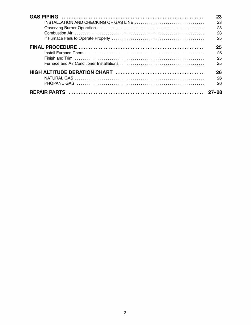
GAS PIPING 23. . . . . . . . . . . . . . . . . . . . . . . . . . . . . . . . . . . . . . . . . . . . . . . . . . . . . . . . . .INSTALLATION AND CHECKING OF GAS LINE 23. . . . . . . . . . . . . . . . . . . . . . . . . . . . . . . . . .Observing Burner Operation 23. . . . . . . . . . . . . . . . . . . . . . . . . . . . . . . . . . . . . . . . . . . . . . . . . . . .Combustion Air 23. . . . . . . . . . . . . . . . . . . . . . . . . . . . . . . . . . . . . . . . . . . . . . . . . . . . . . . . . . . . . . .If Furnace Fails to Operate Properly 25. . . . . . . . . . . . . . . . . . . . . . . . . . . . . . . . . . . . . . . . . . . . .
FINAL PROCEDURE 25. . . . . . . . . . . . . . . . . . . . . . . . . . . . . . . . . . . . . . . . . . . . . . . . . . .Install Furnace Doors 25. . . . . . . . . . . . . . . . . . . . . . . . . . . . . . . . . . . . . . . . . . . . . . . . . . . . . . . . . .Finish and Trim 25. . . . . . . . . . . . . . . . . . . . . . . . . . . . . . . . . . . . . . . . . . . . . . . . . . . . . . . . . . . . . . .Furnace and Air Conditioner Installations 25. . . . . . . . . . . . . . . . . . . . . . . . . . . . . . . . . . . . . . . . .
HIGH ALTITUDE DERATION CHART 26. . . . . . . . . . . . . . . . . . . . . . . . . . . . . . . . . . . .NATURAL GAS 26. . . . . . . . . . . . . . . . . . . . . . . . . . . . . . . . . . . . . . . . . . . . . . . . . . . . . . . . . . . . . . .PROPANE GAS 26. . . . . . . . . . . . . . . . . . . . . . . . . . . . . . . . . . . . . . . . . . . . . . . . . . . . . . . . . . . . . .
REPAIR PARTS 27--28. . . . . . . . . . . . . . . . . . . . . . . . . . . . . . . . . . . . . . . . . . . . . . . . . . . . . . .
4
LIST OF FIGURES
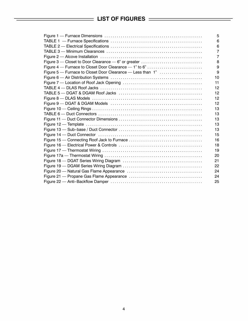
Figure 1 — Furnace Dimensions 5. . . . . . . . . . . . . . . . . . . . . . . . . . . . . . . . . . . . . . . . . . . . . . . .TABLE 1 — Furnace Specifications 6. . . . . . . . . . . . . . . . . . . . . . . . . . . . . . . . . . . . . . . . . . . . .TABLE 2 — Electrical Specifications 6. . . . . . . . . . . . . . . . . . . . . . . . . . . . . . . . . . . . . . . . . . . . .TABLE 3 — Minimum Clearances 7. . . . . . . . . . . . . . . . . . . . . . . . . . . . . . . . . . . . . . . . . . . . . . .Figure 2 — Alcove Installation 7. . . . . . . . . . . . . . . . . . . . . . . . . . . . . . . . . . . . . . . . . . . . . . . . . .Figure 3 — Closet to Door Clearance — 6” or greater 8. . . . . . . . . . . . . . . . . . . . . . . . . . . . . .Figure 4 — Furnace to Closet Door Clearance — 1” to 6” 9. . . . . . . . . . . . . . . . . . . . . . . . . . .Figure 5 — Furnace to Closet Door Clearance — Less than 1” 9. . . . . . . . . . . . . . . . . . . . .Figure 6 — Air Distribution Systems 10. . . . . . . . . . . . . . . . . . . . . . . . . . . . . . . . . . . . . . . . . . . . .Figure 7 — Location of Roof Jack Opening 11. . . . . . . . . . . . . . . . . . . . . . . . . . . . . . . . . . . . . . .TABLE 4 — DLAS Roof Jacks 12. . . . . . . . . . . . . . . . . . . . . . . . . . . . . . . . . . . . . . . . . . . . . . . . . .TABLE 5 — DGAT & DGAM Roof Jacks 12. . . . . . . . . . . . . . . . . . . . . . . . . . . . . . . . . . . . . . . . .Figure 8 — DLAS Models 12. . . . . . . . . . . . . . . . . . . . . . . . . . . . . . . . . . . . . . . . . . . . . . . . . . . . . .Figure 9 — DGAT & DGAM Models 12. . . . . . . . . . . . . . . . . . . . . . . . . . . . . . . . . . . . . . . . . . . . .Figure 10 — Ceiling Rings 13. . . . . . . . . . . . . . . . . . . . . . . . . . . . . . . . . . . . . . . . . . . . . . . . . . . . . .TABLE 6 — Duct Connectors 13. . . . . . . . . . . . . . . . . . . . . . . . . . . . . . . . . . . . . . . . . . . . . . . . . . .Figure 11 — Duct Connector Dimensions 13. . . . . . . . . . . . . . . . . . . . . . . . . . . . . . . . . . . . . . . . .Figure 12 — Template 13. . . . . . . . . . . . . . . . . . . . . . . . . . . . . . . . . . . . . . . . . . . . . . . . . . . . . . . . .Figure 13 — Sub--base / Duct Connector 13. . . . . . . . . . . . . . . . . . . . . . . . . . . . . . . . . . . . . . . . .Figure 14 — Duct Connector 15. . . . . . . . . . . . . . . . . . . . . . . . . . . . . . . . . . . . . . . . . . . . . . . . . . .Figure 15 — Connecting Roof Jack to Furnace 16. . . . . . . . . . . . . . . . . . . . . . . . . . . . . . . . . . . .Figure 16 — Electrical Power & Controls 18. . . . . . . . . . . . . . . . . . . . . . . . . . . . . . . . . . . . . . . . .Figure 17 — Thermostat Wiring 19. . . . . . . . . . . . . . . . . . . . . . . . . . . . . . . . . . . . . . . . . . . . . . . . .Figure 17a — Thermostat Wiring 20. . . . . . . . . . . . . . . . . . . . . . . . . . . . . . . . . . . . . . . . . . . . . . . .Figure 18 — DGAT Series Wiring Diagram 21. . . . . . . . . . . . . . . . . . . . . . . . . . . . . . . . . . . . . . .Figure 19 — DGAM Series Wiring Diagram 22. . . . . . . . . . . . . . . . . . . . . . . . . . . . . . . . . . . . . . .Figure 20 — Natural Gas Flame Appearance 24. . . . . . . . . . . . . . . . . . . . . . . . . . . . . . . . . . . . .Figure 21 — Propane Gas Flame Appearance 24. . . . . . . . . . . . . . . . . . . . . . . . . . . . . . . . . . . .Figure 22 — Anti--Backflow Damper 25. . . . . . . . . . . . . . . . . . . . . . . . . . . . . . . . . . . . . . . . . . . . .
5
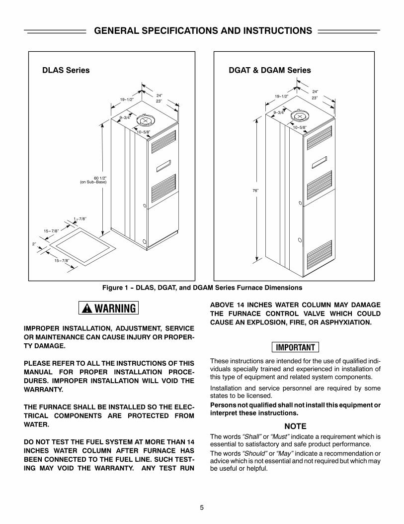
GENERAL SPECIFICATIONS AND INSTRUCTIONS
DGAT & DGAM SeriesDLAS Series
60 1/2”
76”
19--1/2”
9--3/4”
23”24”
10--5/8”
19--1/2”
9--3/4”
23”
24”
10--5/8”
15---7/8”
15---7/8”
2”
1---7/8”
(on Sub--Base)
Figure 1 -- DLAS, DGAT, and DGAM Series Furnace Dimensions
IMPROPER INSTALLATION, ADJUSTMENT, SERVICEORMAINTENANCE CAN CAUSE INJURY OR PROPER-TY DAMAGE.
PLEASE REFER TO ALL THE INSTRUCTIONS OF THISMANUAL FOR PROPER INSTALLATION PROCE-DURES. IMPROPER INSTALLATION WILL VOID THEWARRANTY.
THE FURNACE SHALL BE INSTALLED SO THE ELEC-TRICAL COMPONENTS ARE PROTECTED FROMWATER.
DO NOT TEST THE FUEL SYSTEM AT MORE THAN 14INCHES WATER COLUMN AFTER FURNACE HASBEEN CONNECTED TO THE FUEL LINE. SUCH TEST-ING MAY VOID THE WARRANTY. ANY TEST RUN
ABOVE 14 INCHES WATER COLUMN MAY DAMAGETHE FURNACE CONTROL VALVE WHICH COULDCAUSE AN EXPLOSION, FIRE, OR ASPHYXIATION.
These instructions are intended for the use of qualified indi-viduals specially trained and experienced in installation ofthis type of equipment and related system components.
Installation and service personnel are required by somestates to be licensed.Personsnot qualified shall not install this equipment orinterpret these instructions.
NOTEThe words “Shall” or “Must” indicate a requirement which isessential to satisfactory and safe product performance.The words “Should” or “May” indicate a recommendation oradvicewhich is not essential andnot requiredbut whichmaybe useful or helpful.
6
FURNACE SPECIFICATIONS
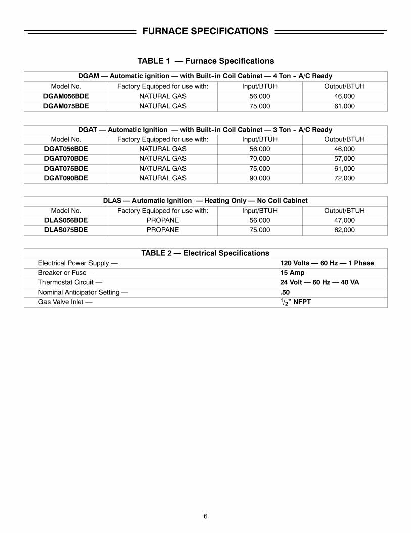
TABLE 1 — Furnace Specifications
DGAM — Automatic ignition — with Built--in Coil Cabinet — 4 Ton -- A/C ReadyModel No. Factory Equipped for use with: Input/BTUH Output/BTUH
DGAM056BDE NATURAL GAS 56,000 46,000
DGAM075BDE NATURAL GAS 75,000 61,000
DGAT — Automatic Ignition — with Built--in Coil Cabinet — 3 Ton -- A/C ReadyModel No. Factory Equipped for use with: Input/BTUH Output/BTUH
DGAT056BDE NATURAL GAS 56,000 46,000DGAT070BDE NATURAL GAS 70,000 57,000DGAT075BDE NATURAL GAS 75,000 61,000DGAT090BDE NATURAL GAS 90,000 72,000
DLAS — Automatic Ignition — Heating Only — No Coil CabinetModel No. Factory Equipped for use with: Input/BTUH Output/BTUH
DLAS056BDE PROPANE 56,000 47,000DLAS075BDE PROPANE 75,000 62,000
TABLE 2 — Electrical SpecificationsElectrical Power Supply — 120 Volts — 60 Hz — 1 PhaseBreaker or Fuse — 15 AmpThermostat Circuit — 24 Volt — 60 Hz — 40 VANominal Anticipator Setting — .50Gas Valve Inlet — 1/2” NFPT
7
INSTALLATION STANDARDS
Comply with Local Codes
The installer shall familiarize himself with and comply with alllocal codes and regulations which govern the installation ofthis appliance. Local codes and regulations shall takeprece-dent over these regulations where applicable. In lieu of localcodes, the appliance shall be installed in accordance with:
In the U.S.A.:
the National Electrical Code, in accordance with recom-mendations made by the National Board of Fire Under-writers, in accordance with the the American NationalStandard Institute National Fuel Gas Code (AnsiZ223.1/NFPA--54).
The installation must conform with:
local building codes,Federal Manufactured Home Construction & SafetyStandard (H.U.D. Title 24, Part 3280),or in the absence of local codes with:American National Standard Mobile Homes A225.1 forinstallation in mobile homes, and American NationalStandard (ANSI--C1/NFPA--70) for all electrical wiring,andAmericanNational Standard (A119.2/NFPA--501C)for installation in recreational vehicles.
In Canada:
Manufactured (Mobile) Homes:Unit installation shall comply with current CSA standardCAN/CSA--Z240.4.1 -- Installation Requirement for GasBurning Appliances in Mobile Homes.
Unit electrical wiring and grounding shall comply withcurrent standard CSA C22.1 -- Canadian ElectricalCode Part 1.
Recreational Vehicles:Unit installation shall comply with current CSA standardCAN/CGA--Z240.4.2 -- Installation Requirements forPropaneAppliances andEquipment in Recreational Ve-hicles.
Unit electrical wiring and grounding shall comply withcurrent CSA standard C22.2 No.148/CAN/CSA--Z240.6.2 -- Electrical Requirements for recreational ve-hicles.
HIGH ALTITUDE INSTALLATIONFor elevation above 2,000 feet, derate furnace orifice4% for each1,000 feet of elevation abovesea level.Der-ating is accomplished by reducing the orifice size.See Derating Chart for orifice size.
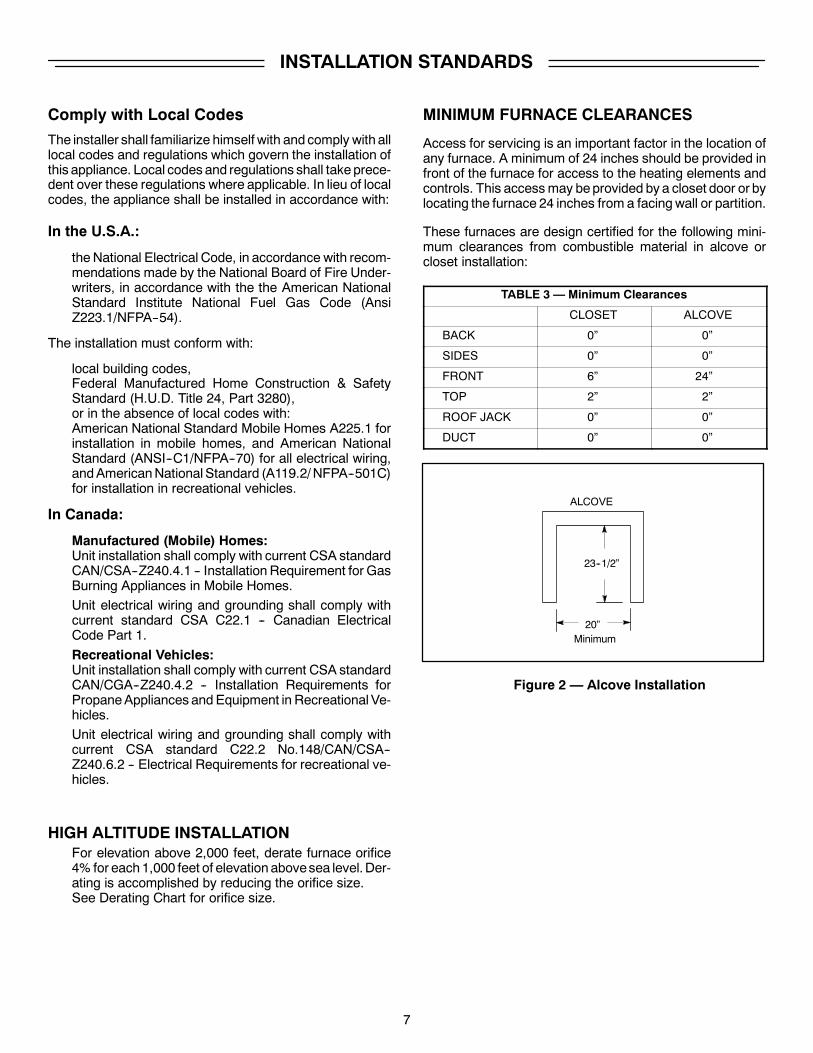
MINIMUM FURNACE CLEARANCES
Access for servicing is an important factor in the location ofany furnace. A minimum of 24 inches should be provided infront of the furnace for access to the heating elements andcontrols. This accessmay beprovided by a closet door or bylocating the furnace 24 inches from a facingwall or partition.
These furnaces are design certified for the following mini-mum clearances from combustible material in alcove orcloset installation:
TABLE 3 — Minimum Clearances
CLOSET ALCOVE
BACK 0” 0”
SIDES 0” 0”
FRONT 6” 24”
TOP 2” 2”
ROOF JACK 0” 0”
DUCT 0” 0”
ALCOVE
20”Minimum
23--1/2”
Figure 2 — Alcove Installation
8
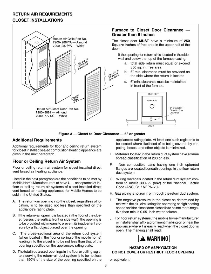
RETURN AIR REQUIREMENTSCLOSET INSTALLATIONS
Figure 3 — Closet to Door Clearance — 6” or greater
CLOSET
FURNACE
DOOR
6” or greater —Closet to DoorClearance
Furnace to Closet Door Clearance —Greater than 6 InchesThe closet door MUST have a minimum of 250Square Inches of free area in the upper half of thedoor.
If the opening for return air is located in the side-wall and below the top of the furnace casing:
a. total side return must equal or exceed350 sq. in. free area
b. 6” min. clearance must be provided onthe side where the return is located
Return Air Grille Part No.7900--286P/A — Almond7900--287P/A — White
Return Air Closet Door Part No.7900--8881 — Almond7900--7771/C — White
c. 6” min. clearancemust bemaintainedin front of the furnace.
Additional RequirementsAdditional requirements for floor and ceiling return systemfor closet installed sealed combustion heating appliance aregiven in the next paragraph.
Floor or Ceiling Return Air SystemFloor or ceiling return air system for closet installed directvent forced air heating appliance.
Listed in the next paragraph are the conditions to be met byMobile HomeManufacturers to have U.L. acceptance of in--floor or ceiling return air systems of closet installed directvent forced air heating appliances for Mobile Homes to besold in the United States.
A. The return--air opening into the closet, regardless of lo-cation, is to be sized not less than specified on theappliance’s rating plate.
B. If the return--air opening is located in the floor of the clos-et (versus the vertical front or side wall), the opening isto be providedwithmeans to prevent its inadvertent clo-sure by a flat object placed over the opening.
C. The cross--sectional area of the return duct system(when located in the floor or ceiling of the mobile home)leading into the closet is to be not less than that of theopening specified on the appliance’s rating plate.
D. The total freeareaof openings in the flooror ceiling regis-ters serving the return--air duct system is to be not lessthan 150% of the size of the opening specified on the
appliance’s rating plate. At least one such register is tobe located where likelihood of its being covered by car-peting, boxes, and other objects is minimized.
E. Materials located in the return duct system have a flamespread classification of 200 or less.
F. Non--combustible pans having one--inch upturnedflanges are located beneath openings in the floor returnduct system.
G. Wiring materials located in the return duct system con-form to Article 300--22 (b&c) of the National ElectricCode (ANSI C1 / NFPA--70).
H. Gas piping is not run in or through the return duct system.
I. The negative pressure in the closet as determined bytest with the air--circulating fan operating at high heatingspeedand the closet door closed is to benot morenega-tive than minus 0.05--inch water column.
J. For floor return systems, the mobile homemanufactureror installer shall affix a prominent marking on or near theappliance where it is easily read when the closet door isopen. The marking shall read:
HAZARD OF ASPHYXIATIONDO NOT COVER OR RESTRICT FLOOR OPENING
or equivalent.
9
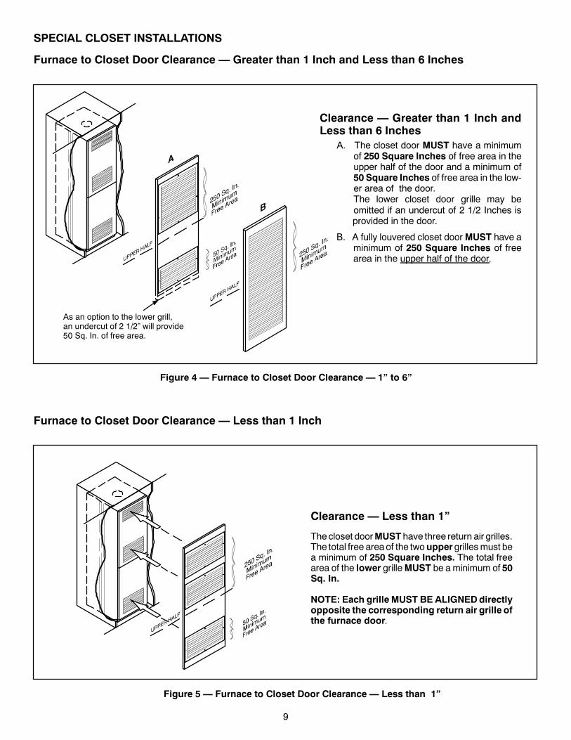
SPECIAL CLOSET INSTALLATIONS
Furnace to Closet Door Clearance — Greater than 1 Inch and Less than 6 Inches
Figure 4 — Furnace to Closet Door Clearance — 1” to 6”
As an option to the lower grill,an undercut of 2 1/2” will provide50 Sq. In. of free area.
Clearance — Greater than 1 Inch andLess than 6 Inches
A. The closet door MUST have a minimumof 250 Square Inches of free area in theupper half of the door and a minimum of50 Square Inches of free area in the low-er area of the door.The lower closet door grille may beomitted if an undercut of 2 1/2 Inches isprovided in the door.
B. A fully louvered closet doorMUST have aminimum of 250 Square Inches of freearea in the upper half of the door.
Furnace to Closet Door Clearance — Less than 1 Inch
Figure 5 — Furnace to Closet Door Clearance — Less than 1”
Clearance — Less than 1”
Thecloset doorMUST have three return air grilles.The total free areaof the twouppergrillesmust bea minimum of 250 Square Inches. The total freearea of the lower grilleMUST be aminimum of 50Sq. In.
NOTE: Each grille MUST BE ALIGNEDdirectlyopposite the corresponding return air grille ofthe furnace door.
10
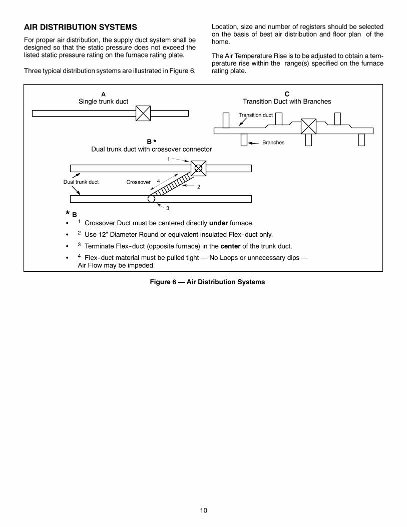
AIR DISTRIBUTION SYSTEMS
For proper air distribution, the supply duct system shall bedesigned so that the static pressure does not exceed thelisted static pressure rating on the furnace rating plate.
Three typical distribution systems are illustrated in Figure 6.
Location, size and number of registers should be selectedon the basis of best air distribution and floor plan of thehome.
The Air Temperature Rise is to be adjusted to obtain a tem-perature rise within the range(s) specified on the furnacerating plate.
ASingle trunk duct
Dual trunk duct
Transition duct
* BS 1 Crossover Duct must be centered directly under furnace.
S 2 Use 12” Diameter Round or equivalent insulated Flex--duct only.
S 3 Terminate Flex--duct (opposite furnace) in the center of the trunk duct.
S 4 Flex--duct material must be pulled tight — No Loops or unnecessary dips —Air Flow may be impeded.
1
2
3
4
B *Dual trunk duct with crossover connector
Crossover
CTransition Duct with Branches
Branches
Figure 6 — Air Distribution Systems
11
ROOF JACKS
Only use the appropriate roof jack.See TABLE 4 & TABLE 5 for correct application.
Do not exceed themaximumheight as determined fromTABLE 4&TABLE 5. Installer should allow an addition-al 1--1/2” travel before the flue pipe assembly is fully ex-tended against the built--in stop. This provides an addi-tional safeguard against the flueassemblybeingpulledfrom the roof jack during transportation or other stressconditions.
Improper installation may damage the equipment, cancreate a hazard, and will void the warranty.
Carefully follow all instructions and warnings to avoidFire, Explosion, Or Asphyxiation.
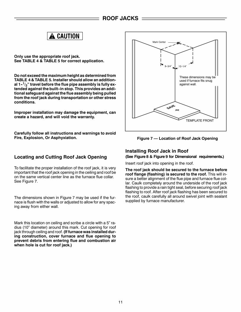
Locating and Cutting Roof Jack Opening
To facilitate the proper installation of the roof jack, it is veryimportant that the roof jack opening in the ceiling and roof beon the same vertical center line as the furnace flue collar.See Figure 7.
The dimensions shown in Figure 7 may be used if the fur-nace is flush with the walls or adjusted to allow for any spac-ing away from either wall.
Mark this location on ceiling and scribe a circle with a 5” ra-dius (10” diameter) around this mark. Cut opening for roofjack through ceiling and roof. (If furnacewas installed dur-ing construction, cover furnace and flue opening toprevent debris from entering flue and combustion airwhen hole is cut for roof jack.)
9--3/4” 12--1/4”
Mark Center
Figure 7 — Location of Roof Jack Opening
TEMPLATE FRONT
These dimensions may beused if furnace fits snugagainst wall.
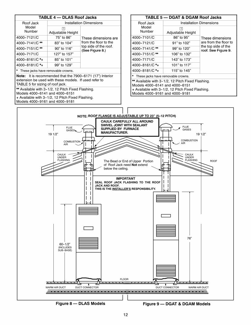
Installing Roof Jack in Roof(See Figure 8 & Figure 9 for Dimensional requirements.)
Insert roof jack into opening in the roof.
The roof jack should be secured to the furnace beforeroof flange (flashing) is secured to the roof. This will in-sure a better alignment of the flue pipe and furnace flue col-lar. Caulk completely around the underside of the roof jackflashing to provide a rain tight seal, before securing roof jackflashing to roof. After roof jack flashing has been secured tothe roof, caulk carefully all around swivel joint with sealantsupplied by furnace manufacturer.
12
TABLE 4 — DLAS Roof JacksRoof Jack Installation DimensionsModelNumber
¡Adjustable Height
4000--7121/C 75” to 86” These dimensions are4000--7141/C ** 83” to 104”
These dimensions arefrom the floor to thetop side of the roof
4000--7151/C ** 90” to 116”top side of the roof.(See Figure 8.)
4000--7171/C 127” to 157”(See Figure 8.)
4000--8161/C *+ 85” to 101”
4000--8181/C *+ 99” to 129”
* These jacks have removable crowns.
Note: It is recommended that the 7900--6171 (17”) Interiorextension be used with these models. If used refer toTABLE 5 for sizing of roof jack.** Available with 3--1/2, 12 Pitch Fixed Flashing.Models 4000--6141 and 4000--6151+ Available with 3--1/2, 12 Pitch Fixed Flashing.Models 4000--9161 and 4000--9181
TABLE 5 — DGAT & DGAM Roof JacksRoof Jack Installation DimensionsModelNumber
¡Adjustable Height
4000--7101/C 86” to 95” These dimensions4000--7121/C 91” to 102”
These dimensionsare from the floor tothe top side of the
4000--7141/C ** 99” to 120”the top side of theroof. See Figure 9.
4000--7151/C ** 106” to 132”roof. See Figure 9.
4000--7171/C 143” to 173”
4000--8161/C *+ 101” to 117”
4000--8181/C *+ 115” to 145”
* These jacks have removable crowns.
** Available with 3--1/2, 12 Pitch Fixed Flashing.Models 4000--6141 and 4000--6151+ Available with 3--1/2, 12 Pitch Fixed Flashing.Models 4000--9161 and 4000--9181
ROOF FLANGE IS ADJUSTABLE UP TO 23” (5--12 PITCH)
WARM AIR DUCTDUCT CONNECTOR
ROOF
76”
CAULK CAREFULLY ALL AROUNDSWIVEL JOINT WITH SEALANTSUPPLIED BY FURNACEMANUFACTURER.
SEAL ROOF JACK FLASHING TO THE ROOFJACK AND ROOF.THIS IS THE INSTALLER’S RESPONSIBILITY.
60--1/2”
WARM AIR DUCT DUCT CONNECTOR
FLOOR
FLUEGASES
COMBUSTIONAIR
CAULKUNDERFLASHING The Bead or End of Upper Portion
of Roof Jack need Not extendbelow the ceiling.
(INCLUDESSUB--BASE)
19 1/2”
CAULKUNDERFLASHING
� �
FLUEGASES
COMBUSTIONAIR
19 1/2”
Figure 8 — DLAS Models Figure 9 — DGAT & DGAM Models
NOTE:
IMPORTANT
13
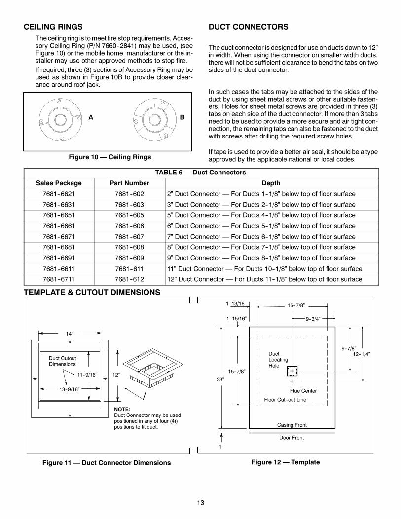
CEILING RINGSTheceiling ring is tomeet fire stop requirements. Acces-sory Ceiling Ring (P/N 7660--2841) may be used, (seeFigure 10) or the mobile home manufacturer or the in-staller may use other approved methods to stop fire.If required, three (3) sections of Accessory Ring may beused as shown in Figure 10B to provide closer clear-ance around roof jack.
Figure 10 — Ceiling Rings
A B
DUCT CONNECTORS
The duct connector is designed for use on ducts down to 12”in width. When using the connector on smaller width ducts,there will not be sufficient clearance to bend the tabs on twosides of the duct connector.
In such cases the tabs may be attached to the sides of theduct by using sheet metal screws or other suitable fasten-ers. Holes for sheet metal screws are provided in three (3)tabs on each side of the duct connector. If more than 3 tabsneed to be used to provide a more secure and air tight con-nection, the remaining tabs can also be fastened to the ductwith screws after drilling the required screw holes.
If tape is used to provide a better air seal, it should be a typeapproved by the applicable national or local codes.
TABLE 6 — Duct Connectors
Sales Package Part Number Depth
7681--6621 7681--602 2” Duct Connector — For Ducts 1--1/8” below top of floor surface
7681--6631 7681--603 3” Duct Connector — For Ducts 2--1/8” below top of floor surface
7681--6651 7681--605 5” Duct Connector — For Ducts 4--1/8” below top of floor surface
7681--6661 7681--606 6” Duct Connector — For Ducts 5--1/8” below top of floor surface
7681--6671 7681--607 7” Duct Connector — For Ducts 6--1/8” below top of floor surface
7681--6681 7681--608 8” Duct Connector — For Ducts 7--1/8” below top of floor surface
7681--6691 7681--609 9” Duct Connector — For Ducts 8--1/8” below top of floor surface
7681--6611 7681--611 11” Duct Connector — For Ducts 10--1/8” below top of floor surface
7681--6711 7681--612 12” Duct Connector — For Ducts 11--1/8” below top of floor surface
TEMPLATE & CUTOUT DIMENSIONS
14”
13--9/16”
11--9/16”
Duct CutoutDimensions
12”
NOTE:Duct Connector may be usedpositioned in any of four (4))positions to fit duct.
Figure 11 — Duct Connector Dimensions
Casing Front
Door Front
15--7/8”
9--7/8”12--1/4”
15--7/8”1--13/16
9--3/4”
23”
1”
Floor Cut--out Line
Flue Center
DuctLocatingHole
1--15/16”
Figure 12 — Template
14
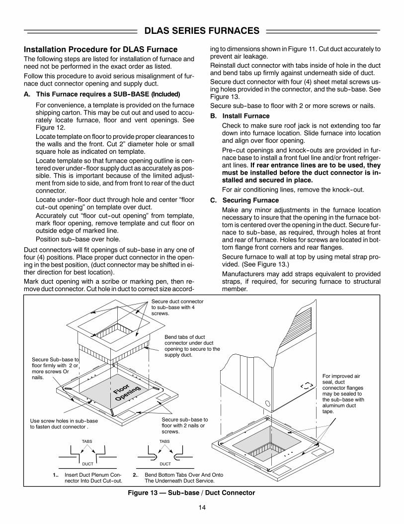
DLAS SERIES FURNACES
Installation Procedure for DLAS FurnaceThe following steps are listed for installation of furnace andneed not be performed in the exact order as listed.
Follow this procedure to avoid serious misalignment of fur-nace duct connector opening and supply duct.
A. This Furnace requires a SUB--BASE (Included)
For convenience, a template is provided on the furnaceshipping carton. This may be cut out and used to accu-rately locate furnace, floor and vent openings. SeeFigure 12.Locate template on floor to provideproper clearances tothe walls and the front. Cut 2” diameter hole or smallsquare hole as indicated on template.Locate template so that furnace opening outline is cen-teredover under--floor supply duct as accurately as pos-sible. This is important because of the limited adjust-ment from side to side, and from front to rear of the ductconnector.Locate under--floor duct through hole and center “floorcut--out opening” on template over duct.Accurately cut “floor cut--out opening” from template,mark floor opening, remove template and cut floor onoutside edge of marked line.Position sub--base over hole.
Duct connectors will fit openings of sub--base in any one offour (4) positions. Place proper duct connector in the open-ing in the best position, (duct connector may be shifted in ei-ther direction for best location).Mark duct opening with a scribe or marking pen, then re-moveduct connector. Cut hole in duct to correct size accord-
ing to dimensions shown inFigure 11. Cut duct accurately toprevent air leakage.Reinstall duct connector with tabs inside of hole in the ductand bend tabs up firmly against underneath side of duct.Secure duct connector with four (4) sheet metal screws us-ing holes provided in the connector, and the sub--base. SeeFigure 13.Secure sub--base to floor with 2 or more screws or nails.
B. Install FurnaceCheck to make sure roof jack is not extending too fardown into furnace location. Slide furnace into locationand align over floor opening.
Pre--cut openings and knock--outs are provided in fur-nace base to install a front fuel line and/or front refriger-ant lines. If rear entrance lines are to be used, theymust be installed before the duct connector is in-stalled and secured in place.For air conditioning lines, remove the knock--out.
C. Securing FurnaceMake any minor adjustments in the furnace locationnecessary to insure that the opening in the furnace bot-tom is centered over the opening in theduct. Secure fur-nace to sub--base, as required, through holes at frontand rear of furnace. Holes for screws are located in bot-tom flange front corners and rear flanges.Secure furnace to wall at top by using metal strap pro-vided. (See Figure 13.)
Manufacturers may add straps equivalent to providedstraps, if required, for securing furnace to structuralmember.
Secure Sub--base tofloor firmly with 2 ormore screws Ornails.
Secure duct connectorto sub--base with 4screws.
Use screw holes in sub--baseto fasten duct connector .
Bend tabs of ductconnector under ductopening to secure to thesupply duct.
Secure sub--base tofloor with 2 nails orscrews.
TABS TABS
DUCT DUCT
1.. Insert Duct Plenum Con-nector Into Duct Cut--out.
2.. Bend Bottom Tabs Over And OntoThe Underneath Duct Service.
For improved airseal, ductconnector flangesmay be sealed tothe sub--base withaluminum ducttape.
Figure 13 — Sub--base / Duct Connector
15
DGAT & DGAM SERIES FURNACES
Installation Procedure for DGAT & DGAMFurnaces
The following steps are listed for installation of furnace andneed not be performed in the exact order as listed:
Follow this procedure to avoid serious misalignment of fur-nace duct connector opening and supply duct.
A. This Furnace requires NO sub--base
For convenience, a template is provided on the furnaceshipping carton. This may be cut out and used to accu-rately locate furnace, floor and vent openings. SeeFigure 12.Locate template on floor to provideproper clearances tothe walls and the front. Cut 2” diameter hole or smallsquare hole as indicated on template.Locate template so that furnace opening outline is cen-teredover under--floor supply duct as accurately as pos-sible. This is important because of the limited adjust-ment from side to side, and from front to rear of the ductconnector.Locate under--floor duct through hole and center “floorcut--out opening” on template over duct.Accurately cut “floor cut--out opening” from template,mark floor opening, remove template and cut floor onoutside edge of marked line.
Duct connectors will fit opening in any one of four (4) posi-tions. Place proper duct connector in the opening in the bestposition, (duct connector may be shifted in either directionfor best location).
Mark duct opening with a scribe or marking pen, then re-moveduct connector. Cut hole in duct to correct size accord-ing to dimensions shown inFigure 11. Cut duct accurately toprevent air leakage.Reinstall duct connector with tabs inside of hole in the ductand bend tabs up firmly against underneath side of duct.Secure duct connector to floor with four (4) sheet metalscrews using holes provided in the connector. SeeFigure 14.
B. Install Furnace
Remove panel from air conditioning compartment.Check to make sure roof jack is not extending too fardown into furnace location. Slide furnace into locationand align over floor opening.
Pre--cut openings and knock--outs are provided in fur-nace base to install a front fuel line and/or front refriger-ant lines. If rear entrance lines are to be used, theymust be installed before the duct connector is in-stalled and secured in place.For air conditioning lines, remove the knock--out.
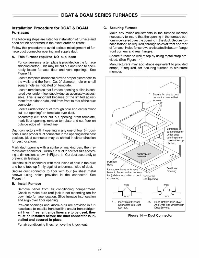
C. Securing Furnace
Make any minor adjustments in the furnace locationnecessary to insure that the opening in the furnace bot-tom is centered over the opening in theduct. Secure fur-nace to floor, as required, throughholes at front and rearof furnace. Holes for screws are located in bottom flangefront corners and rear flanges.Secure furnace to wall at top by using metal strap pro-vided. (See Figure 14.)Manufacturers may add straps equivalent to providedstraps, if required, for securing furnace to structuralmember.
SUPPLY DUCTOPENING
Fuel LineOpening
Use screw holes in furnacebase to fasten to duct connec-tor (relative to position of ductconnector) .
Secure furnace to ductconnector base with 4screws.
RefrigerantLine Opening
FurnaceBase
Bend tabs ofduct connectorunder ductopening to se-cure to the sup-ply duct.
TABS TABS
DUCT DUCT
1. Insert Duct PlenumConnector Into DuctCut--out.
2. Bend Bottom Tabs OverAnd Onto The UnderneathDuct Service.
Figure 14 — Duct Connector
16
CONNECTING ROOF JACK TO FURNACE
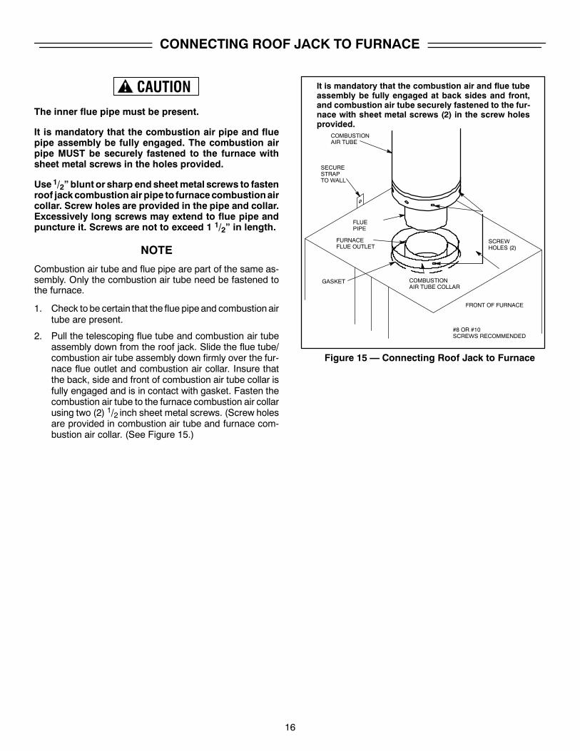
The inner flue pipe must be present.
It is mandatory that the combustion air pipe and fluepipe assembly be fully engaged. The combustion airpipe MUST be securely fastened to the furnace withsheet metal screws in the holes provided.
Use 1/2” blunt or sharp end sheetmetal screws to fastenroof jackcombustion air pipe to furnacecombustionaircollar. Screw holes are provided in the pipe and collar.Excessively long screws may extend to flue pipe andpuncture it. Screws are not to exceed 1 1/2” in length.
NOTE
Combustion air tube and flue pipe are part of the same as-sembly. Only the combustion air tube need be fastened tothe furnace.
1. Check to be certain that the flue pipeand combustion airtube are present.
2. Pull the telescoping flue tube and combustion air tubeassembly down from the roof jack. Slide the flue tube/combustion air tube assembly down firmly over the fur-nace flue outlet and combustion air collar. Insure thatthe back, side and front of combustion air tube collar isfully engaged and is in contact with gasket. Fasten thecombustion air tube to the furnace combustion air collarusing two (2) 1/2 inch sheet metal screws. (Screw holesare provided in combustion air tube and furnace com-bustion air collar. (See Figure 15.)
It is mandatory that the combustion air and flue tubeassembly be fully engaged at back sides and front,and combustion air tube securely fastened to the fur-nace with sheet metal screws (2) in the screw holesprovided.
COMBUSTIONAIR TUBE
FLUEPIPE
SCREWHOLES (2)
COMBUSTIONAIR TUBE COLLAR
#8 OR #10SCREWS RECOMMENDED
FURNACEFLUE OUTLET
SECURESTRAPTO WALL
FRONT OF FURNACE
Figure 15 — Connecting Roof Jack to Furnace
GASKET
17
IMPORTANT
VENT SYSTEM INSTALLATION INSTRUCTIONS
FAILURE TO FOLLOW ALL VENTING INSTRUCT--IONS CAN RESULT IN FIRE, ASPHYXIATION, OREXPLOSION.
Thevent system is an important part of your furnace installa-tion. Carefully read and observe the following basic instruc-tions, as well as those packed with the vent system.
EXISTING FURNACE REPLACEMENT
IF THISFURNACEREPLACESANEXISTINGFURNACE,DO THE FOLLOWING.
1. If a 2nd roof, roof cap or addition has been made to theexisting roof of the home, remove the old vent systemcompletely!... to avoid the possibility of an improp-erly installed pipe or gaps in the old vent system,INSTALL A NEW VENT SYSTEM. Your ceiling androof height will determine the correct vent systemto use. Refer to the vent selection table, of the fur-nace installation instructions.
2. After unpacking the vent system, check the rain caps.Insure they are not damaged, tilted or crooked. Do nottwist, crush or sit on the roof caps during installa-tion. Damaged roof caps will cause improper furnaceoperation. The furnace will not heat properly and couldresult in explosion.
3. Before inserting the vent pipe into the furnace top, in-spect the furnace flue and combustion air opening fordebris or insulation which might have fallen in duringpre--installation steps. Do not proceed unless all debrishave been cleaned out or removed.
4. After installing vent pipe on furnace top collar, check tomake sure there is no gap in back or side between thepipe collar and the furnace casing top.
5. Use only the pipes providedwith the roof jack assembly.Do not add to or adapt other sheet metal pipes. Do notcut, insert or add other pipes to this assembly.
6. In no case should there be a gap between sections ofthe flue pipe or the combustion air pipe. If necessary toprevent excessive air leakage, the installer should sealjoints in the combustion air tube with aluminum type orother suitable sealant.
NEW HOME INSTALLATION
IF THIS FURNACE IS INSTALLED ON A NEW HOME DOTHE FOLLOWING
1. Inspect the furnace top collars for signs of insulation orceiling debris which might have fallen in during cuttingof the ceiling and roof holes. Remove all debris beforecontinuing.
2. After unpacking the vent system, check the rain caps.Insure they are not damaged, tilted or crooked. Do nottwist, crush or sit on the roof caps during installa-tion. Damaged roof caps will cause improper furnaceoperation. The furnace will not heat properly and couldresult in explosion.
3. Before inserting the vent pipe into the furnace top, in-spect the furnace flue and combustion air opening fordebris or insulation which might have fallen in duringpre--installation steps. Do not proceed unless all debrishave been cleaned out or removed.
4. After installing vent pipe on furnace top collar, check tomake sure there is no gap in back or side between thepipe collar and the furnace casing top. If necessary toprevent excessive air leakage, the installer should sealjoints in the combustion air tube with aluminum type orother suitable sealant.
INSTALLATION IN SNOW REGIONS
When the combustion air pipe inlet is covered or blockedwith snow, the furnace will not operate properly due to thedepleted combustion air supply.
Therefore, if the furnace will be located in regions wheresnow accumulation on the roof exceeds 7” or in H.U.D.Snow Load Zones, a # 7680B6541 roof jack extension isrecommended.
18
ELECTRICAL WIRING
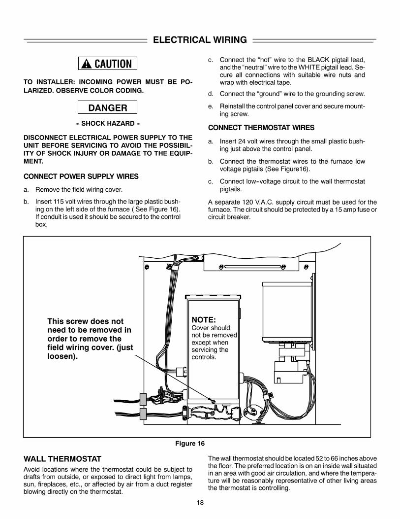
TO INSTALLER: INCOMING POWER MUST BE PO-LARIZED. OBSERVE COLOR CODING.
DANGER-- SHOCK HAZARD --
DISCONNECT ELECTRICAL POWER SUPPLY TO THEUNIT BEFORE SERVICING TO AVOID THE POSSIBIL-ITY OF SHOCK INJURY OR DAMAGE TO THE EQUIP-MENT.
CONNECT POWER SUPPLY WIRES
a. Remove the field wiring cover.
b. Insert 115 volt wires through the large plastic bush-ing on the left side of the furnace ( See Figure 16).If conduit is used it should be secured to the controlbox.
c. Connect the “hot” wire to the BLACK pigtail lead,and the “neutral” wire to theWHITE pigtail lead. Se-cure all connections with suitable wire nuts andwrap with electrical tape.
d. Connect the “ground” wire to the grounding screw.
e. Reinstall the control panel cover and securemount-ing screw.
CONNECT THERMOSTAT WIRES
a. Insert 24 volt wires through the small plastic bush-ing just above the control panel.
b. Connect the thermostat wires to the furnace lowvoltage pigtails (See Figure16).
c. Connect low--voltage circuit to the wall thermostatpigtails.
A separate 120 V.A.C. supply circuit must be used for thefurnace. The circuit should be protected by a 15 amp fuse orcircuit breaker.
Figure 16
This screw does notneed to be removed inorder to remove thefield wiring cover. (justloosen).
NOTE:Cover shouldnot be removedexcept whenservicing thecontrols.
WALL THERMOSTATAvoid locations where the thermostat could be subject todrafts from outside, or exposed to direct light from lamps,sun, fireplaces, etc., or affected by air from a duct registerblowing directly on the thermostat.
Thewall thermostat should be located52 to 66 inches abovethe floor. The preferred location is on an inside wall situatedin an area with good air circulation, and where the tempera-ture will be reasonably representative of other living areasthe thermostat is controlling.
19
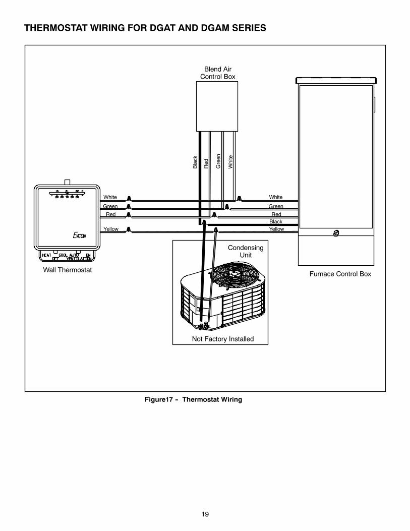
THERMOSTAT WIRING FOR DGAT AND DGAM SERIES
Figure17 -- Thermostat Wiring
White
Green
Black
Red
Blend AirControl Box
CondensingUnit
Wall ThermostatFurnace Control Box
Not Factory Installed
White
Green
BlackRed
Yellow
White
Green
Red
Yellow
20
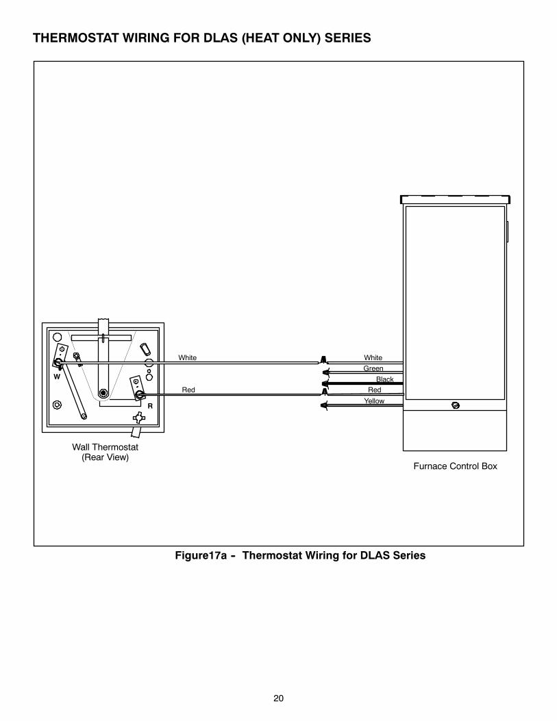
THERMOSTAT WIRING FOR DLAS (HEAT ONLY) SERIES
Wall Thermostat(Rear View)
Furnace Control Box
Figure17a -- Thermostat Wiring for DLAS Series
R
W
White
Green
Black
Red
Yellow
White
Red
21
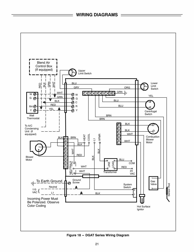
WIRING DIAGRAMS
Figure 18 -- DGAT Series Wiring Diagram
W
G
RH
Y
WallThermostat
1 2 3 4 5 6 7 8 9
UpperLimit Switch
LowerLimitSwitch
CentrifugalSwitch
CombustionBlowerMotor1
23456
Hot SurfaceIgnitor
GasValve
12
3456789
BlowerMotor
SystemSwitch
To Earth Ground
Neutral
L1115VAC{
To A/CCondensingUnit (Ifequipped)
Incoming Power MustBe Polarized. ObserveColor Coding
NEUTRALS
GroundScrew
HEAT
COOL
L1 XFMR
COM
24VAC
RED
BLK
BRN
WHT
WHT
BLK
BLU
REDLOAD
LINE
WHT
WHT
BLK
SensorRod
BLK
BRNBRN
BLK
BLU
BLU
GRN
ORG
BLU
GRY
W
G
R
Y
C
BLK
BLK
BLK
GRN
WHT
RED
YEL
BLK
GRN
WHT
Transformer
YEL
RED
WHT
2
1
Blend AirControl Box(If equipped)
22
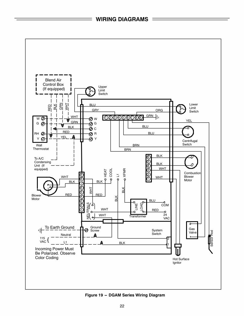
WIRING DIAGRAMS
Figure 19 -- DGAM Series Wiring Diagram
Blend AirControl Box(If equipped)
G
RH
Y
WallThermostat
1 2 3 4 5 6 7 8 9
UpperLimitSwitch
LowerLimitSwitch
CentrifugalSwitch
CombustionBlowerMotor1
2
3456
Hot SurfaceIgnitor
GasValve
1
234567
89
BlowerMotor
SystemSwitch
To Earth Ground
Neutral
L1115VAC{
To A/CCondensingUnit (Ifequipped)
Incoming Power MustBe Polarized. ObserveColor Coding
NEUTRALS
GroundScrew
HEAT
COOL
L1 XFMR
COM
24VAC
RED
BLK
WHT
WHT
BLK
BLU
REDLOAD
LINE
WHT
WHT
BLK
SensorRod
BLK
BRNBRN
BLU
BLU
GRN
ORG
BLU
GRY
WG
R
Y
C
BLK
BLK
BLK
GRN
WHT
RED
YEL
BLK
GRN
WHT
Transformer
YEL
RED
WHT
2
1
WHT
BLK
RED
W
23
GAS PIPING
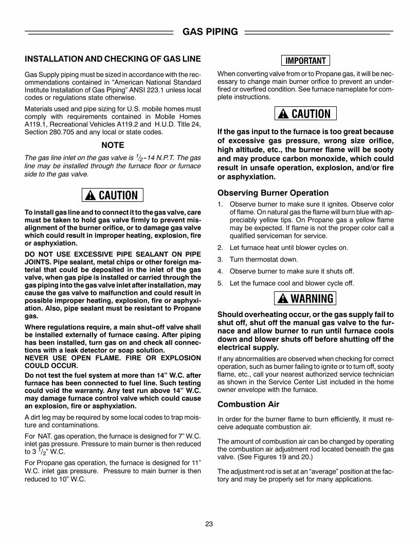
INSTALLATIONANDCHECKINGOF GAS LINE
Gas Supply pipingmust be sized in accordancewith the rec-ommendations contained in “American National StandardInstitute Installation of Gas Piping” ANSI 223.1 unless localcodes or regulations state otherwise.
Materials used and pipe sizing for U.S. mobile homes mustcomply with requirements contained in Mobile HomesA119.1, Recreational Vehicles A119.2 and H.U.D. Title 24,Section 280.705 and any local or state codes.
NOTEThe gas line inlet on the gas valve is 1/2 --14 N.P.T. The gasline may be installed through the furnace floor or furnaceside to the gas valve.
To install gas lineand to connect it to thegasvalve, caremust be taken to hold gas valve firmly to prevent mis-alignment of the burner orifice, or to damage gas valvewhich could result in improper heating, explosion, fireor asphyxiation.
DO NOT USE EXCESSIVE PIPE SEALANT ON PIPEJOINTS. Pipe sealant, metal chips or other foreign ma-terial that could be deposited in the inlet of the gasvalve, when gas pipe is installed or carried through thegaspiping into thegasvalve inlet after installation,maycause the gas valve to malfunction and could result inpossible improper heating, explosion, fire or asphyxi-ation. Also, pipe sealant must be resistant to Propanegas.
Where regulations require, a main shut--off valve shallbe installed externally of furnace casing. After pipinghas been installed, turn gas on and check all connec-tions with a leak detector or soap solution.NEVER USE OPEN FLAME. FIRE OR EXPLOSIONCOULD OCCUR.Do not test the fuel system at more than 14” W.C. afterfurnace has been connected to fuel line. Such testingcould void the warranty. Any test run above 14” W.C.may damage furnace control valve which could causean explosion, fire or asphyxiation.
A dirt leg may be required by some local codes to trapmois-ture and contaminations.
For NAT. gas operation, the furnace is designed for 7” W.C.inlet gas pressure. Pressure to main burner is then reducedto 3 1/2” W.C.
For Propane gas operation, the furnace is designed for 11”W.C. inlet gas pressure. Pressure to main burner is thenreduced to 10” W.C.
Whenconverting valve fromor to Propanegas, it will be nec-essary to change main burner orifice to prevent an under-fired or overfired condition. See furnace nameplate for com-plete instructions.
If the gas input to the furnace is too great becauseof excessive gas pressure, wrong size orifice,high altitude, etc., the burner flame will be sootyand may produce carbon monoxide, which couldresult in unsafe operation, explosion, and/or fireor asphyxiation.
Observing Burner Operation1. Observe burner to make sure it ignites. Observe color
of flame. On natural gas the flamewill burn blue with ap-preciably yellow tips. On Propane gas a yellow flamemay be expected. If flame is not the proper color call aqualified serviceman for service.
2. Let furnace heat until blower cycles on.
3. Turn thermostat down.
4. Observe burner to make sure it shuts off.
5. Let the furnace cool and blower cycle off.
Should overheatingoccur, or the gas supply fail toshut off, shut off the manual gas valve to the fur-nace and allow burner to run until furnace coolsdown and blower shuts off before shutting off theelectrical supply.If any abnormalities are observed when checking for correctoperation, such as burner failing to ignite or to turn off, sootyflame, etc., call your nearest authorized service technicianas shown in the Service Center List included in the homeowner envelope with the furnace.
Combustion Air
In order for the burner flame to burn efficiently, it must re-ceive adequate combustion air.
The amount of combustion air can be changed by operatingthe combustion air adjustment rod located beneath the gasvalve. (See Figures 19 and 20.)
The adjustment rod is set at an “average” position at the fac-tory and may be properly set for many applications.
24
However, the amount of combustion air requiredwill varyde-pending on altitude, actual BTU. content of the gas beingused, gas pressure, conversion to another gas, and othervariable factors.
Therefore, it is essential that the burner flame be observedand any necessary adjustments are made before the fur-nace is put into service at the final home site. Adjusting theburner air is considered part of the normal home set--up pro-cedure and is the responsibility of either the home seller orbuyer, depending on their agreement. Adjustments of thistype are not covered by the warranty.
Combustion air adjustments must be made onlyby a qualified technician. Improper air adjustmentmay cause unsafe operation, explosion or as-phyxiation.
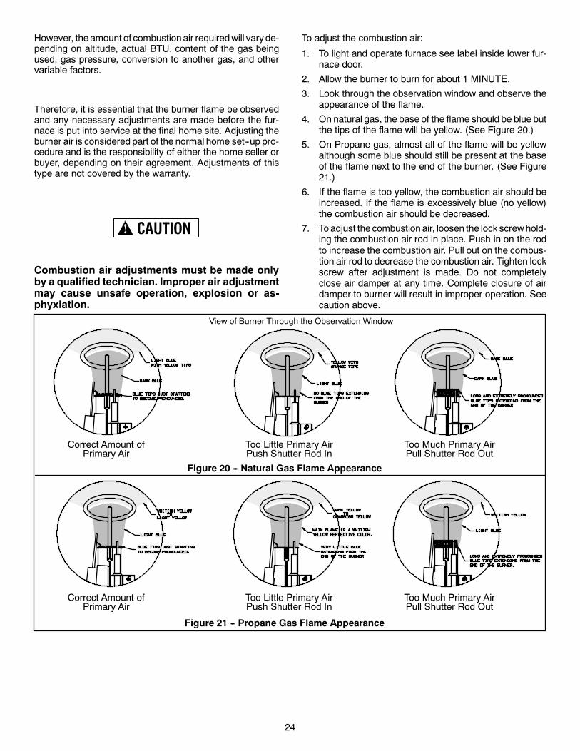
To adjust the combustion air:
1. To light and operate furnace see label inside lower fur-nace door.
2. Allow the burner to burn for about 1 MINUTE.
3. Look through the observation window and observe theappearance of the flame.
4. On natural gas, the base of the flame should be blue butthe tips of the flame will be yellow. (See Figure 20.)
5. On Propane gas, almost all of the flame will be yellowalthough some blue should still be present at the baseof the flame next to the end of the burner. (See Figure21.)
6. If the flame is too yellow, the combustion air should beincreased. If the flame is excessively blue (no yellow)the combustion air should be decreased.
7. Toadjust the combustion air, loosen the lock screwhold-ing the combustion air rod in place. Push in on the rodto increase the combustion air. Pull out on the combus-tion air rod to decrease the combustion air. Tighten lockscrew after adjustment is made. Do not completelyclose air damper at any time. Complete closure of airdamper to burner will result in improper operation. Seecaution above.
View of Burner Through the Observation Window
Correct Amount ofPrimary Air
Too Little Primary AirPush Shutter Rod In
Too Much Primary AirPull Shutter Rod Out
Correct Amount ofPrimary Air
Too Little Primary AirPush Shutter Rod In
Too Much Primary AirPull Shutter Rod Out
Figure 20 -- Natural Gas Flame Appearance
Figure 21 -- Propane Gas Flame Appearance
25
If Furnace Fails to Operate Properly1. Check setting of thermostat -- and position of HEAT/
COOL switch if air conditioning is installed. If a set--backtype thermostat is employedbe sure that the thermostatis in the correct operating mode.
2. Check to see that electrical power is ON.3. Check to see that the knob on the gas control valve is
in the full ON position.
4. Make sure filters are clean, return grilles are not ob-structed, and supply registers are open.
5. Be sure that furnace flue piping is open and unob-structed.
If the cause for the failure to operate is not obvious, donot attempt to service the furnace yourself. Call a quali-fied service agency or your gas supplier.
FINAL PROCEDURE
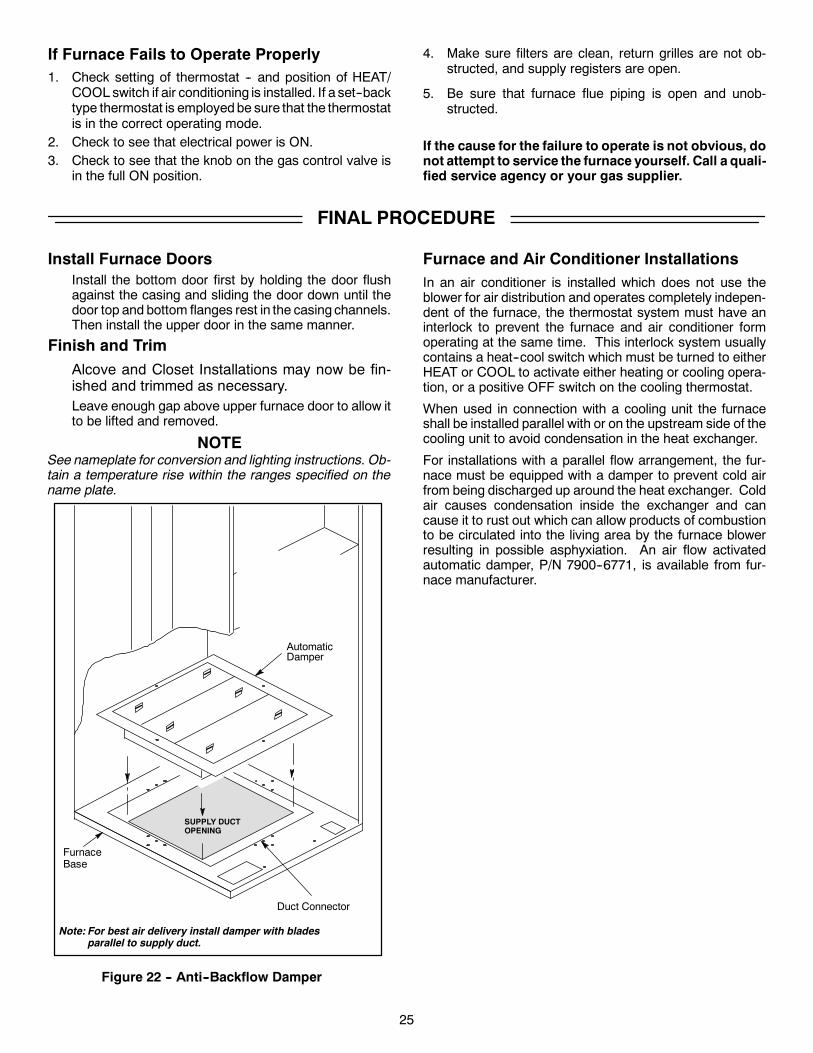
Install Furnace DoorsInstall the bottom door first by holding the door flushagainst the casing and sliding the door down until thedoor top and bottom flanges rest in the casing channels.Then install the upper door in the same manner.
Finish and TrimAlcove and Closet Installations may now be fin-ished and trimmed as necessary.Leave enough gap above upper furnace door to allow itto be lifted and removed.
NOTESee nameplate for conversion and lighting instructions. Ob-tain a temperature rise within the ranges specified on thename plate.
SUPPLY DUCTOPENING
FurnaceBase
Figure 22 -- Anti--Backflow Damper
Duct Connector
AutomaticDamper
Note: For best air delivery install damper with bladesparallel to supply duct.
Furnace and Air Conditioner InstallationsIn an air conditioner is installed which does not use theblower for air distribution and operates completely indepen-dent of the furnace, the thermostat system must have aninterlock to prevent the furnace and air conditioner formoperating at the same time. This interlock system usuallycontains a heat--cool switch which must be turned to eitherHEAT or COOL to activate either heating or cooling opera-tion, or a positive OFF switch on the cooling thermostat.
When used in connection with a cooling unit the furnaceshall be installed parallel with or on the upstream side of thecooling unit to avoid condensation in the heat exchanger.
For installations with a parallel flow arrangement, the fur-nace must be equipped with a damper to prevent cold airfrom being discharged up around the heat exchanger. Coldair causes condensation inside the exchanger and cancause it to rust out which can allow products of combustionto be circulated into the living area by the furnace blowerresulting in possible asphyxiation. An air flow activatedautomatic damper, P/N 7900--6771, is available from fur-nace manufacturer.
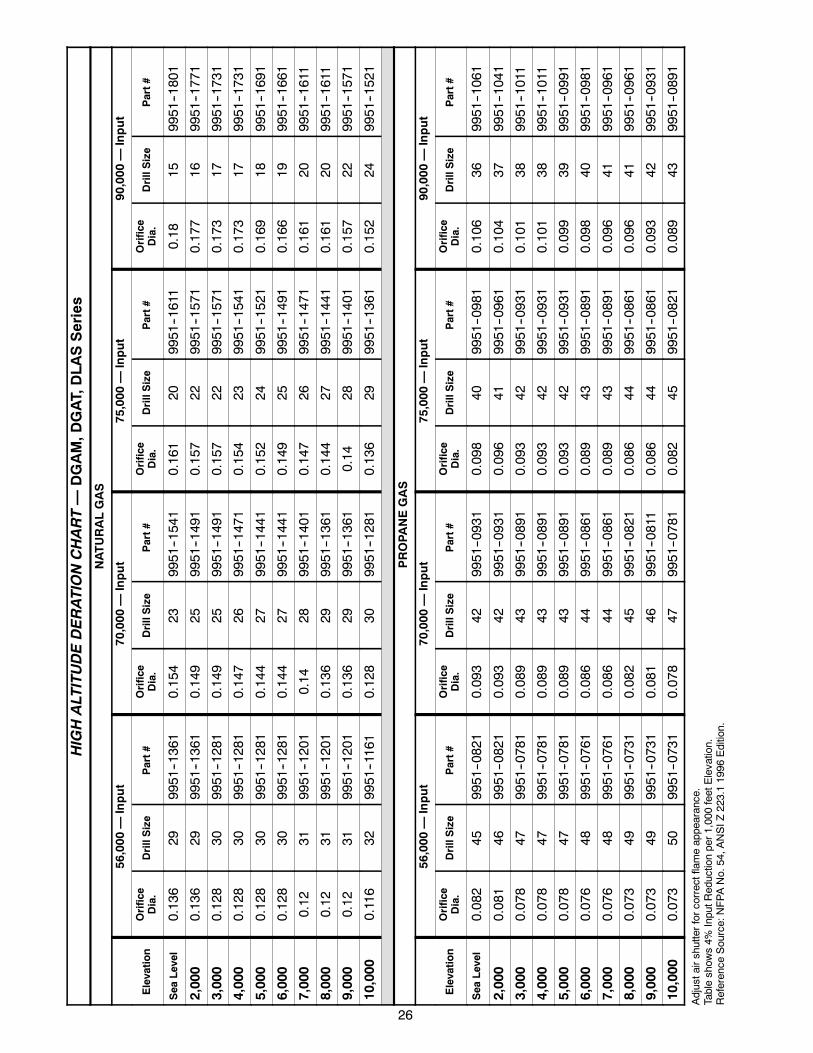
HIGHALTITUDEDERATIONCHART—
DGAM,D
GAT,DLASSeries
NATURALGAS
56,000
—Input
70,000
—Input
75,000
—Input
90,000
—Input
Elevation
Orifice
Dia.
DrillSize
Part#
Orifice
Dia.
DrillSize
Part#
Orifice
Dia.
DrillSize
Part#
Orifice
Dia.
DrillSize
Part#
Sea
Level
0.136
299951--1361
0.154
239951--1541
0.161
209951--1611
0.18
159951--1801
2,000
0.136
299951--1361
0.149
259951--1491
0.157
229951--1571
0.177
169951--1771
3,000
0.128
309951--1281
0.149
259951--1491
0.157
229951--1571
0.173
179951--1731
4,000
0.128
309951--1281
0.147
269951--1471
0.154
239951--1541
0.173
179951--1731
5,000
0.128
309951--1281
0.144
279951--1441
0.152
249951--1521
0.169
189951--1691
6,000
0.128
309951--1281
0.144
279951--1441
0.149
259951--1491
0.166
199951--1661
7,000
0.12
319951--1201
0.14
289951--1401
0.147
269951--1471
0.161
209951--1611
8,000
0.12
319951--1201
0.136
299951--1361
0.144
279951--1441
0.161
209951--1611
9,000
0.12
319951--1201
0.136
299951--1361
0.14
289951--1401
0.157
229951--1571
10,000
0.116
329951--1161
0.128
309951--1281
0.136
299951--1361
0.152
249951--1521
PROPA
NEGAS
56,000
—Input
70,000
—Input
75,000
—Input
90,000
—Input
Elevation
Orifice
Dia.
DrillSize
Part#
Orifice
Dia.
DrillSize
Part#
Orifice
Dia.
DrillSize
Part#
Orifice
Dia.
DrillSize
Part#
Sea
Level
0.082
459951--0821
0.093
429951--0931
0.098
409951--0981
0.106
369951--1061
2,000
0.081
469951--0821
0.093
429951--0931
0.096
419951--0961
0.104
379951--1041
3,000
0.078
479951--0781
0.089
439951--0891
0.093
429951--0931
0.101
389951--1011
4,000
0.078
479951--0781
0.089
439951--0891
0.093
429951--0931
0.101
389951--1011
5,000
0.078
479951--0781
0.089
439951--0891
0.093
429951--0931
0.099
399951--0991
6,000
0.076
489951--0761
0.086
449951--0861
0.089
439951--0891
0.098
409951--0981
7,000
0.076
489951--0761
0.086
449951--0861
0.089
439951--0891
0.096
419951--0961
8,000
0.073
499951--0731
0.082
459951--0821
0.086
449951--0861
0.096
419951--0961
9,000
0.073
499951--0731
0.081
469951--0811
0.086
449951--0861
0.093
429951--0931
10,000
0.073
509951--0731
0.078
479951--0781
0.082
459951--0821
0.089
439951--0891
Adjustairshutterforcorrectflameappearance.
Tableshow
s4%
InputR
eductionper1,000feetElevation.
Reference
Source:NFPANo.54,A
NSIZ
223.11996
Edition.
26
27
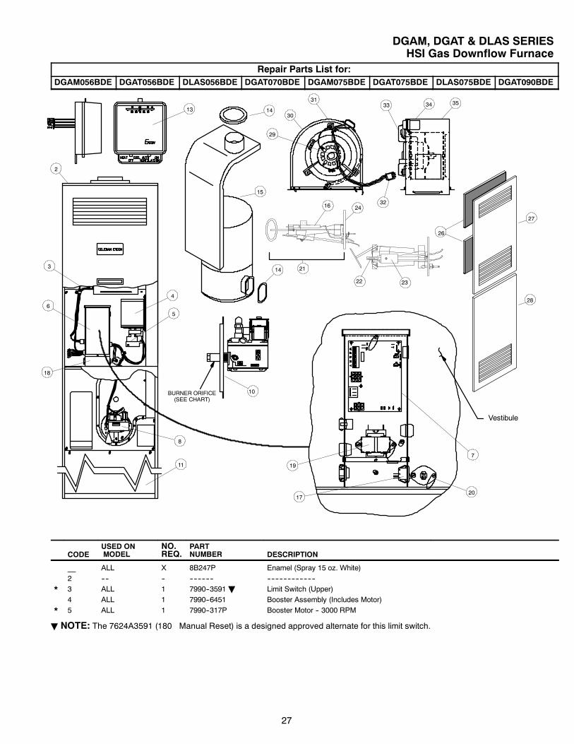
DGAM, DGAT & DLAS SERIESHSI Gas Downflow Furnace
Repair Parts List for:DGAM056BDE DGAT056BDE DLAS056BDE DGAT070BDE DGAM075BDE DGAT075BDE DLAS075BDE DGAT090BDE
13
26
27
28
15
14
14
30
34 3533
32
31
29
22
21
16
Vestibule
23
24
2
6
3
18
4
5
19
8
11
BURNER ORIFICE(SEE CHART)
10
1720
7
CODEUSED ONMODEL
NO.REQ.
PARTNUMBER DESCRIPTION
__ ALL X 8B247P Enamel (Spray 15 oz. White)2 ---- -- ------------ ------------------------
* 3 ALL 1 7990--3591B Limit Switch (Upper)4 ALL 1 7990--6451 Booster Assembly (Includes Motor)
* 5 ALL 1 7990--317P Booster Motor -- 3000 RPM
B NOTE: The 7624A3591 (180� Manual Reset) is a designed approved alternate for this limit switch.
28
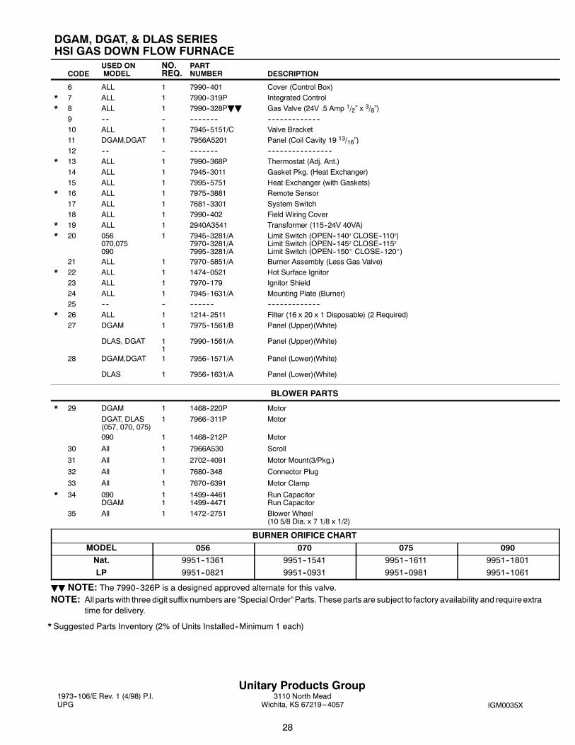
DGAM, DGAT, & DLAS SERIESHSI GAS DOWN FLOW FURNACE
CODEUSED ONMODEL
NO.REQ.
PARTNUMBER DESCRIPTION
6 ALL 1 7990--401 Cover (Control Box)
* 7 ALL 1 7990--319P Integrated Control
* 8 ALL 1 7990--328PBB Gas Valve (24V .5 Amp 1/2” x 3/8”)9 ---- -- -------------- --------------------------10 ALL 1 7945--5151/C Valve Bracket11 DGAM,DGAT 1 7956A5201 Panel (Coil Cavity 19 13/16”)12 ---- -- -------------- --------------------------------
* 13 ALL 1 7990--368P Thermostat (Adj. Ant.)14 ALL 1 7945--3011 Gasket Pkg. (Heat Exchanger)15 ALL 1 7995--5751 Heat Exchanger (with Gaskets)
* 16 ALL 1 7975--3881 Remote Sensor17 ALL 1 7681--3301 System Switch18 ALL 1 7990--402 Field Wiring Cover
* 19 ALL 1 2940A3541 Transformer (115--24V 40VA)
* 20 056070,075090
1 7945--3281/A7970--3281/A7995--3281/A
Limit Switch (OPEN--140º CLOSE--110º)Limit Switch (OPEN--145º CLOSE--115ºLimit Switch (OPEN--150_ CLOSE--120_)
21 ALL 1 7970--5851/A Burner Assembly (Less Gas Valve)
* 22 ALL 1 1474--0521 Hot Surface Ignitor23 ALL 1 7970--179 Ignitor Shield24 ALL 1 7945--1631/A Mounting Plate (Burner)25 ---- -- ------------ --------------------------
* 26 ALL 1 1214--2511 Filter (16 x 20 x 1 Disposable) (2 Required)27 DGAM
DLAS, DGAT
1
11
7975--1561/B
7990--1561/A
Panel (Upper)(White)
Panel (Upper)(White)
28 DGAM,DGAT
DLAS
1
1
7956--1571/A
7956--1631/A
Panel (Lower)(White)
Panel (Lower)(White)
BLOWER PARTS
* 29 DGAM 1 1468--220P Motor
DGAT, DLAS(057, 070, 075)
1 7966--311P Motor
090 1 1468--212P Motor
30 All 1 7966A530 Scroll
31 All 1 2702--4091 Motor Mount(3/Pkg.)
32 All 1 7680--348 Connector Plug
33 All 1 7670--6391 Motor Clamp
* 34 090DGAM
11
1499--44611499--4471
Run CapacitorRun Capacitor
35 All 1 1472--2751 Blower Wheel(10 5/8 Dia. x 7 1/8 x 1/2)
BURNER ORIFICE CHARTMODEL 056 070 075 090Nat. 9951--1361 9951--1541 9951--1611 9951--1801
LP 9951--0821 9951--0931 9951--0981 9951--1061
BB NOTE: The 7990--326P is a designed approved alternate for this valve.NOTE: All parts with three digit suffix numbers are “SpecialOrder”Parts. These parts are subject to factory availability and requireextra
time for delivery.
* Suggested Parts Inventory (2% of Units Installed--Minimum 1 each)
1973--106/E Rev. 1 (4/98) P.I.UPG IGM0035X
Unitary Products Group3110 North Mead
Wichita, KS 67219---4057