HEAD START INVITATION FOR SEALED BIDS SINE HEAD ...
360
Page 1 of 48 CATHOLIC CHARITIES WESTSIDE ‐ HEAD START INVITATION FOR SEALED BIDS SINE HEAD START ‐ MODULAR CLASSROOM BUILDING A. INSTRUCTIONS Through this Request for Proposal, Catholic Charities Westside Head Start is seeking the services of a licensed, general contractor, with the best favorable competive rates and to provide all qualified businesses, including those that are owned by minorities, woman, persons with disabilities and/or small business enterprises to do business with Catholic Charities Westside Head Start. Notice is hereby given that Catholic Charities Westside Head Start will receive proposals for the furnishing of professional services, labor, materials, transportation and construction for the PROJECT entitled: SINE HEAD START ‐ MODULAR CLASSROOM BUILDING 4933 W. Orangewood Ave Glendale Arizona 85301 Beginning September 24 th , 2020 proposal documents may be obtained electronically from: https://www.catholiccharitiesaz.org/wshs‐rfp/ Documents will also be available electronically through: Techniprint Company, Inc. 2545 N. 7th Street Telephone: 602‐257‐0686, 1‐877‐215‐2460 [email protected] Bid documents may also be examined at: Shirley's Plan Room 425 S. Plumer Tucson, AZ 85719 Telephone: (520) 791‐ 7436 Facsimile: (520) 882‐9208 All hardcopies or file downloads are at the bidder’s expense. Interested bidders must attend the following: MANDATORY PRE‐BID MEETING ON: Friday, October 9 th , 2020 9:00am AZ time Sine Head Start Campus 4933 West Orangewood Avenue Glendale, Arizona 85301 Attendance of bidders who intend to submita a bid is required. The purpose of the meeting is to clarify to concepts of the invitation to bid and bid documents. This meeting is to prevent any misunderstanding of the work requested and to answer any questions. Bids will not be accepted fron Bidders who have not attended the Mandatory Pre‐Bid meeting and signed the meeting sign in sheet. All bids must be on a lump‐sum basis. Segregated bids will not be accepted. Each Bid shall be submitted on the Proposal Form (see Attachment I) which shall be accompanied by all items listed in Section E, Paragraph 2, of this document, as well as a certified or cashier's check or Bid Bond for five percent (5%) of the total amount of the bid made payable to Catholic Charities Westside Head Start. Such check or Bid Bond will be given as a guarantee that the Bidder will enter into the contract to perform the work, if so awarded, and provide satisfactory Statutory Performance and Payment Bonds, pursuant to Title 34, Chapter 2, Article 2 of the Arizona Revised Statutes, and shall be declared forfeited as liquidated damages if the successful Bidder refuses to enter into the said contract after being requested to do so by Catholic Charities Westside Head Start. Such check or Bid Bond will be returned to the respective unsuccessful Bidders upon the Award of the Contract to the successful Bidder and will be returned to the successful Bidder upon the delivery of satisfactory surety company bonds and construction contract.
-
Upload
khangminh22 -
Category
Documents
-
view
1 -
download
0
Transcript of HEAD START INVITATION FOR SEALED BIDS SINE HEAD ...

Page 1 of 48
CATHOLIC CHARITIES WESTSIDE ‐ HEAD START INVITATION FOR SEALED BIDS
SINE HEAD START ‐ MODULAR CLASSROOM BUILDING
A. INSTRUCTIONS Through this Request for Proposal, Catholic Charities Westside Head Start is seeking the services of a licensed, general contractor, with the best favorable competive rates and to provide all qualified businesses, including those that are owned by minorities, woman, persons with disabilities and/or small business enterprises to do business with Catholic Charities Westside Head Start. Notice is hereby given that Catholic Charities Westside Head Start will receive proposals for the furnishing of professional services, labor, materials, transportation and construction for the PROJECT entitled:
SINE HEAD START ‐ MODULAR CLASSROOM BUILDING 4933 W. Orangewood Ave Glendale Arizona 85301
Beginning September 24th, 2020 proposal documents may be obtained electronically from: https://www.catholiccharitiesaz.org/wshs‐rfp/ Documents will also be available electronically through: Techniprint Company, Inc. 2545 N. 7th Street Telephone: 602‐257‐0686, 1‐877‐215‐2460 [email protected] Bid documents may also be examined at: Shirley's Plan Room 425 S. Plumer Tucson, AZ 85719 Telephone: (520) 791‐7436 Facsimile: (520) 882‐9208 All hardcopies or file downloads are at the bidder’s expense. Interested bidders must attend the following: MANDATORY PRE‐BID MEETING ON: Friday, October 9th, 2020 9:00am AZ time Sine Head Start Campus 4933 West Orangewood Avenue Glendale, Arizona 85301 Attendance of bidders who intend to submita a bid is required. The purpose of the meeting is to clarify to concepts of the invitation to bid and bid documents. This meeting is to prevent any misunderstanding of the work requested and to answer any questions. Bids will not be accepted fron Bidders who have not attended the Mandatory Pre‐Bid meeting and signed the meeting sign in sheet. All bids must be on a lump‐sum basis. Segregated bids will not be accepted. Each Bid shall be submitted on the Proposal Form (see Attachment I) which shall be accompanied by all items listed in Section E, Paragraph 2, of this document, as well as a certified or cashier's check or Bid Bond for five percent (5%) of the total amount of the bid made payable to Catholic Charities Westside Head Start. Such check or Bid Bond will be given as a guarantee that the Bidder will enter into the contract to perform the work, if so awarded, and provide satisfactory Statutory Performance and Payment Bonds, pursuant to Title 34, Chapter 2, Article 2 of the Arizona Revised Statutes, and shall be declared forfeited as liquidated damages if the successful Bidder refuses to enter into the said contract after being requested to do so by Catholic Charities Westside Head Start. Such check or Bid Bond will be returned to the respective unsuccessful Bidders upon the Award of the Contract to the successful Bidder and will be returned to the successful Bidder upon the delivery of satisfactory surety company bonds and construction contract.

Page 2 of 48
SEALED BIDS DUE ON: Tuesday, October 20th, 2020 10:00 am AZ time Bids shall be sealed and delivered to: Catholic Charities Westside Head Start 7400 W. Olive Ave Suite 10 Peoria, AZ 85345
Attn: Yatin Dua, Executive Director RFI’s and Questions should be directed in writing to the Architect no later than Tuesday, October 13th, 2020, 5:00pm AZ time:
Architectural Resource Team 1055 E. Indian School Road Phoenix, AZ 85014 Telephone: 602.513.6031 E‐mail: tsoliman@art‐team.com
Proposals will be publicly opened and read aloud by Catholic Charities Westside Head Start on Thursday October 22nd, 2020 at 10:30am AZ time. The opening can be attended via the Zoom Link provided:
https://us02web.zoom.us/meeting/register/tZAlcuCspzkoH9OJ_qUyVHIFAfcJKJbrzypg After registering you will receive a confirmation email about joining the meeting.
The Proposal contract shall be awarded, if at all, to the most responsive and responsible Bidder (see Section D. Evaluation Criteria) whose proposal conforms in all material aspects to the requirements of the proposal documents including the Scope of Work. "Responsive Bidder" means the Bidder who submits a proposal that conforms in all material respects to the Instructions and Scope of Work that are incorporated herein by this reference. “Responsible Bidder" means the Bidder who has the capability to perform the contract requirements and the integrity and reliability to assure complete and good faith performance and who submits the proposal most advantageous to Catholic Charities Westside Head Start. The awarded Contract or any part thereof shall not be sublet to a contractor who has not paid taxes as provided in Section 34‐241, Arizona Revised Statutes. It shall be mandatory on the Bidder to whom the Contract is awarded, and upon any subcontractor working under the Bidder, to comply in every respect with the provisions of Title 23, 32, 34, Arizona Revised Statutes and with all other requirements of the State of Arizona, applicable to contracts for the construction of public works, and with all applicable City, County, State and Federal Laws and Ordinances (see Attachment III: Assurances of Compliance with Federal and State Laws). Catholic Charities Westside Head Start reserves the right to reject any or all Proposals, to withhold the award of a contract for any reason it may determine and to hold any or all Proposal(s) for a period of ninety (90) days. Catholic Charities Westside Head Start also reserves the right to waive any irregularities in any Proposal if such action is, determined by Catholic Charities Westside Head Start, in its sole discretion, to be in the interest of Catholic Charities Westside Head Start. Request for Sealed Bids Advertisement: Will be published for two weeks beginning on September, 24th, 2020. Posting of the RFP will appear on the following web link location: https://www.catholiccharitiesaz.org/wshs‐rfp/ Advertisement shall run in the following publications:
Arizona Capitol Times Glendale Star Peoria Times West Valley View

Page 3 of 48
B. INTRODUCTION & BACKGROUND Catholic Charities Westside Head Start and Early Head Start will be providing comprehensive, early, continuous, year‐round, childhood education through a holistic approach by working with the whole family at the Catholic Charities Westside Headstart Sine Campus at 4933 West Orangewood Avenue, Glendale, Arizona. The programs emphasize pre‐reading, language, math, cognitive skills, health, and social and emotional competence to prepare disadvantaged children for school and to maximize their potential for a bright future. This project will enable Catholic Charities Westside Head Start to provide additional Head Start and Early Head Start opportunities to families in need in the communities of Glendale. This project is 100% federally funded by the Department of Health and Human Services, Office of Head Start. All work performed on site, including site improvements and site work for setting and installing the building are subject to Davis Bacon Wage requirements. C. PROJECT SCOPE The project is manufacturing and placement of an approximately 6,200 square modular classrooms building at 4933 West Orangewood Avenue, Glendale Arizona. The project includes; site improvement work; including refurbishing of the existing parking lot, new trash enclosure, fencing, concrete work and other site improvements for preparation and placement of a manufactured modular classroom building. Should a bidder find any discrepancy, error or omission with the invitations vor Bids or in the scope of work, please contact Terri Soliman with Architectural Resource Team writing, at tsoliman@art‐team.com. The last day for Requests for Information and Clarification is 5pm, October 13th, 2020. If a question submitted warrants a response, the architect will when issue a written addendum to all contractors who attended the pre‐bid meeting to inform them of the clarification. Oral instructions or information shall not constitue an addendum to this Invitiation for Sealed Bids. D. EVALUATION CRITERIA 1. All Proposals shall be evaluated using the following criteria:
a. Total Cost based on Proposal Form and Schedule of Values Form. 40% b. Contractor’s proposed schedule to complete site work and the manufacturing and installation of
classroom building. 15% c. Qualifications and education of project personnel. 10% d. Contractor’s experience on projects of similar size and complexity. 10% e. Contractor’s experience with Fedderally Funded Projects and Davis‐Bacon wage rate regulations. 10% f. Manufacturers and materials used. 10% g. Contractor’s adherence to Request for Proposal Instructions. 5%
E. SUBMISSION OF SEALED BID
1. The Proposal, together with required enclosures, shall be submitted in an opaque, sealed envelope bearing on the outside the project name, and bidder's name and address.
2. Included in each envelope shall be the following tabbed sections for reference:
a. Attachment I: Proposal Form completed and signed. b. Attachment II: Schedule of Values completed. c. Attachment III: Signed Catholic Charities Procurement Contract Provisions, giving Assurances of
Compliance with Federal and State Laws. d. Qualifications and education of project personnel. e. Experience on: Projects of similar size and complexity; Davis‐Bacon projects. f. Proposed Project Schedule and completion date.

Page 4 of 48
g. Manufactures and materials to be used, including: Mechanical, Electrical Equipment and plumbing cut sheets.
h. Photocopy of General Contractor’s and Building Manufacturer’s and Installer’s Licenses. i. Name and contact information for two references for which the Contractor has completed work that
demonstrates the Contractor’s experience in providing the requested services. j. Completed and Signed Attachment IV: Bid Bond Form. Note: Performance and Payment Bonds will be
required of awarded bidder. 3. A proposal may not be modified, withdrawn, or canceled by the Bidder until ninety (90) days after the time
and date for receipt of Bids.
F. POST‐BID INFORMATION
C. Contractor’s Liability Insurance Certificates shall be submitted in original and one copy to Catholic Charities
Westside Head Start within seven (7) days after notification of award of Contract. Insurance is to be placed with insurers duly licensed or authorized to do business in the state of Arizona and with an “A.M. Best” rating of not less than A.
2. Contractor and all subcontractors shall purchase and maintain at all times during the execution of this
project the following forms of insurance by carriers acceptable to and approved by Catholic Charities Westside Head Start.
C. Worker’s Compensation coverage (including Occupational Disease coverage) as required by all
applicable Federal, State, Maritime and other laws, including Employer’s Liability. All contractors and subcontractors providing services under this contract must provide Workers’ Compensation insurance as follows:
Workers’ Compensation: Statutory Employers’ Liability: Each Accident $1,000,000 Disease – Each Employee $1,000,000 Disease – Policy Limit $1,000,000
Policy shall contain a waiver of subrogation in favor of Catholic Charities Westside Head Start, and Architectural Resource Team.
b. Commercial General Liability – The Contractor and its subcontractors policies shall include bodily injury, property damage, broad form contractual liability, personal and advertising liability and XCU coverage and shall carry a liability of $1,000,000 per occurrence and $2,000,000 in the aggregate and a per project aggregate endorsement.
The Contractor’s liability policies shall name Catholic Charities Westside Head Start and Architectural Resource Team as additional insureds with respect to liability arising out of the activities performed by, or on behalf of the Contractor, including completed operations. The Contractor’s coverage should be primary/non‐contributary and include a waiver of subrogation for those listed as additionally insured.
c. Comprehensive Automobile Liability – The Contractor and any subcontractor using an owned, hired,
or non‐owned vehicle to perform services under this Contract shall provide insurance including bodily injury and property damage coverage with a combined single limit of $1,000,000.
The Contractor’s liability policies shall name Catholic Charities Westside Head Start and Architectural Resource Team as additional insureds with respect to liability arising out of the activities performed by, or on behalf of the Contractor, including completed operations. The Contractor’s coverage should be primary/non‐contributary and include a waiver of subrogation for those listed as additionally insured.

Page 5 of 48
d. Excess Liability/Umbrella Liability Coverage of $5,000,000. e. Contractor agrees to carry or cause its contractors and subcontractors to carry a policy of Builder’s
Risk insurance adequate to protect the value of the project and assets used in construction
3. Notice of Cancellation: Each insurance policy required by the insurance provisions of this Proposal shall provide the required coverage and shall not be suspended, voided or canceled except after thirty (30) days prior written notice has been given to Catholic Charities Westside Head Start, except when cancellation is for nonpayment of premium, then ten (10) days prior notice must be given.
4. All insurance policies shall be approved by Catholic Charities Westside Head Start before the successful bidder may proceed with the Project.
5. Assurances – As a Federally funded project, Bidders are required to provide assurances of compliance with
the following regulations (see Attachment III):
a. Equal Employment Opportunity b. Copeland ‘‘Anti‐Kickback’’ Act c. Davis‐Bacon Act d. Contract Work Hours & Safety Standards Act e. Discovery or Invention Provisions f. Clean Air Act g. Byrd Anti‐Lobbying Amendment h. Debarment & Suspension i. Certificate of Insurance verifying general liability and Workers Compensation coverage.
In addition to Federal regulations:
j. Federal Water Pollution Control Act k. Drug‐Free Workplace Act of 1988 l. Federal & State Immigration Laws m. Access to Records and Records Retention n. Conflict of Interest o. Comply with All Applicable Laws & Regulations p. Subcontractors Complaince q. Copyright Provisions r. Submission of Forms
Aggreement to: Catholic Charities Vendor Code of Conduct (Attachment I)
6. The bidder to whom the Contract is awarded by Catholic Charities Westside Head Start shall, within seven
(7) days after award and receipt of Agreement forms from Catholic Charities Westside Head Start, sign and deliver to Catholic Charities Westside Head Start, all required copies of the contract.
G. PROTESTS
C. Any actual or prospective Bidder may protest the request for proposal or the award of a contract on the grounds that Catholic Charities Westside Head Start has substantially failed to follow the standards set forth in the Proposal Instructions or has violated Federal procurement regulations. Protesters may file a protest with respect to any phase of the solicitation or award, including, without limitation, proposal solicitation; determination by Catholic Charities Westside Head Start of Bidder responsibility or Bidder responsiveness; and contract award.

Page 6 of 48
2. If the protest is made by a potential Bidder that has not submitted a proposal, the protest shall be limited
to a challenge of the notice procedures followed by Catholic Charities Westside Head Start. This right to protest shall not apply to protest regarding the denial of a request for a release from bid.
3. Catholic Charities Westside Head Start may make a determination that the proposals received are non‐
responsive or that the highest rated Bidder is non‐responsible. Upon making a determination of non‐responsibility with respect to the highest rated Bidder, Catholic Charities Westside Head Start shall notify the affected Bidder in writing of that determination.
4. The notification shall state the reasons upon which the determination is based. In addition, the notification
shall advise the Bidder of the time period within which a formal written protest (the “Protest”) may be filed and of the requirements for filing such Protest. Catholic Charities Westside Head Start is not required to provide written notice of determinations of non‐responsiveness.
5. To expedite handling of Protest, a protester shall address its envelope to: Yatin Dua, Catholic Charities Westside
Head Start Administrative Offices at 7400 W. Olive Ave Suite 10, Peoria, AZ 85345 and such envelope be labeled “Protest”. The Protest shall include, without limitation, the following information:
a. The name, address and telephone number of the protester; b. Appropriate identification of the procurement; c. A statement of the reasons for the Protest; d. Supporting exhibits and documentary evidence to substantiate any arguments; e. The form of relief requested.
6. Any protests concerning this proposal must be delivered in writing within ten (10) calendar days of the
Proposal Due Date to: Yatin Dua Catholic Charities Westside Head Start 7400 W. Olive Ave Suite 10, Peoria, AZ 85345 7. A Protest is considered filed when such Protest is received by Yatin Dua as previously instructed. Protests
received after the previously prescribed period shall not be considered unless Catholic Charities Westside Head Start, in its sole discretion determines that good cause is shown for considering the late Protest.
8. Any additional information reasonably requested by Catholic Charities Westside Head Start must be
submitted within the time period established by Catholic Charities Westside Head Start in order to expedite consideration of the Protest. Failure of a protester to comply with a request for information within the specified time period may result in a resolution of the Protest without consideration of any information subsequently submitted by the protester in an untimely manner.
9. Catholic Charities Westside Head Start shall make a decision on a Protest within ten (10) calendar days after
receiving all relevant information requested of the protester. The Catholic Charites Westside Head Start representative may, at the agency’s sole discretion, meet with the protester and any other affected party to discuss the Protest.
10. If a Protest is granted (i.e., sustained in favor of the protester), Catholic Charities Westside Head Start shall
so notify the protester in writing and remedies appropriate to comply with the Protest decision shall be implemented.

Page 7 of 48
ATTACHMENT I: PROPOSAL FORM Having examined the all matters referred to in the Request for Proposal, we, the undersigned, hereby offer to enter
into a Contract to perform the Work for the Fixed Lump Sum Price of: $ _____________________, in United States of America currency. All applicable Federal, State and local taxes are included in the sum. There is no Owner’s Contingency included in the proposal. The following Addenda have been received. The modifications to the Proposal Documents noted below have been considered and all costs are included in the Proposal Sum. Addenda # _______________ Dated _____________ Addenda # _______________ Dated __________________
ACCEPTANCE A. This offer shall be open to acceptance and is irrevocable for ninety (90) calendar days from the proposal
closing date. B. If this proposal is accepted by the Owner within the time period stated above, we will:
1. Submit a Contract within seven (7) calendar days of receipt of Notice of Award. 2. Furnish required bonds and insurance within (7) seven calendar days of receipt of Notice of Award. 3. Commence work within (7) seven calendar days of receipt of Notice to Proceed.
C. If this proposal is accepted within the time stated, and we fail to commence the Work, or we fail to provide the required Bond(s), the security deposit, if required, shall be forfeited as damages to Owner by reason of our failure, limited in amount to the lesser of the face value of the security deposit or the difference between this proposal and the proposal upon which a Contract is signed.
D. In the event our proposal is not accepted within the time stated above, the security deposit, if required, shall be returned, in accordance with the provisions of the Request for Proposal; unless a mutually satisfactory arrangement is made for its retention and validity for an extended period of time.
CONTRACT TIME A. If Proposal is accepted, all work will be completed within two hundred and fifty‐three (253) consecutive
calendar days from Notice to Proceed, or per schedule agreed upon in contract documents. B. The undersigned agrees that time is of the essence and the Owner will suffer financial damages due to the
Contractor’s failure to complete the work within the contract time. The undersigned understands and agrees to the terms and basis of the liquidated damages provision of the Contract and General Conditions between Owner and Contractor. The liquidated damages shall be as follows for each calendar day beyond the Contract time for which the Contractor shall fail to complete the work. 1. Final Completion: $5,231.00 per calendar day
C. The Corporate Seal of: ________________________________________ _________________________________________ Contractor Company Name Owner’s Name
________________________________________ _________________________________________ Authorized Signer Name and Title‐ Printed Authorized Signature
Address __________________________ __________________________ ___________________________ Date Telephone License No.

Page 8 of 48
ATTACHMENT II: SCHEDULE OF VALUES CATHOLIC CHARITIES HEAD START 4933 W ORANGEWOOD AVE. GLENDALE AZ
1. General Conditions $__________
Site Work
2. Demolition $__________
3. Parking $__________
4. Concrete and Site Work $__________
5. Fencing $__________
6. Utilities $__________
Manufactured Building
7. Building Framing $__________
8. Roof $__________
9. Stucco and Exterior Metal Panels $__________
10. Shade Canopies $__________
11. Thermal, Moisture & Acoustic Protection $__________
12. Windows & Glazing $__________
13. Doors and Door Hardware $__________
14. Interior Drywall and Painting $__________
15. Interior Finishes $__________
16. Finished Ceilings $__________
17. Toilet partitions and Accessories $__________
18. Millwork and Shelving $__________
19. Equipment and Appliances $__________
20. Window Blinds $__________
21. Plumbing $__________
22. Mechanical $__________
23. Electrical $__________
24. Fire Protection $__________
Misc
25. Building Engineering & Permits $__________
26. Insurance, Overhead & Profit, Sales Tax and Bonds $__________
27. 10% Contract Contingency $__________
TOTAL FIXED LUMP SUM BID $_________________

Page 9 of 48
Catholic Charities Westside Head Start & Early Head Start
Attachment III
Procurement Contract Provisions The following provisions, as applicable, are conditions and assurances agreed and certified to by the contractor upon acceptance of a contract to provide certain goods or services, and are made part thereof.
1. The contractor shall comply with Executive Order 11246, as amended by Executive Order 11375, “Amending Executive Order 1246 Relating to Equal Employment Opportunity,” and as supplemented by regulations at 41 CFR Part 60, “Office of Federal Contract Compliance Programs, Equal Employment Opportunity, Department of Labor.”
2. All contracts and sub grants in excess of $2000 for construction or repair of facilities awarded by recipients and sub recipients are subject to the Copeland “Anti‐Kickback” Act, 18 U.S.C. 874, as supplemented by Department of Labor regulations, (29 CFR Part 3, “Contractors and Subcontractors on Public Building or Public Work Financed in Whole or in Part by Loans or Grants from the United States”). The Act provides that each contractor or sub recipient shall be prohibited from inducing, by any means, any person employed in the construction, completion or repair of public work, to give up any part of the compensation to which s/he is otherwise entitled.
3. When required by Federal program legislation, all construction contracts awarded by recipients and sub recipients of more than $2000 are subject to the Davis‐Bacon Act, (40 U.S.C., 276a to a‐7) and as supplemented by Dept. of Labor regulations (29 CFR part 5, “Labor Standards Provisions Applicable to Contracts Governing Federally Financed and Assisted Construction”. Under this Act, contractors are required to pay wages to laborer and mechanics at a rate not less than the minimum wages specified in the current wage determination made by the Secretary of Labor. In addition, contractors are required to pay wages not
less than once a week. Copies of these provisions are attached and made part of this contract. Weekly payroll information recorded on Optional Form WH‐347 or its equivalent (also attached) must be submitted to the local CCCS project official for inclusion with billing information.
4. Where applicable, all contracts awarded by recipients in excess of $2000 for construction contracts and in excess of$2500 for other contracts that involve the employment of laborers or mechanics are required to comply with sections 102 and 107 of the Contract Work Hours and Safety Standards Act, (40 U.S.C. 327‐333) as supplemented by Department of Labor regulations (29 CFR part 5). Section 102 requires the contractor to compute the wages of every mechanic and laborer on the basis of a standard, work week of 40 hours. Work in excess of the standard work week is permissible provided that the payment of wages in excess of 40 hours at 1 ½ times the basic pay rate. Section 107 provides that no laborer or mechanic shall be required to work in surroundings or under working conditions that are unsanitary, hazardous or dangerous.
5. Any inventions resulting from experimental, developmental or research work shall be subject to 37 CFR part 401, “Rights to Inventions Made by Nonprofit Organizations and Small Business Firms Under Government Grants, Contracts and Cooperative Agreements.”
6. Recipients of contracts and sub grants in excess of $100,000 agree to comply with all applicable standards, orders or regulations issued pursuant to the Clean Air Act, (42 U.S.C., 7401 et seq.) and the Federal Water Pollution Control Act, as amended (33 U.S.C. 1251 et seq.).

Page 10 of 48
7. Contractors who bid for an award of more than $100,000 must file, with CCCS, a certification of compliance with restrictions of the Byrd Anti‐Lobbying Amendment, (31 U.S.C., 1352), that it has not and will not use federally appropriated funds to pay any person or organization for influencing or attempting to influence a member of Congress, officer or employee of Congress, or an employee of a member of Congress in connection with obtaining any federal contract, grant or other award covered by the amendment. Contractors shall also disclose any lobbying with non‐Federal funds that takes place in connection with obtaining any Federal award.
8. Contractors shall certify that they are not prohibited from receiving procurement awards pursuant to Executive Orders 12549 and 12689, “Debarment and Suspension”, and do not appear on the General Services Administration’s “List of Parties Excluded from Federal Procurement or Non procurement Programs.”
9. Contractors shall provide a current Certificate of Insurance which verifies general liability and Workers Compensation coverage.
CONTRACTOR: DATE:
By: Title:

Page 11 of 48
ATTACHMENT IV: BOND FORMS (1 of 2)
ARIZONA STATUTORY BID BOND PURSUANT TO TITLE 28, 34 AND 41, ARIZONA REVISED STATUTES (Penalty of this bond must not be less than 5% of the bid amount)
KNOW ALL PERSONS BY THESE PRESENTS THAT: __________________________ (hereinafter "Principal"), as
Principal, and _______________________________________________, (hereinafter "Surety"), a corporation
organized and existing under the laws of the State of ____________________ , with it principal offices in the City
of ____________________, holding a certificate of authority to transact surety business in Arizona issued by the
Director of the Department of Insurance pursuant to Title 20, Chapter 2, Article 1, as Surety are held and firmly
bound unto_________________________________________________________ (hereinafter "Obligee"), in
the sum of Five Percent (5%) of the amount of the bid of Principal, submitted by Principal to the Obilgee for the work
described below, for the payment of which sum, the Principal and Surety bind themselves, and their heirs,
administrators, executors, successors and assigns, jointly and severally, firmly by these presents.
WHEREAS, the Principal has submitted a bid for ______________________________________ NOW, THEREFORE, if the Obligee shall accept the proposal of the Principal and the Principal shall enter into a contract with the Obligee in accordance with the terms of the proposal and give the bonds and certificates of insurance as specified in the standard specifications with good and sufficient surety for the faithful performance of the contract and for the prompt payment of labor and materials furnished in the prosecution of the contract, or in the event of the failure of the Principal to enter into the contract and give the bonds and certificates of insurance, if the Principal pays to the Obligee the difference not to exceed the penalty of the bond between the amount specified in the proposal and such larger amount for which the Obligee may in good faith contract with another party to perform the work covered by the proposal then this obligation is void. Otherwise, it remains in full force and effect provided, however, that this bond is executed pursuant to the provisions of Section 34‐201, Arizona Revised Statutes, and all liabilities on this bond shall be determined in accordance with the provisions of that section to the extent as if it were copied at length herein. Witness our hands this __________day of _____________________ , 20 ______. ________________________________________ _______________________________________ PRINCIPAL SEAL SURETY SEAL By: ____________________________________ By: ____________________________________ Its: ____________________________________ Its: ____________________________________ _______________________________________
AGENCY ADDRESS

Page 12 of 48
ATTACHMENT IV: BOND FORMS (2 of 2)
STATUTORY PERFORMANCE BOND PURSUANT TO TITLE 34, CHAPTER 2, ARTICLE 2, OF THE ARIZONA REVISED STATUTES
(Penalty of this bond must be 100% of Contract Amount) KNOW ALL PERSONS BY THESE PRESENTS: That __________________________________________ (hereinafter
called Principal), as Principal, and__________________________________________________, a corporation
organized and existing under the laws of the State of _____________________ , with its principal office in the City
of ______________________________________, (hereinafter called the Surety), as surety, are held and firmly
bound unto_________________________________________________ , (hereinafter called the Obligee) in the
amount of _______________________ Dollars ($ ), for the payment whereof, the said Principal and Surety bind
themselves, and their heirs, administrators, executors, successors and assigns, jointly and severally, firmly by these
presents.
WHEREAS, the Principal has entered into a certain written Contract with the Obligee, dated the_________ day
________________________ of 20_______ , to _________________________________________________
__________________________________________________________which Contract is hereby referred to and
made a part hereof as fully and to the same extent as if copied at length herein.
NOW, THEREFORE, THE CONDITION OF THIS OBLIGATION IS SUCH, that if the said Principal shall faithfully perform and fulfill all the undertakings, covenants, terms, conditions and agreements of said contract during the original term of said contract and any extension thereof, with or without notice of the Surety, and during the life of any warranty required under the contract, and shall also perform and fulfill all the undertakings, covenants, terms, conditions, and agreements of any and all duly authorized modifications of said contract that may hereafter be made, notice of which modifications to the Surety being hereby waived, then the above obligation shall be void, otherwise to remain in full force and effect. PROVIDED, HOWEVER, that this bond is executed pursuant to the provisions of Title 34, Chapter 2, Article 2, of the Arizona Revised Statutes, and all liabilities on this bond shall be determined in accordance with the provisions of said Title, Chapter and Article, to the extent as if it were copied at length herein. The prevailing party in a suit on this bond shall recover as a part of his judgment such reasonable attorneys' fees as may be fixed by a judge of the Court. WITNESS our hands this _________ day of_____________________ , 20_______ .
_________________________________ Principal

Page 13 of 48
ATTACHMENT V: DAVIS BACON REGULATIONS & WAGE DECISION REGULATIONS 29 CFR Part 5 ‐ LABOR STANDARDS PROVISIONS APPLICABLE TO CONTRACTS COVERING FEDERALLY FINANCED AND ASSISTED CONSTRUCTION (ALSO LABOR STANDARDS PROVISIONS APPLICABLE...SUBJECT TO THE CONTRACT WORK HOURS AND SAFETY STANDARDS ACT) § 5.5 Contract provisions and related matters. (a) The Agency head shall cause or require the contracting officer to insert in full in any contract in excess of $2,000 which is entered into for the actual construction, alteration and/or repair, including painting and decorating, of a public building or public work, or building or work financed in whole or in part from Federal funds or in accordance with guarantees of a Federal agency or financed from funds obtained by pledge of any contract of a Federal agency to make a loan, grant or annual contribution (except where a different meaning is expressly indicated), and which is subject to the labor standards provisions of any of the acts listed in § 5.1, the following clauses (or any modifications thereof to meet the particular needs of the agency, Provided, That such modifications are first approved by the Department of Labor): (1) Minimum wages. (i) All laborers and mechanics employed or working upon the site of the work (or under the United States Housing Act of 1937 or under the Housing Act of 1949 in the construction or development of the project), will be paid unconditionally and not less often than once a week, and without subsequent deduction or rebate on any account (except such payroll deductions as are permitted by regulations issued by the Secretary of Labor under the Copeland Act (29 CFR part 3)), the full amount of wages and bona fide fringe benefits (or cash equivalents thereof) due at time of payment computed at rates not less than those contained in the wage determination of the Secretary of Labor which is attached hereto and made a part hereof, regardless of any contractual relationship which may be alleged to exist between the contractor and such laborers and mechanics. Contributions made or costs reasonably anticipated for bona fide fringe benefits under section 1(b)(2) of the Davis‐Bacon Act on behalf of laborers or mechanics are considered wages paid to such laborers or mechanics, subject to the provisions of paragraph (a)(1)(iv) of this section; also, regular contributions made or costs incurred for more than a weekly period (but not less often than quarterly) under plans, funds, or programs which cover the particular weekly period, are deemed to be constructively made or incurred during such weekly period. Such laborers and mechanics shall be paid the appropriate wage rate and fringe benefits on the wage determination for the classification of work actually performed, without regard to skill, except as provided in § 5.5(a)(4). Laborers or mechanics performing work in more than one classification may be compensated at the rate specified for each classification for the time actually worked therein: Provided, That the employer's payroll records accurately set forth the time spent in each classification in which work is performed. The wage determination (including any additional classification and wage rates conformed under paragraph (a)(1)(ii) of this section) and the Davis‐Bacon poster (WH‐1321) shall be posted at all times by the contractor and its subcontractors at the site of the work in a prominent and accessible place where it can be easily seen by the workers. (ii) (A) The contracting officer shall require that any class of laborers or mechanics, including helpers, which is not listed in the wage determination and which is to be employed under the contract shall be classified in conformance with the wage determination. The contracting officer shall approve an additional classification and wage rate and fringe benefits therefore only when the following criteria have been met: (1) The work to be performed by the classification requested is not performed by a classification in the wage determination; and (2) The classification is utilized in the area by the construction industry; and (3) The proposed wage rate, including any bona fide fringe benefits, bears a reasonable relationship to the wage rates contained in the wage determination. (B) If the contractor and the laborers and mechanics to be employed in the classification (if known), or their representatives, and the contracting officer agree on the classification and wage rate (including the amount designated for fringe benefits where appropriate), a report of the action taken shall be sent by the contracting officer to the Administrator of the Wage and Hour Division, Employment Standards Administration, U.S. Department of Labor, Washington, DC 20210. The Administrator, or an authorized representative, will approve, modify, or

Page 14 of 48
disapprove every additional classification action within 30 days of receipt and so advise the contracting officer or will notify the contracting officer within the 30‐day period that additional time is necessary. (C) In the event the contractor, the laborers or mechanics to be employed in the classification or their representatives, and the contracting officer do not agree on the proposed classification and wage rate (including the amount designated for fringe benefits, where appropriate), the contracting officer shall refer the questions, including the views of all interested parties and the recommendation of the contracting officer, to the Administrator for determination. The Administrator, or an authorized representative, will issue a determination within 30 days of receipt and so advise the contracting officer or will notify the contracting officer within the 30‐day period that additional time is necessary. (D) The wage rate (including fringe benefits where appropriate) determined pursuant to paragraphs (a)(1)(ii) (B) or (C) of this section, shall be paid to all workers performing work in the classification under this contract from the first day on which work is performed in the classification. (iii) Whenever the minimum wage rate prescribed in the contract for a class of laborers or mechanics includes a fringe benefit which is not expressed as an hourly rate, the contractor shall either pay the benefit as stated in the wage determination or shall pay another bona fide fringe benefit or an hourly cash equivalent thereof. (iv) If the contractor does not make payments to a trustee or other third person, the contractor may consider as part of the wages of any laborer or mechanic the amount of any costs reasonably anticipated in providing bona fide fringe benefits under a plan or program, Provided, That the Secretary of Labor has found, upon the written request of the contractor, that the applicable standards of the Davis‐Bacon Act have been met. The Secretary of Labor may require the contractor to set aside in a separate account assets for the meeting of obligations under the plan or program. (2) Withholding. The (write in name of Federal Agency or the loan or grant recipient) shall upon its own action or upon written request of an authorized representative of the Department of Labor withhold or cause to be withheld from the contractor under this contract or any other Federal contract with the same prime contractor, or any other federally‐assisted contract subject to Davis‐Bacon prevailing wage requirements, which is held by the same prime contractor, so much of the accrued payments or advances as may be considered necessary to pay laborers and mechanics, including apprentices, trainees, and helpers, employed by the contractor or any subcontractor the full amount of wages required by the contract. In the event of failure to pay any laborer or mechanic, including any apprentice, trainee, or helper, employed or working on the site of the work (or under the United States Housing Act of 1937 or under the Housing Act of 1949 in the construction or development of the project), all or part of the wages required by the contract, the (Agency) may, after written notice to the contractor, sponsor, applicant, or owner, take such action as may be necessary to cause the suspension of any further payment, advance, or guarantee of funds until such violations have ceased. (3) Payrolls and basic records. (i) Payrolls and basic records relating thereto shall be maintained by the contractor during the course of the work and preserved for a period of three years thereafter for all laborers and mechanics working at the site of the work (or under the United States Housing Act of 1937, or under the Housing Act of 1949, in the construction or development of the project). Such records shall contain the name, address, and social security number of each such worker, his or her correct classification, hourly rates of wages paid (including rates of contributions or costs anticipated for bona fide fringe benefits or cash equivalents thereof of the types described in section 1(b)(2)(B) of the Davis‐Bacon Act), daily and weekly number of hours worked, deductions made and actual wages paid. Whenever the Secretary of Labor has found under 29 CFR 5.5(a)(1)(iv) that the wages of any laborer or mechanic include the amount of any costs reasonably anticipated in providing benefits under a plan or program described in section 1(b)(2)(B) of the Davis‐Bacon Act, the contractor shall maintain records which show that the commitment to provide such benefits is enforceable, that the plan or program is financially responsible, and that the plan or program has been communicated in writing to the laborers or mechanics affected, and records which show the costs anticipated or the actual cost incurred in providing such benefits. Contractors employing apprentices or trainees under approved programs shall maintain written evidence of the registration of apprenticeship programs and certification of trainee programs, the registration of the apprentices and trainees, and the ratios and wage rates prescribed in the applicable programs. (ii) (A) The contractor shall submit weekly for each week in which any contract work is performed a copy of all payrolls to the (write in name of appropriate federal agency) if the agency is a party to the contract, but if the agency is not such a party, the contractor will submit the payrolls to the applicant, sponsor, or owner, as the case may be, for

Page 15 of 48
transmission to the (write in name of agency). The payrolls submitted shall set out accurately and completely all of the information required to be maintained under 29 CFR 5.5(a)(3)(i), except that full social security numbers and home addresses shall not be included on weekly transmittals. Instead the payrolls shall only need to include an individually identifying number for each employee (e.g., the last four digits of the employee's social security number). The required weekly payroll information may be submitted in any form desired. Optional Form WH‐347 is available for this purpose from the Wage and Hour Division Web site at: http://www.dol.gov/esa/whd/forms/wh347instr.htm or its successor site. The prime contractor is responsible for the submission of copies of payrolls by all subcontractors. Contractors and subcontractors shall maintain the full social security number and current address of each covered worker, and shall provide them upon request to the (write in name of appropriate federal agency) if the agency is a party to the contract, but if the agency is not such a party, the contractor will submit them to the applicant, sponsor, or owner, as the case may be, for transmission to the (write in name of agency), the contractor, or the Wage and Hour Division of the Department of Labor for purposes of an investigation or audit of compliance with prevailing wage requirements. It is not a violation of this section for a prime contractor to require a subcontractor to provide addresses and social security numbers to the prime contractor for its own records, without weekly submission to the sponsoring government agency (or the applicant, sponsor, or owner). (B) Each payroll submitted shall be accompanied by a “Statement of Compliance,” signed by the contractor or subcontractor or his or her agent who pays or supervises the payment of the persons employed under the contract and shall certify the following: (1) That the payroll for the payroll period contains the information required to be provided under § 5.5 (a)(3)(ii) of Regulations, 29 CFR part 5, the appropriate information is being maintained under § 5.5 (a)(3)(i) of Regulations, 29 CFR part 5, and that such information is correct and complete; (2) That each laborer or mechanic (including each helper, apprentice, and trainee) employed on the contract during the payroll period has been paid the full weekly wages earned, without rebate, either directly or indirectly, and that no deductions have been made either directly or indirectly from the full wages earned, other than permissible deductions as set forth in Regulations, 29 CFR part 3; (3) That each laborer or mechanic has been paid not less than the applicable wage rates and fringe benefits or cash equivalents for the classification of work performed, as specified in the applicable wage determination incorporated into the contract. (C) The weekly submission of a properly executed certification set forth on the reverse side of Optional Form WH‐347 shall satisfy the requirement for submission of the “Statement of Compliance” required by paragraph (a)(3)(ii)(B) of this section. (D) The falsification of any of the above certifications may subject the contractor or subcontractor to civil or criminal prosecution under section 1001 of title 18 and section 231 of title 31 of the United States Code. (iii) The contractor or subcontractor shall make the records required under paragraph (a)(3)(i) of this section available for inspection, copying, or transcription by authorized representatives of the (write the name of the agency) or the Department of Labor, and shall permit such representatives to interview employees during working hours on the job. If the contractor or subcontractor fails to submit the required records or to make them available, the Federal agency may, after written notice to the contractor, sponsor, applicant, or owner, take such action as may be necessary to cause the suspension of any further payment, advance, or guarantee of funds. Furthermore, failure to submit the required records upon request or to make such records available may be grounds for debarment action pursuant to 29 CFR 5.12. (4) Apprentices and trainees‐ (i) Apprentices. Apprentices will be permitted to work at less than the predetermined rate for the work they performed when they are employed pursuant to and individually registered in a bona fide apprenticeship program registered with the U.S. Department of Labor, Employment and Training Administration, Office of Apprenticeship Training, Employer and Labor Services, or with a State Apprenticeship Agency recognized by the Office, or if a person is employed in his or her first 90 days of probationary employment as an apprentice in such an apprenticeship program, who is not individually registered in the program, but who has been certified by the Office of Apprenticeship Training, Employer and Labor Services or a State Apprenticeship Agency (where appropriate) to be eligible for probationary employment as an apprentice. The allowable ratio of apprentices to journeymen on the job site in any craft classification shall not be greater than the ratio permitted to the contractor as to the entire work force under the registered program. Any worker listed on a payroll at an apprentice wage rate, who is not registered

Page 16 of 48
or otherwise employed as stated above, shall be paid not less than the applicable wage rate on the wage determination for the classification of work actually performed. In addition, any apprentice performing work on the job site in excess of the ratio permitted under the registered program shall be paid not less than the applicable wage rate on the wage determination for the work actually performed. Where a contractor is performing construction on a project in a locality other than that in which its program is registered, the ratios and wage rates (expressed in percentages of the journeyman's hourly rate) specified in the contractor's or subcontractor's registered program shall be observed. Every apprentice must be paid at not less than the rate specified in the registered program for the apprentice's level of progress, expressed as a percentage of the journeymen hourly rate specified in the applicable wage determination. Apprentices shall be paid fringe benefits in accordance with the provisions of the apprenticeship program. If the apprenticeship program does not specify fringe benefits, apprentices must be paid the full amount of fringe benefits listed on the wage determination for the applicable classification. If the Administrator determines that a different practice prevails for the applicable apprentice classification, fringes shall be paid in accordance with that determination. In the event the Office of Apprenticeship Training, Employer and Labor Services, or a State Apprenticeship Agency recognized by the Office, withdraws approval of an apprenticeship program, the contractor will no longer be permitted to utilize apprentices at less than the applicable predetermined rate for the work performed until an acceptable program is approved. (ii) Trainees. Except as provided in 29 CFR 5.16, trainees will not be permitted to work at less than the predetermined rate for the work performed unless they are employed pursuant to and individually registered in a program which has received prior approval, evidenced by formal certification by the U.S. Department of Labor, Employment and Training Administration. The ratio of trainees to journeymen on the job site shall not be greater than permitted under the plan approved by the Employment and Training Administration. Every trainee must be paid at not less than the rate specified in the approved program for the trainee's level of progress, expressed as a percentage of the journeyman hourly rate specified in the applicable wage determination. Trainees shall be paid fringe benefits in accordance with the provisions of the trainee program. If the trainee program does not mention fringe benefits, trainees shall be paid the full amount of fringe benefits listed on the wage determination unless the Administrator of the Wage and Hour Division determines that there is an apprenticeship program associated with the corresponding journeyman wage rate on the wage determination which provides for less than full fringe benefits for apprentices. Any employee listed on the payroll at a trainee rate who is not registered and participating in a training plan approved by the Employment and Training Administration shall be paid not less than the applicable wage rate on the wage determination for the classification of work actually performed. In addition, any trainee performing work on the job site in excess of the ratio permitted under the registered program shall be paid not less than the applicable wage rate on the wage determination for the work actually performed. In the event the Employment and Training Administration withdraws approval of a training program, the contractor will no longer be permitted to utilize trainees at less than the applicable predetermined rate for the work performed until an acceptable program is approved. (iii) Equal employment opportunity. The utilization of apprentices, trainees and journeymen under this part shall be in conformity with the equal employment opportunity requirements of Executive Order 11246, as amended, and 29 CFR part 30. (5) Compliance with Copeland Act requirements. The contractor shall comply with the requirements of 29 CFR part 3, which are incorporated by reference in this contract. (6) Subcontracts. The contractor or subcontractor shall insert in any subcontracts the clauses contained in 29 CFR 5.5(a)(1) through (10) and such other clauses as the (write in the name of the Federal agency) may by appropriate instructions require, and also a clause requiring the subcontractors to include these clauses in any lower tier subcontracts. The prime contractor shall be responsible for the compliance by any subcontractor or lower tier subcontractor with all the contract clauses in 29 CFR 5.5. (7) Contract termination: debarment. A breach of the contract clauses in 29 CFR 5.5 may be grounds for termination of the contract, and for debarment as a contractor and a subcontractor as provided in 29 CFR 5.12. (8) Compliance with Davis‐Bacon and Related Act requirements. All rulings and interpretations of the Davis‐Bacon and Related Acts contained in 29 CFR parts 1, 3, and 5 are herein incorporated by reference in this contract. (9) Disputes concerning labor standards. Disputes arising out of the labor standards provisions of this contract shall not be subject to the general disputes clause of this contract. Such disputes shall be resolved in accordance with the procedures of the Department of Labor set forth in 29 CFR parts 5, 6, and 7. Disputes within the meaning of this

Page 17 of 48
clause include disputes between the contractor (or any of its subcontractors) and the contracting agency, the U.S. Department of Labor, or the employees or their representatives. (10) Certification of eligibility. (i) By entering into this contract, the contractor certifies that neither it (nor he or she) nor any person or firm who has an interest in the contractor's firm is a person or firm ineligible to be awarded Government contracts by virtue of section 3(a) of the Davis‐Bacon Act or 29 CFR 5.12(a)(1). (ii) No part of this contract shall be subcontracted to any person or firm ineligible for award of a Government contract by virtue of section 3(a) of the Davis‐Bacon Act or 29 CFR 5.12(a)(1). (iii) The penalty for making false statements is prescribed in the U.S. Criminal Code, 18 U.S.C. 1001. (b) Contract Work Hours and Safety Standards Act. The Agency Head shall cause or require the contracting officer to insert the following clauses set forth in paragraphs (b)(1), (2), (3), and (4) of this section in full in any contract in an amount in excess of $100,000 and subject to the overtime provisions of the Contract Work Hours and Safety Standards Act. These clauses shall be inserted in addition to the clauses required by § 5.5(a) or 4.6 of part 4 of this title. As used in this paragraph, the terms laborers and mechanics include watchmen and guards. (1) Overtime requirements. No contractor or subcontractor contracting for any part of the contract work which may require or involve the employment of laborers or mechanics shall require or permit any such laborer or mechanic in any workweek in which he or she is employed on such work to work in excess of forty hours in such workweek unless such laborer or mechanic receives compensation at a rate not less than one and one‐half times the basic rate of pay for all hours worked in excess of forty hours in such workweek. (2) Violation; liability for unpaid wages; liquidated damages. In the event of any violation of the clause set forth in paragraph (b)(1) of this section the contractor and any subcontractor responsible therefor shall be liable for the unpaid wages. In addition, such contractor and subcontractor shall be liable to the United States (in the case of work done under contract for the District of Columbia or a territory, to such District or to such territory), for liquidated damages. Such liquidated damages shall be computed with respect to each individual laborer or mechanic, including watchmen and guards, employed in violation of the clause set forth in paragraph (b)(1) of this section, in the sum of $10 for each calendar day on which such individual was required or permitted to work in excess of the standard workweek of forty hours without payment of the overtime wages required by the clause set forth in paragraph (b)(1) of this section. (3) Withholding for unpaid wages and liquidated damages. The (write in the name of the Federal agency or the loan or grant recipient) shall upon its own action or upon written request of an authorized representative of the Department of Labor withhold or cause to be withheld, from any moneys payable on account of work performed by the contractor or subcontractor under any such contract or any other Federal contract with the same prime contractor, or any other federally‐assisted contract subject to the Contract Work Hours and Safety Standards Act, which is held by the same prime contractor, such sums as may be determined to be necessary to satisfy any liabilities of such contractor or subcontractor for unpaid wages and liquidated damages as provided in the clause set forth in paragraph (b)(2) of this section. (4) Subcontracts. The contractor or subcontractor shall insert in any subcontracts the clauses set forth in paragraph (b)(1) through (4) of this section and also a clause requiring the subcontractors to include these clauses in any lower tier subcontracts. The prime contractor shall be responsible for compliance by any subcontractor or lower tier subcontractor with the clauses set forth in paragraphs (b)(1) through (4) of this section. (c) In addition to the clauses contained in paragraph (b), in any contract subject only to the Contract Work Hours and Safety Standards Act and not to any of the other statutes cited in § 5.1, the Agency Head shall cause or require the contracting officer to insert a clause requiring that the contractor or subcontractor shall maintain payrolls and basic payroll records during the course of the work and shall preserve them for a period of three years from the completion of the contract for all laborers and mechanics, including guards and watchmen, working on the contract. Such records shall contain the name and address of each such employee, social security number, correct classifications, hourly rates of wages paid, daily and weekly number of hours worked, deductions made, and actual wages paid. Further, the Agency Head shall cause or require the contracting officer to insert in any such contract a clause providing that the records to be maintained under this paragraph shall be made available by the contractor or subcontractor for inspection, copying, or transcription by authorized representatives of the (write the name of agency) and the Department of Labor, and the contractor or subcontractor will permit such representatives to interview employees during working hours on the job.

Page 18 of 48
"General Decision Number: AZ20200031
08/21/2020 Superseded General Decision Number:
AZ20190031
State: Arizona Construction Type: Building
County: Maricopa County in Arizona.
BUILDING CONSTRUCTION PROJECTS (does not include single family homes or apartments up to and including 4 stories).
Note: Under Executive Order (EO) 13658, an hourly minimum wage of $10.80 for calendar year 2020 applies to all contracts subject to the Davis‐Bacon Act for which the contract is awarded (and any solicitation was issued) on or after January 1, 2015. If this contract is covered by the EO, the contractor must pay all workers in any classification listed on this wage determination at least $10.80 per hour (or the applicable wage rate listed on this wage determination, if it is higher) for all hours spent performing on the contract in calendar year 2020. If this contract is covered by the EO and a classification considered necessary for performance of work on the contract does not appear on this wage determination, the contractor must pay workers in that classification at least the wage rate determined through the conformance process set forth in 29 CFR 5.5(a)(1)(ii) (or the EO minimum wage rate,if it is higher than the conformed wage rate). The EO minimum wage rate will be adjusted annually. Please note that this EO applies to the above‐mentioned types of contracts entered into by the federal government that are subject to the Davis‐Bacon Act itself, but it does not apply to contracts subject only to the Davis‐Bacon Related Acts, including those set forth at 29 CFR 5.1(a)(2)‐(60). Additional information on contractor requirements and worker protections under the EO is available at www.dol.gov/whd/govcontracts.
Modification Number Publication Date
0 01/03/2020
1 01/31/2020
2 05/15/2020
3 06/05/2020
4 ASBE0073‐002
08/01/2019
08/21/2020
Rates
Fringes
ASBESTOS WORKER/HEAT & FROST INSULATOR........................$ 40.84 14.52

Page 19 of 48
BOIL0627‐001 10/01/2017
Rates Fringes
BOILERMAKER......................$ 35.30 28.41
BRAZ0003‐009 07/01/2019
Rates Fringes BRICKLAYER.......................$ 25.31 8.13
ZONE PAY:
(Radius miles from the intersection of Central Ave. and Washington St., Phoenix, AZ)
Zone A: 0‐60 miles‐ Base Rate Zone B: 61‐75 miles‐ Base Rate plus $2.00 per hour Zone C: 75‐100 miles‐ Base Rate plus $3.00 per hour Zone D: 101‐200 miles‐ Base Rate plus $3.50 per hour Zone E: Over 200 miles‐ Base Rate plus $6.50 per hour
CARP0408‐009 07/01/2019
Rates Fringes CARPENTER (Excludes Acoustical Ceiling Installation, Drywall Finishing/Taping, Drywall Hanging, Form Work, and Metal Stud Installation)...............$ 27.89 12.23
CARP1327‐001 07/01/2019
Rates Fringes
CARPENTER (Drywall Hanging Only)............................$ 26.24 8.86
* ELEC0640‐005 07/01/2020
Rates Fringes
ELECTRICIAN (Includes Low Voltage Wiring; Excludes Installation of Alarms

Page 20 of 48
and Sound and Communication Systems).........................$ 30.00 11.55
ENGI0428‐012 06/01/2020
Rates Fringes
POWER EQUIPMENT OPERATOR (1) Oiler...................$ 27.04 11.72 (2) Crane under 15 tons.....$ 30.31 11.72 (3) Crane,15 tons to 100 tons, Tower Crane...........$ 31.39 11.72
(4) Crane, 100 tons and (5) over........................$ 32.42 11.72
IRON0075‐011 08/01/2019
Rates Fringes
IRONWORKER, STRUCTURAL AND ORNAMENTAL.......................$ 27.80 19.05
Zone 1: 0 to 50 miles from City Hall in Phoenix or Tucson Zone 2: 050 to 100 miles ‐ Add $4.00 Zone 3: 100 to 150 miles ‐ Add $5.00 Zone 4: 150 miles & over ‐ Add $6.50
LABO1184‐010 06/01/2020
Rates Fringes
LABORER (MASON TENDER‐BRICK).....$ 21.63 6.06
PAIN0086‐006 04/01/2017
Rates Fringes DRYWALL FINISHER/TAPER
ZONE A ..................... $ 20.05 6.68 ZONE
ZONE PAY:
B ..................... $ 23.55 6.68
ZONE A: Free Zone: A distance of 0 to 100 miles from the old Phoenix courthouse.
ZONE B: A distance of 101 miles and over from the old Phoenix courthouse: $3.50 per hour over ZONE A
Page 21 of 48
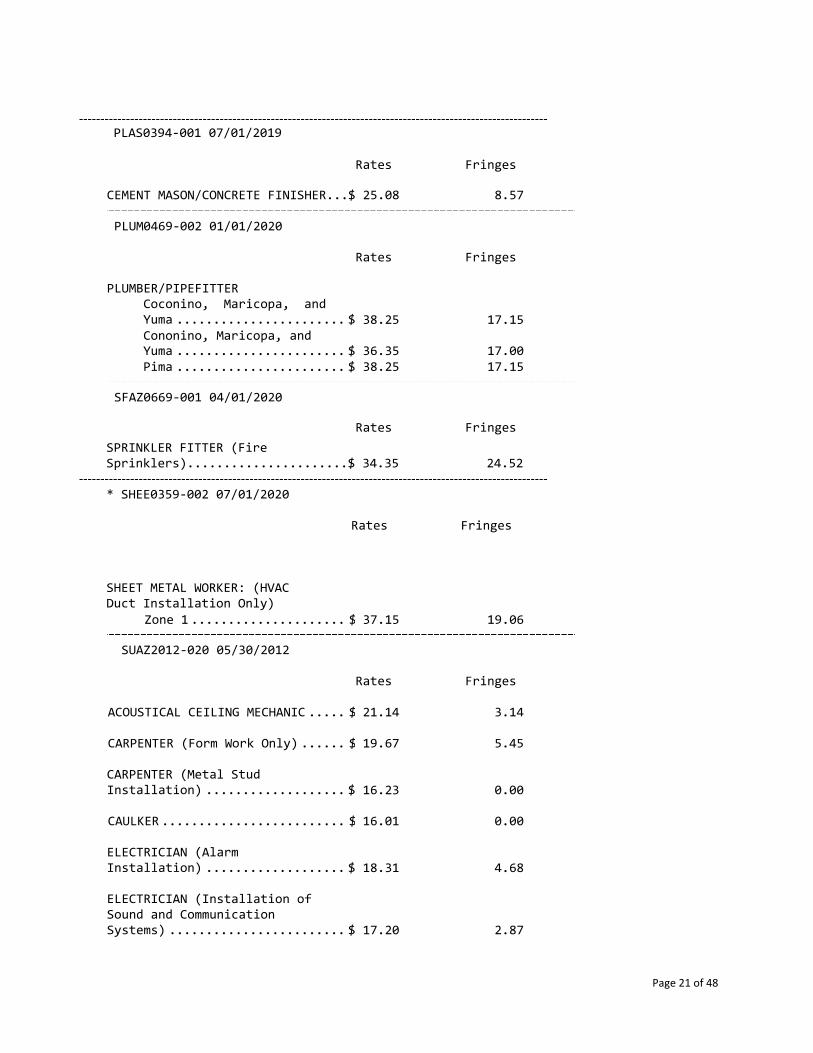
PLAS0394‐001 07/01/2019
Rates Fringes
CEMENT MASON/CONCRETE FINISHER...$ 25.08 8.57
PLUM0469‐002 01/01/2020
Rates Fringes
PLUMBER/PIPEFITTER Coconino, Maricopa, and Yuma ....................... $
38.25
17.15
Cononino, Maricopa, and Yuma ....................... $
36.35
17.00 Pima ....................... $ 38.25 17.15
SFAZ0669‐001 04/01/2020
Rates Fringes
SPRINKLER FITTER (Fire Sprinklers)......................$ 34.35 24.52
* SHEE0359‐002 07/01/2020
Rates Fringes
SHEET METAL WORKER: (HVAC Duct Installation Only)
Zone 1 ..................... $ 37.15 19.06
SUAZ2012‐020 05/30/2012
Rates Fringes
ACOUSTICAL CEILING MECHANIC ..... $ 21.14 3.14
CARPENTER (Form Work Only) ...... $ 19.67 5.45
CARPENTER (Metal Stud Installation) ................... $
16.23
0.00
CAULKER ......................... $ 16.01 0.00
ELECTRICIAN (Alarm Installation) ................... $
18.31
4.68
ELECTRICIAN (Installation of Sound and Communication Systems) ........................ $
17.20
2.87

Page 22 of 48
FIREPROOFER ..................... $ 15.00 0.00
GLAZIER ......................... $ 18.67 1.44
INSTALLER ‐ SIGN ................ $ 19.16 3.58
INSULATOR ‐ BATT ................ $ 11.96 3.06
IRONWORKER, REINFORCING ......... $ 14.92 0.00
LABORER: Asphalt Raker ......... $ 15.18 1.30
LABORER: Common or General ..... $ 13.80 2.24
LABORER: Concrete Saw (Hand Held/Walk Behind) ............... $
21.00
7.37
LABORER: Fence Erection ........ $ 19.73 0.00
LABORER: Landscape & Irrigation ...................... $
11.33
0.43
LABORER: Mason Tender ‐ Cement/Concrete ................. $
15.24
3.90
LABORER: Pipelayer ............. $ 15.10 0.85
LABORER: Plaster Tender ........ $ 12.00 0.00
LABORER: Power Tool Operator ... $ 14.85 4.20
LATHER...........................$ 16.15 0.00
MASON ‐ STONE ................... $ 18.48 0.82
MILLWRIGHT.......................$ 20.00 2.87
OPERATOR: Backhoe/Ex
cavator/Trackhoe ...... $
19.20
2.47
OPERATOR: Bulldozer ............ $ 21.12 6.14
OPERATOR: Drill Rig Caissons ... $ 19.06 2.39
OPERATOR: Drill ................ $ 19.16 0.00
OPERATOR: Forklift ............. $ 17.36 0.00
OPERATOR: Grader/Blade ......... $ 21.00 7.07
OPERATOR: Loader (Front End) ... $ 18.55 0.95
OPERATOR: Aggregate,
Paver (Asphalt, and Concrete) ........ $
21.09
3.96

Page 23 of 48
OPERATOR: Roller ............... $ 25.00 0.00
OPERATOR: Scraper .............. $ 21.41 0.00
OPERATOR: Screed ............... $ 22.17 4.42
OPERATOR: Trencher ............. $ 15.01 0.58
PAINTER: Spray and
Brush, Roller, Steel ................. $
16.53
2.63
PLASTERER........................$ 16.71 0.00
ROOFER, InWaterproofInstallati
cludes ing, and on of Metal Roofs ..... $
16.71
1.67
SHEET METAHVAC Duct
L WORKER, Excludes Installation .......... $
18.85
2.79
TERRAZZO WORKER/SETTER .......... $ 21.13 0.00
TILE FINISHER ................... $ 12.50 0.00
TILE SETTER ..................... $ 15.00 0.00
TRUCK DRIVER: Dump Trucks ...... $ 15.55 1.42
TRUCK DRIVER: Pickup Truck ..... $ 11.00 0.87
TRUCK DRIVER: Water Truck.......$ 17.72 4.21
TRUCKDRIVER: 3 and 4 Axle.......$ 19.29 1.36
WELDERS ‐ Receive rate prescribed for craft performing operation to which welding is incidental.
================================================================
Note: Executive Order (EO) 13706, Establishing Paid Sick Leave for Federal Contractors applies to all contracts subject to the Davis‐Bacon Act for which the contract is awarded (and any solicitation was issued) on or after January 1, 2017. If this contract is covered by the EO, the contractor must provide employees with 1 hour of paid sick leave for every 30 hours they work, up to 56 hours of paid sick leave each year. Employees must be permitted to use paid sick leave for their own illness, injury or other health‐related needs, including preventive care; to assist a family member (or person who is like family to the employee) who is ill, injured, or has other health‐related needs, including preventive care; or for reasons resulting from, or to assist a family member (or

Page 24 of 48
person who is like family to the employee) who is a victim of, domestic violence, sexual assault, or stalking. Additional information on contractor requirements and worker protections under the EO is available at www.dol.gov/whd/govcontracts.
Unlisted classifications needed for work not included within the scope of the classifications listed may be added after award only as provided in the labor standards contract clauses (29CFR 5.5 (a) (1) (ii)).
The body of each wage determination lists the classification and wage rates that have been found to be prevailing for the cited type(s) of construction in the area covered by the wage determination. The classifications are listed in alphabetical order of ""identifiers"" that indicate whether the particular rate is a union rate (current union negotiated rate for local), a survey rate (weighted average rate) or a union average rate (weighted union average rate).
Union Rate Identifiers A four letter classification abbreviation identifier enclosed in dotted lines beginning with characters other than ""SU"" or ""UAVG"" denotes that the union classification and rate were prevailing for that classification in the survey. Example: PLUM0198‐005 07/01/2014. PLUM is an abbreviation identifier of the union which prevailed in the survey for this classification, which in this example would be Plumbers. 0198 indicates the local union number or district council number where applicable, i.e., Plumbers Local 0198. The next number,
005 in the example, is an internal number used in processing the wage determination. 07/01/2014 is the effective date of the most current negotiated rate, which in this example is July 1, 2014. Union prevailing wage rates are updated to reflect all rate changes in the collective bargaining agreement (CBA) governing this classification and rate.
Survey Rate Identifiers
Classifications listed under the ""SU"" identifier indicate that no one rate prevailed for this classification in the survey and the published rate is derived by computing a weighted average rate based on all the rates reported in the survey for that classification. As this weighted average rate includes all rates reported in the survey, it may include both union and non‐union rates. Example: SULA2012‐007 5/13/2014. SU indicates the rates are survey rates based on a weighted

Page 25 of 48
average calculation of rates and are not majority rates. LA indicates the State of Louisiana. 2012 is the year of survey on which these classifications and rates are based. The next number, 007 in the example, is an internal number used in producing the wage determination. 5/13/2014 indicates the survey completion date for the classifications and rates under that identifier.
Survey wage rates are not updated and remain in effect until a new survey is conducted.
Union Average Rate Identifiers
Classification(s) listed under the UAVG identifier indicate that no single majority rate prevailed for those classifications; however, 100% of the data reported for the classifications was union data. EXAMPLE: UAVG‐OH‐0010 08/29/2014. UAVG indicates that the rate is a weighted union average rate. OH indicates the state. The next number, 0010 in the example, is an internal number used in producing the wage determination. 08/29/2014 indicates the survey completion date for the classifications and rates under that identifier.
A UAVG rate will be updated once a year, usually in January of each year, to reflect a weighted average of the current negotiated/CBA rate of the union locals from which the rate is based.
WAGE DETERMINATION APPEALS PROCESS
1.) Has there been an initial decision in the matter? This can be:
* an existing published wage determination * a survey underlying a wage determination * a Wage and Hour Division letter setting forth a position on
a wage determination matter * a conformance (additional classification and rate) ruling
On survey related matters, initial contact, including requests for summaries of surveys, should be with the Wage and Hour Regional Office for the area in which the survey was conducted because those Regional Offices have responsibility for the Davis‐Bacon survey program. If the response from this initial contact is not satisfactory, then the process described in 2.) and 3.) should be followed.
With regard to any other matter not yet ripe for the formal process described here, initial contact should be with the Branch of Construction Wage Determinations.

Page 26 of 48
Write to:
Branch of Construction Wage Determinations Wage and Hour Division U.S. Department of Labor 200 Constitution Avenue, N.W. Washington, DC 20210
2.) If the answer to the question in 1.) is yes, then an interested party (those affected by the action) can request review and reconsideration from the Wage and Hour Administrator (See 29 CFR Part 1.8 and 29 CFR Part 7). Write to:
Wage and Hour Administrator U.S. Department of Labor 200 Constitution Avenue, N.W. Washington, DC 20210
The request should be accompanied by a full statement of the interested party's position and by any information (wage payment data, project description, area practice material, etc.) that the requestor considers relevant to the issue.
3.) If the decision of the Administrator is not favorable, an interested party may appeal directly to the Administrative Review Board (formerly the Wage Appeals Board). Write to:
Administrative Review Board U.S. Department of Labor 200 Constitution Avenue, N.W. Washington, DC 20210
4.) All decisions by the Administrative Review Board are final.
===============================================================
= END OF GENERAL DECISION"

Page 27 of 48
ATTACHMENT VII: REQUIRED FORMS

Page 28 of 48

Page 29 of 48

Page 30 of 48

Page 31 of 48

Page 32 of 48

Page 33 of 48

Page 34 of 48

Page 35 of 48

Page 36 of 48

Page 37 of 48
CERTIFICATION OF UNDERSTANDING AND AUTHORIZATION
PROJECT NAME: ____________________________________ PROJECT NUMBER:__________________ The following person(s) is designated as the payroll officer for the undersigned and is authorized to sign the Federal Statement of Compliance which will accompany our weekly certified payroll reports for this project: IRS Employer Identification Number Authorized Payroll Officer Authorized Payroll Officer Signature Prime Contractor/Subcontractor Prime Contractor/Subcontractor Signature Title Date

Page 38 of 48
AUTHORIZATION FOR DEDUCTIONS PROJECT NAME: ____________________________________ PROJECT NUMBER:__________________ Undersigned authorize deductions, as noted, to be made from their wages. It is understood that these deductions:
(a) are in the interest of the employee, (b) are not a condition of employment, (c) provide no direct or indirect financial benefit accruing to the employer, and (d) are not otherwise forbidden by law.
Employee’s Name Employee’s Signature Date Deductions ______________________ _________________________ _______________ _____________________
______________________ _________________________ _______________ _____________________
______________________ _________________________ _______________ _____________________
______________________ _________________________ _______________ _____________________
______________________ _________________________ _______________ _____________________
______________________ _________________________ _______________ _____________________
______________________ _________________________ _______________ _____________________
_________________________________________________ Contractor’s Name _________________________________________________ _____________________________________ Authorized Representative’s Name Title _________________________________________________ Authorized Representative Signature Date

Page 39 of 48
CERTIFICATION FOR APPLICABLE FRINGE BENEFIT PAYMENTS
PROJECT NAME: ____________________________________ PROJECT NUMBER:__________________ Classification/Fringe Benefits Provided Name, Address, Phone of Plan/Fund/Program Employee: ___________________________________
$___________ Health & Welfare ______________________________________________
$___________ Pension ______________________________________________
$___________ Vacation ______________________________________________
$___________ Apprenticeship/Training ______________________________________________
$___________ Other ______________________________________________
Employee: ___________________________________
$___________ Health & Welfare ______________________________________________
$___________ Pension ______________________________________________
$___________ Vacation ______________________________________________
$___________ Apprenticeship/Training ______________________________________________
$___________ Other ______________________________________________
OR CHECK IF APPLICABLE ___ I CERTIFY THAT I DO NOT MAKE PAYMENTS TO APPROVED FRINGE BENEFIT PLANS, FUNDS OR PROGRAMS. ____________________________________________ ______________________________________________ Contractor/Subcontractor Signature _____________________ ______________________________________________ Date Title

Page 40 of 48

Page 41 of 48

Page 42 of 48

Page 43 of 48

Page 44 of 48

Page 45 of 48

Page 46 of 48

Page 47 of 48

Page 48 of 48

Principals:
Doug McCord, AIA, LFA, LEEDap
Dev Pawar, AIA, EDAC, LFA, LEEDap
Erica Quintana
Architectural Resource Team 1055 E. Indian School Road
Phoenix, AZ 85014 V | 602.307.5399
www.art-team.com
PROJECT MANUAL
Sine Head Start Modular Classroom Building and Site Improvements 4933 West Orangewood Avenue, Glendale, Arizona 85301
Catholic Charities Westside Head Start 7400 W. Olive Avenue Peoria, Arizona 85345 CONSTRUCTION DOCUMENTS September 2020 ART 19032


Catholic Charities Westside Head Start – Sine Modular Building
REQUEST FOR PROPOSALS
TABLE OF CONTENTS
This document contains the following:
1. Instructions to Bidders Page 1
2. Proposal Form Page 7
3. Schedule of Values Form Page 8
4. Procurement Contract Provisions Page 9
5. Attachments IV Bond Forms Page 11
6. Attachment V Davis Bacon Regulations & Wage Decision Page 13
7. Attachment VII Business Information Form Page 27
8. Certification Concerning Labor Standards Page 29
9. Certificate of Compliance Page 32
10. Affirmative Action Plan Page 33
11. Request for Taxpayer Identification Number and Certification Page34
12. Department of Labor Payroll Forms Page35
13. Certificate of Understanding and Authorization Page 37
14. Authorization for Deductions Page38
15. Certification for Applicable Fringe Benefit Payments Page 39
16. Unconditional Waiver and Release Upon Final Payment Page 40
17. Vendor Code of Conduct Page 41
18. Instructions for Completion of SF‐LLL,
Disclosure of Lobbying Activities Page 44
19. Byrd Anti‐Lobbying Amendment Certification Page 45
20. Disclosure of Lobbying Activities Page 46
21. Instructions for Suspension and Debarment Certification Page 47
22. Debarment and Suspension Certification Page 48
23. Technical Specifications SEE 00 01 10


Page 1 of 48
CATHOLIC CHARITIES WESTSIDE ‐ HEAD START INVITATION FOR SEALED BIDS
SINE HEAD START ‐ MODULAR CLASSROOM BUILDING
A. INSTRUCTIONS Through this Request for Proposal, Catholic Charities Westside Head Start is seeking the services of a licensed, general contractor, with the best favorable competive rates and to provide all qualified businesses, including those that are owned by minorities, woman, persons with disabilities and/or small business enterprises to do business with Catholic Charities Westside Head Start. Notice is hereby given that Catholic Charities Westside Head Start will receive proposals for the furnishing of professional services, labor, materials, transportation and construction for the PROJECT entitled:
SINE HEAD START ‐ MODULAR CLASSROOM BUILDING 4933 W. Orangewood Ave Glendale Arizona 85301
Beginning September 24th, 2020 proposal documents may be obtained electronically from: https://www.catholiccharitiesaz.org/wshs‐rfp/ Documents will also be available electronically through: Techniprint Company, Inc. 2545 N. 7th Street Telephone: 602‐257‐0686, 1‐877‐215‐2460 [email protected] Bid documents may also be examined at: Shirley's Plan Room 425 S. Plumer Tucson, AZ 85719 Telephone: (520) 791‐7436 Facsimile: (520) 882‐9208 All hardcopies or file downloads are at the bidder’s expense. Interested bidders must attend the following: MANDATORY PRE‐BID MEETING ON: Friday, October 9th, 2020 9:00am AZ time Sine Head Start Campus 4933 West Orangewood Avenue Glendale, Arizona 85301 Attendance of bidders who intend to submita a bid is required. The purpose of the meeting is to clarify to concepts of the invitation to bid and bid documents. This meeting is to prevent any misunderstanding of the work requested and to answer any questions. Bids will not be accepted fron Bidders who have not attended the Mandatory Pre‐Bid meeting and signed the meeting sign in sheet. All bids must be on a lump‐sum basis. Segregated bids will not be accepted. Each Bid shall be submitted on the Proposal Form (see Attachment I) which shall be accompanied by all items listed in Section E, Paragraph 2, of this document, as well as a certified or cashier's check or Bid Bond for five percent (5%) of the total amount of the bid made payable to Catholic Charities Westside Head Start. Such check or Bid Bond will be given as a guarantee that the Bidder will enter into the contract to perform the work, if so awarded, and provide satisfactory Statutory Performance and Payment Bonds, pursuant to Title 34, Chapter 2, Article 2 of the Arizona Revised Statutes, and shall be declared forfeited as liquidated damages if the successful Bidder refuses to enter into the said contract after being requested to do so by Catholic Charities Westside Head Start. Such check or Bid Bond will be returned to the respective unsuccessful Bidders upon the Award of the Contract to the successful Bidder and will be returned to the successful Bidder upon the delivery of satisfactory surety company bonds and construction contract.

Page 2 of 48
SEALED BIDS DUE ON: Tuesday, October 20th, 2020 10:00 am AZ time Bids shall be sealed and delivered to: Catholic Charities Westside Head Start 7400 W. Olive Ave Suite 10 Peoria, AZ 85345
Attn: Yatin Dua, Executive Director RFI’s and Questions should be directed in writing to the Architect no later than Tuesday, October 13th, 2020, 5:00pm AZ time:
Architectural Resource Team 1055 E. Indian School Road Phoenix, AZ 85014 Telephone: 602.513.6031 E‐mail: tsoliman@art‐team.com
Proposals will be publicly opened and read aloud by Catholic Charities Westside Head Start on Thursday October 22nd, 2020 at 10:30am AZ time. The opening can be attended via the Zoom Link provided:
https://us02web.zoom.us/meeting/register/tZAlcuCspzkoH9OJ_qUyVHIFAfcJKJbrzypg After registering you will receive a confirmation email about joining the meeting.
The Proposal contract shall be awarded, if at all, to the most responsive and responsible Bidder (see Section D. Evaluation Criteria) whose proposal conforms in all material aspects to the requirements of the proposal documents including the Scope of Work. "Responsive Bidder" means the Bidder who submits a proposal that conforms in all material respects to the Instructions and Scope of Work that are incorporated herein by this reference. “Responsible Bidder" means the Bidder who has the capability to perform the contract requirements and the integrity and reliability to assure complete and good faith performance and who submits the proposal most advantageous to Catholic Charities Westside Head Start. The awarded Contract or any part thereof shall not be sublet to a contractor who has not paid taxes as provided in Section 34‐241, Arizona Revised Statutes. It shall be mandatory on the Bidder to whom the Contract is awarded, and upon any subcontractor working under the Bidder, to comply in every respect with the provisions of Title 23, 32, 34, Arizona Revised Statutes and with all other requirements of the State of Arizona, applicable to contracts for the construction of public works, and with all applicable City, County, State and Federal Laws and Ordinances (see Attachment III: Assurances of Compliance with Federal and State Laws). Catholic Charities Westside Head Start reserves the right to reject any or all Proposals, to withhold the award of a contract for any reason it may determine and to hold any or all Proposal(s) for a period of ninety (90) days. Catholic Charities Westside Head Start also reserves the right to waive any irregularities in any Proposal if such action is, determined by Catholic Charities Westside Head Start, in its sole discretion, to be in the interest of Catholic Charities Westside Head Start. Request for Sealed Bids Advertisement: Will be published for two weeks beginning on September, 24th, 2020. Posting of the RFP will appear on the following web link location: https://www.catholiccharitiesaz.org/wshs‐rfp/ Advertisement shall run in the following publications:
Arizona Capitol Times Glendale Star Peoria Times West Valley View

Page 3 of 48
B. INTRODUCTION & BACKGROUND Catholic Charities Westside Head Start and Early Head Start will be providing comprehensive, early, continuous, year‐round, childhood education through a holistic approach by working with the whole family at the Catholic Charities Westside Headstart Sine Campus at 4933 West Orangewood Avenue, Glendale, Arizona. The programs emphasize pre‐reading, language, math, cognitive skills, health, and social and emotional competence to prepare disadvantaged children for school and to maximize their potential for a bright future. This project will enable Catholic Charities Westside Head Start to provide additional Head Start and Early Head Start opportunities to families in need in the communities of Glendale. This project is 100% federally funded by the Department of Health and Human Services, Office of Head Start. All work performed on site, including site improvements and site work for setting and installing the building are subject to Davis Bacon Wage requirements. C. PROJECT SCOPE The project is manufacturing and placement of an approximately 6,200 square modular classrooms building at 4933 West Orangewood Avenue, Glendale Arizona. The project includes; site improvement work; including refurbishing of the existing parking lot, new trash enclosure, fencing, concrete work and other site improvements for preparation and placement of a manufactured modular classroom building. Should a bidder find any discrepancy, error or omission with the invitations vor Bids or in the scope of work, please contact Terri Soliman with Architectural Resource Team writing, at tsoliman@art‐team.com. The last day for Requests for Information and Clarification is 5pm, October 13th, 2020. If a question submitted warrants a response, the architect will when issue a written addendum to all contractors who attended the pre‐bid meeting to inform them of the clarification. Oral instructions or information shall not constitue an addendum to this Invitiation for Sealed Bids. D. EVALUATION CRITERIA 1. All Proposals shall be evaluated using the following criteria:
a. Total Cost based on Proposal Form and Schedule of Values Form. 40% b. Contractor’s proposed schedule to complete site work and the manufacturing and installation of
classroom building. 15% c. Qualifications and education of project personnel. 10% d. Contractor’s experience on projects of similar size and complexity. 10% e. Contractor’s experience with Fedderally Funded Projects and Davis‐Bacon wage rate regulations. 10% f. Manufacturers and materials used. 10% g. Contractor’s adherence to Request for Proposal Instructions. 5%
E. SUBMISSION OF SEALED BID
1. The Proposal, together with required enclosures, shall be submitted in an opaque, sealed envelope bearing on the outside the project name, and bidder's name and address.
2. Included in each envelope shall be the following tabbed sections for reference:
a. Attachment I: Proposal Form completed and signed. b. Attachment II: Schedule of Values completed. c. Attachment III: Signed Catholic Charities Procurement Contract Provisions, giving Assurances of
Compliance with Federal and State Laws. d. Qualifications and education of project personnel. e. Experience on: Projects of similar size and complexity; Davis‐Bacon projects. f. Proposed Project Schedule and completion date.

Page 4 of 48
g. Manufactures and materials to be used, including: Mechanical, Electrical Equipment and plumbing cut sheets.
h. Photocopy of General Contractor’s and Building Manufacturer’s and Installer’s Licenses. i. Name and contact information for two references for which the Contractor has completed work that
demonstrates the Contractor’s experience in providing the requested services. j. Completed and Signed Attachment IV: Bid Bond Form. Note: Performance and Payment Bonds will be
required of awarded bidder. 3. A proposal may not be modified, withdrawn, or canceled by the Bidder until ninety (90) days after the time
and date for receipt of Bids.
F. POST‐BID INFORMATION
C. Contractor’s Liability Insurance Certificates shall be submitted in original and one copy to Catholic Charities
Westside Head Start within seven (7) days after notification of award of Contract. Insurance is to be placed with insurers duly licensed or authorized to do business in the state of Arizona and with an “A.M. Best” rating of not less than A.
2. Contractor and all subcontractors shall purchase and maintain at all times during the execution of this
project the following forms of insurance by carriers acceptable to and approved by Catholic Charities Westside Head Start.
C. Worker’s Compensation coverage (including Occupational Disease coverage) as required by all
applicable Federal, State, Maritime and other laws, including Employer’s Liability. All contractors and subcontractors providing services under this contract must provide Workers’ Compensation insurance as follows:
Workers’ Compensation: Statutory Employers’ Liability: Each Accident $1,000,000 Disease – Each Employee $1,000,000 Disease – Policy Limit $1,000,000
Policy shall contain a waiver of subrogation in favor of Catholic Charities Westside Head Start, and Architectural Resource Team.
b. Commercial General Liability – The Contractor and its subcontractors policies shall include bodily injury, property damage, broad form contractual liability, personal and advertising liability and XCU coverage and shall carry a liability of $1,000,000 per occurrence and $2,000,000 in the aggregate and a per project aggregate endorsement.
The Contractor’s liability policies shall name Catholic Charities Westside Head Start and Architectural Resource Team as additional insureds with respect to liability arising out of the activities performed by, or on behalf of the Contractor, including completed operations. The Contractor’s coverage should be primary/non‐contributary and include a waiver of subrogation for those listed as additionally insured.
c. Comprehensive Automobile Liability – The Contractor and any subcontractor using an owned, hired,
or non‐owned vehicle to perform services under this Contract shall provide insurance including bodily injury and property damage coverage with a combined single limit of $1,000,000.
The Contractor’s liability policies shall name Catholic Charities Westside Head Start and Architectural Resource Team as additional insureds with respect to liability arising out of the activities performed by, or on behalf of the Contractor, including completed operations. The Contractor’s coverage should be primary/non‐contributary and include a waiver of subrogation for those listed as additionally insured.

Page 5 of 48
d. Excess Liability/Umbrella Liability Coverage of $5,000,000. e. Contractor agrees to carry or cause its contractors and subcontractors to carry a policy of Builder’s
Risk insurance adequate to protect the value of the project and assets used in construction
3. Notice of Cancellation: Each insurance policy required by the insurance provisions of this Proposal shall provide the required coverage and shall not be suspended, voided or canceled except after thirty (30) days prior written notice has been given to Catholic Charities Westside Head Start, except when cancellation is for nonpayment of premium, then ten (10) days prior notice must be given.
4. All insurance policies shall be approved by Catholic Charities Westside Head Start before the successful bidder may proceed with the Project.
5. Assurances – As a Federally funded project, Bidders are required to provide assurances of compliance with
the following regulations (see Attachment III):
a. Equal Employment Opportunity b. Copeland ‘‘Anti‐Kickback’’ Act c. Davis‐Bacon Act d. Contract Work Hours & Safety Standards Act e. Discovery or Invention Provisions f. Clean Air Act g. Byrd Anti‐Lobbying Amendment h. Debarment & Suspension i. Certificate of Insurance verifying general liability and Workers Compensation coverage.
In addition to Federal regulations:
j. Federal Water Pollution Control Act k. Drug‐Free Workplace Act of 1988 l. Federal & State Immigration Laws m. Access to Records and Records Retention n. Conflict of Interest o. Comply with All Applicable Laws & Regulations p. Subcontractors Complaince q. Copyright Provisions r. Submission of Forms
Aggreement to: Catholic Charities Vendor Code of Conduct (Attachment I)
6. The bidder to whom the Contract is awarded by Catholic Charities Westside Head Start shall, within seven
(7) days after award and receipt of Agreement forms from Catholic Charities Westside Head Start, sign and deliver to Catholic Charities Westside Head Start, all required copies of the contract.
G. PROTESTS
C. Any actual or prospective Bidder may protest the request for proposal or the award of a contract on the grounds that Catholic Charities Westside Head Start has substantially failed to follow the standards set forth in the Proposal Instructions or has violated Federal procurement regulations. Protesters may file a protest with respect to any phase of the solicitation or award, including, without limitation, proposal solicitation; determination by Catholic Charities Westside Head Start of Bidder responsibility or Bidder responsiveness; and contract award.

Page 6 of 48
2. If the protest is made by a potential Bidder that has not submitted a proposal, the protest shall be limited
to a challenge of the notice procedures followed by Catholic Charities Westside Head Start. This right to protest shall not apply to protest regarding the denial of a request for a release from bid.
3. Catholic Charities Westside Head Start may make a determination that the proposals received are non‐
responsive or that the highest rated Bidder is non‐responsible. Upon making a determination of non‐responsibility with respect to the highest rated Bidder, Catholic Charities Westside Head Start shall notify the affected Bidder in writing of that determination.
4. The notification shall state the reasons upon which the determination is based. In addition, the notification
shall advise the Bidder of the time period within which a formal written protest (the “Protest”) may be filed and of the requirements for filing such Protest. Catholic Charities Westside Head Start is not required to provide written notice of determinations of non‐responsiveness.
5. To expedite handling of Protest, a protester shall address its envelope to: Yatin Dua, Catholic Charities Westside
Head Start Administrative Offices at 7400 W. Olive Ave Suite 10, Peoria, AZ 85345 and such envelope be labeled “Protest”. The Protest shall include, without limitation, the following information:
a. The name, address and telephone number of the protester; b. Appropriate identification of the procurement; c. A statement of the reasons for the Protest; d. Supporting exhibits and documentary evidence to substantiate any arguments; e. The form of relief requested.
6. Any protests concerning this proposal must be delivered in writing within ten (10) calendar days of the
Proposal Due Date to: Yatin Dua Catholic Charities Westside Head Start 7400 W. Olive Ave Suite 10, Peoria, AZ 85345 7. A Protest is considered filed when such Protest is received by Yatin Dua as previously instructed. Protests
received after the previously prescribed period shall not be considered unless Catholic Charities Westside Head Start, in its sole discretion determines that good cause is shown for considering the late Protest.
8. Any additional information reasonably requested by Catholic Charities Westside Head Start must be
submitted within the time period established by Catholic Charities Westside Head Start in order to expedite consideration of the Protest. Failure of a protester to comply with a request for information within the specified time period may result in a resolution of the Protest without consideration of any information subsequently submitted by the protester in an untimely manner.
9. Catholic Charities Westside Head Start shall make a decision on a Protest within ten (10) calendar days after
receiving all relevant information requested of the protester. The Catholic Charites Westside Head Start representative may, at the agency’s sole discretion, meet with the protester and any other affected party to discuss the Protest.
10. If a Protest is granted (i.e., sustained in favor of the protester), Catholic Charities Westside Head Start shall
so notify the protester in writing and remedies appropriate to comply with the Protest decision shall be implemented.

Page 7 of 48
ATTACHMENT I: PROPOSAL FORM Having examined the all matters referred to in the Request for Proposal, we, the undersigned, hereby offer to enter
into a Contract to perform the Work for the Fixed Lump Sum Price of: $ _____________________, in United States of America currency. All applicable Federal, State and local taxes are included in the sum. There is no Owner’s Contingency included in the proposal. The following Addenda have been received. The modifications to the Proposal Documents noted below have been considered and all costs are included in the Proposal Sum. Addenda # _______________ Dated _____________ Addenda # _______________ Dated __________________
ACCEPTANCE A. This offer shall be open to acceptance and is irrevocable for ninety (90) calendar days from the proposal
closing date. B. If this proposal is accepted by the Owner within the time period stated above, we will:
1. Submit a Contract within seven (7) calendar days of receipt of Notice of Award. 2. Furnish required bonds and insurance within (7) seven calendar days of receipt of Notice of Award. 3. Commence work within (7) seven calendar days of receipt of Notice to Proceed.
C. If this proposal is accepted within the time stated, and we fail to commence the Work, or we fail to provide the required Bond(s), the security deposit, if required, shall be forfeited as damages to Owner by reason of our failure, limited in amount to the lesser of the face value of the security deposit or the difference between this proposal and the proposal upon which a Contract is signed.
D. In the event our proposal is not accepted within the time stated above, the security deposit, if required, shall be returned, in accordance with the provisions of the Request for Proposal; unless a mutually satisfactory arrangement is made for its retention and validity for an extended period of time.
CONTRACT TIME A. If Proposal is accepted, all work will be completed within two hundred and fifty‐three (253) consecutive
calendar days from Notice to Proceed, or per schedule agreed upon in contract documents. B. The undersigned agrees that time is of the essence and the Owner will suffer financial damages due to the
Contractor’s failure to complete the work within the contract time. The undersigned understands and agrees to the terms and basis of the liquidated damages provision of the Contract and General Conditions between Owner and Contractor. The liquidated damages shall be as follows for each calendar day beyond the Contract time for which the Contractor shall fail to complete the work. 1. Final Completion: $5,231.00 per calendar day
C. The Corporate Seal of: ________________________________________ _________________________________________ Contractor Company Name Owner’s Name
________________________________________ _________________________________________ Authorized Signer Name and Title‐ Printed Authorized Signature
Address __________________________ __________________________ ___________________________ Date Telephone License No.
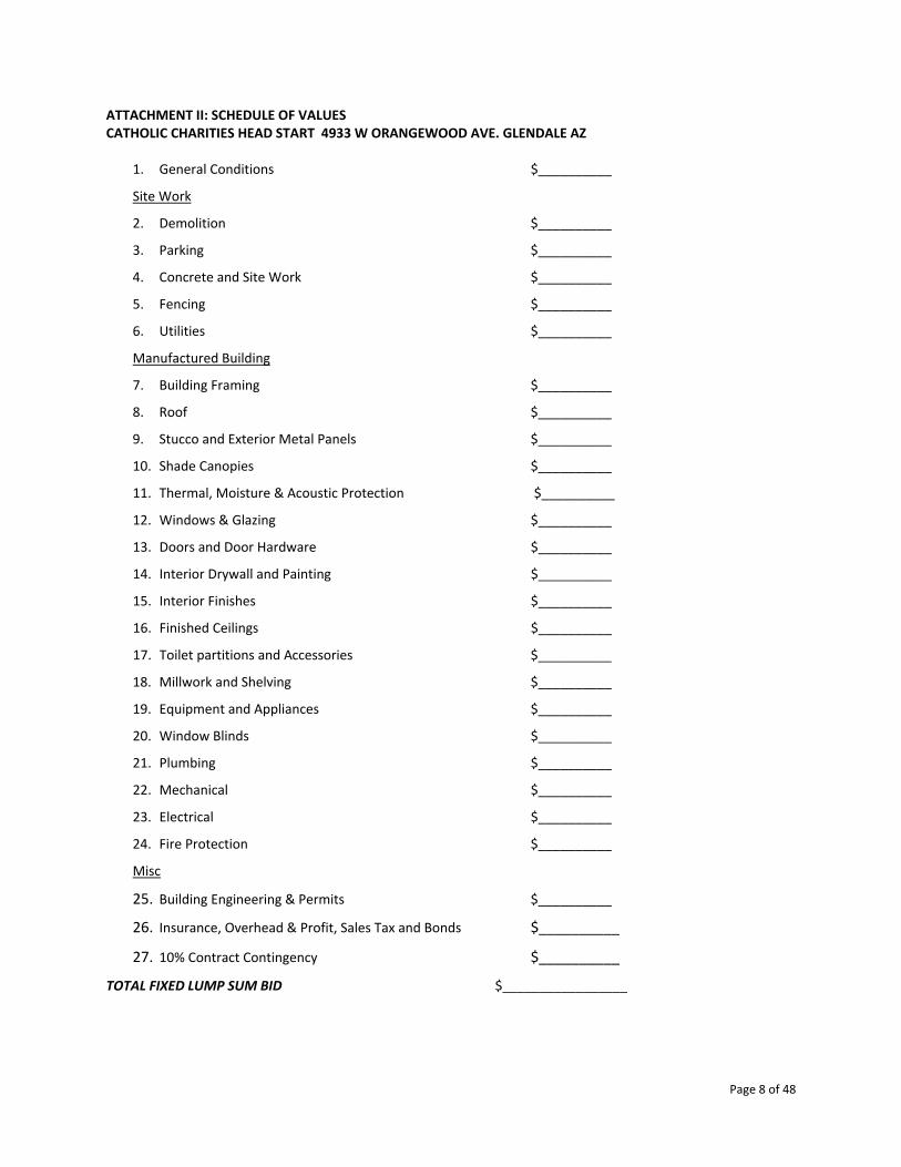
Page 8 of 48
ATTACHMENT II: SCHEDULE OF VALUES CATHOLIC CHARITIES HEAD START 4933 W ORANGEWOOD AVE. GLENDALE AZ
1. General Conditions $__________
Site Work
2. Demolition $__________
3. Parking $__________
4. Concrete and Site Work $__________
5. Fencing $__________
6. Utilities $__________
Manufactured Building
7. Building Framing $__________
8. Roof $__________
9. Stucco and Exterior Metal Panels $__________
10. Shade Canopies $__________
11. Thermal, Moisture & Acoustic Protection $__________
12. Windows & Glazing $__________
13. Doors and Door Hardware $__________
14. Interior Drywall and Painting $__________
15. Interior Finishes $__________
16. Finished Ceilings $__________
17. Toilet partitions and Accessories $__________
18. Millwork and Shelving $__________
19. Equipment and Appliances $__________
20. Window Blinds $__________
21. Plumbing $__________
22. Mechanical $__________
23. Electrical $__________
24. Fire Protection $__________
Misc
25. Building Engineering & Permits $__________
26. Insurance, Overhead & Profit, Sales Tax and Bonds $__________
27. 10% Contract Contingency $__________
TOTAL FIXED LUMP SUM BID $_________________

Page 9 of 48
Catholic Charities Westside Head Start & Early Head Start
Attachment III
Procurement Contract Provisions The following provisions, as applicable, are conditions and assurances agreed and certified to by the contractor upon acceptance of a contract to provide certain goods or services, and are made part thereof.
1. The contractor shall comply with Executive Order 11246, as amended by Executive Order 11375, “Amending Executive Order 1246 Relating to Equal Employment Opportunity,” and as supplemented by regulations at 41 CFR Part 60, “Office of Federal Contract Compliance Programs, Equal Employment Opportunity, Department of Labor.”
2. All contracts and sub grants in excess of $2000 for construction or repair of facilities awarded by recipients and sub recipients are subject to the Copeland “Anti‐Kickback” Act, 18 U.S.C. 874, as supplemented by Department of Labor regulations, (29 CFR Part 3, “Contractors and Subcontractors on Public Building or Public Work Financed in Whole or in Part by Loans or Grants from the United States”). The Act provides that each contractor or sub recipient shall be prohibited from inducing, by any means, any person employed in the construction, completion or repair of public work, to give up any part of the compensation to which s/he is otherwise entitled.
3. When required by Federal program legislation, all construction contracts awarded by recipients and sub recipients of more than $2000 are subject to the Davis‐Bacon Act, (40 U.S.C., 276a to a‐7) and as supplemented by Dept. of Labor regulations (29 CFR part 5, “Labor Standards Provisions Applicable to Contracts Governing Federally Financed and Assisted Construction”. Under this Act, contractors are required to pay wages to laborer and mechanics at a rate not less than the minimum wages specified in the current wage determination made by the Secretary of Labor. In addition, contractors are required to pay wages not
less than once a week. Copies of these provisions are attached and made part of this contract. Weekly payroll information recorded on Optional Form WH‐347 or its equivalent (also attached) must be submitted to the local CCCS project official for inclusion with billing information.
4. Where applicable, all contracts awarded by recipients in excess of $2000 for construction contracts and in excess of$2500 for other contracts that involve the employment of laborers or mechanics are required to comply with sections 102 and 107 of the Contract Work Hours and Safety Standards Act, (40 U.S.C. 327‐333) as supplemented by Department of Labor regulations (29 CFR part 5). Section 102 requires the contractor to compute the wages of every mechanic and laborer on the basis of a standard, work week of 40 hours. Work in excess of the standard work week is permissible provided that the payment of wages in excess of 40 hours at 1 ½ times the basic pay rate. Section 107 provides that no laborer or mechanic shall be required to work in surroundings or under working conditions that are unsanitary, hazardous or dangerous.
5. Any inventions resulting from experimental, developmental or research work shall be subject to 37 CFR part 401, “Rights to Inventions Made by Nonprofit Organizations and Small Business Firms Under Government Grants, Contracts and Cooperative Agreements.”
6. Recipients of contracts and sub grants in excess of $100,000 agree to comply with all applicable standards, orders or regulations issued pursuant to the Clean Air Act, (42 U.S.C., 7401 et seq.) and the Federal Water Pollution Control Act, as amended (33 U.S.C. 1251 et seq.).

Page 10 of 48
7. Contractors who bid for an award of more than $100,000 must file, with CCCS, a certification of compliance with restrictions of the Byrd Anti‐Lobbying Amendment, (31 U.S.C., 1352), that it has not and will not use federally appropriated funds to pay any person or organization for influencing or attempting to influence a member of Congress, officer or employee of Congress, or an employee of a member of Congress in connection with obtaining any federal contract, grant or other award covered by the amendment. Contractors shall also disclose any lobbying with non‐Federal funds that takes place in connection with obtaining any Federal award.
8. Contractors shall certify that they are not prohibited from receiving procurement awards pursuant to Executive Orders 12549 and 12689, “Debarment and Suspension”, and do not appear on the General Services Administration’s “List of Parties Excluded from Federal Procurement or Non procurement Programs.”
9. Contractors shall provide a current Certificate of Insurance which verifies general liability and Workers Compensation coverage.
CONTRACTOR: DATE:
By: Title:

Page 11 of 48
ATTACHMENT IV: BOND FORMS (1 of 2)
ARIZONA STATUTORY BID BOND PURSUANT TO TITLE 28, 34 AND 41, ARIZONA REVISED STATUTES (Penalty of this bond must not be less than 5% of the bid amount)
KNOW ALL PERSONS BY THESE PRESENTS THAT: __________________________ (hereinafter "Principal"), as
Principal, and _______________________________________________, (hereinafter "Surety"), a corporation
organized and existing under the laws of the State of ____________________ , with it principal offices in the City
of ____________________, holding a certificate of authority to transact surety business in Arizona issued by the
Director of the Department of Insurance pursuant to Title 20, Chapter 2, Article 1, as Surety are held and firmly
bound unto_________________________________________________________ (hereinafter "Obligee"), in
the sum of Five Percent (5%) of the amount of the bid of Principal, submitted by Principal to the Obilgee for the work
described below, for the payment of which sum, the Principal and Surety bind themselves, and their heirs,
administrators, executors, successors and assigns, jointly and severally, firmly by these presents.
WHEREAS, the Principal has submitted a bid for ______________________________________ NOW, THEREFORE, if the Obligee shall accept the proposal of the Principal and the Principal shall enter into a contract with the Obligee in accordance with the terms of the proposal and give the bonds and certificates of insurance as specified in the standard specifications with good and sufficient surety for the faithful performance of the contract and for the prompt payment of labor and materials furnished in the prosecution of the contract, or in the event of the failure of the Principal to enter into the contract and give the bonds and certificates of insurance, if the Principal pays to the Obligee the difference not to exceed the penalty of the bond between the amount specified in the proposal and such larger amount for which the Obligee may in good faith contract with another party to perform the work covered by the proposal then this obligation is void. Otherwise, it remains in full force and effect provided, however, that this bond is executed pursuant to the provisions of Section 34‐201, Arizona Revised Statutes, and all liabilities on this bond shall be determined in accordance with the provisions of that section to the extent as if it were copied at length herein. Witness our hands this __________day of _____________________ , 20 ______. ________________________________________ _______________________________________ PRINCIPAL SEAL SURETY SEAL By: ____________________________________ By: ____________________________________ Its: ____________________________________ Its: ____________________________________ _______________________________________
AGENCY ADDRESS

Page 12 of 48
ATTACHMENT IV: BOND FORMS (2 of 2)
STATUTORY PERFORMANCE BOND PURSUANT TO TITLE 34, CHAPTER 2, ARTICLE 2, OF THE ARIZONA REVISED STATUTES
(Penalty of this bond must be 100% of Contract Amount) KNOW ALL PERSONS BY THESE PRESENTS: That __________________________________________ (hereinafter
called Principal), as Principal, and__________________________________________________, a corporation
organized and existing under the laws of the State of _____________________ , with its principal office in the City
of ______________________________________, (hereinafter called the Surety), as surety, are held and firmly
bound unto_________________________________________________ , (hereinafter called the Obligee) in the
amount of _______________________ Dollars ($ ), for the payment whereof, the said Principal and Surety bind
themselves, and their heirs, administrators, executors, successors and assigns, jointly and severally, firmly by these
presents.
WHEREAS, the Principal has entered into a certain written Contract with the Obligee, dated the_________ day
________________________ of 20_______ , to _________________________________________________
__________________________________________________________which Contract is hereby referred to and
made a part hereof as fully and to the same extent as if copied at length herein.
NOW, THEREFORE, THE CONDITION OF THIS OBLIGATION IS SUCH, that if the said Principal shall faithfully perform and fulfill all the undertakings, covenants, terms, conditions and agreements of said contract during the original term of said contract and any extension thereof, with or without notice of the Surety, and during the life of any warranty required under the contract, and shall also perform and fulfill all the undertakings, covenants, terms, conditions, and agreements of any and all duly authorized modifications of said contract that may hereafter be made, notice of which modifications to the Surety being hereby waived, then the above obligation shall be void, otherwise to remain in full force and effect. PROVIDED, HOWEVER, that this bond is executed pursuant to the provisions of Title 34, Chapter 2, Article 2, of the Arizona Revised Statutes, and all liabilities on this bond shall be determined in accordance with the provisions of said Title, Chapter and Article, to the extent as if it were copied at length herein. The prevailing party in a suit on this bond shall recover as a part of his judgment such reasonable attorneys' fees as may be fixed by a judge of the Court. WITNESS our hands this _________ day of_____________________ , 20_______ .
_________________________________ Principal

Page 13 of 48
ATTACHMENT V: DAVIS BACON REGULATIONS & WAGE DECISION REGULATIONS 29 CFR Part 5 ‐ LABOR STANDARDS PROVISIONS APPLICABLE TO CONTRACTS COVERING FEDERALLY FINANCED AND ASSISTED CONSTRUCTION (ALSO LABOR STANDARDS PROVISIONS APPLICABLE...SUBJECT TO THE CONTRACT WORK HOURS AND SAFETY STANDARDS ACT) § 5.5 Contract provisions and related matters. (a) The Agency head shall cause or require the contracting officer to insert in full in any contract in excess of $2,000 which is entered into for the actual construction, alteration and/or repair, including painting and decorating, of a public building or public work, or building or work financed in whole or in part from Federal funds or in accordance with guarantees of a Federal agency or financed from funds obtained by pledge of any contract of a Federal agency to make a loan, grant or annual contribution (except where a different meaning is expressly indicated), and which is subject to the labor standards provisions of any of the acts listed in § 5.1, the following clauses (or any modifications thereof to meet the particular needs of the agency, Provided, That such modifications are first approved by the Department of Labor): (1) Minimum wages. (i) All laborers and mechanics employed or working upon the site of the work (or under the United States Housing Act of 1937 or under the Housing Act of 1949 in the construction or development of the project), will be paid unconditionally and not less often than once a week, and without subsequent deduction or rebate on any account (except such payroll deductions as are permitted by regulations issued by the Secretary of Labor under the Copeland Act (29 CFR part 3)), the full amount of wages and bona fide fringe benefits (or cash equivalents thereof) due at time of payment computed at rates not less than those contained in the wage determination of the Secretary of Labor which is attached hereto and made a part hereof, regardless of any contractual relationship which may be alleged to exist between the contractor and such laborers and mechanics. Contributions made or costs reasonably anticipated for bona fide fringe benefits under section 1(b)(2) of the Davis‐Bacon Act on behalf of laborers or mechanics are considered wages paid to such laborers or mechanics, subject to the provisions of paragraph (a)(1)(iv) of this section; also, regular contributions made or costs incurred for more than a weekly period (but not less often than quarterly) under plans, funds, or programs which cover the particular weekly period, are deemed to be constructively made or incurred during such weekly period. Such laborers and mechanics shall be paid the appropriate wage rate and fringe benefits on the wage determination for the classification of work actually performed, without regard to skill, except as provided in § 5.5(a)(4). Laborers or mechanics performing work in more than one classification may be compensated at the rate specified for each classification for the time actually worked therein: Provided, That the employer's payroll records accurately set forth the time spent in each classification in which work is performed. The wage determination (including any additional classification and wage rates conformed under paragraph (a)(1)(ii) of this section) and the Davis‐Bacon poster (WH‐1321) shall be posted at all times by the contractor and its subcontractors at the site of the work in a prominent and accessible place where it can be easily seen by the workers. (ii) (A) The contracting officer shall require that any class of laborers or mechanics, including helpers, which is not listed in the wage determination and which is to be employed under the contract shall be classified in conformance with the wage determination. The contracting officer shall approve an additional classification and wage rate and fringe benefits therefore only when the following criteria have been met: (1) The work to be performed by the classification requested is not performed by a classification in the wage determination; and (2) The classification is utilized in the area by the construction industry; and (3) The proposed wage rate, including any bona fide fringe benefits, bears a reasonable relationship to the wage rates contained in the wage determination. (B) If the contractor and the laborers and mechanics to be employed in the classification (if known), or their representatives, and the contracting officer agree on the classification and wage rate (including the amount designated for fringe benefits where appropriate), a report of the action taken shall be sent by the contracting officer to the Administrator of the Wage and Hour Division, Employment Standards Administration, U.S. Department of Labor, Washington, DC 20210. The Administrator, or an authorized representative, will approve, modify, or

Page 14 of 48
disapprove every additional classification action within 30 days of receipt and so advise the contracting officer or will notify the contracting officer within the 30‐day period that additional time is necessary. (C) In the event the contractor, the laborers or mechanics to be employed in the classification or their representatives, and the contracting officer do not agree on the proposed classification and wage rate (including the amount designated for fringe benefits, where appropriate), the contracting officer shall refer the questions, including the views of all interested parties and the recommendation of the contracting officer, to the Administrator for determination. The Administrator, or an authorized representative, will issue a determination within 30 days of receipt and so advise the contracting officer or will notify the contracting officer within the 30‐day period that additional time is necessary. (D) The wage rate (including fringe benefits where appropriate) determined pursuant to paragraphs (a)(1)(ii) (B) or (C) of this section, shall be paid to all workers performing work in the classification under this contract from the first day on which work is performed in the classification. (iii) Whenever the minimum wage rate prescribed in the contract for a class of laborers or mechanics includes a fringe benefit which is not expressed as an hourly rate, the contractor shall either pay the benefit as stated in the wage determination or shall pay another bona fide fringe benefit or an hourly cash equivalent thereof. (iv) If the contractor does not make payments to a trustee or other third person, the contractor may consider as part of the wages of any laborer or mechanic the amount of any costs reasonably anticipated in providing bona fide fringe benefits under a plan or program, Provided, That the Secretary of Labor has found, upon the written request of the contractor, that the applicable standards of the Davis‐Bacon Act have been met. The Secretary of Labor may require the contractor to set aside in a separate account assets for the meeting of obligations under the plan or program. (2) Withholding. The (write in name of Federal Agency or the loan or grant recipient) shall upon its own action or upon written request of an authorized representative of the Department of Labor withhold or cause to be withheld from the contractor under this contract or any other Federal contract with the same prime contractor, or any other federally‐assisted contract subject to Davis‐Bacon prevailing wage requirements, which is held by the same prime contractor, so much of the accrued payments or advances as may be considered necessary to pay laborers and mechanics, including apprentices, trainees, and helpers, employed by the contractor or any subcontractor the full amount of wages required by the contract. In the event of failure to pay any laborer or mechanic, including any apprentice, trainee, or helper, employed or working on the site of the work (or under the United States Housing Act of 1937 or under the Housing Act of 1949 in the construction or development of the project), all or part of the wages required by the contract, the (Agency) may, after written notice to the contractor, sponsor, applicant, or owner, take such action as may be necessary to cause the suspension of any further payment, advance, or guarantee of funds until such violations have ceased. (3) Payrolls and basic records. (i) Payrolls and basic records relating thereto shall be maintained by the contractor during the course of the work and preserved for a period of three years thereafter for all laborers and mechanics working at the site of the work (or under the United States Housing Act of 1937, or under the Housing Act of 1949, in the construction or development of the project). Such records shall contain the name, address, and social security number of each such worker, his or her correct classification, hourly rates of wages paid (including rates of contributions or costs anticipated for bona fide fringe benefits or cash equivalents thereof of the types described in section 1(b)(2)(B) of the Davis‐Bacon Act), daily and weekly number of hours worked, deductions made and actual wages paid. Whenever the Secretary of Labor has found under 29 CFR 5.5(a)(1)(iv) that the wages of any laborer or mechanic include the amount of any costs reasonably anticipated in providing benefits under a plan or program described in section 1(b)(2)(B) of the Davis‐Bacon Act, the contractor shall maintain records which show that the commitment to provide such benefits is enforceable, that the plan or program is financially responsible, and that the plan or program has been communicated in writing to the laborers or mechanics affected, and records which show the costs anticipated or the actual cost incurred in providing such benefits. Contractors employing apprentices or trainees under approved programs shall maintain written evidence of the registration of apprenticeship programs and certification of trainee programs, the registration of the apprentices and trainees, and the ratios and wage rates prescribed in the applicable programs. (ii) (A) The contractor shall submit weekly for each week in which any contract work is performed a copy of all payrolls to the (write in name of appropriate federal agency) if the agency is a party to the contract, but if the agency is not such a party, the contractor will submit the payrolls to the applicant, sponsor, or owner, as the case may be, for

Page 15 of 48
transmission to the (write in name of agency). The payrolls submitted shall set out accurately and completely all of the information required to be maintained under 29 CFR 5.5(a)(3)(i), except that full social security numbers and home addresses shall not be included on weekly transmittals. Instead the payrolls shall only need to include an individually identifying number for each employee (e.g., the last four digits of the employee's social security number). The required weekly payroll information may be submitted in any form desired. Optional Form WH‐347 is available for this purpose from the Wage and Hour Division Web site at: http://www.dol.gov/esa/whd/forms/wh347instr.htm or its successor site. The prime contractor is responsible for the submission of copies of payrolls by all subcontractors. Contractors and subcontractors shall maintain the full social security number and current address of each covered worker, and shall provide them upon request to the (write in name of appropriate federal agency) if the agency is a party to the contract, but if the agency is not such a party, the contractor will submit them to the applicant, sponsor, or owner, as the case may be, for transmission to the (write in name of agency), the contractor, or the Wage and Hour Division of the Department of Labor for purposes of an investigation or audit of compliance with prevailing wage requirements. It is not a violation of this section for a prime contractor to require a subcontractor to provide addresses and social security numbers to the prime contractor for its own records, without weekly submission to the sponsoring government agency (or the applicant, sponsor, or owner). (B) Each payroll submitted shall be accompanied by a “Statement of Compliance,” signed by the contractor or subcontractor or his or her agent who pays or supervises the payment of the persons employed under the contract and shall certify the following: (1) That the payroll for the payroll period contains the information required to be provided under § 5.5 (a)(3)(ii) of Regulations, 29 CFR part 5, the appropriate information is being maintained under § 5.5 (a)(3)(i) of Regulations, 29 CFR part 5, and that such information is correct and complete; (2) That each laborer or mechanic (including each helper, apprentice, and trainee) employed on the contract during the payroll period has been paid the full weekly wages earned, without rebate, either directly or indirectly, and that no deductions have been made either directly or indirectly from the full wages earned, other than permissible deductions as set forth in Regulations, 29 CFR part 3; (3) That each laborer or mechanic has been paid not less than the applicable wage rates and fringe benefits or cash equivalents for the classification of work performed, as specified in the applicable wage determination incorporated into the contract. (C) The weekly submission of a properly executed certification set forth on the reverse side of Optional Form WH‐347 shall satisfy the requirement for submission of the “Statement of Compliance” required by paragraph (a)(3)(ii)(B) of this section. (D) The falsification of any of the above certifications may subject the contractor or subcontractor to civil or criminal prosecution under section 1001 of title 18 and section 231 of title 31 of the United States Code. (iii) The contractor or subcontractor shall make the records required under paragraph (a)(3)(i) of this section available for inspection, copying, or transcription by authorized representatives of the (write the name of the agency) or the Department of Labor, and shall permit such representatives to interview employees during working hours on the job. If the contractor or subcontractor fails to submit the required records or to make them available, the Federal agency may, after written notice to the contractor, sponsor, applicant, or owner, take such action as may be necessary to cause the suspension of any further payment, advance, or guarantee of funds. Furthermore, failure to submit the required records upon request or to make such records available may be grounds for debarment action pursuant to 29 CFR 5.12. (4) Apprentices and trainees‐ (i) Apprentices. Apprentices will be permitted to work at less than the predetermined rate for the work they performed when they are employed pursuant to and individually registered in a bona fide apprenticeship program registered with the U.S. Department of Labor, Employment and Training Administration, Office of Apprenticeship Training, Employer and Labor Services, or with a State Apprenticeship Agency recognized by the Office, or if a person is employed in his or her first 90 days of probationary employment as an apprentice in such an apprenticeship program, who is not individually registered in the program, but who has been certified by the Office of Apprenticeship Training, Employer and Labor Services or a State Apprenticeship Agency (where appropriate) to be eligible for probationary employment as an apprentice. The allowable ratio of apprentices to journeymen on the job site in any craft classification shall not be greater than the ratio permitted to the contractor as to the entire work force under the registered program. Any worker listed on a payroll at an apprentice wage rate, who is not registered

Page 16 of 48
or otherwise employed as stated above, shall be paid not less than the applicable wage rate on the wage determination for the classification of work actually performed. In addition, any apprentice performing work on the job site in excess of the ratio permitted under the registered program shall be paid not less than the applicable wage rate on the wage determination for the work actually performed. Where a contractor is performing construction on a project in a locality other than that in which its program is registered, the ratios and wage rates (expressed in percentages of the journeyman's hourly rate) specified in the contractor's or subcontractor's registered program shall be observed. Every apprentice must be paid at not less than the rate specified in the registered program for the apprentice's level of progress, expressed as a percentage of the journeymen hourly rate specified in the applicable wage determination. Apprentices shall be paid fringe benefits in accordance with the provisions of the apprenticeship program. If the apprenticeship program does not specify fringe benefits, apprentices must be paid the full amount of fringe benefits listed on the wage determination for the applicable classification. If the Administrator determines that a different practice prevails for the applicable apprentice classification, fringes shall be paid in accordance with that determination. In the event the Office of Apprenticeship Training, Employer and Labor Services, or a State Apprenticeship Agency recognized by the Office, withdraws approval of an apprenticeship program, the contractor will no longer be permitted to utilize apprentices at less than the applicable predetermined rate for the work performed until an acceptable program is approved. (ii) Trainees. Except as provided in 29 CFR 5.16, trainees will not be permitted to work at less than the predetermined rate for the work performed unless they are employed pursuant to and individually registered in a program which has received prior approval, evidenced by formal certification by the U.S. Department of Labor, Employment and Training Administration. The ratio of trainees to journeymen on the job site shall not be greater than permitted under the plan approved by the Employment and Training Administration. Every trainee must be paid at not less than the rate specified in the approved program for the trainee's level of progress, expressed as a percentage of the journeyman hourly rate specified in the applicable wage determination. Trainees shall be paid fringe benefits in accordance with the provisions of the trainee program. If the trainee program does not mention fringe benefits, trainees shall be paid the full amount of fringe benefits listed on the wage determination unless the Administrator of the Wage and Hour Division determines that there is an apprenticeship program associated with the corresponding journeyman wage rate on the wage determination which provides for less than full fringe benefits for apprentices. Any employee listed on the payroll at a trainee rate who is not registered and participating in a training plan approved by the Employment and Training Administration shall be paid not less than the applicable wage rate on the wage determination for the classification of work actually performed. In addition, any trainee performing work on the job site in excess of the ratio permitted under the registered program shall be paid not less than the applicable wage rate on the wage determination for the work actually performed. In the event the Employment and Training Administration withdraws approval of a training program, the contractor will no longer be permitted to utilize trainees at less than the applicable predetermined rate for the work performed until an acceptable program is approved. (iii) Equal employment opportunity. The utilization of apprentices, trainees and journeymen under this part shall be in conformity with the equal employment opportunity requirements of Executive Order 11246, as amended, and 29 CFR part 30. (5) Compliance with Copeland Act requirements. The contractor shall comply with the requirements of 29 CFR part 3, which are incorporated by reference in this contract. (6) Subcontracts. The contractor or subcontractor shall insert in any subcontracts the clauses contained in 29 CFR 5.5(a)(1) through (10) and such other clauses as the (write in the name of the Federal agency) may by appropriate instructions require, and also a clause requiring the subcontractors to include these clauses in any lower tier subcontracts. The prime contractor shall be responsible for the compliance by any subcontractor or lower tier subcontractor with all the contract clauses in 29 CFR 5.5. (7) Contract termination: debarment. A breach of the contract clauses in 29 CFR 5.5 may be grounds for termination of the contract, and for debarment as a contractor and a subcontractor as provided in 29 CFR 5.12. (8) Compliance with Davis‐Bacon and Related Act requirements. All rulings and interpretations of the Davis‐Bacon and Related Acts contained in 29 CFR parts 1, 3, and 5 are herein incorporated by reference in this contract. (9) Disputes concerning labor standards. Disputes arising out of the labor standards provisions of this contract shall not be subject to the general disputes clause of this contract. Such disputes shall be resolved in accordance with the procedures of the Department of Labor set forth in 29 CFR parts 5, 6, and 7. Disputes within the meaning of this

Page 17 of 48
clause include disputes between the contractor (or any of its subcontractors) and the contracting agency, the U.S. Department of Labor, or the employees or their representatives. (10) Certification of eligibility. (i) By entering into this contract, the contractor certifies that neither it (nor he or she) nor any person or firm who has an interest in the contractor's firm is a person or firm ineligible to be awarded Government contracts by virtue of section 3(a) of the Davis‐Bacon Act or 29 CFR 5.12(a)(1). (ii) No part of this contract shall be subcontracted to any person or firm ineligible for award of a Government contract by virtue of section 3(a) of the Davis‐Bacon Act or 29 CFR 5.12(a)(1). (iii) The penalty for making false statements is prescribed in the U.S. Criminal Code, 18 U.S.C. 1001. (b) Contract Work Hours and Safety Standards Act. The Agency Head shall cause or require the contracting officer to insert the following clauses set forth in paragraphs (b)(1), (2), (3), and (4) of this section in full in any contract in an amount in excess of $100,000 and subject to the overtime provisions of the Contract Work Hours and Safety Standards Act. These clauses shall be inserted in addition to the clauses required by § 5.5(a) or 4.6 of part 4 of this title. As used in this paragraph, the terms laborers and mechanics include watchmen and guards. (1) Overtime requirements. No contractor or subcontractor contracting for any part of the contract work which may require or involve the employment of laborers or mechanics shall require or permit any such laborer or mechanic in any workweek in which he or she is employed on such work to work in excess of forty hours in such workweek unless such laborer or mechanic receives compensation at a rate not less than one and one‐half times the basic rate of pay for all hours worked in excess of forty hours in such workweek. (2) Violation; liability for unpaid wages; liquidated damages. In the event of any violation of the clause set forth in paragraph (b)(1) of this section the contractor and any subcontractor responsible therefor shall be liable for the unpaid wages. In addition, such contractor and subcontractor shall be liable to the United States (in the case of work done under contract for the District of Columbia or a territory, to such District or to such territory), for liquidated damages. Such liquidated damages shall be computed with respect to each individual laborer or mechanic, including watchmen and guards, employed in violation of the clause set forth in paragraph (b)(1) of this section, in the sum of $10 for each calendar day on which such individual was required or permitted to work in excess of the standard workweek of forty hours without payment of the overtime wages required by the clause set forth in paragraph (b)(1) of this section. (3) Withholding for unpaid wages and liquidated damages. The (write in the name of the Federal agency or the loan or grant recipient) shall upon its own action or upon written request of an authorized representative of the Department of Labor withhold or cause to be withheld, from any moneys payable on account of work performed by the contractor or subcontractor under any such contract or any other Federal contract with the same prime contractor, or any other federally‐assisted contract subject to the Contract Work Hours and Safety Standards Act, which is held by the same prime contractor, such sums as may be determined to be necessary to satisfy any liabilities of such contractor or subcontractor for unpaid wages and liquidated damages as provided in the clause set forth in paragraph (b)(2) of this section. (4) Subcontracts. The contractor or subcontractor shall insert in any subcontracts the clauses set forth in paragraph (b)(1) through (4) of this section and also a clause requiring the subcontractors to include these clauses in any lower tier subcontracts. The prime contractor shall be responsible for compliance by any subcontractor or lower tier subcontractor with the clauses set forth in paragraphs (b)(1) through (4) of this section. (c) In addition to the clauses contained in paragraph (b), in any contract subject only to the Contract Work Hours and Safety Standards Act and not to any of the other statutes cited in § 5.1, the Agency Head shall cause or require the contracting officer to insert a clause requiring that the contractor or subcontractor shall maintain payrolls and basic payroll records during the course of the work and shall preserve them for a period of three years from the completion of the contract for all laborers and mechanics, including guards and watchmen, working on the contract. Such records shall contain the name and address of each such employee, social security number, correct classifications, hourly rates of wages paid, daily and weekly number of hours worked, deductions made, and actual wages paid. Further, the Agency Head shall cause or require the contracting officer to insert in any such contract a clause providing that the records to be maintained under this paragraph shall be made available by the contractor or subcontractor for inspection, copying, or transcription by authorized representatives of the (write the name of agency) and the Department of Labor, and the contractor or subcontractor will permit such representatives to interview employees during working hours on the job.

Page 18 of 48
"General Decision Number: AZ20200031
08/21/2020 Superseded General Decision Number:
AZ20190031
State: Arizona Construction Type: Building
County: Maricopa County in Arizona.
BUILDING CONSTRUCTION PROJECTS (does not include single family homes or apartments up to and including 4 stories).
Note: Under Executive Order (EO) 13658, an hourly minimum wage of $10.80 for calendar year 2020 applies to all contracts subject to the Davis‐Bacon Act for which the contract is awarded (and any solicitation was issued) on or after January 1, 2015. If this contract is covered by the EO, the contractor must pay all workers in any classification listed on this wage determination at least $10.80 per hour (or the applicable wage rate listed on this wage determination, if it is higher) for all hours spent performing on the contract in calendar year 2020. If this contract is covered by the EO and a classification considered necessary for performance of work on the contract does not appear on this wage determination, the contractor must pay workers in that classification at least the wage rate determined through the conformance process set forth in 29 CFR 5.5(a)(1)(ii) (or the EO minimum wage rate,if it is higher than the conformed wage rate). The EO minimum wage rate will be adjusted annually. Please note that this EO applies to the above‐mentioned types of contracts entered into by the federal government that are subject to the Davis‐Bacon Act itself, but it does not apply to contracts subject only to the Davis‐Bacon Related Acts, including those set forth at 29 CFR 5.1(a)(2)‐(60). Additional information on contractor requirements and worker protections under the EO is available at www.dol.gov/whd/govcontracts.
Modification Number Publication Date
0 01/03/2020
1 01/31/2020
2 05/15/2020
3 06/05/2020
4 ASBE0073‐002
08/01/2019
08/21/2020
Rates
Fringes
ASBESTOS WORKER/HEAT & FROST INSULATOR........................$ 40.84 14.52

Page 19 of 48
BOIL0627‐001 10/01/2017
Rates Fringes
BOILERMAKER......................$ 35.30 28.41
BRAZ0003‐009 07/01/2019
Rates Fringes BRICKLAYER.......................$ 25.31 8.13
ZONE PAY:
(Radius miles from the intersection of Central Ave. and Washington St., Phoenix, AZ)
Zone A: 0‐60 miles‐ Base Rate Zone B: 61‐75 miles‐ Base Rate plus $2.00 per hour Zone C: 75‐100 miles‐ Base Rate plus $3.00 per hour Zone D: 101‐200 miles‐ Base Rate plus $3.50 per hour Zone E: Over 200 miles‐ Base Rate plus $6.50 per hour
CARP0408‐009 07/01/2019
Rates Fringes CARPENTER (Excludes Acoustical Ceiling Installation, Drywall Finishing/Taping, Drywall Hanging, Form Work, and Metal Stud Installation)...............$ 27.89 12.23
CARP1327‐001 07/01/2019
Rates Fringes
CARPENTER (Drywall Hanging Only)............................$ 26.24 8.86
* ELEC0640‐005 07/01/2020
Rates Fringes
ELECTRICIAN (Includes Low Voltage Wiring; Excludes Installation of Alarms

Page 20 of 48
and Sound and Communication Systems).........................$ 30.00 11.55
ENGI0428‐012 06/01/2020
Rates Fringes
POWER EQUIPMENT OPERATOR (1) Oiler...................$ 27.04 11.72 (2) Crane under 15 tons.....$ 30.31 11.72 (3) Crane,15 tons to 100 tons, Tower Crane...........$ 31.39 11.72
(4) Crane, 100 tons and (5) over........................$ 32.42 11.72
IRON0075‐011 08/01/2019
Rates Fringes
IRONWORKER, STRUCTURAL AND ORNAMENTAL.......................$ 27.80 19.05
Zone 1: 0 to 50 miles from City Hall in Phoenix or Tucson Zone 2: 050 to 100 miles ‐ Add $4.00 Zone 3: 100 to 150 miles ‐ Add $5.00 Zone 4: 150 miles & over ‐ Add $6.50
LABO1184‐010 06/01/2020
Rates Fringes
LABORER (MASON TENDER‐BRICK).....$ 21.63 6.06
PAIN0086‐006 04/01/2017
Rates Fringes DRYWALL FINISHER/TAPER
ZONE A ..................... $ 20.05 6.68 ZONE
ZONE PAY:
B ..................... $ 23.55 6.68
ZONE A: Free Zone: A distance of 0 to 100 miles from the old Phoenix courthouse.
ZONE B: A distance of 101 miles and over from the old Phoenix courthouse: $3.50 per hour over ZONE A

Page 21 of 48
PLAS0394‐001 07/01/2019
Rates Fringes
CEMENT MASON/CONCRETE FINISHER...$ 25.08 8.57
PLUM0469‐002 01/01/2020
Rates Fringes
PLUMBER/PIPEFITTER Coconino, Maricopa, and Yuma ....................... $
38.25
17.15
Cononino, Maricopa, and Yuma ....................... $
36.35
17.00 Pima ....................... $ 38.25 17.15
SFAZ0669‐001 04/01/2020
Rates Fringes
SPRINKLER FITTER (Fire Sprinklers)......................$ 34.35 24.52
* SHEE0359‐002 07/01/2020
Rates Fringes
SHEET METAL WORKER: (HVAC Duct Installation Only)
Zone 1 ..................... $ 37.15 19.06
SUAZ2012‐020 05/30/2012
Rates Fringes
ACOUSTICAL CEILING MECHANIC ..... $ 21.14 3.14
CARPENTER (Form Work Only) ...... $ 19.67 5.45
CARPENTER (Metal Stud Installation) ................... $
16.23
0.00
CAULKER ......................... $ 16.01 0.00
ELECTRICIAN (Alarm Installation) ................... $
18.31
4.68
ELECTRICIAN (Installation of Sound and Communication Systems) ........................ $
17.20
2.87

Page 22 of 48
FIREPROOFER ..................... $ 15.00 0.00
GLAZIER ......................... $ 18.67 1.44
INSTALLER ‐ SIGN ................ $ 19.16 3.58
INSULATOR ‐ BATT ................ $ 11.96 3.06
IRONWORKER, REINFORCING ......... $ 14.92 0.00
LABORER: Asphalt Raker ......... $ 15.18 1.30
LABORER: Common or General ..... $ 13.80 2.24
LABORER: Concrete Saw (Hand Held/Walk Behind) ............... $
21.00
7.37
LABORER: Fence Erection ........ $ 19.73 0.00
LABORER: Landscape & Irrigation ...................... $
11.33
0.43
LABORER: Mason Tender ‐ Cement/Concrete ................. $
15.24
3.90
LABORER: Pipelayer ............. $ 15.10 0.85
LABORER: Plaster Tender ........ $ 12.00 0.00
LABORER: Power Tool Operator ... $ 14.85 4.20
LATHER...........................$ 16.15 0.00
MASON ‐ STONE ................... $ 18.48 0.82
MILLWRIGHT.......................$ 20.00 2.87
OPERATOR: Backhoe/Ex
cavator/Trackhoe ...... $
19.20
2.47
OPERATOR: Bulldozer ............ $ 21.12 6.14
OPERATOR: Drill Rig Caissons ... $ 19.06 2.39
OPERATOR: Drill ................ $ 19.16 0.00
OPERATOR: Forklift ............. $ 17.36 0.00
OPERATOR: Grader/Blade ......... $ 21.00 7.07
OPERATOR: Loader (Front End) ... $ 18.55 0.95
OPERATOR: Aggregate,
Paver (Asphalt, and Concrete) ........ $
21.09
3.96

Page 23 of 48
OPERATOR: Roller ............... $ 25.00 0.00
OPERATOR: Scraper .............. $ 21.41 0.00
OPERATOR: Screed ............... $ 22.17 4.42
OPERATOR: Trencher ............. $ 15.01 0.58
PAINTER: Spray and
Brush, Roller, Steel ................. $
16.53
2.63
PLASTERER........................$ 16.71 0.00
ROOFER, InWaterproofInstallati
cludes ing, and on of Metal Roofs ..... $
16.71
1.67
SHEET METAHVAC Duct
L WORKER, Excludes Installation .......... $
18.85
2.79
TERRAZZO WORKER/SETTER .......... $ 21.13 0.00
TILE FINISHER ................... $ 12.50 0.00
TILE SETTER ..................... $ 15.00 0.00
TRUCK DRIVER: Dump Trucks ...... $ 15.55 1.42
TRUCK DRIVER: Pickup Truck ..... $ 11.00 0.87
TRUCK DRIVER: Water Truck.......$ 17.72 4.21
TRUCKDRIVER: 3 and 4 Axle.......$ 19.29 1.36
WELDERS ‐ Receive rate prescribed for craft performing operation to which welding is incidental.
================================================================
Note: Executive Order (EO) 13706, Establishing Paid Sick Leave for Federal Contractors applies to all contracts subject to the Davis‐Bacon Act for which the contract is awarded (and any solicitation was issued) on or after January 1, 2017. If this contract is covered by the EO, the contractor must provide employees with 1 hour of paid sick leave for every 30 hours they work, up to 56 hours of paid sick leave each year. Employees must be permitted to use paid sick leave for their own illness, injury or other health‐related needs, including preventive care; to assist a family member (or person who is like family to the employee) who is ill, injured, or has other health‐related needs, including preventive care; or for reasons resulting from, or to assist a family member (or

Page 24 of 48
person who is like family to the employee) who is a victim of, domestic violence, sexual assault, or stalking. Additional information on contractor requirements and worker protections under the EO is available at www.dol.gov/whd/govcontracts.
Unlisted classifications needed for work not included within the scope of the classifications listed may be added after award only as provided in the labor standards contract clauses (29CFR 5.5 (a) (1) (ii)).
The body of each wage determination lists the classification and wage rates that have been found to be prevailing for the cited type(s) of construction in the area covered by the wage determination. The classifications are listed in alphabetical order of ""identifiers"" that indicate whether the particular rate is a union rate (current union negotiated rate for local), a survey rate (weighted average rate) or a union average rate (weighted union average rate).
Union Rate Identifiers A four letter classification abbreviation identifier enclosed in dotted lines beginning with characters other than ""SU"" or ""UAVG"" denotes that the union classification and rate were prevailing for that classification in the survey. Example: PLUM0198‐005 07/01/2014. PLUM is an abbreviation identifier of the union which prevailed in the survey for this classification, which in this example would be Plumbers. 0198 indicates the local union number or district council number where applicable, i.e., Plumbers Local 0198. The next number,
005 in the example, is an internal number used in processing the wage determination. 07/01/2014 is the effective date of the most current negotiated rate, which in this example is July 1, 2014. Union prevailing wage rates are updated to reflect all rate changes in the collective bargaining agreement (CBA) governing this classification and rate.
Survey Rate Identifiers
Classifications listed under the ""SU"" identifier indicate that no one rate prevailed for this classification in the survey and the published rate is derived by computing a weighted average rate based on all the rates reported in the survey for that classification. As this weighted average rate includes all rates reported in the survey, it may include both union and non‐union rates. Example: SULA2012‐007 5/13/2014. SU indicates the rates are survey rates based on a weighted

Page 25 of 48
average calculation of rates and are not majority rates. LA indicates the State of Louisiana. 2012 is the year of survey on which these classifications and rates are based. The next number, 007 in the example, is an internal number used in producing the wage determination. 5/13/2014 indicates the survey completion date for the classifications and rates under that identifier.
Survey wage rates are not updated and remain in effect until a new survey is conducted.
Union Average Rate Identifiers
Classification(s) listed under the UAVG identifier indicate that no single majority rate prevailed for those classifications; however, 100% of the data reported for the classifications was union data. EXAMPLE: UAVG‐OH‐0010 08/29/2014. UAVG indicates that the rate is a weighted union average rate. OH indicates the state. The next number, 0010 in the example, is an internal number used in producing the wage determination. 08/29/2014 indicates the survey completion date for the classifications and rates under that identifier.
A UAVG rate will be updated once a year, usually in January of each year, to reflect a weighted average of the current negotiated/CBA rate of the union locals from which the rate is based.
WAGE DETERMINATION APPEALS PROCESS
1.) Has there been an initial decision in the matter? This can be:
* an existing published wage determination * a survey underlying a wage determination * a Wage and Hour Division letter setting forth a position on
a wage determination matter * a conformance (additional classification and rate) ruling
On survey related matters, initial contact, including requests for summaries of surveys, should be with the Wage and Hour Regional Office for the area in which the survey was conducted because those Regional Offices have responsibility for the Davis‐Bacon survey program. If the response from this initial contact is not satisfactory, then the process described in 2.) and 3.) should be followed.
With regard to any other matter not yet ripe for the formal process described here, initial contact should be with the Branch of Construction Wage Determinations.

Page 26 of 48
Write to:
Branch of Construction Wage Determinations Wage and Hour Division U.S. Department of Labor 200 Constitution Avenue, N.W. Washington, DC 20210
2.) If the answer to the question in 1.) is yes, then an interested party (those affected by the action) can request review and reconsideration from the Wage and Hour Administrator (See 29 CFR Part 1.8 and 29 CFR Part 7). Write to:
Wage and Hour Administrator U.S. Department of Labor 200 Constitution Avenue, N.W. Washington, DC 20210
The request should be accompanied by a full statement of the interested party's position and by any information (wage payment data, project description, area practice material, etc.) that the requestor considers relevant to the issue.
3.) If the decision of the Administrator is not favorable, an interested party may appeal directly to the Administrative Review Board (formerly the Wage Appeals Board). Write to:
Administrative Review Board U.S. Department of Labor 200 Constitution Avenue, N.W. Washington, DC 20210
4.) All decisions by the Administrative Review Board are final.
===============================================================
= END OF GENERAL DECISION"

Page 27 of 48
ATTACHMENT VII: REQUIRED FORMS

Page 28 of 48

Page 29 of 48

Page 30 of 48

Page 31 of 48

Page 32 of 48

Page 33 of 48

Page 34 of 48

Page 35 of 48

Page 36 of 48

Page 37 of 48
CERTIFICATION OF UNDERSTANDING AND AUTHORIZATION
PROJECT NAME: ____________________________________ PROJECT NUMBER:__________________ The following person(s) is designated as the payroll officer for the undersigned and is authorized to sign the Federal Statement of Compliance which will accompany our weekly certified payroll reports for this project: IRS Employer Identification Number Authorized Payroll Officer Authorized Payroll Officer Signature Prime Contractor/Subcontractor Prime Contractor/Subcontractor Signature Title Date

Page 38 of 48
AUTHORIZATION FOR DEDUCTIONS PROJECT NAME: ____________________________________ PROJECT NUMBER:__________________ Undersigned authorize deductions, as noted, to be made from their wages. It is understood that these deductions:
(a) are in the interest of the employee, (b) are not a condition of employment, (c) provide no direct or indirect financial benefit accruing to the employer, and (d) are not otherwise forbidden by law.
Employee’s Name Employee’s Signature Date Deductions ______________________ _________________________ _______________ _____________________
______________________ _________________________ _______________ _____________________
______________________ _________________________ _______________ _____________________
______________________ _________________________ _______________ _____________________
______________________ _________________________ _______________ _____________________
______________________ _________________________ _______________ _____________________
______________________ _________________________ _______________ _____________________
_________________________________________________ Contractor’s Name _________________________________________________ _____________________________________ Authorized Representative’s Name Title _________________________________________________ Authorized Representative Signature Date

Page 39 of 48
CERTIFICATION FOR APPLICABLE FRINGE BENEFIT PAYMENTS
PROJECT NAME: ____________________________________ PROJECT NUMBER:__________________ Classification/Fringe Benefits Provided Name, Address, Phone of Plan/Fund/Program Employee: ___________________________________
$___________ Health & Welfare ______________________________________________
$___________ Pension ______________________________________________
$___________ Vacation ______________________________________________
$___________ Apprenticeship/Training ______________________________________________
$___________ Other ______________________________________________
Employee: ___________________________________
$___________ Health & Welfare ______________________________________________
$___________ Pension ______________________________________________
$___________ Vacation ______________________________________________
$___________ Apprenticeship/Training ______________________________________________
$___________ Other ______________________________________________
Employee: ___________________________________
$___________ Health & Welfare ______________________________________________
$___________ Pension ______________________________________________
$___________ Vacation ______________________________________________
$___________ Apprenticeship/Training ______________________________________________
$___________ Other ______________________________________________
OR CHECK IF APPLICABLE ___ I CERTIFY THAT I DO NOT MAKE PAYMENTS TO APPROVED FRINGE BENEFIT PLANS, FUNDS OR PROGRAMS. ____________________________________________ ______________________________________________ Contractor/Subcontractor Signature _____________________ ______________________________________________ Date Title

Page 40 of 48

Page 41 of 48

Page 42 of 48

Page 43 of 48

Page 44 of 48

Page 45 of 48

Page 46 of 48

Page 47 of 48

Page 48 of 48

19032 00 01 20-01 Catholic Charities Westside Head Start - Sine Schedule
Catholic Charities Westside Head Start Sine Head Start Modular Classroom Building
PROJECT SCHEDULE
A. This Calendar of Events is an integral part of the Bidding Requirements and Contract Documents. All times refer to Mountain Standard Time.
Event Item (Referenced Document) Date and Time 1 Advertisement for Bids Thursday, September 24th, 2020 2 Mandatory Pre‐bid Meeting Friday, October 9th, 2020 at 4933 W. Orangewood Ave, Glendale AZ 85301 at 9:00 AM AZ time 3 Last Date for Receipt of RFI’s, Substitution Tuesday, October 13th, 2020 Requests & Prior Approvals at 5:00 PM AZ time. Direct all RFI’s in writing to tsoliman@art‐team.com 4 Receipt of Bid at 7400 W. Olive Ave, Suite 10, Peoria AZ 85345 Tuesday, October 20th, 2020 (On or Before) at 10:00 AM AZ time. 5 Public Bid Opening by Zoom Meeting Thursday, October 22nd, 2020 at 10:30 AM AZ time.
https://us02web.zoom.us/meeting/register/tZAlcuCspzkoH9OJ_qUyVHIFAfcJKJbrzypg After registering you will receive a confirmation email about joining the meeting. 6 Award Contract (On or before) Thursday, October 29th, 2020 8 Notice to Proceed (On or before) Thursday, November 12th, 2020 Pending required documentation, etc… 9 Substantial Completion (Certificate of Completion) Thursday, July 22nd, 2021 10 Final Completion Monday, August 2nd, 2021


Catholic Charities Westside Head StartArchitectural Resource Team Modular Classroom Building
Table of Contents 00 01 10 - 1Construction Documents | 19032 September 2020
SECTION 00 01 10TABLE OF CONTENTS
PROCUREMENT AND CONTRACTING REQUIREMENTS1.01 DIVISION 00 -- PROCUREMENT AND CONTRACTING REQUIREMENTS - DIVISION ON HOLD
PENDING OWNER EDITSA. Cover PageB. Request for Proposals Table of ContentsC. Invitation for Sealed BidsD. 00 01 10 - Table of ContentsE. Project ScheduleF. 00 31 00 - Available Project Information - Geotechnical Engineerring ReportG. 00 43 25 - Substitution Request Form - During ProcurementH. 00 44 00 - Electronic Data TransferI. 00 63 25 - Substitution Request Form - During ConstructionJ. 00 70 00 - General ConditionsK. 00 73 00 - Supplementary Conditions
SPECIFICATIONS2.01 DIVISION 01 -- GENERAL REQUIREMENTS
A. 01 10 00 - SummaryB. 01 20 00 - Price and Payment ProceduresC. 01 21 00 - AllowancesD. 01 26 13 - Request for InformationE. 01 30 00 - Administrative RequirementsF. 01 40 00 - Quality RequirementsG. 01 61 16 - Volatile Organic Compound (VOC) Content RestrictionsH. 01 70 00 - Execution and Closeout RequirementsI. 01 74 19 - Construction Waste Management and Disposal
2.02 DIVISION 02 -- EXISTING CONDITIONS A. 02 41 00 - Demolition
2.03 DIVISION 03 -- CONCRETE A. 03 30 00 - Cast-in-Place Concrete
2.04 DIVISION 04 -- MASONRY A. 04 20 00 - Unit Masonry
2.05 DIVISION 05 -- METALS A. 05 50 00 - Metal Fabrications
2.06 DIVISION 06 -- WOOD, PLASTICS, AND COMPOSITES A. 06 10 00 - Rough CarpentryB. 06 17 53 - Shop-Fabricated Wood TrussesC. 06 41 00 - Architectural Wood CaseworkD. 06 83 16 - Fiberglass Reinforced Paneling
2.07 DIVISION 07 -- THERMAL AND MOISTURE PROTECTION

Catholic Charities Westside Head StartArchitectural Resource Team Modular Classroom Building
Table of Contents 00 01 10 - 2Construction Documents | 19032 September 2020
A. 07 21 00 - Thermal InsulationB. 07 25 00 - Weather BarriersC. 07 41 13 - Metal Roof PanelsD. 07 42 13 - Metal Wall PanelsE. 07 51 00 - Built-Up Bituminous Roofing NOTE: Roofing to be either Built-up or TPO as
submitted and approved by Owner.F. 07 54 00 - Thermoplastic Membrane Roofing See 07 51 00 above.G. 07 62 00 - Sheet Metal Flashing and TrimH. 07 72 00 - Roof AccessoriesI. 07 92 00 - Joint Sealants
2.08 DIVISION 08 -- OPENINGS AA. 08 11 13 - Hollow Metal FramesB. 08 14 16 - Flush Wood DoorsC. 08 31 00 - Access Doors and PanelsD. 08 43 13 - Aluminum-Framed StorefrontsE. 08 51 13 - Aluminum WindowsF. 08 71 00 - Door HardwareG. 08 80 00 - Glazing
2.09 DIVISION 09 -- FINISHES A. 09 21 16 - Gypsum Board AssembliesB. 09 24 53 - One-Coat Stucco SystemC. 09 51 00 - Acoustical CeilingsD. 09 65 00 - Resilient FlooringE. 09 68 13 - Tile CarpetingF. 09 91 00 - Painting
2.10 DIVISION 10 -- SPECIALTIES A. 10 14 00 - SignageB. 10 21 13.13 - Metal Toilet CompartmentsC. 10 28 00 - Toilet, Bath, and Laundry AccessoriesD. 10 44 00 - Fire Protection SpecialtiesE. 10 51 13 - Metal Lockers
2.11 DIVISION 11 -- EQUIPMENT A. 11 30 13 - Residential AppliancesB. 11 40 01 - Custom Fabricated Foodservice Equipment
2.12 DIVISION 12 -- FURNISHINGS A. 12 21 13 - Horizontal Louver BlindsB. 12 36 00 - Countertops
2.13 DIVISION 13 -- SPECIAL CONSTRUCTION (NOT USED) 2.14 MEP DESIGN NARRATIVE2.15 DIVISION 28 -- ELECTRONIC SAFETY AND SECURITY (NOT USED)2.16 DIVISION 31 -- EARTHWORK - SEE CIVIL ENGINEERING DRAWINGS

Catholic Charities Westside Head StartArchitectural Resource Team Modular Classroom Building
Table of Contents 00 01 10 - 3Construction Documents | 19032 September 2020
2.17 DIVISION 32 -- EXTERIOR IMPROVEMENTS A. 32 12 16 - Asphalt PavingB. 32 13 13 - Concrete PavingC. 32 17 13 - Parking BumpersD. 32 17 23.13 - Painted Pavement MarkingsE. 32 31 13 - Chain Link Fences and GatesF. 32 31 19 - Decorative Metal Fences and Gates
END OF SECTION


Catholic Charities Westside Head StartArchitectural Resource Team Modular Classroom Building
Available Project Information 00 31 00 - 1Construction Documents | 19032 September 2020
SECTION 00 31 00AVAILABLE PROJECT INFORMATION
PART 1 GENERAL1.01 EXISTING CONDITIONS
A. Certain information relating to existing surface and subsurface conditions and structures isavailable to bidders but will not be part of Contract Documents, as follows:
B. Geotechnical Engineering :Report Entitled Sine Elementary School Head Start, RAMM ProjectNo. G26828, dated 4-11-2020. Report is included in this specification.
PART 2 PRODUCTS (NOT USED)PART 3 EXECUTION (NOT USED)
END OF SECTION


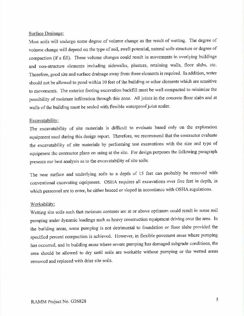


Catholic Charities Westside Head StartArchitectural Resource Team Modular Classroom Building
SUBSTITUTION REQUEST 00 43 25 - 1Construction Documents | 19032 September 2020
SECTION 00 43 25SUBSTITUTION REQUEST
(DURING THE BIDDING PHASE)_______________________________________________________________________________
Project: _______________________ Substitution Request Number: ____________________________________________ From: _____________________________________To: ___________________________ Date: _____________________________________
____________________________ A/E Project Number: ______________________________________________________________________________________Specification Title: _____________ Description: ________________________________Section: _______ Page: ________ Article/Paragraph: _______________________________________________________________________________________________________Proposed Substition: ______________________________________________________Manufacturer: ____________ Address: _______________________ Phone: _________Trade Name: ____________________________________________ Model No.:__________Attached data includes sufficient information, descriptive brochures, drawings, performanceand test data, samples or other data as is necessary for complete evaluation and indicates bydirect comparison how the proposed substitution differs from that specified.Attached data also includes a description of changes to the Contract Documents that theproposed substitution will require for its proper installation. The Contractor shall provide forredesign necessitated by the substitution.
____________________________________________________________________________The Undersigned certifies:* Proposed substitution has been fully investigated and determined to be equal or superiorin all respects to specified product.* Same warranty will be furnished for proposed substitution as for specified product.* Same maintenance service and source of replacement parts, as applicable, is available.* Proposed substitution will have no adverse effect on other trades and will not affect ordelay progress schedule.* Proposed substitution does not affect dimensions and functional clearances.* Payment will be made for changes to building design, including A/E design, detailing, andconstruction costs by the substitution.
___________________________________________________________________________Submitted By: _______________________________________________________________Signed By: __________________________________________________________________Firm:________________________________________________________________________Address: ___________________________________________________________________________________________________________________________________________Telephone: _____________________________________________________________________________________________________________________________________________

Catholic Charities Westside Head StartArchitectural Resource Team Modular Classroom Building
SUBSTITUTION REQUEST 00 43 25 - 2Construction Documents | 19032 September 2020
Supporting Data Attached: _ Drawings _ Product Data _ Samples _ Tests _ Reports ________________________________________________________________________________
A/E’s REVIEW AND ACTIONSubstitution approved (Include in Addendum).Substitution approved as noted (Include in Addendum with notation).Substitution rejected due to lack of information.Substitution rejected due to evaluation that it is not equivalent to specified product.Substitution Request received too late.Signed by: Date:
_______________________________________________________________________________

Catholic Charities Westside Head StartArchitectural Resource Team Modular Classroom Building
ELECTRONIC DATA TRANSFER TERMS ANDCONDITIONS 00 44 00 - 1
Construction Documents | 19032 September 2020
SECTION 00 44 00ELECTRONIC DATA TRANSFER TERMS AND CONDITIONS
IN ACCEPTING AND UTILIZING ELECTRONIC DRAWINGS, MODELS AND/OR DATA,“ELECTRONIC DATA” GENERATED BY ARCHITECTURAL RESOURCE TEAM, INC. (ART) ANDRELATED CONSULTANTS, RECIPIENT COVENANTS AND AGREES THAT ALL SUCH DRAWINGSAND/OR DATA ARE INSTRUMENTS OF SERVICE OF ART AND RELATED CONSULTANTS, WHOSHALL BE DEEMED THE AUTHOR OF THE DRAWINGS AND/OR DATA AND SHALL RETAIN ALLCOMMON LAW, STATUTORY LAW AND OTHER RIGHTS, INCLUDING COPYRIGHTS.
IT IS THE RESPONSIBILITY OF THE RECIPIENT TO FULLY UNDERSTAND THE BUILDING INTERMS OF VERTICAL RELATIONSHIPS, STRUCTURAL COMPONENTS, AND BUILDINGSYSTEMS BY WAY OF THE CONTRACT DOCUMENTS. ANY USE OF, OR RELIANCE ON, THEELECTRONIC DATA SHALL BE AT THEIR SOLE RISK AND WITHOUT LIABILITY TO ARTAND RELATED CONSULTANTS. ANY INFORMATION CONTAINED WITHIN THE ELECTRONICDATA PROVIDED IS COMPLEMENTARY TO ALL OTHER DOCUMENTS AND AS SUCH ISINCOMPLETE IN TERMS OF INFORMATION PROVIDED. ANY INFORMATION PROVIDEDELECTRONICALLY THAT IS NOT IN AGREEMENT WITH OTHER CONTRACT DOCUMENTSSHALL BE BROUGHT TO THE ATTENTION OF THE ARCHITECT FOR CLARIFICATIONPRIOR TO PROCEEDING WITH DESIGN OR CONSTRUCTION. FAILURE TO DO SO WAIVESTHE RIGHT TO MAKE CLAIM FOR COMPENSATION DUE TO ERRORS OR OMISSIONS INDOCUMENTS.
ART PROJECT NAME __________________________________________________ART PROJECT NUMBER _______________________________________________The electronic data is provided for the recipient’s convenience and are not legal documents. The recipient further agrees not to use the electronic data, in whole or in part, for any purposeor project other than the specific project for which it was created. The recipient agrees to waiveall claims against art and related consultants resulting in any way from any unauthorizedchanges, or use of the drawings and/or electronic data for any other project by anyone otherthan ART.In addition, the recipient agrees, to the fullest extent permitted by law, to indemnify and holdART and related consultants harmless from any damage, liability or cost, including reasonableattorneys' fees and costs of defense, arising from any changes made by anyone other thanART or from any reuse of the drawings and/or electronic data without prior written consent ofART.Due to varying environmental and storage conditions, integrity of electronic media and data areinherently subject to corruption. ART makes no warranties, either express or implied, ofmerchantability and/or fitness of the electronic data for any particular purpose
PLEASE ACKNOWLEDGE ACCEPTANCE OF TRANSFER TERMS AND CONDITIONS BYSIGNING AND DATING BELOW AND RETURNING THIS FORM TO ART.
Date Requested: _________________________________________________________________________
Company Name____________________________________________
Signature____________________________________________
Title

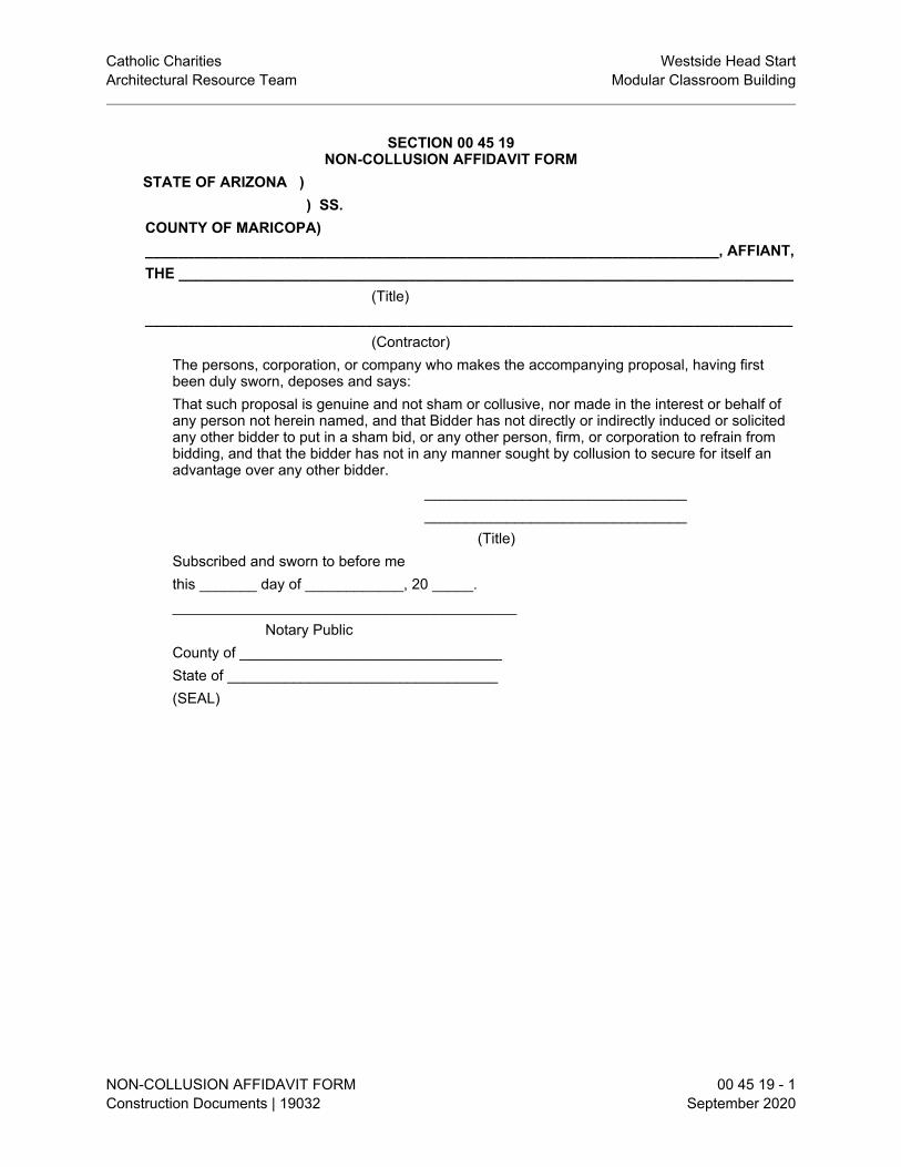
Catholic Charities Westside Head StartArchitectural Resource Team Modular Classroom Building
NON-COLLUSION AFFIDAVIT FORM 00 45 19 - 1Construction Documents | 19032 September 2020
SECTION 00 45 19NON-COLLUSION AFFIDAVIT FORM
STATE OF ARIZONA ) ) SS.
COUNTY OF MARICOPA)______________________________________________________________________, AFFIANT,THE ___________________________________________________________________________
(Title)_______________________________________________________________________________
(Contractor)The persons, corporation, or company who makes the accompanying proposal, having firstbeen duly sworn, deposes and says:That such proposal is genuine and not sham or collusive, nor made in the interest or behalf ofany person not herein named, and that Bidder has not directly or indirectly induced or solicitedany other bidder to put in a sham bid, or any other person, firm, or corporation to refrain frombidding, and that the bidder has not in any manner sought by collusion to secure for itself anadvantage over any other bidder.
________________________________________________________________
(Title)Subscribed and sworn to before methis _______ day of ____________, 20 _____.__________________________________________
Notary PublicCounty of ________________________________State of _________________________________(SEAL)

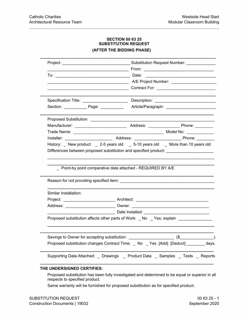
Catholic Charities Westside Head StartArchitectural Resource Team Modular Classroom Building
SUBSTITUTION REQUEST 00 63 25 - 1Construction Documents | 19032 September 2020
SECTION 00 63 25SUBSTITUTION REQUEST
(AFTER THE BIDDING PHASE)______________________________________________________________________________
Project: ______________________________ Substitution Request Number: _________________________________________________ From: _______________________________To: _________________________________ Date: ___________________________________________________________________ A/E Project Number: ________________________________________________________ Contract For: __________________________
______________________________________________________________________________Specification Title: ____________________ Description: ___________________________Section: __________ Page: __________ Article/Paragraph: ______________________
_____________________________________________________________________________Proposed Substitution: _______________________________________________________Manufacturer: _______________________ Address: ______________ Phone: ________Trade Name: ________________________________________ Model No: ____________Installer: _____________________ Address: _____________________ Phone: ________History: _ New product _ 2-5 years old _ 5-10 years old _ More than 10 years oldDifferences between proposed substitution and specified product: _________________________________________________________________________________________________________________________________________________________________________
_ Point-by point comparative data attached - REQUIRED BY A/E_____________________________________________________________________________
Reason for not providing specified item: ____________________________________________________________________________________________________________________Similar Installation:Project: _______________________ Architect: ________________________________Address: ______________________ Owner: ________________________________________________________________ Date Installed: _____________________________Proposed substitution affects other parts of Work: _ No _ Yes; explain _________________________________________________________________________________________
_____________________________________________________________________________Savings to Owner for accepting substitution: ____________________ ($_______________).Proposed substitution changes Contract Time: _ No _ Yes [Add] [Deduct] ________ days.
_____________________________________________________________________________Supporting Data Attached: _ Drawings _ Product Data _ Samples _ Tests _ Reports
_____________________________________________________________________________THE UNDERSIGNED CERTIFIES:
Proposed substitution has been fully investigated and determined to be equal or superior in allrespects to specified product.Same warranty will be furnished for proposed substitution as for specified product.

Catholic Charities Westside Head StartArchitectural Resource Team Modular Classroom Building
SUBSTITUTION REQUEST 00 63 25 - 2Construction Documents | 19032 September 2020
Same maintenance service and source of replacement parts, as applicable, is available.Proposed substitution will have no adverse effect on other trades and will not affect or delayprogress schedule.Cost data as stated above is complete. Claims for additional costs related to acceptedsubstitution which may subsequently become apparent are to be waived.Proposed substitution does not affect dimensions and functional clearances.Payment will be made for changes to building design, including A/E design, detailing, andconstruction costs by the substitution.Coordination, installation, and changes in the Work as necessary for accepted substitution willbe complete in all respects.
____________________________________________________________________________Submitted by: _____________________________________________________________Signed by: ____________________________________________________________
________________________________________________________________________Address:
________________________________________________________________________________________________________________________________________________Telephone: ______________________________________________________________Attachments: _____________________________________________________________________________________________________________________________________________________________________________________________________________
___________________________________________________________________________A/E’S REVIEW AND ACTION
_ Substition approved - Make submittals in accordance with Specifications._ Substitution approved as noted – Make submittals in accordance with Specification_ Substitution rejected - Use specified materials._ Substitution Request received too late - Use specified materials.Signed by: _______________________________________ Date: __________________
___________________________________________________________________________Additional Comments: _ Contractor _ Subcontractor _ Supplier _ Manufacturer A/E ____
_________________________________________________________________________________________________________________________________________________________________________________________________________________________________
END OF SECTION

Catholic Charities Westside Head StartArchitectural Resource Team Modular Classroom Building
General Conditions 00 72 00 - 1Construction Documents | 19032 September 2020
SECTION 00 72 00GENERAL CONDITIONS
FORM OF GENERAL CONDITIONS1.01 THE GENERAL CONDITIONS OF THE CONTRACT FOR CONSTRUCTION, AIA DOCUMENT
A201-2007, PAGES 1-40 (PAGE COUNT MAY VARY WITH ELECTRONIC EDITIONS),HEREAFTER REFERRED TO AS GENERAL CONDITIONS, ARE HEREBY INCORPORATEDINTO AND MADE PART OF THESE CONTRACT DOCUMENTS THE SAME AS IF BOUNDHEREIN IN FULL.
SUPPLEMENTARY CONDITIONS2.01 REFER TO DOCUMENT 00 73 00 - SUPPLEMENTARY CONDITIONS FOR AMENDMENTS TO
THESE GENERAL CONDITIONS.END OF SECTION


Catholic Charities Westside Head StartArchitectural Resource Team Modular Classroom Building
SUPPLEMENTARY CONDITIONS 00 73 00 - 1Construction Documents | 19032 September 2020
SECTION 00 73 00SUPPLEMENTARY CONDITIONS
GENERAL SUPPLEMENTS TO GENERAL CONDITIONS - 2007 EDITION1.01 GENERAL SUPPLEMENTS TO GENERAL CONDITIONS - 2007 EDITION
A. THE FOLLOWING SUPPLEMENTS AIA DOCUMENT A201-2007, GENERAL CONDITIONSOF THE CONTRACT FOR CONSTRUCTION. WHERE A PORTION OF THE GENERALCONDITIONS IS MODIFIED OR DELETED BY THESE SUPPLEMENTARY CONDITIONS,THE UNALTERED PORTIONS OF THE GENERAL CONDITIONS SHALL REMAIN INEFFECT.
1.02 ARTICLE 1 - GENERAL PROVISIONSA. Paragraph 1.1.3 - Delete in its entirety and substitute the following:
1.1.3 THE WORKThe term 'Work' means the completed construction required by the Contract Documents andincludes all labor necessary to produce such construction, and materials and equipmentincorporated or to be incorporated in such construction.
B. Paragraph 1.1 - Add the following subparagraph:1.1.9 MISCELLANEOUS DEFINITIONS1. The term 'Product' as used herein includes materials, systems and equipment."
C. Paragraph 1.2 - Add the following subparagraph:1.2.4 Make no changes from the Contract Documents without having first received permissionfrom the Architect. Where detailed information is lacking, if Work is required in a manner thatmakes it impossible to produce satisfactory Work, or should discrepancies appear amongContract Documents, request interpretation from the Architect before proceeding with Work."
D. Paragraph 1.2.1 – Add the following subsubparagraph:1.2.1.1 In the event of conflicts or discrepancies among the Contract Documents,interpretations will be based on the following priorities:1. Modifications2. The Agreement3. Addenda with those of later date having precedence over those of earlier date4. The Supplementary Conditions5. The General Conditions of the Contract for Construction6. Division 1 of the Specifications7. Divisions 2 – 49 of the Specifications8. Drawings9. Other documents specifically enumerated in the Agreement as part of the Contract
Documents.In the case of conflicts or discrepancies between Drawings and Division 2 – 49 of theSpecifications, or within or among the Contract Documents and not clarified byAddendum, the Architect will determine which takes precedence in accordance withparagraphs 4.2.11, 4.2.12 and 4.2.13.”
E. Paragraph 1.4 - Add the following subparagraphs:1.4.2 The misplacement, addition or omission of any letter, word or punctuation mark shall inno way damage the true spirit, intent, or meaning of the Contract Documents.1.4.3 The words 'shown,' 'indicated,' 'noted,' 'scheduled,' or words of like effect shall beunderstood to mean that reference is made to the Drawings accompanying this Project Manual.1.4.4 Where reference herein is made to products 'as approved' or 'as selected,' selection orapproval shall be by the Architect."

Catholic Charities Westside Head StartArchitectural Resource Team Modular Classroom Building
SUPPLEMENTARY CONDITIONS 00 73 00 - 2Construction Documents | 19032 September 2020
F. Paragraph 1.5.1 - Add the following after the words "Drawings and Specifications" in the firstsentence:(as enumerated on Drawing Title Sheet and Project Manual Table of Contents)".
1.03 ARTICLE 2 - OWNERA. Subparagraph 2.2.5 - Delete in its entirety and substitute the following:
2.2.5 Contract Documents furnished to Contractor for use during construction:1. Owner will provide at no charge to Contractor the Owner's extra copies of the Drawings
and Project Manual which are returned by Bidders.2. Contractor shall obtain from the Architect, with no charge to the Owner, such additional
copies of the Drawings and Project Manual as are reasonably necessary for the executionof the Work. Contractor shall pay to Architect the cost of reproducing such Drawings andProject Manual."
1.04 ARTICLE 3 - CONTRACTORA. Paragraph 3.2.2 - Add the following subparagraphs:
1. In addition to study and comparison of the various Drawings and other ContractDocuments prior to starting each portion of the work, the Contractor shall, prior to startingthe entire Work, review the various Drawings and other Contract Documents in general forplanning purposes and to generally familiarize the Contractor to the overall projectrequirements.
2. A properly prepared request for information shall include a detailed written statement thatindicates the specific Drawings or Specification in need of clarification and the nature ofthe clarification requested. See also Section 01 26 13 - Contractor's Requests forInformation."
B. Paragraph 3.2.4 - Delete the words "for differences between field measurements or conditionsand the Contract Documents" in the 3rd sentence.
C. Paragraph 3.2 - Add the following subparagraphs:3.2.5 Neither the Owner nor the Architect assumes any responsibility for an understanding orrepresentation made by any of their agents or representatives prior to the execution of theAgreement unless (1) such understandings or representations are expressly stated in theAgreement, and (2) the Agreement expressly provides that responsibility therefore is assumedby the Owner."3.2.6 The Owner is entitled to reimbursement from the Contractor for amounts paid to theArchitect for evaluating and responding to the Contractor’s requests for information that are notprepared in accordance with the Contract Documents or where the requested information isavailable to the contractor from a careful study and comparison of the Contract Documents,field conditions, other Owner-provided information, Contractor prepared coordination drawings,or prior Project correspondence or documentation.
D. Paragraph 3.3.1 - Delete the remainder of the sentence following the word "Contract" in thesecond sentence. Change the word "concerning" to the words "which may affect" in the thirdsentence. Delete the words "except as stated below" in the third sentence. Delete the fourthand fifth sentences in their entirety.
E. Paragraph 3.4.2 - Add the following subparagraph:1. Substitutions shall be submitted in accordance with the requirements of Section 01 60 00 -
Materials and Equipment.F. Paragraph 3.12.10 - Change the word "all" to "applicable" prior to the words "performance and
design criteria" in the third and sixth sentences. Delete the words "approve or take otherappropriate action" in the seventh sentence. Add the following to the last sentence:"however, the Contractor shall notify the Architect if additional performance or design criteria isrequired in accordance with paragraph 3.2 of the General Conditions."
G. Paragraph 3.12.11 – Add the following subparagraph:

Catholic Charities Westside Head StartArchitectural Resource Team Modular Classroom Building
SUPPLEMENTARY CONDITIONS 00 73 00 - 3Construction Documents | 19032 September 2020
3.12.11 The Architect’s review of Contractor’s submittals will be limited to examination ofan initial submittal and two (2) resubmittals. The Owner is entitled to obtainreimbursement from the Contractor for amounts paid to the Architect for evaluation ofadditional resubmittals.
1.05 ARTICLE 4 - ARCHITECTA. Subparagraph 4.1.1 - Delete in its entirety and substitute the following:
4.1.1 The Architect is the firm of Architectural Resource Team, Inc., referred throughout theContract Documents as if singular in number. The term 'Architect' means the Architect or theArchitect's authorized representative."
B. Paragraph 4.2 - Add the following subparagraph:4.2.15 Architectural and Engineering Services. It is understood that normalArchitectural and Engineering liaison for the purpose of interpretation of the Drawings andSpecifications is provided for by the Owner. Should the services of the Architect be required toassist in the corrections of errors or omissions in construction by the Contractor, or services ofthe Architect be required because of changes in structure or equipment where the Contractorhas requested approval of substitute products, these services will be provided by the Architectat the standard hourly rates. The Architect will charge the Owner and such costs will bededucted from money still due the Contractor.
1.06 ARTICLE 5 - SUBCONTRACTORSA. Paragraph 5.2 - Add the following subparagraph:
5.2.5 Two weeks after signing of the Owner-Contractor Agreement, the General Contractorshall verify that the Subcontractor List is firm and that the Subcontractors are under contract forthis Project."
B. Paragraph 5.3 - Add the following sentence:"Subcontracts shall be by written agreement for the Subcontractors listed on the 'SubcontractorList Form'."
1.07 ARTICLE 7 - CHANGES IN THE WORKA. This Project is a Fixed Lump Sum. There are NO changes in the Bid Sum or Work.
1.08 ARTICLE 8 - TIMEA. Subparagraph 8.3.1 - Delete from first sentence: "...or by delay authorized by the Owner
pending mediation and arbitration..."B. Add the following paragraphs:
8.3.4 The Owner will not pay for costs related to supervision, construction procedures, generalconditions, overhead and profit, should the time required to substantially complete the Work beextended beyond the Contract Time stated in the Contract due to inclement weather or anyother reason, exclusive of adjustments in time by Change Order which included changes oradditions to the scope of Work. The Contract Amount shall include the costs related tosupervision and construction procedures, general conditions, overhead and profit for timebeyond that stated in the Contract and the Base Bid received by the Owner shall include thesecosts.8.4 RESPONSIBILITY FOR COMPLETION8.4.1 The Contractor shall furnish such manpower, materials, facilities, and equipment and shallwork such hours, including night shifts, overtime operations and Sunday and holidays, as maybe necessary to insure the prosecution and completion of the Work in accordance with theapproved and currently - updated progress schedule. If Work actually in place falls behind thecurrently updated and approved schedule by 14 days or more and it becomes apparent fromthe current schedule that the Work will not be completed within the Contract Time, theContractor agrees to, take some or all of the following actions at no additional cost to theOwner to improve progress as necessary:

Catholic Charities Westside Head StartArchitectural Resource Team Modular Classroom Building
SUPPLEMENTARY CONDITIONS 00 73 00 - 4Construction Documents | 19032 September 2020
1. Increase manpower in such quantities and crafts as will substantially eliminate, in thejudgment of the Architect, the backlog of Work;
2. Increase the number of working hours per shift, shifts per working day, working days perweek, the amount of equipment, or any combination of the foregoing, sufficient tosubstantially eliminate, in the judgment of the Architect, the backlog of Work; and,
3. Reschedule activities to achieve maximum practical concurrency of accomplishment ofactivities.
8.4.2 In addition, the Architect may require the Contractor to submit a revised chartdemonstrating his program and proposed plan to make up lag in scheduled progress and toensure completion of the Work within the Contract Time. If the Architect finds the proposedplan not acceptable, the Architect may require the Contractor to submit a new plan. If theactions taken by the Contractor or the second plan proposed are not satisfactory, the Architectmay require the Contractor to take any of the actions set forth in subparagraph 8.4.1 withoutadditional cost to the Owner to make up the lag in scheduled progress.8.4.3 Failure of the Contractor to substantially comply with the requirements of this paragraph8.4 may be considered grounds for a determination by the Owner, pursuant to Article 14, thatthe Contractor is failing to prosecute the Work with such diligence as will ensure its completionwithin the time specified."
1.09 ARTICLE 9 - PAYMENTS AND COMPLETIONA. Subparagraph 9.3.1 - Delete in its entirety and substitute the following:
9.3.1 The Contractor shall review with the Architect's representative in the field on or about the25th day of the month, the tentative Application for Payment for that month. The form forapplication for payment shall be AIA Document G702 'Application and Certificate for Payment'supported by AIA Document G703 'Continuation Sheet,' and shall be submitted, after the abovereview, to the Architect on or before the first day of the following month. The Application forPayment shall be notarized, if required, and supported by such data substantiating theContractor's right to payment as the Owner or Architect may require, such as copies ofrequisitions from Subcontractors and materials suppliers, and reflecting retainage if provided forelsewhere in the Contract Documents."
B. Subsubparagraph 9.3.1.2 - Add the following:"The Contractor shall include a written notice, on the Contractor's letterhead, stating the nameof and amount owed to such Subcontractor which has requested payment which has not beenincluded on the Application for Payment."
C. Subparagraph 9.3.1 - Add the following subsubparagraph:9.3.1.3 Until final payment the Owner will pay 90 percent of the amount due theContractor on account of Progress Payments."
D. Subparagraph 9.5.1, subsubparagraph .1 - Delete in its entirety and substitute the following:1. Work not in conformance with Contract Documents which is not remedied, or failure to
begin remedial action within five days following notification,"E. Subparagraph 9.6.3 - Delete the word "will" and insert the word "may".F. Subparagraph 9.7 - Change the words "as provided for in the Contract Documents" to "at the
prevailing rate mandated by law" in the last sentence.G. Subparagraph 9.8.2 - Delete in its entirety and substitute the following:
"9.8.2When the Contractor is of the opinion that the Project, (or a portion thereof which theOwner agrees to accept separately), is substantially complete in accordance with the ContractDocuments, the Contractor shall send to the Architect a written statement that the Project issubstantially complete (naming a date) and shall request a substantial completion inspection bythe Architect to determine the status of completion. Such notice shall be given at least threedays prior to the requested date.1. If the Architect finds that the Project is substantially complete, the Architect will prepare a
Certificate of Substantial Completion, AIA Document G704, which shall establish the date

Catholic Charities Westside Head StartArchitectural Resource Team Modular Classroom Building
SUPPLEMENTARY CONDITIONS 00 73 00 - 5Construction Documents | 19032 September 2020
of Substantial Completion, shall state the responsibilities of the Owner and the Contractorfor security, maintenance, heat, utilities, damage to the Work and insurance, and shall fixthe time within which the Work shall be completed. The Architect shall attach to theCertificate a list of all items to be completed and corrected, (the "Punch List"). This list,prepared by the General Contractor's clerical staff based upon information provided byArchitect, will be as complete as possible based on the Architect's observations, but shallnot relieve or otherwise waive the Contractor's responsibility to complete or correctsubsequently discovered items, or to complete the Work in accordance with the ContractDocuments. The Certificate of Substantial Completion shall be submitted to theContractor and the Owner for their approval and acceptance. Warranties required by theContract Documents shall commence on the date of Substantial Completion unlessotherwise provided.
2. If the Architect does not concur in the Contractor's claim of Substantial completion, theArchitect will so notify the Contractor, and thereafter, the Contractor shall initiate a newrequest for Substantial completion Inspection."
H. Subparagraph 9.9.1 - Delete the word "list" in the third sentence and insert the words "writtenstatement".
I. Subparagraph 9.10.1 - Add the following:"Should it become necessary for the Architect to conduct additional inspections subsequent tothe final inspection because of acts or omissions of the Contractor, the Architect will conductsuch inspections at the Architect's standard hourly rate and will charge the Owner, and suchcosts will be deducted from monies still due the Contractor."
J. Subparagraph 9.10.2 - Delete in its entirety and substitute the following:9.10.2 Neither the final payment nor the remaining retained percentage shall becomedue until the Contractor submits to the Architect (1) Affidavit of Payment of Debts and Claims,AIA Document G706 and attachments including Contractor's Release or Waiver of Liens, (2) acertificate evidencing that insurance required by the Contract Documents to remain in forceafter final payment is currently in effect and will not be canceled or allowed to expire until atleast 30 days' prior notice has been given to the Owner, (3) a written statement that theContractor knows of no substantial reason that the insurance will not be renewable to cover theperiod required by the Contract Documents, (4) Consent of Surety to Final Payment, orsatisfaction of all such obligations such as receipts, releases and waivers or liens arising out ofthe Contract, to the extent and in such form as may be designated by the Owner. If aSubcontractor refuses to furnish a release or waiver required by the Owner, the Contractor mayfurnish a bond satisfactory to the Owner to indemnify him against any such lien. If such lienremains unsatisfied after all payments are made, the Contractor shall refund to the Owner allmoney that the latter may be compelled to pay in discharging such lien, including all costs andreasonable attorney's fees."
K. Add the following paragraph:9.11 TIME FOR COMPLETION9.11.1 The Work shall commence as established in Subparagraph 8.1.2. The Contractoragrees that said Work shall be prosecuted regularly, diligently, and without interruption at suchrate of progress as will insure full completion of the Project based on the agreed uponschedule.
L. 9.11.2 It is hereby understood and mutually agreed, by and between the Contractor and theOwner, that the date of beginning, rate of progress, and the time for completion of the Work tobe done hereunder, are ESSENTIAL CONDITIONS of this Contract; and it is further mutuallyunderstood and agreed that all work will be completed within two hundred and fifty‐three (253)consecutive calendar days from Notice to Proceed. The Contractor also shall consider that theOwner needs the complete use of these facilities as quickly as possible.
M. 9.11.3 In the event that the Contractor shall neglect, fail or refuse to Substantially Completethe Project within the time specified, then the Contractor does hereby agree, as a part

Catholic Charities Westside Head StartArchitectural Resource Team Modular Classroom Building
SUPPLEMENTARY CONDITIONS 00 73 00 - 6Construction Documents | 19032 September 2020
consideration for the awarding of this Contract, to pay to the Owner $ 5,231.00 per day for eachcalendar day thereafter, not as a penalty, but as liquidated damages for such breach of contractas hereinafter set forth, for each and every calendar day that the Contractor shall be in defaultafter the time stipulated in the Contract for completing the Work. The stated amounts are fixedand agreed upon by and between the Contractor and the Owner because of the impracticabilityand extreme difficulty in fixing and ascertaining the actual damages which the Owner would, insuch event(s) sustain."
1.10 ARTICLE 11 – INSURANCE AND BONDSA. Subparagraph 11.1.1 - Add the following clause;
9. Liability insurance shall include all major divisions of coverage and be on acomprehensive basis including:a. Premises Operation (including X,C and U coverages as applicable).b. Independent Contractor's Protective.c. Products and Completed Operations.d. Personal Injury Liability with Employment Exclusion deleted.e. Contractual, including specified provision for Contractor's obligation under Paragraph
3.18.f. Owned, non-owned and hired motor vehicles.g. Broad Form Property Damage including Completed Operations.
B. Subparagraph 11.1.2 - Delete in its entirety and substitute the following:11.1.2 The insurance required by Subparagraph 11.1.1 shall be written for not less thanany limits of liability required by law or as specified herein, whichever is greater. TheContractor shall not allow any Subcontractor to commence Work on a Subcontract until thesame types of insurance in the amount specified below have been obtained by theSubcontractor. If any such Subcontractor shall subcontract any portion of his subcontract, theContractor shall require the Secondary Subcontractor to take out and maintain such contingentof protective insurance as will protect the Primary subcontract from damage claims arising fromhis operations. Such Contingency Protective insurance shall be in the same amount as hisPrimary Subcontractor's Public Liability and Property Damage Insurance. Maintain all requiredinsurance for the life of the contract. Coverages, whether written on an occurrence or claims-made basis, shall be maintained without interruption from date of commencement of the Workuntil date of final payment and termination of any coverage required to be maintained after finalpayment, and, with respect to the Contractor’s completed operations coverage, until theexpiration of the period for correction of Work or for such other period for maintenance ofcompleted operations coverage as specified in the Contract Documents."
C. Subparagraph 11.1.3 - Add new subsubparagraphs:1. Furnish one copy of Certificates herein required for each copy of the Agreement;
specifically set forth evidence of all coverage required by Subparagraphs 11.1.1 and11.1.2 and in the amounts required by Subparagraph 11.1.4. The form of the Certificateshall be ACORD from 25-S.
2. Furnish to the Owner copies of endorsements that are subsequently issued namingOwner and Architect as additional insured within 60 days of start of work or endorsementsthat are subsequently issued amending coverage of limits."
3. Catholic Charities and Architectural Resource Team, Inc. and its subconsultants shall benamed as "Additional Insured" on Certificates of Insurance."
4. Contractor's comprehensive general liability policy shall be endorsed to namea. Catholic Charities and Architectural Resource Team, Inc. and its subconsultants as
additional insureds with respect to liability arising out of operations performed for theOwner by or on behalf of the Contractor. The certificate of insurance must reflect thiscondition.
D. Paragraph 11.1 - Add the following subparagraph:11.1.5 Contractor's liability insurance shall be written for not less than the following limitsof liability: See Paragraph F in the Invitation for Sealed Bids.

Catholic Charities Westside Head StartArchitectural Resource Team Modular Classroom Building
SUPPLEMENTARY CONDITIONS 00 73 00 - 7Construction Documents | 19032 September 2020
E. Subparagraph 11.3.1 - Delete in its entirety and substitute the following:11.3.1 The Contractor shall purchase and maintain Property Insurance on an “all risk”builders risk policy upon the entire Work at the site to the full insurable value thereof, includingsubsequent modifications to the Contract Sum for the entire Work at the site on a replacementcost basis without voluntary deductibles. Such insurance shall be issued by a company orcompanies lawfully authorized to do business in the jurisdiction in which the Project is locatedand against which the Owner has no reasonable objection. This insurance shall include theinterest of the Owner, the Contractor, Subcontractor, and Subsubcontractors in the Work. Ifthis insurance is written with stipulated amounts deductible under the terms of the policy, theContractor shall pay the difference attributable to deductions in any payments made by theinsurance carrier on claims paid by this insurance. Such property insurance shall bemaintained, unless otherwise provided in the Contract Documents or otherwise agreed inwriting by all persons and entities who are beneficiaries of such insurance, until final paymenthas been made as provided in Paragraph 9.10 or until no person or entity other than the Ownerhas an insurable interest in the property required by this Paragraph 11.3 to be covered,whichever is earlier.
F. Contractor to carry or cause it's Contractors and Subcontractor's to carry a policy of Builder'sRisk Insurance adequate to protect the value of the Project and Assets used in Construction.
G. Subsubparagraphs 11.3.1.2 through 11.3.1.3 - Delete in their entirety.H. Subparagraph 11.3.4 - Delete in its entirety.I. Subparagraph 11.3.6 - Delete in its entirety and substitute the following:
11.3.6 The Contractor shall file the original and one certified copy of all policies with theOwner and Architect before exposure to loss may occur. If the Owner is damaged by thefailure of the Contractor to maintain such insurance and to so notify the Owner, then theContractor shall bear all reasonable costs properly attributable thereto. Each policy shallcontain all generally applicable condition, definition, exclusions and endorsements related tothis Project. Each policy shall contain a provision that the policy will not be canceled or allowedto expire until at least 30 days' prior written notice has been given to the Owner."
J. Subparagraph 11.3.8 - Delete the word "Owner's" before the words "property insurance; and,delete the remainder of the sentence after the word "clause" in the first sentence.
K. Subparagraph 11.3.9 - Delete in its entirety and substitute the following:11.3.9 If required in writing by any party in interest, the Owner as trustee shall, upon theoccurrence of an insured loss, give bond for the proper performance of the required duties. The Owner shall deposit in a separate account any money so received, and the Owner shalldistribute it in accordance with such agreement as the parties in interest may reach. If aftersuch loss no other special agreement is made, replacement of damaged Work shall be coveredby an appropriate Change Order."
L. Subparagraph 11.3.10 - Delete in its entirety.1.11 ARTICLE 13 - MISCELLANEOUS PROVISIONS
A. Paragraph 13.1 - Add the following sentence:It shall be mandatory on the Contractor to whom the contract is awarded, and upon anysubcontractor under him, to comply in every respect with the provisions of Titles 23, 32, and 34,Arizona Revised Statutes and with all other requirements of the state of Arizona, applicable tocontract for the construction of Public Works, and with all applicable City, County, State, andFederal laws and ordinances.
B. Subparagraph 13.5.1 - Add the following subsubparagraphs:1. When the initial tests indicate variance to the Contract Documents, subsequent retesting
of the same Work to establish compliance shall be performed by the same agency and thecost thereof borne by the Contractor.

Catholic Charities Westside Head StartArchitectural Resource Team Modular Classroom Building
SUPPLEMENTARY CONDITIONS 00 73 00 - 8Construction Documents | 19032 September 2020
2. Representatives of the testing agency shall have access to the Work at all times. TheContractor shall provide facilities for such access in order that the agency may properlyperform its functions.
3. Inspection or Testing performed exclusively for the Contractor's convenience shall be thesole responsibility of the Contractor.
C. Subparagraph 13.5.4 - Delete in its entirety and substitute the following:13.5.4 The independent agency, employed by the Owner, will prepare the test reports,logs, and certificates applicable to the specific inspections and tests and promptly deliver thespecified number of copies of same to the designated parties. Other required certificates ofinspection, testing or approval shall be secured by the Contractor and delivered by theContractor to the Architect, in such time as to not delay progress of the Work or final paymenttherefore."
1.12 ARTICLE 15 – CLAIMS AND DISPUTESA. Paragraph 15.1.6 - Delete the words "losses of use" in subparagraph 15.1.6.1.B. Paragraph 15.4 - Delete in its entirety.C. Add the following Article:
ARTICLE 16 - EQUAL OPPORTUNITY16.1 The Contractor shall maintain policies of employment as follows:16.1.1 The Contractor and all Subcontractors shall not discriminate against anyemployee or applicant for employment because of race, religion, color, sex or national origin. The Contractor shall take affirmative action to insure that applicants are employed, and thatemployees are treated during employment without regard to their race, religion, color, sex, ornational origin. Such action shall include, but not be limited to the following: Employment,upgrading, demotion, or transfer; recruitment or recruitment advertising; layoff or termination;rates of pay or other forms of compensation; and selection for training, includingapprenticeship. The Contractor agrees to post in conspicuous places, available to employeesand applicants for employment, notices setting forth the policies of nondiscrimination.16.1.2 The Contractor and all Subcontractors shall, in all solicitations or advertisementsfor employees placed by them or in their behalf; state that all qualified applicants will receiveconsideration for employment without regard to race, religion, color, sex or national origin."
END OF DOCUMENT

Catholic Charities Westside Head StartArchitectural Resource Team Modular Classroom Building
Summary 01 10 00 - 1Construction Documents | 19032 September 2020
SECTION 01 10 00SUMMARY
PART 1 GENERAL1.01 PROJECT
A. Project Name: Sine Head Start Modular Classroom BuildingB. Owner's Name: Catholic Charities Westside Head StartC. Architect's Name: Architectural Resource Team.D. The Project consists of the fabrication and installation of sprinkiled, modular classroom building
with shaded entry. Site Improvements include bringing power and water to the building.,modifying the existing parking and chain link fencing. Addition of concrete walk ways andfencing for new playground area. .
1.02 CONTRACT DESCRIPTIONA. Contract Type: A single contract based on a Fixed Sum Price.
1.03 OWNER OCCUPANCYA. Owner intends to occupy the Project .
END OF SECTION


Catholic Charities Westside Head StartArchitectural Resource Team Modular Classroom Building
Price and Payment Procedures 01 20 00 - 1Construction Documents | 19032 September 2020
SECTION 01 20 00PRICE AND PAYMENT PROCEDURES
PART 1 GENERAL1.01 SECTION INCLUDES
A. Procedures for preparation and submittal of applications for progress payments.1.02 SCHEDULE OF VALUES
A. Electronic media printout including equivalent information will be considered in lieu of standardform specified; submit draft to Architect for approval.
B. Forms filled out by hand will not be accepted.1.03 APPLICATIONS FOR PROGRESS PAYMENTS
A. Payment Period: Submit at intervals stipulated in the Agreement.B. Electronic media printout including equivalent information will be considered in lieu of standard
form specified; submit sample to Architect for approval.C. Forms filled out by hand will not be accepted.D. Execute certification by signature of authorized officer.E. Submit one electronic and three hard-copies of each Application for Payment.
1.04 MODIFICATION PROCEDURESA. For minor changes not involving an adjustment to the Contract Sum or Contract Time, Architect
will issue instructions directly to Contractor.B. For other required changes, Architect will issue a document signed by Owner instructing
Contractor to proceed with the change, for subsequent inclusion in a Change Order.1. The document will describe the required changes and will designate method of
determining any change in Contract Sum or Contract Time. This is a Fixed Price Contractand changes in the Fixed are not allowed.
2. Promptly execute the change.1.05 APPLICATION FOR FINAL PAYMENT
A. Prepare Application for Final Payment as specified for progress payments, identifying totaladjusted Contract Sum, previous payments, and sum remaining due.
B. Application for Final Payment will not be considered until the following have beenaccomplished:
PART 2 PRODUCTS - NOT USEDPART 3 EXECUTION - NOT USED
END OF SECTION


Catholic Charities Westside Head StartArchitectural Resource Team Modular Classroom Building
Allowances 01 21 00 - 1Construction Documents | 19032 September 2020
SECTION 01 21 00ALLOWANCES
PART 1 GENERAL1.01 SECTION INCLUDES
A. Contingency allowance.1.02 CONTINGENCY ALLOWANCE
A. Contractor's costs for products, delivery, installation, labor, insurance, payroll, taxes, bonding,equipment rental, overhead and profit will be included in Change Orders authorizingexpenditure of funds from this Contingency Allowance.
B. Funds will be drawn from the Contingency Allowance only by Change Order.C. At closeout of Contract, funds remaining in Contingency Allowance will be credited to Owner by
Change Order.1.03 INSPECTING AND TESTING ALLOWANCES
A. Costs Included in Inspecting and Testing Allowances: Cost of engaging an inspecting ortesting agency; execution of inspecting and tests; and reporting results.
1.04 ALLOWANCES SCHEDULEA. Contingency Allowance: Include the stipulated sum/price equal to 10 percent of the Fixed Sum
Price. for use upon Owner's instructions.PART 2 PRODUCTS - NOT USEDPART 3 EXECUTION - NOT USED
END OF SECTION


Catholic Charities Westside Head StartArchitectural Resource Team Modular Classroom Building
CONTRACTOR'S REQUESTS FOR INFORMATION /INTERPRETATION 01 26 13 - 1
Construction Documents | 19032 September 2020
SECTION 01 26 13CONTRACTOR'S REQUESTS FOR INFORMATION / INTERPRETATION
PART 1 GENERAL1.01 SUMMARY
A. Section Includes: Administrative requirements for requests for information / interpretation.1.02 DEFINITIONS
A. Request For Information / Interpretation (RFI):1. A document submitted by the Contractor requesting clarification of a portion of the
Contract Documents, hereinafter referred to as RFI.2. A properly prepared request for information / interpretation shall include a detailed written
statement that indicates the specific Drawings or Specification in need of clarification andthe nature of the clarification requested.a. Drawings shall be identified by drawing number and location on the drawing sheet.b. Specifications shall be identified by Section number, page and paragraph.
3. Request made by Contractor concerning items not indicated on drawings or contained inProject Manual that is required to properly perform the work.
4. Request made by Contractor in accordance with Owner’s Representative’s third partyobligations to the contract for construction.
B. Improper RFI's:1. RFI's that are not properly prepared.2. Improper RFI's will be processed by the Architect at the Architect's standard hourly rate
and Architect will charge the Owner, and such costs will be deducted from monies still duethe Contractor. The Contractor will be notified by the Architect prior to the processing ofimproper RFI's.
C. Frivolous RFI's:1. RFI's that request information that is clearly shown on the Contract Documents.2. Frivolous RFI's may be returned unanswered or may be processed by the Architect at the
Architect's standard hourly rate and Architect will charge the Owner, and such costs willbe deducted from monies still due the Contractor. The Contractor will be notified by theArchitect prior to the processing of frivolous RFI's.
1.03 CONTRACTOR'S REQUESTS FOR INFORMATIONA. RFI's shall be submitted on a form prepared by the Contractor acceptable to the Architect or the
form at the end of this section.1. Forms shall be completely filled in, and if prepared by hand, shall be fully legible after
photocopying or transmission by facsimile (fax).2. RFI’s shall be submitted in numerical order with no breaks in the consecutive numbering.3. Each page of attachments to RFI's shall bear the RFI number and shall be consecutively
numbered in chronological order.4. RFI's may be submitted by E-Mail.
a. Submittal by E-Mail is the preferred method of submittal.b. Address for E-Mail will be distributed by the Architect at the Pre-Construction
Conference.c. An electronic version of RFI form will be provided upon request.
B. When the Contractor is unable to determine from the Contract Documents, the material,process or system to be installed, the Architect shall be requested to make a clarification of theindeterminate item.1. Wherever possible, such clarification shall be requested at the next appropriate project
meeting, with the response entered into the meeting minutes. When clarification at themeeting is not possible, either because of the urgency of the need, or the complexity ofthe item, Contractor shall prepare and submit an RFI to the Architect.

Catholic Charities Westside Head StartArchitectural Resource Team Modular Classroom Building
CONTRACTOR'S REQUESTS FOR INFORMATION /INTERPRETATION 01 26 13 - 2
Construction Documents | 19032 September 2020
2. RFI requesting clarification of an item required of a document known to have beenprepared by a consultant to the Architect, may be sent directly to the consultant with acopy to the Architect, if this direct communication is approved by the Architect.
C. Contractor shall endeavor to keep the number of RFI's to a minimum. In the event that theprocess becomes unwieldy, in the opinion of the Architect, because of the number andfrequency of RFI's submitted, the Architect may require the Contractor to abandon the processand submit future requests as either submittals, substitutions or requests for change.
D. RFI's shall be originated by the Contractor.1. RFI's from subcontractors or material suppliers shall be submitted through, reviewed by,
and signed by the Contractor prior to submittal to the Architect.2. RFI's from subcontractors or material suppliers sent directly to the Owner’s
Representative, Architect or the Architect's consultants shall not be accepted and will bereturned unanswered.
E. Contractor shall carefully study the Contract Documents to assure that the requestedinformation is not available therein. RFI's which request information available in the ContractDocuments will be deemed either "improper" or "frivolous" as noted above.
F. In cases where RFI's are issued to request clarification of coordination issues, for example,pipe and duct routing, clearances, specific locations of work shown diagrammatically, andsimilar items, the Contractor shall fully lay out a suggested solution using drawings or sketchesdrawn to scale, and submit same with the RFI. RFI's which fail to include a suggested solutionwill be returned unanswered with a requirement that the Contractor submit a complete request.
G. RFI's shall not be used for the following purposes:1. To request approval of submittals2. To request approval of substitutions,3. To request changes which are known to entail additional cost or credit. (A Change Order
Request form shall be used.)4. To request different methods of performing work than those drawn and specified.
H. In the event the Contractor believes that a clarification by the Architect results in additional costor time, Contractor shall not proceed with the work indicated by the RFI until a Change Order(or Construction Change Directive, if applicable to project) is prepared and approved. RFI'sshall not automatically justify a cost increase in the work or a change in the project schedule.1. Answered RFI's shall not be construed as approval to perform extra work.2. Unanswered RFI's will be returned with a stamp or notation: Not Reviewed.
I. Contractor shall prepare and maintain a log of RFI'S, and at any time requested by theArchitect, Contractor shall furnish copies of the log showing outstanding RFI'S. Contractor shallnote unanswered RFI's in the log.
J. Contractor shall allow up to 5 working days review and response time for RFI'S, unless reviewis required of multiple consultants, then the review and response period shall be 7 workingdays.1. The Architect will endeavor to respond in a timely fashion to RFI's.2. RFI shall state requested date/time for response, however, this requested date/time for
response is not a guarantee that the RFI will be answered by that date/time if thatdate/time is too expeditious
1.04 ARCHITECT'S RESPONSE TO RFI'SA. Architect will respond to RFI's on one of the following forms:
1. Properly prepared RFI's:a. Response directly upon Request for Information / Interpretation form.b. Architect's Supplemental Instruction.c. Request for Proposal.
2. Improper or Frivolous RFI'sa. Notification of Processing Fee(s).

Catholic Charities Westside Head StartArchitectural Resource Team Modular Classroom Building
CONTRACTOR'S REQUESTS FOR INFORMATION /INTERPRETATION 01 26 13 - 3
Construction Documents | 19032 September 2020
b. Unanswered RFI's will be returned with a stamp or notation: Not Reviewed..3. Answers to properly prepared RFI's may or may not be made directly upon the RFI form
as deemed appropriate by the Architect.B. Architect may opt to retain RFI's for discussion during regularly scheduled project meetings for
inclusion of responses in meeting minutes in lieu of responding on a written form.

Catholic Charities Westside Head StartArchitectural Resource Team Modular Classroom Building
CONTRACTOR'S REQUESTS FOR INFORMATION /INTERPRETATION 01 26 13 - 4
Construction Documents | 19032 September 2020
REQUEST FOR INFORMATION / INTERPRETATION____________________________________________________________________________________PROJECT: _________________________ R.F.I NUMBER: __________________________
____________________________ FROM: _________________________________TO: ____________________________ DATE: _________________________________
____________________________ A/E PROJECT NUMBER: ________________________________________________________________________________________________________SPECIFICATION SECTION: _____ PARAGRAPH: _____ DRAWING REFERENCE: _____ DETAIL: _________REQUEST:
* REQUESTED DATE/TIME FOR RESPONSE:SIGNED BY:____________________________________________________________________________________RESPONSE:
ATTACHMENTS:____________________________________________________________________________________RESPONSE FROM: __________ TO: __________ * DATE REC'D: _________ * DATE RET'D: _________SIGNED BY: __________________________________________COPIES: OWNER ____ CONSULTANTS _______ _______ _______ FILE* CONTRACTOR SHALL ALLOW UP TO 5 WORKING DAYS REVIEW AND RESPONSE TIME FORRFI'S, UNLESS REVIEW IS REQUIRED OF MULTIPLE CONSULTANTS, THEN THE REVIEW ANDRESPONSE PERIOD SHALL BE 7 WORKING DAYS.

Catholic Charities Westside Head StartArchitectural Resource Team Modular Classroom Building
Administrative Requirements 01 30 00 - 1Construction Documents | 19032 September 2020
SECTION 01 30 00ADMINISTRATIVE REQUIREMENTS
PART 1 GENERAL1.01 SECTION INCLUDES
A. General administrative requirements.B. Electronic document submittal service.C. Preconstruction meeting.D. Progress meetings.E. Submittals for review, information, and project closeout.F. Number of copies of submittals.G. Submittal procedures.
1.02 RELATED REQUIREMENTSA. Section 01 70 00 - Execution and Closeout Requirements: Additional coordination
requirements.1.03 GENERAL ADMINISTRATIVE REQUIREMENTS
A. Comply with requirements of Section 01 70 00 - Execution and Closeout Requirements forcoordination of execution of administrative tasks with timing of construction activities.
1.04 PROJECT COORDINATORA. Project Coordinator: Architect.B. Comply with Project Coordinator's procedures for intra-project communications; submittals,
reports and records, schedules, coordination drawings, and recommendations; and resolutionof ambiguities and conflicts.
PART 2 PRODUCTS - NOT USEDPART 3 EXECUTION3.01 ELECTRONIC DOCUMENT SUBMITTAL SERVICE
A. All documents transmitted for purposes of administration of the contract are to be in electronic(PDF, MS Word, or MS Excel) format, as appropriate to the document, and transmitted via anInternet-based submittal service that receives, logs and stores documents, provides electronicstamping and signatures, and notifies addressees via email.1. Besides submittals for review, information, and closeout, this procedure applies to
Requests for Information (RFIs), progress documentation, contract modificationdocuments (e.g. supplementary instructions, change proposals, change orders),applications for payment, field reports and meeting minutes, Contractor's correctionpunchlist, and any other document any participant wishes to make part of the projectrecord.
2. Contractor and Architect are required to use this service.3. It is Contractor's responsibility to submit documents in allowable format.4. Contractor is to provide this service at no additional cost to the owner.5. Subcontractors, suppliers, and Architect's consultants will be permitted to use the service
at no extra charge.6. Users of the service need an email address, internet access, and PDF review software
that includes ability to mark up and apply electronic stamps (such as Adobe Acrobat,www.adobe.com, or Bluebeam PDF Revu, www.bluebeam.com), unless such softwarecapability is provided by the service provider.
7. Paper document transmittals will not be reviewed; emailed electronic documents will notbe reviewed.
8. All other specified submittal and document transmission procedures apply, except thatelectronic document requirements do not apply to samples or color selection charts.

Catholic Charities Westside Head StartArchitectural Resource Team Modular Classroom Building
Administrative Requirements 01 30 00 - 2Construction Documents | 19032 September 2020
B. Submittal Service: The selected service is: to be agreed upon by the Owner, Contractor andArchitect.
C. Project Closeout: Architect will determine when to terminate the service for the project and isresponsible for obtaining archive copies of files for Owner.
3.02 PRECONSTRUCTION MEETINGA. Architect will schedule a meeting after Notice of Award.B. Attendance Required:
1. Owner.2. Architect.3. Contractor.
C. Agenda:1. Execution of Owner-Contractor Agreement.2. Submission of executed bonds and insurance certificates.3. Distribution of Contract Documents.4. Submission of list of subcontractors, list of products, schedule of values, and progress
schedule.5. Designation of personnel representing the parties to Contract, Owner and <1|A/E|>.6. Procedures and processing of field decisions, submittals, substitutions, applications for
payments, proposal request, Change Orders, and Contract closeout procedures.7. Scheduling.
D. Record minutes and distribute copies within two days after meeting to participants, with twocopies to Architect, Owner, participants, and those affected by decisions made.
3.03 PROGRESS MEETINGSA. Architect will schedule and administer meetings throughout progress of the Work at minimum
monthly intervals.B. Attendance Required:
1. Contractor.2. Owner.3. Architect.4. Contractor's superintendent.
C. Agenda:1. Review minutes of previous meetings.2. Review of work progress.3. Field observations, problems, and decisions.4. Identification of problems that impede, or will impede, planned progress.5. Review of submittals schedule and status of submittals.6. Maintenance of progress schedule.7. Corrective measures to regain projected schedules.8. Planned progress during succeeding work period.9. Maintenance of quality and work standards.10. Effect of proposed changes on progress schedule and coordination.11. Other business relating to work.
D. Record minutes and distribute copies within three days after meeting to participants, with digitalcopies to Architect, Owner, participants, and those affected by decisions made.
3.04 CONSTRUCTION PROGRESS SCHEDULE - SEE SECTION 01 32 16A. If preliminary schedule requires revision after review, submit revised schedule within 10 days.B. Within 20 days after review of preliminary schedule, submit draft of proposed complete
schedule for review.
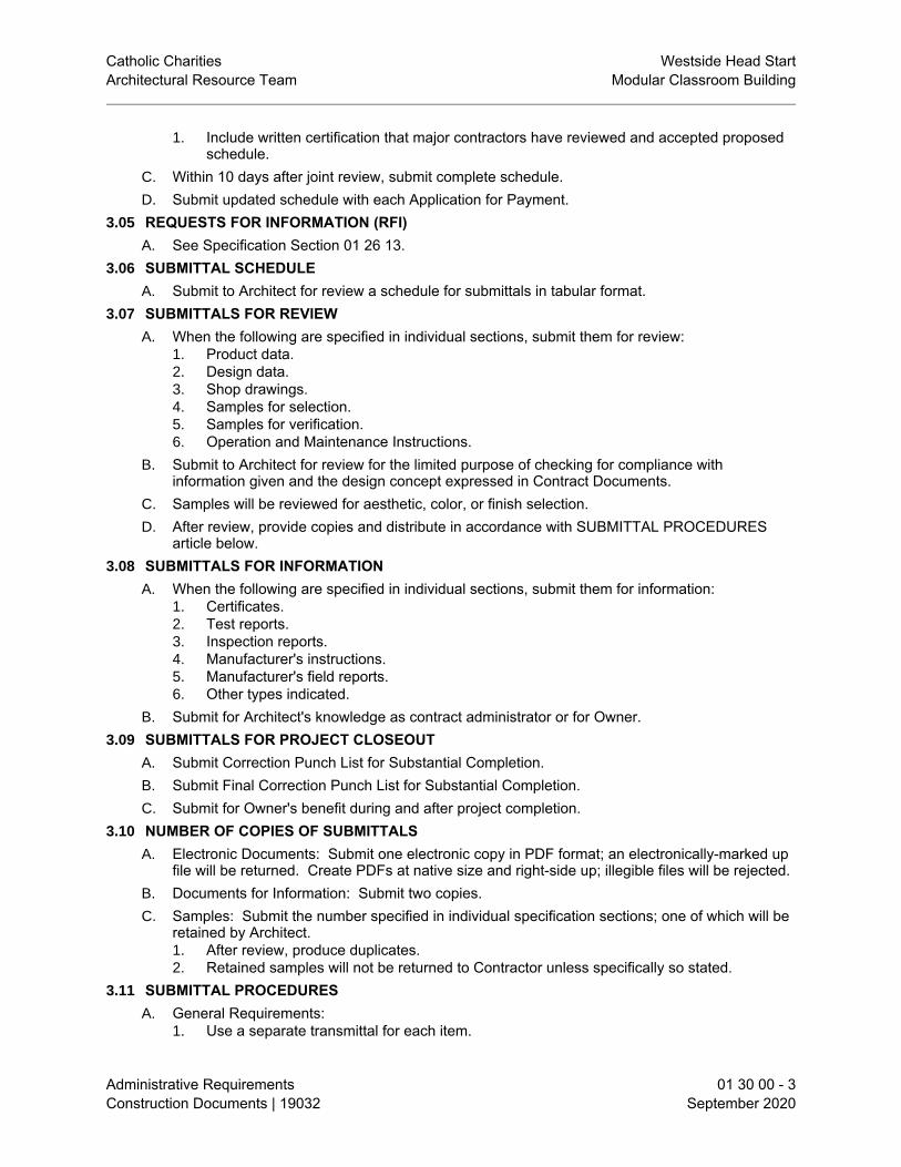
Catholic Charities Westside Head StartArchitectural Resource Team Modular Classroom Building
Administrative Requirements 01 30 00 - 3Construction Documents | 19032 September 2020
1. Include written certification that major contractors have reviewed and accepted proposedschedule.
C. Within 10 days after joint review, submit complete schedule.D. Submit updated schedule with each Application for Payment.
3.05 REQUESTS FOR INFORMATION (RFI)A. See Specification Section 01 26 13.
3.06 SUBMITTAL SCHEDULEA. Submit to Architect for review a schedule for submittals in tabular format.
3.07 SUBMITTALS FOR REVIEWA. When the following are specified in individual sections, submit them for review:
1. Product data.2. Design data.3. Shop drawings.4. Samples for selection.5. Samples for verification.6. Operation and Maintenance Instructions.
B. Submit to Architect for review for the limited purpose of checking for compliance withinformation given and the design concept expressed in Contract Documents.
C. Samples will be reviewed for aesthetic, color, or finish selection.D. After review, provide copies and distribute in accordance with SUBMITTAL PROCEDURES
article below.3.08 SUBMITTALS FOR INFORMATION
A. When the following are specified in individual sections, submit them for information:1. Certificates.2. Test reports.3. Inspection reports.4. Manufacturer's instructions.5. Manufacturer's field reports.6. Other types indicated.
B. Submit for Architect's knowledge as contract administrator or for Owner.3.09 SUBMITTALS FOR PROJECT CLOSEOUT
A. Submit Correction Punch List for Substantial Completion.B. Submit Final Correction Punch List for Substantial Completion.C. Submit for Owner's benefit during and after project completion.
3.10 NUMBER OF COPIES OF SUBMITTALSA. Electronic Documents: Submit one electronic copy in PDF format; an electronically-marked up
file will be returned. Create PDFs at native size and right-side up; illegible files will be rejected.B. Documents for Information: Submit two copies.C. Samples: Submit the number specified in individual specification sections; one of which will be
retained by Architect.1. After review, produce duplicates.2. Retained samples will not be returned to Contractor unless specifically so stated.
3.11 SUBMITTAL PROCEDURESA. General Requirements:
1. Use a separate transmittal for each item.

Catholic Charities Westside Head StartArchitectural Resource Team Modular Classroom Building
Administrative Requirements 01 30 00 - 4Construction Documents | 19032 September 2020
2. Submit separate packages of submittals for review and submittals for information, whenincluded in the same specification section.
3. Transmit using approved form.a. Use Contractor's form, subject to prior approval by Architect.
4. Sequentially identify each item. For revised submittals use original number and asequential numerical suffix.
5. Identify: Project; Contractor; subcontractor or supplier; pertinent drawing and detailnumber; and specification section number and article/paragraph, as appropriate on eachcopy.
6. Apply Contractor's stamp, signed or initialed certifying that review, approval, verification ofproducts required, field dimensions, adjacent construction work, and coordination ofinformation is in accordance with the requirements of the work and Contract Documents.
7. Deliver each submittal on date noted in submittal schedule, unless an earlier date hasbeen agreed to by all affected parties, and is of the benefit to the project.
8. Schedule submittals to expedite the Project, and coordinate submission of related items.9. Identify variations from Contract Documents and product or system limitations that may be
detrimental to successful performance of the completed work.10. Provide space for Contractor and Architect review stamps.11. When revised for resubmission, identify all changes made since previous submission.12. Distribute reviewed submittals. Instruct parties to promptly report inability to comply with
requirements.13. Incomplete submittals will not be reviewed, unless they are partial submittals for distinct
portion(s) of the work, and have received prior approval for their use.B. Product Data Procedures:
1. Submit only information required by individual specification sections.2. Collect required information into a single submittal.3. Do not submit (Material) Safety Data Sheets for materials or products.
C. Shop Drawing Procedures:1. Prepare accurate, drawn-to-scale, original shop drawing documentation by interpreting
Contract Documents and coordinating related work.2. Generic, non-project-specific information submitted as shop drawings do not meet the
requirements for shop drawings.D. Transmit each submittal digitally with a copy of approved submittal form.
3.12 SUBMITTAL REVIEWA. Submittals for Review: Architect will review each submittal, and approve, or take other
appropriate action.B. Submittals for Information: Architect will acknowledge receipt and review. See below for
actions to be taken.C. Architect's actions will be reflected by marking each returned submittal using virtual stamp on
electronic submittals.D. Architect's and consultants' actions on items submitted for review:
1. Authorizing purchasing, fabrication, delivery, and installation:a. "Approved", or language with same legal meaning.b. "Approved as Noted, Resubmission not required", or language with same legal
meaning.1) At Contractor's option, submit corrected item, with review notations
acknowledged and incorporated.c. "Approved as Noted, Resubmit for Record", or language with same legal meaning.
2. Not Authorizing fabrication, delivery, and installation:E. Architect's and consultants' actions on items submitted for information:
1. Items for which no action was taken:

Catholic Charities Westside Head StartArchitectural Resource Team Modular Classroom Building
Administrative Requirements 01 30 00 - 5Construction Documents | 19032 September 2020
a. "Received" - to notify the Contractor that the submittal has been received for recordonly.
2. Items for which action was taken:a. "Reviewed" - no further action is required from Contractor.
END OF SECTION


Catholic Charities Westside Head StartArchitectural Resource Team Modular Classroom Building
Quality Requirements 01 40 00 - 1Construction Documents | 19032 September 2020
SECTION 01 40 00QUALITY REQUIREMENTS
PART 1 GENERAL1.01 SECTION INCLUDES
A. Submittals.B. Quality assurance.C. Testing and inspection agencies and services.D. Control of installation.E. Manufacturers' field services.F. Defect Assessment.
1.02 RELATED REQUIREMENTSA. Section 01 30 00 - Administrative Requirements: Submittal procedures.
1.03 REFERENCE STANDARDS1.04 SUBMITTALS
A. See Section 01 30 00 - Administrative Requirements, for submittal procedures.B. Test Reports: After each test/inspection, promptly submit two copies of report to Architect and
to Contractor.1. Include:
a. Date issued.b. Project title and number.c. Name of inspector.d. Date and time of sampling or inspection.e. Identification of product and specifications section.f. Location in the Project.g. Type of test/inspection.h. Date of test/inspection.i. Results of test/inspection.j. Compliance with Contract Documents.k. When requested by Architect, provide interpretation of results.
C. Certificates: When specified in individual specification sections, submit certification by themanufacturer and Contractor or installation/application subcontractor to Architect, in quantitiesspecified for Product Data.1. Indicate material or product complies with or exceeds specified requirements. Submit
supporting reference data, affidavits, and certifications as appropriate.D. Manufacturer's Instructions: When specified in individual specification sections, submit printed
instructions for delivery, storage, assembly, installation, start-up, adjusting, and finishing, for theOwner's information. Indicate special procedures, perimeter conditions requiring specialattention, and special environmental criteria required for application or installation.
E. Manufacturer's Field Reports: Submit reports for Architect's benefit as contract administrator orfor Owner.1. Submit for information for the limited purpose of assessing compliance with information
given and the design concept expressed in the Contract Documents.1.05 QUALITY ASSURANCE
A. Testing Agency Qualifications:1. Prior to start of work, submit agency name, address, and telephone number, and names
of full time registered Engineer and responsible officer.1.06 TESTING AND INSPECTION AGENCIES AND SERVICES

Catholic Charities Westside Head StartArchitectural Resource Team Modular Classroom Building
Quality Requirements 01 40 00 - 2Construction Documents | 19032 September 2020
A. Owner will employ and pay for services of an independent testing agency to perform specifiedtesting and inspection.
B. Employment of agency in no way relieves Contractor of obligation to perform Work inaccordance with requirements of Contract Documents.
PART 2 PRODUCTS - NOT USEDPART 3 EXECUTION3.01 CONTROL OF INSTALLATION
A. Monitor quality control over suppliers, manufacturers, products, services, site conditions, andworkmanship, to produce work of specified quality.
B. Comply with manufacturers' instructions, including each step in sequence.C. Should manufacturers' instructions conflict with Contract Documents, request clarification from
Architect before proceeding.D. Comply with specified standards as minimum quality for the work except where more stringent
tolerances, codes, or specified requirements indicate higher standards or more preciseworkmanship.
E. Have work performed by persons qualified to produce required and specified quality.F. Verify that field measurements are as indicated on shop drawings or as instructed by the
manufacturer.G. Secure products in place with positive anchorage devices designed and sized to withstand
stresses, vibration, physical distortion, and disfigurement.3.02 TESTING AND INSPECTION
A. Testing Agency Duties:1. Provide qualified personnel at site. Cooperate with Architect and Contractor in
performance of services.2. Perform specified sampling and testing of products in accordance with specified
standards.3. Ascertain compliance of materials and mixes with requirements of Contract Documents.4. Promptly notify Architect and Contractor of observed irregularities or non-compliance of
Work or products.5. Perform additional tests and inspections required by Architect.6. Submit reports of all tests/inspections specified.
B. Limits on Testing/Inspection Agency Authority:1. Agency may not release, revoke, alter, or enlarge on requirements of Contract
Documents.2. Agency may not approve or accept any portion of the Work.3. Agency may not assume any duties of Contractor.4. Agency has no authority to stop the Work.
C. Contractor Responsibilities:1. Deliver to agency at designated location, adequate samples of materials proposed to be
used that require testing, along with proposed mix designs.2. Cooperate with laboratory personnel, and provide access to the Work and to
manufacturers' facilities.3. Provide incidental labor and facilities:
a. To provide access to Work to be tested/inspected.b. To obtain and handle samples at the site or at source of Products to be
tested/inspected.c. To facilitate tests/inspections.d. To provide storage and curing of test samples.

Catholic Charities Westside Head StartArchitectural Resource Team Modular Classroom Building
Quality Requirements 01 40 00 - 3Construction Documents | 19032 September 2020
4. Notify Architect and laboratory 24 hours prior to expected time for operations requiringtesting/inspection services.
5. Employ services of an independent qualified testing laboratory and pay for additionalsamples, tests, and inspections required by Contractor beyond specified requirements.
6. Arrange with Owner's agency and pay for additional samples, tests, and inspectionsrequired by Contractor beyond specified requirements.
D. Re-testing required because of non-compliance with specified requirements shall be performedby the same agency on instructions by Architect.
E. Re-testing required because of non-compliance with specified requirements shall be paid for byContractor.
3.03 MANUFACTURERS' FIELD SERVICESA. When specified in individual specification sections, require material or product suppliers or
manufacturers to provide qualified staff personnel to observe site conditions, conditions of surfaces and installation, quality of workmanship, start-up of equipment, test, adjust, and balance equipment, as applicable, and to initiate instructions when necessary.
B. Report observations and site decisions or instructions given to applicators or installers that are supplemental or contrary to manufacturers' written instructions.
3.04 DEFECT ASSESSMENTA. Replace Work or portions of the Work not complying with specified requirements.
END OF SECTION


Catholic Charities Westside Head StartArchitectural Resource Team Modular Classroom Building
Volatile Organic Compound (VOC) Content Restrictions 01 61 16 - 1Construction Documents | 19032 September 2020
SECTION 01 61 16VOLATILE ORGANIC COMPOUND (VOC) CONTENT RESTRICTIONS
PART 1 GENERAL1.01 SECTION INCLUDES
A. Requirements for Indoor-Emissions-Restricted products.B. Requirements for VOC-Content-Restricted products.C. Requirement for installer certification that they did not use any non-compliant products.
1.02 RELATED REQUIREMENTSA. Section 01 30 00 - Administrative Requirements: Submittal procedures.B. Section 07 92 00 - Joint Sealants: Emissions-compliant sealants.
1.03 DEFINITIONSA. Indoor-Emissions-Restricted Products: All products in the following product categories,
whether specified or not:1. Interior paints and coatings applied on site.2. Interior adhesives and sealants applied on site, including flooring adhesives.3. Composite wood.4. Products making up wall and ceiling assemblies.5. Thermal and acoustical insulation.6. Other products when specifically stated in the specifications.
B. VOC-Content-Restricted Products: All products in the following product categories, whetherspecified or not:1. Interior paints and coatings applied on site.2. Interior adhesives and sealants applied on site, including flooring adhesives.
C. Interior of Building: Anywhere inside the exterior weather barrier.D. Adhesives: All gunnable, trowelable, liquid-applied, and aerosol adhesives, whether specified
or not; including flooring adhesives, resilient base adhesives, and pipe jointing adhesives.E. Sealants: All gunnable, trowelable, and liquid-applied joint sealants and sealant primers,
whether specified or not; including firestopping sealants and duct joint sealers.F. Inherently Non-Emitting Materials: Products composed wholly of minerals or metals, unless
they include organic-based surface coatings, binders, or sealants; and specifically the following:1. Metals that are plated, anodized, or powder-coated.2. Glass.3. Ceramics.
1.04 REFERENCE STANDARDSA. 40 CFR 59, Subpart D - National Volatile Organic Compound Emission Standards for
Architectural Coatings; U.S. Environmental Protection Agency current edition.B. ASTM D3960 - Standard Practice for Determining Volatile Organic Compound (VOC) Content
of Paints and Related Coatings 2005 (Reapproved 2018).C. BIFMA M7.1 - Standard Test Method for Determining VOC Emissions from Office Furniture
Systems, Components, and Seating 2011 (Reapproved 2016).D. CAL (CDPH SM) - Standard Method for the Testing and Evaluation of Volatile Organic
Chemical Emissions From Indoor Sources Using Environmental Chambers 2017, v1.2.E. CARB (ATCM) - Airborne Toxic Control Measure to Reduce Formaldehyde Emissions from
Composite Wood Products; California Air Resources Board current edition.F. CARB (SCM) - Suggested Control Measure for Architectural Coatings; California Air Resources
Board 2007.

Catholic Charities Westside Head StartArchitectural Resource Team Modular Classroom Building
Volatile Organic Compound (VOC) Content Restrictions 01 61 16 - 2Construction Documents | 19032 September 2020
G. CHPS (HPPD) - High Performance Products Database Current Edition at www.chps.net/.H. CRI (GLP) - Green Label Plus Testing Program - Certified Products Current Edition.I. GreenSeal GS-36 - Adhesives for Commercial Use 2013.J. SCAQMD 1113 - Architectural Coatings 1977 (Amended 2016).K. SCAQMD 1168 - Adhesive and Sealant Applications 1989 (Amended 2017).L. SCS (CPD) - SCS Certified Products Current Edition.M. UL (GGG) - GREENGUARD Gold Certified Products Current Edition.
1.05 SUBMITTALSA. See Section 01 30 00 - Administrative Requirements, for submittal procedures.B. Product Data: For each VOC-restricted product used in the project, submit evidence of
compliance.C. Installer Certifications Regarding Prohibited Content: Require each installer of any type of
product (not just the products for which VOC restrictions are specified) to certify that either 1)no adhesives, joint sealants, paints, coatings, or composite wood or agrifiber products havebeen used in the installation of installer's products, or 2) that such products used comply withthese requirements.
1.06 QUALITY ASSURANCEA. Indoor Emissions Standard and Test Method: CAL (CDPH SM), using Standard Private Office
exposure scenario and the allowable concentrations specified in the method, and range of totalVOC's after 14 days.1. Wet-Applied Products: State amount applied in mass per surface area.2. Paints and Coatings: Test tinted products, not just tinting bases.3. Evidence of Compliance: Acceptable types of evidence are the following;
a. Current UL (GGG) certification.b. Current SCS (CPD) Floorscore certification.c. Current SCS (CPD) Indoor Advantage Gold certification.d. Current listing in CHPS (HPPD) as a low-emitting product.e. Current CRI (GLP) certification.f. Test report showing compliance and stating exposure scenario used.
4. Product data submittal showing VOC content is NOT acceptable evidence.5. Manufacturer's certification without test report by independent agency is NOT acceptable
evidence.B. VOC Content Test Method: 40 CFR 59, Subpart D (EPA Method 24), or ASTM D3960, unless
otherwise indicated.1. Evidence of Compliance: Acceptable types of evidence are:
a. Report of laboratory testing performed in accordance with requirements.b. Published product data showing compliance with requirements.
C. Composite Wood Emissions Standard: CARB (ATCM) for ultra-low emitting formaldehyde(ULEF) resins.1. Evidence of Compliance: Acceptable types of evidence are:
a. Current SCS "No Added Formaldehyde (NAF)" certification; www.scscertified.com.b. Report of laboratory testing performed in accordance with requirements.c. Published product data showing compliance with requirements.
D. Testing Agency Qualifications: Independent firm specializing in performing testing andinspections of the type specified in this section.
PART 2 PRODUCTS2.01 MATERIALS

Catholic Charities Westside Head StartArchitectural Resource Team Modular Classroom Building
Volatile Organic Compound (VOC) Content Restrictions 01 61 16 - 3Construction Documents | 19032 September 2020
A. All Products: Comply with the most stringent of federal, State, and local requirements, or thesespecifications.
B. Indoor-Emissions-Restricted Products: Comply with Indoor Emissions Standard and TestMethod, except for:1. Composite Wood, Wood Fiber, and Wood Chip Products: Comply with Composite Wood
Emissions Standard or contain no added formaldehyde resins.2. Inherently Non-Emitting Materials.
C. VOC-Content-Restricted Products: VOC content not greater than required by the following:1. Adhesives, Including Flooring Adhesives: SCAQMD 1168 Rule.2. Aerosol Adhesives: GreenSeal GS-36.3. Joint Sealants: SCAQMD 1168 Rule.4. Paints and Coatings: Each color; most stringent of the following:
a. 40 CFR 59, Subpart D.b. SCAQMD 1113 Rule.c. CARB (SCM).
PART 3 EXECUTION3.01 FIELD QUALITY CONTROL
A. Owner reserves the right to reject non-compliant products, whether installed or not, and requiretheir removal and replacement with compliant products at no extra cost to Owner.
B. Additional costs to restore indoor air quality due to installation of non-compliant products will beborne by Contractor.
END OF SECTION


Catholic Charities Westside Head StartArchitectural Resource Team Modular Classroom Building
Execution and Closeout Requirements 01 70 00 - 1Construction Documents | 19032 September 2020
SECTION 01 70 00EXECUTION AND CLOSEOUT REQUIREMENTS
PART 1 GENERAL1.01 SECTION INCLUDES
A. Examination, preparation, and general installation procedures.B. Cutting and patching.C. Cleaning and protection.D. Starting of systems and equipment.E. Closeout procedures, including Contractor's Correction Punch List, except payment
procedures.1.02 RELATED REQUIREMENTS
A. Section 01 10 00 - Summary: Limitations on working in existing building; continued occupancy;work sequence; identification of salvaged and relocated materials.
B. Section 01 30 00 - Administrative Requirements: Submittals procedures, Electronic documentsubmittal service.
C. Section 01 40 00 - Quality Requirements: Testing and inspection procedures.D. Section 01 74 19 - Construction Waste Management and Disposal: Additional procedures for
trash/waste removal, recycling, salvage, and reuse.1.03 SUBMITTALS
A. See Section 01 30 00 - Administrative Requirements, for submittal procedures.B. Survey work: Submit name, address, and telephone number of Surveyor before starting survey
work.1. On request, submit documentation verifying accuracy of survey work.2. Submit a copy of site drawing signed by the Land Surveyor, that the elevations and
locations of the work are in compliance with Contract Documents.3. Submit surveys and survey logs for the project record.
C. Cutting and Patching: Submit written request in advance of cutting or alteration that affects:1. Structural integrity of any element of Project.2. Integrity of weather exposed or moisture resistant element.3. Efficiency, maintenance, or safety of any operational element.4. Visual qualities of sight exposed elements.5. Work of Owner or separate Contractor.
1.04 PROJECT CONDITIONSA. Ventilate enclosed areas to assist cure of materials, to dissipate humidity, and to prevent
accumulation of dust, fumes, vapors, or gases.1.05 COORDINATION
A. See Section 01 10 00 for occupancy-related requirements.B. In finished areas except as otherwise indicated, conceal pipes, ducts, and wiring within the
construction. Coordinate locations of fixtures and outlets with finish elements.C. Coordinate completion and clean-up of work of separate sections.D. After Owner occupancy of premises, coordinate access to site for correction of defective work
and work not in accordance with Contract Documents, to minimize disruption of Owner'sactivities.
PART 2 PRODUCTS2.01 PATCHING MATERIALS

Catholic Charities Westside Head StartArchitectural Resource Team Modular Classroom Building
Execution and Closeout Requirements 01 70 00 - 2Construction Documents | 19032 September 2020
A. New Materials: As specified in product sections; match existing products and work for patchingand extending work.
B. Type and Quality of Existing Products: Determine by inspecting and testing products wherenecessary, referring to existing work as a standard.
C. Product Substitution: For any proposed change in materials, submit request for substitutiondescribed in Section 01 60 00 - Product Requirements.
PART 3 EXECUTION3.01 EXAMINATION
A. Verify that existing substrate is capable of structural support or attachment of new work beingapplied or attached.
B. Examine and verify specific conditions described in individual specification sections.C. Take field measurements before confirming product orders or beginning fabrication, to minimize
waste due to over-ordering or misfabrication.D. Prior to Cutting: Examine existing conditions prior to commencing work, including elements
subject to damage or movement during cutting and patching. After uncovering existing work,assess conditions affecting performance of work. Beginning of cutting or patching meansacceptance of existing conditions.
3.02 PREPARATIONA. Clean substrate surfaces prior to applying next material or substance.B. Seal cracks or openings of substrate prior to applying next material or substance.C. Apply manufacturer required or recommended substrate primer, sealer, or conditioner prior to
applying any new material or substance in contact or bond.3.03 LAYING OUT THE WORK
A. Verify locations of survey control points prior to starting work.B. Promptly notify Architect of any discrepancies discovered.C. Protect survey control points prior to starting site work; preserve permanent reference points
during construction.D. Promptly report to Architect the loss or destruction of any reference point or relocation required
because of changes in grades or other reasons.E. Replace dislocated survey control points based on original survey control. Make no changes
without prior written notice to Architect.F. Utilize recognized engineering survey practices.G. Establish elevations, lines and levels. Locate and lay out by instrumentation and similar
appropriate means:1. Site improvements including pavements; stakes for grading, fill and topsoil placement;
utility locations, slopes, and invert elevations.2. Grid or axis for structures.3. Building foundation, column locations, ground floor elevations.
H. Periodically verify layouts by same means.I. Maintain a complete and accurate log of control and survey work as it progresses.
3.04 GENERAL INSTALLATION REQUIREMENTSA. Install products as specified in individual sections, in accordance with manufacturer's
instructions and recommendations, and so as to avoid waste due to necessity for replacement.B. Make vertical elements plumb and horizontal elements level, unless otherwise indicated.C. Install equipment and fittings plumb and level, neatly aligned with adjacent vertical and
horizontal lines, unless otherwise indicated.

Catholic Charities Westside Head StartArchitectural Resource Team Modular Classroom Building
Execution and Closeout Requirements 01 70 00 - 3Construction Documents | 19032 September 2020
D. Make consistent texture on surfaces, with seamless transitions, unless otherwise indicated.E. Make neat transitions between different surfaces, maintaining texture and appearance.
3.05 CUTTING AND PATCHINGA. Whenever possible, execute the work by methods that avoid cutting or patching.B. Perform whatever cutting and patching is necessary to:
1. Complete the work.2. Fit products together to integrate with other work.3. Provide openings for penetration of mechanical, electrical, and other services.4. Match work that has been cut to adjacent work.5. Repair areas adjacent to cuts to required condition.6. Repair new work damaged by subsequent work.7. Remove samples of installed work for testing when requested.8. Remove and replace defective and non-complying work.
C. Execute work by methods that avoid damage to other work and that will provide appropriatesurfaces to receive patching and finishing. In existing work, minimize damage and restore tooriginal condition.
D. Employ original installer to perform cutting for weather exposed and moisture resistantelements, and sight exposed surfaces.
E. Cut rigid materials using masonry saw or core drill. Pneumatic tools not allowed without priorapproval.
F. Restore work with new products in accordance with requirements of Contract Documents.G. Fit work air tight to pipes, sleeves, ducts, conduit, and other penetrations through surfaces.H. Patching:
1. Finish patched surfaces to match finish that existed prior to patching. On continuoussurfaces, refinish to nearest intersection or natural break. For an assembly, refinish entireunit.
2. Match color, texture, and appearance.3. Repair patched surfaces that are damaged, lifted, discolored, or showing other
imperfections due to patching work. If defects are due to condition of substrate, repairsubstrate prior to repairing finish.
3.06 PROGRESS CLEANINGA. Maintain areas free of waste materials, debris, and rubbish. Maintain site in a clean and orderly
condition.B. Remove debris and rubbish from pipe chases, plenums, attics, crawl spaces, and other closed
or remote spaces, prior to enclosing the space.C. Broom and vacuum clean interior areas prior to start of surface finishing, and continue cleaning
to eliminate dust.D. Collect and remove waste materials, debris, and trash/rubbish from site periodically and
dispose off-site; do not burn or bury.3.07 PROTECTION OF INSTALLED WORK
A. Protect installed work from damage by construction operations.B. Provide special protection where specified in individual specification sections.C. Provide temporary and removable protection for installed products. Control activity in immediate
work area to prevent damage.D. Provide protective coverings at walls, projections, jambs, sills, and soffits of openings.E. Protect finished floors, stairs, and other surfaces from traffic, dirt, wear, damage, or movement
of heavy objects, by protecting with durable sheet materials.

Catholic Charities Westside Head StartArchitectural Resource Team Modular Classroom Building
Execution and Closeout Requirements 01 70 00 - 4Construction Documents | 19032 September 2020
F. Prohibit traffic or storage upon waterproofed or roofed surfaces. If traffic or activity isnecessary, obtain recommendations for protection from waterproofing or roofing materialmanufacturer.
G. Remove protective coverings when no longer needed; reuse or recycle coverings if possible.3.08 SYSTEM STARTUP
A. Coordinate schedule for start-up of various equipment and systems.B. Verify that each piece of equipment or system has been checked for proper lubrication, drive
rotation, belt tension, control sequence, and for conditions that may cause damage.C. Verify tests, meter readings, and specified electrical characteristics agree with those required
by the equipment or system manufacturer.D. Verify that wiring and support components for equipment are complete and tested.E. Execute start-up under supervision of applicable Contractor personnel and manufacturer's
representative in accordance with manufacturers' instructions.F. Submit a written report that equipment or system has been properly installed and is functioning
correctly.3.09 ADJUSTING
A. Adjust operating products and equipment to ensure smooth and unhindered operation.3.10 FINAL CLEANING
A. Use cleaning materials that are nonhazardous.B. Clean interior and exterior glass, surfaces exposed to view; remove temporary labels, stains
and foreign substances, polish transparent and glossy surfaces, vacuum carpeted and softsurfaces.
C. Remove all labels that are not permanent. Do not paint or otherwise cover fire test labels ornameplates on mechanical and electrical equipment.
D. Clean equipment and fixtures to a sanitary condition with cleaning materials appropriate to thesurface and material being cleaned.
E. Clean filters of operating equipment.F. Clean debris from roofs, overflow drains, area drains, and drainage systems.
3.11 CLOSEOUT PROCEDURESA. Make submittals that are required by governing or other authorities.B. Accompany Project Coordinator on preliminary inspection to determine items to be listed for
completion or correction in the Contractor's Correction Punch List for Contractor's Notice ofSubstantial Completion.
C. Notify Architect when work is considered ready for Architect's Substantial Completioninspection.
D. Submit written certification containing Contractor's Correction Punch List, that ContractDocuments have been reviewed, work has been inspected, and that work is complete inaccordance with Contract Documents and ready for Architect's Substantial Completioninspection.
E. Conduct Substantial Completion inspection and create Final Correction Punch List containingArchitect's and Contractor's comprehensive list of items identified to be completed or correctedand submit to Architect.
F. Correct items of work listed in Final Correction Punch List and comply with requirements foraccess to Owner-occupied areas.
G. Notify Architect when work is considered finally complete and ready for Architect's SubstantialCompletion final inspection.

Catholic Charities Westside Head StartArchitectural Resource Team Modular Classroom Building
Execution and Closeout Requirements 01 70 00 - 5Construction Documents | 19032 September 2020
H. Complete items of work determined by Architect listed in executed Certificate of SubstantialCompletion.
3.12 MAINTENANCEA. Provide service and maintenance of components indicated in specification sections.B. Maintenance Period: As indicated in specification sections or, if not indicated, not less than
one year from the Date of Substantial Completion or the length of the specified warranty,whichever is longer.
C. Examine system components at a frequency consistent with reliable operation. Clean, adjust,and lubricate as required.
D. Include systematic examination, adjustment, and lubrication of components. Repair or replaceparts whenever required. Use parts produced by the manufacturer of the original component.
E. Maintenance service shall not be assigned or transferred to any agent or subcontractor withoutprior written consent of the Owner.
END OF SECTION


Catholic Charities Westside Head StartArchitectural Resource Team Modular Classroom Building
Construction Waste Management and Disposal 01 74 19 - 1Construction Documents | 19032 September 2020
SECTION 01 74 19CONSTRUCTION WASTE MANAGEMENT AND DISPOSAL
PART 1 GENERAL1.01 WASTE MANAGEMENT REQUIREMENTS
A. Owner requires that this project generate the least amount of trash and waste possible.B. Employ processes that ensure the generation of as little waste as possible due to error, poor
planning, breakage, mishandling, contamination, or other factors.C. Minimize trash/waste disposal in landfills; reuse, salvage, or recycle as much waste as
economically feasible.D. Contractor shall submit periodic Waste Disposal Reports; all landfill disposal, incineration,
recycling, salvage, and reuse must be reported regardless of to whom the cost or savingsaccrues; use the same units of measure on all reports.
E. Methods of trash/waste disposal that are not acceptable are:1. Dumping or burying on other property, public or private.2. Other illegal dumping or burying.
F. Regulatory Requirements: Contractor is responsible for knowing and complying with regulatoryrequirements, including but not limited to Federal, state and local requirements, pertaining tolegal disposal of all construction and demolition waste materials.
1.02 DEFINITIONSA. Clean: Untreated and unpainted; not contaminated with oils, solvents, caulk, or the like.B. Construction and Demolition Waste: Solid wastes typically including building materials,
packaging, trash, debris, and rubble resulting from construction, remodeling, repair anddemolition operations.
C. Hazardous: Exhibiting the characteristics of hazardous substances, i.e., ignitibility, corrosivity,toxicity or reactivity.
D. Nonhazardous: Exhibiting none of the characteristics of hazardous substances, i.e., ignitibility,corrosivity, toxicity, or reactivity.
E. Nontoxic: Neither immediately poisonous to humans nor poisonous after a long period ofexposure.
F. Recyclable: The ability of a product or material to be recovered at the end of its life cycle andremanufactured into a new product for reuse by others.
G. Recycle: To remove a waste material from the project site to another site for remanufactureinto a new product for reuse by others.
H. Recycling: The process of sorting, cleansing, treating and reconstituting solid waste and otherdiscarded materials for the purpose of using the altered form. Recycling does not includeburning, incinerating, or thermally destroying waste.
I. Return: To give back reusable items or unused products to vendors for credit.J. Reuse: To reuse a construction waste material in some manner on the project site.K. Salvage: To remove a waste material from the project site to another site for resale or reuse by
others.L. Sediment: Soil and other debris that has been eroded and transported by storm or well
production run-off water.M. Source Separation: The act of keeping different types of waste materials separate beginning
from the first time they become waste.N. Toxic: Poisonous to humans either immediately or after a long period of exposure.O. Trash: Any product or material unable to be reused, returned, recycled, or salvaged.

Catholic Charities Westside Head StartArchitectural Resource Team Modular Classroom Building
Construction Waste Management and Disposal 01 74 19 - 2Construction Documents | 19032 September 2020
P. Waste: Extra material or material that has reached the end of its useful life in its intended use. Waste includes salvageable, returnable, recyclable, and reusable material.
1.03 SUBMITTALSA. See Section 01 30 00 - Administrative Requirements, for submittal procedures.B. Waste Disposal Reports: Submit at specified intervals, with details of quantities of trash and
waste, means of disposal or reuse, and costs; show both totals to date and since last report.1. Submit updated Report with each Application for Progress Payment; failure to submit
Report will delay payment.2. Submit Report on a form acceptable to Owner.3. Landfill Disposal: Include the following information:
a. Identification of material.b. Amount, in tons or cubic yards, of trash/waste material from the project disposed of in
landfills.c. State the identity of landfills, total amount of tipping fees paid to landfill, and total
disposal cost.d. Include manifests, weight tickets, receipts, and invoices as evidence of quantity and
cost.4. Incinerator Disposal: Include the following information:
a. Identification of material.b. Amount, in tons or cubic yards, of trash/waste material from the project delivered to
incinerators.c. State the identity of incinerators, total amount of fees paid to incinerator, and total
disposal cost.d. Include manifests, weight tickets, receipts, and invoices as evidence of quantity and
cost.5. Recycled and Salvaged Materials: Include the following information for each:
a. Identification of material, including those retrieved by installer for use on otherprojects.
b. Amount, in tons or cubic yards, date removed from the project site, and receivingparty.
c. Transportation cost, amount paid or received for the material, and the net total cost orsavings of salvage or recycling each material.
d. Include manifests, weight tickets, receipts, and invoices as evidence of quantity andcost.
e. Certification by receiving party that materials will not be disposed of in landfills or byincineration.
6. Material Reused on Project: Include the following information for each:a. Identification of material and how it was used in the project.b. Amount, in tons or cubic yards.c. Include weight tickets as evidence of quantity.
7. Other Disposal Methods: Include information similar to that described above, asappropriate to disposal method.
PART 2 PRODUCTS - NOT USEDPART 3 EXECUTION3.01 WASTE MANAGEMENT PROCEDURES
A. See Section 01 30 00 for additional requirements for project meetings, reports, submittalprocedures, and project documentation.
B. See Section 01 70 00 for trash/waste prevention procedures related to cutting and patching,installation, protection, and cleaning.
3.02 WASTE MANAGEMENT PLAN IMPLEMENTATION

Catholic Charities Westside Head StartArchitectural Resource Team Modular Classroom Building
Construction Waste Management and Disposal 01 74 19 - 3Construction Documents | 19032 September 2020
A. Manager: Designate an on-site person or persons responsible for instructing workers andoverseeing and documenting results of the Waste Management Plan.
B. Communication: Distribute copies of the Waste Management Plan to job site foreman, eachsubcontractor, Owner, and Architect.
C. Instruction: Provide on-site instruction of appropriate separation, handling, and recycling,salvage, reuse, and return methods to be used by all parties at the appropriate stages of theproject.
D. Facilities: Provide specific facilities for separation and storage of materials for recycling,salvage, reuse, return, and trash disposal, for use by all contractors and installers.1. Provide containers as required.2. Provide adequate space for pick-up and delivery and convenience to subcontractors.3. Keep recycling and trash/waste bin areas neat and clean and clearly marked in order to
avoid contamination of materials.E. Hazardous Wastes: Separate, store, and dispose of hazardous wastes according to applicable
regulations.F. Recycling: Separate, store, protect, and handle at the site identified recyclable waste products
in order to prevent contamination of materials and to maximize recyclability of identifiedmaterials. Arrange for timely pickups from the site or deliveries to recycling facility in order toprevent contamination of recyclable materials.
G. Salvage: Set aside, sort, and protect products to be salvaged for reuse off-site.END OF SECTION


Catholic Charities Westside Head StartArchitectural Resource Team Modular Classroom Building
Demolition 02 41 00 - 1Construction Documents | 19032 September 2020
SECTION 02 41 00DEMOLITION
PART 1 GENERAL1.01 SECTION INCLUDES
A. Selective demolition of built site elements.1.02 RELATED REQUIREMENTS
A. Section 01 10 00 - Summary: Limitations on Contractor's use of site and premises.B. Section 01 10 00 - Summary: Description of items to be removed by Owner.C. Section 01 70 00 - Execution and Closeout Requirements: Project conditions; protection of
bench marks, survey control points, and existing construction to remain; reinstallation ofremoved products; temporary bracing and shoring.
D. Section 01 74 19 - Construction Waste Management and Disposal: Limitations on disposal ofremoved materials; requirements for recycling.
1.03 REFERENCE STANDARDSA. 29 CFR 1926 - U.S. Occupational Safety and Health Standards current edition.
1.04 QUALITY ASSURANCEA. Demolition Firm Qualifications: Company specializing in the type of work required.
1. Minimum of five years of documented experience.PART 2 PRODUCTS -- NOT USEDPART 3 EXECUTION3.01 SCOPE
A. Remove paving and curbs as required to accomplish new work.B. Remove concrete slabs on grade as required by new construction.C. Remove fences and gates as indicated on Drawings.D. Remove other items indicated, for salvage and reuse.
3.02 GENERAL PROCEDURES AND PROJECT CONDITIONSA. Comply with applicable codes and regulations for demolition operations and safety of adjacent
structures and the public.1. Obtain required permits.2. Take precautions to prevent catastrophic or uncontrolled collapse of structures to be
removed; do not allow worker or public access within range of potential collapse ofunstable structures.
3. Provide, erect, and maintain temporary barriers and security devices.4. Conduct operations to minimize effects on and interference with adjacent structures and
occupants.5. Do not close or obstruct roadways or sidewalks without permit.6. Conduct operations to minimize obstruction of public and private entrances and exits; do
not obstruct required exits at any time; protect persons using entrances and exits fromremoval operations.
7. Obtain written permission from owners of adjacent properties when demolition equipmentwill traverse, infringe upon or limit access to their property.
B. Do not begin removal until receipt of notification to proceed from Owner.C. Protect existing structures and other elements that are not to be removed.
1. Provide bracing and shoring.2. Prevent movement or settlement of adjacent structures.3. Stop work immediately if adjacent structures appear to be in danger.

Catholic Charities Westside Head StartArchitectural Resource Team Modular Classroom Building
Demolition 02 41 00 - 2Construction Documents | 19032 September 2020
D. Partial Removal of Paving and Curbs: Neatly saw cut at right angle to surface.3.03 EXISTING UTILITIES
A. Coordinate work with utility companies; notify before starting work and comply with theirrequirements; obtain required permits.
B. Protect existing utilities to remain from damage.C. Do not disrupt public utilities without permit from authority having jurisdiction.D. Do not close, shut off, or disrupt existing life safety systems that are in use without at least 7
days prior written notification to Owner.E. Do not close, shut off, or disrupt existing utility branches or take-offs that are in use without at
least 3 days prior written notification to Owner.F. Locate and mark utilities to remain; mark using highly visible tags or flags, with identification of
utility type; protect from damage due to subsequent construction, using substantial barricades ifnecessary.
G. Remove exposed piping, valves, meters, equipment, supports, and foundations ofdisconnected and abandoned utilities.
3.04 DEBRIS AND WASTE REMOVALA. Remove debris, junk, and trash from site.B. Remove from site all materials not to be reused on site; comply with requirements of Section 01
74 19 - Waste Management.C. Leave site in clean condition, ready for subsequent work.D. Clean up spillage and wind-blown debris from public and private lands.
END OF SECTION

Catholic Charities Westside Head StartArchitectural Resource Team Modular Classroom Building
Cast-in-Place Concrete 03 30 00 - 1Construction Documents | 19032 September 2020
SECTION 03 30 00CAST-IN-PLACE CONCRETE
PART 1 GENERAL1.01 SECTION INCLUDES
A. Concrete formwork.B. Concrete reinforcement.C. Concrete curing.
1.02 REFERENCE STANDARDSA. ACI 211.1 - Standard Practice for Selecting Proportions for Normal, Heavyweight, and Mass
Concrete 1991 (Reapproved 2009).B. ACI 301 - Specifications for Structural Concrete 2016.C. ACI 302.1R - Guide to Concrete Floor and Slab Construction 2015.D. ACI 304R - Guide for Measuring, Mixing, Transporting, and Placing Concrete 2000
(Reapproved 2009).E. ACI 308R - Guide to External Curing of Concrete 2016.F. ACI 318 - Building Code Requirements for Structural Concrete and Commentary 2014 (Errata
2018).G. ASTM A615/A615M - Standard Specification for Deformed and Plain Carbon-Steel Bars for
Concrete Reinforcement 2020.H. ASTM A1064/A1064M - Standard Specification for Carbon-Steel Wire and Welded Wire
Reinforcement, Plain and Deformed, for Concrete 2018a.I. ASTM C33/C33M - Standard Specification for Concrete Aggregates 2018.J. ASTM C94/C94M - Standard Specification for Ready-Mixed Concrete 2020.K. ASTM C150/C150M - Standard Specification for Portland Cement 2020.L. ASTM C494/C494M - Standard Specification for Chemical Admixtures for Concrete 2019.M. ASTM C618 - Standard Specification for Coal Fly Ash and Raw or Calcined Natural Pozzolan
for Use in Concrete 2019.N. ASTM C685/C685M - Standard Specification for Concrete Made by Volumetric Batching and
Continuous Mixing 2017.1.03 SUBMITTALS
A. See Section 01 30 00 - Administrative Requirements, for submittal procedures.B. Product Data: Submit manufacturers' data on manufactured products showing compliance with
specified requirements and installation instructions.C. Mix Design: Submit proposed concrete mix design.D. Test Reports: Submit report for each test or series of tests specified.
1.04 QUALITY ASSURANCEA. Perform work of this section in accordance with ACI 301 and ACI 318.
1. Maintain one copy of each document on site.PART 2 PRODUCTS2.01 FORMWORK
A. Form Materials: Contractor's choice of standard products with sufficient strength to withstandhydrostatic head without distortion in excess of permitted tolerances.1. Form Coating: Release agent that will not adversely affect concrete or interfere with
application of coatings.

Catholic Charities Westside Head StartArchitectural Resource Team Modular Classroom Building
Cast-in-Place Concrete 03 30 00 - 2Construction Documents | 19032 September 2020
2.02 REINFORCEMENT MATERIALSA. Reinforcing Steel: ASTM A615/A615M, Grade 60 (60,000 psi).
1. Type: Deformed billet-steel bars.2. Finish: Unfinished, unless otherwise indicated.
B. Steel Welded Wire Reinforcement (WWR): Galvanized, plain type, ASTM A1064/A1064M.1. WWR Style: As indicated on drawings.
C. Reinforcement Accessories:1. Tie Wire: Annealed, minimum 16 gage, 0.0508 inch.2. Chairs, Bolsters, Bar Supports, Spacers: Sized and shaped for adequate support of
reinforcement during concrete placement.2.03 CONCRETE MATERIALS
A. Cement: ASTM C150/C150M, Type I - Normal Portland type. B. Fine and Coarse Aggregates: ASTM C33/C33M.C. Fly Ash: ASTM C618, Class C or F.D. Water: ASTM C1602/C1602M; clean, potable, and not detrimental to concrete.
2.04 ADMIXTURESA. Do not use chemicals that will result in soluble chloride ions in excess of 0.1 percent by weight
of cement.B. Water Reducing Admixture: ASTM C494/C494M Type A.
2.05 CURING MATERIALSA. Evaporation Reducer: Liquid thin-film-forming compound that reduces rapid moisture loss
caused by high temperature, low humidity, and high winds; intended for application immediatelyafter concrete placement.1. Manufacturers:
a. Euclid Chemical Company ; EUCOBAR: www.euclidchemical.com/#sle.b. W. R. Meadows, Inc; Evapre or Evapre-RTU: www.wrmeadows.com/#sle.
B. Curing Compound, Naturally Dissipating: Clear, water-based, liquid membrane-formingcompound; complying with ASTM C309.1. Product dissipates within 4 to 6 weeks.2. Manufacturers:
a. Euclid Chemical Company; COLOR-CRETE CURE AND SEAL VOC: www.euclidchemical.com/#sle.
b. W. R. Meadows, Inc; 1100-Clear: www.wrmeadows.com/#sle.2.06 CONCRETE MIX DESIGN
A. Proportioning Normal Weight Concrete: Comply with ACI 211.1 recommendations.1. Replace as much Portland cement as possible with fly ash, ground granulated blast
furnace slag, silica fume, or rice hull ash as is consistent with ACI recommendations.B. Admixtures: Add acceptable admixtures as recommended in ACI 211.1 and at rates
recommended or required by manufacturer.2.07 MIXING
A. On Project Site: Mix in drum type batch mixer, complying with ASTM C685/C685M. Mix eachbatch not less than 1-1/2 minutes and not more than 5 minutes.
B. Transit Mixers: Comply with ASTM C94/C94M.C. Adding Water: If concrete arrives on-site with slump less than suitable for placement, do not
add water that exceeds the maximum water-cement ratio or exceeds the maximum permissibleslump.
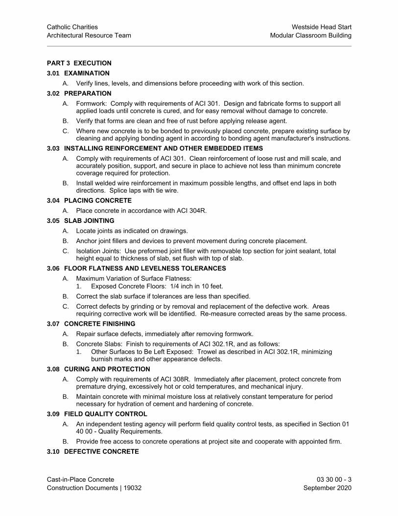
Catholic Charities Westside Head StartArchitectural Resource Team Modular Classroom Building
Cast-in-Place Concrete 03 30 00 - 3Construction Documents | 19032 September 2020
PART 3 EXECUTION3.01 EXAMINATION
A. Verify lines, levels, and dimensions before proceeding with work of this section.3.02 PREPARATION
A. Formwork: Comply with requirements of ACI 301. Design and fabricate forms to support allapplied loads until concrete is cured, and for easy removal without damage to concrete.
B. Verify that forms are clean and free of rust before applying release agent.C. Where new concrete is to be bonded to previously placed concrete, prepare existing surface by
cleaning and applying bonding agent in according to bonding agent manufacturer's instructions.3.03 INSTALLING REINFORCEMENT AND OTHER EMBEDDED ITEMS
A. Comply with requirements of ACI 301. Clean reinforcement of loose rust and mill scale, andaccurately position, support, and secure in place to achieve not less than minimum concretecoverage required for protection.
B. Install welded wire reinforcement in maximum possible lengths, and offset end laps in bothdirections. Splice laps with tie wire.
3.04 PLACING CONCRETEA. Place concrete in accordance with ACI 304R.
3.05 SLAB JOINTINGA. Locate joints as indicated on drawings.B. Anchor joint fillers and devices to prevent movement during concrete placement.C. Isolation Joints: Use preformed joint filler with removable top section for joint sealant, total
height equal to thickness of slab, set flush with top of slab.3.06 FLOOR FLATNESS AND LEVELNESS TOLERANCES
A. Maximum Variation of Surface Flatness:1. Exposed Concrete Floors: 1/4 inch in 10 feet.
B. Correct the slab surface if tolerances are less than specified.C. Correct defects by grinding or by removal and replacement of the defective work. Areas
requiring corrective work will be identified. Re-measure corrected areas by the same process.3.07 CONCRETE FINISHING
A. Repair surface defects, immediately after removing formwork.B. Concrete Slabs: Finish to requirements of ACI 302.1R, and as follows:
1. Other Surfaces to Be Left Exposed: Trowel as described in ACI 302.1R, minimizingburnish marks and other appearance defects.
3.08 CURING AND PROTECTIONA. Comply with requirements of ACI 308R. Immediately after placement, protect concrete from
premature drying, excessively hot or cold temperatures, and mechanical injury.B. Maintain concrete with minimal moisture loss at relatively constant temperature for period
necessary for hydration of cement and hardening of concrete.3.09 FIELD QUALITY CONTROL
A. An independent testing agency will perform field quality control tests, as specified in Section 0140 00 - Quality Requirements.
B. Provide free access to concrete operations at project site and cooperate with appointed firm.3.10 DEFECTIVE CONCRETE

Catholic Charities Westside Head StartArchitectural Resource Team Modular Classroom Building
Cast-in-Place Concrete 03 30 00 - 4Construction Documents | 19032 September 2020
A. Repair or replacement of defective concrete will be determined by the Architect. The cost ofadditional testing shall be borne by Contractor when defective concrete is identified.
B. Do not patch, fill, touch-up, repair, or replace exposed concrete except upon express directionof Architect for each individual area.
3.11 PROTECTIONA. Do not permit traffic over unprotected concrete floor surface until fully cured.
END OF SECTION

Catholic Charities Westside Head StartArchitectural Resource Team Modular Classroom Building
Unit Masonry 04 20 00 - 1Construction Documents | 19032 September 2020
SECTION 04 20 00UNIT MASONRY
PART 1 GENERAL1.01 SECTION INCLUDES
A. Concrete block.B. Mortar and grout.C. Reinforcement and anchorage.D. Accessories.
1.02 RELATED REQUIREMENTSA. Section 03 20 00 - Concrete Reinforcing: Reinforcing steel for grouted masonry.
1.03 REFERENCE STANDARDSA. ASTM A641/A641M - Standard Specification for Zinc-Coated (Galvanized) Carbon Steel Wire
2019.B. ASTM A1064/A1064M - Standard Specification for Carbon-Steel Wire and Welded Wire
Reinforcement, Plain and Deformed, for Concrete 2018a.C. ASTM C91/C91M - Standard Specification for Masonry Cement 2018.D. ASTM C129 - Standard Specification for Nonloadbearing Concrete Masonry Units 2017.E. ASTM C144 - Standard Specification for Aggregate for Masonry Mortar 2018.F. ASTM C150/C150M - Standard Specification for Portland Cement 2020.G. ASTM C207 - Standard Specification for Hydrated Lime for Masonry Purposes 2018.H. ASTM C270 - Standard Specification for Mortar for Unit Masonry 2019.I. ASTM C404 - Standard Specification for Aggregates for Masonry Grout 2018.J. ASTM C476 - Standard Specification for Grout for Masonry 2020.K. TMS 402/602 - Building Code Requirements and Specification for Masonry Structures 2016.
1.04 SUBMITTALSA. See Section 01 30 00 - Administrative Requirements, for submittal procedures.B. Product Data: Provide data for masonry units, fabricated wire reinforcement, mortar, and
masonry accessories.1.05 QUALITY ASSURANCE
A. Installer Qualifications: Company specializing in performing work of the type specified and withat least three years of documented experience.
1.06 DELIVERY, STORAGE, AND HANDLINGA. Deliver, handle, and store masonry units by means that will prevent mechanical damage and
contamination by other materials.PART 2 PRODUCTS2.01 CONCRETE MASONRY UNITS
A. Concrete Block: Comply with referenced standards and as follows:1. Size: Standard units with nominal face dimensions of 16 by 8 inches and nominal depth
of 8 inches.2. Non-Loadbearing Units: ASTM C129.
a. Hollow block, as indicated.b. Normal weight .
2.02 MORTAR AND GROUT MATERIALS

Catholic Charities Westside Head StartArchitectural Resource Team Modular Classroom Building
Unit Masonry 04 20 00 - 2Construction Documents | 19032 September 2020
A. Masonry Cement: ASTM C91/C91M, Type N.B. Portland Cement: ASTM C150/C150M, Type I; color as required to produce approved color
sample.C. Hydrated Lime: ASTM C207, Type S.D. Mortar Aggregate: ASTM C144.E. Grout Aggregate: ASTM C404.F. Water: Clean and potable.
2.03 REINFORCEMENT AND ANCHORAGEA. Reinforcing Steel: Type specified in Section 03 30 00; size as indicated on drawings;
galvanized finish.B. Single Wythe Joint Reinforcement: Truss or ladder type; ASTM A1064/A1064M steel wire, mill
galvanized to ASTM A641/A641M, Class 3; 0.1483 inch side rods with 0.1483 inch cross rods; width as required to provide not more than 1 inch and not less than 1/2 inch of mortarcoverage on each exposure.
2.04 ACCESSORIESA. Preformed Control Joints: Rubber material. Provide with corner and tee accessories, fused
joints.B. Cleaning Solution: Non-acidic, not harmful to masonry work or adjacent materials.
2.05 MORTAR AND GROUT MIXINGA. Mortar for Unit Masonry: ASTM C270, using the Proportion Specification.
1. Exterior, non-loadbearing masonry: Type N.2. Interior, non-loadbearing masonry: Type O.
B. Grout: ASTM C476; consistency required to fill completely volumes indicated for grouting; finegrout for spaces with smallest horizontal dimension of 2 inches or less; coarse grout for spaceswith smallest horizontal dimension greater than 2 inches.
PART 3 EXECUTION3.01 EXAMINATION
A. Verify that field conditions are acceptable and are ready to receive masonry.B. Verify that related items provided under other sections are properly sized and located.
3.02 PREPARATIONA. Direct and coordinate placement of metal anchors supplied for installation under other sections.
3.03 COLD AND HOT WEATHER REQUIREMENTSA. Comply with requirements of ACI 530/530.1/ERTA or applicable building code, whichever is
more stringent.3.04 COURSING
A. Establish lines, levels, and coursing indicated. Protect from displacement.B. Maintain masonry courses to uniform dimension. Form vertical and horizontal joints of uniform
thickness.C. Concrete Masonry Units:
1. Bond: Running.3.05 PLACING AND BONDING
A. Lay hollow masonry units with face shell bedding on head and bed joints.B. Buttering corners of joints or excessive furrowing of mortar joints is not permitted.C. Remove excess mortar and mortar smears as work progresses.

Catholic Charities Westside Head StartArchitectural Resource Team Modular Classroom Building
Unit Masonry 04 20 00 - 3Construction Documents | 19032 September 2020
D. Do not shift or tap masonry units after mortar has achieved initial set. Where adjustment mustbe made, remove mortar and replace.
E. Perform job site cutting of masonry units with proper tools to provide straight, clean, unchippededges. Prevent broken masonry unit corners or edges.
3.06 REINFORCEMENT AND ANCHORAGE - GENERAL A. Unless otherwise indicated on drawings or specified under specific wall type, install horizontal
joint reinforcement 16 inches on center.B. Lap joint reinforcement ends minimum 6 inches.
3.07 CONTROL AND EXPANSION JOINTSA. Do not continue horizontal joint reinforcement through control or expansion joints.B. Install preformed control joint device in continuous lengths. Seal butt and corner joints in
accordance with manufacturer's instructions.3.08 TOLERANCES
A. Maximum Variation From Unit to Adjacent Unit: 1/16 inch.B. Maximum Variation from Plane of Wall: 1/4 inch in 10 ft and 1/2 inch in 20 ft or more.C. Maximum Variation from Level Coursing: 1/8 inch in 3 ft and 1/4 inch in 10 ft; 1/2 inch in 30 ft.
3.09 CUTTING AND FITTINGA. Obtain approval prior to cutting or fitting masonry work not indicated or where appearance or
strength of masonry work may be impaired.3.10 FIELD QUALITY CONTROL
A. An independent testing agency will perform field quality control tests, as specified in Section 0140 00 - Quality Requirements.
3.11 CLEANINGA. Clean soiled surfaces with cleaning solution.
3.12 PROTECTIONA. Without damaging completed work, provide protective boards at exposed external corners that
are subject to damage by construction activities.END OF SECTION


Catholic Charities Westside Head StartArchitectural Resource Team Modular Classroom Building
Metal Fabrications 05 50 00 - 1Construction Documents | 19032 September 2020
SECTION 05 50 00METAL FABRICATIONS
PART 1 GENERAL1.01 SECTION INCLUDES
A. Shop fabricated steel items.B. Metal shade canopy at front and back of Building.
1.02 RELATED REQUIREMENTS1.03 REFERENCE STANDARDS
A. ASTM A53/A53M - Standard Specification for Pipe, Steel, Black and Hot-Dipped, Zinc-Coated,Welded and Seamless 2018.
B. ASTM A283/A283M - Standard Specification for Low and Intermediate Tensile Strength CarbonSteel Plates 2018.
C. ASTM A307 - Standard Specification for Carbon Steel Bolts, Studs, and Threaded Rod 60 000PSI Tensile Strength 2014, with Editorial Revision (2017).
D. ASTM A501/A501M - Standard Specification for Hot-Formed Welded and Seamless CarbonSteel Structural Tubing 2014.
E. AWS D1.1/D1.1M - Structural Welding Code - Steel 2015, with Errata (2016).F. IAS AC172 - Accreditation Criteria for Fabricator Inspection Programs for Structural Steel 2018.G. SSPC-Paint 15 - Steel Joist Shop Primer/Metal Building Primer 1999 (Ed. 2004).H. SSPC-SP 2 - Hand Tool Cleaning 2018.
1.04 SUBMITTALSA. See Section 01 30 00 - Administrative Requirements, for submittal procedures.B. Shop Drawings: Indicate profiles, sizes, connection attachments, reinforcing, anchorage, size
and type of fasteners, and accessories. Include erection drawings, elevations, and detailswhere applicable.
C. Welders' Certificates: Submit certification for welders employed on the project, verifying AWSqualification within the previous 12 months.
D. Designer's Qualification Statement.1.05 QUALITY ASSURANCE
A. Design required items under direct supervision of a Professional Structural Engineerexperienced in design of this Work and licensed in Arizona.
B. Fabricator Qualifications: A qualified steel fabricator that is accredited by IAS AC172.PART 2 PRODUCTS2.01 MATERIALS - STEEL
A. Steel Tubing: ASTM A501/A501M hot-formed structural tubing.B. Plates: ASTM A283/A283M.C. Pipe: ASTM A53/A53M, Grade B Schedule 40, black finish.D. Bolts, Nuts, and Washers: ASTM A307, Grade A, plain.E. Welding Materials: AWS D1.1/D1.1M; type required for materials being welded.F. Shop and Touch-Up Primer: SSPC-Paint 15, complying with VOC limitations of authorities
having jurisdiction.2.02 FABRICATION
A. Fit and shop assemble items in largest practical sections, for delivery to site.

Catholic Charities Westside Head StartArchitectural Resource Team Modular Classroom Building
Metal Fabrications 05 50 00 - 2Construction Documents | 19032 September 2020
B. Fabricate items with joints tightly fitted and secured.C. Grind exposed joints flush and smooth with adjacent finish surface. Make exposed joints butt
tight, flush, and hairline. Ease exposed edges to small uniform radius.D. Supply components required for anchorage of fabrications. Fabricate anchors and related
components of same material and finish as fabrication, except where specifically notedotherwise.
2.03 FABRICATED ITEMSA. Bollards: Steel pipe, concrete filled, crowned cap, as detailed; prime paint finish.
2.04 FINISHES - STEELA. Prepare surfaces to be primed in accordance with SSPC-SP2.B. Prime Painting: One coat.
2.05 FABRICATION TOLERANCESA. Squareness: 1/8 inch maximum difference in diagonal measurements.B. Maximum Offset Between Faces: 1/16 inch.C. Maximum Misalignment of Adjacent Members: 1/16 inch.D. Maximum Bow: 1/8 inch in 48 inches.E. Maximum Deviation From Plane: 1/16 inch in 48 inches.
PART 3 EXECUTION3.01 EXAMINATION
A. Verify that field conditions are acceptable and are ready to receive work.3.02 PREPARATION
A. Clean and strip primed steel items to bare metal where site welding is required.3.03 INSTALLATION
A. Install items plumb and level, accurately fitted, free from distortion or defects.B. Provide for erection loads, and for sufficient temporary bracing to maintain true alignment until
completion of erection and installation of permanent attachments.C. Obtain approval prior to site cutting or making adjustments not scheduled.
3.04 TOLERANCESA. Maximum Variation From Plumb: 1/4 inch per story, non-cumulative.B. Maximum Offset From True Alignment: 1/4 inch.C. Maximum Out-of-Position: 1/4 inch.
END OF SECTION

Catholic Charities Westside Head StartArchitectural Resource Team Modular Classroom Building
Rough Carpentry 06 10 00 - 1Construction Documents | 19032 September 2020
SECTION 06 10 00ROUGH CARPENTRY
PART 1 GENERAL1.01 SECTION INCLUDES
A. Structural dimension lumber framing.B. Non-structural dimension lumber framing.C. Rough opening framing for doors, windows, and roof openings.D. Sheathing.E. Subflooring.F. Roof-mounted curbs.G. Roofing nailers.H. Roofing cant strips.I. Fire retardant treated wood materials.J. Communications and electrical room mounting boards.K. Concealed wood blocking, nailers, and supports.
1.02 RELATED REQUIREMENTSA. Section 01 61 16 - Volatile Organic Compound (VOC) Content Restrictions.B. Section 06 17 53 - Shop-Fabricated Wood Trusses.C. Section 07 25 00 - Weather Barriers: Water-resistive barrier over sheathing.D. Section 07 62 00 - Sheet Metal Flashing and Trim: Sill flashings.E. Section 07 72 00 - Roof Accessories: Prefabricated roof curbs.F. Section 09 21 16 - GYPSUM BOARD ASSEMBLIES: Gypsum-based sheathing.
1.03 REFERENCE STANDARDSA. AWC (WFCM) - Wood Frame Construction Manual for One- and Two-Family Dwellings 2015.B. ASTM A153/A153M - Standard Specification for Zinc Coating (Hot-Dip) on Iron and Steel
Hardware 2016a.C. ASTM C557 - Standard Specification for Adhesives for Fastening Gypsum Wallboard to Wood
Framing 2003 (Reapproved 2017).D. ASTM D2898 - Standard Test Methods for Accelerated Weathering of Fire-Retardant-Treated
Wood for Fire Testing 2010 (Reapproved 2017).E. ASTM D3498 - Standard Specification for Adhesives for Field-Gluing Wood Structural Panels
(Plywood or Oriented Strand Board) to Wood Based Floor System Framing 2019a.F. ASTM E84 - Standard Test Method for Surface Burning Characteristics of Building Materials
2020.G. ASTM E96/E96M - Standard Test Methods for Water Vapor Transmission of Materials 2016.H. AWPA U1 - Use Category System: User Specification for Treated Wood 2018.I. ICC-ES AC380 - Acceptance Criteria for Termite Physical Barrier Systems 2014, with Editorial
Revision (2017).J. PS 1 - Structural Plywood 2009.K. PS 2 - Performance Standard for Wood-Based Structural-Use Panels 2010.L. PS 20 - American Softwood Lumber Standard 2020.M. WWPA G-5 - Western Lumber Grading Rules 2017.

Catholic Charities Westside Head StartArchitectural Resource Team Modular Classroom Building
Rough Carpentry 06 10 00 - 2Construction Documents | 19032 September 2020
1.04 SUBMITTALSA. See Section 01 30 00 - Administrative Requirements, for submittal procedures.B. Product Data: Provide technical data on wood preservative materials.
1.05 DELIVERY, STORAGE, AND HANDLINGA. General: Cover wood products to protect against moisture. Support stacked products to prevent
deformation and to allow air circulation.1.06 WARRANTY
A. See Section 01 70 00, for additional warranty requirements.B. Correct defective Work within a five year period after Date of Substantial Completion.
PART 2 PRODUCTS2.01 GENERAL REQUIREMENTS
A. Dimension Lumber: Comply with PS 20 and requirements of specified grading agencies.1. If no species is specified, provide any species graded by the agency specified; if no
grading agency is specified, provide lumber graded by any grading agency meeting thespecified requirements.
2. Grading Agency: Any grading agency whose rules are approved by the Board of Review,American Lumber Standard Committee (www.alsc.org) and who provides grading servicefor the species and grade specified; provide lumber stamped with grade mark unlessotherwise indicated.
B. Lumber fabricated from old growth timber is not permitted.2.02 DIMENSION LUMBER
A. Grading Agency: Western Wood Products Association; WWPA G-5.B. Sizes: Nominal sizes as indicated on drawings, S4S.C. Moisture Content: S-dry or MC19.D. Stud Framing (2 by 2 through 2 by 6 ):
1. Species: Douglas Fir-Larch.2. Grade: No. 2.
E. Joist, Rafter, and Small Beam Framing (2 by 6 through 4 by 16 ):1. Machine stress-rated (MSR) as follows:
a. Fb-single (minimum extreme fiber stress in bending): 1350 psi.b. E (minimum modulus of elasticity): 1,300,000 psi.
2. Species: Douglas Fir-Larch.3. Grade: No. 1 and Better.
F. Miscellaneous Framing, Blocking, Nailers, Grounds, and Furring:1. Lumber: S4S, No. 2 or Standard Grade.2. Boards: Standard or No. 3.
2.03 CONSTRUCTION PANELSA. Subfloor/Underlayment Combination: Any PS 2 type, rated Single Floor.
1. Bond Classification: Exterior.2. Span Rating: 48.3. Performance Category: 1-1/8 PERF CAT.4. Edges: Tongue and groove.
B. Roof Sheathing: Any PS 2 type, rated Structural I Sheathing.1. Bond Classification: Exterior.2. Span Rating: 60.3. Performance Category: 3/4 PERF CAT.

Catholic Charities Westside Head StartArchitectural Resource Team Modular Classroom Building
Rough Carpentry 06 10 00 - 3Construction Documents | 19032 September 2020
C. Wall Sheathing: Any PS 2 type.1. Grade: Sheathing.2. Span Rating: 16.3. Performance Category: 5/8 PERF CAT.4. Edge Profile: Square edge.
D. Communications and Electrical Room Mounting Boards: PS 1 A-D plywood, or medium densityfiberboard; 3/4 inch thick; flame spread index of 25 or less, smoke developed index of 450 orless, when tested in accordance with ASTM E84.
2.04 ACCESSORIESA. Fasteners and Anchors:
1. Metal and Finish: Hot-dipped galvanized steel complying with ASTM A153/A153M forhigh humidity and preservative-treated wood locations, unfinished steel elsewhere.
2. Drywall Screws: Bugle head, hardened steel, power driven type, length three timesthickness of sheathing.
B. Joist Hangers: Hot dipped galvanized steel, sized to suit framing conditions.C. Termite-Resistant Sill Plate Barrier: Self-adhesive, film-backed barrier with release sheet;
adheres to concrete substrates and blocks termite access.1. Thickness: 68 mils (0.068 inch).2. Termite Resistance: 100 percent when tested in accordance with ICC-ES AC380.3. Water Vapor Permeance: 0.035 perm, maximum, when tested in accordance with ASTM
E96/E96M.4. Manufacturers:
a. Polyguard Barrier Systems, Inc, a division of Polyguard Products, Inc; TERM SillPlate Barrier: www.polyguardbarriers.com/#sle.
D. Subfloor Adhesives: Waterproof, air cure type, cartridge dispensed; adhesives designed forsubfloor applications and complying with either ASTM C557 or ASTM D3498.
E. Water-Resistive Barrier: As specified in Section 07 25 00.2.05 FACTORY WOOD TREATMENT
A. Fire Retardant Treatment:1. Manufacturers:
a. Hoover Treated Wood Products, Inc; [____]: www.frtw.com/#sle.b. Koppers, Inc; [____]: www.koppersperformancechemicals.com/#sle.
2. Exterior Type: AWPA U1, Category UCFB, Commodity Specification H, chemicallytreated and pressure impregnated; capable of providing a maximum flame spread index of25 when tested in accordance with ASTM E84, with no evidence of significant combustionwhen test is extended for an additional 20 minutes both before and after acceleratedweathering test performed in accordance with ASTM D2898.a. Kiln dry wood after treatment to a maximum moisture content of 19 percent for
lumber and 15 percent for plywood.b. Do not use treated wood in direct contact with the ground.
3. Interior Type A: AWPA U1, Use Category UCFA, Commodity Specification H, lowtemperature (low hygroscopic) type, chemically treated and pressure impregnated;capable of providing a maximum flame spread index of 25 when tested in accordance withASTM E84, with no evidence of significant combustion when test is extended for anadditional 20 minutes.a. Kiln dry wood after treatment to a maximum moisture content of 19 percent for
lumber and 15 percent for plywood.b. Treat rough carpentry items as indicated .c. Do not use treated wood in applications exposed to weather or where the wood may
become wet.PART 3 EXECUTION

Catholic Charities Westside Head StartArchitectural Resource Team Modular Classroom Building
Rough Carpentry 06 10 00 - 4Construction Documents | 19032 September 2020
3.01 PREPARATIONA. Where wood framing bears on cementitious foundations, install full width sill flashing
continuous over top of foundation, lap ends of flashing minimum of 4 inches and seal.B. Coordinate installation of rough carpentry members specified in other sections.
3.02 INSTALLATION - GENERALA. Contractor's Option: Drawings and specifications are based upon the use of metal framing as
specified in Section 09 21 16 for interior partitions. If approved by Architect, Contractor mayuse wood for framing in lieu of metal framing.
B. Select material sizes to minimize waste.C. Reuse scrap to the greatest extent possible; clearly separate scrap for use on site as accessory
components, including: shims, bracing, and blocking.D. Where treated wood is used on interior, provide temporary ventilation during and immediately
after installation sufficient to remove indoor air contaminants.3.03 FRAMING INSTALLATION
A. Set structural members level, plumb, and true to line. Discard pieces with defects that wouldlower required strength or result in unacceptable appearance of exposed members.
B. Make provisions for temporary construction loads, and provide temporary bracing sufficient tomaintain structure in true alignment and safe condition until completion of erection andinstallation of permanent bracing.
C. Install structural members full length without splices unless otherwise specifically detailed.D. Comply with member sizes, spacing, and configurations indicated, and fastener size and
spacing indicated, but not less than required by applicable codes and AWC (WFCM) WoodFrame Construction Manual.
E. Construct double joist headers at floor and ceiling openings and under wall stud partitions thatare parallel to floor joists; use metal joist hangers unless otherwise detailed.
F. Frame wall openings with two or more studs at each jamb; support headers on cripple studs.3.04 BLOCKING, NAILERS, AND SUPPORTS
A. Provide framing and blocking members as indicated or as required to support finishes, fixtures,specialty items, and trim.
B. In walls, provide blocking attached to studs as backing and support for wall-mounted items,unless item can be securely fastened to two or more studs or other method of support isexplicitly indicated.
C. Provide the following specific non-structural framing and blocking:1. Cabinets and shelf supports.2. Wall brackets.3. Handrails.4. Grab bars.5. Towel and bath accessories.6. Wall-mounted door stops.7. Chalkboards and marker boards.8. Joints of rigid wall coverings that occur between studs.
3.05 ROOF-RELATED CARPENTRYA. Coordinate installation of roofing carpentry with deck construction, framing of roof openings,
and roofing assembly installation.B. Provide wood curb at all roof openings except where prefabricated curbs are specified and
where specifically indicated otherwise. Form corners by alternating lapping side members.3.06 TOLERANCES

Catholic Charities Westside Head StartArchitectural Resource Team Modular Classroom Building
Rough Carpentry 06 10 00 - 5Construction Documents | 19032 September 2020
A. Framing Members: 1/4 inch from true position, maximum.B. Variation from Plane (Other than Floors): 1/4 inch in 10 feet maximum, and 1/4 inch in 30 feet
maximum.3.07 FIELD QUALITY CONTROL
A. See Section 01 40 00 - Quality Requirements, for additional requirements.3.08 CLEANING
A. Waste Disposal: Comply with the requirements of Section 01 74 19 - Construction WasteManagement and Disposal.1. Comply with applicable regulations.
END OF SECTION


Catholic Charities Westside Head StartArchitectural Resource Team Modular Classroom Building
Shop-Fabricated Wood Trusses 06 17 53 - 1Construction Documents | 19032 September 2020
SECTION 06 17 53SHOP-FABRICATED WOOD TRUSSES
PART 1 GENERAL1.01 SECTION INCLUDES
A. Shop fabricated wood trusses for roof framing.B. Bridging, bracing, and anchorage.C. Preservative treatment of wood.
1.02 RELATED REQUIREMENTSA. Section 06 10 00 - Rough Carpentry: Material requirements for blocking, bridging, plates, and
miscellaneous framing.1.03 REFERENCE STANDARDS
A. AWPA U1 - Use Category System: User Specification for Treated Wood 2018.B. TPI 1 - National Design Standard for Metal-Plate-Connected Wood Truss Construction 2014.C. TPI BCSI 1 - Building Component Safety Information Booklet: The Guide to Good Practice for
Handling, Installing & Bracing of Metal Plate Connected Wood Trusses 2018.D. TPI DSB-89 - Recommended Design Specification for Temporary Bracing of Metal Plate
Connected Wood Trusses 1989.1.04 SUBMITTALS
A. See Section 01 30 00 - Administrative Requirements, for submittal procedures.1.05 QUALITY ASSURANCE
A. Designer Qualifications: Perform design by or under direct supervision of a ProfessionalStructural Engineer experienced in design of this Work and licensed in Arizona.
1.06 DELIVERY, STORAGE, AND HANDLINGA. Handle and erect trusses in accordance with TPI BCSI 1.B. Store trusses in vertical position resting on bearing ends.
PART 2 PRODUCTS2.01 TRUSSES
A. Wood Trusses: Designed and fabricated in accordance with TPI 1 and TPI DSB-89 to achievestructural requirements indicated.
2.02 MATERIALSA. Lumber:
1. Moisture Content: Between 7 and 9 percent.2. Lumber fabricated from old growth timber is not permitted.
B. Truss Bridging: Type, size and spacing recommended by truss manufacturer.2.03 WOOD TREATMENT
A. Treated Lumber and Plywood: Comply with requirements of AWPA U1 - Use Category Systemfor wood treatments determined by use categories, expected service conditions, and specificapplications.
B. Preservative Pressure Treatment of Lumber: AWPA U1, Use Category UC3B, CommoditySpecification A using waterborne preservative to 0.25 lb/cu ft retention.1. Kiln dry after treatment to maximum moisture content of 19 percent.
C. Preservative Pressure Treatment of Plywood: AWPA U1, Use Category UC3B usingwaterborne preservative to 0.25 lb/cu ft retention.1. Kiln dry plywood after treatment to maximum moisture content of 19 percent.

Catholic Charities Westside Head StartArchitectural Resource Team Modular Classroom Building
Shop-Fabricated Wood Trusses 06 17 53 - 2Construction Documents | 19032 September 2020
PART 3 EXECUTION3.01 EXAMINATION
A. Verify that supports and openings are ready to receive trusses.3.02 PREPARATION
A. Coordinate placement of bearing items.3.03 ERECTION
A. Install trusses in accordance with manufacturer's instructions and TPI DSB-89 and TPI BCSI 1;maintain a copy of each TPI document on site until installation is complete.
B. Set members level and plumb, in correct position.C. Install permanent bridging and bracing.
3.04 SITE APPLIED WOOD TREATMENTA. Apply treatment in accordance with manufacturer's instructions.
3.05 TOLERANCESA. Framing Members: 1/2 inch maximum, from true position.
END OF SECTION

Catholic Charities Westside Head StartArchitectural Resource Team Modular Classroom Building
Architectural Wood Casework 06 41 00 - 1Construction Documents | 19032 September 2020
SECTION 06 41 00ARCHITECTURAL WOOD CASEWORK
PART 1 GENERAL1.01 SECTION INCLUDES
A. Specially fabricated cabinet units.B. Countertops.C. Hardware.
1.02 RELATED REQUIREMENTSA. Section 01 61 16 - Volatile Organic Compound (VOC) Content Restrictions.B. Section 06 10 00 - Rough Carpentry: Support framing, grounds, and concealed blocking.C. Section 12 36 00 - Countertops.
1.03 REFERENCE STANDARDSA. AWI/AWMAC/WI (AWS) - Architectural Woodwork Standards 2014, with Errata (2018).B. AWI (QCP) - Quality Certification Program Current Edition.C. BHMA A156.9 - American National Standard for Cabinet Hardware 2015.D. NEMA LD 3 - High-Pressure Decorative Laminates 2005.
1.04 SUBMITTALSA. See Section 01 30 00 - Administrative Requirements, for submittal procedures.B. Product Data: Provide data for hardware accessories.C. Samples: Submit 2 sets of actual sample items of proposed pulls, hinges, shelf standards, and
locksets , demonstrating hardware design, quality, and finish.1.05 QUALITY ASSURANCE
A. Fabricator Qualifications: Company specializing in fabricating the products specified in thissection with minimum five years of documented experience.1. Accredited participant in the specified certification program prior to the commencement of
fabrication and throughout the duration of the project.B. Quality Certification:
1. Comply with AWI (QCP) woodwork association quality certification service/program inaccordance with requirements for work specified in this section: www.awiqcp.org/#sle.
1.06 DELIVERY, STORAGE, AND HANDLINGA. Protect units from moisture damage.
1.07 FIELD CONDITIONSA. During and after installation of custom cabinets, maintain temperature and humidity conditions
in building spaces at same levels planned for occupancy.PART 2 PRODUCTS2.01 CABINETS
A. Quality Standard: Custom Grade , in accordance with AWI/AWMAC/WI (AWS) , unless notedotherwise.
B. Plastic Laminate Faced Cabinets: Custom grade.C. Cabinets :
1. Finish - Exposed Exterior Surfaces: Decorative laminate .2. Finish - Exposed Interior Surfaces: Decorative laminate .3. Finish - Semi-Exposed Surfaces: Decorative laminate 4. Finish - Concealed Surfaces: Manufacturer's option.

Catholic Charities Westside Head StartArchitectural Resource Team Modular Classroom Building
Architectural Wood Casework 06 41 00 - 2Construction Documents | 19032 September 2020
5. Door and Drawer Front Edge Profiles: Square edge with thin applied band.6. Casework Construction Type: Type A - Frameless.7. Cabinet Design Series: As indicated on drawings.8. Adjustable Shelf Loading: 50 lbs. per sq. ft.9. Cabinet Doors and Drawer Fronts: Flush style.10. Drawer Side Construction: Multiple-dovetailed.
2.02 WOOD-BASED COMPONENTSA. Wood fabricated from old growth timber is not permitted.B. Provide sustainably harvested wood, certified or labeled as specified in Section 01 60 00.
2.03 LAMINATE MATERIALSA. Manufacturers:
1. Formica Corporation : www.formica.com.2. Panolam Industries International, Inc; Nevamar : www.nevamar.com.3. Wilsonart LLC[<>]: www.wilsonart.com/#sle.4. Approved equal .5. Colors:
a. Base and upper cabinets are Formica - White Twill 9285-58, matte finish.B. High Pressure Decorative Laminate (HPDL): NEMA LD 3, types as recommended for specific
applications.2.04 COUNTERTOPS
A. Countertops are specified in Section 12 36 00.2.05 ACCESSORIES
A. Adhesive: Type recommended by fabricator to suit application.B. Plastic Edge Banding: Extruded PVC, convex shaped; smooth finish; self locking serrated
tongue; of width to match component thickness.1. Color: As selected by Architect from manufacturer's standard range.
C. Fasteners: Size and type to suit application.2.06 HARDWARE
A. Hardware: BHMA A156.9, types as recommended by fabricator for quality grade specified.B. Adjustable Shelf Supports: Standard side-mounted system using recessed metal shelf
standards or multiple holes for pin supports and coordinated self rests, polished chrome finish,for nominal 1 inch spacing adjustments.
C. Drawer and Door Pulls: "U" shaped wire pull, steel with brushed nickel finish, 4 inch centers.D. Cabinet Locks: Keyed cylinder, two keys per lock, master keyed, steel with chrome finish.E. Tot Loks: Locking hardware at classrooms.F. Drawer Slides:
1. Type: Extension types as indicated.2. Static Load Capacity: Commercial grade.3. Mounting: Side mounted.4. Stops: Integral type.5. Features: Provide self closing/stay closed type.6. Manufacturers:
a. Accuride International, Inc : www.accuride.com.b. Knape & Vogt Manufacturing Company : www.knapeandvogt.com.
G. Hinges: European style concealed self-closing type, steel with polished finish.2.07 FABRICATION

Catholic Charities Westside Head StartArchitectural Resource Team Modular Classroom Building
Architectural Wood Casework 06 41 00 - 3Construction Documents | 19032 September 2020
A. Assembly: Shop assemble cabinets for delivery to site in units easily handled and to permitpassage through building openings.
B. Edging: Fit shelves, doors, and exposed edges with specified edging. Do not use more thanone piece for any single length.
C. Fitting: When necessary to cut and fit on site, provide materials with ample allowance forcutting. Provide matching trim for scribing and site cutting.
D. Plastic Laminate: Apply plastic laminate finish in full uninterrupted sheets consistent withmanufactured sizes. Fit corners and joints hairline; secure with concealed fasteners. Slightlybevel arises. Locate counter butt joints minimum 2 feet from sink cut-outs.
PART 3 EXECUTION3.01 EXAMINATION
A. Verify adequacy of backing and support framing.3.02 INSTALLATION
A. Install work in accordance with AWI/AWMAC/WI (AWS) requirements for grade indicated.B. Set and secure custom cabinets in place, assuring that they are rigid, plumb, and level.C. Use concealed joint fasteners to align and secure adjoining cabinet units.
3.03 ADJUSTINGA. Adjust installed work.
3.04 CLEANINGA. Clean casework, counters, shelves, hardware, fittings, and fixtures.
END OF SECTION


Catholic Charities Westside Head StartArchitectural Resource Team Modular Classroom Building
Fiberglass Reinforced Paneling 06 83 16 - 1Construction Documents | 19032 September 2020
SECTION 06 83 16FIBERGLASS REINFORCED PANELING
PART 1 GENERAL1.01 SECTION INCLUDES
A. Fiberglass reinforced plastic panels.B. Trim.
1.02 REFERENCE STANDARDSA. ASTM D256 - Standard Test Methods for Determining the Izod Pendulum Impact Resistance of
Plastics 2010 (Reapproved 2018).B. ASTM D2583 - Standard Test Method for Indentation Hardness of Rigid Plastics by Means of
Barcol Impressor 2013a.C. ASTM D3273 - Standard Test Method for Resistance to Growth of Mold on the Surface of
Interior Coatings in an Environmental Chamber 2016.D. ASTM D5319 - Standard Specification for Glass-Fiber Reinforced Polyester Wall and Ceiling
Panels 2017.E. ASTM E84 - Standard Test Method for Surface Burning Characteristics of Building Materials
2020.1.03 SUBMITTALS
A. See Section 01 30 00 - Administrative Requirements, for submittal procedures.B. Product Data: Provide 2 sets of data on specified products, describing physical and
performance characteristics; including sizes, patterns and colors available; and installationinstructions.
C. Maintenance Materials: Furnish the following for Owner's use in maintenance of project.1. Extra Panels: Quantity equal to 10 percent of total installed.
1.04 DELIVERY, STORAGE, AND HANDLINGA. Store panels flat, indoors, on a clean, dry surface. Remove packaging and allow panels to
acclimate to room temperature for 48 hours prior to installation.PART 2 PRODUCTS2.01 MANUFACTURERS
A. Fiberglass Reinforced Plastic Panels:1. MFG Crane Composites, Inc: www.cranecomposites.com.2. Panolam Industries International, Inc ; Panolam FRP : www.panolam.com/#sle.
2.02 PANEL SYSTEMSA. Wall Panels:
1. Panel Size: 4 by 8 feet.2. Panel Thickness: 0.10 inch.3. Surface Design: Embossed.4. Color: Smooth White at Classrooms; Linen White at Toilet Rooms.5. Attachment Method: Adhesive only, sealant joints, no trim.
2.03 MATERIALSA. Panels: Fiberglass reinforced plastic (FRP), complying with ASTM D5319.
1. Surface Burning Characteristics: Maximum flame spread index of 25 and smokedeveloped index of 450; when system tested in accordance with ASTM E84.
2. Mold Resistance: Score of 10, when tested in accordance with ASTM D3273.3. Scratch Resistance: Barcol hardness score greater than 35, when tested in accordance
with ASTM D2583.

Catholic Charities Westside Head StartArchitectural Resource Team Modular Classroom Building
Fiberglass Reinforced Paneling 06 83 16 - 2Construction Documents | 19032 September 2020
4. Impact Strength: Greater than 6 ft lb force per inch, when tested in accordance withASTM D256.
B. Trim: Aluminum; color coordinating with panel.C. Adhesive: Type recommended by panel manufacturer.D. Sealant: Type recommended by panel manufacturer; white.
PART 3 EXECUTION3.01 EXAMINATION
A. Verify existing conditions and substrate flatness before starting work.B. Verify that substrate conditions are ready to receive the work of this section.
3.02 INSTALLATION - WALLSA. Install panels in accordance with manufacturer's instructions.B. Cut and drill panels with carbide tipped saw blades, drill bits, or snips.C. Apply adhesive to the back side of the panel using trowel as recommended by adhesive
manufacturer.D. Apply panels to wall with seams plumb and pattern aligned with adjoining panels.E. Install panels with manufacturer's recommended gap for panel field and corner joints.F. Place trim on panel before fastening edges, as required.G. Fill channels in trim with sealant before attaching to panel.H. Install trim with adhesive and screws or nails, as required.I. Seal gaps at floor, ceiling, and between panels with applicable sealant to prevent moisture
intrusion.J. Remove excess sealant after paneling is installed and prior to curing.
END OF SECTION

Catholic Charities Westside Head StartArchitectural Resource Team Modular Classroom Building
Thermal Insulation 07 21 00 - 1Construction Documents | 19032 September 2020
SECTION 07 21 00THERMAL INSULATION
PART 1 GENERAL1.01 SECTION INCLUDES
A. Board insulation at cavity wall construction, exterior wall behind specified wall finish, and underfloor decking.
B. Batt insulation in exterior wall, roof, and floor construction.C. Batt insulation for filling acoustical partitions.D. Any insulation type meeting Building Code and insulation requirements will be considered
subject to approval.1.02 RELATED REQUIREMENTS
A. Section 01 61 16 - Volatile Organic Compound (VOC) Content Restrictions.B. Section 07 25 00 - Weather Barriers: Separate air barrier and vapor retarder materials.C. Section 09 21 16 - GYPSUM BOARD ASSEMBLIES: Insulation on inside surface of existing
masonry walls1.03 REFERENCE STANDARDS
A. ASTM C578 - Standard Specification for Rigid, Cellular Polystyrene Thermal Insulation 2019.B. ASTM C665 - Standard Specification for Mineral-Fiber Blanket Thermal Insulation for Light
Frame Construction and Manufactured Housing 2017.C. ASTM C1289 - Standard Specification for Faced Rigid Cellular Polyisocyanurate Thermal
Insulation Board 2019.D. ASTM E84 - Standard Test Method for Surface Burning Characteristics of Building Materials
2020.E. ASTM E136 - Standard Test Method for Assessing Combustibility of Materials Using a Vertical
Tube Furnace at 750°C 2019a.1.04 SUBMITTALS
A. See Section 01 30 00 - Administrative Requirements, for submittal procedures.B. Product Data: Provide 2 sets of data on product characteristics, performance criteria, and
product limitations.C. ABAA Field Quality Control Submittals: Submit third-party reports of testing and inspection
required by ABAA QAP.D. ABAA Manufacturer Qualification: Submit documentation of current evaluation of proposed
manufacturer and materials.E. ABAA Installer Qualification: Submit documentation of current contractor accreditation and
current installer certification. Keep copies of contractor accreditation and installer certificationon site during and after installation. Present on-site documentation upon request.
1.05 QUALITY ASSURANCEA. Air Barrier Association of America (ABAA) Quality Assurance Program (QAP);
www.airbarrier.org/#sle:1. Installer Qualification: Use accredited contractor, certified installers, evaluated materials,
and third-party field quality control audit.2. Manufacturer Qualification: Use evaluated materials from a single manufacturer regularly
engaged in air barrier material manufacture. Use secondary materials approved in writingby primary material manufacturer.
1.06 FIELD CONDITIONS

Catholic Charities Westside Head StartArchitectural Resource Team Modular Classroom Building
Thermal Insulation 07 21 00 - 2Construction Documents | 19032 September 2020
A. Do not install insulation adhesives when temperature or weather conditions are detrimental tosuccessful installation.
PART 2 PRODUCTS2.01 MANUFACTURERS
A. Furnish products of one of the following Manufacturers, except as approved by the Architect,subject to compliance with Specification requirements:1. Minimum R19 at exterior walls, R38 at roof and R30 at floor.
a. Batt and Blanket Insulation:1) Johns-Manville www.jm.com2) Owens-Corning Fiberglas Corp. www.owenscorning.com3) Certainteed www.certainteed.com4) Or approved equal.
b. Board Insulation:1) The Dow Chemical Co. www.dow.com/styrofoam/na/2) Amoco Foam Products Co. www.bp.com3) UCI4) Or approved equal.
2.02 APPLICATIONSA. Insulation Over Wood Stud Framed Walls, Continuous: Extruded polystyrene board.B. Insulation in Wood Framed Walls: Batt insulation with separate vapor retarder.C. Insulation Over Roof Deck: Polyisocyanurate board.
2.03 FOAM BOARD INSULATION MATERIALSA. Extruded Polystyrene (XPS) Board Insulation: Complies with ASTM C578 with either natural
skin or cut cell surfaces.1. Type: ASTM C578, Type IV.2. Flame Spread Index (FSI): Class A - 0 to 25, when tested in accordance with ASTM E84.3. Smoke Developed Index (SDI): 450 or less, when tested in accordance with ASTM E84.4. Type and Thermal Resistance, R-value: Type IV, 5.0 (0.88) per 1 inch thickness at 75
degrees F mean temperature.B. Polyisocyanurate (ISO) Board Insulation with Facers Both Sides: Rigid cellular foam,
complying with ASTM C1289.1. Classifications:
a. Type II:1) Class 1 - Faced with glass fiber reinforced cellulosic felt facers on both major
surfaces of core foam.2) Compressive Strength: Classes 1-2-3, Grade 1 - 16 psi (110 kPa), minimum.3) Thermal Resistance, R-value: At 1-1/2 inch thick; Class 1, Grades 1-2-3 - 8.4
(1.48) at 75 degrees F.2. Flame Spread Index (FSI): Class A - 0 to 25, when tested in accordance with ASTM E84.3. Smoke Developed Index (SDI): 450 or less, when tested in accordance with ASTM E84.
2.04 BATT INSULATION MATERIALSA. Where batt insulation is indicated, either glass fiber or mineral fiber batt insulation may be used,
at Contractor's option.B. Glass Fiber Batt Insulation: Flexible preformed batt or blanket, complying with ASTM C665;
friction fit.1. Flame Spread Index: 25 or less, when tested in accordance with ASTM E84.2. Smoke Developed Index: 50 or less, when tested in accordance with ASTM E84.3. Combustibility: Non-combustible, when tested in accordance with ASTM E136, except for
facing, if any.

Catholic Charities Westside Head StartArchitectural Resource Team Modular Classroom Building
Thermal Insulation 07 21 00 - 3Construction Documents | 19032 September 2020
4. Formaldehyde Content: Zero.5. GREENGUARD Indoor Air Quality Certified6. Manufacturers:
a. CertainTeed Corporation: www.certainteed.com.b. Johns Manville: www.jm.com.c. Owens Corning Corporation; EcoTouch PINK FIBERGLAS Insulation:
www.ocbuildingspec.com/#sle.d. Or approved equal.
2.05 ACCESSORIESA. Tape: Reinforced polyethylene film with acrylic pressure sensitive adhesive.
1. Application: Sealing of interior circular penetrations, such as pipes or cables.2. Width: Are required for application.
B. Insulation Fasteners: Impaling clip of unfinished steel with washer retainer and clips, to beadhered to surface to receive insulation, length to suit insulation thickness and substrate,capable of securely and rigidly fastening insulation in place.
PART 3 EXECUTION3.01 EXAMINATION
A. Verify that substrate, adjacent materials, and insulation materials are dry and that substratesare ready to receive insulation.
B. Verify substrate surfaces are flat, free of honeycomb, fins, irregularities, or materials orsubstances that may impede adhesive bond.
3.02 BOARD INSTALLATION AT EXTERIOR WALLSA. Install boards vertically on walls.B. Cut and fit insulation tightly to protrusions or interruptions to the insulation plane.
3.03 BOARD INSTALLATION AT CAVITY WALLSA. Install boards to fit snugly between wall ties.B. Install boards horizontally on walls.C. Cut and fit insulation tightly to protrusions or interruptions to the insulation plane.
3.04 INSULATION UNDER FLOOR SYSTEMA. Provide code approved vapor barrier on the under side of insulation installed under the floor
system.3.05 BATT INSTALLATION
A. Install insulation and vapor retarder in accordance with manufacturer's instructions.B. Trim insulation neatly to fit spaces. Insulate miscellaneous gaps and voids.C. Fit insulation tightly in cavities and tightly to exterior side of mechanical and electrical services
within the plane of the insulation.D. At wood framing, place vapor retarder on warm side of insulation by stapling at 6 inches on
center. Lap and seal sheet retarder joints over member face.E. Tape seal tears or cuts in vapor retarder.F. Extend vapor retarder tightly to full perimeter of adjacent window and door frames and other
items interrupting the plane of the membrane. Tape seal in place.3.06 FIELD QUALITY CONTROL
A. See Section 01 40 00 - Quality Requirements, for additional requirements.B. Coordination of Air Barrier Association of America (ABAA) Tests and Inspections:
1. Provide testing and inspection required by ABAA Quality Assurance Program (QAP).

Catholic Charities Westside Head StartArchitectural Resource Team Modular Classroom Building
Thermal Insulation 07 21 00 - 4Construction Documents | 19032 September 2020
2. Notify in ABAA writing of schedule for air barrier work, and allow adequate time for testingand inspection.
3. Cooperate with ABAA testing agency.4. Allow access to air barrier work areas and staging.5. Do not cover air barrier work until tested, inspected, and accepted.
3.07 PROTECTIONA. Do not permit installed insulation to be damaged prior to its concealment.
END OF SECTION

Catholic Charities Westside Head StartArchitectural Resource Team Modular Classroom Building
Weather Barriers 07 25 00 - 1Construction Documents | 19032 September 2020
SECTION 07 25 00WEATHER BARRIERS
PART 1 GENERAL1.01 SECTION INCLUDES
A. Air Barriers: Materials that form a system to stop passage of air through exterior walls, jointsbetween exterior walls and roof, joints around frames of openings in exterior walls, and floorstructure.
1.02 RELATED REQUIREMENTSA. Section 06 10 00 - Rough Carpentry: Water-resistive barrier under exterior cladding.B. Section 07 21 00 - Thermal Insulation: Vapor retarder installed in conjunction with batt
insulation.C. Section 07 51 00 - Built-Up Bituminous Roofing: Vapor retarder installed as part of roofing
system.D. Section 07 54 00 - Thermoplastic Membrane Roofing: Vapor retarder installed as part of
roofing system.E. Section 07 62 00 - Sheet Metal Flashing and Trim: Metal flashings installed in conjunction with
weather barriers.F. Section 07 92 00 - Joint Sealants: Sealing building expansion joints.
1.03 DEFINITIONSA. Weather Barrier: Assemblies that form either water-resistive barriers, air barriers, or vapor
retarders.B. Air Barrier: Air tight barrier made of material that is relatively air impermeable but water vapor
permeable, both to the degree specified, with sealed seams and with sealed joints to adjacentsurfaces. Note: For the purposes of this specification, vapor impermeable air barriers areclassified as vapor retarders.
C. Vapor Retarder: Air tight barrier made of material that is relatively water vapor impermeable, tothe degree specified, with sealed seams and with sealed joints to adjacent surfaces.1. Water Vapor Permeance: For purposes of conversion, 57.2 ng/(Pa s sq m) = 1 perm.
1.04 REFERENCE STANDARDSA. ASTM D1970/D1970M - Standard Specification for Self-Adhering Polymer Modified Bituminous
Sheet Materials Used as Steep Roofing Underlayment for Ice Dam Protection 2019.B. ASTM E84 - Standard Test Method for Surface Burning Characteristics of Building Materials
2020.C. ASTM E96/E96M - Standard Test Methods for Water Vapor Transmission of Materials 2016.D. ASTM E2178 - Standard Test Method for Air Permeance of Building Materials 2013.E. ICC-ES AC38 - Acceptance Criteria for Water-Resistive Barriers 2016.
1.05 SUBMITTALSA. See Section 01 30 00 - Administrative Requirements, for submittal procedures.B. Product Data: Provide data on material characteristics.C. ABAA Field Quality Control Submittals: Submit third-party reports of testing and inspection
required by ABAA QAP.D. ABAA Manufacturer Qualification: Submit documentation of current evaluation of proposed
manufacturer and materials.E. ABAA Installer Qualification: Submit documentation of current contractor accreditation and
current installer certification; keep copies of each contractor accreditation and installercertification on site during and after installation, and present on-site documentation upon

Catholic Charities Westside Head StartArchitectural Resource Team Modular Classroom Building
Weather Barriers 07 25 00 - 2Construction Documents | 19032 September 2020
request.1.06 QUALITY ASSURANCE
A. Air Barrier Association of America (ABAA) Quality Assurance Program (QAP);www.airbarrier.org/#sle:1. Installer Qualification: Use accredited contractor, certified installers, evaluated materials,
and third-party field quality control audit.2. Manufacturer Qualification: Use evaluated materials from a single manufacturer regularly
engaged in air barrier material manufacture, and use secondary materials approved inwriting by primary material manufacturer.
1.07 FIELD CONDITIONSA. Maintain temperature and humidity recommended by the materials manufacturers before,
during and after installation.PART 2 PRODUCTS2.01 WEATHER BARRIER ASSEMBLIES
A. Air Barrier:1. On outside surface of sheathing of exterior walls use air barrier sheet, self-adhesive type.
B. Exterior Vapor Retarder:1. On under side of elevated floors over enclosed soffit space use vapor retarder specialized
for modular buildings .2.02 WATER-RESISTIVE BARRIER MATERIALS (NEITHER AIR BARRIER OR VAPOR RETARDER)
A. Plastic Sheet: Polymeric-based sheet complying with requirements of ICC-ES AC38 Grade Dwith 60-minute water-resistance; do not use polyethylene sheet.
2.03 AIR BARRIER MATERIALS (WATER VAPOR PERMEABLE AND WATER-RESISTIVE)A. Air Barrier Sheet, Self-Adhered:
1. Air Permeance: 0.004 cfm/sq ft, maximum, when tested in accordance with ASTM E2178.2. Water Vapor Permeance: 10 perms, minimum, when tested in accordance with ASTM
E96/E96M Procedure A (Desiccant Method) at 73.4 degrees F.3. Ultraviolet (UV) and Weathering Resistance: Approved in writing by manufacturer for up
to 90 days of weather exposure.4. Surface Burning Characteristics: Flame spread index of 25 or less, smoke developed
index of 450 or less (Class A), when tested in accordance with ASTM E84.5. Seam and Perimeter Tape: As recommended by sheet manufacturer.6. Manufacturers:
a. Carlisle Coatings and Waterproofing, Inc; Fire Resist 705 VP: www.carlisleccw.com/#sle.
b. Dorken Systems Inc; DELTA-VENT SA: www.dorken.com/#sle.c. Henry Company; Blueskin VP160: www.henry.com/#sle.d. SIGA Cover Inc; SIGA-Majvest 500 SA: www.siga.swiss/#sle.e. Or approved equal.
2.04 ACCESSORIESA. Sealants, Tapes, and Accessories for Sealing Weather Barrier and Sealing Weather Barrier to
Adjacent Substrates: As specified or as recommended by weather barrier manufacturer.B. Flexible Flashing: Self-adhesive sheet flashing complying with ASTM D1970/D1970M, except
slip resistance requirement is waived if not installed on a roof.C. Vapor Retarder Tape: Coated polyester film with acrylic adhesive backing; pressure sensitive.
PART 3 EXECUTION3.01 EXAMINATION
A. Verify that surfaces and conditions are ready to accept the work of this section.

Catholic Charities Westside Head StartArchitectural Resource Team Modular Classroom Building
Weather Barriers 07 25 00 - 3Construction Documents | 19032 September 2020
3.02 PREPARATIONA. Remove projections, protruding fasteners, and loose or foreign matter that might interfere with
proper installation.B. Clean and prime substrate surfaces to receive adhesives in accordance with manufacturer's
instructions.3.03 INSTALLATION
A. Install materials in accordance with manufacturer's instructions.B. Air Barriers: Install continuous air tight barrier over surfaces indicated, with sealed seams and
with sealed joints to adjacent surfaces.C. Mechanically Fastened Sheets - On Exterior:
1. Install sheets shingle-fashion to shed water, with seams generally horizontal.2. Overlap seams as recommended by manufacturer but at least 6 inches.3. Overlap at outside and inside corners as recommended by manufacturer but at least 12
inches.4. Install water-resistive barrier over jamb flashings.5. Install air barrier and vapor retarder UNDER jamb flashings.6. Install head flashings under weather barrier.7. At openings to be filled with frames having nailing flanges, wrap excess sheet into
opening; at head, seal sheet over flange and flashing.D. Self-Adhered Sheets:
1. Prepare substrate in manner recommended by sheet manufacturer; fill and tape joints insubstrate and between dissimilar materials.
2. Lap sheets shingle-fashion to shed water and seal laps air tight.3. Once sheets are in place, press firmly into substrate with resilient hand roller; ensure that
laps are firmly adhered with no gaps or fishmouths.4. Use same material, or other material approved by sheet manufacturer for the purpose, to
seal to adjacent construction and as flashing.5. At wide joints, provide extra flexible membrane allowing joint movement.
E. Openings and Penetrations in Exterior Weather Barriers:1. Install flashing over sills, covering entire sill frame member, extending at least 5 inches
onto weather barrier and at least 6 inches up jambs; mechanically fasten stretched edges.2. At openings to be filled with frames having nailing flanges, seal head and jamb flanges
using a continuous bead of sealant compressed by flange and cover flanges with sealingtape at least 4 inches wide; do not seal sill flange.
3. At openings to be filled with non-flanged frames, seal weather barrier to each side ofopening framing, using flashing at least 9 inches wide, covering entire depth of framing.
4. At head of openings, install flashing under weather barrier extending at least 2 inchesbeyond face of jambs; seal weather barrier to flashing.
5. At interior face of openings, seal gap between window/door frame and rough framing,using joint sealant over backer rod.
6. Service and Other Penetrations: Form flashing around penetrating item and seal toweather barrier surface.
3.04 FIELD QUALITY CONTROLA. See Section 01 40 00 - Quality Requirements, for additional requirements.B. Coordination of ABAA Tests and Inspections:
1. Provide testing and inspection required by ABAA QAP.2. Notify ABAA in writing of schedule for air barrier work, and allow adequate time for testing
and inspection.3. Cooperate with ABAA testing agency.4. Allow access to air barrier work areas and staging.

Catholic Charities Westside Head StartArchitectural Resource Team Modular Classroom Building
Weather Barriers 07 25 00 - 4Construction Documents | 19032 September 2020
5. Do not cover air barrier work until tested, inspected, and accepted.C. Do not cover installed weather barriers until required inspections have been completed.
3.05 PROTECTIONA. Do not leave materials exposed to weather longer than recommended by manufacturer.
END OF SECTION

Catholic Charities Westside Head StartArchitectural Resource Team Modular Classroom Building
Metal Roof Panels 07 41 13 - 1Construction Documents | 19032 September 2020
SECTION 07 41 13METAL ROOF PANELS
PART 1 GENERAL1.01 SECTION INCLUDES
A. Architectural roofing system of preformed aluminum panels.1.02 RELATED REQUIREMENTS
A. Section 06 10 00 - Rough Carpentry: Roof sheathing.B. Section 07 92 00 - Joint Sealants: Sealing joints between metal roof panel system and
adjacent construction.1.03 REFERENCE STANDARDS
A. AAMA 2605 - Voluntary Specification, Performance Requirements and Test Procedures forSuperior Performing Organic Coatings on Aluminum Extrusions and Panels (with Coil CoatingAppendix) 2017a.
B. ASTM A653/A653M - Standard Specification for Steel Sheet, Zinc-Coated (Galvanized) or Zinc-Iron Alloy-Coated (Galvannealed) by the Hot-Dip Process 2020.
C. ASTM A1011/A1011M - Standard Specification for Steel, Sheet and Strip, Hot-Rolled, Carbon,Structural, High-Strength Low-Alloy, High-Strength Low-Alloy with Improved Formability, andUltra-High Strength 2018a.
D. ASTM B209 - Standard Specification for Aluminum and Aluminum-Alloy Sheet and Plate 2014.E. ASTM B209M - Standard Specification for Aluminum and Aluminum-Alloy Sheet and Plate
(Metric) 2014.1.04 SUBMITTALS
A. See Section 01 30 00 - Administrative Requirements, for submittal procedures.B. Product Data: Manufacturer's data sheets on each product to be used, including:
1. Storage and handling requirements and recommendations.2. Installation methods.3. Specimen warranty.
C. Shop Drawings: Include layouts of roof panels, details of edge and penetration conditions,spacing and type of connections, flashings, underlayments, and special conditions.1. Show work to be field-fabricated or field-assembled.
D. Selection Samples: For each roofing system specified, submit color chips representingmanufacturer's full range of available colors and patterns.
E. Warranty: Submit specified manufacturer's warranty and ensure that forms have beencompleted in Owner's name and are registered with manufacturer.
1.05 QUALITY ASSURANCEA. Manufacturer Qualifications: Company specializing in manufacturing products specified in this
section, with not less than three years of documented experience.B. Installer Qualifications: Company specializing in performing work of the type specified and with
at least three years of documented experience.1.06 DELIVERY, STORAGE, AND HANDLING
A. Store roofing panels on project site as recommended by manufacturer to minimize damage topanels prior to installation.
1.07 WARRANTYA. Finish Warranty: Provide manufacturer's special warranty covering failure of factory-applied
exterior finish on metal roof panels and agreeing to repair or replace panels that show evidenceof finish degradation, including significant fading, chalking, cracking, or peeling within specified

Catholic Charities Westside Head StartArchitectural Resource Team Modular Classroom Building
Metal Roof Panels 07 41 13 - 2Construction Documents | 19032 September 2020
warranty period of five years from Date of Substantial Completion.PART 2 PRODUCTS2.01 MANUFACTURERS
A. Metal Roof Panels:1. ATAS International, Inc; Colonial Seam: www.atas.com/#sle.2. Firestone Building Products LLC: www.firestonebpco.com/#sle.3. Metal Roofing Systems, Inc; System 1000 - Metal Roof Panels:
www.metalroofingsystems.biz/#sle.4. Metl-Span, a Division of NCI Group, Inc: www.metlspan.com/#sle.5. Morin Corporation; Symmetry Roof Systems: www.morincorp.com/#sle.
2.02 ARCHITECTURAL METAL ROOF PANELSA. Architectural Metal Roofing: Provide complete engineered system complying with specified
requirements and capable of remaining weathertight while withstanding anticipated movementof substrate and thermally induced movement of roofing system.
B. Metal Panels: Factory-formed panels with factory-applied finish.1. Aluminum Panels:
a. Alloy and Temper: Aluminum complying with ASTM B209 (ASTM B209M); temperas required for forming.
b. Thickness: Minimum 20 gage (0.032 inch).2. Profile: Standing seam, with minimum 1.0 inch seam height; concealed fastener system
for field seaming with special tool.3. Texture: Smooth.4. Width: Maximum panel coverage of 24 inches.
2.03 ATTACHMENT SYSTEMA. Concealed System: Provide manufacturer's standard stainless steel or nylon-coated aluminum
concealed anchor clips designed for specific roofing system and engineered to meetperformance requirements, including anticipated thermal movement.
B. Exposed System: Provide manufacturer's recommended stainless steel fasteners engineeredto meet performance requirements and equipped with appropriate sealant separators to provideweathertight connections that will accommodate anticipated thermal movement.
2.04 SECONDARY FRAMINGA. Miscellaneous Secondary Framing: Light gage steel framing incidental to structural supports;
fabricated from steel sheet.B. Framing Material: ASTM A 1011/A 1011M, Designation SS steel sheet.
1. Profile: Manufacturer's standard cee, zee, asymmetrical zee, hat channel, plain channel,single slope eave strut, double slope eave strut, and angle.
2. Thickness: 12 gage, 0.1046 inch.3. Finish: Galvanized per ASTM A653/A653M, G90.
2.05 FABRICATIONA. Panels: Provide factory fabricated panels with applied finish and accessory items, using
manufacturer's standard processes as required to achieve specified appearance andperformance requirements.
2.06 FINISHESA. Fluoropolymer Coil Coating System: Manufacturer's standard multi-coat aluminum coil coating
system complying with AAMA 2605, including at least 70 percent polyvinylidene fluoride(PVDF) resin, and at least 80 percent of coil coated aluminum surfaces having minimum totaldry film thickness (DFT) of 0.9 mil, 0.0009 inch; color and gloss to match sample.
2.07 ACCESSORIES

Catholic Charities Westside Head StartArchitectural Resource Team Modular Classroom Building
Metal Roof Panels 07 41 13 - 3Construction Documents | 19032 September 2020
A. Miscellaneous Sheet Metal Items: Provide flashings, gutters, downspouts, trim, moldings,closure strips, preformed crickets, caps, and equipment curbs of the same material, thickness,and finish as used for the roofing panels. Items completely concealed after installation mayoptionally be made of stainless steel.
B. Rib and Ridge Closures: Provide prefabricated, close-fitting components of steel with corrosionresistant finish or combination steel and closed-cell foam.
C. Sealants:1. Exposed Sealant: Elastomeric; silicone, polyurethane, or silyl-terminated
polyether/polyurethane.2. Concealed Sealant: Non-curing butyl sealant or tape sealant.
PART 3 EXECUTION3.01 EXAMINATION
A. Do not begin installation of preformed metal roof panels until substrates have been properlyprepared.
B. If substrate preparation is the responsibility of another installer, notify Architect of unsatisfactorypreparation before proceeding.
3.02 PREPARATIONA. Coordinate roofing work with provisions for roof drainage, flashing, trim, penetrations, and other
adjoining work to assure that the completed roof will be free of leaks.B. Separate dissimilar metals by applying a bituminous coating, self-adhering rubberized asphalt
sheet, or other permanent method approved by roof panel manufacturer.C. Where metal will be in contact with wood or other absorbent material subject to wetting, seal
joints with sealing compound and apply one coat of heavy-bodied bituminous paint.3.03 INSTALLATION
A. Overall: Install roofing system in accordance with approved shop drawings and panelmanufacturer's instructions and recommendations, as applicable to specific project conditions.Anchor all components of roofing system securely in place while allowing for thermal andstructural movement.1. Install roofing system with concealed clips and fasteners, except as otherwise
recommended by manufacturer for specific circumstances.2. Install roofing system with exposed fasteners prefinished to match panels.3. Minimize field cutting of panels. Where field cutting is absolutely required, use methods
that will not distort panel profiles. Use of torches for field cutting is absolutely prohibited.B. Accessories: Install all components required for a complete roofing assembly, including
flashings, gutters, downspouts, trim, moldings, closure strips, preformed crickets, caps,equipment curbs, rib closures, ridge closures, and similar roof accessory items.
C. Roof Panels: Install panels in strict accordance with manufacturer's instructions, minimizingtransverse joints except at junction with penetrations.
3.04 CLEANINGA. Clean exposed sheet metal work at completion of installation. Remove grease and oil films,
excess joint sealer, handling marks, and debris from installation, leaving the work clean andunmarked, free from dents, creases, waves, scratch marks, or other damage to the finish.
3.05 PROTECTIONA. Do not permit storage of materials or roof traffic on installed roof panels. Provide temporary
walkways or planks as necessary to avoid damage to completed work. Protect roofing untilcompletion of project.
B. Touch-up, repair, or replace damaged roof panels or accessories before Date of SubstantialCompletion.

Catholic Charities Westside Head StartArchitectural Resource Team Modular Classroom Building
Metal Roof Panels 07 41 13 - 4Construction Documents | 19032 September 2020
END OF SECTION

Catholic Charities Westside Head StartArchitectural Resource Team Modular Classroom Building
Metal Wall Panels 07 42 13 - 1Construction Documents | 19032 September 2020
SECTION 07 42 13METAL WALL PANELS
PART 1 GENERAL1.01 SECTION INCLUDES
A. Manufactured metal panels for exterior wall panels , with related flashings .1.02 REFERENCE STANDARDS
A. ASTM B209 - Standard Specification for Aluminum and Aluminum-Alloy Sheet and Plate 2014.B. ASTM B209M - Standard Specification for Aluminum and Aluminum-Alloy Sheet and Plate
(Metric) 2014.1.03 SUBMITTALS
A. See Section 01 30 00 - Administrative Requirements, for submittal procedures.B. Shop Drawings: Indicate dimensions, layout, joints, construction details, [_____], and methods
of anchorage.C. Samples: Submit two samples of wall panel and soffit panel, 12 inch by 12 inch in size
illustrating finish color, sheen, and texture.D. Manufacturer's Qualification Statement.E. Warranty Documentation for Installation of Building Rainscreen Assembly: Submit installer
warranty and ensure that forms have been completed in Owner's name and registered withinstaller.
1.04 QUALITY ASSURANCEA. Manufacturer Qualifications: Company specializing in manufacturing the products specified in
this section with minimum three years of documented experience.1.05 DELIVERY, STORAGE, AND HANDLING
A. Protect panels from accelerated weathering by removing or venting sheet plastic shipping wrap.1.06 WARRANTY
A. Correct defective work within a five year period after Date of Substantial Completion fordegradation of panel finish, including color fading caused by exposure to weather.
PART 2 PRODUCTS2.01 MANUFACTURERS
A. Metal Wall Panels - Concealed Fasteners:1. ATAS International, Inc : www.atas.com/#sle.2. Firestone Building Products LLC: www.firestonebpco.com/#sle.3. Metal Roofing Systems, Inc : www.metalroofingsystems.biz/#sle.4. Metl-Span, a Division of NCI Group, Inc: www.metlspan.com/#sle .5. Morin Corporation; Symmetry Roof Systems: www.morincorp.com/#sle.
2.02 MANUFACTURED METAL PANELSA. Wall Panel System: Factory fabricated prefinished metal panel system, site assembled.
1. Provide exterior wall panels .2. Design and size components to support assembly dead loads, and to withstand live loads
caused by positive and negative wind pressure acting normal to plane of wall.3. Maximum Allowable Deflection of Panel: L/180 for length(L) of span.4. Movement: Accommodate movement within system without damage to components or
deterioration of seals, movement between system and perimeter components whensubject to seasonal temperature cycling; dynamic loading and release of loads; anddeflection of structural support framing.

Catholic Charities Westside Head StartArchitectural Resource Team Modular Classroom Building
Metal Wall Panels 07 42 13 - 2Construction Documents | 19032 September 2020
5. Drainage: Provide positive drainage to exterior for moisture entering or condensationoccurring within panel system.
6. Fabrication: Formed true to shape, accurate in size, square, and free from distortion ordefects; pieces of longest practical lengths.
7. Corners: Factory-fabricated in one continuous piece with minimum 2 inch returns.B. Exterior Wall Panels:
1. Profile: Vertical ; Corrugated .2. Side Seams: Double-interlocked, tight-fitting, sealed with continuous gaskets.3. Material: Precoated aluminum sheet, 20 gage, 0.032 inch minimum thickness.4. Panel Width: 24 inches .5. Color: As selected by Architect from manufacturer's standard line.
C. Internal and External Corners: Same material, thickness, and finish as exterior sheets; profileto suit system; shop cut and factory mitered to required angles.
D. Expansion Joints: Same material, thickness and finish as exterior sheets; [___] gage, [___]inch thick; manufacturer's standard brake formed type, of profile to suit system.
E. Trim: Same material, thickness and finish as exterior sheets; brake formed to required profiles.F. Anchors: Aluminum .
2.03 MATERIALSA. Precoated Aluminum Sheet: ASTM B209 (ASTM B209M), 3105 alloy, O temper, smooth
surface texture; continuous-coil-coated on exposed surfaces with specified finish coating andon panel back with specified panel back coating.
2.04 FINISHESA. Exposed Surface Finish: Panel manufacturer's standard polyvinylidene fluoride (PVDF)
coating, top coat over epoxy primer.2.05 ACCESSORIES
A. Gaskets: Manufacturer's standard type suitable for use with system, permanently resilient;ultraviolet and ozone resistant.
B. Fasteners: Manufacturer's standard type to suit application; with soft neoprene washers, steel,hot dip galvanized. Fastener cap same color as exterior panel.
PART 3 EXECUTION3.01 EXAMINATION
A. Verify that building framing members are ready to receive panels.3.02 PREPARATION
A. Install subgirts perpendicular to panel length, securely fastened to substrates and shimmed andleveled to uniform plane. Space at intervals indicated.
3.03 INSTALLATIONA. Install panels on walls and soffits in accordance with manufacturer's instructions.
3.04 TOLERANCESA. Maximum Offset From True Alignment Between Adjacent Members Butting or In Line: 1/16
inch.3.05 CLEANING
A. Remove protective material from wall panel surfaces.B. See Section 01 74 19 - Construction Waste Management and Disposal, for additional
requirements.END OF SECTION

Catholic Charities Westside Head StartArchitectural Resource Team Modular Classroom Building
Built-Up Bituminous Roofing 07 51 00 - 1Construction Documents | 19032 September 2020
SECTION 07 51 00BUILT-UP BITUMINOUS ROOFING
PART 1 GENERAL1.01 SECTION INCLUDES
A. Built-up roofing membrane, conventional application.B. Insulation, flat and tapered.C. Vapor retarders.D. Base flashings.E. Roofing cant strips, accessories, roofing expansion joints, and roofing vents.
1.02 RELATED REQUIREMENTSA. Section 06 10 00 - Rough Carpentry: Wood nailers and curbs.B. Section 07 62 00 - Sheet Metal Flashing and Trim: Counterflashings, reglets.C. Section 07 72 00 - Roof Accessories: Roof-mounted units.
1.03 REFERENCE STANDARDSA. ASTM C1289 - Standard Specification for Faced Rigid Cellular Polyisocyanurate Thermal
Insulation Board 2019.B. ASTM D41/D41M - Standard Specification for Asphalt Primer Used in Roofing, Dampproofing,
and Waterproofing 2011 (Reapproved 2016).C. ASTM D312/D312M - Standard Specification for Asphalt Used in Roofing 2016a.D. ASTM D2178/D2178M - Standard Specification for Asphalt Glass Felt Used in Roofing and
Waterproofing 2015a.E. ASTM D3909/D3909M - Standard Specification for Asphalt Roll Roofing (Glass Felt) Surfaced
with Mineral Granules 2014.F. ASTM D4586/D4586M - Standard Specification for Asphalt Roof Cement, Asbestos-Free 2007
(Reapproved 2018).G. ASTM D4601/D4601M - Standard Specification for Asphalt-Coated Glass Fiber Base Sheet
Used in Roofing 2004 (Reapproved 2020).H. ASTM E1980 - Standard Practice for Calculating Solar Reflectance Index of Horizontal and
Low-Sloped Opaque Surfaces 2011 (Reapproved 2019).I. FM (AG) - FM Approval Guide current edition.J. FM DS 1-28 - Wind Design 2016.K. NRCA (RM) - The NRCA Roofing Manual 2019.L. UL (FRD) - Fire Resistance Directory Current Edition.
1.04 ADMINISTRATIVE REQUIREMENTSA. Coordinate with installation of associated counterflashings installed by other sections as the
work of this section proceeds.B. Preinstallation Meeting: Convene one week before starting work of this section.
1. Review preparation and installation procedures and coordinating and scheduling requiredwith related work.
1.05 SUBMITTALSA. See Section 01 30 00 - Administrative Requirements, for submittal procedures.B. Product Data: Provide data indicating membrane and bitumen materials, base flashing
materials, insulation, vapor retarder, and surfacing.

Catholic Charities Westside Head StartArchitectural Resource Team Modular Classroom Building
Built-Up Bituminous Roofing 07 51 00 - 2Construction Documents | 19032 September 2020
1. Sustainable Design Submittal: Include test documentation of solar reflectance andthermal emissivity of membrane, and calculation of solar reflectance index (SRI).
C. Shop Drawings: Indicate joint or termination detail conditions, conditions of interface with othermaterials, and setting plan for tapered insulation.
D. Warranty: Submit manufacturer warranty and ensure forms have been completed in Owner'sname and registered with manufacturer.
1.06 QUALITY ASSURANCEA. Manufacturer Qualifications: Company specializing in manufacturing the products specified in
this section with minimum three years of documented experience.B. Installer Qualifications: Company specializing in performing the work of this section with
minimum three years documented experience.1.07 DELIVERY, STORAGE, AND HANDLING
A. Deliver materials in manufacturer's original containers, dry and undamaged, with seals andlabels intact.
B. Ensure storage and staging of materials does not exceed static and dynamic load-bearingcapacities of roof decking.
1.08 FIELD CONDITIONSA. Do not apply roofing membrane during unsuitable weather.B. Do not apply roofing membrane to damp or frozen deck surface or when precipitation is
expected or occurring.C. Do not expose materials vulnerable to water or sun damage in quantities greater than can be
weatherproofed the same day.D. Schedule applications so that no partially completed sections of roof are left exposed at end of
workday.1.09 WARRANTY
A. See Section 01 78 00 - Closeout Submittals, for additional warranty requirements.B. Provide 20 year manufacturer's material and labor warranty to cover failure to prevent
penetration of water.PART 2 PRODUCTS2.01 MANUFACTURERS
A. Sheet and Bitumen Materials:1. CertainTeed Corporation: www.certainteed.com/#sle.2. GAF: www.gaf.com/#sle.3. Johns Manville: www.jm.com/#sle.4. Or approved equal.
B. Insulation:1. Dow Chemical Company: www.dow.com/#sle.2. GAF: www.gaf.com/#sle.3. Owens Corning Corporation: www.owenscorning.com/#sle.4. ROCKWOOL (ROXUL, Inc); [_____]: www.rockwool.com/#sle.5. Or approved equal.
2.02 ROOFING - CONVENTIONAL APPLICATIONA. Built-up Bituminous Roofing: Asphalt felt membrane, four ply plus base sheet, with vapor
retarder and insulation.B. Roofing Assembly Requirements:
1. Solar Reflectance Index (SRI): 78, minimum, calculated in accordance with ASTM E1980.

Catholic Charities Westside Head StartArchitectural Resource Team Modular Classroom Building
Built-Up Bituminous Roofing 07 51 00 - 3Construction Documents | 19032 September 2020
a. Field applied coating may not be used to achieve specified SRI.2. Roof Covering External Fire Resistance Classification: UL (FRD) Class A.3. Factory Mutual Classification: Class 1 and windstorm resistance of 1-90, in accordance
with FM DS 1-28.4. Insulation Thermal Resistance (R-Value): 3 per inch, minimum; R 38.
C. Acceptable Insulation Types - Tapered Application: Any of the types specified.1. Polyisocyanurate, Tapered extruded polystyrene, or Tapered cellular glass board covered
with uniform thickness composite board.2.03 SHEET MATERIALS
A. Vapor Retarder Felt: Asphalt-saturated organic, ASTM D226/D226M Type I ("No.15") felt,unperforated.
B. Base Sheet: ASTM D4601/D4601M Type I; asphalt-coated glass fiber; unperforated.C. Roofing Felt: ASTM D2178/D2178M Asphalt-saturated glass fiber felt; standard duty.D. White Cap Sheet: Asphalt-saturated glass fiber roll roofing surfaced with flexible acrylic coating
and ceramic granules; complying with ASTM D3909/D3909M.1. Solar Reflectance: 0.75, minimum, initial, and 0.60, minimum, 3-year aged, certified by
Cool Roof Rating Council.2. Thermal Emissivity: 0.80, minimum, initial, and 0.85, minimum, 3-year aged, certified by
Cool Roof Rating Council.3. Manufacturers:
a. CertainTeed Corporation: www.certainteed.com/#sle.b. GAF: www.gaf.com/#sle.c. Johns Manville: www.jm.com/#sle.
2.04 BITUMINOUS MATERIALSA. Bitumen: ASTM D312/D312M Type I, asphalt.B. Primer: ASTM D41/D41M, asphalt type.C. Roof Cement: ASTM D4586/D4586M, Type I, asbestos free.
2.05 INSULATIONA. Polyisocyanurate (ISO) Board Insulation: Rigid cellular foam, complying with ASTM C1289.
1. Classifications:2. Board Size: 48 by 96 inch.3. Board Thickness: 1.0 inch.
2.06 ACCESSORIESA. Cant and Edge Strips: Bitumen-impregnated wood fiberboard, compatible with roofing
materials ; cants formed to 45 degree angle, tapered edge strips, and other configurations asdetailed.
B. Pre-Cut Tapered Insulation:C. Sheathing Adhesive: Non-combustible type, for adhering gypsum sheathing to metal deck.D. Insulation Fasteners: Appropriate for purpose intended and approved by roofing manufacturer.
1. Length as required for thickness of insulation material and penetration of deck substrate,with metal washers.
E. Roofing Nails: Galvanized, hot dipped type, size and configuration as required to suitapplication.
F. Roof Insulation Vents: Aluminum , with perforated inner tube; protective cap and mountingflange.
PART 3 EXECUTION3.01 EXAMINATION
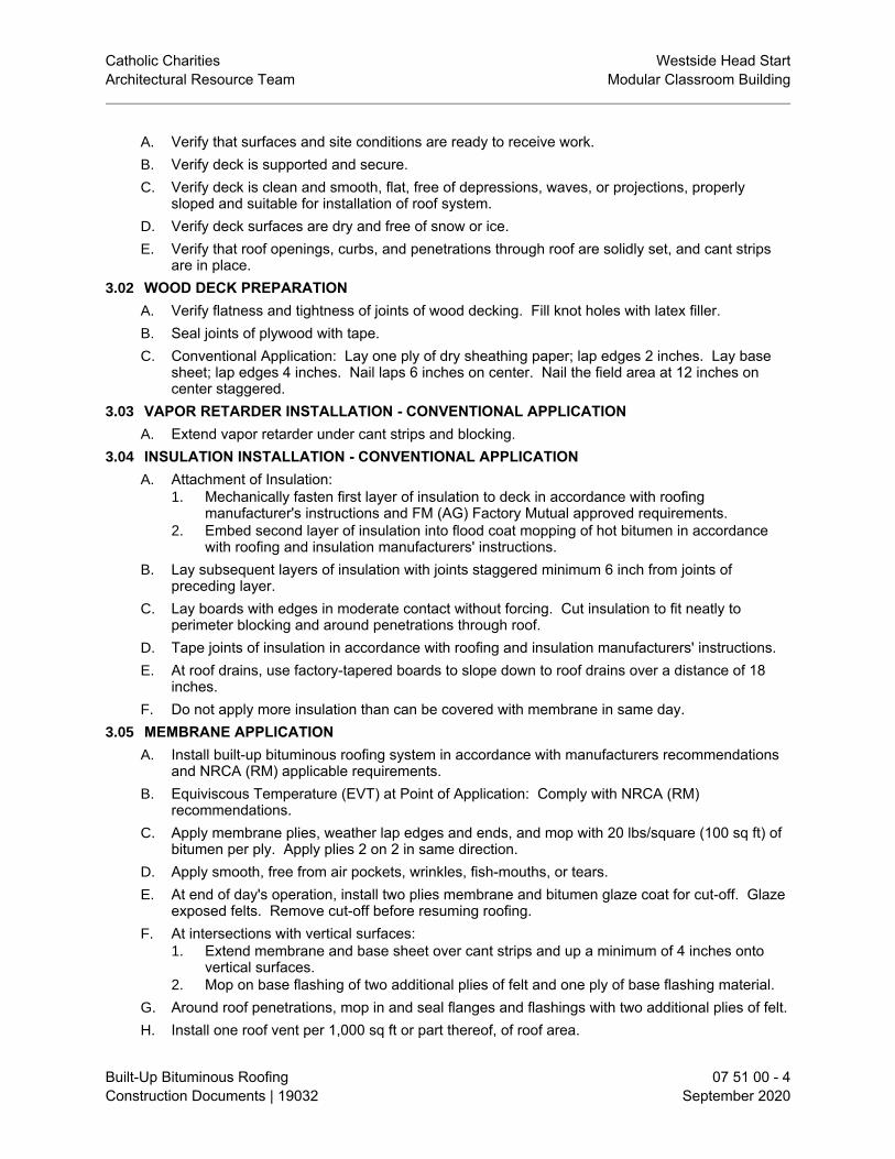
Catholic Charities Westside Head StartArchitectural Resource Team Modular Classroom Building
Built-Up Bituminous Roofing 07 51 00 - 4Construction Documents | 19032 September 2020
A. Verify that surfaces and site conditions are ready to receive work.B. Verify deck is supported and secure.C. Verify deck is clean and smooth, flat, free of depressions, waves, or projections, properly
sloped and suitable for installation of roof system.D. Verify deck surfaces are dry and free of snow or ice.E. Verify that roof openings, curbs, and penetrations through roof are solidly set, and cant strips
are in place.3.02 WOOD DECK PREPARATION
A. Verify flatness and tightness of joints of wood decking. Fill knot holes with latex filler.B. Seal joints of plywood with tape.C. Conventional Application: Lay one ply of dry sheathing paper; lap edges 2 inches. Lay base
sheet; lap edges 4 inches. Nail laps 6 inches on center. Nail the field area at 12 inches oncenter staggered.
3.03 VAPOR RETARDER INSTALLATION - CONVENTIONAL APPLICATIONA. Extend vapor retarder under cant strips and blocking.
3.04 INSULATION INSTALLATION - CONVENTIONAL APPLICATIONA. Attachment of Insulation:
1. Mechanically fasten first layer of insulation to deck in accordance with roofingmanufacturer's instructions and FM (AG) Factory Mutual approved requirements.
2. Embed second layer of insulation into flood coat mopping of hot bitumen in accordancewith roofing and insulation manufacturers' instructions.
B. Lay subsequent layers of insulation with joints staggered minimum 6 inch from joints ofpreceding layer.
C. Lay boards with edges in moderate contact without forcing. Cut insulation to fit neatly toperimeter blocking and around penetrations through roof.
D. Tape joints of insulation in accordance with roofing and insulation manufacturers' instructions.E. At roof drains, use factory-tapered boards to slope down to roof drains over a distance of 18
inches.F. Do not apply more insulation than can be covered with membrane in same day.
3.05 MEMBRANE APPLICATIONA. Install built-up bituminous roofing system in accordance with manufacturers recommendations
and NRCA (RM) applicable requirements.B. Equiviscous Temperature (EVT) at Point of Application: Comply with NRCA (RM)
recommendations.C. Apply membrane plies, weather lap edges and ends, and mop with 20 lbs/square (100 sq ft) of
bitumen per ply. Apply plies 2 on 2 in same direction.D. Apply smooth, free from air pockets, wrinkles, fish-mouths, or tears.E. At end of day's operation, install two plies membrane and bitumen glaze coat for cut-off. Glaze
exposed felts. Remove cut-off before resuming roofing.F. At intersections with vertical surfaces:
1. Extend membrane and base sheet over cant strips and up a minimum of 4 inches ontovertical surfaces.
2. Mop on base flashing of two additional plies of felt and one ply of base flashing material.G. Around roof penetrations, mop in and seal flanges and flashings with two additional plies of felt.H. Install one roof vent per 1,000 sq ft or part thereof, of roof area.

Catholic Charities Westside Head StartArchitectural Resource Team Modular Classroom Building
Built-Up Bituminous Roofing 07 51 00 - 5Construction Documents | 19032 September 2020
I. Coordinate installation of roof drains and related flashings.3.06 ROOF COATING INSTALLATION - CONVENTIONAL APPLICATION
A. Apply roof coatings in accordance with roofing and coating manufacturers' instructions.3.07 FIELD QUALITY CONTROL
A. See Section 01 40 00 - Quality Requirements, for general requirements for field quality controland inspection.
3.08 CLEANINGA. Remove bituminous markings from finished surfaces.B. In areas where finished surfaces are soiled by bitumen or other source of soiling caused by
work of this section, consult manufacturer of surfaces for cleaning advice and comply with theirdocumented instructions.
C. Repair or replace defaced or damaged finishes caused by work of this section.3.09 PROTECTION
A. Protect installed roofing and flashings from construction operations.B. Where traffic must continue over finished roof membrane, protect surfaces using durable
materials.END OF SECTION


Catholic Charities Westside Head StartArchitectural Resource Team Modular Classroom Building
Thermoplastic Membrane Roofing 07 54 00 - 1Construction Documents | 19032 September 2020
SECTION 07 54 00THERMOPLASTIC MEMBRANE ROOFING
PART 1 GENERAL1.01 SECTION INCLUDES
A. Mechanically attached system with thermoplastic roofing membrane.B. Deck sheathing.C. Cover boards.D. Flashings.
1.02 RELATED REQUIREMENTSA. Section 06 10 00 - Rough Carpentry: Wood nailers and curbs.B. Section 06 10 00 - Rough Carpentry: Wood cant strips.C. Section 07 72 00 - Roof Accessories: Roof-mounted units; prefabricated curbs.
1.03 REFERENCE STANDARDSA. ASTM C1177/C1177M - Standard Specification for Glass Mat Gypsum Substrate for Use as
Sheathing 2017.B. ASTM C1289 - Standard Specification for Faced Rigid Cellular Polyisocyanurate Thermal
Insulation Board 2019.C. ASTM C1396/C1396M - Standard Specification for Gypsum Board 2017.D. ASTM D6878/D6878M - Standard Specification for Thermoplastic Polyolefin Based Sheet
Roofing 2019.E. ASTM E1980 - Standard Practice for Calculating Solar Reflectance Index of Horizontal and
Low-Sloped Opaque Surfaces 2011 (Reapproved 2019).F. NRCA (RM) - The NRCA Roofing Manual 2019.G. NRCA (WM) - The NRCA Waterproofing Manual 2005.
1.04 SUBMITTALSA. See Section 01 30 00 - Administrative Requirements, for submittal procedures.B. Product Data: Provide data indicating membrane materials, flashing materials and fasteners .C. Shop Drawings: Submit drawings that indicate joint or termination detail conditions, conditions
of interface with other materials, and paver layout.D. Samples for Verification: Submit two samples 8 by 8 inches in size illustrating insulation,
colored coating, and [________] .E. Manufacturer's Certificate: Certify that products meet or exceed specified requirements.F. Manufacturer's Installation Instructions: Indicate membrane seaming precautions and
perimeter conditions requiring special attention.G. Manufacturer's Field Reports: Indicate procedures followed, ambient temperatures, humidity,
wind velocity during application, and supplementary instructions given.H. Manufacturer's Qualification Statement.I. Installer's Qualification Statement.J. Warranty Documentation:
1. Submit manufacturer warranty and ensure that forms have been completed in Owner'sname and registered with manufacturer.
2. Submit installer's certification that installation complies with warranty conditions forwaterproof membrane.
1.05 QUALITY ASSURANCE

Catholic Charities Westside Head StartArchitectural Resource Team Modular Classroom Building
Thermoplastic Membrane Roofing 07 54 00 - 2Construction Documents | 19032 September 2020
A. Manufacturer Qualifications: Company specializing in manufacturing the products specified inthis section with minimum three years of documented experience.
B. Installer Qualifications: Company specializing in performing the work of this section with atleast three years of documented experience.
1.06 DELIVERY, STORAGE, AND HANDLINGA. Deliver materials in manufacturer's original containers, dry and undamaged, with seals and
labels intact.B. Store materials in weather protected environment, clear of ground and moisture.C. Ensure storage and staging of materials does not exceed static and dynamic load-bearing
capacities of roof decking.D. Protect foam insulation from direct exposure to sunlight.
1.07 WARRANTYA. See Section 01 78 00 - Closeout Submittals, for additional warranty requirements.B. System Warranty: Provide manufacturer's system warranty agreeing to repair or replace
roofing that leaks or is damaged due to wind or other natural causes.1. Warranty Term: 20 years.2. For repair and replacement include costs of both material and labor in warranty.
PART 2 PRODUCTS2.01 MANUFACTURERS
A. Thermoplastic Polyolefin (TPO) Membrane Roofing Materials:1. Firestone Building Products, LLC; [_____]: www.firestonebpco.com/#sle.2. GAF ; EverGuard Extreme TPO 60 mil: www.gaf.com/#sle.3. Johns Manville ; 60 mil: www.jm.com/#sle.4. Versico, a division of Carlisle Construction Materials Inc; VersiWeld TPO:
www.versico.com/#sle.2.02 ROOFING - UNBALLASTED APPLICATIONS
A. Thermoplastic Membrane Roofing: One ply membrane, mechanically fastened .B. Roofing Assembly Requirements:
1. Solar Reflectance Index (SRI): Minimum of 64 based on three-year aged value; if three-year aged data is not available, minimum of 82 initial value.a. Calculate SRI in accordance with ASTM E1980.b. Field applied coating may not be used to achieve specified SRI.
2.03 MEMBRANE ROOFING AND ASSOCIATED MATERIALSA. Membrane Roofing Materials:
1. TPO: Thermoplastic polyolefin (TPO) complying with ASTM D6878/D6878M, sheetcontains reinforcing fabrics or scrims.a. Thickness: 60 mil, 0.060 inch, minimum.
2. Sheet Width: Factory fabricated into largest sheets possible.B. Seaming Materials: As recommended by membrane manufacturer.C. Membrane Fasteners: As recommended and approved by membrane manufacturer.D. Flexible Flashing Material: Same material as membrane.
2.04 DECK SHEATHINGA. Deck Sheathing: Gypsum sheathing complying with ASTM C1396/C1396M and ASTM
C1177/C1177M, paper faced.B. Deck Sheathing: Polyisocyanurate (ISO) board insulation, complying with ASTM C1289; Type
V, Faced with oriented strand board (OSB) or plywood on one major surface of the foam and a

Catholic Charities Westside Head StartArchitectural Resource Team Modular Classroom Building
Thermoplastic Membrane Roofing 07 54 00 - 3Construction Documents | 19032 September 2020
glass fiber reinforced cellulosic felt or uncoated or coated polymer-bonded glass fiber mat faceron the other major surface of the core foam.
2.05 COVER BOARDSA. Cover Board: Polyisocyanurate (ISO) board insulation complying with ASTM C1289, and the
following characteristics:1. Classification: Type II, Class 4 - Faced with coated or uncoated polymer-bonded glass
fiber mat facers on both major surfaces of the core foam.2.06 ACCESSORIES
A. Prefabricated Roofing Expansion Joint Flashing: Sheet butyl over closed-cell foam backingseamed to galvanized steel flanges.
B. Cant Strips: Wood, pressure preservative treated. See Section 06 10 00.C. Membrane Adhesive: As recommended by membrane manufacturer.D. Surface Conditioner for Adhesives: Compatible with membrane and adhesives.E. Thinners and Cleaners: As recommended by adhesive manufacturer, compatible with
membrane.PART 3 EXECUTION3.01 EXAMINATION
A. Verify that surfaces and site conditions are ready to receive work.B. Verify deck is supported and secure.C. Verify deck is clean and smooth, flat, free of depressions, waves, or projections, properly
sloped and suitable for installation of roof system.D. Verify deck surfaces are dry and free of snow or ice.E. Verify that roof openings, curbs, and penetrations through roof are solidly set, and cant strips
are in place.3.02 PREPARATION - WOOD DECK
A. Verify flatness and tightness of joints of wood decking. Fill knot holes with latex filler.3.03 INSTALLATION - GENERAL
A. Perform work in accordance with manufacturer's instructions, NRCA (RM), and NRCA (WM)applicable requirements.
B. Do not apply roofing membrane during unsuitable weather.C. Do not apply roofing membrane when ambient temperature is outside the temperature range
recommended by manufacturer.D. Do not apply roofing membrane to damp or frozen deck surface or when precipitation is
expected or occurring.E. Do not expose materials vulnerable to water or sun damage in quantities greater than can be
weatherproofed the same day.3.04 MEMBRANE APPLICATION
A. Roll out membrane, free from wrinkles or tears. Place sheet into place without stretching.B. Shingle joints on sloped substrate in direction of drainage.C. Overlap edges and ends and seal seams by contact adhesive, minimum 3 inches. Seal
permanently waterproof. Apply uniform bead of sealant to joint edge.D. Mechanical Attachment: Apply membrane and mechanical attachment devices in accordance
with manufacturer's instructions.E. At intersections with vertical surfaces:
1. Extend membrane over cant strips and up a minimum of 4 inches onto vertical surfaces.

Catholic Charities Westside Head StartArchitectural Resource Team Modular Classroom Building
Thermoplastic Membrane Roofing 07 54 00 - 4Construction Documents | 19032 September 2020
2. Fully adhere flexible flashing over membrane and up to nailing strips.F. Around roof penetrations, seal flanges and flashings with flexible flashing.G. Install roofing expansion joints where indicated. Make joints watertight.
1. Install prefabricated joint components in accordance with manufacturer's instructions.H. Coordinate installation of roof drains and sumps and related flashings.
3.05 FIELD QUALITY CONTROLA. See Section 01 40 00 - Quality Requirements, for general requirements for field quality control
and inspection.B. Require site attendance of roofing and insulation material manufacturers daily during
installation of the work.3.06 CLEANING
A. See Section 01 74 19 - Construction Waste Management and Disposal, for additionalrequirements.
B. Remove bituminous markings from finished surfaces.C. In areas where finished surfaces are soiled by work of this section, consult manufacturer of
surfaces for cleaning advice and comply with their documented instructions.D. Repair or replace defaced or damaged finishes caused by work of this section.
3.07 PROTECTIONA. Protect installed roofing and flashings from construction operations.B. Where traffic must continue over finished roof membrane, protect surfaces using durable
materials.END OF SECTION

Catholic Charities Westside Head StartArchitectural Resource Team Modular Classroom Building
Sheet Metal Flashing and Trim 07 62 00 - 1Construction Documents | 19032 September 2020
SECTION 07 62 00SHEET METAL FLASHING AND TRIM
PART 1 GENERAL1.01 SECTION INCLUDES
A. Fabricated sheet metal items, including flashings, counterflashings, gutters, downspouts, andother items indicated in Schedule.
1.02 RELATED REQUIREMENTSA. Section 06 10 00 - Rough Carpentry: Wood nailers for sheet metal work.B. Section 07 41 13 - Sheet Metal RoofingC. Section 07 72 00 - Roof Accessories: Manufactured metal roof curbs.D. Section 07 92 00 - Joint Sealants: Sealing non-lap joints between sheet metal fabrications and
adjacent construction.1.03 REFERENCE STANDARDS
A. AAMA 2604 - Voluntary Specification, Performance Requirements and Test Procedures forHigh Performance Organic Coatings on Aluminum Extrusions and Panels (with Coil CoatingAppendix) 2017a.
B. AAMA 2605 - Voluntary Specification, Performance Requirements and Test Procedures forSuperior Performing Organic Coatings on Aluminum Extrusions and Panels (with Coil CoatingAppendix) 2017a.
C. ASTM A653/A653M - Standard Specification for Steel Sheet, Zinc-Coated (Galvanized) or Zinc-Iron Alloy-Coated (Galvannealed) by the Hot-Dip Process 2020.
D. ASTM B209 - Standard Specification for Aluminum and Aluminum-Alloy Sheet and Plate 2014.E. ASTM B209M - Standard Specification for Aluminum and Aluminum-Alloy Sheet and Plate
(Metric) 2014.F. ASTM C920 - Standard Specification for Elastomeric Joint Sealants 2018.G. ASTM D4586/D4586M - Standard Specification for Asphalt Roof Cement, Asbestos-Free 2007
(Reapproved 2018).H. CDA A4050 - Copper in Architecture - Handbook current edition.I. SMACNA (ASMM) - Architectural Sheet Metal Manual 2012.
1.04 SUBMITTALSA. See Section 01 30 00 - Administrative Requirements, for submittal procedures.
1.05 QUALITY ASSURANCEA. Perform work in accordance with SMACNA (ASMM) and CDA A4050 requirements and
standard details, except as otherwise indicated.B. Maintain one copy of each document on site.C. Fabricator and Installer Qualifications: Company specializing in sheet metal work with five
years of documented experience.1.06 DELIVERY, STORAGE, AND HANDLING
A. Stack material to prevent twisting, bending, and abrasion, and to provide ventilation. Slopemetal sheets to ensure drainage.
B. Prevent contact with materials that could cause discoloration or staining.PART 2 PRODUCTS2.01 SHEET MATERIALS

Catholic Charities Westside Head StartArchitectural Resource Team Modular Classroom Building
Sheet Metal Flashing and Trim 07 62 00 - 2Construction Documents | 19032 September 2020
A. Galvanized Steel: ASTM A653/A653M, with G90/Z275 zinc coating; minimum 24 gage,(0.0239 inch) thick base metal.
B. Pre-Finished Galvanized Steel: ASTM A653/A653M, with G90/Z275 zinc coating; minimum 24gage, (0.0239) inch thick base metal, shop pre-coated with PVDF coating.1. PVDF (Polyvinylidene Fluoride) Coating: Superior Performance Organic Finish, AAMA
2605; multiple coat, thermally cured fluoropolymer finish system.C. Pre-Finished Aluminum: ASTM B209 (ASTM B209M) ; 20 gage, (0.032 inch) thick; plain finish
shop pre-coated with fluoropolymer coating.1. Fluoropolymer Coating: High Performance Organic Finish, AAMA 2604; multiple coat,
thermally cured fluoropolymer finish system.2. Color: As selected by Architect from manufacturer's standard colors.
2.02 FABRICATIONA. Form sections true to shape, accurate in size, square, and free from distortion or defects.B. Form pieces in longest possible lengths.C. Hem exposed edges on underside 1/2 inch; miter and seam corners.D. Form material with flat lock seams, except where otherwise indicated; at moving joints, use
sealed lapped, bayonet-type or interlocking hooked seams.E. Fabricate corners from one piece with minimum 18 inch long legs; seam for rigidity, seal with
sealant.F. Fabricate flashings to allow toe to extend 2 inches over roofing gravel. Return and brake
edges.2.03 GUTTER AND DOWNSPOUT FABRICATION
A. Downspouts: Rectangular profile.B. Downspout Shoes: Steel.C. Seal metal joints.
2.04 ACCESSORIESA. Fasteners: Galvanized steel, with soft neoprene washers.B. Primer: Zinc chromate type.C. Concealed Sealants: Non-curing butyl sealant.D. Exposed Sealants: ASTM C920; elastomeric sealant, with minimum movement capability as
recommended by manufacturer for substrates to be sealed; color to match adjacent material.E. Plastic Cement: ASTM D4586/D4586M, Type I.
PART 3 EXECUTION3.01 PREPARATION
A. Install starter and edge strips, and cleats before starting installation.B. Back paint concealed metal surfaces with protective backing paint to a minimum dry film
thickness of 15 mil.3.02 INSTALLATION
A. Secure flashings in place using concealed fasteners, and use exposed fasteners only wherepermitted..
B. Apply plastic cement compound between metal flashings and felt flashings.C. Fit flashings tight in place; make corners square, surfaces true and straight in planes, and lines
accurate to profiles.D. Secure gutters and downspouts in place with concealed fasteners.

Catholic Charities Westside Head StartArchitectural Resource Team Modular Classroom Building
Sheet Metal Flashing and Trim 07 62 00 - 3Construction Documents | 19032 September 2020
E. Connect downspouts to downspout shoes, and seal connection watertight.3.03 FIELD QUALITY CONTROL
A. See Section 01 40 00 - Quality Requirements, for field inspection requirements.B. Inspection will involve surveillance of work during installation to ascertain compliance with
specified requirements.END OF SECTION


Catholic Charities Westside Head StartArchitectural Resource Team Modular Classroom Building
Roof Accessories 07 72 00 - 1Construction Documents | 19032 September 2020
SECTION 07 72 00ROOF ACCESSORIES
PART 1 GENERAL1.01 SECTION INCLUDES
A. Curbs.B. Roof penetrations mounting curbs.
1.02 RELATED REQUIREMENTSA. Section 07 51 00 - Built-Up Bituminous RoofingB. Section 07 62 00 - Sheet Metal Flashing and Trim: Roof accessory items fabricated from sheet
metal.1.03 REFERENCE STANDARDS1.04 SUBMITTALS
A. See Section 01 30 00 - Administrative Requirements, for submittal procedures.B. Product Data: Manufacturer's data sheets on each product to be used.
1. Preparation instructions and recommendations.2. Storage and handling requirements and recommendations.3. Installation methods.4. Maintenance requirements.
C. Shop Drawings: Submit detailed layout developed for this project and provide dimensionedlocation and number for each type of roof accessory.
D. Warranty Documentation:1. Submit manufacturer warranty.2. Ensure that forms have been completed in Owner's name and registered with
manufacturer.1.05 DELIVERY, STORAGE, AND HANDLING
A. Store products in manufacturer's unopened packaging until ready for installation.B. Store products under cover and elevated above grade.
1.06 WARRANTYA. See Section 01 70 00 - Closeout Submittals, for additional warranty requirements.
PART 2 PRODUCTS2.01 ROOF CURBS
A. Manufacturers:1. AES Industries Inc: www.aescurb.com/#sle.2. The Pate Company: www.patecurbs.com/#sle.
B. Roof Curbs Mounting Assemblies: Factory fabricated hollow sheet metal construction,internally reinforced, and capable of supporting superimposed live and dead loads anddesignated equipment load with fully mitered and sealed corner joints welded or mechanicallyfastened, and integral counterflashing with top and edges formed to shed water.1. Roof Curb Mounting Substrate: Curb substrate consists of standing seam metal roof
panel system.2. Sheet Metal Material:
a. Aluminum: 0.080 inch minimum thickness, with 3003 alloy, and H14 temper.3. Fabricate curb bottom and mounting flanges for installation directly on metal roof panel
system to match slope and configuration of system.a. Extend side flange to next adjacent roof panel seam and comply with seam
configurations and seal connection, providing at least 6 inch clearance between curb

Catholic Charities Westside Head StartArchitectural Resource Team Modular Classroom Building
Roof Accessories 07 72 00 - 2Construction Documents | 19032 September 2020
and metal roof panel flange allowing water to properly flow past curb.b. Where side of curb aligns with metal roof panel flange, attach fasteners on upper
slope of flange to curb connection allowing water to flow past below fasteners, andseal connection.
c. Maintain at least 12 inch clearance from curb, and lap upper curb flange on undersideof down sloping metal roof panel, and seal connection.
d. Lap lower curb flange overtop of down sloping metal roof panel and seal connection.4. Provide layouts and configurations indicated on drawings.
PART 3 EXECUTION3.01 EXAMINATION
A. Do not begin installation until substrates have been properly prepared.B. If substrate preparation is the responsibility of another installer, notify Architect of unsatisfactory
preparation before proceeding.3.02 PREPARATION
A. Clean surfaces thoroughly prior to installation.B. Prepare surfaces using methods recommended by manufacturer for achieving acceptable
results for applicable substrate under project conditions.3.03 INSTALLATION
A. Install in accordance with manufacturer's instructions, in manner that maintains roofing systemweather-tight integrity.
3.04 CLEANINGA. Clean installed work to like-new condition.
3.05 PROTECTIONA. Protect installed products until completion of project.B. Touch-up, repair or replace damaged products before Date of Substantial Completion.
END OF SECTION

Catholic Charities Westside Head StartArchitectural Resource Team Modular Classroom Building
Joint Sealants 07 92 00 - 1Construction Documents | 19032 September 2020
SECTION 07 92 00JOINT SEALANTS
PART 1 GENERAL1.01 SECTION INCLUDES
A. Nonsag gunnable joint sealants.B. Joint backings and accessories.
1.02 RELATED REQUIREMENTSA. Section 01 61 16 - Volatile Organic Compound (VOC) Content Restrictions: Additional
requirements for sealants and primers.B. Section 08 71 00 - Door Hardware: Setting exterior door thresholds in sealant.C. Section 08 80 00 - Glazing: Glazing sealants and accessories.D. Section 09 21 16 - GYPSUM BOARD ASSEMBLIES: Sealing acoustical and sound-rated walls
and ceilings.E. Section 09 30 00 - Tiling: Sealant between tile and plumbing fixtures and at junctions with
other materials and changes in plane.1.03 REFERENCE STANDARDS
A. ASTM C834 - Standard Specification for Latex Sealants 2017.B. ASTM C919 - Standard Practice for Use of Sealants in Acoustical Applications 2018.C. ASTM C920 - Standard Specification for Elastomeric Joint Sealants 2018.D. ASTM C1193 - Standard Guide for Use of Joint Sealants 2016.E. ASTM C1248 - Standard Test Method for Staining of Porous Substrate by Joint Sealants 2018.F. ASTM C1330 - Standard Specification for Cylindrical Sealant Backing for Use with Cold Liquid-
Applied Sealants 2018.G. SCAQMD 1168 - Adhesive and Sealant Applications 1989 (Amended 2017).
1.04 SUBMITTALSA. See Section 01 30 00 - Administrative Requirements, for submittal procedures.B. Product Data for Sealants: Submit 2 sets of manufacturer's technical data sheets for each
product to be used, that includes the following:1. Physical characteristics, including movement capability, VOC content, hardness, cure
time, and color availability.2. List of backing materials approved for use with the specific product.3. Substrates that product is known to satisfactorily adhere to and with which it is compatible.4. Substrates the product should not be used on.5. Sample product warranty.
C. Color Cards for Selection: Where sealant color is not specified, submit manufacturer's colorcards showing standard colors available for selection.
D. Sustainable Design Documentation: For sealants and primers, submit VOC content andemissions documentation as specified in Section 01 61 16.
1.05 QUALITY ASSURANCEA. Installer Qualifications: Company specializing in performing the work of this section and with at
least three years of documented experience.B. Field Adhesion Testing: Perform preconstruction adhesion testing for each type of sealant and
substrate as follows:1. Arrange for manufacturer’s field technical representative to be present during testing.2. Install sealant in test joints in minimum 60 inch lengths.

Catholic Charities Westside Head StartArchitectural Resource Team Modular Classroom Building
Joint Sealants 07 92 00 - 2Construction Documents | 19032 September 2020
3. Test joints by standard field adhesion hand pull test.4. For joints with dissimilar substrates, test adhesion to each substrate separately as
recommended by sealant manufacturer.5. Conduct number of field adhesion tests for each type of sealant and each type of
substrate as follows:a. Not less than 10 tests for the first 1,000 feet of installed sealant and 1 test for each
additional 1,000 feet of sealant installed, or 1 test per floor per elevation.6. Document results of field adhesion tests and record results in field adhesion test log.7. Include in log data on pull distance used to test each joint sealant.8. Include data on joints where material connected with pull portion of sealant failed to
adhere to joint substrate or tore cohesively.9. Inspect joints and record data for the following:
a. Complete fill.b. No voids.c. Joint dimensions matching those of manufacturer’s recommended details.
10. For sealants that fail adhesively, retest until satisfactory adhesion is obtained.11. Do not install joint sealants that fail to adhere to joint substrates during testing.12. Repair sealant test areas by removing damaged materials and applying sealant to test
area using same procedure used to originally install the sealant.C. Field Color and Workmanship Samples: Caulk a section of joint as directed, under job
conditions, at least 7 days prior to start of work for review by Architect. When approved,sample shall be used as a standard of comparison for remainder of work.
1.06 WARRANTYA. See Section 01 70 00 - Closeout Submittals, for additional warranty requirements.B. Provide warranty, in writing and signed jointly by the installer and sealant manufacturer, to
replace sealants which fail at no additional cost to the Owner because of loss of cohesion oradhesion, or do not cure, and which fail to achieve air-tight and water-tight seal as follows:1. Sealant Types "A1" : 20 years.2. Sealant Types "C", "D," and "E" : 2 years.
C. Warranty: Include coverage for installed sealants and accessories that fail to achieve watertight seal , exhibit loss of adhesion or cohesion, or do not cure.
PART 2 PRODUCTS2.01 MANUFACTURERS
A. Non-Sag Sealants: Permits application in joints on vertical surfaces without sagging orslumping.1. BASF Construction Chemicals-Building Systems: www.buildingsystems.basf.com.2. Dow Corning Corporation: www.dowcorning.com/construction/#sle.3. Franklin International, Inc: www.titebond.com/#sle.4. Pecora Corporation: www.pecora.com.5. Sika Corporation: www.usa-sika.com/#sle.6. Sonneborn/Chemrex.
2.02 JOINT SEALANT APPLICATIONSA. Scope:
1. Exterior Joints: Seal open joints, whether or not the joint is indicated on drawings, unlessspecifically indicated not to be sealed. Exterior joints to be sealed include, but are notlimited to, the following items.a. Wall expansion and control joints.b. Joints between door, window, and other frames and adjacent construction.c. Joints between different exposed materials.d. Openings below ledge angles in masonry.

Catholic Charities Westside Head StartArchitectural Resource Team Modular Classroom Building
Joint Sealants 07 92 00 - 3Construction Documents | 19032 September 2020
e. Other joints indicated below.2. Interior Joints: Do not seal interior joints unless specifically indicated to be sealed. Interior
joints to be sealed include, but are not limited to, the following items.a. Joints between door, window, and other frames and adjacent construction.b. In sound-rated wall and ceiling assemblies, gaps at electrical outlets, wiring devices,
piping, and other openings; between wall/ceiling and other construction; and otherflanking sound paths.
c. Other joints indicated below.3. Do not seal the following types of joints.
a. Joints indicated to be treated with manufactured expansion joint cover or some othertype of sealing device.
b. Joints where sealant is specified to be provided by manufacturer of product to besealed.
c. Joints where installation of sealant is specified in another section.B. Interior Wet Areas: restrooms and break rooms; fixtures in wet areas include plumbing fixtures,
countertops, cabinets, and other similar items.C. Sound-Rated Assemblies: Walls and ceilings identified as "STC-rated", "sound-rated", or
"acoustical".2.03 JOINT SEALANTS - GENERAL
A. Sealants and Primers: Provide products having lower volatile organic compound (VOC)content than indicated in SCAQMD 1168.
B. Single Source Responsibility for Joint Sealer Materials:C. Obtain joint sealer materials from a single manufacturer for each different product required.
1. The following requirement is due to incompatibility problems experienced with differentproducts which come in contact with each other at locations such as windowwalls. Forexample, Tremco urethane sealants and Dow silicone sealants are NOT compatible.
2. If sealants from separate manufacturers must be used and could come in contact witheach other, provide written certification from every manufacturer involved that the sealantsare compatible and will adhere to each other
D. Sealants, primers, back-up materials, preformed joint fillers, bond breakers and relatedmaterials shall be compatible with adjoining materials.
2.04 NONSAG JOINT SEALANTSA. Type A-1 - Non-Staining Silicone Sealant: ASTM C920, Grade NS, Uses M and A; not
expected to withstand continuous water immersion or traffic.1. Movement Capability: Plus 100 percent, minus 50 percent, minimum.2. Non-Staining To Porous Stone: Non-staining to light-colored natural stone when tested in
accordance with ASTM C1248.3. Dirt Pick-Up: Reduced dirt pick-up compared to other silicone sealants.4. Service Temperature Range: Minus 20 to 180 degrees F.
B. Type D - Mildew-Resistant Silicone Sealant: ASTM C920, Grade NS, Uses M and A; singlecomponent, mildew resistant; not expected to withstand continuous water immersion or traffic.1. Color: White.2. Manufacturers:
a. Sika Corporation; Sikasil GP: www.usa-sika.com/#sle.b. Dow Corning 786.c. Tremco Tremsil 200.
C. Type C - Polyurethane Sealant for Continuous Water Immersion: ASTM C920, Grade NS,Uses M and A; single or multicomponent; explicitly approved by manufacturer for continuouswater immersion; suitable for traffic exposure when recessed below traffic surface .1. Movement Capability: Plus and minus 35 percent, minimum.

Catholic Charities Westside Head StartArchitectural Resource Team Modular Classroom Building
Joint Sealants 07 92 00 - 4Construction Documents | 19032 September 2020
2. Color: Match adjacent finished surfaces.3. Service Temperature Range: Minus 40 to 180 degrees F.4. Manufacturers:
a. Sika Corporation; Sikaflex-1a: www.usa-sika.com/#sle.b. Sonneborn NP-1.c. Pecora 345.
D. Type E - Acrylic Emulsion Latex: Water-based; ASTM C834, single component, non-staining,non-bleeding, non-sagging; not intended for exterior use. Acoustic Sealant1. Color: To be selected by Architect from manufacturer's standard range.2. Manufacturers:
a. Franklin International, Inc; Titebond GREENchoice Acoustical Smoke & SoundSealant: www.titebond.com/#sle.
b. Hilti, Inc; CP 506 Smoke and Acoustical Sealant: www.us.hilti.com/#sle.c. Pecora Corporation; AC-20 +Silicone: www.pecora.com/#sle.
2.05 ACCESSORIESA. Backer Rod: Cylindrical cellular foam rod with surface that sealant will not adhere to,
compatible with specific sealant used, and recommended by backing and sealantmanufacturers for specific application.1. Type for Joints Subject to Pedestrian or Vehicular Traffic: ASTM C1330; Type B - Bi-
Cellular Polyethylene.2. Closed Cell and Bi-Cellular: 25 to 33 percent larger in diameter than joint width.
B. Backing Tape: Self-adhesive polyethylene tape with surface that sealant will not adhere to andrecommended by tape and sealant manufacturers for specific application.
C. Masking Tape: Self-adhesive, nonabsorbent, non-staining, removable without adhesiveresidue, and compatible with surfaces adjacent to joints and sealants.
D. Joint Cleaner: Non-corrosive and non-staining type, type recommended by sealantmanufacturer; compatible with joint forming materials.
E. Primers: Type recommended by sealant manufacturer to suit application; non-staining.PART 3 EXECUTION3.01 EXAMINATION
A. Verify that joints are ready to receive work.B. Verify that backing materials are compatible with sealants.C. Verify that backer rods are of the correct size.
3.02 PREPARATIONA. Remove loose materials and foreign matter that could impair adhesion of sealant.B. Clean joints, and prime as necessary, in accordance with manufacturer's instructions.C. Perform preparation in accordance with manufacturer's instructions and ASTM C1193.D. Mask elements and surfaces adjacent to joints from damage and disfigurement due to sealant
work; be aware that sealant drips and smears may not be completely removable.E. Concrete Floor Joints That Will Be Exposed in Completed Work: Test joint filler in
inconspicuous area to verify that it does not stain or discolor slab.3.03 INSTALLATION
A. Perform work in accordance with sealant manufacturer's requirements for preparation ofsurfaces and material installation instructions.
B. Perform installation in accordance with ASTM C1193.C. Perform acoustical sealant application work in accordance with ASTM C919.

Catholic Charities Westside Head StartArchitectural Resource Team Modular Classroom Building
Joint Sealants 07 92 00 - 5Construction Documents | 19032 September 2020
D. Install bond breaker backing tape where backer rod cannot be used.E. Install sealant free of air pockets, foreign embedded matter, ridges, and sags, and without
getting sealant on adjacent surfaces.F. Do not install sealant when ambient temperature is outside manufacturer's recommended
temperature range, or will be outside that range during the entire curing period, unlessmanufacturer's approval is obtained and instructions are followed.
G. Nonsag Sealants: Tool surface concave, unless otherwise indicated; remove masking tapeimmediately after tooling sealant surface.
H. Concrete Floor Joint Filler: After full cure, shave joint filler flush with top of concrete slab.3.04 FIELD QUALITY CONTROL
A. Perform field quality control inspection/testing as specified in PART 1 under QUALITYASSURANCE article.
B. Remove and replace failed portions of sealants using same materials and procedures asindicated for original installation.
3.05 SCHEDULEA. Expansion and Control Joints:
1. Glass (except insulating glass or special coated glass), aluminum, E.I.F.S., Natural Stone,and plastics: Type "A-1".
B. Non-expanding Joints:1. Glass (except insulating glass or special coated glass), aluminum, E.I.F.S., Natural Stone,
and plastics: Type "A-1".C. Mechanical (ductwork and air conditioning): Type "C".D. Plumbing Fixtures (around toilet, bath, kitchen fixtures, and food service equipment): Type "D".E. Acoustical (acoustical applications where sealant is required): Type "E".
END OF SECTION


Catholic Charities Westside Head StartArchitectural Resource Team Modular Classroom Building
Hollow Metal Doors and Frames 08 11 13 - 1Construction Documents | 19032 September 2020
SECTION 08 11 13HOLLOW METAL DOORS AND FRAMES
PART 1 GENERAL1.01 SECTION INCLUDES
A. Hollow metal frames for wood doors.B. Fire-rated hollow metal doors and frames.C. Thermally insulated hollow metal doors with frames.D. Hollow metal borrowed lites glazing frames.
1.02 RELATED REQUIREMENTSA. Section 08 71 00 - Door Hardware.B. Section 09 91 00 - Painting.C. Section 08 80 00 - Glazing: Glass for doors and borrowed lites.
1.03 REFERENCE STANDARDSA. ADA Standards - Americans with Disabilities Act (ADA) Standards for Accessible Design 2010.B. ANSI/SDI A250.4 - Test Procedure and Acceptance Criteria for Physical Endurance for Steel
Doors, Frames and Frame Anchors 2011.C. ANSI/SDI A250.8 - Specifications for Standard Steel Doors and Frames (SDI-100) 2017.D. ANSI/SDI A250.10 - Test Procedure and Acceptance Criteria for Prime Painted Steel Surfaces
for Steel Doors and Frames 2011.E. ASTM A653/A653M - Standard Specification for Steel Sheet, Zinc-Coated (Galvanized) or Zinc-
Iron Alloy-Coated (Galvannealed) by the Hot-Dip Process 2020.F. ASTM A1008/A1008M - Standard Specification for Steel, Sheet, Cold-Rolled, Carbon,
Structural, High-Strength Low-Alloy, High-Strength Low-Alloy with Improved Formability,Solution Hardened, and Bake Hardenable 2018.
G. ASTM A1011/A1011M - Standard Specification for Steel, Sheet and Strip, Hot-Rolled, Carbon,Structural, High-Strength Low-Alloy, High-Strength Low-Alloy with Improved Formability, andUltra-High Strength 2018a.
H. ICC A117.1 - Accessible and Usable Buildings and Facilities 2017.I. NAAMM HMMA 840 - Guide Specifications For Receipt, Storage and Installation of Hollow
Metal Doors and Frames 2007.1.04 SUBMITTALS
A. See Section 01 30 00 - Administrative Requirements, for submittal procedures.B. Product Data: 2 sets of materials and details of design and construction, hardware locations,
reinforcement type and locations, anchorage and fastening methods, and finishes.C. Shop Drawings: Details of each opening, showing elevations, glazing, frame profiles, and any
indicated finish requirements.D. Manufacturer's Qualification Statement.
1.05 QUALITY ASSURANCEA. Manufacturer Qualifications: Provide hollow metal doors and frames from SDI Certified
manufacturer: www.steeldoor.org/sdicertified.php/#sle.1.06 DELIVERY, STORAGE, AND HANDLING
A. Comply with NAAMM HMMA 840 or ANSI/SDI A250.8 (SDI-100) in accordance with specifiedrequirements.
PART 2 PRODUCTS

Catholic Charities Westside Head StartArchitectural Resource Team Modular Classroom Building
Hollow Metal Doors and Frames 08 11 13 - 2Construction Documents | 19032 September 2020
2.01 MANUFACTURERSA. Hollow Metal Doors and Frames:
1. Republic Doors, an Allegion brand: www.republicdoor.com/#sle.2. Steelcraft, an Allegion brand: www.allegion.com/#sle.
2.02 PERFORMANCE REQUIREMENTSA. Requirements for Hollow Metal Frames:
1. Steel used for fabrication of frames shall comply with one or more of the followingrequirements; Galvannealed steel conforming to ASTM A653/A653M, cold-rolled steelconforming to ASTM A1008/A1008M, or hot-rolled pickled and oiled (HRPO) steelconforming to ASTM A1011/A1011M, Commercial Steel (CS) Type B for each.
2. Accessibility: Comply with ICC A117.1 and ADA Standards.B. Combined Requirements: If a particular door and frame unit is indicated to comply with more
than one type of requirement, comply with the specified requirements for each type; forinstance, an exterior door that is also indicated as being sound-rated must comply with therequirements specified for exterior doors and for sound-rated doors; where two requirementsconflict, comply with the most stringent.
2.03 HOLLOW METAL DOORSA. Door Finish: Factory primed and field finished.B. Exterior Doors: Thermally insulated.
1. Based on SDI Standards: ANSI/SDI A250.8 (SDI-100).a. Level 2 - Heavy-duty.b. Physical Performance Level B 500 000 cycles; in accordance with ANSI/SDI A250.4.c. Model 1 - Full Flush.d. Door Face Metal Thickness: 18 gage, 0.042 inch, minimum.
2. Door Core Material: Manufacturers standard core material/construction and in compliancewith requirements.
3. Door Thickness: 1-3/4 inch, nominal.C. Interior Doors, Non-Fire-Rated:
1. Based on SDI Standards: ANSI/SDI A250.8 (SDI-100).a. Level 1 - Standard-duty.b. Physical Performance Level C, 250,000 cycles; in accordance with ANSI/SDI A250.4.c. Model 1 - Full Flush.d. Door Face Metal Thickness: 20 gage, 0.032 inch, minimum.
2. Door Thickness: 1-3/4 inch, nominal.3. Door Finish: Factory primed and field finished.
2.04 HOLLOW METAL FRAMESA. Comply with standards and/or custom guidelines as indicated for corresponding door in
accordance with applicable door frame requirements.B. Frame Finish: Factory primed and field finished.C. Exterior Door Frames: Full profile/continuously welded type.
1. Weatherstripping: Separate, see Section 08 71 00.D. Interior Door Frames, Non-Fire Rated: Knock-down type, TA-8 standard steel.
1. Terminated Stops: Provide at interior doors; closed end stop terminated 6 inch,maximum, above floor at 45 degree angle.
2. Frame Metal Thickness: 18 gage, 0.042 inch, minimum.3. Frame Finish: Alumatone.
E. Frames for Wood Doors: Comply with frame requirements in accordance with correspondingdoor.

Catholic Charities Westside Head StartArchitectural Resource Team Modular Classroom Building
Hollow Metal Doors and Frames 08 11 13 - 3Construction Documents | 19032 September 2020
F. Borrowed Lites Glazing Frames: Construction and face dimensions to match door frames, andas indicated on drawings.
2.05 FINISHESA. Primer: Rust-inhibiting, complying with ANSI/SDI A250.10, door manufacturer's standard.
2.06 ACCESSORIESA. Glazing: As specified in Section 08 80 00, factory installed.B. Silencers: Resilient rubber, fitted into drilled hole; provide three on strike side of single door,
three on center mullion of pairs, and two on head of pairs without center mullions.C. Temporary Frame Spreaders: Provide for factory- or shop-assembled frames.
PART 3 EXECUTION3.01 EXAMINATION
A. Verify existing conditions before starting work.B. Verify that opening sizes and tolerances are acceptable.C. Verify that finished walls are in plane to ensure proper door alignment.
3.02 PREPARATION3.03 INSTALLATION
A. Install frames in accordance with manufacturer's instructions and related requirements ofspecified door and frame standards or custom guidelines indicated.
B. Coordinate frame anchor placement with wall construction.C. Install door hardware as specified in Section 08 71 00.
3.04 TOLERANCESA. Maximum Diagonal Distortion: 1/16 inch measured with straight edge, corner to corner.
3.05 ADJUSTINGA. Adjust for smooth and balanced door movement.
END OF SECTION


Catholic Charities Westside Head StartArchitectural Resource Team Modular Classroom Building
Flush Wood Doors 08 14 16 - 1Construction Documents | 19032 September 2020
SECTION 08 14 16FLUSH WOOD DOORS
PART 1 GENERAL1.01 SECTION INCLUDES
A. Flush wood doors; flush configuration; non-rated.1.02 RELATED REQUIREMENTS
A. Section 08 11 13 - Hollow Metal Doors and Frames.B. Section 08 71 00 - Door Hardware.C. Section 09 21 16 - GYPSUM BOARD ASSEMBLIES: Bullet-resistant sheathing and wallboard
for bullet-resistant partitions and walls.1.03 REFERENCE STANDARDS
A. AWI (QCP) - Quality Certification Program Current Edition.B. AWI/AWMAC/WI (AWS) - Architectural Woodwork Standards 2014, with Errata (2018).
1.04 SUBMITTALSA. See Section 01 30 00 - Administrative Requirements, for submittal procedures.B. Product Data: Indicate door core materials and construction; veneer species, type and
characteristics.C. Shop Drawings: Show doors and frames, elevations, sizes, types, swings, undercuts, beveling,
blocking for hardware, factory machining, factory finishing, cutouts for glazing and other details. 2 sets required.1. Provide information as required by AWI/AWMAC/WI (AWS).
D. Samples: Submit two samples of door construction, 6 by 6 inch in size cut from top corner ofdoor.
E. Manufacturer's Installation Instructions: Indicate special installation instructions.F. Installer's Qualification Statement.G. Warranty, executed in Owner's name.
1.05 QUALITY ASSURANCEA. Manufacturer Qualifications: Company specializing in manufacturing the products specified in
this section, with not less than three years of documented experience.1. Accredited participant in the specified certification program prior to the commencement of
fabrication and throughout the duration of the project.B. Quality Certification:
1. Comply with AWI (QCP) woodwork association quality certification service/program inaccordance with requirements for work specified in this section: www.awiqcp.org/#sle.
1.06 DELIVERY, STORAGE, AND HANDLINGA. Package, deliver and store doors in accordance with specified quality standard.B. Accept doors on site in manufacturer's packaging. Inspect for damage.C. Protect doors with resilient packaging sealed with heat shrunk plastic. Do not store in damp or
wet areas; or in areas where sunlight might bleach veneer. Seal top and bottom edges withtinted sealer if stored more than one week. Break seal on site to permit ventilation.
1.07 WARRANTYA. See Section 01 78 00 - Closeout Submittals, for additional warranty requirements.B. Interior Doors: Provide manufacturer's warranty for the life of the installation.

Catholic Charities Westside Head StartArchitectural Resource Team Modular Classroom Building
Flush Wood Doors 08 14 16 - 2Construction Documents | 19032 September 2020
C. Include coverage for delamination of veneer, warping beyond specified installation tolerances,defective materials, and telegraphing core construction.
PART 2 PRODUCTS2.01 MANUFACTURERS
A. Wood Veneer Faced Doors:1. Eggers Industries: www.eggersindustries.com/#sle.2. Marshfield DoorSystems, Inc: www.marshfielddoors.com/#sle.
2.02 DOORS A. Doors: Refer to drawings for locations and additional requirements. White birch with grey stain
as selected by Owner . 1. Wood Veneer Faced Doors: 5-ply unless otherwise indicated.
B. Interior Doors: 1-3/4 inches thick unless otherwise indicated; flush construction.1. Provide solid core doors at each location.2. Wood white birch veneer facing with factory transparent grey stain finish selected by
Owner.2.03 DOOR AND PANEL CORES
A. Non-Rated Solid Core and 20 Minute Rated Doors: Type particleboard core (PC), plies andfaces as indicated.
2.04 DOOR FACINGSA. Veneer Facing for Transparent Finish: White oak, veneer grade in accordance with quality
standard indicated, plain sliced (flat cut), with book match between leaves of veneer, runningmatch of spliced veneer leaves assembled on door or panel face.
2.05 DOOR CONSTRUCTIONA. Fabricate doors in accordance with door quality standard specified.B. Cores Constructed with stiles and rails: C. Factory machine doors for hardware other than surface-mounted hardware, in accordance with
hardware requirements and dimensions.D. Provide edge clearances in accordance with the quality standard specified.
2.06 ACCESSORIESA. Hollow Metal Door Frames: As specified in Section 08 11 13.B. Door Hardware: As specified in Section 08 71 00.
PART 3 EXECUTION3.01 EXAMINATION
A. Verify existing conditions before starting work.B. Verify that opening sizes and tolerances are acceptable.C. Do not install doors in frame openings that are not plumb or are out-of-tolerance for size or
alignment.3.02 INSTALLATION
A. Install doors in accordance with manufacturer's instructions and specified quality standard.B. Field-Finished Doors: Trimming to fit is acceptable.
1. Adjust width of non-rated doors by cutting equally on both jamb edges.2. Trim maximum of 3/4 inch off bottom edges.
C. Use machine tools to cut or drill for hardware.D. Coordinate installation of doors with installation of frames and hardware.

Catholic Charities Westside Head StartArchitectural Resource Team Modular Classroom Building
Flush Wood Doors 08 14 16 - 3Construction Documents | 19032 September 2020
3.03 TOLERANCESA. Comply with specified quality standard for fit and clearance tolerances.B. Comply with specified quality standard for telegraphing, warp, and squareness.
3.04 ADJUSTINGA. Adjust doors for smooth and balanced door movement.B. Adjust closers for full closure.
END OF SECTION


Catholic Charities Westside Head StartArchitectural Resource Team Modular Classroom Building
Access Doors and Panels 08 31 00 - 1Construction Documents | 19032 September 2020
SECTION 08 31 00ACCESS DOORS AND PANELS
PART 1 GENERAL1.01 SECTION INCLUDES
A. Wall and ceiling access door and frame units.1.02 SUBMITTALS
A. See Section 01 30 00 - Administrative Requirements, for submittal procedures.B. Product Data: Provide sizes, types, finishes, hardware, scheduled locations, and details of
adjoining work.1.03 QUALITY ASSURANCE
A. Manufacturer Qualifications: Company specializing in manufacturing the products specified inthis section with minimum three years documented experience.
B. Installer Qualifications: Company specializing in performing work of the type specified and withat least three years documented experience.
PART 2 PRODUCTS2.01 ACCESS DOORS AND PANELS ASSEMBLIES
A. Wall-Mounted Units:1. Location: As indicated on drawings.2. Material: Steel.3. Size: 12 inch by 12 inch.4. Door/Panel: Hinged, standard duty, with tool-operated spring or cam lock and no handle.5. Wall Mounting Criteria: Provide surface-mounted face frame and door surface flush with
frame surface.B. Wall-Mounted Units in Wet Areas:
1. Location: As indicated on drawings.2. Size: 12 inch by 12 inch.3. Door/Panel: Hinged, standard duty, with tool-operated spring or cam lock and no handle.4. Wall Mounting Criteria: Provide surface-mounted face frame and door surface flush with
frame surface.C. Ceiling-Mounted Units:
1. Location: As indicated on drawings.2. Material: Steel.3. Size - Lay-In Grid Ceilings: To match module of ceiling grid.
2.02 WALL AND CEILING MOUNTED UNITSA. Manufacturers:
1. Babcock-Davis; [______]: www.babcockdavis.com/#sle.2. Milcor, Inc; [____]: www.milcorinc.com/#sle.
B. Wall and Ceiling Mounted Units: Factory fabricated door and frame, fully assembled units withcorner joints welded, filled and ground flush; square and without rack or warp; coordinaterequirements with type of installation assembly being used for each unit.1. Material: Steel.2. Style: Exposed frame with door surface flush with frame surface.3. Door Style: Single thickness with rolled or turned in edges.4. Steel Finish: Primed.5. Hardware:
a. Hinges for Non-Fire-Rated Units: Concealed, constant force closure spring type.PART 3 EXECUTION

Catholic Charities Westside Head StartArchitectural Resource Team Modular Classroom Building
Access Doors and Panels 08 31 00 - 2Construction Documents | 19032 September 2020
3.01 EXAMINATIONA. Verify that rough openings are correctly sized and located.B. Begin installation only after substrates have been properly prepared, and if the responsibility of
another installer, notify Architect of unsatisfactory preparation before proceeding.3.02 PREPARATION
A. Clean surfaces thoroughly prior to proceeding with this work.B. Prepare surfaces using methods recommended by manufacturer for applicable substrates in
accordance with project conditions.3.03 INSTALLATION
A. Install units in accordance with manufacturer's instructions.B. Install frames plumb and level in openings, and secure units rigidly in place.C. Position units to provide convenient access to concealed equipment when necessary.
END OF SECTION

Catholic Charities Westside Head StartArchitectural Resource Team Modular Classroom Building
Aluminum-Framed Storefronts 08 43 13 - 1Construction Documents | 19032 September 2020
SECTION 08 43 13ALUMINUM-FRAMED STOREFRONTS
PART 1 GENERAL1.01 SECTION INCLUDES
A. Aluminum doors.1.02 RELATED REQUIREMENTS
A. Section 07 92 00 - Joint Sealants: Sealing joints between frames and adjacent construction.B. Section 08 80 00 - Glazing: Glass and glazing accessories.
1.03 REFERENCE STANDARDSA. AAMA CW-10 - Care and Handling of Architectural Aluminum From Shop to Site 2015.B. AAMA 611 - Voluntary Specification for Anodized Architectural Aluminum 2014 (2015 Errata).C. ASTM B221 - Standard Specification for Aluminum and Aluminum-Alloy Extruded Bars, Rods,
Wire, Profiles, and Tubes 2014.D. ASTM B221M - Standard Specification for Aluminum and Aluminum-Alloy Extruded Bars, Rods,
Wire, Profiles, and Tubes (Metric) 2013.1.04 SUBMITTALS
A. See Section 01 30 00 - Administrative Requirements, for submittal procedures.B. Product Data: Provide component dimensions, describe components within assembly,
anchorage and fasteners, glass and infill, internal drainage details.C. Shop Drawings: Indicate system dimensions, framed opening requirements and tolerances,
affected related work, expansion and contraction joint location and details, and field weldingrequired.
D. Manufacturer's Certificate: Certify that the products supplied meet or exceed the specifiedrequirements.
1.05 QUALITY ASSURANCEA. Manufacturer Qualifications: Company specializing in performing work of type specified and
with at least three years of documented experience.B. Installer Qualifications: Company specializing in performing work of type specified and with at
least three years of documented experience.1.06 DELIVERY, STORAGE, AND HANDLING
A. Handle products of this section in accordance with AAMA CW-10.B. Protect finished aluminum surfaces with wrapping. Do not use adhesive papers or sprayed
coatings that bond to aluminum when exposed to sunlight or weather.1.07 FIELD CONDITIONS
A. Do not install sealants when ambient temperature is less than 40 degrees F. Maintain thisminimum temperature during and 48 hours after installation.
1.08 WARRANTYA. Provide five year manufacturer warranty against failure of glass seal on insulating glass units,
including interpane dusting or misting. Include provision for replacement of failed units.B. Provide five year manufacturer warranty against excessive degradation of exterior finish.
Include provision for replacement of units with excessive fading, chalking, or flaking.PART 2 PRODUCTS2.01 BASIS OF DESIGN -- FRAMING FOR INSULATING GLAZING
A. Center-Set Style, Wind-Borne-Debris Resistance Tested:

Catholic Charities Westside Head StartArchitectural Resource Team Modular Classroom Building
Aluminum-Framed Storefronts 08 43 13 - 2Construction Documents | 19032 September 2020
1. Basis of Design: Arcadia AFG451T (fixed) thermally broken .2. Vertical Mullion Dimensions: 2 inches wide by 4-1/2 inches deep.
2.02 BASIS OF DESIGN -- FRAMING FOR MONOLITHIC GLAZINGA. Center-Set Style:
1. Basis of Design: Arcadia.2.03 BASIS OF DESIGN -- SWINGING DOORS
A. Wind-Borne-Debris Resistance Tested:1. Basis of Design: Arcadia.2. Thickness: 1-3/4 inches.
B. Medium Stile, Insulating Glazing, Not Thermally-Broken:1. Thickness: 1-3/4 inches.
2.04 STOREFRONTA. Aluminum-Framed Storefront: Factory fabricated, factory finished aluminum framing members
with infill, and related flashings, anchorage and attachment devices.1. Glazing Rabbet: For 1 inch insulating glazing.2. Finish: Superior performing organic coatings.
a. Factory finish all surfaces that will be exposed in completed assemblies.b. Touch-up surfaces cut during fabrication so that no natural aluminum is visible in
completed assemblies, including joint edges.3. Finish Color: Clear anodized.4. Fabrication: Joints and corners flush, hairline, and weatherproof, accurately fitted and
secured; prepared to receive anchors and hardware; fasteners and attachmentsconcealed from view; reinforced as required for imposed loads.
5. Construction: Eliminate noises caused by wind and thermal movement, prevent vibrationharmonics, and prevent "stack effect" in internal spaces.
6. System Internal Drainage: Drain to the exterior by means of a weep drainage network anywater entering joints, condensation occurring in glazing channel, and migrating moistureoccurring within system.
7. Expansion/Contraction: Provide for expansion and contraction within system componentscaused by cycling temperature range of 170 degrees F over a 12 hour period withoutcausing detrimental effect to system components, anchorages, and other buildingelements.
8. Movement: Allow for movement between storefront and adjacent construction, withoutdamage to components or deterioration of seals.
9. Perimeter Clearance: Minimize space between framing members and adjacentconstruction while allowing expected movement.
2.05 COMPONENTSA. Aluminum Framing Members: Tubular aluminum sections, drainage holes and internal weep
drainage system. 1. Glazing Stops: Flush.
B. Glazing: As specified in Section 08 80 00.2.06 MATERIALS
A. Extruded Aluminum: ASTM B221 (ASTM B221M).B. Fasteners: Stainless steel.C. Glazing Gaskets: Type to suit application to achieve weather, moisture, and air infiltration
requirements.2.07 FINISHES
A. Class I Color Anodized Finish: AAMA 611 AA-M12C22A42 Integrally colored anodic coatingnot less than 0.7 mils thick.

Catholic Charities Westside Head StartArchitectural Resource Team Modular Classroom Building
Aluminum-Framed Storefronts 08 43 13 - 3Construction Documents | 19032 September 2020
PART 3 EXECUTION3.01 EXAMINATION
A. Verify dimensions, tolerances, and method of attachment with other work.B. Verify that wall openings and adjoining air and vapor seal materials are ready to receive work of
this section.3.02 INSTALLATION
A. Install wall system in accordance with manufacturer's instructions.B. Attach to structure to permit sufficient adjustment to accommodate construction tolerances and
other irregularities.C. Provide alignment attachments and shims to permanently fasten system to building structure.D. Align assembly plumb and level, free of warp or twist. Maintain assembly dimensional
tolerances, aligning with adjacent work.E. Provide thermal isolation where components penetrate or disrupt building insulation.F. Install sill flashings. Turn up ends and edges; seal to adjacent work to form water tight dam.G. Where fasteners penetrate sill flashings, make watertight by seating and sealing fastener heads
to sill flashing.H. Pack fibrous insulation in shim spaces at perimeter of assembly to maintain continuity of
thermal barrier.I. Touch-up minor damage to factory applied finish; replace components that cannot be
satisfactorily repaired.3.03 TOLERANCES
A. Maximum Variation from Plumb: 0.06 inch per 3 feet non-cumulative or 0.06 inch per 10 feet,whichever is less.
B. Maximum Misalignment of Two Adjoining Members Abutting in Plane: 1/32 inch.3.04 FIELD QUALITY CONTROL3.05 CLEANING
A. Remove protective material from pre-finished aluminum surfaces.3.06 PROTECTION
A. Protect installed products from damage until Date of Substantial Completion.END OF SECTION


Catholic Charities Westside Head StartArchitectural Resource Team Modular Classroom Building
Aluminum Windows 08 51 13 - 1Construction Documents | 19032 September 2020
SECTION 08 51 13ALUMINUM WINDOWS
PART 1 GENERAL1.01 SECTION INCLUDES
A. Extruded aluminum windows with fixed sash, operating sash, and infill panels.B. Factory glazing.C. Operating hardware.D. Insect screens.
1.02 RELATED REQUIREMENTSA. Section 06 10 00 - Rough Carpentry: Rough opening framing.B. Section 07 25 00 - Weather Barriers: Sealing frame to weather barrier installed on adjacent
construction.C. Section 07 92 00 - Joint Sealants: Sealing joints between window frames and adjacent
construction.D. Section 08 80 00 - Glazing.
1.03 REFERENCE STANDARDSA. AAMA/WDMA/CSA 101/I.S.2/A440 - North American Fenestration Standard/Specification for
Windows, Doors, and Skylights 2017.B. AAMA CW-10 - Care and Handling of Architectural Aluminum From Shop to Site 2015.C. AAMA 502 - Voluntary Specification for Field Testing of Newly Installed Fenestration Products
2012.D. AAMA 611 - Voluntary Specification for Anodized Architectural Aluminum 2014 (2015 Errata).E. ASTM B221 - Standard Specification for Aluminum and Aluminum-Alloy Extruded Bars, Rods,
Wire, Profiles, and Tubes 2014.F. ASTM B221M - Standard Specification for Aluminum and Aluminum-Alloy Extruded Bars, Rods,
Wire, Profiles, and Tubes (Metric) 2013.G. ASTM E331 - Standard Test Method for Water Penetration of Exterior Windows, Skylights,
Doors, and Curtain Walls by Uniform Static Air Pressure Difference 2000 (Reapproved 2016).H. ASTM E783 - Standard Test Method for Field Measurement of Air Leakage Through Installed
Exterior Windows and Doors 2002 (Reapproved 2018).I. ASTM E1105 - Standard Test Method for Field Determination of Water Penetration of Installed
Exterior Windows, Skylights, Doors, and Curtain Walls, by Uniform or Cyclic Static Air PressureDifference 2015.
J. ASTM E1996 - Standard Specification for Performance of Exterior Windows, Curtain Walls,Doors, and Impact Protective Systems Impacted by Windborne Debris in Hurricanes 2017.
1.04 ADMINISTRATIVE REQUIREMENTSA. Preinstallation Meeting: Convene one week before starting work of this section.
1.05 SUBMITTALSA. See Section 01 30 00 - Administrative Requirements, for submittal procedures.B. Product Data: Provide component dimensions, information on glass and glazing, internal
drainage details, and descriptions of hardware and accessories.C. Shop Drawings: Indicate opening dimensions, elevations of different types, framed opening
tolerances, method for achieving air and vapor barrier seal to adjacent construction, anchoragelocations, and installation requirements.

Catholic Charities Westside Head StartArchitectural Resource Team Modular Classroom Building
Aluminum Windows 08 51 13 - 2Construction Documents | 19032 September 2020
D. Samples: Submit two samples, 12 by 12 inch in size illustrating typical corner construction,accessories, and finishes.
E. Grade Substantiation: Prior to submitting shop drawings or starting fabrication, submit one ofthe following showing compliance with specified grade:1. Evidence of AAMA Certification.2. Evidence of WDMA Certification.3. Evidence of CSA Certification.4. Test report(s) by independent testing agency itemizing compliance and acceptable to
authorities having jurisdiction.F. Test Reports: Prior to submitting shop drawings or starting fabrication, submit test report(s) by
independent testing agency showing compliance with performance requirements in excess ofthose prescribed by specified grade.
G. Manufacturer's Installation Instructions: Include complete preparation, installation, and cleaningrequirements.
H. Field Quality Control Submittals: Report of field testing for water penetration and air leakage.I. Manufacturer's Qualification Statement.J. Installer's Qualification Statement.K. Warranty: Submit manufacturer warranty and ensure that forms have been completed in
Owner's name and registered with manufacturer.1.06 QUALITY ASSURANCE
A. Manufacturer Qualifications: Company specializing in manufacturing products specified in thissection with minimum three years of documented experience.
B. Installer Qualifications: Company specializing in performing work of type specified and with atleast three years of documented experience.
1.07 DELIVERY, STORAGE, AND HANDLINGA. Comply with requirements of AAMA CW-10.B. Protect finished surfaces with wrapping paper or strippable coating during installation. Do not
use adhesive papers or sprayed coatings that bond to substrate when exposed to sunlight orweather.
1.08 FIELD CONDITIONSA. Do not install sealants when ambient temperature is less than 40 degrees F.
1.09 WARRANTYA. See Section 01 78 00 - Closeout Submittals, for additional warranty requirements.
PART 2 PRODUCTS2.01 BASIS OF DESIGN - AW PERFORMANCE CLASS WINDOWS
A. Grade: AAMA/WDMA/CSA 101/I.S.2/A440 having Performance Class of AW, andPerformance Grade at least as high as specified design pressure.
B. Fixed, Thermally-Broken:1. Basis of Design: Arcadia T200 thermally broken .
C. Hopper Opening; with Matching Fixed Units:1. Basis of Design: Arcadia.
2.02 MANUFACTURERSA. Other Acceptable Manufacturers - Aluminum Windows:
1. Arcadia, Inc : www.arcadiainc.com/#sle.2. Or approved equal.
2.03 WINDOWS

Catholic Charities Westside Head StartArchitectural Resource Team Modular Classroom Building
Aluminum Windows 08 51 13 - 3Construction Documents | 19032 September 2020
A. Aluminum Windows: Extruded aluminum frame and sash, factory fabricated, factory finished,with operating hardware, related flashings, and anchorage and attachment devices.1. Frame Depth: 2 inch.2. Operable Units: Double weatherstripped.3. Provide units factory glazed.4. Fabrication: Joints and corners flush, hairline, and weatherproof, accurately fitted and
secured; prepared to receive anchors; fasteners and attachments concealed from view;reinforced as required for operating hardware and imposed loads.
5. Perimeter Clearance: Minimize space between framing members and adjacentconstruction while allowing expected movement.
6. Movement: Accommodate movement between window and perimeter framing anddeflection of lintel, without damage to components or deterioration of seals.
7. System Internal Drainage: Drain to the exterior by means of a weep drainage network anywater entering joints, condensation occurring in glazing channel, and migrating moistureoccurring within system.
B. Fixed, Non-Operable Type:1. Construction: Thermally broken.2. Glazing: Double; clear; transparent.3. Exterior Finish: Class I natural anodized.4. Interior Finish: Class I natural anodized.
C. Horizontal Sliding Type:1. Construction: Thermally broken.2. Provide screens.3. Glazing: Double; clear; transparent.4. Exterior Finish: Class I natural anodized.5. Interior Finish: Class I natural anodized.
2.04 PERFORMANCE REQUIREMENTSA. Grade: AAMA/WDMA/CSA 101/I.S.2/A440 requirements for specific window type:
1. Performance Class (PC): R.B. Design Pressure (DP): In accordance with applicable codes.C. Member Deflection: Limit member deflection to flexure limit of glass in any direction, with full
recovery of glazing materials.D. Wind-Borne-Debris Resistance: Identical full-size glazed assembly without auxiliary protection,
tested by independent agency in accordance with ASTM E1996 for Wind Zone 4 - AdditionalProtection for Large and Small Missile impact and pressure cycling at design wind pressure.
E. Water Leakage: No uncontrolled leakage on interior face when tested in accordance withASTM E331 at differential pressure of 12.11 psf.
F. Overall Thermal Transmittance (U-value): 0.35, maximum, including glazing, measured onwindow sizes required for this project.
2.05 COMPONENTSA. Frames: 2 inch wide by 1 3/8 inch deep profile, of thick section; thermally broken with interior
portion of frame insulated from exterior portion; flush glass stops of snap-on type.B. Glazing: As specified in Section 08 80 00.C. Sealant for Setting Sills and Sill Flashing: Non-curing butyl type.
1. Refer to Section 07 92 00 for additional requirements.2.06 MATERIALS
A. Extruded Aluminum: ASTM B221 (ASTM B221M), 6063 alloy, T6 temper.2.07 HARDWARE

Catholic Charities Westside Head StartArchitectural Resource Team Modular Classroom Building
Aluminum Windows 08 51 13 - 4Construction Documents | 19032 September 2020
A. Pulls: Manufacturer's standard type.B. Bottom Rollers: Stainless steel, adjustable.C. Limit Stops: Resilient rubber.
2.08 FINISHESA. Class I Natural Anodized Finish: AAMA 611 AA-M12C22A41 Clear anodic coating not less
than 0.7 mils thick.B. Finish Color: Clear anodized.
PART 3 EXECUTION3.01 EXAMINATION
A. Verify that wall openings and adjoining air and vapor seal materials are ready to receivealuminum windows.
3.02 INSTALLATIONA. Install windows in accordance with manufacturer's instructions.B. Attach window frame and shims to perimeter opening to accommodate construction tolerances
and other irregularities.C. Align window plumb and level, free of warp or twist. Maintain dimensional tolerances and
alignment with adjacent work.D. Install sill and sill end angles.E. Provide thermal isolation where components penetrate or disrupt building insulation. Pack
fibrous insulation in shim spaces at perimeter of assembly to maintain continuity of thermalbarrier.
F. Install operating hardware not pre-installed by manufacturer.G. Install glass and infill panels in accordance with requirements specified in Section 08 80 00.
3.03 TOLERANCESA. Maximum Variation from Level or Plumb: 1/16 inches every 3 ft non-cumulative or 1/8 inches
per 10 ft, whichever is less.3.04 FIELD QUALITY CONTROL
A. See Section 01 40 00 - Quality Requirements, for independent field testing and inspectionrequirements, and requirements for monitoring quality of specified product installations.
B. Provide field testing of installed aluminum windows by independent laboratory in accordancewith AAMA 502 and AAMA/WDMA/CSA 101/I.S.2/A440 during construction process and beforeinstallation of interior finishes.1. Field test for water penetration in accordance with ASTM E1105 using Procedure B -
cyclic static air pressure difference; test pressure shall not be less than 1.9 psf.2. Field test for air leakage in accordance with ASTM E783 with uniform static air pressure
difference of 1.57 psf.C. Repair or replace fenestration components that have failed designated field testing, and retest
to verify performance complies with specified requirements.3.05 ADJUSTING
A. Adjust hardware for smooth operation and secure weathertight closure.3.06 CLEANING
A. Refer to Section 01 74 19 - Construction Waste Management and Disposal, for additionalrequirements.
B. Remove protective material from factory finished aluminum surfaces.END OF SECTION

Catholic Charities Westside Head StartArchitectural Resource Team Modular Classroom Building
FINISH HARDWARE 08 71 00 - 1Construction Documents | 19032 September 2020
SECTION 08 71 00FINISH HARDWARE
1.01 PART 1 GENERAL
A. SUMMARY
1. SECTION INCLUDESa. Finish hardware for doors.b. Electronic hardware.c. Thresholds & weatherstrippingd. Keying Systeme. Templatesf. Hardware scheduleg.
A. RELATED SECTIONS4.02
a. 08 11 00 - Hollow metal doors and frames.b. 08 14 00 - Wood doors.c. 08 41 00 - Entrances and Storefronts.d.
A. REFERENCES
1. Publications of agencies and organizations listed below form a part of this specificationsection to the extent referenced.a. DHI - Recommended Locations for Builders' Hardware.b. NFPA 80 - Standards for Fire Doors and Windows.c. NFPA 101 - Code for Safety to Life from Fire in Buildings and Structures.d. UL - Building Material Directory.e. DHI - Door and Hardware Institutef. WHI - Warnock Herseyg. BHMA - Builders Hardware Manufacturers Associationh. ANSI – American National Standards Institutei. IBC - International Building Code Edition as adopted and amended by local building
code authorities
A. SUBMITTALS
1. Schedules: Submit detailed finish hardware schedule and product data in accordance withsection 01 35 00.a. Furnish a typewritten schedule in DHI vertical format complete with catalog cuts.
Schedule shall be complete, including type, manufacturers name and number, andfinish of each item required. Include complete schedule of keying system.
1. Samples: If requested, submit sample of each type of finish hardware proposed for theproject. If approved, samples may be used on project.

Catholic Charities Westside Head StartArchitectural Resource Team Modular Classroom Building
FINISH HARDWARE 08 71 00 - 2Construction Documents | 19032 September 2020
1. Templates: Furnish templates required for fabrication of hollow metal doors and frames,aluminum and glass doors, or other items related to hardware
2.B. QUALITY ASSURANCE
1. Supplier: Hardware supplier shall have a minimum of three years experience in supplyinghardware for projects of this size and scope and shall have in his employ a certifiedArchitectural Hardware Consultant (AHC) to prepare submittals and coordinate properpreparation for and installation of hardware. The hardware supplier needs to be anauthorized factory stocking dealer of the specified products that are being supplied for theproject and in good standings with the factory.
1. Substitutions: Manufacturers and model numbers listed are to establish a standard ofquality. Similar items of approved manufacturers that are equal in design, function andquality will be accepted upon prior approval by the architect, and provided required dataand physical samples are submitted in accordance with Section 01 25 00.
1. Regulatory requirements: Conform to code requirements applicable to fire rated doors andframes and to accessibility for the physically handicapped.
A. DELIVERY, STORAGE AND HANDLING
1. Package each item of hardware in original containers and mark each to correspond withheading numbers on the hardware schedule.
1. Include necessary instructions, templates, drawings and fasteners for proper installation.
1. Store off the floor in a clean dry area out of the way of work in progress
A. WARRANTY
1. Provide warranty of hardware items for one year.a. Provide a Ten-year warranty for door Closers.b. Provide a Five-year warranty for door Lever locks.c. Provide a Three-year warranty for door Exit devices.d.
21.01 PART 2 - PRODUCTS
MANUFACTURERS
1. Catalog numbers of manufacturers listed in the first column have been used to establishthe quality required. Manufacturers listed in the other columns are acceptable, othermanufactures to be prior approved by architect.

Catholic Charities Westside Head StartArchitectural Resource Team Modular Classroom Building
FINISH HARDWARE 08 71 00 - 3Construction Documents | 19032 September 2020
HINGES IVES BOMMERLOCKS SCHLAGE FALCONCLOSERS LCN FALCONFLAT GOODS IVES DON JOEXIT DEVICE VON DUPRIN FALCONOH STOPS GLYNN JOHNSON RIXSONTHRESHOLDS.WEATHERSTRIP
ZEROZERO
PEMKONGP
MATERIALS
1. Screws and Fasteners: Furnish all exposed fasteners to match item being secured. Makeall fasteners of the same material as item being fastened except provide stainless steel orbrass for securing aluminum items.
2.3. Hinges:
FULL MORTISE TEMPLATE HINGES, BALL BEARING TYPE. NON-REMOVABLE PIN AND HEAVY WEIGHT AT EXTERIOR DOORS. FURNISH QUANTITY OF HINGES AS FOLLOWS: DOORS TO 60" HIGH: 2 HINGES DOORS OVER 60" TO 90" HIGH: 3 HINGES DOORS OVER 90" TO 120": 4 HINGES
FURNISH HINGE SIZES AS FOLLOWS:
FOR 1 3/4" DOORS TO 3'0" WIDE: 4.5" X 4.5" FOR 1 3/4" DOORS OVER 3'0" WIDE: 5 X 4.5" WIDTH OF HINGES ADJUSTED TO CLEAR ADJACENT TRIM.
1. Locksets and Latchsets BORED TYPE LOCKSETS COMPLYING WITH ANSI 156.2 SERIES 4000 GRADE 1. PROVIDE 2 3/4" BACKSETS UNLESS JOB CONDITIONS DICTATE OTHERWISE. PROVIDE STRIKES WITH EXTENDED LIP WHERE REQUIRED TO PROTECT TRIM FROM DAMAGEBY LATCHBOLT. SCHLAGE AL SERIES SAT LEVERS SPECIFIED AS THE STANDARD OF QUALITY.
1. EXIT DEVICES ALL TO BE U.L. APPROVED FOR CASUALTY. ALL FIRE DOORS TO BE EQUIPPED WITH RATEDEXIT DEVICES MEETING FIRE LABEL REQUIREMENTS. PROVIDE ALL EXIT DEVICES FROM ONE MANUFACTURER. VON DUPRIN 99 SERIES AT EXTERIOR AND FALCON 25 SERIES AT INTERIOR SPECIFIED ASTHE STANDARD OF QUALITY. PROVIDE CYLINDERS AS REQUIRED BY EXIT DEVICE FOR PROPER OPERATION

Catholic Charities Westside Head StartArchitectural Resource Team Modular Classroom Building
FINISH HARDWARE 08 71 00 - 4Construction Documents | 19032 September 2020
DOOR CLOSERS BODIES TO BE CLOSE GRAINED MALLEABLE IRON OR ALUMINUM WITH THREE SEPARATECONTROL VALVES, INCLUDING BACKCHECK, ANSI GRADE 1. CLOSERS TO MATCH ADJACENT HARDWARE. PROVIDE ALL CLOSERS WITH THRU BOLTS. ALL CLOSERS TO COMPLY WITH AMERICANS WITH DISABILITIES ACT REQUIREMENTS. LCN 1450/1250 SERIES SPECIFIED AS THE STANDARD OF QUALITY.
KICK PLATES PROVIDE .050 X 10" HIGH X 2" LESS THAN DOOR WIDTH FOR SINGLE DOORS AND 1" LESSTHAN DOOR WIDTH FOR PAIRS. IVES 8400 SERIES SPECIFIED AS THE STANDARD OF QUALITY.
PUSH PLATES PROVIDE .050 X 6" X 16" PUSH PLATES UNLESS CONDITIONS DICTATE OTHERWISE. IVES 8200 SERIES SPECIFIED AS THE STANDARD OF QUALITY.
PULL PLATES PROVIDE .050 X 4" X 16" PLATE WITH 10" C/C PULL. IVES 8303 SERIES SPECIFIED AS THE STANDARD OF QUALITY.
DOOR STOPS WALL STOPS SHALL BE USED WHENEVER POSSIBLE. USE DOME TYPE FLOOR STOPS WHEREWALL STOPS CANNOT BE USED. IVES WS406/407 SPECIFIED AS THE STANDARD OF QUALITY.
SILENCERS PROVIDE 3 FOR EACH SINGLE DOOR AND 2 FOR EACH PAIR OF DOORS. NOT REQUIRED ONDOOR HAVING SEALS.
THRESHOLDS AND WEATHER STRIPPING AS LISTED IN HARDWARE SETS.
FINISHES
1. Provide matching finishes for hardware items at each door opening to the greatest extentpossible, except as otherwise indicated.
1. Provide finishes which comply with those established by BHMA listed in "Materials andFinishes Standard 1301".
1. Finishes for this project are as follows;

Catholic Charities Westside Head StartArchitectural Resource Team Modular Classroom Building
FINISH HARDWARE 08 71 00 - 5Construction Documents | 19032 September 2020
a. 652b. 626c. 626d. 630e. 630f. 689
KEYING
KEY ALL LOCKS INTO NEW MASTER KEY SYSTEM IN ACCORDANCE WITH OWNER’SINSTRUCTIONS.
EXECUTION
EXAMINATION
1. Examine doors, frames and related items for conditions that would prevent properapplication of finish hardware. Do not proceed until defects have been corrected.
INSTALLATION
1. Install each item in accordance with manufacturer’s instructions and recommendations.Set units level, plumb and true to line and location. Do not install surface mounted itemsuntil finishes have been completed on substrate.
ADJUST AND CLEAN
1. At final completion hardware shall be left clean and free from disfigurement. Make a finaladjustment to closers and other items of hardware. Where hardware is found defectiverepair, or replace or otherwise correct as required.
HARDWARE SETS
1. While the following hardware sets are intended to cover all doors, and establish a typeand standard of quality, it is the responsibility of the hardware supplier to examine theplans and specifications and furnish proper hardware for all openings. The hardwaresupplier shall review the entire specification versus the door schedule and notify thearchitect of any errors, inconsistencies, or omissions during the bid period.
1) = Hardware Item Requiring Electrical Coordination(a)
(1) HARDWARE GROUP NO. 01(2) For use on Door #(s):

Catholic Charities Westside Head StartArchitectural Resource Team Modular Classroom Building
FINISH HARDWARE 08 71 00 - 6Construction Documents | 19032 September 2020
100
(3) Provide each SGL door(s) with the following:
QTY DESCRIPTION CATALOGNUMBER FINISHMFR
3 EAHINGE 5BB1 4.5 X 4.5 NRP 630 IVE
1 EAPANICHARDWARE CD-99-NL-OP 626 VON
1 EAMORTISE CYL 20-001 626 SCH1 EARIM CYLINDER 20-022 626 SCH1 EADOOR PULL VR910 NL 630 IVE
1 EASURFACECLOSER 1450 EDA 696 LCN
1 EAKICK PLATE 8400 8" X 2" LDW B-CS BLK IVE
1 EAFLOOR STOP FS18S BLK IVE1 EAWEATHERSTRIP 8303AA AA ZER1 EARAIN DRIP 142AA AA ZER1 EADOOR SWEEP 39A A ZER1 EATHRESHOLD 8655A-223 A ZER
(1) HARDWARE GROUP NO. 02(2) For use on Door #(s):
100A
(3) Provide each SGL door(s) with the following:
QTY DESCRIPTION CATALOGNUMBER FINISHMFR
3 EAHINGE 5BB1 4.5 X 4.5 NRP 652 IVE
1 EAPANICHARDWARE 99-L-NL-06 626 VON
1 EARIM CYLINDER 20-022 626 SCH
1 EAELECTRICSTRIKE 6300 FSE 630 VON
1 EASURFACECLOSER 1450 EDA 696 LCN
1 EAKICK PLATE 8400 8" X 2" LDWB-CS BLK IVE
1 EAWALL STOP WS401/402CVX 626 IVE3 EASILENCER SR64 GRY IVE1 EACARD READER MT15 BLK SCH1 EADOOR CONTACT 679-05 BLK SCH1 EABUZZER 660-PB 628 SCH
1 EAPOWER SUPPLY PS902 BBK900-2RS 600 VON
(4)(5)

Catholic Charities Westside Head StartArchitectural Resource Team Modular Classroom Building
FINISH HARDWARE 08 71 00 - 7Construction Documents | 19032 September 2020
(6) -BUZZER MOUNTED AT DIR 128 -DOOR NORMALLY CLOSEDAND LOCKED -PRESENT CREDENTIAL TO READER FOR ENTRYOR BY KEY OVERRIDE. -FREE EGRESS AT ALL TIMES
(1) HARDWARE GROUP NO. 03(2) For use on Door #(s):
101 107A 111A 117A
(3) Provide each SGL door(s) with the following:
QTY DESCRIPTION CATALOGNUMBER FINISHMFR
3 EAHINGE 5BB1 4.5 X 4.5 NRP 630 IVE
1 EAPANICHARDWARE 99-NL-OP 626 VON
1 EARIM CYLINDER 20-022 626 SCH1 EADOOR PULL VR910 NL 630 IVE
1 EASURFACECLOSER 1450 SCUSH 689 LCN
1 EAKICK PLATE 8400 8" X 2" LDW B-CS BLK IVE
1 EARAIN DRIP 142AA AA ZER1 EAWEATHERSTRIP 8303AA AA ZER1 EADOOR SWEEP 39A A ZER1 EATHRESHOLD 8655A-223 A ZER
(1) HARDWARE GROUP NO. 04(2) For use on Door #(s):
102 103 127 128
(3) Provide each SGL door(s) with the following:QTY DESCRIPTION CATALOG NUMBER FINISHMFR3 EAHINGE 5BB1 4.5 X 4.5 652 IVE1 EAENTRANCE LOCK AL53P6D SAT 626 SCH1 EAWALL STOP WS401/402CCV 626 IVE3 EASILENCER SR64 GRY IVE
(1) HARDWARE GROUP NO. 05(2) For use on Door #(s):
104
(3) Provide each SGL door(s) with the following:
QTY DESCRIPTION CATALOGNUMBER FINISHMFR
3 EAHINGE 5BB1 4.5 X 4.5NRP 652 IVE
1 EASTOREROOMLOCK AL80P6D SAT 626 SCH
1 EASURFACE CLOSER1250 EDA 689 LCN1 EAWALL STOP WS401/402CVX 626 IVE

Catholic Charities Westside Head StartArchitectural Resource Team Modular Classroom Building
FINISH HARDWARE 08 71 00 - 8Construction Documents | 19032 September 2020
3 EASILENCER SR64 GRY IVE
(1) HARDWARE GROUP NO. 06(2) For use on Door #(s):
105 106 110 114 118 123
(3) Provide each SGL door(s) with the following:
QTY DESCRIPTION CATALOGNUMBER FINISHMFR
3 EAHINGE 5BB1 4.5 X 4.5 652 IVE
1 EASTOREROOMLOCK AL80P6D SAT 626 SCH
1 EAWALL STOP WS401/402CVX 626 IVE3 EASILENCER SR64 GRY IVE
(1) HARDWARE GROUP NO. 07(2) For use on Door #(s):
107 111 117
(3) Provide each SGL door(s) with the following:QTY DESCRIPTION CATALOG NUMBER FINISHMFR3 EAHINGE 5BB1 4.5 X 4.5 NRP 652 IVE
1 EAPANICHARDWARE 25-R-L-DANE 626 FAL
1 EARIM CYLINDER 20-022 626 SCH
1 EASURFACECLOSER 1250 EDA 689 LCN
1 EAKICK PLATE 8400 8" X 2" LDW B-CS BLK IVE
1 EAFLOOR STOP FS18S BLK IVE3 EASILENCER SR64 GRY IVE
(1) HARDWARE GROUP NO. 08(2) For use on Door #(s):
108 112 121
(3)(4) ALL HARDWARE BY MILLWORK BYPASS DOOR SUPPLIER
(1) HARDWARE GROUP NO. 09(2) For use on Door #(s):
109 113 119
(3)(4) NO DOOR OR HARDWARE, CASED OPEN.
(1) HARDWARE GROUP NO. 10(2) For use on Door #(s):
115 116
(3) Provide each SGL door(s) with the following:

Catholic Charities Westside Head StartArchitectural Resource Team Modular Classroom Building
FINISH HARDWARE 08 71 00 - 9Construction Documents | 19032 September 2020
QTY DESCRIPTION CATALOG NUMBER FINISHMFR3 EAHINGE 5BB1 4.5 X 4.5 652 IVE
1 EAPRIV W/INDICATOR
L9040 06A L583-363L283-722 626 SCH
1 EASURFACECLOSER 1250 REG 689 LCN
1 EAKICK PLATE 8400 8" X 2" LDW B-CS BLK IVE
1 EAWALL STOP WS401/402CVX 626 IVE1 EADOOR SEAL 188S BK ZER
(1) HARDWARE GROUP NO. 11(2) For use on Door #(s):
120
(3) Provide each SGL door(s) with the following:QTY DESCRIPTION CATALOG NUMBER FINISHMFR3 EAHINGE 5BB1 4.5 X 4.5 NRP 630 IVE
1 EAKEYED PRIV W/IND
L9496P6 06AL583-363 L583-375 626 SCH
1 EASURFACECLOSER 1450 SCUSH 689 LCN
1 EAWEATHERSTRIP 8303AA AA ZER1 EARAIN DRIP 142AA AA ZER1 EADOOR SWEEP 39A A ZER1 EATHRESHOLD 8655A-223 A ZER
(1) HARDWARE GROUP NO. 12(2) For use on Door #(s):
122 126
(3) Provide each SGL door(s) with the following:QTY DESCRIPTION CATALOG NUMBER FINISHMFR3 EAHINGE 5BB1 4.5 X 4.5 652 IVE1 EACR DEADLOCK L463P 626 SCH1 EAPUSH PLATE 8200 6" X 16" 630 IVE1 EAPULL PLATE 8303 10" 4" X 16" 630 IVE
1 EASURFACECLOSER 1250 REG 689 LCN
1 EAKICK PLATE 8400 8" X 2" LDW B-CS BLK IVE
1 EAWALL STOP WS401/402CVX 626 IVE3 EASILENCER SR64 GRY IVE
(1) HARDWARE GROUP NO. 13(2) For use on Door #(s):
124
(3) Provide each SGL door(s) with the following:

Catholic Charities Westside Head StartArchitectural Resource Team Modular Classroom Building
FINISH HARDWARE 08 71 00 - 10Construction Documents | 19032 September 2020
QTY DESCRIPTION CATALOGNUMBER FINISHMFR
3 EAHINGE 5BB1 4.5 X 4.5 652 IVE
1 EASTOREROOMLOCK AL80P6D SAT 626 SCH
1 EASURFACE CLOSER1250 REG 689 LCN1 EAWALL STOP WS401/402CVX 626 IVE3 EASILENCER SR64 GRY IVE
(1) HARDWARE GROUP NO. 14(2) For use on Door #(s):
125
(3) Provide each SGL door(s) with the following:
QTY DESCRIPTION CATALOGNUMBER FINISHMFR
3 EAHINGE 5BB1 4.5 X 4.5NRP 630 IVE
1 EASTOREROOMLOCK AL80P6D SAT 626 SCH
1 EALOCK GUARD LG12 630 IVE1 EASURFACE CLOSER 1450 SCUSH 689 LCN1 EARAIN DRIP 142AA AA ZER1 EAWEATHERSTRIP 8303AA AA ZER1 EADOOR SWEEP 39A A ZER1 EATHRESHOLD 8655A-223 A ZER
(a)END OF SECTION

Catholic Charities Westside Head StartArchitectural Resource Team Modular Classroom Building
Glazing 08 80 00 - 1Construction Documents | 19032 September 2020
SECTION 08 80 00GLAZING
PART 1 GENERAL1.01 SECTION INCLUDES
A. Insulating glass units.B. Glazing units.C. Plastic films.D. Glazing compounds and accessories.
1.02 RELATED REQUIREMENTSA. Section 07 25 00 - Weather Barriers.B. Section 07 92 00 - Joint Sealants: Sealants for other than glazing purposes.C. Section 08 51 13 - Aluminum Windows: Glazing furnished by window manufacturer.D. Section 10 28 00 - Toilet, Bath, and Laundry Accessories: Mirrors.
1.03 REFERENCE STANDARDSA. 16 CFR 1201 - Safety Standard for Architectural Glazing Materials Current Edition.B. ANSI Z97.1 - American National Standard for Safety Glazing Materials Used in Buildings -
Safety Performance Specifications and Methods of Test 2015.C. ASTM C864 - Standard Specification for Dense Elastomeric Compression Seal Gaskets,
Setting Blocks, and Spacers 2005 (Reapproved 2015).D. ASTM C1036 - Standard Specification for Flat Glass 2016.E. ASTM C1048 - Standard Specification for Heat-Strengthened and Fully Tempered Flat Glass
2018.F. ASTM C1172 - Standard Specification for Laminated Architectural Flat Glass 2014.G. ASTM C1376 - Standard Specification for Pyrolytic and Vacuum Deposition Coatings on Flat
Glass 2015.H. ASTM E1300 - Standard Practice for Determining Load Resistance of Glass in Buildings 2016.I. ASTM E2190 - Standard Specification for Insulating Glass Unit Performance and Evaluation
2010.J. GANA (GM) - GANA Glazing Manual 2008.K. GANA (SM) - GANA Sealant Manual 2008.L. ICC (IBC) - International Building Code Most Recent Edition Adopted by Authority Having
Jurisdiction, Including All Applicable Amendments and Supplements.M. IGMA TM-3000 - North American Glazing Guidelines for Sealed Insulating Glass Units for
Commercial & Residential Use 1990 (2016).N. NFRC 100 - Procedure for Determining Fenestration Product U-factors 2017.O. NFRC 200 - Procedure for Determining Fenestration Product Solar Heat Gain Coefficient and
Visible Transmittance at Normal Incidence 2014, with Errata (2017).P. NFRC 300 - Test Method for Determining the Solar Optical Properties of Glazing Materials and
Systems 2017.1.04 SUBMITTALS
A. See Section 01 30 00 - Administrative Requirements, for submittal procedures.B. Product Data on Insulating Glass Unit Glazing Types: Provide structural, physical and
environmental characteristics, size limitations, special handling and installation requirements.

Catholic Charities Westside Head StartArchitectural Resource Team Modular Classroom Building
Glazing 08 80 00 - 2Construction Documents | 19032 September 2020
C. Product Data on Glazing Compounds and Accessories: Provide chemical, functional, andenvironmental characteristics, limitations, special application requirements, and identifyavailable colors.
D. Samples: Submit two samples 8" by 8" inch in size of glass units.E. Certificate: Certify that products of this section meet or exceed specified requirements.F. Warranty Documentation: Submit manufacturer warranty and ensure that forms have been
completed in Owner's name and registered with manufacturer.1.05 QUALITY ASSURANCE
A. Perform Work in accordance with GANA (GM) and GANA (SM) for glazing installation methods.
B. Manufacturer Qualifications: Company specializing in manufacturing the products specified inthis section with minimum three years of documented experience.
C. Installer Qualifications: Company specializing in performing work of the type specified and withat least three years documented experience.
1.06 FIELD CONDITIONSA. Do not install glazing when ambient temperature is less than 40 degrees F.
1.07 WARRANTYA. Insulating Glass Units: Provide a ten (10) year manufacturer warranty to include coverage for
seal failure, interpane dusting or misting, including replacement of failed units.B. Heat Soaked Tempered Glass: Provide a five (5) year manufacturer warranty to include
coverage for spontaneous breakage of fully tempered glass caused by nickel sulfide (NiS)inclusions.
PART 2 PRODUCTS2.01 MANUFACTURERS
A. Glass Fabricators:1. Trulite Glass & Aluminum Solutions, LLC: www.trulite.com/#sle.2. Oldcastle Glass Group www.olcastleglass.com.3. Viracon, Inc: www.viracon.com/#sle.
B. Float Glass Manufacturers:1. Guardian Industries Corp.: www.sunguardglass.com.2. PPG Industries, Inc.: www.ppgideascapes.com.3. Viracon Inc.: www.viracon.com
C. Plastic Films Manufacturers:1. 3M Window Film: solutions.3m.com/wps/portal/3M/en_US/Window_Film/Solutions/#sle.2. Flexvue Films: www.flexvuefilms.com/#sle.3. Llumar, an Eastman Chemical Company: www.llumar.com/#sle.
2.02 PERFORMANCE REQUIREMENTS - EXTERIOR GLAZING ASSEMBLIESA. Provide type and thickness of exterior glazing assemblies to support assembly dead loads, and
to withstand live loads caused by positive and negative wind pressure acting normal to plane ofglass.1. Comply with ASTM E1300 for design load resistance of glass type, thickness, dimensions,
and maximum lateral deflection of supported glass.2. Provide glass edge support system sufficiently stiff to limit the lateral deflection of
supported glass edges to less than 1/175 of their lengths under specified design load.3. Glass thicknesses listed are minimum.
B. Vapor Retarder and Air Barrier Seals: Provide completed assemblies that maintain continuityof building enclosure vapor retarder and air barrier.

Catholic Charities Westside Head StartArchitectural Resource Team Modular Classroom Building
Glazing 08 80 00 - 3Construction Documents | 19032 September 2020
1. In conjunction with vapor retarder and joint sealer materials described in other sections.C. Thermal and Optical Performance: Provide exterior glazing products with performance
properties as indicated. Performance properties are in accordance with manufacturer'spublished data as determined with the following procedures and/or test methods:1. Center of Glass U-Value: Comply with NFRC 100 using Lawrence Berkeley National
Laboratory (LBNL) WINDOW 6.3 computer program.2. Center of Glass Solar Heat Gain Coefficient (SHGC): Comply with NFRC 200 using
Lawrence Berkeley National Laboratory (LBNL) WINDOW 6.3 computer program.3. Solar Optical Properties: Comply with NFRC 300 test method.
2.03 GLASS MATERIALSA. Float Glass: Provide float glass based glazing unless otherwise indicated.
1. Annealed Type: ASTM C1036, Type I - Transparent Flat, Class 1 - Clear, Quality - Q3.2. Kind HS - Heat-Strengthened Type: Complies with ASTM C1048.3. Kind FT - Fully Tempered Type: Complies with ASTM C1048.4. Heat-Soak Testing (HST): Provide HST of fully tempered glass used on canopy, point-
supported, spider wall, high-risk, sloping overhead, horizontal overhead, free-standingglass protective barrier, or other demanding applications of project, to reduce risks ofspontaneous breakage due to nickel sulfide (NiS) induced fractures in accordance withindustry established testing requirements.
5. Thicknesses: 3/8 inch thick.B. Laminated Glass: Float glass laminated in accordance with ASTM C1172.
1. Laminated Safety Glass: Complies with ANSI Z97.1 - Class B or 16 CFR 1201 - CategoryI impact test requirements.
2.04 INSULATING GLASS UNITSA. Manufacturers:
1. Any of the manufacturers specified for float glass.2. Vitro Architectural Glass (formerly PPG Glass): www.vitroglazings.com/#sle.
B. Insulating Glass Units: Types as indicated.1. Durability: Certified by an independent testing agency to comply with ASTM E2190.2. Coated Glass: Comply with requirements of ASTM C1376 for pyrolytic (hard-coat) or
magnetic sputter vapor deposition (soft-coat) type coatings on flat glass; coated visionglass, Kind CV; coated overhead glass, Kind CO; or coated spandrel glass, Kind CS.
3. Spacer Color: As selected by Architect.4. Edge Seal:
a. Dual-Sealed System: Provide polyisobutylene sealant as primary seal appliedbetween spacer and glass panes, and silicone, polysulfide, or polyurethane sealantas secondary seal applied around perimeter.
5. Color: Solarban 60 Optigray.6. Purge interpane space with dry air, hermetically sealed.
2.05 BASIS OF DESIGN - INSULATING GLASS UNITSA. Basis of Design - Insulating Glass Units: Vision glazing, with Low-E coating. Match Existing.
1. Applications: Exterior insulating glass glazing unless otherwise indicated.2. Space between lites filled with argon.3. Total Thickness: 1 inch.4. Thermal Transmittance (U-Value): 29, minimum.5. Visible Light Transmittance (VLT): 50 percent, minimum.6. Solar Heat Gain Coefficient (SHGC): 30, minimum.7. Visible Light Reflectance: 8 percent, minimum.8. Glazing Method: Dry glazing method, gasket glazing.9. Coated Glass: Comply with requirements of ASTM C1376 for pyrolytic (hard-coat) or
magnetic sputter vapor deposition (soft-coat) type coatings on flat glass; coated vision

Catholic Charities Westside Head StartArchitectural Resource Team Modular Classroom Building
Glazing 08 80 00 - 4Construction Documents | 19032 September 2020
glass, Kind CV; coated overhead glass, Kind CO; or coated spandrel glass, Kind CS.10. Basis of Design - Match Existing.11. Outboard Lite: Annealed float glass, 1/4 inch thick, minimum.
a. Low-E Coating: Vitro Architectural Glass (formerly PPG Glass) Solarban 60 on #2surface.
12. Inboard Lite: Heat-strengthened float glass, 1/4 inch thick.a. Glass: Clear.
2.06 GLAZING UNITSA. Monolithic Interior Vision Glazing:
1. Applications: Interior glazing unless otherwise indicated.2. Glass Type: Annealed float glass.3. Tint: Clear.4. Thickness: 1/4 inch, nominal.
2.07 PLASTIC FILMSA. Solar Control Plastic Film: Mylar type. Vision blocking.
1. Application: Locations as indicated on drawings.2. Color: Clear.3. Thickness Without Liner: 0.00236 inch.4. Manufacturers:
a. 3M Window Films; White Matte Translucent Film: solutions.3m.com/wps/portal/3M/en_US/Window_Film/Solutions/#sle.
b. Llumar, an Eastman Chemical Company; Solar Control Window Film, Llumar orVista: www.llumar.com/#sle.
2.08 ACCESSORIESA. Spacer Shims: Neoprene, 50 to 60 Shore A durometer hardness; ASTM C864 Option II.
Minimum 3 inch long by one half the height of the glazing stop by thickness to suit application,self adhesive on one face.
B. Glazing Splines: Resilient silicone extruded shape to suit glazing channel retaining slot; ASTMC864 Option II; color black.
PART 3 EXECUTION3.01 VERIFICATION OF CONDITIONS
A. Verify that openings for glazing are correctly sized and within tolerances, including those forsize, squareness, and offsets at corners.
B. Verify that the minimum required face and edge clearances are being provided.C. Verify that surfaces of glazing channels or recesses are clean, free of obstructions that may
impede moisture movement, weeps are clear, and support framing is ready to receive glazingsystem.
D. Proceed with glazing system installation only after unsatisfactory conditions have beencorrected.
3.02 PREPARATIONA. Clean contact surfaces with appropriate solvent and wipe dry within maximum of 24 hours
before glazing. Remove coatings that are not tightly bonded to substrates.B. Seal porous glazing channels or recesses with substrate compatible primer or sealer.C. Prime surfaces scheduled to receive sealant where required for proper sealant adhesion.
3.03 INSTALLATION, GENERALA. Install glazing in compliance with written instructions of glass, gaskets, and other glazing
material manufacturers, unless more stringent requirements are indicated, including those inglazing referenced standards.

Catholic Charities Westside Head StartArchitectural Resource Team Modular Classroom Building
Glazing 08 80 00 - 5Construction Documents | 19032 September 2020
B. Set glass lites in proper orientation so that coatings face exterior or interior as indicated.C. Prevent glass from contact with any contaminating substances that may be the result of
construction operations such as, and not limited to the following; weld splatter, fire-safing,plastering, mortar droppings, etc.
3.04 INSTALLATION - DRY GLAZING METHOD (TAPE AND GASKET SPLINE GLAZING)A. Application - Exterior Glazed: Set glazing infills from the exterior of the building.B. Cut glazing tape to length; install on glazing pane. Seal corners by butting tape and sealing
junctions with butyl sealant.C. Place setting blocks at 1/4 points with edge block no more than 6 inch from corners.D. Rest glazing on setting blocks and push against fixed stop with sufficient pressure to attain full
contact.E. Install removable stops without displacing glazing spline. Exert pressure for full continuous
contact.F. Carefully trim protruding tape with knife.
3.05 FIELD QUALITY CONTROLA. See Section 01 40 00 - Quality Requirements, for additional requirements.
3.06 CLEANINGA. Remove excess glazing materials from finish surfaces immediately after application using
solvents or cleaners recommended by manufacturers.B. Remove non-permanent labels immediately after glazing installation is complete.C. Clean glass and adjacent surfaces after sealants are fully cured.D. Clean glass on both exposed surfaces not more than 4 days prior to Date of Substantial
Completion in accordance with glass manufacturer's written recommendations.3.07 PROTECTION
A. Protect glass from breakage immediately upon installation, by attachment of crossed streamersto framing held away from glass.
B. Do not apply markers of any type to surfaces of glass.C. Remove and replace glass that is damaged during construction period prior to Date of
Substantial Completion.END OF SECTION


Catholic Charities Westside Head StartArchitectural Resource Team Modular Classroom Building
GYPSUM BOARD ASSEMBLIES 09 21 16 - 1Construction Documents | 19032 September 2020
SECTION 09 21 16GYPSUM BOARD ASSEMBLIES
PART 1 GENERAL1.01 SECTION INCLUDES
A. Performance criteria for gypsum board assemblies.B. Metal stud wall framing.C. Metal channel ceiling framing.D. Gypsum wallboard.E. Joint treatment and accessories.
1.02 RELATED REQUIREMENTSA. Section 01 61 16 - Volatile Organic Compound (VOC) Content Restrictions.B. Section 07 21 00 - Thermal Insulation: Acoustic insulation.C. Section 07 92 00 - Joint Sealants: Sealing acoustical gaps in construction other than gypsum
board or plaster work.D. Section 09 30 00 - Tiling: Tile backing board.
1.03 REFERENCE STANDARDSA. ASTM C475/C475M - Standard Specification for Joint Compound and Joint Tape for Finishing
Gypsum Board 2017.B. ASTM C645 - Standard Specification for Nonstructural Steel Framing Members 2018.C. ASTM C754 - Standard Specification for Installation of Steel Framing Members to Receive
Screw-Attached Gypsum Panel Products 2020.D. ASTM C840 - Standard Specification for Application and Finishing of Gypsum Board 2019b.E. ASTM C1002 - Standard Specification for Steel Self-Piercing Tapping Screws for Application of
Gypsum Panel Products or Metal Plaster Bases to Wood Studs or Steel Studs 2018.F. ASTM C1047 - Standard Specification for Accessories For Gypsum Wallboard and Gypsum
Veneer Base 2019.G. ASTM C1396/C1396M - Standard Specification for Gypsum Board 2017.H. ASTM E90 - Standard Test Method for Laboratory Measurement of Airborne Sound
Transmission Loss of Building Partitions and Elements 2009 (Reapproved 2016).I. ASTM E413 - Classification for Rating Sound Insulation 2016.J. GA-216 - Application and Finishing of Gypsum Panel Products 2016.
1.04 SUBMITTALSA. See Section 01 30 00 - Administrative Requirements, for submittal procedures.B. Product Data: Provide data on metal framing, gypsum board, accessories, and joint finishing
system.1.05 QUALITY ASSURANCE
A. Copies of Documents at Site: Maintain at the project site a copy of each referenced documentthat prescribes execution requirements.
PART 2 PRODUCTS2.01 GYPSUM BOARD ASSEMBLIES
A. Provide completed assemblies complying with ASTM C840 and GA-216.B. Interior Partitions, Indicated as Acoustic: Provide completed assemblies with the following
characteristics:

Catholic Charities Westside Head StartArchitectural Resource Team Modular Classroom Building
GYPSUM BOARD ASSEMBLIES 09 21 16 - 2Construction Documents | 19032 September 2020
1. Acoustic Attenuation: STC as indicated calculated in accordance with ASTM E413, basedon tests conducted in accordance with ASTM E90.
2.02 METAL FRAMING MATERIALSA. Manufacturers - Metal Framing, Connectors, and Accessories:
1. Clarkwestern Dietrich Building Systems LLC: www.clarkdietrich.com.2. Jaimes Industries; [____]: www.jaimesind.com/#sle.3. Marino: www.marinoware.com.4. R-stud, LLC; [_______]: www.rstud.com/#sle.5. Phillips Manufacturing Co; [____]: www.phillipsmfg.com/#sle.6. Steel Construction Systems; [_______]: www.steelconsystems.com/#sle.
B. Non-Loadbearing Framing System Components: ASTM C645; galvanized sheet steel, of sizeand properties necessary to comply with ASTM C754 for the spacing indicated, with maximumdeflection of wall framing of L/120 at 5 psf.1. Studs: "C" shaped with flat or formed webs with knurled faces.2. Runners: U shaped, sized to match studs.3. Ceiling Channels: C-shaped.4. Furring: Hat-shaped sections, minimum depth of 7/8 inch.
C. Ceiling Hangers: Type and size as specified in ASTM C754 for spacing required.2.03 BOARD MATERIALS
A. Manufacturers - Gypsum-Based Board:1. American Gypsum Company: www.americangypsum.com.2. CertainTeed Corporation: www.certainteed.com.3. Georgia-Pacific Gypsum: www.gpgypsum.com.4. National Gypsum Company: www.nationalgypsum.com/#sle.5. PABCO Gypsum: www.pabcogypsum.com.6. USG Corporation: www.usg.com.
B. Gypsum Wallboard: Paper-faced gypsum panels as defined in ASTM C1396/C1396M; sizes tominimize joints in place; ends square cut.1. Application: Use for vertical surfaces and ceilings, unless otherwise indicated.2. Thickness:
a. Vertical Surfaces: 5/8 inch.b. Ceilings: 5/8 inch.c. Multi-Layer Assemblies: Thicknesses as indicated on drawings.
3. Paper-Faced Products:a. American Gypsum Company; LightRoc Gypsum Wallboard.b. CertainTeed Corporation; Type C Drywall.c. Continental Building Products; Regular Drywall.d. Georgia-Pacific Gypsum; ToughRock.
4. Mold Resistant Paper Faced Products:a. American Gypsum Company; M-Bloc.b. CertainTeed Corporation; M2Tech 5/8" Type C Moisture & Mold Resistant Drywall.c. Continental Building Products; Mold Defense.d. Georgia-Pacific Gypsum; ToughRock Mold-Guard.e. National Gypsum Company; Gold Bond XP Gypsum Board.
C. Ceiling Board: Special sag resistant gypsum ceiling board as defined in ASTM C1396/C1396M;sizes to minimize joints in place; ends square cut.1. Application: Ceilings, unless otherwise indicated.2. Thickness: 5/8 inch.3. Edges: Tapered.4. Products:
a. CertainTeed Corporation; Interior Ceiling Drywall.

Catholic Charities Westside Head StartArchitectural Resource Team Modular Classroom Building
GYPSUM BOARD ASSEMBLIES 09 21 16 - 3Construction Documents | 19032 September 2020
b. Continental Building Products; Sagcheck.c. Georgia-Pacific Gypsum; ToughRock Span 24 Ceiling Board.
2.04 GYPSUM WALLBOARD ACCESSORIESA. Finishing Accessories: ASTM C1047, galvanized steel, rolled zinc, or rigid plastic, unless noted
otherwise.1. Types: As detailed or required for finished appearance.2. Products:
a. Same manufacturer as framing materials.B. Beads, Joint Accessories, and Other Trim: ASTM C1047, rigid plastic, galvanized steel, or
rolled zinc, unless noted otherwise.1. L-Trim with Tear-Away Strip: Sized to fit 1/2 inch thick gypsum wallboard.
C. Joint Materials: ASTM C475/C475M and as recommended by gypsum board manufacturer forproject conditions.1. Fiberglass Tape: 2 inch wide, coated glass fiber tape for joints and corners, except as
otherwise indicated.2. Paper Tape: 2 inch wide, creased paper tape for joints and corners, except as otherwise
indicated.3. Products:4. Joint Compound: Drying type, vinyl-based, ready-mixed.
a. Products:1) CertainTeed Corporation; Extreme All-Purpose Joint Compound:
www.certainteed.com/#sle.2) Continental Building Products : www.continental-bp.com/#sle.
D. Screws for Fastening of Gypsum Panel Products to Cold-Formed Steel Studs Less than 0.033inch in Thickness and Wood Members: ASTM C1002; self-piercing tapping screws, corrosionresistant.
PART 3 EXECUTION3.01 EXAMINATION
A. Verify that project conditions are appropriate for work of this section to commence.3.02 FRAMING INSTALLATION
A. Metal Framing: Install in accordance with ASTM C754 and manufacturer's instructions.B. Suspended Ceilings and Soffits: Space framing and furring members as indicated.
1. Level ceiling system to a tolerance of 1/1200.2. Laterally brace entire suspension system.
C. Studs: Space studs at 16 inches on center.1. Extend partition framing to structure where indicated and to ceiling in other locations.2. Partitions Terminating at Ceiling: Attach ceiling runner securely to ceiling track in
accordance with manufacturer's instructions.D. Openings: Reinforce openings as required for weight of doors or operable panels, using not
less than double studs at jambs. E. Blocking: Install 2x12 wood blocking for support of:
1. Wall mounted cabinets.2. Plumbing fixtures.3. Bathroom accessories.4. Wall mounted door hardware.5. Toilet Grab Bars6. As otherwise indicated on drawings
3.03 BOARD INSTALLATION

Catholic Charities Westside Head StartArchitectural Resource Team Modular Classroom Building
GYPSUM BOARD ASSEMBLIES 09 21 16 - 4Construction Documents | 19032 September 2020
A. Comply with ASTM C840, GA-216, and manufacturer's instructions. Install to minimize butt endjoints, especially in highly visible locations.
B. Single-Layer Non-Rated: Install gypsum board in most economical direction, with ends andedges occurring over firm bearing.
C. Installation on Metal Framing: Use screws for attachment of gypsum board except face layer ofnon-rated double-layer assemblies, which may be installed by means of adhesive lamination.
3.04 INSTALLATION OF TRIM AND ACCESSORIESA. Control Joints: Place control joints consistent with lines of building spaces and as indicated.
1. Not more than 30 feet apart on walls and ceilings over 50 feet long.B. Corner Beads: Install at external corners, using longest practical lengths. C. Edge Trim: Install at locations where gypsum board abuts dissimilar materials.
3.05 JOINT TREATMENTA. Finish gypsum board in accordance with levels defined in ASTM C840, as follows:
1. Level 5: At Mural and other applied graphics.Walls and ceilings to receive semi-gloss orgloss paint finish and other areas specifically indicated.
2. Level 4: Walls and ceilings to receive paint finish or wall coverings, unless otherwiseindicated.
B. Tape, fill, and sand exposed joints, edges, and corners to produce smooth surface ready toreceive finishes.1. Feather coats of joint compound so that camber is maximum 1/32 inch.2. Taping, filling, and sanding is not required at surfaces behind adhesive applied ceramic
tile and fixed cabinetry.C. Where Level 5 finish is indicated, spray apply high build drywall surfacer over entire surface
after joints have been properly treated; achieve a flat and tool mark-free finish.3.06 TEXTURE FINISH
A. Apply finish texture coating by means of spraying apparatus in accordance with manufacturer'sinstructions and to match approved sample.
B. Texture Required: Smooth.3.07 TOLERANCES
A. Maximum Variation of Finished Gypsum Board Surface from True Flatness: 1/8 inch in 10 feetin any direction.
END OF SECTION

Catholic Charities Westside Head StartArchitectural Resource Team Modular Classroom Building
ONE-COAT STUCCO SYSTEM 09 24 53 - 1Construction Documents | 19032 September 2020
SECTION 09 24 53ONE-COAT STUCCO SYSTEM
PART 1 GENERAL1.01 SUBMITTALS
A. Product Data: Provide Manufacturer's data on stucco materials, and installation instructions.B. Samples: Submit 2 sets of Manufacturer's samples of available colors and textures. Submit
sample of specified color and texture.1.02 QUALITY ASSURANCE
A. Stucco system shall be installed by an applicator approved by the Manufacturer.B. Mock-up Panel: Prior to installation of Stucco Work, provide 4 x 4 foot sample mock-up panel
using materials specified for final Work. Construct sample as directed, and of full thickness. Demonstrate the proposed range of color, texture and workmanship to be expected in thecompleted Work. Obtain Architect's acceptance of visual qualities of the sample panel.
1.03 DELIVERY, STORAGE AND HANDLINGA. Packing and Shipping: Deliver materials to site in Manufacturer's original unopened packaging
with labels intact.B. Storage: Adequately protect against damage while stored at the site.C. Handling: Comply with Manufacturer's instructions.
1.04 JOB CONDITIONSA. Installer must examine surfaces to receive the stucco system and shall notify the Contractor in
writing of conditions detrimental to the proper and timely completion of the Work. Do notproceed with the Work until unsatisfactory conditions have been corrected in a manneracceptable to the installer.
B. Protect adjacent surfaces from damage during installation of stucco system.C. Stucco systems are applied at ambient air temperatures from 43 degrees F. to 120 degrees F..D. Do not apply to frozen surfaces or surfaces containing frost.
PART 2 PRODUCTS2.01 MANUFACTURER
A. Provide Western 1-Kote Exterior Stucco System in compliance with ICBO Report No. 1607 asmanufactured by Western Stucco Company, Glendale, AZ. www.westernblended.com .
2.02 MATERIALS (STUCCO PRODUCTS)A. Western 1-Kote Concentrate.B. Sand must be clean and free from deleterious amounts of silt, loam, soluble salts, clay and
organic matter. Sampling and testing must comply with ASTM C897.C. Water shall be clean, fresh, suitable for domestic consumption and free from such amounts of
mineral and organic substances as would affect the stucco.2.03 MATERIALS (LATH PRODUCTS)
A. Weather Resistive Barrier: Breather typ asphalt saturated paper, water vapor permeable.B. Insulation Board: Dow, minimum 1" thick, 4-sided, tongue and groove rigid insulation board
with a nominal density of 1.0 lb. per cubic foot. Class 1 flame rating and smoke density lessthan 450. 4 inch thick at pop-outs and as required for window sill details.
C. Lath: Minimum 20 gauge, 1 inch galvanized steel wire fabric or 3.4 pounds/square yardexpanded metal lath fabricated from copper bearing steel and painted, or zinc alloy. Lath mustbe self furred when applied over all substrates except polystyrene insulation board. Self furringlath must have sufficient clearance between the wire and substrate to allow embedment in the

Catholic Charities Westside Head StartArchitectural Resource Team Modular Classroom Building
ONE-COAT STUCCO SYSTEM 09 24 53 - 2Construction Documents | 19032 September 2020
Base Coat. All lath and lath attachments shall be of corrosion resistant materials.D. Accessories: Coordinate depth of accessories with thickness and number of coats required.
All trims to be either fabricated from galvanized metal, zinc coated, or plastic.1. Corner Reinforcement: Pre-formed corners with expanded flanges having either small
nose or radius corners or expanded metal lath reinforcement extending minimum of 3inches in either direction for large radius corners.
2. Casing Beads: Pre-formed "J" trim for stucco terminations. Perforated for weep screedwhen required.
3. Control Joints: One piece "V" or “J” profile trim with expanded flanges when required.4. Expansion Joints: Two piece, adjustable width slip joint or pair casing beads installed
back to back to allow for excessive movement between dissimilar substrates.PART 3 EXECUTION3.01 EXAMINATION
A. Verification of Conditions:1. Examine subsurfaces and supports to receive Work and report detrimental conditions in
writing, with a copy to Architect. Commencement of Work will be construed asacceptance of subsurfaces.
2. Verify, before proceeding with this Work, that required inspections of existing conditionshave been completed.
B. Coordination with other Work: Coordinate with other work and trades which affect, connectwith, or will be concealed by this Work.
3.02 LATH INSTALLATIONA. Weather Resistive Barrier: Install weather resistive barrier directly to framing using adhesive or
other approved method to hold in place. Lap sides and ends a minimum of 1-1/2 inches.B. Insulation Board: Rigid insulation shall be applied directly over weather resistive barrier and
studs. The insulation boards shall be placed horizontally with tongues upward to prevent waterpenetration. All vertical butt joints must be tight, staggered and occur on studs. The insulationboards shall be temporarily held in place with galvanized staples, roofing nails, or self tappingscrews.
C. Lath: Over insulation board, install lath beginning at bottom of wall and apply with longdimension across supports. Lap sides and ends a minimum of 1-1/2 inches. Make end laps oflath only over supports and stagger end laps in adjacent courses. Bend lath around all corners,both internal and external, or provide additional reinforcing lath.
D. Fastening: Fasten lath through sheathing and into steel studs using No. 8 x 1-5/8", Type SWafer Head Screws installed a minimum of 6 inches on center, and penetrating a minimum of1/4 inch into the steel stud.
E. Accessories:1. Install corner beads or corner reinforcement at all external corners.2. Install casing beads where stucco stops and at all stucco terminations.3. Install weep screed at base.4. Install control joints at corners of doors, windows or wall openings, and in the stucco field
to create panels no larger than 144 square feet. Distance between control joints shouldnot exceed 12 feet in any direction.
5. Install expansion joints where dissimilar substrates meet and at structural expansionjoints.
3.03 STUCCO APPLICATIONA. Proportioning and Application: Mix in accordance with ICC report #1607.B. Application of Base Coat: Apply by hand trowel or machine spray to a minimum thickness of
3/8 inch. Bring surface to a true and even plane using rod or darby as required for desiredfinish. Float surface to remove irregularities and leave ready to receive finish coat. Follow

Catholic Charities Westside Head StartArchitectural Resource Team Modular Classroom Building
ONE-COAT STUCCO SYSTEM 09 24 53 - 3Construction Documents | 19032 September 2020
manufacturer’s recommendations regarding hydration after application to ensure proper curing.C. Application of Finish: Follow instructions of finish coat manufacturer shall be sufficient to
achieve the texture specified. When applying the finish, plan Work so that the entire wall canbe completed at one time in order to eliminate joining lines. If not practical, use a corner, dooror window as a breaking point.
3.04 ADJUST AND REPAIRA. Upon completion, point-up stucco around trim and other locations where stucco meets
dissimilar materials.B. Cut out and patch damaged stucco.C. Match patch of damaged stucco to existing Work in form, texture and color.
3.05 CLEANINGA. During the course of the Work and on completion, remove and dispose of excess materials,
equipment and debris away from premises. Leave Work in clean condition.END OF SECTION

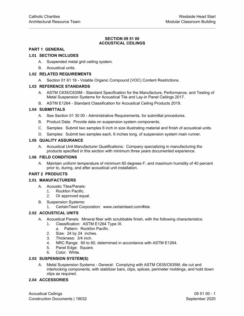
Catholic Charities Westside Head StartArchitectural Resource Team Modular Classroom Building
Acoustical Ceilings 09 51 00 - 1Construction Documents | 19032 September 2020
SECTION 09 51 00ACOUSTICAL CEILINGS
PART 1 GENERAL1.01 SECTION INCLUDES
A. Suspended metal grid ceiling system.B. Acoustical units.
1.02 RELATED REQUIREMENTSA. Section 01 61 16 - Volatile Organic Compound (VOC) Content Restrictions.
1.03 REFERENCE STANDARDSA. ASTM C635/C635M - Standard Specification for the Manufacture, Performance, and Testing of
Metal Suspension Systems for Acoustical Tile and Lay-in Panel Ceilings 2017.B. ASTM E1264 - Standard Classification for Acoustical Ceiling Products 2019.
1.04 SUBMITTALSA. See Section 01 30 00 - Administrative Requirements, for submittal procedures.B. Product Data: Provide data on suspension system components.C. Samples: Submit two samples 6 inch in size illustrating material and finish of acoustical units.D. Samples: Submit two samples each, 6 inches long, of suspension system main runner.
1.05 QUALITY ASSURANCEA. Acoustical Unit Manufacturer Qualifications: Company specializing in manufacturing the
products specified in this section with minimum three years documented experience.1.06 FIELD CONDITIONS
A. Maintain uniform temperature of minimum 60 degrees F, and maximum humidity of 40 percentprior to, during, and after acoustical unit installation.
PART 2 PRODUCTS2.01 MANUFACTURERS
A. Acoustic Tiles/Panels:1. Rockfon Pacific.2. Or approved equal.
B. Suspension Systems:1. CertainTeed Corporation: www.certainteed.com/#sle.
2.02 ACOUSTICAL UNITSA. Acoustical Panels: Mineral fiber with scrubbable finish, with the following characteristics:
1. Classification: ASTM E1264 Type IX.a. Pattern: Rockfon Pacific.
2. Size: 24 by 24 inches.3. Thickness: 3/4 inch.4. NRC Range: 60 to 60, determined in accordance with ASTM E1264.5. Panel Edge: Square.6. Color: White.
2.03 SUSPENSION SYSTEM(S)A. Metal Suspension Systems - General: Complying with ASTM C635/C635M; die cut and
interlocking components, with stabilizer bars, clips, splices, perimeter moldings, and hold downclips as required.
2.04 ACCESSORIES

Catholic Charities Westside Head StartArchitectural Resource Team Modular Classroom Building
Acoustical Ceilings 09 51 00 - 2Construction Documents | 19032 September 2020
A. Support Channels and Hangers: Galvanized steel; size and type to suit application, seismicrequirements, and ceiling system flatness requirement specified.
PART 3 EXECUTION3.01 EXAMINATION
A. Verify existing conditions before starting work.B. Verify that layout of hangers will not interfere with other work.
3.02 INSTALLATION - SUSPENSION SYSTEMA. Rigidly secure system, including integral mechanical and electrical components, for maximum
deflection of 1:360.B. Install after major above-ceiling work is complete. Coordinate the location of hangers with other
work.C. Hang suspension system independent of walls, columns, ducts, pipes and conduit. Where
carrying members are spliced, avoid visible displacement of face plane of adjacent members.D. Where ducts or other equipment prevent the regular spacing of hangers, reinforce the nearest
affected hangers and related carrying channels to span the extra distance.E. Do not support components on main runners or cross runners if weight causes total dead load
to exceed deflection capability.F. Support fixture loads using supplementary hangers located within 6 inches of each corner, or
support components independently.G. Do not eccentrically load system or induce rotation of runners.
3.03 INSTALLATION - ACOUSTICAL UNITSA. Install acoustical units in accordance with manufacturer's instructions.B. Fit acoustical units in place, free from damaged edges or other defects detrimental to
appearance and function.C. Fit border trim neatly against abutting surfaces.D. Install units after above-ceiling work is complete.E. Install acoustical units level, in uniform plane, and free from twist, warp, and dents.F. Cutting Acoustical Units:
1. Make field cut edges of same profile as factory edges.3.04 TOLERANCES
A. Maximum Variation from Flat and Level Surface: 1/8 inch in 10 feet.B. Maximum Variation from Plumb of Grid Members Caused by Eccentric Loads: 2 degrees.
END OF SECTION

Catholic Charities Westside Head StartArchitectural Resource Team Modular Classroom Building
Resilient Flooring 09 65 00 - 1Construction Documents | 19032 September 2020
SECTION 09 65 00RESILIENT FLOORING
PART 1 GENERAL1.01 SECTION INCLUDES
A. Resilient sheet flooring.B. Resilient tile flooring.C. Resilient base.D. Installation accessories.
1.02 RELATED REQUIREMENTSA. Section 01 61 16 - Volatile Organic Compound (VOC) Content Restrictions.
1.03 REFERENCE STANDARDSA. ASTM F1700 - Standard Specification for Solid Vinyl Floor Tile 2020.B. ASTM F1861 - Standard Specification for Resilient Wall Base 2016.C. ASTM F1913 - Standard Specification for Vinyl Sheet Floor Covering Without Backing 2019.
1.04 SUBMITTALSA. See Section 01 30 00 - Administrative Requirements, for submittal procedures.B. Product Data: Provide data on specified products, describing physical and performance
characteristics; including sizes, patterns and colors available; and installation instructions.C. Selection Samples: Submit manufacturer's complete set of color samples for Architect's initial
selection.D. Concrete Testing Standard: Submit a copy of ASTM F710.
1.05 QUALITY ASSURANCEA. Manufacturer Qualifications: Company specializing in manufacturing specified flooring with
minimum three years documented experience.B. Installer Qualifications: Company specializing in installing specified flooring with minimum three
years documented experience.1.06 DELIVERY, STORAGE, AND HANDLING
A. Upon receipt, immediately remove any shrink-wrap and check materials for damage and thecorrect style, color, quantity and run numbers.
B. Store all materials off of the floor in an acclimatized, weather-tight space.C. Do not double stack pallets.
1.07 FIELD CONDITIONSPART 2 PRODUCTS2.01 SHEET FLOORING
A. Vinyl Sheet Flooring: Homogeneous without backing, with color and pattern throughout fullthickness.1. Manufacturers:
a. ShawStyle, Natruelife, 002V .2. Minimum Requirements: Comply with ASTM F1913.3. Wear Layer: 20 mil.4. Thickness: 087 inch nominal.5. Color: Grey Teak 08266 .
2.02 TILE FLOORINGA. Vinyl Tile: Printed film type, with transparent or translucent wear layer.

Catholic Charities Westside Head StartArchitectural Resource Team Modular Classroom Building
Resilient Flooring 09 65 00 - 2Construction Documents | 19032 September 2020
1. Manufacturers:a. Shaw.
2. Minimum Requirements: Comply with ASTM F1700, of Class corresponding to typespecified.
3. Square Tile Size: 12 by 24 inch.4. Wear Layer Thickness: .02 inch.5. Total Thickness: 098 inch.6. Pattern: Shaw Solitude 0648V .7. Color: French Grey 48599 .
2.03 RESILIENT BASEA. Resilient Base: ASTM F1861, Type TS rubber, vulcanized thermoset; top set Style B, Cove.
1. Manufacturers:a. Johnsonite, a Tarkett Company: www.johnsonite.com/#sle.
2. Height: 4 inch.3. Thickness: 0.125 inch.4. Finish: Satin.5. Color: Pewter #38.
2.04 ACCESSORIESA. Primers and Adhesives: Waterproof; types recommended by flooring manufacturer.B. Moldings, Transition and Edge Strips: Same material as flooring.
PART 3 EXECUTION3.01 EXAMINATION
A. Verify that surfaces are flat to tolerances acceptable to flooring manufacturer, free of cracksthat might telegraph through flooring, clean, dry, and free of curing compounds, surfacehardeners, and other chemicals that might interfere with bonding of flooring to substrate.
B. Verify that required floor-mounted utilities are in correct location.3.02 PREPARATION
A. Prepare floor substrates as recommended by flooring and adhesive manufacturers.B. Clean substrate.C. Apply primer as required to prevent "bleed-through" or interference with adhesion by
substances that cannot be removed. 3.03 INSTALLATION - GENERAL
A. Starting installation constitutes acceptance of sub-floor conditions.B. Install in accordance with manufacturer's written instructions.C. Adhesive-Applied Installation:
1. Spread only enough adhesive to permit installation of materials before initial set.D. Where type of floor finish, pattern, or color are different on opposite sides of door, terminate
flooring under centerline of door.3.04 INSTALLATION - SHEET FLOORING
A. Lay flooring with joints and seams parallel to longer room dimensions, to produce minimumnumber of seams. Lay out seams to avoid widths less than 1/3 of roll width; match patterns atseams.
3.05 INSTALLATION - TILE FLOORINGA. Mix tile from container to ensure shade variations are consistent when tile is placed, unless
otherwise indicated in manufacturer's installation instructions.B. Install loose-laid tile, fit interlocking edges tightly.

Catholic Charities Westside Head StartArchitectural Resource Team Modular Classroom Building
Resilient Flooring 09 65 00 - 3Construction Documents | 19032 September 2020
3.06 INSTALLATION - RESILIENT BASEA. Fit joints tightly and make vertical. Maintain minimum dimension of 18 inches between joints.B. Install base on solid backing. Bond tightly to wall and floor surfaces.
3.07 CLEANINGA. Remove excess adhesive from floor, base, and wall surfaces without damage.B. Clean in accordance with manufacturer's written instructions.
3.08 PROTECTIONA. Prohibit traffic on resilient flooring for 48 hours after installation.
END OF SECTION


Catholic Charities Westside Head StartArchitectural Resource Team Modular Classroom Building
Tile Carpeting 09 68 13 - 1Construction Documents | 19032 September 2020
SECTION 09 68 13TILE CARPETING
PART 1 GENERAL1.01 SECTION INCLUDES
A. Carpet tile, fully adhered.1.02 RELATED REQUIREMENTS
A. Section 01 61 16 - Volatile Organic Compound (VOC) Content Restrictions.B. Section 01 74 19 - Construction Waste Management and Disposal: Reclamation/Recycling of
new carpet tile scrap.1.03 REFERENCE STANDARDS1.04 SUBMITTALS
A. See Section 01 30 00 - Administrative Requirements, for submittal procedures.B. Product Data: Provide data on specified products, describing physical and performance
characteristics; sizes, patterns, colors available, and method of installation.C. Samples: Submit two carpet tiles illustrating color and pattern design for each carpet color
selected.D. Maintenance Materials: Furnish the following for Owner's use in maintenance of project.
1. Extra Carpet Tiles: Quantity equal to 5 percent of total installed of each color and patterninstalled.
1.05 QUALITY ASSURANCEA. Manufacturer Qualifications: Company specializing in manufacturing specified carpet tile with
minimum three years documented experience.B. Installer Qualifications: Company specializing in installing carpet tile with minimum three years
documented experience and approved by carpet tile manufacturer.1.06 FIELD CONDITIONS
A. Store materials in area of installation for minimum period of 24 hours prior to installation.PART 2 PRODUCTS2.01 MANUFACTURERS
A. Tile Carpeting:1. Shaw Contract, Tempt Tile, www.shawcontract.com.
2.02 MATERIALSA. Tile Carpeting: Fusion bonded, manufactured in one color dye lot.
1. Product: No Rules manufactured by Shaw.2. Style: Engage tile 5T187.3. Tile Size: 24 by 24 inch, nominal.4. Thickness: 0.226 inch.5. Color: Escape Silver .6. Pattern: Multi-level pattern loop.7. Gage: 1/12 inch.8. Stitches: 9 per inch.9. Primary Backing Material: synthetic.10. Secondary Backing Material: ecoworx tile.11. Total Weight: 16.0 oz/sq yd.12. Installation Method: Brick.
2.03 ACCESSORIESA. Sub-Floor Filler: White premix latex; type recommended by flooring material manufacturer.

Catholic Charities Westside Head StartArchitectural Resource Team Modular Classroom Building
Tile Carpeting 09 68 13 - 2Construction Documents | 19032 September 2020
B. Edge Strips: Embossed aluminum, [_____] color.C. Adhesives:
1. Compatible with materials being adhered; maximum VOC content as specified in Section01 61 16.
D. Carpet Tile Adhesive: Recommended by carpet tile manufacturer; releasable type.PART 3 EXECUTION3.01 EXAMINATION
A. Verify that sub-floor surfaces are smooth and flat within tolerances specified for that type ofwork and are ready to receive carpet tile.
B. Verify that sub-floor surfaces are dust-free and free of substances that could impair bonding ofadhesive materials to sub-floor surfaces.
C. Verify that required floor-mounted utilities are in correct location.3.02 PREPARATION
A. Prepare floor substrates as recommended by flooring and adhesive manufacturers.B. Remove sub-floor ridges and bumps. Fill minor or local low spots, cracks, joints, holes, and
other defects with sub-floor filler.C. Apply, trowel, and float filler to achieve smooth, flat, hard surface. Prohibit traffic until filler is
cured.D. Vacuum clean substrate.
3.03 INSTALLATIONA. Starting installation constitutes acceptance of sub-floor conditions.B. Install carpet tile in accordance with manufacturer's instructions.C. Blend carpet from different cartons to ensure minimal variation in color match.D. Cut carpet tile clean. Fit carpet tight to intersection with vertical surfaces without gaps.E. Lay carpet tile in square pattern, with pile direction parallel to next unit, set parallel to building
lines.F. Locate change of color or pattern between rooms under door centerline.G. Trim carpet tile neatly at walls and around interruptions.H. Complete installation of edge strips, concealing exposed edges.
3.04 CLEANINGA. Remove excess adhesive without damage, from floor, base, and wall surfaces.B. Clean and vacuum carpet surfaces.
END OF SECTION

Catholic Charities Westside Head StartArchitectural Resource Team Modular Classroom Building
PAINTING 09 91 00 - 1Construction Documents | 19032 September 2020
SECTION 09 91 00PAINTING
PART 1 GENERAL1.01 SUMMARY
A. Section Includes: Painting as specified and as noted on Drawings. Surfaces requiring finishingand left unfinished by the requirements of other Sections shall be painted or finished as part ofthe Work of this Section.
1.02 DEFINITIONSA. Touch-Up: Painting of items missed by painter at no additional cost to Owner.B. Re-Paint: Repairs to paint work for damages caused by other trades.
1.03 SUBMITTALSA. Product Data: Submit schedule of manufacturers of products required for the Work, together
with specifications recommended by each manufacturer.B. Samples: Submit samples of each type of finish specified.
1. Architect will furnish Contractor a color schedule of colors selected either frommanufacturer's stock colors or specially requested color mixes before Work is begun.
2. Submit two 8 inch x 10 inch samples of each color, including the correct sheen andtexture, on heavy cardboard or masonry. Submit sealer and stain finishes on material ofthe same quality and species of wood on which that particular finish shall be used. Rejected samples shall be resubmitted until approved.
3. Samples shall be submitted at least 30 days prior to the start of painting work. Label andidentify each sample as to location and application. Upon submittal of color samples,minor variations or changes in color selection may be requested by the Architect and newsamples ordered, until final color approval.
1.04 QUALITY ASSURANCEA. Standards: Preparation, application and workmanship shall be in accordance with
manufacturer's recommendations and applicable provisions of the following:1. Painting and Decorating Contractors of America (PDCA) "Painting Specification Manual"
and "Standards".a. PDCA P1-92, "Touch-Up Painting and Damage Repair - Financial Responsibility:" A
properly painted surface shall be as defined in this Standard.b. PDCA P2-92, "Third Party Inspection Qualifications and Responsibilities."c. PDCA P3-93, "Designation of Paint Colors."d. PDCA P4-94, "Responsibilities for Inspection and Acceptance of Surfaces Prior to
Painting and Decorating."e. PDCA P5-94, "Benchmark Sample Procedures for Paint and Other Decorative
Coating Systems."2. Gypsum Association - GA210, "Gypsum Board for Walls and Ceilings."3. 40 CFR 59, Subpart D - National Volatile Organic Compound Emission Standards for
Architectural Coatings; U.S. Environmental Protection Agency; current edition.4. GreenSeal GS-11 - Paints; 1993.
1.05 DELIVERY, STORAGE, AND HANDLINGA. Packing and Shipping: Deliver materials to site in manufacturer's sealed containers, legends
and labels, intact.B. Storage:
1. Adequately protect against damage while stored at site.2. In no case shall the amount or method of materials stored exceed the amount permitted or
the manner allowed by local ordinances, state laws, or fire underwriter regulations.1.06 PROJECT/SITE CONDITIONS

Catholic Charities Westside Head StartArchitectural Resource Team Modular Classroom Building
PAINTING 09 91 00 - 2Construction Documents | 19032 September 2020
A. Environmental Requirements: Do not apply exterior paint in damp or rainy weather or until afterthe surface has dried thoroughly from the effects of such weather.1. Do not apply varnish or paint when temperature is below 50 degrees F.. Avoid painting
surfaces exposed to hot sunlight.2. During interior application, maintain minimum temperature of 65 degrees F. unless
otherwise directed by Architect or manufacturer's printed instructions. Hold temperatureas constant as possible.
3. Provide adequate ventilation at all times so the humidity cannot rise above the dew pointof the coldest surface to be painted.
4. Moisture-containing surfaces, such as concrete, stucco and cement plaster shall have amoisture content of less than 8 percent as measured by moisture meter. Remove surfacesalt deposits prior to painting. Verify that pH is neutral, or within acceptable limits of PaintManufacturer. Paint after thoroughly cured.
1.07 MAINTENANCEA. Extra Materials: Upon completion of the Work, furnish Owner with one fresh gallon of each
type and color of paint and finish used on this Project. Label containers with manufacturer'sname, batch, color, shelf life, instructions, and cautions.
PART 2 PRODUCTS2.01 MANUFACTURERS
A. Furnish products of one of the following manufacturers, except as otherwise approved byArchitect, subject to compliance with specification requirements.1. Dunn-Edwards Corporation www.dunnedwards.com2. Color Life.3. Kelly Moore.4. The Sherwin Williams Company www.sherwin-williams.com5. Benjamin Moore www.benjaminmoore.com
B. Low-Emitting Materials: All interior paint finishes must be Zero VOC products. Other interiorproducts that do not have Zero VOC options must not exceed the VOC content limits listed inthe May 1993 edition of the Green Seal Standard GS-11, Paints.
2.02 MATERIALSA. Provide materials in accordance with the systems specified at the end of Part 3 of this
Specification and as applicable to project. Contractor shall provide either waterborne orsolventborne products at contractor's option and as follows:1. Waterborne:
a. Provide where low odor and fast dry are desired.b. Non-blocking materials shall be used for doors, door jambs, railings and other
locations subject to handling, or where surfaces will come into contact with otherpainted surfaces or belongings.
2. Solventborne:a. Provide where harder finish is required (such as "wet" areas) and odor will not create
problems with occupants.b. These products shall not be used where color retention is a concern. Verify with
Architect.3. Materials used shall comply with applicable Federal and local air pollution regulations,
lead content laws, and current VOC requirements. If products listed systems specified atthe end of Part 3 of this Specification are not in compliance with regulations, laws, orrequirements, Contractor shall notify Architect and shall provide information regardingsubstitute products.
B. Basic painting materials such as linseed oil, shellac, turpentine, thinners, driers, and othersimilar products, shall be of highest quality, made by reputable, recognized manufacturers, andhave identifying labels on containers. Paint materials shall be factory fresh.

Catholic Charities Westside Head StartArchitectural Resource Team Modular Classroom Building
PAINTING 09 91 00 - 3Construction Documents | 19032 September 2020
C. Alternate materials submitted for prior approval shall have qualities and materials equal to theother listed manufacturer's scheduled, top of the line, first quality products. Materials selectedfor coating systems for each type of surface shall be the products of a single manufacturer.
D. Standard Gloss Range: Provide paints in accordance with the following MPI standard rangesas measured in accordance with ASTM D523-08:1. MPI Gloss and Sheen Standards Gloss @ 60º Sheen @ 85º2. Gloss Level 1 – traditional matte finish – flat max. 5 units, and max. 10 units3. Gloss Level 2 – high side sheen flat – velvet-like max. 10 units, and 10-35 units4. Gloss Level 3 – traditional ‘eggshell-like’ finish 10-25 units, and10-35 units5. Gloss Level 4 – ‘satin-like’ finish 20-35 units, andmin. 35 units6. Gloss Level 5 – traditional semi-gloss 35-70 units7. Gloss Level 6 – traditional gloss 70-85 units8. Gloss Level 7 – a high gloss more than 85 units
E. Paints shall be ready mixed except for field catalyzed coatings.PART 3 EXECUTION3.01 EXAMINATION
A. Verification of Conditions: Examine subsurfaces to receive Work and report in writing with acopy to Architect, conditions detrimental to Work. Commencement of Work will be construedas acceptance of subsurfaces.
3.02 PROTECTIONA. Before painting, remove hardware, accessories, electrical plates, lighting fixtures and similar
items and protect.1. Provide “Wet-Paint” signs and other barricades and protections as required to protect
adjacent surfaces and work of other trades, whether being painted or not.2. Mask permanent labels.3. Provide, distribute, and maintain a sufficient supply of clean drop cloths and other
protective coverings.4. Protect foliage and other exterior finished surfaces from contact with cleaning materials
and thoroughly flush with water after contact.5. On completion of each space, replace above items.
3.03 SURFACE PREPARATIONA. General:
1. Surfaces requiring painting or finishing shall be thoroughly dry and cured, free of dirt, dust,rust, stains, scale, mildew, wax, grease, oil, deteriorated substrates, bond-breakers,efflorescence and other foreign matter detrimental to the coating’s adhesion andperformance. Repair voids, cracks, nicks and other surface defects with appropriatepatching material. Finish flush with surrounding surfaces and match adjacent finishtexture.
2. Spot prime marred or damaged shop coats on metal surfaces with appropriate metalprimer.
3. Determine moisture content of plaster, stucco, cementitious materials, wood and othermoisture-holding materials by use of a reliable electronic moisture meter.
4. Determine alkalinity of plaster, stucco and other cementitious materials by performingappropriate tests.
5. Do not paint surfaces where moisture content or alkalinity exceeds that which is allowedby paint manufacturer.
B. Steel and Iron:1. Remove grease, oil, mill scale, rust and rust scale and touch-up chipped or abraded
places on items that have been shop coated. Remove and reprime incompatible ordamaged shop applied primers. Comply with the Steel Structures Painting Council's(SSPC) recommendations for cleaning of uncoated steel and iron surfaces.

Catholic Charities Westside Head StartArchitectural Resource Team Modular Classroom Building
PAINTING 09 91 00 - 4Construction Documents | 19032 September 2020
2. When area will be exposed to view, sandpaper the entire primed area smooth, feather theedge of surrounding undamaged prime coat and spot prime in a manner to eliminateevidence of repair.
3. Where steel or iron at existing Work have a heavy coating of scale, remove by sandblasting, sanding, descaling, grinding or wire brushing, as necessary, to produce asatisfactory surface for painting.
C. Galvanized Metal and Aluminum:1. Thoroughly clean by wiping surfaces with a non-hydrocarbon solvent that will not leave an
oily residue. Apply surface conditioner or vinyl-wash pretreatment as required for properadhesion if required by paint manufacturer. Prime galvanized metal with galvanized ironprimer as recommended by paint manufacturer. A test sample of the complete paintingsystem should be applied and checked for adhesion before final painting begins.
2. Clean visible portions of throats of galvanized steel ductwork with solvent; wipe dry withclean rags and paint flat black.
D. Plaster and Gypsum Board Surfaces:1. Fill cracks, holes or imperfections with compatible patching material and smooth off to
match adjoining surfaces. Before painting, surfaces shall be first tested for dryness with amoisture testing device.
2. Apply no paint or sealer on gypsum board or plaster when the moisture content exceeds 8percent. Test sufficient areas in each space and as often as necessary to determine if thesurface has the proper moisture content for painting. If the moisture content is between 8percent and 12 percent, prime with alkali resistant primer.
3. If 8 percent or less, prime with specified primer. Remove the dry salt deposits from plastersurfaces by brushing with a stiff brush before painting.
3.04 WORKMANSHIPA. Apply products to achieve paint manufacturer's printed specifications for dry mil thicknessB. Apply each coat of paint evenly and comply with manufacturer's drying time before applying
subsequent coats.C. Finished work shall be uniform, match approved color, texture and coverage, and free from
runs, sags, clogging or excessive flooding. Make edges of paint adjoining other materials orcolors sharp and clean, without overlapping. Where varnishes or enamel is used, lightly sand,dust and clean undercoats to obtain a smooth finish coat. Sand carefully between each coat offinish on smooth surfaces for good adhesion of subsequent coats.
D. Where clear finishes are required, ensure tinted fillers match wood. Work fillers well into thegrain before set. Wipe excess from the surface.
E. Where specific mil thicknesses are required, check thickness by the following methods:1. Over ferrous metal - Elecometer Film Gauge2. Other surfaces - Tooke Dry Mil Inspection Gauge
3.05 APPLICATIONA. The number of coats scheduled is the minimum number of coats required. Additional coat(s)
shall be applied, at no additional cost to the Owner, to completely hide base material, provideuniform color and to produce satisfactory finish results.
B. Apply coatings without thinning except as specifically required by label directions, or requiredby these specifications. In such cases, thinning shall be the minimum reduction permitted.
C. Priming will not be required on items delivered with prime or shop coats, unless otherwisespecified. Touch up prime coats applied by others as required to ensure an even primedsurface before applying finish coat.
D. Plumbing, Mechanical and Electrical:1. Exterior and interior exposed water, gas, waste piping, sprinkler piping, conduit, lighting
and electrical panels, telephone terminal boxes, galvanized ducts and insulated ducts,

Catholic Charities Westside Head StartArchitectural Resource Team Modular Classroom Building
PAINTING 09 91 00 - 5Construction Documents | 19032 September 2020
shall be painted in areas other than mechanical rooms, unless otherwise scheduled.2. Paint exposed unfinished fixtures, metal ducts, switch boxes, control panels, devices,
starters, junction boxes, vents, drains, and other similar items, as directed by Architect.E. Spray paint prime coated (not pre-finished) grilles and registers with enamel or lacquer to
match walls and ceilings. Paint materials shall not sag, run or bind movable parts of grilles,registers, louvers, baffles and other similar items.1. Throats of ducts shall be given one coat of flat black paint, wherever visibility of the interior
of the duct is allowed through registers or other similar items. At fiber lined duct, useblack latex paint.
2. Examine the Mechanical and Electrical Drawings and Specifications to determine theamount of exposed work to be painted.
F. Paint exposed surfaces of every member, paint items inaccessible after installation beforeinstallation, if required to be painted. Paint all exposed surfaces of overhead roof or floorstructures, including deck, except where specifically indicated not to be painted.
G. Edges, tops, and bottoms of wood doors shall be sealed and finished with the same finish asthe door faces, to meet door manufacturer's warranty requirements. Verify edge color withArchitect as different colors may be selected for each face.
H. Paint items fitted with finish hardware after hardware has been temporarily removed.I. Heating and other equipment on or adjacent to walls or surfaces scheduled for painting, shall
be disconnected, using workmen skilled in appropriate trades and moved temporarily to permitpainting of surface. Following completion of painting, replace and reconnect items.
J. Each succeeding pigmented coat shall be distinguishably lighter than the previous coat. Tintprime and undercoats to a color similar to finish coat. Each coat of material applied must beinspected and approved by the Architect before the application of the succeeding specifiedcoat; otherwise no credit for the concealed coat will be given, and the Contractor shall assumethe responsibility to recoat work in question. Contractor shall notify the Architect when eachcoat is completed.
K. Do not paint over Underwriters' Laboratory labels, fusible links, exposed sprinkler heads andother similar items.
L. Paint piping, electrical or other equipment, conduit, vents and other similar items, on roof orother exterior locations as directed by Architect.
M. Finish closets and the interior of cabinets with same color as adjoining rooms, unless otherwisespecified. Finish other surfaces same as nearest or adjoining surfaces, unless otherwiseshown or scheduled.
N. Paint surface of walls which will be concealed by cabinets and other items mounted on orattached to walls.
3.06 ADJUSTINGA. At completion, do touch-up and re-paint work and leave finish surfaces in good condition.
3.07 CLEANINGA. During the course of the Work, remove misplaced paint and stain spots or spills. Leave Work in
clean condition acceptable to Architect.B. Remove oily rags and waste daily, taking precaution to prevent fire.
3.08 SCHEDULESA. Color Schedule:
1. Architect will provide a complete schedule of colors. Colors may be selected from variousmanufacturer's color palettes. Manufacturer supplying paint shall match these colors. Contractor shall prepare duplicate set of samples of treatments for major surfaces. If aspecific surface or item receiving a paint finish does not have a specific color indicated orselected by the Architect, obtain clarification from the Architect. Do not assume the

Catholic Charities Westside Head StartArchitectural Resource Team Modular Classroom Building
PAINTING 09 91 00 - 6Construction Documents | 19032 September 2020
confirmation of the same color on the adjacent surfaces.2. Final coat of paint shall be not be applied until colors have been approved by the
Architect.B. Finishing of the following listed items and materials will not be required and shall be protected:
1. Stainless Steel, brass, bronze, copper, monel, chromium, anodized aluminum; speciallyfinished articles such as porcelain enamel, plastic coated fabrics, and baked enamel,unless otherwise indicated.
2. Finished products such as ceramic tile, glass, brick, resilient flooring and acoustical tiles,board and metal tees.
3. Pre-finished products such as wood folding partitions and doors, wood classroom andlaboratory casework, bleachers and elevator cabs.
3.09 EXTERIOR PAINT FINISHESA. System 101 (Ferrous Metals): Apply to exposed steel such as beams and column connectors,
metal doors and frames, grilles, light fixture standards in parking areas, metal handrails,sectional and coiling doors, canopy overhangs and other exposed miscellaneous ferrousmetals that are not pre-finished.1. 1st Coat: Ferrous Metal Primer (Red or White color as applicable to finish coats).
a. Dunn-Edwards Bloc-Rust Premium Int./Ext. Rust Preventative Metal Primer(BRPR00).
b. Sherwin Williams Pro-Cryl Universal Acrylic Primer (B66-310 Series).c. PPG Paints: Pitt Tech Plus DTM Acrylic Primer 90-912.
2. 2nd Coat: Same material as 3rd coat in accordance with manufacturer'srecommendations.
3. 3rd Coat:a. Semi-Gloss unless noted otherwise. Enamel, Semi-Gloss - Waterborne (100%
Acrylic - Non-Blocking).1) Dunn-Edwards adSpartashield 100% Acrylic Ext. Semi-Gloss Paint (SSHL50).2) Sherwin Williams A76 SOLO Semi-Gloss.3) PPG Paints: Sun Proof 100% Acrylic Exterior Semi-Gloss 78-45.
B. System 102 (Galvanized Metals): Apply to exposed galvanized metal such as copings, louversand metal flashings.1. Clean metal to remove foreign matter or any coating applied by the metal manufacturer.
Apply Surface Conditioner or Vinyl Wash Pretreatment (if required by paintmanufacturer).
2. 1st Coat: Galvanized Metal Primer.a. Dunn-Edwards UltraShield Galvanized Metal Primer (ULGM00).b. Sherwin Williams Multi-purpose Zero VOC Int/Ext Latex Primer B51W00450
(waterborne).c. PPG Paints: Pitt Tech Plus DTM Acrylic Primer 90-912.
3. 2nd Coat: Same material as 3rd coat as recommended by manufacturer.4. 3rd Coat:
a. Flat: Paint, Flat - Waterborne (100% Acrylic) unless noted otherwise.1) Dunn-Edwards Spartashield 100% Acrylic Ext. Flat Paint (SSHL10).2) Sherwin Williams A74 SOLO Flat.3) PPG Paints: Sun Proof 100% Acrylic Exterior Flat 72-45 Series.
C. System 103 (Aluminum): Apply to exterior louvers and other miscellaneous exposed exteriorunfinished aluminum surfaces.1. Clean metal to remove foreign matter or any coating applied by the metal manufacturer.
Apply Surface Conditioner or Vinyl Wash Pretreatment.2. 1st Coat: Aluminum Primer.
a. Dunn-Edwards UltraShield Galvanized Metal Primer (ULGM00).

Catholic Charities Westside Head StartArchitectural Resource Team Modular Classroom Building
PAINTING 09 91 00 - 7Construction Documents | 19032 September 2020
b. Sherwin Williams Multi-purpose Zero VOC Int/Ext Latex Primer B51W00450(waterborne).
c. PPG Paints: Pitt Tech Plus DTM Acrylic Primer 90-912.3. 2nd Coat: Same material as 3rd coat as recommended by manufacturer.4. 3rd Coat:
a. Semi-Gloss unless noted otherwise. Enamel, Semi-Gloss - Waterborne (100%Acrylic - Non-Blocking).1) Dunn-Edwards Spartashield 100% Acrylic Ext. Semi-Gloss Paint (SSHL50).2) Sherwin Williams A76 SOLO Semi-Gloss.3) PPG Paints: Sun Proof 100% Acrylic Exterior Semi-Gloss 78-45.
D. System 105 (Stucco): Apply to exterior cementitious surfaces as indicated or noted. Rollerapply 2nd or 3rd coat.1. 1st Coat: Concrete and Masonry Primer.
a. Dunn-Edwards Eff-Stop Select Int./Ext. Masonry Primer/Sealer (ESSL00).b. Sherwin Williams (waterborne) Loxon Concrete Masonry Primer A24W08300.c. PPG Paints Perma-Crete Alkali Resistant Primer 4-603.
2. 2nd Coat: Same material as 3rd coat as recommended by manufacturer.3. 3rd Coat:
a. Select the sheen desired. 4 to 6% is the "standard" value.b. Flat: Paint, Flat - Waterborne (100% Acrylic) unless noted otherwise. One of the
coats shall be roller applied.1) Dunn-Edwards Acri-Build 100% Acrylic Ext. Flat Paint (ACBL10).2) Sherwin Williams Duracraft Acrylic Latex Flat, C01W00251.3) PPG Paints Speedhide Exterior 100% Acrylic Flat 6-6110XI.
3.10 INTERIOR PAINT FINISHESA. System 201 (Ferrous Metals): Apply to exposed metals such as steel doors, hollow metal
frames, metal beam saddles, columns, grilles and registers, stair and hand railings, ladders,and other exposed miscellaneous metals.1. 1st Coat: Ferrous Metal Primer (Red or White color as applicable to finish coats).
a. Dunn-Edwards Rust-Oleum Sierra Performance Metal Max Zero VOC Int./Ext. DTMGray Primer.
b. Sherwin Williams Zero VOC: Not availablec. PPG Paints Zero VOC: Not availabled. Behr Pro i300 Interior Eggshell
2. 2nd Coat: Same material as 3rd Coat as recommended by manufacturer.3. 3rd Coat:
a. Eggshell: Enamel, Eggshell.1) Dunn-Edwards Spartazero Zero VOC Int. Eggshell Paint (SZRO30).2) Sherwin Williams Promar 400 Zero VOC Egshel, B20W04651.3) PPG Paints Zero VOC: Speedhide zero Interior Latex Eggshell 6-4310XI.4) Behr Pro i300 Interior Eggshell
B. System 204 (Galvanized Metals): Apply to exposed galvanized metal.1. Clean metal to remove foreign matter or any coating applied by the metal manufacturer.
Apply Surface Conditioner or Vinyl Wash Pretreatment (if required by paint manufacturer)2. 1st Coat: Galvanized Metal Primer
a. Dunn-Edwards Rust-Oleum Sierra Performance Griptec Zero VOC Multi-SurfacePrimer.
b. Sherwin Williams Zero VOC: Not available.c. PPG Paints Zero VOC: Not available.d. Behr Pro i300 Interior Eggshell
3. 2nd and 3rd Coats:a. Eggshell: Enamel, Eggshell

Catholic Charities Westside Head StartArchitectural Resource Team Modular Classroom Building
PAINTING 09 91 00 - 8Construction Documents | 19032 September 2020
1) Dunn-Edwards Spartazero Zero VOCInt. Eggshell Paint (SZRO30).2) Sherwin Williams Promar 400 Zero VOC Egshel, B20W04651.3) PPG Paints Zero VOC: Speedhide zero Interior Latex Eggshell 6-4310XI.4) Behr Pro i300 Interior Eggshell
C. System 205 (Aluminum): Apply to interior louvers and other miscellaneous exposed unfinishedaluminum surfaces.1. Clean metal to remove foreign matter or any coating applied by the metal manufacturer.
Apply Surface Conditioner or Vinyl Wash Pretreatment.2. 1st Coat: Aluminum Primer
a. Dunn-Edwards Rust-Oleum Sierra Performance Griptec Zero VOC Multi-SurfacePrimer
b. Sherwin Williams Zero VOC: Not available.c. PPG Paints Zero VOC: Not available.d. Behr Pro i300 Interior Eggshell
3. 2nd and 3rd Coats:a. Eggshell: Enamel, Eggshell
1) Dunn-Edwards Spartazero Zero VOC Int. Eggshell Paint (SZRO30).2) Sherwin Williams Promar 400 Zero VOC Egshel, B20W04651.3) PPG Paints Zero VOC: Speedhide zero Interior Latex Eggshell 6-4310XI.4) Behr Pro i300 Interior Eggshell
D. System 206 (Gypsum Board, Plaster and Concrete - Wet Areas): Apply to gypsum board,plaster and concrete surfaces in toilet rooms, janitor rooms, kitchens, and other areas asscheduled.1. 1st Coat: Enamel Undercoater – Water-based, unless noted otherwise.
a. Dunn-Edwards Ultra-Grip Select Zero VOC Int/Ext Multi-Surface Primer (UGSL00).b. Sherwin Williams Multi-purpose Zero VOC Int/Ext Latex Primer B51W00450
(waterborne).c. PPG Paints: Seal Grip Acrylic Universal Primer 17-921.
2. 2nd and 3rd Coats:a. Semi-Gloss: Enamel, Semi-Gloss – High Performance Water-Based Epoxy Acrylic
Finish.1) Dunn-Edwards Endurcat Pre-Catalyzed Acrylic Epoxy Semi-Gloss (ENPX50).2) Sherwin Williams Pro Industrial Zero VOC water based Epoxy
B73W00311/B73V00300.3) PPG Paints: Pitt Glaze WB1 Pre-Catalyzed Acrylic Epoxy Semi-Gloss 16-510.
E. System 207 (Gypsum Board, Plaster and Concrete - Non-Wet Areas): Apply to gypsum board,plaster and concrete except for wet areas.1. 1st Coat: Waterborne Primer/Sealer – Gypsum Board.
a. Dunn-Edwards Spartazero products are self-priming over gypsum board. Specifysame product as 2nd and 3rd Coat/
b. Sherwin Williams High Build Primer Surfacer, B28W8601c. PPG Paints Zero VOC: Speedhide zero Interior Latex Primer Sealer 6-4900XI.d. Behr Pro i300 Interior Eggshell
2. 2nd and 3rd Coat:a. Eggshell: Enamel, Eggshell
1) Dunn-Edwards Spartazero Zero VOC Int. Eggshell Paint (SZRO30).2) Sherwin Williams Promar 400 Zero VOC Egshel, B20W04651.3) PPG Paints Zero VOC: Speedhide zero Interior Latex Eggshell 6-4310XI.4) Behr Pro i300 Interior Eggshell
END OF SECTION

Catholic Charities Westside Head StartArchitectural Resource Team Modular Classroom Building
Signage 10 14 00 - 1Construction Documents | 19032 September 2020
SECTION 10 14 00SIGNAGE
PART 1 GENERAL1.01 SECTION INCLUDES
A. Room and door signs.B. Traffic signs.
1.02 REFERENCE STANDARDSA. 36 CFR 1191 - Americans with Disabilities Act (ADA) Accessibility Guidelines for Buildings and
Facilities; Architectural Barriers Act (ABA) Accessibility Guidelines current edition.B. ADA Standards - Americans with Disabilities Act (ADA) Standards for Accessible Design 2010.C. ICC A117.1 - Accessible and Usable Buildings and Facilities 2017.
1.03 SUBMITTALSA. See Section 01 30 00 - Administrative Requirements, for submittal procedures.B. Product Data: Manufacturer's printed product literature for each type of sign, indicating sign
styles, font, foreground and background colors, locations, overall dimensions of each sign.C. Signage Schedule: Provide information sufficient to completely define each sign for fabrication,
including room number, room name, other text to be applied, sign and letter sizes, fonts, andcolors.1. When room numbers to appear on signs differ from those on drawings, include the
drawing room number on schedule.2. When content of signs is indicated to be determined later, request such information from
Owner through Architect at least 2 months prior to start of fabrication; upon request,submit preliminary schedule.
3. Submit for approval by Owner through Architect prior to fabrication.1.04 QUALITY ASSURANCE
A. Manufacturer Qualifications: Company specializing in manufacturing the products specified inthis section with minimum three years of documented experience.
1.05 DELIVERY, STORAGE, AND HANDLINGA. Package signs as required to prevent damage before installation.B. Package room and door signs in sequential order of installation, labeled by floor or building.C. Store tape adhesive at normal room temperature.
1.06 FIELD CONDITIONSA. Do not install tape adhesive when ambient temperature is lower than recommended by
manufacturer.B. Maintain this minimum temperature during and after installation of signs.
PART 2 PRODUCTS2.01 MANUFACTURERS
A. Flat Signs:1. Best Sign Systems, Inc: www.bestsigns.com/#sle.2. Cosco Industries (ADA signs); ADA Series 1: www.coscoarchitecturalsigns.com/#sle.3. FASTSIGNS: www.fastsigns.com/#sle.
2.02 SIGNAGE APPLICATIONSA. Accessibility Compliance: Signs are required to comply with ADA Standards and ICC A117.1,
unless otherwise indicated; in the event of conflicting requirements, comply with the mostcomprehensive and specific requirements.

Catholic Charities Westside Head StartArchitectural Resource Team Modular Classroom Building
Signage 10 14 00 - 2Construction Documents | 19032 September 2020
B. Room and Door Signs: Provide a sign for every doorway, whether it has a door or not, notincluding corridors, lobbies, and similar open areas.1. Sign Type: Flat signs with engraved panel media as specified.2. Provide "tactile" signage, with letters raised minimum 1/32 inch and Grade II braille.3. Character Height: 1 inch.4. Sign Height: 2 inches, unless otherwise indicated.5. Office Doors: Identify with room numbers to be determined later, not the numbers
indicated on drawings; in addition, provide "window" section for replaceable occupantname.
6. Conference and Meeting Rooms: Identify with room numbers to be determined later, notthe numbers indicated on drawings; in addition, provide "window" section with sliding "InUse/Vacant" indicator.
7. Service Rooms: Identify with room names and numbers to be determined later, not thoseindicated on drawings.
8. Rest Rooms: Identify with pictograms, the names "MEN" and "WOMEN", room numbersto be determined later, and braille.
2.03 SIGN TYPESA. Flat Signs: Signage media without frame.
1. Edges: Square.2. Corners: Square.3. Wall Mounting of One-Sided Signs: Tape adhesive.4. ADA Exterior signage as required to match existing sighnage if it cannot be reused.
B. Color and Font: Unless otherwise indicated:1. Character Font: as selected by Owner.2. Background Color: as selected by Owner.3. Character Color: Contrasting color.
2.04 TACTILE SIGNAGE MEDIAA. Engraved Panels: Laminated colored plastic; engraved through face to expose core as
background color:1. Total Thickness: 1/16 inch.
2.05 ACCESSORIESA. Concealed Screws: Stainless steel, galvanized steel, chrome plated, or other non-corroding
metal.B. Tape Adhesive: Double sided tape, permanent adhesive.
PART 3 EXECUTION3.01 EXAMINATION
A. Verify that substrate surfaces are ready to receive work.3.02 INSTALLATION
A. Install in accordance with manufacturer's instructions.B. Install neatly, with horizontal edges level.C. Locate signs and mount at heights indicated on drawings and in accordance with ADA
Standards and ICC A117.1.D. Protect from damage until Substantial Completion; repair or replace damaged items.
END OF SECTION

Catholic Charities Westside Head StartArchitectural Resource Team Modular Classroom Building
Metal Toilet Compartments 10 21 13.13 - 1Construction Documents | 19032 September 2020
SECTION 10 21 13.13METAL TOILET COMPARTMENTS
PART 1 GENERAL1.01 SECTION INCLUDES
A. Metal toilet compartments.1.02 RELATED REQUIREMENTS
A. Section 06 10 00 - Rough Carpentry: Blocking and supports.B. Section 10 28 00 - Toilet, Bath, and Laundry Accessories.
1.03 REFERENCE STANDARDSA. ASTM A653/A653M - Standard Specification for Steel Sheet, Zinc-Coated (Galvanized) or Zinc-
Iron Alloy-Coated (Galvannealed) by the Hot-Dip Process 2020.B. ASTM A666 - Standard Specification for Annealed or Cold-Worked Austenitic Stainless Steel
Sheet, Strip, Plate, and Flat Bar 2015.1.04 ADMINISTRATIVE REQUIREMENTS1.05 SUBMITTALS
A. See Section 01 30 00 - Administrative Requirements, for submittal procedures.B. Shop Drawings: Indicate partition plan, elevation views, dimensions, details of wall, floor, and
ceiling supports, door swings.C. Product Data: Provide data on panel construction, hardware, and accessories.D. Samples: Submit two samples of partition panels, 4 x 4 inch in size illustrating panel finish,
color, and sheen.PART 2 PRODUCTS2.01 MANUFACTURERS
A. Metal Toilet Compartments:1. All American Metal Corp - AAMCO: www.allamericanmetal.com/#sle.2. General Partitions Mfg. Corp: www.generalpartitions.com/#sle.3. Global Steel Products Corp: www.globalpartitions.com/#sle.4. Metpar Corp: www.metpar.com/#sle.5. Substitutions: Section 01 60 00 - Product Requirements.
2.02 MATERIALSA. Steel Sheet: Hot-dipped galvanized steel sheet, ASTM A653/A653M, with G90/Z275 coating.B. Stainless Steel Sheet: ASTM A666, Type 304.
2.03 COMPONENTSA. Toilet Compartments: Powder coated steel, floor-to-ceiling.B. Door and Panel Dimensions:
1. Thickness: 1 inch.2. Height: custom see Drawings inch.
C. Pilasters: 1-1/4 inch thick, of sizes required to suit compartment width and spacing.2.04 ACCESSORIES
A. Pilaster Shoes: Formed chromed steel with polished finish, 3 inch high, concealing floorfastenings.
B. Head Rails: Hollow chrome-plated steel tube, 1 by 1-5/8 inch size, with anti-grip strips and castsocket wall brackets.
C. Brackets: Polished chrome-plated non-ferrous cast metal.

Catholic Charities Westside Head StartArchitectural Resource Team Modular Classroom Building
Metal Toilet Compartments 10 21 13.13 - 2Construction Documents | 19032 September 2020
D. Attachments, Screws, and Bolts: Stainless steel , tamper proof type.E. Hardware: Polished chrome plated non-ferrous cast metal:
1. Pivot hinges, gravity type, adjustable for door close positioning; two per door.2. Thumb turn or sliding door latch with exterior emergency access feature.3. Door strike and keeper with rubber bumper; mounted on pilaster in alignment with door
latch.4. Coat hook with rubber bumper; one per compartment, mounted on door.5. Provide door pull for outswinging doors.
2.05 FINISHINGA. Powder Coated Steel Compartments: Clean, degrease, and neutralize. Follow immediately
with a phosphatizing treatment, prime coat and two finish coats powder coat enamel.B. Color: As selected by Architect.
PART 3 EXECUTION3.01 EXAMINATION
A. Verify existing conditions before starting work.B. Verify that field measurements are as indicated.C. Verify correct spacing of and between plumbing fixtures.D. Verify correct location of built-in framing, anchorage, and bracing.
3.02 INSTALLATIONA. Install partitions secure, rigid, plumb, and level in accordance with manufacturer's instructions.B. Maintain 3/8 to 1/2 inch space between wall and panels and between wall and end pilasters.C. Attach panel brackets securely to walls using anchor devices.D. Attach panels and pilasters to brackets. Locate head rail joints at pilaster center lines.
3.03 TOLERANCESA. Maximum Variation From True Position: 1/4 inch.
3.04 ADJUSTINGA. Adjust and align hardware to uniform clearance at vertical edge of doors, not exceeding 3/16
inch.END OF SECTION

Catholic Charities Westside Head StartArchitectural Resource Team Modular Classroom Building
Toilet, Bath, and Laundry Accessories 10 28 00 - 1Construction Documents | 19032 September 2020
SECTION 10 28 00TOILET, BATH, AND LAUNDRY ACCESSORIES
PART 1 GENERAL1.01 SECTION INCLUDES
A. Commercial toilet accessories.B. Diaper changing stations.C. Utility room accessories.
1.02 RELATED REQUIREMENTSA. Section 06 10 00: Concealed supports for accessories, including in wall framing and plates.B. Section 10 21 13.13 - Metal Toilet Compartments.
1.03 REFERENCE STANDARDSA. ASTM A269/A269M - Standard Specification for Seamless and Welded Austenitic Stainless
Steel Tubing for General Service 2015a (Reapproved 2019).B. ASTM A666 - Standard Specification for Annealed or Cold-Worked Austenitic Stainless Steel
Sheet, Strip, Plate, and Flat Bar 2015.C. ASTM B456 - Standard Specification for Electrodeposited Coatings of Copper Plus Nickel Plus
Chromium and Nickel Plus Chromium 2017.D. ASTM C1036 - Standard Specification for Flat Glass 2016.E. ASTM C1048 - Standard Specification for Heat-Strengthened and Fully Tempered Flat Glass
2018.1.04 ADMINISTRATIVE REQUIREMENTS
A. Coordinate the work with the placement of internal wall reinforcement, concealed ceilingsupports, and reinforcement of toilet partitions to receive anchor attachments.
1.05 SUBMITTALSA. See Section 01 30 00 - Administrative Requirements, for submittal procedures.B. Product Data: Submit data on accessories describing size, finish, details of function, and
attachment methods.C. Manufacturer's Installation Instructions: Indicate special procedures and conditions requiring
special attention.PART 2 PRODUCTS2.01 MANUFACTURERS
A. Toilet, Shower, and Bath Accessories:1. Bobrick2. American Specialties, Inc[<>]: www.americanspecialties.com.
B. Diaper Changing Stations:1. American Specialties, Inc: www.americanspecialties.com/#sle.2. Bradley Corporation: www.bradleycorp.com/#sle.3. Koala Kare Products: www.koalabear.com/#sle.
2.02 MATERIALSA. Accessories - General: Shop assembled, free of dents and scratches and packaged complete
with anchors and fittings, steel anchor plates, adapters, and anchor components for installation.B. Keys: Provide 2 keys for each accessory to Owner; master key lockable accessories.C. Stainless Steel Sheet: ASTM A666, Type 304.D. Stainless Steel Tubing: ASTM A269/A269M, Grade TP304 or TP316.

Catholic Charities Westside Head StartArchitectural Resource Team Modular Classroom Building
Toilet, Bath, and Laundry Accessories 10 28 00 - 2Construction Documents | 19032 September 2020
E. Mirror Glass: Tempered safety glass, ASTM C1048; and ASTM C1036 Type I, Class 1, QualityQ2, with silvering as required.
F. Adhesive: Two component epoxy type, waterproof.G. Fasteners, Screws, and Bolts: Hot dip galvanized; tamper-proof; security type.
2.03 FINISHESA. Stainless Steel: Satin finish, unless otherwise noted.B. Chrome/Nickel Plating: ASTM B456, SC 2, polished finish, unless otherwise noted.
2.04 ADA TOILET ACCESSORIESA. Toilet Paper/Seat Cover/ Dispenser and Sanitary Napkin Disposal: Double roll, surface-
mounted, stainless steel unit with pivot hinge.1. Products:
a. B-357.B. Wall Hook:
1. Products:a. B-6727.
C. Paper Towel Dispenser: Electric, roll paper type.1. Cover: High Impact Plastic .2. Paper Discharge: Touchless automatic.3. Capacity: 8 inch diameter roll.4. Mounting: Surface mounted .5. Power: Battery operated.6. Refill Indicator: Illuminated refill indicator.7. Products:
a. Bobrick B-72974 .D. Automated Soap Dispenser: Soap lather dispenser, wall-mounted, with stainless steel cover
and window to gauge soap level , tumbler lock.1. Minimum Capacity: 27 ounces .2. Products:
a. Bradley 6A01 .E. Mirrors: Stainless steel framed, 1/4 inch thick annealed float glass; ASTM C1036.
1. Size: 30 x 42.F. Grab Bars: Stainless steel, smooth surface.
1. Standard Duty Grab Bars:a. Push/Pull Point Load: 250 pound-force, minimum.b. Dimensions: 1-1/2 inch outside diameter, minimum 0.05 inch wall thickness, exposed
flange mounting, 1-1/2 inch clearance between wall and inside of grab bar.c. Finish: Satin.d. Length and Configuration: As indicated on drawings.e. Products:
1) B-6897.2.05 UTILITY ROOM ACCESSORIES
A. Combination Utility Shelf/Mop and Broom Holder: 0.05 inch thick stainless steel, Type 304,with 1/2 inch returned edges, 0.06 inch steel wall brackets.1. Drying rod: Stainless steel, 1/4 inch diameter.2. Hooks: Two, 0.06 inch stainless steel rag hooks at shelf front.3. Mop/broom holders: Three spring-loaded rubber cam holders at shelf front.4. Length: 36 inches.5. Length: Manufacturer's standard length for number of holders/hooks.

Catholic Charities Westside Head StartArchitectural Resource Team Modular Classroom Building
Toilet, Bath, and Laundry Accessories 10 28 00 - 3Construction Documents | 19032 September 2020
PART 3 EXECUTION3.01 EXAMINATION
A. Verify existing conditions before starting work.B. Verify exact location of accessories for installation.
3.02 PREPARATIONA. Deliver inserts and rough-in frames to site for timely installation.B. Provide templates and rough-in measurements as required.
3.03 INSTALLATIONA. Install accessories in accordance with manufacturers' instructions in locations indicated on
drawings.B. Install plumb and level, securely and rigidly anchored to substrate.C. Mounting Heights: As required by accessibility regulations, unless otherwise indicated.
1. Grab Bars: As indicated on drawings.2. Electric Hand Dryers: Measured from floor to bottom of nozzle:
a. Men: 44 inches.b. Women: 42 inches.c. Teenager: 41 inches.d. Child: 32 inches.e. Handicap: 36 inches.
3.04 PROTECTIONA. Protect installed accessories from damage due to subsequent construction operations.
END OF SECTION


Catholic Charities Westside Head StartArchitectural Resource Team Modular Classroom Building
Fire Protection Specialties 10 44 00 - 1Construction Documents | 19032 September 2020
SECTION 10 44 00FIRE PROTECTION SPECIALTIES
PART 1 GENERAL1.01 SECTION INCLUDES
A. Fire extinguishers.B. Fire extinguisher cabinets.C. Accessories.
1.02 RELATED REQUIREMENTSA. Section 06 10 00 - Rough Carpentry: Wood blocking product and execution requirements.
1.03 REFERENCE STANDARDSA. NFPA 10 - Standard for Portable Fire Extinguishers 2017, with Errata (2018).
1.04 SUBMITTALSA. See Section 01 30 00 - Administrative Requirements, for submittal procedures.B. Product Data: Provide extinguisher operational features and color and finish. 2 sets of each.C. Manufacturer's Certificate: Certify that products meet or exceed specified requirements.
PART 2 PRODUCTS2.01 MANUFACTURERS
A. Fire Extinguishers:1. Larsen's Manufacturing Co..2. J.L. Industries3. General4. Knox5. Supra Products Co.
2.02 FIRE EXTINGUISHERSA. Fire Extinguishers - General: Comply with product requirements of NFPA 10 and applicable
codes, whichever is more stringent.B. Multi-Purpose Dry Chemical Type Fire Extinguishers: Carbon steel tank, with pressure gage.
1. Class: A:B:C type.2. Size: 2.5 pound. 1 per unit3. Size 10 pound - quantity per code plans
2.03 FIRE EXTINGUISHER CABINETSA. Cabinet Configuration: Semi-recessed type.
1. Size to accommodate accessories.2. Trim: Flat, 1 inch wide face.
B. Door: 0.036 inch metal thickness, reinforced for flatness and rigidity with nylon catch. Hingedoors for 180 degree opening with two butt hinge.
C. Door Glazing: Acrylic plastic, clear, 1/8 inch thick, flat shape and set in resilient channel glazinggasket.
D. Cabinet Mounting Hardware: Appropriate to cabinet, with pre-drilled holes for placement ofanchors.
E. Finish of Cabinet Interior: White colored enamel.F. Provide signage on fronT of Fire Extinguisher Cabinet "FIRE EXTINGUISHER".
2.04 ACCESSORIESA. Extinguisher Brackets: Formed steel, chrome-plated.

Catholic Charities Westside Head StartArchitectural Resource Team Modular Classroom Building
Fire Protection Specialties 10 44 00 - 2Construction Documents | 19032 September 2020
PART 3 EXECUTION3.01 EXAMINATION
A. Verify existing conditions before starting work.B. Verify rough openings for cabinet are correctly sized and located.
3.02 INSTALLATIONA. Install in accordance with manufacturer's instructions.B. Secure rigidly in place.
3.03 MAINTENANCEA. See Section 01 70 00 - Execution and Closeout Requirements, for additional requirements
relating to maintenance service.B. Provide a separate maintenance contract for specified maintenance service.
END OF SECTION

Catholic Charities Westside Head StartArchitectural Resource Team Modular Classroom Building
Metal Lockers 10 51 13 - 1Construction Documents | 19032 September 2020
SECTION 10 51 13METAL LOCKERS
PART 1 GENERAL1.01 SECTION INCLUDES
A. Metal lockers.1.02 REFERENCE STANDARDS
A. ADA Standards - Americans with Disabilities Act (ADA) Standards for Accessible Design 2010.B. ASTM A653/A653M - Standard Specification for Steel Sheet, Zinc-Coated (Galvanized) or Zinc-
Iron Alloy-Coated (Galvannealed) by the Hot-Dip Process 2020.C. ICC A117.1 - Accessible and Usable Buildings and Facilities 2017.
PART 2 PRODUCTS2.01 MANUFACTURERS
A. Metal Lockers:1. ASI Storage Solutions, Traditional Collection: www.asi-storage.com .
2.02 LOCKER APPLICATIONSA. Student Lockers: Metal lockers, wall mounted with matching closed base.
1. Width: 12 inches .2. Depth: 12 inches.3. Height: 72 inches.4. Configuration: Three tier .5. Fittings: Size and configuration as indicated on drawings.
a. Hooks: One single prong. 3 wall hooks per each locker.6. Ventilation: Louvers at top and bottom of door panel.7. Locking: Padlock hasps, for padlocks provided by Owner .
2.03 METAL LOCKERSA. Accessibility: Comply with ICC A117.1 and ADA Standards.B. Lockers: Factory assembled, made of formed sheet steel, ASTM A653/A653M SS Grade
33/230, with G60/Z180 coating, stretcher leveled; metal edges finished smooth without burrs;powder coated finished inside and out.1. Color: To be selected by Architect.
C. Locker Body: Formed and flanged; with steel stiffener ribs; electric spot welded.1. Body and Shelves: 24 gage, 0.0239 inch.2. Base: 20 gage, 0.036 inch.3. Metal Base Height: 4 inch.
D. Frames: Formed channel shape, welded and ground flush, welded to body, resilient gasketsand latching for quiet operation.1. Door Frame: 16 gage, 0.0598 inch, minimum.
E. Doors: Channel edge; welded construction, manufacturer's standard stiffeners, grind and finishedges smooth with louvers for ventillation.1. Door Thickness: 16 gage, 0.0598 inch, minimum.2. Form recess for operating handle and locking device.
F. Hinges: Continuous piano hinge with powder coat finish to match locker color.G. Coat Hooks: Stainless steel or zinc-plated steel.H. Number Plates: Provide rectangular shaped, polished aluminum plates. Form numbers 1/2 inch
high of block font style with ADA designation, in contrasting color.PART 3 EXECUTION

Catholic Charities Westside Head StartArchitectural Resource Team Modular Classroom Building
Metal Lockers 10 51 13 - 2Construction Documents | 19032 September 2020
3.01 EXAMINATIONA. Verify that prepared bases are in correct position and configuration.
3.02 INSTALLATIONA. Install in accordance with manufacturer's instructions.B. Place and secure on prepared base.C. Install lockers plumb and square.D. Install fittings if not factory installed.E. Replace components that do not operate smoothly.
3.03 CLEANINGA. Clean locker interiors and exterior surfaces.
END OF SECTION

Catholic Charities Westside Head StartArchitectural Resource Team Modular Classroom Building
Residential Appliances 11 30 13 - 1Construction Documents | 19032 September 2020
SECTION 11 30 13RESIDENTIAL APPLIANCES
PART 1 GENERAL1.01 SECTION INCLUDES
A. Kitchen appliances.B. Laundry appliances.
1.02 REFERENCE STANDARDSA. UL (DIR) - Online Certifications Directory Current Edition.
1.03 SUBMITTALSA. See Section 01 30 00 - Administrative Requirements, for submittal procedures.B. Product Data: Manufacturer's data indicating dimensions, capacity, and operating features of
each piece of residential equipment specified.C. Copies of Warranties: Submit manufacturer warranty and ensure that forms have been
completed in Owner's name and registered with manufacturer.1.04 QUALITY ASSURANCE
A. Manufacturer Qualifications: Company specializing in manufacturing products specified in thissection, with not less than three years of documented experience.
B. Electric Appliances: Listed and labeled by UL (DIR) and complying with NEMA Standards(National Electrical Manufacturers Association).
1.05 WARRANTYA. Provide five (5) year manufacturer warranty on refrigeration system of refrigerators.B. Provide ten (10) year manufacturer warranty on magnetron tube of microwave ovens.C. Provide ten (10) year manufacturer warranty on tub and door liner of dishwashers.
PART 2 PRODUCTS2.01 GENERAL
A. Equipment is Contractor Furnished, Contractor Installed.B. Provide Equipment that is Energy Star Rated when applicable.
2.02 KITCHEN 122A. Cambro Hotbox (2) Two ompartment Ultra Camcarts UPCH800.B. Kratos 69K-773, 2 Solid Door Reach-in Refrigerator, 49 cuft..C. Microwave, Solwave 1200 watt 180MW1200T, stainless steel commercial.D. Sanitizer - Hobart LT1-1 low Temp chemical Sanitizing Dishwasher.
2.03 UTILITY 123.A. Clothes Washer , LG High Efficiency, 4.5 cu ft : Top-loading stationary .
1. Finish: Painted steel with porcelain enamel top, color white.B. Clothes Dryer, LG High Efficiency Top Load, 7.3 cu f: Electric ,.
1. Finish: Painted steel, color white.2.04 BREAK ROOM 102
A. Dishwasher , GE GDT225SGL/SSL : .1. Controls: Solid state electronic.2. Finish: Porcelain enameled steel , color as indicated.
B. Refrigerator , GE 21.9 cu ft counter depth : Free-standing , side-by-side, and frost-free .

Catholic Charities Westside Head StartArchitectural Resource Team Modular Classroom Building
Residential Appliances 11 30 13 - 2Construction Documents | 19032 September 2020
1. Features: Include glass shelves, automatic icemaker, light in freezer compartment, andin-door water and ice dispenser.
2. Exterior Finish: Stainless steel .3. Manufacturers:
a. GE Appliances; [____]: www.geappliances.com.C. Garbage Disposal: In-Sink-Erator Model "Badger5", 1/2 HP, 120v.D. Microwave. GE JES1095SSMSS 0.9 cu ft countertop microwave with 900 watt cooking power.
Stainless Steel Finish.2.05 MISCELLANEOUS
A. Laminator: Sircle Desktop Roll Laminator, Model SircleLam SRL-2700-HRPART 3 EXECUTION3.01 EXAMINATION
A. Verify utility rough-ins are provided and correctly located.3.02 INSTALLATION
A. Install in accordance with manufacturer's instructions.3.03 ADJUSTING
A. Adjust equipment to provide efficient operation.3.04 CLEANING
A. Remove packing materials from equipment and properly discard.B. Wash and clean equipment.
END OF SECTION

Catholic Charities Westside Head StartArchitectural Resource Team Modular Classroom Building
Custom Fabricated Foodservice Equipment 11 40 01 - 1Construction Documents | 19032 September 2020
SECTION 11 40 01CUSTOM FABRICATED FOODSERVICE EQUIPMENT
PART 1 GENERAL1.01 SECTION INCLUDES
A. Custom fabricated stainless steel units, including:1.02 REFERENCE STANDARDS
A. ASTM A240/A240M - Standard Specification for Chromium and Chromium-Nickel StainlessSteel Plate, Sheet, and Strip for Pressure Vessels and for General Applications 2019.
B. ASTM A666 - Standard Specification for Annealed or Cold-Worked Austenitic Stainless SteelSheet, Strip, Plate, and Flat Bar 2015.
C. NSF 2 - Food Equipment 2019.D. SMACNA (KVS) - Kitchen Ventilation Systems and Food Service Equipment Fabrication and
Installation Guidelines 2001.E. SMACNA (SRM) - Seismic Restraint Manual Guidelines for Mechanical Systems 2008.
1.03 SUBMITTALSA. See Section 01 30 00 - Administrative Requirements, for submittal procedures.B. Shop Drawings: Submit floor plans, elevations, cross-sections, and construction details for
fabricated units specified, including:1. Layout and anchorage of equipment and accessories, including clearances for
maintenance and operation and required electrical or plumbing connections.2. Size, type, and location of equipment drain lines and floor drains.3. Special conditions, including required slab depressions, cores, wall openings, blockouts,
ceiling pockets, access panels, and above ceiling hanger assemblies.4. Wiring, piping, and schematic diagrams.
1.04 QUALITY ASSURANCE1.05 DELIVERY, STORAGE, AND HANDLING
A. Do not deliver fixed equipment that is not to be integrated into structure until after completion offinished ceilings, floor and walls, painting, and lighting.
B. Store products in manufacturer's unopened packaging until ready for installation.C. Tape fiberboard or plywood to surfaces as required by equipment shape and installation access
requirements.D. Store and dispose of solvent-based materials, and materials used with solvent-based materials,
in accordance with requirements of local authorities having jurisdiction.1.06 FIELD CONDITIONS
A. Maintain environmental conditions (temperature, humidity, and ventilation) within limitsrecommended by manufacturer for optimum results, and do not install products underenvironmental conditions outside manufacturer's absolute limits.
PART 2 PRODUCTS2.01 MATERIALS
A. Stainless Steel: 18-8 percent chromium-nickel composition, minimum; alloy Type 302, 304, or316; No. 4 - Brushed finish on exposed surfaces.1. Sheets: ASTM A240/A240M or ASTM A666.
B. Manufactured Components:1. Finish Hardware: Manufacturer's standard; stainless steel with polished finish.
C. Bolts, Screws, and Rivets: Stainless steel; do not use on exposed surfaces unless specificallyindicated or unavoidable.

Catholic Charities Westside Head StartArchitectural Resource Team Modular Classroom Building
Custom Fabricated Foodservice Equipment 11 40 01 - 2Construction Documents | 19032 September 2020
1. Bolt and Screw Caps: Provide lock washer and chromium-plated brass/bronze acorn nutto cap visible or exposed threads on inside of fixtures.
D. Anchoring Devices: Stainless steel, of type appropriate for use; provide seismic anchorage asspecified in SMACNA (KVS).
2.02 CUSTOM FABRICATED UNITS - GENERAL REQUIREMENTSA. See drawings for dimensions and configurations; ensure proper fit by taking field
measurements prior to fabrication.B. Provide fully shop assembled units complying with SMACNA (KVS) and NSF 2 and stainless
steel components, unless otherwise indicated.1. Where details are referenced as "SMACNA" details, refer to SMACNA (KVS).2. Stainless Steel Sheet: For surfaces up to 12 feet in length provide one continuous sheet
without joints or welds, including back and end splashes.3. Joints: Provide welded joints unless specifically indicated or not possible; do not solder or
braze stainless steel; do not use bolts, screws, or other fasteners on work surfaces, foodcontact surfaces, or wet surfaces.
4. Drainage of Surfaces: Provide distinct pitch of top surfaces toward waste or drain outletswhile maintaining level tops of rolled and marine edges and back and end splashes.
5. Drainage of Equipment: Provide drain piping as indicated; where compartments or pansare intended to hold liquids or catch drips and no drain piping is indicated, provide drainfitting and gravity draining piping terminating over nearest floor drain.
6. Shop prepare openings for plumbing fixtures, fittings, and other service components.7. Sound Deadening: Apply sound deadening material to accessible internal surfaces of
metal work and underside of metal counters and sinks.C. Shelves: Stainless steel.
1. Overshelves: 16 gage, 0.0598 inch thick.2. Wall Mounted Shelf Supports: Stainless steel, 14 gage, 0.0747 inch thick.
2.03 FABRICATIONA. Joints, Bends, and Edges: Make each joint close fitting, especially butt and contact joints.
1. Make brake bends free of open-texture or orange peel appearance.2. Make sheared edges free of burrs, projections, and fins.3. Neatly finish mitered and bullnosed corners with under edge of material ground to uniform
condition, without overlapping materials or cracks.B. Welding: Make each welded joint smooth, ductile, and watertight, without gaps, holes, or
discoloration or marring of surface adjacent to welds.1. Use welding processes and filler metal compatible with material being welded. Do not use
carbon arc welding on surfaces that will be exposed to view in finished work.2. Grind exposed welds flush with adjacent material; finish and polish to match adjacent
surface.a. Avoid excessive heating of metal and metal discoloration.b. When grinding, use iron-free abrasives, wheels, and belts that have not been used on
carbon-steel.c. Remove pits, runs, sputter, cracks, low spots, voids, buckles, and other
imperfections.d. Remove grain of rough grinding by several successively finer polishings until
specified finish is attained.3. When welding sheet, penetrate entire thickness for entire length of joint; make joints flat,
continuous and homogeneous with sheet metal without reliance on straps under seams,filling with solder, or spot welding.
4. When stainless steel is joined to dissimilar materials, use stainless steel for fasteningdevices and welding material.
5. Protection Against Corrosion: Eliminate possibility of corrosion wherever welding occurson stainless steel, and minimize possibility of carbide precipitation in welding bolts and

Catholic Charities Westside Head StartArchitectural Resource Team Modular Classroom Building
Custom Fabricated Foodservice Equipment 11 40 01 - 3Construction Documents | 19032 September 2020
screws.6. When welding galvanized steel, thoroughly clean and repair damaged galvanizing and
coat welds with polyurethane coating.7. Where bolts or screws are welded to underside of tops or trim, finish and undepress the
exposed side of welds.8. Coat welds and discolorations that are not exposed to view in finished work with metallic-
based paint to prevent the possibility of progressive corrosion of joints, unless welds areground and polished smooth.
C. Brazing of Copper Tubing to Brass and Bronze Fittings: Use silver solder, and do not brazestainless steel.
PART 3 EXECUTION3.01 EXAMINATION
A. Do not begin installation until substrates have been properly prepared.B. Verify correct locations of utility connections, floor drains, ventilation connections, and supports.C. If substrate preparation is the responsibility of another installer, notify Architect of unsatisfactory
preparation before proceeding.3.02 PREPARATION
A. Clean surfaces thoroughly prior to installation.B. Prepare surfaces using methods recommended by manufacturer for achieving best result for
substrate under project conditions.3.03 INSTALLATION
A. Install in accordance with fabricator's instructions and recommendations, plumb and level andin proper locations, ready for utility connections.
B. Lay out work in advance to prevent damage to building, piping, wiring, or equipment; cut, fit,and patch where necessary; coordinate work with others.
C. Do not cut or fit units in the field; if adjustments are necessary due to inadequate fieldmeasurement prior to fabrication, take unit back to shop and perform modifications there.
D. Do not field weld unless absolutely necessary; weld and grind field joints in accordance withspecified fabrication procedures.
E. Securely anchor and attach non-mobile or adjustable-leg equipment to walls, floors, or baseswith stainless steel bolts.
F. Follow SMACNA (SRM) seismic restraint recommendations for project location.3.04 CLEANING
A. Remove masking or protective covering from stainless steel and other finished surfaces.3.05 PROTECTION
A. Protect installed products until completion of project.B. Touch-up, repair or replace damaged products before Date of Substantial Completion.
END OF SECTION


Catholic Charities Westside Head StartArchitectural Resource Team Modular Classroom Building
Horizontal Louver Blinds 12 21 13 - 1Construction Documents | 19032 September 2020
SECTION 12 21 13HORIZONTAL LOUVER BLINDS
PART 1 GENERAL1.01 SECTION INCLUDES
A. Horizontal slat louver blinds.1.02 RELATED REQUIREMENTS
A. Section 06 10 00 - Rough Carpentry: Concealed wood blocking for attachment of headrailbrackets.
1.03 REFERENCE STANDARDS1.04 SUBMITTALS
A. See Section 01 30 00 - Administrative Requirements, for submittal procedures.B. Product Data: Provide data indicating physical and dimensional characteristics.C. Shop Drawings: Indicate opening sizes, tolerances required, method of attachment,
clearances, and operation.D. Samples: Submit two samples, 6 inch long illustrating slat materials and finish, cord type and
color.PART 2 PRODUCTS2.01 MANUFACTURERS
A. Horizontal Louver Blinds:1. Levolor; Metal Blinds: www.levolor.com/commercial/#sle.
a. Cordless Model #MARK138C.2.02 BLINDS
A. Description: Horizontal slat louvers hung from full-width headrail with full-width bottom rail.B. Metal Slats: Spring tempered pre-finished aluminum; square slat corners, with manufacturing
burrs removed.1. Width: 1-3/8 inch.2. Thickness: 025 inch.3. Color: Metallic Brushed Aluminum #00034.
C. Head Rail: Pre-finished, formed steel box, with end caps; internally fitted with hardware,pulleys, and bearings for operation; same depth as width of slats.
D. Headrail Attachment: Wall brackets.2.03 FABRICATION
A. Determine sizes by field measurement.B. Fabricate blinds to cover window frames completely.
PART 3 EXECUTION3.01 EXAMINATION
A. Verify that openings are ready to receive the work.B. Ensure structural blocking and supports are correctly placed. See Section 06 10 00.
3.02 INSTALLATIONA. Install blinds in accordance with manufacturer's instructions.B. Secure in place with flush countersunk fasteners.
3.03 TOLERANCESA. Maximum Variation of Gap at Window Opening Perimeter: 1/4 inch.

Catholic Charities Westside Head StartArchitectural Resource Team Modular Classroom Building
Horizontal Louver Blinds 12 21 13 - 2Construction Documents | 19032 September 2020
3.04 ADJUSTINGA. Adjust blinds for smooth operation.
3.05 CLEANINGA. Clean blind surfaces just prior to occupancy.
END OF SECTION

Catholic Charities Westside Head StartArchitectural Resource Team Modular Classroom Building
Countertops 12 36 00 - 1Construction Documents | 19032 September 2020
SECTION 12 36 00COUNTERTOPS
PART 1 GENERAL1.01 SECTION INCLUDES
A. Countertops for architectural cabinet work.1.02 RELATED REQUIREMENTS
A. Section 06 41 00 - Architectural Wood Casework.1.03 REFERENCE STANDARDS
A. ASTM E84 - Standard Test Method for Surface Burning Characteristics of Building Materials2020.
B. AWI (QCP) - Quality Certification Program Current Edition.C. AWI/AWMAC/WI (AWS) - Architectural Woodwork Standards 2014, with Errata (2018).D. ISFA 3-01 - Classification and Standards for Quartz Surfacing Material 2013.E. MIA (DSDM) - Dimensional Stone Design Manual, Version VIII 2016.F. NEMA LD 3 - High-Pressure Decorative Laminates 2005.G. PS 1 - Structural Plywood 2009.
1.04 SUBMITTALSA. See Section 01 30 00 - Administrative Requirements, for submittal procedures.B. Product Data: Manufacturer's data sheets on each product to be used, including:
1. Preparation instructions and recommendations.2. Storage and handling requirements and recommendations.3. Specimen warranty.
C. Shop Drawings: Complete details of materials and installation ; combine with shop drawings ofcabinets and casework specified in other sections.
D. Verification Samples: For each finish product specified, 2 sets, minimum size 6 inches square,representing actual product, color, and patterns.
E. Test Reports: Chemical resistance testing, showing compliance with specified requirements.1.05 QUALITY ASSURANCE
A. Installer Qualifications: Company specializing in performing work of the type specified in thissection, with not less than three years of documented experience.
B. Quality Certification:1. Comply with AWI (QCP) woodwork association quality certification service/program in
accordance with requirements for work specified in this section: www.awiqcp.org/#sle.1.06 DELIVERY, STORAGE, AND HANDLING
A. Store products in manufacturer's unopened packaging until ready for installation.B. Store and dispose of solvent-based materials, and materials used with solvent-based materials,
in accordance with requirements of local authorities having jurisdiction.1.07 FIELD CONDITIONS
A. Maintain environmental conditions (temperature, humidity, and ventilation) within limitsrecommended by manufacturer for optimum results. Do not install products underenvironmental conditions outside manufacturer's absolute limits.
PART 2 PRODUCTS2.01 COUNTERTOPS - AS SELECTED BY ARCHITECT

Catholic Charities Westside Head StartArchitectural Resource Team Modular Classroom Building
Countertops 12 36 00 - 2Construction Documents | 19032 September 2020
A. Quality Standard: Custom Grade , in accordance with AWI/AWMAC/WI (AWS) , unless notedotherwise.
B. Natural Quartz and Resin Composite Countertops: Sheet or slab of natural quartz and plasticresin over continuous substrate.1. Flat Sheet Thickness: 1/2 inch thick.2. Natural Quartz and Resin Composite Sheets, Slabs and Castings: Complying with ISFA
3-01 and NEMA LD 3; orthopthalic polyester resin, mineral filler, and pigments;homogenous, non-porous and capable of being worked and repaired using standardwoodworking tools; no surface coating; color and pattern consistent throughout thickness.
3. Basis of Design: Della Terra Quartz (Distributor: AZ Tile, Megan Wise Rep 480-272-5148)Color: Gringo Nube..a. Factory fabricate components to the greatest extent practical in sizes and shapes
indicated; comply with the MIA Dimension Stone Design Manual.b. Surface Burning Characteristics: Flame spread index of 25, maximum; smoke
developed index of 450, maximum; when tested in accordance with ASTM E84.c. NSF approved for food contact.d. Finish on Exposed Surfaces: Polished.
2.02 MATERIALSA. Wood-Based Components:
1. Wood fabricated from old growth timber is not permitted.B. Plywood for Supporting Substrate: PS 1 Exterior Grade, A-C veneer grade, minimum 5-ply;
minimum 3/4 inch thick; join lengths using metal splines.C. Adhesives: Chemical resistant waterproof adhesive as recommended by manufacturer of
materials being joined.D. Joint Sealant: Mildew-resistant silicone sealant, white .
2.03 FABRICATIONA. Fabricate tops and splashes in the largest sections practicable, with top surface of joints flush.
1. Join lengths of tops using best method recommended by manufacturer.2. Fabricate to overhang fronts and ends of cabinets 1 inch except where top butts against
cabinet or wall.3. Prepare all cutouts accurately to size; replace tops having improperly dimensioned or
unnecessary cutouts or fixture holes.B. Provide back/end splash wherever counter edge abuts vertical surface unless otherwise
indicated.1. Secure to countertop with concealed fasteners and with contact surfaces set in waterproof
glue.2. Height: 4 inches, unless otherwise indicated.
PART 3 EXECUTION3.01 EXAMINATION
A. Do not begin installation until substrates have been properly prepared.B. If substrate preparation is the responsibility of another installer, notify Architect of unsatisfactory
preparation before proceeding.C. Verify that wall surfaces have been finished and mechanical and electrical services and outlets
are installed in proper locations.3.02 PREPARATION
A. Clean surfaces thoroughly prior to installation.B. Prepare surfaces using the methods recommended by the manufacturer for achieving the best
result for the substrate under the project conditions.

Catholic Charities Westside Head StartArchitectural Resource Team Modular Classroom Building
Countertops 12 36 00 - 3Construction Documents | 19032 September 2020
3.03 INSTALLATIONA. Securely attach countertops to cabinets using concealed fasteners. Make flat surfaces level;
shim where required.B. Seal joint between back/end splashes and vertical surfaces.
3.04 TOLERANCESA. Variation From Horizontal: 1/8 inch in 10 feet, maximum.B. Offset From Wall, Countertops: 1/8 inch maximum; 1/16 inch minimum.C. Field Joints: 1/8 inch wide, maximum.
3.05 CLEANINGA. Clean countertops surfaces thoroughly.
3.06 PROTECTIONA. Protect installed products until completion of project.B. Touch-up, repair or replace damaged products before Date of Substantial Completion.
END OF SECTION


TABLE OF CONTENTS
HEATING, VENTILATION, AND AIR CONDITIONING .................................................................................. 2
General................................................................................................2
Mechanical Design Criteria .................................................................2
Mechanical Systems Design Criteria ..................................................3
PLUMBING ............................................................................................................................................... 3
General................................................................................................3
Water Supply .......................................................................................3
Domestic Hot and Cold Water ............................................................3
Sanitary Sewer and Waste System ....................................................4
Plumbing Fixtures ...............................................................................4
FIRE SUPPRESSION ................................................................................................................................... 5
General................................................................................................5
Water Supply .......................................................................................5
Sprinkler Systems ...............................................................................5
ELECTRICAL .............................................................................................................................................. 5
General................................................................................................5
Normal Power Service ........................................................................5
Grounding System ..............................................................................5
Distribution System .............................................................................6
Lighting System ...................................................................................6
BUILDING TECHNOLOGY SYSTEMS ........................................................................................................... 7
General................................................................................................7
Telecommunications Design ...............................................................7
Telecommunications Spaces ..............................................................8
Telecommunications Pathways ..........................................................8
Telecommunications Cabling ..............................................................8
Pathways, Spaces and Media Identification .......................................8
General................................................................................................8

HEATING, VENTILATION, AND AIR CONDITIONING
GENERAL
Mechanical systems will be designed in accordance with all applicable Codes, Standards and
Authorities having jurisdiction, the Underwriter’s Laboratory and in accordance with current
engineering practices.
MECHANICAL DESIGN CRITERIA
Climatological Data
Outdoor Design Conditions
Summer Cooling: 115 °F DB / 72.0 °F WB Winter Heating: 32.0 °F DB
Indoor Design Conditions
All spaces are designed to maintain the following interior design conditions unless otherwise noted.
Summer: 75.0 °F ± 2°F (humidity is not controlled) Winter: 70.0 °F ± 2°F (humidity is not controlled)
Building Envelope
Glazing
Glazing Assembly U-value: Per 2018IECC Table C402.4 climate zone 2 Glazing SHGC: Per 2018IECC Table C402.4 climate zone 2
Opaque Elements
Wall U-value: R-19, 0.053 Btu/h-ft2-°F or better. Roof U-value: R-38, 0.028 Btu/h-ft2-°F Floor U-value: R-30, 0.033 Btu/h-ft2-°F
Internal Heat Gains
Cooling loads to be based on industry standards practices. Spaces will be zoned per the table
below.
Ventilation Criteria
All occupied spaces will be designed to meet ASHRAE 62.1 using GPS Ionization system
ventilation reduction calculations.
Airside Sizing Criteria
The following criteria are used to size air side system components unless otherwise indicated.
Duct Sizing
Supply Air – 0.08” wc/100ft loss
Return Air – 0.05” wc/100ft loss
Exhaust Air – 0.5” wc/100ft loss

Air Register Sizing Criteria:
Air Pressure Relationships
Spaces will be designed to maintain the following air pressure relationships:
• Typical Office Spaces: Generally positive pressure compared to outdoors
• Classrooms: Generally positive pressure compared to outdoors
• Restrooms: Negative to adjacent spaces
MECHANICAL SYSTEMS DESIGN CRITERIA
Space Cooling and Heating Systems
All areas will be served by Packaged rooftop heat pumps. Layout of heat pumps and zoning shall
minimize cross connections of ducting between modules.
Each classroom and its connected space shall be an individual zone, all other areas to be zoned
to allow proper occupant comfort at all times.
24x7 Space Cooling Systems
IDF Room requiring 24x7 cooling will be conditioned by Mini-split air conditioner with wall cassette
and roof mounted condensing unit.
General Exhaust Systems
Each restroom and Kitchen area will be served by individual ceiling mounted cabinet exhaust fans.
PLUMBING
GENERAL
Plumbing system will be designed in accordance with all applicable Codes, Standards and
Authorities having jurisdiction, the Underwriter’s Laboratory and in accordance with current
engineering practices.
WATER SUPPLY
The building will be served by a 2” water supply main entering the building below grade at the fire
riser room. The 2” service is sized to support a domestic water demand of 82 wsfu or 39 gpm.
DOMESTIC HOT AND COLD WATER
An electric water heater located in the Utility room will generate and store potable hot water at
120°F and circulated to fixtures throughout the building.
Point of use mixing valves will be provided to all locations where water temperatures below 120°F
are required.
All faucets, pipe, valves, solder, and fittings will comply with lead free requirements.
NC Rating of
Space
Supply Air
Outlets
Return Air
Openings
25 350 450
30 425 500
35 500 600
40 560 675
45 625 750
50 700 830
Maximum Airflow Speed (fpm)

SANITARY SEWER AND WASTE SYSTEM
A complete sanitary waste and vent system will be provided in accordance with the International
Plumbing Code (IPC). A 6” sanitary waste lines will exit the building based on to be developed site
utility plan.
PLUMBING FIXTURES
Plumbing fixtures shall meet the following standards.
FIXTURE TYPE DESCRIPTION
Electric water cooler (duel) Stainless steel wall-mount bi-level electric water cooler, push
bar operation, in-wall chiller unit
Electric water cooler (single) Stainless steel wall-mount electric water cooler, ADA
mounting height, push bar operation
Floor drain Cast iron body, 5" diameter adjustable nickel bronze strainer.
Provide with 1/2" trap primer connection.
Hose bibb Anti-siphon, vacuum breaker hydrant in wall box with ¾”
male hose thread outlet, and loose key operation.
Lavatory (wall mounted)
20" x 17" vitreous china, self-rimming, wall hung lavatory
with 4" center faucet holes. 4” center set sensor operated
faucet.
Mop sink
28"x28" terrazzo stone floor service sink. Provide hose and
hose bracket, and mop hanger. Polished chrome-plated cast
brass service sink faucet with integral check stops, bucket
hook and support bracket
Sink (in millwork)
19” x 21” single compartment stainless steel undermount
basin, Polished chrome-plated widespread with adjustable
centers, 5" centerline swing gooseneck spout, sensor
operated faucet
Sink (breakroom)
19” x 25” single compartment stainless steel, drop-in basin,
Polished chrome-plated widespread with adjustable centers,
5" centerline swing gooseneck spout, disposal
Handwash sink (wall mount)
14”x10” x5” deep stainless steel, wall mounted sink, integral
backsplash, 3-1/2” rigid gooseneck, backsplash mounted,
sensor operated faucet
3 compartment sink
Advance Tabco FC-3-1818-18RL stainless steel 3
compartment wash sink, 18” x18” bowls, left and right 18”
drain boards, flexible wand control spray faucet
Trap primer Will prime 1-4 drains using du-4/du-u distribution system
Urinal - wall hung Top spud urinal. Exposed chrome plated 0.5 gpf sensor
operated urinal flush valve.
Water closet (floor mount flush tank)
Elongated, vitreous china, floor mounted, open front seat,
exposed chrome plated, sensor operated, flushometer valve,
1.28 gpf

Water closet ADA (wall hung flush tank) Elongated, vitreous china, floor mounted, ADA height, open
front seat, 1.28 gpf
Adolescent water closet (floor mount
flush tank)
Elongated, vitreous china, floor mounted, reduced seat
height, open front seat, 1.28 gpf
Adolescent water closet ADA (wall hung
flush tank)
Elongated, vitreous china, floor mounted, adolescent ADA
height, open front seat, 1.28 gpf
FIRE SUPPRESSION
GENERAL
Fire Protection systems will be designed in accordance with all applicable Codes and Standards,
with the requirements of the Authorities Having Jurisdiction and in accordance with current
engineering practices.
WATER SUPPLY
The building fire protection service is fed from a 4 or 6” inch fire main connected to the city water
distribution system.
Two 2-way fire department connections serve the sprinkler and standpipe systems.
SPRINKLER SYSTEMS
Automatic sprinkler systems will be installed as part of the modular building construction.
ELECTRICAL
GENERAL
Electrical systems will be designed in accordance with current applicable Codes, Standards and
Authorities having jurisdiction, the Underwriter’s Laboratory and in accordance with current
engineering practices.
NORMAL POWER SERVICE
Existing site power distribution will be extended to serve the new building. Route underground
conduit and feeders from existing 1600A – 277/480V, 3 Phase, 4 Wire Switchboard. Terminate
feeders above grade with 400A fused safety switch.
GROUNDING SYSTEM
A base building grounding system complying with National Electrical Code will be provided.
• Base Building Grounding System consists of the following:
o Bonding to structural steel.
o Bonding to incoming water main.
o A ground bar will be provided at the service entrance equipment with
transformers and tele- communications room. The ground bar shall consist of
bare copper conductor from the main building ground bus to the ground bar.
Each ground bus will be bonded to the nearest building steel.
o Each transformer secondary neutral ground bar will be bonded to the ground bus
in addition to the nearest building steel.

DISTRIBUTION SYSTEM
Panelboards and transformers
Provide pad mounted transformer (300kVA approx.) – 480V-3P Primary to 120/208V-WYE- 3P
Secondary. Distribute Secondary feeders through 800A panelboard to several (four or more) –
200A distribution panels. All equipment upstream of distribution panels shall be exterior/outdoor
rated, NEMA 3R enclosure.
Disconnect Switches will be heavy duty, horsepower rated, quick-make, and quick-break, dead-
front type with lock-out and interlock defeat features. Self-contained units in a NEMA 1 enclosure
(NEMA 3R where installed outdoors).
Dry Type Transformers will be 480V, 3 phase, 3 wire, delta connected primary, 208Y/120V, 3
phase, 4 wire, wye connected secondary.
Panelboards: Corrosion resistant galvanized (zinc finished) sheet steel. Fronts shall be cold rolled
steel; finish coated with ANSI 61 grey enamel over a rust inhibitor. Bus bars shall be copper only,
full size neutral bus. Provide an equipment ground bus in each panelboard. Overcurrent protection
devices shall be molded case circuit breakers, bolt-on type for branch panelboards.
Panelboard AIC is to be fully rated.
Copper shall be used for feeders, branch circuits, transformer windings, and switchboard and
panelboard bus bars.
Raceways
Wire and cable shall be installed in conduit Electrical Metallic Tubing indoors and Rigid Steel
Conduit outdoors.
Provide empty conduit for IT, A/V, security, FA and PA system as required by specialty consultant.
Flexible Steel Conduit: Use in dry locations only, connections to lighting fixtures in suspended
ceilings, connections to equipment installed above suspended ceilings, transformer connections,
bus duct plug in units, and connections to equipment where vibration isolation is required, maximum
length of 6 feet.
Liquid Tight Flexible Steel Conduit: Same as flexible steel conduit except with watertight plastic
outer jacket. Use same as flexible steel conduit in damp or wet locations and at motor connections.
Wiring Devices
Switches and receptacles shall be specification grade. All switches shall be silent acting fully rated
20 amperes. Special purpose receptacles shall be provided as required by the equipment
characteristics. Device cover plates finish shall be determined by Architect.
Branch circuits less shall use EMT where exposed or concealed above ceilings or within partitions,
with flexible steel conduit or MC cable at final equipment connections.
LIGHTING SYSTEM
General
This narrative serves as the basis of design for the project's lighting and lighting control systems. It
is intended to advise the owner and operators concerning the system's rationale and operation, as
well as to inform preparation of relevant contract documents and specifications; guide
manufacturers and contractors during bidding, shop drawing development and system installation;

and be used by parties engaged in programming, device calibration, performance testing and fine
tuning.
Lighting Design Criteria
Lighting will be designed for the typical space types as described by architectural drawings.
Minimum lighting level at work surface (36” above finished floor) shall be 50fc.
Lighting systems shall utilize high efficiency LED fixtures.
Electrically internally illuminated exit signs will be provided as required for safe egress and as
required by code.
Exit signs shall be edge-lit utilizing high efficiency LED sources.
External Building lighting at exit doors shall be wall mounted low profile LED downlight with
lighting level equal to 1fc on grade.
Electrical circuiting to all lighting system will be provided to control above that required by Energy
Code.
BUILDING TECHNOLOGY SYSTEMS
GENERAL
The building technology systems will be designed in compliance with industry standards, best
engineering practices, building codes, site specific conditions and as determined owner
representative.
TELECOMMUNICATIONS DESIGN
The telecommunications system shall be designed as a structured cabling infrastructure with
sufficient capacity and flexibility to accommodate present and future communications technologies
over its life cycle.
The telecommunications design shall meet or exceed the applicable requirements of the following
industry standards, as revised and amended, including related Technical Service Bulletins:
• 2012 International Building Code (IBC)
• 2012 International Fire Code (IFC)
• National Fire Protection Association (NFPA).
• Federal OSHA requirements.
• Underwriters' Laboratories (UL).
• National Electric Manufacturer’s Association (NEMA).
• Institute of Electrical and Electronic Engineers (IEEE).
• American National Standards Institute (ANSI).
• Electronics Industries Association (EIA).
• ANSI/TIA-568-C.1 Commercial Building Telecommunications Cabling Standard
• ANSI/TIA-568-C.2 Balanced Twisted-Pair Telecommunications Cabling and Components
• ANSI/TIA-568-C.3 Optical Fiber Cabling Components Standard
• ANSI/TIA-569 Commercial Building Standard for Telecommunications Pathways and Spaces
• ANSI/TIA-606 Administration Standard for the Telecommunications Infrastructure
• ANSI/TIA-607 Generic Telecommunications Bonding and Grounding (Earthing) for Customer
Premises
• ANSI/NFPA 70 National Electrical Code, Articles 800 and 830 in particular
• Building Industry Consulting Service International (BICSI), Telecommunications Distribution
Methods Manual

TELECOMMUNICATIONS SPACES
Main Distribution Frame (MDF)
The MDF will serve as the main point of distribution of optical fiber backbone cabling to intermediate
distribution frames (IDF’s) within the building.
Intermediate Distribution Frames (IDFs)
The IDF’s are located in the building. Cable run lengths from the IDF’s to the furthest point of
termination is under 90m (295ft.)
TELECOMMUNICATIONS PATHWAYS
All telecommunications pathways shall be in accordance with the ANSI/TIA-569 standard, including
minimum bend radii on all telecommunications conduits.
Backbone Cable Pathways:
• Riser: (3) 4” conduit sleeves will be provided by the design. This pathway will be near the MDF
of the building.
• The maximum fill ratio of 40% shall be observed for all cable installations in conduit and conduit
sleeves.
TELECOMMUNICATIONS CABLING
Backbone Cable
• All optical fiber backbone cabling shall be Corning brand or pre-approved substitution.
Horizontal Cable
• Horizontal cabling shall be Category 6a Copper UTP cable terminated in RJ-45 connectors and
patch panels using T568B pin assignments.
• All copper-based data cabling shall be CommScope brand or pre-approved substitution.
PATHWAYS, SPACES AND MEDIA IDENTIFICATION
An identification system compliant with ANSI/TIA-607 Administration Standard for the
Telecommunications Infrastructure shall be developed to uniquely identify each equipment rack,
pathway segment, equipment room, telecommunications room, rack, patch panel and cable in the
facility fire alarm.
GENERAL
Fire alarm design is of a diagrammatic / preliminary nature. The final, "shop level", fire alarm design
shall conform to applicable areas of these publications unless where modified by the AHJ:
• 2012 IFC, with City of Bellevue amendments (TITLE 23)
• 2012 IBC, with City of Bellevue amendments (TITLE 23)
• 2016 NFPA 72
• 2015 NFPA 101
• 2013 ASME A17.1
• 2014 Washington Administrative Code (WAC) chapter 296-96
Extend Core and Shell addressable fire alarm system with the following additional provisions for
tenant build-out:
• Speaker/strobe notification appliances shall be provided.
• Smoke/heat detection and fire sprinkler monitoring per build-out/HVAC modifications will be
added.
• Connections to the fire alarm system for pre-action system(s) in MDF room.

• Connections to tenant security system(s).
• Connections to tenant audio/visual (A/V) equipment shutdown.
• Provide fire alarm system monitoring connections to all kitchen hood/suppression equipment.
• Utilize free-run wire in open office spaces (no conduit, except where required).


Catholic Charities Westside Head StartArchitectural Resource Team Modular Classroom Building
Asphalt Paving 32 12 16 - 1Construction Documents | 19032 September 2020
SECTION 32 12 16ASPHALT PAVING
PART 1 GENERAL1.01 SECTION INCLUDES
A. Aggregate base course.B. Single course bituminous concrete paving.C. Surface sealer.
1.02 REFERENCE STANDARDSA. AI MS-2 - Asphalt Mix Design Methods 2015.B. AI MS-19 - Basic Asphalt Emulsion Manual 2008.
1.03 QUALITY ASSURANCEA. Perform Work in accordance with Municipality of Peoria Arizona Public Work's standard .B. Mixing Plant: Complying with Municipality of Peoria Arizona Public Work's standard .C. Obtain materials from same source throughout.
1.04 FIELD CONDITIONSA. Do not place asphalt when ambient air or base surface temperature is less than 40 degrees F,
or surface is wet or frozen.PART 2 PRODUCTS2.01 MATERIALS
A. Aggregate for Base Course: In accordance with Municipality of Peoria Arizona Public Work'sstandards .
B. Aggregate for Binder Course: In accordance with Municipality of Peoria Arizona Public Work'sstandards .
C. Aggregate for Wearing Course: In accordance with Municipality of Peoria Arizona PublicWork's standards .
D. Fine Aggregate: In accordance with Municipality of Peoria Arizona Public Work's standards .E. Primer: In accordance with Municipality of Peoria Arizona Public Work's standards .
2.02 ASPHALT PAVING MIXES AND MIX DESIGNA. Base Course: 3.0 to 6 percent of asphalt cement by weight in mixture in accordance with AI
MS-2.B. Binder Course: Municipality of Peoria Arizona Public Work's standards .C. Wearing Course: 5 to 7 percent of asphalt cement by weight in mixture in accordance with AI
MS-2.PART 3 EXECUTION3.01 EXAMINATION
A. Verify that compacted subgrade is dry and ready to support paving and imposed loads.B. Verify gradients and elevations of base are correct.
3.02 BASE COURSEA. Place and compact base course.
3.03 PREPARATION - PRIMERA. Apply primer in accordance with manufacturer's instructions.B. Apply primer on aggregate base or subbase at uniform rate of 1/3 gal/sq yd.

Catholic Charities Westside Head StartArchitectural Resource Team Modular Classroom Building
Asphalt Paving 32 12 16 - 2Construction Documents | 19032 September 2020
C. Use clean sand to blot excess primer.3.04 PREPARATION - TACK COAT
A. Apply tack coat in accordance with manufacturer's instructions.B. Apply tack coat on asphalt or concrete surfaces over subgrade surface at uniform rate of 1/3
gal/sq yd.3.05 PLACING ASPHALT PAVEMENT - SINGLE COURSE
A. Install Work in accordance with Municipality of Peoria Arizona Public Work's standards .B. Place asphalt within 24 hours of applying primer or tack coat.C. Compact pavement by rolling to specified density. Do not displace or extrude pavement from
position. Hand compact in areas inaccessible to rolling equipment.D. Perform rolling with consecutive passes to achieve even and smooth finish without roller marks.
3.06 SEAL COATA. Apply seal coat to surface course and asphalt curbs in accordance with AI MS-19.
3.07 TOLERANCESA. Flatness: Maximum variation of 1/4 inch measured with 10 foot straight edge.B. Variation from True Elevation: Within 1/2 inch.
3.08 FIELD QUALITY CONTROLA. See Section 01 40 00 - Quality Requirements, for general requirements for quality control.B. Provide field inspection and testing. Take samples and perform tests in accordance with AI
MS-2.3.09 PROTECTION
A. Immediately after placement, protect pavement from mechanical injury for [____] days or untilsurface temperature is less than 140 degrees F.
END OF SECTION

Catholic Charities Westside Head StartArchitectural Resource Team Modular Classroom Building
Concrete Paving 32 13 13 - 1Construction Documents | 19032 September 2020
SECTION 32 13 13CONCRETE PAVING
PART 1 GENERAL1.01 SECTION INCLUDES
A. Concrete sidewalks and integral curbs.1.02 RELATED REQUIREMENTS
A. Section 03 30 00 - Cast-in-Place Concrete.1.03 REFERENCE STANDARDS
A. ACI 211.1 - Standard Practice for Selecting Proportions for Normal, Heavyweight, and MassConcrete 1991 (Reapproved 2009).
B. ACI 301 - Specifications for Structural Concrete 2016.C. ACI 305R - Guide to Hot Weather Concreting 2010.D. ACI 306R - Guide to Cold Weather Concreting 2016.E. ASTM A615/A615M - Standard Specification for Deformed and Plain Carbon-Steel Bars for
Concrete Reinforcement 2020.F. ASTM C94/C94M - Standard Specification for Ready-Mixed Concrete 2020.G. ASTM C309 - Standard Specification for Liquid Membrane-Forming Compounds for Curing
Concrete 2019.H. ASTM D1751 - Standard Specification for Preformed Expansion Joint Filler for Concrete Paving
and Structural Construction (Nonextruding and Resilient Bituminous Types) 2018.I. ASTM D1752 - Standard Specification for Preformed Sponge Rubber Cork and Recycled PVC
Expansion Joint Fillers for Concrete Paving and Structural Construction 2018.1.04 SUBMITTALS
A. See Section 01 30 00 - Administrative Requirements, for submittal procedures.PART 2 PRODUCTS2.01 PAVING ASSEMBLIES
A. Concrete Sidewalks and Median Barrier: 3,000 psi 28 day concrete, 4 inches thick, buff colorPortland cement, exposed aggregate finish.
2.02 FORM MATERIALSA. Form Materials: As specifiec in Section 03 30 00, comply with ACI 301.B. Joint Filler: Preformed; non-extruding bituminous type (ASTM D1751) or sponge rubber or cork
(ASTM D1752).2.03 REINFORCEMENT
A. Reinforcing Steel: ASTM A615/A615M, Grade 80 (80,000 psi) yield strength; deformed billetsteel bars; unfinished.
2.04 CONCRETE MATERIALSA. Concrete Materials: As specified in Section 03 30 00.
2.05 ACCESSORIESA. Curing Compound: ASTM C309, Type 1, Class A.
2.06 CONCRETE MIX DESIGNA. Proportioning Normal Weight Concrete: Comply with ACI 211.1 recommendations.B. Concrete Strength: Establish required average strength for each type of concrete on the basis
of field experience or trial mixtures, as specified in ACI 301.

Catholic Charities Westside Head StartArchitectural Resource Team Modular Classroom Building
Concrete Paving 32 13 13 - 2Construction Documents | 19032 September 2020
1. For trial mixtures method, employ independent testing agency acceptable to Architect forpreparing and reporting proposed mix designs.
C. Concrete Properties:1. Fly Ash Content: Maximum 15 percent of cementitious materials by weight.
2.07 MIXINGA. Transit Mixers: Comply with ASTM C94/C94M.
PART 3 EXECUTION3.01 EXAMINATION
A. Verify compacted subgrade is acceptable and ready to support paving and imposed loads.B. Verify gradients and elevations of base are correct.
3.02 SUBBASEA. Prepare subbase in accordance with State of Nevada Highways standards.
3.03 PREPARATIONA. Moisten base to minimize absorption of water from fresh concrete.
3.04 FORMINGA. Place and secure forms to correct location, dimension, profile, and gradient.
3.05 REINFORCEMENTA. Place reinforcement as indicated.B. Place dowels to achieve pavement and curb alignment as detailed.
3.06 COLD AND HOT WEATHER CONCRETINGA. Follow recommendations of ACI 305R when concreting during hot weather.B. Follow recommendations of ACI 306R when concreting during cold weather.C. Do not place concrete when base surface temperature is less than 40 degrees F, or surface is
wet or frozen.3.07 PLACING CONCRETE
A. Place concrete in accordance with State of Nevada Highways standards.B. Ensure reinforcement, inserts, embedded parts, formed joints are not disturbed during concrete
placement.3.08 JOINTS
A. Align curb, gutter, and sidewalk joints.B. Place 3/8 inch wide expansion joints at 20 foot intervals and to separate paving from vertical
surfaces and other components and in pattern indicated.C. Provide scored joints.
1. At 3 feet intervals.D. Saw cut contraction joints 3/16 inch wide at an optimum time after finishing. Cut 1/3 into depth
of slab.3.09 FINISHING
A. Sidewalk Paving: Light broom, texture perpendicular to direction of travel with troweled andradiused edge 1/4 inch radius.
B. Curbs and Gutters: Light broom, texture parallel to pavement direction.3.10 TOLERANCES
A. Maximum Variation of Surface Flatness: 1/4 inch in 10 ft.3.11 FIELD QUALITY CONTROL

Catholic Charities Westside Head StartArchitectural Resource Team Modular Classroom Building
Concrete Paving 32 13 13 - 3Construction Documents | 19032 September 2020
A. An independent testing agency will perform field quality control tests, as specified in Section 0140 00 - Quality Requirements.1. Provide free access to concrete operations at project site and cooperate with appointed
firm.3.12 PROTECTION
A. Immediately after placement, protect pavement from premature drying, excessive hot or coldtemperatures, and mechanical injury.
END OF SECTION


Catholic Charities Westside Head StartArchitectural Resource Team Modular Classroom Building
Parking Bumpers 32 17 13 - 1Construction Documents | 19032 September 2020
SECTION 32 17 13PARKING BUMPERS
PART 2 PRODUCTS1.01 MATERIALS
END OF SECTION


Catholic Charities Westside Head StartArchitectural Resource Team Modular Classroom Building
Painted Pavement Markings 32 17 23.13 - 1Construction Documents | 19032 September 2020
SECTION 32 17 23.13PAINTED PAVEMENT MARKINGS
PART 2 PRODUCTS1.01 MATERIALS
A. Line and Zone Marking Paint: MPI (APL) No. 97 Latex Traffic Marking Paint; color(s) asindicated.
END OF SECTION


Catholic Charities Westside Head StartArchitectural Resource Team Modular Classroom Building
Chain Link Fences and Gates 32 31 13 - 1Construction Documents | 19032 September 2020
SECTION 32 31 13CHAIN LINK FENCES AND GATES
PART 1 GENERAL1.01 SECTION INCLUDES
A. Posts, rails, and frames.B. Wire fabric.C. Concrete.D. Manual gates with related hardware.E. Accessories.
1.02 RELATED REQUIREMENTSA. Section 03 30 00 - Cast-in-Place Concrete: Concrete anchorage for posts.
1.03 REFERENCE STANDARDSA. ASTM A392 - Standard Specification for Zinc-Coated Steel Chain-Link Fence Fabric 2011a
(Reapproved 2017).B. ASTM A1011/A1011M - Standard Specification for Steel, Sheet and Strip, Hot-Rolled, Carbon,
Structural, High-Strength Low-Alloy, High-Strength Low-Alloy with Improved Formability, andUltra-High Strength 2018a.
C. ASTM F567 - Standard Practice for Installation of Chain-Link Fence 2014a.D. ASTM F1043 - Standard Specification for Strength and Protective Coatings on Steel Industrial
Fence Framework 2018.E. ASTM F1083 - Standard Specification for Pipe, Steel, Hot-Dipped Zinc-Coated (Galvanized)
Welded, for Fence Structures 2018.1.04 SUBMITTALS
A. See Section 01 30 00 - Administrative Requirements, for submittal procedures.B. Product Data: Provide data on fabric, posts, accessories, fittings and hardware.C. Manufacturer's Installation Instructions: Indicate installation requirements, post foundation
anchor bolt templates, and [________].1.05 QUALITY ASSURANCE
A. Manufacturer Qualifications: Company specializing in manufacturing products specified in thissection, with not less than three years of documented experience.
B. Fence Installer: Company with demonstrated successful experience installing similar projectsand products, with not less than five years of documented experience.
1.06 WARRANTYA. Correct defective Work within a five year period after Date of Substantial Completion.
PART 2 PRODUCTS2.01 MANUFACTURERS
A. Chain Link Fences and Gates:1. Match Existing .
2.02 MATERIALSA. Posts, Rails, and Frames :
1. ASTM A1011/A1011M, Designation SS; hot-rolled steel strip, cold formed to pipeconfiguration, longitudinally welded construction, minimum yield strength of 50 ksi; zinccoating complying with ASTM F1043 and ASTM F1083.
B. Wire Fabric :

Catholic Charities Westside Head StartArchitectural Resource Team Modular Classroom Building
Chain Link Fences and Gates 32 31 13 - 2Construction Documents | 19032 September 2020
1. ASTM A392 zinc coated steel chain link fabric.C. Concrete :
1. Type specified in Section 03 30 00.2.03 COMPONENTS
A. Line Posts: 1.9 inch diameter.B. Corner and Terminal Posts: 2.38 inch diameter.C. Fabric: 2 inch diamond mesh interwoven wire, 6 gage, 0.1920 inch thick, top selvage knuckle
end closed, bottom selvage twisted tight.2.04 MANUAL GATES AND RELATED HARDWARE
A. Hinges: Finished to match fence components.B. Latches: Finished to match fence components. Provide MagnaLatch hardware to match
existing.2.05 ACCESSORIES
A. Caps: Cast steel galvanized; sized to post diameter, set screw retainer.B. Fittings: Sleeves, bands, clips, rail ends, tension bars, fasteners and fittings; steel.C. Privacy Slats: Prefinished metal. strips, sized to fit fabric weave.
PART 3 EXECUTION3.01 EXAMINATION
A. Verification of Conditions: Verify that areas are clear of obstructions or debris .3.02 PREPARATION
A. Removal: Obstructions or debris.3.03 INSTALLATION
A. Install framework, fabric, accessories and gates in accordance with ASTM F567.3.04 TOLERANCES
A. Maximum Variation From Plumb: 1/4 inch.B. Maximum Offset From True Position: 1 inch.C. Do not infringe on adjacent property lines.
3.05 FIELD QUALITY CONTROLA. See Section 01 40 00 - Quality Requirements, for additional requirements.
3.06 CLEANINGA. Clean jobsite of excess materials; scatter excess material from post hole excavations uniformly
away from posts. Remove excess material if required.B. Clean fence with mild household detergent and clean water rinse well.
END OF SECTION

Catholic Charities Westside Head StartArchitectural Resource Team Modular Classroom Building
Decorative Metal Fences and Gates 32 31 19 - 1Construction Documents | 19032 September 2020
SECTION 32 31 19DECORATIVE METAL FENCES AND GATES
PART 1 GENERAL1.01 SECTION INCLUDES
A. Decorative steel fences.1.02 RELATED REQUIREMENTS
A. Section 03 30 00 - Cast-in-Place Concrete.1.03 REFERENCE STANDARDS
A. ASTM A276/A276M - Standard Specification for Stainless Steel Bars and Shapes 2017.B. ASTM A653/A653M - Standard Specification for Steel Sheet, Zinc-Coated (Galvanized) or Zinc-
Iron Alloy-Coated (Galvannealed) by the Hot-Dip Process 2020.C. ASTM F2408 - Standard Specification for Ornamental Fences Employing Galvanized Steel
Tubular Pickets 2016.D. CLFMI WLG 2445 - Wind Load Guide for the Selection of Line Post and Line Post Spacing
2018.1.04 SUBMITTALS
A. See Section 01 30 00 - Administrative Requirements, for submittal procedures.B. Product Data: Submit manufacturer's data sheets on each product to be used, including:
1. Preparation instructions and recommendations.2. Storage and handling requirements and recommendations.3. Installation methods.
C. Design Calculations: For high wind load areas, provide calculations for fence panels andaccessory selection as well as line post spacing and foundation details. See CLFMI WLG 2445for line post and spacing guidance.
D. Shop Drawings:1. Indicate plan layout, spacing of components, post foundation dimensions, hardware
anchorage, gates, and schedule of components.E. Samples: Submit two samples of fence panels, slat infill, [____] inch by [____] inch in size
illustrating construction and colored finish.F. Manufacturer's Qualification Statement.G. Installer's Qualification Statement.H. Installer's Qualification Statement.I. Manufacturer's Warranty.
1.05 QUALITY ASSURANCEA. Manufacturer Qualifications: Company specializing in manufacturing products specified in this
section with minimum five years documented experience.B. Installer Qualifications: Experienced with type of construction involved and materials and
techniques specified and approved by fence manufacturer.1.06 DELIVERY, STORAGE AND HANDLING
A. Store materials in a manner to ensure proper ventilation and drainage. Protect against damage,weather, vandalism and theft.
1.07 WARRANTYA. Correct defective Work within a five year period after Date of Substantial Completion.B. Finish: 10 years.

Catholic Charities Westside Head StartArchitectural Resource Team Modular Classroom Building
Decorative Metal Fences and Gates 32 31 19 - 2Construction Documents | 19032 September 2020
PART 2 PRODUCTS2.01 FENCES
A. Fences: Complete factory-fabricated system of posts and panels, accessories, fittings, andfasteners; finished with electrodeposition coating, and having the following performancecharacteristics:
B. Steel: ASTM A653/A653M; tensile strength 45,000 psi, minimum.1. Hot-dip galvanized; ASTM A653/A653M, G60.2. 62 percent recycled steel, minimum.
C. Fasteners: ASTM A276/A276M, Type 302 stainless steel; finished to match fence components.D. Hinges: Finished to match fence components.E. Latches: Finished to match fence components. and Drawing DetailsF.
2.02 WELDED STEEL FENCEA. Provide fence meeting requirements for Industrial class as defined by ASTM F2408.B. Fence Panels: Fusion welded; 6 feet high by 6 feet long.
1. Panel Style: Three rail with flush bottom treatment .2. Attach panels to posts with manufacturer's standard panel brackets.
C. Posts: Steel tube.1. Size: 2 inches square by 11 gage.2. Size at Double Gates: 4 inches square by 11 gage.3. Horizontal Rails: 1.5 inch square, 14 gage.
D. Pickets: Steel tube.1. Spacing: 3-3/4 inch clear.2. Size: 3/4 inch square, 16 gage.3. Style: Flush top rail.4. Finial: None.
E. Flexibility: Capable of following variable slope of up to 1:2.PART 3 EXECUTION3.01 EXAMINATION
A. Do not begin installation until substrates have been properly prepared.B. If substrate preparation is the responsibility of another installer, notify Architect of unsatisfactory
preparation before proceeding.3.02 PREPARATION
A. Clean surfaces thoroughly prior to installation.3.03 INSTALLATION
A. Install in accordance with manufacturer's instructions.B. Set fence posts in accordance with the manufacturer recommended spacing.C. Space gate posts according to the manufacturers' drawings, dependent on standard out-to-out
gate leaf dimensions and gate hardware selected.3.04 TOLERANCES
A. Maximum Variation From Plumb: 1/4 inch.B. Maximum Offset From Indicated Position: 1 inch.C. Minimum Distance from Property Line: 6 inches.
3.05 FIELD QUALITY CONTROL

Catholic Charities Westside Head StartArchitectural Resource Team Modular Classroom Building
Decorative Metal Fences and Gates 32 31 19 - 3Construction Documents | 19032 September 2020
A. See Section 01 40 00 - Quality Requirements, for additional requirements.B. Fence Height: Randomly measure fence height at three locations or at areas that appear out of
compliance with design.C. Gates: Inspect for level, plumb, and alignment.
3.06 CLEANINGA. Clean jobsite of excess materials; scatter excess material from post hole excavations uniformly
away from posts. Remove excess material if required.B. Clean fence with mild household detergent and clean water rinse well.
3.07 PROTECTIONA. Protect installed products until completion of project.
END OF SECTION

WH
DW
DW
WH
DW
DW
935 SF
Classroom117 938 SF
Classroom111
939 SF
Classroom107
128 SF
Area Manager126
128 SF
Director127
158 SF
Break Room102
402 SF
Training Room103
158 SF
Kitchen122 57 SF
Toilet116
155 SF
Office125
36 SF
IT104
111 SF
Utility123
56 SF
Storage118
109 SF
Toilet113
112 SF
Work/Storage106
84 SF
Storage110
91 SF
Toilet119
Fire Riser
89 SF
Toilet109
56 SF
Toilet120
62 SF
Storage114
89 SF
Lobby100
582 SF
Hall101
57 SF
Stor.105
58 SF
Toilet115 Storage
112
Stor.108
118
120
107
100a
124
101
123
103
127
116
126
106
111
105
115
125
104
100
107a111a117a
114
122
102
110Stor121
117 CUBBIES
CUB
BIES
CUBBIES
1C 1C 1C 1C 1C 1C1B
1D1D
16
1D1D1D 1D1D 1D
1A1A
1D
1A
1B
Partial Ht Wall
A8.019 13
A8.01
4
A8.01
5
14
10
218
207
201
202
203202
201
203
203
201
202
222
222
201221
221
212
212
212
212
212
212 212
212
212
213
222
222
150
153
151154202
152
155
156
156
157
A8.0111
A8.013
A8.01
2
165
224 224
130
130
160
231
231
231
A8.01
16
12
324
324
324
A8.01
1
203
206
206
206
228310
135
136 132
135
136 132
312
314
935 SF
Classroom117 939 SF
Classroom107
128 SF
Area Manager126
128 SF
Director127
158 SF
Break Room102
402 SF
Training Room103
158 SF
Kitchen122
57 SF
Toilet116
9'-11"
155 SF
Office125
36 SF
IT104
111 SF
Utility123
56 SF
Storage118
109 SF
Toilet113
112 SF
Work/Storage106
84 SF
Storage110
91 SF
Toilet119
Fire Riser
89 SF
Toilet109
56 SF
Toilet120
62 SF
Storage114
89 SF
Lobby100
582 SF
Hall101
57 SF
Stor.105
58 SF
Toilet115
26'-8"
9'-11" 8'-9"
93'-4"
Storage112
8'-0"
12'-3"12'-0"
938 SF
Classroom111
18 SF
Stor.108
16'-1
1"
94'-8"
64'-8
"
Stor121
94'-8"
23'-8" 8'-0" 24'-11 1/4"
5'-9"4'-6" 6'-6" 20'-7"
5'-0
"7'
-6"12
'-10
3/4"
5'-0
"8'
-8"
35'-5
"
7'-10 1/2"8'-4 3/4"
7'-0"
14'-10"
7'-4
"
9'-4
1/4
"
6'-9
1/2
"
2'-6
"
7'-9
"9'
-2"
12'-1
0 3/
4"
2'-6
"
8'-1
0 3/
4"11
'-0"
7'-0
"8'
-10"
10'-0 1/2"
12'-6
"
11'-8
"11
'-0"
2'-4
"
3'-3"
2'-6
"
11'-8" 7'-0"
18'-8"
CUBBIES
CUB
BIES
CUBBIES
7'-0"
7'-4 3/4"8'-7 1/2"8'-6"18'-8"
6'-8 1/2"
3'-3"11 7/8"
9'-6
"
2'-6
3/4
"
2'-6
3/4
"
2'-6
3/4
"
1'-4"
2'-10"
GENERAL NOTESA. PROVIDE MINIMUM R VALUES OF R-30 AT FLOOR, R-19 AT EXTERIOR WALLS, AND
R-38 AT ROOF.B. PROVIDE ALL CODE REQUIRED INTERIOR AND EXTERIOR SIGNAGE.C. PROVIDE DROPS FOR OWNER PROVIDED BUILDING WIDE INTERCOM SYSTEM.D. PROVIDE DATA DROPS FOR ALL CLASSROOMS, OFFICES, TRAINING AND WORK
ROOM.E. PROVIDE DROPS FOR INTERIOR AND EXTERIOR BUILDING SECURITY CAMERA SYSTEM
TO BE PROVIDED AND INSTALLED BY OWNER.F. PROVIDE FLOOR DRAINS AT EACH TOILET ROOM, KITCHEN AND UTILITY ROOM.G. PROVIDE CHILD HT. TOILETS AND LAVATORIES AT CLASSROOM TOILETS. PROVIDE
ONE ADA ACCESSIBLE TOILET PER CLASSROOM TOILET ROOM.H. PROVIDE ROOF MOUNTED MECHANICAL SYSTEMS, CURBING AND FLASHING.
PROVIDE REMOTE THERMOSTAT SENSORS IN CLASSROOMS WITH 7 DAY PROGRAMABLE THERMOSTAT CONTROLS IN DIRECTORS OFFICE.
Door Type Door Frame Type
1 A2 3
2"
2"2"
6"
6"6"
1'-0
"
6"
6"6"
2'-1
0"
"T"
"T" indicateds Tempered glazing.Laminated glazing to be provide at glazing at Lobby.
"T"
FINISH LEGENDFLOORF1 LVT PLANK - SHAW CONTRACT GROUP - SOLITUDE #0648V, COLOR:
FRENCH GREY #48599F2 SHEET VINYL - SHAW CONTRACT GROUP - NATURAL LIFE, #002V,
COLOR: GREY TEAK #08266F3 CARPET TILE - SHAW CONTRACT GROUP - ENGAGE TILE #5TG187,
COLOR: ESCAPE SILVER
BASERB1 4" RUBBER BASE - TARKETT, COLOR: PEWTER #38, PROFILE: COVE BASE.
WALLSW1 GYPSUM BOARD W/LIGHT ORANGE PEEL TEXTURE.W2 FRP TO 48" A.F.F. @ ALL WALLS.
CEILINGSACT ROCKFON 24" x 24" PACIFIC SL260, STONEWOOL CEILING TILE,
TEGULAR, COLOR: WHITEGYP PAINTED GYPSUM BOARD
PAINT (BASED ON DUNN EDWARDS)P1 PAINT - WALL FIELD COLOR: SO CHIC DET614, EPOXY SATIN FINISH,
UNLESS NOTED OTHERWISE. P2 PAINT - SOFFIT AND CEILINGS: COLOR: COOL DECEMBER, FLAT FINISH.P3 PAINT - HM FRAMES - COLOR AS SELECTED BY OWNER.P4 PAINT AT STEEL COLUMNS AND SHADE CANOPIES - COLOR AS SELECTED BY OWNER.P5 PAINT AT STUCCO - COLOR AS SELECTED BY OWNER.
PLASTIC LAMINATEPL1 BASE CABINETS & UPPER - WILSONART LAMINATE, COLOR: AS SELECTED
BY ARCHITECTPL2 PLASTIC LAMINATE COUNTER TOP - WILSONART, COLOR: AS SELECTED BY
ARCHITECT.
MISCQRZ QUARTZ SOLID SURFACE AT WET COUNTERTOPS - DELLA TERRA, COLOR:
GRIGIO NUBEFRP -1 FRP WALL PANELS - CRANE, FINISH: LINEN, COLOR: WHITE (RESTROOMS)FRP -2 FRP WALL PANELS - CRANE, FINISH: SMOOTH, COLOR: WHITE
(CLASSROOM & PARENT BOARDS)
Typical Window Type
1A
4' -
0"3'
- 0"
2' - 6"
2"2"
2"2"
7'-0
"
1B
6' -
8"4"
2' - 0"
2"2"
2"2"
7'-0
"
1C
3' -
0"4'
- 0"
4' - 0"
2"2"
2"2"
7'-0
"
1D
4' -
6"2'
- 6"
2' - 6"
2"2"
2"2"
7'-0
"
Provide Tempered Glazing where adjacent to doors.Provide laminated glazing at windows and doors at Lobby.
0'3'
3" =
1'
0'1'
2'
1 1/
2" =
1'
0'1'
2'4'
6'
1/2"
= 1
'
0'2'
4'8'
12'
1/4"
= 1
'
0'4'
8'16
'24
'
1/8"
= 1
'
0'8'
16'
32'
48'
1/16
" =
1'
PLEA
SE R
ECYC
LE
DATE
DRAWN BY
CHECKED BY
ART PROJECT NO.
DRAWING No.
DRAWING TITLE
THIS DRAWING IS AN INSTRUMENT OF SERVICE AND THE PROPERTY OF ARCHITECTURAL RESOURCE TEAM, INC. THIS
DRAWING MAY NOT BE REPRODUCED, OR REPRODUCTIONS HEREOF USED, WITHOUT WRITTEN PERMISSION
1055 e indian school rdphoenix, az 85014602-307-5399 | v
www.art-team.com
IF T
HIS
IS N
OT
24"X
36",
IT IS
A R
EDU
CED
PRI
NT
-SC
ALE
AC
CO
RDIN
GLY
9/22
/202
0 9:
21:2
9 AM
A2.01
Floor Plan
Cat
holic
Cha
ritie
s W
ests
ide
Hea
d St
art
Mod
ular
Cla
ssro
om B
uild
ing
dmc
ts
September, 2020
19032
ConstructionDocuments
1/8" = 1'-0"1 Modular Building Floor Plan
1/8" = 1'-0"2 Dimension Plan
KEYNOTES130 Provide lockable hose bib.132 Provide shade canopy and structural support elements, design and engineering by modular
building manufacturer.135 Dashed line indicates metal shade canopy above.136 Provide concrete walk.150 Provide overhead millwork cabinets at laundry station.151 Provided commercial sanitizer.152 Provided Cambro Hot Boxes. (2)153 Provide stainless steel work bench (1) 24x60x34"ht, with undershelf and splash.154 Provide stainless steel 3-compartment sink with drainboards each side.155 Owner provided free standing carts. (3)156 Provide overhead cabinets at kitchen.157 Provide commercial refrigerator.160 Provide (2) flush, floor electrical/data boxes. Coordinate location with Owner.165 Provide blocking, power and data at wall for Owner provided TV mounting and connection.201 Stainless steel Hand sink. Child Mounting Ht 22"' to top of rim. Provide touchless faucet.202 Stainless steel hand sink. Adult mounting ht. Provide touchless faucet. Provide side splash
guards at kitchen location.203 Drinking fountian. Child mounting ht. 22" to top of rim.206 Storage shelving. Heavy duty aluminum double slotted standards and brackets, Knape and
Vogt 85/185 Series (or approved equal) with white melamine over 3/4" high densityparticle board, 15" deep shelves.
207 High low drinking fountain.212 Provide 4x8 white FRP with 1" painted wood frame at wall.213 Provide 4x4 white FRP with 1" painted wood frame at wall.218 Provide a minimum 50 gallow water heater.221 Provide overhead millwork cabinets at changing stations. Free standing changing table by
Owner.222 Wall mounted cubbies by Owner. Provide blocking at wall.224 Provide 4x6 white FRP with 1" painted wood frame at wall.228 Provide stainless steel, Elkay Equipment/microwave shelf to accommodate commercial
microwave.231 Provide wall mounted hardware to hold dust mop, broom and dust pan.310 Contractor provided commercial microwave.312 Owner provided copier.314 Provide power above counter for Contractor provided laminator.324 Plastic laminate cot storage cabinet. Typical at each classroom.
1/4" = 1'-0"3 Door and Frame Types
1/4" = 1'-0"5 Window Type
Door ScheduleDoor Number Type
DoorHardware Set
FrameCommentsWidth Height Thickness Material Material
100 C 3' - 0" 7' - 0" 0' - 1 3/4" AL 01 AL100a B 3' - 0" 7' - 0" 0' - 1 3/4" WD 02 Timely ST Provide keypad/fob access101 A 3' - 0" 7' - 0" 0' - 1 3/4" HM 03 HM102 A 3' - 0" 7' - 0" 0' - 1 3/4" WD 12 Timely ST103 A 3' - 0" 7' - 0" 0' - 1 3/4" WD 04 Timely ST104 A 3' - 0" 7' - 0" 0' - 1 3/4" WD 05 Timely ST105 A 3' - 0" 7' - 0" 0' - 1 3/4" WD 06 Timely ST106 A 3' - 0" 7' - 0" 0' - 1 3/4" WD 06 Timely ST107 B 3' - 0" 7' - 0" 0' - 1 3/4" WD 07 Timely ST107a B 3' - 0" 7' - 0" 0' - 1 3/4" HM 03 HM110 A 3' - 0" 7' - 0" 0' - 1 3/4" WD 06 Timely ST111 B 3' - 0" 7' - 0" 0' - 1 3/4" WD 07 Timely ST111a B 3' - 0" 7' - 0" 0' - 1 3/4" HM 03 HM114 A 3' - 0" 7' - 0" 0' - 1 3/4" WD 06 Timely ST115 A 3' - 0" 7' - 0" 0' - 1 3/4" WD 10 Timely ST116 A 3' - 0" 7' - 0" 0' - 1 3/4" WD 10 Timely ST117 B 3' - 0" 7' - 0" 0' - 1 3/4" WD 07 Timely ST117a B 3' - 0" 7' - 0" 0' - 1 3/4" HM 03 HM118 A 3' - 0" 7' - 0" 0' - 1 3/4" WD 06 Timely ST120 A 3' - 0" 7' - 0" 0' - 1 3/4" HM 11 HM122 A 3' - 0" 7' - 0" 0' - 1 3/4" WD 12 Timely ST123 A 3' - 0" 7' - 0" 0' - 1 3/4" WD 06 Timely ST124 A 3' - 0" 7' - 0" 0' - 1 3/4" HM 14 HM125 A 3' - 0" 7' - 0" 0' - 1 3/4" WD 04 Timely ST126 A 3' - 0" 7' - 0" 0' - 1 3/4" WD 04 Timely ST127 A 3' - 0" 7' - 0" 0' - 1 3/4" WD 04 Timely ST
Room Finish ScheduleRoom Number Room Name Floor Finish Base Finish Wall Finish Ceiling Finish Comments
100 Lobby F1 B1 P1 ACT101 Hall F1 B1 P1 ACT102 Break Room F1 B1 P1 ACT103 Training Room F3 B1 P1 ACT104 IT F1 B1 P1 ACT105 Stor. F1 B1 P1 ACT106 Work/Storage F1 B1 P1 ACT107 Classroom F1 B1 P1 ACT108 Stor. F1 B1 P1 ACT109 Toilet F2 B1 P1/W2 ACT110 Storage F1 B1 P1 ACT111 Classroom F1 B1 P1 ACT112 Storage F1 B1 P1 ACT113 Toilet F2 B1 P1/W2 ACT114 Storage F1 B1 P1 ACT115 Toilet F2 B1 P1/W2 ACT116 Toilet F2 B1 P1/W2 ACT117 Classroom F1 B1 P1 ACT118 Storage F1 B1 P1 ACT119 Toilet F2 B1 P1/W2 ACT120 Toilet F2 B1 P1/W2 ACT121 Stor B1 P1 ACT122 Kitchen F2 B1 P1/W2 ACT123 Utility F2 B1 P1/W2 ACT124 Fire Riser B1 P1 ACT125 Office F3 B1 P1 ACT126 Area Manager F3 B1 P1 ACT127 Director F3 B1 P1 ACT
4933
Wes
t Ora
ngew
ood
Ave
nue
Gle
ndal
e, A
Z 85
301
Revision Schedule
No. Date Description

2'-1
0"1'
-10"
9'-6"3'-4 3/4"
313
315217
311 215
3'-0"
6"
319
319
317
2'-1
0"
313
303
316
319
321
321
2'-1
0"
313
305
303
319
2'-6
"
7'-2
"
1'-1
0"
314
10'-10 1/2"
1'-0
"6'
-0"
6"
312
301
302
319
302 301
312
319
5'-0
"
8'-2"
4'-2
" 7'-2
"
4'-2
"
4'-2"
212
213
3'-0
"
6'-2"
4'-2
"3'
-0"
224
2'-1
0"
Varies by classroom
9'-6"
EQ EQ3'-0" 3'-0"
1'-1
0"
5'-0"
2'-0
"
2'-6
"
TypicalMillwork over
Changing TablesWhere Occurs
2'-6" 2'-6" 315
307
315
306304
319
2'-4
"
321
321
2'-0
"5'
-0"
5'-0"
303
321
319
149
7'-2
"
2'-2"4'-8"2"
320
322
321
319
321
323
320
2'-1
0"2'
-4"
5"
3'-9" 7'-6"
2'-0
"
151 153 154 202
303
319
303
157303
1'-6"
4'-6
"
152
155
228
310
3'-9
"
5'-5"
2'-0
"4'
-9"
2'-6
"
3'-0
"
3'-0" 4'-0"
Open
2'-3
1/2
"
224
327
326 325
321319
229
3'-0
"
0'3'
3" =
1'
0'1'
2'
1 1/
2" =
1'
0'1'
2'4'
6'
1/2"
= 1
'
0'2'
4'8'
12'
1/4"
= 1
'
0'4'
8'16
'24
'
1/8"
= 1
'
0'8'
16'
32'
48'
1/16
" =
1'
PLEA
SE R
ECYC
LE
DATE
DRAWN BY
CHECKED BY
ART PROJECT NO.
DRAWING No.
DRAWING TITLE
THIS DRAWING IS AN INSTRUMENT OF SERVICE AND THE PROPERTY OF ARCHITECTURAL RESOURCE TEAM, INC. THIS
DRAWING MAY NOT BE REPRODUCED, OR REPRODUCTIONS HEREOF USED, WITHOUT WRITTEN PERMISSION
1055 e indian school rdphoenix, az 85014602-307-5399 | v
www.art-team.com
IF T
HIS
IS N
OT
24"X
36",
IT IS
A R
EDU
CED
PRI
NT
-SC
ALE
AC
CO
RDIN
GLY
9/22
/202
0 9:
21:3
0 AM
A8.01
Interior Elevations
Cat
holic
Cha
ritie
s W
ests
ide
Hea
d St
art
Mod
ular
Cla
ssro
om B
uild
ing
dmc
ts
September, 2020
19032
ConstructionDocuments
3/8" = 1'-0"9 Break Room Millwork3/8" = 1'-0"13 Break Room Lockers
3/8" = 1'-0"4 Training Room Millwork
3/8" = 1'-0"5 Work/Storage Room Millwork3/8" = 1'-0"14 Work/Storage Open Shelves3/8" = 1'-0"10 Work/Storage Open Shelves @ Copy
KEYNOTES149 Contractor provided washer/dryer.151 Provided commercial sanitizer.152 Provided Cambro Hot Boxes. (2)153 Provide stainless steel work bench (1) 24x60x34"ht, with undershelf and
splash.154 Provide stainless steel 3-compartment sink with drainboards each side.155 Owner provided free standing carts. (3)157 Provide commercial refrigerator.202 Stainless steel hand sink. Adult mounting ht. Provide touchless faucet. Provide
side splash guards at kitchen location.215 Garbage disposal at stainless steel sink and faucet. Provide Reverse Osmosis
system with dispenser at sink and connect to refrigerator for filtered water.217 Provide refrigerator with ice maker and connections.224 Provide 4x6 white FRP with 1" painted wood frame at wall.228 Provide stainless steel, Elkay Equipment/microwave shelf to accommodate
commercial microwave.229 Provide power outlet below millwork counter ht. Provide grommet with
grommet cover at counter.301 Heavy duty aluminum double slotted standards and brackets, Knape and
Vogt 85/185 Series (or approved equal)302 3/4" high density particle board, 15" deep shelves with plastic laminate
finish at work room, white melamine at storage rooms.303 12" deep upper cabinets, plastic laminate all exposed surfaces. Locked
Keyed per location.304 Solid quartz countertop with 4" splash305 24" deep base cabinets plastic laminate all exposed surfaces. Locks keyed
per location.306 12" deep, wall mounted, open plastic laminate shelf cabinet. Adjustable ht.
shelves.307 24" deep locking base cabinets, with TotLok locking hardware, at doors and
drawers. Plastic laminate all exposed surfaces.310 Contractor provided commercial microwave.311 Contractor provided dishwasher.312 Owner provided copier.313 Plastic laminate counter top with 4" splash.314 Provide power above counter for Contractor provided laminator.315 12" deep upper cabinets, plastic laminate all exposed surfaces.316 24" deep locking base cabinets plastic laminate all exposed surfaces.317 Three Tier Metal Lockers. (15) lockers. Color: As Selected by Owner.319 Base per schedule.320 Plastic laminate filler panel to allow cabinet door to swing fully open.321 Adjustable ht shelving.322 Plastic laminate door to full ht cabinet with open base to allow for roll-in
storage of sleeping cots. Provide with TotLok locking hardware, plasticlaminate all exposed surfaces.
323 Plastic laminate cabinet door. Provide with TotLok locking hardware, plasticlaminate all exposed surfaces.
325 Plastic laminate standing ht sign in counter with base cabinet. Provide grometfor access to power outlet within cabinet.
326 Plastic laminate accessibel sign-in desk. Open below.327 Plastic laminate end panel.
3/8" = 1'-0"15 FRP Boards - Typ Mounting Hts.3/8" = 1'-0"11 Typical Classroom Millwork
3/8" = 1'-0"3 Laundry Millwork Elevation
3/8" = 1'-0"2 Typical Cot Storage Cabinet
3/8" = 1'-0"12 Kitchen Elevation at 3 Compartment Sink3/8" = 1'-0"16 Kitchen Elevation
3/8" = 1'-0"1 Sign-In Counter
4933
Wes
t Ora
ngew
ood
Ave
nue
Gle
ndal
e, A
Z 85
301
Revision Schedule
No. Date Description

1055 E. Indian School Rd.Phoenix, AZ 85014-4811
v | 602.307.5399
www.art-team.com
Catholic Charities Westside Head Start
Sine Elementary Head Start
ART Project No:19032
Construction Documents 09.16.2020
Sine
Ele
men
tary
Hea
d St
art
4933 West Orangewood AvenueGlendale, AZ 85301
09.16.2020
4933
Wes
t Ora
ngew
ood
Ave
nue
Gle
ndal
e, A
Z 85
301

ABBREVIATIONSAB ACTAFFABCALUMBLDGBSBDBSKBDRBF BSDBABSABDABFBSDACIP CJ C.T. CPTCHANSCMU COL CONC CONT CONTR/GC DIA DIMDW EDF EJ ELEC EQUIP EXIST EXP EXT FBO FEC FFFDNFF& E
FIN FOM FOS GA GALV GLS GYP BD HMHORIZ HRINT JST BRGJT
ANCHOR BOLTSACOUSTIC CEILING TILEABOVE FINISH FLOORAGGREGATE BASE COURSEALUMINUM BUILDING BASE CABINET, SINGLEBASE CABINET, DOUBLE DOORBASE CABINET, SINKBASE CABINET, DRAWERBASE CABINET, FILLERBASE CABINET, SINGLE WITH DRAWERBASE CABINET, ADABASE CABINET, SINK ADABASE CABINET, DRAWER ADABASE CABINET, FILLER ADABASE CABINET, SINGLE WITH DRAWER ADACAST-IN-PLACE CONTROL JOINT CERAMIC TILE CARPET CHANNELSCONCRETE MASONRY UNITSCOLUMN CONCRETE CONTINUOUS CONTRACTOR DIAMETER DIMENSIONDISHWASHERELECTRIC DRINKING FOUNTAINEXPANSION JOINTELECTRICALEQUIPMENT EXISTING EXPOSED EXTERIORFURNISHED BY OWNER FIRE EXTINGUISHER CABINET FINISH FLOORFOUNDATIONFURNITURE, FIXTURES,& EQUIPMENT FINISH FACE OF MASONRYFACE OF STUD GAUGE GALVANIZED STEELGLASS GYPSUM BOARD HOLLOW METAL HORIZONTAL HOURINTERIORJOIST BEARINGJOINT
LAM MECH MSNMFGR MW OTRMIN MTLNICNRNTSOC OFO OFOI
OH DOORPNL RC RD RDO REFREINFRHRM RNGRUB SHG SHT MTLSIMSKSKSPA STL STRUCT STUCSUSPTSTDTFTO TOC TRD TYP UNO USUDUFVCT VIFVAR VERTVSVSRVDBVDRBVSBWF WD
LAMINATEMECHANICAL MASONRYMANUFACTURERMICROWAVE OVER-THE-RANGEMINIMUM METALNOT IN CONTRACTNOT RATED NOT TO SCALEON CENTEROVERFLOW OUTLET OWNER FURNISHED, OWNER INSTALLOVERHEAD DOORPANELRESILIENT CHANNELROOF DRAIN ROOF DRAIN OUTLETREFRIGERATORREINFORCINGRANGE HOODROOM RANGERUBBERSHEATHINGSHEET METALSIMILARSINK SKIRTSPACESSTEELSTRUCTURALSTUCCOSUSPENDEDTALL CABINET, SINGLE DOORTALL CABINET, DOUBLE DOORTALL CABINET, FILLERTOP OFTOP OF CONCRETE TOP OF ROOF DECKTYPICALUNLESS NOTED OTHERWISEUPPER CABINET, SINGLE DOORUPPER CABINET, DOUBLE DOORUPPER CABINET, FILLERVINYL COMPOSITION TILEVERIFY IN FIELDVARIES VERTICALVANITY CABINET, SINKVANITY CABINET, SINK RAISEDVANITY CABINET, DOUBLE BASEVANITY CABINET, DRAWER BASEVANITY CABINET, SINGLE BASEWIDE FLANGE BEAM WOOD
GENERAL NOTES1.
2.
3.
4.
5.
6.
7.
8.
9.
10.
11.
12.
13.
14.
15.
16.
17.
18.
19.
20.
21.
PROVIDE PROTECTIVE COATINGS WHERE DISSIMILAR METALS MAKE CONTACT.
ALL PARTITIONS OCCURRING BETWEEN AREAS HAVING CEILINGS OF EXPOSED CONSTRUCTION, CARRY THE PARTITION FULL HEIGHT TO THE UNDERSIDE OF THE EXPOSED CONSTRUCTION AND CONTINUE THE PARTITION FINISH ON THE EXPOSED CONSTRUCTION SIDE FULL HEIGHT.
ALL WALL PENETRATION THROUGH EXTERIOR WALL MATERIALS SHALL BE SEALED PER TYPICAL WALL PENETRATION.
UNLESS NOTED OTHERWISE ELECTRICAL CONDUITS, PLUMBING LINES, AND MECHANICAL PIPING SHALL BE CONCEALED AND FRAMING SHALL BE OF ADEQUATE DIMENSION TO ACCOMPLISH THIS RESULT WITHOUT UNNECESSARY CHANGES IN THE WALL PLANE.
REMOVE ALL EXISTING MATERIALS, EQUIPMENT, FURNISHINGS, FIXTURES, EARTHWORK, UTILITIES OR OTHER ELEMENTS REQUIRED TO PROPERLY CONSTRUCT NEW WORK. REPAIR THESE SURFACES IF NOT REPLACED BY NEW WORK.
PROVIDE 2X12 BLOCKING FOR ALL MOUNTED HARDWARE, CABINETRY, HANDRAILS, CHALK BOARDS, OR SIM.
INTERIOR FINISH SURFACES SHALL NOT BE INSTALLED PRIOR TO HAVING THE BUILDING WEATHER TIGHT.
INSULATION SHALL EXTEND TO DECK AT ALL EXTERIOR WALLS.
ALL SURFACES EXPOSED SHALL BE FINISHED AS SPECIFIED, STAINED OR PAINTED.
ALL MECHANICAL, ELECTRICAL, PLUMBING AND SPECIAL SYSTEMS, PIPING, CONDUIT, EQUIPMENT, DUCT, WIRING, ETC. SHALL RUN CONCEALED BEHIND FINISHED SURFACES INCLUDING THOSE AREAS WHERE A CONCEALED INSTALLATION REQUIRES CUTTING AND PATCHING OF EXISTING SURFACES.
TYPICAL DETAILS MAY NOT NECESSARILY BE CUT ON PLANS, BUT APPLY UNLESS NOTED OTHERWISE. GENERAL CONTRACTOR SHALL COORDINATE ALL TRADES AND METHODS OF CONSTRUCTION AS REQUIRED FOR COMPLETION OF THE PROJECT WITH THE INTENT OF THESE DOCUMENTS.
CONSTRUCTION DEBRIS SHALL BE REGULARLY REMOVED ON A CONTINUING BASIS. THE SITE SHALL BE MAINTAINED 'NEAT' IN APPEARANCE.
VERIFY LOCATIONS OF UTILITIES PRIOR TO EXCAVATION, TRENCHING, ETC. CONTRACTOR SHALL REPAIR OR REPLACE ANY UTILITIES DAMAGED.
PROVIDE AND COORDINATE BLOCK-OUTS, SLEEVES, INSERTS, BOLTS, PLATES, ETC., FOR ALL TRADES PRIOR TO PLACING CONCRETE OR MASONRY
EXISTING STRUCTURES, MATERIALS, LANDSCAPING, ETC., THAT ARE TO REMAIN, WHICH ARE DAMAGED IN THE PERFORMANCE OF THE WORK ARE THE CONTRACTOR'S RESPONSIBILITY FOR REPAIR OR REPLACEMENT IN KIND. THE ARCHITECT SHALL BE THE JUDGE OF ACCEPTABILITY OF REPAIR OR REPLACEMENT.
DO NOT SCALE DRAWINGS, USE DIMENSIONS PROVIDED. CONTRACTOR TO VERIFY ANY DISCREPANCIES WITH ARCHITECT OR ENGINEERS REGARDING DIMENSIONS NOT CALLED OUT ON DRAWINGS PRIOR TO STARTING CONSTRUCTION
ALL PRODUCTS LISTED BY ICBO/WER NUMBER SHALL BE INSTALLED PER THE REPORT AND MANUFACTURER'S WRITTEN INSTRUCTION. PRODUCT SUBSTITUTIONS SHALL ALSO HAVE ICBO APPROVED AND LISTED BY OTHER NATIONALLY RECOGNIZED TESTING AGENCY.
ALL WORK SHALL CONFORM TO LOCAL CODES AND ORDINANCES. INSPECTIONS BY LOCAL BUILDING AUTHORITIES SHALL BE COORDINATED IN A TIMELY MANNER.
IMMEDIATELY NOTIFY THE ARCHITECT OF ANY DISCREPANCIES OR UNUSUAL CONDITIONS OF THE PROJECT SITE.
ALTERNATES INDICATED (IF ANY) ON DOCUMENTS REFER TO ITEMS TO BE FUNDED BY SOURCES OUTSIDE OF THE BASE BID. DEPENDING ON AVAILABLE FUNDING ITEMS MAY BE REMOVED FROM SCOPE OF WORK AT A LATER DATE. DOCUMENTS WILL BE RESUBMITTED TO REFLECT ACTUAL SCOPE OF WORK.
WHEN NEW UNDERGROUND CONDUITS, WATER LINES AND UTILITIES NEED TO GO BENEATH EXISTING CONCRETE/ASPHALT ROADWAYS, SIDEWALKS, CONCRETE FLOORS OR WALL SYSTEMS NO OVER CUTS SHALL BE ALLOWED. POWER CUTS SHALL BE MADE TO A POINT WHERE THEY WILL BE FINISHED EITHER MANUALLY OR WITH EQUIPMENT THAT WILL PRODUCE A CLEAN SQUARE CUT.
Earth ABC or Gravel Concrete Asphalt
Rough Wood Wood Blocking Finished Wood Plywood
Masonry Foam Insulation
Batt Insulation Gypsum Wall Board
Steel Sand Plastic Cork
Glu-Lam Aluminum Glass Stone
LEGEND OF MATERIALS
PROJECT DESIGN TEAM
ARCHITECTArchitectural Resource Team, Inc1055 e indian school rdPhoenix, AZ 85014V | 602.307.5399Design Professional in Respinsble ChargeDoug McCord, AIA, LFA, LEEDapE | [email protected]
SURVEY / CIVILCypress Civil Development4450 North 12th Street Suite 228Phoenix, AZ 85014V | 623.282.2498Contact: Derick SchumacherE | [email protected]
STRUCTURAL/MECHANICAL/PLUMBING/ELECTRICAL/FIRE PROTECTION(BY MODULAR BUILDING MANUFACTURER)to be reviewed by Arizona Department of Housing
PROJECT LEGENDROOM NAME,ROOM #, AREA
DETAIL REFERENCE
BUILDING SECTION REFERENCE
KEY NOTE
REVISIONS
ELEVATION
WALL TAG
WINDOW TAG
DOOR TAG
ELEVATIONREFERENCE
1
A1011
SIM
?1
A4.11
1
A3.11
1
NameElevation
Room1
100 SF
1
1
1
PROJECT SITE
VICINITY MAP
PROJECT INFORMATIONCatholic Charities Westside Head Start - Sine ElementaryW Orangewood AvenueGlendale, AZ 85301
Catholic Charities Westside Head Start7400 W. Olive Ave, Suite 10Peoria, AZ 85345
Architectural Resource Team, Inc1055 E, Indian School RoadPhoenix, AZ 85004V | 602.307.5399Contact: Terri SolimanE | [email protected]
Addition of 6,200 square foot, sprinkled modular building to the existing Catholic Charities Westside Head Start site. Resurfacing and striping of existing parking lot. Replacement of a portion of existing chain link fencing and gates and replacing with new to accommodate building security and access.Provide fenced playground area .Fire Protection system engineering and design by modular building manufacturer.
PROJECT:
OWNER:
APPLICANT:
PROJECT DESCRIPTION:
SITE AREA: Total: 196,891 N.S.F. (4.52ac)207,891 G.S.F. (4.77ac)
PARCEL NUMBER: 147-14-007
EXISTING ZONING: R1-6, NO CHANGE
BUILDING HT. ALLOWED | PROPOSED30' | 16'
Existing Bldg Structures 3,600sf.Partial Exist. Bldge Structure 1,542sf.Existing Shade Canopies&Shed Structures 1,904sfNew Bldg Structure 6,200sfw/attached & detatchedshade structures 1,648sf.
14,894 s.f. total
LOT COVEREAGE ALLOWED | PROPOSED 40% | 8%
PARKING3,600sf Existing, PLUS 6,200sf New DayCare (9,800 total sf.)Requires (3) parking spaces required per 1,000sf of facility.
TOTAL REQUIRED 10 SPACES MINIMUM
Proposed Existing and New (5) classrooms to be licensed to serve (78) clients.Of these (1) space for every 12 clients the facility is licesned to serve must be marked as drop off space. (7) Designated drop off
PROVIDED: 67 Total spaces (4) ADA (7) Designated drop off
GENERAL ZONING ANALYSIS
33'-0
"
12'-0"
15'-0"
33'-8 1/2"
147-14-007
EXISTING BUILDING1,800sf
EXISTING CONCRETECOURT SURFACE
EXISTING CONCRETECOURT SURFACE
EXISTING BUILDING1,800sf
EXISTING BUILDING1,542 SF
25'-4" 24'-5 1/2"
New Manufactured BuildingVB/Sprinkled
PLAYGROUND AREAPlay equiptment, fall surface
and shade structure by Owner.
Factory Built Building -Building Review by Arizona
Department of Housing
391'
-4"
ORANGEWOOD AVENUE
0'3'
3" =
1'
0'1'
2'
1 1/
2" =
1'
0'1'
2'4'
6'
1/2"
= 1
'
0'2'
4'8'
12'
1/4"
= 1
'
0'4'
8'16
'24
'
1/8"
= 1
'
0'8'
16'
32'
48'
1/16
" =
1'
PLEA
SE R
ECYC
LE
DATE
DRAWN BY
CHECKED BY
ART PROJECT NO.
DRAWING No.
DRAWING TITLE
THIS DRAWING IS AN INSTRUMENT OF SERVICE AND THE PROPERTY OF ARCHITECTURAL RESOURCE TEAM, INC. THIS
DRAWING MAY NOT BE REPRODUCED, OR REPRODUCTIONS HEREOF USED, WITHOUT WRITTEN PERMISSION
1055 e indian school rdphoenix, az 85014602-307-5399 | v
www.art-team.com
IF T
HIS
IS N
OT
24"X
36",
IT IS
A R
EDU
CED
PRI
NT
-SC
ALE
AC
CO
RDIN
GLY
9/16
/202
0 9:
48:0
2 PM
A0.1
Project Information
Cat
holic
Cha
ritie
s W
ests
ide
Hea
d St
art
Sine
Ele
men
tary
Hea
d St
art
dmc
ts
09.16.2020
19032
ConstructionDocuments
4933
Wes
t Ora
ngew
ood
Ave
nue
Gle
ndal
e, A
Z 85
301
1/32" = 1'-0"1 Reference Plan
Sheet IndexSheet Number Sheet Name
A0.01 CoverA0.1 Project InformationCIVIL1 of 4 Cover2 of 4 Grading and Drainage Plan3 of 4 Unility4 of 4 DetailsARCHITECTURALA1.01 Existing/Demo SiteA1.11 Site PlanA1.12 Site Details
Revision Schedule
No. Date Description

0'
3'
3"
= 1
'
0'
1'
2'
1 1
/2
" =
1'
0'
1'
2'
4'
6'
1/2
" =
1'
0'
2'
4'
8'
12
'
1/4
" =
1'
0'
4'
8'
16
'2
4'
1/8
" =
1'
0'
8'
16
'3
2'
48
'
1/1
6"
= 1
'
PLE
AS
E R
EC
YC
LE
DATE
DRAWN BY
CHECKED BY
ART PROJECT NO.
DRAWING No.
DRAWING TITLE
THIS DRAWING IS AN INSTRUMENT OF SERVICE AND THE
PROPERTY OF ARCHITECTURAL RESOURCE TEAM, INC. THIS
DRAWING MAY NOT BE REPRODUCED, OR REPRODUCTIONS
HEREOF USED, WITHOUT WRITTEN PERMISSION
IF T
HIS
IS N
OT
24
"X3
6",
IT
IS A
RED
UC
ED P
RIN
T -
SC
ALE
AC
CO
RD
ING
LY
Ca
th
olic C
ha
ritie
s W
estsid
e H
ea
d S
ta
rt
Sin
e E
le
me
nta
ry H
ea
d S
ta
rt
jph
pt
September 2nd, 2020
19.094
ConstructionDocuments
4933 W
est
Ora
ngew
ood A
venu
e
Gle
ndale
, A
Z 8
5301
Revision Schedule
No. Date Description
OF
4450
nor
th 1
2th
stre
etsu
ite 2
28ph
oeni
x, a
rizon
a 85
014
p: 6
23.2
82.2
498
e: jp
hunt
@cy
pres
sciv
il.co
m
4
Call at least two full working days
before you begin excavation.
Dial 8-1-1 or 1-800-STAKE-IT (782-5348)
In Maricopa County: (602) 263-1100
Regis
tered P
rofessional Engineer (Civil)53640
JEFFREY P.
HUNT
CER TIFIC A T E NO.
Date S igned .
.
ARIZONA, U.S.A.
09 02 2020
IMPROVEMENT PLAN forHEAD START - SINE ELEMENTARY
4933 WEST ORANGEWOOD AVENUE GLENDALE, ARIZONAA PORTION SOUTHWEST QUARTER OF SECTION 4, TOWNSHIP 2 NORTH, RANGE 2 EAST OF THE
GILA AND SALT RIVER MERIDIAN, MARICOPA COUNTY, ARIZONA
SCOPE:THE PROJECT CONSISTS OF THE CONSTRUCTION OF A NEW SINGLE-STORYFREE-STANDING SCHOOL BUILDING WITH REQUIRED GRADING & DRAINAGE, PAVINGAND PARKING IMPROVEMENTS.
ADDRESS:4933 WEST ORANGEWOOD AVENUEGLENDALE, ARIZONA 85301
APN: 147-14-007
ZONING: R1-6
AREATOTAL: 196,891 SF (4.52 AC)DISTURBED: 14,000 SF (0.32 AC)
PROJECT INFORMATION
DEVELOPERCATHOLIC CHARITIES WESTSIDE HEAD START4747 NORTH 7TH AVENUEPHOENIX, ARIZONA 85013PH: 602-650-4807ATTN: STEVE CAPOBRES
CIVIL ENGINEERCYPRESS CIVIL DEVELOPMENT4450 NORTH 12TH STREET, #228PHOENIX, ARIZONA 85014PH: 623-282-2498ATTN: JEFF HUNT
ARCHITECTARCHITECTURAL RESOURCE TEAM1055 EAST INDIAN SCHOOL ROADPHOENIX, ARIZONA 85014PH: 602-307-5300ATTN: TERRI SOLIMAN
SHEET INDEX1. COVER SHEET2. GRADING & DRAINAGE PLAN3. UTILITY PLAN4. DETAILS
UTILITIESWATER: CITY OF GLENDALESEWER: CITY OF GLENDALEELECTRIC: SALT RIVER PROJECTGAS: SOUTHWEST GASTELEPHONE: CENTURYLINKCABLE: COX
FLOODPLAIN INFORMATIONACCORDING TO THE FEDERAL EMERGENCY MANAGEMENT AGENCY FLOODINSURANCE RATE MAP PANEL NUMBER 04013C1720L, DATED OCTOBER 16, 2013THE PARCEL IS LOCATED IN THE ZONE X (SHADED) AREA, WHICH IS DEFINED ASAREAS OF 0.2% ANNUAL CHANCE FLOOD; AREAS OF 1% ANNUAL CHANCE FLOODWITH AVERAGE DEPTHS OF LESS THAN 1 FOOT OR WITH DRAINAGE AREAS LESSTHAN 1 SQUARE MILE; AND AREAS PROTECTED BY LEVEES FROM 1% ANNUALCHANCE FLOOD.
PARCEL NO. 1THE WEST 110.00 FEET OF TRACT "A", MONTEREY VILLAGE PLAT NO. 2 AMENDED,ACCORDING TO BOOK 102 OF MAPS, PAGE 1, RECORDS OF MARICOPA COUNTY,ARIZONA;
EXCEPT THE SOUTH 80.00 THEREOF;
EXCEPTING UNTO THE STATE OF ARIZONA 1/16TH OF ALL GAS, OIL, METALS ANDMINERAL RIGHTS IN ACCORDANCE WITH HOUSE BILL NO. 224, CHAPTER NO. 108,TWENTY FIRST LEGISLATURE, SECOND REGULAR SESSION AS RESERVED IN THEPATENT TO SAID LAND.
PARCEL NO. 2AN EASEMENT FOR INGRESS OVER AND ACROSS THE EAST 20 FEET OF THE WEST 120FEET OF SAID TRACT A;
EXCEPTING UNTO THE STATE OF ARIZONA 1/16TH OF ALL GAS, OIL, METALS ANDMINERAL RIGHTS IN ACCORDANCE WITH HOUSE BILL NO. 224, CHAPTER NO. 108,TWENTY FIRST LEGISLATURE, SECOND REGULAR SESSION AS RESERVED IN THEPATENT TO SAID LAND.
EXCEPT ANY PORTION LYING WITHIN PARCEL NO. 1 ABOVE.
LEGAL DESCRIPTION
SURVEY NOTES1. THE SURVEY FOR THIS PROJECT WAS PERFORMED BY:
SUPERIOR SURVEYING SERVICES, INC.2122 WEST LONE CACTUS DRIVE, SUITE 11PHOENIX, ARIZONA 85027PH: 623-869-0223CONTACT: DAVID S. KLEIN, R.L.S.
2. THE BASIS OF BEARINGS FOR THIS PROJECT IS THE MONUMENT LINE OFORANGEWOOD AVENUE, USING A BEARING OF N 89°55'59" E PER MINOR LANDDIVISION MAP OF RANCHO DEL HIGO AMENDED, BOOK 855 OF MAPS, PAGE 37,MARICOPA COUNTY, ARIZONA.
3. THE BASIS OF ELEVATION FOR THIS PROJECT IS THE MARICOPA COUNTYDEPARTMENT OF TRANSPORTATION UNIQUE POINT IDENTIFICATION 3080 BEINGA 3" BRASS CAP IN HANDHOLE LOCATED AT 51ST AVENUE AND ORANGEWOODAVENUE, HAVING AN ELEVATION OF 1173.445 FEET, (NAVD88).
BENCHMARKTHE BENCHMARK USED FOR THIS PLAN IS THE MARICOPA COUNTY DEPARTMENT OFTRANSPORTATION UNIQUE POINT IDENTIFICATION 3080 BEING A 3" BRASS CAP INHANDHOLE LOCATED AT 51ST AVENUE AND ORANGEWOOD AVENUE, HAVING ANELEVATION OF 1173.445 FEET, (NAVD88).
UTILITY UNDERGROUNDING STATEMENT PURSUANT TO CHAPTER 32.5 OF THE GLENDALE CITY CODE, ALL NEW AND EXISTINGUTILITIES WITHIN OR CONTIGUOUS TO THIS SITE SHALL BE PLACED UNDERGROUNDIN CONDUIT.
I HEREBY CERTIFY THAT THIS DESIGN IS BASED ON A SITE VISIT OR ACCURATEFIELD DATA WHICH HAS BEEN CHECKED IN THE FIELD WITHIN 180 DAYS PRIORTO SUBMISSION FOR CITY APPROVAL.
09/02/2020BY: JEFFREY P. HUNT, PE DATE:
CERTIFICATION
APPROVAL FOR:
ENGINEERING DEPARTMENT DATE
APPROVAL
IN THE NW 1/4 OF THE SW 1/4 OF SECTION 4,T. 2 N., R. 2 E., G.&S.R.M.,
CITY OF GLENDALE, MARICOPA COUNTY, ARIZONA
LOCATION MAP NORTH
3" = 1 MILE
32 3345
33 3434
458 9
349 10
NORTHERN AVENUE
ORANGEWOOD AVENUE
GLENDALE AVENUE
51ST
AVE
NU
E
47TH
AVE
NU
E
43RD
AVE
NU
E
THISPROJECT
cover
I HEREBY CERTIFY THAT THE "RECORD DRAWING" MEASUREMENTS ASSHOWN HEREON WERE MADE UNDER MY SUPERVISION OR AS NOTED ANDARE CORRECT TO THE BEST OF MY KNOWLEDGE AND BELIEF.
REGISTERED ENGINEER/LAND SURVEYOR DATE
REGISTRATION NUMBER
AS-BUILT CERTIFICATION
1. ALL ON-SITE BUILDING SEWER CONNECTION LINES ARE PRIVATE. THEMATERIALS AND INSTALLATION SHALL BE PER THE REQUIREMENTS OF THEINTERNATIONAL PLUMBING CODE, LATEST EDITION.
2. ALL ON-SITE DOMESTIC WATER SUPPLY LINES ARE PRIVATE. THE MATERIALSAND INSTALLATION SHALL BE PER THE REQUIREMENTS OF THE INTERNATIONALPLUMBING CODE, LATEST EDITION.
3. COMPACTION, BEDDING, AND BACKFILL SHALL BE PER M.A.G. UNIFORMSTANDARD SPECIFICATIONS FOR PUBLIC WORKS CONSTRUCTION AND THERECOMMENDATIONS FOR UTILITY EXCAVATION CONTAINED WITHIN THEGEOTECHNICAL REPORT.
4. CONTRACTOR SHALL SUBMIT PIPE, FITTING, PIPE TAPPING, VALVE, TESTING,AND BACKFILL SUBMITTAL TO ENGINEER FOR REVIEW AND APPROVAL PRIOR TOORDER AND START OF INSTALLATION.
5. WATER PIPING SHALL BE INSTALLED A MINIMUM OF 12" ABOVE THE SEWER ATCROSSINGS PER IPC SECTION 603.2.
6. CONTRACTOR SHALL TEST ALL SEWER AND WATER PIPING PER IPC SECTIONS107.2 AND 312 PRIOR TO BACKFILL AND COVER. CALL FOR INSPECTION ANDWITNESS TESTING PRIOR TO CONCEALING WATER AND SEWER PIPING.
7. CONTRACTOR SHALL FLUSH AND DISINFECT ALL POTABLE WATER PIPING PER IPCSECTION 610 PRIOR TO OCCUPANCY.
8. THE TRANSITION FITTINGS FROM COPPER TO PVC SHALL COMPLY WITH SECTION605.23 OF THE IPC (2018 EDITION).
9. ALL BACKFLOW PREVENTION ASSEMBLIES SHALL BE APPROVED BY THEUNIVERSITY OF SOUTHERN CALIFORNIA FOUNDATION FOR CROSS-CONNECTIONCONTROL AND HYDRAULIC RESEARCH.
1. ALL ONSITE IMPROVEMENTS SHALL BE CONSTRUCTED IN ACCORDANCE WITHTHE LATEST REVISION OF THE "UNIFORM STANDARD SPECIFICATIONS FORPUBLIC WORKS CONSTRUCTION" AND THE "UNIFORM STANDARD DETAILS FORPUBLIC WORKS CONSTRUCTION" AS SPONSORED AND DISTRIBUTED BY THEMARICOPA ASSOCIATION OF GOVERNMENTS (M.A.G.), AND CITY OF GLENDALESTANDARD DETAILS (MEASUREMENT AND PAYMENT TERMS DO NOT APPLY).
2. SUBGRADE PREP SHALL CONFORM TO MAG 2013 STANDARD SPECIFICATIONSSECTION 301.
3. AGGREGATE BASE COURSE SHALL CONFORM TO MAG 2013 STANDARDSPECIFICATION SECTION 310.
4. ASPHALTIC CONCRETE SHALL CONFORM TO MAG 2013 STANDARDSPECIFICATION SECTION 321, 3/4" MIX.
5. ALL CONCRETE SHALL CONFORM TO MAG 2013 STANDARD SPECIFICATIONSECTION 725, CLASS B (2,500 PSI COMPRESSIVE STRENGTH AT 28 DAYS), CLASSA (3,000 PSI COMPRESSIVE STRENGTH AT 28 DAYS), OR CLASS AA (4,000 PSICOMPRESSIVE STRENGTH AT 28 DAYS).
6. ALL PERMITS FROM APPLICABLE GOVERNMENT AGENCIES NECESSARY FORCONSTRUCTION SHALL BE ACQUIRED PRIOR TO START OF CONSTRUCTION.THE CONTRACTOR IS RESPONSIBLE FOR OBTAINING ALL PERMITS NECESSARYFOR THE COMPLETION OF THIS PROJECT.
7. ALL REQUIRED AND APPLICABLE TRAFFIC CONTROL IS THE RESPONSIBILITY OFTHE CONTRACTOR AND SUBJECT TO REVIEW OF THE CITY AND SHALLCONFORM TO THE LATEST EDITION OF THE CITY OF PHOENIX TRAFFICBARRICADE MANUAL.
8. THE CONTRACTOR SHALL VERIFY ALL QUANTITIES, INCLUDING EXCAVATION,BORROW EMBANKMENT, SHRINK OR SWELL, GROUND COMPACTION, HAULAND ANY OTHER ITEMS AFFECTING THE BID TO COMPLETE THE GRADING TOTHE ELEVATIONS SHOWN ON THESE PLANS AND TO BASE THE BID SOLELYUPON HIS OWN CALCULATED QUANTITIES. IT SHALL BE THE CONTRACTORSRESPONSIBILITY TO NOTIFY THE OWNER/DEVELOPER PRIOR TOCONSTRUCTION OF ANY MAJOR DISCREPANCIES BETWEEN HIS ESTIMATEDQUANTITIES AND THOSE SHOWN ON THE PLANS. ALL GRADE ADJUSTMENTSSHALL BE APPROVED IN WRITING BY THE OWNER PRIOR TO MAKING ANYCHANGES.
9. THE CONTRACTOR SHALL VERIFY ALL DIMENSIONS AND COORDINATE SITECONDITIONS WITH THE DRAWINGS PRIOR TO CONSTRUCTION, ANYDISCREPANCIES AND OMISSIONS SHALL BE RESOLVED WITH THE PROJECTENGINEER. DO NOT USE SCALED DIMENSIONS.
10. THE CONTRACTOR SHALL PROVIDE ADEQUATE MEANS FOR CLEANING TRUCKSAND/OR OTHER EQUIPMENT OF MUD PRIOR TO ENTERING PUBLIC STREETS,AND IT IS THE CONTRACTOR'S RESPONSIBILITY TO CLEAN STREETS AND TAKEWHATEVER MEANS NECESSARY TO INSURE THAT ALL ROADS ARE MAINTAINEDIN A CLEAN, MUD AND DUST FREE CONDITION AT ALL TIMES.
11. AN APPROVED SET OF PLANS SHALL BE MAINTAINED ON THE JOB SITE AT ALLTIMES WORK IS IN PROGRESS. DEVIATION FROM THE PLANS WILL NOT BEALLOWED WITHOUT AN APPROVED PLAN REVISION.
12. THE CONTRACTOR SHALL INSTALL ALL FRAMES AND COVERS FOR MANHOLES,VALVES, AND CLEANOUTS TO THE FINISHED GRADE IN ACCORDANCE WITHM.A.G. STANDARD DETAILS 270 AND 422, AS APPLICABLE. ALL UTILITY ACCESSPOINTS PLACED IN TRAFFIC AREAS SHOULD BE TRAFFIC RATED.
13. CUT AND FILL SLOPES SHALL BE TRIMMED TO THE FINISH GRADE TO PRODUCEA SMOOTH SURFACE AND UNIFORM CROSS-SECTION. THE SLOPE OF THEEXCAVATIONS OR EMBANKMENTS SHALL BE SHAPED AND TRIMMED ASSHOWN ON THE PLANS AND LEFT IN A NEAT AND ORDERLY CONDITION. ALLSTONES, ROOTS, OR OTHER WASTE MATTER EXPOSED ON EXCAVATION OREMBANKMENT SLOPES SHALL BE REMOVED AND LEGALLY DISPOSED OFOFF-SITE BY THE CONTRACTOR.
14. THE CONTRACTOR SHALL RETAIN THE SERVICES OF A REGISTERED LANDSURVEYOR TO PROVIDE THE CONSTRUCTION LAYOUT. THE SURVEYOR SHALLVERIFY THE KNOWN BENCHMARK AND COMPARE THE SITE CONDITIONS WITHTHE PLANS AND SHALL NOTIFY THE OWNER OF ANY DISCREPANCIESOBSERVED SHOULD ANY BENCHMARK, GRADE OR DESIGN INDICATED ON THEPLANS BE SUSPECT. THE OWNER SHALL BE NOTIFIED OF SAID BENCHMARK,GRADE OR DESIGN PROBLEM AT LEAST TWENTY-FOUR (24) HOURS BEFORECONSTRUCTION IS SCHEDULED TO BEGIN IN THE AFFECTED AREA.
15. UPON COMPLETION OF THE WORK, THE CONTRACTOR AND HIS SURVEYORSHALL CERTIFY IN WRITING TO THE OWNER THAT THE PROJECT CIVILENGINEERING IMPROVEMENTS WERE STAKED AND BUILT IN SUBSTANTIALCONFORMANCE TO THE LINES AND GRADES SHOWN. UNLESS NOTEDOTHERWISE, SUBSTANTIAL CONFORMANCE SHALL MEAN THAT BUILDINGSITES HAVE BEEN CONSTRUCTED TO WITHIN 0.10± FEET OF FINISH BUILDINGPAD ELEVATIONS AS DESIGNED BY THE ENGINEER. PARKING AREAS SHALL BECONSTRUCTED TO WITHIN 0.10± FEET OF FINISH GRADE AS DESIGNED BY THEENGINEER. SITE FEATURES SHALL BE WITHIN 0.25 FEET OF SPECIFIEDPOSITION.
16. ACCESSIBLE STANDARDS MUST BE MET PER 2012 IBC, CHAPTER 11, AND 2009ICC A117.1.
THE MINIMUM WIDTH OF THE HANDICAP ACCESSIBLE ROUTE SHALL BE36", THE MAXIMUM SLOPE SHALL BE 8.33% AT RAMPS (6" MAXIMUMRISE) AND 5% ELSEWHERE WITHOUT HANDRAILING AND WITHHANDRAILING WHERE GREATER THAN 5%. THE MAXIMUM CROSS SLOPESHALL BE 2%. NO LEVEL CHANGES OR STEPS SHALL BE PERMITTED ALONGTHIS ROUTE.
17. THE CONTRACTOR SHALL RETAIN THE SERVICES OF AN INDEPENDENTENGINEERING TESTING LABORATORY ACCEPTABLE TO PROVIDE THECONSTRUCTION TESTING OF THE PROJECT EARTHWORK, ASPHALTPLACEMENT, AND CIVIL CONCRETE PLACEMENT. THE GEOTECHNICALENGINEER SHALL VERIFY THAT INITIAL SITE CONDITIONS CONFORM WITH THEPLANS AND SHALL NOTIFY THE OWNER OF ANY DISCREPANCIES OBSERVEDSHOULD ANY SOIL CONDITION ON THE SITE BE SUSPECT OF DETRIMENTALCHARACTERISTICS. THE OWNER SHALL BE NOTIFIED OF CONCERNS AT LEASTTWENTY-FOUR (24) HOURS BEFORE CONSTRUCTION IS SCHEDULED TO BEGINON THE AFFECTED AREA.
18. DURING THE COURSE OF CONSTRUCTION, TEST RESULTS SHALL BE SUBMITTEDTO THE CONTRACTOR AND OWNER WHICH INDICATE IF WORK IS BEING DONEIN CONFORMANCE WITH THE PLANS AND SPECIFICATIONS.
19. CONTRACTOR SHALL COMPLY WITH ALL APPLICABLE OCCUPATIONAL SAFETYAND HEALTH ADMINISTRATION REGULATIONS.
1. THE CONTRACTOR SHALL RETAIN THE SERVICES OF, AND FACILITATE THE WORKOF, AN INDEPENDENT ENGINEERING TESTING LABORATORY ACCEPTABLE TOPROVIDE THE CONSTRUCTION TESTING OF THE PROJECT EARTHWORK, UTILITYBACKFILL, ASPHALT PLACEMENT, AND CIVIL CONCRETE PLACEMENT. THEGEOTECHNICAL ENGINEER SHALL VERIFY THAT INITIAL SITE CONDITIONSCONFORM WITH THE PLANS AND SHALL NOTIFY THE CONTRACTOR OF ANYDISCREPANCIES OBSERVED SHOULD ANY SOIL CONDITION ON THE SITE BESUSPECT OF DETRIMENTAL CHARACTERISTICS. THE CONTRACTOR SHALL BENOTIFIED OF CONCERNS AT LEAST TWENTY-FOUR (24) HOURS BEFORECONSTRUCTION IS SCHEDULED TO BEGIN ON THE AFFECTED AREA.
2. DURING THE COURSE OF CONSTRUCTION, TEST RESULTS SHALL BE SUBMITTEDTO THE CONTRACTOR AND OWNER WHICH INDICATE IF WORK IS BEING DONE INCONFORMANCE WITH THE PLANS AND SPECIFICATIONS.
3. THE CONTRACTOR SHALL PROVIDE POSITIVE GRADE AWAY FROM ALL BUILDINGFOUNDATIONS.
1. EXISTING UTILITY LOCATIONS, AS SHOWN ON THE PLANS, WERE COMPILED ANDARE PRESENTED BASED UPON PRELIMINARY INFORMATION AVAILABLE TOCYPRESS CIVIL DEVELOPMENT. UTILITY LOCATIONS AS SHOWN ARE NOTINTENDED TO BE EXACT OR COMPLETE AND CYPRESS CIVIL DEVELOPMENT DOESNOT ACCEPT LIABILITY OR RESPONSIBILITY FOR ANY INACCURACIES IN THEUTILITY LOCATIONS OR ANY UTILITY RELOCATIONS THAT MAY BE NECESSARY.PRIOR TO EXCAVATION, ARIZONA STATUTES REQUIRE THAT ANYONE WHOINTENDS TO EXCAVATE MUST PROVIDE TWO FULL WORKING DAYS NOTICE TOTHE OWNERS OF ALL UTILITIES WITHIN THE PROJECT AREA. EXCAVATORSSHOULD CONTACT "ARIZONA BLUE STAKE" @ 1-800-782-5348 TWO (2) FULLWORKING DAYS PRIOR TO EXCAVATION. SATURDAYS, SUNDAYS, AND STATEHOLIDAYS ARE NOT CONSIDERED WORKING DAYS. ALSO BE ADVISED THATTHERE MAY BE OTHER UTILITIES IN THE PROJECT AREA THAT ARE NOTMEMBERS OF "ARIZONA BLUE STAKE". THE CONTRACTOR IS RESPONSIBLE TOPOTHOLE ALL UTILITIES (SHOWN OR NOT SHOWN ON THE PLANS) MARKED BYBLUE STAKE PRIOR TO COMMENCING CONSTRUCTION OPERATIONS.
2. IT SHALL BE THE CONTRACTOR'S RESPONSIBILITY TO UNCOVER ALL EXISTINGWATER AND SEWER LINES BEING CONNECTED TO AND TO VERIFY THELOCATIONS, DEPTH, FLOW LINE, ELEVATIONS, AND SIZE OF PIPE BEFORE ANYCONSTRUCTION BEGINS.
3. ANY CONSTRUCTION PERFORMED WITHOUT THE KNOWLEDGE OF THEINSPECTOR OR HIS REPRESENTATIVE IS LIABLE FOR REMOVAL ANDREPLACEMENT AT THE CONTRACTOR'S EXPENSE.
4. THE CONTRACTOR SHALL VERIFY FINISHED GRADES AS SHOWN ON THEAPPROVED GRADING AND DRAINAGE PLANS PRIOR TO CONSTRUCTION. THECONTRACTOR SHALL ALSO VERIFY THE LOCATION AND INVERT OF THE BUILDINGUTILITIES AS SHOWN ON THE APPROVED PLUMBING PLAN PRIOR TOCONSTRUCTION.
5. ALL WORK AND MATERIALS WHICH DO NOT CONFORM TO THE SPECIFICATIONSARE SUBJECT TO REMOVAL AND REPLACEMENT AT THE CONTRACTOR'SEXPENSE.
6. ANY QUESTIONS RAISED RELATIVE TO THE ACCURACY OF IMPROVEMENTINSTALLATION SHALL BE RAISED PRIOR TO THE COMMENCEMENT OF THE WORKIN QUESTION.
7. THE CONTRACTOR SHALL FURNISH ALL MATERIALS, LABOR, AND EQUIPMENTTO CONSTRUCT/INSTALL THE IMPROVEMENTS SHOWN ON THESE PLANSUNLESS SPECIFICALLY NOTED OTHERWISE.
8. THE CONTRACTOR SHALL BE RESPONSIBLE FOR PROVIDING "AS-BUILT"DRAWINGS TO THE MUNICIPALITY HAVING JURISDICTION.
9. DIMENSIONS SHOWN ON THESE PLANS ARE FOR REFERENCE ONLY; SEE THEARCHITECT'S DIMENSIONED SITE PLAN OR HORIZONTAL CONTROL PLAN FORSITE LAYOUT. DO NOT SCALE THESE PLANS.
10. THE CONTRACTOR SHALL REPAIR OR REPLACE ANY DISTURBED OR DAMAGEDPROPERTY INCLUDING CONCRETE, PAVEMENT, LANDSCAPING, AND IRRIGATIONSYSTEMS TO ORIGINAL CONDITION PER MAG SPECIFICATIONS.
11. THE INVERT ELEVATIONS SHOWN ON THESE PLANS HAVE BEEN DESIGNED TOPROVIDE AT LEAST ONE (1) FOOT OF COVER OVER THE TOP OF THE PIPE(EXCLUDING THE PAVEMENT THICKNESS). THE CONTRACTOR IS RESPONSIBLEFOR FOR PROTECTING THE NEWLY INSTALLED PIPES FROM DAMAGE CAUSED BYCONSTRUCTION ACTIVITY ON THE SITE PRIOR TO THE FINAL PAVEMENT SECTIONBEING INSTALLED.
12. CONTRACTOR SHALL COMPLY WITH ALL APPLICABLE OCCUPATIONAL SAFETYAND HEALTH ADMINISTRATION REGULATIONS.
13. THE CONTRACTOR SHALL RETAIN THE SERVICES OF AN INDEPENDENTGEOTECHNICAL TESTING LABORATORY ACCEPTABLE TO PROVIDE THECONSTRUCTION TESTING OF THE PROJECT BEDDING AND BACKFILL. DURINGTHE COURSE OF CONSTRUCTION, TEST RESULTS SHALL BE SUBMITTED TO THECONTRACTOR AND OWNER WHICH INDICATE IF WORK IS BEING DONE INCONFORMANCE WITH THE PLANS AND SPECIFICATIONS.
14. ALL VALVE BOXES, METER BOXES, MANHOLE RIMS, SEWER CLEAN OUT RIMS,ETC. SHALL BE ADJUSTED TO FINAL FINISHED GRADE PER MAG STANDARDDETAIL 270 AND 422 PRIOR TO ACCEPTANCE OF THE WORK BY OWNER.
15. ALL NON-METALLIC BURIED UTILITY LINES SHALL HAVE #12 AWG COPPER CLADSTEEL TRACER WIRE WITH 30 MIL (HDPE) INSULATION. SECURELY ATTACH WIRETO PIPE AT 8' INTERVALS. SEE WATER LINE TERMINATION DETAIL THIS SHEET.TRACER WIRE COLORS SHALL BE AS FOLLOWS:
PRIVATE WATER LINE - BLUEPRIVATE SEWER LINE - GREENPRIVATE STORM DRAIN LINE - GREENPRIVATE GAS - YELLOW
1. ALL ON-SITE FIRE SERVICE MAINS ARE PRIVATE. INSTALLATION, MATERIALS,AND TESTING SHALL BE PER THE REQUIREMENTS OF THE INTERNATIONAL FIRECODE AND THE LATEST EDITION AND THE NATIONAL FIRE PROTECTIONASSOCIATION (NFPA) PUBLICATION 24.
2. COMPACTION, BEDDING, AND BACKFILL SHALL BE PER M.A.G. UNIFORMSTANDARD SPECIFICATIONS FOR PUBLIC WORKS CONSTRUCTION AND THERECOMMENDATIONS FOR UTILITY EXCAVATION CONTAINED WITHIN THEGEOTECHNICAL REPORT.
ENGINEER'S GRADING NOTES
ENGINEER'S GENERAL UTILITY NOTES
ENGINEER'S PRIVATE FIRE LINE NOTES
EARTHWORK + MATERIALS TESTING
ENGINEER'S PRIVATE UTILITY NOTES
20. THE CONTRACTOR SHALL BE RESPONSIBLE FOR THE CARE AND MAINTENANCEOF EXISTING IMPROVEMENTS AND VEGETATION IN THE WORK AREA.PAVEMENT, CURBS, AND ANY OTHER OBSTRUCTION DAMAGED DURINGCONSTRUCTION SHALL BE REPLACED BY THE CONTRACTOR.
21. IF UNANTICIPATED CONDITIONS ARE ENCOUNTERED DURING THE COURSE OFCONSTRUCTION AND ARE BEYOND THE SCOPE OF THE DESIGN, THE OWNERSHALL BE NOTIFIED IMMEDIATELY.
22. CYPRESS CIVIL HEREBY CERTIFIES THAT ALL FINISHED GRADED AND PAVEDAREAS CONTAINED WITHIN THIS DEVELOPMENT ARE DESIGNED WITH SLOPESOF AT LEAST 0.5%. CYPRESS CIVIL FURTHER CERTIFIES THAT THE PROPOSEDDESIGN PROVIDES POSITIVE DRAINAGE THROUGHOUT THE DEVELOPMENTEXCEPT WITHIN DETENTION/RETENTION AREAS SPECIFIED WITHIN THEAPPROVED DRAINAGE ANALYSIS FOR THIS PROJECT.
23. THE CONTRACTOR AGREES THAT HE SHALL ASSUME SOLE AND COMPLETERESPONSIBILITY FOR JOBSITE CONDITIONS DURING THE COURSE OF THEPROJECT, INCLUDING SAFETY OF ALL PERSONS AND PROPERTY. THISREQUIREMENT SHALL APPLY CONTINUOUSLY AND NOT BE LIMITED TONORMAL WORKING HOURS. THE CONTRACTOR SHALL DEFEND, INDEMNIFYAND HOLD THE OWNER AND CYPRESS CIVIL HARMLESS FROM ANY AND ALLLIABILITY, REAL OR ALLEGED, IN CONNECTION WITH THE PERFORMANCE OFWORK ON THIS PROJECT, EXCEPTING FOR LIABILITY ARISING FROM THE SOLENEGLIGENCE OF THE OWNER OR CYPRESS CIVIL.
24. IF THERE ARE ANY QUESTIONS REGARDING THESE PLANS OR FIELD STAKES,THE CONTRACTOR SHALL REQUEST AN INTERPRETATION BEFORE DOING ANYWORK BY CALLING CYPRESS CIVIL AT 623-282-2498.
ENGINEER'S GRADING NOTES CONT'D
LEGEND
(99.99P)
99.99P
ROADWAY CENTERLINE
EXISTING EASEMENT
EXISTING CONTOUR
SPOT ELEV. (NEW GRADE)SPOT ELEV. (EXIST. GRADE)
NEW SEWER LINE
EXISTING SEWER LINE
NEW WATER LINE
EXISTING WATER LINE
NEW FIRE SERVICE
EXISTING FIRE SERVICE
EXISTING GAS LINE
NEW CURB
EXISTING CURB
NEW PAINT STRIPE
NEW ASPHALT
EXISTING PAVEMENT EDGE
NEW CONCRETE
EXISTING CONCRETE
NEW FENCE
EXISTING RAILING
EXISTING WALL
EXISTING UNDERGROUND ELECTRIC
EXISTING OVERHEAD ELECTRIC
EXISTING SEWER MANHOLE
NEW SEWER CLEANOUT
EXISTING SEWER CLEANOUT
NEW WATER VALVE
EXISTING WATER VALVE
EXISTING WATER METER
NEW BACKFLOW PREVENTER
EXISTING BACKFLOW PREVENTER
EXISTING FIRE HYDRANT
NEW FIRE CONNECTION
EXISTING TRANSFORMER
EXISTING SIGN
EXISTING SITE LIGHT
EXISTING ELECTRIC PULL BOX
EXISTING COMMUNICATION PEDESTAL
EXISTING TELEPHONE PEDESTAL
EXISTING UTILITY POLE
SURVEY MONUMENT AS NOTED
CO
W
BF
BF
C
T
E
EXISTING CHAINLINK FENCE
EXISTING TELEPHONE LINE
RIGHT-OF-WAY
RECORDED VALUEMEASURED VALUERADIUSPAVEMENT (ASPHALT)CONCRETE
TOP OF CURBFINISHED GRADETOP OF FOOTINGLOW POINTHIGH POINTGRADE BREAKFINISHED FLOOR ELEVATION
RIM
LENGTHSLOPE
ROW
(R)(M)
RPC
TCFGTFLPHPGBFFE
R:
L:S:
GUTTERG
EXISTING IRRIGATION LINE
EXISTING RIGHT-OF-WAY
PROJECT/NEW PROPERTY LINE
EXISTING PROPERTY LINE
PROJECT RIGHT-OF-WAY
BACK OF CURBB/CSIDEWALKS/W
MATCH EXISTINGME
INVERTI:
CO
NEW ASPHALT OVERLAY
1
AutoCAD SHX Text
S
AutoCAD SHX Text
W
AutoCAD SHX Text
F
AutoCAD SHX Text
G
AutoCAD SHX Text
E
AutoCAD SHX Text
OHE
AutoCAD SHX Text
T
AutoCAD SHX Text
S
AutoCAD SHX Text
W
AutoCAD SHX Text
F
AutoCAD SHX Text
IRR
AutoCAD SHX Text
2321

C C C
L
G
WW W
BF BF
BF
CO
CO CO
CO CO
I
CO
CO
CO
COCO
CO
I
I
0'
3'
3"
= 1
'
0'
1'
2'
1 1
/2
" =
1'
0'
1'
2'
4'
6'
1/2
" =
1'
0'
2'
4'
8'
12
'
1/4
" =
1'
0'
4'
8'
16
'2
4'
1/8
" =
1'
0'
8'
16
'3
2'
48
'
1/1
6"
= 1
'
PLE
AS
E R
EC
YC
LE
DATE
DRAWN BY
CHECKED BY
ART PROJECT NO.
DRAWING No.
DRAWING TITLE
THIS DRAWING IS AN INSTRUMENT OF SERVICE AND THE
PROPERTY OF ARCHITECTURAL RESOURCE TEAM, INC. THIS
DRAWING MAY NOT BE REPRODUCED, OR REPRODUCTIONS
HEREOF USED, WITHOUT WRITTEN PERMISSION
IF T
HIS
IS N
OT
24
"X3
6",
IT
IS A
RED
UC
ED P
RIN
T -
SC
ALE
AC
CO
RD
ING
LY
Ca
th
olic C
ha
ritie
s W
estsid
e H
ea
d S
ta
rt
Sin
e E
le
me
nta
ry H
ea
d S
ta
rt
jph
pt
September 2nd, 2020
19.094
ConstructionDocuments
4933 W
est
Ora
ngew
ood A
venu
e
Gle
ndale
, A
Z 8
5301
Revision Schedule
No. Date Description
OF
4450
nor
th 1
2th
stre
etsu
ite 2
28ph
oeni
x, a
rizon
a 85
014
p: 6
23.2
82.2
498
e: jp
hunt
@cy
pres
sciv
il.co
m
4
Call at least two full working days
before you begin excavation.
Dial 8-1-1 or 1-800-STAKE-IT (782-5348)
In Maricopa County: (602) 263-1100
Regis
tered P
rofessional Engineer (Civil)53640
JEFFREY P.
HUNT
CER TIFIC A T E NO.
Date S igned .
.
ARIZONA, U.S.A.
09 02 2020
KEYNOTES
grading and
ORANGEWOOD AVENUE315.00'
N 89°55'59" E 1264.33' (BASIS OF BEARINGS)
634.13' 315.20'
N 0
0°51
'47"
W33
.00'
N 0
0°51
'47"
W33
.00'
0' 20' 40'10'
SCALE: 1"=20'C.I. = 1 FOOT
NORTHWEST CORNER OFSOUTHWEST 1/4, SECTION 4,T2N, R2E, FOUND 3" BRASS CAPIN HANDHOLE (DOWN 0.9')BENCHMARK = 1173.445'
FOUND 3" CITY OF GLENDALEBRASS CAP FLUSH
FOUND 3" CITY OF GLENDALEBRASS CAP FLUSH
EXISTING BUILDINGFFE=1176.53
EXISTING BUILDINGFFE=1176.48
EXISTING 12' WATER LINE EASEMENTPER DOC. 1994-0707251, M.C.R.
(75.52G)
(76.11G)
(76.11G)(76.01G)
(75.73G)
(76.56G) (76.80G)
EXISTING SEWERMANHOLERIM=1176.88INV=1168.52
EXISTING SEWERMANHOLERIM=75.98INV=67.58
(76.04P)
(76.21P) (76.60P)
(76.78P)
(76.34G)(76.27G)
(76.21G)
(75.87G)
(77.20TC)
(76.72G)
(77.57TC)
(77.13G)
(76.88P)
(76.82P)(76.73P)
(76.08P)(76.12P)
(77.48P)
(77.30P)
(77.19
P)
(77.52P)
(76.60P)(76.65P)(76.92P)
(77.40P)(76.88P)
(77.45P)(77
.04TC
)
(76.55
G)(76.88TC)(76.49G)
77.00TC76.50G 76
.52T
C76
.52G(76.55TC)
(76.10G)
(76.72
TC)
(76.22
G)
(76.70C) (76.79C) 77.05C
76.55C
NEW BUILDINGFFE=1177.30
77.15C
77.25
C
77.28C
77.10
C76
.50C
(76.49C)
drainageplan
76.97G
(76.01TC)(75.93G)
(76.44TC
(75.96G)
(75.79G)
(75.31G)
75.30C
76.20C
75.30C
75.40C
76.51TC
76.51G
76.5
5C
77.03TC
76.53G
77.05
C
76.70TC76.20G
76.6
8TC
76.1
8G
76.64TC76.14G
76.72C76.16TC76.16G
(76.94C)
EXISTING CURB OPENINGAND CONCRETE SWALE
G.B. G.B.
(78.16TC)
(77.74G)
76.74TC76.24C
76.76TC
76.26C
76.78C
76.45P76.3
5P
1.0%
1.0%
76.75P
1.0%
76.80P
1.0%
77.20
C
77.25C
77.30FF
77.00FG
77.30FF
77.30C
77.14FG
(76.50FG)
75.95FG76.80C
76.72FG
(77.00FG)
76.80C
76.72FG
1.0%
1.0%
77.30
FF77
.30C
77.14
FG
77.23C
77.28C
77.23C
77.28C
76.45C76.05C
76.05C76.55C
76.0
0C
76.00C76.55C
77.30FF77.30C
77.20FG77.30FF
77.30C
(77.40C)
1 EXISTING CONCRETE SIDEWALK TO REMAIN.
2 EXISTING CURB TO REMAIN.
3 EXISTING CONCRETE VALLEY GUTTER TO REMAIN.
4 EXISTING CONCRETE DRIVEWAY TO REMAIN.
5 NEW 6" VERTICAL CURB PER MAG DETAIL 222, TYPE 'A'.
6 NEW 6" VERTICAL CURB AND GUTTER PER MAG DETAIL220, TYPE 'A'.
7 NEW TRASH ENCLOSURE AND CONCRETE APRON. REFERTO ARCHITECTURAL PLANS FOR DETAILS AND DETAIL A,SHEET 4 FOR PAVEMENT SECTION DETAIL. NSTALL WITHTHICKENED EDGE ON ALL SIDES PER DETAIL B, SHEET 4.
8 SAWCUT A MINIMUM 24" INTO THE EXISTINGPAVEMENT, AT FULL DEPTH. REMOVE EXISTINGASPHALT, TACK, JOIN AND REPLACE PAVEMENT IN KIND.
9 NEW CONCRETE SIDEWALK PER MAG DETAIL 230.MAXIMUM CROSS SLOPE = 1.8%, MAXIMUM RUNNINGSLOPE = 4.8% PER ICC A117.1, CHAPTER 4, ACCESSIBLEROUTES.
10 EXISTING IRRIGATION VALVE TO REMAIN, PROTECT INPLACE. EXCAVATE AROUND VALVE AND POUR NEWCONCRETE COLLAR PER MAG DETAIL 506.
11 NEW CONCRETE ACCESS RAMP, 6" MAXIMUM RISE, PERIBC CHAPTER 11 AND ICC A117.1, SECTION 405, RAMPS.PROVIDE TRACTION SURFACE CONSISTING OF 1/4"x1/4"TOOLED GROOVES, 1" O.C. REFER TO DETAIL C, SHEET 4.
12 EXISTING PARKING LOT TO BE CRACK SEALED PER MAGSPECIFICATION SECTION 337. APPLY FOG SEAL PER MAGSPECIFICATION SECTION 334, TYPE 3 PER MAGSPECIFICATION SECTION 718.
13 NEW PRECAST CONCRETE SAFETY CURB PER MAG DETAIL150, TYPE 'B-3'.
14 NEW CONCRETE SIDEWALK PER MAG DETAIL 230,MODIFIED TO 6" MIN THICKNESS. MAXIMUM CROSSSLOPE = 1.8%, MAXIMUM RUNNING SLOPE = 4.8% PERICC A117.1, CHAPTER 4, ACCESSIBLE ROUTES.
15 NEW 6" VERTICAL CURB PER MAG 222, TYPE 'B'. MODIFYTO INSTALL FLUSH WITH ADJACENT FINISHED GRADE.
4 4
1
1
111
1
22
12
12
12
3
55
66
7
8 8
88
9
9
9
9 11 111111
10
9
13TYP
13TYP
2
9
1
11 11
4.5%
(76.36G)
G.B.G.B.
(75.96FG)
(77.3
4C)
(77.17
C)77
.20C
77.0
0C
77.10
FG
0.5%
14
14
(75.85FG)
(75.83FG)
1176
10
1177
1176
1176
10
1177
4:1
1176
AutoCAD SHX Text
1176
AutoCAD SHX Text
1176
AutoCAD SHX Text
1176
AutoCAD SHX Text
1176
AutoCAD SHX Text
1176
AutoCAD SHX Text
1176
AutoCAD SHX Text
1176
AutoCAD SHX Text
1176
AutoCAD SHX Text
1176
AutoCAD SHX Text
1176
AutoCAD SHX Text
1176
AutoCAD SHX Text
1176
AutoCAD SHX Text
1176
AutoCAD SHX Text
1176
AutoCAD SHX Text
1176
AutoCAD SHX Text
1177
AutoCAD SHX Text
1177
AutoCAD SHX Text
1177
AutoCAD SHX Text
1177
AutoCAD SHX Text
1177
AutoCAD SHX Text
1177
AutoCAD SHX Text
1177
AutoCAD SHX Text
1177
AutoCAD SHX Text
1177
AutoCAD SHX Text
1177
AutoCAD SHX Text
1177

C C C
L
G
WW W
BF BF
BF
CO
CO CO
CO CO
I
CO
CO
CO
COCO
CO
I
I
0'
3'
3"
= 1
'
0'
1'
2'
1 1
/2
" =
1'
0'
1'
2'
4'
6'
1/2
" =
1'
0'
2'
4'
8'
12
'
1/4
" =
1'
0'
4'
8'
16
'2
4'
1/8
" =
1'
0'
8'
16
'3
2'
48
'
1/1
6"
= 1
'
PLE
AS
E R
EC
YC
LE
DATE
DRAWN BY
CHECKED BY
ART PROJECT NO.
DRAWING No.
DRAWING TITLE
THIS DRAWING IS AN INSTRUMENT OF SERVICE AND THE
PROPERTY OF ARCHITECTURAL RESOURCE TEAM, INC. THIS
DRAWING MAY NOT BE REPRODUCED, OR REPRODUCTIONS
HEREOF USED, WITHOUT WRITTEN PERMISSION
IF T
HIS
IS N
OT
24
"X3
6",
IT
IS A
RED
UC
ED P
RIN
T -
SC
ALE
AC
CO
RD
ING
LY
Ca
th
olic C
ha
ritie
s W
estsid
e H
ea
d S
ta
rt
Sin
e E
le
me
nta
ry H
ea
d S
ta
rt
jph
pt
September 2nd, 2020
19.094
ConstructionDocuments
4933 W
est
Ora
ngew
ood A
venu
e
Gle
ndale
, A
Z 8
5301
Revision Schedule
No. Date Description
OF
4450
nor
th 1
2th
stre
etsu
ite 2
28ph
oeni
x, a
rizon
a 85
014
p: 6
23.2
82.2
498
e: jp
hunt
@cy
pres
sciv
il.co
m
4
Call at least two full working days
before you begin excavation.
Dial 8-1-1 or 1-800-STAKE-IT (782-5348)
In Maricopa County: (602) 263-1100
Regis
tered P
rofessional Engineer (Civil)53640
JEFFREY P.
HUNT
CER TIFIC A T E NO.
Date S igned .
.
ARIZONA, U.S.A.
09 02 2020
PRIVATE WATER KEYNOTES1 EXISTING 2" METER AND BACKFLOW PREVENTER
MANIFOLD TO REMAIN FOR DOMESTIC SERVICE.
2 NEW 2" PVC (SCHEDULE 80) WATER LINE. ALL PIPE ANDFITTINGS SHALL BE NSF-61 COMPLIANT. 3' MINIMUMCOVER. SIZE AND LENGTH INDICATED ON PLAN.
3 NEW 2" PVC (SCHEDULE 80) FITTING. ALL PIPE ANDFITTINGS SHALL BE NSF-61 COMPLIANT. ANGLE ANDSIZE INDICATED ON PLAN.
4 REMOVE EXISTING FITTING AND REPLACE WITH 2" TEE.
5 CONNECT TO BUILDING PER PLUMBING PLANS.CONTRACTOR TO VERIFY SIZE AND LOCATION PRIOR TOCONSTRUCTION.ORANGEWOOD AVENUE
315.00'
N 89°55'59" E 1264.33' (BASIS OF BEARINGS)
634.13' 315.20'
N 0
0°51
'47"
W33
.00'
N 0
0°51
'47"
W33
.00'
NORTHWEST CORNER OFSOUTHWEST 1/4, SECTION 4,T2N, R2E, FOUND 3" BRASS CAPIN HANDHOLE (DOWN 0.9')BENCHMARK = 1173.445'
FOUND 3" CITY OF GLENDALEBRASS CAP FLUSH
FOUND 3" CITY OF GLENDALEBRASS CAP FLUSH
EXISTING BUILDINGFFE=1176.53
EXISTING BUILDINGFFE=1176.48
EXISTING 12' WATER LINE EASEMENTPER DOC. 1994-0707251, M.C.R.
EXISTING SEWERMANHOLERIM=76.88INV=68.52
EXISTING SEWERMANHOLERIM=1175.98INV=1167.58
NEW BUILDINGFFE=1177.30
utility plan
PRIVATE FIRE LINE KEYNOTES1 INSTALL 8"x6" TAPPING SLEEVE, VALVE, BOX, AND
COVER PER MAG DETAIL 340, 391-1 TYPE 'A', AND MAGSPECIFICATION 630.
2 NEW 6" DUCTILE IRON PIPE (PRESSURE CLASS 350).POLYWRAP PER MAG SECTION 610. LENGTH INDICATEDPER PLAN. MINIMUM BURIAL DEPTH SHALL BE 36".
3 CONNECT TO BUILDING FIRE RISER PER FIRESUPPRESSION PLANS. VERIFY SIZE AND LOCATION PRIORTO CONSTRUCTION.
4 FIRE DEPARTMENT CONNECTION (FDC) PER SEPARATEPLAN.
PRIVATE SEWER KEYNOTES1 TAP EXISTING 8" SEWER MAIN. CONTRACTOR TO VERIFY
SIZE, LOCATION, INVERT, AND CONDITION PRIOR TOCONSTRUCTION.
2 NEW 6" PVC SDR-35 SEWER. LENGTH AND SLOPEINDICATED ON PLAN. INSTALL TRACER WIRE PERGENERAL UTILITY NOTE 15, SHEET 1.
3 NEW ONE-WAY SEWER CLEAN OUT PER DETAIL 1, SHEET4. RIM AND INVERT INDICATED ON PLAN. CONTRACTORTO ADJUST RIM TO FINAL GRADE.
4 NEW TWO-WAY SEWER CLEAN OUT PER DETAIL 2, SHEET4. RIM AND INVERT INDICATED ON PLAN. CONTRACTORTO ADJUST RIM TO FINAL GRADE.
5 NEW DROP SEWER CLEAN OUT PER DETAIL 3, SHEET 4.RIM AND INVERT INDICATED ON PLAN. CONTRACTORTO ADJUST RIM TO FINAL GRADE.
6 CONNECT TO BUILDING SANITARY SEWER PERPLUMBING PLANS. CONTRACTOR TO VERIFY TIE-INLOCATION AND INVERT PRIOR TO CONSTRUCTION.
EXISTING SEWERMANHOLERIM=1174.78INV=1166.68
EXISTING SEWERMAIN
11
4 2
2
390°
390°
5
1
2
3
4
1 I:67.86(6")I:67.20(8")
BOT WTR:70.83TOP SWR:69.30
2 L:17.8'S:0.5%
3 R:76.20I:68.05
2 L:94.0'S:0.5%
2 L:91.0'S:0.5%
3 R:76.20I:68.05 3 R:77.05
I:68.84
2 L:15.1'S:2.0%
4 R:77.25I:74.25
6
5 R:77.10I:73.95(IN)I:69.00(OUT)
2 L:8.0'S:2.0%
EXISTING 2" WATERSERVICE
3

0'
3'
3"
= 1
'
0'
1'
2'
1 1
/2
" =
1'
0'
1'
2'
4'
6'
1/2
" =
1'
0'
2'
4'
8'
12
'
1/4
" =
1'
0'
4'
8'
16
'2
4'
1/8
" =
1'
0'
8'
16
'3
2'
48
'
1/1
6"
= 1
'
PLE
AS
E R
EC
YC
LE
DATE
DRAWN BY
CHECKED BY
ART PROJECT NO.
DRAWING No.
DRAWING TITLE
THIS DRAWING IS AN INSTRUMENT OF SERVICE AND THE
PROPERTY OF ARCHITECTURAL RESOURCE TEAM, INC. THIS
DRAWING MAY NOT BE REPRODUCED, OR REPRODUCTIONS
HEREOF USED, WITHOUT WRITTEN PERMISSION
IF T
HIS
IS N
OT
24
"X3
6",
IT
IS A
RED
UC
ED P
RIN
T -
SC
ALE
AC
CO
RD
ING
LY
Ca
th
olic C
ha
ritie
s W
estsid
e H
ea
d S
ta
rt
Sin
e E
le
me
nta
ry H
ea
d S
ta
rt
jph
pt
September 2nd, 2020
19.094
ConstructionDocuments
4933 W
est
Ora
ngew
ood A
venu
e
Gle
ndale
, A
Z 8
5301
Revision Schedule
No. Date Description
OF
4450
nor
th 1
2th
stre
etsu
ite 2
28ph
oeni
x, a
rizon
a 85
014
p: 6
23.2
82.2
498
e: jp
hunt
@cy
pres
sciv
il.co
m
4
Call at least two full working days
before you begin excavation.
Dial 8-1-1 or 1-800-STAKE-IT (782-5348)
In Maricopa County: (602) 263-1100
Regis
tered P
rofessional Engineer (Civil)53640
JEFFREY P.
HUNT
CER TIFIC A T E NO.
Date S igned .
.
ARIZONA, U.S.A.
09 02 2020
A PAVEMENT SECTIONREINFORCED SCALE: 1"=1'
7" CLASS AA PORTLANDCEMENT CONCRETE
4" ABC, COMPACT TO100%
12" SUBGRADE @ 95%COMPACTION
NO. 4 REBAR, 6" O.C.BOTH WAYS. 3" CLEAR
7" CLASS AA PORTLANDCEMENT CONCRETE WITH6x6-W2xW2 W.W.M. OVER4" ABC, COMPACT TO 100%.
B THICKENED PAVEMENT EDGESCALE: 1"=1'
PAVEMENTSECTIONPER PLAN
THICKENED ASPHALTEDGE 2x STANDARDPAVEMENT SECTION
12" 12"
12"
7" CLASS AA PORTLANDCEMENT CONCRETE WITH6x6-W2xW2 W.W.M. OVER4" ABC, COMPACT TO 100%.
PAVEMENTSECTIONPER PLAN
THICKENED ASPHALTEDGE 2x STANDARDPAVEMENT SECTION
12" 12"
12"
1:12MAX
MAKE SMOOTHTRANSITION TOPAVEMENT
PROVIDE TRACTION SURFACECONSISTING OF 1/4"x1/4"TOOLED GROOVES, 1" O.C. (TYP)
5'x5' LANDING SURFACE.2% MAXIMUM SLOPE ALLDIRECTIONS.
6 MAX'
CURB
CURBMAKE SMOOTHTRANSITION TOPAVEMENT
CURB
PROVIDE TRACTION SURFACECONSISTING OF 1/4"x1/4"TOOLED GROOVES, 1" O.C. (TYP)1:12
MAX
1:12MAX
2%MAX
5'
6' MAX
6' MAX
C ACCESSIBLE RAMPN.T.S.
INSTALL RAMPS PER 2010 AMERICAN WITHDISABILITY ACT ACCESSIBLE GUIDELINES(ADAAG) AND MAG SPECIFICATION SECTION340. TRUNCATED DOMES ARE NOT REQUIRED.
MAKE SMOOTHTRANSITION TOPAVEMENT
PROVIDE TRACTION SURFACECONSISTING OF 1/4"x1/4"TOOLED GROOVES, 1" O.C. (TYP)
1:12MAX
1:12MAX
2%MAX
8.75'
6' MAX
6' MAX
TRAFFIC RATED6" MIN THICKNESS
details
4
SCHEDULE 40 PVCEXTENSION PIPE
FINISH GRADE(PAVEMENT)
FINISH GRADE(CONCRETE)
2 TWO-WAY CLEAN OUTSCALE: N.T.S.
TRAFFIC RATED CASTIRON FRAME & LID
CLEANOUT PLUGPER IPC 708
6" CONCRETE COLLAR
6" GRAVEL BASEPLUG WYE AT ENDOF RUN
1 ONE-WAY CLEAN OUTSCALE: N.T.S.
FINISH GRADE(PAVEMENT)
FINISH GRADE
TRAFFIC RATED CASTIRON FRAME & LID
CLEANOUT PLUGPER IPC 708
6" CONCRETE COLLAR
SCHEDULE 40 PVCEXTENSION PIPE6" GRAVEL BASE
FLUSH BRASS CAPWITH CAST-IRONFRAME.
6" CONCRETE COLLAR,FLUSH WITH RIM
NON-TRAFFIC AREAS
SIDEWALK LANDSCAPE
CLEANOUT PLUGPER IPC 708
CLEANOUTRISER PIPE
3 DROP CLEAN OUT SCALE: N.T.S.
FINISH GRADE(PAVEMENT)
TRAFFIC RATED CASTIRON FRAME & LID
CLEANOUT PLUGPER IPC 708
6" CONCRETE COLLAR,FLUSH WITH RIM
FINISH GRADE(CONCRETE)
SCHEDULE 40 PVCEXTENSION PIPE
6" GRAVEL BASE
INVERT
PER PLAN
INVERTPER PLAN
TO MAIN
PVC WYE
PVC 45°
FLOW FROMBUILDING
PVC 45°

32'-1 1/2"
105
107 107
121121
44
66
7
7
108108
116
22
115
111 5
116
7
9
33
10
121213
Wat
er L
ine
Ease
men
t
WEST ORANGEWOOD AVENUE
33'-0
"
PROPERTY LINE
PRO
PERT
Y LI
NE
PRO
PERT
Y LI
NE
Existing Drive
Existing Drive
31'-7"
0'3'
3" =
1'
0'1'
2'
1 1/
2" =
1'
0'1'
2'4'
6'
1/2"
= 1
'
0'2'
4'8'
12'
1/4"
= 1
'
0'4'
8'16
'24
'
1/8"
= 1
'
0'8'
16'
32'
48'
1/16
" =
1'
PLEA
SE R
ECYC
LE
DATE
DRAWN BY
CHECKED BY
ART PROJECT NO.
DRAWING No.
DRAWING TITLE
THIS DRAWING IS AN INSTRUMENT OF SERVICE AND THE PROPERTY OF ARCHITECTURAL RESOURCE TEAM, INC. THIS
DRAWING MAY NOT BE REPRODUCED, OR REPRODUCTIONS HEREOF USED, WITHOUT WRITTEN PERMISSION
1055 e indian school rdphoenix, az 85014602-307-5399 | v
www.art-team.com
IF T
HIS
IS N
OT
24"X
36",
IT IS
A R
EDU
CED
PRI
NT
-SC
ALE
AC
CO
RDIN
GLY
9/16
/202
0 9:
48:0
3 PM
A1.01
Existing/Demo Site
Cat
holic
Cha
ritie
s W
ests
ide
Hea
d St
art
Sine
Ele
men
tary
Hea
d St
art
dmc
ts
09.16.2020
19032
ConstructionDocuments
4933
Wes
t Ora
ngew
ood
Ave
nue
Gle
ndal
e, A
Z 85
301
1" = 20'-0"1 Existing SiteNORTH
KEYNOTESKey Value Keynote Text
2 Existing classroom building. No changes.3 Existing playground. No changes.4 Remove existing wheel stops and parking sign and posts.5 Remove section of chainlink fence, including posts and footings. See Site Plan for extent and for new
fence information.6 Remove existing curbing and DG. Prepare for new curbing and patching.7 Prepare parking surface resurfacing and for restripping. See Civil for extent of parking surface repair.9 Existing trash receptical10 Existing concrete walk.12 Existing sloped drive to be removed to provide accessible access from parking and sidewalks. See Civil
Drawings.13 Remove existing asphalt to prepare for new trash enclosure and required concrete slab and approach.105 Existing site wall w/iron fence.107 Existing pole light.108 Existing fire hydrant.111 Existing chainlink posts.115 Existing 8' PUE easement.116 Existing irrigation structure.121 Existing power pole.
Revision Schedule
No. Date Description

DW
DW
PLAYGROUND AREA
Existing
32'-1 1/2"
33'-0
"
107 107
121
121
Existing
31'-7"21 spaces
6 spaces
13'-4"
23 spaces
22 spaces
23'-0
"
Typ.
20'-0
"
28'-0
1/2
"
12'-0"
Wat
er L
ine
Ease
men
t
115 12'-0"
120
118
108
116
108121
122
102
109114
102
103 103 103
112112 113
101
101
8
22
3
3
8 8
126
126
126124
125124125
TYP.
9'-0"
9'-0"
20'-0
"
127
20'-0
"13'-5"
9'-0"11'-0"
10'-4
"
10'-0
"
6'-0"6'-0"
6'-0
"
49'-1
0"
33'-1
0"
82'-6"
94'-6"
R 8' - 0"
R 8' - 0
"
R 8' - 0" R 8' -
0"
Play equiptment, fall surface and shade structure by
Owner.
12'-0"
Factory Built Building -Building Review by
Arizona Department of Housing
12'-0
"
18'-0"
PROPERTY LINE
PRO
PERT
Y LI
NE
PRO
PERT
Y LI
NE
8'-0"
R 31' - 2
"
WEST ORANGEWOOD AVENUE
5'-0
"
5'-0"
5'-0
"5'
-0"
128
5'-0"
8'-6"
133133
6'-0
"
10'-0
"
130
129
120
123
130130
133
133
123
102
109
109
15'-0"
116
25'-4"
Typ.
9'-0"9'-4" 9'-4"
20'-0"
Typ.
9'-0
"
39
134
135
136
137
132
132
Typical
9'-0"
Typ.
9'-0"
138
138
39
39
39
40
57
57
57
57 57575757
38
38
134
16'-0"
139
16'-0"
139
57
5757
Acc
essib
le R
oute
R 32' - 6"
R 32
' - 6
"
5858
42
41
Accessible Route
GENERAL NOTESA. RESEED GRASS IN AREAS DISTURBED BY CONSTRUCTION, UNLESS NOTED
OTHERWISE.B. PROVIDE SIGNAGE AT (7) PARKING SPACE LOCATIONS TO DESIGNATE AS DROP
OFF, PER THE CITY OF GLENDALE PARKING ORDINANCE. COORDINATE WITH OWNER PARKING SPACES TO BE DESIGNATED.
0'3'
3" =
1'
0'1'
2'
1 1/
2" =
1'
0'1'
2'4'
6'
1/2"
= 1
'
0'2'
4'8'
12'
1/4"
= 1
'
0'4'
8'16
'24
'
1/8"
= 1
'
0'8'
16'
32'
48'
1/16
" =
1'
PLEA
SE R
ECYC
LE
DATE
DRAWN BY
CHECKED BY
ART PROJECT NO.
DRAWING No.
DRAWING TITLE
THIS DRAWING IS AN INSTRUMENT OF SERVICE AND THE PROPERTY OF ARCHITECTURAL RESOURCE TEAM, INC. THIS
DRAWING MAY NOT BE REPRODUCED, OR REPRODUCTIONS HEREOF USED, WITHOUT WRITTEN PERMISSION
1055 e indian school rdphoenix, az 85014602-307-5399 | v
www.art-team.com
IF T
HIS
IS N
OT
24"X
36",
IT IS
A R
EDU
CED
PRI
NT
-SC
ALE
AC
CO
RDIN
GLY
9/22
/202
0 2:
08:2
7 PM
A1.11
Site Plan
Cat
holic
Cha
ritie
s W
ests
ide
Hea
d St
art
Sine
Ele
men
tary
Hea
d St
art
dmc
ts
09.16.2020
19032
ConstructionDocuments
4933
Wes
t Ora
ngew
ood
Ave
nue
Gle
ndal
e, A
Z 85
301
1" = 20'-0"1 Site PlanNORTH
KEYNOTESKey Value Keynote Text
2 Existing classroom building. No changes.3 Existing playground. No changes.8 Existing shed structure.38 Provide Metal Shade Canopy above. By Building manufacturer.39 Provide roof crickets and down spouts. See Civil drawings for drainage away from building.40 Provide roof structure to accommodate support of rooftop mechanical units.41 Provide "Do Not Enter" Engineer grade prismatic reflective aluminum sign. Provide 7' clearance to
bottom edge of sign. Provide Steel channel post. Signage to face away from direction of travel.Provide "Enter Only" at opposite side of sign post.
42 Provide "Do Not Enter" Engineer grade prismatic reflective aluminum sign. Provide 7' clearance tobottom edge of sign. Provide Steel channel post. Signage to face away from direction of travel.Provide "Exit Only" at opposite side of sign post.
57 Building mounted LED lighting to be provided by building manufacturer. To comply with State andCity of Glendale requirements.
58 Provide 3/4" Desert Gold DG. Spread to a thickness of 4" depth minimum.101 Existing asphalt drive.102 Existing sidewalk.103 Existing shade canopy.107 Existing pole light.108 Existing fire hydrant.109 Existing curb.112 Provide new curb at existing parking island. Provide new DG to match existing. Patch asphalt where
curbing and DG has been removed. See Civil Drawings.113 Provide new stripping and concrete wheel stops for parking.114 Existing DG.115 Existing 12' water line easement.116 Existing irrigation structure.118 Existing electrical transformer.120 Provide 4" deep concrete walk over 4" compacted abc. See Civil drawings.121 Existing power pole.122 Existing masonry site wall.123 Existing chainlink gate.124 Provide concrete curb stop and ADA parking signage at van parking. Signage be installed a minimum
of 5' from the ground to the bottom of the sign but no more than 6'. Signage to comply with state law- ARS 28-882 and the requirements fot he US Access Board
125 Provide curb stop and ADA parking signage at ADA car parking. Signage be installed a minimum of5' from the ground to the bottom of the sign but no more than 6'. Signage to comply with state law -ARS 28-882 and the requirements fot he US Access Board
126 Provide new stripping and markings for parking, including handicap symbols, access aisles andcrossing zones.
127 Provide concrete block trash enclosure Per City of Glendale Standard Detail G-934 and relocateexisting trash receptacle. Paint CMU to match building.
128 Provide 3' gate opening at new 5' high, tube steel fencing with powdercoat finish . Provide weatherrated panic and gate closure hardware.
129 Provide new 5' tube steel fence with powdercoat finish.130 Artificial turf by Owner.132 Concrete landing for access from parking lot.133 Accessible slope to level sidewalk. See Civil Drawings.134 Provide 6' high chainlink fencing system with privacy slats at new playground location.135 Provide 3' wide gate opening at new 6' high chainlink fence with privacy slats, Provide weather rated
Magnalatch gate latching hardware.136 Provide 8' wide gate opening at new 6' high chainlink fence with privacy slats. Provide cane bolts for
each leaf and locking hardware with padlock.137 Provide 12' gate opening at new 5' high steel fencing with powdercoat finish. Provide 4"x4" gate
posts. Provide cane bolts for each leaf and padlock locking system.138 Provide crossing zone striping. Align with accessible access aisles.139 Parking shall meet City of Glendale Sanitation turning requirements Detail G-954.
Revision Schedule
No. Date Description

FOR VEHICLESSHOWING DISABLED
INSIGNIA OR LICENSEPLATE ONLY
CITY OF PHOENIXSEC. 38-149
PHOENIX CITY CODE
RESERVEDPARKING
FRONT VIEW
Top ViewN.T.S.
D0289-08
Grade (at parking lot surface).
Securely mount sign on a galv pole, pinned to sleeve mounted in concrete.
3/4" x 3/32" LETTERS.
Recommended lettering size 2" x 1/4" letters.
Standared regulatory sign reflective 0.080 aluminum white blue letters on white backgrund.
Concrete footing, TYP.
Concrete Depth Per Geotech report and Structural
Concrete or asphalt if required
Course Bedding material if required
6" steel pipe submerged in concrete
6" steel pipe filled solid w/ concrete painted safety yellow
Concrete crown painted to match steel pipe
F.F.
Top with capped bond beam (2) #4S continuous.
Dowels to match and lap vertical wall reinforcement, per GSN.
Two (2) #5 bottom reinforced U.N.O. on plan.
See soils report for bearing condition, per GSN.
(2) #4 in bond beam at adjacent
floor elevation.
#5's @ 48" O.C.
D0289-10
HANDICAPPLATE OR PERMIT
ONLYA.R.S SEC. 28-884
MESA CITY CODE 10-3-21(K)
VANACCESSIBLE
PARKINGRESERVED
THE BOTTOM OF THE SIGN SHOULD BE NO LESS THAN 36" AND NO MORE THAN54 INCHES ABOVE FINISH GRADE.SIGNS SHALL BE PROPERLY CENTERED WITHIN THE PARKING SPACE.THE SIGN FACE SHOULD BE LOCATED NO FARTHER THAN 6'-0" FROM THEFRONT OF EA. PARKING SPACEALL LETTERING SERIES "C", GREEN COLOR.
NOTES:
TYP.
R 1-1/2"
3/8" wide green color band.
International symbol of Accessibility shown white on 6" x 6" blue field with 1/2" radius corners.
White reflective background, TYP.
1/4" letters as shown(verify with local city ordinance).
White reflective background, TYP.
3/8" wide green color band.
Van accessible sign where applicable as indicated on site plan. The bottom of the van accessible sign shall be no less than 36" above finish grade.
1. Provide 3/4"x3/4" steel fencing pickets (16ga.). Powdercoat finish. Color as selected by Owner.
2. Provide tube steel gate (2"x2" tube steel) and gate hardware. Provide lock box and 18 ga. solid steel panel for panic hardware installation.
3. Provide 2"x2" steel fence post (11 ga.) with concrete footing. Powdercoat finish.
4. Metal gate stop. Powder coat finish.5. Provide 2"x2" steel fence post.
Prepare and paint.6. Provide concrete footing.7. Horzontal rails 1-1/2x1-1/2" (14
ga) square tube steel.
1
3
2
5
4
3'-0"
dia.1'-4"
6
7
4'-0
"
5'-0
"
7" 7"
6"
max
.1/
2"
TYPICAL POSTFOOTING
A. All gates to have heavy duty, self-closing hinge hardware. B. Gap between bottom rail of fencing/gates shall not exceed
3-1/2". C. Gap between pickets shall not exceed 3-1/2".D. Provide 4"x4" posts at double swing gate at tube steel fencing. E. Provide equally spaced fence posts, not to exceed 8'-0" apart.F. Gate hardware to meet ADA 2010 Accessibility Standards. Typical
throughout.
GATE & FENCING NOTES
Grout cap. Slope to interior.
6'-0" tall CMU screen wall beyond. Paint to match building.
8" x 8" x 3/16" HSS column.
2" x 2" x 3/16” steel tube agte frame fully welded.
1 1/2” x 18 ga. galv. metal deck. Paint to match panels.
HD hinges - 3 per jamb. weld to frame and post.
Finish grade.
Heavy duty cane bolt w/ holes in open and closed positions.
0' - 8"12'-0"0'
3'
3" =
1'
0'1'
2'
1 1/
2" =
1'
0'1'
2'4'
6'
1/2"
= 1
'
0'2'
4'8'
12'
1/4"
= 1
'
0'4'
8'16
'24
'
1/8"
= 1
'
0'8'
16'
32'
48'
1/16
" =
1'
PLEA
SE R
ECYC
LE
DATE
DRAWN BY
CHECKED BY
ART PROJECT NO.
DRAWING No.
DRAWING TITLE
THIS DRAWING IS AN INSTRUMENT OF SERVICE AND THE PROPERTY OF ARCHITECTURAL RESOURCE TEAM, INC. THIS
DRAWING MAY NOT BE REPRODUCED, OR REPRODUCTIONS HEREOF USED, WITHOUT WRITTEN PERMISSION
1055 e indian school rdphoenix, az 85014602-307-5399 | v
www.art-team.com
IF T
HIS
IS N
OT
24"X
36",
IT IS
A R
EDU
CED
PRI
NT
-SC
ALE
AC
CO
RDIN
GLY
9/16
/202
0 9:
48:1
1 PM
A1.12
Site Details
Cat
holic
Cha
ritie
s W
ests
ide
Hea
d St
art
Sine
Ele
men
tary
Hea
d St
art
dmc
ts
09.16.2020
19032
ConstructionDocuments
4933
Wes
t Ora
ngew
ood
Ave
nue
Gle
ndal
e, A
Z 85
301
3/4" = 1'-0"3 ACCESSIBLE SIGN - TYPICAL3/4" = 1'-0"15 BOLLARD DETAIL
1" = 1'-0"16 CMU SITE WALL12" = 1'-0"20 Sanitation Truck Turning Radius
Revision Schedule
No. Date Description12" = 1'-0"18 Trash Enclosure
1 1/2" = 1'-0"4 ACCESSIBLE PARKING SIGN - TYPICAL
1/2" = 1'-0"14 Entry Gate Elevation
1/2" = 1'-0"17 TRASH ENCLOSURE GATE DOUBLE