October 3, 2018 Sealed Bids, subject to the general conditions ...
485
1 BID: # 10-19 DATE: October 3, 2018 Sealed Bids, subject to the general conditions and specifications hereby attached, will be received at the Office of the City Clerk, Second Floor, Municipal Building, 300 North Main Street, Hopewell, Virginia 23860 until, but not later than 11:00 a.m. THURSDAY, November 1, 2018 and then publicly opened in the Council Chambers, Municipal Building, 300 North Main Street, Hopewell, Virginia on the aforementioned date and time for furnishing the solicited supplies or services. 1. All bids must be submitted in a sealed envelope. 2. Regardless of delivery method of bid, the outside of each envelope must clearly indicate the following: (if bid is delivered by Federal Express, UPS, USPS Priority, etc. or any other means, the outside of each envelope must also clearly indicate): Office of the City Clerk Second Floor Municipal Building 300 North Main Street Hopewell, Virginia 23860 Closing Date of Bid: November 1, 2018 Commodity Name: HWR Centrifuge Building Ventilation Improvements Bid #: 10-19 FOR YOUR BID TO BE CONSIDERED, IT MUST BE SUBMITTED ON THIS INVITATION FOR BID IN THE PLACES PROVIDED. BIDDERS SHALL SIGN THIS FORM (PAGE 3) WITHOUT DETACHING FROM REST OF BID AND MUST RETURN BID IN ITS ENTIRETY. ANY BID RECEIVED AFTER THE ANNOUNCED TIME AND DATE OF OPENING, WHETHER BY MAIL OR OTHERWISE, WILL NOT BE CONSIDERED AND WILL BE RETURNED UNOPENED. The right is reserved to reject any or all Bids submitted and also to place the order where it appears it will be to the best interest of the city. All quoted prices shall be FOB INVITATION FOR BID CITY OF HOPEWELL HWR CENTRIFUGE BUILDING VENTILATION IMPROVEMENTS
-
Upload
khangminh22 -
Category
Documents
-
view
0 -
download
0
Transcript of October 3, 2018 Sealed Bids, subject to the general conditions ...

1
BID: # 10-19 DATE: October 3, 2018 Sealed Bids, subject to the general conditions and specifications hereby attached, will be received at the Office of the City Clerk, Second Floor, Municipal Building, 300 North Main Street, Hopewell, Virginia 23860 until, but not later than 11:00 a.m. THURSDAY, November 1, 2018 and then publicly opened in the Council Chambers, Municipal Building, 300 North Main Street, Hopewell, Virginia on the aforementioned date and time for furnishing the solicited supplies or services.
1. All bids must be submitted in a sealed envelope. 2. Regardless of delivery method of bid, the outside of each envelope must
clearly indicate the following: (if bid is delivered by Federal Express, UPS, USPS Priority, etc. or any other means, the outside of each envelope must also clearly indicate):
Office of the City Clerk
Second Floor Municipal Building
300 North Main Street Hopewell, Virginia 23860
Closing Date of Bid: November 1, 2018 Commodity Name: HWR Centrifuge Building Ventilation Improvements
Bid #: 10-19 FOR YOUR BID TO BE CONSIDERED, IT MUST BE SUBMITTED ON THIS INVITATION FOR BID IN THE PLACES PROVIDED. BIDDERS SHALL SIGN THIS FORM (PAGE 3) WITHOUT DETACHING FROM REST OF BID AND MUST RETURN BID IN ITS ENTIRETY.
ANY BID RECEIVED AFTER THE ANNOUNCED TIME AND DATE OF OPENING, WHETHER BY MAIL OR OTHERWISE, WILL NOT BE CONSIDERED AND WILL BE RETURNED UNOPENED. The right is reserved to reject any or all Bids submitted and also to place the order where it appears it will be to the best interest of the city. All quoted prices shall be FOB
INVITATION FOR BID
CITY OF HOPEWELL
HWR CENTRIFUGE BUILDING VENTILATION IMPROVEMENTS

2
locations. If you desire not to bid on this invitation, please forward your acknowledgement of NO BID. All bid quotations are subject to general terms and conditions hereby attached and will be rejected if not properly executed. Individual contractors must provide their social security numbers and other types of firms must provide their federal employer identification numbers in the payment clauses to be included in contracts. Quantities indicated herein are estimates of anticipated usage. It is understood and agreed to between the parties of a resulting contract that the City may increase or decrease quantities at the quoted price. Furthermore, it is agreed to between the parties of a resulting contract that the City shall not be obligated to purchase or pay for materials by such contract unless and until they are ordered and delivered. The City reserves the right to be sole judge and to make the award in accordance with its own judgement as to what will best meet its requirements and be in the best interest of the City. The City reserves the right to reject any or all bids, to waive all informalities, and to reject any or all items of any bid. AVAILABILITY OF FUNDS: It is understood and agreed between the Bidder and the City that the City shall be bound hereunder only to the extent of the funds available or which may hereafter become available for the purpose of this quotation or agreement. WITHDRAWAL OF BID: No bid may be withdrawn for a period of ninety (90) days from the date of bid opening unless the bidder has made a clerical error. The bidder shall give notice in writing of his claim of right to withdraw his bid within two (2) business days after the conclusion of the bid opening procedure and shall submit original work papers substantiating the error with such notice.
Bidding and contracting procedures shall conform to all applicable regulations and provisions of the City of Hopewell Procurement Ordinance effective June 27, 2017, as amended; a copy of which is available on the City Attorney’s website (www.hopewellva.gov) under the tab GOVERNMENT, section LAWS/ORDINANCES. Click the link at the bottom of the page and click Chapter 2A-Procurement to view the Procurement Ordinance.
Glenise Evans Purchasing Agent

3
Please return the bids to the Office of the City Clerk, Second Floor, Municipal Building, 300 North Main Street, Hopewell, Virginia 23860. Regardless of delivery method of bid, the outside of each envelope must clearly indicate the following: (if bid is delivered by Federal Express, UPS, USPS Priority, etc. or any other means, the outside of each envelope must also clearly indicate):
Office of the City Clerk Second Floor
Municipal Building 300 North Main Street
Hopewell, Virginia 23860 Closing Date of Bid: November 1, 2018
Commodity Name: HWR Centrifuge Building Ventilation Improvements Bid #: 10-19
In compliance with Invitation for Bid # 10-19 and subject to all conditions thereof and attached thereto, the undersigned offers and agrees if the Bid price and conditions will be accepted within ninety (90) calendar days from the date of opening to evaluate, to furnish any and all of the items upon which the prices are quoted, at the price set opposite each item, delivered at the points as specified and as scheduled.
NAME OF ORGANIZATION TELEPHONE NUMBER
STREET ADDRESS FAX NUMBER
CITY, STATE, ZIP CODE EMAIL ADDRESS
NAME (TYPE OR PRINT) OFFICIAL TITLE
SIGNATURE DATE
STATE CORPORATION COMMISSION ID#
IRS I.D. #

4
VIRGINIA STATE CORPORATION COMMISSION FORM: The bidder shall submit the State Corporation Commission Form (located on page 5) with their bid. If bid submission does not include this form, the bid will be considered non-responsive.

5
State Corporation Commission Form,
Virginia State Corporation Commission (“SCC”) registration information: The undersigned Offeror: is a corporation or other business entity with the following SCC identification number: -OR- is not a corporation, limited liability company, limited partnership, registered limited liability partnership, or business trust -OR- is an out-of-state business entity that does not regularly and continuously maintain as part of its ordinary and customary business any employees, agents, offices, facilities, or inventories in Virginia (not counting any employees or agents in Virginia who merely solicit orders that require acceptance outside Virginia before they become contracts, and not counting any incidental presence of the Offeror in Virginia that is needed in order to assemble, maintain, and repair goods in accordance with the contracts by which such goods were sold and shipped into Virginia from bidder’s out- of-state location) -OR- is an out-of-state business entity that is including with this bid an opinion of legal counsel which accurately and completely discloses the undersigned Offeror’s current contacts with Virginia and describes why those contacts do not constitute the transaction of business in Virginia within the meaning of § 13.1-757 or other similar provisions in Titles 13.1 or 50 of the Code of Virginia. **NOTE** >> Check the following box if you have not completed any of the foregoing options but currently have pending before the SCC an application for authority to transact business in the Commonwealth of Virginia and wish to be considered for a waiver to allow you to submit the SCC identification number after the due date for proposals (the City reserves the right to determine in its sole discretion whether to allow such waiver):
Signature: Date: _____________________ Name: (Print) Title: ____________________________
Name of Firm:

6
GENERAL TERMS AND CONDITIONS
A. APPLICABLE LAWS AND COURTS: This solicitation and any resulting contract shall be governed in all respects by the laws of the Commonwealth of Virginia and the City of Hopewell, Virginia; any litigation with respect thereto shall be brought in the courts of the City. The contractor shall comply with all applicable federal, state and local laws, rules and regulations. This compliance includes obtaining a City business license, if required, before work is performed.
B. EMPLOYMENT DISCRIMINATION/DRUG-FREE WORKPLACE BY
CONTRACTOR: By submitting the bids/proposals, the bidders/offerors certify to the City that they will conform to the provisions of the Federal Civil Rights Act of 1964, as amended, as well as the Virginia Fair Employment Contracting Act of 1975, as amended, where applicable, the Virginians With Disabilities Act, the Americans With Disabilities Act and §2.2-4311 of the Virginia Public Procurement Act. If the award is made to a faith-based organization, the organization shall not discriminate against any recipient of goods, services, or disbursements made pursuant to the contract on the basis of the recipient's religion, religious belief, refusal to participate in a religious practice, or on the basis of race, age, color, gender or national origin and shall be subject to the same rules as other organizations that contract with the City to account for the use of the funds provided; however, if the faith-based organization segregates public funds into separate accounts, only the accounts and programs funded with public funds shall be subject to audit by the City. (Code of Virginia, § 2.2-4343.1E). Every contract over Ten Thousand Dollars ($10,000) shall include the provisions below. During the performance of this contract, the contractor agrees as follows: 1. The contractor will not discriminate against any employee or applicant for
employment because of race, religion, color, sex, national origin, age, disability or other basis prohibited by state law relating to discrimination employment, except where there is a bona fide occupational qualification reasonably necessary to the normal operation of the contractor. The contractor agrees to post in conspicuous places, available to employees and applicants for employment, notices setting forth the provisions of this non-discrimination clause.
2. The contractor, in all solicitations or advertisements for employees placed by or
on behalf of the contractor, will state that such contractor is an equal opportunity employer.
3. Notices, advertisements and solicitations placed in accordance with federal law,
rule or regulation shall be deemed sufficient for the purpose of meeting these requirements of this section.
4. To provide a drug-free workplace for the contractor’s employees.

7
5. To post in conspicuous places, available to employees and applicants for
employment, a statement notifying employees that the unlawful manufacture, sale, distribution, dispensation, possession, or use of a controlled substance or marijuana is prohibited in the contractor’s workplace and specifying the actions that will be taken against employees for violations of such prohibition.
6. To state in all solicitations or advertisements for employees placed by or on
behalf of the contractor that the contractor maintains a drug-free workplace. For the purposes of this section, “drug-free workplace” means a site for the performance of work done in connection with a specific contract awarded to a contractor, the employees of whom are prohibited from engaging in the unlawful manufacture, sale, distribution, dispensation, possession or use of any controlled substance or marijuana during the performance of the contract. The contractor will include the provisions of the foregoing paragraphs 1, 2, 3, 4, 5 and 6 in every subcontract or purchase order over Ten Thousand Dollars ($10,000) so that the provisions will be binding upon each subcontractor or vendor.
C. DIRECT TAXES: All bids/proposals shall be submitted exclusive of direct federal,
state, and local taxes. However, if the bidder/offeror believes that certain taxes are properly payable by the City, he may list such taxes separately in each case directly below the respective item bid/proposal price. Tax exemption certification will be furnished on request.
D. INDEMNITY: All contractors agree to defend, indemnify and hold harmless, the City
and its council, officers, employees, agents, and other representatives from and against any and all claims, damages, demands, losses, costs and expenses, including attorney’s fees, and any other losses of any kind or nature whatsoever including claims for bodily injuries, illness, disease, or death and physical property loss or damage in favor of contractor, its sub-contractors, their employees, agents, and third parties arising during the performance of services and resulting from tort, strict liability, or negligent acts or omissions of contractor, its sub-contractors and their employees or agents under the agreement, or resulting from breaches of contract, whatever by statue or otherwise. Each contractor shall assume the responsibility for damage to or loss of its material, equipment or facilities located at any site and, in order to effect this limitation of liability, each contractor will agree to insure or self-insure such property against any such risk.
E. SALES TAXES: The City is exempt from payment of state sales and use tax on all
tangible personal property purchased or leased for the City’s use or consumption and a certificate of exemption will be furnished upon request.
F. QUOTATION FORM: The bidder/offeror must sign and properly fill out all forms in

8
this invitation for bid/proposal or be subject to being declared unresponsive. If unable to submit a bid/proposal, please sign and return this solicitation form, advising reason for no bid/proposal.
G. CONTRACTOR’S DEFAULT: In case of default of a contractor, the City may
procure the articles or service from other sources and hold the contractor responsible for any excess cost incurred.
H. COMPUTATION OF TIME FOR DISCOUNTS: Time in connection with discount
offered will be computed from date of delivery of the supplies or materials to carrier when final inspection and acceptance are at those points or from date correct invoice is received if latter is later than the date of delivery.
I. ETHICS IN PUBLIC CONTRACTING: By submitting bids/proposals, the
bidders/offerors certify that the bids/proposals are made without collusion or fraud and that the bidders/offerors have not offered or received any kickbacks or inducements from any other bidder/offeror, supplier, manufacturer or subcontractor in connection with the bid/proposal, and that they have not conferred on any public employee having official responsibility for this procurement transaction any payment, loan, subscription, advance, deposit of money, services or anything of more than nominal value, present or promised, unless consideration of substantially equal or greater value was exchanged.
J. GOVERNMENTAL RESTRICTIONS: In the event any governmental restrictions
may be imposed which would necessitate alteration of the materials, quality, workmanship, or performance of the items offered in this bid/proposal prior to their delivery, it shall be the responsibility of the successful bidder/offeror to notify the City at once, indicating in writing the specific regulation which requires such alterations. The City reserves the right to accept any such alterations, including any price adjustments occasioned thereby, or to cancel the contract.
K. IMMIGRATION REFORM AND CONTROL ACT OF 1986: By entering into a
written contract with the City, the contractor will certify that the contractor does not, and shall not during the performance of the contract for goods and services in or for the City, knowingly employ an unauthorized alien as defined in the federal Immigration Reform and Control Act of 1986.
L. DEBARMENT STATUS: By submitting bids/proposals, the bidders/offerors certify
that they are not currently debarred by the Commonwealth of Virginia from submitting bids or proposals on contracts for the type of goods and/or services covered by this solicitation, nor are they an agent of any person or entity that is currently so debarred.
M. ANTITRUST: By entering into a contract, the contractor will convey, sell, assign,
and transfer to the City all rights, title and interest in and to all causes of action they

9
may now have or hereafter acquire under the antitrust laws of the United States and the Commonwealth of Virginia, relating to the particular goods or services purchased or acquired by the City under said contract.
N. PAYMENT: Payment by the City is due thirty days (30) after delivery is made to the
City and inspected unless otherwise specifically provided: subject to any discounts allowed.
To Prime Contractor:
Invoices for items ordered, delivered and accepted shall be submitted by the contractor directly to the payment address shown on the purchase order/contract. All invoices shall show the contract number and/or purchase order number, social security number (for individual contractors) or the federal employer identification number (for proprietorships, partnerships, and corporations). All goods or services provided under this contract or purchase order, that are to be paid for with public funds, shall be billed by the contractor at the contract price, regardless of which public agency is being billed.
The following shall be deemed to be the date of payment: the date of postmark in all cases where payment is made by mail, or the date of offset when offset proceedings have been instituted as authorized. Unreasonable Charges: Under certain emergency procurements and for most time and material purchases, final job costs cannot be accurately determined at the time orders are placed. In such cases, contractors should be put on notice that final payment in full is contingent on a determination of reasonableness with respect to all invoiced charges. Charges, which appear to be unreasonable, will be researched and challenged, and that portion of the invoice held in abeyance until a settlement can be reached. Upon determining that invoiced charges are not reasonable, the City shall promptly notify the contractor, in writing, as to those charges, which it considers unreasonable, and the basis for the determination. A contractor may not institute legal action unless a settlement cannot be reached within thirty (30) days of notification.
To Subcontractors: A contractor awarded a contract under this solicitation is hereby obligated:
1. To pay the subcontractor(s) within seven (7) days of the contractor’s receipt of payment from the City for the proportionate share of the payment received for work performed by the subcontractor(s) under the contract; or
2. To notify the City and the subcontractor(s), in writing, of the contractor’s intention
to withhold payment and the reason.

10
3. The contractor is obligated to pay the subcontractor(s) interest at the rate of one
percent per month (unless otherwise provided under the terms of the contract) on all amounts owed by the contractor that remain unpaid seven (7) days following receipt of payment from the City, except for amounts withheld as stated in (2) above. The date of mailing of any payment by U. S. Mail is deemed to be payment to the addressee. These provisions apply to each sub-tier contractor performing under the primary contract. A contractor’s obligation to pay an interest charge to a subcontractor may not be construed to be an obligation of the City.
O. PRECEDENCE OF TERMS: Paragraphs A-N of these General Terms and
Conditions shall apply in all instances. In the event there is a conflict between any of the other General Terms and Conditions and any Special Terms and Conditions in this solicitation, the Special Terms and Conditions shall apply.
P. TESTING AND INSPECTION: The City reserves the right to conduct any
test/inspection it may deem advisable to assure goods and services conform to the specifications.
Q. ASSIGNMENT OF CONTRACT: A contract shall not be assignable by the
contractor in whole or in part without the written consent of the City. R. CHANGES TO THE CONTRACT: Changes can be made to the contract in any of
the following ways:
1. The parties may agree in writing to modify the scope of the contract. An increase or decrease in the price of the contract resulting from such modification shall be agreed to by the parties as a part of their written agreement to modify the scope of the contract.
2. The Purchasing Department may order changes within the general scope of the
contract at any time by written notice to the contractor. Changes within the scope of the contract include, but are not limited to, things such as services to be performed, the method of packing or shipment, and the place of delivery or installation. The contractor shall comply with the notice upon receipt. The contractor shall be compensated for any additional costs incurred as the result of such order and shall give the Purchasing Department a credit for any savings. Said compensation shall be determined by one of the following methods:
a. By mutual agreement between the parties in writing; or
b. By agreeing upon a unit price or using a unit price set forth in the contract, if the work to be done can be expressed in units, and the contractor accounts for the number of units of work performed, subject to the Purchasing Department’s right to audit the contractor’s records and/or to determine the
11
correct number of units independently; or c. By ordering the contractor to proceed with the work and keep a record of all costs incurred and savings realized. A markup for overhead and profit may be allowed if provided by the contract. The same markup shall be used for determining a decrease in price as the result of savings realized. The contractor shall present the Purchasing Department with all vouchers and records of expenses incurred and savings realized. The Purchasing Department shall have the right to audit the records of the contractor, as it deems necessary to determine costs or savings. Any claim for an adjustment in price under this provision must be asserted by written notice to the Purchasing Department within thirty (30) days from the date of receipt of the written order from the Purchasing Department. If the parties fail to agree on an amount of adjustment, the question of an increase or decrease in the contract price or time for performance shall be resolved in accordance with the procedures for resolving disputes provided by the Disputes Clause of this contract or, if there is none, in accordance with the disputes provisions of the Virginia Public Procurement Act. Neither the existence of a claim nor a dispute resolution process, litigation or any other provision of this contract shall excuse the contractor from promptly complying with the changes ordered by the Purchasing Department or with the performance of the contract generally.
S. DEFAULT: In case of failure to deliver goods or services in accordance with the
contract, the City, after due oral or written notice, may procure them from other sources and hold the contractor responsible for any resulting additional purchase and administrative costs. This remedy shall be in addition to any other remedies that the City may have.
T. AUTHORIZATION TO TRANSACT BUSINESS IN THE COMMONWEALTH: A contractor organized as a stock or non-stock corporation, limited liability company, business trust, limited partnership, or other entity, or registered as a registered limited liability partnership shall be authorized to transact business in the Commonwealth as a domestic or foreign business entity if so required by Title 13.1 or Title 50 of the Code of Virginia or as otherwise required by law. Any business entity described above that enters into a contract with the City pursuant to the Virginia Public Procurement Act shall not allow its existence to lapse or its certificate of authority or registration to transact business in the Commonwealth, if so required under Title 13.1 or Title 50, to be revoked or cancelled at any time during the term of the contract. The City may void any contract with a business entity if the business entity fails to remain in compliance with the provisions of this section.
U. INSURANCE: All contractors shall secure and maintain in force, at their own
expense all required forms of insurance and payment bonds to insure the completion for the work under contract to the satisfaction of the City and without damage to, or claims against, the City. The contractor shall provide satisfactory evidence of bonds and insurance on behalf of the sub-contractors, before entering into an agreement to

12
sublet any part of the work to be done under the contract.
The following performance and payment bonds and forms of insurance shall be secured by the contractor to cover all work under contract and to protect the contractor, the City, and general public against any damage or claims in connection with the performance of the contract. The bonds and insurance shall be by companies duly authorized to do business in the Virginia. Certificates of insurance, naming the City as an additional insured for each type of coverage shall be required. At the discretion of the City’s purchasing agent, bidders/offerors may be required to submit with their bid/proposal a bid/proposal bond, or a certified check, in an amount to be determined by the purchasing agent, which shall be forfeited to the City as liquidated damages upon the bidder's/offeror’s failure to execute a contract awarded or upon the bidder's/offeror’s failure to furnish any required performance or payment bonds in connection with a contract awarded. At the discretion of the purchasing agent, the winning contractor(s) may be required to submit a performance and payment bond to the City which shall be evoked upon contractor’s failure to execute a contract awarded or the failure to satisfactorily complete work for which a contract or purchase order was awarded. Performance bond and payment bond in the amount of one hundred (100) percent of contract price will be required as security of contract, or security for payment of all persons performing labor and furnishing materials in connection with the contract, and protecting the City from all damages or claims resulting from, or in connection with the performance of the contract or purchase order. The performance bond and payment bond shall bind the surety company to protect the City from damages, claims or costs by failure of the contractor to make corrective action due to financial solvency or for any other cause whatever.
INSURANCE COVERAGES AND LIMITS REQUIRED:
1. Worker's Compensation - Statutory requirements and benefits; require that the City of Hopewell, Virginia be added as an additional named insured on contractor’s policy.
2. Employers Liability - $500,000.
3. Comprehensive general liability for bodily injury liability and property damage
liability shall be provided as to limits specified. 4. Contractor’s protective liability shall be provided for bodily injury liability and
property damage liability.
5. Fire and extended coverage shall be provided on the completed builder risk form

13
if specified in bid specifications.
6. The contractor shall require each subcontractor to carry Workers’ CompensationInsurance and public liability and property damages liability.
7. Commercial General Liability - $1,000,000 combined single limit. The City ofHopewell, Virginia is to be named as an additional named insured with respect tothe services being procured. This coverage is to include Products andCompleted Operations Coverage.
8. Automobile Liability – bodily injury and property damage shall be provided as tolimits set forth in the contract specifications.
The contractor shall execute and deliver to the City copies of all insurance certificates. Executed copies of the performance bond shall become a part of all copies of the contract.
SPECIAL TERMS AND CONDITIONS
A. ADVERTISING: In the event a contract is awarded for supplies, equipment, or services resulting from a bid/proposal, no indication of such sales or services to the City will be used in product literature or advertising. The contractor shall not state in any of its advertising or product literature that the City or any department or institution of the City has purchased or used the products or services.
B. AUDIT: The contractor shall retain all books, records, and other documents relative to this contract for five (5) years after final payment, or until audited by the City, whichever is sooner. The City, its authorized agents, and/or state auditors shall have full access to and the right to examine any of said materials during said period.
C. AWARD OF CONTRACT: An award will be made to the lowest responsive and responsible bidder/offeror. Evaluation will be based on net prices. Unit prices, extensions and grand total must be shown. In case of arithmetic errors, the unit price will govern. If cash discount for prompt payment is offered, it must be clearly shown in the space provided. Discounts for prompt payment will not be considered in making awards. The City reserves the right to reject any and all bids/proposals in whole or in part, to waive any informality, and to delete items prior to making an award.
D. BID/PROPOSAL ACCEPTANCE PERIOD: Any bid/proposal in response to this solicitation shall be valid for 90 days. At the end of the 90 days the bid/proposal may be withdrawn at the written request of the bidder/offeror. If the bid/proposal is not withdrawn at that time it remains in effect until an award is made or the solicitation is

14
canceled. E. CANCELLATION OF CONTRACT: The City reserves the right to cancel and
terminate any resulting contract, in part or in whole, without penalty, upon 30 days written notice to the contractor. In the event the initial contract period is for more than 12 months, the contract may be terminated by either party, without penalty, after the initial 12 months of the contract period upon 30 days written notice to the other party. Any contract cancellation notice shall not relieve the contractor of the obligation to deliver and/or perform on all outstanding orders issued prior to the effective date of cancellation.
F. EXTRA CHARGES NOT ALLOWED: The bid/proposal price shall be for complete installation ready for the City’s use, and shall include all applicable freight and installation charges; extra charges will not be allowed.
G. MINORITY/WOMEN-OWNED BUSINESSES SUBCONTRACTING AND
REPORTING: Where it is practicable for any portion of an awarded contract to be subcontracted to other suppliers, the contractor is encouraged to offer such business to minority and/or women-owned businesses. Names of firms may be available from the City. When such business has been subcontracted to minority or women-owned businesses, upon completion of the contract the contractor agrees to furnish the City the following information: name of business, address, phone number, total dollar amount subcontracted and type of product/service provided.
H. PREPARATION AND SUBMISSION OF BIDS/PROPOSALS: Bids/proposals must
give the full business address of the bidder/offeror and be signed by the bidder’s/offeror’s authorized signature. Bids/proposals by partnerships must furnish the full name of all partners and must be signed in the partnership name by one of the members of the partnership or any authorized representative, followed by the designation of the person signing. Bids/proposals by corporations must be signed with the legal name of the corporation followed by the name of the state in which it is incorporated and by the signature and designation of the president, secretary, or other person authorized to bind the corporation. The name of each person signing shall also be typed or printed below the signature. A bid/proposal by a person, who affixes to the signature the word “President,” “Secretary,” “Agent” or other designation without disclosing the principal, may be held to be the bid/proposal of the individual signing. When requested by the City or other entity, satisfactory evidence of the authority of the officer signing in behalf of the corporation shall be furnished.
I. WITHDRAWAL OR MODIFICATION OF BIDS/PROPOSALS: Bids/proposals may
be withdrawn or modified by written notice received from bidders/offerors prior to the deadline fixed for bid/proposal receipt. The withdrawal or modification may be made by the person signing the bid/proposal or by an individual who is authorized on the face of the bid. Written modifications may be made on the bid/proposal form itself, on the envelope in which the bid/proposal is enclosed, or on a separate

15
document. Written modifications, whether the original is delivered, or transmitted by facsimile, email, or otherwise, must be signed by the person making the modification or withdrawal.
J. RECEIPT AND OPENING OF BIDS/PROPOSALS: It is the responsibility of the
bidder/offeror to assure that the bid/proposal is delivered to the place designated for receipt of bids/proposals and prior to the time set for receipt of bids/proposals. Bids/proposals received after the time designated for receipt of bids/proposals will not be considered. Bids/proposals will be opened at the time and place advertised, and their contents made public for the information of bidders/offerors and others interested who may be present either in person or by representative. The officer or agent of the City, whose duty it is to open bids/proposals, will decide when the specified time has arrived. No responsibility will be attached to any officer or agent for the premature opening of a bid/proposal not properly addressed and identified.
K. NEGOTIATION WITH THE LOWEST BIDDER: Unless all bids are cancelled or
rejected, the City reserves the right granted by §2.2-4318 of the Code of Virginia to negotiate with the lowest responsive, responsible bidder to obtain a contract price within the funds available to the agency whenever such low bid exceeds the City’s available funds. For the purpose of determining when such negotiations may take place, the term “available funds” shall mean those funds which were budgeted to and by the agency for the contract prior to the issuance of the written solicitation. Negotiations with the low bidder/offeror may include both modifications of the bid price and the scope of work/specifications to be performed. The City shall initiate such negotiations by written notice to the lowest responsive, responsible bidder/offeror that its bid exceeds the available funds and that the City wishes to negotiate a lower contract price. The times, places, and manner of negotiating shall be agreed to by the City and the lowest responsive, responsible bidder/offeror.

Technical Specifications
Hopewell Water Renewal
Centrifuge Building Ventilation
Improvements
Issued for Bids
City of Hopewell, Virginia
September 2018
Volume 1 of 2
HDR Engineering, Inc.
11820 Fountain Way, Suite 204
Newport News, Virginia 23606
757-599-7010


10203-10110220 City of Hopewell – Hopewell Water Renewal September 19, 2018
Centrifuge Building Ventilation Improvements 8:10 AM
TABLE OF CONTENTS TOC - 1
CITY OF HOPEWELL
HOPEWELL WATER RENEWAL
CENTRIFUGE BUILDING VENTILATION IMPROVEMENTS
TABLE OF CONTENTS
BIDDING REQUIREMENTS
• ADVERTISEMENT FOR BIDS
• INSTRUCTIONS TO BIDDERS
• BID FORM
CONTRACT FORMS
• AGREEMENT
• PERFORMANCE BOND
• PAYMENT BOND
• CERTIFICATE OF LIABILITY INSURANCE
CONDITIONS OF THE CONTRACT
• GENERAL CONDITIONS
• SUPPLEMENTARY CONDITIONS
TECHNICAL SPECIFICATIONS Page Responsible
Engineer/
Architect
DIVISION 01 - GENERAL REQUIREMENTS
01 11 00 SUMMARY OF WORK ............................................................................................01 11 00-1 1
01 25 13 PRODUCT SUBSTITUTIONS..................................................................................01 25 13-1 1
01 26 13 REQUEST FOR INFORMATION ............................................................................01 26 13-1 1
01 29 73 SCHEDULE OF VALUES ........................................................................................01 29 73-1 1
01 31 19 PROJECT MEETINGS ..............................................................................................01 31 19-1 1
01 32 16 CONSTRUCTION PROGRESS SCHEDULE ..........................................................01 32 16-1 1
01 32 30 RECORD DOCUMENTS ..........................................................................................01 32 30-1 1
01 33 00 SUBMITTALS ...........................................................................................................01 33 00-1 1
01 33 04 OPERATION AND MAINTENANCE MANUALS .................................................01 33 04-1 1
01 52 00 MAINTENANCE OF PLANT OPERATIONS .........................................................01 52 00-1 1
01 61 03 EQUIPMENT: BASIC REQUIREMENTS .............................................................01 61 03-1 1
01 65 50 PRODUCT DELIVERY, STORAGE, AND HANDLING........................................01 65 50-1 1
01 73 20 OPENINGS AND PENETRATIONS IN CONSTRUCTION ...................................01 73 20-1 1
01 73 29 DEMOLITION, CUTTING AND PATCHING .........................................................01 73 29-1 1/3
01 74 13 CLEANING ...............................................................................................................01 74 13-1 1
01 75 00 FACILITY AND SYSTEM START-UP ...................................................................01 75 00-1 1
DIVISION 03 - CONCRETE
03 09 00 CONCRETE ...............................................................................................................03 09 00-1 3
03 15 19 ANCHORAGE TO CONCRETE...............................................................................03 15 19-1 3
DIVISION 05 - METALS
05 12 00 STRUCTURAL STEEL .............................................................................................05 12 00-1 3
05 14 00 STRUCTURAL ALUMINUM ..................................................................................05 14 00-1 3
05 50 00 METAL FABRICATIONS ........................................................................................05 50 00-1 3
05 52 02 ALUMINUM RAILINGS ..........................................................................................05 52 02-1 3
DIVISION 07 - THERMAL AND MOISTURE PROTECTION
07 72 33 ROOF HATCHES ......................................................................................................07 72 33-1 6

10203-10110220 City of Hopewell – Hopewell Water Renewal September 19, 2018
Centrifuge Building Ventilation Improvements 8:10 AM
TABLE OF CONTENTS TOC - 2
DIVISION 09 - FINISHES
09 96 00 HIGH PERFORMANCE INDUSTRIAL COATINGS .............................................. 09 96 00-1 1
DIVISION 10 - SPECIALTIES
10 14 00 IDENTIFICATION DEVICES .................................................................................. 10 14 00-1 1
DIVISION 23 - HEATING, VENTILATING, AND AIR CONDITIONING (HVAC)
23 05 53 IDENTIFICATION FOR HVAC, DUCTWORK, PIPING AND HVAC
EQUIPMENT ............................................................................................................. 23 05 53-1 4
23 05 93 HVAC SYSTEMS: BALANCING AND TESTING ................................................ 23 05 93-1 4
23 31 00 HVAC: DUCTWORK ................................................................................................ 23 31 00-1 4
DIVISION 26 - ELECTRICAL
26 05 00 ELECTRICAL: BASIC REQUIREMENTS ............................................................. 26 05 00-1 2
26 05 19 WIRE AND CABLE: 600 VOLT AND BELOW ..................................................... 26 05 19-1 2
26 05 26 GROUNDING AND BONDING ............................................................................... 26 05 26-1 2
26 05 33 RACEWAYS AND BOXES ...................................................................................... 26 05 33-1 2
26 08 13 ACCEPTANCE TESTING ........................................................................................ 26 08 13-1 2
26 09 16 CONTROL EQUIPMENT ACCESSORIES.............................................................. 26 09 16-1 2
26 24 19 MOTOR CONTROL EQUIPMENT .......................................................................... 26 24 19-1 2
26 28 00 OVERCURRENT AND SHORT CIRCUIT PROTECTIVE DEVICES ................... 26 28 00-1 2
DIVISION 31 - EARTHWORK
31 23 00 EARTHWORK .......................................................................................................... 31 23 00-1 1
31 25 00 SOIL EROSION AND SEDIMENT CONTROL ...................................................... 31 25 00-1 1
DIVISION 32 - EXTERIOR IMPROVEMENTS
32 16 13 CONCRETE CURB AND GUTTER .........................................................................32 16 13-1 1
32 16 23 CONCRETE SIDEWALK AND STEPS ...................................................................32 16 23-1 1
DIVISION 40 - PROCESS INTERCONNECTIONS
40 05 00 PIPE AND PIPE FITTINGS: BASIC REQUIREMENTS ........................................ 40 05 00-1 1
40 05 07 PIPE SUPPORT SYSTEMS ...................................................................................... 40 05 07-1 1
40 05 19 PIPE: DUCTILE ........................................................................................................ 40 05 19-1 1
40 05 31 PIPE: PLASTIC ......................................................................................................... 40 05 31-1 1
40 10 15 FIBERGLASS REINFORCED PLASTIC PIPING ................................................... 40 10 15-1 1
40 63 43 PROGRAMMABLE LOGIC CONTROLLERS (PLC) CONTROL SYSTEM ........ 40 63 43-1 5
40 90 00 INSTRUMENTATION FOR PROCESS CONTROL –
BASIC REQUIREMENTS ........................................................................................ 40 90 00-1 5
40 90 05 CONTROL LOOP DESCRIPTIONS ......................................................................... 40 90 05-1 5
40 96 52 CONFIGURATION REQUIREMENTS – HUMAN MACHINE INTERFACES
(HMI) AND REPORTS ............................................................................................. 40 96 52-1 5
40 97 00 CONTROL AUXILIARIES ....................................................................................... 40 97 00-1 5
40 99 00 SURGE PROTECTION DEVICES (SPD) FOR INSTRUMENTATION AND
CONTROL EQUIPMENT ......................................................................................... 40 99 00-1 5
DIVISION 44- POLLUTION AND WASTE CONTROL EQUIPMENT
44 31 90 ODOR CONTROL EQUIPMENT: HIGH PLUME FAN ......................................... 44 31 90-1 1
APPENDICES
A. High Plume Fans Procurement Documents


10203-10110220 City of Hopewell – Hopewell Water Renewal September 20, 2018
Centrifuge Building Ventilation Improvements 10:10 AM
TABLE OF CONTENTS TOC - 4
VOLUME 2 of 2
Drawings
G-01 Cover Sheet
G-02 Index of Drawings and Abbreviations
G-03 General Legend
G-04 Mechanical Legend
G-05 Electrical Legend
G-06 Solids Handling Building Odor Control Fans Area Classification
C-01 Overall Site Plan
C-02 Erosion and Sediment Control Overhead and Yard Piping Demolition Plan
C-02A Erosion and Sediment Control Overhead and Yard Piping Demolition Plan Alternate A
C-03 Erosion and Sediment Control Details
C-10 Overall Ducting Site Plan
C-10A Overall Ducting Site Plan Alternate A
C-11 Odorous Air Ducting Sections 1
C-12 Odorous Air Ducting Sections 2
C-13 Civil Details
X-10 Centrifuge Building Lower Level Demolition Plan
S-01 Structural General Notes and Standard Details
S-10 Solids Handling Building Third Floor and Roof Partial Framing Plan
S-20 Ducting and Equipment Support Partial Plan
S-21 Structural Elevations
S-22 Structural Platform Plans
S-25 Structural Sections and Details 1
S-26 Structural Sections and Details 2
S-27 Structural Sections and Details 3
S-28 Structural Sections and Details 4
A-20 Solids Handling Building Roof, Wall, and Floor Penetration Details
M-10 Centrifuge Building Odorous Air Schematic
M-20 Solids Handling Building Odorous Air Ducting and Equipment Partial Roof Plan
H-10 Centrifuge Building Lower Level Plan
H-11 Centrifuge Building Lower Level Section
E-20 Solids Handling Building Roof and First Floor Partial Power Plans
E-21 Solids Handling Building Second Floor Partial Power Plan
E-22 Solids Handling Building Electrical Diagrams
E-23 Centrifuge Building Ventilation Alarm Plan – Lower Level
E-24 Centrifuge Building Ventilation Alarm Plan – Upper Level
Y-01 Instrumentation Legends and Symbols
Y-20 High Plume Fan P&ID

10203-10110220 City of Hopewell – Hopewell Water Renewal September 18, 2018 Centrifuge Building Ventilation Improvements 9:38 PM
ADVERTISEMENT FOR BIDS
C-111 - 1
ADVERTISEMENT FOR BIDS

10203-10110220 City of Hopewell – Hopewell Water Renewal September 18, 2018 Centrifuge Building Ventilation Improvements 9:38 PM
ADVERTISEMENT FOR BIDS
C-111 - 2
CITY OF HOPEWELL
HOPEWELL WATER RENEWAL
HOPEWELL, VIRGINIA
CENTRIFUGE BUILDING VENTILATION IMPROVEMENTS
ADVERTISEMENT FOR BIDS
Sealed Bids for the construction of the Hopewell Water Renewal (HWR) Centrifuge Building Ventilation
Improvements project will be received, by the City of Hopewell, at the office of the Office of the City Clerk,
located at Second Floor, Municipal Building, 300 North Main Street, Hopewell, VA, 23860, until 11:00 AM local
time on November 1, 2018, at which time the Bids received will be publically opened and read.
General Description of the Work:
The Centrifuge Building Ventilation Improvements includes installation of owner-furnished equipment that
includes high plume fans and associated motorized inlet dampers, flexible connectors, and inlet plenum. The
Work also includes furnishing the labor, materials, equipment, disposal, and services for the construction of
fiberglass reinforced plastic ducting, dampers, HVAC ductwork, high plume fan access platform, stairs and hatch
in Solids Handling Building roof, roofing repair / patchwork, ducting supports and other work as described in the
Specifications and Drawings.
Bids will be received for a single prime Contract. Bids shall be on a lump sum, with additive alternate bid items
as indicated in the Bid Form.
The Issuing Office for the Bidding Documents is: HDR Engineering, Inc., 11820 Fountain Way, Suite 204,
Newport News, VA, 23606. Contact David G. Sisson, P.E. at 757-599-7019 or [email protected].
Prospective Bidders may examine the Bidding Documents at the Issuing Office on Mondays through Fridays
between the hours of 8:00 AM and 5:00 PM, and may obtain copies of the Bidding Documents from the Issuing
Office as described below.
Printed copies of the Bidding Documents may be obtained from the Issuing Office, during the hours indicated
above, upon payment of a deposit of $50 for each set. Bidding Documents may also be obtained from the Issuing
Office during the hours indicated above and will be provided on compact disc in PDF for a non-refundable charge
of $25. Return of the Bidding Documents will not be accepted and the amount paid for the documents is not
refundable. Checks for Bidding Documents shall be payable to “HDR.” Upon request and receipt of the
document deposit indicated above plus a shipping account number, which the prospective bidder will specify
and pay for desired shipping method, the Issuing Office will transmit the Bidding Documents via delivery service.
Partial sets of Bidding Documents will not be available from the Issuing Office. Neither Owner nor Engineer will
be responsible for full or partial sets of Bidding Documents, including Addenda if any, obtained from sources
other than the Issuing Office.
A pre-bid conference will be held at 10:00 AM local time on October 16, 2018, at the Hopewell Water Renewal’s
Gravelly Run Training Center at 231 Hummel Ross Road, Hopewell, VA, 23860. Attendance at the pre-bid
conference is highly encouraged but is not mandatory.
Bid security shall be furnished in accordance with the Instructions to Bidders.
+ + END OF ADVERTISEMENT FOR BIDS + +

10203-10110220 City of Hopewell – Hopewell Water Renewal September 18, 2018
Centrifuge Building Ventilation Improvements 9:41 PM
INSTRUCTIONS TO BIDDERS C-200 - 1
INSTRUCTION TO BIDDERS

10203-10110220 City of Hopewell – Hopewell Water Renewal September 18, 2018
Centrifuge Building Ventilation Improvements 9:41 PM
INSTRUCTIONS TO BIDDERS C-200 - 2
INSTRUCTIONS TO BIDDERS
TABLE OF CONTENTS
Page
ARTICLE 1 – Defined Terms ........................................................................................................................... 3
ARTICLE 2 – Copies of Bidding Documents ................................................................................................... 3
ARTICLE 3 – Qualifications of Bidders ........................................................................................................... 3
ARTICLE 4 – Site and Other Areas; Existing Site Conditions; Examination of Site; Owner’s Safety Program;
Other Work at the Site .................................................................................................................................. 3
ARTICLE 5 – Bidder’s Representations .......................................................................................................... 5
ARTICLE 6 – Pre-Bid Conference ................................................................................................................... 6
ARTICLE 7 – Interpretations and Addenda .................................................................................................... 6
ARTICLE 8 – Bid Security ............................................................................................................................... 7
ARTICLE 9 – Contract Times .......................................................................................................................... 7
ARTICLE 10 – Liquidated Damages ................................................................................................................ 7
ARTICLE 11 – Substitute and “Or-Equal” Items............................................................................................. 7
ARTICLE 12 – Subcontractors, Suppliers, and Others ................................................................................... 8
ARTICLE 13 – Preparation of Bid ................................................................................................................... 8
ARTICLE 14 – Basis of Bid .............................................................................................................................. 9
ARTICLE 15 – Submittal of Bid ....................................................................................................................... 9
ARTICLE 16 – Modification and Withdrawal of Bid ..................................................................................... 10
ARTICLE 17 – Opening of Bids ..................................................................................................................... 10
ARTICLE 18 – Bids to Remain Subject to Acceptance ................................................................................. 10
ARTICLE 19 – Evaluation of Bids and Award of Contract ............................................................................ 10
ARTICLE 20 – Bonds and Insurance ............................................................................................................. 11
ARTICLE 21 – Signing of Agreement ............................................................................................................ 11
ARTICLE 22 – Sales and Use Taxes .............................................................................................................. 11
ARTICLE 23 – Contracts to be Assigned ...................................................................................................... 11
10203-10110220 City of Hopewell – Hopewell Water Renewal September 18, 2018
Centrifuge Building Ventilation Improvements 9:41 PM
INSTRUCTIONS TO BIDDERS C-200 - 3
ARTICLE 1 – DEFINED TERMS
1.01 Terms used in these Instructions to Bidders have the meanings indicated in the General Conditions
and Supplementary Conditions. Additional terms used in these Instructions to Bidders have the
meanings indicated below:
A. Issuing Office – The office from which the Bidding Documents are to be issued.
ARTICLE 2 – COPIES OF BIDDING DOCUMENTS
2.01 Complete sets of the Bidding Documents may be obtained from the Issuing Office in the number
and format stated in the advertisement or invitation to bid.
2.02 Complete sets of Bidding Documents shall be used in preparing Bids; neither Owner nor Engineer
assumes any responsibility for errors or misinterpretations resulting from the use of incomplete
sets of Bidding Documents.
2.03 Owner and Engineer, in making copies of Bidding Documents available on the above terms, do so
only for the purpose of obtaining Bids for the Work and do not authorize or confer a license for
any other use.
ARTICLE 3 – QUALIFICATIONS OF BIDDERS
3.01 To demonstrate Bidder’s qualifications to perform the Work, Bidder shall submit with its Bid (a)
written evidence establishing its qualifications such as financial data, previous experience, and
present commitments, and (b) the following additional information:
A. Evidence of Bidder’s authority to do business in the state where the Project is located.
B. Bidder’s state contractor license number. Bidder shall be a Class A Contractor registered and
in good standing with the Commonwealth of Virginia.
3.02 A Bidder’s failure to submit required qualification information within the times indicated may
disqualify Bidder from receiving an award of the Contract.
3.03 No requirement in this Article 3 to submit information will prejudice the right of Owner to seek
additional pertinent information regarding Bidder’s qualifications.
3.04 Bidder is advised to carefully review those portions of the Bid Form requiring Bidder’s
representations and certifications.
ARTICLE 4 – SITE AND OTHER AREAS; EXISTING SITE CONDITIONS; EXAMINATION OF SITE; OWNER’S
SAFETY PROGRAM; OTHER WORK AT THE SITE
4.01 Site and Other Areas
A. The Site is identified in the Bidding Documents. By definition, the Site includes rights-of-way,
easements, and other lands furnished by Owner for the use of the Contractor. Any additional
lands required for temporary construction facilities, construction equipment, or storage of
materials and equipment, and any access needed for such additional lands, are to be
obtained and paid for by Contractor.
4.02 Existing Site Conditions
A. Subsurface and Physical Conditions; Hazardous Environmental Conditions

10203-10110220 City of Hopewell – Hopewell Water Renewal September 18, 2018
Centrifuge Building Ventilation Improvements 9:41 PM
INSTRUCTIONS TO BIDDERS C-200 - 4
1. The Supplementary Conditions identify:
a. those reports known to Owner of explorations and tests of subsurface conditions
at or adjacent to the Site.
b. those drawings known to Owner of physical conditions relating to existing surface
or subsurface structures at the Site (except Underground Facilities).
c. reports and drawings known to Owner relating to Hazardous Environmental
Conditions that have been identified at or adjacent to the Site.
d. Technical Data contained in such reports and drawings.
2. Owner will make copies of reports and drawings referenced above available to any
Bidder on request. These reports and drawings are not part of the Contract Documents,
but the Technical Data contained therein upon whose accuracy Bidder is entitled to rely,
as provided in the General Conditions, has been identified and established in the
Supplementary Conditions. Bidder is responsible for any interpretation or conclusion
Bidder draws from any Technical Data or any other data, interpretations, opinions, or
information contained in such reports or shown or indicated in such drawings.
3. If the Supplementary Conditions do not identify Technical Data, the default definition of
Technical Data set forth in Article 1 of the General Conditions will apply.
4. Geotechnical Baseline Report: The Bidding Documents contain a Geotechnical Baseline
Report (GBR). The GBR describes certain select subsurface conditions that are
anticipated to be encountered by Contractor during construction in specified locations
(“Baseline Conditions”). The GBR is a Contract Document.
The Baseline Conditions in the GBR are intended to reduce uncertainty and the degree
of contingency in submitted Bids. However, Bidders cannot rely solely on the Baseline
Conditions. Bids should be based on a comprehensive approach that includes an
independent review and analysis of the GBR, all other Contract Documents, Technical
Data, other available information, and observable surface conditions. Not all potential
subsurface conditions are baselined.
Nothing in the GBR is intended to relieve Bidders of the responsibility to make their own
determinations regarding construction costs, bidding strategies, and Bid prices, nor of
the responsibility to select and be responsible for the means, methods, techniques,
sequences, and procedures of construction, and for safety precautions and programs
incident thereto.
B. Underground Facilities: Information and data shown or indicated in the Bidding Documents
with respect to existing Underground Facilities at or adjacent to the Site are set forth in the
Contract Documents and are based upon information and data furnished to Owner and
Engineer by owners of such Underground Facilities, including Owner, or others.
C. Adequacy of Data: Provisions concerning responsibilities for the adequacy of data furnished
to prospective Bidders with respect to subsurface conditions, other physical conditions, and
Underground Facilities, and possible changes in the Bidding Documents due to differing or
unanticipated subsurface or physical conditions appear in Paragraphs 5.03, 5.04, and 5.05 of
the General Conditions. Provisions concerning responsibilities for the adequacy of data
furnished to prospective Bidders with respect to a Hazardous Environmental Condition at the
Site, if any, and possible changes in the Contract Documents due to any Hazardous
Environmental Condition uncovered or revealed at the Site which was not shown or indicated

10203-10110220 City of Hopewell – Hopewell Water Renewal September 18, 2018
Centrifuge Building Ventilation Improvements 9:41 PM
INSTRUCTIONS TO BIDDERS C-200 - 5
in the Drawings or Specifications or identified in the Contract Documents to be within the
scope of the Work, appear in Paragraph 5.06 of the General Conditions.
4.03 Site Visit and Testing by Bidders
A. Bidder shall conduct the required Site visit during normal working hours, and shall not disturb
any ongoing operations at the Site.
B. Bidder is not required to conduct any subsurface testing, or exhaustive investigations of Site
conditions.
C. On request, and to the extent Owner has control over the Site, and schedule permitting, the
Owner will provide Bidder access to the Site to conduct such additional examinations,
investigations, explorations, tests, and studies as Bidder deems necessary for preparing and
submitting a successful Bid. Owner will not have any obligation to grant such access if doing
so is not practical because of existing operations, security or safety concerns, or restraints on
Owner’s authority regarding the Site.
D. Bidder shall comply with all applicable Laws and Regulations regarding excavation and
location of utilities, obtain all permits, and comply with all terms and conditions established
by Owner or by property owners or other entities controlling the Site with respect to
schedule, access, existing operations, security, liability insurance, and applicable safety
programs.
E. Bidder shall fill all holes and clean up and restore the Site to its former condition upon
completion of such explorations, investigations, tests, and studies.
4.04 Owner’s Safety Program
A. Site visits and work at the Site may be governed by an Owner safety program. As the General
Conditions indicate, if an Owner safety program exists, it will be noted in the Supplementary
Conditions.
4.05 Other Work at the Site
A. Reference is made to Article 8 of the Supplementary Conditions for the identification of the
general nature of other work of which Owner is aware (if any) that is to be performed at the
Site by Owner or others (such as utilities and other prime contractors) and relates to the
Work contemplated by these Bidding Documents. If Owner is party to a written contract for
such other work, then on request, Owner will provide to each Bidder access to examine such
contracts (other than portions thereof related to price and other confidential matters), if any.
ARTICLE 5 – BIDDER’S REPRESENTATIONS
5.01 It is the responsibility of each Bidder before submitting a Bid to:
A. examine and carefully study the Bidding Documents, and any data and reference items
identified in the Bidding Documents;
B. visit the Site, conduct a thorough, alert visual examination of the Site and adjacent areas,
and become familiar with and satisfy itself as to the general, local, and Site conditions that
may affect cost, progress, and performance of the Work;
C. become familiar with and satisfy itself as to all Laws and Regulations that may affect cost,
progress, and performance of the Work;
10203-10110220 City of Hopewell – Hopewell Water Renewal September 18, 2018
Centrifuge Building Ventilation Improvements 9:41 PM
INSTRUCTIONS TO BIDDERS C-200 - 6
D. carefully study all: (1) reports of explorations and tests of subsurface conditions at or
adjacent to the Site and all drawings of physical conditions relating to existing surface or
subsurface structures at the Site that have been identified in the Supplementary Conditions,
especially with respect to Technical Data in such reports and drawings, and (2) reports and
drawings relating to Hazardous Environmental Conditions, if any, at or adjacent to the Site
that have been identified in the Supplementary Conditions, especially with respect to
Technical Data in such reports and drawings;
E. consider the information known to Bidder itself; information commonly known to
contractors doing business in the locality of the Site; information and observations obtained
from visits to the Site; the Bidding Documents; and the Site-related reports and drawings
identified in the Bidding Documents, with respect to the effect of such information,
observations, and documents on (1) the cost, progress, and performance of the Work; (2)
the means, methods, techniques, sequences, and procedures of construction to be employed
by Bidder; and (3) Bidder’s safety precautions and programs;
F. agree, based on the information and observations referred to in the preceding paragraph,
that at the time of submitting its Bid no further examinations, investigations, explorations,
tests, studies, or data are necessary for the determination of its Bid for performance of the
Work at the price bid and within the times required, and in accordance with the other terms
and conditions of the Bidding Documents;
G. become aware of the general nature of the work to be performed by Owner and others at
the Site that relates to the Work as indicated in the Bidding Documents;
H. promptly give Engineer written notice of all conflicts, errors, ambiguities, or discrepancies
that Bidder discovers in the Bidding Documents and confirm that the written resolution
thereof by Engineer is acceptable to Bidder;
I. determine that the Bidding Documents are generally sufficient to indicate and convey
understanding of all terms and conditions for the performance and furnishing of the Work;
and
J. agree that the submission of a Bid will constitute an incontrovertible representation by
Bidder that Bidder has complied with every requirement of this Article, that without
exception the Bid and all prices in the Bid are premised upon performing and furnishing the
Work required by the Bidding Documents.
ARTICLE 6 – PRE-BID CONFERENCE
6.01 A pre-Bid conference will be held at the time and location stated in the invitation or advertisement
to bid. Representatives of Owner and Engineer will be present to discuss the Project. Bidders are
encouraged to attend and participate in the conference. Engineer will transmit to all prospective
Bidders of record such Addenda as Engineer considers necessary in response to questions arising
at the conference. Oral statements may not be relied upon and will not be binding or legally
effective.
ARTICLE 7 – INTERPRETATIONS AND ADDENDA
7.01 All questions about the meaning or intent of the Bidding Documents are to be submitted to
Engineer in writing. Interpretations or clarifications considered necessary by Engineer in response
to such questions will be issued by Addenda delivered to all parties recorded as having received
the Bidding Documents. Questions received less than seven days prior to the date for opening of

10203-10110220 City of Hopewell – Hopewell Water Renewal September 18, 2018
Centrifuge Building Ventilation Improvements 9:41 PM
INSTRUCTIONS TO BIDDERS C-200 - 7
Bids may not be answered. Only questions answered by Addenda will be binding. Oral and other
interpretations or clarifications will be without legal effect.
7.02 Addenda may be issued to clarify, correct, supplement, or change the Bidding Documents.
ARTICLE 8 – BID SECURITY
8.01 A Bid must be accompanied by Bid security made payable to Owner in an amount of five percent
of Bidder’s maximum Bid price (determined by adding the base bid and all alternates) and in the
form of a certified check, bank money order, or a Bid bond (on the form included in the Bidding
Documents) issued by a surety meeting the requirements of Paragraphs 6.01 and 6.02 of the
General Conditions.
8.02 The Bid security of the apparent Successful Bidder will be retained until Owner awards the
contract to such Bidder, and such Bidder has executed the Contract Documents, furnished the
required contract security, and met the other conditions of the Notice of Award, whereupon the
Bid security will be released. If the Successful Bidder fails to execute and deliver the Contract
Documents and furnish the required contract security within 15 days after the Notice of Award,
Owner may consider Bidder to be in default, annul the Notice of Award, and the Bid security of
that Bidder will be forfeited. Such forfeiture shall be Owner’s exclusive remedy if Bidder defaults.
8.03 The Bid security of other Bidders that Owner believes to have a reasonable chance of receiving
the award may be retained by Owner until the earlier of seven days after the Effective Date of the
Contract or 61 days after the Bid opening, whereupon Bid security furnished by such Bidders will
be released.
8.04 Bid security of other Bidders that Owner believes do not have a reasonable chance of receiving
the award will be released within seven days after the Bid opening.
ARTICLE 9 – CONTRACT TIMES
9.01 The number of days within which the Work is to be substantially completed, and completed and
ready for final payment, are set forth in the Agreement.
ARTICLE 10 – LIQUIDATED DAMAGES
10.01 Provisions for liquidated damages, if any, for failure to timely attain a Milestone, Substantial
Completion, or completion of the Work in readiness for final payment, are set forth in the
Agreement.
ARTICLE 11 – SUBSTITUTE AND “OR-EQUAL” ITEMS
11.01 The Contract for the Work, as awarded, will be on the basis of materials and equipment specified
or described in the Bidding Documents without consideration during the bidding and Contract
award process of possible substitute or “or-equal” items. In cases in which the Contract allows
the Contractor to request that Engineer authorize the use of a substitute or “or-equal” item of
material or equipment, application for such acceptance may not be made to and will not be
considered by Engineer until after the Effective Date of the Contract.
11.02 All prices that Bidder sets forth in its Bid shall be based on the presumption that the Contractor
will furnish the materials and equipment specified or described in the Bidding Documents, as
supplemented by Addenda. Any assumptions regarding the possibility of post-Bid approvals of
“or-equal” or substitution requests are made at Bidder’s sole risk.

10203-10110220 City of Hopewell – Hopewell Water Renewal September 18, 2018
Centrifuge Building Ventilation Improvements 9:41 PM
INSTRUCTIONS TO BIDDERS C-200 - 8
ARTICLE 12 – SUBCONTRACTORS, SUPPLIERS, AND OTHERS
12.01 A Bidder shall be prepared to retain specific Subcontractors, Suppliers, or other individuals or
entities for the performance of the Work if required by the Bidding Documents (most commonly
in the Specifications) to do so. If a prospective Bidder objects to retaining any such Subcontractor,
Supplier, or other individual or entity, and the concern is not relieved by an Addendum, then the
prospective Bidder should refrain from submitting a Bid.
12.02 Subsequent to the submittal of the Bid, Owner may not require the Successful Bidder or
Contractor to retain any Subcontractor, Supplier, or other individual or entity against which
Contractor has reasonable objection.
12.03 The apparent Successful Bidder, and any other Bidder so requested, shall within five days after
Bid opening, submit to Owner a list of the Subcontractors or Suppliers proposed for the Work.
If requested by Owner, such list shall be accompanied by an experience statement with pertinent
information regarding similar projects and other evidence of qualification for each such
Subcontractor, Supplier, or other individual or entity. If Owner or Engineer, after due
investigation, has reasonable objection to any proposed Subcontractor, Supplier, individual, or
entity, Owner may, before the Notice of Award is given, request apparent Successful Bidder to
submit an acceptable substitute, in which case apparent Successful Bidder shall submit a
substitute, Bidder’s Bid price will be increased (or decreased) by the difference in cost occasioned
by such substitution, and Owner may consider such price adjustment in evaluating Bids and
making the Contract award.
12.04 If apparent Successful Bidder declines to make any such substitution, Owner may award the
Contract to the next lowest Bidder that proposes to use acceptable Subcontractors, Suppliers, or
other individuals or entities. Declining to make requested substitutions will constitute grounds for
forfeiture of the Bid security of any Bidder. Any Subcontractor, Supplier, individual, or entity so
listed and against which Owner or Engineer makes no written objection prior to the giving of the
Notice of Award will be deemed acceptable to Owner and Engineer subject to subsequent
revocation of such acceptance as provided in Paragraph 7.06 of the General Conditions.
ARTICLE 13 – PREPARATION OF BID
13.01 The Bid Form is included with the Bidding Documents.
A. All blanks on the Bid Form shall be completed in ink and the Bid Form signed in ink. Erasures
or alterations shall be initialed in ink by the person signing the Bid Form. A Bid price shall be
indicated for each section, Bid item, alternate, adjustment unit price item, and unit price item
listed therein.
B. If the Bid Form expressly indicates that submitting pricing on a specific alternate item is
optional, and Bidder elects to not furnish pricing for such optional alternate item, then Bidder
may enter the words “No Bid” or “Not Applicable.”
13.02 A Bid by a corporation shall be executed in the corporate name by a corporate officer (whose title
must appear under the signature), accompanied by evidence of authority to sign. The corporate
address and state of incorporation shall be shown.
13.03 A Bid by a partnership shall be executed in the partnership name and signed by a partner (whose
title must appear under the signature), accompanied by evidence of authority to sign. The
partnership’s address for receiving notices shall be shown.

10203-10110220 City of Hopewell – Hopewell Water Renewal September 18, 2018
Centrifuge Building Ventilation Improvements 9:41 PM
INSTRUCTIONS TO BIDDERS C-200 - 9
13.04 A Bid by a limited liability company shall be executed in the name of the firm by a member or
other authorized person and accompanied by evidence of authority to sign. The state of formation
of the firm and the firm’s address for receiving notices shall be shown.
13.05 A Bid by an individual shall show the Bidder’s name and address for receiving notices.
13.06 A Bid by a joint venture shall be executed by an authorized representative of each joint venturer
in the manner indicated on the Bid Form. The joint venture’s address for receiving notices shall
be shown.
13.07 All names shall be printed in ink below the signatures.
13.08 The Bid shall contain an acknowledgment of receipt of all Addenda, the numbers of which shall
be filled in on the Bid Form.
13.09 Postal and e-mail addresses and telephone number for communications regarding the Bid shall
be shown.
13.10 The Bid shall contain evidence of Bidder’s authority and qualification to do business in the state
where the Project is located, or Bidder shall covenant in writing to obtain such authority and
qualification prior to award of the Contract and attach such covenant to the Bid. Bidder’s state
contractor license number, if any, shall also be shown on the Bid Form.
ARTICLE 14 – BASIS OF BID
14.01 Base Bid with Alternates
A. Bidders shall submit a Bid on a lump sum basis for the base Bid and include a separate price
for each alternate described in the Bidding Documents and as provided for in the Bid Form.
The price for each alternate will be the amount added to or deleted from the base Bid if
Owner selects the alternate.
B. In the comparison of Bids, alternates will be applied in the same order of priority as listed in
the Bid Form.
ARTICLE 15 – SUBMITTAL OF BID
15.01 With each copy of the Bidding Documents, a Bidder is furnished one separate unbound copy of
the Bid Form, and, if required, the Bid Bond Form. The unbound copy of the Bid Form is to be
completed and submitted with the Bid security and the other documents required to be
submitted under the terms of Article 7 of the Bid Form.
15.02 A Bid shall be received no later than the date and time prescribed and at the place indicated in
the advertisement or invitation to bid and shall be enclosed in a plainly marked package with the
Project title (and, if applicable, the designated portion of the Project for which the Bid is
submitted), the name and address of Bidder, and shall be accompanied by the Bid security and
other required documents. If a Bid is sent by mail or other delivery system, the sealed envelope
containing the Bid shall be enclosed in a separate package plainly marked on the outside with the
notation “BID ENCLOSED.”
15.03 Bids received after the date and time prescribed for the opening of bids, or not submitted at the
correct location or in the designated manner, will not be accepted and will be returned to the
Bidder unopened.

10203-10110220 City of Hopewell – Hopewell Water Renewal September 18, 2018
Centrifuge Building Ventilation Improvements 9:41 PM
INSTRUCTIONS TO BIDDERS C-200 - 10
ARTICLE 16 – MODIFICATION AND WITHDRAWAL OF BID
16.01 A Bid may be withdrawn by an appropriate document duly executed in the same manner that a
Bid must be executed and delivered to the place where Bids are to be submitted prior to the date
and time for the opening of Bids. Upon receipt of such notice, the unopened Bid will be returned
to the Bidder.
16.02 If a Bidder wishes to modify its Bid prior to Bid opening, Bidder must withdraw its initial Bid in the
manner specified in Paragraph 16.01 and submit a new Bid prior to the date and time for the
opening of Bids.
16.03 If within 24 hours after Bids are opened any Bidder files a duly signed written notice with Owner
and promptly thereafter demonstrates to the reasonable satisfaction of Owner that there was a
material and substantial mistake in the preparation of its Bid, that Bidder may withdraw its Bid,
and the Bid security will be returned. Thereafter, if the Work is rebid, that Bidder will be
disqualified from further bidding on the Work.
ARTICLE 17 – OPENING OF BIDS
17.01 Bids will be opened at the time and place indicated in the advertisement or invitation to bid and,
unless obviously non-responsive, read aloud publicly. An abstract of the amounts of the base Bids
and major alternates, if any, will be made available to Bidders after the opening of Bids.
ARTICLE 18 – BIDS TO REMAIN SUBJECT TO ACCEPTANCE
18.01 All Bids will remain subject to acceptance for the period of time stated in the Bid Form, but Owner
may, in its sole discretion, release any Bid and return the Bid security prior to the end of this
period.
ARTICLE 19 – EVALUATION OF BIDS AND AWARD OF CONTRACT
19.01 Owner reserves the right to reject any or all Bids, including without limitation, nonconforming,
nonresponsive, unbalanced, or conditional Bids. Owner will reject the Bid of any Bidder that
Owner finds, after reasonable inquiry and evaluation, to not be responsible. If Bidder purports to
add terms or conditions to its Bid, takes exception to any provision of the Bidding Documents, or
attempts to alter the contents of the Contract Documents for purposes of the Bid, then the Owner
will reject the Bid as nonresponsive; provided that Owner also reserves the right to waive all minor
informalities not involving price, time, or changes in the Work.
19.02 If Owner awards the contract for the Work, such award shall be to the responsible Bidder
submitting the lowest responsive Bid.
19.03 Evaluation of Bids
A. In evaluating Bids, Owner will consider whether or not the Bids comply with the prescribed
requirements, and such alternates, unit prices, and other data, as may be requested in the
Bid Form or prior to the Notice of Award.
B. In the comparison of Bids, alternates will be applied in the same order of priority as listed in
the Bid Form. To determine the Bid prices for purposes of comparison, Owner shall announce
to all bidders a “Base Bid plus alternates” budget after receiving all Bids, but prior to opening
them. For comparison purposes alternates will be accepted, following the order of priority
established in the Bid Form, until doing so would cause the budget to be exceeded. After

10203-10110220 City of Hopewell – Hopewell Water Renewal September 18, 2018
Centrifuge Building Ventilation Improvements 9:41 PM
INSTRUCTIONS TO BIDDERS C-200 - 11
determination of the Successful Bidder based on this comparative process and on the
responsiveness, responsibility, and other factors set forth in these Instructions, the award
may be made to said Successful Bidder on its base Bid and any combination of its additive
alternate Bids for which Owner determines funds will be available at the time of award.
19.04 In evaluating whether a Bidder is responsible, Owner will consider the qualifications of the Bidder
and may consider the qualifications and experience of Subcontractors and Suppliers proposed for
those portions of the Work for which the identity of Subcontractors and Suppliers must be
submitted as provided in the Bidding Documents.
19.05 Owner may conduct such investigations as Owner deems necessary to establish the responsibility,
qualifications, and financial ability of Bidders and any proposed Subcontractors or Suppliers.
ARTICLE 20 – BONDS AND INSURANCE
20.01 Article 6 of the General Conditions, as may be modified by the Supplementary Conditions, sets
forth Owner’s requirements as to performance and payment bonds and insurance. When the
Successful Bidder delivers the Agreement (executed by Successful Bidder) to Owner, it shall be
accompanied by required bonds and insurance documentation.
ARTICLE 21 – SIGNING OF AGREEMENT
21.01 When Owner issues a Notice of Award to the Successful Bidder, it shall be accompanied by the
unexecuted counterparts of the Agreement along with the other Contract Documents as
identified in the Agreement. Within 15 days thereafter, Successful Bidder shall execute and deliver
the required number of counterparts of the Agreement (and any bonds and insurance
documentation required to be delivered by the Contract Documents) to Owner. Within ten days
thereafter, Owner shall deliver one fully executed counterpart of the Agreement to Successful
Bidder, together with printed and electronic copies of the Contract Documents as stated in
Paragraph 2.02 of the General Conditions.
ARTICLE 22 – SALES AND USE TAXES
22.01 Owner is exempt from Virginia state sales and use taxes on materials and equipment to be
incorporated in the Work. Said taxes shall not be included in the Bid. Refer to Paragraph SC-7.09
of the Supplementary Conditions for additional information.
ARTICLE 23 – CONTRACTS TO BE ASSIGNED

10203-10110220 City of Hopewell – Hopewell Water Renewal September 18, 2018
Centrifuge Building Ventilation Improvements 9:41 PM
INSTRUCTIONS TO BIDDERS C-200 - 12
THIS PAGE INTENTIONALLY LEFT BLANK

10203-10110220 City of Hopewell – Hopewell Water Renewal September 19, 2018
Centrifuge Building Ventilation Improvements 6:40 PM BID FORM
C-410 - 1
BID FORM

10203-10110220 City of Hopewell – Hopewell Water Renewal September 19, 2018
Centrifuge Building Ventilation Improvements 6:40 PM BID FORM
C-410 - 2
BID FORM
Hopewell Water Renewal, Hopewell, Virginia
Centrifuge Building Ventilation Improvements
THIS PAGE INTENTIONALLY LEFT BLANK

10203-10110220 City of Hopewell – Hopewell Water Renewal September 19, 2018
Centrifuge Building Ventilation Improvements 6:40 PM BID FORM
C-410 - 3
TABLE OF CONTENTS
Page
ARTICLE 1 – Bid Recipient ............................................................................................................................. 4
ARTICLE 2 – Bidder’s Acknowledgements ..................................................................................................... 4
ARTICLE 3 – Bidder’s Representations .......................................................................................................... 4
ARTICLE 4 – Bidder’s Certification................................................................................................................. 5
ARTICLE 5 – Basis of Bid ................................................................................................................................ 6
ARTICLE 6 – Time of Completion ................................................................................................................... 6
ARTICLE 7 – Attachments to this Bid............................................................................................................. 6
ARTICLE 8 – Defined Terms ........................................................................................................................... 6
ARTICLE 9 – Bid Submittal ............................................................................................................................. 7

10203-10110220 City of Hopewell – Hopewell Water Renewal September 19, 2018
Centrifuge Building Ventilation Improvements 6:40 PM BID FORM
C-410 - 4
ARTICLE 1 – BID RECIPIENT
1.01 This Bid is submitted to:
Hopewell Water Renewal, City of Hopewell,
Office of the City Clerk, Second Floor, Municipal Building
300 North Main Street, Hopewell, VA, 23680
1.02 The undersigned Bidder proposes and agrees, if this Bid is accepted, to enter into an Agreement
with Owner in the form included in the Bidding Documents to perform all Work as specified or
indicated in the Bidding Documents for the prices and within the times indicated in this Bid and
in accordance with the other terms and conditions of the Bidding Documents.
ARTICLE 2 – BIDDER’S ACKNOWLEDGEMENTS
2.01 Bidder accepts all of the terms and conditions of the Instructions to Bidders, including without
limitation those dealing with the disposition of Bid security. This Bid will remain subject to
acceptance for 60 days after the Bid opening, or for such longer period of time that Bidder may
agree to in writing upon request of Owner.
2.02 BIDDER will sign and deliver the required number of counterparts of the AGREEMENT with the
Bonds and other documents required by the Bidding Requirements within 15 days after the date
of OWNER's Notice of Award.
ARTICLE 3 – BIDDER’S REPRESENTATIONS
3.01 In submitting this Bid, Bidder represents that:
A. Bidder has examined and carefully studied the Bidding Documents, and any data and
reference items identified in the Bidding Documents, and hereby acknowledges receipt of
the following Addenda:
Addendum No. Addendum, Date
B. Bidder has visited the Site, conducted a thorough, alert visual examination of the Site and
adjacent areas, and become familiar with and satisfied itself as to the general, local, and Site
conditions that may affect cost, progress, and performance of the Work.
C. Bidder is familiar with and has satisfied itself as to all Laws and Regulations that may affect
cost, progress, and performance of the Work.
D. Bidder has carefully studied all: (1) reports of explorations and tests of subsurface conditions
at or adjacent to the Site and all drawings of physical conditions relating to existing surface
or subsurface structures at the Site that have been identified in the Supplementary
Conditions, especially with respect to Technical Data in such reports and drawings, and (2)
reports and drawings relating to Hazardous Environmental Conditions, if any, at or adjacent
10203-10110220 City of Hopewell – Hopewell Water Renewal September 19, 2018
Centrifuge Building Ventilation Improvements 6:40 PM BID FORM
C-410 - 5
to the Site that have been identified in the Supplementary Conditions, especially with respect
to Technical Data in such reports and drawings.
E. Bidder has considered the information known to Bidder itself; information commonly known
to contractors doing business in the locality of the Site; information and observations
obtained from visits to the Site; the Bidding Documents; and any Site-related reports and
drawings identified in the Bidding Documents, with respect to the effect of such information,
observations, and documents on (1) the cost, progress, and performance of the Work; (2)
the means, methods, techniques, sequences, and procedures of construction to be employed
by Bidder; and (3) Bidder’s safety precautions and programs.
F. Bidder agrees, based on the information and observations referred to in the preceding
paragraph, that no further examinations, investigations, explorations, tests, studies, or data
are necessary for the determination of this Bid for performance of the Work at the price bid
and within the times required, and in accordance with the other terms and conditions of the
Bidding Documents.
G. Bidder is aware of the general nature of work to be performed by Owner and others at the
Site that relates to the Work as indicated in the Bidding Documents.
H. Bidder has given Engineer written notice of all conflicts, errors, ambiguities, or discrepancies
that Bidder has discovered in the Bidding Documents, and confirms that the written
resolution thereof by Engineer is acceptable to Bidder.
I. The Bidding Documents are generally sufficient to indicate and convey understanding of all
terms and conditions for the performance and furnishing of the Work.
J. The submission of this Bid constitutes an incontrovertible representation by Bidder that
Bidder has complied with every requirement of this Article, and that without exception the
Bid and all prices in the Bid are premised upon performing and furnishing the Work required
by the Bidding Documents.
ARTICLE 4 – BIDDER’S CERTIFICATION
4.01 Bidder certifies that:
A. This Bid is genuine and not made in the interest of or on behalf of any undisclosed individual
or entity and is not submitted in conformity with any collusive agreement or rules of any
group, association, organization, or corporation;
B. Bidder has not directly or indirectly induced or solicited any other Bidder to submit a false or
sham Bid;
C. Bidder has not solicited or induced any individual or entity to refrain from bidding; and
D. Bidder has not engaged in corrupt, fraudulent, collusive, or coercive practices in competing
for the Contract. For the purposes of this Paragraph 4.01.D:
1. “corrupt practice” means the offering, giving, receiving, or soliciting of any thing of value
likely to influence the action of a public official in the bidding process;
2. “fraudulent practice” means an intentional misrepresentation of facts made (a) to
influence the bidding process to the detriment of Owner, (b) to establish bid prices at
artificial non-competitive levels, or (c) to deprive Owner of the benefits of free and open
competition;

10203-10110220 City of Hopewell – Hopewell Water Renewal September 19, 2018
Centrifuge Building Ventilation Improvements 6:40 PM BID FORM
C-410 - 6
3. “collusive practice” means a scheme or arrangement between two or more Bidders,
with or without the knowledge of Owner, a purpose of which is to establish bid prices
at artificial, non-competitive levels; and
4. “coercive practice” means harming or threatening to harm, directly or indirectly,
persons or their property to influence their participation in the bidding process or affect
the e execution of the Contract.
ARTICLE 5 – BASIS OF BID
5.01 Bidder will complete the Work in accordance with the Contract Documents for the following
price(s):
Lump Sum Bid Price for Base Bid $
Alternate A [Add] – Lump Sum $
Total of Bid Price for Base Bid and Alternate A Lump
Sums $
ARTICLE 6 – TIME OF COMPLETION
6.01 Bidder agrees that the Work will be substantially complete and will be completed and ready for
final payment in accordance with Paragraph 15.06 of the General Conditions on or before the
dates or within the number of calendar days indicated in the Agreement.
6.02 Bidder accepts the provisions of the Agreement as to liquidated damages.
ARTICLE 7 – ATTACHMENTS TO THIS BID
7.01 The following documents are submitted with and made a condition of this Bid:
A. Required Bid security;
B. List of Project References;
C. Evidence of authority to do business in the state of the Project; or a written covenant to
obtain such license within the time for acceptance of Bids;
D. Copy of Bidder’s Class A Contractor License issued by the Commonwealth of Virginia;
E. Required Bidder Qualification Statement with supporting data; and
7.03 Other Requirements
ARTICLE 8 – DEFINED TERMS
8.01 The terms used in this Bid with initial capital letters have the meanings stated in the Instructions
to Bidders, the General Conditions, and the Supplementary Conditions.
10203-10110220 City of Hopewell – Hopewell Water Renewal September 19, 2018
Centrifuge Building Ventilation Improvements 6:40 PM BID FORM
C-410 - 7
ARTICLE 9 – BID SUBMITTAL
BIDDER: [Indicate correct name of bidding entity]
By:
[Signature]
[Printed name]
(If Bidder is a corporation, a limited liability company, a partnership, or a joint venture, attach
evidence of authority to sign.)
Attest:
[Signature]
[Printed name]
Title:
Submittal Date:
Address for giving notices:
Telephone Number:
Fax Number:
Contact Name and e-mail address:
Bidder’s License No.:
(where applicable)

10203-10110220 City of Hopewell – Hopewell Water Renewal September 19, 2018
Centrifuge Building Ventilation Improvements 6:40 PM BID FORM
C-410 - 8
THIS PAGE INTENTIONALLY LEFT BLANK

10203-10110220 City of Hopewell – Hopewell Water Renewal September 18, 2018
Centrifuge Building Ventilation Improvements 9:47 PM AGREEMENT (STIPULATED PRICE)
C-520 - 1
AGREEMENT
10203-10110220 City of Hopewell – Hopewell Water Renewal September 18, 2018
Centrifuge Building Ventilation Improvements 9:47 PM AGREEMENT (STIPULATED PRICE)
C-520 - 2
AGREEMENT
BETWEEN OWNER AND CONTRACTOR
FOR CONSTRUCTION CONTRACT (STIPULATED PRICE)
THIS AGREEMENT is by and between City of Hopewell, Hopewell Water Renewal (“Owner”) and
(“Contractor”).
Owner and Contractor hereby agree as follows:
ARTICLE 1 – WORK
1.01 Contractor shall complete all Work as specified or indicated in the Contract Documents. The Work
is generally described as follows:
ARTICLE 2 – THE PROJECT
2.01 The Project, of which the Work under the Contract Documents is a part, is generally described as
follows: City of Hopewell, Hopewell Water Renewal, Centrifuge Building Ventilation
Improvements.
ARTICLE 3 – ENGINEER
3.01 The part of the Project that pertains to the Work has been designed by HDR, located at 11820
Fountain Way, Suite 204, Newport News, VA, 23606.
3.02 The Owner has retained HDR (“Engineer”) to act as Owner’s representative, assume all duties and
responsibilities, and have the rights and authority assigned to Engineer in the Contract Documents
in connection with the completion of the Work in accordance with the Contract Documents.
ARTICLE 4 – CONTRACT TIMES
4.01 Time of the Essence
A. All time limits for Milestones, if any, Substantial Completion, and completion and readiness
for final payment as stated in the Contract Documents are of the essence of the Contract.
4.02 Contract Times: Days
A. The Work will be substantially completed within 209 days after the date when the Contract
Times commence to run as provided in Paragraph 4.01 of the General Conditions, and
completed and ready for final payment in accordance with Paragraph 15.06 of the General
Conditions within 244 days after the date when the Contract Times commence to run.
4.03 Liquidated Damages
A. Contractor and Owner recognize that time is of the essence as stated in Paragraph 4.01 above
and that Owner will suffer financial and other losses if the Work is not completed and
Milestones not achieved within the times specified in Paragraph 4.02 above, plus any
extensions thereof allowed in accordance with the Contract. The parties also recognize the
10203-10110220 City of Hopewell – Hopewell Water Renewal September 18, 2018
Centrifuge Building Ventilation Improvements 9:47 PM AGREEMENT (STIPULATED PRICE)
C-520 - 3
delays, expense, and difficulties involved in proving, in a legal or arbitration proceeding, the
actual loss suffered by Owner if the Work is not completed on time. Accordingly, instead of
requiring any such proof, Owner and Contractor agree that as liquidated damages for delay
(but not as a penalty):
1. Substantial Completion: Contractor shall pay Owner $1,000 for each day that expires
after the time (as duly adjusted pursuant to the Contract) specified in Paragraph 4.02.A
above for Substantial Completion until the Work is substantially complete.
2. Completion of Remaining Work: After Substantial Completion, if Contractor shall
neglect, refuse, or fail to complete the remaining Work within the Contract Times (as
duly adjusted pursuant to the Contract) for completion and readiness for final payment,
Contractor shall pay Owner $1,000 for each day that expires after such time until the
Work is completed and ready for final payment.
3. Liquidated damages for failing to timely attain Substantial Completion and final
completion are not additive and will not be imposed concurrently.
ARTICLE 5 – CONTRACT PRICE
5.01 Owner shall pay Contractor for completion of the Work in accordance with the Contract
Documents the amounts that follow, subject to adjustment under the Contract:
A. For all Work, a lump sum of: ${__________}.
ARTICLE 6 – PAYMENT PROCEDURES
6.01 Submittal and Processing of Payments
A. Contractor shall submit Applications for Payment in accordance with Article 15 of the General
Conditions. Applications for Payment will be processed by Engineer as provided in the
General Conditions.
6.02 Progress Payments; Retainage
A. Owner shall make progress payments on account of the Contract Price on the basis of
Contractor’s Applications for Payment each month during performance of the Work as
provided in Paragraph 6.02.A.1 below, provided that such Applications for Payment have
been submitted in a timely manner and otherwise meet the requirements of the Contract.
All such payments will be measured by the Schedule of Values established as provided in the
General Conditions or, in the event there is no Schedule of Values, as provided elsewhere in
the Contract.
1. Prior to Substantial Completion, progress payments will be made in an amount equal to
the percentage indicated below but, in each case, less the aggregate of payments
previously made and less such amounts as Owner may withhold, including but not
limited to liquidated damages, in accordance with the Contract
a. 95 percent of Work completed (with the balance being retainage); and
b. 95 percent of cost of materials and equipment not incorporated in the Work (with
the balance being retainage).
B. Upon Substantial Completion, Owner shall pay an amount sufficient to increase total
payments to Contractor to 95 percent of the Work completed, less such amounts set off by

10203-10110220 City of Hopewell – Hopewell Water Renewal September 18, 2018
Centrifuge Building Ventilation Improvements 9:47 PM AGREEMENT (STIPULATED PRICE)
C-520 - 4
Owner pursuant to Paragraph 15.01.E of the General Conditions, and less 100 percent of
Engineer’s estimate of the value of Work to be completed or corrected as shown on the
punch list of items to be completed or corrected prior to final payment.
6.03 Final Payment
A. Upon final completion and acceptance of the Work in accordance with Paragraph 15.06 of
the General Conditions, Owner shall pay the remainder of the Contract Price as
recommended by Engineer as provided in said Paragraph 15.06.
ARTICLE 7 – INTEREST (NOT USED)
ARTICLE 8 – CONTRACTOR’S REPRESENTATIONS
8.01 In order to induce Owner to enter into this Contract, Contractor makes the following
representations:
A. Contractor has examined and carefully studied the Contract Documents, and any data and
reference items identified in the Contract Documents.
B. Contractor has visited the Site, conducted a thorough, alert visual examination of the Site
and adjacent areas, and become familiar with and is satisfied as to the general, local, and Site
conditions that may affect cost, progress, and performance of the Work.
C. Contractor is familiar with and is satisfied as to all Laws and Regulations that may affect cost,
progress, and performance of the Work.
D. Contractor has carefully studied all: (1) reports of explorations and tests of subsurface
conditions at or adjacent to the Site and all drawings of physical conditions relating to existing
surface or subsurface structures at the Site that have been identified in the Supplementary
Conditions, especially with respect to Technical Data in such reports and drawings, and (2)
reports and drawings relating to Hazardous Environmental Conditions, if any, at or adjacent
to the Site that have been identified in the Supplementary Conditions, especially with respect
to Technical Data in such reports and drawings.
E. Contractor has considered the information known to Contractor itself; information
commonly known to contractors doing business in the locality of the Site; information and
observations obtained from visits to the Site; the Contract Documents; and the Site-related
reports and drawings identified in the Contract Documents, with respect to the effect of such
information, observations, and documents on (1) the cost, progress, and performance of the
Work; (2) the means, methods, techniques, sequences, and procedures of construction to be
employed by Contractor; and (3) Contractor’s safety precautions and programs.
F. Based on the information and observations referred to in the preceding paragraph,
Contractor agrees that no further examinations, investigations, explorations, tests, studies,
or data are necessary for the performance of the Work at the Contract Price, within the
Contract Times, and in accordance with the other terms and conditions of the Contract.
G. Contractor is aware of the general nature of work to be performed by Owner and others at
the Site that relates to the Work as indicated in the Contract Documents.
H. Contractor has given Engineer written notice of all conflicts, errors, ambiguities, or
discrepancies that Contractor has discovered in the Contract Documents, and the written
resolution thereof by Engineer is acceptable to Contractor.

10203-10110220 City of Hopewell – Hopewell Water Renewal September 18, 2018
Centrifuge Building Ventilation Improvements 9:47 PM AGREEMENT (STIPULATED PRICE)
C-520 - 5
I. The Contract Documents are generally sufficient to indicate and convey understanding of all
terms and conditions for performance and furnishing of the Work.
J. Contractor’s entry into this Contract constitutes an incontrovertible representation by
Contractor that without exception all prices in the Agreement are premised upon performing
and furnishing the Work required by the Contract Documents.
ARTICLE 9 – CONTRACT DOCUMENTS
9.01 Contents
A. The Contract Documents consist of the following:
1. This Agreement (pages 1 to 8, inclusive).
2. Performance bond (pages 1 to 4 inclusive).
3. Payment bond (pages 1 to 4 inclusive).
4. General Conditions (pages 1 to 76, inclusive).
5. Supplementary Conditions (pages 1 to 10, inclusive).
6. Specifications as listed in the table of contents of the Project Manual.
7. Drawings as listed in the table of contents of the Project Manual.
8. Addenda (numbers {___} to {___}, inclusive).
9. Exhibits to this Agreement (enumerated as follows):
a. Contractor’s Bid (pages {___} to {___}, inclusive).
10. The following which may be delivered or issued on or after the Effective Date of the
Contract and are not attached hereto:
a. Notice to Proceed.
b. Work Change Directives.
c. Change Orders.
d. Field Orders.
B. The documents listed in Paragraph 9.01.A are attached to this Agreement (except as
expressly noted otherwise above).
C. There are no Contract Documents other than those listed above in this Article 9.
D. The Contract Documents may only be amended, modified, or supplemented as provided in
the General Conditions.
ARTICLE 10 – MISCELLANEOUS
10.01 Terms
A. Terms used in this Agreement will have the meanings stated in the General Conditions and
the Supplementary Conditions.

10203-10110220 City of Hopewell – Hopewell Water Renewal September 18, 2018
Centrifuge Building Ventilation Improvements 9:47 PM AGREEMENT (STIPULATED PRICE)
C-520 - 6
10.02 Assignment of Contract
A. Unless expressly agreed to elsewhere in the Contract, no assignment by a party hereto of
any rights under or interests in the Contract will be binding on another party hereto without
the written consent of the party sought to be bound; and, specifically but without limitation,
money that may become due and money that is due may not be assigned without such
consent (except to the extent that the effect of this restriction may be limited by law), and
unless specifically stated to the contrary in any written consent to an assignment, no
assignment will release or discharge the assignor from any duty or responsibility under the
Contract Documents.
10.03 Successors and Assigns
A. Owner and Contractor each binds itself, its successors, assigns, and legal representatives to
the other party hereto, its successors, assigns, and legal representatives in respect to all
covenants, agreements, and obligations contained in the Contract Documents.
10.04 Severability
A. Any provision or part of the Contract Documents held to be void or unenforceable under any
Law or Regulation shall be deemed stricken, and all remaining provisions shall continue to be
valid and binding upon Owner and Contractor, who agree that the Contract Documents shall
be reformed to replace such stricken provision or part thereof with a valid and enforceable
provision that comes as close as possible to expressing the intention of the stricken provision.
10.05 Contractor’s Certifications
A. Contractor certifies that it has not engaged in corrupt, fraudulent, collusive, or coercive
practices in competing for or in executing the Contract. For the purposes of this Paragraph
10.05:
1. “corrupt practice” means the offering, giving, receiving, or soliciting of any thing of value
likely to influence the action of a public official in the bidding process or in the Contract
execution;
2. “fraudulent practice” means an intentional misrepresentation of facts made (a) to
influence the bidding process or the execution of the Contract to the detriment of
Owner, (b) to establish Bid or Contract prices at artificial non-competitive levels, or (c)
to deprive Owner of the benefits of free and open competition;
3. “collusive practice” means a scheme or arrangement between two or more Bidders,
with or without the knowledge of Owner, a purpose of which is to establish Bid prices
at artificial, non-competitive levels; and
4. “coercive practice” means harming or threatening to harm, directly or indirectly,
persons or their property to influence their participation in the bidding process or affect
the execution of the Contract.
10.06 Other Provisions
A. Owner stipulates that if the General Conditions that are made a part of this Contract are
based on EJCDC® C-700, Standard General Conditions for the Construction Contract,
published by the Engineers Joint Contract Documents Committee®, and if Owner is the party
that has furnished said General Conditions, then Owner has plainly shown all modifications
to the standard wording of such published document to the Contractor, through a process

10203-10110220 City of Hopewell – Hopewell Water Renewal September 18, 2018
Centrifuge Building Ventilation Improvements 9:47 PM AGREEMENT (STIPULATED PRICE)
C-520 - 7
such as highlighting or “track changes” (redline/strikeout), or in the Supplementary
Conditions.

10203-10110220 City of Hopewell – Hopewell Water Renewal September 18, 2018
Centrifuge Building Ventilation Improvements 9:47 PM AGREEMENT (STIPULATED PRICE)
C-520 - 8
IN WITNESS WHEREOF, Owner and Contractor have signed this Agreement.
This Agreement will be effective on {______} (which is the Effective Date of the Contract).
OWNER: CONTRACTOR:
By: By:
Title: Title:
(If Contractor is a corporation, a partnership, or a joint
venture, attach evidence of authority to sign.)
Attest: Attest:
Title: Title:
Address for giving notices: Address for giving notices:
License No.:
(where applicable)
(If Owner is a corporation, attach evidence of authority
to sign. If Owner is a public body, attach evidence of
authority to sign and resolution or other documents
authorizing execution of this Agreement.)
NOTE TO USER: Use in those states or other
jurisdictions where applicable or required.

10203-10110220 City of Hopewell – Hopewell Water Renewal September 18, 2018 Centrifuge Building Ventilation Improvements 9:58 PM
PERFORMANCE BOND
C-610 - 1
PERFORMANCE BOND
CONTRACTOR (name and address):
SURETY (name and address of principal place of business):
OWNER (name and address):
CONSTRUCTION CONTRACT
Effective Date of the Agreement:
Amount:
Description (name and location):
BOND
Bond Number:
Date (not earlier than the Effective Date of the Agreement of the Construction Contract):
Amount:
Modifications to this Bond Form: None See Paragraph 16
Surety and Contractor, intending to be legally bound hereby, subject to the terms set forth below, do each cause
this Performance Bond to be duly executed by an authorized officer, agent, or representative.
CONTRACTOR AS PRINCIPAL SURETY
(seal) (seal)
Contractor’s Name and Corporate Seal Surety’s Name and Corporate Seal
By: By:
Signature Signature (attach power of attorney)
Print Name Print Name
Title Title
Attest: Attest:
Signature Signature
Title Title
Notes: (1) Provide supplemental execution by any additional parties, such as joint venturers. (2) Any singular reference to
Contractor, Surety, Owner, or other party shall be considered plural where applicable.
10203-10110220 City of Hopewell – Hopewell Water Renewal September 18, 2018 Centrifuge Building Ventilation Improvements 9:58 PM
PERFORMANCE BOND
C-610 - 2
1. The Contractor and Surety, jointly and severally, bind themselves,
their heirs, executors, administrators, successors, and assigns to the
Owner for the performance of the Construction Contract, which is
incorporated herein by reference.
2. If the Contractor performs the Construction Contract, the Surety
and the Contractor shall have no obligation under this Bond, except
when applicable to participate in a conference as provided in
Paragraph 3.
3. If there is no Owner Default under the Construction Contract, the
Surety’s obligation under this Bond shall arise after:
3.1 The Owner first provides notice to the Contractor and
the Surety that the Owner is considering declaring a Contractor
Default. Such notice shall indicate whether the Owner is
requesting a conference among the Owner, Contractor, and
Surety to discuss the Contractor’s performance. If the Owner
does not request a conference, the Surety may, within five (5)
business days after receipt of the Owner’s notice, request such a
conference. If the Surety timely requests a conference, the
Owner shall attend. Unless the Owner agrees otherwise, any
conference requested under this Paragraph 3.1 shall be held
within ten (10) business days of the Surety’s receipt of the
Owner’s notice. If the Owner, the Contractor, and the Surety
agree, the Contractor shall be allowed a reasonable time to
perform the Construction Contract, but such an agreement shall
not waive the Owner’s right, if any, subsequently to declare a
Contractor Default;
3.2 The Owner declares a Contractor Default, terminates
the Construction Contract and notifies the Surety; and
3.3 The Owner has agreed to pay the Balance of the
Contract Price in accordance with the terms of the Construction
Contract to the Surety or to a contractor selected to perform the
Construction Contract.
4. Failure on the part of the Owner to comply with the notice
requirement in Paragraph 3.1 shall not constitute a failure to comply
with a condition precedent to the Surety’s obligations, or release the
Surety from its obligations, except to the extent the Surety
demonstrates actual prejudice.
5. When the Owner has satisfied the conditions of Paragraph 3, the
Surety shall promptly and at the Surety’s expense take one of the
following actions:
5.1 Arrange for the Contractor, with the consent of the
Owner, to perform and complete the Construction Contract;
5.2 Undertake to perform and complete the Construction
Contract itself, through its agents or independent contractors;
5.3 Obtain bids or negotiated proposals from qualified
contractors acceptable to the Owner for a contract for
performance and completion of the Construction Contract,
arrange for a contract to be prepared for execution by the Owner
and a contractor selected with the Owners concurrence, to be
secured with performance and payment bonds executed by a
qualified surety equivalent to the bonds issued on the
Construction Contract, and pay to the Owner the amount of
damages as described in Paragraph 7 in excess of the Balance of
the Contract Price incurred by the Owner as a result of the
Contractor Default; or
5.4 Waive its right to perform and complete, arrange for
completion, or obtain a new contractor, and with reasonable
promptness under the circumstances:
5.4.1 After investigation, determine the amount for
which it may be liable to the Owner and, as soon as
practicable after the amount is determined, make payment
to the Owner; or
5.4.2 Deny liability in whole or in part and notify the
Owner, citing the reasons for denial.
6. If the Surety does not proceed as provided in Paragraph 5 with
reasonable promptness, the Surety shall be deemed to be in default on
this Bond seven days after receipt of an additional written notice from
the Owner to the Surety demanding that the Surety perform its
obligations under this Bond, and the Owner shall be entitled to enforce
any remedy available to the Owner. If the Surety proceeds as provided
in Paragraph 5.4, and the Owner refuses the payment or the Surety has
denied liability, in whole or in part, without further notice the Owner
shall be entitled to enforce any remedy available to the Owner.
7. If the Surety elects to act under Paragraph 5.1, 5.2, or 5.3, then
the responsibilities of the Surety to the Owner shall not be greater than
those of the Contractor under the Construction Contract, and the
responsibilities of the Owner to the Surety shall not be greater than
those of the Owner under the Construction Contract. Subject to the
commitment by the Owner to pay the Balance of the Contract Price,
the Surety is obligated, without duplication for:
7.1 the responsibilities of the Contractor for correction of
defective work and completion of the Construction Contract;
7.2 additional legal, design professional, and delay costs
resulting from the Contractor’s Default, and resulting from the
actions or failure to act of the Surety under Paragraph 5; and
7.3 liquidated damages, or if no liquidated damages are
specified in the Construction Contract, actual damages caused by
delayed performance or non-performance of the Contractor.
8. If the Surety elects to act under Paragraph 5.1, 5.3, or 5.4, the
Surety’s liability is limited to the amount of this Bond.
9. The Surety shall not be liable to the Owner or others for
obligations of the Contractor that are unrelated to the Construction
Contract, and the Balance of the Contract Price shall not be reduced or
set off on account of any such unrelated obligations. No right of action
shall accrue on this Bond to any person or entity other than the Owner
or its heirs, executors, administrators, successors, and assigns.
10. The Surety hereby waives notice of any change, including changes
of time, to the Construction Contract or to related subcontracts,
purchase orders, and other obligations.

10203-10110220 City of Hopewell – Hopewell Water Renewal September 18, 2018 Centrifuge Building Ventilation Improvements 9:58 PM
PERFORMANCE BOND
C-610 - 3
11. Any proceeding, legal or equitable, under this Bond may be
instituted in any court of competent jurisdiction in the location in
which the work or part of the work is located and shall be instituted
within two years after a declaration of Contractor Default or within two
years after the Contractor ceased working or within two years after the
Surety refuses or fails to perform its obligations under this Bond,
whichever occurs first. If the provisions of this paragraph are void or
prohibited by law, the minimum periods of limitations available to
sureties as a defense in the jurisdiction of the suit shall be applicable.
12. Notice to the Surety, the Owner, or the Contractor shall be mailed
or delivered to the address shown on the page on which their signature
appears.
13. When this Bond has been furnished to comply with a statutory or
other legal requirement in the location where the construction was to
be performed, any provision in this Bond conflicting with said statutory
or legal requirement shall be deemed deleted herefrom and provisions
conforming to such statutory or other legal requirement shall be
deemed incorporated herein. When so furnished, the intent is that this
Bond shall be construed as a statutory bond and not as a common law
bond.
14. Definitions
14.1 Balance of the Contract Price: The total amount payable
by the Owner to the Contractor under the Construction Contract
after all proper adjustments have been made including allowance
for the Contractor for any amounts received or to be received by
the Owner in settlement of insurance or other claims for damages
to which the Contractor is entitled, reduced by all valid and proper
payments made to or on behalf of the Contractor under the
Construction Contract.
14.2 Construction Contract: The agreement between the
Owner and Contractor identified on the cover page, including all
Contract Documents and changes made to the agreement and the
Contract Documents.
14.3 Contractor Default: Failure of the Contractor, which has
not been remedied or waived, to perform or otherwise to comply
with a material term of the Construction Contract.
14.4 Owner Default: Failure of the Owner, which has not
been remedied or waived, to pay the Contractor as required
under the Construction Contract or to perform and complete or
comply with the other material terms of the Construction
Contract.
14.5 Contract Documents: All the documents that comprise
the agreement between the Owner and Contractor.
15. If this Bond is issued for an agreement between a contractor and
subcontractor, the term Contractor in this Bond shall be deemed to be
Subcontractor and the term Owner shall be deemed to be Contractor.
16. Modifications to this Bond are as follows:

10203-10110220 City of Hopewell – Hopewell Water Renewal September 18, 2018 Centrifuge Building Ventilation Improvements 9:58 PM
PERFORMANCE BOND
C-610 - 4
THIS PAGE INTENTIONALLY LEFT BLANK

10203-10110220 City of Hopewell – Hopewell Water Renewal September 18, 2018 Centrifuge Building Ventilation Improvements 10:06 PM
PAYMENT BOND
C-615 - 1
PAYMENT BOND
CONTRACTOR (name and address):
SURETY (name and address of principal place of business):
OWNER (name and address):
CONSTRUCTION CONTRACT
Effective Date of the Agreement:
Amount:
Description (name and location):
BOND
Bond Number:
Date (not earlier than the Effective Date of the Agreement of the Construction Contract):
Amount:
Modifications to this Bond Form: None See Paragraph 18
Surety and Contractor, intending to be legally bound hereby, subject to the terms set forth below, do each cause
this Payment Bond to be duly executed by an authorized officer, agent, or representative.
CONTRACTOR AS PRINCIPAL SURETY
(seal) (seal)
Contractor’s Name and Corporate Seal Surety’s Name and Corporate Seal
By: By:
Signature Signature (attach power of attorney)
Print Name Print Name
Title Title
Attest: Attest:
Signature Signature
Title Title
Notes: (1) Provide supplemental execution by any additional parties, such as joint venturers. (2) Any singular reference
to Contractor, Surety, Owner, or other party shall be considered plural where applicable.

10203-10110220 City of Hopewell – Hopewell Water Renewal September 18, 2018 Centrifuge Building Ventilation Improvements 10:06 PM
PAYMENT BOND
C-615 - 2
1. The Contractor and Surety, jointly and severally, bind
themselves, their heirs, executors, administrators,
successors, and assigns to the Owner to pay for labor,
materials, and equipment furnished for use in the
performance of the Construction Contract, which is
incorporated herein by reference, subject to the following
terms.
2. If the Contractor promptly makes payment of all sums due
to Claimants, and defends, indemnifies, and holds harmless
the Owner from claims, demands, liens, or suits by any
person or entity seeking payment for labor, materials, or
equipment furnished for use in the performance of the
Construction Contract, then the Surety and the Contractor
shall have no obligation under this Bond.
3. If there is no Owner Default under the Construction
Contract, the Surety’s obligation to the Owner under this
Bond shall arise after the Owner has promptly notified the
Contractor and the Surety (at the address described in
Paragraph 13) of claims, demands, liens, or suits against the
Owner or the Owner’s property by any person or entity
seeking payment for labor, materials, or equipment
furnished for use in the performance of the Construction
Contract, and tendered defense of such claims, demands,
liens, or suits to the Contractor and the Surety.
4. When the Owner has satisfied the conditions in Paragraph
3, the Surety shall promptly and at the Surety’s expense
defend, indemnify, and hold harmless the Owner against a
duly tendered claim, demand, lien, or suit.
5. The Surety’s obligations to a Claimant under this Bond shall
arise after the following:
5.1 Claimants who do not have a direct contract with
the Contractor,
5.1.1 have furnished a written notice of non-
payment to the Contractor, stating with
substantial accuracy the amount claimed
and the name of the party to whom the
materials were, or equipment was,
furnished or supplied or for whom the labor
was done or performed, within ninety (90)
days after having last performed labor or
last furnished materials or equipment
included in the Claim; and
5.1.2 have sent a Claim to the Surety (at the
address described in Paragraph 13).
5.2 Claimants who are employed by or have a direct
contract with the Contractor have sent a Claim to
the Surety (at the address described in Paragraph
13).
6. If a notice of non-payment required by Paragraph 5.1.1 is
given by the Owner to the Contractor, that is sufficient to
satisfy a Claimant’s obligation to furnish a written notice of
non-payment under Paragraph 5.1.1.
7. When a Claimant has satisfied the conditions of Paragraph
5.1 or 5.2, whichever is applicable, the Surety shall promptly
and at the Surety’s expense take the following actions:
7.1 Send an answer to the Claimant, with a copy to the
Owner, within sixty (60) days after receipt of the
Claim, stating the amounts that are undisputed and
the basis for challenging any amounts that are
disputed; and
7.2 Pay or arrange for payment of any undisputed
amounts.
7.3 The Surety’s failure to discharge its obligations
under Paragraph 7.1 or 7.2 shall not be deemed to
constitute a waiver of defenses the Surety or
Contractor may have or acquire as to a Claim, except
as to undisputed amounts for which the Surety and
Claimant have reached agreement. If, however, the
Surety fails to discharge its obligations under
Paragraph 7.1 or 7.2, the Surety shall indemnify the
Claimant for the reasonable attorney’s fees the
Claimant incurs thereafter to recover any sums
found to be due and owing to the Claimant.
8. The Surety’s total obligation shall not exceed the amount of
this Bond, plus the amount of reasonable attorney’s fees
provided under Paragraph 7.3, and the amount of this Bond
shall be credited for any payments made in good faith by
the Surety.
9. Amounts owed by the Owner to the Contractor under the
Construction Contract shall be used for the performance of
the Construction Contract and to satisfy claims, if any,
under any construction performance bond. By the
Contractor furnishing and the Owner accepting this Bond,
they agree that all funds earned by the Contractor in the
performance of the Construction Contract are dedicated to
satisfy obligations of the Contractor and Surety under this
Bond, subject to the Owner’s priority to use the funds for
the completion of the work.
10. The Surety shall not be liable to the Owner, Claimants, or
others for obligations of the Contractor that are unrelated
to the Construction Contract. The Owner shall not be liable
for the payment of any costs or expenses of any Claimant
under this Bond, and shall have under this Bond no
obligation to make payments to or give notice on behalf of
Claimants, or otherwise have any obligations to Claimants
under this Bond.
11. The Surety hereby waives notice of any change, including
changes of time, to the Construction Contract or to related
subcontracts, purchase orders, and other obligations.
12. No suit or action shall be commenced by a Claimant under
this Bond other than in a court of competent jurisdiction in
the state in which the project that is the subject of the
Construction Contract is located or after the expiration of
one year from the date (1) on which the Claimant sent a
Claim to the Surety pursuant to Paragraph 5.1.2 or 5.2, or

10203-10110220 City of Hopewell – Hopewell Water Renewal September 18, 2018 Centrifuge Building Ventilation Improvements 10:06 PM
PAYMENT BOND
C-615 - 3
(2) on which the last labor or service was performed by
anyone or the last materials or equipment were furnished
by anyone under the Construction Contract, whichever of
(1) or (2) first occurs. If the provisions of this paragraph are
void or prohibited by law, the minimum period of limitation
available to sureties as a defense in the jurisdiction of the
suit shall be applicable.
13. Notice and Claims to the Surety, the Owner, or the
Contractor shall be mailed or delivered to the address
shown on the page on which their signature appears.
Actual receipt of notice or Claims, however accomplished,
shall be sufficient compliance as of the date received.
14. When this Bond has been furnished to comply with a
statutory or other legal requirement in the location where
the construction was to be performed, any provision in this
Bond conflicting with said statutory or legal requirement
shall be deemed deleted herefrom and provisions
conforming to such statutory or other legal requirement
shall be deemed incorporated herein. When so furnished,
the intent is that this Bond shall be construed as a statutory
bond and not as a common law bond.
15. Upon requests by any person or entity appearing to be a
potential beneficiary of this Bond, the Contractor and
Owner shall promptly furnish a copy of this Bond or shall
permit a copy to be made.
16. Definitions
16.1 Claim: A written statement by the Claimant
including at a minimum:
1. The name of the Claimant;
2. The name of the person for whom the labor
was done, or materials or equipment
furnished;
3. A copy of the agreement or purchase order
pursuant to which labor, materials, or
equipment was furnished for use in the
performance of the Construction Contract;
4. A brief description of the labor, materials, or
equipment furnished;
5. The date on which the Claimant last performed
labor or last furnished materials or equipment
for use in the performance of the Construction
Contract;
6. The total amount earned by the Claimant for
labor, materials, or equipment furnished as of
the date of the Claim;
7. The total amount of previous payments
received by the Claimant; and
8. The total amount due and unpaid to the
Claimant for labor, materials, or equipment
furnished as of the date of the Claim.
16.2 Claimant: An individual or entity having a direct
contract with the Contractor or with a
subcontractor of the Contractor to furnish labor,
materials, or equipment for use in the performance
of the Construction Contract. The term Claimant
also includes any individual or entity that has
rightfully asserted a claim under an applicable
mechanic’s lien or similar statute against the real
property upon which the Project is located. The
intent of this Bond shall be to include without
limitation in the terms of “labor, materials, or
equipment” that part of the water, gas, power, light,
heat, oil, gasoline, telephone service, or rental
equipment used in the Construction Contract,
architectural and engineering services required for
performance of the work of the Contractor and the
Contractor’s subcontractors, and all other items for
which a mechanic’s lien may be asserted in the
jurisdiction where the labor, materials, or
equipment were furnished.
16.3 Construction Contract: The agreement between the
Owner and Contractor identified on the cover page,
including all Contract Documents and all changes
made to the agreement and the Contract
Documents.
16.4 Owner Default: Failure of the Owner, which has not
been remedied or waived, to pay the Contractor as
required under the Construction Contract or to
perform and complete or comply with the other
material terms of the Construction Contract.
16.5 Contract Documents: All the documents that
comprise the agreement between the Owner and
Contractor.
17. If this Bond is issued for an agreement between a
contractor and subcontractor, the term Contractor in this
Bond shall be deemed to be Subcontractor and the term
Owner shall be deemed to be Contractor.
18. Modifications to this Bond are as follows:

10203-10110220 City of Hopewell – Hopewell Water Renewal September 18, 2018 Centrifuge Building Ventilation Improvements 10:06 PM
PAYMENT BOND
C-615 - 4
THIS PAGE INTENTIONALLY LEFT BLANK


THIS PAGE INTENTIONALLY LEFT BLANK

��������������� ������������������������������������������������������������� ��� !��"���#�$��%�&��������������!����'��������������"��������()��������������������"�������"���) �������
����()�������������!������������"������ ��(�����"������������ �
�
*+,-./0123456.+7-.,38096756.:4;7:.105-4<24514-=.105-2:676,05.>,6+.75.7660954?.,-.4510297;4/.>,6+.94-8416.60.,6-.2-4.09.30/,@,176,05A..*+,-./0123456.-+02:/.B4.7/7864/.60.6+4.8796,12:79.1,[email protected]+4.1056438:764/.C90D416.75/.6+4.105690::,5;.E7>-.75/.F4;2:76,05-A.
.
�G(&�(����&�(H��I&�JGJI&��IK�GL���I&�GM�GJI&��I&G(�G�
�
.
.
.
.
.
.
.

��������������� ������������������������������������������������������������� ��� !��"���#�$��%�&��������������!����'��������������"��������()��������������������"�������"���) �������
����()�������������!������������"������ ��(�����"������������ �
*+,-,./,0,123.450678750-.+29,.:,,0.;1,;21,6.<51.=-,.>78+.8+,.?@1,,A,08.B,8>,,0.C>0,1.206.450812D851.<51.450-81=D8750.450812D8.EFG4H4I.4JKLMN.O87;=328,6.O=AN.51.4JKLKN.45-8JP3=-N.LMQR.F678750-ST.*+,71.;1597-750-.21,.708,11,328,6.206.2.D+20@,.70.50,.A2U.0,D,--7828,.2.D+20@,.70.8+,.58+,1T.
VWXYZ[Y\Z[X]YY_[ [ab\ZcXdWaefbfWa]Xbg\bX\Z[XdWWZefa\b[eXhfbgXbg[Xi[a[Z\_XjWaefbfWa]kX][Xlmjnjo]X/=76,.85.8+,.P1,;2128750.5<.O=;;3,A,0821U.450678750-.EFG4H4I.4JpMMN.LMQR.F678750ST.*+,.<=33.FG4H4.450-81=D8750.-,17,-.5<.65D=A,08-.7-.67-D=--,6.70.8+,.45AA,0821U.50.8+,.LMQR.FG4H4.450-81=D8750.H5D=A,08-.EFG4H4I.4JMMQN.LMQR.F678750ST.
.
.
45;U17@+8.q.LMQRr.
.
s2875023.O5D7,8U.5<.P15<,--75023.F0@70,,1-.
[email protected],,8N.?3,v206172N.w?.LLRQtJLxyt.
ExMRS.zptJLppL.
>>>T0-;,T51@.
.
?A,17D20.45=0D73.5<.F0@70,,[email protected];207,-.
QMQK.QK8+.O81,,8.sT{TN.{[email protected].
ELMLS.RtxJxtxt.
>>>T2D,DT51@.
.
?A,17D20.O5D7,8U.5<.47973.F0@70,,1-.
QpMQ.?3,v206,1.B,33.H179,N.|,-850N.w?.LMQyQJttMM.
EpMMS.KtpJLxLR.
>>>T2-D,T51@.
.
.
.
*+,.D5;U17@+8.<51.8+7-.65D=A,08.7-.5>0,6.}57083U.:U.8+,.8+1,,.-;[email protected]@207~28750-.37-8,6.2:59,T..*+,.s2875023.O5D7,8U.5<.P15<,--75023.F0@70,,1-.7-.8+,.45;U17@+8.?6A707-812851.<51.8+,.FG4H4.65D=A,08-�.;3,2-,.671,D8.233.70�=717,-.1,@[email protected];U17@+8-.85.sOPFT.
.
sC*Fr.FG4H4.;=:37D28750-.A2U.:,.;=1D+2-,6.28.>>>T,}[email protected].<15A.20U.5<.8+,.-;[email protected]@207~28750-.2:59,T.

��������������� ������������������������������������������������������������� ��� !��"���#�$��%�&��������������!����'��������������"��������()��������������������"�������"���) �������
����()�������������!������������"������ ��(�����"������������ �����'�"����
*
�+(&�(����&�(,��-&�.+.-&��-/�+0���-&�+1�+.-&��-&+(�+�
�+(2,��-/��-&+�&+��
'�"��3456789*:*;*<9=6>656?>@*A>B*C94D6>?8?EF*GGGGGGGGGGGGGGGGGGGGGGGGGGGGGGGGGGGGGGGGGGGGGGGGGGGGGGGGGGGGGGGGGGGGGGGGGGGGGGGGGGGGGGGGG*:*
:GH:* <9=6>9B*C94D@*GGGGGGGGGGGGGGGGGGGGGGGGGGGGGGGGGGGGGGGGGGGGGGGGGGGGGGGGGGGGGGGGGGGGGGGGGGGGGGGGGGGGGGGGGGGGGGGGGGGGGGGGGGGGGGGGGGGGGGGG*:*
:GHI* C94D6>?8?EF*GGGGGGGGGGGGGGGGGGGGGGGGGGGGGGGGGGGGGGGGGGGGGGGGGGGGGGGGGGGGGGGGGGGGGGGGGGGGGGGGGGGGGGGGGGGGGGGGGGGGGGGGGGGGGGGGGGGGGGGGGGG*J*
3456789*I*;*K4986D6>A4F*LA5594@*GGGGGGGGGGGGGGGGGGGGGGGGGGGGGGGGGGGGGGGGGGGGGGGGGGGGGGGGGGGGGGGGGGGGGGGGGGGGGGGGGGGGGGGGGGGGGGGGGGGGGGG*M*
IGH:* <986N94F*?=*O?>B@*A>B*PN6B9>79*?=*Q>@R4A>79*GGGGGGGGGGGGGGGGGGGGGGGGGGGGGGGGGGGGGGGGGGGGGGGGGGGGGGGGGGGGGGGGGGGGGGGG*M*
IGHI* S?T69@*?=*<?7RD9>5@*GGGGGGGGGGGGGGGGGGGGGGGGGGGGGGGGGGGGGGGGGGGGGGGGGGGGGGGGGGGGGGGGGGGGGGGGGGGGGGGGGGGGGGGGGGGGGGGGGGGGGGGGGGGGG*M*
IGHU* O9=?49*V5A456>E*S?>@54R756?>*GGGGGGGGGGGGGGGGGGGGGGGGGGGGGGGGGGGGGGGGGGGGGGGGGGGGGGGGGGGGGGGGGGGGGGGGGGGGGGGGGGGGGGGGGGGGGGGGG*M*
IGHW* K497?>@54R756?>*S?>=949>79X*<9@6E>A56?>*?=*3R5Y?46Z9B*[9T49@9>5A56N9@*GGGGGGGGGGGGGGGGGGGGGGGGGGG*\*
IGHJ* Q>656A8*3779T5A>79*?=*V7Y9BR89@*GGGGGGGGGGGGGGGGGGGGGGGGGGGGGGGGGGGGGGGGGGGGGGGGGGGGGGGGGGGGGGGGGGGGGGGGGGGGGGGGGGGGGGGGGGGGG*\*
IGHM* P89754?>67*C4A>@D655A8@*GGGGGGGGGGGGGGGGGGGGGGGGGGGGGGGGGGGGGGGGGGGGGGGGGGGGGGGGGGGGGGGGGGGGGGGGGGGGGGGGGGGGGGGGGGGGGGGGGGGGGGGGGGG*\*
3456789*U*;*<?7RD9>5@]*Q>59>5*[9_R649D9>5@*[9R@9*GGGGGGGGGGGGGGGGGGGGGGGGGGGGGGGGGGGGGGGGGGGGGGGGGGGGGGGGGGGGGGGGGGGG**
UGH:* Q>59>5*GGGGGGGGGGGGGGGGGGGGGGGGGGGGGGGGGGGGGGGGGGGGGGGGGGGGGGGGGGGGGGGGGGGGGGGGGGGGGGGGGGGGGGGGGGGGGGGGGGGGGGGGGGGGGGGGGGGGGGGGGGGGGGGGGGGGGG**
UGHI* [9=949>79*V5A>BA4B@*GGGGGGGGGGGGGGGGGGGGGGGGGGGGGGGGGGGGGGGGGGGGGGGGGGGGGGGGGGGGGGGGGGGGGGGGGGGGGGGGGGGGGGGGGGGGGGGGGGGGGGGGGGGGGG**
UGHU* [9T?456>E*A>B*[9@?8N6>E*<6@749TA>769@*GGGGGGGGGGGGGGGGGGGGGGGGGGGGGGGGGGGGGGGGGGGGGGGGGGGGGGGGGGGGGGGGGGGGGGGGGGGGGGGGG**
UGHW* [9_R649D9>5@*?=*5Y9*S?>54A75*<?7RD9>5@*GGGGGGGGGGGGGGGGGGGGGGGGGGGGGGGGGGGGGGGGGGGGGGGGGGGGGGGGGGGGGGGGGGGGGGGGGGGG*a*
UGHJ* [9R@9*?=*<?7RD9>5@*GGGGGGGGGGGGGGGGGGGGGGGGGGGGGGGGGGGGGGGGGGGGGGGGGGGGGGGGGGGGGGGGGGGGGGGGGGGGGGGGGGGGGGGGGGGGGGGGGGGGGGGGGGGG*:H*
3456789*W*;*S?DD9>79D9>5*A>B*K4?E49@@*?=*5Y9*b?4c*GGGGGGGGGGGGGGGGGGGGGGGGGGGGGGGGGGGGGGGGGGGGGGGGGGGGGGGGGGGGGGGG*:H*
WGH:* S?DD9>79D9>5*?=*S?>54A75*C6D9@X*d?5679*5?*K4?799B*GGGGGGGGGGGGGGGGGGGGGGGGGGGGGGGGGGGGGGGGGGGGGGGGGGGGGG*:H*
WGHI* V5A456>E*5Y9*b?4c*GGGGGGGGGGGGGGGGGGGGGGGGGGGGGGGGGGGGGGGGGGGGGGGGGGGGGGGGGGGGGGGGGGGGGGGGGGGGGGGGGGGGGGGGGGGGGGGGGGGGGGGGGGGGGGGGG*:H*
WGHU* [9=949>79*K?6>5@*GGGGGGGGGGGGGGGGGGGGGGGGGGGGGGGGGGGGGGGGGGGGGGGGGGGGGGGGGGGGGGGGGGGGGGGGGGGGGGGGGGGGGGGGGGGGGGGGGGGGGGGGGGGGGGGGGG*:H*
WGHW* K4?E49@@*V7Y9BR89*GGGGGGGGGGGGGGGGGGGGGGGGGGGGGGGGGGGGGGGGGGGGGGGGGGGGGGGGGGGGGGGGGGGGGGGGGGGGGGGGGGGGGGGGGGGGGGGGGGGGGGGGGGGGGGGG*:H*
WGHJ* efghijklmknompqhrpoqsjktqouqfjj*GGGGGGGGGGGGGGGGGGGGGGGGGGGGGGGGGGGGGGGGGGGGGGGGGGGGGGGGGGGGGGGGGGGGGGGGGGGGGGGGGGGGGGGGGGG*::*
3456789*J*;*3NA68Av6865F*?=*wA>B@X*VRv@R4=A79*A>B*KYF@67A8*S?>B656?>@X*xAZA4B?R@*P>N64?>D9>5A8*S?>B656?>@*GGGGGGGGGGGGGGGGGGGGGGGGGGGGGGGGGGGGGGGGGGGGGGGGGGGGGGGGGGGGGGGGGGGGGGGGGGGGGGGGGGGGGGGGGGGGGGGGGGGGGGGGGGGGGGGGGGGGGGGGGGGGGGGGGGGGG*:I*
JGH:* 3NA68Av6865F*?=*wA>B@*GGGGGGGGGGGGGGGGGGGGGGGGGGGGGGGGGGGGGGGGGGGGGGGGGGGGGGGGGGGGGGGGGGGGGGGGGGGGGGGGGGGGGGGGGGGGGGGGGGGGGGGGGGGGG*:I*
JGHI* y@9*?=*V659*A>B*z5Y94*349A@*GGGGGGGGGGGGGGGGGGGGGGGGGGGGGGGGGGGGGGGGGGGGGGGGGGGGGGGGGGGGGGGGGGGGGGGGGGGGGGGGGGGGGGGGGGGGGGGGG*:I*
JGHU* VRv@R4=A79*A>B*KYF@67A8*S?>B656?>@*GGGGGGGGGGGGGGGGGGGGGGGGGGGGGGGGGGGGGGGGGGGGGGGGGGGGGGGGGGGGGGGGGGGGGGGGGGGGGGGGGGGGG*:U*
JGHW* <6==946>E*VRv@R4=A79*?4*KYF@67A8*S?>B656?>@*GGGGGGGGGGGGGGGGGGGGGGGGGGGGGGGGGGGGGGGGGGGGGGGGGGGGGGGGGGGGGGGGGGGGGGGG*:W*
JGHJ* y>B94E4?R>B*{A7686569@*GGGGGGGGGGGGGGGGGGGGGGGGGGGGGGGGGGGGGGGGGGGGGGGGGGGGGGGGGGGGGGGGGGGGGGGGGGGGGGGGGGGGGGGGGGGGGGGGGGGGGGGGG*:J*

��������������� ������������������������������������������������������������� ��� !��"���#�$��%�&��������������!����'��������������"��������()��������������������"�������"���) �������
����()�������������!������������"������ ��(�����"������������ �����'�"�����
*
+,-.* /01023456*789:248;<8=0>*?483:=:486*0=*@:=<,,,,,,,,,,,,,,,,,,,,,,,,,,,,,,,,,,,,,,,,,,,,,,,,,,,,,,,,,,,,,,,,,,,,,,,*AB*
C2=:D><*.*E*F4836*083*G865208D<*,,,,,,,,,,,,,,,,,,,,,,,,,,,,,,,,,,,,,,,,,,,,,,,,,,,,,,,,,,,,,,,,,,,,,,,,,,,,,,,,,,,,,,,,,,,,,,,,,,,*AH*
.,-A* I<2J42;08D<K*I0L;<8=K*083*M=N<2*F4836*,,,,,,,,,,,,,,,,,,,,,,,,,,,,,,,,,,,,,,,,,,,,,,,,,,,,,,,,,,,,,,,,,,,,,,,,,,,*AH*
.,-O* G865208D<PQ<8<20>*I249:6:486*,,,,,,,,,,,,,,,,,,,,,,,,,,,,,,,,,,,,,,,,,,,,,,,,,,,,,,,,,,,,,,,,,,,,,,,,,,,,,,,,,,,,,,,,,,,,*AH*
.,-R* STUVWXYVTWZ[\]U[WXUY_*,,,,,,,,,,,,,,,,,,,,,,,,,,,,,,,,,,,,,,,,,,,,,,,,,,,,,,,,,,,,,,,,,,,,,,,,,,,,,,,,,,,,,,,,,,,,,,,,,,,,,,,,,*O-*
.,-* abU_WZ[\cdXedfdVg\]U[WXUY_*,,,,,,,,,,,,,,,,,,,,,,,,,,,,,,,,,,,,,,,,,,,,,,,,,,,,,,,,,,,,,,,,,,,,,,,,,,,,,,,,,,,,,,,,,,,,,,,,,,*OR*
.,-+* I24h<2=L*G865208D<*,,,,,,,,,,,,,,,,,,,,,,,,,,,,,,,,,,,,,,,,,,,,,,,,,,,,,,,,,,,,,,,,,,,,,,,,,,,,,,,,,,,,,,,,,,,,,,,,,,,,,,,,,,,,,,,*OR*
.,-.* i0:9<2*4J*j:kN=6*,,,,,,,,,,,,,,,,,,,,,,,,,,,,,,,,,,,,,,,,,,,,,,,,,,,,,,,,,,,,,,,,,,,,,,,,,,,,,,,,,,,,,,,,,,,,,,,,,,,,,,,,,,,,,,,,,,,*O+*
.,-B* j<D<:h=*083*Chh>:D0=:48*4J*I24h<2=L*G865208D<*I24D<<36*,,,,,,,,,,,,,,,,,,,,,,,,,,,,,,,,,,,,,,,,,,,,,,,,,,,*O+*
C2=:D><*B*E*STUVWXYVTWZ[\l_[mTU[dedfdVd_[*,,,,,,,,,,,,,,,,,,,,,,,,,,,,,,,,,,,,,,,,,,,,,,,,,,,,,,,,,,,,,,,,,,,,,,,,,,,,,,,,,,,,,,,*O.*
B,-A* @5h<29:6:48*083*@5h<2:8=<83<8D<*,,,,,,,,,,,,,,,,,,,,,,,,,,,,,,,,,,,,,,,,,,,,,,,,,,,,,,,,,,,,,,,,,,,,,,,,,,,,,,,,,,,,,,,*O.*
B,-O* n0o42p*i42q:8k*/4526*,,,,,,,,,,,,,,,,,,,,,,,,,,,,,,,,,,,,,,,,,,,,,,,,,,,,,,,,,,,,,,,,,,,,,,,,,,,,,,,,,,,,,,,,,,,,,,,,,,,,,,,,,,*O.*
B,-R* @<29:D<6K*r0=<2:0>6K*083*7s5:h;<8=*,,,,,,,,,,,,,,,,,,,,,,,,,,,,,,,,,,,,,,,,,,,,,,,,,,,,,,,,,,,,,,,,,,,,,,,,,,,,,,,,,,,,,*O.*
B,-* taW\uvXf[w*,,,,,,,,,,,,,,,,,,,,,,,,,,,,,,,,,,,,,,,,,,,,,,,,,,,,,,,,,,,,,,,,,,,,,,,,,,,,,,,,,,,,,,,,,,,,,,,,,,,,,,,,,,,,,,,,,,,,,,,,,,,*OB*
B,-+* @5o6=:=5=<6*,,,,,,,,,,,,,,,,,,,,,,,,,,,,,,,,,,,,,,,,,,,,,,,,,,,,,,,,,,,,,,,,,,,,,,,,,,,,,,,,,,,,,,,,,,,,,,,,,,,,,,,,,,,,,,,,,,,,,,,,,,,*Ox*
B,-.* ?48D<28:8k*@5oD48=20D=426K*@5hh>:<26K*083*M=N<26*,,,,,,,,,,,,,,,,,,,,,,,,,,,,,,,,,,,,,,,,,,,,,,,,,,,,,,,,,,,,,*OH*
B,-B* I0=<8=*y<<6*083*j4L0>=:<6*,,,,,,,,,,,,,,,,,,,,,,,,,,,,,,,,,,,,,,,,,,,,,,,,,,,,,,,,,,,,,,,,,,,,,,,,,,,,,,,,,,,,,,,,,,,,,,,,,,,,*RA*
B,-x* I<2;:=6*,,,,,,,,,,,,,,,,,,,,,,,,,,,,,,,,,,,,,,,,,,,,,,,,,,,,,,,,,,,,,,,,,,,,,,,,,,,,,,,,,,,,,,,,,,,,,,,,,,,,,,,,,,,,,,,,,,,,,,,,,,,,,,,,,*RA*
B,-H* z0{<6*,,,,,,,,,,,,,,,,,,,,,,,,,,,,,,,,,,,,,,,,,,,,,,,,,,,,,,,,,,,,,,,,,,,,,,,,,,,,,,,,,,,,,,,,,,,,,,,,,,,,,,,,,,,,,,,,,,,,,,,,,,,,,,,,,,,,*RO*
B,A-* n0|6*083*j<k5>0=:486*,,,,,,,,,,,,,,,,,,,,,,,,,,,,,,,,,,,,,,,,,,,,,,,,,,,,,,,,,,,,,,,,,,,,,,,,,,,,,,,,,,,,,,,,,,,,,,,,,,,,,,,,,,,*RO*
B,AA* j<D423*}4D5;<8=6*,,,,,,,,,,,,,,,,,,,,,,,,,,,,,,,,,,,,,,,,,,,,,,,,,,,,,,,,,,,,,,,,,,,,,,,,,,,,,,,,,,,,,,,,,,,,,,,,,,,,,,,,,,,,,,,*RO*
B,AO* @0J<=L*083*I24=<D=:48*,,,,,,,,,,,,,,,,,,,,,,,,,,,,,,,,,,,,,,,,,,,,,,,,,,,,,,,,,,,,,,,,,,,,,,,,,,,,,,,,,,,,,,,,,,,,,,,,,,,,,,,,,,,*RO*
B,AR* @0J<=L*j<h2<6<8=0=:9<*,,,,,,,,,,,,,,,,,,,,,,,,,,,,,,,,,,,,,,,,,,,,,,,,,,,,,,,,,,,,,,,,,,,,,,,,,,,,,,,,,,,,,,,,,,,,,,,,,,,,,,,,,,*RR*
B,A* /01023*?4;;58:D0=:48*I24k20;6*,,,,,,,,,,,,,,,,,,,,,,,,,,,,,,,,,,,,,,,,,,,,,,,,,,,,,,,,,,,,,,,,,,,,,,,,,,,,,,,,,,,,,,,*RR*
B,A+* 7;<2k<8D:<6*,,,,,,,,,,,,,,,,,,,,,,,,,,,,,,,,,,,,,,,,,,,,,,,,,,,,,,,,,,,,,,,,,,,,,,,,,,,,,,,,,,,,,,,,,,,,,,,,,,,,,,,,,,,,,,,,,,,,,,,,,*R*
B,A.* @N4h*}20|:8k6K*@0;h><6K*083*M=N<2*@5o;:==0>6*,,,,,,,,,,,,,,,,,,,,,,,,,,,,,,,,,,,,,,,,,,,,,,,,,,,,,,,,,,,,,,,,,,*R*
B,AB* STUVWXYVTWZ[\~_U_WXf\�XWWXUVg\XU�\~XWXUV__,,,,,,,,,,,,,,,,,,,,,,,,,,,,,,,,,,,,,,,,,,,,,,,,,,,,,,,,,,,,,,,,,,,*R.*
B,Ax* G83<;8:J:D0=:48*,,,,,,,,,,,,,,,,,,,,,,,,,,,,,,,,,,,,,,,,,,,,,,,,,,,,,,,,,,,,,,,,,,,,,,,,,,,,,,,,,,,,,,,,,,,,,,,,,,,,,,,,,,,,,,,,,,,,*RB*
B,AH* }<><k0=:48*4J*I24J<66:480>*}<6:k8*@<29:D<6*,,,,,,,,,,,,,,,,,,,,,,,,,,,,,,,,,,,,,,,,,,,,,,,,,,,,,,,,,,,,,,,,,,,,,,,,,*RB*
C2=:D><*x*E*M=N<2*i42q*0=*=N<*@:=<*,,,,,,,,,,,,,,,,,,,,,,,,,,,,,,,,,,,,,,,,,,,,,,,,,,,,,,,,,,,,,,,,,,,,,,,,,,,,,,,,,,,,,,,,,,,,,,,,*Rx*
x,-A* M=N<2*i42q*,,,,,,,,,,,,,,,,,,,,,,,,,,,,,,,,,,,,,,,,,,,,,,,,,,,,,,,,,,,,,,,,,,,,,,,,,,,,,,,,,,,,,,,,,,,,,,,,,,,,,,,,,,,,,,,,,,,,,,,,,,*Rx*
x,-O* ?4423:80=:48*,,,,,,,,,,,,,,,,,,,,,,,,,,,,,,,,,,,,,,,,,,,,,,,,,,,,,,,,,,,,,,,,,,,,,,,,,,,,,,,,,,,,,,,,,,,,,,,,,,,,,,,,,,,,,,,,,,,,,,,,*RH*
x,-R* n<k0>*j<>0=:486N:h6*,,,,,,,,,,,,,,,,,,,,,,,,,,,,,,,,,,,,,,,,,,,,,,,,,,,,,,,,,,,,,,,,,,,,,,,,,,,,,,,,,,,,,,,,,,,,,,,,,,,,,,,,,,,,,,,*RH*

��������������� ������������������������������������������������������������� ��� !��"���#�$��%�&��������������!����'��������������"��������()��������������������"�������"���) �������
����()�������������!������������"������ ��(�����"������������ �����'�"������
*
+,-./01*2*3*456789:;<7:=>6:?@?A?B?7:*CCCCCCCCCCCCCCCCCCCCCCCCCCCCCCCCCCCCCCCCCCCCCCCCCCCCCCCCCCCCCCCCCCCCCCCCCCCCCCCCCCCCCCCCCCCCCC*DE*
2CEF* GHIIJK./L-.HKM*-H*GHK-,L/-H,*CCCCCCCCCCCCCCCCCCCCCCCCCCCCCCCCCCCCCCCCCCCCCCCCCCCCCCCCCCCCCCCCCCCCCCCCCCCCCCCCCCCCCCCCCCCC*DE*
2CEN* O1P0L/1I1K-*HQ*RKS.K11,*CCCCCCCCCCCCCCCCCCCCCCCCCCCCCCCCCCCCCCCCCCCCCCCCCCCCCCCCCCCCCCCCCCCCCCCCCCCCCCCCCCCCCCCCCCCCCCCCCCCCC*DE*
2CET* UJ,K.MV*WL-L*CCCCCCCCCCCCCCCCCCCCCCCCCCCCCCCCCCCCCCCCCCCCCCCCCCCCCCCCCCCCCCCCCCCCCCCCCCCCCCCCCCCCCCCCCCCCCCCCCCCCCCCCCCCCCCCCCCCCCCCCC*DE*
2CED* XLY*ZV1K*WJ1*CCCCCCCCCCCCCCCCCCCCCCCCCCCCCCCCCCCCCCCCCCCCCCCCCCCCCCCCCCCCCCCCCCCCCCCCCCCCCCCCCCCCCCCCCCCCCCCCCCCCCCCCCCCCCCCCCCCCCC*DE*
2CE[* \LK]M*LK]*RLM1I1K-M*O1PH,-M_*1M-M_*LK]*W,La.KSM*CCCCCCCCCCCCCCCCCCCCCCCCCCCCCCCCCCCCCCCCCCCCCCCCCCCCCCCCCC*DE*
2CEb* cKMJ,LK/1*CCCCCCCCCCCCCCCCCCCCCCCCCCCCCCCCCCCCCCCCCCCCCCCCCCCCCCCCCCCCCCCCCCCCCCCCCCCCCCCCCCCCCCCCCCCCCCCCCCCCCCCCCCCCCCCCCCCCCCCCCCCCCC*DE*
2CEd* GVLKS1*e,]1,M*CCCCCCCCCCCCCCCCCCCCCCCCCCCCCCCCCCCCCCCCCCCCCCCCCCCCCCCCCCCCCCCCCCCCCCCCCCCCCCCCCCCCCCCCCCCCCCCCCCCCCCCCCCCCCCCCCCCCCC*DE*
2CEf* cKMP1/-.HKM_*1M-M_*LK]*+PP,HgL0M*CCCCCCCCCCCCCCCCCCCCCCCCCCCCCCCCCCCCCCCCCCCCCCCCCCCCCCCCCCCCCCCCCCCCCCCCCCCCCCCCCCCCCCCC*DF*
2CE2* h?i?BjB?>6:;>6;456789:;<7:=>6:?@?A?B?7:*CCCCCCCCCCCCCCCCCCCCCCCCCCCCCCCCCCCCCCCCCCCCCCCCCCCCCCCCCCCCCCCCCCCCCCCCCCCCCC*DF*
2CFE* kK].M/0HM1]*lLmL,]HJM*RKg.,HKI1K-L0*GHK].-.HK*CCCCCCCCCCCCCCCCCCCCCCCCCCCCCCCCCCCCCCCCCCCCCCCCCCCCCCCCCCCCCCC*DF*
2CFF* Rg.]1K/1*HQ*U.KLK/.L0*+,,LKS1I1K-M*CCCCCCCCCCCCCCCCCCCCCCCCCCCCCCCCCCCCCCCCCCCCCCCCCCCCCCCCCCCCCCCCCCCCCCCCCCCCCCCCCCCC*DF*
2CFN* nLQ1-Y*X,HS,LIM*CCCCCCCCCCCCCCCCCCCCCCCCCCCCCCCCCCCCCCCCCCCCCCCCCCCCCCCCCCCCCCCCCCCCCCCCCCCCCCCCCCCCCCCCCCCCCCCCCCCCCCCCCCCCCCCCCCC*DF*
+,-./01*FE*3*o6p?67789:;qBj-JM*WJ,.KS*GHKM-,J/-.HK*CCCCCCCCCCCCCCCCCCCCCCCCCCCCCCCCCCCCCCCCCCCCCCCCCCCCCCCCCCCCCCCCCCCCCC*DF*
FECEF*456789:;<7=87:76BjB?r7*CCCCCCCCCCCCCCCCCCCCCCCCCCCCCCCCCCCCCCCCCCCCCCCCCCCCCCCCCCCCCCCCCCCCCCCCCCCCCCCCCCCCCCCCCCCCCCCCCCCCCCC*DF*
FECEN*s.M.-M*-H*n.-1*CCCCCCCCCCCCCCCCCCCCCCCCCCCCCCCCCCCCCCCCCCCCCCCCCCCCCCCCCCCCCCCCCCCCCCCCCCCCCCCCCCCCCCCCCCCCCCCCCCCCCCCCCCCCCCCCCCCCCCCCCC*DF*
FECET*X,Ht1/-*O1P,1M1K-L-.g1*CCCCCCCCCCCCCCCCCCCCCCCCCCCCCCCCCCCCCCCCCCCCCCCCCCCCCCCCCCCCCCCCCCCCCCCCCCCCCCCCCCCCCCCCCCCCCCCCCCCCCCCCC*DN*
FECED*O1t1/-.KS*W1Q1/-.g1*ZH,u*CCCCCCCCCCCCCCCCCCCCCCCCCCCCCCCCCCCCCCCCCCCCCCCCCCCCCCCCCCCCCCCCCCCCCCCCCCCCCCCCCCCCCCCCCCCCCCCCCCCCC*DN*
FECE[*nVHP*W,La.KSM_*GVLKS1*e,]1,M*LK]*XLYI1K-M*CCCCCCCCCCCCCCCCCCCCCCCCCCCCCCCCCCCCCCCCCCCCCCCCCCCCCCCCCCCCCCCCCCCC*DN*
FECEb*W1-1,I.KL-.HKM*QH,*kK.-*X,./1*ZH,u*CCCCCCCCCCCCCCCCCCCCCCCCCCCCCCCCCCCCCCCCCCCCCCCCCCCCCCCCCCCCCCCCCCCCCCCCCCCCCCCCCCCC*DN*
FECEd*W1/.M.HKM*HK*O1vJ.,1I1K-M*HQ*GHK-,L/-*WH/JI1K-M*LK]*+//1P-Lw.0.-Y*HQ*ZH,u*CCCCCCCCCCCCCCCC*DN*
FECEf*h?i?BjB?>6:;>6;o6p?67789:;xyBz>8?B{;j6|;<7:=>6:?@?A?B?7:*CCCCCCCCCCCCCCCCCCCCCCCCCCCCCCCCCCCCCCCCCCCCCCCCCCCC*DN*
FECE2*GHIP0.LK/1*a.-V*nLQ1-Y*X,HS,LI*CCCCCCCCCCCCCCCCCCCCCCCCCCCCCCCCCCCCCCCCCCCCCCCCCCCCCCCCCCCCCCCCCCCCCCCCCCCCCCCCCCCCCCCCC*DT*
+,-./01*FF*3*+I1K].KS*-V1*GHK-,L/-*WH/JI1K-M*GVLKS1M*.K*-V1*ZH,u*CCCCCCCCCCCCCCCCCCCCCCCCCCCCCCCCCCCCCC*DT*
FFCEF*+I1K].KS*LK]*nJPP01I1K-.KS*GHK-,L/-*WH/JI1K-M*CCCCCCCCCCCCCCCCCCCCCCCCCCCCCCCCCCCCCCCCCCCCCCCCCCCCCCCCCC*DT*
FFCEN*eaK1,}+J-VH,.m1]*GVLKS1M*.K*-V1*ZH,u*CCCCCCCCCCCCCCCCCCCCCCCCCCCCCCCCCCCCCCCCCCCCCCCCCCCCCCCCCCCCCCCCCCCCCCCCCCCCC*DD*
FFCET*kKLJ-VH,.m1]*GVLKS1M*.K*-V1*ZH,u*CCCCCCCCCCCCCCCCCCCCCCCCCCCCCCCCCCCCCCCCCCCCCCCCCCCCCCCCCCCCCCCCCCCCCCCCCCCCCCCCCCCCC*DD*
FFCED*GVLKS1*HQ*GHK-,L/-*X,./1*CCCCCCCCCCCCCCCCCCCCCCCCCCCCCCCCCCCCCCCCCCCCCCCCCCCCCCCCCCCCCCCCCCCCCCCCCCCCCCCCCCCCCCCCCCCCCCCCCCCCC*DD*
FFCE[*GVLKS1*HQ*GHK-,L/-*.I1M*CCCCCCCCCCCCCCCCCCCCCCCCCCCCCCCCCCCCCCCCCCCCCCCCCCCCCCCCCCCCCCCCCCCCCCCCCCCCCCCCCCCCCCCCCCCCCCCCCCCC*D[*
FFCEb*GVLKS1*X,HPHML0M*CCCCCCCCCCCCCCCCCCCCCCCCCCCCCCCCCCCCCCCCCCCCCCCCCCCCCCCCCCCCCCCCCCCCCCCCCCCCCCCCCCCCCCCCCCCCCCCCCCCCCCCCCCCCCCCCC*D[*
FFCEd*R~1/J-.HK*HQ*GVLKS1*e,]1,M*CCCCCCCCCCCCCCCCCCCCCCCCCCCCCCCCCCCCCCCCCCCCCCCCCCCCCCCCCCCCCCCCCCCCCCCCCCCCCCCCCCCCCCCCCCCCCCCCC*Db*
FFCEf*�H-.Q./L-.HK*-H*nJ,1-Y*CCCCCCCCCCCCCCCCCCCCCCCCCCCCCCCCCCCCCCCCCCCCCCCCCCCCCCCCCCCCCCCCCCCCCCCCCCCCCCCCCCCCCCCCCCCCCCCCCCCCCCCCCCC*Dd*
+,-./01*FN*3*G0L.IM*CCCCCCCCCCCCCCCCCCCCCCCCCCCCCCCCCCCCCCCCCCCCCCCCCCCCCCCCCCCCCCCCCCCCCCCCCCCCCCCCCCCCCCCCCCCCCCCCCCCCCCCCCCCCCCCCCCCCCCCCC*Dd*
��������������� ������������������������������������������������������������� ��� !��"���#�$��%�&��������������!����'��������������"��������()��������������������"�������"���) �������
����()�������������!������������"������ ��(�����"������������ �����'�"�����
*
+,-.+*/01234*-----------------------------------------------------------------------------------------------------------------------------------*56*
7892:0;*+<*=*/>49*>?*9@;*A>8BC*700>D1E:;4C*FE29*G82:;*A>8B*--------------------------------------------------------*5H*
+<-.+*/>49*>?*9@;*A>8B*------------------------------------------------------------------------------------------------------------------*5H*
+<-.,*700>D1E:;4*---------------------------------------------------------------------------------------------------------------------------*I.*
+<-.<*FE29*G82:;*A>8B*--------------------------------------------------------------------------------------------------------------------*I+*
7892:0;*+5*=*J;494*1EK*LE4M;:92>E4C*/>88;:92>EN*O;3>P10*>8*7::;M91E:;*>?*Q;?;:92P;*A>8B*-------*I,*
+5-.+*7::;44*9>*A>8B*---------------------------------------------------------------------------------------------------------------------*I,*
+5-.,*J;494N*LE4M;:92>E4N*1EK*7MM8>P104*----------------------------------------------------------------------------------------*I,*
+5-.<*Q;?;:92P;*A>8B---------------------------------------------------------------------------------------------------------------------*I<*
+5-.5*7::;M91E:;*>?*Q;?;:92P;*A>8B*---------------------------------------------------------------------------------------------*I<*
+5-.I*FE:>P;82ER*A>8B*-----------------------------------------------------------------------------------------------------------------*I<*
+5-.S*TDE;8*U1V*W9>M*9@;*A>8B*--------------------------------------------------------------------------------------------------*I5*
+5-.6*TDE;8*U1V*/>88;:9*Q;?;:92P;*A>8B*------------------------------------------------------------------------------------*I5*
7892:0;*+I*=*G1V3;E94*9>*/>E981:9>8C*W;9XT??4C*/>3M0;92>EC*/>88;:92>E*G;82>K*--------------------------*II*
+I-.+*G8>R8;44*G1V3;E94*---------------------------------------------------------------------------------------------------------------*II*
+I-.,*YZ[\]_\Z]abc ]][\dbZebfg\hi*---------------------------------------------------------------------------------------------*IH*
+I-.<*Wjk491E9210*/>3M0;92>E*--------------------------------------------------------------------------------------------------------*IH*
+I-.5*G189210*F4;*>8*T::jM1E:V*-----------------------------------------------------------------------------------------------------*Il*
+I-.I*m2E10*LE4M;:92>E*--------------------------------------------------------------------------------------------------------------------*Il*
+I-.S*m2E10*G1V3;E9*-----------------------------------------------------------------------------------------------------------------------*Il*
+I-.6*A12P;8*>?*/01234*------------------------------------------------------------------------------------------------------------------*S+*
+I-.H*/>88;:92>E*G;82>K*-----------------------------------------------------------------------------------------------------------------*S+*
7892:0;*+S*=*Wj4M;E42>E*>?*A>8B*1EK*J;832E192>E*-----------------------------------------------------------------------*S,*
+S-.+*TDE;8*U1V*Wj4M;EK*A>8B*--------------------------------------------------------------------------------------------------*S,*
+S-.,*TDE;8*U1V*J;832E19;*?>8*/1j4;*-----------------------------------------------------------------------------------------*S,*
+S-.<*TDE;8*U1V*J;832E19;*m>8*/>EP;E2;E:;*-----------------------------------------------------------------------------*S<*
+S-.5*/>E981:9>8*U1V*W9>M*A>8B*>8*J;832E19;*----------------------------------------------------------------------------*S<*
7892:0;*+6*=*m2E10*O;4>0j92>E*>?*Q24Mj9;4*--------------------------------------------------------------------------------------*S5*
+6-.+*U;9@>K4*1EK*G8>:;Kj8;4*-----------------------------------------------------------------------------------------------------*S5*
7892:0;*+H*=*U24:;001E;>j4*------------------------------------------------------------------------------------------------------------*S5*
+H-.+*n2P2ER*o>92:;*------------------------------------------------------------------------------------------------------------------------*S5*
+H-.,*/>3Mj9192>E*>?*J23;4*----------------------------------------------------------------------------------------------------------*S5*
+H-.<*/j3j0192P;*O;3;K2;4*----------------------------------------------------------------------------------------------------------*S5*

��������������� ������������������������������������������������������������� ��� !��"���#�$��%�&��������������!����'��������������"��������()��������������������"�������"���) �������
����()�������������!������������"������ ��(�����"������������ �����'�"����
*
+,-./*0121343156*57*84249:;*---------------------------------------------------------------------------------------------------------*<=*
+,-.=*>5*?41@:A*----------------------------------------------------------------------------------------------------------------------------*<=*
+,-.<*BCA@1@4D*57*EFD1943156;*---------------------------------------------------------------------------------------------------------*<=*
+,-.G*H563A5DD169*04I*--------------------------------------------------------------------------------------------------------------------*<=*
+,-.,*J:4K169;*-------------------------------------------------------------------------------------------------------------------------------*<=*
*
��������������� ������������������������������������������������������������� ��� !��"���#�$��%�&��������������!����'��������������"��������()��������������������"�������"���) �������
����()�������������!������������"������ ��(�����"������������ �������������'�"�*�����+,*
(-.�/����0���1.&.-.2&��(&��-�3.&2/2�4�
56758 9:;<=:>?@:ABC?
D68EFGHGIGH*JKGL*MN*OFG*PMLLMNQ*RGSJMHGTGNOK*UH*VUNOHWXO*YUXJTGNOKZ*W*OGHT*[HMNOGL*\MOF*]]_]abcd]_abae__efghb]caij]kb_leb_efmngbg]kiafb jbdaifabopfmghbq]aablreb_lebme ]kbMNLMXWOGL*MN*OFG*LGsMNMOMUNK*tGuU\6*vN*WLLMOMUN*OU*OGHTK*K[GXMsMXWuuw*LGsMNGLZ*OGHTK*\MOF*MNMOMWu*XW[MOWu*uGOOGHK*MN*OFG*VUNOHWXO*YUXJTGNOK*MNXuJLG*HGsGHGNXGK*OU*MLGNOMsMGL*WHOMXuGK*WNL*[WHWQHW[FKZ*WNL*OFG*OMOuGK*Us*UOFGH*LUXJTGNOK*UH*sUHTK6*
568x>>:=>yzEHMOOGN*UH*QHW[FMX*MNKOHJTGNOK*MKKJGL*[HMUH*OU*OFG*U[GNMNQ*Us*PMLK*\FMXF*XuWHMswZ*XUHHGXOZ*UH*XFWNQG*OFG*PMLLMNQ*RGSJMHGTGNOK*UH*OFG*[HU[UKGL*VUNOHWXO*YUXJTGNOK6*
{68x|A::B:=}z~FG*\HMOOGN*MNKOHJTGNOZ*G�GXJOGL*tw*�\NGH*WNL*VUNOHWXOUHZ*OFWO*KGOK*sUHOF*OFG*VUNOHWXO*�HMXG*WNL*VUNOHWXO*~MTGKZ*MLGNOMsMGK*OFG*[WHOMGK*WNL*OFG*�NQMNGGHZ*WNL*LGKMQNWOGK*OFG*K[GXMsMX*MOGTK*OFWO*WHG*VUNOHWXO*YUXJTGNOK6*
�68x���<�y}<�=?;�A?�y�B:=}z~FG*sUHT*WXXG[OWtuG*OU*�NQMNGGH*\FMXF*MK*OU*tG*JKGL*tw*VUNOHWXOUH*LJHMNQ*OFG*XUJHKG*Us*OFG*EUH�*MN*HGSJGKOMNQ*[HUQHGKK*UH*sMNWu*[WwTGNOK*WNL*\FMXF*MK*OU*tG*WXXUT[WNMGL*tw*KJXF*KJ[[UHOMNQ*LUXJTGNOWOMUN*WK*MK*HGSJMHGL*tw*OFG*VUNOHWXO*YUXJTGNOK6*
�68�<>z~FG*UssGH*Us*W*PMLLGH*KJtTMOOGL*UN*OFG*[HGKXHMtGL*sUHT*KGOOMNQ*sUHOF*OFG*[HMXGK*sUH*OFG*EUH�*OU*tG*[GHsUHTGL6*
�68�<>>:AzDN*MNLMIMLJWu*UH*GNOMOw*OFWO*KJtTMOK*W*PML*OU*�\NGH6*
�68�<>><=|?9���B:=}Cz~FG*PMLLMNQ*RGSJMHGTGNOKZ*OFG*[HU[UKGL*VUNOHWXO*YUXJTGNOKZ*WNL*Wuu*DLLGNLW6*
�68�<>><=|?�:��<A:B:=}Cz~FG*WLIGHOMKGTGNO*UH*MNIMOWOMUN*OU*tMLZ*vNKOHJXOMUNK*OU*PMLLGHKZ*PML*PUNL*UH*UOFGH*PML*KGXJHMOwZ*Ms*WNwZ*OFG*PML*�UHTZ*WNL*OFG*PML*\MOF*WNw*WOOWXFTGNOK6*
�68��y=|:?�A>:AzD*LUXJTGNO*\FMXF*MK*KMQNGL*tw*VUNOHWXOUH*WNL*�\NGH*WNL*WJOFUHM�GK*WN*WLLMOMUNZ*LGuGOMUNZ*UH*HGIMKMUN*MN*OFG*EUH�*UH*WN*WL�JKOTGNO*MN*OFG*VUNOHWXO*�HMXG*UH*OFG*VUNOHWXO*~MTGKZ*UH*UOFGH*HGIMKMUN*OU*OFG*VUNOHWXOZ*MKKJGL*UN*UH*WsOGH*OFG*�ssGXOMIG*YWOG*Us*OFG*VUNOHWXO6*
�68��y=|:?�A���Cy�zD*\HMOOGN*HGSJGKO*tw*VUNOHWXOUHZ*LJuw*KJtTMOOGL*MN*XUT[uMWNXG*\MOF*OFG*[HUXGLJHWu*HGSJMHGTGNOK*KGO*sUHOF*FGHGMNZ*KGG�MNQ*WN*WL�JKOTGNO*MN*VUNOHWXO*�HMXG*UH*VUNOHWXO*~MTGKZ*UH*tUOF�*XUNOGKOMNQ*WN*MNMOMWu*LGXMKMUN*tw*�NQMNGGH*XUNXGHNMNQ*OFG*HGSJMHGTGNOK*Us*OFG*VUNOHWXO*YUXJTGNOK*UH*OFG*WXXG[OWtMuMOw*Us*EUH�*JNLGH*OFG*VUNOHWXO*YUXJTGNOK�*XFWuuGNQMNQ*W*KGO�Uss*WQWMNKO*[WwTGNOK*LJG�*UH*KGG�MNQ*UOFGH*HGuMGs*\MOF*HGK[GXO*OU*OFG*OGHTK*Us*OFG*VUNOHWXO6*
5768��y<Bz�W�*D*LGTWNL*UH*WKKGHOMUN*tw*�\NGH*LMHGXOuw*OU*VUNOHWXOUHZ*LJuw*KJtTMOOGL*MN*XUT[uMWNXG*\MOF*OFG*[HUXGLJHWu*HGSJMHGTGNOK*KGO*sUHOF*FGHGMN�*KGG�MNQ*WN*WL�JKOTGNO*Us*VUNOHWXO*�HMXG*UH*VUNOHWXO*~MTGKZ*UH*tUOF�*XUNOGKOMNQ*WN*MNMOMWu*LGXMKMUN*tw*�NQMNGGH*XUNXGHNMNQ*OFG*HGSJMHGTGNOK*Us*OFG*VUNOHWXO*YUXJTGNOK*UH*OFG*WXXG[OWtMuMOw*Us*EUH�*ijefb_leb p_fc_b¡pcime_g¢bcp_eg_]kb£k]eefngbjec]g]pbfekfj]kbb l keb�HU[UKWu�*KGG�MNQ*HGKUuJOMUN*Us*W*XUNOHWXOJWu*MKKJG*OFWO*�NQMNGGH*FWK*LGXuMNGL*OU*WLLHGKK�*UH*KGG�MNQ*UOFGH*HGuMGs*\MOF*HGK[GXO*OU*OFG*OGHTK*Us*OFG*VUNOHWXO�*UH*�t�*W*LGTWNL*UH*WKKGHOMUN*tw*VUNOHWXOUH*LMHGXOuw*OU*�\NGHZ*LJuw*KJtTMOOGL*MN*XUT[uMWNXG*q]_lb_lebdfpcejifabfe¤i]feme_gbge_bopf_lblefe]hbcp_eg_]kb£k]eefngbjec]g]pbHGQWHLMNQ*W*VFWNQG*�HU[UKWu�*UH*KGG�MNQ*HGKUuJOMUN*Us*W*XUNOHWXOJWu*MKKJG*OFWO*�NQMNGGH*

��������������� ������������������������������������������������������������� ��� !��"���#�$��%�&��������������!����'��������������"��������()��������������������"�������"���) �������
����()�������������!������������"������ ��(�����"������������ �������������'�"�*$����+,*
-./*01234510*67*.0081//9*:*01;.50*<78*;751=*78*/18>421/*?=*.*6-480*@.86=*4/*576*.*A3.4;9*
BB9CDEFGHIHJKFHLEMLDEFNKOFP:/?1/67/Q*@168731R;Q*8.047.264>1*;.6184.3/Q*@73=2-37845.610*?4@-15=3/*STAU/VQ*-.W.807R/*X./61Q*.50*.5=*/R?/6.521Q*@870R26Q*X./61Q*78*76-18*;.6184.3*7<*.5=*5.6R81*X-.6/71>18*6-.6*4/*78*?127;1/*34/610Q*81YR3.610Q*78*.0081//10*@R8/R.56*67*S.V*6-1*A7;@81-15/4>1*Z5>4875;156.3*[1/@75/1Q*A7;@15/.6475*.50*\]_]]abcdeafcghcijkjljcmmnopqcracsrtjcuvlwxl\dyz{cu_zca|rc}~����sc� ar�]sc�8.5/@786.6475*:26Q*��*�9�9A9*���B�B*16*/1�9�*S2V*6-1*[1/7R821*A75/18>.6475*.50*xre��r�bcdeafcghcijkjljcmmonpqcracsrtjcuvxlxdyz{cu�zca|rc���]eck�_sa�erscl��a��cdeafcB�*�9�9A9*�����B*16*/1�9�*S1V*6-1*A31.5*�.618*:26Q*��*�9�9A9*��B��B*16*/1�9�*S<V*6-1*A31.5*:48*:26Q*��*�9�9A9*�����B*16*/1�9�*78*SYV*.5=*76-18*<1018.3Q*/6.61Q*78*372.3*/6.6R61Q*3.XQ*8R31Q*81YR3.6475Q*78045.521Q*81/73R6475Q*2701Q*78018Q*78*012811*81YR3.645YQ*813.645Y*67Q*78*4;@7/45Y*34.?4346=*78*/6.50.80/*7<*2750R26*275218545YQ*.5=*-.W.807R/Q*67�42Q*78*0.5Y187R/*X./61Q*/R?/6.521Q*78*;.6184.39*
B�9CDEFHO�NHP�-1*156481*.50*4561Y8.610*X846615*27568.26*?16X115*6-1*�X518*.50*A7568.2678*275218545Y*6-1*�78�9*
B�9CDEFHO�NHL�ENJ�KFHGP�-7/1*461;/*/7*01/4Y5.610*45*6-1*:Y811;156Q*.50*X-42-*67Y16-18*27;@84/1*6-1*A7568.269*
B�9CDEFHO�NHL�OINKP�-1*;751=*6-.6*�X518*-./*.Y8110*67*@.=*A7568.2678*<78*27;@316475*7<*6-1*�78�*45*.22780.521*X46-*6-1*A7568.26*�72R;156/9*9*
B�9CDEFHO�NHL�I�KGP�-1*5R;?18*7<*0.=/*78*6-1*0.61/*?=*X-42-*A7568.2678*/-.33 *S.V*.2-41>1*¡431/6751/Q*4<*.5=�*S?V*.2-41>1*�R?/6.564.3*A7;@316475�*.50*S2V*27;@3161*6-1*�78�9*
B�9CDEFHO�NHEOP�-1*4504>40R.3*78*15646=*X46-*X-42-*�X518*-./*27568.2610*<78*@18<78;.521*7<*6-1*�78�9*
B�9CDEGHLEMLH¢KL£EO¤P�11*T.8.Y8.@-*B�9�B*<78*01<45464759*
B¥9C�O�¦IF§GP�-1*@.86*7<*6-1*A7568.26*6-.6*[email protected]=*/-7X/*6-1*/27@1Q*1�6156Q*.50*2-.8.2618*7<*6-1*�78�*67*?1*@18<78;10*?=*A7568.26789*
B�9CMMKNHI©KL��HKLEMLH¢KLDEFHO�NHP�-1*0.61Q*45042.610*45*6-1*:Y811;156Q*75*X-42-*6-1*A7568.26*?127;1/*1<<1264>19*
��9CF§IFKKOP�-1*4504>40R.3*78*15646=*5.;10*./*/R2-*45*6-1*:Y811;1569*
�B9CªIK«¬LO¬KOP:*X846615*78018*4//R10*?=*Z5Y45118*X-42-*81�R481/*;4578*2-.5Y1/*45*6-1*�78�*?R6*071/*576*2-.5Y1*6-1*A7568.26*T8421*78*6-1*A7568.26*�4;1/9*
��9C®��O¬EJGLF©IOEF�KFH�«LDEF¬IHIEFP�-1*@81/1521*.6*6-1*�461*7<*A75/646R156/*7<*A752185*45*/R2-*�R.564641/*78*2482R;/6.521/*6-.6*;.=*@81/156*.*0.5Y18*67*@18/75/*78*@87@186=*1�@7/10*6-181679**�-1*@81/1521*.6*6-1*�461*7<*;.6184.3/*6-.6*.81*5121//.8=*<78*6-1*1�12R6475*7<*6-1*�78�Q*78*6-.6*.81*67*?1*[email protected]*45*6-1*�78�Q*.50*6-.6*.81*2756873310*.50*2756.4510*@R8/R.56*67*450R/68=*@8.26421/Q*°.X/*.50*[1YR3.6475/Q*.50*6-1*81�R481;156/*7<*6-1*A7568.26Q*071/*576*1/6.?34/-*.*±.W.807R/*Z5>4875;156.3*A750464759*
��9C²�¦GL�F¬L³K§J«�HIEFGL²�¦GLEOL³K§J«�HIEFGP:5=*.50*.33*.@@342.?31*3.X/Q*/6.6R61/Q*8R31/Q*81YR3.6475/Q*78045.521/Q*2701/Q*.50*78018/*7<*.5=*.50*.33*Y7>185;156.3*?7041/Q*.Y15241/Q*.R6-784641/Q*.50*27R86/*-.>45Y*µR84/04264759*

��������������� ������������������������������������������������������������� ��� !��"���#�$��%�&��������������!����'��������������"��������()��������������������"�������"���) �������
����()�������������!������������"������ ��(�����"������������ �������������'�"�*%����+,*
-./0123456789:;<=>*=<?@:ABC*ADB<:<=B=>*E:*<D?@FG:9D?<=*@HED*7EDB:9?BI:<J9B<K*L@DK=>*:<9J*H:EH<:BC>*E:*H<:=ED9J*H:EH<:BC/*
-M/0N2O35PQ436R*H:AD?AH9J*<S<DB*AD*B8<*H<:LE:F9D?<*EL*B8<*TE:U*B89B*B8<*7EDB:9?B*:<V@A:<=*7EDB:9?BE:*BE*9?8A<S<*GC*9D*ADB<:F<KA9B<*?EFHJ<BAED*K9B<*E:*GC*9*BAF<*H:AE:*BE*W@G=B9DBA9J*7EFHJ<BAED*EL*9JJ*B8<*TE:U/*
-X/0YQP2Z3[Q\[] _a6bcdefghiidjejkihldemneofjdgeikepeqhrrdgekseofjdgtueplldvipjldekseB8<*wAK/*
-x/0YQP2Z3[PQ[yQZ33a6R*z:ABB<D*DEBA?<*GC*{zD<:*BE*7EDB:9?BE:*LA|AD;*B8<*K9B<*ED*z8A?8*B8<*7EDB:9?B*}AF<=*zAJJ*?EFF<D?<*BE*:@D*9DK*ED*z8A?8*7EDB:9?BE:*=89JJ*=B9:B*BE*H<:LE:F*B8<*TE:U/*
-~/0� 436}8<*ADKASAK@9J*E:*<DBABC*zAB8*z8A?8*7EDB:9?BE:*89=*?EDB:9?B<K*:<;9:KAD;*B8<*TE:U>*9DK*z8A?8*89=*9;:<<K*BE*H9C*7EDB:9?BE:*LE:*B8<*H<:LE:F9D?<*EL*B8<*TE:U>*H@:=@9DB*BE*B8<*B<:F=*EL*B8<*7EDB:9?B/*
-�/0yQ�355[�Z�3a�O36R*=?8<K@J<>*H:<H9:<K*9DK*F9ADB9AD<K*GC*7EDB:9?BE:>*K<=?:AGAD;*B8<*=<V@<D?<*9DK*K@:9BAED*EL*B8<*9?BASABA<=*?E�vghuhj�eicde�kjigplikgtuev�pjeike9??EFHJA=8*B8<*TE:U*zAB8AD*B8<*7EDB:9?B*}AF<=/*
��/0yQ�3ZP6}8<*BEB9J*@DK<:B9UAD;*BE*G<*9??EFHJA=8<K*LE:*{zD<:*GC*<D;AD<<:=>*?EDB:9?BE:=>*9DK*EB8<:=>*AD?J@KAD;*HJ9DDAD;>*=B@KC>*K<=A;D>*?ED=B:@?BAED>*B<=BAD;>*?EFFA==AEDAD;>*9DK*=B9:BI@H>*9DK*EL*z8A?8*B8<*TE:U*BE*G<*H<:LE:F<K*@DK<:*B8<*7EDB:9?B*�E?@F<DB=*A=*9*H9:B/*
��/0yQ�3ZP[N_4�_O6}8<*z:ABB<D*KE?@F<DB=*H:<H9:<K*LE:>*E:*F9K<*9S9AJ9GJ<*LE:>*H:E?@:AD;*9DK*?ED=B:@?BAD;*B8<*TE:U>*AD?J@KAD;*G@B*DEB*JAFAB<K*BE*B8<*wAKKAD;*�E?@F<DB=*E:*EB8<:*?ED=B:@?BAED*H:E?@:<F<DB*KE?@F<DB=>*;<EB<?8DA?9J*9DK*<|A=BAD;*?EDKABAED=*ADLE:F9BAED>*B8<*R;:<<F<DB>*GEDK*LE:F=>*�<D<:9J*7EDKABAED=>*W@HHJ<F<DB9:C*7EDKABAED=>*9DK*WH<?ALA?9BAED=/*}8<*?EDB<DB=*EL*B8<*�:E�<?B*�9D@9J*F9C*G<*GE@DK*AD*ED<*E:*FE:<*SEJ@F<=/*
�-/0�352a34P[yQ�3ZP[�3�3534P_P2�36}8<*9@B8E:A�<K*:<H:<=<DB9BAS<*EL*�D;AD<<:*9==A;D<K*BE*9==A=B*�D;AD<<:*9B*B8<*WAB</*R=*@=<K*8<:<AD>*B8<*B<:F*�<=AK<DB*�:E�<?B*�<H:<=<DB9BAS<*kge�����ehjl��rduepjnepuuhuipjiuekgeshd�reuipssekse�duhrdjie�gk�dlie�dvgdudjipih�d�*
��/0�_ �O356�8C=A?9J*<|9FHJ<=*EL*F9B<:A9J=>*<V@AHF<DB>*E:*zE:UF9D=8AH*B89B*9:<*:<H:<=<DB9BAS<*EL*=EF<*HE:BAED*EL*B8<*TE:U*9DK*B89B*<=B9GJA=8*B8<*=B9DK9:K=*GC*z8A?8*=@?8*HE:BAED*EL*B8<*TE:U*zAJJ*G<*�@K;<K/*
�./0�Z�3a�O3[Q\[��¡ 2PP_O56R*=?8<K@J<>*H:<H9:<K*9DK*F9ADB9AD<K*GC*7EDB:9?BE:>*EL*gd¢�hgdreu�m�hiip�uepjreicdeih�degd¢�hgd�djiueskge£j�hjddgtuegd�hdfekseicdeu�m�hiip�ue9DK*B8<*H<:LE:F9D?<*EL*:<J9B<K*?ED=B:@?BAED*9?BASABA<=/*
�M/0�Z�3a�O3[Q\[¤_O�356R*=?8<K@J<>*H:<H9:<K*9DK*F9ADB9AD<K*GC*7EDB:9?BE:>*9JJE?9BAD;*HE:BAED=*EL*B8<*7EDB:9?B*�:A?<*BE*S9:AE@=*HE:BAED=*EL*B8<*TE:U*9DK*@=<K*9=*B8<*G9=A=*LE:*gd�hdfhj�e�kjigplikgtue¥vv�hlpihkjueskge�pn�dji�*
�X/0��Q�[¦_24�56RJJ*K:9zAD;=>*KA9;:9F=>*AJJ@=B:9BAED=>*=?8<K@J<=>*9DK*EB8<:*K9B9*E:*ADLE:F9BAED*B89B*9:<*=H<?ALA?9JJC*H:<H9:<K*E:*9==<FGJ<K*GC*E:*LE:*7EDB:9?BE:*9DK*=@GFABB<K*GC*7EDB:9?BE:*BE*AJJ@=B:9B<*=EF<*HE:BAED*EL*B8<*TE:U/**W8EH*�:9zAD;=>*z8<B8<:*9HH:ES<K*E:*DEB>*9:<*DEB*�:9zAD;=*9DK*9:<*DEB*7EDB:9?B*�E?@F<DB=/*

��������������� ������������������������������������������������������������� ��� !��"���#�$��%�&��������������!����'��������������"��������()��������������������"�������"���) �������
����()�������������!������������"������ ��(�����"������������ �������������'�"�*+����,-*
./0123456789:;*<=*8=>8;*?9:?@8A>:*?9*AB>*C<9A=8@A*D<@EF>9A;*8;*G>?9H*IE=9?;B>:*GJ*KL9>=*EM<9*LB?@B*AB>*N<=O*?;*A<*G>*M>=I<=F>:P*?9@QE:?9H*=?HBA;R<IRL8J*89:*>8;>F>9A;P*89:*;E@B*<AB>=*Q89:;*IE=9?;B>:*GJ*KL9>=*LB?@B*8=>*:>;?H98A>:*I<=*AB>*E;>*<I*C<9A=8@A<=0*
.S012T5U3V3UW43XYZ6[B>*M8=A*<I*AB>*C<9A=8@A*AB8A*@<9;?;A;*<I*L=?AA>9*=>\E?=>F>9A;*I<=*F8A>=?8Q;P*>\E?MF>9AP*;J;A>F;P*;A89:8=:;P*89:*L<=OF89;B?M*8;*8MMQ?>:*A<*AB>*N<=OP*89:*@>=A8?9*8:F?9?;A=8A?]>*=>\E?=>F>9A;*89:*M=<@>:E=8Q*F8AA>=;*8MMQ?@8GQ>*A<*AB>*N<=O0*
.012_UXY4aWU4Xa6b9*?9:?]?:E8Q*<=*>9A?AJ*B8]?9H*8*:?=>@A*@<9A=8@A*L?AB*C<9A=8@A<=*<=*L?AB*89J*<AB>=*cEG@<9A=8@A<=*I<=*AB>*M>=I<=F89@>*<I*8*M8=A*<I*AB>*N<=O0*
de012_Z4WY43WfghXiTf543XY6[B>*A?F>*8A*LB?@B*AB>*N<=O*j<=*8*;M>@?I?>:*M8=A*AB>=><Ik*B8;*M=<H=>;;>:*A<*AB>*M<?9A*LB>=>P*?9*AB>*<M?9?<9*<I*l9H?9>>=P*AB>*N<=O*j<=*8*;M>@?I?>:*M8=A*AB>=><Ik*?;*;EII?@?>9AQJ*@<FMQ>A>P*?9*8@@<=:89@>*L?AB*AB>*C<9A=8@A*D<@EF>9A;P*;<*AB8A*AB>*N<=O*j<=*8*;M>@?I?>:*M8=A*AB>=><Ik*@89*G>*EA?Q?m>:*I<=*AB>*ME=M<;>;*I<=*LB?@B*?A*nopnqrsqtstupvwsprsxyopzo{|or}qrn}~~�p��y�~srs�p}qtpzo{|or}qrn}~~�p��y�~srst�p}op8MMQ?>:*A<*8QQ*<=*M8=A*<I*AB>*N<=O*=>I>=*A<*cEG;A89A?8Q*C<FMQ>A?<9*AB>=><I0*
d�012_UU5ZZV_fg�3��5a6[B>*�?::>=*LB<;>*�?:*AB>*KL9>=*8@@>MA;P*89:*A<*LB?@B*AB>*KL9>=*F8O>;*89*8L8=:*<I*@<9A=8@AP*;EG�>@A*A<*;A8A>:*@<9:?A?<9;0*
d�012_TTf5i5Y4Wa�ghXY�343XYZ6[B>*M8=A*<I*AB>*C<9A=8@A*AB8A*8F>9:;*<=*;EMMQ>F>9A;*AB>;>*�>9>=8Q*C<9:?A?<9;0*
d.012_TTf35a6b*F89EI8@AE=>=P*I8G=?@8A<=P*;EMMQ?>=P*:?;A=?GEA<=P*F8A>=?8QF89P*<=*]>9:<=*B8]?9H*8*:?=>@A*@<9A=8@A*L?AB*C<9A=8@A<=*<=*L?AB*89J*cEG@<9A=8@A<=*A<*IE=9?;B*F8A>=?8Q;*<=*>\E?MF>9A*A<*G>*?9@<=M<=8A>:*?9*AB>*N<=O*GJ*C<9A=8@A<=*<=*8*cEG@<9A=8@A<=0*
dd01�5U�Y3UWfg�W4W6[B<;>*?A>F;*>�M=>;;QJ*?:>9A?I?>:*8;*[>@B9?@8Q*D8A8*?9*AB>*cEMMQ>F>9A8=J*C<9:?A?<9;P*L?AB*=>;M>@A*A<*>?AB>=*j8k*;EG;E=I8@>*@<9:?A?<9;*8A*AB>*c?A>P*<=*MBJ;?@8Q*@<9:?A?<9;*=>Q8A?9H*A<*>�?;A?9H*;E=I8@>*<=*;EG;E=I8@>*;A=E@AE=>;*8A*AB>*c?A>*j>�@>MA*�9:>=H=<E9:*�8@?Q?A?>;k*<=*jGk*�8m8=:<E;*l9]?=<9F>9A8Q*C<9:?A?<9;*8A*AB>*c?A>0*�I*9<*;E@B*>�M=>;;*?:>9A?I?@8A?<9;*<I*[>@B9?@8Q*D8A8*B8]>*G>>9*F8:>*L?AB*=>;M>@A*A<*@<9:?A?<9;*8A*AB>*c?A>P*AB>9*AB>*:8A8*@<9A8?9>:*?9*G<=?9H*Q<H;P*=>@<=:>:*F>8;E=>F>9A;*<I*;EG;E=I8@>*L8A>=*Q>]>Q;P*Q8G<=8A<=J*A>;A*=>;EQA;P*89:*<AB>=*I8@AE8QP*<G�>@A?]>*?9I<=F8A?<9*=>H8=:?9H*@<9:?A?<9;*8A*AB>*c?A>*AB8A*8=>*;>A*I<=AB*?9*89J*H><A>@B9?@8Q*<=*>9]?=<9F>9A8Q*=>M<=A*M=>M8=>:*I<=*AB>*�=<�>@A*89:*F8:>*8]8?Q8GQ>*A<*C<9A=8@A<=*8=>*B>=>GJ*:>I?9>:*8;*[>@B9?@8Q*D8A8*L?AB*=>;M>@A*A<*@<9:?A?<9;*8A*AB>*c?A>*E9:>=*�8=8H=8MB;*�0e.P*�0edP*89:*�0e�0*
d�01�Y�5a�aX_Y�g�WU3f3435Z6bQQ*E9:>=H=<E9:*M?M>Q?9>;P*@<9:E?A;P*:E@A;P*@8GQ>;P*L?=>;P*F89B<Q>;P*]8EQA;P*A89O;P*AE99>Q;P*<=*<AB>=*;E@B*I8@?Q?A?>;*<=*8AA8@BF>9A;P*89:*89J*>9@8;>F>9A;*@<9A8?9?9H*;E@B*I8@?Q?A?>;P*?9@QE:?9H*GEA*9<A*Q?F?A>:*A<*AB<;>*AB8A*@<9]>J*>Q>@A=?@?AJP*H8;>;P*;A>8FP*Q?\E?:*M>A=<Q>EF*M=<:E@A;P*A>Q>MB<9>*<=*<AB>=*@<FFE9?@8A?<9;P*I?G>=*<MA?@*A=89;F?;;?<9;P*@8GQ>*A>Q>]?;?<9P*L8A>=P*L8;A>L8A>=P*;A<=F*L8A>=P*<AB>=*Q?\E?:;*<=*@B>F?@8Q;P*<=*A=8II?@*<=*<AB>=*@<9A=<Q*;J;A>F;0*
d�01�Y34g�a3U5g�Xa�6N<=O*A<*G>*M8?:*I<=*<9*AB>*G8;?;*<I*E9?A*M=?@>;0*
d/01�Xa�6[B>*>9A?=>*@<9;A=E@A?<9*<=*AB>*]8=?<E;*;>M8=8A>QJ*?:>9A?I?8GQ>*M8=A;*AB>=><I*=>\E?=>:*A<*G>*M=<]?:>:*E9:>=*AB>*C<9A=8@A*D<@EF>9A;0*N<=O*?9@QE:>;*89:*?;*AB>*=>;EQA*<I*M>=I<=F?9H*<=*M=<]?:?9H*8QQ*Q8G<=P*;>=]?@>;P*89:*:<@EF>9A8A?<9*9>@>;;8=J*A<*M=<:E@>*;E@B*@<9;A=E@A?<9�*IE=9?;B?9HP*?9;A8QQ?9HP*89:*?9@<=M<=8A?9H*8QQ*F8A>=?8Q;*89:*>\E?MF>9A*?9A<*;E@B*@<9;A=E@A?<9�*89:*F8J*?9@QE:>*=>Q8A>:*;>=]?@>;*;E@B*8;*A>;A?9HP*;A8=AREMP*89:*@<FF?;;?<9?9HP*8QQ*8;*=>\E?=>:*GJ*AB>*C<9A=8@A*D<@EF>9A;0*

��������������� ������������������������������������������������������������� ��� !��"���#�$��%�&��������������!����'��������������"��������()��������������������"�������"���) �������
����()�������������!������������"������ ��(�����"������������ �������������'�"�*+����,+*
-./0123456789:;5<=3;>?=@;AB*CDEFFGH*IEDGJFEKG*FL*MLHFDNJFLD*EOOPGI*LH*LD*NQFGD*FRG*SQQGJFEKG*TNFG*LQ*FRG*MLHFDNJFU*OEVHGI*WX*YCHGD*NHI*DGJLZZGHIGI*WX*SHVEHGGDU*LDIGDEHV*NH*NIIEFELHU*IG[GFELHU*LD*DGKEOELH*EH*FRG*\LD]/*
/_0 a;3b=92c2:d5
B/0eRG*CLDIO*NHI*FGDZO*IEOJPOOGI*EH*FRG*QL[[LCEHV*fNDNVDNfRO*NDG*HLF*IGQEHGI*WPFU*CRGH*POGI*EH*FRG*gEIIEHV*hGiPEDGZGHFO*LD*MLHFDNJF*TLJPZGHFOU*RNKG*FRG*EHIEJNFGI*ZGNHEHV/*
g/0j9?;9?52k56;3?8=95a;3bl5235mno;>?=@;lp5
/0qrstuvwxyz{xt|v{}~swx�t�w{�}�stxrstxsy~�t�z�tz��v�s���t�z�tz��yv�s���t�z�tvy�sys���t�z�t��ys{xs��tvytxsy~�tv�t���sts��s{xtvyt�~�vyxtxvtz}xrvy��stzwts�sy{��stv�t�yv�s���vwz�t�PIVZswxt��t�w��wssy�t�wtz���x�vw�txrstz��s{x��s�t�ysz�vwz��s��t��}�xz��s��t�z{{s�xz��s��t��yv�sy��t��zx���z{xvy���tvytz��s{x��s�tv�t���sts��s{xtvyt�~�vyxtzyst}�s�txvtIGOJDEWG*NH*NJFELH*LD*IGFGDZEHNFELH*LQ*SHVEHGGD*NO*FL*FRG*\LD]/*�F*EO*EHFGHIGI*FRNF*OPJR*G�GDJEOG*LQ*fDLQGOOELHN[*�PIVZGHFU*NJFELHU*LD*IGFGDZEHNFELH*CE[[*WG*OL[G[X*FL*GKN[PNFGU*EH*VGHGDN[U*FRG*\LD]*QLD*JLZf[ENHJG*CEFR*FRG*EHQLDZNFELH*EH*FRG*MLHFDNJF*TLJPZGHFO*NHI*CEFR*FRG*IGOEVH*JLHJGfF*LQ*FRG*�DL�GJF*NO*N*QPHJFELHEHV*CRL[G*NO*ORLCH*LD*EHIEJNFGI*EH*FRG*MLHFDNJF*TLJPZGHFO*�PH[GOO*FRGDG*EO*N*OfGJEQEJ*OFNFGZGHF*EHIEJNFEHV*LFRGDCEOG�/*eRG*POG*LQ*NHX*OPJR*FGDZ*LD*NI�GJFEKG*EO*HLF*EHFGHIGI*FL*NHI*ORN[[*HLF*WG*GQQGJFEKG*FL*NOOEVH*FL*SHVEHGGD*NHX*IPFX*LD*NPFRLDEFX*FL*OPfGDKEOG*LD*IEDGJF*FRG*fGDQLDZNHJG*LQ*FRG*\LD]U*LD*NHX*IPFX*LD*NPFRLDEFX*FL*PHIGDFN]G*DGOfLHOEWE[EFX*JLHFDNDX*FL*FRG*fDLKEOELHO*LQ*BDFEJ[G*_*LD*NHX*LFRGD*fDLKEOELH*LQ*FRG*MLHFDNJF*TLJPZGHFO/*
M/0<8dp5
/0qrst�vy�t��z��t~szw�tzt{z�sw�zyt�z�tv�t��trv}y�t~sz�}ys�t�yv~t~��w��rxtxvtxrstws�xtZEIHEVRF/*
T/0<;k;>?=@;p5
/0qrst�vy�t��s�s{x��s��t�rswt~v�����w�txrst�vy�t��vy���tys�sy�txvt�vy�txrzxt��tPHONFEOQNJFLDXU*QNP[FXU*LD*IGQEJEGHF*EH*FRNF*EFp*
N/0ILGO*HLF*JLHQLDZ*FL*FRG*MLHFDNJF*TLJPZGHFO�*LD*
W/0ILGO*HLF*ZGGF*FRG*DGiPEDGZGHFO*LQ*NHX*Nff[EJNW[G*EHOfGJFELHU*DGQGDGHJG*OFNHINDIU*FGOFU*LD*NffDLKN[*DGQGDDGI*FL*EH*FRG*MLHFDNJF*TLJPZGHFO�*LD*
J/0rz�t�sswt�z~z�s�t�y�vytxvt�w��wssy��tys{v~~sw�zx�vwtv�t��wz�t�z�~swxt�}w�s��tDGOfLHOEWE[EFX*QLD*FRG*fDLFGJFELH*FRGDGLQ*RNO*WGGH*NOOPZGI*WX*YCHGD*NF* PWOFNHFEN[*MLZf[GFELH*EH*NJJLDINHJG*CEFR*�NDNVDNfR*¡/_¢*LD*¡/_-�/*
S/0£¤39=l7¥5j9l?8cc¥5¦;3k23b¥5¦32@=n;p5
/0qrst�vy�t��}yw��r��t�rswt}�s�t�wt{vwws{x�vwt��xrt�sy��{s��t~zxsy�z���tvyts§}��~swx�tORN[[*ZGNH*FL*OPff[X*NHI*IG[EKGD*ONEI*OGDKEJGOU*ZNFGDEN[OU*LD*GiPEfZGHF*FL*FRG* EFG*�LD*OLZG*LFRGD*OfGJEQEGI*[LJNFELH�*DGNIX*QLD*POG*LD*EHOFN[[NFELH*NHI*EH*PONW[G*LD*LfGDNW[G*JLHIEFELH/*
/0qrst�vy�t��w�xz����t�rswt}�s�t�wt{vwws{x�vwt��xrt�sy��{s��t~zxsy�z���tvyts§}��~swx�tORN[[*ZGNH*FL*fPF*EHFL*POG*LD*f[NJG*EH*QEHN[*fLOEFELH*ONEI*OGDKEJGOU*ZNFGDEN[OU*LD*GiPEfZGHF*JLZf[GFG*NHI*DGNIX*QLD*EHFGHIGI*POG/*

��������������� ������������������������������������������������������������� ��� !��"���#�$��%�&��������������!����'��������������"��������()��������������������"�������"���) �������
����()�������������!������������"������ ��(�����"������������ �������������'�"�*+����+,*
-./01234567839:26;56<=35639:65>?72@=3412A3B8273?A3C5AA2CD?5A34?D13826>?C28@3<ED26?EF8@3GH*IJKLMNIOPQ*RSTUU*NITO*PG*VKHOLRS*TOW*LORPTUU*RTLW*RIHXLYIRQ*NTPIHLTURQ*GH*IJKLMNIOP*YGNMUIPI*TOW*HITWZ*VGH*LOPIOWIW*KRI.*
[./\V*PSI*]GOPHTYP*GYKNIOPR*IRPT_ULRS*TO*G_ULTPLGO*GV*]GOPHTYPGH*aLPS*HIRMIYP*PG*RMIYLVLY*RIHXLYIRQ*NTPIHLTURQ*GH*IJKLMNIOPQ*_KP*WG*OGP*IbMHIRRUZ*KRI*TOZ*GV*PSI*VGKH*4567839;B6A?81@=39?A8DEFF@=39:26;56<@=35639:65>?72@=3D12A3c5AD6ECD56381EFF3;B6A?813EA73LORPTUU*RTLW*RIHXLYIRQ*NTPIHLTURQ*GH*IJKLMNIOP*YGNMUIPI*TOW*HITWZ*VGH*LOPIOWIW*KRI.*
d./eOUIRR*RPTPIW*GPSIHaLRI*LO*PSI*]GOPHTYP*GYKNIOPRQ*aGHWR*GH*MSHTRIR*PSTP*STXI*T*aIUUfgOGaO*PIYSOLYTU*GH*YGORPHKYPLGO*LOWKRPHZ*GH*PHTWI*NITOLO*THI*KRIW*LO*PSI*]GOPHTYP*GYKNIOPR*LO*TYYGHWTOYI*aLPS*RKYS*HIYGOLhIW*NITOLO.*
(ij�k��$�l�'�kjmj&(n�m(ii���
o.pq/ rstuvswxyz{y|z}~�y�}~y�vu~s}�syz{y�}��w�}�sy
�./|z}~��*�SIO*]GOPHTYPGH*WIULXIHR*PSI*IbIYKPIW*YGKOPIHMTHPR*GV*PSI*�HIINIOP*PG*�aOIHQ*]GOPHTYPGH*RSTUU*TURG*WIULXIH*PG*�aOIH*RKYS*_GOWR*TR*]GOPHTYPGH*NTZ*_I*HIJKLHIW*PG*VKHOLRS.*
�./�����������������������������������*�SIO*]GOPHTYPGH*WIULXIHR*PSI*IbIYKPIW*YGKOPIHMTHPR*GV*PSI*�HIINIOP*PG*�aOIHQ*]GOPHTYPGH*RSTUU*TURG*WIULXIH*PG*�aOIHQ*aLPS*YGMLIR*PG*ITYS*OTNIW*LORKHIW*TOW*TWWLPLGOTU*LORKHIW*�TR*LWIOPLVLIW*LO*PSI*�KMMUINIOPTHZ*]GOWLPLGOR*GH*IURIaSIHI*LO*PSI*]GOPHTYP�Q*PSI*YIHPLVLYTPIR*TOW*GPSIH*IXLWIOYI*GV*LORKHTOYI*HIJKLHIW*PG*_I*MHGXLWIW*_Z*]GOPHTYPGH*LO*TYYGHWTOYI*aLPS*�HPLYUI*�.*
]./������������ ¡����������������*�VPIH*HIYILMP*GV*PSI*IbIYKPIW*YGKOPIHMTHPR*GV*PSI*�HIINIOP*TOW*TUU*HIJKLHIW*_GOWR*TOW*LORKHTOYI*WGYKNIOPTPLGOQ*�aOIH*RSTUU*MHGNMPUZ*WIULXIH*PG*]GOPHTYPGHQ*aLPS*YGMLIR*PG*ITYS*OTNIW*LORKHIW*TOW*TWWLPLGOTU*LORKHIW*�TR*LWIOPLVLIW*LO*PSI*�KMMUINIOPTHZ*]GOWLPLGOR*GH*GPSIHaLRI�Q*PSI*YIHPLVLYTPIR*TOW*GPSIH*IXLWIOYI*GV*LORKHTOYI*HIJKLHIW*PG*_I*MHGXLWIW*_Z*�aOIH*KOWIH*�HPLYUI*�.*
o.po/ ¢z£us�yz{yrz��¤s}¥�y
�./�aOIH*RSTUU*VKHOLRS*PG*]GOPHTYPGH*VGKH*MHLOPIW*YGMLIR*GV*PSI*]GOPHTYP*�LOYUKWLO*GOI*VKUUZ*IbIYKPIW*YGKOPIHMTHP*GV*PSI*�HIINIOP�Q*TOW*GOI*YGMZ*LO*IUIYPHGOLY*MGHPT_UI*WGYKNIOP*VGHNTP*�¦d�.*�WWLPLGOTU*MHLOPIW*YGMLIR*aLUU*_I*VKHOLRSIW*KMGO*HIJKIRP*TP*PSI*YGRP*GV*HIMHGWKYPLGO.*
�./�aOIH*RSTUU*NTLOPTLO*TOW*RTVIKTHW*TP*UITRP*GOI*GHLLOTU*MHLOPIW*HIYGHW*XIHRLGO*GV*PSI*]GOPHTYPQ*LOYUKWLO*HTaLOR*TOW*�MIYLVLYTPLGOR*RLOIW*TOW*RITUIW*_Z*§OLOIIH*TOW*GPSIH*WIRLO*MHGVIRRLGOTUR.**�aOIH*RSTUU*NTgI*RKYS*GHLLOTU*MHLOPIW*HIYGHW*XIHRLGO*GV*PSI*]GOPHTYP*TXTLUT_UI*PG*]GOPHTYPGH*VGH*HIXLIa.*�aOIH*NTZ*WIUITPI*PSI*HIRMGORL_LULPLIR*KOWIH*PSLR*MHGXLRLGO*PG*§OLOIIH.*
o.p-/ yy|s{zwsy¥�w¥u}©y¢z}�¥w��¥uz}y
�./ªwstu¤u}�wxy�«s~�ts��*�LPSLO*qp*WTZR*TVPIH*PSI*§VVIYPLXI*TPI*GV*PSI*]GOPHTYP*�GH*TR*GPSIHaLRI*RMIYLVLYTUUZ*HIJKLHIW*_Z*PSI*]GOPHTYP*GYKNIOPR�Q*]GOPHTYPGH*RSTUU*RK_NLP*PG*§OLOIIH*VGH*PLNIUZ*HIXLIa�*
q./T*MHIULNLOTHZ*¦HGHIRR*�YSIWKUI*LOWLYTPLO*PSI*PLNIR*�OKN_IHR*GV*WTZR*GH*WTPIR�*VGH*RPTHPLO*TOW*YGNMUIPLO*PSI*XTHLGKR*RPTIR*GV*PSI*�GHgQ*LOYUKWLO*TOZ*¬LUIRPGOIR*RMIYLVLIW*LO*PSI*]GOPHTYP*
o./T*MHIULNLOTHZ*�YSIWKUI*GV*�K_NLPPTUR*TOW*

��������������� ������������������������������������������������������������� ��� !��"���#�$��%�&��������������!����'��������������"��������()��������������������"�������"���) �������
����()�������������!������������"������ ��(�����"������������ �������������'�"�*�����+,*
-./0*12345657028*9:;3<=43*>?*@04=3A*?>2*044*>?*B;3*C>2D*E;5:;*57:4=<3A*F=07B5B53A*07<*125:3A*>?*5B36A*E;5:;*E;37*0<<3<*B>G3B;32*3F=04*B;3*H>7B20:B*I25:3*07<*A=J<5K5<3A*B;3*C>2D*57B>*:>61>737B*102BA*57*A=??5:537B*<3B054*B>*A32K3*0A*B;3*J0A5A*?>2*12>G23AA*108637BA*<=257G*132?>2607:3*>?*B;3*C>2D.*9=:;*125:3A*E544*57:4=<3*07*0112>1250B3*06>=7B*>?*>K32;30<*07<*12>?5B*01145:0J43*B>*30:;*5B36*>?*C>2D.*
L.MN/ OPQRSTUVPWRVXSTYZST[QPQTRQ\Y]QUXT_VXSTYS[YWVaSPXbQcYdQePQUQTV_VXfQUY
g./h3?>23*078*C>2D*0B*B;3*95B3*5A*AB02B3<i*0*:>7?3237:3*0BB37<3<*J8*jE732i*H>7B20:B>2i*k7G57332i*07<*>B;32A*0A*0112>1250B3*E544*J3*;34<*B>*3AB0J45A;*0*E>2D57G*=7<32AB07<57G*06>7G*B;3*102B53A*0A*B>*B;3*C>2D*07<*B>*<5A:=AA*B;3*A:;3<=43A*23?3223<*B>*57*I020G201;*L.M-.gi*12>:3<=23A*?>2*;07<457G*9;>1*l20E57GAi*906143Ai*07<*>B;32*A=J65BB04Ai*12>:3AA57G*g1145:0B5>7A*?>2*I08637Bi*343:B2>75:*>2*<5G5B04*B207A65BB04Ai*07<*6057B05757G*23F=523<*23:>2<A.*
h./gB*B;5A*:>7?3237:3*jE732*07<*H>7B20:B>2*30:;*A;044*<3A5G70B3i*57*E25B57Gi*0*A13:5?5:*57<5K5<=04*B>*0:B*0A*5BA*0=B;>25m3<*23123A37B0B5K3*E5B;*23A13:B*B>*B;3*A32K5:3A*07<*23A1>7A5J545B53A*=7<32*B;3*H>7B20:B.**9=:;*57<5K5<=04A*A;044*;0K3*B;3*0=B;>25B8*B>*B207A65B*07<*23:35K3*57?>260B5>7i*237<32*<3:5A5>7A*2340B5K3*B>*B;3*H>7B20:Bi*07<*>B;32E5A3*0:B*>7*J3;04?*>?*30:;*23A13:B5K3*102B8.*
L.Mn/ oTXVX_pYRRQeV_TRQYS[YqRaQcWpQUY
g./gB*430AB*rM*<08A*J3?>23*A=J65AA5>7*>?*B;3*?52AB*g1145:0B5>7*?>2*I08637B*0*:>7?3237:3i*0BB37<3<*J8*H>7B20:B>2i*k7G57332i*07<*>B;32A*0A*0112>1250B3i*E544*J3*;34<*B>*23K53E*?>2*0::31B0J545B8*B>*k7G57332*0A*12>K5<3<*J34>E*B;3*A:;3<=43A*A=J65BB3<*57*0::>2<07:3*E5B;*I020G201;*L.M-.g.*H>7B20:B>2*A;044*;0K3*07*0<<5B5>704*rM*<08A*B>*60D3*:>223:B5>7A*07<*0<s=AB637BA*07<*B>*:>6143B3*07<*23A=J65B*B;3*A:;3<=43A.*t>*12>G23AA*108637B*A;044*J3*60<3*B>*H>7B20:B>2*=7B54*0::31B0J43*A:;3<=43A*023*A=J65BB3<*B>*k7G57332.*
r./u;3*I2>G23AA*9:;3<=43*E544*J3*0::31B0J43*B>*k7G57332*5?*5B*12>K5<3A*07*>2<3248*12>G23AA5>7*>?*B;3*C>2D*B>*:>6143B5>7*E5B;57*B;3*H>7B20:B*u563A.*9=:;*0::31B07:3*E544*7>B*561>A3*>7*k7G57332*23A1>7A5J545B8*?>2*B;3*I2>G23AA*9:;3<=43i*?>2*A3F=37:57Gi*A:;3<=457Gi*>2*12>G23AA*>?*B;3*C>2Di*7>2*57B32?323*E5B;*>2*23453K3*H>7B20:B>2*?2>6*vwxyz{|ywz}~������z�~�wx~�����y��y��z��wz�*
L./vwxyz{|ywz}~��|�������w�������yy{�~���������{||��y{����yw��x��x��z�����y��zw����~�{�E>2D0J43*02207G3637B*?>2*23K53E57G*07<*12>:3AA57G*B;3*23F=523<*A=J65BB04A.*
-./vwxyz{|ywz}~��|�������w���{4=3A*E544*J3*0::31B0J43*B>*k7G57332*0A*B>*?>26*07<*A=JAB07:3*5?*5B*12>K5<3A*0*230A>70J43*044>:0B5>7*>?*B;3*H>7B20:B*I25:3*B>*B;3*:>61>737B*102BA*>?*B;3*C>2D.*
L.M�/ �pQRVPSTXRY�P_TU�XVV_pUY
g./k�:31B*0A*>B;32E5A3*AB0B3<*34A3E;323*57*B;3*H>7B20:Bi*B;3*jE732i*k7G57332i*07<*H>7B20:B>2*608*B207A65Bi*07<*A;044*0::31Bi*I2>s3:B�2340B3<*:>223A1>7<37:3i*B3�Bi*<0B0i*<>:=637BAi*<20E57GAi*57?>260B5>7i*07<*G201;5:Ai*57:4=<57G*J=B*7>B*4565B3<*B>*9;>1*l20E57GA*07<*>B;32*A=J65BB04Ai*57*343:B2>75:*63<50*>2*<5G5B04*?>260Bi*35B;32*<523:B48i*>2*B;2>=G;*0::3AA*B>*0*A3:=23*I2>s3:B*E3JA5B3.*
h./�?*B;3*H>7B20:B*<>3A*7>B*3AB0J45A;*12>B>:>4A*?>2*343:B2>75:*>2*<5G5B04*B207A65BB04Ai*B;37*jE732i*k7G57332i*07<*H>7B20:B>2*A;044*s>57B48*<3K34>1*A=:;*12>B>:>4A.*
H./C;37*B207A65BB57G*5B36A*57*343:B2>75:*63<50*>2*<5G5B04*?>260Bi*B;3*B207A65BB57G*102B8*60D3A*7>*23123A37B0B5>7A*0A*B>*4>7G*B326*:>610B5J545B8i*=A0J545B8i*>2*230<0J545B8*>?*B;3*5B36A*z�~��y�x���zw��y���z�|����xy}~��~��w��~w�y�{z��{����|{y�wx��{|�{��~��w��z{y�x��~�~y��~��wz�

��������������� ������������������������������������������������������������� ��� !��"���#�$��%�&��������������!����'��������������"��������()��������������������"�������"���) �������
����()�������������!������������"������ ��(�����"������������ �������������'�"�*+����,-*
./012345*67589754*8:;;45:<=*;5/0*36/>4*2>48*:<*364*857;3:<=*/5*357<>0:337?*/;*364*:340>@*/5*;5/0*36/>4*4>37A?:>648*:<*711?:.7A?4*357<>0:337?*15/3/./?>B*
(CD�E��%�F��G�HI�&C�J�D&C�&C���KHD�I�&C����H���
LBMNO PQRSQRT
UBOV64*W/<357.3*X/.204<3>*754*./01?404<375YZ*9673*:>*54[2:548*AY*/<4*:>*7>*A:<8:<=*7>*:;*54[2:548*AY*7??B*
\BO]3*:>*364*:<34<3*/;*364*W/<357.3*X/.204<3>*3/*84>.5:A4*7*;2<.3:/<7??Y*./01?434*15/4.3*_/5*1753*36454/;*3/*A4*./<>352.348*:<*7../587<.4*9:36*364*W/<357.3*X/.204<3>B*
WBOa<?4>>*/36459:>4*>37348*:<*364*W/<357.3*X/.204<3>@*:;*36454*:>*7*8:>.5417<.Y*A43944<*364*4?4.35/<:.*/5*8:=:37?*b45>:/<>*/;*364*W/<357.3*X/.204<3>*_:<.?28:<=*7<Y*15:<348*./1:4>*845:b48*;5/0*>2.6*4?4.35/<:.*/5*8:=:37?*b45>:/<>*7<8*364*15:<348*54./58*b45>:/<@*364*15:<348*54./58*b45>:/<*>67??*=/b45<B*
XBOV64*W/<357.3*>2145>484>*15:/5*<4=/3:73:/<>@*54154>4<373:/<>@*7<8*7=54404<3>@*9643645*95:334<*/5*/57?B*
cBOc<=:<445*9:??*:>>24*.?75:;:.73:/<>*7<8*:<345154373:/<>*/;*364*W/<357.3*X/.204<3>*7>*15/b:848*6454:<B*
LBMdO eSfSgSQhSTiRjQkjgklT
UBOm37<8758>*m14.:;:.73:/<>@*W/84>@*n79>*7<8*o4=2?73:/<>*
NBOo4;454<.4*:<*364*W/<357.3*X/.204<3>*3/*>37<8758*>14.:;:.73:/<>@*07<27?>@*54;454<.4*>37<8758>@*/5*./84>*/;*7<Y*34.6<:.7?*>/.:43Y@*/5=7<:p73:/<@*/5*7>>/.:73:/<@*/5*3/*n79>*/5*o4=2?73:/<>@*9643645*>2.6*54;454<.4*A4*>14.:;:.*/5*AY*:01?:.73:/<@*>67??*047<*364*>37<8758*>14.:;:.73:/<@*07<27?@*54;454<.4*>37<8758@*./84@*/5*n79>*/5*o4=2?73:/<>*:<*4;;4.3*73*364*3:04*/;*/14<:<=*/;*\:8>*_/5*/<*364*c;;4.3:b4*X734*/;*364*W/<357.3*:;*36454*9454*</*\:8>@*4q.413*7>*07Y*A4*/36459:>4*>14.:;:.7??Y*>37348*:<*364*W/<357.3*X/.204<3>B*
dBOr/*15/b:>:/<*/;*7<Y*>2.6*>37<8758*>14.:;:.73:/<@*07<27?@*54;454<.4*>37<8758@*/5*./84@*/5*7<Y*:<>352.3:/<*/;*7*m211?:45@*>67??*A4*4;;4.3:b4*3/*.67<=4*364*823:4>*/5*54>1/<>:A:?:3:4>*/;*s9<45@*W/<357.3/5@*/5*c<=:<445@*/5*7<Y*/;*364:5*>2A./<357.3/5>@*./<>2?37<3>@*7=4<3>@*/5*401?/Y44>@*;5/0*36/>4*>43*;/536*:<*364*1753*/;*364*W/<357.3*X/.204<3>*15417548*AY*/5*;/5*c<=:<445B*r/*>2.6*15/b:>:/<*/5*:<>352.3:/<*>67??*A4*4;;4.3:b4*3/*7>>:=<*3/*s9<45@*c<=:<445@*/5*7<Y*/;*364:5*/;;:.45>@*8:54.3/5>@*040A45>@*1753<45>@*401?/Y44>@*7=4<3>@*./<>2?37<3>@*/5*>2A./<357.3/5>@*7<Y*823Y*/5*7236/5:3Y*3/*>2145b:>4*/5*8:54.3*364*145;/507<.4*/;*364*t/5u*/5*7<Y*823Y*/5*7236/5:3Y*3/*2<84537u4*54>1/<>:A:?:3Y*:<./<>:>34<3*9:36*364*15/b:>:/<>*/;*364*1753*/;*364*W/<357.3*X/.204<3>*15417548*AY*/5*;/5*c<=:<445B*
LBMLO eSvwgRxQyTjQkTeSlwz{xQyT|xlhgSvjQhxSlT
UBOeSvwgRxQyT|xlhgSvjQhxSl}T
NBO~����������������������������������������������������������}*\4;/54*2<84537u:<=*47.6*1753*/;*364*t/5u@*W/<357.3/5*>67??*.754;2??Y*>328Y*364*W/<357.3*X/.204<3>@*7<8*.64.u*7<8*b45:;Y*1453:<4<3*;:=254>*7<8*8:04<>:/<>*36454:<@*1753:.2?75?Y*9:36*54>14.3*3/*711?:.7A?4*;:4?8*047>25404<3>B*W/<357.3/5*>67??*15/013?Y*541/53*:<*95:3:<=*3/*c<=:<445*7<Y*./<;?:.3@*455/5@*70A:=2:3Y@*/5*8:>.5417<.Y*3673*W/<357.3/5*8:>./b45>@*/5*67>*7.327?*u</9?48=4*/;@*7<8*>67??*</3*15/.448*9:36*7<Y*t/5u*7;;4.348*36454AY*2<3:?*364*./<;?:.3@*

��������������� ������������������������������������������������������������� ��� !��"���#�$��%�&��������������!����'��������������"��������()��������������������"�������"���) �������
����()�������������!������������"������ ��(�����"������������ �������������'�"�*+����,-*
.//0/1*2345675891*0/*:5;</.=2><9*5;*/.;0?@.:1*49*2*<?2/5A5<2850>*0/*5>8./=/.82850>*49*B>65>../1*0/*49*2>*23.>:3.>8*0/*;7==?.3.>8*80*8C.*D0>8/2<8*E0<73.>8;*5;;7.:*=7/;72>8*80*F2/26/2=C*GGHIGH*
JHKLMNOPQROMPSTUVWXYWZUM[ULMNOPQROU\MR] WNOT_*A1*4.A0/.*0/*:7/5>6*8C.*=./A0/32><.*0A*8C.*a0/b1*D0>8/2<80/*:5;<0@./;*2>9*<0>A?5<81*.//0/1*2345675891*0/*:5;</.=2><9*c58C5>*8C.*D0>8/2<8*E0<73.>8;1*0/*4.8c..>*8C.*D0>8/2<8*E0<73.>8;*2>:*d2e*2>9*2==?5<24?.*f2c*0/*g.67?2850>1*d4e*2<872?*A5.?:*<0>:5850>;1*d<e*2>9*;82>:2/:*;=.<5A5<2850>1*32>72?1*/.A./.><.*;82>:2/:1*0/*<0:.1*0/*d:e*2>9*5>;8/7<850>*0A*2>9*h7==?5./1*8C.>*D0>8/2<80/*;C2??*=/03=8?9*/.=0/8*58*80*B>65>../*5>*c/585>6H*D0>8/2<80/*;C2??*>08*=/0<..:*c58C*8C.*a0/b*2AA.<8.:*8C./.49*d.i<.=8*5>*2>*.3./6.><9*2;*/.j75/.:*49*F2/26/2=C*kHGle*7>85?*8C.*<0>A?5<81*.//0/1*2345675891*0/*:5;</.=2><9*5;*/.;0?@.:1*49*2*<?2/5A5<2850>*0/*5>8./=/.82850>*49*B>65>../1*0/*49*2>*23.>:3.>8*0/*;7==?.3.>8*80*8C.*D0>8/2<8*E0<73.>8;*5;;7.:*=7/;72>8*80*F2/26/2=C*GGHIGH*
mHKD0>8/2<80/*;C2??*>08*4.*?524?.*80*nc>./*0/*B>65>../*A0/*A25?7/.*80*/.=0/8*2>9*<0>A?5<81*.//0/1*2345675891*0/*:5;</.=2><9*5>*8C.*D0>8/2<8*E0<73.>8;*7>?.;;*D0>8/2<80/*C2:*2<872?*b>0c?.:6.*8C./.0AH*
oHKpqrstuvwxyzvr{|q}~w{vqr_y
GHKBi<.=8*2;*329*4.*08C./c5;.*;=.<5A5<2??9*;828.:*5>*8C.*D0>8/2<8*E0<73.>8;1*8C.*=/0@5;50>;*0A*8C.*=2/8*0A*8C.*D0>8/2<8*E0<73.>8;*=/.=2/.:*49*0/*A0/*B>65>../*;C2??*82b.*=/.<.:.><.*5>*/.;0?@5>6*2>9*<0>A?5<81*.//0/1*2345675891*0/*:5;</.=2><9*4.8c..>*;7<C*=/0@5;50>;*0A*8C.*D0>8/2<8*E0<73.>8;*2>:_*
2HK8C.*=/0@5;50>;*0A*2>9*;82>:2/:*;=.<5A5<2850>1*32>72?1*/.A./.><.*;82>:2/:1*0/*<0:.1*0/*8C.*5>;8/7<850>*0A*2>9*h7==?5./*dcC.8C./*0/*>08*;=.<5A5<2??9*5><0/=0/28.:*49*/.A./.><.*2;*2*D0>8/2<8*E0<73.>8e�*0/*
4HK8C.*=/0@5;50>;*0A*2>9*f2c;*0/*g.67?2850>;*2==?5<24?.*80*8C.*=./A0/32><.*0A*8C.*a0/b*d7>?.;;*;7<C*2>*5>8./=/.82850>*0A*8C.*=/0@5;50>;*0A*8C.*D0>8/2<8*E0<73.>8;*c07?:*/.;7?8*5>*@50?2850>*0A*;7<C*f2c*0/*g.67?2850>eH*
mHI�K pq��v|q�qw�rys�y��qy�sw�|~{�yzs{��qw�ry
�HKE7/5>6*8C.*=./A0/32><.*0A*8C.*a0/b*2>:*7>85?*A5>2?*=293.>81*D0>8/2<80/*2>:*nc>./*;C2??*;74358*80*8C.*B>65>../*2??*3288./;*5>*j7.;850>*<0><./>5>6*8C.*/.j75/.3.>8;*0A*8C.*D0>8/2<8*E0<73.>8;*d;03.853.;*/.A.//.:*80*2;*/.j7.;8;*A0/*5>A0/32850>*0/*5>8./=/.82850>�g�;e1*0/*/.?285>6*80*8C.*2<<.=8245?589*0A*8C.*a0/b*7>:./*8C.*D0>8/2<8*E0<73.>8;1*2;*;00>*2;*=0;;54?.*2A8./*;7<C*3288./;*2/5;.H*B>65>../*c5??*4.*8C.*5>5852?*5>8./=/.8./*0A*8C.*/.j75/.3.>8;*0A*8C.*D0>8/2<8*E0<73.>8;1*2>:*�7:6.*0A*8C.*2<<.=8245?589*0A*8C.*a0/b*8C./.7>:./H*
oHKB>65>../*c5??1*c58C*/.2;0>24?.*=/03=8>.;;1*/.>:./*2*c/588.>*<?2/5A5<2850>1*5>8./=/.82850>1*0/*:.<5;50>*0>*8C.*5;;7.*;743588.:1*0/*5>58528.*2>*23.>:3.>8*0/*;7==?.3.>8*80*8C.*D0>8/2<8*������������������������������������������� ������¡�������� ����¢����������??*4.*A5>2?*2>:*45>:5>6*0>*D0>8/2<80/1*7>?.;;*58*2==.2?;*49*;7435885>6*2*DC2>6.*F/0=0;2?1*2>:*0>*nc>./1*7>?.;;*58*2==.2?;*49*A5?5>6*2*D?253H*
DHK A*2*;743588.:*3288./*5>*j7.;850>*<0><./>;*8./3;*2>:*<0>:5850>;*0A*8C.*D0>8/2<8*E0<73.>8;*8C28*:0*>08*5>@0?@.*dGe*8C.*=./A0/32><.*0/*2<<.=8245?589*0A*8C.*a0/b*7>:./*8C.*D0>8/2<8*E0<73.>8;1*dJe*8C.*:.;56>*d2;*;.8*A0/8C*5>*8C.*E/2c5>6;1*h=.<5A5<2850>;1*0/*08C./c5;.e1*0/*dme*08C./*.>65>../5>6*0/*8.<C>5<2?*3288./;1*8C.>*B>65>../*c5??*=/03=8?9*65@.*c/588.>*>085<.*80*nc>./*2>:*D0>8/2<80/*8C28*B>65>../*5;*7>24?.*80*=/0@5:.*2*:.<5;50>*0/*5>8./=/.82850>H*A*nc>./*2>:*D0>8/2<80/*2/.*7>24?.*80*26/..*0>*/.;0?7850>*0A*;7<C*2*3288./*5>*j7.;850>1*.58C./*=2/89*329*=7/;7.*/.;0?7850>*2;*=/0@5:.:*5>*�/85<?.*GJH*

��������������� ������������������������������������������������������������� ��� !��"���#�$��%�&��������������!����'��������������"��������()��������������������"�������"���) �������
����()�������������!������������"������ ��(�����"������������ �������������'�"�*������+,*
-./01 23453678697:4;3<=56
>.1?@ABCDEB@C*DAF*GBH*IJKE@ABCDEB@CH*DAF*IJLLMGNCH*HODMM*A@BP*
Q.1ODRN*@C*DESJGCN*DAT*BGBMN*B@*@C*@UANCHOGL*CGVOBH*GA*DAT*@W*BON*XCDUGAVHY*ILNEGWGEDBG@AHY*@C*@BONC*F@EJZNABH*[@C*E@LGNH*@W*DAT*BONCN@W\*LCNLDCNF*KT*@C*KNDCGAV*BON*HNDM*@W*]AVGANNC*@C*GBH*E@AHJMBDABHY*GAEMJFGAV*NMNEBC@AGE*ZNFGD*NFGBG@AHY*@C*CNJHN*DAT*HJEO*XCDUGAVHY*ILNEGWGEDBG@AHY*@BONC*F@EJZNABHY*@C*E@LGNH*BONCN@W*@A*NBNAHG@AH*@W*BON*_C@NEB*@C*DAT*@BONC*LC@NEB*UGBO@JB*UCGBBNA*E@AHNAB*@W*aUANC*DAF*]AVGANNC*DAF*HLNEGWGE*UCGBBNA*RNCGWGEDBG@A*@C*DFDLBDBG@A*KT*]AVGANNCb*@C*
c.1ODRN*@C*DESJGCN*DAT*BGBMN*@C*@UANCHOGL*CGVOBH*GA*DAT*@BONC*?@ABCDEB*X@EJZNABHY*CNJHN*defghijkglmenodjngpmjiqrenhgsmogdefgtiotmhrguvnkmingwueroxhgrytorhhguovnnregE@AHNABY*@C*RG@MDBN*DAT*E@LTCGVOBH*LNCBDGAGAV*B@*HJEO*?@ABCDEB*X@EJZNABH.*
z.1{ON*LC@OGKGBG@AH*@W*BOGH*_DCDVCDLO*-./0*UGMM*HJCRGRN*WGADM*LDTZNABY*@C*BNCZGADBG@A*@W*BON*?@ABCDEB.*|@BOGAV*ONCNGA*HODMM*LCNEMJFN*?@ABCDEB@C*WC@Z*CNBDGAGAV*E@LGNH*@W*BON*?@ABCDEB*X@EJZNABH*W@C*CNE@CF*LJCL@HNH.*
(}~�������������&����&}�(&��'���������}�������
�./Q1 �7;;3<:3;3<=6786�7<=��:=6��;35�6�7=�:36=76��7:33�6
>.1{ON*?@ABCDEB*{GZNH*UGMM*E@ZZNAEN*B@*CJA*@A*BON*BOGCBGNBO*FDT*DWBNC*BON*]WWNEBGRN*XDBN*@W*BON*?@ABCDEB*@CY*GW*D*|@BGEN*B@*_C@ENNF*GH*VGRNAY*@A*BON*FDT*GAFGEDBNF*GA*BON*|@BGEN*B@*_C@ENNF.*>*|@BGEN*B@*_C@ENNF*ZDT*KN*VGRNA*DB*DAT*BGZN*UGBOGA*-/*FDTH*DWBNC*BON*]WWNEBGRN*XDBN*@W*BON*?@ABCDEB.*�A*A@*NRNAB*UGMM*BON*?@ABCDEB*{GZNH*E@ZZNAEN*B@*CJA*MDBNC*BODA*BON*HGBGNBO*FDT*DWBNC*BON*FDT*@W*zGF*@LNAGAV*@C*BON*BOGCBGNBO*FDT*DWBNC*BON*]WWNEBGRN*XDBN*@W*BON*?@ABCDEBY*UOGEONRNC*FDBN*GH*NDCMGNC.*
�./c1 �=��=�<�6=�36�7��6
>.1?@ABCDEB@C*HODMM*HBDCB*B@*LNCW@CZ*BON*�@C�*@A*BON*FDBN*UONA*BON*?@ABCDEB*{GZNH*E@ZZNAEN*B@*CJA.*|@*�@C�*HODMM*KN*F@AN*DB*BON*IGBN*LCG@C*B@*HJEO*FDBN.*
�./-1 2383�3<:36�7�<=56
>.1aUANC*HODMM*LC@RGFN*NAVGANNCGAV*HJCRNTH*B@*NHBDKMGHO*CNWNCNAEN*L@GABH*W@C*E@AHBCJEBG@A*ukvjkgveg�e�verroxhg�i��qrengdorgerjrhhdofgnmgred��rglmenodjnmognmgtomjrr�guvnkgnkrg�@C�.*?@ABCDEB@C*HODMM*KN*CNHL@AHGKMN*W@C*MDTGAV*@JB*BON*�@C�Y*HODMM*LC@BNEB*DAF*LCNHNCRN*BON*NHBDKMGHONF*CNWNCNAEN*L@GABH*DAF*LC@LNCBT*Z@AJZNABHY*DAF*HODMM*ZD�N*A@*EODAVNH*@C*CNM@EDBG@AH*UGBO@JB*BON*LCG@C*UCGBBNA*DLLC@RDM*@W*aUANC.*?@ABCDEB@C*HODMM*CNL@CB*B@*]AVGANNC*UONANRNC*DAT*CNWNCNAEN*L@GAB*@C*LC@LNCBT*Z@AJZNAB*GH*M@HB*@C*FNHBC@TNF*@C*CNSJGCNH*CNM@EDBG@A*KNEDJHN*@W*ANENHHDCT*EODAVNH*GA*VCDFNH*@C*M@EDBG@AHY*DAF*HODMM*KN*CNHL@AHGKMN*W@C*BON*DEEJCDBN*CNLMDENZNAB*@C*CNM@EDBG@A*@W*HJEO*CNWNCNAEN*L@GABH*@C*LC@LNCBT*Z@AJZNABH*KT*LC@WNHHG@ADMMT*SJDMGWGNF*LNCH@AANM.*
�./�1 ��7��3556�:�3�4 36
>.1?@ABCDEB@C*HODMM*DFONCN*B@*BON*_C@VCNHH*IEONFJMN*NHBDKMGHONF*GA*DEE@CFDAEN*UGBO*_DCDVCDLO*c./0*DH*GB*ZDT*KN*DFJHBNF*WC@Z*BGZN*B@*BGZN*DH*LC@RGFNF*KNM@U.*
Q.1?@ABCDEB@C*HODMM*HJKZGB*B@*]AVGANNC*W@C*DEENLBDAEN*[B@*BON*NBNAB*GAFGEDBNF*GA*_DCDVCDLO*c./0\*LC@L@HNF*DFJHBZNABH*GA*BON*_C@VCNHH*IEONFJMN*BODB*UGMM*A@B*CNHJMB*GA*EODAVGAV*BON*?@ABCDEB*{GZNH.*

��������������� ������������������������������������������������������������� ��� !��"���#�$��%�&��������������!����'��������������"��������()��������������������"�������"���) �������
����()�������������!������������"������ ��(�����"������������ �������������'�"�*������+,*
-./01232456*76894:;5<:4*=<*:>5*012?1544*@A>569B5*:>7:*C=BB*A>7<?5*:>5*D2<:17A:*E=;54*4>7BB*F5*49F;=::56*=<*7AA2167<A5*C=:>*:>5*15G9=15;5<:4*2H*I1:=AB5*JJ.*
K./D2<:17A:21*4>7BB*A711L*2<*:>5*M21N*7<6*76>515*:2*:>5*012?1544*@A>569B5*691=<?*7BB*6=439:54*21*6=47?155;5<:4*C=:>*OC<51.*P2*M21N*4>7BB*F5*65B7L56*21*324:32<56*35<6=<?*1542B9:=2<*2H*7<L*6=439:54*21*6=47?155;5<:4Q*21*691=<?*7<L*73357B*312A544Q*5RA53:*74*351;=::56*FL*0717?173>*JS.TUQ*21*74*OC<51*7<6*D2<:17A:21*;7L*2:>51C=45*7?155*=<*C1=:=<?.*
U.TV/ WXYZ[\]_]a_bcZdbace\]fcagcX\\h
I./iH*OC<51Q*j<?=<551Q*21*7<L2<5*H21*C>2;*OC<51*=4*15432<4=FB5Q*65B7L4Q*6=4193:4Q*21*=<:51H5154*C=:>*:>5*351H21;7<A5*21*312?1544*2H*:>5*M21NQ*:>5<*D2<:17A:21*4>7BB*F5*5<:=:B56*:2*7<*5G9=:7FB5*76894:;5<:*=<*:>5*D2<:17A:*E=;54*klmnoplqrksqntrusvwnoplqrksqprxyn5<:=:B5;5<:*:2*7<*76894:;5<:*2H*:>5*D2<:17A:*E=;54*=4*A2<6=:=2<56*2<*49A>*76894:;5<:*zvul{nvyyvlquk|nqpnoplqrksqprxynkzu|uq}nqpnsp~�|vqvnq�vn�pr�n�uq�ulnq�vnoplqrksqn�u~vyw*
K./D2<:17A:21*4>7BB*<2:*F5*5<:=:B56*:2*7<*76894:;5<:*=<*D2<:17A:*01=A5*21*D2<:17A:*E=;54*H21*65B7LQ*6=4193:=2<Q*21*=<:51H515<A5*A79456*FL*21*C=:>=<*:>5*A2<:12B*2H*D2<:17A:21.*�5B7LQ*6=4193:=2<Q*7<6*=<:51H515<A5*7::1=F9:7FB5*:2*7<6*C=:>=<*:>5*A2<:12B*2H*7*@9FA2<:17A:21*21*@933B=51*4>7BB*F5*655;56*:2*F5*C=:>=<*:>5*A2<:12B*2H*D2<:17A:21.*
D./��noplqrksqprxyn�vr�pr~klsvnprn�rp{rvyynuynmv|k}vm�nmuyr��qvm�nprnulqvr�vrvmn�uq�nz}n9<7<:=A=37:56*A79454*<2:*:>5*H79B:*2H*7<6*F5L2<6*:>5*A2<:12B*2H*OC<51Q*D2<:17A:21Q*7<6*:>245*H21*C>=A>*:>5L*715*15432<4=FB5Q*:>5<*D2<:17A:21*4>7BB*F5*5<:=:B56*:2*7<*5G9=:7FB5*km��yq~vlqnulnoplqrksqn�u~vywnoplqrksqprxynvlquq|v~vlqnqpnklnkm��yq~vlqnp�nq�vnoplqrksqn�u~vynuynsplmuquplvmnplny�s�nkm��yq~vlqnzvul{nvyyvlquk|nqpnoplqrksqprxynkzu|uq}nqpnsp~�|vqvn:>5*M21N*C=:>=<*:>5*D2<:17A:*E=;54.*@9A>*7<*km��yq~vlqny�k||nzvnoplqrksqprxynyp|vnklmn5RAB94=�5*15;56L*H21*:>5*65B7L4Q*6=4193:=2<Q*7<6*=<:51H515<A5*654A1=F56*=<*:>=4*3717?173>.*D79454*2H*65B7LQ*6=4193:=2<Q*21*=<:51H515<A5*:>7:*;7L*?=�5*1=45*:2*7<*76894:;5<:*=<*D2<:17A:*E=;54*9<651*:>=4*3717?173>*=<AB965*F9:*715*<2:*B=;=:56*:2*:>5*H2BB2C=<?�*
J./45�515*7<6*9<7�2=67FB5*<7:917B*A7:74:123>54*49A>*74*H=154Q*HB2264Q*53=65;=A4Q*7<6*571:>G97N54�*
-./7F<21;7B*C57:>51*A2<6=:=2<4�*
�./7A:4*21*H7=B9154*:2*7A:*2H*9:=B=:L*2C<514*�2:>51*:>7<*:>245*351H21;=<?*2:>51*C21N*7:*21*7687A5<:*:2*:>5*@=:5*FL*7117<?5;5<:*C=:>*:>5*OC<51Q*74*A2<:5;3B7:56*=<*I1:=AB5*���*7<6*
U./7A:4*2H*C71*21*:51121=4;.*
�./�5B7L4Q*6=4193:=2<Q*7<6*=<:51H515<A5*:2*:>5*351H21;7<A5*21*312?1544*2H*:>5*M21N*1549B:=<?*H12;*:>5*5R=4:5<A5*2H*7*6=HH51=<?*49F491H7A5*21*3>L4=A7B*A2<6=:=2<Q*7<*�<651?129<6*�7A=B=:L*:>7:*C74*<2:*4>2C<*21*=<6=A7:56*FL*:>5*D2<:17A:*�2A9;5<:4Q*21*<2:*4>2C<*21*=<6=A7:56*C=:>*15742<7FB5*7AA917ALQ*7<6*:>245*1549B:=<?*H12;*�7�716294*j<�=12<;5<:7B*D2<6=:=2<4Q*715*?2�51<56*FL*I1:=AB5*V.*
j./0717?173>*�.T�*?2�51<4*65B7L4Q*6=4193:=2<Q*7<6*=<:51H515<A5*:2*:>5*351H21;7<A5*21*312?1544*2H*:>5*M21N*1549B:=<?*H12;*:>5*351H21;7<A5*2H*A51:7=<*2:>51*C21N*7:*21*7687A5<:*:2*:>5*@=:5.*
�./D2<:17A:21*4>7BB*<2:*F5*5<:=:B56*:2*7<*76894:;5<:*=<*D2<:17A:*01=A5*21*D2<:17A:*E=;54*H21*7<L*65B7LQ*6=4193:=2<Q*21*=<:51H515<A5*=H*49A>*65B7L*=4*A2<A9115<:*C=:>*7*65B7LQ*6=4193:=2<Q*21*=<:51H515<A5*A79456*FL*21*C=:>=<*:>5*A2<:12B*2H*D2<:17A:21.*

��������������� ������������������������������������������������������������� ��� !��"���#�$��%�&��������������!����'��������������"��������()��������������������"�������"���) �������
����()�������������!������������"������ ��(�����"������������ �������������'�"�*�$����+,*
-./0123456314*7893*98:7;3*52<*0=52>?*@41A195B*9??C;2>*52*5DE8937?23*;2*01234563*@4;6?*14*01234563*F;7?9*82D?4*3=;9*A545>45A=*G;3=;2*HI*D5<9*1J*3=?*6177?26?7?23*1J*3=?*D?B5<;2>K*D;948A3;2>K*14*;23?4J?4;2>*?L?23.*
(MN�O��,�P�(Q(NO(RNONMS�TU�O(&��V��WR�WU(���(&��'XS�N�(O��T&�NMNT&�V�X(Y(�TW���&QNT&Z�&M(O��T&�NMNT&��
[.I\/ ]_a_bacdefgeh_ijke
l./mG2?4*9=5BB*J842;9=*3=?*n;3?.*mG2?4*9=5BB*213;J<*0123456314*1J*52<*?2687:4526?9*14*4?934;63;129*213*1J*>?2?45B*5AAB;653;12*:83*9A?6;J;65BB<*4?B53?D*31*89?*1J*3=?*n;3?*G;3=*G=;6=*0123456314*7893*617AB<*;2*A?4J147;2>*3=?*o14C.*
p./qA12*4?59125:B?*G4;33?2*4?r8?93K*mG2?4*9=5BB*J842;9=*0123456314*G;3=*5*6844?23*9353?7?23*1J*4?614D*B?>5B*3;3B?*52D*B?>5B*D?964;A3;12*1J*3=?*B52D9*8A12*G=;6=*A?4752?23*;7A41L?7?239*stuvwxvyuvzs{uvs|{v}~|ut��v�|wutu�wvw�utu�|vs�v|u�u��st�v�xtv����|�v|xw��uvx�vxtv����|�vsvzu��s|����vxtv�x|�wt��w�x|v��u|vs�s�|�wv����v�s|{�*;2*56614D526?*G;3=*5AAB;65:B?*�5G9*52D*�?>8B53;129.*
0./0123456314*9=5BB*A41L;D?*J14*5BB*5DD;3;125B*B52D9*52D*566?99*3=?4?31*3=53*75<*:?*4?r8;4?D*J14*3?7A1454<*612934863;12*J56;B;3;?9*14*93145>?*1J*753?4;5B9*52D*?r8;A7?23.*
[.I�/ �k�efge�c�e_ije�c���e]��_ke
l./h�c_cfiefie�k�efge�c�e_ije�c���e]��_k�e
\./0123456314*9=5BB*612J;2?*612934863;12*?r8;A7?23K*3?7A1454<*612934863;12*J56;B;3;?9K*3=?*93145>?*1J*753?4;5B9*52D*?r8;A7?23K*52D*3=?*1A?453;129*1J*G14C?49*31*3=?*n;3?K*5DE56?23*54?59*3=53*0123456314*=59*54452>?D*31*89?*3=418>=*612934863;12*?59?7?239*14*13=?4G;9?K*52D*13=?4*5DE56?23*54?59*A?47;33?D*:<*�5G9*52D*�?>8B53;129K*52D*9=5BB*213*824?59125:B<*?2687:?4*3=?*n;3?*52D*986=*13=?4*5DE56?23*54?59*G;3=*612934863;12*?r8;A7?23*14*13=?4*753?4;5B9*14*?r8;A7?23.*0123456314*9=5BB*59987?*J8BB*4?9A129;:;B;3<*J14*�5�*D575>?*31*3=?*n;3?�*�:�*D575>?*31*52<*986=*13=?4*5DE56?23*54?59*89?D*J14*�x|wts�wxt��vx�utsw�x|��v���v{szs�uvwxvs|�vxw�utvs{�s�u|wv�s|{vxtvstus��vs|{v�{�v�xtv;2E84;?9*52D*B199?9*98935;2?D*:<*3=?*1G2?49*14*1668A5239*1J*52<*986=*B52D*14*54?59�*A41L;D?D*3=53*986=*D575>?*14*;2E84;?9*4?98B3*J417*3=?*A?4J147526?*1J*3=?*o14C*14*J417*13=?4*563;129*14*612D863*1J*3=?*0123456314*14*3=19?*J14*G=;6=*0123456314*;9*4?9A129;:B?.*
�./�J*5*D575>?*14*;2E84<*6B5;7*;9*75D?*:<*3=?*1G2?4*14*1668A523*1J*52<*986=*B52D*14*54?5*:?6589?*1J*3=?*A?4J147526?*1J*3=?*o14CK*14*:?6589?*1J*13=?4*563;129*14*612D863*1J*3=?*0123456314*14*3=19?*J14*G=;6=*0123456314*;9*4?9A129;:B?K*0123456314*9=5BB*�5�*35C?*;77?D;53?*6144?63;L?*14*4?7?D;5B*563;12*59*4?r8;4?D*:<*@545>45A=*�.\�K*14*13=?4G;9?�*�:�*A417A3B<*533?7A3*31*9?33B?*3=?*6B5;7*59*31*5BB*A543;?9*3=418>=*2?>13;53;129*G;3=*986=*1G2?4*14*1668A523K*14*13=?4G;9?*4?91BL?*3=?*6B5;7*:<*54:;3453;12*14*13=?4*D;9A83?*4?91B83;12*A416??D;2>K*14*53*B5G�*52D*�6�*31*3=?*J8BB?93*? 3?23*A?47;33?D*:<*�5G9*52D*�?>8B53;129K*;2D?72;J<*52D*=1BD*=547B?99*mG2?4*52D*¡2>;2??4K*52D*3=?*1JJ;6?49K*D;4?63149K*7?7:?49K*A5432?49K*?7AB1<??9K*5>?239K*61298B35239*52D*98:61234563149*1J*?56=*52D*52<*1J*3=?7*J417*52D*5>5;293*52<*986=*6B5;7K*52D*5>5;293*5BB*61939K*B199?9K*52D*D575>?9*�;26B8D;2>*:83*213*B;7;3?D*31*5BB*J??9*52D*6=54>?9*1J*?2>;2??49K*546=;3?639K*533142?<9K*52D*13=?4*A41J?99;125B9*52D*5BB*61843*14*54:;3453;12*14*13=?4*D;9A83?*4?91B83;12*61939�*54;9;2>*183*1J*14*4?B53;2>*31*52<*6B5;7*14*563;12K*B?>5B*14*?r8;35:B?K*:418>=3*:<*52<*986=*1G2?4*14*1668A523*5>5;293*mG2?4K*¡2>;2??4K*14*52<*13=?4*A543<*;2D?72;J;?D*=?4?82D?4*31*3=?*? 3?23*6589?D*D;4?63B<*14*;2D;4?63B<K*;2*G=1B?*14*;2*A543*

��������������� ������������������������������������������������������������� ��� !��"���#�$��%�&��������������!����'��������������"��������()��������������������"�������"���) �������
����()�������������!������������"������ ��(�����"������������ �������������'�"�*�%����+,*
-./0120-345607819/0:19;23<;12=40852>12?39<501>0;@50A12B/0120-5<37450CD*CEFGH*IJEKCLM*CH*JCLNOJE*CD*EFG*PCLEHIJECH*CH*EFCMG*DCH*QFKJF*PCLEHIJECH*KM*HGMRCLMKSTGU*
VUWXYZ[\]_[_aYbcde_afcdgh_iYc[cZ]gjY_[_klY_m[cno*pOHKLq*EFG*RHCqHGMM*CD*EFG*rCHs*EFG*PCLEHIJECH*MFITT*sGGR*EFG*tKEG*ILN*CEFGH*INuIJGLE*IHGIM*DHGG*DHCv*IJJOvOTIEKCLM*CD*QIMEG*vIEGHKITMw*HOSSKMFw*ILN*CEFGH*NGSHKMU*xGvCyIT*ILN*NKMRCMIT*CD*MOJF*QIMEG*vIEGHKITMw*HOSSKMFw*ILN*CEFGH*NGSHKM*MFITT*JCLDCHv*EC*IRRTKJISTG*zIQM*ILN*xGqOTIEKCLMU*
PUW{Y]gdgho*|HKCH*EC*tOSMEILEKIT*PCvRTGEKCL*CD*EFG*rCHs*PCLEHIJECH*MFITT*JTGIL*EFG*tKEG*ILN*EFG*rCHs*ILN*vIsG*KE*HGIN}*DCH*OEKTK~IEKCL*S}*�QLGHU*�E*EFG*JCvRTGEKCL*CD*EFG*rCHs*PCLEHIJECH*MFITT*HGvCyG*DHCv*EFG*tKEG*ILN*INuIJGLE*IHGIM*ITT*ECCTMw*IRRTKILJGMw*JCLMEHOJEKCL*G�OKRvGLE*ILN*vIJFKLGH}w*ILN*MOHRTOM*vIEGHKITM*ILN*MFITT*HGMECHG*EC*CHKqKLIT*JCLNKEKCL*ITT*RHCRGHE}*LCE*NGMKqLIEGN*DCH*ITEGHIEKCL*S}*EFG*PCLEHIJE*pCJOvGLEMU*
pUW�[]�dgh_[_�kcfjkfcYeo*PCLEHIJECH*MFITT*LCE*TCIN*LCH*RGHvKE*IL}*RIHE*CD*IL}*MEHOJEOHG*EC*SG*TCINGN*KL*IL}*vILLGH*EFIE*QKTT*GLNILqGH*EFG*MEHOJEOHGw*LCH*MFITT*PCLEHIJECH*MOSuGJE*IL}*RIHE*CD*EFG*rCHs*CH*INuIJGLE*MEHOJEOHGM*CH*TILN*EC*MEHGMMGM*CH*RHGMMOHGM*EFIE*QKTT*GLNILqGH*EFGvU*
�U��W �fbefc]jY_]g�_il�edj]_{[g�dkd[ge_
�UWXY�[cke_]g�_ac]�dgheo*�FG*tORRTGvGLEIH}*PCLNKEKCLM*KNGLEKD}o*
�UWEFCMG*HGRCHEM*sLCQL*EC*�QLGH*CD*G�RTCHIEKCLM*ILN*EGMEM*CD*MOSMOHDIJG*JCLNKEKCLM*IE*CH*INuIJGLE*EC*EFG*tKEG�*
�UWEFCMG*NHIQKLqM*sLCQL*EC*�QLGH*CD*RF}MKJIT*JCLNKEKCLM*HGTIEKLq*EC*G�KMEKLq*MOHDIJG*CH*MOSMOHDIJG*MEHOJEOHGM*IE*EFG*tKEG*�G�JGRE*�LNGHqHCOLN*�IJKTKEKGM��*ILN*
�UW�GJFLKJIT*pIEI*JCLEIKLGN*KL*MOJF*HGRCHEM*ILN*NHIQKLqMU*
VUWXYd]gjY_b�_{[gkc]jk[c_[g_�Yjlgdj]_a]k]_�fkl[cd�Y�o*PCLEHIJECH*vI}*HGT}*ORCL*EFG*IJJOHIJ}*CD*EFG*�GJFLKJIT*pIEI*G�RHGMMT}*KNGLEKDKGN*KL*EFG*tORRTGvGLEIH}*PCLNKEKCLM*QKEF*HGMRGJE*EC*MOJF*HGRCHEM*ILN*NHIQKLqMw*SOE*MOJF*HGRCHEM*ILN*NHIQKLqM*IHG*LCE*PCLEHIJE*pCJOvGLEMU*�D*LC*MOJF*G�RHGMM*KNGLEKDKJIEKCL*FIM*SGGL*vINGw*EFGL*PCLEHIJECH*vI}*HGT}*ORCL*EFG*IJJOHIJ}*CD*EFG*�GJFLKJIT*pIEI*�IM*NGDKLGN*KL*�HEKJTG*��*JCLEIKLGN*KL*IL}*qGCEGJFLKJIT*CH*GLyKHCLvGLEIT*HGRCHE*RHGRIHGN*DCH*EFG*|HCuGJE*ILN*vING*IyIKTISTG*EC*PCLEHIJECHU*��JGRE*DCH*MOJF*HGTKILJG*CL*�GJFLKJIT*pIEIw*PCLEHIJECH*vI}*LCE*HGT}*ORCL*CH*vIsG*IL}*JTIKv*IqIKLME*�QLGH*CH*�LqKLGGHw*CH*IL}*CD*EFGKH*CDDKJGHMw*NKHGJECHMw*vGvSGHMw*RIHELGHMw*GvRTC}GGMw*IqGLEMw*JCLMOTEILEMw*CH*MOSJCLEHIJECHMw*QKEF*HGMRGJE*ECo*
�UW;@50<1?8�5;5954401>047<@025812;403960623��9�40>120:19;23<;12=4087281454/0�9<�76�9�/0SOE*LCE*TKvKEGN*ECw*IL}*IMRGJEM*CD*EFG*vGILMw*vGEFCNMw*EGJFLK�OGMw*MG�OGLJGMw*ILN*RHCJGNOHGM*CD*JCLMEHOJEKCL*EC*SG*GvRTC}GN*S}*PCLEHIJECHw*ILN*MIDGE}*RHGJIOEKCLM*ILN*RHCqHIvM*KLJKNGLE*EFGHGEC�*CH*
�UWCEFGH*NIEIw*KLEGHRHGEIEKCLMw*CRKLKCLMw*ILN*KLDCHvIEKCL*JCLEIKLGN*KL*MOJF*HGRCHEM*CH*MFCQL*CH*KLNKJIEGN*KL*MOJF*NHIQKLqM�*CH*
�UWIL}*PCLEHIJECH*KLEGHRHGEIEKCL*CD*CH*JCLJTOMKCL*NHIQL*DHCv*IL}*�GJFLKJIT*pIEI*CH*IL}*MOJF*CEFGH*NIEIw*KLEGHRHGEIEKCLMw*CRKLKCLMw*CH*KLDCHvIEKCLU*

��������������� ������������������������������������������������������������� ��� !��"���#�$��%�&��������������!����'��������������"��������()��������������������"�������"���) �������
����()�������������!������������"������ ��(�����"������������ �������������'�"�*�+����,-*
./012 345567489:;<=><75?@6:A7:BCD>4@?E:FA8G4H4A8>:
I/2JAH4@6:=D:FA8H7?@HA7K*LM*NOPQRSTQOR*UVWXVYVZ*Q[SQ*SP\*Z]UZ]RMSTV*OR*[\ZXTSW*TOP_XQXOP*Q[SQ*XZ*]PTOYVRV_*OR*RVYVSWV_*SQ*Q[V*XQV*VXQ[VRK*
a/2XZ*OM*Z]T[*S*PSQ]RV*SZ*QO*VZQSUWXZ[*Q[SQ*SP\*bVT[PXTSW*cSQS*OP*d[XT[*NOPQRSTQOR*XZ*VPQXQWV_*QO*RVW\*SZ*ROYX_V_*XP*eSRSfRS[*./0g*XZ*hSQVRXSWW\*XPSTT]RSQVi*OR*
j/2XZ*OM*Z]T[*S*PSQ]RV*SZ*QO*RVk]XRV*S*T[SPfV*XP*Q[V*cRSdXPfZ*OR*VTXMXTSQXOPZi*OR*
g/2_XMMVRZ*hSQVRXSWW\*MROh*Q[SQ*Z[OdP*OR*XP_XTSQV_*XP*Q[V*NOPQRSTQ*cOT]hVPQZi*OR*
1/2XZ*OM*SP*]P]Z]SW*PSQ]RVl*SP_*_XMMVRZ*hSQVRXSWW\*MROh*TOP_XQXOPZ*OR_XPSRXW\*VPTO]PQVRV_*SP_*fVPVRSWW\*RVTOfPXmV_*SZ*XP[VRVPQ*XP*dORn*OM*Q[V*T[SRSTQVR*ROYX_V_*MOR*XP*Q[V*NOPQRSTQ*cOT]hVPQZi*
Q[VP*NOPQRSTQOR*Z[SWWl*ROh QW\*SMQVR*UVTOhXPf*SdSRV*Q[VRVOM*SP_*UVMORV*M]RQ[VR*_XZQ]RUXPf*Q[V*Z]UZ]RMSTV*OR*[\ZXTSW*TOP_XQXOPZ*OR*VRMORhXPf*SP\*oORn*XP*TOPPVTQXOP*Q[VRVdXQ[*pVqTVQ*XP*SP*VhVRfVPT\*SZ*RVk]XRV_*U\*eSRSfRS[*r/a.sl*POQXM\*tdPVR*SP_*uPfXPVVR*XP*dRXQXPf*SUO]Q*Z]T[*TOP_XQXOP/*NOPQRSTQOR*Z[SWW*POQ*M]RQ[VR*_XZQ]RU*Z]T[*TOP_XQXOP*OR*VRMORh*SP\*oORn*XP*TOPPVTQXOP*Q[VRVdXQ[*pVqTVQ*dXQ[*RVZVTQ*QO*SP*VhVRfVPT\s*]PQXW*RVTVXQ*OM*S*dRXQQVP*ZQSQVhVPQ*VRhXQQXPf*NOPQRSTQOR*QO*_O*ZO/*
v/2wxyzx{{|}~��{�z{�K*IMQVR*RVTVXQ*OM*dRXQQVP*POQXTV*SZ*RVk]XRV_*U\*Q[V*RVTV_XPf*SRSfRS[l*uPfXPVVR*dXWW*ROh QW\*RVYXVd*Q[V*Z]UZ]RMSTV*OR*[\ZXTSW*TOP_XQXOP*XP*k]VZQXOPi*_VQVRhXPV*���������������������������������������������������������������������������������������TOP_XQXOPi*TOPTW]_V*d[VQ[VR*Q[V*TOP_XQXOP*MSWWZ*dXQ[XP*SP\*OPV*OR*hORV*OM*Q[V*_XMMVRXPf*ZXQV*TOP_XQXOP*TSQVfORXVZ*XP*eSRSfRS[*./01/I*SUOYVi*OUQSXP*SP\*VRQXPVPQ*TOZQ*OR*ZT[V_]WV*XPMORhSQXOP*MROh*NOPQRSTQORi* RVSRV*RVTOhhVP_SQXOPZ*QO*tdPVR*RVfSR_XPf*Q[V*��������������������������������������������������*Q[V*Z]UZ]RMSTV*OR*[\ZXTSW*TOP_XQXOP*XP*k]VZQXOP*SP_*Q[V*PVV_*MOR*SP\*T[SPfV*XP*Q[V*cRSdXPfZ*OR* VTXMXTSQXOPZi*SP_*S_YXZV*tdPVR*�������������������������������������������������������������������� *
N/2¡�x{|}~�¢£¤£{¥{x£�£¦�§¦x£|¤£¦|��{y¤|©zxy�¢z£{�§¦x©z£z¦xª�«���������������������������dRXQQVP*MXP_XPfZl*TOPTW]ZXOPZl*SP_*RVTOhhVP_SQXOPZl*tdPVR*Z[SWW*XZZ]V*S*dRXQQVP*ZQSQVhVPQ*QO*NOPQRSTQOR*pdXQ[*S*TO\*QO*uPfXPVVRs*RVfSR_XPf*Q[V*Z]UZ]RMSTV*OR*[\ZXTSW*TOP_XQXOP*XP*k]VZQXOPl*S__RVZZXPf*Q[V*RVZ]h QXOP*OM*oORn*XP*TOPPVTQXOP*dXQ[*Z]T[*TOP_XQXOPl*XP_XTSQXPf*d[VQ[VR*SP\*T[SPfV*XP*Q[V*cRSdXPfZ*OR* VTXMXTSQXOPZ*dXWW*UV*hS_Vl*SP_*S_OQXPf*OR*��¬�������������������������������������������������������������������������������������SRQ/*
c/2BA>>4=E6:B74@6:?8G:4®6>:G°<>H®68H>K:
a/2NOPQRSTQOR*Z[SWW*UV*VPQXQWV_*QO*SP*Vk]XQSUWV*S_±]ZQhVPQ*XP*NOPQRSTQ*eRXTV*OR*NOPQRSTQ*bXhVZl*OR*UOQ[l*QO*Q[V*VqQVPQ*Q[SQ*Q[V*VqXZQVPTV*OM*S*_XMMVRXPf*Z]UZ]RMSTV*OR*[\ZXTSW*TOP_XQXOPl*OR*SP\*RVWSQV_*_VWS\l*_XZR]QXOPl*OR*XPQVRMVRVPTVl*TS]ZVZ*SP*XPTRVSZV*OR*��������������������������������������������²����������������������������������³�Z]U±VTQl*[OdVYVRl*QO*Q[V*MOWWOdXPfK*
S/2Z]T[*TOP_XQXOP*h]ZQ*MSWW*dXQ[XP*SP\*OPV*OR*hORV*OM*Q[V*TSQVfORXVZ*_VZTRXUV_*XP*eSRSfRS[*./01/Ii*
U/2dXQ[*RVZVTQ*QO*oORn*Q[SQ*XZ*SX_*MOR*OP*S*]PXQ*RXTV*USZXZl*SP\*S_±]ZQhVPQ*XP*NOPQRSTQ*eRXTV*dXWW*UV*Z]U±VTQ*QO*Q[V*ROYXZXOPZ*OM*eSRSfRS[*ag/0gi*SP_l*

��������������� ������������������������������������������������������������� ��� !��"���#�$��%�&��������������!����'��������������"��������()��������������������"�������"���) �������
����()�������������!������������"������ ��(�����"������������ �������������'�"�*�+����,+*
-./0123456314789:23;3<:=:2393195295>?@83=:2391A93B:9012345639C;=:89;89612>;3;12:>91298@6B95>?@83=:239D:;2E9:88:23;5<931901234563147895D;<;3F9319-GHIJKLK*LMK*NGOP*QRLMRS*LMK*TGSLOU-L*VRHKW.*
X./TGSLOU-LGO*WMUJJ*SGL*YK*KSLRLJKZ*LG*US[*UZ\]WLHKSL*RS*LMK*TGSLOU-L*OR-K*GO*TGSLOU-L*VRHKW*QRLM*OKWIK-L*LG*U*W]YW]O_U-K*GO*IM[WR-UJ*-GSZRLRGS*R_*
U./TGSLOU-LGO*PSKQ*G_*LMK*KaRWLKS-K*G_*W]-M*-GSZRLRGS*UL*LMK*LRHK*TGSLOU-LGO*HUZK*U*-GHHRLHKSL*LG*bQSKO*QRLM*OKWIK-L*LG*TGSLOU-L*OR-K*USZ*TGSLOU-L*VRHKW*Y[*LMK*W]YHRWWRGS*G_*U*cRZ*GO*YK-GHRSd*YG]SZ*]SZKO*U*SKdGLRULKZ*-GSLOU-Le*GO*GLMKOQRWKf*GO*
Y./LMK*KaRWLKS-K*G_*W]-M*-GSZRLRGS*OKUWGSUYJ[*-G]JZ*MUgK*YKKS*ZRW-GgKOKZ*GO*OKgKUJKZ*UW*U*OKW]JL*G_*US[*KaUHRSULRGSe*RSgKWLRdULRGSe*KaIJGOULRGSe*LKWLe*GO*WL]Z[*G_*LMK*hRLK*USZ*-GSLRd]G]W*UOKUW*KaIOKWWJ[*OKi]ROKZ*Y[*LMK*cRZZRSd*jKi]ROKHKSLW*149012345639k16@=:2389319D:9612>@63:>9DF9149A14901234563149l4;1493190123456314789HUPRSd*W]-M*-GHHRLHKSLf*GO*
-./TGSLOU-LGO*_URJKZ*LG*dRgK*LMK*QORLLKS*SGLR-K*UW*OKi]ROKZ*Y[*UOUdOUIM*m.no.p.*
q./rA9st2:4952>9012345631495E4::94:E54>;2E90123456314789:23;3<:=:23931952>93B:95=1@239GO*KaLKSL*G_*US[*UZ\]WLHKSL*RS*LMK*TGSLOU-L*OR-K*GO*TGSLOU-L*VRHKWe*GO*YGLMe*LMKS*US[*W]-M*UZ\]WLHKSL*WMUJJ*YK*WKL*_GOLM*RS*U*TMUSdK*bOZKO.*
o./TGSLOU-LGO*HU[*W]YHRL*U*TMUSdK*OGIGWUJ*OKdUOZRSd*RLW*KSLRLJKHKSL*LG*GO*LMK*UHG]SL*GO*KaLKSL*G_*US[*UZ\]WLHKSL*RS*LMK*TGSLOU-L*OR-K*GO*TGSLOU-L*VRHKWe*GO*YGLMe*SG*JULKO*3B529uv9>5F895A3:49st2:4789;88@526:91A93B:9st2:4789t4;33:298353:=:23931901234563149OKdUOZRSd*LMK*W]YW]O_U-K*GO*IM[WR-UJ*-GSZRLRGS*RS*i]KWLRGS.*
m.nm/ wxyz{|{}~xy���������z��
p./�����������������������������*VMK*RS_GOHULRGS*USZ*ZULU*WMGQS*GO*RSZR-ULKZ*RS*LMK*TGSLOU-L*�G-]HKSLW*QRLM*OKWIK-L*LG*KaRWLRSd*�SZKOdOG]SZ*�U-RJRLRKW*UL*GO*UZ\U-KSL*LG*LMK*hRLK*RW*YUWKZ*GS*RS_GOHULRGS*USZ*ZULU*_]OSRWMKZ*LG*bQSKO*GO*�SdRSKKO*Y[*LMK*GQSKOW*G_*W]-M*�SZKOdOG]SZ*�U-RJRLRKWe*RS-J]ZRSd*bQSKOe*GO*Y[*GLMKOW.*�SJKWW*RL*RW*GLMKOQRWK*KaIOKWWJ[*IOGgRZKZ*RS*LMK*h]IIJKHKSLUO[*TGSZRLRGSW*
�./bQSKO*USZ*�SdRSKKO*ZG*SGL*QUOOUSL*GO*d]UOUSLKK*LMK*U--]OU-[*GO*-GHIJKLKSKWW*G_*US[*W]-M*RS_GOHULRGS*GO*ZULU*IOGgRZKZ*Y[*GLMKOWf*USZ*
X./LMK*-GWL*G_*UJJ*G_*LMK*_GJJGQRSd*QRJJ*YK*RS-J]ZKZ*RS*LMK*TGSLOU-L*OR-Ke*USZ*TGSLOU-LGO*WMUJJ*MUgK*_]JJ*OKWIGSWRYRJRL[*_GO*
U./OKgRKQRSd*USZ*-MK-PRSd*UJJ*RS_GOHULRGS*USZ*ZULU*OKdUOZRSd*KaRWLRSd*�SZKOdOG]SZ*�U-RJRLRKW*UL*LMK*hRLKf*
Y./JG-ULRSd*UJJ*�SZKOdOG]SZ*�U-RJRLRKW*WMGQS*GO*RSZR-ULKZ*RS*LMK*TGSLOU-L*�G-]HKSLW*UW*YKRSd*UL*LMK*hRLKf*
-./-GGOZRSULRGS*G_*LMK*NGOP*QRLM*LMK*GQSKOW*�RS-J]ZRSd*bQSKO�*G_*W]-M*�SZKOdOG]SZ*�U-RJRLRKWe*Z]ORSd*-GSWLO]-LRGSf*USZ*
Z./LMK*WU_KL[*USZ*IOGLK-LRGS*G_*UJJ*KaRWLRSd*�SZKOdOG]SZ*�U-RJRLRKW*UL*LMK*hRLKe*USZ*OKIURORSd*US[*ZUHUdK*LMKOKLG*OKW]JLRSd*_OGH*LMK*NGOP.*
c./�}���z�� �¡}x�{���}{*¢_*TGSLOU-LGO*YKJRKgKW*LMUL*US*�SZKOdOG]SZ*�U-RJRL[*LMUL*RW*]S-GgKOKZ*GO*OKgKUJKZ*UL*LMK*hRLK*QUW*SGL*WMGQS*GO*RSZR-ULKZ*RS*LMK*TGSLOU-L*�G-]HKSLWe*GO*QUW*SGL*WMGQS*GO*RSZR-ULKZ*QRLM*OKUWGSUYJK*U--]OU-[e*LMKS*TGSLOU-LGO*WMUJJe*IOGHILJ[*U_LKO*

��������������� ������������������������������������������������������������� ��� !��"���#�$��%�&��������������!����'��������������"��������()��������������������"�������"���) �������
����()�������������!������������"������ ��(�����"������������ �������������'�"�*�+����+,*
-./01234*5657.*89.7.0:*53;*-.:07.*:<789.7*;2=8<7-234*/03;28203=*5::./8.;*89.7.->*07*?.7:071234*53>*@07A*23*/033./8203*89.7.6289*B.C/.?8*23*53*.1.74.3/>*5=*7.D<27.;*->*E575475?9*FGHIJK*2;.382:>*89.*063.7*0:*=</9*L3;.7470<3;*M5/2N28>*53;*42O.*67288.3*3082/.*80*8958*063.7*53;*80*P63.7*53;*Q3423..7G*
RGSTUVWUXXYZ[\]XWX_*Q3423..7*62NN*?701?8N>*7.O2.6*89.*L3;.7470<3;*M5/2N28>*53;*/03/N<;.*69.89.7*=</9*L3;.7470<3;*M5/2N28>*65=*308*=9063*07*23;2/58.;*23*89.*R03875/8*a0/<1.38=K*07*65=*308*=9063*07*23;2/58.;*6289*7.5=035-N.*5//<75/>b*0-8523*53>*?.7823.38*/0=8*07*=/9.;<N.*23:07158203*:701*R03875/807b*?7.?57.*7./011.3;58203=*80*P63.7*7.457;234*89.*cdefghifdgjklgmknopfqdeldrlsdgtlqelideemifqdeluqfvlfvmlwexmgygdnexlzhiq{qf|lqel}nmkfqde~l;.8.7123.*89.*.C8.38K*2:*53>K*80*692/9*5*/9534.*2=*7.D<27.;*23*89.*a756234=*07*�?./2:2/58203=*80*7.:N./8*53;*;0/<1.38*89.*/03=.D<.3/.=*0:*89.*.C2=8.3/.*07*N0/58203*0:*89.*L3;.7470<3;*zhiq{qf|~lhexlhx�qkml�uemglqelugqfqeylldrl�eyqemmgjklrqexqeyk�lidei{nkqdek�lhexl7./011.3;58203=G*a<7234*=</9*821.K*R03875/807*=95NN*-.*7.=?03=2-N.*:07*89.*=5:.8>*53;*?708./8203*0:*=</9*L3;.7470<3;*M5/2N28>G*
aGS�_UXYZ[\����X�XU�\��\��U�Y����Y\]XV�Y�WUV\�U�XYVY��U�\���W�W��*�:8.7*7./.2?8*0:*�eyqemmgjklugqffmelrqexqeyk�lidei{nkqdek�lhexlgmidoomexhfqdek�l�uemglkvh{{lqkknmlhlugqffmel=858.1.38*80*R03875/807*B6289*5*/0?>*80*Q3423..7J*7.457;234*89.*L3;.7470<3;*M5/2N28>*23*D<.=8203K*5;;7.==234*89.*7.=<1?8203*0:*@07A*23*/033./8203*6289*=</9*L3;.7470<3;*M5/2N28>K*23;2/58234*69.89.7*53>*/9534.*23*89.*a756234=*07*�?./2:2/58203=*62NN*-.*15;.K*53;*5;0?8234*07*7m�mifqeyl�eyqemmgjklugqffmelrqexqeyk�lidei{nkqdek�lhexlgmidoomexhfqdeklqeluvd{mldglqel?578G*
QGS����������������� �¡�¢���£ ¤¥�¦¢��¦��
HGSR03875/807*=95NN*-.*.3828N.;*80*53*.D<285-N.*5;§<=81.38*23*89.*R03875/8*E72/.*07*R03875/8*21.=K*07*-089K*80*89.*.C8.38*8958*53>*.C2=8234*L3;.7470<3;*M5/2N28>*58*89.*�28.*8958*65=*308*=9063*07*23;2/58.;*23*89.*R03875/8*a0/<1.38=K*07*65=*308*=9063*07*23;2/58.;*6289*7.5=035-N.*5//<75/>K*07*53>*7.N58.;*;.N5>K*;2=7<?8203K*07*238.7:.7.3/.K*ihnkmklhelqeigmhkmldglxmigmhkmlqelcdefghifdgj=*/0=8*0:K*07*821.*7.D<27.;*:07K*?.7:07153/.*0:*89.*@07Ab*=<-§./8K*906.O.7K*80*89.*:0NN06234*
5GSR03875/807*;2;*308*A306*0:*53;*/0<N;*308*7.5=035-N>*95O.*-..3*.C?./8.;*80*-.*5657.*0:*07*80*95O.*5382/2?58.;*89.*.C2=8.3/.*07*5/8<5N*N0/58203*0:*89.*L3;.7470<3;*M5/2N28>*23*D<.=8203b*
-GS@289*7.=?./8*80*@07A*8958*2=*?52;*:07*03*5*<328*?72/.*-5=2=K*53>*5;§<=81.38*23*R03875/8*E72/.*62NN*-.*=<-§./8*80*89.*?70O2=203=*0:*E575475?9*H©Gª©b*
/GScdefghifdgjklmefqf{momeflfdlhelhx�nkfomefldrlfvmlcdefghifl«qomklqklidexqfqdemxl03*=</9*hx�nkfomefl¬mqeylmkkmefqh{lfdlcdefghifdgjklh¬q{qf|lfdlidop{mfmlfvmlsdgtl628923*89.*R03875/8*21.=b*53;*
;GSR03875/807*45O.*89.*3082/.*7.D<27.;*23*E575475?9*IGªIGG*
®GS rl�uemglhexlcdefghifdglhygmmlgmyhgxqeylcdefghifdgjklmefqf{momeflfdlhexlfvmlhodnefl07*.C8.38*0:*53>*5;§<=81.38*23*89.*R03875/8*E72/.*07*R03875/8*21.=K*07*-089K*89.3*53>*=</9*5;§<=81.38*=95NN*-.*=.8*:0789*23*5*R9534.*P7;.7G*
©GSR03875/807*15>*=<-128*5*R9534.*E70?0=5N*7.457;234*28=*.3828N.1.38*80*07*89.*510<38*07*.C8.38*0:*53>*5;§<=81.38*23*89.*R03875/8*E72/.*07*R03875/8*21.=K*07*-089K*30*N58.7*fvhel°±lxh|klhrfmgl�uemgjklqkknheimldrlfvml�uemgjklugqffmelkfhfmomeflfdlcdefghifdgl7.457;234*89.*L3;.7470<3;*M5/2N28>*23*D<.=8203G*

��������������� ������������������������������������������������������������� ��� !��"���#�$��%�&��������������!����'��������������"��������()��������������������"�������"���) �������
����()�������������!������������"������ ��(�����"������������ �������������'�"�*������+,*
-./01 234356789:;<=>57<?@<A3B:C7<6>A>7<9:3A:D>A@:
E.1F@G75A9:3<6:H53I><J9K*LMN*OPQQRNSNTUVWX*YZT[\U\ZT]*\[NTU\XK*
_.1UMZ]N*WNQZWU]*VT[*[WV\Ta]*bTZT*UZ*c TNW*WNRVU\Ta*UZ*dVeVW[ZP]*fTg\WZTSNTUVR*YZT[\U\ZT]*UMVU*MVgN*hNNT*\[NTU\\N[*VU*ZW*V[iVjNTU*UZ*UMN*O\UNk*VT[*
l.1LNjMT\jVR*mVUV*jZTUV\TN[*\T*]PjM*WNQZWU]*VT[*[WV\Ta].*
n.1F@B>3<o@:pq:C7<A53oA75:7<:r@os<>o3B:H3A3:t8As75>4@6K*YZTUWVjUZW*SVX*WNRX*PQZT*UMN*VjjPWVjX*Z*UMN*LNjMT\jVR*mVUV*NuQWN]]RX*\[NTU\\N[*\T*UMN*OPQQRNSNTUVWX*YZT[\U\ZT]*\UM*WN]QNjU*UZ*]PjM*WNQZWU]*VT[*[WV\Ta]v*hPU*]PjM*WNQZWU]*VT[*[WV\Ta]*VWN*TZU*YZTUWVjU*mZjPSNTU].*w*TZ*]PjM*NuQWN]]*\[NTU\\jVU\ZT*MV]*hNNT*SV[Nv*UMNT*YZTUWVjUZW*SVX*WNRX*ZT*UMN*VjjPWVjX*Z*UMN*LNjMT\jVR*mVUV*xV]*[N\TN[*\T*EWU\jRN*_y*jZTUV\TN[*\T*VTX*aNZUNjMT\jVR*ZW*NTg\WZTSNTUVR*WNQZWU*QWNQVWN[*ZW*UMN*zWZiNjU*VT[*SV[N*VgV\RVhRN*UZ*YZTUWVjUZW.*fujNQU*ZW*]PjM*WNR\VTjN*ZT*LNjMT\jVR*mVUVv*YZTUWVjUZW*SVX*TZU*WNRX*PQZT*ZW*SVbN*VTX*jRV\S*VaV\T]U*c TNW*ZW*fTa\TNNWv*ZW*VTX*Z*UMN\W*Z\jNW]v*[\WNjUZW]v*SNShNW]v*QVWUTNW]v*NSQRZXNN]v*VaNTU]v*jZT]PRUVTU]v*ZW*]PhjZTUWVjUZW]*\UM*WN]QNjU*UZK*
_.1UMN*jZSQRNUNTN]]*Z*]PjM*WNQZWU]*VT[*[WV\{|}~���~��{��������}~�����}�}�~�{�����{|�~hPU*TZU*R\S\UN[*UZv*VTX*V]QNjU]*Z*UMN*SNVT]v*SNUMZ[]v*UNjMT\�PN]v*]N�PNTjN]*VT[*QWZjN[PWN]*Z*jZT]UWPjU\ZT*UZ*hN*NSQRZXN[*hX*YZTUWVjUZW*VT[*]VNUX*QWNjVPU\ZT]*VT[*QWZaWVS]*\Tj\[NTU*UMNWNUZk*ZW*
l.1ZUMNW*[VUVv*\TUNWQWNUVU\ZT]v*ZQ\T\ZT]*VT[*\TZWSVU\ZT*jZTUV\TN[*\T*]PjM*WNQZWU]*ZW*]MZT*ZW*\T[\jVUN[*\T*]PjM*[WV\Ta]k*ZW*
�.1VTX*YZTUWVjUZW*\TUNWQWNUVU\ZT*Z*ZW*jZTjRP]\ZT*[WVT*WZS*VTX*LNjMT\jVR*mVUV*ZW*VTX*]PjM*ZUMNW*[VUVv*\TUNWQWNUVU\ZT]v*ZQ\T\ZT]*ZW*\TZWSVU\ZT.*
Y.1YZTUWVjUZW*]MVRR*TZU*hN*WN]QZT]\hRN*ZW*WNSZg\Ta*ZW*WNSN[\VU\Ta*VTX*dVeVW[ZP]*fTg\WZTSNTUVR*YZT[\U\ZT*NTjZPTUNWN[v*PTjZgNWN[v*ZW*WNgNVRN[*VU*UMN*O\UN*PTRN]]*]PjM*WNSZgVR*ZW*WNSN[\VU\ZT*\]*NuQWN]]RX*\[NTU\\N[*\T*UMN*YZTUWVjU*mZjPSNTU]*UZ*hN*\UM\T*UMN*]jZQN*Z*UMN*�ZWb.*
m.1YZTUWVjUZW*]MVRR*hN*WN]QZT]\hRN*ZW*jZTUWZRR\Tav*jZTUV\T\Tav*VT[*[PRX*WNSZg\Ta*VRR*YZT]U\UPNTU]*Z*YZTjNWT*hWZPaMU*UZ*UMN*O\UN*hX*YZTUWVjUZWv*OPhjZTUWVjUZW]v*OPQQR\NW]v*ZW*VTXZTN*NR]N*ZW*MZS*YZTUWVjUZW*\]*WN]QZT]\hRNv*VT[*ZW*VTX*V]]Zj\VUN[*jZ]U]k*VT[*ZW*UMN*jZ]U]*Z*WNSZg\Ta*VT[*WNSN[\VU\Ta*VTX*dVeVW[ZP]*fTg\WZTSNTUVR*YZT[\U\ZT*jWNVUN[*hX*UMN*QWN]NTjN*Z*VTX*]PjM*YZT]U\UPNTU]*Z*YZTjNWT.*
f.1w*YZTUWVjUZW*NTjZPTUNW]v*PTjZgNW]v*ZW*WNgNVR]*V*dVeVW[ZP]*fTg\WZTSNTUVR*YZT[\U\ZT*MZ]N*WNSZgVR*ZW*WNSN[\VU\ZT*\]*TZU*NuQWN]]RX*\[NTU\\N[*\T*UMN*YZTUWVjU*mZjPSNTU]*V]*hN\Ta*\UM\T*UMN*]jZQN*Z*UMN*�ZWbv*ZW*\*YZTUWVjUZW*ZW*VTXZTN*ZW* MZS*YZTUWVjUZW*\]*WN]QZT]\hRN*jWNVUN]*V*dVeVW[ZP]*fTg\WZTSNTUVR*YZT[\U\ZTv*UMNT*YZTUWVjUZW*]MVRR*\SSN[\VUNRXK*x_y*]NjPWN*ZW*ZUMNW\]N*\]ZRVUN*]PjM*jZT[\U\ZTk*xly*]UZQ*VRR*�ZWb*\T*jZTTNjU\ZT*\UM*]PjM*jZT[\U\ZT*VT[*\T*VTX*VWNV*VNjUN[*UMNWNhX*xNujNQU*\T*VT*NSNWaNTjX*V]*WN�P\WN[*hX*zVWVaWVQM*�._-yk*VT[*x�y*TZU\X*c TNW*VT[*fTa\TNNW*xVT[*QWZSQURX*UMNWNVUNW*jZT\WS*]PjM*TZU\jN*\T* W\U\Tay.*c TNW*]MVRR*QWZSQURX*jZT]PRU* \UM*fTa\TNNW*jZTjNWT\Ta*UMN*TNjN]]\UX*ZW*c TNW*UZ*WNUV\T*V*�PVR\\N[*NuQNWU*UZ*NgVRPVUN*]PjM*jZT[\U\ZT*ZW*UVbN*jZWWNjU\gN*VjU\ZTv*\*VTX.*zWZSQURX*VUNW*jZT]PRU\Ta*\UM*fTa\TNNWv*c TNW*]MVRR*UVbN*]PjM*VjU\ZT]*V]*VWN*TNjN]]VWX*UZ*QNWS\U*c TNW*UZ*U\SNRX*ZhUV\T*WN�P\WN[*QNWS\U]*VT[*QWZg\[N*YZTUWVjUZW*UMN*W\UUNT*TZU\jN*WN�P\WN[*hX*zVWVaWVQM*-./0.�.*w*YZTUWVjUZW*ZW*VTXZTN*ZW*MZS*YZTUWVjUZW*\]*WN]QZT]\hRN*jWNVUN[*UMN*dVeVW[ZP]*fTg\WZTSNTUVR*YZT[\U\ZT*\T*�PN]U\ZTv*UMNT*c TNW*SVX*WNSZgN*VT[*WNSN[\VUN*UMN*dVeVW[ZP]*fTg\WZTSNTUVR*YZT[\U\ZTv*VT[*\SQZ]N*V*]NU�Z*VaV\T]U*QVXSNTU]*UZ*VjjZPTU*ZW*UMN*V]]Zj\VUN[*jZ]U].*

��������������� ������������������������������������������������������������� ��� !��"���#�$��%�&��������������!����'��������������"��������()��������������������"�������"���) �������
����()�������������!������������"������ ��(�����"������������ �������������'�"�*�+����,-*
./01234567425*896::*324*5;8<=;*>25?*@3*7233;74@23*A@49*8<79*B6C65D2<8*E3F@523=;346:*123D@4@23*25*@3*63G*6HH;74;D*65;6*<34@:*6H4;5*IA3;5*968*2J46@3;D*63G*5;K<@5;D*L;5=@48*5;:64;D*49;5;42M*63D*D;:@F;5;D*A5@44;3*324@7;*42*1234567425*;@49;5*NOP*8L;7@HG@3Q*4964*8<79*723D@4@23*63D*63G*6HH;74;D*65;6*@8*25*968*J;;3*5;3D;5;D*86H;*H25*49;*5;8<=L4@23*2H*>25?M*25*NRP*8L;7@HG@3Q*63G*8L;7@6:*723D@4@238*<3D;5*A9@79*8<79*>25?*=6G*J;*5;8<=;D*86H;:G/*
S/0TH*IA3;5*63D*1234567425*763324*6Q5;;*68*42*;34@4:;=;34*42*25*23*49;*6=2<34*25*;U4;34M*@H*63GM*2H*63G*6DV<84=;34*@3*12345674*W5@7;*25*12345674*X@=;8M*25*J249M*68*6*5;8<:4*2H*8<79*>25?*842LL6Q;*25*8<79*8L;7@6:*723D@4@238*<3D;5*A9@79*>25?*@8*6Q5;;D*42*J;*5;8<=;D*JG*YZ[\]_\Z]a\bc[ade\be[afgahijaZkald[c]mjad]e\\c[a[Z\e_ca]cn]he[na\bca]cjopq\eZ[aZka>25?M*1234567425*=6G*8<J=@4*6*1963Q;*W52L286:M*25*IA3;5*=6G*@=L28;*6*8;4r2HH/*
B/0TH*6H4;5*5;7;@L4*2H*8<79*A5@44;3*324@7;*1234567425*D2;8*324*6Q5;;*42*5;8<=;*8<79*>25?*J68;D*23*6*5;68236J:;*J;:@;H*@4*@8*<386H;M*25*D2;8*324*6Q5;;*42*5;8<=;*8<79*>25?*<3D;5*8<79*8L;7@6:*723D@4@238M*49;3*IA3;5*=6G*25D;5*49;*L254@23*2H*49;*>25?*4964*@8*@3*49;*65;6*6HH;74;D*JG*8<79*723D@4@23*42*J;*D;:;4;D*H52=*49;*>25?M*H2::2A@3Q*49;*72345674<6:*7963Q;*L527;D<5;8*@3*s54@7:;*OO/*IA3;5*=6G*96F;*8<79*D;:;4;D*L254@23*2H*49;*>25?*L;5H25=;D*JG*ld[c]mjaZd[akZ]_cjaZ]aZ\bc]jae[a__Z]h[_cade\bat]\e_ucavw*
T/0 X2*49;*H<::;84*;U4;34*L;5=@44;D*JG*x6A8*63D*y;Q<:64@238M*IA3;5*896::*@3D;=3@HG*63D*92:D*965=:;88*1234567425M*z<J72345674258M*63D*E3Q@3;;5M*63D*49;*2HH@7;58M*D@5;74258M*=;=J;58M*L6543;58M*;=L:2G;;8M*6Q;348M*7238<:46348M*63D*8<J72345674258*2H*;679*63D*63G*2H*49;=*H52=*63D*6Q6@384*6::*7:6@=8M*72848M*:288;8M*63D*D6=6Q;8*N@37:<D@3Q*J<4*324*:@=@4;D*42*6::*H;;8*63D*7965Q;8*2H*;3Q@3;;58M*6579@4;748M*644253;G8M*63D*249;5*L52H;88@236:8*63D*6::*72<54*25*65J@4564@23*25*249;5*D@8L<4;*5;82:<4@23*72848P*65@8@3Q*2<4*2H*25*5;:64@3Q*42*6*B6C65D2<8*E3F@523=;346:*123D@4@23M*L52F@D;D*4964*8<79*B6C65D2<8*E3F@523=;346:*123D@4@23*NOP*A68*324*892A3*25*@3D@764;D*@3*49;*{56A@3Q8M*zL;7@H@764@238M*25*249;5*12345674*{27<=;348M*@D;34@H@;D*68*X;793@76:*{646*;34@4:;D*42*:@=@4;D*5;:@637;*L<58<634*42*W656Q56L9*|/}~/�M**25*@D;34@H@;D*@3*49;*12345674*{27<=;348*42*J;*@37:<D;D*A@49@3*49;*872L;*2H*49;*>25?M*63D*NRP*A68*324*75;64;D*JG*1234567425*25*JG*63G23;*H25*A92=*1234567425*@8*5;8L238@J:;/*�249@3Q*@3*49@8*W656Q56L9*|/}~/T*896::*2J:@Q64;*IA3;5*42*@3D;=3@HG*63G*@3D@F@D<6:*25*;34@4G*H52=*63D*ne[j\a\bca_Z[jc�oc[_cjaZka\b\ae[he�ehoumjaZ]ac[\e\imjaZd[a[cnuenc[_cw*
�/0 X2*49;*H<::;84*;U4;34*L;5=@44;D*JG*x6A8*63D*y;Q<:64@238M*1234567425*896::*@3D;=3@HG*63D*92:D*965=:;88*IA3;5*63D*E3Q@3;;5M*63D*49;*2HH@7;58M*D@5;74258M*=;=J;58M*L6543;58M*;=L:2G;;8M*6Q;348M*7238<:46348M*63D*8<J72345674258*2H*;679*63D*63G*2H*49;=*H52=*63D*6Q6@384*6::*7:6@=8M*72848M*:288;8M*63D*D6=6Q;8*N@37:<D@3Q*J<4*324*:@=@4;D*42*6::*H;;8*63D*7965Q;8*2H*;3Q@3;;58M*6579@4;748M*644253;G8M*63D*249;5*L52H;88@236:8*63D*6::*72<54*25*65J@4564@23*25*249;5*D@8L<4;*5;82:<4@23*72848P*65@8@3Q*2<4*2H*25*5;:64@3Q*42*49;*H6@:<5;*42*723452:M*72346@3M*25*5;=2F;*6*12384@4<;34*2H*1237;53*J52<Q94*42*49;*z@4;*JG*1234567425*25*JG*63G23;*H25*A92=*1234567425*@8*5;8L238@J:;M*25*42*6*B6C65D2<8*E3F@523=;346:*123D@4@23*75;64;D*JG*1234567425*25*JG*63G23;*H25*A92=*1234567425*@8*5;8L238@J:;/*�249@3Q*@3*49@8*W656Q56L9*|/}~/�*896::*2J:@Q64;*1234567425*42*@3D;=3@HG*63G*@3D@F@D<6:*25*;34@4G*H52=*63D*ne[j\a\bca_Z[jc�oc[_cjaZka\b\ae[he�ehoumjaZ]ac[\e\imjaZd[a[cnu@Q;37;/*
�/0X9;*L52F@8@238*2H*W656Q56L98*|/}�M*|/}�M*63D*|/}|*D2*324*6LL:G*42*49;*L5;8;37;*2H*12384@4<;348*2H*1237;53*25*42*6*B6C65D2<8*E3F@523=;346:*123D@4@23*<372F;5;D*25*5;F;6:;D*64*49;*z@4;/*

��������������� ������������������������������������������������������������� ��� !��"���#�$��%�&��������������!����'��������������"��������()��������������������"�������"���) �������
����()�������������!������������"������ ��(�����"������������ �������������'�"�*�+����,-*
(./�0��,�1�23&���(&��/&�4(&���
56789 :;<=><?@AB;CD:@E?;AFCD@AGDHFI;<DJ>AGKD
L69MNOPQRSPNQ*TURVV*WXQOYTU*R*Z[QWNQ\ROS[*]NO*RO*R*ZR_\[OP*]NO *[RSU*YO*RO*R\NXOP*RP*V[RTP*[aXRV*PN*PU[*MNOPQRSP*bQYS[*RT*T[SXQYP_*WNQ*PU[*WRYPUWXV*Z[QWNQ\ROS[*RO*ZR_\[OP*NW*RVV*cdefcghijkhcilmecnopqjhpcgmergstiehutefcghijkhvewutmtencgsmemujooeitxjpgepgetddtkheXOPYV*NO[*_[RQ*RWP[Q*PU[*RP[*yU[O*WYORV*ZR_\[OP*][SN\[T*X[*NQ*XOPYV*SN\ZV[PYNO*NW*PU[*SNQQ[SPYNO*Z[QYN*TZ[SYWY[*YO*bRQRzQRZU*8{67|*yUYSU[}[Q*YT*VRP[Q*[~S[ZP*RT*ZQN}Y[*NPU[QyYT[*]_*�RyT*NQ*�[zXVRPYNOT*PU[*�XZZV[\[OPRQ_*MNOYPYNOT*NQ*NPU[Q*TZ[SYWYS*ZQN}YTYNOT*NW*PU[*MNOPQRSP6*MNOPQRSPNQ*TURVV*RVTN*WXQOYTU*TXSU*NPU[Q*]NOT*RT*RQ[*Q[aXYQ[*]_*PU[*�XZZV[\[OPRQ_*MNOYPYNOT*NQ*NPU[Q*TZ[SYWYS*ZQN}YTYNOT*NW*PU[*MNOPQRSP6*
�69LVV*]NOT*TURVV*][*YO*PU[*WNQ\*ZQ[TSQY][*]_*PU[*MNOPQRSP*[~S[ZP*RT*ZQN}Y[*NPU[QyYT[*]_*�j�mecie�tqrojhpcgm�ejgsemujooentet�tkrhtsen�emrkuemrithptmejmejitegjxtsepge�fcx�jgptme�NVYOz*M[QPYWYSRP[T*NW*LXPUNQYP_*RT*LSS[ZPR]V[*�XQ[PY[T*NO*�[[QRV*�NOT*RO*RT*�kkt�hjnote�tpgmripgqefcx�jgptm�ejme�rnopmutsepgefpikrojie���e�jmejxtgstsejgseTXZZV[\[OP[�*]_*PU[*�YOROSYRV*�RORz[\[OP*�[Q}YS[*�XQ[P_*�NO*�QROSU*�6�6*�[ZRQP\[OP*NW*PU[*�Q[RTXQ_6*L*]NO*TYzO[*]_*RO*Rz[OP*NQ*RPPNQO[_�YO�WRSP*\XTP*][*jkkcx�jgptsen�ejektihpdptsekc��ecdehujhepgsp�psrjolmejrhuciph�ehcenpgsehutemrith�veewute[}Y[OS[*NW*RXPUNQYP_*TURVV*TUNy*PURP*YP*YT*[WW[SPY}[*NO*PU[*RP[*PU[*Rz[OP*NQ*RPPNQO[_�YO�WRSP*TYzO[*PU[*RSSN\ZRO_YOz*]NO6*
M69MNOPQRSPNQ*TURVV*N]PRYO*PU[*Q[aXYQ[*]NOT*WQN\*TXQ[P_*SN\ZROY[T*PURP*RQ[*XV_*VYS[OT[*NQ*RXPUNQY�[*YO*PU[*�XQYTYSPYNO*YO*yUYSU*PU[*bQN�[SP*YT*VNSRP[*PN*YTTX[*]NOT*YO*PU[*Q[aXYQ[*R\NXOPT6*
�69�W*PU[*TXQ[P_*NO*R*]NO*WXQOYTU[*]_*MNOPQRSPNQ*YT*[SVRQ[*]RO�QXZP*NQ*][SN\[T*YOTNV}[OP*NQ*YPT*QYzUP*PN*N*]XTYO[TT*YT*P[Q\YORP[*YO*RO_*TPRP[*NQ*�XQYTYSPYNO*yU[Q[*RO_*ZRQP*NW*PU[*bQN�[SP*YT*VNSRP[ *NQ*PU[*TXQ[P_*S[RT[T*PN*\[[P*PU[*Q[aXYQ[\[OPT*R]N}[*PU[O*MNOPQRSPNQ*TURVV*ZQN\ZPV_*ONPYW_*�yO[Q*RO*�OzYO[[Q*RO*TURVV*yYPUYO* 7*R_T*RWP[Q*PU[*[}[OP*zY}YOz*QYT[*PN*TXSU*ONPYWYSRPYNO*ZQN}Y[*RONPU[Q*]NO*RO*TXQ[P_*]NPU*NW*yUYSU*TURVV*SN\ZV_*yYPU*PU[*]NO*RO*TXQ[P_*Q[aXYQ[\[OPT*R]N}[6*
�69�W*MNOPQRSPNQ*URT*WRYV[*PN*N]PRYO*R*Q[aXYQ[*]NO *�yO[Q*\R_*[~SVX[*PU[*MNOPQRSPNQ*WQN\*hute¡phtejgset�tikpmte¢�gtilmehtixpgjhpcgeipquhmergstie�ihpkote£¤v*
�69�ZNO*Q[aX[TP*�yO[Q*TURVV*ZQN}Y[*R*SNZ_*NW*PU[*ZR_\[OP*]NO*PN*RO_*�X]SNOPQRSPNQ*�XZZVY[Q*NQ*NPU[Q*Z[QTNO*NQ*[OPYP_*SVRY\YOz*PN*UR}[*WXQOYTU[*VR]NQ*NQ*\RP[QYRVT*XT[*YO*PU[*Z[QWNQ\ROS[*NW*PU[*¥NQ�6*
567 9 ¦AK§<@AB; ©;A;<@ªD:<>«¬K¬>AKD
L69�yO[Q*RO*MNOPQRSPNQ*TURVV*N]PRYO*RO*\RYOPRYO*YOTXQROS[*RT*Q[aXYQ[*YO*PUYT*LQPYSV[*RO*YO*PU[*�XZZV[\[OPRQ_*MNOYPYNOT6*
�69LVV*YOTXQROS[*Q[aXYQ[*]_*PU[*MNOPQRSP*PN*][*ZXQSURT[*RO*\RYOPRYO[*]_*�yO[Q*NQ*MNOPQRSPNQ*TURVV*][*N]PRYO[*WQN\*YOTXQROS[*SN\ZROY[T*PURP*RQ[*XV_*VYS[OT[*NQ*RXPUNQY�[ *YO*PU[*TPRP[*NQ*�XQYTYSPYNO*YO*yUYSU*PU[*bQN�[SP*YT*VNSRP[ *PN*YTTX[*YOTXQROS[*ZNVYSY[T*WNQ*PU[*Q[aXYQ[*VY\YPT*RO*SN}[QRz[T6*�OV[TT*R*YWW[Q[OP*TPRORQ*YT*YOYSRP[*YO*PU[*�XZZV[\[OPRQ_*MNOYPYNOT*RVV*SN\ZROY[T*PURP*ZQN}Y[*YOTXQROS[*ZNVYSY[T*Q[aXYQ[*XO[Q*PUYT*MNOPQRSP*TURVV*UR}[*RO*L6�6*�[TP*QRPYOz*NW*L���*NQ*][PP[Q6*
M69MNOPQRSPNQ*TURVV*[VY}[Q*PN*�yO[Q*yYPU*SNZY[T*PN*[RSU*OR\[*YOTXQ[*RO*R YPYNORV*YOTXQ[*®RT*Y[OPYWY[*YO*PUYT*LQPYSV[*YO*PU[*�XZZV[\[OPRQ_*MNOYPYNOT*NQ*[VT[yU[Q[*YO*PU[*MNOPQRSP�*S[QPYWYSRP[T*NW*YOTXQROS[*[TPR]VYTUYOz*PURP*MNOPQRSPNQ*URT*N]PRYO[*RO*YT*
��������������� ������������������������������������������������������������� ��� !��"���#�$��%�&��������������!����'��������������"��������()��������������������"�������"���) �������
����()�������������!������������"������ ��(�����"������������ �������������'�"�*$�����+,*
-./01./0/02*134*567/8/49:*86;4<.249:*.0=*40=6<94-4019*<4>?/<4=*@A*134*B601<.81C**D560*<4>?491*@A*EF04<*6<*.0A*6134<*/09?<4=:*B601<.816<*93.77*.796*G?<0/93*6134<*4;/=4084*6G*9?83*<4>?/<4=*/09?<.084:*/087?=/02*@?1*061*7/-/14=*16*865/49*6G*567/8/49*.0=*40=6<94-4019:*.0=*=68?-401.1/60*6G*.557/8.@74*947GH/09?<4=*<41401/609*.0=*=4=?81/@749C*B601<.816<*-.A*@768I*6?1*J<4=.81K*.0A*860G/=401/.7*5<4-/?-*6<*5</8/02*/0G6<-.1/60*8601./04=*/0*.0A*567/8A*6<*40=6<94-401*G?<0/934=*?0=4<*13/9*5<6;/9/60C*
LCMEF04<*93.77*=47/;4<*16*B601<.816<:*F/13*865/49*16*4.83*0.-4=*/09?<4=*.0=*.==/1/60.7*/09?<4=*J.9*/=401/G/4=*/0*13/9*N<1/874:*134*O?5574-401.<A*B60=/1/609:*6<*4794F34<4*/0*134*B601<.81K:*84<1/G/8.149*6G*/09?<.084*491.@7/93/02*13.1*EF04<*3.9*6@1./04=*.0=*/9*-./01./0/02*134*567/8/49:*86;4<.249:*.0=*40=6<94-4019*<4>?/<4=*6G*EF04<*@A*134*B601<.81*J/G*.0AKC**D560*<4>?491*@A*B601<.816<*6<*.0A*6134<*/09?<4=:*EF04<*93.77*.796*5<6;/=4*6134<*4;/=4084*6G*9?83*<4>?/<4=*/09?<.084*J/G*.0AK:*/087?=/02*@?1*061*7/-/14=*16*865/49*6G*567/8/49*.0=*40=6<94-4019:*.0=*=68?-401.1/60*6G*.557/8.@74*947GH/09?<4=*<41401/609*.0=*=4=?81/@749C**EF04<*-.A*@768I*6?1*J<4=.81K*.0A*860G/=401/.7*5<4-/?-*6<*5</8/02*/0G6<-.1/60*8601./04=*/0*.0A*567/8A*6<*40=6<94-401*G?<0/934=*?0=4<*13/9*5<6;/9/60C*
PCMQ./7?<4*6G*EF04<*6<*B601<.816<*16*=4-.0=*9?83*84<1/G/8.149*6<*6134<*4;/=4084*6G*134*6134<*RSTUVWXYZ[\\Y]_R\Sa]bYcUdYUdbXbYaX[TSa]bYTbe[Tb_baUXfYTYZS\[TbYZYgcabTYTYB601<.816<*16*/=401/GA*.*=4G/8/408A*/0*86-57/.084*G<6-*134*4;/=4084*5<6;/=4=:*93.77*061*@4*]aXUT[bhYSXYSYcSibTYZYUdbYUdbTYRSTUVWXYj\kSUaYUYjUSaYSahY_SaUSaYX[]dYaX[TSa]bl*
QCMmG*4/134<*5.<1A*=649*061*5?<83.94*6<*-./01./0*.77*6G*134*/09?<.084*<4>?/<4=*6G*9?83*5.<1A*@A*134*B601<.81:*9?83*5.<1A*93.77*061/GA*134*6134<*5.<1A*/0*F</1/02*6G*9?83*G./7?<4*16*5?<83.94*5</6<*16*134*91.<1*6G*134*n6<I:*6<*6G*9?83*G./7?<4*16*-./01./0*5</6<*16*.0A*83.024*/0*134*<4>?/<4=*86;4<.24C*
oCMmG*B601<.816<*3.9*G./74=*16*6@1./0*.0=*-./01./0*<4>?/<4=*/09?<.084:*EF04<*-.A*4p87?=4*134*B601<.816<*G<6-*134*O/14:*/-5694*.0*.55<65</.14*941H6GG*.2./091*5.A-401:*.0=*4p4<8/94*gcabTWXYUbT_aSUaYTkdUXY[ahbTYqTU]\bYrsl*
tCMn/136?1*5<4u?=/84*16*.0A*6134<*</231*6<*<4-4=A:*/G*.*5.<1A*3.9*G./74=*16*6@1./0*<4>?/<4=*/09?<.084:*134*6134<*5.<1A*-.A*47481*16*6@1./0*4>?/;.7401*/09?<.084*16*5<61481*9?83*6134<*RSTUVWXYaUbTbXUXYSUYUdbYbvRbaXbYZYUdbYRSTUVYcdYcSXYTbe[TbhYUYRTihbYX[]dY]ibTSkbfY.0=*134*B601<.81*w</84*93.77*@4*.=u?914=*.886<=/027AC*
mCM EF04<*=649*061*<45<49401*13.1*/09?<.084*86;4<.24*.0=*7/-/19*491.@7/934=*/0*13/9*B601<.81*ab]bXXST\VYc\\YjbYShbe[SUbYUYRTUb]UYxaUTS]UTYTYxaUTS]UTWXYaUbTbXUXl*
yCM z34*/09?<.084*.0=*/09?<.084*7/-/19*<4>?/<4=*34<4/0*93.77*061*@4*=44-4=*.9*.*7/-/1.1/60*60*xaUTS]UTWXY\Sj\UVY[ahbTYUdbYahb_aUbXYkTSaUbhYUYgcabTYSahYUdbTYahih[.79*.0=*401/1/49*/0*134*B601<.81C*
{C|}M ~����������������������
NCM���������~������������YxaUTS]UTYXdS\\YR[T]dSXbYSahY_SaUSaYcT�bTXWY]_RbaXSUaYSahYb_R\VbTWXY\Sj\UVYaX[TSa]bYZT�*
�CM]\S_XY[ahbTYcT�bTXWY]_RbaXSUafYhXSj\UVYjbabZUXfYSahYUdbTYX_\STY4-576A44*@404G/1*.819C*
�CM�aUbhY�USUbXY�akXdTb_SaYSahY�STjTY� T�bTXWYx_RbaXSUaYq]UYSahY�abXYq]UY86;4<.24*J/G*.557/8.@74KC*
}CM87./-9*G6<*=.-.249*@48.?94*6G*@6=/7A*/0u?<A:*688?5.1/60.7*9/8I0499*6<*=/94.94:*6<*=4.13*ZYxaUTS]UTWXYb_R\VbbXY�jVYXURH2.5*40hTXb_baUYaY_ aR\XUYcT�bTWXY86-5409.1/60*91.149KC*

��������������� ������������������������������������������������������������� ��� !��"���#�$��%�&��������������!����'��������������"��������()��������������������"�������"���) �������
����()�������������!������������"������ ��(�����"������������ �������������'�"�*$�����+,*
-./0123456*71896:;2<*=12>32*?1@A36B;:416*C4D*;AA84?;E83F.*
G./HIJJKLMNOPQRKSKLOPQTNOUNPNVWXHPONJYQHIZKLK[\*]16:2;?:12*B;88*A92?;B3*;6_*@;46:;46*?1@@32?4;8*53632;8*84;E484:<*46B92;6?3*?1732465*;88*1A32;:416B*E<*12*16*E3;8D*1D*]16:2;?:12*16*;6*1??92236?3*E;B4B*;5;46B:\*
a./?8;4@B*D12*_;@;53B*E3?;9B3*1D*E1_48<*46b92<*B4?>63BB*12*_4B3;B3*12*_3;:*1D*;6<*cdefghigjkdeijklhimghjelnjgeofidpcqgrddfs*
t./?8;4@B*D12*_;@;53B*46B923_*E<*23;B16;E8<*;7;48;E83*A32B16;8*46b92<*84;E484:<*?1732;53.*
u./?8;4@B*D12*_;@;53B*1:32*:;6*:1*:3*v12>*4:B38D*E3?;9B3*1D*46b92<*:1*12*_3B:29?:416*1D*:;654E83*A21A32:<*=323732*81?;:3_*46?89_465*81BB*1D*9B3*23B98:465*:323D21@.*
]./HIJJKLMNOPQRKSKLOPQTNOUNPNVWXwILJQOS[QHISVKSVximghjelnjgeofingppde?4;8*84;E484:<*A184?<*B;88*E3*=24::36*16*;*ayyz*C12*8;:32F*{|}*?1@@32?4;8*53632;8*84;E484:<*D12@*C1??92236?3*D12@F*;6_*46?89_3*:3*D1881=465*?1732;53B*;6_*36_12B3@36:B\*
a./~21_9?:B*;6_*?1@A83:3_*1A32;:416B*?1732;53\*
;./|9?*46B92;6?3*B;88*E3*@;46:;463_*D12*:233*<3;2B*;D:32*D46;8*A;<@36:.*
E./]16:2;?:12*B;88*D9264B*}=632*;6_*3;?*1:32*;__4:416;8*46B923_*C;B*4_36:4D43_*46*:3*|9AA83@36:;2<*]16_4:416B*12*38B3=323*46*:3*]16:2;?:F*374_36?3*1D*?16:469;:416*1D*B9?*46B92;6?3*;:*D46;8*A;<@36:*;6_*:233*<3;2B*:323;D:32.*
t./G8;6>3:*?16:2;?:9;8*84;E484:<*?1732;53*:1*:3*3�:36:*A32@4::3_*E<*8;=*46?89_465*E9:*61:*q�p�jd�ijging�del�dig�imghjelnjgeofinghjelnj�lqi�h�dph�jrig�q��lj�ghfi�hi�lel�elcki�.a�.*
u./G21;_*D12@*A21A32:<*_;@;53*?1732;53.*
-./|3732;E484:<*1D*46:323B:.*
�./�6_3252196_*3�A81B416*;6_*?188;AB3*?1732;53.*
z./*~32B16;8*46b92<*?1732;53.*
�./�__4:416;8*46B923_*36_12B3@36:B*:;:*46?89_3*E1:*1651465*1A32;:416B*;6_*A21_9?:B*;6_*?1@A83:3_*1A32;:416B*?1732;53*:2195*{|}*�6_12B3@36:B*]�*t�*a�*a�*�a*;6_*]�*t�*u�*a�*�a*C:153:32F�*12*]�*t�*a�*��*�-*;6_*]�*t�*u�*��*�-*C:153:32F�*12*:342*3�947;836:.*
�./012*_3B456*A21D3BB416;8*;__4:416;8*46B923_B*{|}*�6_12B3@36:*]�*t�*ut*��*�-*�����j�ghlqi�hf�ed���6546332B*�2?4:3?:B*12*|9273<12B*�1:*�65;53_*E<*:3*�;@3_*�hf�ed��igei�jfid����lqdhjs*
�./��VIJIUNPKQPNOUNPNVW\*]16:2;?:12*B;88*A92?;B3*;6_*@;46:;46*;9:1@1E483*84;E484:<*46B92;6?3*;5;46B:*?8;4@B*D12*_;@;53B*E3?;9B3*1D*E1_48<*46b92<*12*_3;:*1D*;6<*A32B16*12*A21A32:<*_;@;53*;24B465*19:*1D*:3*1=632B4A*@;46:36;6?3*12*9B3*1D*;6<*@1:12*734?83.*�3*;9:1@1E483*84;E484:<*A184?<*B;88*E3*=24::36*16*;6*1??92236?3*E;B4B.*
�./�JULKPPOQILQK�MKYYQPNOUNPNVW\*]16:2;?:12*B;88*A92?;B3*;6_*@;46:;46*9@E2388;*12*3�?3BB*q�l��q�jri�hf�elhndi�e�jjdhig�deijkdi�h�deqr�h�idpcqgrdeofiq�l��q�jr ingppden�lqi�dhdelqi84;E484:<*;6_*;9:1@1E483*84;E484:<*46B92;6?3*_3B?24E3_*46*:3*A;2;52;AB*;E173.*|9Eb3?:*:1*46_9B:2<¡B:;6_;2_*3�?89B416B*:3*?1732;53*;DD12_3_*B;88*D1881=*D12@*;B*:1*3;?*;6_*3732<*163*1D*:3*96_328<465*A184?43B.*
0./¢£¤¥¦§¥£¦©ª«¬£®¥£¤«§°¥±«¤ª®¦§¤²\*]16:2;?:12*B;88*A92?;B3*;6_*@;46:;46*;*A184?<*?1732465*:42_¡A;2:<*46b92<*;6_*A21A32:<*_;@;53*?8;4@B*46?89_465*?83;6¡9A*?1B:B*;B*;*23B98:*

��������������� ������������������������������������������������������������� ��� !��"���#�$��%�&��������������!����'��������������"��������()��������������������"�������"���) �������
����()�������������!������������"������ ��(�����"������������ �������������'�"�*$$����+,*
-./0-11234-5/6-57434-58/9:4845;/.:-</=-53:963-:>8/-0?:934-58/957/6-<01?3?7/-0?:934-58@/AB48/CDEFGHDIJ*EKHLL*MJ*NHCDOHCDJP*QRG*DR*LJEE*OKHD*OKGJJ*SJHGE*HQOJG*QCDHL*IRNTLJOCRDU*
VUWXYYZ[Z\]_Z]abcdYae/AB?/=-53:963-:>8/6-<<?:6491/;?5?:91/149f4143gh/923-<-f41?/149f4143gh/FNMGJLLH*RG*JiIJEEj*HDP*TRLLFOCRD*LCHMCLCOS*TRLCICJE*EKHLL*CDILFPJ*HDP*LCEO*HE*HPPCOCRDHL*CDEFGJPE*klDJG*HDP*mDnCDJJGj*HDP*HDS*CDPCoCPFHLE*RG*JDOCOCJE*CPJDOCQCJP*CD*OKJ*pFTTLJNJDOHGS*qRDPCOCRDEr*CDILFPJ*IRoJGHnJ*QRG*OKJ*GJETJIOCoJ*RQQCIJGEj*PCGJIORGEj*NJNMJGEj*THGODJGEj*JNTLRSJJEj*HnJDOEj*IRDEFLOHDOEj*HDP*EFMIRDOGHIORGE*RQ*JHIK*HDP*HDS*RQ*HLL*EFIK*HPPCOCRDHL*CDEFGJPEr*HDP*OKJ*CDEFGHDIJ*HQQRGPJP*OR*OKJEJ*HPPCOCRDHL*CDEFGJPE*EKHLL*TGRoCPJ*TGCNHGS*IRoJGHnJ*QRG*HLL*ILHCNE*IRoJGJP*OKJGJMS*sCDILFPCDn*HE*HTTLCIHMLJ*OKREJ*HGCECDn*QGRN*MROK*RDnRCDn*HDP*IRNTLJOJP*RTJGHOCRDEt*RD*H*DRDuIRDOGCMFORGS*MHECEU*qRDOGHIORG*EKHLL*RMOHCD*HLL*DJIJEEHGS*JDPRGEJNJDOE*OR*EFTTRGO*OKJEJ*GJvFCGJNJDOEU*
wUWxyz{|}~{y|����|y�����yz}����}����{���z��|}z~��*�Q*qRDOGHIORG*lCLL*TGRoCPJ*RG*QFGDCEK*TGRQJEECRDHL*EJGoCIJE*FDPJG*OKCE*qRDOGHIOj*OKGRFnK*H*PJLJnHOCRD*RQ*TGRQJEECRDHL*PJECnD*EJGoCIJE*RG*ROKJGlCEJj*OKJD*qRDOGHIORG*EKHLL*MJ*GJETRDECMLJ*QRG*TFGIKHECDn*HDP*NHCDOHCDCDn*HTTLCIHMLJ*TGRQJEECRDHL*LCHMCLCOS*CDEFGHDIJU*�KCE*CDEFGHDIJ*EKHLL*TGRoCPJ*TGROJIOCRD*HnHCDEO*ILHCNE*HGCECDn*RFO*RQ*TJGQRGNHDIJ*RQ*TGRQJEECRDHL*PJECnD*RG*GJLHOJP*EJGoCIJEj*HDP*IHFEJP*MS*H*DJnLCnJDO*JGGRGj*RNCEECRDj*RG*HIO*QRG*lKCIK*OKJ*CDEFGJP*THGOS*CE*LJnHLLS*LCHMLJU*�O*EKHLL*MJ*NHCDOHCDJP*OKGRFnKRFO*OKJ*PFGHOCRD*RQ*OKJ*qRDOGHIO*HDP*QRG*H*NCDCNFN*RQ*OlR*SJHGE*HQOJG*pFMEOHDOCHL*qRNTLJOCRDU*�Q*EFIK*TGRQJEECRDHL*PJECnD*EJGoCIJE*HGJ*TJGQRGNJP*MS*H*pFMIRDOGHIORGj*HDP*DRO*MS*qRDOGHIORG*COEJLQj*OKJD*OKJ*GJvFCGJNJDOE*RQ*OKCE*THGHnGHTK*NHS*MJ*EHOCEQCJP*OKGRFnK*OKJ*TFGIKHECDn*HDP*NHCDOJDHDIJ*RQ*EFIK*CDEFGHDIJ*MS*EFIK*pFMIRDOGHIORGU*
�UW �d]dc_�c\�ZaZ\]a�*�KJ*TRLCICJE*RQ*CDEFGHDIJ*GJvFCGJP*MS*OKCE*�HGHnGHTK*�U��*EKHLL�*
�UWCDILFPJ*HO*LJHEO*OKJ*ETJICQCI*IRoJGHnJE*TGRoCPJP*CD*OKCE*�GOCILJU*
�UWMJ*lGCOOJD*QRG*DRO*LJEE*OKHD*OKJ*LCNCOE*RQ*LCHMCLCOS*TGRoCPJP*CD*OKCE*�GOCILJ*HDP*CD*OKJ*pFTTLJNJDOHGS*qRDPCOCRDEj*RG*GJvFCGJP*MS*�HlE*RG*�JnFLHOCRDEj*lKCIKJoJG*CE*nGJHOJGU*
�UWIRDOHCD*H*TGRoCECRD*RG*JDPRGEJNJDO*OKHO*OKJ*IRoJGHnJ*HQQRGPJP*lCLL*DRO*MJ*IHDIJLJPj*NHOJGCHLLS*IKHDnJPj*RG*GJDJlHL*GJQFEJP*FDOCL*HO*LJHEO*��*PHSE*TGCRG*lGCOOJD*DROCIJ*KHE*MJJD*nCoJD*OR*qRDOGHIORGU**�COKCD*OKGJJ*PHSE*RQ*GJIJCTO*RQ*HDS*EFIK*lGCOOJD*DROCIJj*qRDOGHIORG*EKHLL*TGRoCPJ*H*IRTS*RQ*OKJ*DROCIJ*OR*klDJGj*mDnCDJJGj*HDP*JHIK*ROKJG*CDEFGJP*FDPJG*OKJ*TRLCISU*
�UWGJNHCD*CD*JQQJIO*HO*LJHEO*FDOCL*QCDHL*THSNJDO*sHDP*LRDnJG*CQ*JiTGJEELS*GJvFCGJP*CD*OKCE*�GOCILJt*HDP*HO*HLL*OCNJE*OKJGJHQOJG*lKJD*qRDOGHIORG*NHS*MJ*IRGGJIOCDnj*GJNRoCDnj*RG*GJTLHICDn*PJQJIOCoJ*�RG�*HE*H*lHGGHDOS*RG*IRGGJIOCRD*RMLCnHOCRDj*RG*ROKJGlCEJj*RG*GJOFGDCDn*OR*OKJ*pCOJ*OR*IRDPFIO*ROKJG*OHE�E*HGCECDn*QGRN*OKJ*qRDOGHIO*�RIFNJDOEU*
�UWMJ*HTTGRTGCHOJ*QRG*OKJ*�RG�*MJCDn*TJGQRGNJP*HDP*TGRoCPJ*TGROJIOCRD*QGRN*ILHCNE*OKHO*<9g/9:48?/-23/-./-:/:?8213/.:-</=-53:963-:>8/0?:.-:<956?/-./3B?/�-:�/957/=-53:963-:>8/ROKJG*RMLCnHOCRDE*FDPJG*OKJ*qRDOGHIO*�RIFNJDOEj*lKJOKJG*CO*CE*OR*MJ*TJGQRGNJP*MS*qRDOGHIORGj*HDS*pFMIRDOGHIORG*RG*pFTTLCJGj*RG*MS*HDSRDJ*PCGJIOLS*RG*CDPCGJIOLS*JNTLRSJP*MS*HDS*RQ*OKJN*OR*TJGQRGN*HDS*RQ*OKJ*�RG�j*RG*MS*HDSRDJ*QRG*lKREJ*HIOE*HDS*RQ*OKJN*NHS*MJ*LCHMLJU*
UW �KJ*IRoJGHnJ*GJvFCGJNJDOE*QRG*ETJICQCI*TRLCICJE*RQ*CDEFGHDIJ*NFEO*MJ*NJO*MS*EFIK*TRLCICJEj*HDP*DRO*MS*GJQJGJDIJ*OR*JiIJEE*RG*FNMGJLLH*CDEFGHDIJ*TGRoCPJP*CD*ROKJG*TRLCICJEU*

��������������� ������������������������������������������������������������� ��� !��"���#�$��%�&��������������!����'��������������"��������()��������������������"�������"���) �������
����()�������������!������������"������ ��(�����"������������ �������������'�"�*$%����+,*
-./01 23456789:;<=;>;?@9A48B6<4C5D
E.1FG*HIIJKJLG*KL*KMN*JGOPQHGRN*QNSPJQNI*KL*TN*UQLVJINI*TW*XLGKQHRKLQ*PGINQ*YHQHZQHUM*-./[\*] _abcdec] _afgchiejh_bckdlcimanodgcd_pckdj_edj_cdec] _afgcqi_gc] _afgch_crJHTJrJKW*JGOPQHGRN*HO*sJrr*UQLKNRK*tsGNQ*HZHJGOK*RrHJuO*sMJRM*uHW*HQJON*vQLu*LUNQHKJLGO*PGINQ*KMN*XLGKQHRK*wLRPuNGKO.*
x.1] _afgcyjdzjyjelcihyjnjgbcj{cd_lbchiadecgidadeylcd_pcj_pi_p_eylc{ahkcihyjnjgca|mjapcehczciah}jppczlc~h_eadnehabcd_pc~h_eadnehacnd__hecaylcmih_c] _afgcyjdTJrJKW*ihyjnjgc{hacd_lch{c~h_eadnehafgchzyj�dejh_gcehceoc] _abc�_�j_ abchaceojapcidaejg�*
-./�1 ��������D���������D
E.1�B;>�56789�;8��*�GrNOO*LKMNQsJON*UQLVJINI*JG*KMN*�PUUrNuNGKHQW*XLGIJKJLGO\*XLGKQHRKLQ*OMHrr*imanodgcd_pckdj_edj_czmjypafgcajg�cj_gmad_ncmih_*KMN*�LQ�*LG*H*RLuUrNKNI*VHrPN*THOJO\*JG*KMN*HuLPGK*Lv*KMN*vPrr*JGOPQHTrN*QNUrHRNuNGK*RLOK*KMNQNLv*�OPT�NRK*KL*OPRM*INIPRKJTrN*HuLPGKO*HO*uHW*TN*UQLVJINI*JG*KMN*�PUUrNuNGKHQW*XLGIJKJLGO*LQ*QNSPJQNI*TW*�HsO*HGI*�NZPrHKJLGO�.*�MJO*JGOPQHGRN*OMHrr�*
.1JGRrPIN*KMN*tsGNQ*HGI*XLGKQHRKLQ*HO*GHuNI*JGOPQNIO\*HGI*Hrr*�PTRLGKQHRKLQO\*HGI*HGW*JGIJVJIPHrO*LQ*NGKJKJNO*QNSPJQNI*TW*KMN*�PUUrNuNGKHQW*XLGIJKJLGO*KL*TN*JGOPQNI*PGINQ*gmnoczmjypafgcajg�cihyjnlbcdgcj_gmapgchac_dk pcj_gmapg�c¡hacimaihggch{ceocQNuHJGINQ*Lv*KMJO*YHQHZQHUM*-./�\*YHQHZQHUMO*-./-*HGI*-./¢\*HGI*HGW*RLQQNOULGIJGZ*�PUUrNuNGKHQW*XLGIJKJLGO\*KMN*UHQKJNO*QNSPJQNI*KL*TN*JGOPQNI*OMHrr*RLrrNRKJVNrW*TN*a{aapcehcdgc£j_gmapg�¤*
¥.1zcajee_ch_cdczmjypafgcajg�c£dyycajg�¤cihyjnlc{hakceodecgodyycdecydgecj_nympcJGOPQHGRN*vLQ*UMWOJRHr*rLOO*LQ*IHuHZN*KL*KMN*�LQ�\*KNuULQHQW*TPJrIJGZO\*vHrONsLQ�\*HGI*uHKNQJHrO*HGI*NSPJUuNGK*JG*KQHGOJK\*HGI*OMHrr*JGOPQN*HZHJGOK*HK*rNHOK*KMN*vLrrLsJGZ*UNQJrO*LQ*RHPONO*Lv*rLOO�*vJQN¦*rJZMKGJGZ¦*sJGIOKLQu¦*QJLK¦*RJVJr*RLuuLKJLG¦*KNQQLQJOu¦*VNMJRrN*JuUHRK¦*HJQRQHvK¦*OuL�N¦*KMNvK¦*VHGIHrJOu*HGI*uHrJRJLPO*uJORMJNv¦*uNRMHGJRHr*TQNH�ILsG\*TLJrNQ*N§UrLOJLG\*HGI*HQKJvJRJHrrW*ZNGNQHKNI*NrNRKQJR*RPQQNGK¦*NHQKMSPH�N¦*VLrRHGJR*HRKJVJKW\*HGI*LKMNQ*NHQKM*uLVNuNGK¦*vrLLI¦*RLrrHUON¦*N§UrLOJLG¦*INTQJO*QNuLVHr¦*INuLrJKJLG*LRRHOJLGNI*TW*NGvLQRNuNGK*Lv*�HsO*HGI*�NZPrHKJLGO¦*sHKNQ*IHuHZN*�LKMNQ*KMHG*KMHK*RHPONI*TW*vrLLI�¦*HGI*OPRM*LKMNQ*UNQJrO*LQ*RHPONO*Lv*rLOO*HO*uHW*TN*OUNRJvJRHrrW*QNSPJQNI*TW*KMN*�PUUrNuNGKHQW*XLGIJKJLGO.*Fv*JGOPQHGRN*HZHJGOK*uNRMHGJRHr*TQNH�ILsG\*TLJrNQ*N§UrLOJLG\*HGI*HQKJvJRJHrrW*ZNGNQHKNI*NrNRKQJR*RPQQNGK¦*NHQKMSPH�N¦*VLrRHGJR*HRKJVJKW\*HGI*LKMNQ*NHQKM*uLVNuNGK¦*LQ*vrLLI\*HQN*GLK*RLuuNQRJHrrW*HVHJrHTrN*m_paczmjypafgcajg�cihyjnjgbczlc_phagk _echacheoajgbcgmnocj_gmad_nckdlczcUQLVJINI*KMQLPZM*LKMNQ*JGOPQHGRN*ULrJRJNO*HRRNUKHTrN*KL*tsGNQ*HGI*XLGKQHRKLQ.*
[.1RLVNQ\*HO*JGOPQNI*UQLUNQKW\*HK*rNHOK*KMN*vLrrLsJGZ�*�H�*KMN*�LQ�*HGI*Hrr*uHKNQJHrO\*OPUUrJNO\*uHRMJGNQW\*HUUHQHKPO\*NSPJUuNGK\*vJ§KPQNO\*HGI*LKMNQ*UQLUNQKW*Lv*H*OJuJrHQ*GHKPQN*KMHK*HQN*KL*TN*JGRLQULQHKNI*JGKL*LQ*PONI*JG*KMN*UQNUHQHKJLG\*vHTQJRHKJLG\*RLGOKQPRKJLG\*NQNRKJLG\*LQ*RLuUrNKJLG*Lv*KMN*�LQ�\*JGRrPIJGZ*tsGNQvPQGJOMNI*LQ*HOOJZGNI*UQLUNQKW¦*�T�*OUHQN*UHQKO*JGVNGKLQW*QNSPJQNI*sJKMJG*KMN*ORLUN*Lv*KMN*XLGKQHRK¦*HGI*�R�*KNuULQHQW*sLQ�O*sMJRM*HQN*GLK*JGKNGINI*KL*vLQu*UHQK*Lv*KMN*UNQuHGNGK*RLGOKQPRKNI*�LQ�*TPK*sMJRM*HQN*JGKNGINI*KL*UQLVJIN*sLQ�JGZ*HRRNOO*KL*KMN*�JKN\*LQ*KL*KMN*�LQ�*PGINQ*RLGOKQPRKJLG\*LQ*sMJRM*HQN*JGKNGINI*KL*UQLVJIN*KNuULQHQW*OPUULQK*vLQ*KMN*�LQ�*PGINQ*RLGOKQPRKJLG\*JGRrPIJGZ*ORHvvLrIJGZ\*vLQu*sLQ�\*vNGRNO\*OMLQJGZ\*vHrONsLQ�\*HGI*KNuULQHQW*OKQPRKPQNO.*
0.1RLVNQ*N§UNGONO*JGRPQQNI*JG*KMN*QNUHJQ*LQ*QNUrHRNuNGK*Lv*HGW*JGOPQNI*UQLUNQKW*�JGRrPIJGZ*TPK*GLK*rJuJKNI*KL*vNNO*HGI*RMHQZNO*Lv*NGZJGNNQO*HGI*HQRMJKNRKO�.*
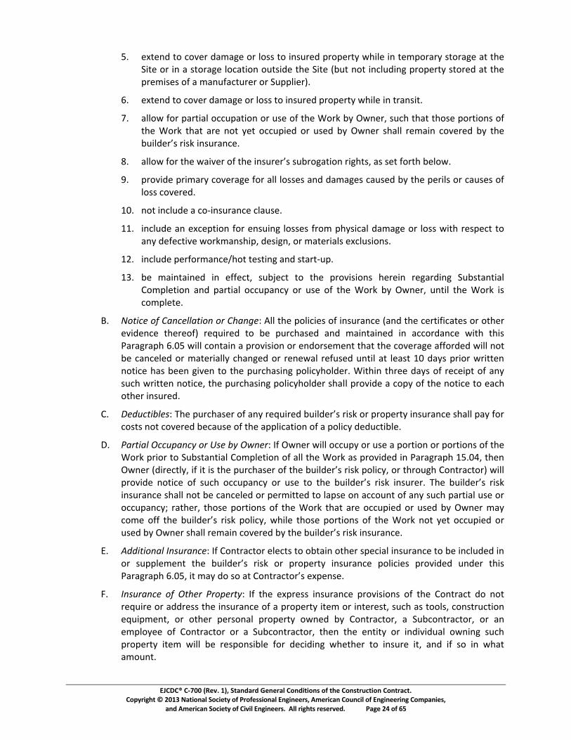
��������������� ������������������������������������������������������������� ��� !��"���#�$��%�&��������������!����'��������������"��������()��������������������"�������"���) �������
����()�������������!������������"������ ��(�����"������������ �������������'�"�*$+����,-*
./0123145*36*76819*5:;:<1*69*=6>>*36*?4>@915*A96A193B*CD?=1*?4*31;A69:9B*>369:<1*:3*3D1*E?31*69*?4*:*>369:<1*=67:3?64*6@3>?51*3D1*E?31*FG@3*463*?47=@5?4<*A96A193B*>36915*:3*3D1*A91;?>1>*6H*:*;:4@H:73@919*69*E@AA=?19I/*
J/0123145*36*76819*5:;:<1*69*=6>>*36*?4>@915*A96A193B*CD?=1*?4*39:4>?3/*
K/0:==6C*H69*A:93?:=*677@A:3?64*69*@>1*6H*3D1*L69M*GB*NC419O*>@7D*3D:3*3D6>1*A693?64>*6H*3D1*L69M*3D:3*:91*463*B13*677@A?15*69*@>15*GB*NC419*>D:==*91;:?4*7681915*GB*3D1*PQRSTUVWXYVRXZYR[XQV\[]U*
_/0\SSaYbVYcdUYa\ReUVYbYcdUYR[XQVUVWXYXQPVf\cR[YV?<D3>O*:>*>13*H693D*G1=6C/*
g/0A968?51*A9?;:9B*76819:<1*H69*:==*=6>>1>*:45*5:;:<1>*7:@>15*GB*3D1*A19?=>*69*7:@>1>*6H*=6>>*7681915/*
hi/0463*?47=@51*:*76j?4>@9:471*7=:@>1/*
hh/0?47=@51*:4*1271A3?64*H69*14>@?4<*=6>>1>*H96;*ADB>?7:=*5:;:<1*69*=6>>*C?3D*91>A173*36*:4B*51H173?81*C69M;:4>D?AO*51>?<4O*69*;:319?:=>*127=@>?64>/*
hk/0?47=@51*A19H69;:471lD63*31>3?4<*:45*>3:93j@A/*
hm/0G1*;:?43:?415*?4*1HH173O*>@Gn173*36*3D1*A968?>?64>*D191?4*91<:95?4<*E@G>3:43?:=*o6;A=13?64*:45*A:93?:=*677@A:47B*69*@>1*6H*3D1*L69M*GB*NC419O*@43?=*3D1*L69M*?>*76;A=131/*
p/0qrstuvwrxwyz{uv||zstr{wr}wy~z{�v�*�==*3D1*A6=?7?1>*6H*?4>@9:471*F:45*3D1*7193?H?7:31>*69*63D19*18?51471*3D1916HI*91�@?915*36*G1*A@97D:>15*:45*;:?43:?415*?4*:77695:471*C?3D*3D?>*�:9:<9:AD*J/i.*C?==*7643:?4*:*A968?>?64*69*14569>1;143*3D:3*3D1*76819:<1*:HH69515*C?==*463*G1*7:471=15*69*;:319?:==B*7D:4<15*69*9141C:=*91H@>15*@43?=*:3*=1:>3*hi*5:B>*A9?69*C9?3314*463?71*D:>*G114*<?814*36*3D1*A@97D:>?4<*A6=?7BD6=519/*L?3D?4*3D911*5:B>*6H*9171?A3*6H*:4B*>@7D*C9?3314*463?71O*3D1*A@97D:>?4<*A6=?7BD6=519*>D:==*A968?51*:*76AB*6H*3D1*463?71*36*1:7D*63D19*?4>@915/*
o/0�v��ust�|v��Y�dUY�QV]d\XUVYbY\[�YVU�QRVUTYPQRSTUVWXYVRXZYVY�V�UVc�YR[XQV\[]UYXd\SSY�\�YbVY76>3>*463*7681915*G17:@>1*6H*3D1*:AA=?7:3?64*6H*:*A6=?7B*515@73?G=1/*
�/0�z}stz|w�uu��z{u�wr}w��vw��w��{v}�*�H*NC419*C?==*677@AB*69*@>1*:*A693?64*69*A693?64>*6H*3D1*L69M*A9?69*36*E@G>3:43?:=*o6;A=13?64*6H*:==*3D1*L69M*:>*A968?515*?4*�:9:<9:AD*h./i�O*3D14*�a[UVY�TRVU]cS��YRbYRcYRXYcdUY�QV]d\XUVYbYcdUYPQRSTUVWXYVRXZY�SR]��YVYcdVQfdY�[cV\]cV�YaRSSYA968?51*463?71*bYXQ]dY]]Q�\[]�YVYQXUYcYcdUYPQRSTUVWXYVRXZYR[XQVUVY�dUYPQRSTUVWXYVRXZY?4>@9:471*>D:==*463*G1*7:471=15*69*A19;?3315*36*=:A>1*64*:776@43*6H*:4B*>@7D*A:93?:=*@>1*69*677@A:47B�*9:3D19O*3D6>1*A693?64>*6H*3D1*L69M*3D:3*:91*677@A?15*69*@>15*GB*NC419*;:B*76;1*bbYcdUYPQRSTUVWXYVRXZY�SR]��YadRSUYcdXUY�VcR[XYbYcdUY� VZY[cY�UcY]]Q�RUTYVYQXUTYP�Y�a[UVYXd\SSYVU�\R[Y]eUVUTYP�YcdUYPQRSTUVWXYVRXZYR[XQV\[]U*
�/0 ��tstr{z|w¡{��}z{uv�*�H*o6439:7369*1=173>*36*6G3:?4*63D19*>A17?:=*?4>@9:471*36*G1*?47=@515*?4*69*>@AA=U�U[cYcdUYPQRSTUVWXYVRXZYVY�V�UVc�YR[XQV\[]UY�SR]RUXY�VeRTUTYQ[TUVYcdRXY¢\V\fV\�dY£¤¥�YRcY�\�YTYXY\cY�[cV\]cVWXYU¦�U[XU*
§/0¡{��}z{uvwrxw�s~v}w�}r�v}s��*�H*3D1*12A91>>*?4>@9:471*A968?>?64>*6H*3D1*o6439:73*56*463*91�@?91*69*:5591>>*3D1*?4>@9:471*6H*:*A96A193B*?31;*69*?43191>3O*>@7D*:>*366=>O*764>39@73?64*1�@?A;143O*69*63D19*A19>64:=*A96A193B*6C415*GB*o6439:7369O*:*E@G76439:7369O*69*:4*1;A=6B11*6H*o6439:7369*69*:*E@G76439:7369O*3D14*3D1*143?3B*69*?45?8?5@:=*6C4?4<*>@7D*A96A193B*?31;*C?==*G1*91>A64>?G=1*H69*517?5?4<*CD13D19*36*?4>@91*?3O*:45*?H*>6*?4*CD:3*:;6@43/*
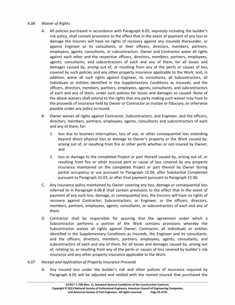
��������������� ������������������������������������������������������������� ��� !��"���#�$��%�&��������������!����'��������������"��������()��������������������"�������"���) �������
����()�������������!������������"������ ��(�����"������������ �������������'�"�*$+����,+*
-./-0 1234567897:3;<=>7
?.0@AABCDAEFEGHBCIJFKLHGMBENBLFFDJMLNFGBOEPKBQLJLRJLCKBSTUVWBGXCJGHHAYBENFAIMENRBPKGBZIEAMGJ[HB\]_*ab]cde*fgbb*cahig]h*\aj]]ah*ia*ifk*kllkci*ifgi*]h*ifk*kjkhi*al*gdmkhi*al*ghd*ba *a\*ngmgok*ifk*]hp\k\*q]bb*fgjk*ha*\]ofi*al*\kcajk\d*gog]hi*ghd*]hp\kn*ifk\kphnk\e*a\*gog]hi*rho]hkk\*a\*]i*cahpbighie*a\*ifk]\*all]ck\e*n]\kcia\e*mkmsk\e*g\ihk\e*km badkke*gokhie*cahpbighie*a\*pscahi\gcia\.*tqhk\*ghn*uahi\gcia\*qg]jk*gbb*\]ofi*gog]hi*kgcf*aifk\*ghn*ifk*\k kci]jk*all]ck\e*n]\kcia\e*mkmsk\e*g\ihk\e*km badkke*gokhie*cahpbighie*ghn*pscahi\gcia\*al*kgcf*ghn*ghd*al*ifkme*la\*gbb*ba k*ghn*ngmgok*cgpkn*sde*g\]]ho*api*ale*a\*\kpbi]ho*l\am*ghd*al*ifk*k\]b*a\*cgpk*al*ba *cajk\kn*sd*pcf*ab]c]k*ghn*ghd*aifk\*\ak\id*]hp\ghck*g b]cgsbk*ia*ifk*va\_w*ghne*]h*gnn]i]ahe*qg]jk*gbb*pcf*\]ofi*gog]hi*rho]hkk\e*]i*cahpbighie*gbb*xpscahi\gcia\e*gbb*]hn]j]npgb*a\*khi]i]k*]nkhi]l]kn*]h*ifk*xp bkmkhig\d*uahn]i]ah*g*]hp\kne*ghn*ifk*all]ck\e*n]\kcia\e*mkmsk\e*g\ihk\e*km badkke*gokhie*cahpbighie*ghn*pscahi\gcia\*al*kgcf*ghn*ghd*al*ifkme*phnk\*pcf*ab]c]k*la\*ba k*ghn*ngmgok*a*cgpkn.*yahk*al*ifk*gsajk*qg]jk\*fgbb*kzikhn*ia*ifk*\]ofi*ifgi*ghd*g\id*mg_]ho*pcf*qg]jk\*mgd*fgjk*ia*ifk*\ackkn*al*]hp\ghck*fkbn*sd*tqhk\*a\*uahi\gcia\*g*i\pikk*a\*l]npc]g\de*a\*aifk\q]k*gdgsbk*phnk\*ghd*ab]cd*a*]pkn.*
{.0tqhk\*qg]jk*gbb*\]ofi*gog]hi*uahi\gcia\e*xpscahi\gcia\e*ghn*rho]hkk\e*ghn*ifk*all]ck\e*n]\kcia\e*mkmsk\e*g\ihk\e*km badkke*gokhie*cahpbighi*ghn*pscahi\gcia\*al*kgcf*ghn*ghd*al*ifkme*la\|*
}.0ba *npk*ia*sp]hk *]hik\\pi]ahe*ba *al*pke*a\*aifk\*cahk~pkhi]gb*ba *kzikhn]ho*ZGYDNMBMEJGFPBCKYHEFLABADHHBDJBML�LRGBPDB�ONGJ[*\ak\id*a\*ifk*va\_*cgpkn*sde*g\]]ho*api*ale*a\*\kpbi]ho*l\am*l]\k*a\*aifk\*k\]b*qfkifk\*a\*hai*]hp\kn*sd*tqhk\w*ghn*
�.0ba *a\*ngmgok*ia*ifk*cam bkikn*�\a�kci*a\*g\i*ifk\kal*cgpkn*sde*g\]]ho*api*ale*a\*\kpbi]ho*l\am*l]\k*a\*aifk\*]hp\kn*k\]b*a\*cgpk*al*ba *cajk\kn*sd*ghd*\ak\id*]hp\ghck*mg]hig]hkn*ah*ifk*cam bkikn*�\a�kci*a\*g\i*ifk\kal*sd*tqhk\*np\]ho*g\i]gb*accpghcd*a\*pk*p\pghi*ia*�g\go\gf*}�./�e*glik\*xpsighi]gb*uam bki]ah*p\pghi*ia*�g\go\gf*}�./�e*a\*glik\*l]hgb*gdmkhi*p\pghi*ia*�g\go\gf*}�./-.*
u.0?hd*]hp\ghck*ab]cd*mg]hig]hkn*sd*tqhk\*cajk\]ho*ghd*ba e*ngmgok*a\*cahk~pkhi]gb*ba *\klk\\kn*ia*]h*�g\go\gf*-./-.{*fgbb*cahig]h*\aj]]ah*ia*ifk*kllkci*ifgi*]h*ifk*kjkhi*al*gdmkhi*al*ghd*pcf*ba e*ngmgoke*a\*cahk~pkhi]gb*ba e*ifk*]hp\k\*q]bb*fgjk*ha*\]ofi*al*\kcajk\d*gog]hi*uahi\gcia\e*xpscahi\gcia\e*a\*rho]hkk\e*a\*ifk*all]ck\e*n]\kcia\e*mkmsk\e*g\ihk\e*km badkke*gokhie*cahpbighie*a\*pscahi\gcia\*al*kgcf*ghn*ghd*al*ifkm.*
�.0uahi\gcia\*fgbb*sk*\k ah]sbk*la\*g p\]ho*ifgi*ifk*go\kkmkhi*phnk\*qf]cf*g*xpscahi\gcia\*k\la\m*g* a\i]ah*al*ifk*va\_*cahig]h* \aj]]ah*qfk\ksd*ifk*xpscahi\gcia\*qg]jk*gbb*\]ofi*gog]hi*tqhk\e*uahi\gcia\e*gbb*]hn]j]npgb*a\*khi]i]k*]nkhi]l]kn*]h*ifk*xp bkmkhig\d*uahn]i]ah*g*]hp\kne*ifk*rho]hkk\*ghn*]i*cahpbighie*ghn*ifk*all]ck\e*n]\kcia\e*mkmsk\e*g\ihk\e*km badkke*gokhie*cahpbighie*ghn*pscahi\gcia\*al*kgcf*ghn*ghd*al*ifkme*la\*gbb*ba k*ghn*ngmgok*cgpkn*sde*g\]]ho*api*ale*\kbgi]ho*iae*a\*\kpbi]ho*l\am*ghd*D�BPKGBCGJEAHBDJBFLIHGHBD�BADHHBFD�GJGMBZYBZIEAMGJ[HBJEH�B]hp\ghck*ghn*ghd*aifk\*\ak\id*]hp\ghck*g b]cgsbk*ia*ifk*va\_.*
-./�0 :5�53�=72��7����3�2=38�7897�68�56=�7��>�62��57�68�55�>7
?.0@NYBENHIJGMBADHHBINMGJBPKGBZIEAMGJ[HBJEH�BLNMBDPKGJBCDAEFEGHBD�BENHIJLNFGBJk~p]\kn*sd*�g\go\gf*-./�*q]bb*sk*gn�pikn*ghn*kiibkn*q]if*ifk*hgmkn*]hp\kn*ifgi*p\cfgkn*ifk*

��������������� ������������������������������������������������������������� ��� !��"���#�$��%�&��������������!����'��������������"��������()��������������������"�������"���) �������
����()�������������!������������"������ ��(�����"������������ �������������'�"�*$+����+,*
-./0123*4516*789:;*07<5=:;*<68//*81>*8<*?0;5108=2*?.=*>6:*.>6:=*07<5=:;<@*87;*A0B:*7.>01:*>.*<516*.>6:=*07<5=:;<*>68>*8;C5<>9:7>*87;*<:>>/:9:7>*.?*8*1/809*0<*07*-=.A=:<<3*D72*.>6:=*07<5=:;*982*<>8>:*0><*-.<0>0.7*=:A8=;07A*8*1/809*?.=*07<5=:;*/.<<*07*E=0>07A*E0>607*FG*;82<*8?>:=*7.>01:*.?*<516*1/8093*
H3IJ=.1::;<*?.=*<516*07<5=:;*/.<<:<*982*K:*98;:*-828K/:*K2*>6:*07<5=:=*:0>6:=*C.07>/2*>.*95/>0-/:*07<5=:;<@*.=*>.*>6:*789:;*07<5=:;*>68>*-5=168<:;*>6:*-./012*07*0><*.E7*=0A6>*87;*8<*?0;5108=2*?.=*.>6:=*07<5=:;<@*<5KC:1>*>.*>6:*=:L50=:9:7><*.?*872*8--/018K/:*9.=>A8A:*1/85<:3*MNOPQRSNTOUVWRSNWRXRTYTOZNTOUVWPOXRN[W\XRRSUNVOSRWN]RN_VTSRWaUNWTUbNPOSN\]RWN[\TXTRUN\cN07<5=871:*=:L50=:;*K2*J8=8A=8-6*d3eG*<68//*;0<>=0K5>:*<516*-=.1::;<*07*811.=;871:*E0>6*<516*8A=::9:7>*8<*>6:*-8=>0:<*07*07>:=:<>*982*=:816@*.=*8<*.>6:=E0<:*=:L50=:;*57;:=*>6:*;0<-5>:*=:<./5>0.7*-=.B0<0.7<*.?*>60<*f.7>=81>*.=*8--/018K/:*g8E<*87;*h:A5/8>0.7<3*
f3Ii?*7.*.>6:=*<-:108/*8A=::9:7>*0<*=:816:;@*>6:*;898A:;*j.=k*<68//*K:*=:-80=:;*.=*=:-/81:;@*>6:*9.7:2*<.*=:1:0B:;*8--/0:;*.7*811.57>*>6:=:.?@*87;*>6:*j.=k*87;*>6:*1.<>*>6:=:.?*1.B:=:;*K2*f687A:*l=;:=@*0?*7::;:;3*
(mn�o����p�qrstuvqtruwxyuzx{rsxn|nonmn���
}3eFI ~���������������~���������������
D3If.7>=81>.=*<68//*<5-:=B0<:@*07<-:1>@*87;*;0=:1>*>6:*j.=k*1.9-:>:7>/2*87;*:??010:7>/2@*;:B.>07A*<516*8>>:7>0.7*>6:=:>.*87;*8--/207A*<516*<k0//<*87;*:�-:=>0<:*8<*982*K:*7:1:<<8=2*>.*-:=?.=9*>6:*j.=k*07*811.=;871:*E0>6*>6:*f.7>=81>*�.159:7><3*f.7>=81>.=*<68//*K:*<./:/2*=:<-.7<0K/:*?.=*>6:*9:87<@*9:>6.;<@*>:1670L5:<@*<:L5:71:<@*87;*-=.1:;5=:<*.?*1.7<>=51>0.73*
H3ID>*8//*>09:<*;5=07A*>6:*-=.A=:<<*.?*>6:*j.=k@*f.7>=81>.=*<68//*8<<0A7*8*1.9-:>:7>*=:<0;:7>*<5-:=07>:7;:7>*E6.*<68//*7.>*K:*=:-/81:;*E0>6.5>*E=0>>:7*7.>01:*>.*lE7:=*87;*�7A07::=*:�1:->*57;:=*:�>=8.=;078=2*10=159<>871:<3*
}3e�I ���������������������
D3If.7>=81>.=*<68//*-=.B0;:*1.9-:>:7>@*<50>8K/2*L58/0?0:;*-:=<.77:/*>.*<5=B:2*87;*/82*.5>*>6:*j.=k*87;*-:=?.=9*1.7<>=51>0.7*8<*=:L50=:;*K2*>6:*f.7>=81>*�.159:7><3*f.7>=81>.=*<68//*8>*8//*>09:<*9807>807*A..;*;0<10-/07:*87;*.=;:=*8>*>6:*40>:3*
H3I��1:->*8<*.>6:=E0<:*=:L50=:;*?.=*>6:*<8?:>2*.=*-=.>:1>0.7*.?*-:=<.7<*.=*>6:*j.=k*.=*-=.-:=>2*8>*>6:*40>:*.=*8;C81:7>*>6:=:>.@*87;*:�1:->*8<*.>6:=E0<:*<>8>:;*07*>6:*f.7>=81>*�.159:7><@*8//*j.=k*8>*>6:*40>:*<68//*K:*-:=?.=9:;*;5=07A*=:A5/8=*E.=k07A*6.5=<@*�.7;82*>6=.5A6*�=0;823*f.7>=81>.=*E0//*7.>*-:=?.=9*j.=k*.7*8*48>5=;82@*457;82@*.=*872*/:A8/*6./0;823*f.7>=81>.=*982*-:=?.=9*j.=k*.5><0;:*=:A5/8=*E.=k07A*6.5=<*.=*.7*48>5=;82<@*45OSP�U�N\WNRZPN \TSP�UN\O�N�T]N��ORWaUN�WT]]RONX\OURO]�N�TXN�TNO\]N_RN57=:8<.78K/2*E0>66:/;3*
}3e�I ~��������� ������¡�������¢£���¤����
D3I¥7/:<<*.>6:=E0<:*<-:10?0:;*07*>6:*f.7>=81>*�.159:7><@*f.7>=81>.=*<68//*-=.B0;:*87;*8<<59:*?5//*=:<-.7<0K0/0>2*?.=*8//*<:=B01:<@*98>:=08/<@*:L50-9:7>@*/8K.=@*>=87<-.=>8>0.7@*1.7<>=51>0.7*:L50-9:7>*87;*981607:=2@*>../<@*8--/0871:<@*?5:/@*-.E:=@*/0A6>@*6:8>@*>:/:-6.7:@*E8>:=@*<870>8=2*?810/0>0:<@*>:9-.=8=2*?810/0>0:<@*87;*8//*.>6:=*?810/0>0:<*87;*0710;:7>8/<*7:1:<<8=2*?.=*>6:*-:=?.=9871:@*>:<>07A@*<>8=>*5-@*87;*1.9-/:>0.7*.?*>6:*j.=k@*E6:>6:=*.=*7.>*<516*0>:9<*8=:*<-:10?018//2*18//:;*?.=*07*>6:*f.7>=81>*�.159:7><3*
H3ID//*98>:=08/<*87;*:L50-9:7>*071.=-.=8>:;*07>.*>6:*j.=k*<68//*K:*.?*A..;*L58/0>2*87;*7:E@*:�1:->*8<*.>6:=E0<:*-=.B0;:;*07*>6:*f.7>=81>*�.159:7><3*D//*<-:108/*E8==87>0:<*87;*

��������������� ������������������������������������������������������������� ��� !��"���#�$��%�&��������������!����'��������������"��������()��������������������"�������"���) �������
����()�������������!������������"������ ��(�����"������������ �������������'�"�*$�����+,*
-./0/12334*035.6037*89*2:3*;<3=6>6=/26?14*4:/@@*3A<0344@9*0.1*2?*2:3*8313>62*?>*BC130D*E>*035.6037*89*F1-61330G*H?120/=2?0*4:/@@*>.0164:*4/264>/=2?09*3I6731=3*[email protected]*03<?024*?>*035.6037*23424K*/4*2?*2:3*4?.0=3G*L617G*/17*5./@629*?>*M/2306/@4*/17*35.6<M312D*
HDNO@@*M/2306/@4*/17*35.6<M312*4:/@@*83*42?037G*/<<@637G*6142/@@37G*=?113=237G*303=237G*<0?23=237G*.437G*=@3/137G*/17*=?17626?137*61*/==?07/1=3*C62:*61420.=26?14*?>*2:3*/<<@6=/8@3*;.<<@630G*3A=3<2*/4*?2:30C643*M/9*83*<0?I6737*61*2:3*H?120/=2*P?=.M3124D*
QDRSN TUVWXYZ[\]_
ODN`:313I30*/1*623M*?>*M/2306/@*?0*35.6<M312*64*4<3=6>637*?0*734=06837*61*2:3*H?120/=2*P?=.M3124*89*.461-*2:3*1/M3*?>*/*<0?<0632/09*623M*?0*2:3*1/M3*?>*/*</026=.@/0*;.<<@630G*2:3*H?120/=2*a06=3*:/4*8331*8/437*.<?1*H?120/=2?0*>.0164:61-*4.=:*623M*/4*4<3=6>637D*b:3*4<3=6>6=/26?1*?0*734=06<26?1*?>*4.=:*/1*623M*64*61231737*2?*342/8@64:*2:3*29<3G*>.1=26?1G*/<<3/0/1=3G*/17*5./@629*035.6037D*c1@344*2:3*4<3=6>6=/26?1*?0*734=06<26?1*=?12/614*?0*64*>?@@defghijhedkglhkfmgnophqrmqhodhsntfuhfvwnxmsfoquhdkhydkhfvwmszhnqf{hnlh|fk{nqqfguhH?120/=2?0*M/9*035.342*2:/2*F1-61330*/.2:?06}3*2:3*.43*?>*?2:30*623M4*?>*M/2306/@*?0*35.6<M312G*?0*623M4*>0?M*?2:30*<0?<?437*4.<<@6304*.1730*2:3*=60=.M42/1=34*734=06837*83@?CD*
~DNE>*F1-61330*61*624*4?@3*764=0326?1*73230M6134*2:/2*/1*623M*?>*M/2306/@*?0*35.6<M312*<0?<?437*89*H?120/=2?0*64*>.1=26?1/@@9*35./@*2?*2:/2*1/M37*/17*4.>>6=6312@9*46M6@/0*4?*qrmqhodh�rmopfhnohkfsmqfgh�dkthensshifhkfvwnkfguh�opnoffkhlrmsshgff{hnqhmohydkhfvwmszh623MD*�?0*2:3*<.0<?434*?>*2:64*</0/-0/<:G*/*<0?<?437*623M*?>*M/2306/@*?0*35.6<M312*C6@@*83*=?14673037*>.1=26?1/@@9*35./@*2?*/1*623M*4?*1/M37*6>�*
/DN61*2:3*3A30=643*?>*03/4?1/8@3*�.7-M312*F1-61330*73230M6134*2:/2�*
~KN62*64*/2*@3/42*35./@*61*M/2306/@4*?>*=?1420.=26?1G*5./@629G*7.0/86@629G*/<<3/0/1=3G*42031-2:G*/17*7346-1*=:/0/=2306426=4�*
�KN62*C6@@*03@6/8@9*<30>?0M*/2*@3/42*35./@@9*C3@@*2:3*>.1=26?1*/17*/=:63I3*2:3*034.@24*6M<?437*89*2:3*7346-1*=?1=3<2*?>*2:3*=?M<@3237*a0?�3=2*/4*/*>.1=26?161-*C:?@3�*
�KN62*:/4*/*<0?I31*03=?07*?>*<30>?0M/1=3*/17*/I/6@/86@629*?>*034<?146I3*430I6=3�*/17*
SKN62*64*1?2*?8�3=26?1/8@3*2?*BC130D*
8DNH?120/=2?0*=3026>634*2:/2G*6>*/<<0?I37*/17*61=?0<?0/237*612?*2:3*?0L�*
~KN2:303*C6@@*83*1?*61=03/43*61*=?42*2?*2:3*BC130*?0*61=03/43*61*H?120/=2*b6M34�*/17*
�KN62*C6@@*=?1>?0M*4.842/126/@@9*2?*2:3*732/6@37*035.603M3124*?>*2:3*623M*1/M37*61*2:3*H?120/=2*P?=.M3124D*
�DN����V[���V�]WX����]��h�doqkm�qdkhlrmssh|kdxngfhmsshgmqmhnohlw||dkqhd�hmojh|kd|dlfghydkhfvwmszhnqf{hmqh�doqkm�qdk�lhf�|folf�*
HDNX������V�]WX�[\Z[����W[��W������� ¡¢�£ �*F1-61330*C6@@*83*/@@?C37*/*03/4?1/8@3*26M3*2?*fxmswmqfhfm�rhydk¤fvwmszhkfvwflq�hh�opnoffkh{mjhkfvwnkfh�doqkm�qdkhqdh�wkonlrhmggnqndomshgmqmhmidwqhqrfh|kd|dlfghydk¤fvwmszhnqf{�h�opnoffkhensshifhqrfhldsfh¥wgpfhd�hm��f|qminsnqj�h¦dhydk¤fvwmszhnqf{hensshifhdkgfkfguh�wkonlrfguhnolqmssfguhdkhwqnsn§fghwoqnsh�opnoffk�lhkfxnfehnlh�d{|sfqfhmogh�opnoffkhgfqfk{noflhqrmqhqrfh|kd|dlfghnqf{hnlhmohydk¤fvwmszuhern�rhensshifh3I6731=37*89*/1*/<<0?I37*;:?<*P0/C61-*?0*?2:30*C062231*=?MM.16=/26?1D*F1-61330*C6@@*/7I643*H?120/=2?0*61*C06261-*?>*/19*13-/26I3*73230M61/26?1D*

��������������� ������������������������������������������������������������� ��� !��"���#�$��%�&��������������!����'��������������"��������()��������������������"�������"���) �������
����()�������������!������������"������ ��(�����"������������ �������������'�"�*$+����,-*
./01223456726189:833;<=6>353;?:8@5:78ABCDEFGDHBIJJHKLIMBNKHBODNEIMBKPBINBQKHRDSTIMUBHDSTDVFBVGIMMBHDVTMFBENBINWBXGINYDBENBZKNFHIXFB[HEXD\B]GDBNYENDDH_VBODNEIMBKPBINBQKHRDSTIMUBHDSTDVFBabcc*de*fghbc*bhi*dghighjk*bhi*lbm*hno*de*peqepei*oapnrja*bh*bssebc*rhiep*bhm*spnqggnh*nf*oae*tnhopbuo*.nurleho/*
v/0wxyz{|y}{~z�~z~����{�{�{��}~�y��y�{�*�f*vhjgheep*ieoeplghe*oabo*bh*goel*nf*lboepgbc*np*DSTEJ�DNFBJHKJKVDOB�WBZKNFHIXFKHBOKDVBNKFBSTIMEPWBIVBINBQKHRDSTIMUBEFD�k*tnhopbuonp*lbm*pe�reo*oabo*vhjgheep*unhgiepei*oae*spnsnei*goel*b*b*rdogoroe*srprbho*on*�bpbjpbsa*�/��/*
�/��0 ����{�{�{y�~
�/0�hce *oae*seugfgubognh*np*ieupgsognh*nf*bh*goel*nf*lboepgbc*np*e�rgsleho*pe�rgpei*on*de*frphgaei*rhiep*oae*tnhopbuo*.nurleho*unhobgh*np*g*fnccn�ei*dm*�npi*pebighj*oabo*hn*rdogorognh*g*seplgooeik*tnhopbuonp*lbm*pe�reo*oabo*vhjgheep*broanpg�e*oae*re*nf*noaep*goel*nf*lboepgbc*np*e�rgsleho*rhiep*oae*ugpurlobhue*ieupgdei*decn�/*�n*oae*e�oeho*sn gdce*rua*pe�reo*abcc*de*lbie*defnpe*unllehueleho*nf*pecboei*unhopruognh*bo*oae*�goe/*
�/0tnhopbuonp*abcc*rdlgo*rffgugeho*ghfnplbognh*b*spnqgiei*decn�*on*bccn�*vhjgheep*on*ieoeplghe*gf*oae*goel*nf*lboepgbc*np*e�rgsleho*spnsnei*g*frhuognhbccm*e�rgqbceho*on*oabo*hblei*bhi*bh*buuesobdce*rdogoroe*oaepefnp/*vhjgheep*�gcc*hno*buueso*pe�reo*fnp*peqge�*nf*spnsnei*rdogoroe*goel*nf*lboepgbc*np*e�rgsleho*fpnl*bhmnhe*noaep*oabh*tnhopbuonp/*
�/0�ae*pe�rgpeleho*fnp*peqge�*dm*vhjgheep*�gcc*de*b*eo*fnpoa*gh*�bpbjpbsa*�/��/�k*b*rsscelehoei*dm*oae*�seugfgubognhk*bhi*b*vhjgheep*lbm*ieugie*g*bsspnspgboe*rhiep*oae*ugpurlobhue/*
�/0tnhopbuonp*abcc*lb�e*�pgooeh*bsscgubognh*on*vhjgheep*fnp*peqge�*nf*b*spnsnei*rdogoroe*goel*nf*lboepgbc*np*e�rgsleho*oabo*tnhopbuonp*ee�*on*frphga*np*re/*�ae*bsscgubognh�*
b/0 abcc*uepogfm*oabo*oae*spnsnei*rdogoroe*goel*�gcc�*
��0sepfnpl*bie�rboecm*oae*frhuognh*bhi*buageqe*oae*perco*ubccei*fnp*dm*oae*jehepbc*iegjhk*
��0de*glgcbp*gh*rdobhue*on*oabo*seugfgeik*bhi*
��0de*rgoei*on*oae*ble*re*b*oabo*seugfgei/*
d/0�gcc*oboe�*
��0oae*e�oehok*gf*bhmk*on*�agua*oae*re*nf*oae*spnsnei*rdogoroe*goel*�gcc*heue goboe*b*uabhje*gh*tnhopbuo*�glek*
��0�aeoaep*re*nf*oae*spnsnei*rdogoroe*goel*gh*oae*�np�*�gcc*pe�rgpe*b*uabhje*gh*bhm*nf*oae*tnhopbuo*.nurleho*�np*gh*oae*spnqggnh*nf*bhm*noaep*igpeuo*unhopbuo*�goa*��hep*fnp*noaep*�np�*nh*oae*�pn euo�*on*bibso*oae*iegjh*on*oae*spnsnei*rdogoroe*goelk*bhi*
��0�aeoaep*ghunpsnpbognh*np*re*nf*oae*spnsnei*rdogoroe*goel*gh*unhheuognh*�goa*oae*�np�*g*rd euo*on*sbmleho*nf*bhm*cguehe*fee*np*pnmbcom/*
u/0�gcc*giehogfm�*
��0bcc*qbpgbognh*nf*oae*spnsnei*rdogoroe*goel*fpnl*oabo*seugfgeik*bhi*

��������������� ������������������������������������������������������������� ��� !��"���#�$��%�&��������������!����'��������������"��������()��������������������"�������"���) �������
����()�������������!������������"������ ��(�����"������������ �������������'�"�*$+����,-*
./0121341546*67837669378:*;146;:*<137=6717>6:*96?139:*17@*96?41>6<67=*;6923>6;A*
@A0;B144*>C7=137*17*3=6<3D6@*6;=3<1=6*CE*144*>C;=;*C9*>96@3=;*=B1=*F344*96;G4=*@396>=4H*C9*37@396>=4H*E9C<*G;6*CE*;G>B*;G5;=3=G=6*3=6<:*37>4G@378*5G=*7C=*43<3=6@*=C*>B1786;*37*IC7=91>=*J93>6:*;B196@*;12378;:*>C;=;*CE*96@6;387:*17@*>413<;*CE*C=B69*>C7=91>=C9;*1EE6>=6@*5H*17H*96;G4=378*>B1786A*
KA0LMNOMPPQRSTLUVWXVYOZMTVM[T\PYPQ]OMVYOZM*_7837669*F344*56*144CF6@*1*961;C71546*=3<6*=C*6214G1=6*61>B*;G5;=3=G=6*96G6;=:*17@*=C*C5=137*>C<<67=;*17@*@396>=3C7*E9C<*aF769A*_7837669*<1H*96G396*IC7=91>=C9*=C*EG973;B*1@@3=3C714*@1=1*15CG=*=B6*?9C?C;6@*;G5;=3=G=6*3=6<A*_7837669*F344*56*=B6*;C46*bG@86*CE*1>>6?=15343=HA*cC*;G5;=3=G=6*F344*56*C9@696@:*defghijklmnhgiopqqklmnrfneohqhsklnegohqntguhgkkfvinfkwhkxnhinyrz{qkoknpglntguhgkkfnlkokfzhgkinojponojkn{fr{riklnhokznhinpgnpyyk{op|qknie|iohoeok}ntguhgkkfvinlkokfzhgpohrgnxhqqn|kn623@67>6@*5H*1*~364@*a9@69*C9*1*?9C?C;6@*IB1786*a9@69*1>>CG7=378*EC9*=B6*;G5;=3=G=3C7*3=;64E*17@*144*9641=6@*3<?1>=;:*37>4G@378*>B1786;*37*IC7=91>=*J93>6*C9*IC7=91>=*�3<6;A*_7837669*F344*1@23;6*IC7=91>=C9*37*F93=378*CE*17H*7681=326*@6=69<371=3C7A*
IA0�����������������*aF769*<1H*96G396*IC7ofpyorfnorndefghijnpon�rgofpyorfvink�{kgiknpn;?6>314*?69EC9<17>6*8G1917=66*C9*C=B69*;G96=H*F3=B*96;?6>=*=C*17H*;G5;=3=G=6A*
�A0�PO]�XQSP]PMYTZ�TLMNOMPPQRST�ZSY�ntguhgkkfnxhqqnfkyrflntguhgkkfvinyrioinhgnkwpqepohgunpn;G5;=3=G=6*?9C?C;6@*C9*;G5<3==6@*5H*IC7=91>=C9A*�B6=B69*C9*7C=*_7837669*1??9C26;*1*;G5;=3=G=6*;C*?9C?C;6@*C9*;G5<3==6@*5H*IC7=91>=C9:*IC7=91>=C9*;B144*963<5G9;6*aF769*EC9*=B6*961;C71546*>B1986;*CE*_7837669*EC9*6214G1=378*61>B*;G>B*?9C?C;6@*;G5;=3=G=6A*IC7=91>=C9*;B144*14;C*963<5G9;6*aF769*EC9*=B6*961;C71546*>B1986;*CE*_7837669*EC9*<1�378*>B1786;*37*=B6*IC7=91>=*�C>G<67=;*�C9*37*=B6*?9C23;3C7;*CE*17H*C=B69*@396>=*>C7=91>=*F3=B*aF769/*96;G4=378*E9C<*=B6*1>>6?=17>6*CE*61>B*?9C?C;6@*;G5;=3=G=6A*
_A0�ZMYQV�YZQRSTL��PMSP*IC7=91>=C9*;B144*?9C23@6*144*@1=1*37*;G??C9=*CE*17H*?9C?C;6@*ie|iohoeoknpon�rgofpyorfvink�{kgik}*
~A0L��P�YTZ�TLMNOMPPQRST\PYPQ]OMVYOZM*�E*_7837669*1??9C26;*=B6*;G5;=3=G=3C7*96G6;=:*IC7=91>=C9*;B144*6�6>G=6*=B6*?9C?C;6@*IB1786*a9@69*17@*?9C>66@*F3=B*=B6*;G5;=3=G=3C7A*�jkntguhgkkfvinlkghpqnrdnpnie5;=3=G=3C7*96G6;=*;B144*56*E3714*17@*537@378:*17@*<1H*7C=*56*96269;6@*=B9CG8B*17*1??614*G7@69*17H*?9C23;3C7*CE*=B6*IC7=91>=*�C>G<67=;A*IC7=91>=C9*<1H*>B1446786*=B6*;>C?6*CE*963<5G9;6<67=*>C;=;*3<?C;6@*G7@69*J191891?B*�A� A�:*5H*=3<64H*;G5<3==14*CE*1*IB1786*J9C?C;14A*
�A�¡0 ¢£�������¤���¥�£������£�¦§���������¦§����©�ª��¦�
«A0IC7=91>=C9*<1H*96=137*¬G5>C7=91>=C9;*17@*¬G??4369;*EC9*=B6*?69EC9<17>6*CE*?19=;*CE*=B6*�C9�A**¬G>B*¬G5>C7=91>=C9;*17@*¬G??4369;*<G;=*56*1>>6?=1546*=C*aF769A*
KA0IC7=91>=C9*;B144*96=137*;?6>3E3>*¬G5>C7=91>=C9;:*¬G??4369;:*C9*C=B69*37@323@G14;*C9*67=3=36;*EC9*=B6*?69EC9<17>6*CE*@6;3871=6@*?19=;*CE*=B6*�C9�*3E*96G396@*5H*=B6*IC7=91>=*=C*@C*;CA*
IA0e|ik®ekgonornojknie|zhoopqnrdn�rgofpyorfvinhlnrfndhgpqngkurohpohrgnrdnojknokfzinrdnojknIC7=91>=:*aF769*<1H*7C=*96G396*IC7=91>=C9*=C*96=137*17H*¬G5>C7=91>=C9:*¬G??4369:*C9*C=B69*37@323@G14*C9*67=3=H*=C*EG973;B*C9*?69EC9<*17H*CE*=B6*�C9�*18137;=*FB3>B*IC7=91>=C9*B1;*961;C71546*C5b6>=3C7A*
�A0J93C9*=C*67=9H*37=C*17H*537@378*;G5>C7=91>=*C9*?G9>B1;6*C9@69:*IC7=91>=C9*;B144*;G5<3=*=C*aF769*=B6*3@67=3=H*CE*=B6*?9C?C;6@*¬G5>C7=91>=C9*C9*¬G??4369*�G746;;*aF769*B1;*14961@H*@66<6@*;G>B*?9C?C;6@*¬G5>C7=91>=C9*C9*¬G??4369*1>>6?=1546:*@G9378*=B6*53@@378*?9C>6;;*C9*C=B69F3;6/A*¬G>B*?9C?C;6@*¬G5>C7=91>=C9*C9*¬G??4369*;B144*56*@66<6@*1>>6?=1546*=C*aF769*G746;;*aF769*913;6;*1*;G5;=17=326:*961;C71546*C5b6>=3C7*F3=B37*E326*@1H;A*

��������������� ������������������������������������������������������������� ��� !��"���#�$��%�&��������������!����'��������������"��������()��������������������"�������"���) �������
����()�������������!������������"������ ��(�����"������������ �������������'�"�*%�����+,*
-./01234*567*4389:43*;<3*43=>6?3532;*@A*627*B9C?@2;46?;@4D*B9==>:34D*@4*@;<34*:2E:F:E96>*@4*32;:;7*43;6:23E*C7*G@2;46?;@4*;@*=34A@45*627*=64;*@A*;<3*H@4I.*01234*6>J@*567*4389:43*G@2;46?;@4*;@*43;6:2*J=3?:A:?*43=>6?3532;JK*=4@F:E3ED*<@13F34D*;<6;*01234*567*2@;*4389:43*6*43=>6?3532;*;@*1<:?<*G@2;46?;@4*<6J*6*436J@26C>3*@CL3?;:@2.*MA*G@2;46?;@4*<6J*J9C5:;;3E*;<3*:E32;:;7*@A*?34;6:2*B9C?@2;46?;@4JD*B9==>:34JD*@4*@;<34*:2E:F:E96>J*@4*32;:;:3J*A@4*6??3=;62?3*C7*01234D*62E*01234*<6J*6??3=;3E*:;*N3:;<34*:2*14:;:2O*@4*C7*A6:>:2O*;@*56I3*14:;;32*@CL3?;:@2*;<343;@PD*;<32*01234*567*J9CJ38932;>7*43F@I3*;<3*6??3=;62?3*@A*627*J9?<*B9C?@2;46?;@4D*B9==>:34D*@4*@;<34*:2E:F:E96>*@4*32;:;7*J@*:E32;:A:3E*J@>3>7*@2*;<3*C6J:J*@A*J9CJ;62;:F3D*436J@26C>3*@CL3?;:@2*6A;34*E93*:2F3J;:O6;:@2.*G@2;46?;@4*J<6>>*J9C5:;*62*6??3=;6C>3*43=>6?3532;*A@4*;<3*43L3?;3E*B9C?@2;46?;@4D*B9==>:34D*@4*@;<34*:2E:F:E96>*@4*32;:;7.*
Q./MA*01234*4389:43J*;<3*43=>6?3532;*@A*627*B9C?@2;46?;@4D*B9==>:34D*@4*@;<34*:2E:F:E96>*@4*32;:;7*43;6:23E*C7*G@2;46?;@4*;@*=34A@45*627*=64;*@A*;<3*H@4ID*;<32*G@2;46?;@4*J<6>>*C3*32;:;>3E*;@*62*6EL9J;532;*:2*G@2;46?;*R4:?3*@4*G@2;46?;*S:53JD*@4*C@;<D*1:;<*43J=3?;*;@*;<3*43=>6?3532;K*62E*G@2;46?;@4*J<6>>*:2:;:6;3*6*G<62O3*R4@=@J6>*A@4*J9?<*6EL9J;532;*1:;<:2*TU*VWXYZ[\Z] _abYZacdeaf _gZ[\ZahiWjf _gk*
l./m@*6??3=;62?3*C7*01234*@A*627*J9?<*B9C?@2;46?;@4D*B9==>:34D*@4*@;<34*:2E:F:E96>*@4*32;:;7D*1<3;<34*:2:;:6>>7*@4*6J*6*43=>6?3532;D*J<6>>*?@2J;:;9;3*6*16:F34*@A*;<3*4:O<;*@A*01234*;@*;<3*?@5=>3;:@2*@A*;<3*H@4I*:2*6??@4E62?3*1:;<*;<3*G@2;46?;*n@?9532;J.*
o./02*6*5@2;<>7*C6J:J*G@2;46?;@4*J<6>>*J9C5:;*;@*-2O:2334*6*?@5=>3;3*>:J;*@A*6>>*B9C?@2;46?;@4J*62E*B9==>:34J*<6F:2O*6*E:43?;*?@2;46?;*1:;<*G@2;46?;@4D*62E*@A*6>>*@;<34*B9C?@2;46?;@4J*62E*B9==>:34J*I2@12*;@*G@2;46?;@4*6;*;<3*;:53*@A*J9C5:;;6>.*
M./ G@2;46?;@4*J<6>>*C3*A9>>7*43J=@2J:C>3*;@*01234*62E*-2O:2334*A@4*6>>*6?;J*62E*@5:JJ:@2J*@A*;<3*B9C?@2;46?;@4JD*B9==>:34JD*62E*@;<34*:2E:F:E96>J*@4*32;:;:3J*=34A@45:2O*@4*A942:J<:2O*627*@A*gpZq[arZsdYgZWYZt[_gaWjg[aZeYZaYh[_YeuiZ\[aZt[_gaWjg[abYZ[_ZWjgYZW_VZ[feYYe[_Yk*
v./ G@2;46?;@4*J<6>>*C3*J@>3>7*43J=@2J:C>3*A@4*J?<3E9>:2O*62E*?@@4E:26;:2O*;<3*1@4I*@A*B9C?@2;46?;@4JD*B9==>:34JD*62E*6>>*@;<34*:2E:F:E96>J*@4*32;:;:3J*=34A@45:2O*@4*A942:J<:2O*627*@A*;<3*H@4I.*
w./G@2;46?;@4*J<6>>*43J;4:?;*6>>*B9C?@2;46?;@4JD*B9==>:34JD*62E*J9?<*@;<34*:2E:F:E96>J*@4*32;:;:3J*=34A@45:2O*@4*A942:J<:2O*627*@A*;<3*H@4I*A4@5*?@5592:?6;:2O*1:;<*-2O:2334*@4*01234D*3x?3=;*;<4@9O<*G@2;46?;@4*@4*:2*?6J3*@A*62*3534O32?7D*@4*6J*@;<341:J3*3x=43JJ>7*6>>@13E*<343:2.*
y./S<3*E:F:J:@2J*62E*J3?;:@2J*@A*;<3*B=3?:A:?6;:@2J*62E*;<3*:E32;:A:?6;:@2J*@A*627*n461:2OJ*J<6>>*2@;*?@2;4@>*G@2;46?;@4*:2*E:F:E:2O*;<3*H@4I*65@2O*B9C?@2;46?;@4J*@4*B9==>:34J*@4*E3>:236;:2O*;<3*H@4I*;@*C3*=34A@453E*C7*627*J=3?:A:?*;46E3.*
z./{>>*H@4I*=34A@453E*A@4*G@2;46?;@4*C7*6*B9C?@2;46?;@4*@4*B9==>:34*J<6>>*C3*=94J962;*;@*62*6==4@=4:6;3*?@2;46?;96>*6O433532;*;<6;*J=3?:A:?6>>7*C:2EJ*;<3*B9C?@2;46?;@4*@4*B9==>:34*;@*;<3*6==>:?6C>3*;345J*62E*?@2E:;:@2J*@A*;<3*G@2;46?;*n@?9532;J*A@4*;<3*C323A:;*@A*01234*62E*-2O:2334.*
m./01234*567*A942:J<*;@*627*B9C?@2;46?;@4*@4*B9==>:34D*;@*;<3*3x;32;*=46?;:?6C>3D*:2A@456;:@2*6C@9;*65@92;J*=6:E*;@*G@2;46?;@4*@2*6??@92;*@A*H@4I*=34A@453E*A@4*G@2;46?;@4*C7*;<3*=64;:?9>64*B9C?@2;46?;@4*@4*B9==>:34.*

��������������� ������������������������������������������������������������� ��� !��"���#�$��%�&��������������!����'��������������"��������()��������������������"�������"���) �������
����()�������������!������������"������ ��(�����"������������ �������������'�"�*%�����+,*
-./0123456*45*237*81529:;2*<1;=>752?@*
A./?3:BB*;97:27*C19*237*D757C42*1C*:5E*?=;3*F=D;1529:;219G*F=HHB479G*19*12379*45I4J4I=:B*19*75242E*:5E*;1529:;2=:B*97B:2415?34H*D72K775*-K579*19*L5645779*:5I*:5E*?=;3*F=D;1529:;219G*F=HHB479G*19*12379*45I4J4I=:B*19*75242EM*519*
N./?3:BB*;97:27*:5E*1DB46:2415*15*237*H:92*1C*-K579*19*L5645779*21*H:E*19*21*?77*21*237*H:E>752*1C*:5E*>157E*I=7*:5E*?=;3*F=D;1529:;219G*F=HHB479G*19*12379*45I4J4I=:B*19*75242E*7O;7H2*:?*>:E*12379K4?7*D7*97P=497I*DE*Q:K?*:5I*R76=B:2415?.*
S.TS/ UVWXYWZ[XX\ZVY]Z_VaWbX\Z
c./81529:;219*?3:BB*H:E*:BB*B4;75?7*C77?*:5I*91E:B247?*:5I*:??=>7*:BB*;1?2?*45;4I752*21*237*=?7*45*237*H79C19>:5;7*1C*237*d19e*19*237*45;19H19:2415*45*237*d19e*1C*:5E*45J752415G*I7?465G*H91;7??G*H91I=;2G*19*I7J4;7*K34;3*4?*237*?=Df7;2*1C*H:2752*94632?*19*;1HE94632?*37BI*DE*12379?.*gC*:*H:924;=B:9*45J752415G*I7?465G*H91;7??G*H91I=;2G*19*I7J4;7*4?*?H7;4C47I*45*237*81529:;2*<1;=>752?*C19*=?7*45*237*H79C19>:5;7*1C*237*d19e*:5I*4CG*21*237*:;2=:B*e51KB7I67*1C*-K579*19*L5645779G*42?*=?7*4?*?=Df7;2*21*H:2752*94632?*19*;1HE94632?*;:BB456*C19*237*H:E>752*1C*:5E*B4;75?7*C77*19*91E:B2E*21*12379?G*237*7O4?275;7*1C*?=;3*94632?*?3:BB*D7*I4?;B1?7I*DE*-K579*45*237*81529:;2*<1;=>752?.*
h./i1*237*C=BB7?2*7O2752*H79>4227I*DE*Q:K?*:5I*R76=B:2415?G*-K579*?3:BB*45I7>54CE*:5I*31BI*3:9>B7??*81529:;219G*:5I*42?*1CC4;79?G*I497;219?G*>7>D79?G*H:92579?G*7>HB1E77?G*:6752?G*;15?=B2:52?G*:5I*?=D;1529:;219?*C91>*:5I*:6:45?2*:BB*;B:4>?G*;1?2?G*B1??7?G*:5I*I:>:67?*j45;B=I456*D=2*512*B4>427I*21*:BB*C77?*:5I*;3:967?*1C*75645779?G*:9;3427;2?G*:221957E?G*:5I*12379*H91C7??415:B?G*:5I*:BB*;1=92*19*:9D429:2415*19*12379*I4?H=27*97?1B=2415*;1?2?k*:94?456*1=2*1C*19*97B:2456*21*:5E*45C94567>752*1C*H:2752*94632?*19*;1HE94632?*45;4I752*21*237*=?7*45*237*H79C19>:5;7*1C*237*d19e*19*97?=B2456*C91>*237*45;19H19:2415*45*237*d19e*1C*:5E*45J752415G*I7?465G*H91;7??G*H91I=;2G*19*I7J4;7*?H7;4C47I*45*237*81529:;2*<1;=>752?G*D=2*512*4I7524C47I*:?*D7456*?=Df7;2*21*H:E>752*1C*:5E*B4;75?7*C77*19*91E:B2E*21*12379?*97P=497I*DE*H:2752*94632?*19*;1HE94632?.*
8./i1*237*C=BB7?2*7O2752*H79>4227I*DE*Q:K?*:5I*R76=B:2415?G*81529:;219*?3:BB*45I7>54CE*:5I*31BI*3:9>B7??*-K579*:5I*L5645779G*:5I*237*1CC4;79?G*I497;219?G*>7>D79?G*H:92579?G*7>HB1E77?G*:6752?G*;15?=B2:52?*:5I*?=D;1529:;219?*1C*7:;3*:5I*:5E*1C*237>*C91>*:5I*:6:45?2*:BB*;B:4>?G*;1?2?G*B1??7?G*:5I*I:>:67?*j45;B=I456*D=2*512*B4>427I*21*:BB*C77?*:5I*;3:967?*1C*75645779?G*:9;3427;2?G*:221957E?G*:5I*12379*H91C7??415:B?*:5I*:BB*;1=92*19*:9D429:2415*19*12379*I4?H=27*97?1B=2415*;1?2?k*:94?456*1=2*1C*19*97B:2456*21*:5E*45C94567>752*1C*H:2752*94632?*19*;1HE94632?*45;4I752*21*237*=?7*45*237*H79C19>:5;7*1C*237*d19e*19*97?=B2456*C91>*237*45;19H19:2415*45*237*d19e*1C*:5E*45J752415G*I7?465G*H91;7??G*H91I=;2G*19*I7J4;7*512*?H7;4C47I*45*237*81529:;2*<1;=>752?.*
S.Tl/ UXmnbW\Z
c./o5B7??*12379K4?7*H91J4I7I*45*237*81529:;2*<1;=>752?G*81529:;219*?3:BB*1D2:45*:5I*H:E*C19*:BB*;15?29=;2415*H79>42?*:5I*B4;75?7?.*-K579*?3:BB*:??4?2*81529:;219G*K375*57;7??:9EG*45*1D2:45456*?=;3*H79>42?*:5I*B4;75?7?.*81529:;219*?3:BB*H:E*:BB*61J795>752:B*;3:967?*:5I*45?H7;2415*C77?*57;7??:9E*C19*237*H91?7;=2415*1C*237*d19e*K34;3*:97*:HHB4;:DB7*:2*237*24>7*pqrsturvwxyzvvzp{rpqr|p{s}~�sp}�vr�z�r�p}r�tu{r|p{s}~�sp}rxu�~yurxpw{�rw{�u}r~r576124:27I*;1529:;2k.*-K579*?3:BB*H:E*:BB*;3:967?*1C*=24B42E*1K579?*C19*;1557;2415?*C19*H91J4I456*H79>:5752*?79J4;7*21*237*d19e*
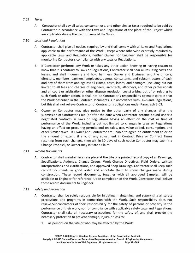
��������������� ������������������������������������������������������������� ��� !��"���#�$��%�&��������������!����'��������������"��������()��������������������"�������"���) �������
����()�������������!������������"������ ��(�����"������������ �������������'�"�*%$����+,*
-./01 234567
8.1*9:;<=>?<:=*@A>BB*C>D*>BB*@>BE@F*?:;@GHE=F*G@EF*>;I*:<AE=*@JHJB>=*<>KE@*=ELGJ=EI*<:*ME*C>JI*MD*9:;<=>?<:=*J;*>??:=I>;?E*NJ<A*<AE*O>N@*>;I*PEQGB><J:;@*:R*<AE*CB>?E*:R*<AE*S=:TE?<*NAJ?A*>=E*>CCBJ?>MBE*IG=J;Q*<AE*CE=R:=H>;?E*:R*<AE*U:=V.*
-.W/1 X3Y673Z[7\5]_3abZ67
8.19:;<=>?<:=*@A>BB*QJcE*>BB*;:<J?E@*=ELGJ=EI*MD*>;I*@A>BB*?:HCBD*NJ<A*>BB*O>N@*>;I*PEQGB><J:;@*>CCBJ?>MBE*<:*<AE*CE=R:=H>;?E*:R*<AE*U:=V.*dK?EC<*NAE=E*:<AE=NJ@E*EKC=E@@BD*=ELGJ=EI*MD*>CCBJ?>MBE*O>N@*>;I*PEQGB><J:;@F*;EJ<AE=*eN;E=*;:=*d;QJ;EE=*@A>BB*ME*=E@C:;@JMBE*R:=*fghijgkihlmnghjkopjgkqrmpgfstiohpumvijwmohxmyovrmgkmzul{tojighr|*
}.1~R*9:;<=>?<:=*CE=R:=H@*>;D*U:=V*:=*<>VE@*>;D*:<AE=*>?<J:;*V;:NJ;Q*:=*A>cJ;Q*=E>@:;*<:*V;:N*<A><*J<*J@*?:;<=>=D*<:*O>N@*:=*PEQGB><J:;@F*9:;<=>?<:=*@A>BB*ME>=*>BB*=E@GB<J;Q*?:@<@*>;I*B:@@E@F*>;I*@A>BB*J;IEH;JRD*>;I*A:BI*A>=HBE@@*eN;E=*>;I*d;QJ;EE=F*>;I*<AE*:RRJ?E=@F*IJ=E?<:=@F*HEHME=@F*C>=<;E=@F*EHCB:DEE@F*>QE;<@F*?:;@GB<>;<@F*>;I*@GM?:;<=>?<:=@*:R*E>?A*>;I*>;D*:R*<AEH*R=:H*>;I*>Q>J;@<*>BB*?B>JH@F*?:@<@F*B:@@E@F*>;I*I>H>QE@*�J;?BGIJ;Q*MG<*;:<*BJHJ<EI*<:*>BB*REE@*>;I*?A>=QE@*:R*E;QJ;EE=@F*>=?AJ<E?<@F*><<:=;ED@F*>;I*:<AE=*C=:RE@@J:;>B@*>;I*>BB*?:G=<*:=*>=MJ<=><J:;*:=*:<AE=*IJ@CG<E*=E@:BG<J:;*?:@<@�*>=J@J;Q*:G<*:R*:=*=EB><J;Q*<:*@G?A*U:=V*gkmgjwukmopjigh|m�jmrwottmhgjm�umnghjkopjgkqrmkursghri�itijxmjgmfo�umpukjoihmjwojm<AE*U:=V*IE@?=JMEI*J;*<AE*9:;<=>?<*�:?GHE;<@*J@*J;*>??:=I>;?E*NJ<A*O>N@*>;I*PEQGB><J:;@F*�{jmjwirmrwottmhgjmkutiu�umnghjkopjgkmg�mnghjkopjgkqrmg�tilojighrm{h�ukm�okolkoswm�|/�.*
9.1eN;E=*:=*9:;<=>?<:=*H>D*QJcE*;:<J?E*<:*<AE*:<AE=*C>=<D*:R*>;D*?A>;QE@*>R<E=*<AE*r{�firrighmg�mnghjkopjgkqrm�i�m�gkmo�jukmjwum�ojumvwuhmnghjkopjgkm�upofum�g{h�m{h�ukmom;EQ:<J><EI*?:;<=>?<�*J;*O>N@*:=*PEQGB><J:;@*A>cJ;Q*>;*ERRE?<*:;*<AE*?:@<*:=*<JHE*:R*CE=R:=H>;?E*:R*<AE*U:=VF*J;?BGIJ;Q*MG<*;:<*BJHJ<EI*<:*?A>;QE@*J;*O>N@*:=*PEQGB><J:;@*A>cJ;Q*>;*ERRE?<*:;*C=:?G=J;Q*CE=HJ<@*>;I*:;*@>BE@F*G@EF*c>BGE�>IIEIF*?:;@GHC<J:;F*>;I*:<AE=*@JHJB>=*<>KE@.**~R*eN;E=*>;I*9:;<=>?<:=*>=E*G;>MBE*<:*>Q=EE*:;*E;<J<BEHE;<*<:*:=*:;*<AE*>H:G;<*:=*EK<E;<F*JR*>;DF*:R*>;D*>ITG@<HE;<*J;*9:;<=>?<*S=J?E*:=*9:;<=>?<*�JHE@*=E@GB<J;Q*R=:H*@G?A*?A>;QE@F*<AE;*NJ<AJ;*�/*I>D@*:R*@G?A*;:<J?E*9:;<=>?<:=*H>D*@GMHJ<*>*9A>;QE*S=:C:@>BF*:=*eN;E=*H>D*J;J<J><E*>*9B>JH.*
-.WW1 7\5�b�[7�b��5Z67
8.19:;<=>?<:=*@A>BB*H>J;<>J;*J;*>*@>RE*CB>?E*><*<AE*�J<E*:;E*C=J;<EI*=E?:=I*?:CD*:R*>BB*�=>NJ;Q@F*�CE?JRJ?><J:;@F*8IIE;I>F*9A>;QE*e=IE=@F*U:=V*9A>;QE*�J=E?<JcE@F*�JEBI*e=IE=@F*N=J<<E;*J;<E=C=E<><J:;@*>;I*?B>=JRJ?><J:;@F*>;I*>CC=:cEI*�A:C*�=>NJ;Q@.*9:;<=>?<:=*@A>BB*VEEC*@G?A*=E?:=I*I:?GHE;<@*J;*Q::I*:=IE=*>;I*>;;:<><E*<AEH*<:*@A:N*?A>;QE@*H>IE*IG=J;Q*?:;@<=G?<J:;.*�AE@E*=E?:=I*I:?GHE;<@F*<:QE<AE=*NJ<A*>BB*>CC=:cEI*�>HCBE@F*NJBB*ME*>c>JB>MBE*<:*d;QJ;EE=*R:=*=ERE=E;?E.*�C:;*?:HCBE<J:;*:R*<AE*U:=VF*9:;<=>?<:=*@A>BB*IEBJcE=*<AE@E*=E?:=I*I:?GHE;<@*<:*d;QJ;EE=.*
-.W�1 �3�5�73Z[7��b5�abZ7
8.19:;<=>?<:=*@A>BB*ME*@:BEBD*=E@C:;@JMBE*R:=*J;J<J><J;QF*H>J;<>J;J;QF*>;I*@GCE=cJ@J;Q*>BB*@>RE<D*C=E?>G<J:;@*>;I*C=:Q=>H@*J;*?:;;E?<J:;*NJ<A*<AE*U:=V.*�G?A*=E@C:;@JMJBJ<D*I:E@*;:<*=EBJEcE*�GM?:;<=>?<:=@*:R*<AEJ=*=E@C:;@JMJBJ<D*R:=*<AE*@>RE<D*:R*CE=@:;@*:=*C=:CE=<D*J;*<AE*CE=R:=H>;?E*:R*<AEJ=*N:=VF*;:=*R:=*?:HCBJ>;?E*NJ<A*>CCBJ?>MBE*@>RE<D*O>N@*>;I*PEQGB><J:;@.**9:;<=>?<:=*@A>BB*<>VE*>BB*;E?E@@>=D*C=E?>G<J:;@*R:=*<AE*@>RE<D*:RF*>;I*@A>BB*C=:cJIE*<AE*;E?E@@>=D*C=:<E?<J:;*<:*C=EcE;<*I>H>QEF*J;TG=DF*:=*B:@@*<:�*
W.1>BB*CE=@:;@*:;*<AE*�J<E*:=*NA:*H>D*ME*>RRE?<EI*MD*<AE*U:=V�*

��������������� ������������������������������������������������������������� ��� !��"���#�$��%�&��������������!����'��������������"��������()��������������������"�������"���) �������
����()�������������!������������"������ ��(�����"������������ �������������'�"�*%%����+,*
-./011*234*5678*09:*;0247<01=*09:*4>?<@;492*26*A4*<9B67@67024:*23474<9C*D342347*<9*=2670E4*69*67*6FF*234*G<24H*09:*
I./62347*@76@472J*02*234*G<24*67*0:K0B492*2347426C*<9B1?:<9E*2744=C*=37?A=C*10D9=C*D018=C*@0L4;492=C*760:D0J=C*=27?B2?74=C*62347*D678*<9*@76E74==C*?2<1<2<4=C*09:*M9:47E76?9:*N0B<1<2<4=*962*:4=<E9024:*F67*74;6L01C*7416B02<69C*67*74@10B4;492*<9*234*B6?7=4*6F*B69=27?B2<69.*
O./P69270B267*=3011*B6;@1J*D<23*011*0@@1<B0A14*Q0D=*09:*R4E?102<69=*74102<9E*26*234*=0F42J*6F*@47=69=*67*@76@472JC*67*26*234*@7624B2<69*6F*@47=69=*67*@76@472J*F76;*:0;0E4C*<9K?7JC*67*16==H*09:*=3011*474B2*09:*;0<920<9*011*94B4==07J*=0F4E?07:=*F67*=?B3*=0F42J*09:*@7624B2<69.*P69270B267*=3011*962<FJ*SD947H*234*6D947=*6F*0:K0B492*@76@472JC*M9:47E76?9:*N0B<1<2<4=C*09:*62347*?2<1<2<4=H*09:*62347*B69270B267=*09:*?2<1<2J*6D947=*@47F67;<9E*D678*02*67*0:K0B492*26*234*G<24C*D349*@76=4B?2<69*6F*234*5678*;0J*0FF4B2*234;C*09:*=3011*B66@47024*D<23*234;*<9*234*@7624B2<69C*74;6L01C*7416B02<69C*09:*74@10B4;492*6F*234<7*@76@472J*67*D678*<9*@76E74==.*
P./TUVWXYZWUX[\]Y[ZU_ a[bcW][W]d[Y`cZYed[XdfgcXd_dVW\[Uh[ibVdXj\[\YhdWa[XUkXY_\l[ch[YVam[[n]d[og`d_dVWYXa[TUVpcWcUV\[cpdVWcha[YVa[ibVdXj\[\YhdWJ*@76E70;=*2302*074*0@@1<B0A14*26*234*5678.*
q./TUVWXYZWUX[\]Y[cVhUX_[ibVdX[YVp[rVkcVddX[Uh[W]d[\dZchcZ[XdfgcXd_dVW\[Uh[TUVWXYZWUXj\[\YhdWa[XUkXY_[bcW][b]cZ][ibVdXj\[YVp[rVkcVddXj\[d_ Uadd\[YVp[XdXd\dVWYWcsd\[_g\W[B6;@1J*D3<14*02*234*G<24.*
t./u11*:0;0E4C*<9K?7JC*67*16==*26*09J*@76@472J*74F4774:*26*<9*v070E70@3*w.x-.u.-*67*w.x-.u.I*B0?=4:C*:<74B21J*67*<9:<74B21JC*<9*D3614*67*<9*@072C*AJ*P69270B267C*09J*G?AB69270B267C*G?@@1<47C*67*09J*62347*<9:<L<:?01*67*492<2J*:<74B21J*67*<9:<74B21J*4;@16J4:*AJ*09J*6F*234;*26*@47F67;*09J*6F*234*5678C*67*09J694*F67*D36=4*0B2=*09J*6F*234;*;0J*A4*1<0A14C*=3011*A4*74;4:<4:*AJ*P69270B267*02*<2=*4y@49=4*z4yB4@2*:0;0E4*67*16==*0227<A?20A14*26*234*F0?12*6F*q70D<9E=*67*G@4B<F<B02<69=*67*26*234*0B2=*67*6;<==<69=*6F*SD947*67*t9E<9447*67*09J694*4;@16J4:*AJ*09J*6F*234;C*67*09J694*F67*D36=4*0B2=*09J*6F*234;*;0J*A4*1<0A14C*09:*962*0227<A?20A14C*:<74B21J*67*<9:<74B21JC*<9*D3614*67*<9*@072C*26*234*F0?12*67*94E1<E49B4*6F*P69270B267*67*09J*G?AB69270B267C*G?@@1<47C*67*62347*<9:<L<:?01*67*492<2J*:<74B21J*67*<9:<74B21J*4;@16J4:*AJ*09J*6F*234;{.*
N./TUVWXYZWUXj\[pgWcd\[YVp[Xd\UV\ceccWcd\[hUX[\YhdWa[YVp[XUWdZWcUV[\]Y[ZUVWcVgd[gVWc[\gZ][2<;4*0=*011*234*5678*<=*B6;@1424:*09:*t9E<9447*30=*<==?4:*0*962<B4*26*SD947*09:*P69270B267*<9*0BB67:09B4*D<23*v070E70@3*x|.}~.O*2302*234*5678*<=*0BB4@20A14*z4yB4@2*0=*62347D<=4*4y@74==1J*@76L<:4:*<9*B6994B2<69*D<23*G?A=2092<01*P6;@142<69{.*
�./TUVWXYZWUXj\[pgWcd\[YVp[Xd\UV\ceccWcd\[hUX[\YhdWa[YVp[XUWdZWcUV[\]Y[Xd\g_d[b]dVdsdX[P69270B267*67*09J*G?AB69270B267*67*G?@@1<47*742?79=*26*234*G<24*26*F?1F<11*D077092J*67*B6774B2<69*6A1<E02<69=C*67*26*B69:?B2*62347*20=8=*07<=<9E*F76;*234*P69270B2*q6B?;492=.*
w.xI/ ����������������������
u./P69270B267*=3011*:4=<E9024*0*>?01<F<4:*09:*4y@47<49B4:*=0F42J*74@74=49202<L4*02*234*G<24*D36=4*:?2<4=*09:*74=@69=<A<1<2<4=*=3011*A4*234*@74L492<69*6F*0BB<:492=*09:*234*;0<920<9<9E*09:*=?@47L<=<9E*6F*=0F42J*@74B0?2<69=*09:*@76E70;=.*
w.x�/ ������������������������������
u./P69270B267*=3011*A4*74=@69=<A14*F67*B667:<902<9E*09J*4yB309E4*6F*;0247<01*=0F42J*:020*=3442=*67*62347*30�07:*B6;;?9<B02<69*<9F67;02<69*74>?<74:*26*A4*;0:4*0L0<10A14*26*67*

��������������� ������������������������������������������������������������� ��� !��"���#�$��%�&��������������!����'��������������"��������()��������������������"�������"���) �������
����()�������������!������������"������ ��(�����"������������ �������������'�"�*%+����,-*
./01234.5*6.78..3*9:*2;934*.;<=9>.:?*27*71.*@A7.*A3*2009:5230.*8A71*B28?*9:*C.4D=27A93?E*
FEGHI JKLMNLOPQLRS
TEIU3*.;.:4.30A.?*2VV.07A34*71.*?2V.7>*9:*<:97.07A93*9V*<.:?93?*9:*71.*W9:X*9:*<:9<.:7>*27*71.*@A7.*9:*25Y20.37*71.:.79Z*[937:2079:*A?*96=A427.5*79*207*79*<:.\.37*71:.27.3.5*52;24.Z*A3YD:>Z*9:*=9??E*[937:2079:*?12==*4A\.*]34A3..:*<:9;<7*8:A77.3*397A0.*AV*[937:2079:*6.=A.\.?*7127*23>*?A43AVA0237*01234.?*A3*71.*W9:X*9:*\2:A27A93?*V:9;*71.*[937:207*90D;.37?*12\.*6..3*02D?.5*71.:.6>*9:*2:.*:._DA:.5*2?*2*:.?D=7*71.:.9VE*UV*]34A3..:*5.7.:;A3.?*7127*2*01234.*A3*71.*[937:207*90D;.37?*A?*:._DA:.5*6.02D?.*9V*71.*207A93*72X.3*6>*[937:2079:*A3*:.?<93?.*79*?D01*23*.;.:4.30>Z*2*W9:X*[1234.*A:.07A\.*9:*[1234.*:5.:*8A==*6.*A??D.5E*
FEGaI bcdeSfMghQONRiSbgKejLRiSgOkSlmcLMSbnoKQmmgjRS
TEIbcdeSfMghQONSgOkSbgKejLSbnoKQmmgjSpLqnQMLKLOmRrS
GEIs.V9:.*?D6;A77A34*2*@19<*:28A34*9:*@2;<=.Z*[937:2079:*?12==*12\.r*
2EI:.\A.8.5*235*099:5A327.5*71.*@19<*:28A34*9:*@2;<=.*8A71*971.:*@19<*:28A34?*235*@2;<=.?*235*8A71*71.*:._DA:.;.37?*9V*71.*W9:X*235*71.*[937:207*90D;.37?t*
6EI5.7.:;A3.5*235*\.:AVA.5*2==*VA.=5*;.2?D:.;.37?Z*_D237A7A.?Z*5A;.3?A93?Z*?<.0AVA.5*<.:V9:;230.*235*5.?A43*0:A7.:A2Z*A3?72==27A93*:._DA:.;.37?Z*;27.:A2=?Z*0272=94*3D;6.:?Z*235*?A;A=2:*A3V9:;27A93*8A71*:.?<.07*71.:.79t*
0EI5.7.:;A3.5*235*\.:AVA.5*71.*?DA726A=A7>*9V*2==*;27.:A2=?*235*._DA<;.37*9VV.:.5*8A71*:.?<.07*79*71.*A35A027.5*2<<=A027A93Z*V26:A027A93Z*?1A<<A34Z*1235=A34Z*?79:24.Z*2??.;6=>Z*235*A3?72==27A93*<.:72A3A34*79*71.*<.:V9:;230.*9V*71.*W9:Xt*235*
5EIuvwvxyz{vu|}{u|~vxz�zvu|}��|z{��xy}wz�{|xv�}wz~v|w�|��{wx}�w�x��|xv���{�z�z�zwzv�|V9:*;.23?Z*;.7195?Z*7.013A_D.?Z*?._D.30.?Z*235*<:90.5D:.?*9V*093?7:D07A93Z*235*?2V.7>*<:.02D7A93?*235*<:94:2;?*A30A5.37*71.:.79E*
�EI]201*?D6;A772=*?12==*6.2:*2*?72;<*9:*?<.0AVA0*8:A77.3*0.:7AVA027A93*7127*[937:2079:*12?*�}wz��zvu|��{wx}�w�x��|���z�}wz�{�|�{uvx|w�v|��{wx}�w|����yv{w�|�zw�|xv��v�w|w�|��{wx}�w�x��|xv~zv�|��|w�}w|���yzww}��|}{u|w�}w|��{wx}�w�x|}��x�~v�|w�v|���yzww}��*
�EIWA71*.201*?D6;A772=Z*[937:2079:*?12==*4A\.*]34A3..:*?<.0AVA0*8:A77.3*397A0.*9V*23>*\2:A27A93?*7127*71.*@19<*:28A34*9:*@2;<=.*;2>*12\.*V:9;*71.*:._DA:.;.37?*9V*71.*[937:207*90D;.37?E*�1A?*397A0.*?12==*6.*?.7*V9:71*A3*2*8:A77.3*09;;D3A027A93*?.<2:27.*V:9;*71.*@19<*:28A34?*9:*@2;<=.*?D6;A772=t*235Z*A3*255A7A93Z*A3*71.*02?.*9V*@19<*:28A34?*6>*2*?<.0AVA0*39727A93*;25.*93*.201*@19<*:28A34*?D6;A77.5*79*]34A3..:*V9:*:.\A.8*235*2<<:9\2=*9V*.201*?D01*\2:A27A93E*
sEIbnoKQmmgjS�MdPLknMLRS�dMSbcdeSfMghQONRSgOkSbgKejLRr*[937:2079:*?12==*?D6;A7*@19<*:28A34?*235*@2;<=.?*79*]34A3..:*V9:*:.\A.8*235*2<<:9\2=*A3*2009:5230.*8A71*71.*200.<7.5*@01.5D=.*9V*@D6;A772=?E*]201*?D6;A772=*8A==*6.*A5.37AVA.5*2?*]34A3..:*;2>*:._DA:.E*
GEIbcdeSfMghQONRrS
2EI[937:2079:*?12==*?D6;A7*71.*3D;6.:*9V*09<A.?*:._DA:.5*A3*71.*@<.0AVA027A93?E*
6EI 272*?1983*93*71.*@19<*:28A34?*8A==*6.*09;<=.7.*8A71*:.?<.07*79*_D237A7A.?Z*5A;.3?A93?Z*?<.0AVA.5*<.:V9:;230.*235*5.?A43*0:A7.:A2Z*;27.:A2=?Z*235*?A;A=2:*5272*79*?198*]34A3..:*71.*?.:\A0.?Z*;27.:A2=?Z*235*._DA<;.37*[937:2079:*<:9<9?.?*79*

��������������� ������������������������������������������������������������� ��� !��"���#�$��%�&��������������!����'��������������"��������()��������������������"�������"���) �������
����()�������������!������������"������ ��(�����"������������ �������������'�"�*%+����,+*
-./0123*452*6/*354783*95:1533.*6/*.3013;*6<3*15=/.>461/5*=/.*6<3*81>1632*-?.-/@3@*.3A?1.32*7B*C4.4:.4-<*DEFGEHE*
IEJKLMNOPQRS
4EJT/56.4U6/.*@<488*@?7>16*6<3*5?>73.*/=*V4>-83@*.3A?1.32*15*6<3*V-3U1=1U461/5@E*
7EJT/56.4U6/.*@<488*U834.8B*123561=B*34U<*V4>-83*4@*6/*>463.148W*V?--813.W*-3.615356*2464*@?U<*4@*U4648/:*5?>73.@W*6<3*?@3*=/.*;<1U<*15635232*452*/6<3.*2464*4@*95:1533.*>4B*.3A?1.3*6/*354783*95:1533.*6/*.3013;*6<3*@?7>16648*=/.*6<3*81>1632*-?.-/@3@*.3A?1.32*7B*C4.4:.4-<*DEFGEHE*
XEJY<3.3*4*V</-*H.4;15:*/.*V4>-83*1@*.3A?1.32*7B*6<3*T/56.4U6*H/U?>356@*/.*6<3*Z[\]_]abcaZ_defgghijahklam]hg]anbmoap]mcbme]apmfbmagbaqkrfk]]msiam]tf]uahka4--./048*/=*6<3*-3.615356*@?7>16648*;188*73*46*6<3*@/83*3v-35@3*452*.3@-/5@171816B*/=*T/56.4U6/.E*
TEJwxyPzSK{|M}xxLOQR*T/56.4U6/.*@<488*@?7>16*/6<3.*@?7>16648@*6/*95:1533.*15*4UU/.245U3*;16<*6<3*4UU3-632*VU<32?83*/=*V?7>16648@W*452*-?.@?456*6/*6<3*4--81U4783*63.>@*/=*6<3*V-3U1=1U461/5@E*
HEJ~����������������RS
FEJ95:1533.*;188*-./0123*61>38B*.3013;*/=*V</-*H.4;15:@*452*V4>-83@*15*4UU/.245U3*;16<*g\]aZ[\]_]abcaZ_defgghiah[[]pghd]agbaqkrfk]]m�aqkrfk]]msiam]tf]uahkahppmbthaufa73*/58B*6/*2363.>153*1=*6<3*163>@*U/03.32*7B*6<3*@?7>16648@*;188W*4=63.*15@6488461/5*/.*15U/.-/.461/5*15*6<3*Y/.�W*U/5=/.>*6/*6<3*15=/.>461/5*:1035*15*6<3*T/56.4U6*H/U?>356@*452*73*U/>-461783*;16<*6<3*23@1:5*U/5U3-6*/=*6<3*U/>-83632*C./�3U6*4@*4*=?5U61/515:*;</83*4@*1521U4632*7B*6<3*T/56.4U6*H/U?>356@E*
IEJqkrfk]]msiam]tf]uahkahppmbthaufakbga]�g]kagbae]hkijae]g\bijag][\kf�_]ija@3A?35U3@W*/.*-./U32?.3@*/=*U/5@6.?U61/5*/.*6/*@4=36B*-.3U4?61/5@*/.*-./:.4>@*15U12356*6<3.36/E*
XEJqkrfk]]msiam]tf]uahkahppmbthabcahai]phmhg]afg]eahiai_[\aufakbgafkf[hg]ahppmbthabca6<3*4@@3>78B*15*;<1U<*6<3*163>*=?5U61/5@E*
�EJqkrfk]]msiam]tf]uahkahppmbthabcahaZ\bpa�mhufkrabmaZhep]ai\hakbgam]f303*T/56.4U6/.*=./>*.3@-/5@171816B*=/.*45B*04.1461/5*=./>*6<3*.3A?1.3>356@*/=*6<3*T/56.4U6*H/U?>356@*?583@@*T/56.4U6/.*<4@*U/>-8132*;16<*6<3*.3A?1.3>356@*/=*C4.4:.4-<*DEFGE�EX*452*95:1533.*<4@*:1035*;.16635*4--./048*/=*34U<*@?U<*04.1461/5*7B*@-3U1=1U*;.16635*5/6461/5*6<3.3/=*15U/.-/.4632*15*/.*4UU/>-45B15:*6<3*V</-*H.4;15:*/.*V4>-83E*95:1533.*;188*2/U?>356*45B*@?U<*4--./032*04.1461/5*=./>*6<3*.3A?1.3>356@*/=*6<3*T/56.4U6*H/U?>356@*15*4*�1382*�.23.E*
�EJqkrfk]]msiam]tf]uahkahppmbthabcahaZ\bpa�mhufkrabmaZhep]a@<488*5/6*.381303*T/56.4U6/.*=./>*.3@-/5@171816B*=/.*U/>-8B15:*;16<*6<3*.3A?1.3>356@*/=*C4.4:.4-<*DEFGE�*452*�E*
GEJqkrfk]]msiam]tf]uahkahppmbthabcahaZ\bpa�mhufkrabmaZhep]jabmabcahathmfhgfbkacmbea6<3*.3A?1.3>356@*/=*6<3*T/56.4U6*H/U?>356@W*@<488*5/6W*?523.*45B*U1.U?>@645U3@W*U<45:3*6<3*T/56.4U6*�1>3@*/.*T/56.4U6*C.1U3W*?583@@*@?U<*U<45:3@*4.3*15U8?232*15*4*T<45:3*�.23.E*
DEJ�]fg\]maqkrfk]]msiam][]fpgjam]tf]ujah[[]pghk[]abmahppmbthabcahaZ\bpa�mhufkrjaZhep]ja/.*/6<3.*@?7>16648*@<488*.3@?86*15*@?U<*163>*73U/>15:*4*T/56.4U6*H/U?>356E*

��������������� ������������������������������������������������������������� ��� !��"���#�$��%�&��������������!����'��������������"��������()��������������������"�������"���) �������
����()�������������!������������"������ ��(�����"������������ �������������'�"�*%+����+,*
-./0123456314*78599*:;4<14=*38;*>14?*@2*61=:9@526;*A@38*38;*4;BC@4;=;237*52D*61==@3=;237*7;3*<1438*@2*5::41E;D*F81:*G45A@2H7*52D*F5=:9;7I*7CJK;63*31*38;*:41E@7@127*1<*L545H45:8*M.NO.G.P.*
Q./RSTUVWXYYZ[\]_SaUSTb\
N./0123456314*78599*=5?;*6144;63@127*4;BC@4;D*Jc*Q2H@2;;4*52D*78599*4;3C42*38;*4;BC@4;D*2C=J;4*1<*6144;63;D*61:@;7*1<*F81:*G45A@2H7*52D*7CJ=@3I*57*4;BC@4;DI*2;A*F5=:9;7*<14*4;E@;A*52D*5::41E59.*0123456314*78599*D@4;63*7:;6@<@6*533;23@12*@2*A4@3@2H*31*4;E@7@127*138;4*3852*38;*6144;63@127*6599;D*<14*Jc*Q2H@2;;4*12*:4;E@1C7*7CJ=@33597.*
d./0123456314*78599*<C42@78*4;BC@4;D*7CJ=@33597*A@38*7C<<@6@;23*@2<14=53@12*52D*566C456c*31*1J35@2*4;BC@4;D*5::41E59*1<*52*@3;=*A@38*21*=14;*3852*384;;*7CJ=@33597.*Q2H@2;;4*efgghijklimhnopfojjiqrhsftjhulihijvfjA@2H*5*<1C438*14*7CJ7;BC;23*7CJ=@3359*1<*5*F81:*G45A@2H7I*75=:9;I*14*138;4*@3;=*4;BC@4@2H*5::41E59I*52D*0123456314*78599*J;*ijrwlorfxgjhulihnopfojjiqrhkyzipjrhslh{eojihulihr|kyhsftj}h{eojihtz~hftwlrjhzhrjs�1<<*5H5@273*:5c=;237*DC;*31*0123456314*31*7;6C4;*4;@=JC47;=;23*<14*7C68*6854H;7.*
�./�<*0123456314*4;BC;737*5*6852H;*1<*5*:4;E@1C79c*5::41E;D*7CJ=@3359*@3;=I*0123456314*ryzgghxjhijrwlorfxgjhulihnopfojjiqrhkyzipjrhslh{eojihulihfsrhijvfjehsftj�hzomh{eojih=5c*@=:17;*5*7;3�1<<*5H5@273*:5c=;237*DC;*31*0123456314*31*7;6C4;*4;@=JC47;=;23*<14*7C68*6854H;7I*C29;77*38;*2;;D*<14*7C68*6852H;*@7*J;c12D*38;*6123419*1<*0123456314.*
M.NM/ �������������������������������������������\
�./0123456314*A5445237*52D*HC54523;;7*31*�A2;4*3853*599*>14?*A@99*J;*@2*56614D526;*A@38*38;*01234563*G16C=;237*52D*A@99*213*J;*D;<;63@E;.*Q2H@2;;4*52D*@37*1<<@6;47I*D@4;63147I*=;=J;47I*:5432;47I*;=:91c;;7I*5H;237I*6127C935237I*52D*7CJ61234563147*78599*J;*;23@39;D*31*ijg~hloh�losizksliqrheziizos~hzomhp|zizosjj}*
�./�losizksliqrheziizos~hzomhp|zizosjjhyjij|omjihj�k9CD;7*D;<;637*14*D5=5H;*65C7;D*Jcb*
N./5JC7;I*=1D@<@653@12I*14*@=:41:;4*=5@23;2526;*14*1:;453@12*Jc*:;47127*138;4*3852*0123456314I*FCJ61234563147I*FC::9@;47I*14*52c*138;4*@2D@E@DC59*14*;23@3c*<14*A81=*0123456314*@7*4;7:127@J9;�*14*
d./214=59*A;54*52D*3;54*C2D;4*214=59*C75H;.*
0./�losizksliqrhlxgfpzsflohslhwjiulithzomhkltwgjsjhsyjh�li�hfohzkklimzokjhefsyhsyjh�losizkshG16C=;237*78599*J;*5J719C3;.*�12;*1<*38;*<1991A@2H*A@99*61273@3C3;*52*566;:3526;*1<*>14?*3853*@7*213*@2*56614D526;*A@38*38;*01234563*G16C=;237*14*5*4;9;57;*luh�losizksliqrh1J9@H53@12*31*:;4<14=*38;*>14?*@2*56614D526;*A@38*38;*01234563*G16C=;237b*
N./1J7;4E53@127*Jc*Q2H@2;;4�*
d./4;61==;2D53@12*Jc*Q2H@2;;4*14*:5c=;23*Jc*�A2;4*1<*52c*:41H4;77*14*<@259*:5c=;23�*
�./38;*@77C526;*1<*5*6;43@<@653;*1<*FCJ73523@59*01=:9;3@12*Jc*Q2H@2;;4*14*52c*:5c=;23*4;953;D*38;4;31*Jc*�A2;4�*
P./C7;*14*166C:526c*1<*38;*>14?*14*52c*:543*38;4;1<*Jc*�A2;4�*
�./52c*4;E@;A*52D*5::41E59*1<*5*F81:*G45A@2H*14*F5=:9;*7CJ=@3359�*
O./38;*@77C526;*1<*5*213@6;*1<*566;:35J@9@3c*Jc*Q2H@2;;4�*
M./52c*@27:;63@12I*3;73I*14*5::41E59*Jc*138;47�*14*
-./52c*6144;63@12*1<*D;<;63@E;*>14?*Jc*�A2;4.*

��������������� ������������������������������������������������������������� ��� !��"���#�$��%�&��������������!����'��������������"��������()��������������������"�������"���) �������
����()�������������!������������"������ ��(�����"������������ �������������'�"�*%�����+,*
-./01*234*567289:2*84;<=84>*234*567289:268*26*9::4?2*234*9>>=@7A472*61*9*:67289:2*472484B*=726*CD*EF748G*2347*234*>?4:=1=:*F988972=4>G*@<9897244>G*97B*:6884:2=67*6CH=@92=67>*:6729=74B*=7*234*9>>=@IJKLMNIOPQMOLRSQTTLUNVJPILWXOSLPJRYJMOLONLZNIOPQMONP[RLYJP\NP]QIMJLNTXUQOXNIRLONLEF748*168*234*_68*B4>:8=C4B*=7*234*9>>=@74B*:67289:2.*
a.bc/ defgheijiklmineo
p./q6*234*1<HH4>2*4r2472*?48A=224B*CD*s9F>*97B*t4@<H92=67>G*97B*=7*9BB=2=67*26*97D*62348*6CH=@92=67>*61*567289:268*<7B48*234*567289:2**68*62348F=>4G*567289:268*>39HH*=7B4A7=1D*97B*36HB*398AH4>>*EF748*97B*u7@=7448G*97B*234*611=:48>G*B=84:268>G*A4AC48>G*?982748>G*4A?H6D44>G*9@472>G*:67><H2972>*97B*><C:67289:268>*61*49:3*97B*97D*61*234A*186A*97B*9@9=7>2*9HH*:H9=A>G*:6>2>G*H6>>4>G*97B*B9A9@4>*v=7:H<B=7@*C<2*762*H=A=24B*26*9HH*144>*97B*:398@4>*61*47@=7448>G*98:3=24:2>G*9226874D>G*97B*62348*?8614>>=679H>*97B*9HH*:6<82*68*98C=2892=67*68*62348*B=>?<24*84>6H<2=67*:6>2>w*98=>=7@*6<2*61*68*84H92=7@*26*234*?48168A97:4*61*234*_68G*?86x=B4B*2392*97D*><:3*:H9=AG*:6>2G*H6>>G*68*B9A9@4*=>*9228=C<29CH4*26*C6B=HD*=7y<8DG*>=:74>>G*B=>49>4G*68*B4923G*68*26*=7y<8D*26*68*B4>28<:2=67*61*297@=CH4*?86?482D*v62348*2397*234*_68*=2>4H1wG*=7:H<B=7@*234*H6>>*61*<>4*84><H2=7@*23484186A*C<2*67HD*26*234*4r2472*:9<>4B*CD*97D*74@H=@472*9:2*68*6A=>>=67*61*567289:268G*97D*z<C:67289:268G*97D*z<??H=48G*68*97D*=7B=x=B<9H*68*472=2D*B=84:2HD*68*=7B=84:2HD*4A?H6D4B*CD*97D*61*234A*26*?48168A*97D*61*234*_68*68*97D674*168*F36>4*9:2>*97D*61*234A*A9D*C4*H=9CH4.*
{./07*97D*97B*9HH*:H9=A>*9@9=7>2*EF748*68*u7@=7448*68*97D*61*234=8*611=:48>G*B=84:268>G*A4AC48>G*?982748>G*4A?H6D44>G*9@472>G*:67><H2972>G*68*><C:67289:268>*CD*97D*4A?H6D44*v68*234*><8x=x68*68*?48>679H*84?84>47292=x4*61*><:3*4A?H6D44w*61*567289:268G*97D*z<C:67289:268G*97D*z<??H=48G*68*97D*=7B=x=B<9H*68*472=2D*B=84:2HD*68*=7B=84:2HD*4A?H6D4B*CD*97D*61*234A*26*?48168A*97D*61*234*_68G*68*97D674*168*F36>4*9:2>*97D*61*234A*A9D*C4*H=9CH4G*234*=7B4A7=1=:92=67*6CH=@92=67*<7B48*|989@89?3*a.bc.p*>39HH*762*C4*H=A=24B*=7*97D*F9D*CD*97D*H=A=292=67*67*234*9A6<72*68*2D?4*61*B9A9@4>G*:6A?47>92=67G*68*C4741=2>*?9D9CH4*CD*68*168*ZNIOPQMONPLNPLQI}LR~MSL�~MNIOPQMONP�L�~YYTXJP�LNPLNOSJPLXIKXVXK~QTLNPLJIOXO}L~IKJPLWNP�JPR[L:6A?47>92=67*9:2>G*B=>9C=H=2D*C4741=2*9:2>G*68*62348*4A?H6D44*C4741=2*9:2>.*
5./q34*=7B4A7=1=:92=67*6CH=@92=67>*61*567289:268*<7B48*|989@89?3*a.bc.p*>39HH*762*4r247B*26*OSJLTXQXTXO}LN\L�IUXIJJPLQIKL�IUXIJJP[RLN\\XMJPR�LKXPJMONPR�L]J] JPR�LYQPOIJPR�LJ]YTN}JJR�L9@472>G*:67><H2972>*97B*><C:67289:268>*98=>=7@*6<2*61�*
b./234*?84?9892=67*68*9??86x9H*61G*68*234*19=H<84*26*?84?984*68*9??86x4*A9?>G*-89F=7@>G*6?=7=67>G*84?682>G*><8x4D>G*5397@4*E8B48>G*B4>=@7>G*68*z?4:=1=:92=67>�*68*
�./@=x=7@*B=84:2=67>*68*=7>28<:2=67>G*68*19=H=7@*26*@=x4*234AG*=1*2392*=>*234*?8=A98D*:9<>4*61*234*=7y<8D*68*B9A9@4.*
a.b�/ �g�g�lmineonjo��njg��inel�o�g�i�eo�g��ikg�o
p./567289:268*F=HH*762*C4*84;<=84B*26*?86x=B4*?8614>>=679H*B4>=@7*>48x=:4>*<7H4>>*><:3*>48x=:4>*984*>?4:=1=:9HHD*84;<=84B*CD*234*567289:2*-6:<A472>*168*9*?682=67*61*234*_68*68*<7H4>>*><:3*>48x=:4RLQPJLPJ�~XPJKLONLMQPP}LN~OLZNIOPQMONP[RLPJRYNIRXXTXOXJRL\NPLMNIROP~MOXNIL]JQIR�LA4236B>G*24:37=;<4>G*>4;<47:4>*97B*?86:4B<84>.*567289:268*>39HH*762*C4*84;<=84B*26*?86x=B4*?8614>>=679H*>48x=:4>*=7*x=6H92=67*61*9??H=:9CH4*s9F>*97B*t4@<H92=67>.*
{./01*?8614>>=679H*B4>=@7*>48x=:4>*68*:482=1=:92=67>*CD*9*B4>=@7*?8614>>=679H*84H924B*26*>D>24A>G*A9248=9H>G*68*4;<=?A472*984*>?4:=1=:9HHD*84;<=84B*61*567289:268*CD*234*567289:2*-6:<A472>G*EF748*97B*u7@=7448*F=HH*>?4:=1D*9HH*?48168A97:4*97B*B4>=@7*:8=248=9*2392*><:3*>48x=:4>*A<>2*>92=>1D.*567289:268*>39HH*:9<>4*><:3*>48x=:4>*68*:482=1=:92=67>*26*C4*?86x=B4B*CD*9*?86?48HD*H=:47>4B*?8614>>=679HG*F36>4*>=@792<84*97B*>49H*>39HH*9??498*67*9HH*B89F=7@>G*:9H:<H92=67>G*>?4:=1=:92=67>G*:482=1=:92=67>G*97B*62348*><CA=229H>*?84?984B*CD*><:3*?8614>>=679H.*z36?*

��������������� ������������������������������������������������������������� ��� !��"���#�$��%�&��������������!����'��������������"��������()��������������������"�������"���) �������
����()�������������!������������"������ ��(�����"������������ �������������'�"�*%+����,-*
./012345*036*789:/*5;<=2880>5*/:>08:6*87*89:*?7/@*6:5243:6*7/*A:/82B2:6*<C*5;A9*DEFGHIIJFKLMNOJGODEHDLEHPOQROFSTHEINOITLMMOQHLEOIUVTODEFGHIIJFKLMWIOXEJSSHKOLDDEFYLMOXTHKO5;<=288:6*87*Z3423::/[*
\[] 13:/*036*Z3423::/*590>>*<:*:3828>:6*87*/:>C*;_73*89:*06:;0ACa*0AA;/0ACa*036*A7=_>:8:3:55*7B*89:*5:/b2A:5a*A:/82B2A082735a*7/*0__/7b0>5*_:/B7/=:6*<C*5;A9*6:5243*_/7B:552730>5a*_/7b26:6*13:/*036*Z3423::/*90b:*5_:A2B2:6*87*\738/0A87/*0>>*_:/B7/=03A:*036*6:5243*A/28:/20*8908*5;A9*5:/b2A:5*=;58*50825BC[*
.[]cUEIULKSOSFOSTJIODLELdELDTNOeKdJKHHEWIOEHYJHXOLKPOLDDEFYLMOFGOPHIJdKOVLMVUMLSJFKIOLKPO6:5243*6/012345*12>>*<:*73>C*B7/*89:*>2=28:6*_;/_75:*7B*A9:A@234*B7/*A73B7/=03A:*1289*_:/B7/=03A:*036*6:5243*A/28:/20*42b:3*036*89:*6:5243*A73A:_8*:f_/:55:6*23*89:*\738/0A8*gFVUhHKSIiOeKdJKHHEWIOEHYJHXOLKPOLDDEFYLMOFGOjTFDOgELXJKdIOLKPOFSTHEOIUQhJSSLMIOkHlVHDSO6:5243*A0>A;>082735*036*6:5243*6/012345m*12>>*<:*73>C*B7/*89:*_;/_75:*5808:6*23*n0/04/0_9*o[pq[.[p[*
Z[]\738/0A87/*590>>*378*<:*/:5_7352<>:*B7/*89:*06:;0AC*7B*89:*_:/B7/=03A:*7/*6:5243*A/28:/20*5_:A2B2:6*<C*13:/*7/*Z3423::/[*
(rs�t��+�u�vrw��xvy�(r�rw���sr��
z[{p] |}~��������
�[]�3*06628273*87*036*0_0/8*B/7=*89:*?7/@*;36:/*89:*\738/0A8*.7A;=:385a*89:*13:/*=0C*_:/B7/=*789:/*17/@*08*7/*06�0A:38*87*89:*�28:[*�;A9*789:/*17/@*=0C*<:*_:/B7/=:6*<C*�XKHEWIOHhDMFRHHINOFEOSTEFUdTOVFKSELVSIOQHSXHHKOSTHO�XKHEOLKPOSTJEPODLESJHIiO�XKHEO=0C*0>57*0//034:*87*90b:*892/6�_0/8C*;82>28C*713:/5*_:/B7/=*17/@*73*89:2/*;82>282:5*036*B0A2>282:5*08*7/*06�0A:38*87*89:*�28:[*
�[]�B*13:/*_:/B7/=5*789:/*17/@*08*FEOLP�LVHKSOSFOSTHOjJSHOXJSTO�XKHEWIOHhDMFRHHINOFEO89/7;49*A738/0A85*B7/*5;A9*789:/*17/@a*89:3*13:/*590>>*42b:*\738/0A87/*1/288:3*3782A:*89:/:7B*_/27/*87*580/8234*03C*5;A9*789:/*17/@[*�B*13:/*905*06b03A:*23B7/=08273*/:40/6234*89:*580/8*7B*03C*;82>28C*17/@*08*7/*06�0A:38*87*89:*�28:a*13:/*590>>*_/7b26:*5;A9*23B7/=08273*87*\738/0A87/[*
\[]\738/0A87/*590>>*0BB7/6*:0A9*789:/*A738/0A87/*8908*_:/B7/=5*5;A9*789:/*17/@a*:0A9*;82>28C*713:/*_:/B7/=234*789:/*17/@a*036*13:/a*2B*13:/*25*_:/B7/=234*789:/*17/@*1289*13:/WIO:=_>7C::5a*_/7_:/*036*50B:*0AA:55*87*89:*�28:a*036*_/7b26:*0*/:05730<>:*7__7/8;328C*B7/*89:*238/76;A8273*036*587/04:*7B*=08:/20>5*036*:;2_=:38*036*89:*:f:A;8273*7B*5;A9*789:/*17/@[*\738/0A87/*590>>*67*0>>*A;88234a*B288234a*036*_08A9234*7B*89:*?7/@*8908*=0C*<:*/:;2/:6*87*_/7_:/>C*A733:A8*7/*789:/125:*=0@:*285*5:b:/0>*_0/85*A7=:*874:89:/*036*_/7_:/>C*238:4/08:*1289*5;A9*789:/*17/@[*\738/0A87/*590>>*378*:36034:/*03C*17/@*7B*789:/5*<C*A;88234a*:fA0b08234a*7/*789:/125:*0>8:/234*5;A9*17/@�*_/7b26:6a*971:b:/a*8908*\738/0A87/*=0C*A;8*7/*0>8:/*789:/5�*17/@*1289*89:*1/288:3*A735:38*7B*Z3423::/*036*89:*789:/5*1975:*17/@*12>>*<:*0BB:A8:6[*
.[]�GOSTHODEFDHEOHlHVUSJFKOFEOEHIUMSIOFGOLKRODLESOFGO�FKSELVSFEWIO�FE�OPHDHKPIOUDFKOXFE�O_:/B7/=:6*<C*789:/5*;36:/*8925*�/82A>:*za*\738/0A87/*590>>*235_:A8*5;A9*789:/*17/@*036*_/7=_8>C*/:_7/8*87*Z3423::/*23*1/28234*03C*6:>0C5a*6:B:A85a*7/*6:B2A2:3A2:5*23*5;A9*789:/*17/@*8908*/:36:/*28*;30b02>0<>:*7/*;35;280<>:*B7/*89:*_/7_:/*:f:A;8273*036*/:5;>85*7B*�FKSELVSFEWIO�FE�iO�FKSELVSFEWIOGLJ>;/:*87*57*/:_7/8*12>>*A735828;8:*03*0AA:_803A:*7B*5;A9*FSTHEOXFE�OLIOGJSOLKPODEFDHEOGFEOJKSHdELSJFKOXJSTO�FKSELVSFEWIO�FE�OHlVHDSOGFEOMLSHKSO6:B:A85*036*6:B2A2:3A2:5*23*5;A9*789:/*17/@[*

��������������� ������������������������������������������������������������� ��� !��"���#�$��%�&��������������!����'��������������"��������()��������������������"�������"���) �������
����()�������������!������������"������ ��(�����"������������ �������������'�"�*%+����,-*
./012 34456789:748;
</2=>*?@ABC*DAEBAFG*EH*IHAECJIE*@DEK*HEKBCG*>HC*EKB*LBC>HCMJAIB*H>*HEKBC*@HCN*JE*HC*JFOJIBAE*PQRPSTRUVPTWRPQRXTYZQY[RQPSTYR\QY]RPRQYR_ aTbPRPQRPSTRUVPTR\VPSRc\bTYdeRT[XfQgTTeWRQYRPQRJCCJAhB*EH*KJiB*jEDkDEl*H@ABCG*LBC>HCM*@HCN*JE*HC*JFOJIBAE*EH*EKB*mDEBn*EKB*>HkkH@DAh*@Dkk*oB*GBE*>HCEK*DA*EKB*mjLLkBMBAEJCl*pHAFDEDHAG*HC*LCHiDFBF*EH*pHAECJIEHC*LCDHC*EH*EKB*GEJCE*H>*JAl*GjIK*HEKBC*@HCNq*
r/2EKB*DFBAEDEl*H>*EKB*DAFDiDFjJk*HC*BAEDEl*EKJE*@Dkk*KJiB*JjEKHCDEl*JAF*CBGLHAGDoDkDEl*>HC*IHHCFDAJEDHA*H>*EKB*JIEDiDEDBG*JMHAh*EKB*iJCDHjG*IHAECJIEHCGs*
1/2JA*DEBMDtJEDHA*H>*EKB*GLBID>DI*MJEEBCG*EH*oB*IHiBCBF*ol*GjIK*JjEKHCDEl*JAF*CBGLHAGDoDkDEls*JAF*
u/2EKB*BvEBAE*H>*GjIK*JjEKHCDEl*JAF*CBGLHAGDoDkDEDBG/*
w/2xAkBGG*HEKBC@DGB*LCHiDFBF*DA*EKB*mjLLkBMBAEJCl*pHAFDEDHAGn*?@ABC*GKJkk*KJiB*GHkB*JjEKHCDEl*JAF*CBGLHAGDoDkDEl*>HC*GjIK*IHHCFDAJEDHA/*
./0u2 yz{9|;}z|9:748~�7�~;
</2�ZWRVbRPSTRaQ�YeTRQZRXTYZQY[Vb�RQPSTYR\QY]RPRQYR_ aTbPRPQRPSTRUVPTRZQYRc\bTYWRPSTRc\bTYdeRBMLkHlBBGn*JAl*HEKBC*IHAECJIEHC*@HCNDAh*>HC*?@ABCn*HC*JAl*jEDkDEl*H@ABC*>HC*@KHM*EKB*?@ABC*DG*CBGLHAGDokB*IJjGBG*FJMJhB*EH*EKB*�HCN*HC*EH*EKB*LCHLBCEl*H>*pHAECJIEHC*HC*DEG*mjoIHAECJIEHCGn*HC*FBkJlGn*FDGCjLEGn*DAEBC>BCBG*@DEKn*HC*DAICBJGBG*EKB*GIHLB*HC*IHGE*H>*EKB*LBC>HCMJAIB*H>*EKB*�HCNn*EKCHjhK*JIEDHAG*HC*DAJIEDHAn*EKBA*pHAECJIEHC*GKJkk*oB*BAEDEkBF*EH*JA*B�jDEJokB*JFOjGEMBAE*DA*EKB*pHAECJIE*�CDIB*HC*EKB*pHAECJIE*�DMBGn*HC*oHEK/*pHAECJIEHC*MjGE*GjoMDE*JAl*pKJAhB*�CHLHGJk*GBBNDAh*JA*B�jDEJokB*JFOjGEMBAE*DA*EKB*pHAECJIE*�CDIB*HC*EKB*pHAECJIE*�DMBG*jAFBC*EKDG*LJCJhCJLK*@DEKDA*u0*FJlG*H>*EKB*FJMJhDAhn*FBkJlDAhn*FDGCjLEDAhn*HC*DAEBC>BCDAh*BiBAE/*�KB*BAEDEkBMBAE*EHn*JAF*BvEBAE*H>n*JAl*GjIK*B�jDEJokB*JFOjGEMBAE*GKJkk*EJNB*DAEH*JIIHjAE*DA>HCMJEDHA*�D>*JAl�*CBhJCFDAh*GjIK*HEKBC*@HCN*EKJE*@JG*LCHiDFBF*EH*pHAECJIEHC*DA*EKB*pHAECJIE*�HIjMBAEG*LCDHC*EH*EKB*GjoMDEEJk*H>*EKB*wDF*HC*EKB*>DAJk*ABhHEDJEDHA*H>*EKB*EBCMG*H>*EKB*pHAECJIE/*�KBA*JLLkDIJokBn*JAl*GjIK*B�jDEJokB*JFOjGEMBAE*DA*pHAECJIE*�CDIB*GKJkk*oB*IHAFDEDHABF*HA*pHAECJIEHC*JGGDhADAh*EH*?@ABC*Jkk*�QbPYaPQYdeRYV�SPeR�VbePRe�aSRQPSTYRaQbPYaPQYRQYR�PVfVPgRQ\bTYR\VPSRYTeXTaPRPQRPSTRFJMJhBn*FBkJln*FDGCjLEDHAn*HC*DAEBC>BCBAIB*EKJE*DG*EKB*GjoOBIE*H>*EKB*JFOjGEMBAE/*�QbPYaPQYdeRTbPVPfT[TbPRPQRbR_�eP[TbPRQZRPSTR�QbPYaPR�V[TeRVeRaQb_VPVQbT_RQbRe�aSR_�eP[TbPR�TVb�RTeeTbPVfRPQR�QbPYaPQYdeR�VfVPgRPQRaQ[XfTPTRPSTR�QY]R\VPSVbRPSTR�QbPYaPR�DMBG/*
w/2pHAECJIEHC*GKJkk*EJNB*CBJGHAJokB*JAF*IjGEHMJCl*MBJGjCBG*EH*JiHDF*FJMJhDAhn*FBkJlDAhn*FDGCjLEDAhn*HC*DAEBC>BCDAh*@DEK*EKB*@HCN*H>*?@ABCn*JAl*HEKBC*IHAECJIEHCn*HC*JAl*jEDkDEl*H@ABC*LBC>HCMDAh*HEKBC*@HCN*JE*HC*JFOJIBAE*EH*EKB*mDEB/*=>*pHAECJIEHC*>JDkG*EH*EJNB*GjIK*MBJGjCBG*JAF*JG*J*CBGjkE*FJMJhBGn*FBkJlGn*FDGCjLEGn*HC*DAEBC>BCBG*@DEK*EKB*@HCN*H>*JAl*GjIK*HEKBC*IHAECJIEHC*HC*jEDkDEl*H@ABCn*EKBA*?@ABC*MJl*DMLHGB*J*GBE�H>>*JhJDAGE*LJlMBAEG*FjB*EH*�QbPYaPQYWRb_ReeV�bRPQRe�aSRQPSTYRaQbPYaPQYRQYR�PVfVPgRQ\bTYRPSTRc\bTYdeRaQbPYaP�k*CDhKEG*JhJDAGE*pHAECJIEHC*@DEK*CBGLBIE*EH*EKB*oCBJIK*H>*EKB*HokDhJEDHAG*GBE*>HCEK*DA*EKDG*LJCJhCJLK/*
p/2�STbRc\bTYRVeRXTYZQY[Vb�RQPSTYR\QY]RPRQYR_ aTbPRPQRPSTRUVPTR\VPSRc\bTYdeRT[XfQgTTeWRpHAECJIEHC*GKJkk*oB*kDJokB*EH*?@ABC*>HC*FJMJhB*EH*GjIK*HEKBC*@HCNn*JAF*>HC*EKB*CBJGHAJokB*FDCBIE*FBkJln*FDGCjLEDHAn*JAF*DAEBC>BCBAIB*IHGEG*DAIjCCBF*ol*?@ABC*JG*J*CBGjkE*H>*�QbPYaPQYdeRZVf�YTRPQRP]TRYTeQb�fTRb_Ra�ePQ[ YgR[Te�YTeR\VPSRYTeXTaPRPQRc\bTYdeRHEKBC*@HCN/*=A*CBGLHAGB*EH*GjIK*FJMJhBn*FBkJln*FDGCjLEDHAn*HC*DAEBC>BCBAIBn*?@ABC*MJl*DMLHGB*J*GBE�H>>*JhJDAGE*LJlMBAEG*FjB*EH*pHAECJIEHC/*

��������������� ������������������������������������������������������������� ��� !��"���#�$��%�&��������������!����'��������������"��������()��������������������"�������"���) �������
����()�������������!������������"������ ��(�����"������������ �������������'�"�*+�����,-*
./012*3456789647*:8;8<=>?*:=@8A>?*:B>7CD6>?*47*B56=72=7=>*EB6F*6F=*E47G*42*85A*46F=7*9456789647?*47*85A*C6B@B6A*4E5=7*D=7247;B5<*46F=7*E47G*86*47*8:H89=56*64*6F=*IB6=?*6F74C<F*3456789JKLMNO28B@C7=*64*68G=*7=8>458P@=*85:*9C>64;87A*;=8>C7=>*64*8Q4B:*>C9F*B;D896>?*47*B2*85A*9@8B;*RLSNSTUOKVJOKWOXKTJLRYJKLMNORYJSKTNZOSTRYJSKTNZOKLOT[U\SU[TY[OSTO][LWKLRTY[OKWOJ_[OKLaORJO47*8:H89=56*64*6F=*IB6=*B>*;8:=*PA*85A*>C9F*46F=7*9456789647*47*C6B@B6A*4E5=7*8<8B5>6*3456789647?*bE5=7?*47*c5<B5==7?*6F=5*3456789647*>F8@@*def*D74;D6@A*866=;D6*64*>=66@=*6F=*9@8B;*8>*64*8@@*D876B=>*6F74C<F*5=<46B86B45>*EB6F*>C9F*46F=7*9456789647*47*C6B@B6A*4E5=7?*47*46F=7EB>=*7=>4@Q=*6F=*9@8B;*PA*87PB6786B45*47*46F=7*:B>DC6=*7=>4@C6B45*D749==:B5<*47*86*@8E?*85:*dgf*B5:=;5B2A*85:*F4@:*F87;@=>>*bE5=7*85:*c5<B5==7?*85:*6F=*422B9=7>?*:B7=9647>?*;=;P=7>?*D8765=7>?*=;D@4A==>?*8<=56>?*945>C@6856>*85:*>CP9456789647>*42*=89F*85:*85A*42*6F=;*274;*85:*8<8B5>6*85A*>C9F*9@8B;>?*85:*8<8B5>6*8@@*94>6>?*@4>>=>?*85:*:8;8<=>*dB59@C:B5<*PC6*546*@B;B6=:*64*8@@*2==>*85:*9F87<=>*42*=5<B5==7>?*879FB6=96>?*866475=A>?*85:*46F=7*D742=>>B458@>*85:*8@@*94C76*47*87PB6786B45*47*46F=7*:B>DC6=*7=>4@C6B45*94>6>f*87B>B5<*4C6*42*47*7=@86B5<*64*>C9F*:8;8<=?*:=@8A?*:B>7CD6B45?*47*B56=72=7=59=/*
(hi�j��k�l�mnopqrstqpsumosvwvxvhi���
y/ze0 {|}}~������|����|�{|������|��
�/0c�9=D6*8>*46F=7EB>=*D74QB:=:*B5*6F=>=*�=5=78@*345:B6B45>?*bE5=7*>F8@@*B>>C=*8@@*94;;C5B986B45>*64*3456789647*6F74C<F*c5<B5==7/*
y/zg0 �������}����|�����������
�/0bE5=7*;8A*86*B6>*:B>97=6B45*8DD4B56*85*=5<B5==7*64*7=D@89=*c5<B5==7?*D74QB:=:*3456789647*Ra[NOTKOL[RNKTR�\[OK��[YJSKTOJKOJ_[OL[]\RY[ [TJO[TUST[[L�O�_[OL[]\RY[ [TJO[TUST[[LMNO>686C>*C5:=7*6F=*34567896*.49C;=56>*>F8@@*P=*6F86*42*6F=*247;=7*c5<B5==7/*
y/z�0 �~�����������
�/0bE5=7*>F8@@*D74;D6@A*2C75B>F*6F=*:868*7=�CB7=:*42*bE5=7*C5:=7*6F=*34567896*.49C;=56>/*
y/z�0 ����������~��
�/0bE5=7*>F8@@*;8G=*D8A;=56>*64*3456789647*EF=5*6F=A*87=*:C=*8>*D74QB:=:*B5*6F=*�<7==;=56/*
y/z�0 ��� ���� �����}����¡����|���¢�£����¢��� ����¤�����
�/0¥¦T[LMNO§VJS[NO¦SJ_OL[N][YJOJK*D74QB:B5<*@85:>*85:*=8>=;=56>*87=*>=6*2476F*B5*878<78DF*�/ze/*
©/0¥¦T[LMNO§VJS[NO¦SJ_OL[N][YJOJKO]LKªS§STUO[TUST[[LSTUONVLª[«NOJKO[NJR�\SN_OL[W[L[TY[O]KSTJNO87=*>=6*2476F*B5*878<78DF*�/z�/*
3/0¬LJSY\[OOL[W[LNOJKO¥¦T[LMNOS§[TJSW«STUORT§ORaSTUORªRS\R�\[OJKOXKTJ789647*94DB=>*42*7=D476>*42*=�D@4786B45>*85:*6=>6>*42*945:B6B45>*86*6F=*IB6=?*85:*:78EB5<>*42*DFA>B98@*945:B6B45>*7=@86B5<*64*=�B>6B5<*>C7289=*47*>CP>C7289=*>67C96C7=>*86*6F=*IB6=/*
y/z®0 ��~������
�/0¥¦T[LMNOL[N]KTNS�S\SJS[NZOSWORT«ZO¦SJ_OL[N][YJOJKO]VLY_RNSTUORT§O;8B568B5B5<*@B8PB@B6A*85:*D74D=76A*B5>C7859=*87=*>=6*2476F*B5*�76B9@=*®/*
y/z°0 {������±� ����
�/0¥¦T[LMNOL[N]KTNS�S\SJS[NO¦SJ_OL[N][YJOJKOX_RTU[O¥L§[LNORL[ON[JOWKLJ_OSTO¬LJSY\[O²²�*

��������������� ������������������������������������������������������������� ��� !��"���#�$��%�&��������������!����'��������������"��������()��������������������"�������"���) �������
����()�������������!������������"������ ��(�����"������������ �������������'�"�*+�����,-*
./012 3456789:;45<=>7595<=?4@=A66B;C?D5=
E/2FGHIJKLMJILNOHLPQPRPSTMGPSUMJILNIVSMSOMVIJSWPHMPHLNXYZ[\]_*ZXZ_*]a*bbc\de*[*XZ*f\cZg*[]*hcicbg*jk/0l/m/*
./0.2 nopoqrqostuvstvwxtyz{uv|yu}stuo~o�oqoyu=
E/2�gX*��]Xc*gee*]\Z*�bXcd[X_*a[cXYZ_*\c*gdX*Y\]Zc\e*\c*�Zg\c[Z�*\dXc_*]\c*�X*cXb\][�eX*�OJ�M�OHSJWVSOJKLM�IWHL�M�ISUO�L�MSIVUHP��IL�MLI��IHVIL�MOc*bc\YXa�cX*\f*Y\]Zc�YZ[\]_*\c*ZgX*fXZ�*bcXY�Z[\]*]a*bc\ic�*[]Y[aX]Z*ZgXcXZ\_*\c*f\c*]�*f[e�cX*\f*�\]ZcYZ\c*Z\*Y\�be�*�[Zg*��*]a*�Xi�eZ[\]*bbe[Y�eX*Z\*ZgX*bXcf\c� ]YX*\f*ZgX*�\c�/*��]Xc*�[ee*HOSMQIMJILNOHLPQRIM�OJM�OHSJWVSOJKLM�WPR�JIMSO*bXcf\c�*ZgX*�\c�*[]*YY\ca]YX*�[Zg*ZgX*�\]ZcYZ*�\Y��X]Z/*
./j02 �4@:58D;57@=�?�?B@;�5=�4C:B;4�749?D=�;4@:9:;4=
E/2FGHIJKLMJILNOHLPQPRPSTMPHMJILNIVSMSOMWHM�H�PLVROLI�M�W�WJ�O�LM�H�PJOH�IHSWRM�OH�PSPOHMPLMXZ*f\cZg*[]*hcicbg*�/0 /*
./jj2 �C:@7487=;¡=¢:4?48:?D=ABB?4£7�7495=
E/2¤b\]*cX¥�XZ*\f*�\]ZcYZ\c_*��]Xc*gee*f�c][g*�\]ZcYZ\c*cX \]�eX*Xd[aX]YX*ZgZ*�PHWHVPWRMWJJWH¦I�IHSLMUW�IMQIIHM�W�IMSOMLWSPL�TMFGHIJKLMOQRP¦WSPOHLM�H�IJMSUIM�OHSJWVSM�\Y��X]Z*§[]Ye�a[]i*\�e[iZ[\]*�]aXc*bc\b\Xa*Yg]iX*[]*ZgX*�\c�/*
./jl2 ©?¡79ª=«B;£B?�5=
E/2¬UPRIMWSMSUIMPSI�MFGHIJKLMI�NROTIILMWH�MJINJILIHSWSP�ILMLUWRRMVO�NRTMGPSUMSUIMLNIVP�PVMWNNRPVWQRIMJI��PJI�IHSLMO�M�OHSJWVSOJKLMLW�ISTMNJO¦JW�LMO�MGUPVUMFGHIJMUWLMQIIHM[]f\c�Xa/*
m/2��]Xc*gee*f�c][g*Y\b[X*\f*]�*bbe[Y�eX*��]Xc*fXZ�*bc\ic�*Z\*�\]ZcYZ\c/*
(®�°�����±�²³ µ³²²¶·¹º»º¼¹½¼&���¾&�®¿�®¾&�
j0/0j2wxtyz{uv|y}zyuytqrqoÀy=
E/2�H¦PHIIJMGPRRMQIMFGHIJKLMJINJILIHSWSP�IM��JPH¦MSUIMVOHLSJ�VSPOHMNIJPO�ÁMÂUIM��SPILMWH�MJILNOHLPQPRPSPILMWH�MSUIMRP�PSWSPOHLMO�MW�SUOJPSTMO�M�H¦PHIIJMWLMFGHIJKLMJINJILIHSWSP�IMa�c[]i*Y\]Zc�YZ[\]*cX*XZ*f\cZg*[]*ZgX*�\]ZcYZ/*
j0/0l2Ã:5:95=9;=©:97=
E/2Ä]i[]XXc*�[ee*� �X*d[[Z*Z\*ZgX*Å[ZX*Z*[]ZXcde*bbc\bc[ZX*Z\*ZgX*dc[\�*ZiX*\f*Y\]Zc�YZ[\]* *Ä]i[]XXc*aXX�*]XYX^c�*[]*\caXc*Z\*\�XcdX* *]*XÆbXc[X]YXa*]a*¥�e[f[Xa*aX[i]*bc\fX [\]e*ZgX*bc\icX *ZgZ*g *�XX]*� aX*]a*ZgX*¥�e[Z�*\f*ZgX*�WJPO�LMWLNIVSLMO�M�OHSJWVSOJKLMIÇIV�SI�M¬OJÈÁMÉWLI�MOHMPH�OJ�WSPOHMOQSWPHI�M��JPH¦ML�VUMd[[Z*]a*\�XcdZ[\]_*Ä]i[]XXc_*f\c*ZgX*�X]Xf[Z*\f*��]Xc_*�[ee*aXZXc�[]X_*[]*iX]Xce_*[f*ZgX*�\c�*[*bc\YXXa[]i*[]*YY\ca]YX*�[Zg*ZgX*�\]ZcYZ*�\Y��X]Z/*Ä]i[]XXc*�[ee*]\Z*�X*cX¥�[cXa*Z\*� �X*XÆg�Z[dX*\c*Y\]Z[]�\�*[]bXYZ[\]*\]*ZgX*Å[ZX*Z\*YgXY�*ZgX*¥�e[Z�*\c*��WHSPSTMO�MSUIM¬OJÈÁM�H¦PHIIJKLMI��OJSLMGPRRMQIM�PJIVSI�MSOGWJ�MNJO�P�PH¦M�OJMFGHIJMWMicXZXc*aXicXX*\f*Y\]f[aX]YX*ZgZ*ZgX*Y\�beXZXa*�\c�*�[ee*Y\]f\c�*iX]Xcee�*Z\*ZgX*�\]ZcYZ*�\Y��X]Z/*�]*ZgX*� [*\f*�Yg*d[[Z*]a*\�XcdZ[\]_*Ä]i[]XXc*�[ee*�XXb*��]Xc*[]f\c�Xa*\f*ZgX*bc\icX *\f*ZgX*�\c�*]a*�[ee*X]aXd\c*Z\*i�ca*��]Xc*i[]Z*aXfXYZ[dX*�\c�/*
m/2�H¦PHIIJKLM�PLPSLMWH�MOQLIJ�WSPOHLMWJIML�QÊIVSMSOMWRRMSUIMRP�PSWSPOHLMOHM�H¦PHIIJKLMW�SUOJPSTM]a*cXb\][�[e[Z�*XZ*f\cZg*[]*hcicbg*j0/01/**hcZ[Y�ece�_*��Z*�[Zg\�Z*e[�[ZZ[\]_*a�c[]i*

��������������� ������������������������������������������������������������� ��� !��"���#�$��%�&��������������!����'��������������"��������()��������������������"�������"���) �������
����()�������������!������������"������ ��(�����"������������ �������������'�"�*+$����,-*
./012010/324560.7089:;933/<20=;2;620./0.>23/=16;.920.70?.96/1@6./<A*BCDEF*GHIJHKKD*LJMM*HCN*24O3/=;23P0Q;/3@[email protected]/.5P0./0R1=30146R./;6S0.=3/0./0>30/32O.92;>5307./0?.96/1@6./<20T3192P0UKNVCWAF*NKXVHJYZKAF*AKYZKHXKAF*CD*[DCXKWZDKA*C\*XCHANDZXNJCHF*CD*NVK*A]\KN*[DKX]ZNJCHA*]HW*[DCID]UA*JHXJWKHN*NVKDKNCF*CD*\CD*]H*\]JMZDK*C\*_CHND]XNCD*NC*XCU[M*LJNV*]LA*]HW*aKIZM]NJCHA*][[MJX]bMK*NC*NVK*[KD\CDU]HXK*C\*NVK*BCDEc*
decefghijklmnoplqilrlsntnuvlo
wcgx\*yLHKD*]HW*GHIJHKKD*V]zK*]IDKKW*NV]N*GHIJHKKD*LJMM*\ZDHJAV*]*aKAJWKHN*{DC|KXN*aK[DKAKHN]NJzK*NC*DK[DKAKHN*GHIJHKKD*]N*NVK*}JNK*]HW*]AAJAN*GHIJHKKD*JH*CbAKDzJHI*NVK*[DCIDKAA*]HW*YZ]MJN*C\*NVK*BCDEF*NVKH*NVK*]ZNVCDJN*]HW*DKA[CHAJbJMJNJKA*C\*]H*AZXV*aKAJWKHN*{DC|KXN*aK[DKAKHN]NJzK*LJMM*bK*]A*[DCzJWKW*JH*NVK*}Z[[MKUKHN]D*_CHWJNJCHAF*]HW*MJUJN]NJCHA*CH*NVK*DKA[CHAJbJMJNJKA*NVKDKC\*LJMM*bK*]A*[DCzJWKW*JH*{]D]ID][V*dece~c*x\*yLHKD*WKAJIH]NKA*]HCNVKD*DK[DKAKHN]NJzK*CD*]IKHN*NC*DK[DKAKHN*yLHKD*]N*NVK*}JNK*LVC*JA*HCN*89:;933/<[email protected]:396P0./03TO5.S33P06R30/32O.92;>;5;6;32019Q0146R./;6S019Q0MJUJN]NJCHA*NVKDKCH*C\*AZXV*CNVKD*JHWJzJWZ]M*CD*KHNJN*LJMM*bK*]A*[DCzJWKW*JH*NVK*}Z[[MKUKHN]D*_CHWJNJCHAc*
dece�gplklmnus�o�l�lmnuvlo�ji�o
wcgGHIJHKKD*V]A*NVK*]ZNVCDJN*NC*DK|KXN*BCDE*JH*]XXCDW]HXK*LJNV*wDNJXMK*d�c*
dece�g��jqo�it�us�r�o��ts�lo�i�lirots�oht��lsnro
wcg89:;933/<20146R./;6SP019Q05;T;616;.9206R3/3.7P01206.0�R.O*�D]LJHIA*]HW*}]U[MKAF*]DK*AKN*\CDNV*JH*{]D]ID][V*�cd�c*
�cg89:;933/<20146R./;6SP019Q05;T;616;.9206R3/3.7P01206.0Q32;:90@15@4516;.92019Q0Q32;:90Q/1�;9:20AZbUJNNKW*JH*DKA[CHAK*NC*]*WKMKI]NJCH*C\*[DC\KAAJCH]M*WKAJIH*AKDzJXKAF*J\*]HF*]DK*AKN*\CDNV*JH*{]D]ID][V*�cd�c*
_cg89:;933/<20146R./;6S01206.0?R19:30�/Q3/20;2023607./6R0;90�/6;@530���*
�cg89:;933/<20146R./;6S01206.0�OO5;@16;.9207./0�1ST3960;2023607./6R0;90�/6;@530���*
dece�g�lnli�ustnujsro�jio�sunohiumlo�ji�o
wcgGHIJHKKD*LJMM*WKNKDUJHK*NVK*]XNZ]M*YZ]HNJNJKA*]HW*XM]AAJ\JX]NJCHA*C\*�HJN*{DJXK*BCDE*[KD\CDUKW*b*_CHND]XNCD*]A*AKN*\CDNV*JH*{]D]ID][V*dfcefc*
dece�g�lmurujsrojsopl��uil�lsnroj�o�jsnitmno�jm��lsnrots�o mmlqnt¡u¢un�oj�o�ji�o
wcgGHIJHKKD*LJMM*DKHWKD*WKXJAJCHA*DKI]DWJHI*NVK*DKYZJDKUKHNA*C\*NVK*_CHND]XN*�CXZUKHNAF*]HW*|ZWIK*NVK*]XXK[N]bJMJN*C\*NVK*BCDEF*[ZDAZ]HN*NC*NVK*A[KXJ\JX*[DCXKWZDKA*AKN*\CDNV*VKDKJH*\CD*JHJNJ]M*JHNKD[DKN]NJCHAF*_V]HIK*{DC[CA]MAF*]HW*]XXK[N]HXK*C\*NVK*BCDEc*xH*DKHWKDJHI*AZXV*WKXJAJCHA*]HW*|ZWIUKHNAF*GHIJHKKD*LJMM*HCN*AVCL*[]DNJ]MJN*NC*yLHKD*CD*_CHND]XNCDF*]HW*LJMM*HCN*bK*MJ]bMK*NC*yLHKDF*_CHND]XNCDF*CD*CNVKDA*JH*XCHHKXNJCH*LJNV*]H*[DCXKKWJHIAF*JHNKD[DKN]NJCHAF*WKXJAJCHAF*CD*|ZWIUKHNA*XCHWZXNKW*CD*DKHWKDKW*JH*ICCW*\]JNVc*
dece~g£¤¥¤¦§¦¤©ª«©«¬©¤©®®°ª«±²¦³ ¤¦«§©µ«¶®ª·©ª¤¤¹¤¦¤®ªo
wcgº3;6R3/089:;933/<20146R./;6S0./0/32O.9AJbJMJN*ZHWKD*NVJA*wDNJXMK*de*CD*ZHWKD*]H*CNVKD*[DCzJAJCH*C\*NVK*_CHND]XNF*HCD*]H*WKXJAJCH*U]WK*b*GHIJHKKD*JH*ICCW*\]JNV*KJNVKD*NC*K»KDXJAK*CD*HCN*K»KDXJAK*AZXV*]ZNVCDJN*CD*DKA[CHAJbJMJN*CD*NVK*ZHWKDN]EJHIF*K»KDXJAKF*CD*[KD\CDU]HXK*C\*]H*]ZNVCDJN*CD*DKA[CHAJbJMJN*b*GHIJHKKDF*AV]MM*XDK]NKF*JU[CAKF*CD*IJzK*DJAK*NC*]H*WZN*JH*XCHND]XNF*NCDNF*CD*CNVKDLJAK*CLKW*b*GHIJHKKD*NC*_CHND]XNCDF*]H*}ZbXCHND]XNCDF*]H*}Z[[MJKDF*]H*CNVKD*JHWJzJWZ]M*CD*KHNJNF*CD*NC*]H*AZDKN*\CD*CD*KU[MCKK*CD*]IKHN*C\*]H*C\*NVKUc*

��������������� ������������������������������������������������������������� ��� !��"���#�$��%�&��������������!����'��������������"��������()��������������������"�������"���) �������
����()�������������!������������"������ ��(�����"������������ �������������'�"�*+%����,-*
./012342556*7488*29:*;<=56>4;5?*@465A:?*A92:698?*96*BC>5*C<:B964:D*9>56*96*E5*65;=92;4E85*F96*GHIJKLMJHKNOPQRLIOSPQRJTHUOSPJRMTIVWXROSPORWXRIMROSPHKPYKHMRUXKROPHZPMHIOJKXMJVHISPHKPJTRP;CF5:D*=65AC<:492;*C2@*=6936C[;*42A4@52:*:B565:9?*96*F96*C2D*FC48<65*9F*\92:6CA:96*:9*A9[=8D*74:B*]C7;*C2@*53<8C:492;*C==84ACE85*:9*:B5*=56F96[C2A5*9F*:B5*_96/*12342556*7488*IHJPaRPKROYHIOVabRPZHKPGHIJKLMJHKNOPZLVbXKRPJHPYRKZHKQPJTRPcHKdPVIPLMMHKULIMRPeVJTPJTRP\92:6CA:*f9A<[52:;/*
\/012342556*7488*29:*E5*65;=92;4E85*F96*:B5*CA:;*96*9[4;;492;*9F*\92:6CA:96*96*9F*C2D*g<EA92:6CA:96?*C2D*g<==8456?*96*9F*C2D*9:B56*42@4>4@<C8*96*52:4:D*=56F96[423*C2D*9F*:B5*_96/*
f/0hIiVIRRKNOPKRjVRePHZPJTRPZVILbPkYYbVMLJVHIPZHKPlLmQRIJPLIUPLMMHQYLImVIiPUHMXQRIJLJVHIPC2@*C88*[C42:52C2A5*C2@*9=56C:423*42;:6<A:492;?*;AB5@<85;?*3<C6C2:55;?*E92@;?*A56:4F4AC:5;*9F*42;=5A:492?*:5;:;*C2@*C==69>C8;?*C2@*9:B56*@9A<[52:C:492*65n<465@*:9*E5*@584>565@*ED*oC6C36C=B*pq/rs/t*7488*928D*E5*:9*@5:56[425*35256C88D*:BC:*:B546*A92:52:*A9[=845;*74:B*:B5*65n<465[52:;*9F?*C2@*42*:B5*AC;5*9F*A56:4F4AC:5;*9F*42;=5A:492;?*:5;:;?*C2@*C==69>C8;?*:BC:*:B5*65;<8:;*A56:4F45@*42@4AC:5*A9[=84C2A5*74:B*:B5*\92:6CA:*f9A<[52:;/*
1/0uB5*84[4:C:492;*<=92*C<:B964:D*C2@*65;=92;4E484:D*;5:*F96:B*42*:B4;*oC6C36C=B*pr/rv*;BC88*C8;9*C==8D*:9*:B5*5;4@52:*o69w5A:*5=65;52:C:4>5?*4F*C2D/*
pr/rx0yz{|}~������~������������z���{�
t/0cTVbRPLJPJTRP�VJRSPhIiVIRRKNOPRQYbHmRROPLIUPKRYKRORIJLJVjROPeVbbPMHQYbmPeVJTPJTRPOYRMVZVMPLYYbVMLabRPKRWXVKRQRIJOPHZP�eIRKNOPLIUPGHIJKLMJHKNOPOLZRJmPYKHiKLQOP�VZPLIm�PHZPeTVMTP12342556*BC;*E552*42F96[5@/*
(�����������(��&��&��������&�(���������&������(&�����&���������
pp/rp0�{���~���������||}�{���~���yz��������z��{��� �
t/0uB5*\92:6CA:*f9A<[52:;*[CD*E5*C[52@5@*96*;<==85[52:5@*ED*C*\BC235*¡6@56?*C*_96*\BC235*f465A:4>5?*96*C*¢458@*¡6@56/*
p/0y������£���� ¤�
C/0¥F*C2*C[52@[52:*96*;<==85[52:*:9*:B5*\92:6CA:*f9A<[52:;*42A8<@5;*C*ABC235*42*:B5*\92:6CA:*o64A5*96*:B5*\92:6CA:*u4[5;?*;<AB*C[52@[52:*96*;<==85[52:*[<;:*E5*;5:*F96:B*42*C*\BC235*¡6@56/*t*\BC235*¡6@56*C8;9*[CD*E5*<;5@*:9*5;:CE84;B*C[52@[52:;*C2@*;<==85[52:;*9F*:B5*\92:6CA:*f9A<[52:;*:BC:*@9*29:*CFF5A:*:B5*\92:6CA:*o64A5*96*\92:6CA:*u4[5;/*
E/0¡7256*C2@*\92:6CA:96*[CD*C[52@*:B9;5*:56[;*C2@*A92@4:492;*9F*:B5*\92:6CA:*f9A<[52:;*:BC:*@9*29:*42>98>5*¦p§*:B5*=56F96[C2A5*96*CAA5=:CE484:D*9F*:B5*_96?*¦§*:B5*@5;432*¦C;*;5:*F96:B*42*:B5*f6C7423;?*g=5A4F4AC:492;?*96*9:B5674;5§?*96*¦©§*9:B56*52342556423*96*:5AB24AC8*[C::56;?*74:B9<:*:B5*65A9[[52@C:492*9F*:B5*12342556/*g<AB*C2*C[52@[52:*;BC88*E5*;5:*F96:B*42*C*\BC235*¡6@56/*
/0ªz�«�y�������~����~¬� ¤*t*_96*\BC235*f465A:4>5*7488*29:*ABC235*:B5*\92:6CA:*o64A5*96*:B5*\92:6CA:*u4[5;*E<:*4;*5>4@52A5*:BC:*:B5*=C6:45;*5=5A:*:BC:*:B5*[9@4F4AC:492*96@565@*96*@9A<[52:5@*ED*C*_96*\BC235*f465A:4>5*7488*E5*42A96=96C:5@*42*C*;<E;5n<52:8D*4;;<5@*\BC235*¡6@56?*F98897423*2539:4C:492;*ED*:B5*=C6:45;*C;*:9*:B5*cHKdPGTLIiRP®VKRMJVjRNOPRZZRMJSPVZPLImSPHIPJTRPGHIJKLMJPlKVMRPLIUPGHIJKLMJPVQRO°PHKSPVZP2539:4C:492;*C65*<2;<AA5;;F<8?*ED*C*@5:56[42C:492*<2@56*:B5*:56[;*9F*:B5*\92:6CA:*f9A<[52:;*39>562423*C@w<;:[52:;?*5=65;;8D*42A8<@423*oC6C36C=B*pp/r±*653C6@423*ABC235*9F*\92:6CA:*o64A5/*\92:6CA:96*[<;:*;<E[4:*C2D*\BC235*o69=9;C8*;55423*C2*
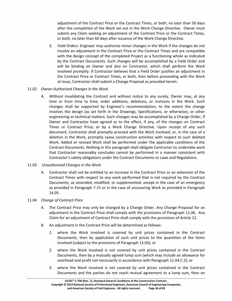
��������������� ������������������������������������������������������������� ��� !��"���#�$��%�&��������������!����'��������������"��������()��������������������"�������"���) �������
����()�������������!������������"������ ��(�����"������������ �������������'�"�*++����,-*
./01234563*78*395*:763;.<3*=;><5*7;*395*:763;.<3*?>452@*7;*A739@*67*B.35;*39.6*CD*/.E2*
.835;*395*<74FB53>76*78*395*G7;H*253*713*>6*395*G7;H*:9.6I5*J>;5<3>K5L**MN65;*4123*21A4>3*.6E*:B.>4*255H>6I*.6*./01234563*78*395*:763;.<3*=;><5*7;*395*:763;.<3*?>452@*7;*A739@*67*B.35;*39.6*OD*/.E2*.835;*>221.6<5*78*395*G7;H*:9.6I5*J>;5<3>K5L*
CLPQRSTUVWXUSXYZ*[6I>655;*4.E*.1397;>\5*4>67;*<9.6I52*>6*395*G7;H*>8*395*<9.6I52*/7*673*>6K7BK5*.6*./01234563*>6*395*:763;.<3*=;><5*7;*395*:763;.<3*?>452*.6/*.;5*<74F.3>AB5*N>39*395*/52>I6*<76<5F3*78*395*<74FB535/*=;705<3*.2*.*816<3>76>6I*N97B5*.2*>6/><.35/*AE*395*:763;.<3*J7<145632L*]1<9*<9.6I52*N>BB*A5*.<<74FB>295/*AE*.*>5B/*M;/5;*.6/*N>BB*A5*A>6/>6I*76*MN65;*.6/*.B27*76*:763;.<37;@*N9><9*29.BB*F5;87;4*395*G7;H*>6K7BK5/*F;74F3BEL*_8*:763;.<37;*A5B>5K52*39.3*.*>5B/*M;/5;*0123>8>52*.6*./01234563*>6*395*:763;.<3*=;><5*7;*:763;.<3*?>452@*7;*A739@*3956*A587;5*F;7<55/>6I*N>39*395*G7;H*.3*>2215@*:763;.<37;*29.BB*21A4>3*.*:9.6I5*=;7F72.B*.2*F;7K>/5/*95;5>6L*
`LDaPWbcSXdefghiXRjSUVkhlcmSYVRcVghSVniXoV
pLPG>39713*>6K.B>/.3>6I*395*:763;.<3*.6/*N>39713*673><5*37*.6E*21;53E@*MN65;*4.E@*.3*.6E*3>45*7;*8;74*3>45*37*3>45@*7;/5;*.//>3>762@*/5B53>762@*7;*;5K>2>762*>6*395*G7;HL*]1<9*qrstuvwxwrsyyxzvxw{||}~�v�xz�x�tu�tvv~�wx~vq}��vt�s��}t�x�}x�rvxv��vt�x�rvxqrstuvx>6K7BK52*395*/52>I6*�.2*253*87;39*>6*395*J;.N>6I2@*]F5<>8><.3>762@*7;*7395;N>25�@*7;*7395;*56I>655;>6I*7;*35<96><.B*4.335;2L*]1<9*<9.6I52*4.E*A5*.<<74FB>295/*AE*.*:9.6I5*M;/5;@*>8*MN65;*.6/*:763;.<37;*9.K5*.I;55/*.2*37*395*5885<3@*>8*.6E@*78*395*<9.6I52*76*:763;.<3*?>452*7;*:763;.<3*=;><5�*7;*AE*.*G7;H*:9.6I5*J>;5<3>K5L*�F76*;5<5>F3*78*.6E*21<9*/7<14563@*:763;.<37;*29.BB*F;74F3BE*F;7<55/*N>39*395*G7;H*>6K7BK5/�*7;@*>6*395*<.25*78*.*/5B53>76*>6*395*G7;H@*F;74F3BE*<5.25*<7623;1<3>76*.<3>K>3>52*N>39*;52F5<3*37*21<9*/5B535/*G7;HL*p//5/*7;*;5K>25/*G7;H*29.BB*A5*F5;87;45/*16/5;*395*.FFB><.AB5*<76/>3>762*78*395*:763;.<3*J7<145632L*�739>6I*>6*39>2*F.;.I;.F9*29.BB*7AB>I.35*:763;.<37;*37*16/5;3.H5*N7;H*39.3*:763;.<37;*;5.276.ABE*<76<B1/52*<.6673*A5*F5;87;45/*>6*.*4.665;*<762>23563*N>39*�}t�~sq�}~�wxws�v��x}zy�us��}twx{t�v~x�rvx�}t�~sq�x�}q{�vt�wx}~x�s�wxst�x�vu{ys��}tw�*
`LDCPV�clfghiXRjSUVkhlcmSYVRcVghSVniXoV
pLP:763;.<37;*29.BB*673*A5*563>3B5/*37*.6*>6<;5.25*>6*395*:763;.<3*=;><5*7;*.6*5�3562>76*78*395*:763;.<3*?>452*N>39*;52F5<3*37*.6E*N7;H*F5;87;45/*39.3*>2*673*;5�1>;5/*AE*395*:763;.<3*J7<145632@*.2*.456/5/@*47/>8>5/@*7;*21FFB545635/@*5�<5F3*>6*395*<.25*78*.6*545;I56<E*.2*F;7K>/5/*>6*=.;.I;.F9*�L�*7;*>6*395*<.25*78*16<7K5;>6I*G7;H*.2*F;7K>/5/*>6*=.;.I;.F9*�LD�L*
`LD�PkhlcmSVi�VkicgXl�gV�XR�SV
pLP?95*:763;.<3*=;><5*4.E*76BE*A5*<9.6I5/*AE*.*:9.6I5*M;/5;L*p6E*:9.6I5*=;7F72.B*87;*.6*./01234563*>6*395*:763;.<3*=;><5*29.BB*<74FBE*N>39*395*F;7K>2>762*78*=.;.I;.F9* LDOL**p6E*:B.>4*87;*.6*./01234563*78*:763;.<3*=;><5*29.BB*<74FBE*N>39*395*F;7K>2>762*78*p;3><B5*aL*
�LPp6*./01234563*>6*395*:763;.<3*=;><5*N>BB*A5*/535;4>65/*.2*87BB7N2Z*
LPN95;5*395*G7;H*>6K7BK5/*>2*<7K5;5/*AE*16>3*F;><52*<763.>65/*>6*395*:763;.<3*J7<145632@*3956*AE*.FFB><.3>76*78*21<9*16>3*F;><52*37*395*�1.63>3>52*78*395*>3542*>6K7BK5/*�21A05<3*37*395*F;7K>2>762*78*=.;.I;.F9*CLDC��*7;*
aLPN95;5*395*G7;H*>6K7BK5/*>2*673*<7K5;5/*AE*16>3*F;><52*<763.>65/*>6*395*:763;.<3*J7<145632@*3956*AE*.*4131.BBE*.I;55/*B14F*214*�N9><9*4.E*>6<B1/5*.6*.BB7N.6<5*87;*7K5;95./*.6/*F;78>3*673*65<522.;>BE*>6*.<<7;/.6<5*N>39*=.;.I;.F9*LD�L:La��*7;*
CLPN95;5*395*G7;H*>6K7BK5/*>2*673*<7K5;5/*AE*16>3*F;><52*<763.>65/*>6*395*:763;.<3*J7<145632*.6/*395*F.;3>52*/7*673*;5.<9*4131.B*.I;554563*37*.*B14F*214@*3956*76*

��������������� ������������������������������������������������������������� ��� !��"���#�$��%�&��������������!����'��������������"��������()��������������������"�������"���) �������
����()�������������!������������"������ ��(�����"������������ �������������'�"�*+,����-,*
./0*12343*56*./0*753.*56*./0*859:*;<0.09=4>0<*23*?95@4<0<*4>*A292B92?/*CDEFCG*?HI3*2*JKLMNOPMKNQRSTUUSTKNSKVUNWUOXSOLXSYNKTZMS[XUMUN\ZLUXSORSYNKVZXUXSZLS]ONONOYWSCCEF_E7GE*
7E abcdefgdbehijkllmSnWULSOYYoZPOpoUqSMWUSJKLMNOPMKNQRSTUUSTKNS5@09/02<*2><*?9564.*3/2HH*10*<0.09=4>0<*23*65HH5r3s*
CE 2*=I.I2HHt*2uu0?.21H0*64v0<*600w*59*
xE 46*2*64v0<*600*43*>5.*2B900<*I?5>y*./0>*2*600*1230<*5>*./0*65HH5r4>B*?09u0>.2B03*56*./0*@2945I3*?59.45>3*56*./0*753.*56*./0*859:s*
2E 659*u53.3*4>uI990<*I><09*A292B92?/3*CDz{|z}z|SOLXS|~z{|z}z�qSMWUSJKLMNOPMKNQRSTUUS3/2HH*10*C�*?09u0>.w*
1E TKNSPKRMRSZLP�NNUXS�LXUNS]ONONOYWS|~z{|z}z~qSMWUSJKLMNOPMKNQRSTUUSRWOooSpUSTZVUS?09u0>.w*
uE r/090*5>0*59*=590*.4093*56*3I1u5>.92u.3*290*5>*./0*12343*56*753.*56*./0*859:*?HI3*2*600*2><*>5*64v0<*600*43*2B900<*I?5>y*./0*4>.0>.*56*A292B92?/3*CCEF_E7ExE2*2><*CCEF_E7ExE1*ZRSMWOMSMWUSJKLMNOPMKNQRSTUUSRWOooSpUSpORUXSKLmS[|�SOSTUUSKTS|�SYUNPULMS56*./0*u53.3*4>uI990<*I><09*A292B92?/3*CDEFCE�EC*2><*CDEFCE�Ex*1t*./0*�I1u5>.92u.59*./2.*2u.I2HHt*?09659=3*./0*859:y*2.*r/2.0@09*.409y*2><*;xG*r4./*903?0u.*.5*75>.92u.59*4.30H6*2><*.5*2>t*�I1u5>.92u.593*56*2*.409*/4B/09*./2>*./2.*56*./0*�I1u5>.92u.59*./2.*2u.I2HHt*?09659=3*./0*859:y*2*600*56*64@0*?09u0>.*56*./0*2=5I>.*;600*?HI3*I><09Ht4>B*u53.3*4>uI990<G*2..941I.21H0*.5*./0*>0v.*H5r09*.409*�I1u5>.92u.59w*?95@4<0<y*/5r0@09y*./2.*659*2>t*3Iu/*3I1u5>.92u.0<*r59:*./0*=2v4=I=*.5.2H*600*.5*10*?24<*1t*�r>09*3/2HH*10*>5*B902.09*./2>*x�*?09u0>.*56*./0*u53.3*4>uI990<*1t*./0*�I1u5>.92u.59*./2.*2u.I2HHt*?09659=3*./0*r59:w*
<E >5*600*3/2HH*10*?2t21H0*5>*./0*12343*56*u53.3*4.0=4�0<*I><09*A292B92?/3*CDEFCE�E_y*CDEFCE�E�y*2><*CDEFCE7w*
0E ./0*2=5I>.*56*u90<4.*.5*10*2HH5r0<*1t*75>.92u.59*.5*�r>09*659*2>t*u/2>B0*r/4u/*903IH.3*4>*2*>0.*<0u90230*4>*u53.*r4HH*10*./0*2=5I>.*56*./0*2u.I2H*>0.*<0u90230*4>*PKRMSYo�RSOSXUX�PMZKLSZLSJKLMNOPMKNQRSTUUSp�SOLSO\K�LMSU��OoSMKSTZVUSYUNPULMSKTS3Iu/*>0.*<0u90230w*2><*
6E r/0>*15./*2<<4.45>3*2><*u90<4.3*290*4>@5H@0<*4>*2>t*5>0*u/2>B0y*./0*2<�I3.=0>.*ZLSJKLMNOPMKNQRSTUUSRWOooSpUSPK\Y�MUXSKLSMWUSpORZRSKTSMWUSLUMSPWOLB0*4>*2uu59<2>u0*r4./*A292B92?/3*CCEF_E7ExE2*./95IB/*CCEF_E7ExE0y*4>uHI34@0E*
CCEF� �������������������������
�E �/0*75>.92u.*�4=03*=2t*5>Ht*10*u/2>B0<*1t*2*7/2>B0*�9<09E*�>t*7/2>B0*A95?532H*659*2>*2<�I3.=0>.*4>*./0*75>.92u.*�4=03*3/2HH*u5=?Ht*r4./*./0*?95@4345>3*56*A292B92?/*CCEF�E*�>t*7H24=*659*2>*2<�I3.=0>.*4>*./0*75>.92u.*�4=03*3/2HH*u5=?Ht*r4./*./0*?95@4345>3*56*�9.4uH0*CxE*
�E �>*2<�I3.=0>.*56*./0*75>.92u.*�4=03*3/2HH*10*3I1�0u.*.5*./0*H4=4.2.45>3*30.*659./*4>*]ONONOYWS�z{�qSPKLPUNLZLSXUoO�RSZLSJKLMNOPMKNQRSYNKNU33E*
CCEF� ������� ��¡���¢��
�E 75>.92u.59*3/2HH*3I1=4.*2*7/2>B0*A95?532H*.5*£>B4>009*.5*90¤I03.*2>*2<�I3.=0>.*4>*./0*75>.92u.*�4=03*59*75>.92u.*A94u0w*2??02H*2>*4>4.42H*<0u4345>*1t*£>B4>009*u5>u09>4>B*./0*90¤I490=0>.3*56*./0*75>.92u.*¥5uI=0>.3*59*90H2.4>B*.5*./0*2uu0?.214H4.t*56*./0*859:*I><09*./0*75>.92u.*¥5uI=0>.3w*u5>.03.*2*30.¦566*2B24>3.*?2t=0>.*<I0w*59*300:*5./09*90H406*I><09*

��������������� ������������������������������������������������������������� ��� !��"���#�$��%�&��������������!����'��������������"��������()��������������������"�������"���) �������
����()�������������!������������"������ ��(�����"������������ �������������'�"�*+,����,-*
./0*123.456.7*8/0*1/5390*:42;2<5=*</5==*<;06>?@*53@*;42;2<0A*6/5390*>3*123.456.*8>B0<*24*123.456.*:4>60C*24*D2./C*24*2./04*;42;2<0A*40=>0?C*53A*0E;=5>3*./0*405<23*?24*./0*;42;2<0A*6/5390C*F>./*6>.5.>23<*.2*53@*92G043>39*24*5;;=>65D=0*;42G><>23<*2?*./0*123.456.*H26IB03.<7*
J7KLMNOPQRMPST*123.456.24*</5==*<IDB>.*056/*1/5390*:42;2<5=*.2*U39>3004*;42B;.=@*VDI.*>3*32*0G03.*=5.04*./53*WX*A5@<Y*5?.04*./0*<.54.*2?*./0*0G03.*9>G>39*4><0*./040.2C*24*5?.04*<I6/*>3>.>5=*A06><>237*8/0*123.456.24*</5==*<IDB>.*<I;;24.>39*A5.5C*>36=IA>39*./0*;42;2<0A*6/5390*>3*123.456.*:4>60*24*123.456.*8>B0*V>?*53@YC*.2*./0*U39>3004*53A*ZF304*F>./>3*J[*A5@<*5?.04*./0*<IDB>..5=*2?*./0*1/5390*:42;2<5=7*8/0*<I;;24.>39*A5.5*</5==*D0*5662B;53>0A*D@*5*F4>..03*<.5.0B03.*./5.*./0*<I;;24.>39*A5.5*540*566I45.0*53A*62B;=0.0C*53A*./5.*53@*40\I0<.0A*.>B0*24*;4>60*5A]I<.B03.*><*./0*03.>40*5A]I<.B03.*.2*F/>6/*123.456.24*D0=>0G0<*>.*><*03.>.=0A*5<*5*40<I=.*2?*<5>A*0G03.7*U39>3004*F>==*5AG><0*ZF304*40954A>39*./0*1/5390*:42;2<5=C*53A*623<>A04*53@*62BB03.<*24*40<;23<0*?42B*ZF304*40954A>39*./0*1/5390*:42;2<5=7*
7K _abccdefghijbkT*U39>3004*F>==*40G>0F*056/*1/5390*:42;2<5=*53AC*F>./>3*WX*A5@<*5?.04*40lmnopqrsqptmqurvpwxlprwyzqz{oorwpnv|q}xpx~qmnptmwq}mv�qptmqutxv|mq�wrorzx�qnvq�tr�m~q5;;42G0*>.*>3*F/2=0C*24*A03@*>.*>3*;54.*53A*5;;42G0*>.*>3*;54.7*�I6/*56.>23<*</5==*D0*>3*F4>.>39C*F>./*5*62;@*;42G>A0A*.2*ZF304*53A*123.456.247*�?*U39>3004*A20<*32.*.5�0*56.>23*23*./0*1/5390*:42;2<5=*F>./>3*WX*A5@<C*./03*0>./04*ZF304*24*123.456.24*B5@*5.*53@*.>B0*./0405?.04*<IDB>.*5*=0..04*.2*./0*2./04*;54.@*>3A>65.>39*./5.*5<*5*40<I=.*2?*�v|nvmmwyzqnvxlpnrvqptmqutxv|mq�wrorzx�qnzq}mm�m}q}mvnm}~qptmwm��qlr��mvlnv|qptmq.>B0*?24*5;;05=*2?*./0*A03>5=*I3A04*�4.>6=0*J7*
W7K���Q�����PO�S�N��q�v|nvmmwyzq}mlnznrvq�n��q�mqsnvx�qxv}q�nv}nv|q{orvq��vmwqxv}q123.456.24C*I3=0<<*ZF304*24*123.456.24*5;;05=<*./0*A06><>23*D@*?>=>39*5*1=5>B*I3A04*�4.>6=0*J7*
�7K�PSN�R��N��N���PM����������P�LMN�NS��ST*�?*./0*1/5390*:42;2<5=*A20<*32.*>3G2=G0*./0*A0<>93*V5<*<0.*?24./*>3*./0*H45F>39<C*�;06>?>65.>23<C*24*2./04F><0YC*./0*5660;.5D>=>.@*2?*./0*�24�C*24*2./04*039>3004>39*24*.06/3>65=*B5..04<C*./03*U39>3004*F>==*32.>?@*./0*;54.>0<*./5.*./0*U39>3004*><*I35D=0*.2*40<2=G0*./0*1/5390*:42;2<5=7*�24*;I4;2<0<*2?*?I4./04*40<2=I.>23*2?*<I6/*5*1/5390*:42;2<5=C*<I6/*32.>60*</5==*D0*A00B0A*5*A03>5=C*53A*123.456.24*B5@*6/22<0*.2*<00�*40<2=I.>23*I3A04*./0*.04B<*2?*�4.>6=0*J7*
JJ7X�K��POR��N��N�������P� MQPMS�
�7KZF304*53A*123.456.24*</5==*0E06I.0*5;;42;4>5.0*1/5390*Z4A04<*62G04>39T*
J7K6/5390<*>3*./0*123.456.*:4>60*24*123.456.*8>B0<*F/>6/*540*59400A*.2*D@*./0*;54.>0<C*>36=IA>39*53@*I3A><;I.0A*<IB*24*5B2I3.*2?*.>B0*?24*�24�*56.I5==@*;04?24B0A*>3*56624A5360*F>./*5*�24�*1/5390*H>406.>G0¡*
7K6/5390<*>3*123.456.*:4>60*40<I=.>39*?42B*53*ZF304*<0.¢2??C*I3=0<<*123.456.24*/5<*AI=@*623.0<.0A*<I6/*<0.¢2??¡*
W7K6/5390<*>3*./0*�24�*F/>6/*540T*V5Y*24A040A*D@*ZF304*;I4<I53.*.2*:545945;/*JJ7XC*VDY*wm£{nwm}q�mlx{zmqrsq��vmwyzqxllmopxvlmqrsq}msmlpn¤mq¥rw¦q{v}mwq�x45945;/*J§7X§*24*��vmwyzqlrwwmlpnrvqrsq}msmlpn¤mq¥rw¦q{v}mwq�xwx|wxotq©ª«¬~qrwql®qx|wmm}qprq��qptmqoxwpnmz~qz{�mlpqprqptmqvmm}qsrwq�v|nvmmwyzqwmlr��mv}xpnrvqnsqptmqltxv|mqqnvqptmq¥rw¦q>3G2=G0<*./0*A0<>93*V5<*<0.*?24./*>3*./0*H45F>39<C*�;06>?>65.>23<C*24*2./04F><0YC*24*2./04*039>3004>39*24*.06/3>65=*B5..04<¡*53A*
§7K6/5390<*>3*./0*123.456.*:4>60*24*123.456.*8>B0<C*24*2./04*6/5390<C*F/>6/*0BD2A@*./0*<ID<.5360*2?*53@*?>35=*53A*D>3A>39*40<I=.<*I3A04*:545945;/*JJ7X°C*24*�4.>6=0*J7*

��������������� ������������������������������������������������������������� ��� !��"���#�$��%�&��������������!����'��������������"��������()��������������������"�������"���) �������
����()�������������!������������"������ ��(�����"������������ �������������'�"�*+�����,-*
./012*34567*87*985:7;<:87*762=>6>*:8*6?6<=:6*;*9@;5A6*37B67*:@;:*C>*76D=C76B*:8*E6*6?6<=:6B*=5B67*:@6*:67F>*82*:@C>*G;7;A7;H@*II/JKL*C:*>@;MM*E6*B66F6B*:8*E6*82*2=MM*287<6*;5B*6226<:L*;>*C2*2=MMN*6?6<=:6B/*
II/JO0PQRSTSUVRSQWXRQXYZ[\R]X
/012*:@6*H78_C>C85>*82*;5N*E85B*76D=C76*58:C<6*:8*E6*AC_65*:8*;*>=76:N*82*;5N*<@;5A6*;226<:C5A*:@6*A6567;M*><8H6*82*:@6*87a*87*:@6*H78_C>C85>*82*:@6*985:7;<:*b8<=F65:>*cC5<M=BC5AL*E=:*58:*MCFC:6B*:8L*985:7;<:*G7C<6*87*985:7;<:*dCF6>eL*:@6*AC_C5A*82*;5N*>=<@*58:C<6*4CMM*E6*fghijkligjmnojpnqghnrsrtriuvowxpokygzhiog{opk<@*;HHMC<;EM6*E85B*4CMM*E6*;B|=>:6B*:8*762M6<:*:@6*6226<:*82*;5N*>=<@*<@;5A6/*
(}~�����$�����(~���
I�/JI0��VS��X
/0��VS��X�[QU\���*d@6*28MM84C5A*BC>H=:6>*E6:4665*34567*;5B*985:7;<:87*>@;MM*E6*>=EFC::6B*:8*:@6*9M;CF>*H78<6>>*>6:*287:@*C5*:@C>*7:C<M6�*
I/0 HH6;M>*EN*34567*87*985:7;<:gjog{o�h�rhppjmno�plrnrghnojp�kj�rh�ofxkh�po�jgqgnktn�*
�/034567*B6F;5B>*287*;B|=>:F65:>*C5*:@6*985:7;<:*G7C<6*87*985:7;<:*dCF6>L*87*8:@67*76MC62*=5B67*:@6*985:7;<:*b8<=F65:>�*;5B*
�/0bC>H=:6>*:@;:*�5AC5667*@;>*E665*=5;EM6*:8*;BB76>>*E6<;=>6*:@6N*B8*58:*C5_8M_6*:@6*B6>CA5*c;>*>6:*287:@*C5*:@6*b7;4C5A>L*�H6<C2C<;:C85>L*87*8:@674C>6eL*:@6*;<<6H:;ECMC:N*82*:@6*87aL*87*8:@67*65AC5667C5A*87*:6<@5C<;M*F;::67>/*
./0YZ��SRRV�XQTX��VS��*d@6*H;7:N*>=EFC::C5A*;*9M;CF*>@;MM*B6MC_67*C:*BC76<:MN*:8*:@6*8:@67*H;7:N*:8*:@6*985:7;<:*H78FH:MN*cE=:*C5*58*6_65:*M;:67*:@;5*�J*B;N>e*;2:67*:@6*>:;7:*82*:@6*6_65:*AC_C5A*7C>6*:@676:8�*C5*:@6*<;>6*82*;HH6;M>*76A;7BC5A*9@;5A6*G78H8>;M>*4C:@C5*�J*B;N>*82*:@6*B6<C>C85*=5B67*;HH6;M/*d@6*H;7:N*>=EFC::C5A*:@6*9M;CF*>@;MM*;M>8*2=75C>@*;*<8HN*:8*:@6*�5AC5667L*287*C:>*C5287F;:C85*85MN/*d@6*76>H85>CECMC:N*:8*>=E>:;5:C;:6*;*9M;CF*>@;MM*76>:*4C:@*:@6*H;7:N*F;aC5A*:@6*9M;CF/*15*:@6*<;>6*82*;*9M;CF*EN*985:7;<:87*>66aC5A*;5*C5<76;>6*C5*:@6*985:7;<:*dCF6>*87*985:7;<:*G7C<6L*87*E8:@L*985:7;<:87*>@;MM*<67:C2N*:@;:*:@6*9M;CF*C>*F;B6*C5*A88B*2;C:@L*:@;:*:@6*>=HH87:C5A*B;:;*;76*;<<=7;:6*;5B*<8FHM6:6L*;5B*:@;:*:8*:@6*E6>:*82*fghijkligjmno�hg�tp��pokh�osptrp{oixpokygzhiog{oirypogjoyghpuojp�zpnip�okllzjkiptuo762M6<:>*:@6*2=MM*;F8=5:*:8*4@C<@*985:7;<:87*C>*65:C:M6B/*
9/0�\�S\�XVW�X�\�Q�ZRSQW�*d@6*H;7:N*76<6C_C5A*;*9M;CF*>@;MM*76_C64*C:*:@878=A@MNL*AC_C5A*2=MM*<85>CB67;:C85*:8*C:>*F67C:>/*d@6*:48*H;7:C6>*>@;MM*>66a*:8*76>8M_6*:@6*9M;CF*:@78=A@*:@6*6?<@;5A6*82*C5287F;:C85*;5B*BC76<:*56A8:C;:C85>/**d@6*H;7:C6>*F;N*6?:65B*:@6*:CF6*287*76>8M_C5A*:@6*9M;CF*EN*F=:=;M*;A766F65:/*MM*;<:C85>*:;a65*85*;*9M;CF*>@;MM*E6*>:;:6B*C5*47C:C5A*;5B*>=EFC::6B*:8*:@6*8:@67*H;7:NL*4C:@*;*<8HN*:8*�5AC5667/*
b/0�\�SVRSQW�X
I/0 :*;5N*:CF6*;2:67*C5C:C;:C85*82*;*9M;CFL*34567*;5B*985:7;<:87*F;N*F=:=;MMN*;A766*:8*F6BC;:C85*82*:@6*=5B67MNC5A*BC>H=:6/*d@6*;A766F65:*:8*F6BC;:6*>@;MM*>:;N*:@6*9M;CF*>=EFC::;M*;5B*76>H85>6*H78<6>>/*
�/012*34567*;5B*985:7;<:87*;A766*:8*F6BC;:C85L*:@65*;2:67*�J*B;N>*278F*>=<@*;A766F65:L*6C:@67*34567*87*985:7;<:87*F;N*=5CM;:67;MMN*:67FC5;:6*:@6*F6BC;:C85*H78<6>>L*;5B*:@6*9M;CF*>=EFC::;M*;5B*B6<C>C85*H78<6>>*>@;MM*76>=F6*;>*82*:@6*B;:6*82*:@6*:67FC5;:C85/*12*:@6*F6BC;:C85*H78<66B>*E=:*C>*=5>=<<6>>2=M*C5*76>8M_C5A*:@6*BC>H=:6L*:@6*9M;CF*

��������������� ������������������������������������������������������������� ��� !��"���#�$��%�&��������������!����'��������������"��������()��������������������"�������"���) �������
����()�������������!������������"������ ��(�����"������������ �������������'�"�*+,����-.*
/01234456*578*89:3/3;7*<=;:9//*/>566*=9/029*5/*;?*4>9*8549*;?*4>9*:;7:60/3;7*;?*4>9*2983543;7@*5/*8949=23798*1A*4>9*298354;=B*
CBDEF79=*578*G;74=5:4;=*/>566*95:>*<5A*;79HIJKLMNLMOIPMQPRSJONTUVMLPPVMJWRMXNVOVY*
ZBD[\]_\abcc]de\f*g?*4>9*<5=4A*=9:93h37i*5*G6532*5<<=;h9/*4>9*G6532*37*<5=4*578*89739/*34*37*<5=4@*/0:>*5:43;7*/>566*19*?3756*578*137837i*0769//*F34>37*Cj*85A/*;?*/0:>*5:43;7*4>9*;4>9=*<5=4A*37h;k9/*4>9*<=;:980=9*/94*?;=4>*37*l=43:69*mn*?;=*?3756*=9/;6043;7*;?*83/<049/B*
oBDpqr_\adsat\_uf*g?*9??;=4/*4;*=9/;6h9*5*G6532*5=9*7;4*/0::9//?06@*4>9*<5=4A*=9:93h37i*4>9*G6532*25A*897A*34*1A*i3h37i*F=34497*7;43:9*;?*897356*4;*4>9*;4>9=*<5=4AB*g?*4>9*=9:93h37i*<5=4A*8;9/*7;4*45k9*5:43;7*;7*4>9*G6532*F34>37*vj*85A/@*4>97*934>9=*EF79=*;=*G;74=5:4;=*25A*54*57A*4329*4>9=95?49=*/01234*5*69449=*4;*4>9*;4>9=*<5=4A*3783:5437i*4>54*5/*5*=9/064*;?*4>9*375:43;7@*4>9*G6532*3/*899298*897398@*4>9=91A*:;2297:37i*4>9*4329*?;=*5<<956*;?*4>9*897356B*l*897356*;?*4>9*G6532*/>566*19*?3756*578*137837i*0769//*F34>37*Cj*85A/*;?*4>9*897356*4>9*;4>9=*<5=4A*37h;k9/*4>9*<=;:980=9*/94*?;=4>*37*l=43:69*mn*?;=*4>9*?3756*=9/;6043;7*;?*83/<049/B*
wBDx_r\a\ryaz_ry_r{a|q}~}f*g?*4>9*<5=439/*=95:>*5*204056*5i=992974*=9i5=837i*5*G6532@*F>94>9=*4>=;0i>*5<<=;h56*;?*4>9*G6532@*83=9:4*79i;43543;7/@*2983543;7@*;=*;4>9=F3/9�*;=*3?*5*G6532*3/*5<<=;h98*37*<5=4*578*897398*37*<5=4@*;=*897398*37*?066@*578*/0:>*5:43;7/*19:;29*?3756*578*137837i�*4>97*4>9*=9/064/*;?*4>9*5i=992974*;=*5:43;7*;7*4>9*G6532*/>566*19*37:;=<;=5498*37*5*G>57i9*E=89=*4;*4>9*9�4974*4>9A*5??9:4*4>9*G;74=5:4@*37:60837i*4>9*�;=k@*4>9*G;74=5:4*�329/@*;=*4>9*G;74=5:4*�=3:9B*
(�������%��������������������(����(&������&���'��������
mCBjmDtd}adsa�qa�d]�a
lBD[~]cd}q}asd]apqq]u_r\_dradsatd}adsa�qa�d]�f*�>9*49=2*G;/4*;?*4>9*�;=k*2957/*4>9*/02*;?*566*:;/4/*79:9//5=A*?;=*4>9*<=;<9=*<9=?;=257:9*;?*4>9*�;=k*54*3//09@*5/*?0=4>9=*89?3798*196;FB*�>9*<=;h3/3;7/*;?*4>3/*�5=5i=5<>*mCBjm*5=9*0/98*?;=*4F;*83/437:4*<0=<;/9/f*
mBD�;*8949=2379*G;/4*;?*4>9*�;=k*F>97*G;/4*;?*4>9*�;=k*3/*5*:;2<;7974*;?*4>9*G;74=5:4*�=3:9@*0789=*:;/4H<60/H?99@*4329H578H2549=356/@*;=*;4>9=*:;/4H15/98*49=2/�*;=*
�BD�;*8949=2379*4>9*h5609*;?*5*G>57i9*E=89=@*G>57i9*�=;<;/56@*G6532@*/94H;??@*;=*;4>9=*58�0/42974*37*G;74=5:4*�=3:9B*�>97*4>9*h5609*;?*57A*/0:>*58�0/42974*3/*8949=23798*;7*4>9*15/3/*;?*G;/4*;?*4>9*�;=k@*G;74=5:4;=*3/*97434698*;76A*4;*4>;/9*588343;756*;=*37:=9297456*:;/4/*=9�03=98*19:50/9*;?*4>9*:>57i9*37*4>9*�;=k*;=*19:50/9*;?*4>9*9h974*i3h37i*=3/9*4;*4>9*58�0/42974B*
�BDtd}}a�r�~yqyf*Z�:9<4*5/*;4>9=F3/9*25A*19*5i=998*4;*37*F=3437i*1A*EF79=@*:;/4/*37:60898*37*4>9*G;/4*;?*4>9*�;=k*/>566*19*37*52;074/*7;*>3i>9=*4>57*4>;/9*<=9h53637i*37*4>9*6;:5634A*;?*4>9*�=;�9:4@*/>566*7;4*37:6089*57A*;?*4>9*:;/4/*34923�98*37*�5=5i=5<>*mCBjmBG@*578*/>566*37:6089*;76A*4>9*?;66;F37i*3492/f*
mBD�5A=;66*:;/4/*?;=*92<6;A99/*37*4>9*83=9:4*92<6;A*;?*G;74=5:4;=*37*4>9*<9=?;=257:9*;?*4>9*�;=k*0789=*/:>98069/*;?*�;1*:65//3?3:543;7/*5i=998*0<;7*1A*EF79=*578*G;74=5:4;=B*�0:>*92<6;A99/*/>566*37:6089@*F34>;04*63234543;7@*/0<9=374978974/@*?;=9297@*578*;4>9=*<9=/;7796*92<6;A98*?066*4329*;7*4>9*�;=kB*�5A=;66*:;/4/*?;=*92<6;A99/*7;4*92<6;A98*?066*4329*;7*4>9*�;=k*/>566*19*5<<;=43;798*;7*4>9*15/3/*;?*4>93=*4329*/<974*;7*4>9*�;=kB*�5A=;66*:;/4/*/>566*37:6089@*104*7;4*19*6323498*4;@*/565=39/*578*F5i9/*<60/*4>9*:;/4*;?*?=37i9*1979?34/@*F>3:>*/>566*37:6089*/;:356*/9:0=34A*:;74=31043;7/@*0792<6;A2974@*9�:3/9@*578*<5A=;66*45�9/�M�NT�PTVUMXNQ�PWVJOSNW�MIPJKOIMJWRM=943=92974*1979?34/@*1;70/9/@*/3:k*695h9@*578*h5:543;7*578*>;6385A*<5A*5<<63:5169*
��������������� ������������������������������������������������������������� ��� !��"���#�$��%�&��������������!����'��������������"��������()��������������������"�������"���) �������
����()�������������!������������"������ ��(�����"������������ �������������'�"�*+,����-.*
/0121/34*501*16718919*3:*712:32;<8=*>32?*3@/9<A1*3:*21=@BC2*D32?<8=*03@29E*38*FC/@2ACGE*F@8ACGE*32*B1=CB*03B<ACG9E*90CBB*H1*<8IB@A1A*<8*/01*CH3J1*/3*/01*16/18/*C@/032<K1A*HG*LD8124*
M4NO39/*3:*CBB*;C/12<CB9*C8A*1P@<7;18/*:@28<901A*C8A*<8I32732C/1A*<8*/01*>32?E*<8IB@A<8=*QRSTSURVUTWXYSZRWTXT[RYUXY\USTRWX]UT_WRVUXY\UabZZc[WSdUV[c\USWe[QSUWfb[W\U[YUI3881I/<38*/0121D</04*gBB*IC90*A<9I3@8/9*90CBB*CII2@1*/3*O38/2CI/32*@8B199*LD812*A1739</9*:@8A9*D</0*O38/2CI/32*D</0*D0<I0*/3*;C?1*7CG;18/9E*<8*D0<I0*IC91*/01*IC90*A<9I3@8/9*90CBB*CII2@1*/3*LD8124*gBB*/2CA1*A<9I3@8/9E*21HC/19E*C8A*21:@8A9*C8A*21/@289*:23;*9CB1*3:*9@27B@9*;C/12<CB9*C8A*1P@<7;18/*90CBB*CII2@1*/3*LD812E*C8A*O38/2CI/32*90CBB*;C?1*723J<9<389*93*/0C/*/01G*;CG*H1*3H/C<81A4*
h4NiCG;18/9*;CA1*HG*O38/2CI/32*/3*F@HI38/2CI/329*:32*>32?*712:32;1A*HG*F@HI38/2CI/3294*j:*21P@<21A*HG*LD812E*O38/2CI/32*90CBB*3H/C<8*I3;71/</<J1*H<A9*:23;*9@HI38/2CI/329*CII17/CHB1*/3*LD812*C8A*O38/2CI/32*C8A*90CBB*A1B<J12*9@I0*H<A9*/3*LD812E*D03*D<BB*/018*A1/12;<81E*D</0*/01*CAJ<I1*3:*k8=<8112E*D0<I0*H<A9E*<:*C8GE*D<BB*H1*CII17/CHB14*j:*C8G*9@HI38/2CI/*723J<A19*/0C/*/01*F@HI38/2CI/32*<9*/3*H1*7C<A*38*/01*HC9<9*3:*O39/*3:*T_UlRWmUZcbSUXUV UT_UabnQRYTWXQTRWdSUoRSTURVUT_UlRWmUXY\UV US_XccUnU\TWp[Y\U[YUT_USXp UpXYYWUXSUoRYTWXQTRWdSUoRSTURVUT_UlRWmUXY\UV UXSU723J<A1A*<8*/0<9*iC2C=2C70*qh4rq4*
s4NO39/9*3:*971I<CB*I389@B/C8/9*t<8IB@A<8=*H@/*83/*B<;</1A*/3*18=<81129E*C2I0</1I/9E*/19/<8=*BCH32C/32<19E*9@2J1G329E*C//3281G9E*C8A*CII3@8/C8/9u*1;7B3G1A*:32*912J<I19*971I<:<ICBBG*21BC/1A*/3*/01*>32?4*
v4NF@77B1;18/CB*I39/9*<8IB@A<8=*/01*:3BB3D<8=w*
C4N501*723732/<38*3:*81I199C2G*/2C89732/C/<38E*/2CJ1BE*C8A*9@H9<9/18I1*16718919*3:*O38/2XQTRWdSUpZcRx SU[YQbWW\U[YU\[SQ_XW]URVU\bT[SUQRYYQT\Uy[T_UT_UlRWmz*
H4NO39/E*<8IB@A<8=*/2C89732/C/<38*C8A*;C<8/18C8I1E*3:*CBB*;C/12<CB9E*9@77B<19E*1P@<7;18/E*;CI0<812GE*C77B<C8I19E*3::<I1E*C8A*/1;732C2G*:CI<B</<19*C/*/01*F</1E*C8A*0C8A*/33B9*83/*3D81A*HG*/01*D32?129E*D0<I0*C21*I389@;1A*<8*/01*712:32;C8I1*3:*/01*>32?E*C8A*I39/E*B199*;C2?1/*JCB@1E*3:*9@I0*</1;9*@91A*H@/*83/*I389@;1A*D0<I0*21;C<8*/01*723712/G*3:*O38/2CI/324*
I4N{18/CB9*3:*CBB*I389/2@I/<38*1P@<7;18/*C8A*;CI0<812GE*C8A*/01*7C2/9*/01213:E*D01/012*218/1A*:23;*O38/2CI/32*32*3/0129*<8*CII32AC8I1*D</0*218/CB*C=211;18/9*C7723J1A*HG*LD812*D</0*/01*CAJ<I1*3:*k8=<8112E*C8A*/01*I39/9*3:*/2C89732/C/<38E*B3CA<8=E*@8B3CA<8=E*C991;HBGE*A<9;C8/B<8=E*C8A*21;3JCB*/01213:4*gBB*9@I0*I39/9*90CBB*H1*<8*CII32AC8I1*D</0*/01*/12;9*3:*9C<A*218/CB*C=211;18/94*501*218/CB*3:*C8G*9@I0*1P@<7;18/E*;CI0<812GE*32*7C2/9*90CBB*I1C91*D018*/01*@91*/01213:*<9*83*B38=12*81I199C2G*:32*/01*>32?4*
A4NFCB19E*I389@;12E*@91E*C8A*3/012*9<;<BC2*/C619*21BC/1A*/3*/01*>32?E*C8A*:32*D0<I0*O38/2CI/32*<9*B<CHB1E*C9*<;7391A*HG*|CD9*C8A*{1=@BC/<3894*
14N}1739</9*B39/*:32*IC@919*3/012*/0C8*81=B<=18I1*3:*O38/2CI/32E*C8G*F@HI38/2CI/32E*32*C8G381*A<21I/BG*32*<8A<21I/BG*1;7B3G1A*HG*C8G*3:*/01;*32*:32*D0391*CI/9*C8G*3:*/01;*;CG*H1*B<CHB1E*C8A*23GCB/G*7CG;18/9*C8A*:119*:32*712;</9*C8A*B<I189194*
:4N |39919*C8A*AC;C=19*tC8A*21BC/1A*16718919u*IC@91A*HG*AC;C=1*/3*/01*>32?E*83/*I3;7189C/1A*HG*<89@2C8I1*32*3/012D<91E*9@9/C<81A*HG*O38/2CI/32*<8*I3881I/<38*D</0*/01*712:32;C8I1*3:*/01*>32?*t16I17/*B39919*C8A*AC;C=19*D</0<8*/01*A1A@I/<HB1*C;3@8/9*3:*723712/G*<89@2C8I1*19/CHB<901A*<8*CII32AC8I1*D</0*iC2C=2C70*~4rvuE*723J<A1A*9@I0*B39919*C8A*AC;C=19*0CJ1*219@B/1A*:23;*IC@919*

��������������� ������������������������������������������������������������� ��� !��"���#�$��%�&��������������!����'��������������"��������()��������������������"�������"���) �������
����()�������������!������������"������ ��(�����"������������ �������������'�"�*+�����,+*
-./01*./23*./0*3045640370*-8*9-3.127.-1:*23;*<=>7-3.127.-1:*-1*23;-30*?6107.5;*-1*63?6107.5;*0@A5-;0?*>;*23;*-8*./0@*-1*8-1*B/-C0*27.C*23;*-8*./0@*@2;*>0*562>50D*<=7/*5-CC0C*C/255*6375=?0*[email protected]*@2?0*B6./*./0*B16..03*7-3C03.*23?*2AA1-E25*-8*FB301D*G-*C=7/*5-CC0C:*?2@240C:*23?*0HA03C0C*C/255*>0*6375=?0?*63*./0*9-C.*-8*./0*I-1J*8-1*./0*A=1A-C0*-8*?0.01@63634*9-3KLMNKOLPQRSTTU*
4DVW/0*7-C.*-8*=.656.60C:*8=05:*23?*C236.21;*827656.60C*2.*./0*<6.0D*
/DVX63-1*0HA03C0C*C=7/*2C*7-@@=3672.6-3*C01E670*2.*./0*<6.0:*0HA10CC*23?*7-=1601*C01E670C:*23?*C6@6521*A0..;*72C/*6.0@C*63*7-3307.6-3*B6./*./0*I-1JD*
6DV W/0*7-C.C*-8*A10@6=@C*8-1*255*>-3?C*23?*63C=12370*./2.*9-3.127.-1*6C*10Y=610?*>;*./0*9-3.127.*[email protected]*.-*A=17/2C0*23?*@263.263D*
9DV[\]]_abcdefeg*W/0*.01@*9-C.*-8*./0*I-1J*C/255*3-.*6375=?0*23;*-8*./0*8-55-B634*6.0@Cg*
hDViMjLOkkRNOQKQRMlmROKnTLRNOopTlQMKqOlROSRrOlKLMNKOLPQROSSqNTLQsRTtTN=.6E0C:*A16376A25C*u-8*A21.301C/6AC*23?*C-50*A1-A160.-1C/6ACv:*4030125*@232401C:*C280.;*@232401C:*03463001C:*217/6.07.C:*[email protected]:*2..-130;C:*2=?6.-1C:*277-=3.23.C:*A=17/2C634*23?*7-3.127.634*2403.C:*0HA0?6.01C:*.6@0J00A01C:*7501JC:*23?*-./01*A01C-3305*0@A5-;0?*>;*rOlKLMNKOLsRwnTKnTLRMKRKnTRxqKTROLRqlRrOlKLMNKOLPQRpLqlNqpMkROLRyLMlNnROSSqNTRSOLRzTlTLMkR2?@636C.12.6-3*-8*./0*I-1J*23?*3-.*CA076867255;*6375=?0?*63*./0*24100?*=A-3*C7/0?=50*-8*{->*752CC68672.6-3C*1080110?*.-*63*|212412A/*h}D~hD�Dh*-1*CA076867255;*7-E010?*>;*|212412A/*h}D~hD�D�D*W/0*A2;1-55*7-C.C*23?*-./01*[email protected]*0H75=?0?*/010*210*.-*yTRNOlQqmTLTmRMmoqlqQKLMKq�TRNOQKQRNO�TLTmRyjRKnTRrOlKLMNKOLPQRSTTU*
�DV�tpTlQTQROSRrOlKLMNKOLPQRpLqlNqpMkRMlmRyLMlNnROSSqNTQROKnTLRKnMlRrOlKLMNKOLPQROSSqNTRMKR./0*<6.0D*
}DV�ljRpMLKROSRrOlKLMNKOLPQRNMpqKMkRTtpTlQTQsRqlNk�mqlzRqlKTLTQKROlRrOlKLMNKOLPQRNMpqKMkR0@A5-;0?*8-1*./0*I-1J*23?*7/2140C*24263C.*9-3.127.-1*8-1*?0563Y=03.*A2;@03.CD*
�DV9-C.C*?=0*.-*./0*3045640370*-8*9-3.127.-1:*23;*<=>7-3.127.-1:*-1*23;-30*?6107.5;*-1*63?6107.5;*0@A5-;0?*>;*23;*-8*./0@*-1*8-1*B/-C0*27.C*23;*-8*./0@*@2;*>0*562>50:*6375=?634*>=.*3-.*[email protected]?*.-:*./0*7-1107.6-3*-8*?0807.6E0*I-1J:*?6CA-C25*-8*@2.01625C*-1*0Y=6A@03.*B1-345;*C=AA560?:*23?*@2J634*4--?*23;*?2@240*.-*A1-A01.;D*
�DVF./01*-E01/02?*-1*4030125*0HA03C0*7-C.C*-8*23;*J63?*23?*./0*7-C.C*-8*23;*6.0@*3-.*CA076867255;*23?*0HA10CC5;*6375=?0?*63*|212412A/*h}D~hD�D*
ZDV����������������g*I/03*./0*I-1J*2C*2*B/-50*6C*A018-1@0?*-3*./0*>2C6C*-8*7-C.�A5=C:*rOlKLMNKOLPQRSTTRQnMkkRyTRmTKTLoqlTmRMQRQTKRSOLKnRql*./0*�[email protected]*I/03*./0*E25=0*-8*23;*I-1J*7-E010?*>;*2*9/2340*F1?01:*9/2340*|1-A-C25:*9526@:*C0.�-88:*-1*-./01*2?{=C.@03.*63*rOlKLMNKRiLqNTRqQRmTKTLoqlTmROlRKnTRyMQqQROSRrOQKROSRKnTR�OL�sRrOlKLMNKOLPQRSTTRQnMkkRyTR?0.01@630?*2C*C0.*8-1./*63*|212412A/*hhD~�D9D*
�DV�\bd�f���\�g*I/030E01*./0*9-C.*-8*./0*I-1J*8-1*23;*A=1A-C0*6C*.-*>0*?0.01@630?*A=1C=23.*.-*./6C*�1.6750*h}:*9-3.127.-1*B655*0C.2>56C/*23?*@263.263*107-1?C*./010-8*63*277-1?2370*B6./*40301255;*2770A.0?*277-=3.634*A127.670C*23?*C=>@6.*63*2*8-1@*2770A.2>50*.-*�3463001*23*6.0@6�0?*7-C.*>102J?-B3*.-40./01*B6./*C=AA-1.634*?2.2D*
h}D~�V�cc\���bf]_
�DV .*6C*=3?01C.--?*./2.*9-3.127.-1*/2C*6375=?0?*63*./0*9-3.127.*|1670*255*255-B2370C*C-*32@0?*63*./0*9-3.127.*[email protected]*23?*C/255*72=C0*./0*I-1J*C-*7-E010?*.-*>0*A018-1@0?*8-1*C=7/*C=@C*23?*>;*C=7/*A01C-3C*-1*03.6.60C*2C*@2;*>0*2770A.2>50*.-*FB301*23?*�3463001D*
��������������� ������������������������������������������������������������� ��� !��"���#�$��%�&��������������!����'��������������"��������()��������������������"�������"���) �������
����()�������������!������������"������ ��(�����"������������ �������������'�"�*+�����,+*
-./012345667819:;2<*=>?@ABC@>A*BDAEEF*@GB@<*
H./@GE*CBFG*BII>JB?CEF*K?CILME*@GE*C>F@*@>*=>?@ABC@>A*NIEFF*B?O*BPPIKCBQIE*@ABME*MKFC>L?@FR*>S*TB@EAKBIF*B?M*EULKPTE?@*AEULKAEM*QO*@GE*BII>JB?CEF*@>*QE*MEIKVEAEM*B@*@GE*WK@EX*B?M*BII*BPPIKCBQIE*@BYEFZ*B?M*
[./\]_ab_]cdeb]d_def]egh]aijkeaielaihjke]e_lmenj_moehap]oejd_ahha_j]oe]qmlmaioePA>SK@X*B?M*>@GEA*EYPE?FEF*C>?@ETPIB@EM*S>A*@GE*CBFG*BII>JB?CEF*GBVE*QEE?*K?CILMEM*K?*@GE*=>?@ABC@*rAKCE*B?M*?>@*K?*@GE*BII>JB?CEFX*B?M*?>*METB?M*S>A*BMMK@K>?BI*PBOTE?@*>?*BCC>L?@*>S*B?O*>S*@GE*S>AED>K?D*JKII*QE*VBIKM.*
=./079st9u;9:v45667819:;<*=>?@ABC@>A*BDAEEF*@GB@*B*C>?@K?DE?CO*BII>JB?CEX*KS*B?OX*KF*S>A*@GE*F>IE*LFE*>S*wJ?EA*@>*C>VEA*L?B?@KCKPB@EM*C>F@F.*
x./rAK>A*@>*SK?BI*PBOTE?@X*B?*BPPA>PAKB@E*=GB?DE*wAMEA*JKII*QE*KFFLEM*BF*AEC>TTE?MEM*QO*y?DK?EEA*@>*AESIEC@*BC@LBI*BT>L?@F*MLE*=>?@ABC@>A*>?*BCC>L?@*>S*z>A{*C>VEAEM*QO*BII>JB?CEFX*B?M*@GE*=>?@ABC@*rAKCE*FGBII*QE*C>AAEFP>?MK?DIO*BM|LF@EM.*
H}.~}/�9ts4��t:;4�7��4
�./zGEAE*@GE*=>?@ABC@*x>CLTE?@F*PA>VKME*@GB@*BII*>A*PBA@*>S*@GE*z>A{*KF*@>*QE*�?K@*rAKCE*z>A{X*K?K@KBIIO*@GE*=>?@ABC@*rAKCE*JKII*QE*MEETEM*@>*K?CILME*S>A*BII*�?K@*rAKCE*z>A{*B?*BT>L?@*EULBI*@>*@GE*FLT*>S*@GE*L?K@*PAKCE*S>A*EBCG*FEPBAB@EIO*KME?@KSKEM*K@ET*>S*�?K@*rAKCE*z>A{*@KTEF*@GE*EF@KTB@EM*ULB?@K@O*>S*EBCG*K@ET*BF*K?MKCB@EM*K?*@GE*�DAEETE?@.*
-./�GE*EF@KTB@EM*ULB?@K@KEF*>S*K@ETF*>S*�?K@*rAKCE*z>A{*BAE*?>@*DLBAB?@EEM*B?M*BAE*F>IEIO*S>A*@GE*PLAP>FE*>S*C>TPBAKF>?*>S*-KMF*B?M*ME@EATK?K?D*B?*K?K@KBI*=>?@ABC@*rAKCE.*rBOTE?@F*@>*=>?@ABC@>A*S>A*�?K@*rAKCE*z>A{*JKII*QE*QBFEM*>?*BC@LBI*ULB?@K@KEF.*
=./yBCG*L?K@*PAKCE*JKII*QE*MEETEM*@>*K?CILME*B?*BT>L?@*C>?FKMEAEM*QO*=>?@ABC@>A*@>*QE*aim�ga_me_]eb]qme\]_ab_]cde]qmlmaieaie�]fj_ef]emabledm�aa_mh�ejim_jfjmiej_m��*
x./y?DK?EEA*JKII*ME@EATK?E*@GE*BC@LBI*ULB?@K@KEF*B?M*CIBFFKSKCB@K>?F*>S*�?K@*rAKCE*z>A{*�mf]�miep�e\]_ab_]�ee�kjmme�jhhemqjm�e�j_le\]_ab_]e_lme�kjmmcde�mhj�ja�eME@EATK?B@K>?F*>?*FLCG*TB@@EAF*QES>AE*AE?MEAK?D*B*JAK@@E?*MECKFK>?*@GEAE>?*NQO*Amb]��mia_j]e]feae���hjba_j]ef]e�a��m_e]e]_lm�jdm��e�kjmmcde�j__meimbjdj]e@GEAE>?*JKII*QE*SK?BI*B?M*QK?MK?D*NEYCEP@*BF*T>MKSKEM*QO*y?DK?EEA*@>*AESIEC@*CGB?DEM*SBC@LBI*C>?MK@K>?F*>A*T>AE*BCCLAB@E*MB@BR*LP>?*wJ?EA*B?M*=>?@ABC@>AX*FLQ|EC@*@>*@GE*PA>VKFK>?F*>S*@GE*S>II>JK?D*PBABDABPG.*
y./�j_lje��eia�de]fe�kjmmcde�j__meimbjdj]egime_lme�mbmijke�aaka�loe\]_ab_]eTBO*FLQTK@*B*=GB?DE*rA>P>FBIX*>A*wJ?EA*TBO*SKIE*B*=IBKTX*FEE{K?D*B?*BM|LF@TE?@*K?*@GE*=>?@ABC@*rAKCE*KS<*
H./@GE*ULB?@K@O*>S*B?O*K@ET*>S*�?K@*rAKCE*z>A{*PEAS>ATEM*QO*=>?@ABC@>A*MKSSEAF*TB@EAKBIIO*B?M*FKD?KSKCB?@IO*SA>T*@GE*EF@KTB@EM*ULB?@K@O*>S*FLCG*K@ET*K?MKCB@EM*K?*@GE*�DAEETE?@Z*
[./@GEAE*KF*?>*C>AAEFP>?MK?D*BM|LF@TE?@*JK@G*AEFPEC@*@>*B?O*>@GEA*K@ET*>S*z>A{Z*B?M*
}./=>?@ABC@>A*QEIKEVEF*@GB@*K@*KF*E?@K@IEM*@>*B?*K?CAEBFE*K?*=>?@ABC@*rAKCE*BF*B*AEFLI@*>S*GBVK?D*K?CLAAEM*BMMK@K>?BI*EYPE?FE*>A*wJ?EA*QEIKEVEF*@GB@*wJ?EA*KF*E?@K@IEM*@>*B*MECAEBFE*K?*=>?@ABC@*rAKCEX*B?M*@GE*PBA@KEF*BAE*L?BQIE*@>*BDAEE*BF*@>*@GE*BT>L?@*>S*B?O*FLCG*K?CAEBFE*>A*MECAEBFE.*

��������������� ������������������������������������������������������������� ��� !��"���#�$��%�&��������������!����'��������������"��������()��������������������"�������"���) �������
����()�������������!������������"������ ��(�����"������������ �������������'�"�*+$����,+*
(-.�/���0�1�-��-��(&��.&�'��-.2&�3��2��-.2&���425(/�2�(���'-(&���26���6��-.5��728�
9:;<9=>??@AABCDBEDFGB
H;=IJKLMN*OKPQKLLMN*RSLQM*TUKVWXRYKRV*YKZ*URSLM*ML[MLVLKRYRQ\LV*YKZ*[LMVUKKLX*U]*IJKLMN*QKZL[LKZLKR*RLVRQKP*XYUMYRUMQLVN*YKZ*YWRSUMQRQLV*SY\QKP*_WMQVZQTRQUK*JQXX*SY\L*YTTLVV*RU*RSL*QRL*YKZ*RSL*aUMb*YR*MLYVUKYXL*RQcLV*]UM*RSLQM*UVLM\YRQUKN*QKV[LTRQUKN*YKZ*RLVRQKP;*dUKRMYTRUM*VSYXX*[MU\QZL*RSLc*[MU[LM*YKZ*VY]L*TUKZQRQUKV*]UM*VWTS*YTTLVV*YKZ*YZ\QVL*RSLc*efgheijklmjeknogolfpjqgrkempstkpoglisgrkeuklvogoegjwljgjwpqgvlqgmUc[Xx*RSLMLJQRS*YV*Y[[XQTYXL;*
9:;<y=z@ACA{B|}A~@?C�D}A{B�}�B>~~FD���AB
H;=dUKRMYTRUM*VSYXX*PQ\L*OKPQKLLM*RQcLXx*KURQTL*U]*MLYZQKLVV*U]*RSL*aUMb*�UM*V[LTQ]QT*[YMRV*RSLMLU]�*]UM*YXX*ML�WQMLZ*QKV[LTRQUKV*YKZ*RLVRVN*YKZ*VSYXX*TUU[LMYRL*JQRS*QKV[LTRQUK*YKZ*RLVRQKP*[LMVUKKLX*RU*]YTQXQRYRL*ML�WQMLZ*QKV[LTRQUKV*YKZ*RLVRV;*
�;=IJKLM*VSYXX*MLRYQK*YKZ*[Yx*]UM*RSL*VLM\QTLV*U]*YK*QKZL[LKZLKR*QKV[LTRUMN*RLVRQKP*XYUMYRUMxN*UM*URSLM*�WYXQ]QLZ*QKZQ\QZWYX*UM*LKRQRx*RU*[LM]UMc*YXX*QKV[LTRQUKV*YKZ*RLVRV*L�[MLVVXx*ML�WQMLZ*x*RSL*dUKRMYTR*�UTWcLKRV*RU*L*]WMKQVSLZ*YKZ*[YQZ*]UM*x*IJKLMN*L�TL[R*RSYR*TUVRV*QKTWMMLZ*QK*TUKKLTRQUK*JQRS*RLVRV*UM*QKV[LTRQUKV*U]*TU\LMLZ*aUMb*VSYXX*L*PU\LMKLZ*x*RSL*[MU\QVQUKV*U]*�YMYPMY[S*9:;<�;*
d;=�]*�YJV*UM*�LPWXYRQUKV*U]*YKx*[WXQT*UZx*SY\QKP*_WMQVZQTRQUK*ML�WQML*YKx*aUMb*�UM*[YMR*RSLMLU]�*V[LTQ]QTYXXx*RU*L*QKV[LTRLZN*RLVRLZN*UM*Y[[MU\LZ*x*YK*Lc[XUxLL*UM*URSLM*ML[MLVLKRYRQ\L*U]*VWTS*[WXQT*UZxN*dUKRMYTRUM*VSYXX*YVVWcL*]WXX*MLV[UKVQQXQRx*]UM*YMMYKPQKP*YKZ*URYQKQKP*VWTS*QKV[LTRQUKVN*RLVRVN*UM*Y[[MU\YXVN*[Yx*YXX*TUVRV*QK*TUKKLTRQUK*RSLMLJQRSN*YKZ*]WMKQVS*OKPQKLLM*RSL*ML�WQMLZ*TLMRQ]QTYRLV*U]*QKV[LTRQUK*UM*Y[[MU\YX;*
�;=dUKRMYTRUM*VSYXX*L*MLV[UKVQXL*]UM*YMMYKPQKPN*URYQKQKPN*YKZ*[YxQKP*]UM*YXX*QKV[LTRQUKV*YKZ*RLVRV*ML�WQMLZ�*
9;= x*RSL*dUKRMYTR*�UTWcLKRVN*WKXLVV*RSL*dUKRMYTR*�UTWcLKRV*L�[MLVVXx*YXXUTYRL*MLV[UKVQQXQRx*]UM*Y*V[LTQ]QT*QKV[LTRQUK*UM*RLVR*RU*IJKLM�*
y;=jegljjl�ig��ipknoglisg�iu�ippknoglmmprjlimpgefgvljpk�l�ogekgp�t�rvpijgjeg�pgQKTUM[UMYRLZ*QK*RSL*aUMb�*
�;= x*cYKW]YTRWMLMV*U]*L�WQ[cLKR*]WMKQVSLZ*WKZLM*RSL*dUKRMYTR*�UTWcLKRV�*
:;=]UM*RLVRQKPN*YZ_WVRQKPN*YKZ*YXYKTQKP*U]*cLTSYKQTYXN*LXLTRMQTYXN*YKZ*URSLM*L�WQ[cLKR*RU*L*QKTUM[UMYRLZ*QKRU*RSL*aUMb�*YKZ*
�;=]UM*YTTL[RYKTL*U]*cYRLMQYXVN*cQ�*ZLVQPKVN*UM*L�WQ[cLKR*VWcQRRLZ*]UM*Y[[MU\YX*[MQUM*RU*heijklmjeknogrtkmwlopgjwpkpefgfekg�KTUM[UMYRQUK*QK*RSL*aUMb;*
WTS*QKV[LTRQUKV*YKZ*RLVRV*VSYXX*L*[LM]UMcLZ*x*QKZL[LKZLKR*QKV[LTRUMVN*RLVRQKP*XYUMYRUMQLVN*UM*URSLM*�WYXQ]QLZ*QKZQ\QZWYXV*UM*LKRQRQLV*YTTL[RYXL*RU*IJKLM*YKZ*OKPQKLLM;*
O;=�]*RSL*dUKRMYTR*�UTWcLKRV*ML�WQML*RSL*aUMb*�UM*[YMR*RSLMLU]�*RU*L*Y[[MU\LZ*x*IJKLMN*OKPQKLLMN*UM*YKURSLM*ZLVQPKYRLZ*QKZQ\QZWYX*UM*LKRQRxN*RSLK*dUKRMYTRUM*VSYXX*YVVWcL*]WXX*MLV[UKVQQXQRx*]UM*YMMYKPQKP*YKZ*URYQKQKP*VWTS*Y[[MU\YXV;*
�;=�]*YKx*aUMb*�UM*RSL*JUMb*U]*URSLMV�*RSYR*QV*RU*L*QKV[LTRLZN*RLVRLZN*UM*Y[[MU\LZ*QV*TU\LMLZ*x*dUKRMYTRUM*JQRSUWR*JMQRRLK*TUKTWMMLKTL*U]*OKPQKLLMN*dUKRMYTRUM*VSYXXN*Q]*ML�WLVRLZ*x*�iu�ippk�gtime�pkgotmwg�ek�gfekge�opk�lj�ei�g�tmwgtime�pk�iugowl��g�pgljgheijklmjeknogL�[LKVL*WKXLVV*dUKRMYTRUM*SYZ*PQ\LK*OKPQKLLM*RQcLXx*KURQTL*U]*dUKRMYTReknog�ijpij�eigjeg

��������������� ������������������������������������������������������������� ��� !��"���#�$��%�&��������������!����'��������������"��������()��������������������"�������"���) �������
����()�������������!������������"������ ��(�����"������������ �������������'�"�*+%����,+*
-./01*230*4560*578*97:;7001*358*7.2*5-208*<;23*1054.75=>0*?1.6?27044*;7*104?.740*2.*4@-3*7.2;-0A*
BCADEFGHIHJKLMHNOPQRN
SAFTUVWXYZWUX[\] _abYWaUVcdefdghdijkflmnfjlohdjpqgrmfgjkdfjdmhhsltdfumfdfutdvjlwdghdkjfd80x0-2;/0A*
yAFzVbaV{{X[\]|}W~UXaW��*97:;7001*354*230*[email protected];2�*2.*802016;70*<302301*�.1�*;4*80x0-2;/0�*578*2.*10�0-2*80x0-2;/0*�.1�A*
�AF�PKLJHNPINGHIHJK��*�1.6?2*7.2;-0*.x*5>>*80x0-2;/0*�.1�*.x*<3;-3*�<701*.1*97:;7001*354*5-2@5>*�7.<>08:0*<;>>*=0*:;/07*2.*�.7215-2.1A*
�AF�PQQHJKLP��NPQN�H�PM��N���N�H���JH�H�K�*�1.6?2>�*5x201*10-0;?2*.x*<1;2207*7.2;-0*.x*80x0-2;/0*�.1��*�.7215-2.1*435>>*-.110-2*5>>*4@-3*80x0-2;/0*�.1��*<302301*.1*7.2*x5=1;-5208�*;7425>>08�*.1*-.6?>0208�*.1�*;x*97:;7001*354*10�0-208*230*80x0-2;/0*�.1��*106./0*;2*x1.6*230*�1.�0-2*578*10?>5-0*;2*<;23*�.1�*2352*;4*7.2*80x0-2;/0A*
9AF�QH�HQM�KLP�NPINO�QQ��KLH��*�307*-.110-2;7:*80x0-2;/0*�.1��*�.7215-2.1*435>>*25�0*7.*mnfgjkdfumfd�jsq�d�jg�djldjfutl�ghtdg��mgld��ktlohdh�tngmqd�mllmkf�dmk�drsmlmkftt�dg�dmk��d.7*45;8*�.1�A*
�AF�P�K�N���NG��� H��*¡7*588;2;.7*2.*;24*-.110-2;.7�*106./5>�*578*10?>5-06072*.=>;:52;.74*<;23*104?0-2*2.*80x0-2;/0*�.1��*�.7215-2.1*435>>*?5�*5>>*->5;64�*-.424�*>.4404�*578*8565:04*51;4;7:*.@2*.x*.1*10>52;7:*2.*80x0-2;/0*�.1��*;7->@8;7:*=@2*7.2*>;6;208*2.*230*-.42*.x*230*;74?0-2;.7�*2042;7:�*-.110-2;.7�*106./5>�*10?>5-06072�*.1*10-.7421@-2;.7*.x*4@-3*80x0-2;/0*�.1��*x;704*>0/;08*5:5;742*�<701*=�*:./01760725>*[email protected];2;04*=0-5@40*230*�.1�*;4*80x0-2;/0�*578*230*-.424*.x*10?5;1*.1*10?>5-06072*.x*<.1�*.x*.23014*104@>2;7:*x1.6*80x0-2;/0*�.1�A*�1;.1*2.*x;75>*?5�6072�*;x*�<701*578*�.7215-2.1*510*@75=>0*2.*5:100*54*2.*230*6054@10*.x*4@-3*->5;64�*-.424�*>.4404�*578*8565:04*104@>2;7:*x1.6*80x0-2;/0*�.1��*2307*�<701*65�*;6?.40*5*1054.75=>0*402¢.xx*5:5;742*?5�60724*8@0*@7801*S12;->0*B£A*
BCADCF¤JJH�K��JHNPINGHIHJKLMHNOPQRN
SAF¡x�*;742058*.x*10¥@;1;7:*-.110-2;.7*.1*106./5>*578*10?>5-06072*.x*80x0-2;/0*�.1��*�<701*?10x014*2.*5--0?2*;2�*�<701*65�*8.*4.*¦4@=�0-2�*;x*4@-3*5--0?257-0*.--@14*?1;.1*2.*x;75>*�m��tkf�dfjd§krgkttlohdnjk�gl�mfgjkdfumfdhsnudmnnt�fmkntdghdgkdrt7015>*5--.18*<;23*230*804;:7*;72072*578*5??>;-5=>0*07:;7001;7:*?1;7-;?>04�*578*<;>>*7.2*07857:01*?@=>;-*45x02�A*ijkflmnfjldhumqqd�m�dmqqdnqmg�h�dnjhfh�dqjhhth�dmk�d�m�mrthdmfflgpsfmpqtdfjd��ktlohd0/5>@52;.7*.x*578*802016;752;.7*2.*5--0?2*4@-3*80x0-2;/0*�.1�*¦4@-3*-.424*2.*=0*5??1./08*=�*97:;7001*54*2.*1054.75=>07044�*578*x.1*230*8;6;7;4308*/5>@0*.x*230*�.1�*2.*230*0©2072*7.2*.2301<;40*?5;8*=�*�.7215-2.1A*¡x*57�*4@-3*5--0?257-0*.--@14*?1;.1*2.*x;75>*?5�6072�*230*70-04451�*10/;4;.74*;7*230*�.7215-2*�.-@60724*<;23*104?0-2*2.*230*�.1�*435>>*=0*;7-.1?.15208*;7*5*�357:0*�1801A*¡x*230*?512;04*510*@75=>0*2.*5:100*54*2.*230*80-10540*;7*230*�.7215-2*�1;-0�*10x>0-2;7:*230*8;6;7;4308*/5>@0*.x*�.1�*4.*5--0?208�*2307*�<701*65�*;6?.40*5*1054.75=>0*402¢.xx*5:5;742*?5�60724*8@0*@7801*S12;->0*B£A*¡x*230*5--0?257-0*.x*80x0-2;/0*�.1�*.--@14*5x201*x;75>*?5�6072�*�.7215-2.1*435>>*?5�*57*5??1.?1;520*56.@72*2.*�<701A*
BCAD£Fª�JPMHQL� NOPQRN
SAF97:;7001*354*230*[email protected];2�*2.*10¥@;10*588;2;.75>*;74?0-2;.7*.1*2042;7:*.x*230*�.1��*<302301*.1*7.2*230*�.1�*;4*x5=1;-5208�*;7425>>08�*.1*-.6?>0208A*

��������������� ������������������������������������������������������������� ��� !��"���#�$��%�&��������������!����'��������������"��������()��������������������"�������"���) �������
����()�������������!������������"������ ��(�����"������������ �������������'�"�*+,����-+*
./012*345*6789*:;*<7=>8>?*<74@8385*@7*@A>*B8:@@>4*8>CD>;@*72*E4F:4>>8G*@A>4*H74@83<@78*;A3IIG*:2*JKLMKNOKPQRSQTUVWUKKJXQMUYZ[KJQNMY\Q]ZJQ_ZJQTUVWUKKJNQZRNKJ[aOWZUXQaUPQO\KUQJKbcaYKQ@A>*<7=>8:4FG*3II*3@*H74@83YOZJNQKdbKUNKe*
H/012*E4F:4>>8*<74;:?>8;*:@*4><>;;385*78*3?=:;3fI>*@A3@*<7=>8>?*6789*f>*7f;>8=>?*f5*E4F:4>>8*ZJQWUNbKYOKPQZJQOKNOKPQRSQZO\KJNXQO\KUQgZUOJaYOZJXQaOQTUVWUKKJNQJKLMKNOXQN\accQMUYZ[KJXQ>hi7;>G*78*7@A>8B:;>*j39>*3=3:I3fI>*278*7f;>8=3@:74G*:4;i><@:74G*78*@>;@:4F*3;*E4F:4>>8*j35*8>CD:8>G*@A3@*i78@:74*72*@A>*6789*:4*CD>;@:74G*34?*i87=:?>*3II*4><>;;385*I3f78G*j3@>8:3IG*34?*>CD:ij>4@/*
k/012*:@*:;*27D4?*@A3@*@A>*D4<7=>8>?*6789*:;*?>2><@:=>G*H74@83<@78*;A3II*f>*8>;i74;:fI>*278*3II*<I3:j;G*<7;@;G*I7;;>;G*34?*?3j3F>;*38:;:4F*7D@*72*78*8>I3@:4F*@7*;D<A*D4<7=>8:4FG*>hi7;D8>G*7f;>8=3@:74G*:4;i><@:74G*34?*@>;@:4FG*34?*72*;3@:;23<@785*8>iI3<>j>4@*78*8><74;@8D<@:74*l:4<ID?:4F*fD@*47@*I:j:@>?*@7*3II*<7;@;*72*8>i3:8*78*8>iI3<>j>4@*72*B789*72*7@A>8;mn*34?*i>4?:4F*H74@83YOZJNQ_MccQPWNY\aJVKQZ_QO\WNQJKNbZUNWRWcWOSQO\KQopUKJQ;A3II*f>*>4@:@I>?*@7*:ji7;>*3*8>3;743fI>*;>@q722*3F3:4;@*i35j>4@;*?D>*D4?>8*r8@:<I>*ks/*
t/012*@A>*D4<7=>8>?*6789*:;*47@*27D4?*@7*f>*?>2><@:=>G*H74@83<@78*;A3II*f>*3II7B>?*34*:4<8>3;>*:4*@A>*H74@83<@*u8:<>*78*34*>h@>4;:74*72*@A>*H74@83<@*v:j>;G*78*f7@AG*?:8><@I5*3@@8:fD@3fI>*@7*;D<A*D4<7=>8:4FG*>hi7;D8>G*7f;>8=3@:74G*:4;i><@:74G*@>;@:4FG*8>iI3<>j>4@G*34?*8><74;@8D<@:74/*12*@A>*i38@:>;*38>*D43fI>*@7*3F8>>*3;*@7*@A>*3j7D4@*78*>h@>4@*@A>8>72G*@A>4*H74@83<@78*j35*;Dfj:@*3*HA34F>*u87i7;3I*B:@A:4*wx*?35;*72*@A>*?>@>8j:43@:74*@A3@*@A>*6789*:;*47@*?>2><@:=>/*
ky/xz0{|}~�������������~������
r/012*@A>*6789*:;*?>2><@:=>G*78*H74@83<@78*23:I;*@7*;DiiI5*;D22:<:>4@*;9:II>?*B789>8;*78*;D:@3fI>*j3@>8:3I;*78*>CD:ij>4@G*78*23:I;*@7*i>8278j*@A>*6789*:4*;D<A*3*B35*@A3@*@A>*<7jiI>@>?*6789*B:II*<74278j*@7*@A>*H74@83<@*�7<Dj>4@;G*@A>4*�B4>8*j35*78?>8*H74@83<@78*@7*;@7i*@A>*6789G*78*345*i78@:74*@A>8>72G*D4@:I*@A>*<3D;>*278*;D<A*78?>8*A3;*f>>4*>I:j:43@>?n*A7B>=>8G*@A:;*8:FA@*72*�B4>8*@7*;@7i*@A>*6789*;A3II*47@*F:=>*8:;>*@7*345*?D@5*74*@A>*i38@*72*�B4>8*@7*>h>8<:;>*@A:;*8:FA@*278*@A>*f>4>2:@*72*H74@83<@78G*345*�Df<74@83<@78G*345*�DiiI:>8G*345*7@A>8*:4?:=:?D3I*78*>4@:@5G*78*345*;D8>@5*278G*78*>jiI75>>*78*3F>4@*72*345*72*@A>j/*
ky/x�0{|}~����������~����~�~����~������
r/012*H74@83<@78*23:I;*B:@A:4*3*8>3;743fI>*@:j>*32@>8*B8:@@>4*47@:<>*287j*E4F:4>>8*@7*<788><@*?>2><@:=>*6789G*78*@7*8>j7=>*34?*8>iI3<>*8>�><@>?*6789*3;*8>CD:8>?*f5*E4F:4>>8G*78*:2*H74@83<@78*23:I;*@7*i>8278j*@A>*6789*:4*3<<78?34<>*B:@A*@A>*H74@83<@*�7<Dj>4@;G*78*:2*H74@83<@78*23:I;*@7*<7jiI5*B:@A*345*7@A>8*i87=:;:74*72*@A>*H74@83<@*�7<Dj>4@;G*@A>4*�B4>8*j35G*32@>8*;>=>4*?35;*B8:@@>4*47@:<>*@7*H74@83<@78G*<788><@*78*8>j>?5*345*;D<A*?>2:<:>4<5/*
./014*>h>8<:;:4F*@A>*8:FA@;*34?*8>j>?:>;*D4?>8*@A:;*u383F83iA*ky/x�G*�B4>8*;A3II*i87<>>?*>hi>?:@:7D;I5/*14*<744><@:74*B:@A*;D<A*<788><@:=>*78*8>j>?:3I*3<@:74G*�B4>8*j35*>h<ID?>*H74@83<@78*287j*3II*78*i38@*72*@A>*�:@>G*@39>*i7;;>;;:74*72*3II*78*i38@*72*@A>*6789*34?*NMNbKUPQgZUOJaYOZJNQNKJ[WYKNQJKcaOKPQO\KJKOZXQaUPQ:4<78i783@>*:4*@A>*6789*3II*j3@>8:3I;*34?*>CD:ij>4@*;@78>?*3@*@A>*�:@>*78*278*BA:<A*�B4>8*A3;*i3:?*H74@83<@78*fD@*BA:<A*38>*NOZJKPQKcNKp\KJKeQgZUOJaYOZJQN\accQaccZpQopUKJXQopUKJNQJKbJKNKUOaOW[KNXQaVKUONQaUPQK�bcZSKKNXQopUKJNQZO\KJQYZUOJaYOZJNXQaUPQTUVWUKKJQaUPQTUVWUKKJNQYZUNMcOaUONQaYYKNNQOZQ@A>*�:@>*@7*>43fI>*�B4>8*@7*>h>8<:;>*@A>*8:FA@;*34?*8>j>?:>;*D4?>8*@A:;*i383F83iA/*
H/0rII*<I3:j;G*<7;@;G*I7;;>;G*34?*?3j3F>;*:4<D88>?*78*;D;@3:4>?*f5*�B4>8*:4*>h>8<:;:4F*@A>*8:FA@;*34?*8>j>?:>;*D4?>8*@A:;*u383F83iA*ky/x�*B:II*f>*<A38F>?*3F3:4;@*H74@83<@78*3;*;>@q722;*3F3:4;@*i35j>4@;*?D>*D4?>8*r8@:<I>*ks/*�D<A*<I3:j;G*<7;@;G*I7;;>;*34?*?3j3F>;*B:II*

��������������� ������������������������������������������������������������� ��� !��"���#�$��%�&��������������!����'��������������"��������()��������������������"�������"���) �������
����()�������������!������������"������ ��(�����"������������ �������������'�"�*++����,+*
-./0123*415*.65*43*0-7-532*56*800*/6959*6:*;3<8-;=*6;*;3<08/373.5*6:*>6;?*6:*65@3;9*2395;6A32*6;*2878B32*4A*/6;;3/5-6.=*;376CDEFGHIGIJKEDLJMJNOGHPGQHNOIDLOHIRSGTJPJLOUCJGVHIWX*
YZ[\6.5;8/56;*9@800*.65*43*8006>32*8.*3]53.9-6.*6:*5@3*\6.5;8/5*-739*43/8193*6:*8.A*2308A*-.*O_JGKJIPHIMDNLJGHPGO_JGVHIWGDOOIUaODEJGOHGO_JGJbJILUSJGcGdeNJIGHPGdeNJIRSGIUf_OSGDNTG;3732-39*1.23;*5@-9*g8;8B;8<@*hiZjkZ*
(lm�n���+�o�'(pq�&l��lr��r&l(�lrs���l�rtt�s��rq'n�lmr&s��r��lmr&�'�mr��
huZjh[vwxywz{{|v}~�z��{|
�Z[�}{�{|�xw|vwxywz{{|v}~�z��{�*@3*�/@32103*6:*�80139*395840-9@32*89*<;6�-232*-.*�;5-/03*�*>-00*93;�3*89*5@3*489-9*:6;*<;6B;399*<8A73.59*8.2*>-00*43*-./6;<6;8532*-.56*8*:6;7*6:*�<<0-/85-6.*:6;*g8A73.5*8//3<58403*56*�.B-.33;Z*g;6B;399*<8A73.59*6.*8//61.5*6:*�.-5*g;-/3*�6;?*>-00*43*48932*6.*5@3*.1743;*6:*1.-59*/67<03532*21;-.B*5@3*<8A*<3;-62=*89*2353;7-.32*1.23;*5@3*<;6�-9-6.9*6:*g8;8B;8<@*h�Zj�Z*g;6B;399*<8A73.59*:6;*/695�48932*�6;?*>-00*43*48932*6.*\695*6:*5@3*�6;?*/67<03532*4A*\6.5;8/56;*21;-.B*5@3*<8A*<3;-62Z*
�Z[������}��x�{|�xw|v}~�z��{�|
hZ[�5*03895*�j*28A9*43:6;3*5@3*2853*395840-9@32*-.*5@3*�B;3373.5*:6;*38/@*<;6B;399*<8A73.5*�415*.65*76;3*6:53.*5@8.*6./3*8*76.5@�=*\6.5;8/56;*9@800*9147-5*56*�.B-.33;*:6;*;3�-3>*8.*�<<0-/85-6.*:6;*g8A73.5*:-0032*615*8.2*9-B.32*4A*\6.5;8/56;*/6�3;-.B*5@3*�6;?*/67<03532*89*6:*5@3*2853*6:*5@3*�<<0-/85-6.*8.2*8//67<8.-32*4A*91/@*91<<6;5-.B*26/173.585-6.*89*-9*;3�1-;32*4A*5@3*\6.5;8/5*Y6/173.59Z*�:*<8A73.5*-9*;3�139532*6.*5@3*489-9*6:*7853;-809*8.2*3�1-<73.5*.65*-./6;<6;8532*-.*5@3*�6;?*415*230-�3;32*8.2*91-5840A*956;32*85*5@3*�-53*6;*85*8.65@3;*06/85-6.*8B;332*56*-.*>;-5-.B=*5@3*�<<0-/85-6.*:6;*g8A73.5*9@800*8096*43*8//67<8.-32*4A*8*4-00*6:*9803=*-.�6-/3=*6;*65@3;*26/173.585-6.*>8;;8.5-.B*5@85*�>.3;*@89*;3/3-�32*5@3*7853;-809*8.2*3�1-<73.5*:;33*8.2*/038;*6:*800*�-3.9=*8.2*3�-23./3*5@85*5@3*7853;-809*8.2*3�1-<73.5*8;3*/6�3;32*4A*8<<;6<;-853*<;6<3;5A*-.91;8./3=*8*>8;3@6193*46.2=*6;*65@3;*8;;8.B373.59*56*<;653/5*deNJIRSGUNOJIJSOGO_JIJUNFGDEEGHPGe_UL_GMaSOGJGSDOUSPDLOHIcGOHGdeNJIX*
�Z[�3B-..-.B*>-5@*5@3*93/6.2*�<<0-/85-6.*:6;*g8A73.5=*38/@*�<<0-/85-6.*9@800*-./0123*8.*8::-28�-5*6:*\6.5;8/56;*9585-.B*5@85*800*<;3�-619*<;6B;399*<8A73.59*;3/3-�32*6.*8//61.5*HPGO_JGVHIWG_DCJGJJNGDKKEUJTGHNGDLLHaNOGOHGTUSL_DIfJGQHNOIDLOHIRSGEJfUOUMDOJG640-B85-6.9*8996/-8532*>-5@*<;-6;*�<<0-/85-6.9*:6;*g8A73.5Z*
�Z[ @3*8761.5*6:*;358-.8B3*>-5@*;39<3/5*56*<;6B;399*<8A73.59*>-00*43*89*95-<108532*-.*5@3*�B;3373.5Z*
\Z[�z��z�|x�|������}��x�{�|
hZ[�.B-.33;*>-00=*>-5@-.*hj*28A9*8:53;*;3/3-<5*6:*38/@*�<<0-/85-6.*:6;*g8A73.5=*-./012-.B*38/@*;39147-5580=*3-5@3;*-.2-/853*-.*>;-5-.B*8*;3/6773.285-6.*6:*<8A73.5*8.2*<;393.5*5@3*�<<0-/85-6.*56*�>.3;=*6;*;351;.*5@3*�<<0-/85-6.*56*\6.5;8/56;*-.2-/85-.B*-.*>;-5-.B*�NfUNJJIRSGIJDSHNSGPHIGIJPaSUNfGOHGIJLHMMJNTGKDcMJNOXG�NGO_JGEDOOJIGLDSJFGQHNOIDLOHIG78A*78?3*5@3*.3/3998;A*/6;;3/5-6.9*8.2*;39147-5*5@3*�<<0-/85-6.Z*
�Z[�NfUNJJIRSGIJLHMMJNTDOUHNGHPGDNcGKDcMJNOGIJ aJSOJTGUNGDNG¡KKEULDOUHNGPHIG¢DcMJNOG>-00*/6.95-515JGDGIJKIJSJNODOUHNGcG�NfUNJJIGOHGdeNJIFGDSJTGHNG�NfUNJJIRSG6493;�85-6.9*6:*5@3*3]3/1532*�6;?*89*8.*3]<3;-3./32*8.2*�180-:-32*239-B.*KIHPJSSUHNDEFGDNTGHNG�NfUNJJIRSGIJCUJeGHPGO_JG¡KKEULDOUHNGPHIG¢DcMJNOGDNTGO_JG8//67<8.A-.B*2858*8.2*9/@321039=*5@85*56*5@3*JSOGHPG�NfUNJJIRSGWNHeEJTfJFG-.:6;785-6.*8.2*430-3:�*

��������������� ������������������������������������������������������������� ��� !��"���#�$��%�&��������������!����'��������������"��������()��������������������"�������"���) �������
����()�������������!������������"������ ��(�����"������������ �������������'�"�*+,����,+*
-./012*3456*1-7*854952772:*04*012*84;<0*;<:;=-02:>*
?./012*@A-B;0C*4D*012*3456*;7*92<25-BBC*;<*-==45:-<=2*E;01*012*F4<05-=0*G4=AH2<07*I7A?J2=0*04*-<*2K-BA-0;4<*4D*012*3456*-7*-*DA<=0;4<;<9*E14B2*85;45*04*45*A84<*LA?70-<0;-B*F4H8B20;4<M*012*527AB07*4D*-<C*7A?72@A2<0*02707*=-BB2:*D45*;<*012*F4<05-=0*G4=AH2<07M*-*D;<-B*:2025H;<-0;4<*4D*@A-<0;0;27*-<:*=B-77;D;=-0;4<7*D45*N<;0*O5;=2*3456*A<:25*O-5-95-81*PQ.RQM*-<:*-<C*40125*@A-B;D;=-0;4<7*70-02:*;<*012*52=4HH2<:-0;4<S>*-<:*
=./TUVWXYZ[\T\YZ]W_VXV[VZTWTYWYZT_aXTY_b]WcV\ZdWVZT\TeV[WTYW]fXUWaghVZTWa Va_WTYWUaiVWcVVZWjfej\eeV[W\ZW]YWja_Wa]W\TW\]WkZd\ZVV_b]W_V]YZ]\c\e\TgWTYWYc]V_iVWTUVW3456.*
Q./lC*52=4HH2<:;<9*-<C*7A=1*8-CH2<0*m<9;<225*E;BB*<40*01252?C*?2*:22H2:*04*1-K2*5285272<02:*01-0n*
-./;<782=0;4<7*H-:2*04*=12=6*012*@A-B;0C*45*012*@A-<0;0C*4D*012*3456*-7*;0*1-7*?22<*825D45H2:*1-K2*?22<*2o1-A70;K2M*2o02<:2:*04*2K25C*-782=0*4D*012*3456*;<*85495277M*45*;<K4BK2:*:20-;B2:*;<782=0;4<7*4D*012*3456*?2C4<:*012*52784<7;?;B;0;27*782=;D;=-BBC*-77;9<2:*04*m<9;<225*;<*012*F4<05-=0>*45*
?./01252*H-C*<40*?2*40125*H-00257*45*;77A27*?20E22<*012*8-50;27*01-0*H;910*2<0;0B2*F4<05-=045*04*?2*8-;:*-::;0;4<-BBC*?C*pE<25*45*2<0;0B2*pE<25*04*E;0114B:*8-CH2<0*04*F4<05-=045.*
q./rV\TUV_WkZd\ZVV_b]W_Vi\VsWYjWYZT_aXTY_b]WtY_uWjY_WTUVWf_Y]V]WYjW_VXYhhVZ[\ZdWaghVZT]WZY_WkZd\ZVV_b]W_VXYhhVZ[aT\YZWYjWaZgWaghVZTvW\ZXef[\ZdWj\ZaeWaghVZTvWE;BB*;H8472*52784<7;?;B;0C*4<*m<9;<225n*
-./04*7A825K;72M*:;52=0M*45*=4<054B*012*3456M*45*
?./D45*012*H2-<7M*H2014:7M*02=1<;@A27M*72@A2<=27M*45*854=2:A527*4D*=4<705A=0;4<M*45*012*7-D20C*852=-A0;4<7*-<:*85495-H7*;<=;:2<0*0125204M*45*
=./jY_WYZT_aXTY_b]Wja\ef_VWTYWXYh egWs\TUWwas]WaZ[WxVdfeaT\YZ]Wa e\XaceVWTYWYZT_aXTY_b]WV_jY_haZXVWYjWTUVWtY_uvWY_*
:./04*H-62*-<C*2o-H;<-0;4<*04*-7=250-;<*14E*45*D45*E1-0*8A584727*F4<05-=045*1-7*A72:*012*H4<2C*8-;:*4<*-==4A<0*4D*012*F4<05-=0*O5;=2M*45*
2./04*:2025H;<2*01-0*0;0B2*04*-<C*4D*012*3456M*H-025;-B7M*45*2@A;8H2<0*1-7*8-772:*04*pE<25*D522*-<:*=B2-5*4D*-<C*y;2<7.*
z./m<9;<225*H-C*52DA72*04*52=4HH2<:*012*E14B2*45*-<C*8-50*4D*-<C*8-CH2<0*;DM*;<*kZd\ZVV_b]WY\Z\YZvW\TWsYfe[WcVW\ZXY__VXTWTYWhauVWTUVW_V_V]VZTaT\YZ]WTYW{sZV_W]TaTV[W;<*O-5-95-81*Pz.RP.F.|.*
}./m<9;<225*E;BB*52=4HH2<:*52:A=0;4<7*;<*8-CH2<0*I720~Yjj]�WZVXV]]a_gW\ZWkZd\ZVV_b]W48;<;4<*04*85402=0*pE<25*D54H*B477*?2=-A72n*
-./012*3456*;7*:2D2=0;K2M*52@A;5;<9*=4552=0;4<*45*528B-=2H2<0>*
?./012*F4<05-=0*O5;=2*1-7*?22<*52:A=2:*?C*F1-<92*p5:257>*
=./pE<25*1-7*?22<*52@A;52:*04*=4552=0*:2D2=0;K2*3456*;<*-==45:-<=2*E;01*O-5-95-81*Pq.R�M*45*1-7*-==2802:*:2D2=0;K2*3456*8A57A-<0*04*O-5-95-81*Pq.Rq>*
:./pE<25*1-7*?22<*52@A;52:*04*52H4K2*45*52H2:;-02*-*�-�-5:4A7*m<K;54<H2<0-B*F4<:;0;4<*D45*E1;=1*F4<05-=045*;7*52784<7;?B2>*45*

��������������� ������������������������������������������������������������� ��� !��"���#�$��%�&��������������!����'��������������"��������()��������������������"�������"���) �������
����()�������������!������������"������ ��(�����"������������ �������������'�"�*+�����,+*
-./01231--4*567*689:6;*<1=>;-?2-*=@*95-*=88:44-18-*=@*61A*=@*95-*-B-197*9569*>=:;?*8=17939:9-*6*?-@6:;9*CA*D=194689=4*61?*95-4-@=4-*E:793@A*9-4F31693=1*@=4*86:7-*:1?-4*95-*D=194689*G=8:F-197.*
G./HIJKLMNOPLQRKLSOTULVO
W./XYZ[\]_[]aYb[cbY_YZa]adeZ[e[afY[gcchdi]adeZ[eb[j]kYZa[ae[lmZYb[mdaf[nZodZYYbp_[4-8=FF-1?693=1q*95-*6F=:19*4-8=FF-1?-?*r7:CE-89*9=*61A*s>1-4*7-9t=@@7u*>3;;*C-8=F-*?:-q*61?*>5-1*?:-*>3;;*C-*v63?*CA*s>1-4*9=*D=194689=4.*
0./wLxUQNyRMSOyMOHIJKLMNOzJO{|ML}VO
W./~1*6??393=1*9=*61A*4-?:893=17*31*v6AF-19*r7-9t=@@7u*4-8=FF-1?-?*CA*01231--4q*s>1-4*37*-1939;-?*9=*3Fv=7-*6*7-9t=@@*6263179*v6AF-19*C67-?*=1*61A*=@*95-*@=;;=>312V*
6./8;63F7*f]�Y[�YYZ[k]\Y[]o]dZ_a[lmZYb[eZ[]iie�Za[e[�eZab]iaebp_[ieZ\�ia[dZ[afY[v-4@=4F618-*=4*@:41375312*=@*95-*�=4<q*=4*s>1-4*567*318:44-?*8=797q*;=77-7q*=4*\]k]oY_[eZ[]iie�Za[e[�eZab]iaebp_[ieZ\�ia[dZ[afY[cYbebk]ZiY[eb[�bZd_fdZo[e[95-*�=4<q*318;:?312*C:9*1=9*;3F39-?*9=*8;63F7q*8=797q*;=77-7q*=4*?6F62-7*@4=F*>=4<v;68-*31E:43-7q*6?E68-19*v4=v-49A*?6F62-q*1=1t8=Fv;3618-*>395*�6>7*61?*�-2:;693=17q*61?*v69-19*31@4312-F-19�*
C./D=194689=4*567*@63;-?*9=*96<-*4-67=16C;-*61?*8:79=F64A*F-67:4-7*9=*6B=3?*?6F62-q*?-;6Aq*?374:v93=1q*61?*319-4@-4-18-*>395*=95-4*>=4<*69*=4*6?E68-19*9=*95-*�39-�*
8./D=194689=4*567*@63;-?*9=*v4=B3?-*61?*F6319631*4-�:34-?*C=1?7*=4*317:4618-�*
?./s>1-4*567*C--1*4-�:34-?*9=*4-F=B-*=4*4-F-?369-*6*�6�64?=:7*01B34=1F-196;*D=1?393=1*@=4*>5385*D=194689=4*37*4-7v=173C;-�*
-./s>1-4*567*318:44-?*-�946*85642-7*=4*-1231--4312*8=797*4-;69-?*9=*7:CF3996;*4-B3->7q*-B6;:693=17*=@*v4=v=7-?*7:C7939:9-7q*9-797*61?*317v-893=17q*=4*4-9:41*B37397*9=*F61:@689:4312*=4*677-FC;A*@683;393-7�*
@./ 95-*�=4<*37*?-@-893B-q*4-�:34312*8=44-893=1*=4*4-v;68-F-19�*
2./s>1-4*567*C--1*4-�:34-?*9=*8=44-89*?-@-893B-*�=4<*31*688=4?618-*>395*�646246v5*W�.��q*=4*567*688-v9-?*?-@-893B-*�=4<*v:47:619*9=*�646246v5*W�.���*
5./95-*D=194689*�438-*567*C--1*4-?:8-?*CA*D5612-*s4?-47�*
3./ 61*-B-19*9569*>=:;?*8=17939:9-*6*?-@6:;9*CA*D=194689=4*61?*95-4-@=4-*E:793@A*6*9-4F31693=1*@=4*86:7-*567*=88:44-?�*
E./ hd��d\]aY\[\]k]oY_[f]�Y[]iib�Y\[]_[][bY_�ha[e[�eZab]iaebp_[]dh�bY[ae[]ifdY�Y[�3;-79=1-7q*�:C7961936;*D=Fv;-93=1q*=4*@316;*8=Fv;-93=1*=@*95-*�=4<�*
<./�3-17*56B-*C--1*@3;-?*31*8=11-893=1*>395*95-*�=4<q*-�8-v9*>5-4-*D=194689=4*567*?-;3B-4-?*6*7v-83@38*C=1?*76937@689=4A*9=*s>1-4*9=*7-8:4-*95-*76937@6893=1*61?*?3785642-*=@*7:85*�3-17�*
;./ 95-4-*64-*=95-4*39-F7*-1939;312*s>1-4*9=*6*7-9*=@@*6263179*95-*6F=:19*4-8=FF-1?-?.*
�./~@*s>1-4*3Fv=7-7*61A*7-9t=@@*6263179*v6AF-19q*>5-95-4*C67-?*=1*397*=>1*<1=>;-?2-*=4*=1*95-*>4399-1*4-8=FF-1?693=17*=@*01231--4q*s>1-4*>3;;*23B-*D=194689=4*3FF-?369-*>4399-1*1=938-*r>395*6*8=vA*9=*01231--4u*7969312*95-*4-67=17*@=4*7:85*6893=1*61?*95-*7v-83@38*6F=:19*=@*95-*4-?:893=1q*61?*v4=Fv9;A*v6A*D=194689=4*61A*6F=:19*

��������������� ������������������������������������������������������������� ��� !��"���#�$��%�&��������������!����'��������������"��������()��������������������"�������"���) �������
����()�������������!������������"������ ��(�����"������������ �������������'�"�*+,����-+*
./0123234*156/.*7/78962:3*:5*6;/*10:836*<:*=26;;/>7?*@=3/.*<;1>>*A.:0A6>B*A1B*C:36.196:.*6;/*10:836*<:*=26;;/>7D*:.*13B*17E8<60/36*6;/./6:*14.//7*6:*FB*@=3/.*137*C:36.196:.D*25*C:36.196:.*./0/72/<*6;/*./1<:3<*5:.*<89;*1962:3?*G;/*./78962:3*20A:</7*<;1>>*F/*F237234*:3*C:36.196:.*83>/<<*26*78>B*<8F026<*1*C;134/*H.:A:<1>*9:36/<6234*6;/*./78962:3?*
I?JKLMNOPOQRSQTURTNVOWTVTXYZNPVZMNOV[PVO\]NTXQOXT_RQPOM_OLPaYTNVO]PQONMVObRQVZ_ZTWcO6;/*10:836*=.:3458>>B*=26;;/>7*<;1>>*F/*6./16/7*1<*13*10:836*78/*1<*7/6/.023/7*FB*H1.14.1A;*de?fd?C?d*137*<8FE/96*6:*236/./<6*1<*A.:g27/7*23*6;/*h4.//0/36?*
de?fiJjklmnopmknqrstonnolmuskvswxmyz{
h?JC:36.196:.*=1..136<*137*481.136//<*6;16*626>/*6:*1>>*|:.}D*016/.21><D*137*/~82A0/36*58.32<;/7*837/.*6;/*C:36.196*=2>>*A1<<*6:*@=3/.*5.//*137*9>/1.*:5*�d�*1>>*�2/3<*137*:6;/.*626>/*7/5/96<D*137*�i�*1>>*A16/36D*>29/3<234D*9:AB.24;6D*:.*.:B1>6B*:F>24162:3<D*3:*>16/.*6;13*</g/3*71B<*156/.*6;/*620/*:5*A1B0/36*FB*@=3/.?*
de?fIJ�����������{����������{
h?J|;/3*C:36.196:.*9:3<27/.<*6;/*/362./*|:.}*./17B*5:.*26<*236/37/7*8</*C:36.196:.*<;1>>*3:625B*@=3/.*137*�3423//.*23*=.26234*6;16*6;/*/362./*|:.}*2<*<8F<613621>>B*9:0A>/6/*137*./~8/<6*6;16*�3423//.*2<<8/*1*9/.6252916/*:5*�8F<613621>*C:0A>/62:3?*C:36.196:.*<;1>>*16*6;/*<10/*620/*<8F026*6:*@=3/.*137*�3423//.*13*232621>*7.156*:5*A839;*>2<6*26/0<*6:*F/*9:0A>/6/7*:.*9:../96/7*F/5:./*5231>*A1B0/36?*
�?J�XMYLVaOP_VTXO�MNVXP�VMXQONMVZ_Z�PVZMNcO\]NTXcO�MNVXP�VMXcOPNWO�N�ZNTTXOQ[POYP�TOPNO23<A/962:3*:5*6;/*|:.}*6:*7/6/.023/*6;/*<6168<*:5*9:0A>/62:3?*�5*�3423//.*7:/<*3:6*9:3<27/.*6;/*|:.}*<8F<613621>>B*9:0A>/6/D*�3423//.*=2>>*3:625B*C:36.196:.*23*=.26234*42g234*6;/*./1<:3<*6;/./5:.?*
C?J�5*�3423//.*9:3<27/.<*6;/*|:.}*<8F<613621>>B*9:0A>/6/D*�3423//.*=2>>*7/>2g/.*6:*@=3/.*1*A./>20231.B*9/.6252916/*:5*�8F<613621>*C:0A>/62:3*=;29;*<;1>>*52�*6;/*716/*:5*�8F<613621>*C:0A>/62:3?*�3423//.*<;1>>*16619;*6:*6;/*9/.6252916/*1*A839;*>2<6*:5*26/0<*6:*F/*9:0A>/6/7*:.*9:../96/7*F/5:./*5231>*A1B0/36?*@=3/.*<;1>>*;1g/*</g/3*71B<*156/.*./9/2A6*:5*6;/*A./>20231.B*9/.6252916/*78.234*=;29;*6:*01}/*=.266/3*:FE/962:3*6:*�3423//.*1<*6:*13B*A.:g2<2:3<*:5*6;/*9/.6252916/*:.*16619;/7*A839;*>2<6?*�5D*156/.*9:3<27/.234*6;/*:FE/962:3<*6:*6;/*A.:g2<2:3<*:5*6;/*A./>20231.B*9/.6252916/D*�3423//.*9:39>87/<*6;16*6;/*|:.}*2<*3:6*<8F<613621>>B*9:0A>/6/D*�3423//.*=2>>D*=26;23*d�*71B<*156/.*<8F02<<2:3*:5*6;/*A./>20231.B*9/.6252916/*6:*@=3/.D*3:625B*C:36.196:.*23*=.26234*6;16*6;/*|:.}*2<*3:6*<8F<613621>>B*9:0A>/6/D*<616234*6;/*./1<:3<*6;/./5:.?*�5*@=3/.*7:/<*3:6*:FE/96*6:*6;/*A.:g2<2:3<*:5*6;/*�TXVZ_Z�PVTcOMXOZ_OWTQLZVTO�MNQZWTXPVZMNOM_O\]NTXQOMSbT�VZMNQO�N�ZNTTXO�MN�RWTQOV[PVOV[TO|:.}*2<*<8F<613621>>B*9:0A>/6/D*6;/3*�3423//.*=2>>D*=26;23*<127*d�*71B<D*/�/986/*137*7/>2g/.*6:*@=3/.*137*C:36.196:.*1*5231>*9/.6252916/*:5*�8F<613621>*C:0A>/62:3*�=26;*1*./g2</7*A839;*>2<6*:5*26/0<*6:*F/*9:0A>/6/7*:.*9:../96/7�*./5>/96234*<89;*9;134/<*5.:0*6;/*A./>20231.B*9/.6252916/*1<*�3423//.*F/>2/g/<*E8<6252/7*156/.*9:3<27/.162:3*:5*13B*:FE/962:3<*5.:0*@=3/.?*
�?Jh6*6;/*620/*:5*./9/2A6*:5*6;/*A./>20231.B*9/.6252916/*:5*�8F<613621>*C:0A>/62:3D*@=3/.*137*�MNVXP�VMXO]ZO�MN_TXOXT�PXWZN�O\]NTXQORQTOMXOM��RLPN�aOM_OV[TO�MX�O_MM]ZN�O�RSQVPNVZPO�MYLTVZMNcOXT�ZT]OV[TOSRZWTXQOXZQ�OZNQRXPN�TOLMZ�aO]ZV[OXTQLT�VOVMOV[TOTNWOM_OV[TOSRZWTXQOXZQ�O�M�TXP�TcOPNWO�MN_ZXYOV[/*6.13<262:3*6:*9:g/.14/*:5*6;/*|:.}*837/.*1*A/.013/36*A.:A/.6B*23<8.139/*A:>29B*;/>7*FB*@=3/.?** 3>/<<*@=3/.*137*C:36.196:.*14.//*:6;/.=2</*23*=.26234D*@=3/.*<;1>>*F/1.*./<A:3<2F2>26B*5:.*</98.26BD*:A/.162:3D*A.:6/962:3*:5*6;/*|:.}D*A.:A/.6B*23<8.139/D*01ZNVTNPN�TcO[TPVcOPNWORVZZVZTQORLMNO\]NTXQORQTOMXO:998A139B*:5*6;/*|:.}?*

��������������� ������������������������������������������������������������� ��� !��"���#�$��%�&��������������!����'��������������"��������()��������������������"�������"���) �������
����()�������������!������������"������ ��(�����"������������ �������������'�"�*+,����-+*
./012345*67893:;3<:=*>?@A=43<?;*3B4*>?;35:C3?5*9B:==*A5?@A3=D*84E<;*F?5G*?;*3B4*A7;CB*=<93*?2*<34@9*3?*84*C?@A=434H*?5*C?554C34H*A5<?5*3?*2<;:=*A:D@4;3/*I;*:AA5?A5<:34*C:949*>?;35:C3?5*@:D*978@<3*@?;3B=D*1AA=<C:3<?;9*2?5*J:D@4;3*2?5*C?@A=434H*A7;CB*=<93*<34@9K*2?==?F<;E*3B4*A5?E5499*A:D@4;3*A5?C4H7549*943*2?53B*:8?L4/*
M/0NF;45*9B:==*B:L4*3B4*5<EB3*3?*4OC=7H4*>?;35:C3?5*25?@*3B4*6<34*:2345*3B4*H:34*?2*67893:;3<:=*>?@A=43<?;*978P4C3*3?*:==?F<;E*>?;35:C3?5*54:9?;:8=4*:CC499*3?*54@?L4*<39*A5?A453D*:;H*C?@A=434*?5*C?554C3*<34@9*?;*3B4*A7;CB*=<93/*
QR/ST0UVWXYVZ[\][_W[aabcVdae[
1/0J5<?5*3?*67893:;3<:=*>?@A=43<?;*?2*:==*3B4*f?5GK*NF;45*@:D*794*?5*?CC7AD*:;D*97893:;3<:==D*C?@A=434H*A:53*?2*3B4*f?5G*FB<CB*B:9*9A4C<2<C:==D*844;*<H4;3<2<4H*<;*3B4*>?;35:C3*g?C7@4;39K*?5*FB<CB*NF;45K*.;E<;445K*:;H*>?;35:C3?5*:E544*C?;93<37349*:*94A:5:34=D*27;C3<?;<;E*:;H*79:8=4*A:53*?2*3B4*f?5G*3B:3*C:;*84*794H*8D*NF;45*2?5*<39*<;34;H4H*A75A?94*F<3B?73*9<E;<2<C:;3*<;3452454;C4*F<3hijklmnopmknqristnuknvolptikuimhtintvowlxtni?2*3B4*f?5GK*978P4C3*3?*3B4*2?==?F<;E*C?;H<3<?;9y*
Q/013*:;D*3<@4*NF;45*@:D*54z7493*<;*F5<3<;E*3B:3*>?;35:C3?5*A45@<3*NF;45*3?*794*?5*?CC7AD*:;D*97CB*A:53*?2*3B4*f?5G*3B:3*NF;45*84=<4L49*3?*84*97893:;3<:==D*C?@A=434/*I2*:;H*FB4;*>?;35:C3?5*:E5449*3B:3*97CB*A:53*?2*3B4*f?5G*<9*97893:;3<:==D*C?@A=434K*>?;35:C3?5K*NF;45K*:;H*.;E<;445*F<==*2?==?F*3B4*A5?C4H7549*?2*J:5:E5:AB*QR/S{/1*3B5?7EB*.*2?5*3B:3*A:53*?2*3B4*f?5G/*
|/013*:;D*3<@4*>?;35:C3?5*@:D*;?3<2D*NF;45*:;H*.;E<;445*<;*F5<3<;E*3B:3*>?;35:C3?5*C?;9<H459*:;D*97CB*A:53*?2*3B4*f?5G*97893:;3<:==D*C?@A=434*:;H*54z7493*.;E<;445*3?*<9974*:*C453<2<C:34*?2*67893:;3<:=*>?@A=43<?;*2?5*3B:3*A:53*?2*3B4*f?5G/*
{/0f<3B<;*:*54:9?;:8=4*3<@4*:2345*4<3B45*97CB*54z7493K*NF;45K*>?;35:C3?5K*:;H*.;E<;445*9B:==*@:G4*:;*<;9A4C3<?;*?2*3B:3*A:53*?2*3B4*f?5G*3?*H4345@<;4*<39*93:379*?2*C?@A=43<?;/*I2*.;E<;445*H?49*;?3*C?;9<H45*3B:3*A:53*?2*3B4*f?5G*3?*84*97893:;3<:==D*C?@A=434K*.;E<;445*F<==*;?3<2D*NF;45*:;H*>?;35:C3?5*<;*F5<3<;E*E<L<;E*3B4*54:9?;9*3B4542?5/*I2*.;E<;445*C?;9<H459*3B:3*A:53*?2*3B4*f?5G*3?*84*97893:;3<:==D*C?@A=434K*3B4*A5?L<9<?;9*?2*J:5:E5:AB*QR/S{*F<==*:AA=D*F<3B*549A4C3*3?*C453<2<C:3<?;*?2*67893:;3<:=*>?@A=43<?;*?2*3B:3*A:53*?2*3B4*f?5G*:;H*3B4*H<L<9<?;*?2*549A?;9<8<=<3D*<;*549A4C3*3B454?2*:;H*:CC499*3B4543?/*
T/0}?*794*?5*?CC7A:;CD*?5*94A:5:34*?A45:3<?;*?2*A:53*?2*3B4*f?5G*@:D*?CC75*A5<?5*3?*pkvs~wolpti�wmhimhtint��wntvtlmrikui�ono�noshi����int�onxwl�i��w~xtnqrinwr�iknikmhtniA5?A453D*<;975:;C4/*
QR/SR0�YdVZ[�d]caXY_d[
1/0�A?;*F5<334;*;?3<C4*25?@*>?;35:C3?5*3B:3*3B4*4;3<54*f?5G*?5*:;*:E544H*A?53<?;*3B454?2*<9*C?@A=434K*.;E<;445*F<==*A5?@A3=D*@:G4*:*2<;:=*<;9A4C3<?;*F<3B*NF;45*:;H*>?;35:C3?5*:;H*F<==*;?3<2D*>?;35:C3?5*<;*F5<3<;E*?2*:==*A:53<C7=:59*<;*FB<CB*3B<9*<;9A4C3<?;*54L4:=9*3B:3*3B4*f?5GK*?5*:E544H*A?53<?;*3B454?2K*<9*<;C?@A=434*?5*H424C3<L4/*>?;35:C3?5*9B:==*<@@4H<:34=D*3:G4*97CB*@4:97549*:9*:54*;4C499:5D*3?*C?@A=434*97CB*f?5G*?5*54@4HD*97CB*H42<C<4;C<49/*
QR/S�0�YdVZ[UVe� dX[
1/0�ccZYaVXY_d[�_W[UVe� dXy[
Q/012345*>?;35:C3?5*B:9K*<;*3B4*?A<;<?;*?2*.;E<;445K*9:3<92:C3?5<=D*C?@A=434H*:==*C?554C3<?;9*<H4;3<2<4H*H75<;E*3B4*2<;:=*<;9A4C3<?;*:;H*B:9*H4=<L454HK*<;*:CC?5H:;C4*F<3B*3B4*>?;35:C3*g?C7@4;39K*:==*@:<;34;:;C4*:;H*?A45:3<;E*<;9357C3<?;9K*9CB4H7=49K*E7:5:;3449K*8?;H9K*C453<2<C:349*?5*?3B45*4L<H4;C4*?2*<;975:;C4K*C453<2<C:349*?2*

��������������� ������������������������������������������������������������� ��� !��"���#�$��%�&��������������!����'��������������"��������()��������������������"�������"���) �������
����()�������������!������������"������ ��(�����"������������ �������������'�"�*+�����+,*
-./0123-4.5*6..436317*812487*7429:1.3/*;6/*084<-717*-.*=686>860?*@ABBC5*6.7*43?18*7429:1.3/5*D4.3862348*:6E*:6F1*600G-263-4.*H48*H-.6G*06E:1.3A*
IAJK?1*H-.6G*L00G-263-4.*H48*=6E:1.3*/?6GG*M1*6224:06.-17*;1N2103*6/*081<-49/GE*71G-<1817C*MEO*
6AJ6GG*7429:1.363-4.*26GG17*H48*-.*3?1*D4.38623*P429:1.3/Q*
MAJ24./1.3*4H*3?1*/9813E5*-H*6.E5*34*H-.6G*06E:1.3Q*
2AJ/63-/H62348E*1<-71.21*3?63*6GG*3-3G1*-//91/*?6<1*M11.*81/4G<17*/92?*3?63*3-3G1*34*6GG*R48F5*:6318-6G/5*6.7*1S9-0:1.3*?6/*06//17*34*TU.18*H811*6.7*2G168*4H*6.E*V-1./*48*43?18*3-3G1*71H123/5*48*U-GG*/4*06//*904.*H-.6G*06E:1.3A*
7AJ6*G-/3*4H*6GG*7-/0931/*3?63*D4.3862348*M1G-1<1/*681*9./133G17Q*6.7*
1AJ24:0G131*6.7*G1>6GGE*1HH123-<1*81G16/1/*48*U6-<18/*;/63-/H62348E*34*TU.18C*4H*6GG*V-1.*8->?3/*68-/-.>*493*4H*3?1*R48F5*6.7*4H*V-1./*H-G17*-.*24..123-4.*U-3?*3?1*R48FA*
WAJX.*G-19*4H*3?1*81G16/1/*48*U6-<18/*4H*V-1./*/012-H-17*-.*=686>860?*BYAZ[ALAI*6.7*6/*60084<17*ME*TU.185*D4.3862348*:6E*H98.-/?*8121-03/*48*81G16/1/*-.*H9GG*6.7*6.*6HH-76<-3*4H*D4.3862348*3?63O*;6C*3?1*81G16/1/*6.7*8121-03/*-.2G971*6GG*G6M485*/18<-21/5*:6318-6G5*6.7*1S9-0:1.3*H48*U?-2?*6*V-1.*249G7*M1*H-G17Q*6.7*;MC*6GG*06E84GG/5*:6318-6G*6.7*1S9-0:1.3*M-GG/5*6.7*43?18*-.71M317.1//*24..12317*U-3?*3?1*R48F*H48*U?-2?*TU.18*:->?3*-.*6.E*U6E*M1*81/04./-MG15*48*U?-2?*:->?3*-.*6.E*U6E*81/9G3*-.*G-1./*48*43?18*M9871./*4.*TU.18\/*0840183E5*?6<1*M11.*06-7*48*43?18U-/1*/63-/H-17A*XH*6.E*]9M24.3862348*48*]900G-18*H6-G/*34*H98.-/?*/92?*6*81G16/1*48*8121-03*-.*H9GG5*D4.3862348*:6E*H98.-/?*6*M4.7*48*43?18*24GG63186G*/63-/H62348E*34*TU.18*34*-.71:.-HE*TU.18*6>6-./3*6.E*V-1.5*48*TU.18*63*-3/*403-4.*:6E*-//91*4-.3*2?12F/*06E6MG1*34*D4.3862348*6.7*/012-H-17*]9M24.3862348/*6.7*]900G-18/A*
_AJ abcaddefghidjcdkhlmhnoopcqrsclahrathnqqdosraqdOu
BAJvwxyz{y|}~y�����yzwy�{��{~~���yz��~���|�z{yzH*3?1*R48F*798-.>*24./38923-4.*6.7*H-.6G*�{��~�|�z{xy�{�y�{��{~~���y�~��~�yzwy|}~yw�{��y�������|�z{ywz�y����~{|y�{�y6224:06.E-.>*7429:1.363-4.*6/*81S9-817*ME*3?1*D4.38623*P429:1.3/5*�.>-.118*-/*��|��w�~�y|}�|y|}~y�z��y}��y�~~{y�z���~|~�y�{�y�z{|���|z���yz|?18*4MG->63-4./*9.718*3?1*D4.38623*?6<1*M11.*H9GH-GG175*�.>-.118*U-GG5*U-3?-.*31.*76E/*6H318*8121-03*4H*3?1*H-.6G*�������|�z{ywz�y����~{|xy�{����|~y�{y���|�{�y�{��{~~���y�~�z��~{��|�z{yzwyw�{��y06E:1.3*6.7*081/1.3*3?1*L00G-263-4.*H48*=6E:1.3*34*TU.18*H48*06E:1.3A*]92?*8124::1.763-4.*/?6GG*62249.3*H48*6.E*/13�4HH/*6>6-./3*06E:1.3*3?63*681*.121//68E*-.*�{��{~~���yz��{�z{y|zy��z|~�|y��{~�yw�z�y�z��ywz�y|}~y�~��z{�y�|�|~�y��z�~y��|}y81/0123*34*084>81//*06E:1.3/A*L3*3?1*/6:1*3-:1*�.>-.118*U-GG*6G/4*>-<1*U8-331.*.43-21*34*TU.18*6.7*D4.3862348*3?63*3?1*R48F*-/*6221036MG15*/9M123*34*3?1*084<-/-4./*4H*=686>860?*BYAZ@A*T3?18U-/15*�.>-.118*U-GG*81398.*3?1*L00G-263-4.*H48*=6E:1.3*34*D4.38623485*-.7-263-.>*-.*U8-3-.>*3?1*816/4./*H48*81H9/-.>*34*8124::1.7*H-.6G*06E:1.35*-.*U?-2?*26/1*D4.3862348*/?6GG*:6F1*3?1*.121//68E*2488123-4./*6.7*81/9M:-3*3?1*L00G-263-4.*H48*=6E:1.3A*
DAJ����������u� u¡�¢£O*K?1*R48F*-/*24:0G131*;/9M123*34*/98<-<-.>*4MG->63-4./C*U?1.*-3*-/*�~���ywz�yw�{��y����~{|y��y~�|�����}~�y��y|}~y�{��{~~���y���||~{y8124::1.763-4.*4H*H-.6G*06E:1.3A*
PAJ¤¥¦����u§����©uª«�O*K?-83E*76E/*6H318*3?1*081/1.363-4.*34*TU.18*4H*3?1*H-.6G*L00G-263-4.*H48*=6E:1.3*6.7*6224:06.E-.>*7429:1.363-4.5*3?1*6:49.3*8124::1.717*ME*�.>-.118*;G1//*6.E*H983?18*/9:*TU.18*-/*1.3-3G17*34*/13*4HH*6>6�{�|y�{��{~~���y�~�z��~{��|�z{xy

��������������� ������������������������������������������������������������� ��� !��"���#�$��%�&��������������!����'��������������"��������()��������������������"�������"���) �������
����()�������������!������������"������ ��(�����"������������ �������������'�"�*+�����+,*
-./012-.3*415*.65*0-7-582*56*985:6;;9*;6<*0-=1-2>582*2>7>389*>.2*985:6;;9*>006?82*1.28<*5@8*A<6B-9-6.9*>46B8*?-5@*<89A8/5*56*A<63<899*A>C78.59D*?-00*48/678*218*>.2*9@>00*48*A>-2*4C*E?.8<*56*F6.5<>/56<G*
HIGJKLMNOPQRSTUSVWNOXYS
ZGL[@8*7>\-.3*6;*;-.>0*A>C78.5*?-00*.65*/6.95-5158*>*?>-B8<*4C*E?.8<*6;*/0>-79*6<*<-3@59*>3>-.95*F6.5<>/56<G*E?.8<*8]A<8990C*<898<B89*/0>-79*>.2*<-3@59*><-9-.3*;<67*1.9855082*-8.9_*;<67*28;8/5-B8* 6<\*>AA8><-.3*>;58<*;-.>0*-.9A8/5-6.*A1<91>.5*56*a><>3<>A@*HIGJI_*;<67*bcdefghecfijklgmnofpkeckhcqrnsktmeukeupkbcdefghekvchoqpdejkcfkeupkepfqjkclkgdskjrphmgnkwogfgdeppjkjrphmlmpxkeupfpmdyklfcqkcoejegdxmdwkbngmqjkzsk{tdpfykcfklfcqkbcdefghecfijk/6.5-.1-.3*640-3>5-6.9*1.28<*5@8*F6.5<>/5*|6/178.59G*
}GL[@8*>//8A5>./8*6;*;-.>0*A>C78.5*4C*F6.5<>/56<*?-00*/6.95-5158*>*?>-B8<*4C*F6.5<>/56<*6;*>00*/0>-79*>.2*<-3@59*>3>-.95*E?.8<*65@8<*5@>.*5@698*A8.2-.3*7>558<9*5@>5*@>B8*488.*210C*9147-5582*6<*>AA8>082*1.28<*5@8*A<6B-9-6.9*6;*Z<5-/08*HKG*
HIGJ~LVTRRQ��OT�S�QROT�S
ZGL�;*?-5@-.*6.8*C8><*>;58<*5@8*2>58*6;*�1495>.5->0*F67A085-6.*�6<*91/@*06.38<*A8<-62*6;*5-78*>9*7>C*48*A<89/<-482*4C*5@8*58<79*6;*>.C*>AA0-/>408*9A8/->0*31><>.588*<8=1-<82*4C*5@8*F6.5<>/5*|6/178.59_*6<*4C*>.C*9A8/-;-/*A<6B-9-6.*6;*5@8*F6.5<>/5*|6/178.59D_*>.C*6<\*-9*;61.2*56*48*28;8/5-B8_*6<*-;*5@8*<8A>-<*6;*>.C*2>7>389*56*5@8*�-58_*>2�>/8.5*><8>9*5@>5*F6.5<>/56<*@>9*><<>.382*56*198*5@<613@*/6.95<1/5-6.*8>9878.59*6<*65@8<?-98_*>.2*65@8<*>2�>/8.5*><8>9*1982*4C*F6.5<>/56<*>9*A8<7-5582*4C*>?9*>.2*�8310>5-6.9_*-9*;61.2*56*48*28;8/5-B8_*5@8.*F6.5<>/56<*9@>00*A<67A50C_*?-5@615*/695*56*E?.8<*>.2*-.*>//6<2>./8*?-5@*{tdpfijktfmeepdkmdjefohemcdj�*
HGL/6<<8/5*5@8*28;8/5-B8*<8A>-<9*56*5@8*�-58*6<*91/@*65@8<*>2�>/8.5*><8>9�*
�GL/6<<8/5*91/@*28;8/5-B8*6<\�*
�GL-;*5@8*28;8/5-B8* 6<\*@>9*488.*<8�8/582*4C*E?.8<_*<876B8*-5*;<67*5@8*a<6�8/5*>.2*<8A0>/8*-5*?-5@*6<\*5@>5*-9*.65*28;8/5-B8_*>.2*
�GL9>5-9;>/56<-0C*/6<<8/5*6<*<8A>-<*6<*<876B8*>.2*<8A0>/8*>.C*2>7>38*56*65@8<*6<\_*56*5@8*?6<\*6;*65@8<9_*6<*56*65@8<*0>.2*6<*><8>9*<89105-.3*5@8<8;<67G*
}GL�;*F6.5<>/56<*2689*.65*A<67renskhcqrnsktmeukeupkepfqjkclk{tdpfijktfmeepdkmdjefohemcdjykcfk-.*>.*878<38./C*?@8<8*280>C*?6102*/>198*98<-619*<-9\*6;*0699*6<*2>7>38_*E?.8<*7>C*@>B8*5@8*28;8/5-B8* 6<\*/6<<8/582*6<*<8A>-<82*6<*7>C*@>B8*5@8*<8�8/582* 6<\*<876B82*>.2*<8A0>/82G*F6.5<>/56<*9@>00*A>C*>00*/0>-79_*/6959_*069989_*>.2*2>7>389*�-./012-.3*415*.65*0-7-582*56*>00*;889*>.2*/@><389*6;*8.3-.88<9_*></@-58/59_*>556<.8C9_*>.2*65@8<*A<6;899-6.>09*>.2*>00*/61<5*6<*><4-5<>5-6.*6<*65@8<*2-9A158*<896015-6.*/6959D*><-9-.3*615*6;*6<*<80>5-.3*56*91/@*/6<<8/5-6.*6<*<8A>-<*6<*91/@*<876B>0*>.2*<8A0>/878.5*�-./012-.3*415*.65*0-7-582*56*>00*/6959*6;*<8A>-<*6<*<8A0>/878.5*6;*?6<\*6;*65@8<9DG*
FGL�.*9A8/->0*/-</1795>./89*?@8<8*>*A><5-/10><*-587*6;*8=1-A78.5*-9*A0>/82*-.*/6.5-.1619*98<B-/8*48;6<8*�1495>.5->0*F67A085-6.*6;*>00*5@8*6<\_*5@8*/6<<8/5-6.*A8<-62*;6<*5@>5*-587*7>C*95><5*56*<1.*;<67*>.*8><0-8<*2>58*-;*96*A<6B-282*-.*5@8*�A8/-;-/>5-6.9G**
|GL`@8<8*28;8/5-B8*6<\*�>.2*2>7>38*56*65@8<*6<\*<89105-.3*5@8<8;<67D*@>9*488.*/6<<8/582*6<*<876B82*>.2*<8A0>/82*1.28<*5@-9*A><>3<>A@_*5@8*/6<<8/5-6.*A8<-62*@8<81.28<*?-5@*<89A8/5*56*91/@* 6<\*?-00*48*8]58.282*;6<*>.*>22-5-6.>0*A8<-62*6;*6.8*C8><*>;58<*91/@*/6<<8/5-6.*6<*<876B>0*>.2*<8A0>/878.5*@>9*488.*9>5-9;>/56<-0C*/67A08582G*

��������������� ������������������������������������������������������������� ��� !��"���#�$��%�&��������������!����'��������������"��������()��������������������"�������"���) �������
����()�������������!������������"������ ��(�����"������������ �������������'�"�*+$����+,*
-./01234563147891:;<=53<1289>2?@493A<89B545=45BA*CDE*FG*CHHFIFJG*IJ*CKK*JILED*JMKFNCIFJGO*CGH*PCDDCGIFEO.*QLE*RDJSFOFJGO*JT*ILFO*RCDCNDCRL*OLCKK*GJI*ME*UJGOIDVEH*CO*C*OVMOIFIVIE*TJDW*JD*C*PCFSED*JTW*ILE*RDJSFOFJGO*JT*CGX*CRRKFUCMKE*OICIVIE*JT*KFYFICIFJG*JD*DERJOE.*
(Z[�\���+�]���'�&�[_&�_�a_b�(&��Z�c[&(Z[_&�
de.fd/ghijklmnolpqrsjitluvkwl
x./xI*CGX*IFYE*CGH*PFILJVI*UCVOEW*yPGED*YCX*OVOREGH*ILE*zJD{*JD*CGX*RJDIFJG*ILEDEJT*TJD*C*REDFJH*JT*GJI*YJDE*ILCG*|f*UJGOEUVIFSE*HCXO*MX*PDFIIEG*GJIFUE*IJ*}JGIDCUIJD*CGH*-GNFGEED.*~VUL*GJIFUE*PFKK*TF�*ILE*HCIE*JG*PLFUL*zJD{*PFKK*ME*DEOVYEH.*}JGIDCUIJD*OLCKK*DEOVYE*ILE*zJD{*JG*ILE*HCIE*OJ*TF�EH.*}JGIDCUIJD*OLCKK*ME*EGIFIKEH*IJ*CG*CH�VOIYEGI*FG*ILE*}JGIDCUI*�DFUE*JD*CG*E�IEGOFJG*JT*ILE*}JGIDCUI*QFYEOW*JD*MJILW*HFDEUIKX*CIIDFMVICMKE*IJ*CGX*OVUL*OVOREGOFJG.*xGX*}LCGNE*�DJRJOCK*OEE{FGN*OVUL*CH�VOIYEGIO*OLCKK*ME*OVMYFIIEH*GJ*KCIED*ILCG*�f*HCXO*CTIED*ILE*HCIE*TF�EH*TJD*DEOVYRIFJG*JT*zJD{.*
de.f�/ghijklmnol�jk��in�jl�vkl�nqrjl
x./QLE*JUUVDDEGUE*JT*CGX*JGE*JD*YJDE*JT*ILE*TJKKJPFGN*ESEGIO*PFKK*UJGOIFIVIE*C*HETCVKI*MX*}JGIDCUIJD*CGH*�VOIFTX*IEDYFGCIFJG*TJD*UCVOE�*
d./0123456314789B@48<83@239�5<;>4@9319B@4�14�93A@9�14�9<2956614?526@9�<3A93A@9012345639�JUVYEGIO*�FGUKVHFGNW*MVI*GJI*KFYFIEH*IJW*TCFKVDE*IJ*OVRRKX*OVTTFUFEGI*O{FKKEH*PJD{EDO*JD*OVFICMKE*YCIEDFCKO*JD*E�VFRYEGI*JD*TCFKVDE*IJ*CHLEDE*IJ*ILE*�DJNDEOO*~ULEHVKE��*
�./�CFKVDE*JT*}JGIDCUIJD*IJ*REDTJDY*JD*JILEDPFOE*IJ*UJYRKX*PFIL*C*YCIEDFCK*IEDY*JT*ILE*}JGIDCUI*�JUVYEGIO�*
�./0123456314789?<84@=54?91�9�5�89149�@=>;53<12891�952�9B>:;<69:1?�9A5�<2=9�>4<8?<63<12�914*
�./01234563147894@B@53@?9?<84@=54?91�93A@95>3A14<3�91�9��2@49149�2=<GEED.*
�./ T*JGE*JD*YJDE*JT*ILE*ESEGIO*FHEGIFTFEH*FG*�CDCNDCRL*de.f�.x*JUUVDOW*ILEG*CTIED*NFSFGN*}JGIDCUIJD*�CGH*CGX*OVDEIX�*IEG*HCXO*PDFIIEG*GJIFUE*ILCI*yPGED*FO*UJGOFHEDFGN*C*HEUKCDCIFJG*ILCI*}JGIDCUIJD*FO*FG*HETCVKI*CGH*IEDYFGCIFJG*JT*ILE*UJGIDCUIW*yPGED*YCX*RDJUEEH*IJ�*
d./HEUKCDE*}JGIDCUIJD*IJ*ME*FG*HETCVKIW*CGH*NFSE*}JGIDCUIJD*�CGH*CGX*OVDEIX�*GJIFUE*ILCI*ILE*}JGIDCUI*FO*IEDYFGCIEH�*CGH*
�./EGTJDUE*ILE*DFNLIO*CSCFKCMKE*IJ*yPGED*VGHED*CGX*CRRKFUCMKE*REDTJDYCGUE*MJGH.*
}./~VM�EUI*IJ*ILE*IEDYO*CGH*JREDCIFJG*JT*CGX*CRRKFUCMKE*REDTJDYCGUE*MJGHW*FT*yPGED*LCO*IEDYFGCIEH*ILE*}JGIDCUI*TJD*UCVOEW*yPGED*YCX*E�UKVHE*}JGIDCUIJD*TDJY*ILE*~FIEW*IC{E*RJOOEOOFJG*JT*ILE*zJD{W*FGUJDRJDCIE*FG*ILE*zJD{*CKK*YCIEDFCKO*CGH*E�VFRYEGI*OIJDEH*CI*ILE*~FIE*JD*TJD*PLFUL*yPGED*LCO*RCFH*}JGIDCUIJD*MVI*PLFUL*CDE*OIJDEH*EKOEPLEDEW*CGH*UJYRKEIE*ILE*zJD{*CO*yPGED*YCX*HEEY*E�REHFEGI.*
�./yPGED*YCX*GJI*RDJUEEH*PFIL*IEDYFGCIFJG*JT*ILE*}JGIDCUI*VGHED*�CDCNDCRL*de.f�.�*FT*}JGIDCUIJD*PFILFG*OESEG*HCXO*JT*DEUEFRI*JT*GJIFUE*JT*FGIEGI*IJ*IEDYFGCIE*MENFGO*IJ*UJDDEUI*FIO*TCFKVDE*IJ*REDTJDY*CGH*RDJUEEHO*HFKFNEGIKX*IJ*UVDE*OVUL*TCFKVDE.*
-./ T*yPGED*RDJUEEHO*CO*RDJSFHEH*FG*�CDCNDCRL*de.f�.�W*}JGIDCUIJD*OLCKK*GJI*ME*EGIFIKEH*IJ*DEUEFSE*CGX*TVDILED*RCXYEGI*VGIFK*ILE*zJD{*FO*UJYRKEIEH.* T*ILE*VGRCFH*MCKCGUE*JT*ILE*}JGIDCUI*�DFUE*E�UEEHO*ILE*UJOI*IJ*UJYRKEIE*ILE*zJD{W*FGUKVHFGN*CKK*DEKCIEH*UKCFYOW*UJOIOW*KJOOEOW*CGH*HCYCNEO*�FGUKVHFGN*MVI*GJI*KFYFIEH*IJ*CKK*TEEO*CGH*ULCDNEO*JT*EGNFGEEDOW*CDULFIEUIOW*CIIJDGEXOW*CGH*JILED*RDJTEOOFJGCKO�*OVOICFGEH*MX*yPGEDW*OVUL*E�UEOO*PFKK*ME*RCFH*IJ*}JGIDCUIJD.* T*ILE*UJOI*IJ*UJYRKEIE*ILE*zJD{*FGUKVHFGN*OVUL*DEKCIEH*UKCFYOW*UJOIOW*KJOOEOW*

��������������� ������������������������������������������������������������� ��� !��"���#�$��%�&��������������!����'��������������"��������()��������������������"�������"���) �������
����()�������������!������������"������ ��(�����"������������ �������������'�"�*+%����+,*
-./*/-0-123*24522/3*3657*6.8-9/*:-;-.52<*=>.?@-5?>@*37-;;*8-A*?72*/[email protected]*?>*CD.2@E*F657*5;-903<*5>3?3<*;>3323<*-./*/-0-123*9.56@@2/*:A*CD.2@*D9;;*:2*@2G92D2/*:A*H.19.22@*-3*?>*?729@*@2-3>.-:;2.233*-./<*D72.*3>*-88@>G2/*:A*H.19.22@<*9.5>@8>@-?2/*9.*-*=7-.12*C@/2@E*I72.*[email protected]*-.A*@917?3*>@*@202/923*6./2@*?793*8-@-1@-87<*CD.2@*37-;;*.>?*:2*@2J69@2/*?>*>:?-9.*?72*;>D23?*8@952*B>@*?72*I>@K*82@B>@02/E*
LEMI72@2*=>.?@NOPQRSTUTVRWXOVTUYNWVUZVV[UTQUPVR\X[NPV]UZU_ [VRaUPYVUPVR\X[NPXQ[UXbbU[QPU-BB25?*-.A*@917?3*>@*@202/923*>B*CD.2@*-1-9.3?*=>.?@-5?>@*?72.*2493?9.1*>@*D7957*0-A*?72@2-B?2@*-55@62<*>@*-.A*@917?3*>@*@202/923*>B*CD.2@*-1-9.3?*=>.?@-5?>@*>@*-.A*36@2?A*6./2@*-.A*8-A02.?*:>./*>@*82@B>@0-.52*:>./E*c.A*@2?2.?9>.*>@*8-A02.?*>B*0>.2A*/62*=>.?@-5?>@*:A*CD.2@*D9;;*.>?*@2;2-32*=>.?@-5?>@*B@>0*;9-:9;9?AE*
dEMeB*-./*?>*?72*24?2.?*?7-?*=>.?@-5?>@*7-3*8@>G9/2/*-*82@B>@0-.52*:>./*6./2@*?72*8@>G939>.3*>B*f-@-1@-87*gEhiEc<*?72*8@>G939>.3*>B*?7-?*:>./*37-;;*1>G2@.*>G2@*-.A*9.5>.393?2.?*8@>G939>.3*>B*f-@-1@-873*igEhjEk*-./*igEhjElE*
igEhmMnopqrstuvswqrxypuzqs{|rs}|p~qpyqp�qs
cEM�8>.*32G2.*/-A3*D@9??2.*.>?952*?>*=>.?@-5?>@*-./*H.19.22@<*CD.2@*0-A<*D9?7>6?*5-632*-./*D9?7>6?*8@2�6/952*?>*-.A*>?72@*@917?*>@*@202/A*>B*CD.2@<*[email protected]?2*?72*=>.?@-5?E*e.*3657*5-32<*=>.?@-5?>@*37-;;*:2*8-9/*B>@*�D9?7>6?*/68;95-?9>.*>B*-.A*9?203��*
iEM5>08;2?2/*-./*-5528?-:;2*I>@K*24256?2/*9.*-55>@/-.52*D9?7*?72*=>.?@-5?*l>5602.?3*8@9>@*?>*?72*2BB25?9G2*/-?2*>B*[email protected]?9>.<*9.5;6/9.1*B-9@*-./*@2-3>.-:;2*3603*B>@*>G2@72-/*-./*8@>B9?*>.*3657*I>@K�*
jEM2482.323*363?-9.2/*8@9>@*?>*?72*2BB25?9G2*/-?2*>B*[email protected]?9>.*9.*82@B>@09.1*32@G9523*-./*[email protected]*;-:>@<*0-?2@9-;3<*>@*2J69802.?*-3*@2J69@2/*:A*?72*=>.?@-5?*l>5602.?3*9.*5>..25?9>.*D9?7*6.5>08;2?2/*I>@K<*8;63*B-9@*-./*@2-3>.-:;2*3603*B>@*>G2@72-/*-./*8@>B9?*>.*3657*2482.323�*-./*
mEM>?72@*@2-3>.-:;2*2482.323*/9@25?;A*-??@9:6?-:;2*?>*[email protected]?9>.<*9.5;6/9.1*5>3?3*9.56@@2/*?>*8@28-@2*-*[email protected]?9>.*B>@*5>.G2.92.52*5>3?*8@>8>3-;E*
kEM=>.?@-5?>@*37-;;*.>?*:2*8-9/*>.*-55>6.?*>B*;>33*>B*-.?9598-?2/*>G2@72-/<*8@>B9?3<*>@*@2G2.62<*>@*>?72@*25>.>095*;>33*[email protected]*>6?*>B*>@*@236;?9.1*B@>0*3657*[email protected]?9>.E*
igEh�M}|pzru�z|rstuvs�z|�s�|r�s|rswqrxypuzqs
cEMeB<*?7@>617*.>*-5?*>@*B-6;?*>B*=>.?@-5?>@<*�i�*?72*I>@K*93*36382./2/*B>@*0>@2*?7-.*�h*5>.3256?9G2*/-A3*:A*CD.2@*>@*6./2@*-.*>@/2@*>B*5>6@?*>@*>?72@*86:;95*-6?7>@9?A<*>@*�j�*H.19.22@*B-9;3*?>*-5?*>.*-.A*c88;95-?9>.*B>@*f-A02.?*D9?79.*mh*/-A3*-B?2@*9?*93*36:09??2/<*>@*�m�*CD.2@*B-9;3*B>@*mh*/-A3*?>*8-A*=>.?@-5?>@*-.A*360*B9.-;;A*/[email protected]/*?>*:2*/62<*?72.*=>.?@-5?>@*0-A<*68>.*32G2.*/-A3*D@9??2.*.>?952*?>*CD.2@*-./*H.19.22@<*-./*8@>G9/2/*CD.2@*>@*H.19.22@*/>*.>?*@202/A*3657*36382.39>.*>@*B-9;6@2*D9?79.*?7-?*?902<*[email protected]?2*?72*5>.?@-5?*-./*@25>G2@*B@>0*CD.2@*8-A02.?*>.*?72*3-02*?2@03*-3*8@>G9/2/*9.*f-@-1@-87*igEhmE*
kEMe.*;926*>B*[email protected]?9.1*?72*=>.?@-5?*-./*D9?7>6?*8@2�6/952*?>*-.A*>?72@*@917?*>@*@202/A<*9B*H.19.22@*7-3*B-9;2/*?>*-5?*>.*-.*c88;95-?9>.*B>@*f-A02.?*D9?79.*mh*/-A3*-B?2@*9?*93*36:09??2/<*>@*CD.2@*7-3*B-9;2/*B>@*mh*/-A3*?>*8-A*=>.?@-5?>@*-.A*360*B9.-;;A*/[email protected]/*?>*:2*/62<*=>.?@-5?>@*0-A<*32G2.*/-A3*-B?2@*D@9??2.*.>?952*?>*CD.2@*-./*H.19.22@<*3?>8*?72*I>@K*6.?9;*8-A02.?*93*0-/2*>B*-;;*3657*-0>6.?3*/62*=>.?@-5?>@<*9.5;6/9.1*9.?2@23?*?72@2>.E*�72*8@>G939>.3*>B*?793*8-@-1@-87*-@2*.>?*9.?2./2/*?>*8@25;6/2*=>.?@-5?>@*B@>0*36:09??9.1*-*=7-.12*f@>8>3-;*B>@*-.*-/�63?02.?*9.*=>.?@-5?*f@952*>@*=>.?@-5?*�9023*>@*>?72@D932*B>@*

��������������� ������������������������������������������������������������� ��� !��"���#�$��%�&��������������!����'��������������"��������()��������������������"�������"���) �������
����()�������������!������������"������ ��(�����"������������ �������������'�"�*+,����+-*
./0.12.2345367879.36:5.;<=>37<<5:?@<7?=.3<43A41<57;<45B232<400:193<C.3D45E37230.58:<<.63FG*HIJK*LMNMONMLIP*
(QR�S�����T�UR&(S���VSWQRV&�VU��R�'WQ���
XYPZX[\]_abcdeacfgh]aig]bc
jP[klbmi]bcniop]hc cqledrcs]brilet*uIv*wxyyxzJ{O*|JKL}Hv|*~MHHvNK*MNv*K}F�v�H*Hx*wJ{My*NvKxy}HJx{*}{|vN*HIv*LNx�JKJx{K*xw*HIJK*jNHJ�yvt*
XP[j*HJ~vyG*MLLvMy*xw*M{*MLLNx�My*J{*LMNH*M{|*|v{JMy*J{*LMNH*xw*M*�yMJ~�*xN*xw*M*|v{JMy*J{*w}yy�*M{|*
�P[�JKL}HvK*FvHzvv{*�z{vN*M{|*�x{HNM�HxN*�x{�vN{J{O*HIv*�xN�*xN*xFyJOMHJx{K*}{|vN*HIv*�x{HNM�H*�x�}~v{HK�*M{|*MNJKJ{O*MwHvN*wJ{My*LMG~v{H*IMK*Fvv{*~M|vP*
�P[qledrcs]brilec�cklbmi]bt*�xN*M{G*|JKL}Hv*K}F�v�H*Hx*NvKxy}HJx{*}{|vN*HIJK*jNHJ�yv�*�z{vN*xN*�x{HNM�HxN*~MGt*
XP[vyv�H*J{*zNJHJ{O*Hx*J{�x�v*HIv*|JKL}Hv*NvKxy}HJx{*LNx�vKK*LNx�J|v|*wxN*J{*HIv*�}LLyv~v{HMNG*�x{|JHJx{K�*xN*
�P[MONvv*zJHI*HIv*xHIvN*LMNHG*Hx*K}F~JH*HIv*|JKL}Hv*Hx*M{xHIvN*|JKL}Hv*NvKxy}HJx{*LNx�vKK�*xN*
�P[Jw*{x*|JKL}Hv*NvKxy}HJx{*LNx�vKK*JK*LNx�J|v|*wxN*J{*HIv*�}LLyv~v{HMNG*�x{|JHJx{K*xN*~}H}MyyG*MONvv|*Hx�*OJ�v*zNJHHv{*{xHJ�v*Hx*HIv*xHIvN*LMNHG*xw*HIv*J{Hv{H*Hx*K}F~JH*HIv*|JKL}Hv*Hx*M*�x}NH*xw*�x~LvHv{H*�}NJK|J�HJx{P*
(QR�S�����T��R���SS(&�VW��
X�PZX[�l�le�c� lh]c
jP[�Iv{v�vN*M{G*LNx�JKJx{*xw*HIv*�x{HNM�H*�x�}~v{HK*Nv�}JNvK*HIv*OJ�J{O*xw*zNJHHv{*{xHJ�v�*JH*zJyy*Fv*|vv~v|*Hx*IM�v*Fvv{*�MyJ|yG*OJ�v{*Jwt*
XP[|vyJ�vNv|*J{*LvNKx{�*FG*M*�x~~vN�JMy*�x}NJvN*KvN�J�v*xN*xHIvNzJKv�*Hx*HIv*J{|J�J|}My*xN*Hx*M*~v~FvN*xw*HIv*wJN~*xN*Hx*M{*xwwJ�vN*xw*HIv*�xNLxNMHJx{*wxN*zIJ�I*JH*JK*J{Hv{|v|�*xN*
�P[|vyJ�vNv|*MH*xN*Kv{H*FG*NvOJKHvNv|*xN*�vNHJwJv|*~MJy�*LxKHMOv*LNvLMJ|�*Hx*HIv*yMKH*F}KJ{vKK*M||NvKK*�{xz{*Hx*HIv*Kv{|vN*xw*HIv*{xHJ�vP*
X�PZ�[��midlec�c�l�]bc
jP[�Iv{*M{G*LvNJx|*xw*HJ~v*JK*NvwvNNv|*Hx*J{*HIv*�x{HNM�H*FG*|MGK�*JH*zJyy*Fv*�x~L}Hv|*Hx*v��y}|v*HIv*wJNKH*M{|*J{�y}|v*HIv*yMKH*|MG*xw*K}�I*LvNJx|P*�w*HIv*yMKH*|MG*xw*M{G*K}�I*LvNJx|*wMyyK*x{*M*�MH}N|MG*xN*�}{|MG*xN*x{*M*|MG*~M|v*M*yvOMy*IxyJ|MG*FG*HIv*yMz*xw*HIv*MLLyJ�MFyv*�}NJK|J�HJx{�*K}�I*|MG*zJyy*Fv*x~JHHv|*wNx~*HIv*�x~L}HMHJx{P*
X�PZ�[�i�irdl�]cs]�]al]bc
jP[uIv*|}HJvK*M{|*xFyJOMHJx{K*J~LxKv|*FG*HIvKv*�v{vNMy*�x{|JHJx{K*M{|*HIv*NJOIHK*M{|*Nv~v|JvK*M�MJyMFyv*IvNv}{|vN*Hx*HIv*LMNHJvK*IvNvHx*MNv*J{*M||JHJx{*Hx�*M{|*MNv*{xH*Hx*Fv*�x{KHN}v|*J{*M{G*zMG*MK*M*yJ~JHMHJx{*xw�*M{G*NJOIHK*M{|*Nv~v|JvK*M�MJyMFyv*Hx*M{G*xN*Myy*xw*HIv~*zIJ�I*MNv*xHIvNzJKv*J~LxKv|*xN*M�MJyMFyv*FG*�MzK*xN*�vO}yMHJx{K�*FG*KLv�JMy*zMNNM{HG*xN*O}MNM{Hvv�*xN*FG*xHIvN*LNx�JKJx{K*xw*HIv*�x{HNM�HP*uIv*LNx�JKJx{K*xw*HIJK*LMNMONMLI*zJyy*Fv*MK*vwwv�HJ�v*MK*Jw*NvLvMHv|*KLv�JwJ�MyyG*J{*HIv*�x{HNM�H*�x�}~v{HK*J{*�x{{v�HJx{*zJHI*vM�I*LMNHJ�}yMN*|}HG�*xFyJOMHJx{�*NJOIH�*M{|*Nv~v|G*Hx*zIJ�I*HIvG*MLLyGP*

��������������� ������������������������������������������������������������� ��� !��"���#�$��%�&��������������!����'��������������"��������()��������������������"�������"���) �������
����()�������������!������������"������ ��(�����"������������ �������������'�"�*+,����+,*
-./0123454676489:8;:<757=>?:
@/2ABCD*EFGHFIC*CJ*KLM*KLN*KOO*PDKLQF*REJHJGKOGS*POKBTGS*NBGHUCFG*GUVWFIC*CJ*XBLKO*EFGJOUCBJLS*KLN*JCDFE*TKCCFEG*KC*BGGUFS*LFBCDFE*YZLFE*LJE*[LQBLFFES*LJE*KLM*JX*CDFBE*JXXBIFEGS*NBEFICJEGS*TFTVFEGS*HKECLFEGS*FTHOJMFFGS*KQFLCGS*IJLGUOCKLCGS*JE*GUVIJLCEKICJEGS*GDKOO*VF*OBKVOF*CJ*PJLCEKICJE*XJE*KLM*IOKBTGS*IJGCGS*OJGGFGS*JE*NKTKQFG*GUGCKBLFN*VM*PJLCEKICJE*JL*JE*BL*IJLLFICBJL*ZBCD*KLM*JCDFE*HEJWFIC*JE*KLCBIBHKCFN*HEJWFIC/*
-./0\2]8:74_>:
@/2abcdefghibjkjlFLXJEIFTFLC*JX*KLM*HEJmBGBJL*GDKOO*LJC*IJLGCBCUCF*K*ZKBmFE*JX*CDKC*HEJmBGBJLS*LJE*GDKOO*BC*KXXFIC*CDF*FLXJEIFKVBOBCM*JX*CDKC*HEJmBGBJL*JE*JX*CDF*EFTKBLNFE*JX*CDBG*PJLCEKIC/*
-./0n2op_4_7q:8;:rsq4=76489?:
@/2@OO*EFHEFGFLCKCBJLGS*BLNFTLBXBIKCBJLGS*ZKEEKLCBFGS*KLN*QUKEKLCFFG*TKNF*BLS*EFtUBEFN*VMS*JE*QBmFL*BL*KIIJENKLIF*ZBCD*CDF*PJLCEKICS*KG*ZFOO*KG*KOO*IJLCBLUBLQ*JVOBQKCBJLG*BLNBIKCFN*BL*CDF*PJLCEKICS*ZBOO*GUEmBmF*XBLKO*HKMTFLCS*IJTHOFCBJLS*KLN*KIIFHCKLIF*JX*CDF*AJEu*JE*CFETBLKCBJL*JE*IJTHOFCBJL*JX*CDF*PJLCEKIC*JE*CFETBLKCBJL*JX*CDF*GFEmBIFG*JX*PJLCEKICJE/*
-./0v2w8968qq49=:37x:
@/2yDBG*PJLCEKIC*BG*CJ*VF*QJmFELFN*VM*CDF*OKZ*JX*CDF*GCKCF*BL*ZDBID*CDF*REJWFIC*BG*OJIKCFN/*
-./0.2z>7{49=?:
@/2@ECBIOF*KLN*HKEKQEKHD*DFKNBLQG*KEF*BLGFECFN*XJE*IJLmFLBFLIF*JLOM*KLN*NJ*LJC*IJLGCBCUCF*HKECG*JX*CDFGF*|FLFEKO*PJLNBCBJLG/*

10203-10110220 City of Hopewell – Hopewell Water Renewal September 19, 2018
Centrifuge Building Ventilation Improvements 6:42 PM SUPPLEMENTARY CONDITIONS
C-800 - 1
SUPPLEMENTARY CONDITIONS

10203-10110220 City of Hopewell – Hopewell Water Renewal September 19, 2018
Centrifuge Building Ventilation Improvements 6:42 PM SUPPLEMENTARY CONDITIONS
C-800 - 2
TABLE OF CONTENTS
Page ARTICLE 2 – Preliminary matters .................................................................................................................. 3
SC- 2.02 Copies of Documents ........................................................................................................ 3
ARTICLE 3 – DOCUMENTS: INTENT, REQUIREMENTS, REUSE ....................................................................... 3
SC- 3.01 Intent ................................................................................................................................. 3
ARTICLE 5 – AVAILABILITY OF LANDS; SUBSURFACE AND PHYSICAL CONDITIONS; HAZARDOUS
ENVIRONMENTAL CONDITIONS .................................................................................................................... 4
SC- 5.03 Subsurface and Physical Conditions .................................................................................. 4
SC- 5.06 Hazardous Environmental Conditions .............................................................................. 4
ARTICLE 6 – BONDS AND INSURANCE ........................................................................................................... 5
SC- 6.03 Contractor’s Insurance ...................................................................................................... 5
SC- 6.05 Property Insurance ............................................................................................................ 6
ARTICLE 7 – CONTRACTOR’S RESPONSIBILITIES ............................................................................................ 6
SC- 7.01 Supervision and Superintendence .................................................................................... 6
SC- 7.02 Labor; Working Hours ....................................................................................................... 7
SC- 7.03 Services, Materials, and Equipment.................................................................................. 7
SC- 7.09 Taxes ................................................................................................................................. 7
SC- 7.12 Safety and Protection........................................................................................................ 7
ARTICLE 9 – OWNER’S RESPONSIBILITIES ..................................................................................................... 8
SC- 9.13 Owner’s Site Representative ............................................................................................. 8
ARTICLE 13 – COST OF THE WORK; ALLOWANCES; UNIT PRICE WORK ........................................................ 8
SC- 13.01 Cost of the Work ............................................................................................................... 8
ARTICLE 15 – PAYMENTS TO CONTRACTOR; SET-OFFS; COMPLETION; CORRECTION PERIOD .................... 8
SC- 15.03 Substantial Completion ..................................................................................................... 8
SC- 15.07 Waiver of Claims ............................................................................................................... 9
ARTICLE 17 – FINAL RESOLUTION OF DISPUTES ........................................................................................... 9
SC- 17.02 Attorneys’ Fees ................................................................................................................. 9

10203-10110220 City of Hopewell – Hopewell Water Renewal September 19, 2018
Centrifuge Building Ventilation Improvements 6:42 PM SUPPLEMENTARY CONDITIONS
C-800 - 3
I. SUPPLEMENTARY CONDITIONS
A. Caption and Introductory Statements
Supplementary Conditions
These Supplementary Conditions amend or supplement the Standard General Conditions of
the Construction Contract, EJCDC® C-700 (2013 Edition). All provisions that are not so
amended or supplemented remain in full force and effect.
The terms used in these Supplementary Conditions have the meanings stated in the General
Conditions. Additional terms used in these Supplementary Conditions have the meanings
stated below, which are applicable to both the singular and plural thereof.
The address system used in these Supplementary Conditions is the same as the address system
used in the General Conditions, with the prefix "SC" added thereto.
ARTICLE 2 – PRELIMINARY MATTERS
SC-2.02 Copies of Documents
SC-2.02.A. Amend the first sentence of Paragraph 2.02.A. to read as follows:
Owner shall furnish to Contractor five copies of the Contract Documents (including one
fully executed counterpart of the Agreement), and one copy in electronic portable
document format (PDF).
SC-2.02 Add the following new paragraph immediately after Paragraph 2.02.B:
C. Conformed documents incorporate and integrate Addenda and amendments
negotiated prior to the Effective Date of the Contract. The conformed documents
are produced for the convenience of the user and are not binding on the Owner
nor do conformed documents take the place of the Contract Documents.
ARTICLE 3 – DOCUMENTS: INTENT, REQUIREMENTS, REUSE
SC-3.01 Intent
SC-3.01 Add the following new paragraphs immediately after Paragraph 3.01.E:
F. The Specifications may vary in form, format and style. Some specification sections
are written in varying degrees of streamlined or declarative style and some
sections may be relatively narrative by comparison. Omissions of such words and
phrases as "the Contractor shall," "in conformity with," "as shown," or "as
specified" are intentional in streamlined sections. Omitted words and phrases
shall be supplied by inference. Similar types of provisions may appear in various
parts of a section or articles within a part depending on the format of the section.
The Contractor shall not take advantage of any variation of form, format or style
in making claims for extra Work.
G. The cross referencing of specification sections under the subparagraph heading
"Related Sections include but are not necessarily limited to:" and elsewhere
within each specification section is provided as an aid and convenience to the

10203-10110220 City of Hopewell – Hopewell Water Renewal September 19, 2018
Centrifuge Building Ventilation Improvements 6:42 PM SUPPLEMENTARY CONDITIONS
C-800 - 4
Contractor. The Contractor shall not rely on the cross referencing provided and
shall be responsible to coordinate the entire Work under the Contract Documents
and provide a complete Project whether or not the cross referencing is provided
in each section or whether or not the cross referencing is complete.
ARTICLE 5 – AVAILABILITY OF LANDS; SUBSURFACE AND PHYSICAL CONDITIONS; HAZARDOUS
ENVIRONMENTAL CONDITIONS
SC-5.03 Subsurface and Physical Conditions
SC-5.03 Add the following new paragraphs immediately after Paragraph 5.03.B:
C. Not Used.
D. The following drawings of physical conditions relating to existing surface or
subsurface structures at or adjacent to the Site (except Underground Facilities) are
known to Owner:
1. Drawings dated July 1, 1974, prepared by R. Kenneth Weeks Engineers and
Buck, Seifert and Jost Consulting Engineers, entitled “For the Construction of
the Regional Wastewater Treatment Plant, City of Hopewell, Virginia”.
2. Drawings dated February 1995, prepared by Malcolm Pirnie Inc.,
Environmental Engineers, Scientists and Planners, Newport News, Virginia,
entitled: “Hopewell Regional Wastewater Treatment Facility, Centrifuge
Dewatering Modifications”.
3. Drawings dated October 2017, prepared by HDR Engineering, Inc., Newport
News, Virginia, entitled: “Hopewell Water Renewal Centrifuge Addition
Improvements”.
4. None of the contents of such drawings is Technical Data on whose accuracy
Contractor may rely.
E. Contractor may examine copies of reports and drawings identified in SC 5.03.C and
SC 5.03.D that were not included with the Bidding Documents at HDR Engineering,
Two City Center, 11820 Fountain Way, Suite 204, Newport News, Virginia, 23606
during regular business hours. Engineer will not distribute copies.
SC 5.03 Delete Paragraphs 5.03.A and 5.03.B in their entirety and insert the following:
A. No reports of explorations or tests of subsurface conditions at or adjacent to the
Site, or drawings of physical conditions relating to existing surface or subsurface
structures at the Site, are known to Owner.
SC-5.06 Hazardous Environmental Conditions
SC 5.06 Delete Paragraphs 5.06.A and 5.06.B in their entirety and insert the following:
A. No reports or drawings related to Hazardous Environmental Conditions at the Site
are known to Owner.
B. Not Used.

10203-10110220 City of Hopewell – Hopewell Water Renewal September 19, 2018
Centrifuge Building Ventilation Improvements 6:42 PM SUPPLEMENTARY CONDITIONS
C-800 - 5
ARTICLE 6 – BONDS AND INSURANCE
SC-6.03 Contractor’s Insurance
SC 6.03 Add the following new paragraph immediately after Paragraph 6.03.J:
K. The limits of liability for the insurance required by Paragraph 6.03 of the General
Conditions shall provide coverage for not less than the following amounts or
greater where required by Laws and Regulations:
1. Workers’ Compensation, and related coverages under Paragraphs 6.03.A.1
and A.2 of the General Conditions:
State: Statutory
Federal, if applicable (e.g., Longshoreman’s): Statutory
Employer’s Liability:
Bodily injury, each accident $ 1,000,000
Bodily injury by disease, each employee $ 1,000,000
Bodily injury/disease aggregate $ 2,000,000
Foreign voluntary worker compensation Statutory
2. Contractor’s Commercial General Liability under Paragraphs 6.03.B and
6.03.C of the General Conditions:
General Aggregate $ 2,000,000
Products - Completed Operations Aggregate $ 2,000,000
Personal and Advertising Injury $ 1,000,000
Each Occurrence (Bodily Injury and Property
Damage) $ 1,000,000
3. Automobile Liability under Paragraph 6.03.D. of the General Conditions:
Combined Single Limit of $ 1,000,000
4. Excess or Umbrella Liability:
Per Occurrence $ 5,000,000
General Aggregate $ 5,000,000
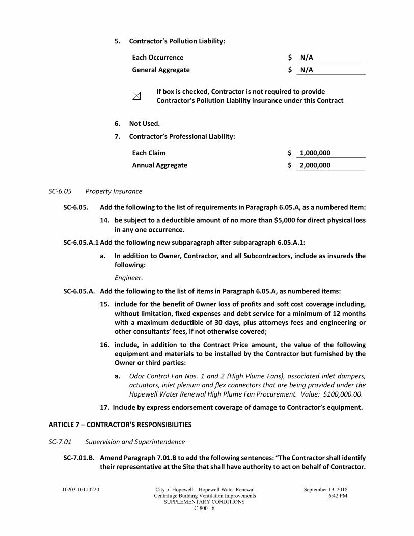
10203-10110220 City of Hopewell – Hopewell Water Renewal September 19, 2018
Centrifuge Building Ventilation Improvements 6:42 PM SUPPLEMENTARY CONDITIONS
C-800 - 6
5. Contractor’s Pollution Liability:
Each Occurrence $ N/A
General Aggregate $ N/A
If box is checked, Contractor is not required to provide
Contractor’s Pollution Liability insurance under this Contract
6. Not Used.
7. Contractor’s Professional Liability:
Each Claim $ 1,000,000
Annual Aggregate $ 2,000,000
SC-6.05 Property Insurance
SC-6.05. Add the following to the list of requirements in Paragraph 6.05.A, as a numbered item:
14. be subject to a deductible amount of no more than $5,000 for direct physical loss
in any one occurrence.
SC-6.05.A.1 Add the following new subparagraph after subparagraph 6.05.A.1:
a. In addition to Owner, Contractor, and all Subcontractors, include as insureds the
following:
Engineer.
SC-6.05.A. Add the following to the list of items in Paragraph 6.05.A, as numbered items:
15. include for the benefit of Owner loss of profits and soft cost coverage including,
without limitation, fixed expenses and debt service for a minimum of 12 months
with a maximum deductible of 30 days, plus attorneys fees and engineering or
other consultants’ fees, if not otherwise covered;
16. include, in addition to the Contract Price amount, the value of the following
equipment and materials to be installed by the Contractor but furnished by the
Owner or third parties:
a. Odor Control Fan Nos. 1 and 2 (High Plume Fans), associated inlet dampers,
actuators, inlet plenum and flex connectors that are being provided under the
Hopewell Water Renewal High Plume Fan Procurement. Value: $100,000.00.
17. include by express endorsement coverage of damage to Contractor’s equipment.
ARTICLE 7 – CONTRACTOR’S RESPONSIBILITIES
SC-7.01 Supervision and Superintendence
SC-7.01.B. Amend Paragraph 7.01.B to add the following sentences: “The Contractor shall identify
their representative at the Site that shall have authority to act on behalf of Contractor.

10203-10110220 City of Hopewell – Hopewell Water Renewal September 19, 2018
Centrifuge Building Ventilation Improvements 6:42 PM SUPPLEMENTARY CONDITIONS
C-800 - 7
All communications given to or received from this representative shall be binding on
Contractor.”
SC-7.01.C. Add the following new paragraph immediately after Paragraph 7.01.B:
Any superintendent or other personnel, who repeatedly fails to follow the Engineer’s
written or oral orders, directions, instructions, or determinations, shall be subject to
removal from the project. Upon the written request of the Engineer, the Contractor
shall immediately remove such superintendent or other personnel and name a
replacement in writing. Noncompliance with the Engineer’s request to remove and
replace personnel at any level shall be grounds for terminating the Contract.
SC-7.02 Labor; Working Hours
SC-7.02.B. Add the following new subparagraphs immediately after Paragraph 7.02.B:
1. Regular working hours will be 7:00 am to 5:00 pm.
SC-7.03 Services, Materials, and Equipment
SC-7.03.B. Add the following new subparagraphs immediately after Paragraph 7.03.B:
1. Where the Work requires equipment be furnished, due to the lack of
standardization of equipment as produced by the various manufacturers, it may
become necessary to make minor modifications in the structures, buildings,
piping, mechanical work, electrical work, accessories, controls, or other work, to
accommodate the particular equipment offered. Contractor's bid price for any
equipment offered shall include the cost of making any necessary changes subject
to the approval of Engineer.
SC-7.09 Taxes
SC 7.09 Add a new paragraph immediately after Paragraph 7.09.A:
B. Owner is exempt from payment of sales and compensating use taxes of the
Commonwealth of Virginia and of cities and counties thereof on all materials to
be incorporated into the Work.
1. Owner’s exemption does not apply to construction tools, machinery,
equipment, or other property purchased by or leased by Contractor, or to
supplies or materials not incorporated into the Work.
SC-7.12 Safety and Protection
SC-7.12 Insert the following after the second sentence of Paragraph 7.12.C:
The following Owner safety programs are applicable to the Work: Safety Policy &
Procedures for Contractors and Subcontractors.

10203-10110220 City of Hopewell – Hopewell Water Renewal September 19, 2018
Centrifuge Building Ventilation Improvements 6:42 PM SUPPLEMENTARY CONDITIONS
C-800 - 8
ARTICLE 9 – OWNER’S RESPONSIBILITIES
SC-9.13 Owner’s Site Representative
SC-9.13 Add the following new paragraph immediately after Paragraph 9.12 of the General
Conditions:
SC-9.13 Owner will furnish an “Owner’s Site Representative” to represent Owner at
the Site and assist Owner in observing the progress and quality of the Work. The
Owner’s Site Representative is not Engineer’s consultant, agent, or employee.
ARTICLE 13 – COST OF THE WORK; ALLOWANCES; UNIT PRICE WORK
SC-13.01 Cost of the Work
SC 13.01.B.5.c Delete Paragraph 13.01.B.5.c in its entirety and insert the following in its place:
c. Construction Equipment and Machinery:
1) Rentals of all construction equipment and machinery, and the parts thereof,
in accordance with rental agreements approved by Owner with the advice of
Engineer, and the costs of transportation, loading, unloading, assembly,
dismantling, and removal thereof. All such costs shall be in accordance with
the terms of said rental agreements. The rental of any such equipment,
machinery, or parts shall cease when the use thereof is no longer necessary
for the Work.
2) Costs for equipment and machinery owned by Contractor will be paid at a
rate shown for such equipment in current version of RS Means. An hourly
rate will be computed by dividing the monthly rates by 176. These computed
rates will include all operating costs. Costs will include the time the
equipment or machinery is in use on the changed Work and the costs of
transportation, loading, unloading, assembly, dismantling, and removal
when directly attributable to the changed Work. The cost of any such
equipment or machinery, or parts thereof, shall cease to accrue when the use
thereof is no longer necessary for the changed Work. Equipment or
machinery with a value of less than $1,000 will be considered small tools.
ARTICLE 15 – PAYMENTS TO CONTRACTOR; SET-OFFS; COMPLETION; CORRECTION PERIOD
SC-15.03 Substantial Completion
SC 15.03.B Add the following new subparagraph to Paragraph 15.03.B:
1. If some or all of the Work has been determined not to be at a point of Substantial
Completion and will require re-inspection or re-testing by Engineer, the cost of
such re-inspection or re-testing, including the cost of time, travel and living
expenses, shall be paid by Contractor to Owner. If Contractor does not pay, or the
parties are unable to agree as to the amount owed, then Owner may impose a
reasonable set-off against payments due under Article 15.
10203-10110220 City of Hopewell – Hopewell Water Renewal September 19, 2018
Centrifuge Building Ventilation Improvements 6:42 PM SUPPLEMENTARY CONDITIONS
C-800 - 9
SC-15.07 Waiver of Claims
SC-15.07.B. Amend Paragraph 15.07.B to state "The acceptance of final payment by Contractor will
constitute a waiver by Contractor of all claims and rights against Owner and/or
Engineer other than those pending matters that have been duly submitted or appealed
under the provisions of Article 17.”
ARTICLE 17 – FINAL RESOLUTION OF DISPUTES
SC-17.02 Attorneys’ Fees
SC-17.02 Add the following new paragraph immediately after Paragraph 17.01.
SC-17.02 Attorneys’ Fees: For any matter subject to final resolution under this Article,
the prevailing party shall be entitled to an award of its attorneys’ fees incurred in the
final resolution proceedings, in an equitable amount to be determined in the discretion
of the court, arbitrator, arbitration panel, or other arbiter of the matter subject to final
resolution, taking into account the parties’ initial demand or defense positions in
comparison with the final result.

10203-10110220 City of Hopewell – Hopewell Water Renewal September 19, 2018
Centrifuge Building Ventilation Improvements 6:42 PM SUPPLEMENTARY CONDITIONS
C-800 - 10
THIS PAGE INTENTIONALLY LEFT BLANK

10203-10110220 City of Hopewell – Hopewell Water Renewal September 18, 2018
Centrifuge Building Ventilation Improvements 6:06 PM
SUMMARY OF WORK 01 11 00 - 1
SECTION 01 11 00 1
SUMMARY OF WORK 2
PART 1 - GENERAL 3
1.1 LOCATION AND SCOPE OF WORK 4
A. The Work is located at the City of Hopewell, Hopewell Water Renewal (HWR), 231 Hummel 5
Ross Road, Hopewell, VA 23860. 6
B. The Work consists of, but is not limited to the following: 7
1. Demolition of existing equipment, piping, various materials and components, etc. 8
2. Installation of Owner furnished equipment to include, but not necessarily limited to: 9
a. High plume fans, including motors, flexible connectors and inlet dampers and 10
associated motor actuators, and inlet plenum. 11
b. Contractor shall provide coordination with high plume fan supplier for delivery, 12
installation, start-up, performance testing, training, etc. See Appendix A for Owner 13
furnished equipment, High Plume Fan Procurement Documents, including the 14
Equipment Supplier responsibilities. 15
3. Furnishing and installing new ventilation ducting. 16
4. Furnishing and installing new associated structural supports for the Owner furnished 17
equipment and Contractor furnished equipment, ducting, ducting supports, utilities and 18
associated appurtenances. 19
5. Furnishing and installing electrical distribution and control equipment. 20
6. Furnishing and installing instrumentation and control systems. 21
7. Furnishing and installing other associated electrical, instrumentation, structural, 22
architectural and miscellaneous support work and systems. 23
8. It is the intent of the Contract Documents to describe a functionally complete project. 24
Furnish and install all supplementary or miscellaneous items, appurtenances, and devices 25
incidental to or necessary for a sound, secure, complete, and functional installation. 26
9. The Work described in this Section is an overall summary of the responsibilities of the 27
Contractor, it does not supersede the specific requirements of the Contract Documents. 28
1.2 ITEMS TO BE SUBMITTED WITH THE BID 29
A. Completed Bid Form. 30
B. Bid Bond (See Instruction To Bidders for Bid Bond Form). 31
C. Completed Contractor’s Qualification Questionnaire (within 48 hours of bid opening). 32
D. Contractor’s Class A License Number. 33
E. Completed City of Hopewell’s Invitation for Bid #06-18. 34
F. Acknowledgement of each Addenda issued. 35
1.3 CONTRACT 36
A. The Work will be constructed under one prime contract. 37
1.4 OWNER OCCUPANCY 38
A. Owner will occupy the premises during the entire period of construction for the conduct of his 39
normal operations. Contractor shall coordinate with Owner in all construction operations to 40
minimize conflicts and to facilitate Owner usage. 41
1.5 MAINTENANCE OF PLANT OPERATIONS 42
A. See Section 01 52 00, Maintenance of Plant Operations. 43

10203-10110220 City of Hopewell – Hopewell Water Renewal September 18, 2018
Centrifuge Building Ventilation Improvements 6:06 PM
SUMMARY OF WORK 01 11 00 - 2
1.6 OWNER-FURNISHED PRODUCTS 1
A. High Plume Fans: Owner will furnish high plume fans, including motors, flexible connectors, 2
vibration switches, inlet dampers and associated motor actuators, and inlet plenum as identified 3
within the Contract Documents. See Appendices for Owner furnished equipment procurement 4
documents. 5
1.7 CONTRACTOR’S USE OF PREMISES 6
A. Use of the premises shall be confined to the Work areas shown on the Drawings and shall allow 7
for Owner occupancy, Owner’s operation of the treatment plant and other contractors working 8
on the site. 9
B. Assume full responsibility for the protection and safekeeping of products furnished under this 10
Contract, for materials stored on or off-site and for Owner furnished equipment that is delivered 11
to the site and released to the Contractor for installation. 12
C. Move any stored products under the Contractor’s control that interfere with operations of the 13
Owner or work of other contractors. 14
D. Obtain and pay for the use of additional storage or work areas needed for Contractor’s 15
operations. 16
E. Confine materials storage, equipment storage, and employee and subcontractor parking to the 17
areas shown on the Drawings. Contractor shall not store materials or equipment, nor shall 18
employees of the Contractor or subcontractors park automobiles on streets, in the Owner’s 19
parking lots, or in the parking and storage areas designated for use by other contractors. 20
F. Restore any areas used for materials storage, equipment storage, or employee and subcontractor 21
parking to their original condition or better, unless specified otherwise. 22
G. Owner and other contractors will occupy the premises during the construction period for the 23
conduct of normal operations and construction activities. These include, but are not limited to: 24
construction, operation and maintenance of the treatment plant facilities, force mains, pipelines, 25
utility easements, fence lines and construction activities. Cooperate with Owner and other 26
contractors to minimize conflict and to maintain usage and operation. 27
H. Contractor is responsible for securing all additional staging areas as required for the duration of 28
the Contract. All costs, contingencies, permits and agreements related to the acquisition and use 29
of any proposed staging area shall be the Contractor’s responsibility. Contractor is responsible 30
for preparation and restoration of areas used to the satisfaction of the property owner. 31
1. Contractor shall provide to the City of Hopewell a listing of all property owners and 32
locations of Contractor negotiated staging areas and copies of such agreements. 33
PART 2 - PRODUCTS - (NOT APPLICABLE TO THIS SPECIFICATION SECTION) 34
PART 3 - EXECUTION - (NOT APPLICABLE TO THIS SPECIFICATION SECTION) 35
END OF SECTION 36

10203-10110220 City of Hopewell – Hopewell Water Renewal September 18, 2018
Centrifuge Building Ventilation Improvements 6:10 PM
PRODUCT SUBSTITUTIONS 01 25 13 - 1
SECTION 01 25 13 1
PRODUCT SUBSTITUTIONS 2
PART 1 - GENERAL 3
1.1 SUMMARY 4
A. Section Includes: 5
1. The procedure for requesting the approval of substitution of a product that is not equivalent 6
to a product which is specified by descriptive or performance criteria or defined by 7
reference to one or more of the following: 8
a. Name of manufacturer. 9
b. Name of vendor. 10
c. Trade name. 11
d. Catalog number. 12
2. Substitutions are not "or-equals." 13
3. This Specification Section does not address substitutions for major equipment. 14
B. Related Specification Sections include but are not necessarily limited to: 15
1. Division 00 - Bidding Requirements, Contract Forms, and Conditions of the Contract. 16
2. Division 01 - General Requirements. 17
C. Request for Substitution - General: 18
1. Base all bids on materials, equipment, and procedures specified. 19
2. Certain types of equipment and kinds of material are described in specifications by means of 20
references to names of manufacturers and vendors, trade names, or catalog numbers. 21
a. When this method of specifying is used, it is not intended to exclude from consideration 22
other products bearing other manufacturer's or vendor's names, trade names, or catalog 23
numbers, provided said products are "or-equals," as determined by Engineer. 24
3. Other types of equipment and kinds of material may be acceptable substitutions under the 25
following conditions: 26
a. Or-equals are unavailable due to strike, discontinued production of products meeting 27
specified requirements, or other factors beyond control of Contractor; or, 28
b. Contractor proposes a cost and/or time reduction incentive to the Owner. 29
1.2 QUALITY ASSURANCE 30
A. In making request for substitution or in using an approved product, Contractor represents they: 31
1. Have investigated proposed product, and have determined that it is adequate or superior in 32
all respects to that specified, and that it will perform function for which it is intended. 33
2. Will provide same guarantee for substitute item as for product specified. 34
3. Will coordinate installation of accepted substitution into Work, to include building 35
modifications if necessary, making such changes as may be required for Work to be 36
complete in all respects. 37
4. Waive all claims for additional costs related to substitution which subsequently arise. 38
1.3 DEFINITIONS 39
A. Product: Manufactured material or equipment. 40
1.4 PROCEDURE FOR REQUESTING SUBSTITUTION DURING BIDDING PERIOD 41
A. See Section 00 21 13, Instructions to Bidders. 42
1.5 PROCEDURE FOR REQUESTING SUBSTITUTION AFTER AWARD OF CONTRACT 43
A. Substitution will only be considered under the conditions stated herein. 44
B. Written request through Contractor only. 45
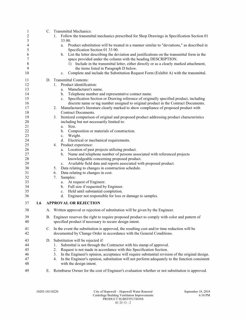
10203-10110220 City of Hopewell – Hopewell Water Renewal September 18, 2018
Centrifuge Building Ventilation Improvements 6:10 PM
PRODUCT SUBSTITUTIONS 01 25 13 - 2
C. Transmittal Mechanics: 1
1. Follow the transmittal mechanics prescribed for Shop Drawings in Specification Section 01 2
33 00. 3
a. Product substitution will be treated in a manner similar to "deviations," as described in 4
Specification Section 01 33 00. 5
b. List the letter describing the deviation and justifications on the transmittal form in the 6
space provided under the column with the heading DESCRIPTION. 7
1) Include in the transmittal letter, either directly or as a clearly marked attachment, 8
the items listed in Paragraph D below. 9
c. Complete and include the Substitution Request Form (Exhibit A) with the transmittal. 10
D. Transmittal Contents: 11
1. Product identification: 12
a. Manufacturer's name. 13
b. Telephone number and representative contact name. 14
c. Specification Section or Drawing reference of originally specified product, including 15
discrete name or tag number assigned to original product in the Contract Documents. 16
2. Manufacturer's literature clearly marked to show compliance of proposed product with 17
Contract Documents. 18
3. Itemized comparison of original and proposed product addressing product characteristics 19
including but not necessarily limited to: 20
a. Size. 21
b. Composition or materials of construction. 22
c. Weight. 23
d. Electrical or mechanical requirements. 24
4. Product experience: 25
a. Location of past projects utilizing product. 26
b. Name and telephone number of persons associated with referenced projects 27
knowledgeable concerning proposed product. 28
c. Available field data and reports associated with proposed product. 29
5. Data relating to changes in construction schedule. 30
6. Data relating to changes in cost. 31
7. Samples: 32
a. At request of Engineer. 33
b. Full size if requested by Engineer. 34
c. Held until substantial completion. 35
d. Engineer not responsible for loss or damage to samples. 36
1.6 APPROVAL OR REJECTION 37
A. Written approval or rejection of substitution will be given by the Engineer. 38
B. Engineer reserves the right to require proposed product to comply with color and pattern of 39
specified product if necessary to secure design intent. 40
C. In the event the substitution is approved, the resulting cost and/or time reduction will be 41
documented by Change Order in accordance with the General Conditions. 42
D. Substitution will be rejected if: 43
1. Submittal is not through the Contractor with his stamp of approval. 44
2. Request is not made in accordance with this Specification Section. 45
3. In the Engineer's opinion, acceptance will require substantial revision of the original design. 46
4. In the Engineer's opinion, substitution will not perform adequately to the function consistent 47
with the design intent. 48
E. Reimburse Owner for the cost of Engineer's evaluation whether or not substitution is approved. 49

10203-10110220 City of Hopewell – Hopewell Water Renewal September 18, 2018
Centrifuge Building Ventilation Improvements 6:10 PM
PRODUCT SUBSTITUTIONS 01 25 13 - 3
PART 2 - PRODUCTS - (NOT APPLICABLE TO THIS SPECIFICATION SECTION) 1
PART 3 - EXECUTION - (NOT APPLICABLE TO THIS SPECIFICATION SECTION) 2
END OF SECTION 3
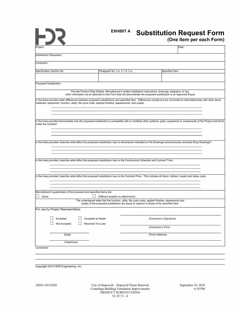
10203-10110220 City of Hopewell – Hopewell Water Renewal September 18, 2018
Centrifuge Building Ventilation Improvements 6:10 PM
PRODUCT SUBSTITUTIONS 01 25 13 - 4
EXHIBIT A Substitution Request Form (One Item per each Form)
Project: Date:
Substitution Requestor:
Contractor:
Specification Section No: Paragraph No. (i.e. 2.1.A.1.c): Specified Item:
Proposed Substitution:
Provide Product Data Sheets, Manufacturer’s written installation instructions, drawings, diagrams, or any other information as an attached to this Form that will demonstrate the proposed substitution is an Approved Equal.
In the lines provided state differences between proposed substitutions and specified item. Differences include but are not limited to interrelationship with other items; materials, equipment, function, utility, life cycle costs, applied finished, appearances, and quality.
____________________________________________________________________________________________ ____________________________________________________________________________________________ ____________________________________________________________________________________________
In the lines provided demonstrate how the proposed substitution is compatible with or modifies other systems, parts, equipment or components of the Project and Work under the Contract
: ____________________________________________________________________________________________ ____________________________________________________________________________________________ ____________________________________________________________________________________________
In the lines provided, describe what effect the proposed substitution has on dimensions indicated on the Drawings and previously reviewed Shop Drawings?
____________________________________________________________________________________________ ____________________________________________________________________________________________ ____________________________________________________________________________________________
In the lines provided, describe what effect the proposed substitution has on the Construction Schedule and Contract Time. ____________________________________________________________________________________________ ____________________________________________________________________________________________ ____________________________________________________________________________________________
In the lines provided, describe what effect the proposed substitution has on the Contract Price. This includes all direct, indirect, impact and delay costs. ____________________________________________________________________________________________ ____________________________________________________________________________________________ ____________________________________________________________________________________________
Manufacturer’s guarantees of the proposed and specified items are:
☐ Same ☐ Different (explain on attachment)
The undersigned state that the function, utility, life cycle costs, applied finishes, appearance and quality of the proposed substitution are equal or superior to those of the specified item.
For use by Project Representative: ______________________________________________
☐ Accepted ☐ Accepted as Noted (Contractor’s Signature)
☐ Not Accepted ☐ Received Too Late ______________________________________________ (Contractor’s Firm)
__________________ ______________________________________________ (Date) (Firms Address)
__________________ ______________________________________________ (Telephone)
Comments:
Copyright 2014 HDR Engineering, Inc.
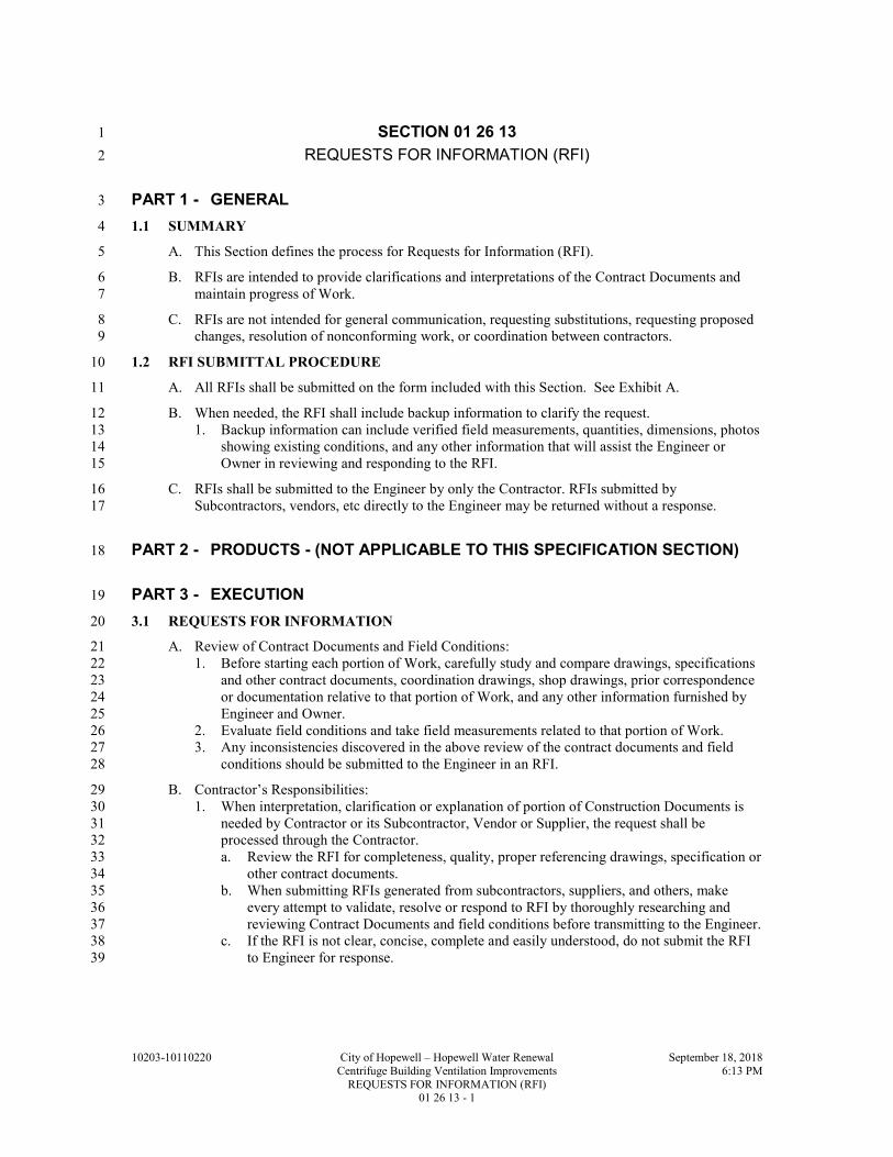
10203-10110220 City of Hopewell – Hopewell Water Renewal September 18, 2018
Centrifuge Building Ventilation Improvements 6:13 PM
REQUESTS FOR INFORMATION (RFI) 01 26 13 - 1
SECTION 01 26 13 1
REQUESTS FOR INFORMATION (RFI) 2
PART 1 - GENERAL 3
1.1 SUMMARY 4
A. This Section defines the process for Requests for Information (RFI). 5
B. RFIs are intended to provide clarifications and interpretations of the Contract Documents and 6
maintain progress of Work. 7
C. RFIs are not intended for general communication, requesting substitutions, requesting proposed 8
changes, resolution of nonconforming work, or coordination between contractors. 9
1.2 RFI SUBMITTAL PROCEDURE 10
A. All RFIs shall be submitted on the form included with this Section. See Exhibit A. 11
B. When needed, the RFI shall include backup information to clarify the request. 12
1. Backup information can include verified field measurements, quantities, dimensions, photos 13
showing existing conditions, and any other information that will assist the Engineer or 14
Owner in reviewing and responding to the RFI. 15
C. RFIs shall be submitted to the Engineer by only the Contractor. RFIs submitted by 16
Subcontractors, vendors, etc directly to the Engineer may be returned without a response. 17
PART 2 - PRODUCTS - (NOT APPLICABLE TO THIS SPECIFICATION SECTION) 18
PART 3 - EXECUTION 19
3.1 REQUESTS FOR INFORMATION 20
A. Review of Contract Documents and Field Conditions: 21
1. Before starting each portion of Work, carefully study and compare drawings, specifications 22
and other contract documents, coordination drawings, shop drawings, prior correspondence 23
or documentation relative to that portion of Work, and any other information furnished by 24
Engineer and Owner. 25
2. Evaluate field conditions and take field measurements related to that portion of Work. 26
3. Any inconsistencies discovered in the above review of the contract documents and field 27
conditions should be submitted to the Engineer in an RFI. 28
B. Contractor’s Responsibilities: 29
1. When interpretation, clarification or explanation of portion of Construction Documents is 30
needed by Contractor or its Subcontractor, Vendor or Supplier, the request shall be 31
processed through the Contractor. 32
a. Review the RFI for completeness, quality, proper referencing drawings, specification or 33
other contract documents. 34
b. When submitting RFIs generated from subcontractors, suppliers, and others, make 35
every attempt to validate, resolve or respond to RFI by thoroughly researching and 36
reviewing Contract Documents and field conditions before transmitting to the Engineer. 37
c. If the RFI is not clear, concise, complete and easily understood, do not submit the RFI 38
to Engineer for response. 39

10203-10110220 City of Hopewell – Hopewell Water Renewal September 18, 2018
Centrifuge Building Ventilation Improvements 6:13 PM
REQUESTS FOR INFORMATION (RFI) 01 26 13 - 2
2. Follow these procedures in developing an RFI: 1
a. List relevant Contract Documents when seeking information being requested. 2
1) Reference all applicable Contract Drawings by sheet number. 3
2) Specifications by section and paragraph number 4
3) Reference any other relevant documents. 5
b. Clearly state any additional information needed so request can be fully understood, 6
including sketches, photos or other reference material. 7
c. Suggest any reasonable solutions and recommendations which will aid in determining a 8
solution or response. 9
d. Any critical RFI requiring a rapid response shall clearly indicate such with an 10
explanation as to why RFI is critical. 11
e. Priority for responses shall be indicated on each RFI. 12
3. A response to RFI shall not be considered a notice to proceed with a change that may revise 13
the Contract Sum or Contract Time, unless authorized by Owner in writing. 14
4. If response to RFI is determined incomplete, it shall be resubmitted with reason response is 15
does not completely address the original RFI and any necessary additional information. 16
C. RFI Submittal Numbering: 17
1. RFIs shall be assigned unique numbers in sequential order (1, 2, 3, 4, etc.). 18
2. A resubmitted RFI or a previously answered RFI requiring revising or further clarification 19
shall be submitted using original RFI number proceeded by ".1” to indicate revision one of 20
RFI (i.e.: RFI No. 34.1 for revision 1 to RFI No. 34). 21
D. Invalid RFI 22
1. Engineer may return RFI without response for following reasons: 23
a. Request is unclear or incomplete. 24
b. Request was answered in a previous RFI. 25
c. Requested information is readily available in the Construction Documents. 26
d. Request is related to construction means, methods or techniques. 27
e. Request is related to health or safety measures. 28
f. Request is due to Contractor’s lack of adequate coordination. 29
g. Issue relates to coordination between Subcontractors. 30
h. Request is a "Substitution Request." 31
i. Request is a "Contractor Proposed Change." 32
j. Request is due to non-conformance. 33
34
2. Should the invalid RFIs continue to be provided, the Owner may deduct the cost of the 35
Engineer’s time to process, review and return the RFIs from the Contract Price. 36
END OF SECTION 37

10203-10110220 City of Hopewell – Hopewell Water Renewal September 18, 2018
Centrifuge Building Ventilation Improvements 6:13 PM
REQUESTS FOR INFORMATION (RFI) 01 26 13 - 3
EXHIBIT A Request for
Information Form 1
RFI No. 2
Contract: Hopewell Water Renewal Centrifuge Building Ventilation Improvements 3
Contractor: 4
Owner: Hopewell Water Renewal (HWR) Owner's Contract No. 5
Engineer HDR Engineering, Inc. Engineer's Contract No. 10110220 6
THIS REQUEST BY: cc to: 7
(Name of the Contractor's Representative) 8
9
REFERENCE: DIVISION _____ SECTION __________ PLAN SHEET NO. __________________ 10
11
12
13
14
15
16
17
ATTACHMENTS 18
19
RESPONSE BY: Date: , 20 20
(Name of the Engineer's Representative) 21
22
23
24
25
26
ATTACHMENTS 27
28
The General Conditions (GCs) specify that once the Engineer provides a response to a Contractor's RFI, 29
that determination shall be final and binding on the Contractor unless the Contractor delivers to the Owner 30
written notice of a change in the work within a certain period of time of receipt of that determination. See 31
the GCs for further clarification. 32
cc to: ______________________________________ 33
___________________________________________ 34

10203-10110220 City of Hopewell – Hopewell Water Renewal September 18, 2018
Centrifuge Building Ventilation Improvements 6:13 PM
REQUESTS FOR INFORMATION (RFI) 01 26 13 - 4
THIS PAGE INTENTIONALLY LEFT BLANK 1
10203-10110220 City of Hopewell – Hopewell Water Renewal September 18, 2018
Centrifuge Building Ventilation Improvements 6:14 PM
SCHEDULE OF VALUES (LUMP SUM PROJECTS) 01 29 73 - 1
SECTION 01 29 73 1
SCHEDULE OF VALUES (LUMP SUM PROJECTS) 2
PART 1 - GENERAL 3
1.1 SUMMARY 4
A. Section Includes: 5
1. Administrative and procedural requirements for: 6
a. Schedule of Values. 7
B. Related Specification Sections include but are not necessarily limited to: 8
1. Division 00 - Bidding Requirements, Contract Forms, and Conditions of the Contract. 9
2. Division 01 - General Requirements. 10
1.2 SUBMITTALS 11
A. See Section 01 33 00. 12
B. As required in EJCDC C-700 2.03.A.3 Schedule of Values. 13
1.3 SCHEDULE OF VALUES 14
A. Where a Contract is awarded on a lump sum basis, the Contractor shall file with the Engineer a 15
balanced price segregation of the lump sum bid into items similar to the various subdivisions of 16
the general and detailed specifications. 17
1. The cost of various materials shall be furnished upon request of the Engineer, and such data 18
will then be used as a basis for making progress estimates. 19
2. Breakdown costs, itemized by Specification Section and trade, and distribute cost to 20
individual applicable units and structures. 21
3. Where structures, units, equipment or other components are identified by a specific series 22
or, identification number, utilize said designation throughout cost breakdown. 23
4. Provide detailed breakdown for individual yard piping or conduit runs and identify 24
approximate quantities involved to satisfaction of the Engineer. 25
5. Provide separate breakdown for change order items requested. 26
6. Contractor may include an item for bond, insurance, temporary facilities and job 27
mobilization. 28
7. Each item shall include a directly proportional amount of the Contractor’s overhead and 29
profit. 30
8. When requested by Owner, support values with data that will substantiate their correctness. 31
9. The sum of the individual values shown on the Schedule of Values shall equal the total 32
Contract Price. 33
B. Contractor's costs shall not govern the allocation of values when application of Contractor's costs 34
to a component part of the Work results in any other component part or combination of 35
component parts being under-valued in relation to conventional estimating guides. 36
C. Schedule of Values shall be agreed upon prior to first Application for Payment. 37
1.4 APPLICATION FOR PAYMENT 38
A. Provide a Summary Sheets and cost breakdown sheets equivalent to those of EJCDC document 39
C-620, Contractor's Application for Payment forms. 40
B. Provide an additional breakdown sheet, equivalent to the Stored Material Summary of EJCDC 41
document C620, showing the tabulation format for stored materials. 42
C. Submit this sheet each month with Contractor's pay request breakdown. 43
D. The detail and format of cost breakdown and stored materials tabulation sheet shall be fully 44
approved by Engineer. 45

10203-10110220 City of Hopewell – Hopewell Water Renewal September 18, 2018
Centrifuge Building Ventilation Improvements 6:14 PM
SCHEDULE OF VALUES (LUMP SUM PROJECTS) 01 29 73 - 2
PART 2 - PRODUCTS - (NOT APPLICABLE TO THIS SPECIFICATION SECTION) 1
PART 3 - EXECUTION - (NOT APPLICABLE TO THIS SPECIFICATION SECTION) 2
END OF SECTION 3

10203-10110220 City of Hopewell – Hopewell Water Renewal September 18, 2018
Centrifuge Building Ventilation Improvements 6:15 PM
PROJECT MEETINGS 01 31 19 - 1
SECTION 01 31 19 1
PROJECT MEETINGS 2
PART 1 - GENERAL 3
1.1 SUMMARY 4
A. Section Includes: 5
1. Preconstruction, progress and other project meetings. 6
B. Related Sections include but are not necessarily limited to: 7
1. Division 00 - Bidding Requirements, Contract Forms, and Conditions of the Contract. 8
2. Division 01 - General Requirements. 9
1.2 PRECONSTRUCTION MEETING 10
A. Meet with the Owner and Engineer for a pre-construction conference at a time mutually agreed 11
upon after the contract is awarded, but before any work is performed. 12
B. The Engineer will schedule a meeting of the Owner, Contractor, Contractor’s Subcontractors, 13
and their respective representatives. 14
1. The purpose of the meeting will be to clarify construction contract administration 15
procedures, to establish lines of authority and communication and identify duties and 16
responsibilities of the parties. 17
C. The Engineer will schedule the pre-construction conference after receipt of the Contractor’s draft 18
proposed schedule. 19
D. The agenda for the meeting shall cover at least the following items: 20
1. Use of site and special concerns regarding adjacent properties. 21
2. Organization of the Contractor's forces and personnel, including all subcontractors, and 22
materials suppliers. 23
3. Channels and procedures for communication. 24
4. Contractor’s construction schedule, including sequence of critical work. 25
5. Contract documents, including distribution of required copies and revisions. 26
6. Processing of shop drawings and other data. 27
7. Processing of Requests for Information (RFI), Construction Change Directives (CCD) and 28
Change Orders and distribution of related forms. 29
8. Rules and regulations applicable to the performance of the work, such as quality control, 30
testing and startup. 31
9. Contractor’s site safety and security protocols. 32
10. Procedures for quality control, housekeeping and related matters. 33
E. The Engineer will compile meeting minutes from the transcribed record of the meeting and 34
electronically distribute copies to all participants. 35
F. Pre-construction conference submittals: 36
1. The names and telephone numbers of Contractor’s Superintendent and Project Manager. 37
2. List of personnel authorized to sign change orders and receive progress payments. 38
3. The name, address and telephone numbers of two or more persons employed by the 39
Contractor who can be reached at any time of the day or night to handle emergency matters. 40
4. A list of all subcontractors that will work on the project, a description of work they will 41
perform, and a contact list for each subcontractor with phone numbers and address. 42
5. A list of materials suppliers. 43
6. A draft proposed Construction Schedule. 44
7. Material Safety Data Sheets for all hazardous chemical products to be used by the 45
Contractor on this project. 46

10203-10110220 City of Hopewell – Hopewell Water Renewal September 18, 2018
Centrifuge Building Ventilation Improvements 6:15 PM
PROJECT MEETINGS 01 31 19 - 2
8. Temporary Erosion and Sediment Controls Plan. 1
9. Traffic Control Plan. 2
1.3 PROGRESS MEETINGS 3
A. Monthly progress meetings will be held a location determined by the Engineer, unless otherwise 4
arranged. 5
B. Attendees will include the Owner, Engineer, Contractor, subcontractors, and suppliers’ 6
representatives as may be needed, other Contractors working at the site, and other interested or 7
affected parties. 8
C. The specific purpose of progress meetings is to coordinate the efforts of all concerned so that the 9
project progresses without delay to completion, with the least inconvenience. 10
D. Bring a four week look ahead schedule to each weekly meeting, including the following items: 11
1. Work completed last month. 12
2. Work anticipated for the next month ("Look Ahead"). 13
3. Subcontractors on site the prior week. 14
4. Subcontractors scheduled on site for the next month. 15
5. Contract document deficiencies or questions noted during prior week. 16
6. Anything that could impede the progress of the work or affect the critical path on the project 17
schedule. 18
7. Corrective measures and procedures planned to regain planned schedule, cost or quality 19
assurance, if necessary. 20
8. Report of any accidents, and any site safety issues that need to be addressed. 21
E. Other Agenda items to be discussed: 22
1. Review and revise as necessary and approve minutes of previous meetings. 23
2. Status of submittals of equipment and shop drawings. 24
3. Identify problems that impede planned progress. 25
4. Other current business. 26
F. Revision of Minutes: 27
1. Unless published minutes are challenged in writing prior to the next regularly scheduled 28
progress meeting, they will be accepted as properly stating the activities and decisions of the 29
meeting. 30
2. Persons challenging published minutes shall reproduce and distribute copies of the 31
challenge to all indicated recipients of the particular set of minutes. 32
3. Challenge to minutes shall be settled as priority item of "old business" at the next regularly 33
scheduled meeting. 34
G. Minutes of Meeting: 35
1. The Engineer will compile minutes of each project meeting and will furnish electronic 36
copies to the Contractor. 37
1.4 OTHER MEETINGS 38
A. Other meetings will be required to facilitate progress of the Work. These include, but are not 39
limited to the following: 40
1. Pre-Installation Conferences: 41
a. Coordinate and schedule with Engineer for each material, product or system specified. 42
1) Conferences to be held prior to initiating installation, but not more than two (2) 43
weeks before scheduled initiation of installation. 44
2) Conferences may be combined if installation schedule of multiple components 45
occurs within the same two-week interval. 46
3) Review manufacturer’s recommendations and Contract Documents Specification 47
Sections. 48
2. Facility Startup Planning and Coordination Meeting. See Section 01 75 00. 49

10203-10110220 City of Hopewell – Hopewell Water Renewal September 18, 2018
Centrifuge Building Ventilation Improvements 6:15 PM
PROJECT MEETINGS 01 31 19 - 3
PART 2 - PRODUCTS - (NOT APPLICABLE TO THIS SPECIFICATION SECTION) 1
PART 3 - EXECUTION - (NOT APPLICABLE TO THIS SPECIFICATION SECTION) 2
END OF SECTION 3

10203-10110220 City of Hopewell – Hopewell Water Renewal September 18, 2018
Centrifuge Building Ventilation Improvements 6:15 PM
PROJECT MEETINGS 01 31 19 - 4
THIS PAGE INTENTIONALLY LEFT BLANK 1
10203-10110220 City of Hopewell – Hopewell Water Renewal September 18, 2018
Centrifuge Building Ventilation Improvements 6:16 PM
CONSTRUCTION PROGRESS SCHEDULE 01 32 16 - 1
SECTION 01 32 16 1
CONSTRUCTION PROGRESS SCHEDULE 2
PART 1 - GENERAL 3
1.1 SUMMARY 4
A. Section Includes: 5
1. Specific requirements for the preparation, submittal, updating, and status reporting of the 6
construction Progress Schedule. 7
B. Related Specification Sections include, but are not necessarily limited to: 8
1. Division 00 - Bidding Requirements, Contract Forms, and Conditions of the Contract. 9
2. Division 01 - General Requirements. 10
C. Review of the Schedule: 11
1. In so far as the Contractor is solely responsible for its means and methods and the schedule 12
represents in part its means and methods, the review of the schedules is for compliance with 13
the requirements as defined in the contract documents. 14
2. The review of the schedule is not intended to be complete or exhaustive or check every 15
activity and its relation to the work. 16
3. Acceptance of the schedule does not imply that the Owner has approved or accepted the 17
Contractor’s means and methods or sequence for performing the work to construct the 18
project. 19
1.2 SUBMITTALS 20
A. Construction Schedule: 21
1. Submittal and review: 22
a. Submit within 10 days after Notice to Proceed or the effective date of the contract, 23
whichever is earlier. 24
b. The Contractor will review and modify the preliminary schedule and return the 25
schedule within five (5) working days. 26
B. Short Interval Schedule: 27
1. Provide a short interval schedule once a month during the Contract Time. This schedule can 28
be presented and reviewed at each progress meeting. 29
a. Provide an accurate representation of the work performed the previous week and work 30
planned for the current week and subsequent four weeks. 31
1.3 GENERAL REQUIREMENTS 32
A. Prepare and submit construction schedule(s) as specified herein. 33
1. Include the following information: 34
a. Construction start dates (Award date, Notice(s) to Proceed date). 35
b. Procurement activities. 36
c. Preparation of key submittals for materials and equipment. 37
d. Engineers review and approval of key submittals. 38
e. Material and equipment fabrication lead times. 39
f. Material and equipment deliveries for Contractor, Owner and third parties. 40
g. Shutdowns/Utility tie-ins/Plant tie-ins. 41
h. Inspections and hold points. 42
i. Start-up of equipment. 43
j. Testing of equipment and systems. 44
k. Commissioning. 45
l. Contract milestones: 46
1) Substantial Completion Date. 47
2) Final Completion Date. 48

10203-10110220 City of Hopewell – Hopewell Water Renewal September 18, 2018
Centrifuge Building Ventilation Improvements 6:16 PM
CONSTRUCTION PROGRESS SCHEDULE 01 32 16 - 2
B. Float: 1
1. The project owns the float, therefore neither the Owner nor the Contractor has exclusive use 2
of the float; the float can used by either party. 3
2. Once float is used, liability for delay of the contractual project completion date rests with 4
the party actually causing delay to the contractual project completion date. 5
1.4 START-UP, DEMONSTRATION, TRAINING, AND FINAL COMPLETION 6
A. The Schedule must include broad-based activities for start-up, operator training, and final 7
completion. 8
1. The Schedule may not necessarily contain sufficient detail on all activities listed in 9
Specification Section 01 75 00 for start-up and demonstration. 10
2. At least 90 days prior to any activities, submit a detailed schedule in conformance with the 11
requirements of Specification Section 01 75 00: 12
a. Identify task for the substantial completion notification. 13
b. Pre-demonstration period: 14
1) Identify equipment start-up for all major equipment. 15
2) Identify all operator trainings required by individual Specification Sections. 16
3) Complete submission of all required submittals. 17
c. Demonstration period: Identify for each project classified system. 18
PART 2 - PRODUCTS - (NOT APPLICABLE TO THIS SPECIFICATION SECTION) 19
PART 3 - EXECUTION - (NOT APPLICABLE TO THIS SPECIFICATION SECTION) 20
END OF SECTION 21

10203-10110220 City of Hopewell – Hopewell Water Renewal September 18, 2018
Centrifuge Building Ventilation Improvements 6:18 PM
RECORD DOCUMENTS 01 32 30- 1
SECTION 01 32 30 1
RECORD DOCUMENTS 2
PART 1 - GENERAL 3
1.1 DESCRIPTION OF WORK 4
A. Contractor shall prepare project record documents as specified below. 5
B. Maintenance of Documents: 6
1. Contractor shall maintain on site, in clean, dry, legible condition complete sets of the 7
following: Contract Drawings, Specifications, Addenda, approved Shop Drawings, 8
Samples, Photographs, Change Orders, other Modifications of Contract, Test Records, 9
Survey Data, Field Orders, and all other documents pertinent to the Work. 10
2. Maintain record documents in electronic format. Where hard copies are necessary, maintain 11
files and racks for proper storage and easy access. File in accordance with filing format of 12
Construction Specification Institute (CSI). 13
3. Make updates to record documents available for review at all times throughout the duration 14
of the project. 15
C. Recording: 16
1. Label final versions of each document with "PROJECT RECORD" in 2 IN high watermark 17
(electronic) or printed letters. 18
2. Keep record documents current and updated at least monthly. 19
3. Do not permanently cover any Work until “as-built” information has been recorded. 20
4. Contract Drawings - Legibly mark to record actual construction including: 21
a. Depths of various elements of foundation in relation to datum. 22
b. Horizontal and vertical location of underground utilities and appurtenances referenced 23
to permanent surface improvements. 24
c. Location of utilities and appurtenances that are concealed in construction referenced to 25
visible features of structure. 26
d. Field changes of dimensions and details. 27
e. Changes made by Change Order or Field Order. 28
f. Details not on original Contract Drawings. 29
g. Changes of different method of construction. 30
h. Use of different products not specified 31
5. Specifications and Addenda - Legibly mark up each Section to record: 32
a. Manufacturer, trade name, catalog number, and supplier of each product and item of 33
equipment actually installed. 34
b. Changes made by Change Order or Field Order. 35
c. Other matters not originally specified. 36
6. Shop Drawings - Maintain as record documents and legibly annotate drawings to record 37
changes made after review. 38
7. Record Documents will be reviewed by the Contractor, its subcontractors and its Engineer 39
on a monthly basis, or as determined by the Engineer. 40
D. Record Drawings: 41
1. Record drawings shall reflect completion of the installation of all work by the Contractor. 42
The drawings shall show the Work in plan and sections as required for clarity with reference 43
dimensions and elevations for complete record drawings. 44
2. The Issued for Construction Drawings may be used as a starting point in developing these 45
drawings. Contractor and its subcontractor’s drawings may be included in this drawing 46
package. The drawing package must be fully integrated and include the necessary cross 47
references between drawings. The drawing package shall include interconnection, 48
numbering, and termination details to equipment furnished under this Contract. 49
10203-10110220 City of Hopewell – Hopewell Water Renewal September 18, 2018
Centrifuge Building Ventilation Improvements 6:18 PM
RECORD DOCUMENTS 01 32 30- 2
E. Submittal: 1
1. At project completion, submit electronic copies of record documents to the Engineer. List 2
and bind any hard copies not otherwise in electronic format for ease of handling. 3
2. Accompany the submittal with an electronic transmittal containing the following: 4
a. Date. 5
b. Project title and number. 6
c. Contractor's name and address. 7
d. Title and number of each record document. 8
e. Certification that each document as submitted is complete and accurate. 9
f. Signature of Contractor. 10
PART 2 - PRODUCTS - (NOT APPLICABLE TO THIS SPECIFICATION SECTION) 11
PART 3 - EXECUTION - (NOT APPLICABLE TO THIS SPECIFICATION SECTION) 12
END OF SECTION 13

10203-10110220 City of Hopewell – Hopewell Water Renewal September 18, 2018
Centrifuge Building Ventilation Improvements 6:20 PM
SUBMITTALS 01 33 00 - 1
SECTION 01 33 00 1
SUBMITTALS 2
PART 1 - GENERAL 3
1.1 SUMMARY 4
A. Section Includes: 5
1. Mechanics and administration of the submittal process for: 6
a. Shop Drawings. 7
b. Samples. 8
c. Informational submittals. 9
2. General content requirements for Shop Drawings. 10
B. Related Specification Sections include but are not necessarily limited to: 11
1. Division 00 - Bidding Requirements, Contract Forms, and Conditions of the Contract. 12
2. Division 01 - General Requirements. 13
3. Construction Progress Schedule submittal requirements are specified in Specification 14
Section 01 32 16. 15
4. Operations and Maintenance Manual submittal requirements are specified in Specification 16
Section 01 33 04. 17
5. Technical Specification Sections identifying required submittals. 18
1.2 DEFINITIONS 19
A. Shop Drawings: 20
1. See General Conditions. 21
2. Product data and samples are Shop Drawing information. 22
B. Informational Submittals: 23
1. Submittals other than Shop Drawings and samples required by the Contract Documents that 24
do not require review and/or approval by the Engineer. 25
2. Representative types of informational submittal items include but are not limited to: 26
a. HVAC test and balance reports. 27
b. Installed equipment and systems performance test reports. 28
c. Manufacturer's installation certification letters. 29
d. Instrumentation and control commissioning reports. 30
e. Warranties. 31
f. Service agreements. 32
g. Construction photographs. 33
h. Survey data. 34
i. Health and safety plans. 35
j. Work plans. 36
k. Delegated designs per performance specification requirements 37
3. For-Information-Only submittals upon which the Engineer is not expected to conduct 38
review or take responsive action may be so identified in the Contract Documents. 39
1.3 SUBMITTAL SCHEDULE 40
A. Schedule of Shop Drawings: 41
1. Submitted and approved within 20 days of receipt of Notice to Proceed. 42
2. Account for multiple transmittals under any specification section where partial submittals 43
will be transmitted. 44

10203-10110220 City of Hopewell – Hopewell Water Renewal September 18, 2018
Centrifuge Building Ventilation Improvements 6:20 PM
SUBMITTALS 01 33 00 - 2
B. Informational Submittals: 1
1. Reports and installation certifications submitted within seven (7) days of conducting testing, 2
installation, or examination. 3
2. Submittals showing compliance with required qualifications submitted twenty (20) days 4
prior to any work beginning using the subject qualifications. 5
C. The submittal schedule shall include the following columns as a minimum: 6
7
Submittal Section
Submittal Description Planned Submittal
Date
Submittal Need Date
8
1.4 PREPARATION OF SUBMITTALS 9
A. General: 10
1. All submittals and all pages of all copies of a submittal shall be completely legible. 11
2. Submittals which, in the Engineer’s sole opinion, are illegible will be returned without 12
review. 13
3. Minimize extraneous information for equipment and products not relevant to the submittal. 14
4. Contractors or vendors written comments on the submittal drawings shall be in green 15
B. Shop Drawings, Product Data, and Samples: 16
1. Scope of any submittal and letter of transmittal: 17
a. Limited to one (1) Specification Section. 18
b. Submittals with more than one Specification section included will be rejected. 19
c. Do not submit under any Specification Section entitled (in part) "Basic Requirements" 20
unless the product or material submitted is specified, in total, in a "Basic Requirements" 21
Specification Section. 22
2. Numbering letter of transmittal: 23
a. Include as prefix the Specification Section number followed by a series number, "-xx", 24
beginning with "01" and increasing sequentially with each additional transmittal for that 25
Specification Section. 26
b. If more than one (1) submittal under any Specification Section, assign consecutive 27
series numbers to subsequent transmittal letters. 28
3. Describing transmittal contents: 29
a. Provide listing of each component or item in submittal capable of receiving an 30
independent review action. 31
b. Identify for each item: 32
1) Manufacturer and Manufacturer's Drawing or data number. 33
2) Contract Document tag number(s). 34
3) Unique page numbers for each page of each separate item. 35
c. When submitting "or-equal" items that are not the products of named manufacturers, 36
include the words "or-equal" in the item description. 37
4. Contractor certification of review and approval: 38
a. Contractor shall execute Exhibit AA, Contractor's Submittal Certification form, to 39
indicate Contractor has reviewed and approved the submittal contents. 40
1) Clearly identify the person who reviewed the submittal and the date it was 41
reviewed." 42
b. Submittals containing multiple independent items shall be prepared with each item 43
listed on the letter of transmittal or on an index sheet for all items listing the discrete 44
page numbers for each page of each item, which shall be stamped with the Contractor's 45
review and approval stamp. 46

10203-10110220 City of Hopewell – Hopewell Water Renewal September 18, 2018
Centrifuge Building Ventilation Improvements 6:20 PM
SUBMITTALS 01 33 00 - 3
1) Each independent item shall have a cover sheet with the transmittal number and 1
item number recorded. 2
a) Provide clear space of 3 IN SQ for Engineer stamping. 3
2) Individual pages or sheets of independent items shall be numbered in a manner that 4
permits the entire contents of a particular item to be readily recognized and 5
associated with Contractor's certification. 6
5. Resubmittals: 7
a. Number with original Specification Section and series number with a suffix letter 8
starting with "A" on a (new) duplicate transmittal form. 9
b. Do not increase the scope of any prior transmittal. 10
c. Provide cover letter indicating how each "B", "C", or "D" Action from previous 11
submittal was addressed and where the correction is found in the resubmittal. 12
d. Account for all components of prior transmittal. 13
1) If items in prior transmittal received "A" or "B" Action code, list them and indicate 14
"A" or "B" as appropriate. 15
a) Do not include submittal information for items listed with prior "A" or "B" 16
Action in resubmittal. 17
2) Indicate "Outstanding-To Be Resubmitted At a Later Date" for any prior "C" or 18
"D" Action item not included in resubmittal. 19
a) Obtain Engineer's approval to exclude items. 20
6. For 8-1/2 x 11 IN, 8-1/2 x 14 IN, and 11 x 17 IN size sheets, provide electronic copies of 21
each submittal for Engineer plus the number required by the Contractor. 22
a. All other size sheets: 23
1) Submit one (1) reproducible transparency or high resolution print and one (1) 24
additional print of each Drawing until approval is obtained. 25
2) Utilize mailing tube; do not fold. 26
3) The Engineer will mark and return the reproducible to the Contractor for 27
reproduction and distribution. 28
7. Contractor shall not use red color for marks on transmittals. 29
a. Duplicate all marks on all copies transmitted, and ensure marks are photocopy 30
reproducible. 31
b. Engineer will use red marks or enclose marks in a cloud. 32
8. Transmittal contents: 33
a. Coordinate and identify Shop Drawing contents so that all items can be easily verified 34
by the Engineer. 35
b. Provide submittal information or marks defining specific equipment or materials 36
utilized on the Project. 37
1) Generalized product information, not clearly defining specific equipment or 38
materials to be provided, will be rejected. 39
c. Identify equipment or material project use, tag number, Drawing detail reference, 40
weight, and other Project specific information. 41
d. Provide sufficient information together with technical cuts and technical data to allow 42
an evaluation to be made to determine that the item submitted is in compliance with the 43
Contract Documents. 44
e. Do not modify the manufacturer's documentation or data except as specified herein. 45
f. Submit items such as equipment brochures, cuts of fixtures, product data sheets or 46
catalog sheets not exceeding 11 x 17 IN pages. 47
1) Indicate exact item or model and all options proposed by arrow and leader. 48
g. When a Shop Drawing submittal is called for in any Specification Section, include as 49
appropriate, scaled details, sizes, dimensions, performance characteristics, capacities, 50
test data, anchoring details, installation instructions, storage and handling instructions, 51
color charts, layout Drawings, rough-in diagrams, wiring diagrams, controls, weights 52
and other pertinent data in addition to information specifically stipulated in the 53
Specification Section. 54

10203-10110220 City of Hopewell – Hopewell Water Renewal September 18, 2018
Centrifuge Building Ventilation Improvements 6:20 PM
SUBMITTALS 01 33 00 - 4
1) Arrange data and performance information in format similar to that provided in 1
Contract Documents. 2
2) Provide, at minimum, the detail specified in the Contract Documents. 3
h. If proposed equipment or materials deviate from the Contract Drawings or 4
Specifications in any way, clearly note the deviation and justify the said deviation in 5
detail in a separate letter immediately following transmittal sheet. Any deviation from 6
plans or specifications not depicted in the submittal or included but not clearly noted by 7
the Contractor may not have been reviewed. Review by the Engineer shall not serve to 8
relieve the Contractor of the contractual responsibility for any error or deviation from 9
contract requirements. 10
9. Samples: 11
a. Identification: 12
1) Identify sample as to transmittal number, manufacturer, item, use, type, project 13
designation, tag number, Specification Section or Drawing detail reference, color, 14
range, texture, finish and other pertinent data. 15
2) If identifying information cannot be marked directly on sample without defacing or 16
adversely altering samples, provide a durable tag with identifying information 17
securely attached to the sample. 18
b. Include application specific brochures, and installation instructions. 19
c. Provide Contractor's review and approval certification stamp or Contractor's Submittal 20
Certification form as indication of Contractor's checking and verification of dimensions 21
and coordination with interrelated work. 22
d. Resubmit revised samples of rejected items. 23
C. Informational Submittals: 24
1. Prepare in the format and detail specified in Specification requiring the informational 25
submittal. 26
1.5 TRANSMITTAL OF SUBMITTALS 27
A. Shop Drawings and Samples: 28
1. Transmit all submittals electronically to the Engineer. Engineer will provide access to the 29
Project Tracker Collaboration System (PTCS) site for this project. 30
1. Utilize the attached Exhibit A to transmit all Shop Drawings and samples. 31
2. All submittals must be from Contractor. 32
a. Submittals will not be received from or returned to subcontractors. 33 34
B. Electronic Transmission of Submittals: 35
1. Transmittals shall be made electronically. 36
a. Use Engineer provided application (PTCS). 37
b. Protocols and processes will be determined at the Pre-Construction Conference. 38
2. Provide documents in Adobe Acrobat Portable Document Format (PDF), latest version. 39
3. Do not password protect or lock the PDF document. 40
4. Drawings or other graphics must be converted to PDF file format from the original drawing 41
file format and made part of the PDF document. 42
a. Scanning of drawings is to be used only where actual file conversion is not possible and 43
drawings must be scanned at a resolution of 300 dpi or greater. 44
b. Required signatures may be applied prior to scanning for transmittal. 45
5. Electronic drawings shall be formatted to be at full-scale (or half-scale when printed to 46
11x17). 47
a. Do not reduce drawings by more than 50% in size. 48
b. Reduced drawings shall be clearly marked "HALF-SIZE" and shall scale accurately at 49
that size. 50
6. Rotate sheets that are normally viewed in landscape mode so that when the PDF file is 51
opened the sheet is in the appropriate position for viewing. 52
7. Create bookmarks in the bookmarks panel for the cover, the Table of Contents, and each 53
major section of the document. 54
10203-10110220 City of Hopewell – Hopewell Water Renewal September 18, 2018
Centrifuge Building Ventilation Improvements 6:20 PM
SUBMITTALS 01 33 00 - 5
8. Using Adobe Acrobat Standard or Adobe Acrobat Professional, set the PDF document 1
properties, initial view as follows: 2
a. Select File PropertiesInitial View. 3
b. Select the Navigation tab: Bookmarks Panel and Page. 4
c. Select the Page layout: Single Page. 5
d. Select the Magnification: Fit Page. 6
e. Select Open to page: 1. 7
f. Set the file to open to the cover page with bookmarks to the left, and the first bookmark 8
linked to the cover page. 9
9. Set the PDF file "Fast Web View" option to open the first several pages of the document 10
while the rest of the document continues to load. 11
a. To do this: 12
1) Select EditPreferences DocumentsSave Settings. 13
2) Check the Save As optimizes for Fast Web View box. 14
10. File naming conventions: 15
a. File names shall use a "ten dot three" convention (XXXXXX-YY-Z.PDF) where 16
XXXXXX is the Specification Section number, YY is the Shop Drawing Root number 17
and Z is an ID number used to designate the associated volume. 18
11. Labeling: 19
a. As a minimum, include the following labeling on all CD-ROM discs and jewel cases: 20
1) Project Name. 21
2) Equipment Name and Project Tag Number. 22
3) Project Specification Section. 23
4) Manufacturer Name. 24
5) Vendor Name. 25
12. Binding: 26
a. Include labeled CD(s) in labeled jewel case(s). 27
1) Bind jewel cases in standard three-ring binder Jewel Case Page(s), inserted at the 28
front of the Final paper copy submittal. 29
2) Jewel Case Page(s) to have means for securing Jewel Case(s) to prevent loss (e.g., 30
flap and strap). 31
1.6 ENGINEER'S REVIEW ACTION 32
A. Shop Drawings and Samples: 33
1. Items within transmittals will be reviewed for overall design intent and will receive one (1) 34
of the following actions: 35
a. A - FURNISH AS SUBMITTED. 36
b. B - FURNISH AS NOTED (BY ENGINEER). 37
c. C - REVISE AND RESUBMIT. 38
d. D - REJECTED. 39
e. E - ENGINEER'S REVIEW NOT REQUIRED. 40
2. Submittals received will be initially reviewed to ascertain inclusion of Contractor's approval 41
stamp. 42
a. Submittals not stamped by the Contractor or stamped with a stamp containing language 43
other than that specified herein will not be reviewed for technical content and will be 44
returned rejected. 45
3. In relying on the representation on the Contractor’s review and approval stamp, Owner and 46
Engineer reserve the right to review and process poorly organized and poorly described 47
submittals as follows: 48
a. Submittals transmitted with a description identifying a single item and found to contain 49
multiple independent items: 50
1) Review and approval will be limited to the single item described on the transmittal 51
letter. 52
10203-10110220 City of Hopewell – Hopewell Water Renewal September 18, 2018
Centrifuge Building Ventilation Improvements 6:20 PM
SUBMITTALS 01 33 00 - 6
2) Other items identified in the submittal will: 1
a) Not be logged as received by the Engineer. 2
b) Be removed from the submittal package and returned without review and 3
comment to the Contractor for coordination, description and stamping. 4
c) Be submitted by the Contractor as a new series number, not as a re-submittal 5
number. 6
b. Engineer, at Engineer’s discretion, may revise the transmittal letter item list and 7
descriptions, and conduct review. 8
1) Unless Contractor notifies Engineer in writing that the Engineer’s revision of the 9
transmittal letter item list and descriptions was in error, Contractor’s review and 10
approval stamp will be deemed to have applied to the entire contents of the 11
submittal package. 12
4. Submittals returned with Action "A" or "B" are considered ready for fabrication and 13
installation. 14
a. If for any reason a submittal that has an "A" or "B" Action is resubmitted, it must be 15
accompanied by a letter defining the changes that have been made and the reason for 16
the resubmittal. 17
b. Destroy or conspicuously mark "SUPERSEDED" all documents having previously 18
received "A" or "B" Action that are superseded by a resubmittal. 19
5. Submittals with Action "A" or "B" combined with Action "C" (Revise and Resubmit) or 20
"D" (Rejected) will be individually analyzed giving consideration as follows: 21
a. The portion of the submittal given "C" or "D" will not be distributed (unless previously 22
agreed to otherwise at the Preconstruction Conference). 23
1) One (1) copy or the one (1) transparency of the "C" or "D" Drawings will be 24
marked up and returned to the Contractor. 25
a) Correct and resubmit items so marked. 26
b. Items marked "A" or "B" will be fully distributed. 27
c. If a portion of the items or system proposed are acceptable, however, the major part of 28
the individual Drawings or documents are incomplete or require revision, the entire 29
submittal may be given "C" or "D" Action. 30
1) This is at the sole discretion of the Engineer. 31
2) In this case, some Drawings may contain relatively few or no comments or the 32
statement, "Resubmit to maintain a complete package." 33
3) Distribution to the Owner and field will not be made (unless previously agreed to 34
otherwise). 35
6. Failure to include any specific information specified under the submittal paragraphs of the 36
Specifications will result in the submittal being returned to the Contractor with "C" or "D" 37
Action. 38
7. Calculations required in individual Specification Sections will be received for information 39
purposes only, as evidence calculations have been stamped by the professional as defined in 40
the specifications and for limited purpose of checking conformance with given performance 41
and design criteria. The Engineer is not responsible for checking the accuracy of the 42
calculations and the calculations will be returned stamped "E. Engineer's Review Not 43
Required" to acknowledge receipt. 44
8. Contractor shall furnish required submittals with sufficient information and accuracy to 45
obtain required approval of an item with no more than three submittals. Engineer will record 46
Engineer’s time for reviewing a fourth or subsequent submittal of a Shop Drawings, sample, 47
or other item requiring approval, and Contractor shall be responsible for Engineer’s charges 48
to Owner for such time. Owner may impose a set-off against payments due to Contractor to 49
secure reimbursement for such charges. 50
9. Transmittals of submittals which the Engineer considers as "Not Required" submittal 51
information, which is supplemental to but not essential to prior submitted information, or 52
items of information in a transmittal which have been reviewed and received "A" or "B" 53
action in a prior submittal, will be returned with action "E. Engineer's Review Not 54
Required." 55
10203-10110220 City of Hopewell – Hopewell Water Renewal September 18, 2018
Centrifuge Building Ventilation Improvements 6:20 PM
SUBMITTALS 01 33 00 - 7
10. Samples may be retained for comparison purposes. 1
a. Remove samples when directed. 2
b. Include in bid all costs of furnishing and removing samples. 3
11. Approved samples submitted or constructed, constitute criteria for judging completed work. 4
a. Finished work or items not equal to samples will be rejected. 5
PART 2 - PRODUCTS - (NOT APPLICABLE TO THIS SPECIFICATION SECTION) 6
PART 3 - EXECUTION - (NOT APPLICABLE TO THIS SPECIFICATION SECTION) 7
END OF SECTION 8

10203-10110220 City of Hopewell – Hopewell Water Renewal September 18, 2018
Centrifuge Building Ventilation Improvements 6:20 PM
SUBMITTALS 01 33 00 - EXHIBIT A - 8
EXHIBIT A Shop Drawing Transmittal No. ________-____(Spec Section) (Series)
Project Name: Date Received:
Project Owner: Checked By:
Contractor: HDR Engineering, Inc. Log Page:
Address: Address: HDR No.:
Spec Section:
Drawing/Detail No.:
Attn: Attn: 1st. Sub ReSub.
Date Transmitted: Previous Transmittal Date:
Item No.
No. Copie
s
Description Manufacturer Mfr/Vendor Dwg or Data No. Action Taken*
Remarks:
* The Action designated above is in accordance with the following legend:
A - Furnish as Submitted
B - Furnish as Noted
C - Revise and Submit 1. Not enough information for
review. 2. No reproducibles submitted. 3. Copies illegible. 4. Not enough copies
submitted. 5. Wrong sequence number. 6. Wrong resubmittal number. 7. Wrong spec. section. 8. Wrong form used. 9. See comments.
D - Rejected
E - Engineer's review not required 1. Submittal not required. 2. Supplemental Information. Submittal retained for informational purposes only. 3. Information reviewed and approved on prior submittal. 4. See comments. 5. Delegated Design - Submittal received as requested by the Contract
Documents. The Engineer did not review the engineering or technical content of the submittal.
Engineer’s review and approval will be only to determine if the items covered by the submittals will, after installation or incorporation in the Work, conform to the information given in the Contract Documents and be compatible with the design concept of the completed Project as a functioning whole as indicated by the Contract Documents. Any deviation from plans or specifications not depicted in the submittal or included but not clearly noted by the Contractor may not have been reviewed. Review by the Engineer shall not serve to relieve the Contractor of the contractual responsibility for any error or deviation from contract requirements.
Comments:
By Date
Distribution: Contractor File Field Owner Other Copyright 1991-2013 HDR Engineering, Inc. - Revised July 2014

10203-10110220 City of Hopewell – Hopewell Water Renewal September 18, 2018
Centrifuge Building Ventilation Improvements 6:20 PM
SUBMITTALS 01 33 00 - EXHIBIT AA- 9
EXHIBIT AA Contractor's Submittal Certification
Shop Drawing Transmittal No.:
Contract/Project Name:
Company Name:
has
1. reviewed and coordinated this Shop Drawing or Sample with other Shop Drawings and Samples and with the requirements of the Work and the Contract Documents;
2. determined and verified all field measurements, quantities, dimensions, specified performance and design criteria, installation requirements, materials, catalog numbers, and similar information with respect thereto;
3. determined and verified the suitability of all materials offered with respect to the indicated application, fabrication, shipping, handling, storage, assembly, and installation pertaining to the performance of the Work; and
4. determined and verified all information relative to Contractor's responsibilities for means, methods, techniques, sequences, and procedures of construction, and safety precautions and programs incident thereto.
This Submittal does not contain any variations from the requirements of the Contract Documents.
This Submittal does contain variations from the requirements of the Contract Documents. A separate
description of said variations and a justification for them is provided in an attachment hereto identified as:
"Shop Drawing Transmittal No. __________________________Variation and Justification Documentation"
Insert picture file or electronic signature of Authorized Representative
Authorized Representative Date
Copyright 1991-2013 HDR Engineering, Inc. - Revised Oct 2011

10203-10110220 City of Hopewell – Hopewell Water Renewal September 18, 2018
Centrifuge Building Ventilation Improvements 6:20 PM
SUBMITTALS 01 33 00 - EXHIBIT AA- 10
THIS PAGE INTENTIONALLY LEFT BLANK
10203-10110220 City of Hopewell – Hopewell Water Renewal September 18, 2018
Centrifuge Building Ventilation Improvements 6:28 PM
OPERATION AND MAINTENANCE MANUALS 01 33 04 - 1
SECTION 01 33 04 1
OPERATION AND MAINTENANCE MANUALS 2
PART 1 - GENERAL 3
1.1 SUMMARY 4
A. Section Includes: 5
1. Administration of the submittal process for Operation and Maintenance Manuals. 6
2. Content requirements for Operation and Maintenance Manuals. 7
B. Related Specification Sections include but are not necessarily limited to: 8
1. Division 00 - Bidding Requirements, Contract Forms, and Conditions of the Contract. 9
2. Division 01 - General Requirements. 10
3. General submittal requirements are specified in Specification Section 01 33 00 - Submittals. 11
4. Technical Specification Sections identifying required Operation and Maintenance Manual 12
submittals. 13
1.2 DEFINITIONS 14
A. Equipment Operation and Maintenance Manuals: 15
1. Contain the technical information required for proper installation, operation and 16
maintenance of process, electrical and mechanical equipment and systems. 17
B. Building Materials and Finishes Operation and Maintenance Manuals: 18
1. Contain the information required for proper installation and maintenance of building 19
materials and finishes. 20
1.3 SUBMITTALS 21
A. List of all the Operation and Maintenance Manuals required by the Contract as identified in the 22
Technical Specification Sections. These may be referred to as "Operation and Maintenance 23
Data" submittals. 24
B. Operation and Maintenance Manuals: 25
1. Draft and final electronic copies. 26
2. Final paper copies: Two (2). 27
1.4 SUBMITTAL SCHEDULE 28
A. List of Required Operation and Maintenance Manuals: 29
1. Submit list with Specification Section number and title within 90 days after Notice to 30
Proceed. 31
B. Draft Operation and Maintenance Manuals: 32
1. Submit approvable draft manuals in electronic format (PDF) within 30 days following 33
approval of the respective Shop Drawing. 34
a. Include placeholders or fly sheet pages where information is not final or is missing 35
from the draft manual. 36
C. Final Operation and Maintenance Manuals: 37
1. Final approval of Operation and Maintenance Manuals in electronic format (PDF) must be 38
obtained 45 days prior to equipment start-up. 39
2. Provide paper copies and CD-ROMs of approved final Operation and Maintenance Manuals 40
in electronic format (PDF), a minimum of 30 days prior to equipment start-up. 41

10203-10110220 City of Hopewell – Hopewell Water Renewal September 18, 2018
Centrifuge Building Ventilation Improvements 6:28 PM
OPERATION AND MAINTENANCE MANUALS 01 33 04 - 2
3. Issue addenda to Final Approved Operation and Maintenance Manual to include: 1
a. Equipment data that requires collection after start-up, for example but not limited to 2
HVAC balancing reports, electrical switchgear, automatic transfer switch and circuit 3
breaker settings. 4
b. Equipment field testing data. 5
c. Equipment start-up reports. 6
1.5 PREPARATION OF SUBMITTALS 7
A. General: 8
1. All pages of the Operation and Maintenance Manual submittal shall be legible. 9
a. Submittals which, in the Engineer’s sole opinion, are illegible will be rejected without 10
review. 11
2. Identify each equipment item in a manner consistent with names and identification numbers 12
used in the Contract Documents, not the manufacturer’s catalog numbers. 13
3. Neatly type any data not furnished in printed form. 14
4. Operation and Maintenance Manuals are provided for Owner's use, to be reproduced and 15
distributed as training and reference materials within Owner's organization. 16
a. This requirement is: 17
1) Applicable to both paper copy and electronic files. 18
2) Applicable to materials containing copyright notice as well as those with no 19
copyright notice. 20
5. Notify supplier and/or manufacturer of the intended use of Operations and Maintenance 21
Manuals provided under the Contract. 22
B. Operation and Maintenance Manual Format and Delivery: 23
1. Draft electronic submittals: 24
a. Provide manual in Adobe Acrobat Portable Document Format (PDF), latest version. 25
b. Create one (1) PDF file for each equipment Operation and Maintenance Manual. 26
c. Do not password protect or lock the PDF document. 27
d. Scanned images of paper documents are not acceptable. Create the Operation and 28
Maintenance Manual PDF file from the original source document. 29
e. Drawings or other graphics must be converted to PDF file format from the original 30
drawing file format and made part of the PDF document. 31
f. Scanning of drawings is to be used only where actual file conversion is not possible and 32
drawings must be scanned at a resolution of 300 dpi or greater. 33
g. Rotate sheets that are normally viewed in landscape mode so that when the PDF file is 34
opened the sheet is in the appropriate position for viewing. 35
h. Create bookmarks in the bookmarks panel for the Operation and Maintenance Manual 36
cover, the Table of Contents and each major section of the Table of Contents. 37
i. Using Adobe Acrobat Standard or Adobe Acrobat Professional, set the PDF document 38
properties, initial view as follows: 39
1) Select File PropertiesInitial View. 40
2) Select the Navigation tab: Bookmarks Panel and Page. 41
3) Select the Page layout: Single Page Continuous. 42
4) Select the Magnification: Fit Page. 43
5) Select Open to page: 1. 44
6) Set the file to open to the cover page of the manual with bookmarks to the left, and 45
the first bookmark linked to the cover page. 46
7) Window Options: Check the "Resize window to initial page" box. 47
j. Set the PDF file "Fast Web View" option to open the first several pages of the 48
document while the rest of the document continues to load. 49
1) To do this: 50
a) Select EditPreferences DocumentsSave Settings. 51
b) Check the "Save As optimizes for Fast Web View" box. 52

10203-10110220 City of Hopewell – Hopewell Water Renewal September 18, 2018
Centrifuge Building Ventilation Improvements 6:28 PM
OPERATION AND MAINTENANCE MANUALS 01 33 04 - 3
k. PDF file naming convention: 1
1) Use the Specification Section number, the manufacturer’s name and the equipment 2
description, separated by underscores. 3
2) Example: 46 51 21_Sanitaire_Coarse_Bubble_Diffusers.pdf. 4
3) Do not put spaces in the file name. 5
2. Final electronic submittals: 6
a. Submit two (2) copies in PDF file format on two (2) CD-ROM discs (one (1) copy per 7
CD-ROM), each secured in a jewel case. 8
b. CD-ROM Labeling: 9
1) Provide the following printed labeling on all CD-ROM discs: 10
a) Project name. 11
b) Specification Section. 12
c) Equipment names and summary of tag(s) covered. 13
d) Manufacturer name. 14
e) Date (month, year). 15
c. CD-ROM Jewel Case Holder: 16
1) Insert jewel cases containing labeled CD-ROM discs in three-ring binder holder 17
(C-Line Products, www.c-lineproducts.com stock number CLI-61968 or 18
equivalent) at the front of each final paper copy. 19
3. Final paper copy submittals: 20
a. Quantity: Provide two (2) copies. 21
b. Paper: 8.5 x 11 IN or 11 x 17 IN bright white, 20 pound paper with standard three-hole 22
punching. 23
c. 3-Ring Binder: 24
1) Provide D-ring binder with clear vinyl sleeves (i.e. view binder) on front and spine. 25
2) Insert binder title sheet with the following information under the front and spine 26
sleeves: 27
a) Project name. 28
b) Specification Section. 29
c) Equipment names and summary of tag(s) covered. 30
d) Manufacturer name. 31
e) Date (month, year). 32
3) Provide plastic sheet lifters prior to first page and following last page. 33
d. Drawings: 34
1) Provide all drawings at 11 x 17 IN size, triple folded and three-hole punched for 35
insertion into manual. 36
2) Where reduction is not practical to ensure readability, fold larger drawings 37
separately and place in three-hole punched vinyl envelopes inserted into the binder. 38
3) Identify vinyl envelopes with drawing numbers. 39
e. Use plastic coated dividers to tab each section of each manual in accordance with the 40
Table of Contents. 41
C. Equipment Operation and Maintenance Manual Content: 42
1. Provide a cover page as the first page of each manual with the following information: 43
a. Manufacturer(s) Name and Contact Information. 44
b. Vendor’s Name and Contact Information. 45
c. Date (month, year). 46
d. Project Owner and Project Name. 47
e. Specification Section. 48
f. Project Equipment Tag Numbers. 49
g. Model Numbers. 50
h. Engineer’s Name. 51
i. Contractor’s Name. 52
2. Provide a Table of Contents for each manual. 53

10203-10110220 City of Hopewell – Hopewell Water Renewal September 18, 2018
Centrifuge Building Ventilation Improvements 6:28 PM
OPERATION AND MAINTENANCE MANUALS 01 33 04 - 4
3. Provide Equipment Record sheets as follows: 1
a. Printed copies of the Equipment Record (Exhibits B1, B2 and B3), as the first tab 2
following the Table of Contents. 3
b. Exhibits B1-B3 are available as Fillable PDF Form documents from the Engineer. 4
c. Each section of the Equipment Record must be completed in detail; simply referencing 5
the related equipment Operation and Maintenance Manual sections for nameplate, 6
maintenance, spare parts or lubricant information is not acceptable. 7
d. For equipment involving separate components (for example, a motor and gearbox), a 8
fully completed Equipment Record is required for each component. 9
e. Submittals that do not include the Equipment Record(s) will be rejected without further 10
content review. 11
4. Provide a printed copy of the Manufacturer’s Field Services report as required by 12
Specification Section 01 75 00 following the Equipment Record sheets. 13
5. Provide the following detailed information, as applicable: 14
a. Use equipment tag numbers from the Contract Documents to identify equipment and 15
system components. 16
b. Equipment function, normal and limiting operating characteristics. 17
c. Instructions for assembly, disassembly, installation, alignment, adjustment, and 18
inspection. 19
d. Operating instructions for start-up, normal operation, control, shutdown, and 20
emergency conditions. 21
e. Lubrication and maintenance instructions. 22
f. Troubleshooting guide. 23
g. Mark each sheet to clearly identify specific products and component parts and data 24
applicable to the installation for the Project; delete or cross out information that does 25
not specifically apply to the Project. 26
h. Parts lists: 27
1) A parts list and identification number of each component part of the equipment. 28
2) Exploded view or plan and section views of the equipment with a detailed parts 29
callout matching the parts list. 30
3) A list of recommended spare parts. 31
4) List of spare parts provided as specified in the associated Specification Section. 32
5) A list of any special storage precautions which may be required for all spare parts. 33
i. General arrangement, cross-section, and assembly drawings. 34
j. Electrical diagrams, including elementary diagrams, wiring diagrams, connection 35
diagrams, and interconnection diagrams. 36
k. Test data and performance curves. 37
l. As-constructed fabrication or layout drawings and wiring diagrams. 38
m. Copy of the equipment manufacturer’s warranty meeting the requirements of the 39
Contract. 40
n. Copy of any service contracts provided for the specific piece of equipment as part of 41
the Contract. 42
6. Additional information as required in the associated equipment or system Specification 43
Section. 44
1.6 TRANSMITTAL OF SUBMITTALS 45
A. Operation and Maintenance Manuals. 46
1. Transmit all submittals to: 47
a. The e-mail address specified in Specification Section 01 33 00 - SUBMITTALS. 48
2. Transmittal form: Use Operation and Maintenance Manual Transmittal, Exhibit A. 49
3. Transmittal numbering: 50
a. Number each submittal with the Specification Section number followed by a series 51
number beginning with "-01" and increasing sequentially with each additional 52
transmittal, followed by "-OM" (for example: 43 23 14-01-OM). 53

10203-10110220 City of Hopewell – Hopewell Water Renewal September 18, 2018
Centrifuge Building Ventilation Improvements 6:28 PM
OPERATION AND MAINTENANCE MANUALS 01 33 04 - 5
4. Submit draft and final Operation and Maintenance Manual in electronic format (PDF) to 1
Engineer, until manual is approved. 2
1.7 ENGINEER'S REVIEW ACTION 3
A. Draft Electronic (PDF) Submittals: 4
1. Engineer will review and indicate one of the following review actions: 5
a. A - ACCEPTABLE 6
b. B - FURNISH AS NOTED 7
c. C - REVISE AND RESUBMIT 8
d. D - REJECTED 9
2. Submittals marked as Acceptable or Furnish As Noted will be retained; however, the 10
transmittal form will be returned with a request for the final paper and electronic documents 11
to be submitted. 12
3. Copies of submittals marked as Revise and Resubmit or Rejected will be returned with the 13
transmittal form marked to indicate deficient areas. 14
4. Resubmit until approved. 15
B. Final Paper Copy Submittals: 16
1. Engineer will review and indicate one (1) of the following review actions: 17
a. A - ACCEPTABLE 18
b. D - REJECTED 19
2. Submittals marked as Acceptable will be retained with the transmittal form returned as 20
noted. 21
3. Submittals marked as Rejected will be returned with the transmittal form marked to indicate 22
deficient areas. 23
4. Resubmit until approved. 24
PART 2 - PRODUCTS - (NOT APPLICABLE TO THIS SPECIFICATION SECTION) 25
PART 3 - EXECUTION - (NOT APPLICABLE TO THIS SPECIFICATION SECTION) 26
END OF SECTION 27

10203-10110220 City of Hopewell – Hopewell Water Renewal September 18, 2018
Centrifuge Building Ventilation Improvements 6:28 PM
OPERATION AND MAINTENANCE MANUALS 01 33 04 - EXHIBIT A - 6
EXHIBIT A Operation and Maintenance Manual Transmittal _________-_____ - OM
(Spec Section) (Series) .Project Name: Date Received:
Project Owner: Checked By:
Contractor: Owner: Log Page:
Address: Attn:
Address: Attn:
HDR No.:
1st. Sub. ReSub.
Date Transmitted: Previous Transmittal Date:
No. Copies
Description of Item Manufacturer Dwg. or Data No. Action Taken*
Remarks:
To: From:
HDR Engineering, Inc.
Date:
* The Action designated above is in accordance with the following legend: A - Acceptable, provide one (1) additional paper copy and two (2) electronic copies on CD-ROM for final review. B - Furnish as Noted C - Revise and Resubmit
This Operation and Maintenance Manual Submittal is deficient in the following area: 1. Equipment Records. 2. Functional description. 3. Assembly, disassembly, installation, alignment,
adjustment & checkout instructions. 4. Operating instructions.
5. Lubrication & maintenance instructions. 6. Troubleshooting guide. 7. Parts list and ordering instructions. 8. Organization (binder, binder titles, index & tabbing). 9. Wiring diagrams & schematics specific to installation. 10. Outline, cross section & assembly diagrams. 11. Test data & performance curves. 12. Tag or equipment identification numbers. 13. Inclusion of all components & subcomponents. 14. Other - see comments.
D - Rejected
Comments:
By Date
Distribution: Contractor File Field Owner Other
(Jun 1990; Revised Oct 2001, Revised Nov 2007, Revised 2013) Copyright 1991-2014 HDR Engineering, Inc.

10203-10110220 City of Hopewell – Hopewell Water Renewal September 18, 2018
Centrifuge Building Ventilation Improvements 6:28 PM
OPERATION AND MAINTENANCE MANUALS 01 33 04 - EXHIBIT B1- 7
EXHIBIT B1 Equipment Record
Equipment Data and Spare Parts Summary
Project Name Specification Section:
Equipment Name Year Installed:
Project Equipment Tag No(s).
Equipment Manufacturer Project/ Order No.
Address Phone
Fax Web Site E-mail
Local Vendor/Service Center
Address Phone
Fax Web Site E-mail
MECHANICAL NAMEPLATE DATA
Equip. Serial No.
Make Model No.
ID No. Frame No. HP RPM Cap.
Size TDH Imp. Sz. CFM PSI
Other:
ELECTRICAL NAMEPLATE DATA
Equip. Serial No.
Make Model No.
ID No. Frame No. HP V. Amp. HZ PH RPM SF
Duty Code Ins. Cl. Type NEMA C Amb. Temp. Rise Rating
Other:
SPARE PARTS PROVIDED PER CONTRACT
Part No. Part Name Quantity
RECOMMENDED SPARE PARTS
Part No. Part Name Quantity
(Jun 1990; Revised Oct 2001, Revised Nov 2007, Revised 2013) Copyright 1991-2014 HDR Engineering, Inc.
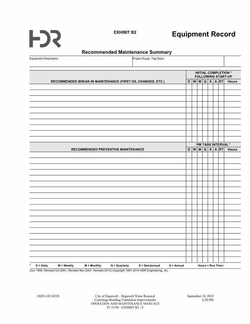
10203-10110220 City of Hopewell – Hopewell Water Renewal September 18, 2018
Centrifuge Building Ventilation Improvements 6:28 PM
OPERATION AND MAINTENANCE MANUALS 01 33 04 - EXHIBIT B2 - 8
EXHIBIT B2 Equipment Record
Recommended Maintenance Summary Equipment Description Project Equip. Tag No(s).
RECOMMENDED BREAK-IN MAINTENANCE (FIRST OIL CHANGES, ETC.)
INITIAL COMPLETION * FOLLOWING START-UP
D W M Q S A RT Hours
RECOMMENDED PREVENTIVE MAINTENANCE
PM TASK INTERVAL *
D W M Q S A RT Hours
* D = Daily W = Weekly M = Monthly Q = Quarterly S = Semiannual A = Annual Hours = Run Time Interval
(Jun 1990; Revised Oct 2001, Revised Nov 2007, Revised 2013) Copyright 1991-2014 HDR Engineering, Inc.

10203-10110220 City of Hopewell – Hopewell Water Renewal September 18, 2018
Centrifuge Building Ventilation Improvements 6:28 PM
OPERATION AND MAINTENANCE MANUALS 01 33 04 - EXHIBIT B3 - 9
EXHIBIT B3 Equipment Record
Lubrication Summary
Equipment Description Project Equip. Tag No(s).
Lubricant Point
Lub
rica
nt
Typ
e
Manufacturer Product AGMA # SAE # ISO
1
2
3
4
5
Lubricant Point
Lub
rica
nt
Typ
e
Manufacturer Product AGMA # SAE # ISO
1
2
3
4
5
Lubricant Point
Lub
rica
nt
Typ
e
Manufacturer Product AGMA # SAE # ISO
1
2
3
4
5
Lubricant Point
Lub
rica
nt
Typ
e
Manufacturer Product AGMA # SAE # ISO
1
2
3
4
5
Lubricant Point
Lub
rica
nt
Typ
e
Manufacturer Product AGMA # SAE # ISO
1
2
3
4
5
Lubricant Point
Lub
rica
nt
Typ
e
Manufacturer Product AGMA # SAE # ISO
1
2
3
4
5
(Jun 1990; Revised Oct 2001, Revised Nov 2007, Revised 2013) Copyright 1991-2014 HDR Engineering, Inc.

10203-10110220 City of Hopewell – Hopewell Water Renewal September 18, 2018
Centrifuge Building Ventilation Improvements 6:28 PM
OPERATION AND MAINTENANCE MANUALS 01 33 04 - EXHIBIT B3 - 10
THIS PAGE INTENTIONALLY LEFT BLANK
10203-10110220 City of Hopewell – Hopewell Water Renewal September 20, 2018
Centrifuge Building Ventilation Improvements 10:38 AM
MAINTENANCE OF PLANT OPERATIONS 01 52 00 - 1
SECTION 01 52 00 1
MAINTENANCE OF PLANT OPERATIONS 2
PART 1 - GENERAL 3
1.1 SUMMARY 4
A. The intent of this Specification is to have the Contractor schedule, coordinate and perform the 5
Work in a manner such that the Owner can keep the existing treatment plant facilities in 6
continuous dependable operation and meet its regulatory requirements. The Contractor shall 7
adhere to the constraints listed in this Section. 8
B. The Contractor shall: 9
1. Keep existing facilities in operation unless otherwise specifically authorized by the Owner 10
and Engineer. 11
2. Perform all construction activities so as to avoid interference with operations of the facility 12
and the work of others that would violate the Owner’s permitting requirements. 13
1.2 GENERAL CONSTRAINTS 14
A. Any temporary work, facilities, roads, walks, protection of existing structures, piping, blind 15
flanges, valves, equipment, bypass pumping, line-stopping, temporary generators, temporary 16
power, temporary equipment, temporary lighting, temporary barriers, etc. that may be required 17
within the Contractor’s work limits to maintain continuous and dependable plant operation 18
shall be furnished by the Contractor. 19
B. The Contractor shall schedule the Work in such a manner so that the plant is maintained in 20
continuous operation. All shutdowns shall be approved by the Owner. If, in the opinion of the 21
Owner, a shutdown is not required to perform the Work, the Contractor shall use alternate 22
methods to accomplish the Work. All shutdowns shall be coordinated with and scheduled at 23
times suitable to the Owner. Unless noted otherwise, the Contractor shall provide a minimum 24
of 21 days’ notice of any shutdown. 25
C. Shutdowns shall not begin until all required materials are on-hand and ready for installation 26
and the written shutdown plan has been approved by the Owner. At a time approved by the 27
Owner, the shutdown period shall commence and the Contractor shall proceed with the Work 28
continuously, start to finish, until the Work is completed and the system is tested and ready for 29
operation. If the Contractor completes all required Work before the specified shutdown period 30
has ended, the Owner may immediately place the system back in service. 31
D. The Owner shall have the authority to order the Work to be performed during a scheduled 32
shutdown stopped or prohibit Work which would, in its opinion, unreasonably result in 33
stopping the necessary functions of the plant operations. The Owner reserves the right to 34
cancel scheduled shutdowns if conditions warrant. 35
E. Safety procedures, equipment and provisions shall be provided by the Contractor as required to 36
complete the Work. Work will be required in active areas of the wastewater treatment plant. 37
High hydrogen sulfide levels (100 ppm or greater) can be present in certain areas of the plant. 38
Contractor shall provide temporary means for access to and working in these areas. 39
F. Operations of existing equipment shall be done by the Owner. Operation of valves and gates 40
required for the Work shall be completed by the Contractor, but only after written request and 41
permission of the Owner. The Owner may assign an operator to witness the valve or gate 42
operation. No existing gate or valve shall be operated without Owner approval and Owner 43
personnel being present. Owner does not guarantee that valves, stop logs, gates, etc., are or 44
will be water or gas tight. Contractor shall provide temporary bulkheads, caps, plugs, 45
dewatering, pumping and other measures required to perform the Work. 46

10203-10110220 City of Hopewell – Hopewell Water Renewal September 20, 2018
Centrifuge Building Ventilation Improvements 10:38 AM
MAINTENANCE OF PLANT OPERATIONS 01 52 00 - 2
G. The Owner is responsible to drain and clean, which consists of a general washdown, existing 1
tanks and structures as necessary for tie-ins of new work by Contractor. Contractor shall be 2
responsible for cleaning to the extent required thereafter to perform and complete the Work. 3
H. Insofar as possible, all equipment shall be tested and in operating condition before the final tie-4
ins are made to connect new equipment to the existing facility. 5
I. Contractor shall provide temporary lighting if shutdowns occur at night. 6
J. Owner will require continuous access to all plant operational areas. Gates, roads and pathways 7
required for vehicle and personnel access shall be maintained such that they are serviceable. If 8
construction activities require interruption of normal access to any area, Contractor shall 9
provide temporary means for Owner access. Contractor shall coordinate access interruptions 10
with the plant and provide at least 14 days’ notice of such interruptions. If vehicle support will 11
be required in an area that is blocked by construction activity, Contractor shall provide such 12
access to Owner upon request. 13
K. Exposed temporary electrical feeders shall be appropriately sized for the intended service and 14
protected during its service. 15
1.3 SUBMITTALS 16
A. A Shutdown Plan shall be submitted for each shutdown identified and be organized as follows: 17
1. General description of the shutdown. 18
2. Work to be completed prior to the shutdown. 19
3. Work to be completed during the shutdown. 20
4. Description of work at the completion of the shutdown. 21
B. Submit detailed information for each shutdown required to complete the Work. Submittal shall 22
include detailed description of shutdown, shutdown time-line, detailed breakdown of work to be 23
completed prior to and during shutdown, materials required and availability, proposed 24
manpower, proposed method of protecting existing equipment, required temporary facilities 25
including bypass pumping, linestops and power, list of valves, gates and equipment that will 26
require operation by the Owner and any other details to adequately describe the proposed 27
shutdown. 28
C. Submittals must be approved before shutdown can begin. Submit information at least 21 days 29
prior to start of proposed shutdown. 30
1.4 WORK AREAS 31
A. The shutdowns in this Section are a general list of tie-in work which require bypasses, 32
shutdowns and major coordination with plant operation. The shutdowns are grouped by work 33
areas. The list does not include all work areas, shutdowns or work necessary and it may be 34
modified to suit existing conditions that are encountered to complete the Work. It shall be used 35
by the Contractor as a guide to prepare the Construction Progress Schedule, the Shutdown 36
Schedule and Master Facility and System Start-up Schedule required in Section 01 75 00. 37
Shutdowns are not necessarily listed in the order they must be performed. Contractor is solely 38
responsible for scheduling the shutdowns in conjunction with the required construction 39
sequence. 40
B. General Shutdown Requirements: 41
1. Two Pre-Shutdown Meetings shall be held prior to any shutdown. The meetings shall be 42
conducted at least one week prior to the schedule shutdown and the day before the 43
shutdown. 44
2. Shutdown periods are indicated in 24-hour calendar days, months or number of hours. 45
3. Simultaneous shutdowns of more than one facility, except as specifically indicated or 46
allowed by the Owner, will not be permitted. 47
4. Insofar as possible, equipment to be incorporated into existing facilities shall be ready for 48
installation before the existing facilities are shutdown. 49

10203-10110220 City of Hopewell – Hopewell Water Renewal September 20, 2018
Centrifuge Building Ventilation Improvements 10:38 AM
MAINTENANCE OF PLANT OPERATIONS 01 52 00 - 3
5. If the work during the shutdown periods is not done satisfactorily, or as planned, or within 1
the time required or approved by the Engineer, the Owner may require the Contractor to 2
work a 24-hour, 7-day week work schedule with a full crew, or he may require the 3
Contractor to place the facility back in service and reschedule the shutdown or, he may 4
order the work required to place the facility back in service done with other forces. If the 5
work is completed by other forces, the Owner's costs will be deducted from the amounts due 6
to the Contractor. In no case shall the Owner be required to make additional payment for 7
overtime work or redoing the work caused by the Contractor's failure to complete the work 8
in the allotted time. 9
6. The list of work required to be performed during and prior to the specific shutdown period 10
described in this Section may not be complete, the Contractor shall schedule work required 11
to be completed during a shutdown of a specific facility during the scheduled shutdown 12
period. 13
7. Sediment control features, water disposal permits and other similar requirements shall be in 14
place prior to starting any shutdown work. 15
8. If alternative shutdown procedures or methods to those indicated herein are proposed by the 16
Contractor, they shall be submitted for approval. Supporting data, calculations and other 17
information requested by the Engineer or the Owner shall be provided with the submittal. 18
9. If bypass pumping is necessary, the Contractor shall provide 100 percent back-up pump 19
capacity available on-site. 20
10. Contractor shall be responsible for cleanup resulting from spills. 21
1.5 WORK AREA: ELECTRICAL 22
A. General: Odor Control Fan Nos. 1 and 2 (FAN-2001 and FAN-2002) will be powered from the 23
existing MCC-810D located in the Solids Handling Building. MCC-810D will require a 24
shutdown to install electrical equipment/devices for Odor Control Fan Nos. 1 and 2. 25
B. Maximum Duration: The maximum duration MCC-810D can be de-energized is 4 hours. 26
C. Work to be completed prior to shutdown: 27
1. Submittal and approval of all Shop Drawings and delivery of all electrical equipment / 28
components required to modify the existing MCC. 29
D. Work to be completed during shutdown: 30
1. De-energizing equipment that is power by MCC-810D (by Owner). 31
2. Isolation of MCC from incoming power source. 32
3. MCC modifications as required to incorporate Odorous Control Fan Nos. 1 and 2, and 33
associated dampers, power and controls. 34
E. Work description at completion of shutdown: 35
1. MCC-810D is energized and providing power to the existing equipment. 36
2. Odor Control Fan Nos. 1 and 2 electrical and control equipment have been installed in the 37
MCC and ready to provide power and control to fans and dampers. 38
1.6 WORK AREA: CENTRIFUGE BUILDING LOWER LEVEL DUCTWORK (NORTH 39
PORTION) 40
A. General: The existing return air ducting will be modified to divert return air to the new Odor 41
Control Fan Nos. 1 and 2. Partial shutdown of the Centrifuge Building lower level HVAC return 42
air system is necessary to demolish sections of the existing ductwork and install the new 43
ductwork. Plant operations shall remain in service. To initiate the partial shutdown of the 44
Centrifuge Building lower level HVAC return air system (north portion), the volume damper 45
shall be closed to isolate the north portion of the return air system. The registers and ductwork at 46
the south wall shall remain in service. 47
B. Maximum Duration: The maximum duration the Centrifuge Building lower level HVAC 48
ductwork system (north portion) can be shutdown is 8 hours. 49

10203-10110220 City of Hopewell – Hopewell Water Renewal September 20, 2018
Centrifuge Building Ventilation Improvements 10:38 AM
MAINTENANCE OF PLANT OPERATIONS 01 52 00 - 4
C. Work to be completed prior to shutdown: 1
1. Verify all field measurements. 2
2. Verify all existing ducting sizes/materials. 3
3. Submittal and approval of all Shop Drawings and delivery of ductwork, fittings and 4
supports required for modifying the HVAC ductwork. 5
4. Installation and pre-demonstration period of Odor Control Fan Nos. 1 and 2, dampers, 6
platforms, including associated ducting to the extent possible without requiring a shutdown 7
or partial shutdown. At minimum, all ducting shall terminate at a damper as shown on the 8
Drawings. 9
D. Work to be completed during shutdown: 10
1. Demolish HVAC ductwork located in the Centrifuge Building lower level (between Column 11
lines 1-3 and above Column line A1 as shown on the Drawings). 12
2. Install new ductwork and connect to the existing ductwork within the Centrifuge Building 13
lower level. Connect HVAC ductwork to the new 42 IN OA ducting. 14
E. Work description at completion of shutdown: 15
1. The Centrifuge Building lower level ductwork (north portion) is connected to the new Odor 16
Control Fan Nos. 1 and 2. 17
2. Damper in the 42 IN OA ducting, connecting the Centrifuge Building Lower Level to the 18
Odor Control Fan Nos. 1 and 2, shall be in the closed position. The volume damper 19
separating the return air system north portion from the south portion shall be in open 20
position. Return air is discharged through the existing exhaust fan. 21
3. Odor Control Fan Nos. 1 and 2 are ready for Demonstration Period, per Section 01 75 00. 22
1.7 WORK AREA: CENTRIFUGE BUILDING LOWER LEVEL DUCTWORK (SOUTH 23
PORTION) 24
A. General: The existing return air ducting requires an isolation damper to isolate the return ducting 25
from the existing exhaust fan. Partial shutdown of the Centrifuge Building lower level HVAC 26
return air system (south portion) is necessary to install the isolation damper. The return air 27
system (north portion) is connected to the new Odor Control Fan Nos. 1 and 2 and shall remain in 28
service. Plant operations shall remain in service. To initiate the partial shutdown of the 29
Centrifuge Building lower level HVAC return air system (south portion), the volume damper 30
shall be closed to isolate the south portion of the return air system. 31
B. Maximum Duration: The maximum duration the Centrifuge Building lower level HVAC return 32
air system (south portion) can be shutdown is 8 hours. 33
C. Work to be completed prior to shutdown: 34
1. Verify all field measurements. 35
2. Verify ductwork sizes for damper installation. 36
3. Submittal and approval of all Shop Drawings and delivery of isolation damper and 37
associated materials necessary to complete the installation. 38
4. Work Area 1.6 completion. 39
5. Odor Control Fan Nos. 1 and 2 Demonstration Period, per Section 01 75 00. 40
D. Work to be completed during the shutdown: 41
1. The volume damper separate the return air system north and south portion is placed into the 42
closed position. 43
2. De-energize exhaust fan (by Owner). 44
3. Demolition of ductwork as required for isolation damper installation. 45
4. Installation of isolation damper and supports. 46
E. Work description at completion of shutdown: 47
1. The newly installed isolation damper is placed in closed position. 48
2. The volume damper separating the return air system north and south portion is in the open 49
position. 50

10203-10110220 City of Hopewell – Hopewell Water Renewal September 20, 2018
Centrifuge Building Ventilation Improvements 10:38 AM
MAINTENANCE OF PLANT OPERATIONS 01 52 00 - 5
3. Odor Control Fan Nos. 1 and 2 are ventilating the entire Centrifuge Building lower level 1
return air system. 2
1.8 WORK AREA: CENTRIFUGE BUILDING – CENTRATE WET WELL DUCTWORK 3
A. General: A shutdown of the dewatering process is required to make modifications to the Centrate 4
Wet Well ductwork, Centrifuge cake / Centrate chute connections, Centrate line connection and 5
to connect to the new 30 IN OA header. 6
B. Maximum duration: The maximum duration the dewatering process can be shutdown down is 48 7
hours. 8
C. Work to be completed prior to shutdown: 9
1. Verify all field measurements. 10
2. Verify all existing ductwork sizing and materials. 11
3. Submittal and approval of all Shop Drawings and delivery of all ductwork, fittings, 12
supports, dampers and materials required for the Centrate Wet Well and associated 13
ductwork modifications. 14
4. Install new ductwork to the extent possible without requiring a shutdown. 15
5. Work Area 1.7 completion. 16
D. Work to be completed during the shutdown: 17
1. Shutdown centrifuges, Centrate pump station and associated equipment (by Owner). 18
2. Demolition of existing Centrate Wet Well odorous air ducting. 19
3. Demolition of 14 IN Centrate 90 degree bend. 20
4. Demolition of existing odorous air ducting serving the Centrifuges’ cake and Centrate 21
chutes. 22
5. Disconnection of the 12 IN odorous air ducting located between the Centrifuge Building and 23
Solids Handling Building. 24
6. Installation of ducting and connection to the Centrate Wet Well, Centrate line, Centrifuges 25
cake and Centrate chutes’ ductwork and to the existing 12 IN PVC ducting within the 26
Centrifuge Building lower level. 27
7. Installation of a new tee fitting for the 14 IN Centrate line and connection of associated 28
ductwork. 29
8. Installation of process drain piping and concrete work at the Centrate Wet Well. 30
9. Installation and connection of the new ductwork to connect the existing 12 IN PVC ducting 31
between the Centrifuge Building and Solids Handling Building to the new 30 IN OA header. 32
a. Connection of the existing 12 IN PVC ducting to the new ducting system will require a 33
concurrent shutdown of Odor Control Fan Nos. 1 and 2. 12 IN OA ducting shall be 34
installed to the extent possible and connected to the new 30 IN OA header prior to 35
shutdown of the Odor Control Fans. The FRP ducting shall be provided with a flanged 36
joint and blind flange to facilitate prompt connections to the existing 12 IN PVC 37
ducting. 38
b. Once completion of all Work listed and associated with items in paragraph 1.8 D.1. 39
through 8 are complete, Odor Control Fan Nos. 1 and 2 shall be shutdown and the 40
existing exhaust fan shall be placed into operation, including operating dampers to 41
appropriate positions, to provide ventilation of the Centrifuge Building lower level. 42
c. Remove blind flange on 12 IN OA ducting that is connected to the 30 IN OA header 43
and connect to the existing 12 IN PVC ducting from the Centrifuge Building lower 44
level. 45
d. Maximum duration the Odor Control Fans shall be shutdown to connect the existing 12 46
IN PVC ducting from the Centrifuge Building lower level to the 30 IN OA header is 47
four hours, and shall be included within the maximum duration of the dewatering 48
process shutdown listed in paragraph 1.8 B. 49
E. Work description at completion of shutdown: 50
1. Centrate Wet Well, Centrate line, Centrifuges cake and Centrate chutes are connected to the 51
existing 12 IN PVC OA ducting in the lower level. 52
10203-10110220 City of Hopewell – Hopewell Water Renewal September 20, 2018
Centrifuge Building Ventilation Improvements 10:38 AM
MAINTENANCE OF PLANT OPERATIONS 01 52 00 - 6
2. The existing 12 IN PVC OA ducting is connected to the new 30 IN OA ducting (located 1
between the Centrifuge Building and Solids Handling Building). 2
3. Odor Control Fan Nos. 1 and 2 are ventilating the Centrate Wet Well, Centrate line and 3
centrifuges cake and Centrate chutes. 4
1.9 WORK AREA: SOLIDS HOLDING TANKS 5
A. General: Ventilation for the Solids Holding Tanks will require a shutdown to connect the facility 6
to the new Odor Control Fan Nos. 1 and 2. No other process/facility shutdowns shall be allowed. 7
Ventilation shall be provided to one Solids Holding Tank at all times. Shutdown is required for 8
each Solids Holding Tank. 9
B. Maximum duration: The maximum duration the Solids Holding Tanks can be without ventilation 10
is 8 hours. 11
C. Work to be completed prior to shutdown: 12
1. Verify all field measurements. 13
2. Verify existing ducting sizes and materials. 14
3. Submittal and approval of all Shop Drawings and delivery of ductwork, fittings, dampers 15
and supports required for the Solids Holding Tanks connections. 16
4. Installation of ductwork to the extent possible without requiring a shutdown. 17
5. 24 IN OA damper (near Centrifuge Building SE corner) shall be in closed position. 18
6. Isolation dampers at the Decant Tanks shall be installed and in the closed position. 19
7. Work Area 1.8 completion. 20
D. Work to be completed during shutdown: 21
1. Demolition of existing ducting and damper at the Solids Holding Tanks. 22
2. Installation of the new damper and associated ductwork to connect to the new OA system. 23
3. Blank off existing OA ducting. 24
E. Work description at completion of shutdown: 25
1. Solids Holding Tank is connected to the new OA system. 26
2. 24 IN OA damper (near Centrifuge Building SE corner) shall be placed in the open position. 27
3. Provide a minimum period of two weeks prior to performing work on the second Solids 28
Holding Tank. 29
1.10 WORK AREA: DECANT TANKS 30
A. General: Ventilation for the Decant Tanks will require a shutdown to connect the facility to the 31
new Odor Control Fan Nos. 1 and 2. No other process / facility shutdowns shall be allowed. 32
Ventilation shall be provided to one Decant Tank at all times. Shutdown is required for each 33
Decant Tank. 34
B. Maximum duration: The maximum duration the Decant Tanks can be without ventilation is 4 35
hours. 36
C. Work to be completed prior to shutdown: 37
1. Verify all field measurements. 38
2. Verify existing ducting sizes and materials. 39
3. Submittal and approval of all Shop Drawings and delivery of ductwork, fittings, dampers 40
and supports required for the Decant Tanks connections. 41
4. CCTV inspection of existing ductwork. Submittal and Owner / Engineer review of 42
inspection, and completion of any necessary repairs. 43
5. Installation of ductwork and supports to the extent possible without requiring a shutdown. 44
6. Exposure of existing buried ducting for connections to the new ducting system and to 45
convert a portion of the existing OA ducting to process drain (Base Bid). 46
7. Work Area 1.9 completion. 47
D. Work to be completed during shutdown: 48
1. Base Bid: 49
a. Re-establishing ducting connections at each Decant Tank. 50

10203-10110220 City of Hopewell – Hopewell Water Renewal September 20, 2018
Centrifuge Building Ventilation Improvements 10:38 AM
MAINTENANCE OF PLANT OPERATIONS 01 52 00 - 7
b. Connect existing 6 IN OA (buried) to the new ducting system. 1
c. Modifications to convert a portion of existing OA ducting to process drain. 2
2. Alternate A: 3
a. Demolition of existing ducting at each Decant Tank. 4
b. Connection of the new ducting to the existing Decant Tank connections. 5
E. Work description at completion of shutdown: 6
1. Decant Tank is connected to the new OA system. 7
2. Once both Decant Tanks are connected, the new OA system is ready for balancing and 8
testing. 9
END OF SECTION10

10203-10110220 City of Hopewell – Hopewell Water Renewal September 20, 2018
Centrifuge Building Ventilation Improvements 10:38 AM
MAINTENANCE OF PLANT OPERATIONS 01 52 00 - 8
THIS PAGE INTENTIONALLY LEFT BLANK 1
10203-10110220 City of Hopewell – Hopewell Water Renewal September 18, 2018
Centrifuge Building Ventilation Improvements 6:36 PM
EQUIPMENT: BASIC REQUIREMENTS 01 61 03 - 1
SECTION 01 61 03 1
EQUIPMENT: BASIC REQUIREMENTS 2
PART 1 - GENERAL 3
1.1 SUMMARY 4
A. Section Includes: 5
1. Requirements of this Specification Section apply to the Owner Furnished equipment. Refer 6
to the High Plume Fan Procurement Specifications. 7
B. Related Specification Sections include but are not necessarily limited to: 8
1. Division 00 - Bidding Requirements, Contract Forms, and Conditions of the Contract. 9
2. Division 01 - General Requirements. 10
3. Section 03 09 00 - Concrete. 11
4. Section 05 50 00 - Metal Fabrications. 12
5. Section 09 96 00 - High Performance Industrial Coatings. 13
6. Section 10 14 00 - Identification Devices. 14
7. Section 40 05 00 - Pipe and Pipe Fittings: Basic Requirements. 15
1.2 QUALITY ASSURANCE 16
A. Referenced Standards: 17
1. American Bearing Manufacturers Association (ABMA). 18
2. American Gear Manufacturers Association (AGMA). 19
3. ASTM International (ASTM): 20
a. E1934, Standard Guide for Examining Electrical and Mechanical Equipment with 21
Infrared Thermography. 22
b. F593, Standard Specification for Stainless Steel Bolts, Hex Cap Screws, and Studs. 23
4. Hydraulic Institute (HI): 24
a. 9.6.4, Centrifugal and Vertical Pumps for Vibration Measurements and Allowable 25
Valves. 26
5. International Electrotechnical Commission (IEC). 27
6. Institute of Electrical and Electronics Engineers, Inc. (IEEE). 28
7. International Organization for Standardization (ISO): 29
a. 1940, Mechanical Vibration - Balance Quality Requirements for Rotors in a Constant 30
(Rigid) State - Part 1: Specification and Verification of Balance Tolerances. 31
8. National Electrical Manufacturers Association (NEMA): 32
a. 250, Enclosures for Electrical Equipment (1000 Volts Maximum). 33
b. ICS 6, Enclosures for Industrial Control and System. 34
c. MG 1, Motors and Generators. 35
9. InterNational Electrical Testing Association (NETA): 36
a. ATS, Acceptance Testing Specification for Electrical Power Distribution Equipment 37
and Systems. 38
10. National Fire Protection Association (NFPA): 39
a. 70, National Electrical Code (NEC): 40
1) Article 430, Motors, Motor Circuits, and Controllers. 41
11. National Institute for Certification in Engineering Technologies (NICET). 42
12. National Institute of Standards and Technology (NIST). 43
13. Occupational Safety and Health Administration (OSHA): 44
a. 29 CFR 1910, Occupational Safety and Health Standards, referred to herein as OSHA 45
Standards. 46
10203-10110220 City of Hopewell – Hopewell Water Renewal September 18, 2018
Centrifuge Building Ventilation Improvements 6:36 PM
EQUIPMENT: BASIC REQUIREMENTS 01 61 03 - 2
14. Underwriters Laboratories, Inc. (UL). 1
a. 508, Standard for Safety Industrial Control Equipment. 2
b. 508A, Standard for Safety Industrial Control Panels. 3
15. Vibration Institute. 4
B. Miscellaneous: 5
1. Equipment, electrical assemblies, related electrical wiring, instrumentation, controls, and 6
system components shall fully comply with specific NEC requirements related to area 7
classification and to NEMA 250 and NEMA ICS 6 designations shown on Electrical Power 8
Drawings and defined in the Electrical specifications. 9
1.3 DEFINITIONS 10
A. Product: Manufactured materials and equipment. 11
B. Major Equipment Supports - Supports for Equipment: 12
1. Located on or suspended from elevated slabs with supported equipment weighing 2000 LBS 13
or greater, or; 14
2. Located on or suspended from roofs with supported equipment weighing 500 LBS or 15
greater, or; 16
3. Located on slab-on-grade or earth with supported equipment weighing 5000 LBS or more. 17
C. Equipment: 18
1. One (1) or more assemblies capable of performing a complete function. 19
2. Mechanical, electrical, instrumentation or other devices requiring an electrical, pneumatic, 20
electronic or hydraulic connection. 21
3. Not limited to items specifically referenced in "Equipment" articles within individual 22
Specifications. 23
D. Installer or Applicator: 24
1. Installer or applicator is the person actually installing or applying the product in the field at 25
the Project site. 26
2. Installer and applicator are synonymous. 27
1.4 SUBMITTALS 28
A. Shop Drawings: 29
1. Qualifications for Electrical equipment and connections testing firm and personnel. 30
B. Contract Closeout Information: 31
1. Operation and Maintenance Data: 32
a. See Specification Section 01 33 04 for requirements for the mechanics, administration, 33
and the content of Operation and Maintenance Manual submittals. 34
C. Informational Submittals: 35
1. Sample form letter for equipment field certification. 36
2. Certification that equipment has been installed properly, has been initially started up, has 37
been calibrated and/or adjusted as required, and is ready for operation. 38
3. Certification for major equipment supports that equipment foundation design loads shown 39
on the Drawings or specified have been compared to actual loads exhibited by equipment 40
provided for this Project and that said design loadings are equal to or greater than the loads 41
produced by the equipment provided. 42
4. Preliminary field quality control testing format to be used as a basis for final field quality 43
control reporting. 44
5. Testing and monitoring reports in accordance with PART 3 of this Specification Section. 45

10203-10110220 City of Hopewell – Hopewell Water Renewal September 18, 2018
Centrifuge Building Ventilation Improvements 6:36 PM
EQUIPMENT: BASIC REQUIREMENTS 01 61 03 - 3
PART 2 - PRODUCTS – NOT USED 1
PART 3 - EXECUTION 2
3.1 INSTALLATION 3
A. Install equipment as shown on Drawings and in accordance with manufacturer's directions. 4
B. Utilize templates for anchorage placement for slab-mounted equipment. 5
C. For equipment having drainage requirements such as seal water, provide 3/4 IN PVC or clear 6
plastic tubing from equipment base to nearest floor or equipment drain. 7
1. Route clear of major traffic areas and as approved by Engineer. 8
D. DO NOT construct foundations until major equipment supports are approved. 9
E. Extend all non-accessible grease fittings using stainless steel tubing to a location which allows 10
easy access of fittings from closest operating floor level. 11
F. Equipment Base: 12
1. Construct level in both directions. 13
2. Take particular care at anchor bolt locations so these areas are flat and level. 14
G. Machine Base: 15
1. Mount machine base of rotating equipment on equipment base. 16
a. Level in both directions, using a machinist level, according to machined surfaces on 17
base. 18
2. Level machine base on equipment base and align couplings between driver and driven unit 19
using steel blocks and shims. 20
a. Size blocks and shims to provide solid support at each mounting bolt location. 21
1) Provide area size of blocks and shims approximately 1-1/2 times area support 22
surface at each mounting bolt point. 23
b. Provide blocks and shims at each mounting bolt. 24
1) Furnish blocks and shims that are square shape with "U" cut out to allow blocks 25
and shims to be centered on mounting bolts. 26
c. After all leveling and alignment has been completed and before grouting, tighten 27
mounting bolts to proper torque value. 28
H. Rotating equipment Couplings: 29
1. Align in the annular and parallel positions. 30
a. For equipment rotating at 1200 rpm or less, align both annular and parallel within 31
0.001 IN tolerance for couplings 4 IN size and smaller. 32
b. Couplings larger than 4 IN size: Increase tolerance 0.0005 IN per inches of coupling 33
diameter, i.e., allow 6 IN coupling 0.002 IN tolerance, and allow a 10 IN coupling 34
0.004 IN tolerance. 35
c. For equipment rotating at speeds greater than 1200 rpm allow both annular and parallel 36
positions within a tolerance rate of 0.00025 IN per inch coupling diameter. 37
2. If equipment is delivered as a mounted unit from factory, verify factory alignment on site 38
after installation and realigned if necessary. 39
3. Check surfaces for runout before attempting to trim or align units. 40
3.2 INSTALLATION CHECKS 41
A. For all equipment specifically required in detailed specifications, secure services of experienced, 42
competent, and authorized representative(s) of equipment manufacturer to visit site of work and 43
inspect, check, adjust and approve equipment installation. 44
1. In each case, representative(s) shall be present during placement and start-up of equipment 45
and as often as necessary to resolve any operational issues which may arise. 46
2. Refer to Owner Furnished Equipment Specifications for Equipment Supplier requirements. 47

10203-10110220 City of Hopewell – Hopewell Water Renewal September 18, 2018
Centrifuge Building Ventilation Improvements 6:36 PM
EQUIPMENT: BASIC REQUIREMENTS 01 61 03 - 4
B. Secure from equipment manufacturer's representative(s) a written report certifying that 1
equipment: 2
1. Has been properly installed and lubricated. 3
2. Is in accurate alignment. 4
3. Is free from any undue stress imposed by connecting piping or anchor bolts. 5
4. Has been operated under full load conditions and that it operated satisfactorily. 6
a. Secure and deliver a field written report to Owner immediately prior to leaving jobsite. 7
C. No separate payment shall be made for installation checks. 8
1. All or any time expended during installation check does not qualify as Operation and 9
Maintenance training or instruction time when specified. 10
3.3 IDENTIFICATION OF EQUIPMENT AND HAZARD WARNING SIGNS 11
A. Identify equipment and install hazard warning signs in accordance with Specification Section 10 12
14 00. 13
3.4 FIELD HIGH PERFORMANCE INDUSTRIAL COATINGS 14
A. For required field High Performance Industrial Coatings, comply with Specification Section 09 15
96 00. 16
3.5 WIRING CONNECTIONS AND TERMINATION 17
A. Clean wires before installing lugs and connectors. 18
B. Coat connection with oxidation eliminating compound for aluminum wire. 19
C. Terminate motor circuit conductors with copper lugs bolted to motor leads. 20
D. Tape stripped ends of conductors and associated connectors with electrical tape. 21
1. Wrapping thickness shall be 150 percent of the conductor insulation thickness. 22
E. Connections to carry full ampacity of conductors without temperature rise. 23
F. Terminate spare conductors with electrical tape. 24
3.6 FIELD QUALITY CONTROL 25
A. General: 26
1. Furnish equipment manufacturer’s field quality control services and testing as specified in 27
the individual equipment Specification Sections. 28
2. Execute pre-demonstration requirements in accordance with Specification Section 01 75 00. 29
3. Perform and report on all tests required by the equipment manufacturer’s Operation and 30
Maintenance Manual. 31
4. Provide testing of electrical equipment and connections in accordance with the Electrical 32
specifications. 33
5. Equip testing and analysis personnel with all appropriate project related reference material 34
required to perform tests, analyze results, and provide documentation including, but not 35
limited to: 36
a. Contract Drawings and Specifications. 37
b. Related construction change documentation. 38
c. Approved Shop Drawings. 39
d. Approved Operation and Maintenance Manuals. 40
e. Other pertinent information as required. 41
3.7 DEMONSTRATION 42
A. Demonstrate equipment in accordance with Specification Section 01 75 00. 43
END OF SECTION 44
10203-10110220 City of Hopewell – Hopewell Water Renewal September 18, 2018
Centrifuge Building Ventilation Improvements 6:40 PM
PRODUCT DELIVERY, STORAGE, AND HANDLING 01 65 50 - 1
SECTION 01 65 50 1
PRODUCT DELIVERY, STORAGE, AND HANDLING 2
PART 1 - GENERAL 3
1.1 SUMMARY 4
A. Section Includes: 5
1. Scheduling of product delivery. 6
2. Packaging of products for delivery. 7
3. Protection of products against damage from: 8
a. Handling. 9
b. Exposure to elements or harsh environments. 10
B. Related Specification Sections include but are not necessarily limited to: 11
1. Division 00 - Bidding Requirements, Contract Forms, and Conditions of the Contract. 12
2. Division 01 - General Requirements. 13
C. Payment: 14
1. No payment will be made to Contractor for equipment or materials not properly stored and 15
insured or without approved Shop Drawings. 16
a. Previous payments for items will be deducted from subsequent progress estimate(s) if 17
proper storage procedures are not observed. 18
1.2 DELIVERY 19
A. Scheduling: Schedule delivery of products or equipment as required to allow timely installation 20
and to avoid prolonged storage. 21
B. Packaging: Deliver products or equipment in manufacturer's original unbroken cartons or other 22
containers designed and constructed to protect the contents from physical or environmental 23
damage. 24
C. Identification: Clearly and fully mark and identify as to manufacturer, item, and installation 25
location. 26
D. Protection and Handling: Provide manufacturer's instructions for storage and handling. 27
PART 2 - PRODUCTS - (NOT APPLICABLE TO THIS SPECIFICATION SECTION) 28
PART 3 - EXECUTION 29
3.1 PROTECTION, STORAGE AND HANDLING 30
A. Manufacturer's Instruction: 31
1. Protect all products or equipment in accordance with manufacturer's written directions. 32
a. Store products or equipment in location to avoid physical damage to items while in 33
storage. 34
b. Handle products or equipment in accordance with manufacturer's recommendations and 35
instructions. 36
2. Protect equipment from exposure to elements and keep thoroughly dry. 37
3. When space heaters are provided in equipment, connect and operate heaters during storage 38
until equipment is placed in service. 39

10203-10110220 City of Hopewell – Hopewell Water Renewal September 18, 2018
Centrifuge Building Ventilation Improvements 6:40 PM
PRODUCT DELIVERY, STORAGE, AND HANDLING 01 65 50 - 2
3.2 FIELD QUALITY CONTROL 1
A. Inspect Deliveries: 2
1. Inspect all products or equipment delivered to the site prior to unloading. 3
a. Reject all products or equipment that are damaged, used, or in any other way 4
unsatisfactory for use on Project. 5
B. Monitor Storage Area: Monitor storage area to ensure suitable temperature and moisture 6
conditions are maintained as required by manufacturer or as appropriate for particular items. 7
END OF SECTION 8

10203-10110220 City of Hopewell – Hopewell Water Renewal September 19, 2018
Centrifuge Building Ventilation Improvements 10:59 AM
OPENINGS AND PENETRATIONS IN CONSTRUCTION 01 73 20 - 1
SECTION 01 73 20 1
OPENINGS AND PENETRATIONS IN CONSTRUCTION 2
PART 1 - GENERAL 3
1.1 SUMMARY 4
A. Section Includes: 5
1. Methods of installing and sealing openings and penetrations in construction. 6
B. Related Specification Sections include but are not necessarily limited to: 7
1. Division 00 - Bidding Requirements, Contract Forms, and Conditions of the Contract. 8
2. Division 01 - General Requirements. 9
3. Section 05 50 00 - Metal Fabrications. 10
4. Section 09 96 00 - High Performance Industrial Coatings. 11
1.2 QUALITY ASSURANCE 12
A. Referenced Standards: 13
1. ASTM International (ASTM): 14
a. A36, Standard Specification for Carbon Structural Steel. 15
b. A53, Standard Specification for Pipe, Steel, Black and Hot-Dipped, Zinc-Coated, 16
Welded and Seamless. 17
c. A269, Standard Specification for Seamless and Welded Austenitic Stainless Steel 18
Tubing for General Service. 19
d. A312, Standard Specification for Seamless, Welded, and Heavily Cold Worked 20
Austenitic Stainless Steel Pipes. 21
e. A351, Standard Specification for Castings, Austenitic, for Pressure-Containing Parts. 22
f. A554, Standard Specification for Welded Stainless Steel Mechanical Tubing. 23
g. A653, Standard Specification for Steel Sheet, Zinc-Coated (Galvanized) or Zinc-Iron 24
Alloy-Coated (Galvannealed) by the Hot-Dip Process. 25
h. A666, Standard Specification for Annealed or Cold-Worked Austenitic Stainless Steel 26
Sheet, Strip, Plate, and Flat Bar. 27
i. A995, Castings, Austenitic-Ferritic (Duplex) Stainless Steel, for Pressure-Containing 28
Parts. 29
2. National Fire Protection Association (NFPA): 30
a. 70, National Electrical Code (NEC): 31
1) Article 501, Class 1 Locations. 32
b. 90A, Standard for Installation of Air Conditioning and Ventilating Systems. 33
C. Sheet Metal and Air Conditioning Contractors' National Association (SMACNA). 34
1.3 DEFINITIONS 35
A. Corrosive Areas: See Drawings for corrosive area designations. 36
B. Hazardous Areas: Areas shown in the Contract Documents as having Class I or Class II area 37
classifications. 38
C. Washdown Areas: Areas having floor drains or hose bibbs. 39
1.4 SUBMITTALS 40
A. Shop Drawings: 41
1. See Specification Section 01 33 00 for requirements for the mechanics and administration of 42
the submittal process. 43

10203-10110220 City of Hopewell – Hopewell Water Renewal September 19, 2018
Centrifuge Building Ventilation Improvements 10:59 AM
OPENINGS AND PENETRATIONS IN CONSTRUCTION 01 73 20 - 2
2. For each structure provide dimensioned or scaled (minimum 1/8 IN = 1 FT) plan view 1
drawings containing the following information: 2
a. Vertical and horizontal location of all required openings and penetrations. 3
b. Size of all openings and penetrations. 4
c. Opening type. 5
d. Seal type. 6
3. Manufacturer's installation instructions for standard manufactured products. 7
PART 2 - PRODUCTS 8
2.1 MATERIALS 9
A. Pipe Sleeves: 10
1. Areas listed as Corrosive Areas in PART 1: 11
a. Stainless steel, Type 316L. 12
b. Penetrations 24 IN DIA or less: ASTM A269, ASTM A312 or ASTM A554, Schedule 13
40. 14
c. Penetrations larger than 24 IN DIA: Stainless steel, ASTM A666, Minimum 1/4 IN 15
thickness. 16
2. All other Areas: 17
a. Steel, Hot-dipped galvanized after fabrication. 18
b. Penetrations 24 IN DIA or less: ASTM A53, Schedule 40. 19
c. Penetrations larger than 24 IN DIA: ASTM A36, Minimum 1/4 IN thickness. 20
B. Modular Mechanical Seals: 21
1. Acceptable manufacturers: 22
a. Link-Seal. 23
2. 316 stainless steel bolts, nuts and washers. 24
C. Sheet Metal Sleeves: 25
1. Areas listed as Corrosive Areas in PART 1: Stainless steel: ASTM A240, Type 316L. 26
2. All other areas: Galvanized steel: ASTM A653, G90. 27
3. Minimum 12 GA. 28
D. Commercial Wall Castings: 29
1. Ductile iron, ASTM A536. 30
2. Grade equal to connecting piping system. 31
PART 3 - EXECUTION 32
3.1 FABRICATION 33
A. Fabricate pipe sleeves in accordance with Specification Section 05 50 00. 34
B. Provide waterstop plate/anchor flange for piping, ducts, castings and sleeves cast-in-place in 35
concrete. 36
1. For fabricated units, weld plate to sleeve, pipe, or ductwork. 37
2. For commercial castings, cast water stop/anchor with wall pipe. 38
3. Plate is to be same thickness as sleeve, pipe, casting or ductwork. 39
4. For fabricated units, diameter of plate or flange to be 4 IN larger than outside diameter of 40
sleeve, pipe or ductwork. 41
5. For commercial castings, waterstop/anchor size to be manufacturer standard. 42
6. Provide continuous around entire circumference of sleeve, pipe, or ductwork. 43
C. Factory or shop-coat painted components in accordance with Specification Section 09 96 00. 44

10203-10110220 City of Hopewell – Hopewell Water Renewal September 19, 2018
Centrifuge Building Ventilation Improvements 10:59 AM
OPENINGS AND PENETRATIONS IN CONSTRUCTION 01 73 20 - 3
3.2 INSTALLATION AND APPLICATION 1
A. Obtain prior approval from Engineer when any opening larger than 100 SQ IN must be made in 2
existing or newly completed construction. 3
B. Perform electrical penetrations in accordance with NFPA 70, Article 501. 4
C. When mechanical or electrical work cannot be installed as structure is being erected, provide and 5
arrange for building-in of boxes, sleeves, insets, fixtures or devices necessary to permit 6
installation later. 7
1. Lay out chases, holes or other openings which must be provided in masonry, concrete or 8
other work. 9
D. Where pipes, conduits or ducts pass through floors in washdown areas, install sleeves with top 10
3 IN above finish floors. 11
1. In non-washdown areas, install sleeves with ends flush with finished surfaces. 12
E. Size sleeves, blockouts and cutouts which will receive sealant seal such that free area to receive 13
sealant is minimized and seal integrity may be obtained. 14
F. For insulated piping and ducts, size sleeves, blockouts and cutouts large enough to accommodate 15
full thickness of insulation. 16
G. Where pipes, conduits or ducts are removed where passing through grating: 17
1. Metal grating: 18
a. Provide banding at perimeter and cover opening with 1/4 IN plate of the same material 19
of the grating. 20
b. See Specification Section 05 50 00. 21
H. Do not cut into or core drill any beams, joists, or columns. 22
I. Do not install sleeves in beams, joists, or columns. 23
J. Do not install recesses in beams, joists, columns, or slabs. 24
K. Field Cutting and Coring: 25
1. Saw or core drill with non-impact type equipment. 26
2. Mark opening and drill small 3/4 IN or less holes through structure following opening 27
outline. 28
3. Sawcut opening outline on both surfaces. 29
a. Knock out within sawcuts using impact type equipment. 30
b. Do not chip or spall face of surface to remain intact. 31
c. Do not allow any overcut with saw kerf. 32
L. Precast-Prestressed Concrete Construction: 33
1. Do not cut openings or core drill vertically or horizontally through stems of members. 34
2. Do not locate or install sleeves or recess sleeves vertically or horizontally through or in 35
stems of members. 36
3. Cast openings and sleeves into flanges of units. 37
4. Cast openings larger than 6 IN in diameter or 6 IN maximum dimension in units at time of 38
manufacture. 39
5. Cast openings smaller than 6 IN in diameter or 6 IN maximum dimensions in flanges of 40
units at time of manufacture or field cut. 41
M. Where alterations are necessary or where new and old work join, restore adjacent surfaces to 42
their condition existing prior to start of work. 43
N. Where area is blocked out to receive sheet metal sleeve at later date: 44
1. If blockout size is sufficient to allow placement, utilize dowels for interface of initially 45
placed concrete and sleeve encasement concrete which is placed later. 46
a. Size blockout based on sleeve size required plus 4 to 6 IN each side of sleeve for 47
concrete encasement. 48

10203-10110220 City of Hopewell – Hopewell Water Renewal September 19, 2018
Centrifuge Building Ventilation Improvements 10:59 AM
OPENINGS AND PENETRATIONS IN CONSTRUCTION 01 73 20 - 4
b. Provide #4 dowels at 12 IN spacing along each side of blockout with minimum of 1
two (2) dowels required per side. 2
2. If blockout size is not sufficient to allow placement of dowels, provide keyway along all 3
sides of blockout. 4
a. Size blockout based on sleeve size required plus 2 to 4 IN each side of sleeve for 5
concrete encasement. 6
O. For interior wall applications where backer rod and sealant are specified, provide backer rod and 7
sealant at each side of wall. 8
P. Use full depth expanding foam sealant for seal applications where single or multiple pipes, 9
conduits, etc., pass through a single sleeve. 10
Q. Do not make duct or conduit penetrations below high water levels when entering or leaving 11
tankage, wet wells, or other water holding structures. 12
R. Modular Mechanical Seals: 13
1. Utilize one (1) seal for concrete thickness less than 8 IN and two (2) seals for concrete, 8 IN 14
thick or greater. 15
2. Utilize two (2) seals for piping 16 IN diameter and larger if concrete thickness permits. 16
3. Install seals such that bolt heads are located on the most accessible side of the penetration. 17
3.3 SCHEDULES 18
A. General Schedule of Penetrations through Floors, Roofs, Foundation Base Slabs, Foundation 19
Walls, Foundation Footings, Partitions and Walls for Ductwork, Piping, and Conduit: 20
1. Provide the following opening and penetration types: 21
a. Type A - Block out 2 IN larger than outside dimensions of duct, pipe, or conduits. 22
b. Type B - Saw cut or line-drill opening. Place new concrete with integrally cast sheet 23
metal or pipe sleeve. 24
c. Type C - Fabricated sheet metal sleeve or pipe sleeve cast-in-place. Provide pipe 25
sleeve with water ring for wet and/or washdown areas. 26
d. Type D - Commercial type casting or fabrication. 27
e. Type E - Saw cut or line-drill opening. Place new concrete with integrally cast pipe, 28
duct or conduit spools. 29
f. Type F - Integrally cast pipe, duct or conduit. 30
g. Type G - Saw cut or line-drill and remove area 1 IN larger than outside dimensions of 31
duct, pipe or conduit. 32
h. Type H - Core drill. 33
i. Type I - Block out area. At later date, place new concrete with integrally cast sheet 34
metal or pipe sleeve. 35
j. Type J- Grating Banding for any field cut openings 36
2. Provide seals of material and method described as follows. 37
a. Category 1 - Modular Mechanical Seal. 38
b. Category 2 - Roof curb and flashing according to SMACNA specifications unless 39
otherwise noted on Drawings. Refer to roofing Specification Sections for additional 40
requirements. 41
c. Category 3 - 12 GA sheet metal drip sleeve set in bed of silicon sealant with backing 42
rod and sealant used in sleeve annulus. 43
d. Category 4 - Backer rod and sealant. 44
e. Category 5 - Full depth compressible sealant with escutcheons on both sides of 45
opening. 46
f. Category 6 - Full depth compressible sealant and flanges on both sides of opening. 47
Flanges constructed of same material as duct, fastened to duct and minimum 1/2 IN 48
larger than opening. 49
g. Category 7 - Full depth compressible sealant and finish sealant or full depth expanding 50
foam sealant depending on application. 51

10203-10110220 City of Hopewell – Hopewell Water Renewal September 19, 2018
Centrifuge Building Ventilation Improvements 10:59 AM
OPENINGS AND PENETRATIONS IN CONSTRUCTION 01 73 20 - 5
h. Category 8 - Banding for all grating openings and banding and cover plate of similar 1
materials for abandoned openings 2
3. Furnish openings and sealing materials through new floors, roofs, grating, partitions and 3
walls in accordance with Schedule A, Openings and Penetrations for New Construction. 4
4. Furnish openings and sealing materials through existing floors, grating, roofs, partitions and 5
walls in accordance with Schedule B, Openings and Penetrations for Existing Construction. 6
10203-10110220 City of Hopewell – Hopewell Water Renewal September 19, 2018
Centrifuge Building Ventilation Improvements 10:59 AM
OPENINGS AND PENETRATIONS IN CONSTRUCTION 01 73 20 - 6
SCHEDULE A. OPENINGS AND PENETRATIONS SCHEDULE 1
FOR NEW CONSTRUCTION 2 3
APPLICATIONS
DUCTS PIPING CONDUIT
OPENING TYPE
SEAL CATEGORY
OPENING TYPE
SEAL CATEGORY
OPENING TYPE
SEAL CATEGORY
Through floors with bottom side a hazardous location
C F I
7 Not Req
7
D F
I (1)
Not Req Not Req
7
C F
7 Not Req
Through floors on grade above water table
C F I
4 Not Req
4
C F
I (1)
7 Not Req
7
C F
I (1)
4 Not Req
7
Through slab on grade below water table
F Not Req F Not Req F Not Req
Through floors in washdown areas
C I
4 4
C H (2) I (1)
4 3 4
F H (2) I (1)
Not Req 3 7
Through walls where one side is a hazardous area
C F I
7 Not Req
7
D F
I (1)
Not Req Not Req
7
C F
7 Not Req
Through exterior wall below grade above water table
C F I
7 Not Req
7
C D F
I (1)
1 Not Req Not Req
1
F I (1)
Not Req 7
Through wall from tankage or wet well (above high water level) to dry well or dry area
C F I
7 Not Req
7
C D F
H (2)
1 Not Req Not Req
1
C F
H (2) I (1)
7 Not Req
7 7
Through wall from tankage or wet well (below high water level) to dry well or dry area
F Not Req F Not Req F Not Req
Through exterior wall above grade
A B C
6 6 6
A B D
H (2)
5 5
Not Req 5
C H (2)
5 4
Roof penetrations A 2 A 2 A 2
Through interior walls and slabs not covered by the above applications
A C
4 4
A C
4 4
A C F
4 4
Not Req
Grating openings and penetrations
J 8 J 8 J 8
4
5

10203-10110220 City of Hopewell – Hopewell Water Renewal September 19, 2018
Centrifuge Building Ventilation Improvements 10:59 AM
OPENINGS AND PENETRATIONS IN CONSTRUCTION 01 73 20 - 7
SCHEDULE B. OPENINGS AND PENETRATIONS SCHEDULE 1
FOR EXISTING CONSTRUCTION 2 3
APPLICATIONS
DUCTS PIPING CONDUIT
OPENING TYPE
SEAL CATEGORY
OPENING TYPE
SEAL CATEGORY
OPENING TYPE
SEAL CATEGORY
Through floors with bottom side a hazardous location
B E
7 Not Req
B (1) E (3) H (2)
7 Not Req
7
B (1) E (3) H (2)
7 Not Req
7
Through floors on grade above water table
B 7 B 7 B 7
Through slab on grade below water table
E Not Req E Not Req E Not Req
Through floors in washdown areas
G 3 G H (2)
3 3
G H (2)
3 3
Through walls where one side is a hazardous area
B E
7 Not Req
B (1)
B (3)_ E
H (2)
7 1
Not Req 7
B (1) (3) E
H (2)
7 Not Req
7
Through exterior wall below grade above water table
B 7 B (1) B (3) H (2)
7 1 7
B (1) (3) H (2)
7 7
Through wall from tankage or wet well (above high water level) to dry well or dry area
B E
7 Not Req
B E
H (2)
1 Not Req
1
B (1) (3) E
H (2)
7 Not Req
7
Through wall from tankage or wet well (below high water level) to dry well or dry area
E Not Req E Not Req E Not Req
Through exterior wall above grade
G 6 G (1) (3) H (2)
5 5
G (1) (3) H (2)
5 7
Roof penetrations G 2 G (1) (3) H (2)
2 G 2
Through interior walls and slabs not covered by the above applications
G 4 G (1) (3) H (2)
4 4
G (1) (3) H (2)
4 4
Grating openings and penetrations
J 8 J 8 J 8
(1) Multiple piping 3 IN and smaller or multiple conduits. 4 (2) Single pipe 3 IN and smaller or single conduit. 5 (3) Single pipe or conduit larger than 3 IN. 6
END OF SECTION 7

10203-10110220 City of Hopewell – Hopewell Water Renewal September 19, 2018
Centrifuge Building Ventilation Improvements 10:59 AM
OPENINGS AND PENETRATIONS IN CONSTRUCTION 01 73 20 - 8
THIS PAGE INTENTIONALLY LEFT BLANK 1

10203-10110220 City of Hopewell – Hopewell Water Renewal September 18, 2018
Centrifuge Building Ventilation Improvements 6:43 PM
DEMOLITION, CUTTING AND PATCHING 01 73 29 - 1
SECTION 01 73 29 1
DEMOLITION, CUTTING AND PATCHING 2
PART 1 - GENERAL 3
1.1 SUMMARY 4
A. Section Includes: 5
1. Demolition, cutting and patching of existing construction where shown on Drawings, or as 6
required to accommodate new work shown or specified. 7
2. Removal and protection of items identified to be saved or reused. 8
B. Related Specification Sections include but are not necessarily limited to: 9
1. Division 00 - Bidding Requirements, Contract Forms, and Conditions of the Contract. 10
2. Division 01 - General Requirements. 11
3. Section 03 09 00 - Concrete. 12
4. Section 09 96 00 - High Performance Industrial Coatings. 13
5. Section 31 23 00 - Earthwork. 14
1.2 SUBMITTALS 15
A. Shop Drawings: 16
1. See Specification Section 01 33 00 for requirements for the mechanics and administration of 17
the submittal process. 18
2. Provide documentation of demolition and removal. Indicate limits and sequencing to be 19
used. Show and identify any items to be kept for Owner reuse or retention. 20
3. Provide schedule of demolition activities including overall schedule, planned utility 21
interruptions, interruptions of Owner/Using Agency services and traffic control if required. 22
4. Indicating manufacturer and type of: 23
a. Proposed non-shrink grout. 24
b. Epoxy bonding adhesive. 25
c. Proposed materials and methods to be used for matching and repairing existing 26
construction. 27
1.3 DELIVERY, STORAGE, AND HANDLING 28
A. General: 29
1. Salvage items, designated for Owner's salvage, as a functional unit. 30
2. Clean, list and tag for storage. 31
3. Protect from damage and deliver to location designated. 32
4. Salvage each item with auxiliary or associated equipment required for operation. 33
1.4 PROJECT CONDITIONS 34
A. Perform preliminary investigations as required to ascertain extent of work. 35
1.5 SEQUENCING AND SCHEDULING 36
A. Coordinate and reschedule work as required to preclude interference with other operations. 37
PART 2 - PRODUCTS 38
2.1 ACCEPTABLE MANUFACTURERS 39
A. Subject to compliance with the Contract Documents, the following products and manufacturers 40
are acceptable: 41
1. Epoxy bonding adhesive: 42
a. Euco No.452 MV by Euclid Chemical Co. 43
b. Sikadur 32, Hi-Mod by Sika Corporation. 44

10203-10110220 City of Hopewell – Hopewell Water Renewal September 18, 2018
Centrifuge Building Ventilation Improvements 6:43 PM
DEMOLITION, CUTTING AND PATCHING 01 73 29 - 2
2. Epoxy patch: 1
a. Depth of patch: 2
1) Greater than 3/4 IN: Five Star MP Epoxy Patch. 3
2) Between 1/8 IN and 3/4 IN: Five Star Fluid Epoxy. 4
2.2 MATERIALS 5
A. Temporary Partitions: 6
1. Plywood: 1/2 IN minimum for interior or exterior use. 7
2. Paneling: 1/4 IN minimum for interior use. 8
B. Non-shrink Grout: 9
1. See Section 03 09 00. 10
C. Epoxy Bonding Adhesive: 11
1. Two component, moisture insensitive adhesive manufactured for the purpose of bonding 12
fresh concrete to hardened concrete. 13
PART 3 - EXECUTION 14
3.1 PREPARATION 15
A. Provide and maintain temporary partitions as required in public areas. 16
1. Construct partitions of braced plywood in exterior areas. 17
2. Adequately braced paneling may be used in interior areas. 18
B. Provide and maintain covered passageways where necessary to ensure safe passage of persons in 19
or near areas of work. 20
C. Provide and maintain substantial barricades and safety lights as required. 21
D. Provide and maintain temporary dustproof partitions where indicated or necessary. 22
1. Prevent infiltration of dust into occupied areas. 23
E. Provide and maintain temporary weather protection as necessary. 24
F. Provide adequate temporary bracing to maintain safety, stability and to resist all loads to which 25
the structure may be subjected. 26
3.2 DEMOLITION 27
A. Cutting and Removal: 28
1. Remove existing work indicated to be removed, or as necessary for installation of new 29
work. 30
2. Neatly cut and remove materials, and prepare all openings to receive new work. 31
3. Remove masonry or concrete in small sections. 32
B. Modification of Existing Concrete: 33
1. Where indicated, remove existing concrete and finish remaining surfaces as specified in 34
Specification Section 03 09 00. 35
a. Make openings by sawing through the existing concrete. 36
1) Core drill with 6 IN DIA core at the corners of rectangular openings to avoid 37
overcutting at corners. 38
b. Break out concrete after initial saw cuts in the event concrete thickness prevents cutting 39
through. 40
c. Where saw cutting is not possible, make openings by drilling holes around perimeter of 41
opening and then chipping out the concrete. 42
1) Holes shall be sufficient in number to prevent damage to remaining concrete. 43
2. Oversize required openings in existing concrete 1 IN on all sides and build back to required 44
opening size by means of grout epoxy bonded to the existing concrete. 45

10203-10110220 City of Hopewell – Hopewell Water Renewal September 18, 2018
Centrifuge Building Ventilation Improvements 6:43 PM
DEMOLITION, CUTTING AND PATCHING 01 73 29 - 3
3. Where oversized openings cannot be made, remove the concrete to the required opening 1
size and cut back exposed reinforcing 2 IN from face of concrete and fill resulting holes 2
with bonding agent and non-shrink grout. 3
a. At liquid containing structures, coat entire surface with cementitious waterproofing 4
mortar. 5
4. Protect remaining concrete from damage. 6
a. If existing concrete to remain becomes damaged, cease demolition and make 7
corrections as required to avoid further damage. 8
b. Notify Engineer immediately of any damage to remaining concrete. 9
C. Removal of Existing Anchor Bolts or Other Protruding Elements: 10
1. Remove all protruding elements. 11
2. Remove to a depth of 1/4 IN from finished surface. 12
3. Fill void with epoxy patch. 13
D. Matching and Patching: 14
1. Walls, ceilings, floors or partitions: 15
a. Repair abutting walls, ceilings, floors or partitions disturbed by removal. 16
b. Match and patch existing construction disturbed during installation of new work. 17
2. Methods and materials: 18
a. Similar in appearance, and equal in quality to adjacent areas for areas or surfaces being 19
repaired. 20
b. Subject to review of Owner. 21
3. Reinforcing steel that is cut and exposed: 22
a. Remove to a depth of 2 IN. 23
b. Fill void with epoxy patch. 24
E. Salvaged Items: 25
1. Thoroughly dry and clean all metal surfaces. 26
2. Prime all bare metal in accordance with Specification Section 09 96 00. 27
3. Clean and lubricate motors and other moving parts. 28
4. Brace motors attached to flexible mountings until reinstallation. 29
5. Dispose of items or materials not designated for Owner's salvage or reuse. 30
a. Promptly remove from site. 31
6. Do not store or sell Contractor salvaged items or materials on-site. 32
7. Carefully remove items to be salvaged and reused or to be delivered to Owner's storage. 33
a. Store and protect items indicated on Drawings or those which have been marked by 34
Owner to be salvaged or to be reused in Work. 35
b. Replace any item damaged through carelessness in removal, storage, or handling with 36
new items of same type. 37
c. Do not reuse materials or equipment not specifically indicated or specified to be reused. 38
8. Preparation of equipment for storage: 39
a. Identify each component with markings or tags to show its position in the assembly and 40
the assembly of which it belongs. 41
b. Place small parts of wooden boxes and clearly mark contents on the outside. 42
c. Remove oil from oil-lubricated bearings and gear boxes and replace with storage oil. 43
d. Grease grease-lubricated bearings. 44
e. Replace any breather plug with solid plug. 45
f. Megger test motor windings: Attach report of the test results to the unit and furnish one 46
(1) copy to the Engineer. 47
g. Attach unit to suitable crate bottom. 48
h. Enclose unit in polyethylene film and seal all seams and the film to the base of the unit 49
with tape. 50
i. Construct crate of wooden slats around top and sides of unit. 51
j. Attach permanent instruction tag to outside of crate stating "This unit has been prepared 52
for storage--replace oil, vent plugs, and lubricant in accordance with manufacturer's 53
instructions before start-up." 54

10203-10110220 City of Hopewell – Hopewell Water Renewal September 18, 2018
Centrifuge Building Ventilation Improvements 6:43 PM
DEMOLITION, CUTTING AND PATCHING 01 73 29 - 4
F. Clean Up: Transport debris and legally dispose of off-site. 1
END OF SECTION 2

10203-10110220 City of Hopewell – Hopewell Water Renewal September 18, 2018
Centrifuge Building Ventilation Improvements 6:44 PM
CLEANING 01 74 13 - 1
SECTION 01 74 13 1
CLEANING 2
PART 1 - GENERAL 3
1.1 SUMMARY 4
A. Section Includes: 5
1. Intermediate and final cleaning of Work not including special cleaning of closed systems 6
specified elsewhere. 7
B. Related Specification Sections include but are not necessarily limited to: 8
1. Division 00 - Bidding Requirements, Contract Forms, and Conditions of the Contract.. 9
2. Division 01 - General Requirements. 10
1.2 STORAGE AND HANDLING 11
A. Store cleaning products and cleaning wastes in containers specifically designed for those 12
materials. 13
1.3 SCHEDULING 14
A. Schedule cleaning operations so that dust and other contaminants disturbed by cleaning process 15
will not fall on newly painted surfaces. 16
PART 2 - PRODUCTS 17
2.1 MATERIALS 18
A. Cleaning Agents: 19
1. Compatible with surface being cleaned. 20
2. New and uncontaminated. 21
3. For Manufactured Surfaces: Material recommended by manufacturer. 22
PART 3 - EXECUTION 23
3.1 CLEANING - GENERAL 24
A. Prevent accumulation of wastes that create hazardous conditions. 25
B. Conduct cleaning and disposal operations to comply with laws and safety orders of governing 26
authorities. 27
C. Do not dispose of volatile wastes such as mineral spirits, oil, or paint thinner in storm or sanitary 28
drains or sewers. 29
D. Dispose of degradable debris at an approved solid waste disposal site. 30
E. Dispose of nondegradable debris at an approved solid waste disposal site or in an alternate 31
manner approved by Engineer and regulatory agencies. 32
F. Handle materials in a controlled manner with as few handlings as possible. 33
G. Do not drop or throw materials from heights greater than 4 FT or less than 4 FT if conditions 34
warrant greater care. 35
H. On completion of work, leave area in a clean, natural looking condition. 36
1. Remove all signs of temporary construction and activities incidental to construction of 37
required permanent Work. 38
I. Do not burn on-site. 39

10203-10110220 City of Hopewell – Hopewell Water Renewal September 18, 2018
Centrifuge Building Ventilation Improvements 6:44 PM
CLEANING 01 74 13 - 2
3.2 INTERIOR CLEANING 1
A. Cleaning During Construction: 2
1. Keep work areas clean so as not to hinder health, safety or convenience of personnel in 3
existing facility operations. 4
2. At maximum weekly intervals, dispose of waste materials, debris, and rubbish. 5
3. Vacuum clean interior areas when ready to receive finish painting. 6
a. Continue vacuum cleaning on an as-needed basis, until substantial completion. 7
B. Final Cleaning: 8
1. Complete immediately prior to Demonstration Period. 9
2. Remove grease, mastic, adhesives, dust, dirt, stains, fingerprints, labels, and other foreign 10
materials from sight-exposed surfaces. 11
3. Wipe all lighting fixture reflectors, lenses, lamps and trims clean. 12
4. Wash and shine glazing and mirrors. 13
5. Polish glossy surfaces to a clear shine. 14
6. Ventilating systems: 15
a. Clean permanent filters and replace disposable filters if units were operated during 16
construction. 17
b. Clean ducts, blowers and coils if units were operated without filters during 18
construction. 19
7. Replace all burned out lamps. 20
8. Broom clean process area floors. 21
9. Mop office and control room floors. 22
3.3 EXTERIOR (SITE) CLEANING 23
A. Cleaning During Construction: 24
1. Construction debris: 25
a. Confine in strategically located container(s): 26
1) Cover to prevent blowing by wind. 27
2) Haul from site minimum once a week. 28
b. Remove from work area to container daily. 29
2. Vegetation: Keep weeds and other vegetation trimmed to 3 IN maximum height. 30
3. Soils, sand, and gravel deposited on paved areas and walks: 31
a. Remove as required to prevent muddy or dusty conditions. 32
b. Do not flush into storm sewer system. 33
B. Final Cleaning: 34
1. Remove trash and debris containers from site. 35
a. Re-seed areas disturbed by location of trash and debris containers. 36
2. Clean paved roadways. 37
3.4 FIELD QUALITY CONTROL 38
A. Immediately prior to Demonstration Period, conduct an inspection with Engineer to verify 39
condition of all work areas. 40
END OF SECTION 41

10203-10110220 City of Hopewell – Hopewell Water Renewal September 18, 2018
Centrifuge Building Ventilation Improvements 6:45 PM
FACILITY AND SYSTEM START-UP 01 75 00 - 1
SECTION 01 75 00 1
FACILITY AND SYSTEM START-UP 2
PART 1 - GENERAL 3
1.1 SUMMARY 4
A. Section Includes: 5
1. Procedures and actions, required of the Contractor, which are necessary to achieve and 6
demonstrate Substantial Completion. 7
2. Requirements for Substantial Completion Submittals. 8
B. Related Sections include but are not necessarily limited to: 9
1. Division 00 - Bidding Requirements, Contract Forms, and Conditions of the Contract.. 10
2. Division 01 - General Requirements. 11
3. Section 01 61 03 - Equipment: Basic Requirements. 12
4. Section 40 90 00 - Instrumentation for Process Control: Basic Requirements. 13
1.2 DEFINITIONS 14
A. Project Classified System (PCS): A defined part of the Project, consisting of an arrangement of 15
items, such as equipment, structures, components, piping, wiring, materials, or incidentals, so 16
related or connected to form an identifiable, unified, functional, operational, safe, and 17
independent system. 18
B. Pre-Demonstration Period: The period of time, of unspecified duration after initial construction 19
and installation activities during which Contractor, with assistance from manufacturer's 20
representatives, performs in the following sequence: 21
1. Finishing type construction work to ensure the Project or each PCS has reached a state of 22
Substantial Completion. 23
2. Equipment start-up. 24
3. Personnel training. 25
C. Demonstration Period: A period of time, of specified duration, following the Pre-Demonstration 26
Period, during which the Contractor initiates process flow through the facility or PCS and starts 27
up and operates the facility or PCS, without exceeding specified downtime limitations, to prove 28
the functional integrity of the mechanical and electrical equipment and components and the 29
control interfaces of the respective equipment and components comprising the facility or PCS as 30
evidence of Substantial Completion. 31
D. Substantial Completion: See the General Conditions. 32
1.3 SUBMITTALS 33
A. See Specification Section 01 33 00 for requirements for the mechanics and administration of the 34
submittal process. 35
B. Submit in the chronological order listed below prior to the completion of the Pre-Demonstration 36
Period. 37
1. Master operation and maintenance training schedule: 38
a. Submit 30 days (minimum) prior to first training session for Owner's personnel. 39
b. Schedule to include: 40
1) Target date and time for Owner witnessing of each system initial start-up. 41
2) Target date and time for Operation and Maintenance training for each system, both 42
field and classroom. 43
3) Target date for initiation of Demonstration Period. 44
c. Submit for review and approval by Owner. 45
d. Include holidays observed by Owner. 46

10203-10110220 City of Hopewell – Hopewell Water Renewal September 18, 2018
Centrifuge Building Ventilation Improvements 6:45 PM
FACILITY AND SYSTEM START-UP 01 75 00 - 2
e. Attend a schedule planning and coordination meeting 45 calendar days prior to first 1
anticipated training session. 2
1) Provide a status report and schedule-to-complete for requirements prerequisite to 3
manufacturer's training. 4
2) Identify initial target dates for individual manufacturer's training sessions. 5
f. Owner reserves the right to insist on a minimum seven (7) days' notice of rescheduled 6
training session not conducted on master schedule target date for any reason. 7
g. Schedule to be resubmitted until approved. 8
2. Substantial Completion Submittal: 9
a. File Contractor's Notice of Substantial Completion and Request for Inspection. 10
b. Approved Operation and Maintenance manuals received by Engineer minimum 30 days 11
prior to scheduled training. 12
c. Written request for Owner to witness each system pre-demonstration start-up. 13
1) Request to be received by Owner minimum one (1) week before scheduled training 14
of Owner's personnel on that system. 15
d. Equipment installation and pre-demonstration start-up certifications. 16
e. Letter verifying completion of all pre-demonstration start-up activities including receipt 17
of all specified items from manufacturers or suppliers as final item prior to initiation of 18
Demonstration Period. 19
1.4 SEQUENCING AND SCHEDULING 20
A. Phased Construction: See Section 01 52 00, Maintenance of Plant Operations. 21
1.5 COST OF START-UP 22
A. Contractor to pay all costs associated with start-up. 23
PART 2 - PRODUCTS - (NOT APPLICABLE TO THIS SPECIFICATION SECTION) 24
PART 3 - EXECUTION 25
3.1 GENERAL 26
A. Facility Start-up Divided into Two Periods: 27
1. Pre-Demonstration Period including: 28
a. Completion of construction work to bring Project to a state of Substantial Completion. 29
b. Start-up of Equipment. 30
c. Training of Personnel. 31
d. Completion of the filing of all required submittals. 32
e. Filing of Contractor's Notice of Substantial Completion and Request for Inspection. 33
2. Demonstration Period including: 34
a. Demonstration of functional integrity of facility or PCS. 35
3.2 PRE-DEMONSTRATION PERIOD 36
A. Completion of Construction Work: 37
1. Complete the work to bring the facility or PCS to a state of substantial completion. 38
B. Equipment Start-up: 39
1. Requirements for individual items of equipment are included in the Technical Specification 40
Sections. 41
2. Prepare the equipment so it will operate properly and safely and be ready to demonstrate 42
functional integrity during the Demonstration Period. 43
3. Perform Equipment Start-up to extent possible without introducing product flow. 44

10203-10110220 City of Hopewell – Hopewell Water Renewal September 18, 2018
Centrifuge Building Ventilation Improvements 6:45 PM
FACILITY AND SYSTEM START-UP 01 75 00 - 3
4. Procedures include but are not necessarily limited to the following: 1
a. Test or check and correct deficiencies of: 2
1) Power, control, and monitoring circuits for continuity prior to connection to power 3
source. 4
2) Voltage of all circuits. 5
3) Phase sequence. 6
4) Cleanliness of connecting piping systems. 7
5) Alignment of connected machinery. 8
6) Vacuum and pressure of all closed systems. 9
7) Lubrication. 10
8) Valve orientation and position status for manual operating mode. 11
9) Pumping equipment using the Owner’s non-potable water. 12
10) Instrumentation and control signal generation, transmission, reception, and 13
response. 14
a) See Specification Section 40 90 00. 15
11) Tagging and identification systems. 16
12) All equipment: Proper connections, alignment, calibration and adjustment. 17
b. Calibrate all safety equipment. 18
c. Manually rotate or move moving parts to assure freedom of movement. 19
d. "Bump" start electric motors to verify proper rotation. 20
e. Perform other tests, checks, and activities required to make the equipment ready for 21
Demonstration Period. 22
f. Documentation: 23
1) Prepare a log showing each equipment item subject to this paragraph and listing 24
what is to be accomplished during Equipment Start-up. 25
2) Provide a place for the Contractor to record date and person accomplishing 26
required work. 27
3) Submit completed document before requesting inspection for Substantial 28
Completion certification. 29
5. Obtain certifications, without restrictions or qualifications, and deliver to Engineer: 30
a. Manufacturer's equipment installation check letters (sometimes referred to as 31
Manufacturer’s Field Services report). 32
b. Instrumentation Supplier's Instrumentation Installation Certificate. 33
C. Personnel Training: 34
1. See individual equipment specification sections. 35
2. Conduct all personnel training after completion of Equipment Start-up for the equipment for 36
which training is being conducted. 37
a. Personnel training on individual equipment or systems will not be considered 38
completed unless: 39
1) All pretraining deliverables are received and approved before commencement of 40
training on the individual equipment or system. 41
2) No system malfunctions occur during training. 42
3) All provisions of field and classroom training specifications are met. 43
b. Training not in compliance with the above will be performed again in its entirety by the 44
manufacturer at no additional cost to Owner. 45
3. Field and classroom training requirements: 46
a. Hold classroom training on-site. 47
b. Notify each manufacturer specified for on-site training that the Owner reserves the right 48
to video record any or all training sessions. 49
1) Organize each training session in a format compatible with video recording. 50
c. Training instructor qualification: Factory trained and familiar with giving both 51
classroom and "hands-on" instructions. 52

10203-10110220 City of Hopewell – Hopewell Water Renewal September 18, 2018
Centrifuge Building Ventilation Improvements 6:45 PM
FACILITY AND SYSTEM START-UP 01 75 00 - 4
d. Training instructors: 1
1) Be at classes on time. 2
2) Session beginning and ending times to be coordinated with the Owner and 3
indicated on the master schedule. 4
3) Normal time lengths for class periods can vary, but brief rest breaks should be 5
scheduled and taken. 6
e. Organize training sessions into maintenance verses operation topics and identify on 7
schedule. 8
f. Plan for minimum class attendance of 15 people at each session and provide sufficient 9
classroom materials, samples, and handouts for those in attendance. 10
g. Instructors to have a typed agenda and well prepared instructional material. 11
1) The use of visual aids, e.g., films, pictures, and slides is recommended for use 12
during the classroom training programs. 13
2) Deliver agendas to the Engineer a minimum of seven (7) days prior to the 14
classroom training. 15
3) Provide equipment required for presentation of films, slides, and other visual aids. 16
h. In the on-site training sessions, cover the information required in the Operation and 17
Maintenance Manuals submitted according to Specification Section 01 33 04 and the 18
following areas as applicable to PCS's. 19
1) Operation of equipment. 20
2) Lubrication of equipment. 21
3) Maintenance and repair of equipment. 22
4) Troubleshooting of equipment. 23
5) Preventive maintenance procedures. 24
6) Adjustments to equipment. 25
7) Inventory of spare parts. 26
8) Optimizing equipment performance. 27
9) Capabilities. 28
10) Operational safety. 29
11) Emergency situation response. 30
12) Takedown procedures (disassembly and assembly). 31
i. Address above Paragraphs 1), 2), 8), 9), 10), and 11) in the operation sessions. Address 32
above Paragraphs 3), 4), 5), 6), 7), and 12) in the maintenance sessions. 33
j. Maintain a log of classroom training provided including: Instructors, topics, dates, 34
time, and attendance. 35
D. Complete the filing of all required submittals: 36
1. Shop Drawings. 37
2. Operation and Maintenance Manuals. 38
3. Training material. 39
E. Filing of Contractor's Notice of Substantial Completion and Request for Inspection of Project or 40
PCS: 41
1. File the notice when the following have been completed: 42
a. Construction work (brought to state of Substantial Completion). 43
b. Equipment Start-up. 44
c. Personnel Training. 45
d. Submittal of required documents. 46
2. Engineer will review required submittals for completeness. If complete, Engineer will 47
complete inspection of the Work. 48
3. Engineer will inform Contractor in writing of the status of the Work reviewed. 49
a. Work determined not meeting state of Substantial Completion: 50
1) Contractor: Correct deficiencies noted or submit plan of action for correction 51
within 5 days of Engineer's determination. 52
2) Engineer: Re-inspect work following Contractor’s notice of correction of 53
deficiencies. 54
10203-10110220 City of Hopewell – Hopewell Water Renewal September 18, 2018
Centrifuge Building Ventilation Improvements 6:45 PM
FACILITY AND SYSTEM START-UP 01 75 00 - 5
3) Re-inspection costs incurred by Engineer will be billed to Owner who will deduct 1
them from final payment due Contractor. 2
b. Work determined to be in state of tentative Substantial Completion: Engineer to 3
prepare tentative "Engineer's Certificate of Substantial Completion." 4
c. Engineer's Certificate of Substantial Completion: 5
1) Certificate tentatively issued subject to successful Demonstration of functional 6
integrity. 7
2) Issued for Project as a whole or for one or more PCS. 8
3) Issued subject to completion or correction of items cited in the certificate (punch 9
list). 10
4) Issued with responsibilities of Owner and Contractor cited. 11
5) Executed by Engineer. 12
6) Accepted by Owner. 13
7) Accepted by Contractor. 14
d. Upon successful completion of Demonstration Period, Engineer will endorse certificate 15
attesting to the successful demonstration, and citing the hour and date of ending the 16
successful Demonstration Period of functional integrity as the effective date of 17
Substantial Completion. 18
3.3 DEMONSTRATION PERIOD 19
A. General: 20
1. Demonstrate the functional integrity of the mechanical, electrical, and control interfaces of 21
the respective equipment and components comprising the facility or PCS as evidence of 22
Substantial Completion. 23
2. Duration of Demonstration Period: 120 consecutive hours. 24
3. If, during the Demonstration Period, the aggregate amount of time used for repair, 25
alteration, or unscheduled adjustments to any equipment or systems that renders the affected 26
equipment or system inoperative exceed 10 percent of the Demonstration Period, the 27
demonstration of functional integrity will be deemed to have failed. 28
a. In the event of failure, a new Demonstration Period will recommence after correction of 29
the cause of failure. 30
b. The new Demonstration Period shall have the same requirements and duration as the 31
Demonstration Period previously conducted. 32
4. Conduct the demonstration of functional integrity under full operational conditions. 33
5. Owner will provide operational personnel to provide process decisions affecting plant 34
performance. 35
a. Owner's assistance will be available only for process decisions. 36
b. Contractor will perform all other functions including but not limited to equipment 37
operation and maintenance until successful completion of the Demonstration Period. 38
6. Owner reserves the right to simulate operational variables, equipment failures, routine 39
maintenance scenarios, etc., to verify the functional integrity of automatic and manual 40
backup systems and alternate operating modes. 41
7. Time of beginning and ending any Demonstration Period shall be agreed upon by 42
Contractor, Owner, and Engineer in advance of initiating Demonstration Period. 43
8. Throughout the Demonstration Period, provide knowledgeable personnel to answer Owner's 44
questions, provide final field instruction on select systems and to respond to any system 45
problems or failures which may occur. 46
a. Provide final field instruction on the following systems: 47
1) Section 40 10 15, Fiberglass Reinforced Plastic Duct: 2 HRS per damper type. 48
2) Section 44 31 90, High Plume Fan (Installation): Refer to Owner Furnished 49
Equipment Specifications. 50
9. Provide all labor, supervision, utilities, chemicals, maintenance, equipment, vehicles or any 51
other item necessary to operate and demonstrate all systems being demonstrated. 52
END OF SECTION 53

10203-10110220 City of Hopewell – Hopewell Water Renewal September 18, 2018
Centrifuge Building Ventilation Improvements 6:45 PM
FACILITY AND SYSTEM START-UP 01 75 00 - 6
THIS PAGE INTENTIONALLY LEFT BLANK 1

10203-10110220 City of Hopewell – Hopewell Water Renewal September 19, 2018
Centrifuge Building Ventilation Improvements 8:58 AM
CONCRETE 03 09 00 - 1
SECTION 03 09 00 1
CONCRETE 2
PART 1 - GENERAL 3
1.1 SUMMARY 4
Section Includes: 5
1. Cast-in-place concrete and grout. 6
Related Specification Sections include but are not necessarily limited to: 7
1. Division 00 - Bidding Requirements, Contract Forms, and Conditions of the Contract. 8
2. Division 01 - General Requirements. 9
3. Section 03 15 19 - Anchorage to Concrete. 10
1.2 QUALITY ASSURANCE 11
Referenced Standards: 12
1. American Concrete Institute (ACI): 13
a. 117, Specification for Tolerances for Concrete Construction and Materials. 14
b. 211.1, Standard Practice for Selecting Proportions for Normal, Heavyweight and Mass 15
Concrete. 16
c. 212.3R, Chemical Admixtures for Concrete. 17
d. 304R, Guide for Measuring, Mixing, Transporting, and Placing Concrete. 18
e. 304.2R, Placing Concrete by Pumping Methods. 19
f. 305.1, Hot Weather Concreting. 20
g. 306.1, Cold Weather Concreting. 21
h. 318, Building Code Requirements for Structural Concrete. 22
i. 347, Guide to Formwork for Concrete. 23
j. CT-13, Concrete Terminology. 24
2. ASTM International (ASTM): 25
a. A82, Standard Specification for Steel Wire, Plain, for Concrete Reinforcement. 26
b. A615, Standard Specification for Deformed and Plain Carbon-Steel Bars for Concrete 27
Reinforcement. 28
c. A1064, Standard Specification for Steel Wire and Welded Wire Replacement, Plain and 29
Deformed, for Concrete. 30
d. C31, Standard Practice for Making and Curing Concrete Test Specimens in the Field. 31
e. C33, Standard Specification for Concrete Aggregates. 32
f. C39, Standard Test Method for Compressive Strength of Cylindrical Concrete 33
Specimens. 34
g. C94/C94M, Standard Specification for Ready-Mixed Concrete. 35
h. C138, Standard Method of Test for Density (Unit Weight), Yield, and Air Content 36
(Gravimetric) of Concrete. 37
i. C143, Standard Test Method for Slump of Hydraulic Cement Concrete. 38
j. C150, Standard Specification for Portland Cement. 39
k. C172, Standard Practice for Sampling Freshly Mixed Concrete. 40
l. C173, Standard Test Method for Air Content of Freshly Mixed Concrete by the 41
Volumetric Method. 42
m. C231, Standard Test Method for Air Content of Freshly Mixed Concrete by the Pressure 43
Method. 44
n. C260, Standard Specification for Air-Entraining Admixtures for Concrete. 45
o. C309, Standard Specification for Liquid Membrane-Forming Compounds for Curing 46
Concrete. 47
p. C494, Standard Specification for Chemical Admixtures for Concrete. 48
q. C618, Standard Specification for Coal Fly Ash and Raw or Calcined Natural Pozzolan 49
for Use in Concrete. 50

10203-10110220 City of Hopewell – Hopewell Water Renewal September 19, 2018
Centrifuge Building Ventilation Improvements 8:58 AM
CONCRETE 03 09 00 - 2
r. C1315, Standard Specification for Liquid Membrane-Forming Compounds Having 1
Special Properties for Curing and Sealing Concrete. 2
s. D882, Standard Test Method for Tensile Properties of Thin Plastic Sheeting. 3
t. D994, Standard Specification for Preformed Expansion Joint Filler for Concrete 4
(Bituminous Type). 5
u. D1056, Standard Specification for Flexible Cellular Materials-Sponge or Expanded 6
Rubber. 7
v. D1709, Standard Test Methods for Impact Resistance of Plastic Film by the Free-Falling 8
Dart Method. 9
w. D1751, Standard Specification for Preformed Expansion Joint Filler for Concrete Paving 10
and Structural Construction (Nonextruding and Resilient Bituminous Types). 11
x. E96, Standard Test Methods for Water Vapor Transmission of Materials. 12
y. E329, Standard Specification for Agencies Engaged in Construction Inspection and/or 13
Testing. 14
3. Corps of Engineers (COE): 15
a. CRD-C621, Standard Specification for Packaged, Dry, Hydraulic-Cement Grout 16
(Nonshrink). 17
4. National Ready Mixed Concrete Association (NRMCA). 18
Quality Control: 19
1. Concrete testing agency: 20
a. Contractor to employ and pay for services of a testing laboratory to: 21
1) Perform materials evaluation. 22
2) Design concrete mixes. 23
b. Concrete testing agency to meet requirements of ASTM E329. 24
2. Do not begin concrete production until proposed concrete mix design has been approved by 25
Engineer. 26
a. Approval of concrete mix design by Engineer does not relieve Contractor of his 27
responsibility to provide concrete that meets the requirements of this Specification. 28
3. Adjust concrete mix designs when material characteristics, job conditions, weather, strength 29
test results or other circumstances warrant. 30
a. Do not use revised concrete mixes until submitted to and approved by Engineer. 31
4. Perform structural calculations as required to prove that all portions of the structure in 32
combination with remaining forming and shoring system has sufficient strength to safely 33
support its own weight plus the loads placed thereon. 34
Qualifications: 35
1. Ready mixed concrete batch plant certified by NRMCA. 36
2. Formwork, shoring and reshoring for slabs and beams except where cast on ground to be 37
designed by a professional engineer currently registered in the state where the Project is 38
located. 39
1.3 DEFINITIONS 40
Per ACI CT-13 except as modified herein: 41
1. Concrete fill: Non-structural concrete. 42
2. Concrete Testing Agency: Testing agency employed to perform materials evaluation, 43
design of concrete mixes or testing of concrete placed during construction. 44
3. Exposed concrete: Exposed to view after construction is complete. 45
4. Indicated: Indicated by Contract Documents. 46
5. Nonexposed concrete: Not exposed to view after construction is complete. 47
6. Required: Required by Contract Documents. 48
7. Specified strength: Specified compressive strength at 28 days. 49
8. Submitted: Submitted to Engineer. 50
10203-10110220 City of Hopewell – Hopewell Water Renewal September 19, 2018
Centrifuge Building Ventilation Improvements 8:58 AM
CONCRETE 03 09 00 - 3
1.4 SUBMITTALS 1
Shop Drawings: 2
1. See Specification Section 01 33 00 for requirements for the mechanics and administration of 3
the submittal process. 4
2. Concrete mix designs proposed for use. 5
a. Concrete mix design submittal to include the following information: 6
1) Sieve analysis and source of fine and coarse aggregates. 7
2) Test for aggregate organic impurities. 8
3) Test for deleterious aggregate per ASTM C289. 9
4) Proportioning of all materials. 10
5) Type of cement with mill certificate for cement. 11
6) Type of fly ash with certificate of conformance to specification requirements. 12
7) Slump. 13
8) Air content. 14
9) Brand, type, ASTM designation, and quantity of each admixture proposed for use. 15
10) 28-day cylinder compressive test results of trial mixes per ACI 318 and as 16
indicated herein. 17
3. Product technical data including: 18
a. Acknowledgement that products submitted meet requirements of standards referenced. 19
b. Manufacturer's installation instructions. 20
c. Manufacturers and types: 21
1) Joint fillers. 22
2) Curing agents. 23
3) Bonding and patching mortar. 24
4) Construction joint bonding adhesive. 25
5) Nonshrink grout with cure/seal compound. 26
4. Reinforcing steel: 27
a. Show grade, sizes, number, configuration, spacing, location and all fabrication and 28
placement details. 29
b. In sufficient detail to permit installation of reinforcing without having to make reference 30
to Contract Drawings. 31
c. Obtain approval of Shop Drawings by Engineer before fabrication. 32
d. Mill certificates. 33
5. Scaled (minimum 1/8 IN per foot) drawings showing proposed locations of construction 34
joints, control joints, expansion joints (as applicable) and joint dimensions. 35
6. Strength test results of in place concrete including slump, air content and concrete 36
temperature. 37
7. Certifications: 38
a. Certification of standard deviation value in psi for ready mix plant supplying the 39
concrete. 40
b. Certification that the material and sources submitted in the mix design will be used in 41
the concrete for this project. 42
8. Test reports: 43
a. Cement mill reports for all cement to be supplied. 44
1.5 DELIVERY, STORAGE, AND HANDLING 45
Storage of Material: 46
1. Cement and pozzolan: 47
a. Store in moistureproof, weathertight enclosures. 48
b. Do not use if caked or lumpy. 49
2. Aggregate: 50
a. Store to prevent segregation and contamination with other sizes or foreign materials. 51
b. Obtain samples for testing from aggregates at point of batching. 52
c. Do not use frozen or partially frozen aggregates. 53
10203-10110220 City of Hopewell – Hopewell Water Renewal September 19, 2018
Centrifuge Building Ventilation Improvements 8:58 AM
CONCRETE 03 09 00 - 4
d. Do not use bottom 6 IN of stockpiles in contact with ground. 1
e. Allow sand to drain until moisture content is uniform prior to use. 2
3. Admixtures: 3
a. Protect from contamination, evaporation, freezing, or damage. 4
b. Maintain within temperature range recommended by manufacturer. 5
c. Completely mix solutions and suspensions prior to use. 6
4. Reinforcing steel: Support and store all rebars above ground. 7
Delivery: 8
1. Concrete: 9
a. Prepare a delivery ticket for each load for ready-mixed concrete. 10
b. Truck operator shall hand ticket to Owner's Representative at the time of delivery. 11
c. Ticket to show: 12
1) Mix identification mark. 13
2) Quantity delivered. 14
3) Amount of each material in batch. 15
4) Outdoor temp in the shade. 16
5) Time at which cement was added. 17
6) Numerical sequence of the delivery. 18
7) Amount of approved water added. 19
2. Reinforcing steel: 20
a. Ship to jobsite with attached plastic or metal tags with permanent mark numbers. 21
b. Mark numbers to match Shop Drawing mark number. 22
PART 2 - PRODUCTS 23
2.1 ACCEPTABLE MANUFACTURERS 24
Subject to compliance with the Contract Documents, the following products and manufacturers 25
are acceptable: 26
1. Nonshrink, nonmetallic grout: 27
a. Sika "SikaGrout 212." 28
b. Euclid Chemical "NS Grout." 29
c. BASF Admixtures, Inc. "Masterflow 713." 30
2. Expansion joint fillers: 31
a. Permaglaze Co. 32
b. Rubatex Corp. 33
c. Williams Products, Inc. 34
3. Form coating: 35
a. Richmond "Rich Cote." 36
b. Industrial Lubricants "Nox-Crete Form Coating." 37
c. Euclid Chemical "Kurez DR VOX." 38
4. Cementitious Concrete Coating: 39
a. Aquafin International. 40
b. BASF Building Systems. 41
c. Euclid Chemical Company. 42
2.2 MATERIALS 43
Portland Cement: Conform to ASTM C150 Type I/II or Type II for cast-in-place concrete. 44
Supplementary Cementitious Material (SCM): 45
1. ASTM C618, Class F fly ash or ASTM C989 Ground Granulated Blast Furnace Slag 46
(GGBFS). 47
2. Nonstaining. 48
a. Hardened concrete containing fly ash to be uniform light gray color. 49
3. Fly ash maximum loss on ignition: 6 percent. 50
4. Compatible with other concrete ingredients. 51

10203-10110220 City of Hopewell – Hopewell Water Renewal September 19, 2018
Centrifuge Building Ventilation Improvements 8:58 AM
CONCRETE 03 09 00 - 5
5. Obtain proposed material from a source approved by the State Highway Department in the 1
state where the Project is located for use in concrete for bridges. 2
Admixtures: 3
1. Air entraining admixtures: ASTM C260. 4
2. Water reducing, retarding, and accelerating admixtures: 5
a. ASTM C494 Type A through E. 6
b. Conform to provisions of ACI 212.3R. 7
c. Do not use retarding or accelerating admixtures unless specifically approved in writing 8
by Engineer and at no cost to Owner. 9
d. Follow manufacturer's instructions. 10
e. Use chloride free admixtures only. 11
3. Add mixtures to be chloride free. Do not use calcium chloride. 12
4. Provide admixtures of same type, manufacturer and quantity as used in establishing required 13
concrete proportions in the mix design. 14
Water: 15
1. Potable, clean, free of oils, acids and organic matter. 16
2. Per ASTM C1602 17
Aggregates: 18
1. Normal weight concrete: ASTM C33, except as modified below. 19
2. Fine aggregate: 20
a. Clean natural sand. 21
b. No manufactured or artificial sand. 22
3. Coarse aggregate: 23
a. Crushed rock, natural gravel, or other inert granular material. 24
b. Maximum amount of clay or shale particles: 1 percent. 25
4. Gradation of coarse aggregate: 26
a. Lean concrete and concrete topping: Size #7. 27
b. All other concrete: Size #57 or #67. 28
Concrete Grout: 29
1. Nonshrink, nonmetallic grout: 30
a. Nonmetallic, noncorrosive, nonstaining, premixed with only water to be added. 31
b. Grout to produce a positive but controlled expansion. 32
c. Mass expansion not to be created by gas liberation. 33
d. Minimum compressive strength of nonshrink grout at 28 days: 6500 psi. 34
e. In accordance with COE CRD-C621. 35
2. Epoxy grout: 36
a. 3-component epoxy resin system. 37
1) Two liquid epoxy components. 38
2) One inert aggregate filler component. 39
b. Each component packaged separately for mixing at jobsite. 40
Reinforcing Steel: 41
1. Reinforcing bars: ASTM A615, Grade 60. 42
2. Welded wire reinforcement: 43
a. ASTM A1064. 44
b. Minimum yield strength: 60,000 psi. 45
3. Column spirals: ASTM A82 or ASTM A1064. 46
Forms: 47
1. Prefabricated or job built. 48
2. Wood forms: 49
a. 5/8 or 3/4 IN 5-ply structural plywood of concrete form grade. 50
b. Built-in-place or prefabricated type panel. 51

10203-10110220 City of Hopewell – Hopewell Water Renewal September 19, 2018
Centrifuge Building Ventilation Improvements 8:58 AM
CONCRETE 03 09 00 - 6
3. Metal forms: 1
a. Metal forms may be used except for aluminum in contact with concrete. 2
b. Forms to be tight to prevent leakage, free of rust and straight without dents to provide 3
members of uniform thickness. 4
4. Chamfer strips: Clear white pine, surface against concrete planed. 5
Form Ties: 6
1. Commercially fabricated for use in form construction. 7
a. Field fabricated ties are unacceptable. 8
2. Constructed so that ends or end fasteners can be removed without causing spalling at 9
surfaces of the concrete. 10
3. 3/4 IN minimum to 1 IN maximum diameter cones on both ends. 11
4. Embedded portion of ties to be not less than 1-1/2 IN from face of concrete after ends have 12
been removed. 13
5. Cone size: 14
a. 3/4 IN minimum to 1 IN maximum diameter cones on both ends. 15
b. Depth of cone not to exceed 1-1/2 IN. 16
6. Form release: Nonstaining and shall not prevent bonding of future finishes to concrete 17
surface. 18
Chairs, Runners, Bolsters, Spacers, and Hangers: 19
1. Stainless steel, epoxy coated, or plastic coated metal. 20
a. Plastic coated: Rebar support tips in contact with the forms only. 21
Cementitious Concrete Coating: 22
1. Polymer modified Portland cement based coating for concrete and masonry. 23
a. Waterproof. 24
b. Resistant to both positive and negative hydrostatic pressure. 25
c. Breathable. 26
2. BASF “Masterseal 581 Thoroseal”. 27
a. Color: 28
1) Interior surfaces: Standard gray. 29
2) Exterior surfaces: Custom color to match concrete surface. 30
3) Texture: Fine. 31
Membrane Curing Compound: 32
1. ASTM C309, Type II-B. 33
2. Resin based, dissipates upon exposure to UV light. 34
3. Curing compound shall not prevent bonding of any future coverings, coatings or finishes. 35
2.3 CONCRETE MIXES 36
General: 37
1. All concrete to be ready mixed concrete conforming to ASTM C94/C94M. 38
2. Provide concrete of specified quality capable of being placed without segregation and, when 39
cured, of developing all properties required. 40
3. All concrete to be normal weight concrete except where lightweight concrete is indicated on 41
Drawings. 42
4. Provide pozzolan content for all cast-in-place construction. 43
Strength: 44
1. Provide specified strength and type of concrete for each use in structure(s) as follows: 45
46
TYPE WEIGHT SPECIFIED
STRENGTH*
Pavement, curbs, sidewalk,
concrete fill and lean concrete
Normal weight 3000 psi
All other general use concrete Normal weight 4,000 psi * Minimum 28-day compressive strength. 47

10203-10110220 City of Hopewell – Hopewell Water Renewal September 19, 2018
Centrifuge Building Ventilation Improvements 8:58 AM
CONCRETE 03 09 00 - 7
Air Entrainment: 1
1. Provide air entrainment in all concrete resulting in a total air content percent by volume as 2
follows: 3
4
MAX AGGREGATE SIZE TOTAL AIR CONTENT PERCENT
1-½ IN 5- ½ ± 1- ½
1 IN and ¾ IN 6 ±1- ½
½ IN 6- ½ ±1- ½
5
2. Air content to be measured in accordance with ASTM C231, ASTM C173, or ASTM C138. 6
Slump - 4 IN maximum, 1 IN minimum: 7
1. Measured at point of discharge of the concrete into the concrete construction member. 8
2. 8 IN maximum after addition of superplasticizer (if used). 9
3. Concrete of lower than minimum slump may be used provided it can be properly placed and 10
consolidated. 11
4. Pumped concrete: 12
a. Provide additional water at batch plant to allow for slump loss due to pumping. 13
b. Provide only enough additional water so that slump of concrete at discharge end of 14
pump hose does not exceed maximum slump specified above. 15
5. Determine slump per ASTM C143. 16
Selection of Proportions: 17
1. General: 18
a. Proportion ingredients to: 19
1) Produce proper workability, durability, strength, and other required properties. 20
2) Prevent segregation and collection of excessive free water on surface. 21
2. Minimum cement contents and maximum water cement ratios for concrete to be as follows: 22
23
SPECIFIED
STRENGTH (psi) at 28
DAYS
TARGET CEMENT
(LBS/CY) (+/- 5%)
MAXIMUM WATER CEMENT
RATIO BY WEIGHT
4,000 564 0.45
3,000 517 0.50
24
3. SCM: 25
a. For cast-in-place concrete only, a maximum of 25 percent by weight of SCM content per 26
cubic yard may be replaced with SCM at rate of 1 LB fly ash for 1 LB of cement. 27
b. When fly ash is used, the water to cementitious materials ratio shall not exceed the 28
maximum value specified herein. 29
4. Concrete mix proportioning methods for normal weight concrete: 30
a. Proportion mixture to provide desired characteristics using one of methods described 31
below: 32
1) Method 1 (Trial Mix): 33
Per ACI 318, Chapter 5, except as modified herein. 34
Air content within range specified above. 35
Record and report temperature of trial mixes. 36
Proportion trial mixes per ACI 211.1. 37
2) Method 2 (Field Experience): 38
Per ACI 318, Chapter 5, except as modified herein: 39
Field test records must be acceptable to Engineer to use this method. 40
Test records shall represent materials, proportions and conditions similar to 41
those specified. 42
5. Required average strength to exceed the specified 28-day compressive strength by the 43
amount determined or calculated in accordance with the requirements of Chapter 5 of ACI 44
318 using the standard deviation of the proposed concrete production facility. 45

10203-10110220 City of Hopewell – Hopewell Water Renewal September 19, 2018
Centrifuge Building Ventilation Improvements 8:58 AM
CONCRETE 03 09 00 - 8
PART 3 - EXECUTION 1
3.1 FORMING AND PLACING CONCRETE 2
Formwork: 3
1. Contractor is responsible for design and erection of formwork. 4
2. Construct formwork so that concrete members and structures are of correct size, shape, 5
alignment, elevation and position. 6
a. Allowable tolerances: As recommended in ACI 347. 7
3. Provide slabs and beams of minimum indicated depth when sloping foundation base slabs or 8
elevated floor slabs to drains. 9
a. For slabs on grade, slope top of subgrade to provide floor slabs of minimum uniform 10
indicated depth. 11
b. Do not place floor drains through beams. 12
4. Openings: 13
a. Provide openings in formwork to accommodate work of other trades. 14
b. Accurately place and securely support items built into forms. 15
5. Chamfer strips: Place 3/4 IN chamfer strips in forms to produce 3/4 IN wide beveled edges 16
on permanently exposed corners of members. 17
6. Clean and adjust forms prior to concrete placement. 18
7. Tighten forms to prevent mortar leakage. 19
8. Coat form surfaces with form release agents prior to placing reinforcing bars in forms. 20
Reinforcement: 21
1. Position, support and secure reinforcement against displacement. 22
2. Locate and support with chairs, runners, bolsters, spacers and hangers, as required. 23
3. Set wire ties so ends do not touch forms and are directed into concrete, not toward exposed 24
concrete surfaces. 25
4. Lap splice lengths: ACI 318 Class B top bar tension splices unless indicated otherwise on 26
the Drawings. 27
5. Extend reinforcement to within 2 IN of concrete perimeter edges. 28
a. If perimeter edge is earth formed, extend reinforcement to within 3 IN of the edge. 29
6. Minimum concrete protective covering for reinforcement: As shown on Drawings. 30
7. Do not weld reinforcing bars. 31
8. Welded wire reinforcement: 32
a. Install welded wire reinforcement in maximum practical sizes. 33
b. Splice sides and ends with a splice lap length measured between outermost cross wires 34
of each fabric sheet not less than: 35
1) One spacing of cross wires plus 2 IN. 36
2) 1.5 x development length. 37
3) 6 IN. 38
c. Development length: ACI 318 basic development length for the specified fabric yield 39
strength. 40
Construction, Expansion, and Contraction Joints: 41
1. Locate joints as indicated on Contract Drawings or as shown on approved Shop Drawings. 42
a. Where construction joint spacing shown on Drawings exceeds the joint spacing 43
indicated in Paragraph below, submit proposed construction joint location in 44
conformance with this Specification Section. 45
2. Unplanned construction joints will not be allowed. 46
3. Install construction joints perpendicular to main reinforcement with all reinforcement 47
continued across construction joints. 48
4. At least 48 HRS shall elapse between placing of adjoining concrete construction. 49
5. Thoroughly clean and remove all laitance and loose and foreign particles from construction 50
joints. 51
6. Before new concrete is placed, dampen concrete surfaces. 52

10203-10110220 City of Hopewell – Hopewell Water Renewal September 19, 2018
Centrifuge Building Ventilation Improvements 8:58 AM
CONCRETE 03 09 00 - 9
Embedments: 1
1. Set and build in anchorage devices and other embedded items required for other work that is 2
attached to, or supported by concrete. 3
2. Use setting diagrams, templates and instructions for locating and setting. 4
Placing Concrete: 5
1. Place concrete in compliance with ACI 304R and ACI 304.2R. 6
2. Place in a continuous operation within planned joints or sections. 7
3. Begin placement when work of other trades affecting concrete is completed. 8
4. Place concrete by methods which prevent aggregate segregation. 9
5. Do not allow concrete to free fall more than 4 FT. 10
6. Where free fall of concrete will exceed 4 FT, place concrete by means of tremie pipe or 11
chute. 12
Consolidation: Consolidate all concrete using mechanical vibrators supplemented with hand 13
rodding and tamping, so that concrete is worked around reinforcement and embedded items into 14
all parts of forms. 15
Protection and Curing: 16
1. Protect concrete from premature drying, excessively hot or cold temperatures, and 17
mechanical injury immediately after placement, and maintain with minimal moisture loss at 18
relatively constant temperature for period necessary for hydration of cement, hardening, and 19
compressive strength gain. Follow recommendations of ACI 308 except as modified herein. 20
a. All traffic shall be kept from the surface for the first 48 hours of curing. 21
2. For surfaces of non-water bearing structures, apply one of the following curing procedures 22
immediately after completion of placement and finishing (surfaces not in contact with 23
forms). 24
a. Ponding or continuous sprinkling. 25
b. Application of absorptive mats or fabric kept continuously wet. 26
c. Application of sand kept continuously wet. 27
d. Continuous mist spray application. 28
e. Application of waterproof sheet materials, conforming to ASTM C171. 29
f. Application of other moisture retaining covering as approved. 30
3. For surfaces of water bearing structures not in contact with forms, apply the following 31
procedure. 32
a. Surfaces shall be covered with a double layer of burlap, wetted before placing, and 33
overlapped at least 6 IN. Keep burlap continually wet, with intimate concrete contact 34
and covered with waterproof sheeting (at least 4 mils thick). 35
4. Surfaces in Contact with Forms: 36
a. Minimize moisture loss from and temperature gain of concrete placed in forms exposed 37
to solar heating by keeping forms wet and cool until they can be safely removed. 38
b. After form removal, cure concrete until end of time prescribed. 39
1) Use one of methods a through d listed in 3.1.G.2 40
2) OR curing compound conforming to ASTM C309 as outlined below: 41
Curing compound may only be used on vertical wall surfaces of non-water 42
bearing structures. 43
Apply curing compound in accordance with manufacturer's recommendations. 44
Do not use on any surface against which additional concrete or other material 45
is to be bonded unless it is proven that curing compound will not prevent 46
bond. 47
Vertical surfaces cured with a curing compound shall be covered with a 48
minimum of two coats of the curing compound. 49
Apply the first coat of curing compound to a vertical surface immediately 50
after form removal. 51
The vertical concrete surface at the time of receiving the first coat shall be 52
damp with no free water on the surface. 53

10203-10110220 City of Hopewell – Hopewell Water Renewal September 19, 2018
Centrifuge Building Ventilation Improvements 8:58 AM
CONCRETE 03 09 00 - 10
Allow the preceding coat to completely dry prior to applying the next 1
coat. 2
Vertical surface: Any surface steeper than 1 vertical to 4 horizontal. 3
5. Forms left in place shall not be used as a method of curing in hot weather. 4
a. The term "hot weather," where used in these specifications, is defined in ACI 305R. 5
b. In hot weather, remove forms from vertical surfaces as soon as concrete has gained 6
sufficient strength so that the formwork is no longer required to support the concrete. 7
6. Water used during curing process shall not be more than 20 DegF colder than the 8
temperature of the concrete. 9
7. Continue curing for at least 7 days. If one of curing procedures indicated above is used 10
initially, it may be replaced by one of other procedures indicated any time after concrete is 1 11
day old, provided concrete is not permitted to become surface dry during transition. 12
8. Cold Weather: 13
a. Follow recommendations of ACI 306R. 14
b. Maintain temperature of concrete between 50 and 70 DegF for required curing period, 15
when outdoor temperature is 40 DegF, or less. 16
c. Use heating, covering, insulating, or housing of the concrete work to maintain required 17
temperature without injury due to concentration of heat. 18
d. Do not use combustion heaters unless precautions are taken to prevent exposure of 19
concrete to exhaust gases which contain carbon dioxide. 20
e. Interior slabs in areas intended to be heated shall be adequately protected so that frost 21
does not develop in the supporting subgrade. 22
9. Hot Weather: 23
a. Follow recommendations of ACI 305R. 24
b. Make provision for cooling forms, reinforcement and concrete, windbreaks, shading, fog 25
spraying, sprinkling, ponding, or wet covering with a light colored material. 26
c. Provide protective measures as quickly as concrete hardening and finishing operations 27
will allow. 28
10. Rate of Temperature Change: 29
a. Keep changes in temperature of air immediately adjacent to concrete as uniform as 30
possible, during and immediately following curing period. 31
b. Do not exceed a temperature change of 5 DegF in any 1 HR or 50 DegF in any 24 HR 32
period. 33
11. Protection from Mechanical Injury: 34
a. Protect concrete from damaging mechanical disturbances, such as load stresses, heavy 35
shock, and excessive vibration. 36
b. Protect finished concrete surfaces from damage by construction equipment, materials, or 37
methods, and by rain or running water. 38
c. Do not load self-supporting structures in such a way as to overstress concrete. 39
Form Removal: 40
1. Remove forms after concrete has hardened sufficiently to resist damage from removal 41
operations or lack of support. 42
2. Where no reshoring is planned, leave forms and shoring used to support concrete until it has 43
reached its specified 28-day compressive strength. 44
3.2 CONCRETE FINISHES 45
Tolerances: 46
1. Class A: 1/8 IN in 10 FT. 47
2. Class B: 1/4 IN in 10 FT. 48
Surfaces Exposed to View: 49
1. Provide a smooth finish for exposed concrete surfaces and surfaces that are: 50
a. To be covered with a coating or covering material applied directly to concrete. 51
b. Scheduled for grout cleaned finish. 52

10203-10110220 City of Hopewell – Hopewell Water Renewal September 19, 2018
Centrifuge Building Ventilation Improvements 8:58 AM
CONCRETE 03 09 00 - 11
2. Remove fins and projections, and patch voids, air pockets, and honeycomb areas with 1
cement grout. 2
3. Cementitious concrete coating: 3
a. Form facing material shall produce a smooth, hard, uniform texture. 4
1) Use forms specified for surfaces exposed to view. 5
b. Prepare the surface in accordance with manufactures printed installation instructions. 6
c. Brush on coating to entire surface. 7
1) As a mixing liquid for the coating, use bonding agent and water mixture as 8
recommended by the manufacture. 9
2) Apply two (2) coats at 2 LB/SQ YD per coat. 10
d. When second coat is set, float to a uniform texture with a sponge coat. 11
e. Provide this finish at the following locations: 12
1) Surfaces exposed to view. 13
Surfaces Not Exposed to View: 14
1. Patch voids, air pockets and honeycomb areas with cement grout. 15
2. Fill tie holes with nonshrink, nonmetallic grout. 16
Slab Float Finish: 17
1. After concrete has been placed, consolidated, struck off, and leveled, do no further work 18
until ready for floating. 19
2. Do not use water to aid in finishing. 20
3. Begin floating when water sheen has disappeared and surface has stiffened sufficiently to 21
permit operation. 22
4. During or after first floating, check planeness of entire surface with a 10 FT straightedge 23
applied at not less than two different angles. 24
5. Cut down all high spots and fill all low spots during this procedure to produce a surface 25
within Class B tolerance throughout. 26
6. Refloat slab immediately to a uniform sandy texture. 27
Troweled Finish: 28
1. Float finish surface. 29
2. Next power trowel, and finally hand trowel. 30
3. Do not use water to aid in finishing. 31
4. Produce a smooth surface which is relatively free of defects with first hand troweling. 32
5. Perform additional trowelings by hand after surface has hardened sufficiently. 33
6. Final trowel when a ringing sound is produced as trowel is moved over surface. 34
7. Thoroughly consolidate surface by hand troweling. 35
8. Leave finished surface essentially free of trowel marks, uniform in texture and appearance 36
and plane to a Class A tolerance. 37
9. On surfaces intended to support floor coverings remove any defects of sufficient magnitude 38
that would show through floor covering by grinding. 39
Broom Finish: Immediately after concrete has received a float finish as specified, give it a 40
transverse scored texture by drawing a broom across surface. 41
3.3 GROUT 42
Preparation: 43
1. Nonshrinking, nonmetallic grout: 44
a. Clean concrete surface to receive grout. 45
b. Saturate concrete with water for 24 HRS prior to grouting. 46
Application: 47
1. Nonshrinking, nonmetallic grout: 48
a. Mix in a mechanical mixer. 49
b. Use no more water than necessary to produce flowable grout. 50
c. Place in accordance with manufacturer's instructions. 51
d. Completely fill all spaces and cavities below the bottom of baseplates. 52

10203-10110220 City of Hopewell – Hopewell Water Renewal September 19, 2018
Centrifuge Building Ventilation Improvements 8:58 AM
CONCRETE 03 09 00 - 12
e. Provide forms where baseplates and bedplates do not confine grout. 1
f. Where exposed to view, finish grout edges smooth. 2
g. Except where a slope is indicated on Drawings, finish edges flush at the baseplate, 3
bedplate, member, or piece of equipment. 4
h. Protect against rapid moisture loss by covering with wet rags or polyethylene sheets. 5
i. Wet cure grout for seven (7) days, minimum. 6
3.4 FIELD QUALITY CONTROL 7
Owner will employ and pay for services of a concrete testing laboratory to perform testing of 8
concrete placed during construction. 9
1. Contractor to cooperate with Owner in obtaining and testing samples. 10
Tests During Construction: 11
1. Strength test: 12
a. Pumped concrete cylinders shall be cast from end of hose location. 13
b. For each strength test, mold and cure cylinders from each sample in accordance with 14
ASTM C31. 15
1) Cylinder size: Per ASTM C31. 16
4 IN cylinders may not be used for concrete mixes with concrete aggregate 17
size larger than 1 IN. 18
2) Quantity: 19
6 IN DIA by 12 IN high: Four (4) cylinders. 20
4 IN DIA by 8 IN high: Six (6) cylinders. 21
c. Field cure one (1) cylinder for the seven (7) day test. 22
1) Laboratory cure the remaining. 23
d. Test cylinders in accordance with ASTM C39. 24
1) 6 IN DIA cylinders: 25
Test two (2) cylinders at 28 days for strength test result and the one (1) field 26
cured sample at seven (7) days for information. 27
Hold remaining cylinder in reserve. 28
2) 4 IN DIA cylinders: 29
Test three (3) cylinders at 28 days for strength test result and the one (1) field 30
cured cylinder at seven (7) days for information. 31
Hold remaining cylinders in reserve. 32
e. Strength test result: 33
1) Average of strengths of two (2) 6 IN DIA cylinders or three (3) 4 IN DIA cylinders 34
from the same sample tested at 28 days. 35
2) If one (1) cylinder in a test manifests evidence of improper sampling, molding, 36
handling, curing, or testing, discard and test reserve cylinder(s); average strength of 37
remaining cylinders shall be considered strength test result. 38
3) Should all cylinders in any test show any of above defects, discard entire test. 39
f. Frequency of tests: 40
1) All concrete: 41
One (1) strength test to be taken not less than once a day, nor less than once 42
for each 30 CU YD or fraction thereof placed in any one (1) day. 43
Once for each 5000 SQ FT of slab or wall surface area placed each day 44
If total volume of concrete on Project is such that frequency of testing required 45
in above paragraph will provide less than five (5) strength tests for each 46
concrete mix, tests shall then be made from at least five (5) randomly selected 47
batches or from each batch if fewer than five (5) batches are provided. 48
2. Slump test: 49
a. Per ASTM C143. 50
b. Determined for each strength test sample. 51
c. Additional slump tests may be taken. 52

10203-10110220 City of Hopewell – Hopewell Water Renewal September 19, 2018
Centrifuge Building Ventilation Improvements 8:58 AM
CONCRETE 03 09 00 - 13
3. Air content: 1
a. Per ASTM C231, ASTM C173, and ASTM C138. 2
b. Determined for each strength test sample. 3
4. Temperature: Determined for each strength test sample. 4
Evaluation of Tests: 5
1. Strength test results: 6
a. Average of 28-day strength of two cylinders from each sample. 7
1) If one cylinder manifests evidence of improper sampling, molding, handling, 8
curing or testing, strength of remaining cylinder will be test result. 9
2) If both cylinders show any of above defects, test will be discarded. 10
Acceptance of Concrete: 11
1. Strength level of each type of concrete shall be considered satisfactory if both of the 12
following requirements are met: 13
a. Average of all sets of three consecutive strength tests equals or exceeds the required 14
specified 28-day compressive strength. 15
b. No individual strength test falls below the required specified 28-day compressive 16
strength by more than 500 psi. 17
2. If tests fail to indicate satisfactory strength level, perform additional tests and/or corrective 18
measures as directed by Engineer. 19
a. Perform additional tests and/or corrective measures at no additional cost to Owner. 20
Concrete tolerances per ACI 117. 21
3.5 SCHEDULES 22
Form Types: 23
1. Surfaces exposed to view: 24
a. Prefabricated or job-built wood forms. 25
b. Laid out in a regular and uniform pattern with long dimensions vertical and joints 26
aligned. 27
c. Produce finished surfaces free from offsets, ridges, waves, and concave or convex areas. 28
d. Construct forms sufficiently tight to prevent leakage of mortar. 29
2. Surfaces normally submerged or not normally exposed to view: Wood or steel forms 30
sufficiently tight to prevent leakage of mortar. 31
3. Other types of forms may be used: 32
a. For surfaces not restricted to plywood or lined forms. 33
b. As backing for form lining. 34
Grout: 35
1. Nonshrinking, nonmetallic grout: General use. 36
Concrete: 37
1. Normal weight concrete: All concrete. 38
Concrete Finishes: 39
1. Slab finishes: 40
a. Use following finishes as applicable, unless otherwise indicated: 41
1) Floated finish: Surfaces intended to receive roofing, concrete topping, lean 42
concrete, concrete fill and waterproofing. 43
2) Troweled finish: Interior floor slabs, exposed roof slabs and base slabs of 44
structures, equipment bases, and column bases. 45
3) Broom finish: Sidewalks, docks, concrete stairs, and ramps. 46
END OF SECTION 47

10203-10110220 City of Hopewell – Hopewell Water Renewal September 19, 2018
Centrifuge Building Ventilation Improvements 8:58 AM
CONCRETE 03 09 00 - 14
THIS PAGE INTENTIONALLY LEFT BLANK 1

10203-10110220 City of Hopewell – Hopewell Water Renewal September 18, 2018
Centrifuge Building Ventilation Improvements 6:51 PM
ANCHORAGE TO CONCRETE 03 15 19 - 1
SECTION 03 15 19 1
ANCHORAGE TO CONCRETE 2
PART 1 - GENERAL 3
1.1 SUMMARY 4
A. Section Includes: 5
1. Requirements for all cast-in-place anchor bolts, anchor rods, reinforcing adhesive 6
anchorage, and post-installed concrete anchors required for the Project but not specified 7
elsewhere in the Contract Documents. 8
2. Design of all concrete anchors not indicated on the Drawings including, but not limited to, 9
installation of anchors into concrete for the following structural and nonstructural 10
components: 11
a. Structural members and accessories. 12
b. Metal, wood, and plastic fabrications. 13
c. Architectural components. 14
d. Mechanical and electrical equipment and components. 15
e. Plumbing, piping, and HVAC work. 16
f. All other components requiring attachment to concrete. 17
B. Related Specification Sections include but are not necessarily limited to: 18
1. Division 00 - Bidding Requirements, Contract Forms, and Conditions of the Contract. 19
2. Division 01 - General Requirements. 20
3. Section 03 05 05 - Concrete Testing and Inspection. 21
4. Section 09 96 00 - High Performance Industrial Coatings. 22
5. Section 40 05 07 - Pipe Support Systems. 23
1.2 QUALITY ASSURANCE 24
A. Referenced Standards: 25
1. American Concrete Institute (ACI): 26
a. 318, Building Code Requirements for Structural Concrete and Commentary. 27
2. American Concrete Institute/Concrete Reinforcing Steel Institute (ACI-CRSI): 28
a. Adhesive Anchor Installation Certification Program: Adhesive Anchor Installer. 29
3. American Institute of Steel Construction (AISC): 30
a. 303, Code of Standard Practice for Steel Buildings and Bridges. 31
4. ASTM International (ASTM): 32
a. A36, Standard Specification for Carbon Structural Steel. 33
b. A108, Standard Specification for Steel Bar, Carbon and Alloy, Cold-Finished. 34
c. A123, Standard Specification for Zinc (Hot-Dip Galvanized) Coatings on Iron and Steel 35
Products. 36
d. A153, Standard Specification for Zinc Coating (Hot-Dip) on Iron and Steel Hardware. 37
e. A307, Standard Specification for Carbon Steel Bolts and Studs, 60,000 PSI Tensile 38
Strength. 39
f. A496, Standard Specification for Steel Wire, Deformed, for Concrete Reinforcement. 40
g. A563, Standard Specification for Carbon and Alloy Steel Nuts. 41
h. A780, Standard Practice for Repair of Damaged and Uncoated Areas of Hot-Dip 42
Galvanized Coatings. 43
i. F436, Standard Specification for Hardened Steel Washers. 44
j. F593, Standard Specification for Stainless Steel Bolts, Hex Cap Screws, and Studs. 45
k. F594, Standard Specification for Stainless Steel Nuts. 46
l. F1554, Standard Specification for Anchor Bolts, Steel, 36, 55, and 105-ksi Yield 47
Strength. 48

10203-10110220 City of Hopewell – Hopewell Water Renewal September 18, 2018
Centrifuge Building Ventilation Improvements 6:51 PM
ANCHORAGE TO CONCRETE 03 15 19 - 2
m. F2329, Standard Specification for Zinc Coating, Hot-Dip, Requirements for 1
Application to Carbon and Alloy Steel Bolts, Screws, Washers, Nuts, and Special 2
Threaded Fasteners 3
5. ICC Evaluation Service (ICC-ES): 4
a. AC193, Acceptance Criteria for Mechanical Anchors in Concrete Elements. 5
b. AC308, Acceptance Criteria for Post-Installed Adhesive Anchors in Concrete 6
Elements. 7
c. ESR-1917, Hilti Kwik Bolt TZ Carbon and Stainless Steel Anchors in Cracked and 8
Uncracked Concrete. 9
d. ESR-3814, Hilti HIT-RE500 V3 Adhesive Anchors and Post-Installed Reinforcing Bar 10
Connections in Cracked and Uncracked Concrete. 11
6. Building code: 12
a. Virginia Uniform Statewide Building Code, 2012 Edition (IBC 2012): 13
1) International Building Code and associated standards, 2012Edition including all 14
amendments, referred to herein as Building Code. 15
B. Qualifications: 16
1. Anchor designer for Contractor-designed post-installed anchors and cast in place anchorage 17
shall be a professional structural engineer licensed in the State that the Project is located in. 18
2. Installer for post-installed anchors shall be trained by the manufacturer or certified by a 19
training program approved by the Engineer. 20
3. Installer for adhesive anchors installed in horizontal, upward incline, or overhead 21
applications shall be certified by ACI-CRSI Adhesive Anchor Installation Certification 22
Program. 23
C. Post-installed anchors and related materials shall be listed by the following agencies: 24
1. ICC-ES. 25
2. Engineer approved equivalent. 26
1.3 DEFINITIONS 27
A. Adhesive Anchors: 28
1. Post-installed anchors developing their strength primarily from chemical bond between the 29
concrete and the anchor. 30
2. Includes anchors using acrylics, epoxy and other similar adhesives. 31
B. Anchor Bolt: Any cast-in-place anchorage that is made of a headed (i.e. bolt) material. 32
C. Anchor Rod: Any cast-in-place or post-installed anchorage made from unheaded, threaded, rod 33
or deformed bar material. 34
D. Concrete Anchor: Generic term for either an anchor bolt or an anchor rod. 35
E. Galvanizing: Hot-dip galvanizing per ASTM A123, ASTM A153 or ASTM F2329 with 36
minimum coating of 2.0 OZ of zinc per square foot of metal (average of specimens) unless noted 37
otherwise or dictated by standard. 38
F. Hardware: As defined in ASTM A153. 39
G. Installer or Applicator: 40
1. Installer or applicator is the person actually installing or applying the product in the field at 41
the Project site. 42
2. Installer and applicator are synonymous. 43
H. MPII: Manufacturer’s printed installation instructions. 44

10203-10110220 City of Hopewell – Hopewell Water Renewal September 18, 2018
Centrifuge Building Ventilation Improvements 6:51 PM
ANCHORAGE TO CONCRETE 03 15 19 - 3
I. Mechanical Anchors: 1
1. Post-installed anchors developing their strength from attachment other than thru adhesives 2
or chemical bond to concrete. 3
2. Includes expansion anchors, expansion sleeve, screw anchors, undercut anchors, specialty 4
inserts and other similar types of anchorages. 5
3. Drop-in anchors and other similar anchors are not allowed. 6
J. Post-Installed Anchor: Any adhesive or mechanical anchor installed into previously placed and 7
adequately cured concrete. 8
1.4 SUBMITTALS 9
A. Shop Drawings: 10
1. See Specification Section 01 33 00 for requirements for the mechanics and administration of 11
the submittal process. 12
2. Product technical data including: 13
a. Acknowledgement that submitted products meet requirements of referenced standards. 14
b. Manufacturer material data sheet for each anchor. 15
1) Clearly indicate which products on the data sheet are proposed for use on the 16
Project. 17
c. Manufacturer's printed installation instructions. 18
d. Current ICC-ES report for each post-installed anchor system indicating the following: 19
1) Certification that anchors meet all requirements indicated in this Specification. 20
2) Performance data showing that anchor is approved for use in cracked concrete. 21
3) Seismic design categories for which anchor system has been approved. 22
4) Required installation procedures. 23
5) Special inspection requirements for installation. 24
e. Anchorage layout drawings and details: 25
1) Indicate anchor diameter, embedment, length, anchor type, material and finish. 26
2) Drawings showing location, configuration, spacing and edge distance. 27
f. Contractor Designed Post-Installed Anchors: 28
1) Show diameter and embedment depth of each anchor. 29
2) Indicate compliance with ACI 318, Appendix D. 30
3) Design tension and shear loads used for anchor design. 31
4) Engineering design calculations: 32
a) Indicate design load to each anchor. 33
b) When the design load is not indicated on Drawings, include calculations to 34
develop anchor forces based on Design Criteria listed herein. 35
c) Sealed and signed by contractor’s professional structural engineer. 36
d) Calculations will be submitted for information purposes only. 37
5) Type of post-installed anchor system used. 38
a) Provide manufacturer's ICC-ES report for the following: 39
(1) Mechanical anchorage per ICC-ES AC193. 40
(2) Adhesive anchorage per ICC-ES AC308. 41
B. Samples: 42
1. Representative samples of concrete anchors may be requested by Engineer. Review will be 43
for type and finish only. Compliance with all other requirements is exclusively the 44
responsibility of the Contractor. 45
C. Informational Submittals: 46
1. See Specification Section 01 33 00 for requirements for the mechanics and administration of 47
the submittal process. 48
2. Certification of qualifications for each installer of post-installed anchors. 49
a. Indicate successful completion or certification for each type of approved post-installed 50
anchor as required by the Contract Documents. 51

10203-10110220 City of Hopewell – Hopewell Water Renewal September 18, 2018
Centrifuge Building Ventilation Improvements 6:51 PM
ANCHORAGE TO CONCRETE 03 15 19 - 4
b. Provide one of the following for each type of anchor, as required by this specification 1
section: 2
1) Letter from manufacturer documenting successful training completion. 3
2) Certification of completion for Engineer approved program. 4
1.5 DELIVERY, STORAGE, AND HANDLING 5
A. Deliver products to job site in manufacturer’s or distributor’s packaging undamaged and 6
complete with installation instructions. 7
B. Store above ground on skids or other supports to keep items free of dirt and other foreign debris 8
and to protect against corrosion. 9
C. Protect and handle materials in accordance with manufacturer’s recommendations to prevent 10
damage or deterioration. 11
PART 2 - PRODUCTS 12
2.1 MATERIALS 13
A. Cast-in-place Concrete Anchors: 14
1. Building, nonbuilding structures, and equipment: 15
a. ASTM F1554, Grade 36 or Grade 55 with weldability supplement S1 for galvanized 16
threaded rods. 17
b. ASTM A307, Grade A for galvanized headed bolts. 18
2. All other cast-in-place concrete anchors: 19
a. Stainless steel with matching nut and washer. 20
b. Submerged application: ASTM F593, Type 316. 21
c. Non-submerged application: ASTM F593, Type 304 or Type 316. 22
B. Post-Installed Mechanical and Adhesive Concrete Anchors: 23
1. Stainless steel with matching nut and washer. 24
2. Submerged application: ASTM F593, Type 316. 25
3. Non-submerged application: ASTM F593, Type 304 or Type 316. 26
C. Reinforcement: See Section 03 21 00. 27
D. Headed Studs: ASTM A108 with a minimum yield strength of 50,000 PSI and a minimum 28
tensile strength of 60,000 PSI. 29
E. Deformed Bar Anchors: ASTM A496 with minimum yield strength of 70,000 PSI and a 30
minimum tensile strength of 80,000 PSI. 31
F. Washers: 32
1. ASTM F436 unless noted otherwise. 33
2. If stainless steel anchorage is being used for cast-in-place anchorage, furnish washers of the 34
same material and alloy as in the accompanying anchorage. 35
3. Plate washers: Minimum 1/2 IN thick fabricated ASTM A36 square plates as required. 36
4. Follow manufacturer’s requirements for all post-installed anchorage. 37
G. Nuts: 38
1. ASTM A563 for all cast-in-place anchorage. 39
2. If stainless steel anchorage is being used for cast-in-place anchorage, nuts shall meet ASTM 40
F594 and be the matching material and alloy as in the accompanying anchorage. 41
3. Follow manufacturer’s requirements if using post-installed anchorage. 42
10203-10110220 City of Hopewell – Hopewell Water Renewal September 18, 2018
Centrifuge Building Ventilation Improvements 6:51 PM
ANCHORAGE TO CONCRETE 03 15 19 - 5
H. Galvanizing Repair Paint: 1
1. High zinc dust content paint for regalvanizing welds and abrasions. 2
2. ASTM A780. 3
3. Zinc content: Minimum 92 PCT in dry film. 4
4. ZRC "ZRC Cold Galvanizing" or Clearco "High Performance Zinc Spray." 5
I. Dissimilar Materials Protection: See Specification Section 09 96 00. 6
2.2 CONTRACTOR DESIGNED ANCHORAGE 7
A. Acceptable Manufacturers: 8
1. Post-installed anchor systems for the listed manufacturers will be considered only if a 9
current ICC-ES evaluation report is submitted in accordance with the SUBMITTALS 10
Article in PART 1 of this Specification Section and if the anchor system is approved by the 11
Engineer. 12
a. Hilti. 13
b. Dewalt. 14
c. Simpson Strong-Tie. 15
B. Design the anchorage when any of the following occur: 16
1. Design load for concrete anchorage is shown on the Drawings. 17
2. When specifically required by the Contract Documents. 18
3. When an anchorage is required but not specified in the Drawings. 19
4. When anchorage is shown on Drawings other than Structural Drawings. 20
C. Anchorage Design Loads: 21
1. Determine all of the design loads, including wind and seismic loads, per the Building Code. 22
a. Anchorage of equipment and non-structural components: Use the actual dead and 23
operating loads provided by the manufacturer. 24
D. When Contract Drawings, other than the Structural Drawings, indicate an anchor diameter or 25
length, the Contractor design shall incorporate these as “minimums.” 26
E. Cast-in-Place Concrete Anchors: 27
1. Provide the material, nominal diameter, embedment length, spacing, edge distance and 28
design capacity to resist the calculated load based on the requirements given in the Building 29
Code including ACI 318, Appendix D. 30
2. Design assuming cracked concrete. 31
F. Post-installed Concrete Anchors: 32
1. Provide the manufacturer’s system name/type, nominal diameter, embedment depth, 33
spacing, minimum edge distance, cover, and design capacity to resist the specified load 34
based on requirements given in the Building Code, ACI 318, Appendix D and current ICC-35
ES report, for the anchor to be used. 36
2. Design assuming cracked concrete. 37
2.3 ENGINEER DESIGNED ANCHORAGE 38
A. When the size, length and details of anchorages are shown on Contract Structural Drawings, 39
Contractor design of anchorage is not required. 40
B. Acceptable Manufacturers: 41
1. Additional newer post-installed anchor systems for the listed manufacturers will be 42
considered only if a current evaluation agency report is submitted in accordance with the 43
SUBMITTALS Article in PART 1 of this Specification Section, the anchor system is 44
certified by ICC-ES for cracked concrete conditions, and if approved by the Engineer. 45
2. Mechanical Anchors: 46
a. Hilti: 47
1) Kwik Bolt TZ (ICC-ES ESR-1917). 48

10203-10110220 City of Hopewell – Hopewell Water Renewal September 18, 2018
Centrifuge Building Ventilation Improvements 6:51 PM
ANCHORAGE TO CONCRETE 03 15 19 - 6
3. Adhesive Concrete Anchors: 1
a. Hilti: 2
1) HIT RE 500 V3 (ICC ESR-3814). 3
4. Concrete Screw Anchors: 4
a. Hilti: 5
1) Kwik HUS-EZ Screw (ICC-ES ESR-3027). 6
PART 3 - EXECUTION 7
3.1 GENERAL 8
A. Cast-in-Place Anchorage: 9
1. Use where anchor rods or bolts are indicated on the Drawings, unless another anchor type is 10
approved by the Engineer. 11
2. Provide concrete anchorage as shown on the Drawings or as required to secure components 12
to concrete. 13
B. Adhesive Anchorage: 14
1. Use only where specifically indicated on the Drawings or when approved for use by the 15
Engineer. 16
2. May be used where subjected to vibration or where buried or submerged. 17
3. Do not use in overhead applications or sustained tension loading conditions such as utility 18
hangers. 19
4. Contact Engineer for clarification when anchors will not be installed in compliance with 20
manufacturer's printed installation requirements. 21
C. Mechanical Anchorage: 22
1. Use only where specifically indicated on the Drawings or when approved for use by the 23
Engineer. 24
2. Do not use where subjected to vibration. 25
3. May be used in overhead applications. 26
4. Contact Engineer for clarification when anchors will not be installed in compliance with 27
manufacturer's printed installation requirements. 28
D. Do not use powder actuated fasteners and other types of bolts and fasteners not specified herein 29
for structural applications unless approved by the Engineer or specified in Contract Documents. 30
3.2 PREPARATION 31
A. Provide adequate time to allow for proper installation and inspection prior to placing concrete 32
for cast-in-place concrete anchorage. 33
B. Prior to installation, inspect and verify areas and conditions under which concrete anchorage is 34
to be installed. 35
1. Notify Engineer of conditions detrimental to proper and timely completion of work. 36
2. Do not proceed with work until unsatisfactory conditions have been corrected in a manner 37
acceptable to the Engineer. 38
C. Special Inspection is required in accordance with the Building Code for all concrete anchorage. 39
1. Notify the Special Inspector that an inspection is required prior to concrete placement (or 40
during post-installed anchorage installation). 41
2. See the FIELD QUALITY CONTROL Article in PART 3 of this Specification Section for 42
additional requirements. 43
D. Post-installed anchor manufacturer’s representative shall demonstrate and observe the proper 44
installation procedures for the post-installed anchors at no additional expense to the Owner. 45
1. Follow such procedures to assure acceptable installation. 46
2. Adhesive anchors must be installed in concrete aged a minimum of 21 days 47

10203-10110220 City of Hopewell – Hopewell Water Renewal September 18, 2018
Centrifuge Building Ventilation Improvements 6:51 PM
ANCHORAGE TO CONCRETE 03 15 19 - 7
3.3 INSTALLATION 1
A. Tie cast-in-place anchorage in position to embedded reinforcing steel using wire. 2
1. Tack welding of anchorage is prohibited. 3
2. Coat the projected portion of carbon steel anchors and nut threads with a heavy coat of clean 4
grease after concrete has cured. 5
3. Anchorage location tolerance shall be in accordance with AISC 303. 6
4. Provide steel or durable wood templates for all column and equipment anchorage. 7
a. Templates to be placed above top of concrete and not impede proper concrete 8
placement and consolidation. 9
B. Unless noted or specified otherwise: 10
1. Connect aluminum and steel members to concrete and masonry using stainless steel cast-in-11
place anchorage unless shown otherwise. 12
a. Provide dissimilar materials protection per Specification Section 09 96 00. 13
2. Provide washers for all anchorage. 14
3. Where exposed, extend threaded anchorage a maximum of 3/4 IN and a minimum of 1/2 IN 15
above the top of the fully engaged nut. 16
a. If anchorage is cut off to the required maximum height, threads must be dressed to 17
allow nuts to be removed without damage to the nuts. 18
C. Do the following after nuts are snug-tightened down: 19
1. If using post-installed anchorage, follow MPII. 20
2. Upset threads of anchorage to prevent nuts from backing off. 21
a. Provide double nut or lock nut in lieu of upset threads for items that may require 22
removal in the future. 23
3. For all other cast-in-place anchorage material, tighten nuts down an additional 1/8 turn to 24
prevent nuts from backing off. 25
4. If two (2) nuts are used per concrete anchor above the base plate, tighten the top nut an 26
additional 1/8 turn to "lock" the two (2) nuts together. 27
5. If using post-installed anchorage, follow manufacturer’s installation procedures. 28
D. Assure that embedded items are protected from damage and are not filled in with concrete. 29
E. Secure architectural components such that it will not be aesthetically distorted nor fasteners 30
overstressed from expansion, contraction or installation. 31
F. Coat aluminum surfaces in contact with dissimilar materials in accordance with Specification 32
Section 09 96 00. 33
G. Repair damaged galvanized surfaces in accordance with ASTM A780. 34
1. Prepare damaged surfaces by abrasive blasting or power sanding. 35
2. Apply galvanizing repair paint to minimum 6 mils DFT in accordance with manufacturer's 36
instructions and ASTM A780. 37
H. For post-installed anchors, comply with the MPII on the hole diameter and depth required to 38
fully develop the tensile strength of the anchor or reinforcing bar. 39
1. Use hammer drills to create holes. 40
2. Properly clean out the hole per the ICC-ES reports utilizing a non-metallic fiber bristle 41
brush and compressed air or as otherwise required to remove all loose material from the 42
hole prior to installing the anchor in the presence of the Special Inspector. 43
3.4 FIELD QUALITY CONTROL 44
A. Special Inspection: 45
1. See Section 01 45 33. 46
2. See Section 03 05 05. 47

10203-10110220 City of Hopewell – Hopewell Water Renewal September 18, 2018
Centrifuge Building Ventilation Improvements 6:51 PM
ANCHORAGE TO CONCRETE 03 15 19 - 8
3.5 CLEANING 1
A. After concrete has been placed, remove protection and clean all anchorage of all concrete, dirt, 2
and other foreign matter. 3
B. Provide surface acceptable to receive field applied paint coatings when specified in Specification 4
Section 09 96 00. 5
END OF SECTION 6

10203-10110220 City of Hopewell – Hopewell Water Renewal September 18, 2018
Centrifuge Building Ventilation Improvements 6:54 PM
STRUCTURAL STEEL 05 12 00 - 1
SECTION 05 12 00 1
STRUCTURAL STEEL 2
PART 1 - GENERAL 3
1.1 SUMMARY 4
A. Section Includes: 5
1. Structural steel, including the fabrication and erection of support and bracing members, 6
including connections. 7
2. Connection detail design as required. 8
B. Related Specification Sections include but are not necessarily limited to: 9
1. Division 00 - Bidding Requirements, Contract Forms, and Conditions of the Contract. 10
2. Division 01 - General Requirements. 11
3. Section 03 15 19 - Anchorage to Concrete. 12
4. Section 09 96 00 - High Performance Industrial Coatings. 13
1.2 QUALITY ASSURANCE 14
A. Referenced Standards: 15
1. American Institute of Steel Construction (AISC): 16
a. 303, Code of Standard Practice for Steel Buildings and Bridges. 17
b. 360, Specifications for Structural Steel Buildings. 18
c. Quality Certification Program for Fabricators. 19
2. American Society of Mechanical Engineers (ASME): 20
a. B18.21.1, Washers: Helical Spring-Lock, Tooth Lock, and Plain Washers (Inch 21
Series). 22
3. ASTM International (ASTM): 23
a. A2, Standard Specification for Carbon Steel Girder Rails of Plain, Grooved, and Guard 24
Types. 25
b. A6/A6M, Standard Specification for General Requirements for Rolled Structural Steel 26
Bars, Plates, Shapes, and Sheet Piling. 27
c. A36/A36M, Standard Specification for Carbon Structural Steel. 28
d. A53/A53M, Standard Specification for Pipe, Steel, Black and Hot-Dipped, Zinc-29
Coated, Welded and Seamless. 30
e. A108, Standard Specification for Steel Bar, Carbon and Alloy, Cold-Finished. 31
f. A123/A123M, Standard Specification for Zinc (Hot-Dip Galvanized) Coatings on Iron 32
and Steel Products. 33
g. A153/A153M, Standard Specification for Zinc Coating (Hot-Dip) on Iron and Steel 34
Hardware. 35
h. A307, Standard Specification for Carbon Steel Bolts and Studs, 60,000 PSI Tensile 36
Strength. 37
i. A500/A500M, Standard Specification for Cold-Formed Welded and Seamless Carbon 38
Steel Structural Tubing in Rounds and Shapes. 39
j. A563, Standard Specification for Carbon and Alloy Steel Nuts. 40
k. A992/A992M, Standard Specification for Structural Steel Shapes. 41
l. A1064/A1064M, Standard Specification for Steel Wire and Welded Wire 42
Reinforcement, Plain and Deformed, for Concrete. 43
m. F436, Standard Specification for Hardened Steel Washers. 44
n. F959, Standard Specification for Compressible-Washer-Type Direct Tension Indicators 45
for Use with Structural Fasteners. 46
o. F1554, Standard Specification for Anchor Bolts, Steel, 36, 55, and 105-ksi Yield 47
Strength. 48

10203-10110220 City of Hopewell – Hopewell Water Renewal September 18, 2018
Centrifuge Building Ventilation Improvements 6:54 PM
STRUCTURAL STEEL 05 12 00 - 2
p. F3125, Standard Specification for High Strength Structural Bolts, Steel and Alloy Steel, 1
Heat Treated, 120 ksi (830 MPa) and 150 ksi (1040 MPa) Minimum Tensile Strength, 2
Inch and Metric Dimensions. 3
4. American Welding Society (AWS): 4
a. A5.1/A5.1M, Specification for Carbon Steel Electrodes for Shielded Metal Arc 5
Welding. 6
b. A5.5/A5.5M, Specification for Low-Alloy Steel Electrodes for Shielded Metal Arc 7
Welding. 8
c. A5.17/A5.17M, Specification for Carbon Steel Electrodes and Fluxes for Submerged 9
Arc Welding. 10
d. A5.18/A5.18M, Specification for Carbon Steel Electrodes and Rods for Gas Shielded 11
Arc Welding. 12
e. A5.20/A5.20M, Specification for Carbon Steel Electrodes for Flux Cored Arc Welding. 13
f. A5.23/A5.23M, Specification for Low-Alloy Steel Electrodes and Fluxes for 14
Submerged Arc Welding. 15
g. A5.28/A5.28M, Specification for Low-Alloy Steel Electrodes and Rods for Gas 16
Shielded Arc Welding. 17
h. A5.29/A5.29M, Specification for Low-Alloy Steel Electrodes for Flux Cored Arc 18
Welding. 19
i. D1.1/D1.1M, Structural Welding Code - Steel. 20
1) Steel stud connectors and their installation to comply with requirements of 21
AWS D1.1/D1.1M. 22
5. National Institute of Steel Detailing (NISD). 23
6. Research Council on Structural Connections (RCSC): 24
a. Specification for Structural Joints Using High-Strength Bolts. 25
7. Building code: 26
a) Virginia Uniform Statewide Building Code, 2012 edition (IBC 2012): 27
(1) International Building Code and associated Standards, 2012 Edition 28
including all amendments, referred to herein as Building Code. 29
B. Qualifications: 30
1. Steel fabricator: 31
a. Minimum of 10 years of experience in fabrication of structural steel or participate in the 32
AISC Certification program and is designated an AISC Certified Plant, Category at 33
time of bid. 34
b. Fabricator plant quality control and inspection program: Meet requirements of the 35
Building Code and/or be an Approved Fabricator. 36
c. Plants that are not an Approved Fabricator may be acceptable, provided: 37
1) Plant meets all remaining qualifications. 38
2) Contractor reimburses the Owner the cost of required Special Inspection services. 39
2. Steel erector: 40
a. Minimum of 10 years of experience in erection of structural steel similar in the scope of 41
this project or certified as CSE under the AISC Quality Certification Program. 42
b. With an active and enforced quality assurance program in place, as described in the 43
applicable Codes. 44
3. Qualify welding procedures and welding operators in accordance with AWS. 45
4. Structural steel connections design: Professional engineer registered in the Commonwealth 46
of Virginia. 47
1.3 DEFINITIONS 48
A. Owner: May mean the Owner's Designated Representative for Construction as defined by the 49
AISC 303. 50
B. Galvanizing: Hot-dipped galvanizing per ASTM A153/A153M and/or ASTM A123/A123M 51
with minimum coating of 2.0 OZ of zinc per square foot of metal (average of specimens) unless 52
noted otherwise or dictated by aforementioned standards. 53

10203-10110220 City of Hopewell – Hopewell Water Renewal September 18, 2018
Centrifuge Building Ventilation Improvements 6:54 PM
STRUCTURAL STEEL 05 12 00 - 3
C. Approved Fabricator: Approved by the Building Official to perform the Building Code required 1
Special Inspections. 2
1.4 SUBMITTALS 3
A. Shop Drawings: 4
1. See Specification Section 01 33 00 for requirements for the mechanics and administration of 5
the submittal process. 6
2. Product technical data including: 7
a. Acknowledgement that products submitted meet requirements of standards referenced. 8
b. Manufacturer's installation instructions. 9
c. Detailed supplemental specification relating to load indicator washers or high-strength 10
bolts. 11
1) Alternate design for Engineer approval (submitted at Contractor's option if desired 12
by Contractor for use). 13
d. Source and certification of quality for high-strength bolts, nuts and washers. 14
3. Fabrication and/or layout drawings: 15
a. Prepare Shop Drawings under NISD Quality Procedures Program certification. 16
b. Complete Shop Drawings for all of the work showing clearly all pieces, sizes, 17
dimensions, details, connections materials and shop coatings. 18
1) All Shop Drawings must be checked and signed "approved" before submittal. 19
2) Show all cuts, copes, and holes. 20
3) Indicate all shop and field bolts. 21
4) Indicate all shop and field welds using AWS symbols. 22
5) Be reviewed and sealed by a Professional Engineer retained by Contractor to verify 23
conformance with design criteria stipulated in the Contract Documents. 24
a) Note connection capacity or design load next to each connection. 25
c. Prepare complete erection drawings showing the location and marks of all pieces. 26
1) Copies of up-to-date erection drawings shall accompany the Shop Drawings. 27
2) Use match marks on the erection drawings to indicate the sheet number on which 28
each particular member is detailed. 29
d. Correct any incorrect or unacceptable material or fabrication due to incorrect detailing, 30
shop work, or erection, without additional charge. 31
4. Certifications: 32
a. Certificates of compliance with standards specified for all major components and 33
fasteners incorporated into work. 34
b. Copies of current welding certificates for each welder assigned to perform welding 35
indicating compliance with testing specified by AWS. 36
c. Welder qualification data and prequalified procedures. 37
d. Special Inspections reports. 38
e. Source Quality Control Documentation, including certificate of compliance stating that 39
the work performed in the fabrication shop was done in accordance with the approved 40
construction documents. 41
1) Certification is required only if the fabricator is fabricator approved by the 42
Building Official. 43
5. Test reports: 44
a. Certified copies of mill tests. 45
b. Manufacturer's load test and temperature sensitivity data for post-installed anchor bolts. 46
c. Test reports for all structural steel work. 47
1.5 DELIVERY, STORAGE, AND HANDLING 48
A. Handle and store steel members above ground on skids or other supports. 49
1. Keep free of dirt and other foreign material and protect against corrosion. 50

10203-10110220 City of Hopewell – Hopewell Water Renewal September 18, 2018
Centrifuge Building Ventilation Improvements 6:54 PM
STRUCTURAL STEEL 05 12 00 - 4
PART 2 - PRODUCTS 1
2.1 MANUFACTURERS 2
A. Subject to compliance with the Contract Documents, the following manufacturers are 3
acceptable: 4
1. High-strength bolts: 5
a. Portland Bolt and Manufacturing Company. 6
b. Lewis Bolt & Nut Company. 7
c. Nucor Fasteners. 8
d. St. Louis Screw and Bolt Company. 9
2. Load indicator washers for high-strength bolts: 10
a. Portland Bolt and Manufacturing Company. 11
b. Mid-South Bolt and Screw Co., Inc. 12
c. J and M Turner, Inc. 13
3. Alternate design high-strength bolts: 14
a. T. C. Bolt Corporation. 15
b. Construction Fastener Systems Division of Bristol Machine Company. 16
c. LeJuene Bolt Co. 17
4. Headed studs and deformed bar anchors: 18
a. Nelson Stud Welding Division, TRW, Inc. 19
b. Stud Welding Products, Inc. 20
5. Mechanical anchor bolts: 21
a. See Section 03 15 19. 22
6. Adhesive anchors bolts: 23
a. See Section 03 15 19 24
7. Anchor bolt sleeves: 25
a. Sinco/Wilson. 26
B. Submit request for substitution in accordance with Specification Section 01 25 13. 27
2.2 MATERIALS 28
A. Steel, Structural Shapes and Plate (unless noted otherwise on Drawings): 29
1. All W-shapes and WT-shapes: ASTM A992/A992M. 30
2. All other plates, bars and rolled shapes: ASTM A36/A36M. 31
B. Pipe: ASTM A53/A53M, Grade B (Type E or S) (Fy=35). 32
C. Hollow Structural Sections (HSS): 33
1. Round: ASTM A500/A500M, Grade B (Fy=42). 34
2. Square or rectangular: ASTM A500/A500M, Grade B (Fy=46). 35
D. High-Strength Bolts, Nuts and Washers: 36
1. ASTM F3125, Grade A325 with ASTM A563 nuts galvanized: 37
2. High-strength bolts: 38
a. Provide two (2) ASTM F436 washers for all bolts galvanized. 39
b. Provide beveled washers at connections of sloped/tapered sections. 40
3. High-strength bolts with compressible washer type direct tension indicators (DTI), 41
ASTM F959. 42
a. Provide at Contractor's option and subject to approval of Engineer. 43
4. Alternate high-strength design: Provide at Contractor's option and subject to approval of 44
Engineer. 45
E. Bolts, Non-high Strength: ASTM A307, Grade A. 46
F. Threaded Rod: ASTM F1554, Grade 36. 47
G. Washers, Plain (for Non-high Strength Bolts): ASME B18.22.1, Type B. 48

10203-10110220 City of Hopewell – Hopewell Water Renewal September 18, 2018
Centrifuge Building Ventilation Improvements 6:54 PM
STRUCTURAL STEEL 05 12 00 - 5
H. Welding Electrodes: 1
1. Shielded metal arc: AWS A5.1/A5.1M or AWS A5.5/A5.5M, E70XX or E801X-X. 2
2. Submerged arc: AWS A5.17/A5.17M or AWS A5.23/A5.23M, F7XX-EXXX or F8XX-3
EXXX-XX. 4
3. Gas metal arc: AWS A5.18/A5.18M, E70S-X or E70U-1 or AWS A5.28/A5.28M, ER80S-5
XX, E80C-XXX. 6
4. Flux cored arc: AWS A5.20/A5.20M, E7XT-X (except 2, 3, 10, GS), AWS A5.29/A5.29M, 7
E7XT-X or E8XTX-X, E8XTX-XM. 8
I. Anchor Rods and Bolts: 9
1. See Section 03 15 19. 10
J. Headed Studs and Deformed Bar Anchors: 11
1. Headed studs: 12
a. ASTM A108, complying with AWS D1.1/D1.1M, Section 7, Type B; minimum yield 13
strength 50,000 PSI, minimum tensile strength 60,000 PSI. 14
b. Uniform diameter. 15
c. Heads: Concentric and normal to shaft. 16
d. Weld end: Chamfered and solid flux. 17
2. Deformed bar anchor: 18
a. ASTM A1064/A1064M, complying with AWS D1.1/D1.1M, Section 7, Type C. 19
b. Minimum yield strength: 70,000 PSI. 20
c. Minimum tensile strength: 80,000 PSI. 21
d. Straight, unless indicated otherwise. 22
e. Solid flux. 23
3. After welding, remove ceramic ferrules and maintain free from any substance which would 24
interfere with function, or prevent bonding to concrete. 25
K. Mechanical and Adhesive Anchor Bolts for Fastening to Concrete: 26
1. See Specification Section 03 15 19. 27
2.3 FABRICATION 28
A. Comply with requirements of applicable Building Code and AISC 360 with modifications and 29
additional requirements specified herein. 30
1. Identify high-strength steel material in fabricated members in accordance with 31
ASTM A6/A6M. 32
B. Minimize the amount of field welding. 33
1. Shop assemble components into largest size possible commensurate with transportation and 34
handling limitations. 35
2. Shop connections: Bolted with high-strength bolts or welded. 36
C. Connection Details: 37
1. Connections not fully detailed on Drawings shall be designed by a Professional Engineer 38
registered in the Commonwealth of Virginia, retained by Contractor, based on requirements 39
of Contract Documents. 40
2. Where beam reactions are shown on Drawings, design beam connection to support specified 41
loads. 42
3. Where no reactions are shown, design each beam connection to support one-half of total 43
uniform load capacity tabulated in AISC tables for "Uniform Load Constants for Beams" for 44
the given shape, span and steel grade specified. 45
4. Where indicated on the Drawings, design beam connections for the axial load or transfer 46
forces indicated in addition to the shear value indicated above. 47
5. Design bracing connections for loads indicated on the Drawings. 48
6. Design girt connections for required lateral wind and/or seismic horizontal load acting either 49
inward or outward in addition to vertical load due to panel and girt weight. 50
7. Provide as a minimum, two (2) 3/4 IN DIA, high-strength bolts for all bolted connections 51
unless otherwise specified. 52

10203-10110220 City of Hopewell – Hopewell Water Renewal September 18, 2018
Centrifuge Building Ventilation Improvements 6:54 PM
STRUCTURAL STEEL 05 12 00 - 6
8. Provide bearing type connections for all bolted connections, unless otherwise noted or 1
required to be slip-critical by the RCSC Specification for Structural Joints Using High-2
Strength Bolts. 3
9. One-sided or other types of eccentric connections not indicated will not be permitted 4
without prior approval. 5
D. Provide bearing type connections for all bolted connections, unless otherwise noted. 6
E. Field Connections: 7
1. Provide bolts for all field connections except where shown otherwise on the Drawings. 8
2. Use high-strength bolts unless shown or specified otherwise. 9
3. Use of high-strength bolts: Conform to RCSC Specification for Structural Joints Using 10
High-Strength Bolts. 11
4. Unfinished bolts may be used for attaching stair treads to stringers. 12
5. If structural steel details (field welds versus shop welds, etc.) shown on design Drawings are 13
not compatible with selected erection procedures, submit proposed modifications for 14
review. 15
6. Connections to structural steel provided by others: Provide all connectors and coordinate 16
location of bolt holes to match connection holes in steel provided by others. 17
F. Accurately mill column end bearing surfaces to true plane. 18
G. Fabricate and erect beams with non-specified camber in accordance with AISC 360, Chapter L1. 19
H. Cut, drill, or punch holes at right angles to surface of metal. 20
1. Do not make or enlarge holes by burning. 21
2. Make holes clean cut, without torn or ragged edges. 22
3. Remove outside burrs resulting from drilling or reaming operations with tool making 23
1/16 IN bevel. 24
4. Provide holes in members to permit connection of work of other trades or contractors. 25
I. Make allowance for draw in all cross bracing to provide small amount of initial tension in 26
members. 27
J. Make splices only where indicated or where approved. 28
K. Wall Girts: 29
1. Extend past columns and miter ends unless noted otherwise. 30
2. Connect girts to each other at corners unless noted otherwise. 31
L. Cope at 45 degrees, corners of stiffener plates at junction of member flanges with webs. 32
M. Flame cut bevels for welds, provided such cutting is done automatically. 33
1. Leave free of burrs and slag by grinding or planing the cut edges. 34
N. Grind smooth all rough welds and sharp steel edges shall be ground to approximately 1/8 IN 35
radius. 36
O. Tolerances (unless noted otherwise on Drawings): 37
1. When material received from the mill does not satisfy ASTM A6/A6M tolerances for 38
camber, profile, flatness or sweep, Contractor is permitted to perform corrective work by the 39
use of controlled heating, and mechanical straightening, subject to the limitations of the 40
AISC 360. 41
2. Fabrication tolerance: 42
a. Member length: 43
1) Both ends finished for contact bearing: 1/32 IN. 44
2) Framing members: 30 FT or less: 1/16 IN. 45
b. Member straightness: 46
1) Compression members: 1/1000 of axial length between points laterally supported. 47
2) Non-compression members: ASTM A6/A6M tolerance for wide flange shapes. 48

10203-10110220 City of Hopewell – Hopewell Water Renewal September 18, 2018
Centrifuge Building Ventilation Improvements 6:54 PM
STRUCTURAL STEEL 05 12 00 - 7
c. Specified member camber (except compression members): 1
1) 50 FT or less: -0/+1/2 IN. 2
2) Over 50 FT: -0/+1/2 IN (plus 1/8 IN per 10 FT over 50 FT). 3
3) Members received from mill with 75 PCT of specified camber require no further 4
cambering. 5
4) Fabricate beams/trusses without specified camber so after erection, camber is 6
upward. 7
5) Measure camber in fabrication shop in unstressed condition. 8
d. Use filler plates at bolted splices to take up depth deviation. 9
1) At welded joints, adjust weld profile to conform to variation in depth. 10
2) Slope weld surface per AWS requirements. 11
e. Free finished members from twists, bends and open joints. 12
1) Sharp kinks, bends and deviation from the above tolerances are cause for rejection 13
of material. 14
2.4 WELDING 15
A. Comply with AWS D1.1/D1.1M, and other requirements indicated herein, for all welding, 16
techniques of welding employed, appearance and quality of welds, and methods used to correct 17
defective work. 18
1. Qualify joint welding procedures or test in accordance with AWS qualification procedures. 19
B. Test and qualify welders, welding operators and tackers in compliance with AWS D1.1/D1.1M 20
for position and type of welding to which they will be assigned. 21
1. Conduct tests in presence of approved testing agency. 22
2. Certification within previous 12 months will be acceptable, provided samples of the 23
welder's work are satisfactory. 24
C. Before Starting Welding: 25
1. Carefully plumb and align members in compliance with specified requirements. 26
2. Fully tighten all bolts. 27
3. Comply with AWS D1.1/D1.1M, Section 5 for assembly and surface preparation. 28
4. Preheat base metal to temperature stated in AWS D1.1/D1.1M. 29
a. When no preheat temperature is given in AWS D1.1/D1.1M and base metal is below 50 30
DegF, preheat base metal to at least 70 DegF. 31
b. Maintain temperature during welding. 32
c. Preheat surface of all base metal within distance from point of welding equal to 33
thickness of thicker part being welded or 3 IN, whichever is greater, to specified 34
preheat temperature. 35
d. Maintain this temperature during welding. 36
5. Mark welds with an identifying mark unique to each welder. 37
D. Make flange welds before making web welds. 38
E. Where groove welds have back-up plates, make first three (3) passes with 1/8 IN round 39
electrodes. 40
1. Use backup plates in accordance with AWS D1.1/D1.1M, extending minimum of 1 IN 41
either side of joint. 42
F. Flame cut edges of stiffener plates at shop or field butt weld. 43
1. Do not shear. 44
G. Grind flush web fillets at webs notched to receive backup plates for flange groove welds. 45
H. Low Hydrogen Electrodes: Dry and store electrodes in compliance with AWS D1.1/D1.1M. 46
I. Do not perform welding when ambient temperature is lower than 0 DegF or where surfaces are 47
wet or exposed to rain, snow, or high wind, or when welders are exposed to inclement 48
conditions. 49

10203-10110220 City of Hopewell – Hopewell Water Renewal September 18, 2018
Centrifuge Building Ventilation Improvements 6:54 PM
STRUCTURAL STEEL 05 12 00 - 8
J. Headed Studs and Deformed Bar Anchors: 1
1. Automatically end welded in accordance with the AWS D1.1/D1.1M and manufacturer's 2
recommendations. 3
2. Fillet welding of headed studs and deformed bar anchors is not allowed unless approved by 4
Engineer. 5
K. Test in-place studs in accordance with requirements of AWS D1.1/D1.1M to ensure satisfactory 6
welding of studs to members. 7
1. Replace studs failing this test. 8
L. When headed stud-type shear connectors are to be applied, clean top surface of members to 9
receive studs in shop to remove oil, scale, rust, dirt, and other materials injurious to satisfactory 10
welding. 11
1. Do not shop paint or galvanize metal surfaces to receive field applied studs. 12
2.5 SHOP COATING 13
A. Refer to Specification Section 09 96 00 and coordinate shop primer, surface preparation and 14
coating with field applied primers and coatings where specified. 15
B. Provide suitable methods of handling and transporting painted steel to avoid damage to coating. 16
C. Do not coat following surfaces: 17
1. Machined surfaces, surfaces adjacent to field welds, and surfaces fully embedded in 18
concrete. 19
2. All other members for which no coating is specified. 20
3. Contact surfaces at bolted slip-critical connections, unless surface condition conforms to the 21
RCSC Specification for Structural Joints Using High-Strength Bolts, Part 3.2.2. 22
D. Clean thoroughly all surfaces not coated before shipping. 23
1. Remove loose mill scale, rust, dirt, oil and grease. 24
2. Protect machined surfaces. 25
3. Galvanize all structural and miscellaneous steel after fabrication per ASTM A123/A123M. 26
2.6 SOURCE QUALITY CONTROL 27
A. Special Inspection and Testing: 28
1. See Specification Section 01 45 33. 29
2. If the fabricator is not an Approved Fabricator, Owner will employ the services of an 30
independent testing agency to inspect and test structural steel shop work for compliance 31
with Specifications. 32
a. Contractor provides sufficient notification and access so inspection and testing can be 33
accomplished. 34
3. Contractor responsible for testing to qualify shop welders and as needed for Contractor's 35
own quality control to ensure compliance with Contract Documents. 36
B. Approved Fabricator or Testing Agency Responsibilities: 37
1. Inspect shop and field welding in accordance with AWS D1.1/D1.1M, Section 6 including 38
the following non-destructive testing: 39
a. Visually inspect all welds. 40
b. In addition to visual inspection, test 50 PCT of full penetration welds and 20 PCT of 41
fillet welds with liquid dye penetrant. 42
c. Test 20 PCT of liquid dye penetrant tested full penetration welds with ultrasonic or 43
radiographic testing. 44
2. Inspect high-strength bolting in accordance with the RCSC Specification for Structural 45
Joints Using High-Strength Bolts, Section 9. 46
a. Verify proper pretension for slip-critical bolted connection only. 47
b. Verify direct tension indicator gaps for slip-critical bolted connection only. 48
3. Inspect stud welding in accordance with AWS D1.1/D1.1M, Section 7.8. 49
4. Prepare and submit inspection and test reports to Engineer. 50

10203-10110220 City of Hopewell – Hopewell Water Renewal September 18, 2018
Centrifuge Building Ventilation Improvements 6:54 PM
STRUCTURAL STEEL 05 12 00 - 9
2.7 GENERAL 1
A. Contractor is solely responsible for safety. 2
1. Construction means and methods and sequencing of work is the prerogative of the 3
Contractor. 4
2. Take into consideration that full structural capacity of many structural members is not 5
realized until structural assembly is complete; e.g., until slabs, decks, bracing or rigid 6
connections are installed. 7
3. Partially complete structural members shall not be loaded without an investigation by the 8
Contractor. 9
4. Until all elements of the permanent structure and lateral bracing system are complete, 10
provide temporary bracing designed, furnished, and installed by the Contractor for the 11
partially complete structure. 12
B. Adequate temporary bracing to provide safety, stability and to resist all loads to which the 13
partially complete structure may be subjected, including wind, construction activities, and 14
operation of equipment, is the responsibility of the Contractor. 15
1. Use temporary guys, braces, shoring, connections, etc., necessary to maintain the structural 16
framing plumb and in proper alignment until permanent connections are made, the 17
succeeding work is in place, and temporary work is no longer necessary. 18
2. Use temporary guys, bracing, shoring, and other work to prevent injury or damage to 19
adjacent work or construction from stresses due to erection procedures and operation of 20
erection equipment, construction loads, and wind. 21
3. Design of the temporary bracing system and consideration of the sequence and schedule of 22
placement of such elements and effects of loads imposed on the structural steel members by 23
partially or completely installed work, including work of all other trades, is the Contractor's 24
responsibility. 25
a. If not obvious from experience or from the Drawings, confer with the Engineer to 26
identify those structural steel elements that must be complete before the temporary 27
bracing system is removed. 28
4. Remove and dispose of all temporary work and facilities off-site. 29
C. Examine work-in-place on which specified work is in any way dependent to ensure that 30
conditions are satisfactory for the installation of the work. 31
1. Report defects in work-in-place which may influence satisfactory completion of the work. 32
2. Absence of such notification will be construed as acceptance of work-in-place. 33
D. Field Measurement: 34
1. Take field measurements as necessary to verify or supplement dimensions indicated on the 35
Drawings. 36
2. Contractor is responsible for the accurate fit of the work. 37
E. Check the elevations of all finished footings or foundations and the location and alignment of all 38
anchor bolts before starting erection. 39
1. Notify Engineer of any errors or deviations found by such checking. 40
PART 3 - EXECUTION 41
3.1 ERECTION 42
A. Framing member location tolerances after erection shall not exceed the framing tolerances listed 43
in the FIELD QUALITY CONTROL Article in PART 3 of this Specification Section. 44
B. Erect plumb and level; introduce temporary bracing required to support erection loads. 45
C. Use light drifting necessary to draw holes together. 46
1. Drifting to match unfair holes is not allowed. 47

10203-10110220 City of Hopewell – Hopewell Water Renewal September 18, 2018
Centrifuge Building Ventilation Improvements 6:54 PM
STRUCTURAL STEEL 05 12 00 - 10
D. Welding: 1
1. Conform to AWS D1.1/D1/1M and requirements of this Specification Section. 2
2. Join two (2) sections of steel of different ASTM designations using welding techniques in 3
accordance with a qualified AWS D1.1/D1.1M procedure. 4
E. Shore existing members when unbolting of common connections is required. 5
1. Use new bolts for rebolting connections. 6
F. Clean stored material of all foreign matter accumulated during erection period. 7
G. Clean bearing and contact surfaces before assembly. 8
H. Set beam and column base and bearing plates accurately, as indicated, on nonshrink grout. 9
1. Set and anchor each base plate to proper line and elevation. 10
2. Use metal wedges, shims or setting nuts as required and tighten anchor bolts. 11
a. Use same metal as base plate. 12
b. Cut off protrusions of wedges and shims flush with edge of base plate. 13
3. Fill sleeves around anchor bolts with nonshrink grout. 14
4. Pack grout solidly between bottom of plate and bearing surface. 15
5. Refer to Specification Division 03 for nonshrink grout requirements. 16
I. Cast-in-place Anchor Bolts: 17
1. See Specification Section 03 15 19. 18
J. Install high strength bolts with hardened washers. 19
1. Install and tighten in accordance with the RCSC Specification for Structural Joints Using 20
High-Strength Bolts, Section 8. 21
2. Coordinate installation with inspection. 22
a. Do not start installation until coordination with Testing Agency is complete. 23
3. Bearing-type connections: High-strength bolts shall be tightened to snug-tight condition. 24
4. Slip-critical connections: 25
a. Perform calibration testing for all methods of installation of high-strength bolts in 26
accordance with RCSC Specification for Structural Joints Using High-Strength Bolts, 27
Section 8.2. 28
b. Turn-of-nut tightening: 29
1) Inspector shall observe the pre-installation verification testing. 30
2) Subsequently, ensure by routine observation that the bolting crew properly rotates 31
the turned element relative to the unturned element by the amount specified. 32
3) Alternatively, when fastener assemblies are match-marked after the initial fit-up of 33
the joint but prior to pretensioning, visual inspection after pretensioning is 34
permitted in lieu of routine observation. 35
c. Calibrated wrench tightening: Calibrate on a daily basis. 36
d. Direct tension indicator tightening: If previously approved by Engineer. 37
e. Installation of alternate design bolts: If previously approved by Engineer. 38
5. In the event any bolt in a connection is found to be defective, check and retighten all bolts in 39
the connection. 40
K. Do not use gas cutting to correct fabrication errors. 41
1. In case members do not fit or holes do not match, ream out the holes and insert the next 42
larger size bolt. 43
a. Drill new holes if the connections require new holes. 44
b. Make no such corrections without prior approval of the Engineer. 45
2. Burning of holes is not permitted. 46
L. Prior to making field connections to existing structural steel, remove completely all paint from 47
existing steel which will be in contact with new steel and new welds. 48
M. Tighten and leave in place erection bolts used in welded construction. 49

10203-10110220 City of Hopewell – Hopewell Water Renewal September 18, 2018
Centrifuge Building Ventilation Improvements 6:54 PM
STRUCTURAL STEEL 05 12 00 - 11
N. Provide beveled washers to give full bearing to bolt head or nut where bolts are to be used on 1
surfaces having slopes greater than 1 IN 20 with a plane normal to bolt axis. 2
O. After bolts are tightened, upset threads of non-high strength bolts and anchor bolts to prevent 3
nuts from backing off. 4
P. After Erection: 5
1. Grind smooth all sharp surface irregularities resulting from field cutting or welding. 6
2. Power tool clean welds, bolts, washers and abrasions to shop coat removing all rust and 7
foreign matter. 8
Q. Mechanical Anchor Bolts and Adhesive Anchor Bolts: 9
1. See Specification Section 03 15 19. 10
3.2 FIELD QUALITY CONTROL 11
A. Special Inspection and Testing: 12
1. Owner will employ and pay for services of an independent testing agency to inspect and test 13
structural steel field work for compliance with Specifications. 14
2. Contractor responsible for testing to qualify field welders and as needed for Contractor's 15
own quality control to ensure compliance with Contract Documents. 16
3. Contractor provides sufficient notification and access so inspection and testing can be 17
accomplished. 18
4. Contractor pays for retesting of failed tests and for additional testing required when defects 19
are discovered. 20
5. Special Inspection to be in accordance with the Building Code. 21
6. Special Inspection is required for: 22
a. Material verification of high-strength bolts, nuts, and washers. 23
1) Verify proper identification markings for high-strength bolts, nuts, and washers per 24
applicable standards. 25
2) Frequency: All high-strength bolts, prior to being covered up or substantial 26
completion. 27
b. Inspection of high-strength boltings: 28
1) Inspect high-strength bolting in accordance with the RCSC Specification for 29
Structural Joints Using High-Strength Bolts, Section 9. 30
a) Verify proper pretension for slip-critical bolted connection only. 31
b) Verify direct tension indicator gaps for slip-critical bolted connection only. 32
2) Frequency: 33
a) All high-strength bolts, prior to being covered up or substantial completion. 34
b) Pretensioned and slip-critical joints using turn-of-nut without match marking 35
or calibrated wrench methods of installation require continuous inspection. 36
c. Material verification of structural steel. 37
1) Frequency: Prior to being covered up or substantial completion, 38
d. Material verification of weld filler materials. 39
1) Frequency: 40
a) Prior to welding on-site. 41
b) Randomly thereafter. 42
e. Inspection of welding. 43
1) Inspect field welding in accordance with AWS D1.1/D1.1M, Section 6. 44
2) Frequency: 45
a) Visually inspect all welds. 46
b) In addition to visual inspection, test 50 PCT of full penetration welds and 20 47
PCT of fillet welds with liquid dye penetrant or magnetic particle. 48
c) Test 20 PCT of liquid dye penetrant tested full penetration welds with 49
ultrasonic or radiographic testing. 50
f. Inspect structural steel which has been erected. 51
1) Frequency: Prior to members being covered up or substantial completion. 52
g. Inspect stud welding in accordance with AWS D1.1/D1.1M, Section 7.8. 53

10203-10110220 City of Hopewell – Hopewell Water Renewal September 18, 2018
Centrifuge Building Ventilation Improvements 6:54 PM
STRUCTURAL STEEL 05 12 00 - 12
7. Special Inspection to be in accordance with the Building Code and AISC 360. 1
a. Special Inspector to perform all quality assurance inspections required by AISC 360, 2
Chapter N. 3
8. Special Inspection is required for: 4
a. Inspection of welds before, during and after welding. 5
b. Nondestructive Testing of Welded Joints. 6
c. Inspection of High Strength Bolts before, during and after bolting. 7
d. Other inspection tasks: 8
1) Anchor rods and embedded items. 9
2) Inspect structural steel which has been erected. 10
e. Inspect stud welding in accordance with AWS D1.1/D1.1M, Section 7.8. 11
B. Erected Framing Tolerance, unless noted otherwise on the Drawings: 12
1. Do not exceed cumulative effect of rolling, fabrication and erection tolerance for overall 13
finished dimensions. 14
2. Erection tolerances are defined relative to member working points and working lines as 15
follows: 16
a. Actual centerline of top flange or surface at each end for horizontal members. 17
b. Actual center of member at each end for all other members. 18
c. Other points may be used, providing they are based on these definitions. 19
d. Working line is straight line connecting member working points. 20
3. Tolerances on position and alignment are as specified in the Code, unless otherwise 21
modified. 22
a. Provide "adjustable items" such as lintels, wall supports, curb angles, window mullions 23
and similar members with adjustable connections to supporting structural framing. 24
4. Certification by steel erector: 25
a. Certify the location of erected structural steel is acceptable for plumbness, level and 26
aligned within tolerances specified. 27
b. Provide certification upon completion of any part of work. 28
c. Provide certification prior to start of work by other trades that may be supported; attach 29
to structural steel work. 30
3.3 CLEANING AND REPAIR OF SHOP PRIMER PAINT 31
A. After erection, clean all steel of mud or other foreign materials, and repair any damage. 32
1. Touchup coatings to comply with Specification Section 09 96 00. 33
END OF SECTION 34
10203-10110220 City of Hopewell – Hopewell Water Renewal September 18, 2018
Centrifuge Building Ventilation Improvements 6:59 PM
STRUCTURAL ALUMINUM 05 14 00 - 1
SECTION 05 14 00 1
STRUCTURAL ALUMINUM 2
PART 1 - GENERAL 3
1.1 SUMMARY 4
A. Section Includes: 5
1. Structural aluminum including the fabrication and erection of framing and bracing 6
members, including connection design as required. 7
B. Related Specification Sections include but are not necessarily limited to: 8
1. Division 00 - Bidding Requirements, Contract Forms, and Conditions of the Contract. 9
2. Division 01 - General Requirements. 10
3. Division 03 - Concrete. 11
4. Section 03 15 19 - Anchorage to Concrete. 12
5. Section 05 50 00 - Metal Fabrications. 13
6. Section 05 52 02 - Aluminum Railings. 14
7. Section 09 96 00 - High Performance Industrial Coatings. 15
1.2 QUALITY ASSURANCE 16
A. Referenced Standards: 17
1. Aluminum Association (AA): 18
a. ADM 1, The Aluminum Design Manual. 19
b. DAF 45, Designation System for Aluminum Finishes. 20
2. American Institute of Steel Construction (AISC): 21
a. 325, Manual of Steel Construction. 22
3. ASTM International (ASTM): 23
a. B209, Standard Specification for Aluminum and Aluminum-Alloy Sheet and Plate. 24
b. B210, Standard Specification for Aluminum and Aluminum-Alloy Drawn Seamless 25
Tubes. 26
c. B221, Standard Specification for Aluminum and Aluminum-Alloy Extruded Bars, 27
Rods, Wire, Profiles, and Tubes. 28
d. B247, Standard Specification for Aluminum and Aluminum-Alloy Die Forgings, Hand 29
Forgings, and Rolled Ring Forgings. 30
e. B308, Standard Specification for Aluminum-Alloy 6061-T6 Standard Structural 31
Profiles. 32
f. B429, Standard Specification for Aluminum-Alloy Extruded Structural Pipe and Tube. 33
g. F467, Standard Specification for Nonferrous Nuts for General Use. 34
h. F468, Standard Specification for Nonferrous Bolts, Hex Cap Screws, Socket Head Cap 35
Screws, and Studs for General Use. 36
i. F593, Standard Specification for Stainless Steel Bolts, Hex Cap Screws, and Studs. 37
j. F594, Standard Specification for Stainless Steel Nuts 38
4. American Welding Society (AWS): 39
a. D1.2, Structural Welding Code - Aluminum. 40
5. Building code: 41
a. Virginia Statewide Uniform Building Code 2012 Edition: 42
1) International Building Code and associated standards (IBC), 2012 Edition 43
including all amendments, referred to herein as Building Code. 44
B. Qualifications: 45
1. Minimum of 10 years of experience in fabrication of structural aluminum. 46
2. For welding aluminum: 47
a. Qualify welding procedures and welding operators in accordance with AWS D1.2. 48

10203-10110220 City of Hopewell – Hopewell Water Renewal September 18, 2018
Centrifuge Building Ventilation Improvements 6:59 PM
STRUCTURAL ALUMINUM 05 14 00 - 2
b. Welding operators to have been qualified during the 12-month period prior to 1
commencement of welding. 2
3. Connections and members not detailed on the Drawings shall be designed by a registered 3
professional Structural Engineer in the state where the Project is located. 4
1.3 SUBMITTALS 5
A. Shop Drawings: 6
1. See Specification Section 01 33 00 for requirements for the mechanics and administration of 7
the submittal process. 8
2. Fabrication and/or layout drawings: 9
a. Erection plans and details of each piece including connection details: 10
1) Show all cuts, copes and holes. 11
2) Indicate all shop welds using AWS symbols. 12
3) Indicate all shop and field bolts. 13
4) Reviewed and sealed by Professional Engineer retained by Contractor to verify 14
conformance with design criteria stipulated in the Contract Documents. 15
a) Note connection capacity or design load next to each connection. 16
b. Complete shop drawings for all of the work showing clearly all pieces, details, 17
connections, materials and shop-applied coatings. 18
c. Prepare complete erection drawings showing the location and marks of all pieces. 19
3. Product technical data including: 20
a. Acknowledgement that products submitted meet requirements of standards referenced. 21
b. Manufacturer's installation instructions. 22
4. Certifications. 23
a. Certificates of compliance with standards specified for all major components and 24
fasteners incorporated into work. 25
b. Copies of current welding certificates for each welder assigned to perform welding 26
indicating compliance with testing specified by AWS. 27
5. Test reports. 28
a. Certified copies of material mill tests. 29
b. Manufacturer's load test and temperature sensitivity data for expansion anchor bolt and 30
adhesive anchor bolts. 31
6. Design calculations for the following items: 32
a. Connection design. 33
b. Calculations will be retained for record purposes only. 34
1.4 CONTRACTOR'S RESPONSIBILITY FOR DESIGN OF STRUCTURAL MEMBER 35
CONNECTIONS 36
A. PART 2 of this Specification Section identifies specific design parameters and criteria which 37
shall be incorporated in the design of structural member connections by a Professional Engineer 38
retained by the Contractor. 39
1. The responsibility for structural adequacy of such connections shall remain with the 40
Contractor to the extent that any costs incurred by the Engineer associated with reviews of 41
Shop Drawings, exceeding the initial review, to correct deficiencies in the design furnished 42
by the Contractor will be borne by the Contractor. 43
2. The Contractor may reimburse the Owner, or the Owner may deduct the costs from monies 44
due the Contractor. 45
PART 2 - PRODUCTS 46
2.1 MANUFACTURERS 47
A. Subject to compliance with the Contract Documents, the following manufacturers are 48
acceptable: 49
1. Mechanical anchor bolts: See Specification Section 03 15 19. 50
2. Mechanical anchor bolts: See Specification Section 05 50 00. 51

10203-10110220 City of Hopewell – Hopewell Water Renewal September 18, 2018
Centrifuge Building Ventilation Improvements 6:59 PM
STRUCTURAL ALUMINUM 05 14 00 - 3
a. Kwik Bolt TZ by Hilti, Inc. 1
b. HSL-3 by Hilti, Inc. 2
c. Strong-Bolt by Simpson Strong-Tie. 3
d. Titen-HD by Simpson Strong-Tie. 4
3. Adhesive anchor bolts: See Specification Section 03 15 19. 5
4. Adhesive anchor bolts: See Specification Section 03 15 19. 6
a. HIT-RE 500-SD Epoxy Adhesive Anchor System by Hilti, Inc. 7
b. SET-XP Epoxy Adhesive Anchor by Simpson Strong-Tie. 8
B. No like, equivalent or "or-equal" item or substitution is permitted. 9
C. Submit request for substitution in accordance with Specification Section 01 25 13. 10
2.2 MATERIALS 11
A. Alloy 6061-T6, 32,000 PSI tensile yield strength minimum. 12
1. ASTM B209 for sheets and plates. 13
2. ASTM B210 for tubes. 14
3. ASTM B221 and ASTM B308 for shapes: Beams, channels, angles, tees and zees. 15
4. ASTM B247 for forgings. 16
B. Nonferrous Bolts and Nuts: ASTM F467 and ASTM F468 of alloy 2024-T4 (60,000 PSI tensile 17
strength minimum). 18
C. Stainless Steel Bolts and Nuts : ASTM F593 and ASTM F594, Type 304 or 316 with a 19
minimum yield strength of 30,000 PSI and a minimum tensile strength of 75,000 PSI. 20
D. Washers: Same material and alloy as found in bolts and nuts with which the washers are to be 21
used. 22
E. Electrodes for Welding Aluminum: AWS D1.2 filler alloy 5356. 23
F. Mechanical and Adhesive Anchor Bolts for Fastening to Concrete: 24
1. Where approved by Engineer. 25
2. Stainless steel, Type 304 or 316. 26
3. See Specification Section 03 15 19. 27
2.3 DESIGN 28
A. All design shall consider effect of welds on material properties. 29
1. Eliminate the use of field welding. 30
2. Observe locations of any specified shop splice welds. 31
B. Where final design of connections for any portion of structure is not indicated, perform final 32
design of such connections in accordance with the Building Code. 33
C. Final designs of connections shall conform to AA ADM 1 and to details and requirements stated 34
in the Contract Documents. 35
1. Design loads for connections to be designed by the Contractor shall be as shown on the 36
Drawings. 37
2. Where design loads are not specified, connections shall be detailed to develop the full 38
capacity of the member. 39
2.4 FABRICATION 40
A. Fabrication of bolted and welded connections of aluminum work shall be in accordance with 41
AA ADM 1. 42
B. Contractor to be solely responsible for correctness of all shop and field fabrication and fit. 43
Verify field conditions and dimensions prior to fabrication. 44
C. Fabricate aluminum work and assemble in shop to greatest extent possible. 45
1. Make splices only where indicated or approved by Engineer. 46

10203-10110220 City of Hopewell – Hopewell Water Renewal September 18, 2018
Centrifuge Building Ventilation Improvements 6:59 PM
STRUCTURAL ALUMINUM 05 14 00 - 4
D. Provide connections as indicated. 1
1. Where not indicated, design and provide connections in accordance with requirements of 2
this Specification Section. 3
2. One-sided or other types of eccentric connections are not acceptable unless indicated on 4
Contract Drawings or approved on Shop Drawings. 5
E. Drill or punch holes at right angles to surface of metal. 6
1. Do not make or enlarge holes by burning. 7
2. Provide holes clean and free of torn or ragged edges. 8
3. Use tools which will make a 1/16 IN bevel to remove outside burrs resulting from drilling or 9
punching operations. 10
4. Punch or drill for field connections and for attachment of work by other trades. 11
F. Cope at 45 degree corners of stiffener plates at junction of member flanges with webs. 12
G. Welding: 13
1. Weld connections to members in shop and bolt connections in field. 14
2. Perform welding using electrodes of filler alloy 5356. 15
3. Perform welding in accordance with AWS D1.2. 16
4. Use only welding procedures and welding operators qualified in accordance with 17
requirements of Paragraph 1.2B. Qualifications. 18
H. All full penetration welds shall be nondestructively tested by liquid penetrant or ultrasonic 19
methods per AWS standards. 20
I. Form to shapes indicated with straight lines, true angles and smooth curves. 21
1. Grind smooth all rough welds and sharp edges. 22
2. Round all corners to approximately 1/8 IN radius. 23
J. Finish: Mill finish as fabricated. 24
2.5 SOURCE QUALITY CONTROL 25
A. Special Inspection and Testing: 26
1. Contractor responsible for testing to qualify shop welders and as needed for Contractor's 27
own quality control to ensure compliance with Contract Documents. 28
2. Contractor to inspect and test fabrication in accordance with the fabricators quality control 29
procedures and in accordance with ADM-1 2015 or later. 30
3. Contractor inspect shop welding in accordance with AWS D1.2, Section 5 including the 31
following non-destructive testing: 32
a. Visually inspect all welds. 33
b. In addition to visual inspection, test 50 PCT of full penetration welds and 20 PCT of 34
fillet welds with liquid dye penetrant. 35
c. Test 20 PCT of liquid dye penetrant tested full penetration welds with ultrasonic or 36
radiographic testing. 37
PART 3 - EXECUTION 38
3.1 ERECTION 39
A. Contractor is solely responsible for safety. 40
1. Construction means and methods and sequencing of work is prerogative of the Contractor. 41
2. Take into consideration that full structural capacity of many structural members is not 42
realized until structural assembly is complete; e.g., until decks and diagonal bracing or rigid 43
moment connections are installed. 44
3. Partially complete structural members shall not be loaded without an investigation by the 45
Contractor. 46
4. Until all elements of the permanent structure and lateral bracing system are complete, 47
provide temporary bracing designed, furnished and installed by the Contractor. 48

10203-10110220 City of Hopewell – Hopewell Water Renewal September 18, 2018
Centrifuge Building Ventilation Improvements 6:59 PM
STRUCTURAL ALUMINUM 05 14 00 - 5
B. Bolting: 1
1. Protect bolt threads from damage. 2
2. Rest bolt heads and nuts squarely against surfaces. 3
3. Where bolt heads or nuts rest on beveled surfaces having slope greater than 1 IN 20 with 4
plane normal to bolt axis, use beveled washers to provide full bearing to head and nut. 5
4. Correct poor matching of holes by drilling to next larger size and use larger diameter bolt. 6
5. Unless otherwise specified, connect aluminum members to: 7
a. Aluminum members using 3/4 IN DIA nonferrous bolts of alloy 2024-T4 or stainless 8
steel bolts (ASTM F593 and ASTM F594). 9
b. Carbon and low alloy steel using 3/4 IN DIA stainless steel bolts (ASTM F593 and 10
ASTM F594). 11
1) Provide dissimilar materials protection. 12
c. Concrete or masonry using stainless steel expansion anchor bolts or adhesive anchor 13
bolts unless shown otherwise. 14
1) Provide dissimilar materials protection. 15
C. Welding: Field welding of aluminum is not allowed unless indicated on Drawings. 16
D. Correct fabrication errors and damaged members in shop. 17
1. Do not use cutting torch in shop or in field to cut any members, to correct fabrication errors, 18
or to cut openings. 19
E. Provide templates for anchors, bolts, and other items to be installed in other work. 20
F. Field Assembly: 21
1. Tolerances shall comply with AISC 325 and the ADM-1. 22
a. Before members are assembled, thoroughly clean all bearing surfaces and surfaces that 23
will be in permanent contact. 24
b. After assembly, carefully align all members of each frame or assembly and accurately 25
adjust until final, correct and true location is achieved. 26
1) As work progresses, securely fasten in place. 27
2. Provide full length members without splices. 28
3. Securely tighten and leave in place all erection bolts used in welded construction, unless 29
removal is required. 30
G. Set beam and column baseplates accurately, as indicated on nonshrink grout, in accordance with 31
Division 03. 32
1. If not indicated, provide minimum of 1 IN grout thickness under base plates. 33
2. Set and anchor each base plate to proper line and elevation. 34
a. Use aluminum wedges, shims, or setting nuts for leveling and plumbing columns and 35
beams. 36
1) Tighten anchor bolts. 37
b. Fill space between bearing surface and bottom of base plate with nonshrink grout. 38
1) Fill space until voids are completely filled and base plates are fully bedded on 39
wedges, shims, and grout. 40
c. Do not remove wedges or shims and where they protrude, cut off flush with edge of 41
base plate. 42
H. Temporary Protection: 43
1. Suitably protect aluminum surfaces against lime mortar stains, discoloration, surface 44
abrasion and other construction abuses. 45
2. Remove protection during Predemonstration Period. 46
I. Contact with Dissimilar Materials: Where aluminum surfaces will be embedded in concrete, 47
built into masonry, or in contact with steel, concrete, grout, masonry, or other dissimilar 48
materials, coat the aluminum surfaces as described in Specification Section 09 96 00. 49

10203-10110220 City of Hopewell – Hopewell Water Renewal September 18, 2018
Centrifuge Building Ventilation Improvements 6:59 PM
STRUCTURAL ALUMINUM 05 14 00 - 6
3.2 FIELD QUALITY CONTROL 1
A. Special Inspection and Testing: 2
1. See Section 01 45 33. 3
2. Special Inspection is required to: 4
a. Inspect structural aluminum delivered on site, prior to erection. 5
1) Visually inspect all welds, bolts and general fabrication 6
b. Verify proper identification markings for bolts, nuts and washers per applicable 7
standards. Verify proper hole and bolt size. 8
1) Frequency: All bolts, prior to being covered up or substantial completion. 9
c. Inspect structural aluminum which has been erected. 10
1) Inspect the following: 11
a) Details such as bracing and stiffening. 12
b) Member locations. 13
c) Erection tolerances. 14
d) Application of joint details at each connection. 15
2) Frequency: Prior to members being covered up or substantially complete. 16
END OF SECTION 17

10203-10110220 City of Hopewell – Hopewell Water Renewal September 19, 2018
Centrifuge Building Ventilation Improvements 6:45 PM
METAL FABRICATIONS 05 50 00 - 1
SECTION 05 50 00 1
METAL FABRICATIONS 2
PART 1 - GENERAL 3
1.1 SUMMARY 4
A. Section Includes: 5
1. Custom fabricated metal items and certain manufactured units not otherwise indicated to be 6
supplied under work of other Specification Sections. 7
2. Design of all temporary bracing not indicated on Drawings. 8
3. Design of systems and components, including but not limited to: 9
a. Stairs. 10
b. Landings. 11
c. Ladders. 12
d. Modular framing system. 13
B. Related Specification Sections include but are not necessarily limited to: 14
1. Division 00 - Bidding Requirements, Contract Forms, and Conditions of the Contract. 15
2. Division 01 - General Requirements. 16
3. Section 03 09 00 - Concrete. 17
4. Section 03 15 19 - Anchorage to Concrete. 18
5. Section 05 12 00 - Structural Steel. 19
6. Section 05 14 00 - Structural Aluminum. 20
7. Section 05 52 02 - Aluminum Railings. 21
8. Section 09 96 00 - High Performance Industrial Coatings. 22
1.2 QUALITY ASSURANCE 23
A. Referenced Standards: 24
1. Aluminum Association (AA): 25
a. ADM 1, Aluminum Design Manual. 26
2. American Association of State Highway and Transportation Officials (AASHTO): 27
a. HB, Standard Specifications for Highway Bridges. 28
3. American Institute of Steel Construction (AISC): 29
a. 325, Manual of Steel Construction. 30
b. 360, Specifications for Structural Steel Buildings (referred to herein as AISC 31
Specification). 32
4. The American Ladder Institute (ALI): 33
a. A14.3, Ladders - Fixed - Safety Requirements. 34
5. American Society of Civil Engineers (ASCE): 35
a. 7, Minimum Design Loads for Buildings and Other Structures. 36
6. ASTM International (ASTM): 37
a. A6, Standard Specification for General Requirements for Rolled Structural Steel Bars, 38
Plates, Shapes, and Sheet Piling. 39
b. A36, Standard Specification for Carbon Structural Steel. 40
c. A47, Standard Specification for Ferritic Malleable Iron Castings. 41
d. A48, Standard Specification for Gray Iron Castings. 42
e. A53, Standard Specification for Pipe, Steel, Black and Hot-Dipped, Zinc-Coated, 43
Welded and Seamless. 44
f. A108, Standard Specification for Steel Bar, Carbon and Alloy, Cold Finished. 45
g. A123/A123M, Standard Specification for Zinc (Hot-Dip Galvanized) Coatings on Iron 46
and Steel Products. 47
h. A153/A153M, Standard Specification for Zinc Coating (Hot-Dip) on Iron and Steel 48
Hardware. 49
i. A197, Standard Specification for Cupola Malleable Iron. 50

10203-10110220 City of Hopewell – Hopewell Water Renewal September 19, 2018
Centrifuge Building Ventilation Improvements 6:45 PM
METAL FABRICATIONS 05 50 00 - 2
j. A269, Standard Specification for Seamless and Welded Austenitic Stainless Steel 1
Tubing for General Service. 2
k. A276, Standard Specification for Stainless Steel Bars and Shapes. 3
l. A307, Standard Specification for Carbon Steel Bolts and Studs, 60,000 PSI Tensile 4
Strength. 5
m. A312, Standard Specification for Seamless, Welded, and Heavily Cold Worked 6
Austenitic Stainless Steel Pipes. 7
n. A380, Standard Practice for Cleaning, Descaling, and Passivation of Stainless Steel 8
Parts, Equipment, and Systems. 9
o. A500, Standard Specification for Cold-Formed Welded and Seamless Carbon Steel 10
Structural Tubing in Rounds and Shapes. 11
p. A501, Standard Specification for Hot-Formed Welded and Seamless Carbon Steel 12
Structural Tubing. 13
q. A536, Standard Specification for Ductile Iron Castings. 14
r. A554, Standard Specification for Welded Stainless Steel Mechanical Tubing. 15
s. A572, Standard Specification for High-Strength Low-Alloy Columbium-Vanadium 16
Structural Steel. 17
t. A563, Standard Specification for Carbon and Alloy Steel Nuts. 18
u. A666, Standard Specification for Annealed or Cold-Worked Austenitic Stainless Steel 19
Sheet, Strip, Plate, and Flat Bar. 20
v. A668, Standard Specification for Steel Forgings, Carbon and Alloy, for General 21
Industrial Use. 22
w. A780, Standard Practice for Repair of Damaged and Uncoated Areas of Hot-Dip 23
Galvanized Coatings. 24
x. A786, Standard Specification for Hot-Rolled Carbon, Low-Alloy, High-Strength Low-25
Alloy, and Alloy Steel Floor Plates. 26
y. A992, Standard Specification for Steel for Structural Shapes. 27
z. A1064, Standard Specification for Steel Wire and Welded Wire Reinforcement, Plain 28
and Deformed, for Concrete. 29
aa. A1011, Standard Specification for Steel, Sheet and Strip, Hot-Rolled, Carbon, 30
Structural, High-Strength Low-Alloy, High-Strength Low-Alloy with Improved 31
Formability, and Ultra-High Strength. 32
bb. B26, Standard Specification for Aluminum-Alloy Sand Castings. 33
cc. B209, Standard Specification for Aluminum and Aluminum-Alloy Sheet and Plate. 34
dd. B221, Standard Specification for Aluminum and Aluminum-Alloy Extruded Bars, 35
Rods, Wire, Profiles, and Tubes. 36
ee. B308, Standard Specification for Aluminum-Alloy 6061-T6 Standard Structural 37
Profiles. 38
ff. B429, Standard Specification for Aluminum-Alloy Extruded Structural Pipe and Tube. 39
gg. B632, Standard Specification for Aluminum-Alloy Rolled Tread Plate. 40
hh. F436, Standard Specification for Hardened Steel Washers Inch and Metric Dimensions. 41
ii. F467, Standard Specification for Nonferrous Nuts for General Use. 42
jj. F468, Standard Specification for Nonferrous Bolts, Hex Cap Screws, and Studs for 43
General Use. 44
kk. F593, Standard Specification for Stainless Steel Bolts, Hex Cap Screws, and Studs. 45
ll. F835, Standard Specification for Alloy Steel Socket Button and Flat Countersunk Head 46
Cap Screws. 47
mm. F879, Standard Specification for Stainless Steel Socket Button and Flat Countersunk 48
Head Cap Screws. 49
nn. F1789, Standard Terminology for F16 Mechanical Fasteners. 50
oo. F3125, Standard Specification for High Strength Structural Bolts, Steel and Alloy Steel, 51
Heat Treated, 120 ksi (830 MPa) and 150 ksi (1040 MPa) Minimum Tensile Strength, 52
Inch and Metric Dimensions. 53

10203-10110220 City of Hopewell – Hopewell Water Renewal September 19, 2018
Centrifuge Building Ventilation Improvements 6:45 PM
METAL FABRICATIONS 05 50 00 - 3
7. American Welding Society (AWS): 1
a. A5.1/A5.1M, Specification for Carbon Steel Electrodes for Shielded Metal Arc 2
Welding. 3
b. D1.1, Structural Welding Code - Steel. 4
c. D1.2, Structural Welding Code - Aluminum. 5
d. D1.6/D1.6M, Structural Welding Code - Stainless Steel. 6
8. National Association of Architectural Metal Manufacturers (NAAMM): 7
a. AMP 510, Metal Stairs Manual. 8
b. AMP 555, Code of Standard Practice for the Architectural Metal Industry (Including 9
Miscellaneous Iron). 10
c. MBG 531, Metal Bar Grating Manual. 11
9. NACE International (NACE). 12
10. Nickel Development Institute (NiDI): 13
a. Publication 11 007, Guidelines for the welded fabrication of nickel-containing stainless 14
steels for corrosion resistant services. 15
11. Occupational Safety and Health Administration (OSHA): 16
a. 29 CFR 1910, Occupational Safety and Health Standards, referred to herein as OSHA 17
Standards. 18
12. Building code: 19
a. Virginia Statewide Building Code, 2012 Edition (IBC 2012): 20
1) International Building Code and associated standards, 2012 Edition including all 21
amendments, referred to herein as Building Code. 22
b. A117.1, Accessible and Usable Buildings and Facilities. 23
B. Qualifications: 24
1. Qualify welding procedures and welding operators in accordance with AWS. 25
2. Fabricator shall have minimum of 10 years of experience in fabrication of metal items 26
specified. 27
3. Engineer for contractor-designed systems and components: Professional structural engineer 28
licensed in the Commonwealth of Virginia. 29
4. NACE certified inspector shall have minimum of two (2) years of experience performing 30
inspections as indicated. 31
a. Have a current Level III coating inspector certification. 32
1.3 DEFINITIONS 33
A. Fasteners: As defined in ASTM F1789. 34
B. Galvanizing: Hot-dip galvanizing per ASTM A123/A123M or ASTM A153/A153M with 35
minimum coating of 2.0 OZ of zinc per square foot of metal (average of specimens) unless noted 36
otherwise or dictated by standard. 37
C. Hardware: As defined in ASTM A153/A153M. 38
D. Installer or Applicator: 39
1. Installer or applicator is the person actually installing or applying the product in the field at 40
the Project site. 41
2. Installer and applicator are synonymous. 42
1.4 SUBMITTALS 43
A. Shop Drawings: 44
1. See Specification Section 01 33 00 for requirements for the mechanics and administration of 45
the submittal process. 46
2. Fabrication and/or layout drawings and details: 47
a. Submit drawings for all fabrications and assemblies. 48
1) Include erection drawings, plans, sections, details and connection details. 49
b. Identify materials of construction, shop coatings and third party accessories. 50
10203-10110220 City of Hopewell – Hopewell Water Renewal September 19, 2018
Centrifuge Building Ventilation Improvements 6:45 PM
METAL FABRICATIONS 05 50 00 - 4
3. Product technical data including: 1
a. Acknowledgement that products submitted meet requirements of standards referenced. 2
b. Manufacturer's installation instructions. 3
c. Provide manufacturer's standard allowable load tables for the following: 4
1) Grating and checkered plate. 5
d. Provide ICC report on the following: 6
1) Mechanical anchor bolts. 7
2) Adhesive anchor bolts. 8
4. Contractor designed systems and components: 9
a. Certification that manufactured units meet all design loads specified. 10
b. Shop Drawings and engineering design calculations: 11
1) Indicate design live loads. 12
2) Sealed by a licensed professional engineer, registered in the Commonwealth of 13
Virginia. 14
3) Engineer will review for general compliance with Contract Documents. 15
c. Contractor designed systems and components include the following: 16
1) Ladders. 17
2) Gates. 18
B. Informational Submittals: 19
1. See Specification Section 01 33 00 for requirements for the mechanics and administration of 20
the submittal process. 21
2. Certification of welders and welding processes. 22
a. Indicate compliance with AWS. 23
1.5 DELIVERY, STORAGE, AND HANDLING 24
A. Deliver and handle fabrications to avoid damage. 25
B. Store above ground on skids or other supports to keep items free of dirt and other foreign debris 26
and to protect against corrosion. 27
PART 2 - PRODUCTS 28
2.1 MANUFACTURERS 29
A. Subject to compliance with the Contract Documents, the following manufacturers are 30
acceptable: 31
1. Headed studs and deformed bar anchors: 32
a. Nelson Stud Welding Div., TRW Inc. 33
b. Stud Welding Products, Inc. 34
2. Mechanical anchor bolts: 35
a. See Section 03 15 19. 36
3. Epoxy adhesive anchor bolts: 37
a. See Section 03 15 19. 38
4. Concrete screw anchors: 39
a. See Section 03 15 19. 40
5. Galvanizing repair paint: 41
a. Clearco Products Co., Inc. 42
b. ZRC Products. 43
6. Modular framing system: 44
a. Unistrut Building Systems. 45
b. B-Line Systems. 46
c. Kindorf. 47
d. Superstrut. 48
7. Ladder safety extension post: 49
a. Bilco. 50

10203-10110220 City of Hopewell – Hopewell Water Renewal September 19, 2018
Centrifuge Building Ventilation Improvements 6:45 PM
METAL FABRICATIONS 05 50 00 - 5
2.2 MATERIALS 1
A. Steel: 2
1. Structural: 3
a. W-shapes and WT-shapes: ASTM A992, Grade 50. 4
b. All other plates and rolled sections: ASTM A36. 5
2. Pipe: ASTM A53, Types E or S, Grade B or ASTM A501. 6
3. Structural tubing: 7
a. ASTM A500, Grade B (46 ksi minimum yield). 8
4. Bolts, high strength: 9
a. ASTM F3125, Grade A325. 10
b. Galvanized, ASTM A153/A153M. Unless noted otherwise on Drawings. 11
5. Nuts, high strength: 12
a. ASTM A563. 13
6. Washers (hardened): 14
a. ASTM F436. 15
b. Provide two (2) washers with all bolts. 16
7. Bolts and nuts (unfinished): 17
a. ASTM A307, Grade A. 18
b. Galvanized, ASTM A153/A153M. Unless noted otherwise on Drawings. 19
8. Welding electrodes: AWS D1.1, E70 Series. 20
9. Steel forgings: ASTM A668. 21
B. Iron: 22
1. Ductile iron: ASTM A536. 23
2. Gray cast iron: ASTM A48 (minimum 30,000 PSI tensile strength). 24
3. Malleable iron: ASTM A47, ASTM A197. 25
C. Stainless Steel: 26
1. Stainless steel in welded applications: Low carbon 'L' type. 27
2. Minimum yield strength of 30,000 PSI and minimum tensile strength of 75,000 PSI. 28
a. Bars, shapes: ASTM A276, Type 304. 29
b. Tubing and pipe: ASTM A269, ASTM A312 or ASTM A554, Type 304 or 316. 30
c. Strip, plate and flat bars: ASTM A666, Type 304 or 316. 31
d. Bolts and nuts: ASTM F593, Type 304 or 316. 32
3. Minimum yield strength of 25,000 PSI and minimum tensile strength of 70,000 PSI. 33
a. Strip, plate and flat bar for welded connections, ASTM A666, Type 304L or 316L. 34
4. Welding electrodes: In accordance with AWS for metal alloy being welded. 35
D. Aluminum: 36
1. Alloy 6061-T6, 32,000 PSI tensile yield strength minimum. 37
a. ASTM B221 and ASTM B308 for shapes including beams, channels, angles, tees and 38
zees. 39
E. Washers: Same material and alloy as found in accompanying bolts and nuts. 40
F. Embedded Anchor Bolts: 41
1. See Specification Section 03 15 19. 42
G. Mechanical Anchor Bolts and Adhesive Anchor Bolts: 43
1. See Specification Section 03 15 19. 44
H. Headed Studs: ASTM A108 with a minimum yield strength of 50,000 PSI and a minimum 45
tensile strength of 60,000 PSI. 46
I. Deformed Bar Anchors: ASTM A1064 with a minimum yield strength of 70,000 PSI and a 47
minimum tensile strength of 80,000 PSI. 48
J. Iron and Steel Hardware: Galvanized in accordance with ASTM A153/A153M when required to 49
be galvanized. 50

10203-10110220 City of Hopewell – Hopewell Water Renewal September 19, 2018
Centrifuge Building Ventilation Improvements 6:45 PM
METAL FABRICATIONS 05 50 00 - 6
K. Galvanizing Repair Paint: 1
1. High zinc dust content paint for regalvanizing welds and abrasions. 2
2. ASTM A780. 3
3. Zinc content: Minimum 92 PCT in dry film. 4
4. ZRC "ZRC Cold Galvanizing" or Clearco "High Performance Zinc Spray." 5
L. Dissimilar Materials Protection: See Specification Section 09 96 00. 6
2.3 MANUFACTURED UNITS 7
A. Ladders: 8
1. General: 9
a. Fully welded type. 10
1) All welds to be full penetration welds, unless otherwise specified. 11
b. All ladders of a particular material shall have consistent construction and material 12
shapes and sizes unless noted otherwise on the Drawings. 13
c. Design ladder in accordance with OSHA Standards, ANSI A14.3, ASCE 7 and 14
applicable Building Codes. 15
d. Ladders shall be designed to support a minimum concentrated live load of 300 LBS at 16
any point to produce the maximum stress in the member being designed. 17
1) Apply additional 300 LB loads for each section of ladder exceeding 10 FT. 18
e. Maximum allowable stresses per AA ADM 1. 19
f. Maximum lateral deflection: Side rail span/240 when lateral load of 100 LBS is 20
applied at any location. 21
2. Material: 22
a. Galvanized steel. 23
b. Finish: 24
1) Steel: Galvanized after fabrication. 25
3. Rails: 26
a. Round pipe or rectangular tubing: 27
1) Flat bars: 28
a) 3/8 IN x 3 IN minimum. 29
b. Spacing: 30
1) Minimum clear distance between rails to be 18 IN. 31
2) Step-through ladder extensions: 24 IN, centerline to centerline. 32
c. Provide cap at exposed top and bottom of side rails. 33
1) Provide weep holes as necessary to prevent the accumulation of moisture within 34
hollow members. 35
d. Extend side rails of step-through ladders a minimum of 42 IN above the landing. 36
4. Rungs: 37
a. Minimum 1 IN DIA or 1 IN square solid bar. 38
1) Integral non-slip finish on all sides. 39
a) Non-slip finish: Coarse knurling or extruded serrations. 40
b) Shop or field-applied grit tape and cap type non-slip finishes are not 41
acceptable. 42
b. Rungs shall penetrate inside wall of side rails. 43
1) Do not extend rungs beyond the outside face of the side rail. 44
2) Provide fillet weld all around rung at inside face of side rail and plug weld at 45
outside face of side rail. 46
c. Rung spacing: 47
1) Uniform, 12 IN. Unless noted otherwise. 48
2) Top rung shall be level with landing or platform. 49
a) Where top of ladder terminates at grating cover, floor access door, roof hatch 50
or similar condition; locate top rung as close as practicable to, but not more 51
than 6 IN below, adjacent walking surface. 52
3) Spacing of bottom rung from grade or platform may vary but shall not exceed 14 53
IN. 54

10203-10110220 City of Hopewell – Hopewell Water Renewal September 19, 2018
Centrifuge Building Ventilation Improvements 6:45 PM
METAL FABRICATIONS 05 50 00 - 7
5. Brackets: 1
a. Angle or bent plate brackets welded to side rails: 2
1) 3/8 IN by 2-1/2 IN by length required. 3
2) Provide punched holes for 3/4 IN bolts or anchors. 4
3) Minimum distance from centerline of rung to wall or any obstruction: 7 IN. 5
4) Maximum spacing: 4 FT OC. 6
b. For floor supported ladders, provide 3/8 by 2-1/2 by 4 IN rectangular bracket or 3/8 by 7
6 by 6 IN square plate welded to rails with punched holes for 3/4 IN bolts. 8
1) Provide wall brackets on floor supported units if vertical run is over 4 FT. 9
6. Landings: 10
a. Construct landing, railing and all supports of same material as the ladder. 11
b. Design live load for landing platform and supporting structure: 12
1) 100 psf, uniform load. 13
2) 300 LBS concentrated load on 4 IN square area. 14
3) All components to be adequate for the uniform load or the concentrated load, 15
whichever requires the stronger component. 16
4) Maximum deflection: 1/300 of span under a superimposed live load of 100 PSF. 17
5) Reference project requirements. 18
c. Grating: 19
1) Per this Specification Section. 20
d. Structural support: Channel or tubular sections with bracing, plates, angles, etc., to 21
support guardrail and grating and to support landing from the side of the structure. 22
1) Weld or bolt all connections using stainless steel bolts, nuts and washers. 23
e. Guardrails: 24
1) Match ladder side rails. 25
a) Space intermediate rails equally between top rail and top of kickplate. 26
2) Provide 4 IN high x 3/8 IN thick toeboard each side of landing. 27
7. Gates: 28
a. Constructed of same material and sizes as the railing system. 29
b. Hinges: 30
1) Stainless steel. 31
2) Heavy-duty, self-closing. 32
c. Gate stop: 33
1) Aluminum. 34
B. Aluminum Grating: 35
1. NAAMM MBG 531. 36
2. Bearing bars: Rectangular, 1-1/2 by 3/16 IN at 1-3/16 IN OC spacing OR I-bar, 1-1/2 IN 37
deep with minimum 1/16 IN thick bar and minimum 1/4 IN flange width at 1-3/16 IN OC 38
spacing (unless noted otherwise on Drawings). 39
3. Cross bars: 40
a. Welded, swaged or pressure locked to bearing bars: 41
b. Maximum 4 IN/OC spacing. 42
4. Top edges of bars: Grooved or serrated. 43
5. Finish: Mill, standard. 44
6. Clips and bolts: Stainless steel. 45
7. Seat angles: Aluminum or stainless steel 46
C. Steel Grating: 47
1. NAAMM MBG 531. 48
2. Bearing bars: 49
a. Rectangular 1-1/2 by 3/16 IN unless otherwise noted on Drawings. 50
b. Maximum 1-3/16 IN OC spacing. 51
3. Cross bars: 52
a. Welded, swagged or pressure locked to bearing bars. 53
b. Maximum 4 IN OC spacing. 54
4. Top edges of bars: Serrated or grooved. 55

10203-10110220 City of Hopewell – Hopewell Water Renewal September 19, 2018
Centrifuge Building Ventilation Improvements 6:45 PM
METAL FABRICATIONS 05 50 00 - 8
5. Removable grating sections: Not wider than 3 FT and not more than 100 LBS. 1
6. Finish: 2
a. Galvanized. 3
b. Clips and bolts: Galvanized. 4
c. Seat angles: Galvanized steel. 5
7. Ends and perimeter edges: Banded. 6
8. Openings through grating: Reinforced to provide required load carrying capacity and 7
banded with 4 IN high toe plate. 8
9. Provide joints at openings between individual grating sections. 9
D. Structural and/or miscellaneous steel required for framing new openings in existing pre-10
engineered metal building roof and/or wall systems. 11
1. Provide all new purlins, girts, angles, clips, channels, plates or other steel items as required 12
for new openings being cut into, or for supporting new equipment from existing pre-13
engineered metal building roof and wall systems. 14
a. All new steel shall be galvanized. 15
2.4 FABRICATION 16
A. Verify field conditions and dimensions prior to fabrication. 17
B. Form materials to shapes indicated with straight lines, true angles, and smooth curves. 18
1. Grind smooth all rough welds and sharp edges. 19
a. Round all corners to approximately 1/32 - 1/16 IN nominal radius. 20
C. Provide drilled or punched holes with smooth edges. 21
1. Punch or drill for field connections and for attachment of work by other trades. 22
D. Weld Shop Connections: 23
1. Welds to be continuous fillet type unless indicated otherwise. 24
2. Full penetration butt weld at bends in stair stringers and ladder side rails. 25
3. Weld structural steel in accordance with AWS D1.1 using Series E70 electrodes conforming 26
to AWS A5.1/A5.1M. 27
4. Weld aluminum in accordance with AWS D1.2. 28
5. Weld stainless steel in accordance with AWS D1.6 . 29
a. Treat all welded areas in accordance with ASTM A380. 30
6. All headed studs to be welded using automatically timed stud welding equipment. 31
7. Grind smooth welds that will be exposed. 32
E. Conceal fastenings where practicable. 33
F. Fabricate work in shop in as large assemblies as is practicable. 34
G. Tolerances: 35
1. Rolling: 36
a. ASTM A6. 37
b. When material received from the mill does not satisfy ASTM A6 tolerances for camber, 38
profile, flatness, or sweep, the Contractor is permitted to perform corrective work by 39
the use of controlled heating and mechanical straightening, subject to the limitations of 40
the AISC Specification. 41
2. Fabrication tolerance: 42
a. Member length: 43
1) Both ends finished for contact bearing: 1/32 IN. 44
2) Framed members: 45
a) 30 FT or less: 1/16 IN. 46
b) Over 30 FT: 1/8 IN. 47
b. Member straightness: 48
1) Compression members: 1/1000 of axial length between points laterally supported. 49
2) Non-compression members: ASTM A6 tolerance for wide flange shapes. 50

10203-10110220 City of Hopewell – Hopewell Water Renewal September 19, 2018
Centrifuge Building Ventilation Improvements 6:45 PM
METAL FABRICATIONS 05 50 00 - 9
c. Specified member camber (except compression members): 1
1) 50 FT or less: Minus 0/plus 1/2 IN. 2
2) Over 50 FT: Minus 0/plus 1/2 IN (plus 1/8 IN per 10 FT over 50 FT). 3
3) Members received from mill with 75 PCT of specified camber require no further 4
cambering. 5
4) Beams/trusses without specified camber shall be fabricated so after erection, 6
camber is upward. 7
5) Camber shall be measured in fabrication shop in unstressed condition. 8
d. At bolted splices, depth deviation shall be taken up by filler plates. 9
1) At welded joints, adjust weld profile to conform to variation in depth. 10
2) Slope weld surface per AWS requirements. 11
e. Finished members shall be free from twists, bends and open joints. 12
1) Sharp kinks, bends and deviation from above tolerances are cause for rejection of 13
material. 14
H. Fabricate grating, checkered plate, stairs, ladders and accessories using aluminum galvanized 15
steel unless shown otherwise on Drawings. 16
1. Finish: 17
a. Mill, unless noted otherwise. 18
b. Coat surfaces in contact with dissimilar materials. 19
1) See Specification Section 09 96 00. 20
I. Fabricate grating in accordance with NAAMM MBG 531. 21
1. Maximum tolerance for difference in depth between grating depth and seat or support angle 22
depth: 1/8 IN. 23
2. Distance between edge of grating and face of embedded seat angle or face of wall or other 24
structural member: 1/4 IN. 25
a. Tolerance: NAAMM MBG 531. 26
3. Removable sections: Not wider than 3 FT and not heavier than 100 LBS. 27
4. Ends and perimeter edges: Banded, with alternate bearing bars welded to band. 28
a. Provide full depth banding unless noted otherwise. 29
b. Banding at trenches and sumps to be 1/4 IN less than grating depth to allow for 30
drainage. 31
5. Openings through grating: Reinforced to provide required load carrying capacity and 32
banded with 4 IN high toe plate. 33
6. Provide joints at openings between individual grating sections. 34
7. Fabricate grating so that bearing bars and cross bars in adjacent sections are aligned. 35
J. See Specification Section 09 96 00 for preparation and painting of ferrous metals and other 36
surfaces. 37
2.5 SOURCE QUALITY CONTROL 38
A. Surface Preparation: 39
1. Refer to Specification Section 09 96 00 for surface preparation requirements. 40
2. All miscellaneous metal fabrication item surfaces shall be inspected and approved by NACE 41
certified coatings inspector prior to application of shop-applied coatings. 42
a. Inspection shall be performed to determine depth of blast profile and cleanliness of 43
surface. 44
b. Fabricator shall reblast and or re-clean surfaces as required until acceptable. 45
B. Shop Applied Coating Application: 46
1. Refer to Specification Section 09 96 00 for coating requirements. 47
2. After surface has been accepted in writing by NACE certified coatings inspector, fabricator 48
may proceed with application of coatings. 49
3. Application of coatings shall be observed and certified by NACE certified coatings 50
inspector. 51

10203-10110220 City of Hopewell – Hopewell Water Renewal September 19, 2018
Centrifuge Building Ventilation Improvements 6:45 PM
METAL FABRICATIONS 05 50 00 - 10
C. Shop Inspection and Testing: 1
1. Owner will employ and pay for the services of a qualified independent testing agency to 2
inspect and test all structural steel work for compliance with Contract Documents. 3
2. Contractor responsible for testing to qualify shop and field welders and as needed for 4
Contractor's own quality control to ensure compliance with Contract Documents. 5
3. Independent testing agency shall have a minimum of five (5) years performing similar work 6
and shall be subject to Owner's approval. 7
D. Responsibilities of Testing Agency: 8
1. Inspect shop and field welding in accordance with AWS Code including the following non-9
destructive testing: 10
a. Visually inspect all welds. 11
b. In addition to visual inspection, test 50 PCT of full penetration welds and 20 PCT of 12
fillet welds with liquid dye penetrant or mag particle. 13
c. Test 20 PCT of liquid dye penetrant tested full penetration welds with ultrasonic or 14
radiographic testing. 15
2. Inspect high-strength bolting in accordance with the RCSC Specification for Structural 16
Joints Using High-Strength Bolts, Section 9. 17
a. Verify direct tension indicator gaps, if applicable. 18
3. Inspect structural steel which has been erected. 19
4. Inspect stud welding in accordance with AWS Code. 20
5. Prepare and submit inspection and test reports to Engineer. 21
a. Assist Engineer to determine corrective measures necessary for defective work. 22
PART 3 - EXECUTION 23
3.1 PREPARATION 24
A. Provide items to be built into other construction in time to allow their installation. 25
1. If such items are not provided in time for installation, cut in and install. 26
B. Prior to installation, inspect and verify condition of substrate. 27
C. Correct surface defects or conditions which may interfere with or prevent a satisfactory 28
installation. 29
1. Field welding aluminum is not permitted unless approved in writing by Engineer. 30
3.2 INSTALLATION 31
A. Set metal work level, true to line, plumb. 32
1. Shim and grout as necessary. 33
B. Meet structural requirements of Specification Section 05 12 00 for erecting items of structural 34
nature: 35
1. Tolerances. 36
2. Inspection and testing. 37
C. Contractor is solely responsible for safety. 38
1. Construction means and methods and sequencing of work is the prerogative of the 39
Contractor. 40
2. Take into consideration that full structural capacity of many structural members is not 41
realized until structural assembly is complete; e.g., until slabs, decks, and diagonal bracing 42
or rigid connections are installed. 43
3. Partially complete structural members shall not be loaded without an investigation by the 44
Contractor. 45
4. Until all elements of the permanent structure and lateral bracing system are complete, 46
temporary bracing for the partially complete structure will be required. 47

10203-10110220 City of Hopewell – Hopewell Water Renewal September 19, 2018
Centrifuge Building Ventilation Improvements 6:45 PM
METAL FABRICATIONS 05 50 00 - 11
D. Adequate temporary bracing to provide safety, stability and to resist all loads to which the 1
partially complete structure may be subjected, including construction activities and operation of 2
equipment is the responsibility of the Contractor. 3
1. Plumb, align, and set structural steel members to specified tolerances. 4
2. Use temporary guys, braces, shoring, connections, etc., necessary to maintain the structural 5
framing plumb and in proper alignment until permanent connections are made, the 6
succeeding work is in place, and temporary work is no longer necessary. 7
3. Use temporary guys, bracing, shoring, and other work to prevent injury or damage to 8
adjacent work or construction from stresses due to erection procedures and operation of 9
erection equipment, construction loads, and wind. 10
4. Contractor shall be responsible for the design of the temporary bracing system and must 11
consider the sequence and schedule of placement of such elements and effects of loads 12
imposed on the structural steel members by partially or completely installed work, including 13
work of all other trades. 14
a. If not obvious from experience or from the Drawings, confer with the Engineer to 15
identify those structural steel elements that must be complete before the temporary 16
bracing system is removed. 17
5. Remove and dispose of all temporary work and facilities off-site. 18
E. Examine work-in-place on which specified work is in any way dependent to ensure that 19
conditions are satisfactory for the installation of the work. 20
1. Report defects in work-in-place which may influence satisfactory completion of the work. 21
2. Absence of such notification will be construed as acceptance of work-in-place. 22
F. Field Measurement: 23
1. Take field measurements as necessary to verify or supplement dimensions indicated on the 24
Drawings. 25
2. Contractor responsible for the accurate fit of the work. 26
G. Check the elevations of all finished footings or foundations and the location and alignment of all 27
anchor bolts before starting erection. 28
1. Use surveyor's level. 29
2. Notify Engineer of any errors or deviations found by such checking. 30
H. Framing member location tolerances after erection shall not exceed the frame tolerances listed in 31
the FIELD QUALITY CONTROL Article in PART 3 of this Specification Section. 32
I. Erect plumb and level; introduce temporary bracing required to support erection loads. 33
J. Use light drifting necessary to draw holes together. 34
1. Drifting to match unfair holes is not allowed. 35
K. Welding: 36
1. Conform to AWS D1.1 and requirements of the FABRICATION Article in PART 2 of this 37
Specification Section. 38
2. When joining two (2) sections of steel of different ASTM designations, welding techniques 39
shall be in accordance with a qualified AWS D1.1 procedure. 40
L. Shore existing members when unbolting of common connections is required. 41
1. Use new bolts for rebolting connections. 42
M. Clean stored material of all foreign matter accumulated prior to the completion of erection. 43
N. Bolt Field Connections: Where practicable, conceal fastenings. 44
O. Field Welding: 45
1. Follow AWS procedures. 46
2. Grind welds smooth where field welding is required. 47
P. Field cutting grating or checkered plate to correct fabrication errors is not acceptable. 48
1. Replace entire section. 49

10203-10110220 City of Hopewell – Hopewell Water Renewal September 19, 2018
Centrifuge Building Ventilation Improvements 6:45 PM
METAL FABRICATIONS 05 50 00 - 12
Q. Remove all burrs and radius all sharp edges and corners of miscellaneous plates, angles, framing 1
system elements, etc. 2
R. Unless noted or specified otherwise: 3
1. Connect steel members to steel members with 3/4 IN DIA ASTM F3125, Grade A325 high 4
strength bolts. 5
2. Connect aluminum to aluminum with 3/4 IN DIA stainless bolts. 6
3. Connect aluminum to structural steel using 3/4 IN DIA stainless steel bolts. 7
a. Provide dissimilar metals protection. 8
4. Connect aluminum and steel members to concrete and masonry using stainless steel 9
mechanical anchor bolts or adhesive anchor bolts unless shown otherwise. 10
a. Provide dissimilar materials protection. 11
5. Provide washers for all bolted connections. 12
6. Where exposed, bolts shall extend a maximum of 3/4 IN and a minimum of 1/2 IN above 13
the top of installed nut. 14
a. If bolts are cut off to required maximum height, threads must be dressed to allow nuts 15
to be removed without damage to the bolt or the nuts. 16
S. Install and tighten ASTM F3125, Grade A325 high-strength bolts in accordance with the AISC 17
325, Allowable Stress Design (ASD). 18
1. Provide hardened washers for all Grade A325 bolts. 19
a. Provide the hardened washer under the element (nut or bolt head) turned in tightening. 20
T. After bolts are tightened, upset threads of ASTM A307 bolts or anchor bolts to prevent nuts 21
from backing off. 22
U. Secure metal to wood with lag screws of adequate size with appropriate washers. 23
V. Do not field splice fabricated items unless said items exceed standard shipping length or change 24
of direction requires splicing. 25
1. Provide full penetration welded splices where continuity is required. 26
W. Provide each fabricated item complete with attachment devices as indicated or required to 27
install. 28
X. Anchor such that work will not be distorted nor fasteners overstressed from expansion and 29
contraction. 30
Y. Set beam and column base plates accurately on nonshrink grout as indicated on Drawings. 31
1. See Division 03 Specification Sections for non-shrink grout and anchorage. 32
2. Set and anchor each base plate to proper line and elevation. 33
a. Use metal wedges, shims, or setting nuts for leveling and plumbing columns and 34
beams. 35
1) Wedges, shims and setting nuts to be of same metal as base plate they support. 36
2) Tighten nuts on anchor bolts. 37
b. Fill space between bearing surface and bottom of base plate with nonshrink grout. 38
1) Fill space until voids are completely filled and base plates are fully bedded on 39
wedges, shims, and grout. 40
c. Do not remove wedges or shims. 41
1) Where they protrude, cut off flush with edge of base plate. 42
d. Fill sleeves around anchor bolts solid with non-shrink grout. 43
Z. Tie anchor bolts in position to embedded reinforcing steel using wire. 44
1. Tack welding prohibited. 45
a. Coat projecting bolt threads and nuts with heavy coat of clean grease. 46
2. Anchor bolt location tolerance: 47
a. Per Section 03 15 19. 48
AA. Install bollards as detailed on Drawings. 49
1. Fill pipe with concrete and round off at top. 50

10203-10110220 City of Hopewell – Hopewell Water Renewal September 19, 2018
Centrifuge Building Ventilation Improvements 6:45 PM
METAL FABRICATIONS 05 50 00 - 13
BB. Provide abrasive stair nosings in each tread and landing of all concrete stairs and at each 1
concrete stair landing having metal stair structure attaching to the concrete landing. 2
1. Center stair nosings in stair width. 3
CC. Accurately locate and place frames for openings before casting into floor slab so top of plate is 4
flush with surface of finished floor. 5
1. Keep screw holes clean and ready to receive screws. 6
DD. Attach grating to end and intermediate supports with grating saddle clips and bolts. 7
1. Maximum spacing: 2 FT OC with minimum of two (2) per side. 8
2. Attach individual units of aluminum grating together with clips at 2 FT OC maximum with 9
a minimum of two (2) clips per side. 10
EE. Coat aluminum surfaces in contact with dissimilar materials in accordance with Specification 11
Section 09 96 00. 12
FF. Repair damaged galvanized surfaces in accordance with ASTM A780. 13
1. Prepare damaged surfaces by abrasive blasting or power sanding. 14
2. Apply galvanizing repair paint to minimum 6 mils DFT in accordance with manufacturer's 15
instructions. 16
GG. Anchor ladder to concrete structure with minimum 3/4 IN stainless steel anchor bolts with 17
minimum 6 IN embedment. 18
HH. Anchor ladder to masonry structure with minimum 3/4 IN stainless steel anchor bolts with 19
minimum 6 IN embedment. 20
1. When anchoring into masonry, fill masonry cores with grout at anchor locations and each 21
masonry core within 8 IN of anchor 22
2. When anchoring into cavity wall construction, provide minimum 6 IN embedment into 23
concrete or masonry back-up wall. 24
a. At each anchor location, provide sleeve between back face of veneer and cavity face of 25
concrete or masonry back-up wall. 26
b. Cut cavity insulation as required and seal around sleeve. 27
1) Sleeve to be 1 IN DIA schedule 40 stainless steel tubing, TP-304L, ASTM A269. 28
a) Minimum wall thickness to be .065 IN. 29
2) Continuously weld 4 by 4 by 1/4 IN Type 304 stainless steel, ASTM A666 flange 30
onto each end of pipe. 31
a) Drill 1 IN hole in flange to match pipe. 32
b) Attach sleeve to concrete or masonry back-up with 1/4 IN concrete screw 33
anchors. 34
3) Grout solid, area around bolt where bolt penetrates veneer. 35
4) Accurately locate sleeves to align with bolt locations on ladder. 36
II. Anchor ladder to metal stud walls using minimum 1/2 IN stainless steel bolts, nuts and washers. 37
1. Verify that stud wall has been provided with adequate backing to accept ladder anchors. 38
3.3 FIELD QUALITY CONTROL 39
A. Tolerances shall meet structural requirements of Specification Section 05 12 00 for erecting 40
items of structural nature. 41
B. Tolerances (unless otherwise noted on the Drawings): 42
1. Frame placement, after assembly and before welding or tightening. 43
a. Deviation from plumb, level and alignment: 1 IN 500, maximum. 44
b. Displacement of centerlines of columns: 1/2 IN maximum, each side of centerline 45
location shown on Drawings. 46
c. Displacement of centerlines of columns: 1/2 IN maximum, each side of centerline 47
location shown on Drawings. 48

10203-10110220 City of Hopewell – Hopewell Water Renewal September 19, 2018
Centrifuge Building Ventilation Improvements 6:45 PM
METAL FABRICATIONS 05 50 00 - 14
C. OWNER Pays for Field Inspection and Testing: 1
1. Owner will employ and pay for services of an independent testing agency to inspect and test 2
structural steel shop and field work for compliance with this Specification Section. 3
2. Contractor provides sufficient notification and access so inspection and testing can be 4
accomplished. 5
3. Contractor pays for retesting of failed tests and for additional testing required when defects 6
are discovered. 7
3.4 CLEANING 8
A. After fabrication, erection, installation or application, clean all miscellaneous metal fabrication 9
surfaces of all dirt, weld slag and other foreign matter. 10
B. All stainless steel products in addition to Paragraph A. above: 11
1. Remove all heat tint, rusting, discoloration by passivation, ASTM A380, or other acceptable 12
means as listed in NiDI 11 007 as approved by the Engineer. 13
C. Provide surface acceptable to receive field applied paint coatings specified in Specification 14
Section 09 96 00. 15
END OF SECTION 16

10203-10110220 City of Hopewell – Hopewell Water Renewal September 18, 2018
Centrifuge Building Ventilation Improvements 7:19 PM
ALUMINUM RAILINGS 05 52 02 - 1
SECTION 05 52 02 1
ALUMINUM RAILINGS 2
PART 1 - GENERAL 3
1.1 SUMMARY 4
A. Section Includes: 5
1. Aluminum handrail, stair rail and guardrail. 6
2. Aluminum guardrail gates. 7
B. Related Specification Sections include but are not necessarily limited to: 8
1. Division 00 - Bidding Requirements, Contract Forms, and Conditions of the Contract. 9
2. Division 01 - General Requirements. 10
3. Section 05 50 00 - Metal Fabrications. 11
4. Section 09 96 00 - High Performance Industrial Coatings. 12
1.2 QUALITY ASSURANCE 13
A. Referenced Standards: 14
1. Aluminum Association (AA): 15
a. ADM 1, Aluminum Design Manual. 16
2. American Society of Mechanical Engineers (ASME): 17
a. Section IX, Qualification Standard for Welding and Brazing Procedures, Welders, 18
Brazers, and Welding and Brazing Operators. 19
3. ASTM International (ASTM): 20
a. B108, Standard Specification for Aluminum-Alloy Permanent Mold Castings. 21
b. B209, Standard Specification for Aluminum and Aluminum-Alloy Sheet and Plate. 22
c. B211, Standard Specification for Aluminum and Aluminum-Alloy Bar, Rod, and Wire. 23
d. B221, Standard Specification for Aluminum and Aluminum-Alloy Extruded Bars, 24
Rods, Wire, Profiles, and Tubes. 25
e. B247, Standard Specification for Aluminum and Aluminum-Alloy Die Forgings, Hand 26
Forgings, and Rolled Ring Forgings. 27
f. B308, Standard Specification for Aluminum-Alloy 6061-T6 Standard Structural 28
Profiles. 29
g. B429, Standard Specification for Aluminum-Alloy Extruded Structural Pipe and Tube. 30
4. American Welding Society (AWS): 31
a. C5.5, Recommended Practices for Gas Tungsten Arc Welding. 32
b. D1.2, Structural Welding Code - Aluminum. 33
5. National Association of Architectural Metal Manufacturers (NAAMM): 34
a. AMP 521, Pipe Railing Systems Manual. 35
6. U.S. Department of Justice, Architectural and Transportation Barriers Compliance Board 36
(Access Board): 37
a. Americans with Disabilities Act (ADA): 38
1) Accessibility Guidelines for Buildings and Facilities (ADAAG). 39
7. Occupational Safety and Health Administration (OSHA): 40
a. 29 CFR 1910, Occupational Safety and Health Standards, referred to herein as OSHA 41
Standards. 42
8. Building code: 43
a. International Code Council (ICC): 44
1) International Building Code and associated standards, 2012 Edition including all 45
amendments, referred to herein as Building Code. 46
B. Qualifications: 47
1. Qualify welding procedures and welding operators in accordance with AWS and ASME 48
Section IX. 49

10203-10110220 City of Hopewell – Hopewell Water Renewal September 18, 2018
Centrifuge Building Ventilation Improvements 7:19 PM
ALUMINUM RAILINGS 05 52 02 - 2
1.3 DEFINITIONS 1
A. Guardrail: A system of building components located near the open sides of elevated walking 2
surfaces for the purpose of minimizing the possibility of an accidental fall from the walking 3
surface to the lower level. 4
B. Handrail: A horizontal or sloping rail intended for grasping by the hand for guidance or support. 5
C. Railing: A generic term referring to guardrail, handrail and/or stair rails. 6
D. Stair Rail: A guardrail, installed at the open side of stairways with either a handrail mounted to 7
the inside face of the guardrail, or where allowed by applicable codes, with the top rail mounted 8
at handrail height and serving the function of a handrail. 9
1.4 SUBMITTALS 10
A. Shop Drawings: 11
1. See Specification Section 01 33 00 for requirements for the mechanics and administration of 12
the submittal process. 13
2. Fabrication and/or layout drawings: 14
a. Drawings showing profile, location, sections and fabrication details including all 15
welding information of each railing. 16
b. Type and details of anchorage. 17
c. Location and type of expansion joints. 18
d. Materials of construction, shop coatings and all third-party accessories. 19
3. Product technical data including: 20
a. Acknowledgement that products submitted meet requirements of standards referenced. 21
b. Manufacturer's installation details. 22
4. Certification that railings have been designed and fabricated to meet the loading 23
requirements specified. 24
5. Calculations for all proposed deviations from the Specification. 25
a. Calculations shall be performed, sealed, signed and dated by a registered professional 26
structural engineer licensed in the Commonwealth of Virginia. 27
b. Calculations shall be specific to this Project and shall include all assumptions, 28
references and design interpretations used to achieve the results obtained by the 29
Engineer. 30
c. Reduction in load criteria is not acceptable as reason for deviation from sizes indicated 31
in the Specification. 32
B. Informational Submittals: 33
1. See Specification Section 01 33 00 for requirements for the mechanics and administration of 34
the submittal process. 35
2. Certification of welders and welding procedures indicating compliance with AWS 36
requirements. 37
1.5 DELIVERY, STORAGE AND HANDLING 38
A. Deliver and handle railings to preclude damage. 39
B. Store railings on skids, keep free of dirt and other foreign matter which will damage railings or 40
finish and protect against corrosion. 41

10203-10110220 City of Hopewell – Hopewell Water Renewal September 18, 2018
Centrifuge Building Ventilation Improvements 7:19 PM
ALUMINUM RAILINGS 05 52 02 - 3
PART 2 - PRODUCTS 1
2.1 MANUFACTURERS 2
A. Subject to compliance with the Contract Documents, the following manufacturers are 3
acceptable: 4
1. Welded railing systems: 5
a. Any manufacturer meeting this Specification Section. 6
B. Submit request for substitution in accordance with Specification Section 01 25 13. 7
2.2 MATERIALS 8
A. Alloy 6061-T6, 32,000 PSI tensile yield strength minimum. 9
1. ASTM B209 for sheets and plates. 10
2. ASTM B221 and ASTM B308 for shapes - beams, channels, angles, tees, and zees. 11
3. ASTM B247 for forgings. 12
B. Alloy 6063-T5 or T6, 15,000 PSI tensile yield strength minimum. 13
1. ASTM B221 and ASTM B429 for bars, rods, wires, pipes and tubes. 14
C. Cast Fittings: Aluminum, ASTM B108. 15
D. Shims: Aluminum of same alloy as component being shimmed. 16
E. Fasteners: See Specification Section 05 50 00. 17
F. Expansion and Adhesive Anchors: See Specification Section 03 15 19. 18
G. Electrodes for Welding: 19
1. Aluminum: AWS D1.2. 20
2. Filler alloy 5356 or 4043. 21
2.3 FABRICATION 22
A. General: 23
1. Verify field conditions and dimensions prior to fabrication. 24
2. For fabrication of items which will be exposed to view, use only materials which are smooth 25
and free of surface blemishes including pitting, seam marks, roller marks, rolled trade 26
names and roughness. 27
a. Remove blemishes by grinding and buffing or by welding and grinding, prior to 28
cleaning, treating and application of surface finishes. 29
3. Form exposed work with smooth, short radius bends, accurate angles and straight edges. 30
a. Ease exposed edges to a radius of approximately 1/32 IN. 31
b. Form bent-metal corners to smallest radius possible without causing grain separation or 32
otherwise impairing work. 33
c. Drill or punch holes with smooth edges. 34
4. Form exposed connections with flush, smooth, hairline joints, using stainless steel or 35
aluminum splice locks to splice sections together or by welding. 36
a. Ease the edges of top rail splices and expansion joints and remove all burrs left from 37
cutting. 38
5. Provide for anchorage of type indicated on Drawings or as required by field conditions. 39
a. Drill or punch holes with smooth edges. 40
6. Design railings and anchorage system in accordance with NAAMM AMP 521 to resist 41
loading as required by Building Code. 42
a. Maximum allowable stresses per AA ADM 1. 43
7. Design railings in accordance with accessibility requirements per the Building Code and 44
ADAAG. 45

10203-10110220 City of Hopewell – Hopewell Water Renewal September 18, 2018
Centrifuge Building Ventilation Improvements 7:19 PM
ALUMINUM RAILINGS 05 52 02 - 4
B. Custom fabricate railings to dimensions and profiles indicated. 1
1. Guardrails: 2
a. Schedule 40 pipe. 3
b. Top rails: 2 IN nominal diameter. 4
c. Intermediate rails: 1-1/2 IN nominal diameter. 5
d. Vertical posts: 6
1) 2 IN nominal diameter. 7
2) Vertical posts that are to be side-bracket mounted to a vertical concrete surface or 8
metal structure shall use Alloy 6063-T6. 9
2. Handrail mounted to wall or to guardrail vertical posts: 1-1/4 IN nominal diameter 10
Schedule 40 pipe. 11
3. Where details are not indicated, space intermediate rails to requirements of the Building 12
Code or OSHA Standards, whichever requires the more restrictive design. 13
4. Space vertical posts as required by loading requirements but not more than 4 FT on center. 14
a. Avoid locating vertical posts at changes in direction of railing. 15
b. Hold vertical post back from corner and provide radiused corners. 16
5. Space handrail brackets as required by loading requirements but not more than 4 FT on 17
center. 18
6. Base plate for vertical guardrail posts mounted to top of concrete surface: 19
a. 3/8 x 6 x 6 IN square plate. 20
b. Predrilled to accept four (4) anchors. 21
c. Provide a 2 IN DIA x 8 IN long solid aluminum rod welded to the base plate. 22
d. Fit the vertical post over the solid rod and weld the post to the base plate. 23
7. Base plate for vertical guardrail post mounted to flange of metal structure: 24
a. 3/8 x 3 x 8 IN plate. 25
b. Predrilled to accept two (2) fasteners. 26
c. Provide a 2 IN DIA x 8 IN long solid aluminum rod welded to the base plate. 27
d. Fit the vertical post over the solid rod and weld the post to the base plate. 28
8. Mounting bracket for vertical guardrail post mounted to vertical concrete surface or web of 29
metal structural member: 30
a. Pair of 3/8 IN angles or bent plates. 31
b. Predrilled to accept two (2) fasteners each. 32
c. Weld angles or bent plates to vertical posts. 33
d. Provide 3/8 IN x 4 IN flat bar toeboards or 1/4 IN minimum thickness x 4 IN high 34
extruded toeboard with stiffener ribs on back side at all elevated walkways, platforms 35
and stair landings, and where indicated on the Drawings or required by OSHA 36
Standards. 37
e. Provide toeboards on walkway side of all elevated walkways, platforms and stair 38
landings, and where indicated on the Drawings or required by OSHA Standards. 39
1) 4 IN high extruded toeboard with stiffener ribs and angled toe. 40
a) Similar to Wagner, Model "IR94102." 41
f. Guardrail gates: 42
1) Constructed of same material and sizes as the guardrail system. 43
2) Width of gate as shown on Drawings. 44
3) Hinges: 45
a) Cast aluminum. 46
b) Self-closing. 47
(1) Stainless steel torsion spring. 48
c) Similar to Wagner, Model "IR100." 49
4) Gate latch and stop: 50
a) Cast aluminum. 51
b) Spring-loaded pin latch. 52
(1) Stainless steel spring. 53
c) Similar to Wagner, Model "IR101." 54

10203-10110220 City of Hopewell – Hopewell Water Renewal September 18, 2018
Centrifuge Building Ventilation Improvements 7:19 PM
ALUMINUM RAILINGS 05 52 02 - 5
C. Railing Fabrication: 1
1. All railings are to be welded systems. 2
2. Use wire welding for all joints. 3
3. All welding to be continuous in accordance with AWS C5.5 and AWS D1.2. 4
a. All welded railing joints shall have full penetration welds unless noted otherwise. 5
4. All exposed welds to be ground smooth and flush to match and blend with adjoining 6
surfaces. 7
a. NAAMM AMP 521, Type 2. 8
5. No ragged edges, surface defects, or undercutting of adjoining surfaces will be accepted. 9
6. Finishing joints with filler is not acceptable. 10
7. Provide flush weld fittings using locking weld connectors or coped drive-on connectors. 11
8. Fit exposed ends of guardrails and handrails with solid terminations. 12
a. Return ends of handrail to wall, but do not attach to wall. 13
b. Where guardrail terminates at a wall, provide a vertical post or end-loop 4 IN off the 14
wall to center of vertical member. 15
9. Preassemble items in shop to greatest extent possible to minimize field splicing and 16
assembly of units at project site. 17
10. Install weeps to drain water from hollow sections of railing at exterior and high humidity 18
conditions. 19
a. Drill 1/4 IN weep hole in railings closed at bottom: 20
1) 1 IN above walkway surface at bottom of posts set in concrete. 21
2) 1 IN above solid aluminum rod at posts having base plate. 22
3) At low point of intermediate rails. 23
b. Do not drill weep holes: 24
1) In bottom of base plate. 25
11. Expansion joints: 26
a. Joints to be designed to allow expansion and contraction of railing and still meet design 27
loads required. 28
1) Top rail splices and expansion joints shall be located within 8 IN of post or other 29
support. 30
2) Where railings span building expansion joints; provide a railing expansion joint in 31
the span crossing the building expansion joint. 32
b. Provide expansion joints in any continuous run exceeding 20 FT in length. 33
1) Space expansion joints at not more than 40 FT on center. 34
c. Provide minimum 0.10 IN of expansion joint for each 20 FT length of top rail for each 35
25 DegF differential between installation temperature and maximum design 36
temperature. 37
1) Maximum expansion joint width at time of installation shall not exceed 3/8 IN. 38
a) Provide additional expansion joints as required to limit expansion joint width. 39
d. Provide slip-joint with internal sleeve. 40
1) Extend slip joint min 2 IN beyond joint at maximum design width. 41
2) Fasten internal sleeve securely to one side 42
a) Provide allen-head set screw located in bottom of rail. 43
b) Rivets or exposed screw heads are not acceptable. 44
D. Finish: Mill. 45
PART 3 - EXECUTION 46
3.1 PREPARATION 47
A. Prior to installation, inspect and verify condition of substrate. 48
B. Correct surface defects or conditions which may interfere with or prevent a satisfactory 49
installation. 50
1. Field welding aluminum is not permitted unless approved in writing by Engineer. 51

10203-10110220 City of Hopewell – Hopewell Water Renewal September 18, 2018
Centrifuge Building Ventilation Improvements 7:19 PM
ALUMINUM RAILINGS 05 52 02 - 6
3.2 INSTALLATION 1
A. Install handrails and guardrails to meet loading requirements of the Building Code. 2
B. Install products in accordance with manufacturer's instructions. 3
C. Set work accurately in location, alignment and elevation; plumb, level and true. 4
1. Measure from established lines and items which are to be built into concrete, masonry or 5
similar construction. 6
D. Align railings prior to securing in place to assure proper matching at butting and expansion 7
joints and correct alignment throughout their length. 8
1. Provide shims as required. 9
E. Install proper sized expansion joints based on temperature at time of installation and differential 10
coefficient of expansion of materials in all railings as recommended by manufacturer. 11
1. Lubricate expansion joint splice bar for smooth movement of railing sections. 12
F. Provide removable railing sections where indicated on Drawings. 13
G. Attach handrails to walls or guardrail with brackets designed for condition: 14
1. Provide brackets which provide a minimum 1-1/2 IN clearance between handrail and 15
nearest obstruction. 16
a. Handrails shall not project more than 4-1/2 IN into required stairway width. 17
2. Anchor handrail brackets to concrete or masonry walls with 1/2 IN stainless steel adhesive 18
anchors with stainless steel hex head bolts. 19
H. Anchor railings to concrete with minimum 1/2 IN stainless steel adhesive anchors with stainless 20
steel bolts, nuts and washers unless noted otherwise in the Contract Documents. 21
1. Where exposed, bolts shall extend minimum 1/2 IN and maximum 3/4 IN above the top nut. 22
a. If bolts are cut off to required height, threads must be dressed to allow nuts to be 23
removed without damage to the bolt or the nut. 24
b. Bevel the top of the bolt after cutting to provide a smooth surface. 25
I. Anchor railings to metal structure with minimum 3/4 IN stainless steel bolts, nuts and washers. 26
J. Install toeboards to fit tight to the walking surface. 27
1. Attach to railing vertical post with manufacturer's standard mounting clamp: 28
a. Adjustable. 29
b. Designed to engage in extruded slot on back of toeboard. 30
2. Provide splice bars, corner splices and brackets: 31
a. Manufacturer's standard items as required for a complete installation. 32
3. Notch toeboards at base plates or other obstructions. 33
4. Bottom of toeboard shall not exceed 1/4 IN above walking surface. 34
K. Coat aluminum in contact with dissimilar metal or concrete in accordance with Specification 35
Section 09 96 00. 36
L. Provide railings as required for stair construction identified in Specification Section 05 50 00. 37
M. Install guardrail gate plumb and level in location shown on Drawings. 38
1. Center gate in opening. 39
2. Top of gate to match top of guardrail. 40
3. Fasten hinges to gate and jamb post: 41
a. Minimum three (3) 1/4 IN stainless steel countersunk machine screws per leaf. 42
b. Drill and tap into railing and gate vertical posts. 43
4. Provide not less than two (2) hinges per gate. 44
5. Install gate latch and stop on strike side of opening. 45
a. Fasten to gate with 1/4 IN stainless steel countersunk machine screws. 46
b. Drill and tap into gate vertical post. 47
c. Drill hole in railing vertical post to receive latch pin. 48

10203-10110220 City of Hopewell – Hopewell Water Renewal September 18, 2018
Centrifuge Building Ventilation Improvements 7:19 PM
ALUMINUM RAILINGS 05 52 02 - 7
6. Adjust to provide smooth operation: 1
a. Self-closing and self-latching. 2
END OF SECTION 3

10203-10110220 City of Hopewell – Hopewell Water Renewal September 18, 2018
Centrifuge Building Ventilation Improvements 7:19 PM
ALUMINUM RAILINGS 05 52 02 - 8
THIS PAGE INTENTIONALLY LEFT BLANK 1

10203-10110220 City of Hopewell – Hopewell Water Renewal September 18, 2018
Centrifuge Building Ventilation Improvements 7:22 PM
ROOF HATCHES 07 72 33 - 1
SECTION 07 72 33 1
ROOF HATCHES 2
PART 1 - GENERAL 3
1.1 SUMMARY 4
A. Section Includes: 5
1. Roof hatches. 6
2. Hatch railing and gate system. 7
1.2 QUALITY ASSURANCE 8
A. Referenced Standards: 9
1. ASTM International (ASTM): 10
a. B209, Standard Specification for Aluminum and Aluminum-Alloy Sheet and Plate. 11
2. Occupational Safety and Health Organization (OSHA). 12
1.3 SUBMITTALS 13
A. Shop Drawings: 14
1. See Specification Section 01 33 00 for requirements for the mechanics and administration of 15
the submittal process. 16
2. Scaled plan of roof showing location of all units and anchoring details. 17
a. Minimum plan scale: 1/8 IN = 1 FT. 18
b. Minimum detail scale: 1-1/2 IN = 1 FT. 19
3. Product technical data including: 20
a. Acknowledgement that products submitted meet requirements of standards referenced. 21
b. Manufacturer's installation instructions. 22
B. Contract Closeout Information: 23
1. Operation and Maintenance Data: 24
a. See Specification Section 01 33 04 for requirements for the mechanics, administration, 25
and the content of Operation and Maintenance Manual submittals. 26
C. Informational Submittals: 27
1. Warranty. 28
1.4 WARRANTY 29
A. Roof Hatches: Manufacturer's standard five-year warranty. 30
B. Hatch Rail System: Manufacturer's standard 25-year warranty. 31
PART 2 - PRODUCTS 32
2.1 MANUFACTURERS 33
A. Products specified are manufactured by "The Bilco Company." 34
B. Subject to compliance with the Contract Documents, the following manufacturers are 35
acceptable: 36
1. Roof hatches: 37
a. Bilco. 38
C. Submit request for substitution in accordance with Specification Section 01 25 13. 39

10203-10110220 City of Hopewell – Hopewell Water Renewal September 18, 2018
Centrifuge Building Ventilation Improvements 7:22 PM
ROOF HATCHES 07 72 33 - 2
2.2 MATERIALS 1
A. Sheet Metal: 2
1. Aluminum: ASTM B209. 3
B. Insulation: 4
1. Curb: 1 IN rigid fiberboard. 5
2. Cover: 1 IN fiberglass. 6
C. Gaskets: Thermoplastic. 7
D. Hardware: Type 316 stainless steel. 8
E. Anchors: 9
1. Type 316 Stainless steel. 10
2. See Specification Section 05 50 00. 11
F. Hatch Rail System: 12
1. Posts and rails: Refer to Section 05 52 02, Aluminum Railings. 13
2. Mounting brackets: Refer to Section 05 52 02, Aluminum Railings. 14
3. Hinges and post guides: Aluminum, 6063T5 alloy. 15
4. Fasteners: Type 316 stainless steel. 16
2.3 MANUFACTURED UNITS 17
A. General: 18
1. 12 IN high. 19
2. Fully welded corners. 20
3. Hardware: 21
a. Lifting mechanism and automatic hold-open device. 22
1) Vinyl-covered grip handle. 23
b. Hinges. 24
c. Latch: Operating handles for inside and outside operation. 25
d. Padlock hasp. 26
4. Finish: Mill. 27
B. Roof Hatches: 28
1. Curb: 29
a. 11 GA. 30
b. Integral cap flashing. 31
c. Mounting flange: 32
1) Minimum 3-1/2 IN wide. 33
2) Punched holes for fastening to roof deck. 34
d. Insulated. 35
2. Curb options: 36
a. Curb liner: Match curb and cap flashing. 37
3. Cover: 38
a. Exterior: 11 GA. 39
b. Interior: 18 GA liner. 40
c. Internally reinforced. 41
1) Minimum 40 PSF live loading. 42
d. Insulated. 43
e. Completely weather sealed and gasketed. 44
4. Finish: Mill. 45
C. Hatch Rail System: 46
1. Manufacturer’s standard OSHA Compliant railing and gate fall protection system. 47
2. Posts and rails: 48
a. Nominal 2 IN round profile. 49
b. Color: Safety Yellow. 50

10203-10110220 City of Hopewell – Hopewell Water Renewal September 18, 2018
Centrifuge Building Ventilation Improvements 7:22 PM
ROOF HATCHES 07 72 33 - 3
3. Railing system designed to mount to roof hatch cap flashing without penetration of roofing 1
material. 2
a. Mounting brackets: 1/4 IN thick strap anchors with aluminum post supports. 3
4. Gate: 4
a. Same materials and construction as posts and rails. 5
b. Self-closing and self-latching. 6
PART 3 - EXECUTION 7
3.1 INSTALLATION 8
A. Install units in accordance with manufacturer's installation instructions. 9
B. Securely anchor units as appropriate. 10
1. Anchor to wood nailers with 1/2 x 3 IN lag bolts. 11
2. Anchor to concrete with 1/2 IN adhesive anchors. 12
3. Anchor to steel with 1/2 IN stainless steel bolts, nuts and washers. 13
4. Maximum anchor spacing: 12 IN. 14
5. Manufacturer's predrilled fastener locations take precedent over this specification. 15
6. Provide attachment at each corner as a minimum. 16
C. Flash and counterflash to provide weathertight installation. 17
1. See Drawings. 18
D. Provide aluminum sheet metal liner at opening through roof. 19
3.2 SCHEDULE 20
A. Model numbers refer to "Bilco" products. 21
B. Units: 22
1. Type L Roof Hatch – Service Stair Access: 36 IN x 120 IN. 23
END OF SECTION 24

10203-10110220 City of Hopewell – Hopewell Water Renewal September 18, 2018
Centrifuge Building Ventilation Improvements 7:22 PM
ROOF HATCHES 07 72 33 - 4
THIS PAGE INTENTIONALLY LEFT BLANK 1

10203-10110220 City of Hopewell – Hopewell Water Renewal September 18, 2018
Centrifuge Building Ventilation Improvements 7:35 PM
HIGH PERFORMANCE INDUSTRIAL COATINGS 09 96 00 - 1
SECTION 09 96 00 1
HIGH PERFORMANCE INDUSTRIAL COATINGS 2
PART 1 - GENERAL 3
1.1 SUMMARY 4
A. Section Includes: 5
1. High performance industrial coatings (HPIC). 6
2. Any other coating, thinner, accelerator, inhibitor, etc., specified or required as part of a 7
complete System specified in this Specification Section. 8
3. Minimum surface preparation requirements. 9
B. Related Specification Sections include but are not necessarily limited to: 10
1. Division 00 - Bidding Requirements, Contract Forms, and Conditions of the Contract. 11
2. Division 01 - General Requirements. 12
3. Section 01 61 03 - Equipment: Basic Requirements. 13
4. Section 01 74 13 - Cleaning. 14
5. Section 03 09 00 - Concrete. 15
6. Division 40 - Process Interconnections. 16
7. Section 40 05 00 - Pipe and Pipe Fittings: Basic Requirements. 17
1.2 QUALITY ASSURANCE 18
A. Referenced Standards: 19
1. ASTM International (ASTM): 20
a. D3359, Standard Test Methods for Measuring Adhesion by Tape Test. 21
b. D4258, Standard Practice for Surface Cleaning Concrete for Coating. 22
c. D4259, Standard Practice for Abrading Concrete. 23
d. D4261, Standard Practice for Surface Cleaning Concrete Unit Masonry for Coating. 24
e. D4262, Standard Test Method for pH of Chemically Cleaned or Etched Concrete 25
Surfaces. 26
f. D4263, Standard Test Method for Indicating Moisture in Concrete by the Plastic Sheet 27
Method. 28
g. D4414, Standard Practice for Measurement of Wet Film Thickness by Notch Gages. 29
h. D4541, Standard Test Method for Pull-Off Strength of Coatings Using Portable 30
Adhesion Testers. 31
i. D6677, Standard Test Method for Evaluating Adhesion by Knife. 32
j. D7091, Standard Practice for Nondestructive Measurement of Dry Film Thickness of 33
Nonmagnetic Coatings Applied to Ferrous Metals and Nonmagnetic, Nonconductive 34
Coatings Applied to Non-Ferrous Metals. 35
k. F1869, Standard Test Method for Measuring Moisture Vapor Emission Rate of 36
Concrete Subfloor Using Anhydrous Calcium Chloride. 37
l. F2170, Standard Test Method for Determining Relative Humidity in Concrete Floor 38
Slabs Using in situ Probes. 39
2. International Concrete Repair Institute (ICRI): 40
a. 310.2, Selecting and Specifying Concrete Surface Preparation for Sealers, Coatings, 41
Polymer Overlays, and Concrete Repair 42
3. National Association of Pipe Fabricators (NAPF): 43
a. 500-03, Surface Preparation Standard for Ductile Iron Pipe and Fittings in Exposed 44
Locations Receiving Special External Coatings and/or Special Internal Linings: 45
1) 500-03-04, Abrasive Blast Cleaning for Ductile Iron Pipe. 46
2) 500-03-05, Abrasive Blast Cleaning for Cast Ductile Iron Fittings. 47
4. NSF International (NSF). 48
a. 61, Drinking Water System Components - Health Effects. 49
50

10203-10110220 City of Hopewell – Hopewell Water Renewal September 18, 2018
Centrifuge Building Ventilation Improvements 7:35 PM
HIGH PERFORMANCE INDUSTRIAL COATINGS 09 96 00 - 2
5. Steel Door Institute/American National Standards Institute (SDI/ANSI): 1
a. A250.10, Test Procedure and Acceptance Criteria For Prime Painted Steel Surfaces for 2
Steel Doors and Frames. 3
6. The Society for Protective Coatings (SSPC): 4
a. PA 2, Measurement of Dry Coating Thickness with Magnetic Gages. 5
b. SP 1, Solvent Cleaning. 6
c. SP 16, Brush-off Blast Cleaning of Coated and Uncoated Galvanized Steel, Stainless 7
Steels, and Non-Ferrous Metals. 8
7. The Society for Protective Coatings/NACE International (SSPC/NACE): 9
a. SP 5/NACE No. 1, White Metal Blast Cleaning 10
b. SP 6/NACE No. 3, Commercial Blast Cleaning. 11
c. SP 7/NACE No. 4, Brush-off Blast Cleaning. 12
d. SP 10/NACE No. 2, Near-White Blast Cleaning. 13
e. SP 13/NACE No. 6, Surface Preparation of Concrete. 14
B. Qualifications: 15
1. Coating manufacturer's authorized representative shall provide written statement attesting 16
that applicator has been instructed on proper preparation, mixing and application procedures 17
for coatings specified. 18
2. Applicators shall have minimum of 10 years of experience in application of similar products 19
on similar project. 20
a. Provide references for minimum of three (3) different projects completed in last five (5) 21
years with similar scope of work. 22
b. Include name and address of project, size of project in value (painting) and contact 23
person. 24
C. Miscellaneous: 25
1. Furnish coating through one (1) manufacturer unless noted otherwise. 26
D. Deviation from specified mil thickness or product type is not allowed without written 27
authorization of Engineer. 28
E. Material shall not be thinned unless approved, in writing, by coating manufacturer's authorized 29
representative. 30
1.3 DEFINITIONS 31
A. Installer or Applicator: 32
1. Installer or applicator is the person actually installing or applying the product in the field at 33
the Project site. 34
2. Installer and applicator are synonymous. 35
B. Approved Factory Finish: Finish on a product in compliance with the finish specified in the 36
Specification Section where the product is specified or in Specification Section 01 61 03. 37
C. Corrosive Environment: 38
1. Immersion in or subject to: 39
a. Condensation, spillage or splash of a corrosive material such as water, wastewater or 40
chemical solution. 41
b. Exposure to corrosive caustic or acidic agent, chemicals, chemical fumes, chemical 42
mixture, or solutions. 43
c. For purposes of this Specification Section, corrosive environments include: 44
1) Exterior areas not otherwise identified as highly corrosive. 45
2) Piping galleries. 46
3) Surfaces within 2 FT of high water level. 47
4) Centrifuge Building Lower Level. 48
5) Centrifuge Building Centrifuge Operating Floor. 49
6) Solids Holding Tanks. 50
7) Decant Tanks. 51

10203-10110220 City of Hopewell – Hopewell Water Renewal September 18, 2018
Centrifuge Building Ventilation Improvements 7:35 PM
HIGH PERFORMANCE INDUSTRIAL COATINGS 09 96 00 - 3
D. Highly Corrosive Environment: 1
1. Immersion in or subject to: 2
a. Condensation, spillage or splash of a highly corrosive material such as wastewater, or 3
chemical solution. 4
b. Exposure to highly corrosive caustic or acidic agent, chemicals, chemical fumes, 5
chemical mixture, or solutions. 6
c. For purposes of this Specification Section, highly corrosive environments include: 7
1) Surfaces within 10 FT of chemical fill stations. 8
2) Areas within 6 FT of chemical tank vents. 9
3) Centrate Wet Well. 10
E. Holiday: 11
1. A void, crack, thin spot, foreign inclusion, or contamination in the coating film that 12
significantly lowers the dielectric strength of the coating. 13
2. May also be identified as a discontinuity or pinhole. 14
F. Exposed Exterior Surface: 15
1. Exterior surface which is exposed to view. 16
2. Exterior surface which is exposed to weather but not necessarily exposed to view. 17
G. Finished Area: An area that is listed in or has finish called for on Room Finish Schedule or is 18
indicated on Drawings to be coated. 19
H. Immersion Service: 20
1. Any surface immersed in water or some other liquid. 21
2. Surface of any pipe, valve, or any other component of the piping system subject to frequent 22
wetting. 23
3. Surfaces within 2 FT above high water level in water bearing structures. 24
I. Surface Hidden from View: 25
1. Within pipe chases. 26
2. Between top side of ceilings and underside of floor or roof structures above. 27
J. HPIC: High performance industrial coatings. 28
1. Epoxies, urethanes, vinyl ester, waterborne vinyl acrylic emulsions, acrylates, silicones, 29
alkyds, acrylic emulsions and any other coating listed as a HPIC. 30
1.4 SUBMITTALS 31
A. Shop Drawings: 32
1. See Specification Section 01 33 00 for requirements for the mechanics and administration of 33
the submittal process. 34
2. Applicator experience qualifications. 35
a. No submittal information will be reviewed until Engineer has received and approved 36
applicator qualifications. 37
3. Product technical data including: 38
a. Acknowledgement that products submitted meet requirements of standards referenced. 39
b. Manufacturer's application instructions. 40
c. Manufacturer's surface preparation instructions. 41
d. If products being used are manufactured by Company other than listed in the 42
MATERIALS Article of this Specification Section, provide complete individual data 43
sheet comparison of proposed products with specified products including application 44
procedure, coverage rates and verification that product is designed for intended use. 45
e. Contractor's written plan of action for containing airborne particles created by blasting 46
operation and location of disposal of spent contaminated blasting media. 47
f. Coating manufacturer's recommendation on abrasive blasting. 48
g. Manufacturer's recommendation for universal barrier coat. 49
h. Manufacturer's recommendation for providing temporary or supplemental heat or 50
dehumidification or other environmental control measures. 51

10203-10110220 City of Hopewell – Hopewell Water Renewal September 18, 2018
Centrifuge Building Ventilation Improvements 7:35 PM
HIGH PERFORMANCE INDUSTRIAL COATINGS 09 96 00 - 4
4. Manufacturer's statement regarding applicator instruction on product use. 1
5. Certification that High Performance Coating Systems proposed for use have been reviewed 2
and approved by Senior Corrosion Specification Specialist employed by the coating 3
manufacturer. 4
B. NACE inspector experience qualifications. 5
C. Samples: 6
1. Manufacturer's full line of colors for Engineer's preliminary color selection. 7
2. After preliminary color selection by Engineer provide two (2) 3 x 5 IN samples of each final 8
color selected. 9
D. Informational Submittals: 10
1. See Specification Section 01 33 00 for requirements for the mechanics and administration of 11
the submittal process. 12
2. Approval of application equipment. 13
3. Applicator's daily records: 14
a. Submit daily records at end of each week in which coating work is performed unless 15
requested otherwise by Engineer's on-site representative. 16
1.5 DELIVERY, STORAGE, AND HANDLING 17
A. Deliver in original containers, labeled as follows: 18
1. Name or type number of material. 19
2. Manufacturer's name and item stock number. 20
3. Contents, by volume, of major constituents. 21
4. Warning labels. 22
5. VOC content. 23
B. Store materials in tightly covered containers in well-ventilated areas with ambient temperatures 24
continuously maintained at not less than 45 DegF. 25
1.6 PROJECT CONDITIONS 26
A. Verify that atmosphere in area where coating is to take place is within coating manufacturer's 27
acceptable temperature, humidity and sun exposure limits. 28
1. Provide temporary heating, shade and/or dehumidification as required to bring area within 29
acceptable limits. 30
a. Provide temporary dehumidification equipment properly sized to maintain humidity 31
levels required by coating manufacturer. 32
b. Provide clean heat with heat exchanger type equipment sufficient in size to maintain 33
temperature on a 24 HR basis. 34
1) Vent exhaust gases to exterior environment. 35
2) No exhaust gases shall be allowed to vent into the space being coated or any 36
adjacent space. 37
2. Do not apply coatings in snow, rain, fog or mist. 38
PART 2 - PRODUCTS 39
2.1 ACCEPTABLE MANUFACTURERS 40
A. Subject to compliance with the Contract Documents, the following manufacturers are 41
acceptable: 42
1. High Performance Industrial Coatings: 43
a. Carboline Protective Coatings. 44
b. PPG Industries. 45
c. Sherwin Williams. 46
d. Tnemec. 47

10203-10110220 City of Hopewell – Hopewell Water Renewal September 18, 2018
Centrifuge Building Ventilation Improvements 7:35 PM
HIGH PERFORMANCE INDUSTRIAL COATINGS 09 96 00 - 5
2.2 MATERIALS 1
A. General: 2
1. High Performance Industrial Coatings: Products listed are manufactured by Tnemec. 3
2. Products of other manufacturers will be considered for use provided that the product: 4
a. Is of the same generic resin. 5
b. Requires comparable surface preparation. 6
c. Has comparable application requirements. 7
d. Meets the same VOC levels or better. 8
e. Provides the same finish and color options. 9
f. Will withstand the atmospheric or immersion conditions of the location where it is to be 10
applied. 11
3. Where manufacturer’s product data sheet indicates a minimum mil thickness per coat that is 12
greater than specified herein, mil thickness for entire coating system shall be increased 13
proportionately. 14
B. Coatings shall comply with the VOC limits of EPA. 15
C. For unspecified materials such as thinner, provide manufacturer's recommended products. 16
D. High Performance Industrial Coatings: 17
18
GENERIC DESCRIPTION PRODUCT
Modified Aromatic Polyurethane Primer Series 1 Omnithane
Modified Polyamine Epoxy (NSF 61) Series 22 Pota-Pox 100
Polyamidoamine Epoxy Series L69 Hi-Build Epoxoline II
Zinc-Rich Urethane Series 94-H20 Hydro-Zinc
Modified Polyamidoamine Epoxy Series 135 Chembuild
Acrylic Emulsion Series 180 WB Tneme-Crete
Polyamidoamine Epoxy (NSF 61) Series L140 Pota-Pox Plus
Modified Polyamine Epoxy Series 201 Epoxoprime
Modified Flexible Polyamine Epoxy Series 206SC Chembloc
Modified Polyamine Epoxy
Surfacer/Filler
Series 215 Surfacing Epoxy
Epoxy Modified Cementitious Mortar Series 218 MortarClad
Modified Polyamine Epoxy Series 237 Power-Tread
Modified Polyamine Epoxy
(Secondary Containment)
Series 237SC Chembloc
Novolac Vinyl Ester (Primer) Series 251SC Chembloc
Novolac Vinyl Ester
(Secondary Containment)
Series 252SC Chembloc
Polyamine Novolac Epoxy Series 282 Tneme-Glaze
Aliphatic Polyester Polyurethane Series 290 CRU
Polyfunctional Hybrid Urethane
(Gloss)
Series 740 UVX

10203-10110220 City of Hopewell – Hopewell Water Renewal September 18, 2018
Centrifuge Building Ventilation Improvements 7:35 PM
HIGH PERFORMANCE INDUSTRIAL COATINGS 09 96 00 - 6
GENERIC DESCRIPTION PRODUCT
Polyfunctional Hybrid Urethane
(Semi-Gloss)
Series 750 UVX
Inorganic Hybrid Water-Based Epoxy Series 1254 Epoxoblock WB
2.3 COATING SYSTEMS: 2
ENVIRONMENT SURFACE
PREPARATION
PRIME COAT INTERMEDIATE
COATS
FINISH COAT
Ferrous Metals (Structural & Miscellaneous Metals)
Interior atmospheric SSPC SP-6/
NACE No. 3
3.0 to 4.0 mil
Series L69
3.0 to 4.0 mil
Series L69
3.0 to 4.0 mil
Series L69
Interior atmospheric
(corrosive
environment)
SSPC SP-10/
NACE No. 2 min. 2
mil anchor profile
2.5 to 3.5 mil
Series 94-H2O
3.0 to 4.0 mil
Series L69
3.0 to 4.0 mil
Series L69
Interior atmospheric
(highly corrosive
environment)
SSPC SP-10/
NACE No. 2 min. 2
mil anchor profile
2.5 to 3.5 mil
Series 94-H2O
3.0 to 4.0 mil
Series L69
2.0 to 3.0 mil
Series 290 CRU
Immersion –
Wastewater
SSPC SP-10/
NACE No. 2
3.0 to 4.0 mil
Series L69
3.0 to 4.0 mil
Series L69
3.0 to 4.0 mil
Series L69
Immersion – non
NSF
SSPC SP-10/
NACE No. 2
mil
Series3.0 to 4.0 mil
Series L69
3.0 to 4.0 mil
Series L69
3.0 to 4.0 mil
Series L69
Exterior atmospheric SSPC SP-6/
NACE No. 3
2.5 to 3.5 mil
Series 94-H2O
3.0 to 5.0 mil
Series L69
2.5 to 3.5 mil
Series 740
Galvanized Steel
Interior atmospheric SSPC SP-16 4.0 to 6.0 mil
Series 135
2.0 to 3.0 mil
Series L69
Immersion – non
NSF
SSPC SP-16 4.0 to 6.0 mil
Series 135
2.0 to 3.0 mil
Series L69
2.0 to 3.0 mil
Series L69
Exterior atmospheric SSPC SP-16 4.0 to 6.0 mil
Series 135
2.5 to 3.5 mil
Series 740
Field cut pipe threads SSPC SP-3 4.0 to 6.0 mil
Series 135
Coat per exposure
above
Coat per exposure
above
Non Ferrous Metals,
Dissimilar Materials
Protection
SSPC SP-2 4.5 to 5.5 mil
Series L69
Interior atmospheric SSPC SP-2 3.0 to 4.0 mil
Series L69
3.0 to 4.0 mil
Series L69
Immersion -
Wastewater
SSPC SP-16 3.0 to 4.0 mil
Series L69
5.0 to 6.0 mil
Series L69

10203-10110220 City of Hopewell – Hopewell Water Renewal September 18, 2018
Centrifuge Building Ventilation Improvements 7:35 PM
HIGH PERFORMANCE INDUSTRIAL COATINGS 09 96 00 - 7
ENVIRONMENT SURFACE
PREPARATION
PRIME COAT INTERMEDIATE
COATS
FINISH COAT
Immersion – non
NSF
SSPC SP-16 3.0 to 4.0 mil
Series L69
5.0 to 6.0 mil
Series L69
Exterior atmospheric SSPC SP-2 4.0 to 6.0 mil
Series L69
2.5 to 3.5 mil
Series 750
Ductile Iron Piping
Interior atmospheric Pipe:
NAPF 500-03-04
Fittings:
NAPF 500-03-05
3.0 to 4.0 mil
Series L69
3.0 to 4.0 mil
Series L69
3.0 to 4.0 mil
Series L69
Immersion –
Wastewater
Pipe:
NAPF 500-03-04
Fittings:
NAPF 500-03-05
3.0 to4.0 mil
Series L69
3.0 to4.0 mil
Series L69
3.0 to4.0 mil
Series L69
Exterior atmospheric Pipe:
NAPF 500-03-04
Fittings:
NAPF 500-03-05
3.0 to 4.0 mil
Series L69
3.0 to 4.0 mil
Series L69
2.5 to 3.5 mil
Series 750
1
ENVIRONMENT SURFACE
PREPARATION
FILLER/
SURFACER
PRIME
COAT
INTERMEDIATE
COAT
FINISH
COAT
Concrete
Interior floors SSPC SP-13/
NACE No. 6
ICRI CSP 5
Series 215 as
necessary to
fill holes and
depressions
175 to 225
SF/GAL
Series 237
clear
200 to 250
SF/GAL
Series 237
pigmented
200 to 250
SF/GAL
Series 237
pigmented
PART 3 - EXECUTION 2
3.1 ITEMS TO BE COATED 3
A. Exterior Surfaces, including but not limited to: 4
1. Piping, valves, fittings, and supports: 5
a. As scheduled in Specification Section 40 05 00. 6
2. Aluminum where in contact with concrete or dissimilar metals. 7
3. Galvanized steel for field touch-up. 8
4. Field touch-up of Odor Control Fan Nos. 1 and 2 mounting frames. 9
B. Interior Areas: 10
1. Ductile iron piping, valves, fittings, and supports. 11
2. Aluminum where in contact with concrete or dissimilar metals. 12
3.2 ITEMS NOT TO BE PAINTED 13
A. General: Do not paint items listed in this Article, unless noted otherwise. 14
B. Items with Approved Factory Finish: These items may require repair of damaged painted areas 15
or painting of welded connections. 16
C. Electrical Equipment. 17

10203-10110220 City of Hopewell – Hopewell Water Renewal September 18, 2018
Centrifuge Building Ventilation Improvements 7:35 PM
HIGH PERFORMANCE INDUSTRIAL COATINGS 09 96 00 - 8
D. Moving parts of mechanical and electrical units where painting would interfere with the 1
operation of the unit. 2
E. Code labels, equipment identification or rating plates and similar labels, tagging and 3
identification. 4
F. Contact surfaces of friction-type structural connections. 5
G. Stainless Steel Surfaces, except: 6
1. Piping where specifically noted to be painted. 7
2. Banding as required to identify piping. 8
H. Aluminum Surfaces, except: 9
1. Where specifically shown in the Contract Documents. 10
2. Where in contact with concrete. 11
3. Where in contact with dissimilar metals. 12
4. Appurtenant surfaces as described in the ITEMS TO BE PAINTED article. 13
I. Fiberglass Surfaces, except: 14
1. Fiberglass piping where specifically noted to be painted. 15
2. Piping supports where specifically noted to be painted. 16
3. Appurtenant surfaces as described in the ITEMS TO BE PAINTED article. 17
J. Mechanical piping scheduled to be insulated. 18
K. Interior of Pipe, Ductwork, and Conduits. 19
1. See Division 23 for ductwork. 20
2. See Division 40 for pipe linings. 21
L. Galvanized Steel Items, unless specifically noted to be painted. 22
M. Architectural Finishes: 23
1. Exterior concrete indicated to receive another finish. 24
2. Precast concrete surfaces, unless specifically indicated to be painted. 25
3. Prefinished masonry surfaces: 26
a. Pre-colored masonry (exterior face). 27
1) Interior face shall be painted where scheduled. 28
b. Burnished (ground face) concrete masonry. 29
c. Prefaced masonry. 30
d. Face brick. 31
e. Glass masonry. 32
4. Plastic laminate. 33
5. Solid surface material. 34
6. Standing and running trim. 35
7. Fiberglass fabrications. 36
8. Anodized aluminum. 37
9. PVDF coated metals. 38
10. Factory finished doors and frames. 39
11. Aluminum windows, curtainwall and storefront framing systems. 40
12. Finish hardware. 41
13. Glass and glazing. 42
14. Ceramic, porcelain, quarry tile or natural stone. 43
15. Acoustical materials. 44
16. Building specialties. 45
17. Louvers. 46
18. Casework and countertops. 47
19. Pipe insulation and jacketing. 48
20. Standing seam metal roof, fascia, trim, soffit and accessories. 49

10203-10110220 City of Hopewell – Hopewell Water Renewal September 18, 2018
Centrifuge Building Ventilation Improvements 7:35 PM
HIGH PERFORMANCE INDUSTRIAL COATINGS 09 96 00 - 9
3.3 PREPARATION 1
A. General: 2
1. Prepare surfaces to be painted in accordance with coating manufacturer's instructions and 3
this Specification Section unless noted otherwise in this Specification Section. 4
a. Where discrepancy between coating manufacturer's instructions and this Specification 5
Section exists, the more stringent preparation shall be provided unless approved 6
otherwise, in writing, by the Engineer. 7
2. Remove all dust, grease, oil, compounds, dirt and other foreign matter which would prevent 8
bonding of coating to surface. 9
3. Adhere to manufacturer's recoat time surface preparation requirements. 10
a. Surfaces that have exceeded coating manufacturer's published recoat time and/or have 11
exhibited surface chalking shall be prepared prior to additional coating in accordance 12
with manufacturer's published recommendations. 13
1) Minimum SSPC SP 7/NACE No. 4 unless otherwise approved by Engineer. 14
B. Protection: 15
1. Protect surrounding surfaces not to be coated. 16
2. Remove and protect hardware, accessories, plates, fixtures, finished work, and similar 17
items; or provide ample in-place protection. 18
3. Protect code labels, equipment identification or rating plates and similar labels, tagging and 19
identification. 20
C. Prepare and paint before assembly all surfaces which are inaccessible after assembly. 21
D. Ferrous Metal: 22
1. Prepare ductile iron pipe in accordance with pipe manufacturer's recommendations and 23
NAPF. 24
a. All piping, pumps, valves, fittings and any other component used in the water piping 25
system that requires preparation for painting shall be prepared in accordance with 26
requirements for immersion service. 27
b. Prepare all areas requiring patch painting in accordance with recommendations of 28
manufacturer and NAPF. 29
c. Remove bituminous coating per piping manufacturer, paint manufacturer and NAPF 30
recommendations. 31
1) The most stringent recommendations shall apply. 32
2. Complete fabrication, welding or burning before beginning surface preparation. 33
a. Chip or grind off flux, spatter, slag or other laminations left from welding. 34
b. Remove mill scale. 35
c. Grind smooth rough welds and other sharp projections. 36
3. Solvent clean in accordance with SSPC SP 1. 37
4. Restore surface of field welds and adjacent areas to original surface preparation. 38
E. Preparation by Abrasive Blasting: 39
1. Schedule the abrasive blasting operation so blasted surfaces will not be wet after blasting 40
and before painting. 41
2. Provide compressed air for blasting that is free of water and oil. 42
a. Provide accessible separators and traps. 43
3. Protect nameplates, valve stems, rotating equipment, motors and other items that may be 44
damaged from blasting. 45
4. All abrasive-blasted ferrous metal surfaces shall be inspected immediately prior to 46
application of paint coatings. 47
a. Inspection shall be performed to determine cleanliness and profile depth of blasted 48
surfaces and to certify that surface has been prepared in accordance with these 49
Specifications. 50

10203-10110220 City of Hopewell – Hopewell Water Renewal September 18, 2018
Centrifuge Building Ventilation Improvements 7:35 PM
HIGH PERFORMANCE INDUSTRIAL COATINGS 09 96 00 - 10
5. Perform additional blasting and cleaning as required to achieve surface preparation required. 1
a. Re-blast surfaces not meeting requirements of these Specifications. 2
b. Prior to painting, re-blast surfaces allowed to set overnight and surfaces that show rust 3
bloom. 4
c. Surfaces allowed to set overnight or surfaces which show rust bloom prior to painting 5
shall be re-inspected prior to paint application. 6
6. Profile depth of blasted surface: Not less than 1 mil or greater than 2 mils unless required 7
otherwise by coating manufacturer. 8
7. Ensure abrasive blasting operation does not result in embedment of abrasive particles in 9
paint film. 10
8. Confine blast abrasives to area being blasted. 11
a. Provide shields of polyethylene sheeting or other such barriers to confine blast material. 12
b. Plug pipes, holes, or openings before blasting and keep plugged until blast operation is 13
complete and residue is removed. 14
9. Abrasive blasting media may be recovered, cleaned and reused providing Contractor 15
submits, for Engineer's review, a comprehensive recovery plan outlining all procedures and 16
equipment proposed in reclamation process. 17
10. Properly dispose of blasting material contaminated with debris from blasting operation. 18
F. All Plastic Surfaces: 19
1. Sand using 80-100 grit sandpaper to scarify surfaces. 20
3.4 APPLICATION 21
A. General: 22
1. Thin, mix and apply coatings by brush, roller, or spray in accordance with manufacturer's 23
installation instructions. 24
a. Application equipment must be inspected and approved in writing by coating 25
manufacturer. 26
b. Hollow metal shall be spray applied only. 27
2. Temperature and weather conditions: 28
a. Do not paint surfaces when surface temperature is below 50 DegF unless product has 29
been formulated specifically for low temperature application and application is 30
approved in writing by Engineer and paint manufacturer's authorized representative. 31
b. Avoid painting surfaces exposed to hot sun. 32
c. Do not paint on damp surfaces. 33
3. Apply materials under adequate illumination. 34
4. Provide complete coverage to mil thickness specified. 35
a. Thickness specified is dry mil thickness. 36
5. Evenly spread to provide full, smooth coverage. 37
a. All paint systems are "to cover." 38
1) In situations of discrepancy between manufacturer's square footage coverage rates 39
and mil thickness, mil thickness requirements govern. 40
b. When color or undercoats show through, apply additional coats until paint film is of 41
uniform finish and color. 42
c. Finished paint system shall be uniform and without voids, bugholes, holidays, laps, 43
brush marks, roller marks, runs, sags or other imperfections. 44
6. If so directed by Engineer, do not apply consecutive coats until Engineer has had an 45
opportunity to observe and approve previous coats. 46
7. Work each application of material into corners, crevices, joints, and other difficult to work 47
areas. 48
8. Avoid degradation and contamination of blasted surfaces and avoid inter-coat 49
contamination. 50
a. Clean contaminated surfaces before applying next coat. 51
9. Smooth out runs or sags immediately, or remove and recoat entire surface. 52
10203-10110220 City of Hopewell – Hopewell Water Renewal September 18, 2018
Centrifuge Building Ventilation Improvements 7:35 PM
HIGH PERFORMANCE INDUSTRIAL COATINGS 09 96 00 - 11
10. Allow preceding coats to dry before recoating. 1
a. Recoat within time limits specified by coating manufacturer. 2
b. If recoat time limits have expired re-prepare surface in accordance with coating 3
manufacturer's printed recommendations. 4
11. Allow coated surfaces to cure prior to allowing traffic or other work to proceed. 5
12. Coat all aluminum in contact with dissimilar materials. 6
13. When coating rough surfaces which cannot be backrolled sufficiently, hand brush coating to 7
work into all recesses. 8
14. Backroll surfaces if paint coatings are spray applied. 9
B. Employ services of coating manufacturer's qualified technical representative to ensure that field-10
applied coatings are compatible with factory-applied or existing coatings. 11
1. Certify through material data sheets. 12
2. Perform test patch. 13
a. Prepare existing coating surface to receive specified coating system. 14
b. Apply coating to a minimum 1 SF area and allow to cure in accordance with 15
manufacturer's recommendations. 16
c. Evaluate adhesion to existing coating: 17
1) Concrete or Masonry substrates: ASTM D4541. 18
2) All other substrates: ASTM D6677 and ASTM D3359 (X-cut method). 19
3. If field-applied coating is found to be not compatible, require the coating manufacturer's 20
technical representative to recommend, in writing, product to be used as barrier coat, 21
thickness to be applied, surface preparation and method of application. 22
a. Perform test patch as described above. 23
4. At Contractor's option, coatings may be removed, surface re-prepared, and new coating 24
applied using appropriate paint system listed in the MATERIALS Article, Paint Systems 25
paragraph of this Specification Section. 26
a. All damage to surface as result of coating removal shall be repaired to original 27
condition or better by Contractor at no additional cost to Owner. 28
C. Prime Coat Application: 29
1. Prime all surfaces indicated to be painted. 30
a. Apply prime coat in accordance with coating manufacturer's written instructions and as 31
written in this Specification Section. 32
2. Prime ferrous metals embedded in concrete to minimum of 1 IN below exposed surfaces. 33
3. Apply zinc-rich primers while under continuous agitation. 34
4. Brush or spray bolts, welds, edges and difficult access areas with primer prior to primer 35
application over entire surface. 36
5. Touch up damaged primer coats prior to applying finish coats. 37
a. Restore primed surface equal to surface before damage. 38
6. All surfaces of steel lintels and steel components of concrete lintels used in wall 39
construction shall be completely painted with both prime and finish coats prior to placing in 40
wall. 41
D. Finish Coat Application: 42
1. Apply finish coats in accordance with coating manufacturer's written instructions and in 43
accordance with this Specification Section; manufacturer instructions take precedent over 44
these Specifications. 45
2. Touch up damaged finish coats using same application method and same material specified 46
for finish coat. 47
a. Prepare damaged area in accordance with the PREPARATION Article of this 48
Specification Section. 49
3.5 COLOR CODING 50
A. Color code piping in accordance with the SCHEDULE Article of this Specification Section. 51

10203-10110220 City of Hopewell – Hopewell Water Renewal September 18, 2018
Centrifuge Building Ventilation Improvements 7:35 PM
HIGH PERFORMANCE INDUSTRIAL COATINGS 09 96 00 - 12
3.6 FIELD QUALITY CONTROL 1
A. Application Deficiencies: 2
1. Surfaces showing runs, laps, brush marks, telegraphing of surface imperfections or other 3
defects will not be accepted. 4
2. Surfaces showing evidence of fading, chalking, blistering, delamination or other defects due 5
to improper surface preparation, environmental controls or application will not be accepted. 6
a. Epoxy surfaces showing evidence of chalking or amine blush shall be prepared and 7
recoated as follows: 8
1) Solvent clean surfaces in accordance with SSPC SP1 and abrasive blast in 9
accordance with SSPC SP7/NACE No. 4. 10
2) Recoat with intermediate and finish coats in accordance with coating system 11
specified herein. 12
B. Provide protection for painted surfaces. 13
1. Surfaces showing soiling, staining, streaking, chipping, scratches, or other defects will not 14
be accepted. 15
C. Contractor Performed Testing: 16
1. The Contractor shall provide ongoing testing and inspection, including but not limited to the 17
following: 18
a. Measurement and recording of environmental conditions as specified herein. 19
b. Measurement and recording of substrate conditions as specified herein. 20
c. Thickness Testing: 21
1) Wet film thickness during application in accordance with ASTM D4414. 22
2) Dry Film Thickness (DFT) in accordance with SSPC PA 2 and ASTM D7091. 23
D. Instrumentation: 24
1. Provide instrumentation as necessary to measure and record atmospheric and substrate 25
conditions, including but not limited to: 26
a. Dry Film Thickness Gauge. 27
b. Wet Film Thickness Gauge. 28
c. Sling Psychrometer. 29
d. Surface Temperature Gauge. 30
e. Anemometer. 31
f. Moisture Meter. 32
E. Maintain Daily Records: 33
1. Record the following information during application: 34
a. Date, starting time, end time, and all breaks taken by painters. 35
b. Air temperature. 36
c. Relative humidity. 37
d. Dew point. 38
e. Moisture content and pH level of concrete or masonry substrates prior to coating. 39
f. Surface temperature of substrate. 40
g. Provisions utilized to maintain work area within manufacturer's recommended 41
application parameters including temporary heating, ventilation, cooling, 42
dehumidification and provisions utilized to mitigate windblown dust and debris from 43
contaminating the wet paint film. 44
h. For exterior painting: 45
1) Sky condition. 46
2) Wind speed and direction. 47
i. Record environmental conditions, substrate moisture content and surface temperature 48
information not less than once every 4 HRS during application. 49
1) Record hourly when temperatures are below 50 DegF or above 100 DegF. 50
2. Record the following information daily for the paint manufacturer's recommended curing 51
period: 52
a. Date and start time of cure period for each item or area. 53
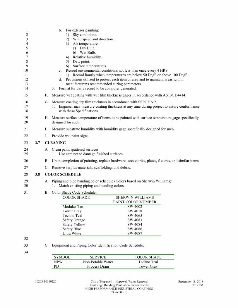
10203-10110220 City of Hopewell – Hopewell Water Renewal September 18, 2018
Centrifuge Building Ventilation Improvements 7:35 PM
HIGH PERFORMANCE INDUSTRIAL COATINGS 09 96 00 - 13
b. For exterior painting: 1
1) Sky conditions. 2
2) Wind speed and direction. 3
3) Air temperature. 4
a) Dry Bulb. 5
b) Wet Bulb. 6
4) Relative humidity. 7
5) Dew point. 8
6) Surface temperatures. 9
c. Record environmental conditions not less than once every 4 HRS. 10
1) Record hourly when temperatures are below 50 DegF or above 100 DegF. 11
d. Provisions utilized to protect each item or area and to maintain areas within 12
manufacturer's recommended curing parameters. 13
3. Format for daily record to be computer generated. 14
F. Measure wet coating with wet film thickness gages in accordance with ASTM D4414. 15
G. Measure coating dry film thickness in accordance with SSPC PA 2. 16
1. Engineer may measure coating thickness at any time during project to assure conformance 17
with these Specifications. 18
H. Measure surface temperature of items to be painted with surface temperature gage specifically 19
designed for such. 20
I. Measure substrate humidity with humidity gage specifically designed for such. 21
J. Provide wet paint signs. 22
3.7 CLEANING 23
A. Clean paint spattered surfaces. 24
1. Use care not to damage finished surfaces. 25
B. Upon completion of painting, replace hardware, accessories, plates, fixtures, and similar items. 26
C. Remove surplus materials, scaffolding, and debris. 27
3.8 COLOR SCHEDULE 28
A. Piping and pipe banding color schedule (Colors based on Sherwin Williams): 29
1. Match existing piping and banding colors. 30
B. Color Shade Code Schedule: 31
COLOR SHADE SHERWIN WILLIAMS
PAINT COLOR NUMBER
Modular Tan SW 4002
Tower Gray SW 4018
Techno Teal SW 4065
Safety Orange SW 4083
Safety Yellow SW 4084
Safety Blue SW 4086
Ultra White SW 4087
32
C. Equipment and Piping Color Identification Code Schedule: 33
34
SYMBOL SERVICE COLOR SHADE
NPW Non-Potable Water Techno Teal
PD Process Drain Tower Gray

10203-10110220 City of Hopewell – Hopewell Water Renewal September 18, 2018
Centrifuge Building Ventilation Improvements 7:35 PM
HIGH PERFORMANCE INDUSTRIAL COATINGS 09 96 00 - 14
END OF SECTION 1

10203-10110220 City of Hopewell – Hopewell Water Renewal September 18, 2018
Centrifuge Building Ventilation Improvements 7:38 PM
IDENTIFICATION DEVICES 10 14 00 - 1
SECTION 10 14 00 1
IDENTIFICATION DEVICES 2
PART 1 - GENERAL 3
1.1 SUMMARY 4
A. Section Includes: 5
1. Tag, tape and stenciling systems for equipment, piping, valves, pumps, ductwork and 6
similar items, and hazard and safety signs. 7
2. Contractor shall provide identification devices for Owner furnished equipment. 8
B. Related Specification Sections include but are not necessarily limited to: 9
1. Division 00 - Bidding Requirements, Contract Forms, and Conditions of the Contract. 10
2. Division 01 - General Requirements. 11
1.2 QUALITY ASSURANCE 12
A. Referenced Standards: 13
1. American Society of Mechanical Engineers (ASME): 14
a. A13.1, Scheme for the Identification of Piping Systems. 15
2. The International Society of Automation (ISA). 16
3. National Electrical Manufacturers Association/American National Standards Institute 17
(NEMA/ANSI): 18
a. Z535.1, Safety Color Code. 19
b. Z535.2, Environmental and Facility Safety Signs. 20
c. Z535.3, Criteria for Safety Symbols. 21
d. Z535.4, Product Safety Signs and Labels. 22
4. National Fire Protection Association (NFPA): 23
a. 70, National Electrical Code (NEC). 24
5. Occupational Safety and Health Administration (OSHA): 25
a. 29 CFR 1910.145, Specification for Accident Prevention Signs and Tags. 26
1.3 SUBMITTALS 27
A. Shop Drawings: 28
1. See Specification Section 01 33 00 for requirements for the mechanics and administration of 29
the submittal process. 30
2. Product technical data including: 31
a. Catalog information for all identification systems. 32
b. Acknowledgement that products submitted meet requirements of standards referenced. 33
3. Identification register, listing all items in PART 3 of this Specification Section to be 34
identified, type of identification system to be used, lettering, location and color. 35
PART 2 - PRODUCTS 36
2.1 ACCEPTABLE MANUFACTURERS 37
A. Subject to compliance with the Contract Documents, the following manufacturers are 38
acceptable: 39
1. W.H. Brady Co. 40
2. Panduit. 41
3. Seton. 42
4. National Band and Tag Co. 43
5. Carlton Industries, Inc. 44

10203-10110220 City of Hopewell – Hopewell Water Renewal September 18, 2018
Centrifuge Building Ventilation Improvements 7:38 PM
IDENTIFICATION DEVICES 10 14 00 - 2
2.2 MANUFACTURED UNITS 1
A. Type A1 - Round Metal Tags: 2
1. Materials: 3
a. Aluminum or stainless steel. 4
b. Stainless steel shall be used in corrosive environments. 5
2. Size: 6
a. Diameter: 1-1/2 IN minimum. 7
b. Thickness: 0.035 IN (20 GA) minimum. 8
3. Fabrication: 9
a. 3/16 IN minimum mounting hole. 10
b. Legend: Stamped and filled with black coloring. 11
4. Color: Natural. 12
B. Type A2 - Rectangle Metal Tags: 13
1. Materials: Stainless steel. 14
2. Size: 15
a. 3-1/2 IN x 1-1/2 IN minimum. 16
b. Thickness: 0.036 IN (20 GA) minimum. 17
3. Fabrication: 18
a. 3/16 IN minimum mounting hole. 19
b. Legend: Stamped and filled with black coloring. 20
4. Color: Natural. 21
C. Type A3 - Metal Tape Tags: 22
1. Materials: Aluminum or stainless steel. 23
2. Size: 24
a. Width 1/2 IN minimum. 25
b. Length as required by text. 26
3. Fabrication: 27
a. 3/16 IN minimum mounting hole. 28
b. Legend: Embossed. 29
4. Color: Natural. 30
D. Type B1- Square Nonmetallic Tags: 31
1. Materials: Fiberglass reinforced plastic. 32
2. Size: 33
a. Surface: 2 x 2 IN minimum. 34
b. Thickness: 100 mils. 35
3. Fabrication: 36
a. 3/16 IN mounting hole with metal eyelet. 37
b. Legend: Preprinted and permanently embedded and fade resistant. 38
4. Color: 39
a. Background: Manufacturer standard or as specified. 40
b. Lettering: Black. 41
E. Type B2 - Nonmetallic Signs: 42
1. Materials: Fiberglass reinforced or durable plastic. 43
2. Size: 44
a. Surface: As required by text. 45
b. Thickness: 60 mils minimum. 46
3. Fabrication: 47
a. Rounded corners. 48
b. Drilled holes in corners with grommets. 49
c. Legend: Preprinted, permanently embedded and fade resistant for a 10-year minimum 50
outdoor durability. 51

10203-10110220 City of Hopewell – Hopewell Water Renewal September 18, 2018
Centrifuge Building Ventilation Improvements 7:38 PM
IDENTIFICATION DEVICES 10 14 00 - 3
4. Color: 1
a. Background: Manufacturer standard or as specified. 2
b. Lettering: Black. 3
5. Standards for OSHA signs: NEMA/ANSI Z535.1, NEMA/ANSI Z535.2, NEMA/ANSI 4
Z535.3, NEMA/ANSI Z535.4, OSHA 29 CFR 1910.145. 5
F. Type C - Laminated Name Plates: 6
1. Materials: Phenolic or DR (high impact) acrylic. 7
2. Size: 8
a. Surface: As required by text. 9
b. Thickness: 1/16 IN. 10
3. Fabrication: 11
a. Outdoor rated and UV resistant when installed outdoors. 12
b. Two (2) layers laminated. 13
c. Legend: Engraved through top lamination into bottom lamination. 14
d. Two (2) drilled side holes, for screw mounting. 15
4. Color: Black top surface, white core, unless otherwise indicated. 16
G. Type D - Self-Adhesive Tape Tags and Signs: 17
1. Materials: Vinyl tape or vinyl cloth. 18
2. Size: 19
a. Surface: As required by text. 20
b. Thickness: 5 mils minimum. 21
3. Fabrication: 22
a. Indoor/Outdoor grade. 23
b. Weather and UV resistant inks. 24
c. Permanent adhesive. 25
d. Legend: Preprinted. 26
e. Wire markers to be self-laminating. 27
4. Color: White with black lettering or as specified. 28
5. Standards for OSHA signs: NEMA/ANSI Z535.1, NEMA/ANSI Z535.2, NEMA/ANSI 29
Z535.3, NEMA/ANSI Z535.4, OSHA 29 CFR 1910.145. 30
H. Type E - Heat Shrinkable Tape Tags: 31
1. Materials: Polyolefin. 32
2. Size: As required by text. 33
3. Fabrication: 34
a. Legend: Preprinted. 35
4. Color: White background, black printing. 36
I. Type F - Underground Warning Tape: 37
1. Materials: Polyethylene. 38
2. Size: 39
a. 6 IN wide (minimum). 40
b. Thickness: 3.5 mils. 41
3. Fabrication: 42
a. Legend: Preprinted and permanently imbedded. 43
b. Message continuous printed. 44
c. Tensile strength: 1750 psi. 45
4. Color: As specified. 46
J. Type G - Stenciling System: 47
1. Materials: 48
a. Exterior type stenciling enamel. 49
b. Either brushing grade or pressurized spray can form and grade. 50
2. Size: As required. 51

10203-10110220 City of Hopewell – Hopewell Water Renewal September 18, 2018
Centrifuge Building Ventilation Improvements 7:38 PM
IDENTIFICATION DEVICES 10 14 00 - 4
3. Fabrication: 1
a. Legend: As required. 2
4. Color: Black or white for best contrast. 3
K. Underground Tracer Wire: 4
1. Materials: 5
a. Wire: 6
1) 12 GA AWG. 7
2) Solid. 8
b. Wire nuts: Waterproof type. 9
c. Split bolts: Brass. 10
2.3 ACCESSORIES 11
A. Fasteners: 12
1. Bead chain: #6 brass, aluminum or stainless steel. 13
2. Plastic strap: Nylon, urethane or polypropylene. 14
3. Screws: Self-tapping, stainless steel. 15
4. Adhesive, solvent activated. 16
2.4 MAINTENANCE MATERIALS 17
A. Where stenciled markers are provided, clean and retain stencils after completion and include in 18
extra stock, along with required stock of paints and applicators. 19
PART 3 - EXECUTION 20
3.1 GENERAL INSTALLATION 21
A. Install identification devices at specified locations. 22
B. All identification devices to be printed by mechanical process, hand printing is not acceptable. 23
C. Attach tags to equipment with sufficient surface or body area with solvent activated adhesive 24
applied to back of each tag. 25
D. Attach tags with 1/8 IN round or flat head screws to equipment without sufficient surface or 26
body area, or porous surfaces. 27
1. Where attachment with screws should not or cannot penetrate substrate, attach with plastic 28
strap. 29
E. Single items of equipment enclosed in a housing or compartment to be tagged on outside of 30
housing. 31
1. Several items of equipment mounted in housing to be individually tagged inside the 32
compartment. 33
F. Tracer Wire: 34
1. Attach to pipe at a maximum of 10 FT intervals with tape or tie-wraps. 35
2. Continuous pass from each valve box and above grade at each structure. 36
3. Coil enough wire at each valve box to extend wire a foot above the ground surface. 37
4. 1,000 FT maximum spacing between valve boxes. 38
5. If split bolts are used for splicing, wrap with electrical tape. 39
6. If wire nuts are used for splicing, knot wire at each splice point leaving 6 IN of wire for 40
splicing. 41
7. Use continuous strand of wire between valve box where possible. 42
a. Continuous length shall be no shorter than 100 FT. 43

10203-10110220 City of Hopewell – Hopewell Water Renewal September 18, 2018
Centrifuge Building Ventilation Improvements 7:38 PM
IDENTIFICATION DEVICES 10 14 00 - 5
3.2 SCHEDULES 1
A. Process Systems: 2
1. General: 3
a. Provide arrows and markers on piping. 4
1) At 20 FT maximum centers along continuous lines. 5
2) At changes in direction (route) or obstructions. 6
3) At valves, risers, "T" joints, machinery or equipment. 7
4) Where pipes pass through floors, walls, ceilings, cladding assemblies and like 8
obstructions provide markers on both sides. 9
b. Position markers on both sides of pipe with arrow markers pointing in flow direction. 10
1) If flow is in both directions use double headed arrow markers. 11
c. Apply tapes and stenciling in uniform manner parallel to piping. 12
2. Trenches with piping: 13
a. Tag type: Type F - Underground Warning Tape 14
b. Location: Halfway between top of piping and finished grade. 15
c. Letter height: 1-1/4 IN minimum. 16
d. Potable water: 17
1) Color: Blue with black letters. 18
2) Legend: 19
a) First line: “CAUTION CAUTION CAUTION” 20
b) Second line: “BURIED WATER LINE BELOW” 21
e. Storm and sanitary sewer lines: 22
1) Color: Green with black letters. 23
2) Legend: 24
a) First line: “CAUTION CAUTION CAUTION” 25
b) Second line: “BURIED SEWER LINE BELOW” 26
f. (Nonpotable) water piping: 27
1) Color: Green with black letters. 28
2) Legend: 29
a) First line: “CAUTION CAUTION CAUTION” 30
b) Second line: “BURIED NONPOTABLE WATER LINE BELOW” 31
g. Chemical feed piping (e.g., chlorine solution, polymer solution, caustic solution, etc.): 32
1) Color: Yellow with black letters. 33
2) Legend: 34
a) First line: “CAUTION CAUTION CAUTION” 35
b) Second line: “BURIED CHEMICAL LINE BELOW” 36
h. Other piping (e.g., compressed air, irrigation, refrigerant, heating water, etc.): 37
1) Color: Yellow with black letters. 38
2) Legend: 39
a) First line: “CAUTION CAUTION CAUTION” 40
b) Second line: “BURIED PIPE LINE BELOW” 41
3. Yard valves, buried, with valve box and concrete pad: 42
a. Tag type: Type A2 - Rectangle Metal Tags. 43
b. Fastener: 3/16 IN x 7/8 IN plastic screw anchor with 1 IN #6 stainless steel pan head 44
screw. 45
c. Legend: 46
1) Letter height: 1/4 IN minimum. 47
2) Valve designation as indicated on the Drawings (e.g., “V-xxx”). 48
4. Valves and slide gates: 49
a. Tag type: 50
1) Outdoor locations: Type B1 - Square Nonmetallic Tags. 51
2) Indoor noncorrosive: 52
a) Type A1 - Round Metal Tags. 53
b) Type B1 - Square Nonmetallic Tags. 54

10203-10110220 City of Hopewell – Hopewell Water Renewal September 18, 2018
Centrifuge Building Ventilation Improvements 7:38 PM
IDENTIFICATION DEVICES 10 14 00 - 6
3) Indoor corrosive: 1
a) Stainless steel Type A1 - Round Metal Tags. 2
b) Type B1 - Square Nonmetallic Tags. 3
b. Fastener: 4
1) Type A1: Chain of the same material. 5
2) Type B1: Stainless steel chain. 6
c. Color: Per ASME A13.1 corresponding to the piping system. 7
d. Legend: 8
1) Letter height: 1/4 IN minimum. 9
2) Valve designation as indicated on the Drawings (e.g., “V-xxx”). 10
5. Process equipment (e.g., pumps, pump motors, blowers, air compressors, bar screens, 11
clarifier drive mechanism, etc.): 12
a. Tag type: 13
1) Type B2 - Nonmetallic Signs. 14
2) Type D - Self-Adhesive Tape Tags and Signs. 15
3) Type G - Stenciling System. 16
b. Fastener: 17
1) Self. 18
2) Screws. 19
3) Adhesive. 20
c. Legend: 21
1) Letter height: 1/2 IN minimum. 22
2) Equipment designation as indicated on the Drawings (e.g., “Primary Sludge Pump 23
P-xxx”). 24
6. Piping systems: 25
a. Tag type: 26
1) Outdoor locations: Type G - Stenciling System. 27
2) Indoor locations: 28
a) Type D - Self-Adhesive Tape Tags and Signs. 29
b) Type G - Stenciling System. 30
b. Fastener: Self. 31
c. Color: Per ASME A13.1. 32
d. Legend: 33
1) Letter height: Manufacturers standard for the pipe diameter. 34
2) Mark piping in accordance with ASME A13.1. 35
3) Use piping designation as indicated on the Drawings. 36
4) Arrow: Single arrow. 37
7. Equipment that starts automatically: 38
a. Tag type: 39
1) Type B2 - Nonmetallic Signs. 40
2) Type D - Self-Adhesive Tape Tags and Signs. 41
b. Fastener: 42
1) Type B2 - Screw or adhesive. 43
2) Type D - Self. 44
c. Size: 5 IN x 7 IN 45
d. Location: 46
1) Odor Control Fan Nos. 1 and 2 47
2) Inlet Damper Nos. 1 and 2 48
e. Legend: 49
1) OSHA Warning Sign. 50
2) Description of Warning: “THIS MACHINE STARTS AUTOMATICALLY.” 51

10203-10110220 City of Hopewell – Hopewell Water Renewal September 18, 2018
Centrifuge Building Ventilation Improvements 7:38 PM
IDENTIFICATION DEVICES 10 14 00 - 7
B. HVAC and Odorous Air Systems: 1
1. General: 2
a. Provide arrows and markers on ducts. 3
1) At 20 FT maximum centers along continuous lines. 4
2) At changes in direction (route) or obstructions. 5
3) At dampers, risers, branches, machinery or equipment. 6
4) Where ducts pass through floors, walls, ceilings, cladding assemblies and like 7
obstructions provide markers on both sides. 8
b. Position markers on both sides of duct with arrow markers pointing in flow direction. 9
1) If flow is in both directions use double headed arrow markers. 10
c. Apply tapes and stenciling in uniform manner parallel to ducts. 11
2. HVAC Equipment (e.g., unit heaters, exhaust fans, air handlers, etc.): 12
a. Tag type: 13
1) Type B2 - Nonmetallic Signs. 14
2) Type C - Phenolic Name Plates. 15
b. Fastener: Screws. 16
c. Legend: 17
1) Letter height: 1 IN minimum. 18
2) Equipment designation as indicated on the Drawings (e.g., "EF-xxx"). 19
3. Ductwork: 20
a. Tag type: 21
1) Type D - Self-Adhesive Tape Tags and Signs. 22
2) Type G - Stenciling System. 23
b. Fastener: Self. 24
c. Legend: 25
1) Letter height: 1 IN minimum. 26
2) Description of ductwork, (e.g., “AIR SUPPLY”). 27
3) Arrows: Single arrow. 28
4. Enclosure for instrumentation and control equipment, (e.g., fan control panels, etc.): 29
a. Tag type: Type C - Phenolic Name Plates. 30
b. Fastener: Screws. 31
c. Legend: 32
1) Letter height: 1/2 IN minimum. 33
2) Equipment designation as indicated on the Drawings (e.g., "FAN CONTROL 34
PANEL FCP-xxx"). 35
5. Wall mounted thermostats: 36
a. Tag type: Type D - Self-Adhesive Tape Tags and Signs. 37
b. Fastener: Self. 38
c. Legend: 39
1) Letter height: 3/16 IN minimum. 40
2) Description of equipment controlled (e.g., "UH-xxx" or AHU-xxx"). 41
6. Components inside equipment enclosure, (e.g., controller’s, control relays, contactors, and 42
timers): 43
a. Tag type: Type D - Self-Adhesive Tape Tags and Signs. 44
b. Fastener: Self. 45
c. Legend: 46
1) Letter height: 3/16 IN minimum. 47
2) Description or function of component (e.g., "CR-xxx"). 48
7. Through enclosure door mounted equipment (e.g., selector switches, controller digital 49
displays, etc.): 50
a. Tag type: Type C - Phenolic Name Plates. 51
b. Fastener: Screws. 52
c. Legend: 53
1) Letter height: 1/4 IN minimum. 54
2) Component tag number as indicated on the Drawings or as defined by contractor 55
(e.g., “HS-xxx”). 56

10203-10110220 City of Hopewell – Hopewell Water Renewal September 18, 2018
Centrifuge Building Ventilation Improvements 7:38 PM
IDENTIFICATION DEVICES 10 14 00 - 8
C. Electrical Systems: 1
1. Trenches with ductbanks, direct-buried conduit, or direct-buried wire and cable. 2
a. Tag type: Type F - Underground Warning Tape. 3
b. Letter height: 1-1/4 IN minimum. 4
c. Location: 5
1) Where trench is 12 IN or more below finished grade: In trench 6 IN below 6
finished grade. 7
2) Where trench is less than 12 IN below finished grade: In trench 3 IN below 8
finished grade. 9
d. Electrical power (e.g., low and medium voltage): 10
1) Color: Red with black letters. 11
2) Legend: 12
a) First line: “CAUTION CAUTION CAUTION”. 13
b) Second line: “BURIED ELECTRIC LINE BELOW”. 14
e. Communications (e.g., telephone, instrumentation, LAN, SCADA): 15
1) Color: Orange with black letters. 16
2) Legend: 17
a) First line: “CAUTION CAUTION CAUTION”. 18
b) Second line: “BURIED COMMUNICATION LINE BELOW”. 19
2. Switchgear, switchboards and motor control centers: 20
a. Tag type: Type C - Phenolic Name Plates. 21
b. Fastener: Screws. 22
c. Main equipment legend: 23
1) Letter height: 24
a) First line: 1 IN minimum. 25
b) Subsequent lines: 3/8 IN minimum. 26
2) First line: Equipment name (e.g., "MAIN SWITCHBOARD MSBxxx"). 27
3) Second line: 28
a) Source of power (e.g., "FED FROM MCCxxx LOCATED IN ROOM xxx"). 29
b) Include the building name or number if the source is in another building. 30
4) Third line: System voltage and phase (e.g., “480/277 V, 3PH”). 31
5) Fourth line: Date installed (e.g., “INSTALLED JULY 20xx”). 32
d. Main and feeder device legend: 33
1) Letter height: 3/8 IN minimum. 34
2) Description of load (e.g., “MAIN DISCONNECT”, "PUMP Pxxx" or 35
"PANELBOARD HPxxx"). 36
3. Components inside equipment enclosures (e.g., circuit breakers, fuses, control power 37
transformers, control relays, contactors, timers, etc.): 38
a. Tag type: Type D - Self-Adhesive Tape Tags and Signs. 39
b. Fastener: Self. 40
c. Legend: 41
1) Letter height: 3/16 IN minimum. 42
2) Description or function of component (e.g., "M-xxx”, “CR-xxx” or “TR-xxx"). 43
4. Through enclosure door mounted equipment (e.g., selector switches, controller digital 44
displays, etc.): 45
a. Tag type: Type C - Phenolic Name Plates. 46
b. Fastener: Screws. 47
c. Legend: 48
1) Letter height: 1/4 IN minimum. 49
2) Component tag number as indicated on the Drawings or as defined by contractor 50
(e.g., “HS-xxx”). 51
5. Conductors in control panels and in pull or junction boxes where multiple circuits exist. 52
a. Tag type: Type D - Self-Adhesive Tape Tags. 53
b. Fastener: Self. 54
c. Tag conductor at both ends. 55
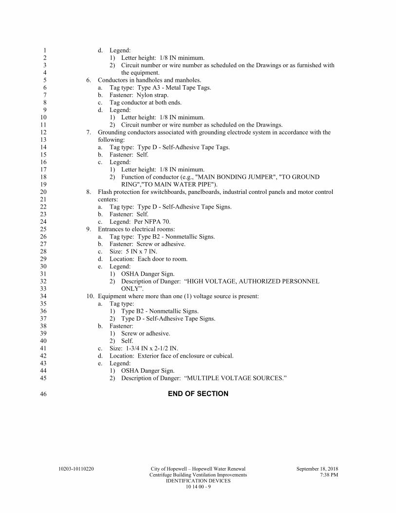
10203-10110220 City of Hopewell – Hopewell Water Renewal September 18, 2018
Centrifuge Building Ventilation Improvements 7:38 PM
IDENTIFICATION DEVICES 10 14 00 - 9
d. Legend: 1
1) Letter height: 1/8 IN minimum. 2
2) Circuit number or wire number as scheduled on the Drawings or as furnished with 3
the equipment. 4
6. Conductors in handholes and manholes. 5
a. Tag type: Type A3 - Metal Tape Tags. 6
b. Fastener: Nylon strap. 7
c. Tag conductor at both ends. 8
d. Legend: 9
1) Letter height: 1/8 IN minimum. 10
2) Circuit number or wire number as scheduled on the Drawings. 11
7. Grounding conductors associated with grounding electrode system in accordance with the 12
following: 13
a. Tag type: Type D - Self-Adhesive Tape Tags. 14
b. Fastener: Self. 15
c. Legend: 16
1) Letter height: 1/8 IN minimum. 17
2) Function of conductor (e.g., "MAIN BONDING JUMPER", "TO GROUND 18
RING","TO MAIN WATER PIPE"). 19
8. Flash protection for switchboards, panelboards, industrial control panels and motor control 20
centers: 21
a. Tag type: Type D - Self-Adhesive Tape Signs. 22
b. Fastener: Self. 23
c. Legend: Per NFPA 70. 24
9. Entrances to electrical rooms: 25
a. Tag type: Type B2 - Nonmetallic Signs. 26
b. Fastener: Screw or adhesive. 27
c. Size: 5 IN x 7 IN. 28
d. Location: Each door to room. 29
e. Legend: 30
1) OSHA Danger Sign. 31
2) Description of Danger: “HIGH VOLTAGE, AUTHORIZED PERSONNEL 32
ONLY”. 33
10. Equipment where more than one (1) voltage source is present: 34
a. Tag type: 35
1) Type B2 - Nonmetallic Signs. 36
2) Type D - Self-Adhesive Tape Signs. 37
b. Fastener: 38
1) Screw or adhesive. 39
2) Self. 40
c. Size: 1-3/4 IN x 2-1/2 IN. 41
d. Location: Exterior face of enclosure or cubical. 42
e. Legend: 43
1) OSHA Danger Sign. 44
2) Description of Danger: “MULTIPLE VOLTAGE SOURCES.” 45
END OF SECTION 46

10203-10110220 City of Hopewell – Hopewell Water Renewal September 18, 2018
Centrifuge Building Ventilation Improvements 7:38 PM
IDENTIFICATION DEVICES 10 14 00 - 10
THIS PAGE INTENTIONALLY LEFT BLANK 1

10203-10110220 City of Hopewell – Hopewell Water Renewal September 18, 2018
Centrifuge Building Ventilation Improvements 7:40 PM
IDENTIFICATION FOR HVAC, DUCTWORK, PIPING AND HVAC EQUIPMENT 23 05 53 - 1
SECTION 23 05 53 1
IDENTIFICATION FOR HVAC, DUCTWORK, PIPING AND HVAC EQUIPMENT 2
PART 1 - GENERAL 3
1.1 SUMMARY 4
A. Section Includes: 5
1. Nameplates. 6
2. Tags. 7
3. Stencils. 8
4. Ceiling tacks. 9
5. Labels. 10
B. Related Sections: 11
1. Section 09 96 00 - High Performance Industrial Coatings. 12
1.2 REFERENCES 13
A. American Society of Mechanical Engineers (ASME): 14
1. A13.1, Scheme for the Identification of Piping Systems. 15
1.3 SUBMITTALS 16
A. Section 01 33 00 - Submittal Procedures: Submittal procedures. 17
B. Product Data: Submit manufacturers catalog literature for each product required. 18
C. Shop Drawings: Submit Identification Register including list of wording, symbols, letter size, 19
and color coding for mechanical identification and valve chart and schedule, including valve tag 20
number, location, function, and valve manufacturer's name and model number. 21
D. Manufacturer's Installation Instructions: Indicate installation instructions, special procedures, 22
and installation. 23
1.4 CLOSEOUT SUBMITTALS 24
A. Project Record Documents: Record actual locations of tagged valves; include valve tag 25
numbers. 26
1.5 QUALITY ASSURANCE 27
A. Conform to ASME A13.1 for color scheme for identification of piping systems and accessories. 28
B. Maintain one copy of each document on site. 29
1.6 FIELD MEASUREMENTS 30
A. Verify field measurements prior to fabrication. 31
PART 2 - PRODUCTS 32
2.1 ACCEPTABLE MANUFACTURERS 33
A. Subject to compliance with the Contract Documents, the following manufacturers are 34
acceptable: 35
1. Nameplates, Tags and Stencils: 36
a. WH Brady Company. 37
b. Panduit. 38
c. Seton. 39
d. National Band and Tag Company. 40
e. Carlton Industries, Inc. 41

10203-10110220 City of Hopewell – Hopewell Water Renewal September 18, 2018
Centrifuge Building Ventilation Improvements 7:40 PM
IDENTIFICATION FOR HVAC, DUCTWORK, PIPING AND HVAC EQUIPMENT 23 05 53 - 2
2. Ceiling tacks: 1
a. Marking Services, Inc. 2
b. R&R Identification Co. 3
c. Seton. 4
2.2 NAMEPLATES 5
A. Laminated two-layer phenolic or DR (high impact) acrylic with engraved black letters on light 6
contrasting background color. 7
1. Thickness: Minimum 1/16 IN. 8
2. Color: Manufacturer standard or as specified. 9
B. Alternate: Laminated three-layer plastic with engraved black letters on light contrasting 10
background color. 11
1. Thickness: Minimum 60 mils. 12
2. Color: Manufacturer standard or as specified. 13
2.3 TAGS 14
A. Nonmetallic Tags: 15
1. Fiberglass reinforced engraved black letters on light contrasting background color. 16
a. Tag size: Minimum 1-1/2 IN square. 17
b. Thickness: Minimum 100 mils. 18
c. Color: Manufacturer standard or as specified. 19
B. Metal Tags: 20
1. Aluminum or stainless steel disc with stamped letters and finished edges. 21
a. Tag size: Minimum 1-1/2 IN diameter. 22
b. Thickness: Minimum 0.035 IN (20 Ga). 23
c. Color: Black color filled into stamped text with natural metal background. 24
C. Tag Chart: Typewritten letter size list of applied tags and location plastic laminated. 25
2.4 STENCILS 26
A. With clean cut symbols and letters of following size: 27
1. Up to 2 IN Outside Diameter of Insulation or Pipe: 1/2 IN high letters. 28
2. 2-1/2 to 6 IN Outside Diameter of Insulation or Pipe: 1 IN high letters. 29
3. Over 6 IN Outside Diameter of Insulation or Pipe: 2 IN high letters. 30
4. Ductwork and Equipment: 2 IN high letters. 31
B. Stencil Paint: As specified in Section 09 96 00, colors and lettering size conforming to ASME 32
A13.1. 33
2.5 SELF ADHESIVE PIPE AND DUCT MARKERS 34
A. Color and Lettering: Conform to ASME A13.1. 35
B. Flexible, vinyl film tape with pressure sensitive adhesive backing and printed markings. 36
1. Thickness: Minimum 5 mils. 37
2. Letter Height: 38
a. Up to 2 IN Outside Diameter of Insulation or Pipe: 1/2 IN high letters. 39
b. 2-1/2 to 6 IN Outside Diameter of Insulation or Pipe: 1 IN high letters. 40
c. Over 6 IN Outside Diameter of Insulation or Pipe: 2 IN high letters. 41
d. Ductwork and Equipment: 2 IN high letters. 42
3. Indoor/outdoor grade. 43
4. Weather and UV resistant inks. 44
5. Permanent adhesive. 45

10203-10110220 City of Hopewell – Hopewell Water Renewal September 18, 2018
Centrifuge Building Ventilation Improvements 7:40 PM
IDENTIFICATION FOR HVAC, DUCTWORK, PIPING AND HVAC EQUIPMENT 23 05 53 - 3
PART 3 - EXECUTION 1
3.1 PREPARATION 2
A. Degrease and clean surfaces to receive adhesive for identification materials. 3
B. Prepare surfaces in accordance with Section 09 96 00 for stencil painting. 4
3.2 INSTALLATION 5
A. Apply stencil painting in accordance with Section 09 96 00. 6
B. Install identifying devices after completion of coverings and painting. 7
C. All identification devices to be printed by mechanical process. Hand printing is not acceptable. 8
D. Install nameplates with adhesive where equipment has sufficient surface area and texture. 9
1. Attach tags with 1/8 IN flat head screws where adhesive application is not suitable. 10
2. Attach tabs with plastic strap where screws should not or cannot penetrate substrate. 11
E. Install labels with sufficient adhesive for permanent adhesion and seal with clear lacquer. 12
F. Install tags using corrosion resistant chain. Number tags consecutively by location. 13
G. Identify ductwork with nameplates or stenciled painting. Identify service and direction. Locate 14
identification at air handling unit, at each side of penetration of structure or enclosure, and at 15
each obstruction and change of direction and not to exceed 20 FT spacing on straight runs. 16
H. Tracer Wire: 17
1. Attach to buried nonmetallic pipe at maximum of 10 FT intervals with tape or tie-wraps. 18
2. Install continuously from structure to structure including valve boxes and buildings. 19
3. Splice wire with split bolts or wire nuts only as needed; use continuous strands of no less 20
than 100 FT length. 21
3.3 SCHEDULES 22
A. Ductwork: 23
1. Install labels on all duct in accordance with Article 3.2. 24
a. Stencils or self-adhesive labels. 25
2. Color Coding: 26
a. Black lettering on yellow background: 27
1) Supply Air, Outside Air or Makeup Air. 28
b. White lettering on green background: 29
1) Return Air, Exhaust Air and Relief Air. 30
END OF SECTION 31

10203-10110220 City of Hopewell – Hopewell Water Renewal September 18, 2018
Centrifuge Building Ventilation Improvements 7:40 PM
IDENTIFICATION FOR HVAC, DUCTWORK, PIPING AND HVAC EQUIPMENT 23 05 53 - 4
THIS PAGE INTENTIONALLY LEFT BLANK 1

10203-10110220 City of Hopewell – Hopewell Water Renewal September 18, 2018
Centrifuge Building Ventilation Improvements 7:42 PM
HVAC SYSTEMS - BALANCING AND TESTING 23 05 93 - 1
SECTION 23 05 93 1
HVAC SYSTEMS - BALANCING AND TESTING 2
PART 1 - GENERAL 3
1.1 SUMMARY 4
A. Section Includes: 5
1. Adjusting, balancing, and testing of all heating, ventilating and air conditioning (HVAC) 6
systems, including the following systems: 7
B. Related Sections include but are not necessarily limited to: 8
1. Division 00 - Bidding Requirements, Contract Forms, and Conditions of the Contract. 9
2. Division 01 - General Requirements. 10
3. Section 23 31 00 - HVAC: Ductwork. 11
4. Section 44 31 90 - High Plume Fans. 12
1.2 QUALITY ASSURANCE 13
A. Referenced Standards: 14
1. Associated Air Balance Council (AABC): 15
a. National Standards for Total System Balance. 16
2. American Industrial Hygiene Association (AIHA): 17
a. Z9.5, Laboratory Ventilation. 18
3. American Society of Heating, Refrigerating and Air Conditioning Engineers (ASHRAE): 19
a. HVAC Applications Handbook, Chapter entitled "Laboratories". 20
b. HVAC Systems and Equipment Handbook, Chapter entitled "Testing, Adjusting, and 21
Balancing". 22
4. National Environmental Balancing Bureau (NEBB): 23
a. Procedural Standards for Testing Adjusting Balancing of Environmental Systems. 24
B. Qualifications: 25
1. Work of this Section to be accomplished by an independent testing and balancing firm 26
certified by one (1) of the following: 27
a. Associated Air Balance Council (AABC). 28
b. National Environmental Balancing Bureau (NEBB). 29
c. Other certification entity approved by Engineer. 30
2. The independent firm shall not be the same firm as the firm installing the HVAC equipment, 31
nor under contract to the firm installing the equipment. 32
1.3 SUBMITTALS 33
A. Shop Drawings: 34
1. See Specification Section 01 33 00 for requirements for the mechanics and administration of 35
the submittal process. 36
2. Certifications: 37
a. Letter stating the name and qualifications of the firm proposed. 38
b. Evidence that relevant subcontractors have been notified of the requirement to 39
coordinate balance and test elements in the work with the testing and balancing firm. 40
3. Report forms: 41
a. Procedures and forms to be used in calibrating of test instruments, balancing systems, 42
and recording and reporting test data. 43
B. Informational Submittals: 44
1. Completed test reports and data forms upon completion of installation, balance and testing 45
of HVAC systems. 46
a. Insert recorded information on report forms required by specifications and approved for 47
use on project. 48

10203-10110220 City of Hopewell – Hopewell Water Renewal September 18, 2018
Centrifuge Building Ventilation Improvements 7:42 PM
HVAC SYSTEMS - BALANCING AND TESTING 23 05 93 - 2
b. Additional written verification and other related information clearly identifying project, 1
date and specifics of verification. 2
c. Utilize report forms similar to those shown in Section V of AABC Standard. 3
d. Provide forms typed and signed by the testing and balancing firm. 4
PART 2 - PRODUCTS - (NOT APPLICABLE TO THIS SPECIFICATION SECTION) 5
PART 3 - EXECUTION 6
3.1 PREPARATION 7
A. Secure approved Shop Drawings of all HVAC equipment. 8
B. Procedures and Forms: 9
1. Submit procedures and forms to be used in calibration of test instruments, balancing 10
systems, and recording and reporting test data. 11
2. Obtain approval before beginning balancing and testing. 12
C. Do not begin balancing and testing until HVAC systems are complete and in full working order. 13
1. Place HVAC systems into full operation and continue their operation during each working 14
day of balancing and testing. 15
D. Provide qualified heating and ventilating Engineer(s) to supervise and perform balancing and 16
testing. 17
E. Review design Drawings, specifications, approved Shop Drawings and other related items to 18
become thoroughly acquainted with the design of HVAC systems. 19
F. Check all installed systems against Contract Drawings, Specifications and Shop Drawings to see 20
that system is installed as required. 21
1. Report deficiencies to the Engineer. 22
2. Report deficiencies to Contractor for remedial action including providing corrective 23
measures required in the function of any part of system to complete balancing. 24
G. Make necessary adjustments as required to balance the systems. 25
H. Contractor to balance HVAC system according to the flows as listed in the contract drawings. 26
3.2 FIELD QUALITY CONTROL 27
A. Balance and Test Air Systems: 28
1. Adjust equipment RPM to design requirements. 29
2. Report motor full load amperes. 30
3. Obtain design CFM at fans. 31
a. Make pitot tube traverse of main supply and exhaust ducts within 5 PCT. 32
4. Test and record system static pressures, suction and discharge. 33
5. Obtain design CFM for recirculated air. 34
6. Obtain design CFM outside air. 35
7. Test and record entering air temperatures, (DB, heating and cooling). 36
8. Test and record leaving air temperatures, (DB, heating and cooling). 37
9. Test and record leaving air temperatures, (WB, cooling). 38
10. Adjust dampers in supply, exhaust and return air ducts to design CFM. 39
11. Test diffusers, grilles, and registers as follows: 40
a. Adjust to comply with design requirements within 10 PCT. 41
b. Identify location and area of each. 42
c. Adjust face velocity to establish required CFM. 43
1) Retest after initial adjustments. 44
d. Adjust to minimize drafts and to ensure uniform air distribution in all areas. 45

10203-10110220 City of Hopewell – Hopewell Water Renewal September 18, 2018
Centrifuge Building Ventilation Improvements 7:42 PM
HVAC SYSTEMS - BALANCING AND TESTING 23 05 93 - 3
12. Identify and list size, type and manufacturer of diffusers, grilles, registers, and HVAC 1
equipment. 2
a. Use manufacturer's ratings on equipment to make required calculations. 3
13. Adjust and assure that the operation of automatically operated dampers are as specified. 4
a. Check and calibrate controls. 5
14. Prepare and submit reports. 6
END OF SECTION 7

10203-10110220 City of Hopewell – Hopewell Water Renewal September 18, 2018
Centrifuge Building Ventilation Improvements 7:42 PM
HVAC SYSTEMS - BALANCING AND TESTING 23 05 93 - 4
THIS PAGE INTENTIONALLY LEFT BLANK 1

10203-10110220 City of Hopewell – Hopewell Water Renewal September 18, 2018
Centrifuge Building Ventilation Improvements 7:45 PM
HVAC - DUCTWORK 23 31 00 - 1
SECTION 23 31 00 1
HVAC - DUCTWORK 2
PART 1 - GENERAL 3
1.1 SUMMARY 4
A. Section Includes: 5
1. HVAC ductwork and accessories. 6
B. Related Specification Sections include but are not necessarily limited to: 7
1. Division 00 - Bidding Requirements, Contract Forms, and Conditions of the Contract. 8
2. Division 01 - General Requirements. 9
3. Section 01 61 03 - Equipment: Basic Requirements. 10
1.2 QUALITY ASSURANCE 11
A. Referenced Standards: 12
1. American Society of Heating, Refrigerating and Air Conditioning Engineers (ASHRAE): 13
a. 52, Method of Testing Air Conditioning Devices Used in General Ventilation for 14
Removing Particulate Matter. 15
2. National Fire Protection Association (NFPA). 16
3. Sheet Metal and Air Conditioning Contractors' National Association (SMACNA): 17
a. Ducted Electric Heat Guide for Air Handling Systems. 18
b. HVAC Duct Construction Standards - Metal and Flexible. 19
4. Underwriters Laboratory, Inc. (UL): 20
a. 555, Standard for Safety Fire Damper and Ceiling Fire Damper. 21
b. 555S, Standard for Safety Leakage Rated Dampers for Use in Smoke Control Systems. 22
c. Building Materials Directory. 23
B. Qualifications: 24
1. Fabricator: Firms regularly engaged in the manufacture of the specific product, of type, size 25
required, whose products have been in use in similar service for not less than three (3) years. 26
2. Installers: Firm with at least five (5) years of installation experience on products similar to 27
that required for this Project. 28
1.3 DEFINITIONS 29
A. Installer or Applicator: 30
1. Installer or applicator is the person actually installing or applying the product in the field at 31
the Project site. 32
2. Installer and applicator are synonymous. 33
1.4 SUBMITTALS 34
A. Shop Drawings: 35
1. See Specification Section 01 33 00 for requirements for the mechanics and administration of 36
the submittal process. 37
2. See Specification Section 01 61 03. 38
3. Efficiency ratings per ASHRAE 52 for factory built and assembled filter units. 39
4. Scaled ductwork drawings (1/4 IN equals 1 FT) showing duct and accessory layout and 40
support. 41
B. Contract Closeout Information: 42
1. Operation and Maintenance Data: 43
a. See Specification Section 01 33 04 for requirements for the mechanics, administration, 44
and the content of Operation and Maintenance Manual submittals. 45

10203-10110220 City of Hopewell – Hopewell Water Renewal September 18, 2018
Centrifuge Building Ventilation Improvements 7:45 PM
HVAC - DUCTWORK 23 31 00 - 2
C. Miscellaneous Submittal: 1
1. Documentation of qualifications for fabricators and installers. 2
PART 2 - PRODUCTS 3
2.1 MANUFACTURERS 4
A. Subject to compliance with the Contract Documents, the following manufacturers are 5
acceptable: 6
1. Transverse joints (factory fabricated aluminum): 7
a. Ductmate Industries, Inc. 8
2. Fiberglass ductwork: 9
a. Peabody Spunstrand. 10
b. Ceilcote. 11
3. Flexible ducts: 12
a. Thermaflex. 13
b. Condu-flex. 14
c. Glass-flex. 15
4. Turning vanes: 16
a. Ductmate Industries, Inc. 17
b. Duro Dyne. 18
c. SEMCO Incorporated. 19
d. Ward Industries, Inc. 20
5. Flexible duct connections: 21
a. Vent Fabrics. 22
b. Duro Dyne. 23
6. Flexible connector thrust restraint: 24
a. Mason WB. 25
7. Access doors in ductwork: 26
a. Vent Fabrics. 27
b. American Warming. 28
8. Backdraft dampers: 29
a. Air Balance. 30
b. Ruskin. 31
c. American Warming. 32
9. Fire and combination smoke and fire dampers: 33
a. Air Balance. 34
b. Ruskin. 35
c. American Warming. 36
10. Ceiling diffusers: 37
a. Anemostat. 38
b. Carnes. 39
c. Titus. 40
11. Grilles and registers: 41
a. Anemostat. 42
b. Carnes. 43
c. Titus. 44
12. Manual (volume) dampers: 45
a. Air Balance. 46
b. Ruskin. 47
c. American Warming. 48
13. Duct sealers: 49
a. Durkee-Atwood 50
b. Unitec McGill 51
c. Benjamin Foster. 52
d. Design Polymerics. 53
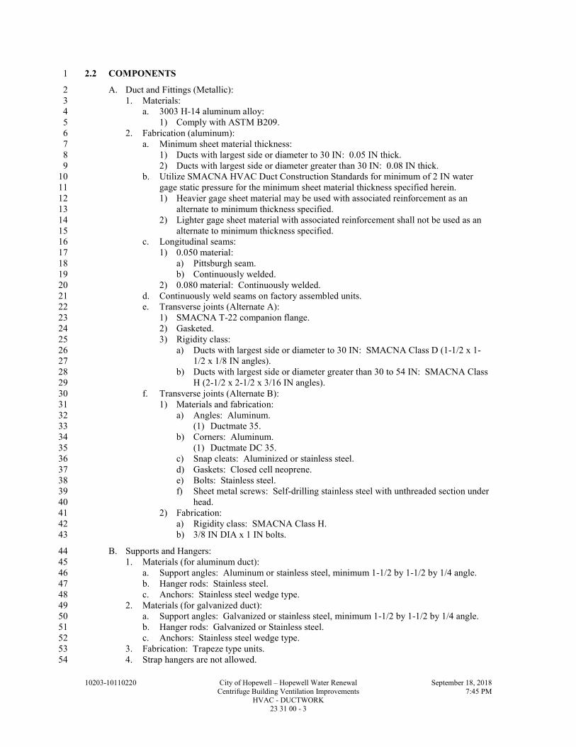
10203-10110220 City of Hopewell – Hopewell Water Renewal September 18, 2018
Centrifuge Building Ventilation Improvements 7:45 PM
HVAC - DUCTWORK 23 31 00 - 3
2.2 COMPONENTS 1
A. Duct and Fittings (Metallic): 2
1. Materials: 3
a. 3003 H-14 aluminum alloy: 4
1) Comply with ASTM B209. 5
2. Fabrication (aluminum): 6
a. Minimum sheet material thickness: 7
1) Ducts with largest side or diameter to 30 IN: 0.05 IN thick. 8
2) Ducts with largest side or diameter greater than 30 IN: 0.08 IN thick. 9
b. Utilize SMACNA HVAC Duct Construction Standards for minimum of 2 IN water 10
gage static pressure for the minimum sheet material thickness specified herein. 11
1) Heavier gage sheet material may be used with associated reinforcement as an 12
alternate to minimum thickness specified. 13
2) Lighter gage sheet material with associated reinforcement shall not be used as an 14
alternate to minimum thickness specified. 15
c. Longitudinal seams: 16
1) 0.050 material: 17
a) Pittsburgh seam. 18
b) Continuously welded. 19
2) 0.080 material: Continuously welded. 20
d. Continuously weld seams on factory assembled units. 21
e. Transverse joints (Alternate A): 22
1) SMACNA T-22 companion flange. 23
2) Gasketed. 24
3) Rigidity class: 25
a) Ducts with largest side or diameter to 30 IN: SMACNA Class D (1-1/2 x 1-26
1/2 x 1/8 IN angles). 27
b) Ducts with largest side or diameter greater than 30 to 54 IN: SMACNA Class 28
H (2-1/2 x 2-1/2 x 3/16 IN angles). 29
f. Transverse joints (Alternate B): 30
1) Materials and fabrication: 31
a) Angles: Aluminum. 32
(1) Ductmate 35. 33
b) Corners: Aluminum. 34
(1) Ductmate DC 35. 35
c) Snap cleats: Aluminized or stainless steel. 36
d) Gaskets: Closed cell neoprene. 37
e) Bolts: Stainless steel. 38
f) Sheet metal screws: Self-drilling stainless steel with unthreaded section under 39
head. 40
2) Fabrication: 41
a) Rigidity class: SMACNA Class H. 42
b) 3/8 IN DIA x 1 IN bolts. 43
B. Supports and Hangers: 44
1. Materials (for aluminum duct): 45
a. Support angles: Aluminum or stainless steel, minimum 1-1/2 by 1-1/2 by 1/4 angle. 46
b. Hanger rods: Stainless steel. 47
c. Anchors: Stainless steel wedge type. 48
2. Materials (for galvanized duct): 49
a. Support angles: Galvanized or stainless steel, minimum 1-1/2 by 1-1/2 by 1/4 angle. 50
b. Hanger rods: Galvanized or Stainless steel. 51
c. Anchors: Stainless steel wedge type. 52
3. Fabrication: Trapeze type units. 53
4. Strap hangers are not allowed. 54

10203-10110220 City of Hopewell – Hopewell Water Renewal September 18, 2018
Centrifuge Building Ventilation Improvements 7:45 PM
HVAC - DUCTWORK 23 31 00 - 4
C. Turning Vanes: 1
1. Materials: Same as duct. 2
2. Fabrication: 3
a. Fabricate double vane units. 4
b. Pressure drop through elbows: Maximum 20 PCT of velocity pressure. 5
D. Flexible Connections: 6
1. Materials: Hypalon, double coated closely woven glass fabric. 7
2. Fabrication: Withstand 4.5 IN water column, positive and negative pressure. 8
E. Access Doors: 9
1. Materials: 10
a. Inner panel, out panel and frame: Same as duct. 11
b. Gaskets: Closed cell neoprene. 12
c. Insulation: 1 LB density fiberglass. 13
d. Hinges: Stainless steel. 14
e. Latches: 15
1) Aluminum-zinc alloy. 16
2) Outside lever handle. 17
3) Adjustable spacer. 18
4) Beveled inside flange. 19
5) Studs: 20
a) Minimum 3/8 IN DIA stud for doors up to 24 IN wide x 48 IN high. 21
b) Minimum 1/2 IN DIA stud for doors larger than 24 x 48 IN. 22
2. Fabrication: 23
a. Provide four-side continuous gaskets. 24
b. Utilize continuous piano hinges. 25
c. Latches required: 26
1) 12 IN in any direction: One (1). 27
2) Up to 18 x 18 IN: Two (2). 28
3) Up to 24 x 48 IN: Two (2) with inside handles. 29
4) Up to 24 x 72 IN: Three (3) with inside handles. 30
5) Minimum door size: 12 x 12 IN. 31
F. Volume Extractors: 32
1. Materials (for aluminum duct): 33
a. Mounting bracket: 0.071 IN aluminum. 34
b. Movement bar: 0.080 IN aluminum. 35
c. Blades: 0.050 IN aluminum. 36
2. Materials (for galvanized duct): 37
a. Mounting bracket, movement bar and blades: 18 gage steel, coated. 38
3. Fabrication: 39
a. Gang operated parallel blade, fully adjustable. 40
b. Minimum two (2) manually operated adjustment arms. 41
c. Rotating shaft: Minimum 3/8 IN SQ. 42
G. Flexible Duct: 43
1. Material: Continuous steel supporting spiral covered with 100 PCT continuous filament 44
fiberglass with nonporous fiberglass/vinyl liner and reinforced Mylar/neoprene outer cover. 45
2. UL listed, Class 1 with flame spread of 25 or less and smoke development rating not to 46
exceed 50. 47
H. Drain Pan: 48
1. Materials: Aluminum. 49
2. Fabrication: 0.080 IN. 50

10203-10110220 City of Hopewell – Hopewell Water Renewal September 18, 2018
Centrifuge Building Ventilation Improvements 7:45 PM
HVAC - DUCTWORK 23 31 00 - 5
I. Acoustical Liners: 1
1. Materials: 2
a. Thickness: 1 IN. 3
b. 3 LBS/CF density fiberglass. 4
c. UL listed, Class 1, non-combustible. 5
J. Backdraft Dampers: 6
1. Material: 7
a. 6063 T5 aluminum. 8
b. Blade edge seals: Extruded vinyl. 9
2. Fabrication: 10
a. Frame thickness: 0.125 IN minimum. 11
b. Blade thickness: 0.070 IN minimum. 12
c. Linkage: 1/2 IN tie bars. 13
d. Bearings: Synthetic. 14
K. Fire Dampers: 15
1. Materials: 16
a. Frame, blades, enclosure: Galvanized steel. 17
2. Fabrication: 18
a. Frame: 20 GA, G60. 19
b. Blades: 20
1) Curtain type. 21
2) 24 GA, G60. 22
c. Enclosure: 20 GA, G60. 23
d. Fusible link: 212 DEGF, UL listed. 24
e. Fire rating: 1-1/2 HR per UL 555. 25
f. Mounting: Vertical or horizontal. 26
g. Design with blade package out of air stream. 27
L. Combination Fire and Smoke Dampers: 28
1. Materials: 29
a. Frame, blades, enclosure: Galvanized. 30
2. Fabrication: 31
a. Frame: 5 IN x 16 GA. 32
b. Blades: 33
1) 6 IN wide. 34
2) 16 GA. 35
c. Bearings: Stainless steel sleeve pressed into frame. 36
d. Jamb seals: 37
1) Flexible metal. 38
2) Compression type. 39
3) Stainless steel. 40
e. Sleeve: Factory-supplied 20 GA. 41
f. Fusible link: 212 DEGF, UL listed. 42
g. Fire rating: 43
1) Per UL 555. 44
2) For rating see Drawings. 45
h. Leakage rate: Class III per UL 555S. 46
3. Mounting: Vertical or horizontal. 47
4. Operator/Actuator: Normally closed (NC). 48
5. Factory installed. 49
6. 120 V, 60 HZ. 50
7. UL listed. 51

10203-10110220 City of Hopewell – Hopewell Water Renewal September 18, 2018
Centrifuge Building Ventilation Improvements 7:45 PM
HVAC - DUCTWORK 23 31 00 - 6
M. Diffusers: 1
1. Materials: 2
a. Body: Extruded aluminum. 3
b. Ceiling diffuser gaskets: Sponge rubber. 4
2. Fabrication: 5
a. Type: Square or rectangular with removable core. 6
b. Key operated opposed blade damper mounted in neck except where indicated on 7
Drawings to be omitted. 8
1) Dampers to be housed in round to square adapters. 9
c. Linear supply diffusers: 10
1) Internal pattern control vanes which also function as volume control dampers, 11
adjustable through slots. 12
2) Mounting: Hanger inside ductwork. 13
3) Length: As indicated on Drawings. 14
4) Number of slots, size, location, and throw: See Drawings. 15
d. Finish: 16
1) Circular diffusers: Clear satin anodized. 17
2) Interior of perforated supply and return diffusers: Flat black paint. 18
N. Volume Dampers and Flow Equalizers for Round Neck Diffusers: 19
1. Material: Aluminum. 20
2. Fabrication: 21
a. Design for neck velocity: 2500 FT/MIN. 22
b. Center rod operator accessible through diffuser without removing diffuser. 23
c. Furnish with screws, duct collars, transitions and air pattern deflectors as required. 24
O. Duct sealer: 25
1. NFPA rating of "Non-Combustible". 26
2. Flame spread rating: 25 or lower, in dry condition. 27
3. Smoke developed rating: 50 or lower, in dry condition. 28
4. Resistant to water and water vapors. 29
5. Comply with UL 181. 30
6. Pressure rupture rating: 16 IN WG, minimum. 31
PART 3 - EXECUTION 32
3.1 INSTALLATION 33
A. See Specification Section 01 61 03. 34
B. Metal Ductwork: 35
1. Install with longitudinal seams sealed for zero leakage. 36
a. For welded seams, submit sample for approval by Engineer. 37
2. Install gaskets at each transverse joint and fasten sections together with bolts. 38
a. Tighten for zero leakage. 39
3. Install supports and hangers with anchors in accordance with SMACNA HVAC Duct 40
Construction Standards. 41
4. Install turning vanes in square elbows: 42
a. Unsupported vane length not to exceed 48 IN. 43
b. Position vanes at proper angle to meet specified pressure drop. 44
5. Install flexible connections at fans: 45
a. Locate as close as possible to fan. 46
b. Allow 1 IN of slack to prevent vibration transmission. 47
c. Install thrust restraints across connectors. 48
6. Install access doors where indicated on Drawings and at smoke and fire damper in 49
accordance with NFPA requirements. 50

10203-10110220 City of Hopewell – Hopewell Water Renewal September 18, 2018
Centrifuge Building Ventilation Improvements 7:45 PM
HVAC - DUCTWORK 23 31 00 - 7
7. Volume extractors: 1
a. Install at supply registers, grilles, diffusers and supply branch connections from ducts. 2
b. Provide branch duct extensions into main duct above and below extractor when branch 3
duct is narrower than main duct. 4
C. Flexible Ductwork: 5
1. Install in concealed areas between: low velocity duct work and diffusers, return air grilles 6
or exhaust outlets and ducts. 7
2. Use low loss fittings for connection to duct. 8
3. Connect to metal duct collars by means of non-combustible synthetic rubber sealing 9
compound and stainless steel drawband. 10
4. Install with maximum length of 3 FT and no change in direction. 11
D. Drain Pans: 12
1. Install at fan coil cooling coils, control valves above finished ceilings and at other sources of 13
moisture. 14
2. Install metal tubing at drain and terminate above floor drain, equipment drain and as shown 15
on Drawings. 16
E. Dampers: 17
1. Install where indicated on Drawings of sizes shown. 18
2. Install fire and smoke dampers in ductwork passing through 1 HR or higher fire-rated 19
construction. 20
a. Install in wall and floor openings utilizing steel sleeves, angles and other materials 21
following practices required to provide installation in accordance with local Building 22
Codes. 23
F. Diffusers: 24
1. Install where shown on Drawings of size and capacities scheduled on Drawings. 25
2. Install painted lay-in type in lay-in ceilings. 26
3. Install prime painted diffusers in areas where duct work is concealed. 27
4. Install anodized diffusers in exposed duct work. 28
END OF SECTION 29

10203-10110220 City of Hopewell – Hopewell Water Renewal September 18, 2018
Centrifuge Building Ventilation Improvements 7:45 PM
HVAC - DUCTWORK 23 31 00 - 8
THIS PAGE INTENTIONALLY LEFT BLANK 1

10203-10110220 City of Hopewell – Hopewell Water Renewal September 18, 2018
Centrifuge Building Ventilation Improvements 7:55 PM
ELECTRICAL: BASIC REQUIREMENTS 26 05 00 - 1
SECTION 26 05 00 1
ELECTRICAL: BASIC REQUIREMENTS 2
PART 1 - GENERAL 3
1.1 SUMMARY 4
A. Section Includes: 5
1. Basic requirements for electrical systems. 6
B. Related Specification Sections include but are not necessarily limited to: 7
1. Division 01 - General Requirements. 8
2. Section 01 61 03 - Equipment: Basic Requirements. 9
3. Section 10 14 00 - Identification Devices. 10
4. Section 26 05 19 - Wire and Cable - 600 Volt and Below. 11
5. Section 26 05 33 - Raceways and Boxes. 12
1.2 QUALITY ASSURANCE 13
A. Referenced Standards: 14
1. Aluminum Association (AA). 15
2. American Iron and Steel Institute (AISI). 16
3. ASTM International (ASTM): 17
a. A123/A123M, Standard Specification for Zinc (Hot-Dip Galvanized) Coatings on Iron 18
and Steel Products. 19
b. A153/A153M, Standard Specification for Zinc Coating (Hot-Dip) on Iron and Steel 20
Hardware. 21
4. ETL Testing Laboratories (ETL). 22
5. Institute of Electrical and Electronics Engineers, Inc. (IEEE): 23
a. C2, National Electrical Safety Code (NESC). 24
6. National Electrical Manufacturers Association (NEMA): 25
a. 250, Enclosures for Electrical Equipment (1000 Volts Maximum). 26
7. National Fire Protection Association (NFPA): 27
a. 70, National Electrical Code (NEC). 28
8. Underwriters Laboratories, Inc. (UL). 29
B. Where UL test procedures have been established for the product type, use UL or ETL approved 30
electrical equipment and provide with the UL or ETL label. 31
1.3 DEFINITIONS 32
A. For the purposes of providing materials and installing electrical work, the following definitions 33
shall be used. 34
1. Outdoor area: exterior locations where the equipment is normally exposed to the weather 35
and including below grade structures, such as vaults, manholes, handholes and in-ground 36
pump stations. 37
2. Architecturally finished interior area: offices, laboratories, conference rooms, restrooms, 38
corridors, and other similar occupied spaces. 39
3. Non-architecturally finished interior area: pump, chemical, mechanical, electrical rooms, 40
and other similar process type rooms. 41
4. Highly corrosive and corrosive area: areas identified on the Drawings where there is a 42
varying degree of spillage or splashing of corrosive materials such as water, wastewater or 43
chemical solutions; or chronic exposure to corrosive, caustic or acidic agents, chemicals, 44
chemical fumes or chemical mixtures. 45
5. Hazardous areas: Class I, II or III areas as defined in NFPA 70. 46
6. Shop fabricated: Manufactured or assembled equipment for which a UL test procedure has 47
not been established. 48

10203-10110220 City of Hopewell – Hopewell Water Renewal September 18, 2018
Centrifuge Building Ventilation Improvements 7:55 PM
ELECTRICAL: BASIC REQUIREMENTS 26 05 00 - 2
1.4 MAINTENANCE OF OPERATIONS 1
A. Execution of this Contract will involve replacement of existing equipment. The Contractor 2
is responsible for coordinating with the Engineer and the Owner that equipment which shall 3
remain in service, or which shall have a limited downtime, and to schedule his work 4
accordingly. 5
B. Temporary equipment and wiring, installed in accordance with the NFPA70, may be used or 6
required to maintain operation or to limit downtime. 7
1.5 SUBMITTALS 8
A. Shop Drawings: 9
1. See Specification Section 01 33 00 for requirements for the mechanics and administration of 10
submittal process. 11
2. See Specification Section 01 61 03 and individual specification sections for submittal 12
requirements for products defined as equipment. 13
3. General requirements: 14
a. Provide manufacturer's technical information on products to be used, including product 15
descriptive bulletin. 16
b. Include data sheets that include manufacturer's name and product model number. 17
1) Clearly identify all optional accessories. 18
c. Acknowledgement that products are UL or ETL listed or are constructed utilizing UL 19
or ETL recognized components. 20
d. Manufacturer's delivery, storage, handling and installation instructions. 21
e. Product installation details. 22
f. See individual specification sections for any additional requirements. 23
B. Operation and Maintenance Manuals: 24
1. See Specification Section 01 33 04 for requirements for: 25
a. The mechanics and administration of the submittal process. 26
b. The content process of Operation and Maintenance Manuals. 27
C. When a Specification Section includes products specified in another Specification Section, each 28
Specification Section shall have the required Shop Drawing transmittal form per Specification 29
Section 01 33 00 and all Specification Sections shall be submitted simultaneously. 30
1.6 DELIVERY, STORAGE, AND HANDLING 31
A. See Specification Section 01 65 50. 32
B. Protect nameplates on electrical equipment to prevent defacing. 33
1.7 AREA DESIGNATIONS 34
A. Designation of an area will determine the NEMA rating of the electrical equipment enclosures, 35
types of conduits and installation methods to be used in that area. 36
1. Outdoor areas: 37
a. Wet. 38
b. Also, corrosive and/or hazardous when specifically designated on the Drawings or in 39
the Specifications. 40
2. Indoor areas: 41
a. Dry. 42
b. Also, wet, corrosive and/or hazardous when specifically designated on the Drawings or 43
in the Specifications. 44

10203-10110220 City of Hopewell – Hopewell Water Renewal September 18, 2018
Centrifuge Building Ventilation Improvements 7:55 PM
ELECTRICAL: BASIC REQUIREMENTS 26 05 00 - 3
PART 2 - PRODUCTS 1
2.1 ACCEPTABLE MANUFACTURERS 2
A. Subject to compliance with the Contract Documents, refer to specific Electrical Specification 3
Sections and specific material paragraphs below for acceptable manufacturers. 4
B. Provide all components of a similar type by one manufacturer. 5
2.2 MATERIALS 6
A. Electrical Equipment Support Pedestals and/or Racks: 7
1. Approved manufacturers: 8
a. Modular strut: 9
1) Unistrut Building Systems. 10
2) Eaton B-Line. 11
3) Globe Strut. 12
4) Thomas & Betts Superstrut. 13
2. Material requirements: 14
a. Modular strut: 15
1) Stainless steel: AISI Type 316. 16
2) PVC coated galvanized steel: ASTM A123/A123M or ASTM A153/A153M and 17
20 mil PVC coating. 18
3) Aluminum: AA Type 6063-T6. 19
b. Mounting hardware: 20
1) Stainless steel. 21
c. Anchors shall be stainless steel 22
B. Field touch-up of galvanized surfaces. 23
1. Zinc-rich primer. 24
a. One coat, 3.0 mils, ZRC by ZRC Products. 25
C. Terminals and connectors for power cable and building wire shall be rated for a minimum 26
temperature of 75 DegC. 27
PART 3 - EXECUTION 28
3.1 INSTALLATION 29
A. Install and wire all equipment, including prepurchased equipment, and perform all tests 30
necessary to assure conformance to the Drawings and Specification Sections and ensure that 31
equipment is ready and safe for energization. 32
B. Install equipment in accordance with the requirements of: 33
1. NFPA 70. 34
2. IEEE C2. 35
3. The manufacturer's instructions. 36
C. In general, conduit routing is not shown on the Drawings. 37
1. The Contractor is responsible for routing all conduits including those shown on one-line and 38
control block diagrams and home runs shown on floor plans. 39
2. Conduit routings and stub-up locations that are shown are approximate; exact routing to be 40
as required for equipment furnished and field conditions. 41
D. When complete branch circuiting is not shown on the Drawings: 42
1. A homerun indicating panelboard name and circuit number will be shown and the circuit 43
number will be shown adjacent to the additional devices (e.g., light fixture and receptacles) 44
on the same circuit. 45
2. The Contractor is to furnish and install all conduit and conductors required for proper 46
operation of the circuit. 47

10203-10110220 City of Hopewell – Hopewell Water Renewal September 18, 2018
Centrifuge Building Ventilation Improvements 7:55 PM
ELECTRICAL: BASIC REQUIREMENTS 26 05 00 - 4
3. The indicated conduit and conductor size shall be used for the entire branch circuit. 1
4. See Specification Section 26 05 19 for combining multiple branch circuits in a common 2
conduit. 3
E. Do not use equipment that exceed dimensions or reduce clearances indicated on the Drawings or 4
as required by the NFPA 70. 5
F. Install equipment plumb, square and true with construction features and securely fastened. 6
G. Install electrical equipment, including pull and junction boxes, minimum of 6 IN from process, 7
gas, air and water piping and equipment. 8
H. Install equipment so it is readily accessible for operation and maintenance, is not blocked or 9
concealed and does not interfere with normal operation and maintenance requirements of other 10
equipment. 11
I. Device Mounting Schedule: 12
1. Unless indicated otherwise on the Drawings, mounting heights are as indicated below: 13
a. Light switch (to center): 48 IN. 14
b. Receptacle in architecturally finished areas (to center): 18 IN. 15
c. Receptacle on exterior wall of building (to center): 18 IN. 16
d. Receptacle in non-architecturally finished areas (to center): 48 IN. 17
e. Safety switch (to center of operating handle): 54 IN. 18
f. Separately mounted motor starter (to center of operating handle): 54 IN. 19
g. Pushbutton or selector switch control station (to center): 48 IN. 20
J. Avoid interference of electrical equipment operation and maintenance with structural members, 21
building features and equipment of other trades. 22
1. When it is necessary to adjust the intended location of electrical equipment, unless 23
specifically dimensioned or detailed, the Contractor may make adjustments in equipment 24
locations in accordance with the following without obtaining the Engineer's approval: 25
a. 1 FT at grade, floor and roof level in any direction in the horizontal plane. 26
b. 1 FT for equipment other than lighting at ceiling level in any direction in the horizontal 27
plane. 28
c. 1 FT on walls in a horizontal direction within the vertical plane. 29
d. Changes in equipment location exceeding those defined above require the Engineer's 30
approval. 31
K. Provide electrical equipment support system per the following area designations: 32
1. Dry areas: 33
a. Aluminum or stainless steel system consisting of stainless steel or aluminum channels 34
and fittings, nuts and hardware. 35
2. Wet areas: 36
a. Stainless steel or PVC coated steel system consisting of channels and fittings, nuts and 37
hardware. 38
b. Aluminum system consisting of aluminum channels and fittings with stainless steel nuts 39
and hardware. 40
c. Field touch-up cut ends and scratches of PVC coated components with the specified 41
primer during the installation before rust appears. 42
3. Corrosive areas: 43
a. PVC coated steel or stainless steel system consisting of PVC coated steel or stainless 44
steel channels and fittings with stainless steel nuts and hardware. 45
L. Provide all necessary anchoring devices and supports rated for the equipment load based on 46
dimensions and weights verified from approved submittals, or as recommended by the 47
manufacturer. 48
1. See Specification Section 05 50 00. 49
2. Do not cut or weld to building structural members. 50

10203-10110220 City of Hopewell – Hopewell Water Renewal September 18, 2018
Centrifuge Building Ventilation Improvements 7:55 PM
ELECTRICAL: BASIC REQUIREMENTS 26 05 00 - 5
3. Do not mount safety switches or other equipment to equipment enclosures, unless enclosure 1
mounting surface is properly braced to accept mounting of external equipment. 2
M. Provide corrosion resistant spacers to maintain 1/4 IN separation between metallic equipment 3
and/or metallic equipment supports and mounting surface in wet areas, on below grade walls and 4
on walls of liquid containment or processing areas such as Basins, Clarifiers, Digesters, 5
Reservoirs, etc. 6
N. Do not place equipment fabricated from aluminum in direct contact with earth or concrete. 7
O. Screen or seal all openings into equipment mounted outdoors to prevent the entrance of rodents 8
and insects. 9
P. Do not use materials that may cause the walls or roof of a building to discolor or rust. 10
Q. Identify electrical equipment and components in accordance with Specification Section 10 14 11
00. 12
3.2 FIELD QUALITY CONTROL 13
A. Verify exact rough-in location and dimensions for connection to electrified equipment, provided 14
by others. 15
1. See Specification Section 01 73 20 for openings and penetrations in structures. 16
B. Replace equipment and systems found inoperative or defective and re-test. 17
C. Cleaning: 18
1. See Specification Section 01 74 13. 19
D. The protective coating integrity of support structures and equipment enclosures shall be 20
maintained. 21
1. Repair painted components utilizing touch up paint provided by or approved by the 22
manufacturer. 23
2. Repair PVC coated components utilizing a patching compound, of the same material as the 24
coating, provided by the manufacturer of the component. 25
3. Repair surfaces which will be inaccessible after installation prior to installation. 26
4. See Specification Section 26 05 33 for requirements for conduits and associated accessories. 27
E. Replace nameplates damaged during installation. 28
END OF SECTION 29

10203-10110220 City of Hopewell – Hopewell Water Renewal September 18, 2018
Centrifuge Building Ventilation Improvements 7:55 PM
ELECTRICAL: BASIC REQUIREMENTS 26 05 00 - 6
THIS PAGE INTENTIONALLY LEFT BLANK 1

10203-10110220 City of Hopewell – Hopewell Water Renewal September 18, 2018
Centrifuge Building Ventilation Improvements 7:59 PM
WIRE AND CABLE: 600 VOLT AND BELOW 26 05 19 - 1
SECTION 26 05 19 1
WIRE AND CABLE: 600 VOLT AND BELOW 2
PART 1 - GENERAL 3
1.1 SUMMARY 4
A. Section Includes: 5
1. Material and installation requirements for: 6
a. Building wire. 7
b. Power cable. 8
c. Control cable. 9
d. Instrumentation cable. 10
e. Wire connectors. 11
f. Insulating tape. 12
g. Pulling lubricant. 13
B. Related Specification Sections include but are not necessarily limited to: 14
1. Division 01 - General Requirements. 15
2. Section 26 05 00 - Electrical: Basic Requirements. 16
1.2 QUALITY ASSURANCE 17
A. Referenced Standards: 18
1. Institute of Electrical and Electronics Engineers, Inc. (IEEE): 19
a. 1202, Standard for Flame-Propagation Testing of Wire and Cable. 20
2. Insulated Cable Engineers Association (ICEA): 21
a. S-58-679, Standard for Control Cable Conductor Identification. 22
3. National Electrical Manufacturers Association (NEMA): 23
a. ICS 4, Industrial Control and Systems: Terminal Blocks. 24
4. National Electrical Manufacturers Association/Insulated Cable Engineers Association 25
(NEMA/ICEA): 26
a. WC 57/S-73-532, Standard for Control Cables. 27
b. WC 70/S-95-658, Non-Shielded Power Cables Rated 2000 Volts or Less for the 28
Distribution of Electrical Energy. 29
5. National Fire Protection Association (NFPA): 30
a. 70, National Electrical Code (NEC). 31
b. 262, Standard Method of Test for Flame Travel and Smoke of Wires and Cables for 32
Use in Air-Handling Spaces. 33
6. Telecommunications Industry Association/Electronic Industries Alliance/American National 34
Standards Institute (TIA/EIA/ANSI): 35
a. 568, Commercial Building Telecommunications Cabling Standard. 36
7. Underwriters Laboratories, Inc. (UL): 37
a. 44, Standard for Safety Thermoset-Insulated Wires and Cables. 38
b. 83, Standard for Safety Thermoplastic-Insulated Wires and Cables. 39
c. 467, Standard for Safety Grounding and Bonding Equipment. 40
d. 486A, Standard for Safety Wire Connectors and Soldering Lugs for use with Copper 41
Conductors. 42
e. 486C, Standard for Safety Splicing Wire Connections. 43
f. 510, Standard for Safety Polyvinyl Chloride, Polyethylene and Rubber Insulating Tape. 44
g. 1277, Standard for Safety Electrical Power and Control Tray Cables with Optional 45
Optical-Fiber Members. 46
h. 1581, Standard for Safety Reference Standard for Electrical Wires, Cables, and Flexible 47
Cords. 48
i. 2250, Standard for Safety Instrumentation Tray Cable. 49

10203-10110220 City of Hopewell – Hopewell Water Renewal September 18, 2018
Centrifuge Building Ventilation Improvements 7:59 PM
WIRE AND CABLE: 600 VOLT AND BELOW 26 05 19 - 2
8. InterNational Electrical Testing Association (NETA): 1
a. ATS, Standard for Acceptance Testing Specifications for Electric Power Equipment 2
and Systems. 3
1.3 DEFINITIONS 4
A. Cable: Multi-conductor, insulated, with outer sheath containing either building wire or 5
instrumentation wire. 6
B. Instrumentation Cable: 7
1. Multiple conductor, insulated, twisted or untwisted, with outer sheath. 8
2. The following are specific types of instrumentation cables: 9
a. Analog signal cable: 10
1) Used for the transmission of low current (e.g., 4-20mA DC) or low voltage (e.g., 0-11
10 Vdc) signals, using No. 16 AWG and smaller conductors. 12
2) Commonly used types are defined in the following: 13
a) TSP: Twisted shielded pair. 14
b) TST: Twisted shielded triad. 15
b. Digital signal cable: Used for the transmission of digital signals between computers, 16
PLC's, RTU's, etc. 17
C. Power Cable: Multi-conductor, insulated, with outer sheath containing building wire, No. 8 18
AWG and larger. 19
D. Control Cable: Multi-conductor, insulated, with outer sheath containing building wires, No. 14, 20
No. 12 or No. 10 AWG. 21
E. Building Wire: Single conductor, insulated, with or without outer jacket depending upon type. 22
1.4 SUBMITTALS 23
A. Shop Drawings: 24
1. See Specification Section 01 33 00 for requirements for the mechanics and administration of 25
the submittal process. 26
2. Product technical data: 27
a. Provide submittal data for all products specified in PART 2 of this Specification 28
Section except: 29
1) Wire connectors. 30
2) Insulating tape. 31
3) Cable lubricant. 32
b. See Specification Section 26 05 00 for additional requirements. 33
1.5 DELIVERY, STORAGE, AND HANDLING 34
A. See Specification Section 26 05 00. 35
PART 2 - PRODUCTS 36
2.1 ACCEPTABLE MANUFACTURERS 37
A. Subject to compliance with the Contract Documents, the following manufacturers are 38
acceptable: 39
1. Building wire, power and control cable and multiplex cable: 40
a. Aetna Insulated Wire. 41
b. Alphawire. 42
c. Cerrowire. 43
d. Encore Wire Corporation. 44
e. General Cable. 45
f. Okonite Company. 46
g. Southwire Company. 47

10203-10110220 City of Hopewell – Hopewell Water Renewal September 18, 2018
Centrifuge Building Ventilation Improvements 7:59 PM
WIRE AND CABLE: 600 VOLT AND BELOW 26 05 19 - 3
2. Instrumentation cable: 1
a. Analog cable: 2
1) Alphawire. 3
2) Belden Inc. 4
3) General Cable. 5
3. Wire connectors: 6
a. Burndy Corporation. 7
b. Buchanan. 8
c. Ideal. 9
d. Ilsco. 10
e. 3M Co. 11
f. Teledyne Penn Union. 12
g. Thomas and Betts. 13
h. Phoenix Contact. 14
4. Insulating and color coding tape: 15
a. 3M Co. 16
b. Plymouth Bishop Tapes. 17
c. Red Seal Electric Co. 18
2.2 MANUFACTURED UNITS 19
A. Building Wire: 20
1. Conductor shall be copper with 600 V rated insulation. 21
2. Conductors shall be stranded, except for conductors used in lighting and receptacle circuits 22
which may be stranded or solid. 23
3. Surface mark with manufacturer's name or trademark, conductor size, insulation type and 24
UL label. 25
4. Conform to NEMA/ICEA WC 70/S-95-658 and UL 83 for type THHN/THWN and 26
THHN/THWN-2 insulation. 27
5. Conform to NEMA/ICEA WC 70/S-95-658 and UL 44 for type XHHW-2 insulation. 28
B. Control Cable: 29
1. Conductor shall be copper with 600 V rated insulation. 30
2. Surface mark with manufacturer's name or trademark, conductor size, insulation type and 31
UL label. 32
3. Conform to NEMA/ICEA WC 57/S-73-532 and UL 83 and UL 1277 for type 33
THHN/THWN insulation with an overall PVC jacket. 34
4. Number of conductors as required, provided with or without bare ground conductor of the 35
same AWG size. 36
a. When a bare ground conductor is not provided, an additional insulated conductor shall 37
be provided and used as the ground conductor (e.g., 6/c No. 14 w/g and 7/c No. 14 are 38
equal). 39
5. Individual conductor color coding: 40
a. ICEA S-58-679, Method 1, Table E-2. 41
b. See PART 3 of this Specification Section for additional requirements. 42
6. Conform to NFPA 70 Type TC and IEEE 1202. 43
C. Electrical Equipment Control Wire: 44
1. Conductor shall be copper with 600 V rated insulation. 45
2. Conductors shall be stranded. 46
3. Surface mark with manufacturer's name or trademark, conductor size, insulation type and 47
UL label. 48
4. Conform to UL 44 for Type SIS insulation. 49
5. Conform to UL 83 for Type MTW insulation. 50
D. Instrumentation Cable: 51
1. Surface mark with manufacturer's name or trademark, conductor size, insulation type and 52
UL label. 53

10203-10110220 City of Hopewell – Hopewell Water Renewal September 18, 2018
Centrifuge Building Ventilation Improvements 7:59 PM
WIRE AND CABLE: 600 VOLT AND BELOW 26 05 19 - 4
2. Analog cable: 1
a. Tinned copper conductors. Minimum wire size #16 AWG. 2
b. 600 V PVC insulation with PVC jacket. 3
c. Twisted with 100 percent foil shield coverage with drain wire. 4
d. Six twists per FT minimum. 5
e. Individual conductor color coding: ICEA S-58-679, Method 1, Table E-2. 6
f. Conform to IEEE 1202 or NFPA 262, UL 2250, UL 1581 and NFPA 70 Type ITC. 7
3. Digital cable: 8
a. As recommended by equipment (e.g., PLC, RTU) manufacturer. 9
b. Horizontal voice and data cable: 10
1) Category 6 per TIA/EIA/ANSI 568. 11
2) Cable shall be label-verified. 12
3) Cable jacket shall be factory marked at regular intervals indicating verifying 13
organization and performance level. 14
4) Conductors: No. 24 AWG solid untinned copper. 15
5) Rated CMP per NFPA 70. 16
c. Conform to IEEE 1202 or NFPA 262 and NFPA 70 Type ITC. 17
E. Wire Connectors: 18
1. Twist/screw on type: 19
a. Insulated pressure or spring type solderless connector. 20
b. 600 V rated. 21
c. Ground conductors: Conform to UL 486C and/or UL 467 when required by local 22
codes. 23
d. Phase and neutral conductors: Conform to UL 486C. 24
2. Compression and mechanical screw type: 25
a. 600 V rated. 26
b. Ground conductors: Conform to UL 467. 27
c. Phase and neutral conductors: Conform to UL 486A. 28
3. Terminal block type: 29
a. High density, screw-post barrier-type with white center marker strip. 30
b. 600 V and ampere rating as required for power circuits. 31
c. 600 V, 20 ampere rated for control circuits. 32
d. 300 V, 15 ampere rated for instrumentation circuits. 33
e. Conform to NEMA ICS 4 and UL 486A. 34
F. Insulating and Color Coding Tape: 35
1. Pressure sensitive vinyl. 36
2. Premium grade. 37
3. Heat, cold, moisture, and sunlight resistant. 38
4. Thickness, depending on use conditions: 7, 8.5, or 10 mil. 39
5. For cold weather or outdoor location, tape must also be all-weather. 40
6. Color: 41
a. Insulating tape: Black. 42
b. Color coding tape: Fade-resistant color as specified herein. 43
7. Comply with UL 510. 44
G. Pulling Lubricant: Cable manufacturer's standard containing no petroleum or other products 45
which will deteriorate insulation. 46

10203-10110220 City of Hopewell – Hopewell Water Renewal September 18, 2018
Centrifuge Building Ventilation Improvements 7:59 PM
WIRE AND CABLE: 600 VOLT AND BELOW 26 05 19 - 5
PART 3 - EXECUTION 1
3.1 INSTALLATION 2
A. Permitted Usage of Insulation Types: 3
1. Type XHHW-2: 4
a. Building wire and power and control cable in architectural and non-architectural 5
finished areas. 6
b. Building wire and power and control cable in conduit below grade. 7
c. Building wire and power cable as type TC-ER for use in cable trays 8
2. Type THHN/THWN and THHN/THWN-2: 9
a. Building wire and power and control cable No. 8 AWG and smaller in architectural and 10
non-architectural finished areas. 11
3. Type SIS and MTW: 12
a. For the wiring of control equipment within control panels and field wiring of control 13
equipment within motor control centers. 14
B. Conductor Size Limitations: 15
1. Feeder and branch power conductors shall not be smaller than No. 12 AWG unless 16
otherwise indicated on the Drawings. 17
2. Control conductors shall not be smaller than No. 14 AWG unless otherwise indicated on the 18
Drawings. 19
3. Instrumentation conductors shall not be smaller than No. 18 AWG unless otherwise 20
indicated on the Drawings. 21
C. Color Code All Wiring as Follows: 22
1. Building wire: 23
24
240 V, 208 V, 240/120 V,
208/120 V
480 V,
480/277 V
Phase 1 Black Brown
Phase 2 Red * Orange
Phase 3 Blue Yellow
Neutral White White or Gray
Ground Green Green
* Orange when it is a high leg of a 120/240 V Delta system. 25
26
a. Conductors No. 6 AWG and smaller: Insulated phase, neutral and ground conductors 27
shall be identified by a continuous colored outer finish along its entire length. 28
b. Conductors larger than No. 6 AWG: 29
1) Insulated phase and neutral conductors shall be identified by one of the following 30
methods: 31
a) Continuous colored outer finish along its entire length. 32
b) 3 IN of colored tape applied at the termination. 33
2) Insulated grounding conductor shall be identified by one of the following methods: 34
a) Continuous green outer finish along its entire length. 35
b) Stripping the insulation from the entire exposed length. 36
c) Using green tape to cover the entire exposed length. 37
3) The color coding shall be applied at all accessible locations, including but not 38
limited to: Junction and pull boxes, wireways, manholes and handholes. 39
2. Power cables ICEA S-58-679, Method 4 with: 40
a. Phase and neutral conductors identified with 3 IN of colored tape, per the Table herein, 41
applied at the terminations. 42
b. Ground conductor: Bare. 43

10203-10110220 City of Hopewell – Hopewell Water Renewal September 18, 2018
Centrifuge Building Ventilation Improvements 7:59 PM
WIRE AND CABLE: 600 VOLT AND BELOW 26 05 19 - 6
3. Control cables ICEA S-58-679, Method 1, Table E-2: 1
a. When a bare ground is not provided, one of the colored insulated conductors shall be 2
re-identified by stripping the insulation from the entire exposed length or using green 3
tape to cover the entire exposed length. 4
b. When used in power applications, the colored insulated conductors used as phase and 5
neutral conductors may have to be re-identified with 3 IN of colored tape, per the Table 6
herein, applied at the terminations. 7
D. Install all wiring in raceway unless otherwise indicated on the Drawings. 8
E. Feeder, branch, control and instrumentation circuits shall not be combined in a raceway, junction 9
or pull box, except as permitted in the following: 10
1. Where specifically indicated on the Drawings. 11
2. Where field conditions dictate and written permission is obtained from the Engineer. 12
3. Control circuits shall be isolated from feeder and branch power and instrumentation circuits 13
but combining of control circuits is permitted. 14
a. The combinations shall comply with the following: 15
1) 12 Vdc, 24 Vdc and 48 Vdc may be combined. 16
2) 125 Vdc shall be isolated from all other AC and DC circuits. 17
3) AC control circuits shall be isolated from all DC circuits. 18
4. Instrumentation circuits shall be isolated from feeder and branch power and control circuits 19
but combining of instrumentation circuits is permitted. 20
a. The combinations shall comply with the following: 21
1) Analog signal circuits may be combined. 22
2) Digital signal circuits may be combined but isolated from analog signal circuits. 23
5. Multiple branch circuits for lighting, receptacle and other 120 Vac circuits are allowed to be 24
combined into a common raceway. 25
a. Contractor is responsible for making the required adjustments in conductor and 26
raceway size, in accordance with all requirements of the NFPA 70, including but not 27
limited to: 28
1) Up sizing conductor size for required ampacity de-ratings for the number of current 29
carrying conductors in the raceway. 30
2) The neutral conductors may not be shared. 31
3) Up sizing raceway size for the size and quantity of conductors. 32
F. Ground the drain wire of shielded instrumentation cables at one end only. 33
1. The preferred grounding location is at the load (e.g., control panel), not at the source (e.g., 34
field-mounted instrument). 35
G. Splices and terminations for the following circuit types shall be made in the indicated enclosure 36
type using the indicated method. 37
1. Feeder and branch power circuits: 38
a. Device outlet boxes: 39
1) Twist/screw on type connectors. 40
b. Junction and pull boxes and wireways: 41
1) Twist/screw on type connectors for use on No. 8 and smaller wire. 42
2) Compression, mechanical screw or terminal block or terminal strip type connectors 43
for use on No. 6 AWG and larger wire. 44
c. Motor terminal boxes: 45
1) Twist/screw on type connectors for use on No. 10 AWG and smaller wire. 46
2) Insulated mechanical screw type connectors for use on No. 8 AWG and larger 47
wire. 48
2. Control circuits: 49
a. Junction and pull boxes: Terminal block type connector. 50
b. Manholes or handholes: Twist/screw on type connectors pre-filled with epoxy. 51
c. Control panels and motor control centers: Terminal block or strips provided within the 52
equipment or field installed within the equipment by the Contractor. 53

10203-10110220 City of Hopewell – Hopewell Water Renewal September 18, 2018
Centrifuge Building Ventilation Improvements 7:59 PM
WIRE AND CABLE: 600 VOLT AND BELOW 26 05 19 - 7
3. Instrumentation circuits can be spliced where field conditions dictate and written permission 1
is obtained from the Engineer. 2
a. Maintain electrical continuity of the shield when splicing twisted shielded conductors. 3
b. Junction and pull boxes: Terminal block type connector. 4
c. Control panels and motor control centers: Terminal block or strip provided within the 5
equipment or field installed within the equipment by the Contractor. 6
4. Non-insulated compression and mechanical screw type connectors shall be insulated with 7
tape or hot or cold shrink type insulation to the insulation level of the conductors. 8
H. Insulating Tape Usage: 9
1. For insulating connections of No. 8 AWG wire and smaller: 7 mil vinyl tape. 10
2. For insulating splices and taps of No. 6 AWG wire or larger: 10 mil vinyl tape. 11
3. For insulating connections made in cold weather or in outdoor locations: 8.5 mil, all 12
weather vinyl tape. 13
I. Color Coding Tape Usage: For color coding of conductors. 14
END OF SECTION 15

10203-10110220 City of Hopewell – Hopewell Water Renewal September 18, 2018
Centrifuge Building Ventilation Improvements 7:59 PM
WIRE AND CABLE: 600 VOLT AND BELOW 26 05 19 - 8
THIS PAGE INTENTIONALLY LEFT BLANK 1

10203-10110220 City of Hopewell – Hopewell Water Renewal September 18, 2018
Centrifuge Building Ventilation Improvements 8:01 PM
GROUNDING AND BONDING 26 05 26 - 1
SECTION 26 05 26 1
GROUNDING AND BONDING 2
PART 1 - GENERAL 3
1.1 SUMMARY 4
A. Section Includes: 5
1. Material and installation requirements for grounding and bonding system(s). 6
B. Related Specification Sections include but are not necessarily limited to: 7
1. Division 00 - Bidding Requirements, Contract Forms and Conditions of the Contract. 8
2. Division 01 - General Requirements. 9
3. Section 10 14 00 - Identification Devices. 10
4. Section 26 05 00 - Electrical - Basic Requirements. 11
5. Section 26 05 19 - Wire and Cable - 600 Volt and Below. 12
6. Section 26 05 33 - Raceways and Boxes. 13
7. Section 26 08 13 - Acceptance Testing. 14
1.2 QUALITY ASSURANCE 15
A. Referenced Standards: 16
1. ASTM International (ASTM): 17
a. B8, Standard Specification for Concentric-Lay-Stranded Copper Conductors, Hard, 18
Medium-Hard, or Soft. 19
2. Institute of Electrical and Electronics Engineers, Inc. (IEEE): 20
a. 837, Standard for Qualifying Permanent Connections Used in Substation Grounding. 21
3. National Fire Protection Association (NFPA): 22
a. 70, National Electrical Code (NEC). 23
4. Underwriters Laboratories, Inc. (UL): 24
a. 467, Grounding and Bonding Equipment. 25
B. Assure ground continuity is continuous throughout the entire Project. 26
1.3 SUBMITTALS 27
A. Shop Drawings: 28
1. See Specification Section 01 33 00 for requirements for the mechanics and administration of 29
the submittal process. 30
2. Product technical data. 31
a. Provide submittal data for all products specified in PART 2 of this Specification 32
Section except: 33
1) Grounding clamps, terminals and connectors. 34
2) Exothermic welding system. 35
b. See Specification Section 26 05 00 for additional requirements. 36
PART 2 - PRODUCTS 37
2.1 MANUFACTURERS 38
A. Subject to compliance with the Contract Documents, the following manufacturers are 39
acceptable: 40
1. Ground rods and bars and grounding clamps, connectors and terminals: 41
a. ERICO by Pentair. 42
b. Harger Lightning & Grounding. 43
c. Heary Bros. Lightning Protection Co. Inc. 44
d. Burndy by Hubbell. 45
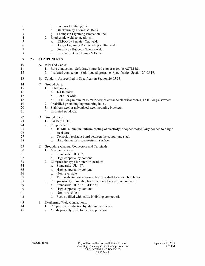
10203-10110220 City of Hopewell – Hopewell Water Renewal September 18, 2018
Centrifuge Building Ventilation Improvements 8:01 PM
GROUNDING AND BONDING 26 05 26 - 2
e. Robbins Lightning, Inc. 1
f. Blackburn by Thomas & Betts. 2
g. Thompson Lightning Protection, Inc. 3
2. Exothermic weld connections: 4
a. ERICO by Pentair - Cadweld. 5
b. Harger Lightning & Grounding - Ultraweld. 6
c. Burndy by Hubbell - Thermoweld. 7
d. FurseWELD by Thomas & Betts. 8
2.2 COMPONENTS 9
A. Wire and Cable: 10
1. Bare conductors: Soft drawn stranded copper meeting ASTM B8. 11
2. Insulated conductors: Color coded green, per Specification Section 26 05 19. 12
B. Conduit: As specified in Specification Section 26 05 33. 13
C. Ground Bars: 14
1. Solid copper: 15
a. 1/4 IN thick. 16
b. 2 or 4 IN wide. 17
c. 24 IN long minimum in main service entrance electrical rooms, 12 IN long elsewhere. 18
2. Predrilled grounding lug mounting holes. 19
3. Stainless steel or galvanized steel mounting brackets. 20
4. Insulated standoffs. 21
D. Ground Rods: 22
1. 3/4 IN x 10 FT. 23
2. Copper-clad: 24
a. 10 MIL minimum uniform coating of electrolytic copper molecularly bonded to a rigid 25
steel core. 26
b. Corrosion resistant bond between the copper and steel. 27
c. Hard drawn for a scar-resistant surface. 28
E. Grounding Clamps, Connectors and Terminals: 29
1. Mechanical type: 30
a. Standards: UL 467. 31
b. High copper alloy content. 32
2. Compression type for interior locations: 33
a. Standards: UL 467. 34
b. High copper alloy content. 35
c. Non-reversible. 36
d. Terminals for connection to bus bars shall have two bolt holes. 37
3. Compression type suitable for direct burial in earth or concrete: 38
a. Standards: UL 467, IEEE 837. 39
b. High copper alloy content. 40
c. Non-reversible. 41
d. Factory filled with oxide inhibiting compound. 42
F. Exothermic Weld Connections: 43
1. Copper oxide reduction by aluminum process. 44
2. Molds properly sized for each application. 45

10203-10110220 City of Hopewell – Hopewell Water Renewal September 18, 2018
Centrifuge Building Ventilation Improvements 8:01 PM
GROUNDING AND BONDING 26 05 26 - 3
PART 3 - EXECUTION 1
3.1 INSTALLATION 2
A. General: 3
1. Install products in accordance with manufacturer's instructions. 4
2. Size grounding conductors and bonding jumpers in accordance with NFPA 70, Article 250, 5
except where larger sizes are indicated on the Drawings. 6
3. Remove paint, rust, or other non-conducting material from contact surfaces before making 7
ground connections. After connection, apply manufacturers approved touch-up paint to 8
protect metallic surface from corrosion. 9
4. Where ground conductors pass through floor slabs or building walls provide nonmetallic 10
sleeves and install sleeve per Specification Section 01 73 20. 11
a. Seal the sleeve interior to stop water penetration. 12
5. Do not splice grounding electrode conductors except at ground rods. 13
6. Install ground rods and grounding electrode conductors in undisturbed, firm soil. 14
a. Provide excavation required for installation of ground rods and conductors. 15
b. Use driving studs or other suitable means to prevent damage to threaded ends of 16
sectional rods. 17
c. Unless otherwise specified, connect conductors to ground rods with compression type 18
connectors or exothermic weld. 19
d. Provide sufficient slack in conductor to prevent conductor breakage during backfill or 20
due to ground movement. 21
e. Backfill excavation completely, thoroughly tamping to provide good contact between 22
backfill materials and ground rods and conductors. 23
7. Do not use exothermic welding if it will damage the structure the grounding conductor is 24
being welded to. 25
B. Grounding Electrode System: 26
1. Exothermic weld to existing building structural steel columns 27
C. Supplemental Grounding Electrode: 28
1. Equipment support rack and pedestals mounted outdoors: 29
a. Connect metallic structure to existing building steel member. 30
b. Grounding conductor: #6 AWG minimum. 31
D. Transformer Separately Derived Grounding System: 32
1. Install the System Bonding Jumper at the transformer. At the first disconnect, ensure the 33
neutral is isolated from ground. 34
2. Structures with a single electrical room/area: 35
a. Connect grounding electrode conductor to the Grounding Electrode System main 36
ground bar. 37
3. Structures with multiple electrical rooms/areas: 38
a. Provide a ground bar mounted in each electrical room/area. 39
b. Interconnect all ground bars in a daisy chain or radial fashion to the main ground bar as 40
indicated on the Drawings. 41
c. Connect grounding electrode conductor to the electrical room/area ground bar. 42
4. See Grounding Electrode System paragraph for conductor termination requirements. 43
E. Raceway Bonding/Grounding: 44
1. Install all metallic raceway so that it is electrically continuous. 45
2. Provide an equipment grounding conductor in all raceways with insulation identical to the 46
phase conductors, unless otherwise indicated on the Drawings. 47
3. NFPA 70 required grounding bushings shall be of the insulating type. 48
4. Provide double locknuts at all panels. 49
5. Bond all conduits, at entrance and exit of equipment, to the equipment ground bus or lug. 50
6. Provide bonding jumpers if conduits are installed in concentric knockouts. 51

10203-10110220 City of Hopewell – Hopewell Water Renewal September 18, 2018
Centrifuge Building Ventilation Improvements 8:01 PM
GROUNDING AND BONDING 26 05 26 - 4
7. Make all metallic raceway fittings and grounding clamps tight to ensure equipment 1
grounding system will operate continuously at ground potential to provide low impedance 2
current path for proper operation of overcurrent devices during possible ground fault 3
conditions. 4
F. Equipment Grounding: 5
1. Ground all utilization equipment with an equipment grounding conductor. 6
3.2 FIELD QUALITY CONTROL 7
A. Leave grounding system uncovered until observed by Owner. 8
B. Acceptance testing: 9
1. See Specification Section 26 08 13. 10
END OF SECTION 11

10203-10110220 City of Hopewell – Hopewell Water Renewal September 18, 2018
Centrifuge Building Ventilation Improvements 8:05 PM
RACEWAYS AND BOXES 26 05 33 - 1
SECTION 26 05 33 1
RACEWAYS AND BOXES 2
PART 1 - GENERAL 3
1.1 SUMMARY 4
A. Section Includes: 5
1. Material and installation requirements for: 6
a. Conduits. 7
b. Conduit fittings. 8
c. Conduit supports. 9
d. Wireways. 10
e. Outlet boxes. 11
f. Pull and junction boxes. 12
B. Related Specification Sections include but are not necessarily limited to: 13
1. Division 01 - General Requirements. 14
2. Section 26 05 00 - Electrical: Basic Requirements. 15
1.2 QUALITY ASSURANCE 16
A. Referenced Standards: 17
1. Aluminum Association (AA). 18
2. American Iron and Steel Institute (AISI). 19
3. ASTM International (ASTM): 20
a. A123/A123M, Standard Specification for Zinc (Hot-Dip Galvanized) Coatings on Iron 21
and Steel Products. 22
b. A153/A153M, Standard Specification for Zinc Coating (Hot-Dip) on Iron and Steel 23
Hardware. 24
c. D2564, Standard Specification for Solvent Cements for Poly (Vinyl Chloride) (PVC) 25
Plastic Piping Systems. 26
4. National Electrical Manufacturers Association (NEMA): 27
a. 250, Enclosures for Electrical Equipment (1000 Volts Maximum). 28
b. RN 1, Polyvinyl Chloride (PVC) Externally Coated Galvanized Rigid Steel Conduit 29
and Intermediate Metal Conduit (IMC). 30
5. National Electrical Manufacturers Association/American National Standards Institute 31
(NEMA/ANSI): 32
a. C80.1, Electric Rigid Steel Conduit (ERSC). 33
b. C80.5, Electrical Aluminum Rigid Conduit. 34
c. OS 1, Sheet-Steel Outlet Boxes, Device Boxes, Covers, and Box Supports. 35
6. National Fire Protection Association (NFPA): 36
a. 70, National Electrical Code (NEC). 37
7. Underwriters Laboratories, Inc. (UL): 38
a. 1, Standard for Flexible Metal Conduit. 39
b. 6, Standard for Electrical Rigid Metal Conduit - Steel. 40
c. 50, Enclosures for Electrical Equipment, Non-Environmental Considerations. 41
d. 360, Standard for Liquid-Tight Flexible Steel Conduit. 42
e. 467, Grounding and Bonding Equipment. 43
f. 514A, Metallic Outlet Boxes. 44
g. 514B, Conduit, Tubing, and Cable Fittings. 45
h. 870, Standard for Wireways, Auxiliary Gutters, and Associated Fittings. 46
i. 886, Standard for Outlet Boxes and Fittings for Use in Hazardous (Classified) 47
Locations. 48

10203-10110220 City of Hopewell – Hopewell Water Renewal September 18, 2018
Centrifuge Building Ventilation Improvements 8:05 PM
RACEWAYS AND BOXES 26 05 33 - 2
1.3 SUBMITTALS 1
A. Shop Drawings: 2
1. See Specification Section 01 33 00 for requirements for the mechanics and administration of 3
the submittal process. 4
2. Product technical data: 5
a. Provide submittal data for all products specified in PART 2 of this Specification 6
Section. 7
b. See Specification Section 26 05 00 for additional requirements. 8
3. Fabrication and/or layout drawings: 9
a. Identify dimensional size of pull and junction boxes to be used. 10
1.4 DELIVERY, STORAGE, AND HANDLING 11
A. See Specification Section 26 05 00. 12
PART 2 - PRODUCTS 13
2.1 ACCEPTABLE MANUFACTURERS 14
A. Subject to compliance with the Contract Documents, the following manufacturers are 15
acceptable: 16
1. Rigid metallic conduits: 17
a. Allied Tube and Conduit Corporation. 18
b. Triangle PWC Inc. 19
c. Western Tube and Conduit Corporation. 20
d. Wheatland Tube Company. 21
e. LTV Steel Company. 22
f. EASCO Aluminum. 23
g. Indalex. 24
h. VAW of American, Inc. 25
2. PVC coated rigid metallic conduits: 26
a. Thomas & Betts Ocal. 27
b. Rob-Roy Ind. 28
3. Flexible conduit: 29
a. AFC Cable Systems. 30
b. Anamet, Inc. 31
c. Electri-Flex. 32
d. Flexible Metal Hose Company. 33
e. International Metal Hose Company. 34
f. Triangle PWC Inc. 35
g. LTV Steel Company. 36
4. Wireway: 37
a. Hoffman Engineering Company. 38
b. Wiegmann. 39
c. Square D. 40
5. Conduit fittings and accessories: 41
a. Appleton Electric Co. 42
b. Carlon. 43
c. Cantex. 44
d. Crouse-Hinds. 45
e. Killark. 46
f. Osburn Associates. 47
g. OZ Gedney Company. 48
h. RACO. 49
i. Steel City. 50
j. Thomas & Betts. 51

10203-10110220 City of Hopewell – Hopewell Water Renewal September 18, 2018
Centrifuge Building Ventilation Improvements 8:05 PM
RACEWAYS AND BOXES 26 05 33 - 3
6. Support systems: 1
a. Unistrut Building Systems. 2
b. Eaton B-Line. 3
c. Kindorf. 4
d. Minerallac Fastening Systems. 5
e. Caddy. 6
f. Thomas & Betts Superstrut. 7
7. Outlet, pull and junction boxes: 8
a. Appleton Electric Co. 9
b. Eaton Crouse-Hinds. 10
c. Killark. 11
d. O-Z/Gedney. 12
e. Thomas & Betts Steel City. 13
f. Raco. 14
g. Bell. 15
h. Hoffman Engineering Co. 16
i. Wiegmann. 17
j. Eaton B-Line. 18
k. Adalet. 19
l. Rittal. 20
m. Stahlin. 21
2.2 RIGID METALLIC CONDUITS 22
A. Rigid Aluminum Conduit (RAC): 23
1. AA Type 6063 aluminum alloy, T-1 temper. 24
2. Maximum copper content of 0.10 percent. 25
3. Extruded, seamless. 26
4. Standards: NEMA/ANSI C80.5, UL 6. 27
B. PVC-Coated Rigid Steel Conduit (PVC-RGS): 28
1. Nominal 40 mil Polyvinyl Chloride Exterior Coating: 29
a. Coating: Bonded to hot-dipped galvanized rigid steel conduit conforming to 30
NEMA/ANSI C80.1. 31
b. The bond between the PVC coating and the conduit surface: Greater than the tensile 32
strength of the coating. 33
2. Nominal 2 mil, minimum, urethane interior coating. 34
3. Urethane coating on threads. 35
4. Conduit: Epoxy prime coated prior to application of PVC and urethane coatings. 36
5. Female Ends: 37
a. Have a plastic sleeve extending a minimum of 1 pipe diameter or 2 IN, whichever is 38
less beyond the opening. 39
b. The inside diameter of the sleeve shall be the same as the outside diameter of the 40
conduit to be used with it. 41
6. Standards: NEMA/ANSI C80.1, UL 6, NEMA RN 1. 42
2.3 FLEXIBLE CONDUIT 43
A. PVC-Coated Flexible Galvanized Steel (liquid-tight) Conduit (FLEX-LT): 44
1. Core formed of continuous, spiral wound, hot-dip galvanized steel strip with successive 45
convolutions securely interlocked. 46
2. Extruded PVC outer jacket positively locked to the steel core. 47
3. Liquid and vaportight. 48
4. Standard: UL 360. 49

10203-10110220 City of Hopewell – Hopewell Water Renewal September 18, 2018
Centrifuge Building Ventilation Improvements 8:05 PM
RACEWAYS AND BOXES 26 05 33 - 4
2.4 WIREWAY 1
A. General: 2
1. Suitable for lay-in conductors. 3
2. Designed for continuous grounding. 4
3. Covers: 5
a. Hinged or removable in accessible areas. 6
b. Non-removable when passing through partitions. 7
4. Finish: Rust inhibiting primer and manufacturer’s standard paint inside and out except for 8
stainless steel type. 9
5. Standards: UL 870, NEMA 250. 10
B. Watertight (NEMA 4X rated) Wireway: 11
1. 14 GA Type 304 or 316 stainless steel bodies and covers without knockouts and 10 GA 12
stainless steel flanges. 13
2. Cover: Fully gasketed and held in place with captive clamp type latches. 14
3. Flanges: Fully gasketed and bolted. 15
C. Dust-tight (NEMA 12 rated) Wireway: 16
1. 14 GA steel bodies and covers without knockouts and 10 GA steel flanges. 17
2. Cover: Fully gasketed and held in place with captive clamp type latches. 18
3. Flanges: Fully gasketed and bolted. 19
2.5 CONDUIT FITTINGS AND ACCESSORIES 20
A. Fittings for Use with RGS and RAC: 21
1. General: 22
a. In hazardous locations listed for use in Class I, Groups C and D locations. 23
2. Locknuts: 24
a. Threaded steel or malleable iron. 25
b. Gasketed or non-gasketed. 26
c. Grounding or non-grounding type. 27
3. Bushings: 28
a. Threaded, insulated metallic. 29
b. Grounding or non-grounding type. 30
4. Hubs: Threaded, insulated and gasketed metallic for raintight connection. 31
5. Couplings: 32
a. Threaded straight type: Same material and finish as the conduit with which they are 33
used on. 34
b. Threadless type: Not permitted except where approved by the Engineer. 35
6. Unions: Threaded galvanized steel or copper free aluminum. 36
7. Conduit bodies (ells and tees): 37
a. Body: cast iron or cast copper free aluminum with threaded hubs. 38
b. Standard and mogul size. 39
c. Cover: 40
1) Clip-on type with stainless steel screws. 41
2) Gasketed or non-gasketed cast copper free aluminum. 42
8. Conduit bodies (round): 43
a. Body: Zinc plated cast iron or cast copper free aluminum with threaded hubs. 44
b. Cover: Threaded screw on type, gasketed, zinc plated cast iron or cast copper free 45
aluminum. 46
9. Sealing fittings: 47
a. Body: Zinc plated cast iron or cast copper free aluminum with threaded hubs. 48
b. Standard and mogul size. 49
c. With or without drain and breather. 50
d. Fiber and sealing compound: UL listed for use with the sealing fitting. 51
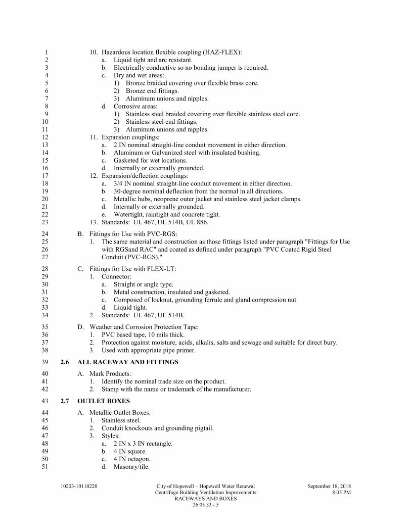
10203-10110220 City of Hopewell – Hopewell Water Renewal September 18, 2018
Centrifuge Building Ventilation Improvements 8:05 PM
RACEWAYS AND BOXES 26 05 33 - 5
10. Hazardous location flexible coupling (HAZ-FLEX): 1
a. Liquid tight and arc resistant. 2
b. Electrically conductive so no bonding jumper is required. 3
c. Dry and wet areas: 4
1) Bronze braided covering over flexible brass core. 5
2) Bronze end fittings. 6
3) Aluminum unions and nipples. 7
d. Corrosive areas: 8
1) Stainless steel braided covering over flexible stainless steel core. 9
2) Stainless steel end fittings. 10
3) Aluminum unions and nipples. 11
11. Expansion couplings: 12
a. 2 IN nominal straight-line conduit movement in either direction. 13
b. Aluminum or Galvanized steel with insulated bushing. 14
c. Gasketed for wet locations. 15
d. Internally or externally grounded. 16
12. Expansion/deflection couplings: 17
a. 3/4 IN nominal straight-line conduit movement in either direction. 18
b. 30-degree nominal deflection from the normal in all directions. 19
c. Metallic hubs, neoprene outer jacket and stainless steel jacket clamps. 20
d. Internally or externally grounded. 21
e. Watertight, raintight and concrete tight. 22
13. Standards: UL 467, UL 514B, UL 886. 23
B. Fittings for Use with PVC-RGS: 24
1. The same material and construction as those fittings listed under paragraph "Fittings for Use 25
with RGSand RAC" and coated as defined under paragraph "PVC Coated Rigid Steel 26
Conduit (PVC-RGS)." 27
C. Fittings for Use with FLEX-LT: 28
1. Connector: 29
a. Straight or angle type. 30
b. Metal construction, insulated and gasketed. 31
c. Composed of locknut, grounding ferrule and gland compression nut. 32
d. Liquid tight. 33
2. Standards: UL 467, UL 514B. 34
D. Weather and Corrosion Protection Tape: 35
1. PVC based tape, 10 mils thick. 36
2. Protection against moisture, acids, alkalis, salts and sewage and suitable for direct bury. 37
3. Used with appropriate pipe primer. 38
2.6 ALL RACEWAY AND FITTINGS 39
A. Mark Products: 40
1. Identify the nominal trade size on the product. 41
2. Stamp with the name or trademark of the manufacturer. 42
2.7 OUTLET BOXES 43
A. Metallic Outlet Boxes: 44
1. Stainless steel. 45
2. Conduit knockouts and grounding pigtail. 46
3. Styles: 47
a. 2 IN x 3 IN rectangle. 48
b. 4 IN square. 49
c. 4 IN octagon. 50
d. Masonry/tile. 51

10203-10110220 City of Hopewell – Hopewell Water Renewal September 18, 2018
Centrifuge Building Ventilation Improvements 8:05 PM
RACEWAYS AND BOXES 26 05 33 - 6
4. Accessories: 1
a. Flat blank cover plates. 2
b. Barriers. 3
c. Extension, plaster or tile rings. 4
d. Box supporting brackets in stud walls. 5
e. Adjustable bar hangers. 6
5. Standards: NEMA/ANSI OS 1, UL 514A. 7
B. Cast Outlet Boxes: 8
1. Die-cast copper free aluminum with manufacturer’s standard finish. 9
2. Threaded hubs and grounding screw. 10
3. Styles: 11
a. "FS" or "FD." 12
b. "Bell." 13
c. Single or multiple gang and tandem. 14
d. "EDS" or "EFS" for hazardous locations. 15
4. Accessories: 40 mil PVC exterior coating and 2 mil urethane interior coating. 16
5. Standards: UL 514A, UL 886. 17
C. See Specification Section 26 27 26 for wiring devices, wallplates and coverplates. 18
2.8 PULL AND JUNCTION BOXES 19
A. NEMA 4X Rated (metallic): 20
1. Body and cover: 14 GA Type 304 or 316 stainless steel. 21
2. Seams continuously welded and ground smooth. 22
3. No knockouts. 23
4. External mounting flanges. 24
5. Hinged door and stainless steel screws and clamps. 25
6. Door with oil-resistant gasket. 26
B. NEMA 12 Rated: 27
1. Body and cover: 28
a. Type 5052 H-32 aluminum, unpainted. 29
2. Seams continuously welded and ground smooth. 30
3. No knockouts. 31
4. External mounting flanges. 32
5. Non-hinged cover held closed with captivated cover screws threaded into sealed wells or 33
hinged cover held closed with stainless steel screws and clamps. 34
6. Flat door with oil resistant gasket. 35
C. Miscellaneous Accessories: 36
1. Rigid handles for covers larger than 9 SF or heavier than 25 LBS. 37
2. Split covers when heavier than 25 LBS. 38
3. Weldnuts for mounting optional panels and terminal kits. 39
4. Terminal blocks: Screw-post barrier-type, rated 600 volt and 20 ampere minimum. 40
D. Standards: NEMA 250, UL 50. 41
2.9 SUPPORT SYSTEMS 42
A. Multi-conduit Surface or Trapeze Type Support and Pull or Junction Box Supports: 43
1. Material requirements. 44
a. Stainless steel: AISI Type 316. 45
b. PVC coat galvanized steel: ASTM A123/A123M or ASTM A153/A153M and 20 mil 46
PVC coating. 47

10203-10110220 City of Hopewell – Hopewell Water Renewal September 18, 2018
Centrifuge Building Ventilation Improvements 8:05 PM
RACEWAYS AND BOXES 26 05 33 - 7
B. Single Conduit and Outlet Box Support Fasteners: 1
1. Material requirements: 2
a. Stainless steel. 3
b. PVC coat malleable iron or steel: 20 mil PVC coating. 4
2.10 OPENINGS AND PENETRATIONS IN WALLS AND FLOORS 5
A. Sleeves, through walls and floors: 6
1. Provide weather tight seal on all wall penetrations. 7
PART 3 - EXECUTION 8
3.1 RACEWAY INSTALLATION - GENERAL 9
A. Shall be in accordance with the requirements of: 10
1. NFPA 70. 11
2. Manufacturer instructions. 12
B. Size of Raceways: 13
1. Raceway sizes are shown on the Drawings, if not shown on the Drawings, then size in 14
accordance with NFPA 70. 15
2. Unless specifically indicated otherwise, the minimum raceway size shall be: 16
a. Conduit: 3/4 IN. 17
b. Wireway: 2-1/2 IN x 2-1/2 IN. 18
C. Field Bending and Cutting of Conduits: 19
1. Utilize tools and equipment recommended by the manufacturer of the conduit, designed for 20
the purpose and the conduit material to make all field bends and cuts. 21
2. Do not reduce the internal diameter of the conduit when making conduit bends. 22
3. Prepare tools and equipment to prevent damage to the PVC coating. 23
4. Degrease threads after threading and apply a zinc rich paint. 24
5. Debur interior and exterior after cutting. 25
D. Male threads of conduit systems shall be coated with an electrically conductive anti-seize 26
compound. 27
E. The protective coating integrity of conduits, fittings, outlet, pull and junction boxes and 28
accessories shall be maintained. 29
1. Repair galvanized components utilizing a zinc rich paint. 30
2. Repair painted components utilizing touch up paint provided by or approved by the 31
manufacturer. 32
3. Repair PVC coated components utilizing a patching compound, of the same material as the 33
coating, provided by the manufacturer of the conduit; or a self-adhesive, highly 34
conformable, cross-linked silicone composition strip, followed by a protective coating of 35
vinyl tape. 36
a. Total nominal thickness: 40 mil. 37
4. Repair surfaces which will be inaccessible after installation prior to installation. 38
F. Remove moisture and debris from conduit before wire is pulled into place. 39
1. Pull mandrel with diameter nominally 1/4 IN smaller than the interior of the conduit, to 40
remove obstructions. 41
2. Swab conduit by pulling a clean, tight-fitting rag through the conduit. 42
3. Tightly plug ends of conduit with tapered wood plugs or plastic inserts until wire is pulled. 43
G. Only nylon or polyethylene rope shall be used to pull wire and cable in conduit systems. 44
H. Where portions of a raceway are subject to different temperatures and where condensation is 45
known to be a problem, as in cold storage areas of buildings or where passing from the interior 46
to the exterior of a building, the raceway shall be sealed to prevent circulation of warm air to 47
colder section of the raceway. 48

10203-10110220 City of Hopewell – Hopewell Water Renewal September 18, 2018
Centrifuge Building Ventilation Improvements 8:05 PM
RACEWAYS AND BOXES 26 05 33 - 8
I. Conduit entering electrical equipment outdoors or in wet environments shall enter from the 1
bottom of the equipment. 2
3.2 RACEWAY ROUTING 3
A. Raceways shall be routed in the field unless otherwise indicated. 4
1. Conduit and fittings shall be installed, as required, for a complete system that has a neat 5
appearance and is in compliance with all applicable codes. 6
2. Run in straight lines parallel to or at right angles to building lines. 7
3. Do not route conduits: 8
a. Through areas of high ambient temperature or radiant heat. 9
b. In suspended concrete slabs. 10
c. Across the surface of floors, walkways, tanks or other walking surfaces 11
4. Conduit shall not interfere with, or prevent access to, piping, valves, ductwork, or other 12
equipment for operation, maintenance and repair. 13
5. Provide pull boxes or conduit bodies as needed so that there is a maximum of 360 degrees 14
of bends in the conduit run or in long straight runs to limit pulling tensions. 15
B. All rigid conduits within a structure shall be installed exposed except as follows: 16
1. As indicated on the Drawings. 17
C. Maintain minimum spacing between parallel conduit and piping runs in accordance with the 18
following when the runs are greater than 30 FT: 19
1. Between instrumentation and telecommunication: 1 IN. 20
2. Between instrumentation and 125 V, 48 V and 24 Vdc, 2 IN. 21
3. Between instrumentation and 600 V and less AC power or control: 6 IN. 22
4. Between instrumentation and greater than 600 Vac power: 12 IN. 23
5. Between telecommunication and 125 V, 48 V and 24 Vdc, 2 IN. 24
6. Between telecommunication and 600 V and less AC power or control: 6 IN. 25
7. Between telecommunication and greater than 600 Vac power: 12 IN. 26
8. Between 125 V, 48 V and 24 Vdc and 600 V and less AC power or control: 2 IN. 27
9. Between 125 V, 48 V and 24 Vdc and greater than 600 Vac power: 2 IN. 28
10. Between 600 V and less AC and greater than 600 Vac: 2 IN. 29
11. Between process, gas, air and water pipes: 6 IN. 30
D. Conduits shall be installed to eliminate moisture pockets. 31
1. Where water cannot drain to openings, provide drain fittings in the low spots of the conduit 32
run. 33
E. Conduit shall not be routed on the exterior of structures except as specifically indicated on the 34
Drawings. 35
F. Where sufficient room exists within the housing of roof-mounted equipment, the conduit shall 36
be stubbed up inside the housing. 37
G. Provide all required openings in walls, floors, and ceilings for conduit penetration. 38
1. Existing construction: 39
a. Core drill openings in masonry and concrete. 40
b. Avoid structural members and rebar. 41
3.3 RACEWAY APPLICATIONS 42
A. Permitted Raceway Types Per Wire or Cable Types: 43
1. Power wire or cables: All raceway types. 44
2. Control wire or cables: All raceway types. 45
3. Instrumentation cables: Metallic raceway 46
B. Permitted Raceway Types Per Area Designations: 47
1. Dry areas: 48
a. RAC. 49

10203-10110220 City of Hopewell – Hopewell Water Renewal September 18, 2018
Centrifuge Building Ventilation Improvements 8:05 PM
RACEWAYS AND BOXES 26 05 33 - 9
2. Wet areas: 1
a. RAC except in contact with concrete, below grade or with other dissimilar metals. 2
b. PVC-RGS. 3
3. Corrosive areas: 4
a. PVC-RGS. 5
C. Permitted Raceway Types Per Routing Locations: 6
1. Through floor penetrations, see Specification Section 01 73 20: 7
a. PVC-RGS in areas designated as wet, corrosive or highly corrosive. 8
D. FLEX-LT conduits shall be install as the final conduit connection to light fixtures, dry type 9
transformers, motors, electrically operated valves, instrumentation primary elements, and other 10
electrical equipment that is liable to vibrate. 11
1. The maximum length shall not exceed: 12
a. 6 FT to light fixtures. 13
b. 3 FT to motors. 14
c. 2 FT to all other equipment. 15
E. NEMA 4X Rated Wireway: 16
1. Surface mounted in areas designated as wet and or corrosive. 17
F. NEMA 12 Rated Wireway: 18
1. Surface mounted in areas designated as dry in architecturally and non-architecturally 19
finished areas. 20
3.4 CONDUIT FITTINGS AND ACCESSORIES 21
A. Install Expansion Fittings: 22
1. Where conduits are exposed to the sun and conduit run is greater than 200 FT. 23
2. Elsewhere as identified on the Drawings. 24
B. Install Expansion/Deflection Fittings: 25
1. Where conduits enter a structure. 26
a. Except electrical manholes and handholes. 27
b. Except where the ductbank is tied to the structure with rebar. 28
2. Where conduits span structural expansions joints. 29
3. Elsewhere as identified on the Drawings. 30
C. Threaded connections shall be made wrench-tight. 31
D. Conduit joints shall be watertight: 32
1. Where subjected to possible submersion. 33
2. In areas classified as wet. 34
E. Terminate Conduits: 35
1. In metallic outlet boxes: 36
a. RAC: 37
1) Conduit hub and locknut. 38
2) Insulated bushing and two locknuts. 39
3) Use grounding type locknut or bushing when required by NFPA 70. 40
2. In NEMA 12 rated enclosures: 41
a. Watertight, insulated and gasketed hub and locknut. 42
b. Use grounding type locknut or bushing when required by NFPA 70. 43
3. In NEMA 4X rated enclosures: 44
a. Watertight, insulated and gasketed hub and locknut. 45
4. When stubbed up through the floor into floor mount equipment: 46
a. With an insulated grounding bushing on metallic conduits. 47
b. With end bells on nonmetallic conduits. 48

10203-10110220 City of Hopewell – Hopewell Water Renewal September 18, 2018
Centrifuge Building Ventilation Improvements 8:05 PM
RACEWAYS AND BOXES 26 05 33 - 10
F. Threadless couplings shall only be used to join new conduit to existing conduit when the 1
existing conduit end is not threaded and it is not practical or possible to cut threads on the 2
existing conduit with a pipe threader. Engineer approval required. 3
3.5 CONDUIT SUPPORT 4
A. Permitted multi-conduit surface or trapeze type support system per area designations and conduit 5
types: 6
1. Dry areas: 7
a. Aluminum system consisting of: Aluminum channels, fittings and conduit clamps with 8
stainless steel nuts and hardware. 9
2. Wet and or Corrosive areas: 10
a. PVC coated steel or stainless steel system consisting of: PVC coated galvanized steel 11
or stainless steel channels and fittings and conduit clamps with stainless steel nuts and 12
hardware. 13
3. Conduit type shall be compatible with the support system material. 14
a. Aluminum system may be used with RAC. 15
b. Stainless steel system may be used with RAC and PVC-RGS. 16
c. PVC coated galvanized steel system may be used with PVC-RGS. 17
B. Permitted single conduit support fasteners per area designations and conduit types: 18
1. Architecturally finished areas: 19
a. Material: Aluminum, or steel protected with zinc phosphate and oil finish. 20
b. Types of fasteners: Spring type hangers and clips, straps, hangers with bolts, clamps 21
with bolts and bolt on beam clamps. 22
c. Provide anti-rattle conduit supports when conduits are routed through metal studs. 23
2. Dry areas: 24
a. Material: Aluminum, and stainless steel. 25
b. Types of fasteners: Straps, hangers with bolts, clamps with bolts and bolt on beam 26
clamps. 27
3. Wet or Corrosive areas: 28
a. Material: Stainless steel and PVC coat steel. 29
b. Types of fasteners: Straps, hangers with bolts, clamps with bolts and bolt on beam 30
clamps. 31
4. Conduit type shall be compatible with the support fastener material. 32
a. Aluminum fasteners may be used with RAC. 33
b. Stainless steel system may be used with RAC and PVC-RGS. 34
c. PVC coated fasteners may be used with PVC-RGS. 35
C. Conduit Support General Requirements: 36
1. Maximum spacing between conduit supports per NFPA 70. 37
2. Support conduit from the building structure. 38
3. Do not support conduit from process, gas, air or water piping; or from other conduits. 39
4. Provide hangers and brackets to limit the maximum uniform load on a single support to 40
25 LBS or to the maximum uniform load recommended by the manufacturer if the support 41
is rated less than 25 LBS. 42
a. Do not exceed maximum concentrated load recommended by the manufacturer on any 43
support. 44
b. Conduit hangers: 45
1) Continuous threaded rods combined with struts or conduit clamps: Do not use 46
perforated strap hangers and iron bailing wire. 47
c. Do not use suspended ceiling support systems to support raceways. 48
d. Hangers in metal roof decks: 49
1) Utilize fender washers. 50
2) Not extend above top of ribs. 51
3) Not interfere with vapor barrier, insulation, or roofing. 52

10203-10110220 City of Hopewell – Hopewell Water Renewal September 18, 2018
Centrifuge Building Ventilation Improvements 8:05 PM
RACEWAYS AND BOXES 26 05 33 - 11
5. Conduit support system fasteners: 1
a. Use sleeve-type expansion anchors as fasteners in masonry wall construction. 2
b. Do not use concrete nails and powder-driven fasteners. 3
3.6 OUTLET, PULL AND JUNCTION BOX INSTALLATION 4
A. General: 5
1. Install products in accordance with manufacturer's instructions. 6
2. See Specification Section 26 05 00 and the Drawings for area classifications. 7
3. Fill unused punched-out, tapped, or threaded hub openings with insert plugs. 8
4. Size boxes to accommodate quantity of conductors enclosed and quantity of conduits 9
connected to the box. 10
B. Outlet Boxes: 11
1. Permitted uses of metallic outlet boxes: 12
a. Housing of wiring devices: 13
b. Pull or junction box: 14
1) Above gypsum wall board or acoustical tile ceilings. 15
2) Above 10 FT in an architecturally finished area where there is no ceiling. 16
2. Permitted uses of cast outlet boxes: 17
a. Housing of wiring devices surface mounted in non-architecturally finished dry, wet, 18
corrosive, and hazardous areas. 19
b. Pull and junction box surface mounted in non-architecturally finished dry, wet, 20
corrosive areas. 21
3. Mount device outlet boxes where indicated on the Drawings and at heights as scheduled in 22
Specification Section 26 05 00. 23
4. Set device outlet boxes plumb and vertical to the floor. 24
5. Outlet boxes recessed in walls: 25
a. Install with appropriate stud wall support brackets or adjustable bar hangers so that they 26
are flush with the face of the wall. 27
b. Locate in ungrouted cell of concrete block with bottom edge of box flush with bottom 28
edge of block and flush with the face of the block. 29
6. Place barriers between switches in boxes with 277 V switches on opposite phases. 30
7. Back-to-back are not permitted. 31
8. When an outlet box is connected to a PVC coated conduit, the box shall also be PVC coated. 32
C. Pull and Junction Boxes: 33
1. Install pull or junction boxes in conduit runs where indicated or required to facilitate pulling 34
of wires or making connections. 35
a. Make covers of boxes accessible. 36
2. Permitted uses of NEMA 4X metallic enclosure: 37
a. Pull or junction box surface mounted in areas designated as wet and/or corrosive. 38
3. Permitted uses of NEMA 12 enclosure: 39
a. Pull or junction box surface mounted in areas designated as dry. 40
END OF SECTION 41

10203-10110220 City of Hopewell – Hopewell Water Renewal September 18, 2018
Centrifuge Building Ventilation Improvements 8:05 PM
RACEWAYS AND BOXES 26 05 33 - 12
THIS PAGE INTENTIONALLY LEFT BLANK 1

10203-10110220 City of Hopewell – Hopewell Water Renewal September 18, 2018
Centrifuge Building Ventilation Improvements 8:10 PM
ACCEPTANCE TESTING 26 08 13 - 1
SECTION 26 08 13 1
ACCEPTANCE TESTING 2
PART 1 - GENERAL 3
1.1 SUMMARY 4
A. Section Includes: 5
1. Basic requirements for acceptance testing. 6
B. Related Specification Sections include but are not necessarily limited to: 7
1. Division 00 - Bidding Requirements, Contract Forms, and Conditions of the Contract. 8
2. Division 01 - General Requirements. 9
3. Section 01 61 03 - Equipment: Basic Requirements. 10
1.2 QUALITY ASSURANCE 11
A. Referenced Standards: 12
1. Institute of Electrical and Electronics Engineers, Inc. (IEEE): 13
a. 400, Guide for Field Testing and Evaluation of the Insulation of Shielded Power Cable 14
Systems. 15
b. 400.3, Guide for Partial Discharge Testing of Power Cable Systems in a Field 16
Environment. 17
2. InterNational Electrical Testing Association (NETA): 18
a. ATS, Standard for Acceptance Testing Specifications for Electric Power Equipment 19
and Systems. 20
3. Nationally Recognized Testing Laboratory (NRTL). 21
4. Telecommunications Industry Association/Electronic Industries Alliance/American National 22
Standards Institute (TIA/EIA/ANSI): 23
a. 455-78-B, Optical Fibres - PART 1-40: Measurement Methods and Test Procedures - 24
Attenuation. 25
B. Qualifications: 26
1. Testing firm qualifications: See Specification Section 01 61 03. 27
2. Field personnel: 28
a. See Specification Section 01 61 03. 29
b. As an alternative, supervising technician may be certified by the equipment 30
manufacturer. 31
3. Analysis personnel: 32
a. See Specification Section 01 61 03 33
As an alternative, supervising technician may be certified by the equipment 34
manufacturer. 35
1.3 SUBMITTALS 36
A. Shop Drawings: 37
1. See Specification Section 01 33 00 for requirements for the mechanics and administration of 38
the submittal process. 39
2. See Specification Section 01 61 03 for electrical equipment and connection testing plan 40
submittal requirements. 41
B. Informational Submittals: 42
1. See Specification Section 01 33 00 for requirements for the mechanics and administration of 43
the submittal process. 44
2. Prior to energizing equipment: 45
a. Coordinated phasing diagram. 46
b. Photocopies of continuity tests. 47

10203-10110220 City of Hopewell – Hopewell Water Renewal September 18, 2018
Centrifuge Building Ventilation Improvements 8:10 PM
ACCEPTANCE TESTING 26 08 13 - 2
3. Within two (2) weeks after successful completion of Demonstration Period (Commissioning 1
Period): 2
a. Single report containing information including: 3
1) Summary of Project. 4
2) Information from pre-energization testing. 5
3) See testing and monitoring reporting requirements in Specification Section 01 61 6
03. 7
PART 2 - PRODUCTS 8
2.1 FACTORY QUALITY CONTROL 9
A. Provide Electrical equipment with all factory tests required by the applicable industry standards 10
or NRTL. 11
B. Factory testing will not be accepted in lieu of field acceptance testing requirements specified in 12
this Specification Section and Specification Section 01 61 03. 13
PART 3 - EXECUTION 14
3.1 FIELD QUALITY CONTROL 15
A. General: 16
1. See Specification Section 01 61 03. 17
2. Complete electrical testing in three (3) phases: 18
a. Pre-energization testing phase. 19
b. Equipment energized with no load. 20
c. Equipment energized under load. 21
3. Perform testing in accordance with this Specification Section and NETA ATS. 22
4. Provide field setting and programming of all adjustable protective devices and meters to 23
settings provided by the Engineer. 24
B. Equipment Monitoring and Testing Plan: See Specification Section 01 61 03. 25
C. Instruments Used in Equipment and Connections Quality Control Testing: See Specification 26
Section 01 61 03. 27
D. Testing and Monitoring Program Documentation: See Specification Section 01 61 03. 28
E. Electrical Equipment and Connections Testing Program: 29
1. See Specification Section 01 61 03. 30
2. See individual Division 26 Specification Sections for equipment specific testing 31
requirements. 32
3. Test all electrical equipment. 33
a. Perform all required NETA testing. 34
b. Perform all required NETA testing plus the optional testing identified with each 35
specific type of equipment in Article 3.2 of this Specification Section. 36
3.2 SPECIFIC EQUIPMENT TESTING REQUIREMENTS 37
A. Cable - Low Voltage: 38
1. Perform inspections and tests per NETA ATS 7.3.2. 39
B. Low Voltage Molded Case Circuit Breakers: 40
1. Perform inspections and tests per NETA ATS 7.6.1.1. 41
2. Components: 42
a. Test all components per applicable paragraphs of this Specification Section and NETA 43
ATS. 44
b. Thermal magnetic breakers: Visual and mechanical inspection per NETA ATS only. 45

10203-10110220 City of Hopewell – Hopewell Water Renewal September 18, 2018
Centrifuge Building Ventilation Improvements 8:10 PM
ACCEPTANCE TESTING 26 08 13 - 3
c. Solid state trip type: Visual and mechanical inspection and electrical tests per NETA 1
ATS. 2
3. Record as-left settings. 3
C. Instrument Transformers: 4
1. Perform inspections and tests per NETA ATS 7.10. 5
2. Components: Test all components per applicable paragraphs of this Specification Section 6
and NETA ATS. 7
3. Perform the following optional tests per NETA ATS: 8
a. Dielectric withstand test on potential transformers. 9
D. Metering: 10
1. Perform inspections and tests per NETA ATS 7.11. 11
2. Components: Test all components per applicable paragraphs of this Specification Section 12
and NETA ATS. 13
E. Motors: 14
1. Perform inspections and tests per NETA ATS 7.15. 15
2. See Specification Section 01 61 03. 16
F. Motor Controllers: 17
1. Perform inspections and tests per NETA ATS 7.16. 18
2. Components: Test all components per applicable paragraphs of this Specification Section 19
and NETA ATS. 20
G. Control System Functional Test: 21
1. Perform test upon completion of equipment acceptance tests. 22
2. The test is to prove the correct interaction of all sensing, processing and action devices. 23
3. Develop a test plan and parameters for the purpose of evaluating the performance of the 24
system. 25
4. Perform the following tests: 26
a. Verify the correct operation of all interlock safety devices for fail-safe functions in 27
addition to design function. 28
b. Verify the correct operation of all sensing devices, alarms and indicating devices. 29
END OF SECTION 30

10203-10110220 City of Hopewell – Hopewell Water Renewal September 18, 2018
Centrifuge Building Ventilation Improvements 8:10 PM
ACCEPTANCE TESTING 26 08 13 - 4
THIS PAGE INTENTIONALLY LEFT BLANK 1

10203-10110220 City of Hopewell – Hopewell Water Renewal September 18, 2018
Centrifuge Building Ventilation Improvements 8:12 PM
CONTROL EQUIPMENT ACCESSORIES 26 09 16 - 1
SECTION 26 09 16 1
CONTROL EQUIPMENT ACCESSORIES 2
PART 1 - GENERAL 3
1.1 SUMMARY 4
A. Section Includes: 5
1. Operator control devices (selector switches, pushbuttons, indicator lights, etc.). 6
2. Control devices (timers, relays, contactors, etc.). 7
3. Industrial Control Panels. 8
4. Operator Control Stations. 9
B. Related Sections include but are not necessarily limited to: 10
1. Division 00 - Bidding Requirements, Contract Forms, and Conditions of the Contract. 11
2. Division 01 - General Requirements. 12
3. Section 26 05 00 - Electrical: Basic Requirements. 13
1.2 QUALITY ASSURANCE 14
A. Referenced Standards: 15
1. National Electrical Manufacturers Association (NEMA): 16
a. 250, Enclosures for Electrical Equipment (1000 Volts Maximum). 17
b. ICS 2, Industrial Control and System Controllers, Contactors and Overload Relays 18
Rated 600 Volts. 19
c. ICS 5, Control Circuit and Pilot Devices. 20
2. Underwriters Laboratories, Inc. (UL): 21
a. 508, Standard for Safety Industrial Control Equipment. 22
b. 508A, Standard for Safety Industrial Control Panels. 23
1.3 SYSTEM DESCRIPTION 24
A. This Specification specifies components used within other equipment as referenced in other 25
technical specifications. 26
B. This Specification is used to specify the components and construction of following Industrial 27
Control Panels. 28
1. Ventilation Alarm Control Panel with control logic per diagram on the Drawings. 29
1.4 SUBMITTALS 30
A. Shop Drawings: 31
1. See Specification Section 01 33 00 for requirements for the mechanics and administration of 32
the submittal process. 33
2. Product technical data: 34
a. Provide submittal data for all products specified in PART 2 of this Specification: 35
1) When components are used within equipment specified in another Section, 36
submittal data for components specified herein shall be included with the submittal 37
for the equipment the components are used in. 38
b. Control Station bill of material. 39
c. See Specification Section 26 05 00 for additional requirements. 40
3. Fabrication and/or layout drawings. 41
a. Industrial Control Panel: 42
1) Interior and exterior layout. 43
2) Wiring/connection diagrams. 44
3) Short circuit rating. 45
4) Copy of the UL 508A label. 46

10203-10110220 City of Hopewell – Hopewell Water Renewal September 18, 2018
Centrifuge Building Ventilation Improvements 8:12 PM
CONTROL EQUIPMENT ACCESSORIES 26 09 16 - 2
b. Operator Control Station: 1
1) Interior (if applicable) and exterior layout. 2
2) Wiring/connection diagrams. 3
c. Associate Industrial Control Panel and Operator Control Stations with associated 4
equipment name and tagging. 5
B. Informational Submittals: 6
1. See Specification Section 01 33 00 for requirements for the mechanics and administration of 7
the submittal process. 8
2. Functional Test Plan. 9
C. Contract Closeout Information: 10
1. Operation and Maintenance Data: 11
a. See Specification Section 01 33 04 for requirements for the mechanics, administration, 12
and the content of Operation and Maintenance Manual submittals. 13
b. Content of Operation and Maintenance Manual: 14
1) Product technical data of components used within Industrial Control Panels and 15
Operator Control Stations. 16
2) As-constructed wiring/connection diagrams for Industrial Control Panels and 17
Operator Control Stations. 18
3) Functional Test Report. 19
PART 2 - PRODUCTS 20
2.1 ACCEPTABLE MANUFACTURERS 21
A. Subject to compliance with the Contract Documents, the following manufacturers are 22
acceptable: 23
1. Pilot devices, relays, contactors, and termination equipment: 24
a. Allen-Bradley. 25
b. ATC Diversified Electronics. 26
c. Edwards Signaling. 27
d. Eaton. 28
e. Idec. 29
f. Phoenix Contact. 30
g. Potter & Brumsfield. 31
h. Schneider Electric. 32
i. Time Mark. 33
2. Alarm devices: 34
a. Edwards Signaling. 35
b. Federal Signal Corp. 36
3. Enclosures: 37
a. Hoffman Engineering Co. 38
b. Wiegmann. 39
c. Eaton B-Line. 40
d. Adalet. 41
e. Stahlin. 42
2.2 PILOT DEVICES 43
A. General Requirements: 44
1. Standards: NEMA ICS 5, UL 508. 45
2. Heavy-duty NEMA 4/4X corrosion resistant. 46
3. Mounting hole: 30.5 mm. 47
4. Contact blocks: 10 amp, NEMA A600 rated, number as required to fulfill functions shown 48
or specified. 49
5. Legend plate marked as indicated on Drawings or specified. 50
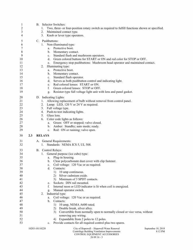
10203-10110220 City of Hopewell – Hopewell Water Renewal September 18, 2018
Centrifuge Building Ventilation Improvements 8:12 PM
CONTROL EQUIPMENT ACCESSORIES 26 09 16 - 3
B. Selector Switches: 1
1. Two, three- or four-position rotary switch as required to fulfill functions shown or specified. 2
2. Maintained contact type. 3
3. Knob or lever type operators. 4
C. Pushbuttons: 5
1. Non-illuminated type: 6
a. Protective boot. 7
b. Momentary contact. 8
c. Standard flush and mushroom operators. 9
d. Green colored buttons for START or ON and red color for STOP or OFF. 10
e. Emergency stop pushbuttons: Mushroom head operator and maintained contact. 11
2. Illuminating type: 12
a. Protective boot. 13
b. Momentary contact. 14
c. Standard flush operator. 15
d. Serves as both pushbutton control and indicating light. 16
e. Red colored lenses: START or ON. 17
f. Green colored lenses: STOP or OFF. 18
g. Resistor-type full voltage light unit with lens and panel gasket. 19
D. Indicating Lights: 20
1. Allowing replacement of bulb without removal from control panel. 21
2. Lamp: LED, 120 V or 24 V as required. 22
3. Full voltage type. 23
4. Push-to-test indicating lights. 24
5. Glass lens. 25
6. Color code lights as follows: 26
a. Green: OFF or stopped; valve closed. 27
b. Amber: Standby; auto mode; ready. 28
c. Red: ON or running; valve open. 29
2.3 RELAYS 30
A. General Requirements: 31
1. Standards: NEMA ICS 5, UL 508. 32
B. Control Relays: 33
1. General purpose (ice cube) type: 34
a. Plug-in housing. 35
b. Clear polycarbonate dust cover with clip fastener. 36
c. Coil voltage: 120 Vac or as required. 37
d. Contacts: 38
1) 10 amp continuous. 39
2) Silver cadmium oxide. 40
3) Minimum of 3 SPDT contacts. 41
e. Sockets: DIN rail mounted. 42
f. Internal neon or LED indicator is lit when coil is energized. 43
g. Manual operator switch. 44
2. Industrial type: 45
a. Coil voltage: 120 Vac or as required. 46
b. Contacts: 47
1) 10 amp, NEMA A600 rated. 48
2) Double break, silver alloy. 49
3) Convertible from normally open to normally closed or vice versa, without 50
removing any wiring. 51
4) Expandable from 2 poles to 12 poles. 52
c. Provide contacts for all required control plus two spares. 53

10203-10110220 City of Hopewell – Hopewell Water Renewal September 18, 2018
Centrifuge Building Ventilation Improvements 8:12 PM
CONTROL EQUIPMENT ACCESSORIES 26 09 16 - 4
C. Time Delay Relays: 1
1. General purpose type: 2
a. Timing modes: On and Off delay, interval, one shot and repeat cycle. 3
b. Plug-in housing. 4
c. Polycarbonate dust cover with clip fastener. 5
d. Coil voltage: 120 Vac or as required. 6
e. Contacts: 7
1) 10 amp continuous. 8
2) Silver cadmium oxide. 9
3) Two normally open and two normally closed DPDT contacts. 10
f. Sockets: DIN rail mounted. 11
g. External timing adjustment knob. 12
h. Timing ranges: 0.05 seconds to 16.65 HRS. 13
i. Repeat accuracy: +1 percent. 14
2. Solid State industrial type: 15
a. Timing modes: On and Off delay and repeat cycle. 16
b. Industrial housing. 17
c. Coil voltage: 120 Vac or as required. 18
d. Contacts: 19
1) 5 amp, NEMA B150 rated. 20
2) Silver alloy. 21
3) Convertible On Delay and Off Delay contacts. 22
4) One normally open and one normally closed timed contacts. 23
5) One normally open and one normally closed instantaneous contacts. 24
e. Furnish with "on" and "timing out" indicators. 25
f. External timing adjustment knob. 26
g. Timing ranges: 0.05 seconds to 10 HRS. 27
h. Repeat accuracy: +1 percent. 28
D. Repeat Cycle Timer: 29
1. Acceptable manufacturer: 30
a. Eagle Signal Controls. 31
2. Design and fabrication: 32
a. Solid state electronic timer capable of repeat cycle function, percentage function and 33
batch function. 34
b. Four digit LED display with LED indicators for input and output status. All 35
programming or status to be accessed from pushbuttons on the front face. 36
c. Time display will be in hours, minutes and seconds with a range from 0.1 sec to 999 37
hours. 38
d. Repeat accuracy: 0.1 PCT. 39
e. Percentage timer shall allow 0 to 100 PCT time selector of the specified time range 40
time setting of 24 HR timer control. 41
f. Automatic repeat cycle-type timer. 42
g. Two individually programmed output relays with SPDT 5A output contacts at 120 43
VAC. 44
h. Current input: 120 V, 1 PH, 60 HZ. 45
2.4 CONTACTORS 46
A. General Requirements: 47
1. Standards: NEMA ICS 2, UL 508. 48
B. Lighting and Remote Control Switches: 49
1. Electrically operated, electrically held. 50
2. Coil voltage: 120 Vac or as required. 51
3. Contacts: Totally enclosed, double-break silver-cadmium-oxide. 52
4. Rated for ballasted lighting, tungsten and general use loads. 53

10203-10110220 City of Hopewell – Hopewell Water Renewal September 18, 2018
Centrifuge Building Ventilation Improvements 8:12 PM
CONTROL EQUIPMENT ACCESSORIES 26 09 16 - 5
5. Number of poles, continuous ampere rating and voltage, as indicated on Drawings or as 1
specified. 2
6. Auxiliary control relays, as indicated on Drawings or as specified. 3
7. Auxiliary contacts, as indicated on Drawings or as specified. 4
D. Definite Purpose: 5
1. Coil voltage: 120 Vac or as required. 6
2. Contacts: Totally enclosed, double-break silver-cadmium-oxide. 7
3. Resistive load and horsepower rated. 8
4. Number of poles, continuous ampere rating and voltage, as indicated on Drawings or as 9
specified. 10
5. Auxiliary contacts, as indicated on Drawings or as specified. 11
2.5 ALARM DEVICES 12
A. Alarm Horns: 13
1. Vibrating horn type. 14
2. PLC compatible as required. 15
3. Heavy-duty die cast housing with corrosion resistant finish. 16
4. Adjustable volume: 78 to 103 dB at 10 FT. 17
5. Voltage: 120 Vac or as required. 18
6. Enclosures/mountings: 19
a. Flush wall or panel mounting in dry areas. 20
b. NEMA 4X panel mounting in wet areas. 21
c. Surface mounting in dry areas. 22
d. NEMA 4X surface mounting in wet areas. 23
e. NEMA 4X, hazardous location surface mounting in wet and hazardous areas. 24
1) Fixed volume: 97 dB at 10 FT. 25
B. Alarm Beacon: 26
1. Panel mounted: 27
a. Strobe type. 28
b. Shatter resistant polycarbonate lens and base. 29
c. Lens color as indicated on Drawings. 30
d. NEMA 4X enclosure. 31
e. PLC compatible. 32
f. Voltage: 120 Vac. 33
2. Corrosive locations: 34
a. Heavy-duty LED flashing type. 35
b. NEMA 4X 36
c. Body: Zinc plated cast iron or cast copper free aluminum and/or polycarbonate-ABS. 37
d. High impact glass dome with guard. 38
e. Shatter resistant polycarbonate lens with color as indicated on Drawings. 39
f. Immune to shock and vibration, no moving parts. 40
g. Flash tube providing a minimum of 65 single flashes per minute. 41
h. Mounting: Wall bracket or pendant. 42
i. Edwards Signaling model 48XBR or equal. 43
2.6 MISCELLANEOUS DEVICES 44
A. Run Time Meters: 45
1. Six-digit wheels including a 1/10 digit. 46
2. Non-reset type. 47
3. Time range in hours. 48
4. Automatic recycle at zero. 49
5. Accuracy: 1 percent. 50
6. Sealed against dirt and moisture. 51
7. Tamperproof. 52

10203-10110220 City of Hopewell – Hopewell Water Renewal September 18, 2018
Centrifuge Building Ventilation Improvements 8:12 PM
CONTROL EQUIPMENT ACCESSORIES 26 09 16 - 6
B. Control Power Transformer: 1
1. Primary voltage: 480 V. 2
2. Secondary voltage: 120 V. 3
3. Sized for 125 percent of required load. 4
4. Fused on primary and secondary. 5
5. Standard: NEMA ST 1. 6
2.7 TERMINATION EQUIPMENT 7
A. General Requirements: 8
1. Modular type with screw compression clamp. 9
2. Screws: Stainless steel. 10
3. Current bar: Nickel-plated copper alloy. 11
4. Thermoplastic insulation rated for -40 to +90 DegC. 12
5. Wire insertion area: Funnel-shaped to guide all conductor strands into terminal. 13
6. End sections and end stops at each end of terminal strip. 14
7. Machine-printed terminal markers on both sides of block. 15
8. Spacing: 6 mm. 16
9. Wire size: 22-12 AWG. 17
10. Rated voltage: 600 V. 18
11. DIN rail mounting. 19
B. Standard-type block: 20
1. Rated current: 30 A. 21
2. Color: Gray body. 22
C. Bladed-type disconnect block: 23
1. Terminal block with knife blade disconnect which connects or isolated the two sides of the 24
block. 25
2. Rated current: 10 A. 26
3. Color: 27
a. Panel control voltage leaves enclosure - normal: Gray body, orange switch. 28
b. Foreign voltage entering enclosure: Orange body, orange switch. 29
D. Grounded-type block: 30
1. Electrically grounded to mounting rail. 31
2. Terminal ground wires and analog cable shields. 32
3. Color: Green and yellow body. 33
E. Fuse Holders: 34
1. Blocks can be ganged for multi-pole operation. 35
2. Spacing: 9.1 mm. 36
3. Wire size: 30-12 AWG. 37
4. Rated voltage: 300 V. 38
5. Rated current: 12 A. 39
6. Fuse size: 1/4 x 1-1/4. 40
7. Blown fuse indication. 41
8. DIN rail mounting. 42
2.8 ENCLOSURES 43
A. Operator Control Stations: 44
1. NEMA 4X rated: 45
a. Type 304 or 316 stainless steel body. 46
b. Gasketed Type 304 or 316 stainless steel cover. 47
c. Number of device mounting holes as required. 48

10203-10110220 City of Hopewell – Hopewell Water Renewal September 18, 2018
Centrifuge Building Ventilation Improvements 8:12 PM
CONTROL EQUIPMENT ACCESSORIES 26 09 16 - 7
PART 3 - EXECUTION 1
3.1 INSTALLATION 2
A. Install as indicated and in accordance with manufacturer's recommendations and instructions. 3
B. Operator Control Stations: 4
1. Permitted uses of NEMA 4X enclosure: 5
a. Surface mounted in areas designated as wet and/or corrosive or highly corrosive. 6
3.2 FIELD QUALITY CONTROL 7
A. See Section 26 05 00. 8
B. Operator Control Station Functional Test: 9
1. The test is to prove the correct interaction of all sensing, processing and action devices. 10
2. Develop a test plan and parameters for the purpose of evaluating the performance of the 11
system. 12
a. Plan shall have witness signature lines for the contractor and owner and submitted 13
when system pass the test. 14
3. Perform the following tests: 15
a. Verify functionality of all control states. 16
b. Verify the correct operation of all interlock safety devices for fail-safe functions 17
c. Verify the correct operation of all sensing devices, alarms and indicating devices. 18
3.3 TRAINING 19
A. A qualified supplier representative shall provide the Owner with on-site training in the operation 20
and maintenance of the Operator Control Panel and its components. 21
END OF SECTION 22

10203-10110220 City of Hopewell – Hopewell Water Renewal September 18, 2018
Centrifuge Building Ventilation Improvements 8:12 PM
CONTROL EQUIPMENT ACCESSORIES 26 09 16 - 8
THIS PAGE INTENTIONALLY LEFT BLANK 1
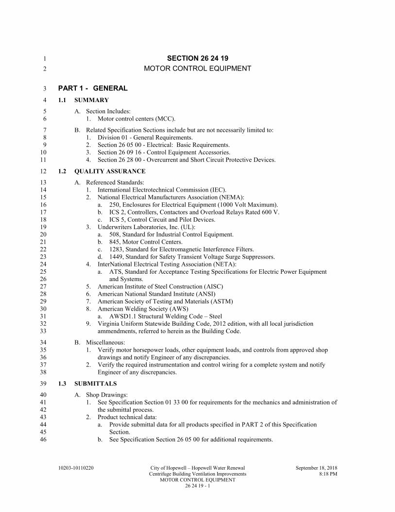
10203-10110220 City of Hopewell – Hopewell Water Renewal September 18, 2018
Centrifuge Building Ventilation Improvements 8:18 PM
MOTOR CONTROL EQUIPMENT 26 24 19 - 1
SECTION 26 24 19 1
MOTOR CONTROL EQUIPMENT 2
PART 1 - GENERAL 3
1.1 SUMMARY 4
A. Section Includes: 5
1. Motor control centers (MCC). 6
B. Related Specification Sections include but are not necessarily limited to: 7
1. Division 01 - General Requirements. 8
2. Section 26 05 00 - Electrical: Basic Requirements. 9
3. Section 26 09 16 - Control Equipment Accessories. 10
4. Section 26 28 00 - Overcurrent and Short Circuit Protective Devices. 11
1.2 QUALITY ASSURANCE 12
A. Referenced Standards: 13
1. International Electrotechnical Commission (IEC). 14
2. National Electrical Manufacturers Association (NEMA): 15
a. 250, Enclosures for Electrical Equipment (1000 Volt Maximum). 16
b. ICS 2, Controllers, Contactors and Overload Relays Rated 600 V. 17
c. ICS 5, Control Circuit and Pilot Devices. 18
3. Underwriters Laboratories, Inc. (UL): 19
a. 508, Standard for Industrial Control Equipment. 20
b. 845, Motor Control Centers. 21
c. 1283, Standard for Electromagnetic Interference Filters. 22
d. 1449, Standard for Safety Transient Voltage Surge Suppressors. 23
4. InterNational Electrical Testing Association (NETA): 24
a. ATS, Standard for Acceptance Testing Specifications for Electric Power Equipment 25
and Systems. 26
5. American Institute of Steel Construction (AISC) 27
6. American National Standard Institute (ANSI) 28
7. American Society of Testing and Materials (ASTM) 29
8. American Welding Society (AWS) 30
a. AWSD1.1 Structural Welding Code – Steel 31
9. Virginia Uniform Statewide Building Code, 2012 edition, with all local jurisdiction 32
ammendments, referred to herein as the Building Code. 33
B. Miscellaneous: 34
1. Verify motor horsepower loads, other equipment loads, and controls from approved shop 35
drawings and notify Engineer of any discrepancies. 36
2. Verify the required instrumentation and control wiring for a complete system and notify 37
Engineer of any discrepancies. 38
1.3 SUBMITTALS 39
A. Shop Drawings: 40
1. See Specification Section 01 33 00 for requirements for the mechanics and administration of 41
the submittal process. 42
2. Product technical data: 43
a. Provide submittal data for all products specified in PART 2 of this Specification 44
Section. 45
b. See Specification Section 26 05 00 for additional requirements. 46

10203-10110220 City of Hopewell – Hopewell Water Renewal September 18, 2018
Centrifuge Building Ventilation Improvements 8:18 PM
MOTOR CONTROL EQUIPMENT 26 24 19 - 2
3. Fabrication and/or layout drawings: 1
a. Motor control center units: 2
1) Elevation drawing with overall dimensions. 3
2) Starter and component schedule. 4
3) Identification of units and their location in the MCC. 5
4) Mounting dimensions. 6
5) Nameplate schedule. 7
6) Assembly ratings (amps, volts, short circuit, etc.). 8
7) Unit ladder logic wiring for each unit depicting electrical interlocking and wiring 9
between units (NEMA ICS 3 Class II) and identification of terminals where field 10
devices or remote control signals are to be terminated (NEMA ICS 3 Class II-S) as 11
indicated on the Drawings and/or loop descriptions. 12
B. Operation and Maintenance Manuals: 13
1. See Specification Section 01 33 04 for requirements for: 14
a. The mechanics and administration of the submittal process. 15
b. The content of Operation and Maintenance Manuals. 16
c. Fabrication and/or layout drawings updated with as-built conditions. 17
PART 2 - PRODUCTS 18
2.1 ACCEPTABLE MANUFACTURERS 19
A. Subject to compliance with the Contract Documents, the following manufacturers are 20
acceptable: 21
1. Eaton. 22
2.2 MOTOR CONTROL CENTER, MODIFICATIONS 23
A. Ratings: 24
1. 600 V class, 3 PH, 60 Hz with operating voltage and number of wires as indicated on the 25
Drawings. 26
2. Assembly short circuit current and interrupting device rating: 65 KAIC symmetrical unless 27
otherwise indicated on the Drawings. 28
3. Service Entrance Equipment rated.. 29
B. Construction: 30
1. Standards: UL 845. 31
2. Totally enclosed, dead front, free standing assemblies, bolted together to form a single 32
assembly. 33
3. Fabricate of not less than 14 GA steel with 16 GA steel doors in standardized units. 34
4. Nominal size per section: 20 IN wide, 20 or 21 IN deep, and 90 IN high. 35
5. Enclosure: 36
a. NEMA 1 gasketed. 37
6. Unit doors: 38
a. Formed round corners and rolled edges. 39
b. Minimum of two heavy-duty hinges or continuous piano hinge. 40
c. Held closed by means of captive fasteners. 41
d. Fabricate to be a part of the structure and not part of the starter. 42
7. Unit cubicles: 43
a. Draw-out type for motor starters through NEMA Size 5. 44
b. Guide rails for supporting and aligning starters. 45
c. Operating handle: 46
1) With the unit stabs engaged and door closed the handle mechanism allows 47
complete ON/OFF control of the unit disconnect and clear indication of the 48
disconnect status. 49
2) Circuit breaker and MCP operators include a separate TRIPPED position. 50

10203-10110220 City of Hopewell – Hopewell Water Renewal September 18, 2018
Centrifuge Building Ventilation Improvements 8:18 PM
MOTOR CONTROL EQUIPMENT 26 24 19 - 3
3) Mechanical interlock to prevent the opening of the door when the disconnect is in 1
the ON position with a defeater mechanism. 2
4) Mechanical interlock to prevent the placement of the disconnect in the ON position 3
with the door open with a defeater mechanism. 4
5) Non-defeatable interlock to prevent the installation or removal of a unit unless the 5
disconnect is in the OFF position. 6
6) Padlockable in the OFF position. 7
d. Control power: 8
1) Control power transformer: 9
a) 120 V secondary. 10
b) Fused on primary and secondary side. 11
c) Sized for 140 percent of required load. 12
e. Minimum of one full size space unit (12 IN) for any combination magnetic motor 13
starter or starter without overload relay. 14
f. One-half full size space unit (6 IN) for circuit breakers 100 A and less. 15
g. Effectively baffled to isolate any ionized gases which may occur within unit starter. 16
8. Externally mounted overload relay pushbutton. 17
9. Assemblies effectively ventilated to allow relocation of starters and other components: 18
a. Within the assembly and with the same load. 19
b. Without having to compensate for changes in location. 20
10. Finish: Rust inhibited primer and manufacturer's standard paint inside and out. 21
11. Provide ample unrestricted space for conduit entry from the bottom. 22
12. Wiring: NEMA ICS 3 Class II, Type B-D. 23
C. Overcurrent and Short Circuit Protective Devices: 24
1. Motor protection with full voltage starters: 25
a. Motor circuit protector. 26
b. Molded case circuit breaker. 27
2. See Specification Section 26 28 00 for overcurrent and short circuit protective device 28
requirements. 29
3. Factory installed. 30
D. Motor Starters: See requirements within this Specification Section. 31
E. Miscellaneous: 32
1. See Drawings for items provided by other but factory installed (e.g., submersible motor 33
temperature/leak controller, control system gateways or switches). 34
2.3 MOTOR STARTERS 35
A. Standards: 36
1. NEMA ICS 2. 37
2. UL 508. 38
B. Full Voltage Non-Reversing (FVNR) Magnetic Starters: 39
1. NEMA full size rated contactor. 40
a. NEMA half sizes and IEC contactors are not permitted. 41
2. Double-break silver alloy contacts. 42
3. Overload relays: 43
1) Ambient insensitive, adjustable solid state type with phase loss protection, phase 44
imbalance protection and manual reset. 45
4. Interlock and auxiliary contacts, wired to terminal blocks: 46
a. Holding circuit contact, normally open. 47
b. Overload alarm contact, normally open. 48
c. Normally open auxiliary contact, for remote run status. 49
d. Additional field replaceable auxiliary contacts as required per the Sequence of 50
Operation. 51
e. Two additional normally open spare field replaceable auxiliary contacts. 52

10203-10110220 City of Hopewell – Hopewell Water Renewal September 18, 2018
Centrifuge Building Ventilation Improvements 8:18 PM
MOTOR CONTROL EQUIPMENT 26 24 19 - 4
C. Full Voltage Reversing (FVR) Magnetic Starters: 1
1. Two (2) FVNR starters with one (1) overload relay assembled together. 2
2. Mechanically and electrically interlocked to prevent line shorts and the energizing of both 3
contactors simultaneously. 4
3. See FVNR paragraph for additional requirements. 5
PART 3 - EXECUTION 6
3.1 INSTALLATION 7
A. Install as indicated on the Drawings and in accordance with manufacturer's recommendations 8
and instructions. 9
1. Install all MCC mounted equipment in dedicated sections. 10
2. Modify existing MCC sections to accommodate new starters and equipment according to 11
manufacturer’s instructions. 12
B. Overload Heaters: 13
1. Size for actual motor full load current of the connected motor. 14
2. For motors with power factor correction capacitors, size to compensate for the capacitors 15
effect on load current. 16
3.2 FIELD QUALITY CONTROL 17
A. Acceptance Testing: 18
1. Low Voltage Molded Case Circuit Breakers: 19
a. Perform inspections and tests per NETA ATS 7.6.1.1. 20
b. Components: 21
1) Test all components per applicable paragraphs of this Specification Section and 22
NETA ATS. 23
2) Thermal magnetic breakers: Visual and mechanical inspection per NETA ATS 24
only. 25
3) Solid state trip type: Visual and mechanical inspection and electrical tests per 26
NETA ATS. 27
c. Record as-left settings. 28
2. Instrument Transformers: 29
a. Perform inspections and tests per NETA ATS 7.10. 30
b. Components: Test all components per applicable paragraphs of this Specification 31
Section and NETA ATS. 32
c. Perform the following optional tests per NETA ATS: 33
1) Dielectric withstand test on potential transformers. 34
3. Metering: 35
a. Perform inspections and tests per NETA ATS 7.11. 36
b. Components: Test all components per applicable paragraphs of this Specification 37
Section and NETA ATS. 38
4. Grounding: 39
a. Perform inspections and tests per NETA ATS 7.13. 40
b. Components: Test all components per applicable paragraphs of this Specification 41
Section and NETA ATS. 42
5. Motor Controllers: 43
a. Perform inspections and tests per NETA ATS 7.16. 44
b. Components: Test all components per applicable paragraphs of this Specification 45
Section and NETA ATS. 46
END OF SECTION 47

10203-10110220 City of Hopewell – Hopewell Water Renewal September 18, 2018
Centrifuge Building Ventilation Improvements 8:23 PM
OVERCURRENT AND SHORT CIRCUIT PROTECTIVE DEVICES 26 28 00 - 1
SECTION 26 28 00 1
OVERCURRENT AND SHORT CIRCUIT PROTECTIVE DEVICES 2
PART 1 - GENERAL 3
1.1 SUMMARY 4
A. Section Includes: 5
1. Low voltage circuit breakers. 6
B. Related Specification Sections include but are not necessarily limited to: 7
1. Division 01 - General Requirements. 8
2. Section 26 05 00 - Electrical: Basic Requirements. 9
1.2 QUALITY ASSURANCE 10
A. Referenced Standards: 11
1. Institute of Electrical and Electronics Engineers, Inc. (IEEE): 12
a. C37.13, Standard for Low-Voltage AC Power Circuit Breakers Used in Enclosures. 13
b. C37.16, Low-Voltage Power Circuit Breakers and AC Power Circuit Protectors - 14
Preferred Ratings, Related Requirements, and Application Recommendations. 15
c. C37.17, Trip Devices for AC and General Purpose DC Low Voltage Power Circuit 16
Breakers. 17
2. National Electrical Manufacturers Association (NEMA): 18
a. AB 1, Molded-Case Circuit Breakers, Molded Case Switches, and Circuit-Breaker 19
Enclosures. (Equivalent to UL 489) 20
3. National Fire Protection Association (NFPA): 21
a. 70, National Electrical Code (NEC). 22
4. Underwriters Laboratories, Inc. (UL): 23
a. 489, Standard for Safety Molded-Case Circuit Breakers, Molded-Case Switches, and 24
Circuit-Breaker Enclosures. 25
b. 943, Standard for Safety for Ground-Fault Circuit-Interrupters. 26
c. 1066, Standard for Low-Voltage AC and DC Power Circuit Breakers Used in 27
Enclosures. 28
5. InterNational Electrical Testing Association (NETA): 29
a. ATS, Standard for Acceptance Testing Specifications for Electric Power Equipment 30
and Systems. 31
1.3 SUBMITTALS 32
A. Shop Drawings: 33
1. See Specification Section 01 33 00 for requirements for the mechanics and administration of 34
the submittal process. 35
2. Product technical data including: 36
a. Provide submittal data for all products specified in PART 2 of this Specification 37
Section. 38
b. See Specification Section 26 05 00 for additional requirements. 39
B. Operation and Maintenance Manuals: 40
1. See Specification Section 01 33 04 for requirements for: 41
a. The mechanics and administration of the submittal process. 42
b. The content of Operation and Maintenance Manuals. 43
C. Informational Submittals: 44
1. See Specification Section 01 33 00 for requirements for the mechanics and administration of 45
the submittal process. 46
2. Reports: 47
a. As-left condition of all circuit breakers that have adjustable settings. 48

10203-10110220 City of Hopewell – Hopewell Water Renewal September 18, 2018
Centrifuge Building Ventilation Improvements 8:23 PM
OVERCURRENT AND SHORT CIRCUIT PROTECTIVE DEVICES 26 28 00 - 2
PART 2 - PRODUCTS 1
2.1 ACCEPTABLE MANUFACTURERS 2
A. Subject to compliance with the Contract Documents, the following manufacturers are 3
acceptable: 4
1. Circuit breakers: 5
a. Eaton. 6
b. Square D Company. 7
2.2 CIRCUIT BREAKERS 8
A. Molded Case Type: 9
1. General: 10
a. Standards: NEMA AB 1, UL 489. 11
b. Unit construction. 12
c. Over-center, toggle handle operated. 13
d. Quick-make, quick-break, independent of toggle handle operation. 14
e. Manual and automatic operation. 15
f. All poles open and close simultaneously. 16
g. Three position handle: On, off and tripped. 17
h. Molded-in ON and OFF markings on breaker cover. 18
i. One-, two- or three-pole as indicated on the Drawings. 19
j. Current and interrupting ratings as indicated on the Drawings. 20
k. Bolt on type. 21
2. Thermal magnetic type: 22
a. Inverse time overload and instantaneous short circuit protection by means of a thermal 23
magnetic element. 24
b. Frame size 150 amp and below: 25
1) Non-interchangeable, non-adjustable thermal magnetic trip units. 26
c. Frame sizes 225 to 400 amp (trip settings less than 400A): 27
1) Interchangeable and adjustable instantaneous thermal magnetic trip units. 28
d. Ground Fault Circuit Interrupter (GFCI) Listed: 29
1) Standard: UL 943. 30
2) One- or two-pole as indicated on the Drawings. 31
3) Class A ground fault circuit. 32
4) Trip on 5 mA ground fault (4-6 mA range). 33
3. Motor circuit protector: 34
a. Adjustable instantaneous short circuit protection by means of a magnetic or solid state 35
trip element. 36
b. Sized for the connected motor. 37
PART 3 - EXECUTION 38
3.1 INSTALLATION 39
A. Current and interrupting ratings as indicated on the Drawings. 40
B. Series rated systems not acceptable. 41
C. Devices shall be ambient temperature compensated. 42
D. Circuit Breakers: 43
1. Molded case circuit breakers shall incorporate the following, unless indicated otherwise on 44
the Drawings: 45
a. Frame sizes 400 amp and less with trip setting less than 400A shall be thermal magnetic 46
type. 47
b. Motor circuit protectors sized for the connected motor. 48
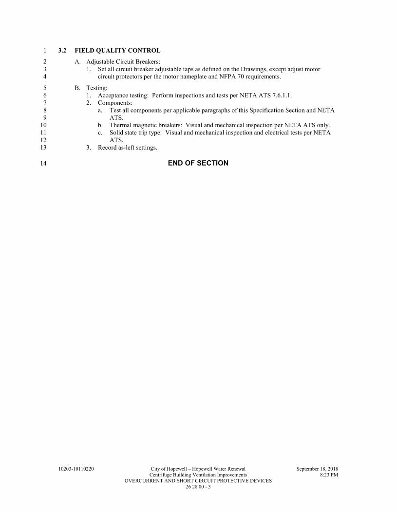
10203-10110220 City of Hopewell – Hopewell Water Renewal September 18, 2018
Centrifuge Building Ventilation Improvements 8:23 PM
OVERCURRENT AND SHORT CIRCUIT PROTECTIVE DEVICES 26 28 00 - 3
3.2 FIELD QUALITY CONTROL 1
A. Adjustable Circuit Breakers: 2
1. Set all circuit breaker adjustable taps as defined on the Drawings, except adjust motor 3
circuit protectors per the motor nameplate and NFPA 70 requirements. 4
B. Testing: 5
1. Acceptance testing: Perform inspections and tests per NETA ATS 7.6.1.1. 6
2. Components: 7
a. Test all components per applicable paragraphs of this Specification Section and NETA 8
ATS. 9
b. Thermal magnetic breakers: Visual and mechanical inspection per NETA ATS only. 10
c. Solid state trip type: Visual and mechanical inspection and electrical tests per NETA 11
ATS. 12
3. Record as-left settings. 13
END OF SECTION 14

10203-10110220 City of Hopewell – Hopewell Water Renewal September 18, 2018
Centrifuge Building Ventilation Improvements 8:23 PM
OVERCURRENT AND SHORT CIRCUIT PROTECTIVE DEVICES 26 28 00 - 4
THIS PAGE INTENTIONALLY LEFT BLANK 1

10203-10110220 City of Hopewell – Hopewell Water Renewal September 18, 2018
Centrifuge Building Ventilation Improvements 8:25 PM
EARTHWORK 31 23 00 - 1
SECTION 31 23 00 1
EARTHWORK 2
PART 1 - GENERAL 3
1.1 SUMMARY 4
A. Section Includes: 5
1. Earthwork - excavation, backfilling, grading, compaction, disposal of waste and surplus 6
materials, placing crushed stone, construction of berms, sheeting, bracing, dewatering and 7
other Earthwork related work. 8
B. Related Specification Sections include but are not necessarily limited to: 9
1. Division 00 - Bidding Requirements, Contract Forms, and Conditions of the Contract. 10
2. Division 01 - General Requirements. 11
3. Section 31 25 00 - Soil Erosion and Sediment Control. 12
1.2 QUALITY ASSURANCE 13
A. Referenced Standards: 14
1. ASTM International (ASTM): 15
a. C33, Standard Specification for Concrete Aggregates. 16
b. D698, Standard Test Methods for Laboratory Compaction Characteristics of Soil Using 17
Standard Effort (12,400 ft-lbf/ft3). 18
c. D1557, Standard Test Methods for Laboratory Compaction Characteristics of Soil 19
Using Modified Effort (56,000 ft-lbf/ft3(2,700 kN-m/m)). 20
d. D2487, Standard Practice for Classification of Soils for Engineering Purposes (Unified 21
Soil Classification System). 22
e. D3786, Standard Test Method for Bursting Strength of Textile Fabrics--Diaphragm 23
Bursting Strength Tester Method. 24
f. D4253, Standard Test Methods for Maximum Index Density and Unit Weight of Soils 25
Using a Vibratory Table. 26
g. D4254, Standard Test Methods for Minimum Index Density and Unit Weight of Soils 27
and Calculation of Relative Density. 28
h. D4632, Standard Test Method for Grab Breaking Load and Elongation of Geotextiles. 29
2. Occupational Safety and Health Administration (OSHA): 30
a. 29 CFR Part 1926.650, Occupational Safety and Health Standards, referred to herein as 31
OSHA Standards. 32
1.3 DEFINITIONS 33
A. Excavation: 34
1. Consists of removal of material encountered to subgrade elevations required or indicated. 35
2. Includes excavation of soils; pavements and other obstructions visible on surface; 36
underground structures, utilities, and other items indicated to be demolished and removed; 37
boulders; and rock. 38
B. Foundations: Footings, base slabs, foundation walls, mat foundations, grade beams, piers and 39
any other support placed directly on soil or rock. 40
C. Non-Structural Fill/Backfill: Soil materials placed and compacted to achieve finish grade 41
elevations that do NOT support foundations, slabs, paving, or other flatwork. 42
D. Structure: Buildings, foundations, slabs, tanks, curbs, or other man-made stationary features 43
occurring above or below ground surface. 44
E. Subgrade: The earth or soil layer immediately below foundation bearing elevation, subbase 45
material, fill material, backfill material, or topsoil materials. 46

10203-10110220 City of Hopewell – Hopewell Water Renewal September 18, 2018
Centrifuge Building Ventilation Improvements 8:25 PM
EARTHWORK 31 23 00 - 2
F. Unauthorized Excavation: 1
1. Consists of removal of materials beyond indicated subgrade elevations or dimensions 2
without specific direction of Engineer. 3
a. Unauthorized excavation, as well as associated remedial work as directed by Engineer, 4
shall be at Contractor’s expense. 5
1.4 SUBMITTALS 6
A. Shop Drawings: 7
1. See Specification Section 01 33 00 for requirements for the mechanics and administration of 8
the submittal process. 9
2. Product technical data including: 10
a. Acknowledgement that products submitted meet requirements of standards referenced. 11
b. Manufacturer's installation instructions. 12
3. Certifications. 13
1.5 PROJECT CONDITIONS 14
A. Dispose of waste materials, legally, off site. 15
1. Burning, as a means of waste disposal, is not permitted. 16
PART 2 - PRODUCTS 17
2.1 MATERIALS 18
A. Fill and Backfill: 19
1. Selected material approved by Engineer from site excavation or from off-site borrow. 20
B. Crushed Stone: VDOT No. 21A Stone. 21
C. Select Bedding/Backfill: VDOT No. 21A Stone. 22
PART 3 - EXECUTION 23
3.1 PROTECTION 24
A. Erosion Control: 25
1. See Specification Section 31 25 00. 26
2. Clean paved roadways daily of any spillage of dirt, rocks or debris from vehicles and 27
equipment entering or leaving site. 28
3. Conduct work to minimize erosion of site. Remove eroded material washed off site. 29
a. If necessary or requested by Engineer, construct stilling areas to settle and detain 30
eroded material. 31
B. Protect existing surface and subsurface features on-site and adjacent to site as follows: 32
1. Provide barricades, coverings, or other types of protection necessary to prevent damage to 33
existing items indicated to remain in place. 34
2. Protect and maintain bench marks, monuments or other established reference points and 35
property corners. 36
a. If disturbed or destroyed, replace at own expense to full satisfaction of Owner and 37
controlling agency. 38
3. Verify location of utilities. 39
a. Omission or inclusion of utility items does not constitute nonexistence or definite 40
location. 41
b. Secure and examine local utility records for location data. 42
c. Take necessary precautions to protect existing utilities from damage due to any 43
construction activity. 44
1) If utilities are indicated to remain in place, provide adequate means of support and 45
protection during earthwork operations. 46

10203-10110220 City of Hopewell – Hopewell Water Renewal September 18, 2018
Centrifuge Building Ventilation Improvements 8:25 PM
EARTHWORK 31 23 00 - 3
2) Do not interrupt existing utilities serving facilities occupied by Owner or others, 1
during occupied hours, except when permitted in writing by Owner and then only 2
after acceptable temporary utility services have been provided. 3
3) Obtain Owner’s approval prior to disconnecting any utility service 4
d. Repair damages to utility items at own expense. 5
e. In case of damage, notify Engineer at once so required protective measures may be 6
taken. 7
4. Maintain free of damage, existing sidewalks, structures, and pavement, not indicated to be 8
removed. 9
a. Protect new and existing structures, utilities, sidewalks, pavements, and other facilities 10
from damage caused by settlement, lateral movement, undermining, washout, and other 11
hazards created by earthwork operations. 12
b. Any item known or unknown or not properly located that is inadvertently damaged 13
shall be repaired to original condition. 14
c. All repairs to be made and paid for by Contractor. 15
5. Provide full access to public and private premises, fire hydrants, street crossings, sidewalks 16
and other points as designated by Owner to prevent serious interruption of travel. 17
6. Maintain stockpiles and excavations in such a manner to prevent inconvenience or damage 18
to structures on-site or on adjoining property. 19
7. Avoid surcharge or excavation procedures which can result in heaving, caving, or slides. 20
3.2 SITE EXCAVATION AND GRADING 21
A. The site excavation and grading work includes the offsite disposition of all material: 22
1. That exceed quantities required for earthwork on the project. 23
2. That the Engineer classifies as unclassified excavation. 24
3. That the Engineer classifies as unacceptable. 25
4. That the Engineer classifies as potentially contaminated. 26
B. Excavation and Grading: 27
1. Perform as required by the Contract Drawings. 28
2. Contract Drawings may indicate both existing grade and finished grade required for 29
construction of Project. 30
a. Stake all units, structures, piping, roads, parking areas and walks and establish their 31
elevations. 32
b. Perform other layout work required. 33
c. Replace property corner markers to original location if disturbed or destroyed. 34
3. Protection of finish grade: 35
a. During construction, shape and drain embankment and excavations. 36
b. Maintain ditches and drains to provide drainage at all times. 37
c. Protect graded areas against action of elements prior to acceptance of work. 38
d. Reestablish grade where settlement or erosion occurs. 39
C. Borrow: 40
1. Provide necessary amount of approved fill compacted to density equal to that indicated in 41
this Specification. 42
2. Include cost of all borrow material in original proposal. 43
3. Fill material to be approved by Engineer prior to placement. 44
D. Grading Tolerances: 0.1 FT +/- of existing grade. 45
3.3 USE OF EXPLOSIVES 46
A. Blasting with any type of explosive is prohibited. 47
3.4 COMPACTION DENSITY REQUIREMENTS 48
A. Obtain approval from Engineer with regard to suitability of soils and acceptable subgrade prior 49
to subsequent operations. 50

10203-10110220 City of Hopewell – Hopewell Water Renewal September 18, 2018
Centrifuge Building Ventilation Improvements 8:25 PM
EARTHWORK 31 23 00 - 4
B. Provide dewatering system necessary to successfully complete compaction and construction 1
requirements. 2
C. Remove frozen, loose, wet, or soft material and replace with approved material as directed by 3
Engineer. 4
D. Stabilize subgrade with well graded granular materials as directed by Engineer. 5
E. Assure by results of testing that compaction densities comply with the following requirements: 6
1. Sitework: 7
8
LOCATION COMPACTION DENSITY MOISTURE CONTENT
Under Paved Areas, Sidewalks and Piping:
Cohesive soils 98 percent per ASTM D698 in the
upper 12 IN of soil and 95 percent
below the upper layer
-2 to +3 percent of optimum
Cohesionless soils 75 percent relative density per
ASTM D4253 and ASTM D4254
Unpaved Areas:
Cohesive soils 90 percent of ASTM D698 -2 to +3 percent of optimum
Cohesionless soils 65 percent relative density per
ASTM D4253 and ASTM D4254
3.5 FIELD QUALITY CONTROL 11
A. All excavation, trenching, and related sheeting, bracing, etc. shall comply with the requirements 12
of OSHA standards 29 CFR Part 1926.650 Subpart P, and state requirements. Where conflict 13
between OSHA and state regulations exists, the more stringent requirements shall apply. 14
B. Responsibilities of Testing Agency for Site Excavation and Grading: 15
1. All testing, observation and work indicated as being performed by the Engineer. 16
2. Services will include verification and documentation of satisfactory soil materials, subgrade 17
quality, sampling, placement, moisture conditioning, compaction and testing of proposed 18
soil materials, and field testing for quality control. 19
3. Extent of compaction testing will be as necessary to assure compliance with specifications. 20
END OF SECTION 21

10203-10110220 City of Hopewell – Hopewell Water Renewal September 18, 2018
Centrifuge Building Ventilation Improvements 8:32 PM
SOIL EROSION AND SEDIMENT CONTROL 31 25 00 - 1
SECTION 31 25 00 1
SOIL EROSION AND SEDIMENT CONTROL 2
PART 1 - GENERAL 3
1.1 SUMMARY 4
A. Section Includes: 5
1. Soil erosion and sediment control. 6
B. Related Specification Sections include but are not necessarily limited to: 7
1. Division 00 - Bidding Requirements, Contract Forms, and Conditions of the Contract. 8
2. Division 01 - General Requirements. 9
1.2 QUALITY ASSURANCE 10
A. Referenced Standards: 11
1. Erosion control standards: Standards and Specifications for Soil Erosion and Sediment 12
Control in Developing Areas by the United Sates Department of Agriculture (USDA), Soil 13
Conservation Service, College Park, Maryland. 14
PART 2 - PRODUCTS 15
2.1 MATERIALS 16
A. Straw bales, twine tied. 17
B. Pipe Riser and Barrel: 16 GA corrugated metal pipe (CMP) of size indicated. 18
C. Stone for Stone Filter: 2 IN graded gravel or crushed stone. 19
D. Grass Seed: Annual ryegrass. 20
PART 3 - EXECUTION 21
3.1 PREPARATION 22
A. Prior to General Stripping Topsoil and Excavating: 23
1. Install perimeter dikes and swales. 24
2. Excavate and shape sediment basins and traps. 25
3. Construct pipe spillways and install stone filter where required. 26
4. Machine compact all berms, dikes and embankments for basins and traps. 27
5. Install straw bales where indicated. 28
a. Provide two stakes per bale. 29
b. First stake angled toward previously installed bale to keep ends tight against each other. 30
B. Construct sediment traps where indicated on Drawings during rough grading as grading 31
progresses. 32
C. Temporarily seed basin slopes and topsoil stockpiles: 33
1. Rate: 1/2 LB/1000 SF. 34
2. Reseed as required until good stand of grass is achieved. 35
3.2 DURING CONSTRUCTION PERIOD 36
A. Maintain Basins, Dikes, Traps, Stone Filters, Straw Bales, etc.: 37
1. Inspect regularly especially after rainstorms. 38
2. Repair or replace damaged or missing items. 39

10203-10110220 City of Hopewell – Hopewell Water Renewal September 18, 2018
Centrifuge Building Ventilation Improvements 8:32 PM
SOIL EROSION AND SEDIMENT CONTROL 31 25 00 - 2
B. After rough grading, sow temporary grass cover over all exposed earth areas not draining into 1
sediment basin or trap. 2
C. Construct inlets as soon as possible. 3
1. Excavate and tightly secure straw bales completely around inlets as detailed on Drawings. 4
D. Provide necessary swales and dikes to direct all water towards and into sediment basins and 5
traps. 6
E. Do not disturb existing vegetation (grass and trees). 7
F. Excavate sediment out of basins and traps when capacity has been reduced by 50 percent. 8
1. Remove sediment from behind bales to prevent overtopping. 9
G. Topsoil and Fine Grade Slopes and Swales, etc.: Seed and mulch as soon as areas become 10
ready. 11
3.3 NEAR COMPLETION OF CONSTRUCTION 12
A. Eliminate basins, dikes, traps, etc. 13
B. Grade to finished or existing grades. 14
C. Fine grade all remaining earth areas, then seed and mulch. 15
END OF SECTION 16

10203-10110220 City of Hopewell – Hopewell Water Renewal September 18, 2018
Centrifuge Building Ventilation Improvements 8:34 PM
CONCRETE CURB AND GUTTER 32 16 13- 1
SECTION 32 16 13 1
CONCRETE CURB AND GUTTER 2
PART 1 - GENERAL 3
1.1 SUMMARY 4
A. Section Includes: 5
1. Concrete curb and gutter. 6
B. Related Specification Sections include but are not necessarily limited to: 7
1. Division 01 - General Requirements. 8
2. Section 03 09 00 - Concrete. 9
1.2 QUALITY ASSURANCE 10
A. Referenced Standards: 11
1. American Association of State Highway and Transportation Officials (AASHTO): 12
a. M153, Preformed Sponge Rubber and Cork Expansion Joint Fillers for Concrete Paving 13
and Structural Construction. 14
b. M171, Standard Specification for Sheet Materials for Curing Concrete. 15
c. M182, Burlap Cloth Made from Jute or Kenef. 16
d. M213, Preformed Expansion Joint Fillers for Concrete Paving and Structure 17
Construction (Nonextruding and Resilient Bituminous Types). 18
e. M233, Boiled Linseed Oil Mixture for Treatment of Portland Cement Concrete. 19
2. American Concrete Institute (ACI): 20
a. 305R, Hot Weather Concreting. 21
b. 306R, Cold Weather Concreting. 22
3. ASTM International (ASTM): 23
a. A615, Standard Specification for Deformed and Plain Carbon-Steel Bars for Concrete 24
Reinforcement. 25
b. C33, Standard Specification for Concrete Aggregates. 26
c. C150, Standard Specification for Portland Cement. 27
d. C309, Standard Specification for Liquid Membrane-Forming Compounds for Curing 28
Concrete. 29
e. D698, Standard Test Methods for Laboratory Compaction Characteristics of Soil Using 30
Standard Effort (12,400 ft-lb/ft3). 31
f. D4253, Standard Test Methods for Maximum Index Density and Unit Weight of Soils 32
Using a Vibratory Table. 33
g. D4254, Standard Test Methods for Minimum Index Density and Unit Weight of Soils 34
and Calculation of Relative Density. 35
4. Federal Specification (FS): 36
a. SS-S-1614, Sealants, Joint, Jet-Fuel-Resistant, Hot-Applied for Portland Cement and 37
Tar Concrete Pavements. 38
1.3 SUBMITTALS 39
A. Shop Drawings: 40
1. See Specification Section 01 33 00 for requirements for the mechanics and administration of 41
the submittal process. 42
2. Product technical data including: 43
a. Acknowledgement that products submitted meet requirements of standards referenced. 44
b. Manufacturer's installation instructions. 45
3. Mix design(s) in accordance with Specification Section 03 09 00. 46
4. Drawings detailing all reinforcing. 47
5. Test reports: 48
a. Concrete cylinder test results from field quality control. 49

10203-10110220 City of Hopewell – Hopewell Water Renewal September 18, 2018
Centrifuge Building Ventilation Improvements 8:34 PM
CONCRETE CURB AND GUTTER 32 16 13- 2
B. Samples: 1
1. See Specification Section 01 33 00 for requirements for the mechanics and administration of 2
the submittal process. 3
2. Samples of fabricated jointing materials and devices. 4
PART 2 - PRODUCTS 5
2.1 ACCEPTABLE MANUFACTURERS 6
A. Subject to compliance with the Contract Documents, the following manufacturers are 7
acceptable: 8
1. Chemical admixtures: 9
a. Sika Chemical Corporation. 10
b. BASF Admixtures, Inc. 11
c. Protex Industries. 12
d. W. R. Grace and Company. 13
2.2 MATERIALS 14
A. Portland Cement: 15
1. ASTM C150, Type I or II. 16
B. Aggregates: 17
1. ASTM C33, gradation size #67, 3/4 IN to #4. 18
C. Water: 19
1. Potable quality. 20
D. Admixtures: 21
1. Comply with Specification Section 03 09 00. 22
E. Reinforcing Bars: 23
1. ASTM A615, Grade 60. 24
F. Preformed Joint Filler: 25
1. Nonextruding cork, self-expanding cork, sponge rubber or cork rubber. 26
2. AASHTO M153 or AASHTO M213. 27
G. Hot-Poured Joint Sealing Material: 28
1. FS SS-S-1614. 29
H. Membrane Curing Compound: 30
1. ASTM C309. 31
I. Cover Materials for Curing: 32
1. Burlap: 33
a. AASHTO M182. 34
b. Minimum Class 2, 8 OZ material (1 YD x 42 IN). 35
2. Polyethylene film, AASHTO M171. 36
J. Paper Subgrade Cover: 37
1. Polyethylene film, AASHTO M171. 38
K. Concrete Treatment: 39
1. Boiled linseed oil mixture. 40
2. AASHTO M233. 41
L. Forms: 42
1. Steel or wood. 43
2. Size and strength to resist movement during concrete placement and to retain horizontal and 44
vertical alignment. 45
3. Free of distortion and defects. 46

10203-10110220 City of Hopewell – Hopewell Water Renewal September 18, 2018
Centrifuge Building Ventilation Improvements 8:34 PM
CONCRETE CURB AND GUTTER 32 16 13- 3
4. Full depth. 1
5. Metal side forms: 2
a. Minimum 7/32 IN thick. 3
b. Depth equal to edge thickness of concrete. 4
c. Flat or rounded top minimum 1-3/4 IN wide. 5
d. Base 8 IN wide or equal to height, whichever is less. 6
e. Maximum deflection 1/8 IN under center load of 1700 LBS. 7
f. Use flexible spring steel forms or laminated boards to form radius bends. 8
2.3 MIXES 9
A. Mix design to provide 3,000 psi 28-day compressive strength, 1-1/2 IN +1 IN slump, 6 percent 10
air. 11
B. Comply with Specification Section 03 09 00. 12
PART 3 - EXECUTION 13
3.1 PREPARATION 14
A. Subgrade Preparation: 15
1. Prepare using methods, procedures, and equipment necessary to attain required compaction 16
densities, elevation and section. 17
2. Scarify and recompact top 6 IN of fills and embankments which will be under concrete curb 18
and gutters. 19
3. Remove soft or spongy areas. 20
a. Replace with aggregate material. 21
4. Compact to the following densities: 22
a. Cohesive soils: 95 percent per ASTM D698. 23
b. Noncohesive soils: 75 percent relative per ASTM D4253 and ASTM D4254. 24
5. Assure moisture content is within limits prescribed to achieve required compaction density. 25
6. Following compaction, trim and roll to exact cross section. 26
7. Check with approved grading template. 27
8. Perform density tests on subgrade to determine that subgrade complies with the 28
specification. 29
B. Aggregate Course: 30
1. Place material in not more than 6 IN thick layers. 31
2. Spread, shape, and compact all material deposited on the subgrade during the same day. 32
3. Compact to 75 percent relative per ASTM D4253 and ASTM D4254. 33
C. Loose and Foreign Material: 34
1. Remove loose and foreign material immediately before application of paving. 35
D. Appurtenance Preparation: 36
1. Block out or box out curb inlets and curb returns. 37
2. Provide for joint construction as detailed and dimensioned on Drawings. 38
3. Adjust manholes, inlets, valve boxes and any other utility appurtenances to design grade. 39
a. Secure to elevation with concrete. 40
b. Place concrete up to 5 IN below design grade. 41
4. Clean and oil forms. 42
3.2 INSTALLATION 43
A. Concrete Production: 44
1. Comply with Specification Section 03 09 00. 45

10203-10110220 City of Hopewell – Hopewell Water Renewal September 18, 2018
Centrifuge Building Ventilation Improvements 8:34 PM
CONCRETE CURB AND GUTTER 32 16 13- 4
B. Forms: 1
1. Form support: 2
a. Compact soil foundation and cut to grade to support forms and superimposed machine 3
loads. 4
b. Use bearing stakes driven flush with bottom of form to supplement support as 5
necessary. 6
c. Do not use earth pedestals. 7
2. Staking forms: 8
a. Joint forms neatly and tightly. 9
b. Stake and pin securely with at least three (3) pins for each 10 FT section. 10
3. Clean and oil forms prior to placement of concrete. 11
4. Set forms sufficiently in advance of work (minimum of 2 HRS) to permit proper inspection. 12
5. Previously finished pavement or sidewalk contiguous with new work may serve as side 13
form when specifically approved. 14
C. Reinforcing: 15
1. Lap nonwelded bars 12 IN minimum. 16
2. Support: 17
a. Place bars securely on chairs at called-for height. 18
D. Joints: 19
1. Hold locations and alignment to within +1/4 IN. 20
2. Finish concrete surface adjacent to previous section to within +1/8 IN, with tooled radius of 21
1/4 IN. 22
3. Expansion joints: 23
a. Locate at 36 FT intervals and at all intersection curb returns. 24
b. Stake in place load transfer device consisting of dowels. 25
c. Supporting and spacing means and premolded joint filler as per Drawing details. 26
d. Provide preformed joint filler at all junctions with existing curb and gutter or other 27
structures. 28
4. Contraction joints: 29
a. Locate at 6 FT intervals. 30
b. Use steel template at least 1/4 IN thick, conforming to cross section of curb and gutter. 31
c. Remove template where concrete has set sufficiently to prevent spalling or adhesion of 32
concrete. 33
d. If machine placed, use tooled joint formed in freshly placed concrete. 34
e. Groove dimensions shall be 3/8 IN at surface and 1/4 IN at root. 35
5. Install construction joints at end of day's work or wherever concreting must be interrupted 36
for 30 minutes or more. 37
6. Thoroughly clean and fill joints with joint sealing material as specified. 38
7. Upper surface of filled joint to be flush to 1/8 IN below finished surface. 39
E. Place Concrete: 40
1. Comply with Specification Section 03 09 00. 41
2. Construct driveway openings, ramps, and other features as per Drawing details. 42
F. Cold and Hot Weather Concreting: 43
1. Cold weather: 44
a. Cease concrete placing when descending air temperature in shade falls below 40 DegF. 45
b. Do not resume until ambient temperature has risen to 40 DegF. 46
c. If placing is authorized below 40 DegF by Design-Builder’s Engineer, maintain 47
temperature of mix between 60 and 80 DegF. 48
d. Heat aggregates or water or both. 49
e. Water temperature may not exceed 175 DegF. 50
f. Aggregate temperature may not exceed 150 DegF. 51
g. Remove and replace frost-damaged concrete. 52

10203-10110220 City of Hopewell – Hopewell Water Renewal September 18, 2018
Centrifuge Building Ventilation Improvements 8:34 PM
CONCRETE CURB AND GUTTER 32 16 13- 5
h. Salt or other antifreeze is not permitted. 1
i. Comply with ACI 306R. 2
2. Hot weather: 3
a. Cease concrete placing when plastic mix temperature cannot be maintained under 90 4
DegF. 5
b. Aggregates or water or both may be cooled. 6
c. Cool water with crushed ice. 7
d. Cool aggregates by evaporation of water spray. 8
e. Never batch cement hotter than 160 DegF. 9
f. Comply with ACI 305R. 10
G. Finishing: 11
1. Bring combination curb and gutter to grade by running straightedge over steel templates 12
with sawing motion. 13
2. Float surface with a wood float to draw cement to surface. 14
3. Broom finish after floating. 15
4. Tool edges with suitable edger. 16
5. Upon removal of forms, fill honeycombed or unevenly filled sections immediately with 17
cement mortar. 18
6. Assure that expansion joints are cleared of concrete, both at bottom of gutter and back of 19
curb. 20
H. Curing: 21
1. Apply membrane curing compound complying with ASTM C309, and in accordance with 22
manufacturer's directions but at a minimum rate of 200 SF per gallon. 23
2. Apply curing compound within 4 HRS after finishing or as soon as surface moisture has 24
dissipated. 25
3. Cure for 7 days. 26
4. When average daily temperature is below 50 DegF, provide insulative protection of 12 IN 27
minimum thickness loose dry straw, or equivalent, for 10 days. 28
I. Protection of Concrete: 29
1. Protect new curb and gutter and its appurtenances from traffic for minimum of 14 days. 30
2. Repair or replace parts of curb and gutter damaged by traffic, or other causes, occurring 31
prior to final acceptance. 32
J. Opening to Traffic: 33
1. After 14 days, area may, at Owner's discretion, be opened to traffic if job cured test 34
cylinders have attained a compressive strength of 3,000 LBS per square inch when tested in 35
accordance with ASTM standard methods. 36
2. Prior to opening to traffic, clean and refill joints as required with specified filler material. 37
K. Cleanup: 38
1. Assure cleanup work is completed within two (2) weeks after work has been opened to 39
traffic. 40
2. No new work will begin until cleanup work has been completed, or is maintained within 41
two (2) weeks after work has been opened to traffic. 42
3.3 FIELD QUALITY CONTROL 43
A. Provide test cylinders in accordance with Specification Section 03 09 00 for each 10 CY of 44
concrete placed. 45
END OF SECTION 46

10203-10110220 City of Hopewell – Hopewell Water Renewal September 18, 2018
Centrifuge Building Ventilation Improvements 8:34 PM
CONCRETE CURB AND GUTTER 32 16 13- 6
THIS PAGE INTENTIONALLY LEFT BLANK 1
10203-10110220 City of Hopewell – Hopewell Water Renewal September 18, 2018
Centrifuge Building Ventilation Improvements 8:36 PM
CONCRETE SIDEWALK AND STEPS 32 16 23- 1
SECTION 32 16 23 1
CONCRETE SIDEWALK AND STEPS 2
PART 1 - GENERAL 3
1.1 SUMMARY 4
A. Section Includes: 5
1. Concrete sidewalk and steps. 6
B. Related Specification Sections include but are not necessarily limited to: 7
1. Division 01 - General Requirements. 8
2. Section 03 09 00 - Concrete. 9
1.2 QUALITY ASSURANCE 10
A. Referenced Standards: 11
1. American Association of State Highway and Transportation Officials (AASHTO): 12
a. M153, Preformed Sponge Rubber and Cork Expansion Joint Fillers for Concrete Paving 13
and Structural Construction. 14
b. M171, Sheet Materials for Curing Concrete. 15
c. M182, Burlap Cloth Made from Jute or Kenaf. 16
d. M213, Preformed Expansion Joint Fillers for Concrete Paving and Structure 17
Construction (Nonextruding and Resilient Bituminous Types). 18
e. M224, Use of Protective Sealers for Portland Cement Concrete. 19
f. M233, Boiled Linseed Oil Mixture for Treatment of Portland Cement Concrete. 20
2. American Concrete Institute (ACI): 21
a. 305R, Hot Weather Concreting. 22
b. 306R, Cold Weather Concreting. 23
3. ASTM International (ASTM): 24
a. A185, Standard Specification for Steel Welded Wire Reinforcement, Plain, for 25
Concrete. 26
b. A615, Standard Specification for Deformed and Plain Carbon-Steel Bars for Concrete 27
Reinforcement. 28
c. A1064, Standard Specification for Steel Wire and Welded Wire Reinforcement, Plain 29
and Deformed, for Concrete. 30
d. C33, Standard Specification for Concrete Aggregates. 31
e. C150, Standard Specification for Portland Cement. 32
f. C309, Standard Specification for Liquid Membrane-Forming Compounds for Curing 33
Concrete. 34
g. D698, Standard Test Methods for Laboratory Compaction Characteristics of Soil Using 35
Standard Effort (12,400 ft-lbf/ft3). 36
h. D4253, Standard Test Methods for Maximum Index Density and Unit Weight of Soils 37
Using a Vibratory Table. 38
i. D4254, Standard Test Methods for Minimum Index Density and Unit Weight of Soils 39
and Calculation of Relative Density. 40
4. Federal Specification (FS): 41
a. SS-S-1614, Sealants, Joint, Jet-Fuel-Resistant, Hot-Applied for Portland Cement and 42
Tar Concrete Pavements. 43
b. TT-S 00227 E(3), Sealing Compound: Elastomeric Type, Multi-Component (for 44
Calking, Sealing, and Glazing in Buildings and Other Structures). 45
1.3 SUBMITTALS 46
A. Shop Drawings: 47
1. See Specification Section 01 33 00 for requirements for the mechanics and administration of 48
the submittal process. 49

10203-10110220 City of Hopewell – Hopewell Water Renewal September 18, 2018
Centrifuge Building Ventilation Improvements 8:36 PM
CONCRETE SIDEWALK AND STEPS 32 16 23- 2
2. Product technical data including: 1
a. Acknowledgement that products submitted meet requirements of standards referenced. 2
b. Manufacturer's installation instructions. 3
3. Mix design(s) in accordance with Specification Section 03 90 00. 4
4. Qualifications of concrete installer. 5
5. Drawings detailing all reinforcing. 6
6. Concrete cylinder test results from field quality control. 7
B. Samples: 8
1. See Specification Section 01 33 00 for requirements for the mechanics and administration of 9
the submittal process. 10
2. Samples of fabricated jointing materials and devices. 11
PART 2 - PRODUCTS 12
2.1 ACCEPTABLE MANUFACTURERS 13
A. Subject to compliance with the Contract Documents, the following manufacturers are 14
acceptable: 15
1. Chemical admixtures: 16
a. Sika Chemical Corporation. 17
b. BASF Admixtures, Inc. 18
c. Protex Industries. 19
d. W. R. Grace and Company. 20
2.2 MATERIALS 21
A. Portland Cement: 22
1. ASTM C150, Type I or II. 23
B. Aggregates: 24
1. ASTM C33, gradation size #67, 3/4 IN to #4. 25
C. Water: 26
1. Potable quality. 27
D. Admixtures: 28
1. Comply with Specification Section 03 90 00. 29
E. Reinforcing Bars: 30
1. ASTM A615, Grade 60. 31
F. Welded Wire Reinforcement: 32
1. ASTM A185 or ASTM A1064. 33
2. Flat. 34
3. Clean, free from dirt, scale, rust. 35
G. Preformed Joint Filler: 36
1. Nonextruding cork, self-expanding cork, sponge rubber or cork rubber. 37
2. Meet AASHTO M153 or AASHTO M213. 38
H. Hot-Poured Joint Sealing Material: 39
1. FS SS-S-1614. 40
I. Sidewalk Joint Sealant: 41
1. Two compound, polyurethane sealant. 42
2. Class A, Type 1. 43
3. Self-leveling. 44
4. Nontracking. 45
5. FS TT-S 00227 E(3). 46

10203-10110220 City of Hopewell – Hopewell Water Renewal September 18, 2018
Centrifuge Building Ventilation Improvements 8:36 PM
CONCRETE SIDEWALK AND STEPS 32 16 23- 3
J. Membrane Curing Compound: 1
1. ASTM C309. 2
K. Cover Materials for Curing: 3
1. Burlap: 4
a. AASHTO M182. 5
b. Minimum Class 2, 8 OZ material (1 YD x 42 IN). 6
2. Polyethylene film: 7
a. AASHTO M171. 8
L. Paper Subgrade Cover: 9
1. Polyethylene film, AASHTO M171. 10
M. Concrete Treatment: 11
1. Boiled linseed oil mixture. 12
2. Meets AASHTO M233. 13
N. Forms: 14
1. Steel or wood. 15
2. Size and strength to resist movement during concrete placement and to retain horizontal and 16
vertical alignment. 17
3. Free of distortion and defects. 18
4. Full depth. 19
5. Metal Side Forms: 20
a. Minimum 7/32 IN thick. 21
b. Depth equal to edge thickness of concrete. 22
c. Flat or rounded top minimum 1-3/4 IN wide. 23
d. Base 8 IN wide or equal to height, whichever is less. 24
e. Maximum deflection 1/8 IN under center load of 1700 LBS. 25
f. Use flexible spring steel forms or laminated boards to form radius bends. 26
2.3 MIXES 27
A. Mix design to provide 4,000 psi 28-day compressive strength, 1-1/2 IN +1 IN slump, 6 percent 28
air. 29
B. Comply with Specification Section 03 90 00. 30
PART 3 - EXECUTION 31
3.1 PREPARATION 32
A. Subgrade Preparation: 33
1. Prepare using methods, procedures, and equipment necessary to attain required compaction 34
densities, elevation and section. 35
2. Scarify and recompact top 6 IN of fills and embankments which will be sidewalk and step 36
areas. 37
3. Remove soft or spongy areas. 38
a. Replace with aggregate material. 39
4. Compact to the following densities: 40
a. Cohesive soils: 95 percent per ASTM D698. 41
b. Noncohesive soils: 75 percent relative per ASTM D4253 and ASTM D4254. 42
5. Assure moisture content is within limits prescribed to achieve required compaction density. 43
6. Following compaction, trim and roll to exact cross section. 44
a. Check with approved grading template. 45
7. Perform density tests on subgrade to determine that subgrade complies with the 46
specification. 47

10203-10110220 City of Hopewell – Hopewell Water Renewal September 18, 2018
Centrifuge Building Ventilation Improvements 8:36 PM
CONCRETE SIDEWALK AND STEPS 32 16 23- 4
B. Aggregate Course: 1
1. Place material in not more than 6 IN thick layers. 2
2. Spread, shape, and compact all material deposited on the subgrade during the same day. 3
3. Compact to 75 percent relative per ASTM D4253 and ASTM D4254. 4
C. Loose and Foreign Material: 5
1. Remove loose and foreign material immediately before application of paving. 6
D. Appurtenance Preparation: 7
1. Block out or box out curb inlets and curb returns. 8
2. Provide for joint construction as detailed and dimensioned on Drawings. 9
3. Adjust manholes, inlets, valve boxes and any other utility appurtenances to design grade. 10
a. Secure to elevation with concrete. 11
b. Place concrete up to 5 IN below design grade. 12
4. Clean and oil forms. 13
3.2 ERECTION, INSTALLATION AND APPLICATION 14
A. Concrete Production: 15
1. Comply with Specification Section 03 90 00. 16
B. Forms: 17
1. Form support: 18
a. Compact soil foundation and cut to grade to support forms. 19
b. Use bearing stakes driven flush with bottom of form to supplement support as 20
necessary. 21
c. Do not use earth pedestals. 22
2. Staking forms: 23
a. Joint forms neatly and tightly. 24
b. Stake and pin securely with at least three (3) pins for each 10 FT section. 25
3. Clean and oil forms prior to placement of concrete. 26
4. Set forms sufficiently in advance of work (minimum 2 HRS) to permit proper inspection. 27
5. Previously finished pavement or curb and gutter contiguous with new work may serve as 28
side form when specifically approved. 29
C. Reinforcing: 30
1. Lap mats one (1) full space. 31
2. Tie end transverse member of upper mat securely to prevent curling. 32
3. Lap nonwelded bars 12 IN minimum. 33
4. Support: 34
a. Place bars securely on chairs at called-for height. 35
b. Place other fabric on the first of a two-course pour and cover promptly with final pour, 36
or place fabric by a fabric-placer if procedure is reviewed and approved by Design-37
Builder’s Engineer. 38
D. Joints: 39
1. Hold locations and alignment to within + 1/4 IN. 40
2. Finish concrete surface adjacent to previous section to within + 1/8 IN, with tooled radius of 41
1/4 IN. 42
3. Metal keyway joints: 43
a. Form by installing metal joint strip, left in place. 44
b. Stake and support like side form. 45
c. Provide dowels or tie bars. 46
4. Weakened plane joints: 47
a. Locate at 6 FT intervals. 48
b. Tool groove in freshly placed concrete with tooling device. 49
c. Groove dimensions shall be 3/8 IN at surface and 1/4 IN at root. 50
5. Install construction joints at end of day's work or wherever concreting must be interrupted 51
for 30 minutes or more. 52

10203-10110220 City of Hopewell – Hopewell Water Renewal September 18, 2018
Centrifuge Building Ventilation Improvements 8:36 PM
CONCRETE SIDEWALK AND STEPS 32 16 23- 5
6. Expansion joints: 1
a. Locate at 48 FT intervals and at all intersection curb returns. 2
b. Stake in place load transfer device consisting of dowels. 3
c. Supporting and spacing means and premolded joint filler as per Drawing details. 4
d. Provide preformed joint filler at all junctions with existing sidewalks, steps, or other 5
structures. 6
7. Thoroughly clean and fill joints with joint sealing material as specified. 7
8. Upper surface of filled joint to be flush to 1/8 IN below finish surface. 8
E. Place Concrete: 9
1. Comply with Specification Section 03 90 00. 10
2. Construct driveway openings and other features as per Drawing details. 11
F. Cold and Hot Weather Concreting: 12
1. Cold weather: 13
a. Cease concrete placing when descending air temperature in shade falls below 40 DegF. 14
b. Do not resume until ambient temperature has risen to 40 DegF. 15
c. If placing is authorized below 40 DegF by Design-Builder’s Engineer, maintain 16
temperature of mix between 60 and 80 DegF. 17
d. Heat aggregates or water or both. 18
e. Water temperature may not exceed 175 DegF. 19
f. Aggregate temperature may not exceed 150 DegF. 20
g. Remove and replace frost damaged concrete. 21
h. Salt or other antifreeze is not permitted. 22
i. Comply with ACI 306R. 23
2. Hot weather: 24
a. Cease concrete placing when plastic mix temperature cannot be maintained under 90 25
DegF. 26
b. Aggregates or water or both may be cooled. 27
c. Cool water with crushed ice. 28
d. Cool aggregates by evaporation or water spray. 29
e. Never batch cement hotter than 160 DegF. 30
f. Comply with ACI 305R. 31
G. Finishing: 32
1. As soon as placed, strike off and screed to crown and cross section, slightly above grade, so 33
that consolidation and finishing will bring to final Drawing elevations. 34
2. Maintain uniform ridge full width with first pass of first screed. 35
3. Test with 6 FT straightedges equipped with long handles and operated from sidewalk. 36
4. Draw excess water and laitance off from surface. 37
5. Float finish so as to leave no disfiguring marks but to produce a uniform granular or sandy 38
texture. 39
6. Broom finish after floating. 40
7. Tool edges with suitable edger. 41
8. Provide exposed aggregate surfaces in areas indicated on the Drawings. 42
9. Provide method such as abrasive blasting, bush hammering, or surface retarder acceptable to 43
the Design-Builder’s Engineer. 44
H. Curing: 45
1. Apply membrane curing compound complying with ASTM C309, and in accordance with 46
manufacturer's directions but at a rate of minimum 200 SF per gallon. 47
2. Apply curing compound within 4 HRS after finishing or as soon as surface moisture has 48
dissipated. 49
3. Cure for minimum of seven (7) days. 50
4. When average daily temperature is below 50 DegF, provide insulative protection of 12 IN 51
minimum thickness loose dry straw, or equivalent, for 10 days. 52
10203-10110220 City of Hopewell – Hopewell Water Renewal September 18, 2018
Centrifuge Building Ventilation Improvements 8:36 PM
CONCRETE SIDEWALK AND STEPS 32 16 23- 6
5. Linseed oil sealant: 1
a. For concrete sidewalk and step, seal surface with linseed oil. 2
b. Apply linseed oil to clean surface as per AASHTO M224 after concrete has cured for 1 3
month. 4
c. Apply first application at rate of 67 SY per gallon. 5
d. Apply second application to a dry surface at rate of 40 SY per gallon. 6
I. Protection of Concrete: 7
1. Protect new sidewalk, steps, and their appurtenances from traffic for a minimum of 14 days. 8
2. Repair or replace parts of sidewalk and steps damaged by traffic, or other causes, prior to 9
final acceptance. 10
J. Opening to Traffic: 11
1. After 14 days, area may, at Owner's discretion, be opened to traffic if job cured cylinders 12
have attained a compressive strength of 3000 LBS per square inch when tested in 13
accordance with ASTM standard methods. 14
2. Prior to opening to traffic, clean and refill joints as required with specified filler material. 15
K. Cleanup: 16
1. Assure cleanup work is completed within two (2) weeks after sidewalk has been opened to 17
traffic. 18
2. No new work will begin until cleanup work has been completed, or is maintained within 2 19
weeks after sidewalk has been opened to traffic. 20
3.3 FIELD QUALITY CONTROL 21
A. Provide test cylinders in accordance with Specification Section 03 90 00 for each 10 CY of 22
placed concrete. 23
END OF SECTION 24

10203-10110220 City of Hopewell – Hopewell Water Renewal September 19, 2018
Centrifuge Building Ventilation Improvements 6:56 PM
PIPE AND PIPE FITTINGS: BASIC REQUIREMENTS 40 05 00 - 1
SECTION 40 05 00 1
PIPE AND PIPE FITTINGS: BASIC REQUIREMENTS 2
PART 1 - GENERAL 3
1.1 SUMMARY 4
A. Section Includes: 5
1. Process piping systems. 6
B. Related Specification Sections include but are not necessarily limited to: 7
1. Division 00 - Bidding Requirements, Contract Forms, and Conditions of the Contract. 8
2. Division 01 - General Requirements. 9
3. Section 09 96 00 - High Performance Industrial Coatings. 10
4. Section 10 14 00 - Identification Devices. 11
5. Section 40 05 07 - Pipe Support Systems. 12
1.2 QUALITY ASSURANCE 13
A. Referenced Standards: 14
1. American Association of State Highway and Transportation Officials (AASHTO): 15
a. M36, Corrugated Steel Pipe, Metallic-Coated, for Sewers and Drains (Equivalent 16
ASTM A760). 17
b. M190, Standard Specification for Bituminous Coated Corrugated Metal Culvert Pipe 18
and Pipe Arches. 19
c. M252, Standard Specification for Corrugated Polyethylene Drainage Tubing. 20
d. M294, Interim Specification for Corrugated Polyethylene Pipe 12 to 24 IN diameter. 21
2. American Iron and Steel Institute (AISI). 22
3. American Society of Mechanical Engineers (ASME): 23
a. B16.3, Malleable Iron Threaded Fittings. 24
b. B16.5, Pipe Flanges and Flanged Fittings. 25
c. B16.9, Factory-Made Wrought Steel Butt-Welding Fittings. 26
d. B16.22, Wrought Copper and Bronze Solder - Joint Pressure Fittings. 27
e. B16.26, Cast Copper Alloy Fittings for Flared Copper Tubes. 28
f. B36.19, Stainless Steel Pipe. 29
g. B40.100, Pressure Gauges and Gauge Attachments. 30
4. ASTM International (ASTM): 31
a. A53, Standard Specification for Pipe, Steel, Black and Hot-Dipped, Zinc-Coated, 32
Welded and Seamless. 33
b. A74, Standard Specification for Cast Iron Soil Pipe and Fittings. 34
c. A106, Standard Specification for Seamless Carbon Steel Pipe for High-Temperature 35
Service. 36
d. A126, Standard Specification for Gray Iron Castings for Valves, Flanges, and Pipe 37
Fittings. 38
e. A182, Standard Specification for Forged or Rolled Alloy-Steel Pipe Flanges, Forged 39
Fittings, and Valves and Parts for High-Temperature Service. 40
f. A197, Standard Specification for Cupola Malleable Iron. 41
g. A234, Standard Specification for Pipe Fittings of Wrought Carbon Steel and Alloy 42
Steel for Moderate and High Temperature Service. 43
h. A269, Standard Specification for Seamless and Welded Austenitic Stainless Steel 44
Tubing for General Service. 45
i. A312, Standard Specification for Seamless, Welded, and Heavily Cold Worked 46
Austenitic Stainless Steel Pipes. 47
j. A518, Standard Specification for Corrosion-Resistant High-Silicon Iron Castings. 48
k. A536, Standard Specification for Ductile Iron Castings. 49

10203-10110220 City of Hopewell – Hopewell Water Renewal September 19, 2018
Centrifuge Building Ventilation Improvements 6:56 PM
PIPE AND PIPE FITTINGS: BASIC REQUIREMENTS 40 05 00 - 2
l. A587, Standard Specification for Electric-Resistance-Welded Low-Carbon Steel Pipe 1
for the Chemical Industry. 2
m. A760, Standard Specification for Corrugated Steel Pipe, Metallic-Coated for Sewers 3
and Drains. 4
n. A774, Standard Specification for As-Welded Wrought Austenitic Stainless Steel 5
Fittings for General Corrosive Service at Low and Moderate Temperatures. 6
o. A778, Standard Specification for Welded, Unannealed Austenitic Stainless Steel 7
Tubular Products. 8
p. B88, Standard Specification for Seamless Copper Water Tube. 9
q. C14, Standard Specification for Concrete Sewer, Storm Drain, and Culvert Pipe. 10
r. C76, Standard Specification for Reinforced Concrete Culvert, Storm Drain, and Sewer 11
Pipe. 12
s. C425, Standard Specification for Compression Joints for Vitrified Clay Pipe and 13
Fittings. 14
t. C443, Standard Specification for Joints for Concrete Pipe and Manholes, Using Rubber 15
Gaskets. 16
u. C564, Standard Specification for Rubber Gaskets for Cast Iron Soil Pipe and Fittings. 17
v. C700, Standard Specification for Vitrified Clay Pipe, Extra Strength, Standard Strength 18
and Perforated. 19
w. D1785, Standard Specification for Poly(Vinyl Chloride) (PVC) Plastic Pipe, Schedules 20
40, 80, and 120. 21
x. D2466, Standard Specification for Poly(Vinyl Chloride) (PVC) Plastic Pipe Fittings, 22
Schedule 40. 23
y. D2467, Standard Specification for Poly(Vinyl Chloride) (PVC) Plastic Pipe Fittings, 24
Schedule 80. 25
z. D4101, Standard Specification for Polypropylene Plastic Injection and Extrusion 26
Materials. 27
aa. F439, Standard Specification for Chlorinated Poly(Vinyl Chloride) (CPVC) Plastic Pipe 28
Fittings, Schedule 80. 29
bb. F441, Standard Specification for Chlorinated Poly(Vinyl Chloride) (CPVC) Plastic 30
Pipe, Schedules 40 and 80. 31
5. American Water Works Association (AWWA): 32
a. B300, Standard for Hypochlorites. 33
b. C200, Standard for Steel Water Pipe - 6 IN and Larger. 34
c. C207, Standard for Steel Pipe Flanges for Waterworks Service - Sizes 4 IN through 144 35
IN. 36
d. C208, Standard for Dimensions for Fabricated Steel Water Pipe Fittings. 37
e. C606, Standard for Grooved and Shouldered Joints. 38
f. C651, Standard for Disinfecting Water Mains. 39
g. C800, Standard for Underground Service Line Valves and Fittings. 40
6. American Water Works Association/American National Standards Institute 41
(AWWA/ANSI): 42
a. C110/A21.10, Standard for Ductile-Iron and Gray-Iron Fittings. 43
b. C111/A21.11, Standard for Rubber-Gasket Joints for Ductile-Iron Pressure Pipe and 44
Fittings. 45
c. C115/A21.15, Standard for Flanged Ductile-Iron Pipe with Ductile-Iron or Gray-Iron 46
Threaded Flanges. 47
d. C151/A21.51, Standard for Ductile-Iron Pipe, Centrifugally Cast, for Water. 48
e. C153/A21.53, Standard for Ductile-Iron Compact Fittings for Water Service. 49
7. Chlorine Institute, Inc. (CI): 50
a. Pamphlet 6, Piping Systems for Dry Chlorine. 51
8. Cast Iron Soil Pipe Institute (CISPI): 52
a. 301, Standard Specification for Hubless Cast Iron Soil Pipe and Fittings for Sanitary 53
and Storm Drain, Waste, and Vent Piping Applications. 54
9. International Plumbing Code (IPC). 55

10203-10110220 City of Hopewell – Hopewell Water Renewal September 19, 2018
Centrifuge Building Ventilation Improvements 6:56 PM
PIPE AND PIPE FITTINGS: BASIC REQUIREMENTS 40 05 00 - 3
10. National Fire Protection Association (NFPA): 1
a. 54, National Fuel Gas Code. 2
b. 69, Standard on Explosion Prevention Systems. 3
11. Underwriters Laboratories, Inc. (UL). 4
B. Coordinate flange dimensions and drillings between piping, valves, and equipment. 5
1.3 DEFINITIONS 6
A. HPIC: High performance industrial coating. 7
B. PVDF: Polyvinylidene fluoride. 8
1.4 SYSTEM DESCRIPTION 9
A. Piping Systems Organization and Definition: 10
1. Piping services are grouped into designated systems according to the chemical and physical 11
properties of the fluid conveyed, system pressure, piping size and system materials of 12
construction. 13
2. See PIPING SPECIFICATION SCHEDULES in PART 3. 14
1.5 SUBMITTALS 15
A. Shop Drawings: 16
1. See Specification Section 01 33 00 for requirements for the mechanics and administration of 17
the submittal process. 18
2. Product technical data including: 19
a. Acknowledgement that products submitted meet requirements of standards referenced. 20
b. Copies of manufacturer's written directions regarding material handling, delivery, 21
storage and installation. 22
c. Separate schedule sheet for each piping system scheduled in this Specification Section 23
showing compliance of all system components. 24
1) Attach technical product data on gaskets, pipe, fittings, and other components. 25
3. Fabrication and/or Layout Drawings: 26
a. Exterior yard piping drawings (minimum scale 1 IN equals 10 FT) with information 27
including: 28
1) Dimensions of piping lengths. 29
2) Invert or centerline elevations of piping crossings. 30
3) Acknowledgement of bury depth requirements. 31
4) Details of fittings, tapping locations, thrust blocks, restrained joint segments, 32
harnessed joint segments, hydrants, and related appurtenances. 33
5) Acknowledge designated valve or gate tag numbers, manhole numbers, instrument 34
tag numbers, pipe and line numbers. 35
6) Line slopes and vents. 36
b. Interior piping drawings (minimum scale 1/8 IN equals 1 FT) with information 37
including: 38
1) Dimensions of piping from column lines or wall surfaces. 39
2) Centerline dimensions of piping. 40
3) Centerline elevation and size of intersecting ductwork, conduit/conduit racks, or 41
other potential interferences requiring coordination. 42
4) Location and type of pipe supports and anchors. 43
5) Locations of valves and valve actuator type. 44
6) Details of fittings, tapping locations, equipment connections, flexible expansion 45
joints, connections to equipment, and related appurtenances. 46
7) Acknowledgement of valve, equipment and instrument tag numbers. 47
8) Provisions for expansion and contraction. 48
9) Line slopes and air release vents. 49
10) Rough-in data for plumbing fixtures. 50
c. Schedule of interconnections to existing piping and method of connection. 51

10203-10110220 City of Hopewell – Hopewell Water Renewal September 19, 2018
Centrifuge Building Ventilation Improvements 6:56 PM
PIPE AND PIPE FITTINGS: BASIC REQUIREMENTS 40 05 00 - 4
B. Contract Closeout Information: 1
1. Operation and Maintenance Data: 2
a. See Specification Section 01 33 04 for requirements for the mechanics, administration, 3
and the content of Operation and Maintenance Manual submittals. 4
C. Informational Submittals: 5
1. Qualifications of lab performing disinfection analysis on water systems. 6
2. Test reports: 7
a. Copies of pressure test results on all piping systems. 8
b. Reports defining results of dielectric testing and corrective action taken. 9
c. Disinfection test report. 10
d. Notification of time and date of piping pressure tests. 11
1.6 DELIVERY, STORAGE, AND HANDLING 12
A. Protect pipe coating during handling using methods recommended by manufacturer. 13
1. Use of bare cables, chains, hooks, metal bars or narrow skids in contact with coated pipe is 14
not permitted. 15
B. Prevent damage to pipe during transit. 16
1. Repair abrasions, scars, and blemishes. 17
2. If repair of satisfactory quality cannot be achieved, replace damaged material immediately. 18
PART 2 - PRODUCTS 19
2.1 ACCEPTABLE MANUFACTURERS 20
A. Subject to compliance with the Contract Documents, the following manufacturers are 21
acceptable: 22
1. Insulating unions: 23
a. "Dielectric" by Epco. 24
2. Dirt strainers (Y type): 25
a. Mueller (#351). 26
b. Sarco. 27
c. Armstrong. 28
3. Chemical strainers (Y type): 29
a. Chemtrol. 30
b. Asahi. 31
4. Dry disconnect couplings: 32
a. Kamlock. 33
5. Dielectric flange kit: 34
a. PSI. 35
b. Maloney. 36
c. Central Plastics. 37
6. Pipe saddles (for gage installation): 38
a. Dresser Style 91 (steel and ductile iron systems). 39
b. Dresser Style 194 (nonmetallic systems). 40
7. Elastomeric bellows type expansion joints: 41
a. Garlock, Guardian 200/204. 42
b. PROCO, equivalent model. 43
c. Red Valve, equivalent model. 44
d. Or equal. 45
8. Dismantling Joint 46
a. Romac DJ400. 47
b. Smith Blair 972. 48

10203-10110220 City of Hopewell – Hopewell Water Renewal September 19, 2018
Centrifuge Building Ventilation Improvements 6:56 PM
PIPE AND PIPE FITTINGS: BASIC REQUIREMENTS 40 05 00 - 5
2.2 PIPING SPECIFICATION SCHEDULES 1
A. Piping system materials, fittings and appurtenances are subject to requirements of specific piping 2
specification schedules located at the end of PART 3 of this Specification Section. 3
2.3 COMPONENTS AND ACCESSORIES 4
A. Insulating Components: 5
1. Dielectric flange kits: 6
a. Flat faced. 7
b. 1/8 IN thick dielectric gasket, phenolic, non-asbestos. 8
c. Suitable for 175 psi, 210 DegF. 9
d. 1/32 IN wall thickness bolt sleeves. 10
e. 1/8 IN thick phenolic insulating washers. 11
2. Dielectric unions: 12
a. Screwed end connections. 13
b. Rated at 175 psi, 210 DegF. 14
c. Provide dielectric gaskets suitable for continuous operation at union rated temperature 15
and pressure. 16
B. Dirt Strainers: 17
1. Y-type. 18
2. Composition bronze. 19
3. Rated for test pressure and temperature of system in which they are installed. 20
4. 20 mesh Monel screen. 21
5. Threaded bronze plug in the blowoff outlet. 22
6. Threaded NPT end connections. 23
C. Strainers for Chemical Applications: 24
1. Y-type. 25
2. Strainers of same material, test pressure, and temperature rating as system in which strainer 26
is placed. 27
D. Reducers: 28
1. Furnish appropriate size reducers and reducing fittings to mate pipe to equipment 29
connections. 30
2. Connection size requirements may change from those shown on Drawings depending on 31
equipment furnished. 32
E. Protective Coating and Lining: 33
1. Include pipe, fittings, and appurtenances where coatings, linings, coating, tests and other 34
items are specified. 35
2. Field coating pipe in accordance with Specification Section 09 96 00. 36
F. Underground Warning Tape: 37
1. See Specification Section 10 14 00. 38
G. Pressure Gages: 39
1. See Specification Section 01 61 03 and Specification Section 40 91 10. 40
H. Dry Disconnect Couplings: 41
1. Adapters: 42
a. Male adapters: Size shown on Drawings. 43
b. Adapters: 44
1) Female NPT end connection for sludge and flush applications. 45
2) Male NPT end connection for chemical applications. 46
c. Construct adapters for sludge applications from cast iron or steel. 47
d. Construct adapters for chemical and PVC system applications 3 IN and below from 48
polypropylene. 49
1) Above 3 IN size, provide stainless steel units. 50

10203-10110220 City of Hopewell – Hopewell Water Renewal September 19, 2018
Centrifuge Building Ventilation Improvements 6:56 PM
PIPE AND PIPE FITTINGS: BASIC REQUIREMENTS 40 05 00 - 6
2. Couplers: 1
a. Built-in valve and spring loaded poppet which close automatically when disconnected. 2
b. Designed to remain with only one (1) arm locked in closed position. 3
c. Construct couplers for sludge applications fabricated from material utilized for 4
adapters. 5
d. Construct couplers for chemical and PVC system applications 3 IN and less from 6
polypropylene with stainless steel arms and pins. 7
1) Above 3 IN, provide stainless steel units. 8
e. Gasket: Compatible with conveyed liquid. 9
3. Dust caps: For all adapters. 10
I. Sacrificial Anode Cathodic Protection: 11
1. 3 LB magnesium sacrificial anodes, prepackaged in a cloth bag containing 75 percent 12
hydrated gypsum, 20 percent bentonite and 5 percent anhydrous sodium sulphate. 13
2. TW 600 V or an HMWPE insulated copper lead attached to the anode. 14
J. Elastomeric Bellows Type Expansion Joints: 15
1. Provide reducing type where indicated on the Drawings. 16
2. Air piping: Refer to stainless steel Specification 40 05 23. 17
3. Flanges: ANSI 125/150. 18
4. Materials: 19
a. Bellows: 20
1) Sludge service: Natural rubber. 21
2) All other: Compatible with fluid. 22
b. Restraint: 23
1) Provide restraint limit bolts (control rods) and nuts to restrain joint at test pressure 24
of piping. 25
2) Control rod material: 316 stainless steel. 26
c. Working pressure: Equal to or greater than test pressure of connecting piping. 27
d. Minimum axial movement: 3/8 IN. 28
5. Arches: 29
a. Sludge service: Provide single filled arches. 30
b. All other service: Provide double open arches. 31
PART 3 - EXECUTION 32
3.1 EXTERIOR BURIED PIPING INSTALLATION 33
A. Unless otherwise shown on the Drawings, provide a minimum of 3 FT and maximum of 8 FT 34
earth cover over exterior buried piping systems and appurtenances conveying water, fluids, or 35
solutions subject to freezing. 36
B. Enter and exit through structure walls, floors, and ceilings by using penetrations and seals 37
specified in Specification Section 01 73 20 and as shown on Drawings. 38
C. When entering or leaving structures with buried mechanical joint piping, install joint within 2 FT 39
of point where pipe enters or leaves structure. 40
1. Install second joint not more than 6 FT nor less than 4 FT from first joint. 41
D. Install expansion devices as necessary to allow expansion and contraction movement. 42
E. Laying Pipe In Trench: 43
1. Excavate and backfill trench in accordance with the Drawings. 44
2. Clean each pipe length thoroughly and inspect for compliance to specifications. 45
3. Grade trench bottom and excavate for pipe bell and lay pipe on trench bottom. 46
4. Install gasket or joint material according to manufacturer's directions after joints have been 47
thoroughly cleaned and examined. 48
5. Except for first two (2) joints, before making final connections of joints, install two (2) full 49
sections of pipe with earth tamped alongside of pipe or final with bedding material placed. 50

10203-10110220 City of Hopewell – Hopewell Water Renewal September 19, 2018
Centrifuge Building Ventilation Improvements 6:56 PM
PIPE AND PIPE FITTINGS: BASIC REQUIREMENTS 40 05 00 - 7
6. Lay pipe in only suitable weather with good trench conditions. 1
a. Never lay pipe in water except where approved by Engineer. 2
7. Seal open end of line with watertight plug if pipe laying stopped. 3
8. Remove water in trench before removal of plug. 4
F. Lining Up Push-On Joint Piping: 5
1. Lay piping on route lines shown on Drawings. 6
2. Deflect from straight alignments or grades by vertical or horizontal curves or offsets. 7
3. Observe maximum deflection values stated in manufacturer's written literature. 8
4. Provide special bends when specified or where required alignment exceeds allowable 9
deflections stipulated. 10
5. Install shorter lengths of pipe in such length and number that angular deflection of any joint, 11
as represented by specified maximum deflection, is not exceeded. 12
G. Anchorage and Blocking: 13
1. Provide reaction blocking, anchors, joint harnesses, or other acceptable means for 14
preventing movement of piping caused by forces in or on buried piping tees, wye branches, 15
plugs, or bends. 16
2. Place concrete blocking so that it extends from fitting into solid undisturbed earth wall. 17
a. Concrete blocks shall not cover pipe joints. 18
3. Provide bearing area of concrete in accordance with drawing detail. 19
H. Install underground hazard warning tape per Specification Section 10 14 00. 20
I. Install insulating components where dissimilar metals are joined together. 21
3.2 INTERIOR AND EXPOSED EXTERIOR PIPING INSTALLATION 22
A. Install piping in vertical and horizontal alignment as shown on Drawings. 23
B. Alignment of piping smaller than 4 IN may not be shown; however, install according to Drawing 24
intent and with clearance and allowance for: 25
1. Expansion and contraction. 26
2. Operation and access to equipment, doors, windows, hoists, moving equipment. 27
3. Headroom and walking space for working areas and aisles. 28
4. System drainage and air removal. 29
C. Enter and exit through structure walls, floor and ceilings using penetrations and seals specified 30
in Specification Section 01 73 20 and as shown on the Drawings. 31
D. Install vertical piping runs plumb and horizontal piping runs parallel with structure walls. 32
E. Pipe Support: 33
1. Use methods of piping support as shown on Drawings and as required in Specification 34
Section 40 05 07. 35
2. Where pipes run parallel and at same elevation or grade, they may be grouped and 36
supported from common trapeze-type hanger, provided hanger rods are increased in size as 37
specified for total supported weight. 38
a. The pipe in the group requiring the least maximum distance between supports shall set 39
the distance between trapeze hangers. 40
3. Size pipe supports with consideration to specific gravity of liquid being piped. 41
F. Locate and size sleeves and castings required for piping system. 42
1. Arrange for chases, recesses, inserts or anchors at proper elevation and location. 43
G. Use reducing fittings throughout piping systems. 44
1. Bushings will not be allowed unless specifically approved. 45
H. Equipment Drainage and Miscellaneous Piping: 46
1. Provide drip pans and piping at equipment where condensation may occur. 47
2. Hard pipe stuffing box leakage to nearest floor drain. 48

10203-10110220 City of Hopewell – Hopewell Water Renewal September 19, 2018
Centrifuge Building Ventilation Improvements 6:56 PM
PIPE AND PIPE FITTINGS: BASIC REQUIREMENTS 40 05 00 - 8
3. Avoid piping over electrical components such as motor control centers, panelboards, etc. 1
a. If piping must be so routed, utilize 16 GA, 316 stainless steel drip pan under piping and 2
over full length of electrical equipment. 3
b. Hard pipe drainage to nearest floor drain. 4
4. Collect system condensate at drip pockets, traps and blowoff valves. 5
5. Provide drainage for process piping at locations shown on Drawings in accordance with 6
Drawing details. 7
6. For applications defined above and for other miscellaneous piping which is not addressed by 8
a specific piping service category in PART 1, provide 304 stainless steel piping and fittings. 9
a. Size to handle application with 3/4 IN being minimum size provided. 10
I. Unions: 11
1. Install in position which will permit valve or equipment to be removed without dismantling 12
adjacent piping. 13
2. Mechanical type couplings may serve as unions. 14
3. Additional flange unions are not required at flanged connections. 15
J. Install expansion devices as necessary to allow expansion/contraction movement. 16
K. Provide full face gaskets on all systems. 17
L. Anchorage and Blocking: 18
1. Block, anchor, or harness exposed piping subjected to forces in which joints are installed to 19
prevent separation of joints and transmission of stress into equipment or structural 20
components not designed to resist those stresses. 21
M. Equipment Pipe Connections: 22
1. Equipment - General: 23
a. Exercise care in bolting flanged joints so that there is no restraint on the opposite end of 24
pipe or fitting which would prevent uniform gasket pressure at connection or would 25
cause unnecessary stresses to be transmitted to equipment flanges. 26
b. Where push-on joints are used in conjunction with flanged joints, final positioning of 27
push-on joints shall not be made until flange joints have been tightened without strain. 28
c. Tighten flange bolts at uniform rate which will result in uniform gasket compression 29
over entire area of joint. 30
1) Provide tightening torque in accordance with manufacturer's recommendations. 31
d. Support and match flange faces to uniform contact over their entire face area prior to 32
installation of any bolt between the piping flange and equipment connecting flange. 33
e. Permit piping connected to equipment to freely move in directions parallel to 34
longitudinal centerline when and while bolts in connection flange are tightened. 35
f. Align, level, and wedge equipment into place during fitting and alignment of 36
connecting piping. 37
g. Grout equipment into place prior to final bolting of piping but not before initial fitting 38
and alignment. 39
h. To provide maximum flexibility and ease of alignment, assemble connecting piping 40
with gaskets in place and minimum of four (4) bolts per joint installed and tightened. 41
1) Test alignment by loosening flange bolts to see if there is any change in 42
relationship of piping flange with equipment connecting flange. 43
2) Realign as necessary, install flange bolts and make equipment connection. 44
i. Provide utility connections to equipment shown on Drawings, scheduled or specified. 45
2. Plumbing and HVAC equipment: 46
a. Make piping connections to plumbing and HVAC equipment, including but not limited 47
to installation of fittings, strainers, pressure reducing valves, flow control valves and 48
relief valves provided with or as integral part of equipment. 49
b. Furnish and install sinks, fittings, strainers, pressure reducing valves, flow control 50
valves, pressure relief valves, and shock absorbers which are not specified to be 51
provided with or as integral part of equipment. 52

10203-10110220 City of Hopewell – Hopewell Water Renewal September 19, 2018
Centrifuge Building Ventilation Improvements 6:56 PM
PIPE AND PIPE FITTINGS: BASIC REQUIREMENTS 40 05 00 - 9
c. For each water supply piping connection to equipment, furnish and install union and 1
gate or angle valve. 2
1) Provide wheel handle stop valve at each laboratory sink water supply. 3
2) Minimum size: 1/2 IN. 4
d. Furnish and install "P" trap for each waste piping connection to equipment if waste is 5
connected directly to building sewer system. 6
1) Size trap as required by IPC. 7
e. Stub piping for equipment, sinks, lavatories, supply and drain fittings, key stops, "P" 8
traps, miscellaneous traps and miscellaneous brass through wall or floor and cap and 9
protect until such time when later installation is performed. 10
N. Provide insulating components where dissimilar metals are joined together. 11
O. Instrument Connections: 12
1. See drawing details. 13
3.3 CONNECTIONS WITH EXISTING PIPING 14
A. Where connection between new work and existing work is made, use suitable and proper fittings 15
to suit conditions encountered. 16
B. Perform connections with existing piping at time and under conditions which will least interfere 17
with service to customers affected by such operation. 18
C. Undertake connections in fashion which will disturb system as little as possible. 19
D. Provide suitable equipment and facilities to dewater, drain, and dispose of liquid removed 20
without damage to adjacent property. 21
E. Where connections to existing systems necessitate employment of past installation methods not 22
currently part of trade practice, utilize necessary special piping components. 23
F. Where connection involves potable water systems, provide disinfection methods as prescribed in 24
this Specification Section. 25
G. Once tie-in to each existing system is initiated, continue work continuously until tie-in is made 26
and tested. 27
3.4 ACCESS PROVISIONS 28
A. Provide access doors or panels in walls, floors, and ceilings to permit access to valves, piping 29
and piping appurtenances requiring service. 30
B. Size of access panels to allow inspection and removal of items served, minimum 10 x 14 IN size. 31
C. Fabricate door and frame of minimum 14 GA, stretcher leveled stock, cadmium plated or 32
galvanized after fabrication and fitted with screw driver lock of cam type. 33
D. Provide with key locks, keyed alike, in public use areas. 34
E. Furnish panels with prime coat of HPIC. See Specification Section 09 96 00. 35
F. Style and type as required for material in which door installed. 36
G. Where door is installed in fire-rated construction, provide door bearing UL label required for 37
condition. 38
3.5 PRESSURE GAGES 39
A. Provide at locations shown on the Drawings and specified. 40
B. See Specification Section 01 61 03. 41

10203-10110220 City of Hopewell – Hopewell Water Renewal September 19, 2018
Centrifuge Building Ventilation Improvements 6:56 PM
PIPE AND PIPE FITTINGS: BASIC REQUIREMENTS 40 05 00 - 10
3.6 FIELD QUALITY CONTROL 1
A. Pipe Testing - General: 2
1. Test piping systems as follows: 3
a. Test exposed, non-insulated piping systems upon completion of system. 4
b. Test exposed, insulated piping systems upon completion of system but prior to 5
application of insulation. 6
c. Test concealed interior piping systems prior to concealment and, if system is insulated, 7
prior to application of insulation. 8
d. Test buried piping (insulated and non-insulated) prior to backfilling and, if insulated, 9
prior to application of insulation. 10
2. Utilize pressures, media and pressure test durations as specified in the PIPING 11
SPECIFICATION SCHEDULES. 12
3. Isolate equipment which may be damaged by the specified pressure test conditions. 13
4. Perform pressure test using calibrated pressure gages and calibrated volumetric measuring 14
equipment to determine leakage rates. 15
a. Select each gage so that the specified test pressure falls within the upper half of the 16
gage's range. 17
b. Notify the Engineer 24 HRS prior to each test. 18
5. Completely assemble and test new piping systems prior to connection to existing pipe 19
systems. 20
6. Acknowledge satisfactory performance of tests and inspections in writing to Engineer prior 21
to final acceptance. 22
7. Bear the cost of all testing and inspecting, locating and remedying of leaks and any 23
necessary retesting and re-examination. 24
B. Pressure Testing: 25
1. Testing medium: Unless otherwise specified in the PIPING SPECIFICATION 26
SCHEDULES, utilize the following test media. 27
a. Process and plant air systems: 28
29
PIPE LINE SIZE SPECIFIED TEST PRESSURE TESTING MEDIUM
2 IN and smaller 75 psi or less Air or water
2 IN and smaller Greater than 75 psi Water
Greater than 2 IN 3 psi or less Air or water
Greater than 2 IN Greater than 3 psi Water
Liquid systems: 30
31
PIPE LINE SIZE (DIA) GRAVITY OR
PUMPED
SPECIFIED TEST
PRESSURE
TESTING
MEDIUM
Up to and including 48 IN Gravity 25 psig or less Air or water
Above 48 IN Gravity 25 psig or less Water
All sizes Pumped 250 psig or less Water
32
2. Allowable leakage rates: 33
a. Hazardous gas systems, all exposed piping systems, all pressure piping systems and all 34
buried, insulated piping systems which are hydrostatically pressure tested shall have 35
zero leakage at the specified test pressure throughout the duration of the test. 36
b. Hydrostatic exfiltration and infiltration for sanitary and stormwater sewers 37
(groundwater level is below the top of pipe): 38
1) Leakage rate: 200 GAL per inch diameter per mile of pipe per day at average head 39
on test section of 3 FT. 40

10203-10110220 City of Hopewell – Hopewell Water Renewal September 19, 2018
Centrifuge Building Ventilation Improvements 6:56 PM
PIPE AND PIPE FITTINGS: BASIC REQUIREMENTS 40 05 00 - 11
2) Average head is defined from groundwater elevation to average pipe crown. 1
3) Acceptable test head leakage rate for heads greater than 3 FT: Acceptable leakage 2
rate (gallons per inch diameter per mile per day) equals 115 by (actual test head to 3
the 1/2 power). 4
c. Hydrostatic infiltration test for sanitary and stormwater sewers (groundwater level is 5
above the top of pipe): 6
1) Allowable leakage rate: 200 GAL per inch diameter per mile of pipe per day when 7
depth of groundwater over top of pipe is 2 to 6 FT. 8
2) Leakage rate at heads greater than 6 FT: Allowable leakage rate (gallons per inch 9
diameter per mile of pipe per day) equals 82 by (actual head to the 1/2 power). 10
d. Large diameter (above 48 IN) gravity plant piping systems shall have a maximum 11
exfiltration of 25 gpd per inch-mile. 12
e. Non-hazardous gas and air systems which are tested with air shall have a maximum 13
pressure drop of 5 percent of the specified test pressure throughout the duration of the 14
test. 15
f. For low pressure (less than 25 psig) air testing, the acceptable time for loss of 1 psig of 16
air pressure shall be: 17
18
PIPE SIZE (IN DIA) TIME, MINUTES/100 FT
4 0.3
6 0.7
8 1.2
10 1.5
12 1.8
15 2.1
18 2.4
21 3.0
24 3.6
27 4.2
30 4.8
33 5.4
36 6.0
42 7.3
48 7.6
19
3. Hydrostatic pressure testing methodology: 20
a. General: 21
1) All joints, including welds, are to be left exposed for examination during the test. 22
2) Provide additional temporary supports for piping systems designed for vapor or gas 23
to support the weight of the test water. 24
3) Provide temporary restraints for expansion joints for additional pressure load under 25
test. 26
4) Isolate equipment in piping system with rated pressure lower than pipe test 27
pressure. 28
5) Do not coat or insulate exposed piping until successful performance of pressure 29
test. 30

10203-10110220 City of Hopewell – Hopewell Water Renewal September 19, 2018
Centrifuge Building Ventilation Improvements 6:56 PM
PIPE AND PIPE FITTINGS: BASIC REQUIREMENTS 40 05 00 - 12
b. Soil, waste, drain and vent systems: 1
1) Test at completion of installation of each stack or section of piping by filling 2
system with water and checking joints and fittings for leaks. 3
2) Eliminate leaks before proceeding with work or concealing piping. 4
3) Minimum test heights shall be 10 FT above highest stack inlet. 5
c. Larger diameter (above 36 IN) gravity plant piping: 6
1) Plug downstream end of segment to be tested. 7
a) Provide bracing as required. 8
2) Fill segment and upstream structure to normal operating level as per hydraulic 9
profile. 10
3) Allow 24 HRS for absorption losses. 11
a) Refill to original level. 12
4) Provide reservoir to maintain constant head over duration of test. 13
5) Record reservoir water volume at beginning and end of test. 14
4. Natural gas systems - testing methodology: 15
a. Maintain specified test pressure until each joint has been thoroughly examined for leaks 16
by means of soap suds and glycerine. 17
b. Wipe joints clean after test. 18
5. Air testing methodology: 19
a. General: 20
1) Assure air is ambient temperature. 21
b. Low pressure air testing: 22
1) Place plugs in line and inflate to 25 psig. 23
2) Check pneumatic plugs for proper sealing. 24
3) Introduce low pressure air into sealed line segment until air pressure reaches 4 psig 25
greater than ground water that may be over the pipe. 26
a) Use test gage conforming to ASME B40.100 with 0 to 15 psi scale and 27
accuracy of 1 percent of full range. 28
4) Allow 2 minutes for air pressure to stabilize. 29
5) After stabilization period (3.5 psig minimum pressure in pipe) discontinue air 30
supply to line segment. 31
6) Record pressure at beginning and end of test. 32
C. Dielectric Testing Methods and Criteria: 33
1. Provide electrical check between metallic non-ferrous pipe or appurtenances and ferrous 34
elements of construction to assure discontinuity has been maintained. 35
2. Wherever electrical contact is demonstrated by such test, locate the point or points of 36
continuity and correct the condition. 37
3.7 CLEANING, DISINFECTION AND PURGING 38
A. Cleaning: 39
1. Clean interior of piping systems thoroughly before installing. 40
2. Maintain pipe in clean condition during installation. 41
3. Before jointing piping, thoroughly clean and wipe joint contact surfaces and then properly 42
dress and make joint. 43
4. Immediately prior to pressure testing, clean and remove grease, metal cuttings, dirt, or other 44
foreign materials which may have entered the system. 45
5. At completion of work and prior to Final Acceptance, thoroughly clean work installed under 46
these Specifications. 47
a. Clean equipment, fixtures, pipe, valves, and fittings of grease, metal cuttings, and 48
sludge which may have accumulated by operation of system, from testing, or from 49
other causes. 50
b. Repair any stoppage or discoloration or other damage to parts of building, its finish, or 51
furnishings, due to failure to properly clean piping system, without cost to Owner. 52

10203-10110220 City of Hopewell – Hopewell Water Renewal September 19, 2018
Centrifuge Building Ventilation Improvements 6:56 PM
PIPE AND PIPE FITTINGS: BASIC REQUIREMENTS 40 05 00 - 13
6. After erection of piping and tubing, but prior to installation of service outlet valves, blow 1
natural gas and digester gas systems clear of free moisture and foreign matter by means of 2
air, nitrogen or carbon dioxide. 3
a. Oxygen shall never be used. 4
7. Clean chlorine piping in accordance with CI Pamphlet 6. 5
8. Purge all neat liquid polymer tubing or piping between the neat polymer storage tank or tote 6
and the polymer blending units with mineral oil to remove residual water prior to 7
introducing neat polymer. Following purging, drain as much of the mineral oil out of the 8
system as possible. Dispose of purged fluids and waste mineral oil in accordance with local 9
environmental regulations. 10
B. Disinfection of Potable Water Systems: 11
1. After favorable performance of pressure test and prior to Final Acceptance, thoroughly flush 12
entire potable water piping system including supply, source and any appurtenant devices 13
and perform disinfection as prescribed. 14
2. Perform work, including preventative measures during construction, in full compliance with 15
AWWA C651. 16
3. Perform disinfection using sodium hypochlorite complying with AWWA B300. 17
4. Flush each segment of system to provide flushing velocity of not less than 2.5 FT per 18
second. 19
5. Drain flushing water to sanitary sewer. 20
a. Do not drain flushing water to receiving stream. 21
6. Use continuous feed method of application. 22
a. Tag system during disinfection procedure to prevent use. 23
7. After required contact period, flush system to remove traces of heavily chlorinated water. 24
8. After final flushing and before placing water in service, obtain an independent laboratory 25
approved by the Owner to collect samples and test for bacteriological quality. 26
a. Repeat entire disinfection procedures until satisfactory results are obtained. 27
9. Secure and deliver to Owner, satisfactory bacteriological reports on samples taken from 28
system. 29
a. Ensure sampling and testing procedures are in full compliance to AWWA C651, local 30
water purveyor and applicable requirements of the Commonwealth of Virginia. 31
3.8 LOCATION OF BURIED OBSTACLES 32
A. Furnish exact location and description of buried utilities encountered and thrust block placement. 33
B. Reference items to definitive reference point locations such as found property corners, entrances 34
to buildings, existing structure lines, fire hydrants and related fixed structures. 35
C. Include such information as location, elevation, coverage, supports and additional pertinent 36
information. 37
D. Incorporate information on "As-Recorded" Drawings. 38
3.9 SCHEDULES 39
SYMBOL SERVICE SYSTEM
NPW Non-potable Water 9
OA Odorous Air Spec 40 10 15
PD Process Drain 28
A. SPECIFICATION SCHEDULE - SYSTEM 1 - NOT USED 40
B. SPECIFICATION SCHEDULE - SYSTEM 2 - NOT USED 41
C. SPECIFICATION SCHEDULE - SYSTEM 3 - NOT USED 42
D. SPECIFICATION SCHEDULE - SYSTEM 4 - NOT USED 43

10203-10110220 City of Hopewell – Hopewell Water Renewal September 19, 2018
Centrifuge Building Ventilation Improvements 6:56 PM
PIPE AND PIPE FITTINGS: BASIC REQUIREMENTS 40 05 00 - 14
E. SPECIFICATION SCHEDULE - SYSTEM 5 - NOT USED 1
F. SPECIFICATION SCHEDULE - SYSTEM 6 - NOT USED 2
G. SPECIFICATION SCHEDULE - SYSTEM 7 - NOT USED 3
H. SPECIFICATION SCHEDULE - SYSTEM 8 - NOT USED 4
1. General: 5
a. Piping symbol and service: 6
1) NPW 7
b. Test requirements: 8
1) Test medium: Water. 9
2) Pressure: 125 psig. 10
3) Duration: 6 HRS. 11
c. Gaskets and O-rings: 12
1) O-rings: Neoprene or rubber. 13
2) Flanged, push-on and mechanical joints (ductile iron): Rubber, 14
AWWA/ANSI C111/A21.11. 15
3) Flanged joints (steel): Rubber, AWWA C207. 16
2. System components: 17
a. Pipe size 3 IN through 24 IN: 18
1) Buried service: 19
a) Materials: Ductile iron, Class 53. 20
b) Reference: AWWA/ANSI C151/A21.51. 21
c) Lining: Cement. 22
d) Coating: Bituminous. 23
(1) Provide polyethylene encasement. 24
e) Fittings: 25
(1) Either AWWA/ANSI C110/A21.10 ductile or gray iron. 26
(2) Optional: AWWA/ANSI C153/A21.53 ductile iron compact fittings for 27
sizes 3 IN to 16 IN. 28
f) Joints: Push-on with mechanical (stuffing box type) joint at fittings and 29
valves. 30

10203-10110220 City of Hopewell – Hopewell Water Renewal September 19, 2018
Centrifuge Building Ventilation Improvements 6:56 PM
PIPE AND PIPE FITTINGS: BASIC REQUIREMENTS 40 05 00 - 15
I. SPECIFICATION SCHEDULE - SYSTEM 10 - NOT USED 1
J. SPECIFICATION SCHEDULE - SYSTEM 11 - NOT USED 2
K. SPECIFICATION SCHEDULE - SYSTEM 12 - NOT USED 3
L. SPECIFICATION SCHEDULE - SYSTEM 13 - NOT USED 4
M. SPECIFICATION SCHEDULE - SYSTEM 14 - NOT USED 5
N. SPECIFICATION SCHEDULE - SYSTEM 15 - NOT USED 6
O. SPECIFICATION SCHEDULE - SYSTEM 16 - NOT USED 7
P. SPECIFICATION SCHEDULE - SYSTEM 17 - NOT USED 8
Q. SPECIFICATION SCHEDULE - SYSTEM 18 - NOT USED 9
R. SPECIFICATION SCHEDULE - SYSTEM 19 - NOT USED 10
S. SPECIFICATION SCHEDULE - SYSTEM 20 - NOT USED 11
T. SPECIFICATION SCHEDULE - SYSTEM 21 - NOT USED 12
U. SPECIFICATION SCHEDULE – SYSTEM 22 - NOT USED 13
V. SPECIFICATION SCHEDULE - SYSTEM 23 - NOT USED 14
W. SPECIFICATION SCHEDULE - SYSTEM 24 - NOT USED 15
X. SPECIFICATION SCHEDULE - SYSTEM 25 - NOT USED 16
Y. SPECIFICATION SCHEDULE - SYSTEM 26 - NOT USED 17
Z. SPECIFICATION SCHEDULE - SYSTEM 27 - NOT USED 18

10203-10110220 City of Hopewell – Hopewell Water Renewal September 19, 2018
Centrifuge Building Ventilation Improvements 6:56 PM
PIPE AND PIPE FITTINGS: BASIC REQUIREMENTS 40 05 00 - 16
AA. SPECIFICATION SCHEDULE - SYSTEM 28 1
1. General: 2
a. Piping symbol and service: 3
1) PD 4
b. Test requirements: 5
1) Test medium: Water 6
2) Pressure: 25 psig. 7
3) Duration: 6 HRS. 8
c. Gaskets and O-rings: 9
1) O-rings and flanged joints: Neoprene or rubber. 10
2. System components: 11
a. Pipe size 12 IN and smaller: 12
1) Exposed service: 13
a) Material: CPVC, Type IV, Grade 1, Schedule 80. 14
b) Reference: ASTM D1784 and F441. 15
c) Lining: None. 16
d) Coating: None. 17
e) Fittings: Solvent welded socket type complying with ASTM F439. 18
f) Joints: 19
(1) Solvent welded with unions at valves, penetrations through structures and 20
equipment connections for pipe 2 IN and less and flanges at those 21
locations for pipe above 2 IN. 22
(2) For PD service, provide pipe joint primer IPS-70 and pipe joint solvent 23
cement IPS-724. 24
END OF SECTION 25
10203-10110220 City of Hopewell – Hopewell Water Renewal September 19, 2018
Centrifuge Building Ventilation Improvements 11:09 AM
PIPE SUPPORT SYSTEMS 40 05 07 - 1
SECTION 40 05 07 1
PIPE SUPPORT SYSTEMS 2
PART 1 - GENERAL 3
1.1 SUMMARY 4
A. Section Includes: 5
1. Pipe support and anchor systems. 6
B. Related Specification Sections include but are not necessarily limited to: 7
1. Division 00 - Bidding Requirements, Contract Forms, and Conditions of the Contract. 8
2. Division 01 - General Requirements. 9
3. Section 03 09 00 - Concrete. 10
4. Section 05 50 00 - Metal Fabrications. 11
5. Section 09 96 00 - High Performance Industrial Coatings. 12
1.2 QUALITY ASSURANCE 13
A. Referenced Standards: 14
1. American Society of Mechanical Engineers (ASME): 15
a. B31.1, Power Piping. 16
b. B31.3, Process Piping. 17
2. ANVIL International (ANVIL). 18
3. ASTM International (ASTM): 19
a. A36, Standard Specification for Carbon Structural Steel. 20
b. A276, Standard Specification for Stainless Steel Bars and Shapes. 21
c. A575, Standard Specification for Steel Bars, Carbon, Merchant Quality, M-Grades. 22
d. A576, Standard Specification for Steel Bars, Carbon, Hot-Wrought, Special Quality. 23
e. A917, Standard Specification for Steel Sheet, Coated by the Electrolytic Process for 24
Applications Requiring Designation of the Coating Mass on Each Surface (General 25
Requirements). 26
f. A918, Standard Specification for Steel Sheet, Zinc-Nickel Alloy Coated by the 27
Electrolytic Process for Applications Requiring Designation of the Coating Mass on 28
Each Surface. 29
g. B633, Standard Specification for Electrodeposited Coatings of Zinc on Iron and Steel. 30
4. American Welding Society (AWS): 31
a. D1.1, Structural Welding Code - Steel. 32
5. Manufacturers Standardization Society of the Valve and Fittings Industry Inc. (MSS): 33
a. SP-58, Pipe Hangers and Supports - Materials, Design and Manufacture. 34
b. SP-69, Pipe Hangers and Supports - Selection and Application. 35
B. Responsibility: 36
1. Support systems for piping greater than 12 IN DIA with internal pressure over 100 psi and 37
piping with product temperatures over 200 DegF are shown on the Drawings. 38
2. Contractor shall design support systems for 12 IN DIA piping and smaller, and for larger 39
diameter piping where supports are not shown on the Drawings. 40
3. Contractor shall provide all labor, materials, equipment and incidentals as shown, specified 41
and required to design, furnish and install the system of hangers, supports, guidance, 42
anchorage and appurtenances. 43
4. General piping support details may be indicated on the Drawings in certain locations for 44
pipe smaller than 12 IN DIA. Contractor shall incorporate those details with requirements 45
of this Specification Section to design and provide the piping support system. 46
C. Each type of pipe hanger or support shall be the product of one manufacturer. 47

10203-10110220 City of Hopewell – Hopewell Water Renewal September 19, 2018
Centrifuge Building Ventilation Improvements 11:09 AM
PIPE SUPPORT SYSTEMS 40 05 07 - 2
1.3 SUBMITTALS 1
A. Shop Drawings: 2
1. See Specification Section 01 33 00 for requirements for the mechanics and administration of 3
the submittal process. 4
2. Product technical data including: 5
a. Acknowledgement that products submitted meet requirements of standards referenced. 6
b. Manufacturer's installation instructions. 7
c. Itemized list of wall sleeves, anchors, support devices and all other items related to pipe 8
support system. 9
d. Scaled drawings showing location, installation, material, loads and forces, and 10
deflection of all hangers and supports. 11
e. Analyze each pipe system for all loads and forces on hangers and supports and their 12
reaction forces to the structure to which they are fastened. 13
f. Support systems for piping systems over 12 IN DIA, systems operating over 100 psig 14
or systems operating over 200 DegF designed by the Contractor: Submit detail design 15
calculations and scaled drawings prepared and signed by a registered Professional 16
Engineer in the Commonwealth of Virginia. 17
PART 2 - PRODUCTS 18
2.1 ACCEPTABLE MANUFACTURERS 19
A. Subject to compliance with the Contract Documents, the manufacturers listed in the applicable 20
Articles below are acceptable. 21
2.2 MANUFACTURED UNITS 22
A. General: 23
1. Galvanized components: 24
a. Electo-galvanized components: 25
1) Bar, forged or cast fabrications: ASTM B633, SC4. 26
2) Rolled sheet fabrications: ASTM A917 and ASTM A918, 50N50NU. 27
b. Hot-dipped galvanized components: See Specification Section 05 50 00. 28
2. Dissimilar metals protection: 29
a. Galvanized-to-galvanized and galvanized-to-aluminum: No protection required. 30
b. All other galvanized-to-dissimilar metal connections: Neoprene or nylon pads, shims, 31
grommets, etc. 32
B. Hanger Rods: 33
1. Material: 34
a. ASTM A36. 35
b. ASTM A510, Grade 1020. 36
c. ASTM A575, Grade M1020. 37
d. ASTM A576, Grade 1020. 38
e. Minimum allowable tensile stress of 12,000 psi at 650 DegF per MSS SP-58. 39
2. Continuously threaded. 40
3. Electro-galvanized after threads are cut. 41
4. Load limit: 42
43
NOMINAL ROD DIAMETER MAXIMUM SAFE LOAD, (LBS)
3/8 IN DIA (min) 610
1/2 IN DIA 1,130
5/8 IN DIA 1,810
3/4 IN DIA 2,710
7/8 IN DIA 3,770
1 IN DIA 4,960

10203-10110220 City of Hopewell – Hopewell Water Renewal September 19, 2018
Centrifuge Building Ventilation Improvements 11:09 AM
PIPE SUPPORT SYSTEMS 40 05 07 - 3
C. Hangers: 1
1. Galvanized. 2
2. Hanger type schedule: 3
4
APPLICATION PIPE SIZE HANGER TYPE
All except noted 4 IN and less ANVIL Figure 108 with Figure 114
All except noted Over 4 IN ANVIL Figure 590
Steam, condensate and hot water All ANVIL Figure 181, Figure 82
Service in chemical storage areas
and as indicated on drawings for
corrosion resistance
All CorPro CP - Hanger or equal
5
D. Concrete Inserts for Hanger Rods: 6
1. Continuous slots: Unistrut #P1000. 7
2. Individual inserts: ANVIL Figure 281. 8
3. See Specification Section 03 15 19, mechanical anchors. 9
E. Beam Clamps for Hanger Rods: 10
1. Heavy duty. 11
2. ANVIL Figure 134. 12
F. Trapeze Hangers for Suspended Piping: 13
1. General: 14
a. Material: Steel. 15
b. Galvanized. 16
c. Angles, channels, or other structural shapes. 17
d. Curved roller surfaces at support point corresponding with type of hanger required. 18
2. In chemical storage and feed areas and as indicated on the drawings: 19
a. Materials: FRP. 20
b. Unistrut fiberglass channel or equal. 21
G. Vertical Pipe Supports: 22
1. At base of riser. 23
2. Lateral movement: 24
a. Clamps or brackets: 25
1) ANVIL. 26
H. Expanding Pipe Supports: 27
1. Spring hanger type. 28
2. MSS SP-58. 29
I. Pipe Support Saddle: 30
1. For pipe located 3 FT or less from floor elevation, except as otherwise indicated on 31
Drawings. 32
2. ANVIL Figure 264. 33
J. Pipe Support Risers: 34
1. Schedule 40 pipe. 35
2. Galvanized. 36
3. Size: As recommended by saddle manufacturer. 37
K. Pipe Support Base Plate: 38
1. 4 IN larger than support. 39
2. Collar 3/16 IN thickness, circular in shape, and sleeve type connection to pipe. 40
3. Collar fitted over outside of support pipe and extended 2 IN from floor plate. 41
4. Collar welded to floor plate. 42
5. Edges ground smooth. 43
6. Assembly hot-dipped galvanized after fabrication. 44

10203-10110220 City of Hopewell – Hopewell Water Renewal September 19, 2018
Centrifuge Building Ventilation Improvements 11:09 AM
PIPE SUPPORT SYSTEMS 40 05 07 - 4
L. Pipe Covering Protection Saddle: 1
1. For insulated pipe at point of support. 2
2. ANVIL Figure 167, Type B. 3
M. Wall Brackets: 4
1. For pipe located near walls and 8 FT or more above floor elevation or as otherwise indicated 5
on the Drawings. 6
2. ANVIL Figure 199. 7
N. Pipe Anchors: 8
1. For locations shown on the Drawings. 9
2. 1/4 IN steel plate construction. 10
3. Hot-dipped galvanized after fabrication. 11
4. Designed to prevent movement of pipe at point of attachment. 12
O. Pipe Guides: 13
1. For locations on both sides on each expansion joint or loop. 14
2. To ensure proper alignment of expanding or contracting pipe. 15
3. ANVIL Figure 256. 16
2.3 DESIGN REQUIREMENTS 17
A. Supports capable of supporting the pipe for all service and testing conditions. 18
1. Provide 5 to 1 safety factor. 19
B. Allow free expansion and contraction of the piping to prevent excessive stress resulting from 20
service and testing conditions or from weight transferred from the piping or attached equipment. 21
C. Design supports and hangers to allow for proper pitch of pipes. 22
D. For chemical and waste piping, design, materials of construction and installation of pipe hangers, 23
supports, guides, restraints, and anchors: 24
1. ASME B31.3. 25
2. MSS SP-58 and MSS SP-69. 26
3. Except where modified by this Specification. 27
E. For steam and hot and cold water piping, design, materials of construction and installation of 28
pipe hangers, supports, guides, restraints, and anchors: 29
1. ASME B31.1. 30
2. MSS SP-58 and MSS SP-69. 31
F. Check all physical clearances between piping, support system and structure. 32
1. Provide for vertical adjustment after erection. 33
G. Support vertical pipe runs in pipe chases at base of riser. 34
1. Support pipes for lateral movement with clamps or brackets. 35
H. Place hangers are to be installed on outside of pipe insulation. 36
1. Use a pipe covering protection saddle for insulated pipe at support point. 37
2. Insulated piping 1-1/2 IN and less: 38
a. Provide a 9 IN length of high density perlite or high density calcium silicate at saddle. 39
3. Insulated piping over 1-1/2 IN: Provide a 12 IN length of high density perlite or high 40
density calcium silicate at saddle. 41
I. Provide 20 GA galvanized steel pipe saddle for fiberglass and plastic support points to ensure 42
minimum contact width of 4 IN. 43
J. Pipe Support Spacing: 44
1. General: 45
a. Factor loads by specific weight of liquid conveyed if specific weight is greater than 46
water. 47

10203-10110220 City of Hopewell – Hopewell Water Renewal September 19, 2018
Centrifuge Building Ventilation Improvements 11:09 AM
PIPE SUPPORT SYSTEMS 40 05 07 - 5
b. Locate pipe supports at maximum spacing scheduled unless indicated otherwise on the 1
Drawings. 2
c. Provide at least one (1) support for each length of pipe at each change of direction and 3
at each valve. 4
2. Steel, stainless steel, cast-iron pipe support schedule: 5
6
PIPE SIZES - IN MAXIMUM SPAN - FT 1-1/2 and less 5 2 thru 4 10 5 thru 8 15 10 and greater 20
7
3. Copper pipe support schedule: 8
9
PIPE SIZES - IN MAXIMUM SPAN - FT 2-1/2 and less 5 3 thru 6 10 8 and greater 15
10
4. PVC pipe support schedule: 11
12
PIPE SIZES - IN MAXIMUM SPAN - FT 1-1/4 and less 3 1-1/2 thru 3 4 4 and greater 5
* Maximum fluid temperature of 120 DegF. 13
14
5. Support each length and every fitting: 15
a. Bell and spigot piping: 16
1) At least one (1) hanger. 17
2) Applied at bell. 18
b. Mechanical coupling joints: 19
1) Place hanger within 2 FT of each side of fittings to keep pipes in alignment. 20
6. Space supports for soil and waste pipe and other piping systems not included above every 21
5 FT. 22
7. Provide continuous support for nylon tubing. 23
8. For PVC, FRP and copper piping: 24
a. Provide Unistruct Unicushion wrap of pipe at each support. 25
PART 3 - EXECUTION 26
3.1 INSTALLATION 27
A. Provide piping systems exhibiting pulsation, vibration, swaying, or impact with suitable 28
constraints to correct the condition. 29
1. Included in this requirement are movements from: 30
a. Trap discharge. 31
b. Water hammer. 32
c. Similar internal forces. 33
B. Weld Supports: 34
1. AWS D1.1. 35
2. Weld anchors to pipe in accordance with ASME B31.3. 36
C. Locate piping and pipe supports as to not interfere with open accesses, walkways, platforms, and 37
with maintenance or disassembly of equipment. 38

10203-10110220 City of Hopewell – Hopewell Water Renewal September 19, 2018
Centrifuge Building Ventilation Improvements 11:09 AM
PIPE SUPPORT SYSTEMS 40 05 07 - 6
D. Inspect hangers for: 1
1. Design offset. 2
2. Adequacy of clearance for piping and supports in the hot and cold positions. 3
3. Guides to permit movement without binding. 4
4. Adequacy of anchors. 5
E. Inspect hangers after erection of piping systems and prior to pipe testing and flushing. 6
F. Install individual or continuous slot concrete inserts for use with hangers for piping and 7
equipment. 8
1. Install concrete inserts as concrete forms are installed. 9
G. Welding: 10
1. Welding rods: ASTM and AWS standards. 11
2. Integral attachments: 12
a. Include welded-on ears, shoes, plates and angle clips. 13
b. Ensure material for integral attachments is of good weldable quality. 14
3. Preheating, welding and postheat treating: ASME B31.3, Chapter V. 15
H. Field Painting: 16
1. Comply with Specification Section 09 96 00. 17
END OF SECTION 18

10203-10110220 City of Hopewell – Hopewell Water Renewal September 18, 2018
Centrifuge Building Ventilation Improvements 8:58 PM
PIPE: DUCTILE 40 05 19 - 1
SECTION 40 05 19 1
PIPE: DUCTILE 2
PART 1 - GENERAL 3
1.1 SUMMARY 4
A. Section Includes: 5
1. Ductile iron piping, fittings, and appurtenances. 6
B. Related Sections include but are not necessarily limited to: 7
1. Division 00 - Bidding Requirements, Contract Forms, and Conditions of the Contract. 8
2. Division 01 - General Requirements. 9
3. Section 40 05 00 - Pipe and Pipe Fittings: Basic Requirements. 10
1.2 QUALITY ASSURANCE 11
A. Referenced Standards: 12
1. American Society of Mechanical Engineers (ASME): 13
a. B1.1, Unified Inch Screw Threads (UN and UNR Thread Form). 14
b. B16.1, Gray Iron Pipe Flanges and Flanged Fittings: Classes 25, 125, and 250. 15
2. ASTM International (ASTM): 16
a. B695, Standard Specification for Coatings of Zinc Mechanically Deposited on Iron and 17
Steel. 18
3. American Water Works Association (AWWA): 19
a. C203, Standard for Coal-Tar Protective Coatings and Linings for Steel Water Pipelines 20
- Enamel and Tape - Hot Applied. 21
b. C606, Standard for Grooved and Shouldered Joints. 22
4. American Water Works Association/American National Standards Institute 23
(AWWA/ANSI): 24
a. C105/A21.5, Standard for Polyethylene Encasement for Ductile-Iron Pipe Systems. 25
b. C110/A21.10, Standard for Ductile-Iron and Gray-Iron Fittings. 26
c. C111/A21.11, Standard for Rubber-Gasket Joints for Ductile-Iron Pressure Pipe and 27
Fittings. 28
d. C115/A21.15, Standard for Flanged Ductile-Iron Pipe with Ductile-Iron or Gray-Iron 29
Threaded Flanges. 30
e. C150/A21.50, Standard for Thickness Design of Ductile-Iron Pipe. 31
f. C151/A21.51, Standard for Ductile-Iron Pipe, Centrifugally Cast, for Water. 32
5. Society of Automotive Engineers (SAE): 33
a. AMS-QQ-P-416, Cadmium Plating - Electro-deposited. 34
1.3 SUBMITTALS 35
A. Shop Drawings: 36
1. See Specification Section 01 33 00 for requirements for the mechanics and administration of 37
the submittal process. 38
2. See Specification Section 40 05 00. 39
3. Certification of factory hydrostatic testing. 40
4. If mechanical coupling system is used, submit piping, fittings, and appurtenant items which 41
will be utilized to meet system requirements. 42

10203-10110220 City of Hopewell – Hopewell Water Renewal September 18, 2018
Centrifuge Building Ventilation Improvements 8:58 PM
PIPE: DUCTILE 40 05 19 - 2
PART 2 - PRODUCTS 1
2.1 ACCEPTABLE MANUFACTURERS 2
A. Subject to compliance with the Contract Documents, the following manufacturers are 3
acceptable: 4
1. Flanged coupling adaptors: 5
a. Smith-Blair Style 911. 6
2. Polyethylene encasement tape: 7
a. Chase (Chasekote 750). 8
b. Kendall (Polyken 900). 9
c. 3 M (Scotchrap 50). 10
3. Restrained joints: 11
a. U.S. Pipe (TR-Flex) - 4 IN to 54 IN. 12
4. Wedge action retainer gland: 13
a. EBAA Iron, Inc. (Megalug Series 1100). 14
b. Star Pipe Products (Stargrip Series 3000). 15
5. Ceramic Epoxy Lining: 16
a. Induron Coatings, Inc., Protecto 401. 17
B. Submit request for substitution in accordance with Specification Section 01 25 13. 18
2.2 MATERIALS 19
A. Ductile Iron Pipe: 20
1. AWWA/ANSI C115/A21.15. 21
2. AWWA/ANSI C150/A21.50. 22
3. AWWA/ANSI C151/A21.51. 23
B. Fittings and Flanges: 24
1. AWWA/ANSI C110/A21.10. 25
2. AWWA/ANSI C115/A21.15. 26
3. Flanges drilled and faced per ASME B16.1 for both 125 and 250 psi applications. 27
C. Nuts and Bolts: 28
1. Buried: Cadmium-plated meeting SAE AMS-QQ-P-416, Type 1, Class 2 (Cor-Ten) for 29
buried application. 30
2. Exposed: Mechanical galvanized ASTM B695, Class 40. 31
3. Heads and dimensions per ASME B1.1. 32
4. Threaded per ASME B1.1. 33
5. Project ends 1/4 to 1/2 IN beyond nuts. 34
D. Gaskets: See individual piping system requirements in Section 40 05 00. 35
E. If mechanical coupling system is used, utilize pipe thickness and grade in accordance with 36
AWWA C606. 37
F. Polyethylene Encasement: See AWWA/ANSI C105/A21.5. 38
G. See Piping Schedules in Section 40 05 00. 39
2.3 MANUFACTURED UNITS 40
A. Couplings: 41
1. Flanged coupling adaptors: 42
a. Unit consisting of steel or carbon steel body sleeve, flange, followers, Grade 30 rubber 43
gaskets. 44
b. Supply flanges meeting standards of adjoining flanges. 45
c. The working pressure rating of the entire assembly shall be greater than or equal to the 46
test pressure specified on piping schedule for each respective piping application. 47
d. Flanged coupling adaptors shall be restrained. 48

10203-10110220 City of Hopewell – Hopewell Water Renewal September 18, 2018
Centrifuge Building Ventilation Improvements 8:58 PM
PIPE: DUCTILE 40 05 19 - 3
2. Wedge action retainer gland: 1
a. Joint restraint shall be incorporated into the design of the mechanical joint follower 2
gland. 3
b. Glands shall be manufactured of ductile iron conforming to ASTM A536-80 and be 4
such that it can replace the standardized mechanical joint gland and can be used with 5
the standardized mechanical joint bell conforming to ANSI/AWWA C111/A21.11 and 6
ANSI/AWWA C153/A21.53 of latest version. 7
c. The restraint mechanism shall consist of individually actuated gripping surfaces with 8
twist-off nuts, sized the same as tee-head bolts, to insure proper actuating of retaining 9
devices. The restraining glands shall have a pressure rating equal to that of the pipe on 10
which it is used and be designed for use on ductile iron pipe. 11
d. The restraining glands shall have been tester to ASTM F1476-07, be listed by UL, and 12
be approved by Factory Mutual. 13
e. The restraining glands shall have a minimum post assembly deflection as follows: 14
1) 3 IN – 12 IN: 3 Deg. 15
2.4 FABRICATION 16
A. Furnish and install without outside coatings of bituminous material any exposed pipe scheduled 17
to be painted. 18
B. Furnish cast parts with lacquer finish compatible with finish coat. 19
2.5 LININGS AND COATINGS 20
A. Where specified in piping schedule, provide linings to a minimum thickness of 40 mils. 21
2.6 SOURCE QUALITY CONTROL 22
A. Factory Test: 23
1. Subject pipe to hydrostatic test of not less than 500 psi with the pipe under the full test 24
pressure for at least 10 seconds. 25
PART 3 - EXECUTION 26
3.1 INSTALLATION 27
A. Joining Method - Push-On Mechanical (Gland-Type) Joints: 28
1. Install in accordance with AWWA/ANSI C111/A21.11. 29
2. Assemble mechanical joints carefully according to manufacturer's recommendations. 30
3. If effective sealing is not obtained, disassemble, thoroughly clean, and reassemble the joint. 31
4. Do not overstress bolts. 32
5. Where piping utilizes mechanical joints with tie rods, align joint holes to permit installation 33
of harness bolts. 34
B. Joining Method - Push-On Joints: 35
1. Install in accordance with AWWA/ANSI C151/A21.51. 36
2. Assemble push-on joints in accordance with manufacturer's directions. 37
3. Bevel and lubricate spigot end of pipe to facilitate assembly without damage to gasket. 38
a. Use lubricant that is non-toxic, does not support the growth of bacteria, has no 39
deteriorating effects on the gasket material, and imparts no taste or odor to water in 40
pipe. 41
4. Assure the gasket groove is thoroughly clean. 42
5. For cold weather installation, warm gasket prior to placement in bell. 43
6. Taper of bevel shall be approximately 30 degrees with centerline of pipe and approximately 44
1/4 IN back. 45

10203-10110220 City of Hopewell – Hopewell Water Renewal September 18, 2018
Centrifuge Building Ventilation Improvements 8:58 PM
PIPE: DUCTILE 40 05 19 - 4
C. Joining Method - Flanged Joints: 1
1. Install in accordance with AWWA/ANSI C115/A21.15. 2
2. Extend pipe completely through screwed-on flanged and machine flange face and pipe in 3
single operation. 4
3. Make flange faces flat and perpendicular to pipe centerline. 5
4. When bolting flange joints, exercise extreme care to ensure that there is no restraint on 6
opposite end of pipe or fitting which would prevent uniform gasket compression or would 7
cause unnecessary stress, bending or torsional strains to be applied to cast flanges or flanged 8
fittings. 9
5. Allow one (1) flange free movement in any direction while bolts are being tightened. 10
6. Do not assemble adjoining flexible joints until flanged joints in piping system have been 11
tightened. 12
7. Gradually tighten flange bolts uniformly to permit even gasket compression. 13
D. Joining Method - Mechanical Coupling Joint: 14
1. Arrange piping so that pipe ends are in full contact. 15
2. Groove and shoulder ends of piping in accordance with manufacturer's recommendations. 16
3. Provide coupling and grooving technique assuring a connection which passes pressure 17
testing requirements. 18
E. Flange Adaptors 12 IN and Less: 19
1. Locate and drill holes for anchor studs after pipe is in place and bolted tight. 20
2. Drill holes not more than 1/8 IN larger than diameter of stud projection. 21
F. Cutting: 22
1. Do not damage interior lining material during cutting. 23
2. Use abrasive wheel cutters or saws. 24
3. Make square cuts. 25
4. Bevel and free cut ends of sharp edges after cutting. 26
G. Support exposed pipe in accordance with Section 40 05 00. 27
H. Install buried piping in accordance with Section 40 05 00. 28
I. Install restrained joint systems where specified in Section 40 05 00 under specific piping system. 29
3.2 FIELD QUALITY CONTROL 30
A. Test piping systems in accordance with Section 40 05 00. 31
END OF SECTION 32

10203-10110220 City of Hopewell – Hopewell Water Renewal September 18, 2018
Centrifuge Building Ventilation Improvements 9:00 PM
PIPE: PLASTIC 40 05 31 - 1
SECTION 40 05 31 1
PIPE: PLASTIC 2
PART 1 - GENERAL 3
1.1 SUMMARY 4
A. Section Includes: 5
1. Plastic pipe. 6
B. Related Specification Sections include but are not necessarily limited to: 7
1. Division 00 - Bidding Requirements, Contract Forms, and Conditions of the Contract. 8
2. Division 01 - General Requirements. 9
3. Section 40 05 00 - Pipe and Pipe Fittings: Basic Requirements. 10
1.2 QUALITY ASSURANCE 11
A. See Specification Section 40 05 00. 12
B. Referenced Standards: 13
1. ASTM International (ASTM): 14
a. PVC (polyvinyl chloride) materials: 15
1) D1784, Standard Specification for Rigid Poly(Vinyl Chloride) (PVC) Compounds 16
and Chlorinated Poly(Vinyl Chloride) (CPVC) Compounds. 17
2) D1785, Standard Specification for Poly(Vinyl Chloride) PVC Plastic Pipe, 18
Schedules 40, 80 and 120. 19
3) D2467, Standard Specification for Poly(Vinyl Chloride) (PVC) Plastic Pipe 20
Fittings, Schedule 80. 21
4) D3034, Standard Specification for Type PSM Poly(Vinyl Chloride) (PVC) Sewer 22
Pipe and Fittings. 23
5) D3139, Standard Specification for Joints for Plastic Pressure Pipes Using Flexible 24
Elastomeric Seals. 25
6) D3212, Standard Specification for Joints for Drain and Sewer Plastic Pipes Using 26
Flexible Elastomeric Seals. 27
7) F593, Standard Specification for Stainless Steel Bolts, Hex Cap Screws, and Studs. 28
8) F679, Standard Specification for Poly(Vinyl Chloride) (PVC) Large-Diameter 29
Plastic Gravity Sewer Pipe and Fittings. 30
9) F794, Standard Specification for Poly(Vinyl Chloride) (PVC) Profile Gravity 31
Sewer Pipe and Fittings Based on Controlled Inside Diameter. 32
10) F949, Standard Specification for Poly(Vinyl Chloride) (PVC) Corrugated Sewer 33
Pipe with a Smooth Interior and Fittings. 34
b. Installation: 35
1) D2321, Standard Practice for Underground Installation of Thermoplastic Pipe for 36
Sewers and Other Gravity-Flow Applications. 37
2. American Water Works Association (AWWA): 38
a. PVC (polyvinyl chloride) materials: 39
1) C900, Standard for Polyvinyl Chloride (PVC) Pressure Pipe and Fabricated 40
Fittings, 4 IN Through 12 IN, for Water Distribution. 41
2) C905, Standard for Polyvinyl Chloride (PVC) Pressure Pipe and Fabricated 42
Fittings, 14 IN through 48 IN, for Water Transmission and Distribution. 43
b. Polyethylene (PE) materials: 44
1) C901, Standard for Polyethylene (PE) Pressure Pipe and Tubing, 1/2 IN through 45
3 IN, for Water Service. 46
3. NSF International (NSF). 47

10203-10110220 City of Hopewell – Hopewell Water Renewal September 18, 2018
Centrifuge Building Ventilation Improvements 9:00 PM
PIPE: PLASTIC 40 05 31 - 2
1.3 SUBMITTALS 1
A. See Specification Section 01 33 00 for requirements for the mechanics and administration of the 2
submittal process. 3
B. See Specification Section 40 05 00. 4
PART 2 - PRODUCTS 5
2.1 PVC PRESSURE PIPING (EXPOSED) 6
A. General: 7
1. Provide Schedule 80 pipe with Schedule 80 fittings. 8
2. Furnish materials in full compliance to following material specifications: 9
a. Manufacture pipe, fittings and appurtenances from polyvinyl chloride (PVC) compound 10
which meets the requirements of Type 1, Grade 1 (12454-B) Polyvinyl Chloride as 11
outlined in ASTM D1784. 12
b. CPVC, Type IV, Grade 1, Chlorinated Polyvinyl Chloride per ASTM D1784 and F441. 13
c. Manufacture pipe, fittings and valves from materials that have been tested and 14
approved for conveying potable water by the NSF. 15
3. Minimum working pressure rating at 73 DegF: 250 psi. 16
B. Pipe: 17
1. Furnish pipe meeting requirements of ASTM D1785. 18
2. Pipe 2 IN and less to be solvent welded. 19
3. Pipe larger than 2 IN may be either flanged or solvent welded unless otherwise specified. 20
C. Fittings: 21
1. Provide ASTM D2467 PVC socket type fittings having the same pressure and temperature 22
rating as the pipe. 23
2. CPVC: ASTM F 439 CPVC socket type fittings having the same pressure and temperature 24
rating as the pipe. 25
D. Flanges/Unions: 26
1. Furnish flanges and unions at locations shown on Drawings and as specified. 27
2. Provide either flanges or unions at valves, penetrations through structures and equipment 28
connections. 29
3. For pipe larger than 2 IN, provide 150 LB socket type PVC flange. 30
4. For pipe 2 IN and less, provide socket type PVC union with Buna O-rings. 31
5. Use flat, full faced natural rubber gaskets at flanged connections. 32
a. Furnish heavy hex head bolts, each with one (1) heavy hex nut, ASTM F593 Type 316 33
stainless steel. 34
6. Use spacers supplied by pipe manufacturer when mating raised-faced flanges to other 35
flanges. 36
E. Installation: 37
1. Field threading PVC will not be permitted. 38
a. Perform required threaded connections or attachments by the use of factory molded 39
socket by threaded adapters. 40
b. Female adapters are not acceptable. 41
2. Employ installation and pipe support practices and solvent welding all in compliance to the 42
manufacturer's printed recommendation. 43
a. Continuously support PVC piping at liquid operating temperatures in excess of 100 44
DegF. 45
b. For vertical piping, band the pipe at intervals to rigidly support load of twice vertical 46
load. 47
c. Support riser clamps on spring hangers. 48
d. Do not clamp PVC tightly or restrict movement for expansion and contraction. 49

10203-10110220 City of Hopewell – Hopewell Water Renewal September 18, 2018
Centrifuge Building Ventilation Improvements 9:00 PM
PIPE: PLASTIC 40 05 31 - 3
PART 3 - EXECUTION 1
3.1 IDENTIFICATION 2
A. Identify each length of pipe clearly at intervals of 5 FT or less. 3
1. Include manufacturer's name and trademark. 4
2. Nominal size of pipe, appurtenant information regarding polymer cell classification and 5
critical identifications regarding performance specifications and NSF approvals when 6
applicable. 7
END OF SECTION 8

10203-10110220 City of Hopewell – Hopewell Water Renewal September 18, 2018
Centrifuge Building Ventilation Improvements 9:00 PM
PIPE: PLASTIC 40 05 31 - 4
THIS PAGE INTENTIONALLY LEFT BLANK 1

10203-10110220 City of Hopewell – Hopewell Water Renewal September 18, 2018
Centrifuge Building Ventilation Improvements 9:06 PM
FIBERGLASS REINFORCED PLASTIC DUCT 40 10 15 - 1
SECTION 40 10 15 1
FIBERGLASS REINFORCED PLASTIC PIPING 2
PART 1 - GENERAL 3
1.1 SUMMARY 4
A. General: the term piping is used throughout this Specification Section. For the purposes of this 5
Specification, duct, ducting, ductwork or any variation thereof are synonymous to pipe, piping, 6
etc. 7
B. Section Includes: 8
1. Fiberglass reinforced plastic (FRP) piping and accessories as specified and as shown on the 9
Contract Documents. 10
C. Related Sections include but are not necessarily limited to: 11
1. Division 00 - Bidding Requirements, Contract Forms, and Conditions of the Contract. 12
2. Division 01 - General Requirements. 13
1.2 QUALITY ASSURANCE 14
A. Referenced Standards: 15
1. American National Standards Institute (ANSI). 16
2. American Society of Mechanical Engineers (ASME). 17
3. ASTM International (ASTM): 18
a. C582, Standard Specification for Contact-Molded Reinforced Thermosetting Plastic 19
(RTP) Laminates for Corrosion-Resistant Equipment. 20
b. D2310, Standard Classification for Machine-Made “Fiberglass” (Glass-Fiber-21
Reinforced Thermosetting-Resin) Pipe. 22
c. D2563, Standard Practice for Classifying Visual Defects in Glass-Reinforced Plastic 23
Laminate Parts. 24
d. D2996, Standard Specification for Filament-Wound “Fiberglass” (Glass-Fiber-25
Reinforced Thermosetting-Resin) Pipe. 26
e. D3982, Standard Specification for Contact Molded “Fiberglass” (Glass Fiber 27
Reinforced Thermosetting Resin) Ducts. 28
f. E84, Standard Test Method for Surface Burning Characteristics of Building Materials. 29
4. Sheet Metal and Air-Conditioning National Contractors Association (SMACNA): 30
a. Thermoset FRP Duct Construction Manual, 1997. 31
B. Manufacturer's FRP Quality Assurance Program: 32
1. Either in-house program or retained from qualified and approved outside source. 33
2. Independent from manufacturing production personnel. 34
3. Quality control manager experienced in the FRP industry with at least five (5) years of 35
verifiable experience in fabrication of fiberglass structures. 36
4. All steps of the duct fabrication to be witnessed by the quality control manager 37
5. Maintain fabrication logs including: 38
a. Record of each level of quality control inspections 39
6. All areas of the facility where duct is manufactured or stored must be available for 40
inspection by Owner's representative during normal working hours. Inspection will be at 41
the Owner’s discretion. 42
C. Manufacturer’s Qualifications: Manufacturer shall have experience in manufacturing FRP 43
piping of similar size and configuration to the piping specified herein. For a manufacturer to be 44
determined acceptable for providing the FRP piping on this project, they must show evidence of 45
a minimum of five installations and five years of experience in the design and manufacturer of 46
FRP piping of similar size and type as specified herein. Verifiable installations with contact 47
numbers are required for at least three (3) similar applications. 48

10203-10110220 City of Hopewell – Hopewell Water Renewal September 18, 2018
Centrifuge Building Ventilation Improvements 9:06 PM
FIBERGLASS REINFORCED PLASTIC DUCT 40 10 15 - 2
D. Except where shown in the Contract Documents, the manufacturer is responsible for locating 1
flexible connections and expansion joints to accommodate installation and thermal expansion, 2
respectively. 3
E. Provide, coordinate, service, and guarantee piping and piping accessories specified in this 4
Specification, from one supplier. 5
1.3 SUBMITTALS 6
A. See Specification Section 01 33 00 for requirements for the mechanics and administration of the 7
submittal process. 8
B. Shop Drawings and Product Data shall include the following: 9
1. Technical Data: 10
a. Technical bulletins, technical data sheets from “soft-cover” catalogs with name of the 11
manufacturer and all the manufacturer details for systems and products being provided. 12
Items being provided are to be specifically identified in a summary listing. 13
b. All illustrations, detailed drawings, and instructions necessary for installing, operation, 14
and maintenance repair. 15
c. Drawings for each shop fabricated piping assembly, flexible couplings, 16
expansion/contraction joints, dampers, or blast gates. 17
d. Piping pressure, vacuum, and temperature ratings. 18
e. Flexible Connections and Expansion Joints: Expansion and contraction characteristics 19
and limits. 20
f. Manufacturer’s recommended spare parts list. 21
g. Manufacturer’s delivery, storage, handling and installation instructions. 22
h. Acknowledgement that products submitted fully complies with the requirements of 23
referenced standards and specifications. 24
2. System Design sealed by a Professional Engineer registered in the Commonwealth of 25
Virginia. 26
a. Piping system flexible connectors, expansion joint, fittings and appurtenances location 27
and detail Drawings. 28
b. Piping interfacing requirements with piping accessories and method of fastening or 29
support. 30
c. Piping support reactions at each support for all applicable loads including dead load, 31
live load, wind load and thermal expansion and contraction loads. 32
d. Fabricator’s detailed structural calculations for fiberglass laminate design. 33
1) Design for pressure, vacuum, expansion, wind, snow loading as well as deflection 34
for support spacing shown on Drawings. 35
2) Detailed structural calculations for wall thickness, stress and strain support 36
reactions (including expansion/contraction forces) and expected loadings. 37
3. Scaled installation Drawings which shall include the following minimum information: 38
a. Dimensioned locations. 39
b. Elevations (centerline). 40
c. Piping and joint description. 41
d. Location of dampers and fittings. 42
e. Location of supports. 43
f. Location of expansion and contraction joints. 44
g. Details of piping supports (frames, stanchions, towers, etc.) including modifications (if 45
any) to details shown on Drawings. 46
h. Connections to other piping systems. 47
4. Samples of duct materials. 48
C. Warranty Certificate: Submit manufacturer's sample warranty certificate with product data 49
submittal for Engineer's review. Warranty certificate shall reflect the warranty requirements and 50
duration and as specified herein. 51
10203-10110220 City of Hopewell – Hopewell Water Renewal September 18, 2018
Centrifuge Building Ventilation Improvements 9:06 PM
FIBERGLASS REINFORCED PLASTIC DUCT 40 10 15 - 3
D. Testing: 1
1. Preliminary source and field quality control testing format to be used as basis for final 2
quality control reporting. 3
2. Source quality control test reports in accordance with Article 2.4 of this Specification. 4
3. Field quality control test reports in accordance with Article 3.3 of this Specification. 5
PART 2 - PRODUCTS 6
2.1 ACCEPTABLE MANUFACTURERS 7
A. Subject to compliance with the Contract Documents, the following manufacturers are 8
acceptable: 9
1. Piping, Ductwork and Dampers: 10
a. Augusta Fiberglass. 11
b. Belco Manufacturing Company, Inc. 12
c. Daniel Company. 13
2. Flexible Connections and Expansion Joints: 14
a. Mercer Rubber Co. 15
b. Holz Rubber Co., Inc. 16
2.2 SERVICE CONDITIONS 17
A. Outdoors and Indoors. 18
B. Temperature: -10 to +110 DegF. 19
C. Design operating conditions: 20
1. Vacuum service, inches water: -12 (OA). 21
2. Pressure service, inches water: 95 (CENT). 22
D. Gases or Fluid conveyed: 23
1. CENT: Dewatering centrifuge centrate. 24
2. OA: Odorous Air. 25
E. Relative humidity: 30 to 100 percent. 26
F. CENT Flow: 900 gallons per minute. 27
G. OA maximum velocity: 3,000 FT per minute 28
H. Hydrogen sulfide exposure: 1,200 ppm. 29
2.3 COMPONENTS 30
A. Piping: 31
1. Piping shall consist of a filament-wound, exterior, structural layer and an internal corrosion 32
barrier composed of a resin-rich inner surface followed by a layed-up interior layer. 33
2. The internal corrosion barrier shal1 be in compliance with ASTM C582, ASTM D3982, and 34
Thermoset FRP Duct Construction Manual, 1997. 35
3. Resin: 36
a. Hetron 992FR, Derakane 510B. 37
b. Premium grade and corrosion resistant. 38
c. Shall not contain thixotropic agents or fillers unless specified. 39
d. Shall not contain dyes, pigments or colorants except in the exterior gel coats. 40
e. Include ultraviolet absorbers added to outer layers to improve weather resistance. 41
f. May contain up to 3 percent antimony oxide in order to meet the class I flame spread 42
rating per ASTM E84. 43
4. Inner surface: 44
a. Minimum of 20 mils thick and consist of a "C" glass surfacing veil with approximately 45
90 percent resin content by weight. 46

10203-10110220 City of Hopewell – Hopewell Water Renewal September 18, 2018
Centrifuge Building Ventilation Improvements 9:06 PM
FIBERGLASS REINFORCED PLASTIC DUCT 40 10 15 - 4
b. Free of cracks and crazing with a smooth finish comparable to that achieved by the 1
rotary contact molding method, with an average of not over two (2) pits/SQ FT, 2
providing the pits are less than 1/8 IN DIA and not over 1/32 IN deep. Pits shall be 3
covered with sufficient resin to avoid exposure of interior layer. 4
5. Interior layer: 5
a. Reinforced by not less than two plies of 1-1/2 OZ/SQ FT chopped strand mat with 6
approximately 75 percent resin and 25 percent glass content by weight. Total thickness 7
shall be at least 100 mils. 8
6. Exterior layer: 9
a. The exterior layer or body of the laminate shall be of chemically resistant construction 10
suitable for operating in the service conditions above and providing additional 11
mechanical strength necessary to meet the tensile and flexural requirements. 12
b. The exterior layer shall conform to the requirements of ASTM D2310 Type I, Grade 2, 13
Class E and be in compliance with ASTM C582 and Thermoset FRP Duct Construction 14
Manual, 1997 unless otherwise specified. The exterior layer shall be constructed of 15
continuous roving by filament winding per ASTM D2996 with a single layer of woven 16
roving to be applied after every 3/8 IN of filament winding to allow for exotherming. 17
c. Woven roving: Type E glass, nominal 24 OZ per square yard, four by five weave, with 18
silane type finish. 19
d. Continuous roving used in chopper gun for spray-up: Type E glass. 20
e. Continuous roving used in filament winding: Type E glass, with silane type finish. 21
f. Shop applied resin gel coat of a color selected by the Engineer shall be provided to the 22
exterior of the duct. 23
7. Laminate quality: Meet requirements of the visual acceptance criteria in ASTM D2563, 24
Level II for the interior and Level III for the exterior. 25
8. Wall thickness shall be calculated using a safety factor of five to one for vacuum pressure 26
and 10 to 1 for positive pressure per ASTM D3982. Calculations shall be based on the 27
structural fiberglass reinforced portion of the wall only. Where calculated structural wall 28
thickness is less than the corresponding minimum wall thickness provided below, the 29
minimum wall thickness dictated by the schedule shall be used. 30
31
DUCT SIZE ROUND DUCTING
(WALL THICKNESS, IN)
For 18 IN & smaller ducts 0.25
For 20 IN to 36 IN ducts 0.375
For 42 IN to 54 IN ducts 0.50
32
9. Piping shall be supplied in the largest possible fabricated sections, allowing as few field 33
joints as possible while assuring maximum quality control. 34
a. Minimize the use of flanges with butt wrapped joints where required for installation. 35
b. Shop spool piping and fittings as much as possible. 36
10. Reinforcing shall be factory installed with spacing between reinforcing located to avoid all 37
hangers and support saddles. 38
B. Flanges: 39
1. Drill per ANSI B16.1, Class 125. 40
2. Flanges shall be hand laid up to PS 15-69 thickness or 3/4 IN thickness, whichever is 41
greater. 42
3. Spot-faced back, flat and parallel with the flange face, of sufficient diameter to accept a 43
SAE metal washer under the bolt head or nut. 44
4. Provide full-faced, 1/8 IN thick, fabricated from ethylene propylene rubber (EPR) gaskets at 45
each flanged connection. 46
5. Flat washers shall be provided on all flange back faces. 47
10203-10110220 City of Hopewell – Hopewell Water Renewal September 18, 2018
Centrifuge Building Ventilation Improvements 9:06 PM
FIBERGLASS REINFORCED PLASTIC DUCT 40 10 15 - 5
C. Fasteners: 1
1. Bolts for flanges: ASTM A193, Type 316 L stainless steel, Grade B8M hex head bolts 2
fabricated in accordance with ANSI B18.2. 3
2. Nuts: ASTM A194, Type 316 L stainless steel, Grade 8M hex head nuts. 4
3. Washers: ASME B18.22.1, Type 316 L stainless steel. 5
D. Joints: 6
1. All joints shall be of the same resin as is equal or superior in strength to the adjacent duct 7
section, and shall have the same internal dimensions as the adjacent duct. 8
2. Total width of overlay for butt-wrap joints: 6 IN minimum. 9
3. Bell and spigot joints shall be sealed with a standard butt joint overlay as per ASTM D3982. 10
The interior opening between the bell and spigot joint shall be sealed with a resin paste so 11
that no glass fibers are exposed and all voids are filled. 12
E. Fittings: 13
1. All fittings shall be of the same resin as and equal or superior in strength to the adjacent 14
piping section, and shall have the same internal dimensions as the adjacent duct. 15
2. Construction: Spray-up/contact molding or mitered/hand lay-up methods. 16
3. Unless restricted by space constraints, bends shall have a minimum radius of 1.5 times the 17
piping diameter. Under no circumstances shall bends have a radius less than 1.0 times the 18
piping diameter. 19
F. Flexible Connections and Expansion Joints: 20
1. Flexible connections shall be provided for connections to draw-offs and equipment 21
including as indicated on the Drawings. Supports shall be provided where necessary to 22
avoid strain on the flexible connections. 23
2. Flexible connections and expansion joints shall be furnished and installed as determined by 24
the manufacturer and where indicated on the Drawings. Expansion joints shall be used for 25
lateral, torsional, angular and axial movement due to expansion/contraction and vibration or 26
where required to accommodate thermal expansion. 27
3. Flexible connections and expansion joints shall be constructed of multiple layers of 28
vulcanized polyester tire cord fabric reinforcement, sandwiched between 60 - 70 durometer 29
EPDM elastomer inner liner and exterior cover. Tire cord fabric shall be layered at an 30
optimal bias angle with Resorcinol Formaldehyde latex for superior rubber-to-fabric 31
bonding. 32
4. Flexible connections and expansion joints shall be of seamless construction, built as one 33
continuous piece with integral molded, hollow arched volutes permitting up to 4 IN of axial 34
contraction and expansion. 35
5. Type 316 L stainless steel back up retainers and Type 316 L stainless steel nuts, bolts and 36
washers shall be provided. 37
6. Flexible connections shall be able to withstand the 25 IN water column, positive and 38
negative pressure. 39
7. Flexible connections shall be designed to withstand a maximum temperature of 220 DegF 40
continuous service with 250 DegF intermittent spikes. 41
8. Flexible connections and expansion joints shall be UV resistant. 42
9. Flexible connections shall be designed to allow for a minimum of 1 IN of offset movement 43
in any direction. 44
10. Flanges shall be provided in accessible locations for removal of flexible connections and 45
expansion joints. Flanges shall be drilled per ASTM D3982 Table 1 for all duct-to-duct 46
connections and drilled to match for all equipment connections. 47
11. Manufacturers. 48
a. RM Holtz. 49
b. Mercer. 50
G. FRP Butterfly Dampers: 51
1. Butterfly balancing dampers for odorous air service shall be fiberglass reinforced plastic 52
body, disc, and shaft. All dampers shall be flanged. 53
10203-10110220 City of Hopewell – Hopewell Water Renewal September 18, 2018
Centrifuge Building Ventilation Improvements 9:06 PM
FIBERGLASS REINFORCED PLASTIC DUCT 40 10 15 - 6
2. Dampers must be suitable for service conditions previously mentioned. 1
3. Laminate construction shall conform to ASTM C582. Laminating resins for exposed 2
dampers shall contain compounds for fire retardance. All inner surfaces shall be reinforced 3
with C-glass. All interior layers shall be a minimum of 0.1 IN thick, reinforced with 4
chopped strand mat applied in a minimum of two (2) piles. The structural layer shall be 5
alternating layers of chopped strand mat and woven roving. 6
4. The final resin coat color shall be the same as the adjacent ductwork. 7
5. Connections to FRP ductwork shall conform to ASTM D3982. 8
6. Isolation Dampers are to be bubble tight, no leak. These include dampers to isolate fans and 9
ductwork systems. 10
7. Construction: 11
a. Round, flange ends matching inside diameter of connecting ductwork. 12
b. Single blade type complete with channel type frame. 13
c. Full circumference blade seal. 14
d. Angle type blade stop. 15
e. Body material: FRP. 16
f. Disc material: FRP. 17
g. Shaft: Type 316 stainless steel. 18
h. Shaft seal: EPDM or Teflon. 19
i. Blade stop: FRP bar or angle. 20
j. Blade seal: EPDM. 21
k. Sleeve bearings: Molded Teflon. 22
8. Dampers shall carry the AMCA Certified Ratings Seal for air leakage and shall be tested as 23
specified herein. 24
a. Leakage: 2 cfm/SQ FT at 30 IN w.g., maximum. 25
9. Manufacturers: 26
a. Daniel Mechanical Company. 27
b. Indusco. 28
c. Belco. 29
d. Augusta Fiberglass. 30
H. FRP Butterfly Damper Operators: 31
1. Manual Operator: 32
a. Operator force not to exceed 40 LBS under any operating condition, including initial 33
breakaway. Gear reduction operator when force exceeds 40 LBS. 34
b. Operator self-locking type or equipped with self-locking device. 35
c. Worm and gear operators 1-piece design worm gears of gear bronze material. Worm 36
hardened alloy steel with thread ground and polished. Traveling nut type operators 37
threaded steel reach rods with internally threaded bronze or ductile iron nut. 38
d. For dampers less than 30 IN DIA, provide Type 316 stainless steel shaft, lever 39
operators, and accessories. For dampers 30 IN DIA or larger, provide handwheel and 40
necessary hardware in lieu of lever operator. 41
e. Chainwheel operators with tiebacks, extension stem, and other accessories will be 42
required at all FRP dampers with the operator mounted higher than 6 FT. 43
f. All dampers must permit operation from normal operation level. The operator shall 44
maintain the damper in a fixed position, preventing accidental movement. 45
g. Provide damper position indicator such that position can be identified from a distance 46
of 15 FT. 47
h. Provide motorized operators where shown on the drawings. 48
I. Accessories: 49
1. Extra Tappings: 50
a. Test port tappings shall be positioned as necessary for air balancing. Manufacturer 51
shall ensure tapping points are accessible for measurement. 52

10203-10110220 City of Hopewell – Hopewell Water Renewal September 18, 2018
Centrifuge Building Ventilation Improvements 9:06 PM
FIBERGLASS REINFORCED PLASTIC DUCT 40 10 15 - 7
b. Drain tappings shall be positioned as indicated on Drawings. Drains shall be FRP 1
threaded couplings glassed into the bottom of the duct. The fitting shall be trimmed 2
flush with the interior surface of the duct and the duct shall be recoated at the 3
connection. 4
2.4 SOURCE QUALITY CONTROL 5
A. Factory inspection: Inspect fabrications for required construction, intended function, and 6
conformance with referenced standards. 7
B. Inspection of products is required prior to shipment, unless specifically waived in writing by 8
Engineer. 9
C. Notify Engineer one week prior to estimated date of factory inspection. 10
D. Engineer has the option to test FRP duct materials and inspect the manufacturing facility at any 11
time to assure compliance with specifications. 12
PART 3 - EXECUTION 13
3.1 DESIGN 14
A. Project Engineer’s Bidding Drawings contain information on duct support locations which are 15
only estimates. Duct support design shall be the responsibility of the Duct supplier and 16
Contractor. Sealed layout drawings are to be provided for review and approval prior to 17
fabrication and installation. 18
B. Final location of supports may be affected by below grade piping or utilities. Contractor shall 19
coordinate. 20
3.2 INSTALLATION 21
A. Install piping systems as shown on plans in conformance with duct manufacturer's instructions. 22
1. Instruction should include review of material safety data sheets as well as storage and 23
handling of materials. 24
2. Install to the lines and grades shown on the Drawings and approved duct layout submittals. 25
3. Whenever duct laying is stopped, close open end of the duct with an end board closely 26
fitting the end of the duct to keep foreign material out of the duct. 27
B. Field joints: 28
1. Field assembly joints must be completed in a neat and orderly manner, in compliance with 29
manufacturer’s instructions. 30
2. Provide material for each field joint in kit form. One kit shall make one joint. 31
3. Make field joints only when temperature is between 40 and 100 DegF. 32
4. Provide craftsmen who are trained and certified by the manufacturer to perform field joints. 33
5. The Engineer shall inspect the first field joint made for quality purposes. No additional 34
field joints shall be made without approval of the Engineer. The first joint will set the 35
quality standard for all subsequent joints. 36
C. After laminate inspection has been completed, touch-up duct with field applied resin gel coat. 37
Match color to factory applied gel coat, using resin supplied from duct manufacturer. Obtain 38
Engineer’s approval for uniform quality of field and factory applied gel coats. 39
3.3 FIELD QUALITY CONTROL 40
A. Testing: 41
1. Testing shall not start without an approved leak testing procedure from the Piping Supplier. 42
Unless otherwise approved in this procedure the following is required. 43
2. Prior to testing, pressurize system to 1.0 psi and survey all joints for audible or visual leaks. 44
a. Repair/seal as necessary to seal all audible leaks. 45
3. After all audible leaks have been eliminated, test piping system at 0.75 psi pressure with air 46
for one hour. 47

10203-10110220 City of Hopewell – Hopewell Water Renewal September 18, 2018
Centrifuge Building Ventilation Improvements 9:06 PM
FIBERGLASS REINFORCED PLASTIC DUCT 40 10 15 - 8
4. Pressure drop during test shall be less than 5 percent. 1
5. Contractor to repair all leaks and repeat test. 2
6. Determine leakage by loss of pressure. 3
7. Plug or cap branch lines as required during testing. 4
8. All testing shall be at the expense of the Contractor. 5
B. Identification: 6
1. Identify each shop fabricated duct section with a permanent marker on the inside near the 7
ends. 8
2. Project Engineer has option to test FRP duct during construction to ensure compliance with 9
specifications. 10
C. Engineer has the option to require testing of FRP duct materials and inspect the manufacturing 11
facility at any time to assure compliance with specifications. 12
END OF SECTION 13
10203-10110220 City of Hopewell – Hopewell Water Renewal September 18, 2018
Centrifuge Building Ventilation Improvements 9:09 PM
PROGRAMMABLE LOGIC CONTROLLER (PLC) CONTROL SYSTEM 40 63 43 - 1
SECTION 40 63 43 1
PROGRAMMABLE LOGIC CONTROLLER (PLC) CONTROL SYSTEM 2
PART 1 - GENERAL 3
1.1 SUMMARY 4
A. Section Includes: 5
1. Programmable logic controller (PLC) control system(s), including Hardware, software, 6
programming, documentation, and training. 7
B. Related Sections include but are not necessarily limited to: 8
1. Division 00 - Bidding Requirements, Contract Forms, and Conditions of the Contract. 9
2. Division 01 - General Requirements. 10
3. Section 01 61 03 - Equipment - Basic Requirements. 11
4. Section 10 14 00 - Identification Devices. 12
5. Section 26 05 19 - Wire and Cable - 600 Volt and Below. 13
6. Section 40 90 05 - Control Loop Descriptions. 14
7. Section 40 96 52 - Configuration Requirements - Human Machine Interface (HMI) and 15
Reports. 16
8. Section 40 97 00 - Control Auxiliaries. 17
1.2 QUALITY ASSURANCE 18
A. Referenced Standards: 19
1. The Institute of Electrical and Electronics Engineers, Inc. (IEEE): 20
a. C37.90.2, Withstand Capability of Relay Systems to Radiated Electromagnetic 21
Interference from Transceivers. 22
b. C62.41.2, Recommended Practice on Characterization of Surges in Low-Voltage (1000 23
V and Less) AC Power Circuits. 24
2. National Electrical Manufacturers Association (NEMA): 25
a. ICS 1, Industrial Control and Systems General Requirements. 26
B. Qualifications: 27
1. Installation supervisor shall have had experience in overseeing installation and startup of at 28
least three (3) similar installations within the last 5 years. 29
2. Programmer(s) shall have had experience in programming PLCs for at least two (2) projects 30
of similar size and complexity. 31
1.3 SUBMITTALS 32
A. Shop Drawings: 33
1. See Specification Section 01 33 00 for requirements for the mechanics and administration of 34
the submittal process. 35
2. Section 40 90 00 - Instrumentation for Process Control: Basic Requirements Product 36
technical data including: 37
a. Annotated copies of complete PLC software programs. 38
1) Provide one PDF-format file with fully annotated PLC code that can be read 39
without the native configuration and programming environment on electronic 40
media (DVD or USB drive). 41
2) Provide written descriptions completely defining all function blocks used in 42
program. 43
3) Provide list of all addresses referenced in logic diagram with description of data 44
associated with each address (Tag database). 45
b. Results of factory testing or simulation procedures. 46
c. DIP Switch and Jumper Settings, if applicable. 47
d. I/O Rack and I/O Module Layout. 48

10203-10110220 City of Hopewell – Hopewell Water Renewal September 18, 2018
Centrifuge Building Ventilation Improvements 9:09 PM
PROGRAMMABLE LOGIC CONTROLLER (PLC) CONTROL SYSTEM 40 63 43 - 2
e. Wiring and Interconnection diagrams. 1
1) Power Supplies. 2
2) I/O Points. 3
3) Communications. 4
f. Catalog cut sheets containing information on PLC components to be submitted as part 5
of these Specification Section submittals. 6
3. Certifications: 7
a. Qualifications of installation supervisor. 8
b. Qualifications of programmer(s). 9
4. Software Licenses: 10
a. Documentation proving all software package licenses are assigned to owner. 11
B. Operation and Maintenance Data: 12
1. See Specification Section 01 33 00 for requirements for: 13
a. The mechanics and administration of the submittal process. 14
b. The content of Operation and Maintenance Manuals. 15
2. Program Documentation. 16
a. Program Overview. 17
b. Program Listing. 18
c. I/O Listing. 19
d. Memory Map. 20
e. I/O Cross Reference. 21
3. Submit maintenance procedures available to Owner. 22
a. Include the location and phone numbers of service centers (including 24 HR "hot 23
lines"). 24
b. Provide specific information including operation and maintenance requirements, 25
programming assistance, troubleshooting guide, parts ordering, field service personnel 26
requests, and service contracts. 27
PART 2 - PRODUCTS 28
2.1 MANUFACTURERS 29
A. Use existing PLC. 30
B. Products nearing their "End of Life" shall not be used. "Used" hardware shall also not be used. 31
2.2 PERFORMANCE AND DESIGN REQUIREMENTS 32
A. See Specification Section 40 90 00 - Instrumentation for Process Control: Basic Requirements. 33
The PLC system shall accomplish the control requirements of the Loop Descriptions, Drawings, 34
and Specifications. 35
B. PLC programming shall be documented and factory tested. 36
C. The PLC system shall operate in ambient conditions of 32 to 140 DegF temperatures and 5 to 95 37
PCT relative humidity without the need for purging or air conditioning. 38
D. Environmental Controls: 39
1. Furnish circulation fans in solid state control system enclosures. 40
2. Over-temperature switches shall be utilized to provide special cooling if required to 41
maintain operating temperatures within the manufacturer's specified range. 42
3. Air conditioning applications shall include means of preventing moisture condensation. 43
E. Where the PLC is utilized to control multiple trains of equipment and where the equipment in 44
each train operates as a unit relatively independent of other equipment trains (e.g., facility with 45
multiple boiler units or filter trains), the PLC components (I/O modules, power supplies, etc.) 46
shall be assigned so that the failure of any one (1) component does not affect equipment on all 47
trains. 48
10203-10110220 City of Hopewell – Hopewell Water Renewal September 18, 2018
Centrifuge Building Ventilation Improvements 9:09 PM
PROGRAMMABLE LOGIC CONTROLLER (PLC) CONTROL SYSTEM 40 63 43 - 3
1. I/O modules shall be segregated on a train basis unless required otherwise for safety 1
reasons. 2
2. Where several equipment units operate in parallel, but are not considered assigned to a 3
particular equipment train (e.g., multiple raw water pumps or chemical feed pumps all 4
discharging into a common system), the PLC I/O modules associated with each equipment 5
unit shall be assigned so that the failure of any one (1) I/O module does not affect all of the 6
parallel operating equipment units. 7
2.3 HARDWARE 8
A. I/O modules shall be capable of being replaced while under power. 9
B. All I/O modules shall report to the CPU should a terminal block fail or be removed. 10
C. Provide electric isolation between logic and field device. 11
D. Field wiring shall not be disturbed when removing or replacing an I/O module. 12
E. All PLC control system components shall be capable of meeting or exceeding electromagnetic 13
interference tests per IEEE C37.90.2. 14
F. Incorporate the following minimum safety measures: 15
1. Watchdog function to monitor: 16
a. Internal processor clock failure. 17
b. Processor memory failure. 18
c. Loss of communication between processor and I/O modules. 19
d. Processor ceases to execute logic program. 20
2. Safety function wiring: Emergency shutdown switches shall not be wired into the 21
controller. 22
3. Safe wiring: 23
a. Unless otherwise specified, activation of alarms and stopping of equipment shall result 24
from the de-energization of control circuits, rather than the energization of control 25
circuits. 26
b. Low voltage control signal wires: 27
1) Place in conduit segregated for that purpose only. 28
2) Twisted shielded wire pair. 29
3) Not located in the same conduit or bundle with power wiring. 30
4. Initial safety conditions: 31
a. Utilize program module to dictate output states in a known and safe manner prior to 32
running of control program. 33
b. Utilize program each time PLC is re-initiated and the control program activated. 34
5. Monitoring of internal faults and display: 35
a. Internal PLC system status and faults shall be monitored and displayed. 36
1) Monitored items shall include: 37
a) Memory ok/loss of memory. 38
b) Processor ok/processor fault. 39
c) Scan time overrun. 40
6. Control of programs: Protect access to PLC program loading with password protection or 41
with locked, key operated selector switches. 42
a. Provide passwords and/or keys to owner at Substantial Completion. 43
7. Design PLC system with high noise immunity to prevent occurrence of false logic signals 44
resulting from switching transients, relay and circuit breaker noise or conducted and 45
radiated radio frequency interference. 46
8. Operator intervention: 47
a. Logic system failure shall not preclude proper operator intervention. 48
b. Safety shutdown of equipment or a system shall require manual operator intervention 49
before the equipment or system operation may be reestablished. 50

10203-10110220 City of Hopewell – Hopewell Water Renewal September 18, 2018
Centrifuge Building Ventilation Improvements 9:09 PM
PROGRAMMABLE LOGIC CONTROLLER (PLC) CONTROL SYSTEM 40 63 43 - 4
2.4 SOFTWARE 1
A. All software will be furnished and licensed to owner. 2
1. Once project is accepted as complete, transfer all licenses and media to owner. 3
2. All software must be latest edition and licensed to the Owner. 4
B. Programming. 5
1. Languages supported: All application programming in IEC 61131-3 compliant language. 6
2. Program PLC utilizing ladder diagram, function block, or structured text format. 7
3. Protect program via removable key switch or password to prevent unauthorized changes. 8
Provide password and/or programming keys to owner. 9
4. Capable of on-line and off-line programming. 10
C. PLC program Structure. 11
1. Clear, concise, well-annotated logic. 12
2. Implement a modular design to allow specific functions to be replicated to ensure 13
consistency. 14
3. Program shall align with the control strategies. Include comments reflecting alignment with 15
control strategies. 16
4. Include named variables that reflect the actual use of the variable. 17
5. Annotate program listing to include the following (using the features of the appropriate PLC 18
programming software): 19
a. Clearly identified variables, I/O points, contacts, and analog values. 20
b. Written description of each functional area. 21
c. Written description of each rung's function. 22
d. Reference to control loop number for each rung where applicable. 23
e. Reference to instrumentation tag number of I/O devices for each rung where applicable. 24
2.5 COMPONENTS 25
A. Input/output (I/O) Modules: 26
1. Provide plug-in modular-type I/O racks with cables to connect to all other required PLC 27
system components. 28
2. Provide I/O system with: 29
a. I/O solid state boards with status lights indicating I/O status. 30
b. Electric isolation between logic and field device. 31
c. Capability of withstanding low energy common mode transient to 1000 V without 32
failure. 33
d. Incorporate noise suppression design. 34
e. Capable of meeting or exceeding electrical noise tests, NEMA ICS 1-109.60-109.66. 35
f. Capable of being removed and inserted into the I/O rack under power, without affecting 36
any other I/O modules in the rack. 37
g. Install 20 PCT spare I/O points for each type. 38
3. Input/output connection requirements: 39
a. Make connections to I/O subsystem by terminating all field wiring on terminal blocks 40
within the I/O enclosure. 41
b. Prewire I/O modules to terminal blocks. 42
c. Provide terminal blocks with continuous marking strip. 43
d. Size terminals to accommodate all active data base points and spares. 44
e. Provide terminals for individual termination of each signal shield. 45
f. Field wiring shall not be disturbed when removing or replacing an I/O module. 46
4. Discrete I/O modules: 47
a. Interface to ON/OFF devices. 48
b. I/O status indicator on module front. 49
c. Voltage rating to match circuit voltage. 50
d. Output module current rating: 51
1) Match maximum circuit current draw. 52
2) Minimum 1.0 continuous A/point for 120 VAC applications. 53

10203-10110220 City of Hopewell – Hopewell Water Renewal September 18, 2018
Centrifuge Building Ventilation Improvements 9:09 PM
PROGRAMMABLE LOGIC CONTROLLER (PLC) CONTROL SYSTEM 40 63 43 - 5
e. Isolated modules for applications where one (1) module interfaces with devices 1
utilizing different sources of power. 2
5. Discrete outputs shall be fused: 3
a. Provide one (1) fuse per common or per isolated output. 4
b. Provide blown fuse indication. 5
c. External fusing shall be provided if output module does not possess internal fusing. 6
d. Fuses provided external to output model shall: 7
1) Be in accordance with module manufacturer's specifications. 8
2) Be installed at terminal block. 9
B. PLC System Software and Programming: 10
1. Provide all hardware and programming required to provide communication between the 11
PLC and the human-machine interface. 12
2. Coordinate with HMI programmer to allow modification of all setpoint through the HMI 13
utilizing appropriate security considerations. 14
3. Provide programming to accomplish all control and monitoring requirements of the 15
Drawings and Specifications. 16
4. Full documentation capability. 17
5. Online and offline programming. 18
6. Offline simulation prior to download. 19
7. Program over network capability. 20
8. Two-step commands requiring PLC programmer verification prior to modification of any 21
programming. 22
2.6 ACCESSORIES 23
A. Provide all accessories required to install and test a complete PLC control system to accomplish 24
the requirements of the Drawings and Specifications. 25
B. Provide all programming cables required to configure the PLC logic. 26
2.7 SOURCE QUALITY CONTROL 27
A. Provide a performance test after factory completion and prior to shipment. 28
1. Conduct a test where the system is operated continuously and checked for correct operation 29
including loop controls, displays, printing, keyboard functions, alarm responses, and on/off 30
sequencing control. 31
2. Conduct testing with simulated I/O to verify each control loop operation. 32
3. Allow for Owner and Engineer representatives to witness program testing. 33
a. Provide minimum of 15 days’ notice prior to testing. 34
4. Do not ship prior to successful completion of this testing program. 35
2.8 MAINTENANCE MATERIALS 36
A. Furnish Owner with the following extra materials: 37
1. One (1) spare I/O card of each card type for every 10 cards or fraction thereof installed. 38
B. Include a complete bill of materials indicating detailed part model number. 39
C. Include a complete set of all special tools required to install, maintain and test the PLCs. 40
PART 3 - EXECUTION 41
3.1 FUNCTIONALITY 42
A. Complete System. 43
1. Provide all programming, configuration, coordination, integration, and testing required for 44
furnishing a fully functioning system. 45

10203-10110220 City of Hopewell – Hopewell Water Renewal September 18, 2018
Centrifuge Building Ventilation Improvements 9:09 PM
PROGRAMMABLE LOGIC CONTROLLER (PLC) CONTROL SYSTEM 40 63 43 - 6
3.2 FACTORY TESTING 1
A. After assembly, wiring, configuration, and programming, and prior to shipment of the control 2
system to the project site, verify system functionality by applying test signals to all input points 3
and observing system response at output points. 4
B. Submit a factory test report indicating how the system was tested and which items were tested. 5
C. After Owner has had sufficient time to review the factory test report, provide an opportunity for 6
Owner and Owner’s technical representative to witness a factory acceptance test. 7
D. Retain the system in test configuration until approval of the factory acceptance test. 8
3.3 INSTALLATION 9
A. Install PLC control system in accordance with manufacturer's written instructions. 10
3.4 FIELD QUALITY CONTROL 11
A. Employ and pay for services of equipment manufacturer's field service representative(s) to: 12
1. Inspect equipment covered by these Specifications. 13
2. Supervise adjustments and installation checks. 14
3. Maintain and submit an accurate daily or weekly log of all commissioning functions. 15
a. All commissioning functions may be witnessed by the Engineer. 16
b. All reports shall be cosigned by the Contractor and the Engineer if witnessed. 17
4. Conduct startup of equipment and perform operational checks. 18
5. Provide Owner with a written statement that manufacturer's equipment has been installed 19
properly, started up, and is ready for operation by Owner's personnel. 20
3.5 COMMISSIONING AND ACCEPTANCE 21
A. Commission system in accordance with Specification Section 01 75 00, System Startup. 22
B. Demonstrate system in accordance with Specification Section 26 08 13, Acceptance Testing. 23
3.6 TRAINING 24
A. Employee of the manufacturer or certified representative to provide one (1) day of operation and 25
maintenance training at the Project site after the system has successfully undergone all field 26
testing and acceptance procedures. 27
B. As a minimum, training shall cover: 28
1. Hardware overview. 29
2. Software overview. 30
3. Documentation. 31
4. Maintenance. 32
5. Trouble shooting. 33
6. Operation, e.g., changing set points, passwords, etc. 34
3.7 DOCUMENTATION 35
A. Update O&M manuals to reflect as-built conditions. 36
3.8 SUPPORT 37
A. Provide on-call technical support for a period of one (1) year after substantial completion. 38
Include a minimum of two site visits to work with owner on any final modifications to the logic. 39
END OF SECTION 40
IO LIST
I/O Type PLC ID User Description Field Device ID Signal Type Interposing Relay P&ID
DI PLC-8 Odor Control Fan No. 1 High-High Vibratrion Alarm FAN-2001 N/A No Y-20
DI PLC-8 Odor Control Fan No. 1 Ready FAN-2001 N/A No Y-20
DI PLC-8 Odor Control Fan No. 1 Run Status FAN-2001 N/A No Y-20
DI PLC-8 Odor Control Fan No. 1 Fail FAN-2001 N/A No Y-20
DI PLC-8 Odor Control Fan No. 1 Damper 1 Fail to Open Fully FAN-2001 N/A No Y-20
DI PLC-8 Odor Control Fan No. 2 High-High Vibratrion Alarm FAN-2002 N/A No Y-20
DI PLC-8 Odor Control Fan No. 2 Ready FAN-2002 N/A No Y-20
DI PLC-8 Odor Control Fan No. 2 Run Status FAN-2002 N/A No Y-20
DI PLC-8 Odor Control Fan No. 2 Fail FAN-2002 N/A No Y-20
DI PLC-8 Odor Control Fan No. 2 Damper 2 Fail to Open Fully FAN-2002 N/A No Y-20
DO PLC-8 Odor Control Fan No. 1 Run Command FAN-2001 N/A Yes Y-20
DO PLC-8 Odor Control Fan No. 2 Run Command FAN-2002 N/A Yes Y-20
DO PLC-7 Fans Not Running Alarm VACP-2001 N/A Yes Y-20
10203-10110220
City of Hopewell - Hopewell Water Renewal
Centrifuge Building Ventilation Improvements
40 63 43A - 1
9/18/2018
9:13 PM

IO LIST
10203-10110220
City of Hopewell - Hopewell Water Renewal
Centrifuge Building Ventilation Improvements
40 63 43A -
9/18/2018
9:13 PM
SGILLIS
Text Box
2

10203-10110220 City of Hopewell – Hopewell Water Renewal September 18, 2018
Centrifuge Building Ventilation Improvements 9:22 PM
INSTRUMENTATION FOR PROCESS CONTROL: BASIC REQUIREMENTS 40 90 00 - 1
SECTION 40 90 00 1
INSTRUMENTATION FOR PROCESS CONTROL: BASIC REQUIREMENTS 2
PART 1 - GENERAL 3
1.1 SUMMARY 4
A. Section Includes: 5
1. Basic requirements for complete instrumentation system for process control. 6
B. Related Specification Sections include but are not necessarily limited to: 7
1. Division 00 - Bidding Requirements, Contract Forms, and Conditions of the Contract. 8
2. Division 01 - General Requirements. 9
3. Section 10 14 00 - Identification Devices. 10
4. Section 26 05 19 - Wire and Cable - 600 Volt and Below. 11
5. Section 40 63 43 - Programmable Logic Controller (PLC) Control System. 12
6. Section 40 90 05 - Control Loop Descriptions. 13
7. Section 40 96 52 - Configuration Requirements – Human Machine Interface (HMI) and 14
Reports. 15
8. Section 40 97 00 - Control Auxiliaries. 16
9. Section 40 99 00 - Surge Protection Devices (SPD) for Instrumentation and Control 17
Equipment. 18
19
1.2 QUALITY ASSURANCE 20
A. Referenced Standards: 21
1. Canadian Standards Association (CSA). 22
2. FM Global (FM). 23
3. The International Society of Automation (ISA): 24
a. 7.0.01, Quality Standard for Instrument Air. 25
b. S5.1, Instrumentation Symbols and Identification. 26
c. S5.3, Graphic Symbols for Distributed Control/Shared Display Instrumentation, Logic 27
and Computer Systems. 28
d. S5.4, Standard Instrument Loop Diagrams. 29
e. S20, Standard Specification Forms for Process Measurement and Control Instruments, 30
Primary Elements and Control Valves. 31
4. National Electrical Manufacturers Association (NEMA): 32
a. 250, Enclosures for Electrical Equipment (1000 Volts Maximum). 33
5. National Fire Protection Association (NFPA): 34
a. 70, National Electrical Code (NEC). 35
6. National Institute of Standards and Technology (NIST). 36
7. Underwriters Laboratories, Inc. (UL): 37
a. 913, Standard for Safety, Intrinsically Safe Apparatus and Associated Apparatus for 38
Use in Class I, II, and III, Division 1, Hazardous (Classified) Locations. 39
B. Qualifications: 40
1. Instrumentation subcontractor: See acceptable Instrumentation Subcontractors in paragraph 41
1.4.C.1. 42
C. Miscellaneous: 43
1. Comply with electrical classifications and NEMA enclosure types shown on Drawings. 44
1.3 DEFINITIONS 45
A. Architecturally finished area: Offices, laboratories, conference rooms, restrooms, corridors and 46
other similar occupied spaces. 47

10203-10110220 City of Hopewell – Hopewell Water Renewal September 18, 2018
Centrifuge Building Ventilation Improvements 9:22 PM
INSTRUMENTATION FOR PROCESS CONTROL: BASIC REQUIREMENTS 40 90 00 - 2
B. Non-architecturally Finished Area: Pump, chemical, mechanical, electrical rooms and other 1
similar process type rooms. 2
C. Hazardous Areas: Class I, II or III areas as defined in NFPA 70. 3
D. Highly Corrosive and Corrosive Areas: Rooms or areas identified on the Drawings where there 4
is a varying degree of spillage or splashing of corrosive materials such as water, wastewater or 5
chemical solutions; or chronic exposure to corrosive, caustic or acidic agents, chemicals, 6
chemical fumes or chemical mixtures. 7
E. Outdoor Area: Exterior locations where the equipment is normally exposed to the weather and 8
including below grade structures, such as vaults, manholes, handholes and in-ground pump 9
stations. 10
F. Instrument Air Header: The segment of air supply piping and tubing which transports air from 11
the compressed instrument air source through the branch isolation valve of any takeoff (branch) 12
line. 13
G. Branch Line: The segment of air supply piping and tubing which transports air from the outlet 14
of the air header branch isolation valve through an air user's isolation valve. 15
H. Intrinsically Safe Circuit: A circuit in which any spark or thermal effect is incapable of causing 16
ignition of a mixture of flammable or combustible material in air under test conditions as 17
prescribed in UL 913. 18
I. Calibrate: To standardize a device so that it provides a specified response to known inputs. 19
1.4 SYSTEM DESCRIPTION 20
A. Control System Requirements: 21
1. This Specification Section provides the general requirements for the instrument and control 22
system. 23
2. The instrument and control system consists of all primary elements, transmitters, switches, 24
controllers, computers, recorders, indicators, panels, signal converters, signal boosters, 25
amplifiers, special power supplies, special or shielded cable, special grounding or isolation, 26
auxiliaries, software, wiring, and other devices required to provide complete control of the 27
plant as specified in the Contract Documents. 28
B. All signals shall be directly linearly proportional to measured variable unless specifically noted 29
otherwise. 30
C. Single Instrumentation Subcontractor: 31
1. Acceptable Instrumentation Subcontractors: 32
a. Instrumentation & Control Systems Engineering, Inc. 33
b. MC Dean, Inc. 34
2. Furnish and coordinate instrumentation system through a single instrumentation 35
subcontractor. 36
a. The instrumentation subcontractor shall provide a complete and working system. 37
b. The instrumentation subcontractor shall select equipment based on hazardous area 38
classifications for work areas as per the contract documents. 39
c. The instrumentation subcontractor shall be responsible for functional operations of all 40
systems, performance of control system engineering, PLC programming, operator 41
interface configuration, supervision of installation, final connections, wiring 42
verification and loop checks, instrumentation calibrations, factory testing, preparation 43
of Drawings and Operation and Maintenance Manuals, start-up, training, demonstration 44
of substantial completion and all other aspects of the control system. 45
3. Ensure coordination of instrumentation with other work to ensure that necessary wiring, 46
conduits, contacts, relays, converters, and incidentals are provided in order to transmit, 47
receive, and control necessary signals to other control elements, to control panels, and to 48
receiving stations. 49

10203-10110220 City of Hopewell – Hopewell Water Renewal September 18, 2018
Centrifuge Building Ventilation Improvements 9:22 PM
INSTRUMENTATION FOR PROCESS CONTROL: BASIC REQUIREMENTS 40 90 00 - 3
4. Prior to Shop Drawing preparation, the Instrumentation Subcontractor shall inspect the 1
Owner's existing equipment and as-constructed electrical documentation so as to be able to 2
fully coordinate the interface of new and existing instrumentation and controls. 3
a. All costs associated with this Work shall be incorporated into the original bid. 4
b. Although such Work is not specifically indicated, furnish and install all supplementary 5
or miscellaneous items, appurtenances and devices incidental to or necessary for a 6
sound, secure, complete and compatible installation. 7
c. Additional hardware including power supplies, I/O modules, protocol converters, 8
interposing relays, terminals, etc. may be necessary. 9
d. Unwired spare I/O points are required to be connected to terminals prior to use. 10
e. Perform all software and configuration changes as required to ensure a complete and 11
working system. 12
5. Existing equipment that is removed from service shall be turned over to the Owner at their 13
discretion. 14
D. Contractor shall be responsible for integrating all equipment, including the Owner furnished 15
Equipment identified in Section 01 11 00, into the existing plant PLC-8/SCADA network. 16
1.5 SUBMITTALS 17
A. Shop Drawings: 18
1. See Specification Section 01 33 00 for requirements for the mechanics and administration of 19
the submittal process. 20
2. Submittals shall be original printed material or clear unblemished photocopies of original 21
printed material. 22
a. Facsimile information is not acceptable. 23
3. Limit the scope of each submittal to one (1) Specification Section. 24
a. Each submittal must be submitted under the Specification Section containing 25
requirements of submittal contents. 26
b. Do not provide any submittals for Specification Section 40 90 00. 27
4. Product technical data including: 28
a. Equipment catalog cut sheets. 29
b. Instrument data sheets: 30
1) ISA S20 or approved equal. 31
2) Separate data sheet for each instrument. 32
c. Equipment data sheets: 33
1) Device description, manufacturer, model number. 34
2) Quantity provided. 35
3) Tag number as per the contract documents (as applicable). 36
4) Pertinent technical data as required in the specifications including: 37
a) Materials of construction. 38
b) Minimum and maximum flow ranges. 39
c) Pressure loss curves. 40
d) Physical limits of components including temperature and pressure limits. 41
e) Size and weight. 42
f) Electrical power requirements and wiring diagrams. 43
g) NEMA rating of housings. 44
d. Submittals shall be marked with arrows to show exact features to be provided. 45
5. Loop diagrams per ISA S5.4 as specified in Specification Section 40 98 00. 46
6. Comprehensive set of wiring diagrams as specified in Specification Section 40 98 00. 47
7. PLC/DCS equipment drawings. 48
8. HMI graphics. 49
9. Nameplate layout drawings. 50
10. Drawings, systems, and other elements are represented schematically in accordance with 51
ISA S5.1 and ISA S5.3. 52

10203-10110220 City of Hopewell – Hopewell Water Renewal September 18, 2018
Centrifuge Building Ventilation Improvements 9:22 PM
INSTRUMENTATION FOR PROCESS CONTROL: BASIC REQUIREMENTS 40 90 00 - 4
a. The nomenclature, tag numbers, equipment numbers, panel numbers, and related series 1
identification contained in the Contract Documents shall be employed exclusively 2
throughout submittals. 3
11. All Shop Drawings shall be modified with as-built information/corrections. 4
12. All panel and wiring drawings shall be provided in both hardcopy and softcopy. 5
a. Furnish electronic files on CD-ROM or DVD-ROM media. 6
b. Drawings in AUTO CAD format. 7
13. Provide a parameter setting summary sheet for each field configurable device. 8
14. Certifications: 9
a. Documentation verifying that calibration equipment is certified with NIST traceability. 10
b. Approvals from independent testing laboratories or approval agencies, such as UL, FM 11
or CSA. 12
1) Certification documentation is required for all equipment for which the 13
specifications require independent agency approval. 14
15. Testing reports: Source quality control reports. 15
B. Contract Closeout Information: 16
1. Operation and Maintenance Data: 17
a. See Specification Section 01 33 00 for requirements for the mechanics, administration, 18
and the content of Operation and Maintenance Manual submittals. 19
2. Warranties: Provide copies of warranties and list of factory authorized service agents. 20
1.6 DELIVERY, STORAGE, AND HANDLING 21
A. Do not remove shipping blocks, plugs, caps, and desiccant dryers installed to protect the 22
instrumentation during shipment until the instruments are installed and permanent connections 23
are made. 24
1.7 SITE CONDITIONS 25
A. Unless designated otherwise on the Drawings, area designations are as follows: 26
1. Outdoor area: 27
a. Wet. 28
b. Corrosive and/or hazardous when specifically designated on the Drawings or in the 29
Specifications. 30
c. Below grade vaults and manholes: 31
1) Subject to temporary submergence when specifically designated on the Drawings 32
or Specifications. 33
2. Architecturally finished area: 34
a. Dry. 35
b. Noncorrosive unless designated otherwise on the Drawings or in the Specifications. 36
c. Nonhazardous unless designated otherwise on the Drawings or in the Specifications. 37
3. Non-architecturally finished area: As designated elsewhere on the Drawings or in the 38
Specifications. 39
PART 2 - PRODUCTS 40
2.1 NEMA TYPE REQUIREMENTS 41
A. Provide enclosures/housing for control system components in accordance with the following: 42
1. Areas designated as wet: NEMA Type 4. 43
2. Areas designated as wet and/or corrosive: NEMA Type 4X. 44
3. Areas designated as Class I hazardous, Groups A, B, C, or D as defined in NFPA 70: 45
a. NEMA Type 7 unless all electrical components within enclosure utilize intrinsically 46
safe circuitry. 47
1) Utilize intrinsically safe circuits to the maximum extent practical and as depicted in 48
the Contract Documents. 49

10203-10110220 City of Hopewell – Hopewell Water Renewal September 18, 2018
Centrifuge Building Ventilation Improvements 9:22 PM
INSTRUMENTATION FOR PROCESS CONTROL: BASIC REQUIREMENTS 40 90 00 - 5
4. Areas designated as Class II hazardous, Groups E, F, or G as defined in NFPA 70: 1
a. NEMA Type 9 unless all electrical components within enclosure utilize intrinsically 2
safe circuitry. 3
1) Utilize intrinsically safe circuits to the maximum extent practical and as depicted in 4
the Contract Documents. 5
5. Either architecturally or non-architecturally finished areas designated as dry, noncorrosive, 6
and nonhazardous: NEMA Type 12. 7
6. Areas designated to be subject to temporary submersion: NEMA 6P. 8
2.2 PERFORMANCE AND DESIGN REQUIREMENTS 9
A. System Operating Criteria: 10
1. Stability: After controls have taken corrective action, as result of a change in the controlled 11
variable or a change in setpoint, oscillation of final control element shall not exceed two (2) 12
cycles per minute or a magnitude of movement of 0.5 percent full travel. 13
2. Response: Any change in setpoint or change in controlled variable shall produce a 14
corresponding corrective change in position of final control element and become stabilized 15
within 30 seconds. 16
3. Agreement: Setpoint indication of controlled variable and measured indication of controlled 17
variable shall agree within 3 percent of full scale over a 6:1 operating range. 18
4. Repeatability: For any repeated magnitude of control signal, from either an increasing or 19
decreasing direction, the final control element shall take a repeated position within 0.5 20
percent of full travel regardless of force required to position final element. 21
5. Sensitivity: Controls shall respond to setpoint deviations and measured variable deviations 22
within 1.0 percent of full scale. 23
6. Performance: All instruments and control devices shall perform in accordance with 24
manufacturer's specifications. 25
2.3 ACCESSORIES 26
A. Provide identification devices for instrumentation system components in accordance with 27
Specification Section 10 14 00. 28
B. Provide corrosion resistant spacers to maintain 1/4 IN separation between equipment and 29
mounting surface in wet areas, on below grade walls and on walls of liquid containment or 30
processing areas such as Clarifiers, Digesters, Reservoirs, etc. 31
PART 3 - EXECUTION 32
3.1 INSTALLATION 33
A. Wherever feasible, use bottom entry for all conduit entry to instruments and junction boxes. 34
B. Install electrical components per the requirements of the Electrical design. 35
C. Panel-Mounted Instruments: 36
1. Mount and wire so removal or replacement may be accomplished without interruption of 37
service to adjacent devices. 38
2. Locate all devices mounted inside enclosures so terminals and adjustment devices are 39
readily accessible without use of special tools and with terminal markings clearly visible. 40
D. See Specification Section 26 05 19. 41
3.2 FIELD QUALITY CONTROL 42
A. See Specification Section 01 75 00. 43
B. Maintain accurate daily log of all startup activities, calibration functions, and final setpoint 44
adjustments. 45
1. Documentation requirements include the utilization of the forms located at the end of this 46
Specification Section. 47

10203-10110220 City of Hopewell – Hopewell Water Renewal September 18, 2018
Centrifuge Building Ventilation Improvements 9:22 PM
INSTRUMENTATION FOR PROCESS CONTROL: BASIC REQUIREMENTS 40 90 00 - 6
a. Loop Check-out Sheet. 1
b. Instrument Certification Sheet. 2
c. Final Control Element Certification Sheet. 3
C. In the event that instrument air is not available during calibration and testing, supply either 4
filtered, dry, instrument quality air from a portable compressor or bottled, dry, instrument quality 5
air. 6
1. Do not, under any circumstances, apply hydrostatic test to any part of the air supply system 7
or pneumatic control system. 8
D. Loop check-out requirements are as follows: 9
1. Check control signal generation, transmission, reception and response for all control loops 10
under simulated operating conditions by imposing a signal on the loop at the instrument 11
connections. 12
a. Use actual signals where available. 13
b. Closely observe controllers, indicators, transmitters, HMI displays, recorders, alarm and 14
trip units, remote setpoints, ratio systems, and other control components. 15
1) Verify that readings at all loop components are in agreement. 16
2) Make corrections as required. 17
a) Following any corrections, retest the loop as before. 18
2. Stroke all control valves, cylinders, drives and connecting linkages from the local control 19
station and from the control room operator interface. 20
3. Check all interlocks to the maximum extent possible. 21
4. In addition to any other as-recorded documents, record all setpoint and calibration changes 22
on all affected Contract Documents and turn over to the Owner. 23
E. Provide verification of system assembly, power, ground, and I/O tests. 24
F. Verify existence and measure adequacy of all grounds required for instrumentation and controls. 25
END OF SECTION 26

(Version 2.0, May 2014) Copyright 2014 HDR Inc.
Loop Check-out Sheet
Project Name: Owner’s Project No. (if applicable): Page of
Project Owner: Regulatory Agency Project No. (if applicable):
HDR Project No.: Date:
LEAK AND TERMINATION/CONTINUITY CHECKS FIELD CONTROL CAB
DESCRIPTION LEAK CHECK(1) TERM/CONT CHECK(2) TERM/CONT CHECK(2)
Device Tag No.
Process Conn.
Signal Tube
Device Tag No.
Termination Ident.
Device Tag No.
Termination Ident.
1. Leak check for pneumatic signal tubing to be per ISA-PR7.1. 2. Termination/continuity check includes check at terminated equipment for: (a) correct polarity, (b) appropriate signal generation, transmission
and reception, and (c) correct shield & ground terminations.
OPERATOR INTERFACE CHECK-OUT
MONITORING POINTS OBSERVED PARAMETER TYPE TAG NO. TAG NO. TAG NO. TAG NO. TAG NO. TAG NO.
PROCESS VAR
EQUIP STATUS
ALARM POINT
OPERATOR CONTROL FUNCTIONS CHECKED FUNCTION TYPE TAG NO. LOCATION TAG NO. LOCATION TAG NO. LOCATION
AS LEFT SETTINGS TAG NO. SWITCH & ALARM SP CONTROLLERS
Gain Reset, rpm Deriv. (rate), min PV Set Point
Describe all interlocks checked, equipment started/stopped, valves/operators stroked. Describe modes of operation checked, and location of operator interface (local/remote).
I certify that the control loop referenced on this page has been completely checked and functions in accordance with applicable drawings and specifications.
Certified by: Date: (Work Performed By)

(Version 2.0, May 2014) Copyright 2014 HDR Inc.
SGILLIS
Text Box
THIS PAGE INTENTIONALLY LEFT BLANK

(Version 2.0, May 2014) Copyright 2014 HDR Inc.
Instrument Certification Sheet
Project Name: Owner’s Project No. (if applicable):
Project Owner: Regulatory Agency Project No. (if applicable):
HDR Project No. Date:
Control Loop No.:
Instrument Tag No. Transmitter/gauge span:
Manufacturer: Switch set-point:
Model No. Switch dead band:
Serial No. Switch range:
TRANSMITTERS AND INDICATORS INCREASING INPUT DECREASING INPUT
% OF SPAN INPUT OUTPUT ERROR (% of span)
INPUT OUTPUT ERROR (% of span)
0%
25%
50%
75%
100%
Other (if applicable)
Other (if applicable)
SWITCHES INCREASING INPUT DECREASING INPUT ACTUATION POINT INPUT OUTPUT ERROR
(% of range) INPUT OUTPUT ERROR
(% of range)
High (Increasing input)
Low (Decreasing input)
Maximum allowable error (per Contract Documents): Remarks:
CALIBRATION EQUIPMENT UTILIZED DEVICE TYPE MFR/MODEL NO. ACCURACY NIST TRACEABILITY?
Certified by: Date Certified:

(Version 2.0, May 2014) Copyright 2014 HDR Inc.
SGILLIS
Text Box
THIS PAGE INTENTIONALLY LEFT BLANK

(Version 2.0, May 2014) Copyright 2014 HDR Inc.
Final Control Element Certification Sheet
Project Name: Owner’s Project No. (if applicable):
Project Owner: Regulatory Agency Project No. (if applicable):
HDR Project No. Date:
Control Loop No.:
Actuator: Pneumatic: Electric:
Tag No. Positioner: Direct: Reverse:
Description: Positioner: Input: Output:
Manufacturer: I/P Converter: Input: Output:
Model No. Valve to on air failure
Serial No. Valve to on power failure
I/P CONVERTER INCREASING INPUT DECREASING INPUT
% OF SPAN INPUT OUTPUT ERROR (% of span)
INPUT OUTPUT ERROR (% of span)
0%
25%
50%
75%
100%
Specified I/P converter accuracy: % of span.
FINAL CONTROL ELEMENT INCREASING INPUT DECREASING INPUT
% OF SPAN INPUT TRAVEL ERROR (% of full travel)
INPUT TRAVEL ERROR (% of full travel)
0%
25%
50%
75%
100%
Remarks:
CALIBRATION EQUIPMENT UTILIZED DEVICE TYPE MFR/MODEL NO. ACCURACY NIST TRACEABILITY?
Certified by: Date Certified:

(Version 2.0, May 2014) Copyright 2014 HDR Inc.
SGILLIS
Text Box
THIS PAGE INTENTIONALLY LEFT BLANK

10203-10110220 City of Hopewell – Hopewell Water Renewal September 18, 2018
Centrifuge Building Ventilation Improvements 9:30 PM
CONTROL LOOP DESCRIPTIONS 40 90 05 - 1
SECTION 40 90 05 1
CONTROL LOOP DESCRIPTIONS 2
PART 1 - GENERAL 3
1.1 SUMMARY 4
A. Section Includes: 5
1. Instrumentation control loops. 6
B. Related Specification Sections include but are not necessarily limited to: 7
1. Division 00 - Bidding Requirements, Contract Forms, and Conditions of the Contract. 8
2. Division 01 - General Requirements. 9
3. Section 40 90 00 - Instrumentation for Process Control: Basic Requirements. 10
1.2 QUALITY ASSURANCE 11
A. See Specification Section 40 90 00. 12
1.3 SYSTEM DESCRIPTION 13
A. The control loop descriptions provide the functional requirements of the control loops 14
represented in the Contract Documents. 15
1. Descriptions are provided as follows: 16
a. Control system overview and general description. 17
b. Major equipment to be controlled. 18
c. Major field-mounted instruments (does not include local gauges). 19
d. Manual control functions. 20
e. Automatic control functions/interlocks. 21
f. Major indications provided at local control panels and motor starters/VFD's. 22
g. Remote indications and alarms. 23
B. The control loop descriptions are not intended to be an inclusive listing of all elements and 24
appurtenances required to execute loop functions, but are rather intended to supplement and 25
complement the Drawings and other Specification Sections. 26
1. The control loop descriptions shall not be considered equal to a bill of materials. 27
C. Provide instrumentation hardware and software as necessary to perform control functions 28
specified herein and shown on Drawings. 29
D. Existing PLC-8 is located in the Solids Handling Building and is a Modicon 984 processor. 30
1.4 DEFINITIONS 31
A. HMI – Human Machine Interface. Screens associated with the SCADA system are referred to as 32
SCADA graphical display in the control loop descriptions. 33
B. OIT – Operator Interface Terminal. Screens associated with individual process area PLCs. 34
Referred to as PLC graphical display in the control loop descriptions. 35
C. PID – Proportional-Integral-Derivative. 36
D. P&ID – Process and Instrumentation Diagram. 37
E. PLC – Programmable Logic Controller. 38
F. SCADA – Supervisory Control and Data Acquisition. 39
G. LCP – Local Control Panel. 40
H. HWR – Hopewell Water Renewal. 41
I. GPM – Gallon per minute. 42

10203-10110220 City of Hopewell – Hopewell Water Renewal September 18, 2018
Centrifuge Building Ventilation Improvements 9:30 PM
CONTROL LOOP DESCRIPTIONS 40 90 05 - 2
J. OCS – Operator Control Station (Existing, located in the Centrifuge Building Control Room) 1
K. CSCP – Centrifuge System Control Panel (Existing, panel is located in the Centrifuge Building 2
Control Room) 3
L. LCP-1 – Local Control Panel No. 1 (Existing, panel is located in the Centrifuge Building Lower 4
Level). 5
M. LCP-2 – Local Control Panel No. 2 (Existing, panel is located in the Centrifuge Building 6
Centrifuge Room). 7
N. LCP-3 – Local Control Panel No. 3 (Existing, panel is located in the Centrifuge Building Lower 8
Level). 9
O. LCP-5 – Local Control Panel No. 5 (Existing, panel is located in the Centrifuge Building Lower 10
Level). 11
P. IFPCP – Incinerator Feed Pump Control Panel (Existing, panels are located in the Centrifuge 12
Building Lower Level). 13
Q. PSCP – Polymer System Control Panel (Existing, panel is located in the Solids Handling 14
Building Polymer Room). 15
1.5 SUBMITTALS 16
A. See Specification Section 01 33 00 for requirements for the mechanics and administration of the 17
submittal process. 18
B. See Specification Section 40 90 00. 19
C. Contract Closeout Information: 20
1. Operation and Maintenance Data: 21
a. See Specification Section 01 33 04 for requirements for the mechanics, administration, 22
and the content of Operation and Maintenance Manual submittals. 23
D. Control Strategy for Record Documents: 24
1. Obtain this Specification Section 40 90 05 in electronic format (Microsoft Word) from 25
Engineer at beginning of Project. 26
2. Revise and update the file monthly during construction and start-up to reflect all changes 27
that occur due to specific equipment and systems supplied on the Project. 28
a. Show all revisions in 'track change' mode. 29
b. Change Specification Section Title to read "Control Loop Descriptions - Contractor 30
Record Document." 31
c. Reference all changes by Request for Information (RFI) number or Change Proposal 32
Request (CPR) number. 33
d. Submit revised file monthly to Engineer for review. 34
3. Deliver the revised and updated file as a final control loop description Record Document in 35
the Operation and Maintenance Manual described in Specification Section 01 33 04. 36
4. Provide both paper copy and electronic copy of the Record Document control loop 37
descriptions in the Operation and Maintenance Manual described in Specification Section 38
01 33 04. 39
PART 2 - PRODUCTS - (NOT APPLICABLE TO THIS SPECIFICATION SECTION) 40
PART 3 - EXECUTION 41
3.1 GENERAL REQUIREMENTS 42
A. The P&IDs in the Drawings do not indicate all PLC and/or SCADA functions. Major 43
requirements and elements are illustrated. 44

10203-10110220 City of Hopewell – Hopewell Water Renewal September 18, 2018
Centrifuge Building Ventilation Improvements 9:30 PM
CONTROL LOOP DESCRIPTIONS 40 90 05 - 3
B. Provide the following information at the HMI for all control loops: 1
1. Motor status: Status displayed as flashing symbols with legends in graphic displays. 2
2. Control switches: Switches shown and labeled with actuation using function keys on 3
keyboard. 4
3. PID Controllers: Controller faceplates shown and labeled with setpoint changes from the 5
keyboard. 6
4. Graphic displays: Provide real time, animated graphic displays as indicated on the P&IDs 7
or as required/described in the specifications. Number of separate displays to be as required 8
for system complexity. Related equipment and piping shall be shown. 9
5. Internal logic: All control functions (interlocks, timing, etc.) shall be implemented in PLC 10
software to allow process operation to continue in event of HMI failure. 11
6. Motor run times: PLC shall calculate/accumulate motor run times for display on the HMI. 12
7. Alarm reset: Provide alarm resets from the keyboard. 13
8. “Ready” function: Where indicated by the control schematics, the “Ready” function shall 14
be illuminated on the graphic display to indicate that there are no conditions which prohibit 15
operation of that equipment in an “Auto” mode. 16
9. Change of State Alarms: Alarm SCADA whenever a command is sent and no status is 17
returned. 18
10. Whenever LITs display level on HMI, calculate and display elevation data. 19
11. All calculations, trip points from analog values, timers, numeric manipulations, etc. shall be 20
accomplished in the PLC and not in the operator interface software. 21
C. Alarms: 22
1. All open/close valves and on/off motors monitored by the PLC system shall have a 23
maximum time value allowed to either open/close or start/stop. 24
2. Failure to achieve the control function within this maximum time value shall result in a time 25
out alarm for each piece of equipment. 26
3. An alarm will be generated from the PLC to the operator interface software for indication of 27
the control function time out failure (i.e. Pump XXXX-XXX-XX FAIL TO START or 28
Valve XXXX-XXX-XX FAIL TO CLOSE, etc.). 29
4. Other specific alarms are designated in the control loop descriptions. 30
5. All alarms are to be sealed in at the PLC until acknowledged via the operator interface. 31
D. Operator entries: Entries made by the operator (such as operation modes, setpoints, etc.) shall be 32
displayed on the process screens. 33
E. HMI Screens: 34
1. HMI screen development shall match existing HMI screens as to content and format. The 35
Systems Integrator shall familiarize himself with the SCADA system currently in place and 36
shall match development of new HMI screens and displays to existing screens. 37
2. Process screens: The Process Screens shall be developed to show the full status for each 38
piece of equipment within the process displayed and generally match the process flow 39
diagram indicated on the P&IDs. 40
3. Equipment control detail pop-up: Follow the existing system’s set of standard equipment 41
control detail pop-ups for each type of new equipment controlled from the HMI. 42
4. Alarm screen: Follow current methodology for displays, content, and required actions, such 43
as outputs to printers, etc. 44
5. The HMI screens shall be animated as necessary to clearly convey equipment status, 45
operation modes, process displays, alarms, etc. Follow current, established representations 46
for equipment status color, numeric representation of process signals, equipment tagging, 47
graphical animation, and other HMI screens and features. 48
3.2 CONTROL LOOPS 49
A. Odor Control Fans (P&ID Y-20) 50
1. Major Equipment: 51
a. Odor Control Fan Nos. 1 and 2: FAN-2001, FAN-2002 52
b. Inlet Damper Nos. 1 and 2: DPR-2001, DPR-2002 53

10203-10110220 City of Hopewell – Hopewell Water Renewal September 18, 2018
Centrifuge Building Ventilation Improvements 9:30 PM
CONTROL LOOP DESCRIPTIONS 40 90 05 - 4
2. Major Instrumentation: 1
a. None 2
3. Control Modes: 3
a. Local Manual 4
b. SCADA Manual 5
4. Control Strategy 6
a. Operator Entry: 7
1) Fans Not Running Timer – Operator enters an operator adjustable time delay 8
(initially set at 60 seconds) for when a fan is cycling. 9
b. Provide a Hand/Off/Auto (HOA) selector switch for each FAN-2001 and FAN-2001 on 10
the MCC. 11
c. FAN-2001 and FAN-2002 shall not run at the same time. 12
d. Local Manual: 13
1) In Hand, the fan is called to start and an OPEN signal is sent to the associated 14
damper. 15
2) Once the closed limit switch on the damper is released, the fan will be energized. 16
The damper will continue to move to the open position. A field adjustable timer 17
will be provided for the damper opening duration. When this timer expires and the 18
damper open limit switch is not engaged, an alarm will be activated and send to 19
SCADA. 20
3) In Off, the fan will not operate. If running, the fan will be de-energized and a 21
CLOSE signal will be sent to the associated damper. 22
4) The second fan will not start until the first fan is de-energized and the closed limit 23
switch on the first fan’s damper is engaged. 24
e. SCADA Manual: 25
1) In SCADA Manual, the Operator starts the fans from the HMI. The fans will 26
operate as described in the Local Manual section above. 27
2) The fan operation cycle can be changed once a week. 28
5. Interlocks: 29
a. Hardwired interlocks: 30
1) Overload: An overload alarm will shut down the fan and a “Common Fail” alarm is 31
sent to SCADA as described in the section below. 32
2) High-High Vibration Alarm: A high-high vibration alarm will shut down the 33
associated fan and a “High-High Vibration” alarm is sent to SCADA. 34
3) FAN-2001 and FAN-2002 shall not operate at the same time. 35
4) DPR-2001 and DPR-2002: there shall be at least one damper in the closed position 36
at all times. 37
5) Fans shall not be energized when the associated inlet damper is in the closed 38
position. 39
6) DPR-2001 and DPR-2002 shall operate to the closed position upon failure / 40
shutdown of the associated fan. 41
6. Alarms: 42
a. Damper Fail to Open: If the fully open status for the damper is not reached within a 43
field adjustable time limit (initially set at 90 seconds) and alarm is reported to SCADA. 44
b. Common Fail: Common “Fan No. “X” Fail” is reported to SCADA from the MCC. The 45
common fail includes the following: 46
1) Overload 47
2) High motor temperature 48
3) Fan Fail to Start: If the run status is not achieved within a field adjustable timer 49
(initially set at 90 seconds) 50
c. Fans Not Running: If a Fan Running Status is not seen for an operator adjustable time 51
limit (initially set at 60 seconds). An alarm signal is sent from PLC 7 to the Ventilation 52
Alarm Control Panel. 53
d. The Operator resets a failure locally at the MCC using the RESET pushbutton 54
55

10203-10110220 City of Hopewell – Hopewell Water Renewal September 18, 2018
Centrifuge Building Ventilation Improvements 9:30 PM
CONTROL LOOP DESCRIPTIONS 40 90 05 - 5
7. HMI Screen Indications: 1
a. Odor Control Fan No. 1 RUNNING. 2
b. Odor Control Fan No. 1 FAIL. 3
c. Odor Control Fan No. 1 READY. 4
d. Inlet Damper No.1 FAIL TO FULLY OPEN. 5
e. Odor Control Fan No. 2 RUNNING. 6
f. Odor Control Fan No. 2 FAIL. 7
g. Odor Control Fan No. 2 READY. 8
h. Inlet Damper No. 2 FAIL TO FULLY OPEN. 9
i. Alarms. 10
END OF SECTION 11

10203-10110220 City of Hopewell – Hopewell Water Renewal September 18, 2018
Centrifuge Building Ventilation Improvements 9:30 PM
CONTROL LOOP DESCRIPTIONS 40 90 05 - 6
THIS PAGE INTENTIONALLY LEFT BLANK 1

10203-10110220 City of Hopewell – Hopewell Water Renewal September 18, 2018
Centrifuge Building Ventilation Improvements 9:31 PM
CONFIGURATION REQUIREMENTS - HUMAN MACHINE INTERFACE (HMI) AND REPORTS 40 96 52 - 1
SECTION 40 96 52 1
CONFIGURATION REQUIREMENTS - HUMAN MACHINE INTERFACE (HMI) AND 2
REPORTS 3
PART 1 - GENERAL 4
1.1 SUMMARY 5
A. Section Includes: 6
1. Configuration requirements for HMI which include but are not necessarily limited to. 7
a. Specific software functional descriptions. 8
b. Graphics requirements. 9
c. HMI functionality requirements. 10
d. Plant overview screens. 11
e. Process overview screens. 12
f. Detail displays. 13
g. Trend displays. 14
h. PLC hardware/HMI status screen. 15
i. Alarm monitoring. 16
j. Configuration standards and conventions. 17
k. Screen configuration review meetings. 18
l. Coordination. 19
B. Related Specification Sections include but are not necessarily limited to: 20
1. Division 00 - Bidding Requirements, Contract Forms, and Conditions of the Contract. 21
2. Division 01 - General Requirements. 22
3. Section 40 90 00 - Instrumentation for Process Control: Basic Requirements. 23
4. Section 40 90 05 - Control Loop Descriptions. 24
1.2 QUALITY ASSURANCE 25
A. Referenced Standards: 26
1. ISA 101 – Human-Machine Interfaces 27
B. Qualifications: 28
1. Programmer(s) shall have had experience in software configuration and installation for at 29
least two (2) projects of similar size and complexity. 30
1.3 DEFINITIONS 31
A. HMI: Human Machine Interface. 32
B. I/O: Input/Output. 33
C. OLE: Object Linking and Embedding, a document standard developed by Microsoft that 34
enables the creation of an object with one application and the linking or embedding of the object 35
in a second application. 36
D. OPC: "OLE for Process Control"; a software standard utilizing a client/server model that makes 37
interoperability possible between automation/control applications and field systems/devices. 38
E. PC: Personal Computer. 39
F. PLC: Programmable Logic Controller. 40
1.4 SUBMITTALS 41
A. Shop Drawings: 42
1. See Specification Section 01 33 00 for requirements for the mechanics and administration of 43
the submittal process. 44

10203-10110220 City of Hopewell – Hopewell Water Renewal September 18, 2018
Centrifuge Building Ventilation Improvements 9:31 PM
CONFIGURATION REQUIREMENTS - HUMAN MACHINE INTERFACE (HMI) AND REPORTS 40 96 52 - 2
2. See Specification Section 40 90 00. 1
3. Software Configuration Standards and Conventions document. 2
4. Certifications: 3
a. Qualifications of programmer(s). 4
B. Contract Closeout Information: 5
1. Operation and Maintenance Data: 6
a. See Specification Section 01 33 04 for requirements for the mechanics, administration, 7
and the content of Operation and Maintenance Manual submittals. 8
2. Software Configuration Standards and Conventions - final version. 9
C. Informational Submittals: 10
1. Results of factory testing procedures. 11
2. Proposed training agendas and schedule. 12
1.5 GENERAL FUNCTIONAL REQUIREMENTS 13
A. Software Functional Requirements: 14
1. General functional requirements for system configuration are indicated on the Drawings and 15
described in the Specifications. 16
2. The information presented herein and indicated on the Drawings illustrates the general 17
functional intent of the system and may not be sufficient to fully configure the system. 18
3. The Contractor is responsible for determining what additional information may be required 19
to complete the configuration tasks, and for obtaining this information from the Owner. 20
B. Available Process Values: 21
1. All process alarm, equipment status, and process variable values shall be available at any 22
HMI. 23
2. If communications to a particular I/O point has failed for any reason, then wherever that 24
data is displayed, the software shall post a visual indication that the point is not valid. 25
C. Provide comprehensive on-line help for all development functions. 26
D. Manual Entry of Data: 27
1. All PC-based HMIs must allow manual entry of surrogate data and other variables, which 28
must then be available for display and use in reports. 29
a. Operator-entered commands from any of the operator workstations must be logged by 30
the computer servers. 31
E. System Failure: 32
1. Failure of any PLC, remote I/O hardware, or network communication link must be 33
individually alarmed at HMIs. 34
2. Unless otherwise specified, each alarm must be specific to a single point of failure. 35
F. Software licensing shall to be active simultaneously. 36
G. All process related functions, calculations, timers, and numeric manipulations, shall be 37
accomplished in the PLC hardware and not in the HMI. 38
1. The HMI shall function as a monitoring system, not as a process controller. 39
2. The HMI shall transfer data to the PLC system and the PLC system shall perform all control 40
algorithms. 41
1.6 SECURITY 42
A. Fully integrate security into the SCADA system to allow only users with appropriate security 43
levels access to individual parts of the system. 44

10203-10110220 City of Hopewell – Hopewell Water Renewal September 18, 2018
Centrifuge Building Ventilation Improvements 9:31 PM
CONFIGURATION REQUIREMENTS - HUMAN MACHINE INTERFACE (HMI) AND REPORTS 40 96 52 - 3
PART 2 - PRODUCTS 1
2.1 SPECIFIC SOFTWARE FUNCTIONAL DESCRIPTIONS 2
A. Specific functional requirements for various software control blocks within the computer system 3
are as follows. 4
B. Descriptions are general and are not intended to fully indicate the complete functionality of the 5
system. 6
1. Monitoring of process values: 7
a. Process values derived from analog process variable signals must be historically 8
archived. 9
1) Store all historical data with time and date of occurrence. 10
2) Make values available for use in reports. 11
3) Assign high and low alarms to process values as defined below and otherwise 12
deemed appropriate. 13
b. Provide capability for computer server(s) to retrieve real-time values from the PLC 14
system at adjustable time periods. 15
c. Alarm limits: 16
1) Set per direction from the Owner. 17
2) An operator having proper security authorization must be able to enable, disable, 18
and adjust the setpoint of any individual alarm. 19
C. Utilize graphic screen displays at the HMI(s) to provide monitoring and control functionality. 20
1. Hierarchy of HMI screens is in descending order as follows: 21
a. Plant overview screen(s). 22
b. Process overview screens. 23
c. Process screens. 24
d. Pop-up/control screens. 25
D. HMI operator interface functionality shall include: 26
1. Indication of process variables. 27
2. Configuration of control loop parameters (e.g., setpoints, gains, etc.). 28
3. Adjustment of controller output. 29
4. Display of real time and historical process trends. 30
5. Selector switch and pushbutton station controls. 31
6. System and process status indicators. 32
7. Graphic representation of plant operations with interactive status and measurement symbols. 33
8. Annunciation. 34
E. Graphics: 35
1. Utilize dynamic variables with unique tags per graphic. 36
2. HMI screen development shall match Owner’s existing graphic standards. 37
3. Dragging the mouse over designated process areas of screen shall allow the operator to 38
select predetermined processes or equipment and drill down to site-specific detail screens. 39
4. Critical "overview" information such as tank levels, flows and pressures shall be indicated 40
through data fields or animation effects such as level fills or color change. 41
5. All monitored and or controlled process equipment shall be animated or color-highlighted to 42
indicate status changes. 43
a. For example, a pump "running" condition shall be signified by the pump color changing 44
to bright red. 45
6. Tank and vessel levels shall be indicated with a tabular data field and by graphic "fill" 46
simulating a rising or falling level within the tank or vessel. 47
7. Provide the ability to "drill down" to detail screens or graphics. 48
a. Clicking on a device or process area shall generate a detail graphic or pop-up window 49
to access specific data or control functions. 50
b. All operator adjustments (e.g., set point adjustment, mode selection) shall be 51
accomplished via a pop-up display, and shall not be allowed on the process screen. 52

10203-10110220 City of Hopewell – Hopewell Water Renewal September 18, 2018
Centrifuge Building Ventilation Improvements 9:31 PM
CONFIGURATION REQUIREMENTS - HUMAN MACHINE INTERFACE (HMI) AND REPORTS 40 96 52 - 4
8. Standard symbol library: 1
a. User defined. 2
b. Must not require software programming. 3
9. Single keystroke access from graphic to group display or other custom graphic displays. 4
10. Capable of being edited by moving, copying, or grouping user defined areas of screen. 5
11. Utilize a navigation bar. 6
a. Navigation bar utilized on every screen. 7
b. Navigation bar to include navigation functions, active alarm notification, security 8
functions, current date/time display, "PRINT SCREEN" pushbutton, and other 9
functions as required and as agreed upon at the Screen Configuration Review Meetings. 10
F. Process Overview Screens: 11
1. As a minimum, provide screens as listed below. 12
a. This list is meant to serve as an initial guide; final determination of process and 13
equipment screen requirements will be made during the Configuration Conferences. 14
1) Centrifuge Odorous Air 15
2. At a process overview screen, the operator shall be able to select a specific process screen 16
for monitoring/control purposes. 17
a. Monitoring and control functions available at the selected process screen include but 18
are not limited to the following: 19
1) Select individual equipment items for monitoring and control. 20
2) Select a control loop or point for control action. 21
3) Change control mode of loop selected (manual, automatic, cascade). 22
4) Change setpoint. 23
5) Issue commands to start/stop and open/close two-state equipment. 24
6) For manual loading output stations, the operator shall be able to manipulate analog 25
output values. 26
7) Select a loop and initiate further display, such as the detail display, trend, or hourly 27
averaging. 28
8) Display and change ratio and bias values. 29
9) Control field equipment such as motor-operated valves and switches. 30
G. Detail Display: 31
1. Provide separate display for each point. 32
a. Representations of each analog and digital point shall be single user configured 33
faceplate. 34
b. Display shall include alphanumeric representations of all variables and parameters for 35
single loops including but not limited to: 36
1) Alarm points. 37
2) Limits. 38
3) Constants. 39
4) Interconnections to other loops. 40
5) Calculating functions. 41
H. Trend Displays: 42
1. Real time historical trend displays. 43
2. Real time on-line trend displays. 44
3. Capable of displaying multiple points per display. 45
4. Operator shall be able to select any desired sample time interval. 46
5. Provide flexibility and easy access to real time and historical trend information for any 47
variable TAG defined within the SCADA application. 48
a. As a minimum, provide the following: 49
1) Provide capability for the user to define trend scenarios. 50
2) Provide a button to open a dialog window to select multiple variable TAGS and 51
save them as a trend scenario for future use. 52
3) Provide a pull-down menu to allow the user to open saved trend scenarios. 53
4) Provide a button to allow the user to select real-time or historical trends. 54

10203-10110220 City of Hopewell – Hopewell Water Renewal September 18, 2018
Centrifuge Building Ventilation Improvements 9:31 PM
CONFIGURATION REQUIREMENTS - HUMAN MACHINE INTERFACE (HMI) AND REPORTS 40 96 52 - 5
5) Provide a button to save displayed trend info to a file for export to external 1
software applications (such as Microsoft Excel). 2
6) Provide a Print Trend button to allow user to print current trend. 3
6. Utilize Historical Data Server(s) to collect and manage data. 4
I. PLC Hardware/HMI Status Screen: 5
1. Provide a status screen to depict status conditions and diagnostic information for all major 6
networked equipment. 7
2. Depict communication status for all networked communicating devices, such as PLC 8
processors, Ethernet switches, PCs, and radios. 9
J. Alarm Monitoring: 10
1. Provide standard alarm screen functionality to ensure flexibility and quick access to live 11
alarms, alarm history and alarm grouping parameters. 12
a. As a minimum, include the following features and functionality: 13
1) An Alarm Screen header bar to head all alarm pages and reside below the 14
Navigation Bar. 15
2) Buttons to dynamically switch between Alarm Summary and Alarm History. 16
3) A menu to allow user to select and open historical alarm archives. 17
a) Utilize a time-date stamp file structure. 18
4) Pull-down menu bar to select operator configured alarm groups. 19
5) Capability to sort alarms by priority and to define priority for all system alarms. 20
6) Capability to filter or group alarms. 21
2. Present alarms in order of: 22
a. Priority. 23
b. Time of occurrence. 24
c. Non-acknowledged presented ahead of acknowledged. 25
3. Utilize single keystroke or pushbutton to: 26
a. Acknowledge alarms. 27
4. Alarm list presented to operator shall include: 28
a. Time of occurrence. 29
b. Time of acknowledgement. 30
c. Description. 31
d. Acknowledgement status. 32
5. Alarm list printed by either of the following: 33
a. On command. 34
b. Periodically. 35
6. Audible alarming capability for user selected alarms. 36
2.2 SOURCE QUALITY CONTROL 37
A. Include performance test of HMI software in factory with the overall PLC System test. 38
1. Conduct a test where the system is operated continuously and checked for correct operation 39
including loop controls, displays, printing, keyboard functions, alarm responses, and on/off 40
sequencing control. 41
2. Allow for Owner and Engineer representatives to witness testing program. 42
a. Provide minimum of 15 days’ notice prior to testing. 43
PART 3 - EXECUTION 44
3.1 CONFIGURATION REQUIREMENTS 45
A. Provide all programming and configuration required for all HMIs furnished under this Contract: 46
3.2 CONFIGURATION STANDARDS AND CONVENTIONS 47
A. Prepare and submit a "Software Configuration Standards and Conventions." 48
1. Submit for review and approval prior to commencing with software configuration. 49
10203-10110220 City of Hopewell – Hopewell Water Renewal September 18, 2018
Centrifuge Building Ventilation Improvements 9:31 PM
CONFIGURATION REQUIREMENTS - HUMAN MACHINE INTERFACE (HMI) AND REPORTS 40 96 52 - 6
2. Describe and define such items as: 1
a. Proposed graphic display process colors/representations. 2
b. Color standards for "ON," "OFF," and "ALARM" conditions. 3
c. Font type and size. 4
d. Alarm handling conventions. 5
e. Methods for navigation between displays. 6
f. Address usage/naming conventions. 7
g. Security setup. 8
3. Prior to submitting the initial draft document, the Contractor must meet with the Owner to 9
review any of the Owner’s existing standards and conventions. 10
4. In addition to submitting the initial document for review, submit an updated version of the 11
document as part of the Operation and Maintenance Manuals. 12
a. Revise this document to include any additional standards that are established 13
throughout the configuration process. 14
B. It is the intent of these specifications to provide the end user with state-of-the-art functionality. 15
1. Minimum standards are as follows: 16
a. Depict the actual process equipment configuration as accurately as possible. 17
b. Graphics shall confirm to ISA-101, Human Machine Interface Standard. 18
2. All overview and site-specific screens shall incorporate a "navigational header bar" similar 19
in function and appearance to Microsoft Internet Explorer. 20
a. The intention of this Specification is to provide a familiar, user-friendly navigation 21
throughout the graphical displays. 22
3.3 SCREEN CONFIGURATION REVIEW MEETINGS 23
A. Conduct a minimum of one configuration conferences with the Owner to review and discuss 24
system configuration programming and related topics. 25
1. The purpose of the conference will be to discuss, in detail, how each I/O point will be 26
handled and the types, quantities, hierarchies, and functioning of display screens. 27
2. Review of the Owner’s existing systems, standards, conventions, file and tag naming 28
requirements, font type and size requirements, and reporting requirements must be part of 29
each conference. 30
3. Review the navigation bar to be utilized. 31
4. Conferences will be held at a site designated by the Owner. 32
5. Each screen will be reviewed at each conference. 33
a. If required, to review all screens, each conference will occur on multiple days. 34
6. Submit 10 color copies of printed screens via shop drawing submittal process 10 calendar 35
days before each conference. 36
7. Bring equipment to project screens on wall or provide multiple monitors for viewing by 37
attendees. 38
B. Proposed graphic screens and report formats must be reviewed with the Owner throughout the 39
configuration process. 40
3.4 COORDINATION 41
A. Coordinate as required with other contractors and vendors to seamlessly integrate all HMI 42
monitoring and control functions. 43
1. To the greatest extent possible, integrate graphics presentation for all systems into screens 44
utilizing one common HMI software. 45
B. Examples of systems that utilize separate application software packages and thus require 46
coordination include, but are not necessarily limited to: 47
1. Generator Controls. 48
2. Digital Metering Package. 49
3. Distributed UPS System. 50
4. Pre-purchased control systems. 51
5. Lime Slaking and Plate/Frame Press Controls. 52

10203-10110220 City of Hopewell – Hopewell Water Renewal September 18, 2018
Centrifuge Building Ventilation Improvements 9:31 PM
CONFIGURATION REQUIREMENTS - HUMAN MACHINE INTERFACE (HMI) AND REPORTS 40 96 52 - 7
3.5 FIELD QUALITY CONTROL 1
A. Employ and pay for services of equipment manufacturer's field service representative(s) to: 2
1. Inspect equipment covered by this Specification Section. 3
2. Supervise adjustments and installation checks. 4
3. Maintain and submit an accurate daily or weekly log of all commissioning functions. 5
a. All commissioning functions may be witnessed by the Engineer. 6
b. All reports shall be cosigned by the Contractor and the Engineer if witnessed. 7
4. Conduct startup of equipment and perform operational checks. 8
5. Provide Owner with a written statement that manufacturer's equipment has been installed 9
properly, started up, and is ready for operation by Owner's personnel. 10
3.6 COMMISIONING AND ACCEPTANCE 11
A. Demonstrate system in accordance with Specification Section 01 75 00. 12
B. Demonstrate system in accordance with Specification Section 26 08 13, Acceptance Testing. 13
C. On-Site Training: 14
a. Training in accordance with Specification Section 01 75 00, Facility and System 15
Startup As a minimum, training shall cover: 16
1) Hardware overview. 17
2) Software overview. 18
3) Maintenance. 19
4) Trouble shooting. 20
5) Operation, e.g., changing set points, passwords, etc. 21
END OF SECTION 22

10203-10110220 City of Hopewell – Hopewell Water Renewal September 18, 2018
Centrifuge Building Ventilation Improvements 9:31 PM
CONFIGURATION REQUIREMENTS - HUMAN MACHINE INTERFACE (HMI) AND REPORTS 40 96 52 - 8
THIS PAGE INTENTIONALLY LEFT BLANK 1

10203-10110220 City of Hopewell – Hopewell Water Renewal September 18, 2018
Centrifuge Building Ventilation Improvements 9:34 PM
CONTROL AUXILIARIES 40 97 00 - 1
SECTION 40 97 00 1
CONTROL AUXILIARIES 2
PART 1 - GENERAL 3
1.1 SUMMARY 4
A. Section Includes: 5
1. Signal modules: 6
a. Loop isolator. 7
b. Potentiometer transmitter. 8
2. Pilot devices: 9
a. Selector switches. 10
b. Pushbuttons. 11
c. Indicating lights. 12
d. Potentiometer 13
3. Relays/timers: 14
a. Control relay. 15
b. Signal-level switching relays. 16
c. Time delay relays. 17
4. Termination equipment: 18
a. Terminal blocks. 19
b. Fuse holders. 20
5. Power supplies: 21
a. DC power supplies. 22
6. Voltage surge protection devices. 23
7. Intrinsic safety isolators. 24
8. Running time indicator. 25
B. Related Specification Sections include but are not necessarily limited to: 26
1. Division 00 - Bidding Requirements, Contract Forms, and Conditions of the Contract. 27
2. Division 01 - General Requirements. 28
3. Section 40 90 00 - Instrumentation for Process Control: Basic Requirements. 29
4. Section 40 99 00 - Surge Protective Devices (SPD) for Instrumentation and Control 30
Equipment. 31
1.2 QUALITY ASSURANCE 32
A. Referenced Standards: 33
1. The International Society of Automation (ISA): 34
a. S18.1, Annunciator Sequences and Specifications. 35
2. National Electrical Manufacturers Association (NEMA): 36
a. 250, Enclosures for Electrical Equipment (1000 Volts Maximum). 37
b. ICS 2, Industrial Control and Systems: Controllers, Contactors, and Overload Relays 38
Rated 600 Volts. 39
c. 504, Intrinsically Safe Systems. 40
3. Underwriters Laboratories, Inc. (UL). 41
a. 913, Standard for Intrinsically Safe Apparatus and Associated Apparatus for Use in 42
Class I, II, III, Division 1, Hazardous (Classified) Locations. 43
B. Miscellaneous: 44
1. Assure units comply with electrical area classifications and NEMA enclosure type shown on 45
Drawings. 46
10203-10110220 City of Hopewell – Hopewell Water Renewal September 18, 2018
Centrifuge Building Ventilation Improvements 9:34 PM
CONTROL AUXILIARIES 40 97 00 - 2
1.3 DEFINITIONS 1
A. Associated Apparatus: apparatus in which the circuits are not necessarily intrinsically safe 2
themselves but that affects the energy in the intrinsically safe circuits and is relied on to maintain 3
intrinsic safety. 4
B. Intrinsically Safe Apparatus: apparatus in which all the circuits are intrinsically safe. 5
C. Intrinsically Safe Circuit: A circuit in which any spark or thermal effect is incapable of causing 6
ignition of a mixture of flammable or combustible material in air under prescribed test 7
conditions. 8
D. Intrinsically Safe System: An assembly of interconnected intrinsically safe apparatus, associated 9
apparatus, and interconnecting cables, in that those parts of the system that may be used in 10
hazardous (classified) locations are intrinsically safe circuits. 11
12
1.4 SUBMITTALS 13
A. Shop Drawings: 14
1. See Specification Section 01 33 00 for requirements for the mechanics and administration of 15
the submittal process. 16
2. See Specification Section 40 90 00. 17
3. Control drawings for intrinsically safe systems: 18
a. Print on 8 ½ x 11 IN sheets. 19
b. In accordance with recommendations of ANSI/ISA-12.02.02-2014. 20
c. One control drawing per sheet. 21
d. Identify model numbers of both the associated apparatus and the intrinsically safe 22
apparatus. 23
e. Include wiring diagram showing interconnections of the intrinsically safe apparatus and 24
the associated apparatus. 25
f. Provide entity parameters for both the associated apparatus and the intrinsically safe 26
apparatus. 27
g. Identify line of demarcation between classified (hazardous) and unclassified 28
(nonhazardous) locations and identify equipment that is installed in each location. 29
h. Identify hazardous areas by class, groups, and divisions. 30
i. Show maximum nonhazardous location voltage that may be used with the associated 31
apparatus. 32
j. Include any specific conditions that are necessary to maintain the intrinsic safety 33
protection. 34
B. Contract Closeout Information: 35
1. Operation and Maintenance Data: 36
a. See Specification Section 01 33 04 for requirements for the mechanics, administration, 37
and the content of Operation and Maintenance Manual submittals. 38
PART 2 - PRODUCTS 39
2.1 ACCEPTABLE MANUFACTURERS 40
A. Subject to compliance with the Contract Documents, the manufacturers listed in the applicable 41
Articles below are acceptable. 42
B. Provide similar components from the same manufacturer for uniformity of appearance, 43
operations, and maintenance. 44

10203-10110220 City of Hopewell – Hopewell Water Renewal September 18, 2018
Centrifuge Building Ventilation Improvements 9:34 PM
CONTROL AUXILIARIES 40 97 00 - 3
2.2 SIGNAL MODULE 1
A. Loop Isolators: 2
1. Acceptable manufacturers: 3
a. AGM Electronics. 4
b. Moore Industries. 5
2. Design and fabrication: 6
a. Solid state electronics. 7
b. Transmit analog output signal directly proportional to measured input signal. 8
c. Power source: 24 Vdc. 9
d. Analog input: 4-20 mA DC or 1-5 Vdc. 10
e. Output signal: 4-20 mA DC into 1400 ohms. 11
f. Impedance: 12
1) Voltage input: 10 Meg. 13
2) Current input: 50 ohms. 14
3) Voltage output: 1 ohm. 15
4) Current output: 1650 ohms. 16
g. Accuracy: Better than ± 0.10 percent of span. 17
h. Isolation: Up to 500 V rms (input, output and case). 18
i. Temperature effect: ±0.0025 percent of span per DegF. 19
j. Ambient temperature range: 0-140 DegF. 20
k. Factory calibrated. 21
B. Potentiometer Transmitters: 22
1. Acceptable manufacturers: 23
a. Transmation, Inc. 24
b. Moore Industries. 25
c. AGM Electronics. 26
2. Design and fabrication: 27
a. Solid state electronics. 28
b. Transmit analog signal directly proportional to measured impedance input. 29
c. Power source: 24 Vdc. 30
d. Input: 0-1000 ohms. 31
e. Output signal: 4-20 mA DC. 32
f. Accuracy (maximum error): ±o.25 percent. 33
g. Ambient temperature range: 0-140 DegF. 34
2.3 PILOT DEVICES 35
A. Selector Switches: 36
1. Acceptable manufacturers: 37
a. Eaton. 38
b. Allen-Bradley. 39
2. Design and fabrication: 40
a. Heavy-duty type. 41
b. NEMA 4X. 42
c. Rotary cam units conforming to NEMA ICS 2-216.22. 43
d. Mounting hole: 30.5 mm. 44
e. Supply switches having number of positions required with contact blocks to fulfill 45
functions shown and specified. 46
f. UL listed. 47
g. Maintained contact type. 48
h. Knob type operators. 49
i. Black colored operators. 50
j. Designed with cam and contact block with approximate area of 2 IN SQ. 51
k. Legend plate marked per Contract Documents. 52

10203-10110220 City of Hopewell – Hopewell Water Renewal September 18, 2018
Centrifuge Building Ventilation Improvements 9:34 PM
CONTROL AUXILIARIES 40 97 00 - 4
l. Contact block requirements: 1
1) Dry and indoor locations: Standard contact blocks rated for 10 A continuous 2
current. 3
2) Wet or outside locations: Hermetically sealed contact blocks. 4
B. Pushbuttons: 5
1. Acceptable manufacturers: 6
a. Eaton. 7
b. Allen-Bradley. 8
2. Materials: 9
a. Backing diaphragm: Buna-N. 10
3. Design and fabrication: 11
a. Heavy-duty type non-illuminated. 12
b. NEMA 4X. 13
c. Conforming to NEMA ICS 2-216.22. 14
d. Mounting hole: 30.5 mm. 15
e. Diaphragm backed. 16
f. UL listed. 17
g. Emergency stop pushbuttons to have mushroom head operator and maintained contact. 18
h. Non-illuminated type: 19
1) Momentary contact with necessary contact blocks. 20
2) Molded, solid color melamine buttons. 21
3) Standard flush operators with no shroud. 22
4) Black colored buttons 23
5) Appropriate contact blocks to fulfill functions shown or specified. 24
i. Contact block requirements: 25
1) Dry and indoor locations: Standard contact blocks rated for 10 A continuous 26
current. 27
2) Wet or outside locations: Hermetically sealed contact blocks. 28
3) Legend plate marked per Contract Documents. 29
j. Illuminating type: 30
1) Momentary contact with necessary contact blocks. 31
2) Serves as both pushbutton control and indicating light. 32
3) Red colored lenses for START or ON and green for STOP or OFF. 33
4) Resistor-type full voltage light unit with lens and panel gasket. 34
5) Legend plate marked per Contract Documents. 35
6) Appropriate contact blocks to fulfill functions shown or specified. 36
C. Indicating Lights: 37
1. Acceptable manufacturers: 38
a. Eaton. 39
b. Allen-Bradley. 40
2. Design and fabrication: 41
a. Heavy duty. 42
b. NEMA 4X. 43
c. Type allowing replacement of bulb without removal from control panel. 44
d. LED. 45
e. UL listed. 46
f. 24 V lamp. 47
g. Legends marked per Contract Documents. 48
h. Nominal 2 IN SQ face. 49
i. Mounting hole: 30.5 mm. 50
j. Push-to-test indicating lights. 51
k. Glass lens. 52

10203-10110220 City of Hopewell – Hopewell Water Renewal September 18, 2018
Centrifuge Building Ventilation Improvements 9:34 PM
CONTROL AUXILIARIES 40 97 00 - 5
l. Color code lights as follows: 1
1) Green: OFF or stopped; valve closed. 2
2) Amber: Standby; auto mode; ready. 3
3) Red: ON or running ; valve open. 4
m. Legend plate engraved for each light. 5
D. Potentiometer: 6
1. Acceptable manufacturers: 7
a. Eaton. 8
b. Allen-Bradley. 9
2. Design and fabrication: 10
a. Heavy-duty, NEMA 4X type. 11
b. Mounting hole: 30.5 mm. 12
c. UL listed. 13
d. Linear adjustment through 0-1000 ohms with 1 percent resolution. 14
e. 3-wire interface. 15
f. Dial plate with 0-100 percent scale. 16
g. Panel mounted. 17
h. One-turn adjustment knob. 18
2.4 RELAYS/TIMERS 19
A. Control Relays: 20
1. Acceptable manufacturers: 21
a. Idec. 22
b. Potter & Brumsfield. 23
c. Allen-Bradley. 24
2. Design and fabrication: 25
a. Plug-in general purpose relay. 26
b. Blade connector type. 27
c. Switching capacity: 10 A. 28
d. Contact material: Silver cadmium oxide. 29
e. Provide relays with a minimum of 3 SPDT contacts. 30
f. Coil voltage: 120 Vac or 24 Vdc. 31
g. Relay sockets are DIN rail mounted. 32
h. Internal neon or LED indicator is lit when coil is energized. 33
i. Clear polycarbonate dust cover with clip fastener. 34
j. Check button. 35
k. Temperature rise: 36
1) Coil: 85 DegF max. 37
2) Contact: 65 DegF max. 38
l. Insulation resistance: 100 Meg min. 39
m. Frequency response: 1800 operations/hour. 40
n. Operating temperature: -20 to +150 DegF. 41
o. Life expectancy: 42
1) Electrical: 500,000 operations or more. 43
2) Mechanical: 50,000,000 operations or more. 44
p. UL listed or recognized. 45
B. Signal-Level Switching Relays: 46
1. Acceptable manufacturers: 47
a. Idec. 48
b. Potter & Brumsfield. 49
2. Design fabrication: 50
a. Minimum of 2 SPDT gold-flashed, bifurcated contacts. 51
b. Hermetically sealed. 52
c. Rated at 3 A resistive at 120 Vac or 24 Vdc. 53

10203-10110220 City of Hopewell – Hopewell Water Renewal September 18, 2018
Centrifuge Building Ventilation Improvements 9:34 PM
CONTROL AUXILIARIES 40 97 00 - 6
C. Time Delay Relays: 1
1. Acceptable manufacturers: 2
a. Idec. 3
b. Square D 4
c. Diversified Electronics 5
2. Design and fabrication: 6
a. Melt design test and performance requirements of NEMA ICS 2-218. 7
b. Heavy-duty. 8
c. Solid-state construction. 9
d. External adjusting dial. 10
e. Auxiliary relays as required to perform functions specified or shown on Drawings. 11
f. Operates on 117 Vac (±10 percent) power source. 12
g. Contact rating: A150 per NEMA ICS 2-125. 13
h. Furnish with "on" and "timing out" indicators. 14
2.5 TERMINATION EQUIPMENT 15
A. Terminal Blocks: 16
1. Acceptable manufacturers: 17
a. Phoenix Contact. 18
b. Allen-Bradley. 19
2. Design and fabrication: 20
a. Modular type with screw compression clamp. 21
b. Screws: Stainless steel. 22
c. Current bar: Nickel-plated copper allow. 23
d. Thermoplastic insulation rated for -40 to +90 DegC. 24
e. Wire insertion area: Funnel-shaped to guide all conductor strands into terminal. 25
f. Install end sections and end stops at each end of terminal strip. 26
g. Install machine-printed terminal markers on both sides of block. 27
h. Spacing: 6 mm. 28
i. Wire size: 22-12 AWG. 29
j. Rated voltage: 600 V. 30
k. Din rail mounting. 31
l. UL listed. 32
3. Standard-type block: 33
a. Rated current: 30 A. 34
b. Color: Gray body. 35
4. Bladed-type block: 36
a. Terminal block with knife blade disconnect which connects or isolated the two (2) sides 37
of the block. 38
b. Rated current: 10 A. 39
c. Color: 40
1) Panel control voltage leaves enclosure - normal: Gray body, orange switch. 41
2) Foreign voltage entering enclosure: Orange body, orange switch. 42
5. Grounded-type block: 43
a. Electrically grounded to mounting rail. 44
b. Use to terminal ground wires and analog cable shields. 45
c. Color: Green and yellow body. 46
B. Fuse Holders: 47
1. Acceptable manufacturers: 48
a. Phoenix Contact. 49
b. Allen-Bradley. 50
2. Design and fabrication: 51
a. Modular-type with screw compression clamp. 52
b. Screws: Stainless steel. 53
c. Current bar: Nickel-plated copper alloy. 54

10203-10110220 City of Hopewell – Hopewell Water Renewal September 18, 2018
Centrifuge Building Ventilation Improvements 9:34 PM
CONTROL AUXILIARIES 40 97 00 - 7
d. Thermoplastic insulation rated for -40 to +105 DegC. 1
e. Wire insertion area: Funnel-shaped to guide all conductor strands into terminal. 2
f. Blocks can be ganged for multi-pole operation. 3
g. Install end sections and end stops at each end of terminal strip. 4
h. Install machine-printed terminal markers on both sides of block. 5
i. Spacing: 9.1 mm. 6
j. Wire size: 30-12 AWG. 7
k. Rated voltage: 300 V. 8
l. Rated current: 12 A. 9
m. Fuse size: 1/4 x 1-1/4. 10
n. Blown fuse indication. 11
o. DIN rail mounting. 12
p. UL listed. 13
2.6 POWER SUPPLIES 14
A. DC Power Supplies: 15
1. Acceptable manufacturers: 16
a. Sola Hevi-Duty. 17
b. Phoenix Contact. 18
c. Rockwell Automation. 19
2. Design and fabrication: 20
a. Converts 120 Vac input to DC power at required voltage. 21
b. DIN rail mount with enclosure (i.e., not open frame). 22
c. Switching type. 23
d. AC input: 120 Vac +/-15 percent, nominal 60 Hz. 24
e. Efficiency: Minimum 86 percent. 25
f. Rated mean time between failure (MTBF): 500,000 HRS. 26
g. Voltage regulation: 27
1) Static: Less than 1.0 percent Vout. 28
2) Dynamic: +/-2 percent Vout overall. 29
h. Output ripple/noise: Less than 100 mV peak to peak (20 MHz). 30
i. Overload, short circuit and open circuit protection. 31
j. Temperature rating: 0 to 60 DegC full rated, derated linearly to 50 percent at 70 DegC. 32
k. Humidity rating: Up to 90 percent, non-condensing. 33
l. LED status indication for DC power. 34
2.7 VOLTAGE SURGE PROTECTION DEVICES 35
A. See Specification Section 40 99 00. 36
2.8 RUNNING TIME INDICATORS 37
A. Acceptable Manufacturer: 38
1. Eagle Signal Controls. 39
B. Design and Fabrication: 40
1. Six-digit wheels including a 1/10 digit. 41
2. Non-reset type. 42
3. Time range in hours. 43
4. Automatic recycle at zero. 44
5. Accuracy: 1 percent. 45
6. Sealed against dirt and moisture. 46
7. Tamperproof. 47

10203-10110220 City of Hopewell – Hopewell Water Renewal September 18, 2018
Centrifuge Building Ventilation Improvements 9:34 PM
CONTROL AUXILIARIES 40 97 00 - 8
PART 3 - EXECUTION 1
3.1 INSTALLATION 2
A. Install products in accordance with manufacturer's instructions. 3
B. Intrinsically safe apparatus and associated apparatus shall be installed in accordance with the 4
manufacturer’s control drawings and in accordance with NEC Article 504. 5
C. Control auxiliaries shall be suitable for installation in hazardous area as required per area 6
classification shown in contract drawings. 7
D. Mount adder/subtractors, multiplier/dividers, square root extractors, transducers and program 8
timers on separate subpanel in control panel. 9
E. Instrument Air Compressors: 10
1. Pipe condensate outside panel to nearest floor drain. 11
2. Mount compressors with rubber vibration isolators. 12
END OF SECTION 13

10203-10110220 City of Hopewell – Hopewell Water Renewal September 18, 2018
Centrifuge Building Ventilation Improvements 9:36 PM
SURGE PROTECTION DEVICES (SPD) FOR INSTRUMENTATION AND CONTROL EQUIPMENT 40 99 00 - 1
SECTION 40 99 00 1
SURGE PROTECTION DEVICES (SPD) FOR INSTRUMENTATION 2
AND CONTROL EQUIPMENT 3
PART 1 - GENERAL 4
1.1 SUMMARY 5
A. Section Includes: 6
1. Type IC1 SPD - Dedicated 120 VAC circuit, series connection, control panel mounted. 7
2. Type IC2 SPD - Individual equipment plug-in device (point of use protection). 8
3. Type IC3 SPD - Discrete 120 VAC control signal, control panel mounted. 9
4. Type IC4 SPD - Analog instrumentation signal, field mounted. 10
5. Type IC5 SPD - Analog instrumentation signal, control panel mounted. 11
6. Type IC6 SPD - Combination 120 VAC circuit and analog signal, field mounted. 12
7. Type IC7 SPD - Discrete low voltage control signal, control panel mounted. 13
8. Type IC8 SPD - Data line, control panel mounted. 14
B. Related Sections include but are not necessarily limited to: 15
1. Division 00 - Bidding Requirements, Contract Forms, and Conditions of the Contract. 16
2. Division 01 - General Requirements. 17
3. Section 40 90 00 - Instrumentation for Process Control: Basic Requirements. 18
1.2 QUALITY ASSURANCE 19
A. Referenced Standards: 20
1. Institute of Electrical and Electronics Engineers, Inc. (IEEE): 21
a. C62.41, Recommended Practice for Surge Voltages in Low-Voltage AC Power 22
Circuits. 23
2. National Electrical Manufacturers Association (NEMA): 24
a. 250, Enclosures for Electrical Equipment (1000 Volts Maximum). 25
b. LS 1, Low Voltage Surge Protection Devices. 26
3. Underwriters Laboratories, Inc. (UL): 27
a. 497B, Standard for Safety Protectors for Data Communications and Fire-Alarm 28
Circuits. 29
b. 1283, Standard for Safety Electromagnetic Interference Filters. 30
c. 1363, Standard for Safety Relocatable Power Taps. 31
d. 1449, Standard for Safety Transient Voltage Surge Suppressors. 32
B. Qualifications: 33
1. Provide devices for a manufacturer who has been regularly engaged in the development, 34
design, testing, listing and manufacturing of SPDs of the types and ratings required for a 35
period of 10 years or more and whose products have been in satisfactory use in similar 36
service. 37
2. Upon request, suppliers or manufacturers shall provide a list of not less than three (3) 38
customer references showing satisfactory operation. 39
1.3 DEFINITIONS 40
A. Clamping Voltage: The voltage measured at the end of the 6 IN output leads of the SPD and 41
from the zero voltage reference to the peak of the surge when the applied surge is induced at the 42
90 degree phase angle of the applied system frequency voltage. 43
B. Let-Through Voltage: The voltage measured at the end of the 6 IN output leads of the SPD and 44
from the system peak voltage to the peak of the surge when the applied surge is induced at the 45
90 degree phase angle of the applied system frequency voltage. 46

10203-10110220 City of Hopewell – Hopewell Water Renewal September 18, 2018
Centrifuge Building Ventilation Improvements 9:36 PM
SURGE PROTECTION DEVICES (SPD) FOR INSTRUMENTATION AND CONTROL EQUIPMENT 40 99 00 - 2
C. Maximum Continuous Operating Voltage (MCOV): The maximum steady state voltage at 1
which the SPD device can operate and meet it specification within its rated temperature. 2
D. Maximum Surge Current: 3
1. The maximum 8 x 20 microsecond surge current pulse the SPD device is capable of 4
surviving on a single-impulse basis without suffering either performance degradation or 5
more than 10 PCT deviation of clamping voltage at a specified surge current. 6
2. Listed by mode, since number and type of components in any SPD may vary by mode. 7
E. Protection Modes: This parameter identifies the modes for which the SPD has directly 8
connected protection elements, i.e., line-to-neutral (L-N), line-to-line (L-L), line-to-ground (L-9
G), neutral-to-ground (N-G). 10
F. Surge Current per Phase: 11
1. The per phase rating is the total surge current capacity connected to a given phase 12
conductor. 13
2. For example, a wye system surge current per phase would equal L-N plus L-G; a delta 14
system surge current per phase would equal L-L plus L-G. 15
a. The N-G mode is not included in the per phase calculation. 16
G. System Peak Voltage: The electrical equipment supply voltage sine wave peak (i.e., for a 120 V 17
system the L-N peak voltage is 170 V). 18
1.4 SUBMITTALS 19
A. Shop Drawings: 20
1. See Specification Section 01 33 00 for requirements for the mechanics and administration of 21
the submittal process. 22
2. For named products, submit only a catalog cut sheet. 23
a. For all other products, submit the data required below. 24
3. See Specification Section 40 90 00. 25
4. Product technical data for non-specified models: 26
a. Manufacturer’s experience. 27
b. Standard catalog cut sheet. 28
c. Electrical and mechanical drawing showing unit dimensions, weights, mounting 29
provisions, connection details and layout diagram of the unit. 30
d. Create a Product Data Sheet for each different model number of SPD provided. 31
1) Data in the Product Data Sheet heading: 32
a) SPD Type per PART 2 of the Specification. 33
b) Manufacturer’s Name. 34
c) Product model number. 35
2) Data in the Product Data Sheet body: 36
a) Column one: Specified value/feature of every paragraph of PART 2 of the 37
Specification. 38
b) Column two: Manufacturer’s certified value confirming the product meets the 39
specified value/feature. 40
3) Data in the Product Data Sheet closing: 41
a) Signature of the manufacturer’s official (printed and signed). 42
b) Title of the official. 43
c) Date of signature. 44
B. Contract Closeout Information: 45
1. Operation and Maintenance Data: 46
a. See Specification Section 01 33 04 for requirements for the mechanics, administration, 47
and the content of Operation and Maintenance Manual submittals. 48

10203-10110220 City of Hopewell – Hopewell Water Renewal September 18, 2018
Centrifuge Building Ventilation Improvements 9:36 PM
SURGE PROTECTION DEVICES (SPD) FOR INSTRUMENTATION AND CONTROL EQUIPMENT 40 99 00 - 3
1.5 WARRANTY 1
A. The manufacturer shall provide a minimum of a five (5) year Limited Warranty from date of 2
shipment against failure when installed in compliance with applicable national/local electrical 3
codes and the manufacturer’s installation, operation and maintenance instructions. 4
PART 2 - PRODUCTS 5
2.1 MANUFACTURERS 6
A. Subject to compliance with the Contract Documents, the manufacturers model numbers listed in 7
the individual product paragraphs below are acceptable. 8
2.2 TYPE IC1 SPD 9
A. Approved Products: 10
1. Eaton AGSHW CH-120N-15-XS. 11
2. EDCO HSP121BT-1RU. 12
3. MTL MA15/D/1/SI. 13
4. Phoenix Contact SFP 1-20/120AC (2856702). 14
B. Standards: UL 1449. 15
C. Design: 16
1. General: 17
a. Mounted internally to control panels for point-of-use loads. 18
b. MOV based or multi-stage hybrid solid state high performance suppression system. 19
c. Designed for series connection. 20
d. Enclosure: Metallic or plastic, flange or DIN rail mounting. 21
e. Field connection: Provide unit with external terminal screws for each phase, neutral 22
and ground that will accept #14 through #12 conductors. 23
f. Device monitoring: Long-life, solid state, externally visible indicators that monitors the 24
on-line status of the units suppression filter system or power loss in any of the phases. 25
2. Operating voltage: 120 VAC. 26
3. Operating current: 15 A minimum. 27
4. Operating frequency: 45 to 65 Hz. 28
5. Modes of protection: All modes, L-N, L-G and N-G. 29
6. Maximum continuous operating voltage: Less than 130 PCT of system peak voltage. 30
7. Maximum surge current: 20,000A per phase, 10,000A per mode minimum. 31
8. Minimum repetitive surge current capacity: 1000 impulses with no degradation of more 32
than 10 PCT deviation of the clamping voltage. 33
9. Fusing: Optional integral unit level and/or component level short circuit and/or thermal 34
overload protection. 35
a. External protection as recommended by manufacturer. 36
10. Maximum clamping voltages, dynamic test with voltages measured from the zero voltage 37
reference and 90 degree phase angle: 38
39
SYSTEM
VOLTAGE
TEST
MODE
IEEE C62.41
UL 1449 B Comb. Wave A Ring Wave
L-N = 120 V
L-N 400 V 300 V 330 V
L-G 500 V 400 V 400 V
N-G 500 V 400 V 400 V
40
2.3 TYPE IC2 SPD 41
A. Approved Product: 42
1. MTL Zone Guardian ZG-43006. 43
2. Tripp Lite Isobar 6 Ultra. 44

10203-10110220 City of Hopewell – Hopewell Water Renewal September 18, 2018
Centrifuge Building Ventilation Improvements 9:36 PM
SURGE PROTECTION DEVICES (SPD) FOR INSTRUMENTATION AND CONTROL EQUIPMENT 40 99 00 - 4
B. Standards: UL 1283, UL 1363 and UL 1449. 1
C. Design: 2
1. General: 3
a. Multi-stage hybrid solid state high performance suppression system. 4
b. Point of use protection, designed for plug-in devices. 5
c. Enclosure: Metallic or impact resistant plastic. 6
d. Field connection: 7
1) The minimum line cord shall be #14 three (3) conductors, 6 FT in length, with a 8
single piece strain relief NEMA 5-15P plug. 9
2) The minimum plug-in strip shall have six (6) single NEMA 5-15R receptacles. 10
e. ON/OFF toggle switch. 11
f. Device monitoring: 12
1) Long-life, solid state, externally visible indicators that monitor the on-line status of 13
the units suppression filter system or power loss in any of the phases. 14
2) A fuse or circuit breaker status only monitor system is not acceptable. 15
2. Operating voltage: 120 VAC. 16
3. Modes of protection: All modes, L-N, L-G and N-G. 17
4. Maximum continuous operating voltage: Less than 130 PCT of system peak voltage. 18
5. Operating frequency: 45 to 65 Hz. 19
6. Maximum surge current: 20,000 A per phase, 10,000A per mode minimum. 20
7. Minimum repetitive surge current capacity: 1000 impulses with no degradation of more 21
than 10 PCT deviation of the clamping voltage. 22
8. Overcurrent protection: The SPD may contain internal fuses or circuit breaker, but an IEEE 23
B3 combination wave shall not cause the fuse or circuit breaker to open and render the SPD 24
inoperable. 25
9. Maximum clamping voltages, dynamic test with voltages measured from the zero voltage 26
reference and 90 degree phase angle: 27
10. EMI-RFI noise rejection: Attenuation greater than 30 dB for frequencies between 100 kHz 28
and 100 MHz. 29
2.4 TYPE IC3 SPD 30
A. Approved Products: 31
1. EDCO DRS-130RMS. 32
2. Inovative Technology HS-120-10A. 33
3. MTL MA-15/D/1/SI. 34
4. MTL SD-150X. 35
5. Phoenix Contact PT 2x1VA-120AC-ST (2839185) with PT BE/FM (2839282) base for non-36
isolated wiring. 37
6. Phoenix Contact PT-2 PE/S-120 AC-ST (2839334 with PT-BE/FM (2839282) base for 38
isolated wiring. 39
B. Standards: UL 497B or UL 1449. 40
C. Design: 41
1. General: 42
a. Mounted internally to control panels for point-of-use loads. 43
b. Multi-stage hybrid solid state high performance suppression system. 44
c. Designed for series connection. 45
d. Enclosure: Metallic or plastic, flange or DIN rail mounting. 46
e. Field connection: Provide unit with external terminal screws for each phase, neutral 47
and ground that will accept #14 through #12 conductors. 48
f. Device monitoring: Long-life, solid state, externally visible indicators that monitors the 49
on-line status of the units suppression filter system or power loss in any of the phases. 50
2. Operating voltage: 120 VAC. 51
3. Operating current: 3 A minimum. 52
4. Operating frequency: 45 to 65 Hz. 53

10203-10110220 City of Hopewell – Hopewell Water Renewal September 18, 2018
Centrifuge Building Ventilation Improvements 9:36 PM
SURGE PROTECTION DEVICES (SPD) FOR INSTRUMENTATION AND CONTROL EQUIPMENT 40 99 00 - 5
5. Modes of protection: L-N; when ground conductor is present L-G and N-G. 1
6. Maximum continuous operating voltage: Less than 130 PCT of system peak voltage. 2
7. Maximum surge current: 6000 A per phase, 3000A per mode minimum. 3
8. Minimum repetitive surge current capacity: 4
a. The SPD shall meet one (1) of the following: 5
1) 1000 occurrences of a 200A, 10x1000 microsecond waveform. 6
2) 400 occurrences of a 500A, 10x1000 microsecond waveform. 7
3) 100 occurrences of a 400A, 10x700 microsecond waveform. 8
4) 100 occurrences of a 2000A, 8x20 microsecond waveform. 9
9. Maximum clamping voltages, measured from the zero voltage reference: 10
a. The SPD shall meet one (1) of the following: 11
1) 400A, 10x700 microsecond waveform: 200 PCT of system voltage. 12
2) IEEE B3 combination wave: 250 PCT of system voltage. 13
3) IEEE B3 ring wave: 200 PCT of system peak voltage. 14
4) IEEE A3 ring wave: 200 PCT of system peak voltage. 15
5) Mode N-G clamping voltage may be 175 PCT higher than the L-G levels. 16
2.5 TYPE IC4 SPD 17
A. Approved Products: 18
1. Eaton DPIPE S0362. 19
2. EDCO SS64-036-1, SS64-036-2, SS65-036-1 or SS65-036-2. 20
3. Inovative Technology OEM-D24-6 or OEM-D24-6C. 21
4. MTL TP48-NDI. 22
5. Phoenix Contact S-PT1-2PE-24DC (2818122). 23
B. Standards: None. 24
C. Design: 25
1. General: 26
a. For protection of field mounted equipment connected to 4-20mA analog signal loops. 27
b. Mounted directly to an unused conduit entry on a process transmitter housing. 28
c. Multi-stage hybrid solid state high performance suppression system. 29
d. Designed for series connection. 30
e. Enclosure: 1/2 IN to 3/4 IN stainless steel conduit pipe nipple. 31
2. Operating voltage: 24 VDC or as indicated on the Drawings. 32
3. Modes of protection: All modes, L-L and L-G. 33
4. Maximum continuous operating voltage: Less than 130 PCT of system peak voltage. 34
5. Maximum surge current: 10,000 A. 35
6. Minimum repetitive surge current capacity: 36
a. The SPD shall meet one (1) of the following: 37
1) 1000 occurrences of a 200A, 10x1000 microsecond waveform. 38
2) 400 occurrences of a 500A, 10x1000 microsecond waveform. 39
3) 100 occurrences of a 400A, 10x700 microsecond waveform. 40
4) 100 occurrences of a 2000A, 8x20 microsecond waveform. 41
5) 10 occurrences of a 10,000A, 8x20 microsecond waveform. 42
7. Maximum clamping voltages, L-L: 43
a. The SPD shall meet one (1) of the following: 44
1) 400A, 10x700 microsecond waveform: 400 PCT of system voltage. 45
2) 10,000A, 8x20 microsecond waveform: 400 PCT of system voltage. 46
3) IEEE B3 combination wave: 250 PCT of system voltage. 47
8. Maximum clamping voltages, L-G: 48
a. The SPD shall meet one (1) of the following: 49
1) 400A, 10x700 microsecond waveform: 200 PCT of system voltage. 50
2) 10,000A, 8x20 microsecond waveform: 200 PCT of system voltage. 51
3) IEEE B3 combination wave: 300 PCT of system voltage. 52

10203-10110220 City of Hopewell – Hopewell Water Renewal September 18, 2018
Centrifuge Building Ventilation Improvements 9:36 PM
SURGE PROTECTION DEVICES (SPD) FOR INSTRUMENTATION AND CONTROL EQUIPMENT 40 99 00 - 6
2.6 TYPE IC5 SPD 1
A. Approved Products: 2
1. Eaton DHW2P036. 3
2. EDCO DRS-036 or PC642C-036 with PCB1B base. 4
3. Inovative Technology OEM-D22TX-24D-LF. 5
4. MTL SD32 or SD32X. 6
5. Phoenix Contact PT 2x2-24DC-ST (2838228) with PT 2x2-BE (2838208) or PT 2x2+F-BE 7
(2839224) base. 8
B. Standards: UL 497B. 9
C. Design: 10
1. General: 11
a. Mounted internally to control panels for protection of equipment connected to analog 12
signal loops. 13
b. Multi-stage hybrid solid state high performance suppression system. 14
c. Designed for series connection. 15
d. Enclosure: Metallic or plastic, flange or DIN rail mounting. 16
e. Field connection: The unit shall have external terminal screws for line and ground 17
conductors. 18
2. Operating voltage: 24 VDC or as indicated on the Drawings. 19
3. Modes of protection: All modes, L-L and L-G. 20
4. Maximum continuous operating voltage: Less than 130 PCT of system peak voltage. 21
5. Maximum surge current: 10,000 A. 22
6. Minimum repetitive surge current capacity: 23
a. The SPD shall meet one (1) of the following: 24
1) 1000 occurrences of a 200A, 10 x 1000 microsecond waveform. 25
2) 400 occurrences of a 500A, 10 x 1000 microsecond waveform. 26
3) 100 occurrences of a 400A, 10 x 700 microsecond waveform. 27
4) 100 occurrences of a 2000A, 8 x 20 microsecond waveform. 28
5) 10 occurrences of a 10,000A, 8 x 20 microsecond waveform. 29
7. Maximum clamping voltages, L-L: 30
a. The SPD shall meet one (1) of the following: 31
1) 400A, 10x700 microsecond waveform: 400 PCT of system voltage. 32
2) 10,000A, 8x20 microsecond waveform: 400 PCT of system voltage. 33
3) IEEE B3 combination wave: 225 PCT of system voltage. 34
8. Maximum clamping voltages, L-G: 35
a. The SPD shall meet one (1) of the following: 36
1) 400A, 10x700 microsecond waveform: 200 PCT of system voltage. 37
2) 10,000A, 8x20 microsecond waveform: 200 PCT of system voltage. 38
3) IEEE B3 combination wave: 300 PCT of system voltage. 39
2.7 TYPE IC6 SPD 40
A. Approved Products: 41
1. EDCO SLAC-12036. 42
2. MTL TPAC-4W. 43
3. Phoenix Contact BXT-N4X 4-Wire. 44
B. Product: 45
1. Field mounted for protection of field mounted equipment connected to 120V power and 4-46
20mA analog signal loops. 47
2. Type IC1 and Type IC5 SPDs mounted in a common enclosure. 48
3. Enclosure: Metallic or nonmetallic NEMA 4X. 49

10203-10110220 City of Hopewell – Hopewell Water Renewal September 18, 2018
Centrifuge Building Ventilation Improvements 9:36 PM
SURGE PROTECTION DEVICES (SPD) FOR INSTRUMENTATION AND CONTROL EQUIPMENT 40 99 00 - 7
2.8 TYPE IC7 SPD 1
A. Approved Products: 2
1. Eaton DDIN Series. 3
2. EDCO DRS Series. 4
3. Inovative Technology HS Series. 5
4. MTL SD Series. 6
5. Phoenix Contact: PT Series. 7
B. Standards: UL 497B. 8
C. Design: 9
1. General: 10
a. Mounted internally to control panels for protection of equipment connected to a discrete 11
signal. 12
b. Multi-stage hybrid solid state high performance suppression system. 13
c. Designed for series connection. 14
d. Enclosure: Metallic or plastic, flange or DIN rail mounting. 15
e. Field connection: Provide unit with external terminal screws for line and ground 16
conductors. 17
2. Operating voltage: 24 VDC or 24 VAC or 120 VAC or as indicated on the Drawings. 18
3. Modes of protection: All modes: 19
a. AC applications: L-N, L-G, N-G 20
b. DC applications: Pos-Neg, Pos-Gnd, Neg-Gnd. 21
4. Maximum continuous operating voltage: Less than 130 PCT of system peak voltage. 22
5. Maximum surge current: 10,000 A. 23
6. Minimum repetitive surge current capacity: 24
a. The SPD shall meet one (1) of the following: 25
1) 1000 occurrences of a 200A, 10 x 1000 microsecond waveform. 26
2) 400 occurrences of a 500A, 10 x 1000 microsecond waveform. 27
3) 100 occurrences of a 400A, 10 x 700 microsecond waveform. 28
4) 100 occurrences of a 2000A, 8 x 20 microsecond waveform. 29
5) 10 occurrences of a 10,000A, 8 x 20 microsecond waveform. 30
7. Maximum clamping voltages, L-L (Pos-Neg): 31
a. The SPD shall meet one (1) of the following: 32
1) 400A, 10x700 microsecond waveform: 400 PCT of system voltage. 33
2) 10,000A, 8x20 microsecond waveform: 400 PCT of system voltage. 34
3) IEEE B3 combination wave: 250 PCT of system voltage. 35
8. Maximum clamping voltages, L-G: 36
a. The SPD shall meet one (1) of the following: 37
1) 400A, 10x700 microsecond waveform: 200 PCT of system voltage. 38
2) 10,000A, 8x20 microsecond waveform: 200 PCT of system voltage. 39
3) IEEE B3 combination wave: 300 PCT of system voltage. 40
2.9 TYPE IC8 SPD 41
A. Approved Products: 42
1. Eaton DHW2P Series. 43
2. EDCO PC642 Series. 44
3. Inovative Technology Data-Line Series. 45
4. MTL SD Series. 46
5. Phoenix Contact: PT Series. 47
B. Standards: UL 497B. 48
C. Design: 49
1. General: 50
a. Mounted internally to control panels for protection of equipment connected to data lines 51
(RS485, RS232, telephone line, etc.). 52

10203-10110220 City of Hopewell – Hopewell Water Renewal September 18, 2018
Centrifuge Building Ventilation Improvements 9:36 PM
SURGE PROTECTION DEVICES (SPD) FOR INSTRUMENTATION AND CONTROL EQUIPMENT 40 99 00 - 8
b. Multi-stage hybrid solid state high performance suppression system. 1
c. Designed for series connection. 2
d. Enclosure: Metallic or plastic, flange or DIN rail mounting. 3
e. Field connection: Provide unit with external terminal screws for line and ground 4
conductors. 5
2. Operating voltage: Nominal unit operating voltage and configuration as specified or as 6
indicated on the Drawings. 7
3. Modes of protection: All modes. 8
4. Maximum continuous operating voltage: Less than 130 PCT of system peak voltage. 9
5. Maximum surge current: 10,000 A. 10
6. Minimum repetitive surge current capacity: 11
a. The SPD shall meet one (1) of the following: 12
1) 1000 occurrences of a 200A, 10 x 1000 microsecond waveform. 13
2) 400 occurrences of a 500A, 10 x 1000 microsecond waveform. 14
3) 100 occurrences of a 400A, 10 x 700 microsecond waveform. 15
4) 100 occurrences of a 2000A, 8 x 20 microsecond waveform. 16
5) 10 occurrences of a 10,000A, 8 x 20 microsecond waveform. 17
7. Maximum clamping voltages, L-L (Pos-Neg): 18
a. The SPD shall meet one (1) of the following: 19
1) 400A, 10x700 microsecond waveform: 400 PCT of system voltage. 20
2) 10,000A, 8x20 microsecond waveform: 400 PCT of system voltage. 21
3) IEEE B3 combination wave: 250 PCT of system voltage. 22
8. Maximum clamping voltages, L-G: 23
a. The SPD shall meet one (1) of the following: 24
1) 400A, 10x700 microsecond waveform: 200 PCT of system voltage. 25
2) 10,000A, 8x20 microsecond waveform: 200 PCT of system voltage. 26
3) IEEE B3 combination wave: 300 PCT of system voltage. 27
2.10 SOURCE QUALITY CONTROL 28
A. Performance tests to be performed or independently verified by a certified testing laboratory. 29
B. The SPD are to be tested as a complete SPD system including: Integral unit level and/or 30
component level fusing. 31
PART 3 - EXECUTION 32
3.1 INSTALLATION 33
A. Install products in accordance with manufacturer's instructions. 34
B. Surge protection devices shall be suitable for installation in hazardous area as required per area 35
classification shown in Contract Drawings. 36
C. Type IC1 SPD: 37
1. Provide on the following applications: 38
a. Incoming 120 V power to all control panels. 39
b. Line side of 120 V power terminals to equipment (e.g., PLCs, transmitters). 40
2. Connected in series with the panel's or equipment’s branch circuit. 41
3. Provide fuse protection as recommended by manufacturer. 42
4. Flange mount or DIN rail mount in control panel. 43
5. Connect all SPDs in the panel to the same grounding point. 44
D. Type IC2 SPD: 45
1. Provide on the following applications: 46
a. All desk top or rack mounted equipment that is cord and plug connected (e.g., 47
computers, printers) 48
2. Locate near equipment to be protected. 49

10203-10110220 City of Hopewell – Hopewell Water Renewal September 18, 2018
Centrifuge Building Ventilation Improvements 9:36 PM
SURGE PROTECTION DEVICES (SPD) FOR INSTRUMENTATION AND CONTROL EQUIPMENT 40 99 00 - 9
E. Type IC3 SPD: 1
1. Provide on the following applications: 2
a. 120 V discrete PLC signals into a control panel from float switches, position switches, 3
etc., where the device is mounted outdoors or in a remote building or structure from the 4
control panel and where the control conductors are routed above grade or underground. 5
b. 120 V discrete PLC signals into a control panel from float switches, position switches, 6
etc., where both the device and control panel are mounted outdoors and the control 7
conductors are routed above grade or underground. 8
c. 120 V discrete hardwired relay signals into a control panel from float switches, position 9
switches, etc., where the device is mounted outdoors or in a remote building or 10
structure from the control panel and where the control conductors are routed above 11
grade or underground. 12
d. 120 V discrete hardwired relay signals into a control panel from float switches, position 13
switches, etc., where both the device and control panel are mounted outdoors and the 14
control conductors are routed above grade or underground. 15
2. Connected in series with the equipment. 16
3. Provide fuse protection as recommended by manufacturer. 17
4. Flange mount or DIN rail mount in control panel. 18
5. Connect all SPDs in the panel to the same grounding point. 19
F. Type IC4 SPD: 20
1. Provide on the following applications: 21
a. Loop powered transmitter (flow, level, etc.) where the transmitter is mounted outdoors 22
or in a remote building or structure from the control panel and the signal conductors are 23
routed above grade or underground. 24
b. Loop powered transmitter (flow, level, etc.) where both the transmitter and control 25
panel are mounted outdoors and the signal conductors are mounted above grade or 26
underground. 27
2. Connect in series with the equipment. 28
3. Attach to spare conduit entry of transmitter or inline of conduit at the transmitter. 29
4. Bond transmitter to a grounded structure or provide a ground rod. 30
5. Ground shield at control panel end. 31
6. Verify SPDs series resistance and capacitance does not interfere with the transmitters signal. 32
G. Type IC5 SPD: 33
1. Provide on the following applications: 34
a. Incoming 4-20mA signals into a control panel from transmitters (flow, level, etc.) 35
where the transmitter is mounted outdoors or in a remote building or structure from the 36
control panel and the signal conductors are routed above grade or underground. 37
b. Incoming 4-20mA signals into a control panel from transmitters (flow, level, etc.) 38
where both the transmitter and control panel are mounted outdoors and the signal 39
conductors are routed above grade or underground. 40
2. Connect in series with the equipment. 41
3. Flange mount or DIN rail mount in control panel. 42
4. Connect all SPDs in the control panel to the same grounding point. 43
5. Verify SPDs series resistance and capacitance does not interfere with the transmitters signal. 44
H. Type IC6 SPD: 45
1. Provide on the following applications: 46
a. Outdoor field mounted transmitter (flow, level, etc.) that requires 120 V power and 47
provides a 4-20mA signal to a control panel where the conductors are routed above 48
grace or underground. 49
2. Connect in series with the equipment. 50
3. Mounted adjacent to equipment. 51
4. Bond transmitter to a grounded structure or provide a ground rod. 52
5. Ground shield at control panel end. 53
6. Verify SPDs series resistance and capacitance does not interfere with the transmitters signal. 54

10203-10110220 City of Hopewell – Hopewell Water Renewal September 18, 2018
Centrifuge Building Ventilation Improvements 9:36 PM
SURGE PROTECTION DEVICES (SPD) FOR INSTRUMENTATION AND CONTROL EQUIPMENT 40 99 00 - 10
I. Type IC7 SPD: 1
1. Provide on the following applications: 2
a. Low voltage (e.g., 24 VAC, 24 VDC) discrete PLC signals into a control panel from 3
float switches, position switches, etc., where the device is mounted outdoors or in a 4
remote building or structure from the control panel and where the control conductors 5
are routed above grade or underground. 6
b. Low voltage (e.g., 24 VAC, 24 VDC) discrete PLC signals into a control panel from 7
float switches, position switches, etc., where both the device and control panel are 8
mounted outdoors and the control conductors are routed above grade or underground. 9
c. Low voltage (e.g., 24 VAC, 24 VDC) hardwired relay signals into a control panel from 10
float switches, position switches, etc., where the device is mounted outdoors or in a 11
remote building or structure from the control panel and where the control conductors 12
are routed above grade or underground. 13
d. Low voltage (e.g., 24 VAC, 24 VDC) hardwired relay signals into a control panel from 14
float switches, position switches, etc., where both the device and control panel are 15
mounted outdoors and the control conductors are routed above grade or underground. 16
2. Connect in series with the equipment. 17
3. Flange mount or DIN rail mount in control panel. 18
4. Connect all SPDs in the control panel to the same grounding point. 19
J. Type IC8 SPD: 20
1. Provide on the following applications: 21
a. On both ends of data lines that interconnect devices that are locked outdoors or in 22
remote buildings or structures where the conductors are routed above grade or 23
underground. 24
1) PLC network (e.g., RS-485). 25
2) Fieldbus (e.g., Profibus). 26
3) Telephone modem. 27
2. Connect in series with the equipment. 28
3. Flange mount or DIN rail mount in control panel. 29
4. Connect all SPDs in the control panel to the same grounding point. 30
5. Verify SPDs series resistance and capacitance does not interfere with the data line signal. 31
END OF SECTION 32
10203-10110220 City of Hopewell – Hopewell Water Renewal September 18, 2018
Centrifuge Building Ventilation Improvements 9:37 PM
ODOR CONTROL EQUIPMENT: HIGH PLUME FAN 44 31 90 - 1
SECTION 44 31 90 1
ODOR CONTROL EQUIPMENT: HIGH PLUME FAN 2
PART 1 - GENERAL 3
1.1 SUMMARY 4
A. Owner is furnishing the equipment/accessories specified in this Specification Section. 5
Contractor shall install all Owner furnished equipment/accessories specified herein. Contractor 6
shall coordinate with Owner furnished equipment supplier (Equipment Supplier) for delivery, 7
storage, installation, start-up/commissioning, trouble-shooting, etc. 8
B. Section Includes: 9
1. High Plume Fans. 10
2. Motors. 11
3. Flexible Connectors. 12
4. Inlet Dampers and motor actuator. 13
5. Inlet Plenum. 14
C. Other Related Specification Sections include but are not necessarily limited to: 15
1. Division 00 - Bidding Requirements, Contract Forms, and Conditions of the Contract. 16
2. Division 01 - General Requirements. 17
3. Division 05 - Metals. 18
4. Division 09 - Finishes. 19
5. Division 23 - Heating, Ventilating, and Air Conditioning (HVAC). 20
6. Division 26 - Electrical. 21
7. Division 40 - Process Interconnections. 22
1.2 QUALITY ASSURANCE 23
A. Reference Standards: 24
1. Air Movement and Control Association (AMCA). 25
2. American Society of Mechanical Engineers (ASME): 26
a. B16.5, Pipe Flanges and Flanged Fittings NPS 1/2 through NPS 24 Metric/IN Standard. 27
3. American National Standards Institute (ANSI). 28
4. ASTM International (ASTM): 29
a. C582, Standard Specification for Contact Molded Reinforced Thermosetting Plastic 30
(RTP) Laminates for Corrosion-Resistant Equipment. 31
b. C1147, Standard Practice for Determining the Short Term Tensile Weld Strength of 32
Chemical-Resistant Thermoplastics. 33
c. D2563, Standard Practice for Classifying Visual Defects in Glass-Reinforced Plastic 34
Laminate Parts. 35
d. D2583, Standard Test Method for Indentation Hardness of Rigid Plastics by Means of a 36
Barcol Impressor. 37
e. D2584, Standard Test Method for Ignition Loss of Cured Reinforced Resins. 38
f. D2854, Standard Test Method for Apparent Density of Activated Carbon. 39
g. D2867, Standard Test Methods for Moisture in Activated Carbon. 40
h. D2996, Standard Specification for Filament-Wound “Fiberglass” (Glass-Fiber-41
Reinforced Thermosetting-Resin) Pipe. 42
i. D3299, Standard Specification for Filament-Wound Glass-Fiber-Reinforced Thermoset 43
Resin Corrosion-Resistant Tanks. 44
j. D3467, Standard Test Method for Carbon Tetrachloride Activity of Activated Carbon. 45
k. D3802, Standard Test Method for Ball-Pan Hardness of Activated Carbon. 46
l. D4097, Standard Specification for Contact-Molded Glass-Fiber-Reinforced Thermoset 47
Resin Corrosion-Resistant Tanks. 48
m. D4167, Standard Specification for Fiber-Reinforced Plastic Fans and Blowers. 49

10203-10110220 City of Hopewell – Hopewell Water Renewal September 18, 2018
Centrifuge Building Ventilation Improvements 9:37 PM
ODOR CONTROL EQUIPMENT: HIGH PLUME FAN 44 31 90 - 2
n. D4607, Standard Test Method for Determination of Iodine Number of Activated 1
Carbon. 2
o. D5504, Standard Test Method for Determination of Sulfur Compounds in Natural Gas 3
and Gaseous Fuels by Gas Chromatography and Chemiluminescence. 4
p. D6646, Standard Test Method for Determination of the Accelerated Hydrogen Sulfide 5
Breakthrough Capacity of Granular and Pelletized Activated Carbon. 6
1.3 DEFINITIONS 7
A. SCFM – Standard cubic feet per minute. 8
B. IN WC – inches, water column 9
C. HP – horsepower 10
D. SP – static pressure 11
1.4 SUBMITTALS 12
A. Information to be submitted for informational purposes: 13
1. Manufacturer’s certificate of proper installation. 14
1.5 DELIVERY, STORAGE, AND HANDLING 15
A. Contractor shall coordinate with Equipment Supplier for delivery. Equipment Supplier will 16
provide two weeks’ notice for equipment / material delivery to the project site. Contractor shall 17
be prepare to handle and receive equipment / materials. 18
B. Equipment Supplier will transport Owner furnished equipment and materials to the Project Site. 19
C. Contractor shall inspect, receive, unload and store Owner furnished equipment and materials. 20
D. Contractor shall comply with the manufacturer’s storage and handling requirements and the 21
following minimum requirements: 22
1. Store products/equipment in location to avoid physical damage. Equipment shall be 23
carefully transported, stored, handled and set in place in a manner that will prevent 24
distortion, misalignment or other damage to the unit. 25
2. Protect equipment from exposure to elements and keep thoroughly dry. 26
3. When space heaters are provided in equipment, connect and operate. 27
4. Maintain/exercise storage products, equipment, etc. as recommended or required by the 28
manufacturer. 29
a. Keep a log of all such recommended or required maintenance and exercise items 30
indicating, at minimum, the date(s) of when each item was maintained or exercised. 31
Upon request, log shall be made available to Owner. 32
PART 2 - PRODUCTS 33
2.1 REFER TO APPENDICES FOR OWNER FURNISHED EQUIPMENT SPECIFICATIONS. 34
PART 3 - EXECUTION 35
3.1 GENERAL 36
A. The manufacturing, shipment, storage, handling and installation shall be in strict accordance 37
with the applicable standards and the manufacturer's printed instructions. 38
3.2 INSTALLATION 39
A. Install fans and accessories per manufacturer’s requirements. 40

10203-10110220 City of Hopewell – Hopewell Water Renewal September 18, 2018
Centrifuge Building Ventilation Improvements 9:37 PM
ODOR CONTROL EQUIPMENT: HIGH PLUME FAN 44 31 90 - 3
B. Coordinate start-up, pre-demonstration and demonstration period requirements with the 1
Equipment Supplier. Equipment Supplier will assist Contractor with the following: 2
1. Equipment Supplier will provide services of a factory-trained manufacturer’s representative 3
to assist Owner’s Contractor in the installation of the equipment. The installation assistance 4
shall include the following: 5
a. Minimum of three 8-hour days of on-site services for each fan or a total of six 8-hour 6
days. 7
b. Minimum of two trips. 8
2. Contractor shall assist and cooperate with Equipment Supplier throughout the installation, 9
start-up, pre-demonstration and demonstration periods. Refer to the Appendices for Owner 10
Furnished Equipment Specifications and requirements of the Equipment Supplier. 11
C. Equipment Supplier will submit a Certificate of Proper Installation to the Owner for Owner 12
Furnished Equipment. Contractor shall coordinate with Equipment Supplier to provide an 13
installation meeting the requirements and recommendations of the manufacturer, perform 14
System Start-up and ready equipment for operation by Owner. 15
END OF SECTION 16

10203-10110220 City of Hopewell – Hopewell Water Renewal September 18, 2018
Centrifuge Building Ventilation Improvements 9:37 PM
ODOR CONTROL EQUIPMENT: HIGH PLUME FAN 44 31 90 - 4
THIS PAGE INTENTIONALLY LEFT BLANK 1