SANBI G411/2022 REQUEST FOR BIDS FOR THE ...
547
South African National Biodiversity Institute Requests for bids for the appointment of a contractor for the renovation work to the Goldfields Education Centre for the South African National Biodiversity Institute at the Kirstenbosch National Botanical Garden, Cape Town Contract No: SANBI G411/2022 SOUTH AFRICAN NATIONAL BIODIVERSITY INSTITUTE Contract No: SANBI G411/2022 REQUEST FOR BIDS FOR THE APPOINTMENT OF A CONTRACTOR FOR THE RENOVATION WORK TO THE GOLDFIELDS EDUCATION CENTRE FOR THE SOUTH AFRICAN NATIONAL BIODIVERSITY AT THE KIRSTENBOSCH NATIONAL BOTANICAL GARDEN, CAPE TOWN PROCUREMENT DOCUMENT JANUARY 2022 Issued by: Prepared by: South African National Biodiversity Institute Private Bag X101 Silverton 0184 Gauteng Virtual Consulting Engineers VCE (Pty) Ltd P.O. Box 82 Crawford 7779 Cape Town Contact: Contact: Supply Chain Management Mr M.S. Ishmail E-mail: [email protected] Tel: 021 685 0789 E-mail: [email protected] Name of tenderer: ................................................................................................................... Address: .................................................................................................................................. Tel no.: ..................................................... Fax no.: ........................................................ Email: .......................................................................................................................................
-
Upload
khangminh22 -
Category
Documents
-
view
0 -
download
0
Transcript of SANBI G411/2022 REQUEST FOR BIDS FOR THE ...

South African National Biodiversity Institute Requests for bids for the appointment of a contractor for the renovation work to the Goldfields Education Centre for the South African National Biodiversity Institute at the Kirstenbosch National Botanical Garden, Cape Town Contract No: SANBI G411/2022
SOUTH AFRICAN NATIONAL BIODIVERSITY INSTITUTE
Contract No: SANBI G411/2022
REQUEST FOR BIDS FOR THE APPOINTMENT OF A CONTRACTOR FOR THE RENOVATION WORK TO THE GOLDFIELDS EDUCATION CENTRE FOR THE SOUTH
AFRICAN NATIONAL BIODIVERSITY AT THE KIRSTENBOSCH NATIONAL BOTANICAL GARDEN, CAPE TOWN
PROCUREMENT DOCUMENT
JANUARY 2022 Issued by: Prepared by:
South African National Biodiversity Institute Private Bag X101 Silverton 0184 Gauteng
Virtual Consulting Engineers VCE (Pty) Ltd P.O. Box 82 Crawford 7779 Cape Town
Contact: Contact: Supply Chain Management Mr M.S. Ishmail E-mail: [email protected] Tel: 021 685 0789 E-mail: [email protected]
Name of tenderer: ................................................................................................................... Address: .................................................................................................................................. Tel no.: ..................................................... Fax no.: ........................................................ Email: .......................................................................................................................................

South African National Biodiversity Institute Requests for bids for the appointment of a contractor for the renovation work to the Goldfields Education Centre for the South African National Biodiversity Institute at the Kirstenbosch National Botanical Garden, Cape Town Contract No: SANBI G411/2022
Any reference to words “Bid” or Bidder” herein and/or in any other documentation shall be construed to have the same meaning as the words “Tender” or “Tenderer”.
Page 2 of 125
INDEX
PART T TENDER INFORMATION
Part T1 Tendering procedures T1.1 Tender notice and invitation to tender ..................................................................... 3 T1.2 Tender data ..................................................................................................... 4 - 21 Part T2 Returnable documents
T2.1 List of returnable documents .......................................................................... 22 - 25 T2.2 Returnable documents/Schedules ................................................................. 26 - 73 PART C THE CONTRACT
Part C1 Agreement and contract data C1.1 Form of offer and acceptance ........................................................................ 74 - 79 C1.2 Contract data ................................................................................................. 80 - 98 C1.3 Form of guarantee ....................................................................................... 99 - 103 C1.4 Occupational Health & Safety Agreement 37(2) ........................................ 104 - 105 Part C2 Pricing data C2.1 Pricing instructions……………...………………………………………………..107 -108 C2.2 Bill of Quantities .................................................................................................. 109 Part C3 Scope of works C3.1 Description of the works............................................................................. 111 - 117 C3.2 Construction ............................................................................................... 118 - 119 C3.3 Management .............................................................................................. 120 - 121 Part C4 Site information C4.1 Site information ................................................................................................... 123 Annexures Annexure A: Specifications .................................................................................................. 124 Annexure B: Drawings ......................................................................................................... 125

South African National Biodiversity Institute Requests for bids for the appointment of a contractor for the renovation work to the Goldfields Education Centre for the South African National Biodiversity Institute at the Kirstenbosch National Botanical Garden, Cape Town Contract No: SANBI G411/2022
Any reference to words “Bid” or Bidder” herein and/or in any other documentation shall be construed to have the same meaning as the words “Tender” or “Tenderer”.
Page 3 of 125
PART T: THE TENDER
Part T1: Tendering Procedures
T1.1 Tender Notice and Invitation to Tender THE SOUTH AFRICAN NATIONAL BIODIVERSITY INSTITUTE INVITES TENDERERS FOR THE PROVISION OF: The appointment of a contractor for the renovation work to the Goldfields Education Centre for the SANBI at the
Kirstenbosch National Botanical Garden, Cape Town.
Tender documents will be available as from 21 January 2022 and will be available ONLINE ONLY on the SANBI website www.sanbi.org (click on “Opportunities”).
SANBI is committed to the health and safety of all bidders and staff members and reducing the spread of COVID-19. As a result, with guidance from regulations published by the National Department of Health, no briefing session or site inspection will be held.
Bidders are encouraged to direct all technical and bidding procedure enquiries to the email address below. Department: Supply Chain Management
Email: [email protected]
Cut-off date for enquiries: 10 February 2022 at 12:00
All clarifications / addendums will be uploaded on the SANBI website by the 11 February 2022. Any queries regarding the tender document or any related matter prior to submission of tenders must be directed to:
The closing time and date for the receipt of tenders is 11:00 on 17 February 2022. The tenders will NOT be opened in public (please note that the two-envelope system is being followed). Requirements for sealing, addressing, delivery, opening and assessment of tenders are stated in the Tender Data.
PROJECT TITLE:
REQUEST FOR BIDS FOR THE APPOINTMENT OF A CONTRACTOR FOR THE RENOVATION WORK TO THE GOLDFIELDS EDUCATION CENTRE FOR THE SANBI AT THE KIRSTENBOSCH NATIONAL BOTANICAL GARDEN, CAPE TOWN
CONTRACT NO: SANBI G411/2022
Advertising date: 21 January 2022 Closing date: 17 February 2022
Closing time: 11:00 Validity period: 90 days
SANBI Representative (Technical Queries Only)
Virtual Consulting Engineers VCE (Pty) Ltd 021 685 0789 [email protected]
SANBI SCM Representative [email protected]

South African National Biodiversity Institute Requests for bids for the appointment of a contractor for the renovation work to the Goldfields Education Centre for the South African National Biodiversity Institute at the Kirstenbosch National Botanical Garden, Cape Town Contract No: SANBI G411/2022
Any reference to words “Bid” or Bidder” herein and/or in any other documentation shall be construed to have the same meaning as the words “Tender” or “Tenderer”.
Page 4 of 125
PART T: THE TENDER
Part T1: Tendering Procedures
T1.2 Tender Data The conditions of tender are the Standard Conditions of Tender as contained in Annex C of the CIDB Standard for Uniformity in Engineering and Construction Works Contracts – August 2019. (See www.cidb.org.za). The Standard Conditions of Tender make several references to the Tender Data for details that apply specifically to this tender. The Tender Data shall have precedence in the interpretation of any ambiguity or inconsistency between it and the Standard Conditions of Tender. Each item of data given below is cross-referenced to the clause in the Standard Conditions of Tender to which it mainly applies.
Clause number
Tender Data
C.1.1.1 The Employer is: South African National Biodiversity Institute (SANBI): The Employer’s domicilium citandi et executandi (permanent physical business address) is: Pretoria National Botanical Garden 2 Cussonia Avenue, Biodiversity Centre Brummeria, Pretoria The Employer’s address for communication relating to this project is: Private Bag X101 Silverton 0184
C.1.2 The Tender Documents issued by the Employer comprise the following documents: PART T: THE TENDER Part T1: Tendering procedures T1.1 - Tender notice and invitation to tender T1.2 - Tender data Part T2: Returnable documents T2.1 - List of returnable documents T2.2 - Returnable documents/schedules PART C: THE CONTRACT Part C1: Agreements and Contract data C1.1 - Form of offer and acceptance C1.2 - Contract data C1.3 - Construction guarantee C1.4 - Occupational Health & Safety Agreement 37(2) Part C2: Pricing Data C2.1 - Pricing Instructions C2.2 - Bill of Quantities
PROJECT TITLE:
REQUEST FOR BIDS FOR THE APPOINTMENT OF A CONTRACTOR FOR THE RENOVATION WORK TO THE GOLDFIELDS EDUCATION CENTRE FOR THE SANBI AT THE KIRSTENBOSCH NATIONAL BOTANICAL GARDEN, CAPE TOWN
CONTRACT NO: SANBI G411/2022

South African National Biodiversity Institute Requests for bids for the appointment of a contractor for the renovation work to the Goldfields Education Centre for the South African National Biodiversity Institute at the Kirstenbosch National Botanical Garden, Cape Town Contract No: SANBI G411/2022
Any reference to words “Bid” or Bidder” herein and/or in any other documentation shall be construed to have the same meaning as the words “Tender” or “Tenderer”.
Page 5 of 125
Clause number
Tender Data
Part C3: Scope of Works C3.1 - Description of the works C3.2 - Construction Part C4: Site Information C4.1 - Site location Annexures Annexure A - Specifications Annexure B - Drawings
C.1.4 The employer’s agent is: Virtual Consulting Engineers VCE (Pty) Ltd Contact Person: Mr M.S. Ishmail Tel: 021 685 0789 E-mail: [email protected]
C.2.1 Only those tenderers who satisfy the following eligibility criteria are eligible to submit tenders
Only those tenderers who score the minimum score in respect of the quality criteria stated in C.3.11.1 of this Tender Data shall be considered responsive and have their tenders evaluated further. (a) CIDB registration Only those tenderers who are registered with the CIDB or are capable of being so prior to the evaluation of submissions, in a contractor grading designation equal to or higher than a contractor grading designation determined in accordance with the sum tendered, or a value determined in accordance with Regulation 25 (1B) or 25(7A) of the Construction Industry Development Regulations, for a 5 GB class of construction work, are eligible to have their tenders evaluated. Joint ventures are eligible to submit tenders provided that: 1. every member of the joint venture is registered with the CIDB;
2. the lead partner has a contractor grading designation in the 4 GB class of construction work;
and
3. the combined contractor grading designation calculated in accordance with the Construction Industry Development Regulations is equal to or higher than a contractor grading designation determined in accordance with the sum tendered for a 5 GB class of construction work or a value determined in accordance with Regulation 25 (1B) or 25(7A) of the Construction Industry Development Regulations.
(b) National Treasury Central Supplier Database
Tenderers who are not registered on the National Treasury Central Supplier Database at close of tender, shall submit a copy of their application of registration, with their tender submission. Tenders received from such tenderers who have not submitted proof of their registration within 21 days after the closing date for tender submissions, will not be considered.
C.2.6 Failure to apply instructions contained in addenda may render a tenderer’s offer non-responsive in terms of clause C.3.8.
C.2.7 The arrangements for a compulsory clarification meeting are as stated in the Tender Notice and Invitation to Tender.
Tenderers must sign the attendance list in the name of the tendering entity. Addenda will be issued to and tenders will be received only from those tendering entities appearing on the attendance list
C.2.8 Request clarifications at least 7 working days before the closing time.

South African National Biodiversity Institute Requests for bids for the appointment of a contractor for the renovation work to the Goldfields Education Centre for the South African National Biodiversity Institute at the Kirstenbosch National Botanical Garden, Cape Town Contract No: SANBI G411/2022
Any reference to words “Bid” or Bidder” herein and/or in any other documentation shall be construed to have the same meaning as the words “Tender” or “Tenderer”.
Page 6 of 125
Clause number
Tender Data
C.2.12 Main tender offers are required to be submitted together with alternative tenders. If a tenderer wishes to submit an alternative tender offer, the only criteria permitted for such alternative tender offer is that it demonstrably satisfies the Employer’s standards and requirements, the details of which may be obtained from the Employer’s Agent. Calculations, drawings and all other pertinent technical information and characteristics as well as modified or proposed Pricing Data must be submitted with the alternative tender offer to enable the Employer to evaluate the efficacy of the alternative and its principal elements, to take a view on the degree to which the alternative complies with the Employer’s standards and requirements and to evaluate the acceptability of the pricing proposals. Calculations must be set out in a clear and logical sequence and must clearly reflect all design assumptions. Pricing Data must reflect all assumptions in the development of the pricing proposal. Acceptance of an alternative tender offer will mean acceptance in principle of the offer. It will be an obligation of the contract for the tenderer, in the event that the alternative is accepted, to accept full responsibility and liability that the alternative offer complies in all respects with the Employer’s standards and requirements. The modified Pricing Data must include an amount equal to 5% of the amount tendered for the alternative offer to cover the Employer’s costs in confirming the acceptability of the detailed design.
C.2.13.6 A two-envelope procedure will be followed as described in clause C.2.13.7.
C.2.13.7 Tenderers shall note the specific requirements for packaging of their tender documents and include only the following: • Financial: one (1) original document marked “Original” including Form of Offer and
Acceptance, Estimated monthly expenditure and Priced Bills of Quantities; and • Technical: one (1) document pack without any pricing (files in PDF format) on a memory
stick Financial or pricing details should ONLY be included in the printed document pack marked ‘ORIGINAL’, and not in the PDF file(s) of the document(s) on the memory stick. NB: Failure to submit one printed document pack with pricing in one envelope, and a document pack without pricing on a memory stick will lead to your bid being disqualified. INCLUSION OF ANY PRICING INFORMATION ANYWHERE ON THE MEMORY STICK WILL LEAD TO THE BID BEING DISQUALIFIED. The original document will be placed in one envelope and the memory stick will be placed in another envelope. The two envelopes shall be placed together in an outer envelope sealed and bearing the following: • The address as stated in C.2.15.1 below • The identification details as stated in C.2.15.1 below • Name of the Tenderer • The words “Not be opened before the Tender opening” The Technical and Financial envelopes should also contain the details of the last three bullets on them. The financial envelope must contain the words NOT TO BE OPENED WITH THE TECHNICAL ENVELOPE
C.2.13.9 Telephonic, telegraphic, telex, facsimile or e-mailed tender offers will not be accepted.

South African National Biodiversity Institute Requests for bids for the appointment of a contractor for the renovation work to the Goldfields Education Centre for the South African National Biodiversity Institute at the Kirstenbosch National Botanical Garden, Cape Town Contract No: SANBI G411/2022
Any reference to words “Bid” or Bidder” herein and/or in any other documentation shall be construed to have the same meaning as the words “Tender” or “Tenderer”.
Page 7 of 125
Clause number
Tender Data
C.2.15.1
The Employer’s address for delivery of tender offers and identification details to be shown on each tender offer package are: Location of Tender box: Biodiversity Centre Physical address: Pretoria National Botanical Garden 2 Cussonia Avenue Brummeria
Pretoria Identification details: Tender number: SANBI G411/2022 Title of Tender: REQUEST FOR BIDS FOR THE APPOINTMENT OF A
CONTRACTOR FOR THE RENOVATION WORK TO THE GOLDFIELDS EDUCATION CENTRE FOR THE SANBI AT THE KIRSTENBOSCH NATIONAL BOTANICAL GARDEN, CAPE TOWN
C.2.15.2 The closing time for submission of tender offers is as stated in the Tender Notice and Invitation to Tender.
C.2.16.1 The tender offer validity period is 90 days.
C.2.16.3 Where a tenderer, at any time after the opening of his tender offer but prior to entering into a contract based on his tender offer: (1) withdraws his tender; (2) gives notice of his inability to execute the contract in terms of his tender; or (3) fails to comply with a request made in terms of C.2.17, C.2.18 or C.3.9 such tenderer shall be barred from tendering on any of the Employer’s future tenders for a period to be determined by the Employer, but not less than six (6) months, from the date of tender closure. The Employer may fully or partly exempt a tenderer from the provisions of this condition if he is of the opinion that the circumstances justify the exemption
C.2.18 The tenderer shall, when requested by the Employer to do so, submit the names of all management and supervisory staff that will be employed to supervise the Labour-Intensive portion of the works together with satisfactory evidence that such staff members satisfy the eligibility requirements.
C.2.22 Tender Documents will not be returned to bidders
C.2.23 The tenderer is required to submit with his/her tender, the following (failure to provide below documentation will result in the tender being rejected): 1) A copy of the Central Suppliers Database (CSD) registration report or registration
number.
2) A printed copy of the Active Contractor’s Listing off the CIDB website (www.cidb.org.za)
3) UIF compliance demonstrated by submission of one of the following:
• A valid copy of the UIF Letter of Compliance issued by the Department of Labour, or
• Labour uFiling Employer Statement of Account indicating UIF payments or accruals not older than 12 months, or
• SARS eFiling Employer Statement of Account indicating UIF payments or accruals not older than 12 months, or
• Valid proof of exemption for UIF.
4) Letter of Good Standing from the office of the Compensation Commissioner as required by the Compensation for Occupational Injuries and Diseases Act (COIDA). The letter should be issued by the Department of Labour.
5) A valid certified copy or original Broad-Based Black Economic Empowerment (B-BBEE) Status Level 1 certificate. Note that for this tender, the following pre-qualification

South African National Biodiversity Institute Requests for bids for the appointment of a contractor for the renovation work to the Goldfields Education Centre for the South African National Biodiversity Institute at the Kirstenbosch National Botanical Garden, Cape Town Contract No: SANBI G411/2022
Any reference to words “Bid” or Bidder” herein and/or in any other documentation shall be construed to have the same meaning as the words “Tender” or “Tenderer”.
Page 8 of 125
Clause number
Tender Data
criterion for preferential procurement will be applied: Section 4(1) a Tenderer having a B-BBEE status level of contributor Level 1. In case of a Joint Venture, bidders are required to submit a consolidated B-BBEE certificate or sworn affidavit, as well as a joint venture agreement that clearly outlines each party's percentage involvement or role.
C.3.1.1 The Employer shall respond to clarifications received up to 7 working days before the tender closing time.
C.3.2 The Employer shall issue addenda until 5 working days before the tender closing time.
C.3.4.1 The tenders will not be opened in public.
C.3.5.1 The two-envelope system will be followed for this Tender.
C.3.7 In the event of disqualification, the Employer may, at his sole discretion, impose a specified period during which tender offers will not be accepted from the offending tenderer and report same to the CIDB and National Treasury.
C.3.11.1 The procedure for the evaluation of responsive tenders is stated in Annexure A.
C.3.13 In addition to the requirements of the Condition of Tender, offers will only be accepted if:
a) the tenderer submits a copy of the CSD registration report or registration number (refer to T2.1.13);
b) the tenderer is registered with the Construction Industry Development Board in an appropriate contractor grading designation (refer to T2.1.12);
c) the tenderer or any of its directors/shareholders is not listed on the Register of Tender Defaulters in terms of the Prevention and Combating of Corrupt Activities Act of 2004 as a person prohibited from doing business with the public sector (refer to SBD 8 – T2.1.17);
d) the tenderer has not (refer to SBD 8 – T2.1.17):
i) abused the Employer’s Supply Chain Management System; or
ii) failed to perform on any previous contract and has been given a written notice to this
effect;
e) the tenderer has completed the Compulsory Enterprise Questionnaire and there are no conflicts of interest which may impact on the tenderer’s ability to perform the contract in the best interests of the employer or potentially compromise the tender process and persons in the employ of the state are permitted to submit tenders or participate in the contract (refer to T2.1.16);
f) the tenderer is registered and in good standing with the compensation fund issued by the Department of Labour (Letter of good standing with COIDA);
g) the employer is reasonably satisfied that the tenderer has in terms of the Construction Regulations, 2014, issued in terms of the Occupational Health and Safety Act, 1993, the necessary competencies and resources to carry out the work safely.
h) UIF compliance demonstrated by submission of one of the following:
• A valid copy of the UIF Letter of Compliance issued by the Department of Labour, or
• Labour uFiling Employer Statement of Account indicating UIF payments or accruals not older than 12 months, or
• SARS eFiling Employer Statement of Account indicating UIF payments or accruals not older than 12 months, or
• Valid proof of exemption for UIF.
i) A valid certified copy or original Broad-Based Black Economic Empowerment (B-BBEE) Status Level 1 certificate. Note that for this tender, the following pre-qualification criterion for preferential procurement will be applied: Section 4(1) a Tenderer having a B-BBEE status level of contributor Level 1. In case of a Joint Venture, bidders are required to submit a consolidated B-BBEE certificate or sworn affidavit, as well as a joint venture agreement that clearly outlines each party's percentage involvement or role.

South African National Biodiversity Institute Requests for bids for the appointment of a contractor for the renovation work to the Goldfields Education Centre for the South African National Biodiversity Institute at the Kirstenbosch National Botanical Garden, Cape Town Contract No: SANBI G411/2022
Any reference to words “Bid” or Bidder” herein and/or in any other documentation shall be construed to have the same meaning as the words “Tender” or “Tenderer”.
Page 9 of 125
Annexure A
This annexure contains all the criteria that the Employer shall use to evaluate tenders. In accordance with clause C.3.11 of the Standard conditions of tender. No other factors, methods or criteria shall be used. The tenderer shall provide all the information requested in the forms included in Part T2.2 – Returnable schedules. Tenders shall be evaluated in three stages as follows
• Stage 1 – Evaluation of Eligibility and Administrative compliance
• Stage 2 – Evaluation of Functionality
• Stage 3 – Evaluation of Tender Price and Preference
1 Stage 1: Eligibility and Administrative compliance
The first stage will determine whether bids are compliant with all mandatory and disqualifiable submission requirements. Bidders that are deemed compliant will be eligible for further evaluation. The criteria as identified in Clauses C.2.23 and C.3.13 in the Tender Data will be used to determine the tenders eligibility. For administrative compliance the tenderers must complete all the returnable forms in Part T2.2, the Bill of Quantities and the Offer section in Part C1.1.
2 Stage 2: Functionality
The tenderers who complied with the eligibility and administrative criteria in stage 1 are considered for further evaluation on their capability to execute the project.
In this stage tenders will be evaluated on functionality according to the criteria listed below. Tenderers who fail to
score a minimum of 70 points out of a possible 100 points on functionality criteria will not be eligible for further
consideration.
Scoring quality
The functionality (quality) evaluation criteria are listed below. Maximum points for each criterion are in bold while
points for each sub-criterion are indicated in brackets.
FUNCTIONALITY CRITERIA
ID CRITERIA POINTS
1
Implementation method and project plan or programme
• Method to be followed in delivering this project
• Weekly plan/programme with milestones
25
(15)
(10)
2
Contractor’s Experience
• Three reference letters regarding work of similar scope and scale completed in
last three years
Sub-Criteria Points
One reference letter 5
Two reference letters 10
Three reference letters or more 15
• List of at least five other similar projects with telephonic references and indicating
35
(15)

South African National Biodiversity Institute Requests for bids for the appointment of a contractor for the renovation work to the Goldfields Education Centre for the South African National Biodiversity Institute at the Kirstenbosch National Botanical Garden, Cape Town Contract No: SANBI G411/2022
Any reference to words “Bid” or Bidder” herein and/or in any other documentation shall be construed to have the same meaning as the words “Tender” or “Tenderer”.
Page 10 of 125
value of works completed in the last ten years
Sub-Criteria Points
One Project 4
Two Projects 8
Three Projects 12
Four Projects 16
Five or more Projects 20
(20)
3
Contractor's Resources – Personnel and Plant
Proposed personnel:
• CV for proposed key personnel (at least 3) indicating:
o Previous work experience of similar projects
o Total number of years’ working experience in construction
o Individual experience on similar work in last five years
Sub-Criteria Points
Combined CV experience of less than 5 years 6
Combined CV experience of more than 5 years 12
Combined CV experience of more than 10 years 18
Combined CV experience of more than 15 years 24
Combined CV experience of more than 20 years 30
Note: Each CV with 10 years or more experience will receive a maximum of 10 points.
o Qualifications or artisan’s certification or other recognized training
courses completed
o Membership of professional bodies or guilds
Availability of Plant:
• Equipment owned by contractor or to be rented (if any)
40
(30)
(5)
(5)
TOTAL 100
Functionality shall be scored by not less than three evaluators in accordance with the following schedules: Each evaluation criterion will be assessed in terms of five indicators – no response, poor, satisfactory, acceptable, good and very good. Scores ranging from of 0 to 5 will be allocated to no response, very poor, poor, acceptable, good and very good responses, respectively. The scores submitted by each of the evaluators will be averaged, weighted and then totalled to obtain the final score for functionality. The prompts for judgment and the associated scores used in the evaluation of quality shall be as follows:

South African National Biodiversity Institute Requests for bids for the appointment of a contractor for the renovation work to the Goldfields Education Centre for the South African National Biodiversity Institute at the Kirstenbosch National Botanical Garden, Cape Town Contract No: SANBI G411/2022
Any reference to words “Bid” or Bidder” herein and/or in any other documentation shall be construed to have the same meaning as the words “Tender” or “Tenderer”.
Page 11 of 125
Score Prompt for judgement
0 Failed to address the question / issue
1 Very poor response: - response / answer / solution lacks convincing evidence of skill / experience sought or medium risk that relevant skills will not be available.
2 Poor response – some elements of the response / answer / solution are present but documentary evidence is mostly lacking in respect of the required information
3 Acceptable response / answer / solution to the particular aspect of the requirements and evidence given of skill / experience sought
4 Above acceptable - response / answer / solution demonstrating real understanding of requirements and evidence of ability to meet it.
5 Excellent - response / answer / solution provides confidence that the tenderer will add real value to the project.
The minimum number of evaluation points for functionality proposal is 70 points in order to progress to stage 3 of the evaluation
3 Stage 3: Tender Price and Preference
The tenderers who complied with the functionality criteria in stage 2 are considered for further evaluation in terms
of their Tender Price and Preference points.
3.1 Correction of arithmetical errors
Pursuant to clause C.3.9 of the standard conditions of tender as amended in the Tender Data, correction of
arithmetical errors shall be undertaken.
3.2 Calculation of score for Tender Price
The score for Tender Price shall be calculated using the following formula:
𝑁𝐹 = 𝑊𝑓 × [1 − (𝑃𝑡 − 𝑃𝑚𝑖𝑛
𝑃𝑚𝑖𝑛
)]
Where:
NF = the score for Tender Price awarded for the tender under consideration
Wf = the weighting given to financial offer, determined as follows:
• 90 where the Tender Price, inclusive of VAT, of all responsive tender offers received has a value in excess of R50 000 000,00; or
• 80 where the Tender Price, inclusive of VAT, of one or more responsive tender offers has a value that equals or is less than R50 000 000,00.
Pt = Tender Price of the tender under consideration
Pmin = Tender Price of the lowest responsive tender
In the event that the calculated value of NF is negative, the allocated score shall be 0
3.3 Calculation of Preference points
Up to 100 minus Wf tender evaluation points will be awarded to tenderers who submit responsive tenders and who
are found to be eligible for the preference claimed. Points are based on a tenderer’s scorecard measured in terms

South African National Biodiversity Institute Requests for bids for the appointment of a contractor for the renovation work to the Goldfields Education Centre for the South African National Biodiversity Institute at the Kirstenbosch National Botanical Garden, Cape Town Contract No: SANBI G411/2022
Any reference to words “Bid” or Bidder” herein and/or in any other documentation shall be construed to have the same meaning as the words “Tender” or “Tenderer”.
Page 12 of 125
of the Broad-Based Black Economic Empowerment Act (B-BBEE, Act 53 of 2003) and the Regulations (2017) to
the Preferential Procurement Policy Framework Act (PPPFA, Act 5 of 2000).
Points awarded will be according to a tenderer’s B-BBEE status level of contributor and summarised in the table
below:
B-BBEE Status Level of contributor
Qualification Number of Points for Contract value up to
R50 000 000
Number of Points for Contract Value above
R50 000 000
1 ≥ 100 points 20 10
2 ≥ 85 but < 100 points 18 9
3 ≥ 75 but < 85 points 14 6
4 ≥ 65 but < 75 points 12 5
5 ≥ 55 but < 65 points 8 4
6 ≥ 45 but < 55 points 6 3
7 ≥ 40 but < 45 points 4 2
8 ≥ 30 but < 40 points 2 1
Non-compliant Contributor < 30 points 0 0
Eligibility for preference points is subject to the following conditions:
(1) A tenderer’s scorecard shall be based on the Construction Sector Codes of Practice promulgated in Government Gazette 32305 of 5 June 2009, only if such certificate has been issued before 17 February 2016, alternatively a B-BBEE Certificate issued in accordance with the revised Notice of Clarification published in Notice 444 of 2015 of Government Gazette No.38799 on 15 May 2015 by the Department of Trade and Industry; and
(2) The scorecard shall be submitted as a certificate attached to Returnable Schedule Form T2.1.06; and (3) The certificate shall:
(a) be an original or an original certified copy of the original; and (b) have been issued by a verification agency accredited by the South African National Accreditation
System (SANAS); or (c) have been issued by a registered auditor approved by the Independent Regulatory Board of Auditors
(IRBA), and (4) The Verification Certificate must be valid at the tender closing date; and (5) The date of issue of the certificate must be less than 12 (twelve) months prior to the advertised tender
closing date (see Tender Data C.2.15.2); and (6) Compliance with any other information requested to be attached to Form T2.1.06; and (7) If a tenderer claims a preference score without submitting an acceptable verification certificate, a period of
24 hours will be granted to submit an acceptable verification certificate which was valid at date of tender closure; and
(8) Failure to submit a valid verification certificate will result in the award of 0 (zero) points for preference; and (9) In the event of a joint venture (JV), a consolidated B-BBEE verification certificate in the name of the JV shall
be submitted.
3.4 Financial and Preference
After calculation of the scores for Tender Price and for Preference, a combined score will be calculated as follows:
NT = NF + NP
Where:
NT = Total score for tender under consideration
NF = Score for Tender Price
NP = Score for Preference
The tender with the highest score should be recommended for appointment.

South African National Biodiversity Institute Requests for bids for the appointment of a contractor for the renovation work to the Goldfields Education Centre for the South African National Biodiversity Institute at the Kirstenbosch National Botanical Garden, Cape Town Contract No: SANBI G411/2022
Any reference to words “Bid” or Bidder” herein and/or in any other documentation shall be construed to have the same meaning as the words “Tender” or “Tenderer”.
Page 13 of 125
Annexure C
Standard Conditions of Tender C.1 General
C.1.1 Actions
C.1.1.1 The employer and each tenderer submitting a tender offer shall comply with these conditions of tender. In their dealings with each other, they shall discharge their duties and obligations as set out in C.2 and C.3, timeously and with integrity, and behave equitably, honestly and transparently, comply with all legal obligations and not engage in anticompetitive practices.
C.1.1.2 The employer and the tenderer and all their agents and employees involved in the tender process shall avoid conflicts of interest and where a conflict of interest is perceived or known, declare any such conflict of interest, indicating the nature of such conflict. Tenderers shall declare any potential conflict of interest in their tender submissions. Employees, agents and advisors of the employer shall declare any conflict of interest to whoever is responsible for overseeing the procurement process at the start of any deliberations relating to the procurement process or as soon as they become aware of such conflict and abstain from any decisions where such conflict exists or recuse themselves from the procurement process, as appropriate.
Note: 1) A conflict of interest may arise due to a conflict of roles which might provide an incentive for improper acts in some circumstances. A conflict of interest can create an appearance of impropriety that can undermine confidence in the ability of that person to act properly in his or her position even if no improper acts result.
2) Conflicts of interest in respect of those engaged in the procurement process include direct, indirect or family interests in the tender or outcome of the procurement process and any personal bias, inclination, obligation, allegiance or loyalty which would in any way affect any decisions taken.
C.1.1.3 The employer shall not seek and a tenderer shall not submit a tender without having a firm intention and the capacity to proceed with the contract.
C.1.2 Tender Documents
The documents issued by the employer for the purpose of a tender offer are listed in the tender data.
C.1.3 Interpretation
C.1.3.1 The tender data and additional requirements contained in the tender schedules that are included in the returnable documents are deemed to be part of these conditions of tender.
C.1.3.2 These conditions of tender, the tender data and tender schedules which are required for tender evaluation purposes, shall form part of any contract arising from the invitation to tender.
C.1.3.3 For the purposes of these conditions of tender, the following definitions apply:
a) conflict of interest means any situation in which:
i) someone in a position of trust has competing professional or personal interests which make it difficult to fulfil his or her duties impartially;
ii) an individual or tenderer is in a position to exploit a professional or official capacity in some way for their personal or corporate benefit; or
iii) incompatibility or contradictory interests exist between an employee and the tenderer who employs that employee.
b) comparative offer means the price after the factors of a non-firm price and all unconditional discounts it can be utilised to have been taken into consideration;
c) corrupt practice means the offering, giving, receiving or soliciting of anything of value to influence the action of the employer or his staff or agents in the tender process;

South African National Biodiversity Institute Requests for bids for the appointment of a contractor for the renovation work to the Goldfields Education Centre for the South African National Biodiversity Institute at the Kirstenbosch National Botanical Garden, Cape Town Contract No: SANBI G411/2022
Any reference to words “Bid” or Bidder” herein and/or in any other documentation shall be construed to have the same meaning as the words “Tender” or “Tenderer”.
Page 14 of 125
d) fraudulent practice means the misrepresentation of the facts in order to influence the tender process or the award of a contract arising from a tender offer to the detriment of the employer, including collusive practices intended to establish prices at artificial levels;
C.1.4 Communication and employer’s agent
Each communication between the employer and a tenderer shall be to or from the employer's agent only, and in a form that can be readily read, copied and recorded. Communications shall be in the English language. The employer shall not take any responsibility for non-receipt of communications from or by a tenderer. The name and contact details of the employer’s agent are stated in the tender data.
C.1.5 Cancellation and Re-Invitation of Tenders
C.1.5.1 An employer may, prior to the award of the tender, cancel a tender if-
a) due to changed circumstances, there is no longer a need for the engineering and construction works specified in the invitation;
b) funds are no longer available to cover the total envisaged expenditure; or
c) no acceptable tenders are received.
d) there is a material irregularity in the tender process.
C.1.5.2 The decision to cancel a tender invitation must be published in the same manner in which the original tender invitation was advertised
C.1.5.3 An employer may only with the prior approval of the relevant treasury cancel a tender invitation for the second time.
C.1.6 Procurement procedures
C.1.6.1 General
Unless otherwise stated in the tender data, a contract will, subject to C.3.13, be concluded with the tenderer who in terms of C.3.11 is the highest ranked or the tenderer scoring the highest number of tender evaluation points, as relevant, based on the tender submissions that are received at the closing time for tenders.
C.1.6.2 Competitive negotiation procedure
C.1.6.2.1 Where the tender data require that the competitive negotiation procedure is to be followed, tenderers shall submit tender offers in response to the proposed contract in the first round of submissions. Notwithstanding the requirements of C.3.4, the employer shall announce only the names of the tenderers who make a submission. The requirements of C.3.8 relating to the material deviations or qualifications which affect the competitive position of tenderers shall not apply.
C.1.6.2.2 All responsive tenderers or at least a minimum of not less than three responsive tenderers that are highest ranked in terms of the evaluation criteria stated in the tender data shall be invited to enter into competitive negotiations based on the principle of equal treatment, keeping confidential the proposed solutions and associated information.
Notwithstanding the provisions of C.2.17, the employer may request that tenders be clarified, specified and fine-tuned in order to improve a tenderer’s competitive position provided that such clarification, specification, fine-tuning or additional information does not alter any fundamental aspects of the offers or impose substantial new requirements which restrict or distort competition or have a discriminatory effect.
C.1.6.2.3 At the conclusion of each round of negotiations, tenderers shall be invited by the employer to revise their tender offer based on the same evaluation criteria, with or without adjusted weightings. Tenderers shall be advised when they are to submit their best and final offer.
C.1.6.2.4 The contract shall be awarded in accordance with the provisions of C.3.11 and C.3.13 after tenderers have been requested to submit their best and final offer.

South African National Biodiversity Institute Requests for bids for the appointment of a contractor for the renovation work to the Goldfields Education Centre for the South African National Biodiversity Institute at the Kirstenbosch National Botanical Garden, Cape Town Contract No: SANBI G411/2022
Any reference to words “Bid” or Bidder” herein and/or in any other documentation shall be construed to have the same meaning as the words “Tender” or “Tenderer”.
Page 15 of 125
C.1.6.3 Proposal procedure using the two stage-system
C.1.6.3.1 Option 1
Tenderers shall in the first stage submit technical proposals and, if required, cost parameters around which a contract may be negotiated. The employer shall evaluate each responsive submission in terms of the method of evaluation stated in the tender data, and in the second stage negotiate a contract with the tenderer scoring the highest number of evaluation points and award the contract in terms of these conditions of tender.
C.1.6.3.2 Option 2
C.1.6.3.2.1 Tenderers shall submit in the first stage only technical proposals. The employer shall invite all responsive tenderers to submit tender offers in the second stage, following the issuing of procurement documents.
C.1.6.3.2.2 The employer shall evaluate tenders received during the second stage in terms of the method of evaluation stated in the tender data, and award the contract in terms of these conditions of tender.
C.2 Tenderer’s obligations
C.2.1 Eligibility
C.2.1.1 Submit a tender offer only if the tenderer satisfies the criteria stated in the tender data and the tenderer, or any of his principals, is not under any restriction to do business with employer.
C.2.1.2 Notify the employer of any proposed material change in the capabilities or formation of the tendering entity (or both) or any other criteria which formed part of the qualifying requirements used by the employer as the basis in a prior process to invite the tenderer to submit a tender offer and obtain the employer’s written approval to do so prior to the closing time for tenders.
C.2.2 Cost of tendering
C.2.2.1 Accept that, unless otherwise stated in the tender data, the employer will not compensate the tenderer for any costs incurred in the preparation and submission of a tender offer, including the costs of any testing necessary to demonstrate that aspects of the offer complies with requirements.
C.2.2.2 The cost of the tender documents charged by the employer shall be limited to the actual cost incurred by the employer for printing the documents. Employers must attempt to make available the tender documents on its website so as not to incur any costs pertaining to the printing of the tender documents.
C.2.3 Check documents
Check the tender documents on receipt for completeness and notify the employer of any discrepancy or omission.
C.2.4 Confidentiality and copyright of documents
Treat as confidential all matters arising in connection with the tender. Use and copy the documents issued by the employer only for the purpose of preparing and submitting a tender offer in response to the invitation.
C.2.5 Reference documents
Obtain, as necessary for submitting a tender offer, copies of the latest versions of standards, specifications, conditions of contract and other publications, which are not attached but which are incorporated into the tender documents by reference.
C.2.6 Acknowledge addenda
Acknowledge receipt of addenda to the tender documents, which the employer may issue, and if necessary apply for an extension to the closing time stated in the tender data, in order to take the addenda into account.
C.2.7 Clarification meeting
Attend, where required, a clarification meeting at which tenderers may familiarize themselves with aspects of the proposed work, services or supply and raise questions. Details of the meeting(s) are stated in the tender data.

South African National Biodiversity Institute Requests for bids for the appointment of a contractor for the renovation work to the Goldfields Education Centre for the South African National Biodiversity Institute at the Kirstenbosch National Botanical Garden, Cape Town Contract No: SANBI G411/2022
Any reference to words “Bid” or Bidder” herein and/or in any other documentation shall be construed to have the same meaning as the words “Tender” or “Tenderer”.
Page 16 of 125
C.2.8 Seek clarification
Request clarification of the tender documents, if necessary, by notifying the employer at least five (5) working days before the closing time stated in the tender data.
C.2.9 Insurance
Be aware that the extent of insurance to be provided by the employer (if any) might not be for the full cover required in terms of the conditions of contract identified in the contract data. The tenderer is advised to seek qualified advice regarding insurance.
C.2.10 Pricing the tender offer
C.2.10.1 Include in the rates, prices, and the tendered total of the prices (if any) all duties, taxes except Value Added Tax (VAT), and other levies payable by the successful tenderer, such duties, taxes and levies being those applicable fourteen (14) days before the closing time stated in the tender data.
C.2.10.2 Show VAT payable by the employer separately as an addition to the tendered total of the prices.
C.2.10.3 Provide rates and prices that are fixed for the duration of the contract and not subject to adjustment except as provided for in the conditions of contract identified in the contract data.
C.2.10.4 State the rates and prices in Rand unless instructed otherwise in the tender data. The conditions of contract identified in the contract data may provide for part payment in other currencies.
C.2.11 Alterations to documents
Do not make any alterations or additions to the tender documents, except to comply with instructions issued by the employer, or necessary to correct errors made by the tenderer. All signatories to the tender offer shall initial all such alterations.
C.2.12 Alternative tender offers
C.2.12.1 Unless otherwise stated in the tender data, submit alternative tender offers only if a main tender offer, strictly in accordance with all the requirements of the tender documents, is also submitted as well as a schedule that compares the requirements of the tender documents with the alternative requirements that are proposed.
C.2.12.2 Accept that an alternative tender offer must be based only on the criteria stated in the tender data or criteria otherwise acceptable to the employer.
C.2.12.3 An alternative tender offer must only be considered if the main tender offer is the winning tender.
C.2.13 Submitting a tender offer
C.2.13.1 Submit one tender offer only, either as a single tendering entity or as a member in a joint venture to provide the whole of the works identified in the contract data and described in the scope of works, unless stated otherwise in the tender data.
C.2.13.2 Return all returnable documents to the employer after completing them in their entirety, either electronically (if they were issued in electronic format) or by writing legibly in non-erasable ink.
C.2.13.3 Submit the parts of the tender offer communicated on paper as an original plus the number of copies stated in the tender data, with an English translation of any documentation in a language other than English, and the parts communicated electronically in the same format as they were issued by the employer.
C.2.13.4 Sign the original and all copies of the tender offer where required in terms of the tender data. The employer will hold all authorized signatories liable on behalf of the tenderer. Signatories for tenderers proposing to contract as joint ventures shall state which of the signatories is the lead partner whom the employer shall hold liable for the purpose of the tender offer.
C.2.13.5 Seal the original and each copy of the tender offer as separate packages marking the packages as "ORIGINAL" and "COPY". Each package shall state on the outside the employer's address and identification details stated in the tender data, as well as the tenderer's name and contact address.
C.2.13.6 Where a two-envelope system is required in terms of the tender data, place and seal the returnable documents listed in the tender data in an envelope marked “financial proposal” and place the remaining returnable documents in an envelope marked “technical proposal”. Each envelope shall

South African National Biodiversity Institute Requests for bids for the appointment of a contractor for the renovation work to the Goldfields Education Centre for the South African National Biodiversity Institute at the Kirstenbosch National Botanical Garden, Cape Town Contract No: SANBI G411/2022
Any reference to words “Bid” or Bidder” herein and/or in any other documentation shall be construed to have the same meaning as the words “Tender” or “Tenderer”.
Page 17 of 125
state on the outside the employer’s address and identification details stated in the tender data, as well as the tenderer's name and contact address.
C.2.13.7 Seal the original tender offer and copy packages together in an outer package that states on the outside only the employer's address and identification details as stated in the tender data.
C.2.13.8 Accept that the employer will not assume any responsibility for the misplacement or premature opening of the tender offer if the outer package is not sealed and marked as stated.
C.2.13.9 Accept that tender offers submitted by facsimile or e-mail will be rejected by the employer, unless stated otherwise in the tender data.
C.2.14 Information and data to be completed in all respects
Accept that tender offers, which do not provide all the data or information requested completely and in the form required, may be regarded by the employer as non-responsive.
C.2.15 Closing time
C.2.15.1 Ensure that the employer receives the tender offer at the address specified in the tender data not later than the closing time stated in the tender data. Accept that proof of posting shall not be accepted as proof of delivery.
C.2.15.2 Accept that, if the employer extends the closing time stated in the tender data for any reason, the requirements of these conditions of tender apply equally to the extended deadline.
C.2.16 Tender offer validity
C.2.16.1 Hold the tender offer(s) valid for acceptance by the employer at any time during the validity period stated in the tender data after the closing time stated in the tender data.
C.2.16.2 If requested by the employer, consider extending the validity period stated in the tender data for an agreed additional period with or without any conditions attached to such extension.
C.2.16.3 Accept that a tender submission that has been submitted to the employer may only be withdrawn or substituted by giving the employer’s agent written notice before the closing time for tenders that a tender is to be withdrawn or substituted. If the validity period stated in C.2.16 lapses before the employer evaluating tender, the contractor reserves the right to review the price based on Consumer Price Index (CPI).
C.2.16.4 Where a tender submission is to be substituted, a tenderer must submit a substitute tender in accordance with the requirements of C.2.13 with the packages clearly marked as “SUBSTITUTE”.
C.2.17 Clarification of tender offer after submission
Provide clarification of a tender offer in response to a request to do so from the employer during the evaluation of tender offers. This may include providing a breakdown of rates or prices and correction of arithmetical errors by the adjustment of certain rates or item prices (or both). No change in the competitive position of tenderers or substance of the tender offer is sought, offered, or permitted.
Note: Sub-clause C.2.17 does not preclude the negotiation of the final terms of the contract with a preferred tenderer following a competitive selection process, should the Employer elect to do so.
C.2.18 Provide other material
C.2.18.1 Provide, on request by the employer, any other material that has a bearing on the tender offer, the tenderer’s commercial position (including notarized joint venture agreements), preferencing arrangements, or samples of materials, considered necessary by the employer for the purpose of a full and fair risk assessment.
Should the tenderer not provide the material, or a satisfactory reason as to why it cannot be provided, by the time for submission stated in the employer’s request, the employer may regard the tender offer as non-responsive.
C.2.18.2 Dispose of samples of materials provided for evaluation by the employer, where required.
C.2.19 Inspections, tests and analysis
Provide access during working hours to premises for inspections, tests and analysis as provided for in the tender data.

South African National Biodiversity Institute Requests for bids for the appointment of a contractor for the renovation work to the Goldfields Education Centre for the South African National Biodiversity Institute at the Kirstenbosch National Botanical Garden, Cape Town Contract No: SANBI G411/2022
Any reference to words “Bid” or Bidder” herein and/or in any other documentation shall be construed to have the same meaning as the words “Tender” or “Tenderer”.
Page 18 of 125
C.2.20 Submit securities, bonds and policies
If requested, submit for the employer’s acceptance before formation of the contract, all securities, bonds, guarantees, policies and certificates of insurance required in terms of the conditions of contract identified in the contract data.
C.2.21 Check final draft
Check the final draft of the contract provided by the employer within the time available for the employer to issue the contract.
C.2.22 Return of other tender documents
If so instructed by the employer, return all retained tender documents within twenty-eight (28) days after the expiry of the validity period stated in the tender data.
C.2.23 Certificates
Include in the tender submission or provide the employer with any certificates as stated in the tender data.
C.3 The employer’s undertakings
C.3.1 Respond to requests from the tenderer
C.3.1.1 Unless otherwise stated in the tender Data, respond to a request for clarification received up to five (5) working days before the tender closing time stated in the Tender Data and notify all tenderers who collected tender documents.
C.3.1.2 Consider any request to make a material change in the capabilities or formation of the tendering entity (or both) or any other criteria which formed part of the qualifying requirements used to prequalify a tenderer to submit a tender offer in terms of a previous procurement process and deny any such request if as a consequence:
a) an individual firm, or a joint venture as a whole, or any individual member of the joint venture fails to meet any of the collective or individual qualifying requirements;
b) the new partners to a joint venture were not prequalified in the first instance, either as individual firms or as another joint venture; or
c) in the opinion of the Employer, acceptance of the material change would compromise the outcome of the prequalification process.
C.3.2 Issue Addenda
If necessary, issue addenda that may amend or amplify the tender documents to each tenderer during the period from the date that tender documents are available until three (3) working days before the tender closing time stated in the Tender Data. If, as a result a tenderer applies for an extension to the closing time stated in the Tender Data, the Employer may grant such extension and, shall then notify all tenderers who collected tender documents.
C.3.3 Return late tender offers
Return tender offers received after the closing time stated in the Tender Data, unopened, (unless it is necessary to open a tender submission to obtain a forwarding address), to the tenderer concerned.
C.3.4 Opening of tender submissions
C.3.4.1 Unless the two-envelope system is to be followed, open valid tender submissions in the presence of tenderers’ agents who choose to attend at the time and place stated in the tender data. Tender submissions for which acceptable reasons for withdrawal have been submitted will not be opened.
C.3.4.2 Announce at the meeting held immediately after the opening of tender submissions, at a venue indicated in the tender data, the name of each tenderer whose tender offer is opened and, where applicable, the total of his prices, number of points claimed for its BBBEE status level and time for completion for the main tender offer only.
C.3.4.3 Make available the record outlined in C.3.4.2 to all interested persons upon request.

South African National Biodiversity Institute Requests for bids for the appointment of a contractor for the renovation work to the Goldfields Education Centre for the South African National Biodiversity Institute at the Kirstenbosch National Botanical Garden, Cape Town Contract No: SANBI G411/2022
Any reference to words “Bid” or Bidder” herein and/or in any other documentation shall be construed to have the same meaning as the words “Tender” or “Tenderer”.
Page 19 of 125
C.3.5 Two-envelope system
C.3.5.1 Where stated in the tender data that a two-envelope system is to be followed, open only the technical proposal of valid tenders in the presence of tenderers’ agents who choose to attend at the time and place stated in the tender data and announce the name of each tenderer whose technical proposal is opened.
C.3.5.2 Evaluate functionality of the technical proposals offered by tenderers, then advise tenderers who remain in contention for the award of the contract of the time and place when the financial proposals will be opened. Open only the financial proposals of tenderers, who score in the functionality evaluation more than the minimum number of points for functionality stated in the tender data, and announce the score obtained for the technical proposals and the total price and any points claimed on BBBEE status level. Return unopened financial proposals to tenderers whose technical proposals failed to achieve the minimum number of points for functionality.
C.3.6 Non-disclosure
Not disclose to tenderers, or to any other person not officially concerned with such processes, information relating to the evaluation and comparison of tender offers, the final evaluation price and recommendations for the award of a contract, until after the award of the contract to the successful tenderer.
C.3.7 Grounds for rejection and disqualification
Determine whether there has been any effort by a tenderer to influence the processing of tender offers and instantly disqualify a tenderer (and his tender offer) if it is established that he engaged in corrupt or fraudulent practices.
C.3.8 Test for responsiveness
C.3.8.1 Determine, after opening and before detailed evaluation, whether each tender offer properly received:
a) complies with the requirements of these Conditions of Tender,
b) has been properly and fully completed and signed, and
c) is responsive to the other requirements of the tender documents.
C.3.8.2 A responsive tender is one that conforms to all the terms, conditions, and specifications of the tender documents without material deviation or qualification. A material deviation or qualification is one which, in the Employer's opinion, would:
a) detrimentally affect the scope, quality, or performance of the works, services or supply identified in the Scope of Work,
b) significantly change the Employer's or the tenderer's risks and responsibilities under the contract, or
c) affect the competitive position of other tenderers presenting responsive tenders, if it were to be rectified.
Reject a non-responsive tender offer, and not allow it to be subsequently made responsive by correction or withdrawal of the non-conforming deviation or reservation.
C.3.9 Arithmetical errors, omissions and discrepancies
C.3.9.1 Check responsive tenders for discrepancies between amounts in words and amounts in figures. Where there is a discrepancy between the amounts in figures and the amount in words, the amount in words shall govern.
C.3.9.2 Check the highest ranked tender or tenderer with the highest number of tender evaluation points after the evaluation of tender offers in accordance with C.3.11 for:
a) the gross misplacement of the decimal point in any unit rate;
b) omissions made in completing the pricing schedule or bills of quantities; or
c) arithmetic errors in:
(i) line item totals resulting from the product of a unit rate and a quantity in bills of quantities or schedules of prices; or

South African National Biodiversity Institute Requests for bids for the appointment of a contractor for the renovation work to the Goldfields Education Centre for the South African National Biodiversity Institute at the Kirstenbosch National Botanical Garden, Cape Town Contract No: SANBI G411/2022
Any reference to words “Bid” or Bidder” herein and/or in any other documentation shall be construed to have the same meaning as the words “Tender” or “Tenderer”.
Page 20 of 125
(ii) the summation of the prices.
C.3.9.3 Notify the tenderer of all errors or omissions that are identified in the tender offer and either confirm the tender offer as tendered or accept the corrected total of prices.
C.3.9.4 Where the tenderer elects to confirm the tender offer as tendered, correct the errors as follows:
a) If bills of quantities or pricing schedules apply and there is an error in the line item total resulting from the product of the unit rate and the quantity, the line item total shall govern and the rate shall be corrected. Where there is an obviously gross misplacement of the decimal point in the unit rate, the line item total as quoted shall govern, and the unit rate shall be corrected.
b) Where there is an error in the total of the prices either as a result of other corrections required by this checking process or in the tenderer's addition of prices, the total of the prices shall govern and the tenderer will be asked to revise selected item prices (and their rates if bills of quantities apply) to achieve the tendered total of the prices.
C.3.10 Clarification of a tender offer
Obtain clarification from a tenderer on any matter that could give rise to ambiguity in a contract arising from the tender offer.
C.3.11 Evaluation of tender offers
The Standard Conditions of Tender standardize the procurement processes, methods and procedures from the time that tenders are invited to the time that a contract is awarded. They are generic in nature and are made project specific through choices that are made in developing the Tender Data associated with a specific project.
Conditions of tender are by definition the document that establishes a tenderer’s obligations in submitting a tender and the employer’s undertakings in soliciting and evaluating tender offers. Such conditions establish the rules from the time a tender is advertised to the time that a contract is awarded and require employers to conduct the process of offer and acceptance in terms of a set of standard procedures.
The CIDB Standard Conditions of Tender are based on a procurement system that satisfies the following system requirements:
Requirement Qualitative interpretation of goal
Fair The process of offer and acceptance is conducted impartially without bias, providing simultaneous and timely access to participating parties to the same information.
Equitable Terms and conditions for performing the work do not unfairly prejudice the interests of the parties.
Transparent The only grounds for not awarding a contract to a tenderer who satisfies all requirements are restrictions from doing business with the employer, lack of capability or capacity, legal impediments and conflicts of interest.
Competitive The system provides for appropriate levels of competition to ensure cost effective and best value outcomes.
Cost effective Cost effective
The activities associated with evaluating tender offers are as follows:
a) Open and record tender offers received
b) Determine whether or not tender offers are complete
c) Determine whether or not tender offers are responsive
d) Evaluate tender offers
e) Determine if there are any grounds for disqualification
f) Determine acceptability of preferred tenderer
g) Prepare a tender evaluation report
h) Confirm the recommendation contained in the tender evaluation report

South African National Biodiversity Institute Requests for bids for the appointment of a contractor for the renovation work to the Goldfields Education Centre for the South African National Biodiversity Institute at the Kirstenbosch National Botanical Garden, Cape Town Contract No: SANBI G411/2022
Any reference to words “Bid” or Bidder” herein and/or in any other documentation shall be construed to have the same meaning as the words “Tender” or “Tenderer”.
Page 21 of 125
C.3.11.1 General
The employer must appoint an evaluation panel of not less than three persons conversant with the proposed scope of works to evaluate each responsive tender offer using the tender evaluation methods and associated evaluation criteria and weightings that are specified in the tender data.
C.3.12 Insurance provided by the employer
If requested by the proposed successful tenderer, submit for the tenderer's information the policies and / or certificates of insurance which the conditions of contract identified in the contract data, require the employer to provide.
C.3.13 Acceptance of tender offer
Accept the tender offer; if in the opinion of the employer, it does not present any risk and only if the tenderer:
a) is not under restrictions, or has principals who are under restrictions, preventing participating in the employer’s procurement;
b) can, as necessary and in relation to the proposed contract, demonstrate that he or she possesses the professional and technical qualifications, professional and technical competence, financial resources, equipment and other physical facilities, managerial capability, reliability, experience and reputation, expertise and the personnel, to perform the contract;
c) has the legal capacity to enter into the contract;
d) is not; insolvent, in receivership, under Business Rescue as provided for in chapter 6 of the Companies Act No. 2008, bankrupt or being wound up, has his/her affairs administered by a court or a judicial officer, has suspended his/her business activities or is subject to legal proceedings in respect of any of the foregoing;
e) complies with the legal requirements, if any, stated in the tender data; and
f) is able, in the opinion of the employer, to perform the contract free of conflicts of interest.
C.3.14 Prepare contract documents
C.3.14.1 If necessary, revise documents that shall form part of the contract and that were issued by the employer as part of the tender documents to take account of:
a) addenda issued during the tender period,
b) inclusion of some of the returnable documents and
c) other revisions agreed between the employer and the successful tenderer.
C.3.14.2 Complete the schedule of deviations attached to the form of offer and acceptance, if any.
C.3.15 Complete adjudicator's contract
Unless alternative arrangements have been agreed or otherwise provided for in the contract, arrange for both parties to complete formalities for appointing the selected adjudicator at the same time as the main contract is signed.
C.3.16 Registration of the award
An employer must, within twenty-one (21) working days from the date on which a contractor's offer to perform a construction works contract is accepted in writing by the employer, register and publish the award on the CIDB Register of Projects.
C.3.17 Provide copies of the contracts
Provide to the successful tenderer the number of copies stated in the Tender Data of the signed copy of the contract as soon as possible after completion and signing of the form of offer and acceptance.
C.3.18 Provide written reasons for actions taken
Provide upon request written reasons to tenderers for any action that is taken in applying these conditions of tender but withhold information which is not in the public interest to be divulged, which is considered to prejudice the legitimate commercial interests of tenderers or might prejudice fair competition between tenderers.

South African National Biodiversity Institute Requests for bids for the appointment of a contractor for the renovation work to the Goldfields Education Centre for the South African National Biodiversity Institute at the Kirstenbosch National Botanical Garden, Cape Town Contract No: SANBI G411/2022
Any reference to words “Bid” or Bidder” herein and/or in any other documentation shall be construed to have the same meaning as the words “Tender” or “Tenderer”.
Page 22 of 125
PART T: THE TENDER
Part T2: Returnable Documents
T2.1 List of Returnable Documents 1. RETURNABLE SCHEDULES REQUIRED FOR TENDER EVALUATION PURPOSES
Tender document name Number of
pages issued Returnable document
Resolution of Board of Directors (T2.1.01) 1 Page ■ Yes □ No
Resolution of Board of Directors to enter into consortia or JV’s (T2.1.02) (If Applicable)
2 Pages ■ Yes □ No
Special Resolution of Consortia or JV’s (T2.1.03) (If Applicable) 3 Pages ■ Yes □ No
Schedule of proposed sub-contractors (T2.1.04) 1 Page ■ Yes □ No
Capacity of Tenderer (T2.1.05) 3 Pages ■ Yes □ No
Preference Point System (T2.1.06) 6 Pages ■ Yes □ No
Resources to be employed in terms of organization and staffing (T2.1.07)
2 Pages ■ Yes □ No
Estimated Monthly Expenditure (T2.1.08) 1 Page ■ Yes □ No
Compensation of Occupational Injuries and Disease Act (COIDA) (T2.1.18)
1 Page ■ Yes □ No
Unemployment Insurance Fund (UIF) (T2.1.19) 1 Page ■ Yes □ No
PROJECT TITLE:
REQUEST FOR BIDS FOR THE APPOINTMENT OF A CONTRACTOR FOR THE RENOVATION WORK TO THE GOLDFIELDS EDUCATION CENTRE FOR THE SANBI AT THE KIRSTENBOSCH NATIONAL BOTANICAL GARDEN, CAPE TOWN
CONTRACT NO: SANBI G411/2022

South African National Biodiversity Institute Requests for bids for the appointment of a contractor for the renovation work to the Goldfields Education Centre for the South African National Biodiversity Institute at the Kirstenbosch National Botanical Garden, Cape Town Contract No: SANBI G411/2022
Any reference to words “Bid” or Bidder” herein and/or in any other documentation shall be construed to have the same meaning as the words “Tender” or “Tenderer”.
Page 23 of 125
2. OTHER DOCUMENTS REQUIRED FOR TENDER EVALUATION PURPOSES
Tender document name Number of
pages issued Returnable document
Declaration of Interest (T2.1.10) 2 Pages ■ Yes □ No
Medical Certificate for the confirmation of permanent disabled status (T2.1.11)
1 Page ■ Yes □ No
Proof of registration with Construction Industry Development Board (T2.1.12)
1 Page ■ Yes □ No
Copy of CSD Registration Certificate (T2.1.14) 1 Page ■ Yes □ No
Financial Reference (T2.1.15) 1 Page ■ Yes □ No
Equipment Datasheets (T2.1.20) 1 Page ■ Yes □ No
Proof of Liability Insurance (T2.1.22) 1 Page ■ Yes □ No
SBD 6.2 Local Content Declaration and Annexures B, C, D & E 7 Pages ■ Yes □ No
3. RETURNABLE SCHEDULES THAT WILL BE INCORPORATED INTO THE
CONTRACT
Tender document name Number of
pages issued Returnable document
Record of Addenda to Tender Documents (T2.1.16) 1 Page ■ Yes □ No
Compulsory Enterprise Questionnaire (T2.1.17) 3 Pages ■ Yes □ No
4. OTHER DOCUMENTS THAT WILL BE INCORPORATED INTO THE CONTRACT
Tender document name Number of
pages issued Returnable document
Applicable Form of Guarantee 3 Pages ■ Yes □ No
Priced Bill of Quantities 79 Pages ■ Yes □ No
C1.1 Offer portion of Form of Offer and Acceptance
C1.2 Contract Data (Part 2)
C1.3 Form of Guarantee

South African National Biodiversity Institute Requests for bids for the appointment of a contractor for the renovation work to the Goldfields Education Centre for the South African National Biodiversity Institute at the Kirstenbosch National Botanical Garden, Cape Town Contract No: SANBI G411/2022
Any reference to words “Bid” or Bidder” herein and/or in any other documentation shall be construed to have the same meaning as the words “Tender” or “Tenderer”.
Page 24 of 125
RETURNABLE DOCUMENT CHECKLIST This form has been created as an aid to ensure a tenderer’s compliance with the completion of the returnable schedules and subsequent placement in the correct Technical and Financial envelopes.
A TECHNICAL ENVELOPE (1 COPY)
Reference No
Document Description Tick if
completed
T2.1.01 Resolution of Board of Directors
T2.1.02 Resolution of Board of Directors to enter into consortia or JV’s (If Applicable)
T2.1.03 Special Resolution of Consortia or JV’s (If Applicable)
T2.1.04 Schedule of proposed sub-contractors
T2.1.05 Capacity of Tenderer
T2.1.06 Preference Point System
T2.1.07 Resources to be employed in terms of organization and staffing
T2.1.07 Estimated Monthly Expenditure
T2.1.10 Declaration of Interest
T2.1.11 Medical Certificate for the confirmation of permanent disabled status
T2.1.12 Proof of registration with Construction Industry Development Board (T2.1.12)
T2.1.13 Original Valid Tax Clearance Certificate
T2.1.14 CSD Registration Certificate
T2.1.15 Financial Reference
T2.1.16 Record of Addenda to Tender Documents
T2.1.17 Compulsory Enterprise Questionnaire
T2.1.18 Compensation of Occupational Injuries and Disease Act (COIDA)
T2.1.19 Unemployment Insurance Fund (UIF)
T2.1.22 Proof of Liability Insurance
SBD 8 Declaration of Bidder’s Past Supply Chain Management Practices
SBD 9 Certificate of Independent Quotation Determination

South African National Biodiversity Institute Requests for bids for the appointment of a contractor for the renovation work to the Goldfields Education Centre for the South African National Biodiversity Institute at the Kirstenbosch National Botanical Garden, Cape Town Contract No: SANBI G411/2022
Any reference to words “Bid” or Bidder” herein and/or in any other documentation shall be construed to have the same meaning as the words “Tender” or “Tenderer”.
Page 25 of 125
B FINANCIAL ENVELOPE (ORIGINAL DOCUMENT) The entire original tender document must be submitted in this envelope including the forms as listed below:
Reference No Document Description Tick if
completed
Form C1.1 Form of Offer and Acceptance
Form C1.2 Contract Data – Part 1
Form C2.2 Priced Bill of Quantities
Form T2.1.08 Estimated Monthly Expenditure
SBD 6.2 Local Content Declaration and Annexures

South African National Biodiversity Institute Requests for bids for the appointment of a contractor for the renovation work to the Goldfields Education Centre for the South African National Biodiversity Institute at the Kirstenbosch National Botanical Garden, Cape Town Contract No: SANBI G411/2022
Any reference to words “Bid” or Bidder” herein and/or in any other documentation shall be construed to have the same meaning as the words “Tender” or “Tenderer”.
Page 26 of 125
T2.1.01: RESOLUTION OF BOARD OF DIRECTORS RESOLUTION of a meeting of the Board of *Directors / Members / Partners of: ................................................................................................................................................................................... ...................................................................................................................................................................................
(legally correct full name and registration number, if applicable, of the Enterprise) Held at ........................................................................................................................................................... (place) On .................................................................................................................................................................. (date) RESOLVED that: 1. The Enterprise submits a Bid / Tender to the South African National Biodiversity Institute in respect of the
following project: ........................................................................................................................................................................... ...........................................................................................................................................................................
(project description as per Bid / Tender Document)
Bid / Tender Number: ................................................... (Bid / Tender Number as per Bid / Tender Document)
2. *Mr/Mrs/Ms: ........................................................................................................................................................ in *his/her Capacity as: ........................................................................................... (Position in the Enterprise)
and who will sign as follows: ..............................................................................................................................
be, and is hereby, authorised to sign the Bid / Tender, and any and all other documents and/or correspondence in connection with and relating to the Bid / Tender, as well as to sign any Contract, and any and all documentation, resulting from the award of the Bid / Tender to the Enterprise mentioned above.
Name Capacity Signature
1
2
3
4
ENTERPRISE STAMP Note:
1. * Delete which is not applicable 2. NB. This resolution must be signed by all the Directors /
Members / Partners of the Bidding Enterprise. 3. Should the number of Directors / Members/Partners
exceed the space available above, additional names and signatures must be supplied on a separate page.

South African National Biodiversity Institute Requests for bids for the appointment of a contractor for the renovation work to the Goldfields Education Centre for the South African National Biodiversity Institute at the Kirstenbosch National Botanical Garden, Cape Town Contract No: SANBI G411/2022
Any reference to words “Bid” or Bidder” herein and/or in any other documentation shall be construed to have the same meaning as the words “Tender” or “Tenderer”.
Page 27 of 125
T2.1.02: RESOLUTION OF BOARD OF DIRECTORS TO ENTER INTO CONSORTIA OR JOINT VENTURES
RESOLUTION of a meeting of the Board of *Directors / Members / Partners of: ................................................................................................................................................................................... ...................................................................................................................................................................................
(Legally correct full name and registration number, if applicable, of the Enterprise) Held at ........................................................................................................................................................... (place) On .................................................................................................................................................................. (date) RESOLVED that: 1. The Enterprise submits a Bid /Tender, in consortium/Joint Venture with the following Enterprises: ........................................................................................................................................................................... ...........................................................................................................................................................................
(List all the legally correct full names and registration numbers, if applicable, of the Enterprises forming the Consortium/Joint Venture)
to the South African National Biodiversity Institute in respect of the following project: ........................................................................................................................................................................... ...........................................................................................................................................................................
(Project description as per Bid /Tender Document)
Bid / Tender Number: .................................................. (Bid / Tender Number as per Bid / Tender Document)
2. *Mr/Mrs/Ms: .......................................................................................................................................................
in *his/her Capacity as: .......................................................................................... (Position in the Enterprise)
and who will sign as follows: .............................................................................................................................
be, and is hereby, authorised to sign a consortium/joint venture agreement with the parties listed under item 1 above, and any and all Other documents and/or correspondence in connection with and relating to the consortium/joint venture, in respect of the project described under item 1 above.
3. The Joint Venture formation/arrangement will be in the following proportions:
Name of Contractor Proportion (%)
4. The Enterprise accepts joint and several liability with the parties listed under item 1 above for the due fulfilment
of the obligations of the joint venture deriving from, and in any way connected with, the Contract to be entered into with the Employer in respect of the project described under item 1 above.

South African National Biodiversity Institute Requests for bids for the appointment of a contractor for the renovation work to the Goldfields Education Centre for the South African National Biodiversity Institute at the Kirstenbosch National Botanical Garden, Cape Town Contract No: SANBI G411/2022
Any reference to words “Bid” or Bidder” herein and/or in any other documentation shall be construed to have the same meaning as the words “Tender” or “Tenderer”.
Page 28 of 125
5. The Enterprise chooses as its domicilium citandi et executandi for all purposes arising from this joint venture agreement and the Contract with the Employer in respect of the project under item 1 above:
Physical address: ...................................................................................... .................................................................................................................. ........................................................................................................ (code) Postal address: ......................................................................................... .................................................................................................................. ........................................................................................................ (code)
Telephone number: ........................................................................ (code) Fax number: ................................................................................... (code)
Name Capacity Signature
1
2
3
4
5
6
7
8
9
10
ENTERPRISE STAMP Note: 1. * Delete which is not applicable. 2. NB. This resolution must be signed by all the Directors /
Members / Partners of the Bidding Enterprise. 3. Should the number of Directors / Members / Partners
exceed the space available above, additional names and signatures must be supplied on a separate page.

South African National Biodiversity Institute Requests for bids for the appointment of a contractor for the renovation work to the Goldfields Education Centre for the South African National Biodiversity Institute at the Kirstenbosch National Botanical Garden, Cape Town Contract No: SANBI G411/2022
Any reference to words “Bid” or Bidder” herein and/or in any other documentation shall be construed to have the same meaning as the words “Tender” or “Tenderer”.
Page 29 of 125
T2.1.03: SPECIAL RESOLUTION OF CONSORTIA OR JOINT VENTURES RESOLUTION of a meeting of the duly authorised representatives of the following legal entities who have entered into a consortium/joint venture to jointly bid for the project mentioned below: (legally correct full names and registration numbers, if applicable, of the Enterprises forming a Consortium/Joint Venture) 1. ......................................................................................................................................................................... ......................................................................................................................................................................... 2. ......................................................................................................................................................................... ......................................................................................................................................................................... 3. ......................................................................................................................................................................... ......................................................................................................................................................................... 4. ......................................................................................................................................................................... ......................................................................................................................................................................... 5. ......................................................................................................................................................................... ......................................................................................................................................................................... 6. ......................................................................................................................................................................... ......................................................................................................................................................................... 7. ......................................................................................................................................................................... ......................................................................................................................................................................... 8. ......................................................................................................................................................................... ......................................................................................................................................................................... Held at ........................................................................................................................................................... (place) On .................................................................................................................................................................. (date)
RESOLVED that: A. The above-mentioned Enterprises submit a Bid in Consortium/Joint Venture to the South African National
Biodiversity Institute in respect of the following project: .............................................................................................................................................................................. .............................................................................................................................................................................. (Project description as per Bid /Tender Document)
Bid / Tender Number: .................................................... (Bid / Tender Number as per Bid / Tender Document)
*Mr/Mrs/Ms: ......................................................................................................................................................... in *his/her Capacity as: ........................................................................................... (Position in the Enterprise)
and who will sign as follows: ..............................................................................................................................

South African National Biodiversity Institute Requests for bids for the appointment of a contractor for the renovation work to the Goldfields Education Centre for the South African National Biodiversity Institute at the Kirstenbosch National Botanical Garden, Cape Town Contract No: SANBI G411/2022
Any reference to words “Bid” or Bidder” herein and/or in any other documentation shall be construed to have the same meaning as the words “Tender” or “Tenderer”.
Page 30 of 125
be, and is hereby, authorised to sign the Bid, and any and all other documents and/or correspondence in connection with and relating to the Bid, as well as to sign any Contract, and any and all documentation, resulting from the award of the Bid to the Enterprises in Consortium/Joint Venture mentioned above.
B. The Enterprises constituting the Consortium/Joint Venture, notwithstanding its composition, shall conduct all business under the name and style of: ..............................................................................................................
C. The Enterprises to the Consortium/Joint Venture accept joint and several liabilities for the due fulfilment of the
obligations of the Consortium/Joint Venture deriving from, and in any way connected with, the Contract entered into with the Employer in respect of the project described under item A above.
D. Any of the Enterprises to the Consortium/Joint Venture intending to terminate the consortium/joint venture
agreement, for whatever reason, shall give the Employer 30 day’s written notice of such intention. Notwithstanding such decision to terminate, the Enterprises shall remain jointly and severally liable to the Employer for the due fulfilment of the obligations of the Consortium/Joint Venture as mentioned under item D above.
E. No Enterprise to the Consortium/Joint Venture shall, without the prior written consent of the other Enterprises
to the Consortium/Joint Venture and of the Employer, cede any of its rights or assign any of its obligations under the consortium/joint venture agreement in relation to the Contract with the Employer referred to herein.
F. The Enterprises choose as the domicilium citandi et executandi of the Consortium/Joint Venture for all
purposes arising from the consortium/joint venture agreement and the Contract with the Employer in respect of the project under item A above:
Physical address: ................................................................................. ............................................................................................................. ................................................................................................... (code) Postal address: .................................................................................... ............................................................................................................. ................................................................................................................... (code) Telephone number: ................................................................... (code) Fax number: .............................................................................. (code)
Name Capacity Signature
1
2
3
4
5

South African National Biodiversity Institute Requests for bids for the appointment of a contractor for the renovation work to the Goldfields Education Centre for the South African National Biodiversity Institute at the Kirstenbosch National Botanical Garden, Cape Town Contract No: SANBI G411/2022
Any reference to words “Bid” or Bidder” herein and/or in any other documentation shall be construed to have the same meaning as the words “Tender” or “Tenderer”.
Page 31 of 125
Name Capacity Signature
6
7
8
9
10
11
12
13
14
15
Note: 1. * Delete which is not applicable. 2. NB. This resolution must be signed by all the Duly Authorised Representatives of the Legal Entities to the Consortium Joint Venture
submitting this Bid. 3. Should the number of Duly Authorised Representatives of the Legal Entities joining forces in this Bid exceed the space available
above, additional names and signatures must be supplied on a separate page. 4. Resolutions, duly completed and signed, from the separate Enterprises who participate in this Consortium/Joint Venture must be
attached to the Special Resolution.

South African National Biodiversity Institute Requests for bids for the appointment of a contractor for the renovation work to the Goldfields Education Centre for the South African National Biodiversity Institute at the Kirstenbosch National Botanical Garden, Cape Town Contract No: SANBI G411/2022
Any reference to words “Bid” or Bidder” herein and/or in any other documentation shall be construed to have the same meaning as the words “Tender” or “Tenderer”.
Page 32 of 125
T2.1.04: SCHEDULE OF PROPOSED SUBCONTRACTORS
PROJECT TITLE:
REQUEST FOR BIDS FOR THE APPOINTMENT OF A CONTRACTOR FOR THE RENOVATION WORK TO THE GOLDFIELDS EDUCATION CENTRE FOR THE SANBI AT THE KIRSTENBOSCH NATIONAL BOTANICAL GARDEN, CAPE TOWN
CONTRACT NO: SANBI G411/2022
We notify you that it is our intention to employ the following Subcontractors for work in this contract. If we are awarded a contract we agree that this notification does not change the requirement for us to submit the names of proposed Subcontractors in accordance with requirements in the contract for such appointments. If there are no such requirements in the contract, then your written acceptance of this list shall be binding between us.
Name and address of
proposed Subcontractor Nature and extent of work
Previous experience with Subcontractor
1
2
3
4
Name of representative
Signature Capacity Date
Name of organisation:

South African National Biodiversity Institute Requests for bids for the appointment of a contractor for the renovation work to the Goldfields Education Centre for the South African National Biodiversity Institute at the Kirstenbosch National Botanical Garden, Cape Town Contract No: SANBI G411/2022
Any reference to words “Bid” or Bidder” herein and/or in any other documentation shall be construed to have the same meaning as the words “Tender” or “Tenderer”.
Page 33 of 120
T2.1.05: CAPACITY OF TENDERER
PROJECT TITLE: REQUEST FOR BIDS FOR THE APPOINTMENT OF A CONTRACTOR FOR THE RENOVATION WORK TO THE GOLDFIELDS EDUCATION CENTRE FOR THE SANBI AT THE KIRSTENBOSCH NATIONAL BOTANICAL GARDEN, CAPE TOWN
CONTRACT NO: SANBI G411/2022
1. WORK CAPACITY: (The Tenderer is requested to furnish the following particulars, attach additional pages if more space is required. Failure to
furnish the particulars may result in the Tender being disregarded.)
Skilled technicians employed Unskilled employees employed
Categories of technicians Number Categories of employees Number
1.1. Provide full particulars of:
Machinery Equipment Workshops

South African National Biodiversity Institute Requests for bids for the appointment of a contractor for the renovation work to the Goldfields Education Centre for the South African National Biodiversity Institute at the Kirstenbosch National Botanical Garden, Cape Town Contract No: SANBI G411/2022
Any reference to words “Bid” or Bidder” herein and/or in any other documentation shall be construed to have the same meaning as the words “Tender” or “Tenderer”.
Page 34 of 120
2. PARTICULARS OF COMMITMENTS WHICH THE TENDERER HAS PREVIOUSLY COMPLETED AND PRESENTLY ENGAGED WITH: 2.1. Current projects:
Project Place (town)
Reference / Contact person
Contact Tel. No.
Contract amount
Contract period
Date of commencement
Scheduled date of
completion
1
2
3
4
5
6
7
8
9
10
11

South African National Biodiversity Institute Requests for bids for the appointment of a contractor for the renovation work to the Goldfields Education Centre for the South African National Biodiversity Institute at the Kirstenbosch National Botanical Garden, Cape Town Contract No: SANBI G411/2022
Any reference to words “Bid” or Bidder” herein and/or in any other documentation shall be construed to have the same meaning as the words “Tender” or “Tenderer”.
Page 35 of 120
2.2. Previous projects:
Project Place (town)
Reference / Contact person
Contact Tel. No.
Contract amount
Contract period
Date of commencement
Scheduled date of
completion
Actual date of
completion
1
2
3
4
5
6
7
8
9
Name of Tenderer Signature Date

South African National Biodiversity Institute Requests for bids for the appointment of a contractor for the renovation work to the Goldfields Education Centre for the South African National Biodiversity Institute at the Kirstenbosch National Botanical Garden, Cape Town Contract No: SANBI G411/2022
Any reference to words “Bid” or Bidder” herein and/or in any other documentation shall be construed to have the same meaning as the words “Tender” or “Tenderer”
Page 36 of 125
T2.1.06: PREFERENCE POINT SYSTEM
PREFERENCE POINTS CLAIM FORM IN TERMS OF THE PREFERENTIAL PROCUREMENT
REGULATIONS 2017
This preference form must form part of all bids invited. It contains general information and serves as a claim form for preference points for Broad-Based Black Economic Empowerment (B-BBEE) Status Level of Contribution NB: BEFORE COMPLETING THIS FORM, BIDDERS MUST STUDY THE GENERAL CONDITIONS,
DEFINITIONS AND DIRECTIVES APPLICABLE IN RESPECT OF B-BBEE, AS PRESCRIBED IN THE PREFERENTIAL PROCUREMENT REGULATIONS, 2017.
1. GENERAL CONDITIONS 1.1 The following preference point systems are applicable to all bids:
- the 80/20 system for requirements with a Rand value of up to R50 000 000 (all applicable taxes included).
a) The value of this bid is estimated to not to exceed R50 000 000 (all applicable taxes included) and therefore the 80/20 preference point system shall be applicable;
or
b) Either the 80/20 preference point system will be applicable to this tender
1.2 Points for this bid shall be awarded for:
(a) Price; and
(b) B-BBEE Status Level of Contributor.
1.3 The maximum points for this bid are allocated as follows:
POINTS
PRICE 80
B-BBEE STATUS LEVEL OF CONTRIBUTOR 20
Total points for Price and B-BBEE must not exceed 100
1.4 Failure on the part of a bidder to submit proof of B-BBEE Status level of contributor together with the bid, will be interpreted to mean that preference points for B-BBEE status level of contribution are not claimed.
1.5 The purchaser reserves the right to require of a bidder, either before a bid is adjudicated or at any time subsequently, to substantiate any claim in regard to preferences, in any manner required by the purchaser.

South African National Biodiversity Institute Requests for bids for the appointment of a contractor for the renovation work to the Goldfields Education Centre for the South African National Biodiversity Institute at the Kirstenbosch National Botanical Garden, Cape Town Contract No: SANBI G411/2022
Any reference to words “Bid” or Bidder” herein and/or in any other documentation shall be construed to have the same meaning as the words “Tender” or “Tenderer”
Page 37 of 125
2. DEFINITIONS
(a) “B-BBEE” means broad-based black economic empowerment as defined in section 1 of the Broad-Based Black Economic Empowerment Act;
(b) “B-BBEE status level of contributor” means the B-BBEE status of an entity in terms of a code of good practice on black economic empowerment, issued in terms of section 9(1) of the Broad-Based Black Economic Empowerment Act;
(c) “bid” means a written offer in a prescribed or stipulated form in response to an invitation by an organ of state for the provision of goods or services, through price quotations, advertised competitive bidding processes or proposals;
(d) “Broad-Based Black Economic Empowerment Act” means the Broad-Based Black Economic Empowerment Act, 2003 (Act No. 53 of 2003);
(e) “EME” means an Exempted Micro Enterprise in terms of a code of good practice on black economic empowerment issued in terms of section 9 (1) of the Broad-Based Black Economic Empowerment Act;
(f) “functionality” means the ability of a tenderer to provide goods or services in accordance with specifications as set out in the tender documents.
(g) “prices” includes all applicable taxes less all unconditional discounts;
(h) “proof of B-BBEE status level of contributor” means:
1) B-BBEE Status level certificate issued by an authorized body or person;
2) A sworn affidavit as prescribed by the B-BBEE Codes of Good Practice;
3) Any other requirement prescribed in terms of the B-BBEE Act;
(i) “QSE” means a qualifying small business enterprise in terms of a code of good practice on black economic empowerment issued in terms of section 9 (1) of the Broad-Based Black Economic Empowerment Act;
(j) “rand value” means the total estimated value of a contract in Rand, calculated at the time of bid invitation, and includes all applicable taxes;
3. POINTS AWARDED FOR PRICE
3.1 THE 80/20 OR 90/10 PREFERENCE POINT SYSTEMS
A maximum of 80 or 90 points is allocated for price on the following basis: 80/20 or 90/10
or
Where
Ps = Points scored for price of bid under consideration
Pt = Price of bid under consideration
Pmin = Price of lowest acceptable bid
4. POINTS AWARDED FOR B-BBEE STATUS LEVEL OF CONTRIBUTOR
4.1 In terms of Regulation 6 (2) and 7 (2) of the Preferential Procurement Regulations, preference points must be awarded to a bidder for attaining the B-BBEE status level of contribution in accordance with the table below:
−−=
min
min180
P
PPtPs
−−=
min
min190
P
PPtPs

South African National Biodiversity Institute Requests for bids for the appointment of a contractor for the renovation work to the Goldfields Education Centre for the South African National Biodiversity Institute at the Kirstenbosch National Botanical Garden, Cape Town Contract No: SANBI G411/2022
Any reference to words “Bid” or Bidder” herein and/or in any other documentation shall be construed to have the same meaning as the words “Tender” or “Tenderer”
Page 38 of 125
B-BBEE Status Level of Contributor
Number of points
(90/10 system)
Number of points
(80/20 system)
1 10 20
2 9 18
3 6 14
4 5 12
5 4 8
6 3 6
7 2 4
8 1 2
Non-compliant contributor 0 0
5. BID DECLARATION
5.1 Bidders who claim points in respect of B-BBEE Status Level of Contribution must complete the following:
6. B-BBEE STATUS LEVEL OF CONTRIBUTOR CLAIMED IN TERMS OF PARAGRAPHS 1.4 AND 4.1
6.1 B-BBEE Status Level of Contributor: = ………(maximum of 10 or 20 points)
(Points claimed in respect of paragraph 7.1 must be in accordance with the table reflected in paragraph 4.1 and must be substantiated by relevant proof of B-BBEE status level of contributor.
7. SUB-CONTRACTING
7.1 Will any portion of the contract be sub-contracted?
(Tick applicable box)
YES NO
7.1.1 If yes, indicate:
i) What percentage of the contract will be subcontracted............…………….…………% ii) The name of the sub-contractor………………………………………………………….. iii) The B-BBEE status level of the sub-contractor......................................…………….. iv) Whether the sub-contractor is an EME or QSE
(Tick applicable box)
YES NO
v) Specify, by ticking the appropriate box, if subcontracting with an enterprise in terms of Preferential Procurement Regulations,2017:
Designated Group: An EME or QSE which is at last 51% owned by: EME √
QSE √
Black people
Black people who are youth
Black people who are women
Black people with disabilities
Black people living in rural or underdeveloped areas or townships
Cooperative owned by black people
Black people who are military veterans
OR
Any EME
Any QSE

South African National Biodiversity Institute Requests for bids for the appointment of a contractor for the renovation work to the Goldfields Education Centre for the South African National Biodiversity Institute at the Kirstenbosch National Botanical Garden, Cape Town Contract No: SANBI G411/2022
Any reference to words “Bid” or Bidder” herein and/or in any other documentation shall be construed to have the same meaning as the words “Tender” or “Tenderer”
Page 39 of 125
8. DECLARATION WITH REGARD TO COMPANY/FIRM
8.1 Name of company/firm:…………………………………………………………………………….
8.2 VAT registration number:……………………………………….…………………………………
8.3 Company registration number:…………….……………………….…………………………….
8.4 TYPE OF COMPANY/ FIRM
Partnership/Joint Venture / Consortium
One person business/sole propriety
Close corporation
Company
(Pty) Limited [TICK APPLICABLE BOX]
8.5 DESCRIBE PRINCIPAL BUSINESS ACTIVITIES
…………………………………………………………………………………………………………………
…………………………………………………………………………………………………………………
…………………………………………………………………………………………………………………
…………………………………………………………………..
8.6 COMPANY CLASSIFICATION
Manufacturer
Supplier
Professional service provider
Other service providers, e.g. transporter, etc. [TICK APPLICABLE BOX]
8.7 Total number of years the company/firm has been in business:……………………………
8.8 I/we, the undersigned, who is / are duly authorised to do so on behalf of the company/firm, certify
that the points claimed, based on the B-BBE status level of contributor indicated in paragraphs 1.4
and 6.1 of the foregoing certificate, qualifies the company/ firm for the preference(s) shown and I /
we acknowledge that:
i) The information furnished is true and correct;
ii) The preference points claimed are in accordance with the General Conditions as indicated in paragraph 1 of this form;
iii) In the event of a contract being awarded as a result of points claimed as shown in paragraphs 1.4 and 6.1, the contractor may be required to furnish documentary proof to the satisfaction of the purchaser that the claims are correct;
iv) If the B-BBEE status level of contributor has been claimed or obtained on a fraudulent basis or any of the conditions of contract have not been fulfilled, the purchaser may, in addition to any other remedy it may have –
(a) disqualify the person from the bidding process;
(b) recover costs, losses or damages it has incurred or suffered as a result of that person’s conduct;
(c) cancel the contract and claim any damages which it has suffered as a result of having to make less favourable arrangements due to such cancellation;
(d) recommend that the bidder or contractor, its shareholders and directors, or only the shareholders and directors who acted on a fraudulent basis, be restricted by the National Treasury from obtaining business from any organ of state for a

South African National Biodiversity Institute Requests for bids for the appointment of a contractor for the renovation work to the Goldfields Education Centre for the South African National Biodiversity Institute at the Kirstenbosch National Botanical Garden, Cape Town Contract No: SANBI G411/2022
Any reference to words “Bid” or Bidder” herein and/or in any other documentation shall be construed to have the same meaning as the words “Tender” or “Tenderer”
Page 40 of 125
period not exceeding 10 years, after the audi alteram partem (hear the other side) rule has been applied; and
(e) forward the matter for criminal prosecution.
………………………………………. SIGNATURE(S) OF BIDDERS(S)
DATE: …………………………………..
ADDRESS …………………………………..
…………………………………..
…………………………………..
WITNESSES 1. ……………………………………..
2. …………………………………….

South African National Biodiversity Institute Requests for bids for the appointment of a contractor for the renovation work to the Goldfields Education Centre for the South African National Biodiversity Institute at the Kirstenbosch National Botanical Garden, Cape Town Contract No: SANBI G411/2022
Any reference to words “Bid” or Bidder” herein and/or in any other documentation shall be construed to have the same meaning as the words “Tender” or “Tenderer”
Page 41 of 125
T2.1.07: RESOURCES TO BE EMPLOYED IN TERMS OF ORGANIZATION AND STAFFING
The Tenderer shall list below the key personnel (including first nominee and the second choice alternate), whom he proposes to employ on the Contract should his tender be accepted, both at his headquarters and on the Site, to direct and for the execution of the work, together with their qualifications, experience, positions held and their nationalities.
DESIGNATION NAME AND NATIONALITY OF:
(i) NOMINEE (ii) ALTERNATE
SUMMARY OF QUALIFICATIONS, EXPERIENCE AND PRESENT
OCCUPATION
HEADQUARTERS Partner/Director Project manager Other key staff (give designation)

South African National Biodiversity Institute Requests for bids for the appointment of a contractor for the renovation work to the Goldfields Education Centre for the South African National Biodiversity Institute at the Kirstenbosch National Botanical Garden, Cape Town Contract No: SANBI G411/2022
Any reference to words “Bid” or Bidder” herein and/or in any other documentation shall be construed to have the same meaning as the words “Tender” or “Tenderer”
Page 42 of 125
DESIGNATION NAME AND NATIONALITY OF: (i) NOMINEE (ii) ALTERNATE
SUMMARY OF QUALIFICATIONS, EXPERIENCE AND PRESENT
OCCUPATION
SITE OFFICE Site Agent Site Engineer/Technician Construction supervisor (give designation) Other key staff (give designation)

South African National Biodiversity Institute Requests for bids for the appointment of a contractor for the renovation work to the Goldfields Education Centre for the South African National Biodiversity Institute at the Kirstenbosch National Botanical Garden, Cape Town Contract No: SANBI G411/2022
Any reference to words “Bid” or Bidder” herein and/or in any other documentation shall be construed to have the same meaning as the words “Tender” or “Tenderer”
Page 43 of 125
T2.1.08: ESTIMATED MONTHLY EXPENDITURE The Tenderer shall state below the estimated value of work to be completed every month, based on his preliminary programme and his tendered unit rates. The amounts for contingencies and Contract Price Adjustment must not be included *OR the amount for contingencies must not be included.
MONTH VALUE
1
2
3
4
5
6
7
8
9
10
R ...........................................................................................................................
R ...........................................................................................................................
R ...........................................................................................................................
R ……………………………………………………………………………………........
R ………………………………………………………………………………………….
R ………………………………………………………………………………………….
R ………………………………………………………………………………………….
R ………………………………………………………………………………………….
R ………………………………………………………………………………………….
R ………………………………………………………………………………………….
COMPLETION OF CONTRACT
TOTAL
R ...........................................................................................................................

South African National Biodiversity Institute Requests for bids for the appointment of a contractor for the renovation work to the Goldfields Education Centre for the South African National Biodiversity Institute at the Kirstenbosch National Botanical Garden, Cape Town Contract No: SANBI G411/2022
Any reference to words “Bid” or Bidder” herein and/or in any other documentation shall be construed to have the same meaning as the words “Tender” or “Tenderer”
Page 44 of 125
T2.1.10: DECLARATION OF INTEREST
PROJECT TITLE:
REQUEST FOR BIDS FOR THE APPOINTMENT OF A CONTRACTOR FOR THE RENOVATION WORK TO THE GOLDFIELDS EDUCATION CENTRE FOR THE SANBI AT THE KIRSTENBOSCH NATIONAL BOTANICAL GARDEN, CAPE TOWN
CONTRACT NO: SANBI G411/2022
Any person, including persons in the employ of the South African National Biodiversity Institute ; or persons acting on behalf of the South African National Biodiversity Institute performing business as a sole proprietor or in partnership; or persons acting in the capacity of a trustee/s of a trust; or any legal entity, including legal entities and trusts, of which the members, directors, shareholders, trustees and/or beneficiaries are in the employ of the South African National Biodiversity Institute or act on behalf of the South African National Biodiversity Institute, may make an offer or offers in terms of this tender invitation. In view of the possible allegations of favouritism, should the resulting tender, or part thereof, be awarded to persons employed by the South African National Biodiversity Institute; or to persons who act on behalf of the South African National Biodiversity; or to persons connected or related to them, the bidder / tenderer or the bidder / tenderer’s duly authorized representative shall disclose herein any relationship and/or kinship, including blood relation, which he/she; his/her employer; the bidder / tenderer’s management; members; directors; partners; shareholders; trustees; and/or beneficiaries may have with any person or persons in the employ of the South African National Biodiversity Institute and/or with any person or persons acting on behalf of the South African National Biodiversity Institute and who may directly or indirectly be involved in, and/or may be in a position to influence the adjudication and/or evaluation and/or award of this bid / tender.
In order to give effect to the above, the following questionnaire shall be completed and submitted with the tender. Failure to furnish the information requested in the questionnaire below may render the tender submission not to be considered at all.
(In answering the questions below, indicate the applicable answer with a ✔ and cross the other out)
1. Is the bidder / tenderer and/or the duly authorized representative in the employ of the South African
National Biodiversity Institute?
YES NO If yes, State the full particulars of such person/s, together with their current position held as an employee
of the South African National Biodiversity Institute.
___________________________________________________________________________________
___________________________________________________________________________________ 2. Is the bidder / tenderer and/or the duly authorized representative in the employ of the person/s or legal
entity acting on behalf of the South African National Biodiversity Institute, and who may directly or indirectly be involved in, and/or may be in a position to influence, the adjudication and/or evaluation and/or award of this tender? YES NO If yes, State the full particulars of such person/s, together with their current position held as an employee of such person/s or legal entity acting on behalf of the South African National Biodiversity Institute.
___________________________________________________________________________________
___________________________________________________________________________________

South African National Biodiversity Institute Requests for bids for the appointment of a contractor for the renovation work to the Goldfields Education Centre for the South African National Biodiversity Institute at the Kirstenbosch National Botanical Garden, Cape Town Contract No: SANBI G411/2022
Any reference to words “Bid” or Bidder” herein and/or in any other documentation shall be construed to have the same meaning as the words “Tender” or “Tenderer”
Page 45 of 125
3. Does the bidder / tenderer, the bidder’s / tenderer’s duly authorised representative, and/or any of the
bidder’s / tenderer’s employees, management, partners, members, directors, shareholders, trustees and/or beneficiaries have any relationship (family, friend, business- or financial interest) with a person, or persons in the employ of the South African National Biodiversity Institute and/or in the employ of the person/s or legal entity acting on behalf of the South African National Biodiversity Institute, and who may directly or indirectly be involved in, and/or may be in a position to influence, the adjudication and/or evaluation and/or award of this tender?
YES NO If yes, State the full particulars of the persons between whom the relationship exists, the nature of the relationship and the current position/status of such employee/s of the South African National Biodiversity Institute and/or of the person/s and/or legal entity acting on behalf of the South African National Biodiversity Institute herein.
___________________________________________________________________________________ ___________________________________________________________________________________
I, the undersigned, ____________________________________________________________________ (name of the person duly authorised to sign the bid / tender documents on behalf of the bidder / tenderer) hereby certify that the information, furnished above, is correct in all respects. I accept and understand that the South African National Biodiversity Institute, may act against me and the bidder / tenderer, jointly and severally, should this declaration prove to be false.
Duly signed at .......................................... on this ......... day of................................. (month) of ........... (year) .......................................................................... ...................................................................................
Full name of signatory Name of Bidder / Tenderer
.......................................................................... ...................................................................................
Capacity of Signatory Signature
COMMISSIONER OF OATHS

South African National Biodiversity Institute Requests for bids for the appointment of a contractor for the renovation work to the Goldfields Education Centre for the South African National Biodiversity Institute at the Kirstenbosch National Botanical Garden, Cape Town Contract No: SANBI G411/2022
Any reference to words “Bid” or Bidder” herein and/or in any other documentation shall be construed to have the same meaning as the words “Tender” or “Tenderer”
Page 46 of 125
T2.1.11: MEDICAL CERTIFICATE FOR THE CONFIRMATION OF PERMANENT DISABLED STATUS
PROJECT TITLE:
REQUEST FOR BIDS FOR THE APPOINTMENT OF A CONTRACTOR FOR THE RENOVATION WORK TO THE GOLDFIELDS EDUCATION CENTRE FOR THE SANBI AT THE KIRSTENBOSCH NATIONAL BOTANICAL GARDEN, CAPE TOWN
CONTRACT NO: SANBI G411/2022
I, ............................................................................................................. (surname and name), Identity number, ............................................................... do hereby declare that I am a registered medical practitioner, with my practice number being ..................................................., practicing at ................................................................ ............................................................... (Physical and postal addresses) declare that I have examined Mr/Mrs ......................................................................................., identity number of ....................................................... and have found the said person to be permanently disabled or having a recurring disability. “Disability” means, in respect of a person, a permanent impairment of a physical, intellectual, or sensory function, which results in restricted, or lack of, ability to perform an activity in the manner, or within the range, considered normal for a human being.” – As per Preferential Procurement Policy Framework Act: No 5 of 2000 (PPPFA) The nature of the disability is as follows: .............................................................................................................................................................................. .............................................................................................................................................................................. .............................................................................................................................................................................. Thus signed at ....................... on this ................................ day of................................................... of .................
................................................................
Signature
................................................................
Date
OFFICIAL STAMP OF MEDICAL PRACTITIONER

South African National Biodiversity Institute Requests for bids for the appointment of a contractor for the renovation work to the Goldfields Education Centre for the South African National Biodiversity Institute at the Kirstenbosch National Botanical Garden, Cape Town Contract No: SANBI G411/2022
Any reference to words “Bid” or Bidder” herein and/or in any other documentation shall be construed to have the same meaning as the words “Tender” or “Tenderer”
Page 47 of 125
T2.1.12: PROOF OF REGISTRATION WITH CONSTRUCTION INDUSTRY DEVELOPMENT BOARD
PROJECT TITLE:
REQUEST FOR BIDS FOR THE APPOINTMENT OF A CONTRACTOR FOR THE RENOVATION WORK TO THE GOLDFIELDS EDUCATION CENTRE FOR THE SANBI AT THE KIRSTENBOSCH NATIONAL BOTANICAL GARDEN, CAPE TOWN
CONTRACT NO: SANBI G411/2022
The Tenderer shall provide a printed copy of the Active Contractor’s Listing off the CIDB website. (www.cidb.org.za). In the case of a joint venture, a printed copy of the Active Contractor's listing must be provided for each member of the joint venture. Name of Contractor: ......................................................................................................................... Contractor Grading Designation: ................................................................................................................ CIDB Contractor Registration Number: ......................................................................................................

South African National Biodiversity Institute Requests for bids for the appointment of a contractor for the renovation work to the Goldfields Education Centre for the South African National Biodiversity Institute at the Kirstenbosch National Botanical Garden, Cape Town Contract No: SANBI G411/2022
Any reference to words “Bid” or Bidder” herein and/or in any other documentation shall be construed to have the same meaning as the words “Tender” or “Tenderer”
Page 48 of 125
T2.1.14: COPY OF CSD REGISTRATION CERTIFICATE
PROJECT TITLE:
REQUEST FOR BIDS FOR THE APPOINTMENT OF A CONTRACTOR FOR THE RENOVATION WORK TO THE GOLDFIELDS EDUCATION CENTRE FOR THE SANBI AT THE KIRSTENBOSCH NATIONAL BOTANICAL GARDEN, CAPE TOWN
CONTRACT NO: SANBI G411/2022
A copy of Central Suppliers Database (CSD) Registration Certificate must be included for evaluation purposes.

South African National Biodiversity Institute Requests for bids for the appointment of a contractor for the renovation work to the Goldfields Education Centre for the South African National Biodiversity Institute at the Kirstenbosch National Botanical Garden, Cape Town Contract No: SANBI G411/2022
Any reference to words “Bid” or Bidder” herein and/or in any other documentation shall be construed to have the same meaning as the words “Tender” or “Tenderer”
Page 49 of 125
T2.1.15: FINANCIAL REFERENCES
PROJECT TITLE:
REQUEST FOR BIDS FOR THE APPOINTMENT OF A CONTRACTOR FOR THE RENOVATION WORK TO THE GOLDFIELDS EDUCATION CENTRE FOR THE SANBI AT THE KIRSTENBOSCH NATIONAL BOTANICAL GARDEN, CAPE TOWN
CONTRACT NO: SANBI G411/2022
Notes to tenderer: 1. The tenderer shall attach to this form a letter from the bank in which it is declared how he conducts his
account. The contents of the bank’s letter must state the credit rating that the bank, in addition to the information required below, accords to the tenderer for the business envisaged by this tender. Failure to provide the required letter with the tender submission may render the tenderer’s offer unresponsive in terms of tender condition C3.8.
2. The tenderer’s banking details as they appear below shall be completed. 3. In the event that the tenderer is a joint venture enterprise, details of all the members of the joint venture
shall be similarly provided and attached to this form. Details of Company's Bank
DESCRIPTION OF
BANK DETAIL BANK DETAILS APPLICABLE TO
TENDERER’S HEAD OFFICE
Name of bank
Branch name
Branch code
Street address
Postal address
Name of manager
Telephone number
Fax number
Account number

South African National Biodiversity Institute Requests for bids for the appointment of a contractor for the renovation work to the Goldfields Education Centre for the South African National Biodiversity Institute at the Kirstenbosch National Botanical Garden, Cape Town Contract No: SANBI G411/2022
Any reference to words “Bid” or Bidder” herein and/or in any other documentation shall be construed to have the same meaning as the words “Tender” or “Tenderer”
Page 50 of 125
T2.1.16: RECORD OF ADDENDA TO TENDER DOCUMENTS
PROJECT TITLE:
REQUEST FOR BIDS FOR THE APPOINTMENT OF A CONTRACTOR FOR THE RENOVATION WORK TO THE GOLDFIELDS EDUCATION CENTRE FOR THE SANBI AT THE KIRSTENBOSCH NATIONAL BOTANICAL GARDEN, CAPE TOWN
CONTRACT NO: SANBI G411/2022
I / We confirm that the following communications received from the South African National Biodiversity Institute before the submission of this tender offer, amending the tender documents, have been taken into account in this tender offer: (Attach additional pages if more space is required)
Date Title or Details
1.
2.
3.
4.
5.
6.
7.
8.
9.
Name of Tenderer Signature Date
I / We confirm that no communications were received from the South African National Biodiversity Institute before the submission of this tender offer, amending the tender documents.
Name of Tenderer Signature Date

South African National Biodiversity Institute Requests for bids for the appointment of a contractor for the renovation work to the Goldfields Education Centre for the South African National Biodiversity Institute at the Kirstenbosch National Botanical Garden, Cape Town Contract No: SANBI G411/2022
Any reference to words “Bid” or Bidder” herein and/or in any other documentation shall be construed to have the same meaning as the words “Tender” or “Tenderer”
Page 51 of 125
T2.1.17: COMPULSORY ENTERPRISE QUESTIONNAIRE The following particulars must be furnished. In the case of a joint venture, separate enterprise questionnaires in respect of each partner must be completed and submitted. Section 1: Name of enterprise: .................................................................................................................. Section 2: VAT registration number, if any: ............................................................................................. Section 3: SAQCC Fire registration number, if any: ............................................................................... Section 4: Particulars of sole proprietors and partners in partnerships
Name* Identity number* Personal income tax number*
*Complete only if sole proprietor or partnership and attach separate page if more than 3 partners. Section 5: Particulars of companies and close corporations Company registration number: ............................................................................................................................. Close corporation number: ................................................................................................................................... Tax reference number: ......................................................................................................................................... Section 6: Record in the service of the state Indicate by marking the relevant boxes with a cross, if any sole proprietor, partner in a partnership or director, manager, principal shareholder or stakeholder in a company or close corporation is currently, or has been within the last 12 months, in the service of any of the following:
□ a member of any municipal council
□ a member of any provincial legislature
□ a member of the National Assembly or the National Council of Province
□ a member of the board of directors of any municipal entity
□ an official of any municipality or municipal entity
□ an employee of any provincial department, national or provincial public entity or constitutional institution within the meaning of the Public Finance Management Act, 1999 (Act No 1 of 1999)
□ a member of an accounting authority of any national or provincial public entity
□ an employee of Parliament or a provincial legislature

South African National Biodiversity Institute Requests for bids for the appointment of a contractor for the renovation work to the Goldfields Education Centre for the South African National Biodiversity Institute at the Kirstenbosch National Botanical Garden, Cape Town Contract No: SANBI G411/2022
Any reference to words “Bid” or Bidder” herein and/or in any other documentation shall be construed to have the same meaning as the words “Tender” or “Tenderer”
Page 52 of 125
If any of the above boxes are marked, disclose the following:
Name of sole proprietor, partner, director, manager, principal shareholder or stakeholder
Name of institution, public office, board or organ of state
and position held
Status of service (tick appropriate column)
Current Within last 12
months
*Insert separate page if necessary. Section 7: Record of spouses, children and parents in the service of the state Indicate by marking the relevant boxes with a cross, if any spouse, child or parent or a sole proprietor, partner in a partnership or director, manager, principal shareholder or stakeholder in a company or close corporation is currently, or has been within the last 12 months, in the service of any of the following:
□ a member of any municipal council
□ a member of any provincial legislature
□ a member of the National Assembly or the National Council of Province
□ a member of the board of directors of any municipal entity
□ an official of any municipality or municipal entity
□ an employee of any provincial department, national or provincial public entity or constitutional institution within the meaning of the Public Finance Management Act, 1999 (Act No 1 of 1999)
□ a member of an accounting authority of any national or provincial public entity
□ an employee of Parliament or a provincial legislature
Name of spouse, child or parent Name of institution, public office, board or organ of state and position held
Status of service (tick appropriate column)
Current Within last 12
months
*Insert separate page if necessary.

South African National Biodiversity Institute Requests for bids for the appointment of a contractor for the renovation work to the Goldfields Education Centre for the South African National Biodiversity Institute at the Kirstenbosch National Botanical Garden, Cape Town Contract No: SANBI G411/2022
Any reference to words “Bid” or Bidder” herein and/or in any other documentation shall be construed to have the same meaning as the words “Tender” or “Tenderer”
Page 53 of 125
The undersigned, who warrants that he/she is duly authorised to do so on behalf of the enterprise: (i) authorises the Employer to obtain a tax clearance certificate from the South African Revenue
Services that my/our tax matters are in order; (ii) confirms that neither the name of the enterprise or the name of any partner, manager, director or
other person, who wholly or partly exercises, or may exercise, control over the enterprise appears on the Register of Tender Defaulters established in terms of the Prevention and Combating of Corrupt Activities Act, 2004;
(iii) confirms that no partner, member, director or other person, who wholly or partly exercises, or may
exercise, control over the enterprise, has within the last five years been convicted of fraud or corruption;
(iv) confirms that I/we are not associated, linked or involved with any other tendering entities submitting
tender offers and have no other relationship with any of the Tenderers or those responsible for compiling the Scope of Work that could cause or be interpreted as a conflict of interest; and
(v) confirms that the contents of this questionnaire are within my personal knowledge and are to the best
of my belief both true and correct. Signed: ................................................................. Date: ....................................................................... Name: .................................................................... Position: ................................................................. Enterprise name: ..................................................................................................................................................

South African National Biodiversity Institute Requests for bids for the appointment of a contractor for the renovation work to the Goldfields Education Centre for the South African National Biodiversity Institute at the Kirstenbosch National Botanical Garden, Cape Town Contract No: SANBI G411/2022
Any reference to words “Bid” or Bidder” herein and/or in any other documentation shall be construed to have the same meaning as the words “Tender” or “Tenderer”
Page 54 of 125
T2.1.18: COMPENSATION OF OCCUPATIONAL INJURIES AND DISEASE ACT (COIDA)
PROJECT TITLE:
REQUEST FOR BIDS FOR THE APPOINTMENT OF A CONTRACTOR FOR THE RENOVATION WORK TO THE GOLDFIELDS EDUCATION CENTRE FOR THE SANBI AT THE KIRSTENBOSCH NATIONAL BOTANICAL GARDEN, CAPE TOWN
CONTRACT NO: SANBI G411/2022
Letter of Good Standing from the office of the Compensation Commissioner as required by the Compensation for Occupational Injuries and Diseases Act (COIDA) must be included for evaluation purposes. The letter should be issued by the Department of Labour.

South African National Biodiversity Institute Requests for bids for the appointment of a contractor for the renovation work to the Goldfields Education Centre for the South African National Biodiversity Institute at the Kirstenbosch National Botanical Garden, Cape Town Contract No: SANBI G411/2022
Any reference to words “Bid” or Bidder” herein and/or in any other documentation shall be construed to have the same meaning as the words “Tender” or “Tenderer”
Page 55 of 125
T2.1.19: UNEMPLOYMENT INSURANCE FUND (UIF)
PROJECT TITLE:
REQUEST FOR BIDS FOR THE APPOINTMENT OF A CONTRACTOR FOR THE RENOVATION WORK TO THE GOLDFIELDS EDUCATION CENTRE FOR THE SANBI AT THE KIRSTENBOSCH NATIONAL BOTANICAL GARDEN, CAPE TOWN
CONTRACT NO: SANBI G411/2022
UIF compliance should be demonstrated by submission of one of the following:
• A valid copy of the UIF Letter of Compliance issued by the Department of Labour, or
• Labour uFiling Employer Statement of Account indicating UIF payments or accruals not older than 12 months, or
• SARS eFiling Employer Statement of Account indicating UIF payments or accruals not older than 12 months, or
• Valid proof of exemption for UIF.

South African National Biodiversity Institute Requests for bids for the appointment of a contractor for the renovation work to the Goldfields Education Centre for the South African National Biodiversity Institute at the Kirstenbosch National Botanical Garden, Cape Town Contract No: SANBI G411/2022
Any reference to words “Bid” or Bidder” herein and/or in any other documentation shall be construed to have the same meaning as the words “Tender” or “Tenderer”
Page 56 of 125
T2.1.22: PROOF OF LIABILITY INSURANCE
PROJECT TITLE:
REQUEST FOR BIDS FOR THE APPOINTMENT OF A CONTRACTOR FOR THE RENOVATION WORK TO THE GOLDFIELDS EDUCATION CENTRE FOR THE SANBI AT THE KIRSTENBOSCH NATIONAL BOTANICAL GARDEN, CAPE TOWN
CONTRACT NO: SANBI G411/2022
The tender shall append their Proof of Liability Insurance behind this page.

South African National Biodiversity Institute Requests for bids for the appointment of a contractor for the renovation work to the Goldfields Education Centre for the South African National Biodiversity Institute at the Kirstenbosch National Botanical Garden, Cape Town Contract No: SANBI G411/2022
Any reference to words “Bid” or Bidder” herein and/or in any other documentation shall be construed to have the same meaning as the words “Tender” or “Tenderer”
Page 57 of 125
SBD 6.2
DECLARATION CERTIFICATE FOR LOCAL PRODUCTION AND CONTENT FOR DESIGNATED SECTORS
This Standard Bidding Document (SBD) must form part of all bids invited. It contains general information and serves as a declaration form for local content (local production and local content are used interchangeably).
Before completing this declaration, bidders must study the General Conditions, Definitions, Directives applicable in respect of Local Content as prescribed in the Preferential Procurement Regulations, 2017, the South African Bureau of Standards (SABS) approved technical specification number SATS 1286:2011 (Edition 1) and the Guidance on the Calculation of Local Content together with the Local Content Declaration Templates [Annex C (Local Content Declaration: Summary Schedule), D (Imported Content Declaration: Supporting Schedule to Annex C) and E (Local Content Declaration: Supporting Schedule to Annex C)].
1. General Conditions
1.1. Preferential Procurement Regulations, 2017 (Regulation 8) make provision for the promotion of local
production and content.
1.2. Regulation 8.(2) prescribes that in the case of designated sectors, organs of state must advertise such tenders with the specific bidding condition that only locally produced or manufactured goods, with a stipulated minimum threshold for local production and content will be considered.
1.3. Where necessary, for tenders referred to in paragraph 1.2 above, a two stage bidding process may be
followed, where the first stage involves a minimum threshold for local production and content and the second stage price and B-BBEE.
1.4. A person awarded a contract in relation to a designated sector, may not sub-contract in such a manner
that the local production and content of the overall value of the contract is reduced to below the stipulated minimum threshold.
1.5. The local content (LC) expressed as a percentage of the bid price must be calculated in accordance
with the SABS approved technical specification number SATS 1286: 2011 as follows: LC = [1 - x / y] * 100
Where
x is the imported content in Rand y is the bid price in Rand excluding value added tax (VAT)
Prices referred to in the determination of x must be converted to Rand (ZAR) by using the exchange rate published by South African Reserve Bank (SARB) at 12:00 on the date of advertisement of the bid as indicated in paragraph 4.1 below. The SABS approved technical specification number SATS 1286:2011 is accessible on http:/www.thedti.gov.za/industrial development/ip.jsp at no cost.
1.6. A bid may be disqualified if this Declaration Certificate and the Annex C (Local Content Declaration: Summary Schedule) are not submitted as part of the bid documentation;

South African National Biodiversity Institute Requests for bids for the appointment of a contractor for the renovation work to the Goldfields Education Centre for the South African National Biodiversity Institute at the Kirstenbosch National Botanical Garden, Cape Town Contract No: SANBI G411/2022
Any reference to words “Bid” or Bidder” herein and/or in any other documentation shall be construed to have the same meaning as the words “Tender” or “Tenderer”
Page 58 of 125
2. The stipulated minimum threshold(s) for local production and content (refer to Annex A of SATS 1286:2011) for this bid is/are as follows:
Description of services, works or goods Stipulated minimum threshold
Electrical Cables 100% Laminated PV Modules 15% Module Frame 65% DC Combiner Boxes 65% Inverter 40% Fabricated Structural Steel 100% Joining / Connecting Components 100% Roof and Cladding 100% Fasteners 100% Gutters and Downpipes 100% Sections 100% Reinforcing Bars 100% Cement 100%
3. Does any portion of the goods or services offered have any imported content? (Tick applicable box)
YES NO
3..1 If yes, the rate(s) of exchange to be used in this bid to calculate the local content as prescribed in
paragraph 1.5 of the general conditions must be the rate(s) published by SARB for the specific currency at 12:00 on the date of advertisement of the bid.
The relevant rates of exchange information is accessible on www.reservebank.co.za Indicate the rate(s) of exchange against the appropriate currency in the table below (refer to Annex A of SATS 1286:2011):
Currency Rates of exchange
US Dollar
Pound Sterling
Euro
Yen
Other
NB: Bidders must submit proof of the SARB rate (s) of exchange used.
4. Where, after the award of a bid, challenges are experienced in meeting the stipulated minimum threshold
for local content the dti must be informed accordingly in order for the dti to verify and in consultation with the AO/AA provide directives in this regard.
5. Only locally produced or locally manufactured cement (for all civil and building construction)
with the stipulated minimum threshold for local production and content will be considered.

South African National Biodiversity Institute Requests for bids for the appointment of a contractor for the renovation work to the Goldfields Education Centre for the South African National Biodiversity Institute at the Kirstenbosch National Botanical Garden, Cape Town Contract No: SANBI G411/2022
Any reference to words “Bid” or Bidder” herein and/or in any other documentation shall be construed to have the same meaning as the words “Tender” or “Tenderer”
Page 59 of 125
LOCAL CONTENT DECLARATION (REFER TO ANNEX B OF SATS 1286:2011)
LOCAL CONTENT DECLARATION BY CHIEF FINANCIAL OFFICER OR OTHER LEGALLY RESPONSIBLE PERSON NOMINATED IN WRITING BY THE CHIEF EXECUTIVE OR SENIOR MEMBER/PERSON WITH MANAGEMENT RESPONSIBILITY (CLOSE CORPORATION, PARTNERSHIP OR INDIVIDUAL)
IN RESPECT OF BID NO. ................................................................................. ISSUED BY: (Procurement Authority / Name of Institution): SOUTH AFRICAN NATIONAL BIODIVERSITY INSTITUTE. NB 1 The obligation to complete, duly sign and submit this declaration cannot be transferred to an
external authorized representative, auditor or any other third party acting on behalf of the bidder.
2 Guidance on the Calculation of Local Content together with Local Content Declaration Templates (Annex C, D and E) is accessible on http://www.thdti.gov.za/industrial development/ip.jsp. Bidders should first complete Declaration D. After completing Declaration D, bidders should complete Declaration E and then consolidate the information on Declaration C. Declaration C should be submitted with the bid documentation at the closing date and time of the bid in order to substantiate the declaration made in paragraph (c) below. Declarations D and E should be kept by the bidders for verification purposes for a period of at least 5 years. The successful bidder is required to continuously update Declarations C, D and E with the actual values for the duration of the contract.
I, the undersigned, …………………………….................................................... (full names), do hereby declare, in my capacity as ……………………………………… ……….. of ...............................................................................................................(name of bidder entity), the following:
(a) The facts contained herein are within my own personal knowledge.
(b) I have satisfied myself that:
(i) the goods/services/works to be delivered in terms of the above-specified bid comply with the minimum local content requirements as specified in the bid, and as measured in terms of SATS 1286:2011; and
(c) The local content percentage (%) indicated below has been calculated using the formula given in clause 3 of SATS 1286:2011, the rates of exchange indicated in paragraph 4.1 above and the information contained in Declaration D and E which has been consolidated in Declaration C:
Bid price, excluding VAT (y) R
Imported content (x), as calculated in terms of SATS 1286:2011 R
Stipulated minimum threshold for local content (paragraph 3 above)
Local content %, as calculated in terms of SATS 1286:2011
If the bid is for more than one product, the local content percentages for each product contained in Declaration C shall be used instead of the table above. The local content percentages for each product has been calculated using the formula given in clause 3 of SATS 1286:2011, the rates of exchange indicated in paragraph 4.1 above and the information contained in Declaration D and E.
(d) I accept that the Procurement Authority / Institution has the right to request that the local content
be verified in terms of the requirements of SATS 1286:2011.

South African National Biodiversity Institute Requests for bids for the appointment of a contractor for the renovation work to the Goldfields Education Centre for the South African National Biodiversity Institute at the Kirstenbosch National Botanical Garden, Cape Town Contract No: SANBI G411/2022
Any reference to words “Bid” or Bidder” herein and/or in any other documentation shall be construed to have the same meaning as the words “Tender” or “Tenderer”
Page 60 of 125
(e) I understand that the awarding of the bid is dependent on the accuracy of the information furnished in this application. I also understand that the submission of incorrect data, or data that are not verifiable as described in SATS 1286:2011, may result in the Procurement Authority / Institution imposing any or all of the remedies as provided for in Regulation 14 of the Preferential Procurement Regulations, 2017 promulgated under the Preferential Policy Framework Act (PPPFA), 2000 (Act No. 5 of 2000).
SIGNATURE: DATE: ___________ WITNESS No. 1 DATE: ___________ WITNESS No. 2 DATE: ___________

South African National Biodiversity Institute Requests for bids for the appointment of a contractor for the renovation work to the Goldfields Education Centre for the South African National Biodiversity Institute at the Kirstenbosch National Botanical Garden, Cape Town Contract No: SANBI G411/2022
Any reference to words “Bid” or Bidder” herein and/or in any other documentation shall be construed to have the same meaning as the words “Tender” or “Tenderer”
Page 61 of 120
ANNEXURE C SATS 1286.2011
Local Content Declaration – Summary Schedule
(C1) Tender No. G411/2022 NOTE: VAT to be excluded
from all calculations
(C2) Tender Description Renovation Work to the Goldfields Education Centre at the Kirstenbosch National Botanical Garden, Cape Town
(C3) Designated product(s)
(C4) Tender Authority SANBI
(C5) Name of Tendering Entity
(C6) Tender Exchange Rate
Currency Rate
(C7) Specified local content %
Calculation of local content Tender summary
Tender Item No’s
List of Items Tender Price – each
Exempted imported
value
Tender value net
of exempted imported content
Imported value
Local value
Local content % (per item)
Tender Quantity
Total tender value
Total exempted imported content
Total imported content
(C8) (C9) (C10) (C11) (C12) (C13) (C14) (C15) (C16) (C17) (C18) (C19)
Sch 2 Item 201.01.01
0,6mm "Kliplok"or similair heavy indistrial sheeting
60
Sch 2 Item 201.01.02
0,6mm thick galvanised IBR or equivalent sheeting
75
Sch 2 Item 201.04.01.01
Seamless aluminium gutters 125 x 150mm
30
Sch 2 Item 201.04.01.02
Seamless aluminium downpipe 125 x 150mm
4

South African National Biodiversity Institute Requests for bids for the appointment of a contractor for the renovation work to the Goldfields Education Centre for the South African National Biodiversity Institute at the Kirstenbosch National Botanical Garden, Cape Town Contract No: SANBI G411/2022
Any reference to words “Bid” or Bidder” herein and/or in any other documentation shall be construed to have the same meaning as the words “Tender” or “Tenderer”
Page 62 of 120
Sch 2 Item 204.01.01
Class 25MPa / 19mm concrete
3
Sch 2 Item 204.01.02
Class 30MPa / 19mm concrete
39
Sch 2 Item 205.01.01.01
Square hollow section columns
1
Sch 2 Item 205.01.01.02
Square hollow section rafters
0.85
Sch 2 Item 205.01.01.03
Cold rolled lipped channels
1
Sch 2 Item 205.01.01.04
Angle section bracing
0.15
Sch 2 Item 205.04.01
4 x M20 x holding down bolt with 150 x 320 x 10mm holed plates
8
Sch 2 Item 205.04.02
2 x M16 x long holding down bolt on 8mm thick cleath
4
Sch 2 Item 205.05.01
Grade 4.8/M12 x 40 bolt, nut and washer
10
Sch 2 Item 205.05.02
Grade 8.8/M16 x 40 bolt, nut and washer
96
Sch 2 Item 205.05.03
Grade 8.8/M16 x 40 bolt 200mm long, nut and washer
40
Sch 2 Item 205.05.04
Grade 8.8/M20 x 55 bolt, nut and washer
10
Sch 2 Item 206.01.01
Welded steel mesh
160

South African National Biodiversity Institute Requests for bids for the appointment of a contractor for the renovation work to the Goldfields Education Centre for the South African National Biodiversity Institute at the Kirstenbosch National Botanical Garden, Cape Town Contract No: SANBI G411/2022
Any reference to words “Bid” or Bidder” herein and/or in any other documentation shall be construed to have the same meaning as the words “Tender” or “Tenderer”
Page 63 of 120
Sch 2 Item 206.01.02
High tensile steel bars
0.1
Sch 2 Item 209.01.02.02
50mm dia tubular handrail
20
Sch 3 Item 301.05.04.01
20mm dia HDPE pipe
30
Sch 4 Item 402.01.01
2,5mm2 PVC insulated
400
Sch 4 Item 402.01.02
4mm2 PVC insulated
200
Sch 4 Item 402.01.03
6mm2 PVC insulated
100
Sch 4 Item 402.01.04
10mm2 PVC insulated
100
Sch 4 Item 402.01.05
2,5mm2 BCEW
200
Sch 4 Item 402.01.06
4mm2 BCEW
100
Sch 4 Item 402.01.07
6mm2 BCEW
50
Sch 4 Item 402.01.08
4mm2 3-core surfix cable
20
Sch 4 Item 402.01.09
2,5mm2 3-core surfix cable
40
Sch 5 Item 501.01.01
365W JA Canadian panels
45
Sch 5 Item 501.03.01
Victron or similar approved battery solar and battery inverters
3

South African National Biodiversity Institute Requests for bids for the appointment of a contractor for the renovation work to the Goldfields Education Centre for the South African National Biodiversity Institute at the Kirstenbosch National Botanical Garden, Cape Town Contract No: SANBI G411/2022
Any reference to words “Bid” or Bidder” herein and/or in any other documentation shall be construed to have the same meaning as the words “Tender” or “Tenderer”
Page 64 of 120
Sch 5 Item 501.04.02
Battery mounting structure
Sum
Sch 5 Item 503.05.01
16mm2 4-core
40
Sch 5 Item 503.05.02
10mm2 2-core
70
Sch 5 Item 503.06.01
10mm2
40
Sch 5 Item 503.06.02
6mm2
70
Sch 5 Item 503.07.01
16mm2 4-core
40
Sch 5 Item 503.07.02
10mm2 2-core
70
Sch 6 Item 602.05.02.01
Portland composite cement
3
Sch 7 Item 704.03.01
Fire retardant cable 2x1mm2 PH30-100/100V
400
(C20) Total tender value
(C21) Total Exempt imported content
(C22) Total Tender value net of exempt imported content
SIGNATURE OF TENDERER AS PER LOCAL CONTENT DECLARATION (C23) Total Imported content
(C24) Total local content
DATE (C25) Average local content % of tender

South African National Biodiversity Institute Requests for bids for the appointment of a contractor for the renovation work to the Goldfields Education Centre for the South African National Biodiversity Institute at the Kirstenbosch National Botanical Garden, Cape Town Contract No: SANBI G411/2022
Any reference to words “Bid” or Bidder” herein and/or in any other documentation shall be construed to have the same meaning as the words “Tender” or “Tenderer”
Page 65 of 120
ANNEXURE D SATS 1286.2011
Imported Content Declaration – Supporting Schedule to Annexure C
(D1) Tender No.
G411/2022 NOTE: VAT to be excluded from all calculations
(D2) Tender Description
Renovation Work to the Goldfields Education Centre at the Kirstenbosch National Botanical Garden, Cape Town
(D3) Designated product(s)
(D4) Tender Authority SANBI
(D5) Tendering Entity’s Name
(D6) Tender Exchange Rate
Currency Rate
A. Exempted imported content Calculation of imported content Summary
Tender item no’s
Description of imported content
Local supplie
r
Overseas
supplier
Foreign currency
value as per Commercial
Invoice
Tender Exchange
Rate
Local value of imports
Freight costs to port of entry
All locally incurred landing costs & duties
Total landed
cost
Tender Quantity
Exempted imported
value
(D7) (D8) (D9) (D10) (D11) (D12) (D13) (D14) (D15) (D16) (D17) (D18)
(D19) Total exempt imported value
This total must
correspond with Annex C – C21

South African National Biodiversity Institute Requests for bids for the appointment of a contractor for the renovation work to the Goldfields Education Centre for the South African National Biodiversity Institute at the Kirstenbosch National Botanical Garden, Cape Town Contract No: SANBI G411/2022
Any reference to words “Bid” or Bidder” herein and/or in any other documentation shall be construed to have the same meaning as the words “Tender” or “Tenderer”
Page 66 of 120
B. Imported directly by the Tenderer Calculation of imported content Summary
Tender item no’s
Description of imported content
Unit of measur
e
Overseas
supplier
Foreign currency
value as per Commercial
Invoice
Tender Exchange
Rate
Local value of imports
Freight costs to port of entry
All locally incurred landing costs & duties
Total landed
cost
Tender
Quantity
Total imported value
(D20)
(D21) (D22) (D23) (D24) (D25) (D26) (D27) (D28) (D29) (D30) (D31)
(D32) Total imported value by tenderer

South African National Biodiversity Institute Requests for bids for the appointment of a contractor for the renovation work to the Goldfields Education Centre for the South African National Biodiversity Institute at the Kirstenbosch National Botanical Garden, Cape Town Contract No: SANBI G411/2022
Any reference to words “Bid” or Bidder” herein and/or in any other documentation shall be construed to have the same meaning as the words “Tender” or “Tenderer”
Page 67 of 125
ANNEX E SATS 1286.2011
Local content Declaration – Summary Schedule
(E1) Tender No. G411/2022 NOTE: VAT to be excluded
from all calculations
(E2) Tender Description
Renovation Work to the Goldfields Education Centre at the Kirstenbosch National Botanical Garden, Cape Town
(E3) Designated product(s)
(E4) Tender Authority SANBI
(E5) Tendering Entity’s Name
LOCAL PRODUCTS (Goods, Services and Works)
Description of items purchased Local suppliers Value
(E6) (E7) (E8)
0,6mm "Kliplok"or similair heavy indistrial sheeting 60
0,6mm thick galvanised IBR or equivalent sheeting 75
Seamless aluminium gutters 125 x 150mm 30
Seamless aluminium downpipe 125 x 150mm 4
Class 25MPa / 19mm concrete 3
Class 30MPa / 19mm concrete 39
Square hollow section columns 1
Square hollow section rafters 0.85
Cold rolled lipped channels 1
Angle section bracing 0.15
4 x M20 x holding down bolt with 150 x 320 x 10mm holed plates 8
2 x M16 x long holding down bolt on 8mm thick cleath 4
Grade 4.8/M12 x 40 bolt, nut and washer 10
Grade 8.8/M16 x 40 bolt, nut and washer 96
Grade 8.8/M16 x 40 bolt 200mm long, nut and washer 40
Grade 8.8/M20 x 55 bolt, nut and washer 10
Welded steel mesh 160
High tensile steel bars 0.1
50mm dia tubular handrail 20
20mm dia HDPE pipe 30
365W JA Canadian panles 400
Victron or similar approved battery solar and battery inverters 200
Battery mounting structure 100
2,5mm2 PVC insulated 100
4mm2 PVC insulated 200
6mm2 PVC insulated 100

South African National Biodiversity Institute Requests for bids for the appointment of a contractor for the renovation work to the Goldfields Education Centre for the South African National Biodiversity Institute at the Kirstenbosch National Botanical Garden, Cape Town Contract No: SANBI G411/2022
Any reference to words “Bid” or Bidder” herein and/or in any other documentation shall be construed to have the same meaning as the words “Tender” or “Tenderer”
Page 68 of 125
10mm2 PVC insulated 50
2,5mm2 BCEW 20
4mm2 BCEW 40
6mm2 BCEW 45
4mm2 3-core surfix cable 3
2,5mm2 3-core surfix cable Sum
16mm2 4-core 40
10mm2 2-core 70
10mm2 40
6mm2 70
16mm2 4-core 40
10mm2 2-core 70
Portland composite cement 3
Fire retardant cable 2x1mm2 PH30-100/100V 400
(E9) Total local products (Goods, service and works)
(E10) Manpower costs (Tenderer’s own manpower cost)
(E11) Factory overheads (Rental, depreciation & amortization, utility costs, consumables, etc.)
(E12) Administration overheads and mark-up (Marketing, insurance, financing interest, etc.)
(E13) Total local content
This total must correspond with Annex C – C24
SIGNATURE OF TENDERER AS PER LOCAL CONTENT DECLARATION
DATE
SBD 8

South African National Biodiversity Institute Requests for bids for the appointment of a contractor for the renovation work to the Goldfields Education Centre for the South African National Biodiversity Institute at the Kirstenbosch National Botanical Garden, Cape Town Contract No: SANBI G411/2022
Any reference to words “Bid” or Bidder” herein and/or in any other documentation shall be construed to have the same meaning as the words “Tender” or “Tenderer”
Page 69 of 125
DECLARATION OF BIDDER’S PAST SUPPLY CHAIN MANAGEMENT PRACTICES
1 This Standard Bidding Document must form part of all bids invited.
2 It serves as a declaration to be used by institutions in ensuring that when goods and services are
being procured, all reasonable steps are taken to combat the abuse of the supply chain
management system.
3 The bid of any bidder may be disregarded if that bidder, or any of its directors have-
a. abused the institution’s supply chain management system;
b. committed fraud or any other improper conduct in relation to such system; or
c. failed to perform on any previous contract.
4 In order to give effect to the above, the following questionnaire must be completed and
submitted with the bid.
Item Question Yes No
4.1 Is the bidder or any of its directors listed on the National Treasury’s database as companies or persons prohibited from doing business with the public sector?
(Companies or persons who are listed on this database were informed in writing of this restriction by the National Treasury after the audi alteram partem rule was applied).
Yes
No
4.1.1 If so, furnish particulars:
4.2 Is the bidder or any of its directors listed on the Register for Tender Defaulters in terms of section 29 of the Prevention and Combating of Corrupt Activities Act (No 12 of 2004)? To access this Register enter the National Treasury’s website, www.treasury.gov.za, click on the icon “Register for Tender Defaulters” or submit your written request for a hard copy of the Register to facsimile number (012) 3265445.
Yes
No
4.2.1 If so, furnish particulars:
4.3 Was the bidder or any of its directors convicted by a court of law (including a court outside of the Republic of South Africa) for fraud or corruption during the past five years?
Yes
No
4.3.1 If so, furnish particulars:
4.4 Was any contract between the bidder and any organ of state terminated during the past five years on account of failure to perform on or comply with the contract?
Yes
No
4.4.1 If so, furnish particulars:
SBD 8
CERTIFICATION

South African National Biodiversity Institute Requests for bids for the appointment of a contractor for the renovation work to the Goldfields Education Centre for the South African National Biodiversity Institute at the Kirstenbosch National Botanical Garden, Cape Town Contract No: SANBI G411/2022
Any reference to words “Bid” or Bidder” herein and/or in any other documentation shall be construed to have the same meaning as the words “Tender” or “Tenderer”
Page 70 of 125
I, THE UNDERSIGNED (FULL NAME) ………………………………………………… CERTIFY THAT THE INFORMATION FURNISHED ON THIS DECLARATION FORM IS TRUE
AND CORRECT. I ACCEPT THAT, IN ADDITION TO CANCELLATION OF A CONTRACT, ACTION MAY BE TAKEN
AGAINST ME SHOULD THIS DECLARATION PROVE TO BE FALSE.
………………………………………………… …………………………………
Signature Date
…………………………………………………. …………………………………
Position Name of Bidder

South African National Biodiversity Institute Requests for bids for the appointment of a contractor for the renovation work to the Goldfields Education Centre for the South African National Biodiversity Institute at the Kirstenbosch National Botanical Garden, Cape Town Contract No: SANBI G411/2022
Any reference to words “Bid” or Bidder” herein and/or in any other documentation shall be construed to have the same meaning as the words “Tender” or “Tenderer”
Page 71 of 125
SBD 9
CERTIFICATE OF INDEPENDENT QUOTATION DETERMINATION
1 This Standard Bidding Document (SBD) must form part of all quotations¹ invited.
2 Section 4 (1) (b) (iii) of the Competition Act No. 89 of 1998, as amended, prohibits an agreement
between, or concerted practice by, firms, or a decision by an association of firms, if it is between
parties in a horizontal relationship and if it involves collusive bidding (or bid rigging).² Collusive
bidding is a pe se prohibition meaning that it cannot be justified under any grounds.
3 Treasury Regulation 16A9 prescribes that accounting officers and accounting authorities must take all reasonable steps to prevent abuse of the supply chain management system and authorizes accounting officers and accounting authorities to:
a. disregard the bid of any bidder if that bidder, or any of its directors have abused the institution’s
supply chain management system and or committed fraud or any other improper conduct in relation to such system.
b. cancel a contract awarded to a supplier of goods and services if the supplier committed any
corrupt or fraudulent act during the bidding process or the execution of that contract.
4 This SBD serves as a certificate of declaration that would be used by institutions to ensure that, when
bids are considered, reasonable steps are taken to prevent any form of bid-rigging.
5 In order to give effect to the above, the attached Certificate of Bid Determination (SBD 9) must be
completed and submitted with the bid:
¹ Includes price quotations, advertised competitive bids, limited bids and proposals.
² Bid rigging (or collusive bidding) occurs when businesses, that would otherwise be expected to
compete, secretly conspire to raise prices or lower the quality of goods and / or services for purchasers
who wish to acquire goods and / or services through a bidding process. Bid rigging is, therefore, an
agreement between competitors not to compete.

South African National Biodiversity Institute Requests for bids for the appointment of a contractor for the renovation work to the Goldfields Education Centre for the South African National Biodiversity Institute at the Kirstenbosch National Botanical Garden, Cape Town Contract No: SANBI G411/2022
Any reference to words “Bid” or Bidder” herein and/or in any other documentation shall be construed to have the same meaning as the words “Tender” or “Tenderer”
Page 72 of 125
SBD 9
CERTIFICATE OF INDEPENDENT BID DETERMINATION I, the undersigned, in submitting the accompanying bid:
G411/2022: REQUEST FOR BIDS FOR THE APPOINTMENT OF A CONTRACTOR FOR THE RENOVATION WORK TO THE GOLDFIELDS EDUCATION CENTRE FOR THE SANBI AT THE
KIRSTENBOSCH NATIONAL BOTANICAL GARDEN, CAPE TOWN (Bid Number and Description)
in response to the invitation for the quote made by:
SANBI (Name of Institution)
do hereby make the following statements that I certify to be true and complete in every respect:
I certify, on behalf of: _______________________________________________________that:
(Name of Bidder)
1. I have read and I understand the contents of this Certificate;
2. I understand that the accompanying bid will be disqualified if this Certificate is found not to be true and
complete in every respect;
3. I am authorized by the bidder to sign this Certificate, and to submit the accompanying bid, on behalf
of the bidder;
4. Each person whose signature appears on the accompanying bid has been authorized by the bidder to
determine the terms of, and to sign the bid, on behalf of the bidder;
5. For the purposes of this Certificate and the accompanying bid, I understand that the word “competitor”
shall include any individual or organization, other than the bidder, whether or not affiliated with the
bidder, who:
(a) has been requested to submit a bid in response to this bid invitation;
(b) could potentially submit a bid in response to this bid invitation, based on their
qualifications, abilities or experience; and
(c) provides the same goods and services as the bidder and/or is in the same line of
business as the bidder
6. The bidder has arrived at the accompanying bid independently from, and without consultation,
communication, agreement or arrangement with any competitor. However communication between
partners in a joint venture or consortium³ will not be construed as collusive bidding.
7. In particular, without limiting the generality of paragraphs 6 above, there has been no consultation,
communication, agreement or arrangement with any competitor regarding:
(a) prices;
(b) geographical area where product or service will be rendered (market allocation)
(c) methods, factors or formulas used to calculate prices;
(d) the intention or decision to submit or not to submit, a bid;

South African National Biodiversity Institute Requests for bids for the appointment of a contractor for the renovation work to the Goldfields Education Centre for the South African National Biodiversity Institute at the Kirstenbosch National Botanical Garden, Cape Town Contract No: SANBI G411/2022
Any reference to words “Bid” or Bidder” herein and/or in any other documentation shall be construed to have the same meaning as the words “Tender” or “Tenderer”
Page 73 of 125
(e) the submission of a bid which does not meet the specifications and conditions of the
bid; or
(f) bidding with the intention not to win the bid.
8. In addition, there have been no consultations, communications, agreements or arrangements with any
competitor regarding the quality, quantity, specifications and conditions or delivery particulars of the
products or services to which this bid invitation relates.
³ Joint venture or Consortium means an association of persons for the purpose of combining their expertise, property, capital, efforts, skill and knowledge in an activity for the execution of a contract.
9. The terms of the accompanying bid have not been, and will not be, disclosed by the bidder, directly or
indirectly, to any competitor, prior to the date and time of the official bid opening or of the awarding of
the contract.
10. I am aware that, in addition and without prejudice to any other remedy provided to combat any
restrictive practices related to bids and contracts, bids that are suspicious will be reported to the
Competition Commission for investigation and possible imposition of administrative penalties in terms
of section 59 of the Competition Act No 89 of 1998 and or may be reported to the National Prosecuting
Authority (NPA) for criminal investigation and or may be restricted from conducting business with the
public sector for a period not exceeding ten (10) years in terms of the Prevention and Combating of
Corrupt Activities Act No 12 of 2004 or any other applicable legislation.
………………………………………………… …………………………………
Signature Date
…………………………………………………. …………………………………
Position Name of Bidder

South African National Biodiversity Institute Requests for bids for the appointment of a contractor for the renovation work to the Goldfields Education Centre for the South African National Biodiversity Institute at the Kirstenbosch National Botanical Garden, Cape Town Contract No: SANBI G411/2022
Any reference to words “Bid” or Bidder” herein and/or in any other documentation shall be construed to have the same meaning as the words “Tender” or “Tenderer”
Page 74 of 125
PART C: THE CONTRACT
Part C1: Agreement and Contract Data
PROJECT TITLE:
REQUEST FOR BIDS FOR THE APPOINTMENT OF A CONTRACTOR FOR THE RENOVATION WORK TO THE GOLDFIELDS EDUCATION CENTRE FOR THE SANBI AT THE KIRSTENBOSCH NATIONAL BOTANICAL GARDEN, CAPE TOWN
CONTRACT NO: SANBI G411/2022
C1.1 Form of Offer and Acceptance
The Employer, identified in the Acceptance signature block, has solicited offers to enter into a contract for: REQUEST FOR BIDS FOR THE APPOINTMENT OF A CONTRACTOR FOR THE RENOVATION WORK TO THE GOLDFIELDS EDUCATION CENTRE FOR THE SANBI AT THE KIRSTENBOSCH NATIONAL BOTANICAL GARDEN, CAPE TOWN The tenderer, identified in the Offer signature block, has examined the documents listed in the Tender Data and addenda thereto as listed in the Returnable Schedules, and by submitting this Offer has accepted the Conditions of Tender. The tenderer, identified in the Offer signature block, has examined the draft contract as listed in the Acceptance section and agreed to provide this Offer. By the representative of the tenderer, deemed to be duly authorised, signing this part of this Form of Offer and Acceptance the tenderer offers to perform all of the obligations and liabilities of the Contractor under the contract including compliance with all its terms and conditions according to their true intent and meaning for an amount to be determined in accordance with the conditions of contract identified in the Contract Data. THE OFFERED TOTAL OF THE PRICES INCLUSIVE OF VAT IS: (in words) ................................................................................................................................................... Rand; R ......................................................................................................................................................... (in figures) THE OFFERED PRICES ARE AS STATED IN THE PRICING SCHEDULE This Offer may be accepted by the Employer by signing the Acceptance part of this Form of Offer and Acceptance and returning one copy of this document including the Schedule of Deviations (if any) to the tenderer before the end of the period of validity stated in the Tender Data, or other period as agreed, whereupon the tenderer becomes the party named as the Contractor in the conditions of contract identified in the Contract Data. Signature(s) ............................................................................ Name(s) ............................................................................ Capacity ............................................................................

South African National Biodiversity Institute Requests for bids for the appointment of a contractor for the renovation work to the Goldfields Education Centre for the South African National Biodiversity Institute at the Kirstenbosch National Botanical Garden, Cape Town Contract No: SANBI G411/2022
Any reference to words “Bid” or Bidder” herein and/or in any other documentation shall be construed to have the same meaning as the words “Tender” or “Tenderer”
Page 75 of 125
For the Tenderer: .................................................................................................................................................... ....................................................................................................................................................
(Insert name and address of organisation) Name & signature of ............................................................................ Date .................................................... witness ............................................................................ [Failure of a Tenderer to complete and sign this form will invalidate the tender]

South African National Biodiversity Institute Requests for bids for the appointment of a contractor for the renovation work to the Goldfields Education Centre for the South African National Biodiversity Institute at the Kirstenbosch National Botanical Garden, Cape Town Contract No: SANBI G411/2022
Any reference to words “Bid” or Bidder” herein and/or in any other documentation shall be construed to have the same meaning as the words “Tender” or “Tenderer”
Page 76 of 125
Acceptance By signing this part of this Form of Offer and Acceptance, the Employer identified below accepts the tenderer’s Offer. In consideration thereof, the Employer shall pay the Contractor the amount due in accordance with the conditions of contract identified in the Contract Data. Acceptance of the tenderer’s Offer shall form an agreement between the Employer and the tenderer upon the terms and conditions contained in this agreement and in the contract that is the subject of this agreement. The terms of the Contract are contained in Part C1 Agreements and Contract Data [which includes this Agreement] Part C2 Pricing Data Part C3 Scope of Work Part C4 Site Information and drawings and documents or parts thereof, which may be incorporated by reference into Parts C1 to C4 above. Deviations from and amendments to the documents listed in the Tender Data and any Addenda thereto listed in the Tender Schedules, as well as any changes to the terms of the Offer agreed by the Tenderer and the Employer during this process of offer and acceptance, are contained in the Schedule of Deviations attached to and forming part of this Agreement. No amendments to or deviations from the said documents are valid unless contained in this Schedule, which must be duly signed by the authorised representative(s) of both parties. The Tenderer shall within the time required to submit documentation in accordance with clause 5.3.2 of the Contract Data (C1.2) after receiving a completed copy of this Agreement, including the Schedule of Deviations (if any), contact the Employer's agent (whose details are given in the Contract Data) to arrange the delivery of any bonds, guarantees, proof of insurance and any other documentation to be provided in terms of the Conditions of Contract identified in the Contract Data at, or just after, the date this Agreement comes into effect. Failure to fulfil any of these obligations in accordance with those terms shall constitute a repudiation of this Agreement. Notwithstanding anything contained herein, this Agreement comes into effect on the date when the Tenderer receives one fully completed original copy of this document, including the Schedule of Deviations (if any). Unless the Tenderer (now Contractor) within five working days of the date of such receipt notifies the Employer in writing of any reason why he cannot accept the contents of this Agreement, this Agreement shall constitute a binding Contract between the parties. Signature(s) ............................................................................ Name(s) ............................................................................ Capacity ............................................................................ For the Employer: .................................................................................................................................................... .................................................................................................................................................... ....................................................................................................................................................
(Insert name and address of organisation) Name & signature of ............................................................................ Date .................................................... witness ............................................................................

South African National Biodiversity Institute Requests for bids for the appointment of a contractor for the renovation work to the Goldfields Education Centre for the South African National Biodiversity Institute at the Kirstenbosch National Botanical Garden, Cape Town Contract No: SANBI G411/2022
Any reference to words “Bid” or Bidder” herein and/or in any other documentation shall be construed to have the same meaning as the words “Tender” or “Tenderer”
Page 77 of 125
Schedule of Deviations 1 Subject ......................................................................................................................................................
Details .......................................................................................................................................................
....................................................................................................................................................................
....................................................................................................................................................................
....................................................................................................................................................................
2 Subject ......................................................................................................................................................
Details .......................................................................................................................................................
....................................................................................................................................................................
....................................................................................................................................................................
....................................................................................................................................................................
3 Subject ......................................................................................................................................................
Details .......................................................................................................................................................
....................................................................................................................................................................
....................................................................................................................................................................
....................................................................................................................................................................
4 Subject ......................................................................................................................................................
Details .......................................................................................................................................................
....................................................................................................................................................................
....................................................................................................................................................................
....................................................................................................................................................................
5 Subject ......................................................................................................................................................
Details .......................................................................................................................................................
....................................................................................................................................................................
....................................................................................................................................................................
....................................................................................................................................................................
By the duly authorised representatives signing this Schedule of Deviations, the Employer and the Tenderer agree to and accept the foregoing Schedule of Deviations as the only deviations from and amendments to the documents listed in the Tender Data and Addenda thereto as listed in the Tender Schedules, as well as any confirmation, clarification or change to the terms of the offer agreed by the Tenderer and the Employer during this process of offer and acceptance. It is expressly agreed that no other matter whether in writing, oral communication or implied during the period between the issue of the Tender Documents and the receipt by the Tenderer of a completed signed copy of this Agreement shall have any meaning or effect in the Contract between the parties arising from this Agreement.

South African National Biodiversity Institute Requests for bids for the appointment of a contractor for the renovation work to the Goldfields Education Centre for the South African National Biodiversity Institute at the Kirstenbosch National Botanical Garden, Cape Town Contract No: SANBI G411/2022
Any reference to words “Bid” or Bidder” herein and/or in any other documentation shall be construed to have the same meaning as the words “Tender” or “Tenderer”
Page 78 of 125
FOR THE TENDERER: Signature(s) .................................................................. ............................................................. Name(s) .................................................................. ............................................................. Capacity .................................................................. ............................................................. ..........................................................................................................................................
[Name and address of organisation] Name and signature of witness .................................................................. Date ..................................................... FOR THE EMPLOYER: Signature(s) .................................................................. ............................................................. Name(s) .................................................................. ............................................................. Capacity .................................................................. ............................................................. ..........................................................................................................................................
[Name and address of organisation] Name and signature of witness .................................................................. Date .....................................................

South African National Biodiversity Institute Requests for bids for the appointment of a contractor for the renovation work to the Goldfields Education Centre for the South African National Biodiversity Institute at the Kirstenbosch National Botanical Garden, Cape Town Contract No: SANBI G411/2022
Any reference to words “Bid” or Bidder” herein and/or in any other documentation shall be construed to have the same meaning as the words “Tender” or “Tenderer”
Page 79 of 125
CONFIRMATION OF RECEIPT The Tenderer (now Contractor), identified in the Offer part of this Agreement, hereby confirms receipt from the Employer, identified in the Acceptance part of this Agreement, of one fully completed original copy of this Agreement, including the Schedule of Deviations (if any) today: The .................................. [day] of ..................................................................... [month]
20 ..................... [year] at ....................................................................................... [place] For the Contractor: ........................................................................................................... Signature ........................................................................................................... Name ........................................................................................................... Capacity Signature and name of witness: ........................................................................................................... Signature ........................................................................................................... Name

South African National Biodiversity Institute Requests for bids for the appointment of a contractor for the renovation work to the Goldfields Education Centre for the South African National Biodiversity Institute at the Kirstenbosch National Botanical Garden, Cape Town Contract No: SANBI G411/2022
Any reference to words “Bid” or Bidder” herein and/or in any other documentation shall be construed to have the same meaning as the words “Tender” or “Tenderer”
Page 80 of 125
PART C: THE CONTRACT
Part C1: Agreement and Contract Data
PROJECT TITLE:
REQUEST FOR BIDS FOR THE APPOINTMENT OF A CONTRACTOR FOR THE RENOVATION WORK TO THE GOLDFIELDS EDUCATION CENTRE FOR THE SANBI AT THE KIRSTENBOSCH NATIONAL BOTANICAL GARDEN, CAPE TOWN
CONTRACT NO: SANBI G411/2022
C1.2 Contract Data The Conditions of Contract are the JBCC Series 2000 Principal Building Agreement (July 2007 Edition 5.0 - Reprint 1) published by the Joint Building Contract Committee. Copies of these documents may be obtained from the Association of South African Quantity Surveyors (011-315 4140), the Master Builders Association (011-205 9000), the South African Association of Consulting Engineers (011-463 2022) or the South African Institute of Architects (011-486 0684). The JBCC Principal Building Agreement Contract Data EC and the JBCC Principal Building Agreement Contract Data CE form an integral part of this agreement. The ASAQS Preliminaries (November 2007 Edition) published by the Association of South African Quantity Surveyors for use with the said JBCC Principal Building Agreement shall be deemed to be incorporated in the bills of quantities. The Model Preambles for Trades (2008 Edition) as published by the Association of South African Quantity Surveyors shall be deemed to be incorporated in the bills of quantities and no claims arising from brevity of description of items fully described in the said Model Preambles will be entertained.

South African National Biodiversity Institute Requests for bids for the appointment of a contractor for the renovation work to the Goldfields Education Centre for the South African National Biodiversity Institute at the Kirstenbosch National Botanical Garden, Cape Town Contract No: SANBI G411/2022
Any reference to words “Bid” or Bidder” herein and/or in any other documentation shall be construed to have the same meaning as the words “Tender” or “Tenderer”
Page 81 of 125
Section C1.2.1: Contract Data: Employer to Contractor (EC)
Employer Addendum Code 2101-EC
For information purposes only. To be signed on appointment.
Introduction
This addendum contains all variables referred to in the Principal Building Agreement that are the responsibility of the Contractor to provide the appropriate information that is necessary for the Contractor to complete his tender. The Addendum must be completed in full and included in the tender documents. The Addendums “Contract Data – EC”, “Contract Data – CE”, “Contract Data – ES” and “Contract Data – SE” form part of the contract between the parties. Definitions
The definitions used in this document and the interpretation thereof are as listed in the Principal Building Agreement. The work or phrase of a definition is in bold text and shall bear the meaning assigned to it in the Principal Building Agreement. Where such word or phrase is not highlighted it shall bear the meaning consistent with the context of its use. The listed defined word or phrase does not quality as a definition where information required to be stated in the contract data has not been provided. Provision of Contract Data
Spaces requiring information must be filled in, shown as “not applicable” or deleted and not left blank. Where choices are offered, the non-applicable items are to be clearly struck out. Where insufficient space is provided the additional information should be annexed hereto and cross referenced to the applicable clause of the contract data. Reference Clauses
Where relevant the Principal Building Agreement clause applicable to the required information is printed in italics under the Contract Data clause number i.e. [27.4.2]

South African National Biodiversity Institute Requests for bids for the appointment of a contractor for the renovation work to the Goldfields Education Centre for the South African National Biodiversity Institute at the Kirstenbosch National Botanical Garden, Cape Town Contract No: SANBI G411/2022
Any reference to words “Bid” or Bidder” herein and/or in any other documentation shall be construed to have the same meaning as the words “Tender” or “Tenderer”
Page 82 of 125
TABLE OF CONTENTS
Section No. Description
1.0
2.0
3.0
4.0
5.0
6.0
7.0
CONTRACTING AND OTHER PARTIES
CONTRACT AND SITE INFORMATION
INSURANCES AND SECURITIES
PRACTICAL COMPLETION DATES AND PENALTIES
DOCUMENTS AND GENERAL
CHANGES MADE TO THE STANDARD JBCC DOCUMENT
DECLARATION BY THE PRINCIPAL AGENT

South African National Biodiversity Institute Requests for bids for the appointment of a contractor for the renovation work to the Goldfields Education Centre for the South African National Biodiversity Institute at the Kirstenbosch National Botanical Garden, Cape Town Contract No: SANBI G411/2022
Any reference to words “Bid” or Bidder” herein and/or in any other documentation shall be construed to have the same meaning as the words “Tender” or “Tenderer”
Page 83 of 125
CONTRACT DATA – EMPLOYER
1.0 CONTRACTING AND OTHER PARTIES
1.1 [1.2]
Employer: South African National Biodiversity Institute
Postal Address: Private Bag X101,
Silverton, Gauteng Code: 0184
Physical Address:
Pretoria National Botanical Garden
2 Cussonia Avenue, Brummeria, Gauteng
Code: 0184
Tel no.: 012 843 5000 Fax no.: 012 843 5205
VAT no.
E-mail:
1.2 [5.1]
Principal Agent: Virtual Consulting Engineers VCE (Pty) Ltd
Person: Mr. Shahien Ishmail
Postal Address: P.O. Box 82, Crawford Code: 7779
Tel no.: 021 685 0789 Fax no.: 086 655 2690
E-mail: [email protected]
1.2 [5.2]
Agent (1): Person:
Agent’s Service:
Postal Address: Code:
Tel no.: Fax no.:
E-mail:
1.3 [5.2]
Agent (2):
Agent’s Service:
Postal Address: Code:
Tel no.: Fax no.:
E-mail:
1.4 [5.2]
Agent (3): Person:
Agent’s Service:
Postal Address: Code:
Tel no.: Fax no.:
E-mail:
1.5 [5.2]
Agent (4): Person:
Agent’s Service:
Postal Address: Code:

South African National Biodiversity Institute Requests for bids for the appointment of a contractor for the renovation work to the Goldfields Education Centre for the South African National Biodiversity Institute at the Kirstenbosch National Botanical Garden, Cape Town Contract No: SANBI G411/2022
Any reference to words “Bid” or Bidder” herein and/or in any other documentation shall be construed to have the same meaning as the words “Tender” or “Tenderer”
Page 84 of 125
Tel no.: Fax no.:
E-mail:
1.6 [5.2]
Agent (5): Person:
Agent’s Service:
Postal Address: Code:
Tel no.: Fax no.:
E-mail:
1.7 [5.2]
Agent (6): Person:
Agent’s Service:
Postal Address: Code:
Tel no.: Fax no.:
E-mail:
1.8 [5.2]
Agent (7): Person:
Agent’s Service:
Postal Address: Code:
Tel no.: Fax no.:
E-mail:
1.9 [5.5]
Interest of principal agent or other agent in the project. (Yes / No) No
Details where “yes”: N/A
2.0 CONTRACT AND SITE INFORMATION
2.1 [1.7]
The law applicable to this agreement: (Country / State) RSA
2.2 [1.1]
Works identification:
REQUEST FOR BIDS FOR THE APPOINTMENT OF A CONTRACTOR FOR THE RENOVATION WORK TO THE GOLDFIELDS EDUCATION CENTRE FOR THE SANBI AT THE KIRSTENBOSCH NATIONAL BOTANICAL GARDEN, CAPE TOWN
2.3 [1.1]
Site description: Kirstenbosch National Botanical Garden
2.4 [15.2.1]
Possession of the site is to be given on:
(Date)
Within 5 (five) working days after receipt of documentary evidence that: • Insurances have been effected [12.2]; • Security has been provided to the Employer [14.1]; • Contractor’s Lien has been signed; • Safety Plan has been approved by the Employer.
2.5 [15.3]
Period for the commencement of the works after the contractor takes possession of the site:
(Working days) 5 (Five)

South African National Biodiversity Institute Requests for bids for the appointment of a contractor for the renovation work to the Goldfields Education Centre for the South African National Biodiversity Institute at the Kirstenbosch National Botanical Garden, Cape Town Contract No: SANBI G411/2022
Any reference to words “Bid” or Bidder” herein and/or in any other documentation shall be construed to have the same meaning as the words “Tender” or “Tenderer”
Page 85 of 125
2.6 [15.4], [28.0]
Completion of the works in sections is required.
(Yes / No) No (No. of sections) N/A
2.7 [3.3], [31.16.2]
Waiver of the contractor’s lien or right of continuing possession is required.
(Yes / No) Yes
2.8 [16.1]
Defined restrictions to the site area. Where “yes” the specific requirements are described below or detailed in the contract documents.
(Yes / No) No
2.9 [16.4]
Geotechnical investigation of the site has been undertaken. Where “yes” the results are included in the contract documents.
(Yes / No) N/A
2.10 [16.6]
Existing premises will be occupied. Where “yes” the specific requirements are described below or detailed in the contract documents.
(Yes / No) Yes
2.11 [16.7]
Provision of temporary services is required. Where “yes” the specific requirements are described below or detailed in the contract documents.
(Yes / No) Yes
2.11.1 Water Option A
Contractor – his cost
Option B Employer – free of charge
Option C
Contractor – metered (contractor cost)
(A, B or C)
B
2.11.2 Electricity
Option A
Contractor – his cost
Option B
Employer – free of charge
Option C
Contractor – metered (contractor cost)
(A, B or C)
B
2.11.3 Telecom
Option A
Contractor – his cost
Option B
Employer – free of charge
Option C
Contractor – metered (contractor cost)
(A, B or C)
A
2.11.4 Ablutions
Option A
Contractor – his cost
Option B
Employer – free of charge
Option C
Contractor – metered (contractor cost)
(A, B or C)
A
2.12 [16.8]
Protection of existing trees and shrubs is required. Where “yes” the specific requirements are described below or detailed in the contract documents.
(Yes / No) Yes

South African National Biodiversity Institute Requests for bids for the appointment of a contractor for the renovation work to the Goldfields Education Centre for the South African National Biodiversity Institute at the Kirstenbosch National Botanical Garden, Cape Town Contract No: SANBI G411/2022
Any reference to words “Bid” or Bidder” herein and/or in any other documentation shall be construed to have the same meaning as the words “Tender” or “Tenderer”
Page 86 of 125
3.0 INSURANCE AND SECURITIES
3.1 [10.1.1], [12.6]
Contract works insurance to be effected by:
(Employer / Contractor) Contractor
For the sum of: (Amount) Contract Sum Plus 20%
With a deductible of: (Amount) R20 000
3.2 [10.1.2], [11.1-3], [12.6]
Supplementary / Special insurance to be effected by:
(Employer / Contractor) N/A
For the sum of: (Amount) N/A
With a deductible of: (Amount) N/A
3.3 [10.1.3], [12.6]
Public liability insurance to be effected by:
(Employer / Contractor) Contractor
For the sum of: (Amount) R5 000 000 per claim
With a deductible of: (Amount) R20 000
3.4 [11.1.1]
Support insurance to be effected by: (Employer / Contractor) N/A
For the sum of: (Amount) N/A
With a deductible of: (Amount) N/A
3.5 [11.1.2-3],
Special insurance to be effected by: (Employer / Contractor) N/A

South African National Biodiversity Institute Requests for bids for the appointment of a contractor for the renovation work to the Goldfields Education Centre for the South African National Biodiversity Institute at the Kirstenbosch National Botanical Garden, Cape Town Contract No: SANBI G411/2022
Any reference to words “Bid” or Bidder” herein and/or in any other documentation shall be construed to have the same meaning as the words “Tender” or “Tenderer”
Page 87 of 125
[12.1]
Type: N/A
For the sum of: (Amount) N/A
With a deductible of: (Amount) N/A
4.0 PRACTICAL COMPLETION DATES AND PENALTIES
Date Penalty Amount
4.1 [24.3.1], [30.1-36]
For the works as a whole: The date for practical completion and the penalty per calendar day is:
12 months (incl Builders Holiday) after date of site
handover
R2 100-00 per calendar day (Excl. VAT)
Or 4.2 [24.3.1], [28.1]
For the works in sections: The date for practical completion and the penalty per calendar day is:
Date Penalty Amount
Section 1 N/A R
Section 2 N/A R
Section 3 N/A R
Section 4 N/A R
5.0 DOCUMENTS AND GENERAL
5.1 [3.7]
Construction document copies to be supplied to the contractor free of charge.
(No. of copies) 3
5.2 [3.9]
The priced document may be used as a specification of materials and goods and work methods.
(Yes / No) Yes
5.3 [3.10]
The contractor shall provide a schedule of rates.
(Yes / No) No (Addendum No.) Refer to Bill of
Quantities
5.4 [3.11]
Changes made to JBCC standard documents.
(Yes / No) Yes (Addendum No.) Refer to Point 6
below

South African National Biodiversity Institute Requests for bids for the appointment of a contractor for the renovation work to the Goldfields Education Centre for the South African National Biodiversity Institute at the Kirstenbosch National Botanical Garden, Cape Town Contract No: SANBI G411/2022
Any reference to words “Bid” or Bidder” herein and/or in any other documentation shall be construed to have the same meaning as the words “Tender” or “Tenderer”
Page 88 of 125
5.5 [15.1.1]
On acceptance of the tender the priced document is to be submitted within the stated working days.
(No. of days) Priced document to be submitted with Tender
5.6 [22.2]
Work to be undertaken by direct contractors.
(Yes / No) No (Addendum No.) N/A
5.7 [24.9]
On achievement of practical completion the contractor is to hand over all certificates and manuals etc. related to the works.
5.8 [31.1]
Interim payment certificate to be issued by: (Date of Month) 25th
5.8 [4.1]
The following items of works shall be designed by the Contractor:
(1) PV System (2) All guarantees
(3) Fire Detection (4)
(5)
6.0 STATE PROVISIONS AND SUBSTITUTIONS
6.1 Replace the following definitions with: “CONSTRUCTION PERIOD” means the period commencing on the date of acceptance of the bid as stated in [15.2.1] And ending on the date of practical completion “INTEREST” means the interest rate as determined by the Minister of Finance, from time to time, in terms of section 80(1)(b) of the Public Finance Management Act, 1999 (Act No. 1 of 1999).
6.2 [3.6]
Replace the last sentence with the following: The original signed set of contract documents shall be held by the Employer.
6.3 [5.1]
Replace the clause with the following: In terms of the clauses listed hereunder the Employer has retained its authority and has not given a mandate to the Principal Agent. The Employer shall sign all documents in relation to the following clauses: 20.1, 20.7, 26.2.1, 26.3.1, 29.1, 29.2, 29.4.1, 29.4.3, 29.7, 29.8, 32.1, 32.6.2, 32.15, 34.3 Copies of the signed documents shall be provided to the Principal Agent.
6.4 [8.4]
Replace the clause with the following: The Contractor shall bear the full risk of damage to and/or destruction of the works by whatever cause during construction of the works and hereby indemnifies and holds harmless the Employer against any such damage. The Contractor shall take such precautions and security measures and other steps for the protection and security of the works as the Contractor may deem necessary.
6.6 [9.3]
Add the following clause: The Employer’s rights to claim damages for the Contractor’s omissions and actions will not be affected.

South African National Biodiversity Institute Requests for bids for the appointment of a contractor for the renovation work to the Goldfields Education Centre for the South African National Biodiversity Institute at the Kirstenbosch National Botanical Garden, Cape Town Contract No: SANBI G411/2022
Any reference to words “Bid” or Bidder” herein and/or in any other documentation shall be construed to have the same meaning as the words “Tender” or “Tenderer”
Page 89 of 125
6.7 [10.1]
Replace the clause with the following: The Contractor shall effect contract works insurances and, where available, supplementary insurance in respect of civil commotion, riot and strike shall be effected for the works for the Contractor’s all risk and, in addition, covering the Contractor’s subcontractors. Such insured amounts shall include the full value of materials and goods supplied by the Employer to the Contractor. Supplementary insurance shall not be effected where the Employer makes such an election as stated in [11.1.2 – 3]
6.8 [11.2]
Add the following clause: The Contractor shall effect public liability insurance for not less than the amount and the deductible as stated in [10.1.3]. In addition the Contractor shall affect any relevant workmen’s compensation or similar insurances as are required by law. The Contractor shall ensure that his sub-contractors effect their own similar insurances.
6.9 [11.3]
Add the following clause: Should the Employer decide that the execution of the works could cause the weakening or interference with the support of the land adjacent to the site, the Employer shall state in [11.1.1] That the Contractor shall effect support insurance
6.12 [12.3]
Replace the clause with the following: Where the Contractor fails to effect any of the required insurances or to keep them in force, the Employer may cancel this agreement in terms of clause [36.0]
6.13 [12.4]
Replace the clause with the following: Before effecting support insurance in terms of [11.2] the Contractor shall engage an engineer or technologist to design and inspect the provision of the necessary support.
6.14 [14.1]
Replace the clause with the following: Security: The securities to be provided by the Contractor are:
(1) Variable construction guarantee (2) Fixed construction guarantee (3) Advance payment guarantee
6.14 [15.2.1]
Replace the clause with the following: Give the Contractor possession of site within ten (10) working days of the commencement of the construction period provided that the Contractor has complied with the terms of [15.1.1] and [15.1.2]
6.15 [25.3]
Replace the clause with the following: Should the Principal Agent not issue a works completion list, in terms of [25.1] or [25.2.2], within seven (7) calendar days from the end of the inspection period, the Contractor shall notify the Employer and Principal Agent. Should the Principal Agent not issue such works completion list within seven (7) calendar days of such notice, the Employer may within seven (7) calendar days issue to the Contractor a works completion list. Should the Employer:
6.16 [25.3.1]
Replace the clause with the following:

South African National Biodiversity Institute Requests for bids for the appointment of a contractor for the renovation work to the Goldfields Education Centre for the South African National Biodiversity Institute at the Kirstenbosch National Botanical Garden, Cape Town Contract No: SANBI G411/2022
Any reference to words “Bid” or Bidder” herein and/or in any other documentation shall be construed to have the same meaning as the words “Tender” or “Tenderer”
Page 90 of 125
Not issue such works completion list within seven (7) calendar days, then the certificate of works completion shall be deemed to have been issued on the date of expiry of the initial notice period and works completion shall be deemed to have been achieved on such date.
6.17 [25.3.2]
Replace the clause with the following: Issue a works completion list and the work on the works completion list not have been completed or where further defects have become apparent, the Employer shall forthwith identify such items on the updated works completion list and notify the Contractor. The Contractor shall repeat the procedure in terms of [25.2.2] until such items have been completed to the satisfaction of the Employer.
6.18 [26.1]
Replace the clause with the following: The defects liability period for the works shall commence on the date of works completion and end after three hundred and sixty-five (365) calendar days for items stated in the bills of quantities.
6.19 [26.4]
Replace the clause with the following: Should the Principal Agent not issue a defects list in terms of [26.2.2 or 26.3.2], within seven (7) calendar days from the end of the defects liability period, the Contractor shall notify the Employer and Principal Agent. Should the Principal Agent not issue such defects list within seven (7) calendar days of receipt of such notice, the Employer may within seven (7) calendar days issue to the Contractor a defects list. Should the Employer:
6.20 [26.4.1]
Replace the clause with the following: Not issue such defects list within seven (7) calendar days, then the certificate of final completion shall be deemed to have been issued on the date of expiry of the initial notice period and final completion shall be deemed to have been achieved on such date.
6.21 [26.4.2]
Replace the clause with the following: Issue a defects list and the work on the defects list has not been completed or where further defects have become apparent, the Employer shall forthwith identify such items on the updated defects list and notify the Contractor. The Contractor shall repeat the procedure in terms of [26.3.2] until such items have been completed to the satisfaction of the Employer
6.22 [26.6]
Replace the clause with the following: A certificate of final completion issued in terms of [26.0] shall be prima facie evidence as to the sufficiency of the works and that the Contractor’s obligations in terms of [2.0] and [15.0] have been fulfilled other than for latent defects.
6.23 [27.1]
Replace the clause with the following: The latent defects liability period shall commence at the start of the construction period and end ten (10) years from the date of final completion where final completion in terms of [26.0] is achieved.
6.24 [27.2]
Replace the clause with the following: Where cancellation of this agreement occurs before the achievement of final completion the latent defects liability period shall end ten (10) years from the date of cancellation.
6.27 [31.4.2]
Replace the clause with the following: A reasonable estimate of the value of materials and goods in terms of [31.6] unless the Employer elects not to pay for such.

South African National Biodiversity Institute Requests for bids for the appointment of a contractor for the renovation work to the Goldfields Education Centre for the South African National Biodiversity Institute at the Kirstenbosch National Botanical Garden, Cape Town Contract No: SANBI G411/2022
Any reference to words “Bid” or Bidder” herein and/or in any other documentation shall be construed to have the same meaning as the words “Tender” or “Tenderer”
Page 91 of 125
6.29 [31.9]
Replace the clause with the following: The Employer shall pay the Contractor the amount certified within thirty (30) calendar days of the date for issue of the payment certificate. Payment shall be subject to the Contractor giving the Employer a tax invoice for the amount due.
6.30 [31.11.2]
Replace the last sentence with the following: The principle agent shall calculate such default interest at the rate as determined by the Minister of Finance, from time to time, in terms of section 80(1)(b) of the Public Finance Management Act, 1999 (Act No. 1 of 1999).
6.31 [31.12]
Replace the clause with the following: Where a payment certificate reflects an amount in favour of the Employer, the Contractor shall pay the amount certified within twenty-one (21) calendar days of the date of issue of the payment certificate. Where such an amount has not been paid, the Contractor shall be liable for default interest and the Principal Agent shall include such an amount in the recovery statement in terms of [33.0]. Payment shall be subject to the Employer giving the Contractor a tax invoice for the amount due. The Principal Agent shall calculate such interest at the rate as determined by the Minister of Finance, from time to time, in terms of section 80(1)(b) of the Public Finance Management Act, 1999 (Act No. 1 of 1999).
6.32 [34.1]
Replace the clause with the following: The Contractor shall cooperate with and assist the Principal Agent in the preparation of the final account by timeously providing all relevant documents on request. The Principal Agent shall issue the final account to the Contractor within one hundred and twenty (120) working days.
6.33 [34.2]
Add the following clause: The Principal Agent shall allow the Employer twenty (20) working days, within the period provided in [34.1] to accept the final account before presentation to the Contractor in terms of [34.3]
6.34 [34.5]
Add the following: The final payment certificate shall be issued by the Employer.
6.35 [34.9]
Replace the clause with the following: The Employer shall concurrently with the issue of the final payment certificate issue a statement to the Contractor showing the total amount of tax certified.
6.36 [34.10]
The Employer shall pay to the Contractor the amount certified for payment in the final payment certificate within thirty (30) calendar days of the date of issue of the final payment certificate subject to the Contractor giving the Employer a tax invoice for the amount due.
6.37 [34.12]
Replace the last sentence with: Such interest shall be calculated at the rate as determined by the Minister of Finance, from time to time, in terms of section 80(1)(b) of the Public Finance Management Act, 1999 (Act No. 1 of 1999).
6.38 [36.1]
Replace the clause with the following: The Employer may, without prejudice of any other rights available to him, cancel this agreement where the Contractor:

South African National Biodiversity Institute Requests for bids for the appointment of a contractor for the renovation work to the Goldfields Education Centre for the South African National Biodiversity Institute at the Kirstenbosch National Botanical Garden, Cape Town Contract No: SANBI G411/2022
Any reference to words “Bid” or Bidder” herein and/or in any other documentation shall be construed to have the same meaning as the words “Tender” or “Tenderer”
Page 92 of 125
6.39 [36.2]
Replace the clause with the following: Where the Contractor is in default, the Employer may notify the Contractor, either directly or through the Principal Agent, of his default and of the Employer’s intention to cancel this agreement in terms of [36.1], should the default not be remedied.
6.40 [37.2]
Replace the clause with the following: Where the Employer considers cancelling this agreement in terms of [37.1] the Employer shall notify the Contractor of the Employer’s intention to cancel this agreement.
6.41 [39.2]
Add the following clause: The Employer shall be entitled at any time to unilaterally terminate or cancel this agreement or any part thereof. Save for the following the Contractor shall not be entitled to claim any other amounts whatsoever in respect of such termination or cancellation of this agreement. The Employer shall be obliged to pay the Contractor as damages and/or loss of profit the lesser of:
6.42 [39.2.1]
Add the following clause: An amount not exceeding ten per cent (10%) of the contract sum.
6.43 [39.2.2]
Add the following clause: Ten per cent (10%) of the value of incomplete work.
6.43 [39.2.3]
Add the following clause: The Contractor’s actual damage or loss as determined by the Employer after receipt of evidence substantiating any such damage or loss.
6.44 [40.2.2]
Replace the clause with the following: Litigation where the Employer so elects. Institution of the action shall be commenced and process served with one (1) year from the date of existence of the dispute, failing which the dispute shall lapse.
7.0 CHANGES MADE TO THE STANDARD JBCC DOCUMENT
Changes made to the standard JBCC document are listed in section 6 above.
8.0 DECLARATION BY THE PRINCIPAL AGENT
I, the Principal Agent named in 1.2 above, declare that the information provided above is complete and accurate at the time of calling for tenders. Where necessary, should any of the above information need to be varied, tenderers will be forthwith informed thereof in writing,
…………………………………………………. Principal Agent
…………………………………………………. Date

South African National Biodiversity Institute Requests for bids for the appointment of a contractor for the renovation work to the Goldfields Education Centre for the South African National Biodiversity Institute at the Kirstenbosch National Botanical Garden, Cape Town Contract No: SANBI G411/2022
Any reference to words “Bid” or Bidder” herein and/or in any other documentation shall be construed to have the same meaning as the words “Tender” or “Tenderer”.
Page 93 of 125
Section C1.2.2: Contract Data: Contractor to Employer (CE)
Contractor Addendum Code 2101-CE Introduction
This addendum contains all variables referred to in the Principal Building Agreement that are the responsibility of the Contractor to provide the appropriate information that is necessary for the Contractor to complete his tender. The Addendum must be completed in full and included in the tender documents. The Addendums “Contract Data – EC”, “Contract Data – CE”, “Contract Data – ES” and “Contract Data – SE” form part of the contract between the parties. Definitions
The definitions used in this document and the interpretation thereof are as listed in the Principal Building Agreement. The work or phrase of a definition is in bold text and shall bear the meaning assigned to it in the Principal Building Agreement. Where such word or phrase is not highlighted it shall bear the meaning consistent with the context of its use. The listed defined word or phrase does not quality as a definition where information required to be stated in the contract data has not been provided. Provision of Contract Data
Spaces requiring information must be filled in, shown as “not applicable” or deleted and not left blank. Where choices are offered, the non-applicable items are to be clearly struck out. Where insufficient space is provided the additional information should be annexed hereto and cross referenced to the applicable clause of the contract data. Reference Clauses
Where relevant the Principal Building Agreement clause applicable to the required information is printed in italics under the Contract Data clause number i.e. [27.4.2]

South African National Biodiversity Institute Requests for bids for the appointment of a contractor for the renovation work to the Goldfields Education Centre for the South African National Biodiversity Institute at the Kirstenbosch National Botanical Garden, Cape Town Contract No: SANBI G411/2022
Any reference to words “Bid” or Bidder” herein and/or in any other documentation shall be construed to have the same meaning as the words “Tender” or “Tenderer”.
Page 94 of 125
TABLE OF CONTENTS
Section No. Description
1.0
2.0
3.0
4.0
5.0
CONTRACTING PARTY
SECURITIES
PAYMENT AND ADJUSTMENT OF PRELIMINARIES
EMPLOYER CHANGES TO JBCC STANDARD DOCUMENTS
THE TENDER

South African National Biodiversity Institute Requests for bids for the appointment of a contractor for the renovation work to the Goldfields Education Centre for the South African National Biodiversity Institute at the Kirstenbosch National Botanical Garden, Cape Town Contract No: SANBI G411/2022
Any reference to words “Bid” or Bidder” herein and/or in any other documentation shall be construed to have the same meaning as the words “Tender” or “Tenderer”.
Page 95 of 125
CONTRACT DATA – CONTRACTOR
1.0 CONTRACTING PARTY
1.1 [1.2] Contractor:
Postal Address:
Code:
Physical Address:
Code:
E-mail:
Tel no.:
Fax no.:
VAT no.:
2.0 SECURITIES
2.1 The security provisions selected are:
2.1.1 [14.3]
Variable Construction Guarantee
(Yes / No)
2.1.2 [14.4]
Fixed Construction Guarantee and Payment Reduction
(Yes / No)
2.1.3 [14.5]
Advanced Payment is required. Where “Yes” Amount N/A
2.1.4 [14.5]
An Advance Payment Guarantee to be provided
(Yes / No) No
3.0 PAYMENT AND ADJUSTMENT OF PRELIMINARIES
3.1 Payment of preliminaries
The payment of preliminaries shall be according to the option selected by the contractor. The amount included in each monthly payment certificate in respect of preliminaries as stated in the contract data shall be:
3.1.1 Option A
Assessed by the principal agent as an amount prorated to the value of the work duly executed in the same ratio as the preliminaries bears to the contract sum excluding:
• The amount for preliminaries
• Any contingency sum
• Any amount in respect of CPAP All inclusive of tax.

South African National Biodiversity Institute Requests for bids for the appointment of a contractor for the renovation work to the Goldfields Education Centre for the South African National Biodiversity Institute at the Kirstenbosch National Botanical Garden, Cape Town Contract No: SANBI G411/2022
Any reference to words “Bid” or Bidder” herein and/or in any other documentation shall be construed to have the same meaning as the words “Tender” or “Tenderer”.
Page 96 of 125
3.1.2 Option B
Calculated from the priced items in the bills of quantities / lump sum document. The contractor and the principal agent shall agree on a division of the priced preliminaries items into:
• An initial or establishment charge
• A monthly charge
• A final or disestablishment charge All inclusive of tax. In arriving at such a division cognizance shall be taken of such factors as:
• Premiums for annually renewable insurance policies.
• Plant, scaffolding and the like remaining the property of the contractor or the hiring company and the capital costs thereof not treated as part of the initial charge.
Where the initial construction period is extended the monthly charge shall be recalculated on the same basis as was originally applied but taking into account the revised construction period and the amounts already paid to the contractor. Should the contractor and the principal agent be unable to agree such division then the principal agent shall make a division of the amount of preliminaries to be incorporated in the valuations of each monthly payment certificate.
3.2 Adjustment of preliminaries
The amount of items of preliminaries shall be adjusted to take account of the theoretical financial effect which changes in time and/or value have on preliminaries. Such ad adjustment shall be based on the particulars provided by the contractor for this purpose in terms of Option A or B and shall preclude any further adjustment of preliminaries. Adjustment of preliminaries in terms of Options A or B shall apply notwithstanding the actual employment of resources by the contractor in the execution of the works. The adjustment of preliminaries shall be based on the options as selected in the contractor’s tender. For the adjustment of the preliminaries both the contract sum and the contract value shall exclude:
• The amount of preliminaries
• Any contingency sum
• Any amount in respect of CPAP All inclusive of tax.
3.2.1 Option A
The amount of preliminaries shall be adjusted in the following categories:
• An amount which shall not be varied.
• An amount which shall be varied in proportion to the contract value as compared with the contract sum.
• An amount which shall be varied in proportion to the construction period as compared to the initial construction period excluding revisions to the construction period for which the contractor is not entitled to adjustment of the contract value in terms of the agreement.
The contractor shall, within fifteen (15) working days of taking possession of the site, give the principal agent a breakdown, subdivided into the above categories, of the amount for preliminaries in tabulated form, all to the satisfaction of the principal agent.
Should the contractor fail to provide such information within the period stipulated then the amount for preliminaries shall be deemed to be subdivided into the following proportions:

South African National Biodiversity Institute Requests for bids for the appointment of a contractor for the renovation work to the Goldfields Education Centre for the South African National Biodiversity Institute at the Kirstenbosch National Botanical Garden, Cape Town Contract No: SANBI G411/2022
Any reference to words “Bid” or Bidder” herein and/or in any other documentation shall be construed to have the same meaning as the words “Tender” or “Tenderer”.
Page 97 of 125
• 10% (ten percent) which amount shall not be varied.
• 15% (fifteen percent) which amount shall be varied in proportion to the contract value as compared with the contract sum.
• 75% (seventy-five percent) which amount shall be varied in proportion to the construction period as compared with the initial construction period.
For a lump sum document, should the contractor fail to identify the amount for preliminaries, then such an amount shall be deemed to be 7,5% (seven and a half percent) of the contract sum excluding:
• Any contingency sum
• Any amount in respect of CPAP All inclusive of tax. Where sectional completion is required in terms of the agreement, the contractor shall provide the principal agent with the division of the above categorised amounts into sections. Should the contractor fail to provide such information within the period stipulated the categorised amounts shall be prorated to the value of each section.
3.2.2 Option B
The contractor shall, within fifteen (15) working days of taking possession of the site, provide the principal agent with a detailed breakdown of the amount for preliminaries. This breakdown shall set out, among others, full particulars of administrative, supervisory and other personnel, plant, transport and other resources and charges included in the amount for preliminaries. The contractor shall show the periods to which the individual items related with the charge rate for such items by means of a programme all to the satisfaction of the principal agent. Where sectional completion is required in terms of the agreement, the contractor shall provide the principal agent with details of the resources required for each section and those that are common to sections. Should the contractor fail to provide such information within the period stipulated, Option A shall apply.
3.2.3 Payment certificate cash flow
The contractor shall provide all reasonable assistance to the principal agent in the preparation of cash flow projections of claims for payment certificates where required by the employer. The projections shall be based on the programme and shall be updated as and when the programme requires updating. The cooperation of the contractor in terms of this item shall not prejudice his right to receive payment in terms of the agreement.
3.2.4 The contract value shall be adjusted according CPAP [3.1] (Yes / No) No
3.2.5 Payment of preliminaries [3.1.1-2] (A or B)
3.2.6 Adjustment of preliminaries [3.2.1-2] (A or B)
4.0 EMPLOYER CHANGES TO JBCC STANDARD DOCUMENTS
4.1 Changes (if any) in terms of the Employer’s Contract Data are accepted [3.11]. Where “no” an addendum referenced to this clause is to be attached.
(Yes / No) Yes. Refer to
EC 6

South African National Biodiversity Institute Requests for bids for the appointment of a contractor for the renovation work to the Goldfields Education Centre for the South African National Biodiversity Institute at the Kirstenbosch National Botanical Garden, Cape Town Contract No: SANBI G411/2022
Any reference to words “Bid” or Bidder” herein and/or in any other documentation shall be construed to have the same meaning as the words “Tender” or “Tenderer”.
Page 98 of 125
5.0 THE TENDER
5.1 This tender is to be submitted to the principal agent at the street address provided in the invitation to tender before the tender closing date and time stated herein.
5.2 By the submission of this tender to the employer the tenderer offers and agrees to contract for,
execute and complete the works for the tender sum as stated below. 5.3 Tenders will be opened in public directly after the stated closing time. Only the total tender sum as
stated in each tender will be announced. 5.4 The lowest or any tender will not necessarily be accepted.
5.5 This tender shall remain in full legal force for one hundred and twenty (120) calendar days. The
tenderer accepts liability for damages as may be suffered by the employer should the tender validity period not be honoured.
5.6 This tender takes into account all listed items [4.0] for the purpose of preparing and submitting this
tender. 5.7 The successful tenderer will be appointed in terms of the JBCC Principal Building Agreement.
5.8 TENDER SUM COMPILATION Amount
5.8.1 Tenderer’s work including prime cost amounts R
5.8.2 Employer allowances stated by the principal agent R
5.8.3 SUB TOTAL R
5.8.4 Add tax on 5.8.3 R
5.8.5 TOTAL TENDER SUM inclusive of tax R
5.8.6 Tender Sum in words
Thus done and signed at ............................................................................ on ........................... ........................................................................ ..................................................................... Name of Signatory Capacity of Authorised Signatory ........................................................................ ..................................................................... As witness for and on behalf of the Tenderer who
warrants authorisation hereto

South African National Biodiversity Institute Requests for bids for the appointment of a contractor for the renovation work to the Goldfields Education Centre for the South African National Biodiversity Institute at the Kirstenbosch National Botanical Garden, Cape Town Contract No: SANBI G411/2022
Any reference to words “Bid” or Bidder” herein and/or in any other documentation shall be construed to have the same meaning as the words “Tender” or “Tenderer”.
Page 99 of 125
PART C: THE CONTRACT Part C1: Agreement and Contract Data
PROJECT TITLE:
REQUEST FOR BIDS FOR THE APPOINTMENT OF A CONTRACTOR FOR THE RENOVATION WORK TO THE GOLDFIELDS EDUCATION CENTRE FOR THE SANBI AT THE KIRSTENBOSCH NATIONAL BOTANICAL GARDEN, CAPE TOWN
CONTRACT NO: SANBI G411/2022
C1.3 Form of Construction Guarantee (Pro Forma) C1.3.1 FIXED CONSTRUCTION GUARANTEE - JBCC 2000 PRINCIPAL BUILDING AGREEMENT
(Edition 5.0 of July 2007)
To: South African National Biodiversity Institute Private Bag X101 Silveron 0184 Sir,
FIXED CONSTRUCTION GUARANTEE FOR THE EXECUTION OF A CONTRACT IN TERMS OF JBCC 2000 (5.0 EDITION JULY 2007)
1. With reference to the contract between …………………………………………………(hereinafter referred
to as the “Contractor”) and the South African National Biodiversity Institute (hereinafter referred to as the “Employer”), Contract/Tender No: SANBI G411/2022 for REQUEST FOR BIDS FOR THE APPOINTMENT OF A CONTRACTOR FOR THE RENOVATION WORK TO THE GOLDFIELDS EDUCATION CENTRE FOR THE SANBI AT THE KIRSTENBOSCH NATIONAL BOTANICAL GARDEN, CAPE TOWN (hereinafter referred to as the “contract”) in the amount of R ……………………………………..(insert amount), … .............................................................................. ............................................................................................................................ (insert amount in words), (hereinafter referred to as the contract sum), I / We, ......................................................................................................................................................... in my/our Capacity as ............................................................................................................. and hereby representing ...............................................................................................................................................
(hereinafter referred to as the “Guarantor”) advise that the Guarantor holds at the Employer’s disposal
the sum of R...................................................................................................... , (insert amount in figures)
............................................................................................................................ (insert amount in words) being 5% of the contract sum (excluding VAT), for the due fulfilment of the contract.
2. The Guarantor hereby renounces the benefits of the exceptions non numeratae punia; non causa debiti; excussionis et divisionis; and de duobus vel pluribus reis debendi which could be pleaded against the enforcement of this guarantee, with the meaning and effect whereof I/we declare myself/ourselves to be conversant, and undertake to the Employer the amount guaranteed, on receipt of a written demand from the Employer to do so, stating that the Employer has a right of recovery against the Contractor in terms of 33.0 of the contract.

South African National Biodiversity Institute Requests for bids for the appointment of a contractor for the renovation work to the Goldfields Education Centre for the South African National Biodiversity Institute at the Kirstenbosch National Botanical Garden, Cape Town Contract No: SANBI G411/2022
Any reference to words “Bid” or Bidder” herein and/or in any other documentation shall be construed to have the same meaning as the words “Tender” or “Tenderer”.
Page 100 of 125
3. Subject to the above, but without in any way detracting from the Employer’s rights to adopt any of the procedures provided for in the contract, the said demand can be made by the Employer, at any stage prior to the expiry of this guarantee.
4. The amount id by the Guarantor in terms of this guarantee may be retained by the Employer on
condition that upon the issue of the last final payment certificate, the Employer shall account to the Guarantor showing how this amount has been expended and refund any balance due to the Guarantor.
5. The Employer shall have the absolute right to arrange his affairs with the Contractor in any manner
which the Employer deems fit and the Guarantor shall not have the right to claim his release on account of any conduct alleged to be prejudicial to the Guarantor. Without derogating from the aforegoing, any compromise, extension of the construction period, indulgence, release or variation of the Contractor’s obligation shall not affect the validity of this guarantee.
6. The Guarantor reserves the right to withdraw from this guarantee at any time by depositing the
guaranteed amount with the Employer, whereupon the Guarantor’s liability seizes. 7. This guarantee is neither negotiable nor transferable, and
(a) must be surrendered to the Guarantor at the time when the Employer accounts to the Guarantor in terms of clause 4 above, or
(b) shall lapse on the date of the last certificate of practical completion.
8. This guarantee shall not be interpreted as extending the Guarantor’s liability to anything more than payment of the amount guaranteed.
Signed at ....................................................... on this ................. day of ...................................... 20 ................ AS WITNESS 1. ....................................................................... 2. ....................................................................... ................................................................................. By and on behalf of ................................................................................. ................................................................................. (insert the name and physical address of the
Guarantor) Name: ................................................................................. Capacity: ................................................................................. (Duly authorised thereto by resolution attached
marked Annexure A) Date: ................................................................................. A. No alterations and/or additions of the wording of this form will be accepted. B. The physical address of the Guarantor must be clearly indicated and will be regarded as the
Guarantor’s domicilium citandi et executandi, for all purposes arising from this guarantee. C. This GUARANTEE must be returned to: ............................................................................................
.................................................................................................................................................................

South African National Biodiversity Institute Requests for bids for the appointment of a contractor for the renovation work to the Goldfields Education Centre for the South African National Biodiversity Institute at the Kirstenbosch National Botanical Garden, Cape Town Contract No: SANBI G411/2022
Any reference to words “Bid” or Bidder” herein and/or in any other documentation shall be construed to have the same meaning as the words “Tender” or “Tenderer”.
Page 101 of 125
C1.3.2: VARIABLE CONSTRUCTION GUARANTEE - JBCC 2000 PRINCIPAL BUILDING AGREEMENT (Edition 5.0 of July 2007)
To: South African National Biodiversity Institute Private Bag X101 Silverton 0184 Sir,
VARIABLE CONSTRUCTION GUARANTEE FOR THE EXECUTION OF A CONTRACT IN TERMS OF JBCC 2000 (5.0 EDITION JULY 2007)
5. With reference to the contract between …………………………………………………(hereinafter referred to as the “Contractor”) and the South African National Biodiversity Institute (hereinafter referred to as the “Employer”), Contract/Tender No: SANBI G411/2022 for REQUEST FOR BIDS FOR THE APPOINTMENT OF A CONTRACTOR FOR THE RENOVATION WORK TO THE GOLDFIELDS EDUCATION CENTRE FOR THE SANBI AT THE KIRSTENBOSCH NATIONAL BOTANICAL GARDEN, CAPE TOWN
(hereinafter referred to as the “contract”) in the amount of R ……………………………………..(insert amount), … .............................................................................. ............................................................................................................................ (insert amount in words), (hereinafter referred to as the contract sum), I / We, ......................................................................................................................................................... in my/our Capacity as ............................................................................................................. and hereby representing ...............................................................................................................................................
(hereinafter referred to as the “Guarantor”) advise that the Guarantor holds at the Employer’s disposal
the sum of R...................................................................................................... , (insert amount in figures)
............................................................................................................................ (insert amount in words) being 10% of the contract sum (excluding VAT), for the due fulfilment of the contract.
1. I / We advise that the Guarantor’s liability in terms of this guarantee shall be as follows:
(a) From and including the date on which this guarantee is issued and up to and including the date of payment of the amount in the last final payment certificate, the Guarantor will be liable in terms of this guarantee to the maximum amount of 10% of the contract sum (excluding VAT);
(b) The Guarantor’s liability shall reduce to 3 % of the contract value (excluding VAT) as determined
at the date of the last certificate of practical completion, subject to such amount not exceeding 10% of the contract sum (excluding VAT).
(c) The Guarantor’s liability shall reduce to 1 % of the contract value (excluding VAT) as determined
at the date of the last certificate of final completion, subject to such amount not exceeding 10 % of the contract sum (excluding VAT).
(d) This guarantee shall expire on the date of the last final payment certificate.
(e) The practical completion certificate and the final completion certificate referred to in this
guarantee shall mean the certificates issued in terms of the contract.

South African National Biodiversity Institute Requests for bids for the appointment of a contractor for the renovation work to the Goldfields Education Centre for the South African National Biodiversity Institute at the Kirstenbosch National Botanical Garden, Cape Town Contract No: SANBI G411/2022
Any reference to words “Bid” or Bidder” herein and/or in any other documentation shall be construed to have the same meaning as the words “Tender” or “Tenderer”.
Page 102 of 125
2. The Guarantor hereby renounces the benefits of the exceptions non numeratae punia; non causa debiti; excussionis et divisionis; and de duobus vel pluribus reis debendi which could be pleaded against the enforcement of this guarantee, with the meaning and effect whereof I/we declare myself/ourselves to be conversant, and undertake to y the Employer the amount guaranteed on receipt of a written demand from the Employer to do so, stating that the Employer has a right of recovery against the Contractor in terms of 33.0 of the contract.
4. Subject to the above, but without in any way detracting from the Employer’s rights to adopt any of the
procedures provided for in the contract, the said demand can be made by the Employer at any stage prior to the expiry of this guarantee.
5. The amount id by the Guarantor in terms of this guarantee may be retained by the Employer on
condition that upon the issue of the last final payment certificate, the Employer shall account to the Guarantor showing how this amount has been expended and refund any balance due to the Guarantor.
6. The Employer shall have the absolute right to arrange his affairs with the Contractor in any manner
which the Employer deems fit and the Guarantor shall not have the right to claim his release on account of any conduct alleged to be prejudicial to the Guarantor. Without derogating from the aforegoing, any compromise, extension of the construction period, indulgence, release or variation of the Contractor’s obligation shall not affect the validity of this guarantee.
7. The Guarantor reserves the right to withdraw from this guarantee at any time by depositing the amount
guaranteed with the Employer, whereupon the Guarantor’s liability ceases. 8. This guarantee is neither negotiable nor transferable, and
(a) must be surrendered to the Guarantor at the time when the Employer accounts to the Guarantor in terms of clause 5 above, or
(b) shall lapse in accordance with clause 2(d) above.
9. This guarantee shall not be interpreted as extending the Guarantor’s liability to anything more than the payment of the amount guaranteed.
Signed at ....................................................... on this ................. day of ...................................... 20 ................ AS WITNESS 1. ....................................................................... 2. ....................................................................... ................................................................................. By and on behalf of ................................................................................. ................................................................................. (insert the name and physical address of the
Guarantor)

South African National Biodiversity Institute Requests for bids for the appointment of a contractor for the renovation work to the Goldfields Education Centre for the South African National Biodiversity Institute at the Kirstenbosch National Botanical Garden, Cape Town Contract No: SANBI G411/2022
Any reference to words “Bid” or Bidder” herein and/or in any other documentation shall be construed to have the same meaning as the words “Tender” or “Tenderer”.
Page 103 of 125
Name: ................................................................................. Capacity: ................................................................................. (Duly authorised thereto by resolution attached
marked Annexure A) Date: .................................................................................
A. No alterations and/or additions of the wording of this form will be accepted.
B. The physical address of the Guarantor must be clearly indicated and will be regarded as the Guarantor’s domicilium citandi et executandi, for all purposes arising from this guarantee.
C. This GUARANTEE must be returned to: ......................................................................................
.........................................................................................................................................................

South African National Biodiversity Institute Requests for bids for the appointment of a contractor for the renovation work to the Goldfields Education Centre for the South African National Biodiversity Institute at the Kirstenbosch National Botanical Garden, Cape Town Contract No: SANBI G411/2022
Any reference to words “Bid” or Bidder” herein and/or in any other documentation shall be construed to have the same meaning as the words “Tender” or “Tenderer”.
Page 104 of 125
PART C: THE CONTRACT
Part C1: Agreement and Contract Data
PROJECT TITLE:
REQUEST FOR BIDS FOR THE APPOINTMENT OF A CONTRACTOR FOR THE RENOVATION WORK TO THE GOLDFIELDS EDUCATION CENTRE FOR THE SANBI AT THE KIRSTENBOSCH NATIONAL BOTANICAL GARDEN, CAPE TOWN
CONTRACT NO: SANBI G411/2022
C1.4 Occupational Health and Safety Agreement 37(2)
AGREEMENT MADE AND ENTERED INTO BETWEEN THE
SOUTH AFRICAN NATIONAL BIODIVERSITY INSTITUTE (SANBI)
(Hereinafter called the “EMPLOYER”)
...................................................................................................................................................................
(Contractor / Mandatary / Company / CC Name)
IN TERMS OF SECTION 37(2) OF THE OCCUPATIONAL HEALTH AND SAFETY ACT, ACT NO. 85 OF 1993 AS AMENDED
I, ..................................................................................................................................................... , representing
................................................................................................................................................... , as an Employer in its own right, do hereby undertake to ensure, as far as is reasonably practicable, that all work will be performed, and all equipment, machinery or plant used in such a manner as to comply with the provisions of the Occupational Health and Safety Act (OHSA) and the Regulations promulgated there under. I furthermore confirm that I am / we are registered with the Compensation Commissioner and that all registration and assessment monies due to the Compensation Commissioner have been fully paid or that I / we are insured with an approved licensed compensation insurer. COID ACT Registration Number: ........................................................................................................................ Or Compensation Insurer: ........................................................... Policy No.: ................................................ I undertake to appoint, where required, suitable competent persons, in writing, in terms of the requirements of OHSA and the Regulations and to charge him / them with the duty of ensuring that the provisions of OHSA and Regulations as well as the Council’s Special Conditions of Contract, Way Leave, Lock-Out and Work Permit Procedures are adhered to as far as reasonably practicable. I further undertake to ensure that any Sub-contractors employed by me will enter into an Occupational Health and Safety Agreement separately, and that such Sub-contractors comply with the conditions set. I hereby declare that I have read and understand the appended Occupational Health and Safety Conditions and undertake to comply therewith at all times. I hereby also undertake to comply with the Occupational Health and Safety Specification and Plan.
Signed at .......................................................... this ............................... day of ................... 20 .....................
................................................................................. .................................................................................... WITNESS MANDATARY

South African National Biodiversity Institute Requests for bids for the appointment of a contractor for the renovation work to the Goldfields Education Centre for the South African National Biodiversity Institute at the Kirstenbosch National Botanical Garden, Cape Town Contract No: SANBI G411/2022
Any reference to words “Bid” or Bidder” herein and/or in any other documentation shall be construed to have the same meaning as the words “Tender” or “Tenderer”.
Page 105 of 125
Signed at .......................................................... this ............................... day of ................... 20 ..................... ................................................................................. .................................................................................... WITNESS FOR AND ON BEHALF OF THE EMPLOYER
OCCUPATIONAL HEALTH AND SAFETY CONDITIONS
1. The Chief Executive Officer of the Contractor shall assume the responsibility in terms of Section 16(1) of the Occupational Health and Safety Act (as amended). Should the Contractor assign any duty in terms of Section 16(2), a copy of such assignment shall immediately be provided to the representative of the Employer as defined in the Contract.
2. All work performed on the Employer’s premises shall be performed under the supervision of the
construction supervisor who understand the hazards associated with any work that the Contractor performs on the site in terms of Construction Regulations 2003.
3. The Contractor shall appoint a Competent Person who shall be trained on any occupational health and
safety aspect pertaining to them or to the work that is to be performed. 4. The Contractor shall ensure that he familiarises himself with the requirements of the Occupational Health
and Safety Act and that he, his employees, and any sub-contractors, comply with them. 5. Discipline in the interests of occupational health and safety shall be strictly enforced. 6. Personal protective equipment shall be issued by the Contractor as required and shall be worn at all
times where necessary. 7. Written safe work procedures and appropriate precautionary measures shall be available and enforced,
and all employees shall be made conversant with the contents of these practices. 8. No substandard equipment/machinery/articles or substances shall be used on the site. 9. All incidents referred to in terms of Section 24 of the Occupational Health and Safety Act shall be
reported by the Contractor to the Department of Labour and the Employer. 10 The Employer hereby obtains an interest in the issue of any formal inquiry conducted in terms of Section
32 of the Occupational Health and Safety Act and into any incident involving a Contractor and/or his employees and/or his Sub-Contractor/s.
11. No use shall be made of any of the Employer’s machinery / plant / equipment / substance / personal
protective equipment or any other article without prior arrangement and written approval. 12. No alcohol or any other intoxicating substance shall be allowed on the site. Any person suspected of
being under the influence of alcohol or any other intoxicating substance shall not be permitted access to, or allowed to remain on the site.
13. Prior to commencement of any work, verified copies of all documents mentioned in the agreement, must
be presented to the Employer.

South African National Biodiversity Institute Requests for bids for the appointment of a contractor for the renovation work to the Goldfields Education Centre for the South African National Biodiversity Institute at the Kirstenbosch National Botanical Garden, Cape Town Contract No: SANBI G411/2022
Any reference to words “Bid” or Bidder” herein and/or in any other documentation shall be construed to have the same meaning as the words “Tender” or “Tenderer”.
Page 106 of 125
PART C: THE CONTRACT
Part C2: Pricing Data and Bill of Quantities
PROJECT TITLE:
REQUEST FOR BIDS FOR THE APPOINTMENT OF A CONTRACTOR FOR THE RENOVATION WORK TO THE GOLDFIELDS EDUCATION CENTRE FOR THE SANBI AT THE KIRSTENBOSCH NATIONAL BOTANICAL GARDEN, CAPE TOWN
CONTRACT NO: SANBI G411/2022
Page
C2.1 Pricing Instructions 107
C2.2 Bill of Quantities 109

South African National Biodiversity Institute Requests for bids for the appointment of a contractor for the renovation work to the Goldfields Education Centre for the South African National Biodiversity Institute at the Kirstenbosch National Botanical Garden, Cape Town Contract No: SANBI G411/2022
Any reference to words “Bid” or Bidder” herein and/or in any other documentation shall be construed to have the same meaning as the words “Tender” or “Tenderer”.
Page 107 of 125
PART C: THE CONTRACT
Part C2: Pricing Instruction and Bill of Quantities
PROJECT TITLE:
REQUEST FOR BIDS FOR THE APPOINTMENT OF A CONTRACTOR FOR THE RENOVATION WORK TO THE GOLDFIELDS EDUCATION CENTRE FOR THE SANBI AT THE KIRSTENBOSCH NATIONAL BOTANICAL GARDEN, CAPE TOWN
CONTRACT NO: SANBI G411/2022
C2.1 Pricing Instructions 1. GENERAL INFORMATION
a. Bills of Quantities
The bills of quantities forms part of and must be read and priced in conjunction with all the other documents forming part of the contract documents, the Standard Conditions of Tender, Conditions of Contract, Specifications, Drawings and all other relevant documentation.
b. Value Added Tax
The contract sum must include for Value Added Tax (VAT). All rates, provisional sums, etc. in the bills of quantities must however be net (exclusive of VAT) with VAT calculated and added to the total value thereof in the Final Summary.
c. Fixed Price Contract
Tenderers are to take note that contract price adjustments are not applicable to this contract. Tenderers should therefore make provision in the contract sum, schedule of rates, etc., for possible price increases during the contract period, as no claims in this regard shall be entertained.
2. PRICING INFORMATION
1. These schedules of quantities contain sequentially numbered pages as indicated in the contents list. Tenderers are required to check that the pages in their schedules of quantities are complete. If any pages are duplicated or omitted, or if any quantity or typing is unclear or if the schedules of quantities contain any obvious errors, the tenderer shall immediately notify the engineer so that the problem may be rectified. No responsibility for any errors arising from any of the above shall be accepted by the engineer.
2. The schedules of quantities form part of and shall be read in conjunction with the specification,
which contains full description of the work required to be performed and the materials and equipment to be supplied and used in the execution of the works. Tenderers shall refer to the specification for the full meaning and description of work to be executed and materials and equipment to be supplied or used in the execution of the work.
3. Tenders shall be submitted with schedules of quantities completed in full. Non or partial
completion of the schedules of quantities shall render tenders liable for disqualification. 4. The total tender price as carried forward to the tender form, after correction for arithmetic
extension errors, etc. shall be the contract price as awarded to the successful tenderer. Tenderers are requested to check multiplication and addition of the schedules of quantities. The rate submitted shall be regarded as the price offered per item.
5. No changes, additions or omissions to the contents of the schedules of quantities shall be
permitted. If any changes, additions or omissions are made these shall not be recognised and the original wording of the schedules of quantities shall apply.

South African National Biodiversity Institute Requests for bids for the appointment of a contractor for the renovation work to the Goldfields Education Centre for the South African National Biodiversity Institute at the Kirstenbosch National Botanical Garden, Cape Town Contract No: SANBI G411/2022
Any reference to words “Bid” or Bidder” herein and/or in any other documentation shall be construed to have the same meaning as the words “Tender” or “Tenderer”.
Page 108 of 125
6. The priced schedules of quantities of tender shall be checked by the principal agent. The principal agent reserves the right to request adjustments to one or more individual tender prices and to rectify contradictions and thereby alter the total tender price as submitted. The acceptance of this tender does not preclude the principal agent from querying or requesting of the contractor to adjust the rates at any stage during the contract period or any extension thereto.
7. The responsibility of the accuracy of the quantities included in the schedules, remains with the
person who prepared the schedules. The tenderer is relieved from the responsibility of the measurement of quantities at tender stage and the tender amounts shall be for the quantities as listed in the schedules. It is however expected from the tenderer to include for minor construction items such as would be required for the complete execution of works in accordance with the specification.
8. The quantities in these schedules of quantities shall not be used for the ordering of materials. 9. Changes in the scope of works included in the schedule of quantities shall be permitted and shall
be measured and priced at the tariffs as included in the schedules of quantities and shall form an addition to or omission from the total of the schedule of quantities. Any changes not covered by any rates in the schedules of quantities shall be agreed and priced as non-schedule items in accordance with the conditions of contract.
10. The extent and value of variations shall be in accordance with the conditions of contract.
Variations to the works prior to the execution thereof shall be priced as above. Variations to work already executed shall not necessarily be priced in accordance with the schedule of quantities and shall be judged individually on merit.
11. Except where the separate rate for the material and labour components of any item is specifically
called for, the unit price of such item shall be deemed to include the supply and installation of that item.
The description of any items shall, except where otherwise specified, allow for the purchase,
delivery, off-loading, storage, packing, lifting, placing, positioning and fixing in position, cutting and wastage, dies and patterns, models and equipment, temporary work, return of packing material, fixing costs, profit or other obligations of the contract arising out of the conditions of contract. All items prices shall exclude VAT but include any other tax or levy as applicable.
All items are measured to the net final quantity as indicated on the drawings with the completed
work in the position as indicated on the drawing. All prices and rates shall allow for wastage for whatever reason, irrespective of any other standard measurement which may be currently used elsewhere.
12. Should the contractor identify any additional issues or items which in his opinion are necessary
for the complete and proper execution of the works, he shall identify such items in a covering letter attached to his tender and submit rates for these items. Mistakes in the physical measurement of items in the schedules of quantities shall be rectified but no claim shall be considered for the non-measurement of doubtful or minor items or claims resulting of criticism of method of measurement used or descriptions given. The priced schedule of quantities shall not be adjusted on the grounds of the items which in the opinion of the tenderer should have been brought into account unless so detailed in the accompanying letter.
13. The schedule of quantities shall be adjusted to reflect the quantities of materials used on
completion of whole or part of the works as a result of remeasurement, qualification or variations. The remeasured quantities shall form the basis for the calculation of payment certificates. The schedules of quantities are not intended for the ordering of materials, etc. and the contractor is advised to extract the quantities for the ordering of materials directly from the drawings and specification. Any order placed directly from the schedules of quantities shall be solely at the contractor's risk.
14. The unit rates as entered in the schedule of quantities with the exclusion of dayworks items shall in all cases include any present and applicable sales tax or similar statutory duties.

South African National Biodiversity Institute Requests for bids for the appointment of a contractor for the renovation work to the Goldfields Education Centre for the South African National Biodiversity Institute at the Kirstenbosch National Botanical Garden, Cape Town Contract No: SANBI G411/2022
Any reference to words “Bid” or Bidder” herein and/or in any other documentation shall be construed to have the same meaning as the words “Tender” or “Tenderer”.
Page 109 of 125
PART C: THE CONTRACT
Part C2: Pricing Data and Bill of Quantities
PROJECT TITLE:
REQUEST FOR BIDS FOR THE APPOINTMENT OF A CONTRACTOR FOR THE RENOVATION WORK TO THE GOLDFIELDS EDUCATION CENTRE FOR THE SANBI AT THE KIRSTENBOSCH NATIONAL BOTANICAL GARDEN, CAPE TOWN
CONTRACT NO: SANBI G411/2022
C2.2 Bill of Quantities

1-1
TENDER NO: G411/2022
CLIENT: SOUTH AFRICAN NATIONAL BIODIVERSITY INSTITUTE
FILE NO:
TITLE OF THE
PROJECT:
SCHEDULES FOR REPAIR WORK REPAIR MAINTENANCE
SCHEDULE NO 1: PRELIMINARY AND GENERAL 100
SCHEDULE NO 2: STRUCTURAL AND BUILDING RELATED REPAIR WORK 200
SCHEDULE NO 3: PLUMBING AND DRAINAGE RELATED REPAIR WORK 300
SCHEDULE NO 4: BUILDING ELECTRICAL RELATED REPAIR WORK 400
SCHEDULE NO 5: PV INSTALLATION 500
SCHEDULE NO 6: CIVIL RELATED REPAIR WORK 600
SCHEDULE NO 7: CONVENTIONAL FIRE FIGHTING EQUIPMENT AND FIRE DETECTION SYSTEM 700
SCHEDULE NO 8: HEATING VENTILATION AND AIRCONDITIONING 800
REQUEST FOR BIDS FOR THE APPOINTMENT OF A CONTRACTOR FOR THE RENOVATION WORK TO THE GOLDFIELDS EDUCATION
CENTRE FOR THE SANBI AT THE KIRSTENBOSCH NATIONAL BOTANICAL GARDEN, CAPE TOWN

1.1-2
Tender No: SANBI G408/2021
SCHEDULE OF QUANTITIES
NB TENDERES MUST COMPLETE THE SCHEDULE OF QUANTITIES IN BLAC INK
SCHEDULE NO 1: PRELIMINARY AND GENERAL
A1.0
AMOUNT
MEANING OF TERMS “TENDER / TENDERER”
Any reference to the words “Tender" or "Tenderer" herein and/or in any other
documentation shall be construed to have the same meaning as the words "Bid"
or "Bidder"
PRELIMINARIES
SOUTH AFRICAN NATIONAL BIODIVERSITY INSTITUTE (SANBI)
REPAIRS AND UPGRADES OF THE EXISTING NURSERIES AND ASSOCIATED
GLASSHOUSE INFRASTRUCTURE AT THE KIRSTENBOSCH NATIONAL BOTANICAL
ITEM DESCRIPTION
Items not priced in these Preliminaries shall be deemed to be included elsewhere
in these Bills of Quantities
SECTION A: JBCC PRINCIPAL BUILDING AGREEMENT
DEFINITIONS
The JBCC Preliminaries Code 2101, July 2007 edition for use with the JBCC
Principal Building Agreement Edition 5.0 (Reprint 1) Code 2101, July 2007 is
taken to be incorporated herein. The tenderer is deemed to have referred to
these documents for the full intent and meaning of each clause. These clauses
are referred to by number and heading only. Where standard clauses or options
are not applicable to the contract such modifications or corrections as are
necessary are given under each relevant clause. Where an item is not relevant
to this specific contract such item is marked "N/A" signifying "Not Applicable"
PRICING OF PRELIMINARIES
Should Option A, as set out in clause B10.3.1 hereinafter be used for the
adjustment of preliminaries then each item priced is to be allocated to one or
more of the three categories Fixed, Value Related or Time Related and the
respective amounts entered in the spaces provided under each item
DEFINITIONS AND INTERPRETATION
Refer to Contract Data
Fixed: Value related:_ Time related:_
Item
SCHEDULE 1: PRELIMINARIES AND GENDERAL (SECTION A) EACH ITEM CARRIED TO COLLECTION

1.1-3
SCHEDULE NO 1: PRELIMINARY AND GENERAL
AMOUNTITEM DESCRIPTION
A2.0
A3.0
A4.0
A5.0
A6.0
A7.0
OBJECTIVE AND PREPARATION
OFFER, ACCEPTANCE AND PERFORMANCE
Clause 3.0
Clause 3.2.1 is amended by replacing “14.1” with “14.0” Clause 3.7 is amended by
the addition of the following:
The contractor shall supply and keep a copy of the JBCC Series 2000
Principal Building Agreement and Preliminaries applicable to this contract on
the site, to which the employer, principal agent and agents shall have access
at all times
Clause 3.11 is amended by replacing the second reference to “principal agent”
with the word “employer”
Fixed: Value related:_ Time related:_
Item
Clause 2.0
Fixed: Value related:_ Time related:_
Item
DOCUMENTS
EMPLOYER’S AGENTS
Clause 5.0
Clause 5.1.2 is amended to include clauses 32.6.3, 34.3, 34.4 and 38.5.8
DESIGN RESPONSIBILITY
Clause 4.0
Fixed: Value related:_ Time related:_
Item
Fixed: Value related:_ Time related:_
Item
COMPLIANCE WITH LAWS AND REGULATIONS
Clause 7.0
Fixed: Value related:_ Time related:_
Item
CONTRACTOR'S SITE REPRESENTATIVE
Clause 6.0
Note: A separate clause has been included in Section C: Specific Preliminaries of
the bills of quantities / lump sum document for the contractor to have the
opportunity to price for all the requirements of the Occupational Health and Safety
Act, Construction Regulations and Health and Safety Specification
Fixed: Value related:_ Time related:_
Item
SCHEDULE 1: PRELIMINARIES AND GENDERAL (SECTION A) EACH ITEM CARRIED TO COLLECTION

1.1-4
SCHEDULE NO 1: PRELIMINARY AND GENERAL
AMOUNTITEM DESCRIPTION
A8.0
A9.0
A10.0
Clause 8.0
Fixed: Value related:_ Time related:_
Item
INDEMNITIES
WORKS RISK
Clause 10.0
Clause 10.0 is amended by the addition of the following clauses:
10.5 Damage to the Works
Clause 9.0
Fixed: Value related:_ Time related:_
Item
GENERAL INSURANCES
(a) The contractor shall be liable for and hereby indemnifies the employer
against any liability, loss, claim or proceeding whether arising in common law or
by statute, consequent upon personal injuries to or the death of any person
whomsoever arising out of or in the course of or caused by the execution of the
works unless due to any act or negligence of any person for whose actions the
employer is legally liable
(b) The contractor shall be liable for and hereby indemnifies the employer against
any liability, loss, claim or proceeding consequent upon loss of or damage
to any moveable or immovable or personal property or property contiguous to
the site, whether belonging to or under the control of the employer or any
other body or person, arising out of or in the course of or by reason of the
execution of the works unless due to any act or negligence of any person for
whose actions the employer is legally liable
(a) Without in any way limiting the contractor’s obligations in terms of the
contract, the contractor shall bear the full risk of damage to and/or destruction of
the works by whatever cause during construction of the works and hereby
indemnifies and holds harmless the employer against any such damage.
The contractor shall take such precautions and security measures and
other steps for the protection and security of the works as the contractor
may deem necessary
(b) The contractor shall at all times proceed immediately to remove or dispose of
any debris arising from damage to or destruction of the works and to rebuild,
restore, replace and/or repair the works
(c) The employer shall carry the risk of damage to or destruction of the works
and materials paid for by the employer that is the result of the excepted risks as
set out in 10.6
(d) Where the employer bears the risk in terms of this contract, the
contractor shall, if requested to do so, reinstate any damage or destroyed
portions of the works and the costs of such reinstatement shall be measured and
valued in terms of 32.0 hereof
10.6 Injury to Persons or loss of or damage to Properties
SCHEDULE 1: PRELIMINARIES AND GENDERAL (SECTION A) EACH ITEM CARRIED TO COLLECTION

1.1-5
SCHEDULE NO 1: PRELIMINARY AND GENERAL
AMOUNTITEM DESCRIPTION
(c) The contractor shall, upon receiving a contract instruction from the
principal agent, cause the same to be made good in a perfect and workmanlike
manner at his own cost and in default thereof the employer shall be entitled to
cause it to be made good and to recover the cost thereof from the contractor
or to deduct the same from amounts due to the contractor
10.7.1 Damage to the works
The contractor shall, from the commencement date of the works until the
date of the certificate of practical completion bear the full risk of and
hereby indemnifies and holds harmless the employer against any damage to
and/or destruction of the works consequent upon a catastrophic ground
movement as mentioned above. The contractor shall take such precautions and
security measures and other steps for the protection of the works as he may
deem necessary
When so instructed to do so by the principal agent, the contractor shall proceed
immediately to remove and/or dispose of any debris arising from damage to or
destruction of the works and to rebuild, restore, replace and/or repair the works,
at the contractor’s own costs
(d) The contractor shall be responsible for the protection and safety of such
portions of the premises placed under his control by the employer for the purpose
of executing the works until the issue of the certificate of practical completion
(e) Where the execution of the works involves the risk of removal of or
interference with support to adjoining properties including land or structures or
any structures to be altered or added to, the contractor shall obtain adequate
insurance and will remain adequately insured or insured to the specific limit
stated in the contract against the death of or injury to persons or damage to such
property consequent on such removal or interference with the support until such
portion of the works has been completed
10.7 High risk insurance
In the event of the project being executed in a geological area classified as a
“High Risk Area”, that is an area which is subject to highly unstable
subsurface conditions that might result in catastrophic ground movement
evident by sinkhole or doline formation the following will apply:
10.7.2 Injury to persons or loss of or damage to property
The contractor shall be liable for and hereby indemnifies and holds harmless the
employer against any liability, loss, claim or proceeding arising at any time
during the period of the contract whether arising in common law or by statute,
consequent upon personal injuries to or the death of any person whomsoever
resulting from, arising out of, or caused by a catastrophic ground movement as
mentioned above
The contractor shall be liable for and hereby indemnifies the employer against
any and all liability, loss, claim or proceeding consequent upon loss of or damage
to any moveable or immovable or personal property or property contiguous to the
site, whether belonging to or under the control of the employer or any other body
or person whomsoever arising out of or caused by a catastrophic ground
movement, as mentioned above, which occurred during the period of the contract
SCHEDULE 1: PRELIMINARIES AND GENDERAL (SECTION A) EACH ITEM CARRIED TO COLLECTION

1.1-6
SCHEDULE NO 1: PRELIMINARY AND GENERAL
AMOUNTITEM DESCRIPTION
A11.0
A12.0
A13.0
A14.0
10.7.4 The employer shall be entitled to recover any and all losses and/or
damages of whatever nature suffered or incurred consequent upon the
contractor’s default of his obligations as set out in 10.7.1; 10.7.2 and 10.7.3.
Such losses or damages may be recovered from the contractor or by deducting
the same from any amounts still due under this contract or under any other
contract presently or hereafter existing between the employer and the contractor
and for this purpose all these contracts shall be considered one indivisible whole
Fixed: Value related:_ Time related:_
Item
SPECIAL INSURANCES
10.7.3 It is the responsibility of the contractor to ensure that he has adequate
insurance to cover his risk and liability as mentioned in 10.7.1 and 10.7.2. Without
limiting the contractor’s obligations in terms of the contract, the contractor shall,
within twenty-one (21) calendar days of the commencement date but before
commencement of the works, submit to the employer proof of such insurance
policy, if requested to do so
Clause 12.0
Fixed: Value related:_ Time related:_
Item
No clause
Clause 11.0
Fixed: Value related:_ Time related:_
Item
EFFECTING INSURANCES
14.1 In respect of contracts with a contract sum up to R1 million, the security to
be provided by the contractor to the employer will be a payment reduction of five
per cent (5%) of the value certified in the payment certificate (excluding VAT)
14.1.1 The payment reduction of the value certified in a payment certificate shall
be mutatis mutandi in terms of 31.8(A)
14.1.2 The employer shall be entitled to recover expense and loss from the
payment reduction in terms of 33.0 provided that the employer complies with the
provisions of 33.4 in which event the employer’s entitlement shall take
precedence over his obligations to refund the payment reduction security or
portions thereof to the contractor
SECURITY
Clause 14.0
Clauses 14.1 - 14.8 are amended by replacing them with the following:
SCHEDULE 1: PRELIMINARIES AND GENDERAL (SECTION A) EACH ITEM CARRIED TO COLLECTION

1.1-7
SCHEDULE NO 1: PRELIMINARY AND GENERAL
AMOUNTITEM DESCRIPTION
14.3.2 Within twenty-one (21) calendar days of the date of practical completion of
the works the employer shall reduce the cash deposit to an amount equal to three
per cent (3%) of the contract value (excluding VAT), and refund the balance to the
contractor
14.3.3 Within twenty-one (21) calendar days of the date of final completion of the
works the employer shall reduce the cash deposit to an amount equal to one per
cent (1%) of the contract value (excluding VAT) and refund the balance to the
contractor
14.3.4 On the date of payment of the amount in the final payment certificate, the
employer shall refund the remainder of the cash deposit to the contractor
14.2 In respect of contracts with a contract sum above R1 million, the contractor
shall have the right to select the security to be provided in terms of 14.3, 14.4,
14.5, 14.6, or 14.7 as stated in the schedule. Such security shall be provided to
the employer within twenty-one (21) calendar days from commencement date.
Should the contractor fail to select the security to be provided or should the
contractor fail to provide the employer with the selected security within twenty-
one (21) calendar days from commencement date, the security in terms of 14.7
shall be deemed to have been selected
14.3 Where security as a cash deposit of ten per cent (10%) of the contract sum
(excluding VAT) has been selected:
14.3.1 The contractor shall furnish the employer with a cash deposit equal in value
to ten per cent (10%) of the contract sum (excluding VAT) within twenty-one (21)
calendar days from commencement date
14.4.1 The contractor shall furnish the employer with an acceptable
variable construction guarantee equal in value to ten per cent (10%) of the
contract sum (excluding VAT) within twenty-one (21) calendar days from
commencement date
14.4.2 The variable construction guarantee shall reduce and expire in terms of
the Variable Construction Guarantee form included in the invitation to tender
14.4.3 The employer shall return the variable construction guarantee to
the contractor within fourteen (14) calendar days of it expiring
14.4.4 Where the employer has a right of recovery against the contractor in
terms of 33.0, the employer shall issue a written demand in terms of the variable
construction guarantee
14.3.5 The employer shall be entitled to recover expense and loss from the cash
deposit in terms of 33.0 provided that the employer complies with the provisions of
33.4 in which event the employer’s entitlement shall take precedence over his
obligations to refund the cash deposit security or portions thereof to the contractor
14.3.6 The parties expressly agree that neither the employer nor the contractor
shall be entitled to cede the rights to the deposit to any third party
14.4 Where security as a variable construction guarantee of ten percent (10%) of
the contract sum (excluding VAT) has been selected:
SCHEDULE 1: PRELIMINARIES AND GENDERAL (SECTION A) EACH ITEM CARRIED TO COLLECTION

1.1-8
SCHEDULE NO 1: PRELIMINARY AND GENERAL
AMOUNTITEM DESCRIPTION
14.5 Where security as a fixed construction guarantee of five per cent (5%) of
the contract sum (excluding VAT) and a five per cent (5%) payment reduction of
the value certified in the payment certificate (excluding VAT) has been selected:
14.5.1 The contractor shall furnish a fixed construction guarantee to the
employer equal in value to five per cent (5%) of the contract sum (excluding
14.6.2 Within twenty-one (21) calendar days of the date of practical completion
of the works the employer shall refund the cash deposit in total to the contractor
14.6.3 The payment reduction of the value certified in a payment certificate shall
be mutatis mutandi in terms of 31.8(A)
14.6.4 Where the employer has a right of recovery against the contractor in
terms of 33.0, the employer may issue a written notice in terms of 33.4 or may
recover from the payment reduction or may do both
14.7 Where security as a payment reduction of ten per cent (10%) of the value
certified in the payment certificate (excluding VAT) has been selected:
14.7.1 The payment reduction of the value certified in a payment certificate shall
be mutatis mutandi in terms of 31.8(B)
14.7.2 The employer shall be entitled to recover expense and loss from the
payment reduction in terms of 33.0 provided that the employer complies with the
provisions of 33.4 in which event the employer’s entitlement shall take
precedence over his obligations to refund the payment reduction or portions
thereof to the contractor
14.5.2 The fixed construction guarantee shall come into force on the date of
issue and shall expire on the date of the last certificate of practical completion
14.5.3 The employer shall return the fixed construction guarantee to the
contractor within fourteen (14) calendar days of it expiring
14.5.4 The payment reduction of the value certified in a payment certificate shall
be in terms of 31.8 (A) and 34.8
14.5.5 Where the employer has a right of recovery against the contractor in
terms of the 33.0 the employer shall be entitled to issue a written demand in
terms of the fixed construction guarantee or may recover from the payment
reduction or may do both
14.6 Where security as a cash deposit of five per cent (5%) of the contract sum
(excluding VAT) and a payment reduction of five per cent (5%) of the value
certified in the payment certificate (excluding VAT) has been selected:
14.6.1 The contractor shall furnish the employer with a cash deposit equal in
value to five per cent (5%) of the contract sum (excluding VAT) within twenty-one
(21) calendar days from commencement date
14.8 Payments made by the guarantor to the employer in terms of the fixed or
variable construction guarantee shall not prejudice the rights of the employer or
contractor in terms of this agreement
14.9 Should the contractor fail to furnish the security in terms of 14.2, the
employer, in his sole discretion and without notification to the contractor, is entitled
to change the contractor’s selected form of security to that of a ten per cent (10%)
payment reduction of the value certified in the payment certificate (excluding VAT),
whereafter 14.7 shall be applicable
SCHEDULE 1: PRELIMINARIES AND GENDERAL (SECTION A) EACH ITEM CARRIED TO COLLECTION
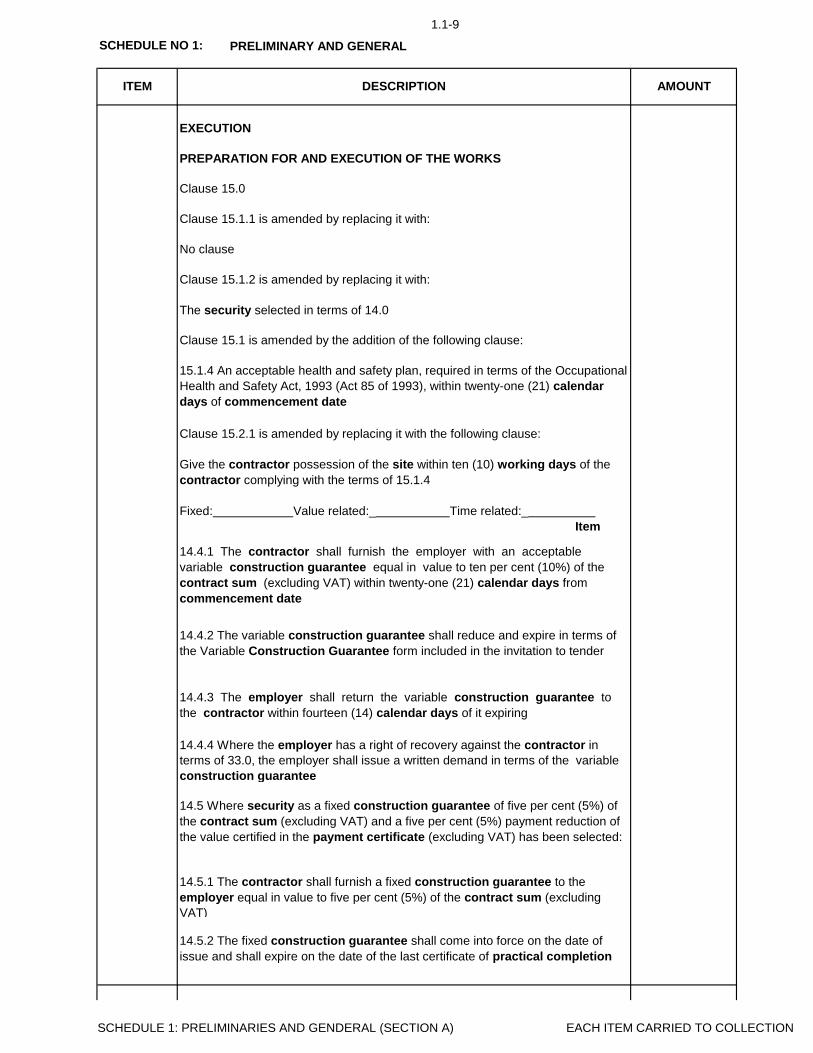
1.1-9
SCHEDULE NO 1: PRELIMINARY AND GENERAL
AMOUNTITEM DESCRIPTION
Clause 15.0
Clause 15.1.1 is amended by replacing it with:
No clause
Clause 15.1.2 is amended by replacing it with:
EXECUTION
PREPARATION FOR AND EXECUTION OF THE WORKS
Clause 15.2.1 is amended by replacing it with the following clause:
Give the contractor possession of the site within ten (10) working days of the
contractor complying with the terms of 15.1.4
Fixed: Value related:_ Time related:_
Item
The security selected in terms of 14.0
Clause 15.1 is amended by the addition of the following clause:
15.1.4 An acceptable health and safety plan, required in terms of the Occupational
Health and Safety Act, 1993 (Act 85 of 1993), within twenty-one (21) calendar
days of commencement date
14.5.2 The fixed construction guarantee shall come into force on the date of
issue and shall expire on the date of the last certificate of practical completion
14.4.1 The contractor shall furnish the employer with an acceptable
variable construction guarantee equal in value to ten per cent (10%) of the
contract sum (excluding VAT) within twenty-one (21) calendar days from
commencement date
14.4.2 The variable construction guarantee shall reduce and expire in terms of
the Variable Construction Guarantee form included in the invitation to tender
14.4.3 The employer shall return the variable construction guarantee to
the contractor within fourteen (14) calendar days of it expiring
14.4.4 Where the employer has a right of recovery against the contractor in
terms of 33.0, the employer shall issue a written demand in terms of the variable
construction guarantee
14.5 Where security as a fixed construction guarantee of five per cent (5%) of
the contract sum (excluding VAT) and a five per cent (5%) payment reduction of
the value certified in the payment certificate (excluding VAT) has been selected:
14.5.1 The contractor shall furnish a fixed construction guarantee to the
employer equal in value to five per cent (5%) of the contract sum (excluding
VAT)
SCHEDULE 1: PRELIMINARIES AND GENDERAL (SECTION A) EACH ITEM CARRIED TO COLLECTION

1.1-10
SCHEDULE NO 1: PRELIMINARY AND GENERAL
AMOUNTITEM DESCRIPTION
14.5.3 The employer shall return the fixed construction guarantee to the
contractor within fourteen (14) calendar days of it expiring
14.5.4 The payment reduction of the value certified in a payment certificate shall
be in terms of 31.8 (A) and 34.8
14.5.5 Where the employer has a right of recovery against the contractor in
terms of the 33.0 the employer shall be entitled to issue a written demand in
terms of the fixed construction guarantee or may recover from the payment
reduction or may do both
14.6 Where security as a cash deposit of five per cent (5%) of the contract sum
(excluding VAT) and a payment reduction of five per cent (5%) of the value
certified in the payment certificate (excluding VAT) has been selected:
14.7.2 The employer shall be entitled to recover expense and loss from the
payment reduction in terms of 33.0 provided that the employer complies with the
provisions of 33.4 in which event the employer’s entitlement shall take
precedence over his obligations to refund the payment reduction or portions
thereof to the contractor
14.8 Payments made by the guarantor to the employer in terms of the fixed or
variable construction guarantee shall not prejudice the rights of the employer or
contractor in terms of this agreement
14.9 Should the contractor fail to furnish the security in terms of 14.2, the
employer, in his sole discretion and without notification to the contractor, is entitled
to change the contractor’s selected form of security to that of a ten per cent (10%)
payment reduction of the value certified in the payment certificate (excluding VAT),
whereafter 14.7 shall be applicable
14.6.1 The contractor shall furnish the employer with a cash deposit equal in
value to five per cent (5%) of the contract sum (excluding VAT) within twenty-one
(21) calendar days from commencement date
14.6.2 Within twenty-one (21) calendar days of the date of practical completion
of the works the employer shall refund the cash deposit in total to the contractor
14.6.3 The payment reduction of the value certified in a payment certificate shall
be mutatis mutandi in terms of 31.8(A)
14.6.4 Where the employer has a right of recovery against the contractor in
terms of 33.0, the employer may issue a written notice in terms of 33.4 or may
recover from the payment reduction or may do both
14.7 Where security as a payment reduction of ten per cent (10%) of the value
certified in the payment certificate (excluding VAT) has been selected:
14.7.1 The payment reduction of the value certified in a payment certificate shall
be mutatis mutandi in terms of 31.8(B)
SCHEDULE 1: PRELIMINARIES AND GENDERAL (SECTION A) EACH ITEM CARRIED TO COLLECTION

1.1-11
SCHEDULE NO 1: PRELIMINARY AND GENERAL
AMOUNTITEM DESCRIPTION
A15.0
A16
A17.0
A18.0
A19.0
EXECUTION
PREPARATION FOR AND EXECUTION OF THE WORKS
The security selected in terms of 14.0
Clause 15.1 is amended by the addition of the following clause:
15.1.4 An acceptable health and safety plan, required in terms of the Occupational
Health and Safety Act, (Act 85 of 1993), R84 of February 7, 2014 Construction
Regulations that came into effect within twenty-one (21) calendar days of
commencement date
Clause 15.0
Clause 15.1.1 is amended by replacing it with:
Clause 15.1.2 is amended by replacing it with:
Fixed: Value related:_ Time related:_
Item
CONTRACT INSTRUCTIONS
Clause 17.0
Clause 17.1.11 is amended by deleting the words “and the appointment of
Clause 15.2.1 is amended by replacing it with the following clause:
Give the contractor possession of the site within ten (10) working days of the
contractor complying with the terms of 15.1.4
Fixed: Value related:_ Time related:_
Item
SITE AND ACCESS
Clause 16.0
Fixed: Value related:_ Time related:_
Item
TEMPOARARY WORKS AND PLANT
Clause 19.0
Fixed: Value related:_ Time related:_
Item
SETTING OUT OF THE WORKS
Clause 18.0
Fixed: Value related:_ Time related:_
Item
SCHEDULE 1: PRELIMINARIES AND GENDERAL (SECTION A) EACH ITEM CARRIED TO COLLECTION
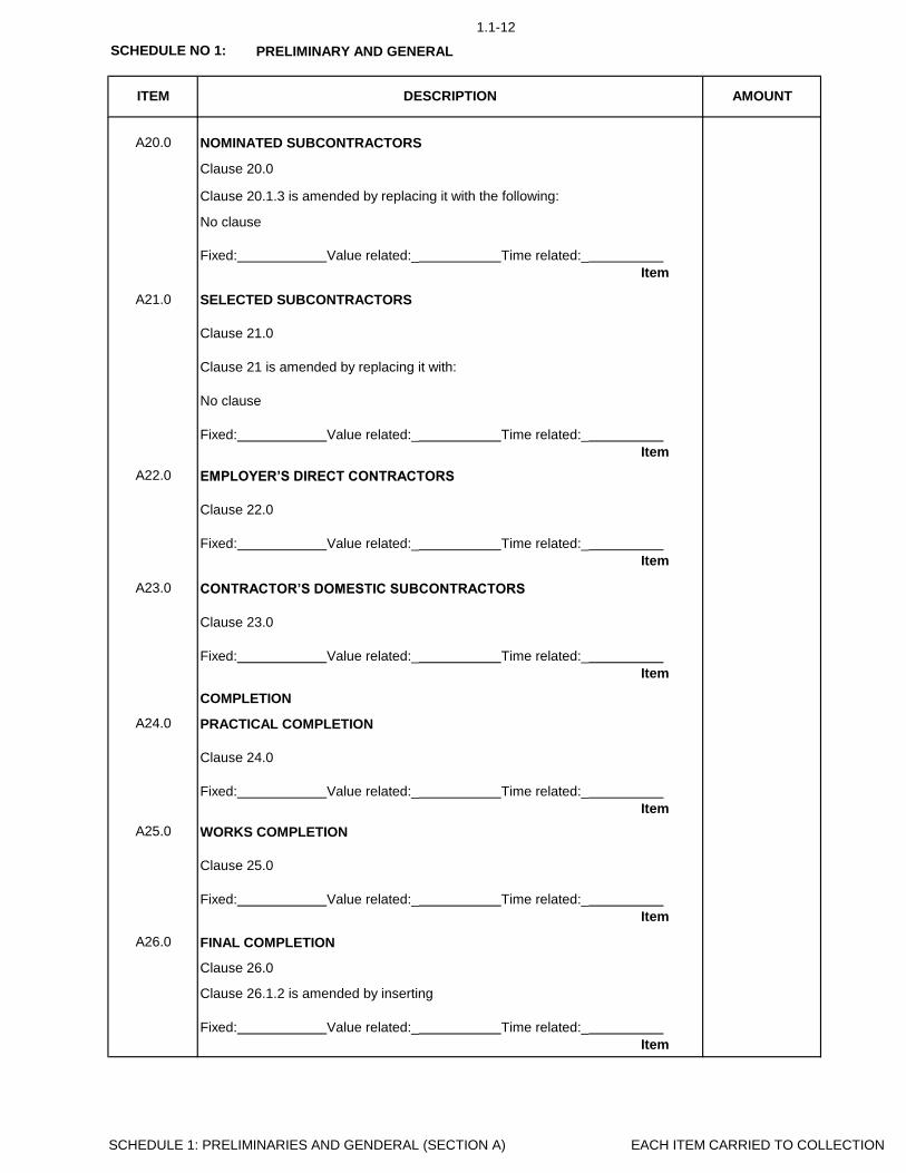
1.1-12
SCHEDULE NO 1: PRELIMINARY AND GENERAL
AMOUNTITEM DESCRIPTION
A20.0
No clause
A21.0
A22.0
A23.0
A24.0
A25.0
A26.0
Fixed: Value related:_ Time related:_
Item
SELECTED SUBCONTRACTORS
Clause 21.0
NOMINATED SUBCONTRACTORS
Clause 20.0
Clause 20.1.3 is amended by replacing it with the following:
EMPLOYER’S DIRECT CONTRACTORS
Clause 22.0
Fixed: Value related:_ Time related:_
Item
Clause 21 is amended by replacing it with:
No clause
Fixed: Value related:_ Time related:_
Item
COMPLETION
PRACTICAL COMPLETION
Clause 24.0
CONTRACTOR’S DOMESTIC SUBCONTRACTORS
Clause 23.0
Fixed: Value related:_ Time related:_
Item
Fixed: Value related:_ Time related:_
Item
FINAL COMPLETION
Clause 26.0
Fixed: Value related:_ Time related:_
Item
WORKS COMPLETION
Clause 25.0
Clause 26.1.2 is amended by inserting
Fixed: Value related:_ Time related:_
Item
SCHEDULE 1: PRELIMINARIES AND GENDERAL (SECTION A) EACH ITEM CARRIED TO COLLECTION

1.1-13
SCHEDULE NO 1: PRELIMINARY AND GENERAL
AMOUNTITEM DESCRIPTION
A27.0
A28.0
A29.0
A30.0
A31.0
Clause 27.0
Fixed: Value related:_ Time related:_
Item
SECTIONAL COMPLETION
LATENT DEFECTS LIABILITY PERIOD
Clause 29.0
Clause 29.2.5 is amended by replacing it with:
No clause
Clause 28.0
Fixed: Value related:_ Time related:_
Item
REVISION OF DATE FOR PRACTICAL COMPLETION
Fixed: Value related:_ Time related:_
Item
PAYMENT
INTERIM PAYMENT TO THE CONTRACTOR
Fixed: Value related:_ Time related:_
Item
PENALTY FOR LATE OR NON-COMPLETION
Clause 30.0
Clause 31.0
Clause 31.5.2 is amended by replacing “14.7.1” with “14.0”
Clause 31.8 is amended by replacing it with the following two alternative clauses:
Alternative A
31.8(A) Where a security is selected in terms of 14.1; 14.5 or 14.6, the value of
the works in terms of 31.4.1 and materials and goods in terms of 31.4.2 shall be
certified in full. The value certified shall be subject to the following percentage
adjustments:
31.8(A).1 Ninety-five per cent (95%) of such value in interim payment certificates
issued up to the date of practical completion
31.8(A).2 Ninety-seven per cent (97%) of such value in interim payment
certificates issued on the date of practical completion and up to but excluding
the date of final completion
31.8(A).3 Ninety-nine per cent (99%) of such value in interim payment
certificates issued on the date of final completion and up to but excluding the
final payment certificate in terms of 34.6
31.8(A).4 One hundred per cent (100%) of such value in the final payment
certificate in terms of 34.6 except where the amount certified is in favour of the
employer. In such an event the payment reduction shall remain at the adjustment
SCHEDULE 1: PRELIMINARIES AND GENDERAL (SECTION A) EACH ITEM CARRIED TO COLLECTION

1.1-14
SCHEDULE NO 1: PRELIMINARY AND GENERAL
AMOUNTITEM DESCRIPTION
A32.0
A33.0
A34.0
Clause 31.12 is amended by deleting the following:
Payment shall be subject to the employer giving the contractor a tax invoice for the
amount due
Fixed: Value related:_ Time related:_
Item
Alternative B
31.8(B) Where security as a payment reduction in terms of 14.7 has been
selected, the value of the works in terms of 31.4.1 and materials and goods in
terms of 31.4.2 shall be certified in full. The value certified shall be subject to the
following percentage adjustments:
31.8(B).1 Ninety per cent (90%) of such value in interim payment certificates
issued up to the date of practical completion
31.8(B).2 Ninety-seven per cent (97%) of such value in interim payment
certificates issued on the date of practical completion and up to but excluding
the date of final completion
31.8(B).3 Ninety-nine per cent (99%) of such value in interim payment
certificates issued on the date of final completion and up to but excluding the
final payment certificate in terms of 34.6
31.8(B).4 One hundred per cent (100%) of such value in the final payment
certificate in terms of 34.6 except where the amount certified is in favour of the
employer. In such an event the payment reduction shall remain at the adjustment
"due to no fault of the contractor"
Fixed: Value related:_ Time related:_
Item
RECOVERY OF EXPENSE AND LOSS
Clause 33.0
ADJUSTMENT TO THE CONTRACT VALUE
Clause 32.0
Clauses 32.5.1, 32.5.4 and 32.5.7 are amended by the addition of the following at
the end of the sentence:
Clause 34.1 is amended by removing
Clause 34.2 is amended by inserting
Fixed: Value related:_ Time related:_
Item
FINAL ACCOUNT AND FINAL PAYMENT
Clause 34.0
SCHEDULE 1: PRELIMINARIES AND GENDERAL (SECTION A) EACH ITEM CARRIED TO COLLECTION

1.1-15
SCHEDULE NO 1: PRELIMINARY AND GENERAL
AMOUNTITEM DESCRIPTION
A35.0
A36.0
A37.0
Clause 34.8 is amended by deleting the words “where security as a fixed
construction guarantee in terms of 14.4 has been selected or where payment
reduction has been applied in terms of 14.7.1”
Clause 34.13 is amended by replacing “seven (7) calendar days” with “twenty-
one (21) calendar days” and deleting the words “subject to the employer giving
the contractor a tax invoice for the amount due”
Fixed: Value related:_ Time related:_
Item
TERMINATION BY EMPLOYER – CONTRACTOR’S DEFAULT
Clause 36.0
Fixed: Value related:_ Time related:_
Item
PAYMENT TO OTHER PARTIES
Clause 35.0
36.1.5 in the judgement of the employer, has engaged in corrupt or fraudulent
practices in competing for or in executing the contract
Clause 36.3 is amended by removing the reference to “No clause” and replacing
the words “principal agent” with “employer”
Clause 36.0 is amended by the addition of the following clause:
Clause 36.1 is amended by the addition of the following clauses
36.1.3 refuses or neglects to comply strictly with any of the conditions of contract
36.1.4 estate being sequestrated, liquidated or surrendered in terms of the
insolvency laws in force within the Republic of South Africa
TERMINATION BY EMPLOYER – LOSS AND DAMAGE
Clause 37.0
Clause 37.3.5 is amended by replacing “ninety (90)” with “one-hundred and twenty
(120)”
Clause 36.0 is amended by the addition of the following clause:\
36.7 Notwithstanding any clause to the contrary, on cancellation of this
agreement either by the employer or the contractor; or for any reason
whatsoever, the contractor shall on written instruction, discontinue with the works
on a date stated and withdraw himself from the site. The contractor shall not be
entitled to refuse to withdraw from the works on the grounds of any lien or right of
retention or on the grounds of any other right whatsoever
Fixed: Value related:_ Time related:_
Item
Clause 37.0 is amended by the addition of the following clause:
SCHEDULE 1: PRELIMINARIES AND GENDERAL (SECTION A) EACH ITEM CARRIED TO COLLECTION

1.1-16
SCHEDULE NO 1: PRELIMINARY AND GENERAL
AMOUNTITEM DESCRIPTION
A38.0
A39.0
A40.0
Clause 38.0
Clause 38.5.4 is amended by replacing “ninety (90)” with “one-hundred and twenty
(120)”
Clause 38.0 is amended by the addition of the following clause:
37.5 Notwithstanding any clause to the contrary, on cancellation of this
agreement either by the employer or the contractor; or for any reason
whatsoever, the contractor shall on written instruction, discontinue with the
works on a date stated and withdraw himself from the site. The contractor shall
not be entitled to refuse to withdraw from the works on the grounds of any lien or
right of retention or on the grounds of any other right whatsoever
Fixed: Value related:_ Time related:_
Item
TERMINATION BY CONTRACTOR – EMPLOYER’S DEFAULT
Clause 39.0
Clause 39.3.5 is amended by the addition of the following at the end of the
sentence:
“within one hundred and twenty (120) working days of completion of such a
report”
38.7 Notwithstanding any clause to the contrary, on cancellation of this
agreement either by the employer or the contractor; or for any reason
whatsoever, the contractor shall on written instruction, discontinue with the
works on a date stated and withdraw himself from the site. The contractor shall
not be entitled to refuse to withdraw from the works on the grounds of any lien or
right of retention or on the grounds of any other right whatsoever
Fixed: Value related:_ Time related:_
Item
TERMINATION – CESSATION OF THE WORKS
Clause 40.0
Clause 40.2.2 is amended by replacing “one (1) year” with “three (3) years”
Clause 40.6 is amended by removing the reference to:
Fixed: Value related:_ Time related:_
Item
DISPUTE
SETTLEMENT OF DISPUTES
Fixed: Value related:_ Time related:_
Item
No clause
Clause 40.7.1 is amended by replacing “(10)” with “(15)” and by the addition of the
following:
Whether or not mediation resolves the dispute, the parties shall bear their own
costs concerning the mediation and equally share the costs of the mediator and
related costs
SCHEDULE 1: PRELIMINARIES AND GENDERAL (SECTION A) EACH ITEM CARRIED TO COLLECTION

1.1-17
SCHEDULE NO 1: PRELIMINARY AND GENERAL
B1.1
B2.0
B2.1
B2.2
B2.3
B2.4
B2.5
B2.6
B3.0
B3.1
B3.2
B3.3
B3.4
ITEM DESCRIPTION AMOUNT
Definitions and interpretation
Fixed: Value related: Time related:
Item
Provisional bills of quantities
Fixed: Value related: Time related:
Item
See also clause A1.0 of Section A for additional and/or amended definitions which
shall apply equally to this Section
Fixed: Value related: Time related:
Item
DOCUMENTS
Checking of documents
Fixed: Value related: Time related:
Item
Priced documents
Fixed: Value related: Time related:
Item
Availability of construction documentation
Fixed: Value related: Time related:
Item
Interests of agents
THE SITE
Defined works area
Geotechnical investigation
Tender submission
Clause 2.6 is amended by replacing “JBCC Form of Tender” with “The
Tender Page 97”
Fixed: Value related: Time related:
Item
Existing premises occupied
Fixed: Value related: Time related:
Item
Fixed: Value related: Time related:
Item
Inspection of the site
Fixed: Value related: Time related:
Item
SCHEDULE 1: PRELIMINARIES AND GENDERAL (SECTION B) EACH ITEM CARRIED TO COLLECTION

1.1-18
SCHEDULE NO 1: PRELIMINARY AND GENERAL
ITEM DESCRIPTION AMOUNT
B3.5
B3.6
B3.7
B3.8
B3.9
B3.9
B3.10
B3.11
B4. 0
B4.1
B4.2
B4.3
B4.4
B4.5
Previous work – dimensional accuracy
Services – known
Fixed: Value related: Time related:
Item
Services – unknown
Fixed: Value related: Time related:
Item
Previous work – defects
Fixed: Value related: Time related:
Item
Protection of trees
Fixed: Value related: Time related:
Item
Articles of value
Fixed: Value related: Time related:
Item
Protection of trees
Fixed: Value related: Time related:
Item
MANAGEMENT OF CONTRACT
Management of the works
Fixed: Value related: Time related:
Item
Fixed: Value related: Time related:
Item
Inspection of adjoining properties
Fixed: Value related: Time related:
Item
Fixed: Value related: Time related:
Item
Technical meetings
Fixed: Value related: Time related:
Item
Programme for the works
Fixed: Value related: Time related:
Item
Progress meetings
Labour and plant records
Fixed: Value related: Time related:
Item
SCHEDULE 1: PRELIMINARIES AND GENDERAL (SECTION B) EACH ITEM CARRIED TO COLLECTION

1.1-19
SCHEDULE NO 1: PRELIMINARY AND GENERAL
ITEM DESCRIPTION AMOUNT
B5.0
B5.1
B5.2
B5.3
B5.4
B6.0
B6.1
B6.2
B6.3
B6.4
B6.5
B6.6
B7.0
B7.1
Fixed: Value related: Time related:
Item
Workmanship samples
Fixed: Value related: Time related:
Item
SAMPLES, SHOP DRAWINGS AND MANUFACTURERS’ INSTRUCTIONS
Samples of materials
Fixed: Value related: Time related:
Item
TEMPORARY WORKS AND PLANT
Deposits and fees
Shop drawings
Fixed: Value related: Time related:
Item
Compliance with manufacturers’ instructions
Advertising
Fixed: Value related: Time related:
Item
Plant, equipment, sheds and offices
Fixed: Value related: Time related:
Item
Enclosure of the works
Fixed: Value related: Time related:
Item
Subcontractors’ notice board
Fixed: Value related: Time related:
Item
TEMPORARY SERVICES
Fixed: Value related: Time related:
Item
Main notice board
Fixed: Value related: Time related:
Item
Location
Fixed: Value related: Time related:
Item
SCHEDULE 1: PRELIMINARIES AND GENDERAL (SECTION B) EACH ITEM CARRIED TO COLLECTION

1.1-20
SCHEDULE NO 1: PRELIMINARY AND GENERAL
ITEM DESCRIPTION AMOUNT
B7.2
B7.3
B7.4
B7.5
B8.0
B8.1
B9.0
B9.1
B9.2
B9.3
B10.0
B10.1
B10.2
B10.3
Fixed: Value related: Time related:
Item
Electricity
Fixed: Value related:_ Time related:_
Item
Telecommunication facilities
Water
PRIME COST AMOUNTS
Responsibility for prime cost amounts
Fixed: Value related: Time related:
Item
Fixed: Value related: Time related:
Item
Ablution facilities
Fixed: Value related: Time related:
Item
Special attendance
Fixed: Value related: Time related:
Item
Commissioning – fuel, water and electricity
ATTENDANCE ON N/S SUBCONTRACTORS
General attendance
Fixed: Value related: Time related:
Item
Fixed: Value related: Time related:
Item
Payment for preliminaries
Fixed: Value related: Time related:
Item
Fixed: Value related: Time related:
Item
FINANCIAL ASPECTS
Statutory taxes, duties and levies
Adjustment of preliminaries
Clauses B10.3.1 and B10.3.2 are amended by replacing “within fifteen (15)
working days of taking possession of the site” with “when submitting his priced
bills of quantities / lump sum document”
Fixed: Value related: Time related:
Item
SCHEDULE 1: PRELIMINARIES AND GENDERAL (SECTION B) EACH ITEM CARRIED TO COLLECTION

1.1-21
SCHEDULE NO 1: PRELIMINARY AND GENERAL
ITEM DESCRIPTION AMOUNT
B10.4
B11.0
B11.1
B11.2
B11.3
B11.4
B11.5
B11.6
B11.7
B11.8
B11.9
B11.10
Fixed: Value related: Time related:
Item
GENERAL
Protection of the works
Fixed: Value related: Time related:
Item
Payment certificate cash flow
Fixed: Value related: Time related:
Item
Notice before covering work
Fixed: Value related: Time related:
Item
Protection / isolation of existing / sectionally occupied works
Fixed: Value related: Time related:
Item
Security of the works
Fixed: Value related: Time related:
Item
Works cleaning and clearing
Fixed: Value related: Time related:
Item
Disturbance
Fixed: Value related: Time related:
Item
Environmental disturbance
Fixed: Value related: Time related:
Item
Instruction manuals and guarantees
Fixed: Value related: Time related:
Item
Vermin
Fixed: Value related: Time related:
Item
Overhand work
SCHEDULE 1: PRELIMINARIES AND GENDERAL (SECTION B) EACH ITEM CARRIED TO COLLECTION

1.1-22
SCHEDULE NO 1: PRELIMINARY AND GENERAL
ITEM DESCRIPTION AMOUNT
B11.11
B11.12
B12.0
B12.1
12,1,1 PRE-TENDER INFORMATION
Refer to Contract Data
12,1,2 POST-TENDER INFORMATION
Refer to Contract Data
Fixed: Value related: Time related:
Item
This schedule contains all variables referred to in this document and is divided
into pre-tender and post-tender categories. The pre-tender category must be
completed in full and included in the tender documents. Both the pre-tender and
post-tender categories form part of these Preliminaries
Fixed: Value related: Time related:
Item
SCHEDULE OF VARIABLES
Schedule of variables
As built information
Fixed: Value related: Time related:
Item
Tenant installations
SCHEDULE 1: PRELIMINARIES AND GENDERAL (SECTION B) EACH ITEM CARRIED TO COLLECTION

1.1-23
SCHEDULE NO 1:
C1.0
C2.0
C3.0
ITEM DESCRIPTION AMOUNT
* The drawings issued with the tender documents do not comprise the complete
set but serve as a guide only for tendering purposes and for indicating the scope
of the work to enable the tenderer to acquaint himself with the nature and extent of
the works and the manner in which they are to be executed
Wherever a trade name for any product has been described in the bills of
quantities / lump sum document, the tenderer’s attention is drawn to the fact
that any other product of equal quality may be used subject to the written approval
of the principal agent being obtained prior to the closing date for submission of
tenders
Should any part of the drawings not be clearly understood by the tenderer he shall,
before submitting his tender, obtain clarification in writing from the principal agent
Fixed: Value related: Time related:
Item
PRELIMINARY AND GENERAL (SECTION C)
CONTRACT DRAWINGS
* Select relevant paragraph and delete whichever is not applicable depending on
whether the contract is based on a bills of quantities or lump sum document
SECTION C: SPECIFIC PRELIMINARIES
Fixed: Value related: Time related:
Item
TRADE NAMES
PREAMBLES
The Specifications shall be read in conjunction with the bills of quantities / lump
sum document and be referred to for the full descriptions of work to be done and
materials to be used
The speciifications are issued and shall be read in conjunction with the drawings
and the bills of quantities / lump sum document
Section C contains specific preliminary items which apply to this contract except
where N/A (Not Applicable) appears against an item
If prior written approval for an alternative product is not obtained, the product
described shall be deemed to have been tendered for
Fixed: Value related: Time related:
Item
SCHEDULE 1: PRELIMINARIES AND GENDERAL (SECTION C) EACH ITEM CARRIED TO COLLECTION

1.1-24
SCHEDULE NO 1:
ITEM DESCRIPTION AMOUNT
PRELIMINARY AND GENERAL (SECTION C)
C4.0
C5.0
0,1
0,2
0,3
IMPORTED MATERIALS AND EQUIPMENT
Where imported items are listed in the tender documents, the tenderer shall
provide all the information called for, failing which the price of any such item,
materials or equipment shall be excluded from currency fluctuations. (refer to
Annexure D Imported Content Declaration)
Notwithstanding any provisions elsewhere regarding the adjustment of contract
prices, the price of any item, material or equipment listed in terms of this clause
shall be excluded from the Contract Price Adjustment Provisions (if applicable)
Fixed: Value related: Time related:
Item
Fixed: Value related: Time related:
Item
OCCUPATIONAL HEALTH AND SAFETY ACT
The contractor shall comply with all the requirements as set out in the
Construction Regulations, 2014 issued under the Occupational Health and Safety
Act, 1993 (Act No 85 of 1993)
It is required of the contractor to thoroughly study the Health and Safety
Specification that must be read together with and is deemed to be incorporated
under this Section of the bills of quantities / lump sum document
The contractor must take note that compliance with the Occupational Health and
Safety Act, Construction Regulations and Health and Safety Specification is
compulsory. In the event of partial or total non-compliance, the principal agent,
notwithstanding the provisions of clause A31.0 of Section A or any other clause to
the contrary, reserves the right to delay issuing any progress payment certificate
until the contractor provides satisfactory proof of compliance. The contractor
shall not be entitled to any compensation of whatsoever nature, including interest,
due to such delay of payment
Provision for pricing of the Occupational Health and Safety Act, Construction
Regulations and Health and Safety Specification is made under this clause and it
is explicitly pointed out that all requirements of the aforementioned are deemed to
be priced hereunder and no additional claims in this regard shall be entertained
Preparartion of Health and Safety Plan. Impleamentation and
maintenance of Health and Safety Plan
Fixed: Value related: Time related:
Item
Health and Safety Training. Implementation and maintenance of Training
Personal Protective Clothing and equipment. Maintenance of Personal
Protective Clothing and Equipment
Fixed: Value related: Time related:
Item
SCHEDULE 1: PRELIMINARIES AND GENDERAL (SECTION C) EACH ITEM CARRIED TO COLLECTION

1.1-25
SCHEDULE NO 1:
ITEM DESCRIPTION AMOUNT
PRELIMINARY AND GENERAL (SECTION C)
0,4
0,5
0,6
C6.0
0,1
0,2
0,3
0,4
The contractor shall comply with all the requirements as set out in the
Construction Regulations, 2014 issued under the Occupational Health and Safety
Act, 1993 (Act No 85 of 1993), in conjunction with the Hazardous Biological
Agents Regulation.
Fences, Signs and Barricades. Maintenance of Fence, Signs and
Barricades
Fixed: Value related: Time related:
Item
Establishment of Safety Administration. Implementation and maintenance
of Safety Administration
Fixed: Value related: Time related:
Item
Other Health and Safety Fixed-charge Obligations. Other Health and
Safety Time-Related Obligations
Fixed: Value related: Time related:
Item
COVID-19 GUIDELINES
Fixed: Value related: Time related:
Item
It is required of the contractor to thoroughly study the COVID-19 Specification
that must be read together with and is deemed to be incorporated under this
Section of the bills of quantities / lump sum document
The contractor must take note that compliance with the Occupational Health and
Safety Act, Construction Regulations and Health and Safety Specification is
compulsory. In the event of partial or total non-compliance, the principal agent,
notwithstanding the provisions of clause A31.0 of Section A or any other clause to
the contrary, reserves the right to delay issuing any progress payment certificate
until the contractor provides satisfactory proof of compliance. The contractor
shall not be entitled to any compensation of whatsoever nature, including interest,
due to such delay of payment
Provision for pricing of the COVID-19 is made under this clause and it is explicitly
pointed out that all requirements of the aforementioned are deemed to be priced
hereunder and no additional claims in this regard shall be entertained
Appointment of COVID-19 awareness champion
Fixed: Value related: Time related:
Item
Arranging awareness workshops
Fixed: Value related: Time related:
Item
Providing Sanitizing/ Washing facilities
Fixed: Value related: Time related:
Item
Provide notices and posters
SCHEDULE 1: PRELIMINARIES AND GENDERAL (SECTION C) EACH ITEM CARRIED TO COLLECTION

1.1-26
SCHEDULE NO 1:
ITEM DESCRIPTION AMOUNT
PRELIMINARY AND GENERAL (SECTION C)
0,5 Provide screening facility
Fixed: Value related: Time related:
Item
SCHEDULE 1: PRELIMINARIES AND GENDERAL (SECTION C) EACH ITEM CARRIED TO COLLECTION

1.1-27
SCHEDULE NO 1: PRELIMINARIES AND GENERAL
COLLECTION Page AMOUNT
Item
A1.0 1.1-2
A2.0 1.1-3
A3.0 1.1-3
A4.0 1.1-3
A5.0 1.1-3
A6.0 1.1-3
A7.0 1.1-3
A8.0 1.1-4
A9.0 1.1-4
A10.0 1.1-4
A11.0 1.1-6
A12.0 1.1-6
A13.0 1.1-6
A14.0 1.1-6
A15.0 1.1-11
A16.0 1.1-11
A17.0 1.1-11
A18.0 1.1-11
A19.0 1.1-11
A20.0 1.1-12
A21.0 1.1-12
A22.0 1.1-12
A23.0 1.1-12
A24.0 1.1-12
A25.0 1.1-12
A26.0 1.1-12
A27.0 1.1-13
A28.0 1.1-13
A29.0 1.1-13
A30.0 1.1-13
A31.0 1.1-13
A32.0 1.1-14
A33.0 1.1-14
A34.0 1.1-14
A35.0 1.1-15
Design responsibility
Employer’s agents
Contractor's Site representative
Compliance with laws and regulations
Works risk
Indemnities
SECTION A: JBCC PRINCIPAL BUILDING AGREEMENT
Definitions
Definitions and interpretation
Objective and Preparation
Offer, acceptance and performance
Documents
Preparation for and execution of the works
Site and Access
Contract instructions
Setting out of the works
Temporary Works and Plant
Nominated subcontractors
General insurances
Special insurances
Effecting insurances
Assignment
Security
Execution
Works completion
Final completion
Latent defects liability period
Sectional completion
Revision of date for practical completion
Penalty for late or non-completion
Selected subcontractors
Employer's direct contractors
Contractor’s domestic subcontractors
Completion
Practical completion
Payment to other parties
Carried forward R
Payment
Interim payment to the contractor
Adjustment to the contract value
Recovery of expense and loss
Final account and final payment
SCHEDULE 1: PRELIMINARIES AND GENDERAL: COLLECTION EACH ITEM CARRIED TO COLLECTION

1.1-28
SCHEDULE NO 1: PRELIMINARIES AND GENERAL
COLLECTION Page AMOUNT
Item
A36.0 1.1-15
A37.0 1.1-15
A38.0 1.1-16
A39.0 1.1-16
A40.0 1.1-16
B1.0
B1.1 1.1-17
B2.0
B2.1 1.1-17
B2.2 1.1-17
B2.3 1.1-17
B2.4 1.1-17
B2.5 1.1-17
B2.6 1.1-17
B3.0
B3.1 1.1-17
B3.2 1.1-17
B3.3 1.1-17
B3.4 1.1-17
B3.5 1.1-18
B3.6 1.1-18
B3.7 1.1-18
B3.8 1.1-18
B3.9 1.1-18
B3.10 1.1-18
B3.11 1.1-18
B4.0
B4.1 1.1-18
B4.2 1.1-18
B4.3 1.1-18
B4.4 1.1-18
B4.5 1.1-18
Cancellation
Settlement of disputes
Termination by employer – contractor’s default
Termination by employer – loss and damage
Termination by contractor – employer’s default
Termination – cessation of the works
Dispute
Provisional bills of quantities
Availability of construction documentation
Interests of agents
Priced documents
Tender submission
The Site
SECTION B: JBCC PRELIMINARIES
Definitions and interpretation
Definitions and interpretation
Documents
Checking of documents
Services – known
Services – unknown
Protection of trees
Articles of value
Inspection of adjoining properties
Management of contract
Defined works area
Geotechnical investigation
Inspection of the site
Existing premises occupied
Previous work – dimensional accuracy
Previous work – defects
Management of the works
Programme for the works
Progress meetings
Technical meetings
Labour and plant records
Carried forward R
SCHEDULE 1: PRELIMINARIES AND GENDERAL: COLLECTION EACH ITEM CARRIED TO COLLECTION

1.1-29
SCHEDULE NO 1: PRELIMINARIES AND GENERAL
COLLECTION Page AMOUNT
Item
B5.0
B5.1 1.1-19
B5.2 1.1-19
B5.3 1.1-19
B5.4 1.1-19
B6.0
B6.1 1.1-19
B6.2 1.1-19
B6.3 1.1-19
B6.4 1.1-19
B6.5 1.1-19
B6.6 1.1-19
B7.0
B7.1 1.1-19
B7.2 1.1-20
B7.3 1.1-20
B7.4 1.1-20
B7.5 1.1-20
B8.0
B8.1 1.1-20
B9.0
B9.1 1.1-20
B9.2 1.1-20
B9.3 1.1-20
B10
B10.1 1.1-20
B10.2 1.1-20
B10.3 1.1-20
B10.4 1.1-21
B11.0
B11.1 1.1-21
B11.2 1.1-21
B11.3 1.1-21
B11.4 1.1-21
B11.5 1.1-21
B11.7 1.1-21
B11.8 1.1-21
B11.9 1.1-21
B11.10 1.1-21
B11.11 1.1-22
B11.12 1.1-22
Samples, shop drawings and manufacturers’ instructions
Samples of materials
Workmanship samples
Plant, equipment, sheds and offices
Main notice board
Subcontractors’ notice board
Temporary services
Location
Shop drawings
Compliance with manufacturers’ instructions
Temporary works and plant
Deposits and fees
Enclosure of the works
Advertising
Responsibility for prime cost amounts
Attendance on N/S subcontractors
General attendance
Special attendance
Commissioning – fuel, water and electricity
Water
Electricity
Telecommunication facilities
Ablution facilities
Prime cost amounts
General
Protection of the works
Protection / isolation of existing / sectionally occupied works
Security of the works
Notice before covering work
Disturbance
Financial aspects
Statutory taxes, duties and levies
Payment for preliminaries
Adjustment of preliminaries
Payment certificate cash flow
Carried forward R
Works cleaning and clearing
Vermin
Overhand work
Instruction manuals and guarantees
As built information
Tenant installations
SCHEDULE 1: PRELIMINARIES AND GENDERAL: COLLECTION EACH ITEM CARRIED TO COLLECTION

1.1-30
SCHEDULE NO 1: PRELIMINARIES AND GENERAL
COLLECTION Page AMOUNT
Item
B12.0
B12.1 1.1-22
C1.0 1.1-23
C2.0 1.1-23
C3.0 1.1-23
C4.0 1.1-24
C5.0 1.1-24
C6.0 1.1-25
R
Schedule of Variables
Schedule of variables
Occupational Health and Safety Act
COVID-19
SECTION 1
PRELIMINARIES
SECTION C: JBCC PRELIMINARIES
Contract drawings
Preambles
Trade names
Imported materials and equipment
CARRIED TO FINAL SUMMARY
SUBTOTALS:
Category: Fixed R
Category: Value R
Category: Time R
SCHEDULE 1: PRELIMINARIES AND GENDERAL: COLLECTION EACH ITEM CARRIED TO COLLECTION

2-1
SCHEDULE NO 2:
PAYMENT
REFERS ITEM DESCRIPTION UNIT QUAN- RATE AMOUNT
TO NO TITY
200,00
201,00
BA.01 201,01
.01
,01
m2
60
,02
m2
580
.02
,01
m2
75
BA.03 201,02
.01
m2
60
.02m
2580
BA.06 201,03
.01
.01 m 40
.02 m 80
Carried forward
Carefully refix existing roof sheeting
that was stockpiled.
0,8mm thick Ridge flashing
0,47mm thick Roof closures
STRUCTURAL AND BUILDING RELATED REPAIR WORK
Supply and install cladding and sheeting:
0,6 mm Thick galvanised IBR or equivalent
approved sheeting with CHROMADEK
silicone polyester finish on one side and
CHROMADEK finish on the other side in:
Carefully remove existing cladding and
sheeting
Existing galvanised sheet metal roof
covering removed from timber or steel
purlins or girts
Supply and install sundry items, etc.:
Galvanised sheet iron flashings with
CHROMADEK silicone polyester finish to
one side of sundry items to Kliplok or
concealed fixing roof sheeting complete as
detailed in BA 03.01:
Roof covering with pitches exceeding
not 15°, fixed to timber or steel purlins
0,6 mm "Kliplok" or similar heavy industrial
AZ150 Zincalume sheeting roll formed in
continuous lengths from certified steel, all
to carry a minimum 20 year guarantee for
both the material and paintwork fixed to
timber purlins or rails complete with
flashing:
Roof covering with pitches exceeding
15°, fixed to timber or steel purlins
Carefully remove roof sheeting, stockpile,
clean and store.
STRUCTURAL AND BUILDING
BA : ROOFS

2-2
SCHEDULE NO 2:
PAYMENT
REFERS ITEM DESCRIPTION UNIT QUAN- RATE AMOUNT
TO NO TITY
STRUCTURAL AND BUILDING RELATED REPAIR WORK
Brought forward
BA.08 201,04
.01
,01
m 30
,02
m 4
BA.09 201,05
.01 m 30
.02 m 4
201,06
BA.11 .01 m2
1100
BA.15 .02
m2
100
BA.17 .03m
21100
BC.02.01 201,07
.01
.01
m2
15
202,00
BB.02 202,01
BB.02 .01
.01
m2 820
Carried forward
Down pipes
125 x 150mm Ógee" gutter including
brackets fixed to galvanised steel
purlins.
125 x 150mm Ógee" downpipes
including brackets fixed to brickwall.
Pure acrylic emulsion waterproofing
paint with polyester membrane or
glass-fibre tissue waterproofing
sealing system.
600 mm x 600 mm x 15 mm thick pre-
painted tiles
Rehabilitation:
Roof rehabilitation
Prepare existing galvanised or previously
painted roof sheeting and paint with a
polyurethane coating system as per
technical specification BA 03.01
Pressure wash and clean existing roof
including gutters
Supply and install rainwater goods:
"Watertite"or similar approved seameless
aluminium gutters and downpipes:
Carefully remove existing rainwater goods:
Eaves gutters
Waterproofing system:
Items measured by square metre:
BB: CARPENTRY
Ceilings:
Pre-painted "OWA" Mineral fibre acoustic
suspended ceiling tiles or similar approved
on "OWA" pre-painted exposed tee
suspension system, including main and
cross tees, necessar hangers, grids, etc.
hung from steel purlins :

2-3
SCHEDULE NO 2:
PAYMENT
REFERS ITEM DESCRIPTION UNIT QUAN- RATE AMOUNT
TO NO TITY
STRUCTURAL AND BUILDING RELATED REPAIR WORK
Brought forward
.02
m2
570
.03
m2
610
.02
m 1200
.03
No 1140
BB.04 202,02
.01
.01
m2
50
.02
m2
570
.03
m2
80
203,00
SANS
1200 DA
8,3 203,01
8.3.2 .01
m3
81
.02 Extra over item 203.01.01 above for:
.01 m³ 15
.03m
35
8.3.4 .04
m3
10
.05
m3
140
Carried forward
Install 50mm thick Isoboard recovered
from existing roof on to new strand
wire above bottom chord (strand wire
measured elsewhere).
Sisalation 420 heavy industrial grade
aluminium foil over rafters at
approximatley 760mm centes
including straining wires
Alterations and repairs to existing
structures:
Remove:
BD: WALLS
Suspended ceiling 600 x 1200mm
inncluding all main tees, cross tees
and ancillary items.
Remove 50mm thick Isoboard from
underside of roof and store for re-use
Galvanised steel 3mm thick wire rope
cable including ancillary fixing accessories
Remove existing 1200 x 600mm
suspended ceiling board, place one
side, and re-fit back into original
position (Offices).
Galvanised steel Y-rope clamps for 3mm
diameter wire
EARTHWORKS (SMALL WORKS)
Scheduled Items:
Excavate for restricted foundation, footings
and trenches in all materials and use for
backfill or embankment or dispose
Break up, hack of and remove existing
concrete
Importing, placing and compacting
approved G7 material in layers of 150mm
from commercial sources or from borrow
pits to 93% MOD AASHTO
Backfill stockpiled soil around retaining wall
in layers of 150mm and compact.
Intermediate excavation

2-4
SCHEDULE NO 2:
PAYMENT
REFERS ITEM DESCRIPTION UNIT QUAN- RATE AMOUNT
TO NO TITY
STRUCTURAL AND BUILDING RELATED REPAIR WORK
Brought forward
SABS 204,00
1200 G
8,4
8.4.3 204,01
.01 m3 3
.02
m3 39
.03m3 2
SABS 205,00 STRUCTURAL STEELWORK
1200 H
8.3.1 205,01
.01 Supply only:
.01
t 1
.02
t 0,85
.03
t 1
.04
t 0,15
8.3.2 205,02 Delivery to site
.01 Normal Delivery
.01
t 3
8.3.3 205,03 Erection on site
.01
t 3
Carried forward
CONCRETE (STRUCTURAL)
SCHEDULED CONCRETE ITEMS
Strength concrete:
Class 25 MPa / 19mm concrete for bases
Strength concrete: 30MPa/19mm for
retaining wall
Square Hollow Section columns with
flat section base and end plates
Square Hollow Section rafters with flat
section end plates, etc
Cold rolled lipped channels purlins
with angle section fixing cleats
Angle section bracing with flat section
connection plates
Columns, rafters, purlins and braces.
For carport structure as measured
under item 205,01 as measured above
Columns, rafters, purlins and braces and
bolts complete as scheduled under items
205,01 above
Supply and fabrication of steelwork as per
DWG 0534-02-01:
Class 25 MPa / 19mm concrete in floor
slabs up to 150mm thick
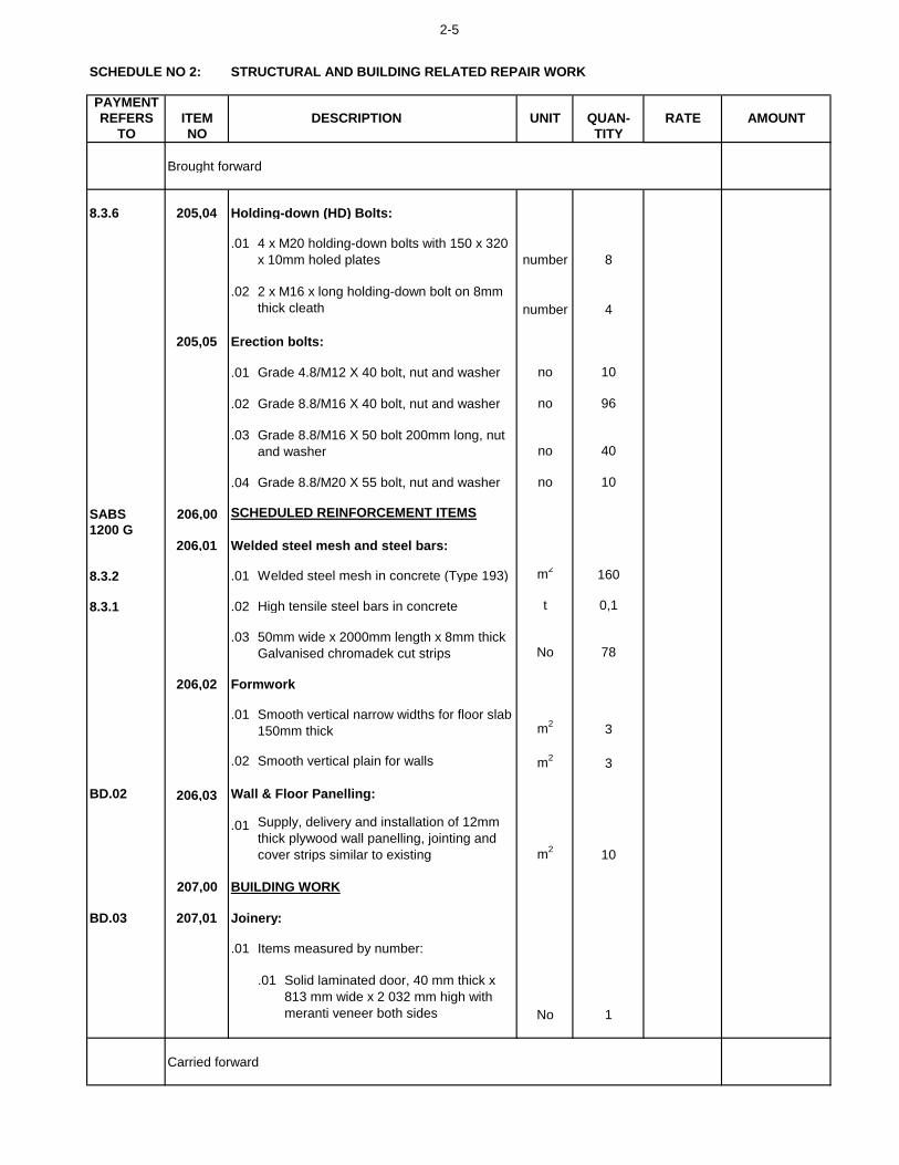
2-5
SCHEDULE NO 2:
PAYMENT
REFERS ITEM DESCRIPTION UNIT QUAN- RATE AMOUNT
TO NO TITY
STRUCTURAL AND BUILDING RELATED REPAIR WORK
Brought forward
8.3.6 205,04 Holding-down (HD) Bolts:
.01
number 8
.02
number 4
205,05 Erection bolts:
.01 Grade 4.8/M12 X 40 bolt, nut and washer no 10
.02 Grade 8.8/M16 X 40 bolt, nut and washer no 96
.03
no 40
.04 Grade 8.8/M20 X 55 bolt, nut and washer no 10
SABS 206,00 SCHEDULED REINFORCEMENT ITEMS
1200 G
206,01 Welded steel mesh and steel bars:
8.3.2 .01 Welded steel mesh in concrete (Type 193) m2
160
8.3.1 .02 High tensile steel bars in concrete t 0,1
.03No 78
206,02 Formwork
.01m
23
.02 m2
3
BD.02 206,03 Wall & Floor Panelling:
.01
m2
10
207,00
BD.03 207,01
.01 Items measured by number:
.01
No 1
Carried forward
Smooth vertical narrow widths for floor slab
150mm thick
Smooth vertical plain for walls
4 x M20 holding-down bolts with 150 x 320
x 10mm holed plates
2 x M16 x long holding-down bolt on 8mm
thick cleath
Supply, delivery and installation of 12mm
thick plywood wall panelling, jointing and
cover strips similar to existing
BUILDING WORK
Joinery:
Solid laminated door, 40 mm thick x
813 mm wide x 2 032 mm high with
meranti veneer both sides
Grade 8.8/M16 X 50 bolt 200mm long, nut
and washer
50mm wide x 2000mm length x 8mm thick
Galvanised chromadek cut strips
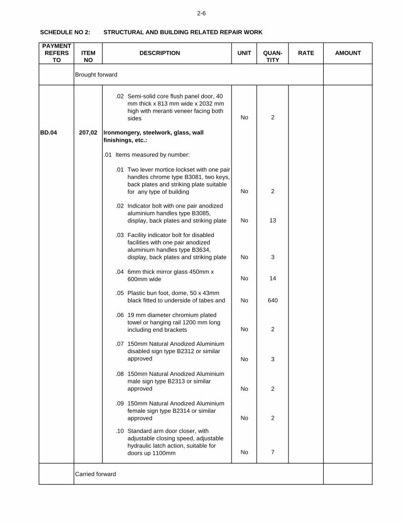
2-6
SCHEDULE NO 2:
PAYMENT
REFERS ITEM DESCRIPTION UNIT QUAN- RATE AMOUNT
TO NO TITY
STRUCTURAL AND BUILDING RELATED REPAIR WORK
Brought forward
.02
No 2
BD.04 207,02
.01
.01
No 2
.02
No 13
.03
No 3
.04No 14
.05
No 640
.06
No 2
.07
No 3
.08
No 2
.09
No 2
.10
No 7
Carried forward
Semi-solid core flush panel door, 40
mm thick x 813 mm wide x 2032 mm
high with meranti veneer facing both
sides
Two lever mortice lockset with one pair
handles chrome type B3081, two keys,
back plates and striking plate suitable
for any type of building
Indicator bolt with one pair anodized
aluminium handles type B3085,
display, back plates and striking plate
Facility indicator bolt for disabled
facilities with one pair anodized
aluminium handles type B3634,
display, back plates and striking plate
6mm thick mirror glass 450mm x
600mm wide
Ironmongery, steelwork, glass, wall
finishings, etc.:
Items measured by number:
Plastic bun foot, dome, 50 x 43mm
black fitted to underside of tabes and
19 mm diameter chromium plated
towel or hanging rail 1200 mm long
including end brackets
150mm Natural Anodized Aluminium
disabled sign type B2312 or similar
approved
150mm Natural Anodized Aluminium
male sign type B2313 or similar
approved
150mm Natural Anodized Aluminium
female sign type B2314 or similar
approved
Standard arm door closer, with
adjustable closing speed, adjustable
hydraulic latch action, suitable for
doors up 1100mm

2-7
SCHEDULE NO 2:
PAYMENT
REFERS ITEM DESCRIPTION UNIT QUAN- RATE AMOUNT
TO NO TITY
STRUCTURAL AND BUILDING RELATED REPAIR WORK
Brought forward
BD.04 .11
No 4
.12
No 4
.12
No 3
.13
No 10
.14
No 2
.15
No 4
.16No 3
.17No 3
.18No 1
.02
.01 No 3
.02
No 3
.03
.01
m 60
.02
m 25
.03
m 10
Carried forward
Ceasarstone Quartz countertops
30mm thick code:3040 Titan for
bathroom wash hand basins as per
DWG 0534-02-03, (WHB measured
elsewhere)
1200 x 600mm high bulletin board,
complete with aluminium frame and
mounting hooks code: BD0540
1200 x 800mm high magnetic
whiteboard, complete with pen tray
and anodised aluminium frame fixed to
wall
3000 x 1000mm high magnetic
whiteboard, complete with pen tray
and anodised aluminium frame fixed to
wall code: BD1240
430 x 650mm ceiling mounting bracket
for projector, height and angle
adjustable
Electric projector screen 2440 x
2440mm
Projector screen ceiling box to fit
2440mm screen
Defy 600mm slimline touch control
ceran hob and oven
Cistern back rail 750mm long
Dog leg side grab rail 300 x 300 x
300mm
Silicone sealant in 6 mm contact joint
between sanitary fittings and wall
Polyurethane sealant in 12 mm
expansion joint in face brick walls
1200 x 900mm high Pinning Display
case, complete with aluminium frame
with reinforced plastic covers,
toughened glass, sliding doors and
mounting hooks
32mm diameter stainless steel grab bars
for disabled facilities:
Items measured by linear metre:
1000 x 1000mm high bulletin board,
complete with aluminium frame and
mounting hooks code: BD0544

2-8
SCHEDULE NO 2:
PAYMENT
REFERS ITEM DESCRIPTION UNIT QUAN- RATE AMOUNT
TO NO TITY
STRUCTURAL AND BUILDING RELATED REPAIR WORK
Brought forward
BD.04 .04
.01
.01 On walls m2 230
.02m
25
.03m
230
.04 m2
30
.05 m2
30
.06
m2
5
.07 m2
70
.08 m2
20
.09
m2
70
BD.05 207,03
.01
.01
No 35
.02
No 15
Carried forward
Corrective work to existing structures:
Repair and re-fix:
Attend to, service and repair as
necessary timber door 1600 x
2100mm high overall including
replacing any defective or misisng
parts, ancillary items and edge plane
door if necessary to ensure door is
properly aligned to open and close
correctly.
230mm thick face brick walls buff satin
- FBS or similar approved
Internal cement plaster to walls
External cement plaster to walls
30mm thick Ceasarstone Quartz
countertops code:3040 Titan for
classrooms
Attend to, service and repair as
necessary timber door 890 x 2100mm
high overall including replacing any
defective or misisng parts, ancillary
items and edge plane door if
necessary to ensure door is properly
aligned to open and close correctly.
Allow a PC amount of R 300,00/m2 for
supply only of porcelain tiles fixed with
adhesive to bedding (bedding
elsewhere) and flush pointed with
tinted waterproof jointing compound:
4 mm clear float glass to steel sashes
with putty
4 mm fosted glass with meural to steel
sashes with putty
110 mm thick brick walls
230 mm thick brick walls
Items measured by area:

2-9
SCHEDULE NO 2:
PAYMENT
REFERS ITEM DESCRIPTION UNIT QUAN- RATE AMOUNT
TO NO TITY
STRUCTURAL AND BUILDING RELATED REPAIR WORK
Brought forward
BD.05 .02
.01 No 10
.02 No 4
.03 No 13
.04 No 7
.05No 20
.06
No 3
.07 No 3
.08 No 8
.09 No 1
.10 No 2
.03
.01 m2 10
.02 m2 70
.03 m 20
.04m
25
.05 m2
70
208,00
BE.03 208,01
.01
.01
.01 On floors m2 50
.02
.01 On floors m2 87
.02 Tile skirting 100mm high m 42
Carried forward
Remove:
Break out/hack up/demolish and remove:
External plaster to walls
Timber single or double door
All types of locksets with handles
Allow a PC amount of R 300,00/m2 for
supply only of porcelain tiles fixed with
adhesive to bedding (bedding
elsewhere) and flush pointed with
tinted waterproof jointing compound:
4 mm clear float glass to steel sashes
with putty
Wooden counter tops
Allow a PC amount of R 500,00/m2 for
supply only of 660mm long x 75mm x
16mm thick hardwood timber flooring
fixed to match existing:
BE: FLOORS
Internal plaster to walls
Curtain rails
Floor tiling and finishes, etc.:
Items measured by area:
Mirror glass 450mm x 600mm wide
15 mm roller ball catch with striking
plate
Towel or hanging rail including end
brackets
Standard arm door closers
1200 x 800mm green board
2700 x 2450mm green board
1200 x 800mm white board
Door frames

2-10
SCHEDULE NO 2:
PAYMENT
REFERS ITEM DESCRIPTION UNIT QUAN- RATE AMOUNT
TO NO TITY
STRUCTURAL AND BUILDING RELATED REPAIR WORK
Brought forward
.03
.01 On floors m2 273
.02 On treads, risers etc. m2 15
.04
.01 20mm thick cement screed m2 282
.02 6mm thick self-leveling screed m2 510
.05
.01 On floors m2 273
.02
.01
m 30
.02
m 8
.03
m 85
BE.04 208,02
.01
.01 m2 190
.02 m2 10
.03 m2 140
209,00
BH.01 209,01
BH.02
.01
.01
Carried forward
Carpet tiles
Vinyl tiles
Wooden flooring
BH: FITTINGS
Steelwork and joinery:
Items measured by number:
Floor screeds:
S128 Aluminium finish trims to door
openings
32mm Stained Fin Oak quadrants or
similair approved
Allow a PC amount of R 450,00/m2 for
supply only of Diamond Core
SPC antique wood finish 1500 x 228 x
6,5mm thick incl 1,5mm IXPE underlay
stone plastic composite vinyl flooring,
fixed with adhesive to bedding
(bedding measured elsewhere):
Alterations and repairs to existing
structures:
Remove:
Kitchen cupboard.
Carcase to be manufactured from
white Bison "A" grade board with high
impact edging. Backing to be 5mm
white hardboard. Doors to be 16mm
melamine Handles to be 10mm dia X
190mm stainless steel bar handles.
Door hinges to be "Blum" or similar
approved.
Supply and and istall HDPE 80 Micron
Damp Proof Membrane:
Items measured by linear:
S231 Aluminium nosing to tread and
risers of steps

2-11
SCHEDULE NO 2:
PAYMENT
REFERS ITEM DESCRIPTION UNIT QUAN- RATE AMOUNT
TO NO TITY
STRUCTURAL AND BUILDING RELATED REPAIR WORK
Brought forward
.01 Type A:
Bottom unit size 1400 mm wide x
600 mm x 900 mm high with three
doors, and one shelf. Carcase to
be on 150mm high adjustable
legs. Cupboard plinth to be cherry
royale melamine. 30mm thick
Ceasarstone quartz counter tops
to cupboard to have 180 degree
edge and shall be waterproof. No 2
BH.01
BH.02 .02 Type B:
Bottom unit size up to 1500 mm x
600 mm x 900 mm high with two
doors with one shelf and one
section for 4 drawers (500 wide x
200 high x 500 deep mounted on
full extension telescopic runners.
Carcase to be on 150mm high
adjustable legs. Cupboard plinth
to be aluminium (Raiel or similar
approved). 30mm thick
Ceasarstone quartz counter tops
to cupboard to have 180 degree
edge and shall be waterproof.
Drawer fronts to be Cherry Royale
melamine No 2
.03 Type C:
Bottom unit size up to 5500 mm x
600 mm x 900 mm high with eight
doors with one shelf and two
sections for 4 drawers (500 wide x
200 high x 500 deep mounted on
full extension telescopic runners.
Carcase to be on 150mm high
adjustable legs. Cupboard plinth
to be aluminium (Raiel or similar
approved). Ceasarstone quartz
counter tops to cupboard to have
180 degree edge and shall be
waterproof. Drawer fronts to be
Cherry Royale melamine
No 3
Carried forward

2-12
SCHEDULE NO 2:
PAYMENT
REFERS ITEM DESCRIPTION UNIT QUAN- RATE AMOUNT
TO NO TITY
STRUCTURAL AND BUILDING RELATED REPAIR WORK
Brought forward
.04 Type D:
Bottom unit size up to 11000 mm
x 600 mm x 900 mm high with
eighteen doors one shelf and two
sections for 4 drawers (500 wide x
200 high x 500 deep mounted on
full extension telescopic runners.
Carcase to be on 150mm high
adjustable legs. Cupboard plinth
to be aluminium (Raiel or similar
approved). Ceasarstone quartz
30mm thick counter tops to
cupboard to have 180 degree
edge and shall be waterproof.
Drawer fronts to be Cherry Royale
melamine No 1
.05 Type E:
Bottom corner unit size: 900mm x
900 mm x 600mm with twoo doors
and one shelf Height: 900mm
Carcase to be on 150mm high
adjustable legs. Cupboard plinth
to be cherry royale melamine.
30mm thick Ceasarstone quartz
counter tops to cupboard to have
180 degree edge and shall be
waterproof.No 3
.06 Type F:
Top unit size up to 5500 mm x
300 mm x 900 mm high with ten
doors and one shelf. No 3
.07 Timber shelving 580 x 20mm thick m 10
.08 Stainless steel shelving 300 x
20mm thick including heavy duty
stayed bracket at 500mm centres m 20
.03
.01 Window size 5500 x 2300mm
high overall No 2
Carried forward
38mm Natural anodised aluminium
double glazed casement system
windows, glazed in accordance with
Part N glazing regulations using 2 x
6,38mm laminated safety glass
including all ironmongery, glass and
polyurethane sealant. Machine screws
to be used during installation.

2-13
SCHEDULE NO 2:
PAYMENT
REFERS ITEM DESCRIPTION UNIT QUAN- RATE AMOUNT
TO NO TITY
STRUCTURAL AND BUILDING RELATED REPAIR WORK
Brought forward
.02 Window size 1900 x 500mm high
overall No 1
.03 Window size 5350 x 500mm high
overall No 4
.04 Window size 4700 x 1000mm
high overall No 1
.05 Window size 2800 x 1600mm
high overall No 1
.06 Window size 1000 x 1000 mm
high overall No 2
BH.01 .07 Window size 1300 x 2000mm
high overall No 6
BH.02.08 Window size 1500 x 1200mm
high overall No 2
.09 Window size 2000 x 1250mm
high overall No 1
.10 Window size 7000 x 1000mm
high overall No 1
.11 Window size 7000 x 500mm high
overall No 1
.12 Window size 4000 x 2000mm
high overall No 1
.13 Window size 7000 x 1000mm
high overall No 1
.14 Window size 2650 x 2000mm
high overall No 1
.15 Window size 2500 x 500mm high
overall No 1
.16 Window size 2800 x 1200mm
high overall No 3
.17 Window size 1800 x 1200mm
high overall No 1
.18 Window size 2500 x 500mm high
overall No 1
Carried forward

2-14
SCHEDULE NO 2:
PAYMENT
REFERS ITEM DESCRIPTION UNIT QUAN- RATE AMOUNT
TO NO TITY
STRUCTURAL AND BUILDING RELATED REPAIR WORK
Brought forward
.19 Window size 1800 x 500mm high
overall No 1
.04
.01 Blind to suit window approximate
size 1830 x 2300mm high overall No 6
.02 Blind to suit window approximate
size 1900 x 500mm high overall No 1
.03 Blind to suit window approximate
size 1800 x 500mm high overall No 12
.04 Blind to suit window approximate
size 1560 x 1000mm high overall No 3
.05 Blind to suit window approximate
size 1400 x 1600mm high overall No 1
.06 Blind to suit window approximate
size 2000 x 1250mm high overall No 1
.07 Blind to suit window approximate
size 1500 x 1200mm high overall No 2
.08 Blind to suit window approximate
size 1000 x 1000mm high overall No 2
.09 Blind to suit window approximate
size 2000 x 1000mm high overall No 2
.10 Blind to suit window approximate
size 1200 x 2000mm high overall No 6
.11 Blind to suit window approximate
size 1350 x 1200mm high overall No 6
BH.01
BH.02 .12 Blind to suit window approximate
size 1800 x 1200mm high overall No 1
.13 Blind to suit window approximate
size 2000 x 2000mm high overall No 2
Carried forward
Venetian horizontal blinds 50mm wide
(colour white/grey), fitted with
aluminium head and bottom rail and
corrosion free spacer links including all
fixing brackets, etc. fixed in position
completed:

2-15
SCHEDULE NO 2:
PAYMENT
REFERS ITEM DESCRIPTION UNIT QUAN- RATE AMOUNT
TO NO TITY
STRUCTURAL AND BUILDING RELATED REPAIR WORK
Brought forward
.14 Blind to suit window approximate
size 1250 x 2000mm high overall No 4
.15 Blind to suit window approximate
size 1325 x 2000mm high overall No 4
.16 Blind to suit window approximate
size 1000 x 1000mm high overall No 1
.17 Blind to suit window approximate
size 1300 x 2000mm high overall No 6
.18 Blind to suit window approximate
size 900 x 500mm high overall No 2
.05
.01 Double door size 2600 x 2100mm
high overall with 600 fixed pane
above door and 800mm fixed
pane to the side. No 3
.02
.01
m 20
.02
m 20
.03
BH.01
BH.02 .01 Window size 5500 x 2300mm
high overall No 2
.02 Window size 1900 x 500mm high
overall No 1
Carried forward
50mm dia tubular handrail 1000 metre
high with horizontal bars at 500mm
centres to include stanchions, bends,
hand railing tubing and all ancillary
accessories
Natural anodised aluminium doors
plugged to brickwork, or concrete,
glazed with and including 6,38mm
clear laminated safety glass with
aluminium beads, gaskets, neoprene
setting blocks and sealed with silicone
sealant:
SA Pine shelving, 250 x 22mm
shelving on 'Shelco' or simlar
approved adjustable wall bands and
brackets at approximatley 500mm
centres, etc, fixed complete
Cut out steel window section and
prepare window to receive new
aluminium casement (measured
Items measured by linear metre:

2-16
SCHEDULE NO 2:
PAYMENT
REFERS ITEM DESCRIPTION UNIT QUAN- RATE AMOUNT
TO NO TITY
STRUCTURAL AND BUILDING RELATED REPAIR WORK
Brought forward
.03 Window size 5350 x 500mm high
overall No 4
.04 Window size 4700 x 1000mm
high overall No 1
.05 Window size 2800 x 1600mm
high overall No 1
.06 Window size 2000 x 1250mm
high overall No 1
.07 Window size 1500 x 1200mm
high overall No 2
.08 Window size 1000 x 1000mm
high overall No 2
.09 Window size 7000 x 1000mm
high overall No 1
.10 Window size 1200 x 2000mm
high overall No 6
210,00
BJ.01 210,01
.01
.01
.01 I-section columns and rafters m2 18
.02 Lipped channel purlins m2 51
.03 Angle section bracing m2 12
BJ.02 210,02
.01
.01
.01 Walls m2 1420
Carried forward
PREVIOUSLY PAINTED SURFACES:
New unpainted surfaces:
Steel surfaces:
High gloss enamel paint:
Prepare surfaces and remove all loose
material, apply one coat alkali
resistant plaster primer and two coats
interior acrylic emulsion paint with
smooth sheen appeal:
BJ: PAINT WORK
Paint to previously painted surfaces:
Plaster surfaces:

2-17
SCHEDULE NO 2:
PAYMENT
REFERS ITEM DESCRIPTION UNIT QUAN- RATE AMOUNT
TO NO TITY
STRUCTURAL AND BUILDING RELATED REPAIR WORK
Brought forward
.02
.01
.01 Ceilings and cornices m2 50
.02 Fascia and barge boards m2 50
.03
.01
.01 Containers m2 310
.04
.01
.01 Ceilings m2 125
.02 Door frames m2 30
.03 Security gates m2 20
.04 Rails, posts, pipes, steel
structures etc. not exceeding 50
mm diameter m 60
BJ.02 .02
.01 Manhole covers m² 10
.05
.01
.01 Doors m2 20
.02
.01 Floors m2
190
.02 Doors m2
192
Carried forward
Prepare surfaces and remove all loose
material, apply one coat plaster primer
and two coats polyurethane enamel
paint:
Wash down thoroughly with degreaser
and rinse with water removing all
traces of degreaser. Allow to dry and
prime with one coat primer and two
coats polyurethane enamel paint on
steel:
Fibre cement surfaces:
Steel surfaces:
Stop, fill, sand down and prepare
wood surfaces and apply one
undercoat and two coats polyurethane
Clean, fill holes, sand down and
prepare wood surfaces and apply
three coats polyurethane varnish with
light sanding between coats:
Concrete surfaces:
Two coats interior quality PVA
emulsion paint on work in bad
condition
Alkali resistant solvent based
(modified alkyd) stoep paint:
Wood surfaces:

2-18
SCHEDULE NO 2:
PAYMENT
REFERS ITEM DESCRIPTION UNIT QUAN- RATE AMOUNT
TO NO TITY
STRUCTURAL AND BUILDING RELATED REPAIR WORK
Brought forward
.03 Shower benches m2
5
.04 Skirtings and quadrant beads not
exceeding 150 mm girth m 120
.06
BJ.02 .01
.01 Walls m2 860
BJ.02 .02
.01 Floors m2 410
.07
BJ.02 .01
.01 Walls m2 150
.08
BJ.02 .01
.01 Interior partitions m2 200
BF 211,00
PSA 8.6 .01 PC Sum - 20 000,00
.02
% 20000 ……….. %
212,00
.01
m2 - 350,00 Rate only
Scrub clean facebrick with sugarsoap,
rinse surface thoroughly with clean
water and apply 3 coats of brick
dressing:
Prepare surfaces and remove all loose
material, apply one coat alkali
resistant plaster primer and two coats
interior acrylic emulsion paint with
smooth sheen appeal:
Prepare surfaces and remove all loose
material, apply two coats alkali
resistant paint:
Facebrick surfaces:
Fair faced brickwork:
Scrub clean facebrick with sugarsoap,
rinse surface thoroughly with clean
water and apply 2 coats of Gripseal
Bricksealer:
Plaster board:
TOTAL SCHEDULE NO 2: CARRIED TO SUMMARY: REPAIR WORK
PEST CONTROL
Preventative Pest Control
Charge required by Contractor on sub item
.01 above
Payment reduction due to breakages of
blocks in item 208.02.03
PAYMENT REDUCTION ITEMS

3-1
SCHEDULE NO 3:
PAYMENT
REFERS ITEM DESCRIPTION UNIT QUAN- RATE AMOUNT
TO NO TITY
300,00
301,00
PAA 05
PAA.03 301,01
.01
.01 No 14
.02 No 14
.03 No 4
.04No 14
.05 No 14
.06 No 14
.02
.01No 14
.02 No 14
.03 No 14
.04 No 14
.05 m 50
.06 m 50
.03
.01 No 2
.02 No 4
.03 No 2
PAA.03 .04
.01 No 5
.03 No 5
.04 No 12
Carried forward
Rubber flexi p-trap or CP bottle trap
Copper pipes
CP Shower heads
Under tile stop cocks
Shower gratings
Toilet seat and cover
Vitreous china wall-mounted wash
hand basin
15 mm ø pillar taps and mixers
15 mm ø pipe connections to pillar
Rubber flexi p-trap or CP bottle trap
Wash hand basins:
Showers:
Sinks and Wash troughs:
Vitreous china WC pan (cistern type)
Vitreous china WC cistern
PLUMBING AND DRAINAGE
DETAIL WORK
Isolation, stripping, dismantling and
removal of existing brassware, sanitary
ware and piping:
Water closets:
Flushing mechanisms
Tailpipe connections to WC, including
shut of valve
Pan connector
PVC wall mounted waste pipes
Porcelain sink
15mm sink mounted raised tap
PLUMBING AND DRAINAGE RELATED REPAIR WORK

3-2
SCHEDULE NO 3:
PAYMENT
REFERS ITEM DESCRIPTION UNIT QUAN- RATE AMOUNT
TO NO TITY
PLUMBING AND DRAINAGE RELATED REPAIR WORK
Brought forward
.05
.01 No 9
.02
No 9
.03 No 9
.06
.01 No 2
PAA.05 301,02
.01
.01No 11
.02
No 3
.03No 1
.04
No 9
.05
No 14
.06 No 14
.07
No 14
.08
No 14
.09
No 5
Carried forward
Geberit Sigma concealed cistern
12cm, 6/3 litres including all ancillary
accessories
Geberit Sigma 01 actuator (white
alpine)
100 mm ø PVC pan connector
15 mm ø CP ball-o-stop valve with
CP flexi tail pipe to WC cistern
Heavy duty white buckalite type toilet
seat and cover with CP hinge and
spindle
New Ceramic no mix WC pan
including seat and cover for
bathrooms 3 and 5
Built-in or wall hung urinal
Under wall Stop tap or flushing
mechanism including spreader and
tail pipe
External:
Urinals:
Supply and installation of sanitary ware and
brassware:
Water closets:
Rubber flexi p-trap or CP bottle trap
20mm dia. RB hose bip tap
Vitreous china floor mounted WC
washdown pan with enlarged
Vitreous china WC pan - white
paraplegic low level suite
Vitreous china WC cistern - white 9
litres complete with lid and fitments

3-3
SCHEDULE NO 3:
PAYMENT
REFERS ITEM DESCRIPTION UNIT QUAN- RATE AMOUNT
TO NO TITY
PLUMBING AND DRAINAGE RELATED REPAIR WORK
Brought forward
.02
.01
No 2
.02
No 12
.02
No 1
.03No 14
.04
No 2
.05
No 12
.03
.01
No 4
.02
No 4
.03 No 4
.04 No 4
.04
.01No 2
.02
No 4
Carried forward
Mondo white wall hung basin 530 x
410 x 145mm
Showers:
Vaal or similar approved 600 x 400 x
200mm Lab Sink
Sink mounted chrome IQ plus sink
mixer deck type code:TAP-DID-IQPL-
CH-002
Plug and chain for WHB
5 Function water saving shower rose
with a spray rate of 9 l/min
Flexi rubber P-trap
15 mm ø under-tile Cobra FSTAF1S5-
0GT01 star concealed stop-cocks
Wash hand basins:
Sinks and wash troughs:
Vitreous china 520 x 415mm rounded
wall mounted wash hand basin -
white
Starna SQ basin 465 x 375 x 135mm
NTH-WHITE code: YWBST08A
CP Bottle trap with 75mm deep re-
seal and adjustable telescopic pipe.
15 mm ø CP pillar taps SANS 226,
JASWIC Listed
"Grohe" Euroeco cosmopolitan T self
closing Bib tap, flow rate of 5.7 l/min,
adjustable flows times and includes
facucet aerator.

3-4
SCHEDULE NO 3:
PAYMENT
REFERS ITEM DESCRIPTION UNIT QUAN- RATE AMOUNT
TO NO TITY
PLUMBING AND DRAINAGE RELATED REPAIR WORK
Brought forward
.03 No 2
.04
No 2
.05
.01
No 9
.02 No 1
.03 No 1
.06
.01
No 2
PAA.06 301,03
.01
.01m 60
.02m 14
.02
.01 No 9
.02 No 9
.03 No 9
.04 No 9
.05 No 9
.06 No 9
.07 No 14
.08 No 14
.09 No 14
Carried forward
50 mm ø pipe chased into walls and
fixed to soffits
110mm ø soil pipe fixed to walls and
soffits
50 mm dia. plain bend 87.5º
110mm dia. access bend 95º
50 mm dia. access bend 87.5º
50mm dia. plain bend 135º
Duravit urinal spray cleaner 6x500ml
Duravit airtrap including gels
20mm Hose bip tap, rough brass, with
BSP hose union - SANS 226 Type 2
(BS 1010), JASWIC Listed
CP shower grating
15mm CP shower arm with fascia
plate and male iron connection
Duravit "Durastyle" waterless urinal
340 x 300mm with a 50mm dia
horizontal outlet
Urinal:
50mm dia. access bend 135º
50mm junction plain 87.5º
50mm junction access heel 87.5º
110mm dia. plain bend 135º
110mm dia. access bend 135º
uPVC soil and waste pipes:
External:
Supply and installation of above ground
sanitary drainage piping installation:
uPVC soil and waste pipe fittings:

3-5
SCHEDULE NO 3:
PAYMENT
REFERS ITEM DESCRIPTION UNIT QUAN- RATE AMOUNT
TO NO TITY
PLUMBING AND DRAINAGE RELATED REPAIR WORK
Brought forward
.10 No 14
.11No 14
.12No 14
PAA.06 301,04
.01
(LI) .01
m³ 25
(LI) .02
m³ 25
(LI) .03
m³ 14
.02
.01 m 30
.03
.01 No 1
.02 No 1
.03 No 1
.04 No 6
.05 No 7
Carried forward
110 mm ø square double junction
110 mm ø 135° junction
110 mm ø 90° junction
Supply and installation of pipe
bedding for flexible pipes of
compacted selected granular material
as well as compacted selected fill
material by importation from
commercial sources if so required.
Backfilling and compacting to 93%
modified AASHTO density with
selected material
110 mm dia.
110 mm ø plain bend 87,5°
110mm dia. plain bend 95º
110mm vent horn bend access heel
95º
110mm junction single access heel
95º
Excavate in all materials for pipe
trenches to depth of 1100 mm x 600
mm wide
110 mm ø plain bend 135°
Supply and installation of underground
sanitary drainage installation:
Pipe trench excavations, bedding and
backfilling:
uPVC Solid wall sewer pipes Class 34 -
300 kPa to SANS 791 specifications:
uPVC soil and waste pipe fittings:

3-6
SCHEDULE NO 3:
PAYMENT
REFERS ITEM DESCRIPTION UNIT QUAN- RATE AMOUNT
TO NO TITY
PLUMBING AND DRAINAGE RELATED REPAIR WORK
Brought forward
.04
.01
No 1
PAA.07 301,05
.01
.01 m 5
.02 m 5
.02
.01 m 5
.02 m 5
.03
.01 m 5
.02 m 5
.03 m 5
.04 m 30
Carried forward
15 mm ø including fittings
100 mm ø inline cleaning eye,
constructed complete with Square
inspection eye cast iron cover and
frame Type 14A (SANS 558) daylight
opening size 295 x 295mm and 500 x
500 x 75mm thick concrete
encasement
22 mm ø including fittings
15 mm ø including fittings
22 mm ø including fittings
Copper piping Class 0 SANS 460 with
capillary soldered type joints for hot-water
piping installed in voids including
bracketing, lagging and cladding:
Copper piping Class 0 SANS 460 with
capillary soldered type joints for hot and
cold-water piping chased in walls including
wrapping of pipes with builders paper,
chasing and reinstatement of chased
surfaces:
Cleaning eyes:
Supply and installation of domestic water
piping installation:
Copper piping Class 0 SANS 460 with
capillary soldered type joints for cold-
water piping installed in voids inclusive of
bracketing:
32 mm ø including fittings
28 mm ø including fittings
22 mm ø including fittings
15 mm ø including fittings

3-7
SCHEDULE NO 3:
PAYMENT
REFERS ITEM DESCRIPTION UNIT QUAN- RATE AMOUNT
TO NO TITY
PLUMBING AND DRAINAGE RELATED REPAIR WORK
Brought forward
.04
.01 m 30
.05No 3
PAA.08 301,06
.01
No 1
PAA.11 301,07
.01
.01 No 8
.02 No 2
.03 No 1
PAA.12 301,08
.01
.01
m 200
.02
m 200
.03
No 4
Carried forward
Replace damaged gully with pre-cast
concrete gully
20 mm ø HDPE pipe, including
15 or 22 mm ø CP pillar taps
Unblock and clean pipe work
including fittings,100 mm ø pipe
Supply and installation of Class 6
pressure HDPE piping, including fittings,
jointing and testing:
Supply and installation of domestic geyser
installations including shut-off valves,
strainers, non-return valves, expansion
relief valve, safety valve, drain piping and
electrical connection:
SANS151 dual 150 litre, 3 kW 600kPa
approved geyser
20 mm ø brass hose bib taps
15 or 22 mm CP sink mixers
Unblock and clean pipe work
including fittings, 50 mm ø pipe
Replace 20 mm ø shut-off ball-o-stop
valve
Servicing, overhauling and cleaning of
brassware:
Replace washers on brassware with
washer kits:
Servicing, cleaning and repair of domestic
water and drainage pipe installations:
Servicing and repair of drainage
installations:

3-8
SCHEDULE NO 3:
PAYMENT
REFERS ITEM DESCRIPTION UNIT QUAN- RATE AMOUNT
TO NO TITY
PLUMBING AND DRAINAGE RELATED REPAIR WORK
Brought forward
.04
No 2
PAA.13 301,09
.01 No 1
PAA.13 301,10
.01No 1
CF.01.03 301,11
.01
.01
No 2
CJ.05 302,00
CJ.05.01 .01
No 6
CJ.05.03 .02
No 2
CJ.05.04 .03 No 7
CJ.05.05 .04
No 12
CJ.05.08 .05 No 6
Carried forward
Stainless steel 20L square Wall Bin
Stainless steel 400ml hand spray foam
soap dispenser with anti vandal stainless
steel cover
Replace missing or broken square
cast iron gully gratings 250mm x
250mm wide
SANS 558 Type 9E - Medium Duty
Class Square Manhole Covers and
(Square Base) Frame, Double Seal
Type 900 mm x 900 mm wide:
SUPPLY OF EQUIPMENT FOR ABLUTIONS
Stainless Steel Hand dryer unit with
blower output of 450 watt @ 20 000 rpm
similar or equal to accelerator
Servicing, cleaning and repair of domestic
geysers, including replacement of element,
thermostat, safety valve and vacuum
breakers and rectifying of pipe work where
necessary:
150 litre electric geyser
Manhole covers and grid inlets:
Replacement of manhole covers, grid
inlets, etc.:
Stainless steel toilet paper dispensing
units, capable of holding two toilet paper
rolls per unit
Stainless steel she bins 15L Small
Servicing, cleaning and repair of heat pump
as necessary:
Air to hot water Heatpump Model: KP
40DD 3,5kW

3-9
SCHEDULE NO 3:
PAYMENT
REFERS ITEM DESCRIPTION UNIT QUAN- RATE AMOUNT
TO NO TITY
PLUMBING AND DRAINAGE RELATED REPAIR WORK
Brought forward
302,01
.01
m3
11
.02
m2
40
.03
m2
20
.04
m 15
302,02
.01
No 1
302,03
.01 No 1
.01 No 1
Supply deliver and install Water meter
station including strainer and one shutt-off
valve with plastered brickwork chamber
and 450mm x 450mm cast iron manhole
cover
32mm dia.
32mm dia Pressure reducing valve
110mm slotted pipes laid in stone
encasing (encasing elsewhere)
Supply, deliver and install
Supply deliver and install 1.25m3 septic
tank or similar approved for urine
separation including 110 mm diameter
connection to tank for inlet and outlet.
Tank to be fitted with screw top 250mm
screw lid to form water tight seal
Subsoil Drainage
TOTAL SCHEDULE NO 3: CARRIED TO SUMMARY: REPAIR WORK
19mm crushed stone packed inside a filter
blanket around a drainage pipe (blanket
and pipe measured elsewhere)
A2 geofabric filter blanket wrapped around
stone encasing or pipe with 150mm side
and 300mm end laps, including stitching
Non-woven geotextile A2 filter blanket
wrapped around stone encasing or pipe
with 150mm side and 300mm end laps,
including stitching

4-1
SCHEDULE NO 4:
PAYMENT
REFERS ITEM DESCRIPTION UNIT QUAN- RATE AMOUNT
TO NO TITY
400,00
401,00
AB.01.02 401,01 Replace distribution board:
.01
No 1
.02
No 1
AB.01.13 401,02
.01 No 2
.02 No 6
.03 No 1
.04 No 1
AB.01.14 401,03
.01 No 1
.02 No 1
AB.01.15 401,04
.01 No 1
AB.01.16 401,05
.01No 1
AB.01.17 401,05
.01 No 1
AB.01.19 401,06
.01
No 1
60A, 5kA double pole
Supply and install surge arrestors:
3 Pole and Neutral 275V 5kA with
indication
BUILDING ELECTRICAL REPAIR WORK
DISTRIBUTION BOARDS
BUILDING ELECTRICAL RELATED REPAIR WORK
30A, 3 pole
Supply and install switching timers:
Electronic QAT-R-type time switch with
24hr time reserve
Supply and install earth leakage units
(SABS approved):
Supply and installation of isolators (SABS
approved):
60A, 6kA double pole
60A, 6kA triple pole
Supply and installation of circuit breakers
(SABS approved):
5-10A, 6kA single pole
10-30A, 6kA single pole
10-40A, 6kA single pole
10-40A, 6kA triple pole
Supply and install contactors:
Surface mounted Main Distribution Board
with essential and non essential section as
per drawing 0534/03/04
Surface mounted Main Distribution Board
complete with 60A 6kA T.P Isolator and 2X
60A 6KA T.P C.B as per drawing
0534/03/03
Carried forward

4-2
SCHEDULE NO 4:
PAYMENT
REFERS ITEM DESCRIPTION UNIT QUAN- RATE AMOUNT
TO NO TITY
BUILDING ELECTRICAL RELATED REPAIR WORK
AB.01.11 401,07 Supply and install earth continuity conductor:
.01 50 mm² BCEW m 10
.02 9.5 mm² aluminium m 30
AB.01.12 401,08 Terminate earth continuity conductor:
.01 50 mm² BCEW No 6
.02 9.5 mm² aluminium No 12
402,00
AB.01.04 402,01
.01 m 400
.02 m 200
.03 m 100
.04 m 100
.05 m 200
.06 m 100
.07 m 50
.08 m 20
.09 m 40
403,00
AB.02.01 403,01
.01 No 6
.02 No 27
.03 No 4
.04 No 4
AB.02.02 403,02
.01 No 9
T8 36W Fluorescent
T8 LED Tube 18W
T8 LED Tube 24W
Service luminaire:
Type 3X36W LLB Flush Mounted
Carried forward
6mm² BCEW
4 mm² 3 core surfix cable
2.5 mm² 3 core surfix cable
LIGHTING INSTALLATION
Re-lamp luminaire:
T8 58W Fluorescent
Brought forward
4 mm² PVC insulated
6 mm² PVC insulated
10 mm² PVC insulated
2,5 mm² BCEW
4 mm² BCEW
WIRING
Replace wiring :
2,5 mm² PVC insulated

4-3
SCHEDULE NO 4:
PAYMENT
REFERS ITEM DESCRIPTION UNIT QUAN- RATE AMOUNT
TO NO TITY
BUILDING ELECTRICAL RELATED REPAIR WORK
AB.02.03 403,03
.01
No 4
.02
No 2
.03
No 4
.04
No 58
.04
No 20
.04
No 20
.04
No 8
.05
No 19
Type C: 46W IP65 SABS LED Luminaire -
Beka Type : VLNLED 46N With Watertight
Diffuser or Similar Approved
Type D 600X600 LED Backlit Panel
Recessed mounted complete with flicker
free driver 400K 36W LED's Acrylic (Opal)
Diffuser, 3m cord set and 5A plug top
Type Beka or Genesis One LED Panel
600x600 30W/36W or similar approved
Carried forward
Type F 600X600 LED Backlit Panel
Surface mounted complete with flicker free
driver 400K 36W LED's Acrylic (Opal)
Diffuser, 3m cord set and 5A plug top
Type Beka or Genesis One LED Panel
600x600 30W/36W or similar approved
Type E 600X600 Emergency LED Backlit
Panel Recessed mounted complete with
flicker free driver 400K 36W LED's Acrylic
(Opal) Diffuser, 3m cord set and 5A plug
top Type Beka or Genesis One LED Panel
600x600 30W/36W or similar approved
Type G 600X600 Emergency LED Backlit
Panel Surface mounted complete with
flicker free driver 400K 36W LED's Acrylic
(Opal) Diffuser, 3m cord set and 5A plug
top Type Beka or Genesis One LED Panel
600x600 30W/36W or similar approved
Type H 1200X600 LED Panel Recessed
mounted complete with 400K 48W LED's
Acrylic (Opal) Diffuser, 3m cord set and 5A
plug top Type Beka LED Panel 1200x600
48W or similar approved
Brought forward
Replace luminaire:
Type A1: 2x 58W SABS Open Channel
Fluorescent Luminaire - Lascon Type : R1-
258 SS or Similar Approved
Type B1: 2x 36W SABS Open Channel
Fluorescent Luminaire - Lascon Type : R1-
236 SS or Similar Approved

4-4
SCHEDULE NO 4:
PAYMENT
REFERS ITEM DESCRIPTION UNIT QUAN- RATE AMOUNT
TO NO TITY
BUILDING ELECTRICAL RELATED REPAIR WORK
.06
No 6
.07 m 30
.08 No 4
.09
No 20
.10
No 12
.11
No 8
.12 No 4
AB.02.06 403,04
.01 No 2
AB.02.10 403,05
.01 No 2
.02 No 20
AB.02.08 403,06
.01 No 5
AB.02.07 403,06 No 12
AB.02.04 403,07
.01 No 30
.02 No 4
.03 No 2
.04 No 10
.05
No 4
Carried forward
Type I: 36W Decorative Highperformance
outdoor IP65 LED bulkhead down facing
or eye lid similar or equal to Beka Q-Val
350mm wall mounted extractor fan
Replace luminaire diffuser or lens:
Type K
Replace luminaire internal components :
Choke for 36W Fluorescent
Fluorescent starter
Remove, clean, store and reinstallation of
luminaire:
Luminaire removal and reinstallation
Service light switch (all types)
Replace light switch:
16A, one lever, one way
16A, two lever, one way
16A, three lever, one way
16A, one lever, two way
16A, two lever, two way
Type K: 9W LED Down Light surface
mounted Beka Rondo Type or Similar
Brought forward
Type F: 13W LED Bulkhead Luminaire -
Beka Type Series 30 Or Similar Approved
Type G: Strip LED LIGHTS Clear White
Type H: LED Picture Wall Lights
Type J: 17W LED Down Light Recessed
mounted complete with 3m cord set and
5A Plug top Beka Rondo Type or Similar
approved

4-5
SCHEDULE NO 4:
PAYMENT
REFERS ITEM DESCRIPTION UNIT QUAN- RATE AMOUNT
TO NO TITY
BUILDING ELECTRICAL RELATED REPAIR WORK
.06 No 1
AB.02.05 403,08
.01
No 1
AB.02.09 403,10 No 2
404,00
AB.03.07 404,01
.01 No 4
.02 No 14
AB.03.01 404,02
.01 No 10
.02 No 8
.03 No 10
.04
No 10
.04No 18
.04 No 98
AB.03.08 404,03
.01 No 1
AB.03.02 404,04
.01 No 1
.02 No 4
.03 No 2
.04 No 1
AB.03.03 404,05
.01
No 10
Carried forward
30A, 2 pole
30A 2 pole with cord grip
30A 2 pole in S15 type york box
60A 2pole
Replace plug tops:
3-pin 16A
16A, single SSO with two switched Euro
sockets
6A USO for Lights installed in round box
Service isolator:
60 A, 2 pole
Replace isolators:
16A water tight, robust
16A, double SSO
16A, single SSO power skirting mounted
16A, dedicated SSO power skirting
mounted
Replace lamp holder (Ceramic)
POWER OUTLETS
Service socket outlet:
16A, single SSO
16A, double SSO
Replace socket outlet:
Brought forward
Replace Photo-electric switch:
16A unit with bracket and mounted in
dummy bulkhead fitting
16A, single SSO

4-6
SCHEDULE NO 4:
PAYMENT
REFERS ITEM DESCRIPTION UNIT QUAN- RATE AMOUNT
TO NO TITY
BUILDING ELECTRICAL RELATED REPAIR WORK
405,00
AB.03.19 405,01
.01 No 1
.02 No 1
AB.03.06 404,06
.01
No 1
.02
No 1
405,00
AB.03.04 405,02
.01 m 20
.02 m 120
.03 m 40
AB.03.11 405,03
.01 No 5
.02 No 6
.03 50 x 100 mm white enamel extension box No 4
.04 100 x 100 mm white enamel extension box No 4
.05 No 4
.06 No 60
Circular 20mm Galvanized
Circular 20mm PVC
100 x 50 Galv. Steel
100 x 100 Galv. Steel
Brought forward
Replace connection from isolator to fixed
appliance, with flexible copex (Sprague)
conduit and conductors, e.g. stove or
geyser :
Stove : 2 x 6 mm² PVC and 2,5 mm²
BCEW conductors.
Geyser : 2 x 4 mm² PVC and 2,5 mm²
BCEW conductors.
WIRE WAYS CONDUITS AND
ACCESSORIES
Replace conduit :
Carried forward
FIXED APPLIANCE AND COMPONENTS
Replace geyser components:
Replace domestic geyser element
Replace geyser thermostat
20 mm dia. Galv. Steel
20mm PVC Surface Mounted
20mm PVC Chased in walls
Supply and install outlet (draw) boxes :

4-7
SCHEDULE NO 4:
PAYMENT
REFERS ITEM DESCRIPTION UNIT QUAN- RATE AMOUNT
TO NO TITY
BUILDING ELECTRICAL RELATED REPAIR WORK
AB.03.12 405,04 Supply and install draw box cover
plates (white enamel) to fit:
.01 No 2
.02 No 2
.03 No 4
.04 No 60
AB.03.09 405,05
.01m 24
AB.03.05 405,06
.01 m 8
AB.03.20 405,07
No 1
406,00
AB.04.01 406,01
Sum - -
407,00
AB.04.03 407,01
.01 No 10
AB.04.04 407,02 No 10
AB.04.05 407,03 No 2
AB.04.02 407,04
Sum -
AB.03.21 407,05
No 1
Provide cadweld joint on 50 mm² cable
Earth building roof structure
Testing of lightning earthing by a
specialist contractor and provide earthing
certificate
Provide Certificate of Compliance for the
Installation as required on instruction from
the Engineer
TOTAL SCHEDULE NO 4: CARRIED TO SUMMARY: REPAIR WORK
Supply and install 4 plate stove with oven
and warm drawer similar or equal to Defy
621
EARTHING AND BONDING
Supply and install earthing and bonding in
all ablution rooms, laundries and kitchens
LIGHTNING PROTECTION
Supply and install earth electrodes:
16 mm dia. 1.2 m long Cu rod and clamp
Brought forward
Replace power skirting:
2-tier powder-coated AL8 Series
Aluminium
Replace wiring channel:
OL 2000, 41.3 x 41.3 mm
100 x 50 box
100 x 100 box
Circular galvanised box
Circular PVC box

5-1
SCHEDULE NO 5:
PAYMENT
REFERS ITEM DESCRIPTION UNIT QUAN- RATE AMOUNT
TO NO TITY
PVS 12 500,00
PV INSTALLATION
PV INSTALLATION
a design that will service Gold Fields
Educational Centre (historic power
consumption 20kWh/d) with battery bank
that can provide power for all times during
a normal day during which the Solar panels
cannot directly meet the demand of the
building. Additionally the powerbank must
be able to meet the demand of the building
in the event of grid power failure and lack of
PV power generation for a period of 8 hours
during working hours plus the overnight
power requirements. The design must be
NRS 097-2-3 complient. Calculated peak
power demand 20kW, contractor to conduct
logging to determine actual peak demand.
Providing the required materials,
equipment, tools, machines and skilled
labours for providing and installing a grid
tie Photovoltaic system with backup set for
a production capacity of 20kWh/d .Built-in
MPPT to accommodate 45x 365W mono
solar panels, Grid/Generator automatic
start, Built-in fuse box, Monitoring and data
Storage and Operator panel) consisting of
Solar Panels, Solar Racks, Smart
Invertor(s), Regulators, Connection Cables,
Plugs and Sockets ...etc as Main / Stand-by
Power Sources that supply power during
the day and according to the below item
descriptions/specifications. The mode of
operation is that the System must always
operate from solar and the excess power
generation from the Solar panels charging
the battery bank. Any additional power
generated over and above the building use
and battery bank will be supplied back into
the local power grid. If the solar production
is too low or unavailable it should have an
automatic compensation/changeover to
work from grid power with possibility of full
programming and monitoring. Contractor
shall be required to complete a detailed
design; producing
Carried forward

5-2
SCHEDULE NO 5:
PAYMENT
REFERS ITEM DESCRIPTION UNIT QUAN- RATE AMOUNT
TO NO TITY
PV INSTALLATION
501,00
PVS 12.01 501,01
.01
No 45
PVS 12 501,02
.01
No 45
PVS 12 501,03
.01
No 3
.02
No 3
.03
Prov
Sum - 50 000,00
PVS 12 501,04
.01
.01 20kWh Lithium-Ion battery to be
approved by Engineer Sum -
.02 Battery mounting structure Sum -
.03 Cabling, labelling and consumables
including cable fusing protection Sum -
Extra over marginal cost should inverter
requirements be higher based on logging
data
Supply and Deliver Solar Panels
Victron or similar approved complete with
PVC trunking, electrical distribution box
and associated electrical components.
Item to include all MPPT handeling units
as well as monitoring and intelligence
associated to ensure operation accroding
to Solar/Battery/Grid operation.
Victron or similar approved complete with
PVC trunking, electrical distribution box
and associated electrical components.
Item to include all MPPT handeling units
as well as monitoring and intelligence
associated to ensure operation accroding
to Solar/Battery/Grid operation.
365W Mono JA CANADIAN panels or
similar approved
GENERAL
Brought forward
Supply and deliver:
Installation and mounting of solar panels
Mounting of solar PV panels at 24o Titled,
fixed to Azimuth N, Hot dip Galvanised
tubular on carport structure. Complete with
all associated cabling and terminations.
Solar and battery inverters
Storage batteries
Install, test and commission:
Carried forward
Supply and deliver:

5-3
SCHEDULE NO 5:
PAYMENT
REFERS ITEM DESCRIPTION UNIT QUAN- RATE AMOUNT
TO NO TITY
PV INSTALLATION
.02
.01 20kW Lithium-Ion battery to be
approved by Engineer Sum -
.02 Battery mounting structure Sum -
.03 Cabling, labelling and consumables Sum -
AB.01.11 501,05 Fuses, Isolators and Distribution
.01 Sum -
.02 DC and AC surge protection Sum -
502,00
AB.04.03 502,01
.01 No 6
AB.04.04 502,02 No 6
AB.04.05 502,03 No 1
AB.04.02 502,04
Sum -
AB.03.21 502,05
No 1
AB.01.11 502,06 Supply and install earth continuity conductor:
.01 50 mm² BCEW m 20
AB.01.12 502,07 Terminate earth continuity conductor:
.01 50 mm² BCEW No 12
503,00
PVS12.04 503,01
.01 Sum -
Provide cadweld joint on 70 mm² cable
Earth carport roof structure
LIGHTNING PROTECTION
Supply and install earth electrodes:
16 mm dia. 1.2 m long Cu rod and clamp
Install, test and commission:
Brought forward
Testing and Commissioning
Testing and Commissioning
Test and commission complete PV system
Cabling, handling, labelling and
Testing of lightning earthing by a specialist
contractor and provide Earthing Certificate
Provide Certificate of Compliance as
required on instruction from the Engineer
for PV Installation
Carried forward

5-4
SCHEDULE NO 5:
PAYMENT
REFERS ITEM DESCRIPTION UNIT QUAN- RATE AMOUNT
TO NO TITY
PV INSTALLATION
PVS12.03 501,05
.01
Sum -
AB.01.07 503,02
m3
60
AB.01.08 503,03
.01m 70
AB.03.11 503,04
.01No 2
AB.01.03 503,05
.01 m 40
.02 m 70
AB.01.11 503,06
.01 m 40
.02 m 70
503,07
.01 m 40
.02 m 70
AB.01.12 503,08 Termination sets of PVC/SWA/PVC Cu LV cable:
.01 16 mm², 4-core No 2
.02 10 mm², 2-core No 2
503,09
Sum -
Power logging to confirm peak power demand
for 14 days
TOTAL SCHEDULE NO 5: CARRIED TO SUMMARY: REPAIR WORK
Design Drawing
Single line diagram as well as shop
drawings of the installation and associated
documentation
IP 65 Termination box for cabling between
PV panels and Inverter
50mm ø galvanized steel complete with
bends
Excavate in all materials for trenches,
backfill, compact and dispose of surplus
material
Supply and install cable sleeves
Termination box
Supply and delivery of PVC/SWA/PVC/ECC
Cu low-voltage cable:
10 mm2, 2-core
6 mm2
16 mm2, 4-core
10 mm2, 2-core
Brought forward
16 mm2, 4-core
Lay PVC/SWA/PVC/ECC Cu LV cable:
Supply, delivery and install bare copper
earth conductor
10 mm2

6-1
SCHEDULE NO 6:
PAYMENT
REFERS ITEM DESCRIPTION UNIT QUAN- RATE AMOUNT
TO NO TITY
600,00
601,00
CA.05.01 601,01
.01
m2
410
.02m
220
.03m
230
.04
m2
140
602,00
602,01
8.3.3 .01
m3
105
8.3.7 .02m
35
SANS 1200
MJ
602,02
8.2.2 .02
m2
700
.02
m2
50
ROAD AND STORMWATER REPAIRS
Remove paving blocks:
CONCRETE BLOCK PAVEMENTS AND
WALKWAYS
Pickup, stockpile, clean and store
masonry paving blocks one side
Discard concrete paving blocks (Remove
from site)
Pickup, stockpile, clean and store
concrete paving blocks one side
Pickup, stockpile, and store hollow
concrete blocks one side.
Carried forward
CIVIL RELATED REPAIR WORK
Paving
Allow a PC amount of R250/m2 for 200 x
200mm fine exposed aggregate paving
with 35MPa 70mm thick blocks with butt
joints on 50mm thick river sand bed with
sand and cement mixture swept into
joints and hosed down including
preparation of ground or filling
CONCRETE BLOCK PAVEMENT
Earth Works
Road bed preparation and compaction of
material to 90% Mod AASTHO max
density
Cut to spoil from road prism to dumping
site identified by the Contractor
Supply and install 450 x 450mm concrete
paving 80mm thick blocks with butt joints
on 50mm thick river sand bed with sand
and cement mixture swept into joints and
hosed down including preparation of
ground or filling
SANS 1200
DM

6-2
SCHEDULE NO 6:
PAYMENT
REFERS ITEM DESCRIPTION UNIT QUAN- RATE AMOUNT
TO NO TITY
CIVIL RELATED REPAIR WORK
.02
m2
20
.02
m2
30
602,03
CA.06
.01
m2
20
CA.05.02 602,04
.01m
362
8.3.3 .02
m3
20
.03
m3
20
SANS 602,05
1200ME
8.3.3 .01
m3
65
8.3.8 .02
.01 Portland composite cement (Cem II
AL:32,5) t 3
Brought forward
Stabilizing agent:
Carried forward
Excavation for repair of segmented paving:
Excavate in in-situ material up to 150mm
deep to spoil
Ancillary Items:
Repair of kerbing and aprons:
Replacing of 150mm thick concrete
aprons
Selected layer (150mm layer thickness)
compacted to minimum of 93% of
modified AASHTO maximum density
(min. G9 quality material)
Selected layer (150mm layer thickness)
compacted to minimum of 98% of
modified AASHTO maximum density
(min. G7 quality material)
Subbase
Construct the subbase with gravel
material from commercial sources or from
borrow and compact to 98% of modified
AASHTO density (min. G5 quality
material)
Relay concrete paving brick from
stockpile on 50mm thick river sand bed
with sand and cement mixture swept into
joints and hosed down including
preparation of ground or filling
Relay concrete paving brick from
stockpile on 50mm thick river sand bed
with sand and cement mixture swept into
joints and hosed down including
preparation of ground or filling

6-3
SCHEDULE NO 6:
PAYMENT
REFERS ITEM DESCRIPTION UNIT QUAN- RATE AMOUNT
TO NO TITY
CIVIL RELATED REPAIR WORK
CA.05.03 602,06
.01m
310
.02
m3
10
CA.06 602,07
.01
.01 E1 Edging kerb m 120
.02 E3 Edging kerb m 20
.03 W1 rainwater channels m 120
.04 W3 rainwater channels m 20
.05 Remove and discard kerbs m 140
.06 Remove and discard rainwater
channels m 140
603,00
603,01
8.3.3 .01
m3
25
8.3.7 .02
m3
70
.03
m3
6
.04
m3
21
Backfilling and reinstatement of pavement
layers:
Selected layers (G6) compacted to 93%
of modified
Cement stabilized subbase (min. C4
quality material) (G5) layers compacted
to 95% of modified AASHTO density
Repair of kerbing:
Replacing of kerbs:
TERRAFORCE WALL
Supply and place 20Mpa concrete in
foundations
Supply and place crushed stone pad in
foundations
Carried forward
Brought forward
SANS 1200
DM Earth Works
Excavate for restricted foundation,
footings and trenches in all materials and
use for backfill or embankment or
dispose
Excavate material behind wall face to
specidfied width and stockpile, to allow
for placement of geosynthetic
reinforcement and improted fill.

6-4
SCHEDULE NO 6:
PAYMENT
REFERS ITEM DESCRIPTION UNIT QUAN- RATE AMOUNT
TO NO TITY
CIVIL RELATED REPAIR WORK
.05
m2
140
.06
m2
140
604,00
.01
m2 - 350,00 Rate only
Payment reduction due to breakages of
blocks in item 601.01.04
TOTAL SCHEDULE NO 6: CARRIED TO SUMMARY: REPAIR WORK
Supply and install Terraforce blocks type
L12 with a minimum constructed mass of
288 kg/m2 including a minimum 300mm
wide coarse drainage layer behind blocks
retaining structure with stepped face and
curves as required to suit slopes as per
drawing interlocking Terraforce blocks
laid with horizontal bed joints to specified
degree slope including backfilling with
earth obtained from the excavation and
filling the blocks with stockpiled soil
lightly tampered as the work proceeds.
Brought forward
Later place hollow concrete blocks back
into original position from item 601.01.04
PAYMENT REDUCTION ITEMS

2.12-1
SCHEDULE NO 7:
PAYMENT
REFERS ITEM DESCRIPTION UNIT QUAN- RATE AMOUNT
TO NO TITY
700,00
PJC.14 700,01
.01 No 3
.02 No 6
PJC.13 700,02
.01
.01 190mm x 190mm No 5
.02 190mm x 384mm No 20
.03 190mm x 578mm No 1
.02
.01 190mm x 190mm No 5
.02 190mm x 384mm No 4
.03 190mm x 578mm No 1
701,00
PJC.05 701,01
.01 No 3
.02 No 3
.03 No 3314 Stainless Steel Lockable, metal
cabinet for a Fire Hose Reel powder
CONVENTIONAL FIRE FIGHTING EQUIPMENT AND FIRE DETECTION REPAIR WORK
DETAIL WORK
Supply and installation of fire hose reel
equipement:
Shut-off valve
Carried forward
INSTALLATION A12: CONVENTIONAL FIRE
FIGHTING EQUIPMENT
GENERAL
Labelling of all conventional fire fighting
equipment with identifying tags and
recording of details:
Fire hose reel with 30 m hose
Silk-screened escape and fire fighting
equipment signs installed complete with
aluminium frame, mountings, brackets,
etc.:
Photo luminescent escape and fire fighting
equipment signs installed complete with,
aluminium frame, mountings, brackets,
etc.:
Fire hose reels
Fire extinguishers
Supply and Installation of Fire Equipment
Signage:

2.12-2
SCHEDULE NO 7:
PAYMENT
REFERS ITEM DESCRIPTION UNIT QUAN- RATE AMOUNT
TO NO TITY
CONVENTIONAL FIRE FIGHTING EQUIPMENT AND FIRE DETECTION REPAIR WORK
PJC.06 701,02
.01
No 4
.02 No 2
.03
No 12
702,00
PJC.09 702,01
PJC.09 .01
No 6
PJC.09 .02No 4
PJC.09 .03
No 1
PJC.09 .04
No 2
PJC.09 .05
No 2
PJC.11 .06 No 1
PJC.10 .07 No 1
IG.01 702,02
commissioning of fire detection
system
.01
No 1
Carried forward
Fire Fighting Training
Servicing, cleaning, and repair of 9kg STP
fire extinguishers:
Servicing, cleaning, and repair of 4.5kg
STP fire extinguishers:
Servicing, cleaning, and repair of 6kg CO2
fire extinguishers:
Replace missing fire extinguisher cabinet
key.
Replace broken 3mm thick fire
extinguisher glass.
Complilation of a fire plan for building
Supply, delivery, installation, testing and
Supply and Install ZP2 Fire Panel Large
Cabinet - 2 loop compelre with 1XZP2-ZI-
40,1 X ZP2-LB & 2 x BS131N
Supply and installation of fire extinguisher
equipment:
Provide Full service of Fire Extinguishing
Equipment units according to the
manufacturer's specification:
5 kg CO2 fire extinguisher.
314 Stainless Steel Lockable, metal
cabinet for fire extinguisher powder coated
red
SERVICE OF EQUIPMENT AT START OF
THE CONTRACT
9 kg Dry chemical powder (STP) fire
extinguisher.
Brought forward

2.12-3
SCHEDULE NO 7:
PAYMENT
REFERS ITEM DESCRIPTION UNIT QUAN- RATE AMOUNT
TO NO TITY
CONVENTIONAL FIRE FIGHTING EQUIPMENT AND FIRE DETECTION REPAIR WORK
Brought forward
.03
No 1
.04
No 8
.05
No 8
.06
No 40
.07
No 2
.08
No 4
.09
No 6
.10
No 6
.11 No 4
.12
Sum -
.13
No 2
703,02
AB.03.04 703,03
.01 m 200
Carried forward
GRPS (Cell Phone) Modem Link to local
Fire Department.
Supply and Install 12AH, 12V sealed lead
acid, deep cycle rechargeable Battery
WIRE WAYS CONDUITS AND
Supply and Install conduit :
25 mm dia. Galv. Steel painted red
Supply and Install fire alarm system
omniderectional sounder with strobe
(indicatror) light ZP755HAV-2R complete
with base Polar White
Supply and Install fire sensor base ZP7-
R81 Polar White
Replace call point glasses
Supply and install surface mounted red
analogue Call-Point Break Glass unit
Suply and install surace mounted Box with
Earth Connector
Supply and Install Annalogue Adressiable
Optical Smoke detector ZP730-2 &
surface mounted detector base ZP7-SB1-
P Polar White
Supply and Install Annalogue Thermal
(Ionization) Sensor ZP720-3 complete with
base Polar White
Supply and Install Multisensor(optical and
heat) detector including the surface
base,Colour Polar White
Adressable Fire Panel Accessory -
Network Printed Circuit Board

2.12-4
SCHEDULE NO 7:
PAYMENT
REFERS ITEM DESCRIPTION UNIT QUAN- RATE AMOUNT
TO NO TITY
CONVENTIONAL FIRE FIGHTING EQUIPMENT AND FIRE DETECTION REPAIR WORK
Brought forward
.02 m 200
AB.03.11 703,04
.01 No 5
.02 No 5
.05 No 10
.05 No 10
704,02
704,03
.01
m 400
705,02
SB 06.01 705,03
.01
Sum -
.02
No 6
.03 No 1
706,02
SC 12.03 706,03
.01 sum -
Commissioning and testing of the
installation
Fire Detection System
Supply and deliver operating and
maintenance manual to submit a complete
set of operating and maintenance manuals:
Fire Detection System (O&M Manual &
Drawings)
Block plans Laminated and installed in
Aluminium Clipper Frames
Log Book Holder
COMMISSIONING
Circular 20 mm PVC
WIRING & CABLING
Supply and Install wiring/cabling :
Fire retardant cable 2X1mm² PH30 -
100/100V
OPERATING AND MAINTENANCE
MANUALS:
25 mm dia.PVC
Supply and install outlet (draw) boxes :
100 x 50 Galv. Steel
100 x 100 Galv.Steel
Circular 20 mm Galvanized
TOTAL SCHEDULE NO 7: CARRIED TO SUMMARY: REPAIR WORK

2.12-1
SCHEDULE NO 8:
PAYMENT
REFERS ITEM DESCRIPTION UNIT QUAN- RATE AMOUNT
TO NO TITY
800,00
800,01
No 1
800,02
No 1
800,03
No 9
800,04
.01 m 42
.02 m 22
.03 No 20
.04 No 20
800,05
No 1
TOTAL SCHEDULE NO 8: CARRIED TO SUMMARY: REPAIR WORK
Extraction installation to remove exhausted
air from building for 500m3/h, supply and
install power connection from local DB
300mm diameter ducting
Supply, install and commission Heat
Recovery Ventilation (HRV) unit to recover
Supply and install 600 mm x 600 mm steel
diffuser units
Supply and installation of ducting including
supports in space above ceiling:
150mm diameter ducting
Duct bends and joints
Dampeners
Fresh air supply unit to supply constant air
flow of 500m3/h of heated filtered air.
Including heating unit, associated mounting
and installation of unit, supply and install
power connection from local DB
HEATING VENTILATION AND AIRCONDITIONING
HEATING, VENTILATION, AND
AIRCONDITIONING WORK
Supply, Install and Commission

Repair Sum -1
TENDER NO: G411/2022
SOUTH AFRICAN NATIONAL BIODIVERSITY INSTITUTE
SUMMARY OF SCHEDULE OF QUANTITIES: REPAIR WORK
SCHEDULE NO 1: PRELIMINARY AND GENERAL R
SCHEDULE NO 2: R
SCHEDULE NO 3: R
SCHEDULE NO 4: R
SCHEDULE NO 5: R
SCHEDULE NO 6: CIVIL RELATED REPAIR WORK R
SCHEDULE NO 7:R
SCHEDULE NO 8: R
CONTINGENCY R 500 000,00
TOTAL OF SCHEDULE OF QUANTITIES - REPAIR WORK R
CARRIED TO CALCULATION OF TENDER SUM
REQUEST FOR BIDS FOR THE APPOINTMENT OF A CONTRACTOR FOR THE RENOVATION WORK TO THE
GOLDFIELDS EDUCATION CENTRE FOR THE SANBI AT THE KIRSTENBOSCH NATIONAL BOTANICAL GARDEN, CAPE
TOWN
HEATING VENTILATION AND AIRCONDITIONING
STRUCTURAL AND BUILDING RELATED REPAIR WORK
CONVENTIONAL FIRE FIGHTING EQUIPMENT AND FIRE
DETECTION SYSTEM
PLUMBING AND DRAINAGE RELATED REPAIR WORK
BUILDING ELECTRICAL RELATED REPAIR WORK
PV INSTALLATION

Sum-1
TENDER NO: G411/2022
SOUTH AFRICAN NATIONAL BIODIVERSITY INSTITUTE
CALCULATION OF TENDER SUM
R
SUBTOTAL R
VALUE-ADDED TAX (VAT)
The tenderer shall add 15% of the subtotal for value-added tax R
TENDER SUM CARRIED TO FORM OF OFFER AND ACCEPTANCE R
REQUEST FOR BIDS FOR THE APPOINTMENT OF A CONTRACTOR FOR THE RENOVATION WORK TO THE
GOLDFIELDS EDUCATION CENTRE FOR THE SANBI AT THE KIRSTENBOSCH NATIONAL BOTANICAL GARDEN,
CAPE TOWN
TOTAL OF SCHEDULE OF QUANTITIES - REPAIR WORK

South African National Biodiversity Institute Requests for bids for the appointment of a contractor for the renovation work to the Goldfields Education Centre for the South African National Biodiversity Institute at the Kirstenbosch National Botanical Garden, Cape Town Contract No: SANBI G411/2022
Any reference to words “Bid” or Bidder” herein and/or in any other documentation shall be construed to have the same meaning as the words “Tender” or “Tenderer”.
Page 110 of 125
PART C: THE CONTRACT
Part C3: Scope of Work
PROJECT TITLE:
REQUEST FOR BIDS FOR THE APPOINTMENT OF A CONTRACTOR FOR THE RENOVATION WORK TO THE GOLDFIELDS EDUCATION CENTRE FOR THE SANBI AT THE KIRSTENBOSCH NATIONAL BOTANICAL GARDEN, CAPE TOWN
CONTRACT NO: SANBI G411/2022
Page
C3.1 DESCRIPTION OF THE WORKS 111
C3.2 CONSTRUCTION 118
C3.3 MANAGEMENT 120

South African National Biodiversity Institute Requests for bids for the appointment of a contractor for the renovation work to the Goldfields Education Centre for the South African National Biodiversity Institute at the Kirstenbosch National Botanical Garden, Cape Town Contract No: SANBI G411/2022
Any reference to words “Bid” or Bidder” herein and/or in any other documentation shall be construed to have the same meaning as the words “Tender” or “Tenderer”.
Page 111 of 125
PART C: THE CONTRACT
Part C3: Scope of Work
PROJECT TITLE:
REQUEST FOR BIDS FOR THE APPOINTMENT OF A CONTRACTOR FOR THE RENOVATION WORK TO THE GOLDFIELDS EDUCATION CENTRE FOR THE SANBI AT THE KIRSTENBOSCH NATIONAL BOTANICAL GARDEN, CAPE TOWN
CONTRACT NO: SANBI G411/2022
C3.1. Description of the Works
C3.1.1 Employer’s Objectives
The employer’s objective is to deliver improved infrastructure in the Kirstenbosch National Botanical Garden.
C3.1.2 Overview of the Works
The project entails the Renovation Work to the Goldfields Education Centre at the Kirstenbosch National Botanical Garden, Cape Town.
C3.1.3 Extent of the Works
The Contractor will be required to construct the works in conformity with design criteria specified in the project’s scope of work, part C3 of the tender document The scope of works includes but is not limited to the following: Roofs The entire roof will be pressure washed to remove existing dirt and cleaning surfaces with an approved degreaser and rinsing thereof. The roof will then be inspected and repaired as needed by supplying and fixing new screws and sealants or sealer strips. The roof will then receive one new primer coat and one coat dual pack poly-urethane enamel system with acrylic finish roof paint. An allowance has been made for the replacement of damaged roof sheeting. Gutters and Downpipes The building currently has seamless gutters with downpipes. All these gutters and downpipes are to be pressure cleaned. There is an allowance made to replaced damaged gutters and downpipes. External Facade All external face brick walls will be scrubbed down with sugar soap, rinsed thoroughly with clean water and sealed with an approved brick sealant. All other external surfaces that have been plastered will have the cracks repaired and will be repainted. Floor Covering There is a variety of internal floor coverings such as vinyl, wooden tongue and groove planks and carpet in the building.

South African National Biodiversity Institute Requests for bids for the appointment of a contractor for the renovation work to the Goldfields Education Centre for the South African National Biodiversity Institute at the Kirstenbosch National Botanical Garden, Cape Town Contract No: SANBI G411/2022
Any reference to words “Bid” or Bidder” herein and/or in any other documentation shall be construed to have the same meaning as the words “Tender” or “Tenderer”.
Page 112 of 125
Lecture Room 1 has wooden flooring which will be removed. A 25mm screed will be cast above the existing concrete floor and the installation of a stone plastic composite vinyl flooring. Lecture Room 2 has two types of floors covering namely vinyl tiles and wooden planks. The existing vinyl floor coverings are in a poor state and will be replaced with stone plastic composite vinyl flooring. The wooden flooring will be varnished and damaged areas will be repaired in sections. All the bathrooms and Passageways (1 ,2, 3, 6 and foyer) have a brick exposed type of flooring that will be cleaned and sealed with three coats of brick dressing. The Laboratory and Passage 7 has vinyl floor tiles that will be replaced will full body porcelain tiles. The Offices, Library, Passage 4 and Passage 7 have carpet tiles coverings that will be removed to expose the original wooden flooring. The wooden flooring will be sanded down and three coats of polyurethane varnish with light sanding between coats will be applied. Paintwork The internal walls, ceilings and windows will be painted. The existing surfaces will be cleaned, all loose material will be removed and cracks filled before painting commences. All plastered wall surfaces will be prepared and all loose material to be removed, application of one coat of primer and two coats polyurethane Alkyd enamel paint. The painting of steel surfaces such as containers, door frames and rails shall be washed down with a degreaser and rinsed with water. The area will be allowed to dry and then one coat of primer to be applied and two coats polyurethane enamel paint. Fibre cement surfaces around the building will be prepared and all loose material to be removed, application of one coat of plaster primer and two coats of polyurethane enamel paint. Timber surfaces such as doors, cupboards, skirtings, floors and overhangs will be varnished. The timber will be cleaned and holes filled. The timber will be sanded down and three coats of polyurethane varnish with light sanding between coats will applied. Fairface brickwork in the garages will be prepared and all loose material to be removed, application of one coat of primer and two coats polyurethane Alkyd enamel paint. The external manholes will cleaned and a Alkali resistant solvent based paint will be applied. A polyurethane sealant will be installed in all expansion joints. Joinery The cupboards have been damaged by water or fair wear and tear. All the damaged cupboards will be replaced with cupboards manufactured from Bison “A” grade board with high impact edging and 32mm thick “post-form” top. The backing will be 5mm white hardboard, whilst doors are 16mm thick with 10mm dia x 190mm stainless steel bar handles and a Ceasarstone Quartz countertop. Kitchen cupboards will only be replaced in the kitchen, Lecture Room 1 and Lecture Room 2. All the other cupboards that will not be replaced will be refurbished (Library, Laboratory and Offices). The refurbished cupboards countertops will be replaced with a new Ceasarstone Quartz countertop. Damaged shelving will also be replaced as required. The existing curtain rails will be removed and venetian vertical blinds will be installed in all the offices, Lecture Rooms 1 and 2, Laboratory Bathroom 1, Bathroom 2, Bathroom 3, Bathroom 4, Bathroom 5, Storeroom 2 and Storeroom 3. His will be used to control the amount of natural light entering the rooms.

South African National Biodiversity Institute Requests for bids for the appointment of a contractor for the renovation work to the Goldfields Education Centre for the South African National Biodiversity Institute at the Kirstenbosch National Botanical Garden, Cape Town Contract No: SANBI G411/2022
Any reference to words “Bid” or Bidder” herein and/or in any other documentation shall be construed to have the same meaning as the words “Tender” or “Tenderer”.
Page 113 of 125
Ironmongery In Laboratory and Lecture Room 2 along the disabled ramps a 1 meter high handrail will be installed to ensure the ramp is compliant with SANS 10400. A new 32mm diameter stainless steel cistern back rail and dog leg side grab rail will be installed in each disabled bathroom and the old grab rails to be removed. SA Pine shelving 250 x 22mm thick will be fixed on to one side of the Library wall with adjustable wall band at approximately 500mm centres, to provide additional storage for books. All the bathroom doors will receive new indicator locks and as specialized disabled indicator lock with aluminium handles will be installed at all the disabled bathrooms. Damaged internal door handles will be replaced with a two-lever lockset with chrome handles and a set of keys. A 450 x 600 x 6mm thick mirror will be installed above each wash hand basin in the bathrooms. All bathroom standard arm closers will be replaced with new. Walls The bathroom wall tiles will be removed and new full body porcelain wall tiles will be installed. The shower walls and floors will be waterproofed with an approved cementitious water proofing system to prevent water damage to the rear end of the wall. The shower walls and floor will receive one coat of waterproof slurry primer coat, one layer of fabric soaked in slurry and two final coats of slurry. The existing kitchen splash back tiles are to be removed and new full body porcelain tiles are to be installed. The existing waste pipes are wall mounted. Prior to the tiling of the bathroom walls the contractor will chase all exposed pipework into the walls. A one brick skin wall will be built in the bathrooms where the Geberit system will be installed. Windows and Doors All doors will be assessed to determine not only their general condition, but also the condition of hinges and handles etc. Any unsuitable or damaged doors and door frames will be replaced. Damaged internal doors to be replaced with a semi-solid core flush panel door that is 40mm thick with meranti veneer on both sides. Damaged external doors to be replaced with a solid laminated door that is 40mm thick with meranti veneer on both sides. All doors will be serviced to ensure it is in a fully functional state. The servicing will include repairing as necessary any defective or missing parts and ensure that the door is correctly aligned to open and close properly. All cracked or broken glazing will be replaced with 4mm thick obscure glass in the bathrooms and clear glass in all the other rooms one metre above final floor level. Safety glass will be installed in glass panes that are required within one meter of the floor level such as glazed entrance doors. Three new natural anodised aluminium double doors, glazed with 6,38mm clear laminated safety glass and sealed with silicone sealant will be installed at the exit in Passage 5, Laboratory and Lecture Room 2.

South African National Biodiversity Institute Requests for bids for the appointment of a contractor for the renovation work to the Goldfields Education Centre for the South African National Biodiversity Institute at the Kirstenbosch National Botanical Garden, Cape Town Contract No: SANBI G411/2022
Any reference to words “Bid” or Bidder” herein and/or in any other documentation shall be construed to have the same meaning as the words “Tender” or “Tenderer”.
Page 114 of 125
The glass windowpanes between the Laboratory and the Lecture Room 1 will be replaced with new windowpanes with a mueral printed on it as per the clients requirements. The existing steel windows will be replaced with aluminium double layered windowpanes Ceilings In the Laboratory, Library, Lecture Room 1 and Lecture Room 2 new mineral fibre acoustic suspended ceiling 600 x 600 x 15mm thick tiles with 2,5mm wire hangers will be installed. The main tees will be suspended at 1200mm centres by means of a pre-straightened 2,5mm diameter galvanised wire fixed through holes in main tee and hung from steel purlins with purlin clips to the underside of the 80 x 80 x 8mm thick L angle. Both ends of wire hangers to be twisted three times. Installation to be in accordance with CAPCO and SABISA installation instructions. In Passageway 4 and 5 the existing damaged 1200 x 600mm ceiling tiles will be removed and replaced with new mineral fibre acoustic suspended ceiling 600 x 600 x 15mm thick tiles 2,5mm thick wire hangers. Lecture Room 1 will have an electronic project screen 2440 x 2440mm installed which will retract into the projector screen ceiling box fixed into he suspended ceiling. The mounting bracket for the projector will be replaced with a new 430 x 650mm ceiling mounted bracket. Signage and White Boards The old bulletin boards and green boards found in the passageways and Lecture Rooms will be removed ad replaced with new aluminium frame bulletin boards and anodised aluminium frame white board with pen tray fixed to the wall. Dilapidated Male, Female and disabled bathroom signages will be remove and new signage to be installed. Plumbing and Drainage The existing geyser system can be replaced or supplemented by the same heating system used for the office heating or equipped with heat pumps. Further green building technologies include replacing all the existing conventional water fixtures with water saving fixtures. All the bathrooms where alterations take place will receive new sanitary fixtures. The following work is planned:
• Removal of all existing cisterns and pans in the bathrooms and installation of a Geberit Sigma concealed cistern with WC pan.
• Remove the wash hand basins in Bathrooms 1, 2, 3 and 5 and install new floating Granite tops with mixer taps.
• Removal of all existing urinals and installation of new waterless urinals.
• Install support cistern rail and angle side in the Disabled Bathroom.
• Each bathroom to receive a Franke Rodan 0,8mm thick satin finish stainless steel paper towel and soap dispenser.
• Replace porcelain sinks in classrooms with stainless steel sinks with Cobra single lever raised chrome basin mixer.
• Service all taps and mixer units that will not be replaced.
• Removal of existing shower heads and under tile taps to be replaced with water saving showerheads.
• Exposed PVC waste pipes to be chased into wall.
• Damaged copper and PVC piping to be replaced.
• In Bathrooms 3 and 5 new Laufen Save! Urine wall hung separation WC will be installed.

South African National Biodiversity Institute Requests for bids for the appointment of a contractor for the renovation work to the Goldfields Education Centre for the South African National Biodiversity Institute at the Kirstenbosch National Botanical Garden, Cape Town Contract No: SANBI G411/2022
Any reference to words “Bid” or Bidder” herein and/or in any other documentation shall be construed to have the same meaning as the words “Tender” or “Tenderer”.
Page 115 of 125
The urine from the waterless urinals and urine separating toilets in bathroom 3 and bathroom 5 will be separated from the solid waste. The undiluted urine will be collected in a 1.25m3 underground tank located next to Bathroom 5. The underground tank will have an outflow which allow for the urine to flow into the sewer system to reunite with the solid waste. This allows for urine samples to be taken from the tank while the urine is still removed as part of the sewer system. The underground tank will be covered in soil and the top access will be closed with a cap and a 0.9 x 0.9m manhole cover installed. Structural The overall structural condition of the building is good, with minor items to be fixed. The roof generates a periodic noise due to thermal expansion and roof joint movement from the insulation board connected directly underneath the Kliplok roof sheeting. The insulation will be removed from the underside of the roof sheeting in the Lecture Rooms, Laboratory and Library to prevent noise generation. In the Laboratory, Library, Lecture Room 1 and Lecture Room 2 the existing isoboard that’s fixed to the underside of the roof sheeting will be removed and stored for later re-use. The stored isoboard will then be supported by straining wire fixed to the bottom chord steel. Firefighting All existing fire extinguishers will be serviced, cleaned, and repaired according to the manufacturer’s specification. Photo luminescent escape and fire fighting equipment signs will also be installed. Additional 9kg Dry chemical powder (STP) and 5kg CO2 fire extinguishers will be installed. A 314 stainless steel lockable metal cabinet will also be installed. Firehose reels and smoke detectors will be installed to supplement the existing firefighting equipment. Firefighting training will be implemented within the contract as well as the compilation of a fire plan for the building. Civil Work The following will be executed improve the surface draining around the building:
• All the concrete paving blocks will be removed and replaced with 200 x 200 x 70mm thick fine exposed aggregate non-slip pavers. Concrete edgings (E1) will be installed along the edges of the paving to prevent movement of the paving. The paving will be installed to accommodate the flow of stormwater and to direct the stormwater runoff into the rainwater channels.
• New pavers will also be installed at the north side of the building where the concrete floor slab is present.
• The vegetative growth between the masonry pavers will be removed.
• The damaged manhole covers to be replaced and all manhole covers to be painted.
• All damaged rainwater channels to be replaced and where it is possible move the rainwater channel away from the building.
• Clean all manholes, grid inlets and rainwater channels to ensure stormwater is channelled efficiently towards stormwater manholes.
• The unblocking and cleaning of 50mm and 100mm dia pipelines will also be executed to prevent future blockages.
• Replaced damaged gulley with a concrete gulley.
• The wheelchair ramp on the North side will be lifted, and a 110mm subsoil drainage pipe will be installed. The water collected by the new subsoil drain will drain into the nearest rainwater channel.
• Terraforce blocks will be used for the wall construction with a concrete footing. The design features a vertical wall height of 2.5m footing of 300mm thickness and 0.7m cross sectional width at the highest point with the wall sloping along the existing embankment profile. A subsoil drain will be installed on the uphill side of retaining wall with weeping holes to prevent water build up behind the retaining wall.

South African National Biodiversity Institute Requests for bids for the appointment of a contractor for the renovation work to the Goldfields Education Centre for the South African National Biodiversity Institute at the Kirstenbosch National Botanical Garden, Cape Town Contract No: SANBI G411/2022
Any reference to words “Bid” or Bidder” herein and/or in any other documentation shall be construed to have the same meaning as the words “Tender” or “Tenderer”.
Page 116 of 125
Electrical The following work is planned under the electrical repair work:
• The light fixtures will be replaced as per drawing 0534-03-02.
• Service existing distribution board, labelling and provide legend card. Replacement of old Fuchs type circuit breakers. Install additional circuit breakers for power circuits to the hand dryers and other fixed equipment.
• Provide Certificate of Compliance on the Electrical Installation
• Supply and install new separate power supplies to the hand dryers in the ablutions. Power supply will be complete with conduit and PVC wiring. Hand Dryers currently work from light switches and socket outlets.
• Replace the existing power supply on the outside of the building to the outside lights that is in PVC trucking with PVC conduit complete with draw boxes and round boxes.
• Install a light switch for the library as the light switch is located in the passage.
• Supply and install power skirting complete with socket outlets above the work tops in the classrooms.
• Replace the existing old light switches and rusted light switch covers. The lights switches will furthermore be serviced and labelled.
• Replacement of socket outlets with single euro sockets as per latest SANS 10142 regulations.
• All socket outlets, light switches and isolators will be labelled with PVC brother labels according to the circuit number in the D.B Board (C.B 10 DB A)
• Replacement of defective light fittings, lamps and control gear. Defective light fittings to be replaced with LED type lights to minimize maintenance and to save on energy consumption.
• Supply and install 600x600mm panel LED lights at the new suspended ceilings in the classrooms.
• Supply and install power supply complete with 6A USO sockets for new LED panel lights that will be installed in the classrooms.
• Check and repair earthing and bonding of the building and at all the ablutions, geysers, heat pumps and equipment.
• Install LED strip lights underneath the cupboards to provide lightning at the worktops in the classrooms.
• Replacement of the outside lights with LED lights that with directional reflectors to minimize light pollution.
• Add additional outside lights on certain places around the building for security purposes. Photovoltaic System A new Photovoltaic (PV) system with changeover and battery backup can be installed in the parking area of the Goldfields building. The PV system will empower the building to be less dependent on the city power grid with the battery backup making up for any shortfall of power during power interruptions on the main grid. A new PV system will be installed with 44x 365W new solar panels which can generate up to 77kWh/d. The solar panels will be installed on a new carport structure HVAC A fresh air supply unit to supply constant air flow of 500m3/h of heated filtered air to be installed. Pest Control A provisional amount has been allocated for pest control to be executed at the building. The project period will be 12 months (incl Builders Holiday).
C3.1.4 Location of the Works
The Goldfields Education Centre site is located at the Kirstenbosch National Botanical Garden (KNBG), Rhodes Drive, Newlands, Cape Town.

South African National Biodiversity Institute Requests for bids for the appointment of a contractor for the renovation work to the Goldfields Education Centre for the South African National Biodiversity Institute at the Kirstenbosch National Botanical Garden, Cape Town Contract No: SANBI G411/2022
Any reference to words “Bid” or Bidder” herein and/or in any other documentation shall be construed to have the same meaning as the words “Tender” or “Tenderer”.
Page 117 of 125
C3.1.5 Description of Site and Access Kirstenbosch National Botanical Garden lies in the heart of the Cape Floristic Region, also known as the Cape Floral Kingdom. It is the first botanic garden in the world to be included within a natural World Heritage Site. The 36-hectare garden is part of a 528 hectare estate that contains protected mountainside supporting natural forest and fynbos along with a variety of animals and birds. The Kirstenbosch Estate borders the Table Mountain National Park, and the Garden merges seamlessly with the natural fynbos and forest of the mountain. Kirstenbosch displays a wide variety of the unique plant life of the Cape Flora. Plants from all the diverse regions and biomes of southern Africa are also grown at Kirstenbosch. There are over 7 000 species in cultivation at Kirstenbosch, including many rare and threatened species. The garden is accessible via Rhodes drive, Newlands. The Goldfield Education Building is located in the Kirstenbosch National Botanical Garden. The building can be accessed from the main entrance and then drive straight up the road to the end of the parking lot. The building is approximately 1152m2.
C3.1.6 Temporary Works
All design and construction of any temporary works must be approved by the Principal Agent.

South African National Biodiversity Institute Requests for bids for the appointment of a contractor for the renovation work to the Goldfields Education Centre for the South African National Biodiversity Institute at the Kirstenbosch National Botanical Garden, Cape Town Contract No: SANBI G411/2022
Any reference to words “Bid” or Bidder” herein and/or in any other documentation shall be construed to have the same meaning as the words “Tender” or “Tenderer”.
Page 118 of 125
PART C: THE CONTRACT
Part C3: Scope of Work
PROJECT TITLE:
REQUEST FOR BIDS FOR THE APPOINTMENT OF A CONTRACTOR FOR THE RENOVATION WORK TO THE GOLDFIELDS EDUCATION CENTRE FOR THE SANBI AT THE KIRSTENBOSCH NATIONAL BOTANICAL GARDEN, CAPE TOWN
CONTRACT NO: SANBI G411/2022
C3.2. Construction
C3.2.1 Construction Standards
The “Model Preambles for Trades (2008 Edition)” recommended and published by the Association of South African Quantity Surveyors shall be deemed to be incorporated in the Bills of Quantities, with amendments as follows: References to “Architect” in the Model Preambles are to be read as “Principal Agent” shall apply to this contract. This publication is available from The Association of South African Quantity Surveyors, P.O. Box 3527, Halfway House, 1685 - telephone (011) 315-4140, before a Tender is submitted. The SANS 1200 Standardised Specification for Civil Engineering Construction prepared by Standards South Africa and specific amendments and additions to the SANS 1200 Standardized Specifications shall apply to this contract. The SANS 1200 Standardised Specification publications are available from Standard south Africa, Private Bag X 191, Pretoria, 0001.
C3.2.2 Plant and Materials C3.2.2.1 Plant and Materials Supplied by the Employer
None C3.2.2.2 Materials, Samples and Shop Drawings
All materials are to be SANS approved as directed by the Engineer. C3.2.3 Construction Equipment C3.2.3.1 Requirements for Equipment
The Contractor is required to use plant and equipment that is sufficient for the contract. C3.2.3.2 Equipment Provided by the Employer
None C3.2.4 Existing Services

South African National Biodiversity Institute Requests for bids for the appointment of a contractor for the renovation work to the Goldfields Education Centre for the South African National Biodiversity Institute at the Kirstenbosch National Botanical Garden, Cape Town Contract No: SANBI G411/2022
Any reference to words “Bid” or Bidder” herein and/or in any other documentation shall be construed to have the same meaning as the words “Tender” or “Tenderer”.
Page 119 of 125
C3.2.4.1 Known Services
None
C3.2.4.2 Treatment of Existing Services
Contractor to use caution. C3.2.4.3 Use of Detection Equipment for the Location of Underground Services
There are no ground services expected to be disturbed during construction.
C3.2.4.4 Damage to Services
It is the responsibility of the Contractor to ensure that no services are damaged during the construction process. In case the known services are damaged, the main Contractor shall be responsible for the repair off the services to the original state before it was damaged, as well as all cost associated with the damaged service.
C3.2.5 Site Establishment C3.2.5.1 Services and Facilities Provided by the Employer
None.
C3.2.5.2 Facilities Provided by the Contractor
The onus lies with the main Contractor to find a suitable camp site, approved by the Employer.
C3.2.5.3 Storage
No requirements are specified. C3.2.5.4 Other Facilities and Services
No requirements are specified. C3.2.5.5 Vehicles and Equipment
No requirements are specified. C3.2.5.6 Advertising Rights
It is the main Contractor’s responsibility that no suppliers advertise on site. Any advertisement from suppliers shall be removed at the cost of the main Contractor.
C3.2.5.7 Notice Boards
The main Contractor is allowed to place a Notice board on site. The maximum allowed size of this board should be 2 x 3m.
C3.2.6 Site Usage
The Contractors are not allowed to work outside the allowed working hours, as agreed with the Engineer. The disturbance to the residence should be kept at a minimum.

South African National Biodiversity Institute Requests for bids for the appointment of a contractor for the renovation work to the Goldfields Education Centre for the South African National Biodiversity Institute at the Kirstenbosch National Botanical Garden, Cape Town Contract No: SANBI G411/2022
Any reference to words “Bid” or Bidder” herein and/or in any other documentation shall be construed to have the same meaning as the words “Tender” or “Tenderer”.
Page 120 of 125
PART C: THE CONTRACT
Part C3: Scope of Work
PROJECT TITLE:
REQUEST FOR BIDS FOR THE APPOINTMENT OF A CONTRACTOR FOR THE RENOVATION WORK TO THE GOLDFIELDS EDUCATION CENTRE FOR THE SANBI AT THE KIRSTENBOSCH NATIONAL BOTANICAL GARDEN, CAPE TOWN
CONTRACT NO: SANBI G411/2022
C3.3. Management
C3.3.1 Planning and Programming C3.3.1.1 General
This clause describes the requirements for the preparation, submission, updating and revision of the programme for the works. The requirements are in addition to or in expansion of the JBCC PBA clause [15.6]. The programme shall be used by the contractor to plan and execute the works. The programme shall also be used by the Principal Agent to monitor progress and be the sole basis for the assessment of revisions of the date for Practical Completion. The programme shall be produced by the contractor as follows:
a) A programme for the totality of the works shall be submitted to the principal agent for acceptance.
If the principal does not accept such programme, it shall be revised and amended until it is accepted by the principal agent. This programme will then be regarded as the baseline programme.
b) This baseline programme shall be updated with actual progress on a monthly basis, or any more
frequent basis as necessitated by construction events. The contractor may submit to the principal for acceptance revisions to the baseline programme.
c) Acceptance by the Principal Agent of any programme submitted by the contractor does not make
such programme a contract document, nor does it mandate that the works shall be constructed strictly in accordance therewith. The contractor at all times remains responsible for the construction of the works.
C3.3.1.2 Submission of Programme
Within 10 (Ten) working days of been given possession of the site the Contractor shall submit to the Principal Agent for his review and acceptance a programme for the whole of the works showing the order in which the contractor proposes to execute the works. This programme becomes the baseline programme upon acceptance by the Principal Agent. The baseline programme shall have regard to the contract completion dates, any other milestones and any restraints set out in the contract. Thereafter, if the actual progress does not conform with the baseline programme, the Principal Agent is entitled to require the Contractor to submit a revised programme showing the order of activities necessary to ensure completion of the works by the contract completion dates. The Contractor shall supply the Principal Agent with an electronic copy of each programme, together with a print-out bar chart or tabular report in a pre-agreed format. All programmes shall be prepared and submitted using Microsoft Project software.

South African National Biodiversity Institute Requests for bids for the appointment of a contractor for the renovation work to the Goldfields Education Centre for the South African National Biodiversity Institute at the Kirstenbosch National Botanical Garden, Cape Town Contract No: SANBI G411/2022
Any reference to words “Bid” or Bidder” herein and/or in any other documentation shall be construed to have the same meaning as the words “Tender” or “Tenderer”.
Page 121 of 125
Within 10 (Ten) working days of the contractor submitting a programme complete with all the information required by this clause to the principal agent for acceptance, the principal agent will accept the programme or state reasons for not accepting the programme. If such reasons are given, the contractor shall take account of the reasons and resubmit the programme within 5 (five) working days. If the Principal Agent fails to act the programme is deemed to be rejected.
C3.3.1.3 Default in submission of programs
Should the contractor fail to submit a programme for acceptance as the baseline programme or not update the programme as described above, the principal agent shall be entitled to withhold 25% of the amount due to the contractor in interim payment certificates until the contractor has complied with its obligations in this regard.
C3.3.2 Health and Safety C3.3.2.1 Health and Safety specification
In terms of the Occupational Health and Safety Act (Act 85 of 1993) (OHSA) and the Construction Regulation 2014, the Client must provide the Contractor with a Health and Safety Specification to which the Contractor must respond with a Health and Safety Plan for approval by the Client. The purpose of this Specification is to ensure that Principal Contractors entering into a contract with the Employer maintain an acceptable level of performance with regard to health and safety issues during the performance of the contract. In this regard the OHSA Specification form an integral part of the Contract and the Principal Contractor shall ensure that their contractors and/or suppliers comply with the requirements of this Specification.

South African National Biodiversity Institute Requests for bids for the appointment of a contractor for the renovation work to the Goldfields Education Centre for the South African National Biodiversity Institute at the Kirstenbosch National Botanical Garden, Cape Town Contract No: SANBI G411/2022
Any reference to words “Bid” or Bidder” herein and/or in any other documentation shall be construed to have the same meaning as the words “Tender” or “Tenderer”.
Page 122 of 125
PART C: THE CONTRACT
Part C4: Site Information
PROJECT TITLE:
REQUEST FOR BIDS FOR THE APPOINTMENT OF A CONTRACTOR FOR THE RENOVATION WORK TO THE GOLDFIELDS EDUCATION CENTRE FOR THE SANBI AT THE KIRSTENBOSCH NATIONAL BOTANICAL GARDEN, CAPE TOWN
CONTRACT NO: SANBI G411/2022
Page
C4.1 SITE INFORMATION 123

South African National Biodiversity Institute Requests for bids for the appointment of a contractor for the renovation work to the Goldfields Education Centre for the South African National Biodiversity Institute at the Kirstenbosch National Botanical Garden, Cape Town Contract No: SANBI G411/2022
Any reference to words “Bid” or Bidder” herein and/or in any other documentation shall be construed to have the same meaning as the words “Tender” or “Tenderer”.
Page 123 of 125
PART C: THE CONTRACT
Part C4: Site Information
PROJECT TITLE:
REQUEST FOR BIDS FOR THE APPOINTMENT OF A CONTRACTOR FOR THE RENOVATION WORK TO THE GOLDFIELDS EDUCATION CENTRE FOR THE SANBI AT THE KIRSTENBOSCH NATIONAL BOTANICAL GARDEN, CAPE TOWN
CONTRACT NO: SANBI G411/2022
C4.1 Site Information
C4.1.1 Site Location
The site is located at the Kirstenbosch National Botanical Garden, Rhodes Drive, Newlands, Cape Town.
Figure 1: Location of Goldfields Education Centre
Goldfields Education Centre

South African National Biodiversity Institute Requests for bids for the appointment of a contractor for the renovation work to the Goldfields Education Centre for the South African National Biodiversity Institute at the Kirstenbosch National Botanical Garden, Cape Town Contract No: SANBI G411/2022
Any reference to words “Bid” or Bidder” herein and/or in any other documentation shall be construed to have the same meaning as the words “Tender” or “Tenderer”.
Page 124 of 125
ANNEXURE A: SPECIFICATIONS
1) SI: OCCUPATIONAL HEALTH & SAFETY
2) SJ: COVID19 GUIDELINES
3) PVS: PHOTO VOLTAIC INSTALLATION
4) AA: PLUMBING AND DRAINAGE
5) AB: BUILDING ELECTRICAL
6) BA: ROOF COVERINGS
7) BB: CARPENTRY AND JOINERY FOR ROOFS AND CEILINGS
8) BC: WATERPROOFING
9) BD: WALLS
10) BE: FLOORS
11) BH: FITTINGS
12) BJ: PAINTWORK
13) CA: ROADS
14) CF: SEWERAGE
15) CJ: SITE KEEPING
16) HE: EXTERIOR LIGHTING SYSTEMS

PARTICULAR SPECIFICATION
PVS PHOTOVOLTAIC SPECIFICATION
CONTENTS
PVS 1 SCOPE OF WORK
PVS 2 STANDARD SPECIFICATIONS
PVS 3 OCCUPATIONAL HEALTH AND SAFETY ACT OF 1993
PVS 4 MUNICIPAL REGULATIONS, LAWS AND BY-LAWS
PVS 5 EXTENT OF WORK
PVS 6 CERTIFICATE OF COMPLIANCE
PVS 7 GENERAL REQUIREMENTS
PVS 8 DRAWINGS
PVS 9 AS-BUILT INFORMATION AND OPERATING AND MAINTENANCE
MANUALS
PVS 10 PV INSTALLATION DETAILS
PVS 11 TESTING AND COMMISSIONING
PVS 12 MEASUREMENTS AND PAYMENT
PVS 01 SCOPE OF WORK
This specification covers the installation, testing, commissioning of solar photovoltaic
system and appurtenant devices.
PVS 01.01 PHOTOVOLTAIC SOLAR AND BACKUP BATTERIES INSTALLATION:
Supply and install additional PV solar panels
Supply and install battery backup bank
Supply and install solar and battery inverters
Supply and install all other related items such as fuses, wiring cables, connecters and PV
earthing system.
Supply and install PV mounting structure over parking area.
PVS 02 STANDARD SPECIFICATIONS
PVS 02.01 GENERAL STANDARD SPECIFICATIONS, REGULATIONS AND CODES
The latest edition, including all amendments up to date of tender, of the following
specifications, publications and codes of practice shall be read in conjunction with this
specification and shall be deemed to form part thereof:

General
Distribution and meter
boards
LV cables
and conductors
Embedded Generation
Earthing
and lightning
protection system
Batteries
Conduits, power-
skirting, cable trays and ducting
SANS 10142 SANS 152 SANS 10198 NRS 097 SANS 03 IEC 60086 SANS 950
SANS 10160 SANS 156 SANS 1411 NRS 048 SANS 10199 IEC 61427 SANS 1065
SANS 10400 SANS 172 SANS 1507 IEC 60364 SANS 1085
SANS 1222 NRS 052
PVS 02.02 STANDARD SPECIFICATIONS FOR NON-GRID CONNECTED SYSTEMS
Solar PV systems of nominal capacity less than 100kW shall at minimum comply with the
following standards:
NRS 052-3:2008: Off-grid solar home systems.
IEC 61194: Characteristic parameters of stand-alone photovoltaic (PV) systems.
IEC 61702: Rating of direct coupled photovoltaic (PV) pumping systems.
IEC/PAS 62111: Specifications for the use of renewable energies in rural
decentralised electrification.
IEC 62124: Photovoltaic Stand-Alone Systems - Design Qualification and Type
Approval.
IEC 61173: Overvoltage protection for photovoltaic (PV) power generating systems
- Guide.
Charge Controllers
IEC 62509: Battery charge controllers for photovoltaic systems - Performance and
functioning.
IEC 62093: Balance-of-system components for photovoltaic systems - Design
qualification natural environments.
Batteries
IEC 60086: Primary batteries
IEC 61427: Secondary cells and batteries for solar photovoltaic energy systems -
General requirements and methods of test.
IEEE Std. 937: Recommended practice for installation and maintenance of lead-
acid batteries for PV systems.
IEEE Std. 1013: Recommended Practice for Sizing Lead-Acid Batteries for
Photovoltaic (PV) Systems.

IEEE Std. 1361: Recommended practice for determining performance
characteristics and suitability of batteries in PV systems.
PVS 02.03 PHOTOVOLTAIC MODULES
The standards for PV modules have been categorized according to concentrating and
non-concentrating. For definitions and terms used in the PV industry, please refer to IEC
61836: Solar photovoltaic energy systems - Terms, definitions and symbols.
A. Non- concentrating
IEC 61724: Photovoltaic system performance monitoring – Guidelines for
measurement, data exchange and analysis
IEC 61727: Photovoltaic (PV) systems - Characteristics of the utility interface
IEC 61215: Crystalline silicon terrestrial photovoltaic (PV) modules – Design
qualification and type approval
IEC 61646: Thin-film terrestrial photovoltaic (PV) modules - Design qualification
and type approval
IEC 61730: Photovoltaic (PV) module safety qualification
IEC 61277: Terrestrial photovoltaic (PV) power generating systems - General and
guide.
B. Concentrating
IEC 62108: Concentrator photovoltaic (CPV) modules and assemblies - Design
qualification and type approval.
IEC 62688: Concentrator photovoltaic (CPV) module and assembly safety
qualification.
IEC 62670-1: Concentrator photovoltaic (CPV) module and assembly performance
testing and energy rating - Part 1: Performance measurements and power rating -
Irradiance and temperature.
IEC 62670-2: TS Concentrator photovoltaic (CPV) module and assembly
performance testing and energy rating - Part 2: Energy rating by measurement.
PVS 02.04 INVERTERS
IEC 62109-1 Safety of power converters for use in photovoltaic power systems -
Part 1: General requirements.
IEC 62109-2 Safety of power converters for use in photovoltaic power systems -
Part 2: Particular requirements for inverters.
IEC 61683 Photovoltaic systems - Power conditioners - Procedure for measuring
efficiency.
UL 1741: Standard for Inverters, Converters, and Controllers for Use in
Independent Power Systems.

PVS 02.05 BALANCE OF SYSTEM
IEC 60870 Telecontrol equipment and systems
IEC 62093: Balance-of-system components for photovoltaic systems - Design
qualification natural environments.
PVS 03 OCCUPATIONAL HEALTH AND SAFETY ACT OF 1993
All regulations and statutory requirements as lay down in the latest edition of the
Occupational Health and Safety Act, 1993 (Act no 85 of 1993) shall be adhered to.
PVS 04 MUNICIPAL REGULATIONS, LAWS AND BY-LAWS
All municipal regulations laws, by-laws and special requirements of the Local Authority
shall be adhered to unless otherwise specified.
PVS 05 EXTENT OF WORK
The work covered by this contract comprises the complete PV solar supply design,
specify , installation, test and commission, in working order, as described in scope work
and as per this specification, including the supply and installation of all fittings and also
the installation of any additional equipment supplied by the Engineer.
PVS 06 CERTIFICATE OF COMPLIANCE
All installations must be installed and tested in accordance with SANS 10142-1 and IEC
60364-7-712. On completion of the service, a certificate of compliance must be issued to
the Engineer’s Representative/Agent in terms of the Occupational Health and Safety Act,
1993 (Act 85 of 1993).

PVS 07 GENERAL REQUIREMENTS
The photovoltaic installation shall be carried out by and certified PV installer only.
Equipment and material installed shall be new and unused.
Only materials of first-class quality shall be used and all materials shall be subject to the
approval of the Engineer. Samples or datasheets of items must be approved by Engineer
before complete purchase of all items required.
Wherever applicable the material is to comply with the relevant South African Bureau of
Standards (SANS), specifications, or to International Electrotechnical Commission (IEC),
where no SANS Specifications exist. Materials wherever possible, must be of South
African manufacture.
The PV installation will supply power to the Gold Fields Educational Centre. The Gold
Fields Educational Centre is located in the local SANBI Kirstenbosch power grid which
receives power from Eskom at two local grid connection points.
The method of operation shall be that power generated from the PV panels will be utilised
when available to power the building and recharge the batteries. Excess power
generation will be supplied back into the local SANBI operated grid.
The installation shall include 44 JA Canadian 365W mono PV or similar approved panels
mounted on a new carport structure. 20kW Hybrid inverter(s) to house all 44 panels
suitable strings or similar approved. Excess power generated from the PV panels will
recharge a 6x 5kW Lithium-Ion battery bank.
The Gold Fields Educational Centre will draw power from the battery bank when PV
generated power is not available until the battery bank reaches minimum charge. Once
the battery bank has reached the minimum allowable charge then power will be drawn
from the local SANBI grid to power the building.
Batteries can be charged from grid power in the event that PV power is not available due
to overcast weather conditions or unavailability of the PV system power.
The system must include a by-pass that allows for power to be supplied directly from the
local SANBI grid to the Golds Fields Centre.
The new carport structure will feature a slanted top at 5o and facing North. The contractor
will be responsible for mounting structures for the PV panels onto the carport structure.
The overall layout as follows:

PVS 08 DRAWINGS
The drawings supplied by Engineer generally show the scope and extent of the proposed
work and shall not be held as showing every minute detail of the work to be executed.
The position of electrical boards or system connection points must be established on site,
prior to these items being built in.
Upon confirmation of appointment, the contractor shall issue single-line drawing showing
the complete system design for approval with Engineer
PVS 09 AS-BUILT INFORMATION AND OPERATING AND MAINTENANCE MANUALS
The Contractor shall be responsible for the compilation of an inventory and operating and
maintenance manuals supplied in three sets.
PVS 10 PV INSTALLATION DETAILS
PVS 10.01 INSTALLATION DESCRIPTION
PV Solar installation and Electrical systems to the Gold Fields Educational Centre. The
internal electrical work of the buildings does not form part of this installation. This
installation must include:
1. Interpreting 3-phase power supply from local Kirstenbosch power distribution network
Location of new carport
structure to house 44x 365W
solar panels
N

2. 20kWh battery bank (20kWh functional capacity, DOD requirements to be calculated
and accounted for by contractor).
3. Inverter units(s) to supply 3-Phase power to the Gold Fields Educational Centre,
including all associated cabling, installation, equipment, labour etc.
4. Mounting of 44x Solar Panels on top of a new carport structure (carport to be
constructed by others) including all associated cabling, installation, labour, joining.
5. Programming and control of the power supply system to set priority for sourcing
power.
PVS 10.02 PHOTOVOLAIC INSTALLATION
PVS 10.02.01 GENERAL:
Contractor is responsible for complying with all relevant local & national codes for
installing the PV system
All conductors shown on this sheet shall be copper
Breaker wiring convention: utility side is always the top of the breaker, and
load/inverter side into the bottom of the breaker
Inverter supplies shall feed in on the utility side of any power factor correction
device and/or diesel generator changeover switch unless specifically noted
Ac & dc cables shall not be in the same wireways
Phase conductors shall not be green/yellow or black
Wireways and any other exposed metal parts within reach shall be earthed
The contractor shall ensure reliable electrical connection between PV panel frames,
mounting structure & ground wiring, and between interconnected mounting
structures.
Cables shall not lie loose on roof.
No part of cables shall be exposed to direct sunlight.
Plastic cable ties shall not be used where exposed to direct or indirect sunlight.
Each string pair's conductors shall be labelled for easy identification.
The battery inverter must be supplied complete with charge controller.
PVS 10.02.02 PV PANEL EARTHING:
6mm2 bare copper earth wiring connects PV panel frames, mounting structures &
surge arrestors to ground spike. Use separate earth electrode close to panels if
excessive distance to main DB earth electrode.
Use earth continuity wire of 10mm2 to connect this earth to the main DB earth
electrode.

PVS 10.02.03 LABLING & DANGER SIGNS:
A string layout diagram must be displayed near the distribution boards, clearly
indicating how PV strings are connected to inverters and DBs
Labelling application: permanent, coloured red, and with white lettering of height at
least 8 mm.
Label below PV AC breaker in DBs:
"Solar supply main switch"
Label on outside of DBs:
"Warning: dual supply. Isolate both normal & solar/ups supply before working on
this board"
Label on outside of DBs:
"On-site embedded generation (EG) connected. Use selector switch to switch
between the supplies."
PV string junction box (if specified):
"Caution: high voltage dc cable. Do not disconnect under load."
PV array junction box (if specified):
“Danger: contains live parts during daylight."
DC cables within reach:
"Caution: high voltage dc cable."
PVS 10.03 GENERAL
Invertor and Battery monitoring system shall be provided by contractor
Design shall incorporate 44 new 365W mono solar power panels subject to
Engineer approval.
Delivery of all equipment shall be included in contractor final pricing including all
labour related fees
PVS 10.04 ISOLATORS
Isolators shall be similar or approved equal to GEWISS GW70432 or Lumex Clipsal
type WHD.
The isolators shall be the water resistant, surface mounted type installed in a non-
corrosive enclosure
The enclosure shall bear a permanently fixed (screwed) engraved Traffolite label
indicating the DB and circuit number.
PVS 10.05 WIRING
Wiring shall not be drawn into conduit until the conduit installation has been completed,
fitted with bushes and all moisture and debris have been removed.

Joints of any kind will not be permitted in wiring. No more than 2 single or 1 three phase
circuit may be drawn into any 20mmø conduit.
PVS 10.06 D.C. CIRCUITS - INSTALLATION
Personnel
All persons working on the live DC cabling of a Photovoltaic (PV) system must be
experienced / trained in working with such systems and fully acquainted with the voltages
present on that system in particular.
Sequence of Works
All DC wiring should if possible be completed prior to installing a PV array. This will allow
effective electrical isolation of the DC system (via the DC switch-disconnector and PV
module cable connectors) while the array is installed; and effective electrical isolation of
the PV array while the inverter is installed.
Typically, this would require an installation sequence of:
DC switch-disconnector and DC junction box(es)
String/array positive and negative cables - from the DC disconnect/junction box to
either end of the PV string/array.
PV array main cables from DC switch to inverter.
This should be carried out in such a way that it should never be necessary for an installer
to work in any enclosure or situation featuring simultaneously accessible live PV string
positive and negative parts.
Note: While the installer will be handling live cables during the subsequent module
installation, because the circuit is broken at the DC switch-disconnector, there is no
possibility of an electric shock current flowing from the partially completed PV string. The
maximum electric shock voltage that should ever be encountered is that of one individual
PV module.
Where it is not possible to pre-install a DC isolator (eg a new-build project where a PV
array is installed prior to the plant room being completed), cable ends/ connectors should
be put temporarily into an isolation box and suitably labelled (as per DC junction box –
section PVS 10.02.03).
Cables are to be well supported, especially those cables exposed to the wind. Cables
must be routed in prescribed zones or within mechanical protection, fully supported /
cable tied (using UV stabilised ties) and they must also be protected from sharp edges.

Live Working
A temporary warning sign and barrier must be posted for any period while live PV array
cables or other d.c. cables are being installed.
PVS 10.07 ARRAY MOUNTING
The manufacturer’s instructions should always be observed when designing a PV array
mounting structure. In particular, attention shall be paid to the clamping zones as
prescribed by each manufacturer as these will often vary.
PVS 10.08 LOAD CALCULATIONS
The design and specification of the PV array mounting system should take into account
the wind and snow loads to be expected. Wind loads vary considerably across locations
and are influenced by factors such as site altitude, building height and local topography.
Even where an approved mounting system kit is utilised, site specific calculations will be
required to ensure that the system proposed is sufficient to withstand the imposed loads.
The PV array fixings (type and quantity) shall be checked to ensure that they can
withstand the imposed (dead) load and wind uplift loads as calculated.
The roof structure shall be checked to ensure it can withstand the imposed loads as
calculated. This is to include a site inspection by a suitably competent person.
PVS 10.09 SYSTEM MONITORING
The system shall comprise of panels, system and battery monitoring whose information
shall be transmitted to a remote monitoring station (computer or mobile). Quantities to be
monitored shall be voltage, current, and capacity for battery bank. All other items such as
solar panels, MPPTs, inverters shall be monitored using a centralised monitoring system.
In case of network transmission failures to remote stations, data shall be stored internally
for up to 48 hours
PVS 11 TESTING AND COMMISSIONING
PVS 11.01 TEST TO BE PERFORMED
Inspection and testing of the completed system to the requirements of SANS must be
carried out and documented. Inspection and testing documentation for the AC side may
comprise of 3 documents:
Electrical installation certificate,
Schedule of items inspected

Schedule of test results
The inspection and testing of the DC side of the PV system shall be in accordance with
the requirements of SANS and may include:
Inspection schedule
Continuity test of protective earthing and/or equipotential bonding conductors (if
fitted)
Polarity test
String open circuit voltage test
String short circuit current test
Functional tests
Insulation resistance of the d.c. circuits
PVS 11.05 TEST CONDITIONS
All tests shall be performed on site.
PVS 11.06 ADDITIONAL TESTS
Additional tests may be specified in the detail of work.
PVS 12 MEASUREMENT AND PAYMENT
PVS 12.01 SUPPLY, DELIVERY AND INSTALLATION OF EQUIPMENT………...…UNIT: NUMBER
The unit of measurement shall be the number of specified items and other equipment
units supplied, delivered and installed.
The tendered rates shall include full compensation for the design, manufacture, corrosion
protection, patent rights, pre-delivery testing and test certificates, transport for delivery to
site and off-loading, including all handling of the equipment. The equipment shall include
the following:
Solar panels
Inverters
Battery backup
PV power cable
All required installation materials, labour and consumables to render a complete
and working installation.
Separate items will be listed in the Schedule of Quantities for different types and sizes of
equipment.
PVS 12.02 TESTING AND COMMISSIONING OF EQUIPMENT……………..….…….UNIT: NUMBER
The unit of measurement shall be the number of main equipment units tested and
commissioned.

The tendered rates shall include full compensation for the site handling and positioning of
the equipment, including the fastening of the equipment in its designated position.
The tendered rates shall include full compensation for all preliminary tests, efficiency tests
if required and commissioning tests. Commissioning tests shall comply with the section
dealing with testing and commissioning.
Separate items will be listed in the Schedule of Quantities for different types and sizes of
equipment.
PVS12.03 COMPILATION OF DRAWINGS……………….…………………..UNIT: SUM
The unit of measurement shall be a sum for drawings compiled.
The tendered rates shall include full compensation for drawing, printing, computer time
and any other associated costs necessary for the compilation the required drawings.
PVS12.04 COMMISSIONING AND TESTING OF INSTALLATIONS SYSTEMS AS A WHOLE
………………………………………………………. UNIT: SUM
The unit of measurement shall be a sum.
The bid sum shall include full compensation for commissioning of the installations
specified and listed as part of the system as a whole and for all costs and expenses
related to labour, removal, repair, reinstallation and testing of material components and
equipment during the commissioning period for each part of the system. The bid sum
shall include full compensation for the final commissioning and testing, including Day 1
and Day 30 tests and all work during the 30 day commissioning period of all parts and
components of the system to the specified functional condition.
All work, handling of temporary live electrical cables, lock-out and tag out procedures,
temporary diversion of flows and all safety requirements shall be included in the bid sum.
All actions for on-site testing, sampling, analysis, logging of data and recording of results
shall be covered under the costs for commissioning. The contractor shall also be
responsible for assisting the client with operation of the system during the commissioning
period, all related costs deemed included with the bid sum.
Payment shall be based on successful completion of the Day 30 tests.

SI. 1
Signature Client H&S: _________________________ Signature: Principal Contractor: _________________________ Date: _________________________ Date: _________________________
ADDITIONAL SPECIFICATION
SI OCCUPATIONAL HEALTH AND SAFETY
CONTENTS
SI 1 DEFINITIONS .................................................................................................................... 5
SI 2 INTRODUCTION ............................................................................................................... 5
SI 3 SCOPE .............................................................................................................................. 6
SI 4 GENERAL OCCUPATIONAL HEALTH AND SAFETY PROVISIONS .............................. 8
SI 4.1 HAZARD IDENTIFICATION AND RISK ASSESSMENT ................................................... 8
SI 4.1.1 Risk assessments ............................................................................................................ 8
SI 4.1.2 Development of Risk Assessments ................................................................................ 9
SI 4.1.3 Review of Risk Assessments .......................................................................................... 9
SI 4.2 LEGAL REQUIREMENTS ............................................................................................... 10
SI 4.3 STRUCTURE AND RESPONSIBILITIES ........................................................................ 10
SI 4.3.1 Overall Supervision and Responsibility for Occupational Health and Safety ........... 10
SI 4.3.2 Operational responsibilities for Occupational Health and Safety .............................. 10
SI 4.3.3 Designation of Occupational Health and Safety Representatives .............................. 11
SI 4.3.4 Duties and Functions of the Occupational Health and Safety Representatives ........ 12
SI 4.3.5 Appointment of Occupational Health and Safety Committee ..................................... 12
SI 4.4 MANDATARIES & CONTRACTORS SAFETY FILE ....................................................... 12
SI 4.5 ADMINISTRATIVE CONTROLS AND THE OCCUPATIONAL HEALTH AND SAFETY FILE ................................................................................................................................. 12
SI 4.5.1 The Occupational Health and Safety File ..................................................................... 12
SI 4.5.2 Non-conformance to any Health and Safety requirements ......................................... 14
SI 4.6 OCCUPATIONAL HEALTH AND SAFETY GOALS AND OBJECTIVES AND ARRANGEMENTS FOR MONITORING AND REVIEW OF OCCUPATIONAL HEALTH AND SAFETY PERFORMANCE ..................................................................................... 14
SI 4.7 NOTIFICATION OF CONSTRUCTION WORK ................................................................ 14
SI 4.8 TRAINING, AWARENESS AND COMPETENCE ............................................................ 14
SI 4.8.1 General Induction Training ........................................................................................... 14
SI 4.8.2 Site-specific Induction Training .................................................................................... 15

SI. 2
Signature Client H&S: _________________________ Signature: Principal Contractor: _________________________ Date: _________________________ Date: _________________________
SI 4.8.3 Other Training ................................................................................................................ 15
SI 4.8.4 Awareness and Promotion ............................................................................................ 15
SI 4.8.5 Notices and Signs .......................................................................................................... 15
SI 4.8.6 Competence ................................................................................................................... 16
SI 4.9 CONSULTATION, COMMUNICATION AND LIAISON .................................................... 16
SI 4.10 CHECKING, REPORTING AND CORRECTIVE ACTIONS ............................................. 17
SI 4.10.1 Monthly compliance assessment by Client ................................................................. 17
SI 4.10.2 Other assessments and inspections by the Client ...................................................... 17
SI 4.10.3 Conducting an assessment .......................................................................................... 17
SI 4.10.4 Contractor’s assessments and inspections ................................................................ 17
SI 4.10.5 Inspections by Occupational Health and Safety representatives and other appointees ...................................................................................................................... 17
SI 4.10.6 Recording and review of inspection results ................................................................ 18
SI 4.10.7 Reporting of Inspection results .................................................................................... 18
SI 4.11 INCIDENT REPORTING AND INVESTIGATION ............................................................. 18
SI 4.11.1 Reporting of Accidents and Incidents .......................................................................... 18
SI 4.11.2 Accident and Incident Investigation ............................................................................. 18
SI 5 OPERATIONAL CONTROL ............................................................................................ 19
SI 5.1 EMERGENCY PREPAREDNESS, CONTINGENCY PLANNING AND RESPONSE ....... 19
SI 5.2 FIRST-AID ....................................................................................................................... 19
SI 5.3 MEDICAL CERTIFICATE ................................................................................................ 19
SI 5.4 SECURITY ...................................................................................................................... 19
SI 5.5. FALL PROTECTION PLAN (WORKING IN A FALL RISK POSITION)........................... 20
SI 5.6 STRUCTURES ................................................................................................................ 20
SI 5.7 ACCESS SCAFFOLDING ............................................................................................... 21
SI 5.8 LIFTING EQUIPMENT ..................................................................................................... 21
SI 5.8.1 Lifting equipment must be designed and constructed in accordance with the manufactures/designers specifications as well as generally accepted technical standards and operated, used, inspected and maintained in accordance with the manufactures requirements as well as that of the Driven Machinery Regulation 18 of the OHS Act. ................................................................................................................... 21
SI 5.9 LIFTING TACKLE ........................................................................................................... 22
SI 5.10 MACHINE OPERATORS ................................................................................................ 22

SI. 3
Signature Client H&S: _________________________ Signature: Principal Contractor: _________________________ Date: _________________________ Date: _________________________
SI 5.11 CONSTRUCTION VEHICLES AND MOBILE PLANT ..................................................... 22
SI 5.12 ELECTRICAL INSTALLATIONS ..................................................................................... 23
SI 5.13 ELECTRICAL AND MECHANICAL LOCKOUT .............................................................. 24
SI 5.14 USE AND STORAGE OF FLAMMABLES ...................................................................... 24
SI 5.15 HOUSEKEEPING ............................................................................................................ 25
SI 5.16 STACKING AND STORAGE ........................................................................................... 25
SI 5.17 STORAGE OF FLAMMABLE AND HAZARDOUS CHEMICALS .................................... 26
SI 5.18 FIRE PREVENTION AND PROTECTION ........................................................................ 26
SI 5.19 EATING, CHANGING, WASHING AND TOILET FACILITIES ........................................ 27
SI 5.19.1 Toilets ............................................................................................................................. 27
SI 5.19.2 Showers.......................................................................................................................... 27
SI 5.19.3 Change Rooms .............................................................................................................. 27
SI 5.19.4 Eating Facility ................................................................................................................ 27
SI 5.19.5 Living Accommodation ................................................................................................. 27
SI 5.20 PERSONAL AND OTHER PROTECTIVE EQUIPMENT (SECTIONS 8, 15 AND 23 OF THE OHS ACT & GSR 2) ................................................................................................ 27
SI 5.21 PORTABLE ELECTRICAL TOOLS AND EQUIPMENT .................................................. 28
SI 5.22 PORTABLE LIGHTS ....................................................................................................... 28
SI 5.23 PUBLIC HEALTH AND SAFETY (SECTION 9 OF THE OHS ACT) ................................ 29
SI 5.24 HAZARDOUS CHEMICAL SUBSTANCES ..................................................................... 29
SI 5.25 EXCAVATIONS (INCLUDING PILING) ........................................................................... 30
SI 5.26 WORKING IN CONFINED SPACES (SUCH AS MANHOLES) ....................................... 31
SI 5.26.1 VENTILATION ................................................................................................................. 31
SI 5.26.2 LATERAL SUPPORT ...................................................................................................... 31
SI 5.26.3 ENTERING A MANHOLE ................................................................................................ 32
SI 5.26.4 GENERAL ....................................................................................................................... 32
SI 5.26.5 SAFETY EQUIPMENT .................................................................................................... 32
SI 5.26.6 GENERAL RECORDS .................................................................................................... 32
SI 5.27 TEMPORARY WORKS ................................................................................................... 33
SI 5.28 DEMOLITION WORK ...................................................................................................... 34
SI 5.29 EXPLOSIVE POWERED TOOLS .................................................................................... 35

SI. 4
Signature Client H&S: _________________________ Signature: Principal Contractor: _________________________ Date: _________________________ Date: _________________________
SI 5.30 WELDING, FLAME CUTTING OR SIMILAR OPERATIONS ........................................... 36
SI 5.31 TRANSPORTATION OF EMPLOYEES........................................................................... 37
SI 5.32 PILING DRIVING OPERATIONS..................................................................................... 37
SI 5.33 HEALTH AND SAFETY POLICY .................................................................................... 37
SI 5.34 COST FOR HEALTH AND SAFETY MEASURES DURING THE CONSTRUCTION PROCESS ....................................................................................................................... 37
SI 5.35 SITE ACCESS ................................................................................................................. 37
SI 5.36 SITE ORGANOGRAM ..................................................................................................... 38
SI 5.37 DUTY TO INFORM .......................................................................................................... 38
SI 6 MEASUREMENT AND PAYMENT .................................................................................. 38
SI 6.2 SCHEDULING ITEMS .................................................................................................... 39
SI 6.2.1 FIXED-CHARGE ITEMS .................................................................................................. 39
SI 6.2.2 TIME-RELATED ITEMS ................................................................................................. 39
SI 7 MANDATARY AGREEMENT BETWEEN CLIENT AND PRINCIPAL CONTRACTOR ... 41

SI. 5
Signature Client H&S: _________________________ Signature: Principal Contractor: _________________________ Date: _________________________ Date: _________________________
SI 1 DEFINITIONS
In this document the following expressions shall bear the meanings assigned to them below: Agent Means a competent person who acts as a representative for a Client; Client Means any person for whom construction work is being performed (i.e. Voorberg Prison / Department of Public Works) for purposes of this specification; COID ACT Means the Compensation of Occupational Injuries and Diseases Act and Regulations, Act 130/1993 Construction Regulations Means the Occupational Health and Safety Act’s, No 85 of 1993, R 84 of February 7, 2014 Construction Regulations that came into effect on February 7, 2014; Occupational Health and Safety Plan Means a documented plan, which addresses hazards identified and includes safe working procedures to mitigate, reduce or control the hazards identified; Occupational Health and Safety specification Means a documented specification of all Health and Safety requirements pertaining to the associated works on a construction site, so as to ensure the Health and Safety of persons working, visiting, passing, staying and/or working close to the site;
OHS ACT
Means the Occupational Health and Safety Act and Regulations, Act 85 of 1993, as amended; Principal Contractor Means an Employer, as defined in Section 1 of the OHS Act, who performs construction work and is appointed by the Client to be in overall control and management of the construction site and works.
SI 2 INTRODUCTION
In terms of Construction Regulation 5(1)(b) of the OHS Act, the Client is required to compile an Occupational Health and Safety Specification for any intended project and provide such specification to prospective tenderers.

SI. 6
Signature Client H&S: _________________________ Signature: Principal Contractor: _________________________ Date: _________________________ Date: _________________________
This specification has as objective to ensure that the Principle Contractor entering into a contract with the Client achieves and maintains an acceptable level of Occupational Health and Safety performance and compliance. This document forms an integral part of the contract between the Client and the Principal Contractor and the Principal- and other contractors should make it part of any contract/s that they may have with other contractors and/or suppliers as far as this project is concerned.
Compliance with this document does not absolve the Principal Contractor from complying with any other minimum legal requirements and the Principal Contractor remains responsible for the Health and Safety of his employees, those of his mandataries as well as any persons on adjacent properties as far as it relates to the construction activities. Standing time claims related to any health & safety matter will not be entertained.
SI 3 SCOPE
To develop a project specific Occupational Health and Safety specification that addresses the reasonable and foreseeable risks, exposures and aspects of Occupational Health and Safety as affected by the abovementioned contract work. The specification will provide the requirements that the Principal Contractor and other contractors will have to comply with in order to reduce the risks associated with the abovementioned contract work and that may lead to incidents causing injury and/or ill health, to a level as low as reasonably practicable and possible. A contractor appointed as the Principal Contractor response to the Client’s formal tender for the construction project, has to prepare an Occupational Health and Safety Plan based on his specification. The Client will evaluate this plan to ensure compliance with Construction Regulation 5(1)(h) that stipulates that the Client may only appoint a contractor who has the necessary competencies and resources to carry out this work safely.
The following corrective maintenance work is included at Voorberg Prison The items allowed for in the scope of works will only be executed upon instruction from the Engineer when so required and when necessary. General Items Description of repair work: General Items • Compliance with the Occupational Health and Safety Act and Construction Regulations • HIV/AIDS awareness campaigns and training, which includes awareness workshops and
awareness champions. This should also include training and the provision of condoms, posters, booklets, videos, etc.
• Provision should be made for additional facilities during Easter and Christmas seasons or any peak season as identified by the Client
Structural and Building Related Corrective Maintenance Work • General structural corrective maintenance due to operation damage, wear and tear work such as
paintwork, replacement of damaged items, e.g. doors, locks, windows, etc. on all buildings. • Apply varnish to all exterior timber doors. • Paint roof timbers and facia boards. • Sealing of roofs. • Replacement of roof tiles at certain houses.

SI. 7
Signature Client H&S: _________________________ Signature: Principal Contractor: _________________________ Date: _________________________ Date: _________________________
• Replacement of roof tiles at houses. • Replacement of rotten purlins and rafters on roofs • Paint all previously painted surfaces. • Remove damaged carpet / vinyl and tile or vinyl floors as indicated. • Replace damaged doors. • Remove old kitchen cupboards and install new. • Pressure wash roof tiles. • Replace damaged gutters and downpipes. • Waterproof shower walls and floors. • Tiles entire bathroom. • Replace damaged ceilings. • Services all doors, windows and bedroom cupboards. • Replace damaged joinery. Plumbing and Drainage Related Corrective Maintenance Work • Replace missing or damaged toilet seats. • Replace damaged toilet pans. • Service cisterns and flush masters. • Service all taps, valves, etc. • Service and clean geysers due to hardness salt precipitation. • Replace defective geysers due to hardness salt precipitation. • Shower heads to be replaced. • Undertile shower taps to be replaced. • Damaged WC pans and cisterns to be replaced. Building Electrical Related Corrective Maintenance Work • Lamp replacements if required. • Service distribution boards. • Replace faulty/damaged lights, light switches and socket outlets. • Bulk Lamp replacement. • Replace faulty earth-leakage units and circuit breakers. • Provide Certificates of Compliances Roads and Storm Water Related Corrective Maintenance Work • Replacement of damaged paving. • Replacement of cracked and damaged concrete edge beams • Replacement of damaged paving if required. • Installation of paving around dwellings. • Installation of rainwater channels around dwellings. Conventional Fire-Fighting Equipment
• Service all firefighting equipment and replace defective equipment • Replacement of fire extinguisher cabinets • Replacement of fire hose reel cabinets • Compile fire plans for operational buildings

SI. 8
Signature Client H&S: _________________________ Signature: Principal Contractor: _________________________ Date: _________________________ Date: _________________________
SI 4 GENERAL OCCUPATIONAL HEALTH AND SAFETY PROVISIONS SI 4.1 Hazard Identification and Risk Assessment SI 4.1.1 Risk assessments
This specification contains a list of risk assessment headings that have been identified by the Client as possibly applicable to the abovementioned contract work. It is, by no means, exhaustive and is only offered as assistance to the contractors intending to tender for the applicable works. List of Risk Assessments to be used on site:
• Aggregate/Sand Delivery • Brickwork • Crane Operations • Cutting of pipes • Demolition Work • Distribution boards – Electrical • Drivers – of vehicles • Electrical installation and Maintenance • Electrical Welding Machines • Fire prevention and protection • Gas welding-cutting operations • Generators • Grinding Machines Operation • Hand and spray painting • Hand Excavation • Hand tools • Installation of Glass • Laying of pipes • Levelling – off materials • Loading supervisor • Loading/unloading – of trucks • Machine operator • Material delivery • Material handling • Plastering • Portable Electrical Tools • Portable ladders • Scaffolding • Site establishment • Skill Saw • Tile stacking • Tiling • Traffic control • Trenches – Digging of • Use of portable electrical tools • Work in elevated positions • Working close to existing services i.e. electrical, waste water etc • Working close to traffic

SI. 9
Signature Client H&S: _________________________ Signature: Principal Contractor: _________________________ Date: _________________________ Date: _________________________
• Workshops • Working at/on open edges • Working at a Wastewater and Water Treatment Works with associated hazards.
SI 4.1.2 Development of Risk Assessments
Every Principal Contractor performing construction work shall, before the commencement of any construction work or work associated with the aforesaid construction work and during such work, ensure that risk assessments are undertaken by a competent person, appointed full time on site in writing, including proof of training, and the risk assessments shall form part of the Occupational Health and Safety plan and be implemented and maintained. The risk assessments shall include, at least: • The identification of the current as well as emerging risks and hazards to which persons may be
exposed to • The analysis and evaluation of the risks and hazards identified • A documented plan of safe working procedures (SWP) and any method statements to mitigate,
reduce or control the risks and hazards that have been identified • A plan to monitor the application of the SWP’s; and • A plan to review the risk assessments as the work progresses and changes are introduced. • A Plan Task Observation (PTO) must be done on a weekly basis on all risk assessments and
the record of it must be in the safety file.
Based on the risk assessments, the Principal Contractor must develop a set of site-specific Occupational Health and Safety rules that will be applied to regulate the Occupational Health and Safety aspects of the construction. The risk assessments, together with the site-specific Occupational Health and Safety rules, must be submitted to the Client before mobilization on site commences. Despite the risk assessments listed, the Principal Contractor is required to conduct a baseline risk assessment and the aforesaid risk assessments must be incorporated into the baseline risk assessment. The baseline risk assessment must further include the SWP’s and the applicable method statements based on the risk assessments.
Hazard identification and risk assessments must be undertaken whilst SWP’s must be developed for all out-of-scope work.
SI 4.1.3 Review of Risk Assessments
The Principal Contractor is to review the hazards identified, the risk assessments and the SWP’s at each production planning and progress report meeting as the contract work develops and progresses and each time changes are made to the designs, plans and construction methods and/or processes. The Principal Contractor must provide the Client, other contractors and all other concerned or affected parties with copies of any changes, alterations or amendments as soon as possible but within 14 days of such changes.

SI. 10
Signature Client H&S: _________________________ Signature: Principal Contractor: _________________________ Date: _________________________ Date: _________________________
SI 4.2 LEGAL REQUIREMENTS
All Contractors entering into a contract with the Client shall, as a minimum, comply with the –
• OHS Act and a current, up-to-date copy of the OHS Act and its Regulations must be available on site at all times
• Compensation for Occupational Injuries and Diseases Act, No 130 of 1993 (COID Act). The Principal Contractor will be required to submit a letter of registration and “good-standing” from the Compensation Commissioner or compensation insurer before being awarded the contract. A current, up-to-date copy of the COID Act must be available on site at all times; and
• Where work is being carried out on mine premises, as well as where any tunneling will be done, the contractor will comply with the Mine Health and Safety Act and Regulations (Act. 29 of 1996), the Minerals Act and Regulations (Act 50 of 1991) and any other Occupational Health and Safety requirements that the mine may specify. Current, up-to-date copies of the last two mentioned Acts must be available on site at all times.
SI 4.3 STRUCTURE AND RESPONSIBILITIES
SI 4.3.1 Overall Supervision and Responsibility for Occupational Health and Safety
The Principal Contractor is responsible to implement and maintain the Occupational Health and Safety Plan approved by the Client. The Chief Executive Officer (in terms of Section 16(1) of the OHS Act) of the Principal Contractor is to ensure that the Employer (as defined in the OHS Act) complies with the OHS Act. “Legal Compliance Checklist” may be used for this purpose. The Principal Contractor’s Chief Executive Officer may appoint any person reporting to him/her as Designated Person in terms of Section 16(2) of the OHS Act. Such Designated Person is responsible to assist the Chief Executive Officer to ensure that the Employer complies with the requirements of the OHS Act. The construction supervisor(s) appointed are responsible for supervising the construction work and in specific to ensure that all work undertaken comply with the requirements of the OHS Act, its Regulations and the Client’s specifications.
SI 4.3.2 Operational responsibilities for Occupational Health and Safety
The Principal Contractor shall appoint designated competent employees and/or other competent persons as outlined in the following list to assist with the operational responsibilities for Occupational Health and Safety (this list is only the minimum requirement and is therefore in no way exhaustive):
Appointment description Appointment required in terms of Accident/ Incident Investigator General Safety Regulation 9(2) Assistant Construction Manager Construction Regulation 8(2) Assistant Construction Work Supervisor Construction Regulation 8(8) Construction Manager Construction Regulation 8(1) Construction Supervisor Construction Regulation 8(7)

SI. 11
Signature Client H&S: _________________________ Signature: Principal Contractor: _________________________ Date: _________________________ Date: _________________________
Appointment description Appointment required in terms of Construction vehicle, mobile plant and machinery supervisor / operators
Construction Regulation 23
Demolition Supervisor Construction Regulation 14(1) Drivers of construction vehicles and operators or plant
Construction Regulation 23
Emergency/ Fire Co-ordinator Construction Regulation 29 Excavation Supervisor Construction Regulation 13(1)(a) Explosive powered tool Controller Construction Regulation 21(g)(i) Explosive powered tool Operator Construction Regulation 21(1)(b) Fall Protection Planner Construction Regulation 10(1)(a) First-aiders General Safety Regulation 3 Temp Works/ Form & Support Work Inspector Construction Regulation 12(3)(f) Temp Works/ Form & Support Work Supervisor Construction Regulation 12(2) H&S Safety Representative Section 17 of the OHS Act Appointment description Appointment required in terms of Lifting machines and equipment inspector / Operators
Construction Regulation 22
Risk Assessor Construction Regulation 9(1) Safety Officer / Consultant Construction Regulation 8(5) Scaffolding Erector Construction Regulation 16 Scaffolding Inspector Construction Regulation 16 Scaffolding Supervisor Construction Regulation 16
These appointments must be in writing and the responsibilities clearly stated together with the period for which each appointment is made. This information must be communicated to and agreed with the appointees. Appointments should also include proof of training where applicable. Register by a statutory body SACPCMP (with effect 6 August 2015). Copies of appointments must be submitted to the Client together with short concise CV’s of the appointees as part of the Principal Contractor’s Health and Safety plan and if appointed copies of the appointments included in the Occupational Health and Safety file. All appointments must be approved by the Client and any changes in appointees or appointments must be communicated to the Client and agreed upon before being implemented. The Principal Contractor must, furthermore provide the Client with an organogram of all contractors that he/she has appointed or intends to appoint and keep this list updated on a weekly basis.
SI 4.3.3 Designation of Occupational Health and Safety Representatives
Where the Principal Contractor employs more than 20 persons [including the employees of other contractors (sub-contractors)] he has to appoint one Occupational Health and Safety representative for every 50 employees or part thereof. General Administrative Regulation 6 requires that the election, appointment and subsequent designation of the Occupational Health and Safety representatives be executed in consultation with employee representatives or employees. Occupational Health and Safety representatives have to be designated in writing and the designation must include the area of responsibility of the person and term of the designation.

SI. 12
Signature Client H&S: _________________________ Signature: Principal Contractor: _________________________ Date: _________________________ Date: _________________________
Should the appointed representatives require any training, assistance or facilities, the Principal Contractor must provide these.
SI 4.3.4 Duties and Functions of the Occupational Health and Safety Representatives
The Principal Contractor must ensure that the designated Occupational Health and Safety representatives conduct a weekly inspection of their respective areas of responsibility, using a checklist, and report thereon to the Principal Contractor. Occupational Health and Safety representatives must be included in accident and/or incident investigations. Occupational Health and Safety representatives must attend all Occupational Health and Safety committee meetings.
SI 4.3.5 Appointment of Occupational Health and Safety Committee
The Principal Contractor must establish an Occupational Health and Safety committee consisting of all the designated Occupational Health and Safety representatives together with a number of management representatives that are not allowed to exceed the number of Occupational Health and Safety representatives on the committee and a representative of the Client who shall act as a co-opt without voting rights. The members of the Occupational Health and Safety committee must be appointed in writing and copies of the appointments included in the Occupational Health and Safety file. The Occupational Health and Safety committee must meet as a minimum on a monthly basis and consider, at least, the following agenda items:
• Opening and welcome • Members present, apologies and absent • Minutes of previous meeting • Matters arising from the previous meeting • Occupational Health and Safety representatives’ reports • Incident and/or accident reports and investigations • Incident, accident and/or injury statistics • Other matters • Endorsement of registers and other statutory documents by a duly authorised representative of
the Principal Contractor • Close and next meeting.
SI 4.4 MANDATARIES & CONTRACTORS SAFETY FILE
It is a requirement that the Principal Contractor, when he appoints Contractors, includes an OHS Act Section 37(2) agreement (i.e. Agreement with Mandatary) in his agreement with such Contractor.
SI 4.5 ADMINISTRATIVE CONTROLS AND THE OCCUPATIONAL HEALTH AND SAFETY FILE SI 4.5.1 The Occupational Health and Safety File
As required by Construction Regulation 7(2)(b), the Principal Contractor and other Contractors will each keep a completed and updated Occupational Health and Safety File on site, containing the following documents as a minimum:

SI. 13
Signature Client H&S: _________________________ Signature: Principal Contractor: _________________________ Date: _________________________ Date: _________________________
• Notification of construction work • Updated copy of the OHS ACT and its Regulations (General Administrative Regulation 4) • Proof of registration and good standing with the Compensation Commissioner or a COID
Insurer • Occupational Health and Safety plan agreed with the Client including the underpinning risk
assessment(s) and method statements • Copies of Occupational Health and Safety committee meetings and other relevant minutes. • Designs and/or drawings • A list of Contractors (Sub-Contractors) including copies of the agreements between the parties
and the type of work being done by each Contractor
Appointment and designation forms in the safety file
• The following registers: Accident and/or incident register (Annexure 1 of the General Administrative Regulations) Occupational Health and Safety representatives inspection register Construction vehicles and mobile plant inspections by controller Daily inspections of vehicles, plant and other equipment by the operator, driver and/or
user Designer’s inspections and structures record Inspection and maintenance of explosive powered tools Inspection of electrical installations (including inspection of portable electrical tools,
electrical equipment and other electrical appliances) Fall protection inspections First-aid box content Record of first-aid treatment Fire equipment inspections and maintenance Record of hazardous chemical substances kept and used on site Ladder inspections Machine safety inspections (including machine guards, lock-outs etcetera); Inspection registers and logbooks for lifting machines and – tackle (including daily
inspections by drivers/operators) Inspection of scaffolding Inspection of stacking and storage Inspections of structures Pressure Equipment inspections; and Inspection of welding equipment.
• All other applicable record.
The Client will conduct an evaluation of the Principal Contractor’s Occupational Health and Safety file from time to time during a month, but at least once a month. The Principal Contractor will conduct an evaluation of the Contractor’s Occupational Health and Safety file from time to time during a month, but at least once a month. Each Contractor must keep his/her Health and Safety File updated for the Principal Contractor, on a weekly basis. The Subcontractor will agree to comply with the terms of the Provisions of Section 37(2) of the Occupational & Safety Act, Act No. 85 of 1993 together with the Construction Regulations 2014 as amended.

SI. 14
Signature Client H&S: _________________________ Signature: Principal Contractor: _________________________ Date: _________________________ Date: _________________________
Furthermore the sub ccontractor is to indemnify the Employer against any claims in this regard.
SI 4.5.2 Non-conformance to any Health and Safety requirements
The Employer’s Safety Consultant (Employer’s Agent in terms of the Contract Data) has the right to impose penalties for non-conformance to any safety requirements in terms of the Act and Regulations and the safety specification / plan. A first and only written warning will be issued by the Safety Consultant (and ratified by the Principal Agent) to the Principal Contractor in the event of any non-conformance, by means of a contract instruction (in terms of the Principal Building Agreement). Immediate compliance (within 1 (one) calendar day) should be achieved after a written warning has been issued, to the full satisfaction of the Safety Consultant and or Safety Representative of the Principal Contractor, failing which a penalty will be imposed on the Principal Contractor. This penalty will be recovered through a recovery statement and will be equal to an amount calculated at a rate of R 3,000-00 per calendar day for each and every calendar day of default in terms of the Act and Regulations, safety specification and or safety plan. The Principal Contractor will recover this penalty in full from the defaulting Sub-Contractor through the N/S recovery statement issued in terms of their Subcontract Agreement.
SI 4.6 OCCUPATIONAL HEALTH AND SAFETY GOALS AND OBJECTIVES AND ARRANGEMENTS
FOR MONITORING AND REVIEW OF OCCUPATIONAL HEALTH AND SAFETY PERFORMANCE
The Principal Contractor is required to maintain a casualty incident frequency rate (CIFR) of at least 4 to this document: “Measuring Injury Experience” and report on this to the Client on a monthly basis.
SI 4.7 NOTIFICATION OF CONSTRUCTION WORK
The Principal Contractor must, where the contract meets the requirements laid down in Construction Regulation 4, within 7 days before the work is to be carried out, notify the Department of Labour of the intention to carry out construction work and use the form (Annexure A in the Construction Regulations) for this purpose. A copy of the notification must be held on the Occupational Health and Safety file and a copy must also be forwarded to the Client for record purposes.
SI 4.8 TRAINING, AWARENESS AND COMPETENCE
The contents and syllabi of all training required by the OHS Act and Regulations must be included in the Principal Contractor’s Occupational Health and Safety plan.
SI 4.8.1 General Induction Training
All members of the Contractor’s site management as well as all the persons appointed as responsible for Occupational Health and Safety in terms of the Construction and other Regulations will be required to attend a general induction session. All employees of the principal and other Contractors must be in possession of proof of general induction training.

SI. 15
Signature Client H&S: _________________________ Signature: Principal Contractor: _________________________ Date: _________________________ Date: _________________________
SI 4.8.2 Site-specific Induction Training
The Principal Contractor will be required to develop a contract work project specific induction training course based on the risk assessments for the contract work and train all employees and other Contractors and their employees in this. All employees of the Principal and other Contractors must be in possession of proof that they have attended a site-specific Occupational Health and Safety induction training at all times.
SI 4.8.3 Other Training
All operators, drivers and users of construction vehicles, mobile plant and other equipment must be in possession of valid proof of training and where applicable licenses for this applicable construction vehicles & mobile plant. All employees in jobs requiring training in terms of the OHS Act and Regulations must be in possession of valid proof of training. Occupational Health and Safety training requirements [as required by the Construction Regulations and as indicated by the Occupational Health and Safety Specification and the risk assessment(s)] i.e.: • General induction (Section 8 of the OHS Act) • Site and job specific induction, including visitors (Sections 8 and 9 of the Act) • Site and project manager • Construction supervisor • Occupational Health and Safety representatives (Section 18 (3) of the Act) • Training of the appointees indicated in paragraphs 4.3.1 and 4.3.2 above • Operators and drivers of construction vehicles and mobile plant (Construction Regulation 23) • Basic fire prevention and protection (Environmental Regulations 9 and Construction
Regulation 29) • Basic first-aid (General Safety Regulations 3) • Storekeeping methods and safe stacking (Construction Regulation 28); and • Emergency, security and fire coordinator.
SI 4.8.4 Awareness and Promotion
The Principal Contractor is required to have a promotion and awareness programme in place to create an Occupational Health and Safety culture within employees. The following are some of the methods that may be used:
• Toolbox talks (Weekly) • Posters • Videos • Competitions • Suggestion schemes • Participative activities such as employee “Occupational Health and Safety circles”.
SI 4.8.5 Notices and Signs
The following notices and signs are, where applicable, compulsory on the construction site as well as the Contractors’ yards:

SI. 16
Signature Client H&S: _________________________ Signature: Principal Contractor: _________________________ Date: _________________________ Date: _________________________
Area and/or activity where notice or sign is required Notice or sign required in terms of
Display of notices and signs General Safety Regulation 2B and SABS Code 1186 Entry General Safety Regulation 2C(2) First-aid General Safety Regulation 3(6) Toilets and change rooms Facilities Regulation 2(5); 4(2)(f)
Storage of flammable materials General Safety Regulation 4(8)(a)(i) and (ii) (10(e) only applicable to Contractor’s yards)
Grinding wheels Driven Machinery Regulation 8(1)(7) Machinery General Machinery Regulation 9 (Schedule D) Explosive powered tools Construction Regulation 21(2)(f) Prohibition on smoking and eating or drinking at the workplaces where high risk substances [FR5 (1)] are stored or handled
Facilities Regulation 6(b)
Non-potable water Facilities Regulation 7(b)
SI 4.8.6 Competence
The Principal Contractor shall ensure that his and other Contractors’ employees appointed are competent and that all training required doing the work safely and without risk to health of their or other persons, has been successfully completed before work commences. The Principal Contractor shall ensure that follow-up and refresher training is conducted on a regular basis as well as the contract work progresses and the work situation changes. Records of all training must be kept on the Occupational Health and Safety file for auditing purposes.
SI 4.9 CONSULTATION, COMMUNICATION AND LIAISON
The following arrangements will apply: Occupational Health and Safety liaison between the Client, the Principal Contractor, the other Contractors, the designer and other concerned parties will be through the Occupational Health and Safety committee. In the absence of a Health and Safety committee, the Client and Principal Contractor will agree on an alternative communication forum to be implemented. In addition to the above, communication may be directly to the Client or his appointed Agent, verbally (followed up in writing within 14 days) or in writing, as and when the need arises.
Consultation with the workforce on Occupational Health and Safety matters will be through their supervisors, Occupational Health and Safety representatives, the Occupational Health and Safety committee and their elected trade union representatives, if any. The Principal Contractor will be responsible for the dissemination of all relevant Occupational Health and Safety information to the other Contractors, for example design changes agreed with the Client and the designer, instructions by the Client and/or his agent, exchange of information between Contractors, the reporting of hazardous and/or dangerous conditions and/or situations etc.

SI. 17
Signature Client H&S: _________________________ Signature: Principal Contractor: _________________________ Date: _________________________ Date: _________________________
The Principal Contractor will be required to do site safety walks with the Client and/or his Agent on a basis to be determined and agreed between the parties. The Principal and other Contractors will be required to conduct toolbox talks with their employees on a weekly basis and records of these must be kept on the Occupational Health and Safety file. Employees must acknowledge the receipt of toolbox talks which record must, likewise be kept on the Occupational Health and Safety file. Toolbox talk topics must include applicable health and safety issues. The Principal Contractor’s most senior manager on site will be required to attend all the Client’s Occupational Health and Safety meetings. The Client or his Agent and the Principal Contractor will agree of the dates, times and venues of the Occupational Health and Safety meetings.
SI 4.10 CHECKING, REPORTING AND CORRECTIVE ACTIONS SI 4.10.1 Monthly compliance assessment by Client
The Client will be conducting a monthly assessment to comply with Construction Regulation 5(1)(o) and to confirm that the Principal Contractor has implemented and is maintaining the agreed and approved Occupational Health and Safety plan.
SI 4.10.2 Other assessments and inspections by the Client
The Client reserves the right to conduct other ad-hoc assessments and inspections as deemed necessary. This could include among others site safety walks and Sub Contractor safety file audits.
SI 4.10.3 Conducting an assessment
A representative of the Principal Contractor must accompany the Client on all assessments and inspections and may conduct his/her own inspection at the same time. Each party will, however, take responsibility for the results of his/her own assessment and/or inspection.
SI 4.10.4 Contractor’s assessments and inspections
The Principal Contractor is to conduct his own internal assessments and inspections to verify compliance with his own Occupational Health and Safety plan and management system as well as the requirements of this specification and the compliance of other Contractors under his/her control. These assessments and inspections must include an audit on documentation no less than once every month.
SI 4.10.5 Inspections by Occupational Health and Safety representatives and other appointees
Occupational Health and Safety representatives must conduct weekly inspections of their areas of responsibility and report thereon to their foreman or supervisor whilst other appointees must conduct inspections and report thereon as specified in their appointments for example vehicle, plant and machinery drivers, operators and users must conduct daily inspections before start-up.

SI. 18
Signature Client H&S: _________________________ Signature: Principal Contractor: _________________________ Date: _________________________ Date: _________________________
SI 4.10.6 Recording and review of inspection results
All the results of the abovementioned inspections must be in writing, reviewed at Occupational Health and Safety committee meetings, endorsed by the chairperson of the meeting and placed on the Occupational Health and Safety file.
SI 4.10.7 Reporting of Inspection results
The Principal Contractor is required to provide the Client Health and Safety Consultant with monthly reports and inspections.
SI 4.11 INCIDENT REPORTING AND INVESTIGATION SI 4.11.1 Reporting of Accidents and Incidents
The Principal Contractor must report all incidents where an employee is injured on duty to the extent that he/she:
• dies • becomes unconscious • loses a limb or part of a limb • is injured or becomes ill to such a degree that he/she is likely either to die or to suffer a
permanent physical defect or likely to be unable for a period of at least 14 days either to work or continue with the activity for which he/she was usually employed
or where – • a major incident occurred • the health or safety of any person was endangered • where a dangerous substance was spilled • the uncontrolled release of any substance under pressure took place • machinery or any part of machinery fractured or failed resulting in flying, falling or uncontrolled
moving objects • machinery ran out of control to the Client within two days and to the Provincial Director of the Department of Labour within seven days from date of incident (Section 24 of the OHS ACT and General Administrative Regulation 8), except that, where a person has died, has become unconscious for any reason or has lost a limb or part of a limb or may die or suffer a permanent physical defect, the incident must be reported to both the Client and the Provincial Director of the Department of Labour forthwith by telephone, telefax or e-mail. All other reports should still be completed and provided as required. The Principal Contractor is required to provide the Client with copies of all statutory reports required in terms of the OHS ACT within 7 days of the incident occurring. The Principal Contractor is required to provide the Client with copies of all internal and external accident/incident investigation reports, including the reports contemplated in 4.11.2 below, within 7 days of the incident occurring.
SI 4.11.2 Accident and Incident Investigation

SI. 19
Signature Client H&S: _________________________ Signature: Principal Contractor: _________________________ Date: _________________________ Date: _________________________
The Principal Contractor is responsible for the investigation of all accidents and/or incidents where employees and non-employees were injured to the extent that he, she and/or they had to be referred for medical treatment by a doctor, hospital or clinic. The results of the investigation are to be entered into the accident and/or incident register. The Principal Contractor is responsible for the investigation of all minor and non-injury incidents as described in Section 24(1)(b) and (c) of the OHS Act and keeping a record of the results of such investigations including the steps taken to prevent similar accidents in future. The Principal Contractor is responsible for the investigation of all road traffic accidents, related to the construction activities, and keeping a record of the results of such investigations including the steps taken to prevent similar accidents in future. The Client reserves the right to hold its own investigation into an incident or call for an independent external investigation.
SI 5 OPERATIONAL CONTROL SI 5.1 EMERGENCY PREPAREDNESS, CONTINGENCY PLANNING AND RESPONSE
The Principal Contractor must appoint a competent person to act as emergency controller and/or coordinator. The Principal Contractor must conduct an emergency identification exercise and establish what emergencies could possibly develop. He/she must then develop detailed contingency plans and emergency procedures, taking into account any emergency plan that the Client may have in place. The Principal Contractor and the other Contractors must hold regular practice drills of contingency plans and emergency procedures to test them and familiarize employees with them.
SI 5.2 FIRST-AID
The Principal Contractor must provide first-aid equipment (including a stretcher) and have qualified first-aider(s) on site as required by General Safety Regulation 3 of the OHS Act. The contingency plan of the Principal Contractor must include arrangements for the speedily and timeously transportation of injured and/or ill person(s) to a medical facility or of getting emergency medical aid to person(s) that may require it. The Principal Contractor must have firm arrangements with his other Contractors in place regarding the responsibility of the other Contractors injured and/or ill employees.
SI 5.3 MEDICAL CERTIFICATE
A Contractor must ensure that all his or her employees have a valid medical certificate of fitness specific to the construction work to be performed and issued by an Occupational Health Practitioner in the form of Annexure 3 of the Construction Regulations 2014.
SI 5.4 SECURITY
The Principal Contractor must establish site access rules and implement and maintain these throughout the construction period.

SI. 20
Signature Client H&S: _________________________ Signature: Principal Contractor: _________________________ Date: _________________________ Date: _________________________
Access control must be controlled and handled by a security company that is registered by SIRA and the rule that non-employees will not be allowed on site unaccompanied.
The Principal Contractor must develop a set of project applicable security rules and procedures and maintain these throughout the construction period.
SI 5.5 FALL PROTECTION PLAN (WORKING IN A FALL RISK POSITION)
A pre-emptive risk assessment will be required for any work to be carried out above (2) two metres from the ground or any floor level and will be classified as “work in elevated positions”. As far as is practicable, any person working in an elevated position will work from a stable platform, ladder or other device that is at least as safe as if he or she is working at ground level and whilst working in this position be wearing a single belt with lanyard to prevent the person falling from the platform, ladder or other device utilized. This safety belt will be, as far as is possible, secured to a point away from the edge over which the person might fall and the lanyard must be of such a length and strength that the person will not be able to move over the edge. Alternatively any platform, slab, deck or surface forming an edge over which a person may fall may be fitted with suitable guard rails at two different heights as prescribed in SANS 10085 code of practice for the design, erection, use and inspection of access scaffolding.
Where the requirement is not practicable, the person will be provided with a full body harness that will be worn and attached above the wearer’s head at all times and the lanyard must be fitted with a shock absorbing device or the person must be attached to a fall arrest system that is approved by the Client. Where the requirements are not practicable, a suitable catch net must be erected. Employees working in elevated positions must be trained to do this safely and without risk to their Health and Safety. Where work on roofs is carried out, the risk assessment must take into account the possibility of persons falling through fragile material, i.e. skylights and openings in the roof as well as the possibility of working in unsafe weather conditions. Updated medical certificate confirming the fitness of employees working at a fall risk position should be kept on the Health and Safety file at all times.
SI 5.6 STRUCTURES
The Principal Contractor must ensure that: Only skilled employees are allowed to erect structures and that the skills of these employees are being verified at regular intervals. Steps are taken to ensure that no structure becomes unstable or collapses due to construction work being performed on it or in the vicinity of it. No structure is overloaded to the extent where it becomes unsafe. He or she has received from the designer the following information:

SI. 21
Signature Client H&S: _________________________ Signature: Principal Contractor: _________________________ Date: _________________________ Date: _________________________
• Information on known or anticipated hazards relating to the construction work and the relevant information required for the safe execution of the construction work
• A geo-scientific report (where applicable) • The loading the structure is designed to bear • The methods and sequence of the construction process • Any other applicable information • All drawings pertaining to the design are on site and available for inspection
SI 5.7 ACCESS SCAFFOLDING
Access scaffolding must be erected, used and maintained safely in accordance with Construction Regulation 16 and SA National of Standards Code of Practice, SANS 10085 entitled, “The Design, Erection, Use and Inspection of Access Scaffolding”. Detailed consideration must be given to all scaffolding to ensure that it is properly planned to meet the working requirements, designed to carry the necessary loadings and maintained in a sound condition. It must also be ensured that there is sufficient material available to erect the scaffolding properly. Scaffolding must be erected, altered or dismantled by person(s) who has/have adequate training and experience in this type of work or under the continuous supervision of such a person.
SI 5.8 LIFTING EQUIPMENT SI 5.8.1 Lifting equipment must be designed and constructed in accordance with the
manufactures/designers specifications as well as generally accepted technical standards and operated, used, inspected and maintained in accordance with the manufactures requirements as well as that of the Driven Machinery Regulation 18 of the OHS Act. The Driven Machinery Regulation requires that:
• Lifting equipment is clearly and conspicuously marked with the maximum mass load (MML) that
it is designed to carry safely. When the MML varies with the conditions of use, the table of maximum loads should be used by the driver/operator
• Each winch on a lifting machine must at all-time have, at least, three full turns of rope on the drum when the winch has been run to its lowest limit
• Lifting equipment be fitted with a brake or other applicable device capable of holding the MML. This brake or device must automatically prevent the downward movement of the load when the lifting power is interrupted
• Lifting equipment fitted with a load limiting device that automatically arrest the lift when the load reaches its highest safe position or when the mass of the load is greater than the MML
• Every chain or rope on a lifting machine that forms an integral part of the machine must have a factor of safety as prescribed by the manufacturer of the machine and where no standard is available the factor of safety must be: chains – 4 (four) steel wire ropes – 5 (five) fiber ropes – 10 (ten)
• Every hook or load attaching device must be designed such or fitted with a device that will
prevent the load from slipping off or disconnecting

SI. 22
Signature Client H&S: _________________________ Signature: Principal Contractor: _________________________ Date: _________________________ Date: _________________________
• Every lifting machine must be inspected and load tested by a competent person every time it has been dismantled and re-erected and every 12 months after that. The load test must be in accordance with the manufacturers prescription or to 110% of the MML in addition all ropes, chains, hooks or other attaching devices, sheaves, brakes and safety devices forming an integral part of a lifting machine must be inspected every 6 months by a competent person
• All maintenance, repairs, alterations and inspection results must be recorded in a log book and each lifting machine must have its own log book; and
• No person may be lifted by a lifting machine not designed for lifting persons unless in a cradle approved by an inspector of the Department of Labour
SI 5.9 LIFTING TACKLE
The following requirements will apply to lifting tackle:
• All lifting tackle must be examined at intervals not exceeding 3 months by person as prescribed in DMR 18(10)(e) Records of such inspections must be kept in the safety file. Manufactured of sound material, well-constructed and free from patent defects
• Clearly and conspicuously marked with and identity number • Maximum mass load factor of safety:
Natural fiber ropes 10 (ten) Man-made fiber ropes and woven webbing 6 (six) Steel wire ropes – single rope 6 (six) Steel wire ropes – combination slings 6 (six) Mild Steel chains 5 (five) High tensile/alloy steel chains 4 (four)
• Steel wire ropes must be discarded (not used any further for lifting purposes) when wear and
corrosion is evident and must be examined by a competent person every three months for this purpose and the results recorded in a designated log book
• Lifting tackle must be stored or protected as to prevent damage or deterioration when not in use.
SI 5.10 MACHINE OPERATORS
The following requirements will apply to machine operators:
• Only certified and/or competent employees may be allowed to operate any machinery • Every lifting machine operator must be trained specifically for the type of lifting machine that he
or she is operating • Operators of Jib cranes with a maximum mass load of 500 kg or more must be in possession of
a certificate of training issued by an accredited (by the Department of Labour) training provider.
SI 5.11 CONSTRUCTION VEHICLES AND MOBILE PLANT
Construction vehicles and mobile plant will initially during the competency evaluation process be inspected by the Principal Contractor prior to being allowed on a project site and suppliers of hired vehicles, plant and equipment will be required to comply with this specification as well as the OHS Act and Regulations. Construction vehicles and mobile plant must be:

SI. 23
Signature Client H&S: _________________________ Signature: Principal Contractor: _________________________ Date: _________________________ Date: _________________________
• Of acceptable design and construction • Maintained in good working order • Used in accordance with their design and intention for which they were designed • Operated and/or driven by trained, competent and authorised operators/drivers • No unauthorised persons to be allowed to drive construction vehicles and mobile plant • Provided with safe and suitable means of access • Fitted with adequate signalling devices to make movement safe including reversing • Excavations and other openings must be provided with sufficient barriers to prevent
construction vehicles and mobile plant from falling into same • Provided with roll-over protection • Inspected daily before start-up by the driver, operator and/or user and the findings recorded in a
register/log book • Fitted with two head and two tail lights that is in good working condition whilst operating under
poor visibility conditions; and • Used for transporting persons must have seats firmly secured and sufficient for the number of
persons being transported • Operators and drivers of construction vehicles and mobile plant must be in possession of a valid
medical certificate declaring the operator and/or driver physically and psychologically fit to operate or drive construction vehicles and mobile plant
• No loose tools, material etc. is allowed in the driver and/or operators compartment/cabin nor in the compartment in which any other persons are transported
• No person may ride on construction vehicles and mobile plant except for in a safe place designed and provided for this purpose
• The construction site must be organized to facilitate the movement of construction vehicles and mobile plant in such a manner that pedestrians and other vehicles are not endangered. Traffic routes to be suitable, sufficient in number and adequately demarcated
• Construction vehicles and mobile plant left unattended after hours adjacent to roads and areas where there is traffic movement must be fitted with lights, reflectors or barricades to prevent moving traffic from a sudden emergency, or to come into contact with the parked construction vehicles and mobile plant
• In addition construction vehicles and mobile plant left unattended after hours must be parked with all buckets, booms etc. full lowered, the emergency brakes engaged and, where necessary, the wheels chocked, the transmission in neutral and the motor switched off and the ignition key removed and stored safely
• Employees employed adjacent or on public roads must wear reflective safety vests • All construction vehicles and mobile plant daily inspection records must be kept in the
Occupational Health and Safety file. SI 5.12 ELECTRICAL INSTALLATIONS
The installation of temporary electricity for construction use shall be in accordance with Construction Regulation 24 and the Electrical Installation Regulations. The Principal Contractor must ensure that:
• Existing services are located and marked before construction commences and during the
progress thereof • Where the abovementioned is not possible, employees with jackhammers etc. are protected
against electric shock by the use of suitable protective equipment e.g. rubber mats, insulated handles etc

SI. 24
Signature Client H&S: _________________________ Signature: Principal Contractor: _________________________ Date: _________________________ Date: _________________________
• Electrical installations and -machinery are sufficiently robust to withstand normal working conditions on site
• Temporary electrical installations must be inspected at least once per week by a competent person and a record of the inspections kept on the Occupational Health and Safety file
• Electrical machinery used on a construction site must be inspected daily before start-up by the competent driver/operator or any other competent person and a record of the inspections kept on the Occupational Health and Safety file; and
• A competent person appointed in writing must control all temporary electrical installations. SI 5.13 ELECTRICAL AND MECHANICAL LOCKOUT
An electrical and mechanical lockout procedure must be developed by the Principal Contractor and submitted to the Client for approval before construction commences. All Contractors on site must adhere to this lockout procedure.
SI 5.14 USE AND STORAGE OF FLAMMABLES
The Principal Contractor must ensure that:
• No person is required or permitted to work in a place where there is the danger of fire or an explosion due to flammable vapors being present unless adequate precautions is taken
• No flammables is used or applied e.g. in spray painting, unless in a room or cabinet or other enclosure specially designed and constructed for the purpose unless there is no danger of fire or explosion due to the application of adequate ventilation
• The workplace is effectively ventilated. Where this cannot be achieved: Employees must wear suitable respiratory equipment No smoking or other sources of ignition is allowed in the area The area is conspicuously demarcated as “flammable”
• Flammables stored on a construction site are stored in a well-ventilated, reasonably fire-
resistant container, cage or room that is kept locked with access control measures in place and sufficient firefighting equipment installed and fire prevention methods practiced for example proper housekeeping
• Flammables stored in a permanent flammable store are stored so that no fire or explosion is caused i.e.: Stored in a locked and well-ventilated reasonably fire resistant container, cage or room
conspicuously demarcated as “Flammable Store – No Smoking or Naked Lights”
• The flammables store to be constructed of two-hour fire retardant walls, door and roof and separated from adjoining rooms or workplaces by means of a two-hour fire retardant fire wall
• Adequate and suitable firefighting equipment installed around the flammables store and marked with the prescribed signs
• All electrical switches and fittings to be of a flameproof design • Any work done with tools in a flammable store or work areas to be of a non-sparking nature • No Class A combustibles such as paper, cardboard, wood, plastic, straw etcetera to be stored
together with flammables • The flammable store to be designed and constructed to, in the event of spillage of liquids in the
store, to contain the full quantity + 10% of the liquids stored • A sign indicating the capacity of the store to be displayed on the door

SI. 25
Signature Client H&S: _________________________ Signature: Principal Contractor: _________________________ Date: _________________________ Date: _________________________
• Only one day’s quantity of flammable is to be kept in the workplace • Containers (including empty containers) to be kept closed to prevent fumes/vapors from
escaping and accumulating in low lying areas • Metal containers to be bonded to earth whilst decanting to prevent build-up of static forces; and • Welding and other flammable gases to be stored segregated as to the type of gas and empty
and full cylinders. SI 5.15 HOUSEKEEPING
The Principal Contractor must ensure that:
• Housekeeping is continuously implemented and maintained • Materials and equipment is properly stored • Scrap, waste and debris is removed regularly • Materials placed for use are placed safely and not allowed to accumulate or cause obstruction
to the free-flow of pedestrians and vehicular traffic • Waste and debris not to be removed by throwing from heights but by chute or crane • Where practicable, construction sites are fenced off to prevent entry of unauthorized persons • Catch platforms or -nets are erected over entry and exit ways or over places where persons are
working to prevent them being struck by falling objects • An unimpeded work space is maintained for every employee • Every workplace is kept clean, orderly and free of tools and the likes that are not required for
the work being done • As far as is practicable, every floor, walkway, stair, passage and gangway is kept in good state
of repair, skid-free and free of obstruction, waste and materials • The walls and roof of every indoor workplace be sound and leak-free; and • Openings in floors, hatchways, stairways and open sides of floors or buildings are barricaded,
fences, boarded over or provided with protection to prevent persons from falling. SI 5.16 STACKING AND STORAGE
The Principle Contractor must ensure that:
• A competent person is appointed in writing to supervise all stacking and storage on a construction site
• Adequate storage areas are provided and demarcated • The storage areas are kept neat and under control • The base of any stack is level and capable of sustaining the weight exerted on it by the stack • The items in the lower layers can support the weight exerted by the top layers • Cartons and other containers that may become unstable due to wet conditions are kept dry • Pallets and containers are in good condition and no material is allowed to spill out • The height of any stack does not exceed 3 times the base unless stepped back at least half the
depth of a single container at least every fifth tier or the approval of an inspector of the Department of Labour has been obtained to build the stacks higher with the aid of a machine. (The operator of the machine must be protected against items falling from overhead or off the stack and no items may overhang)
• The articles that make up a single tier are consistently of the same size, shape and mass • Structures for supporting stacks are structural or brick wall sound and able to support the mass
of the stack • No articles are removed from the bottom of the stack first but from the top tier first

SI. 26
Signature Client H&S: _________________________ Signature: Principal Contractor: _________________________ Date: _________________________ Date: _________________________
• Anybody climbing onto a stack can and does do it safely and that the stack is sufficiently stable to support him or her
• Stacks that are in danger of collapsing are broken down and restacked • Stability of stacks are not threatened by vehicles or other moving plant and machinery • Stacks are built in a header and stretcher fashion and that corners are securely bonded • Persons climbing onto stacks do not approach unguarded moving machinery or electrical
installations. SI 5.17 STORAGE OF FLAMMABLE AND HAZARDOUS CHEMICALS
See paragraphs 5.18 and 5.23 below. SI 5.18 FIRE PREVENTION AND PROTECTION
The Principal Contractor must ensure that:
• The risk of fire is avoided • Sufficient and suitable storage of flammables is provided • Sources of ignition is obviated wherever flammable or highly combustible material is present in
the workplace, for example • Notices prohibiting smoking is displayed and enforced • Welding and flame cutting is only allowed under controlled conditions that includes written hot
work permits • Only spark-free hand and power tools are used • No grinding, cutting and shaping of ferrous metals are allowed using electrically driven power
tools that produces sparks • Flameproof switches and fittings are to be used in the flammable atmosphere • Good housekeeping is maintained to prevent the accumulation of unnecessary combustibles • Adequate ventilation is maintained • Adequate and suitable fixed and portable firefighting equipment are provided and maintained in
good working order • Maintenance must include:
Regular inspections by a competent person appointed in writing and records of such
inspections should be kept in the Occupational Health and Safety file Annual inspection and service by an accredited service provider
• All employees are instructed in the use of the firefighting equipment and know how to attempt to
extinguish a fire • A sufficient number of employees are appointed and trained to act as an emergency team to
deal with fires and other emergencies
Employees are informed regarding emergency evacuation procedures and escape routes;
• Emergency escape routes are kept clear at all times and clearly marked • Evacuation assembly points are demarcated and made known to employees; • Evacuation is practiced to ensure that all persons are evacuated timeously • Roll call is held after evacuation to account for all employees and to ensure that no-one
including visitors have been left behind; and • A clearly audible, to all persons on site, siren or alarm is fitted and regularly tested.

SI. 27
Signature Client H&S: _________________________ Signature: Principal Contractor: _________________________ Date: _________________________ Date: _________________________
SI 5.19 EATING, CHANGING, WASHING AND TOILET FACILITIES SI 5.19.1 Toilets
The provision of toilets for each sex is required in terms of the National Building Regulations and Construction Regulation 30. Chemical toilets are allowed instead of the water borne sewerage type. Toilets have to be provided at a ratio of at least 1 toilet per 30 employees.
SI 5.19.2 Showers
At least cold-water showers of some sort for each sex have to be provided at a ratio of at least 1 shower per 15 employees.
SI 5.19.3 Change Rooms
Some form of screened off changing facility must be provided separately for each sex. SI 5.19.4 Eating Facility
Some form of eating facility sheltered from the sun, wind and rain must be provided. SI 5.19.5 Living Accommodation
Where the site is in a remote location and transport to home is not readily available, reasonable and suitable living accommodation must be provided.
SI 5.20 PERSONAL AND OTHER PROTECTIVE EQUIPMENT (SECTIONS 8, 15 AND 23 OF THE OHS ACT & GSR 2)
The Principal Contractor is required to proactively identify the hazards in the workplace and deal with them on an ongoing basis. He/she must either remove them or, where impracticable take steps to protect employees and make it possible for them to work safely and without risk to health under the hazardous conditions. Personal protective equipment should, however, be the last resort and there should always first be an attempt to apply engineering and other solutions to mitigating hazardous situations before the issuing of personal protective equipment is considered. Where it is not possible to create an absolutely safe and healthy workplace the Principal Contractor is required to inform employees regarding this and issue, free of charge, suitable equipment to protect them from any hazards being present and that allows them to work safely and without risk to health in the hazardous environment. It is a further requirement that the Principal Contractor maintain the said equipment, that he/she instructs and trains the employees in the use of the equipment and ensures that the prescribed equipment is used by the employee/s. Employees do not have the right to refuse to use and/or wear the equipment prescribed by the employer and, if it is impossible for an employee to use or wear prescribed protective equipment through health or any other valid reason, the employee cannot be allowed to continue working under

SI. 28
Signature Client H&S: _________________________ Signature: Principal Contractor: _________________________ Date: _________________________ Date: _________________________
the hazardous condition(s) for which the equipment was prescribed but an alternative solution has to be found that may include relocating the employee. The Principal Contractor may not charge any fee for protective equipment prescribed by him or her but may charge for equipment under the following conditions: • Where the employee requests additional issue in excess of what is prescribed • Where the employee has patently abused or neglected the equipment leading to early failure; • Where the employee has lost the equipment. All employees shall, as a minimum, be required to wear the following personal protective equipment on any of the Client’s projects: • New protective overalls • New protective footwear • New protective headwear; and • Eye/face & hand protection where necessary.
SI 5.21 PORTABLE ELECTRICAL TOOLS AND EQUIPMENT
Portable electrical tools and equipment includes every unit that takes electrical power from a 15 ampere plug point and is moved around for use in the workplace i.e. drills, saws, grindstones, portable lights, etcetera. In addition electrical appliances such as fridges, hotplates, heaters, and etcetera must be inspected and maintained to the same standards as portable electrical tools and appliances. The use, inspection and maintenance of portable electrical tools and equipment must be governed by the following: • Regular inspections by a competent person appointed in writing • Inspection results must be recorded in a register • Only competent authorized persons are allowed to use portable electrical tools and equipment;
and • The correct protective equipment is worn / used whilst operating portable electrical tools and
equipment.
This equipment:
• Must be maintained in good condition at all times to prevent an electrical shock to the user • The main source should incorporate an earth leakage protection device or receive power
through a double wound transformer or be double insulated and clearly marked as such; and • All equipment must be fitted with a switch to allow for safe and easy starting and stopping.
SI 5.22 PORTABLE LIGHTS
The following requirements apply to portable lights:
• Must be fitted with a robust non-hygroscopic non-conducting handle • Live metal parts which may become live must be protected against contact • The lamp must be protected by a strong guard • The cable lead-in must withstand rough handling

SI. 29
Signature Client H&S: _________________________ Signature: Principal Contractor: _________________________ Date: _________________________ Date: _________________________
• A register be kept for each piece of equipment with findings of regular inspections undertaken to evaluate the condition of these lights
• Inspections must be undertaken that concentrate on at least the plug, cord, switch and any obvious faults; and
• When used in wet/damp/metal container conditions, it must be protected. SI 5.23 PUBLIC HEALTH AND SAFETY (SECTION 9 OF THE OHS ACT)
The Principal Contractor is responsible for ensuring that non-employees affected by the construction work are made aware of the dangers likely to arise from said construction work as well as the precautionary measures to be observed to avoid or minimize those dangers. This includes:
• Non- employees entering the site for whatever reason • The surrounding community; and • Passersby the site.
Appropriate signage must be posted to this effect and all employees on site must be instructed to ensure that non-employees are protected at all times. All non-employees entering the site must receive site applicable induction into the hazards and risks and the control measures for these.
SI 5.24 HAZARDOUS CHEMICAL SUBSTANCES
The Principal Contractor must ensure that:
• Employees receive the necessary information and training to be able to use and store
hazardous chemical substances safely • Employees obey lawful instructions regarding • The wearing and use of protective equipment • The use and storage of hazardous chemical substances • The prevention of the release of hazardous chemical substances • The wearing of exposure monitoring and measuring equipment • The cleaning up and disposal of materials containing hazardous chemical substances • Housekeeping, personal hygiene and the protection of the environment • The risk assessments required in terms of Construction Regulation 7 include employee
exposure to hazardous chemical substances and that the necessary measures be taken to protect persons from being detrimentally affected by hazardous chemical substances present or used in the workplace
• Suppliers provide the necessary information in the form of a material safety data sheet regarding hazardous chemical substances required to ensure the safe use and storage of that substances
• An up-to-date list is kept on site of hazardous chemical substances stored and used together with the material safety data sheet of the said hazardous chemical substances
• Hazardous chemical substances containers be clearly marked as to the contents and main hazardous category e.g. “Flammable” or “Corrosive” and the reference number of the hazardous chemical substances on the list indicated above
• Hazardous chemical substances for example asbestos dust is not cleared by using compressed air but should be vacuumed
• No person eats or drinks in a hazardous chemical substances workplace; and

SI. 30
Signature Client H&S: _________________________ Signature: Principal Contractor: _________________________ Date: _________________________ Date: _________________________
• Hazardous chemical substances waste is disposed of safely in terms of hazardous waste disposal requirements.
SI 5.25 EXCAVATIONS (INCLUDING PILING)
Where excavations or any part thereof will exceed 1.5 m in depth the Principal Contractor will be required to submit a method statement to the Client for approval before commencing with the excavation and the Client will issue a permit to precede once the risk assessment and method statement is approved. Regardless of the above, all excavation work has to comply with the following: • Excavation work must be carried out under the supervision of a competent person with at least
two years practical experience in excavation work who has been appointed in writing • Before excavation work begins the stability of the ground must be evaluated • Whilst excavation work is being performed, the Principal Contractor must take suitable and
sufficient steps to prevent any person from being buried or trapped by a fall or dislodgement of material
• No person may be required or permitted to work in an excavation that has not been adequately shored or braced
• Where the excavation is in stable material or where the sides of the excavation are sloped back to at least the maximum angle of repose measured relative to the horizontal plane, shoring or bracing may be left out but only after written permission has been obtained from the appointed competent person
• Shoring and bracing must be designed and constructed to safely support the sides of the excavation and prevent it from collapsing
• Where uncertainty exists regarding the stability of the soil the opinion of a competent professional engineer or professional technologist must be obtained whose opinion will be decisive. The opinion must be in writing and signed by the engineer or technologist as well as the appointed excavator
• No load or material may be placed near the edge of an excavation if it is likely to cause a collapse of the excavation, unless suitable shoring has been installed to be able to carry the additional load
• Neighbouring/adjoining buildings, structures or roads that may be affected or endangered by the excavation must be suitably protected
• Every excavation must be provided with means of access that must be within 6 meters of any employee within the excavation at any time
• The location and nature of any existing services such as water, electricity, gas, telecommunication etcetera must be established before any excavation is commenced with and any service that may be affected by the excavation must be protected and made safe for employees working in or near in the excavation
• Every excavation, including the shoring and bracing or any other method to prevent collapse, must be inspected by the appointed competent person as follows: Daily before work commences After every blasting operation After an unexpected collapse of the excavation or part thereof After substantial damage to any support After rain
• The results of any inspections must be recorded in a register kept on site

SI. 31
Signature Client H&S: _________________________ Signature: Principal Contractor: _________________________ Date: _________________________ Date: _________________________
• Every excavation accessible to the public or that is adjacent to a public road or thoroughfare or that threatens the safety of persons, must be adequately barricaded or fenced off to at least one meter high and as close to the excavation perimeter as practicable
• Provided with warning lights or visible boundary indicators after dark or when visibility is poor • Upon entering an excavation the requirements of General Safety Regulation 5 must be
observed: Any confined space may only be entered after the air quality has been tested to ensure that it is
safe to breathe and does not contain any flammable or noxious air mixture. • The confined space must be purged and ventilated of any hazardous or flammable gas, vapor,
dust or fumes • The safe atmosphere must be maintained • Employees are to be provided with breathing apparatus and wearing a safety harness with a
rope with the free end of the rope being continuously attended to by a person outside the confined space
• Furthermore, an additional person, trained in resuscitation, to be in full-time attendance immediately outside the confined space
• Additional serviceable breathing and rescue apparatus is kept immediately outside the confined space for rescue purposes
• All pipes, ducts etcetera that may leak into the confined space to be blanked off sufficiently to prevent any leakage or seepage
• The employer must ensure that all employees have left the confined space after the completion of work
• Where flammable gas is present on or in a confined space no work may be performed in close proximity to the flammable atmosphere that may ignite the flammable gas or vapor.
SI 5.26 WORKING IN CONFINED SPACES (SUCH AS MANHOLES)
SI 5.26.1 VENTILATION
The confined space or manhole cover and two adjacent covers must be opened (i.e. a total of three manholes) and the confined space or manhole be allowed to ventilate for at least 15 minutes before entering the manhole. All open manholes must be barricaded and manned at all times. A gas monitor must be lowered to the bottom of the confined space or manhole with a rope to test the presence of any toxic/flammable gas. If any gas is detected, the space or line must be force ventilated by means of a blower for at least 15 minutes where after the air must be tested again. Under no circumstances may any space or manhole be entered while there is a toxic/flammable gas present.
After the undertaking of the necessary work, the person in charge of the activities must confirm that all the employees are accounted for and ensure that all the manholes are properly closed and barricading removed.
SI 5.26.2 LATERAL SUPPORT
Lateral support is a specialized operation. The results of the preliminary examination of the structure to be underpinned and any adjacent structure will determent the working method to be adopted. The Engineer in charge must specify the precise plan of operations and timetable, together with a list of the necessary material and equipment. Before the work begins all the equipment and materials required for safety measures should be provided and ready for use.

SI. 32
Signature Client H&S: _________________________ Signature: Principal Contractor: _________________________ Date: _________________________ Date: _________________________
Lateral support operations should be carried out under the direction of a competent experienced person who should be in constant attendance at the site.
SI 5.26.3 ENTERING A MANHOLE
When entering a confined space or manhole, the person entering the space or manhole must wear a safety harness, fully operational gas detector as well as a self-rescuer. A lifeline must be attached to the safety harness and a person on the surface must be in continuous contact with the person in the manhole. At least one person on the surface must be trained in basic first-aid (level 1). No person shall remain within a confined space or manhole for a period of more than one hour at a time. A minimum of 5 minute rest periods on the surface must be taken after this period before re-entering. Should the alarm sound on the gas monitor, the employees must exit the confined space or manhole and the immediate area must also be evacuated immediately. The area must be properly ventilated and re-tested before re-entering the confined space or manhole. Professional support should be called for if necessary. Employees must be provided with flameproof lighting when entering deep manholes or manholes with flammable gases. No naked lights, smoking or unprotected electrical apparatus which may cause sparks, shall be permitted in any manhole or confined space or in their vicinity.
SI 5.26.4 GENERAL
All employees working in confined spaces or manholes must be issued with fully functioning gas monitoring equipment and safety harnesses as well as self-rescuers where applicable. All these employees must be trained (including refresher training on a continuous basis) in the use thereof. Where over-pumping between manholes is involved, only leak free pumping machines and conveyance tubes must be used and allowed.
SI 5.26.5 SAFETY EQUIPMENT
All teams must be issued with fully functional gas monitoring equipment and safety harnesses and self-rescuers where applicable. All employees must be trained (including refresher training on a continuous basis) in the use thereof.
SI 5.26.6 GENERAL RECORDS
The following records shall be implemented and maintained by the Principal Contractor:
• Confined space entry permits • Confined space entry registers • Safety harness registers

SI. 33
Signature Client H&S: _________________________ Signature: Principal Contractor: _________________________ Date: _________________________ Date: _________________________
SI 5.26.7 TRAINING
All employees that have to enter a confined space or manholes must be formally trained before being required to enter such areas (new employees to complete this training before working in a confined space). Refresher courses must be attended by employees at least every 2 years or immediately if new methodologies or equipment are adopted or acquired. Continuous onsite training and support by supervisory staff should be undertaken.
SI 5.27 TEMPORARY WORKS
Temporary Works must be carried out under the supervision of competent person designated in writing. Temporary Works structures must be so designed, erected, supported, braced and maintained that it will be able to support any vertical or lateral loads that may be applied. No load may be imposed onto the structure that the structure is not designed to carry. Temporary Works must be erected in accordance with the structural or brick wall design drawings for such Temporary Works and if there is any uncertainty, the designer must be consulted before proceeding with the erection/use of the Temporary Works. All drawings pertaining to the Temporary Works must be kept available on site. All equipment used in the erection of Temporary Works must be checked by a competent person before use. The foundation or base upon which the Temporary Works is erected must be able to bear the weight and keep the structure stable.
Employees erecting Temporary Works must be trained in the safe work procedures for the erection, moving and dismantling of the Temporary Works. Safe access and emergency escape must be provided for employees. A competent person must inspect the Temporary Works structures that have been erected before, during and after pouring of concrete or the placing of any other load and thereafter daily until the Temporary Works is stripped. The results of all inspections must be recorded in a register kept on site.
The Temporary Works must be left in place until the designated competent person has authorised its stripping in writing. Any damaged Temporary Works must be repaired and/or rectified without delay. Deck panels must be secured against displacement. The slipping of employees and other persons on release agents on deck panels must be prevented at all times.

SI. 34
Signature Client H&S: _________________________ Signature: Principal Contractor: _________________________ Date: _________________________ Date: _________________________
Employees’ health must be protected against the use of solvents, oils or other similar substances.
SI 5.28 DEMOLITION WORK
Demolition work must be carried out under the supervision of a competent person who has been appointed in writing. • A detailed structural or brick wall engineering survey of the structure to be demolished must be
carried out and a method statement on the procedure to be followed in demolishing the structure or brick wall must be developed by a competent person, before any demolition may be commenced
• As demolishing progresses the structural or brick wall or brick wall integrity of the structure must be checked at intervals as determined in the method statement by the appointed competent person in order to prevent any premature collapse.
Steps must be taken to ensure that where a structure or brick wall is being demolished: • No floor, roof or any other part of the structure is overloaded with debris or material that would
make it unsafe • Precautions are taken to prevent the collapse of the structure or brick wall when any frame or
support is cut or removed • Shoring or propping is applied where necessary • No employee is required or allowed to work under unsupported overhanging material; and • The stability of an adjacent building, structure or brick wall or road is maintained at all times • The location and nature of any existing services such as water, electricity, and gas etcetera
must be established before any demolition is commenced with and any service that may be affected by the demolition must be protected and made safe for employees and other persons
• Every stairwell in a building being demolished must be adequately illuminated • Convenient and safe means of access must be provided • A catch platform or net must be erected over every entrance to the building or structure being
demolished where the likelihood exists of material or debris falling on employees and/or persons entering and leaving and every other area where the likelihood exists of material or debris falling on employees and/or persons must be fenced or barricaded
• No material may be dropped on the outside of the building unless the area into which it is dropped is fenced off or barricaded.
Waste and debris may only be disposed of from a height in a chute with the following design:
• Adequately constructed and rigidly fastened • Inclined >45 degrees and enclosed on all four sides • Fitted with a gate or control mechanism to control the flow of material that may not freefall down
the chute • Discharged into a container or a barricaded area; and • Demolition equipment may only be used on floors or slabs that are able to support it. Asbestos related work must be conducted to the requirements of the Asbestos Regulations promulgated under the OHS ACT and in particular Asbestos Regulation 21, i.e.: • Demolition of asbestos may only be carried out by a registered (with the Department of Labour)
asbestos contractor

SI. 35
Signature Client H&S: _________________________ Signature: Principal Contractor: _________________________ Date: _________________________ Date: _________________________
• All asbestos materials likely to become airborne must be identified; and • A plan of work must be submitted for approval to an Approved Asbestos Inspection Authority
(AAIA), whom is approved by the Department of Labour, 30 days prior to commencement of demolishing work unless the plan was drawn up by an AAIA and a signed (by all parties) copy is submitted to the Department of Labour 14 days before commencement of the demolishing.
During demolition work:
• All asbestos containing material must be disposed of safely • Employees must be issued with appropriate PPE and the proper use thereof enforced; and • After the demolition has been completed the area/premises must be thoroughly checked to
ensure that all asbestos waste has been removed
• No employee is allowed to:
Use compressed air or permit the use of compressed air to remove asbestos dust from any surface or employee or person;
Smoke, eat, drink or keep food or beverages in an area not specifically designated for this; and
Apply asbestos by spraying.
• Lead related work must be conducted to the requirements of the Lead Regulations promulgated under the OHS Act
• Where demolition works will involve the use of explosives, a method statement must be developed by a competent person in accordance with applicable explosives legislation.
SI 5.29 EXPLOSIVE POWERED TOOLS
The Principal Contractor shall not use or permit any person to use an explosive powered tool, unless:
• it is provided with a protective guard around the muzzle end, which effectively confines any flying fragments or particles
• The firing mechanism is so designed that the explosive powered tool will not function unless- • It is held against the surface with a force of at least twice its weight; and • The angle of inclination of the barrel to the work surface is not more than 15 degrees from a
right angle, provided that the provisions of this requirement will not apply to explosive powered tools in which the energy of the cartridge is transmitted to the bolts, nails or similar relevant objects by means of an intermediate piston which has a limited distance of travel.
The Principal Contractor shall ensure that:
• Only cartridges suited for the explosive powered tool and the work to be performed are used; • The explosive powered tool is cleaned and examined daily before use and as often as may be
necessary for its safe operation by a competent person who has been appointed • That the safety devices are in proper working order prior to use • When not in use, the explosive powered tool and the cartridges are locked up in a safe place,
which is inaccessible to unauthorised persons • The explosive powered tool is not stored in a loaded condition • A warning notice is displayed in a conspicuous manner wherever the explosive powered tool is
used

SI. 36
Signature Client H&S: _________________________ Signature: Principal Contractor: _________________________ Date: _________________________ Date: _________________________
• The issuing and collection of cartridges and nails or studs are- controlled and done in writing by a person having been appointed in writing; and
• Recorded in a register and that the recipient has accordingly signed for the receipt thereof as well as the returning of any spent and unspent cartridges;
The Principal Contractor shall not permit or require any person to use an explosive powered tool unless such person has been: • Provided with and uses suitable protective equipment; and • Trained in the operation, maintenance and use of such tool.
SI 5.30 WELDING, FLAME CUTTING OR SIMILAR OPERATIONS
A competent person will be appointed to supervise welding, flame cutting or similar operations on site. The following rules will govern all welding and flame cutting or similar operations:
• The welder will be trained regarding the safe use/operation of the equipment • The welder and his assistant will be provided with effective and appropriate personal protective
equipment and/or clothing • Cables and electrode holders will be effectively insulated • The workplace will be effectively screened off to prevent bystanders from being affected by the
welding rays or they will be provided with protective equipment • Special precautions will be taken where welding is undertaken in confined spaces e.g. proper
and sufficient ventilation will be provided • In wet or damp conditions the welding equipment and the welder will be properly insulated and
someone will be on standby to assist in the event of any emergency • A qualified person will certify in writing that it is safe to enter and work in a specific confined
space before welding or flame cutting is undertaken • No welding, flame cutting, grinding, soldering or similar work shall be undertaken in respect of
any drum, vessels or similar object or container where such object or container: Is completely closed, unless the rise in internal pressure cannot render in dangerous; or Contains any substance which, under the action of heat may explode or react to form
dangerous or poisonous substances.
• Where pressure vessels/welding cylinders containing oxygen or acetylene are transported or used, the proper precautionary measures will be taken against bumping, falling, rolling etcetera.
• Gas welding hoses may only be joined with approved connectors and clamps • No oil or grease may be applied to oxygen valves and fittings • It is a sound practice to store pressure vessels and/or welding cylinders vertically and to secure
them by means of a chain • Acetylene cylinders may never be inclined in excess of 45º • Proper and adequate fire prevention measures will be instituted and maintained for as long as
the welding continues; and • Where explosive and/or flammable vapors are present, welding will be done under “hot work”
permits.

SI. 37
Signature Client H&S: _________________________ Signature: Principal Contractor: _________________________ Date: _________________________ Date: _________________________
SI 5.31 TRANSPORTATION OF EMPLOYEES
Any vehicle used to transport employees must have seats firmly secured and adequate for the number of employees to be carried. The Principal Contractor shall not allow employees to be transported in a goods vehicle unless the portion of the vehicle in which the employees are being conveyed is enclosed to a height of:
• at least 350 mm above the surface on which employees are seated; or • at least 900 mm above the surface on which employees are standing,
in a manner and with a material of sufficient strength to prevent employees from falling from such vehicle when it is in motion.
SI 5.32 PILING DRIVING OPERATIONS
The Contractor appointed to do Piling Driving Operations will be competent and will also appointed. The area where Piling Driving Operation is to be done will be barricaded. The necessary signs will be promptly displayed. Daily checklist will be completed on piling machines and operators will comply with Construction Regulation 23(1)(k). The Method statement and Risk assessment will be available.
SI 5.33 HEALTH AND SAFETY POLICY
The Principal Contractor has to provide the Client, as an annexure to the Health and Safety Plan, with a detailed Health and Safety Policy outlining the Principal Contractor’s stance on and principles adopted for Health and Safety.
SI 5.34 COST FOR HEALTH AND SAFETY MEASURES DURING THE CONSTRUCTION PROCESS To ensure that the appointed Principal Contractor comply with Construction Regulation 5(1)(g) and have made provision for the cost of Health and Safety measures during the construction process.
SI 5.35 SITE ACCESS
The owner of any land on which excavation work is in progress or on any building is erected or demolished shall take precautions in the working area and on surrounding roads and footways to limit to a reasonable level the amount of dust arising from the work or surroundings thereof. Access will be through the contractor’s entrance. Proper site identification must be issued to all workers. No person shall during the course of any building, demolition or excavation work use any machine, machinery, engine, apparatus, tool or contrivance, which in the opinion of the local authority may unreasonably disturb or interfere with the amenity of the neighbourhood.

SI. 38
Signature Client H&S: _________________________ Signature: Principal Contractor: _________________________ Date: _________________________ Date: _________________________
The working hours state in Regulation F6(2)(a) of the National Building Regulations and Building Standards 103/1977 to be strictly obeyed:
i. Working hours: Monday – Friday before 07:00 or after 18:00 on any day other than those days
contemplated in subparagraphs ii and iii. ii. Saturdays: before 07:00 or after 15:00. iii. Public Holidays & Sundays: no work.
• Working on site outside these hours is prohibited unless arrangements have been made with the Project Manager for competent supervision and the correct equipment will be on site.
• The site will be adequately fenced or hoarded and access to the site shall be controlled, signs will be placed on gates/ fence warning public of construction area. All visitors/ deliveries shall be recorded in the visitor's book in site/ foreman office.
SI 5.36 SITE ORGANOGRAM
The Principal Contractor will display a site organogram and a comprehensive and updated list of all the Contractors on site accountable to the Principal Contractor, the agreements between the parties and the type of work being done are included and available in the site office.
SI 5.37 DUTY TO INFORM
The Principal Contractor will inform the CLIENT of any information that is not covered in the Health and Safety Specifications.
SI 6 MEASUREMENT AND PAYMENT
SI 6.1 MEASUREMENT AND PAYMENT SI 6.1.1 The scheduled items for health and safety will be included in the preliminary and general section of the
schedule of quantities. Measurement will be in terms of Clause 8.1.2 of SABS 1200 A.
SI 6.1.2 The Contractor shall price all items scheduled in this section of the schedule of quantities to enable the Employer to comply with clause 5.1(g) of the Construction Regulations, 2014. Failure by the Contractor to price these items will force the Employer to reject the Contractor’s tender in terms of clause 5.1(h) of the Construction Regulations, 2014.
SI 6.1.3 Payment for the scheduled items will be in terms of clause 8.2 of SABS 1200 A.

SI. 39
Signature Client H&S: _________________________ Signature: Principal Contractor: _________________________ Date: _________________________ Date: _________________________
SI 6.2 SCHEDULING ITEMS SI 6.2.1 FIXED-CHARGE ITEMS
a) Preparation of Health and Safety Plan………………………………………….…………...Unit: Sum
The sum shall cover all costs involved in the preparing the Health and Safety Plan (which includes the risk assessment), which shall include the preparation of all permit applications and notifications as required by this specification and shall include the employment cost of all health and safety personnel employed for the preparation of the Contractor’s Health and Safety Plan.
b) Health and Safety Training (site specific and other) …………….…………...……….…Unit: sum
The sum shall cover all costs involved in preparation of all the necessary Health and Safety Induction Training materials required from the training of the Contractor’s employees, Subcontractors and all visitors to the Works.
c) Personal Protective Clothing and equipment………………….…………...……….………Unit: Sum
The sum shall cover all costs involved in the initial provision of all personal protective clothing and equipment for the Contractor’s employees and Subcontractors and any visitors to the Works, as required by this specification (which includes the requirements of the Occupational health and Safety Act, 1993 and its regulations, as amended)
d) Fences, Signs and Barricades………………………………….…………...……….…… Unit: Sum
The sum shall cover all costs involved in the initial provision of all fences, signs and barricades necessary for the protection of all persons, plant, vehicles, equipment or facilities, as required by this specification (which includes the requirements of the Occupational Health and Safety Act, 1993 and its regulations, as amended)
e) Establishment of Safety Administration……………………….…………...……….…… Unit: Sum
The sum shall cover all costs involved in establishment of all administrative matters required by this specification which shall include, but not be limited to, the establishment of the Health and Safety File.
f) Other Health and safety Fixed-charge Obligations…………….…………...……….……Unit: Sum
The sum shall cover the fixed costs of all other obligations that are required for the safe execution of the Works in accordance with the requirements of this specification and that are not specifically covered in 10.2.1(a),(b),(c),(d) or (e).
SI 6.2.2 TIME-RELATED ITEMS
a) Implementation and maintenance of Health and Safety Plan……….…………...…. Unit: Month
The rate shall cover all the monthly costs involved in the implementation and maintenance of the Health and Safety Plan. This shall include but shall not be limited to the following:
1) The employment cost of all health and safety personnel including consultants, health and

SI. 40
Signature Client H&S: _________________________ Signature: Principal Contractor: _________________________ Date: _________________________ Date: _________________________
safety officers, inspectors, supervisors and issuers required in terms of the Contractor’s Health and safety Plan,
2) Updating the Health and safety Plan as needed. 3) Carrying out of periodic audits and follow-up audits, 4) Compilation of ongoing risk assessments and risk assessment reports as are required by
the Works, 5) Convening of regular safety meetings with the Safety Representatives, 6) Accompanying and supporting the Employer or his Safety Agent during ad hoc audits, 7) Compilation of monthly safety reports and statistics for the Employer or his Safety Agent.
b) Implementation and maintenance of Training……………….…………...……….………Unit: Month The rate shall cover all the monthly costs involved in the implementation of the induction training
of the Contractor’s employees, Subcontractors and all visitors to the Works. c) Maintenance of Personal Protective Clothing and Equipment………….…………...…Unit: Month The rate shall cover all the monthly costs involved in maintenance, repair or replacement of
personal protective clothing required by the Contractor’s employees or Subcontractors and all visitors to the Works.
d) Maintenance of Fences, Signs and Barricades……………….…………...……….…….Unit: Month
The rate shall cover all the monthly costs involved in maintenance, repair or replacement for whatever reason of fences, signs and barricades used for the Works. The rate shall include for the provision of security guards for the safeguarding of the items provided should this be necessary.
e) Implementation and maintenance of Safety Administration………….…………...……Unit: Month The rate shall cover all the monthly costs involved in establishment of all administrative matters
required by his specification which shall include, but not limited to, the maintenance of the Health and Safety File or the completion and recording of the safety check lists required by this specification.
f) Other Health and Safety Time-related Obligations…………….…………...……….……Unit: Month The rate shall cover all the monthly time-related costs of all other obligations that are required
for the proper execution of the Works in accordance with the requirements of this specification and that are not specifically covered in 10.2.2(a), (b), (c), (d) or (e).

SI. 41
Signature Client H&S: _________________________ Signature: Principal Contractor: _________________________ Date: _________________________ Date: _________________________
SI 7 MANDATARY AGREEMENT BETWEEN CLIENT AND PRINCIPAL CONTRACTOR OCCUPATIONAL HEALTH & SAFETY ACT 85 of 1993 CONSTRUCTION REGULATIONS 2014
1 AGREEMENT WITH MANDATARY In terms of Section 37(1) & (2)
1.1 WRITTEN AGREEMENT ENTERED INTO AND BETWEEN __________________________________________________________________________ (Hereinafter referred to as Client)
1.1.1 AND ___________________________________________________________________________________
1.2 (PRINCIPAL CONTRACTOR)

SI. 42
Signature Client H&S: _________________________ Signature: Principal Contractor: _________________________ Date: _________________________ Date: _________________________
AGREEMENT WITH MANDATARY TO BE COMPLETED IN BLACK INK AND EACH PAGE AND ANY CHANGE MADE TO BE INITIALLED
Occupational Health & Safety Act of 1993 and Construction Regulations 2014 Requirements: 1. Your attention is drawn to “General Duties of Employers to their Employees” as required by Section 8 of the Act 2. You are required to: 2.1 Sign a written “Agreement with Mandatary” as required by Sect 37(1)) 2) of the Act before commencing any work on
site. 2.2 Ensure that all your employees receive the necessary Induction Training and have proof of thereof.
Note: You must ensure that all employees under your control are informed, instructed and trained by a competent person regarding any hazard and the related work procedures before any work commences.
2.3 Ensure the provision of Welfare Facilities for your employees as per Construction Regulation 30. 2.4 Provide the Client with your SHE Plan. 2.5 Ensure that Method Statements, Risk Assessments and Safe Work Procedures are done and available. 2.6 Provide the Client with written appointment of the person who is going to supervise the construction per Construction
Reg. 8(7). 2.7 Provide the Client with written designation of your nominated Health & Safety Representative as per Section 17(1).
Note: Your Health & Safety Representative will be expected to attend the Client safety meetings. 2.8 If you employ more than five (5) persons, you are required to provide your own First Aid Box GSR 3(2). 2.9 If you employ more than ten (10) persons, you are required to provide your own qualified First Aider as per GSR 3(4).
Note: If you have difficulty in complying with items 2.7 & 2.8 above, you may arrange/come to an agreement with the Client to make use of his First Aid facilities in case of injury. You will be expected to communicate such an agreement to your employees.
2.10 When working with Hazardous Chemical Substances, comply with HCS Reg. 3. Note: Asbestos and Lead Regulations are separate.
2.11 When using a Materials Hoist, comply with the requirements of Construction Reg. 19. 2.12 When using Lifting Machines & Lifting Tackle, comply with DMR. 18.
Note: You may be required to appoint a Banksman to control Lifting / Slinging operations. 2.13 When erecting / using Scaffolding comply with the requirements of SANS 10085 “Access Scaffolding”. 2.14 When erecting / using Suspended Platforms comply with the requirements of Construction Reg. 17. 2.15 When doing Demolition Work, comply with Construction Reg. 14. 2.16 When doing Blasting to comply with Explosives Regulations Chapter 10. 2.17 When doing Excavation Work, comply with Construction Reg. 13. 2.18 When doing Electrical Installations, comply with the requirements of Construction Reg. 24.
Note: Electrician to provide copy of registration as per Elect. Install. Reg. 9(3). 2.19 When using Construction Vehicles, comply with Construction Reg. 23. 2.20 When using / erecting Temporary Works, comply with Construction Reg.12. 2.21 When working over or in close proximity to Water, comply with Construction Reg.26. 2.22 Ensure that good Housekeeping, Stacking & Storage principles are applied on this project as per Construction Reg.
27 & 28. 2.23 Ensure that appropriate measures are taken to avoid the risk of Fire / Explosion and comply with requirements of
Construction Reg. 29. 2.24 If you are going to work at heights a Fall Protection Plan must be submitted (roof work included) as per requirements
of Construction Reg. 10. 2.25 When using Explosive Powered Tools, comply with GSR 19. 2.26 When Welding, Flame Cutting / Soldering, comply with GSR 9. 2.27 When working in Confined Spaces, comply with GSR 5. 3 You are responsible for providing your own legal safety documents and registers to comply with the Act’s
requirements. A copy of the OHS Act of 1993 and the Construction Regulations 2014 will be available for perusal in the Client’s site office.
4 You are required to comply with General Safety Regulation 2(1) to (7) and provide your employees with personal protective equipment which will allow them to carry out their work in a safe manner, e.g. hard hats, safety harnesses, gloves, safe footwear, eye protection, ear protection, waterproof clothing etc.

SI. 43
Signature Client H&S: _________________________ Signature: Principal Contractor: _________________________ Date: _________________________ Date: _________________________
5 Reporting of Incidents and Occupational Diseases shall be done as per General Admin. Regulation 8 (Also see Sect 24 of the Act).
6. Compensation for Occupational Injuries & Diseases Act (No 130 of 1993). You are required to provide the Client/Client with proof of registration with the Compensation Commissioner/Federated Employer(s) Mutual when signing this agreement. If you are not registered, the Client/Client may deduct the necessary amounts from your progress payments and pay it over to the Commissioner to ensure that you are insured. See Section 80 & 89 of the COID Act.
Signature: _____________________________ Signature: ____________________________
(Client) (Principal Contractor)
AGREEMENT WITH MANDATARY In terms of Section 37(1) and (2) Definition of Mandatary
• Includes an agent, a contractor or sub-contractor for work, but without derogating from his status in his
own right as an employer or user Section 37(1) Whenever an employee does or omits to do any act, which it would be an offence in terms of this Act for the employer of such employee or a user to do or omit to do, then, unless it is proved that- (a) in doing or omitting to do that act the employee was acting without the connivance or permission of the
employer or any such user; (b) it was not under any condition or in any circumstance within the scope of the authority of the employee to
do or omit to do an act, whether lawful or unlawful, of the character of the act or omission charged; and (c) all reasonable steps were taken by the employer or any such user to prevent any act or mission of the
kind in question, the employer or any such user himself shall be presumed to have done or omitted to do that act, and shall be liable to be convicted and sentenced in respect thereof; and the fact that he issued instructions forbidding any act or omission of the kind in question shall not, in itself, be accepted as sufficient proof that he took all reasonable steps to prevent the act or omission.
Section 37(2) The provisions of subsection (1) shall mutatis mutandis apply in the case of a mandatary of any employer or user, except if the parties have agreed in writing to the arrangements and procedures between them to ensure compliance by the mandatary with the provisions of this Act.

SI. 44
Signature Client H&S: _________________________ Signature: Principal Contractor: _________________________ Date: _________________________ Date: _________________________
ACCEPTANCE OF MANDATARY In terms of the provisions of Section 37(2) of the Occupational Health & Safety Act 1993 I, ___________________________________________________________________________ acting for and on behalf of _______________________________________________________ (Company/Close Corporation/ Enterprise/Owner /User) undertake to ensure that the requirements and provisions of the Act and Regulations are complied with. Signature: ______________________ Print Name: ____________________________________
(Principal Contractor)
Designation: _________________________________ Date: ____________________________
Mandatary-Workmen’s Compensation/Federated Employers Mutual No.: _______________________ A copy of company/Close corporation “Letter of Good Standing” to be attached. Signature: ________________________ Print Name: _________________________________
(Client)
Designation: __________________________________ Date: ____________________________ Company: ___________________________________________________________________ Project / Site: _________________________________________________________________
CLIENT Construction Regulation 5
5(1) A client must: (a) prepare a baseline risk assessment for an intended construction work project; (b) prepare a suitable, sufficiently documented and coherent site specific health and safety specification for the intended
construction work based on the baseline risk assessment contemplated in paragraph (a) (k) to appoint each Principal Contractor in writing for the project or part thereof on a construction site

SI. 45
Signature Client H&S: _________________________ Signature: Principal Contractor: _________________________ Date: _________________________ Date: _________________________
APPOINTMENT
I (Client), _________________________________________________________________________ of: (Company) _____________________________________________________________________ appoint (Name): ___________________________________________________________________ as the Principal Contractor for PROJECT/SITE: _________________________________________________________________________ ___________________________________________________________________________ CONSTRUCTION COMPANY / CLOSE CORPORATION: ______________________________________________ Your attention is drawn to the following requirements: 1. Ensure that the Provincial Director is notified of the intended construction work. 2. Provide the Client with a suitable and sufficiently documented health & safety plan, based on the Client’s documented H & S
specifications. 3. Take reasonable steps to ensure co-operation between all contractors so as to enable compliance with the Construction
Regulations. 4. Provide appointed Contractors with the applicable sections of the health & safety specifications pertaining to their work. 5. Appoint each Contractor in writing for the construction work he/she has to carry out. 6. Take reasonable steps to ensure compliance by Contractors which shall include monthly safety audits 7. Stop any Contractor from executing work which is not in compliance with safety specifications or poses a threat to other
persons. 8. Ensure that where changes are brought about to the design / construction, sufficient health & safety information and
appropriate resources are made available to Contractors to execute their work safely. 9. Ensure that every Contractor is registered and in good standing with the Compensation Commissioner. 10. Ensure that potential Contractors, submitting tenders have made provision for the cost for health & safety during
construction. 11. Ensure that a health & safety file, with all documentation required in terms of the Act & Regulations is open & kept available
on site. 12. Keep a comprehensive and updated list of all Contractors accountable to the Client; as well as all agreements between the
parties and the type of work to be done. 13. On completion of construction work, hand over a consolidated health & safety file to the Client. 14. Notify the Client of all incidents that have to be reported, recorded and investigated as per Sec. 24 of the Act and Gen. Adm.
Reg. 8. 15. Ensure that method statements, risk assessments and safe work procedures are in place before commencement of
construction work. 16. Ensure that all employees, including those of Contractors, undergo health & safety induction training pertaining to the
construction hazards and be in possession of proof of the health & safety induction training given. Signature: _________________________ Date: ______________________________ (Client) Designation: ________________________________________________________________

SI. 46
Signature Client H&S: _________________________ Signature: Principal Contractor: _________________________ Date: _________________________ Date: _________________________
ACCEPTANCE OF APPOINTMENT
I,______________________________________________Designation: __________________ (Principal Contractor) hereby accept the requirements of this appointment. Signature: ________________________________ Date: ____________________________________

SJ.1
ADDITIONAL SPECIFICATION SJ COVID-19 GUIDELINES FOR MANAGEMENT OF RISK ON CONSTRUCTION
SITES CONTENTS
SJ 01 SCOPE
SJ 02 SPECIFICATIONS, ACTS AND REGULATIONS
SJ 03 GENERAL REQUIREMENTS
SJ 04 DEGREE OF RISK PER SITE TYPE
SJ 05 RISK MITIGATION PLAN
SJ 06 MEASUREMENT AND PAYMENT
SJ 01 SCOPE
This specification covers guidelines and requirements to reduce the risk of a COVID-19 outbreak in the workplace and the possible impact on workers and the public.
SJ 02 SPECIFICATIONS, ACTS AND REGULATIONS
SJ 02.01 GENERAL STANDARD SPECIFICATIONS
The latest edition, including all amendments up to the date of tender, of the following specifications, publications and codes of practice shall be read in conjunction with this specification and shall be deemed to form part thereof:
CODE DESCRIPTION SH HIV/AIDS Requirements SI OHS Act: Health and Safety SANS 1200 Standard Specifications. A. General.
SJ 02.02 ACTS AND REGULATIONS
All regulations and statutory requirements as laid down in the latest edition of the following Acts and Regulations shall be adhered to:
ACT DESCRIPTION Act No. 85 of 1993 Occupational Health and Safety Act Construction Regulations, 2014
Hazardous Biological Agents Regulation, 2000 Act No. 57 of 2002 Disaster Management Act COVID-19 Occupational Health and Safety Measures in
Workplaces Covid-19 (C19 OHS), 2020 Section 27(2) Regulations, 29 April 2020

SJ.2
SJ 02.03 MANUFACTURERS' SPECIFICATIONS, CODES OF PRACTICE AND INSTALLATION INSTRUCTIONS
All equipment and materials shall be installed, serviced and repaired strictly in accordance with the manufacturers' specifications, instructions and codes of practice.
SJ 02.04 MUNICIPAL REGULATIONS, LAWS AND BY-LAWS
All municipal regulations, laws, by-laws and special requirements of the Local Authority shall be adhered to unless otherwise specified.
SJ 03 GENERAL REQUIREMENTS
SJ 03.01 IMPLEMENTING WORKPLACE CONTROLS
The legislation governing workplaces in relation to COVID-19 is the Occupational Health and Safety Act (Act 85 of 1993) as amended, in conjunction with the Hazardous Biological Agents Regulation.
A COVID-19 specific risk assessment together with a written policy concerning the health and safety of all employees, clients, suppliers and sub-contractors who are associated with the Contractor, shall be drawn up and communicated to all the relevant parties, along with mitigation measures which need to be monitored and adjusted should the need arise.
SJ 03.01.01 WORKPLACE CONTROLS
• All offices (including site offices) will be sanitised before opening for business each day.
• Place posters that encourage staying home when sick, cough and sneeze-etiquette, and hand hygiene at the entrances of offices and sites.
• On-site induction with special emphasis on COVID-19 will be done with all employees upon return to work.
• Provide tissues and waste bins lined with a plastic bag so that they can be emptied without contact with the contents.
• Instruct employees to clean their hands frequently using soap and water, for at least 20 seconds or with an alcohol-based hand sanitiser that contains at least 70% alcohol.
• Continue routine environmental cleaning, which includes tools and equipment. • Increase ventilation in offices by natural or mechanical means. • Provide soap and water and/or alcohol-based hand sanitiser (at least 70%) in the
workplace in multiple locations and in common areas to encourage hand hygiene. • Practice social distancing (2m) as far as possible (no handshakes, hugs, kissing,
horseplay or touching each other). Keep distance from each other while working on site. Supervisors will monitor this throughout the day.
• While queuing at the gate to enter the site, employees must stand in a line, with at least 2m between them.

SJ.3
• Desks for employees working in the office (site office) will be spaced at least 1.5m apart or where this is not possible, protective barriers will be erected between desks.
• It is compulsory to wear face masks at all times. Each employee will be issued with two cloth face masks to wear at work and while commuting, with appropriate training on the use of these masks. Arrangements will be made for the washing, drying and ironing of cloth masks.
• Temperature testing will be done on all employees every morning upon arrival to site, and also randomly during the day. All readings will be recorded, monitored and sent to the SHEQ department. The testing will be conducted by the site safety officer. On sites where a full-time safety officer is not available, the responsibility will fall onto the supervisor.
• During the temperature screening, employees will be screened for any additional symptoms such as body aches, loss of smell or taste, nausea, vomiting, diarrhoea, fatigue, weakness or tiredness. The results will be recorded in the Social Distancing Control Sheet and send to the SHEQ department. If an employee displays any of the symptoms, he will not be permitted to enter the site/offices.
• In addition to posters, brief employees and sub-contractors that anyone with a mild cough or low-grade fever (37.3 or more) needs to stay at home and take sick leave.
• Any employee who develops flu-like symptoms (i.e. cough, shortness of breath, fever) or any of the additional symptoms should inform his supervisor immediately.
• Where practical, the minimum number of employees will be allowed on site, and rotation, staggered working hours and shift work may be implemented. Promote working from home for employees who are able to do so.
• All visitors to site will undergo induction and temperature screening and must be in possession of the appropriate PPE (i.e. face mask) prior to being allowed access to site. No access will be granted to visitors not complying.
• All visitors will be required to sanitize their hands before entering the site as well as when they leave.
• Sub-contractors shall ensure that all of their employees are issued with face masks and any other necessary PPE, and that hand sanitiser and soap is available for their employees.
• Temperature testing will be done by the sub-contractor and records kept. Failure to do so will result in the sub-contractor’s employee/s being put off-site until compliant.
• A copy of the Essential Service Permit must be available on site at all times. All sub-contractors to provide a copy of their Permit prior to being granted permission to work.
• All employees are obliged to comply with measures introduced in the workplace. SJ 03.01.02 WHAT TO DO WHEN AN EMPLOYEE ON SITE BECOMES ILL WITH COVID-19
If someone becomes ill in the workplace and there is reason to suspect they may have contracted or come into contact with someone who has contracted the COVID-19 virus, the person must be isolated immediately, provided with a FFP1 surgical mask, and transport arranged for the employee to go home to be self-isolated or for medical examination. Ensure testing is done at an identified testing site.

SJ.4
The Department of Health and Department of Labour will be informed of any employees testing positive for COVID-19, whereafter an investigation will be conducted to establish the cause, including any control failures. The risk assessment will be reviewed to ensure necessary controls and PPE is in place.The risk of transmission will be assessed, the employees working area disinfected.
If an employee is confirmed to have COVID-19, his/her fellow employees will be informed of their possible exposure to COVID-19 in the workplace and referred for screening, but confidentiality must be maintained at all times, and no discrimination must be shown toward an employee who tested positive for COVID-19. If evidence exist that the employee contracted COVID-19 as a result of Occupation Exposure, a Claim for Compensation will be lodged in terms of the Compensation of Occupational Injuries and Diseases Act 1993 (Act No. 130 of 1993) in accordance with Notice 193 published on 3 March 2020. Once an employee was positively diagnosed with COVID-19 and isolated in accordance with the Department of Health Guidelines, the employee may only return to work after he has undergone a medical evaluation confirming the employee has tested negative for COVID-19. The employee will be required to wear a face mask, maintain social distancing and adhere to cough and sneeze-etiquette. The employee will also be monitored for symptoms upon his/her return to work.
SJ 03.01.03 TRANSPORT
• Where transport is provided, occupancy of the vehicle should be reduced in line with social distancing practice.
• All passengers must wear face masks or respirators. • All passengers to sanitise their hands before getting into the transport, as well as
when disembarking. • Transport vehicles should be sanitised before and after each trip. • Employees making use of public transport to ensure they wear face masks and
sanitise their hands regularly (before getting into the transport and when disembarking) and attempt not to touch any surfaces unless absolutely necessary.
SJ 03.01.04 MEETINGS
Wherever possible, meetings are to be held via tele or video conference in order to maintain social distancing and prevent the possible spread of COVID-19.
Toolbox talk meetings, inductions and briefing sessions should be done in open areas with social distancing in place. Progress meetings and technical meetings will be held in the site meeting building specified as 14 meter x 5 meter = 70m² to accommodate 12 persons. The conference table will accommodate 12 attendees, 2 meters apart. The room shall be well ventilated at a maximum temperature of 22°C.

SJ.5
SJ 03.01.05 TRACKING RECORD LOG Example: Tracking Record log (Employees/Visitors) DATE NAME ID
NUMBER AGE TEMPERATURE
IN SIGNATURE TEMPERATURE
OUT SIGNATURE SECURITY
CONTROL SIGNATURE

SJ.6
SJ 03.01.05 TRAINING ATTENDANCE REGISTER Example:
Training Attendance Register Training Description:
Session No
Date of training
Time training started Time training ended
Duration of training
Instructor name and signature
Training provided (Tick applicable box)
Read only Class Room Practical Demonstration Communicated Changes
Employee number Employee name
Employee signature (Signature indicates
acknowledgement that training was understood)
Type of training received

SJ.7
SJ 04 DEGREE OF RISK PER SITE TYPE BUILDING AND PROJECT
TYPE SITE SET-UP AND STAFF WELFARE CONSTRUCTION STAGE
Lower Risk For most, but not all project construction stage risk may be as follows:
For most but not all sites, set-up risk may be as follows:
Industrial, Logistical, Roads and Bridge Construction
Lower Risk Lower Risk
Medium Risk • Excavation and groundworks • Foundations and Piling
• Large Sites
Residential Accommodation Medium Risk Medium Risk High Risk • Basement and Substructure
• Structural Frame • Roofing • Interior First Fix • Interior Second Fix
• Site and management offices Healthcare facilities, Correctional Centers, Military Bases, Police Stations, Magistrates Offices
High Risk
• Scaffolding • Travel to and from site and
access to site • Horizontal walkways and
vertical access • Staff changing and locker
rooms • Showers and toilets • Confined Spaces • Confined Sites
High Risk
• Cladding and Glazing • M+E and Lifts • Interior First Fix • Interior Second Fix
GUIDLINE For each construction contract there will be different levels of risk and it will be critical to evaluate the specific risks of each individual project.
GUIDLINE For each construction site there will be different levels of risk and it will be critical to evaluate the specific risk of each individual project.
SJ 05 RISK MITIGATION PLAN
RISK DESCRIPTION MITIGATION PLAN/ACTION RESPONSIBILITY Demographics of Labour:
• Inadequate procedures in place to identify potential infected employees and workers
• Manage the exposure to COVID-19 on the project, including visitors and suppliers
Contractor is to maintain a register of all employees and workers on the project, including Sub-Contractors (inclusive of employees and workers) and Professional Team, keeping records of the following information as a minimum (Note: the NIOH document that is currently available):
• Name • Age of employee/visitor • Contact Details • Health status • Socio-economic status/unskilled labour
(work force) • Accommodation arrangements (work force)
CONTRACTOR

SJ.8
RISK DESCRIPTION • MITIGATION PLAN/ACTION RESPONSIBILITY Origin of labour and transportation Need to minimize the risk of exposure to virus whilst in transport
• On site transportation: Where on site transportation is done, a policy needs to be available for how such transportation will be made safe and limit any opportunity for cross infection. If possible, the Principal Contractor should provide their own transportation of work force. (Where not possible, use of public transport can be considered to comply to transport limitations)
• Parking areas: Private and public vehicles are required to park outside of the construction site
• Support staff for professional service providers are to work from office location or from home
• Education and information: Information boards are required at entrance of sites and within Site Offices with information on the virus and precautions to be taken during working hours and traveling.
• Social Distancing: O On site: As far as possible, work
activities must be so arranged that social distance is kept to a minimum of 2 metre.
O Site office: seating arrangements must be of such that social distancing for roll players is kept to a minimum of 1 metre, ie; ‘ONE CHAIR, SKIP CHAIR, ONE CHAIR, SKIP CHAIR’.
O Roll players must be limited to Professional Team and principal contractor.
O Facial Masks must be worn at all times by all roll players.
O Contractor work force when on site and transportation to and from site, where hand gloves can be used, they should be worn at all times to minimize touching of possible contaminated surfaces and injury.
CONTRACTOR AND PROFESSIONAL TEAM

SJ.9
RISK DESCRIPTION MITIGATION PLAN/ACTION RESPONSIBILITY Public transportation across boarders/towns/cities Where a return to work will necessitate travel between Provinces and cities for employees and workers to return to the project, The Principal Contractor and Sub-Contractors are to have in place procedures for or provision of transport for the return of workers to minimize the risk of exposure to the virus whilst in transit.
The contractor to source/recommend a transport service provider that complies with all travel restrictions and requirements as gazetted by the government, inter alia:
• Maximum occupancy of vehicles to allow for social distancing
• Vehicles sanitized before passengers board
• Passengers provided with Face Masks and hand sanitizers provided within vehicles for passengers sanitization before boarding and after returning from vehicles for comfort breaks
• Regular testing of body temperature • Adequate number of vehicles to be
provided to comply with the maximum occupancy
• Principal Contractor to put in place procedures for sanitization of personal belongings and luggage of work force on arrival at final destination
• Permits to be provided per vehicle and per passenger from Authorising Authority
CONTRACTOR
Social Distancing: Construction site and facilities not set up in such a way that it will be possible as far as is practicable to maintain the required social distancing of 2 metres between persons when at work Risk: Manual labour for physical tasks and tasks that will not allow for social distancing;
Tasks that require more than 1 person to complete:
• Providing adequate supplies of suitable PPE such as face masks, task specific gloves, safety glasses, disposable/additional coveralls;
• PPE used during multi-person activities to be exchanged immediately after the task is completed;
• Sealed bins to be provided for disposable PPE such as masks, disposable coveralls, disposable gloves, etc.;
• Sealable bags provided to each person for keeping PPE requiring laundering, such as gloves and coveralls, and
• Sanitizing/washing facilities provided for immediate sanitizing of hard hats, safety glasses, shoes, safety harnesses etc, on completion of multi-person tasks
CONTRACTOR

SJ.10
RISK DESCRIPTION MITIGATION PLAN/ACTION RESPONSIBILITY Site access by non-employees/security access Inadequate access control measures in places
• Stop all non-essential visitors • All employees and non-employees to
be screened with non-contact thermometers (Thermal Thermometers);
• Body temperature checks with thermometer upon employee’s arrival and departure;
• Introduce staggered start and finish times to reduce congestion and contact at all times;
• Take body temperatures of anybody stepping on or off site;
• Monitor site access points to enable social distancing;
• Number of access points to be reduced to enable controlled monitoring;
• Ensure disinfectants are in place for disinfecting of shoes on entering/leaving the site;
• Provide hand sanitizer for all entering the site to sanitize hands;
• Allow social distancing of 2 metres in ques for all entering the site;
• Regular cleaning of common contact surfaces areas, e.g.; desks, telephones handsets, site office door handles, chairs, etc.;
• Drivers of suppliers of materials and goods and services must remain with their vehicles if load will allow it, if not, drivers are to wash hands before unloading goods and materials
CONTRACTOR
Alcohol and Drug Testing Lack of safe testing procedures in place for alcohol and drug testing
• Alcohol testing may only be done using single use test units, and must be disposed of in the appropriate contaminated waste bins provided on site;
• Drug testing will only be done by an occupational health facility either using urine or blood sampling;
• A protocol will be drawn up by the Principal Contractor to manage this with the occupational health service being used.
CONTRACTOR

SJ.11
RISK DESCRIPTION MITIGATION PLAN/ACTION RESPONSIBILITY Medical Surveillance No methodology in place as part of the normal requirements for pre-placement, periodic and exit medicals that includes factors related to COVID-19
• The normal requirements of pre-placement, periodic and exit medicals will remain, with the Occupational health service providing a methodology of how they will be including factors relating to Covid-19. No lung functions or peak flows will be done until deemed safe to do so by the South African Thoracic Society.
• It is preferable that occupational health service providers use a cloud-based record keeping service to ensure easy tracking and tracing. Free apps such as Square 1 is such an example.
• Any person who contracts the virus may need to be reported to the Compensation Commissioner as an occupational disease where their work is to monitor and in contact with others. Such details are provided in the Compensation for Injuries and Diseases Act (COIDA).
• Isolation of workers who have a temperature or any symptoms, and removal to the closest facility for testing and treatment, through the numbers provided. The PC is to ensure their policy on this includes such information.
• Workers will be required to complete COVID-19 questionnaires prior to returning to site. Any worker with any symptoms is not to return to work, or notify the PC of same.
CONTRACTOR
Ablution Facilities on Site Unhygienic ablution facilities leading to poor hygiene
• Restrict the number of people using toilet facilities at any one time. e.g. use a welfare attendant; • Hand washing facilities (soap and water,
paper towel) to be available where possible, and if not, to provide hand sanitizer. Wash hands before and after using the facilities
• Induction training to educate to ensure all users are hand washing correctly;
• Enhance the cleaning regimes for toilet facilities particularly door handles, locks and the toilet flush handle. Flush toilets preferably 1:15 ratio unless increased cleaning regime present;
• Portable toilets should be avoided wherever possible, but where in use these should be cleaned and emptied more frequently. Portable toilets to be provided at a 1:10 ratio;
• Provide suitable and enough rubbish bins for hand towels with regular removal and disposal be cleaned and emptied more frequently;
• Introduce staggered start and finish times to reduce congestion and contact at all times;
• Consider increasing the number or size of facilities available on site if possible.
CONTRACTOR AND EMPLOYEES

SJ.12
RISK DESCRIPTION MITIGATION PLAN/ACTION RESPONSIBILITY Waste Management for Covid-19 Waste Outdated waste management arrangements in place that leads to an increased risk of the spread of Covid-19
Waste management arrangements to be updated to include provision for the disposal of additional waste generated due to preventative measures implemented. All waste to be managed as hazardous waste. a. Disposal of any gloves, masks The contractor shall dispose of all used gloves and masks as hazardous waste and provide sealable bags and containers for the safe disposal of this waste. b. Paper towels The contractor shall provide adequate supplies of paper towels on site. At points where these towels are provided lined waste bins to be placed in order to collect all used towels and then to be disposed of in hazardous waste. c. Disinfectant solution The contractor to provide adequate supplies of disinfectant on site where the use of water and soap for cleaning is not practical. If disinfectant dispensers are not refilled it should be disposed with other hazardous waste. d. Wastewater Wastewater at washing points, toilets, and bathrooms to be contained in a drainage system that prevent surface spills. If wastewater is contained in waste buckets it must be sealed when removed and disinfected after it is cleaned.
CONTRACTOR
Site Meetings Not limiting the number of employees at all activities to the minimum required to do the work in a safe manner.
Only necessary meeting participants should attend.
• Attendees should be two metres apart from each other.
• Rooms should be well ventilated / windows opened to allow fresh air circulation.
• Consider holding meetings in open areas where possible.
• Technological alternatives to be exploited for
meeting • Attendance if possible (Zoom, Skype,
MS Teams). • Training and awareness to address
procedures and the importance of social distancing.
• Toolbox talks to be conducted outdoors when possible in order for persons to maintain social distancing. Where inclement weather does not allow for this, toolbox talks to be conducted with smaller groupings of workers in a sheltered area large enough to maintain social distancing.
CONTRACTOR

SJ.13
RISK DESCRIPTION MITIGATION PLAN/ACTION RESPONSIBILITY Signage Conflicting messages/notices displayed on the site in contravention with current requirements to respond to Covid-19
The Principal Contractor is to review all current signs and notices displayed on site. The PC is to avoid conflicting messages/notices that have been in place prior to lockdown and review accordingly. a. Access rules The contractor shall install additional signage with site rules specific to the prevention of spreading the COVID-19 virus at the access control points of the site. b. Notices/Posters with protocols Notices and posters shall be placed and installed to raise awareness and regarding protocols to be followed on site. These notices and posters shall be placed conspicuously at various points on the site including the following places: • Entrance • Site notice board • Site Office • Eating areas • Next to toilets and bathrooms • Hand washing stations • Storerooms
CONTRACTOR
Emergency Planning Emergency plan not completed and undated in line with current Regulations of the National Disaster Management Act
An updated emergency plan is to be completed that is in line with the current Regulations of the National Disaster Management Act. a. First aid Extra gloves, and disinfectants are to be available, first aiders are to be issued with at least FFP2 masks should they be required to respond b. Evacuation plans Evacuation plans should consider social distancing. c. Isolation of potentially infected workers The emergency plan is to consider how anyone who arrives on site and displays any of the symptoms, or has a raised temperature.
CONTRACTOR

SJ.14
RISK DESCRIPTION MITIGATION PLAN/ACTION RESPONSIBILITY Welfare facilities Lack of procedures and arrangements for the provision of welfare facilities to prevent the spread of Covid-19 between employees on site
The Principal Contractor shall adapt arrangements regarding the provision of welfare facilities to be in line with Government guidelines and requirements. a. Clean, storage for food and personal belongings The Principal Contractor to provide lockable storage for all employees on site, which shall be disinfected daily. Training and awareness to address procedures and the importance of good hygiene practice. b. No personal belongings to be kept on site Apart from extra clean personal clothing no other personal belongings allowed on site accept if kept in locker provided by the Principal Contractor. c. No communal drinking facilities (shared cups etc.) The Principal Contractor to provide adequate supplies of bottled water to all employees on site. Empty bottles to be disposed of as normal waste. Training and awareness to address procedures and the importance of good hygiene practice. d. Eating areas The Principal Contractor is to limit the number of employees at all activities to the minimum. Stagger lunchbreaks and resting periods for work teams. Training and awareness to address procedures and the importance of good hygiene practice and
social distancing.
• Workers are required to stay on site once they have entered it and not use local shops.
• Dedicated eating areas should be identified on site to reduce food waste and contamination.
Where catering is provided on site, it should provide pre-prepared and wrapped food only;
• Payments should be taken by contactless card wherever possible;
• Crockery, eating utensils, cups etc. should be disposable if supplied;
• Drinking water should be provided with enhanced cleaning measures of the tap mechanism introduced;
• Tables should be cleaned and disinfected between each use;
• All rubbish should be put straight in the bin and not left for someone else to clear up;
• All areas used for eating must be thoroughly cleaned at the end of each break and shift, including chairs, door handles, vending machines and payment devices.
CONTRACTOR AND EMPLOYEES

SJ.15
RISK DESCRIPTION MITIGATION PLAN/ACTION RESPONSIBILITY Consequence Management Inadequate processes and procedures in place for consequence management
• When non-compliance activities are noted, that activity will be stopped. Should the remedial actions not take place the site will be shut down till the corrective actions have been implemented.
• Employees that do not work according to the SSHSS and SSHSP must be disciplined according to the company’s disciplinary codes and practices.
• Supervisory employees on site must ensure compliance, and when non conformances are noted disciplinary actions should also be followed.
• Principal Contractor’s should note that they could be fined and even according to the Disaster Management Act, arrested.
CONTRACTOR
SJ 06 MEASUREMENT AND PAYMENT SJ 06.01 APPOINTMENT OF A COVID-19 AWARENESS CHAMPION…….............Unit: Month
The unit of measurement shall be for the number of months the Awareness Champion is employed. The tender rate shall include the training of the person on basic COVID-19 information and regulations and to ensure that the person has the necessary skills to handle questions and apply correct procedures regarding the COVID-19 regulations.
SJ 06.02 ARRANGING AWARENESS WORKSHOP…….........................................Unit: Number
The unit of measurement shall be for the number of events arranged. The tender rate shall include the cost of the service provider, suitable venue and all tuition material and performing assessment procedures.
SJ 06.03 PROVIDING PERSONAL PROTECTIVE EQUIPMENT (PPE) (TO BE ALLOWED
FOR IN P&G AND H&S).................................................................................Unit: Month The unit of measurement shall be for the number of months the Contractor must provide PPE to all workers on site. The tender rate shall include for face masks, gloves, tissues, towels etc. for all workers for the full construction period of 36 months.
SJ 06.04 PROVIDING SANITIZING/WASHING FACILITIES…….…...........................Unit: Month
The unit of measurement shall be for the number of months the Contractor must provide sanitizing and washing facilities on site for the total 36 month contract period.

SJ.16
The tender rate shall include for providing sanitizing and washing facilities for all construction workers at all the different construction sites for all PPE equipment as specified.
SJ 06.05 ADDITIONAL ABLUTION FACILITIES (TO BE ALLOWED FOR IN P&G AND H&S) …………………………………………………………………………………....Unit: Number
The unit of measurement shall be for the number of facilities on the different construction sites. The tender rate shall include for the construction of sanitizing and washing facilities consisting of a concrete floor area min 3 x 3 meter with 3 hand wash basins and IBR roof covering, including 5000ℓ water tank on stand, as well as soak away for grey water. The facilities to be maintained for the duration of construction at each site.
SJ 06.06 SITE MEETING VENUE (TO BE ALLOWED FOR IN P&G AND
H&S)…..............................................................................................................Unit: Sum
The unit of measurement shall be for the additional cost relating to the site meeting venue building as specified in SANS 1200 and PS 5.4. The additional rate shall include for the additional m² size of the building and furniture which will consist of a separate chair and an 800mm x 600mm table desk for each of the 12 places.
SJ 06.07 PROVIDE NOTICES AND POSTERS………...…...........................................Unit: Month
The unit of measurement shall be for the posters and information notices and booklets to raise awareness and to share information about COVID-19. The posters and notices must be maintained at places as indicated in Item 1.10.7 at all the different construction sites for the duration of construction.
SJ 06.08 PROVIDE SCREENING FACILITY…….........................................................Unit: Month
The unit of measurement shall be for the provision of a screening facility to accommodate workers daily at the start of every working day, including provision of infrared forehead thermometers and the maintenance of the equipment for the duration of the 24 month contract period.

AA . 1
TECHNICAL SPECIFICATION AA PLUMBING AND DRAINAGE INSTALLATIONS CONTENTS AA 01 SCOPE AA 02 STANDARD SPECIFICATIONS AA 03 VARIATIONS AND ADDITIONS TO STANDARD SPECIFICATIONS AA 04 OPERATING AND MAINTENANCE MANUALS AA 05 TESTS AND INSPECTIONS ON COMPLETION OF MAINTENANCE WORK AA 06 QUALITY ASSURANCE SYSTEM AA 07 OPERATING AND COMMISSIONING OF PLANT AND INSTALLATION AA 08 GUARANTEE OF INSTALLATION AND EQUIPMENT AA 09 MAINTENANCE WORK TO INSTALLATIONS, SYSTEMS AND EQUIPMENT AA 10 MAINTENANCE TO INSTALLATIONS, SYSTEMS AND EQUIPMENT AA 01 SCOPE This specification covers the general maintenance and servicing of plumbing and
drainage installations, which include the following:
(a) Rainwater disposal systems (b) Soil and wastewater drainage systems (c) Domestic water distribution and reticulation systems (d) Sanitary and brassware equipment (e) Fire water piped reticulation networks.
This specification shall form an integral part of the maintenance and servicing contract
document, and shall be read in conjunction with the additional and particular specifications compiled as part of this document.
This specification shall act as a guideline to the Particular Specification and, in the
event of any discrepancies between the Technical Specification and the Particular Specification, the latter shall take precedence.
AA 02 STANDARD SPECIFICATIONS AA 02.01 GENERAL STANDARD SPECIFICATIONS, REGULATIONS AND CODES The latest edition, including all amendments up to date of tender, of the following
specifications, publications and codes of practice shall be read in conjunction with this specification and shall be deemed to form part thereof:
AA 02.01.01 SANS SPECIFICATIONS AND CODES
SANS 10400 - The application of the National Building Regulations SANS 1200 DB - Earthworks (pipe trenches) SANS 1200 LB - Bedding (pipes) SANS 1200 - Medium-pressure pipelines SANS 1200 LD - Sewers SANS 10252. Part 1 - Water supply installations for buildings SANS 10252. Part 2 - Drainage installations for buildings SANS Specifications listed on page 3 of the DPW Specification OW 371

AA . 2
AA 02.01.02 DEPARTMENT OF PUBLIC WORKS SPECIFICATIONS
OW 371 - Specification of materials and methods to be used. (Fourth revision, October 1993) Guide for architects concerning drainage, water supply and stormwater drainage PW 343 - Building specifications for regional offices FPO/G61/3E - Guide to architects Drainage details.
AA 02.01.03 OCCUPATIONAL HEALTH AND SAFETY
The Contractor shall be required to comply with the Occupational Health and Safety Act 85 of 1993, Construction Regulations 2014 and related regulations. Non-compliance with these regulations, in any way whatsoever, will be adequate reason for suspending the Works.
AA 02.01.04 Manufacturers' specifications, codes of practice and installation instructions All equipment and materials shall be installed, serviced and repaired strictly in
accordance with the manufacturers' specifications, instructions and codes of practice. AA 02.01.05 Municipal regulations, laws and by-laws All municipal regulations, laws, by-laws and special requirements of the Local
Authority shall be adhered to unless otherwise specified. AA 03 VARIATIONS AND ADDITIONS TO STANDARD SPECIFICATIONS The following additional general specifications and requirements shall be read in
conjunction with this specification and shall be adhered to unless otherwise specified in the Particular Specification.
AA 03.01 GENERAL REPAIR AND INSTALLATION REQUIREMENTS
(a) All materials and equipment supplied and installed shall be new, high quality and designed and manufactured to the relevant specifications and suitable for providing efficient, reliable and trouble-free service.
(b) All work shall be executed in a first-class workman-like manner by qualified registered plumbers.
(c) All equipment, component parts, fittings and materials supplied and/or installed, shall conform in respect of quality, manufacture, test and performance to the requirements of the applicable current SANS specifications and codes, except where otherwise specified or approved by the Engineer in writing.
(d) All materials and workmanship which, in the opinion of the Engineer, are inferior to that specified for the work will be condemned. All condemned material and workmanship shall be replaced or rectified as directed and approved by the Engineer.
(e) The Contractor shall submit a detailed list of the equipment and material to be used to the Engineer for approval before placing orders or commencing installation.

AA . 3
(f) All new piping shall be installed and positioned such as to not impede on access routes, entrances and other services. The Contractor shall coordinate these new pipe routes taking other services and equipment into account.
(g) All control equipment and serviceable items shall be installed and positioned such that they will be easily accessible and maintainable.
(h) The Contractor shall make sure that all safety regulations and measures are applied and enforced during the repair and maintenance work to ensure the safety of the public and the User Client.
(i) Repair and maintenance work shall be programmed in such a manner as to ensure the shortest possible downtime of any service and the least inconvenience to the User Client and the public. The Contractor shall make sure that the necessary notifications and notices are timeously put into place for these activities.
AA 03.02 GENERAL REQUIREMENTS FOR REPAIR AND INSTALLATION OF DOMESTIC
WATER INSTALLATIONS
(a) All pipes are to be carefully examined for defects and flaws before installation and shall be neatly fitted. They shall be installed in such manner as to prevent the formation of air locks. Automatic air vents shall be installed on all high points of the installation.
(b) The ends of all the pipes are to be cleaned, free from burrs, and rough edges,
and joined together tightly. Where applicable, an approved pipe joint compound may be sparingly used with best quality hemp. All surplus or exposed hemp is to be thoroughly cleaned off joints before the painting of pipes.
(c) All vertical pipes must be securely fixed with brackets and supports of
approved type, fixed securely into the wall and not more than 40 mm from the wall. These fixings must be strictly adhered to.
(d) Pipes installed in service ducts and ceiling voids are to be perfectly plumbed
and secured with approved brackets, fixed securely at distances not exceeding the specified distances and not more than 40 mm away from the face of the walls or soffits. Pipes inside buildings and where specified shall be chased into walls, wrapped with building paper and properly secured and covered. Pipes must be free to move in the brackets.
(e) Pipes passing through the walls and concrete floors are to be provided with
suitable pipe sleeves extending 10 mm beyond finished floor or wall surfaces. All pipe fixings and throughways shall be free to allow movement for expansion and contraction. Any pipe fitting feeding a pipe which is rigidly secured by a structural element shall be securely anchored to prevent any stress developing between the fitting and the structural element.
(f) Chromium or nickel-plated metal covering plates are to be provided and fixed
securely to pipes passing through the ceilings and walls. This requirement is not applicable to concrete floors and ceilings.
(g) Pipes passing through the ceilings or floors shall be offset from the wall to the
front of the cornice with sufficient clearance to allow for the clear fixing of a ceiling plate. Pipes installed directly through the cornice will not be allowed. In multi-storey buildings where wall thickness varies, the same shall apply.
(h) All offsets are to be evenly and symmetrically set, the offsets being as high
and as near the ceiling as possible.
(i) Pipes shall be installed in such a manner to allow for contraction and expansion.

AA . 4
(j) During construction all pipe ends shall be kept plugged to prevent any ingress
of dirt, rubble, etc. (k) Damages, chases, holes, etc, in brickwork, concrete and other finishes
resulting from repair, replacement and service work shall be made good to match the existing and shall include plaster, concrete work, brickwork, paint, tiling, ceilings and all required materials for the remedial action.
(l) The work shall be of a high quality and executed by qualified tradesmen in
accordance with the relevant specifications. AA 03.03 GENERAL REQUIREMENTS FOR REPAIR AND INSTALLATION OF SOIL AND
WASTEWATER INSTALLATIONS The following requirements shall apply to this installation unless otherwise specified. AA 03.03.01 Underground sanitary drainage installations
(a) All manhole covers and frames shall be cast into the concrete cover slabs. (b) Manholes in trafficable areas shall be provided with type 1A heavy-duty cover
and frame and surrounded by concrete slabs. (c) Fittings in the ground and below floor slabs shall be without access eyes. (d) Sewer pipes in the ground with a slope steeper than 1:5 and under surface
beds shall be encased in concrete as detailed. (e) The sewer outside the boundary of the building complex shall be constructed
strictly in accordance with the details and specifications of the local authorities. (f) Existing drainage invert levels and positions are to be checked against invert
levels given on the drawings before commencing the work. The Contractor shall inform the Engineer immediately of any discrepancy.
(g) All existing services are to be located and opened before commencing the
proposed drainage work. (h) The drainage system shall be tested according to the specifications laid down
by the NBRI. This shall be carried out in the presence and to the satisfaction and approval of the Engineer.
(i) During construction all pipe ends are to be suitably plugged to prevent any
ingress of dirt, rubble, etc. (j) Modern technology video surveying equipment and detection equipment shall
be utilised to establish blockage problems and indicate the positions of such problems.
(k) Any drainage pipe within the 45° range below building foundations shall be
encased in concrete or soilcrete as specified. AA 03.03.02 Above ground sanitary drainage installations
(a) All accessible waste and soil fittings above ground level shall have inspection eyes. Inspection eyes shall not be underneath any fittings.

AA . 5
(b) All single wash hand basins shall be connected to a 40 mm internal diameter waste pipe.
(c) All groups of wash hand basins and sinks shall be connected to a 50 mm
internal diameter waste pipe, unless otherwise indicated. (d) All traps up to and including 50 mm diameter shall be of the "deep reseal" (75
mm) type. (e) The maximum bend on any single fitting shall be 45°, with the exception of
ventilation pipes where bends of up to 90° may be used. (f) Drainage pipes and fittings running below concrete slabs and along walls and
columns shall be suspended by means of approved type hangers, holderbats, etc, and at appropriate intervals, to provide a rigid, proper suspended system and as required by the manufacturer.
(g) All ventilation pipes shall be finished off with a suitable durable grating. (h) All S-trap WC pans shall have plugged anti-siphon horns fitted to provide for
cleaning access. AA 03.04 PRESSURE TESTING OF PIPES
(a) All new pipe installations under the repair Contract shall be pressure tested before being taken into use. The Engineer shall witness this pressure test.
(b) Completed sections of the pipe installation shall be filled with water after all
branches have been plugged, sealed or closed. (c) The section of pipe shall be hydraulically pressure tested by means of a
suitable manually operated or mechanically driven pressure pump. (d) A pressure of at least 1,5 times the working pressure of the class rating of
pipes or fittings shall be applied for a period of time specified in the specifications or as recommended by the manufacturers. (Refer to SANS 1200 L for minimum and maximum test pressures.)
(e) Tests shall not be performed against closed valves. (f) Leakage which occurs shall be measured and calculated and checked against
the allowable losses, as specified in SANS 1200 L. (g) If the completed section of pipe complies with all specifications and passes the
tests and inspection, it can be approved by the Engineer and the Contractor instructed to backfill the open sections of trench at the joints and connections, where applicable.
(h) The Contractor shall then proceed to build all the valve chambers, inspection
chambers, etc, for underground installations and close off pipes in walls, voids and ducts for above ground installations.
AA 03.05 STERILISING OF WATER PIPES
(a) Before any repaired and new pipeline is taken into use, the pipeline shall be sterilised over its complete length, including the fittings. The pipe shall be filled with potable water chlorinated to a concentration of 15 mg of chlorine per

AA . 6
litre of water, which shall remain in contact with the inner surface of the pipeline for a period of not less than 24 hours. The pipeline shall be filled for sterilising in such a manner that no chlorine shock is created or air is trapped in the pipeline.
(b) The Contractor shall submit full details of the proposed method of sterilising the pipeline to the Engineer for approval at least fourteen days prior to the commencement of sterilising.
(c) The cost of water for filling the pipeline for sterilising shall be borne by the Contractor.
(d) The Contractor shall provide all necessary materials, tools, equipment and labour required for sterilising the pipeline. After sterilising the pipeline the Contractor shall, at no extra cost, empty the pipeline and dispose of the water in a manner approved by the Engineer.
The Contractor may use the following products as a source of chlorine: - chloride of lime to SANS 295 yielding 33 % free chlorine by mass; - calcium hypochlorite to SANS 295 yielding 70 % free chlorine by mass; - chlorine gas applied by chlorinator. After sterilisation, an approved water quality test shall be carried out to a
minimum number of 10 % of the total water points, randomly selected, evenly spread and marked on drawings. These tests shall include a full bacteriological test as per SANS 241 and the results shall be submitted to the Engineer for approval. Each abortive test shall be for the Contractor’s account.
AA 03.05.01 Bacteriological requirements When tested the water shall comply with the limits given in table AA 03.05.01/1. TABLE AA 03.05.01/1
PROPERTY RECOMMENDED MAXIMUM LIMIT
MAXIMUM ALLOWABLE LIMIT
Total coliform bacteria count per 100 millilitre
Nil* 5
Faecal coliform bacteria count per 100 millilitre
Nil Nil
Standard plate count per millilitre
100 Not specified
*(a) If any coliform bacteria are found in a sample, a second sample must be taken
immediately after the tests on the first sample have been completed. This sample shall be free from coliform bacteria.
(b) Not more than 5 % of the total number of water samples (from any one
reticulation system) tested per year may contain coliform bacteria. The Engineer shall witness the sterilising of the pipes. The Contractor shall ensure that during the sterilising procedure the necessary safety
precautions are instituted to prevent the intake of water by the user and/or public from the system. On completion the system shall be properly flushed out.
AA 03.06 AIR TEST FOR SEWER AND DRAINS The following air test requirements as specified in the NBRI information sheet X/BOU
2-34 shall be applicable to all air tests on new sewers and drains installed under the repair work phase, and shall be executed by the Contractor and witnessed by the Engineer.

AA . 7
AA 03.06.01 Method of air testing All openings in the pipeline are plugged by means of sewer testing plugs. The sewer
plug at the lowest end of the pipeline is connected to an air supply hose, which is attached to a mechanically driven air blower, compressor or hand pump. Air is pumped into the pipeline at a pressure of approximately 375 mm water gauge. The pressure is held at this level for a period of two minutes to allow the air temperature to become constant. Subsequently the air supply is closed off and the time recorded for the air pressure to drop from 250 to 125 mm water gauge. If the recorded time is less than the value given in table AA 03.06.01/1 below, it means that the pipeline leaks and does not comply with the required standards of tightness. The apparatus required for the air test is commercially available.
The following requirements have to be taken into account when performing the air test:
(a) Air-permeable pipelines such as vitrified clay or asbestos cement should preferably be tested when moist or wet.
(b) The trench should be partially backfilled before the test is carried out. This is
to stop possible temperature variations and to prevent damage to the pipeline during subsequent backfilling operations.
(c) The testing equipment should be shielded from the direct rays of the sun. (d) Flexible joints are recommended for sewer and drain pipelines. Good quality
flexible joints are superior to cement caulked joints and they also provide the pipeline with flexibility to prevent cracking due to subsequent soil movement.
(e) The test method is very sensitive to flaws in the pipeline, such as cracks or
leaking joints. The actual positions of flaws along the pipeline can be determined by using the special equipment.
(f) If the pipeline is below the water table and subjected to external water
pressure, the test method should be modified so that the final pressure value is higher than that of the external water pressure acting on the lowest part of the installation.

AA . 8
TABLE AA 03.06.01/1: MINIMUM TIMES FOR PRESSURE DROP OF 250 mm TO 125 mm WATER GAUGE
PIPE
(DIAMETER (mm)
MINIMUM TIME
(min - s)
CRITICAL LENGTH OF
PIPELINE (m)
(58 m2 INTERNAL SURFACE AREA)
MINIMUM TIME (S) FOR LONGER
LENGTH (L)
OF PIPELINE
100 150 200 225 250 300 375 450 525 600
1 - 58 2 - 57 3 - 56 4 - 26 4 - 55 5 - 54 7 - 23 8 - 51
10 - 20 11 - 49
184,6 123,1 92,3 82,1 73,8 61,5 49,2 41,0 35,2 30,8
0,640 L 1,439 L 2,559 L 3,239 L 3,998 L 5,757 L 8,996 L 12,954 L 17,632 L 23,030 L
AA 04 OPERATING AND MAINTENANCE MANUALS The Contractor shall be responsible for the compilation of an inventory list and
operating and maintenance manuals. This shall be done in accordance with Additional Specification SB: Operating and
Maintenance manuals. All information shall be recorded and captured in electronic format as well as supplying
the Department with three sets of hard copies. AA 05 TESTS AND INSPECTIONS ON COMPLETION OF REPAIR WORK Except where otherwise provided in the Contract, the Contractor shall provide all
labour, materials, power, fuel, accessories and properly calibrated and certified instruments necessary for carrying out such tests. The Contractor shall make arrangements for such tests and he shall give at least 72 hours notice to the Engineer, in writing, prior to commencing test.
In the event of the plant or installation not passing the test, the Employer shall be at
liberty to deduct from the Contract price all reasonable expenses incurred by the Employer or the Engineer attending the repeated test.
Whenever any installation or equipment is to be operated for testing or adjusting as
provided for above, the Contractor shall operate the entire system for as long a period as may be required to prove satisfactory performance at all times in the occupied space served by that system for up to twenty-four hours a day continuously until the system is handed over.
The Contractor shall provide all labour and supervision required for such operation
and the Department may assign operating personnel as observers, but such observation time shall not be counted as instruction time.
After completing the installation or system, all equipment shall be tested, adjusted and
readjusted until it operates to the satisfaction and approval of the Engineer.

AA . 9
The Contractor shall submit certificates of tests carried out to prove the performance of all equipment and also certificates to be obtained from all relevant authorities and statutory bodies, etc.
AA 06 QUALITY ASSURANCE SYSTEM The Contractor shall institute an approved quality assurance (QA) system which shall
be submitted to the Engineer for approval. The records of this QA system shall be kept throughout the duration of the Contract and be submitted to the Engineer at regular intervals as required.
AA 07 OPERATING AND COMMISSIONING OF PLANT AND INSTALLATION On completion of the repair work and/or the installation of new systems the plant and
equipment shall be put into operation after all tests and adjustments have been carried out to the satisfaction of the Engineer. The Contractor shall run and operate the system for a period of time as specified by the Engineer and train the staff of the User Client to operate and maintain the system. This period of time shall not exceed one month.
Logging of the operation of the installations shall commence immediately upon start-
up. The Contractor shall submit a full commissioning report. AA 08 GUARANTEE OF INSTALLATION AND EQUIPMENT The Contractor shall provide and obtain guarantees from the manufacturer(s) and/or
supplier(s) to the effect that each piece of new equipment, supplied and installed under the repair contract, shall comply with the required performance and will function as part of the complete system.
All new equipment, including the complete new installations and the systems as a
whole shall be guaranteed for a period of 12 (twelve) months commencing on the day of issue of a certificate of completion for repair work of the installation.
AA 09 REPAIR WORK TO INSTALLATIONS, SYSTEMS AND EQUIPMENT AA 09.01 GENERAL During the repair and maintenance Contract all the systems, installations and
equipment shall be repaired as specified in the Particular Specification. This repair work shall include but not be limited to the specified Particular Specification details.
All repair work shall be executed using approved materials and equipment suitable to
the systems and/or installations they serve. All materials and equipment shall comply fully with the requirements as specified for
each installation. The said repair work shall be executed in accordance with the relevant codes of
practice, standards, regulations, municipal laws and by-laws, manufacturer’s specifications and codes of practice and all additional and particular specifications included in this document.
The repair work items shall be listed in tabular form in the Particular Specification with
all relevant details, such as capacity, size, manufacturer, model number, etc.

AA . 10
All repair work shall be executed within the specified durations listed in the Appendix to Tender. All new equipment, materials and systems shall be furnished with a written guarantee with a defects liability period of 12 months from date of issue of a certificate of completion for the repair work. These guarantees shall be furnished in favour of the Department of Public Works. On completion of the required and specified repair work the systems, installations and equipment shall be commissioned and handed over to the satisfaction of the Engineer.
Repair work items for the plumbing and drainage installations shall be categorised
under the following headings:
(a) Rainwater disposal systems (b) Soil and wastewater drainage systems (c) Domestic water distribution and reticulation networks (d) Sanitary and brassware equipment (e) Fire water piped reticulation networks.
AA 09.02 RAINWATER DISPOSAL SYSTEMS AA 09.02.01 General Repair work to the rainwater disposal system shall be detailed in the Particular
Specification and shall include but not be limited to the following:
(a) Replacement of damaged, broken, leaking, corroded pipework and fittings; (b) Replacement of damaged, broken and missing rainwater outlets, stormwater
catch pit gratings, manhole covers and frames and floor drains; (c) Repair work to damaged manholes, catch pits, kerb inlets, channel drains and
drain points including builder’s work and benching; (d) Initial unblocking and clearing of all rainwater drainage pipes, manholes, catch
pits, drain points, channel drains and gutters; (e) Repair and upgrading of drainage system where necessary; (f) Provision of additional rainwater drainage points where outlets are insufficient
and ponding occurs; (g) Prevention of any unauthorised effluent into this drainage system; (h) Reinstatement and making good of walls, tiling, floors, concrete, road
surfaces, etc, to approved acceptable levels where any repair, upgrade and/or service work have been executed;
(i) Realign and fix gutters to correct falls where necessary, including additional
brackets where required.

AA . 11
AA 09.02.02 Material and equipment specification for rainwater disposal systems Materials and equipment to be used for repair items shall be suitable and/or adaptable
to the existing installation and shall comply with the following: (a) Vitrified clay pipe and fittings
Vitrified clay pipes shall only be used for underground installations. The pipes and fitting shall strictly conform to SANS 559. The pipes and fittings shall have a minimum crushing strength of 45 kN/m.
The joining method to be used shall be polypropylene couplings with integral
rubber seal similar or equal to Vitrosleeve in accordance with SANS 974 allowing up to 2,5° angular movement per joint and 5 mm line displacement per joint. The joint shall retain an effective water seal with regard to above conditions with a 6 m water head.
Pipes shall be cut using an approved pipe cutter and the ends shall then be
trimmed by means of a pipe trimmer to remove any sharp edges. The piping system shall be tested as indicated in this specification.
(b) Supercast cast-iron pipe and fittings
Supercast cast-iron pipes can be used for underground and above ground installations. Plain-ended cast-iron pipes and fittings, manufactured from 150, grade A grey iron in accordance with SANS 1034 shall be used. Fittings and pipes shall be free of pinholes, blowholes, blemishes, flash and foundry sand and have a smooth bore. All pipes and fittings shall be sand-blasted and coated on the inside and outside by submersion in a corrosion inhibiting oxide primer or bitumen paint.
The pipes and fittings shall be joined by means of stainless steel neoprene
couplings as supplied by the manufacturer of the pipe system. The coupling shall be installed according to the manufacturer's specification and tightened with a torque wrench to a torque of 6,8 Nm.
(c) uPVC pipe and fittings above ground uPVC pipes and fittings can be used for above ground installations. For pipe sizes larger than 160 mm diameter uPVC class 6 pressure pipe to
SANS 966 shall be used with prefabricated uPVC bends and junctions. Prefabrication shall be done by means of hot-air welding of fittings to be covered with three layers of fibreglass reinforced lining over welded sections. The resin to be used shall be as specified by the manufacturer for usage with PVC. Bends shall be manufactured out of 3 to 4 sections per bend. Pipe joints shall be done by means of couplings fixed with solvent cement for PVC piping. This joint shall be reinforced with a fibreglass lining of three layers.
Piping has to be supported and bracketed with properly sized and designed
brackets consisting of two half sections clamped over the pipe and hanged with two hanger rods.
Pipes to be pressure tested in sections as specified in this specification.

AA . 12
(d) Prefabricated galvanized steel piping and fittings above ground Prefabricated galvanized steel piping can be used for above ground rainwater
drainage systems. The pipe to be used shall be plain ended medium gauge uncoated pipe to SANS 62 galvanized to SANS 763. All fittings are to be manufactured from the same material welded with flanged ends or rolled ends to fit clambon fittings. Fittings are only to be galvanized after manufacturing. All joints to be either flanged or equipped with clambon couplings. All fittings and junction to be 45° sections.
The pipe system shall be properly secured and bracketed at regular intervals
with correctly sized and designed galvanized brackets. Pipes are to be pressure tested in sections as specified in this specification. (e) Geberit HDPe pipe and fittings
Geberit HDPe pipes and fittings can be used for underground and above ground installations where specified. Pipes shall be plain ended and only Geberit HDPe bends and fittings shall be used. Jointing of pipes and fittings shall be done by butt welding, electro-sleeve couplings and/or flanged joints. Pipes and fittings shall only be installed by Geberit approved installers and the Contractor shall furnish a certificate to this effect. Pipes and fittings shall be installed strictly according to the Geberit application technique.
Pipes to be pressure tested in sections as specified in this specification.
(f) Roof outlets
Where waterproofing is installed, as for roof slabs, an adjustable roof outlet/drainage point to be used consisting of a cast-iron unit with cast-iron ring clamp to fit over waterproofing edge and an adjustable height outlet to fit in with the screed level. For surfaces such as paving and walkways a flat grating of brass or cast iron shall be used with a catch basket. Within paving blocks a square top frame shall be used. For roof outlets a domed grating is to be used. Where roofs are to be covered with stones, a mesh shall be installed to prevent any stones from entering the rainwater system.
Two-way side outlets shall be used in cases where required. Floor and roof outlets to be fitted to cast-iron pipe by means of SSN couplings. AA 09.03 SOIL AND WASTEWATER DRAINAGE SYSTEM AA 09.03.01 General Repair work to the soil and wastewater drainage system shall be detailed in the
Particular Specification and shall include but not be limited to the following:
(a) Replacement of damaged, broken, leaking, corroded above and underground pipework and fittings;
(b) Replacement of damaged, broken and missing gully gratings, manhole covers
and frames, cleaning eye covers, screws and bolts, inspection eye covers, end caps and vent cowls;
(c) Repair work to damaged manholes, gullies, cleaning eyes, floor drains, etc,
including builder’s work and benching; (d) Initial unblocking and cleaning of all drainage pipework, traps, floor drains,
gullies and sanitary ware equipment;

AA . 13
(e) Video surveying of all underground drainage pipework to establish root ingress, damaged pipework, fat build-up, blockages, incorrect falls, sagging and as-built information. This survey shall be utilised to establish the extent of repair and upgrade work to be executed;
(f) Repair and upgrading of soil and wastewater drainage systems where
necessary; (g) Repair work to bracketing systems including fixing and repair of existing
brackets and the introduction of additional brackets where required; (h) Repair, re-fix and bracket sanitary ware equipment to walls, floors, etc, where
required; (i) Repair, replace and clean out sanitary ware and equipment traps; (j) Test pipe system, traps and equipment for leakage; (k) Empty, clean out separators, clean out strainers, and test for leak tightness,
repair and recommission oil and grease separators. Check the conformance of the capacities of the oil and grease separators in relation to the facilities they serve; where necessary these shall be upgraded and where no separators have been provided, new separators shall be provided;
(l) Reinstatement of walls, tiling, floors, concrete finishes, holes, chases,
surfaces, etc, to an approved acceptable level where any repair, upgrade and/or service work have been executed;
(m) Prepare, paint and repaint pipework and equipment where necessary, in
accordance with Technical Specification BH: Fittings. AA 09.03.02 Material and equipment specification for soil and wastewater drainage systems Materials and equipment to be used for repair items shall be suitable and/or adaptable
to the existing installation and shall comply with the following: (a) Vitrified clay pipe and fittings
Vitrified clay pipes shall only be used for underground installations. The pipes and fittings shall strictly conform to SANS 559. The pipes and fittings shall have a minimum crushing strength of 45 kN/m.
The jointing method to be used shall be polypropylene couplings with integral
rubber seal similar or equal to Vitrosleeve according to SANS 974 allowing up to 2,5 ° angular movement per joint and 5 mm line displacement per joint. The joint shall retain an effective water seal with regard to the above conditions with a 6 meter water head.
Pipes shall be cut using an approved pipe cutter and the ends shall then be
trimmed by means of a pipe trimmer to remove any sharp edges. The installation shall be tested according to the NBRI information sheet
X/BOU 2-34. (b) Supercast cast-iron pipe and fittings
Supercast cast-iron pipes can be used for underground and above ground installations. Plain-ended spun cast-iron pipes and fittings manufactured from 150 grade A grey iron in accordance with SANS 1034 shall be used. Fittings and pipes shall be free of pinholes, blowholes, blemishes, flash and foundry sand and to have a smooth bore. All pipes and fittings are to be sand-blasted

AA . 14
and coated on the inside and outside by submersion in corrosion inhibited oxide primer or bitumen paint.
The pipes and fittings shall be joined by means of stainless steel neoprene
couplings as supplied by the manufacturer of the pipe system. The coupling shall be installed according to the manufacturer’s specification and be tightened with a torque wrench to a torque of 6,8 Nm.
Where cast-iron stub stack overflow gullies are used with pipe materials such
as PVC a rubber O-ring shall be used to fit over the PVC pipe into the cast-iron fitting. The joint shall be grouted up afterwards.
Above ground piping shall be bracketed with properly sized and designed
brackets according to the manufacturer's specification at correct intervals. The piping system shall be tested in accordance with the NBRI information
sheet X/BOU 2-34. (c) uPVC soil and waste pipe and fittings
UPVC soil, vent and waste pipe systems can be used for underground and above ground drainage installations. This piping shall conform in all respects to SANS 971 for underground systems and to SANS 967 for above ground systems.
All underground pipes, as well as soil pipes above ground, shall be joined by
means of rubber ring seal couplings and fittings in accordance with the manufacturer's specification. All waste and vent pipes shall be joined by means of solvent weld fittings and couplings. The solvent weld glue to be used shall be as specified by the pipe manufacturer, allowing for thermal contraction and expansion.
The piping system shall be pressure tested in accordance with the NBRI
information sheet X/BOU 2-34. (d) Structural wall uPVC pipes and fittings
Structural wall uPVC drainage pipe can be used for underground drainage systems. This piping system shall be used with standard underground uPVC pipe fittings, equipped with rubber ring joints. The pipe shall be equipped with z-lock type rubber ring joints.
The piping system shall be pressure tested in accordance with the NBRI
information sheet X/BOU 2-34. (e) Geberit HDPe pipes and fittings
Geberit HDPe pipes and fittings can be used for underground and above ground installations. Pipes shall be plain ended and only Geberit HDPe bends and fittings shall be used. Jointing of pipes and fittings shall be done by butt welding, electro-sleeve couplings and/or flanged joints. Pipes and fittings may only be installed by Geberit approved installers and the Contractor shall furnish a certificate to this effect. Pipes and fittings shall be installed strictly according to the Geberit application technique.
The complete system shall be pressure tested in accordance with the NBRI
information sheet X/BOU 2-34.

AA . 15
(f) Stainless steel floor traps and floor channels
Stainless steel floor traps and channels shall be manufactured from 304 stainless steel with a load capacity of 1 500 kg. The floor traps shall have a flow capacity of 3 litre/second.
The units shall be fitted with a double water seal, large sludge box and shall
be easily dismantleable for cleaning purposes. Tiling keys and waterproofing flanges shall be provided where required. Side inlets with diameter of 50 mm shall be provided for waste connections to other equipment where required.
(g) Cast-iron floor traps
Cast-iron floor traps shall be manufactured from cast iron and shall be fitted with a water seal and a large sludge box and lid to be easy removable for maintenance purposes. The unit shall be designed such as to provide access to the drainage system and to be used as a cleaning point.
AA 09.04 DOMESTIC WATER DISTRIBUTION AND RETICULATION NETWORKS AA 09.04.01 General Repair work to the domestic water distribution and reticulation networks shall be
detailed in the Particular Specification and shall include, but not be limited to the following:
(a) Replacement of damaged, broken, leaking, corroded above and underground
pipe work, fittings and equipment; (b) Repair, replace and service valves, which shall include new gaskets, gland
packings, seals, bolts and nuts, etc; (c) Where valves do not close properly, all these valves shall be refurbished,
descaled and replaced where necessary; (d) Repair, clean and service all strainers, including the replacement of strainer
elements where corroded and installation of new gaskets; (e) Repair, service, test and readjust pressure-reducing valves. Pressure gauges
are to be recalibrated and checked. Up and downstream pressures are to be logged. Downstream pressure has to be adjusted to an acceptable level, taking into account the allowable working pressure of the system and its components;
(f) Repair, service and check the proper functioning of all non-return valves; (g) Repair, service, readjust and calibrate all safety and expansion relief valves; (h) Repair, service and clean out all air release valves and vacuum breakers; (i) Repair work to bracketing systems including fixing and repair of existing
brackets and provision of additional brackets where required; (j) Hot-water pipe lagging and cladding shall be inspected, repaired, sealed and
replaced where required; (k) Repair, service and log readings of water meters including cleaning of integral
strainers;

AA . 16
(l) Water storage tanks are to be emptied, cleaned out, repaired, sealed and put back into operation. Ball float and/or filling valves to these tanks are to be serviced and repaired where required;
(m) Water pipes are to be sampled for corrosion and scaling. The Engineer will
evaluate the actions to be taken if the results of this sampling indicate that attention is required;
(n) Water supply has to be sampled and chemically analysed for the suitability to
the systems and materials it serves; (o) Domestic geysers are to be repaired and serviced in accordance with the
manufacturer’s specification and shall include descaling, replacement of elements, testing for any leaks, checking of safety valve operation (replace if required), testing of the thermostat operation and set point (replace if necessary);
(p) Pressure test and sterilise repaired new installation and equipment; (q) Reinstatement and making good of walls, tiling, floors, concrete, finishes,
holes, chases, surfaces, etc, to an acceptable level where repair, upgrade and/or service work have been executed.
AA 09.04.02 Material and equipment specification for domestic water distribution and
reticulation networks Materials and equipment to be used for repair items shall be suitable and/or adaptable
to the existing installation and shall comply with the following requirements: (a) Copper pipe installation
(i) The installation of copper piping systems shall be done in accordance with the manufacturer’s code of practice and all relevant codes, standards and regulations.
(ii) Copper pipes shall only be installed downstream of galvanized mild steel pipes when applicable.
(iii) Where dissimilar metals are joined, dielectric or isolating couplings shall be used. This is not required where copper and brass dezincified alloys join.
(iv) Copper pipes shall be of the hard drawn type Class 0 in accordance with SANS 460 and shall be joined by means of capillary soldered type fittings. No compression type fittings shall be allowed unless otherwise specified.
(v) Copper capillary soldered type fittings shall be used in accordance with ISO 2016, SANS 1067, DIN 2856 or BSS 864.
(vi) The soldering flux to be used shall be water based and easily flushed out, withstand temperatures above 240 °C and shall contain no ammonia. The flux shall be non-toxic when dissolved in water.
(vii) The solder to be used shall be in accordance with SANS 24 and shall consist of a material containing 97 % tin and 3 % copper. Solders containing lead, resin core and acid core shall not be used.
(viii) The heat source to be used shall be propane gas with induction air, at a temperature not higher than 240 °C. The pipe ends and fittings shall be cleaned and waxed with an approved solder flux, before soldering. The pipe and fittings shall then be fitted together and heated to the correct temperature before the solder is applied. Care must be taken not to add too much or too little solder to the joint. Immediately after setting of the solder the joint shall be wiped clean with a wet cloth. Pipes shall be washed out as soon as possible after jointing and all traces of flux shall be removed.
(ix) All bronze or brass equipment and fittings shall be of the dezincified type.

AA . 17
(x) Copper pipes and fitting shall be installed strictly to the manufacturer's specification and include the following: (1) No labour bends; (2) Provision for thermal contraction and expansion of pipes; (3) Pipe brackets shall be installed at appropriate positions where
pipes are installed on surface level; (4) Pipes chased or built into walls or floors shall be wrapped with
two layers of building paper or similar approved material. Hot and cold water pipes running next to each other shall be at least 50 mm apart;
(5) Equipment fixed to copper pipe outlets, where the pipes are surface mounted or built into walls, shall be done by means of copper wall plate fittings on the copper pipes, properly secured to the structure to prevent structural damage to soldered joints.
(xi) Pipe hangers and brackets shall be of copper, copper alloy or non-conductive materials. No piece of copper pipe shall touch any other conductive surface. Brackets shall be designed to structurally support and fix the pipe system, and shall allow enough clearance from walls, soffits, etc, to insulate hot-water pipes and maintain equipment.
(xii) Pipe hangers and brackets shall be installed according to the manufacturer's specification on the following maximum spacings:
PIPE DIAMETER
(mm) HORIZONTAL
(metre) VERTICAL
(metre) 15 1,3 1,9
22 and 28 1,9 2,5 35 and 42 2,5 2,8
54 2,5 3,9 67 – 108 2,8 3,9
(xiii) All copper pipes open to structural damage, shall be protected by steel sleeves or structurally designed cover.
(xiv) All pipework shall be pressure tested and sterilised as specified. (xv) Where flanged fittings are used, cadmium-plated bolts, nuts and
spring washer shall be used to joint these flanges. (xvi) All hot-water pipes shall be lagged as specified. (xvii) Shut-off valves shall be installed on all branch pipes and ball-o-stop
valves shall be installed on all connectors to basin pillar cocks, sink mixers, cistern type WCs and other fittings.
(xviii) All types shall be marked in accordance with SANS 10140 or as specified by the Engineer.
(xix) Approved type expansion bellows shall be installed where required for expansion and contraction to prevent excessive strain on fittings and soldered joints.
(b) Galvanized steel pipe installations
(i) All galvanized steel pipes shall be medium gauge mild steel screwed and socketed pipes to SANS 62 and shall be normalised and marked as such by the manufacturer. Pipes shall be hot-dip galvanized to SANS 763.
(ii) All fittings shall be malleable cast-iron fittings to SANS 509 and galvanized to SANS 763.
(iii) All 80 mm diameter and larger pipes shall be joined with Class 16 flanged couplings to SANS 1123/1600. The bolts, nuts and spring washers to be used on these joints shall be cadmium-plated.
(iv) In pipe ducts and elsewhere pipes shall be fixed onto walls, soffits, etc, with approved type of supports, holderbats, clamps, etc. Brackets shall be designed to structurally support and fix the pipe system and shall have enough clearance from walls, soffits, etc, to insulate hot-water pipes and maintain equipment.

AA . 18
(v) Pipes shall be supported according to the manufacturer's specifications with approved brackets at the following maximum intervals:
PIPE DIAMETER
(mm) HORIZONTAL
(metre) VERTICAL
(metre) 15 dia to 20 dia 1,200 1,830 32 dia to 40 dia 1,830 2,450 50 dia to 150 dia 2,450 3,050
(vi) Pipes shall be installed in such a manner as to prevent air locks. A minimum rise of 1:250 shall be maintained to high points, which shall be fitted with suitable air release valves.
(vii) All pipes shall be marked according to SANS 10140 or as specified by the Engineer. All surface pipes shall be painted.
(viii) Pipes shall be installed flush unless otherwise instructed by the Engineer.
(ix) Provision shall be made for thermal contraction and expansion. (x) The type of pipe joint compound shall be approved by the Engineer
and used sparingly with good quality hemp. For pipes larger than 80 mm diameter a jointing compound such as Epidermix 32 shall be used.
(xi) Any pipe buried shall have at least 900 mm cover and be coated and wrapped to SANS 1117 and tested in the presence of the Engineer.
(xii) All exposed hot-water pipes shall be lagged as specified. (xiii) All pipework and fittings shall be pressure tested and sterilised as
specified (xiv) Valves shall be installed on all branch pipes and ball-o-stop valves on
all connectors to basin pillar cocks, sink mixers, cistern type WCs and other fittings.
(xv) Approved type expansion bellows shall be installed where required for expansion and contraction to prevent excessive strain on fittings and pipe joints.
(c) uPVC underground pipe installations
(i) uPVC piping shall conform to SANS 966 with rubber ring type joints. (ii) All bends shall be uPVC type fittings with rubber ring joints. (iii) All other fittings such as T-pieces, reducers, flanges, etc, shall be
bitumen-dipped cast-iron rubber ring jointed fittings to SANS 546. (iv) No solvent weld type fittings will be allowed. (v) All cast-iron fittings shall be coated and wrapped to SANS 1117. (vi) All pipes shall be layed on a 100 mm sand-bedding cradle and
covered with 300 mm sand before backfilling. (vii) All backfilling shall be in accordance with SANS 1200 DB and to the
Engineer's and approval. (viii) Pipe trenching and bedding:
AREA MINIMUM
COVER BEDDING
TYPE MAIN FILL
Vehicle traffic 1 100 Flexible pipe bedding as per SANS 1200 LB
Soilcrete Under surface bed
600 Soilcrete
Other areas 900 90 % of modified AASHTO density
(ix) All thrust blocks shall be cast between the pipe and the undisturbed trench material.
(x) No concrete shall come into direct contact with the UPVC pipe. At the thrust blocks the bend shall be wrapped with a Densopol 80 HT Tape or similar approved.
(xi) HDPe pipe connections to uPVC pipes up to 50 mm can be done by means of SG Iron manufactured saddles with the appropriate gaskets and cadmium-plated bolts and nuts.

AA . 19
(xii) All pipe crossings under traffic areas shall be backfilled with soilcrete and compacted as specified.
(xiii) All pipework shall be pressure tested with all joints uncovered, to the satisfaction of the Engineer.
(xiv) Suitably sized air release valves built into valve chambers shall be installed at all high points of the pipeline.
(d) HDPe underground pipe installations
(i) HDPE piping shall be Type 4 HDPe pipe to SANS 533. (ii) All fittings shall be of Plasson compression type and shall conform to
ISO/DIS 3458. (iii) All pipes shall be laid on a 100 mm sand bedding cradle and covered
with 300 mm of sand of selected material. (iv) All backfilling shall be in accordance with SANS 1200 DB and to the
Engineer’s and approval. (v) Pipe trenching and bedding:
AREA MINIMUM
COVER BEDDING
TYPE MAIN FILL
Vehicle traffic 1 100 Flexible pipe bedding as per SANS 1200 LB
Soilcrete Under surface bed
600 Soilcrete
Other areas 900 90 % of modified AASHTO density
(vi) No concrete shall come into direct contact with the HDPe pipe. At these points the fittings shall be wrapped with Densopol 80 HT tape or similar approved.
(vii) All pipe crossings under traffic areas shall be backfilled with soilcrete and compacted as specified.
(viii) All pipework shall be pressure tested with all joints uncovered to the satisfaction of the Engineer.
(ix) Suitably sized air release valves built into valve chambers shall be installed at all high points of the pipeline.
(e) Valves (i) Gate valves underground in valve chambers to connect to uPVC
piping (65 mm NB and larger) Gate valves are to be equipped with non-rising spindle, spherical
graphite iron body to SANS 936 Grade 42, cast-iron nitrile butadiene rubber covered gate, stainless steel spindle, nitrile butadiene rubber O-rings and seals, cast-iron bonnet and gunmetal thrust collar to BS 1400 LG2.
The valves shall conform to SANS 664 and/or 665 and shall be
capable of withstanding a working pressure of 1 600 kPa. The valves shall be fitted with a square key spindle top to close the
valves in clockwise direction and socket ends to SANS 665 to fit into uPVC Class 12 pipe and installed to detail.
(ii) Gate valves underground in valve chamber to connect to HDPe piping The gate valves shall be of the dezincified brass type with brass gate,
brass body, non-rising spindle and BSP threaded socket ends. The valves shall conform to SANS 776 Class 125. The valves shall be able to withstand a working pressure of 1 600 kPa. The valve shall be fitted with a hand wheel on an extended spindle shaft of 700 mm to close in a clockwise direction and installed to detail.

AA . 20
(iii) Gate valves above ground for temperatures up to 40 °C to connect to
steel piping (65 mm NB and larger) Gate valves are to be equipped with non-rising spindle, spherical
graphite iron body to SANS 936 Grade 42, cast-iron nitrile butadiene rubber covered gate, stainless steel spindle, nitrile butadiene rubber O-rings and seals, cast-iron bonnet and gunmetal thrust collar to BS 1400 LG2.
The valves shall conform to SANS 664 and/or 665 and shall be
capable of withstanding a working pressure of 1 600 kPa. The valves shall be fitted with flanged ends to SANS 1123, table 16,
hand wheel to close the valves in a clockwise direction and installed in an upright position or sideways to a maximum 90 ° from upright.
(iv) Gate valves above ground for temperatures above 40 °C to connect to
steel piping (65 NB mm and larger) Gate valves shall be equipped with non-rising spindle, spherical
graphite iron body to SANS 963 Grade 42, cast-iron gate, gunmetal seat and gate rings, high-tensile bronze spindle, cast-iron bonnet and gunmetal thrust collar to BS 1400 LG2.
The valves shall conform to SANS 665 and shall be capable of
withstanding a working pressure of 1 600 kPa and a temperature of 90 °C.
The valve shall be fitted with flanged ends to SANS 1123, table 16,
hand wheel to close the valve in a clockwise direction and installed in an upright position or side ways to a maximum 90° from upright.
(v) Gate valves above ground to fit to copper pipes (65 mm NB and
larger) Gate valves shall be equipped with non-rising spindle, gunmetal
bronze or dezincified brass body, gunmetal or dezincified brass gate and graphite asbestos packing in the gland.
The valve shall be fitted with a hand wheel to close in a clockwise
direction and installed in an upright position or sideways to maximum 90° from upright.
The valve shall be equipped with flanges to SANS 1123, table 16,
hand wheel to close the valve in a clockwise direction and installed in an upright position or sideways to a maximum 90° from upright.
(vi) Gate valves above ground for temperatures up to 100 °C (up to 50
mm NB) The gate valves shall be of the dezincified brass type with brass gate,
brass body, non-rising spindle and BSP threaded socket ends. The valve shall conform to SANS 776, Class 125.
The valves shall be able to withstand a working pressure of 1 600 kPa. The valve shall be equipped with a hand wheel to close in a clockwise
direction. The valve shall be installed in an upright position or sideways to a
maximum 90° from upright and shall be so placed with other fittings to be removable without cutting the pipework.

AA . 21
(vii) Ball-O-Stop valves (15 mm diameter - 25 mm diameter) These valves shall be full-way ballcock type with BSP threaded ends.
The valves shall conform to SANS 1056, Part 3, shall be rated for a test pressure of 2 000 kPa, and shall be chrome-finished when exposed.
(viii) Angle regulating valves These valves shall be 15 mm chromium-plated angle regulating valves
with a 350 mm chromium-plated copper tube and cap nuts where required.
(f) Strainers (i) Strainers for connection to steel or UPVC pipes (65 mm NB and
larger) These strainers shall be of the Y-type with cast-iron body, stainless
steel or bronze strainer element and shall be equipped with flanged ends to SANS 1123, table 16. The hole sizes of the strainer element shall be maximum 1 mm diameter and be removable without dismantling of pipework. The strainer shall be suitable for a temperature of up to 90 °C at a 1 000 kPa pressure rating and installed with the element facing downwards or a maximum of 45° sideways.
(ii) Strainers for connection to copper pipes (65 mm NB and larger) These strainers shall be of the Y-type with bronze or dezincified brass
body, stainless steel strainer element and must be equipped with flanged ends to SANS 1123, table 16. The hole sizes of the strainer element shall be maximum 1 mm diameter. The strainer element shall be removable without dismantling of pipework. The strainer shall be suitable for a temperature of up to 90 °C at a 1 000 kPa pressure rating and installed with the element facing downwards or a maximum of 45° sideways.
(iii) Strainers for connection to steel and copper pipes (up to 50 mm NB) These strainers shall be of the Y-type with bronze or dezincified brass
body, stainless steel strainer element and must be equipped with BSP threaded socket ends. The hole sizes of the strainer element shall be maximum 0,8 mm diameter. The strainer shall be suitable for a temperature of up to 90 °C at a pressure rating of 1 000 kPa and installed with the element facing downwards or a maximum of 45° sideways.
(g) Non-return valves (i) Non-return valves for cold water (65 mm NB and larger) The non-return valve shall be of the spring-loaded dual flap plate type
fitted between two flanges (wafer).

AA . 22
The non-return valve shall be equipped with a cast-iron body, aluminium bronze plates, stainless steel springs and neoprene seals on the plates. The valves shall be suitable for a working pressure of 1 000 kPa.
(ii) Non-return valves for hot water (up to 100 mm NB) and cold water (up
to 50 mm NB) These non-return valves shall be of the spring-loaded piston type, with
bronze or dezincified brass body, stainless steel spring and bronze disc with neoprene seal fitted with BSP threaded socket ends. The valve shall be suitable for a working pressure of 1 000 kPa and a temperature of up to 90 °C. All valves shall be installed as to be removable without extensive pipework removal.
(h) Air release valves and vacuum breakers (i) Double orifice double-acting air release valves with sizes from 50 mm
NB to 200 mm NB This air release valve shall be fitted with small and large orifice. The
air release valve shall be fitted with a cast-iron body, stainless steel or fibreglass balls, integral shut-off valve and flanged ends to SANS 1123, table 16.
The valve shall be suitable for maximum pressure of 1 600 kPa.
(ii) Single orifice air release valves for main water lines with sizes from 25 mm NB to 50 mm NB
This air release valve shall be fitted with a small orifice, cast-iron body, fibre glass or stainless steel ball float and BSP threaded inlet.
When the valve is installed a shut-off valve shall be installed on the inlet side. The valve shall be suitable for maximum pressure of 1 600 kPa.
(iii) Single orifice double purpose air release valves for domestic water
lines up to 15 mm NB This air release valve shall be fitted with a stainless steel float, brass
or cast steel body with an integral shut-off valve fitted. The valve shall be capable to withstand a working pressure of
1 000 kPa at 110 °C. (iv) Vacuum breaker up to 40 mm diameter The vacuum breaker shall be fitted with neoprene seal, spring-loaded
disc in a dezincified brass or bronze body. The valve shall seal watertight and shall be designed to withstand a working pressure of 1 000 kPa and a temperature of 90 °C.
(i) Pressure-reducing valves (i) Combination pressure-reducing stations Where a high peak flow as well as a small flow can occur and the
small flow is out of the range of the large pressure-reducing valve, a small pressure-reducing valve is installed in parallel with the large

AA . 23
pressure-reducing valve. The two pressure-reducing valves in parallel shall be set according to the manufacturer's specification.
(ii) Large pressure-reducing valves (65 mm NB and larger) This pressure-reducing valve shall be equipped with a cast-iron body,
neoprene nylon-reinforced diaphragm, bronze seal disc washer, stainless steel shaft and flanged ends. The valve shall be pilot operated and shall be designed to handle high flows at a minimum head loss.
The valve must be adjustable to handle a wide range of incoming
pressures at a constant downstream pressure. The valve shall be equipped with flanged ends to SANS 1123, table
16. (iii) Small pressure-reducing valves (15 mm NB to 50 mm NB) This pressure-reducing valve shall be equipped with brass body,
balanced single seat and integral strainer. The valve shall be able to handle a wide range of incoming pressures while the downstream pressure stays constant with maximum inlet pressure of 1 000 kPa and a maximum water temperature of 40 °C.
The valve shall be equipped with BSP male threaded brass union
couplings. (j) Water meters (i) Combination water meters Where high peak flow, as well as a small flow, can occur and the small
flow is out of the registration range of the large water meter, a small water meter shall be installed in parallel with the large water meter to cater for the small flows with integral automatic change-over valves. These valves shall be designed to have a minimum pressure drop at operating point.
(ii) Water meters (50 mm NB and larger) These water meters shall be of the dry type with all gears and
transmission and roller counters in a dry head, and shall be equipped with flanged ends to SANS 1123, cast-iron body with high quality corrosion-proof coating. The meter shall be protected from magnetic fields and sealed to prevent tampering with adjustments. The meter must be able to work up to a pressure of 1600 kPa under a maximum water temperature of 40 °C. The scale of meter must be in cubic metre (m3) and equipped with needle indicators reading in litres. Accuracy of meter shall be not less than 98 %.
The meters shall be installed with leading and trailing lengths of pipes
to the manufacturer's specification. (iii) Water meters (up to 50 mm NB) The meter shall be of the volumetric rotary piston type with brass body
equipped with union couplers. The meter reading must be in kilolitres. The meter shall have an accuracy of not less than 98 %. The meter must be able to operate up to a water pressure of 1000 kPa at a water temperature of 40 °C.

AA . 24
The meters shall be installed with leading and trailing lengths of pipes
to the manufacturer's specification. (k) Adjustable balancing valves Adjustable balancing valves shall be supplied and installed as indicated on the
applicable drawings. A portable differential pressure meter shall be used, with all the necessary pipes, shut-off valves and air release valves to set the balancing valves. A graph chart shall be supplied to indicate the flow units against the valve adjustment and as the pressure differential over the valve.
The pressure gauge shall be calibrated according to the current accepted SI
units. The calibrated adjustable balancing valves shall be of the angle valve type
equipped with bronze valve body, bronze disc, internal seals with BSP threaded ends. The valve shall be fitted with stop-cock connection ends on inlet and outlet onto which the differential pressure gauge can be coupled. The valve shall be equipped with an indicator on the valve handle to show the position of the valve opening. The valve shall be suitable for operating at a temperature of 90 °C against a pressure of 1 000 kPa.
(l) Semi-conductive reheating tape for hot-water pipes Semi-conductive reheating tape shall be strapped to the hot-water pipes under
the thermal insulation. This reheating tape shall be installed strictly according to the manufacturer's specification.
The system shall be fitted with all the necessary end seals, tee splices, straps,
etc, as required by the supplier. The reheating tape shall be of the self-regulating type equipped with a parallel
circuit, self-regulating conductive core, polyolefin jacket and tinned copper braid on the outside.
The reheating tape shall be sized to maintain an operating temperature of
60 °C of water inside the pipe. (m) Expansion bellows (i) Expansion bellows for pipes (50 mm NB and larger) Expansion bellows shall be of the rubber-lined type fitted between
flanges. These bellows shall be suitable for an operating temperature of -10 °C to 110 °C at an operating pressure of 1 500 kPa. The bellows shall be installed strictly in accordance with the manufacturer's specifications.
(ii) Expansion bellows for copper pipes (up to 40 mm NB) These expansion bellows shall have a copper body with corrugated
stainless steel lining and soldered capillary type couplings. The bellows shall be capable to withstand a working pressure of 600 kPa at a temperature of 140 °C. Installation shall be strictly in accordance with the manufacturer's specifications.
(n) Lagging of hot-water pipes (i) Preformed closed cell flame retarded flexible insulation sections

AA . 25
Where pipes are installed in service ducts, ceiling voids and where specified the pipes shall be insulated with Thermaflex preformed pipe insulation sections. This insulation shall be used with pipe systems where the maximum temperature is 80 °C. For a temperature higher than 80 °C preformed fibreglass sections shall be used with galvanized sheet metal muffs.
All bends and T-pieces shall be cut in a 45° mitre box to form a neat
joint. All joints shall be glued together with a contact adhesive supplied by the manufacturer. Pipe sizes larger than 50 mm diameter shall be insulated with preformed fibreglass sections with canvas covers glued together with cold wood glue.
Thermaflex thickness for various pipe sizes shall be as follows:
PIPE SIZE (STEEL) PIPE SIZE
(COPPER) THERMAFLEX THICKNESS
50 mm dia 54 mm dia 20 mm 40 mm dia 42 mm dia 20 mm dia 32 mm dia 35 mm dia 15 mm dia 25 mm dia 28 mm dia 15 mm dia 20 mm dia 22 mm dia 15 mm dia 15 mm dia 15 mm dia 15 mm dia
(ii) Preformed fibreglass sections with galvanized sheet metal muffs All hot-water pipes in service tunnels, service corridors and where
exposed to damage and/or weather shall be insulated with preformed fibreglass sections covered with galvanized sheet metal muffs in a watertight manner. Sheet metal muffs shall be installed with the joints overlapping at least 50 mm and the longitudinal overlap pointing downwards to prevent ingress of water. The sheet metal muff shall be strapped with 10 mm galvanized straps by means of a strapping tool with a minimum of 2 straps/section. All pipe bends, T-pieces, etc, shall be insulated with 25 mm diameter fibreglass rope covered with a 12 mm thick layer of self-setting fibre cement. A reinforcing gauge shall be wrapped over the fibre cement while wet and painted with mastic paint when dry.
Fibreglass section thickness for the various pipe sizes shall be as follows:
PIPE SIZE (STEEL)
PIPE SIZE (COPPER)
FIRBREGLASS THICKNESS
100 mm dia 108 mm dia 50 mm dia 80 mm dia 76 mm dia 40 mm dia 65 mm dia 67 mm dia 40 mm dia 40 mm dia 54 mm dia 25 mm dia 40 mm dia 42 mm dia 25 mm dia 32 mm dia 35 mm dia 25 mm dia 25 mm dia 28 mm dia 20 mm dia 20 mm dia 22 mm dia 20 mm dia 15 mm dia 15 mm dia 20 mm dia
AA 09.05 SANITARY AND BRASSWARE EQUIPMENT Repair work to the sanitary and brassware equipment is detailed in the Particular
Specification and shall include but not be limited to the following:

AA . 26
(a) Damaged and/or broken irreparable sanitary and brassware equipment shall be replaced with equal specification equipment or approved alternative. These shall be installed strictly to the manufacturer's specifications.
(b) Sanitary and brassware equipment that are unsuitable for the purpose and
application they serve are to be replaced with suitable equipment. (c) The quantity of sanitary and brassware equipment for the number of people
and application they serve, shall be investigated in accordance with the current SANS 10400 application regulations. If found to be insufficient these facilities shall be upgraded only if approved by the Engineer.
(d) Loose sanitary ware shall be re-fixed and bracketed to structures in
accordance with the manufacturer’s specifications. (e) Stained sanitary ware equipment shall be cleaned, where possible, with
approved cleaning agent in accordance with the manufacturer’s specification. (f) All cisterns are to be cleaned out and filling and flushing mechanisms shall be
serviced and repaired. Where beyond repair status these items shall be replaced with equal specification or approved alternatives.
(g) All worn-out and leaking flush valves are to be repaired by utilising the
manufacturer’s replacement kits. Where flush valves are damaged beyond repair these shall be replaced with equal specification or approved alternatives.
(h) All pillar taps, mixers, sink taps and other taps are to be serviced, utilising
repair kits. Where equipment is beyond repair these items shall be replaced with equal specification or approved alternatives. Where equipment connections are loose these shall be properly secured to sanitary ware and other equipment.
(i) Leaking, corroded or damaged chromium-plated flush pipes to water-
closets and urinals are to be replaced where required. (j) Replace missing and/or damaged shower gratings with equal specification or
approved alternatives. (k) Service and repair water metering taps by utilising manufacturer’s
replacement kits where necessary. Where damaged beyond repair the complete item shall be replaced with equal specification or approved alternative.
(l) Replace missing or damaged tap handles with matching handles from the
manufacturer of the tap. (m) Readjust all timing mechanisms on flush valves and metering taps in
accordance with repairs and services to the correct flushing and flow times. (n) Replace damaged or missing basin and/or sink mixer swivel arms with equal
specification or approved alternative. (o) Replace missing or damaged toilet seats and covers with equal specification
or approved alternatives. (p) Repair and service urinal syphonic valves with replacement kits from
manufacturer. Where no spares are available or equipment is damaged beyond repair, these items are to be replaced with equal specification or approved alternatives.
(q) Repair and clean out all bottle traps. Bottle traps that are damaged beyond
repair are to be replaced with equal specification or approved alternatives.

AA . 27
(r) Repair and service bath taps and mixers by utilising manufacturer’s
replacement kits. Where damaged beyond repair, the taps and mixers shall be replaced with equal specification or approved alternatives.
AA 09.06 FIRE WATER PIPED RETICULATION NETWORKS AA 09.06.01 General Repair work to the fire water piped reticulation networks is detailed in the Particular
Specification and shall include but no be limited to the work described below. This specification only covers the water piped reticulation for the fire water protection system, while the equipment to this installation, such as fire hydrants, hose reels and extinguishers, are covered and detailed in Technical Specification JC: Conventional Fire Fighting Equipment. This specification has to be read in conjunction with the afore-mentioned specification.
(a) Replace damaged, broken, leaking, corroded above and underground
pipework, fittings and equipment. (b) Repair, replace and service valves which shall include new gaskets, gland
packings, seals, bolt and nuts, etc. (c) Where valves do not close properly, all these valves are to be refurbished,
descaled and if necessary replaced. (d) Repair, service and check the proper functioning of all non-return valves and
backflow preventers. (e) Repair, service, readjust and calibrate all pressure gauges. (f) Repair bracketing systems including fixing and repair of existing brackets and
the provision of additional brackets where required. (g) Report all problems related to fire fighting equipment to the Engineer. (h) Water storage tanks are to be emptied, cleaned out, repaired, sealed and put
back into operation. Ball float and/or filling valves to these tanks are to be serviced and repaired where required.
(i) Pressure test and sterilise repaired new installation and equipment. (j) Reinstate and make good walls, tiling, floors, concrete, finishes, holes,
chases, surfaces, etc, to an acceptable level where any repair, upgrade and/or service work have been executed.
(k) Record pressure readings on supply to installation.
AA 09.06.02 Material and equipment specification for fire water piped reticulation networks Materials and equipment to be used for repair items shall be suitable and/or adaptable
to the existing installation and shall comply with the following: (a) Galvanized steel pipe installation
(i) All galvanized steel pipes shall be medium gauge mild steel screwed and socketed pipes to SANS 62 and shall be normalised and marked as such by the manufacturer. Pipes shall be hot-dip galvanized to SANS 763.

AA . 28
(ii) All fittings shall be malleable cast-iron fittings to SANS 509 and galvanized to SANS 763.
(iii) All 80 mm diameter and larger pipes shall be joined with Class 16 flanged couplings to SANS 1123/1600. The bolts, nuts and spring washers to be used on these joints shall be cadmium-plated.
(iv) In pipe ducts and elsewhere pipes shall be fixed onto walls, soffits, etc, with approved type of supports, holderbats, clamps, etc. Brackets shall be designed to structurally support and fix the pipe system and shall have enough clearance from walls, soffits, etc, to maintain equipment.
(v) Pipes shall be supported according to the manufacturer's specifications at the following maximum intervals:
NORMAL SIZE
(mm) HORIZONTAL
(mm) VERTICAL
(mm) 15 dia to 20 dia 1 200 1 830 32 dia to 40 dia 1 830 2450 50 dia to 150 dia 2 450 3 050
(vi) All pipes shall be marked according to SANS 10140 or as specified by the Engineer. All surface pipes shall be painted.
(vii) Pipes shall be installed on the surface, unless otherwise specified. (viii) Provision shall be made for thermal contraction and expansion. (ix) The type of pipe joint compound shall be approved by the Engineer
and used sparingly with good quality hemp. For pipes larger than 80 mm diameter a jointing compound such as Epidermix 32 shall be used.
(x) Any buried pipe shall have at least 900 mm cover and be coated and wrapped to SANS 1117 and tested in the presence of the Engineer.
(xi) All pipework and fittings shall be pressure tested as specified. (b) uPVC underground pipe installations
(i) uPVC piping shall conform to SANS 966 with rubber ring type joints. (ii) All bends shall be uPVC type fittings with rubber ring joints. (iii) All other fittings such as T-pieces, reducers, flanges, etc, shall be
bitumen-dipped cast-iron rubber ring jointed fittings to SANS 546. (iv) No solvent weld type fittings will be allowed. (v) All cast-iron fittings shall be coated and wrapped to SANS 1117. (vi) All pipes shall be laid on a 100 mm sand bedding cradle and covered
with 300 mm sand before backfilling. (vii) Pipe trenching and bedding:
AREA MINIMUM
COVER BEDDING
TYPE MAIN FILL
Vehicle traffic 1 100 Flexible pipe bedding as per SANS 1200 LB
Soilcrete Under surface bed
600 Soilcrete
Other areas 900 90 % of modified AASHTO density
(viii) All thrust blocks shall be cast between the pipe and the undisturbed trench material.
(ix) No concrete shall come into direct contact with the uPVC pipe. At the thrust blocks the bend shall be wrapped with Densopol 80 HT tape or similar approved.
(x) HDPe pipe connections to uPVC pipes up to 40 mm diameter can be done by means of SG Iron manufactured saddles with the appropriate gaskets and cadmium-plated bolts and nuts.
(xi) All pipe crossings under traffic areas shall be backfilled with soilcrete and compacted as specified.
(xii) All pipework shall be pressure tested with all joints uncovered to the satisfaction of the Engineer.

AA . 29
(xiii) Suitably sized air release valves built into valve chambers shall be installed at all high points of the pipeline.
(xiv) Duckfoot bends shall be used to all fire hydrants at the foot of fire hydrants. This to be cast into thrust blocks.
(c) HDPe underground pipe installations (i) All HDPe piping shall be Type 4 HDPe pipe to SANS 533. (ii) All fittings shall be of Plasson compression type and shall conform to
ISO/DIS 3458. (iii) All pipes shall be laid on a 100 mm sand bedding cradle and covered
with 300 mm of sand or selected material. (iv) All backfilling shall be to the SANS 1200 DB and to the Engineer's
approval. (v) Pipe trenching and bedding:
AREA MINIMUM
COVER BEDDING
TYPE MAIN FILL
Vehicle traffic 1 100 Flexible pipe bedding as per SANS 1200 LB
Soilcrete Under surface bed
600 Soilcrete
Other areas 900 90 % of modified AASHTO density
(vi) No concrete shall come into direct contact with the HDPe pipe. At these points the fittings shall be wrapped with Densopol 80 HT tape or similar approved.
(vii) All pipe crossings under traffic areas shall be backfilled with soilcrete and compacted as specified.
(viii) All pipework shall be pressure tested with all joints uncovered to the satisfaction of the Engineer.
(ix) Suitably sized air release valves built into valve chambers shall be installed at all high points of the pipeline.
(d) Valves
(i) Gate valves underground in valve chambers to connect to uPVC piping (65 mm NB and larger) Gate valves are to be equipped with non-rising spindle, spherical graphite iron body to SANS 936 Grade 42, cast-iron nitrile butadiene rubber covered gate, stainless steel spindle, nitrile butadiene rubber O-rings and seals, cast-iron bonnet and gunmetal thrust collar to BS 1400 LG2. The valves shall conform to SANS 664 and/or 665 and shall be capable of withstanding a working pressure of 1 600 kPa. The valves shall be fitted with a square key spindle top to close the valves in clockwise direction and socket ends to SANS 665 to fit into uPVC. Valves are to be provided with locking devices to lock valves in open position.
(ii) Gate valves underground in valve chambers to connect to uPVC piping The gate valves shall be of the dezincified brass type with brass gate, brass body, non-rising spindle and BSP threaded socket ends. The valves shall conform to SANS 776 Class 125. The valves shall be able to withstand a working pressure of 1 600 kPa. The valve shall be fitted with a hand wheel on an extended spindle shaft of 700 mm to close in a clockwise direction and installed to detail.
(iii) Gate valves above ground to connect to steel (65 NB and larger) Gate valves are to be equipped with non-rising spindle, spherical graphite iron body to SANS 936 Grade 42, cast-iron nitrile butadiene
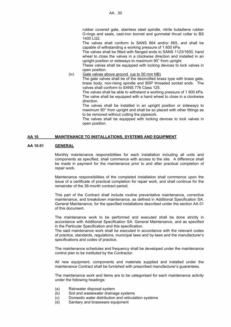
AA . 30
rubber covered gate, stainless steel spindle, nitrile butadiene rubber O-rings and seals, cast-iron bonnet and gunmetal thrust collar to BS 1400 LG2. The valves shall conform to SANS 664 and/or 665, and shall be capable of withstanding a working pressure of 1 600 kPa. The valves shall be fitted with flanged ends to SANS 1123/1600, hand wheel to close the valves in a clockwise direction and installed in an upright position or sideways to maximum 90° from upright. These valves shall be equipped with locking devices to lock valves in open position.
(iv) Gate valves above ground (up to 50 mm NB) The gate valves shall be of the dezincified brass type with brass gate, brass body, non-rising spindle and BSP threaded socket ends. The valves shall conform to SANS 776 Class 125. The valves shall be able to withstand a working pressure of 1 600 kPa. The valve shall be equipped with a hand wheel to close in a clockwise direction. The valves shall be installed in an upright position or sideways to maximum 90° from upright and shall be so placed with other fittings as to be removed without cutting the pipework. The valves shall be equipped with locking devices to lock valves in open position.
AA 10 MAINTENANCE TO INSTALLATIONS, SYSTEMS AND EQUIPMENT AA 10.01 GENERAL
Monthly maintenance responsibilities for each installation including all units and components as specified, shall commence with access to the site. A difference shall be made in payment for the maintenance prior to and after practical completion of repair work. Maintenance responsibilities of the completed installation shall commence upon the issue of a certificate of practical completion for repair work, and shall continue for the remainder of the 36-month contract period.
This part of the Contract shall include routine preventative maintenance, corrective
maintenance, and breakdown maintenance, as defined in Additional Specification SA: General Maintenance, for the specified installations described under the section AA 01 of this document.
The maintenance work to be performed and executed shall be done strictly in
accordance with Additional Specification SA: General Maintenance, and as specified in the Particular Specification and this specification.
The said maintenance work shall be executed in accordance with the relevant codes of practice, standards, regulations, municipal laws and by-laws and the manufacturer’s specifications and codes of practice.
The maintenance schedules and frequency shall be developed under the maintenance
control plan to be instituted by the Contractor. All new equipment, components and materials supplied and installed under the
maintenance Contract shall be furnished with prescribed manufacturer’s guarantees. The maintenance work and items are to be categorised for each maintenance activity
under the following headings:
(a) Rainwater disposal system (b) Soil and wastewater drainage systems (c) Domestic water distribution and reticulation systems (d) Sanitary and brassware equipment

AA . 31
(e) Fire water piped reticulation networks. AA 10.02 ROUTINE PREVENTATIVE MAINTENANCE This routine maintenance of the installations, systems and equipment shall be done in
accordance with Additional Specification SA: General Maintenance and the Particular Specification related to this work.
The routine maintenance work to be performed and executed shall include, but not be
limited to the items listed in tables AA 10.02/1, AA 10.02/2, AA 10.02/3, AA 10.02/4 and AA 10/02/5 below under each heading.
These actions and findings shall be logged and reported on the relevant approved
schedules and reports. TABLE AA 10.02/1 - RAINWATER DISPOSAL SYSTEM
NO ROUTINE PREVENTATIVE MAINTENANCE ITEM DESCRIPTION
MAINTENANCEFREQUENCY
1 Clean out and clear all rainwater gutters and full bores Monthly 2 Clean out and clear all catch pits, channel drains and
floor outlets Monthly 3 Clean and unblock all drain pipes Monthly 4 Check alignments of gutters Six-monthly 5 Check and inspect all rainwater outlet gratings and
replace if necessary Six-monthly 6 Check gutter and pipe bracketing system and repair
and replace if necessary Four-monthly 7 Check and inspect manhole covers and frames for
damages and replace if necessary Six-monthly 8 Paint repairs to surface piping and equipment Annually 9 Visually inspect and report on total system Monthly
TABLE AA 10.02/2 - SOIL AND WASTEWATER DRAINAGE SYSTEM
NO
ROUTINE PREVENTATIVE MAINTENANCE ITEM DESCRIPTION
MAINTENANCEFREQUENCY
1 Visually inspect and report on complete installation Monthly 2 Check, service and clean out grease traps Monthly 3 Check, service and clean out oil separators Monthly 4 Check, inspect and clean out all floor drains Monthly 5 Check, inspect and clean out all gullies Monthly 6 Replace broken or missing gully gratings Four-monthly 7 Check, inspect, repair or replace all manhole covers
and frames and builder’s work to manholes Four-monthly
8 Check, inspect and repair manhole benching. Four-monthly 9 Check, inspect, repair or replace all inspection eyes,
end caps and cleaning eye covers Four-monthly
10 Check, inspect, repair or replace all bracketing systems
Four-monthly
11 Check, inspect, report and unblock any blockage that occurs
Monthly
12 Check, inspect, repair/replace and clean out all Monthly

AA . 32
NO
ROUTINE PREVENTATIVE MAINTENANCE ITEM DESCRIPTION
MAINTENANCEFREQUENCY
equipment traps 13 Paint repairs to surface piping and equipment Annually 14 Rodding of all main sewer lines
At start of Contract
15 Check, inspect, service, repair/replace all vacuum and two-way vents
Four-monthly
TABLE AA 10.02/3 - DOMESTIC WATER DISTRIBUTION AND RETICULATION SYSTEMS
NO ROUTINE PREVENTATIVE MAINTENANCE ITEM
DESCRIPTION MAINTENANCE FREQUENCY
1 Visually inspect and report on complete system Monthly 2 Log all water meter readings Monthly 3 Log all pressure gauge readings Monthly 4 Check, inspect, report and repair leaks Monthly 5 Replace all valve gaskets, gland packings and seals Annually 6 Sample water supply and chemical analyses to be
provided by approved company Annually
7 Bulk Water storage tanks to be emptied, cleaned out, inspected, repaired and resealed where necessary
Annually
8 Check, inspect, service, repair and readjust all pressure-reducing valves
Six-monthly
9 Check, inspect and test operation of all valves on site Monthly 10 Clean out all strainers Monthly 11 Check, inspect, service test and repair/replace all
safety and expansion release valves Six-monthly
12 Check, inspect, repair or replace all bracketing systems
Six-monthly
13 Check, inspect, service, repair/replace all air release valves and vacuum breakers
Six-monthly
14 Check, service, repair or replace all ball float valves Four-monthly 15 Check, inspect, test, service, repair/replace all geyser
installations Six-monthly
16 Check, inspect, test, service and repair/replace all non-return valves
Four-monthly
17 Paint repairs to piping, fittings and equipment Annually TABLE AA 10.02/4 - SANITARY AND BRASSWARE EQUIPMENT
NO ROUTINE PREVENTATIVE MAINTENANCE ITEM DESCRIPTION
MAINTENANCE FREQUENCY
1 Visually inspect and report on complete installation Monthly 2 Inspect, repair/replace WC seats and covers Monthly 3 Replace all tap washers Six-monthly 4 Replace all tap gland packings Six-monthly 5 Check, inspect, repair, fix and where necessary
replace sanitary ware mountings and brackets Four-monthly
6 Check, inspect, service, repair/replace all cistern flushing mechanisms
Monthly
7 Check, inspect, service, repair/replace all brassware Four-monthly 8 Check, inspect, service, repair/replace all sanitary
ware Four-monthly
9 Check, inspect, service, repair, readjust all flushing Four-monthly

AA . 33
NO ROUTINE PREVENTATIVE MAINTENANCE ITEM DESCRIPTION
MAINTENANCE FREQUENCY
valves 10 Replace all flushing valve internal parts with
replacement kits Once per Contract
11 Stained equipment to be cleaned with approved manufacturer's cleaning agent
Six-monthly
12 Check, inspect, report and repair all leaks Monthly 13 Check, inspect, repair/replace all shower gratings Four-monthly 14 Paint repairs to all equipment Annually 15 Check, inspect, repair, service, replace all missing
valves Six-monthly
16 Replace missing tap handles As occur 17 Replace missing bath, basin, sink, etc, plugs As occur
TABLE AA 10.02/5 - FIRE WATER PIPED RETICULATION NETWORKS
NO ROUTINE PREVENTATIVE MAINTENANCE ITEM DESCRIPTION
MAINTENANCE FREQUENCY
1 Visually inspect and report on complete system Monthly 2 Report any failures/breakage of fire fighting equipment
to the Engineer Monthly
3 Log all pressure gauge readings Monthly 4 Replace all valve gaskets, gland packings and seals Annually 5 Water storage tanks to be cleaned out
resealed/repaired if necessary Annually
6 Check, inspect, service, repair/replace all non-return valves and backflow preventers
Four-monthly
7 Check, inspect, report and repair all leaks Monthly 8 Inspect, service, readjust and calibrate all pressure
gauges Four-monthly
9 Paint repairs to piping, fittings and equipment Annually 10 Check, inspect, repair or replace all bracketing
systems Four-monthly
AA 10.03 CORRECTIVE MAINTENANCE The corrective maintenance of the installations, systems and equipment shall be done
in accordance with Additional Specification SA: General Maintenance and the Particular Specification related to this work.
The Contractor shall inspect and check all equipment, materials, systems and
installation for any pending breakdowns, maladjustments or anomalies of equipment. The Contractor shall report and take actions to correct such deficiencies. AA 10.04 BREAKDOWN MAINTENANCE Breakdown maintenance of the installations, systems and equipment shall be done in
accordance with Additional Specification SA: General Maintenance. All breakdown problems experienced shall be acted upon within the time limitations
allowed in the General Maintenance documents. All breakdown maintenance shall be done in accordance with the related
specifications, standards, regulations and codes. The Contractor shall have access to the necessary spares, equipment and tools for
the expected breakdowns.

AA . 34

PAA. 1
PARTICULAR SPECIFICATION PAA PLUMBING AND DRAINAGE INSTALLATION CONTENTS PAA 01 SCOPE PAA 02 GENERAL DESCRIPTION OF INSTALLATION PAA 03 TECHNICAL DETAILS OF EXISTING INSTALLATION PAA 04 STATUS OF EXISTING INSTALLATION PAA 05 DETAILS OF REPAIR WORK PAA 06 MEASUREMENT AND PAYMENT PAA 07 DETAILS OF MAINTENANCE WORK PAA 01 SCOPE
(a) This specification covers the particulars of the maintenance work to the plumbing and drainage installations at Voorberg Prison. This particular specification shall be read in conjunction with the Technical Specification AA: Plumbing and Drainage Installation, and all additional and technical specifications compiled as part of this document, in particular the following Additional Specifications:
SA: General Maintenance SB: Operating and Maintenance Manuals SC: General Decommissioning, Testing and Commissioning Procedures SD: General Training
The intended maintenance work to this installation will restore the existing installation to a safe, efficiently functional system that complies with all statutory regulations and applicable standards, in the process repairing all defects and shortfalls. Monthly maintenance responsibilities for each installation shall commence with access to the site. The Contractor shall be responsible to take over the completed installation which shall be maintained and serviced by the Contractor for the duration of the 36-month Contract period. Additional repair work will also form part of the Maintenance work in the Contract.
The various sites consist of various facilities, as listed below, which form part of the maintenance and servicing contract for plumbing and drainage installation.
PAA 01.02 OCCUPATIONAL HEALTH AND SAFETY
The Contractor shall be required to comply with the Occupational Health and Safety Act 85 of 1993, Construction Regulations 2014 and related regulations. Non-compliance with these regulations, in any way whatsoever, will be adequate reason for suspending the Works.

PAA. 2
PAA 01.01 GENERAL PLUMBING AND DRAINAGE INFORMATION
All the buildings are connected to water meters. Other items in buildings are described below:
PAA 01.01.02 PLUMBING AND DRAINAGE INFORMATION
PLUMBING AND DRAINAGE INFORMATION
No. DESCRIPTION
Taps Valves
WC Pan
WC Cistern
Urinal Wash Hand Basin
No. No. No. No. No. 97 House Type A 11 1 1 - 1 54 House Type B 11 1 1 - 2 10 House Type C 13 2 2 - 2 7 House Type D 11 1 1 - 2 16 House Type E 15 2 2 - 2 1 Male Single Quarters 91 7 7 9 30 1 Female Single Quarters 91 7 7 9 30
PAA 02 GENERAL DESCRIPTION OF INSTALLATIONS The existing plumbing and drainage installations provide potable hot and cold water to
the various buildings on these sites. The potable cold-water installation is provided with supply points from the underground reticulation networks outside the buildings to an above ground reticulation network via service ducts, ceiling voids and chased into walls to outlet points. The potable hot-water installation is provided with supplies from various domestic or industrial geysers where applicable.
This contract also provides for repair and maintenance of the fire water piped
reticulation network, excluding the fire fighting equipment which is dealt with under Particular Specification PJC: Conventional Fire Fighting equipment.
Technical details of sanitary and brassware, as well as the plumbing and drainage
installations are given in PAA 03. PAA 03 TECHNICAL DETAILS OF EXISTING INSTALLATIONS At the time of compilation of this document the existing installations consisted of the
equipment and plant listed below with their relevant technical details. PAA 03.01 SANITARY AND BRASSWARE: GENERAL
SANITARY WARE BRASSWARE TRAP
WCs (cistern)
Armitage Shanks/Vaal: white, floor-mounted, vitreous china
Brass shut-off valves
Not applicable
Cistern (WC) Wall-mounted, white, CI; Wall-mounted, white, vitreous china; Wall-mounted, white, plastic
Brass shut-off valves
Not applicable

PAA. 3
SANITARY WARE BRASSWARE TRAP Urinals (flush)
Armitage Shanks, white, wall-mounted, vitreous china; Citimetal stainless steel wall-mounted.
Junior flush valve, exposed type, shut-off valves; Brass shut-off valves
CP bottle trap. Flexi P-trap; Flexi S-trap
WHBs Armitage Shanks, white wall-mounted, white enamel; Wall-mounted stainless steel
Cobra 15 mm, CP star handle pillar taps
Flexi P-trap; Flexi S-trap
Showers 15 mm CP under-tile stop-cocks
Wash troughs
Stainless steel, double bowl, wall-mounted
Cobra 15 mm, CP star handle wall type taps
Flexi P-trap
Baths Steel enamel, white, 2 m long
Cobra 20 mm, CP star handle wall type taps
Not applicable
Sinks Stainless steel, cabinet-mounted
20 mm CP star handle taps, 20 mm Cobra taps CP sink mixer with over arm swivel outlet
Flexi P-trap, lead P-trap
Wash tubs Concrete double bowl CP wall type taps Lead P-trap PAA 03.02 SANITARY DRAINAGE PIPING: GENERAL
PIPE FITTINGS EQUIPMENT Gullies VCP CI or plastic grating Not
applicable Waste pipes GMS, uPVC Brass, uPVC Not
applicable Soil pipes S&S CI, uPVC S&S CI, uPVC Not
applicable Cleaning eyes CI (ABC), uPVC Not applicable Not
applicable Vent pipes S&S CI S&S CI Not
applicable PAA 03.03 DOMESTIC WATER PIPING: GENERAL
PIPE FITTINGS EQUIPMENT Cold-water piping Cu
GMS Conex,
soldered GMS
Brass gate shut-off valve
Brass gate shut-off valve
Hot-water piping Cu GMS
Conex, soldered
GMS
Brass gate shut-off valve
Brass gate shut-off valve
PAA 03.04 FIRE WATER PIPING: GENERAL
PIPE FITTINGS EQUIPMENT

PAA. 4
Fire water piping GMS, Cu GMS, Conex soldered
See specifications
PAA 03.06 FIRE WATER INSTALLATION QUANTITIES The firefighting equipment currently installed is listed in Particular Specification PJC:
Conventional Fire Fighting Equipment. The piped reticulation networks to these equipment items shall form part of this contract where applicable.
PAA 04 STATUS OF EXISTING INSTALLATION The status of the equipment and installation at the time of compilation of this
document is summarised below: PAA 04.01 SANITARY AND BRASSWARE
The Scope of Works requires full Maintenance from the inception of the Contract on all facilities, buildings, installations, infrastructure and equipment regardless of any other repair related works that may occur during the Contract Period.
PAA 04.02 PLUMBING AND DRAINAGE INSTALLATION
The Scope of Works requires full Maintenance from the inception of the Contract on all facilities, buildings, installations, infrastructure and equipment regardless of any other repair related works that may occur during the Contract Period.
PAA 05 DETAILS OF REPAIR WORK The following work shall form part of the repair work to Building Services. This work
shall be done in accordance with the relevant regulations, codes, specifications and Technical Specification AA: Plumbing and Drainage Installations, as set out in this document. The work to be included is set out in PAA 05.01 and PAA 05.02 below and shall be read in conjunction with the Schedule of Quantities and Technical Specifications.
The repair work shall be carried out in accordance with the requirements of Additional
Specification SC: General Decommissioning, Testing and Commissioning Procedures. PAA 05.01 GENERAL DESCRIPTION OF WORK
The Contractor shall inspect the items, systems, equipment, components and installations listed below. This inspection shall involve the determination of any defects, leaks, damages, shortfalls, structural soundness, repairs required, details of existing equipment, suitability of equipment for the purpose it serves, etc. The Contractor shall report back to the Engineer in writing on all the above and the following items. No repair work shall commence prior to approval by the Engineer:
(a) Sanitary and brassware, including traps, brackets, piping, pan connectors, etc;
(b) Sanitary drainage installation, including fittings, traps, floor drains, gullies,
cleaning eyes, manholes, grease and oil separators, etc;
(c) Domestic water piped installation, including fittings, valves, strainers, lagging and cladding, non-return valves, safety valves, etc;
(d) Fire water piped installation, including fittings, valves, non-return valves,
pressure gauges, etc; (e) Bracketing system;

PAA. 5
(f) Domestic geysers including valves, pressure reducing valves, strainers, vacuum breakers, safety valves, non-return valves, lagging and cladding, etc.
(g) Industrial geysers including valves, pressure reducing valves, strainers, vacuum
breakers, safety valves, non-return valves, lagging and cladding, etc.
The general scope of work at the time of going on tender is defined as follows:
(a) Replacing of irreparably damaged, missing and unsuitable sanitary and brassware, including the isolation, removal and stripping of the existing equipment;
(b) Replacing of irreparably damaged, corroded and unsuitable sanitary drainage
piping, including fittings, brackets, traps, floor drains, oil and grease separators, cleaning eyes and gullies, etc;
(c) Replacing of irreparably damaged, corroded and unsuitable domestic water
piping, including fittings, brackets, valves, strainers, water meters, lagging and cladding, etc;
(d) Replacing of irreparably damaged, corroded and unsuitable fire water piping,
including fittings, brackets, valves, non-return valves, pressure gauges, etc;
(e) Replacing of irreparably damaged and corroded domestic or industrial geysers, including valves, pressure-reducing valves, air release valves, strainers, non-return valves, vacuum breakers and safety valves;
(f) Servicing, cleaning and repair of existing sanitary ware including removal of
stains, repair of chipped enamel, replacing of damaged and missing seats and lids, de-scaling and cleaning of cisterns and servicing of filling and flushing mechanisms, fixing of loose fixtures and brackets, cleaning of traps, etc;
(g) Servicing, overhauling and cleaning of existing brassware, including
dismantling, de-scaling, repair kits, replacing of washers, gland packing and gaskets, replacing of missing tap handles and flushing assemblies, etc;
(h) Servicing, cleaning and repair of existing domestic water and drainage pipe
installations, including traps, floor drains, gullies, manholes, valve chambers, grease and oil separators, brackets, valves, vacuum breakers, strainers, pipe lagging and cladding, etc;
(i) Servicing and repair of existing fire water piped reticulation, including fittings,
valves, pressure gauges, brackets, etc;
(j) Servicing, cleaning and repair of domestic geysers, including de-scaling, testing for leaks, replacing of elements, safety valves and thermostats if required, etc;
(k) Handing over of complete systems on completion of the repair work to the
satisfaction of the Engineer, when the maintenance period shall commence;
(l) The supply and compilation of operating and maintenance manuals;
(m) The testing, adjusting and commissioning of all systems;
(n) The introduction of a maintenance control plan, including logging, recording and control procedures.
PAA 05.02 PLUMBING AND DRAINAGE INSTALLATION The work to this installation shall at least include, but not be limited to the work listed
below. Any items, components or installations not detailed in particular but found to

PAA. 6
be defective or inoperative during the inspection and report phase, shall be repaired or replaced as instructed by the Engineer.
PAA 05.02.01 Various Sites
(i) Service and repair domestic hot and cold-water installations, including pressure testing of existing systems, and replace items that are beyond repair. Where necessary, replace entire system with capillary soldered copper pipe system.
(ii) Service and repair drainage system, including rodding of system, and replace
damaged or leaking pipes and fittings, manhole covers, cleaning and inspection eyes, gullies and gully gratings.
(iii) Service and repair brassware, such as taps, stop-cocks and flushing
mechanisms with repair kits, and replace items that are missing or beyond repair.
(iv) Service and repair sanitary ware, including chip repair, de-staining and re-
coating of baths, WC bowls and wash hand basins, dent removal and de-staining of wash troughs and kitchen sinks and replacement of damaged or missing parts such as WC seats and lids and cistern lids. Replace missing or irreparably damaged equipment. The following replacement items shall be installed where required:
(1) Ceramic and Plastic cisterns (2) Steel enamel bathtubs (3) Stainless steel wash troughs (4) Ceramic wash hand basins
(v) Service and repair domestic geysers, including de-scaling, testing for leaks,
replacement of electrical heating elements if required, servicing or replacement of valves, or replace leaking and corroded geysers where necessary.
PAA 06 MEASUREMENT AND PAYMENT
All new building work and repair work to existing structures and buildings necessitated by repairs to the plumbing and drainage services as scheduled, shall be done in accordance with the structural and building section of the Technical and Particular Specifications. The costs of such building and repair works shall be deemed to be included in the tendered rates for the applicable items as scheduled in this section.
PAA.01 INSPECTION AND REPORT ON EXISTING INSTALLATIONS……………………………………………….………Unit: installation
The unit of measurement shall be the installation reported on. The tendered rate for the installation shall include full compensation for the inspection and written report on all items, systems, components, equipment and installations, including the establishment of defects, leaks, damage, shortfalls, structural soundness, repairs required, details of existing equipment and suitability of the equipment for the purpose it serves.
PAA.03 ISOLATION, STRIPPING, DISMANTLING AND REMOVAL
OF EXISTING BRASSWARE, SANITARY WARE AND PIPING INSTALLATIONS ..... …..………………………...Unit: number, metre

PAA. 7
The unit of measurement shall be the number of each item of brassware and sanitary ware and metre of piping removed, including fixtures and fittings. The tendered rates shall include full compensation for the isolation, dismantling and removal of irreparably damaged, broken and/or unsuitable brassware (flush valves, taps, mixers, shower roses, under tile stop-cocks, demand bib taps, hose bib taps, shut-off valves, etc) and sanitary ware (water closets, cisterns, basins, urinals, baths, wash troughs, sinks, etc) including all associated pipe work, brackets, traps, pan connectors, etc.
The tendered rates shall also include full compensation for the isolation, stripping, dismantling and removal of irreparably damaged, broken or unsuitable pipe work installed on surface, underground, chased into walls, in ceiling voids and/or service ducts, as well as the plugging off of connections to this pipe work. The tendered rate shall also include full compensation for the removal off site and/or to storage of all removed items as mentioned above.
PAA.04 ISOLATION, STRIPPING, DISMANTLING AND REMOVAL OF EXISTING GEYSER INSTALLATIONS ..... ………………………..Unit: number
The unit of measurement shall be the number of each geyser installation removed, including associated pipe work and fittings. The tendered rates shall include full compensation for the isolation, stripping, dismantling and removal of irreparably damaged, broken and/or corroded domestic geysers, including shut-off valves, non-return valves, strainers, pressure-reducing valves, vacuum breakers, air release valves, safety valves, etc, and the removal off site.
PAA.05 SUPPLY AND INSTALLATION OF SANITARY WARE AND BRASSWARE……………………………………………..……Unit: metre, number
The unit of measurement shall be the number of each item of sanitary and brassware supplied and installed, including all associated pipe work and fittings. The tendered rate shall include full compensation for the supply, delivery, positioning, installation, testing, cleaning, commissioning and hand-over of sanitary and brassware including all necessary pipe work, traps, brackets, fittings, bends, junctions, cleaning eyes, etc, to connect the sanitary and brassware to the existing water supply and/or drainage installation. The tendered rate shall also include full compensation for chasing and/or building into walls and the reinstating of existing surfaces such as floors, walls, ceilings, etc.
PAA.06 SUPPLY AND INSTALLATION OF DRAINAGE PIPING INSTALLATION ................... ……..……………………………....Unit: metre
The unit of measurement shall be the metre of each type of piping in the installation supplied and installed, including all fixtures and fittings. The tendered rates shall include full compensation for the supply, delivery, installation, testing, cleaning, commissioning and handover of new drainage piping, installed on surface against walls or soffits, underground, in ceiling voids, chased or built into walls and/or service ducts, including all necessary bends, junctions, tees, cleaning eyes, covers, traps, floor drains, gratings, brackets, hangers, etc, to hand over a complete and effective installation that complies with local government regulations. The tendered rates shall also include full compensation for the necessary underground works such as excavation, pipe bedding, fill blanket, backfilling and compaction and

PAA. 8
for the reinstatement of existing surfaces such as floors, walls, ceiling, roads, paving, etc, as well as connection to the existing drainage installation.
PAA.07 SUPPLY AND INSTALLATION OF DOMESTIC
WATER PIPING INSTALLATION ...................... ……………………….. Unit: metre
The unit of measurement shall be the metre of each type of piping in the installation supplied and installed, indicating all fixtures and fittings. The tendered rates shall include full compensation for the supply, delivery, installation, testing, cleaning, sterilising, commissioning and hand-over of new water piping installed on surface against walls or soffits, underground, in ceiling voids, chased or built into walls and/or in service ducts, including all necessary bends, tees, reducers, elbows, valves, strainers, adapters, brackets, hangers, etc, to hand over a complete and effective installation that complies with local government regulations.
The tendered rates shall also include full compensation for the supply and installation of hot-water pipe insulation and cladding. The tendered rates shall also include full compensation for the necessary underground works such as excavation, pipe bedding, fill blanket, backfilling and compaction and for the reinstatement of existing surfaces such as floors, walls, ceilings, roads, paving, etc, as well as connection to the existing domestic water installation.
PAA.08 SUPPLY AND INSTALLATION OF DOMESTIC GEYSER INSTALLATION .......... ………………………………………...Unit: number
The unit of measurement shall be the number of each geyser installation supplied and installed, including all associated pipe work and fittings. The tendered rates shall include full compensation for the supply and installation of domestic geysers, including shut-off valves, non-return valves, strainers, pressure-reducing valves, vacuum breakers, air release valves, safety valves, etc, as well as connection to existing piping and electrical supply.
PAA.09 SUPPLY AND INSTALLATION OF FIRE WATER
RETICULATION PIPEWORK ....................………………………………. Unit: metre
The unit of measurement shall be the metre of each type of pipe work supplied and installed in the firewater reticulation, including all fixtures and fittings. The tendered rate shall include full compensation for the supply, delivery, installation, testing, cleaning, commissioning and hand-over of new fire water reticulation pipe work installed on surface against walls or soffits and/or underground, including all necessary bends, tees, reducers, elbows, valves, adapters, brackets, hangers, pressure gauges, etc, to hand over a complete and effective installation that complies with local government regulations. The tendered rates shall also include full compensation for the necessary underground work such as excavation, pipe bedding, fill blanket, backfilling and compaction and for the reinstatement of existing surfaces such as floors, walls, ceilings, roads, paving, etc, as well as connection to the existing fire water reticulation network.
PAA.10 SERVICING, CLEANING AND REPAIR OF SANITARY WARE ...... ……………………………………….…………...Unit: number
The unit of measurement shall be the number of each item of sanitary ware serviced, cleaned and repaired, including all associated pipe work and fittings. The tendered rate shall include full compensation for the repair or replacement of all damaged or missing parts, servicing of all movable parts, cleaning of stained sanitary

PAA. 9
ware with approved cleaning agent, fixing of loose fixtures and brackets according to manufacturer’s specifications, de-scaling and cleaning of cisterns and servicing of filling and flushing mechanisms, cleaning of all traps, fixing or replacing of damaged or missing shower, urinal and channel outlet gratings and any other work or action required to hand over an effective system that complies with local government regulations.
PAA.11 SERVICING, OVERHAULING AND CLEANING OF BRASSWARE .....…………………………………….……………… Unit: number
The unit of measurement shall be the number of each item of brassware serviced, overhauled or cleaned, including all associated pipe work and fittings. The tendered rate shall include full compensation for dismantling, cleaning and de-scaling, replacement of all gaskets, gland packing and seals on all valves, repair or replacement of all damaged or missing parts, replacement kits for worn or leaking flush valves, taps and mixers, repair or replacement of leaking, corroded or damaged flush pipes, readjusting of timing mechanisms on flush valves and metering taps and any other work or action required to hand over an effective system that complies with local government regulations.
PAA.12 SERVICING, CLEANING AND REPAIR OF DOMESTIC WATER AND DRAINAGE PIPE INSTALLATIONS……………………………………... Unit: number, metre, item
The unit of measurement shall be the metre of each type of pipe installation serviced, cleaned and repaired, including all fixtures and fittings. The tendered rates shall include full compensation for inspection, sampling testing, servicing, cleaning and repair of existing piping and equipment such as:
(a) Video surveying of all underground drainage pipe work to establish root ingress,
damaged and corroded pipe work, fat build-up, blockages, incorrect falls, sagging and to provide as-built information;
(b) Initial unblocking and cleaning of all drainage pipe work, traps, floor drains and
gullies; (c) Pressure testing of piping and taking of water piping samples to determine state
of corrosion and scaling; (d) Repair work to damaged manholes, gullies, cleaning eyes, valve chambers, etc,
including builders' work and benching; (e) Repair of existing bracketing systems including fixing and repair of existing
brackets and hangers, as well as the supply and installation of additional brackets where required;
(f) Emptying, cleaning, checking, testing and repair of oil and grease separators;
(g) Service and repair to all valves, strainers, pressure-reducing valves, water meters, non-return valves, air release valves and vacuum breakers, including new gaskets, gland packing and seals;
(h) Taking of water samples and bacteriological testing to determine the
compliance with the relevant codes of practice; (i) Repairing and/or replacement of damaged hot-water pipe lagging and cladding; (j) Preparation, painting and repainting of pipe work and;

PAA. 10
(k) Any other work or action to hand over an effective installation that complies with local government regulations.
PAA.13 SERVICING, CLEANING AND REPAIR OF DOMESTIC GEYSERS ..... ………………………….…………………... Unit: number
The unit of measurement shall be the number of domestic geysers serviced, cleaned and repaired, including all fixtures and fittings.
The tendered rate shall include full compensation for the isolation, servicing, cleaning
and repair of domestic geysers in accordance with the manufacturer’s specifications, including de-scaling, testing for leaks, replacing of elements, replacement of safety valve and replacement of thermostat and set point, and replacement of connections if required and any other work or action to hand over an effective system that complies with local government regulations.
PAA.14 SERVICING AND REPAIR OF FIRE WATER PIPED
RETICULATION NETWORKS .................... …………………………..… Unit: metre
The unit of measurement shall be the metre of each type of piping in the firewater network serviced and repaired, including all fixtures and fittings.
The tendered rates shall include full compensation for the inspection, testing, servicing and repair of existing piping and equipment such as:
(a) Pressure testing of piping and taking of pipe samples to determine the extent of
corrosion and scaling; (b) Repair or replacement of damaged, leaking, broken and corroded pipe work or
fittings; (c) Repair and service to all valves, including new gaskets, gland packing and
seals; (d) Repair, service, adjustment and calibration of all pressure gauges; (e) Repair and fixing of existing brackets and hangers and the installation of
additional brackets and hangers where required; (f) Any other work or action to hand over an effective system that complies with
local government regulations. PAA.15 CLEANING OUT SEPTIC TANKS AND DISPOSE OF CONTENTS OFF-SITE …………………………………………………. Unit: number
The unit of measurement shall be the number of septic tanks thoroughly cleaned and pumping the waste into a tanker and disposing of all the waste off site at a wastewater dumping area.
PAA.16 SUPPLY AND INSTALLATION OF DOMESTIC GEYSER INSTALLATION .......... ………………………………………...Unit: number
The unit of measurement shall be the number of each geyser installation supplied and installed, including all associated pipe work and fittings. The tendered rates shall include full compensation for the supply and installation of industrial geyser installations including isolating lever-ball valves (from 22 to 50mm), 400kPa expansion relief valve, drain connection, overflow pipe, inline circulating pump (25mm), Temperature and pressure safety valve, electrical control panel, bulk hot water vessel, pump supply cable, dual thermostat, hot water outlet, y-strainer, pressure gauge, non-return valve, temperature gauge, balanced cold water and expansion valve stand pipe.

PAA. 11
PAA.17 SERVICING, CLEANING AND REPAIR OF INDUSTRIAL GEYSERS .. ………………………….…………………... Unit: number
The unit of measurement shall be the number of industrial geysers serviced, cleaned and repaired, including all fixtures and fittings.
The tendered rate shall include full compensation for the isolation, servicing, cleaning and repair of industrial geysers in accordance with the manufacturer’s specifications, including de-scaling, testing for leaks, servicing, checking or replacing of isolating lever-ball valves (from 22 to 50mm), 400kPa expansion relief valve, drain connection, overflow pipe, inline circulating pump (25mm), Temperature and pressure safety valve, electrical control panel, dual thermostat, y-strainer, pressure gauge, non-return valve, temperature gauge, and any other work or action to hand over an effective system that complies with local government regulations.
PAA.18 RE-INSTALLATION OF EXISTING GEYSER INSTALLATIONS AT LOCATION INDICATED BY ENGINEER ............................. ………………………..Unit: number
The unit of measurement shall be the number of each geyser re-installed including associated pipe work and fittings. The tendered rates shall include full compensation for the re-installation of the isolated domestic geysers, including servicing, cleaning and repair of domestic geysers in accordance with the manufacturer’s specifications scaling, testing for leaks, replacing of elements, and replacement of thermostat and set point, replacement of two shut-off valves, non-return valve, strainer, two vacuum breakers, safety valve and replacement pipe work not exceeding 10m from the previous location according to SANS specifications and any other work or action to hand over an effective system that complies with local government regulations.
PAA.19 SUPPLY AND INSTALLATION OF DOMESTIC GALVANISED GEYSER DRIP TRAY………………………………………...Unit: number
The unit of measurement shall be the number of each geyser drip tray installation supplied and installed, including isolation and re-installation of geyser. The tendered rates shall include full compensation for the supply and installation of the geyser drip trays including isolation of geyser and re-installation of geyser on drip tray.
PAA.20 SUPPLY AND INSTALLATION OF SOLAR POWERED GEYSER INSTALLATION .......... ………………………………………...Unit: number
The unit of measurement shall be the number of each solar powered geyser installation supplied and installed, including all associated pipe work and fittings. The tendered rates shall include full compensation for the supply and installation of solar powered geysers which shall include all solar storage tanks and solar collector panels, including shut-off valves, non-return valves, strainers, pressure-reducing valves, vacuum breakers, air release valves, safety valves, etc, as well as connection to existing piping, electrical, lagging & cladding supply.
PAA.21 SUPPLY AND INSTALLATION OF DOMESTIC HEAT PUMP INSTALLATION ...... ……………………………………...Unit: number

PAA. 12
The unit of measurement shall be the number of each heat pump installation supplied and installed, including all associated pipe work and fittings. The tendered rates shall include full compensation for the supply and installation of a heat pump installation which shall include the heat pump, circulating pump set, shut-off valves, non-return valves, strainers, pressure-reducing valves, vacuum breakers, air release valves, safety valves, etc., as well as connection to existing piping and electrical connection.(storage tank measured separately)
PAA 07 DETAILS OF MAINTENANCE WORK PAA 07.01 GENERAL
The Contractor shall be responsible for the complete maintenance of all the equipment, components, installations and systems forming part of this repair and maintenance contract and as set out in PAA 03.05. The Contractor shall strictly adhere to Additional Specification SA: General Maintenance, and Technical Specification AA: Plumbing and Drainage Installations, with regard to the maintenance period, obligations, responsibilities, actions and activities, etc, which shall also include the following maintenance actions:
(a) Routine preventative maintenance. A guideline to the required actions is
provided in specification AA. The actions will not be limited to these guidelines, but shall include all additional actions, work, materials, etc. necessary to maintain this installation at an acceptable level.
(b) Corrective maintenance as described and defined in Additional Specification
SA: General Maintenance. (c) Breakdown maintenance as described and defined in Additional Specification
SA: General Maintenance.
Fatal breakdown shall be defined as any equipment, components and systems preventing the supply of water to fire hydrants and fire hoses due to a failure of this system at the particular point of incident. Emergency breakdown shall be defined as any equipment, components and systems preventing the provision of water and the drainage of the equipment to the consumer points due to a failure of part of this system at the particular point of incident.

PAA. 13

PAB. 1
SANBI: GOLDFIELDS EDUCATION CENTRE
TECHNICAL SPECIFICATION AB BUILDING ELECTRICAL INSTALLATIONS CONTENTS
AB 01 SCOPE
AB 02 STANDARD SPECIFICATIONS, REGULATIONS, CODES AND ADDITIONAL
SPECIFICATIONS
AB 03 TEST AND INSPECTION FOLLOWING COMPLETION OF CONSTRUCTION WORK
AB 04 QUALITY ASSURANCE SYSTEM
AB 05 COMMISSIONING OF INSTALLATION
AB 06 QUALITY SPECIFICATION FOR MATERIAL & EQUIPMENT
AB 07 INSTALLATION TECHNICAL DETAILS
AB 08 INSTALLATION DETAILS AND MEASUREMENT AND PAYMENT
AB 01 SCOPE
AB 01.01 This specification comprises all aspects regarding the construction of building
electrical systems. Building electrical systems comprise:
(i) Distribution boards and low voltage cable
(ii) Interior and exterior lighting of buildings
(iii) Small power and fixed appliances
(iv) Earthing and lightning protection system
AB 01.02 This specification shall form an integral part of the Goldfields Education Centre
contract document and shall be read in conjunction with Section 2.3.4, the Additional
Specifications included in the Bid Document.
AB 02 STANDARD SPECIFICATIONS, REGULATIONS, CODES AND ADDITIONAL
SPECIFICATIONS
AB 02.01 The latest edition, including all amendments up to date of tender of the following
specifications, publication and codes of practice shall be read in conjunction with this
specification and shall be deemed to form part thereof.
AB 02.02 SANS SPECIFICATIONS

PAB. 2
SANBI: GOLDFIELDS EDUCATION CENTRE
General
Distribution
and meter
boards
LV cables
and
conductors
Lighting
system
Earthing
and
lightning
protection
system
Small power installation
Power
outlets
Conduits,
powerskirting,
cable trays
and ducting
SANS 10142 SANS 152 SANS 10114 SANS 03 SANS 152 SANS 950
SANS 10160 SANS 156 SANS
10198
SANS 163 SANS
10199
SANS 164 SANS 1065
SANS 10400 SANS 172 SANS 1411 SANS 1012 SANS 1084 SANS 1085
SANS 1222 SANS 1507 SANS 1084 Speed
Drives
SANS 1239 SANS 61084
SANS 1250
SANS 1279 SANS61800
SANS 1777
SANS 10114
AB 02.03 OCCUPATIONAL HEALTH AND SAFETY
The Contractor shall be required to comply with the Occupational Health and Safety
Act 85 of 1993, Construction Regulations 2014 and related regulations. Non-
compliance with these regulations, in any way whatsoever, will be adequate reason for
suspending the Works.
AB 02.04 MANUFACTURER’S SPECIFICATIONS AND INSTALLATION INSTRUCTIONS
AB 02.05 ADDITIONAL REQUIREMENTS
Equipment and material installed shall be new and unused.
Luminaires, control gear, isolators and power outlets shall bear the SANS stamp. The
Contractor shall ensure that all safety regulations and measures are applied and
enforced during repair and maintenance work on cabling, wiring, distribution boards,
luminaires, power points and fixed appliances.
AB 03 TEST AND INSPECTION FOLLOWING COMPLETION OF CONSTRUCTION WORK
AB 03.01 All systems are to be checked by the Contractor prior to commissioning. Copies of all
checks for each installation shall be presented to the Engineer for approval before
commissioning takes place.
AB 03.02 It is the responsibility of the Contractor to provide all labour, accessories and properly
calibrated and certified measuring instruments necessary to record the following
parameters:
AB 03.02.01 continuity of ring final circuit conductors
AB 03.02.02 continuity of protective conductors, including main and supplementary equipotential
bonding
AB 03.02.03 earth electrode resistance
AB 03.02.04 insulation resistance

PAB. 3
SANBI: GOLDFIELDS EDUCATION CENTRE
AB 03.02.05 polarity
AB 03.02.06 earth fault loop impedance
AB 03.02.07 operation of residual current devices
AB 03.02.08 phase voltage
AB 03.02.09 current per phase
AB 03.02.10 illumination levels in lux
AB 03.03 The Contractor is responsible for the arrangement of such tests. He shall give at least
72 hours notice to the Engineer prior to the test date.
AB 04 QUALITY ASSURANCE SYSTEM
AB 04.01 Following formal approval of his Quality Assurance system by Engineer, the
Contractor shall implement the approved QA system.
AB 04.02 Records of this QA system shall be kept throughout the duration of the contract and
shall be submitted to the Engineer as required by the Engineer.
AB 05 COMMISSIONING OF INSTALLATION
AB 05.01 On completion of the repair work, the contractor shall check and put all systems into
operation.
AB 05.02 All commissioning shall be performed by the Contractor, to the satisfaction of the
Engineer. The Contractor shall confirm in writing that all systems have been repaired
according to specification and are fully operational.
AB 05.03 All installations shall be energised for a minimum continuous period of 96 hours
immediately prior to the Engineer’s Practical Completion inspection to verify lamp
stability and reliability of power reticulation
AB 06 QUALITY SPECIFICATION FOR MATERIAL AND EQUIPMENT
AB 06.01 TESTS
After completion of the works and before first delivery is taken, a full test will be carried
out on the installation for a period of sufficient duration to determine the satisfactory
working thereof. During this period the installations will be inspected and the
Contractor shall make good, to the satisfaction of the Representative/Agent, any
defects which may arise.
The Contractor shall provide all instruments and equipment required for testing and
any water, power and fuel required for the commissioning and testing of the
installations at completion.
AB 06.02 NOTICES AND FEES
The Contractor shall give all notices required by and pay all necessary fees, including
any inspection fees, which may be due to the local Supply Authority.

PAB. 4
SANBI: GOLDFIELDS EDUCATION CENTRE
On production of the official account, only the net amount of the fee charged by the
Supply Authority for connection of the installation to the supply mains, will be refunded
to the Contractor by the Engineer.
AB 06.03 SCHEDULE OF FITTINGS
In all instances where schedule of light, socket outlet and power points are attached to
or included on the drawings, these schedules are to be regarded as forming part of the
specification.
AB 06.04 QUALITY OF MATERIALS
Only materials of first class quality shall be used and all materials shall be subject to
the approval of the Engineer.
Wherever applicable the material is to comply with the relevant South African Bureau
of Standards, specifications, or to British Standard Specifications, where no SANS
Specifications exist.
Materials wherever possible, must be of South African manufacture.
AB 06.05 CONDUIT AND ACCESSORIES
The type of conduit and accessories required for the service, i.e. whether the conduit
and accessories shall be of the screwed type, plain-end type or of the non-metallic
type and whether metallic conduit shall be black enamelled or galvanised, is specified
in Part 2 of this specification.
Unless other methods of installation are specified for certain circuits, the installation
shall be in conduit throughout. No open wiring in roof spaces or elsewhere will be
permitted.
The conduit and conduit accessories shall comply fully with the applicable SANS
specifications as set out below and the conduit shall bear the mark of approval of the
South African Bureau of Standards.
• Screwed metallic conduit and accessories: SANS 1065, parts 1 and 2
• Plain-end metallic conduit and accessories: SANS 1065, parts 1 and 2
• Non-metallic conduit and accessories: SANS 950.
All conduit fittings except couplings, shall be of the inspection type. Where cast metal
conduit accessories are used, these shall be of malleable iron. Zinc base fittings will
not be allowed.
Bushes used for metallic conduit shall be brass and shall be provided in addition to
locknuts at all points where the conduit terminates at switchboards, switch-boxes,
draw-boxes, etc.
Draw-boxes are to be provided in accordance with the “Wiring Code” and wherever
necessary to facilitate easy wiring.

PAB. 5
SANBI: GOLDFIELDS EDUCATION CENTRE
For light and socket outlet circuits, the conduit used shall have an external diameter of
20mm. In all other instances the sizes of conduit shall be in accordance with the
“Wiring Code” for the specified number and size of conductors, unless otherwise
directed in part 2 of this specification or indicated on the drawings.
Only one manufactured type of conduit and conduit accessories will be permitted
throughout the installation.
Running joints in screwed conduit are to be avoided as far as possible and all conduit
systems shall be set or bent to the required angles. The use of normal bends must be
kept to a minimum with exception of larger diameter conduits where the use of such
bends is essential.
All metallic conduit shall be manufactured of mild steel with a minimum thickness of
1,2mm for plain-end conduit and 1,6mm in respect of screwed conduit.
Under no circumstances will conduit having a wall thickness of less than 1,6mm be
allowed in screeding laid on top of concrete slabs.
Bending and setting of conduit must be done with special bending apparatus
manufactured for the purpose and which are obtainable from the manufacturers of the
conduit systems. Damage to conduit resulting from the use of incorrect bending
apparatus or methods applied must on indication by the Engineer’s inspectorate staff,
be completely removed and rectified and any wiring already drawn into such damaged
conduits must be completely renewed at the Contractor’s expense.
Conduit and conduit accessories used for flame-proof or explosion proof installations
and for the suspension of luminaires as well as all load bearing conduit shall in all
instances be of the metallic screwed type.
All conduit and accessories used in areas within 50 km of the coast shall be
galvanised to SANS 121 & 32.
Tenderers must ensure that general approval of the proposed conduit system to be
used is obtained from the local electricity supply authority prior to the submission of
their tender. Under no circumstances will consideration be given by the Engineer to
any claim submitted by the Contractor, which may result from a lack of knowledge in
regard to the supply authority’s requirements.
AB 06.06 CONDUIT IN ROOF SPACES
Conduit in roof spaces shall be installed parallel or at right angles to the roof members
and shall be secured at intervals not exceeding 1,5m by means of saddles screwed to
the roof timbers.
Nail or crampets will not be allowed.
Where non-metallic conduit has been specified for a particular service, the conduit
shall be supported and fixed with saddles with a maximum spacing of 450 mm. The
Contractor shall supply and install all additional supporting timbers in the roof space
as required.

PAB. 6
SANBI: GOLDFIELDS EDUCATION CENTRE
Under flat roofs, in false ceilings or where there is less than 0,9m of clearance, or
should the ceilings be insulated with glass wool or other insulating material, the
conduit shall be installed in such a manner as to allow for all wiring to be executed
from below the ceilings.
Conduit runs from distribution boards shall, where possible terminate in fabricated
sheet steel draw-boxes installed directly above or in close proximity to the boards.
AB 06.07 SURFACE MOUNTED CONDUIT
Wherever possible, the conduit installation is to be concealed in the building work;
however, where unavoidable or otherwise specified under Part 2 of the specification,
conduit installed on the surface must be plumbed or levelled and only straight lengths
shall be used.
The use of inspection bends is to be avoided and instead the conduit shall be set
uniformly and inspection coupling used where necessary.
No threads will be permitted to show when the conduit installation is complete, except
where running couplings have been employed.
Running couplings are only to be used where unavoidable, and shall be fitted with a
sliced couplings as a lock nut.
Conduit is to be run on approved spaced saddles rigidly secured to the walls.
Alternatively, fittings, tees, boxes, couplings etc., are to be cut into the surface to allow
the conduit to fit flush against the surface. Conduit is to be bedded into any wall
irregularities to avoid gaps between the surface and the conduit.
Crossing of conduits is to be avoided, however, should it be necessary purpose-made
metal boxes are to be provided at the junction. The finish of the boxes and positioning
shall be in keeping with the general layout.
Where several conduits are installed side by side, they shall be evenly spaced and
grouped under one purpose-made saddle.
Distribution boards, draw-boxes, industrial switches and socket outlets etc., shall be
neatly recessed into the surface to avoid double sets.
In situations where there are no ceilings the conduits are to be run along the wall
plates and the beams.
Painting of surface conduit shall match the colour of the adjacent wall finishes.
Only approved plugging materials such as aluminium inserts, fibre plugs, plastic plugs,
etc., and round-head screws shall be used for fixing saddles, switches, socket outlets,
etc., to walls, wood plugs and the plugging in joints in brick walls are not acceptable.

PAB. 7
SANBI: GOLDFIELDS EDUCATION CENTRE
AB 06.08 CONDUIT IN CONCRETE SLABS
In order not to delay building operations the Contractor must ensure that all conduits
and other electrical equipment which are to be cast in the concrete columns and slabs
are installed in good time.
The Contractor shall have a representative in attendance at all times when the casting
of concrete takes place.
Draw-boxes, expansion joint boxes and round conduit boxes are to be provided where
necessary. Sharp bends of any nature will not be allowed in concrete slabs.
Draw and/or inspection boxes shall be grouped under one common cover plate, and
must preferable be installed in passages or male toilets.
All boxes, etc., are to be securely fixed to the shuttering to prevent displacement when
concrete is cast. The conduit shall be supported and secured at regular intervals and
installed as close as possible to the neutral axis of concrete slabs and/or beams.
Before any concrete slabs are cast, all conduit droppers to switchboards shall be
neatly spaced and rigidly fixed.
AB 06.09 FLEXIBLE CONNECTIONS FOR CONNECTING UP OF STOVES, MACHINES,
ETC
Flexible tubing connections shall be of galvanised steel construction, and in damp
situations of the plastic sheathed galvanised steel type. Other types may only be used
subject to the prior approval of the Engineer’s site electrical representative.
Connectors for coupling onto the flexible tubing shall be of the gland or screw-in types,
manufactured of either brass or cadmium or zinc plated mild steel, and the connectors
after having been fixed onto the tubing, shall be durable and mechanically sound.
Aluminium and zinc alloy connectors will not be acceptable.
AB 06.10 WIRING
Except where otherwise specified in Part 2 of this specification, wiring shall be carried
out in conduit throughout. Only one circuit per conduit will be permitted.
No wiring shall be drawn into conduit until the conduit installation has been completed
and all conduit ends provided with bushes. All conduits to be clear of moisture and
debris before wiring is commenced.
Unless otherwise specified in Part 2 of this specification or indicated on the service
drawings, the wiring of the installation shall be carried out in accordance with the
“Wiring Code”. Further to the requirements concerning the installation of earth
conductors to certain light points as set out in the “Wiring Code”, it is a specific
requirement of this document that where plain-end metallic conduit or non-metallic

PAB. 8
SANBI: GOLDFIELDS EDUCATION CENTRE
conduit has been used, earth conductors must be provided and drawn into the conduit
with the main conductors to all points, including all luminaires and switches throughout
the installation.
Wiring for lighting circuits is to be carried out with 1,5mm² conductors and a 1,5mm²-
earth conductor. For socket outlet circuits the wiring shall comprise 4mm² conductors
and a 2,5mm²-earth conductor. In certain instances, as will be directed in Part 2 of
this specification, the sizes of the aforementioned conductors may be increased for
specified circuits. Sizes of conductors to be drawn into conduit in all other instances,
such as feeders to distribution boards, power points etc., shall be as specified
elsewhere in this specification or indicated on the drawings. Sizes of conductors not
specified must be determined in accordance with the “Wiring Code”.
The loop-in system shall be followed throughout, and no joints of any description will
be permitted.
The wiring shall be done in PVC insulated 600/1000 V grade cable to SANS 1574.
Where cable ends connect onto switches, luminaires etc., the end strands must be
neatly and tightly twisted together and firmly secured. Cutting away of wire strands of
any cable will not be allowed.
AB 06.11 SWITCHES AND SOCKET OUTLETS
All switches and switch-socket outlet combination units shall conform to the Quality
Specifications, which form part of this specification.
No other than 16 A 3 pin sockets are to be used, unless other special purpose types
are distinctly specified or shown on the drawings.
All light switches shall be installed at 1,4m above finished floor level and all socket
outlets as directed in the Schedule of Fittings which forms part of this specification or
alternatively the height of socket outlets may be indicated on the drawings.
AB 06.12 SWITCHGEAR
Switchgear, which includes circuit breakers, iron-clad switches, interlocked switch-
socket outlet units, contactors, time switches, etc., is to be in accordance with the
Quality Specifications which form part of this specification and shall be equal and
similar in quality to such brands as may be specified.
For uniform appearance of switchboards, only one approved make of each of the
different classes of switchgear mentioned in the Quality Specifications shall be used
throughout the installations.
AB 06.13 SWITCHBOARDS
All boards shall be in accordance with the types as specified, be constructed
according to the detail or type drawings and must be approved by the Engineer before
installation.

PAB. 9
SANBI: GOLDFIELDS EDUCATION CENTRE
In all instances where provision is to be made on boards for the supply authority’s
main switch and/or metering equipment the contractor must ensure that all
requirements of the authorities concerned in this respect are met.
Any construction or standard type aboard proposed, as an alternative to that specified
must have the prior approval of the Engineer.
All busbars, wiring, terminals, etc., are to be adequately insulated and all wiring is to
enter the switchgear from the back of the board. The switchgear shall be mounted
within the boards to give a flush front panel. Cable and boxes and other ancillary
equipment must be provided where required.
Clearly engraved labels are to be mounted on or below every switch. The working of
the labels in English, is to be according to the lay-out drawings or as directed by the
Engineer’s representative and must be confirmed on site. Flush mounted boards to
be installed with the top of the board 2,0m above the finished floor level.
AB 06.14 WORKMANSHIP AND STAFF
Except in the case of electrical installations supplied by a single-phase electricity
supply at the point of supply, an accredited person shall exercise general control over
all electrical installation work being carried out.
The workmanship shall be of the highest grade and to the satisfaction of the Engineer.
All inferior work shall, on indication by the Engineer’s inspecting officers, immediately
be removed and rectified by and at the expense of the Contractor.
AB 06.15 CERTIFICATE OF COMPLIANCE
On completion of the service, a certificate of compliance must be issued to the
Engineer’s Representative/Agent in terms of the Occupational Health and Safety Act,
1993 (Act 85 of 1993).
AB 06.16 EARTHING OF INSTALLATION
Main earthing
The type of main earthing must be as required by the supply authority if other than the
Engineers, and in any event as directed by the Engineer’s representative, who may
require additional earthing to meet test standards.
Where required an earth mat shall be provided, the minimum size, unless otherwise
specified, being 1,0m x 1,0m and consisting of 50mm diameter hard-drawn bare
copper wires at 250mm centres, brazed at all intersections.
Alternatively or additionally earth rods or trench earths may be required as specified or
directed by the Engineer’s authorised representative.

PAB. 10
SANBI: GOLDFIELDS EDUCATION CENTRE
Installations shall be effectively earthed in accordance with the “Wiring Code” and to
the requirements of the supply authority. All earth conductors shall be stranded
copper with or without green PVC installation.
Connection from the main earth bar on the main board must be made to the cold
water main, the incoming service earth conductor, if any and the earth mat or other
local electrode by means of 12mm x 1,60 mm solid copper strapping or 16 mm²
stranded (not solid) bare copper wire or such conductor as the Engineer’s
representative may direct. Main earth copper strapping where installed below 3m
from ground level, must be run in 20 mm diameter conduit securely fixed to the walls.
All other hot and cold water pipes shall be connected with 12mm x 0,8mm perforated
for solid copper strapping (not conductors) to the nearest switchboard. The strapping
shall be fixed to the pipework with brass nuts and bolts and against walls with brass
screws at 150-mm centres. In all cases where metal water pipes, down pipes, flues,
etc., are positioned within 1,6m of switchboards an earth connection consisting of
copper strapping shall be installed between the pipework and the board. In vertical
building ducts accommodating both metal water pipes and electrical cables, all the
pipes shall be earthed at each distribution board.
Roofs, gutters and down pipes
Where service connections consist of overhead conductors, all metal parts of roofs,
gutters and down pipes shall be earthed. One bare 10mm² copper conductor shall be
installed over the full length of the ceiling void, fixed to the top purlin and connected to
the main earth conductor and each switchboard. The roof and gutters shall be
connected at 15m intervals to this conductor by means of 12mm X 0,8mm copper
strapping (not conductors) and galvanised bolts and nuts. Self-tapping screws are not
acceptable. Where service connections consist of underground supplies, the above
requirements are not applicable.
Sub-distribution boards
A separate earth connection shall be supplied between the earth busbar in each sub-
distribution board and the earth busbar in the Main Switchboard. These connections
shall consist of a bare or insulated stranded copper conductors installed along the
same routes as the supply cables or in the same conduit as the supply conductors.
Alternatively armoured cables with earth continuity conductors included in the
armouring may be utilised where specified or approved.
Sub-circuits
The earth conductors of fall sub-circuits shall be connected to the earth busbar in the
supply board in accordance with SANS 10142.
Ring Mains
Common earth conductors may be used where various circuits are installed in the
same wire way in accordance with SANS 10142. In such instances the sizes of earth
conductors shall be equivalent to that of the largest current carrying conductor
installed in the wire way, alternatively the size of the conductor shall be as directed by

PAB. 11
SANBI: GOLDFIELDS EDUCATION CENTRE
the Engineer. Earth conductors for individual circuits branching from the ring main
shall by connected to the common earth conductor with T-ferrules or soldered. The
common earth shall not be broken.
Non-metallic Conduit
Where non-metallic conduit is specified or allowed, the installation shall comply with
the Engineer’s standard quality specification for “conduit and conduit accessories”.
Standard copper earth conductors shall be installed in the conduits and fixed securely
to all metal appliances and equipment, including metal switch boxes, socket-outlet
boxes, draw-boxes, switchboards, luminaires, etc. The securing of earth conductors
by means of self-threading screws will not be permitted.
Flexible Conduit
An earth conductor shall be installed in all non-metal flexible conduit. This earth
conductor shall not be installed externally to the flexible conduit but within the conduit
with the other conductors. The earth conductor shall be connected to the earth
terminals at both ends of the circuit.
Connection
Under no circumstances shall any connection points, bolts, screws, etc., used for
earthing be utilised for any other purpose. It will be the responsibility of the Contractor
to supply and fit earth terminals or clamps on equipment and materials that must be
earthed where these are not provided.
Unless earth conductors are connected to proper terminals, the end shall be tinned
and lugged.
AB 06.17 MOUNTING AND POSITIONING OF LUMINAIRES
The Contractor is to note that in the case of board and acoustic tile ceilings, i.e. as
opposed to concrete slabs, close co-operation with the building contractor is
necessary to ensure that as far as possible the luminaires are symmetrically
positioned with regard to the ceiling pattern.
The layout of the luminaires as indicated on the drawings must be adhered to as far as
possible and must be confirmed with the Engineer’s representative.
Fluorescent luminaires installed against concrete ceilings shall be screwed to the
outlet boxes and in addition 2 x 6mm expansion or other approved type fixing bolts are
to be provided. The bolts are to be ¾ of the length of the luminaires apart.
Fluorescent luminaires to be mounted on board ceilings shall be secured by means of
two 40mm x No. 10 round head screws and washers. The luminaires shall also be
bonded to the circuit conduit by means of locknuts and brass bushes. The fixing
screws are to be placed ¾ of the length of the fitting apart.

PAB. 12
SANBI: GOLDFIELDS EDUCATION CENTRE
Earth conductors must be drawn in with the circuit wiring and connected to the
earthing terminal of all fluorescent luminaires as well as other luminaires exposed to
the weather in accordance with the “Wiring Code”.
Incandescent luminaires are to be screwed directly to outlet boxes in concrete slabs.
Against board ceilings the luminaires shall be secured to the brandering or joists by
means of two 40mm x No. 8 round head screws.
AB 07 INSTALLATION TECHNICAL DETAILS
AB 07.01 CABLE SLEEVE PIPES
Where cables cross under roadways, other services and where cables enter buildings,
the cables shall be installed in asbestos-cement pipes, earthenware or high-density
polyethylene pipes.
The ends of all sleeves shall be sealed with a non-hardening watertight compound
after the installation of cables. All sleeves intended for future use shall likewise be
sealed.
AB 07.02 NOTICES
The Contractor shall issue all notices and make the necessary arrangements with
Supply Authorities, the Postmaster-General, S.A. Transport Services, Provincial or
National Road Authorities and other authorities as may be required with respect to the
installation.
AB 07.03 ELECTRICAL EQUIPMENT
All equipment and fittings supplied must be in accordance with the attached quality
specification (Part 3 of this document), suitable for the relevant supply voltage, and
frequency and must be approved by the Engineer’s representative.
AB 07.04 DRAWINGS
The drawings generally show the scope and extent of the proposed work and shall not
be held as showing every minute detail of the work to be executed.
The position of power points, switches and light points that may be influenced by built-
in furniture must be established on site, prior to these items being built in.
AB 07.05 BALANCING OF LOAD
The Contractor is required to balance the load as equally as possible over the
multiphase supply.
AB 07.06 SERVICE CONDITIONS
All plant shall be designed for the climatic conditions appertaining to the service.

PAB. 13
SANBI: GOLDFIELDS EDUCATION CENTRE
AB 07.07 SWITCHES AND SOCKET OUTLETS
The installation of switches and socket outlets must conform to clause PAB.06.11 of
this specification.
AB 07.08 LIGHT FITTINGS AND LAMPS
The installation and mounting of luminaires must conform with clause PAB 06.18 of
this specification.
All fittings to be supplied by the Contractor shall have the approval of the Engineer.
Incandescent lamps shall bear the approved mark of the S.A.B.S. and shall have the
British light centre length.
The light fittings must be of the type specified in the Schedule of Light Fittings.
AB 07.09 EARTHING AND BONDING
The Contractor will be responsible for all earthing and bonding of the building and
installation. The earthing and bonding is to be carried out strictly as described in
clause PAB 09.16 of this specification and to the satisfaction of the Engineer’s
representative.
AB 07.10 MAINTENANCE OF ELECTRICAL SUPPLY
All interruptions of the electrical supply that may be necessary for the execution of the
work, will be subject to prior arrangement between the Contractor and the user
Engineer and the Engineer’s representative.
AB 07.11 EXTENT OF WORK
The work covered by this contract comprises the complete electrical installation, in
working order, as shown on the drawings and as per this specification, including the
supply and installation of all fittings and also the installation of such equipment
supplied by the Engineer.
AB 07.12 SUPPLY AND CONNECTION
The supply will be at 400/230 Volt 50Hz.
The Contractor will be responsible for the supply and installation of the supply cable
from the PV installation to the Main distribution board and cabling between the Main
Distribution Board and Sub Distribution Board. The size and length of the cable is
listed in the Schedule of Cables and measured in the Bills of Quantities.
AB 07.13 CONDUIT AND WIRING
Conduit and conduit accessories shall be black enamelled/galvanised screwed conduit
or black enamelled/galvanised plain end conduit in accordance with SANS 121 and 32
respectively.

PAB. 14
SANBI: GOLDFIELDS EDUCATION CENTRE
All conduits, regardless of the system employed, shall be installed strictly as described
in the applicable paragraphs of clauses 4 to 8 of Part 1 of the specification. Wiring of
the installation shall be carried out as directed in clause 9 part 1 of this specification.
Where plain end conduit is offered all switches and light fittings must be supplied with
a permanent earth terminal for the connection of the earth wire.
Lugs held by switch fixing screws or self tapping screws will not be acceptable.
Power Trunking
The Contractor shall be responsible for the supply and installation of all power trunking
complete with corner pieces, end pieces, junction pieces, supply conduits, cover
plates and power outlets as specified and indicated on the drawings.
The power trunking must comply with SANS 61084-1. The Contractor must ensure
that the power trunking is installed to satisfaction of the Engineer’s representative
before commencing with the wiring of the power trunking.
AB 07.14 POWER POINTS
Allow for the installation of power points and equipment as listed in the schedule,
indicated on the drawings and described below:
Water Heaters
The Contractor must electrically connect all water heaters as specified and listed in
the Schedule of Power Points.
NOTE: The hot water installation must be approved by the Engineer’s
Representative/Agent. Detail with regard to the size and type of water heaters that
must be provided must be obtained from the Architect.
AB 07.15 CABLES
The Contractor shall supply and completely install all distribution cables as indicated
on the drawings, and listed in the Schedule of Cables.
The storage, transportation, handling and laying of the cables shall be according to
first class practice, and the contractor shall have adequate and suitable equipment
and labour to ensure that no damage is done to cables during such operations.
The cable-trenches shall be excavated to a depth of 1m deep below ground level and
shall be 450mm wide for one to three cables, and the width shall be increased where
more than three cables are laid together so that the cables may be placed at least two
cable diameters apart throughout the run. The bottom of the trench shall be level and
clean and the bottom and sites free from rocks or stones liable to cause damage to
the cable.
The Contractor must take all necessary precautions to prevent the trenching work
being in any way a hazard to the personnel and public and to safeguard all structures,

PAB. 15
SANBI: GOLDFIELDS EDUCATION CENTRE
roads, sewage works or other property on the site from any risk of subsidence and
damage.
In the trenches the cables shall be laid on a 75mm thick bed of earth and be covered
with a 150-mm layer of earth before the trench is filled in.
All joints in underground cables and terminations shall be made either by means of
compound filled boxes according to the best established practice by competent cable
jointers using first class materials or by means of approved epoxy-resin pressure type
jointing kits such as “Scotchcast”. Epoxy-resign joints must be made entirely in
accordance with the manufacturer’s instructions and with materials stipulated in such
instructions. Low tension PVCA cables are to be made off with sealing glands and
materials designed for this purpose which must be of an approved make. Where
cables are cut and not immediately made off, the ends are to be sealed without delay.
The laying of cables shall not be commenced until the trenches have been inspected
and approved. The cable shall be removed from the drum in such a way that no
twisting, tension or mechanical damage is caused and must be adequately supported
at intervals during the whole operation. Particular care must be exercised where it is
necessary to draw cables through pipes and ducts to avoid abrasion, elongation or
distortion of any kind. The ends of such pipes and ducts shall be sealed to approval
after drawing in of the cables.
Backfilling (after bedding) of the trenches is to be carried out with a proper grading of
the material to ensure settling without voids, and the material is to be tamped down
after the addition of every 150mm. The surface is to be made good as required.
On each completed section of the laid and jointed cable, the insulation resistance shall
be tested to approval with an approved “Megger” type instrument of not less that 500
V for low tension cables.
Earth continuity conductors are to be run with all underground cables constituting part
of a low tension distribution system. Such continuity conductors are to be stranded
bare copper of a cross-sectional area equal to at least half that of one live conductor
of the cable, but shall not be less than 4mm² or more than 70mm². A single earth wire
may be used as earth continuity conductor for two or more cables run together, branch
earth wires being brazed on where required.
AB 07.16 LAYING, JOINTING AND MAKING OFF OF ELECTRICAL CABLES
[The requirements specified hereafter, are aimed essentially at high tension cable but
are also valid for low tension cable, where applicable.]
The use of the term “Inspector”, includes the engineer or inspector of the Engineer or
an empowered person of the concerned supervising consulting engineer’s firm.
No cable is to be laid before the cable trench is approved and the soil qualification of
the excavation is agreed upon by the Contractor and inspector.
After the cable has been laid and before the cable trench is back-filled the inspector
must ensure that the cable is properly bedded and that there is no undesirable
material included in the bedding layer.
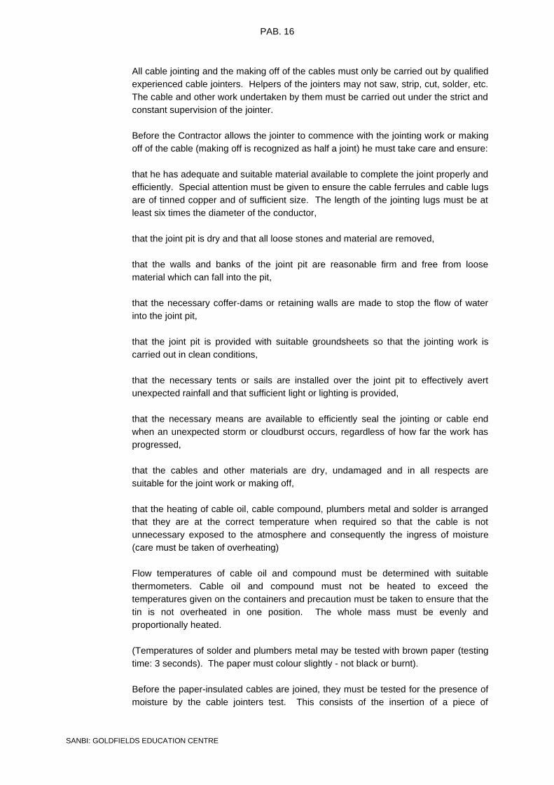
PAB. 16
SANBI: GOLDFIELDS EDUCATION CENTRE
All cable jointing and the making off of the cables must only be carried out by qualified
experienced cable jointers. Helpers of the jointers may not saw, strip, cut, solder, etc.
The cable and other work undertaken by them must be carried out under the strict and
constant supervision of the jointer.
Before the Contractor allows the jointer to commence with the jointing work or making
off of the cable (making off is recognized as half a joint) he must take care and ensure:
that he has adequate and suitable material available to complete the joint properly and
efficiently. Special attention must be given to ensure the cable ferrules and cable lugs
are of tinned copper and of sufficient size. The length of the jointing lugs must be at
least six times the diameter of the conductor,
that the joint pit is dry and that all loose stones and material are removed,
that the walls and banks of the joint pit are reasonable firm and free from loose
material which can fall into the pit,
that the necessary coffer-dams or retaining walls are made to stop the flow of water
into the joint pit,
that the joint pit is provided with suitable groundsheets so that the jointing work is
carried out in clean conditions,
that the necessary tents or sails are installed over the joint pit to effectively avert
unexpected rainfall and that sufficient light or lighting is provided,
that the necessary means are available to efficiently seal the jointing or cable end
when an unexpected storm or cloudburst occurs, regardless of how far the work has
progressed,
that the cables and other materials are dry, undamaged and in all respects are
suitable for the joint work or making off,
that the heating of cable oil, cable compound, plumbers metal and solder is arranged
that they are at the correct temperature when required so that the cable is not
unnecessary exposed to the atmosphere and consequently the ingress of moisture
(care must be taken of overheating)
Flow temperatures of cable oil and compound must be determined with suitable
thermometers. Cable oil and compound must not be heated to exceed the
temperatures given on the containers and precaution must be taken to ensure that the
tin is not overheated in one position. The whole mass must be evenly and
proportionally heated.
(Temperatures of solder and plumbers metal may be tested with brown paper (testing
time: 3 seconds). The paper must colour slightly - not black or burnt).
Before the paper-insulated cables are joined, they must be tested for the presence of
moisture by the cable jointers test. This consists of the insertion of a piece of

PAB. 17
SANBI: GOLDFIELDS EDUCATION CENTRE
unhandled insulated impregnated paper tape in warm cable oil heated to a
temperature of 130 ± 5°C.
Froth on the surface of the oil is an indication that moisture is present in the
impregnated insulation and the amount of the froth gives an indication of the moisture
present.
If the cable contains moisture or is found to be otherwise unsuitable for jointing or
making of the inspector is to be notified immediately and he will issue the necessary
instruction to cope with the situation.
The joint or making off of paper insulated cables must not be commenced during rainy
weather.
Once a joint is in progress the jointer must proceed with the joint until it is complete
and before he leaves the site.
The jointer must ensure that the material and his tools are dry at all times, reasonably
clean and absolutely free from soil.
Relating to the jointing of the cable the following requirements apply:
All jointing must be carried out in accordance with recognized and tried techniques
and comply strictly with the instructions given by the supplier of the jointing kit.
The cables must be twisted by hand so that the cores can be joined according to the
core numbers. If necessary the cable is to be exposed for a short distance to
accomplish this. Under no circumstances may the cores in a joint be crossed so as to
enable cores to be joined according to the core numbers. If it is not possible to twist
the cables so that the preceding requirements can be met, then cores are to be joined
in the normal way without any consideration of the core numbers.
Normally the cables will have profile conductors. The conductors shall be pinched
with gas pliers to form a circular section, bound with binding wire so that they do not
spread, and then tinned before jointing.
Jointing ferrules, the length of which are at least 6 times the diameter of the
conductors, must be slid over the conductor ends to be joined and pinched tightly.
Then they are soldered by means of the ladle process whilst being pinched further
closed.
Use resin only as a flux. The slot opening in the ferrule must be completely filled,
including all depressions.
Remove all superfluous metal with a cloth dipped in tallow. Work during the soldering
process must be from top to bottom. Rub the ferrule smooth and clean with aluminium
oxide tape after it has cooled down to ensure that there are not any sharp points or
edges.

PAB. 18
SANBI: GOLDFIELDS EDUCATION CENTRE
NB: The spaces between the conductor strands must be completely filled by
soldering process and must be carried out quick enough to prevent the paper
insulation from burning or drying out unnecessarily.
After the ferrules have been rubbed smooth and clean, they and the exposed cores
must be treated with hot cable oil (110°C) to remove all dust and moisture. These
parts are to be thoroughly basted with the oil.
The jointer must take care that his hands are dry and clean before the joint is
insulated. Also the insulating tape which is to be used must first be immersed in warm
cable oil (110°C) for a sufficient period to ensure that no moisture is present.
After the individual cores have been installed they must be well basted with hot cable
oil and again after the applicable separator and/or belt insulation tape is applied before
the lead joint sleeve is placed in position.
The lead joint sleeve must be thoroughly cleaned and prepared before it is placed on
the cable and must be kept clean during the whole jointing process. Seal the filling
apertures of the sleeve with tape until the sleeve is ready for compound filling.
The plumbing joints employed to solder the joint sleeve to the cable sheath, must be
cooled off with tallow and the joint sleeve is to be filled with compound while it is still
warm. Top up continuously until the joint is completely filled to compensate for the
compound shrinkage.
The outer joint box must be clean and free from corrosion. After it has been placed in
position it must be slightly heated before being filled with compound. Top up until
completely full.
As far as cable end boxes are concerned the requirements as set out above are valid
where applicable.
AB 07.17 DISTRIBUTION BOARDS
The Contractor shall supply and install the distribution boards as indicated on the
drawings and listed in the distribution Board Schedule. All distribution boards shall
comply with this specification, and be approved by the Engineer’s representative.
The following types of distribution boards are required for the service:
• Surface Mounted Distribution Board situated in the store room for power supply
to the Inverter and Building Sub-Distribution Board.
• Surface Mounted Sub-Distribution Board situated in the passage providing
power to all the equipment, power points, socket outlets and lights.

PAB. 19
SANBI: GOLDFIELDS EDUCATION CENTRE
AB 07.18 SCHEDULE OF POWER POINTS
BOARD POWER
POINT TYPE SIZE OF CABLES, CONDUIT AND WIRING
LOAD
WATTS
DB-1 150 litre 20mm dia. conduit with 2 x 4mm² conductors
and 2,5mm² earth wire 3000
DB-1 Heat Pump 20mm dia. conduit with 2 x 4mm² conductors
and 2,5mm² earth wire 2000
PAB 07.19 SCHEDULE OF CABLES, CONDUIT AND WIRING
Supply, install and connect the following cable, conduit and wiring:
PAB 07.21 SCHEDULE OF DISTRIBUTION BOARDS
The front panels of normal supply, standby power and no-break supply sections shall
be painted in distinctive colours as follows:
Normal supply : Light Orange, colour B26 of SANS 1091.
Standby power : Signal Red, colour A11 of SANS 1091.
No-break supply : Dark Violet, colour F06 or Olive Green,
Colour H05 of SANS 1091.
Indicated is the probable fault level rating (kA) of the busbars. Refer to the Summary
of Switchgear and Circuits for the minimum fault level rating of specified equipment.
BOARD TYPE PANEL FAULT LEVEL LOAD
kVA
Main D.B Surface with lockable door Normal power 6
SUB D.B Surface with lockable door Essential power 6
AB 08 INSTALLATION DETAILS AND MEASUREMENT AND PAYMENT
AB 08.01 INSTALLATION DESCRIPTION
Building electrical systems to the Goldfields Education Centre
AB 08.02 SCOPE OF WORK
• Supply and install new power supply cable from the new PV Installation
to the new Main Distribution Board;
• Supply and install cabling between the Main Distribution Board and the
Sub Distribution
FROM TO SIZE AND TYPE LOAD
(kW)
PV INSTALLATION MAIN D.B 1 x 16mm² 2-core PVCA cable and 6mm² earth wire
MAIN D.B SUB D.B 1 x 16mm² 4-core PVCA cable and 10mm² earth wire

PAB. 20
SANBI: GOLDFIELDS EDUCATION CENTRE
• The existing light fixtures will be evaluated to ensure adherence to
minimum design standards and electrical use good practice.
• Service existing distribution board, labelling and provide legend card.
Replacement of old Fuchs type circuit breakers. Install additional circuit
breakers for power circuits to the hand dryers and other fixed equipment.
• Provide Certificate of Compliance on the Electrical Installation
• Supply and install new separate power supplies to the hand dryers in the
ablutions. Power supply will be complete with conduit and PVC wiring.
Hand Dryers currently work from light switches and socket outlets.
• Replace the existing power supply on the outside of the building to the
outside lights that is in PVC trucking with PVC conduit complete with
draw boxes and round boxes.
• Install a light switch for the library as the light switch is located in the
passage.
• Supply and install power skirting complete with socket outlets above the
work tops in the classrooms.
• Replace the existing old light switches and rusted light switch covers. The
lights switches will furthermore be serviced and labelled.
• Replacement of socket outlets with single euro sockets as per latest
SANS 10142 regulations.
• All socket outlets, light switches and isolators will be labelled with PVC
brother labels according to the circuit number in the D.B Board (C.B 10
DB A)
• Replacement of defective light fittings, lamps and control gear. Defective
light fittings to be replaced with LED type lights to minimize maintenance
and to save on energy consumption.
• Supply and install 600x600mm panel LED lights at the new suspended
ceilings in the classrooms.
• Supply and install power supply complete with 6A USO sockets for new
LED panel lights that will be installed in the classrooms.
• Check and repair earthing and bonding of the building and at all the
ablutions, geysers, heat pumps and equipment.
• Install LED strip lights underneath the cupboards to provide lightning at
the worktops in the classrooms.
• Replacement of the outside lights with LED lights that with directional
reflectors to minimize light pollution.
• Add additional outside lights on certain places around the building for
security purposes.
AB 08.03 CABLE INSTALLATION
AB 08.03.01 All low voltage 400V cables shall have stranded copper conductors, shall be of the
600/1 000V PVC/SWA/PVC type.
AB 08.03.02 Where sleeves are not specified, cables shall be laid directly in the ground. Minimum
laying depths shall be 1000 mm below final ground level unless otherwise specified.
Contractor shall use hand excavation to minimise risk of damage to the existing
services.

PAB. 21
SANBI: GOLDFIELDS EDUCATION CENTRE
AB 08.03.03 All trenching, including excavations, bedding layers, shoring and prevention of
waterlogging, drainage of excavations, backfilling and compaction of trenches form
part of this contract. The contractor shall be deemed to have allowed for the laying of
cables, terminal boxes, glands and termination of cables. Trenches shall be
compacted to a minimum of 93% of modified AASHTO density during backfilling.
AB 08.03.04 Tenderers shall take cognisance of the fact that other services might be installed
along the same routes as the cables. The contractor shall, before commencing with
any excavations, peg out the proposed cable route and confirm it with the Resident
Engineer.
AB 08.03.05 Tenderers are to note that the minimum earth cable size buried in soil shall be 6 mm².
AB 08.03.06 Tenderers are to note that some cables will be installed underneath paved areas. The
contractor shall be required to provide appropriate machinery for this type of
installation and shall allow in his tender price for hiring of such machinery and the
remedial civil work associated with this installation.
AB 08.03.07 Cables running on surfaces of walls shall be routed inside galvanised steel piping.
AB 08.04 DISTRIBUTION BOARDS
AB 08.04.01 Existing Distribution Boards
(a) Tenderers shall note that, all distribution boards shall remain safe at all times.
Adequate provision for the installation of temporary 3mm Perspex faceplates
shall be allowed in the tender rates.
AB 08.04.02 New Distribution Boards
(a) The distribution board requirements are as shown on the schematic drawings.
Note the 6kA minimum fault level.
(b) Electrical Contractors are advised to order the distribution board and equipment
from a reputable manufacturer, as inferior boards will not be accepted.
(c) It shall further be noted that late approval of drawings and distribution boards
due to non-compliance with the specification will not relieve the Electrical
Contractor from his obligations to complete the installation according to
programme. No claims for delays or extension of time in this regard, will be
entertained.
(d) All phase, neutral and earth busbars shall be adequately sized to accept all
present as well as future circuits and connections.
(e) Door hinges shall be of the Perano manufacture. The steel door shall be
padlockable.
(f) The distribution board shall be powder coated
(g) The front face panel shall be secured by means of the Perano type catches.
Catches with slots or square key formats will not be acceptable.

PAB. 22
SANBI: GOLDFIELDS EDUCATION CENTRE
AB 08.05 CONDUIT
AB 08.05.01 Conduit work under open roof structures, along service passages and inside plant
rooms shall be done on the surface in a rectangular grid pattern. Galvanized steel
hospital saddles shall be used on all exposed conduit. Caddy clamps shall be used
on roof purlins. Maximum spacing of saddles and clamps shall be 750 mm.
AB 08.05.02 External draw box covers shall be sealed with white silicone after the installation has
been completed.
AB 08.05.03 Chasing where applicable, shall only be done with a 230mm angle grinder fitted with a
double diamond blade attachment.
AB 08.06 OUTLETS
AB 08.06.01 General
For the power installation, the Contractor shall be responsible for: -
(a) Supply and installation of isolators for equipment, motors including wiring,
earthing and bonding.
(b) Final connection between isolator and equipment/motor.
(c) Supply and installation of 16A switch socket outlets.
(d) Wiring of all circuits back to the DB with SANS approved wire as specified in the
schedule of quantities.
(e) Labelling of all outlets as specified.
(f) Testing and commissioning of all circuits.
AB 08.06.02 Isolators
(a) Isolators shall be similar or approved equal to GEWISS GW70432 or Lumex
Clipsal type WHD.
(b) The isolators shall be the water resistant, surface mounted type installed in a
non-corrosive enclosure
(c) The enclosure shall bear a permanently fixed (screwed) engraved Traffolite
label indicating the DB and circuit number.
AB 08.07 WIRING
AB 08.07.01 Surfix or Norse cable shall not be accepted on this project.
AB 08.07.02 All circuits shall be wired from fresh unused coils of red, white, blue and black
conductors. The colours of conductors shall correspond to the phase from which that
circuit is fed. The use of insulation tape to indicate phases will not be accepted.
AB 08.07.03 Wiring shall not be drawn into conduit until the conduit installation has been
completed, fitted with bushes and all moisture and debris have been removed.
AB 08.07.04 Joints of any kind will not be permitted in wiring. No more than 2 single or 1 three
phase circuit may be drawn into any 20mmø conduit.

PAB. 23
SANBI: GOLDFIELDS EDUCATION CENTRE
AB 08.08 EARTHING AND BONDING
AB 08.08.01 The electrical contractor is to ensure that the installations covered in this document
are effectively earthed and bonded in accordance with the requirements of the
SANS 0313.
AB 08.08.02 Particular attention shall be paid to geyser bonding and earthing.
AB 08.08.03 The earth conductor linking adjacent or back-to-back socket outlets shall not be cut.
The conductor must be kept continuous and be doubled at the intermediate earth
terminals.
AB 08.09 LABELLING OF CIRCUITS
AB 08.09.01 All conductors shall be marked by suitable cable markers indicating the circuit (e.g. P1
or G1 on both line and neutral conductors).
AB 08.09.02 The label shall indicate the supply DB and circuit number (e.g. DB-M-P5).
AB 08.10 INSPECTIONS
AB 08.10.01 The Electrical Engineer’s or Client’s representative will inspect the installation at any
time. All inferior, unsuitable, unacceptable or rejected work shall, if indicated by the
inspecting officers or the Engineer, be removed and shall be rectified by the electrical
contractor at his own expense. Under no circumstances will these inspections relieve
the electrical contractor of his obligations in terms of the document nor will these
inspections be regarded as final approval of the works or portions thereof.
AB 08.10.02 Where inspections are requested by the Contractor, the Electrical Engineer’s or
Client’s inspection shall only be carried out after the Contractor has carried out his
own preliminary inspection to ensure that the Works are completed and comply with
the documents. The Electrical Engineer’s or Client’s inspection shall therefore not be
regarded as supervision, fault listing, quality assurance or site management.
AB 08.10.03 Distribution boards and cabling
(a) Service distribution boards: inspect and clean the distribution boards, treat the
enclosure for moisture ingress and corrosion.
(b) Check for rigidity and fastening of equipment trays, panels, doors and
handling devices.
(c) Check locking mechanism and fit padlock. All padlocks shall be of local
manufacture with brass bodies and 75 mm chrome shackles. Three keys (with
pvc labels) shall be provided for each lock.
(d) Replace damaged or missing faceplates, doors, mounting frames, handles,
thumb catches, etc.
(e) Check operation of distribution board equipment and meters, replace if faulty or
damaged with an approved type.
(f) Remove all obsolete equipment and meters.
(g) Check and fasten wiring and cable terminations.
(h) Re-arrange wiring and equipment to give a neat installation.

PAB. 24
SANBI: GOLDFIELDS EDUCATION CENTRE
(i) Trace outgoing circuits.
(j) Fit labelling and blank face plate covers.
(k) Replace the distribution boards if required and replacement is approved by
Engineer. Check earth bar and earth continuity, record.
(l) Label all wiring and cabling with Grafoplast Trasp PVC markers.
(m) Replace all circuit breakers that are rated below 5 kA.
AB 08.10.04 Lighting system
(a) Indoor luminaires
(i) Operational and complete luminaires
- Remove lamps and wash luminaire body with detergent.
Clean polycarbonate diffusors with detergent. Clean polished
pure aluminium diffusors / reflectors with benzene.
- Check condition of luminaire seal, entrance gland, lampholder
and internal wiring.
- Ensure that earth stud and earth connection is sound.
- Replace missing screws, catches, bolts and plugs.
- Check condition of suspension cords of pendant luminaires.
- Re-lamp.
(ii) Damaged or incomplete luminaires
- Remove luminaire.
- Replace luminaire and reconnect.
- Fit new lamps.
(b) Light switches
Note: All light switches shall have steel faceplates with permanent glued
Traffolite labels.
- Remove switch cover.
- Check continuity of earth connection.
- Check operation of switch and replace if suspect.
- Replace switch cover, fit new csk stainless steel screws if required.
(c) Photocells
- Wash translucent body with detergent.
- Cover photocell and verify operation.
- Check bypass manual switching circuit.
- Enclose all exposed wiring in 16 mm ø Sprague.
- Install photocell in a dummy bulkhead
(d) Floodlight and bulkhead luminaires
- Remove lens and lamp. Wash lens thoroughly.

PAB. 25
SANBI: GOLDFIELDS EDUCATION CENTRE
- Wash luminaire body with detergent.
- Clean polished pure aluminium reflectors with benzene.
- Check condition of internal wiring, capacitor, ballasts and starters.
- Check condition of neoprene seal and replace if worn or damaged.
- Check condition of lampholder.
- Seal conduit and wiring entry with silicone to eliminate water ingress.
- Fit new lamp.
- Check condition of earth stud and luminaire earth connection.
- Replace all missing screws, lens catches, bolts.
- Close cover securely, check stirrup bolts.
SCHEDULE OF LUMINAIRES
TYPE DESCRIPTION
A 2X 58W SABS OPEN CHANNEL FLUORESCENT LUMINAIRE - LASCON TYPE : R1-
258 SS OR SIMILAR APPROVED
B 2X 36W SABS OPEN CHANNEL FLUORESCENT LUMINAIRE - LASCON TYPE : R1-
236 SS OR SIMILAR APPROVED
C 46W IP65 SABS LED LUMINAIRE - BEKA TYPE : VLNLED 46N WITH WATERTIGHT
DIFFUSER OR SIMILAR APPROVED
D
600X600 LED BACKLIT PANEL RECESSED MOUNTED COMPLETE WITH FLICKER
FREE DRIVER 400K 36W LED'S ACRYLIC (OPAL) DIFFUSER, 3M CORD SET AND
5A PLUG TOP TYPE BEKA OR GENESIS ONE LED PANEL 600X600 30W/36W OR
SIMILAR APPROVED
E
600X600 EMERGENCY LED BACKLIT PANEL RECESSED MOUNTED COMPLETE
WITH FLICKER FREE DRIVER 400K 36W LED'S ACRYLIC (OPAL) DIFFUSER, 3M
CORD SET AND 5A PLUG TOP TYPE BEKA OR GENESIS ONE LED PANEL
600X600 30W/36W OR SIMILAR APPROVED
F
600X600 LED BACKLIT PANEL SURFACE MOUNTED COMPLETE WITH FLICKER
FREE DRIVER 400K 36W LED'S ACRYLIC (OPAL) DIFFUSER, 3M CORD SET AND
5A PLUG TOP TYPE BEKA OR GENESIS ONE LED PANEL 600X600 30W/36W OR
SIMILAR APPROVED
G
600X600 EMERGENCY LED BACKLIT PANEL SURFACE MOUNTED COMPLETE
WITH FLICKER FREE DRIVER 400K 36W LED'S ACRYLIC (OPAL) DIFFUSER, 3M
CORD SET AND 5A PLUG TOP TYPE BEKA OR GENESIS ONE LED PANEL
600X600 30W/36W OR SIMILAR APPROVED
H
1200X600 LED PANEL RECESSED MOUNTED COMPLETE WITH 400K 48W LED'S
ACRYLIC (OPAL) DIFFUSER, 3M CORD SET AND 5A PLUG TOP TYPE BEKA LED
PANEL 1200X600 48W OR SIMILAR APPROVED
I 13W LED BULKHEAD LUMINAIRE - BEKA TYPE SERIES 30 OR SIMILAR
APPROVED
J 220V LED STRIP LIGHTS CLEAR WHITE
K LED PICTURE WALL LIGHTS
L 18W DECORATIVE HIGH PERFORMANCE OUTDOOR IP65 LED BULKHEAD
SIMILAR OR EQUAL TO BEKA Q-VAL
M 17W LED DOWN LIGHT RECESSED MOUNTED COMPLETE WITH 3M CORD SET
AND 5A PLUG TOP BEKA RONDO TYPE OR SIMILAR APPROVED
N 9W LED DOWN LIGHT SURFACE MOUNTED BEKA RONDO TYPE OR SIMILAR
APPROVED

PAB. 26
SANBI: GOLDFIELDS EDUCATION CENTRE
AB 08.10.05 Power outlets and fixed appliances
Note: All power outlets shall have steel faceplates with permanent glued Traffolite
labels.
(a) Inspect all power outlets and verify earthing.
(b) Check contact points and tighten screws.
(c) Replace missing screws and covers for outlet and draw boxes.
(d) Replace missing, faulty or damaged socket outlets and plugs.
(e) Check conditions and operation of local isolators and control switches for fixed
equipment and replace if faulty, damaged or missing.
(f) Check earthing of fixed appliances and test for earth continuity.
(g) Inspect cable and wireways.
(h) Check for rigidity and fastening of the cable ducts, ladders, ducting,
powerskirting and surface conduiting, fasten or replace if loose or damaged,
check earthing and test for earth continuity.
AB 08.10.06 Earthing, bonding and lightning protection
(a) Check earthing and bonding of outlet points, equipment, cable and wireways,
fixed appliances, water and gas pipes, etc.
(b) Check installation and termination of protective conductors and earth electrodes
(c) Test for earth continuity.
(d) Provide 6 mm² copper earth wire jumper between roof cladding and all gutter
downpipes. Fasten with lugs and galvanized zinc bolts. Typically ten
downpipes per housing unit. Earth at least two gutter downpipes by means of
16 mm² green insulated earth wire connected to 1,2 m earth electrode by
means of cadwelding. Typically two downpipes per 25 m long housing unit.
(e) Installation of 50 mm² aluminium roof conductor in galvanised conduit from the
roof cladding against the building to the earth electrode.
AB 08.11 MEASUREMENT AND PAYMENT
AB 08.11.01 Distribution boards and cabling
AB.01.01 Service distribution board……………………………………………………Unit: number
The unit of measurement shall be the number of distribution kiosks or boards opened
and serviced.
The tendered rate shall include full compensation for the opening of the distribution
board or kiosk, internal cleaning of the enclosure, cleaning of equipment and meters,
removal of obsolete distribution board equipment, re-arrangement of equipment and
wiring, treatment of the enclosure for moisture ingress and corrosion, vermin
protection, fastening and / or replacement of wiring, tracing of outgoing circuits,
labelling of outgoing wiring and mcb’s and cable terminations and earth testing.
The tendered sum shall further include for replacement of damaged, missing or faulty
distribution board switchgear, meters, face plates, mounting frames, handling devices,

PAB. 27
SANBI: GOLDFIELDS EDUCATION CENTRE
doors, labelling with engraved Traffolite labels, neutral bars, earth bars etc. All
downstream circuit breakers shall be rated at 6 kA fault level.
AB.01.02 Supply and install distribution board…………………………………… Unit: number
The unit of measurement shall be the number of distribution boards supplied and
installed .
The tendered rate shall include full compensation for the supply and installation of an
epoxy painted new enclosure, mounting frames, plates, equipment, meters, labelling
etc.
The tendered sum shall further include for wiring of the board, cable termination, cable
labelling, remedial builders work and earth testing.
AB.01.03 Supply and install cabling Unit: m
The unit of measurement shall be the linear length of cable supplied and installed.
The tendered rate shall include full compensation for the supply, handling, installation
and termination of the specified type of cable.
This rate shall further include for the supply of all cable ties, clamps and other material
necessary to ensure that the installation conforms to the specification.
AB.01.04 Supply and install wiring Unit: m
The unit of measurement shall be the linear length of conductors supplied and
installed.
The tendered rate shall include full compensation for the supply, handling, installation,
pulling in conduit and termination of the specified type of conductor.
This rate shall further include for the supply of all cable ties, labelling, and other
material necessary to ensure that the wiring conforms to the specification.
AB.01.05 Jointing and termination of cables…………………………………………Unit: number
The unit of measurement shall be number of cable joints or terminations.
The tendered rate shall include full compensation for the cost for providing the kits,
complete with compound, ferrules and cable lugs, the cost for cutting the cable,
handling and fitting kits and the cost of testing the joints and terminations. Position of
joints shall be indicated on as-built drawing
AB.01.06 Supply and install padlocks………………………………………………..Unit: number
The unit of measurement shall be number of padlocks supplied and installed.
The tendered rate shall include full compensation for the ordering, supply and
installation of the 75 m locally manufactured padlocks and locking devices as well as
fitting each of the three keys with purpose-made pvc labels.

PAB. 28
SANBI: GOLDFIELDS EDUCATION CENTRE
AB.01.07 Excavate in all materials for trenches, backfill,
compact and dispose of surplus material Unit: m³
The unit of measurement shall be the cubic meter of material excavated in trenches.
The tendered rate shall include full compensation for clearing and grubbing the trench
areas, for excavating the trench, preparing the bottom of the trench, separating
material unsuitable for backfill and dealing with any surface or subsurface water.
The tendered rate shall furthermore cover the cost of installing the sand bed and sand
cover, backfilling, compacting and disposing of the surplus material.
AB.01.08 Supply and install cable sleeves Unit: m
The unit of measurement shall be the linear length in meter of the cable sleeve
supplied and installed.
The tendered rate shall include full compensation for the supply, delivery, handling
and installing the specified sleeves including the all the required, couplings, steel draw
wires and plugs.
AB.01.09 Supply and install plastic warning tape Unit: m
The unit of measurement shall be the linear length in meter of the plastic warning tape
supplied and installed.
The tendered rate shall include full compensation for the supply, handling and laying
of the plastic warning tape.
AB.01.10 Termination of the low voltage cable………………………..……………Unit: number
The unit of measurement shall be the number of low voltage cable terminations.
The tendered rate shall include full compensation for providing the cable glands and
shrouds, the cost for handling, fitting and cutting the cable.
AB.01.11 Supply and install earth continuity conductor Unit: m
The unit of measurement shall be the linear length in meter of the earth continuity
conductor supplied and installed.
The tendered rate shall include full compensation for procuring, furnishing and laying
the specified earth continuity conductor.
AB.01.12 Termination and connect earth continuity conductor…………………Unit: number
The unit of measurement shall be the number of earth continuity conductors
terminated and connected.

PAB. 29
SANBI: GOLDFIELDS EDUCATION CENTRE
The tendered rate shall include full compensation for supplying all the material
required to terminate and connect the earth continuity conductors and the connecting
thereof to the earth bars, including label tags.
AB.01.13 Supply and installation of circuit breakers………………………………Unit: number
The unit of measurement shall be the number of circuit breakers supplied and
installed.
The tendered rate shall include full compensation for the supply and installation of the
specified type and size of circuit breaker, including printed PVC labelling.
AB.01.14 Supply and installation of isolators………………………………….……Unit: number
The unit of measurement shall be the number of isolators supplied and installed.
The tendered rate shall include full compensation for the supply and installation of the
specified isolator, including printed PVC labelling.
AB.01.15 Supply and install contactors…………………………………….…………Unit: number
The unit of measurement shall be the number of contactors supplied and installed.
The tendered rate shall include full compensation for the supply and installation of the
specified type of contactor, including engraved labelling on rear tray.
AB.01.16 Supply and install switching timers………………………………..………Unit: number
The unit of measurement shall be the number of switching timers supplied and
installed.
The tendered rate shall include full compensation for the supply and installation of the
specified type of switching timer, including labelling.
AB.01.17 Supply and install earth leakage units………………………….…………Unit: number
The unit of measurement shall be the number of earth leakage units supplied and
installed.
The tendered rate shall include full compensation for the supply and installation of the
specified type of earth leakage units, including labelling.
AB.01.18 Supply and install fuses………………………………………………………Unit: number
The unit of measurement shall be the number of fuses supplied and installed.
The tendered rate shall include full compensation for the supply and installation of the
specified type of fuse, including engraved label indicating fuse rating.

PAB. 30
SANBI: GOLDFIELDS EDUCATION CENTRE
AB.01.19 Supply and install surge arrestors………………………………..………Unit: number
The unit of measurement shall be the number of surge arrestors supplied and
installed.
The tendered rate shall include full compensation for the supply and installation of the
specified type of surge arrestors, with visual indication.
AB.01.20 Supply wire marker kit………………………………………………………Unit: number
The unit of measurement shall be the number of specified wire marker kits supplied.
The tendered rate shall include full compensation for the procurement and delivery of
the cable marker kit as specified.
AB.08.11.02 LIGHTING SYSTEM
AB.02.01 Re-lamp luminaire Unit: number
The unit of measurement shall be the number of lamps replaced.
The tendered rate shall include full compensation for the supply and installation of the
specified lamp according to the manufacturer’s instructions. Replacement date must
be written on lamp.
AB.02.02 Service luminaire Unit: number
The unit of measurement shall be the number of luminaires opened and serviced.
The tendered rate shall include full compensation for the servicing of the luminaire,
including washing, checking of seals, glands, lamp holders, cleaning of diffusers,
tightening of fixing screws and bolts, corrosion protection and the checking of earthing
continuity and aiming angle if applicable. All external luminaire conduit entries are to
be sealed with silicone, which cost is included in this payment item.
The tendered rate shall further include for replacement of the luminaires internal wiring
where applicable and the tightening of all connections
AB.02.03 Supply and install luminaire Unit: number
The unit of measurement shall be the number of luminaries supplied and installed .
The tendered rate shall include full compensation for the supply and installation of the
specified type of light fitting complete with lamp and control gear, according to
manufacturer’s instructions.

PAB. 31
SANBI: GOLDFIELDS EDUCATION CENTRE
AB.02.04 Supply and install light switch Unit: number
The unit of measurement shall be the number of light switches supplied and installed.
The tendered rate shall include full compensation for the removal of the existing light
switch and for the supply and installation of the specified type of light switch to
manufacturer’s instructions. Light switch face plate shall be fitted with an engraved
Traffolite label as per Nosa-standard, cost of, which is included in rate.
AB.02.05 Supply and install photo-electric switch Unit: number
The unit of measurement shall be number of photocell units replaced.
The tendered rate shall include full compensation for the supply, connecting and
testing of the switch.
The rate shall further include full compensation for the cost of providing and installing
all hardware, screws, wall plugs, 16 mm ø sprague and other material required to
install the photo electric light switch in accordance with the manufacturer’s
specification.
The tendered rate shall further compensate for the supply and installation of the
photocell inside a dummy B10 bulkhead.
AB.02.06 Replace luminaire diffuser Unit: number
The unit of measurement shall be number of luminaire diffusers replaced.
The tendered rate shall include full compensation for the supply and installation of the
specified type of diffuser, including fixing screws and clips.
AB.02.07 Service light switch Unit: number
The unit of measurement shall be the number of light switches opened and serviced.
The tendered rate shall include full compensation for the servicing of the light switch,
internal cleaning of the enclosure, spray painting, inspection of the contact points,
switching mechanism, earthing, etc.
The tendered sum shall further include for replacement of any missing outlet covers
and fixing screw and earth testing. Light switch face plate shall be fitted with an
engraved Traffolite label as per Nosa-standard, cost of, which is included in rate.
AB.02.08 Remove, clean, store and reinstallation of luminaire Unit: number
The unit of measurement shall be the number of light fittings removed, cleaned, stored
and reinstalled.
The tendered rate shall include full compensation for the removal, disconnect,
cleaning, storage (4 weeks) reinstallation, reconnection and testing of the luminaire.

PAB. 32
SANBI: GOLDFIELDS EDUCATION CENTRE
The rate shall further include full compensation for the installation of 2 x 700 mm
supporting timber members above the ceiling (114 x 38 Par SA Pine) and the
mounting of 63 mm ø round conduit outlet box complete with 2 x 4 x 60 mm
galvanised screws.
AB.02.09 Replace Lamp Holder Unit: number
The unit of measurement shall be the number of lamp holders replaced.
The tendered rate shall include full compensation for the removal of the existing lamp
holder and for the supply and installation of the specified type (ceramic) of lamp holder
to the manufacturer’s instructions.
AB.02.10 Replace Luminaire internal components Unit: number
The unit of measurement shall be the number of SANS approved internal luminaire
components replaced.
The tendered rate shall include full compensation for the removal of the defective
component and for the supply, installation and testing of the specified type of
component to the manufacturer’s instructions.
AB.08.11.03 SMALL POWER AND FIXED APPLIANCES
AB.03.01 Supply and install socket outlet Unit: number
The unit of measurement shall be the number of socket outlets supplied and installed.
The tendered rate shall include full compensation for the removal of the existing
socket outlet and the supply and installation of the specified type of socket outlet.
All socket outlets shall be supplied complete with cover plates and boxes where
required. The tendered rate shall therefore include for the supply of the cover plates
and fixing screws where applicable. Outlet face plate shall be fitted with an engraved,
Traffolite label as per Nosa-standard, cost of, which is included in the rate.
AB.03.02 Supply and install isolator Unit: number
The unit of measurement shall be the number of isolators supplied and installed.
The tendered rate shall include full compensation for the supply and installation of the
specified type of isolator or control unit.
The tendered sum shall further include for the provision of 4 wire, 3 phase connections
to the fixed appliance. Isolator face plate shall be fitted with an engraved Traffolite
label as per Nosa-standard, cost of, which is included in the rate.

PAB. 33
SANBI: GOLDFIELDS EDUCATION CENTRE
AB.03.03 Replace plug tops Unit: number
The unit of measurement shall be the number of plug tops replaced.
The tendered rate shall include full compensation for the supply and installation of the
required type of plug top.
AB.03.04 Supply and install conduit Unit: m
The unit of measurement shall be the linear meter of conduit supplied and installed.
The tendered rate shall include full compensation for the supply and installation of the
specified type and size of conduit, including all fixing accessories.
AB.03.05 Supply and install wiring channel Unit: m
The unit of measurement shall be number of linear meter of wiring channel replaced.
The tendered rate shall include full compensation for the supply and installation of the
specified type of wiring channel with 6 x 60 mm fasteners, including the cover and all
the necessary accessories.
AB.03.06 Supply and install connections to fixed appliances Unit: number
The unit of measurement shall be number of connections made.
The tendered rate shall include full compensation for the supply and installing of the
connections to the fixed appliances.
AB.03.07 Service socket outlet Unit: number
The unit of measurement shall be the number of socket outlets opened and serviced.
The tendered rate shall include full compensation for the servicing of the socket outlet
, internal cleaning of the enclosure, inspection of the contact points, switching
mechanism, if applicable, earthing, etc. Outlet face plate shall be fitted with an
engraved, Traffolite label as per Nosa-standard, cost of, which is included in the rate.
The tendered sum shall further include for replacement of any missing outlet covers
and fixing screw and earth testing.
AB.03.08 Service isolator Unit: number
The unit of measurement shall be the number of isolators opened and serviced.
The tendered rate shall include full compensation for the servicing of the isolator ,
internal cleaning of the enclosure, inspection of the contact points, switching
mechanism, earthing and connections to the fixed appliance. Isolator face plate shall
be fitted with an engraved Traffolite label as per Nosa-standard, cost of, which is
included in the rate.

PAB. 34
SANBI: GOLDFIELDS EDUCATION CENTRE
The tendered sum shall further include for replacement of any damaged or missing
outlet covers and fixing screw, connections to appliances including earth continuity
testing.
AB.03.09 Replace power skirting Unit: m
The unit of measurement shall be the linear metre of power skirting supplied and
installed.
The tendered rate shall include full compensation for the removal of the existing power
skirting, the supply and installation of the specified type and size of powerskirting
including all accessories.
AB.03.10 Supply and install Pratley boxes Unit: number
The unit of measurement shall be the number of Pratley boxes supplied and installed.
The tendered rate shall include full compensation for the supply and installation of the
specified type of Pratley box.
AB.03.11 Supply and install draw boxes Unit: number
The unit of measurement shall be the number of draw boxes supplied and installed.
The tendered rate shall include full compensation for supplying and installing the draw
boxes including cover plates where no equipment is installed in the box.
AB.03.12 Supply and install draw box cover plates Unit: number
The unit of measurement shall be the number of draw box cover plates supplied and
installed.
The tendered rate shall include full compensation for the supply and installation of the
specified type and size of cover plates for draw boxes including the fixing screws.
AB.03.13 Replace “stop-start” local control panel Unit: number
The unit of measurement shall be the number of “stop-start” local control panels
supplied and replaced.
The tendered rate shall include full compensation for the supply and installation of
“stop/start” local control panel including emergency stop button and 32A 3 pole
contactor in an IP55 polycarbonate enclosure. The rate shall include an engraved
Traffolite label indicating load and supply DB.

PAB. 35
SANBI: GOLDFIELDS EDUCATION CENTRE
AB.03.14 Test and service ceiling mounted fan Unit: number
The unit of measurement shall be the number of ceiling fans tested.
The tendered rate shall include full compensation for the servicing of the fan,
disconnection, testing, inspection of the contact points, switching mechanism, earthing
and re-connection of the ceiling fan.
AB.03.15 Replace ceiling mounted fan Unit: number
The unit of measurement shall be the number of ceiling fans supplied and installed.
The tendered rate shall include full compensation for the disconnection of the
damaged ceiling fan and for the supply, installation and connection of the new ceiling
fan.
AB.03.16 Service ceiling mounted fan control switch Unit: number
The unit of measurement shall be the number of control switches opened and
serviced.
The tendered rate shall include full compensation for the servicing of the control
switch, inspection of the contact points, switching mechanism, if applicable, earthing
etc.
AB.03.17 Replace ceiling mounted fan control switch Unit: number
The unit of measurement shall be the number of control switches replaced.
The tendered rate shall include full compensation for the supply and installation of the
control switch.
The tendered sum shall further include for the provision of connection to the ceiling
fan.
AB.03.18 Replace domestic stove components Unit: number
The unit of measurement shall be the number of stove components.
The tendered rate shall include full compensation for the supply and installation of the
specified component.
The rate shall further include the disconnection and removal of the faulty component
and the installation and testing of the new component.
AB.03.19 Replace geyser components Unit: number
The unit of measurement shall be the number of geyser components.
The tendered rate shall include full compensation for the supply and installation of the
specified component.

PAB. 36
SANBI: GOLDFIELDS EDUCATION CENTRE
The rate shall further include the disconnection and removal of the faulty component
and the installation and testing of the new component.
The rate shall also include the draining of the water from the geyser and refilling
before testing.
AB.03.20 Supply and Install Stove Unit: number
The unit of measurement shall be the number of electrical four plate stoves with oven
and warm drawer supplied and installed.
The tendered rate shall include full compensation for the supply and installation of the
stove including connection and testing after approval of the Engineer.
AB.03.21 Provide Certificate of Compliance Unit: number
The unit of measurement shall be the number of Certificate of Compliance obtained
from local authorities and issued to the Engineer for all the buildings under the
installation.
The tendered rate shall include full compensation for the testing and all associated
equipment to complete the Certificate of Compliance and certification thereof.
AB.08.11.04 EARTHING AND BONDING
AB.04.01 Supply and install earthing and bonding for the installation Unit: Lump sum
The tendered lump sum shall include full compensation for the provision of all material
required for the earthing and bonding of the installation in accordance with the
specification.
AB.04.02 Testing of the earth installation by a specialist contractor Unit: Lump sum
The tendered lump sum shall include full compensation for the testing of the earth
installation by a specialist contractor approved by the Engineer.
AB.04.03 Supply and install earth electrodes Unit: number
The unit of measurement shall be the number of earth electrodes supplied and
installed.
The tendered sum shall include full compensation for the supply and installation of the
specified type and size of earth electrodes including termination by means of
approved clamps.
AB.04.04 Provide cadweld joint Unit: number
The unit of measurement shall be the number of cadweld joints provided.
The tendered sum shall include full compensation for the supply and installation of the
specified type and size of cadweld pyro joints.

PAB. 37
SANBI: GOLDFIELDS EDUCATION CENTRE
AB.04.05 Earth building roof structure Unit: number
The unit of measurement shall be the number of roof structures earthed.
The tendered sum shall include full compensation for the supply and installation of the
specified type and size of earthwire and the termination there off onto a 1.2 m Cu
earth electrode driven into the soil 1,8 m deep.
AB.08.11.05 INSPECTION OF ELECTRICAL INSTALLATION
AB.05.01 Inspection of building general electrical installation Unit: sum
The unit of measurement shall be the sum for the building inspected prior to
commencement of the repair work phase.
The tendered sum shall include the visual and functional inspection and testing of all
lights, switches, small power points and fixed appliances, to determine the extent of
repairs or replacements required.
The rate shall further include the preparation of a schedule of items requiring repairs
or replacement, for approval by the engineer.

BA . 1
TECHNICAL SPECIFICATION BA ROOF COVERINGS CONTENTS BA 01 SCOPE BA 02 STANDARD SPECIFICATIONS BA 03 MEASUREMENT AND PAYMENT BA 01 SCOPE
This specification covers the removal of existing roof coverings and waterproofing and the supply, delivery and installation of new roof coverings and water-proofing to various types of buildings. Roof coverings shall mean the scope of work related to the removal of existing roof coverings, water-proofing and ancillary items, the supply and installation of new roof sheeting, roofing screws, purlins, flashings, rainwater goods, water-proofing, fascias and barge boards. This specification also includes minor work related to trusses, purlins, paintwork, minor plumbing work and water-proofing to concrete roofs.
BA 02 STANDARD SPECIFICATIONS BA 02.01 GENERAL STANDARD SPECIFICATIONS
The latest edition, including all amendments to date of tender, of the following specifications, publications and codes of practice shall be read in conjunction with this specification and shall be deemed to form part thereof: PW 371 - Specification of Materials and Methods to be used,
fourth edition, Oct 1993 SANS 1200HB - Cladding and Sheeting SANS 1783-4 - Softwood brandering and battens SANS 935 - Hot-dip (galvanised) zinc coatings SANS 1273 - Fasteners for sheet roof and wall coverings
BA 02.02 Occupational Health and Safety
The Contractor shall be required to comply with the Occupational Health and Safety Act 85 of 1993, Construction Regulations 2014 and related regulations. Non-compliance with these regulations, in any way whatsoever, will be adequate reason for suspending the Works.
BA 02.2 ADDITIONAL SPECIFICATIONS Technical Specification BB: Carpentry and Joinery for Roofs and Ceilings Technical Specification BC: Waterproofing of Concrete Roofs

BA . 2
BA 02.3 ADDITIONAL REQUIREMENTS FOR REPAIR OF PROFILED ROOF SHEETING (NON-CONCEALED FIXING AND CONCEALED FIXING)
BA 02.3.1 Roof sheeting
Existing roof sheeting shall either be replaced or to a small extent be repaired according to the Schedule of Quantities and as instructed by the Engineer. Where new sheeting is specified, the existing roof sheeting must be removed. Each day’s removed sheeting shall be fully covered with new roof sheeting at the end of the day. Plastic sheeting or equivalent approved protection to minimize damage possibilities due to rain, etc and to protect the personnel and occupied buildings. The new roof sheeting shall be 0, 6 mm thick galvanised baked silicone polyester enamel paint (baked enamel) IBR or equivalent approved for roof slopes exceeding 15º. Concealed fixed type Galvanised baked enamel roof sheeting will in general be used to cover roofs with slopes not exceeding 15º. The sheeting must be laid in long lengths without end overlaps. The broad flutes must be turned up at the apex to form a dam, and turned down at the eaves to form a drip. Metal closers 0,8 mm thick galvanised (baked enamel), complete with polyclosers set in one run of silicone sealant, are required at apexes, ridges, side and head walls, etc. The Contractor shall take all necessary dimensions and measurements on site prior to manufacturing and installation. Z275 galvanising spelter shall be used and the Contractor shall provide SANS certificates of compliance to the Engineer. Various standard dark colours will be used for baked enamel finished roof sheeting, flashings, gutters and down pipes. In all cases the roofing must be laid strictly in accordance with the manufacturer’s specifications. In certain cases, existing roof sheeting that is removed from buildings, will be re-used to repair similar types of structures. The following paragraphs in specification PW 371 must be specifically read in conjunction with this technical specification:
Paragraph 7.6, excluding 7.6.1(i), 7.6.2(a) and 7.6.2(e) Paragraph 7.7, excluding 7.7.1, 7.7.5 and 7.19.1(a).
BA 02.3.2 Main fasteners to timber purlins: Galvanised/baked enamel IBR or equivalent
approved sheeting
90 mm x no. 14 hexagon head (H/H) carbon steel (C/S) cadmium plated Posidriv or equivalent approved roofing screws with 29 mm diameter x 1,0 mm thick galvanised conical washers and poly-isobutyl grommet assembly must be used. Main fasteners for steel purlins are to be 65 mm long. Fasteners to be provided at alternating ribs and all side laps.
BA 02.3.3 Side lap fasteners: Galvanised/baked enamel IBR or equivalent approved sheeting
Stitching will be done with 25 mm x no. 14 H/H C/S posidriv or equivalent approved roofing screws @ 600 c/c maximum with 29 mm diameter x 1,0 mm thick galvanised conical washers and poly-isobutyl grommet assembly. Provide 10 x 1, 6 mm thick butyl rubber sealer strip between sheets.
BA 02.3.4 Flashings
0, 8 mm thick baked enamel/galvanised flashings at ridge caps, side and head walls, drips, corners, etc, as described elsewhere. The minimum length of an overlap between flashings is 150 mm. Apply two runs of silicone sealant between flashings. Flashings to be stitched together with 25 mm x no. 14 H/H C/S posidriv or equivalent approved roofing screws with 29 mm diameter x 1, 0 mm thick galvanised conical washers at end laps and

BA . 3
longitudinally @ 400 c/c maximum at ribs, etc. The Contractor shall take all necessary dimensions and measurements on site prior to manufacturing and installation.
BA 02.3.5 Sealant Silicone sealant with an amine cure system with primer shall be used to waterproof all flashings and rainwater goods, viz. gutters and down pipes. Two runs of silicone shall be provided at end overlaps.
BA 02.3.6 Pipe flashings
EPDM/silicone pipe-through-roof flashings to diameter or equivalent approved pipe flashings shall be used to waterproof pipe protrusions through the roof sheeting. Installation shall be done strictly in accordance with the manufacturer’s specification and shall include the application of EPDM/silicone pipe through roof flashing and sealant and fastening of flashing to surface with TEKS or equivalent approved self-drilling fasteners.
BA 02.3.7 Insulation
No insulation repairs are required. In certain cases insulation may be necessary to reduce heat load or to comply with hygiene requirements as in abattoirs. Refer to section 7 part 7.6.3 of PW 371. Specification for non-visible roof insulation material: Heavy grammage double sided reflective aluminium foil (heavy grade) laid on 1,6 mm diameter galvanised straining wires at 300 mm centres to the manufacturer’s specification. The insulation shall be laid longitudinally over the purlins and lapped 150 mm at joints.
Specification for visible roof insulation material: White thermal insulation low density polyethylene bubble and Aluminium foil backing fire retardant grade laid on 1,6 mm diameter white plastic (PVC) coated straining wires at 383 mm centres to the manufacturer’s specification. The insulation shall be laid longitudinally over the purlins and lapped at joints.
BA 02.4 ADDITIONAL REQUIREMENTS FOR REPAIR OF PROFILED SIDE WALL CLADDING
(NON-CONCEALED FIXING AND CONCEALED FIXING) BA 02.4.1 Side wall cladding Existing side wall cladding shall either be repaired or replaced in accordance with the
Schedule of Quantities. Where new cladding is specified, the existing side wall cladding must be removed. Each day’s removed cladding shall be fully covered with new cladding at the end of the day. The new side wall cladding shall be 0,6 mm thick galvanised (or baked enamel) IBR or equivalent approved. The cladding must be laid in long lengths without end overlaps. Metal closers 0,8 mm thick galvanised (or baked enamel), complete with polyclosers set in one run of silicone sealant, are required at gables, ridges, side and head walls, etc. The Contractor shall take all necessary dimensions and measurements on site prior to manufacturing and installation. Z275 galvanising spelter shall be used and the Contractor shall provide SANS certificates of compliance to the Engineer. Heavy duty profiled polycarbonate sheets shall be used for translucent sheeting. Various standard dark colours for baked enamel finished side wall cladding, flashings, gutters and down pipes will be used. In all cases the cladding must be laid strictly in accordance with the manufacturer’s specifications.

BA . 4
BA 02.4.2 Main fasteners to timber girts: Galvanised/Galvanised baked enamel IBR (or equivalent approved) and profiled translucent sheeting
90 mm x no. 14 hexagon head (H/H) carbon steel (C/S) cadmium plated posidriv or equivalent approved roofing screws with 29 mm diameter x 1,0 mm thick galvanised conical washers and poly-isobutyl grommet assembly must be used. Main fasteners for steel girts are to be 65 mm long. Fasteners to be provided at alternating ribs.
BA 02.4.3 Side lap fasteners: Galvanised/Galvanised baked enamel IBR (or equivalent approved) sheeting
Stitching will be done with 25 mm x no. 14 H/H C/S posidriv or equivalent approved roofing screws @ 600 c/c with 29 mm diameter x 1,0 mm thick galvanised conical washers and poly-isobutyl grommet assembly. Provide 10 x 1,6 mm butyl rubber sealer strip between sheets.
BA 02.4.4 End overlaps
If unavoidable, the end overlap shall be 300 mm minimum between sheeting and sealed with two rows of silicone sealant between the sheets. Bolt the ribs in the overlap region with the profiled (polycarbonate) translucent sheeting with galvanised no. 14 gutter bolts, bonded washers and nuts through every alternative rib.
BA 02.4.5 Side overlaps: Vertical profiled translucent sheeting
Stitching will be done with 6 mm cadmium-plated cladding bolts and nuts x 25 mm long @ ± 300 c/c with 19 mm diameter x 1,0 mm thick galvanised conical washers and poly-isobutyl grommet assembly.
BA 02.5 RAINWATER GOODS
BA 02.5.1 Gutters
Standard size for houses: 100 x 75 x 0,8 thick standard baked enamel/galvanised non-supporting beaded gutter. Galvanised brackets to be provided at every truss. Brackets to be painted to specification in the Schedule of Quantities. Alternatively standard 140 x 127 x 83 x 0,6 mm thick concealed fix profile sheeting baked enamel/galvanised fascia gutter with galvanised gutter clips can be used. Typical size for other buildings: 125 x 100 x 0,8 thick standard baked enamel self-supporting beaded gutter. Dark colours to Consultant’s specification.
The following paragraphs in specification PW 371 must be read in conjunction with this technical specification: 7.15, 16.12 and 16.13.
The Contractor shall take all necessary dimensions and measurements on site prior to manufacturing and installation.
BA 02.5.2 Joints in gutters, valleys, etc
150 mm overlap sealed with an approved silicone and riveted together with 2 rows of sealed pop rivets. Linings to valleys and secret gutters, etc, shall have an overlap of 225 mm.

BA . 5
BA 02.5.3 Gutter accessories and ancillary items
End stops: 0,8 mm thick baked enamel/galvanised finished end stops joined to gutter on site and sealed as for joints in gutters.
Outlets: 0,8 mm thick baked enamel/galvanised finished outlets fixed to gutter with
pop rivets and sealed with an approved silicone. Outlet to slip into down pipe.
Fascia straps: 25 mm wide x 1,0 mm thick galvanised straps at +/- 686 mm c/c. Corner joints: Corner joints to be neatly mitred, pop riveted together and sealed with an
approved silicone. Sealant: Clear silicone sealant with amine cured system and primer shall be used
to waterproof gutters and down pipes. BA 02.5.4 Down pipes
Standard sizes: 100 x 75 x 0, 6 thick baked enamel/galvanised down pipes 100 x 100 x 0,8 thick baked enamel/galvanised down pipes
Dark colours to Consultant’s specifications. Down pipes to have double-seamed joints. Down pipes, shoes, offsets, etc, shall be joined together by means of 100 mm slip joints and pop riveted together.
The Contractor shall take all necessary dimensions and measurements on site prior to manufacturing and installation.
BA 02.5.5 Down pipe acessories
Brackets: Standard galvanised brackets shall be spaced at centres not exceeding 2,4 metres.
Brackets to be primed and painted with 2 coats of high gloss enamel.
Shoes, offsets and spreaders: Manufactured from 0,8 mm thick baked enamel/galvanised material, cut and mitred to suit. All joints to be sealed with an approved silicone sealant.
BA.02.5.6 General The Contractor will be responsible for the stability of the supporting structure during and
after removal of existing roof cladding and sheeting. SANS 1200 HB "Cladding and Sheeting" will be applicable for the erection of all new
roofs. The Contractor must give a minimum 3 year guarantee for the watertight roof and
workmanship. The manufacturer must carry out inspections at regular intervals during the construction period. He must issue a certificate of acceptance and compliance on completion to the client.

BA . 6
BA 03 MEASUREMENT AND PAYMENT BA.03.1 DETAILS OF MATERIAL TO BE USED For detail descriptions of materials, thicknesses, dimensions and ancillary items to be
used, as specified in the various payment items of roof sheeting, cladding, flashings, etc; refer to the scheduled list below:
Flashings: Refer to Technical Specifications BA Roof: 0,8 mm thick Galvanised baked enamel Ridge Flashing
462 mm girth (231 + 231), 3 x bends (2 are shallow bends). Fix flashing to roof sheeting with posidriv screws and washers. 150 mm overlap sealed with 2 rows of pop rivets and 2 rows of silicone; 2 rows of broad flute polyclosers bedded in silicone, 2 rows x 0,6 mm thick Galvanised baked enamel broad flute metal closers. Bend up trough to form a dam.
0,6 mm thick Galvanised baked enamel Eaves Closer
Fix standard serrated narrow flute eaves closer to timber purlin. Patch plaster and touch up paint work.
0,8 mm thick Galvanised Apex Trim
462 mm girth (231 + 231 vertical), 3 x bends (2 are shallow bends). Fix flashing to roof sheeting with posidriv screws and washers. 150 mm overlap fixed and sealed with 2 rows of pop rivets and 2 rows of silicone. 1 row of broad flute polycloser bedded in silicone, 2 rows x 0,6 mm thick galvanised broad flute metal closers. Bend up trough to form a dam.
0,8 mm thick Galvanised baked enamel Headwall Flashing
385 mm girth (231 + 154 vertical) headwall flashing, 2 x bends (1 is a shallow bend). Fix flashing to roof sheeting with posidriv screws and washers. 150 mm overlap fixed and sealed with 2 rows of pop rivets and 2 rows of silicone. 1 row of broad flute polycloser bedded in silicone, 1 row x 0,6 mm thick Galvanised baked enamel broad flute metal closer. Bend up trough to form a dam. 154 mm girth (114 + 25 + 15 lip @ 15º) Galvanised baked enamel counter flashing, 3 x bends (1 is a shallow bend). Counter flashing to overlap with headwall flashing with at least 75 mm. Cut 6 mm wide groove into brick wall for counter flashing. Prime joint and seal with an approved 6 x 6 mm poly-urethane sealant.
Extra over for cutting into brick wall
6 mm wide groove x 30 mm deep into brick wall. Clean groove from dust and prime groove.
0,8 mm thick Galvanised baked enamel Hip Flashing
462 mm girth (231 + 231), 3 x bends (2 are shallow bends). Fix flashing to roof sheeting with posidriv screws and washers. 150 mm overlap sealed with 2 rows of pop rivets and 2 rows of silicone. 2 rows of broad flute polyclosers bedded in silicone, 2 rows x 0,6 mm thick Galvanised baked enamel broad flute metal closers on rake. Bend up trough to form a dam.
0,8 mm thick Galvanised baked enamel Apron Flashing
462* mm girth (308 + 154* vertical, girt position determines final upstand length on site), 3 x bends (2 are shallow bends). Fix flashing to roof sheeting with posidriv screws and washers. 150 mm overlap sealed with 2 rows of pop rivets and 2 rows of silicone. 2 rows of broad flute polyclosers bedded in silicone, 1 row x 0,6 mm thick Galvanised baked enamel broad flute metal closer. Bend up trough to form a dam.
0,8 mm thick Galvanised baked enamel Eaves
462* mm girth (154 vertical + 308*, girt position determines final upstand length), 3 x bends (2 are shallow bends). Fix flashing to roof sheeting with posidriv screws and washers. 150 mm overlap

BA . 7
Flashing sealed with 2 rows of pop rivets and 2 rows of silicone. 1 row each of broad and narrow flute polyclosers bedded in silicone, 1 row each x 0,6 mm thick Galvanised baked enamel broad and narrow flute metal closers. Turn down trough to form a drip. Overhang length of roof sheeting to be determined on site.
0,8 mm thick Galvanised baked enamel Gable Flashing (residential type)
308 mm girth (262 + 46 vertical), 3 x bends (2 are shallow bends). Fix flashing to roof sheeting with posidriv screws and washers. 150 mm overlap sealed with 2 rows of pop rivets and 2 rows of silicone. Flashing to be fitted tightly over gable fascia board. Provide one row of continuous silicone on rib.
0,8 mm thick Galvanised baked enamel Gable Flashing (industrial type)
462 mm girth (262 +200 vertical), 3 x bends (2 are shallow bends). Fix flashing to roof sheeting with posidriv screws and washers. 150 mm overlap sealed with 2 rows of pop rivets and 2 rows of silicone. 1 row x 0,6 mm thick Galvanised baked enamel broad flute metal closer on side wall cladding. Provide one row of continuous silicone on rib.
0,8 mm thick Galvanised baked enamel Side Wall Flashing
385 mm girth (231 + 154 vertical) side wall flashing, 2 x bends (1 is a shallow bend). Fix flashing to roof sheeting with posidriv screws and washers. 150 mm overlap fixed and sealed with 2 rows of pop rivets and 2 rows of silicone. 1 row of broad flute polycloser bedded in silicone (only for vertical side wall cladding). 154 mm girth (114 + 25 + 15 lip @ 15º) Galvanised baked enamel counter flashing, 3 x bends (1 is a shallow bend). Counter flashing (side wall is a brick wall) to overlap with side wall flashing with at least 75 mm. Cut 6 mm wide groove into brick wall parallel to roof sheeting for counter flashing. Prime joint and seal with an approved 6 x 6 mm poly-urethane sealant.
0,8 mm thick Galvanized Roof Overhang Barge Flashing
616 mm girth (286 + 300 vertical + 20 + 10 vertical) standard Craft-Lock barge flashing, 4 x bends (1 is a shallow bend). Fix flashing to roof sheeting with posidriv screws and washers, and to 250 x 25 wide x 2,5 thick with 25 mm lip galvanised bracket. The galvanised bracket to be screwed to rafter ends with 2 countersunk brass screws. 150 mm overlap fixed and sealed with 2 rows of pop rivets and 2 rows of silicone. 1 row of broad flute polycloser bedded in silicone, 1 row x Galvanised baked enamel broad flute metal closer bedded in a row of silicone. Bend up trough to form a dam.
0,8 mm thick Galvanised baked enamel Side Roof Overhang Flashing (carports)
616 mm girth (286 + 300 vertical + 20 + 10 vertical), 4 x bends (1 is a shallow bend). Fix flashing to roof sheeting with posidriv screws and washers, and to 250 x 25 wide x 2,5 thick with 25 mm lip galvanised bracket. The galvanised bracket to be screwed to timber rafter ends with 2 countersunk brass screws or to be site welded to steel purlins. 150 mm overlap fixed and sealed with 2 rows of pop rivets and 2 rows of silicone.
0,8 mm thick Galvanised Valley Flashing
770 mm girth (308 + 27 vertical + 100 wide gutter + 27 vertical + 308), 6 x bends (2 x shallow bends). Fix valley gutter to top of valley rafters with posidriv screws and washers (seal with silicone). Cut and bend valley gutter at main gutter with 25 mm down lip. 225 mm overlap fixed and sealed with 2 rows of pop rivets and 2 rows of silicone. 2 rows of narrow flute polyclosers in ribs bedded in silicone.
0,8 mm thick Galvanised Valley Side Wall Flashing
616 mm girth (308 + 27 vertical + 140 wide gutter + 141 vertical), 4 x bends (1 is a shallow bend). Fix valley gutter to top of valley rafter with Posidriv screws and washers (seal with silicone) and impact nails (6 mm dia x 60 long @ 200 c/c) to brick wall. Cut and bend valley gutter at main gutter with 25 mm down lip. 225 mm overlap

BA . 8
fixed and sealed with 2 rows of pop rivets and 2 rows of silicone. 1 row of narrow flute polyclosers in ribs bedded in silicone. 154 mm girth (114 + 25 + 15 lip @ 15º) galvanised counter flashing, 3 x bends (1 is a shallow bend). Counter flashing (side wall is a brick wall) to overlap with side wall flashing with at least 75 mm. Cut 6 mm wide groove into brick wall parallel to roof sheeting for counter flashing. Prime joint and seal with an approved 6 x 6 mm poly-urethane sealant.
0,8 mm thick Galvanised baked enamel Flat Back Flashing
1200* mm wide (25 mm lips on sides bend down to angle of rib) x 925 mm girth, * width of roof monitors determine the final width of flat back flashing. Flat back flashing for full length between monitor and ridge. Fix flashing to roof sheeting with posidriv screws or sealed type Aluminium blind pop rivets. 150 mm overlap fixed and sealed with 2 rows of pop rivets and 2 rows of silicone. 1 row of broad flute polycloser bedded in silicone at bottom end of flat back flashing.
0,8 mm thick Galvanised baked enamel Wall Gutter
616 mm girth (154 vertical x 462 at slope), 1 x bend. Fix boundary/side valley gutter to top of valley rafter with posidriv screws and washers (seal with silicone) and impact nails (6 mm dia. x 60 long @ 200 c/c) to brick wall. 225 mm overlap fixed and sealed with 2 rows of pop rivets and 2 rows of silicone. 1 row x 0,6 mm thick galvanised narrow flute closers in ribs fixed to purlins with posidriv screws and washers; seal with silicone. 154 mm girth (114 + 25 + 15 lip @ 15º) Galvanised baked enamel counter flashing, 3 x bends (1 is a shallow bend). Counter flashing (side wall is a brick wall) to overlap with side wall flashing with at least 75 mm. Cut 6 mm wide groove into brick wall for counter flashing. Prime joint and seal with an approved 6 x 6 mm poly-urethane sealant.
0,8 mm thick Galvanised baked enamel Corner Piece Flashing (for monitors)
231 wide x 77 vertical x 462 long, shallow bend for horizontal portion. Fix flashing to roof sheeting with Posidriv screws or sealed type Aluminium blind pop rivets. Seal overlap with 2 rows of pop rivets and 2 rows of silicone. Provide broad flute polyclosers bedded in silicone in troughs.
Walls: (m) 0,8 mm thick Galvanised baked enamel External Vertical Flashing
462 mm girth (231 + 231), 3 x bends (2 x shallow bends). Fix flashing to roof sheeting with Posidriv screws and washers. 150 mm overlap sealed with 2 rows of pop rivets and 2 rows of silicone.
0,8 mm thick Galvanised baked enamel Internal Vertical Flashing
462 mm girth (231 + 231), 3 x bends (2 x shallow bends). Fix flashing to roof sheeting with Posidriv screws with washers. 150 mm overlap sealed with 2 rows of pop rivets and 2 rows of silicone.
0,8 mm thick Galvanised Internal Vertical Flashing
462 mm girth (231 + 231), 3 x bends (2 x shallow bends), fix flashing to roof sheeting with Posidriv screws with washers. 150 mm overlap sealed with 2 rows of pop rivets and 2 rows of silicone.
0,8 mm thick Galvanised Drip Flashing
154 mm girth (64 vertical + 50 + 20 vertical + 20) standard drip flashing, 3 x bends. Fix flashing to girts or roof sheeting with sealed type Aluminium blind pop rivets or Posidriv screws with washers. 50 mm overlap sealed with one row of silicone and stitched together with sealed blind type pop rivets.
0,8 mm thick Galvanised baked enamel Window Flashings
154 mm girth 3 x bends. Different flashing details for sill, jamb and top of window. Contractor to provide details to Engineer for approval. One row of narrow flute polyclosers bedded in silicone above and below window frame. Fix flashings to girts or roof sheeting with Posidriv screws and washers or sealed type Aluminium blind pop rivets. 100 mm overlap sealed with 2 rows of

BA . 9
pop rivets and 2 rows of silicone. Seal around window frame with silicone to waterproof flashings. 1 row x 0,6 mm thick Galvanised baked enamel broad flute metal closer for sill flashing.
0,8 mm thick Galvanised baked enamel Door Flashings
154 mm girth 3 x bends. Different flashing details for sill, jamb and top of window. Contractor to provide details to Engineer for approval. One row of narrow flute polyclosers bedded in silicone above and below window frame. Fix flashings to girts or roof sheeting with Posidriv screws and washers or sealed type Aluminium blind pop rivets. 100 mm overlap sealed with 2 rows of pop rivets and 2 rows of silicone. Seal around window frame with silicone to waterproof flashings. 1 row x 0,6 mm thick Galvanised baked enamel broad flute metal closer for sill flashing
0,8 mm thick Galvanised baked enamel Bull Nose Flashing
462 mm girth (262 +200 vertical), 3 x bends excluding curving (2 are shallow bends), Fix flashing to roof sheeting with Posidriv screws and washers. 300 mm max. overlaps (run outs) sealed with 2 rows of pop rivets and 2 rows of silicone. 1 row x 0,6 mm thick Galvanised baked enamel broad flute metal closer on side wall cladding. Provide one row of continuous silicone on rib. Contractor to measure radius on site prior manufacturing.
Roof Insulation: (m²) White Bubble Foil on white straining wires (abattoirs only)
Lay insulation strictly to manufacturer's specifications. Use 1,6 mm diameter white PVC coated straining wires @ 300 mm c/c max. Refer to clause 2.3.7 of Technical Specification BA: Roof Coverings.
420 RSA heavy duty reinforced reflective Aluminium foil
Lay insulation strictly to manufacturer's specifications. Refer to clause 2.3.7 of Technical Specification BA: Roof Coverings.
Rainwater Goods:(m) 100 x 75 x 0,8 mm thick Galvanised baked enamel beaded non-supporting box gutter
Provide 25 x 1 mm thick galvanised fascia straps @ 686 c/c to support fascia of gutters; fix with 6 mm galvanised gutter bolts, nuts and washers. All accessories and ancillary items included. Roof sheeting troughs to be have drip bend.
100 x 75 x 0,6 mm thick Galvanised baked enamel down pipes; height < 5 m
Provide one down pipe for every 6 m of gutter length. For gutter length of 3 to 6 m, provide two down pipes. All accessories and ancillary items included.
125 x 100 x 0,8 mm thick Galvanised baked enamel self-supporting box gutter
Gutter to be braced back to the roof sheeting with a 25 x 1 mm thick galvanised fascia straps @ 686 c/c. The detail can only be applied to sheeting with a max. cantilever of 450 mm from first purlin. Roof sheeting troughs to be have drip bend.
125 x 100 x 0,8 mm thick Galvanised baked enamel down pipes
Provide one down pipe for every 6 m of gutter length. For gutter length of 4,5 to 6 m, provide two down pipes. All accessories and ancillary items included.
100 x 100 x 0,8 mm thick Galvanised baked enamel down pipes
Provide one down pipe for every 6 m of gutter length. For gutter length of 4,5 to 6 m, provide two down pipes. All accessories and ancillary items included.

BA . 10
Pipe Flashings: (No. and Dia.) EPDM/silicone pipe-through-roof flashings to diameter pipe flashings to diameter
For all residential type of buildings, pipe protrusions through roof sheeting will be eliminated by re-routing existing pipe work. For all other pipe protrusions: Use EPDM/silicone pipe-through-roof flashings to diameter no. 2 for pipe diameters 40 - 80 mm and EPDM/silicone pipe-through-roof flashings to diameter no. 4 for pipe diameters 80 - 150 mm. EPDM/silicone pipe-through-roof flashings to diameter flashings are made of E.P.D.M. rubber compound of a carbon black colour.
0,8 mm thick Galvanised baked enamel Cravat and Cowl Flashing to diameter
Refer to roof and wall details no 1 and 2. (Bound into the back of this document).
Pipework: (No.) Re-route existing pipes; diameter and number
Re-routing of roof void geyser pipework: Disconnect and remove existing overflow pupe from Latco - and or Safety Valve, supply and connect new 15-28mm dia polycop pipe to existing Latco - and or Safety Valve including all necessary fittings, adaptors, brackets, etc and re-route pipework in ceiling or roof void to protrude through external wall, including making good of external wall, irrespective of finish. Allow approximately 7m horizontal and 3m vertical pipework to ground level per geyser, complete with standard primer, one undercoat and two coats of super acrylic paint to exposed pipework to match existing paint system and colour.
Ventilation pipework: Remove existing 100mm dia ventilation pipe section protruding through roof covering. Install 90° bend below roof level and re-route ventilation pipe to clear overhang. Install 90° reducing 100 x 50 bend and rise with 50mm dia pipe to 600mm. Install standard sewer pipe ventilation cowl on top of ventilation pipework. Pipe material must adapt to existing material of ventilation pipework. The bracketing and supports of the ventilation pipework shall be as per manufactuers specifications. Standard primer, one coat undercoat and two coats of super acrylic paint to exposed pipework to match existing paint system and colour.
BA.03.01 DETAILS OF ROOF PAINT REPAIR WORK Specification of paint shall be an extremely durable weather and UV resistant coating
system for Galvanised iron roofs or previously painted galvanised iron roofs. A two coat system shall be used consisting of a two component recoatable polyurethane
acrylic finish. The mixing ratio of the dual pack enamel system shall be as per the manufacturer’s
specifications. Both components shall be stirred with a power mixer until homogeneous. The dual pack enamel system shall always be applied over a suitable primer and/or intermediate coats within the manufacture’s specified over-coating intervals.
Contractor must ensure that the work is done by a competent person and must be
approved by the Engineer before work may commence

BA . 11
SURFACE PREPARATION – PREVIOUSLY PAINTED Remove all peeling paint by sanding, scraping or water cooled grinders fitted with
reversible knotted wire brush. Care must be taken not to remove any sound galvanizing. Any unsound paint will fail at a later stage. Wash roof with Aquasolv degreaser, scotch brite pads and rinse thoroughly with clean water to ensure soluble chloride content <75mg per m2. Ensure that all degreaser is properly washed off.
SURFACE PREPARATION - UNPAINTED GALVANISED Wash roof with degreaser, scotch brite pads and rinse thoroughly with clean water.
Ensure that all degreaser is properly washed off, to ensure soluble chlorine content <75mg per m2.
APPLICATION Apply one coat of a two component anti-corrosive strontium chromate epoxy primer by
using airless spray. Allow 4 hours drying time. Apply a second coat if necessary to achieve the specified DFT of 25 – 35 microns.
Apply one coat of a dual pack polyurethane enamel system with acrylic finish by airless
spray to achieve complete obliteration. Ensure that a single coat of wet film application of 88 – 135 microns is achieved. This will give a DFT of 50 – 75 microns. Application in high humidity environments (75% RH) may cause surface bloom.
GUARANTEE The Contractor must give a written 5 year guarantee for the quality and workmanship of
the paint work (fair wear and tear excepted). The Contract or shall be liable for any peeling or flaking paint applied by the Contractor and shall execute all such work of repair, rectification and making good of painted surfaces as may be ordered in writing by the Engineer. The manufacturer must carry out inspections at regular intervals during the construction period. He must issue a certificate of acceptance and compliance on completion to the client.
BA 03.2 SCHEDULED ITEMS BA.01 Supply and install cladding and sheeting: Unit: m2
The area measured will be that of the exposed surface of the finished building as specified in, Subclause 8.1.1 of SANS 1200 HB.
Separate items will be scheduled for roof sheeting and side cladding, subdivided for each
type of sheeting, cladding and finish, each profile and straight or curved sheets. The rate shall cover the cost of supplying, delivering, storing on Site, handling, moving,
installing and fixing the sheeting or cladding (finished or prepainted as scheduled) complete with all necessary fasteners (all sheeting, cladding and accessories are to be supplied by a South African based manufacturer and are subject to a three year written guarantee for water tightness and workmanship). The rate shall also cover the cost of cutting, notching, waste, all scaffolding, temporary supports, hoisting facilities and safety precautions (see Subclause 8.1.1 of SANS 1200HB).

BA . 12
BA.02 Forming cranks, bullnoses, etc: Unit: m
Cranks, bullnoses, etc will be measured by length, with bullnoses to a maximum of
600mm radius and bend to maximum of 90°. Separate items for cranks, bullnoses, etc, will be scheduled for each different type of
sheeting, profile and finish. The rate shall cover the cost of supplying, delivery, storing on Site, handling, moving,
installing and fixing of cranks, bullnoses, etc and shall be measured as an extra over the specified roof sheeting. The rate shall also cover the cost of cutting, notching, waste, all necessary scaffolding, temporary supports, hoisting facilities and safety precautions (see Subclause 8.1.2 of SANS 1200 HB).
BA.03 Carefully remove existing cladding and sheeting: Unit: m2
The area measured will be that of the exposed surface of finished building (see Subclause
8.1.1 of SANS 1200 HB). Separate items will be scheduled for roof covering and side cladding, without
differentiating amongst different profiles, etc. The rate shall cover the cost of removing of existing roof sheeting or side cladding
inclusive of flashings and sundry items from timber or steel purlins, and the removal from site of all such material. The rate shall also cover the cost of any scaffolding, temporary supports, hoisting facilities etc as well as credit for the redundant material becoming the property of the Contractor.
The rate shall also cover all temporary necessary dust screens, sheets, plastic linings, etc
laid horizontal or vertical inside existing roof spaces or voids on top of ceilings, trusses, etc to protect all contents inside the buildings while replacing or repairing the roof coverings.
BA.04 Carefully remove and store existing cladding and sheeting: Unit: m2
The area measured will be that of the exposed surface of finished building (see Subclause
8.1.1 of SANS 1200 HB). Separate items will be scheduled for roof covering and side cladding without differentiating
amongst different profiles etc. The rate shall cover the cost of removing of existing roof sheeting or side cladding
inclusive of flashings and sundry items from timber or steel purlins, the temporary storage of the removed sheeting or cladding at a store area (position of store area to be indicated on site). The rate shall also cover the cost of any scaffolding, temporary supports, hoisting facilities etc.
The rate shall also cover all temporary necessary dust screens, sheets, plastic linings, etc
laid horizontal or vertical inside existing roof spaces or voids on top of ceilings, trusses, etc to protect all contents inside the buildings while replacing or repairing the roof coverings.
BA.05 Re-erect: Stockpilled cladding and sheeting: Unit: m2
The area measured will be that of the exposed surface off the finished building (see
Subclause 8.1.1 of SANS 1200 HB).

BA . 13
Separate items will be scheduled for roof covering and side cladding without differentiating
amongst different profiles, etc.. The rate shall cover the cost of preparing, re-erecting, handling, moving, installing existing
stockpiled sheeting and cladding including new fixing fastners, etc complete. The rate shall also cover the cost of cutting, notching, waste, all scaffolding, temporary supports, hoisting facilities and safety precautions (see Subclause 8.1.1 of SANS 1200HB).
BA.06 Supply and install sundry items, etc: Unit: m
Flashing, ridging, etc will be measured by length. Separate items will be scheduled for each type, finish and shape of sundry item. The rate shall cover the cost of supplying, delivery, storing on Site, handling, moving,
installing and fixing the relevant item complete with all fasteners and sundry items as stipulated in BA.02.3.4.
The rate shall also cover the cost of cutting, notching, waste and of all scaffolding,
temporary supports, hoisting facilities and safety precautions (see Subclause 8.1.1 of SANS 1200 HB).
BA.07 Supply and install roof insulation: Unit: m2
The area measured will be that of the exposed surface, no deductions being made for
openings left or cut for protrusions such as those specified in Subclause 5.7 of SANS 1200 HB, or for ventilators and the like. Deductions will be made for windows and other openings of similar dimensions.
The rate shall cover the costs of supplying, delivery, storing on Site, handling, moving,
installing and fixing complete with all necessary fasteners as specified in BA.02.3.7, and shall also cover cost of cutting, notching, waste and of all scaffolding, temporary supports, hoisting facilities and safety precautions (see Subclause 8.1.1 of SANS 1200 HB).
BA.08 Supply and install rainwater goods: Unit: m
Rainwater goods and similar lengths of constant profile will be measured by length. Sundry items such as stop-ends, bends, shoes, etc are deemed to be included in the
tendered rate per metre. Separate items will be scheduled for each type, finish, shape and when relevant, profile of
rainwater goods. The rate shall cover the cost of supplying, delivery, storing on Site, handling, moving installing and fixing the relevant goods complete with all necessary fasteners, etc as specified in BA.02.5 (all complete and subject to a three year written guarantee on watertightness and workmanship). The rate shall also cover the cost of cutting, notching and waste, and of all scaffolding, temporary supports, hoisting facilities and safety precautions (see Subclause 8.1.1 of SANS 1200 HB).

BA . 14
BA.09 Carefully remove existing rainwater goods: Unit: m
The length measured will be that of the exposed length of finished building. No separate items will be scheduled for size, thickness, material, profile, galvanized or
Galvanised baked enamel finished items. The rate shall cover the cost of removing of existing rainwater goods inclusive of brackets
and sundry items from timber or steel purlins and trusses, the cost of any scaffolding, temporary supports, hoisting facilities etc and the allowance of credit for material to become the property of the Contractor and to be removed from the site.
BA.10 Miscellaneous items:
(a) Measured by number: (i) (Description of item) Unit: No (ii) Etc.
(b) Measured by linear metre: (i) (Description of item) Unit: m (ii) Etc.
The unit of measurement shall be the number or metre as applicable to each item. The tendered rates shall include full compensation for manufacturing or providing and
installing each item complete as per BA.03.1. BA.11 Roof rehabilitation: Unit: m2
The area measured will be that of the exposed surface of building as specified in
Subclause 8.1.1 of SANS 1200 HB. Separate items will be scheduled for roof sheeting and side cladding, without differentiating between different profiles, finishings, fixing methods, etc.
The rate shall cover the cost for inspecting, removing existing and supplying and fixing
new posidriv screws and mechanisms, sealants, sealer strips, etc complete. The rate shall also cover the cost of cutting, waste, all scaffolding, temporary supports, etc
all to the approval of the Engineer. BA.12 Supply and install additional fixing screws, etc: Unit: No
The unit of measurement will be the number of additional screws installed. The rate shall cover the cost for removing defective fixing screws as indicated by the
Engineer, and replacing aforesaid with new posidriv or equivalent approved fixing screws in similar previous positions.
No separate items will be scheduled for roof sheeting, side cladding or different profiles.
Payment under this item shall not include the screws to be replaced under the roof rehabilitation item above.

BA . 15
BA.13 Carefully remove and re-erect ventilation units: Unit: No
The unit of measurement will be number of ventilation units removed, temporarily stored
and resized to similar positions. The rate shall cover the cost for carefully removing existing ventilation units approximately
2,5m2 in area from existing roof structures, temporary storage, servicing of existing ventilation units, cleaning, re-erecting later onto new roof sheeting (irrespective of type or profile of sheeting), new ventilation flashings and counter flashings, sealants, fixing screws, fasteners, etc complete. The rate shall also cover the cost for cutting openings into new sheeting for ventilation units, waste, all necessary scaffolding, temporary supports, hoisting facilities and safety precautions (see Subclause 8.1.1 of SANS 1200 HB).
BA.14 Carefully remove and re-erect birdproofing: Unit: m2
The area measured will be that of the exposed surface to be covered with bird-proofing. The rate shall cover the cost for carefully removing chicken wire bird-proofing stapled to
each roof truss tie beam at roof overhang between beam-filling and fascia board, temporary storage, cleaning of bird-proofing, re-erecting later into similar previous position. The rate shall also cover the cost for cutting, fixing staples, waste, scaffolding, etc.
BA.15 Prepare existing roof sheeting and repaint: Unit: m2
The area measured will be that of the exposed surface of roof sheeting painted
(measured on flat area as for roof coverings.) The rate shall cover the cost for removing existing paint and cleaning surfaces with an
approved degreaser and scotch brite pads and rinsing thoroughly by means of pressure washing to receive one new primer coat and one coat dual pack poly-urethane enamel system with acrylic finish roof paint, supplying, delivery and applying new primer and finishing coat, etc., without distinguishing between roof sheeting, side cladding, profile, finish, etc., as specified in BA 03.02
The rate shall also cover the cost of waste, all necessary scaffolding, etc. BA.16 Replacement of existing roof tiles in patchwork: Unit: number
The unit of measurement will be number of roof tiles removed, installation of new roof tiles
similar to existing roof tiles. The rate shall cover the cost for carefully removing existing roof tiles approximately
350mm x 350mm in area from existing roof structures, installation of new roof tiles and ridge flashings, sealants, fixing screws, fasteners, etc complete. The rate shall also cover the cost, waste, all necessary scaffolding, temporary supports, hoisting facilities and safety precautions.
BA.17 Pressure Clean existing roof tiles: Unit: m2
The area measured will be that of the exposed surface of roof tiles pressure cleaned
(measured on flat area as for roof coverings.)

BA . 16
The rate shall cover the cost for removing existing dirt and cleaning surfaces by means of pressure washing with an approved degreaser and rinsing thereof.
The rate shall also cover the cost of water connection, all necessary scaffolding, etc.

BB . 1
TECHNICAL SPECIFICATION BB CARPENTRY AND JOINERY FOR ROOFS AND CEILINGS CONTENTS BB 01 SCOPE BB 02 STANDARD SPECIFICATIONS BB 03 VARIATIONS AND ADDITIONS TO STANDARD SPECIFICATIONS BB 04 DETAIL OF REPAIR WORK BB 05 MAINTENANCE BB 06 MEASUREMENT AND PAYMENT BB 01 SCOPE
Carpentry and joinery shall mean the maintenance of materials and components such as removal of existing timber roof trusses, purlins, ceilings, etc, and the installation of new timber trusses and other timber roof members, structural beams, purlins, battens and ceilings. This specification does not include work related to roof coverings and paintwork, which are specified elsewhere. This specification covers the corrective maintenance repairs of existing timber members in roof trusses, the removal and replacement of existing timber members from roof trusses and associated timber roof members and ceilings. This specification also covers the supply, delivery and installation of new timber trusses, purlins, battens and beams for various types of timber related structures and ceilings. The complete scope of repair work shall be as described in BB 04: Detail of repair work. Maintenance of this part of the installation shall be performed in accordance with Additional Specification SA: General Maintenance and the specific requirements included in this Technical Specification.
BB 02 STANDARD SPECIFICATIONS BB 02.01 GENERAL STANDARD SPECIFICATIONS
The latest edition, including all amendments up to date of tender, of the following specifications, publications and codes of practice shall be read in conjunction with this specification and shall be deemed to form part thereof: PW 371 - Specification of Materials and Methods to be used (Fourth revision, October 1993) SANS 10243 - The design, manufacture and erection of timber trusses SANS 266 - Gypsum plasterboard SANS 1783 - 2 - Stress-graded softwood: general structural timber SANS 1783 - 4 - Softwood brandering and battens SANS 803 - Fibre-cement boards
BB 02.02 ADDITIONAL SPECIFICATIONS Technical Specification BA: Roof coverings Technical Specification BD: Walls Technical Specification BJ: Paintwork

BB . 2
BB 02.03 OCCUPATIONAL HEALTH AND SAFETY
The Contractor shall be required to comply with the Occupational Health and Safety Act 85 of 1993, Construction Regulations 2014 and related regulations. Non-compliance with these regulations, in any way whatsoever, will be adequate reason for suspending the Works.
BB 03 VARIATIONS AND ADDITIONS TO STANDARD SPECIFICATIONS BB 03.01 ADDITIONAL REQUIREMENTS FOR REPAIR OF TIMBER ROOF STRUCTURES BB 03.01.01 Timber trusses
(a) Replacing timber trusses
The Engineer shall inspect timber trusses for defects and establish which timber trusses must be replaced. Reasons for replacing trusses will include but not be limited to the following:
(i) Deflection exceeding acceptable limits; (ii) Inadequacy in design, e.g. structural strength, structural instability, load
conditions; (iii) Decay of large portions of truss members (defective timber); (iv) Large portions of truss members having so many defects e.g. cracked
timber, corroded connector nail plates, etc, that it will be uneconomical to repair the defects.
(b) Repair of timber trusses
Repair work shall include but not be limited to the following:
(i) Strengthening of truss members, connections, splices and anchorage at
supports; (ii) Strengthening of truss members due to unforeseen loads, notching and
cutting for services by other contractors; (iii) Repair of truss members where large knots and wanes occur; (iv) Replacing metal plate connectors in cases of corrosion, incorrect application
of connector plates, incorrect size of connector plates, unsymmetrically fitted connector plates, connector plates with teeth flattened, minimum bite of less than 65 mm of a connector plate on a truss member;
(v) Replacing of decayed timber, particularly rafter ends at roof overhangs and at roofing screws. Timber subjected to insect attack and fungal decay should be treated with an appropriate preservative. Where there is a low risk of decay or insect attack, two coats of Creosote may be applied to the timber. Refer to clauses 8.1 and 8.2 in PW 371 for the preservation of wood in high-risk regions;
(vi) Replacing and/or repair of cracked timber members. Galvanised connector plates and metal straps may be considered;
(vii) Maximum slenderness ratio must be less than 180 for compression members that carry forces resulting from dead and live loads. Compression members 36 mm thick and longer than 1,8 m must have a continuous longitudinal runner centrally placed (or T-bracing) and properly connected and braced. For members that resist loads caused by wind, the slenderness ratio must be less than 250;
(viii) Plumb of trusses should not exceed 100 mm or total span/20 whichever is the least;
(ix) Exposed portions of the trusses shall be painted to match existing appearance.
The roof trusses shall be fully braced. The Engineer shall give instructions regarding the provision of bracing members to the roof system.

BB . 3
BB 03.01.02 Purlins (for sheeted roofs, battens for tiled roofs)
(a) Replacing timber purlins
The Engineer shall inspect timber purlins for defects and possible reuse. The Engineer shall establish which timber purlins need to be replaced. Reasons for replacing purlins will include but not be limited to the following: (i) Decayed timber, particularly at gable overhangs; (ii) Broken, warped and brittle timber; (iii) Worn-out roof screw holes; (iv) Inadequacy in design, e.g. structural strength and excessive deflection due
to large spans; (v) Inappropriate spacing of purlins for the specific roof covering.
(b) Repair of timber purlins
Repair work shall include but not be limited to the following: (i) For roof pitches under 45º the purlins shall be erected on edge (narrow
edge). (ii) All purlins shall be secured to rafters at each intersection in addition to nails.
In roof voids a single 3,2 mm diameter galvanised wire tie bound twice with twisted ends or a galvanised bent plate connector shall be used for securing purlins to rafters. On roof overhangs only galvanised bent plate connectors shall be used for securing purlins to rafters.
(iii) Splices shall be staggered. Splices that do not conform to the requirements of clause 8.8 of PW 371, or clauses 8.5.1 and 8.5.2 of SANS 10234, must be repaired. Nailed galvanised plate connectors on either side of purlins are also acceptable.
(iv) Exposed portions of the purlins shall be painted to match existing appearance.
Skew nailing of purlins to trusses shall not be closer than 30 mm from the edge of the member.
BB 03.01.03 Structural timber
(a) Replacing structural timber
The Engineer shall inspect members of structural timber, i.e. beams and columns, for defects and shall establish which of these members must be replaced. Reasons for replacement will include but not be limited to the following:
(i) Deflection exceeding acceptable limits; (ii) Inadequacy in design, e.g. structural strength, structural instability, load
conditions; (iii) Decay of a large portion of the member (defective timber); (iv) Replacing of decayed timber, particularly at ends of beams.
(b) Repair of structural timber
Repair work shall include but not be limited to the following:
(i) Strengthening of members, connections, splices and anchorage at supports; (ii) Strengthening of members due to unforeseen loads, notching and cutting for
services by other contractors; (iii) Exposed portions of structural timber shall be painted to match existing
appearance; (iv) Bolt connections shall be in accordance with the requirements of
SANS 10163.

BB . 4
BB 03.01.04 Ceilings
New ceilings shall be installed in accordance with section 9 of PW 371.
(a) Brandering to ceilings
Brandering to ceilings shall be replaced where:
(i) Ceiling boards are replaced; (ii) Brandering is broken, rotten and beyond any further use.
New brandering shall be provided in accordance with clause 9.4 of PW 371. The brandering shall continue over at least three bays and shall be staggered to ensure that splices do not all occur in one line. Brandering must be provided for light fitting support.
(b) Gypsum ceiling boards
Repairs to existing ceilings shall include the installation of new 6,4 mm thick gypsum ceiling boards with metal H-section jointing strips. The new ceiling boards shall be nailed to brandering with galvanised or cadmium-plated clout-headed nails. Gypsum ceiling boards shall not be used in wet areas such as in ablutions, abattoirs, kitchens and bathrooms. Ceiling boards shall be in long lengths, symmetrically arranged with smaller panels, closely butted and secured at 150 mm centres to brandering as specified. Where it is necessary to replace ceiling boards onto existing brandering, new boards shall be installed by first drilling through and then securing with cadmium-plated flat headed wood screws, or alternatively by shot nailing to suit, to avoid unnecessary vibration or impact damage to adjacent elements. Gypsum cove cornices 76 mm wide shall be provided where existing cornices are to be replaced. Existing trap doors in ceilings shall be reused. If required, new 650 x 650 mm trap doors shall be installed. No ceiling insulation must be provided unless specified. Painting of the ceiling shall be done in accordance with Technical Specification BJ: Paintwork.
(c) Fibre cement ceiling boards
Fibre cement ceiling boards shall be installed in wet areas such as in ablutions, abattoirs, kitchens and bathrooms. Fibre cement ceiling boards shall be 6 mm thick, complying with the requirements of SANS 803 and of the flat pressed type. The boards shall be nailed to the brandering with 2 mm diameter galvanised or cadmium-plated clout-headed nails, spaced at 100 mm centres at edges of boards and 150 mm centres along the intermediate brandering. Ceiling boards shall be in long lengths, symmetrically arranged with smaller panels as required and closely butted. Replacement of new ceiling boards onto existing brandering shall be done as described in BB 03.01.04(b) above.

BB . 5
Fibrous plasterboard cove cornices to ceilings shall be of 100 mm girth, provided by an approved manufacturer. Gypsum cove cornices 76 mm wide can be used in kitchens and bathrooms of houses. Powder-coated wall angles 25 mm wide shall be used for cornices in abattoirs. Existing trap doors in ceilings shall be reused. If required, new 650 x 650 mm trap doors shall be installed. Painting of the ceiling shall be done in accordance with Technical Specification BJ: Paintwork.
(d) Exposed T-system suspended ceilings
Repairs to existing suspended ceilings will include but not be limited to the following:
(i) Replace damaged panels with new ceiling boards; (ii) Replace sections of damaged T-strips or H-strips; (iii) Replace cornices; (iv) Tension, fix and realign existing hangers; (v) Install new hangers as required; (vi) Clean ceiling boards, including washing of the ceiling boards with a mixture
of water and sugar soap and wiping dry, or painting the ceiling boards. (e) External gable fibre cement boards for side cladding
External tongued and grooved boarding shall be removed and replaced with 6 mm thick flat pressed fibre cement boarding. The boarding shall be fixed to new brandering as specified in this section. Provide painted 25 x 25 mm meranti quarter rounds at edges as required. The boarding shall be painted in accordance with Technical Specification BJ: Paintwork.
BB 03.01.05 Fascia and barge boards
Repairs to fascia and barge boards shall include but not be limited to the following: (a) Replace damaged and broken fibre cement fascia and barge boards. (b) Replace missing, corroded and damaged H-profile jointing strips. (c) Replace all nails with suitable length and diameter brass screws. Provide nylon
plugs to timber where necessary.
(d) Align and fix existing fascia and barge boards. (e) Paint fascia and barge boards in accordance with Technical Specification
BJ: Paintwork. All sides including the edges must be painted.
(f) The roof covering shall cover the top edge of the fascia on gables. BB 03.01.06 Timber trusses, purlins and battens
(a) Existing timber trusses and roof structure (i) General
(1) The Contractor shall establish proper access and install adequate lighting to the roof voids to enable detailed inspections of structural deficiencies by the Engineer. Temporary scaffold planks shall be laid across bottom chords to allow access to all critical areas. After inspection, the extent of repairs is to be agreed with the Engineer.

BB . 6
(2) All completed work shall be inspected and approved by the Engineer. (3) All new timber work shall comply with SANS 10163. (4) Timber grade shall be S5 and replacement sizes are to match existing
unless otherwise agreed. (5) Repair details on attached sheets R1 to R3 shall form the basis for
repairs. Any deviations from or variations to these details are to be approved by the Engineer. Any types of failure not covered by these details shall be discussed with the Engineer who will then issue the necessary repair instructions.
(ii) Procedures (watermarked and slightly rotten members)
(1) Watermarked and slightly rotten members need not be replaced or
repaired if the following test indicate these members to be satisfactorily:
Using a 3,5 mm nail, make scratch marks in all these members to
expose good unaffected timber. If scratch depth is 2 mm or less, it is acceptable and these members need only to be treated as described in (2) below.
(2) The members shall be wire-brush cleaned, free of any loose or
deleterious material, then treated with 1 coat of creosote, or similar approved. Apply by brush to affected areas and 200 mm beyond, all to the manufacturer's specifications. Safety precautions shall be taken against possible health or fire hazards as specified by manufacturer.
(iii) Procedures (cracked and failed members)
(1) All members that are cracked right through will be regarded as failed members. Members with minor longitudinal cracks shall be repaired, following procedure 5 on sheet R3.
(2) The Contractor must allow for propping and/or bracing at failed
members to ensure complete structural stability during repairs. (3) Failed members as indicated in details 1 to 4 on sheets R1 to R3 shall
be realigned by means of clamping with temporary backing pieces, after which repairs can proceed.
(4) Members that are damaged too badly to effect repairs will have to be
replaced or doubled up to suit the circumstances. (5) Once all repair work has been completed the Contractor must clean
out the ceiling void, free of all rubbish, excess building material and all other foreign matter and make good any damage caused to ceilings, etc.
(6) Any alternative repair proposal shall be submitted in writing to the
Engineer.

BB . 7
BB 04 DETAIL OF REPAIR WORK
The detail of the work is described in the Schedule of Quantities. BB 05 MAINTENANCE
Note: There will be no maintenance work required for carpentry and joinery for roofs and ceilings in this contract. This specification shall be read in conjunction with Additional Specification SA: General Maintenance. All components forming part of this specification for carpentry and joinery for roofs and ceilings shall be maintained as part of the maintenance of installations as defined in Additional Specification SA: General Maintenance. Maintenance shall include all repair work, replacing of components, routine inspections, fixing of defects or any other actions or rectifying measures necessary to maintain the perfect functional condition of carpentry and joinery for roofs according to the operation and maintenance manuals and as specified in this specification. All timber trusses and members of timber roofs shall be preserved in a good condition, i.e. failure free, free from insect attack and decay due to exposure to moisture. Maintenance on the carpentry and joinery for roofs shall also include all other actions related to (or resulting from) maintenance, such as: - Cleaning of the site and ceiling voids of rubbish and dirt; - replacing any element that has failed; - tightening, fixing or replacing of loose fasteners, premature corrosion of galvanised
items like screws, nail plates, etc. Remuneration for maintenance of the complete carpentry and joinery for roofs shall be deemed included in the tendered monthly payment for maintenance of the applicable installation.
BB 06 MEASUREMENT AND PAYMENT BB 06.01 MEASUREMENT AND RATES BB 06.01.01 General inclusion of costs Notes: All material scheduled to be removed shall be deemed to be existing damaged materials
in small or large sections. All such redundant material shall become the property of the Contractor and must be removed from site immediately.
All new material used for repair work shall be of approved equal quality, colours, profiles,
thickness, etc and shall in all cases match the existing materials and shall be fixed (internally or externally) to existing material or surfaces.
All replacement, removal and repair work shall be done carefully as to not damage any
adjacent or other material or work. Any damage to other or adjacent materials or areas caused by the negligence of the Contractor shall be repaired by him free of charge.
All work scheduled to be removed or taken out shall be deemed to include the cleaning
and preparation of the remaining sections, areas, or work to receive the new material or work specified.

BB . 8
Repair work shall also include all cutting, grinding, cutting into, welding, bending, strengthening, drilling, etc to repair or to improve the items or areas as new and to match the existing.
Work scheduled to be realigned and refixed shall be deemed to include all necessary
new additional materials, brackets, connector plates, bolts, pip rivets, nails, screws, spacer blocks, clamps, timber, and labour, etc to leave the items as new and totally functional.
All new work are measured net and shall include all cutting, lapping, waste, bending,
fixing, corners, mitres, fixing screws, pip rivets, nails, adhesive, grout, putty, etc, as well as cleaning and preparation of surfaces not already prepared as part of removed items, etc.
Unless scheduled otherwise, new ceilings and ceilings in patchwork shall be fixed to
existing brandering and the Contractor must take special care not to damage the existing brandering when removing damaged ceiling boards.
BB 06.02 SCHEDULED ITEMS NEW WORK BB.01 Structural timber:
(a) Plates (sizes indicated) ..................................................................................... Unit: m (b) Beams (sizes indicated) ..................................................................................... Unit: m (c) Joists (sizes indicated) ...................................................................................... Unit: m (d) Rafters (sizes indicated) ..................................................................................... Unit: m (e) Purlins (sizes indicated) .................................................................................... Unit: m (f) Roof trusses complete (drawing number indicated) ............................... Unit: number
(g) Etc
The unit of measurement shall be the metre of individual types of timber elements or number of complete trusses installed. The tendered rates shall include full compensation for the supply of all materials, manufacture, cutting, waste, jointing, scaffolding, temporary supports, hoisting facilities and installation of the timber as specified, scheduled or shown on the Drawings.
BB.02 Ceilings: (a) Ceiling boards, trapdoors, cornices, cover strips, etc
(type and/or thickness indicated): (i) Thickness, shape and description of applications .................. Unit: m2, m, number (ii) Etc for other thicknesses, shapes, etc The unit of measurement shall be the number, metre or square metre of ceiling boards,
trapdoors, cornices, etc installed complete as specified and scheduled. The tendered rates shall also include full compensation for the construction of the
ceilings, trapdoors, cornices, cover strips, etc including jointing strips, insulation blankets and brandering as specified.

BB . 9
BB.03 Joinery:
(a) Items measured by number: (i) Doors, etc (type and size indicated) .................................................. Unit: number (ii) Etc for other items measured by number (b) Items measured by linear metre: (i) Skirtings, rails, cover strips, quadrant beads, etc (size indicated) ............ Unit: m (ii) Etc for other items measured by length (c) Items measured by area: (i) Eaves covering, etc (type and thickness indicated) ................................. Unit: m2
(ii) Etc, for other items measured by area The units of measurement shall be the number, metre or square metre of each type and/or size of joinery item specified and installed complete. The tendered rates shall include full compensation for the supply of all materials, manufacture, cutting, waste, fixing, scaffolding, temporary supports, hoisting facilities and installation of the joinery items. Ironmongery to be included in the rates tendered for doors shall be as specified in the Technical Specification BD: Walls. New joinery, will except where otherwise specified, be fixed or hung to existing material or surfaces.
ALTERATION WORK BB.04 Alterations and repairs to existing structures:
(a) Indicate if repairs, alterations, removal or sealing, etc: (i) Description of individual items to be repaired, replaced, altered, removed, sealed, etc .......................... Unit: m3, m2, m, number The unit of measurement for items repaired, replaced, altered, removed, sealed, etc shall be cubic metre, square metre, metre or number as scheduled. No distinction between sizes or profiles will be made for the removal of structural timber elements. The tendered rates shall include full compensation for all costs to repair, refix, remove, cutting into, re-align, taking off, handling, temporary store, scaffolding, temporary supports, hoisting facilities and preparing existing remaining material or surfaces where applicable to receive new items as well as for credit for the redundant material becoming the property of the Contractor, etc as specified in the Standard and Technical Specifications and shall allow for all necessary labour, plant and new material needed for the repairs, replacement or alterations, etc to leave the scheduled items as new and to the approval of the Engineer. Refer also to the general inclusion of costs in BB.06.01.01."

BB . 10
BB.05 Repairs to watermarked and slightly rotten timber roof members: Unit: m
The unit of measurement shall be the linear metre of timber roof members repaired as
specified. No distinction will be made for size, type of member or position. The tendered rate shall include full compensation for the complete repair work, wire
brushing, creosote, etc as specified by the Engineer. BB.06 Repairs to damaged masonry, plastering and surface finishes: (a) Items measured by number: (i) Description of item Unit: No (ii) Etc Unit: m (b) Items measured by linear metre: (i) Description of item Unit: No (ii) Etc Unit: m The unit of measurement shall be the number or metre as applicable to each item. The tendered rates shall include full compensation for the making good of masonry (stock
or face bricks), beam-filling, plastering, painting, closing ends to troughs of sheet metal roof sheeting, repairs to structure at ends of rafters and purlins, protruding through brick walls, etc.
The tendered rate shall also cover the cost of cutting, notching and waste and of all
scaffolding, temporary supports, etc. BB.07 Painting to top cords of timber trusses in roof voids: Unit: m
The unit of measurement shall be the metre. The tendered rate shall include full compensation to prepare existing top cords (where
applicable) to receive one coat creosote. No distinction will be made for size, type, new or existing members. The rate shall also cover the cost for waste, all scaffolding, etc.
BB.08 Painting of existing members in overhangs: Unit: m
The unit of measurement shall be the metre. Separate items will be listed for paint and/or creosote as specified.
The tendered rate shall include full compensation to prepare existing overhangs to receive paint or creosote as specified. No distinction will be made for size of existing members. The rate shall also cover the cost for waste, all scaffolding, etc.

BC . 1
TECHNICAL SPECIFICATION BC WATERPROOFING OF CONCRETE ROOFS CONTENTS BC 01 SCOPE BC 02 STANDARD SPECIFICATIONS BC 03 VARIATIONS AND ADDITIONS TO STANDARD SPECIFICATIONS BC 04 DETAIL OF REPAIR WORK BC 05 MAINTENANCE BC 06 MEASUREMENT AND PAYMENT BC 01 SCOPE
This specification covers the corrective maintenance repairs of existing cement screeds and waterproofing, including all sundries, the removal of waterproofing and the supply, delivery, installation of new cement screeds, waterproofing and sundries for various types of concrete roofs. Waterproofing shall mean the work to be carried out to repair/replace and maintain waterproofing materials and components, such as the repair/removal and maintenance of existing cement screeds and waterproofing and the installation of new cement screeds and waterproofing. This specification does not include work related to concrete work, plastering, gutters and downpipes specified elsewhere. The complete scope of the repair work shall be as described in BC 04: Detail of repair work. Maintenance of this part of the installation shall be performed in accordance with Additional Specification SA: General Maintenance, and the specific requirements included in this Technical Specification.
BC 02 STANDARD SPECIFICATIONS BC 02.01 GENERAL STANDARD SPECIFICATIONS
The latest edition, including all amendments to date of the following specifications, publications and codes of practice, shall be read in conjunction with this specification and shall be deemed part to form part thereof: PW 371 - Specification of Materials and Methods to be used (Fourth revision, October 1993) SANS 10021 - SANS code of practice: Waterproofing of buildings.
BC 02.02 ADDITIONAL SPECIFICATIONS Technical Specification BE: Floors Technical Specification BF: Structural concrete
BC 02.03 OCCUPATIONAL HEALTH AND SAFETY
The Contractor shall be required to comply with the Occupational Health and Safety Act 85 of 1993, Construction Regulations 2014 and related regulations. Non-compliance with these regulations, in any way whatsoever, will be adequate reason for suspending the Works.

BC . 2
BC 03 VARIATIONS AND ADDITIONS TO STANDARD SPECIFICATIONS BC 03.01 ADDITIONAL REQUIREMENTS FOR REPAIR OF WATERPROOFING ON
CONCRETE ROOFS BC 03.01.01 Introduction
Section 6 Parts 6.4.1, 6.4.2 and 6.4.4 of PW 371 shall be adhered to when open concrete roofs are waterproofed. Existing waterproofing that leaks shall be replaced.
BC 03.01.02 General
Waterproofing materials shall be transported, handled and stored with care and laid strictly in accordance with the manufacturer's instructions. A clean, dry, smooth, firm and structurally adequate base with a fall of at least 1 in 50 (depending on the material selected) is required, with drainage to gutters and/or rainwater outlets on rood edges, as relevant. Attention shall be given to the detailed design of openings, projections, gutters, down pipes and finishes to make adequate provision for run-off water and to minimize blockages.
Corners and edges shall be covered or angle-rounded. Run-off over the edges of slabs shall be eliminated as this causes stains to the building. Fillets of 75 x 75 mm shall be provided at up stand corners.
The necessary gradient for waterproof membranes are normally provided on top of structures in low-density screeds and then finished, if necessary, with a cement/mortar topping. Screeds and toppings shall be of sufficient quality to provide a firm base. The following screed characteristics are suggested for waterproofing purposes:
(a) Compressive strength of at least 25 MPa at 28 days; (b) Steel-trowel finish (light); (c) Drying shrinkage of less than 0,2 % when tested in accordance with the testing
conditions specified in SANS 836; (d) Minimum screed thickness of 40 mm; (e) Maximum moisture content of screeds:
(i) Applications with a density of less than 500 kg/m3 : 10 % (ii) Applications with a density exceeding 500 kg/m3 : 7 %.
The screed should be cast or sawn into panels that do not exceed 9 m² to cater for drying shrinkage and to control cracking.
BC 03.02 MATERIALS The more commonly used waterproofing materials are listed below, as well as some
general comments on these materials. It is suggested that the manufacturers be consulted with regard to specific products. The Engineer's approval of the selected product shall be obtained prior to ordering.
BC 03.02.01 Bituminous materials
(a) Polymer modified bitumen membranes (b) Reinforced bitumen emulsions.
BC 03.02.02 Plastomeric membranes
Plastics such as polyvinyl chloride (PVC) are applied as single-layer systems and are loose-laid or fully bonded. A high degree of skill is required for the laying of these membranes.

BC . 3
BC 03.02.03 Reinforced liquid applied systems
Membranes based on acrylic polymer (or modified acrylic polymers) binders, reinforced with woven polyester or polypropylene fabrics, perform well as waterproofing membranes and are durable. These fully bonded systems require detailed specifications and strict supervision during application to prevent malpractice.
BC 04 DETAILS OF REPAIR WORK The Schedule of Quantities indicates approximate quantities of work. Detailed
instructions will be issued during construction. BC 05 MAINTENANCE
Note: There will be no maintenance work required for waterproofing of concrete roofs in this contract. This specification shall be read in conjunction with Additional Specifications SA: General Maintenance. All components that form part of the waterproofing of concrete roofs shall be maintained during the maintenance phase of the Contract. Maintenance shall include all repair work, replacing of components, routine inspections, repairing of defects or other actions or rectifying measures required to maintain the perfect functional condition of waterproofing on concrete roofs in accordance with the operation and maintenance manuals and as specified. All roofs shall be kept leak-free and watertight. Maintenance of the waterproofed concrete roofs shall include all related actions such as replacing/repairing loose and blistering waterproofing, including cracked waterproofing membranes, loose seams, painting of waterproofing membranes, and cleaning and removing rubbish from waterproofed concrete roofs. Remuneration for maintenance of the complete waterproofing of concrete roofs shall be deemed included in the tendered monthly payment for the maintenance thereof.
BC 06 MEASUREMENT AND PAYMENT BC.01 MEASUREMENT AND RATES BC.01.01 General inclusion of costs Notes:
New waterproofing material scheduled shall be deemed to include all preparation of existing concrete or waterproofed areas and jointing of new to existing material. Where new material is to join existing material, the new material shall be of the same type and system as the existing waterproofing system. All waterproofing shall come with a ten year written guarantee for water-tightness and the cost of such guarantee shall be deemed to be included in the applicable tendered rates.

BC . 4
BC.02 SCHEDULED ITEMS NEW WORK
BC.02.01 Approved waterproofing system to: (a) Description of waterproofing system: (i) Area of application or description of detailed item ..... Unit : m², m, number
The unit of measurement shall be the square metre, meter or number of areas or items waterproofed as specified and scheduled. The tendered rates shall include full compensation for the supplying, delivering, storing on site, handling, moving, applying or installing and fixing the waterproofing system complete with all necessary sundry items, such as forming turn-ups or turn-downs, any flashing strips, dressing waterproofing around pipes and into outlets and channels. The tendered rates shall also cover the cost for cutting and waste and for scaffolding, hoisting facilities, etc. All turn-ups and turn-downs will be deemed to be included in the area measured for the waterproofing and will not be paid for separately.
ALTERATION WORK
BC.02.02 Remove existing waterproofing and sundry items:
(a) Description of waterproofing material to be removed and location ................................................................................................. Unit: m2 (b) Etc, for other material and locations The unit of measurement shall be square metre of material removed. The tendered rate shall include full compensation for the removing of existing waterproofing, flashing strips, sundry items, etc.
BC.02.03 Prepare existing surfaces:
(a) Prepare existing concrete surface to receive new screed as specified .................................................................................... Unit: m2 (b) Prepare existing concrete or screeded surface to receive new waterproofing system ............................................................ Unit: m2 The unit of measurement shall be the square metre of the exposed surface prepared to receive the new screed or waterproofing material. The tendered rates shall cover the cost for preparing the existing surfaces as specified and scheduled in (a) and (b) to receive new screeds or waterproofing.
BC.02.04 Roof screeds: ..................................................................................................... Unit: m2
The unit of measurement shall be the square metre of exposed surfaces to be screeded. The tendered rate shall include all costs for supplying, delivering, storing on site, handling, etc of the materials necessary for the screed, including mixing and laying of screeds to currents and falls and forming of sundry items such as fillets, etc complete. The tendered rate shall also cover the cost for forming of screeds around outlets, waste, and of all scaffolding, temporary supports, hoisting facilities, etc.

BC . 5
BC.02.05 Repair bituminous based waterproofing system ......................................... Unit : m² The unit of measurement shall be the square metre of the horizontal and vertical
surfaces of waterproofing repaired to the approval of the Engineer. All turn-ups and turn-downs will be deemed to be included in the area measured for the waterproofing and will not be paid for separately.
The tendered rate shall include all costs for supplying, delivering, storing on site,
handling, moving, installing and fixing the waterproofing system complete with all necessary sundry items, such as flashing strips, dressing waterproofing around pipes and into outlets and channels. The tendered rate shall also cover the cost of cutting and waste and for scaffolding, hoisting facilities, etc.

BC . 6

BD . 1
TECHNICAL SPECIFICATION BD WALLS CONTENTS BD 01 SCOPE BD 02 STANDARD SPECIFICATIONS BD 03 VARIATIONS AND ADDITIONS TO STANDARD SPECIFICATIONS BD 04 DETAIL OF REPAIR WORK BD 05 MAINTENANCE BD 06 MEASUREMENT AND PAYMENT BD 01 SCOPE
This specification covers the corrective maintenance repairs of existing interior and exterior walls including all related building elements such as plastering, partitioning, wall tiling, windows, doors, etc, which form an integral part of an installation. In determining the remedy for any repair work, the Engineer must take the climatic conditions in which all building elements have to function into consideration. Allowance should be made accordingly for the strength and durability of all components in relation to their purpose and application. This specification does not include any work related to paintwork as this is specified elsewhere. The complete scope of repair work shall be in accordance with the section: Detail of repair work.
BD 02 STANDARD SPECIFICATIONS BD 02.01 GENERAL STANDARD SPECIFICATIONS
The latest edition, including all amendments up to date of tender of the following specifications, publications and codes of practice shall be read in conjunction with this specification and shall be deemed to form part thereof. All other relevant and applicable SANS regulations are also to be considered as minimum requirements, and in particular SANS 10400: The Application of the National Building Regulations. PW 371 - Specification of materials and methods to be used (Fourth revision, October 1993) SANS 22 - Glazed ceramic wall tiles and fittings SANS 227 - Burnt clay masonry units SANS 545 - Wooden doors SANS 622 - Gypsum cove cornice SANC 680 - Glazing putty for wood and steel sashes SANS 727 - Windows and doors made from rolled mill steel sections SANS 10107 - The fixing of glazed wall tiles SANS 1236 - Silvered glass mirrors for general use SANS 1263 - Safety and security glazing materials for buildings
BD 02.02 ADDITIONAL SPECIFICATIONS
Technical Specification BG: Metalwork Technical Specification BH: Fittings Technical Specification BJ: Paintwork

BD . 2
BD 02.03 OCCUPATIONAL HEALTH AND SAFETY
The Contractor shall be required to comply with the Occupational Health and Safety Act 85 of 1993, Construction Regulations 2014 and related regulations. Non-compliance with these regulations, in any way whatsoever, will be adequate reason for suspending the Works.
BD 03 VARIATIONS AND ADDITIONS TO STANDARD SPECIFICATIONS BD 03.01 ADDITIONAL REQUIREMENTS FOR REPAIR OF PLASTERED AND
UNPLASTERED WALL SURFACES BD 03.01.01 Introduction A detailed survey of all existing building elements may reveal the necessity for
remedial work of varying degree. The Engineer shall make an assessment of all aspects that need to be addressed.
BD 03.01.02 Plastering: General
All plaster shall comply with the requirements of SANS Standard Specification 523 and section 14 of OW 371. All plastering shall be painted in accordance with Technical Specification BJ: Paintwork, or tiled according to this specification BD. The Engineer shall inspect the plaster surfaces and establish which wall plastering must be repaired. Reasons for replacing existing plastering will include, but not limited to the following:
(a) Excessive plaster cracking (b) Loose (delaminated) and spalling plaster (c) Dusting (d) Scaling and flaking (e) Defective plaster mix. All chases shall be marked out in straight lines and neatly cut on either side of the recess for the pipe/conduit with an angle grinder. The width of the removed plastering must extend at least 30 mm beyond the edge of the chasing. Pipes or conduits shall be fixed before commencing grouting and plastering. After the pipe has been put in place, the void shall be filled with a non-shrink cement grout of 60 MPa compressive strength at 28 days. The chases shall then be covered by fixing with shot-fired nails a weld mesh strip (30 mm longway x 10 mm shortway x 0,5 mm thick expanded metal lath) before applying the final plaster.
BD 03.01.03 Plastering: Walls of wet areas
Where necessary, hack off and remove existing internal plaster to walls. The
substrates must be prepared to be sound, free from cement, grout, laitance, loose or segregated materials, voids or flaws and substances that could interfere with bonding of the new plaster. This preparation work can be done by means of clipping away with a chisel, steel-wire brush and angle grinders to the satisfaction of the Engineer. Smooth concrete must be chipped mechanically to prepare for bonding of new plaster. Before plastering commences, the substrates must be well wetted with clean water.
Only approved ready-mixed or pre-mixed bagged plaster mortar with 10 MPa compressive strength or equivalent may be used for plastering. Mix a liquid waterproofing admixture in a dilution of one part by volume with ten parts by volume of clean water. The diluted admixture is added to the appropriate dry cement/sand mixture. The mortar shall be produced in such quantities that will be used within one hour after mixing. The finished plasterwork shall be of an even and smooth towel surface finish.

BD . 3
When dry, apply two coats of an approved water dispersed epoxy resin coating to the plastered surfaces of the walls that are to be painted.
BD 03.01.04 External plastering The Engineer shall mark out areas that need to be renovated. The Contractor shall
neatly cut with an angle grinder in straight lines the edges of the poor patches of plaster that must be removed.
The substrate of the brick walls must be prepared to be sound, free from cement grout, laitance, loose or segregated material, voids or flaws and substances that might interfere with the bonding of the new plaster. The surface must not be powdery or crumbly, and must exhibit adequate tensile strength. The preparation work can be done by means of chipping away with a chisel, steel-wire brush and angle grinders to the satisfaction of the Engineer. Smooth surfaces must be chipped to provide mechanical bonding for new plaster. Before plastering commences the substrate must be well wetted with clean water. Only approved ready-mixed or pre-mixed bagged plaster mortar with 5 MPa compressive strength or approved equivalent may be used for plastering. The Contractor shall submit the design mix with the volume of water to be added to the mortar mix for approval by the Engineer. An approved bonding agent must be added to the mortar mix. The mortar shall be produced in quantities that will be used within one hour after mixing. Care shall be taken not to mix old mortar into any new batch.
The finished plasterwork shall be of an even and smooth wooden trowel (surface finish with rounded edges at sharp corners) to the satisfaction of the Engineer. The plasterwork shall be cured for seven days by any approved method to prevent loss of moisture.
Three (3) test cubes per sampling shall be taken at a frequency for every 15 m²
plaster area. Cube moulds for nominal size 100 mm complying with the requirements of SANS Method 863 must be used. Final instructions for sampling, moulding, cutting and testing will be issued to the Contractor on site.
BD 03.01.05 Rough-cast plaster Rough-cast plaster shall be applied in two coats. The undercoat shall be composed
of one part cement and five parts sand finished with a wooden float. The finishing coat shall be composed of one part cement and three parts stone aggregate that will pass through a 4 mm sieve. The finishing coat shall be flicked on with a machine before the undercoat has set to obtain an even texture to match the existing rough-cast plaster.
Where the undercoat has already been plastered, the undercoat shall be prepared to
receive the finishing coat. The surface of the undercoat plaster shall be chipped adequately to form a key and wetted before the finishing coat is applied.
BD 03.01.06 Fine rough-cast plaster Fine rough-cast plaster shall be as for rough-cast plaster but the finishing coat shall
be composed of one part cement and three parts coarse sand. BD 03.01.07 Internal plastering The surface of internal plaster shall be steel trowelled to a smooth, even and true
finish. External plaster shall be finished to a true and even surface with a wood float. All plaster surfaces shall be free from blemishes, cracks, blisters or other defects.

BD . 4
Plaster shall return into reveals and soffits of openings, and all angles shall be true and straight with salient angles slightly rounded.
Plastering of a surface shall be executed in one operation, as no joint marks will be allowed. Plaster on walls shall not be less than 12 mm or more than 20 mm thick and plaster on concrete shall be not less than 10 mm or more than 15 mm thick, except where specifically specified otherwise.
Only approved ready-mixed or pre-mixed bagged plaster mortar with 5 MPa
compressive strength or approved equivalent may be used for plastering. The Contractor must submit the design mix with the volume of water that will be added to the mortar mix to the Engineer for approval.
BD 03.02 PARTITIONS
All internal non-load-bearing walls shall be inspected and the Engineer shall determine whether partitioning such as laminated plastic particleboard, polyester painted steel, vinyl clad gypsum panels or any other demountable partitioning should be replaced. Where partitioning must be relocated or replaced, such new partitioning shall be non-combustible, provide acoustical privacy and comply with SANS 10400. All new partitions shall assemble into a rigid structure and all units shall be readily removable from either side without disturbing adjacent units. All exposed trims for doorframes, glazing and skirting are to be of aluminium, or alternatively be painted in accordance with Technical Specification BJ: Paintwork. The type of boarding and jointing or cover strips shall be in accordance with the Schedule of Quantities.
BD 03.03 WALL CRACKS
Wall cracks shall be evaluated to determine the nature and severity of the occurrence of the cracks. The Engineer shall inspect all plastered and unplastered walls and identify the underlying factors causing cracks. Repairs shall be carried out in accordance with the Particular Specifications.
BD 03.04 FACE BRICKS
Face bricks shall be inspected for dirt, efflorescence, staining, oil, paint, lichens and mosses, water, smoke and soot, rust, or damage caused by chemical reaction. Where efflorescence appears, light brushing and hosing down with clean water is recommended for most cases. The brickwork must be saturated with clean water before applying any chemical and washed down with clean water afterwards. Cleaning can also be achieved with scrubbing, water jetting with cleaning agents and soaps, etc. Staining caused by non-water-soluble salts, such as vanadium, manganese and iron, shall be treated as follows:
(a) Remove vanadium staining by washing the wall with a solution of 100 g to 1 litre
of water using caustic soda. (Use the corresponding secondary potassium salts where available, as these will be less likely to cause visible secondary efflorescence.) If secondary efflorescence occurs, wash it off with clean water.
(b) Manganese stains must be removed using proprietary brand chemical
compounds based on hydrochloric acid with modifiers and sodium fluoride. These solutions should be applied using full strength as recommended by the manufacturer.

BD . 5
(c) Where rust/iron stains occur, wash the affected area with a solution of 50 g
oxalic acid, 20 g sodium fluoride, 15 g citric acid in 1 litre of fresh, clean water. Apply the solution to a dry wall and leave it on the wall until the stain has dissolved. Wash down using a solution of 50 g bicarbonate of soda in one litre of water.
External environmental stains and smears caused by soot, smoke, industrial pollution and spillage of oil, paint and other compounds, including micro-organic growths such as fungi, lichens and mosses on brickwork, must be identified and dealt with in an appropriate and approved way. Care shall be taken to test the effect of some of the chemicals and compounds for possible harmful effects on the colours of the brickwork and on adjacent materials, as well as for possible toxicity to human, animal and plant life. All cleaning procedures shall be carried out with full knowledge of all the potential dangers to human and animal health, and the appropriate safeguarding and precautionary measures shall be put in place.
BD03.04.01 APPLICATION OF SILANE / SILOXANE BASED WATER REPELLENT/IMPREGNATION
The surface to be treated shall be clean, sound and dry. It should be free from dust, dirt, loose particles and oily or greasy deposits. The surface shall be dry to allow maximum penetration. No application shall be made for at least four days after rain. In order to remove any loose particles, the walls shall be pressure-cleaned with water before application of the silane / siloxane based water repellent. After pressure cleaning of the walls, the walls shall be left to dry in sunny conditions for at least 4 days, and where dagha (cement) has come loose in the joints and left a void, dagha (cement) joint filling shall be prepared to match the existing colour and shall be replaced to match the existing. The Contractor shall submit a mix design of the dagha (cement) joint filling for approval before application. The contractor shall arrange for walls to be inspected by the Engineer’s Representative before application of the water repellent, but after pressure cleaning of the walls. The water repellent should be applied by brush or through a low pressure knapsack sprayer. Application should commence from the highest point of the surface and work down the surface. Some run-down of the coating is permissible but should not exceed 250-300 mm. A second coat may be given but only after at least two hours drying time between coats. Avoid working in full sunshine to achieve maximum penetration. Confine activities to the shadow side of the structures. Application temperature shall be +/- 5o to +30o, and shall not be applied if rain is imminent. The penetrating silane / siloxane based water repellent shall be applied to cover 3 – 5 m2 per litre per coat. The water repellent shall be applied in two coats. The penetrating silane / siloxane based water repellent shall be applied in accordance with the instructions of the supplier.

BD . 6
BD 03.05 WALL TILING BD 03.05.01 General
Tiling shall comply with the requirements of SANS Standard Specification 22 and section 15 of OW 371. The code of practice for the fixing of glazed wall tiles, SANS 10107 and the recommendations of the South African Ceramic Tile Manufacturer’s Association (SACTMA) must be adhered to. All tiled areas must be checked for damaged surfaces or to determine where tile adhesion to subsurface proves to be of non-satisfactory standard. In cases where tiled surfaces need to be redone, proper care shall be taken in removing all damaged tiles, as well as any adhesive remains on the subsurface. Matching of existing size and colour should be pursued wherever possible.
BD 03.05.02 Glazed wall tiling
White glazed tiles 150 x 150 x 5 mm thick, first grade, must be laid in a cement-based powder adhesive, strictly in accordance with the manufacturer’s specification. Drying periods for backgrounds and substrates must be strictly adhered to. All tiles must be correctly bedded. This can be achieved by using a 6 mm square notched wall trowel to spread the fixative to the required thickness of 6 mm. Bed the tiles dry and move them firmly into position, ensuring that they are in proper overall contact with the bed and form an even surface. A minimum of 2 mm grouting joints shall be allowed between tiles. Under no circumstances should the tiles be butt-jointed. Do not fill joints between tiles until at least 24 hours after the tiles have been bedded. Ensure that the joints are free of tile adhesive residue and any foreign matter. Fill joints with waterproofed white cement. Existing joints must be cleaned and refilled with new white cement.
BD 03.05.03 Ceramic wall tiling
Glazed ceramic wall tiles 230 x 115 x 11, 5 mm thick, with grade 1 acid resisting quality finish are to be used. Apply an approved epoxy grout into the tile joints and finish off with a wetted nosing tool to a smooth glazed finish. Ceramic tiles include special tiles, such as bull nose and corner tiles. Repairs include replacing damaged tiles and pointing between tiles with an approved epoxy grout.
BD 03.05.04 Corner protectors
Install 75 x 75 x 5 mm thick aluminium angle corner protectors to external vertical wall corners for protection with 8 mm diameter impact nails x 80 mm long @ 300 mm c/c to a maximum height of 1,6 m. Seal the interface gap with approved silicone. Install for abattoirs and dairies 75 x 75 x 3 mm thick stainless steel grade 304 angle corner protectors, polished to a No 2B finish with a grit 180, to external vertical wall corners. Fix the corner protectors with 8 mm diameter impact nails x 80 mm long @ 300 mm c/c to a height of 1,8 m. The interface gap must be sealed with an approved polyurethane sealant.
BD 03.05.05 Expansion joints
Expansion joints for glazed wall tiling shall be provided at 3,5 m centres maximum (vertically and horizontally). The joints shall be 5 mm wide. Prepare the joints by cleaning them thoroughly. The joints shall be primed and sealed with an approved one component 5 x 5 mm white polyurethane joint sealant.

BD . 7
Expansion joints for ceramic wall tiling shall be provided at 4 m centres maximum (vertically and horizontally). The joints shall be 10 mm wide maximum. Prepare the joints by cleaning them thoroughly. The joints shall be primed and sealed with approved one component 10 x 10 mm white polyurethane joint sealant.
BD 03.06 WINDOWS BD 03.06.01 General
All windows shall be inspected to assess the level of workability, paying special attention to hinges, handles, stays, catches, etc. Should any window be found unsuitable due to damage to the frame, opening section or any other part thereof, such window shall be replaced.
The Engineer shall take great care to make sure that the appropriate waterproofing
details are applied strictly to ensure adequate protection against any water penetration.
BD 03.06.02 Steel windows
The Engineer shall inspect for any deficiencies in residential and industrial type steel windows and cell windows. Where necessary, windows shall be serviced and repainted in accordance with Technical Specification BJ: Paintwork.
BD 03.06.03 Burglar bars to steel windows
Where manganese bars are incorporated in the fixed mullions of the windows, this shall be done in such a way that the bars are not wider apart than 15 cm/centre. The bars shall have at least a section of 30 x 16 mm, penetrating at least 100 mm in the lintels and sills. Heavy duty burglar bars shall be 15 mm diameter or 12 mm square. Loose burglar bars shall be site welded to the window frames.
BD 03.06.04 Timber windows
All wooden windows are to be inspected and treated according to the condition of the timber as stipulated in Technical Specification BJ: Paintwork.
BD 03.06.05 Aluminium windows
When working with mortar or plaster great care shall be taken to protect all aluminium sections from staining by applying a film protector or motor oil on the aluminium surface.
BD 03.07 GLAZING BD 03.07.01 Glass
Cracked and broken glazing shall be replaced. The glazing and fixing of glass in buildings shall be carried out strictly in accordance with SANS Code of Practice 0137.
BD 03.07.02 Putty
Care shall be taken to remove all chipped, flaked or damaged putty. The Engineer shall indicate on site which putty must be replaced.
All new putty shall comply with the requirements of the SANS Standard Specification 680. The putty shall be delivered on the site in sealed containers marked with the SANS mark. Type I putty as specified shall only be used for glazing in wood sashes and Type II only in steel sashes.

BD . 8
Paintwork on putty shall not commence until putty has properly dried out, which may necessitate the addition of an accelerating agent. The Contractor shall therefore take programming of trades in Port of Entry areas into consideration.
BD 03.08 DOORS BD 03.08.01 General
All existing doors shall be inspected for the general condition and integrity of hinges, locking mechanisms, etc. All steel doors shall comply with the requirements of SANS Standard Specifications 727 and 1129 and section 13 of OW 371. All new external doors are to be fitted with 1½ pair heavy duty hinges. Door signage, such as door numbers, etc, shall be in accordance with Technical Specification BH: Fittings, and the Schedule of Quantities. Special attention shall be given to the condition of striker plates and hinges that need to be replaced, or properly secured where possible. Doors shall be painted to the requirements of Technical Specification BJ: Paintwork.
BD 03.08.02 Doors, sidelights and fanlights
All wooden stock doors shall comply with the requirements of SANS Standard Specification 545 and section 8, clauses 8.33 and 8.34 of OW 371.
BD 03.08.03 Flush doors
The Contractor shall inspect all doors, internal and external. Where any door needs to be replaced, such door shall be a 40 mm thick solid laminated door as specified for interior or exterior use and shall be capable of withstanding the raking, deflection, puncture and moisture resistance tests for the desired application. Unless otherwise specified, face veneer shall be rotary cut, and shall be of the timber specified, or where doors are to be painted, shall be of timber suitable for painting. Painting shall be done in accordance with Technical Specification BJ: Paintwork, and the Schedule of Quantities. Edge strips for concealing the vertical edges of doors shall be of the same timber as the face veneer and for single doors and hinge edges of double doors not be less than 10 mm thick, and for rebated meeting edges of double doors not less than 20 mm thick. The top and bottom edges of doors showing end grain shall be sealed with lacquer or other suitable material if the edges were disturbed in any way.
BD 03.08.04 Toilet doors in ablutions
Doors showing signs of erosion due to water penetration shall be either replaced or cut short 150 mm from finished floor level. If the existing semi-solid door panel is to be retained, it should be cut short 150 mm from the floor level. A 38 x 50 mm SAP insert must be glued and nailed in at the bottom edge. The steel frame must also be cut short and filled in with grout at the cut edges and fixed to the wall with 2 x 8 mm diameter heavy duty impact nails.
BD 03.09 IRONMONGERY BD 03.09.01 General
All ironmongery shall comply with the requirements of section 11 of OW 371. All ironmongery shall be approved by the agent/representative before fixing. Articles shall be fixed with screws of similar metal and shall be eased, oiled, adjusted and left in perfect working order on completion.

BD . 9
All ironmongery shall be inspected to assess the level of workability, paying special attention to door handles, locks, door closers, door stops, door catches, fixing of these fittings, etc. Should any of these fittings be found unsuitable due to damage, corrosion, etc, they shall be replaced. Where existing holes in wood are worn out, these holes must be plugged with wood to receive the screws. Toilet doors in ablutions must be fitted with approved D-type natural anodised aluminium pull handles and 150 x 150 mm plate. Install 15 mm diameter concealed steel roller ball catch with chromium-plated striker plate with circular hole for roller ball catch. Fix this plate to door frame with two aluminium pop rivets.
BD 03.09.02 Door locks
Each lock shall be provided with two keys and no key shall pass a second lock. All mortice locks, mortice latches and night latches, rim and cylinder rim night latches, and escutcheon for locks shall comply with the requirements of the SANS. The Contractor shall supply all screws, etc, required for completion of the work.
BD 03.09.03 Cupboard doors
Where required according to the Schedule of Quantities, built-in cupboard doors in sleeping quarters are to be provided with 2 x angle iron sections of 35 x 80 x 3 mm thick x 10 mm diameter hole for a padlock that must be fixed to the inside of the cupboard door. Locker doors shall be provided with a 50 x 50 x 5 mm thick mild steel angle x 10 mm diameter hole for a padlock site welded to the locker.
BD 04 DETAIL OF REPAIR WORK The detail of the work is described in the Schedule of Quantities. BD 05 MAINTENANCE
No maintenance will be required for walls under this contract.
BD 06 MEASUREMENT AND PAYMENT BD 06.01 MEASUREMENT AND RATES BD 06.01.01 General inclusion of costs and specific specifications Notes:
Where applicable, standard SANS 1200 measurement and payment items shall be used for Earthworks (Small Works) (1200 DA), Site Clearance (1200 C) and Concrete (Structural) (1200 G).
All material scheduled to be removed shall be deemed to be existing damaged
materials in small or large sections. All such redundant material shall become the property of the Contractor and must be removed from site immediately.
All new material shall be deemed to be in patchwork and shall be of approved equal
quality, colours, profiles, thickness, etc and shall in all cases match the existing materials and shall be fixed (internally or externally) to existing material, frames or surfaces.
All replacement, removal and repair work shall be done carefully as to not damage
any adjacent or other material or work. Any damage to other or adjacent materials or areas caused by the negligence of the Contractor shall be repaired by him free of charge.

BD . 10
All work scheduled to be replaced shall be deemed to include for the careful removal
of the damaged existing material as a whole or partly, as specified, for the cleaning and preparation of the remaining surface(s), frames, etc as well as for the new material scheduled or specified to replace the damaged material.
All work scheduled to be removed, hacked off, or taken out shall be deemed to
include the cleaning and preparation of the remaining surfaces, areas where material were removed, or remaining work to receive new material or work specified.
Repair and service work shall also include all removing, cutting, grinding, cutting into,
welding, bending, strengthening, drilling, tightening, fastening, oiling, greasing, adjusting and providing missing or damaged screws or bolts, etc to repair and service or to improve the items or areas as new and to match the existing. The servicing of windows will be measured in number irrespective of the type of window or the amount of opening sashes present in the overall window size. The rates tendered for servicing of windows or similar items shall be deemed to include for servicing all opening sashes and the total overall frame. The rates tendered for servicing of doors or gates shall include the service of all locks, handles etc.
Work scheduled to be realigned and refixed shall be deemed to include all necessary
new additional materials, brackets, connector plates, bolts, pip rivets, nails, screws, spacer blocks, clamps, timber, and labour, etc to leave the items as new and totally functional.
All new work are measured net and shall include all cutting, lapping, waste, bending,
fixing, corners, mitres, fixing screws, pip rivets, nails, adhesive, grout, putty, etc, as well as cleaning and preparation of surfaces not already prepared as part of removed items, etc. The supply and installation of new window handles, pegs, stays, etc as well as the service of windows shall include for sealing all bolts and screws of handles, stays, etc with epoxy after fixing or tightening into positions.
The removal of doors, gates or windows shall include for the removal of all existing
locks, handles, striking plates, etc but exclude the hinges, etc, which shall be used for the new replaced items. All repair work (excluding paintwork) around and in the thresholds of new door frames, gates or windows build into existing brickwork in new or existing positions shall be deemed to be included in either the rates tendered for the new replacement item or the removal payment item of the frame, window, etc.
The new doors to toilets and wet areas as specified shall be fitted with rubber door stops, D-profiled pull handle and backplate sets, 15 mm roller ball catches with striking plates and all other ironmongery needed to install the doors complete. All new ironmongery shall be measured and paid for separately. The new doors to offices, etc, as specified shall be fitted with rubber door stops, 4 lever mortice locksets with handle sets to match existing, striking plates and all other ironmongery needed to install the doors complete. All new ironmongery shall be measured and paid for separately. All ironmongery installed on the project shall bear the SANS approved trademark and codes. Samples of all ironmongery scheduled must be according to the samples of the Department of Public Works and samples must be handed to the engineer for approval before ordering the material. All brickwork shall include for damp proofing membranes, galvanized brickwork reinforcement to every third course, wire ties and wall anchors as needed. Tile work to walls shall include all cutting, spacers, waste, jointing, mitres, corners, epoxy grout and joint filler.

BD . 11
Ordering of certain specified material ie NCI industrial type wall tiles needs special and urgent attendance and should be ordered timeously as to prevent any construction delays. All new glass mirrors shall be silvered float glass copper backed mirrors with polished edges all round and shall, unless otherwise scheduled, be fixed to walls with chromium plated dome capped mirror screws with rubber buffers. Specific specification : Repairs to galvanised IBR roofs Repairs to the workshops and store room roofs will include the following work and all work must be carried out in accordance with the Technical Specification BA: Roof Coverings. (a) Inspect the roof for defects.
(b) Fasten loose nuts on hook bolts.
(c) Replace damaged and/or severely corroded washers (allow for ± 30% of all
washers to be replaced). The remainder of the existing washers must be painted with an approved rust converter and a grey colour pure acrylic paint system.
(d) Insert sealer strips on all loose side laps.
(e) Stitch side laps together with Leak Plugs for IBR roof cladding (2 between every
hook bolt; purlins are spaced at approximately 1,86 m c/c).
(f) Install new 0,8 mm thick apex trim at the workshops for the length of each bay size 616 mm girth (286 + 300 vertical + 20 + 10 vertical) with Craft-Lock type apex trim fixing brackets. The apex trim 4 x bend (1 is a shallow bend) and fixed to roof sheeting with stitching screws and washers, and to 260 mm vertical x 140 mm (at slope) x 25 mm wide x 2,5 mm thick with 25 mm lip galvanised bracket. The galvanised bracket to be screwed and fixed to roof cladding in trough with 2 galvanised gutter bolts. The spacing of the brackets is 1029 mm. 150 mm overlap fixed and sealed with 2 rows of pop rivets and 2 rows of silicone. Bend up trough to form dam.
(g) Side wall flashings: Inspect existing flashings. All loose flashings must be sealed with two rows of silicone and stitched together with no.10 stitching screws. Counter flashing to be sealed with silicone in brick wall. Existing sealant to be removed. Prepare groove to manufacturer’s specifications to receive new joint sealant.
(h) Ridge flashings: Inspect existing flashings. All loose flashings must be sealed
with two rows of silicone and stitched together with no.10 stitching screws.
(i) Holes (small diameter) in cladding to be sealed with Leak King plugs.
(j) Replace existing galvanised gutters and down pipes with new 125 x 100 x 0,8 mm thick Chromadek gutters with 100 x 100 x 0,8 mm thick galvanized baked enamel rainwater down pipes spaced at approximately 6 to 7 m intervals.
Specific specification : Repairs to concrete gutter at workshops
(a) The existing ± 305 mm x 400 mm deep concrete box gutters must be
waterproofed with a fully bonded waterproofing system to Technical Specification BC: Waterproofing. Prepare the existing cement screed surface by cleaning it and replacing decayed cement screed with new screed. The waterproofing membrane must be dressed over the top ends of the concrete upstand beams of the gutters and down into down pipes. All sharp concrete corners must be chamfered adequately to suit waterproofing membrane requirements.

BD . 12
(b) The existing expansion joints in the box gutter must be cleaned and prepared to
receive joint sealant. The edges of the concrete must be chamfered to comply with waterproofing manufacturer’s requirements. Insert 35 mm diameter low density, non-cross-linked, closed cell, expanded poly-ethylene foam backing cord for 25 mm wide joint. Prime joint and seal joints with 25 mm wide x 15 mm thick approved poly-urethane joint sealant applied strictly according to manufacturer’s specifications. The top surface of the joint sealant must be recessed adequately into joint to allow for a closed cell polyethylene foam strip that will accommodate movement of the waterproofing membrane.
Dressing to expansion joint will comprise of additional strips of reinforced waterproofing membranes that are lapped and sealed to manufacturer’s specifications. The Contractor must submit detail for approval to the Engineer prior installation.
Specific specification : Repairs to roller shutter doors at workshops (a) Replace the whole bottom T-bar including the bottom ± 17 galvanised slats of
the existing roller shutter doors with a new galvanised T-bar (bottom rail) with neoprene weather strip. The Contractor must measure the width of the door (approximately 3000 mm) and the opening width of the wicket door prior ordering the new bottom T-bar and new galvanised slats (± 76 mm high x 1,2 mm thick). When the new bottom T-bar has arrived on site, the Contractor must remove the existing bottom T-bar and slats and slide in the new T-bar and slats.
(b) Provide and insert end locks on the ends of door curtains.
(c) Repairing shall include fixing of missing bracket bolts, screws and pins,
brackets, fittings such as locks, loose rachet and pawls, and brackets. Loose bracket bolts that have broken out of walls shall be replaced with 175 mm long x 12 mm diameter threaded rods that must be anchored to the walls with an approved epoxy grout.
(d) Repairing bent and fixing of damaged steel plates of canopy covers.
(e) Repairing gearbox, gear handle, drive shaft, pinions and bevel gears.
Specific specification: Servicing and adjustments to roller shutter doors
(a) All other door components shall be serviced, adjusted, repaired and replaced, but not restricted to, for the full repair of the complete door installation to a smooth working condition. The door sizes is approximately 3000 mm wide x 3500 mm high. The existing interlocking slats are 76 mm wide.
(b) Servicing shall include cleaning and oiling of hinges, rollers, bearings, gears,
channel guides and locks. Interlocking slats of the roller shutter curtains shall only be washed with a high-pressure water jet and detergent to remove all dirt, grease, etc.
(c) Adjusting, fixing and realigning of door guides. The existing channel guides,
approximately 76 mm wide shall be bent straight to allow free and smooth movement of the roller shutter door slats. The Engineer shall give the necessary instructions where severely damaged channel guides must be replaced.
(d) Adjusting and balancing torsion springs, barrel collar and counter balance.

BD . 13
Specific specification : Welding of thin steel plates Thin steel plates covering the external side of doors must be welded to the door frame members. The existing paint must be removed from the welding areas prior to site welding. A coded or experienced welder must submit the proposed welding procedure to the Engineer for approval. The aim of the site welding is two fold, viz to fix the steel plate to the frame and secondly, to prevent water ingress into the inside of the door. The perimeter of the individual plate sections of the door must be sealed with continuous impervious welds. Specific specification : Repairs and replacements to agricultural kraals Replace diamond mesh fence: Existing diamond mesh shall, where indicated by the Engineer, be removed and replaced with new diamond mesh fence. The new galvanized diamond mesh shall be stretched and properly tied to the fencing wire. The diamond mesh or wire netting shall be secured by means of soft binding wire at 1,2 m centres along the top and bottom straining wires and at 3 m centres along each of the other fencing wires unless otherwise specified. Diamond mesh (a) Diamond mesh (chain-link) fencing shall comply with the requirements of SANS
1373. The edge-finish shall be both sides clinched or barbed. (b) The nominal diameter of the wire shall be 2,5 mm and the mesh size shall be 40
mm x 40 mm. (c) The wire shall be fully galvanized Tensioning fence wires: All fencing wire shall be carefully strained and hung without sag, and with true alignment, care being exercised not to strain the wire so tightly that it will break, or that end, corner, straining or gate posts will be pulled up. Each strand of fencing wire shall be securely fastened in the correct position to each post with soft galvanised binding wire. Smooth wire: (a) Smooth wire shall comply with the requirements of SANS 675 and shall be of the
types specified below: (b) Straining wire shall be 4,0 mm diameter and fully galvanized. (c) Fencing wire shall be high tensile grade, 2,24 mm diameter wire fully galvanized. (d) Tying wire shall be 2,5 mm diameter, mild steel, galvanized wire for tying fencing
wire to standards and droppers, and 1,6 mm diameter, mild steel, galvanized wire for tying netting and mesh wire to fencing wire.

BD . 14
BD 06.02 SCHEDULED ITEMS
NEW WORK BD.01 Doors and windows: (a) (Type of doors, windows, locks, etc and material indicated): (i) Description of item ................................................................. Unit : number The unit of measurement shall be the number of doors, windows, locks, etc installed
complete as specified. The tendered rates shall include full compensation for the manufacturing and
installation of the steel or natural anodised aluminium doors, windows, locks, frames, etc complete with hinges, handles, locks, barrel bolts, retaining devices, door stops, stays and any other work necessary to complete the work as specified, scheduled or as shown on the Drawings. The tendered rates for windows shall also include full compensation for glazing, window sills and damp-proof sheeting as specified or to match existing.
BD.02 Wall panelling: (a) Description of material to be used: (i) Description of item and/or position to be fixed ........................................................................ Unit m, m2, number
The unit of measurement shall be the number, metre, etc for each item as scheduled. The tendered rates shall include full compensation for all costs of material, waste,
labour, plant, transport, delivery, access, scaffolding, fuel, etc to install the material as specified and to match the existing to the Engineer's approval.
BD.03 Joinery:
(a) Items measured by number: (i) Doors, etc (type and size indicated) ........................................ Unit: number (ii) Etc for other items measured by number (b) Items measured by linear metre: (i) Skirtings, etc (type and size indicated) ............................................ Unit: m (ii) Etc for other items measured by length (c) Items measured by area: (i) Eaves covering, etc (type and thickness indicated) ....................... Unit: m2
(ii) Etc, for other items measured by area
The units of measurement shall be the number, metre or square metre of each type and/or size of joinery item specified. The tendered rates shall include full compensation for the supply of all materials, manufacture, cutting, waste, fixing and installation of the joinery items.

BD . 15
BD.04 Ironmongery, steelwork, glass, wall finishings, etc:
(a) Measured by number: (i) (Description of item) ................................................................ Unit: number (ii) Etc (b) Measured by linear metre: (i) (Description of item) ........................................................................ Unit: m (ii) Etc (c) Measured by area: (i) (Description of item) ....................................................................... Unit: m2
(ii) Etc The unit of measurement shall be the number, metre or square metre as applicable to each item. The tendered rates shall include full compensation for manufacturing, providing and installing each item to new or existing steel, wood or plaster complete as per specifications, drawings, descriptions as scheduled or as the existing and shall include for all labour, material, waste, plant, transport, delivery, access, scaffolding, fuel, etc to the Engineer's approval.
ALTERATION WORK BD.05 Alterations and repairs to existing structures: (a) Indicate if repairs, replace, alterations, removal or sealing, etc: (i) Description of individual items to be repaired, altered, removed, sealed, etc ................................ Unit: m3, m2, m, number The unit of measurement for items repaired, replaced, altered, removed, sealed, etc
shall be the cubic metre, square metre, metre or number for each item as scheduled. The tendered rates shall include full compensation for all costs to repair, replace, refix,
remove, cutting into, re-align, taking off, temporary store, etc as specified in the Standard and Technical Specifications and shall allow for all necessary labour, plant and new material needed to do the specified work and to leave the scheduled items as new and to the approval of the Engineer. Refer also to the general inclusion of costs in BD 06.01.01.

BD . 16

BE . 1
TECHNICAL SPECIFICATION BE FLOORS CONTENTS BE 01 SCOPE BE 02 STANDARD SPECIFICATIONS BE 03 VARIATIONS AND ADDITIONS TO STANDARD SPECIFICATIONS BE 04 DETAIL OF REPAIR WORK BE 05 MAINTENANCE BE 06 MEASUREMENT AND PAYMENT BE 01 SCOPE
Floors shall mean the scope of work to maintain materials and components such as removal of existing floors and installation of new floor coverings, skirtings, screeds, concrete floors and paving. This specification does not include work related to metalwork and paintwork, which are specified elsewhere. This specification covers the removal of existing floor coverings, screeds and concrete surface beds, the repair of existing floor coverings, screeds and concrete surface beds. This specification also covers the supply, delivery and installation of new floor coverings, screeds and concrete surface beds for various types of buildings. The complete scope of repair work shall as described in BE 04: Detail of repair work.
BE 02 STANDARD SPECIFICATIONS BE 02.01 GENERAL STANDARD SPECIFICATIONS
The latest edition, including all amendments up to date of tender of the following specifications, publications and codes of practice shall be read in conjunction with this specification and shall be deemed to form part thereof: PW 371 - Specification of Materials and Methods to be used (Fourth edition, October 1993) SANS 281 - Hardwood block and strip flooring SANS 581 - Semi-flexible vinyl floor tiles SANS 786 - Flexible vinyl flooring SANS 978 - Wood mosaic flooring SANS 10070 - The laying of thermoplastic and similar types of flooring SANS 10043 - The laying of wood floors SANS 10186 - The laying of textile floor coverings SANS 1449 - Ceramic wall and floor tiles
BE 02.02 ADDITIONAL SPECIFICATIONS Technical Specification BF: Structural concrete Technical Specification BG: Metalwork
BE 02.03 OCCUPATIONAL HEALTH AND SAFETY
The Contractor shall be required to comply with the Occupational Health and Safety Act 85 of 1993, Construction Regulations 2014 and related regulations. Non-compliance with these regulations, in any way whatsoever, will be adequate reason for suspending the Works.

BE . 2
BE 03 VARIATIONS AND ADDITIONS TO STANDARD SPECIFICATIONS BE 03.01 ADDITIONAL REQUIREMENTS FOR REPAIR OF FLOORS BE 03.01.01 Floor coverings
Existing floors shall be inspected to determine the extent of any damaged floor areas. The existing floors and other building elements shall be protected from damage during the progress of any repair work and on completion shall be cleaned and handed over in a perfect condition. Only skilled workmen experienced in laying any type of floor finishes shall carry out the work.
BE 03.01.02 Preparation of floor slab and surface beds for new floor screeds
The existing concrete screed shall be removed in patches designated by the Engineer.
All laitance on the surface of the existing surface bed must be removed completely.
Mechanised plant such as scabblers or abrasive blasters must be used. The Contractor shall take all necessary precautions to keep dust pollution to a minimum inside the building during the breaking out and removing of existing concrete screeds, as well as during the preparation of the existing concrete surface bed. After the mechanical cleaning of the slab surface to expose the coarse aggregate, all dust and debris must be removed, and the surface must be thoroughly wetted and kept wet for at least 12 hours before application of the new concrete screed.
BE 03.01.03 Surface preparation of existing floor screeds for new floor coverings
The following procedure is suggested where vinyl tiles were laid with bitumen adhesive: (a) The Engineer will specify the where existing vinyl tiles are to be removed. (b) The bitumen must be removed mechanically and/or chemically. Remove as
much bitumen and other contamination as possible by scraping. Bitumen can be heated to soften it.
(c) Sweep or vacuum sub-floor thoroughly to remove dust and grit.
(d) An approved solvent based degreasing and cleaning compound can be used to
remove the bitumen chemically. The Contractor shall ensure the safety of the workers and the building against possible fire.
(e) The concrete surface must be smoothened. Even the surface with Pavelite or
approved equivalent before laying the new vinyl tiles. The Pavelite must be applied in accordance with the manufacturer’s specifications.
(f) Vacuum clean the floor surface again before the adhesive is applied to lay the
vinyl tiles. BE 03.01.04 Cement screed
Cement screed shall be carried out in accordance with clause 14.18 of PW 371. The Engineer shall determine which existing cement screeds are to be replaced. The cement screed shall have a maximum thickness of 30 mm. Where required the cement screed shall be modified with an approved alkali compatible acrylic emulsion by preparing the cement screed with a mixture of the latex and water in the required ratio.

BE . 3
Before the new screed is applied, remove all surface water from the slab. Apply a bond coat to the slab/surface bed, consisting of a 1:1 mix of cement and clean fine sand with just enough water to provide the consistency of slurry. Mix in equal parts an approved alkali compatible acrylic emulsion specially modified for use in cement mortars with water, and add Portland cement to form the slurry. Spread the bond coat evenly using a stiff fibre brush. Do not leave standing pools. Place screed in good time (before the bond coat dries out). The screed must be laid and compacted in one layer. Curing should commence as soon as the finishing operations have been completed and should be continued for at least 7 days. The Engineer must approve the method of curing. Joints must be formed in the screed at all existing contraction and expansion positions, as well as at intermediate positions at 3 m spacing maximum.
BE 03.01.05 Concrete screeds
(a) General
Concrete screeds shall have a minimum thickness of at least 50 mm. The Engineer shall determine the areas of which the concrete screeds need to be replaced.
Only ordinary Portland cement, CEM 1 42,5 in accordance with SANS ENV 197-1, shall be used.
Coarse aggregate maximum size: 10 mm 28-day cube strength: 35 MPa. The use of an approved plasticizer is recommended to reduce the water content
of the mix to the absolute workable minimum. The mix design must be submitted to the Engineer in advance for approval. Four sets of six test cube samples shall be taken for every factory for the testing
of the compressive strength of the concrete. (b) Concrete floor hardener
Concrete natural non-ferrous aggregate floor hardeners shall strictly be applied in
accordance with the manufacturer's specification and under his supervision. Note: The Contractor shall furnish a certificate of compliance, together with a written guarantee after completion.
(c) Compressive strength
At 7 days: 50 MPa At 28 days: 70 MPa
All other aspects of the construction of new concrete screeds shall be adhered to as specified in Technical Specification BF: Structural concrete.
BE 03.01.06 Laying of material (ceramic excluded)
The laying of vinyl and similar flooring material in tile and sheet form and the fixing of plastic skirtings, nosings, etc, shall be carried out in accordance with SANS 1043 and section 10, clause 10.3 of PW 371. The laying of wood block and wood mosaic flooring shall be carried out in accordance with SANS 1043 and section 10, clause 10.2 of PW 371. The laying of textile floor coverings shall be done in accordance with SANS 10186.

BE . 4
Vinyl floor tiles shall be laid with continuous joints in both directions. Tiles shall be cut with a "jointer" at saw and expansion joints. Tiles laid over these types of joints will not be permitted. Only latex-resin type adhesive shall be allowed to glue tiles to the concrete screed or surface bed.
BE 03.01.07 Granolithic screed finish
Granolithic screed finish to floors, treads of steps, thresholds and similar surfaces, unless otherwise specified, shall not be less than 25 mm thick. The granolithic screed shall be composed of three parts granite, or other approved hard stone chips, or approved hard, coarse sharp washed granitic or quartzite sand, half part clean sand and one part of cement, hand or mechanically trowelled to a true and smooth surface. No dry cement powder, grout or wet slurry mix shall be applied to the surface. New granolithic screed shall be laid before the concrete surface bed or floor matures in order to allow for proper binding. If this is not possible, then the top of the surface bed or floor shall be hammered, chipped and then cleaned with a wire brush and a coat of neat cement grout applied immediately before the granolithic is laid. The granolithic shall be laid in panels not exceeding 6 m² in area and jointed to lines of panels with V-joints. The joints between the panels shall coincide with joints in the concrete surface bed or floor. Granolithic finish to stair risers, sides of curbs and other vertical surfaces shall, unless otherwise specified, not be less than 12 mm thick. All granolithic work shall be done by experienced workmen only and shall be protected from damage caused by rain or other extreme weather for 12 hours after being laid. Protection shall be provided against too rapid drying whilst hardening by means of covering with wet sacks or other suitable material. The screed shall also be protected from damage and discoloration during the progress of the remaining work. Edges of granolithic floor butting against different floor finishes and edges of margins, etc, shall be true and sharp, and shall be protected by fixing temporary wood strips which shall remain in position until the laying of the adjoining floor has commenced. Where a non-slip granolithic floor finish is required, the granolithic shall be laid as specified above. Alundum grit shall then be sprinkled over the surface at the rate of 1 kilogram per square meter, lightly tamped in and allowed to set.
BE 03.01.08 Vinyl floor finishes
Existing floors should be inspected and where vinyl tiles need to be replaced, such tiles shall comply with the requirements of SANS 786, and be 300 x 300 x 2 mm thick unless otherwise specified. The flooring shall be of marbled pattern and of an approved colour (to be specified by the Engineer). Vinyl floor tiles or sheets shall be laid with an adhesive recommended by the manufacturer. All the preparation and work in connection with the laying and fixing of the specified flooring and vinyl skirtings shall be done in accordance with SANS 1070 and to the satisfaction of the Engineer. The flooring shall, where necessary, be cut and neatly fitted against adjoining floors, thresholds, etc. Where required the Contractor shall carefully remove existing timber floor skirtings and/or quarter rounds for re-use where vinyl tiles are laid against walls. Reinstate skirtings and/or quarter rounds. Vinyl floor tiles shall, unless otherwise specified, be laid with continuous joints in both directions and vinyl floors shall, unless otherwise specified, be in standard widths with cut sheets at sides of floors as necessary, all to the entire satisfaction of the Engineer.
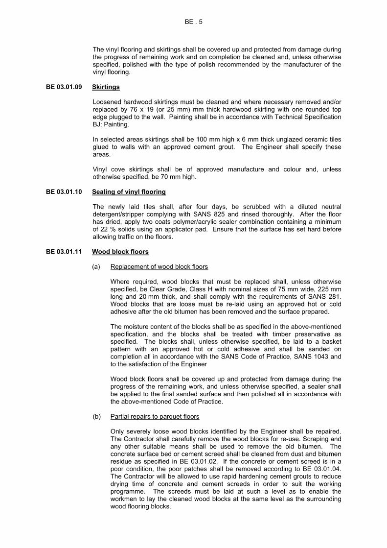
BE . 5
The vinyl flooring and skirtings shall be covered up and protected from damage during the progress of remaining work and on completion be cleaned and, unless otherwise specified, polished with the type of polish recommended by the manufacturer of the vinyl flooring.
BE 03.01.09 Skirtings
Loosened hardwood skirtings must be cleaned and where necessary removed and/or replaced by 76 x 19 (or 25 mm) mm thick hardwood skirting with one rounded top edge plugged to the wall. Painting shall be in accordance with Technical Specification BJ: Painting. In selected areas skirtings shall be 100 mm high x 6 mm thick unglazed ceramic tiles glued to walls with an approved cement grout. The Engineer shall specify these areas. Vinyl cove skirtings shall be of approved manufacture and colour and, unless otherwise specified, be 70 mm high.
BE 03.01.10 Sealing of vinyl flooring
The newly laid tiles shall, after four days, be scrubbed with a diluted neutral detergent/stripper complying with SANS 825 and rinsed thoroughly. After the floor has dried, apply two coats polymer/acrylic sealer combination containing a minimum of 22 % solids using an applicator pad. Ensure that the surface has set hard before allowing traffic on the floors.
BE 03.01.11 Wood block floors (a) Replacement of wood block floors
Where required, wood blocks that must be replaced shall, unless otherwise
specified, be Clear Grade, Class H with nominal sizes of 75 mm wide, 225 mm long and 20 mm thick, and shall comply with the requirements of SANS 281. Wood blocks that are loose must be re-laid using an approved hot or cold adhesive after the old bitumen has been removed and the surface prepared.
The moisture content of the blocks shall be as specified in the above-mentioned
specification, and the blocks shall be treated with timber preservative as specified. The blocks shall, unless otherwise specified, be laid to a basket pattern with an approved hot or cold adhesive and shall be sanded on completion all in accordance with the SANS Code of Practice, SANS 1043 and to the satisfaction of the Engineer
Wood block floors shall be covered up and protected from damage during the
progress of the remaining work, and unless otherwise specified, a sealer shall be applied to the final sanded surface and then polished all in accordance with the above-mentioned Code of Practice.
(b) Partial repairs to parquet floors
Only severely loose wood blocks identified by the Engineer shall be repaired.
The Contractor shall carefully remove the wood blocks for re-use. Scraping and any other suitable means shall be used to remove the old bitumen. The concrete surface bed or cement screed shall be cleaned from dust and bitumen residue as specified in BE 03.01.02. If the concrete or cement screed is in a poor condition, the poor patches shall be removed according to BE 03.01.04. The Contractor will be allowed to use rapid hardening cement grouts to reduce drying time of concrete and cement screeds in order to suit the working programme. The screeds must be laid at such a level as to enable the workmen to lay the cleaned wood blocks at the same level as the surrounding wood flooring blocks.

BE . 6
The cleaned blocks shall be laid in a basket pattern (or the same existing pattern) with approved hot or cold bitumen at the same level as the surrounding blocks. Missing blocks must be replaced.
BE 03.01.12 Sealing of timber floors
Existing timber floors must be mechanically belt-sanded to remove all traces of existing sealer in strict compliance with SANS 1043. Where necessary, existing flooring, skirtings and quarter rounds should be temporarily removed. Before applying the new wooden floor sealer, ensure that the surfaces are dry, sanded smooth and free from varnish or oil. Vacuum the dust from the prepared floor surfaces. Apply three coats of clear, lead free wooden floor sealer with preservative and anti-fungicidal properties according to the manufacturer’s specification. Apply the first coat until an even glossy, wet surface is achieved. Leave to dry thoroughly. Apply at least two other coats in the same way, and finally a fourth and final coat. It is proposed that the Contractor first do a trial section to satisfy himself that he can handle this procedure. The final appearance of the wooden floor must be smooth and have a uniform non-gloss finish. Reinstate skirtings and quarter rounds.
BE 03.01.13 Tiling (general)
Tiles shall be solidly bedded and jointed in cement mortar and, unless otherwise specified, joints shall be 6 mm wide. The joints in all tiling are to be continuous in both directions. The pointing is to be carried out by well pressing in half-dry cement mortar. Under no circumstances may liquid cement grout be used for pointing. All tiling shall be properly covered and shall be protected against any possibility of staining, discolouring or any other damage. At completion, all tiling is to be exposed, checked for damage, repaired where necessary and cleaned off with soft soap and cold water and left in a perfect condition. The application of oil on tiling is not allowed.
BE 03.01.14 Ceramic and quarry floor tiles (a) General requirements
The Engineer shall determine which tiles need replacement. The existing floor screed and floor tiles must be removed in patches and/or areas as determined by the Engineer.
Ensure that the base for floor tiling is rigid, stable and level unless required to
have a fall in one or more direction(s). The surface preparation and cement screed (if required) are described in BE 03.01.03 and BE 03.01.04 respectively. When proprietary brand adhesives are being used for fixing ceramic floor tiles it is essential that the surface to which the tiles are to be fixed is clean, dry, flat and true.
Lay approved unglazed ceramic split floor tiles (230 x 115 x 11,5 mm thick and
of a selected or matching colour) in professional floor grouting with 8 - 10 mm wide joints. The floor grout must be applied with a 10 mm square notched floor trowel evenly over an area not exceeding 1 metre at a time. Coved skirting tiles including external and internal skirting corners must be laid against walls in abattoirs. Setting out must be done correctly. The finished installation must be level plumb and true unless specified otherwise. In abattoirs the floor tiles must be laid to specified falls.

BE . 7
Mortar beds for dust-pressed tiles and quarry tiles shall be formed with a slurry
of 1:1 cement and clean fine sand to a thickness of about 3 mm on an area not exceeding 1 metre at a time. The joints will be 6 - 8 mm wide depending on the size of the tile.
The tiles must be laid in professional cement-based powder adhesive, strictly in
accordance with the manufacturer’s specifications. The Code of Practice for the fixing of tiles in accordance with SANS 1449 and the recommendations of the South African Ceramic Tile Manufacturer’s Association (SACTMA) shall be followed. Important points to be taken into consideration is are summarised below:
(i) Sufficient time must be allowed between building operations. (ii) Drying periods for backgrounds and substrates must be strictly adhered
to. (iii) No tiling may commence prior to the prescribed time. (iv) All tiles must be correctly bedded. The tiles must be properly bedded into
a fixative that is spread evenly to the required thickness using a square notched rubber mallet (10 mm for ceramic tiles). Bed the tiles dry and move firmly into position, ensuring that they are in proper overall contact with the bed, and form an even surface.
(v) A minimum of 6 - 10 mm grouting joints must be allowed between extruded and split tiles (3 mm minimum for pressed tiles). Ensure that the joints are free of tile adhesive and any foreign matter.
(vi) Tiling installation: Setting out and finished installation must be done correctly.
(b) Filling of joints
Do not fill joints between tiles until at least 24 hours after the tiles have been
bedded. Before applying the joint epoxy grout ensure that the joints are free of tile adhesive residue and any foreign matter. Apply the approved epoxy grout into the tile joints. The finishing-off must be completed with a wetted nosing tool or spatula so that a smooth glazed surface finish can be achieved. Application of the epoxy grout must be done strictly in accordance with the manufacturer’s specifications. Finally, the tiles must be thoroughly cleaned.
BE 03.01.15 Movement joints in tiling (a) General requirements
Movement joints are to be provided in tile work due to moisture expansion, thermal expansion and contraction, and crack control at existing expansion joints in the surface bed.
(i) Provide movement joints in the tile work, screed and bedding down to the
concrete surface bed or slab. The spacing of these joints depends on the position of existing joints, column and wall layouts and slab thickness. The maximum spacing of joints should be limited to 30 times the slab (surface bed) thickness or 4,5 m, whichever is the lesser. The length-to-width ratio of tile panels should be limited to between 1,0 and 1,5.
(ii) Provide isolation joints around the perimeter of the floor, around columns, walls and other fixed structural elements.
(iii) Joints shall be aligned with no offsets. Irregular shape tile panels must be avoided. Where included angles are unavoidable, it should be less than 60 degrees.
(iv) The width of the joint shall be 6 mm minimum and 10 mm maximum. Provide an approved closed-cell expanded polyethylene foam joint filler with a hinged temporary blocking piece in the movement joints. The size of the blocking piece must be the same as the joint width.

BE . 8
(b) Joint sealing The joints shall be prepared and primed prior the application of the joint sealant. The liquid sealant in joints shall be an approved one part grey polyurethane
sealant with a shore hardness of A45 and an elongation of 400 %. The manufacturer’s specifications must be strictly followed.
BE 03.02 PAVING
Repairs to paving shall include the improvement of existing paving, drainage channels and the replacement of paving that can not be repaired. Different paving types exist, e.g. concrete, precast paving segmental and regular blocks, bricks and slasto. This specification only covers pedestrian paving around buildings.
The Engineer shall identify the paving areas that are to be repaired. Defects to paving will include but not be limited to the following aspects:
(a) Failure of sub-base material and subsidence of sub-soil due to excessive water
erosion; (b) Broken and severely damaged paving; (c) Distorted and disturbed paving; (d) Drainage problems, eg ponding of water on the paving and in drainage
channels, incorrect falls, etc; (e) The omission of edge restraint; (f) Intrusion of weed or hostile root penetration.
BE 03.02.01 Preparing foundation
If the sub-base and/or sub-grade have failed, this soft and unstable material shall be replaced. Existing paving must be carefully removed and stack for re-use. The new earth filling shall be of inert material, having a maximum plasticity of 10, free from large stones, etc, spread, leveled, watered and compacted in layers not exceeding 150 mm thick to a density of 95% of modified AASHTO density. Cement stabilization to improve the existing sub-grade may be considered to improve the characteristics of the material. The blocks shall be laid true to line, levels and grade on a 25 mm thick layer of approved bedding sand. The bedding sand must not be used to fill hollows in an uneven sub-grade or sub-base surface. Where specified, plastic sheeting must be provided below the bedding sand layer. Refer also to BE 03.02.06.
The Contractor shall be responsible for carrying out all necessary process control tests on the density and moisture content of the completed sub-grade, sub-base, etc, to ensure that the required compaction is being attained.
BE 03.02.02 Laying of segmental block paving
The existing blocks shall be preselected for re-use. Broken and severely damaged paving blocks shall be replaced. New paving blocks shall comply with SANS 1058 Class 30 compressive strength. All blocks shall be laid true to line and level. Care shall be taken to ensure that joint lines are straight and square. The blocks shall have a minimum thickness of 60 mm.
After laying the blocks, the paving shall be compacted by means of vibrating plate compactor with joints between the blocks filled in, after compaction, by sweeping in fine sand. The jointing sand shall have a pass of 1,18 mm sieve and contain 10-50 % material passing the 75 micron sieve. The sand shall be free of all soluble salts or contaminants likely to cause efflorescence or staining.
Areas against curbs, manholes, etc, that require infilling and which exceed 25 % of a full block unit shall be filled with units cut to size using a mechanical or hydraulic guillotine, bolster or angle grinder. Infill areas constituting less than 25 % of a full

BE . 9
block area and are of 25 mm minimum dimension shall be filled with 25 MPa concrete. Smaller areas shall be filled with 1:4 cement mortar.
BE 03.02.03 Laying face brick pavers, precast concrete blocks and slasto
The existing blocks shall be preselected for re-use. Broken and severely damaged paving blocks shall be replaced. All blocks shall be laid true to line and level. Care shall be taken that joint lines are straight and square. Slasto shall be laid in the same pattern to match existing.
After laying the blocks, the paving shall be compacted by means of vibrating plate compactor. Clean the top of the blocks before and after compaction. Thoroughly wet compacted area after compaction and leave 24 hours to dry. The joints between the blocks must be filled in, after compaction, with a 1:4 cement mortar. The joints shall be pointed with a steel tool to a smooth surface finish.
BE 03.02.04 Laying of cast in-situ concrete paving and drainage channels
Severely cracked and/or damaged concrete paving and drainage channels shall be replaced. The Engineer shall indicate which panels and sections of drainage channels are to be removed. Cutting out will be done with an angle grinder or saw cutting machine. Concrete panels must be removed in sizes where the ratio of the sides does not exceed 1:1,5. The foundation material must be improved as specified in BE 03.02.01. New concrete panels and drainage channels must be cast with a compressive strength of 25 MPa. Concrete paving to the specified thickness must be finished off with a smooth wood trowel surface finish or must match the existing surface finish. Edges must be finished off with a steel nosing tool with a radius of 5 mm. Expansion joints must be provided where specified. Drainage channels must be cast in lengths not exceeding 1 metre. Channels must be finished off to have a smooth steel trowel finish.
BE 03.02.05 Precast concrete edge beams, curbs and channels
Edge restraints shall be installed before paving commences. Edge restraints may be cast in-situ, or consist of precast units. Precast edge blocks shall have dimensions of 75 mm wide x 300 mm deep. Cast in-situ beams with 25 MPa concrete shall have dimensions of 300 x 300 mm and cast in lengths on exceeding 1 meter.
Precast concrete curbs and channels shall comply with SANS 927, generally in 1 meter lengths and finished smooth from the mould on exposed surfaces. Curbs and channels shall be bedded on and jointed in 1:3 cement mortar and pointed with keyed joints. Bases to curbs shall be Class B prescribed mix of unreinforced concrete.
BE 03.02.06 Weed control Two types of weed killing shall be carried out:
(a) Mixing weed killer to sub-base for rehabilitated paving; (b) Spraying existing paving excluding concrete paving.
After the base course has been approved and the curbing completed, the prepared base must be treated with a soil applied herbicide with long residual action for the control of broad leaf weeds and grasses, containing active ingredient Bromacil, at a rate of 4 kg/m². Plastic sheeting with a thickness of 375 micron shall be laid to prevent the penetration of grass underneath the segmental paving.
BE 03.02.07 Site clearance
Excess sand and all other debris shall be removed before the pavement is opened to traffic. The site shall be left in a tidy condition.

BE . 10
BE 04 DETAIL OF REPAIR WORK
The detail of the scope of work is described in the Schedule of Quantities. BE 04 MAINTENANCE
Maintenance requirements will be itemised in the Bill of Quantities and will be instructed to the Contractor.
BE 06 MEASUREMENT AND PAYMENT BE 06.01 MEASUREMENT AND RATES BE 06.01.01 General inclusion of costs and specific specifications Notes: Where applicable, standard SANS 1200 measurement and payment items shall be
used for Earthworks (Small Works) (1200 DA), Site Clearance (1200 C) and Concrete (Structural) (1200 G).
All material scheduled to be removed shall be deemed to be existing damaged
materials in small or large sections. All such redundant material shall become the property of the Contractor and must be removed from site immediately.
All new material shall be deemed to be in patchwork and shall be of approved equal
quality, colours, profiles, thickness, etc. and shall in all cases match the existing materials and shall be fixed (internally or externally) to existing material or surfaces.
All replacement, removal and repair work shall be done carefully as to not damage
any adjacent or other material or work. Any damage to other or adjacent materials or areas caused by the negligence of the Contractor shall be repaired by him free of charge.
All work scheduled to be removed, hacked off or taken out shall be deemed to include
the cleaning, removing of contact glue or bitumen and preparation of the remaining surfaces, areas where material were removed, or remaining work to receive new material or work specified.
Repair work shall also include all cutting, grinding, cutting into, welding, bending,
strengthening, drilling, etc. to repair or to improve the items or areas as new and to match the existing.
Work scheduled to be realigned and re-fixed shall be deemed to include all necessary
new additional materials, brackets, connector plates, bolts, pip rivets, nails, screws, spacer blocks, clamps, timber, and labour, etc. to leave the items as new and totally functional.
All floor surfaces scheduled to be cleaned and sealed shall include for stripping the
floors from any fats, grime, dirt, oil and other deposits. Replacement of grout to ceramic and clay floor tiles shall also be included where necessary as per the tendered rate. Sealing of vinyl floor tiles shall be done in accordance with Technical Specification BE 03.01.10.
All new work are measured net and shall include all cutting, lapping, waste, bending,
fixing, corners, mitres, fixing screws, pip rivets, nails, adhesive, grout, putty, etc, as well as cleaning and preparation of surfaces not already prepared as part of removed items, etc.
Tile work to floors shall include all cutting, spacers, waste, jointing, mitres, corners,
epoxy grout and joint filler.

BE . 11
Ordering of certain specified materials ie industrial type extruded/split ceramic floor
tiles needs special and urgent attendance and should be ordered timeously as to prevent any construction delays.
BE 06.02 SCHEDULED ITEMS NEW WORK BUILDING WORK BE.01 Floor screeds: (a) (Thickness indicated) .............................................................................Unit: m2
(b) Etc. for other thicknesses The unit of measurement shall be the square metre of floor screed laid, as specified,
on floors, steps or areas shown on the Drawings or as designated by the Engineer. The tendered rates shall include full compensation for the construction of the floor
screeds, including the supply of all materials, mixing, laying, finishing, the forming of nosings, readings, skirtings, etc.
BE.02 Joinery:
(a) Items measured by number: (i) Doors (type and size indicated ................................................ Unit: number (ii) Etc. for other items measured by number (b) Items measured by linear metre: (i) Skirtings (size indicated) .................................................................. Unit: m (ii) Etc. for other items measured by length
(c) Items measured by area: (i) Eaves covering (type and thickness indicated) ..............................Unit: m2
(ii) Etc. for other items measured by area The units of measurement shall be the number, metre or square metre of each type and/or size of joinery item specified. The tendered rates shall include full compensation for the supply of all materials, manufacture, cutting, waste, fixing and installation of the joinery items.
BE.03 Floor tiling and finishes, etc:
(a) Measured by number: (i) (Description of item) ............................................................... Unit: number (b) Measured by linear metre: (i) (Description of item) ......................................................................... Unit: m

BE . 12
(c) Measured by area: (i) (Description of item) .......................................................................Unit: m2
The unit of measurement shall be the number, metre or square metre as applicable to each item. The tendered rates shall include full compensation for manufacturing, providing and installing each item complete as per specifications, drawings, descriptions as scheduled or as the existing and shall include for all labour, material, waste, plant, transport, delivery, access, scaffolding, fuel, etc. to the Engineer's approval.
ALTERATION WORK BE.04 Alterations and repairs to existing structures: (a) Indicate if repairs, alterations, removal, cleaning or sealing, etc: (i) Description of individual items to be repaired, altered, removed, sealed, etc .............................. Unit: m3, m2, m, number The unit of measurement for items repaired, altered, removed, sealed, etc. shall be
cubic metre, square metre, metre or number as scheduled. The tendered rates shall include full compensation for all costs to repair, refix, remove,
clean and seal, cutting into, realign, taking off, temporary store, etc. as specified in the Standard and Technical Specifications and shall allow for all necessary labour, plant and new material needed to leave the scheduled items as new and to the approval of the Engineer. Refer also to the general inclusion of costs in BE 06.01.01.

BH . 1
TECHNICAL SPECIFICATION BH FITTINGS CONTENTS BH 01 SCOPE BH 02 STANDARD SPECIFICATIONS BH 03 VARIATIONS AND ADDITIONS TO STANDARD SPECIFICATIONS BH 04 DETAIL OF REPAIR WORK BH 05 MAINTENANCE BH 06 MEASUREMENT AND PAYMENT BH 01 SCOPE
Fittings shall mean the scope of work to perform corrective maintenance repairs to materials and components related to cupboards, shelving, signage and counters. The complete scope of repair work shall be as described in BH 04: Detail of repair work.
BH 02 STANDARD SPECIFICATIONS BH 02.01 GENERAL STANDARD SPECIFICATIONS
The latest edition, including all amendments up to date of tender of the following specifications, publications and codes of practice shall be read in conjunction with this specification and shall be deemed to form part thereof: PW 371 - Specification of Materials and Methods to be used (Fourth edition, October 1993) SANS 929 - Plywood and composite board SANS 1099 - Hardwood furniture timber SANS 1783-3 - Softwood timber for industrial use SANS 1385 - Kitchen cupboards of steel, composite board and timber
BH 02.02 ADDITIONAL SPECIFICATIONS Technical Specification BD: Walls Technical Specification BG: Metalwork Technical Specification BJ: Paintwork
BH 02.03 OCCUPATIONAL HEALTH AND SAFETY
The Contractor shall be required to comply with the Occupational Health and Safety Act 85 of 1993, Construction Regulations 2014 and related regulations. Non-compliance with these regulations, in any way whatsoever, will be adequate reason for suspending the Works.
BH 03 VARIATIONS AND ADDITIONS TO STANDARD SPECIFICATIONS BH 03.01 ADDITIONAL REQUIREMENTS FOR REPAIR OF FITTINGS BH 03.01.01 Built-in cupboards
The Engineer shall inspect all cupboards for defects and shall establish which components are to be replaced or repaired. Reasons for replacement will include, but not be limited to: (a) Severely chipped or damaged block board; (b) Severely chipped or damaged decorative laminates; (c) Inadequacy of design, eg strength of hinges, failure of door furniture, etc; (d) Corroded steel elements.

BH . 2
Fixing of defects will include repairing or replacing damaged, corroded and worn-out fittings, eg door handles, knobs and hinges, door catches and holders, door locks, cupboard door vents, drawer slide rails, drawer handles, knobs and locks. Moving parts shall be serviced by cleaning, oiling, tightening loose screws, reinstating missing screws or aluminium pop rivets, etc. Refer to BD 03.08 and BD 03.09 of Technical Specification BD: Walls, for repairs or replacements of cupboard doors and ironmongery.
BH 03.01.02 Kitchen cupboards
Kitchen cupboards shall be inspected for defects. Defects will include repairing or replacing damaged, corroded and worn-out fittings, eg door handles, knobs and hinges, door catches and holders, door locks, cupboard door vents, drawer slide rails, drawer handles, knobs and locks. Moving parts shall be serviced by cleaning, oiling, tightening loose screws, reinstating missing screws or aluminium pop rivets, etc. Where the baked enamel of steel cupboards is scratched and worn off, the steel surface shall be sanded and painted with an approved gloss epoxy paint to match the existing colour. Severely corroded or damaged steel cupboards shall be replaced with approved new steel cupboards complying with SANS 1385, with the baked enamel complying with SANS 783 Type II. Damaged kitchen cupboards manufactured from composite board with laminated plastic covering shall be repaired where possible by gluing loose laminated plastic covering or replacing components with new similar matching finished elements. Damaged kitchen cupboards manufactured from timber shall be repaired by replacing cracked and broken timber components. Painted surfaces shall be varnished with water-resistant varnish (with matching stain) or painted with approved polyurethane paint. Refer to Technical Specification BJ: Paintwork. All cupboards shall be properly screwed and fixed to walls and floors with suitable corrosion resistant screws and plastic plugs, washers, etc. Work tops and sinks against walls shall be sealed with an approved white one part polyurethane sealant. The sealant shall be applied strictly according to the manufacturer’s specifications. Old worn-out and damaged sealant shall also be replaced. Drop-in sink bowls shall also be sealed with this approved polyurethane sealant. Where the possibility exists that water can penetrate composite board, these joints in the worktops shall also be sealed.
BH 03.01.03 Shelving
The stability of shelves must be checked to determine the occurrence of sagging. Where required, provide adequate support for the specific application, eg steel tubing struts, additional timber bearers, steel brackets, etc. Broken timber shelving shall be replaced with approved wrought hardwood or solid laminated pine varnished or painted to specification. Composite board will not be permitted. Shelves shall be in single lengths. Heads of nails and brass countersunk screws in exposed faces of joinery shall be sunk and pelleted.
BH 03.01.04 Signage
Safety signs shall comply with the requirements of SANS 1186 (1997). The Engineer shall survey all signage and list those items that prove to be illegible. Signs that need to be replaced shall be done in the same fashion and material as to match similar signs in the same application. The size of the signs shall be as shown on the schedules.

BH . 3
Where required proper and appropriate signage must be provided for door numbers, room size and room description. The size, colour, position on the door, wall, etc., height above floor level of the lettering shall be instructed by the Engineer on site or shown on the schedules. The lettering must be stencilled on to the doors and walls. All other fire protection signage will be provided for hydrants, hose reels, etc, shall be provided under separate contract.
BH 03.01.05 Counters
The Engineer shall inspect all counters and counter tops for defects and shall establish which components are to be replaced or repaired. Special attention shall be given to the condition of hinges at service hatches. All joinery liable to be damaged shall be covered with temporary coverings to the satisfaction of the Engineer and special care shall be taken to protect surfaces that are to be varnished. Where necessary, timber counters shall be sanded down, uneven surface spots filled with an approved wood filler, all blemishes removed and then finished off in order to restore the wood to its original state. Steel tops that have been damaged excessively shall be replaced.
BH 04 DETAIL OF REPAIR WORK
The detail of the scope of work is described in the Schedule of Quantities. BH 05 MAINTENANCE
No maintenance will be required for fittings under this contract. BH 06 MEASUREMENT AND PAYMENT BH 06.01 MEASUREMENT AND RATES BH 06.01.01 General inclusion of costs Notes: All material scheduled to be removed shall be deemed to be existing damaged
materials in small or large sections. All such redundant material shall become the property of the Contractor and must be removed from site immediately.
All new material shall be deemed to be in patchwork and shall be of approved equal
quality, colours, profiles, thickness, etc and shall in all cases match the existing materials and shall be fixed (internally or externally) to existing material or surfaces.
All replacement, removal and repair work shall be done carefully as to not damage
any adjacent or other material or work. Any damage to other or adjacent materials or areas caused by the negligence of the Contractor shall be repaired by him free of charge.
All work scheduled to be removed or taken out shall be deemed to include the
cleaning and preparation of the remaining sections, areas, or work to receive the new material or work specified.
Repair and service work shall also include all removing, cutting, grinding, cutting into,
welding, bending, strengthening, drilling, tightening, fastening, oiling, greasing, adjusting, and providing missing or damaged screws or bolts, etc to repair or to improve the items or areas as new and to match the existing. The service of

BH . 4
cupboard doors and drawers shall be deemed to include for servicing all locks, hinges, glides, tracks, etc.
Work scheduled to be realigned and refixed shall be deemed to include all necessary
new additional materials, brackets, connector plates, bolts, pip rivets, nails, screws, spacer blocks, clamps, timber, and labour, etc to leave the items as new and totally functional.
All new work are measured net and shall include all cutting, lapping, waste, bending,
fixing, corners, mitres, fixing screws, pip rivets, nails, adhesive, grout, putty, etc, as well as cleaning and preparation of surfaces not already prepared as part of removed items, etc.
The removal of doors, gates or windows shall include for the removal of all existing
locks, handles, striking plates, etc but exclude the hinges, etc, which shall be used for the new replaced items. All repair work (excluding paintwork) around and in the thresholds of new door frames, gates or windows build into existing brickwork in new or existing positions shall be deemed to be included in either the rates tendered for the new replacement item or the removal payment item of the frame, window, etc.
The new doors to toilets and wet areas as specified shall be fitted with rubber door stops, D-profiled pull handle and backplate sets, 15 mm roller ball catches with striking plates and all other ironmongery needed to install the doors complete. All new ironmongery shall be measured and paid for separately. The new doors to offices, etc, as specified shall be fitted with rubber door stops, 4 lever mortice locksets with handle sets to match existing, striking plates and all other ironmongery needed to install the doors complete. All new ironmongery shall be measured and paid for separately. All ironmongery installed on the project shall bear the SANS approved trademark and codes. Samples of all ironmongery scheduled must be according to the samples of the Department of Public Works and samples must be handed to the engineer for approval before ordering the material.
BH 06.02 SCHEDULED ITEMS NEW WORK BH.01 Joinery:
(a) Items measured by number: (i) Timber cupboard doors, shelves, complete cupboards, etc (type and size indicated) ................................ Unit: number (ii) Etc for other items measured by number (b) Items measured by linear metre: (i) Timber rails, planks, frames, shelves, etc (size indicated) ................................................................................ Unit: m (ii) Etc for other items measured by length (c) Items measured by area: (i) Pinning boards, shelves, work tops, etc (type and thickness indicated) ........................................................ Unit: m2
(ii) Etc, for other items measured by area

BH . 5
The units of measurement shall be the number, metre or square metre of each type and/or size of joinery item specified. The tendered rates shall include full compensation for the manufacturing and supplying of all materials, for transport, labour, cutting, waste, fixing, screws, bolts, clamps, etc and installation of the joinery items.
BH.02 Steelwork: (a) Items measured by number: (i) Steel cupboard or locker doors, shelves, complete cupboards, etc (type and size indicated) ................... Unit : number or units (ii) Etc, for other items measured by number (b) Items measured by linear metre: (i) Steel rails, shelves, frames, etc (size indicated) ............................ Unit : m (ii) Etc, for other items measured by length (c) Items measured by area: (i) Shelves, plates, etc (type and thickness indicated) ....................... Unit : m² (ii) Etc, for other items measured by area
The unit of measurement shall be the number, metre or square metre of each type and/or size of steelwork item specified. The tendered rates shall include full compensation for the manufacturing, supplying of all materials and transport, and for all labour, cutting, welding, waste, fixing and installation of the steelwork items complete with a red oxide or equal approved steelwork primer or baked enamel paint finishing as specified.
ALTERATION WORK
BH.03 Alterations and repairs to existing fittings: (a) Indicate if repairs, alterations, removal or sealing, etc: (i) Description of individual items to be repaired, altered, removed, sealed, etc .............................. Unit: m3, m2, m, number The unit of measurement for items repaired, altered, removed, sealed, etc shall be
cubic metre, square metre, metre or number as scheduled. The tendered rates shall include full compensation for all costs to repair, refix, remove,
cutting into, realign, taking off, temporary store, etc as specified in the Standard and Technical Specifications and shall allow for all necessary labour, plant and new material needed to leave the scheduled items as new and to the approval of the Engineer. Refer also to the general inclusion of costs in BH 06.01.01.

BH . 6

BJ . 1
0.TECHNICAL SPECIFICATION BJ PAINTWORK CONTENTS BJ 01 SCOPE BJ 02 STANDARD SPECIFICATIONS BJ 03 VARIATIONS AND ADDITIONS TO STANDARD SPECIFICATIONS BJ 04 DETAIL OF REPAIR WORK BJ 05 MAINTENANCE BJ 06 MEASUREMENT AND PAYMENT BJ 01 SCOPE
This specification covers the painting/repainting and maintenance of new and existing building components and maintenance thereafter for various types of buildings and structures. Paintwork shall mean the scope of work related to the preparation, painting and maintenance of new and existing building components. This specification does not include work related to galvanising of steelwork, which is specified elsewhere. The complete scope of paintwork shall be as described in BJ 04: Detail of repair work.
BJ 02 STANDARD SPECIFICATIONS BJ 02.01 GENERAL STANDARD SPECIFICATIONS
The latest edition, including all amendments up to date of tender of the following specifications, publications and codes of practice shall be read in conjunction with this specification and shall be deemed to form part thereof:
SANS 515 - Decorative paint with a non-aqueous solvent base for interior use SANS 630 - Decorative high gloss enamel for interior and exterior SANS 631 - Decorative oil gloss paint for interior and exterior use SANS 633 - Emulsion paints for interior decorative purposes SANS 634 - Emulsion paints for exterior use SANS 678 - Primers for wood for interior and exterior use SANS 681 - Undercoats for paints SANS 683 - Roof paints (relevant sections) SANS 723 - Wash primer (metal etch primer) SANS 801 - Epoxy-tar paints SANS 887 - Varnish for interior use SANS 926 - Two-pack zinc-rich epoxy primer SANS 1227 - Textured wall coatings, emulsion base, for interior and exterior use SANS 1319 - Zinc phosphate primers for steel SANS 10064 - Preparation of steel surfaces for coating OW 371 - Specification of Materials and Methods to be used (Fourth edition,
October 1993): Section 18 BJ 02.02 ADDITIONAL SPECIFICATIONS
Technical Specification BG: Metalwork Paint manufacturers' specifications. These specifications shall take precedence over
all others.

BJ . 2
BJ 02.03 OCCUPATIONAL HEALTH AND SAFETY
The Contractor shall be required to comply with the Occupational Health and Safety Act 85 of 1993, Construction Regulations 2014 and related regulations. Non-compliance with these regulations, in any way whatsoever, will be adequate reason for suspending the Works.
BJ 03 VARIATIONS AND ADDITIONS TO STANDARD SPECIFICATIONS
BJ 03.01 ADDITIONAL REQUIREMENTS FOR PAINTWORK BJ 03.01.01 General
a) Quality control
i) Application of all paints must be supported by the relevant paint manufacturer’s technical quality control systems with regard to preparation, application, film thickness, colour/pigmentation, mixing, etc.
ii) The Contractor must submit his programme to the Engineer well in advance, particularly where high-risk surface applications (sheet metal roofs, etc) are concerned, in order to keep the manufacturer’s technical personnel informed. Paint application may not commence until the manufacturer has inspected the surface preparation and given written approval thereof to the Engineer.
b) Paint systems
i) All paint shall be delivered to the site in the unopened containers on which the
manufacturer’s name and trademark appear. ii) All materials for paintwork shall comply with the requirements for standards
from the country from which it originated and shall be approved by the Engineer.
iii) The Contractor shall submit copies of the paint manufacturer’s specifications, recommendations and datasheets to the Engineer for approval.
iv) The coating system shall be from one manufacturer unless otherwise specified. The paint manufacturer’s instructions shall be strictly adhered to.
v) Paints, etc, shall be suitable for application on the surfaces on which they are to be applied and various coats must be compatible with each other. Those paints used externally shall be of exterior quality or suitable for exterior use.
c) Guarantee
i) The Contractor must give a 3 year written guarantee for the quality and workmanship of the paint work (fair wear and tear excepted). The Contractor shall be liable for any peeling or flaking paint applied by the Contractor and shall execute all such work of repair, rectification and making good of painted surfaces as may be ordered in writing by the Engineer. The manufacturer must carry out inspections at regular intervals during the construction period. The Manufacturer must issue a certificate of acceptance and compliance on completion to the client.
BJ 03.01.02 General preparation of new and existing work All walls and ceilings, etc, shall be thoroughly cleaned prior to commencement of
painting and the premises kept clean and free from dust during painting operations. Protect all surfaces not to be painted against spotting and spilling. Clean down and make good as necessary. Locks, door handles and similar fittings or fixtures shall be removed (or masked) and refitted on completion of painting.

BJ . 3
(a) Plaster
(i) All surfaces, sills, ceilings, etc, shall be thoroughly dry before painting operations are started. Porous surfaces must be sealed with the appropriate sealer, thinned if necessary, before applying the paint system.
(ii) Exterior surfaces: Any cracks shall be scraped out and filled with an approved filler or patching plaster and rubbed down flush; the whole surface shall be well brushed down to remove all loose dust and powdery material before applying the first coat of the specified paint system.
(iii) Interior surfaces: All cracks, blow holes, etc, shall be filled with suitable stopping and rubbed down flush. The whole surface shall be smoothed to an even finish and dusted down. Any grease marks, crayon marks, etc, shall be cleaned off with sugar soap and thoroughly rinsed with clean water. The surface shall be thoroughly dry before painting operations are started.
(iv) Ceilings: Ceilings shall be brushed down and free of all dust and powdery materials. Cover strips and cornices shall be stopped where necessary and rubbed down smooth. All nail heads shall be primed, stopped and rubbed down flush. The surface shall then be wiped or brushed free of all loose or powdery materials before applying the recommended paint system.
(v) Fibre cement: Fibre cement surfaces shall be cleaned down and primed with an approved sealer and undercoat.
(b) Metalwork
(i) Iron and steel: New iron and steel metalwork shall be cleaned with an approved degreaser and the most effective method available (shot or sand blasting, mechanical wire brushing, hand wire brushing) used to remove all rust and millscale. Any salt deposits resulting from a marine or industrial environment shall be removed by washing with water prior to priming.
(ii) Galvanised surfaces: New galvanised surfaces shall be well cleaned to remove all traces of oil and dirt with galvanised iron cleaner and rinsed with clean water.
(c) Woodwork
New woodwork shall be brushed down and the surface prepared as follows: Knots shall be given a coat of an approved patented knotting. The surface shall be primed overall and all holes shall be filled. The surface shall then be rubbed down with glass paper until smooth and even. Woodwork that needs to be oiled, stained or varnished shall be free of all stains, pencil marks and other surface discolourations and blemishes and shall be stopped with tinted stopping and rubbed down.
(d) General
(i) Colours: All colours and tints are to be submitted to the Engineer for approval. Sample colours are to be prepared in all cases for the final coat and all work must be finished to colour approved by the Engineer. Where necessary, universal undercoat must be tinted to a shade lighter than the finishing coat.
(ii) Doors and windows: All doors and opening sections of windows must be left
ajar after painting or varnishing until the paint is perfectly dry.
(iii) Protection and cleaning off: All necessary precautions are to be taken for the protection of all finished work and other trades during painting, and all ironmongery shall be removed where possible prior to the commencement of painting and re-fixed after completion. All paint spots, stains, etc, are to be cleaned off floors, walls, glass, etc, after completion.

BJ . 4
BJ 03.01.03 Paint specifications for various components
(a) Fibre cement (ceilings) (i) New work
(1) Interior Ceilings to wet areas (ablutions, kitchens and laundries):
- Polyurethane alkyd enamel: Prepare and apply one coat synthetic copolymer primer. Stop with
interior crack filler, seal crack filler with above primer. Apply two coats of polyurethane alkyd enamel interior quality paint.
- Universal fungicidal additive: To be added to above in proportions specified by the manufacturer.
This additive will only be required in specific cases. (2) Exterior Preparation: Clean down to remove all dirt and grease, etc, fill nail-
heads with exterior crack filler and sand down to a smooth and even surface.
Finishing coat (emulsion): Apply two coats of super acrylic copolymer
PVA emulsion or polyurethane alkyd enamel. (ii) Renovation (existing) work (1) Interior Ceilings previously painted, in good condition:
Preparation: Clean down to remove all dirt and grease, etc, fill nail-heads, cracks and defects with interior crack filler and sand down to a smooth and even surface.
Finishing coat (emulsion): Apply two coats of super acrylic copolymer
PVA emulsion or polyurethane alkyd enamel. Ceilings previously painted, in poor condition (to be finished in an
emulsion system): Preparation: Remove all loose and flaking paint, clean down to remove
all dirt, grease, etc, prime nail-heads with zinc phosphate primer for steel. Apply one coat of primer to existing ceiling boards diluted with 20 % turpentine. Fill nail-heads, cracks and defects with interior crack filler and sand down to a smooth and even surface. Seal all repaired areas with above-mentioned primer.
Finishing coat: Apply two coats of super acrylic copolymer PVA. Ceilings to wet areas:
Preparation as above, but to be followed by one coat synthetic copolymer primer and two final coats polyurethane alkyd enamel interior quality paint (with fungicidal additive, only if specified).
In cases where fungicidal attack is prevalent the prepared surface must
be washed down with antiseptic solution, followed by sodium hyperchlorite and allowed to react for 15 minutes before washing down with water. Once dry, primer and finishing coats may be applied.

BJ . 5
(2) Exterior Not applicable.
(b) Woodwork truss/rafters (overhangs) (i) New work
(1) Interior Not applicable.
(2) Exterior
- Egg-shell/High-gloss enamel: Prepare and touch up knots with spirit soluble resin type knotting.
Apply one coat of primer for wood. Stop with wood filler where necessary. Apply one coat of universal undercoat. Apply two coats of enamel.
- Creosote coating:
Prepare surface to be clean, dry and sound Apply on coat of creosote wood treatment coating.
(ii) Renovation (existing) work (1) Interior Not applicable.
(2) Exterior Woodwork truss/rafters (overhangs) previously painted, in good
condition (to be painted in egg-shell/high-gloss enamel):
Preparation: Clean down and sand to a smooth finish. Spot prime where necessary with primer for wood. Allow 24 hours drying. Stop with wood filler.
Undercoat: Apply one coat of universal undercoat. Allow 24 hours
drying.
Finishing coat: Apply two coats of enamel paint. Woodwork truss/rafters (overhangs) previously painted, in poor
condition (to be finished in egg-shell/high-gloss enamel): Preparation: Remove existing paint and sand down thoroughly. Touch
up knots and resinous areas with knotting. Primer: Apply one coat of universal undercoat. Allow 24 hours drying.
Stop with wood filler and sand to a smooth finish. Undercoat: Apply one coat of universal undercoat. Allow 24 hours
drying. Finishing coat: Apply two coats of enamel paint.

BJ . 6
Creosote coating:
Preparation: Prepare surface. Apply two coats creosote wood treatment coating.
(c) Metalwork - steelwork and miscellaneous metal work (including general pipework) (i) New work
(1) Interior
Unpainted:
Prepare and apply one coat zinc phosphate primer for steel. Apply one coat of universal undercoat. Apply two coats of high gloss enamel paint.
Shop-primed: Touch up damaged primer with zinc phosphate primer for steel. Apply
one coat of universal undercoat. Apply two coats of high-gloss enamel paint.
Cast-iron waste pipes:
Prepare and remove as much bitumen as possible. Apply one coat of
aluminium paint. Apply one coat of universal undercoat. Apply two coats of high-gloss enamel paint.
(2) Exterior
Unpainted:
Prepare and apply one coat zinc phosphate primer for steel. Apply one
coat of universal undercoat. Apply two coats of high-gloss enamel or oleoresinous aluminium paint (where applicable).
Shop-primed:
Touch up damaged primer with zinc phosphate primer for steel. Apply
one coat of universal undercoat. Apply two coats of high-gloss enamel or oleoresinous aluminium paint (where applicable).
Cast-iron waste pipes:
Prepare and remove as much bitumen as possible. Apply one coat of
universal undercoat. Apply two coats of high gloss enamel or oleoresinous aluminium paint (where applicable).
(ii) Renovation (existing) work
(1) Interior
Previously painted metalwork, in good condition (steel windows, door frames, miscellaneous steelwork, etc):
Preparation: Wash down with sugar soap and rise with clean water.
Sand lightly and apply one coat universal undercoat. Finishing: Apply two coats high-gloss enamel.

BJ . 7
Previously painted metalwork, in poor condition: Preparation: Remove all existing paint by means of scraping or wire brushing and sanding. Tightly adhering paint that cannot be removed
may remain and be overcoated. Remove all signs of rust back to bright metal by sanding with emery cloth. Wash down with an approved degreaser, rinse with clean water to remove all traces thereof and allow to dry. Treat rusted areas with a water-based rust converter.
Primer: Apply one coat of zinc phosphate primer for steel. Allow
overnight drying. Undercoat: Apply one coat of universal undercoat. Allow overnight drying. Finishing coat: Apply two coats high-gloss enamel. Allow overnight drying between coats.
Previously painted metalwork, to remove all previous paint to original surface:
Preparation: Remove all existing paint by means of scraping or wire Brushing, grinding and sanding Remove all signs of rust back to bright
metal by sanding with emery cloth. Wash down with an approved degreaser, rinse with clean water to remove all traces thereof and allow to dry. Treat rusted areas with a water-based rust converter.
Primer: Apply one coat of zinc phosphate primer for steel. Allow
overnight drying. Undercoat: Apply one coat of universal undercoat. Allow overnight drying. Finishing coat: Apply two coats high-gloss enamel. Allow overnight drying between coats. (2) Exterior
Previously painted metalwork, in good condition:
Preparation: Wash down with sugar soap, followed by light sand-
papering. Rinse with clean water. Undercoat: Apply one coat of universal undercoat. Allow 24 hours for drying. Finishing coat: Apply two coats of high-gloss enamel or oleoresinous
aluminium paint (where applicable).
Previously painted metalwork, in poor condition: Preparation: Remove all existing paint by means of scraping or wire
brushing and sanding. Tightly adhering paint that cannot be removed may remain and be overcoated. Remove all signs of rust back to bright metal by sanding with emery cloth. Wash down with an approved degreaser, rinse with clean water to remove all traces thereof and allow to dry. Treat rusted areas with a water-based rust converter.

BJ . 8
Primer: Apply one coat of zinc phosphate primer for steel. Allow for 24 hours drying.
Undercoat: Apply one coat of universal undercoat. Allow for 24 hours
drying. Finishing coat: Apply two coats of high-gloss enamel or oleoresinous
aluminium paint (where applicable).
Previously painted metalwork, to remove all previous paint to original surface:
Preparation: Remove all existing paint by means of scraping or wire Brushing, grinding and sanding Remove all signs of rust back to bright
metal by sanding with emery cloth. Wash down with an approved degreaser, rinse with clean water to remove all traces thereof and allow to dry. Treat rusted areas with a water-based rust converter.
Primer: Apply one coat of zinc phosphate primer for steel. Allow
overnight drying. Undercoat: Apply one coat of universal undercoat. Allow overnight drying. Finishing coat: Apply two coats high-gloss enamel. Allow overnight drying between coats. (3) Aggressive environments
Not applicable. (d) Gypsum board (ceilings, etc) (i) New work
(1) Interior (dry areas)
- Super acrylic PVA: Prepare and apply one coat synthetic copolymer primer for gypsum
board diluted with 20 % turpentine. Stop with interior crack filler, seal crack filler with above-mentioned primer. Apply two coats of super acrylic copolymer PVA paint.
(2) Exterior (dry areas)
- Super acrylic PVA:
Prepare and supply one coat of synthetic copolymer primer for gypsum board diluted with 20 % turpentine. Stop with interior crack filler, seal crack filler with above-mentioned primer. Apply two coats of super acrylic copolymer PVA paint.
(ii) Renovation (existing) work
(1) Interior
Previously painted gypsum board with PVA in good condition: Preparation: Wash down with sugar soap to remove all dirt, grease,
etc, and rinse off with clean water. When dry, make good all cracks and defects with interior crack filler and sand to a smooth and even surface.

BJ . 9
Finishing coat: Apply two coats super acrylic copolymer PVA.
Previously painted gypsum board, in poor condition: Preparation: Clean down. Remove all paint by sanding and scraping. Primer: Allow overnight drying. Make good cracks and holes with crack
filler. Seal crack filler with above primer and allow to dry. Finishing coat (emulsion): Apply two coats of super acrylic copolymer
PVA. (2) Exterior
Not applicable. (e) Cement plaster (walls) and concrete surfaces (i) New work
(1) Interior
- Polyurethane alkyd enamel (in wet areas, kitchens, etc): Prepare and apply one coat bonding liquid, followed by one coat of synthetic copolymer primer for new plaster. Apply one coat of polyurethane alkyd enamel paint.
- Acrylic emulsion: Same as above, but apply acrylic emulsion with smooth velvet sheen interior quality paint.
- Gloss enamel: Same as for polyurethane alkyd enamel, but apply two coats high-gloss enamel.
- Super acrylic PVA:
Prepare and apply one coat of synthetic copolymer primer. Apply two coats of super acrylic copolymer PVA.
- Semi-gloss pure acrylic finish:
Prepare and apply one coat of synthetic copolymer primer. Apply one coat of pure acrylic paint.
(2) Exterior
- Pure acrylic: Prepare and apply one coat of alkali resistant synthetic resins bonding liquid. Stop with exterior crack filler. Apply one coat of copolymer primer. Apply one final coat of pure acrylic paint.
- Pure acrylic with Teflon:
Preparation, priming and application as above.
- Super acrylic PVA: Prepare and apply one coat of synthetic copolymer primer. Apply two coats of super acrylic copolymer PVA.
- Acrylic emulsion (external textured):
Preparation as above, followed by two coats textured exterior acrylic emulsion, allowing one hour drying time between coats.

BJ . 10
(ii) Renovation (existing) work
(1) Interior
Previously distempered: Preparation: Remove all distemper with a peeling agent. Rinse with
clean water. Allow 48 hours to dry. Fill cracks and defects with interior crack filler. Sand down to a smooth and even surface.
Primer: Apply one coat of bonding liquid, allow a minimum of 24 hours
and maximum of 72 hours for drying. Final primers as specified in BJ 03.01.03(e)(i).
Finishing coat: Apply similar paints to suit as specified in
BJ 03.01.03(e)(i). (2) Exterior
Previously painted cement plaster (walls) and surfaces, in good condition:
Preparation: Wash down thoroughly with sugar soap. Rinse with clean
water. Fill with suitable exterior crack filler. Sand smooth. Prime with one coat bonding liquid Finishing coat: Apply similar paints to suit as specified in
BJ 03.01.03(e)(i).
Previously painted cement plaster (walls) and surfaces, in poor condition (ie peeling, crazing, etc, not previously limewashed):
Preparation: Remove all paint and fill with suitable exterior crack filler. Priming coat: Prime with one coat bonding liquid, allow to dry for a
minimum of 24 hours and a maximum of 72 hours. Finishing coat: Apply similar paints to suit as specified in
BJ 03.01.03(e)(i).
(f) Fibre cement board (fascias and ceilings) (i) New work
(1) Interior
New and wet asbestos sheets shall be allowed to dry out before painting is commenced.
Ceiling boards must be well primed on both sides with an approved sealer/undercoat before fixing.
- Super acrylic PVA:
Prepare and apply one coat of sealer/undercoat. Prime nail heads with metal primer. Stop with filler. Apply two coats of super acrylic copolymer PVA.

BJ . 11
(2) Exterior
New and wet asbestos sheets shall be allowed to dry out before painting is commenced. Fascia boards and barge boards shall be well primed on both sides and edges painted with sealer/undercoat before fixing. All sides of fascia boards must receive final coatings.
- Super acrylic PVA:
Prepare and apply one coat sealer/undercoat. Prime nail heads with zinc phosphate metal primer. Stop with filler. Apply two coats of super acrylic copolymer PVA.
(ii) Renovation (existing) work
(1) Interior
Previously painted fibre cement board with emulsion paint, in good condition:
Preparation: Clean down thoroughly to remove any signs of dirt or
grease. Fill all screw heads with a flexible resistant filler after screw heads have been primed.
Finishing: Apply two coats of super acrylic copolymer PVA paint.
Previously painted fibre cement board in poor condition: Preparation: Remove previous paint coatings with super paint stripper.
Thoroughly wash down with sugar soap and rinse with clean water. Prime nail and screw heads with zinc phosphate metal primer. Allow to dry.
Primer: Apply one coat of synthetic copolymer primer to all surfaces
including back and edges, allow to dry. Fill all screw heads with weather resistant filler, allow to dry, sandpaper smooth and touch up with primer.
Finishing: Apply two coats of super acrylic copolymer PVA paint. (2) Exterior
Previously painted fibre cement board with emulsion paint in good condition:
Preparation: Clean down thoroughly to remove any signs of dirt or
grease. Fill all screw heads with a flexible weather resistant filler after screw heads have been primed.
Finishing: Apply two coats of super acrylic copolymer PVA paint.
Previously painted fibre cement board, in poor condition: Preparation: Remove previous paint coatings with super paint stripper.
Thoroughly wash down with sugar soap and rinse with clean water. Prime nail and screw heads with zinc phosphate metal primer. Allow to dry.

BJ . 12
Primer: Apply one coat of sealer/undercoat to all surfaces including back and edges, allow to dry. Fill all screw heads with weather resistant filler. Allow to dry and sandpaper smooth. Touch up with primer.
Finishing: Apply two coats of super acrylic copolymer PVA paint.
(g) Galvanised iron roof (also gutters and rainwater pipes) (i) New work
(1) Interior
Not applicable. (2) Exterior
Galvanised iron - roofs: Water-based pure acrylic emulsion paint: Scrub down thoroughly with degreaser, followed by a cleaner for galvanised iron. Rinse off thoroughly and ensure that all traces of cleaner have been removed and that the surfaces are free of any grease and oil. Apply one coat of galvanised metal primer. Allow to dry for 5 hours. (Must be overcoated within 24 hours maximum.) Apply one coat of water-based pure acrylic emulsion paint with non-fading pigment. Galvanised iron - roofs: Mat acrylic roof paint: Scrub down thoroughly with degreaser, followed by a cleaner for galvanised iron. Rinse off thoroughly and ensure that all traces of cleaner have been removed and that the surface is free of any grease and oil. Apply two coats of mat acrylic roof paint. Galvanised iron - gutters and rainwater pipes: Gloss enamel: Scrub down thoroughly with degreaser, followed by a cleaner for galvanised iron. Rinse off thoroughly and ensure that all traces of cleaner have been removed and that the surface is free of any grease and oil. Apply one coat of primer for galvanised iron. Allow to dry for 5 hours. (Must be overcoated within 24 hours maximum.) Apply two coats of gloss enamel paint with non-fading pigment.
(ii) Renovation (existing) work
(1) Interior
Not applicable. (2) Exterior
Previously painted galvanised iron, in good condition:
Preparation: Thoroughly scrub down with fibre scrubbing brushes and
sugar soap and rinse with clean water. Finishing coat: Apply one coat water-based pure acrylic emulsion paint
with non-fading pigment.

BJ . 13
Unpainted or previously painted galvanised iron, in poor condition (ie flaking, peeling and rusting):
Preparation: Remove all previous paint coatings with steel wire
brushes, plumber’s egg-shaped lead scrapers, and coarse floor sandpaper. Remove all traces of rust with emery cloth back to bright metal and apply approved rust converter. Thoroughly scrub down using galvanised iron cleaner and rinse with clean water.
Primer: Apply one coat of galvanised metal primer. Allow a minimum
of 5 hours and a maximum of 72 hours for drying. Finishing coat: Apply one coat of water-based pure acrylic emulsion
paint with non-fading pigment.
(h) Timber (doors, cornices, window frames, counters, skirtings, etc) (i) New work
(1) Interior
- Polyurethane alkyd enamel (wet areas, kitchens, etc): Prepare knots with spirit soluble resin type knotting. Prime with primer (sanding sealer) for wood. Fill imperfections where necessary with wood filler. Apply one coat of universal undercoat. Apply two coats of polyurethane alkyd enamel.
- High-gloss/egg-shell enamel: Prepare knots with spirit soluble resin type knotting. Prime with primer (sanding sealer) for wood. Fill imperfections where necessary with wood filler. Apply one coat of universal undercoat. Apply two coats of enamel.
- Gloss/suede varnish (interior quality solvent based):
Prepare knots with spirit soluble resin type knotting. Fill imperfections with wood filler. Sand surfaces to a smooth finish in grain direction and dust off. Thin first coat down in a ratio of 3 parts varnish to 1 part mineral turpentine and apply. Allow to dry for 24 hours. Apply two full-strength final coats with 24 hours drying time between applications.
(2) Exterior
- High-gloss/egg-shell enamel:
Prepare with spirit soluble resin type knotting. Apply one coat of primer for wood. Fill where necessary with wood filler. Apply one coat of universal undercoat. Apply two coats of high gloss enamel.
- Gloss/suede varnish (exterior quality ultraviolet resistant solvent
based): Prepare knots with spirit soluble resin type knotting. Fill imperfections with wood filler. Sand surfaces to a smooth finish in grain direction and dust off. Thin first coat down in a ratio of 3 parts varnish to 1 part mineral turpentine and apply. Allow to dry for 24 hours. Apply two full-strength final coats with 24 hours drying time between applications.

BJ . 14
(ii) Renovation (existing) work
(1) Interior
Previously painted woodwork, in good condition (to be finished in polyurethane alkyd enamel):
Preparation: Wash sown with sugar soap to remove all dirt, grease,
etc, then rinse off with clean water. Sand down to a smooth and mat surface. Make good cracks and defects with wood filler and after 24 hours drying, sand down again.
Finishing coat: Apply two coats of polyurethane alkyd enamel. Allow
24 hours for drying between coats.
Previously varnished woodwork in good condition (to be finished with interior quality varnish):
Repair defects with wood filler. Sand surfaces to a mat finish and apply
two final coats varnish with 24 hours drying time between applications.
Previously painted woodwork in poor condition (to be finished with high-gloss/egg-shell enamel):
Preparation: Remove all paint, varnish and stain with super paint
stripper. Wash down thoroughly with sugar soap and rinse with clean water. When surface is completely dry, sand down and apply one coat of spirit soluble resin type knotting to all knots. Fill all cracks and defects with wood filler and after 24 hours of drying, sand down to a smooth and even surface. Apply one coat oleoresinous wood primer. Apply one coat universal undercoat.
Finishing coat: Apply two final coats enamel.
Previously stained and varnished or painted woodwork in poor condition (to be finished in polyurethane alkyd enamel):
Preparation: Remove all paint, varnish and stain with super paint
stripper. Wash down thoroughly with sugar soap and rinse with clean water. When surface is completely dry, sand down and apply one coat of spirit soluble resin type knotting to all knots. Fill all cracks and defects with wood filler and after 24 hours of drying, sand down to a smooth and even surface. Apply one coat oleoresinous wood primer.
Finishing coat: Apply one coat polyurethane alkyd enamel.
Previously varnished woodwork in poor condition (to be finished with interior quality varnish):
Remove all varnish with paint stripper. Wash down to dry completely.
Further preparation and applications as for BJ 03.01.03(h)(i): New work - interior.
(2) Exterior
Previously painted woodwork, in good condition (to be repainted with high-gloss/egg-shell enamel):
Preparation: Clean down and sand to a smooth finish. Spot prime
where necessary with oleoresinous wood primer. Allow 24 hours for drying. Stop defects with a flexible weather resistant wood filler.

BJ . 15
Undercoat: Apply one coat of universal undercoat. Allow 24 hours drying.
Finishing coat: Apply two coats of enamel.
Previously varnished woodwork in good condition (to be finished with exterior quality ultraviolet resistant solvent based varnish):
Preparation and application as for similar interior item above.
Previously stained and varnished or painted woodwork, in poor condition (to be finished in high-gloss/egg-shell enamel):
Preparation: Remove all paint, varnish and stain with super paint
stripper. Wash down thoroughly with sugar soap and rinse with clean water. When surface is completely dry, sand down and apply one coat of spirit soluble resin type knotting to all knots. Fill all cracks and defects with wood filler and after 24 hours drying, sand down to a smooth and even surface. Apply one coat oleoresinous wood primer. Apply one coat universal undercoat.
Finishing coat: Apply two final coats of enamel.
Previously stained and varnished or painted woodwork, in poor condition (to be finished in polyurethane alkyd enamel):
As for similar interior item above.
Previously varnished woodwork in poor condition (to be finished with exterior quality ultraviolet resistant solvent based varnish):
Preparation and application as for similar interior item above.
(i) Concrete and cement surfaces - floor paint (i) New work
Exterior and interior Preparation: Remove laitance, residual cement spillage, etc, by means of carborundum grinding and vacuum clean to remove all dust. Remove oil, grease or any other surface contaminants with degreaser and wash off with clean water. Allow to dry. The floor must have less than 5 % moisture content before painting may be done. Finishing coats: Apply two coats of an alkali resistant solvent based stoep (modified alkyd) paint. The first coat may be thinned with 25 % mineral turpentine. Sixteen hours drying time must be allowed between coats.
(ii) Renovation (existing) work
Exterior and interior Previously painted concrete and cement surfaces, in good condition: Preparation: Remove any loose and flaking paint by means of carborundum grinding, back to firm feathered edges. Remove any polish, grease, oil and other contaminants with degreaser, wash clean and allow to dry. Sand old paint to a mat finish and vacuum clean to remove all dust. Finishing coats: Apply two coats as for new work above.

BJ . 16
Previously painted concrete and cement surfaces, in poor condition: Strip completely by suitable means and treat as for new work above.
(j) Cement plaster or facebrick walls and concrete surfaces where damp penetration
is evident
(i) Renovation
Exterior and interior
Preparation: Remove all damaged paintwork, efflorescence, loose friable material, etc, back to bare and sound substrate. Repair all damaged surfaces with suitable approved materials to match original surface. Surfaces may remain damp and in some cases will require additional wetting, depending on the particular coating used. Damp sealing coats: Apply two coats approved synthetic polymer modified water barrier coating in strict accordance with the particular product manufacturer's specifications. Allow 24 hours between coats unless otherwise specified. Finishing coats: Apply decorative finishing coats to suit, as in BJ 03.01.03(e).
BJ 04 DETAIL OF REPAIR WORK
The detail of the scope of work is described in the Schedule of Quantities. BJ 05 MAINTENANCE
No maintenance will be required for paintwork under this contract. BJ 06 MEASUREMENT AND PAYMENT BJ 06.01 MEASUREMENT AND RATES BJ 06.01.01 General inclusion of costs and specific specifications Notes: All material scheduled to be removed shall be deemed to be existing damaged
material. All such redundant material shall become the property of the Contractor and must be removed from site immediately.
All new material shall be deemed to be in patchwork and shall be of approved equal
quality, colours, profiles, thickness, etc and shall in all cases match the existing materials and shall be applied (internally or externally) to existing material or surfaces.
All removal and repair work shall be done carefully as to not damage any adjacent or
other material or work. Any damage to other or adjacent materials or areas caused by the negligence of the Contractor shall be repaired by him free of charge.
All work scheduled to be removed or taken out shall be deemed to include the
cleaning and preparation of the remaining sections, areas, or work to receive the new material or work specified.
Repair work shall also include all cutting, grinding, cutting into, welding, bending,
strengthening, drilling, etc to repair or to improve the items or areas as new and to match the existing.

BJ . 17
Work scheduled to be realigned and refixed shall be deemed to include all necessary
new additional materials, brackets, connector plates, bolts, pip rivets, nails, screws, spacer blocks, clamps, timber, and labour, etc to leave the items as new and totally functional.
All new work are measured net and shall include all cutting, lapping, waste, bending,
fixing, corners, mitres, fixing screws, pip rivets, nails, adhesive, grout, putty, etc, as well as cleaning and preparation of surfaces not already prepared as part of removed items, etc.
All paintwork shall include for surface preparation, cleaning, primer(s), undercoat(s)
and final coat(s) as specified by the manufacturers and in the Technical Specifications. Scheduled items in the Schedule of Quantities are mainly brief descriptions of the final coat(s) to identify the paint system as specified in the Specifications.
Most steel surfaces such as gratings, screens, gates, doors, mesh, louvres, burglar
proofing, windows, etc are measured both sides on the net flat overall area of the item. Paint to roof covering and side cladding, etc are measured wet on the flat overall area of the items and not along the girth of the sheeting. All final re-measurements for payment purposes will be done on the same principles.
Rates tendered for paintwork shall be deemed to include for all "line cutting" between
different colours of paint specified by the Engineer in dados, skirtings, etc. Rates tendered for paintwork on ceilings and cornices shall be deemed to include for
paint on cover and jointing strips. Rates tendered for paintwork on ceilings, wall panelling, divisions, etc shall be
deemed to include for timber door frames, jointing and cover strips, skirtings, cornices, quadrant beads, etc if painted with the same specified paint material and in the same colour schemes.
Where specified to be painted in contrasting colours, varnished or with a different paint
material the paintwork on the door frames, skirtings, cornices, beads, cover strips, etc will be measured and paid for separately per linear metre.
Specific specification for floor paint Preparation: The concrete floor must have less than 3% moisture before painting is attempted.
Remove laitance, residual cement spillage, etc by Carborandum grinding. Vacuum clean to remove all dust. Remove oil, grease, or any other surface contaminants with degreaser. Allow to dry thoroughly before painting.
Paint system: Apply one coat of an alkali resistant solvent based stoep (modified alkyd) paint. The
first coat may be thinned with approximately 25% mineral turpentine to aid penetration.
Apply one finishing coat of an alkali resistant solvent based stoep (modified alkyd)
paint.

BJ . 18
Protection of existing furniture, carpets, finishings, cupboards, etc during paint procedures
Protection, sheets and screens:
All existing finishings, carpets, floors, furniture, etc shall be carefully handled, moved when instructed within the specific room, building or area to be painted, covered with sheets, screens or other approved methods to protect the items or finishings against damage or spilled paint spots or stains. Any damage caused to the mentioned existing items shall be rectified or replaced by the Contractor without additional payment. The costs of sheets, covers, screens and all labour to address the above shall be deemed to be included in the tendered rates for the individual payment items or in the general preliminary cost items. No claims by the Contractor in this regard will be entertained.
BJ 06.02 SCHEDULED ITEMS NEW UNPAINTED SURFACES: BJ.01 Paint to new unpainted surfaces:
(a) Description of surface: (i) Brief description of final paint type:
(a) Description of application area or item to be painted ..................................................... Unit: m2, m, number (b) Etc, for other areas or items
The unit of measurement shall be the number, metre or square metre as applicable to
each item.
The tendered rates shall include full compensation for manufacturing, providing and applying each item complete as per specifications, drawings, descriptions as scheduled or as the existing and shall include for all labour, material, preparation work, waste, plant, transport, delivery, access, scaffolding, fuel, miscellaneous items and material, etc to the Engineer's approval.
PREVIOUSLY PAINTED SURFACES: BJ.02 Paint to previously painted surfaces:
(a) Description of surface: (i) Brief description of final paint type: (a) Description of application area or item to be painted...................................................... Unit: m2, m, number (b) Etc, for other areas or items
The unit of measurement shall be the number, metre or square metre as applicable to each item.
The tendered rates shall include full compensation for manufacturing, providing and
applying each item complete as per specifications, drawings, descriptions as scheduled or as the existing and shall include for all labour, material, preparation work, waste, plant, transport, delivery, access, scaffolding, fuel, miscellaneous items and material, etc to the Engineer's approval.

BJ . 19
PREVIOUSLY PAINTED SURFACES IN POOR CONDITION: BJ.03 Paint to previously painted surfaces in poor condition:
(a) Description of surface: (i) Brief description of final paint type: (a) Description of application area or item to be painted ..................................................... Unit: m2, m, number
(b) Etc, for other areas or items The unit of measurement shall be the number, metre or square metre as applicable to each item. The tendered rates shall include full compensation for manufacturing, providing and applying each item complete as per specifications, drawings, descriptions as scheduled or as the existing and shall include for all labour, material, preparation work, waste, plant, transport, delivery, access, scaffolding, fuel, miscellaneous items and material, etc to the Engineer's approval. PREVIOUSLY PAINTED SURFACES TO REMOVE ALL PREVIOUS PAINT TO ORIGINAL SURFACE:
BJ.04 Paint to previously painted surfaces to remove all previous paint to original surface
(a) Description of surface: (i) Brief description of final paint type: (a) Description of application area or item to be painted ..................................................... Unit: m2, m, number
(c) Etc, for other areas or items The unit of measurement shall be the number, metre or square metre as applicable to each item. The tendered rates shall include full compensation for manufacturing, providing and applying each item complete as per specifications, drawings, descriptions as scheduled or as the existing and shall include for all labour, material, preparation work, waste, plant, transport, delivery, access, scaffolding, fuel, miscellaneous items and material, etc to the Engineer's approval.

BJ . 20

CA. 1
TECHNICAL SPECIFICATION CA ROADS CONTENTS CA 01 SCOPE CA 02 STANDARD SPECIFICATIONS CA 03 OPERATING AND MAINTENANCE MANUALS CA 04 EXECUTION OF REPAIR WORK CA 05 MAINTENANCE CA 06 MEASUREMENT AND PAYMENT CA 01 SCOPE This specification covers the materials, equipment, methods, testing and work
required for the repair and maintenance of existing roadways, parking areas, miscellaneous areas subjected to vehicular traffic and other miscellaneous paved areas. It covers both surfaced and unsurfaced roadways and includes appurtenant works such as kerbing, road markings and road signs.
This specification shall form an integral part of the repair and maintenance contract
document and shall be read in conjunction with portion 3: Additional Specifications included in this document.
This specification shall act as a guideline to the Particular Specification and, in the
event of any discrepancies between the Technical Specification and the Particular Specification, the latter shall take precedence.
The Contractor shall at all times adhere to this specification, unless otherwise
specified in the Particular Specification. CA 02 STANDARD SPECIFICATIONS CA 02.01 GENERAL STANDARD SPECIFICATIONS, REGULATIONS AND CODES The latest edition, including all amendments up to date of tender, of the following
specifications, publications and codes of practice shall be read in conjunction with this specification and shall be deemed to form part thereof:
OW 371 - Specification of Materials and Methods to be used, fourth
edition, October 1993 SANS 1200 D - Earthworks SANS 1200 DM - Earthworks (roads, subgrade) SANS 1200 M - Roads (general) SANS 1200 ME - Subbase SANS 1200 MF - Base SANS 1200 MG - Bituminous surface treatment SANS 1200 MH - Asphalt base and surfacing SANS 1200 MJ - Segmented paving SANS 1200 MK - Kerbing and channelling SANS 1200 MM - Ancillary roadworks COLTO Standard specifications for road and bridge works for state road authorities CA 02.02 OCCUPATIONAL HEALTH AND SAFETY
The Contractor shall be required to comply with the Occupational Health and Safety Act 85 of 1993, Construction Regulations 2014 and related regulations. Non-compliance with these regulations, in any way whatsoever, will be adequate reason for suspending the Works.

CA. 2
CA 02.03 MANUFACTURERS' SPECIFICATIONS, CODES OF PRACTICE AND
INSTALLATION INSTRUCTIONS All equipment and materials shall be installed, applied, serviced and repaired strictly in
accordance with the manufacturers' specifications, instructions and codes of practice. CA 02.04 MUNICIPAL REGULATIONS, LAWS AND BY-LAWS All municipal regulations, laws, by-laws and special requirements of the Local
Authority shall be adhered to unless otherwise specified. CA 03 OPERATING AND MAINTENANCE MANUALS No operating and maintenance manuals will be developed for this section. The contractor shall use the Maintenance Control Plan (see SA Maintenance) to
schedule routine preventative maintenance activities. CA 04 EXECUTION OF REPAIR WORK CA 04.01 GENERAL The Contractor shall investigate and inspect all areas of the installation to confirm the
extent of the repair work required and shall report to the Engineer. The Engineer will thereafter demarcate any areas to be repaired and shall instruct the Contractor with regard to the repair work to be done.
At the start of the repair and maintenance contract all the systems, installations and
equipment shall be repaired as specified in the Particular Specification. This repair work shall include, but not be limited to, the details specified in the Particular Specification.
All repair work shall be executed using approved materials and equipment suitable to
the systems and/or installations they serve. All materials and equipment shall comply fully with the requirements as specified for
each installation. The said repair work shall be executed in accordance with the relevant codes of
practice, standards, regulations, municipal laws and by-laws, manufacturer's specifications and codes of practice and all additional and particular specifications included in this document.
All new equipment, materials and systems shall be furnished with a written guarantee
with a defects liability period of twelve (12) months from date of completion of repair work. These guarantees shall be furnished in favour of the Department of Public Works. On completion of the required and specified repair work the systems, installations and equipment shall be commissioned and handed over to the satisfaction of the Engineer.
Repair work items for the existing roadways, parking areas, miscellaneous areas
subject to vehicular traffic and other paved areas shall be categorised under the following headings:
(a) Repair of gravel wearing course and shoulders (b) Surface repairs of concrete pavements (c) Pavement layers and surface repairs (d) Surface patching of surfaced roads (e) Construction of thin bituminous surfacings (f) Repair of segmented paving

CA. 3
(g) Repair of kerbing (h) Erection and repair of road traffic signs (i) Road markings (j) Chemical control of vegetation and eradication of undesirable vegetation.
CA 04.02 REPAIR OF GRAVEL WEARING COURSE AND SHOULDERS This section covers the reprocessing or replacement of an existing gravel wearing
course or road shoulder over part of or over the full road width or parking area. CA 04.02.01 Construction The Engineer will demarcate any areas to be repaired, and shall instruct the
Contractor with regard to the repair work to be done. The reshaped wearing course shall be constructed true to line, level and cross-section
as shown on the drawings or as directed by the Engineer. The reshaping process shall in general be carried out using the existing wearing
course. This material shall be graded to form the correct road profile. If necessary, the Engineer shall instruct the Contractor to rip, redistribute and recompact the wearing course in order to achieve the correct road profile.
Unsuitable or excess material from the road prism shall be removed from the site to
spoil. Any shortfall in material shall be made up by importing suitable material. Material which is ripped or imported shall be placed, watered, mixed and compacted
to a minimum of 93% of modified AASHTO density. The Contractor's attention is specifically drawn to the requirement that only material
approved by the Engineer may be imported. During the reshaping process, the roadside drains and cut and fill slopes shall be
trimmed and finished true to line, level and cross-section. No additional payment will be made for trimming and finishing of cut and fill slopes.
CA 04.02.02 Quality standard The gravel wearing course shall be constructed true to line, level and cross-section as
shown on the drawings or as directed by the Engineer. CA 04.02.03 Materials The materials shall comply with SANS 1200 ME and the additional requirements
detailed below: Additional material requirements for wearing course - natural gravel
Maximum size 37,5 mm Oversize index (lo)a ≤ 5 per cent
Shrinkage product (Sp)b 100 - 365 (maximum of 240 preferable)
Grading coefficient (Gc)c 16 – 34 CBR: ≥ 35 ≥ at 95 per cent modified AASHTO compaction and OMCd

CA. 4
a) Io = Oversize index (per cent retained on 37,5 mm sieve) b) Sp = Linear shrinkage x per cent passing 0,425 mm sieve c) Gc = (Per cent passing 26,5 mm - per cent passing 2,0 mm) x per
cent passing 4,75 mm/100 d) Tested immediately after compaction
CA 04.03 SURFACE REPAIRS OF CONCRETE PAVEMENTS This section covers the repair of spalled concrete at joints, the forming and sealing of
new joints and the sealing or resealing of existing joints and random cracks in existing concrete pavements, and the patching of existing concrete.
Repairs to concrete are regarded as specialist work and shall be undertaken by
approved subcontractors with relevant experience. CA 04.03.01 Construction Patching, resealing of joints and sealing of cracks in concrete pavements shall be
done at the positions indicated by the Engineer. (a) Resealing of joints and cracks
(i) Preparation of joints for resealing
The old deteriorated sealant in the top of the joint to be resealed shall be cut or scraped loose from each joint face with equipment that will not damage joint edges or the concrete surface. Care shall be taken not to damage, spall or bevel the joint edges.
The joints shall be initially cleaned to the full depth of the old sealant
plus its backing material, as well as of all foreign material in the joints. A vacuum process, and not compressed air, shall be used to remove all loosened material from the joints. The Contractor shall continuously remove debris from the road surface and keep the surface clean. After the removal of the old material has been completed, refacing of the joint planes shall be done with an abrasive wheel or a power-driven concrete saw to widen each face of the sealant reservoir portion of the joint by a minimum of 2,0 mm and a maximum of 5,0 mm. No sealant may be applied to other than freshly cut concrete faces. The freshly cut concrete faces shall be degreased to such extent that adhesion of the sealant to the concrete in every respect satisfies the sealant manufacturer's guarantee. Immediately after the sawing operation, the joint grooves shall be thoroughly vacuumed and washed out with a jet of clean water to remove all remaining loose material resulting from the sawing operation. Any slurry resulting from the wet sawing shall be removed from the road surface. Sweeping up old joint material and other debris with hand brooms shall be a continuous process during joint preparation. The joints shall be finally cleaned again prior to resealing, but in no case shall the cleaning precede the sealant by more than 30 m of joint length.
(ii) Preparation of cracks for sealing
Sealing shall be considered only for cracks that are open wide enough to permit entry of joint sealant or mechanical routing tools. The decision of whether a crack is to be sealed or not shall rest with

CA. 5
the Engineer. Sealant in previously sealed cracks shall be removed as described in subclause CA 04.03.01(a)(i) above. A groove of at least 12 mm wide by 18 mm deep shall be made along the crack with a machine capable of closely following the path of the crack without causing excessive spalling or other damage to the adjacent concrete. Cleaning of the cracks after the grooving operation shall be done as described in subclause CA 04.03.01(a)(i) above.
(b) Patching of concrete
Patching of concrete shall be done where indicated by the Engineer.
Unless otherwise instructed by the Engineer, the patching shall have a neat rectangular shape with sides parallel to existing joints. The concrete within the area to be patched shall be broken up and removed to its full depth. The vertical face of the existing concrete adjacent to the patch shall be planted with an abrasive wheel or power-driven concrete saw, if necessary, to provide a smooth face.
Immediately prior to the placing of new concrete, the surface of the
underlying pavement layer shall be compacted with either hand or mechanical equipment, depending on the space available, to ensure a firm foundation surface.
An isolation joint shall be constructed between all interfaces of existing and
new concrete. The isolation joint shall consist of a joint filler, a bond breaking strip and a polysulphide sealant. The isolation joint shall only be sealed between 21 and 28 days after the casting of the concrete, at which time the uppermost portion of the joint filler shall be raked out, the bond breaking strip inserted and the polysulphide sealant applied.
As the patching of concrete will generally occur in trafficked areas, the
Contractor shall allow fully in the relevant rates for accommodation of traffic to enable safe construction conditions. No additional payment will be made over and above the tendered rates for the work.
No traffic shall be allowed over concrete patches for a period of seven (7)
days after casting. CA 04.03.02 Materials
(a) Polysulphide sealant The polysulphide sealant shall be a two-component material that complies
with the requirements of SANS 110.
(b) Additional materials for polysulphide sealant
The sealant shall be supported by a bond breaker backing strip, and, unless otherwise recommended by the manufacturer and approved by the Engineer, the faces of the joint groove shall first be treated with a primer. Supporting and priming materials shall be compatible with adjacent materials or surfaces in contact with the materials and shall be in accordance with the manufacturer's recommendations and subject to approval by the Engineer. Primers, bond breakers and back-up material shall comply with instructions and recommendations issued by the manufacturer of the approved liquid sealant used.

CA. 6
CA 04.03.03 Quality standard Surface repairs shall be executed and finished strictly in accordance with the
prescribed requirements. Repair work shall be carried out in such a manner as to blend in colour, texture and
finish with adjacent concrete surfaces as far as possible. CA 04.04 PAVEMENT LAYERS AND SURFACE REPAIRS CA 04.04.01 General
This section covers the work in connection with the repair of localised failures of the pavement layers. The work comprises excavating the deformed areas and reconstructing the pavement and surfacing layers, including treatment of the floor of the excavation prior to backfilling.
CA 04.04.02 Execution of work (a) Removal of distressed pavement layers
The Engineer will demarcate any failed areas to be repaired, and shall instruct the Contractor with regard to the repair work to be done. The Contractor shall provide assistance and temporary traffic control facilities for marking out failed sections of the road. Unless otherwise instructed by the Engineer, the patching shall have a neat rectangular shape, at right angles to the direction of traffic. The existing material shall be excavated and removed to the specified depth. Asphalt layers and surfacing shall be cut with approved cutting equipment. Excavation for patching shall be cut with sideslopes of approximately 60° to the horizontal. Excavated material from each pavement layer shall be placed in separate stockpiles adjacent to the patch. The stockpiled material shall be reused or removed from the site in accordance with the Engineer’s instructions. After completion of the excavation to the specified depth, the Engineer shall be afforded the opportunity to examine the excavation. Where required, the floor of the excavation shall be compacted to the specified density for the layer concerned. These densities as percentages of modified AASHTO density are as follows: Subbase (150 - 300 mm below final base course level) 95% Selected (300 - 600 mm below final base course level) 93% Fill (Lower than 600 mm below final base course level) 90%
Materials excavated from the various pavement layers shall not be contaminated if the reuse of excavated material for backfilling is instructed by the Engineer.
Excavated material shall be removed from the site, unless re-use of material is
instructed by the Engineer. Under no circumstances shall excess material be dumped in side drains or side banks.
(b) Backfilling
Prior to backfilling, the base and sides of the excavation shall be cleaned of all loose material. The top 150 mm of all excavations shall be regarded as base and all other backfill up to 500 mm below the final road level shall be regarded

CA. 7
as subbase. Deeper excavations shall be backfilled with approved gravel to a density of 90% modified AASHTO density. Backfilling of the excavation shall be done as follows: (i) The Engineer may instruct the Contractor to use cement-stabilized
material excavated from the existing pavement as backfilling, either for subbase layers only or for both subbase and base course layers.
Material shall be broken down and 60 kg/m3 of Portland composite
cement (Cem II:32,5) shall be added. Water shall be uniformly mixed into the material. The material shall then be returned to the road and compacted to at least 95% of modified AASHTO density for the subbase layers and to 97% of modified AASHTO density for the base layers.
(ii) Where required by the Engineer, backfilling for the base course layer
shall be done with imported material of G3 or better quality, treated with bitumen emulsion. Portland composite cement (Cem II:32,5) shall be added at a rate of 25 kg/m3 and mixed off the road by means of a concrete mixer or hand labour if approved by the Engineer. All mixing shall result in a homogenous mixture of additives and parent material which is to the satisfaction of the Engineer.
Thereafter the material shall be treated with a 60% anionic stable-grade
bitumen emulsion diluted with five parts water to one part emulsion and added at a rate of 70 litres/m3 of crushed stone. All mixing shall result in a homogeneous mixture of additives and parent material which is to the satisfaction of the Engineer.
The mixed material shall then be transported to the excavated area,
placed and compacted, all within five hours of the commencement of the mixing process. Thereafter 0,6 litres/m² of the diluted 60% bitumen emulsion shall be applied to the base or layer to ensure a sealed surface.
The density of the backfilling of the base layer shall be at least 100% of
modified AASHTO density.
(iii) Where required by the Engineer the backfilling of the base layer shall be done with continuously graded asphalt base compacted to at least 94% of Marshall density.
The excavated areas shall be tacked at a spray rate of 0,40 litre/m²
using 60% cationic emulsion. The asphalt base material shall be spread and compacted so that the final surface is neat and uniform.
(iv) All the backfilling shall be completed in geometric patterns of squares or
rectangles and in each case it shall be finished off neatly to 40 mm ± 10 mm below the levels of the surrounding sound road surface.
(c) Surfacing
A tack coat of 60% cationic bitumen emulsion shall be applied to the floor at top of base layer level at a rate of 0,55 litre/m² before backfilling is commenced or as otherwise instructed by the Engineer. A layer of hot continuously graded medium asphalt shall be applied, compacted to 94% of Marshall density to bring the level of the patch up to final road level.
(d) Alternatives for application of surfacing layer for limited localised repair work

CA. 8
(i) Where instructed by the Engineer, a cold premixed bituminous mixture
may be used for application of the surfacing layer for minor repair works. The mixture shall either be an approved cold mix from commercial sources, or can be prepared and mixed in a suitable concrete or other type of mixer, and shall have the following mix proportions:
(i) 9,5 mm nominal sized aggregate: 1 part (ii) 6,7 mm nominal sized aggregate: 1 part (iii) Crusher sand (fine grade): 1 part (iv) 60% stable mix-grade emulsion (prepared from 80/100
penetration grade: between 75 and 90 litre/m3 aggregate mix bitumen).
Before spreading the mixture, the surface shall be prepared by painting it with one layer of bituminous emulsion at a rate of 0,6 litre/m², which must be allowed to dry. The mixture shall then be placed on the areas to be sealed and screeded off in a layer of uniform thickness. After the emulsion has broken and the layer has attained sufficient stability, it shall be rolled with a small steel-wheeled roller to obtain compaction. The thickness of the layer shall be the same as that of the adjacent seal.
(ii) Where instructed by the engineer, a commercially available pre-fabricated stone seal with a bitumen rubber binder may be used as final surfacing on minor repair works. The material shall consist of precoated stone chippings of the nominal size as directed by the engineer, held together by a layer of bitumen rubber binder on a workable surface, e.g. treated paper.
Backfilling of the underlying layer works shall be as described in CA 04.05.02 and the top of the base shall be repaired to such a level that the road surface shall be flush with the surrounding surface after repairs have been completed. The top of the base shall be prepared by painting it with one layer of bituminous emulsion at a rate of 0,6 litre/m², which must be allowed to dry (or alternatively according to the supplier's prescriptions). The surfacing material shall be handled and placed according to the supplier's prescriptions.
(e) Production limitations
As far as it is practically possible the size of the area to be repaired shall be limited to that which can be excavated, backfilled and opened to traffic within a single working day. Where this is impractical the Contractor shall consult with the Engineer regarding the signs requirements for controlling the traffic during night time. No area that is to be prepared, shall be left exposed if rain is imminent. The asphalt base material shall be placed in layers not exceeding 80 mm and crushed stone material be placed in layers not exceeding 100 mm measured in the loose. The surfacing material shall be placed in one layer at a thickness of 40 mm ± 10 mm.

CA. 9
(f) Testing
Modified AASHTO densities shall be determined using TMH1 Method A16T (Preparation of Material) and Method A7 (Compaction of Material).
CA 04.04.03 Quality standard The repaired area shall be rectangular in shape.
The edges of the completed surfacing shall not be more than 3 mm above the existing surface. Nowhere shall the edges be below the surrounding road surface.
The thickness of the asphalt surfacing at any point shall be 40 mm ± 10 mm.
The cross-fall of the completed area shall be equal to that of the adjacent surface to within a tolerance of ± 0,5% cross-fall. When tested with a 3 metre straight edge laid parallel to or at right angles to the road centre line the surface of the area shall not deviate from the bottom of the straight edge by more than 7 mm. The reconstruction of the pavement layers shall require a standard of workmanship to produce a patch that will not deteriorate within the contract period.
CA 04.04.04 Plant and equipment
All equipment shall be suitable for the specified use and size of working areas and shall be capable of obtaining the specified results. Only approved cutting or sawing equipment may be used for cutting or sawing asphalt layers. The equipment must be capable of cutting asphalt layers to depths of 200 mm in one operation without fragmenting the material, and in straight lines within the required tolerances. The following items of plant and equipment shall also be available and in good working order: (a) A vibratory roller having a mass approximately equal to that of a Bomag 90 or
similar vibratory roller, with an adjustable amplitude and frequency of vibration (b) A mobile compressor capable of producing at least 3 m3/minute compressed air
at 750 kPa
(c) Appropriate paving breakers (d) Manually-operated pneumatic compactors as required, and (e) Appropriate concrete mixers.
CA 04.04.05 Materials (a) Crushed stone
Crushed stone for use as backfill in patches shall be of G3 or better quality, from an approved commercial source, and shall comply with SANS 1083 in general and the following in particular:
(i) Plasticity index (maximum) = 6
(ii) Maximum flakiness index of the -26,5 mm, + 13,2 mm material = 35

CA. 10
(iii) Maximum aggregate crushing value = 29
(iv) The grading shall comply with the following grading envelope:
Sieve size Percentage passing (mass) 37,50 26,50 19,00 13,20 4,750 2,000 0,425 0,075
100 100 85 - 95 71 - 84 42 - 60 27 - 45 13 - 27 5 - 12
(b) Stabilising agent
The stabilising agent shall be Portland composite cement (Cem II:32,5) or Portland blast furnace cement (PBFC complying with SANS 626) and shall comply with requirements of category ENV 197-1.
(c) Hot-mix asphalt base and surfacing mix requirements
The mix shall be a continuously graded asphalt and shall have the properties specified in table CA 04.04.05/1 below:
TABLE CA 04.04.05/1: PROPERTIES FOR CONTINUOUSLY
GRADED ASPHALT BASE AND SURFACING PROPERTY RANGE
Marshall stability (kN) Marshall flow (mm) Stability/Flow (kN/mm) Static creep modulus (MPa) Indirect tensile strength @ 25 oC (kPa) Dynamic creep modulus (MPa) % Air voids Immersion index%
8 - 16 2 - 4
3 minimum 60 minimum
1 000 minimum 16 minimum
3 - 6 75 minimum
A 60/70 penetration grade bitumen shall be used and the binder type shall comply with the requirements of SANS 307. Grading limits and mix proportions are given in table CA 04.04.05/2.
TABLE CA 04.04.05/2: GRADING LIMITS AND MIX PROPORTIONS FOR CONTINUOUSLY GRADED ASPHALT BASE AND SURFACINGS
PERCENTAGE PASSING THROUGH SIEVE BY MASS SIEVE
SIZE (mm) ASPHALT BASE ASPHALT SURFACING
37,5 mm maximum
26,5 mm maximum
COARSE MEDIUM FINE
53,000 - - - - - 37,500 100 - - - - 26,500 84 - 94 100 100 - - 19,000 71 - 84 85 - 95 85 - 100 - - 13,200 71 - 86 71 - 84 100 9,500 50 - 67 62 - 78 62 - 76 82 - 100 100 6,700 - - -

CA. 11
4,750 36 - 53 42 - 60 42 - 60 54 - 75 64 - 88 2,360 25 - 42 30 - 48 30 - 48 - - 1,180 17 - 34 22 - 38 22 - 38 27 - 42 35 - 54 0,600 16 - 28 16 - 28 18 - 32 24 - 40 0,300 10 - 22 12 - 20 12 - 20 11 - 23 16 - 28 0,150 8 - 15 8 - 15 7 - 16 10 - 20 0,075 5 - 12 5 - 10 4 - 10 4 - 10 4 - 12
NOMINAL MIX PROPORTIONS (BY MASS) Aggregate 94,5% 93,5% 93,0% 93,0% Bitumen 5% 5,5% 6,0% 6,0% Active filler 0,5% 1,0% 1,0% 1,0%
(d) Tack coat
The tack coat shall be 60% cationic emulsion complying with SANS 548. CA 04.04.06 Variation from specified nominal rates of applications or nominal mix proportions The various sections of these specifications specify nominal rates of applications or
nominal mix proportions for materials such as bituminous materials, aggregates, fillers, stabilizing agents, paint and other relevant materials. Tenderers shall base their tenders on these nominal rates of applications and mix proportions.
Where such nominal rates of applications or mix proportions are specified, provision is
made for deviations in the quantities of material in consequence of the rates of application or mix proportions prescribed by the Engineer in each particular case in consideration of the available materials and the site.
Where the actual rates of applications or mix proportions used in the works vary from
the specified nominal rates and mix proportions, adjustment to compensation will be made as:
(a) payment to the Contractor in respect of any authorised increase in quantities
which exceed those specified and where such increase has been ordered in writing by the Engineer;
or (b) a refund to the Employer in respect of the decrease in quantities that are less
than those specified, irrespective of whether such decrease results from an authorised decrease in the rates of applications or mix proportions, or from unauthorised reductions on the part of the Contractor.
Payment for a prescribed rate of application or mix proportion shall be based on the
actual rate of application or mix proportion used, provided that this does not exceed the prescribed rate of application or mix proportion, plus any tolerance in the rate of application or mix proportion allowed. If the actual rate of application or mix proportion exceeds the prescribed rate or proportion, payment shall be based on the prescribed rate of application or mix proportion plus any tolerance allowed. If the actual rate of application or mix proportion is below the prescribed rate of application or mix proportion specified or instructed by the Engineer, payment shall be based on the actual rate of application or mix proportion regardless of any tolerance allowed. Notwithstanding the above, the Engineer shall be entitled to reject work which has not been constructed in accordance with the specifications or the rates of applications or mix proportions prescribed by him.
The Employer shall be refunded for any decrease in the specified rates of application or
mix proportions at the same rate per unit of measurement as that tendered by the Contractor for additional materials required by an increase in the rates of applications or mix proportions.

CA. 12
CA 04.05 SURFACE PATCHING OF SURFACED ROADS CA 04.05.01 General
This section covers the repair of potholes and edge breaks that have developed in the surface of surfaced roads, where there is no evidence of base failure. Potholes are local failures covering an area of less than 1 m². The repair of larger areas will be defined as surface repair. Edge break treatment is necessary for finishing off and/or repairing the edges of the paved road, and also for repairing the edges of the road so that they line up with the true edge of the original road or with other edges as may be required. Pay items CA.04.01 and CA.04.04 shall only apply to edge break widths of 200 mm or less. Edge breaks wider than 200 mm shall be classified as surface repair and paid for under items CA.04.02 and CA.04.03.
CA 04.05.02 Execution of work
Pothole and edge break repairs shall consist of trimming away ravelled edges and loose material to the full depth of the pothole or edge break and the backfilling thereof with asphalt.
(a) Excavation
Potholes: The existing material shall be removed in a neat rectangle to sound base, with a minimum dimension of 200 mm x 200 mm. All sides shall be at right angles or parallel to the direction of traffic. The minimum depth of excavation (layer thickness) is 30 mm and the maximum thickness of each layer shall be 50 mm. Edge breaks: Loose and cracked edges shall be trimmed back in a neat rectangular shape as demarcated by the Engineer, parallel and at right angles to the centre line of the road to sound surrounding surfacing or base and excavated down to sound base. All edges shall be saw cut to a minimum depth of 30 mm below the road surface and the maximum thickness of each layer shall be 50 mm.
(b) Backfilling
After completion of the excavation the Engineer shall be afforded the opportunity to inspect it. The exposed layer shall be trimmed of all undulations to ensure a firm flat base and sides and shall be tacked with 60% cationic stable-grade bitumen emulsion at a rate of 0,6 litre/m2. Continuously graded medium asphalt shall be placed and compacted to the level of the existing surrounding surface. The asphalt shall be placed and well compacted in layers not exceeding 40 mm after compaction. The Contractor shall use suitable compaction equipment and shall ensure that 94% of Marshall density is obtained for the mix used, to produce a dense asphalt layer.
Where the excavation ends up deeper than 100 mm below the existing
surface the Engineer may order the reinstatement to be executed in accordance with Section CA 04.04: Pavement layers and surface repairs.
Where instructed by the Engineer, a cold premixed bituminous mixture shall be used for limited localised surface patching, compacted level with the surface of the existing surrounding surface. The mixture shall either be obtained from approved commercial sources or prepared and mixed in a suitable concrete or other approved type of mixer in the following proportions: (i) 9,5 mm nominal sized aggregate: 1 part (ii) 6,7 mm nominal sized aggregate: 1 part

CA. 13
(iii) Crusher sand (fine grade): 1 part (iv) 60% stable mix-grade emulsion Between 75 and 90 (prepared from 80/100 penetration grade bitumen): litre/m3 aggregate mix
Before spreading the mixture, the surface shall be prepared by painting it with one layer of bituminous emulsion at a rate of 0,6 litre/m2, which shall be allowed to dry. The mixture shall then be placed on the areas to be sealed and screeded off in a layer of uniform thickness. After the emulsion has broken and the layer has attained sufficient stability, it shall be compacted with a steel wheeled roller. The thickness of the layer shall be the same as that of the adjacent seal.
CA 04.05.03 Quality standard
The repaired area shall be rectangular in shape. The edges of the completed surfacing shall not be more than 3 mm higher than the existing surface. Nowhere shall the edges be below the surrounding road surface.
The thickness of the asphalt surfacing at any point shall be 40 mm ± 10 mm. The cross-fall of the completed area shall be equal to that of the adjacent surface to within a tolerance of ± 0,5% cross-fall. When tested with a 3 metre straight edge laid parallel to or at right angles to the road centre line the surface of the area shall not deviate from the bottom of the straight edge by more than 7 mm. The reconstruction of the pavement layers shall require a standard of workmanship such that a patch will not deteriorate within the contract period.
CA 04.05.04 Material (a) Tack coat
The tack coat shall be 60% cationic emulsion complying with the requirements of SANS 548 and shall be applied at a rate of 0,6 litre/m².
(b) Surfacing material
The asphalt shall be a continuously graded medium asphalt either mixed on site or obtained from commercial sources. The asphalt mix to be used shall have the mix properties as specified in table CA 04.04.05/1.
A 60/70 penetration grade bitumen shall be used and the binder type shall comply with the requirements of SANS 307.
Grading limits and mix proportions for continuously graded asphalt applying to asphalt surfacing as stated in table CA 04.04.05/2 shall apply to asphalt used for surface patching.
CA 04.06 THIN BITUMINOUS SURFACINGS - SINGLE SEAL CA 04.06.01 General
This section covers the construction of a bituminous seal consisting of the application of a bituminous tack coat and the spreading and rolling of aggregate as specified, including the required preparation of the existing road surface.

CA. 14
The information contained in this section deals with matters relating to COLTO Section 4300 : Seals : Materials and general requirements, and Section 4400 : Single seals. This section also contains information relevant to where reference is made in the relevant sections of the COLTO specifications to the project specifications, i.e. where a choice of materials or application rates are allowed. Also included in this section are additional requirements applicable to this contract. The nominal rates of application are for tendering purposes only and will not necessarily be used in construction. The actual rates of application to be used on the site shall in all cases be as instructed by the engineer.
CA 04.06.02 Materials (COLTO B4302)
(a) Bituminous binders
The binder used in the construction of the single seal under this contract shall be a conventional 80/100 penetration grade bitumen complying with SANS 307. The binder used in the application of a diluted bitumen emulsion shall be an anionic spray grade bitumen emulsion containing 30% by mass of bitumen. The binder used in the texture correction slurry shall be an anionic stable grade bitumen emulsion containing 60% by mass of bitumen.
(b) Aggregates for seals
The aggregate used for construction of the single stone seal shall be a 9,5 mm nominal size (Grade 1).
CA 04.06.03 Rates of application (COLTO 4308)
(a) Tack coat The nominal rate of application of the conventional bitumen as tack coat for
the singel seal shall be taken as 1,0 ℓ/m2 for tendering purposes. (b) Stone chips
The nominal rate of application of the 9,5 mm stone chips shall be 140 m2/m3
for tendering purposes.
(c) Texture correction slurry
The application of the texture correction slurry shall be taken as 500 m2/m3 for tendering purposes.
(d) Diluted bitumen emulsion The nominal rate of application of the diluted bitumen emulsion shall be taken
as 0,6 ℓ/m2 for tendering purposes. CA 04.06.04 Precoating of aggregate (COLTO 4403)
All chippings used in the construction of single seals shall be precoated with an approved bitumen-based precoating fluid. The precoating shall be executed as described in clause 4302(d) of the standard specifications and at the rates as specified by the supplier. Precoating of aggregate shall be undertaken adequate time ahead of sealing operations to allow the aggregates to dry out properly before application. No free precoating fluid shall be observed when the aggregate is inspected by hand.

CA. 15
CA 04.07 REPAIR OF SEGMENTED PAVING This section covers the replacement of an existing area of segmented paving as well
as the reprocessing and/or replacement of the underlying pavement layers. CA 04.07.01 Construction The Engineer will demarcate any areas to be repaired and shall instruct the Contractor
with regard to the repair work to be done. The demarcated area shall be repaired true to line, level and cross-section as shown
on the drawings or as directed by the Engineer. The demarcated area of damaged segmented paving shall be removed. Unless
otherwise instructed by the Engineer the pavement layers shall be reinstated as follows:
(i) Selected layers shall be of at least a G5 quality and shall be compacted to at
least 93% of modified AASHTO density. (ii) Material for the subbase layers shall be stabilized with 3% cement and
compacted to 95% of modified AASHTO density, and shall be of at least a G5 quality.
(iii) The material for the base layer shall be stabilized with 5% cement and
compacted to at least 97% of modified AASHTO density, and shall be at least a G3 quality.
Pavement layers of segmented paved areas under pedestrian traffic only, shall be excavated and replaced by natural gravel compacted to 93% modified AASHTO density. Damaged concrete edge beams and intermediate beams shall be replaced with class 30 concrete edge beams and intermediate beams similar in dimension to existing undamaged edge beams and intermediate beams in accordance with the relevant SANS specifications or as directed by the Engineer. After the repair of the underlying pavement layers and when the concrete edge beams and intermediate beams have reached sufficient strength, segmented paving blocks, similar to the existing undamaged segmented paving blocks shall be replaced in accordance with the relevant SANS specifications or as directed by the Engineer.
Unsuitable or excess material shall be removed from the site of to spoil. Any shortfall
in material shall be made up by importing suitable material. The Contractor's attention is specifically drawn to the requirement that only material
approved by the Engineer may be imported. CA 04.07.02 Quality standard The repaired segmented paving shall be constructed true to line, level and cross-
section as shown on the drawings or as directed by the Engineer. CA 04.08 REPAIR OF KERBING This section covers the patching and replacing of damaged kerbs CA 04.08.01 Construction Where the damage to kerbs can be repaired satisfactorily by surface patching of the
kerb units, the Engineer will authorize such work to be done. The contractor shall use products and material approved by the Engineer to repair the authorized kerbs to the satisfaction of the Engineer.

CA. 16
Where kerbs or channel units are severely damaged or have been moved out of position, such units will be replaced with similar undamaged units. Precast units and its installation will comply with the relevant SANS specifications and cast in situ concrete work will be done in accordance with the relevant SANS specifications.
CA 04.08.02 Quality standard The repaired kerbing shall be constructed true to line, level and cross-section as
shown on the drawings or as directed by the Engineer. CA 04.09 ERECTION AND REPAIR OF ROAD TRAFFIC SIGNS AND TRAFFIC-CONTROL
DEVICES CA 04.09.01 General
This section covers the erection of permanent road traffic signs. It includes the repair and replacement of faded, damaged or not clearly visible existing signboards and reference marker boards. Specifications relating to manufacturing of road signs are not included in this document, as relevant specifications regarding manufacturing will be issued to a nominated subcontractor who shall be a recognised manufacturer of road signs. The signs shall be the standard regulatory, guidance, warning and information signs and fabricated in accordance with the South African Road Traffic Signs Manual (July 1993) except where otherwise specified, indicated on drawings or directed by the Engineer. The erection and placement of any signs, whether temporary or permanent, shall be in accordance with the South African Road Traffic Signs Manual (June 1999).
CA 04.09.02 Storage and handling
All road signs or parts of road signs shall be transported, handled and stored in a weather-proof storeroom in such a manner as to prevent any damage and deformation. Sign boards shall be stored on blocks in the vertical position so that the signs are not in contact with the ground. There shall be sufficient space between the finished road sign boards to permit free air circulation and moisture evaporation. Contact of road sign boards with treated timber and diesel, or storage where road sign boards come into contact with dirt or water will not be permitted. When required, existing or newly erected road signs shall be fully or partially covered with burlap or other approved adequately ventilated material to obscure destinations that are temporarily inapplicable or irrelevant. The covers shall be neatly and firmly fixed in position so that they will be able to withstand strong gusts of wind or eddies caused by passing traffic. The fixing shall be done in a way that will not cause any damage to the road sign face.
CA 04.09.03 Execution of the work (a) Position
Road signs shall be erected in the positions shown on the drawings or indicated by the Engineer.
(b) Excavation and backfilling
Excavations for the erection of road signs shall be made according to the dimensions shown on the drawings. Where the excavations are to be backfilled with soil, a 1:12 cement/soil mixture (soilcrete) shall be prepared if instructed by the Engineer. The soil or soil-cement mixture shall then be

CA. 17
placed at optimum moisture content in 100 mm thick layers in the excavation and shall be compacted to a minimum of 90% of modified AASHTO density.
Where posts or structures are to be fixed in concrete, or where concrete footings are to be cast, the concrete, formwork and reinforcement shall comply with the relevant requirements. The holes shall be completely filled with concrete up to the level shown on the drawings or indicated by the Engineer. The upper surface of the concrete shall be neatly finished with sufficient fall to ensure proper drainage. This subclause shall apply to ground-mounted signs only. Excavating and backfilling for the foundations of overhead steel structures are specified and regarded as specialised structural work.
Excavation in rock shall be paid for under item CA.07.05.
Where material from the excavations is not suitable for backfilling or for the preparation of soilcrete, suitable material shall be obtained as instructed by the Engineer.
(c) Erection
Road sign boards must be inspected by the Engineer and approved in writing before the boards are taken from the camp site to the erection site. The Contractor shall notify the Engineer at least one (1) week before the said inspections are required. Road signs shall be erected strictly in accordance with the details and instructions on the drawings and as directed by the Engineer.
During erection the structural steelwork shall be firmly bolted and protected to prevent buckling or damage being caused during erection, or by the equipment used for erection. Posts to which road signs are to be fixed shall be vertical and the undersides of road signs shall be horizontal after having been erected. Where timber posts are used for erecting the signs, all holes that are drilled in the timber shall be retreated with the approved preservative. A road sign identification number (as indicated on the layout drawings) shall be painted with white enamel paint on the reverse side of the road sign board, above the month and year of manufacture, in 50 mm high letters and numbers on the side closest to the road shoulder as directed by the Engineer. Any sign damaged during transit to the erection site or during the erection process shall be replaced or repaired to the satisfaction of the Engineer at no extra cost to the Employer.
(d) Field welding
All welding done during erection shall comply with the requirements for welding during manufacture.
(e) On-site painting
All painting done after the road signs have been erected shall comply with the requirements for painting during manufacture. All places where the paintwork has been damaged during erection shall be repaired by the Contractor at his own cost to the satisfaction of the Engineer.
(f) Time of erection

CA. 18
Road signs shall be erected immediately prior to the road being opened to public traffic, unless otherwise decided by the Engineer.
(g) Attachment of overlays
The type of overlay to be used will be specified by the Engineer and will consist either of 1 mm thick Chromadek plate, “pop-riveted” onto the existing sign plate, or System 5 overlay or similar approved.
Before the application of the overlay to any structure, the existing sign board shall be thoroughly cleaned.
(h) Repair of signs The Engineer may require that certain existing signs be dismantled for repair
work or storage and later re-erected. The signs shall be repainted or repaired by replacing the 200 mm profiles or straightening the sheet metal as specified during the manufacturing process. New materials shall be used for part or all of the supporting structure. This work shall be done with as little damage as possible to the signs.
CA 04.09.04 Materials (a) Timber posts for road sign supports
Timber posts for road sign supports shall conform to the requirements of SANS 754, shall be equal to or better than strength group B timber posts and shall be stamped with the SANS mark. The exposed surface of the cut shall be given two coats of creosote. Any holes drilled in the timber posts after treatment with creosote shall be retreated.
(b) Corrosion-protection tape
Corrosion-protection tape used between aluminium and steel shall be black PVC tape not less than 0,25 mm in thickness, shall be resistant to ultra-violet rays, and shall have an adhesive backing. The breaking strength of the material shall be not less than 3,5 kN/m.
CA 04.09.05 Protection and maintenance
The Contractor shall protect the completed road signs against damage until they have been finally accepted by the Employer, and he shall maintain the road signs until the maintenance certificate has been issued. Damage or defects caused by negligence or faulty workmanship shall be rectified by the Contractor at his own cost to the satisfaction of the Engineer.
CA 04.09.06 Dismantling, storing and re-erecting existing road signs
Where instructed by the Engineer, the Contractor shall dismantle existing road signs, store them, and re-erect them at new positions indicated. This work shall be done taking care to cause as little damage as possible to the signs. The method applied for dismantling the existing signs and transporting and storing the signs shall be subject to the Engineer’s approval. No additional payment shall be made for any equipment or handling methods necessary to prevent damage to existing signs which are suitable for re-use, as instructed by the Engineer.
Where required by the Engineer, the signs shall be repainted or repaired and new materials shall be used for part or all of the supporting structure.

CA. 19
CA 04.10 ROAD MARKINGS CA 04.10.01 General
This section covers the permanent marking and maintenance of white, yellow or red painted lines or symbols on the road surface by specialist contractors.
CA 04.10.02 Materials
(a) Plant
(i) Road-marking paint
Road-marking paint shall comply with the requirements of SANS 731 for type 1, type 2 or type 4 paint. The paint shall be delivered at the site in sealed containers bearing the name of the manufacturer and the type of paint. Marking shall be in accordance with SANS 731. The viscosity of the paint shall be such that it can be applied without being thinned down.
(ii) Retro-reflective road-marking paint
Retro-reflective road-marking paint shall comply with the requirements of CKS 192 and SANS 731.
(iii) Colour
The colours to be used shall be bright white, yellow or red. The colour of the yellow and red paint shall be as specified in SANS 731.
(iv) Retro-reflective beads
The retro-reflective beads shall be glass beads that comply with the requirements for glass beads specified in CKS 192.
The beads shall be delivered at the site in sealed bags, marked with the name of the manufacturer, the batch number and an inspection seal of the South African Bureau of Standards (SANS), confirming that the beads form part of a lot that has been tested by the SANS and complies with the requirements of CKS 192. If not, the Contractor shall at all times have an SANS certificate on the site, with details of the batches that make up a lot that has been tested by the SANS, complies with CKS 192 and to which the inspection seal applies.
CA 04.10.03 Weather limitations
Road-marking paint shall not be applied to a damp surface or at temperatures lower than 10 ºC, or when, in the opinion of the Engineer, the wind strength is such that it may adversely affect the painting operations. No road-marking paint may be applied when visibility is dangerously impeded by mist, smoke or smog.

CA. 20
CA 04.10.04 Mechanical equipment for painting
The equipment shall consist of an apparatus for cleaning the surfaces, a mechanical road-painting machine and all additional hand-operated equipment necessary for completing the work. The mechanical road-marking machine shall be capable of painting at least two lines simultaneously and shall apply the paint to a uniform film thickness at the rates of application specified hereinafter. The machine shall be so designed that it will be capable of painting the road markings everywhere to a uniform width with sides within the tolerances specified hereinafter, without the paint running or splashing. The machine shall further be capable of painting lines of different widths by adjusting the spray jets on the machine or by means of additional equipment attached to the machine. The machine shall be provided with clearly visible amber warning flashing lights which shall always be in operation when the machine is on the road.
CA 04.10.05 Surface preparation
Road markings shall be applied to bituminous surfaces only after sufficient time has elapsed to ensure that damage will not be caused to the painted surface by volatiles evaporating from the seal. After completion of the seal no less than two weeks or such longer period as may be directed by the Engineer shall elapse before any road markings shall be applied. However, the Engineer may, in certain cases, require road markings to be painted without waiting for the seal to harden, in which case it shall be done as soon as possible after the instruction has been given. Before the paint is applied, the surface shall be clean and dry and completely free from any soil, grease, oil, acid or any other material that will be detrimental to the bond between the paint and the surface. The surface where the paint is to be applied shall be properly cleaned by means of watering, brooming or compressed air if required. Particular care shall be taken to ensure that the surface shall be clean, where roadstuds are to be fixed. The Contractor shall take note of conditions which he is unable to rectify by himself and may affect the durability of the paint, and he shall point out these conditions to the Engineer in writing. Disputes arising from such conditions shall be referred to the relevant Regional Engineer for arbitration before road marking commences. The Contractor shall protect the retro-reflective surfaces of roadstuds when paint is applied and remove the protection immediately after the paint has been applied. On concrete and bituminous surfaces where polished aggregate is exposed, a tack coat shall be used. On new concrete surfaces any laitance and/or curing compound shall be removed before the markings are applied. The material shall not be laid over loose debris, mud or similar extraneous matter or over old flaking markings of paint or thermoplastic material. If the road surface is at a temperature of less than 5 ºC, or if it is wet, it shall be warmed carefully by a road heater so that, when the material is laid, the surface temperature is above 5 ºC and the surface dry.
CA 04.10.06 Setting out the road markings
The lines, symbols, figures or marks shall be premarked by means of paint spots of the same colour as that of the final lines and marks. These paint spots shall be at such intervals as will ensure that the traffic-markings can be accurately applied, and in no case shall they be more than 1,5 m apart. Normally spots of approximately 10 mm in diameter should be sufficient.

CA. 21
The dimensions and positions of road-markings shall be as indicated by the Engineer, specified in the appropriate statutory provisions and the South African Road Traffic Signs Manual. The repainting of a roadway after the application of a fogspray shall only be done once it is possible to determine the beginning and positions of individual broken line segments. Premarking of such a roadway shall entail the searching for and marking of such broken line segments. Painting shall thereafter be done to the same tolerances as prescribed in CA 04.10.10. After spotting, the positions of the proposed road markings such as broken lines and the starting and finishing points of barrier lines shall be indicated on the road. These premarkings shall be approved by the Engineer prior to commencement of any painting operations. The position and outlines of special markings shall be produced on the finished road in chalk and shall be approved by the Engineer before the markings are painted. Approved templates may be used on condition that the positioning of the marking is approved by the Engineer before painting is commenced. The positions for the beginning and end of all barrier-line road-markings must be suitably indicated by the Engineer before the marking of the road commences.
CA 04.10.07 Applying the paint
The figures, letters, signs, symbols, broken or unbroken lines or other marks shall be painted as shown on the drawings or as directed by the Engineer. Where the paint is applied by machine, it shall be applied in one layer. Before the road-marking machine is used on the permanent works, the satisfactory operation of the machine shall be demonstrated on a suitable site which is not part of the permanent works. Adjustments to the machine shall be followed by further testing. Only when the machine has been correctly adjusted and its use has been approved by the Engineer after testing, may the machine be used on the permanent work. The operator shall be experienced in the use of the machine. After the machine has been satisfactorily adjusted, the rate of application shall be checked and adjusted if necessary before application on a large scale is commenced. Where two or three lines are required next to each other, the lines shall be applied simultaneously by the same machine. The paint shall be stirred before application in accordance with the manufacturer’s instructions. Paint shall be applied without the addition of thinners. Where, under special circumstances, painting is done by hand, it shall be applied in two layers, and the second layer shall not be applied before the first layer has dried out sufficiently. As most road-marking paint reacts with the bitumen surface of the road, the paint shall be applied with one stroke only of the brush or roller. Ordinary road-marking paint shall be applied at a rate not less than 0,42 litre/m². Unless otherwise instructed by the Engineer, the road-marking shall be completed before a particular section of the road is opened to traffic. Each layer of paint shall be continuous over the entire area being painted. Control sheets with details of the order number, work dates, quantities of paint used and surface areas painted shall be completed by the Contractor for every section of road included in an order. One set of copies of these sheets shall be handed to the Engineer on completion of every individual order.

CA. 22
CA 04.10.09 Applying the retro-reflective beads
Where retro-reflective paint is required, the retro-reflective beads shall be applied by means of a suitable machine in one continuous operation, immediately after the paint has been applied. The rate of application of the beads shall be at least 0,8 kg/litre of paint or such other rate as may be directed by the Engineer. Machines that apply the beads by means of gravity only shall not be used. The beads shall be sprayed onto the paint layer by means of a pressure sprayer. If specified or instructed by the Engineer, additional surface reflectorization of plastic road-markings shall be applied at a rate and according to the methods specified in BS 3262, 1987, part 3.
CA 04.10.10 Tolerances
Road-markings shall be constructed to an accuracy within the tolerances given below:
(a) Width
The width of lines and other markings shall not be less than the specified width, nor shall it exceed the specified width by more than 10 mm.
(b) Position
The position of lines, letters, figures, arrows, retro-reflective roadstuds and other markings shall not deviate from the true position by more than 100 mm in the longitudinal and 20 mm in the transverse direction. When an unbroken line and a broken line are painted alongside each other, the beginning and/or the end of the adjacent lines shall coincide. When existing lines are repainted, the new marking shall not deviate more than 100 mm in the longitudinal direction and 10 mm in the transverse direction from the existing marking.
(c) Alignment of markings
The alignment of the edges of longitudinal lines shall not deviate from the true alignment by more than 10 mm in 15 m.
(d) Broken lines
The length of segments of broken longitudinal lines shall not be shorter than the specified length or deviate by more than 150 mm from the specified length.
CA 04.10.11 General
In broken lines the length of segments and the gap between segments shall be as indicated on the drawings. If these lengths are altered by the Engineer, the ratio of the lengths of the painted section to the length of the gap between painted sections shall remain the same. Lines on curves, whether broken or unbroken, shall not consist of chords but shall follow the correct radius. The Contractor shall provide temporary traffic control facilities at his own cost in accordance with specifications to ensure traffic safety where work is being executed. Property and/or road signs damaged by the Contractor, his personnel or his agents shall be repaired or restored at his own cost to their condition as before the damage. Only materials intended for use on this Contract may be stored on the site.

CA. 23
CA 04.10.12 Faulty workmanship or materials
If any material that does not comply with the requirements is delivered to the site, or is used in the works, or if any work of an unacceptable quality is carried out, such material or work shall be removed, replaced or repaired as required by the Engineer at the Contractor’s own cost. While work is in progress, tests shall be carried out on materials and/or the quality of work to ensure compliance with the specified requirements. The sampling methods are specified under the appropriate sampling and testing methods. The sampling methods described in TMH5 shall be followed where applicable. (TMH5 is published for the Committee of State Road Authorities by the National Institute for Transport and Road Research - presently the Division of Road and Transport Technology - as part of the series Technical Methods for Highways.)
CA 04.10.13 Protection
After the paint has been applied, the road markings shall be protected against damage by traffic or other causes. The Contractor shall be responsible for erecting, placing and removing all warning boards, flags, cones, barricades and other protective measures that may be necessary in terms of any statutory provisions and/or as may be recommended in the South African Road Traffic Signs Manual and specified in Road Note 13.
CA 04.11 CHEMICAL CONTROL OF VEGETATION AND ERADICATION OF UNDESIRABLE
VEGETATION CA 04.11.01 General
This section covers the eradication of declared and undesirable vegetation, as well as the chemical control of vegetation growth through the application of herbicide.
CA 04.11.02 Execution of work
The eradication of undesired vegetation and chemical control of vegetation growth shall be executed where directed by the written instruction of the Engineer. Herbicide shall normally only be applied in the spring or summer during the period when the vegetation to be killed is growing strongly.
The Contractor's attention is drawn to the requirement that herbicides may only be applied by duly registered, competent contractors in possession of an AVCASA certificate. Proof of such registration shall be furnished on demand to the Engineer. The Contractor shall ensure that no damage is caused to other plants inside or adjacent to the treated areas as a consequence of the application of herbicides. Application shall not be carried out in high winds or wet weather. The following herbicides may not be used:
- Agents of an explosive, flammable, volatile or corrosive nature - Sodium chlorate - Volatile low hormone type herbicides - Agents which are not registered in the Republic of South Africa.
The Contractor shall state the brand name of the herbicide on which the tendered rate is based, which shall be subject to the approval of the Engineer, prior to the application thereof.

CA. 24
The agent shall be guaranteed to kill at least 90% of the unwanted growth with one application and shall have a residual effect which controls the growth of such vegetation effectively for one growing season. The herbicide should be strictly applied at the rate recommended by the manufacturer.
(a) Chemical control of vegetation growth
The type of herbicide to be used, the correct spray rate, the method of application and when applied, shall be as specified in the Particular Specifications.
(b) The eradication of weeds
The eradication of declared and undesirable vegetation shall take place during the contract period and may include localised patches of noxious weeds, invader plants and other undesired vegetation. Subject to the Engineer's approval, certain aspects, such as the treatment of the stumps of felled trees, may be carried out by the Contractor.
The Contractor shall ensure that no damage whatsoever is caused to any plants inside or adjacent to the areas treated as a consequence of the application of the herbicides, either during or after application. This also includes areas outside the road reserve. The type of weedkiller to be used, the correct application rates and when applied, shall be as specified and according to the manufacturer’s instructions.
CA 04.11.03 Quality standard
Eradication of undesired vegetation shall be carried out as specified and to the satisfaction of the Engineer. The herbicide shall be applied at the correct rate to prevent regrowth and the application confined to the undesired vegetation. Areas shall be left neat and tidy and all vegetation cuttings removed where instructed.
CA 04.11.04 Plant and equipment
Vegetation shall be eradicated using knapsacks or portable weedspray machines. It is important that the equipment be in good working condition. The equipment shall distribute the herbicide evenly without spilling. The nozzle shall be able to move close to the ground in order to prevent mist spray blowing away and killing plants which have to remain. The equipment shall also be safe for the workers, as well as for the travelling public.
CA 05 MAINTENANCE This specification must be read in conjunction with Additional Specification SA:
General Maintenance. All components of the roadway infrastructure, which includes the road surface,
underlying layer works, kerbing, road markings, road signs, sidewalks and gravel shoulders, shall be maintained during the Contract.
The scope of the maintenance work for the road infrastructure includes the following:

CA. 25
CA 05.01 Residential A: (i) Maintenance of approximately 580 m2 of interlocking paving road to residential
areas (ii) Maintenance of approximately 9 059 m2 of masonry paving road to residential
areas
CA 05.02 Residential B:
(i) Maintenance of approximately 480 m² of interlocking paving road to residential areas
(ii) Maintenance of approximately 2 123 m² of masonry paving road to residential areas
CA 05.03 Male and Female Flats:
(i) Maintenance of approximately 400 m² of interlocking paving road to residential
areas
This description of the road and paved areas to be maintained is not necessarily complete and shall not limit the maintenance work to be carried out by the Contractor under this contract.
Maintenance shall include all repair work, replacing of components, fixing of defects,
or any other actions or rectifying measures necessary for complete and safe functioning of the road infrastructure.
Maintenance of the road infrastructure shall also include all other actions related to
maintenance, such as temporary accommodation of traffic through and around work areas, and provision of temporary accesses to properties.
Remuneration for maintenance of the complete roadway infrastructure shall be
deemed included in the tendered monthly payment for maintenance thereof, and shall be paid as detailed in Additional Specification SA: General Maintenance.
CA 05.01 ROAD INFRASTRUCTURE Routine maintenance on the road infrastructure shall be carried out as described in
table CA 05.01/1. TABLE CA 05.01/1
NO ROUTINE PREVENTATIVE MAINTENANCE ITEM DESCRIPTION
MAINTENANCE FREQUENCY
1 Visually inspect and report on complete installation Monthly
1 Broom, clean and inspect for pavement failures Monthly
2 Check, inspect, repair all surface and kerb failures Two monthly
3 Check, inspect, repair all pavement failures Six-monthly
4 Blade all gravel roads and parking areas Six-monthly

CA. 26
5 Inspect and repair gravel shoulders Six monthly
6 Check, inspect, repair, replace road signs Six monthly
7 Check, inspect, repair, repaint, replace road markings Annually
8 Remove loose material from the surface of parking areas by means of mechanical brooming Six monthly
9 Remove loose material from the road surfaces of by means of mechanical brooming Six monthly
CA 06 MEASUREMENT AND PAYMENT CA.01 REPAIR OF GRAVEL WEARING COURSE AND GRAVEL SHOULDERS CA.01.01 Reshaping the wearing course by:
(a) Grading only ................................................................... Unit: square metre (m²) (b) Ripping, redistributing and compacting .......................... Unit: square metre (m²) (c) Importing, placing and compacting material from commercial sources .......................................................... Unit: cubic metre (m³)
The unit of measurement for CA.01.01 (a) and (b) shall be the square metre surface
area graded or ripped and recompacted to a depth of 150 mm, as instructed by the Engineer.
The unit of measurement for CA.01.01 (c) shall be the cubic metre of compacted
material imported from commercial sources as instructed by the Engineer and measured in place.
The tendered rates shall include full compensation for providing all plant, labour,
equipment and materials required and for reshaping and/or constructing the wearing course as instructed by the Engineer. The tendered rates shall also include full compensation for the cost of testing to ensure the finished wearing course complies with the specified requirements, and for disposing of surplus material.
CA.01.02 Gravel shoulders constructed from gravel taken from cut or borrow, including
free-haul up to 1,0 km:
(a) Compacted to 93% of modified AASHTO density (150 mm compacted layer thickness) ………………………………………Unit: cubic metre (m³)
The unit of measurement shall be the cubic metre of compacted material and the
quantity shall be calculated from the authorized dimensions of the completed layer. The tendered rate shall include full compensation for procuring, as if from soft
excavation or pits, breaking down, placing and compacting the material, including transporting the material for a distance of 1,0 km and its removal, disposal and transporting for a distance of 1,0 km, of up to 5% by volume of oversize material, and the protection and maintenance of the layer and the conducting of control tests, all as specified.
CA.01.03 Overhaul on surplus material ......................... Unit: cubic metre kilometer (m³.km) The unit of measurement shall be the cubic metre of material hauled in excess of
1,0 km, the volume determined from the rated capacity of the truck multiplied by the overhaul distance. All trucks shall be fully loaded to their rated capacity.

CA. 27
The tendered rate shall include full compensation for hauling the material in excess of the free-haul distance.
CA.02 SURFACE REPAIRS OF CONCRETE PAVEMENTS CA.02.01 Preparation and sealing or resealing of old joints and cracks in existing
concrete pavements:
(a) Expansion joints .......................................................................... Unit: metre (m)
(b) Construction joints and weakened plane joints:
(i) (Width stated) ...................................................................... Unit: metre (m) (ii) Etc. for other widths ............................................................. Unit: metre (m)
(c) Cracks:
(i) (Width stated) ...................................................................... Unit: metre (m) (ii) Etc. for other widths ............................................................. Unit: metre (m)
The unit of measurement shall be the metre of each type of joint or crack prepared
and sealed or resealed. No distinction will be made between joints or cracks through areas where the concrete has been repaired and other joints or cracks.
The tendered rates shall include full compensation for all labour plant, equipment,
tools and materials, removing old sealant, backing material and any foreign material, refacing or enlarging the faces by sawing, routing of cracks to the specified dimensions, disposing of all debris, all cleaning work involved, installing back-up material where required, installing the bond breaker, applying the primer and mixing and applying the sealant, ensuring acceptable bond with existing work, and for any other operation needed to complete the work as specified and shown on the drawings.
CA.02.02 Patching of concrete:
(a) (Thickness stated) ......................................................... Unit: square metre (m²) (b) Etc. for other thicknesses ............................................... Unit: square metre (m²)
The unit of measurement shall be the square metre of new concrete installed. The tendered rates shall include full compensation for all the necessary labour, plant, equipment, tools and materials required for breaking out the existing concrete, disposing of the debris, saw cutting existing old concrete, compacting the exposed pavement layer, supplying, placing and finishing off the new concrete, texturing and curing, and constructing isolation joints. The tendered rates shall also include full compensation for providing adequate accommodation of traffic where necessary.
CA.03 PAVEMENT LAYERS AND ASPHALT SURFACE REPAIR CA.03.01 Excavation in existing pavements for patching ..................... Unit: cubic metre (m3)
The unit of measurement shall be the cubic metre of material excavated from the
existing pavement irrespective of the type of material. The quantity shall be computed in accordance with the authorised dimensions of the excavation.
The tendered rate shall include full compensation for demarcating the excavation and
excavating and disposing and/or stockpiling of the material, including haul over a free-haul distance of 1,0 km.
Payment will not distinguish between the different types of pavement material
excavated.
CA.03.02 Backfilling of excavations for patching with:

CA. 28
(a) Cement-stabilized gravel excavated from the existing pavement: (i) Areas up to and including 10 m2........................ Unit: cubic metre (m3) (ii) Areas larger than 10 m2 up to and including 50 m2 ................................................... Unit: cubic metre (m3) (iii) Areas larger than 50 m2 ..................................... Unit: cubic metre (m3)
The unit of measurement shall be the cubic metre of chemically stabilized gravel placed
in accordance with the specified requirements. The quantity will be computed in accordance with the authorised dimensions of the layer. No payment shall be made for wasted material.
The tendered rates shall include full compensation for providing all the material,
irrespective of its origin, for all mixing, placing, compacting, including the floor, and finishing as specified in this section and other sections of the appropriate specifications, for all transport, work in restricted areas, and also for all machinery, equipment, labour, tack coat, supervision and other incidentals for executing the work as specified.
The tendered rates for chemically stabilized gravel shall also include full compensation for stabilizing and providing the cement. (b) Asphalt surfacing (continuously graded medium) ......................... Unit: ton (t)
The unit of measurement shall be the ton of asphalt placed in accordance with the
specified requirements. The quantity shall be computed in accordance with the certified weighbridge tickets issued in the case of asphalt. No payment shall be made for wasted material.
The tendered rates shall include full compensation for providing all the material, placing,
compacting and finishing as specified, for work in restricted areas, and also for all machinery, equipment, labour, priming (if specified), tack coat, supervision and other incidentals for executing the work as specified. Unless specified, transportation cost will be included in the rate.
CA.03.03 Supply and apply proprietary brand bitumen rubber 9 mm single seal surface
patches (Roadpatch or similar approved material)
The unit of measurement shall be the square metre of surface repaired in accordance with the specified requirements. No payment will be made for wasted materials. The tendered rate shall include full compensation for providing all material, preparation, placing and finishing as specified in this section and other sections of the appropriate specifications, for all transport, work in restricted areas, and also for all equipment, labour, tack coat, supervision and other incidentals for executing the work as specified.
CA.04 SURFACE TREATMENT OF SURFACED ROADS CA.04.01 Trimming the edges and edge breaks of the existing surfacing .................................................................................. Unit: metre (m)
The unit of measurement for trimming the edges shall be a metre of pavement edge cut back and trimmed as specified measured along the centre line of the road.
The tendered rate for trimming the edges shall include full compensation for cutting back
the edges in accordance with instructions, excavating the material to the specified depth and removing all excavated and loose material. Payment for the backfilling of the edge breaks with hot-mix continuously graded asphalt will be made under item CA.04.04.

CA. 29
The tendered rates shall include full compensation for all transport, handling, labour, material and all incidentals necessary for completing all the work in accordance with the specifications, and also for work in restricted areas.
CA.04.02 Pothole repair using hot-mix continuously graded asphalt ................... Unit: ton (t) The unit of measurement for repairing surfacing shall be the ton of asphalt applied for
the repair of the surfacing, irrespective of the thickness or number of layers. The tendered rates shall include full compensation for procuring, furnishing, and storing
of all materials, providing and transporting all plant, labour and equipment necessary for cutting back the edges, excavation, removing excavated and loose material and disposal thereof, priming, backfilling with the approved product, compaction and trimming as specified in this section.
The quantity shall be calculated by measuring the volume of material used, multiplied by
the density of the compacted material. CA.04.03 Pothole repair using cold mix asphalt surfacing from the following sources: (a) Commercial sources ...................................................................... Unit: ton (t) (b) Mixed on site as specified ............................................................. Unit: ton (t) The unit of measurement for surfacing repair shall be the ton of cold mix asphalt applied
for the repair of surfacing, irrespective of the thickness or number of layers. The tendered rates shall include full compensation for procuring, furnishing, and storing
of all materials, providing and transporting all plant, labour and equipment necessary for cutting back the edges, excavation, removing excavated and loose material and disposal thereof, priming, backfilling with the approved product, compaction and trimming as specified in this section.
The quantity shall be calculated by measuring the volume of material used, multiplied by
the density of the compacted material. CA.04.04 Repairing edge breaks using hot-mix continuously graded asphalt - medium grade ............................................................................................... Unit: ton (t) The unit of measurement for repairing edge breaks shall be the ton of asphalt applied for
the repair of edge breaks, irrespective of the thickness or number of layers. The tendered rates shall include full compensation for compacting the surface on which
the new edge is to be constructed, procuring, furnishing, and mixing all materials and compacting and trimming the asphalt to the required lines and levels. It shall also include full compensation for applying a tack coat of emulsion to the surface to be treated.
The tendered rates shall include full compensation for all transport, handling, labour, material and all incidentals necessary to complete all the work as specified.
The quantity shall be calculated by measuring the volume of material used, multiplied by
the density of the compacted material. No extra payment will be made in regard to this item for producing small quantities of asphalt.
CA.04.05 Mechanical brooming of road surfaces ................................ Unit: square metre (m2) The unit of measurement for the mechanical brooming of the road surface shall be the
area of road swept, measured in square metres.

CA. 30
The tendered rate shall include full compensation for the provision of all equipment, use and maintenance thereof and all labour costs.
CA.04.06 Cleaning of cracks with compressed air ..................................... Unit: kilometre (km) The unit of measurement for cleaning the cracks with compressed air shall be the
kilometre of road along which all cracks have been blown clean. The tendered rate shall include full compensation for the provision of all equipment,
labour, supervision and incidentals for blowing clean the cracks over the full width of the road.
CA.04.07 Applying bituminous binders and herbicides for sealing cracks (a) Herbicide ................................................................................................... Unit: litre (ℓ) (b) MSP/1 or similar prime ............................................................................. Unit: litre (ℓ) (c) Anionic stable-grade emulsion mixed with synthetic modifiers ............... Unit: litre (ℓ) (d) Hot bitumen rubber................................................................................... Unit: litre (ℓ) (e) Other specified agents (type indicated) ................................................... Unit: litre (ℓ) The unit of measurement shall be the litre of material applied as specified or instructed
by the engineer. The tendered rate shall include full compensation for providing, mixing, heating (where
required) and applying all materials as specified, and for all equipment, labour, supervision and incidentals for completing the work. No additional payment will be made for multiple applications of material, and payment will not distinguish between the various types, widths or lengths of cracks.
CA.05 REPAIR OF SEGMENTED PAVING
CA.05.01 Remove concrete paving blocks: (a) Discard paving blocks ....................................................... Unit: square metre (m2) (b) Stockpile and re-use paving blocks .................................. Unit: square metre (m2)
The unit of measurement shall be the square metre of paving blocks removed from the existing pavement, including the bedding sandl. The quantity shall be computed in accordance with the authorised dimensions of the affected area.
The tendered rate shall include full compensation for demarcating the affected area and
excavating and disposing and/or stockpiling of the material, including haul over a free-haul distance of 1,0 km.
CA.05.02 Excavation for repair of segmented paving:
(a) Material excavated .............................................................. Unit: cubic metre (m³)
The unit of measurement shall be the cubic metre of material excavated from the
existing pavement irrespective of the type of material and excluding the volume of the removed paving blocks and bedding material. The quantity shall be computed in accordance with the authorised dimensions of the excavation.

CA. 31
The tendered rate shall include full compensation for demarcating the excavation and
excavating and disposing and/or stockpiling of the material, including haul over a free-haul distance of 1,0 km.
CA.05.03 Backfilling and reinstatement of pavement layers:
(a) Selected layers compacted to 93% of modified AASHTO density Unit: cubic metre (m³) (b) Cement stabilized subbase layers compacted to 95% of modified AASHTO density Unit: cubic metre (m³) (c) Cement stabilized base layers compacted to 97% of modified AASHTO density Unit: cubic metre (m³)
The unit of measurement for CA.05.02(a) shall be the cubic metre of gravel material
placed and compacted according to authorised dimensions on drawings or as specified by the Engineer.
The unit of measurement for CA.05.02 (b) and (c) shall be the cubic metre of
stabilized material placed and compacted according to authorised dimensions.
The tendered rates shall include full compensation for procuring and furnishing, placing, compaction and finishing of materials including stabilizing agent and irrespective of the compaction method, labour, tools and equipment for executing the work to the satisfaction of the Engineer.
CA.05.04 Cast in situ concrete and formwork in edge beams, intermediate beams and
kerbing:
(a) Class 20 concrete ........................................................... Unit: cubic metre (m³) (b) Class 30 concrete ........................................................... Unit: cubic metre (m³)
The unit of measurement shall be the cubic metre of concrete in place. Quantities shall be calculated from the dimensions shown on the drawings or as authorised. The tendered rates shall include full compensation for procuring and furnishing all the materials, storing the materials, providing all plant, excavation, mixing, transporting, providing and preparing all formwork, placing and compacting the concrete, forming the inserts, construction joints and contraction joints, curing and protecting the concrete, repairing defective surfaces and finishing the concrete surface as specified.
CA.05.05 Breaking up and removing concrete edge beams, intermediate beams, etc. ........................................................ Unit: cubic metre (m³) The unit of measurement shall be the cubic metre of concrete removed. Quantities shall be calculated from the dimensions shown on the drawings or as authorised. The tendered rates shall include full compensation for providing all plant, breaking up and excavating the existing concrete, including free-haul of the excavated material up to and including 2 km.
CA.05.06 Steel reinforcement in edge beams, intermediate beams and kerbing: (a) Mild steel bars .....................................................................................Unit: ton (t) (b) High-tensile steel bars ........................................................................Unit: ton (t) (c) Welded steel mesh ................................................................. Unit: kilogram (kg)

CA. 32
The unit of measurement for steel bars shall be the ton of reinforcing, and kilogram of welded steel in place in accordance with the drawings or as authorised. Ties, stools and other steel used for positioning the reinforcing steel shall be measured as steel reinforcement.
The tendered rate shall include full compensation for supplying, delivering, cutting, bending, welding, trial weld joints, placing and fixing the steel reinforcement including all tying wire, spacers and waste.
CA.05.07 Concrete block paving: (a) class, type and thickness similar to existing pavement for areas carrying vehicular traffic .................................................. Unit: square metre (m²) (b) class, type and thickness similar to existing pavement for areas carrying pedestrian traffic ............................................... Unit: square metre (m²) (c) re-use stockpiled paving blocks (80 mm interlocking on 20 mm bedding sand) ............... Unit: square metre (m²) The unit of measurement shall be the square metre of completed concrete block
paving. The quantity shall be calculated from the dimensions shown on the drawings or authorized by the Engineer.
The tendered rate shall include full compensation for supplying, transporting, delivering and placing of all materials, including spreading and levelling of bedding sand, spreading of jointing sand and brooming into joints, compacting using a plate compactor as specified and removal of excess sand from the pavement. The tendered rate shall also include full compensation for all labour, transport, incidentals and equipment required to perform the work according to the specifications.
CA.05.08 Replacement of jointing sand ............................................. Unit: square metre (m²) The unit of measurement for the replacement of jointing sand shall be square metre of
existing paving area treated.
The tendered rate shall include full compensation for supplying, delivering, placing, and spreading of jointing sand, brooming into joints, compacting using a plate compactor as specified and removal of excess sand from the pavement. The tendered rate shall also include full compensation for all labour, transport, incidentals and equipment required to perform the work according to the specifications.
CA.06 REPAIR OF KERBING CA.06.01 Patching of kerbs Unit: metre (m)
The unit of measurement shall be the metre of patched concrete kerbing where patched by an approved product. The quantity shall be calculated from the product of the number of kerb units patched and the length of each unit. Only units authorized by the Engineer will be paid for. The tendered rate shall include full compensation for furnishing all material and for all work necessary to repair the kerbing as specified.
CA.06.02 Reinstalling pre-cast kerbs ............................................................. Unit: metre (m)
The unit of measurement shall be the metre of precast kerbing complete as constructed, measured along the face of the kerb.
The tendered rate shall include full compensation for preparing of bedding, furnishing and installing all materials and reinstalling existing kerbing irrespective of the type of kerb, all complete as specified.

CA. 33
CA.06.03 Replacing of kerbing
(a) Barrier kerbs similar to existing undamaged barrier kerbs ............................................................ Unit: metre (m)
(b) Semi-mountable kerbs similar to existing undamaged semi mountable kerbs ............................................. Unit: metre (m)
(c) Mountable kerbs similar to existing undamaged mountable kerbs ...................................................... Unit: metre (m)
The unit of measurement shall be the metre of replaced precast concrete kerbing. The quantity shall be calculated from the product of the number of kerb units replaced and the length of each unit. Only units authorized by the Engineer will be paid for. The tendered rate shall include full compensation for removing and carting away the damaged kerb units over a free-haul distance of 1 km and furnishing all material and for all work necessary to replace the kerbing as specified. The replacing of kerbs by casting in situ concrete will be paid for under items CA.05.04 and CA.05.05.
CA.07 ERECTION AND REPAIR OF ROAD TRAFFIC SIGNS AND TRAFFIC-CONTROL
DEVICES CA.07.01 Erection or reinstatement of road sign boards
(a) Area not exceeding 2 m2 ....................................... Unit: square metre (m2)
The unit of measurement shall be the square metre of completed road sign erected as required in the Project Specification, instructions or drawings issued by the Engineer. The tendered rates shall include full compensation for attaching the road signboard to a road sign support structure, or to an overhead road sign support structure or to an overbridged and for all equipment, labour, supervision, nuts, bolts, transport, handling, etc., necessary for the installation of the road sign board.
CA.07.02 Road sign supports (overhead road sign structures excluded)
(a) Steel tubing of 76 mm diameter and 3 mm wall thickness ....... Unit: metre (m) The unit of measurement shall be the metre of steel tubing used. Bolts and other accessories shall not be measured.
The tendered rates shall include full compensation for erecting the road sign supports, including all bolts, screws, rivets, welding and accessories, together with the painting and galvanizing required and the provision and treatment of breakaway holes in timber supports. The tendered rates shall also include full compensation for tying up, clearing, trimming, disposing of material at approved dumping sites provided by the Contractor, and finishing the area around each sign footing. Overhead road sign supporting structures shall not be measured and paid for under this item, but shall be considered as specialised structural work.
CA.07.03 Excavation and backfilling for road sign supports .................. Unit: cubic metre (m3) The unit of measurement shall be the cubic metre of excavation measured in place according to the neat dimensions of the footings or excavations as shown on the drawings or as directed by the Engineer. In the case of timber posts not in concrete,

CA. 34
the plan area of the excavated hole shall be taken as 0,15 m2, irrespective of the actual size of the excavated hole. The tendered rate shall include full compensation for excavating, backfilling and compacting the backfill material, for the disposal of all surplus excavated material, and for providing the backfill material.
CA.07.04 Extra over item CA.07.03 for cement-treated soil backfill ................................................................................... Unit: cubic metre (m3)
The unit of measurement shall be the cubic metre. The tendered rate shall include full compensation for the additional cost of providing and mixing in cement.
CA.07.05 Extra over item CA.07.03 for rock excavation .......................... Unit: cubic metre (m3) The unit of measurement shall be the cubic metre. The tendered rate shall include full compensation for the additional cost of excavating
in rock. CA.07.06 Gravel drainage layer below road sign footings ...................... Unit: cubic metre (m3)
The unit of measurement is the cubic metre of compacted gravel placed below road sign footings in accordance with the details on the drawings. The quantity will be calculated from the authorised dimensions, and gravel placed outside the authorised dimensions will not be measured for payment.
The tendered rate shall include full compensation for procuring, furnishing and placing the gravel.
CA.07.07 Hazard plates (600 x 150 mm) Unit: number
The unit of measurement is the number of each size of hazard plate erected complete in accordance with the details on the drawings. The tendered rate shall include full compensation for excavating, disposing of excavated material (including all haul), erecting and for placing and compacting the soilcrete backfilling.
CA.07.08 Repair of road sign faces ......................................................... Unit: square metre (m2)
The unit of measurement shall be the square metre of sign face repaired on the instruction of the Engineer. Only the portion of the sign face actually repaired shall be measured for payment. The tendered rate shall include full compensation for procuring and furnishing all the necessary material, labour and equipment and for repairing as specified.
CA.07.09 Movable New Jersey type barriers ....................................................... Unit: metre (m)
The unit of measurement shall be the metre of movable New Jersey type barriers provided and shall include the cost of erection. The tendered rates shall include full compensation for the supply and initial erection complete with all materials as may be required, for cleaning and maintenance. Units which become unserviceable or are damaged by vehicles shall be replaced upon the instruction of the Engineer.
CA.07.10 Supply and install Sign boards…………………………………………Unit: metre (m)

CA. 35
The unit of measurement is the number of each sign erected or installed complete in accordance with the details on the drawings. The tendered rates shall include full compensation for erecting the signs, including all bolts, screws, rivets, welding and accessories, together with the painting and galvanizing required and the provision and treatment of breakaway holes in timber supports.
CA.08 ROAD MARKINGS
CA.08.01 Retro-reflective road-marking paint
(a) Longitudinal lines: (i) 100 mm wide broken or unbroken lines, white, yellow or red ........................................................... Unit: metre (m) (ii) 150 mm wide broken or unbroken lines, white, yellow or red ........................................................... Unit: metre (m)
(iii) Broken or unbroken lines, white or yellow, other widths....................................................................... Unit: metre (m) (b) Transverse lines and other markings: (i) Broken or unbroken lines, white or yellow ............................................................... Unit: square metre (m2) (ii) Lettering and symbols, white or yellow, repainting existing
markings .............................................................. Unit: square metre (m2)
(iii) Traffic island markings, white or yellow repainting existing markings ................................ Unit: square metre (m2) The unit of measurement for subitem CA.08.01 (a) shall be the metre length of actual painted line at the specified width and in accordance with the instruction by the Engineer. The unit of measurement for subitem CA.08.01 (b) shall be the square metre of the actual surface area of the lettering, symbols, traffic island markings or lines completed in terms of an official order, measured to the nearest tenth of a square metre. The tendered rate shall include full compensation for procuring and providing all the necessary labour, constructional plant, tools, equipment and materials, including the retro-reflective beads. The tendered rate shall also include full compensation for surface preparation, for painting the road markings and applying the retro-reflective beads, for protection and temporary traffic control facilities and its maintenance, and for all incidentals necessary to complete the road markings in accordance with the provisions of the contract, including the setting-out of lettering, symbols and traffic island markings, but excluding setting out and premarking the lines.
CA.08.02 Setting out and premarking of lines (excluding traffic island markings, lettering and symbols) .................................................................................. Unit: kilometre (km) The unit of measurement for setting out and premarking lines shall be a kilometre of line set out and premarked. If two or more parallel lines lie in a strip with a maximum width of 1,0 m the setting out and premarking of the lines will be measured once only as if it is a single line.

CA. 36
The tendered rate shall include full compensation for setting out and premarking the lines in accordance with an official order, including all materials, and measured to the nearest tenth of a kilometre.
CA.08.03 Removal of road markings: (a) Removal of markings by means of grit-blasting .................................................................. Unit: square metre (m2) (b) Removal of markings by other mechanical methods (The tenderer shall state the method he intends to use) ....................................................... Unit: square metre (m2) (c) Removal of markings by chemical methods (The tenderer shall state the method he intends to use) ......................................................................... Unit: square metre (m2) The unit of measurement for the removal of road markings shall be a square metre and the quantity paid for is the actual surface area of the markings removed in terms of an official order, measured to the nearest tenth of a square metre. The tendered rate shall include full compensation for removing the markings, including all material.
CA.09 CHEMICAL CONTROL OF VEGETATION AND ERADICATION OF UNDESIRABLE
VEGETATION CA.09.01 Chemical control of vegetation
(The tenderer shall state the method he intends to use): .... Unit: square metre (m2) CA.09.02 Eradication of undesirable vegetation
(The tenderer shall state the method he intends to use): .... Unit: square metre (m2) The unit of measurement for item CA.09.01 and CA.09.02 above shall be the square
metre of the area treated as described in these specifications. The tendered rate shall include full compensation for the supply of chemicals, plant,
equipment and labour for the spraying of the chemical liquids in accordance with the manufacturer's specifications.
The tendered rates shall be fully inclusive of any costs arising from restricted working
conditions due to the nature of the site or traffic flow. Payment will be made as follows:
(a) 60% will be payable after application
(b) The remaining 40% will be payable once 90% of the vegetation has been controlled to the satisfaction of the Engineer.

CA. 37

CF . 1
TECHNICAL SPECIFICATION CF SEWERAGE NETWORKS CONTENTS CF 01 SCOPE CF 02 STANDARD SPECIFICATIONS CF 03 OPERATING AND MAINTENANCE MANUALS CF 04 EXECUTION OF REPAIR WORK CF 05 TESTS AND INSPECTIONS ON COMPLETION OF REPAIR WORK CF 06 QUALITY ASSURANCE SYSTEM CF 07 MAINTENANCE TO INSTALLATION SYSTEMS AND EQUIPMENT CF 08 MEASUREMENT AND PAYMENT CF 01 SCOPE This specification covers all aspects regarding the general maintenance of sewerage
networks which may include the following installations: (a) Sewer pipelines and manholes (b) Open sewerage channels (c) Conservancy tanks. This specification shall form an integral part of the maintenance and servicing contract
document and shall be read in conjunction with portion 3: Additional Specifications included in this document.
CF 02 STANDARD SPECIFICATIONS CF 02.01 GENERAL STANDARD SPECIFICATIONS, REGULATIONS AND CODES The latest edition, including all amendments up to date of tender, of the following
specifications, publications and codes of practice shall be read in conjunction with this specification and shall be deemed to form part thereof:
SANS 1200 D - Earthworks SANS 1200 DB - Earthworks (pipe trenches) SANS 1200 L - Medium-pressure pipelines SANS 1200 LB - Bedding (pipes) SANS 1200 LC - Cable ducts SANS 1200 LD - Sewers CF 02.02 OCCUPATIONAL HEALTH AND SAFETY
The Contractor shall be required to comply with the Occupational Health and Safety Act 85 of 1993, Construction Regulations 2014 and related regulations. Non-compliance with these regulations, in any way whatsoever, will be adequate reason for suspending the Works.

CF . 2
CF 02.03 MANUFACTURER'S SPECIFICATIONS, CODES OF PRACTICE AND INSTALLATION INSTRUCTIONS
All equipment and materials shall be installed, serviced and repaired strictly in accordance with the manufacturer's specifications, instructions and codes of practice.
CF 02.04 MUNICIPAL REGULATIONS, LAWS AND BY-LAWS
All municipal regulations laws, by-laws and special requirements of the Local Authority shall be adhered to unless otherwise specified.
CF 03 OPERATING AND MAINTENANCE MANUALS
No operating and maintenance manuals will be developed for this section. The contractor shall use the Maintenance Control Plan (see SA Maintenance) to
schedule routine preventative maintenance activities. CF 04 EXECUTION OF REPAIR WORK CF 04.01 GENERAL The Contractor shall investigate and inspect all areas of the installation to confirm
the extent of the repair work required and shall report to the Engineer. The Engineer will thereafter demarcate any areas to be repaired and shall instruct the Contractor with regard to the repair work to be done.
At the start of the repair and maintenance contract all the systems, installations
and equipment shall be repaired as specified in the Particular Specification. This repair work shall include but not be limited to the details specified in the Particular Specification.
All repair work shall be executed using approved materials and equipment suitable
to the systems and/or installations they serve. All materials and equipment shall comply fully with the requirements as specified
for each installation. The said repair work shall be executed in accordance with the relevant codes of
practice, standards, regulations, municipal laws and by-laws, manufacturer’s specifications and codes of practice and all Additional and Particular Specifications included in this document.
All repair work shall be executed within the approved period for repairs to be
agreed at the start of the Contract period. All new equipment, materials and systems shall be furnished with a written guarantee with a defects liability period of twelve (12) months from date of completion of repair work. These guarantees shall be furnished in favour of the Department of Public Works. On completion of the required and specified repair work the systems, installations and equipment shall be commissioned and handed over to the satisfaction of the Engineer.

CF . 3
CF 04.02 REPAIR OF EXISTING PIPELINES AND STRUCTURES This section covers the work in connection with the construction of sewerage
networks and associated sewerage structures such as manholes, cleaning eyes and the like. It also covers the removal and replacement of damaged and broken pipes and sewerage structures, as well as repairs to existing pipes and structures.
CF 04.02.01 General Repair work to the soil and wastewater drainage system shall be detailed in the
Particular Specification and may include the following:
(a) Replacement of damaged, broken, leaking, corroded above-ground and underground pipework and fittings;
(b) Replacement of damaged, broken and missing gully gratings, manhole
covers and frames, cleaning eye covers, screws and bolts, inspection of eye covers, screws and bolts, end caps and vent cowls;
(c) Repair work to damaged manholes, gullies, cleaning eyes, etc, including
builder's work and benching;
(d) Initial unblocking and cleaning of all drainage pipework, traps and gullies;
(e) Repair of sewerage system where necessary;
(f) Provision of additional connections to the sewerage system;
(g) Reinstatement and making good of walls, concrete, road surfaces, etc, to an approved acceptable level where any repair and/or service work have been executed;
(h) Video surveying of all underground drainage pipework to establish root
ingress, damaged pipework, fat build-up, blockages, incorrect falls, sagging and as-built information. This survey shall be utilised to establish the extent of repair and upgrade work to be executed;
(i) Test pipe system and equipment for leakage; (j) Sewerage pipes are to be sampled for corrosion and scaling. The Engineer
will evaluate the actions to be followed if the outcome of this sampling requires attention;
(k) Reinstatement and making good of walls, tiling, floors, concrete, finishes,
holes, chases, surfaces, etc, to an acceptable level where repair and/or service work have been executed.
CF 04.02.02 Construction The Engineer will indicate the location at which sections of pipeline are in need of
repair after the appropriate surveys have been completed by the Contractor. (a) Excavation The width of the excavation shall be sufficient to allow the proper laying,
bedding and backfilling of the pipelines. The width of the excavation for each type and size of pipeline shall be as specified in SANS 1200 DB.
The depth of the excavation for each type and size of pipeline shall depend
on site conditions and the amount by which the excavation is to exceed the proposed level of the invert of the pipeline and shall be sufficient to allow for the type and thickness of bedding material as instructed by the Engineer.

CF . 4
Where excavation is to be carried out through asphalt premix or concrete,
the asphalt/concrete shall be cut neatly and vertically with approved sawing equipment before the asphalt/concrete is removed.
Excavations shall extend such that, where possible, cut in may be reduced
by lifting adjacent pipes.
(b) Classification of excavation All excavations shall be classified as follows for payment purposes: (i) Hard material
Material which cannot be excavated except by drilling and blasting, or with the use of pneumatic tools or mechanical breakers and boulders exceeding 0,10 m³ shall be classified as hard material.
Where more than 40 % of any material (by volume) consists of boulders each exceeding 0,10 m³ in size, the material shall be classified as hard material.
(ii) Soft material
All material not classified as hard material shall be classified as soft material.
Notwithstanding the above classification, all material excavated from previously constructed fills, subgrades and subbases shall be classified as soft material.
(c) Disposal of excavated material Where excavated material does not comply with the requirements for backfilling material as specified or is surplus to backfilling requirements, such excavated material shall be removed from the site. Material suitable for use in the works, however, shall be used as prescribed.
(d) Removal of damaged pipelines Where indicated by the Engineer damaged sections of pipelines shall be completely removed and replaced. Excavation shall be carried out as described for new pipeline installation and the excavated material shall be, if suitable, preserved for backfilling. The damaged pipe materials shall be disposed of where instructed by the Engineer.
(e) Pipe couplings
Repair sections shall be joined utilising existing pipe sockets and collars where possible. Repair couplings shall be used with the approval of the Engineer.
(f) Laying of vitrified clay pipes and fittings
New sections of vitrified clay pipes shall be laid on granular bed as directed by the Engineer. The inside of the pipes shall be smooth and without any displacement and all pipes shall be laid true to line and level with a minimum slope of 2 % or as directed by the Engineer.

CF . 5
(g) Rock foundation Where rock, shale or hard material is encountered on the bottom of
excavations a bed of fine material as required for class B bedding shall be placed before laying the pipe.
(h) Concrete encasement
Where instructed by the Engineer pipes shall be encased in concrete. All
such encasing shall be done in accordance with the Engineer's instructions and sufficient allowance shall be made for movement joints.
(i) Extension of existing pipelines
Where existing pipelines require extension or where damaged sections are
replaced the new sections shall be placed at the same grade and, where they join the existing service, at the same level as the existing pipeline.
Existing chambers or other structures which may obstruct any new work
shall be demolished and removed. The demolition and reconstruction of new structures shall be paid for under the relevant sections in the specification.
(j) Construction in existing roads
Road crossings will either be constructed utilising sufficient provision of
bypass roads, or they will be done utilising the half width of the road. At all times a through route shall be maintained for all traffic.
(k) Repairing of leaks Where leaks occur at pipe sockets or collars the effected section will be cut
from the pipeline and repaired using repair couplings. Where obvious leaks occur due to displaced sealing rubbers they will be
replaced if the replacement can be done economically by lifting adjacent pipes.
(l) Sewer manholes All manhole cover frames shall be cast into the concrete cover slabs. Manholes in trafficable areas shall be provided with heavy duty covers and
frames and surrounded by concrete slabs. (m) Steep sewers Sewer pipes in the ground with a slope steeper than 1:5 and under surface
beds shall be encased in concrete. (n) External sewers The sewer outside the boundary of the building complex shall be constructed
strictly in accordance with the details and specifications of the Local Authority.
(o) As-built services Existing drainage invert levels and positions are to be checked against invert
levels given on the drawings before work commences. The Engineer must be informed immediately of any discrepancy.

CF . 6
The Contractor shall be responsible for the compilation of as-built plans of sewerage network, showing all pipes, pipe diameters, invert levels and associated structures.
All existing services are to be located and opened before the proposed work
commences. (p) Testing The drainage system shall be tested according to the specifications laid
down by the NBRI. This test shall be carried out in the presence and to the satisfaction and approval of the Engineer.
(q) Ingress of foreign material During construction all pipe ends are to be suitably plugged to prevent any
ingress of dirt, rubble, etc. (r) CCTV surveys Modern technology video surveying equipment and detection equipment
shall be utilised to establish blockage problems and positions of such problems.
(s) Proximity to buildings Any drainage pipe within the 45° range below building foundations shall be
encased in concrete or soilcrete as specified. (t) Repair to existing structures
Damaged existing structures shall be demolished to the extent directed by the Engineer on site and the resulting debris shall be spoiled at designated sites. The reinstatement of damaged sections shall be carried out to the same standards prescribed for new construction and shall be paid for under the relevant items scheduled for new structures. Provision shall be made for the reinstatement of existing damaged prefabricated concrete half round channels.
(u) Repair to existing channels Existing channels shall be cleaned. Broken sections of lined channels shall
be repaired. Such repair work shall comprise patching of concrete and replacement of precast sections.
CF 04.02.03 Quality standard Pipelines shall be laid at even gradients to the satisfaction of the Engineer and the
applicable specifications. CF 04.02.04 Materials Materials and equipment to be used for repair items shall be suitable and/or adaptable
to the existing installation and shall comply with the following: (a) Manhole covers Manhole covers, etc, shall have covers and frames complying with SANS 558.

CF . 7
(b) Vitrified clay pipe and fittings
Vitrified clay pipe shall only be used for underground installations. The pipes and fitting shall strictly conform to SANS 559. The pipes and fittings shall have a minimum crushing strength of 45 kN/m.
The joining method to be used shall be polypropylene couplings with integral
rubber seal similar or equal to Vitrosleeve in accordance with SANS EN 295: Vitrified clay pipes and fittings and pipe joints for drains and sewers, allowing up to 2,5° angular movement per joint and 5 mm line displacement per joint. The joint shall retain an affective water seal with respect to above conditions with a 6 m water head.
Pipes shall be cut using an approved pipe cutter and the end shall then be
trimmed by means of a pipe trimmer to remove any sharp edges. All fittings underground shall consist of vitrified clay and shall comply with SANS
559. The piping system shall be tested according to the NBRI information
sheet X/BOU 2-34.
CF 04.02.05 Air test for sewer and drains
The following air test as specified in the NBRI information sheet X/BOU 2-34 shall be applicable to all air tests on new sewers and drains installed under the repair Contract, and shall be executed by the Contractor and witnessed by the Engineer.
(a) Method of air testing
All openings in the pipeline are plugged by means of sewer testing plugs. The sewer plug at the lowest end of the pipeline is connected to an air supply hose, which is attached to a mechanically driven air blower, compressor or hand pump. Air is pumped into the pipeline at a pressure of approximately 375 mm water gauge. The pressure is held at this level for a period of two minutes to allow the air temperature to become constant. Subsequently the air supply is closed off and the time recorded for the air pressure to drop from 250 to 125 mm water gauge. If the recorded time is less than the value given in the table below, it means that the pipeline is leaking and does not comply with the required standards of tightness. The apparatus required for the air test is commercially available.
The following requirements have to be taken into account when performing
the air test:
(i) Air-permeable pipelines such as vitrified clay or asbestos cement should preferably be tested when moist or wet.
(ii) The trench shall be partially backfilled before the test is carried out.
This is required to stop possible temperature variations and to prevent damage to the pipeline during subsequent backfilling operations.
(iii) The testing equipment shall be shielded from the direct rays of the
sun.
(iv) Flexible joints are recommended for sewer and drain pipelines. Good quality flexible joints are superior to cement caulked joints and they also provide the pipeline with flexibility to prevent cracking due to subsequent soil movement.

CF . 8
(v) The test method is very sensitive to flaws in the pipeline, such as cracks or leaking joints. The actual positions of flaws along the pipeline can be determined by using the specialised equipment.
(vi) If the pipeline is below the water table and subjected to external water
pressure, the test method should be modified by the Engineer to ensure that the final pressure value is higher than that of the external water pressure acting on the lowest part of the installation.
The minimum times for pressure drop of 250 mm to 125 mm water gauge are given
in table CF 04.02.05/1 below.
TABLE CF 04.02.05/1
PIPE
DIAMETER (mm)
MINIMUM
TIME (min - s)
CRITICAL
LENGTH OF PIPELINE
(m) (58 m2 internal surface area)
MINIMUM TIME(s)
FOR LONGER LENGTH
(L) OF PIPELINE
100 150 200 225 250 300 375 450 525 600
1 to 58 2 to 57 3 to 56 4 to 26 4 to 55 5 to 54 7 to 23 8 to 51 10 to 20 11 to 49
184,6 123,1 92,3 82,1 73,8 61,5 49,2 41,0 35,2 30,8
0,640 L 1,439 L 2,559 L 3,239 L 3,998 L 5,757 L 8,996 L 12,954 L 17,632 L 23,030 L
CF 04.03 CLEANING OF SEWERAGE NETWORK
The work involved under this section is the removal of silt, debris and vegetation from within the pipelines and manholes and the general cleaning of areas where leakage has occurred. This can be done either mechanically or chemically according to the more appropriate method as specified by the Engineer.
CF 04.03.01 Construction The Contractor shall arrange with the Engineer for an inspection of the pipe route
before the cleaning of any pipeline sections is carried out.. Based on the inspection, the Engineer will instruct the Contractor as to which sections of the network require cleaning.
Visual inspections utilising closed-circuit TV cameras will not be required unless
deemed essential and will be specifically requested by the Engineer. Sections of the pipeline may be removed for a more detailed inspection. Such
sections shall be repaired as specified in Subclause CF 04.02.02. Sections shall only be cut from the pipeline where specifically instructed by the Engineer.
The method to be applied for the cleaning of the pipelines shall be chemical or
mechanical. The method to be used for each section of the pipeline will be instructed by the Engineer.
Material removed from the pipes shall be disposed of as instructed by the
Engineer.

CF . 9
Where insufficient scour values are present, the method for scouring of the pipelines shall be discussed and agreed with the Engineer prior to implementation.
CF 04.04 REPAIR OF FITTINGS
CF 04.04.01 Construction The Engineer will indicate the fittings that are to be repaired, but these fittings shall not be limited to those specifically indicated by the Engineer. Repair of the following fittings may be required: (a) Cleaning eyes (b) Permanent plug stoppers
(c) Channel sections.
CF 05 TESTS AND INSPECTIONS ON COMPLETION OF REPAIR WORK Except where otherwise provided in the Contract, the Contractor shall provide all
labour, materials, power, fuel, accessories and properly calibrated and certified instruments necessary for carrying out such tests. The Contractor shall make arrangements for such tests and he shall give at least 72 hours notice to the Engineer, in writing, prior to commencement of the test.
In the event of the plant or installation not passing the test, the Employer shall be
at liberty to deduct from the Contract price all reasonable expenses incurred by the Employer or the Engineer attending the repeated test.
Whenever any installation or equipment is operated for testing or adjusting as
provided for above, the Contractor shall operate the entire system for as long a period as may be required to prove satisfactory performance at all times in the occupied space served by that system for up to twenty-four hours a day continuously until the system is handed over.
The Contractor shall provide all labour and supervision required for such operation
and the Employer may assign operating personnel as observers, but such observation time shall not be counted as instruction time.
After complete installation of the system all equipment shall be tested, adjusted
and readjusted until it operates to the satisfaction and approval of the Engineer. The Contractor shall submit certificates of tests carried out to prove the quality and
proper functioning of all equipment and also certificates to be obtained from all relevant authorities and statutory bodies, etc.
CF 06 QUALITY ASSURANCE SYSTEM The Contractor shall institute an approved quality assurance (QA) system which
shall be submitted to the Employer or Engineer for approval. The records of this QA system shall be kept throughout the duration of the Contract and submitted to the Engineer at regular intervals as required.

CF . 10
CF 07 MAINTENANCE TO INSTALLATION SYSTEMS AND EQUIPMENT CF 07.01 GENERAL This part of the Contract shall include routine preventative maintenance, corrective
maintenance and breakdown maintenance, as described in Additional Specification SA: General Maintenance, for the specified installations described under the Clause CF 01 of this specification.
The maintenance work to be performed and executed shall be done strictly in
accordance with Additional Specification SA: General Maintenance, and as specified in the Particular Specification and this specification.
The said maintenance work shall be executed in accordance with the relevant
codes of practice, standards, regulations, municipal laws and by-laws and the manufacturer’s specifications and codes of practice.
The maintenance schedules and frequency shall be developed under the
maintenance control plan to be implemented by the Contractor. All new equipment, components and materials supplied and installed under the
maintenance Contract shall be furnished with the prescribed manufacturer’s guarantees.
The maintenance work and items are to be categorised for each maintenance
activity under the following headings:
(a) Sewerage network systems (b) Wastewater treatment systems.
CF 07.02 ROUTINE PREVENTATIVE MAINTENANCE The routine maintenance of the installations, systems and equipment shall be done
in accordance with Additional Specification SA: General Maintenance and the Particular Specification related to this work.
The routine maintenance work to be performed and executed shall include, but not
be limited to the items listed in table CF 07.02/1. The tendered rate shall include full compensation for all material, plant and labour required in order to perform such maintenance to the satisfaction of the engineer.
These actions and findings shall be logged and reported on the relevant approved
schedules and reports.
TABLE CF 07.02/1 – SEWERAGE NETWORK SYSTEM
NO
ROUTINE PREVENTATIVE MAINTENANCE ITEM DESCRIPTION
MAINTENANCE FREQUENCY
1 Visually inspect and report on complete installation Monthly 2 Check, inspect, repair or replace all manhole covers
and frames and builder’s work to manholes Four-monthly
3 Check, inspect and repair manhole benching. Four-monthly 4 Check, inspect, repair or replace all inspection eye,
end caps and cleaning eye covers Four-monthly
5 Check, inspect, report and unblock any blockage that occurs
Monthly
6 Check, inspect, repair/replace and clean out all equipment traps
Monthly

CF . 11
7 Paint repairs to surface piping and equipment Annually 8 Survey and resultant repairs and unblocking of all main
sewer lines At start of Contract
9 Check, inspect, repair/replace sewer pipes where necessary to maintain good working condition at all times
Four-monthly
CF 07.03 CORRECTIVE MAINTENANCE This corrective maintenance of the installations, systems and equipment to be
done in accordance with Additional Specification SA: General Maintenance and the Particular Specification related to this work.
The Contractor shall inspect and check all equipment, materials, systems and
installation for any pending breakdowns, maladjustments or anomalies of equipment.
The Contractor shall report and take actions to correct such deficiencies. CF 07.04 BREAKDOWN MAINTENANCE Breakdown maintenance of the installations, systems and equipment shall be done
in accordance with Additional Specification SA: General Maintenance. All breakdown problems experienced shall be acted upon within the time limitations
allowed in the General Maintenance documents. All breakdown maintenance shall be done in accordance with the related
specifications, standards, regulations and codes. The Contractor shall have access to the necessary spares, equipment and tools for
the expected breakdowns. CF 08 MEASUREMENT AND PAYMENT CF.01 SEWERAGE NETWORKS CF.01.01 Repair of existing pipelines ............................................................. Unit: metre (m) The unit of measurement shall be per metre length of pipe replaced. In each case the
Contractor shall agree on the length of pipe to be replaced and the method of coupling the pipes.
The tendered rate shall include full compensation for cleaning and grubbing,
excavation, removal of existing pipeline, dealing with water logged conditions, provision of bedding and additional backfill, bedding and back filling of replacement pipeline, cutting to length, finishing, repair of kerbs, road surfaces, accommodation of traffic, excavation in all materials, removal of unsuitable material from the trench and disposal of surplus materials.
The tendered rate shall include full compensation for all material, plant and labour required to temporarily by-pass (if required) the pipe section being replaced.
The provision of the materials will be measured separately under CF. 01.02. CF.01.02 Provision of materials (a) Pipelines ...................................................................................... Unit: metre (m) The unit of measurement shall be the metre of pipe replaced.

CF . 12
(b) Fittings ............................................................................................. Unit: number The unit of measurement shall be the number of fittings installed. The tendered rates shall include full compensation for all transport to the place of
installation, storage, labour costs. Separate pay items shall be listed for the pipe materials and fittings per diameter and
class and for the class of bedding to be used. CF.01.03 Replacement of manhole covers, grid inlets and the like
(a) SANS 558 Type 4 - covers, grids, etc, only:
(i) Maximum dimension up to 300 mm ....................................... Unit: number (ii) Maximum dimension 301 mm - 600 mm ................................ Unit: number (iii) Maximum dimension 601 mm - 900 mm ............................... Unit: number (iv) Maximum dimension over 900 mm ........................................ Unit: number
(b) SANS 558 Type 4 - frames only for covers, grids, etc:
(i) Maximum dimension up to 300 mm ........................................ Unit: number (ii) Maximum dimension 301 mm - 600 mm ................................. Unit: number (iii) Maximum dimension 601 mm - 900 mm ................................ Unit: number (iv) Maximum dimension over 900 mm ......................................... Unit: number
(c) SANS 558 Type 2A - covers, grids, etc, only:
(i) Maximum dimension up to 300 mm ........................................ Unit: number (ii) Maximum dimension 301 mm - 600 mm ................................. Unit: number (iii) Maximum dimension 601 mm - 900 mm ................................ Unit: number (iv) Maximum dimension over 900 mm ......................................... Unit: number
(d) SANS 558 Type 2A - frames only for covers, grids, etc:
(i) Maximum dimension up to 300 mm ........................................ Unit: number (ii) Maximum dimension 301 mm - 600 mm ................................. Unit: number (iii) Maximum dimension 601 mm - 900 mm ................................ Unit: number (iv) Maximum dimension over 900 mm ......................................... Unit: number
The unit of measurement shall be the number of covers or frames installed. The
classification of the size of each cover or frame will be based on the nominal dimensions of the cover/unit and not on the actual dimensions.
The tendered rates shall include full compensation for procuring, furnishing and
placing the new covers, grids and/or frames. The tendered rates shall also include full compensation for removing and disposing of the damaged covers, grids and/or frames from the site.
CF.01.04 Manholes and inspection chambers
CF.01.04.01 Raising or lowering of existing manholes or inspection chambers of all types:
(a) Raise/lower 0 m up to and including 0,5 m ............................. Unit: number (b) Raise/lower exceeding 0,5 m up to and including 1 m ............ Unit: number The unit of measurement shall be the number of manholes/inspection chambers raised/lowered within the specified dimensions.

CF . 13
The tendered rates shall include full compensation for all excavation (including around structures), levelling, temporary timbering, shoring and strutting, for preparing the bottom of the excavation for the manhole beds, the disposal of material, dealing with subsurface or surface water, benching and for other operations necessary for completing the work as specified.
Payment shall distinguish between soft and hard material. The tendered rates shall include full compensation for transporting the excavated material from the site.
CF.01.04.02 Breaking into existing sewer and building a new manhole
(a) Pre-cast concrete manhole:
(1) Depth exceeding 0,5 m up to and including 1,0 m............................................................ Unit: number (2) Depth exceeding 1,0 m up to and including 1,5 m............................................................ Unit: number
(3) Depth exceeding 1,5 m up to 2,0 m Unit: number
The unit of measurement shall be the number of manholes constructed within the specified dimensions.
The tendered rate shall include full compensation for excavation, building a new manhole over the sewer, breaking into the existing sewer, building the channelization under wet conditions, ensuring the water tightness of the new connection, supplying all the necessary materials, removing surplus material, all labour and equipment required to make the connection, and liaison with the local authorities. Provision for manhole covers shall be made under CF 01.03 payment.
CF.01.04.03 Connecting to existing sewer ................................................................... Unit: sum
The tendered sum shall include full compensation for excavation, making an opening in the existing manhole, installing new pipes in the new opening, for breaking out and modifying the channelization inside the manhole to suit the new pipe layout, ensuring the water tightness of the new connection, supplying all the necessary materials, removing surplus material and debris all labour and equipment required to make the connection, and liaison with the local authorities.
CF.01.04.04 Repair of channels ............................................................................ Unit: metre (m)
The unit of measurement shall be the length of channel section repaired.
The tendered rate shall include full compensation for cleaning, patching, repairing of existing channels, irrespective of diameter and position. The rate shall also include all necessary materials, equipment and labour required.
CF.02 CLEANING OF SEWERAGE NETWORK CF.02.01 Mechanical cleaning of sewer pipes and structures:
(a) Up to 150 mm .................................................................................. Unit: metre (b) 151 mm to 300 mm .......................................................................... Unit: metre (c) 301 mm to 450 mm .......................................................................... Unit: metre (d) More than 450 mm .......................................................................... Unit: metre
The unit of measurement shall be the metre of pipe cleaned, measured once along the
soffit of the culvert. For multiple pipes each individual pipe shall be measured separately.

CF . 14
The tendered rates shall include full compensation for removing the material, for
disposing of the material in an approved manner and ensuring that the material will not wash into drainage trenches.
CF.02.02 Chemical cleaning of sewer pipes and structures:
(a) Up to and including 150 mm ............................................................ Unit: metre (b) 151 mm to 300 mm .......................................................................... Unit: metre (c) 301 mm to 450 mm .......................................................................... Unit: metre (d) More than 450 mm .......................................................................... Unit: metre
The unit of measurement shall be the metre of pipe cleaned, measured once along the
soffit of the culvert. For multiple pipes each individual pipe shall be measured separately.
The tendered rates shall include full compensation for supply of chemical agents,
equipment, labour and the effective application of the cleaning process. CF.02.03 Provision of equipment for visual inspection of underground pipe networks ............................................................ Unit: lump sum The tendered sum shall include full compensation for the provision of suitable
equipment, such as TV surveillance equipment, torches, lights and mirrors, etc, to enable a thorough visual inspection of the pipe network.
CF.02.04 Use of CCTV surveillance equipment ............................................. Unit: metre (m) The unit of measurement shall be the metre of pipe inspected. The rate shall be fully inclusive of all associated equipment and interpipe moves and
recording equipment. CF.02.05 Visual inspection of underground pipe network .................................... Unit: sum The tendered sum shall include full compensation for all processes necessary to
complete a thorough check of the sewer network including lifting and replacing manhole covers, using relevant equipment and any clearing necessary to allow the visual inspection to proceed.
CF.02.06 Demolition and removal of damaged existing structures:
(a) Plain concrete ................................................................. Unit: cubic metre (m³)
(b) Reinforced concrete ....................................................... Unit: cubic metre (m³)
(c) Kerbing and channelling ........................................................... Unit: metre (m)
(d) Pipework ................................................................................... Unit: metre (m) The unit of measurement for CF.02.06(a) and (b) shall be the cubic metre of existing
material demolished, determined from 70 % of the rates cubic metre capacity of the truck used to remove the material.
The unit of measurement for CF.02.06(c) and (d) shall be the metre length of kerbing
and channelling or pipework removed. The tendered rates shall include full compensation for all labour, equipment and tools
for removal of the damaged sections, trimming the bedding and for loading, transporting and disposing of the material.

CF . 15
The reinstatement of damaged sections shall be paid for under the relevant items for
constructing new structures. CF.03 TESTS AND INSPECTIONS
(a) Pressure testing of pipelines ........................................................... Unit: metre The unit of measurement shall be the length of sewer pipeline tested.
(b) Testing of manholes ..................................................................... Unit: number The unit of measurement shall be the number of manholes tested after repair. The tendered rates shall include full compensation for all labour, materials, power,
fuel, accessories and properly calibrated and certified instruments necessary for carrying out relevant tests as per SANS 1200. Submission of certificates from tests and equipment and any costs involved in obtaining such from relevant authorities shall also be included in the tendered sum.

CJ . 1
TECHNICAL SPECIFICATION CJ SITE KEEPING AND CLEANING CONTENTS CJ 01 SCOPE CJ 02 STANDARD SPECIFICATIONS CJ 03 EXECUTION OF REPAIR WORK CJ 04 MAINTENANCE CJ 05 MEASUREMENT AND PAYMENT CJ 01 SCOPE This specification covers the cleaning and site keeping of the facilities at the various
installations. The scope of work has been divided into:
• Site keeping; and • Cleaning of offices and support facilities
CJ 01.02 OCCUPATIONAL HEALTH AND SAFETY
The Contractor shall be required to comply with the Occupational Health and Safety Act 85 of 1993, Construction Regulations 2014 and related regulations. Non-compliance with these regulations, in any way whatsoever, will be adequate reason for suspending the Works.
CJ 01.01 SITE KEEPING The area where site keeping is to be performed is the area included within the
perimeter fence of the applicable installation and all areas falling within fenced-in residential properties (See Table CJ 01.01). Site keeping will include removal of rubble, removal of weeds, shrubs and other objects and cutting of the grass.
CJ 02 STANDARD SPECIFICATIONS CJ 02.01 GENERAL STANDARD SPECIFICATIONS, REGULATIONS AND CODES The latest edition, including all amendments up to date of tender, of the following
specifications, publications and codes of practice shall be read in conjunction with this specification and shall be deemed to form part thereof.
CODE DESCRIPTION
CKS 285-1971 Dispensers for paper towels CKS 340-1979 Plastic Refuse Bags (Disposable) SANS 1344:2009 Medium duty solvent detergent SABS 1868 Gel detergent cleaner (non-abrasive) SANS 1887-1:2008 Tissue paper Part 1: General requirements SANS 1887-2:2008 Tissue paper Part 2: Toilet paper SANS 1887-4:2008 Tissue paper Part 4: Paper towels SANS 1924:2007 Toilet soaps intended for use in dispensers SANS 60335-1:2007 Household and similar electrical appliances – Safety Part 1:
General requirements SANS 60335-2-67:2003 Household and similar electrical appliances – Safety Part
2-67: Particular requirements for floor treatment and floor cleaning machines, for industrial and commercial use

CJ . 2
CJ 02.02 OCCUPATIONAL HEALTH AND SAFETY ACT OF 1993
The Contractor shall be required to comply with the Occupational Health and Safety Act 85 of 1993, Construction Regulations 2014 and related regulations. Non-compliance with these regulations, in any way whatsoever, will be adequate reason for suspending the Works.
CJ 02.03 MANUFACTURERS’ SPECIFICATIONS, CODES OF PRACTICE AND
INSTALLATION INSTRUCTIONS All equipment and materials shall be installed, serviced and repaired strictly in
accordance with the manufacturer's specifications, instructions and codes of practice. CJ 02.04 MUNICIPAL REGULATIONS, LAWS AND BY-LAWS All municipal regulations laws, by-laws and special requirements of the Local Authority
shall be adhered to unless otherwise specified. CJ 03 EXECUTION OF WORK CJ 03.01 GENERAL The Contractor shall ensure that the necessary materials, skilled personnel, tools and
equipment are available at all times to accommodate the site keeping and cleaning of the facilities.
The Contractor shall be responsible for cleaning ablution facilities as frequently as
necessary to maintain them in a clean and healthy condition. The actions outlined serve only as a benchmark for the cleaning and maintaining of the facilities.
Cleaning activities will include providing all cleaning agents and equipment necessary
for cleaning. Providing of consumables such as toilet paper, hand-wash soap, air fresheners refills,
sanitizer refills and plastic refuse bags for all waste bins and sanitary bins will be the responsibility of the Contractor.
CJ 03.02 ABLUTIONS Each ablution facility shall be equipped with the following equipment:
1) Hand Dryer 2) Stainless steel air freshener 3) Stainless steel toilet paper dispenser units 4) Stainless steel she bins 5) Stainless steel hand soap dispensers 6) Stainless steel sanitizer 7) Stainless steel paper towel dispenser 8) Stainless steel wall bin
CJ 03.02.01 Hand Dryer The hand dryer unit shall comply with at least the following specifications:
• Blower Output: 450 Watt @ 20,000 rpm • Air Heater Output: 900 W • Air Flow Rate: 81 meters per second @ 100 mm from the air outlet nozzle • Air Temperature: 55 °C @ 100 mm from the air outlet nozzle

CJ . 3
The hand dryers units shall be of the wall mounted kind and shall be installed in accordance with the manufacturer’s specifications.
CJ 03.02.02 Air Freshener Doser The stainless steel air freshener dosing units shall be battery operated, wall mounted and lockable. The device shall possess an adjustable automatic timer between at least 5 to 30 minutes and the aerosol spray shall be metered.
CJ 03.02.03 Toilet Paper Dispensing Unit
The stainless steel toilet paper dispensing units shall be able to accommodate two standard size 500 sheet single-ply toilet paper rolls and shall be lockable. The device shall be wall mounted.
CJ 03.02.04 She Bin
One stainless steel she bin shall be supplied for each of the female ablutions. The she bins shall possess a self-closing lid and shall accommodate for plastic bag liners which can be removed and replaced with a new liner.
CJ 03.02.05 Hand Soap Dispenser There shall be at least one stainless steel liquid hand soap dispenser per ablution. The liquid soap dispenser shall be of the wall mounted kind. The dispenser shall dispense a metered amount of liquid soap.
CJ 03.02.06 Urinal Sanitiser Dispenser
There shall be one stainless steel, battery operated, wall mounted, urinal sanitiser dispenser per urinal. The urinals shall furthermore be maintained with deodorised mats.
CJ 03.02.07 Paper Towel Dispenser The paper towel dispenser shall comply with CKS 285-1971. The unit shall be a Type 2, closed dispenser designed to dispense paper towels in sheets. There shall be at least one stainless steel wall mounted paper towel dispenser per ablution.
CJ 03.02.08 Wall Bin There shall be one stainless steel wall bin per ablution. The wall bin shall possess a self-closing lid and shall accommodate for plastic bag liners which may be removed and replaced with a new liner. The device shall be wall mounted.
CJ 04 MAINTENANCE CJ 04.01 GENERAL The maintenance work to be performed under site keeping and cleaning shall be done
strictly in accordance with Additional Specification SA: General Maintenance, and as specified in this specification.
Maintenance implies and shall include routine cleaning (which is the equivalent of
routine preventative maintenance), routine preventative maintenance of site keeping and cleaning equipment, corrective cleaning (which is the equivalent of corrective

CJ . 4
maintenance), corrective maintenance of site keeping and cleaning equipment as well as breakdown maintenance of all site keeping and cleaning equipment.
The maintenance scope in terms of site keeping is set out in table CJ 01.01.01. The maintenance scope in terms of cleaning is set out in table CJ 01.02 The maintenance scope in terms of equipment is set out in table CJ 01.03.
Monthly maintenance responsibilities for site keeping and cleaning of installations
shall commence with access to the site. The maintenance schedules and frequency shall be developed under the maintenance control plan to be implemented by the Contractor.
Remuneration for maintenance of site keeping and cleaning will be deemed included in the tendered monthly payment for maintenance based on the point system, as described in Additional Specification SA: General Maintenance and in accordance with the applicable scheduled in the Pricing Data.
CJ 04.02 ROUTINE PREVENTATIVE MAINTENANCE The tasks related to routine preventative maintenance work shall include but not be
limited to the general actions listed in table CJ 04.02.01 and CJ 04.02.01 and CJ 04.02.03 below.
TABLE CJ 04.02.01: SITE KEEPING
No ROUTINE PREVENTATIVE MAINTENANCE TASKS FREQUENCY
1. Cleaning out of and supply of black refuse bags to all waste bins in public areas. At least daily
2. Watering of plants, shrubs, grass and trees Weekly
3. Removal of weeds Weekly
4. Clearing of weeds and grass along the edges of paved areas. Weekly
5. Cutting of grass. No grass to exceed the length of 50 mm. Monthly
6. Cutting of grass at residential units. No grass to exceed the length of 30 mm. Weekly
7. Restore lawns Monthly
8. Trimming of dense shrubs. 2 Monthly
9. Fertilisation of lawns Quarterly
10. Fertilisation of flower beds and trees Quarterly
11. Removal of undesirable shrubs Quarterly
12. Trimming of trees where branches cause obstruction. Quarterly

CJ . 5
No ROUTINE PREVENTATIVE MAINTENANCE TASKS FREQUENCY
13. Collecting of litter and foreign objects. Continuous
TABLE CJ 04.02.02: CLEANING OF OFFICES AND SUPPORT FACILITIES
ACTION FREQUENCY
1. Cleaning of floors in public areas and open plan offices Daily (before opening of port of entry)
2. Cleaning of counter tops and under counter shelves in public areas and open plan offices.
Daily (before opening of port of entry)
3. Emptying of waste baskets in offices and service buildings Daily
4. Cleaning of office floors Daily
5. Cleaning of floors at public areas of operational buildings Continuous
6. Vacuum carpets Weekly
7. Clean carpets Annually
8. Washing of windows and dusting of window sills and ledges Weekly
9. Clean and polish all fittings Weekly
10. Washing of walls Monthly
11. Dusting of interior of the building to remove dust and spider webs Weekly
TABLE CJ 04.02.03: CLEANING OF ABLUTION FACILITIES
ACTION FREQUENCY
1. Cleaning and ensuring that the ablution facilities are in a sanitary condition Continuous
2. Washing and cleaning of floors Continuous
3. Empty and clean all waste receptacles Continuous
4. Clean all bowls, basins and urinals Daily
5. Clean and polish all fittings and mirrors Daily
6. Washing and cleaning out of she bins Twice weekly

CJ . 6
ACTION FREQUENCY
7. Washing of windows and dusting of window sills, ledges, pipes and fittings Weekly
8. Washing of walls Weekly
9. Dusting of interior of the building to remove dust and spider webs Weekly
CJ 04.03 SITE KEEPING AND CLEANING EQUIPMENT All site keeping and cleaning equipment will be supplied by the Contractor and shall
be maintained in a perfect working order for the duration of the Contract period. Remuneration for provision of cleaning equipment will be deemed included in the monthly tendered monthly payment for maintenance based on the point system, as described in Additional Specification SA: General Maintenance.
CJ 04.03.01 Grass, Shrub and Tree Cutting Equipment Distinction will be made amongst 4 different types of grass, shrub and tree cutting
equipment:
1. Light duty grass and shrub cutter (Weed Eater) The light duty grass and shrub cutter shall be similar to a light duty Brushcutter and comply with the following: Nylon or blade head; Minimum displacement of 40.2 cm3; Minimum power output of 1.6 kW; and Length of 1.77 m.
2. Heavy duty shrub and tree cutter The heavy duty shrub and tree cutter shall be similar to a heavy duty Brushcutter and comply with the following: Blade head; Minimum displacement of 51.7 cm3; Minimum power output of 2.4 kW; Length of 1.69 m.
3. Lawn mower for small lawns The lawn mower for small lawns to be used at the residential areas shall comply with at least the following: Walk behind 4 stroke petrol self-propelled rotary mower; Power output of 4 kW; 422 mm cutting width; 200 mm heavy duty sealed ball bearing wheels; and 54-liter polymer catcher with metal lining.
4. Lawn mower for large lawns
The lawn mower for large lawns shall comply with at least the following: Walk behind 4 stroke petrol self-propelled rotary mower; Power output of 12 kW;

CJ . 7
750 mm cutting width; Rubber wheels.
CJ 04.03.02 Vacuum Cleaner Vacuum cleaners shall be wet and dry and comply with at least the following: Tank capacity: 25 liter Cable length: 10 m Airflow rate: 56 liter per second CJ 04.03.03 Carpet Cleaner Carpet cleaners shall comply with at least the following: Tank capacity fresh water: 40 liter Tank capacity dirty water: 25 liter Cable length: 10 m Suction motor: 2 x 1250 W; Airflow rate: 2 x 60 liter per second Pump delivery: 2.8 liter per minute @ 3 bar Carpet cleaners shall be similar to Wetrok’s Extravac 400. CJ 04.03.04 Mop and bucket system A two bucket mopping system shall be provided and be fitted with metal wringers.
The mops provided shall be suitable for use with the buckets provided. Mop and bucket systems shall be similar to Wetroks Socar L40. The contractor shall furthermore make use of Rubbermaid microfiber pulse mops for
the cleaning of office floors etc. CJ 04.03.05 Window cleaning kit Window cleaners shall have a telescopic handle with a length of 0.5 to 3 m. It shall be
possible to fit squeegees and brushes to the telescopic handle as required in order to clean windows. A bucket with capacity of at least 10 liter shall be provided that is suitable for use with the window cleaning kit.
CJ 04.03.06 Sign boards Sign boards shall be yellow in colour, free standing and printed on both sides. It shall
clearly indicate the dangerous situation. CJ 04.04 CONSUMABLES FOR SITE KEEPING AND CLEANING Provision of consumables will be the responsibility of the Contractor. Remuneration
for provision of consumables will be deemed included in the monthly tendered monthly payment for maintenance based on the point system, as described in Additional Specification SA: General Maintenance.
CJ 04.04.01 Refuse Bags Refuse bags shall comply with CKS 340-1979. CJ 04.04.02 Toilet Paper Toilet paper shall comply with SANS 1887 Part 1 & Part 2.

CJ . 8
Toilet paper provided shall be single-ply, soft with a nominal number of 500 sheets per roll and a nominal outside diameter of 125 mm.
CJ 04.04.03 Toilet soap for hand soap dispensers Toilet soap shall comply with SANS 1924:2007 – Toilet soaps intended for use in
dispensers. Toilet soap shall be Type 1, liquid toilet soap and shall be perfumed. The toilet soap
shall be suitable for use in the hand soap dispensers provided. CJ 04.04.04 Biological detergent for urinal dispenser The urinal dispenser detergent may not contain any disinfectants. A biological
detergent shall be used. The biological detergent shall have an EU ECO-LABEL accreditation and shall be endorsed by Indalo Yethu (South Africa’s official environmental campaign)
The biological detergent shall be similar to nu flush from innu-science. CJ 04.04.05 Air freshener Air freshener shall be supplied that is suitable for use in the air freshener doser. Air fresheners shall be similar to Technical Concepts Neutralle Metered Aerosols
(available from Steiner Hygiene). CJ 04.04.06 SHE bin liners She bin liners shall be provided that is suitable for use in the she bins.
CJ 04.04.07 Paper towels Paper towels shall comply with SANS 1887 Part 1 & Part 4. Paper towels provided shall be supplied in packets of folded towels that can be
dispensed from the supplied paper towel dispenser without sticking or other undue difficulty.
CJ 04.04.08 Wall bin liners Wall bin liners shall be provided that is suitable for use in the wall bins. CJ 04.04.10 Biological detergents for cleaning of ablutions and public areas Disinfectants and Detergent-disinfectants shall not be allowed to clean ablutions and
public areas. A biological detergent shall be used. The biological detergent shall have an EU ECO-LABEL accreditation and shall be endorsed by Indalo Yethu (South Africa’s official environmental campaign)
The following detergents to be utilized for the cleaning of public ablutions and staff ablutions:
Indusan Sanitizer all-purpose Cleaner Prosan XP Sanitary all-purpose Cleaner for cleaning of bathroom floors, walls and surfaces. Prevent limescale build up and leaves behnd a shiny streak free gloss. Probio (MK) Biological Cleaner for odour control in sanitary areas and toilets. Pro-restore Floor Maintainer. Procol MK toilet bowl cleaner for the removal of lime scale and urinary stains with a deodorizing and bacterial action.

CJ . 9
Sinotol Sachets Disincentive Cleaner for floors, toilets and cleaning equipment.
The biological detergent shall be similar to nu kleen smell from innu-science and industro clean.
CJ 04.04.11 Medium duty solvent detergent
Medium duty solvent detergents shall comply with SANS 1344:2009 Medium duty solvent detergent. It shall be used in cases where surfaces, walls and floors are soiled with oil, grease or similar soils. A biological detergent may be used as an alternative where surfaces are soiled with oil, grease or similar soils. The biological detergent shall have an EU ECO-LABEL accreditation and shall be endorsed by Indalo Yethu (South Africa’s official environmental campaign)
CJ 04.04.12 Other Brooms, dusters and muslin cloths shall be seen as consumables.
The Contractor shall furthermore be responsible for the supply of batteries for all battery operated equipment, e.g. the urinal sanitizer and the air freshener dozer.
CJ 04.05 SOLID WASTE MANAGEMENT
All solid waste that is generated as a result of site keeping and cleaning shall be managed in accordance with specification CG Solid Waste.
CJ 05 MEASUREMENT AND PAYMENT Unit CJ.05.01 HAND DRYERS No The tendered rate shall include full compensation for the supply, delivery, labour,
installation and commissioning of the unit. The unit shall be installed in accordance with the manufacturer’s instructions.
Unit CJ.05.02 AIR FRESHENER DOSERS No The tendered rate shall include full compensation for the supply, delivery, labour,
installation and commissioning of the unit. The unit shall be installed in accordance with the manufacturer’s instructions.
Unit CJ.05.03 TOILET PAPER DISPENSING UNITS No The tendered rate shall include full compensation for the supply, delivery, labour,
installation and commissioning of the unit. The unit shall be installed in accordance with the manufacturer’s instructions.
Unit CJ.05.04 SHE BINS No The tendered rate shall include full compensation for the supply, delivery, labour,
installation and commissioning of the unit. The unit shall be installed in accordance with the manufacturer’s instructions.

CJ . 10
Unit CJ.05.05 HAND SOAP DISPENSER No The tendered rate shall include full compensation for the supply, delivery, labour,
installation and commissioning of the unit. The unit shall be installed in accordance with the manufacturer’s instructions.
Unit CJ.05.06 URINAL SANITIZER No The tendered rate shall include full compensation for the supply, delivery, labour and
installation and commissioning of the urinal sanitizer. The unit shall be installed in accordance with the manufacturer’s instructions. Unit
CJ.05.07 PAPER TOWEL DISPENSER No The tendered rate shall include full compensation for the supply, delivery, labour,
installation and commissioning of the unit. The unit shall be installed in accordance with the manufacturer’s instructions.
Unit CJ.05.08 WALL BIN No The tendered rate shall include full compensation for the supply, delivery, labour,
installation and commissioning of the unit. The unit shall be installed in accordance with the manufacturer’s instructions.

HE.1
TECHNICAL SPECIFICATION HE EXTERIOR LIGHTING SYSTEMS CONTENTS HE 01 SCOPE HE 02 STANDARD SPECIFICATIONS, REGULATIONS, CODES AND ADDITIONAL
SPECIFICATIONS HE 03 OPERATING AND MAINTENANCE MANUALS HE 04 TEST AND INSPECTION FOLLOWING COMPLETION OF REPAIR WORK HE 05 LOGGING AND RECORDING PROCEDURES HE 06 QUALITY ASSURANCE SYSTEM HE 07 RE-COMMISSIONING OF INSTALLATION HE 08 REPAIR WORK TO EXTERIOR LIGHTING INSTALLATIONS AND KIOSKS HE 09 AREA LIGHTING: TECHNICAL DETAILS HE 10 SECURITY FENCE LIGHTING: TECHNICAL DETAILS HE 11 STREET LIGHTING: TECHNICAL DETAILS HE 12 MAINTENANCE OF EXTERIOR LIGHTING SYSTEMS AND DISTRIBUTION KIOSKS HE 01 SCOPE HE 01.01 This specification comprises all aspects regarding the maintenance of external lighting
systems. External lighting comprises:
i) Area lighting ii) Security lighting along perimeter fences iii) Street lighting
HE 01.02 This specification shall form an integral part of the maintenance and servicing contract
document and shall be read in conjunction with Part C, the Additional Specifications included with this document.
HE 02 STANDARD SPECIFICATIONS, REGULATIONS AND CODES HE 02.01 The latest edition, including all amendments up to date of tender of the following
specifications, publication and codes of practice shall be read in conjunction with this specification and shall be deemed to form part thereof.
HE 02.02 SANS Specifications 02.02.01 SANS 10400 National Building Regulation 02.02.02 SANS 10142 Wiring code 02.02.03 SANS 10225 Lighting masts 02.02.04 SANS 1277 Read lighting luminaires 02.02.05 SANS 1088 Spigot entries 02.02.06 SANS 1749 Glass polyester poles 02.02.07 SANS 1250 Capacitors, ballasts & lamps 02.02.08 SANS 1279 Floodlight luminaires 02.02.09 SANS 1777 Daylight switches 02.02.10 SANS 763 Galvanised coatings 02.02.11 SANS 1266 Discharge lamps 02.02.12 ARP 035 Streetlighting maintenance HE 02.03 DEPARTMENT OF PUBLIC WORKS SPECIFICATION PW 774

HE.2
HE 02.04 OCCUPATIONAL HEALTH AND SAFETY
The Contractor shall be required to comply with the Occupational Health and Safety Act 85 of 1993, Construction Regulations 2014 and related regulations. Non-compliance with these regulations, in any way whatsoever, will be adequate reason for suspending the Works.
HE 02.05 MANUFACTURER’S SPECIFICATIONS AND INSTALLATION INSTRUCTIONS HE 02.06 Additional requirements Equipment and material supplied and installed shall be new and unused.
Luminaires and control gear shall bear the SANS stamp. The Contractor shall ensure that all safety regulations and measures are applied and enforced during repair and maintenance work on cabling, wiring, luminaires, lighting poles and high masts.
HE 03 OPERATING AND MAINTENANCE MANUALS HE 03.01 The Contractor shall be responsible for the compilation of a complete set of Operating-
and-Maintenance manuals. This shall be done in accordance with the Additional Specification SB – Operating and
Maintenance manuals. All information shall be recorded and reproduced in electronic format as well as
supplying the Engineer with seven sets of hard copies. HE 03.02 Over and above what is specified in the Additional Specification – SB Operating and
Maintenance manuals, the Operating and Maintenance Manual to be compiled shall be structured and shall at least include the following:
03.02.01 Description of Installation
Complete system description of the lighting system. This shall be done for each lighting installation individually. The system description shall contain detailed information regarding the supply configuration (Distribution board, cabling, distribution kiosks, pole mounted distribution board), the switching arrangement (timers, photocells, override facilities) and the lighting (luminaire detail, lamp detail) as well as the earthing and lightning protection arrangement.
03.02.02 Commissioning Data
Complete commissioning, test and inspection data of lighting system. This shall be done for each lighting installation individually. The commissioning data will comprise start-up and running current measurements at each termination point e.g. distribution board, kiosk and mast. Full data on lamps fitted with installation dates.
03.02.03 Operating data
a) Safety precautions to be implemented. b) Operation of lighting systems; automatic, manual and bypass switching.
03.02.04 Maintenance instructions
a) Projected frequency of lamp replacement per lighting system. b) Procedure to verify operation of photocell – controlled circuits. c) Procedure to verify operation of timer – controlled circuits. d) Trouble shooting diagram.

HE.3
e) Luminaire details, including manufacturers brochures / pamphlets, order number, list of components and lamp specification.
f) Schedule of serviceable components per lighting system. These schedules shall include lamps, starters, ignitors, ballasts, lenses, etc.
HE 04 TESTS AND INSPECTIONS PRIOR TO PRACTICAL COMPLETION OF REPAIR
WORK HE 04.01 It is the responsibility of the Contractor to provide all labour, accessories and properly
calibrated and certified measuring instruments necessary to record the following parameters:
04.01.01 Phase voltages 04.01.02 Current per phase 04.01.03 Illumination levels in lux 04.01.04 Insulation testing at 500V 04.01.05 Earthing resistance testing by means of wheatstone bridge instrument
The Contractor is responsible for the arrangement of such tests. He shall give at least 72 hours notice to the Engineer prior to the test date.
HE 05 LOGGING AND RECORDING PROCEDURES HE 05.01 The Contractor shall as part of this Contract institute a Recording system as part of his
Maintenance Control Plan as defined in the Additional Specification SA – General Maintenance. This shall consist of a Record book which shall be utilised to log and record all faults, system checks, breakdowns, maintenance visits, inspections etc.
HE 05.02 The logbook shall be stored in a safe place inside the prison maintenance supervisor’s office and shall only be utilised by the Contractor and Engineer. A copy of the monthly entries and recordings into this logbook shall be submitted by the Contractor together with his monthly report to the Engineer. This logbook shall be structured to at least include the following:
05.02.01 Monthly lamp inspection and maintenance actions. 05.02.02 Bi-annual inspection and testing of lighting systems. 05.02.03 Annual earthing test report. 05.02.04 Breakdown / call out reports. HE 06 QUALITY ASSURANCE SYSTEM HE 06.01 Following formal approval of his Quality Assurance system by the Engineer, the
Contractor shall implement the approved QA system. HE 06.02 Records of this QA system shall be kept throughout the duration of the contract and
shall be submitted to the Engineer as required by the Department. HE 07 RE-COMMISSIONING OF INSTALLATION HE 07.01 On practical completion of the repair work and lamp replacement, the lighting
installations shall be put into operation. HE 07.02 Lighting installations shall be energised for a minimum continuous period of 96 hours
immediately prior to the Engineer’s Practical Completion inspection to verify lamp stability and reliability of power reticulation
HE 08 REPAIR WORK TO EXTERIOR LIGHTING INSTALLATIONS HE 08.01 The various lighting systems shall be repaired as part of installation H during the first
phase of the repair and maintenance contract

HE.4
HE 08.02 The scope of the repair work shall include, but shall not be limited to the activities listed below.
HE 08.03 The Contractor shall record the repair actions in tabular format before the Contractor’s
responsibility for maintenance commences. HE 08.04 Repair work shall be executed within the approved period for repairs. HE 08.05 New equipment and material shall be supplied with a written guarantee confirming a
defects liability period of 12 months from date of practical completion. These guarantees shall be furnished in favour of the Department of Public Works.
HE 08.06 The following measurement and payment items shall apply for repair work
Item Unit
HE 08.06(a) Excavate in all materials for trenches, backfill, compact and dispose of surplus material m3
This rate shall apply to all the excavations. The unit of measurement shall be the cubic metre of material excavated in trenches, classified according to the depth and width specified listed. The width classification shall be in accordance with the authorised dimensions and the depth classification in accordance with the total depth of the trench and not with the depth range in which the material is situated before excavation. The depth of excavation shall be measured to the underside of the bedding. The tendered rate shall include full compensation for clearing and grubbing the trench areas and the temporary removal of improvements from the line of the trench, for excavating the trench, preparing the bottom of the trench, separating material unsuitable for backfill, keeping the excavations safe, dealing with any surface or subsurface water, measuring, classification and keeping of all records and for separating topsoil and selected backfill material where necessary. The rate shall furthermore cover the costs of installing the 150mm sand bed and 200mm sand cover, backfilling, compacting and disposing of the surplus material. Item Unit
HE 08.06(b) Extra over item HE 08.06(a) for excavating in hard material m3
The unit of measurement shall be the cubic metre of material excavated and classified as hard, in accordance with the classification set out hereunder. The tendered rate shall be paid over and above the rate tendered for excavation in respect of items HD 08.06(a) in full compensation for the additional cost of excavating in hard material instead of soft. The tendered rate shall include full compensation for any overbreak as well as the additional backfilling required, reinstating the trench bottom, and for any other incidentals resulting from overbreak. The materials excavated shall be classified as follows for payment purposes: Hard material: Material which cannot be excavated efficiently except with the use of pneumatic tools, blasting or wedging and splitting, and shall include boulders exceeding 0,15 m3 in volume. Soft material: All material not classified as hard material.

HE.5
Notwithstanding the above classification, all material excavated from previously constructed fills, embankments, pavement layers and from above existing services shall be classified as soft material. The decision of the Engineer as to the classification of the material shall be final and binding and any objection as to the classification shall be made before the excavation has been backfilled. Item Unit
HE 08.06(c) Extra over item 3.10.1.1 for excavating by hand in all
materials m3
The unit of measurement shall be the cubic metre of trench material excavated by means of hand tools as instructed or authorised in writing by the Engineer where the use of conventional excavating equipment is either impractical or likely to cause damage to services, trees or property or where the electrical Contractor has to excavate by hand where he cannot excavate by machine. The volumes of the trench excavation will be computed from the length and the depth to the bottom of the specified bedding layer and the minimum base widths specified in the drawings. The rate shall cover the cost of complying with the safety and protection requirements specified except where particular items are scheduled to cover particular costs for the excavation. The tendered rate shall be paid extra over the rates tendered for item HE09.06(a).1in full compensation for the additional expense of excavating by means of hand labour instead of conventional trenching equipment.
Item Unit
HE 08.06(d) Extra over item HD09.06(a) for using backfill material
obtained from sources provided by the Contractor m3
The unit of measurement shall be the cubic metre of imported backfill material. Item HD09.06(d) above will not be measured for payment unless importation has been ordered in writing. The volume will be computed from the trench width and the depth from ground level to the top of the sand bed cover as shown on the tender drawings. The rate for material from designated borrow pits shall cover the cost of excavation and selection of suitable material, the moving of the material to the backfilling site, and the disposal of the material that becomes surplus as a result of the importation, all within 0,5 km. The tendered rate for item HE09.06(d) paid extra over item HE09.06(a) shall cover the cost of the acquisition of the material and of the disposal of the surplus material resulting from the importation together with all the costs of transporting the material to the site regardless of distance. Item Unit
HE 08.06(e) Supply and Install Cable Sleeves m
The unit of measurement shall be the linear length in meter of cable sleeves supplied and installed. The tendered rate shall include full compensation for the supply, delivery, handling and installing the cable sleeves including all the required couplings, steel draw wires and plugs.

HE.6
Item Unit HE 08.06(f) Supply and Install Plastic Warning Tape m
The unit of measurement shall be the length in meter of plastic warning tape supplied and installed. The tendered rate shall include full compensation for the supplying, handling and laying the plastic warning tape. Item Unit
HE 08.06(g) Supply and delivery of low-voltage cable m
The unit of measurement shall be the length of low-voltage cable supplied. The tendered rate shall include full compensation for the manufacture, supply and delivery of the specified cable to the site. Separate items shall be scheduled under this payment item for each size and type of cable required. Item Unit
HE 08.06(h) Lay LV-cable m
The unit of measurement shall be the linear length in meter of LV-cable installed. The tendered rate shall include full compensation for the handling, inspecting, laying, cutting and testing the cable. Cables shall be measured linearly over all lengths laid. Separate items shall be scheduled for each size and each type of cable laid. Item Unit
HE 08.06 (i) Termination of LV-cables No
The unit of measurement shall be the number of LV-cable terminations. The tendered rate shall include full compensation for providing the cable glands, shrouds and lugs, the cost of handling, fitting and cutting the cable. Separate items shall be scheduled for each size and type of cable. Item Unit
HE 08.06(j) Supply bare copper earth conductor m
The unit of measurement shall be the length in meter of bare copper earth conductor supplied. The tendered rate shall include full compensation for procuring, furnishing and laying the specified earth continuity conductor. Item Unit
HE 08.06(k) Installation of bare copper earth conductor m
The unit of measurement shall be the length in meter of bare copper earth conductor installed. The tendered rate shall include full compensation for procuring, furnishing and laying the specified earth continuity conductor. Item Unit

HE.7
HE 08.06(l) Terminate and connect bare copper earth conductor No
The unit of measurement shall be the number of bare copper earth conductors terminated and connected. The tendered rate shall include full compensation for supplying all the material required to terminate and connect the bare copper earth conductors and the connecting thereof to the earth bars.
Item Unit
HE 08.06(m) Jointing of low-voltage cable No
The unit of measurement shall be the number of LV-cables joints. The tendered rate shall include full compensation for the cost of providing the kits, the cost of cutting the cable, handling and fitting the kits and the cost of testing the joints. Item Unit
HE 08.06(n) Re-lamp luminaire No
The unit of measurement shall be the number of luminaire lamps replaced. The tendered rate shall include full compensation for the supply and installation of the lamp according to the manufacturer’s instructions. Separate items shall be scheduled for each type of lamp. Item Unit
HE 08.06(o) Supply and installation of internal luminaire components No
The unit of measurement shall be the number of internal luminaire components replaced. The tendered rate shall include full compensation for the supply and installation of the components according to the manufacturer’s instructions. Separate items shall be scheduled for each component. Item Unit
HE 08.06(p) Internal wiring of luminaire No
The unit of measurement shall be the number of luminaires rewired with silicone insulated wiring. The tendered rate shall include full compensation for the supply and wiring of a luminaire with silicone insulated wiring where the wiring are specified seperately. Item Unit
HE 08.06(q) Supply and install circuit breakers No
The unit of measurement shall be the number of circuit breakers supplied and installed. The tendered rate shall include full compensation for the supply and installation of the circuit breakers where the circuit breakers are specified separately.

HE.8
Item Unit HE 08.06(r) Supply and install isolators No
The unit of measurement shall be the number of isolators supplied and installed. The tendered rate shall include full compensation for the supply and installation of the isolators where the isolators are specified separately. Item Unit
HE 08.06(s) Supply and install contactors No
The unit of measurement shall be the number of contactors supplied and installed. The tendered rate shall include full compensation for the supply and installation of the contactors where the contactors are specified separately. Item Unit
HE 08.06(t) Supply and install of low tension fuses No
The unit of measurement shall be the number of fuses supplied and installed. The tendered rate shall include full compensation for the supply and installation of the fuses where the fuses are specified separately. Item Unit
HE 08.06(u) Supply and install photocell (plug-in type) No
The unit of measurement shall be the number of photocells supplied and installed. The tendered rate shall include full compensation for the supply and installing of the photocells where the photocells are specified separately. Item Unit
HE 08.06(v) Supply and install QAT-R type electronic timer No
The unit of measurement shall be the number of timers supplied and installed. The tendered rate shall include full compensation for the supply and installing of the timers where the timers are specified separately. Item Unit
HE 08.06(w) Supply and install 0-30A HRC fuses No
The unit of measurement shall be the number of fuses supplied and installed. The tendered rate shall include full compensation for the supply and installing of the fuses where the circuit breakers are specified separately.

HE.9
Item Unit HE 08.06(x) Supply and install end connectors and insulating sleeves No
The unit of measurement shall be the number of end connectors and insulating sleeves supplied and installed. The tendered rate shall include full compensation for the supply and installation of the end connectors at the light pole or where cables forms a looping system. Item Unit
HE 08.06 (y) Replace pole
The unit of measure shall be the number of poles replaced. The tendered rate shall include full compensation for the removal of all equipment from the existing pole, removal of the existing pole from site, ordering, supply and installation of the pole in the position specified. The contractor shall install all existing equipment onto the new pole
Item Unit
HE 08.06 (z) Replace Luminaire diffuser
The unit of measure shall be the number of luminaire diffusers replaced. The tendered rate shall include full compensation for the removal of the diffuser from the existing luminaire, ordering, supply and installation of the new diffuser as specified according to manufactures instructions. Item Unit
HE 08.06 (aa) Replace pole mounted brackets
The unit of measure shall be the number of pole brackets replaced. The tendered rate shall include full compensation for the ordering, supply and installation of the pole bracket including all fixing accessories as specified according to manufactures instructions. The tendered rate shall further include for the removal of all old equipment from the pole and the supply and installation of the new equipment onto the pole bracket including the connection of the equipment. Item Unit
HE 08.06 (ab) Replace pole cover
The unit of measure shall be the number of pole covers replaced. The tendered rate shall include full compensation for the removal of the pole cover from the existing pole, ordering, supply and installation of the new pole cover as specified according to manufactures instructions.

HE.10
Item Unit HE 08.06(ac) Junction boxes including pole mount brackets. No.
The unit of measure shall be the number of junction boxes supplied and installed.
The tendered rate shall include full compensation for the supply and installation of junction boxes brackets and strapping. The junction box must be fitted with a neutral bar earth bar, din terminal rails and CBI circuit breaker clips to accommodate the maximum amount of terminals and circuit breakers. Item Unit
HE 08.06(ad) Remove rust and paint kiosks The unit of measurement shall be the total number of kiosks painted.
The tendered rate shall include full compensation for the removal of rust with a anti corrosion agent and the repainting of the whole kiosk.
Item Unit
HE 08.06(ae) Label kiosks No. The unit of measure shall be the total number of kiosks labelled. The tendered rate shall include full compensation for the labelling of kiosks circuit
breakers, cable and the warning notification to be installed.
Item Unit HE 08.06(af) Supply and install padlocks No.
The unit of measurement shall be the number of padlocks installed.
The tendered rate shall include full compensation for the ordering, supply, engraving and installation of the padlocks, locking devices and seals. Lock shall be “keyed alike”.
Item Unit
HE 08.06(ag) Replace distribution meter kiosks. No.
The unit of measurement shall be the number of distribution kiosks replaced.
The tendered rates shall include full compensation for the removal, the ordering, supply and installation of the new 6/4 way meter boxes complete with watt hour meters, circuit breakers, gland plate, labelling and concrete foot strip as specified.
Consumer distribution kiosks
(a) General
The kiosks shall be of adequate size to accommodate the number of outgoing consumer circuits specified. The kiosks shall have two sections, namely:

HE.11
(i) one section containing all incoming and outgoing switchgear and cables, and (ii) one section containing the consumer meters and circuit breakers.
(b) Fabrication The kiosks shall be fabricated from 3CR12 stainless steel of minimum thickness 2,5 mm and shall be mounted on a channel iron steel base. A metal frame work, manufactured from solid angle iron, channel iron, or 2,5 mm 3CR12 folded sheet steel shall be mounted on the base of the kiosk. The kiosk shell shall be completely independent from the frame and equipment so that the kiosk shell can be removed and replaced without disconnecting any equipment. The kiosk shall be bolted down onto the base by means of four M16 high tensile bolts which shall be accessible from the inside of the kiosk only. The kiosks shall be weatherproof, vermin and insect-proof and proved against tampering. To prevent the ingress of water onto live equipment, the door entry surrounds shall have a channel shape, at least 12 mm deep, to accommodate the door edge. A rubber or neoprene closer strip shall be so fitted to the edges of each door as to provide a seal to keep rain water and dust out of the kiosk. The kiosk shall have a pitched roof that slopes downwards at the front and at the back with an overhang of at least 75 mm all round. The kiosks shall be fitted with a door in the front and at the back of the kiosk. The maximum width per door shall be 600 mm. The doors shall provide free access to the equipment and shall provide a full view of all meters. The doors shall have well returning edges to fit into the channel of the door entry surrounds. Each door shall have three robust solid brass hinges each of length at least 100 mm. The hinges shall be completely concealed. Doors shall be fitted with lever locks. The locking mechanism shall facilitate three point latching at the top, side and bottom of the doors. In the case of double doors the first door shall be locked with two slides on the inside onto the kiosk shell. The second door shall close over a lip on the first one. Nylon door restraints shall be provided. The fixing points of the restraints at the door and the canopy shall be reinforced. The doors shall be earthed bonded to the frame by means of a copper braided strap, tooth washers, bolts and nuts. Ventilation louvres with approximate size 225 x 150 mm shall be provided on both sides of the kiosk. Each ventilation louvre shall be covered on the inside with perforated plates with 2,5 mm holes so that - it is not possible to push a steel wire through it into the interior of the kiosk, and - it prevents vermin from entering into the kiosk. A mounting panel shall be positioned in the centre of each kiosk, fixed to the frame work, for the mounting of the specified equipment.
(c) Mounting panel The mounting panel shall consist of a minimum 3 mm thick mild steel plate. The one section of the panel shall be equipped with copper busbars mounted on porcelain or similar insulators and of sufficient length to accommodate three 12 mm brass bolts for the connection of distribution cables and six consumer meter connections per phase. The busbars shall be tinned after the drilling of holes. The busbars shall be able to carry 250 Ampere at a current density of not more then 1,5 A/mm². Each busbar shall be marked red, yellow and blue with black for the neutral bar. The busbars shall be able to withstand the thermal and dynamic forces resulting from short circuits without deformation taking place or parts breaking.

HE.12
The specified consumer equipment shall be installed in the second section. The mounting panel and equipment shall be enclosed by a machine punched removable front panel through which the operating handles of the equipment and the face plates of the meters protrude.
(d) Equipment installed in kiosks
The equipment to be installed in the kiosks shall be as specified in the detail specification.
(e) Wiring of kiosks
The internal wiring in the kiosks shall be done with PVC insulated copper conductors. The wiring shall be done in neat horizontal and vertical columns. Each consumer circuit shall be wired from the phase busbars to the circuit breaker and from the circuit breaker to the meter. Connections to busbars and terminals shall be done by means of cable lugs crimped in an approved manner to the conductor ends. Connections to the busbars shall be made by means of cadmium plated high tensile steel bolts and nuts with locking washers.
(f) Earthing A 25 mm x 6 mm long tinned copper earth bar shall be installed at the bottom of the kiosk. 10 mm diameter holes shall be drilled through the earth bar to provide for the distribution cable and service cable earth conductors. All bolts used for the fixing of the earth conductors shall be cadmium plated and only one earth conductor shall be connected per bolt. The metal work of the kiosk shall be earthed to the earth bar by means of a 70 mm²
stranded copper conductor. An earth stud shall be provided on the kiosk housing for this purpose.
(g) Cable gland plate The cables shall be terminated on a removable galvanised gland plate of suitable dimension and strength. The gland plate shall cover the full length of the kiosk. The gland plate shall be at least 300 mm below the nearest terminal of switchgear allowing sufficient space for bending the cable ends. Sufficient space shall be provided underneath the gland plate to allow for the installation of the cables without removing the gland plate. The gland plate shall be earthed to the earthbar by means of a 70 mm² stranded copper earth conductor.
(h) Terminal blocks A terminal block type suitable for the termination of 16 mm² stranded copper conductors shall be provided. Terminals shall be of the screw type and a terminal shall be provided for each service connection cable.
(i) Labels

HE.13
The kiosks shall be supplied with the following labels: (i) An aluminium label with 40 mm high letters and numeral indicating the kiosk
number. (ii) Engraved trafolite labels with 6 mm high numerals under each circuit breaker,
meter, and terminal on the terminal block indicating the consumer stand number.
The labels shall have a white background and black letters. The 40 mm labels shall be fixed by means of rivets and the 6 mm high labels shall be inserted in 25 mm wide aluminium label holder mounted at the bottom of the relevant equipment.
(i) Danger signs The requirements of Regulation C-52 of the Machinery and Occupational Safety Act No 6 of 1983 shall be complied with. All doors shall be fitted with a 150 x 100 mm Danger/Gevaar/Ingozi signs.
(j) Painting and finishing (i) Post-weld cleaning and passivation of 3CR12
Post-weld cleaning shall be undertaken on all welded areas. One of the following cleaning methods may be used to remove all surface discolouration and scale from welded areas. (1) Wire brushing : Where it is possible to remove the discolouration and
detritus from weld areas by brushing, stainless steel wire brushes, that have not been used on other material other than 3CR12, may be used.
(2) Grinding : Dedicated grinding wheels and discs based on alumina shall be used for the dressing of welds. The use of silicon carbide wheels and discs shall not be used.
(3) Abrasive blast cleaning : The abrasive used shall be washed silica sand or alumina totally free of metallic iron, iron oxides or chlorides.
(ii) Chemical cleaning (pickling)
The pickling of 3CR12 shall be carried out using formulations based on nitric (HNO3) and hydrofluoric (HF) acid. Formulations based on hydrochloric acids shall not be used. Acids used shall conform to commercial purity standards. Where proprietary pickling formulations are used, the manufacturer's directions concerning the application procedures shall be strictly adhered to.
(iii) Passivation The passivation of the 3CR12 shall be carried out as soon as possible after the post-weld cleaning has taken place. A solution made up of nitric acid shall be used for the passivation of the 3CR12. The solution shall be generously applied to the steel by brush, cloth, spray or dipping. Care shall be taken that the solution does not dry on the steel surface. The steel shall be thoroughly washed with clean cold water to remove all traces of the acid use.
(iv) General The entire process of cleaning, pickling, passivation and neutralization shall be completed in one working day. Tenderers shall submit full details of the post weld process their suppliers intend to use.

HE.14
(v) Painting All interior metal work shall be thoroughly derusted and degreased and shall be prepared for painting in accordance with SANS 066. Immediately after cleaning a zinc chromate red oxide primer with a dry film thickness of 25 micrometre shall be applied in accordance with SANS 679. An intermediate enamel coat shall be applied to the primed surface and thereafter the finishing coat of white enamel paint shall be applied to the interior and "light stone", colour C37 SANS 1091 to the exterior. The bases and under sides must be treated in an approved manner and finished with two coats epoxy-tar paint.
(k) Drawings and information
Tenderers shall submit full details of the cubicles offered with the following drawings with the tender - a drawing indicating all dimensions of the kiosks - a drawing indicating the dimensions of the plinth with fixing arrangements - a drawing indicating the general internal equipment layout of the kiosks. The successful tenderer shall, before the manufacturing of the kiosks commences, submit the final drawings to the Engineer for approval. A schematic wiring diagram of the kiosk, as wired and colour coded, shall be submitted at the completion of the contract.
(l) Inspection
The successful tenderer shall allow the representative of the Engineer access to the manufacturer's works at all reasonable times to inspect the progress of the work and to witness all tests
Item Unit
HE 08.06(ah) Replace door hinges on meter and distribution kiosks. No.
The tendered rate shall include full compensation for the removal of damaged hinges, the supply, delivery and installation of new hinges.
Item Unit
HE 08.06(ai) Supply and install handles. No. (Perano type lockable turn catch door handle (heavy duty)
The unit of measure shall be the total number of handles installed.
The tendered rate shall include full compensation for the removal of the old handle and ordering, supply and installation of a lockable turn catch handle.
HE 09 AREA LIGHTING : TECHNICAL DETAILS HE 09.01 Installation description
This section describes the electrical distribution network that will be repaired and maintained in terms of this contract. Luminaries are suspended on fibreglass poles of various lengths. Area lights are controlled by means of photocells and manual on/off switches.

HE.15
HE 09.02 Scope of repair work Open each pole cover and inspect fuse or circuit breaker, tray and shield plate as well
as earthing connection. Check and replace cover seal if required. Service each luminaire, open control gear enclosures and treat for moisture ingress
and corrosion. Wash luminaires with detergent and clean lenses. Check and replace neoprene seals.
Re-lamp luminaires. Replace luminaires: Remove existing damaged luminaires, supply and install similar
and approved luminaires complete with lamps and control gear, if applicable. Open upstream distribution board. Check and fasten cable terminations, fit labelling
and blank face-plate covers. Check locking mechanism and fit padlock. Open distribution kiosk. Clean inside and add termite and rodent poison. Fit circuit
labelling. Check locking mechanism and fit padlock. Service luminaries by washing with detergent and re-lamping where necessary. Clean
lenses. Check condition of seals and glands and test for earth continuity. Check consistency of aiming angles and tighten mounting bracket bolts HE 09.03 Repair work: Measurement and payment Item Unit (a) Relamp luminaire No
The unit of measurement shall be the number of lamps replaced. The tendered rate shall include full compensation for the supply and installation of the lamp according to the manufacturer’s instructions.
Item Unit (b) Service luminaire No The unit of measurement shall be the number of luminaires opened and
serviced. The tendered rate shall include full compensation for the servicing of the
luminaire, including washing, corrosion protection, checking of seals and glands, cleaning of the lenses, tightening of stirrup bracket bolts and the checking of earthing continuity, connections and aiming angle.
Item Unit (c) Service light distribution kiosk or DB No
The unit of measurement shall be the number of distribution boards or kiosks serviced.

HE.16
The tendered rate shall include full compensation for the cleaning and opening of kiosk or DB, vermin protection, checking of MCB’s, checking and tightening of wire terminations, fitting of labels and blank covers. The contractor is to submit a report on the general condition of the kiosk or distribution boards (damaged, rust marks, etc.)
Item Unit (d) Supply and install padlocks No
The unit of measurement shall be the number of 75mm padlocks installed. The tendered rate shall include full compensation for the ordering, supply, engraving and installation of the padlocks, locking devices and seals. Locks shall be “key alike”.
Item Unit (e) Service area light pole No
The unit of measurement shall be number of area light poles opened and serviced. The tendered rate shall include full compensation for the opening of pole cover, visual inspections, tightening all connections and straightening of pole
Item Unit (f) Replace luminaire No
The unit of measurement shall be number of luminaires replaced. The tendered rate shall include full compensation for the supply and installation of the specified luminaire complete with lamp and control gear according to manufacturer’s instructions.
Item Unit (g) Replace pole No
The unit of measure shall be the number of poles replaced. The tendered rate shall include full compensation for the removal of all equipment from the existing pole, removal of the existing pole from site, ordering, supply and installation of the pole in the position specified.
The contractor shall install all existing equipment onto the new pole
Item Unit (h) Supply and install 25m High Scissor Light Mast No
The unit of measurement shall be the number of 25m high scissor light mast hot dip galvanised to SANS 121 ISO 1461 specification supplied and installed. The tendered rate shall include full compensation for the manufacturing, delivery, assemble and erection of the 25m high scissor light mast complete

HE.17
with brackets to carry 9 x 400W HPS Floodlight luminaries, cabling, ring, wiring of luminaries, electrical distribution board and splitter box. The tendered rate shall further include full compensation for grouting the gap between the mast base plate and the foundation with a Prostruct 531 mixture. The earthing, excavations and casting of foundation of the mast will be measured elsewhere.
HIGH MAST SPECIFICATION 1. Construction
The masts shall be constructed from conical sections which, when assembled, will form a tapered column of circular cross section. There shall be no fillet welds of the overlaps. The sections shall be joined by friction fit only. The masts shall be of lightweight construction and a base plate shall be welded to the bottom end of the lowest section suitably drilled for foundation bolts. All welding to be subject to S.A.B.S. Spec 044 Part 3 Grade B and shall be carried out by S.A.B.S. coded welders only. Proof that all welders have been tested by the S.A.B.S. must be submitted on request. Inspection and acceptance certificates shall be furnished on request. The steel used in the manufacture of the mast shall have an ultimate tensile strength of between 450 and 620 MPa and identical to SABS 1431 grade 300WA steel. Proof must be supplied that the manufacturer is ISO 9001 accredited.
2. Dimensions
The masts offered shall give an overall floodlight mounting height of 25 m. The cross-section and wall thickness of the mast is determined on the basis of the working loads.
3. Working Loads
The masts shall be designed in accordance with the S.A.B.S. 0225 Code of Practice for the design and construction of lighting masts. The following site factors shall be considered: Design wind speed = 4Om/s Class of structure = B Category of terrain = 2 Altitude of site = 1200 m The mast shall carry at its top 9 x 400W HPS Floodlights evenly around its circumference. Data on wind induced oscillations and the dynamic behaviour of the mast shall be submitted.
4. Access Opening
An access door adequately protected against the weather shall be provided in the mast, with the bottom lintel 600mm above the base plate. The door shall be

HE.18
adequately protected against vandalism and secured by three screws requiring a special opening tool. A doorframe shall reinforce the opening in the mast. The mounting strips welded opposite the door opening shall be drilled for the mounting of a control board. Earth terminals, as well as a support bar for the incoming supply cables, shall be provided below the door opening.
5. Corrosion Protection
All parts of the mast and raising and lowering device, not specified as manufactured from stainless steel, shall be hot dip galvanised to SAB Specification No. 763/1977 and inspection certificates provided if required. No welding, drilling, punching, bending or removal of burrs shall be carried out after galvanising.
6. Electrical Connection to the Luminaires
A fully enclosed distribution board shall be provided for each mast, containing: 1 x 3 pole isolator (main switch) 3 x single pole MCB’s (lights) 1 x single phase switched socket outlet for the use of a power tool 1 x two pole earth leakage unit protecting the single phase outlet 1 x 7pinCEEsocket 1 x adequately rated contactor 1 x single pole MCB acting as by-pass switch 1 x single pole MCB protecting the contactor All circuit breakers and isolators shall have a rupturing capacity of 5 kA and shall bear the mark of the S.A.B.S. and shall be accessible through cut-outs in the cover without having to remove the cover. All equipment shall be clearly marked with engraved labels. No stick-on embossed tape shall be used. The distribution board shall be fully wired and ready for connection to the incoming supply cables.
7. FOUNDATIONS
Each mast shall be supplied with foundation bolts and templates. The bolts shall be hot dip galvanised over their entire length to S.A.B.S. Specification No. 763/1977. Two galvanised nuts, two washers and one spring washer shall be supplied for each bolt. The number of foundation bolts shall be determined according to the design of I .3 above. Calculations shall be submitted upon request. A foundation plan, adequately designed for the conditions as per I .3 of this specification, and based on a soil bearing capacity of 150 kPa, giving details of the reinforcing required shall be submitted. Soil pressure and overturning safety factor shall be stated. All reinforcing and foundation bolts shall have a minimum of 100mm concrete cover. The 28 days cube strength of the concrete shall be 25 MPa. All foundations shall have a circular flat base from which a square plinth shall rise to above the surrounding ground level.

HE.19
One or two PVC, Class B cable sleeves shall be provided from the centre of the top of the foundation plinth, through the concrete to a point below ground level on the side of the plinth. After casting of the foundation, the slab shall be covered by earth, properly compacted. The area around the plinth shall be brought to the original level and shall be left neat and tidy.
8. LUMINAIRES
• The floodlight luminaire shall be beam type 400W HPS. • The floodlight shall be suitable for HST 1000W lamp. • The body of the luminaire shall be of die-cast aluminium with
polyurethane finish. • The reflector shall be high purity bright anodised aluminium and shall
provide a narrow asymmetrical beam. • The peak intensity shall not be less than 48000 lumens. • The front glass shall be heat resistant armoured glass. • The gaskets shall be silicone rubber. • The fasteners shall be stainless steel. • The luminaire control gear shall be housed in an integral weatherproof
container. HE 10 SECURITY FENCE LIGHTING: TECHNICAL DETAILS HE 10.01 Installation description
This section describes the electrical distribution network that will be repaired and maintained in terms of this contract. Luminaires are suspended on fibreglass poles. Lights are controlled by means of photocells and manual on/off switches.
HE 10.02 Scope of repair work Open each pole cover and inspect fuse or circuit breaker, tray and shield plate as well
as earthing connection. Check and replace cover seal if required. Wash luminaire and lens replace neoprene seal and re-lamp luminaires.

HE.20
Replace luminaires: Remove existing damaged luminaires, supply and install similar and approved luminaires complete with lamps and control gear, if applicable. Check aiming angle and adjust if necessary.
Open upstream distribution board. Check and fasten cable terminations, fit labelling
and blank face-plate covers. Check locking mechanism and fit padlock. Open distribution kiosk. Clean inside and add termite and rodent poison. Fit circuit
labelling. Check locking mechanism and fit padlock. Open each distribution Kiosk, clean inside provide termite and rodent poison. Check
earth bar and earth continuity. Check and fasten cable terminations, fit labelling and blank face-plate covers. Check locking mechanism and fit padlock. Check earth connection to electrode.
Service luminaires by washing with detergent and re-lamping where necessary. Clean
lenses. Check condition of seals and glands and test for earth continuity. HE 10.03 Repair work: Measurement and payment Item Unit (a) Service security light pole No
The unit of measurement shall be the number of security light poles opened and serviced. The tendered rate shall include full compensation for the opening of pole box, visual inspections, corrosion protection, straightening of poles if necessary, treating of wooden poles with cresote and securing circuit breakers and terminations. The contractor shall give a general report on the condition of the pole and equipment. The report should indicate if poles are wrotten (wood poles), bent (steel poles), broken (wood, steel, concrete or fiberglass poles) or if the pole should be painted (steel). Strap all cable to pole.
Item Unit (b) Re-lamp luminaire No
The unit of measurement shall be the number of security lamps replaced.
The tendered rate shall include full compensation for the supply and installation of the lamp according to the manufacturer’s instructions.
Item Unit
(c) Service distribution kiosk No
The unit of measurement shall be the number of distribution kiosks or boards opened and serviced. The tendered rate shall include full compensation for the opening of kiosk or distribution board, vermin protection, cleaning of circuit breakers, earth testing, secure circuit breakers and terminations and fitting of blank covers. The contractor is to submit a report on the general condition of the kiosk or distribution board (damaged, rust marks, etc.)
Item Unit

HE.21
(d) Replace luminaires No
The unit of measurement shall be the number of security floodlight luminaires replaced. The tendered rate shall include full compensation for the supply and installation of the luminaire complete with the lamp and control gear according to the manufacturer’s instructions.
Item Unit
(e) Service luminaire No
The unit of measure shall be the number of luminaires serviced.
The tendered rate shall include full compensation for the service of the luminaire, including washing, corrosion protection, checking of seals and glands, cleaning of lenses, tightening of brackets bolts, checking of earthing continuity, checking of aiming angle and adjust if necessary
HE 11 STREET LIGHTING: TECHNICAL DETAILS HE 11.01 Installation description
This section describes the electrical distribution network that will be repaired and maintained in terms of this contract. Luminaires are suspended on steel, wood, concrete and fibreglass poles of various lengths. Street lights are controlled by means of photocells and manual on/off switches.
HE 11.02 Scope of repair work. Open distribution kiosk, check locks, clean inside, provide termite and rodent poison. Open each mast cover and inspect fuse or circuit breaker, tray and shield plate as well
as earthing connection. Check and replace cover seal if required. Wash luminaire, replace neoprene seal, clean lens and re-lamp luminaires if required. Replace luminaires: Remove existing damaged luminaires, supply and install similar and approved luminaires complete with lamps and control gear, if applicable. Assess aiming angle and adjust if necessary
HE 11.03 Repair work: Measurement and payment Item Unit (a) Service streetlight pole No
The unit of measurement shall be the number of security light poles opened and serviced. The tendered rate shall include full compensation for the opening of pole cover, visual inspections, straightening of poles if necessary and securing circuit breakers and terminations. The contractor shall give a general report on the condition of the pole and equipment. The report should indicate if poles are rotten (wood poles), bent (steel poles), broken (wood, steel, concrete or fiberglass poles) or if the pole should be painted (steel). Strap all cable to pole.

HE.22
Item Unit (b) Re-lamp luminaire No
The unit of measurement shall be the number of street light lamps replaced. The tendered rate shall include full compensation for the supply and installation of the lamp according to the manufacturer’s instructions.
Item Unit (c) Service street Luminaire No
The unit of measure shall be the number of luminaires serviced.
The tendered rate shall include full compensation for the service of the luminaire, including washing, corrosion protection, checking of seals and glands, cleaning of lenses, tightening of brackets bolts, checking of earthing continuity, checking of aiming angle and adjust if necessary
Item Unit (d) Replace streetlight luminaire No
The unit of measurement shall be the number of streetlight luminaires replaced. The tendered rate shall include full compensation for the supply and installation of the luminaire complete with the lamp and control gear as per manufacturer’s instructions.
Item Unit (e) Supply and install photocell bypass No
The unit of measure shall be the number of photocell bypasses installed. The tendered rate shall include full compensation for the design supply and installation of the photocell bypass.
Item Unit (f) Replace 125MV choke in control gear. No
The unit of measure shall be the number of chokes installed. The tendered rate shall make full compensation for ordering, supply and installation of chokes.
Item Unit (g) Replace connection to streetlight luminaire. No
The unit of measure shall be the number of connections replaced from the streetlight luminaire to the overhead line. The tendered rate shall make full compensation for ordering, supply and connection of the luminaire to the overhead line with silicon cable or airduct and cable clamps on to the overhead line.

HE.23
HE 12 MAINTENANCE OF THE INSTALLATION HE 12.01 The various lighting systems shall be maintained in perfect working order following the
initial repair work. The maintenance contract shall run for the balance of the 36-month contract period.
HE 12.02 The following maintenance actions will be required under this phase of the contract: 12.02.01 Routine preventative maintenance 12.02.02 Corrective maintenance 12.02.03 Breakdown maintenance
These actions are defined in the Additional Specification SA – General Maintenance. HE 12.03 The maintenance schedules and frequency of maintenance activities shall be
developed under the maintenance control plan which will be instituted by the Contractor. The Contractors responsibility in this regard is specified in the Additional Specification SA – General Maintenance.
HE 12.04 The following shall be used as guidelines to ensure effective maintenance: 12.04.01 Scope of maintenance work on area lighting
a) Monthly
i) Verify operation of switching element ii) Check lamps iii) Check mast door for weatherproof seal iv) Check earth connection at footing, record value
b) Annual
i) Service all luminaires ii) Measure earth resistance of electrode iii) Measure earth resistance of trench earth v) Record values in record book
12.04.02 Scope of maintenance work on security lighting
a) Monthly
i) Verify operation of switching element. ii) Check lamps. iii) Check that all pole covers are secure. iv) Visually check distribution kiosk.
b) Annual
Measure phase voltages and line currents in distribution kiosk or local distribution board. Record values in record book. Do vermin protection. Service all luminaires.
12.04.03 Scope of maintenance work on street lighting
a) Monthly
i) Verify operation of switching element. ii) Check lamps. iii) Check that all pole covers are secure. iv) Visually check distribution kiosk.

HE.24
b) Annual
Measure phase voltages and line currents in distribution kiosk. Record values in Record book. Do vermin protection. Service all luminaries and distribution kiosks.
HE.12.05 Maintenance shall include all repairs, replacing of components or materials, routine
setting or any other actions necessary to ensure a perfect functional condition.

South African National Biodiversity Institute Requests for bids for the appointment of a contractor for the renovation work to the Goldfields Education Centre for the South African National Biodiversity Institute at the Kirstenbosch National Botanical Garden, Cape Town Contract No: SANBI G411/2022
Any reference to words “Bid” or Bidder” herein and/or in any other documentation shall be construed to have the same meaning as the words “Tender” or “Tenderer”.
Page 125 of 125
ANNEXURE B: DRAWINGS
DRAWING NO. DRAWING TITLE
0534-01-01 GOLDFIELDS BUILDING LAYOUT
0534-02-01 SOLAR PANEL CARPORT STRUCTURE
0534-02-02 CEILING LAYOUT PLAN
0534-02-03 WASH HAND BASIN DETAIL
0534-03-01 PV POWER SYSTEM
0534-03-02 LIGHTING PLAN LAYOUT
0534-03-03 MAIN DISTRIBUTION BOARD
0534-03-04 BUILDING DISTRIBUTION BOARD
0534-04-01 RETAINING STRUCTURE
0534-05-01 WINDOW SCHEDULE 1
0534-05-02 WINDOW SCHEDULE 2
0534-05-03 WINDOW SCHEDULE 3
0534-06-01 HEATING, VENTILATION AND AIRCONDITIONING

KITCHEN
RAMP
FOYER
DOWN
PAVING
SCALE 1:100PLAN LAYOUT
ENTRANCEPAVING
2800x1600
DOWN
DOWN
DOWN
DOWN
5500x2300
5500x2300
PAVING
PAVING
PAVING
PAVING
PAVING
PAVING
4000
x200
0
RAMP
2650x2000
2000x1250
1500
x120
015
00x1
200
1000
x100
0
1800x1200
DOWN
RAMP
3900
x500
3900
x500
5350
x500
3900
x500
3900
x500
2500x5001900x500
5350
x500
4700
x100
0
NOTE: 1*
NOTE: 1*
NOTE: 1*
NOTE: 1*
NOTE: 1*
BATH-ROOM 3
BATHROOM 6
OFFICE 1
OFFICE 4
OFFICE 5
OFFICE 6
STORE 1
7000
x500
1300x20001300x20001300x20001300x20001300x20001300x2000
2800x1200 2800x1200 2800x1200
LECTURE ROOM 1
LIBRARY
1800x500
STO
RE 2
STO
RE 3
PASSAGE 4
PASS
AGE
6
PASSAGE 1
POTTINGAREA
5350
x500
POTT
ING
AREA
WATER FEATURE/POND
PARK HOME/OFFICEPARK HOME/
OFFICE
REFU
RBIS
HED
BOTT
OM
UNI
T
NEW
BO
TTO
M&
TOP
UNIT
NEW
BO
TTO
M&
TOP
UNIT
NEW
BO
TTO
M&
TOP
UNIT
NEW
BO
TTO
M&
TOP
UNIT
REFURBISHED BOTTOM& TOP UNIT
NEW
BO
TTO
M U
NIT
EXISTING LOOSEUNIT
EXISTINGLOOSE
STEEL UNIT
NEW
LO
OSE
STEE
L UN
IT
NEW
QUA
RTZ
TOP
WIT
H B
OTT
OM
UNI
T
NEW
QUA
RTZ
TOP
WIT
H BO
TTO
M U
NIT
NEW
QUA
RTZ
TOP
WIT
H BO
TTO
M U
NIT
NEW QUARTZ TOPWITH WHB REFER DWG 0534-02-03
NEW QUARTZ TOPWITH WHB REFER DWG 0534-02-03
REFU
RBIS
HED
BOTT
OM
UNI
T
NEW QUARTZ TOPWITH BOTTOM UNIT
1000
x100
0
PAVING
PAVING
PHOTOCOPYROOM
PASS
AGE
7
PASSAGE 2PASSAGE 3RAMP
RAMPRE
FURB
ISHE
D BO
TTO
M
& TO
P UN
IT
NEW WC
5350
x500
NEW WC
OFFICE 2NOTE: 1*
NEW UR
NEW UR
BATH-ROOM
2
BATH-ROOM
1
NEW UR
NEW UR
BATH-ROOM 5
NEW WC
7000
x100
0
SHR
SHR
NEWWHB
NOTE: 1*
CARETAKERROOM
NEWWHB
BATHROOM 7
NEW QUARTZ TOPWITH WHB REFER DWG 0534-02-03
NEW QUARTZ TOPWITH WHB REFER DWG 0534-02-03
NOTE: 1*
WOOD
NOTE: 1*OFFICE 3
NEWWHB
LABORATORY
LECTURE ROOM 2
DOWN
DOW
N
DOW
N64
00x3
200
SLID
ING
DO
OR
BATH-ROOM 4
PASS
AGE
5CA
RPET
NEW NO MIX URINESEPARATION TOILETS
NEW NO MIX URINESEPARATION TOILETS
NEW 1.25m³ UNDER GROUNDURINE SEPARATION TANKINCLUDING INLET AND OUTLETCONNECTORS FROM 110mm DIAUPVC
NEW 110mm UPVC URINESEPARATION LINE FROMWATERLESS URINALS AND NOMIX TOILETS
N
GENERAL NOTE:
DUE TO CLOSE PROXIMITY TO THE ENTRANCE BATHROOM 1,2,6 AND 7 ARE GOOD DISPLAY OPTIONS FORNO MIX TOILETS AND WATERLESS URINALS. LOGISTICALLY HOWEVER PLACING A TANK NEAR THESESBATHROOMS IS DIFFICULT. BATHROOMS 3,4 AND 5 ALLOW FOR EASIER LOGISTICS WITH THEINSTALLATION OF A URINE SEPARATION SYSTEM.
SHOULD THERE BE INTEREST IN OFF-GRID WASTEWATER TREATMENT SYSTEMS THEN A SIMILARSYSTEM CAN BE INCORPORATED FOR THE OTHER BATHROOMS AS WELL.
(WOOD FLOOR WILL BE REPLACEDWITH SPC DIAMOND CORE VINYLFLOORING)
CARPET TO BE LIFTED ANDEXPOSED WOODEN FLOORSTO BE SANDED AND SEALED
NOTE: 2CONSTRUCTION ANDINSTALLATION OF URINESEPARATION SYSTEM FROMBATHROOM 3,4 AND 5. URINETO BE CONVEYED TOUNDERGROUND TANK VIA110mm UPVC DIAMETERPIPE.
1.25m3 UNDERGROUNDTANK TO INCLUDE SCREWLID. UNDERGROUND TANKTO INCLUDE CONNECTIONFOR 110mm UPVC INLET ANDOUTLET.
OUTLET TO LINK WITH THECONVENTIONAL 100mm DIAUPVC SEWER PIPE.
NOTE: 3EXISTING PAVING TO BEREMOVED AND REPLACEDWITH 200 x 200 x 70mm THICKFINE EXPOSED AGGREGATENON-SLIP PAVERS.
(REMOVE DEBRIS FROM EXISTING PAVING)
NOTE: 4ALL NEW URINALS TO BEWATERLESS
REPLACE EXISTINGINSTALLATION WITHPARAPLEGIC VITREOUS CHINALOW LEVEL SUITE
NO MIX TOILET SPECIFICATION:CERAMIC NO MIX TOILET WITHHIDDEN URINE SEPARATIONMECHANISM. INCLUDING WC,STAINLESS STEEL PRESSUREPLATE, SEAT AND CONCEALEDCISTERN.
W30
W1
W2
W3
W4
W5
W6 W7 W8 W9 W10 W11
W12
W13
W14 W15
W16W17
W18
W19
W20
W22W24 W23 W21
W25
W26
W28 W27W29
NOTE: 1*
(REPLACE OLD VINYL WITH PORCELAIN TILES)
NOTE: 3*
NOTE: 3*
NOTE: 3*
NOTE: 3*
NOTE: 3*
NOTE: 3*
NOTE: 3*
WOOD FLOOR WILL BE SANDEDDOWN AND THREE COATS OFPOLYURETHANE VARNISH WITHLIGHT SANDING BETWEEN COATS
(VINYL FLOOR WILL BE REPLACED WITHSPC DIAMOND CORE VINYL FLOORING)
(REP
LACE
OLD
VIN
YL W
ITH
PORC
ELAI
N TI
LES)
page typecad file name
Copyright vests in Virtual Consulting Engineers
No. DATE AMENDMENT INIT.
consultant
discipline
service
project number
drawing title
ref.no.
scale
date checked
drawn
designed
drawing number
as-built drawings
name:
date:
professional registration no.:
certified as-built drawings as per Centralised DrawingArchive AS-BUILT DRAWING REQUIREMENTS
LEGEND
VIRTUALCONSULTING ENGINEERS
P O BOX 323
GROENKLOOF0027
A1
revision
0534-01-01_D1_GOLDFIELDS BUILDING PLANLAYOUT (2021.10.25)
Approved by:
Date:
Checked by:
Date:
0
N/A
N/A
N/A
ARCHITECTURAL
GOLDFIELDS BUILDINGLAYOUT
N/A
ISSUED FOR INFORMATIOND1 OCT'21 RI
OCT'21
NTS
-
K JURIES
R ISHMAIL
JA WILSENACH
0534/01/01
SOUTH AFRICAN NATIONALBIODIVERSITY INSTITUTE:
PLANNING, DESIGNING,CONTRACT ADMINISTRATION
MONITORING FOR THERENOVATION WORK TO THE
GOLD FIELDS EDUCATIONCENTRE
FOR INFORMATION

PROF.REGSIGNATURE
R ISHMAIL
K JURIESAS SHOWN
--
N/A
N/A
N/A
A1
Copyright vests in
Virtual Consulting Engineers
as-built drawings
name:
date:
cad file name page type
consultant
discipline
service
project number
drawing title
ref.no.
scale
date
designed
drawn
checked
drawing number
revision
professional registration no.:
LEGEND
AMENDMENT D.P.W.DATENo.
certified as-built drawings as per Centralised DrawingArchive AS-BUILT DRAWING REQUIREMENTS
00 2000 4000
Date:
Approved by:
Date:
Checked by:
FOR INFORMATION
S ISHMAIL
0
A ISSUED FOR INFORMATION SI
client
SANBI KIRSTENBOSCH:
PLANNING, DESIGNING,
CONTRACT ADMINISTRATION
AND CONSTRUCTION
MONITORING FOR THE
RENOVATION WORK TO
THE GOLDFIELDS EDUCATION
CENTRE.
CIVIL & STRUCTURAL
0534
5500
15
0x1
50x4
SH
S
24.0 deg
15
0x1
50x4
SH
S
6000
850
850
850
850
848
875
875
15
0x1
50x4
SH
S
15
0x1
50x4
SH
S
15
0x1
50x4
SH
S
15
0x1
50x4
SH
S
150x75x20x3 LIP CHANNEL @850mm C/C
5000 5000 5000
1000 1000 1000
2000
2000
2000
150
x15
0x4
SH
S
150
x15
0x4
SH
S
150
x15
0x4
SH
S
5000 5000 5000
15
0x7
5x2
0x3
LIP
CH
AN
NE
L @
85
0m
m C
/C15
0x7
5x2
0x3
LIP
CH
AN
NE
L @
850
mm
C/C
FRONT ELEVATION
SECTION
REAR ELEVATION
18.10.21
OCT'21
CLADDING
SCALE 1:50
SCALE 1:50
SCALE 1:50
150
x150
x4 S
HS
CLADDING
25
00
245
0
NOTES1.All hot rolled structural steel sections to be mild
2.All work to be carried out in accordance with
3.Structural steelwork to be fabricated and erected
4.Drilling for and installing of chemset masonry
5.All cold formed sections to be pre-galvanised.
6.All other steelwork to be cleaned in accordance
7.Welding to be in accordance with the relevant
8.Stability of the structure must be ensured during
9.Roof sheeting and cladding to be done in
10.Before commencing any fabrication the steel
11.Grouting under steelwork to be done by main
12.Where steelwork ties in with existing concrete
13.Purlins to span over 2 bays minimum.
recommendation of SABS 0162 and SABS 044.
all stages of the erection and building processes.
with SABS 064 and wire brushed to ST2 specification
on receiving one coat of zinc phosphate primer,
followed by one coat of vinyl (colour to owner`s
spec.) after completion of erection.
in accordance with SABS 1200H and SABS 12OOHA.
anchors to be as per manufacturer`s instructions.
SABS 0162-1984.
Design loads in accordance with SABS 0160.
steel Grade 300W in accordance with SABS 1431.
accordance SABS 01200 HB-1985.
fabricator must check the accessibility of the site
and design of individual parts accordingly.
contractor.
work, dimensions to be checked on site prior tomanufacture.
No welded splices are allowed in purlins.
14.Steel fabricator to submit workshop drawings toconsulting eng. for approval prior to manufacture.
0534-02-01
0534-02-01
150
x15
0x4
SH
S
CROSS BRACING80x80x4 SHS
CROSS BRACING80x80x4 SHS
150x100x4 RHS
150x100x4 RHS
150x100x4 RHS 150x100x4 RHS 150x100x4 RHS
150x100x4 RHS 150x100x4 RHS 150x100x4 RHS
80x8
0x4
SHS
300
1000
300
1000
SANBI KIRSTENBOSCH:
GOLDFIELDS SOLAR PANEL
CARPORT STRUCTURE
1.75m x 1m SOLAR PANELS1.75m x 1m SOLAR PANELS

50mm THICK ISOBOARD REMOVEDFROM UNDERSIDE OF ROOFSHEETING AND RE-FIXED TOSTRAND WIRE
STRAND WIRE FIXED BETWEENBOTTOM CHORDS
EXISTING 80 X 80 X 8mm THICKL ANGLE BACK TO BACKBOTTOM CHORD
EXPOSED TEE GRIDSYSTEM 1200mm CROSSTEES AT 600mm CENTRES
MAIN TEES SUSPENDED AT1200mm CENTRES BY MEANS OFA PRE-STRAIGHTENNED 2,5mmDIA GALVANISED WIRE FIXEDTHROUGH HOLES IN MAIN TEEAND HUNG FROM STEEL PURLINSWITH PURLIN CLIPS. BOTH ENDSOF WIRE HANGERS TO BETWISTED THREE TIMES
EXISTING 80 X 80 X 8mm THICKL ANGLE BACK TO BACKBOTTOM CHORD
EXPOSED TEE GRIDSYSTEM MAIN TEES AT1200mm CENTRES
50mm THICK ISOBOARD REMOVEDFROM UNDERSIDE OF ROOFSHEETING AND RE-FIXED CFLC
125 X 50 X 20 X 3mm THICKCOLDFORM LIPPED CHANNELFIXED TO L ANGLE WITH M12 BOLTS
600 X 600 X 15mm THICKSQUARE EDGE CEILING TILES
600 X 600 X 15mm THICKSQUARE EDGE CEILING TILES
SCALE 1:30
SECTION A-A
SCALE 1:30
SECTION B-B
Notes:1. ISOBOARD TO BE REMOVED
FROM UNDERSIDE OF ROOFSHEETING.
2. ROOF SHEETING TO BE FIXEDAGAIN TO 175 X 50 X 20 X 3mmCOLD FORM SECTION PURLIN
3. STRAND WIRE TO BE FIXEDBETWEEN 80 X 80 X 8mmANGLES.
4. ISOBOARD TO BE RE-USED ANDFIXED ABOVE STRAND WIRES.
5. SUSPESPENDED CEILING TO BEFIXED TO 80 X 80 X 8mm LANGLE.
EXISTING KLIPLOK TO BE FIXED TO125 X 50 X 20 X 3mm COLDFORMSECTION
ISOBOARD TO BE REMOVEDAND RE-USED ELSEWHERE
EXISTING KLIPLOKROOF SHEETING
125 X 50 X 20 X 3mm THICKCOLDFORM LIPPED CHANNEL TOBE REMOVED AND FIXED TO THEBOTTOM CHORD (SECTION A-A)
EXISTING 70 X 70 X8mm THICK L ANGLETOP CHORD
SCALE 1:30
TOP CHORD DETAIL BEFORE
SCALE 1:30
TOP CHORD DETAIL AFTER
125 X 50 X 20 X 3mm THICKCOLDFORM LIPPED CHANNEL TO
BE REMOVED AND FIXED TO THEBOTTOM CHORD (SECTION A-A)
EXISTING 70 X 70 X8mm THICK L ANGLE
TOP CHORD
70
00
x5
00
1300x20001300x20001300x2000
1300x20001300x20001300x2000
RE
FU
RB
IS
HE
D
BO
TT
OM
U
NIT
RE
FU
RB
IS
HE
D B
OT
TO
M
& T
OP
U
NIT
SHR
SHR
NEW
WHB
NEW
WHB
NEW
WHB
64
00
x3
20
0
SL
ID
IN
G D
OO
R
N
STRAND WIRE FIXED TO L ANGLE WITHSPACED AT 600mm CENTRES
EXISTING 80 X 80 X 8mm THICK LANGLE BACK TO BACK
SCALE 1:200
PLAN LAYOUT
AA
B B
AA
B B
FOR INFORMATION
page type
Newcastle Local Municipality
cad file name
Copyright vests in
No. DATEAMENDMENT
INIT.
consultant
discipline
service
project number
drawing title
ref.no.
scale
date checked
drawn
designed
drawing number
as-built drawings
name:
date:
professional registration no.:
certified as-built drawings as per Centralised Drawing
Archive AS-BUILT DRAWING REQUIREMENTS
LEGEND
VIRTUALCONSULTING ENGINEERS
P O BOX 323
GROENKLOOF0027
A1
revision
0534-02-02 GOLDFIELDS CEILING PLAN LAYOUT
Approved by:
Date:
Checked by:
Date:
0
N/A
N/A
N/A
STRUCTURAL
CEILING PLAN LAYOUT
N/A
ISSUED FOR INFORMATIOND1 OCT'21 DU
OCT'21
AS SHOWN
-
R SAMSODIEN
R SAMSODIEN
S ISHMAIL
0534/02/02
SOUTH AFRICAN NATIONALBIODIVERSITY INSTITUTE:
PLANNING, DESIGNING,CONTRACT ADMINISTRATION
MONITORING FOR THERENOVATION WORK TO THE
GOLD FIELDS EDUCATIONCENTRE

DATE AMENDMENTNo. D.P.W.
LEGEND
Virtual Consulting Engineers
Copyright vests in
as-built drawings
PROF.REGSIGNATURE
certified as-built drawings as per Centralised DrawingArchive AS-BUILT DRAWING REQUIREMENTS
date:
name:
professional registration no.:
N/A
N/A
N/A
cad file name page type
A2
consultant
discipline
service
project number
drawing title
drawing title
date
scale
ref.no. designed
drawn
checked
AS SHOWN
--
K JURIES
revision
00 250 500
Date:
Approved by:
Date:
Checked by:
A SI
0
S ISHMAIL
STRUCTURAL
client
FOR INFORMATION
20
0
135
350
30mm THICKCAESARSTONEQUARTZ TOPS
STARNA SQUARE BASIN 465x375x135mm DEEP
STARNA SQUARE BASIN 465x375x135mm DEEP
SELF CLOSING WALL MOUNTEDBASIN FAUCET WITH PUSH
BUTTON
1500
465 465250160 160
SELF CLOSING WALL MOUNTEDBASIN FAUCET WITH PUSHBUTTON
SECTION B-BSCALE 1:10
600
280
135
CP BOTTLE TRAP WITH75mm DEEP RESEAL AND
ADJUSTABLE TELESCOPICPIPE.
350
SELF CLOSING WALL MOUNTEDBASIN FAUCET WITH PUSH
BUTTON
STARNA SQUARE BASIN 465x375x135mm DEEP
30mm THICKCAESARSTONEQUARTZ TOPS
1500
465 465250160 160
600
-
B
STARNA SQUARE BASIN 465x375x135mm DEEP
30mm THICKCAESARSTONEQUARTZ TOPS
SELF CLOSING WALL MOUNTEDBASIN FAUCET WITH PUSHBUTTON
SELF CLOSING WALL MOUNTEDBASIN FAUCET WITH PUSH
BUTTON
DEC'21
R SAMSODIEN
SANBI KIRSTENBOSCH:
PLANNING, DESIGNING,
CONTRACT ADMINISTRATION
AND CONSTRUCTION
MONITORING FOR THE
RENOVATION WORK TO
THE GOLDFIELDS EDUCATION
CENTRE.
0534-02-03
0534-02-03
SANBI KIRSTENBOSCH:
WASH HAND BASIN DETAIL
600
280
SECTION C-CSCALE 1:10
30mm THICKCAESARSTONEQUARTZ TOPS
350
SELF CLOSING WALL MOUNTEDBASIN FAUCET WITH PUSHBUTTON
-
A
STARNA SQUARE BASIN 465x375x135mm DEEP
ANGLES/BRACKET FIXED TOWALL WITH M16 BOLTS.
60x60x5mm STEEL ANGLE(EQUAL LEG) WELDEDTOGETHER TO FORM
TRIANGLE BRACKET, SUPPORTINGCAESARSTONE TOP.
BRACKET FIXED TO WALL WITHM16 BOLTS.
60x60x5mm STEEL ANGLE(EQUAL LEG) WELDEDTOGETHER TO FORMTRIANGLE BRACKET, SUPPORTINGCAESARSTONE TOP.BRACKET FIXED TO WALL WITHM16 BOLTS.
60x60x5mm STEEL ANGLE(EQUAL LEG) WELDEDTOGETHER TO FORM
TRIANGLE BRACKET, SUPPORTINGCAESARSTONE TOP.
BRACKET FIXED TO WALL WITHM16 BOLTS.
60x60x5mm STEEL ANGLE(EQUAL LEG) WELDEDTOGETHER TO FORMTRIANGLE BRACKET, SUPPORTINGCAESARSTONE TOP.BRACKET FIXED TO WALL WITHM16 BOLTS.
60x60x5mm STEEL ANGLE(EQUAL LEG) WELDEDTOGETHER TO FORMTRIANGLE BRACKET, SUPPORTINGCAESARSTONE TOP
WASH HAND BASIN SUPPORTEDBY 2x40X40x5mm THICK STEEL
ANGLES, TIED TO THE WALL WITHM16 BOLTS.
WASH HAND BASIN SUPPORTEDBY 2x40X40x5mm THICK STEEL
ANGLES, TIED TO THE WALL WITHM16 BOLTS.
60x60x5mm STEEL ANGLE(EQUAL LEG) WELDEDTOGETHER TO FORM
TRIANGLE BRACKET, SUPPORTINGCAESARSTONE TOP.
BRACKET FIXED TO WALL WITHM16 BOLTS.
WASH HAND BASIN SUPPORTEDBY 2x40X40x5mm THICK STEELANGLES, TIED TO THE WALL WITHM16 BOLTS.
-
C
PLAN VIEWSCALE 1:10
WASH HAND BASIN SUPPORTEDBY 2x40X40x5mm THICK STEEL
ANGLES, TIED TO THE WALL WITHM16 BOLTS.
CP BOTTLE TRAP WITH75mm DEEP RESEAL AND
ADJUSTABLE TELESCOPICPIPE.
CP BOTTLE TRAP WITH75mm DEEP RESEAL ANDADJUSTABLE TELESCOPICPIPE.
60x60x5mm STEEL ANGLE(EQUAL LEG) WELDEDTOGETHER TO FORM
TRIANGLE BRACKET, SUPPORTINGCAESARSTONE TOP.
BRACKET FIXED TO WALL WITHM16 BOLTS.
SECTION A-ASCALE 1:10
WASH HAND BASIN SUPPORTEDBY 2x40X40x5mm THICK STEELANGLES, TIED TO THE WALL WITHM16 BOLTS.
14.12.21 ISSUED FOR INFORMATION
0534

SCHEMATIC PV POWER SYSTEM
20 kWh STORAGE CAPACITYDEPTH OF DISCHARGE TO BE ACCOUNTED FOR INCONTRACTOR'S DETAIL DESIGN
BUILDING USE 20 kWh/d (HISTORIC AT 19)
58 kWh/d EXCESS POWERGENRATION SUPPLIEDINTO KIRSTENOSCH LOCALDSITRIBUTION RINGNETWORK
77 kWh/d GENERATED FROM 44x SOLAR PANELS
CONTRACTOR SHALL BE REPONSIBLEFOR DETAIL DESIGN (BASED ONMANUFACTURER'S CRITERIA) ANDSUBMIT SHOP DRAWINGS FORAPPROVAL
DC
AC (3 PHASE)
DC
AC (3 PHASE)
365W SOLAR PANELS TO BEINSTALLED ON NEW CARPORTSTRUCTURE AT EXISTING PARKING.44X NEW 1M X 1.75m MONO SOLARPANELS TO BE APPROVED
3X 6.5KW HYBRID INVERTERS TOBE INSTALLED TO MANAGE/DIRECTPOWER SUPPLY AND CONVERTINGBETWEEN NODES
KIRSTENBOSCH BOTANICAL GARDENHAS A LOCAL POWER DISTRIBUTIONRING NETWORK WHICH IS SUPPLIEDWITH ESKOM POWER FROM TWOCONNECTIONS. EXCESS POWERGENERATED BY THE PV SYSTEM ANDNOT USED BY GOLD FIELDSEDUCATIONAL CENTRE (IN EITHERDIRECT USAGE OR BATTERY CHARGE)TO BE SUPPLIED BACK INTO LOCALPOWER GRID.
page typecad file name
Copyright vests in Virtual Consulting Engineers
No. DATEAMENDMENT
INIT.
consultant
discipline
service
project number
drawing title
ref.no.
scale
date checked
drawn
designed
drawing number
as-built drawings
name:
date:
professional registration no.:
certified as-built drawings as per Centralised Drawing
Archive AS-BUILT DRAWING REQUIREMENTS
LEGEND
VIRTUALCONSULTING ENGINEERS
P O BOX 323
GROENKLOOF0027
A1
revision
0534-03-01_D1_PV POWER SYSTEM
Approved by:
Date:
Checked by:
Date:
0
N/A
N/A
N/A
ELECTRICAL
PV POWER SYSTEM
N/A
ISSUED FOR INFORMATIOND1 OCT'21 DU
OCT'21
NTS
-
D UYS
D UYS
J MALAN
0534/03/01
SOUTH AFRICAN NATIONALBIODIVERSITY INSTITUTE:
PLANNING, DESIGNING,CONTRACT ADMINISTRATION
MONITORING FOR THERENOVATION WORK TO THE
GOLD FIELDS EDUCATIONCENTRE
FOR INFORMATION

5500x2300
4000
x200
0
2650x2000
2000x1250
1500
x120
015
00x1
200
1000
x100
0
1800x1200
3900
x500
3900
x500
5350
x500
3900
x500
3900
x500
2500x5001900x500
4700
x100
0
7000
x500
1300x20001300x20001300x20001300x20001300x2000
2800x1200 2800x1200 2800x1200
REFU
RBIS
HED
BOTT
OM
UNI
T
NEW
BO
TTO
M&
TOP
UNIT
NEW
BO
TTO
M&
TOP
UNIT
NEW
BO
TTO
M&
TOP
UNIT
NEW
BO
TTO
M&
TOP
UNIT
REFURBISHED BOTTOM& TOP UNIT
NEW
BO
TTO
M U
NIT
EXISTING LOOSEUNIT
EXISTINGLOOSE
STEEL UNIT
NEW
LO
OSE
STEE
L UN
IT
NEW
QUA
RTZ
TOP
WIT
H B
OTT
OM
UNI
T
NEW
QUA
RTZ
TOP
WIT
H BO
TTO
M U
NIT
NEW
QUA
RTZ
TOP
WIT
H BO
TTO
M U
NIT
NEW QUARTZ TOPWITH WHB
NEW QUARTZ TOPWITH WHB
REFU
RBIS
HED
BOTT
OM
UNI
T
NEW QUARTZ TOPWITH BOTTOM UNIT
1000
x100
0
REFU
RBIS
HED
BOTT
OM
&
TOP
UNIT
NEW WC
NEW WC
NEW WC
5350
x500
NEW WC
NEW UR
NEW UR
NEW UR
NEW WC
7000
x100
0
SHR
SHR
NEWWHB
NEWWHB
NEW QUARTZ TOPWITH WHB
NEWWHB
6400
x320
0SL
IDIN
G D
OO
R
PASS
AGE
5
PASSAGE 4PASSAGE 3
PASSAGE 2
PASSAGE 1
PASS
AGE
6
LABORATORY *CLASSROOM 1
*CLASSROOM 2
*CLASSROOM 3 CLASSROOM 4
CLASSROOM 5
*CLASSROOM 3
FOYER
ENTRANCE
OFFICE 6
OFFICE 5
OFFICE 4
PHOTOCOPYROOM
BATHROOM 7
BATHROOM 6
CARETAKER ROOM
KITCHEN
OFFICE 2
OFFICE 3
OFFICE 1
BATHROOM 1
BATHROOM 2
STO
RE 3
BATHROOM 5
BATHROOM 4
BATHROOM 3
RAMP
DOWN
RAMP
STORE 1
LECTURE ROOM 2
LECTURE ROOM 1
LIBRARY
00 100 200
FOR INFORMATION
page type
Virtual Consulting Engineers
cad file name
Copyright vests in the
No. DATE AMENDMENT D.P.W.consultant discipline
service
WCS number
drawing title
ref.no.
scale
date checked
drawn
designed
drawing number
as-built drawings
name:
date:
professional registration no.:
certified as-built drawings as per Centralised DrawingArchive AS-BUILT DRAWING REQUIREMENTS
VIRTUALCONSULTING ENGINEERS
P O BOX 323
GROENKLOOF0027
A3
revision
Approved by:
Date:
Checked by:
Date:
534-01_A_GOLDFIELDS BUILDINGELECTRICAL.dwg
clientLEGEND
SANBI KIRSTENBOSCH:PLANNING, DESIGNING,CONTRACT
ADMINISTRATION ANDCONSTRUCTION MONITORING FORTHE RENOVATION WORK TO THE
GOLDFIELDS EDUCATION CENTRE. 0534--03-02
M.RATSHITANGA
J. MALAN
B.PHALISO
-
250
OCT'21
-
SANBI KIRSTENBOSCH:GOLDFIELDS LIGHTING
PLAN LAYOUT
ELECTRICAL
N/A
N/A
N/A
SVSEP'21A FOR INFORMATION
0
220-230V ELECTRICALCABLES
1200 x 600 mm RECESSED48W LED PANEL
DOUBLE SOCKET OUTLET1200 mm AFFC
600 x 600 mm 30W RECESSEDLED PANELLIGHT SWITCH 1200 mm AFFC
ELECTRICAL DISTRIBUTIONBOARD
600 x 600 mm 30W SURFACEMOUNTED LED PANEL
1X18W OUTDOOR LIGHTFITTING
9W LED DOWNLIGHTER
17W LED DOWNLIGHTER

3P100A
FED FROM METERING DB
60A3P
INVERTER OFFICE DBNOW
ESSENTIALSUPPLY
30A3P
3P60A
FL = 6 kA
FED FROM INVERTER
60A3P
OFFICE DBESSENTIAL
SUPPLY
1. FLOOR STANDING DISTRIBUTION KIOSK
2. COLOUR : FACE PLATE AND FRAME - ELEC
3. FACE PLATE TO HAVE HANDLES AND BE
SECURED WITH PERANO SUARE CATHES.
ORANGE SABS B26
4. SWITCHGEAR TO BE OF CBI OR EQUAL AND
APPROVED MANUFACTURE
5. LABELLING TO BE THE ENGRAVED TYPE AND
BE 20 MM HIGH
6. COPPER BUSBAR SIZING : 1,5 mm A / SQ
MAXIMUM
7. EARTH BAR MUST EXTEND FOR FULL
WIDTH OF DB
GENERAL NOTES LEGEND
BUSBARS REQUIRED FOR A THREEPHASE SYSTEM, NEUTRAL AND EARTH
BUSBARS REQUIRED FOR A SINGLEPHASE SYSTEM, NEUTRAL AND EARTH
REMOTE DAYLIGHT SWITCH WITH BYPASSSELECTOR SWITCH ON DB
ISOLATOR (NUMBER OF POLES INDICATED BY"X" AND RATING BY "Y")
CIRCUIT BREAKER (NUMBER OF POLESINDICATED BY "X" AND RATING BY "Y")
LIGHTNING ARRESTOR - NOTE EARTHCONDUCTOR SPEC
EARTH LEAKAGE UNIT (NUMBER OF POLESINDICATED BY "X" AND RATING BY "Y")
BY "X" AND RATING BY "Y")CONTACTOR (NUMBER OF POLES INDICATED
EARTH WIRE CONNECTED TO EARTH BAR- NOTE SPEC
CLIPON RSF 1 TERMINAL WITH LABEL
22 mm O LED PANEL INDICATOR LAMP
SELECTOR SWITCH
FUSE HOLDER (LABELLED)
"Y"A"X"P
"Y"A"X"P
"Y"A"X"P
E/L
s s
c "Y"A"X"P
C
SOFT STARTER
FL = 6 kA
page typecad file name
Copyright vests in Virtual Consulting Engineers
No. DATEAMENDMENT
INIT.
consultant
discipline
service
project number
drawing title
ref.no.
scale
date checked
drawn
designed
drawing number
as-built drawings
name:
date:
professional registration no.:
certified as-built drawings as per Centralised Drawing
Archive AS-BUILT DRAWING REQUIREMENTS
LEGEND
VIRTUALCONSULTING ENGINEERS
P O BOX 323
GROENKLOOF0027
A1
revision
0534-03-02 DISTRIBUTION BOARD
Approved by:
Date:
Checked by:
Date:
0
N/A
N/A
N/A
ELECTRICAL
MAIN DISTRIBUTION BOARD
N/A
JAN'22
NTS
-
D UYS
J MALAN
0534/03/03
SOUTH AFRICAN NATIONALBIODIVERSITY INSTITUTE:
PLANNING, DESIGNING,CONTRACT ADMINISTRATION
MONITORING FOR THERENOVATION WORK TO THE
GOLD FIELDS EDUCATIONCENTRE
ISSUED FOR TENDER
AutoCAD SHX Text
X
AutoCAD SHX Text
X
AutoCAD SHX Text
X

1. FLOOR STANDING DISTRIBUTION KIOSK
2. COLOUR : FACE PLATE AND FRAME - ELEC
3. FACE PLATE TO HAVE HANDLES AND BE
SECURED WITH PERANO SUARE CATHES.
ORANGE SABS B26
4. SWITCHGEAR TO BE OF CBI OR EQUAL AND
APPROVED MANUFACTURE
5. LABELLING TO BE THE ENGRAVED TYPE AND
BE 20 MM HIGH
6. COPPER BUSBAR SIZING : 1,5 mm A / SQ
MAXIMUM
7. EARTH BAR MUST EXTEND FOR FULL
WIDTH OF DB
GENERAL NOTES LEGEND
BUSBARS REQUIRED FOR A THREEPHASE SYSTEM, NEUTRAL AND EARTH
BUSBARS REQUIRED FOR A SINGLEPHASE SYSTEM, NEUTRAL AND EARTH
REMOTE DAYLIGHT SWITCH WITH BYPASSSELECTOR SWITCH ON DB
ISOLATOR (NUMBER OF POLES INDICATED BY"X" AND RATING BY "Y")
CIRCUIT BREAKER (NUMBER OF POLESINDICATED BY "X" AND RATING BY "Y")
LIGHTNING ARRESTOR - NOTE EARTHCONDUCTOR SPEC
EARTH LEAKAGE UNIT (NUMBER OF POLESINDICATED BY "X" AND RATING BY "Y")
BY "X" AND RATING BY "Y")CONTACTOR (NUMBER OF POLES INDICATED
EARTH WIRE CONNECTED TO EARTH BAR- NOTE SPEC
CLIPON RSF 1 TERMINAL WITH LABEL
22 mm O LED PANEL INDICATOR LAMP
SELECTOR SWITCH
FUSE HOLDER (LABELLED)"Y"A"X"P
"Y"A"X"P
"Y"A"X"P
E/L
s s
c "Y"A"X"P
C
SOFT STARTER
CDIRECT ONLINE STARTER
ISOLATOR
VSD
3P60A
T
10A1P
5A
C
10A1P
FL = 6 kA
L3 EXTERNALLIGHTS
EL
20A1P
P2
L4
20A1P
P3
60A2P
1P
OFFICE DB ESSENTIAL SECTION
BYPASSSWITCH
N
10A1P
L5
10A1P
10A1P
L1 L2
10A1P
10A1P
L7 CLOCK
10A1P
PD1
20A1P
L6
10A1P
PD2
1P
PD3
1P 1P
PD5 PD6
1P
PD4
1P20A 20A 20A 20A 20A
20A1P
P4
20A1P
P5
20A1P
P1
EL
20A1P
P7
20A1P
P8
60A2P
20A1P
P9
20A1P
P10
20A1P
P6
EL
20A1P
P12
20A1P
P13
60A2P
20A1P
P14
20A1P
P15
20A1P
P11
3P30A
20A1P
40A1P
FL = 6 kA
STOVE HD1
OFFICE DB NON-ESSENTIAL SECTION
20A1P
HD2
20A1P
HD3
20A1P
HD4
30A1P
GEYSERHEATPUMP
30A1P
GEYSERHEATPUMP
30A1P
AC1
30A1P
AC2
30A1P
AC3
30A1P
AC4
30A1P
AC5
30A1P
AC6
page typecad file name
Copyright vests in Virtual Consulting Engineers
No. DATEAMENDMENT
INIT.
consultant
discipline
service
project number
drawing title
ref.no.
scale
date checked
drawn
designed
drawing number
as-built drawings
name:
date:
professional registration no.:
certified as-built drawings as per Centralised Drawing
Archive AS-BUILT DRAWING REQUIREMENTS
LEGEND
VIRTUALCONSULTING ENGINEERS
P O BOX 323
GROENKLOOF0027
A1
revision
0534-03-02 DISTRIBUTION BOARD
Approved by:
Date:
Checked by:
Date:
0
N/A
N/A
N/A
ELECTRICAL
BUILDING DISTRIBUTIONBOARD
N/A
JAN'22
NTS
-
D UYS
J MALAN
0534/03/04
SOUTH AFRICAN NATIONALBIODIVERSITY INSTITUTE:
PLANNING, DESIGNING,CONTRACT ADMINISTRATION
MONITORING FOR THERENOVATION WORK TO THE
GOLD FIELDS EDUCATIONCENTRE
ISSUED FOR TENDER
AutoCAD SHX Text
X
AutoCAD SHX Text
X
AutoCAD SHX Text
X
AutoCAD SHX Text
X
AutoCAD SHX Text
X
AutoCAD SHX Text
X
AutoCAD SHX Text
X
AutoCAD SHX Text
X
AutoCAD SHX Text
X
AutoCAD SHX Text
X
AutoCAD SHX Text
X
AutoCAD SHX Text
X
AutoCAD SHX Text
X
AutoCAD SHX Text
X
AutoCAD SHX Text
X
AutoCAD SHX Text
X
AutoCAD SHX Text
X
AutoCAD SHX Text
X
AutoCAD SHX Text
X
AutoCAD SHX Text
X
AutoCAD SHX Text
X
AutoCAD SHX Text
X
AutoCAD SHX Text
X
AutoCAD SHX Text
X
AutoCAD SHX Text
X
AutoCAD SHX Text
X
AutoCAD SHX Text
X
AutoCAD SHX Text
X
AutoCAD SHX Text
X
AutoCAD SHX Text
X
AutoCAD SHX Text
X
AutoCAD SHX Text
X
AutoCAD SHX Text
X
AutoCAD SHX Text
X
AutoCAD SHX Text
X
AutoCAD SHX Text
X
AutoCAD SHX Text
X
AutoCAD SHX Text
X
AutoCAD SHX Text
X
AutoCAD SHX Text
X
AutoCAD SHX Text
X
AutoCAD SHX Text
X
AutoCAD SHX Text
X
AutoCAD SHX Text
X
AutoCAD SHX Text
X

SCALE 1:150
PLAN LAYOUT WITH PROPOSED RETAINING WALL POSITION
DO
WN
N
E
W
R
E
T
A
I
N
I
N
G
S
T
R
U
C
T
U
R
E
NE
W R
ET
AIN
IN
G S
TR
UC
TU
RE
N
A
A
24562
2680
2
SECTION A - ASCALE 1 : 20
EXISTING NGL
G5 GRADEDMATERIALCOMPACTED TO 95%MOD AASHTO DENSITYIN TWO LAYERS
700
DETAIL A
450
INSITU UNDESTURBED SOIL
EXISTING BLOCKSPROFILE (TO BEREINSTATED AFTERWALL CONSTRUCTION)
MA
X HE
IGHT
2.5
M (D
IMEN
SIO
NS
TBC
BY
CO
NTR
AC
TOR
ON
SITE
)HE
IGHT
TO
FO
LLO
W P
ROFI
LE O
F EX
ISTIN
G E
MBA
NKM
ENT
75mm PVC DRAINPIPES @ 2m SPACING(@ BASE)
50mm THICKCONCRETEAPRON
BACKFILLED SOIL INLAYERS OF 150MM
NEW TERRAFORCE L13BLOCK OR SIMILARAPPROVED WALL
IN-SITU SOILBACKFILLED IN LAYERSOF 150MM AFTERCONSTRUCTION OFWALL
225
VARIES WITH HEIGHT
150
150
30 MPA CONCRETE
LAYER OF A2BIDDEM FORDRAINAGE
40°
DETAIL A: SUB-SOIL DRAIN TO STORM WATER CURB INLET SCALE 1:5
19mm CRUSHERSTONE
A4 BIDDEM WRAPPEDAROUND CRUSHERSTONE
110mm ØPERFORATED PIPE
70
300
300
SPECIFICATIONS
1. ALL DIMENSIONS MUST BE CHECKED ON SITE.2. STRUCTURAL CONCRETE TO BE CONCRETE
CLASS 30/19 (30 MPa). BLINDING TO BE 15MPa.
3. ALL REINFORCEMENT AND FORMWORK MUST BEINSPECTED AND APPROVED BY THE ENGINEERBEFORE CONCRETE MAY BE PLACED.
4. COVER TO REINFORCEMENT TO BE 50 mmUNLESS OTHERWISE NOTED OR INDICATED.
5. CONCRETE MUST BE CURED FOR A PERIOD OFNOT LESS THAN 7 DAYS AFTER HAVING BEENCAST BY KEEPING IT WET. THE METHOD OFCURING SHALL BE APPROVED BY THE ENGINEER.
6. FORMWORK SHALL BE KEPT IN POSITION FOR APERIOD OF NOT LESS THAN 7 DAYS AFTER THECONCRETE HAS BEEN CAST UNLESS OTHER-WISEAPPROVED BY THE ENGINEER.
NOTES
· EXISTING CONCRETE PAVING BLOCK RETAININGBANK TO BE CAREFULLY REMOVED ANDSTORED.
· SOIL TO BE EXCAVATED TO ALLOW FOR THECONSTRUCTION OF THE NEW RETAININGSTRUCTURE.
· NEW RETAINING STRUCTURE TO BECONSTRUCTED
· EXISTING CONCRETE BLOCKS TO BEREINSTALLED IN ORIGINAL LOCATION
· TERRAFORCE L13 BLOCKS TO BE USED OFSIMILAR APPROVED
· EXACT DIMENSIONS TO BE DETERMINED ON SITE
FOR INFORMATION
page typecad file name
Copyright vests in Virtual Consulting Engineers
No. DATEAMENDMENT
INIT.
consultant
discipline
service
project number
drawing title
ref.no.
scale
date checked
drawn
designed
drawing number
as-built drawings
name:
date:
professional registration no.:
certified as-built drawings as per Centralised Drawing
Archive AS-BUILT DRAWING REQUIREMENTS
LEGEND
VIRTUALCONSULTING ENGINEERS
P O BOX 323
GROENKLOOF0027
A1
revision
0534-04-01_D1_RETAINING WALL DETAIL
Approved by:
Date:
Checked by:
Date:
0
N/A
N/A
N/A
STRUCTURAL
RETAINING STRUCTUREDETAIL
N/A
ISSUED FOR INFORMATIOND1 OCT'21 DU
OCT'21
NTS
-
D UYS
D UYS
R SAMSODIEN
0534/04/01
SOUTH AFRICAN NATIONALBIODIVERSITY INSTITUTE:
PLANNING, DESIGNING,CONTRACT ADMINISTRATION
MONITORING FOR THERENOVATION WORK TO THE
GOLD FIELDS EDUCATIONCENTRE

1500
1200
7000
1000
1300
2000
1000
1000
4000
2000
2650
2000
2500
500
5500
2300
1900
500
page typecad file name
Copyright vests in Virtual Consulting Engineers
No. DATE AMENDMENT INIT.
consultant
discipline
service
project number
drawing title
ref.no.
scale
date checked
drawn
designed
drawing number
as-built drawings
name:
date:
professional registration no.:
certified as-built drawings as per Centralised DrawingArchive AS-BUILT DRAWING REQUIREMENTS
LEGEND
VIRTUALCONSULTING ENGINEERS
P O BOX 323
GROENKLOOF0027
A1
revision
0534-05-01_D1_WINDOW SCHEDULE
Approved by:
Date:
Checked by:
Date:
0
N/A
N/A
N/A
ELECTRICAL
WINDOW SCHEDULE
N/A
ISSUED FOR INFORMATIOND1 OCT'21 DU
OCT'21
NTS
-
D UYS
0534/05/01
SOUTH AFRICAN NATIONALBIODIVERSITY INSTITUTE:
PLANNING, DESIGNING,CONTRACT ADMINISTRATION
MONITORING FOR THERENOVATION WORK TO THE
GOLD FIELDS EDUCATIONCENTRE
FOR INFORMATION
Aluminium window frame with 15x3mm thick MILD STEELflat bars screwed to inside of window frame, painted with redoxide primer by manufacturer, touched up on site, finishedwith universal undercoat, and two coats high gloss enamelpaint. FRAME: Powder coated to match existing.GLAZING: 2X 6.4mm safety glass with 20mm gap.WINDOW SILL: To match existing
QUANTITY
DESCRIPTION
ELEVATION
WINDOW NUMBER
QUANTITY QUANTITY
DESCRIPTION
ELEVATION
WINDOW NUMBER
QUANTITY QUANTITY QUANTITY
DESCRIPTION
ELEVATION
WINDOW NUMBER
QUANTITY QUANTITY QUANTITY
2 2 1Aluminium window frame with 15x3mm thick MILD STEELflat bars screwed to inside of window frame, painted with redoxide primer by manufacturer, touched up on site, finishedwith universal undercoat, and two coats high gloss enamelpaint. FRAME: Powder coated to match existing.GLAZING: 2X 6.4mm safety glass with 20mm gap.WINDOW SILL: To match existing
Aluminium window frame with 15x3mm thick MILD STEELflat bars screwed to inside of window frame, painted with redoxide primer by manufacturer, touched up on site, finishedwith universal undercoat, and two coats high gloss enamelpaint. FRAME: Powder coated to match existing.GLAZING: 2X 6.4mm safety glass with 20mm gap.WINDOW SILL: To match existing
6 1 1
W1,W2 W3,W5 W4
W6,W7,W8,W9,W10,W11
Aluminium window frame with 15x3mm thick MILD STEELflat bars screwed to inside of window frame, painted with redoxide primer by manufacturer, touched up on site, finishedwith universal undercoat, and two coats high gloss enamelpaint. FRAME: Powder coated to match existing.GLAZING: 2X 6.4mm safety glass with 20mm gap.WINDOW SILL: To match existing
W13 W14
W17W16W15
Aluminium window frame with 15x3mm thick MILD STEELflat bars screwed to inside of window frame, painted with redoxide primer by manufacturer, touched up on site, finishedwith universal undercoat, and two coats high gloss enamelpaint. FRAME: Powder coated to match existing.GLAZING: 2X 6.4mm safety glass with 20mm gap.WINDOW SILL: To match existing
1 1 1Aluminium window frame with 15x3mm thick MILD STEELflat bars screwed to inside of window frame, painted with redoxide primer by manufacturer, touched up on site, finishedwith universal undercoat, and two coats high gloss enamelpaint. FRAME: Powder coated to match existing.GLAZING: 2X 6.4mm safety glass with 20mm gap.WINDOW SILL: To match existing
Aluminium window frame with 15x3mm thick MILD STEELflat bars screwed to inside of window frame, painted with redoxide primer by manufacturer, touched up on site, finishedwith universal undercoat, and two coats high gloss enamelpaint. FRAME: Powder coated to match existing.GLAZING: 2X 6.4mm safety glass with 20mm gap.WINDOW SILL: To match existing
Aluminium window frame with 15x3mm thick MILD STEELflat bars screwed to inside of window frame, painted with redoxide primer by manufacturer, touched up on site, finishedwith universal undercoat, and two coats high gloss enamelpaint. FRAME: Powder coated to match existing.GLAZING: 2X 6.4mm safety glass with 20mm gap.WINDOW SILL: To match existing
Aluminium window frame with 15x3mm thick MILD STEELflat bars screwed to inside of window frame, painted with redoxide primer by manufacturer, touched up on site, finishedwith universal undercoat, and two coats high gloss enamelpaint. FRAME: Powder coated to match existing.GLAZING: 2X 6.4mm safety glass with 20mm gap.WINDOW SILL: To match existing
NOTE:
ALL WINDOWS 340 SERIES CASEMENT DOUBLEGLAZED WINDOWS WITH 6.4mm SAFETY GLASS

5350
500
4700
1000
2800
1200
1800
1200
1800
500
5500
2300
2800
1600
2000
1250
page typecad file name
Copyright vests in Virtual Consulting Engineers
No. DATE AMENDMENT INIT.
consultant
discipline
service
project number
drawing title
ref.no.
scale
date checked
drawn
designed
drawing number
as-built drawings
name:
date:
professional registration no.:
certified as-built drawings as per Centralised DrawingArchive AS-BUILT DRAWING REQUIREMENTS
LEGEND
VIRTUALCONSULTING ENGINEERS
P O BOX 323
GROENKLOOF0027
A1
revision
0534-05-01_D1_WINDOW SCHEDULE
Approved by:
Date:
Checked by:
Date:
0
N/A
N/A
N/A
ELECTRICAL
WINDOW SCHEDULE
N/A
ISSUED FOR INFORMATIOND1 OCT'21 DU
OCT'21
NTS
-
D UYS
0534/05/02
SOUTH AFRICAN NATIONALBIODIVERSITY INSTITUTE:
PLANNING, DESIGNING,CONTRACT ADMINISTRATION
MONITORING FOR THERENOVATION WORK TO THE
GOLD FIELDS EDUCATIONCENTRE
FOR INFORMATION
DESCRIPTION
ELEVATION
WINDOW NUMBER
DESCRIPTION
ELEVATION
WINDOW NUMBER
QUANTITY QUANTITY
DESCRIPTION
ELEVATION
WINDOW NUMBER
QUANTITY QUANTITY QUANTITY
QUANTITY
Aluminium window frame with 15x3mm thick MILD STEELflat bars screwed to inside of window frame, painted with redoxide primer by manufacturer, touched up on site, finishedwith universal undercoat, and two coats high gloss enamelpaint. FRAME: Powder coated to match existing.GLAZING: 2X 6.4mm safety glass with 20mm gap.WINDOW SILL: To match existing
QUANTITY 4
W18,W20,W25,W26
Aluminium window frame with 15x3mm thick MILD STEELflat bars screwed to inside of window frame, painted with redoxide primer by manufacturer, touched up on site, finishedwith universal undercoat, and two coats high gloss enamelpaint. FRAME: Powder coated to match existing.GLAZING: 2X 6.4mm safety glass with 20mm gap.WINDOW SILL: To match existing
QUANTITY
W19
1
Aluminium window frame with 15x3mm thick MILD STEELflat bars screwed to inside of window frame, painted with redoxide primer by manufacturer, touched up on site, finishedwith universal undercoat, and two coats high gloss enamelpaint. FRAME: Powder coated to match existing.GLAZING: 2X 6.4mm safety glass with 20mm gap.WINDOW SILL: To match existing
3
W21,W23,W24
Aluminium window frame with 15x3mm thick MILD STEELflat bars screwed to inside of window frame, painted with redoxide primer by manufacturer, touched up on site, finishedwith universal undercoat, and two coats high gloss enamelpaint. FRAME: Powder coated to match existing.GLAZING: 2X 6.4mm safety glass with 20mm gap.WINDOW SILL: To match existing
1
W22
Aluminium window frame with 15x3mm thick MILD STEELflat bars screwed to inside of window frame, painted with redoxide primer by manufacturer, touched up on site, finishedwith universal undercoat, and two coats high gloss enamelpaint. FRAME: Powder coated to match existing.GLAZING: 2X 6.4mm safety glass with 20mm gap.WINDOW SILL: To match existing
1
W27
Aluminium window frame with 15x3mm thick MILD STEELflat bars screwed to inside of window frame, painted with redoxide primer by manufacturer, touched up on site, finishedwith universal undercoat, and two coats high gloss enamelpaint. FRAME: Powder coated to match existing.GLAZING: 2X 6.4mm safety glass with 20mm gap.WINDOW SILL: To match existing
1
W28
Aluminium window frame with 15x3mm thick MILD STEELflat bars screwed to inside of window frame, painted with redoxide primer by manufacturer, touched up on site, finishedwith universal undercoat, and two coats high gloss enamelpaint. FRAME: Powder coated to match existing.GLAZING: 2X 6.4mm safety glass with 20mm gap.WINDOW SILL: To match existing
1
W29
Aluminium window frame with 15x3mm thick MILD STEELflat bars screwed to inside of window frame, painted with redoxide primer by manufacturer, touched up on site, finishedwith universal undercoat, and two coats high gloss enamelpaint. FRAME: Powder coated to match existing.GLAZING: 2X 6.4mm safety glass with 20mm gap.WINDOW SILL: To match existing
1
W30
NOTE:
ALL WINDOWS 340 SERIES CASEMENT DOUBLEGLAZED WINDOWS WITH 6.4mm SAFETY GLASS

page typecad file name
Copyright vests in Virtual Consulting Engineers
No. DATEAMENDMENT
INIT.
consultant
discipline
service
project number
drawing title
ref.no.
scale
date checked
drawn
designed
drawing number
as-built drawings
name:
date:
professional registration no.:
certified as-built drawings as per Centralised Drawing
Archive AS-BUILT DRAWING REQUIREMENTS
LEGEND
VIRTUALCONSULTING ENGINEERS
P O BOX 323
GROENKLOOF0027
A1
revision
0534-05-01_D1_WINDOW SCHEDULE
Approved by:
Date:
Checked by:
Date:
0
N/A
N/A
N/A
ELECTRICAL
WINDOW SCHEDULE
N/A
ISSUED FOR INFORMATIOND1 OCT'21 DU
OCT'21
NTS
-
D UYS
0534/05/03
SOUTH AFRICAN NATIONALBIODIVERSITY INSTITUTE:
PLANNING, DESIGNING,CONTRACT ADMINISTRATION
MONITORING FOR THERENOVATION WORK TO THE
GOLD FIELDS EDUCATIONCENTRE
FOR INFORMATION

KITCHEN
RAMP
DOWN
BATHROOM 6
OFFICE 1
OFFICE 4
OFFICE 5
OFFICE 6
STORE 1
LIBRARY
PASSAGE 4
PHOTOCOPY
ROOM
PA
SS
AG
E 7
VIN
YL
OFFICE 2
CARETAKER
ROOM
BATHROOM 7
OFFICE 3
LABORATORY
DO
WN
NEW HEAT RECOVERY
VENTILATOR (HRV) UNIT
INSTALLED IN CEILING
EXTRACTION
FRESH AIR
SCALE 1:100
PLAN LAYOUT
COLD FRESH AIR
WARM EXHAUST AIR
WARM FRESH AIRCOOL EXHAUST AIR
HEAT EXCHANGE
CORE
HEAT RECOVERY
VENTILATOR (HRV) UNIT
STALE AIR EXHAUST
FAN
NEW FRESH AIR
INTRODUCTION AND
HEATING UNIT
DUCTS DROP DOWN
BELOW CEILING IN
STORE ROOM
INLET
OUTLET
page typecad file name
Copyright vests in Virtual Consulting Engineers
No. DATEAMENDMENT
INIT.
consultant
discipline
service
project number
drawing title
ref.no.
scale
date checked
drawn
designed
drawing number
as-built drawings
name:
date:
professional registration no.:
certified as-built drawings as per Centralised Drawing
Archive AS-BUILT DRAWING REQUIREMENTS
LEGEND
VIRTUALCONSULTING ENGINEERS
P O BOX 323
GROENKLOOF0027
A1
revision
0534-01-01_D1_GOLDFIELDS BUILDING PLANLAYOUT (2021.10.25) - Copy
Approved by:
Date:
Checked by:
Date:
0
N/A
N/A
N/A
ARCHITECTURAL
GOLDFIELDS BUILDING HVAC
N/A
ISSUED FOR INFORMATIOND1 OCT'21 RI
NOV'21
NTS
-
D UYS
D UYS
JA WILSENACH
0534/05/01
SOUTH AFRICAN NATIONALBIODIVERSITY INSTITUTE:
PLANNING, DESIGNING,CONTRACT ADMINISTRATION
MONITORING FOR THERENOVATION WORK TO THE
GOLD FIELDS EDUCATIONCENTRE
FOR INFORMATION