ISSUED FOR BIDS
129
19-9287-8015 © February 2020 CAPE HATTERAS ELECTRIC COOPERATIVE BUXTON, NORTH CAROLINA SPECIFICATIONS AND BID DOCUMENTS FOR THE INSTALLATION OF FRISCO SUBSTATION UPGRADE ISSUED FOR BIDS
-
Upload
khangminh22 -
Category
Documents
-
view
3 -
download
0
Transcript of ISSUED FOR BIDS

19-9287-8015 © February 2020
CAPE HATTERAS ELECTRIC COOPERATIVE BUXTON, NORTH CAROLINA
SPECIFICATIONS AND BID DOCUMENTS
FOR THE INSTALLATION OF FRISCO SUBSTATION UPGRADE
ISSUED FOR BIDS

19-9287-8015 © February 2020
CAPE HATTERAS ELECTRIC COOPERATIVE BUXTON, NORTH CAROLINA
SPECIFICATIONS AND BID DOCUMENTS
FOR THE INSTALLATION OF FRISCO SUBSTATION UPGRADE
ISSUED FOR BIDS
Booth & Associates, Inc. Consulting Engineers 5811 Glenwood Avenue, Suite 109 Raleigh, North Carolina 27612 Firm License No. F-0221
© February 2020
mlc
Date
mlc
MLC-NC

19-9287-8015 © February 2020
CAPE HATTERAS ELECTRIC COOPERATIVE BUXTON, NORTH CAROLINA
SPECIFICATIONS AND BID DOCUMENTS
FOR THE INSTALLATION OF FRISCO SUBSTATION UPGRADE
TABLE OF CONTENTS
RUS FORM 830 ELECTRIC SYSTEM CONSTRUCTION CONTRACT – PROJECT CONSTRUCTION
Notice and Instructions to Bidders 1
Proposal 4
Acceptance 20
FORM OF PROPOSAL
Form of Proposal P-1
Labor and Material Proposal P-2
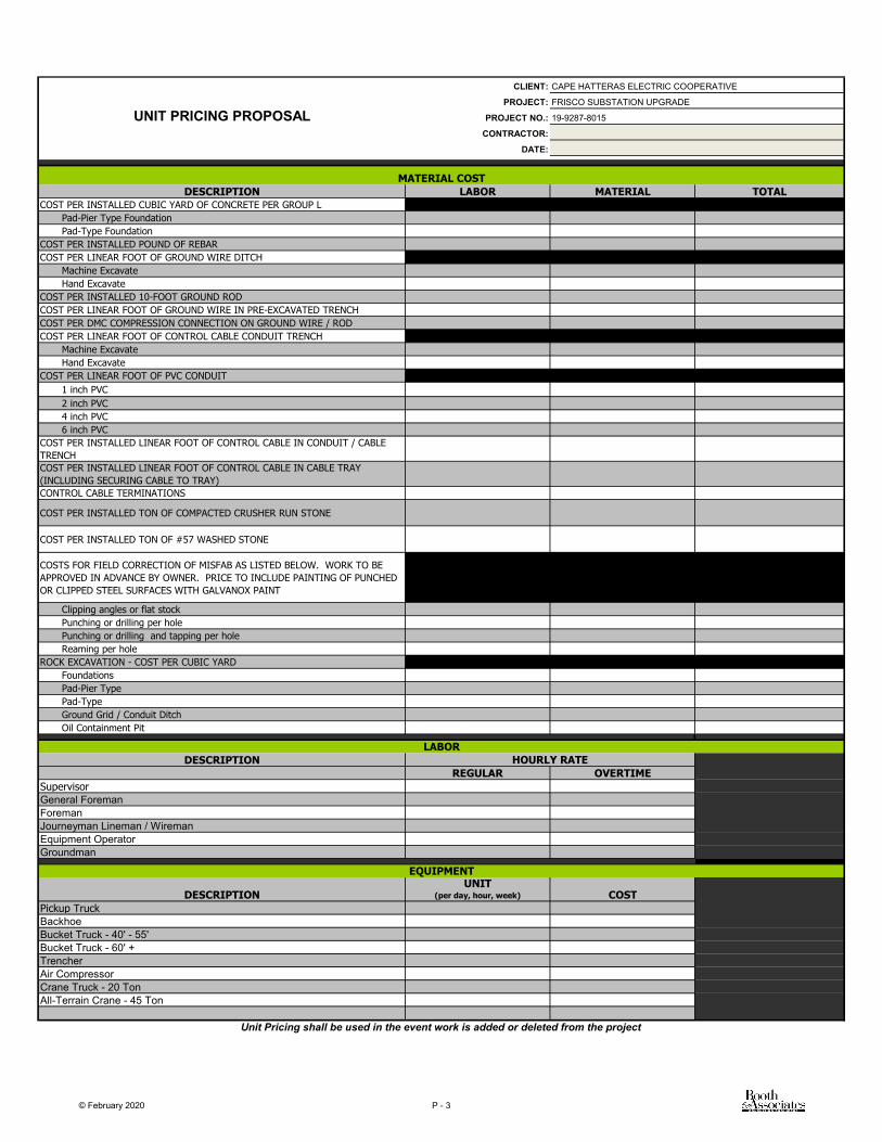
Unit Pricing Proposal P-3
Owner-Furnished Materials List P-4
RUS Form 307: Bid Bond P-5
Debarment Certification P-6
Lobbying Certification P-8
Proposed Construction Schedule P-9
Certificate(s) of Insurance P-10
Contractor’s License P-11
Proposed Project Management Staff P-12
References P-13
List of Subcontractors P-14
Bidder Inserts: Addenda / Clarifications / Bulletins P-15
SUPPLEMENTS TO RUS FORM 830
RUS Form 168b Contractor's Bond
RUS Form 187 Certificate of Completion
RUS Form 213 Certificate Buy American
RUS Form 224 Waiver and Release of Lien
RUS Form 231 Certificate of Contractor
TECHNICAL SPECIFICATIONS
Installation of Frisco Sub Upgrade

19-9287-8015 © February 2020
APPENDICES
1. Booth & Associates, LLC. - List of Drawings 2. Approved Control Cables 3. Bill of Materials 4. Vicinity Map 5. Standard Forms
a. Materials Receipt b. Change Order Form
6. Foundation Specification 7. Oil Containment Specification

RUS FORM 830 ELECTRIC SYSTEM CONSTRUCTION
CONTRACT PROJECT CONSTRUCTION
Notice and Instruction to Bidders Proposal
Acceptance

1 RUS FORM 830 (Rev. 2-04)
According to the Paperwork Reduction Act of 1995, an agency may not conduct or sponsor, and a person is not required to respond to, a collection of information unless it displays a valid OMB control number. The valid OMB control number for this information collection is 0572–0107. The time required to complete this information collection is estimated to average 5 minutes per response, including the time for reviewing instructions, searching existing data sources, gathering and maintaining the data needed, and completing and reviewing the collection of information.
U.S. Department of Agriculture Rural Utilities Service
ELECTRIC SYSTEM CONSTRUCTION CONTRACT
PROJECT CONSTRUCTION
NOTICE AND INSTRUCTIONS TO BIDDERS
1. Sealed proposals for the construction, including the supply of necessary labor, materials and equipment, of a
rural electric project of CAPE HATTERAS ELECTRIC COOPERATIVE., RUS designation NC 0064 ,
(hereinafter called the “Owner”) will be received by the Owner on or before Monday, March 2, 2020 at
2:00 o'clock P M., at the office of the Engineer at 5811 GLENWOOD AVENUE,
RALEIGH, NC 27612 at which time and place the proposals will be publicly opened and read. Any proposals
received subsequent to the time specified will be promptly returned to the Bidder unopened.
2. Owner Furnished Materials. The unit prices in the Contractor's Proposal are to include provisions for Owner Furnished Materials since as stated in Article I, Section 3 of the Contractor's Proposal, the value of the Owner Furnished Materials, if any, will be deducted from payments to the Bidder for completed Construction Units.
3. Obtaining Documents. The Plans, Specifications and Construction Drawings, together with all necessary
forms and other documents for bidders may be obtained from the Owner, or from the Engineer BOOTH & ASSOCIATES, INC. at the latter's office at 5811 GLENWOOD AVENUE, RALEIGH, NC 27612 upon the payment of $ 75.00, which payment will not be subject to refund. The Plans, Specifications, and Construction Drawings may be examined at the office of the Owner or at the office of the Engineer.
4. Manner of Submitting Proposals. Proposals and all supporting instruments must be submitted on the forms
furnished by the Owner and must be delivered in a sealed envelope addressed to the Owner. The name and address of the Bidder, its license number if a license is required by the State, and the date and hour of the opening of bids must appear on the envelope in which the Proposal is submitted. Proposals must be completed in ink or typewritten. No alterations or interlineations will be permitted, unless made before submission, and initialed and dated. The successful Bidder will be required to execute two additional counterparts of the Proposal.
5. Due Diligence. Prior to the submission of the Proposal, the Bidder shall make and shall be deemed to have
made a careful examination of the site of the project and of the Plans, Specifications, Construction Drawings, and forms of Contractor's Proposal and Contractor's Bond, and shall review the location and nature of the proposed construction, the transportation facilities, the kind and character of soil and terrain to be encountered, the kind of facilities required before and during the construction of the project, general local conditions, environmental and historic preservation considerations, and all other matters that may affect the cost and time of completion of the project. Bidder will be required to comply with all federal, state, and local laws, rules, and regulations applicable to its performance, including those pertaining to the licensing of contractors, and the Anti Kick-Back Act of 1986 (41 U.S.C. 51 et seq).
6. Proposals will be accepted only from those prequalified bidders invited by the Owner to submit a proposal.

2 RUS FORM 830 (Rev. 2-04)
7. The Time for Completion of Construction of the project is of the essence of the Contract and shall be as specified by the Engineer in the Proposal.
8. Bid Bond. Each Proposal must be accompanied by a Bid Bond in the form attached hereto or a certified check on a bank that is a member of the Federal Deposit Insurance Corporation, payable to the order of the Owner, in an amount equal to ten percent (10%) of the maximum bid price. Each Bidder agrees, provided its Proposal is one of the three low Proposals, that, by filing its Proposal together with such Bid Bond or check in consideration of the Owner's receiving and considering such Proposals, said Proposal shall be firm and binding upon each such Bidder and such Bid Bond or check shall be held by the Owner until a Proposal is accepted and a satisfactory Contractor's Bond is furnished (where required) by the successful Bidder and such acceptance has been approved by the Administrator, or for a period not to exceed sixty (60) days from the date hereinbefore set for the opening of Proposals, whichever period shall be the shorter. If such Proposal is not one of the three low Proposals, the Bid Bond or check will be returned in each instance within a period of ten (10) days to the Bidder furnishing same.
9. Contractor's Bond. For a Contract in excess of $100,000, the Bidder agrees to furnish a Contractor's Bond in
triplicate in the form attached hereto with sureties listed by the United States Treasury Department as Acceptable Sureties, in a penal sum not less than the contract price.
10. Failure to Furnish Contractor’s Bond. Should the successful Bidder fail or refuse to execute such
counterparts or to furnish a Contractor’s Bond (where required) within ten (10) days after written notification of the acceptance of the Proposal by the Owner, the Bidder will be considered to have abandoned the Proposal. In such event, the Owner shall be entitled (a) to enforce the Bid Bond in accordance with its terms, or (b) if a certified check has been delivered with the Proposal, to retain from the proceeds of the certified check, the difference (not exceeding the amount of the certified check) between the amount of the Proposal and such larger amount for which the Owner may in good faith contract with another party to construct the project. The term “Successful Bidder” shall be deemed to include any Bidder whose Proposal is accepted after another Bidder has previously refused or has been unable to execute the counterparts or to furnish a satisfactory Contractor’s Bond (where required.)
11. Debarment Certification. The Bidder must provide to the Owner a suspension and debarment certificate in
the form attached hereto.
12. Contract is Entire Agreement. The Contract to be effected by the acceptance of the Proposal shall be deemed to include the entire agreement between the parties thereto, and the Bidder shall not claim any modifications thereof resulting from any representation or promise made at any time by any officer, agent or employee of the Owner or by any other person.
13. Minor Irregularities. The Owner reserves the right to waive minor irregularities or minor errors in any
Proposal, if it appears to the Owner that such irregularities or errors were made through inadvertence. Any such irregularities or errors so waived must be corrected on the Proposal in which they occur prior to the acceptance thereof by the Owner.
14. Bid Rejection. The Owner reserves the right to reject any or all Proposals.
15. Discrepancy in Unit Prices. Where the unit prices in the Contractor's Proposal are separated into three
columns designated as “Labor,” “Materials,” and “Labor and Materials,” and where a discrepancy appears between the sum shown in the “Labor and Materials” column and the correct addition of the sums appearing in the “Labor” column and the “Materials” column, the correct addition of the sums appearing in the “Labor” column and the “Materials” column shall control. Similarly, the quantities appearing in the “No. of Units” column multiplied by the correct addition of the sums in the “Labor” column and the “Materials” shall control the amounts appearing in the “Extended Price – Labor & Materials” column. Likewise, the correct extensions shall control the amounts appearing in the “Total, Part ” line for each respective part.
16. Definition of Terms. The terms “Administrator,” “Engineer,” “Completion of Construction,” and

3 RUS FORM 830 (Rev. 2-04)
“Completion of the Project” as used throughout this Contract shall be as defined in Article VI, Section 1, of the Proposal
17. The Owner Represents:
a. If by provisions of the Proposal the Owner shall have undertaken to furnish any materials for the construction of the project, such materials are on hand at locations specified or if such materials are not on hand they will be made available by the Owner to the successful Bidder at the locations specified before the time such materials are required for construction.
b. All titles, easements and rights-of-way, except as shown on maps included in the Plans and Specifications,
have been obtained from the owners of the properties on which the project is to be constructed (including tenants who may reasonably be expected to object to such construction). The remaining easements and rights-of-way, if any, will be obtained as required to avoid delay in construction.
c. All staking, except as shown on the maps included in the Plans and Specifications, has been completed and
sufficient staking crews will be available to maintain stakes at all times in advance of construction.
d. Where underground distribution construction is required, permission has been obtained from state and local highway and road authorities to install underground distribution power facilities and set pedestals, if any, on the highway and road right-of-way in the project area. Notwithstanding such permission granted to the Owner, each Bidder is responsible for ascertaining that the equipment, methods of construction, and repair proposed to be used on the project will meet all requirements of public authorities having jurisdiction over highway and road right-of-way. The successful Bidder will be required to furnish proof satisfactory to the Owner of compliance with this requirement. If required by highway or road authorities, the successful Bidder will furnish to such authorities a bond or meet other guaranty requirements to assure the prompt repair of all damages to highways and roads and their associated rights-of-way caused by the Bidder during construction of the project. This requirement is in addition to and independent of the Contractor's Bond required under this Contract. The acceptance of a bid from any Bidder is not to be construed as approval of the Bidder's equipment or proposed construction methods by or on behalf of the highway and road authorities. Bidders may obtain information concerning the requirements of highway and road authorities by communicating with the following:
N/A N/A
e. All funds necessary for prompt payment for the construction of the project will be available.
If the Owner shall fail to comply with any of the undertakings contained in the foregoing representation or if any of such representations shall be incorrect, the Bidder will be entitled to an extension of time of completion for a period equal to the delay, if any, caused by the failure of the Owner to comply with such undertakings or by any such incorrect representation; provided the Bidder shall have promptly notified the Owner in writing of its desire to extend the time of completion in accordance with the foregoing; provided, however, that such extension, if any, of the time of completion shall be the sole remedy of the Bidder for the Owner's failure, because of conditions beyond the control and without the fault of the Owner, to furnish materials in accordance with subparagraph a. above.
CAPE HATTERAS EC Owner
By: Mr. Mark Rhyne
Manager of Engineering
February 17, 2020 Date

4 RUS FORM 830 (Rev. 2-04)
PROPOSAL
TO:
CAPE HATTERAS ELECTRIC COOPERATIVE BUXTON, NORTH CAROLINA (hereinafter called the “Owner”).
ARTICLE I--GENERAL
Section 1. Offer to Construct. The undersigned (hereinafter called the “Bidder”) hereby proposes to receive
and install such materials and equipment as may hereinafter be specified to be furnished by the Owner, and to furnish all other materials and equipment, all machinery, tools, labor, transportation and other means required to construct the project in strict accordance with the Plans, Specifications and Construction Drawings for the prices hereinafter stated.
The total length of the project lines shall be determined by taking the sum of all straight horizontal span distances between pole stakes or from center to center of poles, or centerline of structures, carrying conductors, plus the length of service drops, if any, measured horizontally from center of last pole to the point of attachment to the consumer's building.
Section 2. Materials and Equipment. The Bidder agrees to furnish and use in the construction of the project
under this Proposal, in the event the Proposal is accepted, only such “fully accepted,” “conditionally accepted,” and “technically accepted” materials and equipment which have been accepted by RUS as indicated in the current RUS Informational Publication 202-1, “List of Materials Acceptable for Use on Systems of RUS Electrification Borrowers,” including revisions adopted prior to the Bid Opening. The use of “conditionally accepted” or “technically accepted” materials and equipment requires prior consent by the Owner or Engineer.
The Bidder agrees that the prices for wood poles, wood crossarms, and other timber products set forth herein shall include the cost of preservative treatment and inspection, insured warranty, or quality assurance. The Bidder further agrees to obtain from the supplier inspection and treatment reports or insured warranties, for checking against the delivered timber, and to submit such reports or warranties to the Owner as one of the prerequisites to monthly and final payments.
The Bidder will purchase all materials and equipment (other than Owner Furnished Materials) outright and not subject to any conditional sales agreements, bailment, lease or other agreement reserving unto the seller any right, title or interest therein. All such materials and equipment shall be new and shall become the property of the Owner when erected in place.
Section 3. Owner Furnished Materials. The Bidder understands and agrees that, if this Proposal is accepted,
the Owner will furnish to the Bidder the material set forth in the attached “List of Owner Furnished Materials.” For those items not yet delivered, the Bidder will, on behalf of the Owner, accept delivery of such of the materials as may be subsequently delivered and will promptly forward to the Owner for payment the supplier's invoice. The Bidder will acknowledge in writing the receipt of all materials received as indicated on the List. The materials referred to are on hand at, or will be delivered to, the locations specified in the List and the Bidder will use such materials in constructing the project.
The value of the completed Construction Units certified by the Bidder each month pursuant to Article III, Section 1.a of the Proposal shall be reduced by an amount equal to the value of the materials installed by the Bidder during the preceding month which have been furnished by the Owner or the delivery of which has been accepted by the Bidder on behalf of the Owner. Only ninety percent (90%) of the remainder shall be paid prior to the Completion of the project. The value of such materials shall be computed on the basis of the unit prices stated in the Lists. Materials, if any, not required for the project, which have been furnished to the Bidder by the Owner or delivery of which

5 RUS FORM 830 (Rev. 2-04)
has been accepted by the Bidder on behalf of the Owner, shall be returned to the Owner by the Bidder
upon completion of construction of the project. The value of all materials not installed in the project nor returned to the Owner shall be deducted from the final payment to the Bidder.
The Owner shall not be obligated to furnish materials in excess of the quantities, size, kind and type set forth in the attached List. If the Owner furnishes, and the Bidder accepts, materials in excess thereof, the values of such excess materials shall be their actual cost as stated by the Owner.
Information on the shipping schedules of materials on the “List of Owner Furnished Materials” will be furnished to the Bidder as necessary during progress of the work.
Upon delivery, the Bidder shall promptly receive, unload, transport and handle all materials and equipment on the “List of Owner Furnished Materials” at its expense and shall be responsible for demurrage, if any.
Section 4. Proposal on Unit Basis. The Bidder understands and agrees that the various Construction Units on
which bids are made are defined by symbols and descriptions in this Proposal, that all said bids are on a unit basis, and that the Owner may specify any number or combination of Construction Units that the Owner may deem necessary for the construction of the project. Separate Construction Units are designated for each different arrangement which may be used in the construction of the project. This Proposal is based on a consideration of each unit in place and includes only the materials listed on the corresponding Construction Drawings or description of unit where no drawing exists.
Section 5. Description of Contract. The Notice and Instructions to Bidders, Plans, Specifications, and
Construction Drawings, which by this reference are incorporated herein, together with the Proposal and Acceptance, constitute the Contract. The Plans, Specifications, and Construction Drawings, including maps, special drawings, and approved modifications in standard specifications are attached hereto and identified as follows:
CAPE HATTERAS ELECTRIC COOPERATIVE INSTALLATION OF FRISCO SUBSTATION UPGRADE
Section 6. Due Diligence. The Bidder has made a careful examination of the site of the project to be constructed
and of the Plans, Specifications, Construction Drawings, and form of Contractor's Bond attached hereto, and has become informed as to the location and nature of the proposed construction, the transportation facilities, the kind and character of soil and terrain to be encountered, and the kind of facilities required before and during the construction of the project, and has become acquainted with the labor conditions, federal, state, and local laws, rules, and regulations applicable to its performance.
Section 7. License. The Bidder warrants that a Contractor's License is X , is not required, and if
required,
it possesses Contractor's License No. for the State of NORTH CAROLINA
in which the project is located and said license expires on , 20 .
Section 8. Warranty of Good Faith. The Bidder warrants that this Proposal is made in good faith and without
collusion or connection with any person or persons bidding for the same work.
Section 9. Financial Resources.

6 RUS FORM 830 (Rev. 2-04)
a. The Bidder warrants that it has or will obtain the financial resources necessary to ensure
completion of the project.
b. The Bidder agrees that in the event this Proposal is accepted and a Contractor's Bond is required, it will furnish a Contractor's Bond in the form attached hereto, in a penal sum not less than the maximum Contract price, with a surety or sureties listed by the United States Department of Treasury as Acceptable Sureties.
Section 10. Taxes. The unit prices for Construction Units in this Proposal include provisions for the payment of
all monies which will be payable by the Bidder or the Owner in connection with the construction of the project on account of taxes imposed by any taxing authority upon the sale, purchase or use of materials, supplies and equipment, or services or labor of installation thereof, to be incorporated in the project as part of such Construction Units. The Bidder agrees to pay all such taxes, except taxes upon the sale, purchase or use of Owner Furnished Materials and it is understood that, as to Owner Furnished Materials, the values stated in the attached “List of Owner Furnished Materials” include taxes upon the sale, purchase or use of Owner Furnished Materials, if applicable. The Bidder will furnish to the appropriate taxing authorities all required information and reports pertaining to the project, except as to the Owner Furnished Materials.
Section 11. Changes in Quantities. The Bidder understands and agrees that the quantities called for in this
Proposal are approximate, and that the total number of units upon which payment shall be made shall be as set forth in the inventory. If the Owner changes the quantity of any unit or units specified in this Proposal by more than fifteen percent (15%) and the materials cost to the Bidder is increased thereby to an extent which would not be adequately compensated by application of the unit prices in this Proposal to the revised quantity of such unit or units, such change, to the extent of the quantities of such units in excess of such fifteen percent (15%) shall be regarded as a change in the construction within the meaning of Article II, Section 1(d) of this proposal.
ARTICLE II--CONSTRUCTION
Section 1. Time and Manner of Construction.
a. The Bidder agrees to commence construction of the project on a date (hereinafter called the
“Commencement Date”) which shall be determined by the Engineer after notice to the bidder in writing of approval of the contract by the Administrator, if approval of the Administrator is required, and notice in writing from the Bidder that the Bidder has sufficient materials to warrant commencement and continuation of construction, but in no event will the Commencement Date be
later than seven (7) calendar days after date of approval of the contract by the Administrator, if approval of the Administrator is required. The Bidder further agrees to prosecute diligently and to complete construction in strict accordance with the Plans,
Specifications and Construction Drawings within Ninety (90) calendar days after Commencement Date: Provided, however, that the Bidder will not be required to dig holes, set poles, install anchors, install underground conduit, perform any plowing for the installation of underground cable, or dig trenches if there are more than six (6) inches of frost on the ground nor to perform any construction on such days when in the judgment of the Engineer snow, rain, or wind, or the results of snow, rain, or frost make it impracticable to perform any operation of construction; provided further that the Bidder will not be required to perform any plowing for the installation of underground cable on public roads or highways if there are more than two (2) inches of frost in the ground. To the extent of the time lost due to the conditions described herein and approved in writing by the Engineer, the time of completion set out above will be extended if the Bidder makes a written request therefore to the Owner as provided in subsection b of this Section 1.
b. The time for Completion of Construction shall be extended for the period of any reasonable delay which is due exclusively to causes beyond the control and without the fault of the Bidder,
7 RUS FORM 830 (Rev. 2-04)
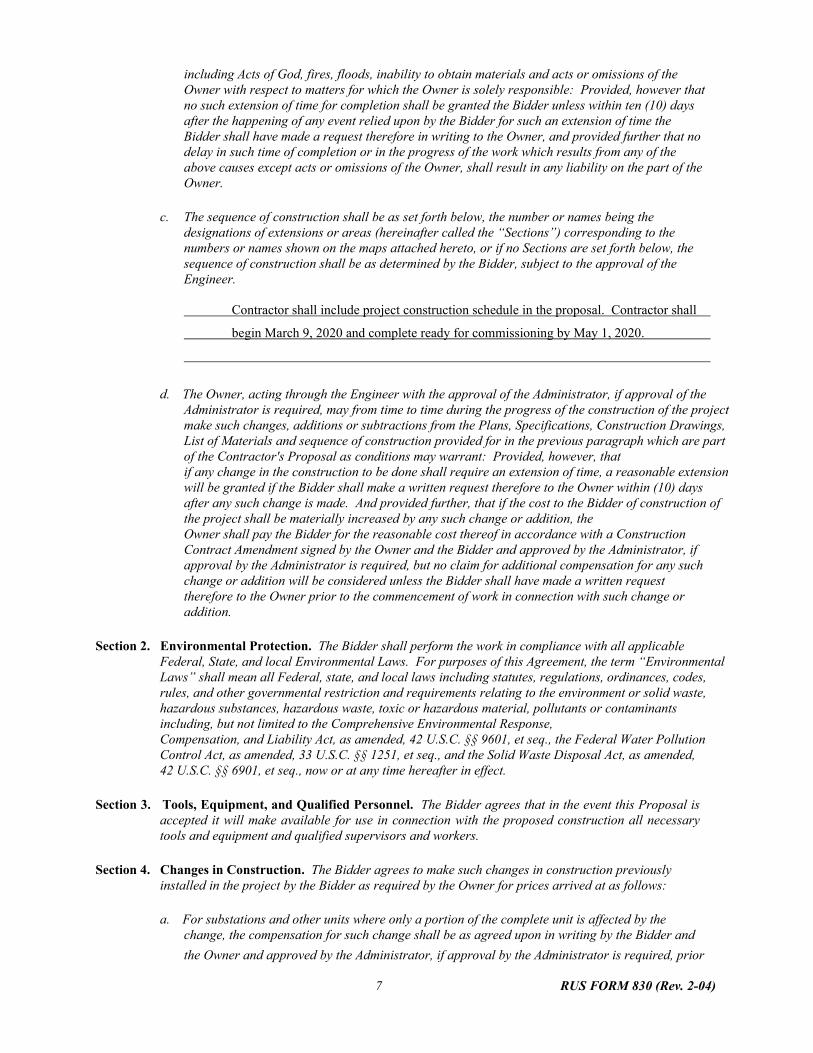
including Acts of God, fires, floods, inability to obtain materials and acts or omissions of the Owner with respect to matters for which the Owner is solely responsible: Provided, however that no such extension of time for completion shall be granted the Bidder unless within ten (10) days after the happening of any event relied upon by the Bidder for such an extension of time the Bidder shall have made a request therefore in writing to the Owner, and provided further that no delay in such time of completion or in the progress of the work which results from any of the above causes except acts or omissions of the Owner, shall result in any liability on the part of the Owner.
c. The sequence of construction shall be as set forth below, the number or names being the
designations of extensions or areas (hereinafter called the “Sections”) corresponding to the numbers or names shown on the maps attached hereto, or if no Sections are set forth below, the sequence of construction shall be as determined by the Bidder, subject to the approval of the Engineer.
Contractor shall include project construction schedule in the proposal. Contractor shall
begin March 9, 2020 and complete ready for commissioning by May 1, 2020.
d. The Owner, acting through the Engineer with the approval of the Administrator, if approval of the
Administrator is required, may from time to time during the progress of the construction of the project make such changes, additions or subtractions from the Plans, Specifications, Construction Drawings, List of Materials and sequence of construction provided for in the previous paragraph which are part of the Contractor's Proposal as conditions may warrant: Provided, however, that if any change in the construction to be done shall require an extension of time, a reasonable extension will be granted if the Bidder shall make a written request therefore to the Owner within (10) days after any such change is made. And provided further, that if the cost to the Bidder of construction of the project shall be materially increased by any such change or addition, the Owner shall pay the Bidder for the reasonable cost thereof in accordance with a Construction Contract Amendment signed by the Owner and the Bidder and approved by the Administrator, if approval by the Administrator is required, but no claim for additional compensation for any such change or addition will be considered unless the Bidder shall have made a written request therefore to the Owner prior to the commencement of work in connection with such change or addition.
Section 2. Environmental Protection. The Bidder shall perform the work in compliance with all applicable
Federal, State, and local Environmental Laws. For purposes of this Agreement, the term “Environmental Laws” shall mean all Federal, state, and local laws including statutes, regulations, ordinances, codes, rules, and other governmental restriction and requirements relating to the environment or solid waste, hazardous substances, hazardous waste, toxic or hazardous material, pollutants or contaminants including, but not limited to the Comprehensive Environmental Response, Compensation, and Liability Act, as amended, 42 U.S.C. §§ 9601, et seq., the Federal Water Pollution Control Act, as amended, 33 U.S.C. §§ 1251, et seq., and the Solid Waste Disposal Act, as amended, 42 U.S.C. §§ 6901, et seq., now or at any time hereafter in effect.
Section 3. Tools, Equipment, and Qualified Personnel. The Bidder agrees that in the event this Proposal is
accepted it will make available for use in connection with the proposed construction all necessary tools and equipment and qualified supervisors and workers.
Section 4. Changes in Construction. The Bidder agrees to make such changes in construction previously
installed in the project by the Bidder as required by the Owner for prices arrived at as follows:
a. For substations and other units where only a portion of the complete unit is affected by the change, the compensation for such change shall be as agreed upon in writing by the Bidder and
the Owner and approved by the Administrator, if approval by the Administrator is required, prior
8 RUS FORM 830 (Rev. 2-04)
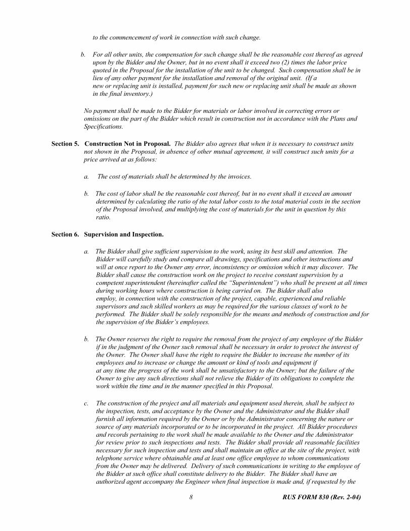
to the commencement of work in connection with such change.
b. For all other units, the compensation for such change shall be the reasonable cost thereof as agreed upon by the Bidder and the Owner, but in no event shall it exceed two (2) times the labor price quoted in the Proposal for the installation of the unit to be changed. Such compensation shall be in lieu of any other payment for the installation and removal of the original unit. (If a new or replacing unit is installed, payment for such new or replacing unit shall be made as shown in the final inventory.)
No payment shall be made to the Bidder for materials or labor involved in correcting errors or omissions on the part of the Bidder which result in construction not in accordance with the Plans and Specifications.
Section 5. Construction Not in Proposal. The Bidder also agrees that when it is necessary to construct units
not shown in the Proposal, in absence of other mutual agreement, it will construct such units for a price arrived at as follows:
a. The cost of materials shall be determined by the invoices.
b. The cost of labor shall be the reasonable cost thereof, but in no event shall it exceed an amount
determined by calculating the ratio of the total labor costs to the total material costs in the section of the Proposal involved, and multiplying the cost of materials for the unit in question by this ratio.
Section 6. Supervision and Inspection.
a. The Bidder shall give sufficient supervision to the work, using its best skill and attention. The
Bidder will carefully study and compare all drawings, specifications and other instructions and will at once report to the Owner any error, inconsistency or omission which it may discover. The Bidder shall cause the construction work on the project to receive constant supervision by a competent superintendent (hereinafter called the “Superintendent”) who shall be present at all times during working hours where construction is being carried on. The Bidder shall also employ, in connection with the construction of the project, capable, experienced and reliable supervisors and such skilled workers as may be required for the various classes of work to be performed. The Bidder shall be solely responsible for the means and methods of construction and for the supervision of the Bidder’s employees.
b. The Owner reserves the right to require the removal from the project of any employee of the Bidder
if in the judgment of the Owner such removal shall be necessary in order to protect the interest of the Owner. The Owner shall have the right to require the Bidder to increase the number of its employees and to increase or change the amount or kind of tools and equipment if at any time the progress of the work shall be unsatisfactory to the Owner; but the failure of the Owner to give any such directions shall not relieve the Bidder of its obligations to complete the work within the time and in the manner specified in this Proposal.
c. The construction of the project and all materials and equipment used therein, shall be subject to
the inspection, tests, and acceptance by the Owner and the Administrator and the Bidder shall furnish all information required by the Owner or by the Administrator concerning the nature or source of any materials incorporated or to be incorporated in the project. All Bidder procedures and records pertaining to the work shall be made available to the Owner and the Administrator for review prior to such inspections and tests. The Bidder shall provide all reasonable facilities necessary for such inspection and tests and shall maintain an office at the site of the project, with telephone service where obtainable and at least one office employee to whom communications from the Owner may be delivered. Delivery of such communications in writing to the employee of the Bidder at such office shall constitute delivery to the Bidder. The Bidder shall have an authorized agent accompany the Engineer when final inspection is made and, if requested by the

9 RUS FORM 830 (Rev. 2-04)
Owner, when any other inspection is made. The performance of such inspections or tests by the Owner or the Administrator shall not relieve the Bidder of its obligations to perform the work in accordance with the requirements of this Contract.
d. In the event that the Owner, or the Administrator, shall determine that the construction contains
or may contain numerous defects, it shall be the duty of the Bidder and the Bidder's Surety or Sureties, if any, to have an inspection made by an engineer approved by the Owner and the Administrator, if approval by the Administrator is required, for the purpose of determining the exact nature, extent and location of such defects.
e. The Engineer may recommend to the Owner that the Bidder suspend the work wholly or in part
for such period or periods as the Engineer may deem necessary due to unsuitable weather or such other conditions as are considered unfavorable for satisfactory prosecution of the work or because of the failure of the Bidder to comply with any of the provisions of the Contract: Provided, however, that the Bidder shall not suspend work pursuant to this provision without written authority from the Owner so to do. The time of completion hereinabove set forth shall be increased by the number of days of any such suspension, except when such suspension is due to the failure of the Bidder to comply with any of the provisions of this Contract. In the event that work is suspended by the Bidder with the consent of the Owner, the Bidder before resuming work shall give the Owner at least twenty-four (24) hours notice thereof in writing.
Section 7. Defective Materials and Workmanship.
a. The acceptance of any materials, equipment (except Owner Furnished Materials) or any workmanship
by the Owner or the Engineer shall not preclude the subsequent rejection thereof if such materials, equipment, or workmanship shall be found to be defective after delivery or installation, and any such materials, equipment or workmanship found defective before final acceptance of the construction shall be replaced or remedied, as the case may be, by and at the expense of the Bidder. Any such condemned material or equipment shall be immediately removed from the site of the project by the Bidder at the Bidder's expense. The Bidder shall not be entitled to any payment hereunder so long as any defective materials, equipment or workmanship in respect to the project, of which the Bidder shall have had notice, shall not have been replaced or remedied, as the case may be.
b. Notwithstanding any certificate which may have been given by the Owner or the Engineer, if any
materials, equipment (except Owner Furnished Materials) or any workmanship which does not comply with the requirements of this Contract shall be discovered within one (1) year after Completion of Construction of the project, the Bidder shall replace such defective materials or equipment or remedy any such defective workmanship within thirty (30) days after notice in writing of the existence thereof shall have been given by the Owner. If any such defective materials, equipment, or workmanship so replaced or repaired is found to be defective within one year after the completion of the replacement or repair, the Bidder shall replace or remedy such defective materials, equipment, or workmanship. If the Bidder shall be called upon to replace any defective materials or equipment or to remedy defective workmanship as herein provided, the Owner, if so requested by the Bidder shall deenergize that section of the project involved in such work. In the event of failure by the Bidder so to do, the Owner may replace such defective materials or equipment or remedy such defective workmanship, as the case may be, and in such event the Bidder shall pay to the Owner the cost and expense thereof.
ARTICLE III--PAYMENTS AND RELEASE OF LIENS
Section 1. Payments to Bidder.
a. On or before the fifth (5) day of each calendar month, the Bidder will make application for

10 RUS FORM 830 (Rev. 2-04)
payment, and the Owner, on or before the fifteenth (15) day of such month, shall make partial payment to the Bidder for construction accomplished during the preceding calendar month on the basis of completed Construction Units furnished and certified to by the Bidder, recommended by
the Engineer and approved by the Owner solely for the purposes of payment: Provided, however, that such approval shall not be deemed approval of the workmanship or materials. Only ninety percent (90%) of each such estimate approved during the construction of the project shall be paid by the Owner to the Bidder prior to Completion of the project. Upon completion by the Bidder of the construction of the project, the Engineer will prepare an inventory of the project showing the total number and character of Construction Units and, after checking such inventory with the
Bidder, will certify it to the Owner. Upon the approval by the Owner and the Administrator, if the approval of the Administrator is required, of a Certificate of Completion in the form attached hereto, showing the total cost of the construction performed, the Owner shall make payment to the Bidder of all amounts to which the Bidder shall be entitled thereunder which shall not have been paid: Provided, however, that such final payment shall be made not later than ninety (90) days after the date of Completion of Construction of the project, as specified in the Certificate of Completion, unless withheld because of the fault of the Bidder.
b. The Bidder shall be paid on the basis of the number of Construction Units actually installed at the
direction of the Owner shown by the inventory based on the staking sheets or structure lists.
c. Notwithstanding the provisions of Section 1.a above, the Bidder may, by giving written notice thereof to the Owner, elect to receive payment in full for any Section of the project upon:
(1) completion of construction of such Section as certified by the Engineer and approved by the
Owner and the Administrator, if approval by the Administrator is required;
(2) submission to the Owner and the Administrator, if submission to the Administrator is required, of the releases of lien and the certificate referred to in Section 2 of this Article;
(3) approval by the Owner and the Administrator, if approval by the Administrator is required,
of the inventory in respect of such Section; and
(4) submission to the Owner and the Administrator, if submission to the Administrator is required, of the consent in writing by the Surety or Sureties, if any, on the Contractor's Bond to payment in full for such Section prior to Completion of the project.
If no Sections are designated in Article II, Section 1c, the term “Section” shall mean for purposes of this subsection c and Article IV, Section 3b only, a part of the project as designated by the Owner which represents at least twenty-five percent (25%) of the contract price, and which is capable of being energized and operated by the Owner.
d. Interest at the rate of five percent1 (5%) per annum shall be paid by the Owner to the Bidder on
all unpaid balances due on monthly estimates, commencing fifteen (15) days after the due date; provided the delay in payment beyond the due date is not caused by any condition within the control of the Bidder. The due date for purposes of such monthly payment or interest on all unpaid balances shall be the fifteenth (15) day of each calendar month provided (1) the Bidder on or before the fifth (5) day of such month shall have submitted its certification of Construction Units completed during the preceding month and (2) the Owner on or before the fifteenth (15) day of such month shall have approved such certification. If, for reasons not due to the Bidder's fault, such approval shall not have been given on or before the fifteenth (15) day of such month, the due date for purposes of this subsection d shall be the fifteenth (15) day of such month notwithstanding the absence of the approval of the certification.
1 The Owner shall insert a rate equal to the lowest “Prime Rate” listed in the “Money Rates” section of the Wall Street Journal on the date such invitation to bid is issued.
11 RUS FORM 830 (Rev. 2-04)
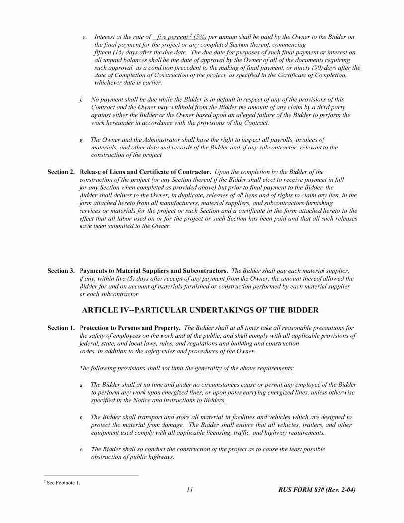
e. Interest at the rate of five percent 2 (5%) per annum shall be paid by the Owner to the Bidder on the final payment for the project or any completed Section thereof, commencing fifteen (15) days after the due date. The due date for purposes of such final payment or interest on all unpaid balances shall be the date of approval by the Owner of all of the documents requiring such approval, as a condition precedent to the making of final payment, or ninety (90) days after the date of Completion of Construction of the project, as specified in the Certificate of Completion, whichever date is earlier.
f. No payment shall be due while the Bidder is in default in respect of any of the provisions of this
Contract and the Owner may withhold from the Bidder the amount of any claim by a third party against either the Bidder or the Owner based upon an alleged failure of the Bidder to perform the work hereunder in accordance with the provisions of this Contract.
g. The Owner and the Administrator shall have the right to inspect all payrolls, invoices of
materials, and other data and records of the Bidder and of any subcontractor, relevant to the construction of the project.
Section 2. Release of Liens and Certificate of Contractor. Upon the completion by the Bidder of the
construction of the project (or any Section thereof if the Bidder shall elect to receive payment in full for any Section when completed as provided above) but prior to final payment to the Bidder, the Bidder shall deliver to the Owner, in duplicate, releases of all liens and of rights to claim any lien, in the form attached hereto from all manufacturers, material suppliers, and subcontractors furnishing services or materials for the project or such Section and a certificate in the form attached hereto to the effect that all labor used on or for the project or such Section has been paid and that all such releases have been submitted to the Owner.
Section 3. Payments to Material Suppliers and Subcontractors. The Bidder shall pay each material supplier, if any, within five (5) days after receipt of any payment from the Owner, the amount thereof allowed the Bidder for and on account of materials furnished or construction performed by each material supplier or each subcontractor. ARTICLE IV--PARTICULAR UNDERTAKINGS OF THE BIDDER
Section 1. Protection to Persons and Property. The Bidder shall at all times take all reasonable precautions for
the safety of employees on the work and of the public, and shall comply with all applicable provisions of federal, state, and local laws, rules, and regulations and building and construction codes, in addition to the safety rules and procedures of the Owner.
The following provisions shall not limit the generality of the above requirements:
a. The Bidder shall at no time and under no circumstances cause or permit any employee of the Bidder
to perform any work upon energized lines, or upon poles carrying energized lines, unless otherwise specified in the Notice and Instructions to Bidders.
b. The Bidder shall transport and store all material in facilities and vehicles which are designed to
protect the material from damage. The Bidder shall ensure that all vehicles, trailers, and other equipment used comply with all applicable licensing, traffic, and highway requirements.
c. The Bidder shall so conduct the construction of the project as to cause the least possible
obstruction of public highways.
2 See Footnote 1.

12 RUS FORM 830 (Rev. 2-04)
d. The Bidder shall provide and maintain all such guard lights and other protection for the public as may be required by applicable statutes, ordinances and regulations or by local conditions.
e. The Bidder shall do all things necessary or expedient to properly protect any and all parallel,
converging and intersecting lines, joint line poles, highways, and any and all property of others from damage, and in the event that any such parallel, converging and intersecting lines, joint line poles, highways or other property are damaged in the course of the construction of the project the Bidder shall at its own expense restore any or all of such damaged property immediately to as good a state as before such damage occurred.
f. Where the right-of-way of the project traverses cultivated or grazing lands, the Bidder shall limit the movement of its crews and equipment so as to cause as little damage as possible to crops, orchards or property and shall endeavor to avoid marring the lands. All fences which are necessarily opened or moved during the construction of the project shall be replaced in as good condition as they were found and precautions shall be taken to prevent the escape of livestock. Except as otherwise provided in the descriptions of underground plowing and trenching assembly units, the Bidder shall not be responsible for loss of or damage to crops, orchards or property (other than livestock) on the right-of-way necessarily incident to the construction of the project and not caused by negligence or inefficient operation of the Bidder. The Bidder shall be responsible for all other loss of or damage to crops, orchards, or property, whether on or off the right-of-way, and for all loss of or damage to livestock caused by the construction of the project.
The right-of-way for purposes of this said section shall consist of an area extending N/A feet on both sides of the center line of the poles along the route of the project lines, plus such area reasonably required by the Bidder for access to the route of the project lines from public roads to carry on construction activities.
g. The project, from the commencement of work to completion, or to such earlier date or dates when the
Owner may take possession and control in whole or in part as hereinafter provided shall be under the charge and control of the Bidder and during such period of control by the Bidder all risks in connection with the construction of the project and the materials to be used therein shall be borne by the Bidder. The Bidder shall make good and fully repair all injuries and damages to the project or any portion thereof under the control of the Bidder by reason of any act of God or other casualty or cause whether or not the same shall have occurred by reason of the Bidder's negligence.
(i) To the maximum extent permitted by law, Bidder shall defend, indemnify, and hold harmless
Owner and Owner's directors, officers, and employees from all claims, causes of action, losses, liabilities, and expenses (including reasonable attorney's fees) for personal loss, injury, or death to persons (including but not limited to Bidder's employees) and loss, damage to or destruction of Owner's property or the property of any other person or entity (including but not limited to Bidder's property) in any manner arising out of or connected with the Contract, or the materials or equipment supplied or services performed by Bidder, its subcontractors and suppliers of any tier. But nothing herein shall be construed as making Bidder liable for any injury, death, loss, damage, or destruction caused by the sole negligence of Owner.
(ii) To the maximum extent permitted by law, Bidder shall defend, indemnify, and hold harmless
Owner and Owner's directors, officers, and employees from all liens and claims filed or asserted against Owner, its directors, officers, and employees, or Owner's property or facilities, for services performed or materials or equipment furnished by Bidder, its subcontractors and suppliers of any tier, and from all losses, demands, and causes of action arising out of any such lien or claim. Bidder shall promptly discharge or remove any such lien or claim by bonding, payment, or otherwise and shall notify Owner promptly when it has done so. If Bidder does not cause such lien or claim to be discharged or released by payment, bonding, or otherwise, Owner shall have the right (but shall not be obligated) to pay all sums necessary to obtain any such discharge or release and to deduct all amounts so paid from the amount due Bidder.

13 RUS FORM 830 (Rev. 2-04)
(iii) Bidder shall provide to Owner's satisfaction evidence of Bidder's ability to comply with the
indemnification provisions of subparagraphs i and ii above, which evidence may include but may not be limited to a bond or liability insurance policy obtained for this purpose through a licensed surety or insurance company.
h. Any and all excess earth, rock, debris, underbrush and other useless materials shall be removed
by the Bidder from the site of the project as rapidly as practicable as the work progresses.
i. Upon violation by the Bidder of any of the provisions of this section, after written notice of such violation given to the Bidder by the Engineer or the Owner, the Bidder shall immediately correct such violation. Upon failure of the Bidder so to do the Owner may correct such violation at the Bidder's expense: Provided, however, that the Owner may, if it deems it necessary or advisable, correct such violation at the Bidder's expense without such prior notice to the Bidder.
j. The Bidder shall submit to the Owner monthly reports in duplicate of all accidents, giving such
data as may be prescribed by the Owner.
k. The Bidder shall not proceed with the cutting of trees or clearing of right-of-way without written notification from the Owner that proper authorization has been received from the owner of the property, and the Bidder shall promptly notify the Owner whenever any landowner objects to the trimming or felling of any trees or the performance of any other work on its land in connection with the project and shall obtain the consent in writing of the Owner before proceeding in any such case.
l. The Bidder will furnish, prior to the commencement of underground distribution construction,
proof, satisfactory to the Owner, of compliance with requirements of highway and road authorities having jurisdiction, including without limitation, the furnishing of a bond or other guaranty, and approval by such authorities of the equipment and methods of construction and repair to be used by the Bidder.
Section 2. Insurance. The Bidder shall take out and maintain throughout the period of this Agreement the
following types and minimum amounts of insurance:
a. Workers' compensation and employers' liability insurance, as required by law, covering all its employees who perform any of the obligations of the Bidder under the contract. If any employer or employee is not subject to the workers' compensation laws of the governing state, then insurance shall be obtained voluntarily to extend to the employer and employee coverage to the same extent as though the employer or employee were subject to the workers' compensation laws.
b. Public liability insurance covering all operations under the contract shall have limits for bodily injury
or death of not less than $1 million each occurrence, limits for property damage of not less than $1 million each occurrence, and $1 million aggregate for accidents during the policy period. A single limit of $1 million of bodily injury and property damage is acceptable. This required insurance may be in a policy or policies of insurance, primary and excess including the umbrella or catastrophe form.
c. Automobile liability insurance on all motor vehicles used in connection with the contract, whether
owned, nonowned, or hired, shall have limits for bodily injury or death of not less than $1 million per person and $1 million each occurrence, and property damage limits of $1 million for each occurrence. A single limit of $1 million of bodily injury and property damage is acceptable. This required insurance may be in a policy or policies of insurance, primary and excess including the umbrella or catastrophe form.
The Owner shall have the right at any time to require public liability insurance and property damage liability insurance greater than those required in subsection “b” and “c” of this Section. In any such

14 RUS FORM 830 (Rev. 2-04)
event, the additional premium or premiums payable solely as the result of such additional insurance shall be added to the Contract price.
The Owner shall be named as Additional Insured on all policies of insurance required in subsections “b” and “c” of this Section.
The policies of insurance shall be in such form and issued by such insurer as shall be satisfactory to the Owner. The Bidder shall furnish the Owner a certificate evidencing compliance with the foregoing requirements which shall provide not less than (30) days prior written notice to the Owner of any cancellation or material change in the insurance.
Section 3. Delivery of Possession and Control to Owner.
a. Upon written request of the Owner the Bidder shall deliver to the Owner full possession and control of any portion of the project provided the Bidder shall have been paid at least ninety percent (90%) of the cost of construction of such portion. Upon such delivery of the possession and control of any portion of the project to the Owner, the risk and obligations of the Bidder as set forth in Article IV, Section 1.g hereof with respect to such portion of the project so delivered to the Owner shall be terminated; Provided, however, that nothing herein contained shall relieve the Bidder of any liability with respect to defective materials and workmanship as contained in Article II, Section 7 hereof.
b. Where the construction of a Section as hereinbefore defined in Article II, Section 1.c and
Article III, Section 1.c shall have been completed by the Bidder, the Owner agrees, after receipt of a written request from the Bidder, to accept delivery of possession and control of such Section upon the issuance by the Engineer of a written statement that the Section has been inspected and found acceptable by the Engineer. Upon such delivery of the possession and control of any such Section to the Owner, the risk and obligations of the Bidder as set forth in Article IV, Section 1.g hereof with respect to such Section so delivered to the Owner shall be terminated: Provided, however, that nothing herein contained shall relieve the Bidder of any liability with respect to defective materials or workmanship as contained in Article II, Section 7 hereof.
Section 4. Energizing the Project.
a. Prior to Completion of the project the Owner, upon written notice to the Bidder, may test the
construction thereof by temporarily energizing any portion or portions thereof. During the period of such test the portion or portions of the project so energized shall be considered as within the possession and control of the Owner and governed by the provisions of Section 3 of this Article. Upon written notice to the Bidder by the Owner of the completion of such test and upon deenergizing the lines involved therein said portion or portions of the project shall be considered as returned to the possession and control of the Bidder unless the Owner shall elect to continue possession and control in the manner provided in Section 3 of this Article.
b. The Owner shall have the right to energize permanently any portion or portions of the project
delivered to its possession and control pursuant to the provisions of Section 3 of this Article.
Section 5. Assignment of Guarantees. All guarantees of materials and workmanship running in favor of the Bidder shall be transferred and assigned to the Owner prior to the time the Bidder receives final payment.
ARTICLE V--REMEDIES
Section 1. Completion on Bidder's Default. If default shall be made by the Bidder or by any subcontractor in the performance of any of the terms of this Proposal, the Owner, without in any manner limiting its legal and equitable remedies in the circumstances, may serve upon the Bidder and the Surety or Sureties, if any, upon the Contractor's Bond or Bonds a written notice requiring the Bidder to cause

15 RUS FORM 830 (Rev. 2-04)
such default to be corrected forthwith. Unless within twenty (20) days after the service of such notice upon the Bidder such default shall be corrected or arrangements for the correction thereof satisfactory to both the Owner and the Administrator shall be made by the Bidder or its Surety or Sureties, if any, the Owner may take over the construction of the project and prosecute the same to completion by Contract or otherwise for the account and at the expense of the Bidder, and the Bidder and its Surety or Sureties, if any, shall be liable to the Owner for any cost or expense in excess of the Contract price occasioned thereby. In such event the Owner may take possession of and utilize, in completing the construction of the project, any materials, tools, supplies, equipment, appliances, and plant belonging to the Bidder or any of its subcontractors, which may be situated at the site of the project. The Owner in such contingency may exercise any rights, claims or demands which the Bidder
may have against third persons in connection with this Contract and for such purpose the Bidder does hereby assign, transfer and set over unto the Owner all such rights, claims and demands.
Section 2. Liquidated Damages. The time of the Completion of Construction of the project is of the essence of the
Contract. Should the Bidder neglect, refuse or fail to complete the construction within the time herein agreed upon, after giving effect to extensions of time, if any, herein provided, then, in that event and in view of the difficulty of estimating with exactness damages caused by such delay, the Owner shall have the right to deduct from and retain out of such moneys which may be then due, or which may become due and payable to the Bidder the sum of Five Hundred dollars ( $500.00 ) per day for each and every day that such construction is delayed in its completion beyond the specified time, as liquidated damages and not as a penalty; if the amount due and to become due from the Owner to the Bidder is insufficient to pay in full any such liquidated damages, the Bidder shall pay to the Owner the amount necessary to effect such payment in full: Provided, however, that the Owner shall promptly notify the Bidder in writing of the manner in which the amount retained, deducted or claimed as liquidated damages was computed.
Section 3. Cumulative Remedies. Every right or remedy herein conferred upon or reserved to the Owner or the
Government or the Administrator shall be cumulative, shall be in addition to every right and remedy now or hereafter existing at law or in equity or by statute and the pursuit of any right or remedy shall not be construed as an election: Provided, however, that the provisions of Section 2 of this Article shall be the exclusive measure of damages for failure by the Bidder to complete the construction of the project within the time herein agreed upon.
ARTICLE VI--MISCELLANEOUS
Section 1. Definitions.
a. The term “Administrator” shall mean the Administrator of the Rural Utilities Service of the United States of America and his or her duly authorized representative or any other person in whom or authority in which may be vested the duties and functions which the Administrator is now authorized by law to perform.
b. The term “Engineer” shall mean the Engineer employed by the Owner, to provide engineering
services for the project and said Engineer's duly authorized assistants and representatives.
c. The term “Completion of Construction” shall mean full performance by the Bidder of the Bidder's obligations under the Contract and all amendments and revisions thereof except the Bidder's obligations in respect of (1) Releases of Liens and Certificate of Contractor under Article III, Section 2 hereof, (2) the inventory referred to in Article III, Section 1 hereof, and (3) other final documents. The term “Completion of the Project” shall mean full performance by the Bidder of the Bidder's obligations under the Contract and all amendments and revisions thereof. The Certificate of Completion, signed by the Engineer and approved in writing by the Owner and the Administrator, if approval by the Administrator is required, shall be the sole and conclusive evidence as to the date of Completion of Construction and as to the fact of Completion of the Project.
Section 2. Materials and Supplies. In the performance of this contract there shall be furnished only such

16 RUS FORM 830 (Rev. 2-04)
unmanufactured articles, materials, and supplies as have been mined or produced in the United States or in any eligible country, and only such manufactured articles, materials, and supplies as have been manufactured in the United States or in any eligible country substantially all from articles, materials, or supplies mined, produced or manufactured, as the case may be, in the United States or in any eligible country; provided that other articles, materials, or supplies may be used in the event and to the extent that the Administrator shall expressly in writing authorize such use pursuant to the provisions of the Rural Electrification Act of 1938, being Title IV of Public Resolution No. 122, 75th Congress, approved June 21, 1938. For the purposes of this section, an “eligible country” is any
country that applies with respect to the United States an agreement ensuring reciprocal access for United States products and services and suppliers to the markets of that country, as determined by the Unites States Trade Representative. The Bidder agrees to submit to the Owner such certificates with respect to compliance with the foregoing provision as the Administrator from time to time may require.
Section 3. Patent Infringement. The Bidder shall hold harmless and indemnify the Owner from any and all
claims, suits and proceedings for the infringement of any patent or patents covering any materials or equipment used in construction of the project.
Section 4. Permits for Explosives. All permits necessary for the handling or use of dynamite or other explosives
in connection with the construction of the project shall be obtained by and at the expense of the Bidder.
Section 5. Compliance with Laws. The Bidder shall comply with all federal, state, and local laws, rules, and
regulations applicable to its performance under the contract and the construction of the project. The Bidder acknowledges that it is familiar with the Rural Electrification Act of 1936, as amended, the Anti Kick-Back Act of 1986 (41 U.S.C. 51 et seq), and 18 U.S.C. §§ 286, 287, 641, 661, 874, 1001, and 1366, as amended.
The Bidder represents that to the extent required by Executive Orders 12549 (3 CFR, 1985-1988 Comp., p. 189) and 12689 (3 CFR, 1989 Comp., p. 235), Debarment and Suspension, and 7 CFR part 3017, it has submitted to the Owner a duly executed certification in the form prescribed in 7 CFR part 3017.
The Bidder represents that, to the extent required, it has complied with the requirements of Pub. L. 101-121, Section 319, 103 Stat. 701, 750-765 (31 U.S.C. 1352), entitled “Limitation on use of appropriated funds to influence certain Federal contracting and financial transactions,” and any rules and regulations issued pursuant thereto.
Section 6. Equal Opportunity Provisions.
a. Bidder's Representations.
The Bidder represents that:
It has , does not have , 100 or more employees, and if it has, that it has , has not , furnished the Equal Employment Opportunity-Employers Information Report EEO-1, Standard Form 100, required of employers with 100 or more employees pursuant to Executive Order 11246 of September 24, 1965, and Title VII of the Civil Rights Act of 1964.
The Bidder agrees that it will obtain, prior to the award of any subcontract for more than $10,000 hereunder to a subcontractor with 100 or more employees, a statement, signed by the proposed subcontractor, that the proposed subcontractor has filed a current report on Standard Form 100.
The Bidder agrees that if it has 100 or more employees and has not submitted a report on Standard Form 100 for the current reporting year and that if this Contract will amount to more than $10,000, the Bidder will file such report, as required by law, and notify the owner in writing

17 RUS FORM 830 (Rev. 2-04)
of such filing prior to the Owner's acceptance of this Proposal.
b. Equal Opportunity Clause. During the performance of this Contract, the Bidder agrees as follows:
(1) The Bidder will not discriminate against any employee or applicant for employment because
of race, color, religion, sex or national origin. The Bidder will take affirmative action to
ensure that applicants are employed, and that employees are treated during employment without regard to their race, color, religion, sex or national origin. Such action shall include, but not be limited to, the following: Employment, upgrading, demotions or transfer; recruitment or recruitment advertising; layoff or termination; rates of pay or other forms of compensation; and selection of training, including apprenticeship. The Bidder agrees to post in conspicuous places, available to employees and applicants for employment, notices to be provided setting forth the provisions of this Equal Opportunity Clause.
(2) The Bidder will, in all solicitations or advertisements for employees placed by or on behalf of
the Bidder, state that all qualified applicants will receive consideration for employment without regard to race, color, religion, sex or national origin.
(3) The Bidder will send to each labor union or representative of workers, with which it has a
collective bargaining agreement or other contract or understanding, a notice to be provided advising the said labor union or workers' representative of the Bidder's commitments under this section, and shall post copies of the notice in conspicuous places available to employees and applicants for employment.
(4) The Bidder will comply with all provisions of Executive Order 11246 of September 24, 1965,
and the rules, regulations and relevant orders of the Secretary of Labor.
(5) The Bidder will furnish all information and reports required by Executive Order 11246 of September 24, 1965, and by rules, regulations, and orders of the Secretary of Labor, or pursuant thereto, and will permit access to its books, records, and accounts by the administering agency and the Secretary of Labor for purposes of investigation to ascertain compliance with such rules, regulations, and orders.
(6) In the event of the Bidder's noncompliance with the Equal Opportunity Clause of this
Contract or with any of the said rules, regulations, or orders, this Contract may be canceled, terminated, or suspended in whole or in part, and the Bidder may be declared ineligible for further Government contracts or federally assisted construction contracts in accordance with procedures authorized in Executive Order 11246 of September 24, 1965, and such other sanctions may be imposed and remedies invoked as provided in Executive Order 11246 of September 24, 1965, or by rule, regulation, or order of the Secretary of Labor, or as provided by law.
(7) The Bidder will include this Equal Opportunity Clause in every subcontract or purchase
order unless exempted by the rules, regulations, or order of the Secretary of Labor issued pursuant to Section 204 of Executive Order 11246 of September 24, 1965, so that such provisions will be binding upon each subcontractor or vendor. The Bidder will take such action with respect to any subcontract or purchase order as the administering agency may direct as a means of enforcing such provisions, including sanctions for noncompliance; Provided, however, that in the event Bidder becomes involved in, or is threatened with, litigation with a subcontractor or vendor as a result of such direction by the administering agency, the Bidder may request the United States to enter into such litigation to protect the interests of the United States.
c. Certificate of Nonsegregated Facilities. The Bidder certifies that it does not maintain or provide for
its employees any segregated facilities at any of its establishments, and that it does not permit

18 RUS FORM 830 (Rev. 2-04)
its employees to perform their services at any location, under its control, where segregated facilities are maintained. The Bidder certifies further that it will not maintain or provide for its employees any segregated facilities at any of its establishments, and that it will not permit its employees to perform their services at any location, under its control, where segregated facilities are maintained. The Bidder agrees that a breach of this certification is a violation of the Equal Opportunity Clause in this Contract. As used in this certification, the term “segregated facilities” means any waiting rooms, work areas, restrooms and washrooms, restaurants and other eating areas, timeclocks, locker rooms and other storage or dressing areas, parking lots, drinking
fountains, recreation or entertainment areas, transportation, and housing facilities provided for employees which are segregated by explicit directive or are in fact segregated on the basis of race, color, religion, or national origin, because of habit, local custom, or otherwise. The Bidder agrees that (except where it has obtained identical certifications from proposed subcontractors for specific time periods) it will obtain identical certifications from proposed subcontractors prior to the award of subcontracts exceeding $10,000 which are not exempt from the provisions of the Equal Opportunity Clause, and that it will retain such certifications in its files.
Section 7. Franchises and Rights-of-Way. The Bidder shall be under no obligation to obtain or assist in
obtaining: Any franchises, authorizations, permits or approvals required to be obtained by the Owner from Federal, State, County, Municipal or other authorities; any rights-of-way over private lands; or any agreements between the Owner and third parties with respect to the joint use of poles, crossings, or other matter incident to the construction and operation of the project.
Section 8. Nonassignment of Contract. The Bidder shall perform directly and without subcontracting not less
than twenty-five percent (25%) of the construction of the project, to be calculated on the basis of the total Contract price. The Bidder shall not assign the Contract effected by an acceptance of this Proposal or any interest in any funds that may be due or become due hereunder or enter into any contract with any person, firm or corporation for the performance of the Bidder's obligations hereunder or any part thereof, without the approval in writing of the Owner and of the Surety or Sureties, if any, on any bond furnished by the Bidder for the faithful performance of the Bidder's obligations hereunder. If the Bidder, with the consent of the Owner and any Surety or Sureties on the Contractor's Bond or Bonds, shall enter into a subcontract with any subcontractor for the performance of any part of this Contract, the Bidder shall be as fully responsible to the Owner and the Government for the acts and omissions of such subcontractor and of persons employed by such subcontractor as the Bidder would be for its own acts and omissions and those of persons directly employed by it.
Section 9. Successors and Assigns. Each and all of the covenants and agreements herein contained shall extend
to and be binding upon the successors and assigns of the parties hereto. The Owner and Bidder acknowledge that this Contract is assigned to the Government, acting through the Administrator, for security purposes under the Owner’s mortgage and security instrument.
Section 10. Independent Contractor. The Bidder shall perform the work as an independent contractor, not as a
subcontractor, agent, or employee of the Owner. Upon acceptance of this Proposal, the successful Bidder shall be the Contractor and all references in the Proposal to the Bidder shall apply to the Contractor.
Section 11. Approval by the Administrator: This contract does , does not X , require approval of the Administrator. No acceptance of a Proposal for a contract upon which approval of the Administrator is required shall become effective until the contract has been approved by the Administrator; provided that no obligation shall arise hereunder unless such approval is given within one-hundred twenty

19 RUS FORM 830 (Rev. 2-04)
(120) days after the date set for the opening of the proposals. The acceptance of a Proposal for a contract upon which approval of the Administrator is not required shall become effective the date of acceptance by the Owner.
ATTEST:
Bidder
Secretary CEO/EVP
Dated Address
The Proposal must be signed with the full name of the Bidder. If the Bidder is a partnership, the Proposal must be signed in the partnership name by a partner. If the Bidder is a corporation, the Proposal must be signed in the corporate name by a duly authorized officer and the corporate seal affixed and attested by the Secretary of the Corporation.

20 RUS FORM 830 (Rev. 2-04)
ACCEPTANCE
Subject to the approval of the Administrator, if approval of the Administrator is required, the Owner
hereby accepts the foregoing Proposal of the Bidder, Cape Hatteras Electric Cooperative
, for the construction of the following:
FRISCO SUBSTATION UPGRADE
for a total contract price of $ ( ___________________________________00/100 dollars.)
CAPE HATTERAS ELECTRIC COOPERATIVE
Owner By: Mrs. Susan E. Flythe
CEO/EVP
Secretary , 20 20
Date of Contract

FORM OF PROPOSAL Form of Proposal
Labor and Material Proposal Unit Pricing Proposal
Owner Furnished Materials List Bid Bond
Debarment Certificate Lobbying Certificate
Proposed Construction Schedule Certificate(s) of Insurance
Copy of Contractor’s License Proposed Project Management Staff
References List of Subcontractors
Addenda / Clarifications / Bulletins

19-9287-8015 P - 1 © February 2020
CAPE HATTERAS ELECTRIC COOPERATIVE BUXTON, NORTH CAROLINA
SPECIFICATIONS AND BID DOCUMENTS
FOR THE INSTALLATION OF FRISCO SUBSTATION UPGRADE
FORM OF PROPOSAL
(Provide one (1) Original and one (1) Copy)
Respectfully submitted this ____ day of ______________, 2020.
OWNER: BIDDER:
Cape Hatteras Electric Cooperative 47109 Light Plant Road Buxton, North Carolina 27920 Attn: Mr. Mark Rhyne Manager of Engineering Phone: (252) 995-5616
NAME TITLE STREET ADDRESS CITY/STATE/ZIP PHONE: FAX: E-MAIL: SIGNATURE
SUPPLIER OF PROPOSED EQUIPMENT
MANUFACTURER
STREET ADDRESS
CITY / STATE / ZIP

CLIENT: CAPE HATTERAS ELECTRIC COOPERATIVE
PROJECT:PROJECT NO.:
CONTRACTOR:DATE:
A Structures 1 LOTA1 Repair of Rusted Steel On 12.47 kV Structure 1 EACHA2 Per unit cost of replacing 25 kV insulators 1 EACHA3 Per unit cost of replacing 69 kV insulators 1 EACHB Three Pole Disconnect Switches 1 EACHD Single Pole Disconnect Switches 1 EACHG Meters, Relays, and Instrument Transformers 1 EACHH Transformers 1 EACHJ Communications and Supervisory Control Equipment 1 LOTK Conduit and Cable 1 LOTL Foundations 1 LOTM Site Preparation 1 LOTN Fence 1 LOTO Station Grounding 1 LOTQ Oil Containment System 1 LOTT Testing 1 LOT
LABOR AND MATERIAL PROPOSAL
LABOR AND MATERIAL
EXTENDED COSTLABOR
FRISCO SUBSTATION UPGRADE
19-9287-8015
TOTAL INSTALLATION:
GROUP QTY
* TOTAL OWNER-FURNISHED MATERIAL COST:
UNIT
TOTAL LABOR AND MATERIALS:
UNIT PRICINGCONTRACTOR-
FURNISHEDMATERIAL
DESCRIPTION
© February 2020 P - 2
CLIENT: CAPE HATTERAS ELECTRIC COOPERATIVE
PROJECT: FRISCO SUBSTATION UPGRADE
PROJECT NO.: 19-9287-8015
CONTRACTOR:DATE:
DESCRIPTION LABOR MATERIAL TOTALCOST PER INSTALLED CUBIC YARD OF CONCRETE PER GROUP L
Pad-Pier Type FoundationPad-Type Foundation
COST PER INSTALLED POUND OF REBARCOST PER LINEAR FOOT OF GROUND WIRE DITCH
Machine ExcavateHand Excavate
COST PER INSTALLED 10-FOOT GROUND RODCOST PER LINEAR FOOT OF GROUND WIRE IN PRE-EXCAVATED TRENCHCOST PER DMC COMPRESSION CONNECTION ON GROUND WIRE / RODCOST PER LINEAR FOOT OF CONTROL CABLE CONDUIT TRENCH
Machine ExcavateHand Excavate
COST PER LINEAR FOOT OF PVC CONDUIT1 inch PVC2 inch PVC4 inch PVC6 inch PVC
COST PER INSTALLED LINEAR FOOT OF CONTROL CABLE IN CONDUIT / CABLE TRENCHCOST PER INSTALLED LINEAR FOOT OF CONTROL CABLE IN CABLE TRAY (INCLUDING SECURING CABLE TO TRAY)CONTROL CABLE TERMINATIONS
COST PER INSTALLED TON OF COMPACTED CRUSHER RUN STONE
COST PER INSTALLED TON OF #57 WASHED STONE
COSTS FOR FIELD CORRECTION OF MISFAB AS LISTED BELOW. WORK TO BE APPROVED IN ADVANCE BY OWNER. PRICE TO INCLUDE PAINTING OF PUNCHED OR CLIPPED STEEL SURFACES WITH GALVANOX PAINT
Clipping angles or flat stockPunching or drilling per holePunching or drilling and tapping per holeReaming per hole
ROCK EXCAVATION - COST PER CUBIC YARDFoundationsPad-Pier TypePad-TypeGround Grid / Conduit DitchOil Containment Pit
DESCRIPTIONREGULAR OVERTIME
SupervisorGeneral ForemanForemanJourneyman Lineman / WiremanEquipment OperatorGroundman
DESCRIPTIONUNIT
(per day, hour, week) COSTPickup TruckBackhoeBucket Truck - 40' - 55'Bucket Truck - 60' +TrencherAir CompressorCrane Truck - 20 TonAll-Terrain Crane - 45 Ton
Unit Pricing shall be used in the event work is added or deleted from the project
EQUIPMENT
UNIT PRICING PROPOSAL
MATERIAL COST
LABORHOURLY RATE
© February 2020 P - 3

CLIENT: CAPE HATTERAS ELECTRIC COOPERATIVE
PROJECT: FRISCO SUBSTATION UPGRADE
PROJECT NO.: 19-9287-8015
CONTRACTOR:DATE:
GROUP SUBSTATION ASSEMBLY UNIT DELIVERYLOCATION SUPPLIER
ESTIMATED DELIVERY
DATEUNIT PRICE EXTENDED
PRICE
H Transformer Site ABB 4/13/20 1 LOT $431,815.00 $431,815.00
TOTAL PRICE: $431,815.00
OWNER-FURNISHED MATERIAL LIST
(1) Item designation corresponds with the group designation in the Form of Proposal. Under RUS Form 830, Article I, Section 3, the value of these materials will be deducted from payments to the Bidder for Completed Construction Assembly Units.
QTY
© February 2020 P - 4

P-5
CAPE HATTERAS ELECTRIC COOPERATIVE
19-9287-8015 © February 2020

LOBYCERT.DOC (Computer generated form, Version 2, 12/96) P-6
CERTIFICATION REGARDING DEBARMENT, SUSPENSION, INELIGIBILITY
AND VOLUNTARY EXCLUSION – LOWER TIER COVERED TRANSACTIONS
INSTRUCTIONS FOR CERTIFICATION
1. By signing and submitting this proposal, the prospective lower tier participant is providing thecertification set out below.
2. The certification in this clause is a material representation of fact upon which reliance was placedwhen this transaction was entered into. If it is later determined that the prospective lower tierparticipant knowingly rendered an erroneous certification, in addition to other remedies availableto the Federal Government, the department or agency with which this transaction originated maypursue available remedies, including suspension and/or debarment.
3. The prospective lower tier participant shall provide immediate written notice to the person towhom this proposal is submitted if at any time the prospective lower tier participant learns that itscertification was erroneous when submitted or had become erroneous by reason of changedcircumstances.
4. The terms covered transaction, debarred, suspended, ineligible, lower tier covered transaction,participant, person, primary covered transaction, principal, proposal, and voluntarily excluded, asused in this clause, have the meaning set out in the Definitions and Coverage sections of the rulesimplementing Executive Order 12549. You may contact the person to which this proposal issubmitted for assistance in obtaining a copy of those regulations.
5. The prospective lower tier participant agrees by submitting this proposal that, should the proposedcovered transaction be entered into, it shall not knowingly enter into any lower tier coveredtransactions with a person who is proposed for debarment under 48 CFR part 9, subpart 9.4,debarred, suspended, declared ineligible, or voluntarily excluded from participation in this coveredtransaction, unless authorized by the department or agency with which this transaction originated.
6. The prospective lower tier participant furtheragrees by submitting this proposal that it will include the clause titled “Certification RegardingDebarment, Suspension, Ineligibility and Voluntary Exclusion - Lower Tier CoveredTransaction,” without modification, in all lower tier covered transactions and in all solicitationsfor lower tier covered transactions.
7. A participant in a covered transaction may rely upon a certification of a prospective participant ina lower tier covered transaction that it is not proposed for debarment under 48 CFR part 9, subpart9.4, debarred, suspended, ineligible, or voluntarily excluded from the covered transaction, unless itknows that the certification is erroneous. A participant may decide the method and frequency bywhich it determines the eligibility of its principals. Each participant may, but is not required to,check the List of Parties Excluded from Federal Procurement and Nonprocurement Programs.
8. Nothing contained in the foregoing shall be construed to require establishment of a system ofrecords in order to render in good faith the certification required by this clause. The knowledgeand information of a participant is not required to exceed that which is normally possessed by aprudent person in the ordinary course of business dealings.
9. Except for transactions authorized under paragraph 5 of these instructions, if a participant in acovered transaction knowingly enters into a lower tier covered transaction with a person who isproposed for debarment under 48 CFR part 9, subpart 9.4, suspended, debarred, ineligible, orvoluntarily excluded from participation in this transaction, in addition to other remedies availableto the Federal Government, the department or agency with which this transaction originated maypursue available remedies, including suspension and/or debarment.
Lower Tier Debarment Certification (Computer generated facsimile, Version 2, 6/98) Page 1 of 2

LOBYCERT.DOC (Computer generated form, Version 2, 12/96) P-7
DEBARMENT CERTIFICATION
(1) The prospective lower tier participant certifies, by submission of this proposal, that neither it nor
its principals is presently debarred, suspended, proposed for debarment, declared ineligible, or voluntarily excluded from participation in this transaction by any Federal department or agency.
(2) Where the prospective lower tier participant is unable to certify to any of the statements in this
certification, such prospective participant shall attach an explanation to this proposal. Installation of Frisco Substation Upgrade Bidder PR/Award or Project Name
Name and Title Signature Date Lower Tier Debarment Certification (Computer generated facsimile, Version 2, 6/98) Page 2 of 2
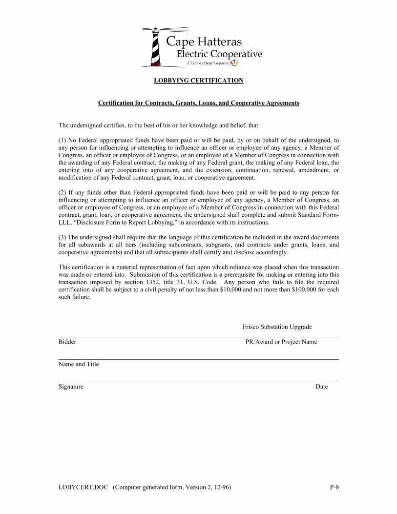
LOBYCERT.DOC (Computer generated form, Version 2, 12/96) P-8
LOBBYING CERTIFICATION
Certification for Contracts, Grants, Loans, and Cooperative Agreements
The undersigned certifies, to the best of his or her knowledge and belief, that: (1) No Federal appropriated funds have been paid or will be paid, by or on behalf of the undersigned, to any person for influencing or attempting to influence an officer or employee of any agency, a Member of Congress, an officer or employee of Congress, or an employee of a Member of Congress in connection with the awarding of any Federal contract, the making of any Federal grant, the making of any Federal loan, the entering into of any cooperative agreement, and the extension, continuation, renewal, amendment, or modification of any Federal contract, grant, loan, or cooperative agreement. (2) If any funds other than Federal appropriated funds have been paid or will be paid to any person for influencing or attempting to influence an officer or employee of any agency, a Member of Congress, an officer or employee of Congress, or an employee of a Member of Congress in connection with this Federal contract, grant, loan, or cooperative agreement, the undersigned shall complete and submit Standard Form-LLL, “Disclosure Form to Report Lobbying,” in accordance with its instructions. (3) The undersigned shall require that the language of this certification be included in the award documents for all subawards at all tiers (including subcontracts, subgrants, and contracts under grants, loans, and cooperative agreements) and that all subrecipients shall certify and disclose accordingly. This certification is a material representation of fact upon which reliance was placed when this transaction was made or entered into. Submission of this certification is a prerequisite for making or entering into this transaction imposed by section 1352, title 31, U.S. Code. Any person who fails to file the required certification shall be subject to a civil penalty of not less than $10,000 and not more than $100,000 for each such failure. Frisco Substation Upgrade Bidder PR/Award or Project Name
Name and Title Signature Date

19-9287-8015 P - 9 © February 2020
INSERT
PROPOSED CONSTRUCTION SCHEDULE
(Reference RUS Form 830, Article II, Section 1.c)

19-9287-8015 P - 10 © February 2020
INSERT
CERTIFICATE(S) OF INSURANCE
(Reference RUS Form 830, Article IV, Section 2)
19-9287-8015 P - 11 © February 2020
INSERT
CONTRACTOR’S LICENSE HERE
(Reference RUS Form 830, Article I, Section 7)

19-9287-8015 P - 12 © February 2020
PROPOSED PROJECT MANAGEMENT STAFF
(Reference RUS Form 830, Article II, Section 6)
Title/Function Name Years
with Firm Total Years Experience
Project Manager
Site Superintendent
General Foreman - Structures
General Foreman - Foundations
General Foreman – Controls
CONTRACTOR HAS ☐ DOES NOT HAVE☐ SIXTY PERCENT (60%) OF PROPOSED WORK FORCE WITH FIVE (5) YEARS CONTINUOUS SERVICE WITH BIDDER’S FIRM.

19-9287-8015 P - 13 © February 2020
REFERENCES
(Reference RUS Form 830, Article II, Section 6)
CONTACT INFORMATION FOR RECENT SIMILAR PROJECTS
Owner Name Project Description Contact Name
and Phone Number

19-9287-8015 P - 14 © February 2020
LIST OF SUBCONTRACTORS
SUBCONTRACTOR PROPOSED WORK TO BE
PERFORMED

19-9287-8015 P - 15 © February 2020
INSERT
ACKNOWLEDGMENT OF ADDENDA / CLARIFICATIONS / BULLETINS

SUPPLEMENTS TO RUS FORM 830 Contractor’s Bond
Certificate of Completion Certificate Buy American
Waiver and Release of Lien Certificate of Contractor

According to the Paperwork Reduction Act of 1995, an agency may not conduct or sponsor, and a person is not required to respond to, a collection of information unless it displays a valid OMB control number. The valid OMB control number for this information collection is 0572–0107. The time required to complete this information collection is estimated to average 1 minute per response, including the time for reviewing instructions, searching existing data sources, gathering and maintaining the data needed, and completing and reviewing the collection of information.
U.S. Department of AgricultureRural Utilities Service
CONTRACTOR'S BOND1. Know all persons that we, _______________________________________________________________ , as
Principal, and __________________________________________________________________ , as Surety,are held and firmly bound unto ______________________________________________________________ (hereinafter called the "Owner") and unto the United States of America (hereinafter called the "Government")and unto all persons, firms and corporations who or which may furnish materials for or perform labor on aRural Utilities Service project known as _______________________________________________________and to their successors and assigns, in the penal sum of ___________________________________________ dollars ($_____________________________), as hereinafter set forth and for the payment of which sum welland truly to be made we bind ourselves, our executors, administrators, successors and assigns jointly and severally by these presents. Said project is described in a certain construction contract (hereinafter called the"Construction Contract") between the Owner and the Principal, dated _______________________, 20_____, pursuant and subject to a certain loan contract (hereinafter called the "Loan Contract") between the Ownerand the Government, acting through the Administrator of the Rural Utilities Service (hereinafter called the "Administrator").
2. The condition of this obligation is such that if the Principal shall well and truly perform and fulfill all the undertakings, covenants, terms, conditions and agreements of the Construction Contract and any amendments thereto, whether such amendments are for additions, decreases, or changes in materials, their quantity, kind or price, labor costs, mileage, routing or any other purpose whatsoever, and whether such amendments are made with or without notice to the Surety, and shall fully indemnify and save harmless the Owner and theGovernment from all costs and damages which they, or either of them, shall suffer or incur by reason of any failure so to do, and shall fully reimburse and repay the Owner and the Government for all outlay and expense which they, or either of them shall incur in making good any such failure of performance on the part of thePrincipal, and shall promptly make payment to all persons working on or supplying labor or materials for use in the construction of the project contemplated in the Construction Contract and any amendments thereto, inrespect of such labor or materials furnished and used therein, to the full extent thereof, and in respect of such labor or materials furnished but not so used, to the extent of the quantities estimated in the Construction Contract and any amendments thereto to be required for the construction of the project, and shall well and truly reimburse the Owner and the Government, as their respective interests may appear, for any excess in cost of construction of said project over the cost of such construction as provided in the Construction Contract and any amendments thereto, occasioned by any default of the Principal under the Construction Contract and any amendments thereto, then this obligation shall be null and void, but otherwise shall remain in full force and effect.3. It is expressly agreed that this bond shall be deemed amended automatically and immediately, without formaland separate amendments hereto, upon any amendment to the Construction Contract, so as to bind thePrincipal and the Surety to the full and faithful performance of the Construction Contract as so amended, provided only that the total amount of all increases in the cost of construction shall not exceed 20 percent of the amount of the maximum price set forth in the Construction Contract. The term "Amendment," wherever used in this bond, and whether referring to this bond, the Construction Contract or the Loan Contract shall include any alteration, addition, extension, modification, amendment, rescission, waiver, release or annulment, of any character whatsoever. 4. It is expressly agreed that any amendment which may be made by agreement or otherwise between thePrincipal and the Owner in the terms, provisions, covenants and conditions of the Construction Contract, or in the terms, provisions, covenants and conditions of the Loan Contract (including, without limitation, the granting by the Administrator to the Owner of any extension of time for the performance of the obligations of
RUS FORM 168b (Rev. 2-04)
dac
Typewritten Text
CAPE HATTERAS ELECTRIC COOPERATIVE
dac
Typewritten Text
dac
Typewritten Text
NC0064
dac
Typewritten Text

the Owner under the Loan Contract or the granting by the Administrator or the Owner to the Principal of any extension of time for the performance of the obligations of the Principal under the Construction Contract, or the failure or refusal of the Administrator or the Owner to take any action, proceeding or step to enforce any remedy or exercise any right under either the Construction Contract or the Loan Contract, or the taking of any action, proceeding or step by the Administrator or the Owner, acting in good faith upon the belief that the same is permitted by the provisions of the Construction Contract or the Loan Contract) shall not in any way release the Principal and the Surety, or either of them or their respective executors, administrators, successors or assigns, from liability hereunder. The Surety hereby acknowledges receipt of notice of any amendment, indulgence or forbearance, made, granted or permitted. 5. This bond is made for the benefit of all persons, firms and corporations who or which may furnish any materials or perform any labor for or on account of the construction to be performed under the ConstructionContract and any amendments thereto, and they, and each of them, are hereby made obligees hereunder withthe same force and effect as if their names were written herein as such, and they and each of them may sue hereon.In witness whereof, the undersigned have caused this instrument to be executed and their respective corporate seals to be affixed and attested by their duly authorized representatives this_________________________________ day of ________________________________ , 20______ .
(Seal)Principal
ATTEST: By
Secretary
(Seal)Surety
ATTEST: By
Secretary
Address of Surety's Home Office
ByResident Agent of Surety
Signatures: The Contractor's Bond must be signed with the full name of the Contractor. If the Contractor is a partnership the Contractor's Bond must be signed in the partnership name by a partner. If the Contractor is a corporation the Contractor's Bond must be signed in the corporate name by a duly authorized officer and the corporate seal affixed and attested by the Secretary of the corporation. A typewritten copy of all such names and signatures shall be appended. Power of Attorney: The Contractor's Bond must be accompanied by a power of attorney authorizing execution on behalf of the Surety and, in jurisdictions so requiring should be countersigned by a duly authorized resident agent of the Surety.
RUS FORM 168b (Rev. 2-04)

According to the Paperwork Reduction Act of 1995, an agency may not conduct or sponsor, and a person is not required to respond to, a collection of information unless it displays a valid OMB control number. The valid OMB control number for this information collection is 0572–0107. The time required to complete this information collection is estimated to average 1 minute per response, including the time for reviewing instructions, searching existing data sources, gathering and maintaining the data needed, and completing and reviewing the collection of information.
U.S. Department of AgricultureRural Utilities Service
CERTIFICATE OF COMPLETION - CONTRACT CONSTRUCTION I, the undersigned Architect or Engineer of the following Rural Utilities Service project, do hereby certify that:1. The construction provided for pursuant to Construction Contract No. ______________________________ ,
dated _________________________________ , 20____ , including all approved amendments, between____________________________________________________ , RUS designation _____________ ("Owner")and _________________________________________________________________________ ("Contractor")has been completed as of _________________________________ , 20____ , and is in compliance with theprovisions of the Construction Contract, including all plans, specifications, maps, and drawings and allmodifications thereof.
2. Payment in full has been made to all persons who have furnished labor for the project.3. The Contractor has obtained valid releases of lien from all manufacturers, material suppliers, and
subcontractors furnishing services or materials which were employed by the Contractor in the performance ofthe Construction Contract, and that such releases have been delivered by the Contractor to the Owner.
4. If applicable, the Final Inventory attached hereto and made a part hereof is a complete and accurate summaryof all units of construction in the project and of all work performed in accordance with the ConstructionContract.
5. If applicable, the staking sheets and tabulation of staking sheets upon which the Final Inventory is based showthe accurate location, number, and kind of all units of construction of the project and show all work performedin accordance with the Construction Contract.
6. All defects in workmanship and materials reported during the period of construction of the project have beencorrected.
7. The total cost of the project as completed is _______________________________________________ dollars($ ________________________________ ).
Dated this ______________________________ day of __________________________ , 20_____.
Name of Architect or EngineerBy
Date
Title
RUS FORM 187 (Rev. 2-04)
dac
Typewritten Text
INSTALLATION OF THE FRISCO SUBSTATION UPGRADE
dac
Typewritten Text
dac
Typewritten Text
CAPE HATTERAS ELECTRIC COOPERATIVE
dac
Typewritten Text
dac
Typewritten Text
NC0064
dac
Typewritten Text
BOOTH & ASSOCIATES, LLC.
dac
Typewritten Text
Byron W. Johnson, PE, PMP
dac
Typewritten Text
dac
Typewritten Text
Operations Manager

CERTIFICATE OF COMPLETION CONTRACT CONSTRUCTION
(continued)We, the undersigned Owner and Contractor, do hereby certify that:1. The project has been completed in accordance with the provisions of the Construction Contract, dated
_________________________________ , 20____ , provided, however, that acceptance of the project by theOwner shall not be deemed to relieve the Contractor of its obligations contained in the Construction Contractwith respect to defective workmanship or, materials discovered within one year after the date of completion.
2. If applicable, the Final Inventory attached hereto and made a part hereof is a complete and accurate summaryof all units of construction in the project and of work performed in accordance with the Construction Contract.
By Date
Owner
CEO/EVP
Name of ContractorBy
Date
Title
RUS FORM 187 (Rev. 2-04)
dac
Typewritten Text
CAPE HATTERAS EC

According to the Paperwork Reduction Act of 1995, an agency may not conduct or sponsor, and a person is not required to respond to, a collection of information unless it displays a valid OMBcontrol number. The valid OMB control number for this information collection is 0572-0107. The time required to complete this information collection is estimated to average I minute perresponse, including the time for reviewing instructions, searching existing data sources, gathering and maintaining the data needed, and completing and reviewing the collection of information.
U.S. Department of AgricultureRural Utilities Service
CERTIFICATE
With respect to compliance with the second paragraph of the Rural Electrification Act of1938, being Title IV of the Work Relief and Public Works Appropriation Act of 1938
(Public Resolution No. 122, 75th Congress, approved June 21, 1938).
Rural Utilities Service Project
1The undersigned, being, the
datedin a certain contract No. , between the undersigned
2and ,
does hereby certify that in the performance of the said contract there have been used or furnished nounmanufactured articles, materials or supplies which have not been mined or produced in the United States or inany eligible country and no manufactured articles, materials or supplies which have not been manufactured in theUnited States or in any eligible country substantially all from articles, materials or supplies mined, produced ormanufactured, as the case may be, in the United States or in any eligible country, except to the extent thatcompliance with the second paragraph of the Rural Electrification Act of 1938, being Title IV of the Work Relief andPublic Works Appropriation Act of 1938 (Public Resolution No. 122, 75th Congress, approved June 21, 1938)has been waived by the Administrator of the Rural Utilities Service. For purposes of this certificate, an ''eligiblecountry'' is any country that applies with respect to the United States an agreement ensuring reciprocal access forUnited States products and services and suppliers to the markets of that country, as determined by the United StatesTrade Representative.
By
Date ,20
Insert ''Contractor,'' ''Subcontractor,'' ''Seller,'' Or ''Material Supplier,'' as the case may be.Insert the name of the RUS Borrower.United States means United States, its territories and possessions.A current list of eligible countries may be obtained by contacting RUS.
RUS FORM 213 (Rev. 2-04)
4
,
.
12
34
,
3
(exp. date 5/31/21)
dac
Typewritten Text
INSTALLATION OF THE FRISCO SUBSTATION UPGRADE
dac
Typewritten Text
CONTRACTOR
dac
Typewritten Text
CAPE HATTERAS ELECTRIC COOPERATIVE
dac
Typewritten Text
According to the Paperwork Reduction Act of 1995, an agency may not conduct or sponsor, and a person is not required to respond to, a collection of information unless it displays a valid OMBcontrol number. The valid OMB control number for this information collection is 0572-0107. The time required to complete this information collection is estimated to average 1 minute perresponse, including the time for reviewing instructions, searching existing data sources, gathering and maintaining the data needed, and completing and reviewing the collection of information.
U.S. Department of AgricultureRural Utilities Service
WAIVER AND RELEASE OF LIEN
WHEREAS the undersigned,NAME OF MANUFACTURER, MATERIAL SUPPLIER OR SUBCONTRACTOR
has furnished to the following:NAME OF CONTRACTOR
forKIND OF MATERIAL AND SERVICES FURNISHED
use in the construction of a project belonging toNAME OF BORROWER
and designated the Rural Utilities Service asRUS DESIGNATION
NOW, THEREFORE, the undersigned,NAME OF MANUFACTURER, MATERIAL SUPPLIER, OR SUBCONTRACTOR
for and in consideration of $ and other good and valuableconsideration, the receipt whereof is hereby acknowledged, do(es) hereby waive and release any and all liens, orright to or claim of lien, on the above described project and premises, under any law, common or statutory, onaccount of labor or materials, or both, heretofore or hereafter furnished by the undersigned to or for the account of
for said projectsaidNAME OF CONTRACTOR
day of ,20Given under my (our) hand(s) and seal(s) this
Name of Manufacturer, Material Supplier, or Subcontractor
ByPresident
RUS FORM 224 (Rev. 2-04)
.
This Waiver and Release of Lien must be signed with the full name of the Manufacturer, Material Supplier, or Subcontractor. If the Manufacturer,Material Supplier, or Subcontractor is a partnership, this Waiver and Release of Lien must be signed in the partnership name by a partner. If theManufacturer, Material Supplier, or Subcontractor is a corporation, this Waiver and Release of Lien must be signed in the corporate name by aduly authorized officer and the corporate seal affixed and attested by the Secretary of the Corporation.
.
(exp. date 5/31/21)
dac
Typewritten Text
CAPE HATTERAS ELECTRIC COOPERATIVE

According to the Paperwork Reduction Act of 1995, an agency may not conduct or sponsor, and a person is not required to respond to, a collection of information unless it displays a valid OMBcontrol number. The valid OMB control number for this information collection is 0572-0107. The time required to complete this information collection is estimated to average 1 minute perresponse, including the time for reviewing instructions, searching existing data sources, gathering and maintaining the data needed, and completing and reviewing the collection of information.
U.S. Department of AgricultureRural Utilities Service
CERTIFICATE OF CONTRACTOR
certifies that he/she is the
of
,
TITLE NAME OF CONTRACTOR
the Contractor, in a Construction Contract No.
dated ,20 , entered into between the Contractor and
,NAME OF RUS BORROWER
the Owner, and that he or she is authorized to and does make this certification on behalf of said Contractor in orderto induce the Owner to make payment to the Contractor, in accordance with the provisions of said ConstructionContract.Undersigned further says that all persons who have furnished labor in connection with said construction have beenpaid in full, that the names of manufacturers, material suppliers, and subcontractors that furnished material orservices or both in connection with such construction and the kind or kinds of material or services or both sofurnished are: KIND OF MATERIAL AND SERVICENAME
and that the releases of liens executed by all such manufacturer material suppliers and subcontractors have beenfurnished the Owner.
PresidentDate
RUS Form 231 (Rev. 2-04)
, RUS designation
This Certificate must be signed with the full name of the Contractor. If the Contractor is a partnership, this Certificate must besigned in the partnership name by a partner. If the Contractor is a corporation, this Certificate must be signed in the corporatename by a duly authorized officer.
,
,
By
dac
Typewritten Text
INSTALLATION OF THE FRISCO SUBSTATION UPGRADE
dac
Typewritten Text
NC0064
dac
Typewritten Text
CAPE HATTERAS ELECTRIC COOPERATIVE

TECHNICAL SPECIFICATIONS

19-9287-8015 S-1 © February 2020
CAPE HATTERAS ELECTRIC COOPERATIVE BUXTON, NORTH CAROLINA
SPECIFICATIONS AND BID DOCUMENTS
FOR THE INSTALLATION OF FRISCO SUBSTATION UPGRADE
TECHNICAL SPECIFICATIONS
1.0 General Conditions
1.1 Should the contractor have any questions they may be submitted to Mackenzie Clements at [email protected] until February 24, 2020. An addendum will be released of all questions and answers to all bidding parties the following Tuesday, February 25, 2020.
1.2 The Drawings and Specifications are complementary, one to the other. That which is shown on the Drawings or called for in the Specifications shall be as binding as if both were called for and shown. The intention of the Drawings and Specifications is to include all labor, materials, transportation, equipment, and any other items necessary to do a complete job.
1.3 In such cases where the nature of the work requires clarification by the Engineer, such clarifications shall be furnished by the Engineer with reasonable promptness by means of written instructions or Detail Drawings, or both. Clarifications and Drawings shall be consistent with the intent of Contract Documents and shall become a part thereof.
1.4 All construction shall be performed in a workmanlike manner and shall conform to the Drawings and Specifications. The installation shall conform to the latest edition of specifications and publications from the following: • National Electrical Safety Code (NESC), • National Electrical Manufacturers Association (NEMA), • North Carolina Building Code, • Occupational Safety and Health Administration (OSHA), • North Carolina Department of Labor, Division of Occupational Safety and Health
(OSHNC) • Rural Utilities Service (RUS) Informational Publications • American National Standards Institute (ANSI), • American Welding Society (AWS), • American Society for Testing and Materials (ASTM), • American Institute of Steel Construction (AISC), • American Concrete Institute (ACI), • Acoustical Society of America (ASA), • Institute of Electrical and Electronics Engineers (IEEE), • Concrete Reinforcing Steel Institute (CRSI) "Manual of Standard Practice," and • Underwriters Laboratories (UL)
1.5 The Contractor shall install major materials and equipment as listed as furnished by "Owner" or "others" and as required for the installation of the project and will furnish and install the miscellaneous materials and equipment listed elsewhere in this Specification and shown on the Drawings. A listing indicating the Owner-furnished materials and equipment is outlined in the "Owner-Furnished Material List" found in the Appendices.
1.6 The Contractor shall provide a Material Person who is competent, organized and familiar with the material associated with this project. The Material Person will be responsible for arranging delivery, receiving, storing, disbursing and tracking all the material associated with this project. This person shall not be changed without prior approval of the Owner. This Material Person will be responsible for reporting material shortages and mis-fabrications to

19-9287-8015 S-2 © February 2020
the Owner, Engineer, and/or Supplier. The Bidder will work directly with the Owner, Engineer, and/or Supplier and will be the person on the project who is totally responsible for material.
1.7 A material receipt, RUS Form 251, shall be completed and signed by the Material Person within twenty-four (24) hours acknowledging receipt of the materials and equipment delivered. The Contractor shall distribute the completed material receipts as follows: one (1) copy shall be mailed to the Owner, one (1) copy to the Engineer, and one (1) copy retained by the Contractor.
1.8 The Contractor shall verify the quantity and condition of all materials delivered to him and in case there is any damage to or shortage of materials, he shall report same to the Owner and Engineer in writing, within twenty-four (24) hours after delivery. If there is any shortage or damage which is sufficient to cause the materials to be unfit for use in the work, and the shortage or damage has not been reported as specified above, the Contractor will be charged with actual cost of replacement of such shortage or damage.
1.9 Stolen materials, or damaged or defective materials and equipment, or waste of materials due to faulty handling or negligence during installation or testing on the part of the Contractor shall be replaced, repaired, or charged against the Contractor at their actual cost to the Owner at the point of delivery to the Contractor, to the satisfaction of the Owner.
1.10 The Contractor shall provide temporary structures or heat, at his own expense, during construction for the proper storage of the materials and equipment furnished by the Owner to adequately house or protect them against deterioration or damage for whatever cause. Materials not adequately protected by the Contractor will be so protected by the Owner at the expense of the Contractor.
1.11 Upon completion of the work, the Contractor shall return to the Owner, at their storage areas, all materials and equipment furnished by the Owner not used in the construction. Surplus materials and equipment thus returned shall be neatly stockpiled. The Contractor will be charged for any materials and equipment not used and not returned in the amount equal to the cost of the materials and equipment to the Owner at point of delivery to the Contractor. Written receipts shall be made for returned materials, and one (1) copy shall be mailed to the Owner, one (1) copy to the Engineer, and one (1) copy retained by the Contractor.
1.12 The Contractor shall submit to the Owner and Engineer for approval a complete list of the miscellaneous materials and equipment he is required to furnish for the substation installation within fifteen (15) days after the award of the Contract. The list of materials and equipment shall include, but not be limited to; concrete mix design, grounding materials, oil containment materials, conduit materials, control cable, power cable, control/power cable terminations, junction boxes, electrical terminal blocks, etc., with specific supplier names, manufacturer names, catalog numbers and catalog data sheets. The Owner reserves the right to strict approval of proposed Contractor-furnished materials to ensure system compatibility.
1.13 The Contractor shall submit to the Owner and Engineer for review, catalog cut sheets, Shop or Setting Drawings and/or manufacturer product data or schedules for each item on the approved list of miscellaneous materials and equipment within thirty (30) days after the award of the Contract, so as not to cause delay in the project.
1.14 The Contractor shall allow for a reasonable amount of time for submittal approval by the Owner and Engineer. This time period shall be seven (7) to ten (10) business days after receipt of submittals.
1.15 The Contractor shall submit to the Engineer for review, the qualifications for the electricians performing the installation and terminations of the power and control wiring.

19-9287-8015 S-3 © February 2020
1.16 The Owner reserves the right to not allow the Contractor to begin work if the Contractor has not submitted the list of miscellaneous material, equipment and/or required certifications. The additional time required to receive approval for the submittals will not extend the completion date of the project or negate the liquidated damages.
1.17 All Contractor-furnished material and equipment shall be new and listed in RUS Informational Publication 202-1, List of Acceptable Materials.
1.18 The Contractor shall submit to the Owner and Engineer a complete Bill of Material, after approval has been given for the Contractor-furnished materials, with an individual unit cost for each item.
1.19 The Contractor shall be responsible for laying out the work. The Contractor shall, immediately upon entering project site for purpose of beginning work, locate all general reference points and take such action as is necessary to prevent their destruction, layout his own work, and be responsible for any error resulting from his failure to exercise such precaution. Station baseline and/or center line stakes will be provided by the Owner for reference only, and the Contractor shall verify the location prior to beginning the work.
1.20 The Contractor shall provide and maintain the adequate number of temporary toilets recommended for the number of the workmen on-site, through the completion of the project. Also, water service for construction, if required, shall be the responsibility of the Contractor.
1.21 Temporary power shall be made at the Contractor’s request. Temporary power shall be at the Contractor’s expense payable to the Owner.
1.22 Note that the Frisco station will be operated at 12.47 kV on the low side and 34.5 kV on the high side but insulated at 25 kV on the low side and 69 kV on the high side. The low side strain bus will use 34.5 kV dead-end insulators
2.0 Scope of Work
2.1 The Contractor's work shall include the furnishing of all labor, tools and equipment, and materials, as outlined in Section 3.0, "Substation Construction Assembly Units" and the installation of those materials and the Owner-Furnished materials as indicated on the Owner-Furnished Material List, necessary to construct the subject station.
2.2 The Frisco Substation Upgrade project consists of: a. Removal of existing four (4) single-phase transformers from the Frisco Substation and
transport to TMS Facility at 1392 Massey Rd, Newton Grove, NC 28366. These units weigh approximately 1800 pounds each
b. Removal and disposal of existing transformer foundations and oil containment c. Installation of new transformer associated foundation and oil containment d. Installation of power cabling from power transformer bushings to new strain bus e. Furnishing, pulling, and terminating all control cable f. Furnishing and installing all conduit for new equipment g. Furnishing and installing fiber optic communications system to new equipment h. Connection of new equipment to existing grounding grid with DMC type compression
connectors i. Repair existing rock layer to a 3” layer of #57 washed stone on top of a 3” layer of
crusher run throughout the substation and 5 feet beyond the fence on the North and West sides of the substation only. Assume no more than 50 cubic yards of crusher run, and 50 cubic yards of #57 washed stone will be required. Should more or less rock be required the cost will be added or deducted based on the unit prices provided with this bid.
j. Replace existing AC station service panel and all associated power cables with a Meter Base/AC combined panel 20 position NEMA 3R 120/240 200A main AC panel with enough knockout positions for 1-2” PVC conduit and 9-1” PVC conduits entering the

19-9287-8015 S-4 © February 2020
panel from the bottom. Mounted to the steel with stainless steel Unistrut. All removed power cables should be returned to CHEC.
k. Replace overhead strain bus for both 25 kV and 34.5 kV buses. This includes replacing the dead-end insulators connecting the bus to the steel. Utilizing 34.5 kV and 69 kV dead-end insulators.
l. Replace 12.47 kV CT’s and PT’s. CHEC to provide the units, but all mounting and connection hardware to be supplied by the Contractor.
m. Service, grease and adjust, the following station switches a. (18) 25 kV Hook stick Switches b. (1) 25 kV GOAB Switch c. (3) 25 kV Fuse Holders d. (3) 34.5 kV Tandem Disconnect Switches e. (1) 69 kV GOAB Switch
n. Repair damages or rusted areas on substation steel structures including, but not limited to grinding down rust, welding new metal, applying zinc coating, and smoothing edges. Provide a unit price.
o. Inspect and replace substation insulators as needed. Provide a unit price for replacement of each 25 kV insulator and 69 kV insulator.
p. Remove section of interior fence that splits substation yard at project start and replace at project close to increase site workability during construction. The fence that is removed will be re-installed. No new fence equipment required. Should it be more cost effective to replace with new fencing that will also be acceptable. Fence must be returned to as found condition or better, no damaged fencing will be accepted
q. Replace existing yard receptacle and associated power cabling/conduit
2.3 The geographic location of the existing Frisco Substation is shown on the Vicinity Map located in the Appendices.
2.4 Owner Responsibilities
Work that will be performed by the Owner or others and is not included in this Contract for the substation includes the following: a. Switching procedures for energizing new facilities b. Transformer settings and commissioning c. Installation of temporary structures and overhead bus to de-energize the station and
energize a mobile. d. Delivery and off loading of new power transformer, assembly and testing to be
performed by the manufacturer
2.5 Owner-Furnished Materials Status
2.5.1 The material and equipment to be furnished by the Owner is listed on Form of Proposal, Page P-4. It includes descriptions, supplier, delivery schedule, quantities, and the purchase prices which shall be included in the Contractor's Proposal
2.6 Contractor-Furnished Materials
2.6.1 The Contractor shall furnish all the miscellaneous material and equipment as required and described in each group of the "Substation Construction Assembly Units" for the complete installation of the project.
2.6.2 The miscellaneous material and equipment to be furnished by the Contractor shall be the following, unless otherwise noted, but are not limited to: a. All items as listed on the BOM in Appendix 3 b. Conduit c. Control wiring system and AC power cable d. Fiber communication cable

19-9287-8015 S-5 © February 2020
d. 25 kV and 69 kV low side and high side strain bus, including all required connectors, jumpers, and dead-end insulators that are labeled as provided by Contractor on the BOM in Appendix 3
e. Meter Base/AC combined panel 20 position AC panel NEMA 3R, 120/240, 200 A main with enough knockout positions for 1-2” PVC conduit and 9-1” PVC conduits entering the panel from the bottom.
f. Above and below grade grounding including DMC connectors g. All mounting hardware and connectors for mounting CHEC provided CT and
PT units h. New outdoor receptacle
2.7 Project Change Orders
The Owner or Engineer, without invalidating the contract, may order changes in the scope of work of the contract, consisting of additions, deletions, or other revisions with the contract amount and completion time, being adjusted accordingly.
2.8 Project Completion
The Award of the Contract shall be made within five (5) days of the bid opening. The station will be available for construction on March 9, 2020 and must be ready for commissioning by May 1, 2020.
3.0 Substation Construction Assembly Units
Group A - Structures. A Construction Assembly Unit consists of a structure, or structures, with bus supports including insulators, buses, conductors and overhead ground wires to adjacent structures within the substation, grounding material to connect equipment with the ground bus, and associated material including mounting brackets, supports for equipment, clamps and connectors, all as in the drawings.
Substation Bus and Leads Substation bus and structures will be existing. It will be responsibility of the Contractor to
furnish and install the necessary connectors for installing all new equipment. Bus and leads shall be sized and installed as indicated on the Drawings.
All conductors shall be brushed, and a suitable compound used on the conductors when connections are made. All bus and lead connections shall be electrically sound. All compression tools shall utilize dies approved by the connector manufacturer.
Connectors shall have all bolts tightened to torque levels specified by the connector manufacturer or the Engineer. Bi-metallic transition plates, 2-hole or 4-hole, shall be used on all copper to aluminum connections.
• Replacement of existing HS and LS strain bus and dead-end insulators only installation, parts will be furnished by the Owner as seen in Appendix 3. Any parts not listed in Appendix 3 that will be required to install the HS and LS strain bus shall be furnished by the Contractor.
• Contractor to only use stainless steel hardware.
Group B - Three-Pole Group-Operated Air Break Switches. B Construction Assembly Unit consists of one three pole group operated air break switch with all accessories and operating mechanisms as shown on the drawings. Service, greasing and adjusting, of existing station GOAB switches.
Group C - Lightning Arresters. C Construction Assembly Unit consists of one single arrester. NOT REQUIRED
Group D - Single-Pole Disconnecting Switches. D Construction Assembly Unit consists of one

19-9287-8015 S-6 © February 2020
single pole disconnecting or by-pass switch as specified in the drawings. If a fuse disconnect switch is specified, the fuse is included with the switch.
Service, greasing and adjusting, of existing station single pole disconnect switches.
Group E – Feeder Circuit Breaker, E Construction Assembly Unit consists of a complete three-phase circuit breaker as specified in the drawings. NOT REQUIRED
Group F - Circuit Reclosers. F Construction Assembly Unit consists of a complete single-phase or three phase oil circuit recloser as specified in the drawings. NOT REQUIRED
Group G - Meters. Relays and Instrument Transformers. G Construction Assembly Unit consists of one meter, relay potential transformer or current transformer.
CHEC to furnish (3) 12.47 kV potential transformers and (3) 12.47 kV current transformers. Contractor will install these units and furnish all mounting hardware and associated connectors or cables. Contractor to use only stainless-steel hardware.
Group H - Transformers. H Construction Assembly Unit consists of one power transformer or one station transformer either single-phase or three-phase as in the drawings. The Owner will be responsible for the dressing out and oil filling of the transformer.
Delivery and offloading, to the substation pad, of the Owner-furnished 12/16/20 MVA power transformer shall be performed by the Owner, however all associated tasks with respect to the transformer shall be performed by the Contractor. These tasks include, but are not limited to: Conduit and cabling, grounding connection to the ground grid, foundation installation, oil containment installation, and the bushing leads to and from the overhead strain bus.
Assembly and testing of the transformer shall be performed by the manufacturer upon delivery.
Removal of existing four (4) single-phase transformers from the Frisco Substation and transport to TMS Facility at 1392 Massey Rd, Newton Grove, NC 28366 These units weigh approximately 1800 pounds each
Group I - Voltage Regulators. I Construction Assembly Unit consists of one single-phase or three-phase voltage regulator as specified in the drawings. NOT REQUIRED
Group J - Communications and Supervisory Control Equipment. J Construction Assembly Unit consists of carrier current equipment, microwave, or other types of communications and supervisory control equipment as in the drawings.
The Contractor shall furnish and install all necessary fiber optic cables and enclosures. Owner will furnish necessary fiber to serial transceivers for Contractor to install.
Group K - Conduit and Cable. K Construction Assembly Unit consists of the wire, cable, conduit and accessories necessary to complete the installation of equipment in accordance with the drawings, where such installation has not been included in other Groups.
1. Conduit
Plastic Conduit - Non-Encased
The Contractor shall furnish and install Schedule 40 PVC (polyvinyl chloride) for all underground conduit runs in the sizes and to the location shown on the Drawings, complete with appropriate pull strings. The Contractor shall extend all conduits stubbed out at ground level into equipment enclosures or junction boxes, as outlined in these plans and specifications. Conduit installation shall be complete with adapters, fittings, bushings, locknuts, and weather heads. Conduits that have been deformed or crushed in any way shall not be installed.

19-9287-8015 S-7 © February 2020
The Contractor shall exercise necessary precautions to prevent the accumulation of water, dirt, or concrete in the conduits during execution of the work. Conduits in which water or other foreign materials have been permitted to accumulate shall be cleaned thoroughly or the conduit run replaced where such accumulation cannot be removed by methods approved by the Engineer.
Trenches shall be of necessary width for the proper laying of the conduits and the trench banks shall be as nearly vertical as practicable. The bottom of the trenches shall be accurately graded to provide uniform bearing and support for each section of conduit on undisturbed soil at every point along its entire length. Care shall be taken not to excavate below the depth indicated. Unauthorized overdepth shall be backfilled with loose, granular, moist earth, thoroughly tamped. Whenever wet or otherwise unstable soil is encountered that is incapable of properly supporting the conduit (as determined by the Engineer) such soil shall be removed to the depth required and the trench backfilled to the proper grade with coarse sand, fine gravel, or other suitable material, as hereinafter specified.
Trenching excavations in excess of five feet (5') in depth shall include shoring or slope-cutting of vertical walls in accordance with OSHA regulations.
Trenching for station service and metering electrical conduit and cables shall provide at least two feet (2'-0") cover (excluding yard stone). Maintain at least six inches (6") separation from conduit runs and cables to ground bus conductors.
In areas adjacent to oil containment facilities, these depths must be adjusted as needed to avoid structural conflicts.
Junction Boxes
Junction boxes shall be furnished and installed by the Contractor. The junction boxes for the project shall be rated NEMA 4 weatherproof, and shall include terminal blocks, cartridge fuses, mounting panel, and power connectors, as shown on the Drawings. Junction boxes shall be Hoffman Engineering Company enclosures with inner mounting panel, or equal, at the minimum dimensions, as shown on the Drawings.
2. Cables
Qualifications for the electrician(s) performing the installation and termination of the power and control wiring will be required to be submitted to the Engineer for approval, upon award of Contract. All existing cables shall be removed by the Contractor and returned to the Owner's warehouse.
Group L - Foundations. L Construction Assembly Unit consists of concrete footings and foundations except for the fence, as in the drawings.
The Contractor will remove the existing foundation for the current three (3) single-phase power transformers on site and dispose of the resulting debris. Once removed, the Contractor will be responsible for furnishing and installing the foundation for the new three-phase power transformer per the foundation specification and drawing.
Group M - Site Preparation. M Construction Assembly Unit consists of clearing, grading, drainage work, and surfacing, as in the drawings.
The Contractor will verify that the rock layer throughout the entire substation is returned to a 3” layer of crusher run underneath a 3” layer of #57 washed stone. This rock layer will be extended to 5’ beyond the fence on the North and West sides of the yard, including gate swings. Assume no more than 50 cubic yards of crusher run, and 50 cubic yards of #57 washed stone will be required. Should more or less rock be required the cost will be added or deducted based on the unit prices provided with this bid.
Group N - Fence. N Construction Assembly Unit consists of the complete installation of the fence, gates, etc., as in the drawings.

19-9287-8015 S-8 © February 2020
The fences and gates for the existing structures are in place. It will be the responsibility of the Contractor to maintain all parts of the fence and gates in good condition. Any damage to these components will be repaired by the Owner at the Contractor’s expense.
An additionally existing fence runs between the substation yard and the adjacent pole storage yard. The Contractor will remove this fence prior to construction, store these fence materials, then re-install the fence upon project completion. This is to provide greater maneuverability and a laydown area for the Contractor throughout the construction window.
Group O - Station Grounding. O Construction Assembly Unit consists of the complete ground bus including ground rods, grounding mats except as otherwise provided in other Groups, with connections to structures, equipment, and fence as in the drawings.
1. Station Below-Grade Grounding System
The station below grade grounding is existing. The Contractor shall be responsible for connecting all new structures and equipment to the existing ground grid as required, reference the grounding drawings for detail. All grounding connections shall be made with DMC type compression connectors.
2. Station Above-Grade Grounding
The Contractor shall provide the above-grade grounding material to include the 2/0 and 4/0 AWG bare copper. The Contractor shall install the above-grade grounding material and connectors for the new low side equipment. All grounding connections shall be made with DMC type compression connectors.
3. Certifications
The Contractor shall have worker certification for all personnel installing DMC compression connections. Certification shall be verified by Owner.
Group P - Building. P Construction Assembly Unit consists of a control building or cabinet, on a foundation of Group L and the facilities and equipment installed therein as specified in the drawings, except as otherwise provided in other Groups. NOT REQUIRED
Group Q - Oil Containment System. Q Construction Assembly Unit consists of the complete oil containment system including dikes, berms, pans with drainage pipes, pumps, sumps, decking and safety barriers as specified in the drawings.
The Contractor shall furnish and install the oil containment system as detailed in the drawings.
Group R - Protective Relaying. R Construction Assembly Unit consists of a control switchboard located within a building under Group P or an outdoor relay cabinet, on a foundation of Group L, used for the protection, control, and metering of the substation. NOT REQUIRED
Group S - Fault Interrupters. S Construction Assembly Unit consists of one complete three-phase high voltage switching device with live tank fault interrupting capability but without current sensing capability complete with supporting frame and mechanism cabinet, unless shown otherwise in the drawings, mounted as specified in the drawings. NOT REQUIRED
Group T - Testing. T Construction Assembly Unit consists of relay testing services / commissioning of the station provided by the Contractor directly or through a testing company. Testing would include those procedures required for equipment installed under other construction assembly units.
1. The Contractor shall perform testing for:
Each control cable by means of Megger Testing conductor-to-conductor and each conductor-to-ground prior to termination.
The Contractor shall verify each control cable for proper cable and conductor size, type, and labeling per the drawings.

19-9287-8015 S-9 © February 2020
Each control cable termination shall be verified per the interconnect drawings for proper conductor lugs, crimping, color codes, lock washers, and tightness.
The Contractor shall verify control circuit ac & dc molded-case circuit breakers and fuses of the correct size and type.
The Contractor shall verify the 120/240 Vac station service systems for each source and transfer capability; branch circuits for proper magnitude and neutral and/or ground terminations at the destination, and
48 Vdc system branch circuits for proper magnitude, polarity, and termination at the destination.
2. The Contractor shall provide the required and acceptable documentation for all testing to the Owner.
Group U - Metalclad Switchgear Enclosure. U Construction Assembly Unit consists of an outdoor sheltered aisle metalclad switchgear enclosure. NOT REQUIRED
Group V - Underground Circuit Plan. V Construction Assembly Unit consists of the conduit and accessories necessary to complete the installation of the required distribution circuit in accordance with the drawings, where such installation has not been included in other groups. NOT REQUIRED
Group W - Padmount Switchgear. W Construction Assembly Unit consists of an outdoor padmount switchgear unit. NOT REQUIRED

APPENDICES 1 - List of Drawings
2 - Approved Control Cables 3 - Bill of Materials
4 - Vicinity Map 5 - Standard Forms
6 - Foundation Specification7 - Oil Containment Specification

1 – LIST OF DRAWINGS

19-9287-8015 Appendix -1 © February 2020
CAPE HATTERAS ELECTRIC COOPERATIVE BUXTON, NORTH CAROLINA
SPECIFICATIONS AND BID DOCUMENTS
FOR THE INSTALLATION OF FRISCO SUBSTATION UPGRADE
LIST OF DRAWINGS
All work shall conform to the following Booth and Associates, LLC. Drawings, all of which form a part of these Specifications. The Contractor is responsible for contacting the Engineer if any drawings not indicated to be furnished at a later date are missing from their bid package. If the Contractor does not contact the Engineer regarding any drawings, their bid will be considered based on all Drawings and Specifications, as issued for bids.
SHEET
NO. TITLE REFERENCE
BOOTH & ASSOCIATES PACKAGE GP1 Conduit Plan and Grounding Plan 11104GP1 C01 Conduit and Cable Schedule 11104C01 SP1 One-Line Diagram and Site Plan 11104SP1 E10 AC Panel 11104E10 FP1 Foundation Plan 11104FP1 FD1 Foundation Details 11104FD1 FD2 Foundation Details 11104FD2 OC1 Oil Containment Details 11104OC1 OC2 Oil Containment Details 11104OC2 PL2 Plan View and Sections 11104PL2

2 – APPROVED CONTROL CABLES

19-9287-8015 - Appendix 3- © February 2020
CAPE HATTERAS ELECTRIC COOPERATIVE BUXTON, NORTH CAROLINA
INSTALLATION OF FRISCO SUBSTATION UPGRADE
CONTRACTOR-FURNISHED CABLE MATERIAL LIST
ITEM
NO
DESCRIPTION
SUPPLIER OR MFR. CATALOG
NO./TYPE
1 CONTROL CABLE
EPR/CPE insulated general purpose control cable, 600 volts, stranded tinned copper conductors, Class B stranding (7 strands), 30 mils flame-retardant Ethylene Propylene Rubber (EPR) insulation color coded per ICEA Method 1, non-hygroscopic fillers with black flame-Retardant Chlorinated Polyethylene (CPE) outer jacket 45 to 80 mils as applicable, all per ICEA S-95-658/NEMA WC 70 for Type TC cables.
a. 2 conductor, #10 AWG Color Table E-2, black, red
Anixter 2MR-1002 or equal
b. 4 conductor, #10 AWG,
Color Table E-1, black, white, red, green
Anixter 2MR-1004-1 or equal c. 4 conductor, #10 AWG
Color Table E-2, black, red, blue, orange
Anixter 2MR-1004 or equal
d. 12 conductor, #10 AWG Color Table E-1
Anixter
2MR-1012 or equal
e. 4 conductor, #8 AWG Color Table E-2, black, red, blue, orange
Anixter
3MR-0804 or equal

19-9287-8015 - Appendix 3- © February 2020
CONTRACTOR-FURNISHED CABLE MATERIAL LIST ITEM
NO
DESCRIPTION
SUPPLIER OR MFR. CATALOG
NO./TYPE
2 POWER CABLE
EPR/CPE power cable, 600 volts, stranded tinned copper conductors, Class B stranding flame-retardant Ethylene Propylene Rubber (EPR) insulation, color coded per ICEA Method 4 (printed numbers), non-hygroscopic fillers with black flame-retardant Chlorinated Polyethylene (CPE) outer jacket, all per ICEA S-95-658/NEMA WC 70 for Type TC cables.
a. 3 conductor, #6 AWG Anixter 3MR-0603 b. 3 conductor, #1/0 AWG Anixter 3MR-1013 EPR/RHH power cable, 600 volt, stranded tinned copper conductors, Class B
stranding flame-retardant and sunlight resistant Ethylene Propylene Rubber (EPR) insulation with hypalon (CSPE) outer jacket, all per ICEA S-68-516/NEMA WC8. Color code as per application.
c. 1 conductor, 2/0 AWG Anixter 3BE-2021

19-9287-8015 - Appendix 3- © February 2020
CONTRACTOR-FURNISHED CABLE MATERIAL LIST ITEM
NO
DESCRIPTION
SUPPLIER OR MFR. CATALOG
NO./TYPE
3 FIBER OPTIC COMMUNICATION CABLES
1. Bulk cable, Corning FreedOm Fanout, 4 fiber, OM1, 2.0mm fiber buffer tube. Terminate in ST Connectors. Build 3 cable numbers. Cable 148, trunk from Yard Patch Panel to SCADA Switchboard, estimated length: Cable 142, trunk from Yard Patch Panel to Feeder F3 Cabinet-351S, estimated length: Cable 149, trunk from Yard Patch Panel to Meter Cabinet-735-meter, estimated length:
Length estimates should be confirmed by on site measurement before ordering total bulk cable. Provide for needed length inside cabinets.
Corning 004K6F-31330-29 2. ST Connectors, manufacturer as indicated or equal. High-Performance
Connector, ST® Compatible, 62.5 µm multimode (OM1), ceramic ferrule, logo, single pack, amber housing, beige boot. As needed
Corning 95-000-51

3 – BILL OF MATERIALS

BILL OF MATERIALS
ITEMNO. DESCRIPTIONS QUANTITY PROVIDED BY MANUFACTURER CATALOG NO./TYPE
A001 12/16/20//22.5 MVA Power Transformer 1 Each Owner - -
A670 Wire, Bare, AAC, 336.4 kcmil 750 Ft. Owner - -A671 Wire, Bare, AAC, 954 kcmil 320 Ft. Owner - -A672 Wire, Bare, #2 AAAC 40 Ft. Owner - -
A702 Connector, Terminal, Aluminum, Compression 336.4 kcmil AAC to 4-Hole NEMA Pad flat 11 Each Owner Burndy
YNA32R4NCHEC# (17087100)
A703 Connector, Aluminum, Compression, Tee 954 kcmil AAC to 4-Hole NEMA Pad flat 20 Each Owner Burndy
YNTA451RCHEC# (17076100)
A704 Connector, Terminal, Aluminum, Compression 954 kcmil AAC to 4-Hole NEMA Pad flat 35 Each Owner Burndy
YCAK45R4NCHEC# (17088000)
A705 Connector, Terminal, Aluminum, Compression 954 kcmil AAC to 4-Hole NEMA Pad flat 90 Degree Pad 5 Each Owner Hubbell ACF1196N490
A706 Connector, Bronze, Compression, Terminal 4/0 Copper to 2-Hole NEMA Pad flat (Transformer Grounding)
4 Each Contractor DMC GC920B004-T
A707 Connector, Terminal, Aluminum, Bolted, 1 inch tube to 4-Hole NEMA Pad flat3 Each Owner Hubbell ACF11C
A708 Connector, Bolted, Aluminum,Terminal, #2 AAAC to 2-Hole NEMA Pad flat(For PT connection to CT strain bus connections using extra long bolts) 3 Each Owner Hubbell ACF6B
A709 Bus Support Cable to 69 kV Insulator 3 in. Bolt Circle for 336.4 kcmil AAC3 Each Contractor Hubbell ACS93
A710 25 kV Insulators (for replacing damaged station insulators after inspection) As Needed Owner LAPP 315208-70A711 69 kV Insulators (for replacing damaged station insulators after inspection) As Needed Owner LAPP 315216-70A712
35 kV Dead-End Insulators 6 Each Owner
TEMAHubbell Power Systems
Maclean Power Systems/ JoslynW.H. Salisbury & Company
34280635401035-0215
DS35M9503U-SI
A713 69 kV Dead-End Insulators 12 Each Owner NGK-Locke 251-SE240-YE
A714 Deadend Bolted, Quadrant Strain Clamp, Aluminum 336.4 kcmil AAC 8 Each OwnerTEMA
HubbellMaclean Power Systems/ Joslyn
11725733SD86S
ADE-23-S
A715 Deadend Bolted, Quadrant Strain Clamp, Aluminum 954 kcmil AAC 14 Each Owner Maclean Power Systems/ Joslyn ADE-26-CA716 Pig Tail, 336 kcmil, Aluminum 3 Each Owner Blackburn PRS30NA717 H Tap, Squeezon, Compression Connector, 954 kcmil AAC 3 Each Owner Cooper Power Series 607-82
G001 12.47 kV Potential Transformer 3 Each Owner ABB VOY-11BG002 Instrument Current Transformer, 15kV, 110kVBIL 3 Each Owner ABB KON-11 E-7524A25G13
BOM FOR FRISCO TRANSFORMER REPLACEMENTGROUP A: 001-100 MAJOR EQUIPMENT
GROUP A: 670-699 - WIRE AND BUS
GROUP A: 700-999 - SUBSTATION CONNECTORS
GROUP G: 001-999 METERS RELAYS AND INSTRUMENT TRANSFORMERS

4 – VICINITY MAP

Booth & Associates , LLC5811 Glenwood Avenue | Raleigh, NC 27612 CONSULTING ENGINEERS NC F-0221
AutoCAD SHX Text
SUBSTATION SITE
AutoCAD SHX Text
c
AutoCAD SHX Text
DATE:
AutoCAD SHX Text
APPD.
AutoCAD SHX Text
DWG. NO.
AutoCAD SHX Text
FILE:
AutoCAD SHX Text
DATE
AutoCAD SHX Text
REVISION
AutoCAD SHX Text
DWN.
AutoCAD SHX Text
CKD.
AutoCAD SHX Text
SCALE:
AutoCAD SHX Text
JOB NO.
AutoCAD SHX Text
08/19
AutoCAD SHX Text
CAPE HATTERAS ELECTRIC COOPERATIVE
AutoCAD SHX Text
BUXTON, NORTH CAROLINA
AutoCAD SHX Text
AAI
AutoCAD SHX Text
MFC
AutoCAD SHX Text
1" = 2000'
AutoCAD SHX Text
199287
AutoCAD SHX Text
08/19/2019
AutoCAD SHX Text
BWJ
AutoCAD SHX Text
11104VM
AutoCAD SHX Text
VM-1
AutoCAD SHX Text
N
AutoCAD SHX Text
S
AutoCAD SHX Text
ADDRESS: 52768, NC-12 HWY FRISCO, NC 27936 COORDINATES: 35° 14' 35.14" N75° 36' 57.61" W
AutoCAD SHX Text
FRISCO 12/16/20 MVA SUBSTATION VICINITY MAP

5 – STANDARD FORMSa. Materials Receiptb. Change Order Form

©February 2020
MATERIALS RECEIPT
OWNER: CAPE HATTERAS EC
CONTRACTOR:
PROJECT NAME: FRISCO SUBSTATION UPGRADE
PROJECT NO.: 19-9287-8015
DATE:
ITEM* QUANTITY DESCRIPTION OF ITEM
MANUFACTURER AND CATALOG
NUMBER UNIT COST EXTENDED
COST
TOTAL
RECEIVED BY FOR
Contractor
Owner
*Item corresponds with item in list of materials in construction drawings.

© February 2020
Description Quantity Unit Unit Cost Extended Cost$0.00$0.00
TOTAL UNIT COSTS: $0.00
Classification Name Base Rate
Total Hoursworked
Straight/Overtime Extended Cost$0.00$0.00$0.00
Material Cost
TOTAL MATERIAL COSTS $0.00
Unit No. Description Base Rate Total Hours Extended Cost$0.00$0.00$0.00
TOTAL COST: $0.00
Description
EQUIPMENT COSTS
TOTAL EQUIPMENT COSTS:
UNIT COSTS
LABOR COSTS
TOTAL LABOR COSTS:MATERIAL COSTS
CHANGE ORDER NO._____
OWNER: CAPE HATTERAS ELECTRIC COOPERATIVE
CONTRACTOR:
PROJECT NAME: FRISCO SUBSTATION UPGRADE
PROJECT NO.: 19-9287-8015
DATE:
Description of Work Performed:
Reason for Change:
Changes Authorized By: Owner: Date: Contractor: Date: Booth & Associates, Inc.: Date: Itemized Cost for Above Order:

6 – FOUNDATION SPECIFICATION
Rev. 1
ISSUED FOR
CONSTRUCTION
REV 1 February 14, 2020
BOOTH & ASSOCIATES, LLC
CAPE HATTERAS ELECTRIC COOPERATIVE BUXTON, NORTH CAROLINA
FOUNDATION SPECIFICATIONS
FOR THE FRISCO 34.5 TO 12.47 kV SUBSTATION
ISSUED FOR CONSTRUCTION

Rev. 1
CAPE HATTERAS ELECTRIC COOPERATIVE BUXTON, NORTH CAROLINA
FOUNDATION SPECIFICATIONS
FOR THE FRISCO 34.5 TO 12.47 kV SUBSTATION
Booth & Associates, LLC Consulting Engineers 5811 Glenwood Avenue Raleigh, North Carolina 27612 Firm License No.: F-0221 © January 2020
m.mannan
New Stamp
m.mannan
North Carolina PE
Rev. 1
19-9287-8005 3 © January 2020
TABLE OF CONTENTS TABLE OF CONTENTS .............................................................................................................................. 3
1.0 General .............................................................................................................................................. 5
1.1. Special Conditions ........................................................................................................................ 5
1.2. Concrete ........................................................................................................................................ 5
1.3. Materials ....................................................................................................................................... 5
1.4. Submittals ..................................................................................................................................... 8
1.5. Mix Requirements ....................................................................................................................... 10
1.6. Storage of Materials .................................................................................................................... 11
1.7. Batching and Mixing ................................................................................................................... 11
1.8. Placement Temperature............................................................................................................... 12
1.9. Hot Weather Concreting ............................................................................................................. 12
1.10. Cold Weather Concreting ........................................................................................................ 13
1.11. Field Control Testing .............................................................................................................. 15
1.12. Compaction ............................................................................................................................. 17
1.13. Protection Against Moisture Loss ........................................................................................... 17
1.14. Curing ..................................................................................................................................... 17
1.15. Protection ................................................................................................................................ 17
1.16. Earthwork ................................................................................................................................ 18
2.0 Slabs on Grade and Mat Foundations ............................................................................................. 22
2.1. General ........................................................................................................................................ 22
2.2. Concrete ...................................................................................................................................... 22
2.3. Subgrade ..................................................................................................................................... 22
2.4. Formwork .................................................................................................................................... 22
2.5. Expansion Joints ......................................................................................................................... 23
2.6. Construction Joints ...................................................................................................................... 23
2.7. Reinforcement ............................................................................................................................. 24
2.8. Installation of Anchorage Items .................................................................................................. 25
2.9. Placing......................................................................................................................................... 25
2.10. Bonding and Grouting ............................................................................................................. 26
2.11. Finishes of Concrete Other Than Floors and Slabs ................................................................. 26
2.12. Clean-Up ................................................................................................................................. 27
3.0 Drilled Cylindrical Foundations ...................................................................................................... 28
3.1. General ........................................................................................................................................ 28
3.2. Concrete ...................................................................................................................................... 28
3.3. Excavations ................................................................................................................................. 28
3.4. Removal of Water ....................................................................................................................... 29

Rev. 1
19-9287-8005 4 © January 2020
3.5. Temporary Casing ....................................................................................................................... 29
3.6. Permanent Casing ....................................................................................................................... 29
3.7. Dimensional Tolerances .............................................................................................................. 30
3.8. Pier Installation Record ............................................................................................................... 30
3.9. Reinforcement ............................................................................................................................. 30
3.10. Concrete Placement General ................................................................................................... 31
3.11. Concrete Placement – Dry Hole .............................................................................................. 31
3.12. Concrete Placement – Wet Hole ............................................................................................. 32
3.13. Concrete Placement – Tremie Method .................................................................................... 32
3.14. Consolidation .......................................................................................................................... 33
3.15. Finishes of Concrete Other Than Floors and Slabs ................................................................. 33
3.16. Clean-Up ................................................................................................................................. 34
3.17. Repairing Defective Concrete ................................................................................................. 34
5.0 References ....................................................................................................................................... 35
5.1. American Concrete Institute ....................................................................................................... 35
5.2. ASTM International .................................................................................................................... 35
5.3. American Welding Society ......................................................................................................... 36
APPENDIX A - SOIL REPORT ............................................................................................................. A-1
APPENDIX B - SUBMITTAL LOG ....................................................................................................... B-1

Rev. 1
19-9287-8005 5 © January 2020
TECHNICAL SPECIFICATIONS 1.0 General
The Foundation Specifications, Oil Containment Specifications, and Drawings are complementary, each to the other. The Contractor shall furnish and install the reinforced concrete foundations as shown on the drawings, complete with excavation, off-site disposal of excavated spoils, grading, backfilling, and compaction of all excavations to restore existing grade levels, foundation layout, concrete, rebar, tie wire, and forming materials. The reinforced concrete foundations, footings, piers and pads shall be installed as indicated on the Drawings, and to undisturbed earth. Dimensions indicated for anchor bolt settings shall be checked against the manufacturer’s erection drawings, structural steel and/or equipment to be installed prior to the construction of the formwork. 1.1. Special Conditions
The contractor is responsible to review and become familiar with the soil boring report by GeoTechnologies, Inc. for the Frisco Substation Additions, Project No. 1-19-0832-EA, dated November 13, 2019, attached in appendices of the project specifications.
1.2. Concrete
This section specifies the minimum materials, workmanship, and performance standards for cast-in-place concrete including reinforcing steel, forms, finishing, curing, and other associated work. Cast-in-place concrete shall be in accordance with the latest applicable requirements of the ACI, ASTM, and CRSI, except as modified by these Specifications. For the purposes of mix design, cast-in-place concrete is considered to be of Exposure Category F2 as defined by ACI 318.
**Source: ACI 318-11, Table 4.3.1 The Owner shall be informed at least 24 hours in advance of the times and places at which concrete will be placed.
1.3. Materials 1.3.1. Cement
Only one (1) brand of cement shall be used for exposed concrete. Cement reclaimed from cleaning bags or leaking containers shall not be used. Cement
Requirements for Concrete By Exposure Class
Exposure Class
Max w/cm Minimum
Compressive Strength
Air Content
Cement Type
F2 0.45 4,500 6 ± 1 I

Rev. 1
19-9287-8005 6 © January 2020
shall be used in the sequence of receipt of shipments, unless otherwise directed by the Engineer. Cement will be accepted on the basis of the manufacturer’s mill certificate of compliance with the Specification requirements. Portland cement shall conform to the “Standard Specifications for Portland Cement”, serial designation C150, Type I of the ASTM.
1.3.2. Cementitious Materials Fly ash shall conform to the latest edition of ASTM C 618 and be of type Class F.
1.3.3. Fine Aggregate Fine aggregate shall consist of washed natural siliceous sand, composed of clean, hard and durable grains, and shall be of a quality and gradation approved by the Engineer. Manufactured sand will not be accepted. All fine aggregate shall be free from injurious amounts of alkaline and organic impurities. Fine aggregate shall be graded from coarse to fine and shall conform to ASTM C33.
1.3.4. Coarse Aggregate Coarse aggregate shall consist of crushed stone or other approved inert material with similar characteristics. It shall be clean, hard, durable, and free from injurious amounts of deleterious matter. Clay and shale particles shall not exceed 1 percent (1%). Course aggregate shall be graded from coarse to fine and shall conform to ASTM C33.
1.3.5. Water Water shall be clean, fresh, and free from injurious amounts of mineral and organic substances. Iron in water shall not exceed 0.25 ppm.
1.3.6. Admixtures All admixtures are to be supplied by a single approved manufacturer, such as: Master Builders, WR Grace & Co., or Sika Chemical. Admixtures shall conform to the following standards:
Water Reducing (plasticizer) ASTM C494, Type A Water Reducing and Retarding ASTM C494, Type D
High Range Water Reducer ASTM C494, Type F High Range Water Reducer and
Retarder ASTM C494, Type G
Air-Entraining Agent ASTM C260 1.3.7. Reinforcing Steel
a. Reinforcing Bars - All reinforcing steel bars shall be of the deformed
type conforming to the requirements of ASTM A615 or A706-Grade 60. b. Welded Wire Fabric – Welded wire fabric reinforcement used in slabs
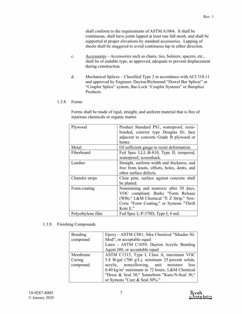
Rev. 1
19-9287-8005 7 © January 2020
shall conform to the requirements of ASTM A1064. It shall be continuous, shall have joints lapped at least one full mesh, and shall be supported at proper elevations by standard accessories. Lapping of sheets shall be staggered to avoid continuous lap in either direction.
c. Accessories – Accessories such as chairs, ties, bolsters, spacers, etc.,
shall be of suitable type, as approved, adequate to prevent displacement during construction.
d. Mechanical Splices – Classified Type 2 in accordance with ACI 318-11
and approved by Engineer. Dayton/Richmond “Dowel Bar Splicer” or “Coupler Splice” system, Bar-Lock “Coupler Systems” or Barsplice Products.
1.3.8. Forms
Forms shall be made of rigid, straight, and uniform material that is free of injurious chemicals or organic matter. Plywood Product Standard PS1, waterproof, resin-
bonded, exterior type Douglas fir; face adjacent to concrete Grade B plywood or better.
Metal Of sufficient gauge to resist deformation. Fiberboard Fed Spec LLL-B-810, Type II; tempered,
waterproof, screenback. Lumber Straight, uniform width and thickness, and
free from knots, offsets, holes, dents, and other surface defects.
Chamfer strips Clear pine, surface against concrete shall be planed.
Form coating Nonstaining and nontoxic after 30 days, VOC compliant; Burke "Form Release (WB)," L&M Chemical "E Z Strip," Nox-Crete "Form Coating," or Symons "Thrift Kote E."
Polyethylene film Fed Spec L-P-378D, Type I; 6 mil.
1.3.9. Finishing Compounds Bonding compound
Epoxy - ASTM C881; Sika Chemical "Sikadur Hi-Mod"; or acceptable equal Latex - ASTM C1059; Dayton Acrylic Bonding Agent J40; or acceptable equal
Membrane Curing compound
ASTM C1315, Type I, Class A, maximum VOC 5.8 lb/gal (700 g/L), minimum 25 percent solids, acrylic, nonyellowing, unit moisture loss 0.40 kg/m2 maximum in 72 hours; L&M Chemical "Dress & Seal 30," Sonneborn "Kure-N-Seal 30," or Symons "Cure & Seal 30%."
Rev. 1
19-9287-8005 8 © January 2020
1.4. Submittals
Three copies of all reports shall be submitted to the Owner and Engineer within fifteen (15) days of contract award and prior to any concreting operations. The Engineer will provide approval within ten days (10 days) of receipt of submittals. All submittals shall be provided to the Owner and Engineer as a single packet. A Submittal Log is provided in Appendix A. 1.4.1. Material Reports
The report should include the source and quality of concrete materials and the concrete proportions proposed for the work. Complete certified reports covering the materials and proportions proposed and tested in accordance with ACI 318 shall be submitted to the Owner and Engineer. Reports shall be prepared by an independent testing laboratory. Owner and Engineer review of these reports will be for general acceptability only; continued compliance with all contract provisions will be required. Reports on cement shall include the type, brand, manufacturer, composition, and method of handling (sack or bulk). Reports on admixtures shall include the ASTM C260 or ASTM C494 classification, brand, manufacturer, and active chemical ingredients. All admixtures shall be the products of one manufacturer. Reports on aggregates shall include the source, type, gradation, deleterious substances, soundness, potential for harmful materials, and potential for alkali reactivity. The results of all tests and field service records to verify potential reactivity are required to verify compliance with ASTM C33, including Appendix XI. A certification that the reinforcing steel furnished complies with the requirements specified in the section titled “Materials” shall be furnished to the Owner and Engineer. The certification shall be signed by the Contractor and the reinforcing steel fabricator.
1.4.2. Mix Design Reports
A tentative concrete mix shall be designed and tested for each size and gradation of aggregates and for each mix class specified. Mix Design Reports shall be provided to the Owner and Engineer for each mix class to be utilized in the project and intended use identified on each mix report. Design quantities and test results of each mix shall be submitted to Owner and Engineer for review. With Engineer’s and/or Owner's approval, acceptable mixes may be field adjusted as necessary to meet the requirements of these Specifications. The report for each tentative concrete mix submitted shall contain the following information: a. Intended use and placement method.

Rev. 1
19-9287-8005 9 © January 2020
b. Design Slump. c. Total gallons of water per cubic yard. d. Cement content. e. Cementitious materials content. f. Ratio of fine to total aggregates. g. Weight (surface dry) of each aggregate per cubic yard. h. Quantity of each admixture. i. Air content. j. Compressive strength based on 7 day and 28 day compression test. k. Times of initial set. l. Documentation of required average compressive strength or mix
proportioning data per ACI 318.
Initial set tests shall be made at ambient temperatures of 70º F and 90º F to determine compliance with the initial set time specified hereinafter. The test at 70º F shall be made using concrete containing the specified plasticizing and air-entraining admixtures. The test at 90º F shall be made using concrete containing the specified plasticizing retarder and air-entraining admixtures. The initial set shall be determined in accordance with ASTM C403.
1.4.3. Mix Class Each concrete mix class shall be designed and controlled within the limits specified in the following table:
Mix Class Table Coarse
Usage
28 Day Strength
(psi)
Nominal MaximumAggregate
Size No. 4 Sieve
Slump ± 1"
Min Cement (lb/cu
yd)
Max Water/ Cement
Ratio General Usage 4,500 1" 5” 535 0.45 Drilled Piers (dry, uncased, or permanent casing)
4,500 3/4" 5" (1) 560 0.45
Drilled Piers (temporary casing)
4,500 3/4” 7” (1) 560 0.45
Drilled Piers (slurry displacement)
4,500 3/4” 8” (1) 560 0.45
Underwater 5,000 3/4" 8" 658 0.41 Note: A plasticizer or plasticizing retarder shall be included in all general usage and drilled piers concrete mixes. High range water reducer (Type F or G) shall be included in all underwater mixes. (1) Slump requirement during placement with any admixtures. **Source: ACI 318-11, Table 4.3.1; ACI 336.1-01, Table 2.4.3; ACI 350-06, Table 4.1.2.1

Rev. 1
19-9287-8005 10 © January 2020
Concrete shall not be deposited under water, except with specific permission of the Owner and Engineer.
1.5. Mix Requirements The acceptability of concrete will be judged on compliance with the specified requirements listed in the Mix Class Table and not on the basis of strength alone. 1.5.1. Total Water Content
Total water content of concrete shall not exceed the amount calculated using the maximum water to cement ratio in the Mix Class Table.
1.5.2. Slump Slump shall not be greater than that indicated in the Mix Class Table for each mix, unless otherwise authorized by the Owner.
1.5.3. Total Air Content The total volumetric air content of concrete after placement shall be six percent plus or minus one percent (6% ± 1%).
1.5.4. Admixtures The admixture content, batching method, and time of introduction to the mix shall be in accordance with the manufacturer’s recommendations for compliance with these Specifications. A plasticizing or plasticizing retarder admixture shall be included in all concrete, unless otherwise accepted by the Owner. Plasticizing retarder admixture shall be adjusted as specified under the initial set.
1.5.5. Strength The minimum 28 day acceptable compressive strength for each mix class as determined by ASTM C39 shall not be less than that indicated in the Mix Class Table. All concrete shall exceed the specified minimum compressive strengths. Each test cylinder will be evaluated separately, and the Owner will be the sole judge of the validity and representative qualities of the tests. In cases where the strength of the test cylinders for any portion of the work falls below the requirements specified herein, the Owner or Engineer may require the Contractor to secure test specimens of the hardened concrete represented by these cylinders. Specimens shall be secured and tested in accordance with ASTM C42 and shall have a minimum diameter of 3 inches.

Rev. 1
19-9287-8005 11 © January 2020
Dependent upon the location of the concrete section in question, the Owner or Engineer may approve low frequency ultrasonic testing or other nondestructive techniques as an alternate to cone drilling and testing. If the additional investigation verifies the existence of defective concrete, one of the following remedial actions shall be implemented as determined by the Owner: a. The Contractor shall assume the costs to remove and replace all defective
concrete. b. The Contractor shall assume the cost of design and construction changes
necessary to incorporate the inferior concrete. c. The Contractor shall provide satisfactory reimbursement or allowance to
the Owner for the acceptance of the lower quality concrete.
1.5.6. Initial Set
The initial set as determined by ASTM C403 shall not be attained until at least 2.5 hours after the water and cement are added to the aggregates. The quantity of retarding admixture shall be adjusted as necessary to compensate for variations in temperature and job conditions.
1.6. Storage of Materials Cement shall be stored in suitable moisture proof enclosures. Reclaimed cement or cement that has become caked or lumpy shall not be used. Aggregates shall be stored so that segregation and the inclusion of foreign materials are prevented. The bottom 6 inches of aggregate piles that have been in contact with the ground shall not be used. Reinforcing steel and embedments shall be carefully handled and stored on supports that will keep the steel from contact with the ground.
1.7. Batching and Mixing Batching and mixing may be performed at the jobsite with suitable equipment, or by an acceptable ready-mix concrete supplier. Personnel performing the batching and mixing shall be qualified and experienced. Mixing and transporting concrete shall be in accordance with ASTM C94 unless otherwise indicated herein. 1.7.1. Batching
Aggregates and cement shall be measured by weight. Aggregate weights shall be adjusted for moisture content. Each admixture shall be dispensed by a mechanical device that will ensure accurate and automatic measurement. The minimum amount of water required to produce the desired slump shall be batched automatically. Any additional water required to produce and maintain a

Rev. 1
19-9287-8005 12 © January 2020
uniform slump shall be added manually by the mixer operator. Slump shall be kept uniform. Aggregates shall float uniformly throughout the mass and the concrete shall flow sluggishly when vibrated.
1.7.2. Mixing Concrete shall be mixed in a rotating drum as specified in ASTM C94 until all ingredients are uniformly distributed throughout the batch. Mixers shall not be loaded in excess of their rated capacities. Each batch shall be completely discharged before the mixer is recharged.
1.7.3. Ready-Mix Concrete Ready-mixed concrete shall conform to ASTM C94, except as otherwise specified herein. Truck mixers shall be revolving drum type and shall be equipped with a mixing water tank. Only the prescribed amount of mixing water shall be placed in the tank for any one batch, unless the tank is equipped with a device by which the amount of water added to each batch can be readily verified by the Owner. A delivery ticket shall be prepared for each load of ready-mixed concrete delivered. The truck operator shall hand a copy of each ticket to the Owner at the time of delivery. Tickets shall indicate the mix identification, the number of yards delivered, the quantities of each material in the batch, the outdoor temperature in the shade, the time at which the cement was added, and the numerical sequence of the delivery. When a truck mixer or agitator is used for transporting concrete, the concrete shall be delivered to the jobsite and completely discharged within 90 minutes, or before the drum has revolved 300 revolutions, whichever comes first, after the introduction of the mixing water to the cement and aggregates, or the introduction of the cement to the aggregates. Longer time periods must be approved by the Engineer. In hot weather, or under conditions contributing to quick stiffening of the concrete, a time less than that specified above may be required by the Engineer. When a truck mixer is used for the complete mixing of the concrete, the mixing operation shall begin within 30 minutes after the cement has been mixed with the aggregates.
1.8. Placement Temperature The temperature of concrete, when being placed, shall be checked in accordance with ASTM C1064 and be as follows: a. Not less than 40°F in moderate weather. b. Not less than 50°F in weather during which the mean daily temperature drops
below 40°F. c. Not greater than 90°F during hot weather.
1.9. Hot Weather Concreting

Rev. 1
19-9287-8005 13 © January 2020
Except as modified herein; hot weather concreting shall comply with ACI 305R. A water-reducing retarder shall be added to the concrete mix when the placement temperature of the concrete exceeds 75°F. At air temperatures of 90°F or above, special procedures shall be applied to keep the concrete as cool as possible during placement and curing. The temperature of the concrete during placement shall not exceed 90°F.
1.10. Cold Weather Concreting The conditions of cold weather concreting exist when the air temperature has fallen to, or is expected to fall below, 40°F during the protection period as described in Section 1.10.7 of this specification. Cold weather concreting shall comply with ACI 306R. 1.10.1. Embedments and Surfaces
All surfaces against which concrete is to be placed, including reinforcement, shall be free from snow, ice, and frost. All metallic items embedded in the concrete, including bars, need to be heated if the air temperature is below 10°F. Metallic embedments with a cross-sectional area great than 4 in.2 should be heated above 32°F.
1.10.2. Subgrade Condition Concrete shall not be placed against frozen base or subgrade. Provisions for heating the subgrade or base shall be the responsibility of the Contractor and should be sufficient to raise and maintain the temperature above 32°F. Contractor shall limit surface temperatures of supporting materials beneath slabs-on-ground and the concrete to a temperature differential of less than 20°F.
1.10.3. Placement and Protection Temperature The minimum temperature of concrete as placed and to be maintained after placement shall be as specified in Line 1 of the Cold Weather Concrete Temperatures Table. Concrete temperatures for placement shall not be more than 20°F of that given in the Cold Weather Concrete Temperatures Table. Methods for ensuring the placement and protection temperature such as concrete mixture acceleration, insulation, heat systems, enclosures, a combination of these practices, or other methods are the responsibility of the Contractor and shall be in accordance with ACI 306R.
1.10.4. Mixing Temperature The minimum temperature of concrete at time of mixing shall be as specified in Lines 2, 3, and 4 of the Cold Weather Concrete Temperatures Table.
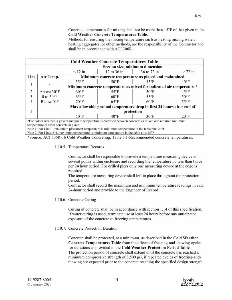
Rev. 1
19-9287-8005 14 © January 2020
Concrete temperatures for mixing shall not be more than 15°F of that given in the Cold Weather Concrete Temperatures Table. Methods for ensuring the mixing temperature such as heating mixing water, heating aggregates, or other methods, are the responsibility of the Contractor and shall be in accordance with ACI 306R.
Cold Weather Concrete Temperatures Table Section size, minimum dimension
< 12 in. 12 to 36 in. 36 to 72 in. > 72 in. Line Air Temp. Minimum concrete temperature as placed and maintained
1 - 55°F 50°F 45°F 40°F
Minimum concrete temperature as mixed for indicated air temperature* 2 Above 30°F 60°F 55°F 50°F 45°F 3 0 to 30°F 65°F 60°F 55°F 50°F 4 Below 0°F 70°F 65°F 60°F 55°F
5 - Max allowable gradual temperature drop in first 24 hours after end of
protection 50°F 40°F 30°F 20°F
*For colder weather, a greater margin in temperature is provided between concrete as mixed and required minimum temperature of fresh concrete in place. Note 1: For Line 1, maximum placement temperature is minimum temperature in the table plus 20°F. Note 2: For Lines 2-4, maximum temperature is minimum temperature in the table plus 15°F
*Source: ACI 306R-16 Cold Weather Concreting, Table 5.1-Recommended concrete temperatures.
1.10.5. Temperature Records Contractor shall be responsible to provide a temperature measuring device at several points within enclosure and recording the temperature no less than twice per 24 hour period. For drilled piers only one measuring device at the edge is required. The temperature measuring device shall left in place throughout the protection period. Contractor shall record the maximum and minimum temperature readings in each 24-hour period and provide to the Engineer of Record.
1.10.6. Concrete Curing Curing of concrete shall be in accordance with section 1.14 of this specification. If water curing is used, terminate use at least 24 hours before any anticipated exposure of the concrete to freezing temperatures.
1.10.7. Concrete Protection Duration Concrete shall be protected, at a minimum, as described in the Cold Weather Concrete Temperatures Table from the effects of freezing-and-thawing cycles for durations as provided in the Cold Weather Protection Period Table. The protection period of concrete shall extend until the concrete has reached a minimum compressive strength of 3,500 psi, if repeated cycles of freezing-and-thawing are expected prior to the concrete reaching the specified design strength.

Rev. 1
19-9287-8005 15 © January 2020
1.11. Field Control Testing The Contractor shall engage an independent professional testing agency and laboratory to provide all necessary equipment and personnel to perform all concrete testing at the Contractor’s expense. The testing agency and laboratory must be approved by the Owner and Engineer, prior to commencing work. Personnel performing tests shall be certified ACI Grade 1 Concrete Field Testing Technician. Copies of the test results shall be sent directly from the testing agency to the Engineer for review. Structures or equipment shall not be placed on the foundations until acceptance of test results by the Engineer. The frequency hereinafter specified for each field control test is a minimum. If directed to do so by the Owner, any additional field control tests required shall be made. 1.11.1. Sampling
All concrete used for testing purposes shall be obtained in accordance with ASTM C172.
1.11.2. Slump
Consistency will be determined in the field by the slump test in accordance with ASTM C143. A minimum of one (1) slump test shall be performed on each load of concrete. If water is added at the job site to increase the slump, the recorded slump shall be tested after the addition of water. The specified slump for each class and usage of concrete can be found in the Mix Class Table.
1.11.3. Air Entrainment Air entrained concrete shall be used in all applications where concrete will be exposed to moisture and cycles of freezing and thawing. Air content shall be determined in accordance with ASTM C231 or ASTM C173. A minimum of one (1) air entrainment test shall be performed for each batch of concrete used on the project and from which concrete compression test cylinders are made. The specified air content shall be between five and seven percent (5% and 7%).
1.11.4. Compression Test Cylinders A set of compression test cylinders is required for each batch of concrete used on the project. Each set will consist of five (5), four inch by eight inch (4” x 8”) compressive test cylinders prepared, cured, and delivered in accordance with ASTM C31. Each cylinder shall be labeled with the project name, date, and cylinder identification number. An information card or field report shall be completed for each set of cylinders and shall include the following: a. Date sampled b. Time batched c. Time sampled d. Ticket number e. Air temperature f. Concrete temperature g. Gallons of water added

Rev. 1
19-9287-8005 16 © January 2020
h. Specified 28-day strength i. Slump j. Air Content k. Admixtures l. Concrete mix identification m. Specific location of pour The test cylinders shall be transported to a professional testing laboratory at least 8 hours after final set and within 20 to 24 hours from the time they were made. Transportation time of test cylinders shall not exceed 4 hours. Testing of the cylinders shall be handled by the Contractor through a qualified testing laboratory in accordance with ASTM C39 in accordance with the following schedule: a. One (1) cylinder at seven (7) days b. Three (3) cylinders at twenty-eight (28) days c. One (1) cylinder reserved for a fifty-six (56) day test, if necessary In cases where early loading of the foundation is required and has been approved by the Engineer, testing of the cylinders shall be handled by the Contractor through a qualified testing laboratory in accordance with ASTM C39 in accordance with the following schedule: a. Two (2) cylinders at seven (7) days b. Three (3) cylinders at twelve (12) days c. Three (3) cylinders at twenty-eight (28) days d. One (1) cylinder reserved for a fifty-six (56) day test, if necessary The Contractor shall require the laboratory to send three sets of compressive test reports to the Owner, in addition to those copies furnished to the Contractor. One (1) copy of the test reports shall be forwarded directly to the Engineer for review within two (2) working days after the tests are performed. In the event a test fails to meet the specified compressive strength requirements, the Engineer may require the Contractor to obtain core samples of the hardened concrete in question. Core samples shall be secured and tested in accordance with ASTM C42 and shall have a minimum diameter of three inches (3”). If tests further substantiates that the concrete represented by the cylinders and core samples is below the strength requirements specified herein, the Engineer may order such concrete removed and replaced at the expense of the Contractor. At the location of pole foundations one of the cylinders shall be taken from the concrete used in the top 5 feet of each pole foundation. Such cylinders shall be individually identified by pole number and tested prior to pole erection.
1.11.5. Test Reports
Certified reports of all tests made by the testing laboratory shall be promptly furnished to the Owner and Engineer, and all other persons designated by the Owner.

Rev. 1
19-9287-8005 17 © January 2020
1.12. Compaction
The contractor shall engage an independent professional Geotechnical engineering firm to provide all necessary equipment and personnel to perform excavation inspections of foundation subgrade. If unsuitable material is encountered at the proposed subgrade elevation shown on the drawings, the contractor shall, under the direction of the geotechnical engineer, remove the unsuitable material and backfill with well compacted six inch (6″) layers of stone or gravel base material, or concrete. Compacted sub grade shall be approved for 3,000 lbs per square foot bearing capacity by the Geotechnical engineer.
1.13. Protection Against Moisture Loss Immediately after placing or finishing, concrete surfaces not covered by forms shall be protected against moisture loss (cured) for not less than seven (7) days by covering with white opaque polyethylene sheets lapped four inches (4”) at edges and ends. Burlap may be used only for unexposed concrete surfaces and shall be in at least two (2) layers. Surface from which forms are removed before the curing period has elapsed shall be protected as specified for surfaces not covered by forms. All materials used for prevention of moisture loss shall be in accordance with ASTM C171.
1.14. Curing Curing of concrete shall be by methods which will keep the concrete surfaces adequately wet during the specified curing period and in accordance with ACI 308R. Troweled surfaces shall be cured, except those which will receive a separate finish or coating, with the membrane curing compound specified in the article titled “Materials” in this section. Float finished surfaces shall be cured, except those which will receive a separate finish, with either the membrane curing compound specified or with water. Only water curing will be permitted on surfaces that will receive a separate finish or coating. Water saturation of concrete surfaces shall begin as quickly as possible, but no later than 12 hours in dry weather and 24 hours in damp weather after initial set of the concrete. The rate of water application shall be regulated to provide complete surface coverage with a minimum of runoff. The application of water to formed surfaces may be interrupted for surface rubbing only over the areas being rubbed at the time. The concrete surface shall not be allowed to become dry during such interruption. After rubbing has been completed, rubbed surfaces shall be covered with saturated burlap for the remainder of the curing period. Membrane curing compound shall be applied within 30 minutes after final finishing of the surface. Membrane curing compound shall be spray applied at a coverage of not more than 300 square feet per gallon. Membrane curing shall not be used on surfaces that will be covered at a later date with grout, mortar, concrete, or other coating.
1.15. Protection The Contractor shall protect all concrete against injury until final acceptance by Owner. The Contractor shall be prepared to protect all concrete in accordance with the

Rev. 1
19-9287-8005 18 © January 2020
requirements of this paragraph. Temperature shall be controlled by controlling the temperature of aggregate and mixing water. Mixing time shall be kept at a minimum and elapsed time between mixing and placing shall be minimized. The interior surfaces of forms and ground upon which concrete is to be placed shall be thoroughly wetted before concrete is poured. After the first frost and until the mean daily temperature in the vicinity of the work rises above 40F for more than 1 day, the concrete shall be protected against freezing for not less than 72 hours after it is placed, using insulation material with or without supplementary heat in accordance with ACI 306R.
1.16. Earthwork 1.16.1. Surveying
Prior to commencing earthwork, the Owner shall provide staking at the site. This will include substation centerline, transmission line center line, including points of intersection (PIs) and line of sight points, and new structure pole and anchor locations. Excavation work shall not proceed until Owner approves staked structure locations. The Contractor shall be responsible for all necessary environmental and roadway surveying necessary to complete the project. The Contractor shall perform all subsequent layout work necessary to ensure that the foundation is constructed to the correct dimensions and in the locations specified on the Drawings. If the Contractor finds that any staking has been disturbed, is missing or is in error, he shall notify the Engineer promptly. The Contractor shall exercise caution to protect all reference staking.
1.16.2. Subsurface Conditions The Contractor shall familiarize himself with the subsurface conditions as shown on the boring logs, and exercise his own judgment as to the nature and difficulty of the proposed work. It should be noted in particular that the ground water level may change from the level existing at the time of the test borings.
1.16.3. Excavations All excavation will be classified as “common excavation.” All excavation, including soft shale, gravel or other material, which can be moved by hand or machine, is defined as common excavation. Owner shall be notified if excavated material is significantly different from that indicated in the soil borings. Excavation work shall include the removal and subsequent handling of all materials excavated or otherwise removed in performance of the contract work, regardless of the type, character, composition, or condition thereof. Over-excavation shall be backfilled with well compacted six inch (6″) layers of stone or gravel base material, or concrete. If the over-excavation is unnecessary, the cost of the backfill shall be borne by the Contractor. The quality of the soil and the adequacy of its bearing value shall be decided by the Engineer before backfill or concrete is placed in any excavation. Where water is encountered, the excavation shall be kept dry by pumping during the installation of the structure and during the backfilling process. If unsuitable material is encountered at the proposed bearing surface under the concrete foundation, the Geotechnical

Rev. 1
19-9287-8005 19 © January 2020
Engineer may require further excavation to reach sound bearing. Proposed washed stone or no frost structural fill indicated under foundations is required as an integral part of the foundations. The dimensions indicated on the drawings are a minimum and required for adequate foundations. All existing underground pipes, conduits, drains, and other underground facilities uncovered or otherwise affected by the excavation work shall be located, protected, shored, braced, supported, and maintained. Excavation for structures shall be performed according to lines and elevations indicated on the drawings and to the limits required to perform the line construction work. Machine excavation shall be controlled to prevent undercutting the proper subgrade elevations. Machine excavation shall not be used within 5 feet of existing permanent structures and facilities. Only hand tools shall be used for excavation around existing permanent structures and facilities. Work shall be performed so that construction areas will be as free as possible from obstructions and from interference with the transportation, storage, or handling of materials. Excavated materials free of trash, rocks, roots, and other foreign materials, and that meet the specified requirements, may be used as required for backfills constructed under these Specifications. Excavations shall be maintained in a safe, clean, and sound condition up to the time of placement of concrete. All excavations shall be suitably protected when not attended. Whenever necessary, the Contractor shall re-excavate materials which have accumulated in previously prepared excavations. Any muck or other unsatisfactory bearing material resulting from frost, action or entrance of water into excavations previously prepared to the required bearing shall be removed and replaced with well-compacted stone or gravel, backfill or concrete at the Contractor’s expense. Subgrades for structures shall be firm, dense, and thoroughly compacted and consolidated; shall be free from mud and muck; and shall be sufficiently stable to remain firm and intact under the feet of the workers. Subgrades that are otherwise solid but become mucky on top due to construction operations shall be reinforced with one or more layers of crushed rock or gravel subgrades. The finished elevation of stabilized structure subgrades shall not be above the subgrade elevations indicated on the drawings.
1.16.4. Backfill (Other than subgrade) Material for backfill shall be composed of earth free of wood, grass, roots, broken concrete, large stones, trash, or debris of any kind. A Standard Proctor Compaction Test shall be performed on the proposed backfill material samples. The samples should be tested to determine the maximum, dry density, optimum moisture content and natural moisture content. These test results are to be used to ensure proper compaction during backfilling procedures.

Rev. 1
19-9287-8005 20 © January 2020
All fill material shall be placed in lifts not to exceed eight inches (8″) in un-compacted thickness and be free of all organic material. Fill shall not be placed in heavy rain or placed on frozen ground. Frozen material shall not be used as backfill. Field compaction tests shall be taken by the approved geotechnical engineer from each fill volume measuring 2,000 feet2 maximum by twelve inches (12″) deep. If testing results indicate that compaction does not meet specified requirements, fill materials shall be removed, replaced as required, and compacted and retested until acceptable. All fill areas shall be compacted to at least ninety-five percent (95%) of the Standard Proctor maximum dry density.
1.16.5. Rock Excavation The Contractor shall be responsible for the removal and proper disposal of solid rock when encountered in holes for concrete foundations. Solid rock shall be defined as solid, naturally-occurring mineral formations that cannot be effectively removed by conventional trenchers, backhoes, or pressure augers. Loose rock or limestone in intermittent layers that result in “difficult digging” shall not be defined as solid rock excavations. “Solid rock” shall require the use of air hammers, blasting or other specialized equipment (Note: Blasting must be approved by the Owner or Engineer in accordance with local ordinances). When solid rock, boulders, or detached stones are encountered and cannot be removed by normal power-driven drills or augers, the Owner shall be notified. Rock excavation techniques shall be used to achieve the desired excavated dimensions. Rock excavation shall consist of igneous, metamorphic, and sedimentary stones, each having a volume of 1/2 cubic yard or more, as determined by physical or visual measurements and approved by Owner. If rock is encountered, it shall be removed and replaced with suitable materials in such a manner as to provide fully compacted earth in all areas disturbed external to foundations. In the event that rock is encountered in the excavation, the Contractor shall be compensated for such rock removal, based upon unit price as set forth by the Contractor in the Form of Proposal. In the event such rock is encountered, it shall be the duty of the Contractor to notify the Engineer and/or Owner and arrange a meeting to agree upon the approximate total cost for the removal of the rock, prior to any removal of the rock. Quantities will be agreed upon jointly by the Contractor and the Owner (or Engineer) as excavations occur. Over-excavation to remove rock will not be counted in the quantity of rock excavations. An accurate record shall be kept of the dates and amounts of rock excavation at each location. The Owner will authorize payment for rock excavation at each location by signing the Contractor's record as excavations occur. Payment will be on a cubic yard basis as measured in place in the hole requiring rock excavation. This measurement will be based on the foundation excavation or normal trench width and depth, as if no rock were encountered.

Rev. 1
19-9287-8005 21 © January 2020
In cases where the extent of rock excavation is questioned, the Engineer and/or Owner may require the Contractor to prove that material should be classified as rock excavation. The Contractor shall provide a demonstration that the material cannot be removed with a backhoe equipped with a minimum one-half (1/2) cubic yard heavy-duty trenching bucket placed on a machine capable of a lifting capacity of 7,500 pounds at a trench depth of ten feet (10'). The Contractor may be required to provide equipment specification data verifying that the above minimum-rated equipment will be used for demonstration purposes. The equipment is to be in good repair and in proper working condition.
1.16.6. Blasting Blasting or other use of explosives will not be permitted without Owner's approval.
1.16.7. Sheeting and Shoring The Contractor shall do all bracing, sheeting, and shoring necessary to perform and protect all excavations as required for safety and to conform to laws and regulations of all governmental bodies having jurisdiction. When sheeting is used, it shall be removed during or upon completion of backfilling. The stability of previously constructed structures and facilities shall not be impaired or endangered by new excavation work. Previously constructed structures and facilities include those existing when this construction begins and those provided under these Specifications. Adequate sheeting and shoring shall be provided as required to protect and maintain the stability of previously constructed structures and facilities and the sides of excavations until they are backfilled. Sheeting, bracing, and shoring shall be designed and built to withstand all loads that might be caused by earth movement or pressure. Sheeting and shoring shall maintain the shape of the excavation under all circumstances.

Rev. 1
19-9287-8005 22 © January 2020
2.0 Slabs on Grade and Mat Foundations 2.1. General
This section covers general installation of concrete slabs on grade, mat foundations, and vertical surfaces; formwork; testing of concrete for slabs on grade and mat foundations; and other appurtenant work. All work shall be in accordance with the Plans, Specifications, and Assembly Drawings.
2.2. Concrete The Contractor shall supply ready mixed concrete prepared in accordance with ASTM C94, “Standard Specification for Ready-Mixed Concrete” with a minimum compressive strength of 4,500 psi at twenty-eight (28) days when tested in accordance with ASTM C39. Concrete shall conform to specifications in Mix Class Table. Air content for concrete in slabs on grade and mat foundations shall be six percent plus or minus one percent (6% ± 1%).
2.3. Subgrade The subgrade shall be brought to an even plane and compacted solid. Washed stone or no frost structural fill shall be installed, at a minimum, as indicated on the drawings and properly compacted. All slabs on grade and mat foundations shall be placed on a minimum six inch (6”) thick layer of compacted washed stone. An independent professional Geotechnical engineering firm shall inspect all subgrades for adequate bearing capacity as specified on the Foundation Drawings.
2.4. Formwork Forms shall be constructed to the shape, form, line, and grade required and shall be maintained sufficiently rigid to prevent deformation under the load imposed by supported inserts or by wet concrete. The top edges of forms shall be finished to a specified elevation, slope, or contour. They shall be brought to a true line and grade so that the top concrete surface can be finished with a screed or template resting on the top edges of the forms. Design and construction tolerances shall be in accordance with ACI 117. Forms shall be designed and constructed in proper position and accurate alignment. Formed surfaces exposed to view shall have a Class C finish, and concealed surfaces may have a Class D finish as defined by ACI 301. Concrete shall be placed against job-built plywood forms or forms that are lined with plywood or fiberboard, except as otherwise specified. At Owner's discretion, prefabricated forms or metal frames may be permitted only for surfaces that are not normally exposed to view when construction has been completed. Plywood and fiberboard shall be new when brought to the construction site and shall be properly coated, protected, and maintained throughout its use. All plywood and fiberboard materials that are damaged, cracked, weathered, or otherwise unsuitable, in the Owner's opinion, for producing smooth, uniformly textured formed surfaces will be rejected as form material.

Rev. 1
19-9287-8005 23 © January 2020
Vertical surfaces of footings extended above grade shall be formed. Form ties shall be of the removable end, permanently embedded body type, and shall have sufficient strength, stiffness, and rigidity to support and maintain the form in proper position and alignment without the use of auxiliary spreaders. Outer ends of the permanently embedded portions of form ties shall be at least 1 inch back from adjacent outer concrete faces. Permanently embedded portions of form ties that are not provided with threaded ends shall be constructed so that the removable ends can be broken off by twisting, without chipping or spalling the concrete surface. The type of form ties used shall be acceptable to the Owner. Form ties shall be uniformly spaced in exposed surfaces and aligned in horizontal and vertical rows. After removal of form ties, the resulting voids in the outer concrete face shall be filled with grout and finish flush with surface of concrete. Chamfer strips shall be placed in forms to bevel all salient edges and corners except edges which are to be buried and edges which are indicated on the drawings as requiring special treatment. Foundations shall have formed beveled salient edges for all vertical and horizontal corners unless specifically indicated otherwise on the drawings. Bevel dimensions shall be 3/4 by 3/4 inch unless indicated otherwise on the drawings. 2.4.1. Coating
Forms shall be coated with form oil before reinforcement is placed.
2.4.2. Removal Forms shall not be removed until permission of the Engineer has been obtained.
2.5. Expansion Joints Expansion joints and joints between slabs and vertical surfaces shall be installed according to the Drawings. Premolded fibrated asphalt expansion joint material shall be in accordance with ASTM 1751 and shall be one-half inch (½”) wide and extend from the bottom of the slab to one half inch (½”) from the top of the slab. The premolded fibrated asphalt expansion joint material shall then be covered by a one-half inch (1/2”) wide strip of polyethylene bond breaker tape. The tape shall be installed along the top of the asphalt expansion joint material only and not on the vertical walls of the slabs. The polyethylene bond breaker tape shall then be covered with one-half inch (½”) wide by one-half inch (½”) thick by required length of Vulkem #45 polyurethane sealant for horizontal joints and Dymonic FC Polyurethane sealant for vertical joints according to the manufacturer’s installation guidelines.
2.6. Construction Joints Construction joints not indicated on the Drawings shall be so made and located as to least impair the strength of the structure. Where a joint is to be made, the surface of the placed concrete shall be thoroughly wetted and slushed with a coat of neat cement grout

Rev. 1
19-9287-8005 24 © January 2020
immediately before placing the new concrete. All laitance shall first be removed from the placed concrete.
2.7. Reinforcement Reinforcements shall be accurately formed. Unless otherwise indicated on the drawings or specified herein, the details of fabrication shall conform to ACI 318. All bar supports, ties, spacers, bolsters, inserts, screeds, and other concrete accessories required shall be provided to maintain reinforcing in its proper position and permit proper placement of concrete. Responsibility for the design of all bar support systems shall be assumed by the contractor. Except where indicated on the drawings, welding of reinforcement for any purpose, and tack welding in particular, is expressly prohibited. Reinforcements upon which unauthorized welding has been performed will be presumed to be damaged and such reinforcing shall be removed and replaced at Contractor's expense. Replacement materials shall conform to all applicable requirements of these specifications. Welded chairs and supports may be used provided they are clamped or wired to the reinforcement. Except as otherwise indicated on the drawings, metal reinforcement for concrete shall have the concrete protective cover specified in Chapter 7 of ACI 318. Steel reinforcing bars shall be placed in the concrete wherever shown on the drawings. Unless otherwise shown on the drawings or directed, measurements made in placing the bars shall be to the center lines of the bars. Before the reinforcing bars are placed, the surfaces of the bars and the surfaces of any metal bar supports shall be cleaned of heavy flaky rust, loose mill scale, dirt, grease, or other foreign substances. After being placed, the reinforcing bars shall be maintained in a clean condition until they are completely embedded in the concrete. Main reinforcement shall have a minimum clear protective cover to the surface of the concrete as shown on the drawings. Reinforcing bars shall be accurately placed and secured in position so that they will not be displaced during the placing of the concrete, and special care shall be exercised to prevent any disturbance of the reinforcing bars in concrete that already has been place. Rustproof metal chairs, metal hangers, metal spacers, or other satisfactory metal supports may be used for supporting reinforcing bars. No metallic reinforcement supports will be allowed to break the plane at the edge of concrete. Precast concrete blocks may be used for supporting reinforcing bars. With the exception of lapped portions of spliced bars that are wired or clamped together, the clear distance between parallel bars shall be not less than 1.5 times the maximum size of coarse aggregate in the concrete, or less than 2 inches. Unless otherwise required by the Specifications or drawings, splices shall conform to ACI 318. Splices shall be Class B tension-lapped splices unless a different class is indicated on the drawings.

Rev. 1
19-9287-8005 25 © January 2020
Splices shall not be used in regions of maximum bending stress. Welded splices shall not be used. Mechanical splices are acceptable if approved by the Owner. All reinforcement shall be shop bent cold. No field bends in reinforcement will be permitted.
2.8. Installation of Anchorage Items Anchorage items, including bolts, dowels, and other similar devices, shall be of sufficient number and size and so located to ensure anchorage sufficient for the purpose intended. Anchorage items shall be checked against equipment base plates and Drawings prior to placing of concrete. Anchor bolts shall be securely fastened in a template in the dimensions / orientation / spacings to match the structural steel base plate as shown on the Drawings. The template shall be secured to support the anchor bolts independent of the concrete being placed and cast in place during the concrete placement around the anchor bolts to ensure the proper bonding to the concrete. In the event the anchor bolts are installed and require re-alignment and/or spacing correction, the Contractor shall contact the Owner and Engineer promptly for permission to proceed prior to any realignment methods. Anchor bolt projection shall be installed per the dimensions as shown on the detail drawings.
2.9. Placing Water shall be removed from excavations before concrete is deposited. Hardened concrete, debris, and other foreign materials shall be removed from the interior of forms and from the inside of mixing and conveying equipment; reinforcement secured in position will be subject to inspection and approval by the Engineer. Runways for buggies or wheelbarrows shall not be supported on reinforcement or formwork Concrete shall be conveyed from mixer to forms as rapidly as practicable without segregation or loss of ingredients. Concrete shall be deposited in its final position without moving it laterally in the forms for a distance greater than 5 feet. Concrete having attained its initial set or having contained its water content for more than one and one half (1 ½) hours shall not be used in the work. Concrete shall not be dropped freely more than five feet (5’) in unexposed work nor more than three feet (3’) in exposed work. Unless approved by the Engineer, concrete shall be mixed and placed only when the temperature is at least 40°F; concrete footings shall be placed upon surfaces free from frost, ice, mud, loose or unsound rock, and other detrimental substances. All concrete shall be thoroughly vibrated with appropriate vibrating equipment while concrete is being placed. Settling concrete with shovels only will not be accepted. Vibrators shall not be used as a method to move concrete laterally. Concrete shall be deposited to the required thickness and finished monolithically to a
Rev. 1
19-9287-8005 26 © January 2020
smooth, level surface by floating and troweling.
2.10. Bonding and Grouting Before depositing new concrete on or against concrete that has set, the existing surfaces shall be roughened and cleaned. Horizontal construction joints shall be given a brush coat of grout consisting of cement and fine aggregate in the same proportion as the concrete to be placed, following by approximately three inches (3”) of concrete of regular mix, except that the proportion of coarse aggregate shall be reduced fifty percent (50%). Grout for setting bearing plates and other items shall be composed of equal parts of sand and Portland Cement.
2.11. Finishes of Concrete Other Than Floors and Slabs Slight honeycomb and minor defects shall be patched with cement mortar made with one (1) part cement and two (2) parts fine aggregate. Exposed surfaces shall be given a rubbed finish. Fins and other projections shall be carefully removed, offsets leveled, and surface damage repaired. The surfaces then shall be rubbed with cement or carborundum bricks and water, leaving the surface uniformly smooth and clean. Projecting ends of all form ties shall be removed and recessed a minimum of 1 inch. The resulting recesses shall be cleaned, wetted, and filled with patching mortar. No surface treatment will be required for buried or permanently submerged concrete not forming an integral part of a structure except that required to obtain the surface elevations or contours and surfaces free of laitance. The unformed surfaces of all other concrete shall be screeded and given an initial float finish, followed by additional floating and troweling where required. Float finished surfaces shall be finished to provide a flat profile per ACI 347 Class C Finishing. Screeding shall provide a concrete surface conforming to the proper elevation and contour with all aggregates completely embedded in adjacent mortar. Surface irregularities in screeded surfaces shall be limited as required to produce finished surfaces within the tolerances specified. If no further finishing is required, surface irregularities shall not exceed ACI 347 Class C. Screeded surfaces shall be given an initial float finish as soon as the concrete has stiffened sufficiently for proper working. Any piece of coarse aggregate that may be disturbed by the float or that causes a surface irregularity shall be removed and replaced with mortar. Initial floating shall produce a surface of uniform texture and appearance with no unnecessary working of the surface with the float. The initial floating shall be followed with a second floating at the time of initial set. The second floating shall produce a smooth, uniform, and workmanlike float finish of uniform texture and color. Unless additional finishing is specifically required, the completed finish for all unformed surfaces shall be a float finish as produced by the second floating. Floating shall be performed with hand floats or suitable mechanical compactor floats. Any surfaces designated on the drawings to be troweled shall be steel trowel finished.

Rev. 1
19-9287-8005 27 © January 2020
Troweling shall be performed after the second floating when the surface has hardened sufficiently to prevent an excess of fines being drawn to the surface. Troweling shall produce a dense, smooth, uniform surface free from blemishes and trowel marks.
2.12. Clean-Up All forms shall be completely removed. All materials, equipment, and rubbish shall be removed and the premises left in a neat condition.

Rev. 1
19-9287-8005 28 © January 2020
3.0 Drilled Cylindrical Foundations
3.1. General This section covers general requirements for the installation of drilled cylindrical foundations and other appurtenant work. All work shall be in accordance with the Plans, Specifications, Plan & Profile Sheets, and Assembly Drawings. Work shall conform to all requirements of ACI 336.1-01 published by the American Concrete Institute, except as modified by these Contract Documents.
3.2. Concrete The Contractor shall supply ready mixed concrete prepared in accordance with ASTM C94, “Standard Specification for Ready-Mixed Concrete” with a minimum compressive strength of 4,500 psi for surface mounted structures and 3,000 psi for direct embedded structures at twenty-eight (28) days when tested in accordance with ASTM C39. Concrete shall conform to specifications in Mix Class Table. Air content shall be six percent plus or minus one percent (6% ± 1%).
3.3. Excavations The diameter and depth of each hole shall be as required for structures to be placed according to the Plans and Drawings. Holes shall be drilled with such types of drilling equipment that will produce the excavation shown on the drawings. Drill rigs, which do not run true, will not be acceptable. Holes for direct embedded structures shall be as required for compaction of backfill around the pole, but shall not be less than the pole diameter at the butt plus 12 inches. Holes for caissons shall be as shown on the Plans and Drawings. The depth noted on the drawings is to be considered minimum. If unsuitable materials affecting required bearing value are encountered, the excavation shall be continued to whatever depth is necessary to obtain suitable material per the approval of the geotechnical engineer on site. When depth required by the Owner is greater than depth shown on the drawings, the neat line excavation and volume of reinforced concrete to fill it will be paid for by the Owner. Hole excavation shall include removal of stumps, roots, and other obstructions necessary to provide a clean vertical hole to the depth specified on the drawings. Excavation shall be performed with a power driven auger. As soon as the auger is withdrawn, any direct embedded structures shall be set to the depth specified on the drawings and in accordance with these specifications. Excavated holes shall be covered and protected when the associated structures will not be set during the same working day. Holes may be excavated by the drilling and mud slurry technique. Prior to start of construction, Owner's approval shall be submitted for a drilling mud procedure for wet hole excavation when sufficient side wall pressure cannot be obtained by use of water void of additives. Drilling mud shall be Super Mud manufactured by Polymer Drilling Systems or acceptable equal. Drilling mud shall be mixed in accordance with manufacturer's recommendations and to the proper consistency for maintaining the sides
Rev. 1
19-9287-8005 29 © January 2020
of the hole. With the Owner's approval, attapulgite clay type drilling mud may be substituted for Super Mud on holes where Super Mud will not provide sufficient side wall pressure to maintain the sides of the hole excavation. Under no circumstances can bentonitic or kaolinitic clay products be used.
3.4. Removal of Water Adequate dewatering equipment shall be provided and maintained to remove and dispose of all surface and groundwater entering excavations and other parts of the work. Each excavation shall be kept dry during subgrade preparation and continually thereafter until construction to be provided therein is completed to the extent that no damage from hydrostatic pressure, flotation, or other cause will result. Disposal of water shall be in accordance with federal, state, and local regulations. If infiltration of groundwater exceeds a rise of one-quarter inch (1/4”) per minute or the total height of water in the bottom of the pier exceeds two inches (2”), the pier shall be considered a wet pier and wet pier concrete placement methods shall be used. Wet pier placement methods shall be approved by the Engineer and Owner, prior to the commencement of work.
3.5. Temporary Casing Temporary casing will be required at all excavations where workmen are required to do hand excavation or remove obstructions in the lower portions of the caissons or to re-clean the bottoms of caissons prior to the placement of concrete. Temporary casings will also be required at locations where the soil will not stand without support or where, because of ground water or soil conditions, sloughing of the sides of caissons may seriously delay or endanger the satisfactory completion of excavation and placement of concrete. The Contractor shall have immediately available for use on the job an ample supply of casing for each size that will be required for use in the caissons and shall provide additional amounts, if required, to ensure orderly progress of the job. Such casing may be in short pieces but with jointing pieces of sufficient strength that assembled sections of casing may be pulled complete as concrete is placed or immediately thereafter. The casing shall also be of such strength and rigidity as to maintain the required excavation lines against the pressure of sloughing material from the sides of the caissons. All temporary casing shall be removed from caissons as concrete is placed or immediately thereafter, and in such a manner as to prevent sloughing material from dropping to the bottoms of caissons, falling on top of freshly placed concrete or intruding into the concrete mass. Permanent casing will not be permitted except by special permission of the Owner or as shown on the drawings.
3.6. Permanent Casing Smooth wall metal pipe casing shall be installed as indicated on the drawings or as permitted by special permission of the Owner. The casing shall not extend more than 6 inches below the top of the hole. Any part of the casing extending above this elevation shall be cut off. Casings shall be installed as

Rev. 1
19-9287-8005 30 © January 2020
drilling proceeds or immediately after the auger is withdrawn as required to prevent sloughing or caving of the excavation walls.
3.7. Dimensional Tolerances The location and dimensions of the drilled caisson shall be as exact as possible to the locations shown on the drawings and staked in the field. The maximum allowable tolerance will be as follows. Top of the drilled caisson shall be set to the elevation shown on drawings, except where otherwise directed by the Owner or Engineer. The variation in elevation of the bottom of the drilled caisson from the specified depth shall be from 0 to +6 inches, except where required to be deeper due to soil conditions. Maximum deviation of the axis of the hole from the vertical shall be no more than 1 inch in 8 feet. The diameter of any drilled caisson shall not be less than specified or more than 4 inches greater than specified.
3.8. Pier Installation Record Accurate pier installation records shall be maintained and shall contain the following information for each pier:
a. Contractor's name. b. Drill rig operator's name. c. Location/Structure Number. d. Shaft diameter. e. Elevation of shaft above grade. f. Depth of rock. g. Depth of shaft. h. Depth of ground water. i. Caving or sloughing of excavation. j. Drilling difficulties. k. Casing insertion, size and length, and whether or not removed. l. Date and time of start and finish excavation. m. Length and diameter of reinforcing bar cage. n. Date and time concrete placed. o. Calculated volume of excavation based on diameter of shaft. p. Total quantity of concrete placed. q. Test Cylinder Numbers in order of placement in foundation (bottom to
top)
3.9. Reinforcement Steel reinforcing bars shall be placed in the concrete wherever shown on the drawings. Unless otherwise shown on the drawings or directed, measurements made in placing the bars shall be to the center lines of the bars. Before the reinforcing bars are placed, the surfaces of the bars and the surfaces of any metal bar supports shall be cleaned of heavy

Rev. 1
19-9287-8005 31 © January 2020
flaky rust, loose mill scale, dirt, grease, or other foreign substances. After being placed, the reinforcing bars shall be maintained in a clean condition until they are completely embedded in the concrete. Main reinforcement shall have a minimum clear protective cover to the surface of the concrete as shown on the drawings. Reinforcing bars shall be accurately placed and secured in position so that they will not be displaced during the placing of the concrete, and special care shall be exercised to prevent any disturbance of the reinforcing bars in concrete that already has been place. All reinforcement shall be shop bent cold. No field bends in reinforcement will be permitted.
3.10. Concrete Placement General The handling, depositing, and compacting of concrete shall conform to these Specifications subject to adjustment by the Owner for weather or placement conditions. Concrete shall not be pumped through aluminum pipe or aluminum alloy pipe. Before concrete is placed, forms and anchor bolts shall be rigidly secured in their proper position; all dirt, mud, water, and debris removed from the space to be occupied by the concrete; and all surfaces cleaned that may have become encrusted with dried mortar or concrete from previous placement operations. The entire installation shall be acceptable to the Owner. Anchorage items shall be checked against equipment base plates and Drawings prior to placing of concrete. In the event the anchor bolts are installed and require re-alignment and/or spacing correction, the Contractor shall contact the Owner and Engineer promptly for permission to proceed prior to any realignment methods. Anchor bolt projection shall be installed per the dimensions as shown on the detail drawings. Cold joints are not allowed unless specifically approved by the Owner and Engineer. When a cold joint is approved the surface of hardened concrete upon which fresh concrete is to be placed shall be rough and clean. An epoxy bonding compound shall be applied in accordance with the manufacturer's recommendation. Concrete shall be brought to the point of final deposit by methods that prevent the separation or loss of the ingredients. Concrete shall not be allowed to free fall, uncontrolled, more than 5 feet. Concrete shall be deposited in its final position without moving it laterally in the forms for a distance greater than 5 feet.
3.11. Concrete Placement – Dry Hole Concrete shall be placed in the drilled caisson as soon after excavation as possible. Immediately prior to the placement of concrete, the caisson shall be cleaned of water, debris, or other materials harmful to concrete including ice, clods, and piles of loose earth. Surfaces against which concrete is being placed shall be free of frost, and in cold weather shall be enclosed or heated, if necessary, prior to placing concrete to ensure this requirement is met. Water in bottom of caissons must be removed or absorbed. Equipment shall include a pump and two vibrators in good working condition, hoppers and elephant trunks for directing the flow of concrete down the caissons, and an ample supply of sacked cement for use in drying the bottom of caissons. The Contractor shall

Rev. 1
19-9287-8005 32 © January 2020
not place any concrete until the excavation and embedded items are checked and approved by the Owner or Engineer. In a drilled caisson where the Contractor can free fall the concrete down the center of the caisson without having the concrete come in contact with the embedded items, which may cause segregation of the aggregate, the Contractor may place the concrete with the use of an elephant trunk or drop chutes and shall use vibrators. The maximum free fall distance shall be no more than 5 feet. If the Owner or Engineer sees the above method cannot be implemented, then the Contractor shall place the concrete for the first lift using hoppers and sections of elephant trunk or drop chutes. Normal procedure expected to be followed by the Contractor will be to place the concrete to an elevation approximately 5 feet above the bottom of the caissons and vibrate this deposit with one pass of the vibrator down to the bottom of the caisson and back to the top of concrete. Following this, the remainder of the concrete may be poured in two or more lifts of equal height with one pass of the vibrator down to the bottom of the lift and back up on each lift. In placing concrete, internally operated vibrators of a minimum diameter of 2-1/4 inches and having a speed of 5,000 rpm or more are to be used. On the upper lifts of the piles, elephant trunks will not be required, but the placing of the concrete shall be done in such a manner as to prevent segregation of the aggregates.
3.12. Concrete Placement – Wet Hole Where sufficient groundwater is encountered during excavation to result in standing water in the caisson, the Contractor shall provide pumps with sumps just large enough for pump sections or special pumps, which can extract water from the bottom of the caisson without the requirement of a sump. Immediately prior to the start of the concrete placement, water shall be pumped from the caisson to the elevation of the bottom of the caisson or, if a sump is used, leaving a depth of water not exceeding 4 inches in the sump. The use of dry cement to “dry up” the water left in the sump will then be permissible provided the rate of inflow is sufficiently slow to permit placement of concrete without increasing the water-cement ratio. To follow this procedure, the Contractor must have dry cement ready to place into the caisson immediately after pumping is terminated and also have adequate concrete at the site. If, in the opinion of the Owner or Engineer, the rate of inflow of ground water is too great to obtain concrete of acceptable quality, it will be necessary for the Contractor to place concrete using the tremie method.
3.13. Concrete Placement – Tremie Method Where the inflow of water into a caisson is too rapid to permit placement of concrete in the dry, the Contractor shall place the concrete underwater by the tremie method. In such cases, a special mix of concrete will be required with coarse aggregate (gravel), ¾ inch maximum size, and a minimum of seven bags of cement per yard. A retarding agent, approved by the Owner and Engineer, may be used. No vibration of the tremie concrete will be required or permitted, but it will be permissible to vibrate the tremie pipe under certain conditions when the flow of concrete becomes sluggish, and it will also be permissible to vibrate the casing, if used, when the caisson is filled with concrete at the time the casing pull is started. The tremie pipe shall have the minimum diameter of 8 inches and shall be equipped with a foot valve or gate at the bottom end, which is watertight and can be positively controlled from the ground surface. If joints are required in the tremic pipe, they shall be watertight. The entire assembly shall be watertight, and under no circumstances will concrete be permitted to flow through water in the tremie. In placing concrete, the lower end of the tremie shall be placed as close to the bottom as

Rev. 1
19-9287-8005 33 © January 2020
possible and no more than 6 inches to the bottom of the caisson and shall not be raised until a seal has been established between the tremie pipe and the concrete sufficient to prevent entry of water into the tremie. The discharge end of the tremie shall be kept submerged in the concrete a sufficient depth to maintain, at all times, an adequate seal during underwater placement. The placing of concrete by tremie in any caisson shall not be started until a sufficient supply of concrete is at the site to complete placing of concrete in the caisson up to the ground surface. Once started, the underwater placement shall proceed without interruption until the top of the concrete has been brought to the above-mentioned elevation. As soon as the level of concrete has reached the above-mentioned level over the tremie pipe, the Contractor shall remove the water being displaced by the concrete. Concrete may be placed by tremie only when authorized by the Owner or Engineer.
3.14. Consolidation During and immediately after depositing, concrete shall be consolidated thoroughly and worked around reinforcements, embedments, and into the corners of the forms. Concrete shall be consolidated by means of mechanical vibrating equipment supplemented by hand rodding, spading, and/or tamping. Unless otherwise accepted by the Owner, mechanical vibrators shall be spud type immersion vibrators which will maintain at least 9,000 cycles per minute when immersed in concrete. The number and type of vibrators shall be subject to the acceptance of the Owner. The vibrator shall be constantly relocated and placed in each location only once for each lift. Lower lifts shall be vibrated with the one immediately above it.
3.15. Finishes of Concrete Other Than Floors and Slabs Slight honeycomb and minor defects shall be patched with cement mortar made with one (1) part cement and two (2) parts fine aggregate. Exposed surfaces shall be given a rubbed finish. Fins and other projections shall be carefully removed, offsets leveled, and surface damage repaired. The surfaces then shall be rubbed with cement or carborundum bricks and water, leaving the surface uniformly smooth and clean. Projecting ends of all form ties shall be removed. The resulting recesses shall be cleaned, wetted, and filled with patching mortar. No surface treatment will be required for buried or permanently submerged concrete not forming an integral part of a structure except that required to obtain the surface elevations or contours and surfaces free of laitance. The unformed surfaces of all other concrete shall be screeded and given an initial float finish, followed by additional floating and troweling where required. Float finished surfaces shall be finished to provide a flat profile per ACI 347 Class C Finishing. Screeding shall provide a concrete surface conforming to the proper elevation and contour with all aggregates completely embedded in adjacent mortar. Surface irregularities in screeded surfaces shall be limited as required to produce finished surfaces within the tolerances specified. If no further finishing is required, surface irregularities shall not exceed ACI 347 Class C.
Rev. 1
19-9287-8005 34 © January 2020
Screeded surfaces shall be given an initial float finish as soon as the concrete has stiffened sufficiently for proper working. Any piece of coarse aggregate that may be disturbed by the float or that causes a surface irregularity shall be removed and replaced with mortar. Initial floating shall produce a surface of uniform texture and appearance with no unnecessary working of the surface with the float. The initial floating shall be followed with a second floating at the time of initial set. The second floating shall produce a smooth, uniform, and workmanlike float finish of uniform texture and color. Unless additional finishing is specifically required, the completed finish for all unformed surfaces shall be a float finish as produced by the second floating. Floating shall be performed with hand floats or suitable mechanical compactor floats. Any surfaces designated on the drawings to be troweled shall be steel trowel finished. Troweling shall be performed after the second floating when the surface has hardened sufficiently to prevent an excess of fines being drawn to the surface. Troweling shall produce a dense, smooth, uniform surface free from blemishes and trowel marks.
3.16. Clean-Up All forms shall be completely removed. All materials, equipment, and rubbish shall be removed and the premises left in a neat condition.
3.17. Repairing Defective Concrete Defects in formed concrete surfaces shall be repaired to the satisfaction of the Owner within 24 hours, and defective concrete replaced within 48 hours after the adjacent forms have been removed. All concrete that is porous, honeycombed, or otherwise defective to a depth in excess of 1 inch shall be cut out and removed to sound concrete, with edges square cut to avoid feathering. Surfaces shall be coated with epoxy bonding compound before the repair concrete is placed. Concrete repair work shall be performed in a manner that will not interfere with thorough curing of surrounding concrete. Mortar and concrete used in repair work shall be adequately cured and finished to match adjacent surfaces.

Rev. 1
19-9287-8005 35 © January 2020
4.0 References
4.1. American Concrete Institute 1. ACI 117 – Specifications for Tolerances for Concrete Construction and
Materials 2. ACI 318 – Building Code Requirements for Structural Concrete and
Commentary 3. ACI 301 – Specifications for Structural Concrete 4. ACI 305R –Hot Weather Concreting 5. ACI 306R –Cold Weather Concreting 6. ACI 308R – Guide to Curing Concrete 7. ACI 336.1 – Specification for the Construction of Drilled Piers 8. ACI 347 – Guide to Formwork for Concrete 9. ACI 350 – Code Requirements for Environmental Engineering Concrete
Structures and Commentary
4.2. ASTM International 1. ASTM A615 – Standard Specification for Deformed and Plain Carbon-
Steel Bars for Concrete Reinforcement 2. ASTM A706 – Standard Specification for Deformed and Plain Low-Alloy
Steel Bars for Concrete Reinforcement 3. ASTM A1064 – Standard Specification for Carbon-Steel Wire and
Welded Wire Reinforcement, Plain and Deformed, for Concrete 4. ASTM C31 – Standard Practice for Making and Curing Concrete Test
Specimens in the Field 5. ASTM C33 – Standard Specification for Concrete Aggregates 6. ASTM C39 – Standard Test Method for Compressive Strength of
Cylindrical Concrete Specimens 7. ASTM C42 – Standard Test Method for Obtaining and Testing Drilled
Cores and Sawed Beams of Concrete 8. ASTM C94 – Standard Specification for Ready Mixed Concrete 9. ASTM C143 – Standard Test Method for Slump of Hydraulic-Cement
Concrete 10. ASTM C150 – Standard Specification for Portland Cement 11. ASTM C171 – Standard Specification for Sheet Materials for Curing
Concrete 12. ASTM C172 – Standard Practice for Sampling Freshly Mixed Concrete 13. ASTM C173 – Standard Test Method for Air Content of Freshly Mixed
Concrete by the Volumetric Method 14. ASTM C231 - Standard Test Method for Air Content of Freshly Mixed
Concrete by the Pressure Method 15. ASTM C260 – Standard Specification for Air-Entraining Admixtures for
Concrete 16. ASTM C403 – Standard Test Method for Time of Setting of Concrete
Mixtures by Penetration Resistance

Rev. 1
19-9287-8005 36 © January 2020
17. ASTM C494 – Standard Specification for Chemical Admixtures for Concrete
18. ASTM C1064 – Standard Test Method for Temperature of Freshly Mixed Hydraulic-Cement Concrete
19. ASTM C1315 – Standard Specification for Liquid Membrane-Forming Compounds Having Special Properties for Curing and Sealing Concrete
20. ASTM D1751 – Standard Specification for Preformed Expansion Joint Filler for Concrete Paving and Structural Construction (Nonextruding and Resilient Bituminous Types)
4.3. American Welding Society
1. AWS D1.1-Structural Welding Code-Steel

Rev. 1
19-9287-8005 A-1 © January 2020
APPENDIX A - SOIL REPORT
SOIL REPORT

November 13, 2019 McKenzie Clements BOOTH & ASSOCIATES 5811 Glenwood Avenue, Suite 109 Raleigh, NC 27612 Re: Report of Subsurface Investigation Frisco Substation Additions Frisco, North Carolina GeoTechnologies Project No. 1-19-0832-EA All: GeoTechnologies, Inc. has completed the authorized investigation to evaluate subsurface soil conditions for the referenced project located in Frisco, North Carolina. Subsurface conditions were investigated by drilling one soil test boring at the location shown on Figure 1. The boring location was established in the field by measuring distances from existing site landmarks and should be considered approximate. Boring coordinates and the Google Earth elevation are summarized below:
Boring Latitude Longitude Google Earth Elevation B-1 35.242943 -76.615949 2
The boring was extended to a depth of 30 feet below existing grade utilizing standard penetration test procedures at selected intervals to evaluate the consistency and density of the subsurface soils. This report presents the findings of our investigation and our recommendations regarding site preparation and soil parameters for foundation design.
SITE AND PROJECT DESCRIPTION
The project is located at an existing substation off Highway 12 in Frisco. The boring location was open at the time of our investigation. The project will involve adding a 100 kip generator supported on a shallow pad.
SUBSURFACE CONDITIONS A generalized subsurface profile prepared from the test boring data is attached to this report as Figure 2 to graphically illustrate subsurface conditions encountered at this site. More detailed descriptions of the conditions encountered at the individual test boring locations are then presented on the attached test boring records. Subsurface conditions encountered at the site were characterized by the presence of near surface fill consisting of gravel and sands to about 2.5 feet. The fill was very loose with a penetration resistance of 4 blows per foot (bpf). From 2.5 to 3.5 feet, the boring encountered wood and organics. Below 3.5 feet, the boring encountered clean sands with penetration resistances of 18 to 34 bpf. The boring was terminated at about 30 feet.

Booth & Associates Re: Frisco Substation November 13, 2019
The boring encountered groundwater at about 2 feet at the time of boring completion. Additionally, it should be noted that groundwater depths will vary during different periods of the year.
RECOMMENDATIONS
The following recommendations are made based upon a review of the attached test boring data, our understanding of the proposed construction, and experience with similar projects and subsurface conditions. As details become available, we would appreciate being provided with that information so that these recommendations may be confirmed, extended, or modified as necessary. Additionally, should subsurface conditions adverse to those indicated by this report be encountered during construction, those differences should be reported to us for review and comment.
Shallow Foundations. The proposed generator will be supported on a shallow spread foundation. We recommend that shallow foundations be designed for an assumed allowable soil bearing pressure of 3,000 psf provided that the very loose surface fill and organics/wood present in the upper 3.5 feet is undercut and replaced with lean concrete. Mat foundations should be designed for an assumed subgrade modulus of 150 pci (for a one foot square foundation) for bearing below the fill and organic materials. We recommend that settlement analyses be completed once foundation and civil drawing details are available; however, on a preliminary basis, we estimate that settlements will be less than 1 inch for bearing on the medium dense to dense sands below 3.5 feet.
Bearing conditions should be inspected by a geotechnical engineer to verify that adequate bearing and
suitable materials have been encountered. Should foundations need to be extended to provide adequate bearing we recommend that over excavated areas be backfilled to design bearing elevation with lean concrete. Foundations should bear at least 12 inches below grade for frost protection. Seismic Design Considerations. Based on the results of the test borings, it is our recommendation that a seismic site class of “D” be used for design.
Recommended Soil Parameters. In order to provide data for design of foundations, the subsurface profiles at the test locations were examined by an experienced professional engineer, and the Unified Soil Classification for the soil stratum, the nature of the soils within that stratum, and experience were used to estimate parameters to include friction angle, cohesion, and unit weight. The attached tables provide recommendations for ultimate strength parameters for each stratum encountered by the test borings. These design parameters may be used to evaluate vertical and lateral load response for foundation elements. An appropriate safety factor should be applied to the strength values presented, and composite bearing capacity analyses may apply. It is noted that the maximum ultimate bearing capacity was limited to 20,000 psf, and that higher values may be available on a case by case basis if we can be provided with foundation details. Buoyant unit weights should be used for the soil layers below the indicated water table depths.
t.elborno
Highlight
t.elborno
Highlight
t.elborno
Highlight
t.elborno
Highlight


SITE GENERAL0.077 Fa 1.60.045 Fv 2.4
8D
BORING SPECIFIC
B-12 (ft)
(ft) (blows/ft) (blows/ft) (blows/ft) (pcf) (deg) (deg) (ksf) (ksi) - (pci) (ksf) (ksf) - - - (psf)
1 3.5 4 3 6 120 29 29 0/0 0.3 NA NA/30 NA NA NA 0.51/0.51 0.51/0.51 NA
2 4 20 15 29 130 35 35 0/0 1.5 NA NA/90 NA NA NA 0.43/0.43 0.43/0.43 9,000
3 22.5 25 24 30 130 35 35 0/0 1.5 NA NA/90 NA NA NA 0.43/0.43 0.43/0.43 20,000
7 Interpreted (I) or Direct Measure (DM) refers to whether the values given have been measured directly or are indirectly interpreted from correlation with measured values.
6 Equivalent Modulus of Elasticity, E s is also referred to as the Pressure Meter Modulus
3 Blow Count, (N l ) 60 is the SPT blow count correct for field procedures and overburden stress4 Total Stress Friction Angle, φT is the total friction angle to be used with total stress analysis5 Effective Stress Friction Angle, φ' is the effective friction angle to be used with effective stress analysis (this value is not zero (0) for clays)
Blow Count2 ,
N 60
2Blow Count, N 60 is the SPT blow count correct for field procedures
1Blow Count, N is the SPT blow count recorded in the field
Saturated Unit Weight,
γ s
Effective Stress Friction Angle5 ,
φ'Cohesion,
c/c'
Blow Count3 , (N l ) 60
Layer Thickness,
H
Total Stress Friction Angle4 ,
φT
Horizontal Stress Coefficient at Top of Soil Layer, K0
(Undrained/Drained)
Ss =
Site Class =
Blow Count1 ,
N
S1 =
Soil Layer
Boring Number:
TL =
Ultimate Bearing Capacity,
q ult
Coefficient of Subgrade Reaction,
k s (undrained/drained)
Axial Strain at 50%,
ε50
Undrained Shear Strength at Bottom of Soil Layer,
s u,b
Depth to Water Table, D w =
Horizontal Stress Coefficient at Bottom of Soil Layer, K0
(Undrained/Drained)
Undrained Shear Strength at Top of Soil Layer,
s u,t
Interpreted (I) or Direct
Measure (DM) 7
Adhesion Factor,
α
Equivalent Modulus of Elasticity6 ,
E s

Figure 1 Boring B-1
Legend
B-1
70 ft
N
➤➤
N© 2018 Google
© 2018 Google
© 2018 Google

0
5
10
15
20
25
30
35
PROJECT:
JOB NO:1-19-0832-EA
FIG NO:2
GENERALIZED SUBSURFACE PROFILE
Frisco Substation
Frisco, North Carolina
Depth (Ft.)
LEGEND
Groundwater at Time of Boring
Silty Sand
Poorly-graded Sand
Standard Penetration Resistance
Fill
4
18
22
26
34
33
26
19
B- 1
SCALE:As Shown
Gravel/Sand
Wood/Organics

Fill - Gravel/Sand
Fill - Very Loose Tan Slightly Silty Fine toMedium SAND
Wood/Organics
Medium Dense Tan Brown Slightly Silty Fine toMedium SAND
Medium Dense to Dense Gray Slightly Silty FineSAND
Boring terminated at 30'
1.0
2.5
3.5
7.5
30.0
SM
SP
SP
3-2-2
8-9-9
8-10-12
8-10-16
12-16-18
11-16-17
11-13-13
8-9-10
PENETRATION(BLOWS/FT.)
BLOWS PERSIX INCHES
ELEVATION(FT.)
1 OF 1PAGE
JOB NUMBERBORING NUMBERDATE
1-19-0832-EAB- 111-13-19
100 20 40 60 100
Groundwater encountered at 2' at time of boring.
DEPTH(FT.)
0.0
TEST BORING RECORD
DESCRIPTION
3200 Wellington Court, Ste 108Raleigh, NC 27615
GT
I_M
AIN
190
832.
GP
J G
TI.G
DT
11/
13/1
9

Rev. 1
19-9287-8005 B-1 © January 2020
APPENDIX B - SUBMITTAL LOG
SUBMITTAL LOG

PRINT DATE: 1/30/2020
Owner: Cape Hatteras Electric CooperativeContractor:
Project: Frisco SubstationScope: Foundations and Oil Containment
SUBM. # RECEIVED REJECTED APPROVED NOTESConcrete
Pad Mix DesignPad Concrete Materials (Cement, Stone, etc.)
Pad Admixtures (Air, Plasticizers, etc.)Reinforcement
Curing CompoundsConcrete Testing Firm with Contacts
Geotechnical Firm with ContactsOil Containment
Petro-PipePre-Filter Basket
PVC PipeJoint Sealants
Ground ClampsWaterstop Materials
StoneGrating
Grating MaterialsSupport Materials
Support layoutGrating Layout
DESCRIPTION
Project Submittals

7 – OIL CONTAINMENT SPECIFICATION

Rev. 1
ISSUED FOR
CONSTRUCTION
REV 1 February 14, 2020
BOOTH & ASSOCIATES, LLC
CAPE HATTERAS ELECTRIC COOPERATIVE BUXTON, NORTH CAROLINA
OIL CONTAINMENT
SPECIFICATIONS FOR THE FRISCO 34.5 TO 12.47 kV SUBSTATION
ISSUED FOR CONSTRUCTION

Rev. 1
CAPE HATTERAS ELECTRIC COOPERATIVE BUXTON, NORTH CAROLINA
OIL CONTAINMENT
SPECIFICATIONS FOR THE FRISCO 34.5 TO 12.47 kV SUBSTATION
Booth & Associates, LLC Consulting Engineers 5811 Glenwood Avenue Raleigh, North Carolina 27612 Firm License No.: F-0221
© January 2020
m.mannan
New Stamp
m.mannan
North Carolina PE

Rev. 1
19-9287-8004 1 © January 2020
TECHNICAL SPECIFICATIONS 1.0 General
The Oil Containment Specifications, Foundation Specifications, and Drawings are complementary, each to the other. The Frisco Substation project includes the placement of the Oil Containment System for the transformer which has been designed to contain accidental spills and/or tank rupture within the area surrounding the power transformer. The installation of this system involves the excavation of a large basin around the transformer foundation. The basin will be permanently formed with reinforced concrete walls and floors. The containment basin is designed with a sloped concrete floor to allow all rainwater to collect at two outlets. The outlets will be fitted with SPI Petro-Pipe oil barrier systems. The oil barrier systems contain a media that will allow water to drain freely but will absorb transformer oil and form a watertight seal in the event of a spill. The Contractor shall be responsible for furnishing the labor and materials to install the concrete basin and shall be responsible for the labor to complete the installation of the oil barrier systems and all associated plumbing materials for a complete system. The Contractor shall furnish the oil barrier system package as outlined in the “List of Materials for the Oil Containment System” following these specifications. The Contractor shall furnish all concrete, reinforcing steel, galvanized steel bar grating, and framing materials for the concrete basin.
2.0 Submittals Copies of all reports shall be submitted to the Owner and Engineer within fifteen (15) days of contract award and prior to the performance of any work on the subject project. The Engineer will provide approval within ten days (10 days) of receipt of submittals. All submittals shall be provided to the Owner and Engineer as a single packet. A Submittal Log can be found in Appendix A of the Foundation Specifications.
2.1. Material Reports
Material reports shall be submitted to the Owner and Engineer certifying approved components as shown in the “List of Materials for the Oil Containment System” or as proposed alternates for the following items: a) PVC Pipe b) Joint Sealants c) Grating d) Steel Angle e) Waterstop
2.2. Equipment Reports
Equipment submittals must include the manufacturer, model, accessory equipment, and performance specifications. Equipment cut sheets shall be submitted to the Owner and Engineer for the following equipment as specified in the “List of Materials for the Oil Containment System”:

Rev. 1
19-9287-8004 2 © January 2020
a) Petro-Pipe Oil Barrier b) Pre-Filter Basket Alternates of equipment other than that specified in the “List of Materials for the Oil Containment System” must be submitted to the Owner and Engineer for approval.
2.3. Coordination Drawings Fabrication drawings showing planned size, shape, location, and arrangement shall be submitted to the Owner and Engineer for the following items: a) Grating b) Steel Angle Drawing shall include plan views of elements layout in the oil containment system, as well as detail drawings of the elements.
3.0 Installation
Installation details of the system have been included in the Drawings. Key elements of the system installation are as follows: 3.1. Excavate for the basin about the transformer foundation over an area of approximately 32
feet x 28 feet to elevations as indicated on the drawings. If unsuitable material is encountered, the contractor shall remove the unsuitable material and backfill with well compacted washed stone or no frost structural fill in six inch (6”) lifts, or concrete.
3.2. When applicable, install and compact washed stone or no frost structural fill in maximum six inch (6”) uncompacted lifts to 80 percent (80%) relative density per ASTM D4253.
3.3. The stone subgrade of this basin area shall be graded for a natural drainage slope as indicated in the Drawings.
3.4. Install the concrete floors and walls to form a permanent basin in accordance with the details shown on the Oil Containment (OC) Drawings. Due care and attention must be given to the placement of conduits, ground conductors, and outlet pipes as illustrated on the Oil Containment Details, the Foundation Details, and the Conduit Plan Drawings. All concrete shall be reinforced with the number and type of steel reinforcing bars or mesh as required by these Drawings. Concrete shall be formed, placed, and cured all in accordance with the provisions of the “Foundations” section of the Technical Specifications.
3.5. When applicable, all galvanized welded steel bar grating must be bonded together in order to form a uniform, continuously grounded area. Individual sheets of welded steel bar grating and galvanized steel angle support members shall be bonded to the grounding loop inside the basin using the appropriate size connectors as shown on the Drawings. Any other type of connector must be approved by the Owner or Engineer. The oil containment basin ground loop shall be bonded to the substation power transformer ground bar locations as indicated on the Drawings.

Rev. 1
19-9287-8004 3 © January 2020
3.6. Install the oil barrier systems in accordance with the manufacturer's recommendations and as shown on the Drawings.
4.0 Testing
After installation of the oil barrier systems and prior to the completion of the project, the systems shall be checked with clean water to ensure that water is able to drain properly.

Rev. 1
19-9287-8004 4 © January 2020
CAPE HATTERAS ELECTRIC COOPERATIVE BUXTON, NORTH CAROLINA
FRISCO 34.5 TO 12.47 kV SUBSTATION
LIST OF MATERIALS FOR THE OIL CONTAINMENT SYSTEM
ITEM DESCRIPTION QUANTITY OC1 Welded Steel Bar Grating – Galvanized with 2” x 3/16” 384 Sq. Ft.
load bearing bars at 1-3/16” o.c., McNichols Company Type GW-200, Smooth Surface Standard MBG-531 Designation: GW-19-4 (2x 3/16) (See Drawing OC2 for Panel Arrangement)
Distributed by: McNichols Company 251 Wille Road #C Des Plaines, IL 60018-1861 Phone: (847) 635-5100 Fax: (847) 635-1115 www.mcnichols.com
OC2 Galvanized Steel Angle L 5” x 5” x 5/16” 175 Lin. Ft. with ½” x 1” slots at 36” o.c. maximum OC3 3” x 3” x ¼” Galvanized Steel Clips As Required
OC4 SPI 6” x 20” Petro-Pipe w/ 2” fitting 2 For FR3 natural ester transformer oil PI620-M2-NE
Distributed By: Solidification Products International, Inc. PO Box 35 Northford, CT 06472 (203) 484-9494 www.oilbarriers.com
OC5 10”L x 12”W x 8”H Pre-Filter Basket 2 PFB-1012 Distributed By: Solidification Products International, Inc. PO Box 35 Northford, CT 06472 (203) 484-9494 www.oilbarriers.com

Rev. 1
19-9287-8004 5 © January 2020
ITEM DESCRIPTION QUANTITY OC6 Grating Saddle Clip Fastener As Required For grating w/ 2” bearing bars spaced 1-3/16” o.c. Galvanized steel McNichols Company Type GG1E Item # 60GG1E4099
Distributed by: McNichols Company 251 Wille Road #C Des Plaines, IL 60018-1861 Phone: (847) 635-5100 Fax: (847) 635-1115 www.mcnichols.com
OC7 NOT USED OC8 PVC Pipe 2” Schedule 80 Pipe 10 Lin. Ft. ± OC9 Schedule 80 PVC Fittings 2” 90° Elbow 2 2” Inline Ball Valve 2 OC10 2" PVC Conduit with fittings As Required OC11 NOT USED OC12 3/8” x 1 ½” Stainless Steel Hex Head Bolt As Required with nut and washer OC13 3/8” x 3” Stainless Steel Anchors – HILTI As Required Kwik Bolt III Distributed by: HILTI, Inc. 5400 South 122nd East Avenue Tulsa, Oklahoma 741461 Phone: (800) 879-8000
www.us.hilti.com OC14 Drop-in Anchor for ½” Bolt As Required OC15 Galvanized Hardware Cloth with ½" square openings 1 Sq. Ft. OC16 Stainless Steel Pipe Clamps
For 2” pipe 2
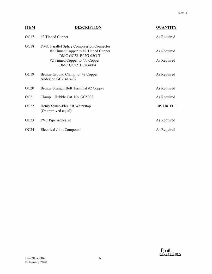
Rev. 1
19-9287-8004 6 © January 2020
ITEM DESCRIPTION QUANTITY OC17 #2 Tinned Copper As Required OC18 DMC Parallel Splice Compression Connector #2 Tinned Copper to #2 Tinned Copper As Required DMC GC721B02G-02G-T #2 Tinned Copper to 4/0 Copper As Required DMC GC721B02G-004 OC19 Bronze Ground Clamp for #2 Copper As Required Anderson GC-141A-02 OC20 Bronze Straight Bolt Terminal #2 Copper As Required OC21 Clamp – Hubble Cat. No. GC5002 As Required OC22 Henry Synco-Flex FR Waterstop 105 Lin. Ft. ± (Or approved equal) OC23 PVC Pipe Adhesive As Required OC24 Electrical Joint Compound As Required