APPENDIX A COARSE PK FACILITY ISSUED FOR ...
66
Gahcho Kué Project February 2020 Coarse PK and Mine Rock Pile Final Detailed Construction Plan Version 2 De Beers Canada Inc. APPENDIX A COARSE PK FACILITY ISSUED FOR CONSTRUCTION DRAWINGS (C410-C416)
-
Upload
khangminh22 -
Category
Documents
-
view
3 -
download
0
Transcript of APPENDIX A COARSE PK FACILITY ISSUED FOR ...

Gahcho Kué Project February 2020 Coarse PK and Mine Rock Pile Final Detailed Construction Plan Version 2
De Beers Canada Inc.
APPENDIX A
COARSE PK FACILITY ISSUED FOR CONSTRUCTION DRAWINGS (C410-C416)

7 039 000 N7 039 000 N
587 0
00 E
587 0
00 E
588 0
00 E
588 0
00 E
589 0
00 E
589 0
00 E
590 0
00 E
590 0
00 E
591 0
00 E
591 0
00 E
592 0
00 E
592 0
00 E
7 038 000 N7 038 000 N
7 037 000 N7 037 000 N
7 036 000 N7 036 000 N
7 035 000 N7 035 000 N
7 034 000 N7 034 000 N
420.7 ±
421.3 ±
421.3 ±
424.2 ±
429.6 ±
427.0 ±
424.0 ±
423.7 ±
423.6 ±
425.9 ±427.4 ±
423.0 ±
422.3 ±
421.8 ±
426.9 ±
424.8 ±425.1 ±
421.4 ±
420.2 ±
418.6 ±
430.4 ±
429.5 ±
424.1 ±
423.0 ±
428.9 ±
427.9 ±
420.8 ±
422.9 ±
423.3 ±
425.7 ±
426.0 ±
427.0 ±
420.1 ±
426.8 ±
432.0 ± 433.9 ±
423.4 ±
429.1 ±
422.2 ±
418.8 ±
422.1 ±
421.2 ±
425.8 ±
427.2 ±
428.2 ±
434.6 ±
429.6 ±430.5 ±
427.1 ±
426.5 ±
423.0 ±
427.8 ±
419.5 ±
419.0 ±
414.0 ±
414.5 ±
414.0 ±
A1
A7
E2
D9
N18
N13
D10
B3
B2
B4C2
B1
F1X1
Kd1
I1
J2
A9
A8
C1
N12
N8
N7
N6b
A2A6
L19
L21
A3
A4N10
L18
L15
L16
D6
Kb2Kb3
I2
AREA 3
AREA 4
AREA 7
AREA 1
AREA 2 FINE PKC FACILITY
SOUTH MINEROCK PILE
COARSE PK AND
MINE ROCK PILE
5034 PIT
TUZO PIT
HEARNE PIT
AREA 8
WEST MINEROCK PILE
NUM DWN CKD DESCRIPTIONDATE APR
REVISIONS
0 2020/02/25 EL HX WTH ISSUED FOR CONSTRUCTION
PROFESSIONAL SEALPERMIT
CLIENT
PROJECT No. OFFICE DES CKD REV
SHEET No. DWN APP STATUS
of
DRAWING
DATE: C700
ENG.EARC03068-22
FEBRUARY 14, 2020 01 06
EDMONTON HX
EL WTH
HX 0
A
GAHCHO KUÉ PROJECTNWT, CANADA
GENERAL LOCATION PLAN
Q:\E
dm
onton\E
ngineering\E
141\P
rojects\_G
AH
CH
O_K
UE
\E
NG
.E
AR
C03068-22\P
roduction D
raw
ings\E
NG
.E
AR
C03068-22_M
RP
-IF
C.dw
g [C
700] F
ebruary 25, 2020 - 2:16:54 pm
(B
Y: LE
E, E
LV
IN
)
0 500m
Scale: 1:12,500 @ 22"x34"
COARSE PK AND MINE ROCK PILE CONSTRUCTION SPECIFICATION:
1. A MINIMUM 2.0 m THICK OF NON-PAG MINE ROCK WILL BE PLACED ON THEAREA ABOVE THE ORIGINAL HIGH WATER MARK OF KENNADY LAKE PRIOR TOPLACEMENT OF COARSE PK.
2. COARSE PK AND MINE ROCK WILL BE HAULED AND END-DUMPED AT ITS ANGLEOF REPOSE AT THE DESIGNATED AREA, AND SPREAD IN LIFTS BY DOZES.
3. MINE ROCK WILL BE PLACED IN LIFTS WITH A MAXIMUM THICKNESS OF 3.0 mEACH LIFT WHEN MINE ROCK IS PLACED ON THE CREST OF THE PILE OR AMAXIMUM LIFT THICKNESS OF 30 m WHEN THE MINE ROCK IS PLACED OF THEADVANCING SLOPE OF THE PILE.
4. COARSE PK WILL BE PLACED IN LIFTS WITH A MAXIMUM THICKNESS OF 2.0 mEACH LIFT AND COMPACTED BY TRAFFIC.
5. THE HEIGHT OF EACH BENCH ABOVE ELEVATION 425.0 m IS 30 m FOR MINEROCK AND 15 m FOR COARSE PK.
6. THE SETBACK DISTANCE BETWEEN BENCHES IS 15 m FOR COARSE PK PILE.7. THE SETBACK DISTANCE FOR THE FIRST BENCH (AT 455 m ELEVATION) ALONG
THE NORTH PERIMETER OF THE PILE IS 60 m, AND 45 m FOR THE REST OFBENCHES.
8. THE SETBACK DISTANCE FOR EACH BENCH ALONG THE SOUTH, WEST, EASTPERIMETERS OF THE PILE IS 35 m.
9. SAFETY BERMS ACCORDING TO MINES ACT REQUIREMENTS WILL BEMAINTAINED AROUND THE PERIMETER OF THE PILE.
64°0
'0" N
62°0
'0" N
64°0'0" N62°0'0" N
108°0'0" W112°0'0" W116°0'0" W
108°0'0" W112°0'0" W116°0'0" W
COARSE PK AND MINE ROCK PILE DRAWING INDEX
DRAWING NUMBER REV. DRAWING TITLE
C700 0 GENERAL LOCATION PLAN
C701 0 COARSE PK AND MINE ROCK PILE - PLAN VIEW AND DESIGN CROSS-SECTIONS AT CREST ELEVATION 455 m
C702 0 COARSE PK AND MINE ROCK PILE - PLAN VIEW AND DESIGN CROSS-SECTIONS AT CREST ELEVATION 485 m
C703 0 COARSE PK AND MINE ROCK PILE - PLAN VIEW AND DESIGN CROSS-SECTIONS AT CREST ELEVATION 515 m
C704 0 COARSE PK AND MINE ROCK PILE - PLAN VIEW AND DESIGN CROSS-SECTIONS AT CREST ELEVATION 545 m
C705 0 COARSE PK AND MINE ROCK PILE - LAYOUT POINTS AND GTC LOCATIONS
DYKE D COFFERDAM
AN BUILDING
DYKE L
DYKE A1EXPLOSIVE MAGAZINES
EMULSION PLANT
AIRSTRIPDYKE A
DYKE K
DYKE G
DYKE F
DYKE H
DYKE J
DYKE I

7 037 500 N7 037 500 N
590 0
00 E
590 0
00 E
590 5
00 E
590 5
00 E
591 0
00 E
591 0
00 E
591 5
00 E
591 5
00 E
7 037 000 N7 037 000 N
7 036 500 N7 036 500 N
7 036 000 N7 036 000 N
7 035 500 N7 035 500 N
A--
B--
C--
D --
589 5
00 E
589 5
00 E
ELEV
ATIO
N (m
) ELEVATION (m)
DISTANCE (m)
400
420
440
460
480
500
520
540
560
400
420
440
460
480
500
520
540
560
0 25 50 75 100 125 150 175 200 225 250 275 300 325 350 375 400 425 450 475 500
ELEV
ATIO
N (m
) ELEVATION (m)
DISTANCE (m)
400
420
440
460
480
500
520
540
560
400
420
440
460
480
500
520
540
560
0 25 50 75 100 125 150 175 200 225 250 275 300 325 350 375 400 425 450 475 500
ELEV
ATIO
N (m
) ELEVATION (m)
DISTANCE (m)
400
420
440
460
480
500
520
540
560
400
420
440
460
480
500
520
540
560
0 25 50 75 100 125 150 175 200 225 250 275 300 325 350 375 400 425 450 475 500
ELEV
ATIO
N (m
) ELEVATION (m)
DISTANCE (m)
400
420
440
460
480
500
520
540
560
400
420
440
460
480
500
520
540
560
0 25 50 75 100 125 150 175 200 225 250 275 300 325 350 375 400 425 450 475 500
455.0 m
425.0 m
455.0 m
455.0 m
455.0 m
SCALE:A---
CROSS-SECTION1:2000
SCALE:B---
CROSS-SECTION1:2000
SCALE:C---
CROSS-SECTION1:2000
SCALE:D---
CROSS-SECTION1:2000
35.0 m
11.3
11.3
11.3
11.3
11.5
11.5
11.5
11.5
11.5
11.5
11.5
11.5
NUM DWN CKD DESCRIPTIONDATE APR
REVISIONS
0 2020/02/25 EL HX WTH ISSUED FOR CONSTRUCTION
PROFESSIONAL SEALPERMIT
CLIENT
PROJECT No. OFFICE DES CKD REV
SHEET No. DWN APP STATUS
of
DRAWING
DATE: C701
ENG.EARC03068-22
FEBRUARY 14, 2020 02 06
EDMONTON HX
EL WTH
HX 0
A
GAHCHO KUÉ PROJECTNWT, CANADA
COARSE PK AND MINE ROCK PILEPLAN VIEW AND DESIGN CROSS-SECTIONS
AT CREST ELEVATION 455 m
Q:\E
dm
onton\E
ngineering\E
141\P
rojects\_G
AH
CH
O_K
UE
\E
NG
.E
AR
C03068-22\P
roduction D
raw
ings\E
NG
.E
AR
C03068-22_M
RP
-IF
C.dw
g [C
701] F
ebruary 25, 2020 - 2:17:15 pm
(B
Y: LE
E, E
LV
IN
)
0 250m
Scale: 1:5,000 @ 22"x34"
CPK
CPK
CPK
MINE ROCKCPK
MINE ROCK
MINE ROCK
MINE ROCK
EXISTING AS-BUILT CPK FOOTPRINT
COARSE PK AND
MINE ROCK PILE
ROAD TO AREA 8
ACCESS ROAD TO AREA 2 LAKE A1
AREA 4
TUZO PIT
EL. 455 m
EL. 455 mEL. 425 m
EL. 455 m
11.3
COARSE PK AND MINE ROCK PILE CONSTRUCTION SPECIFICATION:
1. A MINIMUM 2.0 m THICK OF NON-PAG MINE ROCK WILL BE PLACED ON THEAREA ABOVE THE ORIGINAL HIGH WATER MARK OF KENNADY LAKE PRIOR TOPLACEMENT OF COARSE PK.
2. COARSE PK AND MINE ROCK WILL BE HAULED AND END-DUMPED AT ITS ANGLEOF REPOSE AT THE DESIGNATED AREA, AND SPREAD IN LIFTS BY DOZES.
3. MINE ROCK WILL BE PLACED IN LIFTS WITH A MAXIMUM THICKNESS OF 3.0 mEACH LIFT WHEN MINE ROCK IS PLACED ON THE CREST OF THE PILE OR AMAXIMUM LIFT THICKNESS OF 30 m WHEN THE MINE ROCK IS PLACED OF THEADVANCING SLOPE OF THE PILE.
4. COARSE PK WILL BE PLACED IN LIFTS WITH A MAXIMUM THICKNESS OF 2.0 mEACH LIFT AND COMPACTED BY TRAFFIC.
5. THE HEIGHT OF EACH BENCH ABOVE ELEVATION 425.0 m IS 30 m FOR MINEROCK AND 15 m FOR COARSE PK.
6. THE SETBACK DISTANCE BETWEEN BENCHES IS 15 m FOR COARSE PK PILE.7. THE SETBACK DISTANCE FOR THE FIRST BENCH (AT 455 m ELEVATION) ALONG
THE NORTH PERIMETER OF THE PILE IS 60 m, AND 45 m FOR THE REST OFBENCHES.
8. THE SETBACK DISTANCE FOR EACH BENCH ALONG THE SOUTH, WEST, EASTPERIMETERS OF THE PILE IS 35 m.
9. SAFETY BERMS ACCORDING TO MINES ACT REQUIREMENTS WILL BEMAINTAINED AROUND THE PERIMETER OF THE PILE.
ORIGINAL LAKE BOUNDARY
DYKE A
PROCESS PLANT
COARSE PK
EXISTINGGROUND
EXISTINGGROUND
EXISTINGGROUND
EXISTINGGROUND
EXISTING AS-BUILT CPK(BASED ON JULY 08, 2019 SURVEY)
EMULSION PLANT
APPROXIMATE LOCATION OF LANDFILL EXISTING AS-BUILT CPK(BASED ON JULY 08, 2019 SURVEY)
EXISTING AS-BUILT CPK(BASED ON JULY 08, 2019 SURVEY)NON-PAG MINE ROCK
NON-PAG MINE ROCK
NON-PAG MINE ROCK
NON-PAG MINE ROCK
5034 PIT
RECLAIM WATER CAUSEWAY
AREA 3 AND 5(WMP)
DYKE B

7 037 500 N7 037 500 N
590 0
00 E
590 0
00 E
590 5
00 E
590 5
00 E
591 0
00 E
591 0
00 E
591 5
00 E
591 5
00 E
7 037 000 N7 037 000 N
7 036 500 N7 036 500 N
7 036 000 N7 036 000 N
7 035 500 N7 035 500 N
A--
B--
C--
D --
589 5
00 E
589 5
00 E
ELEV
ATIO
N (m
) ELEVATION (m)
DISTANCE (m)
400
420
440
460
480
500
520
540
560
400
420
440
460
480
500
520
540
560
0 25 50 75 100 125 150 175 200 225 250 275 300 325 350 375 400 425 450 475 500
ELEV
ATIO
N (m
) ELEVATION (m)
DISTANCE (m)
400
420
440
460
480
500
520
540
560
400
420
440
460
480
500
520
540
560
0 25 50 75 100 125 150 175 200 225 250 275 300 325 350 375 400 425 450 475 500
ELEV
ATIO
N (m
) ELEVATION (m)
DISTANCE (m)
400
420
440
460
480
500
520
540
560
400
420
440
460
480
500
520
540
560
0 25 50 75 100 125 150 175 200 225 250 275 300 325 350 375 400 425 450 475 500
ELEV
ATIO
N (m
) ELEVATION (m)
DISTANCE (m)
400
420
440
460
480
500
520
540
560
400
420
440
460
480
500
520
540
560
0 25 50 75 100 125 150 175 200 225 250 275 300 325 350 375 400 425 450 475 500
485.0 m
455.0 m
425.0 m
485.0 m
455.0 m
485.0 m
455.0 m
485.0 m
455.0 m
SCALE:A---
CROSS-SECTION1:2000
SCALE:B---
CROSS-SECTION1:2000
SCALE:C---
CROSS-SECTION1:2000
SCALE:D---
CROSS-SECTION1:2000
35.0 m
35.0 m
35.0 m
35.0 m
60.0 m
RAMP
11.3
11.3
11.3
11.3
11.3
11.3
11.3
11.3
11.31
1.3
11.5
11.5
11.5
11.5
11.5
11.5
11.5
11.5
15.0 m (TYP.)
15.0 m (TYP.)
15.0 m (TYP.)
15.0 m (TYP.)
NUM DWN CKD DESCRIPTIONDATE APR
REVISIONS
0 2020/02/25 EL HX WTH ISSUED FOR CONSTRUCTION
PROFESSIONAL SEALPERMIT
CLIENT
PROJECT No. OFFICE DES CKD REV
SHEET No. DWN APP STATUS
of
DRAWING
DATE: C702
ENG.EARC03068-22
FEBRUARY 14, 2020 03 06
EDMONTON HX
EL WTH
HX 0
A
GAHCHO KUÉ PROJECTNWT, CANADA
COARSE PK AND MINE ROCK PILEPLAN VIEW AND DESIGN CROSS-SECTIONS
AT CREST ELEVATION 485 m
Q:\E
dm
onton\E
ngineering\E
141\P
rojects\_G
AH
CH
O_K
UE
\E
NG
.E
AR
C03068-22\P
roduction D
raw
ings\E
NG
.E
AR
C03068-22_M
RP
-IF
C.dw
g [C
702] F
ebruary 25, 2020 - 2:17:37 pm
(B
Y: LE
E, E
LV
IN
)
0 250m
Scale: 1:5,000 @ 22"x34"
CPK
CPK
CPK
MINE ROCKCPK
MINE ROCK
MINE ROCK
MINE ROCK
EXISTING AS-BUILT CPK FOOTPRINT
ROAD TO AREA 8
ACCESS ROAD TO AREA 2 LAKE A1
AREA 4
COARSE PK
EL. 485 m
EL. 455 m
EL. 485 m
EL. 455 mEL. 425 m
EL. 485 m
EL. 455 m
COARSE PK AND MINE ROCK PILE CONSTRUCTION SPECIFICATION:
1. A MINIMUM 2.0 m THICK OF NON-PAG MINE ROCK WILL BE PLACED ON THEAREA ABOVE THE ORIGINAL HIGH WATER MARK OF KENNADY LAKE PRIOR TOPLACEMENT OF COARSE PK.
2. COARSE PK AND MINE ROCK WILL BE HAULED AND END-DUMPED AT ITS ANGLEOF REPOSE AT THE DESIGNATED AREA, AND SPREAD IN LIFTS BY DOZES.
3. MINE ROCK WILL BE PLACED IN LIFTS WITH A MAXIMUM THICKNESS OF 3.0 mEACH LIFT WHEN MINE ROCK IS PLACED ON THE CREST OF THE PILE OR AMAXIMUM LIFT THICKNESS OF 30 m WHEN THE MINE ROCK IS PLACED OF THEADVANCING SLOPE OF THE PILE.
4. COARSE PK WILL BE PLACED IN LIFTS WITH A MAXIMUM THICKNESS OF 2.0 mEACH LIFT AND COMPACTED BY TRAFFIC.
5. THE HEIGHT OF EACH BENCH ABOVE ELEVATION 425.0 m IS 30 m FOR MINEROCK AND 15 m FOR COARSE PK.
6. THE SETBACK DISTANCE BETWEEN BENCHES IS 15 m FOR COARSE PK PILE.7. THE SETBACK DISTANCE FOR THE FIRST BENCH (AT 455 m ELEVATION) ALONG
THE NORTH PERIMETER OF THE PILE IS 60 m, AND 45 m FOR THE REST OFBENCHES.
8. THE SETBACK DISTANCE FOR EACH BENCH ALONG THE SOUTH, WEST, EASTPERIMETERS OF THE PILE IS 35 m.
9. SAFETY BERMS ACCORDING TO MINES ACT REQUIREMENTS WILL BEMAINTAINED AROUND THE PERIMETER OF THE PILE.
ORIGINAL LAKE BOUNDARY
COARSE PK AND
MINE ROCK PILE
DYKE A
PROCESS PLANT
EXISTINGGROUND
EXISTINGGROUND
EXISTINGGROUND
EXISTINGGROUND
EMULSION PLANT
EXISTING AS-BUILT CPK(BASED ON JULY 08, 2019 SURVEY)
EXISTING AS-BUILT CPK(BASED ON JULY 08, 2019 SURVEY)
EXISTING AS-BUILT CPK(BASED ON JULY 08, 2019 SURVEY)NON-PAG MINE ROCK
NON-PAG MINE ROCK
NON-PAG MINE ROCK
NON-PAG MINE ROCK
TUZO PIT
5034 PIT
RECLAIM WATER CAUSEWAY
AREA 3 AND 5(WMP)
DYKE B

7 037 500 N7 037 500 N
590 0
00 E
590 0
00 E
590 5
00 E
590 5
00 E
591 0
00 E
591 0
00 E
591 5
00 E
591 5
00 E
7 037 000 N7 037 000 N
7 036 500 N7 036 500 N
7 036 000 N7 036 000 N
7 035 500 N7 035 500 N
A--
B--
C--
D --
589 5
00 E
589 5
00 E
ELEV
ATIO
N (m
) ELEVATION (m)
DISTANCE (m)
400
420
440
460
480
500
520
540
560
400
420
440
460
480
500
520
540
560
0 25 50 75 100 125 150 175 200 225 250 275 300 325 350 375 400 425 450 475 500
ELEV
ATIO
N (m
) ELEVATION (m)
DISTANCE (m)
400
420
440
460
480
500
520
540
560
400
420
440
460
480
500
520
540
560
0 25 50 75 100 125 150 175 200 225 250 275 300 325 350 375 400 425 450 475 500
ELEV
ATIO
N (m
) ELEVATION (m)
DISTANCE (m)
400
420
440
460
480
500
520
540
560
400
420
440
460
480
500
520
540
560
0 25 50 75 100 125 150 175 200 225 250 275 300 325 350 375 400 425 450 475 500
ELEV
ATIO
N (m
) ELEVATION (m)
DISTANCE (m)
400
420
440
460
480
500
520
540
560
400
420
440
460
480
500
520
540
560
0 25 50 75 100 125 150 175 200 225 250 275 300 325 350 375 400 425 450 475 500
515.0 m
485.0 m
455.0 m
425.0 m
515.0 m
485.0 m
455.0 m
515.0 m
485.0 m
455.0 m
515.0 m
485.0 m
455.0 m
SCALE:A---
CROSS-SECTION1:2000
SCALE:B---
CROSS-SECTION1:2000
SCALE:C---
CROSS-SECTION1:2000
SCALE:D---
CROSS-SECTION1:2000
35.0 m
35.0 m
35.0 m
35.0 m
60.0 m
RAMP
35.0 m
RAMP
35.0 m
RAMP
11.3
11.3
11.3
11.3
11.3
11.3
11.3
11.3
11.31
1.3
11.3
11.3
11.3
11.3
11.5
11.5
11.5
11.5
11.5
11.5
11.5
11.5
15.0 m (TYP.)
15.0 m (TYP.)
15.0 m (TYP.)
15.0 m (TYP.)
NUM DWN CKD DESCRIPTIONDATE APR
REVISIONS
0 2020/02/25 EL HX WTH ISSUED FOR CONSTRUCTION
PROFESSIONAL SEALPERMIT
CLIENT
PROJECT No. OFFICE DES CKD REV
SHEET No. DWN APP STATUS
of
DRAWING
DATE: C703
ENG.EARC03068-22
FEBRUARY 14, 2020 04 06
EDMONTON HX
EL WTH
HX 0
A
GAHCHO KUÉ PROJECTNWT, CANADA
COARSE PK AND MINE ROCK PILEPLAN VIEW AND DESIGN CROSS-SECTIONS
AT CREST ELEVATION 515 m
Q:\E
dm
onton\E
ngineering\E
141\P
rojects\_G
AH
CH
O_K
UE
\E
NG
.E
AR
C03068-22\P
roduction D
raw
ings\E
NG
.E
AR
C03068-22_M
RP
-IF
C.dw
g [C
703] F
ebruary 25, 2020 - 2:17:58 pm
(B
Y: LE
E, E
LV
IN
)
0 250m
Scale: 1:5,000 @ 22"x34"
CPK
CPK
CPK
MINE ROCK
CPK
MINE ROCK
MINE ROCK
MINE ROCK
EXISTING AS-BUILT CPK FOOTPRINT
ROAD TO AREA 8
ACCESS ROAD TO AREA 2 LAKE A1
AREA 4
EL. 515 m
EL. 485 m
EL. 455 m
EL. 515 mEL. 485 m
EL. 455 mEL. 425 m
EL. 515 m
EL. 485 m
EL. 455 m
COARSE PK AND MINE ROCK PILE CONSTRUCTION SPECIFICATION:
1. A MINIMUM 2.0 m THICK OF NON-PAG MINE ROCK WILL BE PLACED ON THEAREA ABOVE THE ORIGINAL HIGH WATER MARK OF KENNADY LAKE PRIOR TOPLACEMENT OF COARSE PK.
2. COARSE PK AND MINE ROCK WILL BE HAULED AND END-DUMPED AT ITS ANGLEOF REPOSE AT THE DESIGNATED AREA, AND SPREAD IN LIFTS BY DOZES.
3. MINE ROCK WILL BE PLACED IN LIFTS WITH A MAXIMUM THICKNESS OF 3.0 mEACH LIFT WHEN MINE ROCK IS PLACED ON THE CREST OF THE PILE OR AMAXIMUM LIFT THICKNESS OF 30 m WHEN THE MINE ROCK IS PLACED OF THEADVANCING SLOPE OF THE PILE.
4. COARSE PK WILL BE PLACED IN LIFTS WITH A MAXIMUM THICKNESS OF 2.0 mEACH LIFT AND COMPACTED BY TRAFFIC.
5. THE HEIGHT OF EACH BENCH ABOVE ELEVATION 425.0 m IS 30 m FOR MINEROCK AND 15 m FOR COARSE PK.
6. THE SETBACK DISTANCE BETWEEN BENCHES IS 15 m FOR COARSE PK PILE.7. THE SETBACK DISTANCE FOR THE FIRST BENCH (AT 455 m ELEVATION) ALONG
THE NORTH PERIMETER OF THE PILE IS 60 m, AND 45 m FOR THE REST OFBENCHES.
8. THE SETBACK DISTANCE FOR EACH BENCH ALONG THE SOUTH, WEST, EASTPERIMETERS OF THE PILE IS 35 m.
9. SAFETY BERMS ACCORDING TO MINES ACT REQUIREMENTS WILL BEMAINTAINED AROUND THE PERIMETER OF THE PILE.
ORIGINAL LAKE BOUNDARY
COARSE PK AND
MINE ROCK PILE
DYKE A
PROCESS PLANT
COARSE PK
EXISTINGGROUND
EXISTINGGROUND
EXISTINGGROUND
EXISTINGGROUND
EMULSION PLANT
EXISTING AS-BUILT CPK(BASED ON JULY 08, 2019 SURVEY)
EXISTING AS-BUILT CPK(BASED ON JULY 08, 2019 SURVEY)
EXISTING AS-BUILT CPK(BASED ON JULY 08, 2019 SURVEY)NON-PAG MINE ROCK
NON-PAG MINE ROCK
NON-PAG MINE ROCK
NON-PAG MINE ROCK
TUZO PIT
5034 PIT
RECLAIM WATER CAUSEWAY
AREA 3 AND 5(WMP)
DYKE B

7 037 500 N7 037 500 N
590 0
00 E
590 0
00 E
590 5
00 E
590 5
00 E
591 0
00 E
591 0
00 E
591 5
00 E
591 5
00 E
7 037 000 N7 037 000 N
7 036 500 N7 036 500 N
7 036 000 N7 036 000 N
7 035 500 N7 035 500 N
A--
B--
C--
D --
589 5
00 E
589 5
00 E
ELEV
ATIO
N (m
) ELEVATION (m)
DISTANCE (m)
400
420
440
460
480
500
520
540
560
400
420
440
460
480
500
520
540
560
0 25 50 75 100 125 150 175 200 225 250 275 300 325 350 375 400 425 450 475 500
ELEV
ATIO
N (m
) ELEVATION (m)
DISTANCE (m)
400
420
440
460
480
500
520
540
560
400
420
440
460
480
500
520
540
560
0 25 50 75 100 125 150 175 200 225 250 275 300 325 350 375 400 425 450 475 500
ELEV
ATIO
N (m
) ELEVATION (m)
DISTANCE (m)
400
420
440
460
480
500
520
540
560
400
420
440
460
480
500
520
540
560
0 25 50 75 100 125 150 175 200 225 250 275 300 325 350 375 400 425 450 475 500
ELEV
ATIO
N (m
) ELEVATION (m)
DISTANCE (m)
400
420
440
460
480
500
520
540
560
400
420
440
460
480
500
520
540
560
0 25 50 75 100 125 150 175 200 225 250 275 300 325 350 375 400 425 450 475 500
545.0 m
515.0 m
485.0 m
455.0 m
425.0 m
545.0 m
515.0 m
485.0 m
455.0 m
545.0 m
515.0 m
485.0 m
455.0 m
545.0 m
515.0 m
485.0 m
455.0 m
SCALE:A---
CROSS-SECTION1:2000
SCALE:B---
CROSS-SECTION1:2000
SCALE:C---
CROSS-SECTION1:2000
SCALE:D---
CROSS-SECTION1:2000
35.0 m
35.0 m
35.0 m
35.0 m
60.0 m
RAMP
35.0 m
RAMP
35.0 m
RAMP
35.0 mRAMP
35.6 m
35.0 m
43.0 m
11.3
11.3
11.3
11.3
11.3
11.3
11.3
11.3
11.31
1.3
11.3
11.3
11.3
11.3
11.3
11.3
11.3
11.5
11.5
11.5
11.5
11.5
11.5
11.5
11.5
15.0 m (TYP.)
15.0 m (TYP.)
15.0 m (TYP.)
15.0 m (TYP.)
NUM DWN CKD DESCRIPTIONDATE APR
REVISIONS
0 2020/02/25 EL HX WTH ISSUED FOR CONSTRUCTION
PROFESSIONAL SEALPERMIT
CLIENT
PROJECT No. OFFICE DES CKD REV
SHEET No. DWN APP STATUS
of
DRAWING
DATE: C704
ENG.EARC03068-22
FEBRUARY 14, 2020 05 06
EDMONTON HX
EL WTH
HX 0
A
GAHCHO KUÉ PROJECTNWT, CANADA
COARSE PK AND MINE ROCK PILEPLAN VIEW AND DESIGN CROSS-SECTIONS
AT CREST ELEVATION 545 m
Q:\E
dm
onton\E
ngineering\E
141\P
rojects\_G
AH
CH
O_K
UE
\E
NG
.E
AR
C03068-22\P
roduction D
raw
ings\E
NG
.E
AR
C03068-22_M
RP
-IF
C.dw
g [C
704] F
ebruary 25, 2020 - 2:18:18 pm
(B
Y: LE
E, E
LV
IN
)
0 250m
Scale: 1:5,000 @ 22"x34"
COARSE PK AND MINE ROCK PILE CONSTRUCTION SPECIFICATION:
1. A MINIMUM 2.0 m THICK OF NON-PAG MINE ROCK WILL BE PLACED ON THEAREA ABOVE THE ORIGINAL HIGH WATER MARK OF KENNADY LAKE PRIOR TOPLACEMENT OF COARSE PK.
2. COARSE PK AND MINE ROCK WILL BE HAULED AND END-DUMPED AT ITS ANGLEOF REPOSE AT THE DESIGNATED AREA, AND SPREAD IN LIFTS BY DOZES.
3. MINE ROCK WILL BE PLACED IN LIFTS WITH A MAXIMUM THICKNESS OF 3.0 mEACH LIFT WHEN MINE ROCK IS PLACED ON THE CREST OF THE PILE OR AMAXIMUM LIFT THICKNESS OF 30 m WHEN THE MINE ROCK IS PLACED OF THEADVANCING SLOPE OF THE PILE.
4. COARSE PK WILL BE PLACED IN LIFTS WITH A MAXIMUM THICKNESS OF 2.0 mEACH LIFT AND COMPACTED BY TRAFFIC.
5. THE HEIGHT OF EACH BENCH ABOVE ELEVATION 425.0 m IS 30 m FOR MINEROCK AND 15 m FOR COARSE PK.
6. THE SETBACK DISTANCE BETWEEN BENCHES IS 15 m FOR COARSE PK PILE.7. THE SETBACK DISTANCE FOR THE FIRST BENCH (AT 455 m ELEVATION) ALONG
THE NORTH PERIMETER OF THE PILE IS 60 m, AND 45 m FOR THE REST OFBENCHES.
8. THE SETBACK DISTANCE FOR EACH BENCH ALONG THE SOUTH, WEST, EASTPERIMETERS OF THE PILE IS 35 m.
9. SAFETY BERMS ACCORDING TO MINES ACT REQUIREMENTS WILL BEMAINTAINED AROUND THE PERIMETER OF THE PILE.
MINE ROCKCPK
MINE ROCK
CPK
MINE ROCK
CPK
MINE ROCK
CPK
EXISTING AS-BUILT CPK FOOTPRINT
ROAD TO AREA 8
ACCESS ROAD TO AREA 2
AREA 4
LAKE A1
EL. 515 m
EL. 485 m
EL. 455 m
EL. 545 m
EL. 515 mEL. 485 m
EL. 455 mEL. 425 m
EL. 515 m
EL. 485 m
EL. 455 m
ORIGINAL LAKE BOUNDARY
COARSE PK AND
MINE ROCK PILE
DYKE A
PROCESS PLANT
EXISTINGGROUND
EXISTINGGROUND
EXISTINGGROUND
EXISTINGGROUND
EMULSION PLANT
EXISTING AS-BUILT CPK(BASED ON JULY 08, 2019 SURVEY)
EXISTING AS-BUILT CPK(BASED ON JULY 08, 2019 SURVEY)
EXISTING AS-BUILT CPK(BASED ON JULY 08, 2019 SURVEY)NON-PAG MINE ROCK
NON-PAG MINE ROCK
NON-PAG MINE ROCK
NON-PAG MINE ROCK
TUZO PIT
5034 PIT
RECLAIM WATER CAUSEWAY
AREA 3 AND 5(WMP)
DYKE B

7 037 500 N7 037 500 N
590 0
00 E
590 0
00 E
590 5
00 E
590 5
00 E
591 0
00 E
591 0
00 E
591 5
00 E
591 5
00 E
7 037 000 N7 037 000 N
7 036 500 N7 036 500 N
7 036 000 N7 036 000 N
7 035 500 N7 035 500 N
1
2
34
5
6
7
8
9
10
11
12
13
14
1516
17
18
19 20
2122
23
24
2526
2728
2930
31 32
33
3435
3637
38
39
4041 42 43 44 45 46 47 48
4950
51
52
53
54
55
56
57
5859
6061
62
63
64
65
66
67
68
69
7071
72
73
74
7576
7778
79
80
81
82
83
84
8586
87
CPKMRP-GTC01
CPKMRP-GTC02
589 5
00 E
589 5
00 E
COARSE PK AND MINE ROCK PILE LAYOUT POINTS
POINT
1
2
3
4
5
6
7
8
9
10
11
12
13
14
15
16
17
18
19
20
21
22
23
24
25
26
27
28
29
30
31
32
33
34
35
36
37
38
39
40
41
42
43
44
NORTHING
7 036 223.19
7 036 191.07
7 036 218.28
7 036 195.74
7 036 216.48
7 036 253.52
7 036 295.34
7 036 337.87
7 036 380.40
7 036 422.94
7 036 465.47
7 036 508.00
7 036 550.53
7 036 593.07
7 036 635.60
7 036 678.13
7 036 720.66
7 036 764.53
7 036 793.45
7 036 822.38
7 036 771.11
7 036 791.94
7 036 806.19
7 036 853.34
7 036 880.09
7 036 909.06
7 036 936.94
7 036 962.97
7 036 985.16
7 037 007.35
7 037 011.13
7 036 989.38
7 036 869.00
7 036 883.41
7 036 896.17
7 036 910.15
7 036 926.23
7 036 942.29
7 036 974.71
7 037 021.59
7 037 016.25
7 037 008.09
7 036 999.93
7 036 994.79
EASTING
590 502.12
590 488.17
590 420.66
590 391.87
590 366.89
590 333.44
590 306.06
590 279.77
590 253.49
590 227.20
590 200.91
590 174.63
590 148.34
590 122.05
590 095.77
590 069.48
590 043.19
590 051.23
590 092.02
590 132.80
590 035.50
590 012.85
590 026.99
590 116.48
590 154.12
590 194.87
590 236.36
590 279.00
590 323.81
590 368.61
590 397.01
590 410.82
590 168.19
590 215.82
590 263.89
590 311.58
590 358.67
590 405.74
590 465.68
590 475.46
590 524.54
590 573.87
590 623.20
590 672.79
ELEVATION
427.87
428.02
425.00
425.00
425.00
425.00
425.00
425.00
425.00
425.00
425.00
425.00
425.00
425.00
425.00
425.00
425.00
425.00
425.00
425.00
414.00
412.97
414.88
425.00
425.00
425.00
425.00
425.00
425.00
425.00
425.00
425.00
430.35
435.28
440.21
445.14
450.07
455.00
455.00
454.99
455.00
455.00
455.00
455.00
COARSE PK AND MINE ROCK PILE LAYOUT POINTS
POINT
45
46
47
48
49
50
51
52
53
54
55
56
57
58
59
60
61
62
63
64
65
66
67
68
69
70
71
72
73
74
75
76
77
78
79
80
81
82
83
84
85
86
87
NORTHING
7 036 994.09
7 036 993.40
7 036 992.71
7 036 991.03
7 036 984.04
7 036 977.05
7 036 970.06
7 036 962.92
7 036 934.10
7 036 898.57
7 036 863.04
7 036 817.37
7 036 769.73
7 036 742.71
7 036 722.40
7 036 697.98
7 036 670.07
7 036 633.49
7 036 588.77
7 036 543.13
7 036 497.49
7 036 451.85
7 036 406.21
7 036 367.27
7 036 342.61
7 036 317.96
7 036 293.31
7 036 268.66
7 036 244.03
7 036 225.05
7 036 231.28
7 036 254.96
7 036 272.25
7 036 302.68
7 036 342.86
7 036 385.04
7 036 427.23
7 036 412.70
7 036 367.41
7 036 322.13
7 036 278.05
7 036 239.43
7 036 208.43
EASTING
590 722.79
590 772.78
590 822.78
590 872.70
590 922.21
590 971.72
591 021.23
591 070.71
591 110.48
591 145.66
591 180.83
591 200.48
591 210.95
591 171.12
591 125.45
591 081.84
591 040.54
591 006.59
590 984.45
590 964.04
590 943.62
590 923.20
590 902.78
590 874.03
590 830.53
590 787.03
590 743.53
590 700.03
590 656.51
590 610.39
590 564.27
590 522.68
590 476.00
590 436.58
590 406.99
590 380.15
590 353.31
590 321.47
590 342.14
590 362.80
590 385.79
590 416.97
590 455.75
ELEVATION
455.00
455.00
455.00
455.00
455.00
455.00
455.00
455.00
455.00
455.00
455.00
455.00
455.00
455.00
455.00
455.00
455.00
455.00
455.00
455.00
455.00
455.00
455.00
455.00
455.00
455.00
455.00
455.00
455.00
455.00
455.00
455.00
455.00
455.00
455.00
455.00
455.00
455.00
450.30
445.60
440.90
436.20
431.50
PROPOSED GTC
NAME
CPKMRP-GTC01
CPKMRP-GTC02
NORTHING
7 036 654.27
7 036 685.03
EASTING
590 535.62
590 741.65
NUM DWN CKD DESCRIPTIONDATE APR
REVISIONS
0 2020/02/25 EL HX WTH ISSUED FOR CONSTRUCTION
PROFESSIONAL SEALPERMIT
CLIENT
PROJECT No. OFFICE DES CKD REV
SHEET No. DWN APP STATUS
of
DRAWING
DATE: C705
ENG.EARC03068-22
FEBRUARY 14, 2020 06 06
EDMONTON HX
EL WTH
HX 0
A
GAHCHO KUÉ PROJECTNWT, CANADA
COARSE PK AND MINE ROCK PILELAYOUT POINTS AND PROPOSED GTC LOCATIONS
Q:\E
dm
onton\E
ngineering\E
141\P
rojects\_G
AH
CH
O_K
UE
\E
NG
.E
AR
C03068-22\P
roduction D
raw
ings\E
NG
.E
AR
C03068-22_M
RP
-IF
C.dw
g [C
705] F
ebruary 25, 2020 - 2:18:33 pm
(B
Y: LE
E, E
LV
IN
)
0 250m
Scale: 1:5,000 @ 22"x34"
COARSE PK AND MINE ROCK PILE CONSTRUCTION SPECIFICATION:
1. A MINIMUM 2.0 m THICK OF NON-PAG MINE ROCK WILL BE PLACED ON THEAREA ABOVE THE ORIGINAL HIGH WATER MARK OF KENNADY LAKE PRIOR TOPLACEMENT OF COARSE PK.
2. COARSE PK AND MINE ROCK WILL BE HAULED AND END-DUMPED AT ITS ANGLEOF REPOSE AT THE DESIGNATED AREA, AND SPREAD IN LIFTS BY DOZES.
3. MINE ROCK WILL BE PLACED IN LIFTS WITH A MAXIMUM THICKNESS OF 3.0 mEACH LIFT WHEN MINE ROCK IS PLACED ON THE CREST OF THE PILE OR AMAXIMUM LIFT THICKNESS OF 30 m WHEN THE MINE ROCK IS PLACED OF THEADVANCING SLOPE OF THE PILE.
4. COARSE PK WILL BE PLACED IN LIFTS WITH A MAXIMUM THICKNESS OF 2.0 mEACH LIFT AND COMPACTED BY TRAFFIC.
5. THE HEIGHT OF EACH BENCH ABOVE ELEVATION 425.0 m IS 30 m FOR MINEROCK AND 15 m FOR COARSE PK.
6. THE SETBACK DISTANCE BETWEEN BENCHES IS 15 m FOR COARSE PK PILE.7. THE SETBACK DISTANCE FOR THE FIRST BENCH (AT 455 m ELEVATION) ALONG
THE NORTH PERIMETER OF THE PILE IS 60 m, AND 45 m FOR THE REST OFBENCHES.
8. THE SETBACK DISTANCE FOR EACH BENCH ALONG THE SOUTH, WEST, EASTPERIMETERS OF THE PILE IS 35 m.
9. SAFETY BERMS ACCORDING TO MINES ACT REQUIREMENTS WILL BEMAINTAINED AROUND THE PERIMETER OF THE PILE.
EXISTING AS-BUILT CPK FOOTPRINT
ROAD TO AREA 8
ACCESS ROAD TO AREA 2
RECLAIM WATER CAUSEWAY
AREA 3 AND 5(WMP)
AREA 4
LAKE A1
DYKE B
EL. 515 m
EL. 485 m
EL. 455 m
EL. 545 m
EL. 515 mEL. 485 m
EL. 455 mEL. 425 m
EL. 515 m
EL. 485 m
EL. 455 m
ORIGINAL LAKE BOUNDARY
COARSE PK AND
MINE ROCK PILE
DYKE A
PROCESS PLANT
EMULSION PLANT
TUZO PIT
5034 PIT

Gahcho Kué Project February 2020 Coarse PK and Mine Rock Pile Final Detailed Construction Plan Version 2
De Beers Canada Inc.
APPENDIX B
CONSTRUCTION SPECIFICATION AND QUALITY ASSURANCE, GAHCHO KUÉ PROJECT, NT

December
2014
Gahcho Kué Mine
Master Geotechnical Specifications for
Fill Materials and Geotextile/Geomembrane
Supply and Installation

REVISION HISTORY
Version Date Notes/Revisions
Version 1 January 2014 Submitted as a draft document for Dyke Construction Plan.
Version 2 June 2014 Revised draft to be submitted with the Dyke A Final Detailed Design Plan as per Schedule 4, Draft Type A Water Licence Gahcho Kué Project
Version 3 December 2014 Revised draft to be submitted with the Detailed Design Plan

Gahcho Kué Project - ii - December 2014 Master Geotechnical Specifications - IFU Revision 3
De Beers Canada Inc.
PRESENTED TO
De Beers Canada Inc. Suite 900, 250 Ferrand Drive Toronto, ON M3C 3G8
Prepared by:
Cevat Catana, P.Eng. (BC)
Geotechnical Engineer
Tetra Tech EBA Inc.
Date
Reviewed by:
Name
Michael J. Laws, P.Eng. (NT)
Senior Geotechnical Engineer
Tetra Tech EBA Inc.
Date
Authorized by:
Name
Bill Horne, P.Eng. (NT)
Principal Consultant – Arctic
Regions
Tetra Tech EBA Inc.
Date

Gahcho Kué Project - iii - December 2014 Master Geotechnical Specifications - IFU Revision 3
De Beers Canada Inc.

Gahcho Kué Project - iv - December 2014 Master Geotechnical Specifications - IFU Revision 3
De Beers Canada Inc.
TABLE OF CONTENTS
SECTION PAGE
SECTION 1001 – DEFINITIONS & ACRONYMS ............................................................................ 1 1.1 GENERAL ........................................................................................................................ 1 1.2 DEFINITIONS .................................................................................................................. 1 1.3 ACRONYMS .................................................................................................................... 1 1.4 UNITS OF MEASURE ..................................................................................................... 2
SECTION 1002 – GENERAL ........................................................................................................... 3 1.1 GENERAL ........................................................................................................................ 3 1.2 CONSTRUCTION METHODS ......................................................................................... 3 1.3 DRAWING DISCREPANCIES ......................................................................................... 3 1.4 MATERIALS .................................................................................................................... 3 1.5 SITE CLEANUP ............................................................................................................... 3
SECTION 1003 – EXCAVATION, SITE AND FOUNDATION PREPARATION ............................... 4 1.1 GENERAL ........................................................................................................................ 4 1.2 REFERENCE STANDARDS ........................................................................................... 4 1.3 GENERAL EXCAVATION ............................................................................................... 4 1.4 DYKE EXCAVATION ....................................................................................................... 4
1.4.1 Drilling and Blasting ......................................................................................... 5 1.5 GENERAL FOUNDATION PREPARATION .................................................................... 6 1.6 DYKE FOUNDATION PREPARATION ........................................................................... 6
1.6.1 Non-Key Trench Foundations .......................................................................... 6 1.6.2 Key Trench Foundations .................................................................................. 6
1.7 FOUNDATION APPROVAL ............................................................................................ 7 1.7.1 General and Non-Key Trench Foundations ..................................................... 7 1.7.2 Key Trench Foundations .................................................................................. 7
SECTION 1004 – WATER, SNOW, AND ICE CONTROL ............................................................... 8 1.1 GENERAL ........................................................................................................................ 8 1.2 REFERENCE STANDARDS ........................................................................................... 8 1.3 WATER CONTROL ......................................................................................................... 8 1.4 SNOW AND ICE CONTROL ........................................................................................... 8 1.5 EROSION CONTROL FOR DYKE KEY TRENCH BACKFILL........................................ 9
SECTION 1005 – GRANULAR FILL MATERIALS ......................................................................... 10 1.1 GENERAL ...................................................................................................................... 10 1.2 MATERIAL SOURCES .................................................................................................. 10 1.3 MATERIAL SPECIFICATIONS ...................................................................................... 10
SECTION 1006 – GRANULAR FILL PLACEMENT ....................................................................... 14 1.1 GENERAL ...................................................................................................................... 14 1.2 REFERENCE STANDARDS ......................................................................................... 14 1.3 PLACEMENT OF GRANULAR FILL MATERIAL .......................................................... 15
SECTION 1007 – NON-WOVEN GEOTEXTILE ............................................................................ 18

Gahcho Kué Project - v - December 2014 Master Geotechnical Specifications - IFU Revision 3
De Beers Canada Inc.
1.1 GENERAL ...................................................................................................................... 18 1.2 REFERENCES .............................................................................................................. 18 1.3 GEOTEXTILE ................................................................................................................ 18 1.4 INSTALLATION METHODS .......................................................................................... 19
SECTION 1008 – HDPE GEOMEMBRANE ................................................................................... 20 1.1 GENERAL ...................................................................................................................... 20 1.2 REFERENCES .............................................................................................................. 20 1.3 SPECIAL REQUIREMENTS ......................................................................................... 20 1.4 MATERIALS .................................................................................................................. 21 1.5 INSTALLATION ............................................................................................................. 22 1.6 GRADING ...................................................................................................................... 24 1.7 SEAMS AND JOINTS .................................................................................................... 24 1.8 WELDING ...................................................................................................................... 25 1.9 REPAIR PROCEDURES ............................................................................................... 27 1.10 CONTRACTOR CONSTRUCTION QUALITY CONTROL ............................................ 28 1.11 FAILED SEAM PROCEDURES .................................................................................... 29 1.12 SUBMISSIONS .............................................................................................................. 30 1.13 LINER ACCEPTANCE................................................................................................... 30 1.14 COVER OF MEMBRANE .............................................................................................. 31
SECTION 1009 – POLYPROPYLENE GEOMEMBRANE ............................................................. 32 1.1 GENERAL ...................................................................................................................... 32 1.2 REFERENCES .............................................................................................................. 32 1.3 SPECIAL REQUIREMENTS ......................................................................................... 32 1.4 MATERIALS .................................................................................................................. 33 1.5 INSTALLATION ............................................................................................................. 35 1.6 GRADING ...................................................................................................................... 37 1.7 SEAMS AND JOINTS .................................................................................................... 37 1.8 WELDING ...................................................................................................................... 38 1.9 REPAIR PROCEDURES ............................................................................................... 40 1.10 CONTRACTOR CONSTRUCTION QUALITY CONTROL ............................................ 41 1.11 FAILED SEAM PROCEDURES .................................................................................... 42 1.12 SUBMISSIONS .............................................................................................................. 43 1.13 LINER ACCEPTANCE................................................................................................... 43 1.14 COVER OF MEMBRANE .............................................................................................. 43
SECTION 1010 – TURBIDITY BARRIERS .................................................................................... 45 1.1 GENERAL ...................................................................................................................... 45 1.1 REFERENCES .............................................................................................................. 45 1.2 MATERIALS .................................................................................................................. 45 1.3 INSTALLATION ............................................................................................................. 45 1.4 PROGRESSIVE REMOVAL .......................................................................................... 46 1.5 REPAIR PROCEDURES ............................................................................................... 46 1.6 CONTRACTOR CONSTRUCTION QUALITY CONTROL ............................................ 46 1.7 SUBMISSIONS .............................................................................................................. 47 1.8 TURBIDITY BARRIER ACCEPTANCE ......................................................................... 47
SECTION 1011 – QUALITY ASSURANCE TESTING ................................................................... 48

Gahcho Kué Project - vi - December 2014 Master Geotechnical Specifications - IFU Revision 3
De Beers Canada Inc.
1.9 GENERAL ...................................................................................................................... 48 1.10 REFERENCE STANDARDS ......................................................................................... 48 1.11 GRANULAR FILL TESTING REQUIREMENTS ............................................................ 48 1.12 FIELD DENSITY TESTING ........................................................................................... 49
SECTION 1012 – GENERAL TEST PROCEDURES ..................................................................... 50

Gahcho Kué Project - 1 - December 2014 Master Geotechnical Specifications - IFU Revision 3
De Beers Canada Inc.
SECTION 1001 – DEFINITIONS & ACRONYMS
1.1 GENERAL
1. Definitions of terms and acronyms used throughout the Master Geotechnical Construction Specifications are
presented in this Section.
1.2 DEFINITIONS
Construction Drawings or Drawings: The design drawings as issued for construction.
Construction Specifications: This document.
Contract: The legal and binding agreement between the Contractor and DeBeers Canada Inc. (DBCI)
regarding construction of the civil components of the project.
Contractor: The general contractor responsible for construction.
Engineer: Tetra Tech EBA Inc, owner’s on-site geotechnical representative during construction or related
activities.
Owner: De Beers Canada Inc.
Site: The area in which construction or related activities are occurring.
Unsuitable: Not meeting the requirements stated herein or not receiving the Engineer’s approval.
Civil Component: Any portion of construction relating to civil works.
Liner System: A composite structure that comprises a liner, bedding material, and/or geotextile.
1.3 ACRONYMS
ASTM American Society for Testing and Materials
BMPs Best Management Practices
CALA Canadian Association for Laboratory Accreditation
CCME Canadian Council of Ministers of Environment
CDA Canadian Dam Association
CAN/CGSB Canadian General Standards Board, National Standard of Canada
De Beers De Beers Canada Inc.
GRI Geotechnical Research Institute

Gahcho Kué Project - 2 - December 2014 Master Geotechnical Specifications - IFU Revision 3
De Beers Canada Inc.
Mine Gahcho Kué Diamond Mine
MVLWB Mackenzie Valley Land and Water Board
NT Northwest Territories
PLUP Pioneer Land Use Permit
QA/QC Quality Assurance and Quality Control
ROM Run-of-Mine
SNP Surveillance Network Program
1.4 UNITS OF MEASURE
km kilometre
m metre
mm millimeter
m3 cubic metres
END SECTION
Gahcho Kué Project - 3 - December 2014 Master Geotechnical Specifications - IFU Revision 3
De Beers Canada Inc.
SECTION 1002 – GENERAL
1.1 GENERAL
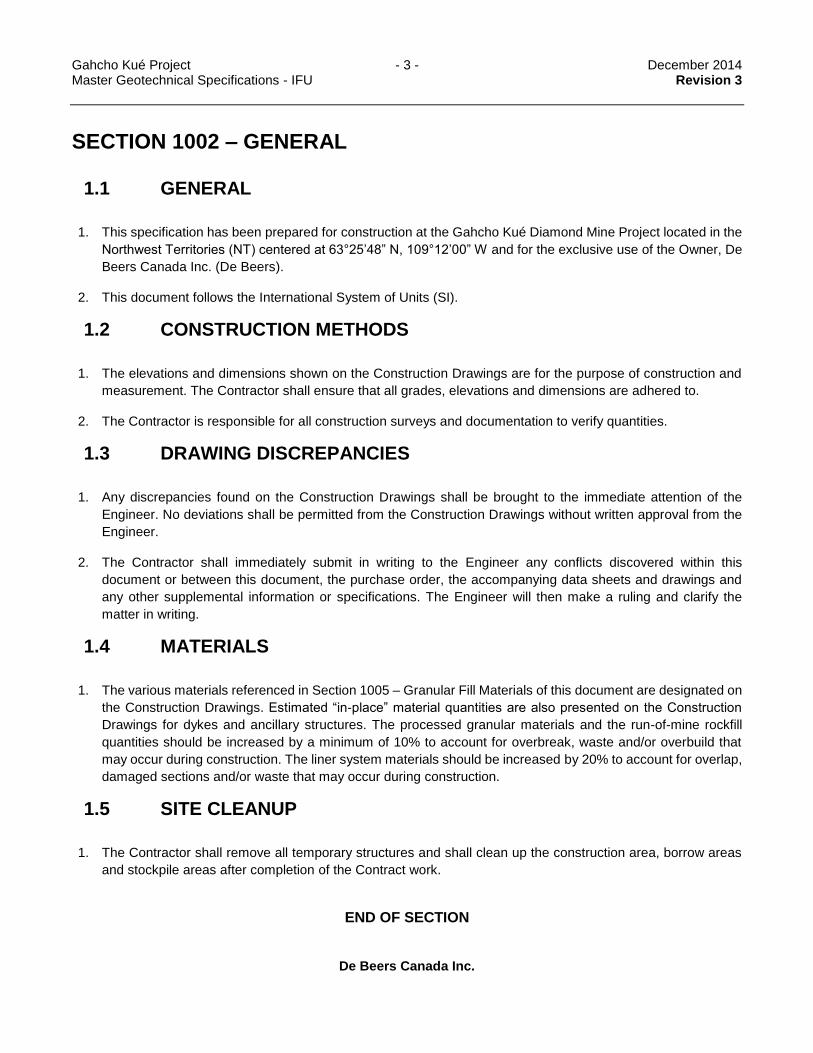
1. This specification has been prepared for construction at the Gahcho Kué Diamond Mine Project located in the
Northwest Territories (NT) centered at 63°25’48” N, 109°12’00” W and for the exclusive use of the Owner, De
Beers Canada Inc. (De Beers).
2. This document follows the International System of Units (SI).
1.2 CONSTRUCTION METHODS
1. The elevations and dimensions shown on the Construction Drawings are for the purpose of construction and
measurement. The Contractor shall ensure that all grades, elevations and dimensions are adhered to.
2. The Contractor is responsible for all construction surveys and documentation to verify quantities.
1.3 DRAWING DISCREPANCIES
1. Any discrepancies found on the Construction Drawings shall be brought to the immediate attention of the
Engineer. No deviations shall be permitted from the Construction Drawings without written approval from the
Engineer.
2. The Contractor shall immediately submit in writing to the Engineer any conflicts discovered within this
document or between this document, the purchase order, the accompanying data sheets and drawings and
any other supplemental information or specifications. The Engineer will then make a ruling and clarify the
matter in writing.
1.4 MATERIALS
1. The various materials referenced in Section 1005 – Granular Fill Materials of this document are designated on
the Construction Drawings. Estimated “in-place” material quantities are also presented on the Construction
Drawings for dykes and ancillary structures. The processed granular materials and the run-of-mine rockfill
quantities should be increased by a minimum of 10% to account for overbreak, waste and/or overbuild that
may occur during construction. The liner system materials should be increased by 20% to account for overlap,
damaged sections and/or waste that may occur during construction.
1.5 SITE CLEANUP
1. The Contractor shall remove all temporary structures and shall clean up the construction area, borrow areas
and stockpile areas after completion of the Contract work.
END OF SECTION

Gahcho Kué Project - 4 - December 2014 Master Geotechnical Specifications - IFU Revision 3
De Beers Canada Inc.
SECTION 1003 – EXCAVATION, SITE AND FOUNDATION PREPARATION
1.1 GENERAL
1. This section describes the general requirements with respect to excavation, site and foundation preparation.
1.2 REFERENCE STANDARDS
1. American Society for Testing Materials
a. ASTM D698-91, Standard Test Methods for Laboratory Compaction Characteristics of Soil Using
Standard Effort (600 kN m/m3) (12,400 ft lbf/ft3).
1.3 GENERAL EXCAVATION
1. The Contractor shall undertake all excavation to the dimensions and lines shown on the Construction
Drawings.
2. The Contractor will be solely responsible for the method of excavation which may include manual excavation,
hydraulic excavation, ripping, and blasting.
3. The Contractor will be solely responsible for the control and diversion of surface and subsurface water flows
into and around the excavation.
4. Excavation beyond the limits shown on the Construction Drawings shall not be undertaken without prior
approval of the Engineer. Any excavation completed outside the design limits without the Engineer’s approval
shall be done at the Contractor’s expense.
5. Over-excavation affecting the design gradelines or elevations shall be backfilled as directed by the Engineer.
Backfill shall be placed in accordance with Section 1006 – Granular Fill Placement.
6. All completed excavations shall be free of loose or deleterious material.
7. The original ground shall remain undisturbed. Any disturbed areas surrounding excavations shall be graded
following construction to promote positive drainage away from the work areas.
8. The Contractor will be responsible for all aspects of safety during the excavation operations including the
stability of the excavations.
1.4 DYKE EXCAVATION
1. All unsuitable foundation soils or rocks shall be removed from within the dyke footprint as directed by the
Engineer and detailed in the Construction Drawings. Excavated materials shall be disposed at approved spoil
locations.

Gahcho Kué Project - 5 - December 2014 Master Geotechnical Specifications - IFU Revision 3
De Beers Canada Inc.
2. The key trench shall be excavated to competent bedrock or frozen till or low permeability till (unfrozen) as
determined by the engineer. The base of the excavation shall have no open voids or joints.
3. The ultimate depth of key trench shall be determined at the time of construction by the Engineer. The depth of
key trench may be increased in some areas at the discretion of the Engineer to confirm the suitability of the
foundation soils beneath the key trench.
4. Loose frozen soil, ice-rich soil, fractured boulders and fractured bedrock, as well as protruding frozen ground,
boulders or bedrock, shall be removed to provide a relatively smooth key trench base. If required, additional
excavation (blasting or mechanical) shall be completed.
5. Excavation of rock shall be conducted in a manner that avoids excessive fracturing or the creation of voids in
the underlying rock.
6. Any inflow of water into the key trench excavation shall be controlled by sumps and pumps in a manner that
minimizes thaw and erosion at the key trench base. The water shall be disposed of in manner to not
contaminate the receiving water bodies. Sedimentation or treatment may be required.
1.4.1 Drilling and Blasting
1. The Contractor is responsible for ensuring that blasting procedures used are within guidelines set by all
regulatory bodies and authorities having jurisdiction on-site.
2. The Contractor shall use excavations methods that minimize fracturing beyond excavation limits.
3. Care shall be taken in locating the drill holes, orienting the drills and while drilling so that accurate positioning
and alignment of the drill holes is achieved.
4. The method of excavation shall produce a key trench base that is free of abrupt changes in elevation.
5. Controlled blasting techniques shall be used to satisfy the excavation requirements stated herein. The initial
explosive type and quantity, blasting sequence and delay pattern shall be modified where required to achieve
the requirements specified herein.
6. The Contractor shall submit complete details of any proposed blast to the Engineer twenty-four (24) hours
prior to commencement of drilling for each blast. Data should include the following:
a. The location, depth and area of the blast;
b. The type, strength, quantity, column load and distribution of explosives to be used per hole, per day,
and per blast;
c. The sequence and pattern of the delay; and,
d. The description and purpose of any special methods to be adopted.
7. If, in a specific area, a plan that was previously adopted does not produce conditions in accordance with the
requirements stated herein, the Contractor shall submit a revised blasting plan to the Engineer before
continuing with drilling and blasting in adjacent areas.

Gahcho Kué Project - 6 - December 2014 Master Geotechnical Specifications - IFU Revision 3
De Beers Canada Inc.
1.5 GENERAL FOUNDATION PREPARATION
1. All fill shall be placed on a firm bearing surface, free from snow, soft and/or loosened areas, ice, or other
detritus material. All unsuitable foundation soils, as determined by the Engineer, shall be excavated and
replaced with the appropriate material specified in the drawings. This material shall be placed and compacted
in accordance with Section 1006 – Granular Fill Placement.
2. Boulders must be removed as determined by the Engineer.
3. The foundation base shall be graded as shown on the Drawings prior to placement of fill.
4. The Contractor shall carry out an accurate (i.e., no more than ±10 mm) survey to act as a reference for material
quantities.
1.6 DYKE FOUNDATION PREPARATION
1.6.1 Non-Key Trench Foundations
1. Surficial vegetation, organic soils or open graded boulders shall be removed as determined by the Engineer.
2. Ice-rich or other soils beneath the dyke footprint deemed to be unsuitable by the Engineer shall be removed.
3. Refer to the construction drawings for other foundation preparation requirements specified for each dyke.
1.6.2 Key Trench Foundations
1. Final cleaning of the key trench shall be conducted with hand excavation, brooms and/or compressed air or
other appropriate equipment such as rippers, jack hammers to remove all loose, broken or altered material
from the base of the key trench.
2. A minimum 200 mm thick layer of compacted bentonite-augmented material shall be used as bedding between
the liner system and the base of the key trench to provide a seal with the key trench foundation and reduce
the permeability underneath the liner.
3. Powdered bentonite clay shall be placed dry and mixed with 20 mm minus material so that a minimum
bentonite content of 8% by weight is achieved. The 20 mm minus material, which will be mixed with dry
bentonite, shall have a moisture content of at least 2% in excess of the optimum moisture content (summer
construction) determined from testing (ASTM D698-91).
4. The remainder of the key trench shall be backfilled with the 20 mm minus material which will have a moisture
content of at least 2% in excess of the optimum moisture content (summer construction) determined from test
method ASTM D698-91. For compaction requirements, see Section 1006 – Granular Fill Placement.
5. The moisture content of the key trench backfill shall be adjusted to ensure that excessive water is not available
to form ice lenses.
Rev 3
Rev 3
Rev 3

Gahcho Kué Project - 7 - December 2014 Master Geotechnical Specifications - IFU Revision 3
De Beers Canada Inc.
6. For winter construction, the key trench backfill shall be spread in lifts thin enough to freeze completely before
the next lift is placed. A maximum lift thickness of 250 mm shall be used to permit daily freezing during the
winter construction season. However, parameters such as mixing water content; surface cleaning and lift
thickness shall be optimized by controlled experimentation early in the construction season. These parameters
shall be periodically checked and, if necessary, changed to suit varied field conditions.
1.7 FOUNDATION APPROVAL
1.7.1 General and Non-Key Trench Foundations
1. The ground surface shall be inspected and approved by the Engineer before any fill material is placed. The
Contractor shall give, not less than twenty-four (24) hours’ notice to the Engineer for subgrade inspection.
1.7.2 Key Trench Foundations
1. The foundation shall be inspected and approved by the Engineer before any fill material is placed. The
Contractor shall give not less than twenty-four (24) hours’ notice to the Engineer regarding approval of a length
of completed key trench excavation. The notice shall include chainages of the areas requiring approval.
END OF SECTION

Gahcho Kué Project - 8 - December 2014 Master Geotechnical Specifications - IFU Revision 3
De Beers Canada Inc.
SECTION 1004 – WATER, SNOW, AND ICE CONTROL
1.1 GENERAL
1. This section describes water, snow and ice control during construction.
2. The key trench and dyke footprint areas shall be dewatered as required to allow for fill placement in a dry
environment.
3. The key trench for all of the Gahcho Kué site dykes shall be protected to avoid erosion by freshet runoff.
4. Water, snow, ice control and construction related dewatering are the responsibilities of the Contractor.
1.2 REFERENCE STANDARDS
1. American Society for Testing Materials
a. ASTM D698-91, Standard Test Methods for Laboratory Compaction Characteristics of Soil Using
Standard Effort (600 kN m/m3) (12,400 ft lbf/ft3).
1.3 WATER CONTROL
1. The Contractor shall employ all measures necessary to control inflow into the various required excavations
during construction. This may include construction of temporary water control structures, such as, berms
around excavation perimeters, or excavation of interceptor trenches and/or sumps.
2. Construction, maintenance and operation of any temporary water control works shall be the responsibility of
the Contractor.
3. Water collected during construction shall be discharged as directed by the Owner, in accordance with the Type
“A” Water Licence. Discharge of water shall not cause erosion or a decrease of water quality in the receiving
water body. Water shall be discharged within the controlled area. The discharge water shall not adversely
affect the water quality in the controlled area. TSS reduction may be required prior to discharge.
Sedimentation, settling ponds or treatment may be required.
4. Following completion of the work, all temporary water control works shall be removed and the affected areas
graded to provide positive drainage to the Dewatering System sumps and/or associated ditches.
5. All temporary sumps shall be backfilled as directed by the Engineer. Backfill shall be placed in accordance
with Section 1006 – Granular Fill Placement.
1.4 SNOW AND ICE CONTROL
1. The Contractor shall employ all measures necessary to control snow and ice accumulation in the open work
areas during construction. This may include snow ploughing and grading.

Gahcho Kué Project - 9 - December 2014 Master Geotechnical Specifications - IFU Revision 3
De Beers Canada Inc.
2. Construction, maintenance and operation of any temporary snow and ice control works shall be the
responsibility of the Contractor.
3. Following completion of the work, all temporary snow and ice control works shall be removed and the affected
areas graded to provide positive drainage to the Dewatering System sumps and/or associated ditches.
1.5 EROSION CONTROL FOR DYKE KEY TRENCH BACKFILL
1. The key trench backfill of all Gahcho Kué site dykes shall be protected to minimize erosion during freshet.
2. Erosion control shall consist of, but not limited to, the following features:
a. Cover the surface of the key trench backfill with the HDPE or polypropylene liner that is tied into the
key trench;
b. Cover the HDPE or polypropylene liner at the bottom of the valley for a width of 20 m (or the width of
the existing natural flow channel, whichever is greater) with a protective nonwoven geotextile (542
g/m2) that extends 3 m both upstream and downstream of the key trench backfill limits;
c. Ballast the nonwoven geotextile with at least a 300 mm thick layer of Transition Rockfill (150 mm Minus)
material; and,
d. Divert runoff water by pumping water retained behind a cofferdam upstream of the key trench area.
3. The erosion protection measures shall be removed following freshet to permit placement of fill materials.
END OF SECTION

Gahcho Kué Project - 10 - December 2014 Master Geotechnical Specifications - IFU Revision 3
De Beers Canada Inc.
SECTION 1005 – GRANULAR FILL MATERIALS
1.1 GENERAL
1. This Section describes the available granular fill materials for construction.
1.2 MATERIAL SOURCES
1. No material of any type shall be borrowed or excavated without the Owner’s prior approval.
2. Borrow Pits and/or quarries shall be maintained and managed in accordance with the requirements set out in
the Owner’s Land Use and Quarry Permits.
3. Transition Rockfill, Coarse and Fine Surfacing Materials shall be processed from material obtained from
sources approved by the Owner, provided the final product meets the requirements specified herein.
Processing will be required to achieve the specified gradations.
4. The parent rock from which all fill materials are derived shall consist of sound, hard, durable material free from
soft, thin, elongated or laminated particles and shall contain no unsuitable substances. The potential quarry
source shall be approved by the Engineer. The Engineer may require trial crushing and durability testing prior
to approving a quarry site.
5. The quarry source for fill materials shall be inspected by the Engineer throughout material processing and
construction activities to ensure that the products meet the requirements specified herein.
1.3 MATERIAL SPECIFICATIONS
1. Run-of-Mine (700 mm Minus)
The Run-of-Mine can have a wide variation of gradation with a maximum particle size of 700 mm. Rockfill
particles shall be angular and shall be derived from hard, durable rock. Any significant concentration of
unsatisfactory materials shall be removed and directed to the waste disposal area or, with the Owner’s approval,
mixed with other materials to produce a material, which would meet specifications.
2. Transition Rockfill (150 mm Minus)
Transition Rockfill shall be used between Run-of-Mine and Granular Till or Surfacing Material. Transition Rockfill
shall consist of, hard durable particles, be free of roots, topsoil and other deleterious material and have a particle
size distribution within the limits specified in Table 5.1. Processing will be required to achieve the specified
gradation.

Gahcho Kué Project - 11 - December 2014 Master Geotechnical Specifications - IFU Revision 3
De Beers Canada Inc.
Table 5.1 Transition Rockfill – Particle Size Distribution Limits
Particle Size (mm) % Passing
150 100
100 60 - 100
50 35 – 65
25 20 – 40
5 5 - 15
0.08 < 2
3. Coarse Surfacing Material (40 mm Minus)
Coarse Surfacing Material shall consist of, hard durable particles, be free of roots, topsoil and other deleterious
material and have a particle size distribution as specified in Table 5.2. Processing will be required to achieve
the specified gradation.
Table 5.2 Coarse Surfacing Material – Particle Size Distribution Limits
Particle Size (mm) % Passing
40 100
19 65 – 100
12.5 45 - 85
5 30 – 60
0.63 15 – 35
0.08 4 - 10
Rev 3

Gahcho Kué Project - 12 - December 2014 Master Geotechnical Specifications - IFU Revision 3
De Beers Canada Inc.
4. Fine Surfacing Material (20 mm Minus)
Fine Surfacing Material shall consist of, hard durable particles, be free of roots, topsoil and other deleterious
material and have a particle size distribution as specified in Table 5.3. Processing will be required to achieve
the specified gradation.
Table 5.3: Fine Surfacing Material – Particle Size Distribution Limits
Particle Size (mm) % Passing
20 100
12.5 65 – 100
5 45 – 70
0.63 15 – 35
0.08 4 - 10
5. Granular Till (150 mm Minus)
Granular Till will be obtained from glacial till excavation. Granular Till shall consist of, hard durable particles, be
free of boulders, roots, topsoil and other deleterious material and have a particle size distribution as specified
in Table 5.4.
Table 5.4: Granular Till – Particle Size Distribution Limits
Particle Size (mm) % Passing
50 100
25 75 - 100
12.5 60 - 100
5 45 – 90
0.08 15 – 70
6. Random Fill (450 mm Minus)
Random Fill shall consist of overburden and/or Run-of-Mine. Random Fill can have a wide variation of gradation
with maximum particle size of 450 mm. Any significant concentration of unsatisfactory materials shall be
removed and directed to the waste disposal area. Rockfill particles shall be angular and shall be derived from
hard, durable rock.
7. Bentonite-Augmented Material
The 20 mm minus crushed material (see Fine Surfacing Material gradation) augmented with >8% bentonite will
be used beneath the key trench liner to provide a seal with the key trench foundation.
Powdered bentonite clay will be placed dry and mixed with 20 mm minus crushed material so that an average
bentonite content of 12% (by weight) with a minimum of 8% (by weight) at any grab sample is achieved. The
bentonite clay shall comprise powdered Wyoming (sodium) bentonite with a minimum 80% passing through a
Rev 3
Rev 3

Gahcho Kué Project - 13 - December 2014 Master Geotechnical Specifications - IFU Revision 3
De Beers Canada Inc.
No.200 sieve with a mineralogical composition comprising a minimum of 90% Montmorillonite and a maximum
10% of native sediments, conforming to the approximate chemical analysis: 60% silica, 20% alumina, 5% iron
oxides, 3% magnesia, 3% soda, 1% lime and chemically bound: 6% water, 2% other.
8. Fine PK Filter Material
Fine PK Filter Material shall consist of, hard durable particles, be free of roots, topsoil and other deleterious
material and have a particle size distribution as specified in Table 5.2. Processing will be required to achieve
the specified gradation.
Table 5.5 Fine PK Filter Material – Particle Size Distribution Limits
Particle Size (mm) % Passing
20 100
12.5 90 - 100
5 70 - 95
0.63 25 - 45
0.08 10 - 15
END OF SECTION
Rev 3

Gahcho Kué Project - 14 - December 2014 Master Geotechnical Specifications - IFU Revision 3
De Beers Canada Inc.
SECTION 1006 – GRANULAR FILL PLACEMENT
1.1 GENERAL
The placement methods to be used during construction are described in this Section.
1. Construction shall be performed in accordance with the best modern practices and with equipment best
adapted to the work being performed.
2. Granular Fill shall be placed so that each layer is homogeneous, free of snow, stratifications, ice chunks, icy
material, frozen soils, organics and deleterious materials.
3. No Granular Fill shall be placed on any part of the foundation until it has been prepared as specified herein
and approved by the Engineer. Placement of Granular Fill shall conform to the lines, grades and elevations
shown on the Construction Drawings.
4. Construction shall not proceed when the work cannot be performed in accordance with the requirements of
the Specifications. Any part of Granular Fill that has been damaged by the action of rain, snow or any other
cause shall be removed and replaced with the appropriate material conforming to the requirements stated
herein before succeeding layers are placed.
5. Stockpiling, loading, transporting, placing and spreading of all materials shall be carried out in such a manner
to avoid segregation. Segregated materials may need to be removed and replaced with the materials meeting
the requirements stated herein, as required by the Engineer.
6. The Contractor shall remove all debris, vegetation or any other material not conforming to the requirements
stated herein. The Contractor shall dispose of these materials in an area approved by the Owner.
1.2 REFERENCE STANDARDS
7. Where material properties are specified the following standards are applicable:
a. ASTM D698-91, Standard Test Methods for Laboratory Compaction Characteristics of Soil Using
Standard Effort (600 kN m/m3) (12,400 ft lbf/ft3).
b. ASTM D422, Test Method for Particle-Size Analysis of Soils.
c. ASTM D1140, Test Method for Amount of Material in Soils Finer than the No. 200 (75 μm) Sieve.
d. ASTM C136, Test Method for Sieve Analysis of Fine and Coarse Aggregates.
e. ASTM D2216, Test Method for Laboratory Determination of Water (Moisture) Content of Soil and Rock.
f. ASTM D2922, Test Methods for Density of Soil and Soil-Aggregate in Place by Nuclear Methods
(shallow depths).
g. CAN/CGSB-8.1-88, Sieves, Testing, Woven Wire, Inch Series.

Gahcho Kué Project - 15 - December 2014 Master Geotechnical Specifications - IFU Revision 3
De Beers Canada Inc.
h. CAN/CGSB-8.2-M88, Sieves, Testing, Woven Wire, Metric.
1.3 PLACEMENT OF GRANULAR FILL MATERIAL
1. Run-of-Mine (700 mm minus)
a. Run-of-Mine shall be placed in loose lift thicknesses not exceeding 1000 mm.
b. Run-of-Mine shall be subjected to at least 6 full passes with a smooth drum vibratory compactor
weighing not less than 10 tonnes or other method approved by the Engineer, where a full pass is
defined as one forward pass followed by a backward pass. Moisture conditioning may be required prior
to compaction.
c. Run-of-Mine must be stockpiled, transported, and placed using techniques, which avoid segregation
and nesting of coarse particles.
d. The material shall be placed and compacted to the satisfaction of the Engineer. Subsequent lifts of
material shall not be placed without approval of the Engineer.
2. Transition Rockfill (150 mm minus)
a. Transition Rockfill shall be placed in loose lift thicknesses not exceeding 300 mm.
b. Transition Rockfill must be stockpiled, transported, and placed using techniques, which avoid
segregation and nesting of coarse particles.
c. Transition Rockfill shall be subjected to at least 6 passes with a smooth drum vibratory compactor
weighing not less than 10 tonnes or other method approved by the Engineer, where a full pass is
defined as one forward pass followed by a backward pass. Moisture conditioning may be required prior
to compaction.
d. Transition Rockfill may be used as “Structural Fill”. The material shall be subjected to at least 6 passes
with a smooth drum vibratory compactor weighing not less than 10 tonnes or other method approved
by the Engineer, where a full pass is defined as one forward pass followed by a backward pass.
Moisture conditioning may be required prior to compaction. Structural fill cannot be placed when the fill
or air temperature is below 0°C.
3. Coarse Surfacing Material (40 mm minus)
a. Coarse Surfacing Material shall be placed in loose lift thicknesses not exceeding 300 mm.
b. Coarse Surfacing Material must be stockpiled, transported, and placed using techniques, which avoid
segregation and nesting of coarse particles.
c. The material shall be moisture conditioned as required and compacted to a minimum of 98% of
maximum dry density (ASTM D698).

Gahcho Kué Project - 16 - December 2014 Master Geotechnical Specifications - IFU Revision 3
De Beers Canada Inc.
d. Coarse Surfacing Material may be used as “Structural Fill”. A compaction requirement of 100% of
maximum dry density (ASTM 698) is required. Structural fill cannot be placed when the fill or air
temperature is below 0°C.
4. Fine Surfacing Material (20 mm minus)
a. Fine Surfacing Material shall be placed in loose lift thickness not exceeding 300 mm. In certain critical
areas, a lift thickness of only 200 mm may be specified. Refer to the construction drawings for lift
thickness requirement in these specific areas.
b. Fine Surfacing Material must be stockpiled, transported, and placed using techniques, which avoid
segregation and nesting of coarse particles.
c. The material shall be moisture conditioned as required and compacted to a minimum of 98% of
maximum dry density (ASTM D698).
d. Fine Surfacing Material may be used as “Structural Fill”. A compaction requirement of 100% of
maximum dry density (ASTM 698) is required. Structural fill cannot be placed when the fill or air
temperature is below 0°C.
5. Granular Till (150 mm minus)
a. Granular Till shall be placed in loose lift thicknesses not exceeding 300 mm. Moisture conditioning may
be required prior to compaction.
b. Granular Till must be stockpiled, transported, and placed using techniques, which avoid segregation
and nesting of coarse particles.
c. The material shall be placed and compacted to 98% maximum dry density (ASTM D698). Subsequent
lifts of material shall not be placed without approval of the prior lift by Engineer.
6. Random Fill (450 mm minus)
a. Random Fill shall be placed in loose lift thicknesses not exceeding 450 mm. Random Fill shall be
subjected to at least 6 passes with a smooth drum vibratory compactor weighing not less than 10 tonnes
or other method approved by the Engineer. Moisture conditioning may be required prior to compaction.
b. Random Fill must be stockpiled, transported, and placed using techniques, which avoid segregation
and nesting of coarse particles.
c. The material shall be placed and compacted to the satisfaction of the Engineer. Subsequent lifts of
material shall not be placed without approval of the Engineer.
d. The placement of Random Fill during winter construction might result in poor trafficability as the material
thaws. The Contractor should anticipate that minor repair might be required where Random Fill is
placed during winter construction.
7. Bentonite-Augmented Material
Rev 3
Rev 3

Gahcho Kué Project - 17 - December 2014 Master Geotechnical Specifications - IFU Revision 3
De Beers Canada Inc.
a. The Bentonite-Augment Material placement and compaction shall follow the specifications provided for
Fine Surfacing Material.
8. Fine PK Filter Material
a. Fine PK Filter Material shall be placed in loose lift thicknesses not exceeding 300 mm.
b. Fine PK Filter Material must be stockpiled, transported, and placed using techniques, which avoid
segregation and nesting of coarse particles.
c. The material shall be moisture conditioned as required and compacted to a minimum of 98% of
maximum dry density (ASTM D698).
END OF SECTION

Gahcho Kué Project - 18 - December 2014 Master Geotechnical Specifications - IFU Revision 3
De Beers Canada Inc.
SECTION 1007 – NON-WOVEN GEOTEXTILE
1.1 GENERAL
1. The product and installation specifications for the non-woven geotextile are presented in this Section.
2. This specification covers non-woven geotextile test properties for subsequent use as protection (or cushioning)
materials. The typical use will be as a protective covering or underlayment of a geomembrane against puncture
or tear due to rock, stones, concrete or other hard surfaces and/or objects.
1.2 REFERENCES
Where material properties are specified the following standards are applicable:
1. American Society for Testing and Materials (ASTM)
a. D 4355, Test Method for Deterioration of Geotextiles from Exposure to Ultraviolet Light and Water
(Xenon-Arc Type Apparatus).
b. D 4533, Test Method for Trapezoidal Tearing Strength of Geotextiles.
c. D 4632, Test Method for Grab Breaking Load and Elongation of Geotextiles.
d. D 4833, Test Method for Index Puncture Resistance of Geotextiles, Geomembranes and Related
Products.
e. D 5261, Test Method for Measuring Mass per Unit Area of Geotextiles.
1.3 GEOTEXTILE
1. Non-woven geotextile shall comprise needle punch polypropylene fabric made of 100% polypropylene staple
fibers conforming to the properties in Table 7.1: Recommended Minimum Non-Woven Geotextile Properties
Table 7.1.
2. The geotextile shall be at minimum weight of 540 g/m2.

Gahcho Kué Project - 19 - December 2014 Master Geotechnical Specifications - IFU Revision 3
De Beers Canada Inc.
3. Physical properties of the non-woven geotextile are as follows:
Table 7.1: Recommended Minimum Non-Woven Geotextile Properties
Test Parameter Required Specifications ASTM Test Method
(Or Approved Equal)
Grab Tensile (N / lbs) 1,690 / 380 D4632
Elongation (%) 50 D4632
Tear (N / lbs) 644 / 145 D4533
Puncture (N / lbs) 4,560 / 1,025 D4833
Weight (g/m2 / oz/yd2) 542 / 16.0 D5261
UV Resistance 70 D4355
1.4 INSTALLATION METHODS
1. The Contractor shall place the geotextile once the bedding surface has been completed and approved by the
Engineer.
2. Place geotextile material by unrolling onto graded surface.
3. Place geotextile material smooth and free of tension, stress, folds, wrinkles and creases.
4. Place geotextile material on sloping surfaces in one continuous length from toe of slope to over crest.
5. Overlap each successive length of geotextile 600 mm, or to manufacturer’s instructions.
6. Heat tack or sew seams.
7. Protect installed geotextile material from displacement and damage. Replace damaged and deteriorated
geotextile.
8. Do not permit passage of any vehicle directly on geotextile at any time.
END OF SECTION

Gahcho Kué Project - 20 - December 2014 Master Geotechnical Specifications - IFU Revision 3
De Beers Canada Inc.
SECTION 1008 – HDPE GEOMEMBRANE
1.1 GENERAL
1. This specification includes furnishing and installing HDPE material.
2. The Work includes the manufacture, supply and installation of the liner, anchor trench, connections, field welds
and supply and inspection of works.
1.2 REFERENCES
Where material properties are specified the following standards are applicable:
1. American Society for Testing and Materials (ASTM):
a. D 638, Standard Test Method for Tensile Properties of Plastics.
b. D 746, Standard Test Method for Brittleness Temperature of Plastics and Elastomers by Impact.
c. D 792, Standard Test Methods for Density and Specific Gravity (Relative Density) of Plastics
by Displacement.
d. D 1004, Standard Test Method for Initial Tear Resistance of Plastic Film and Sheeting.
e. D 1204, Standard Test Method for Linear Dimensional Changes of Non Rigid Thermoplastic Sheeting
or Film at Elevated Temperature.
f. D 1603, Standard Test Method for Carbon Black in Olefin Plastics.
g. D 5596, Standard Practice for Microscopical Examination of Pigment Dispersion in Plastic Compounds.
h. D 5994, Standard Test Method for Measuring Nominal Thickness of Textured Geomembranes.
2. Federal Test Method Standard (FTMS) Puncture Test 101C – Method 2065.
1.3 SPECIAL REQUIREMENTS
1. Guarantee of Geomembrane Material
a. The manufacturer or supplier, on a pro-rata basis shall guarantee the HDPE geomembrane liner in
writing for a period of 20 years. The guarantee shall be against manufacturing defects of workmanship
and against deterioration due to ozone, ultraviolet, or other normal ageing affects.
2. Experience of Contractor
a. The Contractor shall have demonstrated an ability to perform this work by having previously
successfully installed a minimum of 100,000 m2 of similar type flexible liners.

Gahcho Kué Project - 21 - December 2014 Master Geotechnical Specifications - IFU Revision 3
De Beers Canada Inc.
b. The on-site liner supervisor assigned full time to this work shall have directed the installation of a
minimum of 50,000 m2 of similar type flexible liner.
3. Samples and Specifications of Material
a. The Contractor shall submit the manufacturer’s certification stating that the material proposed for use
for this project has physical properties equal to the certified values.
4. Workmanship Guarantee
a. The Liner Contractor shall guarantee the liner installation to be free of defects in workmanship for a
period of one year following the date of acceptance by the Owner or its representative.
b. The Contractor shall agree to make, at his expense, any repairs or replacements made necessary by
defects in workmanship that became evident within said guarantee period.
c. The Contractor shall make repairs and replacements promptly upon receipt of written order from the
Owner or its authorized representative.
d. If the Contractor fails to make repairs and replacements promptly, the Owner may do so and the
Contractor shall be liable for the cost of such repairs and replacements.
1.4 MATERIALS
1. General
a. All materials arriving on site are subject to inspection. Replacement or repair of damaged material will
be at no cost to the Owner.
b. The liner material produced shall be free of blisters, holes, undispersed raw materials, or any sign of
contamination by foreign matter. Any such defect shall be repaired using welding techniques in
accordance with manufacturer’s recommendations. Excessive defects, as determined by the Engineer,
may be grounds for rejection of entire roll of liner.
2. Material Property
a. The material supplied under these Specifications shall be new, first quality products.
b. The liner material shall be a high density polyethylene (HDPE) geomembrane, and have the minimum
property values indicated in Table 8.1. The liner shall be double sided textured liner.
Rev 3

Gahcho Kué Project - 22 - December 2014 Master Geotechnical Specifications - IFU Revision 3
De Beers Canada Inc.
Table 8.1: Recommended Minimum Textured HDPE Geomembrane Properties
Test Parameter Required Specifications ASTM Test Method
(Or Approved Equal)
Minimum Average Thickness (mm / mil) 1.5 / 60 D5994
Density .94 D792
Tensile Properties:
D638
Modified Type IV Die
50 mm/minute
Stress @ Yield (kN/m / ppi) 16 / 90
Stress @ Break (kN/m / ppi) 22 / 126
Strain @ Yield (%) 12
Asperity Height (mm/mil) 0.25/10 ASTM D7466
Strain @ Break (%) 100
Tear Resistance (N / lbs) 187 / 42 D1004
Low Temperature (C / F) -60 / -76 D746 Procedure B
Dimensional Stability (%) +/-2.0 D1204
Puncture Resistance (N / lbs) 400 / 90 FTMS No.101C
Method 2065
Carbon Black (min) 2 D1603
Carbon Black Dispersion Category 1 or 2 D5596
c. Extrusion resin used for extrusion joining of sheets and for repairs shall be HDPE from the same resin
as the sheet resin. Physical properties shall be the same as the liner sheets.
1.5 INSTALLATION
1. General
a. During installation of the liner, the Engineer will have complete authority to order a stop work due to
inclement weather, the use of improper installation procedures, or for any reason that in his sole opinion
may result in a defective liner.
b. Geomembrane shall be free of holes, pinholes, bubbles, blisters, excessive contamination by foreign
matter, and nicks and cuts on roll edges.
c. The geomembrane liners shall be installed in accordance with a panel layout plan submitted by the
Contractor for approval by the Engineer.
d. Horizontal seams on slopes shall not be permitted, unless no other option is available and only as
approved by the Engineer.
e. Tie-in seam shall be a minimum of 1.5 m beyond the toe of slope on the base of the facility.

Gahcho Kué Project - 23 - December 2014 Master Geotechnical Specifications - IFU Revision 3
De Beers Canada Inc.
2. Material Transportation and Storage
a. Labelling: Each roll of geomembrane delivered to the site shall be labelled by the manufacturer. The
label shall clearly state the manufacturer’s name, product identification, thickness, length, and width
and roll number. The label shall be found on either of the end caps, an inside edge of the core, and
outside the core.
b. Delivery: The rolls of liner shall be packaged and shipped by appropriate means to prevent damage to
the material and to facilitate off-loading.
c. Storage: The on-site storage location for the geomembrane material should be level, smooth, elevated
and dry (not wooden pallets). The Contractor shall provide a suitable storage site which will protect the
geomembrane from punctures, abrasions, excessive moisture, dirt, direct sunlight, and adverse
weather.
d. Handling: The materials are to be handled so as to prevent damage. Use equipment that does not
contact the material itself when handling. Slings or other lifting devices shall provide adequate support
without damaging the material. Instructions for moving geomembrane rolls shall be provided by the
Manufacturer upon request.
3. Liner Deployment
a. Deploy materials to minimize handling, damage and contamination during installation.
b. A geotextile should be placed between the soil surface of the berm and the geomembrane to protect
the underside of the geomembrane from damage during deployment.
c. Ensure that the sheet is not folded at any time during manufacturing, shipping or installation.
d. Provide sufficient anchorage against uplift due to wind. Sandbags are preferred.
e. Adequate thermal slack will be incorporated in all layers of geomembrane, to the approval of the
Engineer.
f. Information to be documented on the liner throughout the installation, shall be clearly visible to such
point that the material is covered or construction is complete and will include:
On each panel, the panel number, material roll number and date deployed. A panel number will be a
simple and logical identifying code. The coding system shall be subject to approval and shall be
determined at the job site.
All repairs shall be given an identification number, the welder, welder operator and date shall be
recorded with the identification number.
All destructive sample locations will be identified an identifying number and date removed.
All non-destructive test data and date of test.
g. Key liner system (geomembrane liner and geotextile) completely down along the side and to the back
of the anchor trench, as shown on the Construction Drawings.

Gahcho Kué Project - 24 - December 2014 Master Geotechnical Specifications - IFU Revision 3
De Beers Canada Inc.
h. Do not allow heavy vehicular traffic directly on geomembrane or geotextile.
1.6 GRADING
1. Prior to installation of the liner system, the Engineer shall inspect the bedding to ensure that it is satisfactory,
and any defects noted shall be rectified. The bedding surface (Coarse and Fine Surfacing Materials) shall be
sloped as indicated on the Construction Drawings, to assure proper drainage of surface water. The Contractor
is responsible for providing notice to the Engineer to ensure that he is available for the inspection.
2. Following the liner installation, a geotextile shall be placed on top of the liner system in the presence of the
Engineer and Liner Technician. All necessary precautions shall be taken during this operation to ensure that
no damage is done to the liner system. Any damage to the liner system shall be repaired at the Contractor’s
expense, to the satisfaction of the Engineer.
3. The contractor shall maintain the minimum liner cover thicknesses indicated in Table 8.2 when operating
equipment on the liner. Temporary fill, exceeding those shown on the Construction Drawings, may be required
to permit some equipment to work over the liner.
Table 8.2: Minimum Lift Thicknesses for Equipment Operating Over Liner
Minimum Backfill Thickness Allowable Ground Pressure/Placement
Equipment
No Backfill Foot traffic
150 mm or less Hand placement
300 mm 25 to 60 kPa (D3, D4 – D6 style Cat, Bobcat
(skid-steer))
600 mm 60 to 110 kPa (D7 – D9 style Cat)
900 mm Loaded scrapers, motor graders
1200 mm Loaded tandem axle trucks
1.7 SEAMS AND JOINTS
1. Joints between liner sheets shall be field welded using the manufacturer’s recommended procedures and
equipment. Only repairs and detail welds shall be extrusion welded.
2. Seaming shall be performed using either the extrusion of double wedge automatic fusion welding equipment
and techniques, as recommended by the manufacturer of the liner membrane. Extrusion welding shall be used
where double wedge fusion welding is not possible such as for patches, repairs and runs of seams.
a. The weld area shall be free of all dirt, dust, moisture, or other foreign material. Surfaces to be welded
shall be wiped with oil-free rags when required to remove any contamination by oil, grease, or excessive
dirt.
b. If necessary, grinding of the liner material prior to welding shall be per the manufacturer’s
recommendations. The weld shall be made immediately after preparation and cleaning is complete.

Gahcho Kué Project - 25 - December 2014 Master Geotechnical Specifications - IFU Revision 3
De Beers Canada Inc.
The temperature of the welding apparatus shall be checked a minimum of once every hour during
welding.
c. The liner panels shall be welded together through the anchor trench.
3. An overlap line, a minimum of 150 mm from the edge of the underlying sheet, will be clearly identified on the
underlying panel of every fusion seam.
4. The overlap shall be sufficient to leave a loose flap of geomembrane at least 25 mm wide adjacent to both
sides of the seam.
5. Cross and toe seams shall be staggered a minimum of 1 m.
6. Completed seams and joints shall have a minimum bonded seam strength shall be as follows.
a. Completed seams shall have a minimum strength in shear of at least 21 N/mm (85% of the specified
parent material tensile strength) at yield when tested in accordance with ASTM D 4437, or approved
equal.
b. Completed seams shall have a minimum strength in peal of at least 14 N/mm (60% of the specified
parent material tensile strength) at yield, and break as a film tear bond or a minimum of 10 % adhesion
break when tested in accordance with ASTM D 4437, or approved equal.
7. Seaming shall not proceed when ambient air temperature or adverse weather conditions jeopardize the
integrity of the liner installation. Installer shall demonstrate that acceptable seaming can be performed by
completing acceptable trial welds.
8. Defects and Repairs
a. Examine all seams and non-seam areas of the geomembrane for defects, holes, blisters, undispersed
raw materials, and any sign of contamination by foreign matter.
b. Repair and non-destructively test each suspect location in both seam and non-seam areas. Do not
cover geomembrane at locations which have been repaired until test results with passing values are
available.
9. Seaming and repairs will not be completed without the presence of the QA monitor, or the Engineer.
1.8 WELDING
1. All welds will be completed according to the Contractor’s appropriate welding procedure.
a. Deviation from the written weld procedures in any manner may be cause for rejection of the affected
welds by the Engineer.
b. Any welds that have been rejected shall be remedied to the satisfaction of the Engineer, at no additional
cost to the Owner.
2. Welding equipment and accessories shall meet the following requirements.

Gahcho Kué Project - 26 - December 2014 Master Geotechnical Specifications - IFU Revision 3
De Beers Canada Inc.
a. Gauges showing temperatures in apparatus extrusion welders (preheat and barrel) or wedge welders
(wedge temperature; travel speed) shall be operational and clearly visible.
b. An adequate number of welding apparatus shall be available to avoid delaying work. There should at
all times be an additional wedge welder and extrusion welder not in use, in the case of malfunction of
those in use.
c. Power source capable of providing constant voltage under combined line load shall be used.
3. Qualification of Welders
a. Perform trial, or qualification welds, in the presence of the QA monitor or Engineer, on geomembrane
samples to verify welding equipment is operating properly.
b. No welding equipment or welder shall be allowed to perform production welds until equipment and
welders have successfully completed a trial weld.
c. Trial welds shall be performed prior to use and at a minimum 4-hour frequency throughout each
operating day, or as the origin (existing or new) of the liner panels to be seamed changes.
d. If any welder settings are changed, or maintenance is required other than routine cleaning, the welder
will have to be prequalified.
4. Trial Welds
a. Make trial welds under the same surface and environmental conditions as the production welds, (i.e.,
in contact with subgrade and similar ambient temperature).
b. Trial welds of existing material from representative locations, to new material will be required as directed
by the Engineer.
c. Each trial weld shall be a minimum of 1.5 m in length.
d. Cut five, 25 mm wide by 150 mm long test strips from the trial weld. Quantitatively test four specimens
for peel adhesion, and then one for bonded seam strength (shear).
e. Repeat the trial weld, in its entirety, when any of the trial weld samples fail in either peel or shear.
5. Extrusion Welding
a. Hot-air bond adjacent pieces together using procedures that do not damage the geomembrane, or
underlying material.
b. Purge welding apparatus of heat-degraded extrudate before welding.
c. Extrudate tails shall not be discarded on any geosynthetic surface while still hot, and shall not be left
discarded on or below the liner.
d. Clean geomembrane surfaces according to the appropriate manufacturer approved procedures before
welding, and weld shortly after.

Gahcho Kué Project - 27 - December 2014 Master Geotechnical Specifications - IFU Revision 3
De Beers Canada Inc.
6. Wedge Welding
a. Welding apparatus shall be a self-propelled device equipped with an electronic controller which displays
applicable temperatures.
b. Protect against moisture build-up between sheets.
c. Continuously clean seam area of dust, mud, moisture and debris immediately ahead of the hot wedge
welder.
1.9 REPAIR PROCEDURES
1. Any liner area showing injury due to excessive scuffing, puncture, or distress from any cause, shall, as directed
by the Engineer, be replaced or repaired with an additional piece of HDPE liner welded over the defective
area. All patches shall extend a minimum of 150 mm in all directions from the affected area.
2. Remove damaged geomembrane and replace with acceptable geomembrane materials if damage cannot be
satisfactorily repaired.
3. All repairs shall be completed within 24 hours from when they are identified, except by approval of the
Engineer.
4. Repair any portion of unsatisfactory geomembrane or seam area failing a destructive or non-destructive test.
Installer shall be responsible for repair of damaged or defective areas. Agreement upon the appropriate repair
method shall be decided between the Engineer and the Installer. Procedures available include the following:
a. Patching: Used to repair large holes, tears, undispersed raw materials, and contamination by foreign
matter.
b. Abrading and Re-welding: Used to repair small seam sections.
c. Spot Welding: Used to repair pinholes or other minor, localized flaws or where geomembrane thickness
has been reduced.
d. Capping: Used to repair large lengths of failed seams.
e. Flap Welding: Used to extrusion weld the flap (excess outer portion) of a fusion weld in lieu of a full cap.
f. Removing the unacceptable seam and replace with new material.
5. Repair Verification
a. Number and log each patch repair.
b. Non-destructively test each repair using methods identified in this Specification.

Gahcho Kué Project - 28 - December 2014 Master Geotechnical Specifications - IFU Revision 3
De Beers Canada Inc.
1.10 CONTRACTOR CONSTRUCTION QUALITY CONTROL
1. A visual inspection of the liner panels and joints shall be made as the installation progresses and again upon
completion of the liner. Defective and questionable areas shall be clearly marked and repaired. All areas
identified shall be repaired to the satisfaction of the Engineer.
2. The Contractor shall further test all joints and repairs in the HDPE liner by vacuum testing or pressurized dual
seams testing (for double hot wedge welds only). All testing shall be done in the presence of or with knowledge
of the QA monitor. All defective areas detected shall be repaired to the satisfaction of the Engineer.
3. The Contractor shall perform a vacuum test on all extrusion welded seams and repairs, in the following manner:
a. The area to be tested shall be cleaned of all dirt, debris, and other foreign matter and then a soap and
water solution shall be applied.
b. A gasket vacuum box (American Parts and Service Company, Alhambra, California, Series #A100 or
approved equivalent) assembly consisting of a rigid housing, a clean transparent viewing window, and
a vacuum gauge shall be immediately placed, in a manner as to ensure a seal over the area of the liner
to be tested.
c. A vacuum of 35 kPa shall be induced and held for a minimum of 5 seconds or long enough for the area
to be thoroughly examined.
d. Examine the geomembrane through the viewing window for the presence of soap bubbling, all areas
where leaks are identified shall be marked and repaired.
e. Any portion of an extrusion seam or repair that cannot be vacuum tested, must be pick tested.
f. The Contractor shall perform pressurized testing of all double wedge weld seams, regardless of length,
in the following manner.
4. Both ends of the seam to be tested shall be sealed.
a. A needle with pressure gage, or other approved pressure feed device equipped with a pressure gauge,
shall then be inserted into the channel produced in the middle of the double wedge weld.
b. The channel shall be pressurized to 200 kPa to allow the seam to stretch and stabilize before beginning
the test.
c. If the loss of pressure exceeds 28 kPa during the testing period or does not stabilize, then the seam
will either be repaired entirely or the faulty area will be located and marked for repair.
d. If blockage is present, locate and test seam on both sides of blockage.
e. Remove needle or other approved pressure feed device and seal all penetration holes by extrusion
welding.

Gahcho Kué Project - 29 - December 2014 Master Geotechnical Specifications - IFU Revision 3
De Beers Canada Inc.
5. Destructive testing will be conducted by the QA monitor, with cooperation of the Contractor. The Contractor
will be responsible for cutting destructive samples as directed by the QA monitor, repairing and testing the
repaired area.
a. Sampling procedures are to be performed as follows:
The installer shall cut samples at locations designated as the installation progresses in
order to obtain laboratory test results before the geomembrane is covered.
The QA monitor will number each sample and mark sample number and location on the
installation layout drawing.
The Installer shall repair all holes in the geomembrane resulting from destructive
sampling. Repair and test the continuity of the repair in accordance with these
Specifications.
Samples shall be 300 mm wide and a minimum length of 700 mm, with the seam centred
lengthwise. The samples shall be cut into three equal sections and distributed as follows;
one section given to the QA monitor as an archive sample, one section given to the QA
monitor for laboratory testing, and one section retained by the installer.
b. Location and frequency of testing of wedge welded seams.
Collect destructive test samples at a minimum frequency of one every 150 m of seamed
length per welder.
More frequent samples will be required when numerous welders are used, or if welding is
conducted during adverse weather conditions.
Where possible the QA monitor and Contractor shall coordinate destructive samples to be
extracted from end of seams to be discarded and above the designed maximum fluid level.
Test locations will be determined after seaming.
1.11 FAILED SEAM PROCEDURES
1. The following procedure shall be used when there is a destructive test failure.
a. The installer shall follow one of two options:
Reconstruct the seam, or seams between any two passed test locations.

Gahcho Kué Project - 30 - December 2014 Master Geotechnical Specifications - IFU Revision 3
De Beers Canada Inc.
Track the poor weld by extracting additional samples from either side of the failed sample.
These samples must be taken a minimum of 3 m from the failed sample in both directions
from the location of the failed test.
2. Check next seam welded using same welding device if required to obtain additional sample (i.e., if one side of
the seam is fewer than 3 m long).
3. If any subsequent sample fails, the process shall be repeated to establish the zone in which the seam shall be
reconstructed.
4. Acceptable seams shall be bounded by two locations from which samples have passed destructive tests.
1.12 SUBMISSIONS
1. Identify the material selected for use.
2. With delivery of material, provide written certification from the manufacturer of the material properties for each
lot of material supplied.
3. Additional Submittals (In-Progress and at Completion):
a. Manufacturer's warranty
b. Geomembrane installation warranty
c. Low-temperature seaming procedures
d. Field seam non-destructive test results
e. Field seam destructive test results
f. Daily field installation reports
g. Installation record drawing
1.13 LINER ACCEPTANCE
1. The geomembrane liner will be accepted by the Engineer when:
a. The entire installation is finished.
b. All documentation of installation is completed.
c. Verification of the adequacy of all field seams and repairs and associated testing is complete.

Gahcho Kué Project - 31 - December 2014 Master Geotechnical Specifications - IFU Revision 3
De Beers Canada Inc.
1.14 COVER OF MEMBRANE
1. The Liner Technician shall inspect bedding and protective materials prior to placement and shall confirm their
suitability. The Liner Technician shall remain on the site throughout the placing of protective material and shall
immediately bring to the Engineer’s attention any procedures that he considers to be detrimental to the
membrane.
2. The Contractor shall take the necessary steps to ensure that the integrity of the liner system is not
compromised during placement of the protective cover material.
3. Any damage to the liner system shall be immediately reported to the Engineer. Repair work shall commence
as soon as possible. Granular cover material placement shall cease immediately in an area where the integrity
of the liner system has been compromised. Granular cover material may need to be removed and fill
surrounding the damaged liner system may have to be excavated, without further damaging the integrity of
the liner, to permit repairs to be made.
4. Care shall be taken to avoid any damage to the liner system by making sharp turns, sudden stops or sudden
starts adjacent to the liner system during cover placement. Non-essential heavy equipment traffic in the
immediate vicinity of the liner system shall be minimized.
5. The Contractor shall discuss with the Engineer the schedule for liner system granular cover material
placement. The Engineer shall approve all plans and schedules for covering the liner system.
END OF SECTION

Gahcho Kué Project - 32 - December 2014 Master Geotechnical Specifications - IFU Revision 3
De Beers Canada Inc.
SECTION 1009 – POLYPROPYLENE GEOMEMBRANE
1.1 GENERAL
1. This specification includes furnishing and installing polypropylene geomembrane.
2. The Work includes the manufacture, supply and installation of the liner, anchor, trench, connections, field
welds and supply and inspection of earthworks.
1.2 REFERENCES
Where material properties are specified the following standards are applicable:
1. American Society for Testing and Materials (ASTM):
a. D 471. Standard Test Method for Rubber Property – Effects of Liquids.
b. D 751, Standard Test Methods for Coated Fabrics.
c. D 1149. Standard Test Methods for Rubber Deterioration – Cracking in an Ozone Controlled
Environment.
d. D 1204, Standard Test Method for Linear Dimensional Changes of Non Rigid Thermoplastic Sheeting
or Film at Elevated Temperature.
e. D 2136. Standard Test Method for Coated Fabrics – Low-Temperature Bend Test.
f. D 4637, Standard Specification for EPDM Sheet Used in Single-Ply Roof Membrane.
g. D 4833, Test Method for Index Puncture Resistance of Geotextiles, Geomembranes and
Related Products.
h. D 5261, Standard Test Method for Measuring Mass per Unit Area of Geotextiles.
i. D 5884, Standard Test Method for Determining Tearing Strength of Internally Reinforced
Geomembranes.
j. D 5994, Standard Test Method for Measuring Nominal Thickness of Textured Geomembranes.
k. E 96. Standard Test Method for Water Vapor Transmission of Materials.
l. G 155. Standard Practice for Operating Xenon Arc Light Apparatus for Exposure of Non-Metallic
Materials.
1.3 SPECIAL REQUIREMENTS
1. Guarantee of Geomembrane Material

Gahcho Kué Project - 33 - December 2014 Master Geotechnical Specifications - IFU Revision 3
De Beers Canada Inc.
a. The manufacturer or supplier, on a pro-rata basis shall guarantee the Polypropylene geomembrane
liner in writing for a period of 20 years. The guarantee shall be against manufacturing defects of
workmanship and against deterioration due to ozone, ultraviolet, or other normal ageing effects.
2. Experience of Contractor
a. The Contractor shall have demonstrated ability to perform this work by having previously successfully
installed a minimum of 100,000 m2 of similar type flexible liners.
b. The onsite liner supervisor assigned full time to this work shall have directed the installation of a
minimum of 50,000 m2 of similar type flexible liner.
3. Samples and Specifications of Material
a. The Contractor shall submit the manufacturer’s certification stating that the material proposed for use
for this project has physical properties equal to the certified values.
4. Workmanship Guarantee
a. The Liner Contractor shall guarantee the liner installation to be free of defects in workmanship for a
period of one year following the date of acceptance by the Owner or its representative.
b. The Contractor shall agree to make, at his expense, any repairs or replacements made necessary by
defects in workmanship that became evident within said guarantee period.
c. The Contractor shall make repairs and replacements promptly upon receipt of written order from the
Owner or its authorized representative.
d. If the Contractor fails to make repairs and replacements promptly, the Owner may do so and the
Contractor shall be liable for the cost of such repairs and replacements.
1.4 MATERIALS
1. General
a. All materials arriving on site are subject to inspection. Replacement or repair of damaged material will
be at no cost to the Owner.
b. The liner material produced shall be free of blisters, holes, undispersed raw materials, or any sign of
contamination by foreign matter. Any such defect shall be repaired using welding techniques in
accordance with manufacturer’s recommendations. Excessive defects, as determined by the Engineer,
may be grounds for rejection of entire roll of liner.
2. Material Property
a. The material supplied under these Specifications shall be new, first quality products.

Gahcho Kué Project - 34 - December 2014 Master Geotechnical Specifications - IFU Revision 3
De Beers Canada Inc.
Table 9.1: Recommended Minimum Reinforced Polypropylene Geomembrane Properties
Test Parameter Required
Specifications
ASTM Test Method
(Or Approved Equal)
Property After
Aging
28 days @ 1760F
Minimum Average Thickness (mm / mil) 1.14 / 45 D5994
Tolerance on Nominal Thickness ±10% D751
Thickness Over Scrim 0.330 mm (0.013 in) D4637
(Optical Method)
Mass per Unit Area 1.03 kg/m2 or 0.21 lb/ft2
or 95 g/ft2 (typical) D5261
Breaking Strength 1.1 kN (250 lbf) min.
1.3 kN (300 lbf) (typical)
D751
(Grab Method)
1.1 kN (250 lbf) min.
1.3 kN (300 lbf) (typical)
Elongation at Break of Fabric 25% (typical) D751 25% (typical)
Tearing Strength 445 N (100 lbf) min.
712 N (160 lbf) typical
D5884
(Tongue Tear)
Low Temperature Flexibility -400C (-400F) max.
-460C (-500F) typical D2136
Linear Dimensional Change
(Shrinkage) D1204
±1.0% max.
-0.5% typical
Ozone Resistance, 100 pphm
168 hours No Cracks D1149
No Cracks
Resistance to Water (distilled)
Absorption after 30 days immersion 1220F (500C) Change in Mass
1.0% max.
0.5% typical
D471
(coating compound)
Hydrostatic Resistance
(Mullen Burst)
2.4 MPa (350 lbf/in2 or psi) min.
3.1 MPa (450 lbf/in2 or psi) typical
D751
(Procedure A)
2.4 MPa (350 lbf/in2 or psi) min.
3.1 MPa (450 lbf/in2 or psi) typical
Field Seam Strength
Seam Tested in Peel After Weld
5.25 kN/m (30 lbf/in)
min. D1876
Water Vapor Permeance 0.10 perms max.
0.05 perms typical E96
Puncture Resistance 378 N (85 lbf) min.
489 N (110 lbf) typical
D4833
(Index Puncture)
Resistance to Xenon-Arc weathering (a)
Xenon-arc, 10,080 kJ/m2 total radiant
Exposure, visual condition at 10X
No Cracks
No Loss of Breaking
Or Tearing Strength
G155
0.70 W/m2
800C B.P.T. (b)
(a) Approximately equivalent to 12,000 hours exposure at 0.35 W/m2 irradiance.
(b) B.P.T. is black panel temperature.
b. The liner material produced shall be free of blisters, holes, undispersed raw materials, or any sign of
contamination by foreign matter. Any such defect shall be repaired using welding techniques in

Gahcho Kué Project - 35 - December 2014 Master Geotechnical Specifications - IFU Revision 3
De Beers Canada Inc.
accordance with manufacturer’s recommendations. Excessive defects, as determined by the Engineer,
may be grounds for rejection of entire roll of liner.
c. The liner material shall be a reinforced polypropylene geomembrane, and have the minimum property
values indicated in Table 9.1. The liner shall be double sided textured liner.
1.5 INSTALLATION
1. General
a. During installation of the liner, the Engineer will have complete authority to order a stop work due to
inclement weather, the use of improper installation procedures, or for any reason that in his sole opinion
may result in a defective liner.
b. Geomembrane shall be free of holes, pinholes, bubbles, blisters, excessive contamination by foreign
matter, and nicks and cuts on roll edges.
c. The geomembrane liners shall be installed in accordance with a panel layout plan from the Contractor
which will be approved by the Engineer.
d. Horizontal seams on slopes shall not be permitted, unless no other option is available and only as
approved by the Engineer.
e. Tie-in seam shall be a minimum of 1.5 m beyond the toe of slope on the base of the facility.
2. Material Transportation and Storage
a. Labelling: Each roll of geomembrane delivered to the site shall be labelled by the manufacturer. The
label shall clearly state the manufacturer’s name, product identification, thickness, length, and width
and roll number. The label shall be found on either of the end caps, an inside edge of the core, and
outside the core.
b. Delivery: The rolls of liner shall be packaged and shipped by appropriate means to prevent damage to
the material and to facilitate off-loading.
c. Storage: The on-site storage location for the geomembrane material should be level, smooth, elevated
and dry (not wooden pallets). The Contractor shall provide a suitable storage site which will protect the
geomembrane from punctures, abrasions, excessive moisture, dirt, direct sunlight, and exposure to
adverse weather.
d. Handling: The materials are to be handled so as to prevent damage. Use equipment that does not
contact the material itself when handling. Slings or other lifting devices shall provide adequate support
without damaging the material. Instructions for moving geomembrane rolls shall be provided by the
Manufacturer upon request.
3. Liner Deployment
a. Deploy materials to minimize handling, damage and contamination during installation.

Gahcho Kué Project - 36 - December 2014 Master Geotechnical Specifications - IFU Revision 3
De Beers Canada Inc.
b. A geotextile should be placed between the soil surface of the berm and the geomembrane to protect
the underside of the geomembrane from damage during deployment.
c. Ensure that the sheet is not folded at any time during manufacturing, shipping or installation.
d. When ready to unfold the panels, remove the packaging carefully. Do not use a knife as damage to
liner may occur. Carefully inspect for protrusions before unfolding panels from the pallet. Remove any
protrusions that may cause damage.
e. The panels should always be pulled into the wind to facilitate proper air flotation. Provide sufficient
anchorage against uplift due to wind. Sandbags are preferred.
f. Adequate thermal slack will be incorporated in all layers of geomembrane, to the approval of the
Engineer.
g. Information to be documented on the liner throughout the installation, shall be clearly visible to such
point that the material is covered or construction is complete and will include:
On each panel, the panel number, material roll number and date deployed. A panel number will be a
simple and logical identifying code. The coding system shall be subject to approval and shall be
determined at the job site.
All repairs shall be given an identification number, the welder, welder operator and date shall be
recorded with the identification number.
All destructive sample locations will be identified an identifying number and date removed.
All non-destructive test data and date of test.
h. Key liner system (geomembrane liner and geotextile) completely down along the side and to the back
of the anchor trench, as shown on the Construction Drawings.
i. Do not allow heavy vehicular traffic directly on geomembrane or geotextile.
j. If a gust of wind begins to pull the liner away from the crew and they are about to lose their footing,
they should:
Apply lateral tension in the leading edge and lower it to the ground.
Attempt to restrain it further by placing one knee on the leading edge.
If these efforts fail to restrain it, let it go. Do not hold onto the liner. Don’t be pulled along with the wind.
k. Extreme caution should be exercised when walking on the polypropylene liner material when wet. The
sheeting becomes slippery when wet. It may be necessary to use a rope as an aid for going in or out
of ponds.

Gahcho Kué Project - 37 - December 2014 Master Geotechnical Specifications - IFU Revision 3
De Beers Canada Inc.
1.6 GRADING
1. Prior to installation of the liner system, the Engineer shall inspect the bedding to ensure that it is satisfactory,
and any defects noted shall be rectified. The bedding surface (Coarse and Fine Surfacing Materials) shall be
sloped as indicated on the Construction Drawings, to assure proper drainage of surface water. The Contractor
is responsible for providing notice to the Engineer to ensure that he is available for inspection.
2. Following the liner installation, bedding layer and geotextile shall be placed on top of the liner system in the
presence of the Engineer and Liner Technician. All necessary precautions shall be taken during this operation
to ensure that no damage is done to the liner system. Any damage to the liner system shall be repaired at the
Contractor’s expense, to the satisfaction of the Engineer.
3. The Contractor shall maintain the minimum liner cover thicknesses indicated in Table 9.2 when operating
equipment on the liner. Temporary fill, exceeding those shown on the Construction Drawings, may be required
to permit some equipment to work over the liner.
Table 9.2: Minimum Lift Thicknesses for Equipment Operating Over Liner
Minimum Backfill Thickness Allowable Ground Pressure/Placement Equipment
No Backfill Foot traffic
150 mm or less Hand placement
300 mm 25 to 60 kPa (D3, D4 – D6 style Cat, Bobcat (skid-
steer))
600 mm 60 to 110 kPa (D7 – D9 style Cat)
900 mm Loaded scrapers, motor graders
1200 mm Loaded tandem axle trucks
1.7 SEAMS AND JOINTS
1. Joints between liner sheets shall be field welded using the manufacturer’s recommended procedures and
equipment. Only repairs and detail welds shall be extrusion welded.
2. Seaming shall be performed using either extrusion or double wedge automatic fusion welding equipment and
techniques, as recommended by the manufacturer of the liner membrane. Extrusion welding shall be used
where double wedge fusion welding is not possible such as for patches, repairs and runs of seams.
a. The weld area shall be free of all dirt, dust, moisture, or other foreign material. Surfaces to be welded
shall be wiped with oil-free rags when required to remove any contamination by oil, grease, or excessive
dirt.
b. If necessary, abrading of the liner material prior to welding shall be per the manufacturer’s
recommendations. The weld shall be made immediately after preparation and cleaning is complete.
The temperature of the welding apparatus shall be checked a minimum of once every hour during
welding.
c. The liner panels shall be welded together through the anchor trench.

Gahcho Kué Project - 38 - December 2014 Master Geotechnical Specifications - IFU Revision 3
De Beers Canada Inc.
3. An overlap line, a minimum of 150 mm from the edge of the underlying sheet, will be clearly identified on the
underlying panel of every fusion seam.
4. The overlap shall be sufficient to leave a loose flap of geomembrane at least 25 mm wide adjacent to both
sides of the seam.
5. Cross and toe seams shall be staggered a minimum of 1 m.
6. Completed seams and joints shall have a minimum bonded seam strength shall be as follows.
a. Completed seams shall have a minimum strength in shear of at least 85% of the specified parent
material tensile strength) at yield when tested in accordance with ASTM D 4437, or approved equal.
b. Completed seams shall have a minimum strength in peal of at least 60% of the specified parent material
tensile strength) at yield, and break as a film tear bond or a minimum of 10 % adhesion break when
tested in accordance with ASTM D 4437, or approved equal.
7. Seaming shall not proceed when ambient air temperature or adverse weather conditions jeopardize the
integrity of the liner installation. Installer shall demonstrate that acceptable seaming can be performed by
completing acceptable trial welds.
8. Defects and Repairs
a. Examine all seams and non-seam areas of the geomembrane for defects, holes, blisters, undispersed
raw materials, and any sign of contamination by foreign matter.
b. Repair and non-destructively test each suspect location in both seam and non-seam areas. Do not
cover geomembrane at locations which have been repaired until test results with passing values are
available.
9. Seaming and repairs will not be completed without the presence of the QA monitor, or the Engineer.
1.8 WELDING
1. All welds will be completed according to the Contractor’s appropriate welding procedure.
a. Deviation from the written weld procedures in any manner may be cause for rejection of the affected
welds by the Engineer.
b. Any welds that have been rejected shall be remedied to the satisfaction of the Engineer, at no additional
cost to the Owner.
2. Welding equipment and accessories shall meet the following requirements.
a. Gauges showing temperatures in apparatus extrusion welders (preheat and barrel) or wedge welders
(wedge temperature; travel speed) shall be operational and clearly visible.

Gahcho Kué Project - 39 - December 2014 Master Geotechnical Specifications - IFU Revision 3
De Beers Canada Inc.
b. An adequate number of welding apparatus shall be available to avoid delaying work. There should at
all times be an additional wedge welder and extrusion welder not in use, in the case of malfunction of
those in use.
c. Power source capable of providing constant voltage under combined line load shall be used.
3. Qualification of Welders
a. Perform trial, or qualification welds, in the presence of the QA monitor or Engineer, on geomembrane
samples to verify welding equipment is operating properly.
b. No welding equipment or welder shall be allowed to perform production welds until equipment and
welders have successfully completed a trial weld.
c. Trial welds shall be performed prior to use and at a minimum 4-hour frequency throughout each
operating day, or as the origin (existing or new) of the liner panels to be seamed changes.
d. If any welder settings are changed, or maintenance is required other than routine cleaning, the welder
will have to be prequalified.
4. Trial Welds
a. Make trial welds under the same surface and environmental conditions as the production welds, (i.e.,
in contact with subgrade and similar ambient temperature).
b. Trial welds of existing material from representative locations, to new material will be required as directed
by the Engineer.
c. Each trial weld shall be a minimum of 1.5 m in length.
d. Cut five, 25 mm wide by 150 mm long test strips from the trial weld. Quantitatively test four specimens
for peel adhesion, and then one for bonded seam strength (shear).
e. Repeat the trial weld, in its entirety, when any of the trial weld samples fail in either peel or shear.
5. Extrusion Welding
a. Hot-air bond adjacent pieces together using procedures that do not damage the geomembrane, or
underlying material.
b. Purge welding apparatus of heat-degraded extrudate before welding.
c. Extrudate tails shall not be discarded on any geosynthetic surface while still hot, and shall not be left
discarded on or below the liner.
d. Clean geomembrane surfaces according to the appropriate manufacturer approved procedures before
welding, and weld shortly after.
6. Wedge Welding

Gahcho Kué Project - 40 - December 2014 Master Geotechnical Specifications - IFU Revision 3
De Beers Canada Inc.
a. Welding apparatus shall be a self-propelled device equipped with an electronic controller which displays
applicable temperatures.
b. Protect against moisture build-up between sheets.
c. Continuously clean seam area of dust, mud, moisture and debris immediately ahead of the hot wedge
welder.
1.9 REPAIR PROCEDURES
1. Any liner area showing injury due to excessive scuffing, puncture, or distress from any cause, shall, as directed
by the Engineer, be replaced or repaired with an additional piece of polypropylene liner welded over the
defective area. All patches shall extend a minimum of 150 mm in all directions from the affected area.
2. Before making repairs, the contact surfaces of the lining shall be thoroughly cleaned to remove all dirt, dust,
moisture and other foreign materials.
3. When making repairs, a hot-air gun or other approved heating device shall be used to warm the lining.
4. Remove damaged geomembrane and replace with acceptable geomembrane materials if damage cannot be
satisfactorily repaired.
5. All repairs shall be completed within 24 hours from when they are identified, except by approval of the
Engineer.
6. Repair any portion of unsatisfactory geomembrane or seam area failing a destructive or non-destructive test.
Installer shall be responsible for repair of damaged or defective areas. Agreement upon the appropriate repair
method shall be decided between the Engineer and the Installer. Procedures available include the following:
a. Patching: Used to repair large holes, tears, undispersed raw materials, and contamination by foreign
matter.
b. Abrading and Re-welding: Used to repair small seam sections.
c. Spot Welding: Used to repair pinholes or other minor, localized flaws or where geomembrane thickness
has been reduced.
d. Capping: Used to repair large lengths of failed seams.
e. Flap Welding: Used to extrusion weld the flap (excess outer portion) of a fusion weld in lieu of a full cap.
f. Removing the unacceptable seam and replace with new material.
7. Repair Verification
a. Number and log each patch repair.
b. Non-destructively test each repair using methods identified in this Specification.

Gahcho Kué Project - 41 - December 2014 Master Geotechnical Specifications - IFU Revision 3
De Beers Canada Inc.
1.10 CONTRACTOR CONSTRUCTION QUALITY CONTROL
1. A visual inspection of the liner panels and joints shall be made as the installation progresses and again upon
completion of the liner. Defective and questionable areas shall be clearly marked and repaired. All areas
identified shall be repaired to the satisfaction of the Engineer.
2. The Contractor shall further test all joints and repairs in the polypropylene liner by vacuum testing or
pressurized dual seams testing (for double hot wedge welds only). All testing shall be done in the presence of
or with knowledge of the QA monitor. All defective areas detected shall be repaired to the satisfaction of the
Engineer.
3. The Contractor shall perform a vacuum test on all extrusion welded seams and repairs, in the following manner:
a. The area to be tested shall be cleaned of all dirt, debris, and other foreign matter and then a soap and
water solution shall be applied.
b. A gasket vacuum box (American Parts and Service Company, Alhambra, California, Series #A100 or
approved equal) assembly consisting of a rigid housing, a clean transparent viewing window, and a
vacuum gauge shall be immediately placed, in a manner as to ensure a seal over the area of the liner
to be tested.
c. A vacuum of 35 kPa shall be induced and held for a minimum of 5 seconds or long enough for the area
to be thoroughly examined.
d. Examine the geomembrane through the viewing window for the presence of soap bubbling, all areas
where leaks are identified shall be marked and repaired.
e. Any portion of an extrusion seam or repair that cannot be vacuum tested, must be pick tested.
f. The Contractor shall perform pressurized testing of all double wedge weld seams, regardless of length,
in the following manner.
4. Both ends of the seam to be tested shall be sealed.
a. A needle with pressure gage, or other approved pressure feed device equipped with a pressure gauge,
shall then be inserted into the channel produced in the middle of the double wedge weld.
b. The channel shall be pressurized as per the manufacturer’s instructions manual to allow the seam to
stretch and stabilize before beginning the test.
c. If the loss of pressure exceeds per the manufacturer’s instructions manual during the testing period or
does not stabilize, then the seam will either be repaired entirely or the faulty area will be located and
marked for repair.
d. If blockage is present, locate and test seam on both sides of blockage.
e. Remove needle or other approved pressure feed device and seal all penetration holes by extrusion
welding.

Gahcho Kué Project - 42 - December 2014 Master Geotechnical Specifications - IFU Revision 3
De Beers Canada Inc.
5. Destructive testing will be conducted by the QA monitor, with cooperation of the Contractor. The Contractor
will be responsible for cutting destructive samples as directed by the QA monitor, repairing and testing the
repaired area.
a. Sampling procedures are to be performed as follows:
The installer shall cut samples at locations designated as the installation progresses in order to obtain
laboratory test results before the geomembrane is covered.
The QA monitor will number each sample and mark sample number and location on the installation
layout drawing.
The Installer shall repair all holes in the geomembrane resulting from destructive sampling. Repair and
test the continuity of the repair in accordance with these Specifications.
Samples shall be eight 200 mm wide and a minimum length of 700 mm, with the seam centred
lengthwise.
b. Location and frequency of testing of wedge welded seams.
Collect destructive test samples at a minimum frequency of one every 150 m of seamed length per
welder.
More frequent samples will be required when numerous welders are used, or if welding is conducted
during adverse weather.
Where possible the QA monitor and Contractor shall coordinate destructive samples to be extracted
from end of seams to be discarded and above the designed maximum fluid level.
Test locations will be determined after seaming.
1.11 FAILED SEAM PROCEDURES
1. The following procedure shall be used when there is a destructive test failure.
a. The installer shall follow one of two options:
Reconstruct the seam, or seams between any two passed test locations.
Track the poor weld by extracting additional samples from either side of the failed sample. These
samples must be taken a minimum of 3 m from the failed sample in both directions from the location
of the failed test.
2. Check next seam welded using same welding device if required to obtain additional sample (i.e., if one side of
the seam is fewer than 3 m long).
3. If any subsequent sample fails, the process shall be repeated to establish the zone in which the seam shall be
reconstructed.
4. Acceptable seams shall be bounded by two locations from which samples have passed destructive tests.

Gahcho Kué Project - 43 - December 2014 Master Geotechnical Specifications - IFU Revision 3
De Beers Canada Inc.
1.12 SUBMISSIONS
1. Identify the material selected for use.
2. With delivery of material, provide written certification from the manufacturer of the material properties for each
lot of material supplied.
3. Additional Submittals (In-Progress and at Completion):
a. Manufacturer's warranty
b. Geomembrane installation warranty
c. Low-temperature seaming procedures
d. Field seam non-destructive test results
e. Field seam destructive test results
f. Daily field installation reports
g. Installation record drawing
1.13 LINER ACCEPTANCE
1. The geomembrane liner will be accepted by the Engineer when:
a. The entire installation is finished.
b. All documentation of installation is completed.
c. Verification of the adequacy of all field seams and repairs and associated testing is complete.
1.14 COVER OF MEMBRANE
1. The Liner Technician shall inspect bedding and protective materials prior to placement and shall confirm their
suitability. The Liner Technician shall remain on the site throughout the placing of protective material and shall
immediately bring to the Engineer’s attention any procedures that he considers to be detrimental to the
membrane.
2. The Contractor shall take the necessary steps to ensure that the integrity of the liner system is not
compromised during placement of the protective cover material.
3. Any damage to the liner system shall be immediately reported to the Engineer. Repair work shall commence
as soon as possible. Granular cover material placement shall cease immediately in an area where the integrity
of the liner system has been compromised. Granular cover material may need to be removed and fill
surrounding the damaged liner system may have to be excavated, without further damaging the integrity of
the liner, to permit repairs to be made.

Gahcho Kué Project - 44 - December 2014 Master Geotechnical Specifications - IFU Revision 3
De Beers Canada Inc.
4. Care shall be taken to avoid any damage to the liner system by making sharp turns, sudden stops or sudden
starts adjacent to the liner system during cover placement. Non-essential heavy equipment traffic in the
immediate vicinity of the liner system shall be minimized.
5. The Contractor shall discuss with the Engineer the schedule for liner system granular cover material
placement. The Engineer shall approve all plans and schedules for covering the liner system.
END OF SECTION

Gahcho Kué Project - 45 - December 2014 Master Geotechnical Specifications - IFU Revision 3
De Beers Canada Inc.
SECTION 1010 – TURBIDITY BARRIERS
1.1 GENERAL
1. This specification includes furnishing and installing impervious (silt curtain) turbidity barriers.
2. The Work includes the manufacture, supply, deployment, and monitoring of the turbidity barriers.
1.1 REFERENCES
1. US-EPA, 2000 – Great Lakes Ecological Protection and Restoration, Great Lakes National Program Office.
1.2 MATERIALS
1. General
a. All materials arriving on site are subject to inspection. Replacement or repair of damaged material will
be at no cost to the Owner.
b. The silt curtain produced shall be free of blisters, holes, undispersed raw materials, or any sign of
contamination by foreign matter. Any such defect shall be in accordance with manufacturer’s
recommendations. Excessive defects, as determined by the Engineer, may be grounds for rejection of
entire roll of silt curtain.
2. Material Property
a. The silt curtain shall be made of Low Temperature Arctic, Coated PVC 22 oz LTA.
b. The material supplied under these Specifications shall be new, first quality products.
1.3 INSTALLATION
1. The Contractor shall construct working platforms on land near the points of entry in order to set up the silt
curtain system (i.e., unfurl, attach sections together and furl back).
2. The Contractor shall attach the silt curtain together at the work site. Two anchors (inside and outside of the
curtain alignment) shall be installed at 30 m intervals in order to properly stabilize the sections of the curtain.
3. When approximately 240 m lengths of silt curtain are connected together, the section will be pulled in the water
using the tug boat’s tow line and taken into position, in between the bottom anchors. Two work boats will be
used to attach and adjust the silt curtain.
4. The Contractor shall install the end and bottom anchors on the water using a barge and tug in the lake and a
boom truck shall be used for island mooring.

Gahcho Kué Project - 46 - December 2014 Master Geotechnical Specifications - IFU Revision 3
De Beers Canada Inc.
5. End anchors located on the abutments shall be installed using drilling equipment such as pluggers or air-
tracks, depending on the size and depth of anchors.
6. Bottom anchors shall be lowered with a portable winch from a barge and gently placed on the bed. Buoys shall
be attached to the anchors.
7. The silt curtain shall be deployed as near to the bottom as is practical to accommodate lake current flow while
at the same time not allowing for re-suspension of lake bottom sediment.
8. Silt curtains sections near the shore (i.e., +/- 2 m deep) shall be resting on the bottom of the lake to prevent
suspended solids from going underneath the silt barrier due to wave effects at the shoreline.
9. In still water, silt curtains shall be installed within 0.5 m to 1.0 m of the lake bottom if practical considerations
do not limit the depth in deeper water.
10. In moving water, silt curtains shall be installed no deeper than 6.5 m, (US-EPA, 2000) and/or in fast currents
(i.e., 50 cm/s).
1.4 PROGRESSIVE REMOVAL
1. If schedule restraints trigger the need for progressive removal of the silt curtain, the curtain shall be broken
into sections and pulled onto the newly constructed embankment/ fill area. This progressive removal will help
reduce the mixing zone along the embankment/fill area as well as reduce the risk of damaging the curtain
during removal as the lake ice is forming.
2. In approximately early October, the removal of the last section of curtain shall commence in anticipation of the
formation of ice.
1.5 REPAIR PROCEDURES
1. In case of damage, replacements sections of complete silt curtain system shall be kept on site. When a section
of curtain needs to be repaired, the damaged piece will be removed and replaced by a new one.
2. The damaged section will be taken back to storage for repairs.
1.6 CONTRACTOR CONSTRUCTION QUALITY CONTROL
1. Silt curtain installation shall be carried out under the supervision of the Contractor’s quality control and the QA
inspector.
2. Throughout the construction season the turbidity barrier shall be inspected daily by the Contractor and after
storms. If movement is suspected the position of the curtain shall be checked by GPS.
3. The QA inspector shall conduct daily visual inspections of the silt curtain throughout the environmental
monitoring program. All areas identified shall be repaired to the satisfaction of the Engineer.

Gahcho Kué Project - 47 - December 2014 Master Geotechnical Specifications - IFU Revision 3
De Beers Canada Inc.
4. Additional lengths of silt curtain shall be available for deployment to address local problems or to install a
parallel barrier in certain areas.
1.7 SUBMISSIONS
1. Identify the material selected for use.
2. With delivery of material, provide written certification from the manufacturer of the material properties for each
lot of material supplied.
3. Additional Submittals (In-Progress and at Completion):
a. Manufacturer's warranty
b. Turbidity barrier installation warranty
c. Daily field installation reports
d. Installation record drawing
1.8 TURBIDITY BARRIER ACCEPTANCE
1. The silt curtain will be accepted by the Engineer when:
a. The entire installation is finished.
b. All documentation of installation is completed.
c. Verification of the adequacy of all field repairs is complete.
END OF SECTION

Gahcho Kué Project - 48 - December 2014 Master Geotechnical Specifications - IFU Revision 3
De Beers Canada Inc.
SECTION 1011 – QUALITY ASSURANCE TESTING
1.9 GENERAL
1. This section describes the quality assurance testing that shall be carried out during construction.
2. The testing shall be carried out by the Engineer.
1.10 REFERENCE STANDARDS
3. ASTM C136-04 – Standard Test Method for Sieve Analysis of Fine and Coarse Aggregates.
4. ASTM D698-00ae1 – Standard Test Methods for Laboratory Compaction Characteristics of Soil Using
Standard Effort.
5. ASTM D2922-01 – Standard Test Methods for Density of Soil and Soil-Aggregate in Place by Nuclear Methods
(Shallow Depth).
6. ASTM D5030-89 – Standard Test Method for Density of Soil and Rock in Place by the Water Replacement
Method in a Test Pit.
1.11 GRANULAR FILL TESTING REQUIREMENTS
1. Particle Size Analysis
a. Particle size analyses shall be completed in accordance with ASTM C136.
b. Particle size analysis testing shall be completed on representative samples obtained during production
of the Fine Surfacing Material, Coarse Surfacing Material, Transition Fill, and Granular Till materials.
c. Samples shall be collected and tested at the following frequencies:
Fine Surfacing Material (20 mm Minus): one sample per 500 m3 of material produced or one sample
per 12 hours of production, whichever is more frequent;
Coarse Surfacing Material (40 mm Minus): one sample per 500 m3 of material produced or one sample
per 12 hours of production, whichever is more frequent;
Transition Rockfill (150 mm Minus): one sample per 2000 m3 of material produced or one sample per
24 hours of production, whichever is more frequent;
Granular Till (150 mm Minus): one sample per 2000 m3 of material produced or one sample per 24
hours of production, whichever is more frequent.

Gahcho Kué Project - 49 - December 2014 Master Geotechnical Specifications - IFU Revision 3
De Beers Canada Inc.
2. Moisture-Density Testing
a. The maximum dry-density of Coarse Surfacing and Fine Surfacing materials shall be evaluated by
ASTM D698.
1.12 FIELD DENSITY TESTING
1. Field density testing shall be conducted on the compacted Coarse Surfacing, Fine Surfacing, and Granular Till
Materials in accordance with ASTM D2922. Testing shall be completed at a minimum frequency of one test
per 100 m2 per lift for Coarse Surfacing and Fine Surfacing Materials. Field density testing may be conducted
on the Granular Till Material at the discretion of the Engineer.
2. Proof rolling shall be conducted on the compacted Transition Rockfill using a loaded haul truck. The number
of full passes should be at least six, or until the subgrade does not exhibit more than 12.5 mm rutting. A full
pass is defined as one forward pass followed by a backward pass. Proof rolling may be conducted on
Transition Rockfill at the discretion of the Engineer.
3. A test pad shall be constructed in the early stages of Random Fill construction during freezing conditions and
at least 3 direct, large scale field density tests, shall be performed to obtain roller pass versus settlement
curves, bulk density, and gradation test results to demonstrate adequate compaction of the material in subzero
conditions. The water replacement method shall be used to determine the density of the compacted Random
Fill in accordance with the method specified by ASTM D 5030-89.
END OF SECTION

Gahcho Kué Project - 50 - December 2014 Master Geotechnical Specifications - IFU Revision 3
De Beers Canada Inc.
SECTION 1012 – GENERAL TEST PROCEDURES
1. American Society for Testing and Materials (ASTM)
a. D 413, Standard Test Methods for Rubber Property—Adhesion to Flexible Substrate.
b. D 638, Standard Test Method for Tensile Properties of Plastics.
c. D 751, Standard Test Methods for Coated Fabrics.
d. D 792, Standard Test Methods for Density and Specific Gravity (Relative Density) of Plastics
by Displacement.
e. D 1004, Standard Test Method for Initial Tear Resistance of Plastic Film and Sheeting.
f. D 1238, Standard Test Method for Flow Rates of Thermoplastics by Extrusion Plastometer.
g. D 1505, Standard Test Method for Density of Plastics by Density-Gradient Technique.
h. D 1603, Standard Test Method for Carbon Black in Olefin Plastics.
i. D 1876. Standard Test Method for Peel Resistance of Adhesives. (T-Peel Test).
j. D 3895, Test Method for Oxidative Induction Time of Polyolefins by Thermal Analysis.
k. D 4218, Test Method for Determination of Carbon Black Content in Polyethylene Compounds by the
Muffle-Furnace Technique.
l. D 4354, Practice for Sampling of Geosynthetics for Testing.
m. D 4437, Standard Practice for Determining the Integrity of Field Seams Used in Joining Flexible
Polymeric Sheet Geomembranes.
n. D 4759, Practice for Determining the Specification Conformance of Geosynthetics.
o. D 4833, Test Method for Index Puncture Resistance of Geotextiles, Geomembranes and
Related Products.
p. D 4873, Guide for Identification, Storage and Handling of Geotextiles.
q. D 5199, Standard Test Method for Measuring Nominal Thickness of Smooth Geomembranes.
r. D 5397, Standard Test Method for Evaluation of Stress Crack Resistance of Polyolefins using Notched
Constant Tensile Load Test.
s. D 5494, Test Method for the Determination of Pyramid Puncture Resistance of Unprotected and
Protected Geomembranes.
t. D 5596, Standard Practice for Microscopic Examination of Pigment Dispersion in Plastic Compounds.

Gahcho Kué Project - 51 - December 2014 Master Geotechnical Specifications - IFU Revision 3
De Beers Canada Inc.
u. D 5641, Standard Practice for Geomembrane Seam Evaluation by Vacuum Chamber.
v. D 5820, Test Method for Air Testing.
w. D 5820-95, Pressurized Air Channel Test for Dual Seamed Geomembranes.
x. D 6241, Test Method for Static Puncture Strength of Geotextiles and Geotextile Related Product Using
a 50-mm Probe.
y. D 6365, Standard Practice for the Nondestructive Testing of Geomembrane Seams using The Spark
Test.
z. D 6392, Determining the Integrity of Nonreinforced Geomembrane Seams Produced Using
Thermo-Fusion Methods.
2. Geosynthetic Research Institute (GRI):
a. GRI GM 9, Cold Weather Seaming of Geomembranes.
b. GRI GM 10, The Stress Crack Resistance of HDPE Geomembrane Sheet.
c. GRI GM 12, Measurement of the Asperity Height of Textured Geomembranes Using a Depth Gage.
d. GRI GM 13, Test Properties, Testing Frequency for High Density Polyethylene (HDPE) Smooth and
Textured Geomembranes.
e. GRI GM 14, Selecting Variable Intervals for Taking Geomembrane Destructive Seam Samples Using
the Method of Attributes.
f. GRI GM 19, Seam Strength and Related Properties of Thermally Bonded Polyolefin Geomembranes.
g. GRI GT12. Test Methods and Properties for Non-woven Geotextiles Used as Protection (or Cushioning)
Materials.
END SECTION