Three-dimensional numerical simulation method for gas–solid injector

Single-injector LOX/GCH4 combustion chambers manufacturing
and experimental characterization in the framework of the HYPROB-BREAD project
Francesco Battista, Michele Ferraiuolo, Pasquale Natale, Daniele Cardillo,
Ainslie French, Daniele Ricci, Manrico Fragiacomo, Vito Salvatore
CIRA (Italian Aerospace Research Centre)
Via Maiorise, 81043 Capua (CE), Italy
ABSTRACT The work described in this paper has been conducted in the framework of the HYPROB Program that is carried out by the Italian Aerospace Research Centre (CIRA), under contract by the Italian Ministry of Research. The Program has the main objective to enable and improve National System and Technology capabilities on liquid rocket engines (LRE) for future space propulsion systems and applications, with specific regard to LOX/LCH4 technology. The first implementation of the Program, named HYPROB BREAD, is aimed at designing, manufacturing and testing a LRE demonstrator, of three tons thrust, based on a regenerative cooling system using liquid methane as coolant. In order to achieve such goal some breadboards have been designed in order to investigate major critical phenomena. Among these breadboards, the SSBBs have been designed with the aim of investigating combustion and heat release to the wall. This paper deals with brief design/manufacturing issues, components integration and testing for the SSBB breadboards. Final tests have the main goal to produce experimental results on chamber behaviour in order to improve also design and simulation capabilities.
INTRODUCTION With the aim of supporting and promoting the consolidation and the evolution of competences in the field by the national scientific and industrial community, an integrated national vision for mid-long term R&D activities has been defined, which takes the maximum benefit from both Ministry of Research and University initiatives and ASI on going and future programs, then preparing for the future technical challenges. In this frame the HYPROB Program has the main objective to enable and improve National System and Technology capabilities on liquid rocket engines (LRE) LOX/LCH4. The Program is structured in three main development lines, each corresponding to a specific implementation project. ―System‖: design and development of technology LRE demonstrators, including intermediate breadboards; ―technology‖: R&T development in the areas of CFD combustion modelling, thermo-mechanical modelling and materials, advanced optical diagnostics; ―experimental‖: testing capabilities for both basic physics and system-oriented (demonstrators) experimentation. The first
implementation of the Program (the system line), named HYPROB BREAD is aimed at designing, manufacturing and testing a LRE demonstrator, of three tons thrust, based on a regenerative cooling system using liquid methane as coolant [1]. In the framework of this program single injector combustion chambers (Sub Scale Bread Board SSBB) have been designed and manufactured in order to investigate single injector behaviour, heat transfer to the wall and combustion stability. Sub-scale testing could be used for validation of the analytical models, reducing the risks associated with the use of those models in engine design. Establishing the credibility of design and simulation tools at subscale level where high fidelity measurements can be performed is a critical step in gaining acceptance for the use of these tools and realizing the benefits of reduced design cycle times and costs. Thus, according to this logic (Figure 1, Figure 2), subscale combustion chambers have been designed following two approaches: a calorimetric approach (SSBB-CC) and a heat sink approach (SSBB-HS). They consist in a single coaxial injector (LOX/GCH4) mounted on an injector head that can be used with the two interchangeable combustion chambers. The present paper briefly presents different aspects of the design and is mainly focused on testing preparation, pre-test experimental activities execution (in AVIO/ASI Fast2 facility) and experimental data preliminary rebuilding.
Figure 1 - Logical steps of LOX/CH4 Demonstrator development.
2
Figure 2 - HYPROB-BREAD Study Logic
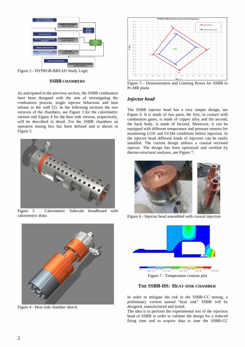
SSBB CHAMBERS As anticipated in the previous section, the SSBB combustors have been designed with the aim of investigating the combustion process, single injector behaviour and heat release to the wall [2]. In the following sections the two versions of the chambers, see Figure 3 for the calorimetric version and Figure 4 for the heat sink version, respectively, will be described in detail. For the SSBB chambers an operative testing box has been defined and is shown in Figure 5.
Figure 3 – Calorimetric Subscale breadboard with calorimetric disks
Figure 4 - Heat sink chamber sketch
Figure 5 - Demonstration and Limiting Boxes for SSBB in Pc-MR plane Injector head The SSBB injector head has a very simple design, see Figure 6. It is made of two parts, the first, in contact with combustion gases, is made of copper alloy and the second, the back body, is made of Inconel. Moreover, it can be equipped with different temperature and pressure sensors for monitoring LOX and GCH4 conditions before injection. In the injector head different kinds of injectors can be easily installed. The current design utilizes a coaxial recessed injector. The design has been optimized and verified by thermo-structural analyses, see Figure 7.
Figure 6 - Injector head assembled with coaxial injectors
Figure 7 - Temperature contour plot
THE SSBB-HS: HEAT SINK CHAMBER In order to mitigate the risk in the SSBB-CC testing, a preliminary version named ―heat sink‖ SSBB will be designed, manufactured and tested. The idea is to perform the experimental test of the injection head of SSBB in order to validate the design for a reduced firing time and to acquire data to tune the SSBB-CC
HYPROB SSBB Demonstration and Limiting Boxes
N A'
B'
C'
D'46
47
48
49
50
51
52
53
54
55
56
57
58
59
60
61
62
63
64
2.0 2.2 2.4 2.6 2.8 3.0 3.2 3.4 3.6 3.8 4.0 4.2 4.4 4.6 4.8 5.0
MR [ - ]
Pc
[b
ar]
Limiting Box
Demonstration Box
A
B
C
D

3
chamber water disks in order to obtain more accurate measurements [3]. The SSBB-HS objectives are the following:
• to investigate the behaviour of the injector • to obtain a first estimate of the heat flux on the
combustion chamber for model validation • to implement a chamber "battleship" for a first
verification of the stability of the combustion.
The SSBB-HS consists of three main parts, see Figure 8 : the injection head, the combustion chamber module made of copper alloy and the throat/nozzle module made of molybdenum alloy in order to withstand the high throat heat fluxes.
Figure 8 – SSBB-HS with visible thermocouples holes.
The combustion chamber is equipped with embedded thermocouples that allow for heat load evaluation and different pressure transducers for monitoring chamber pressure. Heat fluxes rebuilding logic The SSBB-HS is equipped with 15 embedded thermocouples, which will be able to operate to high heat flux levels up to 40 MW/m2. They can be mounted in the copper wall without disturbing the temperature and heat fluxes anf have aresponse time of 0.1 seconds and are easy to install. For these purposes ―K‖ thermocouples have been selected with a frequency response of 100Hz. The thermocouples have been installed in the positions shown in Figure 9.
Figure 9 - Thermocouple triplets and scheme for
measurements A methodology similar to the one proposed in [4] has been applied in order to rebuild data, due to its simplicity and at the same time accuracy, using a polar coordinate system adopting a 4th order polynomial development of the temperature function and using the following 1D equation.
With this kind of approach two thermocouples are needed, the third one is used as a backup and to account for axial effects. System analyses The aim of these analyses is to have a preliminary evaluation of the dynamics of the chamber during the transient phases and a verification of chamber performance. The model is consists mainly of a combustion chamber and nozzle interfaced with different parts of walls 1 to 4 for the copper alloy chamber and 5 to 6 for the molybdenum based alloy part (see schematics in Figure 10). Looking at Figure 11 and Figure 12, the expected behaviour of thermocouples is shown. The derivative of the temperature in time is proportional to the heat fluxes incident on the chamber.
Figure 10 - Schematics of the HEAT SINK SSBB
Figure 11- Chamber Pressure in time
Figure 12 - Wall Nodes temperature in time.
Regarding the system stability study, the ROCCID© code has been used for all the extremes of the operative envelope [5]. No criticalities are foreseen. In any case the SSBB-HS has been designed in order to withstand more than 3 times the nominal pressure level, and a second unit will be equipped with a high frequency pressure transducer.

4
Figure 13 - 1L High Frequency Transfer Functions at
nominal operating condition
Figure 14 - Low frequency transfer function at nominal
condition CFD analysis The main aim of the CFD analysis is to verify pressure levels and heat loads on the combustion chamber [6],[7].
Figure 15 - Pressure distribution in the computational
domain, flood and 50 bar iso-lines The chamber/nozzle and wall heat flux profile is shown in Figure 16. It is worth noting that, because of the fluctuations of the RANS field, the distribution in Figure 16 is only a snapshot of a solution which is continuously evolving, so that it is possible to identify average values only.
Figure 16 - Heat flux distribution along the chamber and
nozzle walls FEM results For the verification of the chamber, a thermo-structural analysis has been carried out in order to evaluate if the maximum firing time is compatible with the structure and by applying a load cycle to evaluate the life cycle of the chamber.
Figure 17 - Equivalent plastic strain after 2 cycles
THE SSBB-CC: CALORIMETRIC CHAMBER The subscale calorimetric breadboard (SSBB-CC) has the main aim of investigating the single injector thermal behavior, in terms of heat flux distributions on the chamber wall following a calorimetric approach [8] . To this end, the design of this system will be optimized to allow accurate measurements of heat flux on the walls and pressures and temperatures inside the combustion chamber. The SSBB-CC concept is shown in Figure 18. It is composed of a certain number of disks that have an independent cooling flow so that is possible to conduct measurement of the heat transferred from the combustion chamber to the coolant. In the way it is designed it can be equipped with different types of injectors. The chamber has also an important technological objective of verifying structural integrity because in the manufacturing phase it is necessary to develop novel brazing capabilities between Inconel and copper alloy. The process adopted to achieve satisfactory joints is the one selected for the demonstrator and so the SSBB-CC testing lowers the risk of develop a similar process in the final regenerative cooling chamber manufacturing.
5
Figure 18 – SSBB-CC sketch
Regarding the system design an iterative procedure has
been applied in order to identify the optimal arrangement of the disks, disk dimensions and the number of disks, defining at the same step the optimal geometry for the cooling channels in terms of aspect ratio and thickness. This has been achieved by applying a series of design constraints that can be summarized as follows:
evaluate measurable temperature differences between the inlet and outlet sections in order to obtain the heat flux profile along the chamber
avoid high thermal stresses for thermo-structural purposes and boiling conditions in the disk channels in order to preserve the reliability of the system for all the design conditions in the limiting box
All the fluid thermo-physical properties were obtained by [9].The breadboard instrumentation foresees high and low frequency pressure transducers in the combustion chamber, temperature measurement on the internal liner of two cooling disks, through two type-K thermocouples installed in the cylindrical region via a hole in the close-out of the disk. Moreover, inlet and outlet water temperatures will be measured to derive heat flux estimations at the wall to validate the design tool. All the other parameters (propellant flow rates, pressure and temperatures) will be guaranteed by the test bench facility.
Figure 19 – Temperature distribution and inverse of safety factor for the throat cooling disk
In order to verify the Breadboard at system level the following ECOSIMPRO [10] model has been used including tuning the mass flow to have measurements useful for rebuilding of the heat fluxes:
Figure 20 – SSBB ECOSIMPRO schematic
The results in terms of cooling disk performance and thruster performance are in line with the design values.
Figure 21 – Water disks exit temperatures
Figure 22 – Thrust and temperature profile
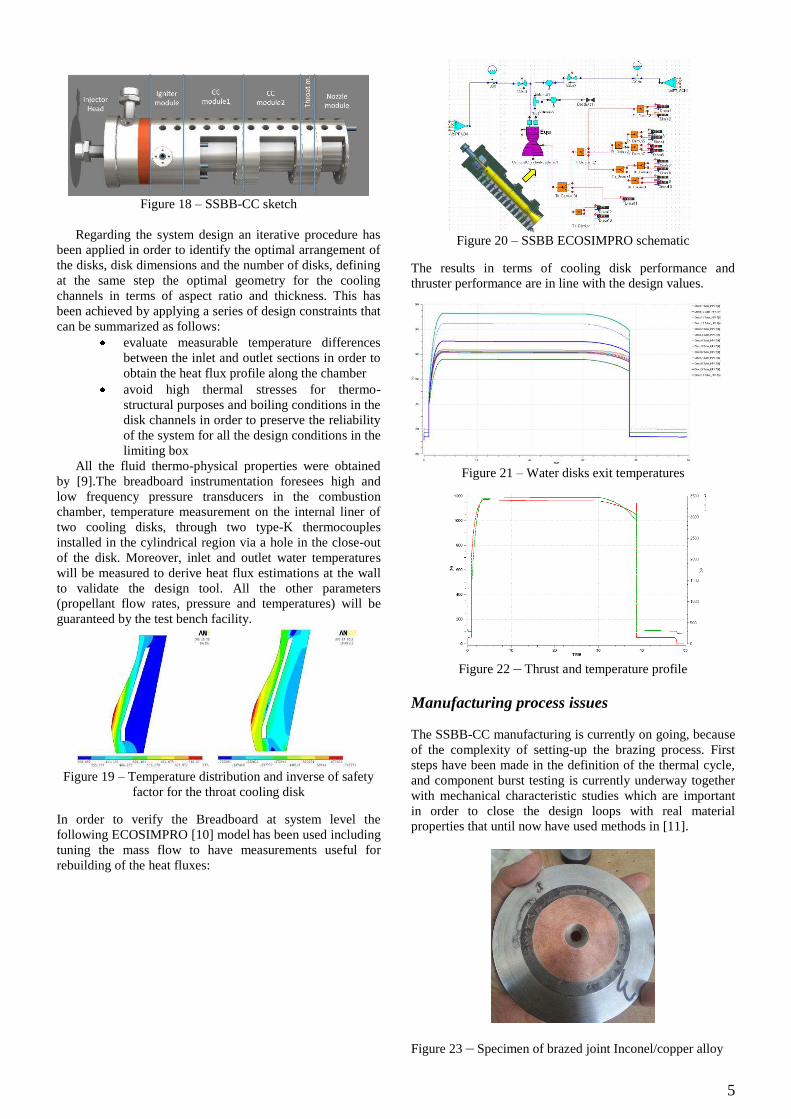
Manufacturing process issues The SSBB-CC manufacturing is currently on going, because of the complexity of setting-up the brazing process. First steps have been made in the definition of the thermal cycle, and component burst testing is currently underway together with mechanical characteristic studies which are important in order to close the design loops with real material properties that until now have used methods in [11].
Figure 23 – Specimen of brazed joint Inconel/copper alloy

6
Figure 24 – Specimen of brazed joint Inconel/copper alloy
under stress test
Figure 25 – Cooling disk module under proof/burst testing
IGNITER A customized igniter has been developed and tested for the SSBB combustion chambers [12]. This is a spark torch ignition system that uses two propellants (GOX and GCH4) that are mixed in the igniter combustion chamber and ignited by a commercial spark plug. The igniter is made up of two main parts, the igniter head (1) and the torch outlet (2) with flanged interfaces sealed by metal O-rings. The fuel and oxidizer are injected via orifices. The inlet paths of CH4 and Oxygen are equipped with PT sensors; additionally a pressure sensor is installed in the main chamber in order to monitor chamber pressure [13].
Figure 26 - Igniter sketch.
Table 1 - Nominal performances of the igniter
Performance Value Total Power (kW) 64 Nominal firing time (s) 1.5 Maximum firing time (s) 2.0 Demonstrated shelf life cycles ≥ 20 Chamber Pressure (bar) 14
Figure 27 - Igniter assembled
Figure 28 – Igniter CFD simulation
COMPONENTS TESTING Injector cold flow testing A cold flow test campaign has been carried out on the SSBB injector design in order to study geometrical parameters effects on jet behaviour. Moreover a high pressure cold flow on gas part has been carried out in order to evaluate gas part pressure drop. The scope of the test campaign is to have a preliminary idea of the behaviour of the jet. Different injectors have been produced for the SSBB; in particular, two different kinds of posts have been manufactured in order to investigate the effect of the inlet orifice on the pressure drop. Moreover some slightly different sleeves have been produced in order to achieve different values of J, M and velocity ratio (VR) for study purposes.
Figure 29 - Injector elements with and without post orifice
Eight types of injectors have been tested (see Table 2 and Table 3) and the flow visualization has been obtained with a simple 8 MP camera. To obtain measurements of angle, a 50% threshold method after histogram levels optimization has been used. As suggested in [14] the tangents around the cone must be considered since it is in this region that the flow is fully developed. The results in terms of pressure drop (and thus liquid velocity) are in line with design values; for what concerns the results with orifice, the pressure drops are slightly higher than expected and so lower liquid jet velocities are achieved. These results will be investigated more fully in the future also using more accurate visualization techniques. In general using similar J and M values the jet profiles are similar. In
2
1

7
the case of the presence of the inlet orifice in the liquid part of the injector the jet is larger thus confirming that the J and M values are fairly under-predicted.
Figure 30 - Jet images captured by camera with and without
orifice
Figure 31 - Jet: α/2
Table 2 - Design parameters without inlet orifice
Table 3 - Design parameters with inlet orifice
Figure 32: Transformed contour for jet spray evaluation
The results confirm the following relation and allow for the tuning of the c constant in the relation for our recessed injectors.
Igniter Testing An experimental campaign has been performed in the AVIO FAST2 facility on the igniter designed for the subscale chambers. Different conditions have been explored around the nominal value of mixture ratio and a qualification box has been defined.
Figure 33 - Qualification box.
No major failures have been ever detected; only with high MR (out of the operative design value) an erosion of the spark plug (red points) occurs.
Figure 34 - Typical test pressure plot
Impingement testing In the experimental test campaign carried out on the igniter, equipment for the evaluation of the thermal impact of the igniter flame on the heat sink chamber has been used being positioned in the chamber orthogonally to injector flow. This equipment has been embedded with 7 thermocouples at different locations as reported in the following figures. Moreover the results of the numerical rebuilding of heat fluxes, shown in Figure 39, have been obtained according to [15].The difference is due to the calculation that has been carried out by considering a 300K wall.
.
Pcc

8
Figure 35 - Impingement equipment section (Impingement
plate in OHFC)
Figure 36 - Equipment for the igniter thermal impact
evaluation mounted on FAST2
Figure 37 – Igniter firing with the impingement equipment.
Figure 38 – Pressure distribution with 5 bar exit pressure.
Figure 39 – Experimental data: heat fluxes measured VS
calculated @5 bar in the chamber Heat sink testing activities Heat sink preliminary test activities have been successfully accomplished in AVIO FAST2 facility, among these are chamber proof tests, injector cold flow testing and integrated igniter testing. The chamber is now ready to perform its first firing test campaign.
Figure 40 – Heat sink chamber on FAST2 test bench under
proof test
Figure 41 – Heat sink chamber on FAST2 test bench detail
of the integrated igniter

9
Figure 42 – Firing of the igniter integrated on the chamber
Conclusions All the design activities and the pre-test activities have been carried out in order to start the test campaign of the SSBB-HS in the forthcoming days. Regarding the realization of the SSBB-CC, activities on brazing characterization are on-going, once this phase is completed the analyses will be repeated with updated material properties. Moreover the data from the SSBB-HS will be analysed and used to tune design models for Demonstrator and to set up the mass flow of the SSBB-CC chamber.
Acknowledgements This work has been carried out within the HYPROB program, funded by the Italian Ministry of University and Research (MIUR) whose financial support is much appreciated. The authors want to thank CIRA-AVIO HYPROB-BREAD team for the cooperation at the realization of this work. In particular for the test activities an important contribution has been given by AVIO FAST2 team, L. De Rose, D. Scarpino, S. Carapellese and G. Malandrucco.
List of Acronyms and Symbols J Momentum Flux Ratio M Momentum ratio VR Velocity Ratio MR Mixture Ratio CFD Computational fluid dynamics α Jet Angle ρ Density c Specific Heat k Thermal conductivity PT Pressure temperature t Time variable r Wall radial position OHFC Oxygen free copper GOX/LOX Gaseous/Liquid Oxygen GCH4/LCH4 Gaseous/Liquid Methane
References [1] Salvatore, V., Battista, F., De Matteis, P., Rudnykh M,,
Arione, L., Ceccarelli, F., 2013, Recent Progress On The Development Of A Lox/Lch4 Rocket Engine Demonstrator In The Framework Of The Italian Hyprob Program. 64rd International Astronautical Congress, IAC-13,C4,3,4,x19439
[2] Kirchberger C.Wagner, R., Kau, H., P., Soller, S., Martin, P., Bouchez M., Bonzom C., 2008, Prediction
and Analysis of Heat Transfer in Small Rocket Chambers, AIAA-2008-1260.
[3] Locke, J.M., Pal, S., Woodward R.D, 2007, Chamber Wall Heat Flux Measurements for a LOx/CH4 Propellant Uni-element Rocket, AIAA 2007-5547.
[4] Coy, E.B., 2007, Code validation of CDD Heat transfer models for liquid rocket engine combustion devices, AFRL-PR-ED-TP-2007-157.
[5] Muss J. A., Nguyen T. V., Johnson C. W., 1991, User’s Manual for Rocket Combustor Interactive Design (ROCCID) and Analysis Computer Program, Volume I, NASA Contractor Report 187109.
[6] ANSYS FLUENT User’s Guide, release 13.0.Ansys Inc., Canonsburg, PA.
[7] Westbrook, C.K., Dryer, F.L., 1981. Simplified Reaction Mechanisms for the Oxidation of Hydrocarbon Fuels in Flames. Combustion Science and Technology , 27, 31-43.
[8] Suslov, D., Woschnak A., Greuel D., Oschwald M., 2005, Measurement techniques for investigation of heat transfer processes at European Research and Technology Test Facility P8, European Conference for Aerospace Sciences (EUCASS). 2005.
[9] NIST Chemistry Web Book, REFPPROP v7,http://webbook.nist.gov/chemistry/fluid/.
[10] ECOSIMPRO, EA Internacional, Magallanes, 3. 28015 Madrid, Spain.
[11] de Groh III, H.C., Ellis D.L., Loewenthal W.S., 2007, Comparison of GRCop-84 to other High Thermal Conductive Cu Alloys, NASA/TM—2007-214663.
[12] Sutton, G.P., Biblarz, O., 2010, Rocket Propulsion Elements. John Wiley & Sons, ISBN-9780470080245.
[13] Battista, F., Ferraiuolo, M, Martucci, A., Fragiacomo M., Natale, P., Ricci, D., Roncioni, P., French, D.A., Vito Salvatore V., 2014, Modelling, Testing and Design Considerations of a GOX/GCH4 Igniter for a HYPROB-SSBB Single Injector Thrust Chamber Journal of the British Interplanetary Society 01/2014; 67.
[14] Gautom, V., 2007, Flow and Atomization Characteristics of Cryogenic Fluid from a Coaxial Rocket Injector, University of Maryland, ProQuest.
[15] Zuckerman, L., Jet Impingement Heat Transfer: Physics, Correlations, and Numerical Modeling, Advancement in Heat transfer n.39.
Copyright © 2022 FDOKUMEN