
RIFLE: A General Purpose Pin-level Fault Injector
18
1 RIFLE: A General Purpose Pin-level Fault Injector Henrique Madeira, Mrio Rela, Francisco Moreira, and Joo Gabriel Silva Laboratrio de Informtica e Sistemas, University of Coimbra 3000 Coimbra, Portugal Abstract. This paper discusses the problems of pin-level fault injection for dependability validation and presents the architecture of a pin-level fault injector called RIFLE. This system can be adapted to a wide range of target systems and the faults are mainly injected in the processor pins. The injection of the faults is deterministic and can be reproduced if needed. Faults of different nature can be injected and the fault injector is able to detect whether the injected fault has produced an error or not without the requirement of feedback circuits. RIFLE can also detect specific circumstances in which the injected faults do not affect the target system. Sets of faults with specific impact on the target system can be generated. The paper also presents fault injection results showing the coverage and latency achieved with a set of simple behavior based error detection mechanisms. It is shown that up to 72,5% of the errors can be detected with fairly simple mechanisms. Furthermore, for over 90% of the faults the target system has behaved according to the fail-silent model, which suggests that a traditional computer equipped with simple error detection mechanisms is relatively close to a fail-silent computer. 1. Introduction The validation of fault-tolerance mechanisms is a difficult task. The mechanisms involved in the fault activation and in the error propagation process are highly complex, which greatly complicates the task of analytical modeling. Experimental evaluation by fault injection has become an attractive way of validating specific fault- tolerance mechanisms, allowing the estimation of fault tolerant system measures such as fault coverage and error latency [1]. This paper addresses the problem of injecting physical faults in physical models [2], i.e. actual systems implementing the fault-tolerance mechanisms under evaluation. In this group we consider not only prototypes implementing specific hardware and/or software features of the developed systems but also actual systems working very closely to real world conditions. In this way fault injection can effectively complement other kind of techniques used in the development and validation phases (e.g. modeling and simulation), as fault injection can be used in the final implementation of the developed system. This is quite important as previous researches of different natures [3, 4, 5] have emphasized the impact of the workload on the performance of the error handling mechanisms. Several techniques have been used for physical fault injection. Most of them fall in two main groups: 1) fault injection at the IC pin-level [6, 7, 8, 9, 10, 1, 11] and 2) injection of internal faults into the ICs, either by exposure to different sources of radiation [12, 3] or by interference with the IC power supply [10, 13]. Methods based on the injection of internal IC faults have the inherent advantage of causing actual faults in the ICs, which may be close to a realistic fault model. A simple method for injecting internal faults in ICs is to interfere with the chip power supply lines [10, 13]. However, it is quite difficult to control the extension of the errors caused inside the chip with this method, and some more sensitive chip areas might be responsible for the majority of the errors.
-
Upload
independent -
Category
Documents
-
view
0 -
download
0
Transcript of RIFLE: A General Purpose Pin-level Fault Injector
1
RIFLE: A General Purpose Pin-level Fault Injector
Henrique Madeira, M�rio Rela, Francisco Moreira, and Jo�o Gabriel Silva
Laborat�rio de Inform�tica e Sistemas, University of Coimbra3000 Coimbra, Portugal
Abstract. This paper discusses the problems of pin-level fault injection for dependabilityvalidation and presents the architecture of a pin-level fault injector called RIFLE. This systemcan be adapted to a wide range of target systems and the faults are mainly injected in theprocessor pins. The injection of the faults is deterministic and can be reproduced if needed.Faults of different nature can be injected and the fault injector is able to detect whether theinjected fault has produced an error or not without the requirement of feedback circuits. RIFLEcan also detect specific circumstances in which the injected faults do not affect the target system.Sets of faults with specific impact on the target system can be generated. The paper also presentsfault injection results showing the coverage and latency achieved with a set of simple behaviorbased error detection mechanisms. It is shown that up to 72,5% of the errors can be detectedwith fairly simple mechanisms. Furthermore, for over 90% of the faults the target system hasbehaved according to the fail-silent model, which suggests that a traditional computer equippedwith simple error detection mechanisms is relatively close to a fail-silent computer.
1. Introduction
The validation of fault-tolerance mechanisms is a difficult task. The mechanismsinvolved in the fault activation and in the error propagation process are highlycomplex, which greatly complicates the task of analytical modeling. Experimentalevaluation by fault injection has become an attractive way of validating specific fault-tolerance mechanisms, allowing the estimation of fault tolerant system measures suchas fault coverage and error latency [1].
This paper addresses the problem of injecting physical faults in physical models[2], i.e. actual systems implementing the fault-tolerance mechanisms under evaluation.In this group we consider not only prototypes implementing specific hardware and/orsoftware features of the developed systems but also actual systems working veryclosely to real world conditions. In this way fault injection can effectively complementother kind of techniques used in the development and validation phases (e.g. modelingand simulation), as fault injection can be used in the final implementation of thedeveloped system. This is quite important as previous researches of different natures[3, 4, 5] have emphasized the impact of the workload on the performance of the errorhandling mechanisms.
Several techniques have been used for physical fault injection. Most of them fall intwo main groups: 1) fault injection at the IC pin-level [6, 7, 8, 9, 10, 1, 11] and 2)injection of internal faults into the ICs, either by exposure to different sources ofradiation [12, 3] or by interference with the IC power supply [10, 13].
Methods based on the injection of internal IC faults have the inherent advantage ofcausing actual faults in the ICs, which may be close to a realistic fault model.
A simple method for injecting internal faults in ICs is to interfere with the chippower supply lines [10, 13]. However, it is quite difficult to control the extension ofthe errors caused inside the chip with this method, and some more sensitive chip areasmight be responsible for the majority of the errors.
2
Fault injection by heavy-ion radiation is another way of injecting faults inside theICs. A fault-injector based on heavy-ion radiation was presented in [3]. However, thismethod is difficult to apply to existing computers mainly because the target chipoutputs have to be compared pin-by-pin with a gold unit in order to know whether theradiation has produced errors inside the target IC or not.
Most of the physical fault injection studies have been performed using pin-levelfault injection [6, 7, 8, 9, 10, 1, 11] ]. Many of these papers concern the evaluation offault-tolerance mechanisms in specific target systems. A general methodology forphysical fault injection has been presented in [1], which also describes theMESSALINE pin-level fault injector.
However, the injection of pin-level faults in the complex microprocessors availabletoday addresses new problems which have not been answered so far. Most of theprocessors use techniques such as prefetching, internal caches, pipelining, and delayedbranches, which greatly difficult (or even make it impossible) the analysis of the results.
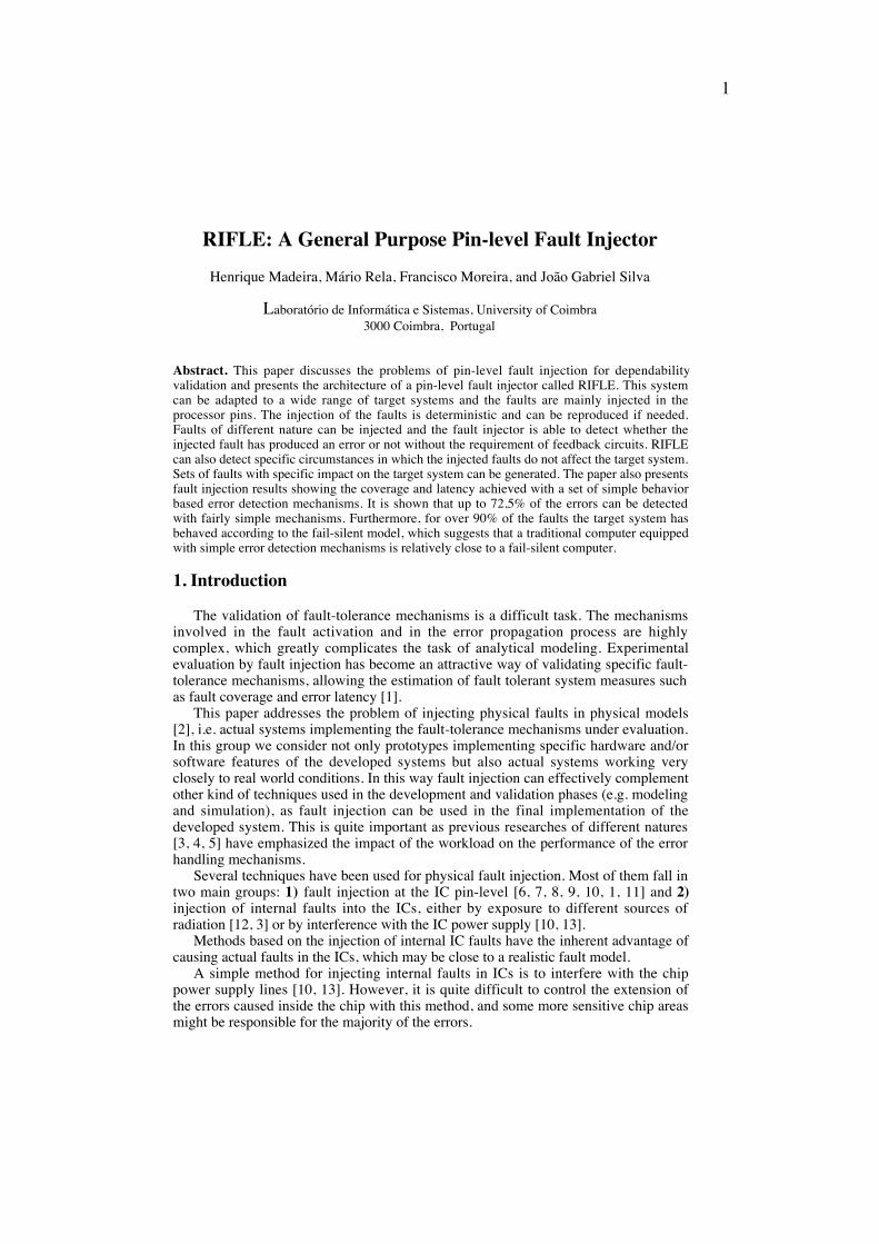
The main problem in injecting pin-level faults in complex chips such as theprocessors is to find out whether the injected fault should be accounted for the results ornot. Fig. 1 illustrates the analysis required at the processor instruction execution levelbehavior after the injection of each processor pin-level fault in order to accomplishedthis goal.
Injection of the fault
Fault
Error(s)
Deviationsfrom the correct
behavior
Correct behavior
Effective fault
Effective errors
Discarded errorsLatent errors
Secondary errors (propagated)
Non effective fault
Fig. 1. Impact of a pin-level fault in the target system at the processor instruction level behavior.
The first step is to detect if the injected fault has produced an error or not. It shouldbe noted that not all pin-level faults produce errors. For example, the injection of astuck-at-high fault in a pin that is already high will not generate errors. After detectingthe faults that have caused errors (effective faults) it is necessary to find out if the errorshave been discarded as normal consequence of the processor prefetch or pipeline. Thisanalysis depends on the processor features and the actual program execution after theinjection of the fault. In most of the cases, only the faults that cause deviations in thetarget system behavior should be considered in order to obtain correct results.
To the best of our knowledge RIFLE is the only pin-level fault injector capable ofperforming the above analysis.
2. Abstractions in the Fault Injection Process
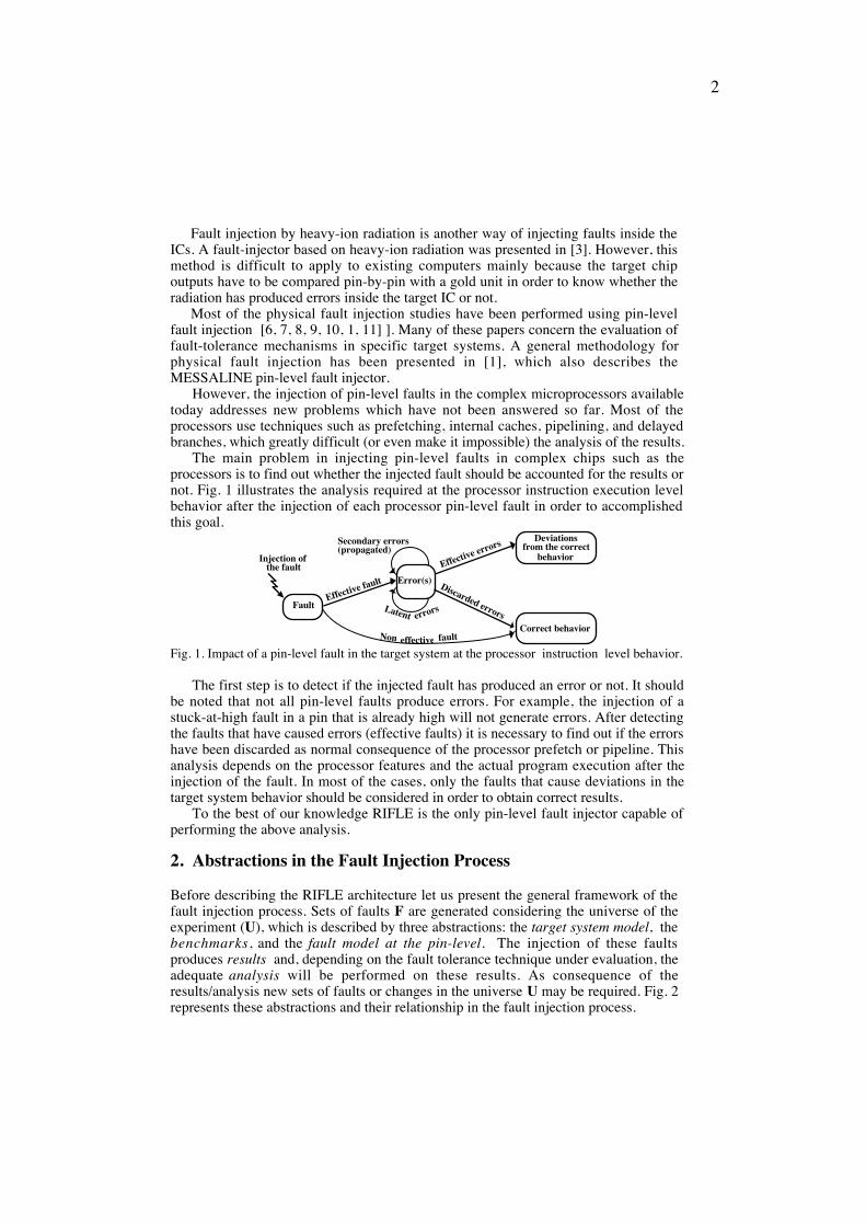
Before describing the RIFLE architecture let us present the general framework of thefault injection process. Sets of faults F are generated considering the universe of theexperiment (U), which is described by three abstractions: the target system model, thebenchmarks, and the fault model at the pin-level. The injection of these faultsproduces results and, depending on the fault tolerance technique under evaluation, theadequate analysis will be performed on these results. As consequence of theresults/analysis new sets of faults or changes in the universe U may be required. Fig. 2represents these abstractions and their relationship in the fault injection process.
3
Target SystemModel
Benchmarks
Fault Modelat pin-level
Set of Faults Results AnalysisInjection
U
Fig. 2 . Abstractions in the Fault Injection Process
Each fault is defined by a set of attributes such as fault duration, lines affected, typeof fault, and specific conditions that trigger the injection of the fault. A set of faults Fdefined from a given universe U is only valid for this universe. Furthermore, twodifferent faults must be described by two different sets of attributes, in order to achieverepetitive fault injection. In other words, the injection of F in the conditions defined byU always produces the same results. Changes in the universe U, for example changesin the benchmarks, will cause the injection of F to produce different results becausethe faults F are no longer valid for the new conditions.
2.1 - Target system model from the fault injector point of view
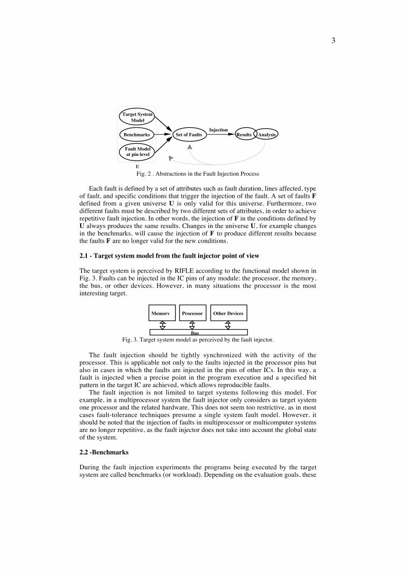
The target system is perceived by RIFLE according to the functional model shown inFig. 3. Faults can be injected in the IC pins of any module: the processor, the memory,the bus, or other devices. However, in many situations the processor is the mostinteresting target.
Bus
ProcessorMemory Other Devices
Fig. 3. Target system model as perceived by the fault injector.
The fault injection should be tightly synchronized with the activity of theprocessor. This is applicable not only to the faults injected in the processor pins butalso in cases in which the faults are injected in the pins of other ICs. In this way, afault is injected when a precise point in the program execution and a specified bitpattern in the target IC are achieved, which allows reproducible faults.
The fault injection is not limited to target systems following this model. Forexample, in a multiprocessor system the fault injector only considers as target systemone processor and the related hardware. This does not seem too restrictive, as in mostcases fault-tolerance techniques presume a single system fault model. However, itshould be noted that the injection of faults in multiprocessor or multicomputer systemsare no longer repetitive, as the fault injector does not take into account the global stateof the system.
2.2 -�Benchmarks
During the fault injection experiments the programs being executed by the targetsystem are called benchmarks (or workload). Depending on the evaluation goals, these

4
programs could be the actual application program or "standard" benchmarks. Usually,these benchmarks are small programs meant to be representative of the most commonprogram structures used in actual programs.
Previous works [3, 14] have shown the strong influence of the benchmarks in theperformance of the evaluated fault-tolerance techniques. This emphasizes the interestof the fault injection in actual systems running real application programs.
2.3 - Transient fault model at the pin-level
A key aspect in fault injection can be expressed in the following question: which arethe pin-level error patterns that are representative of internal IC transient faults?
Transient and intermittent faults are in fact the major physical cause for computerfailures [15]. As the objective of the fault injection is to emulate actual faults, or injectfaults that cause the same error manifestations as actual faults, it seems obvious thattransient faults are the most interesting class of faults.
2.3.1 - The processor as the main target for pin-level fault injection
The choice of the target IC is largely dependent on the evaluation goals. However, inmost cases, the processor should be the main target as the system behavior is mainlydetermined by the processor. In addition to this argument, the following reasons alsojustify the interest of the fault injection at the processor pins:
1) Faults injected in the processor pins can model not only internal processor faultsbut also memory faults, bus faults, and most of the faults in peripheral devices.For instance, faults in a peripheral device can be emulated by injecting faults inthe processor pins during the cycles in which the processor is reading theperipheral device;
2) It is possible to cause errors in other parts of the target system by injecting faultsin the processor pins. For example, a fault injected in the processor data busduring a memory write cycle will cause an error in the addressed memory cell.
2.3.2 - Fault model at the processor pins
Pin-level manifestations of internal processor faults are very difficult to estimate. Intheory, it is possible to determine in advance the faulty pin-level behavior bysimulation or by exposing the IC to some source of radiation. However, this is notrealistic as simulation models or radiation source facilities are not commonly available.
Few works can be found in the literature addressing the problem of how internalmicroprocessor faults are manifested at the pins. Several gate-level simulation studiessuggested that internal faults cause multiple errors at the output pins [14, 16, 17].
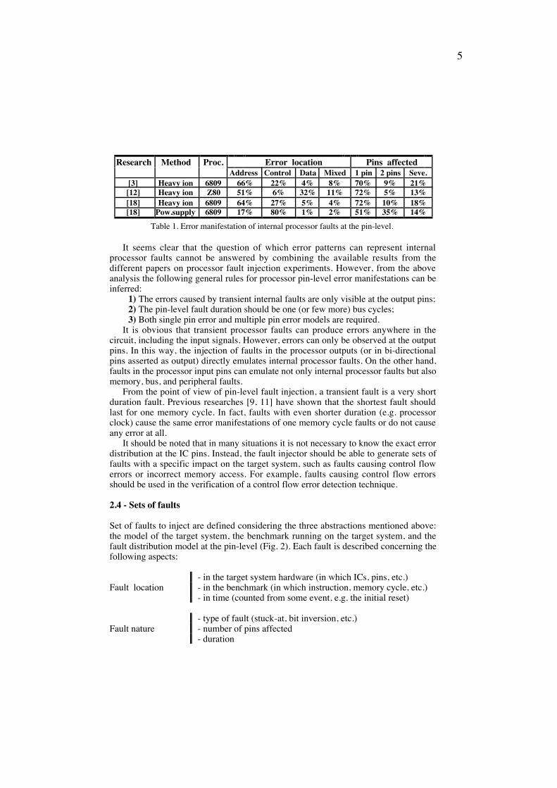
Experiments using radiation and power supply disturbances to inject actual faultsinside processors have also provided some insight on the pin-level manifestations ofinternal faults. The main results published on this topic are summarized in Table 1. The first thing to be noted is that all these works suggested the single pin errormodel, which contradicts the results obtained by the simulation works mentionedabove. Only a small percentage of faults have caused errors in multiple pins. Anotherimportant aspect is the fact that the errors are relatively well distributed among thepins (the greater error percentage in the address pins is because the used processorshave more address pins than data and control pins). The small percentage of errors inthe data pins result from the fact that these pins are normally asserted as input.
5
Research Method Proc. Error location Pins affectedAddress Control Data Mixed 1 pin 2 pins Seve.
[3] Heavy ion 6809 66% 22% 4% 8% 70% 9% 21%[12] Heavy ion Z80 51% 6% 32% 11% 72% 5% 13%[18] Heavy ion 6809 64% 27% 5% 4% 72% 10% 18%[18] Pow.supply 6809 17% 80% 1% 2% 51% 35% 14%
Table 1. Error manifestation of internal processor faults at the pin-level.
It seems clear that the question of which error patterns can represent internalprocessor faults cannot be answered by combining the available results from thedifferent papers on processor fault injection experiments. However, from the aboveanalysis the following general rules for processor pin-level error manifestations can beinferred:
1) The errors caused by transient internal faults are only visible at the output pins;2) The pin-level fault duration should be one (or few more) bus cycles;3) Both single pin error and multiple pin error models are required.
It is obvious that transient processor faults can produce errors anywhere in thecircuit, including the input signals. However, errors can only be observed at the outputpins. In this way, the injection of faults in the processor outputs (or in bi-directionalpins asserted as output) directly emulates internal processor faults. On the other hand,faults in the processor input pins can emulate not only internal processor faults but alsomemory, bus, and peripheral faults.
From the point of view of pin-level fault injection, a transient fault is a very shortduration fault. Previous researches [9, 11] have shown that the shortest fault shouldlast for one memory cycle. In fact, faults with even shorter duration (e.g. processorclock) cause the same error manifestations of one memory cycle faults or do not causeany error at all.
It should be noted that in many situations it is not necessary to know the exact errordistribution at the IC pins. Instead, the fault injector should be able to generate sets offaults with a specific impact on the target system, such as faults causing control flowerrors or incorrect memory access. For example, faults causing control flow errorsshould be used in the verification of a control flow error detection technique.
2.4 - Sets of faults
Set of faults to inject are defined considering the three abstractions mentioned above:the model of the target system, the benchmark running on the target system, and thefault distribution model at the pin-level (Fig. 2). Each fault is described concerning thefollowing aspects:
- in the target system hardware (in which ICs, pins, etc.)Fault location - in the benchmark (in which instruction, memory cycle, etc.)
- in time (counted from some event, e.g. the initial reset)
- type of fault (stuck-at, bit inversion, etc.)Fault nature - number of pins affected
- duration

6
2.5 - Results/analysis
The results depend on the fault-tolerance technique(s) under evaluation and theevaluation goals. In most of the cases, physical fault injection give direct measures onthe specific technique under evaluation. For example, the coverage and the averagelatency of an error detection approach can be directly assessed by fault injection.
The fault injection results can be divided in three categories: 1) binary results (yesor no, corresponding to the occurrence of some event), 2) counter results (e.g. latency;interval between two events, # occurrences of an event), and 3) extensive target systembehavior results. These results can be used in fault removal and fault forecasting [1].
3. The RIFLE architecture
The leading idea of RIFLE is to combine trigger and tracing techniques traditionallyused in digital logic analyzers with the logic required for the pin-level fault insertion.The result is a system able to inject practically all types of pin-level faults, and capableof recording extensive information on the target processor (and system) behavior afterthe injection of each fault. This tracing information is used for the completecharacterization of each fault and its impact on the target system (fault effectiveduration, the type of processor cycle affected, etc.), and for the analysis of the errorpropagation process. The analysis of the tracing information is automatically performed(after the injection of each fault) by the RIFLE software, which stores the key results ina spreadsheet file. Final statistical results (tables, charts, etc.) are obtained from this file.
The architecture of RIFLE is shown in Fig. 4. It is formed by three hardwaremodules and the control and management software running in the host computer (apersonal computer in the present version):Adaptation module: this module replaces the target processor in the socket and
contains the target processor and the fault injection elements. The faults are injectedusing the insertion technique and each injection element is just an electronic switch.
Control
Counters Trace Memory
Fault Trigger
Target System
I/OPorts
ISA Interface
Adaptation Module
Host computer: runs the RIFLE
software
Main ModuleInterface and Counters Module
CPU
RoutingFault injection
elements
Fig. 4. RIFLE organization.
7
Main module: receives the target processor bus signals from the adaptation module andcontains the fault trigger hardware and the trace memory. The fault trigger hardwarereceives the parameters describing each fault from the host computer and activatesthe injection elements when the conditions specified for the injection of the fault aredetected in the target processor bus. The trace memory continuously collects theinformation present in the target processor bus.
Interface and counters module: establishes the interface with the RIFLE hostcomputer and contains the circuits required to gather latency and binary results.
Control and Management Software: the main tasks of the Control and ManagementSoftware are: 1) to assist the experiment set up and the definition of sets of faults,2) to control the fault injection sequence, 3) to validate the faults considering theeventual errors produced, and 4) to collect the relevant results. In the presentimplementation, the software was implemented in C++ under Windows 3.1 in orderto provide a friendly icon and mouse oriented user interface.Each fault is described by a unique set of parameters which completely characterize
the fault (synchronized fault injection), which means that the injection of the faults isdeterministic and can be reproduced if needed. The fault injector is able to detectwhether the injected fault has produced an error or not without the requirement ofanalog feedback circuits (this is achieved by the analysis of the traced information).This feature greatly simplifies the fault injection hardware and avoids the speedrestrictions imposed by the feedback circuits [1]. Furthermore, as the Trace Memorytakes a snapshot of the target system behavior in the vicinity of the memory cycle(s) inwhich the fault was injected, a detailed error propagation analysis can be performed.This analysis is carried out by the RIFLE software without user intervention, fulfillingthe validation of each injected fault as illustrated in Fig. 1.
The specification of faults to inject can be done manually fault by fault, or automati-cally by the system, which generates random values for the fault descriptor parameters.In the latter, the user only supplies adequate ranges/restrictions for the fault descriptorparameters. Once a set of faults is generated it is stored in a file. During the fault injec-tion the parameters of each fault are sent to the fault injector hardware that controls theinjection of the fault. After the injection of a fault, the RIFLE software waits for a userspecified time-out (for fault propagation in the target system) and then reads the contentof the Trace Memory in order to validate the fault and collect the results.
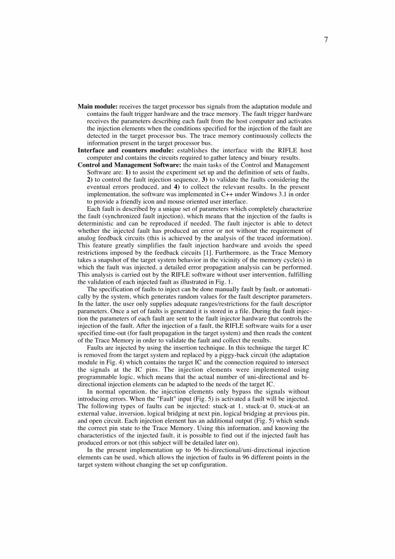
Faults are injected by using the insertion technique. In this technique the target ICis removed from the target system and replaced by a piggy-back circuit (the adaptationmodule in Fig. 4) which contains the target IC and the connection required to intersectthe signals at the IC pins. The injection elements were implemented usingprogrammable logic, which means that the actual number of uni-directional and bi-directional injection elements can be adapted to the needs of the target IC.
In normal operation, the injection elements only bypass the signals withoutintroducing errors. When the "Fault" input (Fig. 5) is activated a fault will be injected.The following types of faults can be injected: stuck-at 1, stuck-at 0, stuck-at anexternal value, inversion, logical bridging at next pin, logical bridging at previous pin,and open circuit. Each injection element has an additional output (Fig. 5) which sendsthe correct pin state to the Trace Memory. Using this information, and knowing thecharacteristics of the injected fault, it is possible to find out if the injected fault hasproduced errors or not (this subject will be detailed later on).
In the present implementation up to 96 bi-directional/uni-directional injectionelements can be used, which allows the injection of faults in 96 different points in thetarget system without changing the set up configuration.
8
µP
Data AddressTo the processor
socket
Bi-directional injection elements
To the Trace Memory To the Trace Memory and Fault Trigger
This outputs the correct pin state (before injecting the fault)
Dir
NC
To the processor socket
Uni-directional injection elements
Fault Fault
Fig. 5. Fault injection elements.
The Trace Memory is 96 bit width by 4096 depth, which allows the tracing of all96 injection points. It is implemented with fast memory chips (40 nsec. access time) inorder to achieve a high tracing rate. Eight data lines of the Trace Memory can be usedoptionally for recording the outputs of a counter (time stamps). The trace clock (whichdepends on the target processor) is generated in the Adaptation Module. The processorbus cycle is normally used as trace clock, because this signal represents the minimumgranularity in terms of target processor behavior from a pin-level point of view.
In the RIFLE the injection of faults by forcing technique (in which the faults areapplied directly to the IC pins by means of special probes) was not implemented. Withthis decision the complexity of the fault injector was significantly reduced withoutgreatly affecting its features. In fact, practically all types of faults that can be injectedby forcing techniques can also be injected by insertion techniques.
The RIFLE can be used in different target systems. The details concerning oneparticular target processor/system are grouped into the Adaptation Module and in a fileused by the fault injector software. All that is required is to remove the target systemprocessor from its socket and place it in the adaptation module, which is then connectedto the processor socket (soldered processors are more complex to handle, but it is stillpossible to do it).
A RIFLE predecessor (with the same basic architecture) has been extensively usedin the evaluation of behavior based error detection techniques [11, 19]. The RIFLE hasalready been used in computers based on the 68000 and in the Z80 processors.Recently, the adaptation modules for the Intel 486DX processor and the Inmos T8001
have been finished.
3.1 Fault trigger capabilities
The Fault Trigger module detects the unique conditions defined for the injection of afault. Each fault is defined by a set of parameters as shown in the table presented inTable 2 (which are a generalization of the fault definition parameters used in [9]).
The size of each parameter is indicated in parenthesis. In the cases of theActivation Address and the Activation Pattern the actual size (which depends on thetarget system) is conformed by the Adaptation Module.
The injection of the fault is triggered in the following way: the Fault TriggerModule looks for the Activation Address at the address bus of the target systemprocessor. The Activation Address should be detected as many times as the value in
1 The fault injector for systems based on the T800 is one of the tasks of the FTMPS(Fault-Tolerant Massively Parallel System) ESPRIT III project.

9
the Activation Address Count. When the specified number of Activation Address isdetected the Fault Trigger Module waits a number of memory cycles indicated inDelay. At this point, the Fault Trigger Module will wait until the Activation Pattern isdetected. After detecting the Activation Pattern the fault is injected during a timedefined in Duration and affecting the lines defined by the Fault Mask.
The Activation Pattern represents a bit pattern in the target system (normally a bitpattern in a random logic) which is of interest to include in the fault trigger conditions.Depending on the Fault Type parameter, the Activation Pattern can be included (as aqualifier) at different points in the fault trigger chain or even be omitted.
Fault parameters DescriptionFault Type Specifies the fault nature and other attributes
Activation Address (up to 32 bits)Activation Address Count (8 bits) These four parameters specify the moment
Delay (16 bits) in which the injection of the fault startsActivation Pattern (up to 16 bits)
Duration (8 bits) Specifies the fault duration (e.g. in mem. cycles)Fault Mask (96 bits) Specifies the pin(s) where the fault is injected
Table 2. Set of parameters required for the definition of a fault.
The Activation Address Count is useful to specify a point inside a program loop.The value in Activation Address Count represents the number of loops required toinject the fault. The Delay parameter allows the injection of faults during the data readand store cycles. For example, the injection of a fault during the execution of a stack-push-instruction can be achieved by specifying the address of the push instruction asthe Activation Address and choosing a Delay equal to the number of bus cycles spentwith the instruction fetch.
An innovative feature of RIFLE is the ability of defining specific sets of faultsfollowing some given criteria. This is achieved through the combination of the faulttrigger capabilities with versatile fault definition software. The ranges/restrictionssupplied by the user can work as a filter in the random fault generation process. Someexamples of specific sets of faults that can be generated are program space randomfaults, execution time random faults, control flow faults, and memory behavior faults.
3.2 Tracing capabilities
The recording in the Trace Memory is controlled by the Fault Trigger module. Afterthe injection of a fault the Trace Memory continues the recording until all the 4096memory positions have been filled. As mentioned above, the Trace Memory records allpoints in which a fault can be injected (processor data, address, and control lines and,optionally, other IC lines). RIFLE software uses the Trace Memory for three purposes:1) error feedback, 2) detection of discarded errors, and 3) detailed behavior analysis.
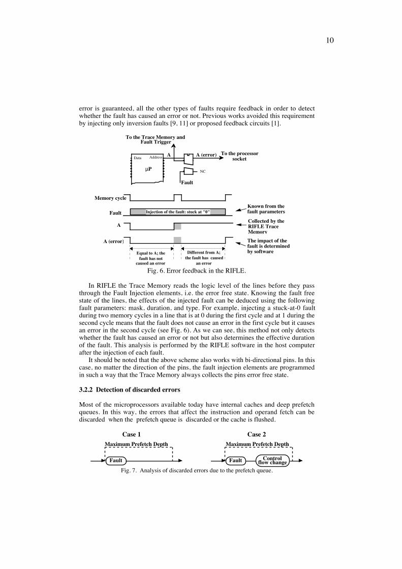
3.2.1 Error Feedback
The injection of a fault may not cause an error. For example, a stuck-at-1 faultinjected in a pin that is already at 1 during the time the fault is injected does not causean error. This effect is highly probable in the injection of very short faults for transientfault emulation and must be accounted for in order to have correct results. With theexception of inversion faults (the logic level at the faulted pin is inverted) in which the
10
error is guaranteed, all the other types of faults require feedback in order to detectwhether the fault has caused an error or not. Previous works avoided this requirementby injecting only inversion faults [9, 11] or proposed feedback circuits [1].
Injection of the fault: stuck at "0"
Equal to A; the fault has not
caused an error
Different from A; the fault has caused
an error
Memory cycle
Fault
A
A (error)
Known from the fault parameters
Collected by the RIFLE Trace Memory
The impact of the fault is determined by software
µP
Data Address
To the Trace Memory andFault Trigger
NC
To the processor socket
Fault
A A (error)
Fig. 6. Error feedback in the RIFLE.
In RIFLE the Trace Memory reads the logic level of the lines before they passthrough the Fault Injection elements, i.e. the error free state. Knowing the fault freestate of the lines, the effects of the injected fault can be deduced using the followingfault parameters: mask, duration, and type. For example, injecting a stuck-at-0 faultduring two memory cycles in a line that is at 0 during the first cycle and at 1 during thesecond cycle means that the fault does not cause an error in the first cycle but it causesan error in the second cycle (see Fig. 6). As we can see, this method not only detectswhether the fault has caused an error or not but also determines the effective durationof the fault. This analysis is performed by the RIFLE software in the host computerafter the injection of each fault.
It should be noted that the above scheme also works with bi-directional pins. In thiscase, no matter the direction of the pins, the fault injection elements are programmedin such a way that the Trace Memory always collects the pins error free state.
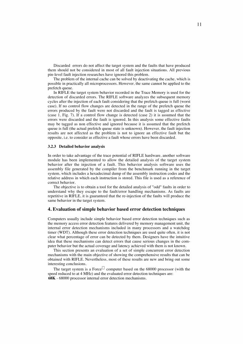
3.2.2 Detection of discarded errors
Most of the microprocessors available today have internal caches and deep prefetchqueues. In this way, the errors that affect the instruction and operand fetch can bediscarded when the prefetch queue is discarded or the cache is flushed.
Case 2
Maximum Prefetch Depth
Fault Controlflow change
Case 1
Maximum Prefetch Depth
Fault
Fig. 7. Analysis of discarded errors due to the prefetch queue.
11
Discarded errors do not affect the target system and the faults that have producedthem should not be considered in most of all fault injection situations. All previouspin-level fault injection researches have ignored this problem.
The problem of the internal cache can be solved by deactivating the cache, which ispossible in practically all microprocessors. However, the same cannot be applied to theprefetch queue.
In RIFLE the target system behavior recorded in the Trace Memory is used for thedetection of discarded errors. The RIFLE software analyzes the subsequent memorycycles after the injection of each fault considering that the prefetch queue is full (worstcase). If no control flow changes are detected in the range of the prefetch queue theerrors produced by the fault were not discarded and the fault is tagged as effective(case 1, Fig. 7). If a control flow change is detected (case 2) it is assumed that theerrors were discarded and the fault is ignored. In this analysis some effective faultsmay be tagged as non effective and ignored because it is assumed that the prefetchqueue is full (the actual prefetch queue state is unknown). However, the fault injectionresults are not affected as the problem is not to ignore an effective fault but theopposite, i.e. to consider as effective a fault whose errors have been discarded.
3.2.3 Detailed behavior analysis
In order to take advantage of the trace potential of RIFLE hardware, another softwaremodule has been implemented to allow the detailed analysis of the target systembehavior after the injection of a fault. This behavior analysis software uses theassembly file generated by the compiler from the benchmark running in the targetsystem, which includes a hexadecimal dump of the assembly instruction codes and therelative address in which each instruction is stored. This file is used as a reference ofcorrect behavior.
The objective is to obtain a tool for the detailed analysis of "odd" faults in order tounderstand why they escape to the fault/error handling mechanisms. As faults arerepetitive in RIFLE, it is guaranteed that the re-injection of the faults will produce thesame behavior in the target system.
4. Evaluation of simple behavior based error detection techniques
Computers usually include simple behavior based error detection techniques such asthe memory access error detection features delivered by memory management unit, theinternal error detection mechanisms included in many processors and a watchdogtimer (WDT). Although these error detection techniques are used quite often, it is notclear what percentage of error can be detected by them. Designers have the intuitiveidea that these mechanisms can detect errors that cause serious changes in the com-puter behavior but the actual coverage and latency achieved with them is not known.
This section presents an evaluation of a set of simple concurrent error detectionmechanisms with the main objective of showing the comprehensive results that can beobtained with RIFLE. Nevertheless, most of these results are new and bring out someinteresting conclusions.
The target system is a Force computer based on the 68000 processor (with thespeed reduced to at 4 MHz) and the evaluated error detection techniques are:68K - 68000 processor internal error detection mechanisms.
12
This processor has several internal error detection mechanisms such as thedetection of accesses to non-implemented memory, fetch of invalid instructions,unaligned instruction fetch, and unaligned word access.
MEM - Memory access error detection.This is a set of error detection mechanisms similar to the memory protectionfeatures of a normal memory management unit. The following mechanisms areconsidered:
AUM - Accesses to unused memory;ECS - Error in the code segment access (error if it is not an instruction fetch);EDS - Error in the data segment access (error if it is not a data read or write);AIM - Accesses to unimplemented memory.
WDT - Watchdog timerTraditional implementation of WDT by means of a hardware programmable timer.
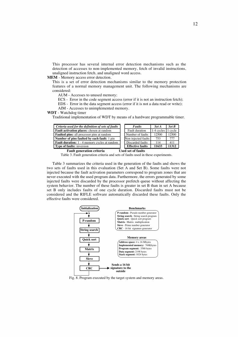
Criteria used for the definition of sets of faults Faults Set A Set BFault activation places: chosen at random Fault duration 1-4 cycles 1 cycleFaulted pins: all processor pins at random Number of faults 12500 12500Number of pins faulted by each fault: 1 pin Non injected faults 753 777Fault duration: 1 - 4 memory cycles at random Discarded faults 114 411Type of faults: inversion Effective faults 11633 11312
Fault generation criteria Used set of faults
Table 3. Fault generation criteria and sets of faults used in these experiments.
Table 3 summarizes the criteria used in the generation of the faults and shows thetwo sets of faults used in this evaluation (Set A and Set B). Some faults were notinjected because the fault activation parameters correspond to program zones that arenever executed with the used program data. Furthermore, the errors generated by someinjected faults were discarded by the processor prefetch queue without affecting thesystem behavior. The number of these faults is greater in set B than in set A becauseset B only includes faults of one cycle duration. Discarded faults must not beconsidered and the RIFLE software automatically discarded these faults. Only theeffective faults were considered.
Address space: 4 x 16 MbytesImplemented memory: 768KbytesProgram segment: 3588 bytesData segment: 2198 bytesStack segment: 1024 bytes
Memory areas
P-random
String search
Quick sort
Matrix
Sieve
CRCSends a 16 bit
signature to the outside
InitializationP-random - Pseudo number generatorString search - String search programQuick sort - Quick sort programMatrix - Matrix multiplication Sieve - Prime number generatorCRC - 16 bit signature generator
Benchmarks
Fig. 8. Program executed by the target system and memory areas.

13
The program executed by the target systems was written in C and is formed byseveral benchmarks as shown in Fig. 8. A CRC signature of the results produced by allbenchmarks is calculated at the end of each program cycle. That signature (consideredas the final result) is sent to the outside by a parallel output port, indicating whetherthe computer has produced wrong results or not. In this way it is possible to measurethe percentage of faults that cause the computer to produce wrong results, i.e. thefaults that cause the computer to violate the fail-silent model [20].
The injection of the faults is fully automatic and does not require operatorintervention. Before injecting each fault the RIFLE causes a reset to the target system,forcing a complete initialization. After the injection of each fault the RIFLE waits 5seconds before collecting the results. It was experimentally verified that if the errorswere not detected within this time they would not be detected.
4.1 - Processor built-in error detection mechanisms
Table 4 shows the coverage and latency obtained for the 68000 built-in error detectionmechanisms. The contributions of each individual error detection mechanism are alsopresented.
Error detection mechanism Coverage Average lat. (µSec) Stand.Dev. (µSec.)BE - Bus Error 8,6% 16785,4 133807,9
AE - Address Error 11,6% 3521,1 60735,5II - Ilegal Instruction 10,5% 4733,5 54527,9
DZ - Division by Zero 0,3% 65,5 268,1CHK - CHECK instruction 0,1% 21,4 3,4
TRAPV - Overflow 0,0% Ñ ÑPV - Previlege Violation 0,2% 32,6 48,7SI - Spurious Interrupt 0,0% Ñ ÑAE - $A code Emulation 1,1% 3345,3 30335,1FE - $F code Emulation 7,0% 5790,3 53505,1
HALT 15,6% 31,7 0,5
68K (All mechanisms) 55,2% 5086,7 67501,4Table 4. Coverage and latency of the 68000 built-in error detection mechanisms (set A).
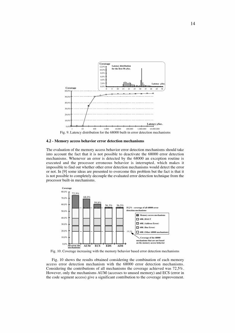
A coverage of 55,2% and a latency of 5,1 msec (with a large standard deviation)have been measured considering all processor built-in error detection mechanisms.However, a more detailed analysis of the latency distribution shows that most of thefaults have been detected within the first 100 µsec after the fault, which represents avery low latency. This conclusion is quite clear in the chart shown in fig. 9. Thesmall figure at the top represents the latency distribution in detail for the first 50 µsecafter the fault (in linear scale). The maximum coverage near the 32 µsec correspondsto the HALT mechanism which is activated after a double bus error (32µsec resultform the 2 x 16 µsec system bus time-out).
The analysis of the impact of a significant number of faults whose errors have beendetected with long latency (this analysis was carried out by using the informationrecorded in the RIFLE trace memory after the injection of each fault) has shown thatmost of these faults caused errors in the system stack or have corrupted the codesegment. In both situations, the errors stayed latent for a long time and the systembehavior was not affected. Only when the corrupted memory area was used by theprogram did the errors become active and were detected.
14
1 10 100 1.000 10.000 100.000 1.000.000 10.000.000
Latency µSec.
Coverage
0,0%
10,0%
20,0%
30,0%
40,0%
50,0%
60,0%
Latency µSec.
Coverage
0,0%
2,0%
4,0%
6,0%
8,0%
10,0%
12,0%
0 5 10 15 20 25 30 35 40 45 50
Latency distribution for the first 50 µSec.
Fig. 9. Latency distribution for the 68000 built-in error detection mechanisms
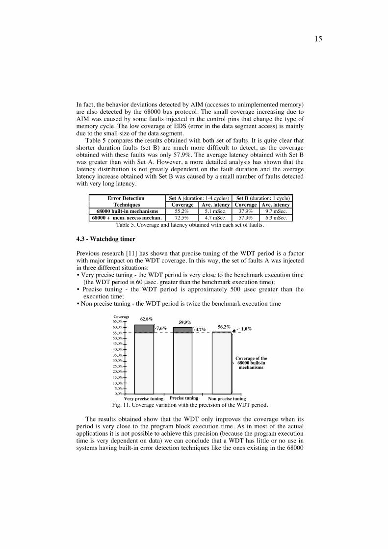
4.2 - Memory access behavior error detection mechanisms
The evaluation of the memory access behavior error detection mechanisms should takeinto account the fact that it is not possible to deactivate the 68000 error detectionmechanisms. Whenever an error is detected by the 68000 an exception routine isexecuted and the processor erroneous behavior is interrupted, which makes itimpossible to find out whether other error detection mechanisms would detect the erroror not. In [9] some ideas are presented to overcome this problem but the fact is that itis not possible to completely decouple the evaluated error detection technique from theprocessor built-in mechanisms.
0,0%
10,0%
20,0%
30,0%
40,0%
50,0%
60,0%
70,0%
AUM ECS EDS AIM
Memory access mechanisms
68K (HALT)
68K (Address Error)
68K (Bus Error)
68K (Other 68000 mechanisms)
68,0%
59,8%56,3% 56,5%
55,2% - coverage of all 68000 error detection mechanisms
19,3%
Coverage of the 68000 mechanisms that are not based on the memory access behavior
Coverage
All error det.
72,5%80,0%
mechanisms
Fig. 10. Coverage increasing with the memory behavior based error detection mechanisms
Fig. 10 shows the results obtained considering the combination of each memoryaccess error detection mechanism with the 68000 error detection mechanisms.Considering the contributions of all mechanisms the coverage achieved was 72,5%.However, only the mechanisms AUM (accesses to unused memory) and ECS (error inthe code segment access) give a significant contribution to the coverage improvement.
15
In fact, the behavior deviations detected by AIM (accesses to unimplemented memory)are also detected by the 68000 bus protocol. The small coverage increasing due toAIM was caused by some faults injected in the control pins that change the type ofmemory cycle. The low coverage of EDS (error in the data segment access) is mainlydue to the small size of the data segment.
Table 5 compares the results obtained with both set of faults. It is quite clear thatshorter duration faults (set B) are much more difficult to detect, as the coverageobtained with these faults was only 57,9%. The average latency obtained with Set Bwas greater than with Set A. However, a more detailed analysis has shown that thelatency distribution is not greatly dependent on the fault duration and the averagelatency increase obtained with Set B was caused by a small number of faults detectedwith very long latency.
Error Detection Set A (duration: 1-4 cycles) Set B (duration: 1 cycle)Techniques Coverage Ave. latency Coverage Ave. latency
68000 built-in mechanisms 55,2% 5,1 mSec. 37,9% 9,7 mSec.68000 + mem. access mechan. 72,5% 4,7 mSec. 57,9% 6,3 mSec.
Table 5. Coverage and latency obtained with each set of faults.
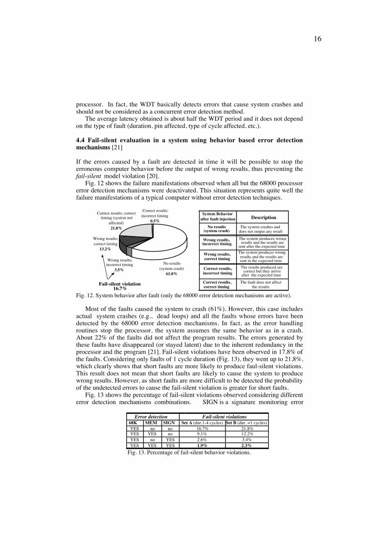
4.3 - Watchdog timer
Previous research [11] has shown that precise tuning of the WDT period is a factorwith major impact on the WDT coverage. In this way, the set of faults A was injectedin three different situations:¥ Very precise tuning - the WDT period is very close to the benchmark execution time
(the WDT period is 60 µsec. greater than the benchmark execution time);¥ Precise tuning - the WDT period is approximately 500 µsec greater than the
execution time;¥ Non precise tuning - the WDT period is twice the benchmark execution time
0,0%5,0%
10,0%
15,0%
20,0%25,0%
30,0%35,0%
40,0%
45,0%50,0%55,0%
60,0%
65,0%
Very precise tuning Precise tuning Non precise tuning
Coverage of the 68000 built-in mechanisms
56,2%59,9%
62,8%
7,6% 4,7% 1,0%
Coverage
Fig. 11. Coverage variation with the precision of the WDT period.
The results obtained show that the WDT only improves the coverage when itsperiod is very close to the program block execution time. As in most of the actualapplications it is not possible to achieve this precision (because the program executiontime is very dependent on data) we can conclude that a WDT has little or no use insystems having built-in error detection techniques like the ones existing in the 68000
16
processor. In fact, the WDT basically detects errors that cause system crashes andshould not be considered as a concurrent error detection method.
The average latency obtained is about half the WDT period and it does not dependon the type of fault (duration, pin affected, type of cycle affected, etc.).
4.4 Fail-silent evaluation in a system using behavior based error detectionmechanisms [21]
If the errors caused by a fault are detected in time it will be possible to stop theerroneous computer behavior before the output of wrong results, thus preventing thefail-silent model violation [20].
Fig. 12 shows the failure manifestations observed when all but the 68000 processorerror detection mechanisms were deactivated. This situation represents quite well thefailure manifestations of a typical computer without error detection techniques.
Fail-silent violation16.7%
No results (system crash)
61.0%
Correct results; incorrect timing
0.5%
Correct results; correct timing (system not
affected)21.8%
Wrong results; incorrect timing
3.5%
Wrong results; correct timing
13.2%
System Behaviorafter fault injection Description
No results(system crash)
Wrong results,incorrect timing
Wrong results,correct timing
Correct results,incorrect timing
Correct results,correct timing
The system crashes anddoes not output any result
The system produces wrong
sent after the expected time results and the results are
The system produces wrong
sent in the expected timeresults and the results are
The results produced are
after the expected timecorrect but they arrive
The fault does not affect the results
Fig. 12. System behavior after fault (only the 68000 error detection mechanisms are active).
Most of the faults caused the system to crash (61%). However, this case includesactual system crashes (e.g., dead loops) and all the faults whose errors have beendetected by the 68000 error detection mechanisms. In fact, as the error handlingroutines stop the processor, the system assumes the same behavior as in a crash.About 22% of the faults did not affect the program results. The errors generated bythese faults have disappeared (or stayed latent) due to the inherent redundancy in theprocessor and the program [21]. Fail-silent violations have been observed in 17,8% ofthe faults. Considering only faults of 1 cycle duration (Fig. 13), they went up to 21,8%,which clearly shows that short faults are more likely to produce faul-silent violations.This result does not mean that short faults are likely to cause the system to producewrong results. However, as short faults are more difficult to be detected the probabilityof the undetected errors to cause the fail-silent violation is greater for short faults.
Fig. 13 shows the percentage of fail-silent violations observed considering differenterror detection mechanisms combinations. SIGN is a signature monitoring error
Error detection Fail-silent violations68K MEM SIGN Set A (dur.1-4 cycles) Set B (dur. =1 cycles)YES no no 16.7% 21.8%YES YES no 9.1% 12.2%YES no YES 2.6% 3.4%YES YES YES 1.9% 2.3%
Fig. 13. Percentage of fail-silent behavior violations.
17
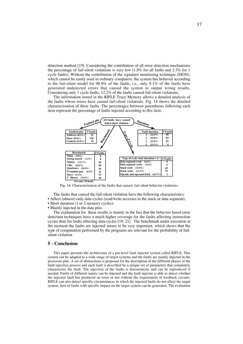
detection method [19]. Considering the contribution of all error detection mechanismsthe percentage of fail-silent violations is very low (1,9% for all faults and 2.3% for 1cycle faults). Without the contribution of the signature monitoring technique (SIGN),which cannot be easily used in ordinary computers, the system has behaved accordingto the fail-silent model for 90,9% of the faults, i.e., only 9,1% of the faults havegenerated undetected errors that caused the system to output wrong results.Considering only 1 cycle faults, 12,2% of the faults caused fail-silent violations.
The information stored in the RIFLE Trace Memory allows a detailed analysis ofthe faults whose errors have caused fail-silent violations. Fig. 14 shows the detailedcharacterization of these faults. The percentages between parentheses following eachitem represent the percentage of faults injected according to this item.
Fault duration 1 (24.4%) 2 (25.0%) 3 (25.4%) 4 (25.2%)
# Faults908342 6
Faulted pinsAddress (40.4%)Data (39.8%)Control (19.8%)
# Faults 8 54333 1
Type of cycle (only duration = 1)Data segment read (0.6%)Data segment write (2.4%)Stack read (21.0%)Stack write (11.3%)Opcode and operand fetch (64.7%)
221 faults have causedfailed-silent violationFaulted pin Duration
Benc
hmar
k Type of C
ycle
# Faults 51138 32
BenchmarkMain (4.0%)String search (3.3%)Matrix (13.1%)CRC (10.5%)Quicksort (26.0%)P-random gen. (4.4%)Sieve (5.3%)C library (33.4%)
# Faults 6 0294416321330
For only 170 faults
Fig. 14. Characterization of the faults that caused fail-silent behavior violations
The faults that caused the fail-silent violation have the following characteristics:¥ Affect (almost) only data cycles (read/write accesses to the stack or data segment);¥ Short duration (1 or 2 memory cycles);¥ Mainly injected in the data pins.
The explanation for these results is mainly in the fact that the behavior based errordetection techniques have a much higher coverage for the faults affecting instructioncycles than for faults affecting data cycles [19, 21]. The benchmark under execution atthe moment the faults are injected seems to be very important, which shows that thetype of computation performed by the programs are relevant for the probability of fail-silent violation.
5 - Conclusion
This paper presents the architecture of a pin-level fault injector system called RIFLE. Thissystem can be adapted to a wide range of target systems and the faults are mainly injected in theprocessor pins. A set of abstractions is proposed for the description of the different phases of thefault injection process and each fault is described by a unique set of parameters that completelycharacterize the fault. The injection of the faults is deterministic and can be reproduced ifneeded. Faults of different nature can be injected and the fault injector is able to detect whetherthe injected fault has produced an error or not without the requirement of feedback circuits.RIFLE can also detect specific circumstances in which the injected faults do not affect the targetsystem. Sets of faults with specific impact on the target system can be generated. The evaluation
18
of a set of simple error detection mechanisms is presented with the main objective of showingthe comprehensive results that it is possible to obtain with RIFLE. These results show that up to72,5% of the errors can be detected with fairly simple mechanisms. Furthermore, for over 90%of the faults the target system has behaved according to the fail-silent model, which suggests thata traditional computer equipped with simple error detection mechanisms is relatively close to afail-silent computer.
AcknowledgmentsThis work has been supported in part by the Junta Nacional de Investiga��o Cientifica e
Tecnol�gica and FTMPS (Fault-Tolerant Massively Parallel System) Esprit III project.
References1 J. Arlat et. al., "Fault injection for dependability validation: a methodology and some appli-
cations", IEEE Trans. on Software Eng., Vol 16, No 2, Feb. 1990, pp. 166-182.2 W. Carter and J. Abraham, "Design and evaluation tools for fault- tolerant systems", Proc.
AIAA Computers in Aerospace Conference, 1987, pp. 70-77.3 U. Gunneflo, J. Karlsson, and J. Torin, "Evaluation of error detection schemes using fault
injection by heavy-ion radiation", Fault Tol. Comp. Symp., FTCS-19, June 1989, p.340-347.4 R. Iyer and D. Rossetti, "A measurement-based model for workload dependance of CPU
errors", IEEE Transactions on Computers, vol. C-35, pp. 511-519, June 1986.5 E. Czeck and D. Siewiorek, "Effects of transient gate-level faults on program behavior",
Fault Tolerant Comp. Symp., FTCS-20, Newcastle Upon Tyne, June 1990, p. 236-243.6 M. Schmid, et. al., "Upset Exposure by Means of Abstraction Verification", Proc. 12th
Symp. on Fault-Tolerant Comp., FTCS-12, St. Monica, June 22-24, 1982, p.237-244.7 Y. Crouzet and B. Decouty, "Measurements of fault detection mechanisms efficiency:
results", Proc. of FTCS-12, Santa Monica, Ca., June 1982, pp. 373-376.8 J. Lala, "Fault detection isolation and reconfiguration in FTMP: methods and experimental
results", 5th AIAA/IEEE Digital Avionics Systems Conf., 1983, pp.21.3.1-21.3.9.9 M. A. Schuette and J. P. Shen, "Processor Control Flow Monitoring Using Signatured
Instruction Streams", IEEE Trans. on Computers, vol. 36, No. 3, March 1987, p. 264-275.10 A. Damm, "Experimental evaluation of error-detection and self-checking coverage of
componentes of a distributed real-time system", Ph.D. thesis, Univ. of Vienne, Oct. 1988.11 H. Madeira, G. Quadros, and J. Silva, "Experimental eval. of a set of simple error detection
mechanisms", The EUROMICRO Journal, vol 30, Aug. 1990, North-Holland, pp 513-520.12 J. Cusick, et. al., "SEU vulnerability of the Zilog Z-80 and NSC-800 microprocessors",
IEEE Tran. on Nuclear Science, Vol. NS-32, N0. 6, Dec. 1986, p. 4206-4211.13 M. Cortes and E. McCluskey, "Properties of transient errors due to power supply distur-
bances", Proc. Int.Symp. on Circuits and Systems, IEEE, pp. 1064-1049, May 1986.14 D. Lomelino and R. Iyer, "Error propagation in a digital avionic processor: a simulation-
based study", Proc. Real Time Systems Symposium, Dec. 1986, p. 218-225.15 D. P. Siewiorek and Robert S. Swarz, The Theory and Practice of Reliable Design, Digital
Press, Educational Services, Digital Equip. Corporation, 1984, Bedford, Massachusetts.16 P. Duba and R. Iyer, "Transient fault behavior in a microprocessor: a case study",
Proceedings of ICCD, October 1988, p. 272-276.17 G. Choi, R. Iyer, et. al. "A fault behavior model for an avionic microprocessor: a case
study", Dependable Computing for Critical Applications, Springer-Verlag, Avizienis &Laprie (eds), 1990, pp. 177-195.
18 J. Karlsson, U. Gunneflo, P Lid�n e J. Torin, "Two Fault Injection Techniques for Test ofFault Handling Mechanisms", Proc. of International Test Conference, 1991, p. 140-149.
19 H. Madeira and J. Silva, "On-line Signature Learning and Checking", Dependable Comp. forCritical Applications, Spriger-Verlag, Meyer & Schlichting (eds.), 1992, pp. 394-420.
20 D. Powell et. al, "The Delta-4 approach tp dependability in open distributed computingsystems", Inter. Symp. on Fault-Tolerant Computing, FTCS-18, Tokyo- Japan, June 1988.
21 H. Madeira and J. G. Silva, "Experimental Evaluation of the Fail-silent Behavior inComputers without Error Masking", to appear at FTCS-24, June, 1994.