Microcontroller Based Anesthesia Injector project
15
Microcontroller Based Anesthesia Injector FROM: Engr Rana Muhammad Shakeel [email protected] https://www.facebook.com/EngnrShakeel plz like my page: https://www.facebook.com/Electrical4Electronics For MORE PROJECTS: http://electro-technolgy.blogspot.com ABSTRACT In the hospitals when any major operation is performed, the patient must be in anesthetize condition. If the operation lasts for a long time, say for suppose for 4 or 5 hours, complete dose of anesthesia cannot be administered in a single stroke. It may lead to the patient’s death. If lower amount of anesthesia is administered, the patient may wakeup at the middle of the operation. To avoid this, the anesthetist administers few milliliters of anesthesia per hour to the patient. If the anesthetist fails to administer the anesthesia to the patient at the particular time interval, other allied problems may arise.
Transcript of Microcontroller Based Anesthesia Injector project

Microcontroller Based Anesthesia Injector
FROM:
Engr Rana Muhammad [email protected]://www.facebook.com/EngnrShakeelplz like my page:https://www.facebook.com/Electrical4Electronics
For MORE PROJECTS:http://electro-technolgy.blogspot.com
ABSTRACT
In the hospitals when
any major operation is performed,
the patient must be in anesthetize
condition. If the operation lasts
for a long time, say for suppose for
4 or 5 hours, complete dose of
anesthesia cannot be administered in
a single stroke. It may lead to the
patient’s death. If lower amount of
anesthesia is administered, the
patient may wakeup at the middle of
the operation.
To avoid this, the
anesthetist administers few
milliliters of anesthesia per hour
to the patient. If the anesthetist
fails to administer the anesthesia
to the patient at the particular
time interval, other allied problems
may arise.

To overcome such
hazardous problems the design of an
automatic operation of an anesthesia
machine based on a micro-controller
is effective. In this system a
keypad is provided along with the
microcontroller and syringe infusion
pump. The anesthetist can set the
level of anesthesia in terms of
milliliters per hour to administer
anesthesia to the patient with the
help of keypad.
After receiving the
signal from the keypad, the
microcontroller controls the signal
to the desire level and fed into the
stepper motor to drive the infusion
pump in proper manner. The
anesthesia is administered to the
patient according to the stepper
motor rotation (the syringe will
move forward or backward direction).
This particular paper
will be very much useful to
physicians to see the current
position of anesthesia of the
patients. If the level of anesthesia
is decreased to lower level (set
value), the alarm will be initiated
to alert the physician to refill the
anesthesia in the Syringe Pump to
continue the process.
INTRODUCTION
EMBEDDED SYSTEMS
An Embedded system is a combination
of computer hardware, software and
additional mechanical parts designed
to perform a specific function. An
example is the microwave oven. It is
hardly realized that the oven
actually consists of a processor and
the software running inside. Another
example is the TV remote control.
Very few actually realize that there
is a microcontroller inside that
runs a set of programs especially
for the TV. Automatic Anesthesia
Injector system is also an
application of embedded technologies
in which a microcontroller is used
to control the entire device.
MICROCONTROLLER
A Microcontroller is a general-
purpose device that is meant to read
data, perform limited calculations
on that data and control its
environment based on those

calculations. The prime use of a
microcontroller is to control the
operation of a machine using a fixed
program that is stored in ROM and
that does not change over the
lifetime of the system. A
microcontroller is a highly
integrated chip that includes all or
most of the parts needed for a
controller in a single chip. The
microcontroller could be rightly
called a one-chip solution.
MICRO CONTROLLER Vs MICRO PROCESSOR
If a system is developed with a
microprocessor, the designer has to
go for external memory such as RAM,
ROM or EPROM and peripherals and
hence the size of the PCB will be
large to hold all the required
peripherals. But, the micro
controller has got all these
peripheral facilities on a single
chip and hence development of
similar system with micro controller
reduces PCB size and the overall
cost of the design.The difference
between a Microprocessor and
Microcontroller is that a
Microprocessor can only process with
the data, but Microcontroller can
control external device in addition
to processing the data. If a device
has to be switched “ON” or “OFF”,
external ICs are needed to do this
work. But with Microcontroller the
device can be directly controlled
without an IC. A Microcontroller
often deals with bits, not bytes as
in the real world application, for
example switch contracts can be open
or close, indicators should be lit
or dark and motors can be either
turned on or off and so forth.
AUTOMATIC ANESTHESIA INJECTOR (AAI)
Major operations are performed to
remove or reconstruct the infected
parts in the human body. These
operations will lead to blood loss
and pain. Therefore it is necessary
to arrest the pain and the blood
loss. Anesthesia plays an important
role in the part of painkilling .AAI
can be defined as “Automatic
administration of anesthesia based
on the bio-medical parameters of the
patient, eliminating future side
effects and the need for an
anesthetist.”
Anesthesia is very essential in
performing painless surgery and so

an Automatic administration of
Anesthesia is needed for a
successful surgery.
PRESENT SYSTEM USED
At present anesthetist controlled
manual operation is employed,
which may cause many difficulties
such as,
Ø Level of anesthesia may get
varied and there is a chance of
getting side effects in future.
Ø If suppose the anesthetist fails
to administer the level of
anesthesia during the
predetermined period, the patient
may be disturbed during the
operation.
Ø Other systems developed to
administer anesthesia operates by
sensing the consciousness level of
the patient and not by measuring
his overall body conditions.
PROPOSED SYSTEM
Now days, embedded systems are
used in many applications in
medical field for controlling
various biomedical parameters. In
this design, a micro-controller is
used for controlling the
anesthesia machine automatically,
depending upon the various
biomedical parameters such as body
temperature, heart rate,
respiration rate etc.
Major operations are performed to
remove or reconstruct the infected
parts in the human body. These
operations lead to blood loss and
pain. Therefore it is necessary to
arrest the pain and the blood
loss. Anesthesia plays important
role in the part of painkilling.
Hence, anesthesia is very
essential in performing painless
surgery. Advantages of using the
proposed system are,
Ø The need for an anesthetist is
eliminated.
Ø Level of anesthesia is not
varied, so the future side effects
are eliminated.
Ø IR detector is also included in
the system for monitoring the
total anesthesia level for the
entire period of the surgery time.
BLOCK DIAGRAM

WORKING OF THE SYSTEM
By using the keypad provided along
with the Microcontroller, the
anesthetist can set the level of
anesthesia to be administered to
the patient in terms of
milliliters per hour (1ml to
1000ml).After receiving the
anesthesia level from the keypad,
the Microcontroller sets the
system to administer anesthesia to
the prescribed level. It then
analyses various bio-medical
parameters obtained from the
sensors to determine the direction
of rotation of the stepper motor.
The rotation of the stepper motor
causes the Infusion Pump to move
in forward or in a backward
direction and the anesthesia
provided in the syringe is
injected into the body of the
patient. If the level of
anesthesia is decreased to lower
level than the set value, the
alarm gets activated to alert the
anesthetist to refill the
anesthesia in the syringe pump to
continue the process. In this
design, the total timing and
opposite flow of blood will also
be detected by using Micro
Controller.
COMPONENTS REQUIRED FOR THE SYSTEM
Ø Temperature Sensor – to measure
body temperature
Ø Respiration Sensor – to measure
respiration
Ø Heart Beat Sensor – to measure
heartbeat
Ø Micro-Controller – to Control
the overall operation
Ø Stepper Motor – to control the
movement of the Syringe Infusion
Pump
Ø A/D Converter – to convert the
analog information in to a digital
format.

MEASUREMENT OF BIO-MEDICAL
PARAMETERS
The measurement of bio-medical
parameters is a vital process.
These parameters determine the
overall condition of the patient.
It plays a very significant
process in the level of anesthesia
that has to be administered to the
patient. Only based on these
parameters the movement of the
stepper motor is determined.
Transducers and Thermistors are
the key links in all sensors
designed to describe and analyze
the bio-medical parameters. The
transducers used here are just
those that find applications in
patient monitoring systems and
experimental work on four
parameters namely blood pressure,
temperature, pulse and respiratory
activity. Both transducers and
thermistors are made in a wide
variety of forms suitable for use
in medical applications. They are
available as
Ø wafers for applying on the skin
surfaces
Ø tiny beads for inserting into
the tissues
.
TEMPERATURE SENSOR
The most accurate method to
measure temperature is to use
Thermistors and Resistance
Thermometers. Thermistor or
thermal resistor is a two-terminal
semiconductor device whose
resistance is temperature
sensitive. The value of such
resistors decreases with increase
in temperature. The thermistors
have very high temperature
coefficient of resistance of the
order of 3% to 5% per ºC, making
it an ideal temperature
transducer. The temperature co-
efficient of resistance is
normally negative. The output of
the temperature sensor is given to
the amplifier stages. Resistance
thermometers can also be used to
measure the body temperature.
Important characteristics of
resistance thermometers are high
temperature co-efficient to
resistance, stable properties so
that the resistance
characteristics does not drift
with repeated heating or cooling
or mechanical strain and high

resistivity to permit the
construction of small sensors.
Circuit to measure Temperature
RESPIRATION SENSOR
The primary functions of the
respiratory system are to supply
oxygen to the tissues and remove
carbon dioxide from the tissues.
The action of breathing is
controlled by muscular action
causing the volume of the lung to
increase and decrease to affect a
precise and sensitive control of
the tension of carbon dioxide in
the arterial blood. Under normal
circumstances, this is rhythmic
action.
Circuit to measure Respiration
Respiratory activity can be
detected by measuring changes in
the impedance across the thorax.
Several types of transducers have
been developed for the measurement
of respiration rate. A Strain
Gauge type Chest Transducer is a
suitable transducer to measure the
respiratory activity. The
respiratory movement results in
the changes of the strain gauge
element of the transducer hence
the respiration rate can be
measured.
HEART BEAT SENSOR
Heart rate is our body's way of
telling how hard it is going. It
is very vital that heart beat has
to be in normal while
administering anesthesia to the
patient. Normal heart beat is 72
beats per minute. A sensor is
designed for monitoring the
changes in the heart beat of the

human body. There are 2 ways of
monitoring heart rate information
from the body. They are
Ø Electrocardiogram (ECG)
Ø PULSE
1) The E.C.G or Electrocardiogram, gives
the electrically picked up signals
from the limbs due to the nervous
activity of the heart. The
electrodes are pasted on to the 2
hands and the left leg, the right
leg electrode serving as the
common or ground reference. The
signals are picked up and
amplified by high gain
differential amplifiers and then
the electrocardiogram signal is
obtained.
2) The pulse signal refers to the flow
of blood that passes from the
heart to the limbs and the
peripheral organs once per beat.
Usually, the physician looks for
the pulse on the wrist of the
patient. The artery is near the
surface of the skin and hence
easily palpable. This pulse occurs
once per heart beat. These pulse
signals can be picked up by
keeping a piezo-electric pick up
on the artery site (in the wrist).
DESIGN OF A MICROCONTROLLER
The design approach of the
microcontroller mirrors that of
the microprocessor. The
microprocessor design accomplishes
a very flexible and extensive
repertoire of multi-byte
instructions. These instructions
work in hardware configurations
that enables large amount of
memory and IO to be connected to
address and data bus pins on the
integrated circuit package. The
microcontroller design uses a much
more limited set of single and
double byte instructions that are
used to move code and data from
internal memory to the ALU. The
pins are programmable that is
capable of having several
different functions depending on
the wishes of the programmer. It
is concerned with getting data
from and to its own pins
.89C51 MICRO CONTROLLER
The Microcontroller that is used
in this system is 89C51
manufactured by Atmel, MC, USA.
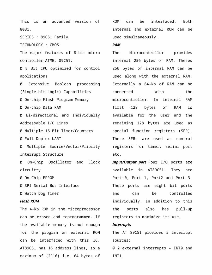
This is an advanced version of
8031.
SERIES : 89C51 Family
TECHNOLOGY : CMOS
The major features of 8-bit micro
controller ATMEL 89C51:
Ø 8 Bit CPU optimized for control
applications
Ø Extensive Boolean processing
(Single-bit Logic) Capabilities
Ø On-chip Flash Program Memory
Ø On-chip Data RAM
Ø Bi-directional and Individually
Addressable I/O Lines
Ø Multiple 16-Bit Timer/Counters
Ø Full Duplex UART
Ø Multiple Source/Vector/Priority
Interrupt Structure
Ø On-Chip Oscillator and Clock
circuitry
Ø On-Chip EPROM
Ø SPI Serial Bus Interface
Ø Watch Dog Timer
Flash ROM
The 4-kb ROM in the microprocessor
can be erased and reprogrammed. If
the available memory is not enough
for the program an external ROM
can be interfaced with this IC.
AT89C51 has 16 address lines, so a
maximum of (2^16) i.e. 64 bytes of
ROM can be interfaced. Both
internal and external ROM can be
used simultaneously.
RAM
The Microcontroller provides
internal 256 bytes of RAM. Theses
256 bytes of internal RAM can be
used along with the external RAM.
Externally a 64-kb of RAM can be
connected with the
microcontroller. In internal RAM
first 128 bytes of RAM is
available for the user and the
remaining 128 bytes are used as
special function registers (SFR).
These SFRs are used as control
registers for timer, serial port
etc.
Input/Output port Four I/O ports are
available in AT89C51. They are
Port 0, Port 1, Port2 and Port 3.
These ports are eight bit ports
and can be controlled
individually. In addition to this
the ports also has pull-up
registers to maximize its use.
Interrupts
The AT 89C51 provides 5 Interrupt
sources:
Ø 2 external interrupts – INT0 and
INT1

Ø 2 timer interrupts – TF0 and TF1
Ø a serial port interrupts.
Memory
The memory is logically separated
into Program memory and Data
memory. This logical separation
allows the data memory to be
addressed by 8-bit address.
Program memory can only read the
information. There can be up to 64
bytes of directly addressable
program memory.
ADC 0808/0809
The ADC 0808/0809 is an 8-bit
digital to analog converter with
8-channel inbuilt Multiplexer.
It is the monolithic CMOS device
manufactured by the National
semiconductors. It uses the
principle of Successive
Approximation technique for the
conversion process. The 8-
channel Multiplexer can directly
access any of the 8-single-ended
analog signals. Easy interfacing
to the microcontrollers is
provided by the latched and
decoded multiplexers address
inputs and latched TTL TIR-STATE
outputs.
The salient features are:Ø High Speed and Accuracy
Ø Minimal temperature Dependence
Ø Excellent temperature dependence
Ø Excellent long term accuracy and
repeatability
Ø Consumes minimal power. (15 mW)
These features make this device
ideally suited to applications
from process and machine control
to consumer and automotive
applications.
STEPPER MOTOR
A stepper motor transforms
electrical pulses into equal
increments of rotary shaft motion
called steps. A one-to-one
correspondence exists between the
electrical pulses and the motor
steps. They work in conjunction
with electronic switching devices.
The function of switching device
is to switch the control windings
of the stepper motor with a
frequency and sequence

corresponding to the issued
command. It has a wound stator and
a non exited rotor. Stepper motors
are classified as 2-phase, 3-phase
or 4-phase depending on the number
of windings on the stator.
STEPPER MOTOR DRIVER CIRCUIT
In Automatic Anesthesia Injector,
a 4-phase stepper motor is used.
Consider the four phases as S1,
S2, S3 and S4. The switch sequence
can be used to rotate the motor
half steps of 0.9º clockwise or
counter clockwise.
To take first step clockwise from
S2 and S1 being on, the pattern of
1’s and 0’s is simply rotated one
bit position around to the right.
The 1 from S1 is rotated around
into bit 4. To take the next step
the switch pattern is rotated one
more bit position. To step anti-
clockwise the pattern is rotated
to the left by one bit position.
This clockwise and counter clockwise
movement of the stepper motor is
coordinated with the movement of the
Syringe by means of a mechanical
interface.
SYRINGE INFUSION PUMP
The Syringe Infusion pump provides
uniform flow of fluid by precisely
driving the plunger of a syringe
towards its barrel. It provides
accurate and continuous flow rate
for precisely delivering
anesthesia medication in critical
medical care. It has an alarm
system activated by Infra-Red
Sensor and limit switches. The
pump will stop automatically with
an alarm when the syringe is empty
or if any air-bubble enters the
fluid line. Glass and plastic
Syringes of all sizes from 1ml to

30ml can be used in the infusion
pump. The flow rates can be
adjusted from 1ml to 99ml/hr.
Since it accepts other syringe
size also, much lower flow rate
can be obtained by using smaller
syringes.
SOFTWARE DETAILS
A program is required which when
burnt into the EPROM will operate
with the AT 89C51 to do the
function of monitoring the bio-
medical parameters. The program
answers the following
requirements:
Ø To read the input from the
keypad provided with the
microcontroller.
Ø To activate the internal timer
and enable it to interrupt the AT
89C51 whenever the timer
overflows.
Ø To read the parameters such as
heart rate, respiration, body
temperature once in every
specified interval.
Ø To check for the correctness of
the parameter values and activate
the alarm set with the system when
the level of Anesthesia goes down.
Ø To calculate the stepper motor
movement (increase the speed or
decrease the speed) with the
parameters provided by the
Sensors.
Ø Continue the above until
switched OFF or RESET.

To Summarize:
By using various electrical
circuits the bio-medical
parameters can be found. The
output of the circuits is
amplified by means of an amplifier
and fed into an A/D converter. The
digitized signal is then fed into
the input port of the
Microcontroller. The
Microcontroller displays the
parameters in digital value in the
display device. If the level of
the temperature or respiration is
increased or decreased the level
of anesthesia was controlled
automatically with the help of
micro-controller and the stepper
motor actions.

EXPERIMENTAL RESULTS
The performance of the
microcontroller was checked
virtually by interfacing it with
the computer. The program was
written in the micro controller
for analyzing the parameters. Then
the microcontroller was interfaced
with the PC using the Microsoft
Communication Port interface in
Visual Basic 6.0.
A Stepper motor designed in VB was
made to run and the motor speed on
various conditions was noted. When
the respiration rate and the
temperature were constant, the
motor speed was found to be
constant. When this parameter was
varied (by manually coding the
change in the microcontroller
program), the stepper motor speed
was also found to vary with the
aid of the microcontroller.
Interface developed
in Visual Basic
FUTURE ENHANCEMENTS
Ø Multiple parameters like Blood
pressure, retinal size, age and
weight can be included as
controlling parameters in the
future.
Ø Specialized embedded anesthesia
machine can be developed, thereby
reducing size, cost and
increasing efficiency.
CONCLUSION
Modern technologies have developed
that promotes comfortable and

better life which is disease free.
PREVENTION IS BETTER THAN CURE and
protection is intelligent than
prevention and our presentation on
MICROCONTROLLER BASED ANESTHESIA
MACHINE is one of the efficient
protecting systems.
REFERENCES
1. Microcontroller and their
applications – Kenneth J.Ayalaa
– Penram International.
2. Bio medical Instrumentation and
Application – William John
Webster.