Aisys Anesthesia Machine - Technical Reference Manual
498
Aisys Anesthesia Machine Technical Reference Manual
-
Upload
khangminh22 -
Category
Documents
-
view
0 -
download
0
Transcript of Aisys Anesthesia Machine - Technical Reference Manual
Aisys Anesthesia Machine
Technical Reference Manual
Aisys
04/08 M1046983
Datex-Ohmeda, Inc., a General Electric Company, doing business as GE Healthcare.
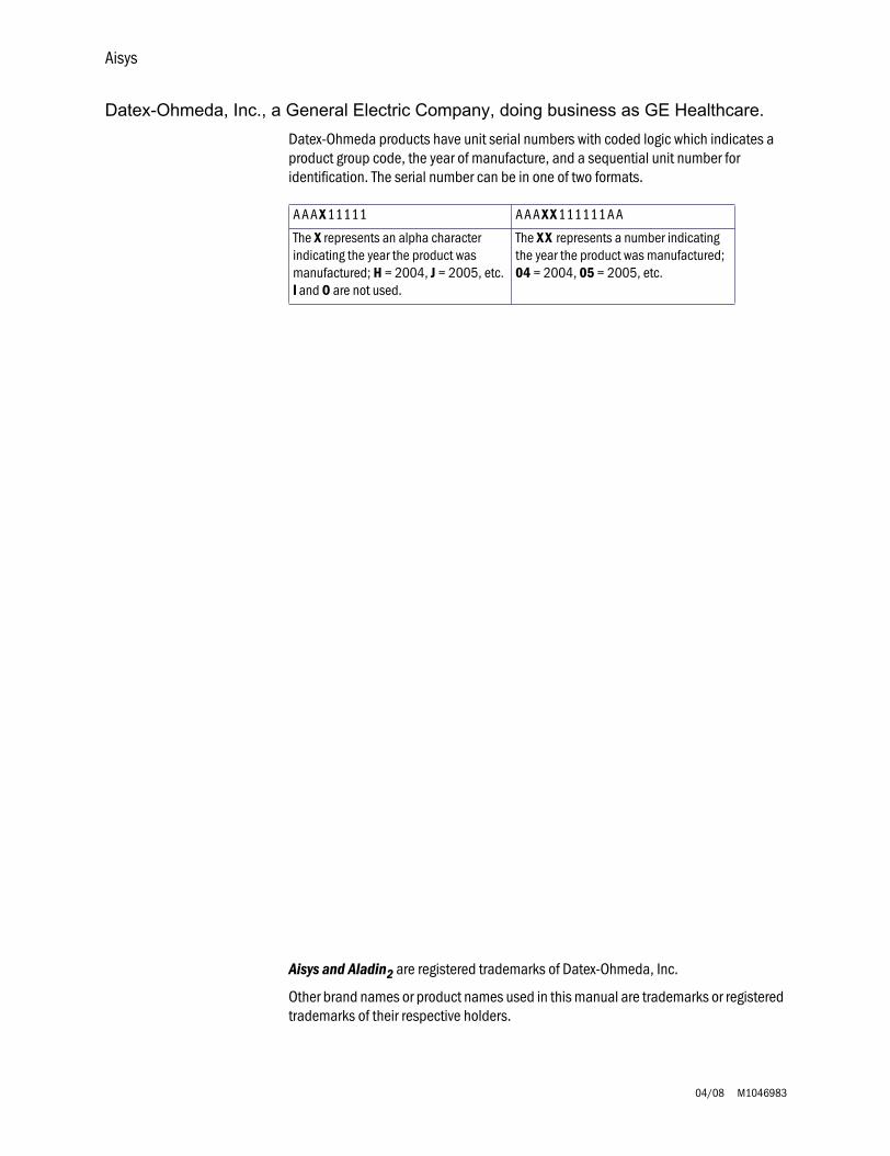
Datex-Ohmeda products have unit serial numbers with coded logic which indicates a product group code, the year of manufacture, and a sequential unit number for identification. The serial number can be in one of two formats.
Aisys and Aladin
2
are registered trademarks of Datex-Ohmeda, Inc.
Other brand names or product names used in this manual are trademarks or registered trademarks of their respective holders.
A A A
X
11111 A A A
X X
111111 A A
The
X
represents an alpha character indicating the year the product was manufactured;
H
= 2004,
J
= 2005, etc.
IIII
and
O
are not used.
The
X X
represents a number indicating the year the product was manufactured;
04
= 2004,
05
= 2005, etc.
Technical Reference Manual
M1046983 04/08
i
This document is not to be reproduced in any manner, nor are the contents to be disclosed to anyone, without the express authorization of the product service department, Datex-Ohmeda, Ohmeda Drive, PO Box 7550, Madison, Wisconsin, 53707.
© 2008 Datex-Ohmeda Inc.
Aisys Anesthesia Machine
Aisys
ii
04/08 M1046983
Important
The information contained in this Technical Reference manual pertains only to those models of products which are marketed by Datex-Ohmeda as of the effective date of this manual or the latest revision thereof. This Technical Reference manual was prepared for exclusive use by Datex-Ohmeda service personnel in light of their training and experience as well as the availability to them of parts, proper tools and test equipment. Consequently, Datex-Ohmeda provides this Technical Reference manual to its customers purely as a business convenience and for the customer's general information only without warranty of the results with respect to any application of such information. Furthermore, because of the wide variety of circumstances under which maintenance and repair activities may be performed and the unique nature of each individual's own experience, capacity, and qualifications, the fact that customer has received such information from Datex-Ohmeda does not imply in anyway that Datex-Ohmeda deems said individual to be qualified to perform any such maintenance or repair service. Moreover, it should not be assumed that every acceptable test and safety procedure or method, precaution, tool, equipment or device is referred to within, or that abnormal or unusual circumstances, may not warrant or suggest different or additional procedures or requirements.
This manual is subject to periodic review, update and revision. Customers are cautioned to obtain and consult the latest revision before undertaking any service of the equipment. Comments and suggestions on this manual are invited from our customers. Send your comments and suggestions to the Manager of Technical Communications, Datex-Ohmeda, Ohmeda Drive, PO Box 7550, Madison, Wisconsin 53707.
wwww
CAUTION
Servicing of this product in accordance with this
Technical Reference
manual should never be undertaken in the absence of proper tools, test equipment and the most recent revision to this service manual which is clearly and thoroughly understood.
Technical Competence
The procedures described in this Technical Reference manual should be performed by trained and authorized personnel only. Maintenance should only be undertaken by competent individuals who have a general knowledge of and experience with devices of this nature. No repairs should ever be undertaken or attempted by anyone not having such qualifications.
Datex-Ohmeda strongly recommends using only genuine replacement parts, manufactured or sold by Datex-Ohmeda for all repair parts replacements.
Read completely through each step in every procedure before starting the procedure; any exceptions may result in a failure to properly and safely complete the attempted procedure.
M1046983 04/08 iii
Table of Contents
Important . . . . . . . . . . . . . . . . . . . . . . . . . . . . . . . . . . . . . . . . . . . . . . . . . . . . . . . . . . . . . . . . . . . . . . ii
Technical Competence . . . . . . . . . . . . . . . . . . . . . . . . . . . . . . . . . . . . . . . . . . . . . . . . . . . . . . . . . . . ii
1 Introduction
1.1 What this manual includes . . . . . . . . . . . . . . . . . . . . . . . . . . . . . . . . . . . . . . . . . . . . . . . . . . .1-2
1.2 User’s Reference manuals . . . . . . . . . . . . . . . . . . . . . . . . . . . . . . . . . . . . . . . . . . . . . . . . . . .1-2
1.3 Overview . . . . . . . . . . . . . . . . . . . . . . . . . . . . . . . . . . . . . . . . . . . . . . . . . . . . . . . . . . . . . . . . . .1-3
1.4 Anesthesia system components . . . . . . . . . . . . . . . . . . . . . . . . . . . . . . . . . . . . . . . . . . . . . .1-4
1.5 Breathing system components . . . . . . . . . . . . . . . . . . . . . . . . . . . . . . . . . . . . . . . . . . . . . . . .1-6
1.5.1 Optional system components. . . . . . . . . . . . . . . . . . . . . . . . . . . . . . . . . . . . . . . . . . 1-7
1.6 Display controls . . . . . . . . . . . . . . . . . . . . . . . . . . . . . . . . . . . . . . . . . . . . . . . . . . . . . . . . . . . .1-8
1.7 Anesthesia system display . . . . . . . . . . . . . . . . . . . . . . . . . . . . . . . . . . . . . . . . . . . . . . . . . . .1-9
1.7.1 Using menus . . . . . . . . . . . . . . . . . . . . . . . . . . . . . . . . . . . . . . . . . . . . . . . . . . . . . . 1-11
1.8 Symbols used in the manual or on the equipment . . . . . . . . . . . . . . . . . . . . . . . . . . . . . . 1-12
Aisys
iv 04/08 M1046983
2 Theory of Operation
2.1 Electrical system . . . . . . . . . . . . . . . . . . . . . . . . . . . . . . . . . . . . . . . . . . . . . . . . . . . . . . . . . . .2-2
2.2 Power subsystem . . . . . . . . . . . . . . . . . . . . . . . . . . . . . . . . . . . . . . . . . . . . . . . . . . . . . . . . . .2-4
2.2.1 U-Frame Power Supply . . . . . . . . . . . . . . . . . . . . . . . . . . . . . . . . . . . . . . . . . . . . . . . .2-5
2.2.2 Power Controller board overview . . . . . . . . . . . . . . . . . . . . . . . . . . . . . . . . . . . . . . . .2-5
2.2.3 Power distribution . . . . . . . . . . . . . . . . . . . . . . . . . . . . . . . . . . . . . . . . . . . . . . . . . . . .2-6
2.2.4 Power Controller Board . . . . . . . . . . . . . . . . . . . . . . . . . . . . . . . . . . . . . . . . . . . . . . .2-7
2.3 Display Unit . . . . . . . . . . . . . . . . . . . . . . . . . . . . . . . . . . . . . . . . . . . . . . . . . . . . . . . . . . . . . 2-10
2.4 System communications . . . . . . . . . . . . . . . . . . . . . . . . . . . . . . . . . . . . . . . . . . . . . . . . . . 2-11
2.4.1 Software Power On Self Tests (POST) . . . . . . . . . . . . . . . . . . . . . . . . . . . . . . . . . . . 2-12
2.5 System connections . . . . . . . . . . . . . . . . . . . . . . . . . . . . . . . . . . . . . . . . . . . . . . . . . . . . . . 2-14
2.5.1 Display Unit . . . . . . . . . . . . . . . . . . . . . . . . . . . . . . . . . . . . . . . . . . . . . . . . . . . . . . . 2-14
2.5.2 Display Connector board . . . . . . . . . . . . . . . . . . . . . . . . . . . . . . . . . . . . . . . . . . . . 2-14
2.6 Power Controller and Anesthesia Control board connections . . . . . . . . . . . . . . . . . . . . . 2-15
2.7 Anesthesia Control board . . . . . . . . . . . . . . . . . . . . . . . . . . . . . . . . . . . . . . . . . . . . . . . . . . 2-16
2.7.1 Overview . . . . . . . . . . . . . . . . . . . . . . . . . . . . . . . . . . . . . . . . . . . . . . . . . . . . . . . . . 2-16
2.7.2 Anesthesia Control Board details . . . . . . . . . . . . . . . . . . . . . . . . . . . . . . . . . . . . . 2-18
2.8 Ventilator Interface board . . . . . . . . . . . . . . . . . . . . . . . . . . . . . . . . . . . . . . . . . . . . . . . . . . 2-22
2.9 Electronic Gas Mixer . . . . . . . . . . . . . . . . . . . . . . . . . . . . . . . . . . . . . . . . . . . . . . . . . . . . . . 2-24
2.9.1 Electronic Gas Mixer (details) . . . . . . . . . . . . . . . . . . . . . . . . . . . . . . . . . . . . . . . . 2-26
2.10 Electronic Vaporizer . . . . . . . . . . . . . . . . . . . . . . . . . . . . . . . . . . . . . . . . . . . . . . . . . . . . . 2-28
2.10.1 Agent cassette . . . . . . . . . . . . . . . . . . . . . . . . . . . . . . . . . . . . . . . . . . . . . . . . . . . 2-28
2.10.2 Electronic Vaporizer subsystem (eVap) . . . . . . . . . . . . . . . . . . . . . . . . . . . . . . . 2-30
2.10.3 Agent Delivery board LED indicators . . . . . . . . . . . . . . . . . . . . . . . . . . . . . . . . . . 2-34
2.11 Gas flow through the anesthesia machine . . . . . . . . . . . . . . . . . . . . . . . . . . . . . . . . . . . 2-36
2.11.1 Overview . . . . . . . . . . . . . . . . . . . . . . . . . . . . . . . . . . . . . . . . . . . . . . . . . . . . . . . . 2-36
2.11.2 Electronic vaporizer . . . . . . . . . . . . . . . . . . . . . . . . . . . . . . . . . . . . . . . . . . . . . . . 2-38
2.11.3 Physical connections (O
2
supply) . . . . . . . . . . . . . . . . . . . . . . . . . . . . . . . . . . . . 2-42
2.11.4 Physical connections (N2O and Air supplies) . . . . . . . . . . . . . . . . . . . . . . . . . . 2-43
2.11.5 Suction regulators . . . . . . . . . . . . . . . . . . . . . . . . . . . . . . . . . . . . . . . . . . . . . . . . 2-44
2.12 Flow through the breathing system . . . . . . . . . . . . . . . . . . . . . . . . . . . . . . . . . . . . . . . . . 2-45
2.12.1 Overview of flow paths . . . . . . . . . . . . . . . . . . . . . . . . . . . . . . . . . . . . . . . . . . . . . 2-45
2.12.2 Manual ventilation . . . . . . . . . . . . . . . . . . . . . . . . . . . . . . . . . . . . . . . . . . . . . . . . 2-46
2.12.3 Mechanical ventilation . . . . . . . . . . . . . . . . . . . . . . . . . . . . . . . . . . . . . . . . . . . . . 2-49
2.12.4 Fresh gas and O
2
flush flow (with SCGO). . . . . . . . . . . . . . . . . . . . . . . . . . . . . . . 2-56
2.12.5 Fresh gas and O
2
flush flow (with ACGO). . . . . . . . . . . . . . . . . . . . . . . . . . . . . . . 2-58
Table of Contents
M1046983 04/08 v
2.13 Ventilator mechanical subsystems . . . . . . . . . . . . . . . . . . . . . . . . . . . . . . . . . . . . . . . . . 2-60
2.13.1 Drive gas filter and Gas Inlet Valve . . . . . . . . . . . . . . . . . . . . . . . . . . . . . . . . . . . 2-60
2.13.2 Pressure regulator . . . . . . . . . . . . . . . . . . . . . . . . . . . . . . . . . . . . . . . . . . . . . . . . 2-61
2.13.3 Flow control valve . . . . . . . . . . . . . . . . . . . . . . . . . . . . . . . . . . . . . . . . . . . . . . . . . 2-61
2.13.4 Drive Gas Check Valve (DGCV) . . . . . . . . . . . . . . . . . . . . . . . . . . . . . . . . . . . . . . 2-62
2.13.5 Bellows Pressure Relief Valve . . . . . . . . . . . . . . . . . . . . . . . . . . . . . . . . . . . . . . . 2-62
2.13.6 Exhalation valve . . . . . . . . . . . . . . . . . . . . . . . . . . . . . . . . . . . . . . . . . . . . . . . . . . 2-63
2.13.7 Mechanical Overpressure Valve . . . . . . . . . . . . . . . . . . . . . . . . . . . . . . . . . . . . . 2-64
2.13.8 Reservoir and bleed resistor . . . . . . . . . . . . . . . . . . . . . . . . . . . . . . . . . . . . . . . . 2-64
2.13.9 Free breathing valve . . . . . . . . . . . . . . . . . . . . . . . . . . . . . . . . . . . . . . . . . . . . . . . 2-65
2.13.10 Breathing circuit flow sensors . . . . . . . . . . . . . . . . . . . . . . . . . . . . . . . . . . . . . . 2-66
3 Checkout Procedure
3.1 Inspect the system . . . . . . . . . . . . . . . . . . . . . . . . . . . . . . . . . . . . . . . . . . . . . . . . . . . . . . . . .3-2
3.2 System checkout . . . . . . . . . . . . . . . . . . . . . . . . . . . . . . . . . . . . . . . . . . . . . . . . . . . . . . . . . . .3-2
3.2.1 Leak < 250 ml . . . . . . . . . . . . . . . . . . . . . . . . . . . . . . . . . . . . . . . . . . . . . . . . . . . . . . .3-2
3.2.2 Machine Check . . . . . . . . . . . . . . . . . . . . . . . . . . . . . . . . . . . . . . . . . . . . . . . . . . . . . .3-3
3.2.3 Machine Check - System (Ventilator Circuit Testing) . . . . . . . . . . . . . . . . . . . . . . . .3-3
3.2.4 Machine Check - Circuit (Bag Circuit Testing) . . . . . . . . . . . . . . . . . . . . . . . . . . . . . .3-3
3.2.5 Machine Check - Circuit O2 . . . . . . . . . . . . . . . . . . . . . . . . . . . . . . . . . . . . . . . . . . . .3-4
3.3 Individual Checks . . . . . . . . . . . . . . . . . . . . . . . . . . . . . . . . . . . . . . . . . . . . . . . . . . . . . . . . . .3-4
3.3.1 System . . . . . . . . . . . . . . . . . . . . . . . . . . . . . . . . . . . . . . . . . . . . . . . . . . . . . . . . . . . . .3-4
3.3.2 Circuit . . . . . . . . . . . . . . . . . . . . . . . . . . . . . . . . . . . . . . . . . . . . . . . . . . . . . . . . . . . . .3-5
3.3.3 Circuit O2 Cell . . . . . . . . . . . . . . . . . . . . . . . . . . . . . . . . . . . . . . . . . . . . . . . . . . . . . . .3-5
3.3.4 Low P Leak . . . . . . . . . . . . . . . . . . . . . . . . . . . . . . . . . . . . . . . . . . . . . . . . . . . . . . . . .3-5
3.3.5 Low P Leak (machines with ACGO) . . . . . . . . . . . . . . . . . . . . . . . . . . . . . . . . . . . . . .3-6
3.3.6 Agent Delivery . . . . . . . . . . . . . . . . . . . . . . . . . . . . . . . . . . . . . . . . . . . . . . . . . . . . . . .3-6
3.4 Bellows drop test . . . . . . . . . . . . . . . . . . . . . . . . . . . . . . . . . . . . . . . . . . . . . . . . . . . . . . . . . . .3-7
3.5 Backlight test . . . . . . . . . . . . . . . . . . . . . . . . . . . . . . . . . . . . . . . . . . . . . . . . . . . . . . . . . . . . . .3-7
3.6 Pipeline and cylinder tests . . . . . . . . . . . . . . . . . . . . . . . . . . . . . . . . . . . . . . . . . . . . . . . . . . .3-8
3.6.1 O
2
supply alarm test . . . . . . . . . . . . . . . . . . . . . . . . . . . . . . . . . . . . . . . . . . . . . . . . . .3-8
3.7 Flush Flow Test . . . . . . . . . . . . . . . . . . . . . . . . . . . . . . . . . . . . . . . . . . . . . . . . . . . . . . . . . . . . .3-9
3.8 Alarm tests . . . . . . . . . . . . . . . . . . . . . . . . . . . . . . . . . . . . . . . . . . . . . . . . . . . . . . . . . . . . . . 3-10
3.9 Alternate O2 flowmeter tests . . . . . . . . . . . . . . . . . . . . . . . . . . . . . . . . . . . . . . . . . . . . . . . 3-11
3.10 Auxiliary O2 flowmeter tests . . . . . . . . . . . . . . . . . . . . . . . . . . . . . . . . . . . . . . . . . . . . . . . 3-11
3.11 Integrated Suction Regulator tests . . . . . . . . . . . . . . . . . . . . . . . . . . . . . . . . . . . . . . . . . 3-11
3.12 Power failure test . . . . . . . . . . . . . . . . . . . . . . . . . . . . . . . . . . . . . . . . . . . . . . . . . . . . . . . 3-12
3.13 Electrical safety tests . . . . . . . . . . . . . . . . . . . . . . . . . . . . . . . . . . . . . . . . . . . . . . . . . . . . 3-12
Aisys
vi 04/08 M1046983
4 Install/Service Menus
4.1 Service and Installation menu structure . . . . . . . . . . . . . . . . . . . . . . . . . . . . . . . . . . . . . . . .4-2
4.2 Install/Service Menu (Super User) . . . . . . . . . . . . . . . . . . . . . . . . . . . . . . . . . . . . . . . . . . . . .4-3
4.2.1 Trends Setup . . . . . . . . . . . . . . . . . . . . . . . . . . . . . . . . . . . . . . . . . . . . . . . . . . . . . . . .4-5
4.2.2 Colors and Units Menu . . . . . . . . . . . . . . . . . . . . . . . . . . . . . . . . . . . . . . . . . . . . . . . .4-6
4.2.3 Cumulative Usage . . . . . . . . . . . . . . . . . . . . . . . . . . . . . . . . . . . . . . . . . . . . . . . . . . .4-7
4.2.4 Factory Defaults . . . . . . . . . . . . . . . . . . . . . . . . . . . . . . . . . . . . . . . . . . . . . . . . . . . . .4-8
4.2.5 Parameter Settings . . . . . . . . . . . . . . . . . . . . . . . . . . . . . . . . . . . . . . . . . . . . . . . . . 4-10
4.2.6 Fresh Gas Controls . . . . . . . . . . . . . . . . . . . . . . . . . . . . . . . . . . . . . . . . . . . . . . . . . 4-10
4.2.7 VCV Cardiac Bypass . . . . . . . . . . . . . . . . . . . . . . . . . . . . . . . . . . . . . . . . . . . . . . . . 4-10
4.3 Installation Menu . . . . . . . . . . . . . . . . . . . . . . . . . . . . . . . . . . . . . . . . . . . . . . . . . . . . . . . . 4-11
4.3.1 Configuration . . . . . . . . . . . . . . . . . . . . . . . . . . . . . . . . . . . . . . . . . . . . . . . . . . . . . 4-12
4.3.2 Configuration Units . . . . . . . . . . . . . . . . . . . . . . . . . . . . . . . . . . . . . . . . . . . . . . . . . 4-13
4.3.3 Options Key . . . . . . . . . . . . . . . . . . . . . . . . . . . . . . . . . . . . . . . . . . . . . . . . . . . . . . . 4-13
4.3.4 Copy Configuration . . . . . . . . . . . . . . . . . . . . . . . . . . . . . . . . . . . . . . . . . . . . . . . . . 4-14
4.4 Service Menu . . . . . . . . . . . . . . . . . . . . . . . . . . . . . . . . . . . . . . . . . . . . . . . . . . . . . . . . . . . . 4-15
4.4.1 Software/Hardware Ver Menu . . . . . . . . . . . . . . . . . . . . . . . . . . . . . . . . . . . . . . . . 4-16
4.4.2 Service Log Menu . . . . . . . . . . . . . . . . . . . . . . . . . . . . . . . . . . . . . . . . . . . . . . . . . . 4-17
4.5 Calibration . . . . . . . . . . . . . . . . . . . . . . . . . . . . . . . . . . . . . . . . . . . . . . . . . . . . . . . . . . . . . . 4-18
4.5.1 Spiro Calibration . . . . . . . . . . . . . . . . . . . . . . . . . . . . . . . . . . . . . . . . . . . . . . . . . . . 4-19
4.5.2 User Calibration menu . . . . . . . . . . . . . . . . . . . . . . . . . . . . . . . . . . . . . . . . . . . . . . 4-20
4.5.3 Manifold P Span . . . . . . . . . . . . . . . . . . . . . . . . . . . . . . . . . . . . . . . . . . . . . . . . . . . 4-21
4.5.4 Insp Flow Zero . . . . . . . . . . . . . . . . . . . . . . . . . . . . . . . . . . . . . . . . . . . . . . . . . . . . . 4-22
4.5.5 Inspiratory Flow Valve . . . . . . . . . . . . . . . . . . . . . . . . . . . . . . . . . . . . . . . . . . . . . . . 4-23
4.5.6 Bleed Resistor . . . . . . . . . . . . . . . . . . . . . . . . . . . . . . . . . . . . . . . . . . . . . . . . . . . . . 4-24
4.5.7 Paw Span . . . . . . . . . . . . . . . . . . . . . . . . . . . . . . . . . . . . . . . . . . . . . . . . . . . . . . . . 4-25
4.5.8 Zero Gas Xducrs . . . . . . . . . . . . . . . . . . . . . . . . . . . . . . . . . . . . . . . . . . . . . . . . . . . 4-26
4.5.9 Cal Config . . . . . . . . . . . . . . . . . . . . . . . . . . . . . . . . . . . . . . . . . . . . . . . . . . . . . . . . 4-27
4.5.10 Mixer P Zero . . . . . . . . . . . . . . . . . . . . . . . . . . . . . . . . . . . . . . . . . . . . . . . . . . . . . 4-28
5 Calibration
5.1 Primary Regulators . . . . . . . . . . . . . . . . . . . . . . . . . . . . . . . . . . . . . . . . . . . . . . . . . . . . . . . . .5-2
5.1.1 Test setup . . . . . . . . . . . . . . . . . . . . . . . . . . . . . . . . . . . . . . . . . . . . . . . . . . . . . . . . . .5-3
5.1.2 Testing Primary Regulators . . . . . . . . . . . . . . . . . . . . . . . . . . . . . . . . . . . . . . . . . . . .5-3
5.1.3 Adjusting Primary Regulators . . . . . . . . . . . . . . . . . . . . . . . . . . . . . . . . . . . . . . . . . . .5-8
5.2 O
2
Flush Regulator . . . . . . . . . . . . . . . . . . . . . . . . . . . . . . . . . . . . . . . . . . . . . . . . . . . . . . . . .5-9
5.3 Adjust Drive Gas Regulator . . . . . . . . . . . . . . . . . . . . . . . . . . . . . . . . . . . . . . . . . . . . . . . . . 5-10
5.4 Ventilator Calibrations . . . . . . . . . . . . . . . . . . . . . . . . . . . . . . . . . . . . . . . . . . . . . . . . . . . . 5-11
5.4.1 Cal Config . . . . . . . . . . . . . . . . . . . . . . . . . . . . . . . . . . . . . . . . . . . . . . . . . . . . . . . . 5-125.4.2 Manifold P Span . . . . . . . . . . . . . . . . . . . . . . . . . . . . . . . . . . . . . . . . . . . . . . . . . . . 5-135.4.3 Inspiratory Flow Valve Cal . . . . . . . . . . . . . . . . . . . . . . . . . . . . . . . . . . . . . . . . . . . . 5-145.4.4 Insp Flow Zero . . . . . . . . . . . . . . . . . . . . . . . . . . . . . . . . . . . . . . . . . . . . . . . . . . . . . 5-165.4.5 Bleed Resistor Cal . . . . . . . . . . . . . . . . . . . . . . . . . . . . . . . . . . . . . . . . . . . . . . . . . . 5-175.4.6 Paw Span . . . . . . . . . . . . . . . . . . . . . . . . . . . . . . . . . . . . . . . . . . . . . . . . . . . . . . . . . 5-18
Table of Contents
M1046983 04/08 vii
6 Installation and Maintenance
6.1 Aisys Installation Checklist . . . . . . . . . . . . . . . . . . . . . . . . . . . . . . . . . . . . . . . . . . . . . . . . . . .6-2
6.2 Aisys Planned Maintenance . . . . . . . . . . . . . . . . . . . . . . . . . . . . . . . . . . . . . . . . . . . . . . . . . .6-4
6.2.1 Every twelve (12) months . . . . . . . . . . . . . . . . . . . . . . . . . . . . . . . . . . . . . . . . . . . . . .6-4
6.2.2 Every twenty-four (24) months . . . . . . . . . . . . . . . . . . . . . . . . . . . . . . . . . . . . . . . . .6-5
6.2.3 Every forty-eight (48) months . . . . . . . . . . . . . . . . . . . . . . . . . . . . . . . . . . . . . . . . . .6-5
6.3 Free breathing valve maintenance . . . . . . . . . . . . . . . . . . . . . . . . . . . . . . . . . . . . . . . . . . . . .6-6
6.4 MOPV pressure relief valve test . . . . . . . . . . . . . . . . . . . . . . . . . . . . . . . . . . . . . . . . . . . . . . .6-7
6.4.1 Test setup . . . . . . . . . . . . . . . . . . . . . . . . . . . . . . . . . . . . . . . . . . . . . . . . . . . . . . . . . .6-7
6.4.2 Test procedure . . . . . . . . . . . . . . . . . . . . . . . . . . . . . . . . . . . . . . . . . . . . . . . . . . . . . .6-7
6.5 Pressure Limit Circuit test . . . . . . . . . . . . . . . . . . . . . . . . . . . . . . . . . . . . . . . . . . . . . . . . . . . .6-8
6.6 Mixer test . . . . . . . . . . . . . . . . . . . . . . . . . . . . . . . . . . . . . . . . . . . . . . . . . . . . . . . . . . . . . . . 6-10
6.6.1 Mixer outlet check valve leak test . . . . . . . . . . . . . . . . . . . . . . . . . . . . . . . . . . . . . 6-10
6.6.2 Mixer flow verification . . . . . . . . . . . . . . . . . . . . . . . . . . . . . . . . . . . . . . . . . . . . . . . 6-10
6.7 Alternate O2 flowmeter tests . . . . . . . . . . . . . . . . . . . . . . . . . . . . . . . . . . . . . . . . . . . . . . . 6-11
6.8 Auxiliary O2 flowmeter tests . . . . . . . . . . . . . . . . . . . . . . . . . . . . . . . . . . . . . . . . . . . . . . . . 6-12
6.9 Integrated Suction Regulator tests . . . . . . . . . . . . . . . . . . . . . . . . . . . . . . . . . . . . . . . . . . 6-13
6.10 Battery capacity test . . . . . . . . . . . . . . . . . . . . . . . . . . . . . . . . . . . . . . . . . . . . . . . . . . . . . 6-15
6.11 Cable routing, upper module rack . . . . . . . . . . . . . . . . . . . . . . . . . . . . . . . . . . . . . . . . . . 6-16
6.11.1 Display Unit and Anesthesia Monitor . . . . . . . . . . . . . . . . . . . . . . . . . . . . . . . . . 6-17
6.11.2 Display arm . . . . . . . . . . . . . . . . . . . . . . . . . . . . . . . . . . . . . . . . . . . . . . . . . . . . . . 6-17
6.11.3 Left-side cable route. . . . . . . . . . . . . . . . . . . . . . . . . . . . . . . . . . . . . . . . . . . . . . . 6-18
6.11.4 Upper left-side cable route. . . . . . . . . . . . . . . . . . . . . . . . . . . . . . . . . . . . . . . . . . 6-18
6.11.5 Front side of Display Connector Board . . . . . . . . . . . . . . . . . . . . . . . . . . . . . . . . 6-18
6.11.6 Upper module rack . . . . . . . . . . . . . . . . . . . . . . . . . . . . . . . . . . . . . . . . . . . . . . . . 6-19
6.11.7 Rear cosmetic panel . . . . . . . . . . . . . . . . . . . . . . . . . . . . . . . . . . . . . . . . . . . . . . . 6-19
6.11.8 Additional cable access points to upper chassis . . . . . . . . . . . . . . . . . . . . . . . . 6-19
6.12 Cable routing, lower module rack . . . . . . . . . . . . . . . . . . . . . . . . . . . . . . . . . . . . . . . . . . 6-20
6.12.1 Display Unit and Anesthesia Monitor . . . . . . . . . . . . . . . . . . . . . . . . . . . . . . . . . 6-21
6.12.2 Display arm . . . . . . . . . . . . . . . . . . . . . . . . . . . . . . . . . . . . . . . . . . . . . . . . . . . . . . 6-21
6.12.3 Left-side cable route. . . . . . . . . . . . . . . . . . . . . . . . . . . . . . . . . . . . . . . . . . . . . . . 6-22
6.12.4 Front side of Display Connector Board and lower module rack. . . . . . . . . . . . . 6-22
6.12.5 Rear cable route . . . . . . . . . . . . . . . . . . . . . . . . . . . . . . . . . . . . . . . . . . . . . . . . . . 6-23
6.12.6 Right-side cable route . . . . . . . . . . . . . . . . . . . . . . . . . . . . . . . . . . . . . . . . . . . . . 6-24
Aisys
viii 04/08 M1046983
7 Troubleshooting
7.1 Troubleshooting Guidelines . . . . . . . . . . . . . . . . . . . . . . . . . . . . . . . . . . . . . . . . . . . . . . . . . .7-2
7.2 Troubleshooting high pressure and low pressure leaks . . . . . . . . . . . . . . . . . . . . . . . . . . . .7-3
7.3 Troubleshooting Startup Screen (POST) messages - for HPDU . . . . . . . . . . . . . . . . . . . . . .7-4
7.4 Troubleshooting the HPDU Display . . . . . . . . . . . . . . . . . . . . . . . . . . . . . . . . . . . . . . . . . . . .7-5
7.5 Troubleshooting System Malfunction (safe-state) screen . . . . . . . . . . . . . . . . . . . . . . . . . .7-6
7.6 Breathing System Leak Test Guide . . . . . . . . . . . . . . . . . . . . . . . . . . . . . . . . . . . . . . . . . . . . .7-7
7.6.1 Check Valves . . . . . . . . . . . . . . . . . . . . . . . . . . . . . . . . . . . . . . . . . . . . . . . . . . . . . . . .7-8
7.6.2 Breathing System Troubleshooting Flowcharts . . . . . . . . . . . . . . . . . . . . . . . . . . . . 7-9
7.6.3 Leak Isolation Tests . . . . . . . . . . . . . . . . . . . . . . . . . . . . . . . . . . . . . . . . . . . . . . . . 7-14
7.7 System Troubleshooting Flowcharts . . . . . . . . . . . . . . . . . . . . . . . . . . . . . . . . . . . . . . . . . 7-29
7.8 System Malfunction and Alt O2 Flowchart Table . . . . . . . . . . . . . . . . . . . . . . . . . . . . . . . 7-41
7.9 Technical Alarms . . . . . . . . . . . . . . . . . . . . . . . . . . . . . . . . . . . . . . . . . . . . . . . . . . . . . . . . . 7-43
7.10 Electronic Vaporizer (eVap) Troubleshooting . . . . . . . . . . . . . . . . . . . . . . . . . . . . . . . . . 7-78
7.10.1 Vaporizer Test Results . . . . . . . . . . . . . . . . . . . . . . . . . . . . . . . . . . . . . . . . . . . . . 7-78
7.10.2 Vaporizer Test Results troubleshooting procedures . . . . . . . . . . . . . . . . . . . . . . 7-79
7.10.3 eVap Troubleshooting Flowchart . . . . . . . . . . . . . . . . . . . . . . . . . . . . . . . . . . . . . 7-83
7.10.4 eVap Error Log table . . . . . . . . . . . . . . . . . . . . . . . . . . . . . . . . . . . . . . . . . . . . . . . 7-84
7.10.5 eVap Flow and Zero troubleshooting . . . . . . . . . . . . . . . . . . . . . . . . . . . . . . . . . . 7-85
7.10.6 eVap Pressure troubleshooting . . . . . . . . . . . . . . . . . . . . . . . . . . . . . . . . . . . . . . 7-86
7.10.7 eVap Leak and Cassette troubleshooting . . . . . . . . . . . . . . . . . . . . . . . . . . . . . . 7-87
7.10.8 eVap Communication troubleshooting . . . . . . . . . . . . . . . . . . . . . . . . . . . . . . . . 7-88
7.10.9 eVap ADB troubleshooting . . . . . . . . . . . . . . . . . . . . . . . . . . . . . . . . . . . . . . . . . . 7-89
7.10.10 eVap Temperature troubleshooting. . . . . . . . . . . . . . . . . . . . . . . . . . . . . . . . . . 7-90
7.10.11 eVap Power and Valves troubleshooting. . . . . . . . . . . . . . . . . . . . . . . . . . . . . . 7-91
7.10.12 Electronic vaporizer 10VA power interconnect fault isolation . . . . . . . . . . . . 7-92
7.10.13 Vaporizer Checkout Troubleshooting. . . . . . . . . . . . . . . . . . . . . . . . . . . . . . . . . 7-93
7.11 eVap Therapy Cassette Leak Test . . . . . . . . . . . . . . . . . . . . . . . . . . . . . . . . . . . . . . . . . . 7-97
7.12 eVap Backpressure Valve Test . . . . . . . . . . . . . . . . . . . . . . . . . . . . . . . . . . . . . . . . . . . . . 7-98
7.13 eVap Inflow Check Valve Test . . . . . . . . . . . . . . . . . . . . . . . . . . . . . . . . . . . . . . . . . . . . . 7-100
7.14 eVap Scavenger Path Testing . . . . . . . . . . . . . . . . . . . . . . . . . . . . . . . . . . . . . . . . . . . . . 7-102
7.15 Steps and Messages displayed during the System Checkout . . . . . . . . . . . . . . . . . . . 7-103
8 Software Download and Special Functions
8.1 Overview . . . . . . . . . . . . . . . . . . . . . . . . . . . . . . . . . . . . . . . . . . . . . . . . . . . . . . . . . . . . . . . . . .8-2
8.1.1 Main Menu and System Information . . . . . . . . . . . . . . . . . . . . . . . . . . . . . . . . . . . . .8-2
8.2 Software Download . . . . . . . . . . . . . . . . . . . . . . . . . . . . . . . . . . . . . . . . . . . . . . . . . . . . . . . . .8-3
8.3 Special Functions . . . . . . . . . . . . . . . . . . . . . . . . . . . . . . . . . . . . . . . . . . . . . . . . . . . . . . . . . .8-5
8.3.1 Display Diagnostics . . . . . . . . . . . . . . . . . . . . . . . . . . . . . . . . . . . . . . . . . . . . . . . . . .8-6
8.3.2 Test Keys and Battery . . . . . . . . . . . . . . . . . . . . . . . . . . . . . . . . . . . . . . . . . . . . . . . . .8-7
8.3.3 System Download Log . . . . . . . . . . . . . . . . . . . . . . . . . . . . . . . . . . . . . . . . . . . . . . . .8-8
Table of Contents
M1046983 04/08 ix
9 Repair Procedures
9.1 Circuit board replacement precautions . . . . . . . . . . . . . . . . . . . . . . . . . . . . . . . . . . . . . . . . .9-4
9.2 How to bleed gas pressure from the machine . . . . . . . . . . . . . . . . . . . . . . . . . . . . . . . . . . . .9-5
9.3 How to remove the rear panels . . . . . . . . . . . . . . . . . . . . . . . . . . . . . . . . . . . . . . . . . . . . . . . .9-6
9.3.1 To remove the rear upper panels . . . . . . . . . . . . . . . . . . . . . . . . . . . . . . . . . . . . . . . .9-6
9.3.2 To remove the lower access panels . . . . . . . . . . . . . . . . . . . . . . . . . . . . . . . . . . . . . .9-6
9.4 How to remove the tabletop . . . . . . . . . . . . . . . . . . . . . . . . . . . . . . . . . . . . . . . . . . . . . . . . . .9-7
9.5 Servicing the pan electrical enclosure components . . . . . . . . . . . . . . . . . . . . . . . . . . . . . . .9-8
9.5.1 Ventilator Interface board . . . . . . . . . . . . . . . . . . . . . . . . . . . . . . . . . . . . . . . . . . . . .9-8
9.5.2 Electronic Gas Mixer assembly . . . . . . . . . . . . . . . . . . . . . . . . . . . . . . . . . . . . . . . . .9-9
9.6 How to access dashboard components . . . . . . . . . . . . . . . . . . . . . . . . . . . . . . . . . . . . . . 9-10
9.7 Replace electronic vaporizer and components . . . . . . . . . . . . . . . . . . . . . . . . . . . . . . . . . 9-11
9.7.1 Remove the electronic vaporizer . . . . . . . . . . . . . . . . . . . . . . . . . . . . . . . . . . . . . . 9-12
9.7.2 Replacing eVap components . . . . . . . . . . . . . . . . . . . . . . . . . . . . . . . . . . . . . . . . . 9-13
9.8 Servicing Aladin
2
cassettes . . . . . . . . . . . . . . . . . . . . . . . . . . . . . . . . . . . . . . . . . . . . . . . . 9-16
9.8.1 Emptying an Aladin
2
cassette . . . . . . . . . . . . . . . . . . . . . . . . . . . . . . . . . . . . . . . . 9-16
9.8.2 Aladin
2
cassette parts replacement . . . . . . . . . . . . . . . . . . . . . . . . . . . . . . . . . . . 9-17
9.9 Replace Alt O2 components . . . . . . . . . . . . . . . . . . . . . . . . . . . . . . . . . . . . . . . . . . . . . . . . 9-20
9.10 Replace system switch assembly . . . . . . . . . . . . . . . . . . . . . . . . . . . . . . . . . . . . . . . . . . 9-21
9.11 Servicing the High Performance Display Unit . . . . . . . . . . . . . . . . . . . . . . . . . . . . . . . . . 9-23
9.11.1 Remove the Display Unit . . . . . . . . . . . . . . . . . . . . . . . . . . . . . . . . . . . . . . . . . . . 9-23
9.11.2 Disassemble the Display Unit . . . . . . . . . . . . . . . . . . . . . . . . . . . . . . . . . . . . . . . 9-24
9.11.3 CPU Fan . . . . . . . . . . . . . . . . . . . . . . . . . . . . . . . . . . . . . . . . . . . . . . . . . . . . . . . . 9-24
9.11.4 To replace the CPU board . . . . . . . . . . . . . . . . . . . . . . . . . . . . . . . . . . . . . . . . . . 9-25
9.11.5 To replace the LCD display . . . . . . . . . . . . . . . . . . . . . . . . . . . . . . . . . . . . . . . . . 9-26
9.11.6 To replace the backlights . . . . . . . . . . . . . . . . . . . . . . . . . . . . . . . . . . . . . . . . . . . 9-28
9.11.7 To replace the Inverters . . . . . . . . . . . . . . . . . . . . . . . . . . . . . . . . . . . . . . . . . . . . 9-28
9.11.8 To replace the front enclosure or components . . . . . . . . . . . . . . . . . . . . . . . . . . 9-30
9.12 Servicing the lower electrical enclosure components . . . . . . . . . . . . . . . . . . . . . . . . . . 9-32
9.12.1 Power Controller board . . . . . . . . . . . . . . . . . . . . . . . . . . . . . . . . . . . . . . . . . . . . 9-32
9.12.2 Power Supply . . . . . . . . . . . . . . . . . . . . . . . . . . . . . . . . . . . . . . . . . . . . . . . . . . . . 9-33
9.12.3 Anesthesia Control board . . . . . . . . . . . . . . . . . . . . . . . . . . . . . . . . . . . . . . . . . . 9-34
9.12.4 Backup batteries . . . . . . . . . . . . . . . . . . . . . . . . . . . . . . . . . . . . . . . . . . . . . . . . . 9-35
9.13 Servicing the Vent Engine . . . . . . . . . . . . . . . . . . . . . . . . . . . . . . . . . . . . . . . . . . . . . . . . . 9-36
9.13.1 To remove the Vent Engine . . . . . . . . . . . . . . . . . . . . . . . . . . . . . . . . . . . . . . . . . 9-37
9.13.2 Replacing Vent Engine components . . . . . . . . . . . . . . . . . . . . . . . . . . . . . . . . . . 9-38
9.13.3 Replacing GIV components . . . . . . . . . . . . . . . . . . . . . . . . . . . . . . . . . . . . . . . . . 9-39
Aisys
x 04/08 M1046983
9.14 Servicing the pipeline inlet manifold components . . . . . . . . . . . . . . . . . . . . . . . . . . . . . 9-40
9.14.1 Replace pipeline inlet filter . . . . . . . . . . . . . . . . . . . . . . . . . . . . . . . . . . . . . . . . . 9-40
9.14.2 Replace pipeline inlet check valve . . . . . . . . . . . . . . . . . . . . . . . . . . . . . . . . . . . 9-40
9.14.3 Replace the inlet manifold . . . . . . . . . . . . . . . . . . . . . . . . . . . . . . . . . . . . . . . . . 9-41
9.15 Service the cylinder supply modules . . . . . . . . . . . . . . . . . . . . . . . . . . . . . . . . . . . . . . . . 9-42
9.15.1 Tightening procedure for high-pressure tube fittings . . . . . . . . . . . . . . . . . . . . . 9-42
9.15.2 Replace primary regulator module (complete replacement) . . . . . . . . . . . . . . 9-42
9.15.3 Replace cylinder inlet filter . . . . . . . . . . . . . . . . . . . . . . . . . . . . . . . . . . . . . . . . . 9-43
9.15.4 Replace cylinder check valve . . . . . . . . . . . . . . . . . . . . . . . . . . . . . . . . . . . . . . . 9-43
9.16 Replace gas-supply pressure transducers . . . . . . . . . . . . . . . . . . . . . . . . . . . . . . . . . . . 9-44
9.17 Replace ACGO selector switch . . . . . . . . . . . . . . . . . . . . . . . . . . . . . . . . . . . . . . . . . . . . . 9-45
9.18 Clean or replace ACGO port flapper valve . . . . . . . . . . . . . . . . . . . . . . . . . . . . . . . . . . . . 9-47
9.19 Replace the APL valve . . . . . . . . . . . . . . . . . . . . . . . . . . . . . . . . . . . . . . . . . . . . . . . . . . . 9-48
9.20 Replace the bag support arm . . . . . . . . . . . . . . . . . . . . . . . . . . . . . . . . . . . . . . . . . . . . . . 9-49
9.20.1 Servicing the bag support arm . . . . . . . . . . . . . . . . . . . . . . . . . . . . . . . . . . . . . . 9-50
9.20.2 Replace bag port housing . . . . . . . . . . . . . . . . . . . . . . . . . . . . . . . . . . . . . . . . . . 9-51
9.21 Replace ABS breathing system components . . . . . . . . . . . . . . . . . . . . . . . . . . . . . . . . . 9-52
9.21.1 Replace Bag/Vent switch assembly . . . . . . . . . . . . . . . . . . . . . . . . . . . . . . . . . . 9-52
9.21.2 Replace bellows base latch assembly . . . . . . . . . . . . . . . . . . . . . . . . . . . . . . . . 9-53
9.21.3 EZchange Canister spring replacement. . . . . . . . . . . . . . . . . . . . . . . . . . . . . . . . 9-54
9.22 Replace casters . . . . . . . . . . . . . . . . . . . . . . . . . . . . . . . . . . . . . . . . . . . . . . . . . . . . . . . . . 9-55
9.23 Reconfigure sample gas return line . . . . . . . . . . . . . . . . . . . . . . . . . . . . . . . . . . . . . . . . . 9-56
9.24 Change drive gas . . . . . . . . . . . . . . . . . . . . . . . . . . . . . . . . . . . . . . . . . . . . . . . . . . . . . . . . 9-57
9.25 Display arm adjustments . . . . . . . . . . . . . . . . . . . . . . . . . . . . . . . . . . . . . . . . . . . . . . . . . 9-58
9.25.1 Display arm counterbalance adjustment . . . . . . . . . . . . . . . . . . . . . . . . . . . . . . 9-58
9.25.2 Wrist Casting adjustment . . . . . . . . . . . . . . . . . . . . . . . . . . . . . . . . . . . . . . . . . . 9-59
9.25.3 Clutch bearing adjustment . . . . . . . . . . . . . . . . . . . . . . . . . . . . . . . . . . . . . . . . . 9-59
10 Illustrated Parts
10.1 Service tools . . . . . . . . . . . . . . . . . . . . . . . . . . . . . . . . . . . . . . . . . . . . . . . . . . . . . . . . . . . 10-3
10.1.1 Software tools . . . . . . . . . . . . . . . . . . . . . . . . . . . . . . . . . . . . . . . . . . . . . . . . . . . . 10-3
10.1.2 Manifold pressure test adapter . . . . . . . . . . . . . . . . . . . . . . . . . . . . . . . . . . . . . . 10-3
10.1.3 Test Devices and service tools . . . . . . . . . . . . . . . . . . . . . . . . . . . . . . . . . . . . . . . 10-4
10.1.4 Lubricants and Adhesives . . . . . . . . . . . . . . . . . . . . . . . . . . . . . . . . . . . . . . . . . . 10-4
10.1.5 Test Tools . . . . . . . . . . . . . . . . . . . . . . . . . . . . . . . . . . . . . . . . . . . . . . . . . . . . . . . . 10-5
10.2 Components - front view . . . . . . . . . . . . . . . . . . . . . . . . . . . . . . . . . . . . . . . . . . . . . . . . . . 10-6
10.3 Components - front view references . . . . . . . . . . . . . . . . . . . . . . . . . . . . . . . . . . . . . . . . 10-7
10.4 Components - rear view . . . . . . . . . . . . . . . . . . . . . . . . . . . . . . . . . . . . . . . . . . . . . . . . . . 10-8
10.5 AC Power cords and AC Inlet . . . . . . . . . . . . . . . . . . . . . . . . . . . . . . . . . . . . . . . . . . . . . . 10-9
10.6 AC Inlet/Outlet Components . . . . . . . . . . . . . . . . . . . . . . . . . . . . . . . . . . . . . . . . . . . . . 10-10
10.7 Lower electronic enclosure components . . . . . . . . . . . . . . . . . . . . . . . . . . . . . . . . . . . . 10-12

Table of Contents
M1046983 04/08 xi
10.8 Upper (pan) electronic enclosure components . . . . . . . . . . . . . . . . . . . . . . . . . . . . . . 10-13
10.9 Electronic Gas Mixer . . . . . . . . . . . . . . . . . . . . . . . . . . . . . . . . . . . . . . . . . . . . . . . . . . . . 10-14
10.10 Pipeline inlet fittings . . . . . . . . . . . . . . . . . . . . . . . . . . . . . . . . . . . . . . . . . . . . . . . . . . . 10-15
10.11 Cylinder Gas Supplies . . . . . . . . . . . . . . . . . . . . . . . . . . . . . . . . . . . . . . . . . . . . . . . . . 10-16
10.11.1 Power outlets and third cylinder high-pressure hoses . . . . . . . . . . . . . . . . . . 10-17
10.11.2 Cylinder inlet fittings. . . . . . . . . . . . . . . . . . . . . . . . . . . . . . . . . . . . . . . . . . . . . 10-18
10.12 ABS to machine Interface Components (SCGO) . . . . . . . . . . . . . . . . . . . . . . . . . . . . 10-19
10.13 ABS to machine Interface Components (ACGO) . . . . . . . . . . . . . . . . . . . . . . . . . . . . 10-20
10.14 O
2
Flush Valve . . . . . . . . . . . . . . . . . . . . . . . . . . . . . . . . . . . . . . . . . . . . . . . . . . . . . . . . 10-21
10.15 Front panel, Alt O2, and system switch . . . . . . . . . . . . . . . . . . . . . . . . . . . . . . . . . . . . 10-22
10.16 Vent Engine Housing . . . . . . . . . . . . . . . . . . . . . . . . . . . . . . . . . . . . . . . . . . . . . . . . . . 10-23
10.17 Vent Engine . . . . . . . . . . . . . . . . . . . . . . . . . . . . . . . . . . . . . . . . . . . . . . . . . . . . . . . . . . 10-24
10.17.1 Vent Engine - under side . . . . . . . . . . . . . . . . . . . . . . . . . . . . . . . . . . . . . . . . . 10-25
10.18 Integrated Suction Regulator . . . . . . . . . . . . . . . . . . . . . . . . . . . . . . . . . . . . . . . . . . . . 10-26
10.18.1 Components . . . . . . . . . . . . . . . . . . . . . . . . . . . . . . . . . . . . . . . . . . . . . . . . . . . 10-26
10.18.2 Suction Control Module . . . . . . . . . . . . . . . . . . . . . . . . . . . . . . . . . . . . . . . . . . 10-27
10.18.3 Venturi assembly . . . . . . . . . . . . . . . . . . . . . . . . . . . . . . . . . . . . . . . . . . . . . . . 10-28
10.19 Auxiliary O
2
Flowmeter and Sample Gas Return . . . . . . . . . . . . . . . . . . . . . . . . . . . . 10-29
10.20 Rear panel components . . . . . . . . . . . . . . . . . . . . . . . . . . . . . . . . . . . . . . . . . . . . . . . . 10-30
10.21 Panels, rear . . . . . . . . . . . . . . . . . . . . . . . . . . . . . . . . . . . . . . . . . . . . . . . . . . . . . . . . . . 10-31
10.22 Panel, cosmetic upper right-side . . . . . . . . . . . . . . . . . . . . . . . . . . . . . . . . . . . . . . . . 10-32
10.23 Panel, cosmetic lower right-side . . . . . . . . . . . . . . . . . . . . . . . . . . . . . . . . . . . . . . . . . 10-33
10.24 Panel, cosmetic upper left-side . . . . . . . . . . . . . . . . . . . . . . . . . . . . . . . . . . . . . . . . . . 10-34
10.25 Panel, cosmetic lower left-side . . . . . . . . . . . . . . . . . . . . . . . . . . . . . . . . . . . . . . . . . . 10-35
10.26 Electronic Vaporizer . . . . . . . . . . . . . . . . . . . . . . . . . . . . . . . . . . . . . . . . . . . . . . . . . . . 10-36
10.26.1 Electronic Vaporizer Agent Delivery . . . . . . . . . . . . . . . . . . . . . . . . . . . . . . . . . 10-37
10.26.2 Electronic Vaporizer - Valve Block . . . . . . . . . . . . . . . . . . . . . . . . . . . . . . . . . . 10-38
10.26.3 Electronic Vaporizer - Flowmeter Assembly . . . . . . . . . . . . . . . . . . . . . . . . . . 10-39
10.27 Aladin2 Cassette Components . . . . . . . . . . . . . . . . . . . . . . . . . . . . . . . . . . . . . . . . . . 10-40
10.28 Anesthetic Gas Scavenging System — AGSS . . . . . . . . . . . . . . . . . . . . . . . . . . . . . . . 10-42
10.28.1 Passive AGSS . . . . . . . . . . . . . . . . . . . . . . . . . . . . . . . . . . . . . . . . . . . . . . . . . . 10-42
10.28.2 Adjustable AGSS . . . . . . . . . . . . . . . . . . . . . . . . . . . . . . . . . . . . . . . . . . . . . . . 10-44
10.28.3 Active AGSS . . . . . . . . . . . . . . . . . . . . . . . . . . . . . . . . . . . . . . . . . . . . . . . . . . . 10-46
10.29 Tabletop components . . . . . . . . . . . . . . . . . . . . . . . . . . . . . . . . . . . . . . . . . . . . . . . . . 10-48
10.30 Legris quick-release fittings . . . . . . . . . . . . . . . . . . . . . . . . . . . . . . . . . . . . . . . . . . . . . 10-49
10.31 Vent Drive and low-pressure tubing . . . . . . . . . . . . . . . . . . . . . . . . . . . . . . . . . . . . . . 10-50
10.32 Tubing for use with Legris fittings (O
2
supplies) . . . . . . . . . . . . . . . . . . . . . . . . . . . . . 10-52
10.33 Tubing for use with Legris fittings (3rd cylinder) . . . . . . . . . . . . . . . . . . . . . . . . . . . . . 10-54
Aisys
xii 04/08 M1046983
10.34 Tubing for use with Legris fittings (Air and N
2
O supplies) . . . . . . . . . . . . . . . . . . . . . 10-56
10.35 Cables and harnesses . . . . . . . . . . . . . . . . . . . . . . . . . . . . . . . . . . . . . . . . . . . . . . . . . 10-58
10.36 Cables and harnesses in lower electronic enclosure . . . . . . . . . . . . . . . . . . . . . . . . . 10-60
10.37 Cables and harnesses in Pan enclosure . . . . . . . . . . . . . . . . . . . . . . . . . . . . . . . . . . . 10-62
10.38 Airway module (M-Gas) components . . . . . . . . . . . . . . . . . . . . . . . . . . . . . . . . . . . . . 10-64
10.39 Breathing system interface . . . . . . . . . . . . . . . . . . . . . . . . . . . . . . . . . . . . . . . . . . . . . 10-65
10.40 Breathing System . . . . . . . . . . . . . . . . . . . . . . . . . . . . . . . . . . . . . . . . . . . . . . . . . . . . . 10-66
10.40.1 APL Valve . . . . . . . . . . . . . . . . . . . . . . . . . . . . . . . . . . . . . . . . . . . . . . . . . . . . . 10-66
10.40.2 Bag/Vent Switch . . . . . . . . . . . . . . . . . . . . . . . . . . . . . . . . . . . . . . . . . . . . . . . 10-67
10.40.3 Absorber canister . . . . . . . . . . . . . . . . . . . . . . . . . . . . . . . . . . . . . . . . . . . . . . . 10-68
10.40.4 Flow Sensor Module . . . . . . . . . . . . . . . . . . . . . . . . . . . . . . . . . . . . . . . . . . . . . 10-69
10.40.5 Breathing Circuit Module . . . . . . . . . . . . . . . . . . . . . . . . . . . . . . . . . . . . . . . . . 10-70
10.40.6 Exhalation valve . . . . . . . . . . . . . . . . . . . . . . . . . . . . . . . . . . . . . . . . . . . . . . . . 10-71
10.40.7 Bellows . . . . . . . . . . . . . . . . . . . . . . . . . . . . . . . . . . . . . . . . . . . . . . . . . . . . . . . 10-72
10.40.8 Bellow base. . . . . . . . . . . . . . . . . . . . . . . . . . . . . . . . . . . . . . . . . . . . . . . . . . . . 10-73
10.40.9 Bag Arms . . . . . . . . . . . . . . . . . . . . . . . . . . . . . . . . . . . . . . . . . . . . . . . . . . . . . . 10-74
10.40.10 EZchange Canister system (CO
2
Bypass) . . . . . . . . . . . . . . . . . . . . . . . . . . . 10-75
10.40.11 Condenser . . . . . . . . . . . . . . . . . . . . . . . . . . . . . . . . . . . . . . . . . . . . . . . . . . . 10-76
10.41 High Performance Display Unit (HPDU) . . . . . . . . . . . . . . . . . . . . . . . . . . . . . . . . . . . 10-78
10.42 Display arm . . . . . . . . . . . . . . . . . . . . . . . . . . . . . . . . . . . . . . . . . . . . . . . . . . . . . . . . . . 10-80
10.42.1 Display arm shroud and covers . . . . . . . . . . . . . . . . . . . . . . . . . . . . . . . . . . . . 10-81
10.43 Wrist casting assembly mounting . . . . . . . . . . . . . . . . . . . . . . . . . . . . . . . . . . . . . . . . 10-82
10.43.1 Wrist casting assembly. . . . . . . . . . . . . . . . . . . . . . . . . . . . . . . . . . . . . . . . . . . 10-83
10.43.2 Wrist casting bearing caps. . . . . . . . . . . . . . . . . . . . . . . . . . . . . . . . . . . . . . . . 10-84
10.44 Display mounting solutions . . . . . . . . . . . . . . . . . . . . . . . . . . . . . . . . . . . . . . . . . . . . . 10-85
10.44.1 Default mounting (DU only — no monitors). . . . . . . . . . . . . . . . . . . . . . . . . . . 10-85
10.44.2 DU with 12-inch monitor (horizontal) option 1011-8361-000 . . . . . . . . . . 10-85
10.44.3 DU with 15- or 17-inch monitor (horizontal) option 1011-8363-000 . . . . . 10-86
10.44.4 DU with 12-, 15-, or 17-inch monitor (vertical) option 1011-8367-000 . . 10-86
10.45 Components - upper bay . . . . . . . . . . . . . . . . . . . . . . . . . . . . . . . . . . . . . . . . . . . . . . . 10-87
10.46 Drawer packs . . . . . . . . . . . . . . . . . . . . . . . . . . . . . . . . . . . . . . . . . . . . . . . . . . . . . . . . 10-88
10.46.1 Drawer pack hardware . . . . . . . . . . . . . . . . . . . . . . . . . . . . . . . . . . . . . . . . . . . 10-89
10.46.2 Drawers . . . . . . . . . . . . . . . . . . . . . . . . . . . . . . . . . . . . . . . . . . . . . . . . . . . . . . . 10-90
10.46.3 Storage bay and lower rack . . . . . . . . . . . . . . . . . . . . . . . . . . . . . . . . . . . . . . . 10-91
10.46.4 Clipboard. . . . . . . . . . . . . . . . . . . . . . . . . . . . . . . . . . . . . . . . . . . . . . . . . . . . . . 10-92
10.46.5 Cable raceway. . . . . . . . . . . . . . . . . . . . . . . . . . . . . . . . . . . . . . . . . . . . . . . . . . 10-93
10.47 Side handle and flip-up shelf. . . . . . . . . . . . . . . . . . . . . . . . . . . . . . . . . . . . . . . . . . . . 10-94
10.48 Outboard cylinder mount . . . . . . . . . . . . . . . . . . . . . . . . . . . . . . . . . . . . . . . . . . . . . . . 10-95
11 Schematics and Diagrams
Table of Contents
M1046983 04/08 xiii
12 Service Application
12.1 Aisys Service Application (PC based) . . . . . . . . . . . . . . . . . . . . . . . . . . . . . . . . . . . . . . . 12-2
12.1.1 PC Requirements . . . . . . . . . . . . . . . . . . . . . . . . . . . . . . . . . . . . . . . . . . . . . . . . . 12-2
12.2 Startup screen — System Status . . . . . . . . . . . . . . . . . . . . . . . . . . . . . . . . . . . . . . . . . . . 12-3
12.3 System Schematics . . . . . . . . . . . . . . . . . . . . . . . . . . . . . . . . . . . . . . . . . . . . . . . . . . . . . 12-4
12.3.1 Power Schematic . . . . . . . . . . . . . . . . . . . . . . . . . . . . . . . . . . . . . . . . . . . . . . . . . 12-4
12.3.2 Gas Delivery Schematic . . . . . . . . . . . . . . . . . . . . . . . . . . . . . . . . . . . . . . . . . . . . 12-5
12.3.3 Vent Schematic . . . . . . . . . . . . . . . . . . . . . . . . . . . . . . . . . . . . . . . . . . . . . . . . . . . 12-6
12.3.4 Vaporizer Schematic. . . . . . . . . . . . . . . . . . . . . . . . . . . . . . . . . . . . . . . . . . . . . . . 12-7
12.4 Menu Items . . . . . . . . . . . . . . . . . . . . . . . . . . . . . . . . . . . . . . . . . . . . . . . . . . . . . . . . . . . . 12-8
12.5 File menu . . . . . . . . . . . . . . . . . . . . . . . . . . . . . . . . . . . . . . . . . . . . . . . . . . . . . . . . . . . . . . 12-9
12.5.1 File — Preferences . . . . . . . . . . . . . . . . . . . . . . . . . . . . . . . . . . . . . . . . . . . . . . . . . 12-9
12.6 Tools menu . . . . . . . . . . . . . . . . . . . . . . . . . . . . . . . . . . . . . . . . . . . . . . . . . . . . . . . . . . . 12-10
12.6.1 Tools — Communication Status . . . . . . . . . . . . . . . . . . . . . . . . . . . . . . . . . . . . . 12-10
12.6.2 Tools — System Calibrations . . . . . . . . . . . . . . . . . . . . . . . . . . . . . . . . . . . . . . . 12-11
12.6.3 Tools — Transfer Logs . . . . . . . . . . . . . . . . . . . . . . . . . . . . . . . . . . . . . . . . . . . . . 12-12
12.7 Power Diagnostics menu . . . . . . . . . . . . . . . . . . . . . . . . . . . . . . . . . . . . . . . . . . . . . . . . 12-13
12.7.1 Power Diagnostics — Power Board . . . . . . . . . . . . . . . . . . . . . . . . . . . . . . . . . . 12-13
12.7.2 Power Diagnostics — Anesthesia Control Board Power . . . . . . . . . . . . . . . . . . 12-14
12.7.3 Power Diagnostics — Mixer Board Power. . . . . . . . . . . . . . . . . . . . . . . . . . . . . . 12-15
12.7.4 Power Diagnostics — Vent Interface Board Power . . . . . . . . . . . . . . . . . . . . . . 12-16
12.7.5 Power Diagnostics — Display Unit Power . . . . . . . . . . . . . . . . . . . . . . . . . . . . . 12-17
12.7.6 Vaporizer Power. . . . . . . . . . . . . . . . . . . . . . . . . . . . . . . . . . . . . . . . . . . . . . . . . . 12-18
12.8 Gas Delivery Subsystem menu . . . . . . . . . . . . . . . . . . . . . . . . . . . . . . . . . . . . . . . . . . . 12-19
12.8.1 Gas Delivery Subsystem — Gas Supply Status . . . . . . . . . . . . . . . . . . . . . . . . . 12-19
12.8.2 Gas Delivery Subsystem — Mixer Output. . . . . . . . . . . . . . . . . . . . . . . . . . . . . . 12-20
12.8.3 Gas Delivery Subsystem — Mixer Pressure and Temperature . . . . . . . . . . . . . 12-21
12.8.4 Gas Delivery Subsystem — Gas Delivery Status . . . . . . . . . . . . . . . . . . . . . . . . 12-22
12.8.5 Gas Delivery Subsystem — Mixer Post/Checkout Test Results . . . . . . . . . . . . 12-23
12.8.6 Gas Delivery Subsystem — Perform Mixer Tests . . . . . . . . . . . . . . . . . . . . . . . . 12-24
12.9 Vent Subsystem menu . . . . . . . . . . . . . . . . . . . . . . . . . . . . . . . . . . . . . . . . . . . . . . . . . . 12-26
12.9.1 Vent Subsystem — Vent Status . . . . . . . . . . . . . . . . . . . . . . . . . . . . . . . . . . . . . 12-26
12.9.2 Vent Subsystem — Vent Flow and Pressure. . . . . . . . . . . . . . . . . . . . . . . . . . . . 12-27
12.10 Vaporizer Subsystem menu . . . . . . . . . . . . . . . . . . . . . . . . . . . . . . . . . . . . . . . . . . . . . 12-28
12.10.1 Vaporizer Subsystem — Vaporizer Output . . . . . . . . . . . . . . . . . . . . . . . . . . . . 12-28
12.10.2 Vaporizer Subsystem — Perform Vaporizer Test . . . . . . . . . . . . . . . . . . . . . . . 12-29
12.11 Window menu . . . . . . . . . . . . . . . . . . . . . . . . . . . . . . . . . . . . . . . . . . . . . . . . . . . . . . . . 12-30
12.12 Help menu . . . . . . . . . . . . . . . . . . . . . . . . . . . . . . . . . . . . . . . . . . . . . . . . . . . . . . . . . . . 12-30

Notes
xiv 04/08 M1046983
M1046983 04/08 1-1
1 Introduction
In this section
This section provides a general overview of the Aisys anesthesia machine.
1.1 What this manual includes . . . . . . . . . . . . . . . . . . . . . . . . . . . . . . . . . . . . . . . . . . . . . . . . . . .1-2
1.2 User’s Reference manuals . . . . . . . . . . . . . . . . . . . . . . . . . . . . . . . . . . . . . . . . . . . . . . . . . . .1-2
1.3 Overview . . . . . . . . . . . . . . . . . . . . . . . . . . . . . . . . . . . . . . . . . . . . . . . . . . . . . . . . . . . . . . . . . .1-3
1.4 Anesthesia system components . . . . . . . . . . . . . . . . . . . . . . . . . . . . . . . . . . . . . . . . . . . . . .1-4
1.5 Breathing system components . . . . . . . . . . . . . . . . . . . . . . . . . . . . . . . . . . . . . . . . . . . . . . . .1-6
1.5.1 Optional ABS components . . . . . . . . . . . . . . . . . . . . . . . . . . . . . . . . . . . . . . . . . . . . 1-7
1.6 Display controls . . . . . . . . . . . . . . . . . . . . . . . . . . . . . . . . . . . . . . . . . . . . . . . . . . . . . . . . . . . .1-8
1.7 Anesthesia system display . . . . . . . . . . . . . . . . . . . . . . . . . . . . . . . . . . . . . . . . . . . . . . . . . . .1-9
1.7.1 Using menus . . . . . . . . . . . . . . . . . . . . . . . . . . . . . . . . . . . . . . . . . . . . . . . . . . . . . . 1-11
1.8 Symbols used in the manual or on the equipment . . . . . . . . . . . . . . . . . . . . . . . . . . . . . . 1-12
Aisys
1-2 04/08 M1046983
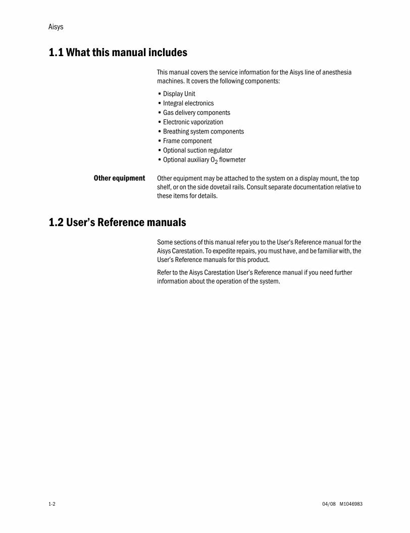
1.1 What this manual includes
This manual covers the service information for the Aisys line of anesthesia machines. It covers the following components:
• Display Unit• Integral electronics• Gas delivery components• Electronic vaporization• Breathing system components• Frame component• Optional suction regulator • Optional auxiliary O
2
flowmeter
Other equipment
Other equipment may be attached to the system on a display mount, the top shelf, or on the side dovetail rails. Consult separate documentation relative to these items for details.
1.2 User’s Reference manuals
Some sections of this manual refer you to the User’s Reference manual for the Aisys Carestation. To expedite repairs, you must have, and be familiar with, the User’s Reference manuals for this product.
Refer to the Aisys Carestation User’s Reference manual if you need further information about the operation of the system.
1 Introduction
M1046983 04/08 1-3
1.3 Overview
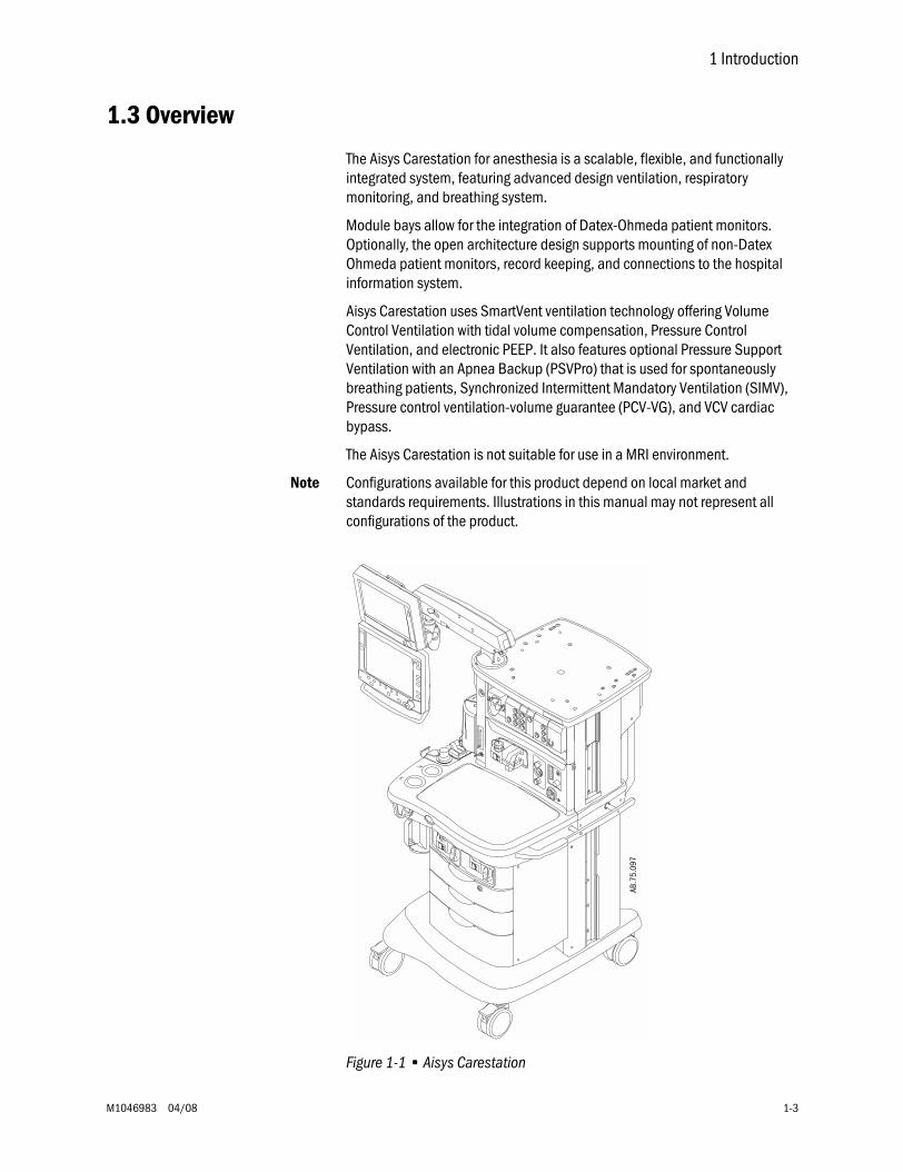
The Aisys Carestation for anesthesia is a scalable, flexible, and functionally integrated system, featuring advanced design ventilation, respiratory monitoring, and breathing system.
Module bays allow for the integration of Datex-Ohmeda patient monitors. Optionally, the open architecture design supports mounting of non-Datex Ohmeda patient monitors, record keeping, and connections to the hospital information system.
Aisys Carestation uses SmartVent ventilation technology offering Volume Control Ventilation with tidal volume compensation, Pressure Control Ventilation, and electronic PEEP. It also features optional Pressure Support Ventilation with an Apnea Backup (PSVPro) that is used for spontaneously breathing patients, Synchronized Intermittent Mandatory Ventilation (SIMV), Pressure control ventilation-volume guarantee (PCV-VG), and VCV cardiac bypass.
The Aisys Carestation is not suitable for use in a MRI environment.
Note
Configurations available for this product depend on local market and standards requirements. Illustrations in this manual may not represent all configurations of the product.
Figure 1-1 • Aisys Carestation
AB.7
5.09
7
Aisys
1-4 04/08 M1046983
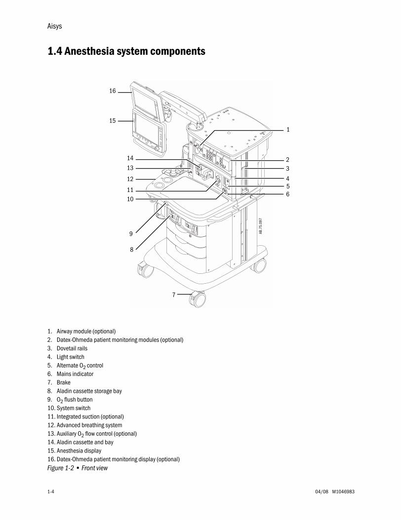
1.4 Anesthesia system components
1. Airway module (optional)2. Datex-Ohmeda patient monitoring modules (optional)3. Dovetail rails4. Light switch5. Alternate O
2
control6. Mains indicator7. Brake8. Aladin cassette storage bay9. O
2
flush button10. System switch11. Integrated suction (optional)12. Advanced breathing system13. Auxiliary O
2
flow control (optional)14. Aladin cassette and bay15. Anesthesia display16. Datex-Ohmeda patient monitoring display (optional)
Figure 1-2 • Front view
23
456
7
8
9
1011
12
13
14
15
AB.7
5.09
7
1
16
1 Introduction
M1046983 04/08 1-5
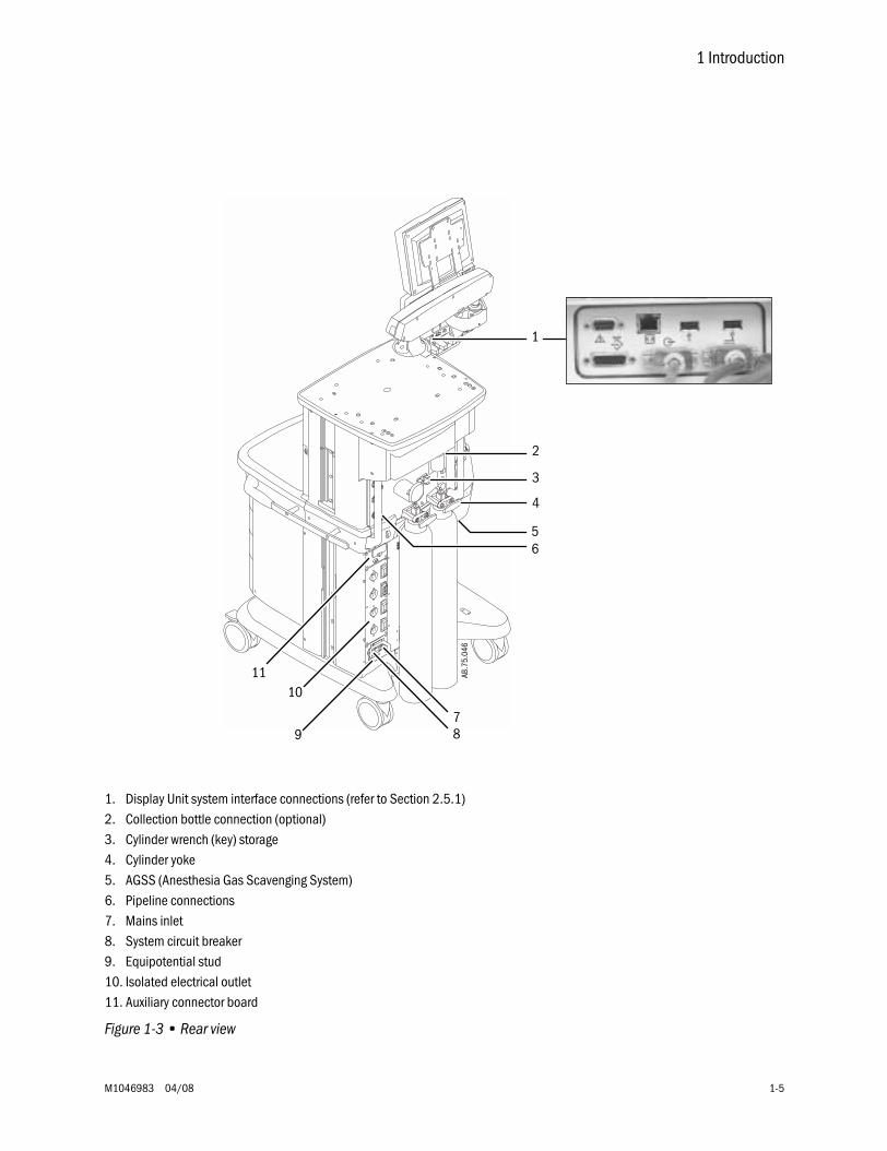
1. Display Unit system interface connections (refer to Section 2.5.1)2. Collection bottle connection (optional)3. Cylinder wrench (key) storage4. Cylinder yoke5. AGSS (Anesthesia Gas Scavenging System)6. Pipeline connections7. Mains inlet8. System circuit breaker9. Equipotential stud10. Isolated electrical outlet11. Auxiliary connector board
Figure 1-3 • Rear view
1
2
4
56
789
10
3AB
.75.
046
11

Aisys
1-6 04/08 M1046983
1.5 Breathing system components
1. Expiratory check valve2. Inspiratory check valve3. Inspiratory flow sensor4. Expiratory flow sensor5. Absorber canister6. Absorber canister release7. Leak test plug8. Manual bag port9. Breathing system release10. Adjustable pressure-limiting (APL) valve11. Bag/Vent switch12. Bellows assembly
Figure 1-4 • Advanced breathing system
12
34
5
6
7
9
8
12
1110
AB.7
5.09
8
1 Introduction
M1046983 04/08 1-7
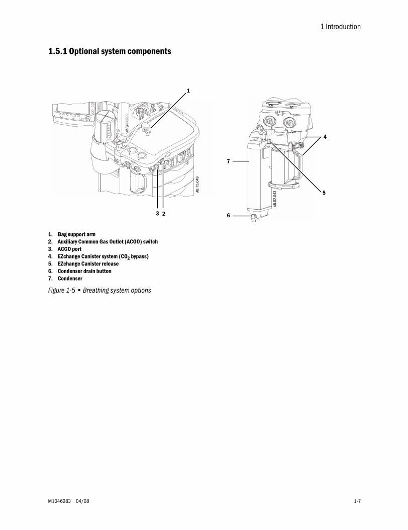
1.5.1 Optional system components
1. Bag support arm2. Auxiliary Common Gas Outlet (ACGO) switch 3. ACGO port4. EZchange Canister system (CO
2
bypass)5. EZchange Canister release6. Condenser drain button7. Condenser
Figure 1-5 • Breathing system options
1
23
AB.7
5.04
9
AB.8
2.04
3
4
6
7
5
Aisys
1-8 04/08 M1046983
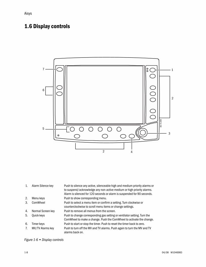
1.6 Display controls
Figure 1-6 • Display controls
1
3
2
5
2
AB.7
5.09
9
6
4
7
1. Alarm Silence key Push to silence any active, silenceable high and medium priority alarms or to suspend/acknowledge any non-active medium or high priority alarms. Alarm is silenced for 120 seconds or alarm is suspended for 90 seconds.
2. Menu keys Push to show corresponding menu.3. ComWheel Push to select a menu item or confirm a setting. Turn clockwise or
counterclockwise to scroll menu items or change settings.4. Normal Screen key Push to remove all menus from the screen.5. Quick keys Push to change corresponding gas setting or ventilator setting. Turn the
ComWheel to make a change. Push the ComWheel to activate the change.6. Timer keys Push to start or stop the timer. Push to reset the timer back to zero.7. MV/TV Alarms key Push to turn off the MV and TV alarms. Push again to turn the MV and TV
alarms back on.
1 Introduction
M1046983 04/08 1-9
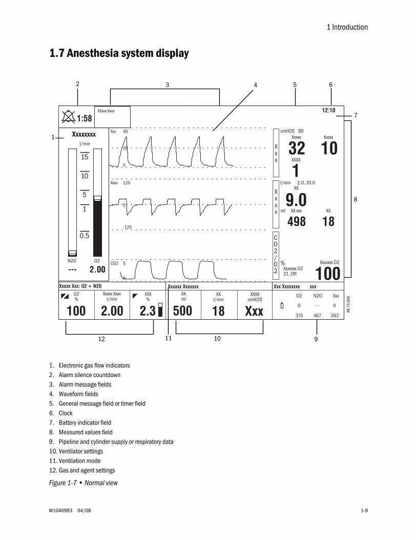
1.7 Anesthesia system display
1. Electronic gas flow indicators2. Alarm silence countdown3. Alarm message fields4. Waveform fields5. General message field or timer field6. Clock7. Battery indicator field8. Measured values field9. Pipeline and cylinder supply or respiratory data10. Ventilator settings11. Ventilation mode12. Gas and agent settings
Figure 1-7 • Normal view
2 3 4 5
8
910AB
.75.
006
6
12
1
11
7
Aisys
1-10 04/08 M1046983
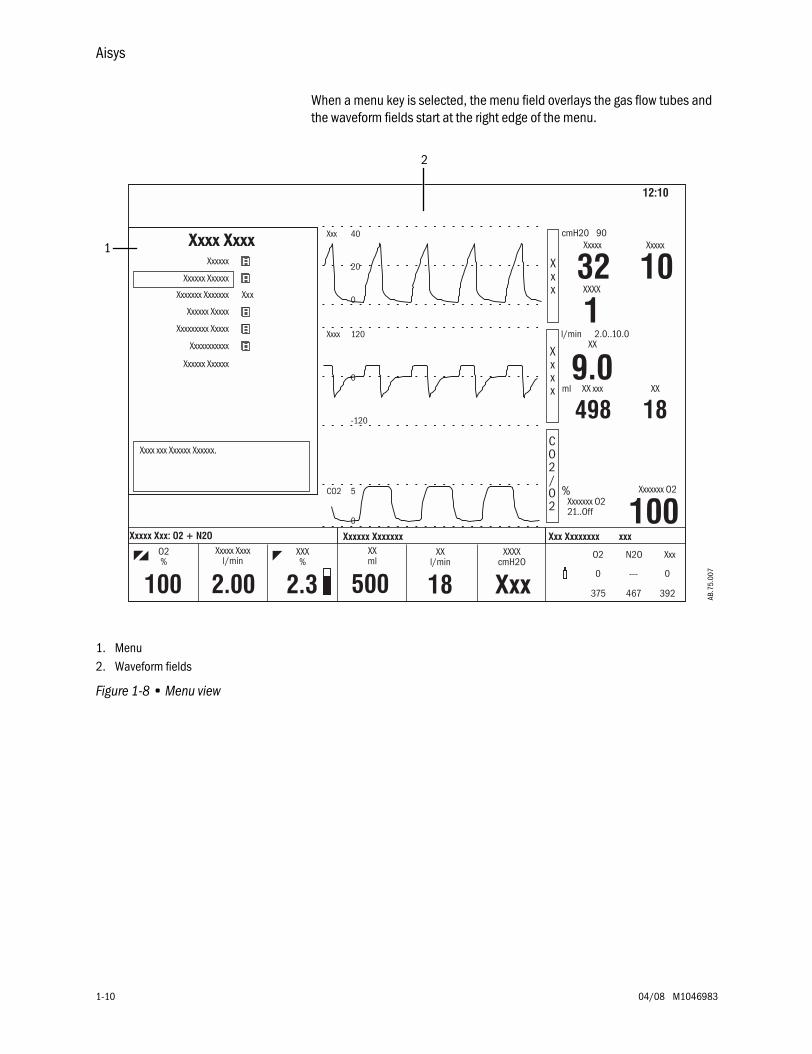
When a menu key is selected, the menu field overlays the gas flow tubes and the waveform fields start at the right edge of the menu.
1. Menu2. Waveform fields
Figure 1-8 • Menu view
1
2
AB.7
5.00
7
1 Introduction
M1046983 04/08 1-11
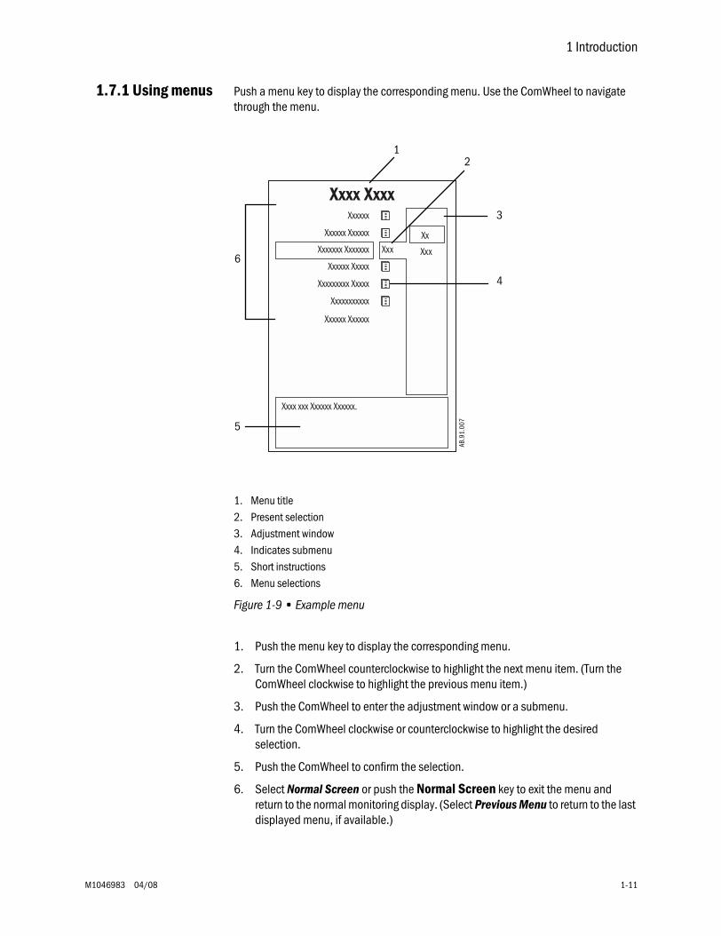
1.7.1 Using menus
Push a menu key to display the corresponding menu. Use the ComWheel to navigate through the menu.
1. Menu title2. Present selection3. Adjustment window4. Indicates submenu5. Short instructions6. Menu selections
Figure 1-9 • Example menu
1. Push the menu key to display the corresponding menu.
2. Turn the ComWheel counterclockwise to highlight the next menu item. (Turn the ComWheel clockwise to highlight the previous menu item.)
3. Push the ComWheel to enter the adjustment window or a submenu.
4. Turn the ComWheel clockwise or counterclockwise to highlight the desired selection.
5. Push the ComWheel to confirm the selection.
6. Select
Normal Screen
or push the
Normal Screen
key to exit the menu and return to the normal monitoring display. (Select
Previous Menu
to return to the last displayed menu, if available.)
Xxxxxx Xxxxxx
12
3
4
6
5
AB.9
1.00
7
Aisys
1-12 04/08 M1046983
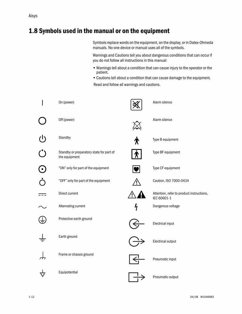
1.8 Symbols used in the manual or on the equipment
Symbols replace words on the equipment, on the display, or in Datex-Ohmeda manuals. No one device or manual uses all of the symbols.
Warnings and Cautions tell you about dangerous conditions that can occur if you do not follow all instructions in this manual:
• Warnings tell about a condition that can cause injury to the operator or the patient.
• Cautions tell about a condition that can cause damage to the equipment.
Read and follow all warnings and cautions.
m
On (power)
A
Alarm silence
L
Off (power) Alarm silence
l
Standby
j
Type B equipment
n
Standby or preparatory state for part of the equipment
J
Type BF equipment
M
“ON” only for part of the equipment
D
Type CF equipment
N
“OFF” only for part of the equipment w
Caution, ISO 7000-0434
†
Direct current wW
Attention, refer to product instructions, IEC 60601-1
p
Alternating current
O
Dangerous voltage
x
Protective earth groundElectrical input
y
Earth groundElectrical output
P
Frame or chassis groundPneumatic input
Y
EquipotentialPneumatic output
1 Introduction
M1046983 04/08 1-13
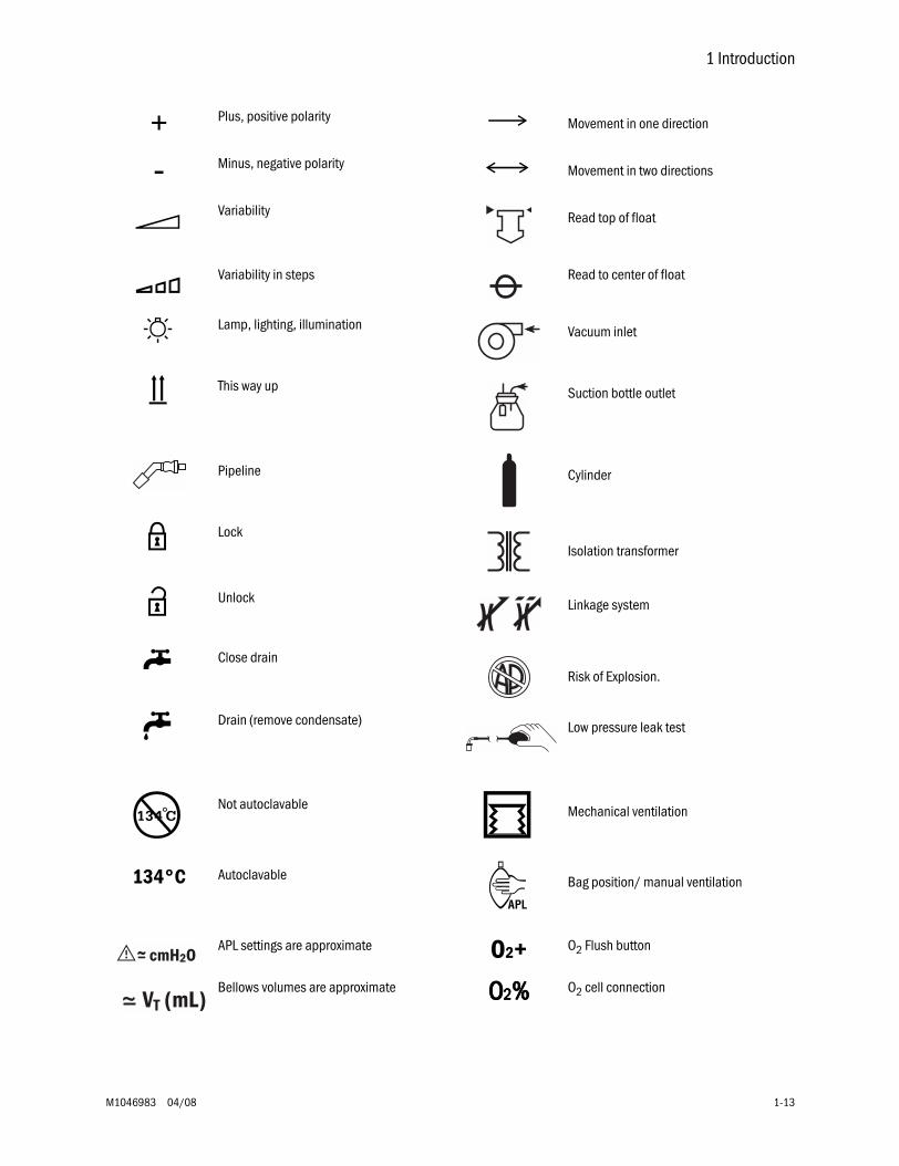
+
Plus, positive polarity
k
Movement in one direction
-
Minus, negative polarity
E
Movement in two directions
t
Variability Read top of float
T
Variability in steps Read to center of float
o
Lamp, lighting, illumination Vacuum inlet
g
This way up Suction bottle outlet
Pipeline Cylinder
z
LockIsolation transformer
Z
Unlock Linkage system
U Close drainRisk of Explosion.
u Drain (remove condensate) Low pressure leak test
ÍNot autoclavable r Mechanical ventilation
134°C Autoclavable R Bag position/ manual ventilation
APL settings are approximate O2+ O2 Flush button
Bellows volumes are approximate OOOO2222%%%% O2 cell connection
Aisys
1-14 04/08 M1046983
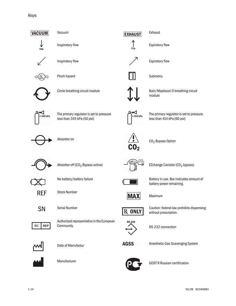
Vacuum Exhaust
q Inspiratory flow Q Expiratory flow
Inspiratory flow Expiratory flow
Pinch hazard Submenu
Circle breathing circuit module Bain/Mapleson D breathing circuit module
The primary regulator is set to pressure less than 345 kPa (50 psi)
The primary regulator is set to pressure less than 414 kPa (60 psi)
Absorber on CO2 Bypass Option
Absorber off (CO2 Bypass active) EZchange Canister (CO2 bypass)
No battery/battery failure Battery in use. Bar indicates amount of battery power remaining.
REF Stock NumberMaximum
SN Serial Number Caution: federal law prohibits dispensing without prescription.
Authorized representative in the European Community RS-232 connection
Date of Manufactur Anesthetic Gas Scavenging System
Manufacturer GOST R Russian certification
VACUUM
< 345 kPa < 414 kPa
AGSS
1 Introduction
M1046983 04/08 1-15
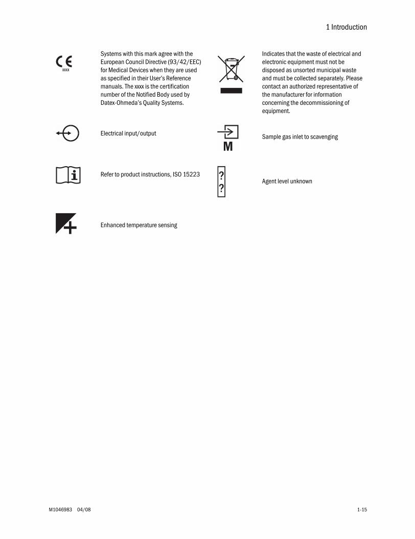
Systems with this mark agree with the European Council Directive (93/42/EEC) for Medical Devices when they are used as specified in their User’s Reference manuals. The xxxx is the certification number of the Notified Body used by Datex-Ohmeda’s Quality Systems.
Indicates that the waste of electrical and electronic equipment must not be disposed as unsorted municipal waste and must be collected separately. Please contact an authorized representative of the manufacturer for information concerning the decommissioning of equipment.
Electrical input/output Sample gas inlet to scavenging
Refer to product instructions, ISO 15223Agent level unknown
Enhanced temperature sensing

Notes
1-16 04/08 M1046983
M1046983 04/08 2-1
2 Theory of OperationIn this section 2.1 Electrical system . . . . . . . . . . . . . . . . . . . . . . . . . . . . . . . . . . . . . . . . . . . . . . . . . . . . . . . . . . .2-2
2.2 Power subsystem . . . . . . . . . . . . . . . . . . . . . . . . . . . . . . . . . . . . . . . . . . . . . . . . . . . . . . . . . .2-4
2.2.1 U-Frame Power Supply . . . . . . . . . . . . . . . . . . . . . . . . . . . . . . . . . . . . . . . . . . . . . . . .2-52.2.2 Power Controller board overview . . . . . . . . . . . . . . . . . . . . . . . . . . . . . . . . . . . . . . . .2-52.2.3 Power distribution . . . . . . . . . . . . . . . . . . . . . . . . . . . . . . . . . . . . . . . . . . . . . . . . . . . .2-62.2.4 Power Controller Board . . . . . . . . . . . . . . . . . . . . . . . . . . . . . . . . . . . . . . . . . . . . . . .2-7
2.3 Display Unit . . . . . . . . . . . . . . . . . . . . . . . . . . . . . . . . . . . . . . . . . . . . . . . . . . . . . . . . . . . . . 2-10
2.4 System communications . . . . . . . . . . . . . . . . . . . . . . . . . . . . . . . . . . . . . . . . . . . . . . . . . . 2-11
2.4.1 Software Power On Self Tests (POST) . . . . . . . . . . . . . . . . . . . . . . . . . . . . . . . . . . . 2-122.5 System connections . . . . . . . . . . . . . . . . . . . . . . . . . . . . . . . . . . . . . . . . . . . . . . . . . . . . . . 2-14
2.5.1 Display Unit . . . . . . . . . . . . . . . . . . . . . . . . . . . . . . . . . . . . . . . . . . . . . . . . . . . . . . . 2-142.5.2 Display Connector board . . . . . . . . . . . . . . . . . . . . . . . . . . . . . . . . . . . . . . . . . . . . 2-14
2.6 Power Controller and Anesthesia Control board connections . . . . . . . . . . . . . . . . . . . . . 2-15
2.7 Anesthesia Control board . . . . . . . . . . . . . . . . . . . . . . . . . . . . . . . . . . . . . . . . . . . . . . . . . . 2-16
2.7.1 Overview . . . . . . . . . . . . . . . . . . . . . . . . . . . . . . . . . . . . . . . . . . . . . . . . . . . . . . . . . 2-162.7.2 Anesthesia Control Board details . . . . . . . . . . . . . . . . . . . . . . . . . . . . . . . . . . . . . 2-18
2.8 Ventilator Interface board . . . . . . . . . . . . . . . . . . . . . . . . . . . . . . . . . . . . . . . . . . . . . . . . . . 2-22
2.9 Electronic Gas Mixer . . . . . . . . . . . . . . . . . . . . . . . . . . . . . . . . . . . . . . . . . . . . . . . . . . . . . . 2-24
2.9.1 Electronic Gas Mixer (details) . . . . . . . . . . . . . . . . . . . . . . . . . . . . . . . . . . . . . . . . 2-262.10 Electronic Vaporizer . . . . . . . . . . . . . . . . . . . . . . . . . . . . . . . . . . . . . . . . . . . . . . . . . . . . . 2-28
2.10.1 Agent cassette . . . . . . . . . . . . . . . . . . . . . . . . . . . . . . . . . . . . . . . . . . . . . . . . . . . 2-282.10.2 Electronic Vaporizer subsystem (eVap) . . . . . . . . . . . . . . . . . . . . . . . . . . . . . . . 2-302.10.3 Agent Delivery board LED indicators . . . . . . . . . . . . . . . . . . . . . . . . . . . . . . . . . . 2-34
2.11 Gas flow through the anesthesia machine . . . . . . . . . . . . . . . . . . . . . . . . . . . . . . . . . . . 2-36
2.11.1 Overview . . . . . . . . . . . . . . . . . . . . . . . . . . . . . . . . . . . . . . . . . . . . . . . . . . . . . . . . 2-362.11.2 Electronic vaporizer . . . . . . . . . . . . . . . . . . . . . . . . . . . . . . . . . . . . . . . . . . . . . . . 2-382.11.3 Physical connections (O2 supply) . . . . . . . . . . . . . . . . . . . . . . . . . . . . . . . . . . . . 2-422.11.4 Physical connections (N2O and Air supplies) . . . . . . . . . . . . . . . . . . . . . . . . . . 2-432.11.5 Suction regulators . . . . . . . . . . . . . . . . . . . . . . . . . . . . . . . . . . . . . . . . . . . . . . . . 2-44
2.12 Flow through the breathing system . . . . . . . . . . . . . . . . . . . . . . . . . . . . . . . . . . . . . . . . . 2-45
2.12.1 Overview of flow paths . . . . . . . . . . . . . . . . . . . . . . . . . . . . . . . . . . . . . . . . . . . . . 2-452.12.2 Manual ventilation . . . . . . . . . . . . . . . . . . . . . . . . . . . . . . . . . . . . . . . . . . . . . . . . 2-462.12.3 Mechanical ventilation . . . . . . . . . . . . . . . . . . . . . . . . . . . . . . . . . . . . . . . . . . . . . 2-492.12.4 Fresh gas and O2 flush flow (with SCGO). . . . . . . . . . . . . . . . . . . . . . . . . . . . . . . 2-562.12.5 Fresh gas and O2 flush flow (with ACGO). . . . . . . . . . . . . . . . . . . . . . . . . . . . . . . 2-58
2.13 Ventilator mechanical subsystems . . . . . . . . . . . . . . . . . . . . . . . . . . . . . . . . . . . . . . . . . 2-60
2.13.1 Drive gas filter and Gas Inlet Valve . . . . . . . . . . . . . . . . . . . . . . . . . . . . . . . . . . . 2-602.13.2 Pressure regulator . . . . . . . . . . . . . . . . . . . . . . . . . . . . . . . . . . . . . . . . . . . . . . . . 2-612.13.3 Flow control valve . . . . . . . . . . . . . . . . . . . . . . . . . . . . . . . . . . . . . . . . . . . . . . . . . 2-612.13.4 Drive Gas Check Valve (DGCV) . . . . . . . . . . . . . . . . . . . . . . . . . . . . . . . . . . . . . . 2-622.13.5 Bellows Pressure Relief Valve . . . . . . . . . . . . . . . . . . . . . . . . . . . . . . . . . . . . . . . 2-622.13.6 Exhalation valve . . . . . . . . . . . . . . . . . . . . . . . . . . . . . . . . . . . . . . . . . . . . . . . . . . 2-632.13.7 Mechanical Overpressure Valve . . . . . . . . . . . . . . . . . . . . . . . . . . . . . . . . . . . . . 2-642.13.8 Reservoir and bleed resistor . . . . . . . . . . . . . . . . . . . . . . . . . . . . . . . . . . . . . . . . 2-642.13.9 Free breathing valve . . . . . . . . . . . . . . . . . . . . . . . . . . . . . . . . . . . . . . . . . . . . . . . 2-652.13.10 Breathing circuit flow sensors . . . . . . . . . . . . . . . . . . . . . . . . . . . . . . . . . . . . . . 2-66
Aisys
2-2 04/08 M1046983
2.1 Electrical system
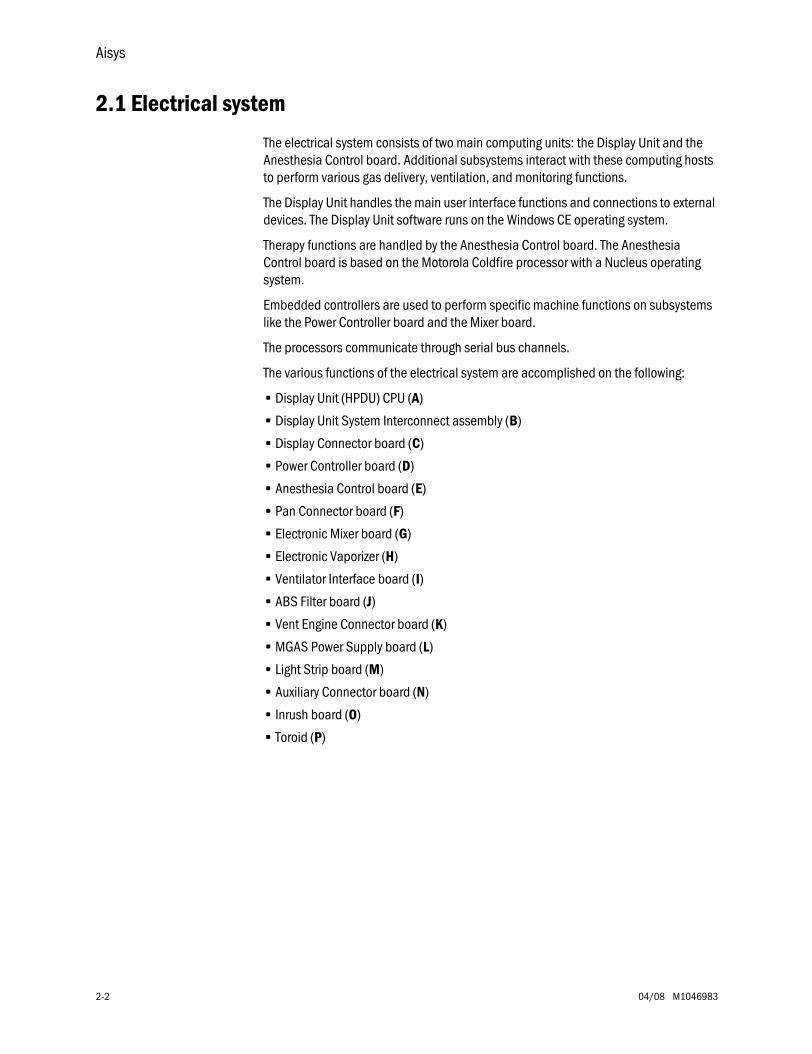
The electrical system consists of two main computing units: the Display Unit and the Anesthesia Control board. Additional subsystems interact with these computing hosts to perform various gas delivery, ventilation, and monitoring functions.
The Display Unit handles the main user interface functions and connections to external devices. The Display Unit software runs on the Windows CE operating system.
Therapy functions are handled by the Anesthesia Control board. The Anesthesia Control board is based on the Motorola Coldfire processor with a Nucleus operating system.
Embedded controllers are used to perform specific machine functions on subsystems like the Power Controller board and the Mixer board.
The processors communicate through serial bus channels.
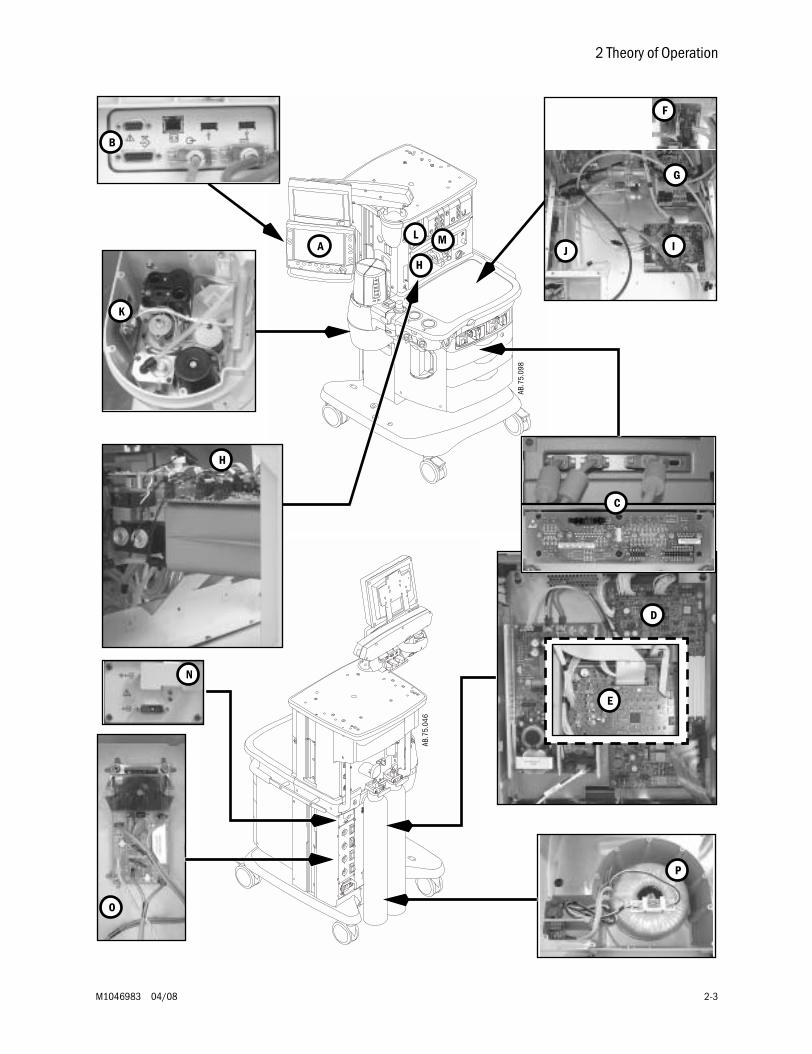
The various functions of the electrical system are accomplished on the following:
• Display Unit (HPDU) CPU (A)
• Display Unit System Interconnect assembly (B)
• Display Connector board (C)
• Power Controller board (D)
• Anesthesia Control board (E)
• Pan Connector board (F)
• Electronic Mixer board (G)
• Electronic Vaporizer (H)
• Ventilator Interface board (I)
• ABS Filter board (J)
• Vent Engine Connector board (K)
• MGAS Power Supply board (L)
• Light Strip board (M)
• Auxiliary Connector board (N)
• Inrush board (O)
• Toroid (P)
2 Theory of Operation
M1046983 04/08 2-3
A M
AB.7
5.09
8
L
H
D
AB.7
5.04
6
J
G
I
F
K
P
O
E
D
B
C
H
N
Aisys
2-4 04/08 M1046983
2.2 Power subsystem
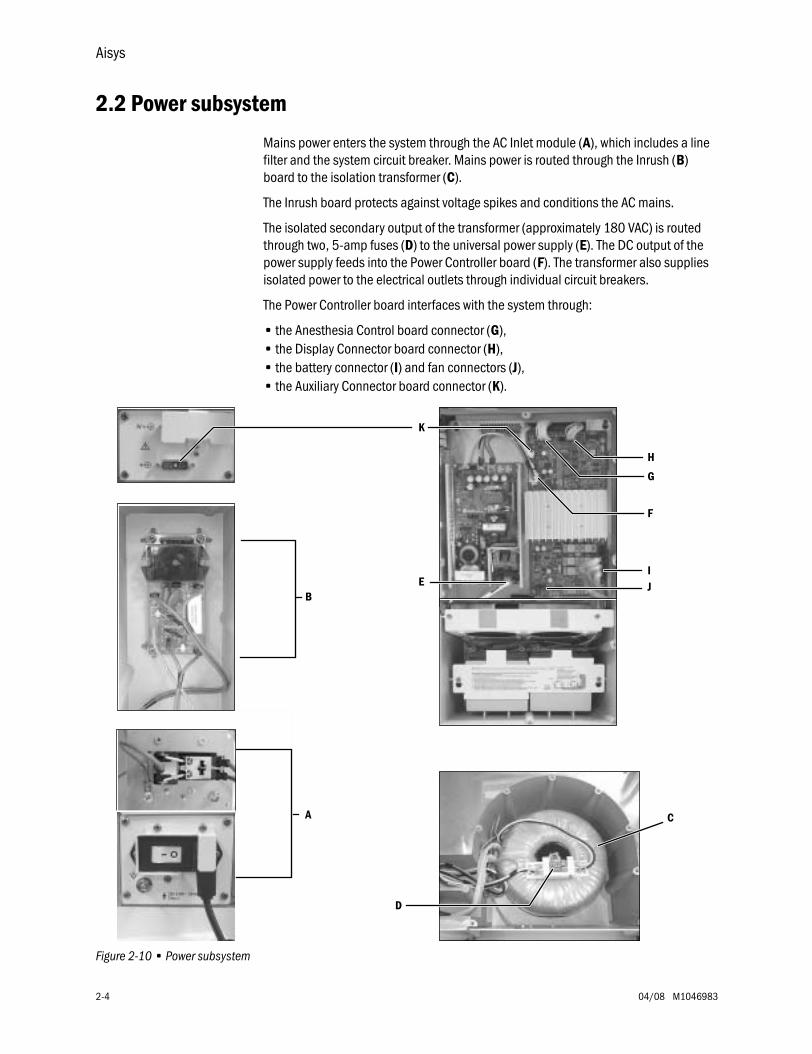
Mains power enters the system through the AC Inlet module (A), which includes a line filter and the system circuit breaker. Mains power is routed through the Inrush (B) board to the isolation transformer (C).
The Inrush board protects against voltage spikes and conditions the AC mains.
The isolated secondary output of the transformer (approximately 180 VAC) is routed through two, 5-amp fuses (D) to the universal power supply (E). The DC output of the power supply feeds into the Power Controller board (F). The transformer also supplies isolated power to the electrical outlets through individual circuit breakers.
The Power Controller board interfaces with the system through:
• the Anesthesia Control board connector (G),• the Display Connector board connector (H),• the battery connector (I) and fan connectors (J),• the Auxiliary Connector board connector (K).
Figure 2-10 • Power subsystem
B
A
D
E
C
G
H
JI
F
K
2 Theory of Operation
M1046983 04/08 2-5
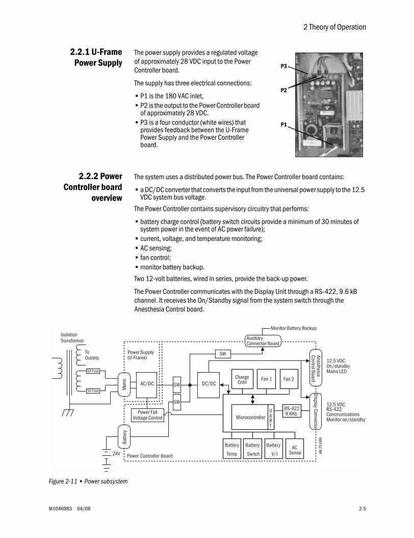
2.2.1 U-FramePower Supply
The power supply provides a regulated voltage of approximately 28 VDC input to the Power Controller board.
The supply has three electrical connections:
• P1 is the 180 VAC inlet,• P2 is the output to the Power Controller board
of approximately 28 VDC.• P3 is a four conductor (white wires) that
provides feedback between the U-Frame Power Supply and the Power Controller board.
2.2.2 PowerController board
overview
The system uses a distributed power bus. The Power Controller board contains:
• a DC/DC converter that converts the input from the universal power supply to the 12.5 VDC system bus voltage.
The Power Controller contains supervisory circuitry that performs:
• battery charge control (battery switch circuits provide a minimum of 30 minutes of system power in the event of AC power failure);
• current, voltage, and temperature monitoring;• AC sensing;• fan control;• monitor battery backup.
Two 12-volt batteries, wired in series, provide the back-up power.
The Power Controller communicates with the Display Unit through a RS-422, 9.6 kB channel. It receives the On/Standby signal from the system switch through the Anesthesia Control board.
Figure 2-11 • Power subsystem
P1
P2
P3
5A Fuse
5A Fuse
Power Controller Board
Microcontroller
Fan 1ChargeCntrl
Battery
Temp
Battery
SwitchAC
SenseBattery
V/I
UART
RS-4229.6Kb
Fan 2AC/DC
24V
DC/DC
ToOutlets 12.5 VDC
On/standbyMains LED
12.5 VDCRS-422CommunicationsMonitor on/standby
IsolationTransformer
Mai
nsBa
ttery
Display ConnectorAnesthesiaControl Board
Power Supply(U-Frame)
Power FailVoltage Control
Monitor Battery Backup
AuxiliaryConnector Board
SW
SW
SW
AB.7
5.06
0
Aisys
2-6 04/08 M1046983
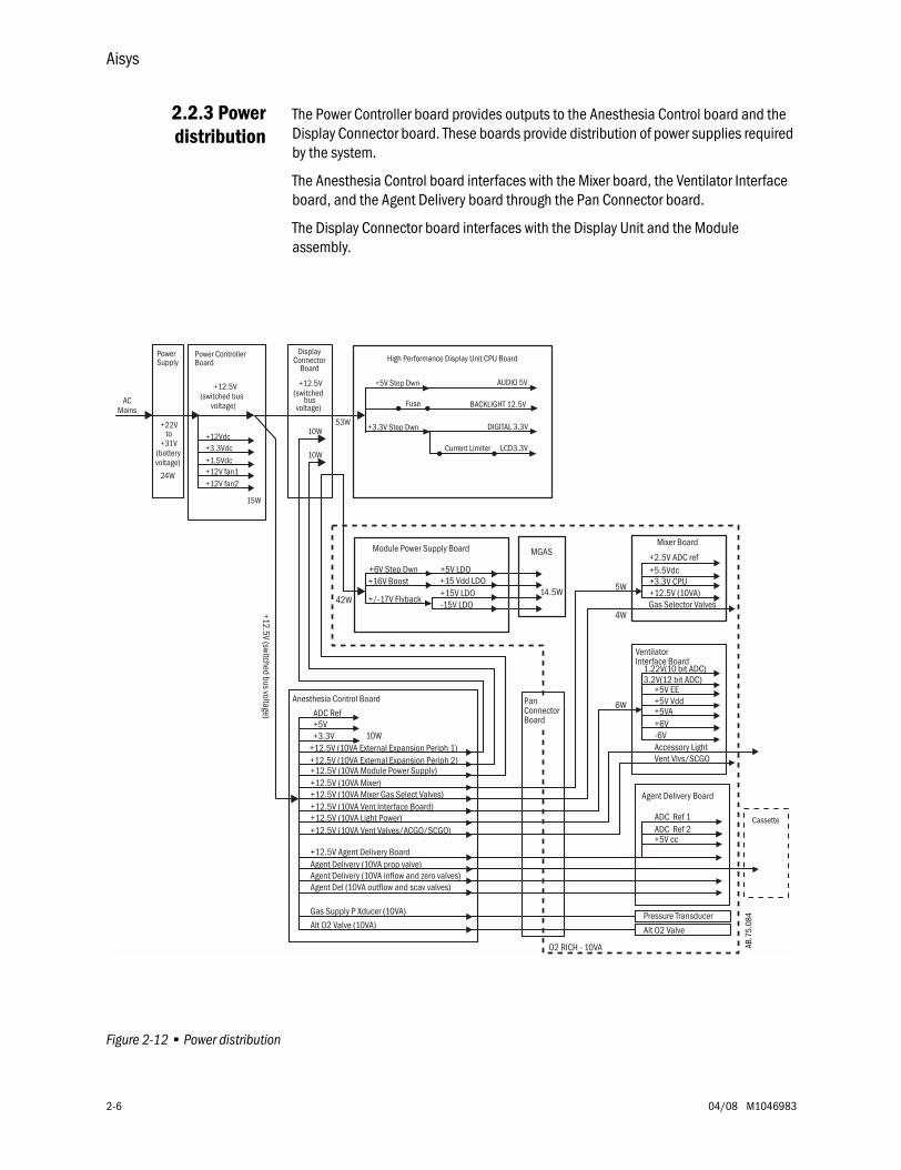
2.2.3 Powerdistribution
The Power Controller board provides outputs to the Anesthesia Control board and the Display Connector board. These boards provide distribution of power supplies required by the system.
The Anesthesia Control board interfaces with the Mixer board, the Ventilator Interface board, and the Agent Delivery board through the Pan Connector board.
The Display Connector board interfaces with the Display Unit and the Module assembly.
Figure 2-12 • Power distribution
DisplayConnector
BoardHigh Performance Display Unit CPU Board
Current Limiter LCD3.3V
Fuse BACKLIGHT 12.5V
AUDIO 5V+5V Step Dwn
DIGITAL 3.3V+3.3V Step Dwn
+12.5V(switched
busvoltage)
+22Vto
+31V(batteryvoltage)
Power ControllerBoard
+12.5V(switched bus
voltage)AC
Mains
15W
24W
10W53W
+3.3Vdc+1.5Vdc
10W
+12V fan1+12V fan2
PowerSupply
+6V
VentilatorInterface Board
+5V EE
+5VA+5V Vdd
-6V
42W
6W
O2 RICH - 10VA
Accessory Light
+12.5V (10VA)
Mixer Board
+3.3V CPU
4W
5W
Gas Selector Valves
Vent Vlvs/SCGO
+5V
Anesthesia Control Board
+12.5V (10VA Vent Interface Board)
+12.5V (10VA Module Power Supply)
10W
+12.5V (10VA Light Power)+12.5V (10VA Vent Valves/ACGO/SCGO)
MGAS
-15V LDO
Module Power Supply Board
+6V Step Dwn
+15V LDO+16V Boost
+5V LDO
+/-17V Flyback
+15 Vdd LDO14.5W
+12.5V (10VA Mixer)+12.5V (10VA Mixer Gas Select Valves)
+3.3V
+12.5V (switched bus voltage)
PanConnectorBoard
Agent Delivery Board
+5V cc
ADC Ref 1ADC Ref 2
+12.5V Agent Delivery BoardAgent Delivery (10VA prop valve)Agent Delivery (10VA inflow and zero valves)Agent Del (10VA outflow and scav valves)
Alt O2 Valve (10VA)
Gas Supply P Xducer (10VA)
ADC Ref
+5.5Vdc+2.5V ADC ref
1.22V(10 bit ADC)3.2V(12 bit ADC)
+12Vdc
Cassette
+12.5V (10VA External Expansion Periph 1)+12.5V (10VA External Expansion Periph 2)
Pressure Transducer
Alt O2 Valve
AB.7
5.08
4
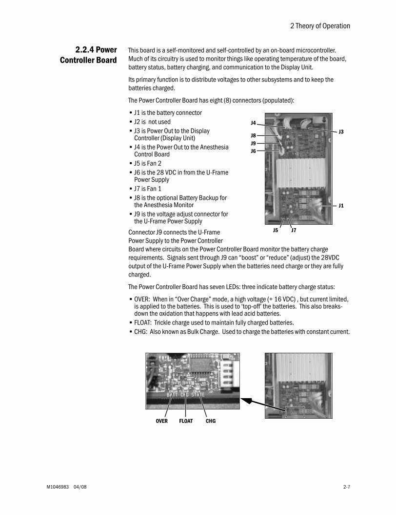
2 Theory of Operation
M1046983 04/08 2-7
2.2.4 PowerController Board
This board is a self-monitored and self-controlled by an on-board microcontroller. Much of its circuitry is used to monitor things like operating temperature of the board, battery status, battery charging, and communication to the Display Unit.
Its primary function is to distribute voltages to other subsystems and to keep the batteries charged.
The Power Controller Board has eight (8) connectors (populated):
• J1 is the battery connector• J2 is not used• J3 is Power Out to the Display
Controller (Display Unit)• J4 is the Power Out to the Anesthesia
Control Board• J5 is Fan 2• J6 is the 28 VDC in from the U-Frame
Power Supply• J7 is Fan 1• J8 is the optional Battery Backup for
the Anesthesia Monitor• J9 is the voltage adjust connector for
the U-Frame Power Supply
Connector J9 connects the U-Frame Power Supply to the Power Controller Board where circuits on the Power Controller Board monitor the battery charge requirements. Signals sent through J9 can “boost” or “reduce” (adjust) the 28VDC output of the U-Frame Power Supply when the batteries need charge or they are fully charged.
The Power Controller Board has seven LEDs: three indicate battery charge status:
• OVER: When in “Over Charge” mode, a high voltage (+ 16 VDC) , but current limited, is applied to the batteries. This is used to ‘top-off’ the batteries. This also breaks-down the oxidation that happens with lead acid batteries.
• FLOAT: Trickle charge used to maintain fully charged batteries.• CHG: Also known as Bulk Charge. Used to charge the batteries with constant current.
J1
J4
J3J8
J7J5
J6J9
FLOAT CHGOVER
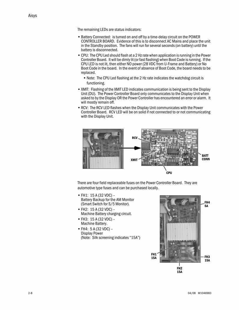
Aisys
2-8 04/08 M1046983
The remaining LEDs are status indicators:
• Battery Connected: is turned on and off by a time-delay circuit on the POWER CONTROLLER BOARD. Evidence of this is to disconnect AC Mains and place the unit in the Standby position. The fans will run for several seconds (on battery) until the battery is disconnected.
• CPU: The CPU Led should flash at a 2 Hz rate when application is running in the Power Controller Board. It will be dimly lit (or fast flashing) when Boot Code is running. If the CPU LED is not lit, then either NO power (28 VDC from U-Frame and Battery) or No Boot Code in the board. In the event of absence of Boot Code, the board needs to be replaced.
• Note: The CPU Led flashing at the 2 Hz rate indicates the watchdog circuit is functioning.
• XMIT: Flashing of the XMIT LED indicates communication is being sent to the Display Unit (DU). The Power Controller Board only communicates to the Display Unit when asked to by the Display OR the Power Controller has encountered an error or alarm. It will mostly remain off.
• RCV: The RCV LED flashes when the Display Unit communicates with the Power Controller Board. RCV LED will be on solid if not connected to or not communicating with the Display Unit.
There are four field replaceable fuses on the Power Controller Board. They are automotive type fuses and can be purchased locally.
• FH1: 15 A (32 VDC) – Battery Backup for the AM Monitor (Smart Switch for S/5 Monitor).
• FH2: 15 A (32 VDC) – Machine Battery charging circuit.
• FH3: 15 A (32 VDC) – Machine Battery.
• FH4: 5 A (32 VDC) – Display Power (Note: Silk screening indicates “15A”)
BATTCONN
CPU
XMIT
RCV
FH3FH1
FH2
15A
15A
15A
FH45A
2 Theory of Operation
M1046983 04/08 2-9
The Power Controller board produces other voltages.
• The 28 VDC that is generated by the U-Frame comes on the Power Controller board and is used to charge the machine batteries in one of three (3) modes. The charge voltage varies depending on the condition of the batteries.
• The 28 VDC is regulated down to +12 VDC, +12.5 VDC and 3.3 VDC.• The 12 VDC and 3.3 VDC remain local on the Power Controller board and are used by on-board circuits and the on-
board processor.• The +12.5 VDC, created by the circuit (Brick) under the large heat sink, is a high current output. It supplies power to
subsystems remote from the Power Controller board (Display Unit and Anesthesia Control board).• Fan 1 and Fan 2 are capable of running at one of two speeds (high and low). They are controlled by the Power
Controller board’s microcontroller as it monitors temperature by circuitry also on the Power Controller board.
There are four conditions the Power Controller board can be placed into:
1. OFF: System unplugged from AC Mains or the AC Mains Circuit Breaker open and the On/Standby Switch in the Standby position.
• In this condition, the Power Controller board is truly OFF. This is indicated by No Fans and No illuminated LEDs. There is no Battery Charging.
2. Standby: The system is plugged into AC Mains and Mains Circuit Breaker closed (receiving 28 VDC from U-Frame Power Supply) and the system switch in the Standby position.
• In this condition, 180 VAC is sent to the U-Frame Power Supply, which converts it to approximately 28 VDC and sends a signal “AC_GOOD” to the Power Controller board (along with the 28 VDC). A “green” AC Mains LED on the front panel of the machine will illuminate because of this signal.
• Even though the On/Standby Switch is in the Standby position, the Power Controller board will receive the 28 VDC and create from it a +12 VDC, a battery charge voltage, and a +3.3 VDC (for microprocessor, ROM, RAM, etc).
• The microprocessor will run its Boot Code. During this brief time, the CPU LED may be dimly lit (or fast flashing). Soon it will begin flashing at a 2 Hz rate (indicating it is running application program). Almost immediately, the fans should turn on. One or more of the battery status LEDs should illuminate and the battery connected LED should also illuminate. The XMIT LED will remain OFF (indicating no communication to the Display Unit). The RCV LED will be on solid (indicating no communication to the Display Unit).
3. ON: system is plugged into AC Mains and Mains Circuit Breaker closed (receiving 28 VDC from U-Frame Power Supply) and the system switch in the ON position.
• The movement of the System Switch to the ON position will trigger the CPU (via On/Standby Logic circuitry) to enable the +12.5 V DC/DC Brick to send +12.5 VDC to the Display Unit and the Anesthesia Control Board. Notice a 12.5v LED under connector J4 (Anesthesia Control Board connector) illuminates solid. Within approximately one minute, the XMIT and RCV LED’s will be mostly off but will briefly and randomly flash indicating communication with the Display Unit.
• Recap LED Status: CPU flashing at 2 Hz rate, XMIT/RCV flash randomly, 12.5v constant illuminated, BATTery CONNected constantly illuminated, battery status LEDs illuminated depending on the battery condition.
4. ON (no AC mains) Batteries ONLY: The system is NOT plugged into AC Mains or the Mains Circuit Breaker is Open and the On/Standby Switch in the On position. The system will switch to battery operation for up to 30 minutes (with AM Monitor backup, longer if not connected to AM Monitor).
• There should be no interruption of operation and the “green” AC Mains LED on the front panel of the machine will NOT be illuminated. The LEDs that indicate battery condition will turn off (this may not happen immediately).
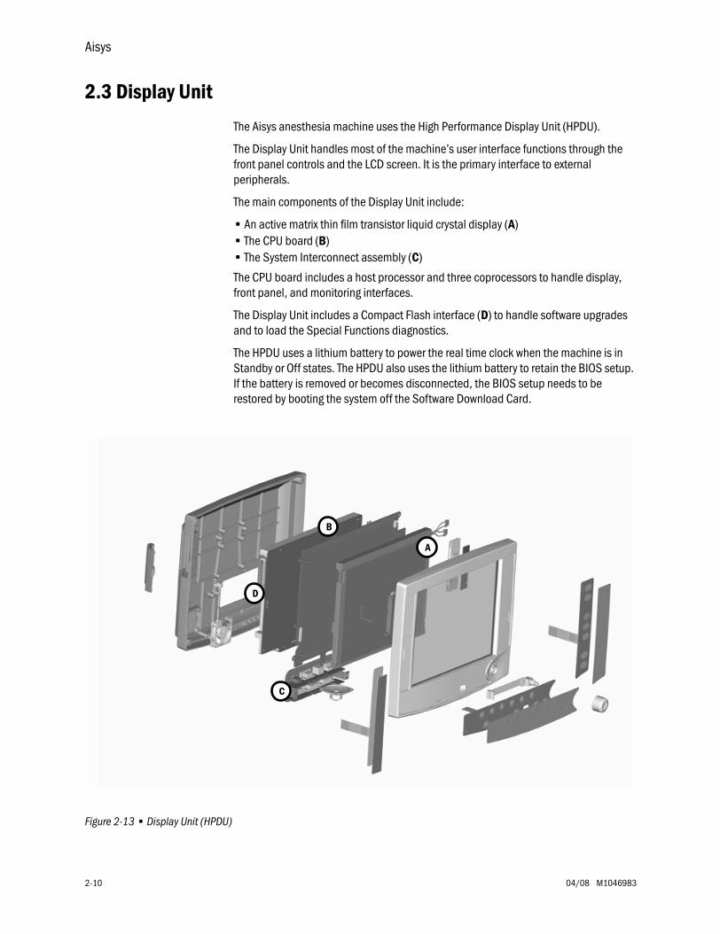
Aisys
2-10 04/08 M1046983
2.3 Display Unit
The Aisys anesthesia machine uses the High Performance Display Unit (HPDU).
The Display Unit handles most of the machine’s user interface functions through the front panel controls and the LCD screen. It is the primary interface to external peripherals.
The main components of the Display Unit include:
• An active matrix thin film transistor liquid crystal display (A)• The CPU board (B)• The System Interconnect assembly (C)
The CPU board includes a host processor and three coprocessors to handle display, front panel, and monitoring interfaces.
The Display Unit includes a Compact Flash interface (D) to handle software upgrades and to load the Special Functions diagnostics.
The HPDU uses a lithium battery to power the real time clock when the machine is in Standby or Off states. The HPDU also uses the lithium battery to retain the BIOS setup. If the battery is removed or becomes disconnected, the BIOS setup needs to be restored by booting the system off the Software Download Card.
Figure 2-13 • Display Unit (HPDU)
A
B
D
C
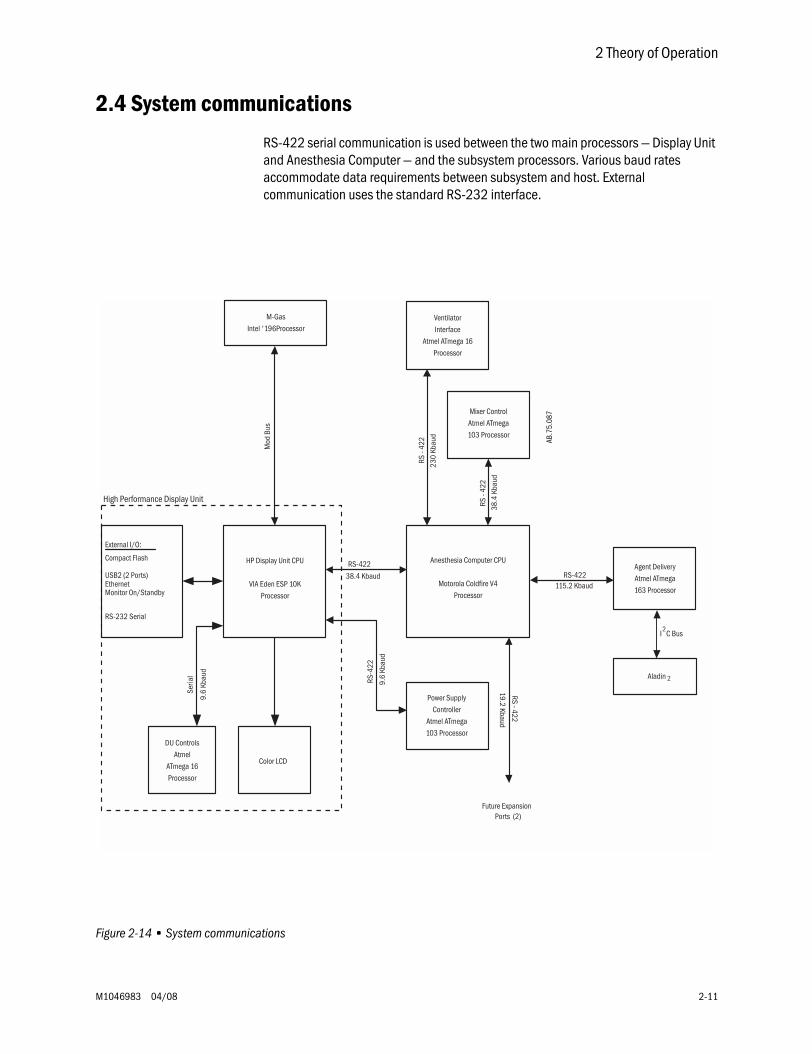
2 Theory of Operation
M1046983 04/08 2-11
2.4 System communications
RS-422 serial communication is used between the two main processors — Display Unit and Anesthesia Computer — and the subsystem processors. Various baud rates accommodate data requirements between subsystem and host. External communication uses the standard RS-232 interface.
Figure 2-14 • System communications
HP Display Unit CPU
VIA Eden ESP 10KProcessor
DU ControlsAtmel
ATmega 16Processor
M-GasIntel '196Processor
Color LCD
External I/O:
Compact Flash
USB2 (2 Ports)
RS-232 Serial
EthernetMonitor On/Standby
Anesthesia Computer CPU
Motorola Coldfire V4Processor
Power SupplyController
Atmel ATmega103 Processor
Mixer ControlAtmel ATmega103 Processor
VentilatorInterface
Atmel ATmega 16Processor
RS-422
38.4 Kbaud
Future ExpansionPorts (2)
RS-4
22
High Performance Display Unit
Agent DeliveryAtmel ATmega163 Processor
RS-422115.2 Kbaud
9.6
Kbau
d
RS -
422
230
Kbau
d
RS -
422
38.4
Kba
ud
Mod
Bus
9.6
Kbau
d
Seria
l
RS - 422
19.2 Kbaud
Aladin 2
I C Bus2
AB.7
5.08
7
Aisys
2-12 04/08 M1046983
2.4.1 Software Power On Self Tests (POST)
When the machine is in the “Off” state, there is no machine activity. Circuitry on the Power Controller Board (PCB) and on the Anesthesia Control Board ACB) monitors the On/Standby Switch for movement.
If the On/Standby switch is moved to the “On” position while the machine is in the “Off” state (machine not connected to AC mains supply), the circuitry on the PCB engages the batteries to power the CPU on the PCB. Standard CPU tests are performed and the PCB application starts. Once the PCB has passed its CPU tests and the application is running, it activates the +12 VDC circuit to power the DU and the ACB. The DU and ACB simultaneously begin powering on. The PCB evaluates the battery capacity.
If the machine state changes from the “Off” state to the “Standby” state (machine connected to AC mains supply), the hospital AC (stepped to approximately 180 VAC by the isolation transformer) enters the U-frame Power Supply. The AC voltage is converted to +12 VDC. Standard CPU tests are performed (including but not limited to RAM, ROM, Watchdog, and application CRC) and the PCB application starts. The PCB evaluates the battery capacity and charges the batteries, if necessary.
If the machine state changes from the “Standby” state to the “On” state, the +12 VDC circuit to power the Display Unit (DU) and the ACB is activated. The DU and ACB simultaneously begin powering on.
Both the ACB and the DU begin by converting the incoming +12 VDC to local needed power (+3.3 V, +4 V, +5 V, +8 V, and others) and perform standard CPU tests. Each board loads their software (that resides locally) and begins their appropriate self tests described below:
• Once the ACB passes all CPU tests and application is loaded, independent circuitry turns on 10 VA limited (+12 VDC) power to the Gas Mixer, the Ventilator Interface Board, the Agent Delivery Board (eVap) and the M-Gas Power Supply Board. These boards convert the incoming +12 VDC into locally need power supplies and simultaneously begin to power up. The ACB energizes the Alt O2 Selector Valve, which closes the valve. The ACB begins testing the GIV.
- The processor on the Gas Mixer board performs standard CPU tests, checks communication link with the ACB, reports to the ACB that it has begun to perform Power-On Self Tests (POST). The Gas Mixer tests the O2 and Balance Gas channels for leaks and flow delivery from both channels. Once completed, reports to the ACB that all Self-Tests have been completed and the Gas Mixer compatibility information (serial number, hardware revision, and software revision).
- The processor on the Ventilator Interface Board (VIB) performs standard CPU tests and begins to download application software and ventilator calibration constants from the ACB. The VIB works in conjunction with the ACB to perform the Gas Inlet Valve (GIV) test (ACB provides valve status information to the VIB, the VIB calculates the voltage necessary to open the valve to the desired value). Once completed, the VIB reports to the ACB that the Self-Tests have been completed and the VIB compatibility information (serial number, hardware revision, and software revision).
Off State:
• AC Power is not connected to the machine and the On/Standby Switch is in the “Standby” position.
Standby State:
• AC Power is connected to the the machine while the On/Standby Switch is in the “Standby” position.
On State:
• AC Power is connected to the machine and the On/Standby Switch is set to the “ON” position.
2 Theory of Operation
M1046983 04/08 2-13
- The processor on the Agent Delivery Board performs standard CPU tests and establishes communications with the Anesthesia Control Board. The Anesthesia Control Board directs other POST activities including valve conditioning (full power for 15 seconds), reading and integrity checking of sensor calibration data, and reporting on serial number, hardware revision, and software revision.
- There is no processor on the M-Gas Power Supply. Local voltages are produced for the M-Gas and available if a M-Gas is installed. The M-Gas module performs its own POST.
• Once the DU passes all the CPU tests, the DU application is started. Part of this application is software that enables the DU CPU to communicate with the M-Gas module. These applications take longer to start than any other system in the machine. When the applications have completely loaded and communication has been established with the ACB, all the systems compatibility information is transferred to the DU for comparison with the compatibility table created during the last software download. If the compatibility does not match, the machine enters the System Malfunction mode.
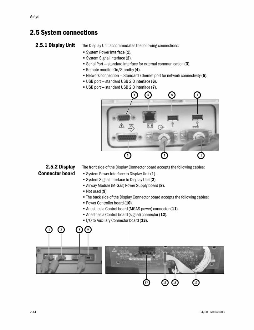
Aisys
2-14 04/08 M1046983
2.5 System connections
2.5.1 Display Unit The Display Unit accommodates the following connections:
• System Power Interface (1).• System Signal Interface (2).• Serial Port — standard interface for external communication (3).• Remote monitor On/Standby (4).• Network connection — Standard Ethernet port for network connectivity (5).• USB port — standard USB 2.0 interface (6).• USB port — standard USB 2.0 interface (7).
2.5.2 DisplayConnector board
The front side of the Display Connector board accepts the following cables:
• System Power Interface to Display Unit (1).• System Signal Interface to Display Unit (2).• Airway Module (M-Gas) Power Supply board (8).• Not used (9).• The back side of the Display Connector board accepts the following cables:• Power Controller board (10).• Anesthesia Control board (MGAS power) connector (11).• Anesthesia Control board (signal) connector (12).• I/O to Auxiliary Connector board (13).
4 5 6 7
3 2 1
9
10111213
821
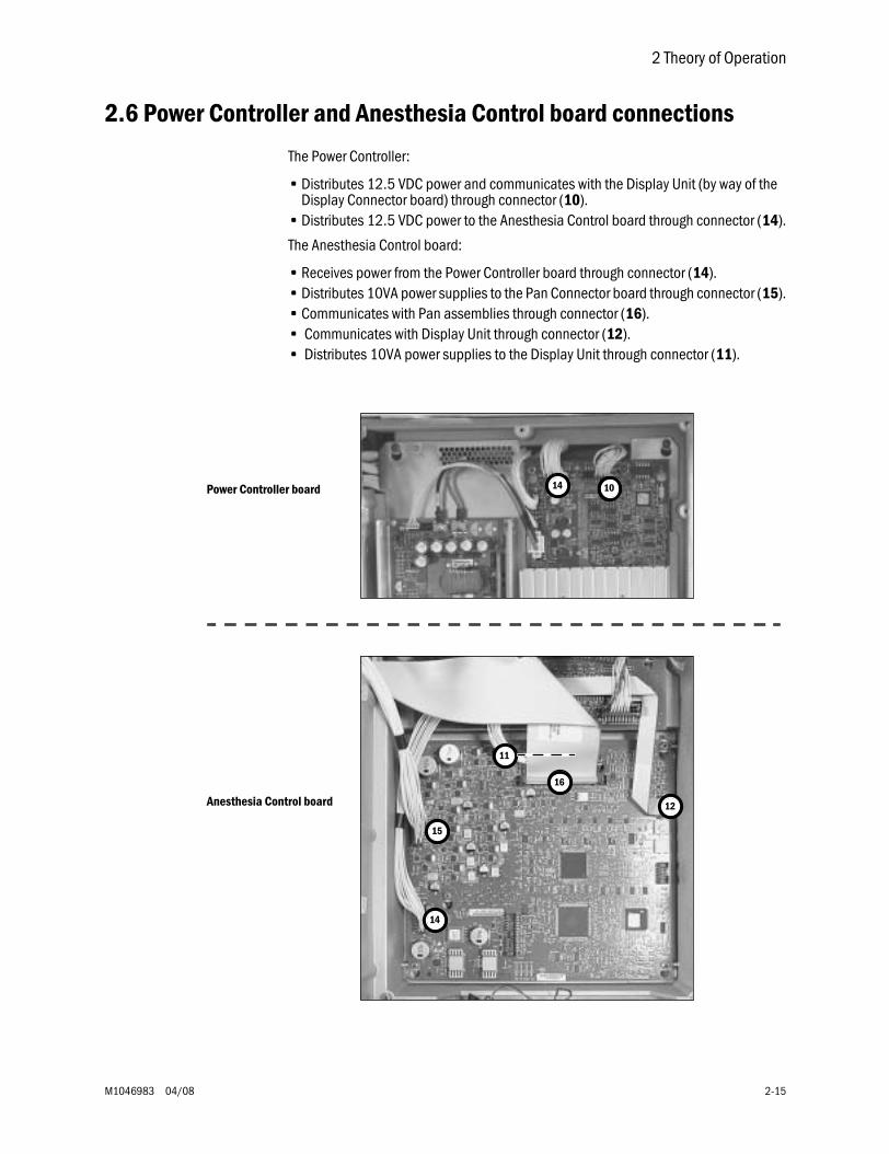
2 Theory of Operation
M1046983 04/08 2-15
2.6 Power Controller and Anesthesia Control board connections
The Power Controller:
• Distributes 12.5 VDC power and communicates with the Display Unit (by way of the Display Connector board) through connector (10).
• Distributes 12.5 VDC power to the Anesthesia Control board through connector (14).
The Anesthesia Control board:
• Receives power from the Power Controller board through connector (14).• Distributes 10VA power supplies to the Pan Connector board through connector (15).• Communicates with Pan assemblies through connector (16).• Communicates with Display Unit through connector (12).• Distributes 10VA power supplies to the Display Unit through connector (11).
14 10
16
11
12
15
14
Anesthesia Control board
Power Controller board
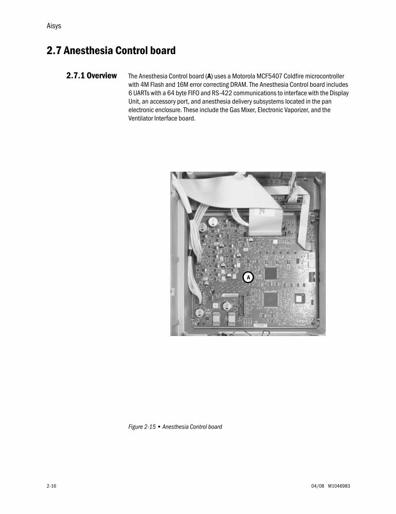
Aisys
2-16 04/08 M1046983
2.7 Anesthesia Control board
2.7.1 Overview The Anesthesia Control board (A) uses a Motorola MCF5407 Coldfire microcontroller with 4M Flash and 16M error correcting DRAM. The Anesthesia Control board includes 6 UARTs with a 64 byte FIFO and RS-422 communications to interface with the Display Unit, an accessory port, and anesthesia delivery subsystems located in the pan electronic enclosure. These include the Gas Mixer, Electronic Vaporizer, and the Ventilator Interface board.
Figure 2-15 • Anesthesia Control board
A
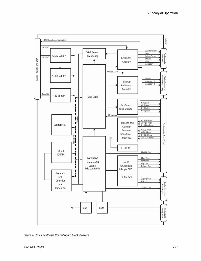
2 Theory of Operation
M1046983 04/08 2-17
Figure 2-16 • Anesthesia Control board block diagram
Gas SelectValve Drivers
BackupAudio andSounder
10VA LimitCircuitry
UARTs6 Channels
64-byte FIFO
6-RS-422
Vent
MixerAccessory
M-Gas
Accessory 2Accessory 1
MCF 5407Motorola V4
ColdfireMicrocontroller
16 MBSDRAM
4 MB Flash
MemoryError
Detectionand
Correction
Glue Logic
10VA PowerMonitoring+3.3V Supply
Acsry 2 Com
Acsry 1 ComDU com
Vent ComMixer Com
O2 SelectAir SelectN2O SelectO2 Bypass
SW Test LEDs
Pipeline andCylinderPressure
TransducerInterface
O2 Pipe PresrAir Pipe PresrN2O Pipe Presr
O2 Cyl PresrAIR Cyl PresrN2O Cyl Presr2nd O2 Cyl Presr
BDMClock
I2C
12.5VDC
12.5VDC
+5V Supply12.5VDC
+1.8V Supply
EEPROM
ON/Standby and Mains LED
O2 Bypass
Pan ConnectorBoard Power
Display ConnectorBoard Power (10VA)
Pan Connector Board SignalBackgroundDebug M
odeDisplay Connector
Board Signal
Addr
ess
Bus
Data
Bus
Powe
r Con
trolle
r Boa
rd
Agent Delivery
Mini AABellow Sensor
Mini AA Com
Bellows ComVap Com
AB.7
5.02
5
Aisys
2-18 04/08 M1046983
2.7.2 AnesthesiaControl Board
details
The 12.5 VDC power enters the Anesthesia Controller Board via connector J6 (see item 14 in Section 2.6). This 12.5 VDC is further regulated down to five additional voltages used by the Anesthesia Controller Board. These include:
• 3.3VDC – VR2• 1.8VDC – VR3• 5.0VDC – VR1: Used for Pipeline and Cylinder Pressure Transducers• 2.5VDC• 5.0VDC
These voltages are self-monitored for out-of-range.
The Anesthesia Controller Board also supplies 10VA-limited power (+12.5VDC & +5.0 VDC) to External subsystems and Pipeline and Cylinder Pressure Transducers.
Valve Drivers The Anesthesia Controller Board contains logic circuits and valve drive circuits for the following devices that reside on subsystems:
• O2 Select Valve (Gas Mixer Board)• N2O Select Valve (Gas Mixer Board)• AIR Select Valve (Gas Mixer Board)• Alt O2 Select Valve (Gas Mixer Board)
Status LEDs The Anesthesia Controller Board contains 2 sets of 4 each (8 total) status LEDs. They are located on the board at approximately the 6 and 9 o’clock positions, near connectors J5 and J6 respectively. Each set contains the following four LEDs:
• RXD (CR19 and CR35) – yellow – Indicating Display Unit communication activity• TXD (CR20 and CR34) – yellow – Indicating Anesthesia Controller Board
communication activity• RESET (CR21 and CR36) – Red – Watchdog Reset• RXD (CR22 and CR33) – yellow – Software LEDs
Connectors: The Anesthesia Controller Board has five populated connectors:
• J1 – 50-pin connector to (signal) Pan Connector Board. • J3 – 24-pin connector to (power) Pan Connector.• J4 – 10-pin connector (JTAG). This is used by Engineering. Not Used by Service.• J6 – 16-pin connector power in from Power Controller Board.• J7 - 12-pin connector to (10VA power) display connector (M-Gas)
Alarms The Anesthesia Controller Board has a backup audio alarm. This is sounded in the event of communication loss between the Anesthesia Controller Board and Display Unit.
2 Theory of Operation
M1046983 04/08 2-19
Power andCommunication toother Subsystems
The Anesthesia Controller Board provides power and communication to:
Ventilator Interface Board (VIB):• Power = 12.5VDC• Communication = RS422
Gas Mixer:• Power = 12.5VDC• Communication = RS422
Agent Delivery Board (ADB):• Power = 12.5VDC• Communication = RS422
M-Gas Power Board:• Power = 12.5VDC• Note: Communication to and from the M-Gas is via the Display Unit
Gas PressureTransducers:
Gas Pressure Transducers monitor the Pipeline pressures of all gases connected to the system. Gasses measured can include O2, Air, and N2O. Their measurement range is form 0 to 697 kPa (101 psi). Though these transducers are located near the machine pipeline connection points, they are maintained and monitored by the Anesthesia Controller Board.
Pressure transducers also monitor all cylinder pressures. Gasses measured can include O2, second O2, Air, and N2O. Their range is:
• from 0 to 27580 kPA (4000 psi) for O2 and Air• from 0 to 9805 kPa (1422 psi) for N2O
The transducers are located on each cylinder yoke; they are maintained and monitored by the Anesthesia Controller Board.
Alt O2 Switch The Anesthesia Controller Board monitors the position of the Alt O2 Switch.
Display Unit The Display Unit receives power from and has limited communication with the PCB. This limited communication allows for data like power supply status and voltage readings to be displayed in service mode.
The MAJOR communication responsible for getting clinical settings to the system and the ability to display parameters occurs between the Anesthesia Controller Board and Display Unit. The Anesthesia Controller Board and Display Unit communicate via RS422.
Aisys
2-20 04/08 M1046983
External Peripheralpower (10VA) circuitry
This circuitry sends 10VA limited 12.5 VDC power to the following subsystems:
Note:These subsystems do not receive power directly from the PCB. Only the Anesthesia Controller Board and Display Unit receive power directly form the PCB.
• Ventilator Interface Board (VIB)• Electronic Gas Mixer (Mixer)• Agent Delivery Board (ADB)• M-Gas Power Board• External Peripheral #1• External Peripheral #2• Accessories (Task Light)
Hardware Reset will happen if:
• Watchdog is not reset• During Anesthesia Controller Board Power-up (Normal)• If the voltages produced on the board become out-of-range (3.3, 2.5, or 1.8VDC).
If the system evokes a Hardware Reset, all the peripheral devices, which is controlled by the Anesthesia Controller Board, loose power. All communication with these peripherals devices will cease to continue.
2 Theory of Operation
M1046983 04/08 2-21
Summary of theAnesthesia Controller
Board
The Anesthesia Controller Board is the central controller for the system. It provides the following services:
• Monitors pressures form the pipeline and cylinder transducers.• Drives some of the valves located on the Electronic Gas Mixer.• Monitors the Alt O2 Switch.• Provides 10VA limited power and communication to the following subsystems:
• Ventilator Interface Board (VIB)
• Electronic Gas Mixer
• Agent Delivery Board (ADB)
• Provides 10VA limited power (no communication) to the M-Gas Power Board
The Anesthesia Controller Board receives power from the PCB on connector J6.
The Anesthesia Controller Board creates internal voltages that remain local to and are used exclusively by circuits on the Anesthesia Controller Board. These voltages are:
• 3.3 VDC• 1.8 VDC (Processor and Digital)• 2.5 VDC• 5 VDC (Gas Pressure Transducers)
The Anesthesia Controller Board also creates fourteen independent 12VDC 10VA limited power sources used by the following subsystems:
• 10VA M-Gas• 10VA Mixer• 10VA eVap ADB Power• 10VA eVap Outflow, Scavenging Power• 10VA eVap Proportional Valve Power• 10VA eVap Inflow, Zero Valve Power• 10VA O2 Bypass Valve• 10VA Ventilator Interface Board• 10VA Vent Valve Power• 10VA Accessories• 10VA Mixer / Pan Fan• 10VA External Peripheral # 1• 10VA External Peripheral # 2
The Anesthesia Controller Board has eight status LEDs. Each LED Status is duplicated on the board. Six are yellow status and two are red reset.
The TXD and RXD flash to indicate communication to and from the Display Unit. A RED LED would indicate a CPU watchdog (RESET) condition.
The Anesthesia Controller Board receives communication from the Display Unit, Electronic Vaporizer, Electronic Gas Mixer, and Ventilator Engine Board. It has a hand in virtually all-major decisions about the delivery of gas, ventilation, and agent to the patient.
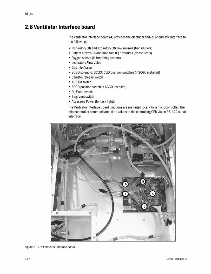
Aisys
2-22 04/08 M1046983
2.8 Ventilator Interface board
The Ventilator Interface board (A) provides the electrical and/or pneumatic interface to the following:
• Inspiratory (B) and expiratory (C) flow sensors (transducers)• Patient airway (D) and manifold (E) pressures (transducers)• Oxygen sensor (in breathing system)• Inspiratory Flow Valve• Gas Inlet Valve• SCGO solenoid, SCGO/CGO position switches (if SCGO installed)• Canister release switch• ABS On switch• ACGO position switch (if ACGO installed)• O2 Flush switch• Bag/Vent switch• Accessory Power (for task lights)
The Ventilator Interface board functions are managed locally by a microcontroller. The microcontroller communicates data values to the controlling CPU via an RS-422 serial interface.
Figure 2-17 • Ventilator Interface board
A
B
C
E
D
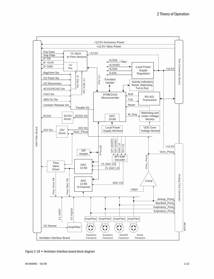
2 Theory of Operation
M1046983 04/08 2-23
Figure 2-18 • Ventilator Interface board block diagram
AB.9
1.06
2
Amp/Filter Amp/Filter Amp/Filter Amp/Filter
RS-422Transceiver
Pa
nC
onne
ctorB
oard
+6.0VA
-6.0VA
ATMEGA16Microcontroller
+5.0VDD
+5.0VA
ADC12-Bit
8-Channel
AB
SF
ilte
rB
oar
d
Local PowerSupply
Regulators
+12.5V
I2C MUX to Flow Sensors
Insp Data
Bag/Vent Sw
O2 Disconnect
O2 Flush Sw
DAC12-Bit
SCGO On
GIV OnI 2C
MU
XS
el
E2
Pw
rO
n
Amp/Filter
Flo
wD
AC
FB
VDD Over-Voltage Monitor
RxD
TxD
O2
Sig
nal
E2 +5.0V
Watchdog andUnder-Voltage
MonitorADC10-Bit
SP
IP
ort
Parallel I/O
FlowValveDriver
GIVDriver
SCGODriver
Exp Data
I2C
Port
ACGO/SCGO Sw
ABS On Sw
Comp
3.2
VR
EF
VREF
Ove
r_P
ress
Over_Press
O2 Sensor
E2 Clk
+12.5V Accessory Power
+12.5V Valve Power
Flo
wD
rive
FB
SPI AddrDecoder
FL DAC CS
FL DAC LD
ADC CS
SP
IA
DD
R0
SP
IA
DD
R1
DA
CLD
SP
IC
S
ISPHeader
EmulatorHeader
E2 GND
CGO Sw
Filter
Local PowerSupply Monitors
+12.5V
Reset
An
alog
Te
stC
onne
ctor
InspiratoryTransducer
ExpiratoryTransducer
ManifoldTransducer
AirwayTransducer
Over_Press
+12.5V
Airway_Press
Manifold_Press
Inspiratory_Press
Expiratory_Press
GIV Drv
SCGO
Activity IndicatorsReset, Watchdog,
Txd & Rxd
W_Dog
+5VReg.
Ventilator Interface Board
Canister Release Sw
AB.9
1.08
0
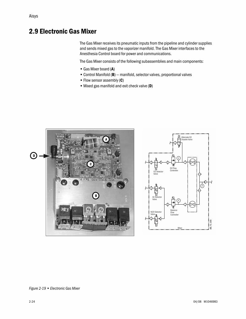
Aisys
2-24 04/08 M1046983
2.9 Electronic Gas Mixer
The Gas Mixer receives its pneumatic inputs from the pipeline and cylinder supplies and sends mixed gas to the vaporizer manifold. The Gas Mixer interfaces to the Anesthesia Control board for power and communications.
The Gas Mixer consists of the following subassemblies and main components:
• Gas Mixer board (A)• Control Manifold (B) — manifold, selector valves, proportional valves• Flow sensor assembly (C)• Mixed gas manifold and exit check valve (D)
Figure 2-19 • Electronic Gas Mixer
A
B
C
D
BalanceFlowController
Air SelectorValve
N2O SelectorValve
O2 FlowController
Alternate O2Disable Valve
O2 SelectorValve
P
P
P
Mixer AB.7
5.16
6
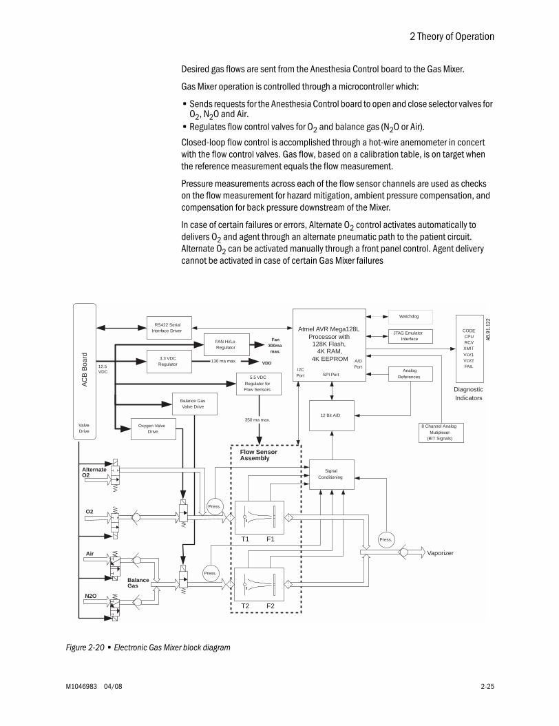
2 Theory of Operation
M1046983 04/08 2-25
Desired gas flows are sent from the Anesthesia Control board to the Gas Mixer.
Gas Mixer operation is controlled through a microcontroller which:
• Sends requests for the Anesthesia Control board to open and close selector valves for O2, N2O and Air.
• Regulates flow control valves for O2 and balance gas (N2O or Air).
Closed-loop flow control is accomplished through a hot-wire anemometer in concert with the flow control valves. Gas flow, based on a calibration table, is on target when the reference measurement equals the flow measurement.
Pressure measurements across each of the flow sensor channels are used as checks on the flow measurement for hazard mitigation, ambient pressure compensation, and compensation for back pressure downstream of the Mixer.
In case of certain failures or errors, Alternate O2 control activates automatically to delivers O2 and agent through an alternate pneumatic path to the patient circuit. Alternate O2 can be activated manually through a front panel control. Agent delivery cannot be activated in case of certain Gas Mixer failures
Figure 2-20 • Electronic Gas Mixer block diagram
Flow SensorAssembly
350 ma max.
BalanceGas
Vaporizer
T1 F1
T2 F2
RS422 SerialInterface Driver
130 ma max.
Signal
Conditioning
8 Channel Analog
Mutiplexer(BIT Signals)
Atmel AVR Mega128LProcessor with
128K Flash, 4K RAM,
4K EEPROM
12 Bit A/D
SPI Port
Watchdog
Analog
References
CODECPURCVXMIT
VLV1VLV2FAIL
DiagnosticIndicators
AC
B B
oard
12.5VDC
3.3 VDCRegulator VDD
5.5 VDC
Regulator forFlow Sensors
FAN Hi/LoRegulator
T
T
Fan300mamax.
Air
N2O
AlternateO2
ValveDrive
I2CPort
A/DPort
JTAG EmulatorInterface
Oxygen ValveDrive
Balance GasValve Drive
O2
Press.
Press.
Press.
AB.9
1.12
2
Aisys
2-26 04/08 M1046983
2.9.1 ElectronicGas Mixer
(details)
The function of the Electronic Gas Mixer is to deliver a combination of Oxygen and a Balance Gas (N2O or Air) at a set percentage and flow rate as set by the user.
Total flow range for the system is 0.20 to 15 l/min of O2 or mixed O2 concentration that is greater than or equal to 25%. The system can flow Air only. The minimum flow though any single flow channel must be greater than or equal to 0.1 l/min.
• O2 flow range is zero or 0.1 to 15 l/min• N2O flow range is zero or 0.1 to 12 l/min• Air flow range is zero or 0.1 to 15 l/min
The flow accuracy of the Electronic Gas Mixer is +/- 20 ml/min or 5% of setting.
Diameter specific tubing (N2O = 4mm; O2 = 6mm; Air = 8mm; Mixed Gas = 1/4 inch) brings supply gasses O2, Air, N2O to the Electronic Gas Mixer control manifold.
The Electronic Gas Mixer contains 6 solenoid valves.
Electronics located on the Electronic Gas Mixer board and flow sensor assembly control and monitor the flow of gas delivered to the Electronic Gas Mixer output connection.
The Electronic Gas Mixer receives 12.5 VDC Accessory power from several of the 10VA power modules located on the Anesthesia Control Board Bd. Circuitry on the Electronic Gas Mixer board further generates internal voltages required for systems local to the Electronic Gas Mixer board. These voltages include: 3.3VDC and 5.5 VDC. The Electronic Gas Mixer also controls the pan fan speed (Hi/Low). All these voltages can be viewed in the service screens.
The microcontroller on the Electronic Gas Mixer has seven activity indicators. They are failcode, Mixer Code, CPU, XMIT, and RCV. Under normal operation, the CPU Activity LED will flash a 2 Hz (once per second) rate. The Red Fail LED should not be lit and the XMIT and RCV LEDs should flash briefly and randomly to indicate communication with the Anesthesia Control Board.
Two additional LEDs (Valve 1 and Valve 2) light to indicate when Channel 1 (O2 Channel) or Channel 2 (Balance Gas Channel) Mixer Proportional Valves are opened.
Control of the Channel 1 and Channel 2 Proportional Valves is provided by circuitry on the Electronic Gas Mixer. Closed loop feedback for these valves is provided by the Hot-Wire Anemometers located on the flow sensor assembly (part of the Electronic Gas Mixer).
Three pressure transducers; located at distal of the O2 Proportional Valve (P1), distal of the Balance Gas Proportional Valve (P2), and proximal of the Outlet Check Valve, are used to verify the accuracy of the flow in the gas channel. Hot-Wire Anemometer Selector Valves (O2, N2O, and Air) are controlled by signals that originate on the Anesthesia Control Board.
Summary Shortly after Power-Up, the Anesthesia Control Board will generate fourteen independent 10 VA Power Circuits, two of which will be used to power the Electronic Gas Mixer.
The Electronic Gas Mixer will generate two local voltages: 5.5 VDC and 3 VDC.
The CPU LED will flash at a 2 Hz rate and the XMIT and RCV LEDs will flash randomly indicating communication with the Anesthesia Control Board.
2 Theory of Operation
M1046983 04/08 2-27
As the system cycles through its self-tests, the six LEDs may cycle on and off throughout this process. It should also be observed the Valve 1 and Valve 2 LEDs cycle On and Off during Checkout. More detail on the timing and operation these valves will be covered later.
O2 and Balance Gas Mixer Valves (Valves 1 and Valves 2) are controlled by circuitry on the Electronic Gas Mixer.
Anesthesia Control Board controls the O2, Air, and N2O Selector Valves.
The Sintered filters and check valves play critical roles in generating backpressure for delta pressure signals for flow verifications. Since the check valves play critical roles in generating backpressure for delta pressure signals for flow verifications, they are not field replaceable.
Three normally closed gas selector valves, two Proportional Valves, and one normally open Alt O2 Valve makeup the valves that control gas flow on the Electronic Gas Mixer.
The Electronic Gas Mixer is a field replaceable unit and comes pre-calibrated. The valves are field replaceable, as well as the cables that interconnect the Electronic Gas Mixer assemblies.
The ONLY field calibration is the pressure transducers zero. Basic flow checks can be done in the service application.
Mixer Service /Diagnosis and
Troubleshooting
Mixer CPU POST tests:
• Memory and CPU tested• Communications tested• Sensor validity tested• Reference Voltage tested
Gas Tests:
• Alt O2 Valve Leak Test• Prop Valve Leak Test• Flow Verification Tests• Selector Valve Leak Tests• Balance Gas Check Valve Leak Test
Failure of any POST Test will render the Electronic Gas Mixer as failed and the Alt O2 will be enabled if the case is started.
CPU Tests include:
• EEPROM holds the flow and pressure calibrations (this is CRC tested);• RAM stores Temp calculations;• Registers arithmetic operations
Communication tests include:
• Serial communication check between Electronic Gas Mixer CPU and TSI Flowmeter board;
• Serial communication check between Electronic Gas Mixer CPU and Anesthesia Control Board.
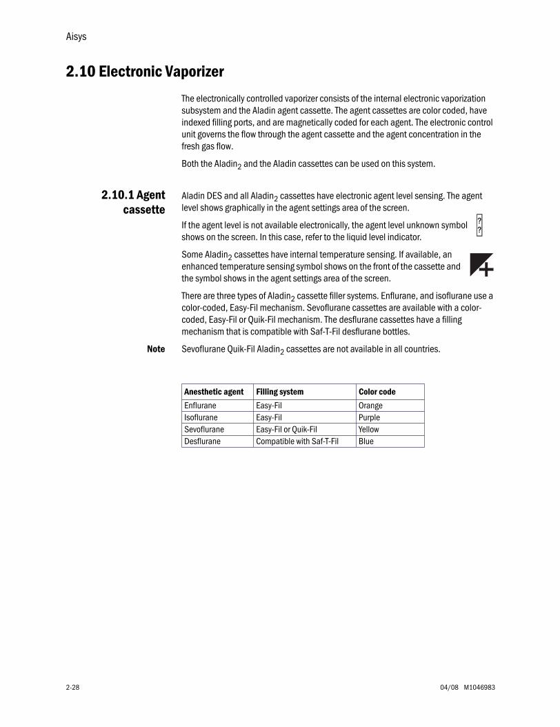
Aisys
2-28 04/08 M1046983
2.10 Electronic Vaporizer
The electronically controlled vaporizer consists of the internal electronic vaporization subsystem and the Aladin agent cassette. The agent cassettes are color coded, have indexed filling ports, and are magnetically coded for each agent. The electronic control unit governs the flow through the agent cassette and the agent concentration in the fresh gas flow.
Both the Aladin2 and the Aladin cassettes can be used on this system.
2.10.1 Agentcassette
Aladin DES and all Aladin2 cassettes have electronic agent level sensing. The agent level shows graphically in the agent settings area of the screen.
If the agent level is not available electronically, the agent level unknown symbol shows on the screen. In this case, refer to the liquid level indicator.
Some Aladin2 cassettes have internal temperature sensing. If available, an enhanced temperature sensing symbol shows on the front of the cassette and the symbol shows in the agent settings area of the screen.
There are three types of Aladin2 cassette filler systems. Enflurane, and isoflurane use a color-coded, Easy-Fil mechanism. Sevoflurane cassettes are available with a color-coded, Easy-Fil or Quik-Fil mechanism. The desflurane cassettes have a filling mechanism that is compatible with Saf-T-Fil desflurane bottles.
Note Sevoflurane Quik-Fil Aladin2 cassettes are not available in all countries.
Anesthetic agent Filling system Color code
Enflurane Easy-Fil OrangeIsoflurane Easy-Fil PurpleSevoflurane Easy-Fil or Quik-Fil YellowDesflurane Compatible with Saf-T-Fil Blue
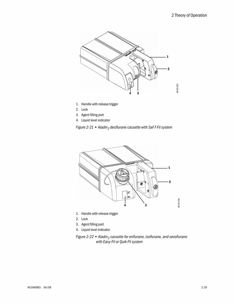
2 Theory of Operation
M1046983 04/08 2-29
1. Handle with release trigger2. Lock3. Agent filling port4. Liquid level indicator
Figure 2-21 • Aladin2 desflurane cassette with Saf-T-Fil system
1. Handle with release trigger2. Lock3. Agent filling port4. Liquid level indicator
Figure 2-22 • Aladin2 cassette for enflurane, isoflurane, and sevoflurane with Easy-Fil or Quik-Fil system
1
2
34 AB.6
0.05
0AB
.60.
038
1
2
4 3
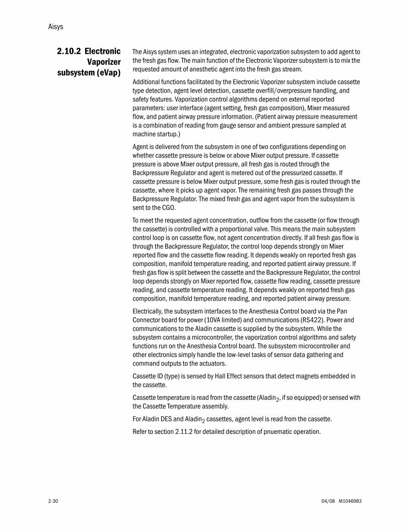
Aisys
2-30 04/08 M1046983
2.10.2 ElectronicVaporizer
subsystem (eVap)
The Aisys system uses an integrated, electronic vaporization subsystem to add agent to the fresh gas flow. The main function of the Electronic Vaporizer subsystem is to mix the requested amount of anesthetic agent into the fresh gas stream.
Additional functions facilitated by the Electronic Vaporizer subsystem include cassette type detection, agent level detection, cassette overfill/overpressure handling, and safety features. Vaporization control algorithms depend on external reported parameters: user interface (agent setting, fresh gas composition), Mixer measured flow, and patient airway pressure information. (Patient airway pressure measurement is a combination of reading from gauge sensor and ambient pressure sampled at machine startup.)
Agent is delivered from the subsystem in one of two configurations depending on whether cassette pressure is below or above Mixer output pressure. If cassette pressure is above Mixer output pressure, all fresh gas is routed through the Backpressure Regulator and agent is metered out of the pressurized cassette. If cassette pressure is below Mixer output pressure, some fresh gas is routed through the cassette, where it picks up agent vapor. The remaining fresh gas passes through the Backpressure Regulator. The mixed fresh gas and agent vapor from the subsystem is sent to the CGO.
To meet the requested agent concentration, outflow from the cassette (or flow through the cassette) is controlled with a proportional valve. This means the main subsystem control loop is on cassette flow, not agent concentration directly. If all fresh gas flow is through the Backpressure Regulator, the control loop depends strongly on Mixer reported flow and the cassette flow reading. It depends weakly on reported fresh gas composition, manifold temperature reading, and reported patient airway pressure. If fresh gas flow is split between the cassette and the Backpressure Regulator, the control loop depends strongly on Mixer reported flow, cassette flow reading, cassette pressure reading, and cassette temperature reading. It depends weakly on reported fresh gas composition, manifold temperature reading, and reported patient airway pressure.
Electrically, the subsystem interfaces to the Anesthesia Control board via the Pan Connector board for power (10VA limited) and communications (RS422). Power and communications to the Aladin cassette is supplied by the subsystem. While the subsystem contains a microcontroller, the vaporization control algorithms and safety functions run on the Anesthesia Control board. The subsystem microcontroller and other electronics simply handle the low-level tasks of sensor data gathering and command outputs to the actuators.
Cassette ID (type) is sensed by Hall Effect sensors that detect magnets embedded in the cassette.
Cassette temperature is read from the cassette (Aladin2, if so equipped) or sensed with the Cassette Temperature assembly.
For Aladin DES and Aladin2 cassettes, agent level is read from the cassette.
Refer to section 2.11.2 for detailed description of pnuematic operation.
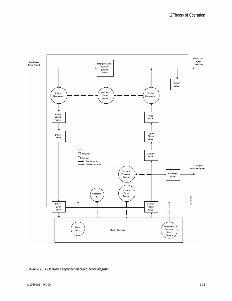
2 Theory of Operation
M1046983 04/08 2-31
Figure 2-23 • Electronic Vaporizer electrical block diagram
PropValve
ScavengeValve
OutflowValve
InflowValve
BackpressureRegulator
(Checkvalve)
Fresh Gas(From Mixer)
ReliefValve
InflowCheckValve
LiquidCheckValve
CassettePressure
Sensor
InflowFlowmeter
OutflowFlowmeter
ManifoldTemp
Sensor
CassetteTemp
SensorCassette
ID
AgentLevel Aladin Cassette
Fresh Gas/Agent
(To CGO)
Gas/Agent(To Scavenging)
CassetteTemp
Sensor
Key:
Actuator
Sensor
Sensor data
Pneumatic flow
InflowConnValve
OutflowConnValve
Enhanced
AB.7
5.06
5
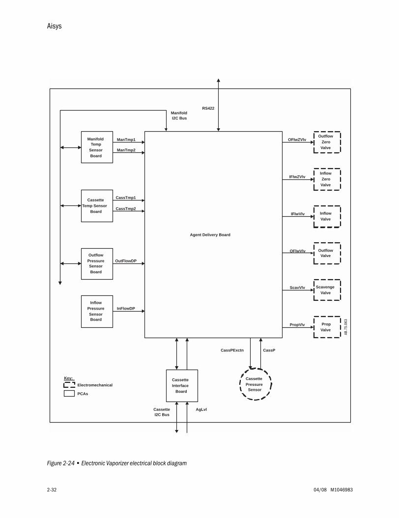
Aisys
2-32 04/08 M1046983
Figure 2-24 • Electronic Vaporizer electrical block diagram
OFlwZVlv
RS422ManifoldI2C Bus
CassetteTemp Sensor
Board
OutflowPressureSensorBoard
PropValve
ScavengeValve
OutflowValve
InflowValve
InflowZero
Valve
OutflowZero
Valve
CassetteInterface
Board
InflowPressureSensorBoard
ManifoldTemp
SensorBoard
Agent Delivery Board
IFlwZVlv
IFlwVlv
OFlwVlv
ScavVlv
PropVlv
CassettePressure
Sensor
ManTmp1
ManTmp2
CassTmp1
CassTmp2
OutFlowDP
InFlowDP
CassPCassPExctn
CassetteI2C Bus
AgLvl
Key:
Electromechanical
PCAs
AB.7
5.06
3
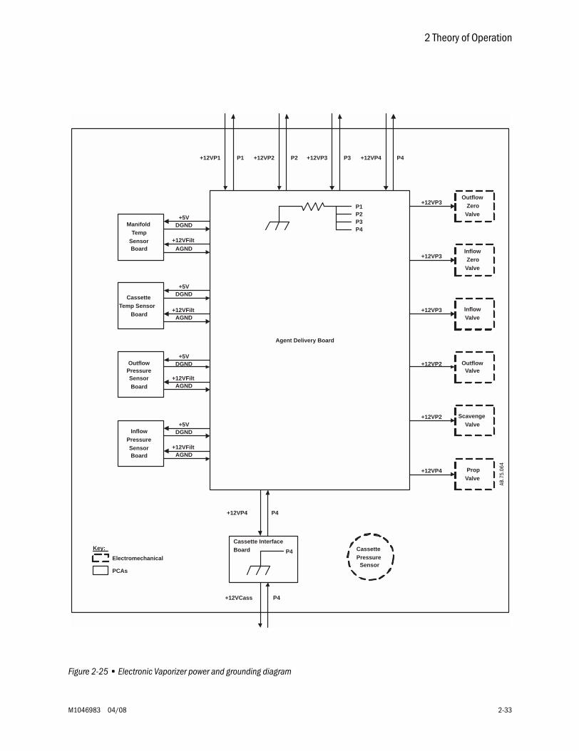
2 Theory of Operation
M1046983 04/08 2-33
Figure 2-25 • Electronic Vaporizer power and grounding diagram
+12VP3
+12VP1 P1
CassetteTemp Sensor
Board
OutflowPressureSensorBoard
PropValve
ScavengeValve
OutflowValve
InflowValve
InflowZero
Valve
OutflowZero
Valve
InflowPressureSensorBoard
ManifoldTemp
SensorBoard
Agent Delivery Board
+12VP3
+12VP3
+12VP2
+12VP2
+12VP4
CassettePressure
Sensor
+5VDGND
+12VCass P4
Key:
Electromechanical
PCAs
+12VFiltAGND
+5VDGND
+12VFiltAGND
+5VDGND
+12VFiltAGND
+5VDGND
+12VFiltAGND
+12VP2 P2 +12VP3 P3 +12VP4 P4
P4
Cassette InterfaceBoard
P1P2P3P4
+12VP4 P4
AB.7
5.06
4
Aisys
2-34 04/08 M1046983
2.10.3 Agent Delivery board LED indicators
LED indicators are provided on the Agent Delivery Board to convey information about subsystem operation. Refer to the following table and to Figure 2-26.
Note: When a failure has been detected in the eVap, only the +12VP1 power rail will be powered. The rest are shut off.
Item Marking Indicates Color
1 WDG Blinks if microcontroller active Yellow
2 TXD Blinks if subsystem sending to Anesthesia Control Board Yellow
3 RXD Blinks if subsystem receiving from Anesthesia Control Board Yellow
4 SCV Lit if Scavenge Valve open Yellow
5 OFV Lit if Outflow Valve open Yellow
6 OFZ Lit if Outflow Zero Valve is performing zero measurement Yellow
7 IFZ Lit if Inflow Zero Valve is performing zero measurement Yellow
8 IFV Lit if Inflow Valve open Yellow
9 CPWR Lit if Cassette powered Green
10 P1 Lit if voltage present on +12VP1 power rail Green
11 P2 Lit if voltage present on +12VP2 power rail Green
12 P3 Lit if voltage present on +12VP3 power rail Green
13 P4 Lit if voltage present on +12VP4 power rail Green
14 All segments lit immediately after reset.Segments flicker during subsystem POST.Segments extinguished upon communications established with ACB.
Red
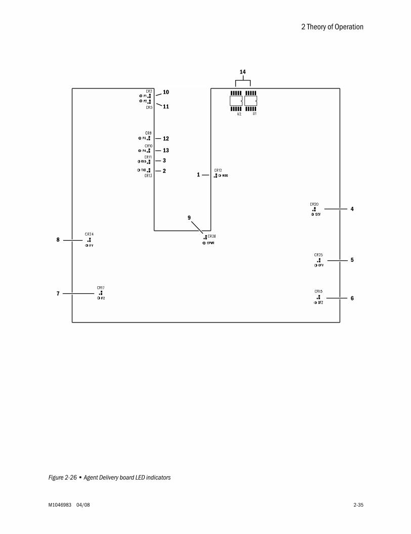
2 Theory of Operation
M1046983 04/08 2-35
Figure 2-26 • Agent Delivery board LED indicators
1
10
11
12
13
3
2
9
4
5
67
8
14
Aisys
2-36 04/08 M1046983
2.11 Gas flow through the anesthesia machine
2.11.1 Overview Refer to Figure 2-27 and Figure 2-28.
Gas supplies Gas comes into the system through a pipeline (1) or cylinder (6) connection. All connections have indexed fittings, filters, and check valves (one-way valves). Pressure transducers monitor the pipeline (2) and cylinder (7) pressures.
The O2 supply failure alarm is derived from the O2 pipeline and the O2 cylinder pressure transducer inputs.
A primary regulator (8) decreases the cylinder pressures to approximately pipeline levels. A pressure relief valve (3) helps protect the system from high pressures.
To help prevent problems with the gas supplies:
• Install yoke plugs on all empty cylinder connections.• When a pipeline supply is adequate, keep the cylinder valve closed.
Gas flow Pipeline or regulated cylinder pressure supplies O2 or Air directly to the ventilator engine (4a or 4b) and as pilot pressure (4) for the SCGO assembly (E). Connection points are also available for venturi suction (5a or 5b) drive gas supply. An additional O2 regulator (18) decreases the pressure for the O2 Flush valve (19) and the auxiliary O2 flowmeter (24).
The O2 Flush valve supplies high flows of O2 to the fresh gas outlet (22 or 23) through the SCGO/ACGO assembly (E/F). The flush pressure switch (20) monitors activation of the flush valve.
Gas mixing Under normal conditions, with the system switch (10) in the On position, the Alternate O2 Disable valve (13) is energized to block alternate O2 flow. Normal gas flows are enabled through their respective selector valves (11). The system controls gas flow through the flow control valves (12) and derives the individual flow rates through the hot-wire anemometers (14).
Under system failure conditions (or if Alt O2 is selected), the normally-open Alternate O2 Disable valve (13) allows delivery of O2 through the Alternate O2 Flowmeter when the system switch is in the On position.
Mixed gas The mixed gas (15) flows through the electronic vaporizer (D) to the SCGO/ACGO assembly (E/F). A pressure relief valve (17) on the electronic vaporizer limits the maximum outlet pressure.
The SCGO assembly (E) directs the mixed gas to the selected circuit: 22 (ABS-circle) or 23 (to Inspiratory port of ABS). On SCGO assemblies, a relief valve (21) limits pressure in the breathing system to approximately 150 cmH2O.
The ACGO assembly (F) directs the mixed gas to the selected circuit: 22 (ABS-circle) or 23 (external ACGO port).
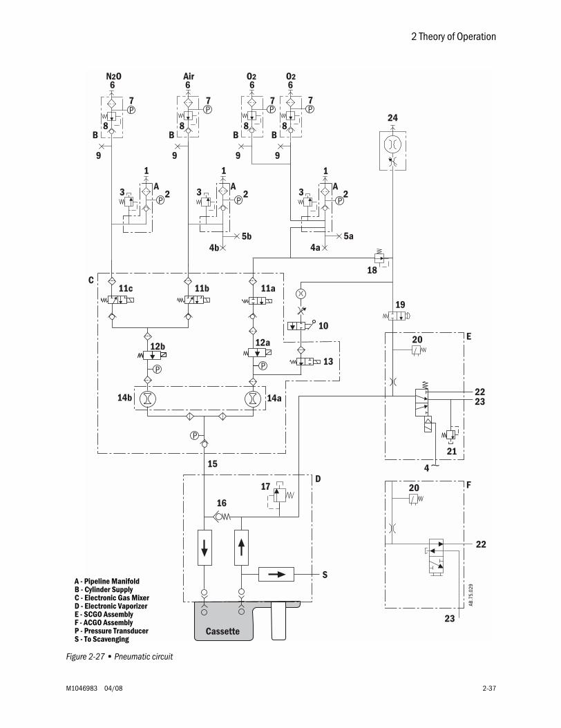
2 Theory of Operation
M1046983 04/08 2-37
Figure 2-27 • Pneumatic circuit
N2O
9 9 9 9
Air O2 O2
24
7 77 7
8B
8B
8B
8B
3 A2
1
3 A2
1
3 A2
18
19
4b 4a
17D
6 6 6 6
1
5a5b
11c 11b 11a
12b 12a
10
13
20
14a14b 2223
21
C
4
E
20
22
23
F
Cassette
S
16
15AB
.75.
029A - Pipeline Manifold
B - Cylinder SupplyC - Electronic Gas MixerD - Electronic VaporizerE - SCGO Assembly
P - Pressure TransducerF - ACGO Assembly
S - To Scavenging
Aisys
2-38 04/08 M1046983
2.11.2 Electronicvaporizer
Agent is delivered from the subsystem in one of two configurations depending on whether cassette pressure is below or above Mixer output pressure. If cassette pressure is above Mixer output pressure, all fresh gas is routed through the Backpressure Regulator and agent is metered out of the pressurized cassette. If cassette pressure is below Mixer output pressure, some fresh gas is routed through the cassette, where it picks up agent vapor. The remaining fresh gas passes through the Backpressure Regulator. The mixed fresh gas and agent vapor from the subsystem is sent to the CGO.
A Backpressure Regulator (16) builds a pressure at the input to the vaporizer to drive gas through the cassette, if necessary. It is not needed to check flow in the reverse direction. A pressure relief valve (17) limits the maximum outlet pressure.
The Inflow and Outflow Flowmeters (26, 27) measure flow by developing a pressure drop across a flow restrictor. The Outflow Flowmeter is used for control, while the Inflow Flowmeter is used for safety. Each Flowmeter includes a zeroing valve that temporarily shorts a pressure transducer’s ports together for an accurate zero measurement. The zeroing valves may be energized during Standby to heat the Flowmeter Manifold to prevent agent condensation.
An Inflow Check Valve (28) prevents unmetered agent vapor from flowing backwards and entering the fresh gas stream.
Inflow and Outflow Valves (29, 30) direct flow in the subsystem, opening for agent delivery and closing for other system states, including safety conditions. The Outflow Valve must open for agent delivery, while the Inflow Valve opens if cassette pressure is lower than Mixer output pressure.
The Scavenge Valve (31) opens periodically during system checkout and, when a cassette is not installed, to automatically sample ambient pressure.
A liquid prevention valve (32) blocks liquid from entering the subsystem in the event that an overfilled cassette is present. This valve can also become temporarily blocked if cassette temperature exceeds Flowmeter Manifold temperature significantly, causing agent condensation. Clearing the blockage depends on the rate of agent evaporation.
Variable control of flow from the cassette is accomplished with a Proportional Valve (33) under software direction.
Connection Valves (34) open and close automatically when a cassette is installed into or removed from the cassette bay.
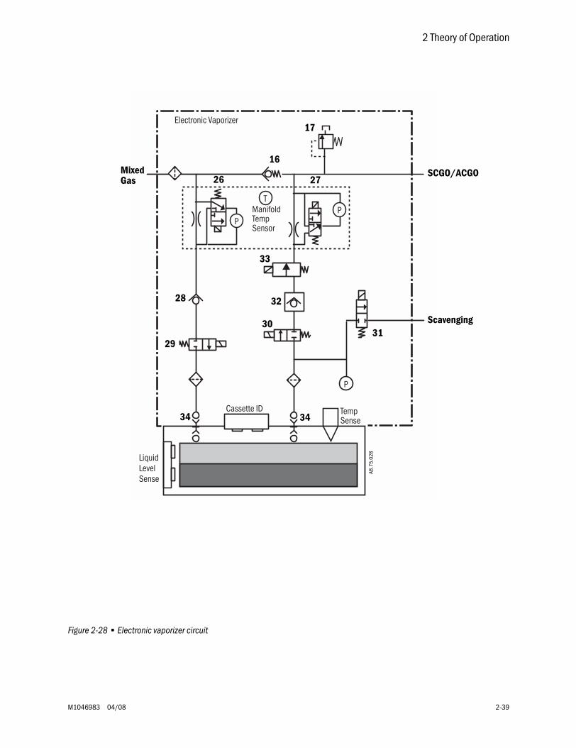
2 Theory of Operation
M1046983 04/08 2-39
Figure 2-28 • Electronic vaporizer circuit
TempSense
Cassette ID
P
PP
T
Electronic Vaporizer
LiquidLevelSense
ManifoldTempSensor
17
26
16
27
28
29
3031
32
33
AB.7
5.02
8
34 34
Mixed SCGO/ACGO
Scavenging
Gas
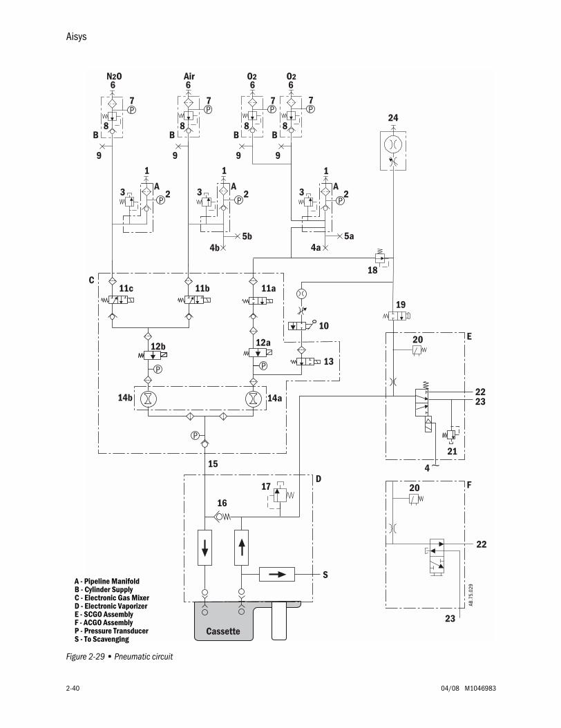
Aisys
2-40 04/08 M1046983
Figure 2-29 • Pneumatic circuit
N2O
9 9 9 9
Air O2 O2
24
7 77 7
8B
8B
8B
8B
3 A2
1
3 A2
1
3 A2
18
19
4b 4a
17D
6 6 6 6
1
5a5b
11c 11b 11a
12b 12a
10
13
20
14a14b 2223
21
C
4
E
20
22
23
F
Cassette
S
16
15AB
.75.
029A - Pipeline Manifold
B - Cylinder SupplyC - Electronic Gas MixerD - Electronic VaporizerE - SCGO Assembly
P - Pressure TransducerF - ACGO Assembly
S - To Scavenging
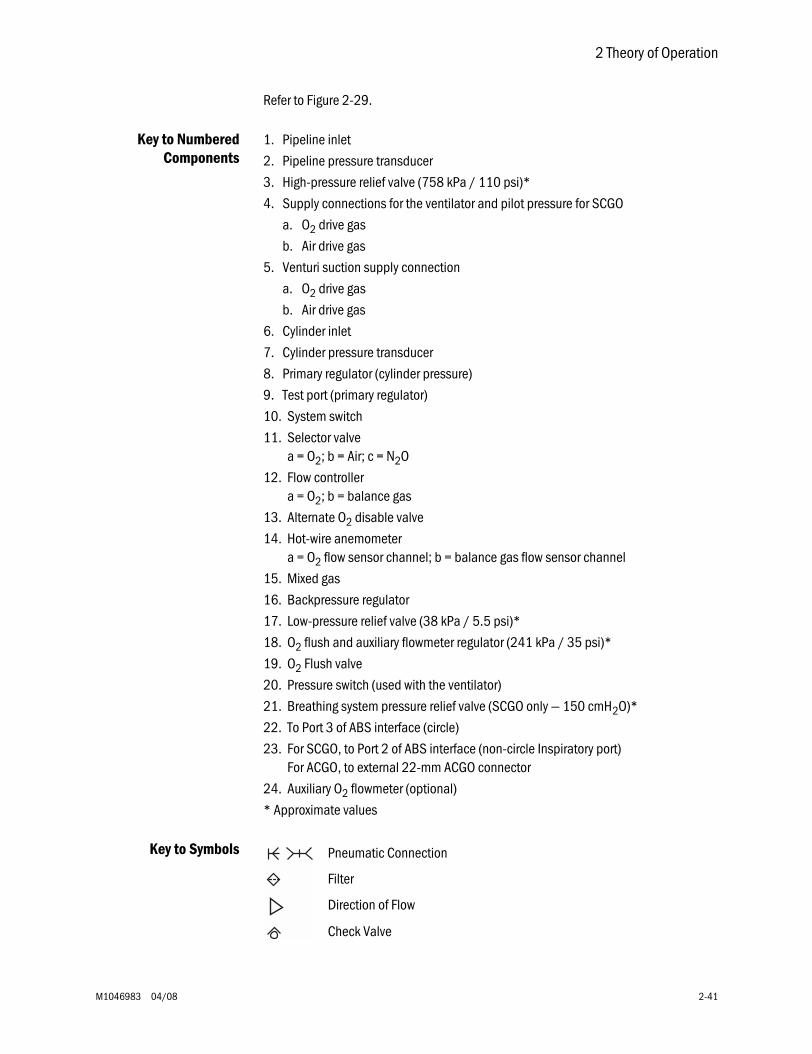
2 Theory of Operation
M1046983 04/08 2-41
Refer to Figure 2-29.
Key to NumberedComponents
1. Pipeline inlet
2. Pipeline pressure transducer
3. High-pressure relief valve (758 kPa / 110 psi)*
4. Supply connections for the ventilator and pilot pressure for SCGO
a. O2 drive gas
b. Air drive gas
5. Venturi suction supply connection
a. O2 drive gas
b. Air drive gas
6. Cylinder inlet
7. Cylinder pressure transducer
8. Primary regulator (cylinder pressure)
9. Test port (primary regulator)
10. System switch
11. Selector valvea = O2; b = Air; c = N2O
12. Flow controllera = O2; b = balance gas
13. Alternate O2 disable valve
14. Hot-wire anemometera = O2 flow sensor channel; b = balance gas flow sensor channel
15. Mixed gas
16. Backpressure regulator
17. Low-pressure relief valve (38 kPa / 5.5 psi)*
18. O2 flush and auxiliary flowmeter regulator (241 kPa / 35 psi)*
19. O2 Flush valve
20. Pressure switch (used with the ventilator)
21. Breathing system pressure relief valve (SCGO only — 150 cmH2O)*
22. To Port 3 of ABS interface (circle)
23. For SCGO, to Port 2 of ABS interface (non-circle Inspiratory port)For ACGO, to external 22-mm ACGO connector
24. Auxiliary O2 flowmeter (optional)
* Approximate values
Key to Symbols Pneumatic Connection
Direction of Flow
Check Valve
Filter
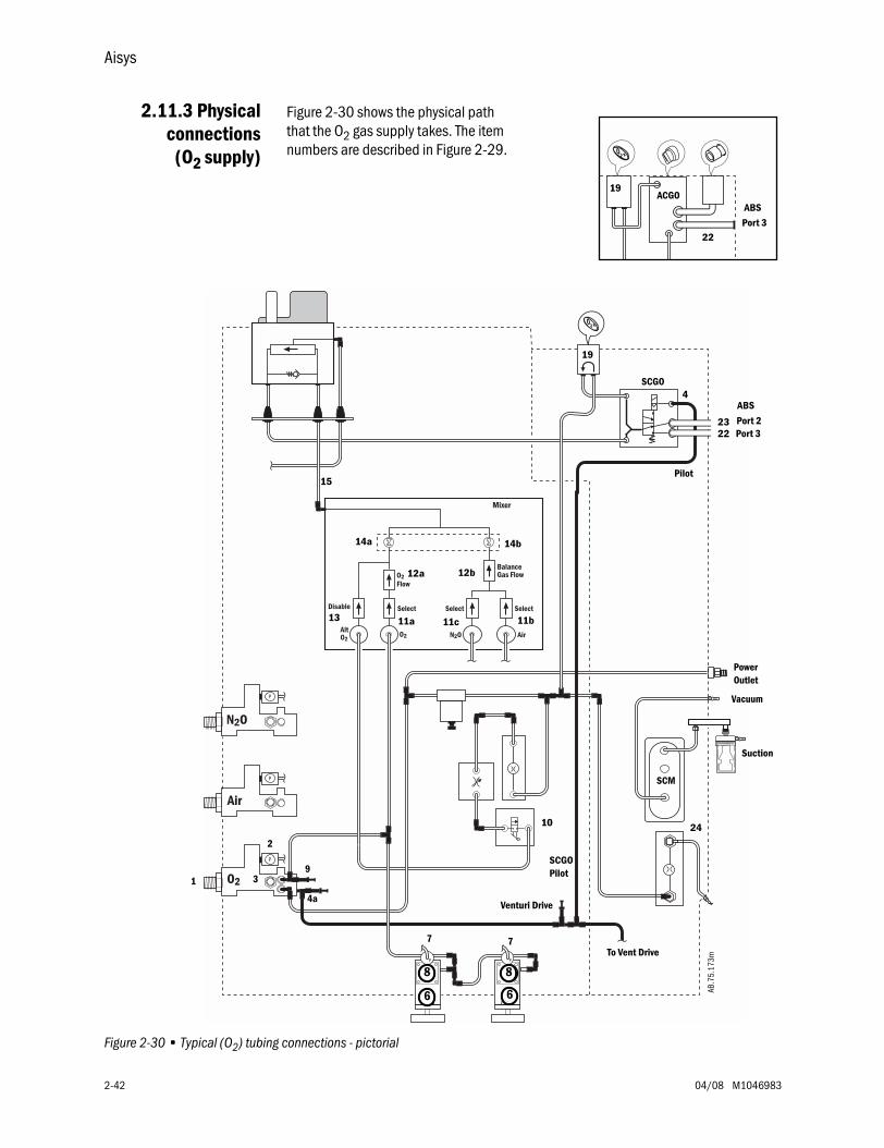
Aisys
2-42 04/08 M1046983
2.11.3 Physicalconnections
(O2 supply)
Figure 2-30 shows the physical path that the O2 gas supply takes. The item numbers are described in Figure 2-29.
Figure 2-30 • Typical (O2) tubing connections - pictorial
19ACGO
ABS
Port 322
P
Air
N2O
O2
N2OAltO2
O2 Air
P
P
SelectDisable
BalanceGas Flow
SelectSelect
O2Flow
PP
Mixer
SCGO
ABS
Port 2Port 3
Pilot
SCGO
To Vent Drive
2
1 3
4a
7 7
9
10
11b11c11a
12a
14a 14b
15
19
4
24
8 8
6 6
SCM
2322
Suction
AB.7
5.17
3m
Venturi Drive
Pilot
Vacuum
PowerOutlet
12b
13
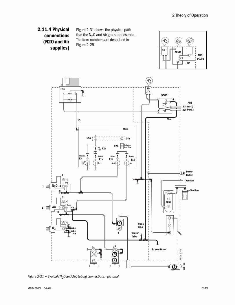
2 Theory of Operation
M1046983 04/08 2-43
2.11.4 Physicalconnections(N2O and Air
supplies)
Figure 2-31 shows the physical path that the N2O and Air gas supplies take. The item numbers are described in Figure 2-29.
Figure 2-31 • Typical (N2O and Air) tubing connections - pictorial
19ACGO
ABS
Port 322
Air
N2O
O2
P
P
N2OAltO2
O2 Air
O2Flow
SelectDisable
BalanceGas Flow
SelectSelect
P
P
P P
eVap
Mixer
SCGO
Pilot
AB.7
5.17
4m
1
1
3
2
2
3
4a
4b
7
7
9
9
11b11c11a
12a
13
14a 14b
15
19
4
2
8
8
6
6
SCM
Vacuum
Suction
2322
Port 2ABS
Port 3
To Vent Drive
SCGO
VenturiDrive
Pilot
PowerOutlet
12b
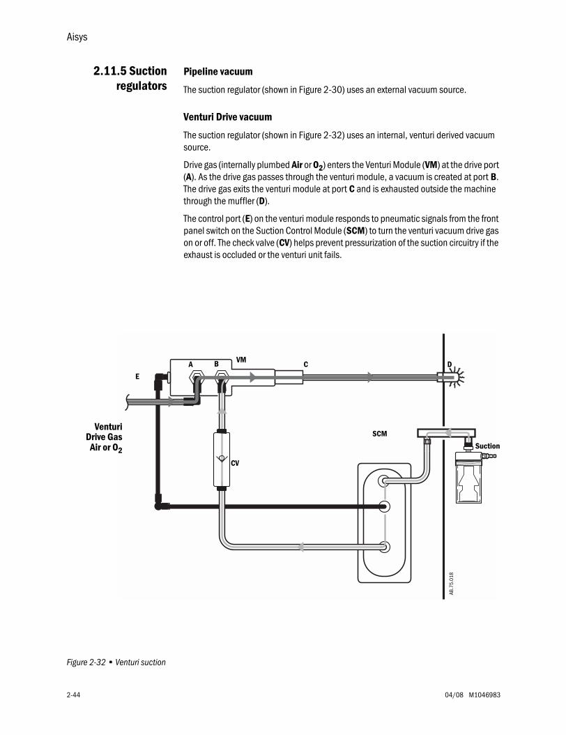
Aisys
2-44 04/08 M1046983
2.11.5 Suctionregulators
Pipeline vacuum
The suction regulator (shown in Figure 2-30) uses an external vacuum source.
Venturi Drive vacuum
The suction regulator (shown in Figure 2-32) uses an internal, venturi derived vacuum source.
Drive gas (internally plumbed Air or O2) enters the Venturi Module (VM) at the drive port (A). As the drive gas passes through the venturi module, a vacuum is created at port B. The drive gas exits the venturi module at port C and is exhausted outside the machine through the muffler (D).
The control port (E) on the venturi module responds to pneumatic signals from the front panel switch on the Suction Control Module (SCM) to turn the venturi vacuum drive gas on or off. The check valve (CV) helps prevent pressurization of the suction circuitry if the exhaust is occluded or the venturi unit fails.
Figure 2-32 • Venturi suction
E
A B C DVM
Venturi
AB.7
5.01
8
SCM
Suction
CV
Air or O2
Drive Gas
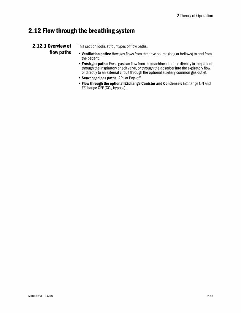
2 Theory of Operation
M1046983 04/08 2-45
2.12 Flow through the breathing system
2.12.1 Overview offlow paths
This section looks at four types of flow paths.
• Ventilation paths: How gas flows from the drive source (bag or bellows) to and from the patient.
• Fresh gas paths: Fresh gas can flow from the machine interface directly to the patient through the inspiratory check valve, or through the absorber into the expiratory flow, or directly to an external circuit through the optional auxiliary common gas outlet.
• Scavenged gas paths: APL or Pop-off.• Flow through the optional EZchange Canister and Condenser: EZchange ON and
EZchange OFF (CO2 bypass).
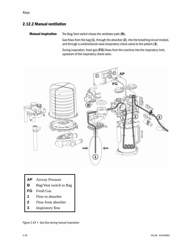
Aisys
2-46 04/08 M1046983
2.12.2 Manual ventilation
Manual inspiration The Bag/Vent switch closes the ventilator path (B)....
Gas flows from the bag (1), through the absorber (2), into the breathing circuit module, and through a unidirectional valve (inspiratory check valve) to the patient (3).
During inspiration, fresh gas (FG) flows from the machine into the inspiratory limb, upstream of the inspiratory check valve.
Figure 2-33 • Gas flow during manual inspiration
AP Airway Pressure
B Bag/Vent switch to Bag
FG Fresh Gas
1 Flow to absorber
2 Flow from absorber
3 Inspiratory flow
3
FG
AP
AB.8
2.02
6
1
B
1 2 3
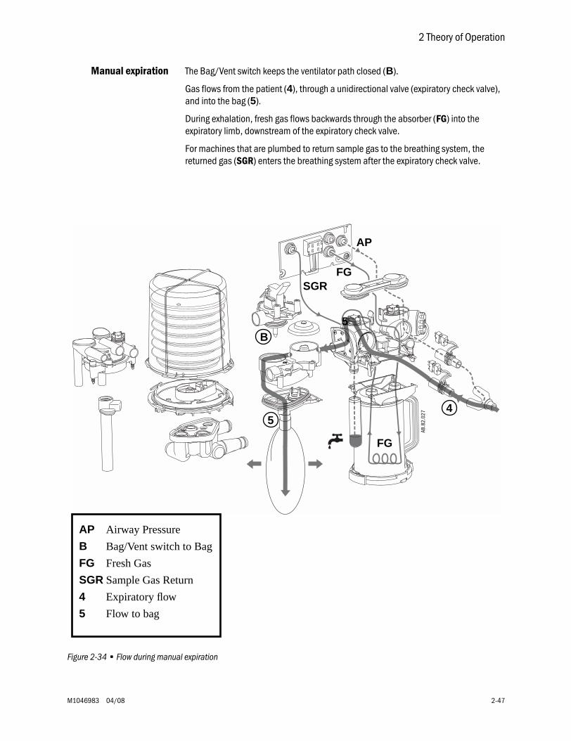
2 Theory of Operation
M1046983 04/08 2-47
Manual expiration The Bag/Vent switch keeps the ventilator path closed (B).
Gas flows from the patient (4), through a unidirectional valve (expiratory check valve), and into the bag (5).
During exhalation, fresh gas flows backwards through the absorber (FG) into the expiratory limb, downstream of the expiratory check valve.
For machines that are plumbed to return sample gas to the breathing system, the returned gas (SGR) enters the breathing system after the expiratory check valve.
Figure 2-34 • Flow during manual expiration
AP Airway Pressure
B Bag/Vent switch to Bag
FG Fresh Gas
SGR Sample Gas Return
4 Expiratory flow
5 Flow to bag
FG
AP
5
FG
AB.8
2.02
7
SGR
45
B
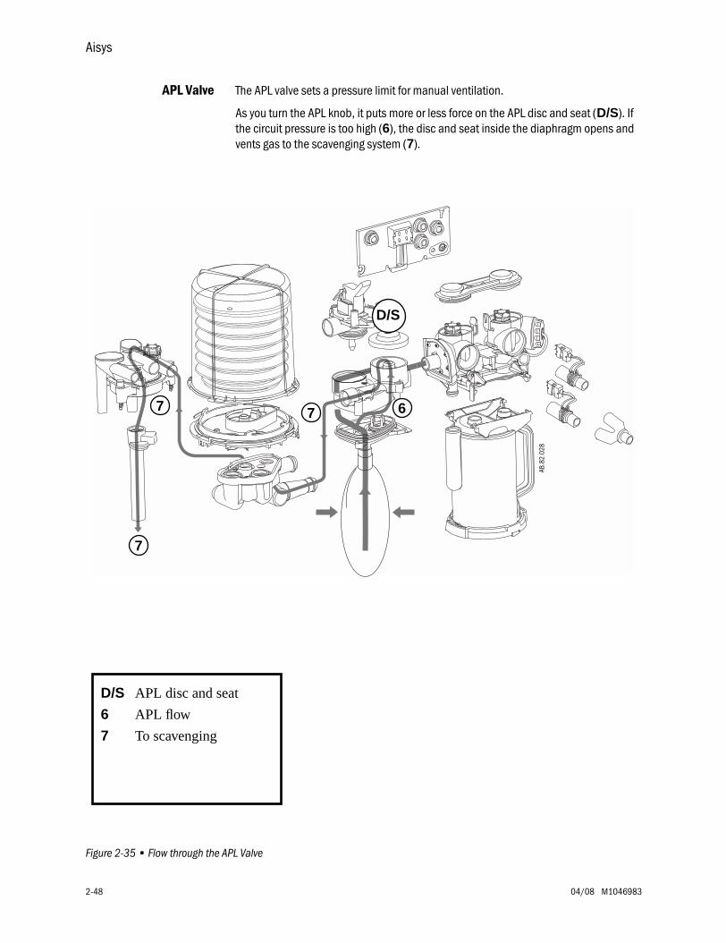
Aisys
2-48 04/08 M1046983
APL Valve The APL valve sets a pressure limit for manual ventilation.
As you turn the APL knob, it puts more or less force on the APL disc and seat (D/S). If the circuit pressure is too high (6), the disc and seat inside the diaphragm opens and vents gas to the scavenging system (7).
Figure 2-35 • Flow through the APL Valve
D/S APL disc and seat
6 APL flow
7 To scavenging
D/S
6
AB.8
2.02
8
77
7
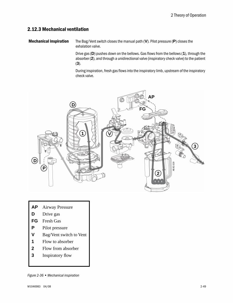
2 Theory of Operation
M1046983 04/08 2-49
2.12.3 Mechanical ventilation
Mechanical inspiration The Bag/Vent switch closes the manual path (V). Pilot pressure (P) closes the exhalation valve.
Drive gas (D) pushes down on the bellows. Gas flows from the bellows (1), through the absorber (2), and through a unidirectional valve (inspiratory check valve) to the patient (3).
During inspiration, fresh gas flows into the inspiratory limb, upstream of the inspiratory check valve.
Figure 2-36 • Mechanical inspiration
AP Airway Pressure
D Drive gas
FG Fresh Gas
P Pilot pressure
V Bag/Vent switch to Vent
1 Flow to absorber
2 Flow from absorber
3 Inspiratory flow
FG
AP
AB.8
2.02
9
1 V
2
3
D
D
P
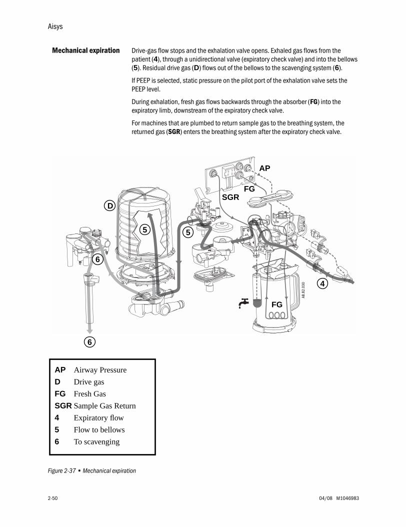
Aisys
2-50 04/08 M1046983
Mechanical expiration Drive-gas flow stops and the exhalation valve opens. Exhaled gas flows from the patient (4), through a unidirectional valve (expiratory check valve) and into the bellows (5). Residual drive gas (D) flows out of the bellows to the scavenging system (6).
If PEEP is selected, static pressure on the pilot port of the exhalation valve sets the PEEP level.
During exhalation, fresh gas flows backwards through the absorber (FG) into the expiratory limb, downstream of the expiratory check valve.
For machines that are plumbed to return sample gas to the breathing system, the returned gas (SGR) enters the breathing system after the expiratory check valve.
Figure 2-37 • Mechanical expiration
AP Airway Pressure
D Drive gas
FG Fresh Gas
SGR Sample Gas Return
4 Expiratory flow
5 Flow to bellows
6 To scavenging
FG
AP
FG
AB.8
2.03
0
SGR
55
6
6
D
4
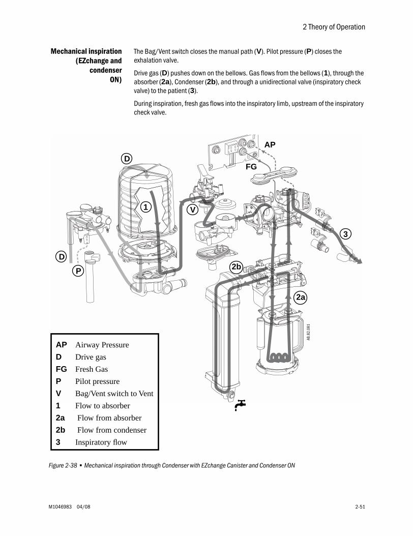
2 Theory of Operation
M1046983 04/08 2-51
Mechanical inspiration(EZchange and
condenserON)
The Bag/Vent switch closes the manual path (V). Pilot pressure (P) closes the exhalation valve.
Drive gas (D) pushes down on the bellows. Gas flows from the bellows (1), through the absorber (2a), Condenser (2b), and through a unidirectional valve (inspiratory check valve) to the patient (3).
During inspiration, fresh gas flows into the inspiratory limb, upstream of the inspiratory check valve.
Figure 2-38 • Mechanical inspiration through Condenser with EZchange Canister and Condenser ON
AP Airway Pressure
D Drive gas
FG Fresh Gas
P Pilot pressure
V Bag/Vent switch to Vent
1 Flow to absorber
2a Flow from absorber
2b Flow from condenser
3 Inspiratory flow
FG
AP
AB.8
2.08
1
u
3
V1
D
D
P 2b
2a
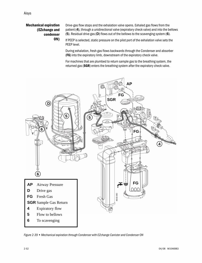
Aisys
2-52 04/08 M1046983
Mechanical expiration(EZchange and
condenserON)
Drive-gas flow stops and the exhalation valve opens. Exhaled gas flows from the patient (4), through a unidirectional valve (expiratory check valve) and into the bellows (5). Residual drive gas (D) flows out of the bellows to the scavenging system (6).
If PEEP is selected, static pressure on the pilot port of the exhalation valve sets the PEEP level.
During exhalation, fresh gas flows backwards through the Condenser and absorber (FG) into the expiratory limb, downstream of the expiratory check valve.
For machines that are plumbed to return sample gas to the breathing system, the returned gas (SGR) enters the breathing system after the expiratory check valve.
Figure 2-39 • Mechanical expiration through Condenser with EZchange Canister and Condenser ON
AP Airway Pressure
D Drive gas
FG Fresh Gas
SGR Sample Gas Return
4 Expiratory flow
5 Flow to bellows
6 To scavenging
FG
AP
FG
AB.8
2.08
3
SGR
FG
4
55
D
6
6
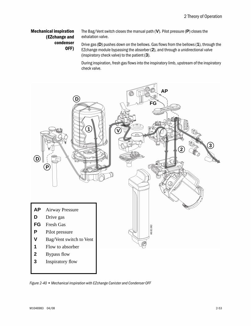
2 Theory of Operation
M1046983 04/08 2-53
Mechanical inspiration(EZchange and
condenserOFF)
The Bag/Vent switch closes the manual path (V). Pilot pressure (P) closes the exhalation valve.
Drive gas (D) pushes down on the bellows. Gas flows from the bellows (1), through the EZchange module bypassing the absorber (2), and through a unidirectional valve (inspiratory check valve) to the patient (3).
During inspiration, fresh gas flows into the inspiratory limb, upstream of the inspiratory check valve.
Figure 2-40 • Mechanical inspiration with EZchange Canister and Condenser OFF
AP Airway Pressure
D Drive gas
FG Fresh Gas
P Pilot pressure
V Bag/Vent switch to Vent
1 Flow to absorber
2 Bypass flow
3 Inspiratory flow
FG
AP
AB.8
2.08
2
D
D
P
1 V
23
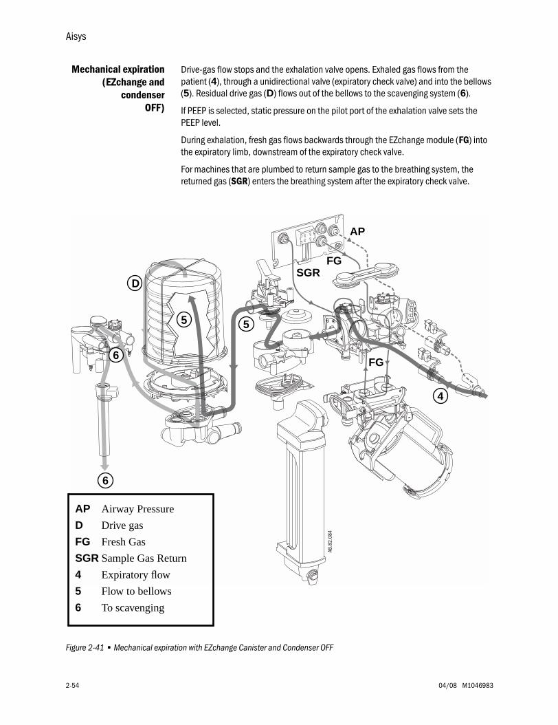
Aisys
2-54 04/08 M1046983
Mechanical expiration(EZchange and
condenserOFF)
Drive-gas flow stops and the exhalation valve opens. Exhaled gas flows from the patient (4), through a unidirectional valve (expiratory check valve) and into the bellows (5). Residual drive gas (D) flows out of the bellows to the scavenging system (6).
If PEEP is selected, static pressure on the pilot port of the exhalation valve sets the PEEP level.
During exhalation, fresh gas flows backwards through the EZchange module (FG) into the expiratory limb, downstream of the expiratory check valve.
For machines that are plumbed to return sample gas to the breathing system, the returned gas (SGR) enters the breathing system after the expiratory check valve.
Figure 2-41 • Mechanical expiration with EZchange Canister and Condenser OFF
AP Airway Pressure
D Drive gas
FG Fresh Gas
SGR Sample Gas Return
4 Expiratory flow
5 Flow to bellows
6 To scavenging
FG
AP
FG
AB.8
2.08
4
SGR
4
55
6
6
D
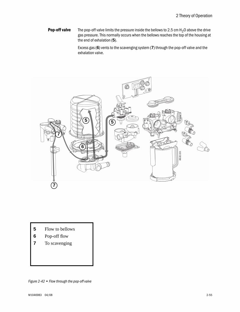
2 Theory of Operation
M1046983 04/08 2-55
Pop-off valve The pop-off valve limits the pressure inside the bellows to 2.5 cm H2O above the drive gas pressure. This normally occurs when the bellows reaches the top of the housing at the end of exhalation (5).
Excess gas (6) vents to the scavenging system (7) through the pop-off valve and the exhalation valve.
Figure 2-42 • Flow through the pop-off valve
5 Flow to bellows
6 Pop-off flow
7 To scavenging
6
AB.8
2.03
1
7
7
55

Aisys
2-56 04/08 M1046983
2.12.4 Fresh gas and O2 flush flow (with SCGO)
To ABS (Circle)breathing system
Fresh gas (1) flows from the electronic vaporizer (EV) to the SCGO assembly.
With the Circle system selected, fresh gas flow is channeled to Port 3 of the breathing system (before the inspiratory check valve).
The output of the O2 Flush regulator (2) is channeled to the O2 Flush valve. When activate, O2 flush flow joins the fresh gas flow in the SCGO assembly.
Figure 2-43 • Fresh gas and O2 flush flow (to ABS)
1
ABS SCGOAssembly
2
AB.7
5.03
0
EV
Circle or CGOSelector Switch(SCGO)
150 cm H2OFG Pressure
Limiting ValveSCGOVariant
Pilot
3
2 1
O2Sensor
5.4 psiO2 FlushSwitch
AB.9
1.11
8
Insp Flow
Paw Trans
FromO2 Supply
FromMixer
ToMixer
ToScavenging
Absorber
2
1
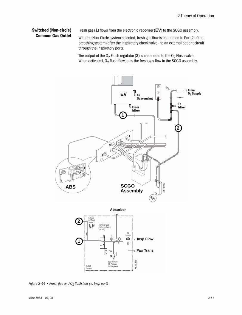
2 Theory of Operation
M1046983 04/08 2-57
Switched (Non-circle)Common Gas Outlet
Fresh gas (1) flows from the electronic vaporizer (EV) to the SCGO assembly.
With the Non-Circle system selected, fresh gas flow is channeled to Port 2 of the breathing system (after the inspiratory check valve - to an external patient circuit through the Inspiratory port).
The output of the O2 Flush regulator (2) is channeled to the O2 Flush valve. When activated, O2 flush flow joins the fresh gas flow in the SCGO assembly.
Figure 2-44 • Fresh gas and O2 flush flow (to Insp port)
Circle or CGOSelector Switch(SCGO)
150 cm H2OFG Pressure
Limiting ValveSCGOVariant
Pilot
3
2 1
O2Sensor
5.4 psiO2 FlushSwitch
AB.9
1.11
9
Insp Flow
Paw Trans
1
ABS SCGOAssembly
2
AB.7
5.03
9
EVFromO2 Supply
ToMixerFrom
Mixer
ToScavenging
2
1
Absorber
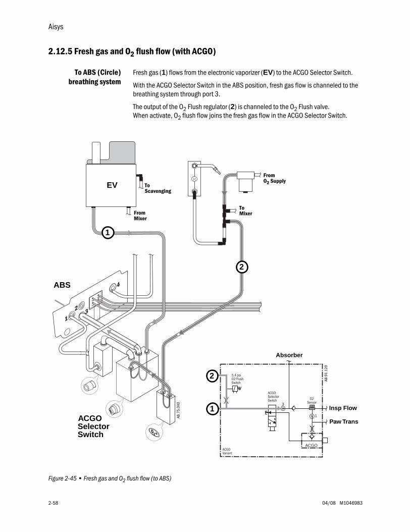
Aisys
2-58 04/08 M1046983
2.12.5 Fresh gas and O2 flush flow (with ACGO)
To ABS (Circle)breathing system
Fresh gas (1) flows from the electronic vaporizer (EV) to the ACGO Selector Switch.
With the ACGO Selector Switch in the ABS position, fresh gas flow is channeled to the breathing system through port 3.
The output of the O2 Flush regulator (2) is channeled to the O2 Flush valve. When activate, O2 flush flow joins the fresh gas flow in the ACGO Selector Switch.
Figure 2-45 • Fresh gas and O2 flush flow (to ABS)
AB.7
5.04
0
ABS
ACGOSelectorSwitch
1
2
EV
ACGOSelectorSwitch
ACGOVariant
O2Sensor3
1
ACGO
5.4 psiO2 FlushSwitch
AB.9
1.12
0
2
1
Absorber
Insp Flow
Paw Trans
FromO2 Supply
ToMixerFrom
Mixer
ToScavenging
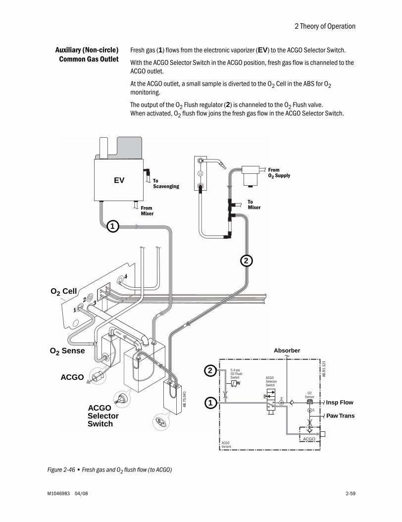
2 Theory of Operation
M1046983 04/08 2-59
Auxiliary (Non-circle)Common Gas Outlet
Fresh gas (1) flows from the electronic vaporizer (EV) to the ACGO Selector Switch.
With the ACGO Selector Switch in the ACGO position, fresh gas flow is channeled to the ACGO outlet.
At the ACGO outlet, a small sample is diverted to the O2 Cell in the ABS for O2 monitoring.
The output of the O2 Flush regulator (2) is channeled to the O2 Flush valve. When activated, O2 flush flow joins the fresh gas flow in the ACGO Selector Switch.
Figure 2-46 • Fresh gas and O2 flush flow (to ACGO)
1
O2 Cell
O2 Sense
ACGO
AB.7
5.04
1
ACGOSelectorSwitch
2
EVFromO2 Supply
ToMixerFrom
Mixer
ToScavenging
ACGOSelectorSwitch
ACGOVariant
O2Sensor3
1
ACGO
5.4 psiO2 FlushSwitch AB
.91.
121
2
1
Absorber
Insp Flow
Paw Trans
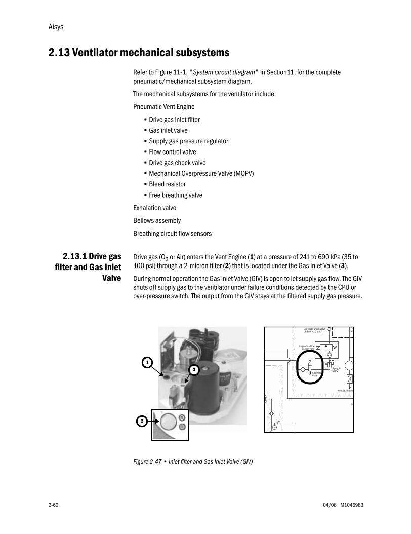
Aisys
2-60 04/08 M1046983
2.13 Ventilator mechanical subsystems
Refer to Figure 11-1, "System circuit diagram" in Section11, for the complete pneumatic/mechanical subsystem diagram.
The mechanical subsystems for the ventilator include:
Pneumatic Vent Engine
• Drive gas inlet filter
• Gas inlet valve
• Supply gas pressure regulator
• Flow control valve
• Drive gas check valve
• Mechanical Overpressure Valve (MOPV)
• Bleed resistor
• Free breathing valve
Exhalation valve
Bellows assembly
Breathing circuit flow sensors
2.13.1 Drive gasfilter and Gas Inlet
Valve
Drive gas (O2 or Air) enters the Vent Engine (1) at a pressure of 241 to 690 kPa (35 to 100 psi) through a 2-micron filter (2) that is located under the Gas Inlet Valve (3).
During normal operation the Gas Inlet Valve (GIV) is open to let supply gas flow. The GIV shuts off supply gas to the ventilator under failure conditions detected by the CPU or over-pressure switch. The output from the GIV stays at the filtered supply gas pressure.
Figure 2-47 • Inlet filter and Gas Inlet Valve (GIV)
3
Vent to Ambient
Exh(2.0
5.
25 psig @15 LPM
Drive Gas Check Valve(3.5 cm H2O bias)
Inspiratory FlowControl Valve
Gas InletValve
P
1
2
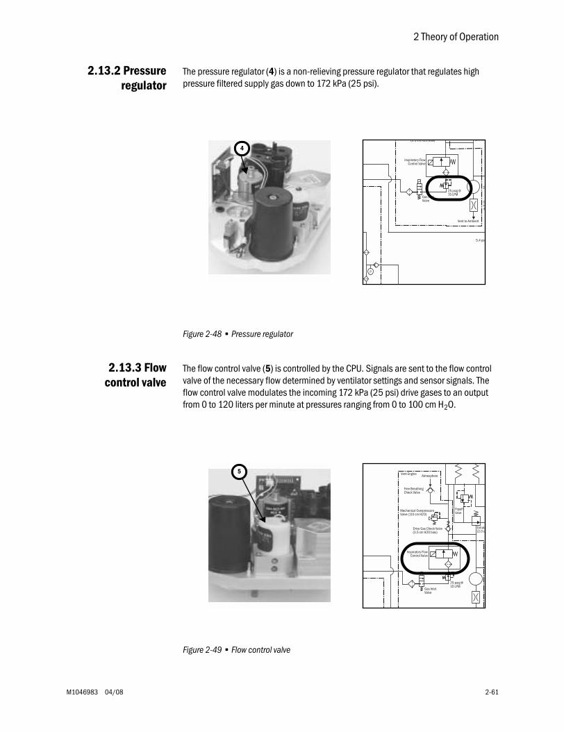
2 Theory of Operation
M1046983 04/08 2-61
2.13.2 Pressureregulator
The pressure regulator (4) is a non-relieving pressure regulator that regulates high pressure filtered supply gas down to 172 kPa (25 psi).
Figure 2-48 • Pressure regulator
2.13.3 Flowcontrol valve
The flow control valve (5) is controlled by the CPU. Signals are sent to the flow control valve of the necessary flow determined by ventilator settings and sensor signals. The flow control valve modulates the incoming 172 kPa (25 psi) drive gases to an output from 0 to 120 liters per minute at pressures ranging from 0 to 100 cm H2O.
Figure 2-49 • Flow control valve
4
Vent to Ambient
(2.0 cm
20
5.4 psi
25 psig @15 LPM
(3.5 cm H2O bias)
Inspiratory FlowControl Valve
Gas InletValve C
if
P
5
Exhala(2.0 c
PopoffValve
Atmosphere
25 psig @15 LPM
Drive Gas Check Valve(3.5 cm H2O bias)
Free BreathingCheck Valve
Mechanical OverpressureValve (110 cm H2O)
Inspiratory FlowControl Valve
Gas InletValve
Vent Engine
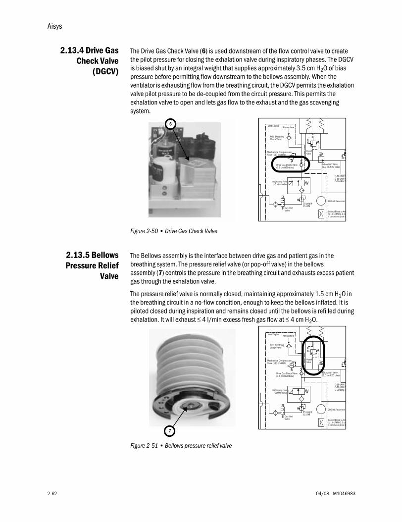
Aisys
2-62 04/08 M1046983
2.13.4 Drive GasCheck Valve
(DGCV)
The Drive Gas Check Valve (6) is used downstream of the flow control valve to create the pilot pressure for closing the exhalation valve during inspiratory phases. The DGCV is biased shut by an integral weight that supplies approximately 3.5 cm H2O of bias pressure before permitting flow downstream to the bellows assembly. When the ventilator is exhausting flow from the breathing circuit, the DGCV permits the exhalation valve pilot pressure to be de-coupled from the circuit pressure. This permits the exhalation valve to open and lets gas flow to the exhaust and the gas scavenging system.
Figure 2-50 • Drive Gas Check Valve
2.13.5 BellowsPressure Relief
Valve
The Bellows assembly is the interface between drive gas and patient gas in the breathing system. The pressure relief valve (or pop-off valve) in the bellows assembly (7) controls the pressure in the breathing circuit and exhausts excess patient gas through the exhalation valve.
The pressure relief valve is normally closed, maintaining approximately 1.5 cm H2O in the breathing circuit in a no-flow condition, enough to keep the bellows inflated. It is piloted closed during inspiration and remains closed until the bellows is refilled during exhalation. It will exhaust ≤ 4 l/min excess fresh gas flow at ≤ 4 cm H2O.
Figure 2-51 • Bellows pressure relief valve
6
Exhalation Valve(2.0 cm H2O bias)
0-10 LPM D0-10 LPM P0-20 LPM To
PopoffValve
200 mL Reservoir
Atmosphere
25 psig @15 LPM
Drive Gas Check Valve(3.5 cm H2O bias)
Free BreathingCheck Valve
Mechanical OverpressureValve (110 cm H2O)
Inspiratory FlowControl Valve
Gas InletValve Control Bleed to Am
1.0 LPM @ 3.0 cmif continuous (rate d
Vent Engine
7
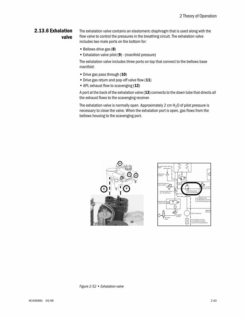
2 Theory of Operation
M1046983 04/08 2-63
2.13.6 Exhalationvalve
The exhalation valve contains an elastomeric diaphragm that is used along with the flow valve to control the pressures in the breathing circuit. The exhalation valve includes two male ports on the bottom for:
• Bellows drive gas (8)• Exhalation valve pilot (9) - (manifold pressure)
The exhalation valve includes three ports on top that connect to the bellows base manifold:
• Drive gas pass through (10)• Drive gas return and pop-off valve flow (11) • APL exhaust flow to scavenging (12)
A port at the back of the exhalation valve (13) connects to the down tube that directs all the exhaust flows to the scavenging receiver.
The exhalation valve is normally open. Approximately 2 cm H2O of pilot pressure is necessary to close the valve. When the exhalation port is open, gas flows from the bellows housing to the scavenging port.
Figure 2-52 • Exhalation valve
8 9
1211
13
10
B
Exhalation Valve(2.0 cm H2O bias)
0-10 LPM Drive Gas0-10 LPM Patient and Fresh0-20 LPM Total Typical Flow
PopoffValve
200 mL Reservoir
Negative relief valv
(10 cm H2O)
Atmosphere
25 psig @15 LPM
Drive Gas Check Valve(3.5 cm H2O bias)
e Breathingeck Valve
anical Overpressure(110 cm H2O)
nspiratory FlowControl Valve
Gas InletValve Control Bleed to Ambient
1.0 LPM @ 3.0 cm H2Oif continuous (rate dependent)
Engine
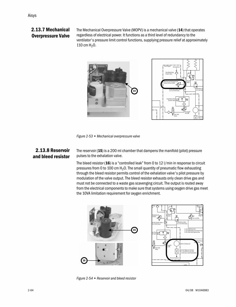
Aisys
2-64 04/08 M1046983
2.13.7 MechanicalOverpressure Valve
The Mechanical Overpressure Valve (MOPV) is a mechanical valve (14) that operates regardless of electrical power. It functions as a third level of redundancy to the ventilator's pressure limit control functions, supplying pressure relief at approximately 110 cm H2O.
Figure 2-53 • Mechanical overpressure valve
2.13.8 Reservoirand bleed resistor
The reservoir (15) is a 200 ml chamber that dampens the manifold (pilot) pressure pulses to the exhalation valve.
The bleed resistor (16) is a “controlled leak” from 0 to 12 l/min in response to circuit pressures from 0 to 100 cm H2O. The small quantity of pneumatic flow exhausting through the bleed resistor permits control of the exhalation valve's pilot pressure by modulation of the valve output. The bleed resistor exhausts only clean drive gas and must not be connected to a waste gas scavenging circuit. The output is routed away from the electrical components to make sure that systems using oxygen drive gas meet the 10VA limitation requirement for oxygen enrichment.
Figure 2-54 • Reservoir and bleed resistor
14Exhalation Va(2.0 cm H2O
PopoffValve
200 m
Atmosphere
25 psig @15 LPM
Drive Gas Check Valve(3.5 cm H2O bias)
Free BreathingCheck Valve
Mechanical OverpressureValve (110 cm H2O)
Inspiratory FlowControl Valve
Gas InletValve Contro
1.0 if conti
Vent Engine
15
Vent to Ambient
Bag/Ve
Exhalation Valve(2.0 cm H2O bias)
0-10 LPM Drive Gas0-10 LPM Patient and Fresh Gas0-20 LPM Total Typical Flow
PopoffValve
200 mL Reservoir
5 4 ig
Negative Pressurelief valve
(10 cm H2O)
25 psig @15 LPM
ve Gas Check Valve5 cm H2O bias)
thinglve
Overpressurem H2O)
tory Flowrol Valve
Gas InletValve Control Bleed to Ambient
1.0 LPM @ 3.0 cm H2Oif continuous (rate dependent)
16
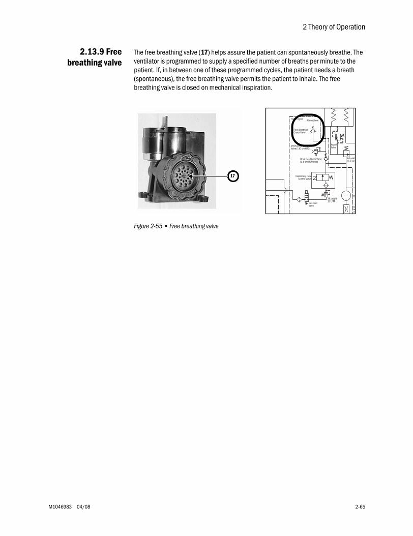
2 Theory of Operation
M1046983 04/08 2-65
2.13.9 Freebreathing valve
The free breathing valve (17) helps assure the patient can spontaneously breathe. The ventilator is programmed to supply a specified number of breaths per minute to the patient. If, in between one of these programmed cycles, the patient needs a breath (spontaneous), the free breathing valve permits the patient to inhale. The free breathing valve is closed on mechanical inspiration.
Figure 2-55 • Free breathing valve
17
Exhalatio(2.0 cm
PopoffValve
20
Atmosphere
25 psig @15 LPM
Drive Gas Check Valve(3.5 cm H2O bias)
Free BreathingCheck Valve
Mechanical OverpressureValve (110 cm H2O)
Inspiratory FlowControl Valve
Gas InletValve Co
if c
Vent Engine
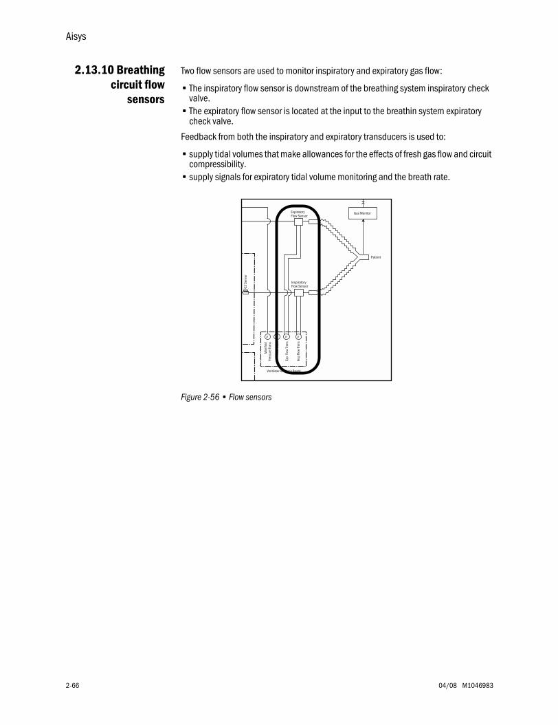
Aisys
2-66 04/08 M1046983
2.13.10 Breathingcircuit flow
sensors
Two flow sensors are used to monitor inspiratory and expiratory gas flow:
• The inspiratory flow sensor is downstream of the breathing system inspiratory check valve.
• The expiratory flow sensor is located at the input to the breathin system expiratory check valve.
Feedback from both the inspiratory and expiratory transducers is used to:
• supply tidal volumes that make allowances for the effects of fresh gas flow and circuit compressibility.
• supply signals for expiratory tidal volume monitoring and the breath rate.
Figure 2-56 • Flow sensors
O2 S
enso
r
Man
ifold
Pres
sure
Tran
s
Exp
Flo
w Tr
ans
Paw
Tran
s
Ventilator Interface Board
Insp
Flo
w Tr
ans
P PPP
Patient
ExpiratoryFlow Sensor
Gas Monitor
InspiratoryFlow Sensor
M1046983 04/08 3-1
3 Checkout Procedure
In this section 3.1 Inspect the system . . . . . . . . . . . . . . . . . . . . . . . . . . . . . . . . . . . . . . . . . . . . . . . . . . . . . . . . .3-2
3.2 System checkout . . . . . . . . . . . . . . . . . . . . . . . . . . . . . . . . . . . . . . . . . . . . . . . . . . . . . . . . . . .3-2
3.2.1 Leak < 250 ml . . . . . . . . . . . . . . . . . . . . . . . . . . . . . . . . . . . . . . . . . . . . . . . . . . . . . . .3-2
3.2.2 Machine Check . . . . . . . . . . . . . . . . . . . . . . . . . . . . . . . . . . . . . . . . . . . . . . . . . . . . . .3-3
3.2.3 Machine Check - System (Ventilator Circuit Testing) . . . . . . . . . . . . . . . . . . . . . . . .3-3
3.2.4 Machine Check - Circuit (Bag Circuit Testing) . . . . . . . . . . . . . . . . . . . . . . . . . . . . . .3-3
3.2.5 Machine Check - Circuit O2 . . . . . . . . . . . . . . . . . . . . . . . . . . . . . . . . . . . . . . . . . . . .3-4
3.3 Individual Checks . . . . . . . . . . . . . . . . . . . . . . . . . . . . . . . . . . . . . . . . . . . . . . . . . . . . . . . . . .3-4
3.3.1 System . . . . . . . . . . . . . . . . . . . . . . . . . . . . . . . . . . . . . . . . . . . . . . . . . . . . . . . . . . . . .3-4
3.3.2 Circuit . . . . . . . . . . . . . . . . . . . . . . . . . . . . . . . . . . . . . . . . . . . . . . . . . . . . . . . . . . . . .3-5
3.3.3 Circuit O2 Cell . . . . . . . . . . . . . . . . . . . . . . . . . . . . . . . . . . . . . . . . . . . . . . . . . . . . . . .3-5
3.3.4 Low P Leak . . . . . . . . . . . . . . . . . . . . . . . . . . . . . . . . . . . . . . . . . . . . . . . . . . . . . . . . .3-5
3.3.5 Low P Leak (machines with ACGO) . . . . . . . . . . . . . . . . . . . . . . . . . . . . . . . . . . . . . .3-6
3.3.6 Agent Delivery . . . . . . . . . . . . . . . . . . . . . . . . . . . . . . . . . . . . . . . . . . . . . . . . . . . . . . .3-6
3.4 Bellows drop test . . . . . . . . . . . . . . . . . . . . . . . . . . . . . . . . . . . . . . . . . . . . . . . . . . . . . . . . . . .3-7
3.5 Backlight test . . . . . . . . . . . . . . . . . . . . . . . . . . . . . . . . . . . . . . . . . . . . . . . . . . . . . . . . . . . . . .3-7
3.6 Pipeline and cylinder tests . . . . . . . . . . . . . . . . . . . . . . . . . . . . . . . . . . . . . . . . . . . . . . . . . . .3-8
3.6.1 O2 supply alarm test . . . . . . . . . . . . . . . . . . . . . . . . . . . . . . . . . . . . . . . . . . . . . . . . . .3-8
3.7 Flush Flow Test . . . . . . . . . . . . . . . . . . . . . . . . . . . . . . . . . . . . . . . . . . . . . . . . . . . . . . . . . . . . .3-9
3.8 Alarm tests . . . . . . . . . . . . . . . . . . . . . . . . . . . . . . . . . . . . . . . . . . . . . . . . . . . . . . . . . . . . . . 3-10
3.9 Alternate O2 flowmeter tests . . . . . . . . . . . . . . . . . . . . . . . . . . . . . . . . . . . . . . . . . . . . . . . 3-11
3.10 Auxiliary O2 flowmeter tests . . . . . . . . . . . . . . . . . . . . . . . . . . . . . . . . . . . . . . . . . . . . . . . 3-11
3.11 Integrated Suction Regulator tests . . . . . . . . . . . . . . . . . . . . . . . . . . . . . . . . . . . . . . . . . 3-11
3.12 Power failure test . . . . . . . . . . . . . . . . . . . . . . . . . . . . . . . . . . . . . . . . . . . . . . . . . . . . . . . 3-12
3.13 Electrical safety tests . . . . . . . . . . . . . . . . . . . . . . . . . . . . . . . . . . . . . . . . . . . . . . . . . . . . 3-12
wwww WARNINGS After any repair or service of the Aisys system, complete all tests in this section.
Before you do the tests in this section:
• Complete all necessary calibrations and subassembly tests. Refer to the individual procedures for a list of necessary calibrations.
• Completely reassemble the system.
If a test failure occurs, make appropriate repairs and test for correct operation.
Aisys
3-2 04/08 M1046983
3.1 Inspect the system
wwww CAUTION The upper shelf weight limit is 45 kg (100 lb).
wwww WARNING Do not leave gas cylinder valves open if the pipeline supply is in use. Cylinder supplies could be depleted, leaving an insufficient reserve supply in case of pipeline failure.
Before testing the system, ensure that:
• The equipment is not damaged.
• Components are correctly attached.
• The breathing circuit is correctly connected, not damaged.
• Pipeline gas supplies are connected.
• Cylinder valves are closed.
• Models with cylinder supplies have a cylinder wrench attached to the system.
• Models with cylinder supplies have a reserve supply of O2 connected to the machine during system checkout.
• The casters are not loose and the brakes are set and prevent movement.
• The power cord is connected to a wall outlet. The mains indicator comes on when AC Power is connected.
3.2 System checkout
3.2.1 Leak < 250 ml The Leak < 250 ml setting is used during the circuit leak check portion of the checkout procedures. This check tests for leaks in the machine, breathing circuit, patient circuit, and manual bag. The default setting is No.
Note Extraction of gas by external gas monitors may cause failure of the leak checks during tests.
When No is selected, the leak test will pass for leaks below 250 ml at 3 kPa (30 cmH2O) pressure with no user interaction required. For leaks between 250 ml and 750 ml, the user can fix the leak and rerun the test or accept the leak and continue. For leaks above 750 ml, the test will fail and the user must fix the leak and rerun the test.
Set to Yes to quantify small leaks above 100 ml during the checkout procedures. Selecting Yes will display the measured leak at 3 kPa (30 cmH2O) pressure and result in the test taking somewhat longer.
3 Checkout Procedure
M1046983 04/08 3-3
3.2.2 Machine Check The machine check runs automatically and beeps to indicate when it is finished or if interaction is required.
The Machine Check does a:
• Machine Check - System check (Ventilator Circuit), • Machine Check- Circuit check (Bag Circuit), • and a Machine Check - Circuit O2 cell check (if circuit O2 cell is present).
When one of the checks is completed, the system will transition to the next check.
1. Turn the System switch to On.
2. Select Machine Check and follow the instructions.
3. If a check fails, follow the instructions to perform a recheck or accept the results.
3.2.3 Machine Check - System (Ventilator Circuit Testing)
The Machine Check-System checks the Bag/Vent switch, proper gas supply pressures, ventilator operation and leak, battery and electrical power, circuit compliance, flow control operation, and vaporizer operation. This is a two-step check.
Note The Machine Check-System can be run with a test cassette to invoke extended diagnostics (Agent Delivery test will take several minutes longer).
1. Set the Bag/Vent switch to Vent.
2. Open the patient Y.
3. (ACGO option only.) Set the ACGO switch to Circle.
4. Select Start. The display shows the checks being run.
• The system beeps when this portion of the check is done.
• The results are shown on the display.
5. Make sure the bellows is fully collapsed.
6. Occlude the patient Y.
7. Select Continue. The display shows the checks being run.
8. When the check passes, the system will transition to the next step.
3.2.4 Machine Check - Circuit (Bag Circuit Testing)
The Machine Check-Circuit checks the Bag/Vent switch, proper gas supply pressures, airway pressure measurement transducer, APL valve, and manual circuit leak.
1. Occlude the patient Y.
2. Set Bag/Vent switch to Bag.
3. Set the APL valve halfway between 30 and 70.
4. (ACGO option only.) Set the ACGO switch to Circle.
5. Select Start. The display shows the checks being run.
• The system beeps when the check is done.
• The results are shown on the display.
6. When the check passes, the system will transition to the next step.
Aisys
3-4 04/08 M1046983
3.2.5 Machine Check - Circuit O2
The Machine Check-Circuit O2 check measures the O2%.
1. Open the patient Y.
2. Set the Bag/Vent switch to Vent.
3. (ACGO option only.) Set the ACGO switch to Circle.
4. The display will show the O2%. Do not select Done when 21 is first displayed. Allow the reading to stabilize, then select Done. Calibrate the O2 cell if necessary (measured reading outside 21% ±3%).
3.3 Individual Checks
Individual checks allow you to perform any combination of single checks. These checks are helpful if there is a specific problem/alarm and you want to test only that portion of the system.
The checks do not automatically move on to the next check.
3.3.1 System The System check checks the Bag/Vent switch, proper gas supply pressures, ventilator operation and leak, battery and electrical power, circuit compliance, flow control operation, and vaporizer operation. This is a two-step check.
Note: This check is performed during the "System Check" of the "System Checkout."
1. Set the Bag/Vent switch to Vent.
2. Open the patient Y.
3. (ACGO option only.) Set the ACGO switch to Circle.
4. Select Start. The display shows the checks being run.
• The results are shown on the display.
5. Make sure the bellows is fully collapsed.
6. Occlude the patient Y.
7. Select Continue. The display shows the checks being run.
8. When the check passes, select Back.
9. Select another check or select Start Case to go to the Start Case menu.
3 Checkout Procedure
M1046983 04/08 3-5
3.3.2 Circuit The Circuit check checks the Bag/Vent switch, proper gas supply pressures, airway pressure measurement transducer, APL valve, and manual circuit leak.
Note: This check is performed during the "System Check" of the "System Checkout."
1. Occlude the patient Y.
2. Set Bag/Vent switch to Bag.
3. Set the APL valve halfway between 30 and 70.
4. (ACGO option only.) Set the ACGO switch to Circle.
5. Select Start. The display shows the checks being run.
6. When the check passes, select Back.
7. Select another check or select Start Case to go to the Start Case menu.
3.3.3 Circuit O2 Cell The Circuit O2 cell check measures the O2%.
Note: This check is performed during the "System Check" of the "System Checkout."
1. Open the patient Y.
2. Set the Bag/Vent switch to Vent.
3. (ACGO option only.) Set the ACGO switch to Circle.
4. The display will show the O2%. Do not select Done when 21 is first displayed. Allow the reading to stabilize, then select Done. Calibrate the O2 cell if necessary (measured reading outside 21% ±3%).
5. Select another check or select Start Case to go to the Start Case menu.
3.3.4 Low P Leak The positive pressure Low P Leak check measures machine leaks before the breathing system and between the gas mixer and the common gas outlet. It measures low pressure pneumatic leaks with a pass/fail limit of 50 ml.
Note: This check is NOT performed during the "System Check." This test is used to aid in troubleshooting if the "System Check" fails.
1. Occlude the inspiratory (right-hand) port.
2. Select Start.
3. The display shows the checks being run.
4. Open the inspiratory port and reconnect the breathing circuit.
5. Select another check or select Start Case to go to the Start Case menu.
Aisys
3-6 04/08 M1046983
3.3.5 Low P Leak (machines with ACGO)
The negative low P leak check measures machine leaks before the breathing system and between the gas mixer and the common gas outlet.
Note: This check is NOT performed during the "System Check." This test is used to aid in troubleshooting if the "System Check" fails.
1. Make sure the ACGO switch is set to ACGO.
2. Attach the squeeze bulb to the ACGO outlet.
3. Squeeze (collapse) the bulb.
4. If the bulb inflates in less than 30 seconds, select Fail.
5. If the bulb remains collapsed, select Pass.
6. Remove the squeeze bulb from the ACGO outlet.
3.3.6 Agent Delivery The Agent Delivery Check checks the Electronic Vaporization (EV) system.
Note: This check is performed during the "System Check" of the "System Checkout."
1. Insert a test cassette, connect a patient circuit, and connect scavenging.
2. Set the Bag/Vent switch to Vent.
3. (ACGO option only.) Set the ACGO switch to Circle.
4. Occlude the patient Y.
5. Select Start.
6. The display shows the checks being run. The system beeps when the check is done.
7. When the check passes, select Back.
8. Select another check or select Start Case to go to the Start Case menu.
3 Checkout Procedure
M1046983 04/08 3-7
3.4 Bellows drop test
Note: This check is NOT performed during the "System Check." This test is used to aid in troubleshooting if the "System Check" fails.
1. End a case.
2. Set the Bag/Vent switch to Vent.
3. Occlude the patient Y piece.
4. Push the O2 Flush button until the bellows is full.
5. After the initial drop, if the bellows falls more than 100 ml/min, it has a leak.
3.5 Backlight test
1. Push the Main Menu key.
2. Select Calibration.
3. Select Backlight Test.
4. Select Start Test.
5. The display will show the test running on light 1 and then on light 2. If the display goes completely blank or flickers during the test, one of the lights has failed.
Aisys
3-8 04/08 M1046983
3.6 Pipeline and cylinder tests
1. Connect the pipeline supplies one at a time and ensure that the corresponding display indicates pipeline pressure.
2. Disconnect all pipeline supplies.
a. Open each cylinder valve.
b. Make sure that each cylinder has sufficient pressure. If not, close the applicable cylinder valve and install a full cylinder.
3. Test the cylinder supplies for a high pressure leak. Make sure that each cylinder has sufficient pressure:
a. If equipped, turn the auxiliary O2 flow control fully clockwise (no flow).
b. If equipped, turn off venturi derived suction.
c. Open each cylinder.
d. Record the cylinder pressure.
e. Close each cylinder valve.
f. Record the cylinder pressure after one minute. If the pressure decreases more than indicated below, there is a leak.
690 kPa (100 psig) for all gases.
If a cylinder supply fails this test, install a new cylinder gasket and do this step again.
4. Close all cylinder valves.
wwww WARNING Do not leave gas cylinder valves open if the pipeline supply is in use. Cylinder supplies could be depleted, leaving an insufficient reserve supply in case of pipeline failure.
3.6.1 O2 supply alarm test 1. Establish O2, Air, and (if equipped) N20 gas supplies.
2. Set O2 to 25% and (if equipped) N20 as balance gas. For machines without N2O, set Air as balance gas.
3. Set total flow to 3 L/min.
4. Stop the O2 supply. (Disconnect the pipeline supply or close the cylinder valve.)
5. Make sure that:
a. The low “O2 supply pressure low” alarm occurs.
b. The N2O (if equipped) and O2 flows stop.
c. Air (if selected) flow continues or an Air selection prompt appears.
6. Reconnect the O2 supply.
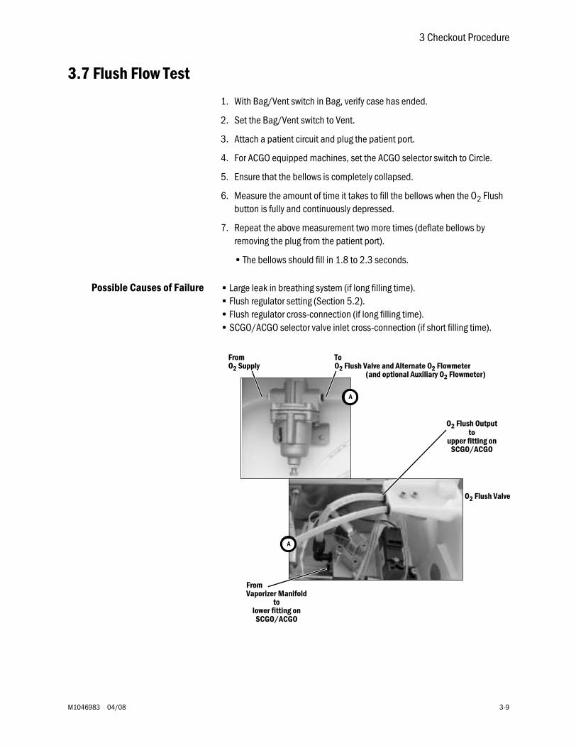
3 Checkout Procedure
M1046983 04/08 3-9
3.7 Flush Flow Test
1. With Bag/Vent switch in Bag, verify case has ended.
2. Set the Bag/Vent switch to Vent.
3. Attach a patient circuit and plug the patient port.
4. For ACGO equipped machines, set the ACGO selector switch to Circle.
5. Ensure that the bellows is completely collapsed.
6. Measure the amount of time it takes to fill the bellows when the O2 Flush button is fully and continuously depressed.
7. Repeat the above measurement two more times (deflate bellows by removing the plug from the patient port).
• The bellows should fill in 1.8 to 2.3 seconds.
Possible Causes of Failure • Large leak in breathing system (if long filling time).• Flush regulator setting (Section 5.2).• Flush regulator cross-connection (if long filling time).• SCGO/ACGO selector valve inlet cross-connection (if short filling time).
FromO2 Supply
ToO2 Flush Valve and Alternate O2 Flowmeter
(and optional Auxiliary O2 Flowmeter)
FromVaporizer Manifold
O2 Flush Outputto
upper fitting onSCGO/ACGO
tolower fitting on
SCGO/ACGO
O2 Flush Valve
A
A
Aisys
3-10 04/08 M1046983
3.8 Alarm tests
1. Connect a test lung to the patient connection.
2. Start a case.
3. Set the Bag/Vent switch to Vent.
4. Set the O2 concentration to 30%, and allow the O2 reading to stabilize.
• For machines configured to individual gas control, set O2 flow to approximately 500 ml/min and Air flow to approximately 5 l/min.
5. Test the O2 alarms:• Set the FiO2 low alarm limit to 50%. Make sure an FiO2 low alarm
occurs.• Set the FiO2 low alarm limit back to 21% and make sure that the
FiO2 low alarm cancels.• Set the FiO2 high alarm limit to 50%.• Push and hold the O2 flush button.• Make sure the FiO2 high alarm occurs.• Release the O2 flush button.• Set the FiO2 high alarm limit back to 100%. Make sure that the
FiO2 high alarm cancels.
6. Test the MVexp low alarm:• Go to the Alarm Setup menu.• Set the MV low alarm limit to greater than the measured minute
volume.• Make sure that a MVexp low alarm occurs.• Set the MV low alarm limit to off.
7. Test the Ppeak high alarm:• Set the Pmax to less than the peak airway pressure.• Make sure that the Ppeak high alarm occurs.• Set the Pmax to the desired level.
8. Test the PEEP high. Blockage? alarm:• Close the APL valve.• Set the Bag/Vent switch to Bag. Mechanical ventilation stops.• Block the patient connection and push the O2 flush button.• Make sure that the PEEP high. Blockage? alarm occurs after
approximately 15 seconds.
9. Test the Ppeak low. Leak? alarm:• Unblock the patient connection.• Set the Bag/Vent switch to Vent.• Set the tidal volume and total flow to minimum.• Other alarms such as MVexp low can occur.• Make sure that the Ppeak low. Leak? alarm occurs.
10. Set all alarm limits to approved clinical values.
NOTE: If an Airway Gas Module is installed, FiO2 readings are taken from the module instead of the O2 sensor in the breathing circuit. When using an Airway Gas Module, a sample line must be connected to the patient circuit for testing the O2 alarms.
3 Checkout Procedure
M1046983 04/08 3-11
3.9 Alternate O2 flowmeter tests
1. Open the O2 cylinder valve or connect an O2 pipeline.
2. Rotate the Alt O2 flow control fully clockwise to minimum flow.
3. Press the Alternate O2 switch to turn on Alternate O2 flow. The flowmeter should indicate 0.5 to 0.7 L/min.
4. Rotate the flow control counterclockwise (increase). The ball should rise immediately after rotation is begun. It should rise smoothly and steadily with continued counterclockwise rotation. When a desired flow is set, the ball should maintain in a steady position.
5. Rotate the flow control clockwise to minimum flow.
6. Press the Alternate O2 switch to turn off Alternate O2 flow; confirm yes.
3.10 Auxiliary O2 flowmeter tests
1. Open the O2 cylinder valve or connect an O2 pipeline.
2. Rotate the flow control clockwise (decrease) to shut off the flow. The ball should rest at the bottom of the flow tube and not move.
3. Rotate the flow control counterclockwise (increase). The ball should rise immediately after rotation is begun. It should rise smoothly and steadily with continued counterclockwise rotation. When a desired flow is set, the ball should maintain in a steady position.
4. Occlude the auxiliary O2 outlet. The ball should rest at the bottom of the flow tube and not move. A ball that does not rest at the bottom of the flow tube indicates a leak and requires service.
5. Rotate the flow control clockwise to shut off the flow.
3.11 Integrated Suction Regulator tests
The gauge needle should come to rest within the zero range bracket when no suction is being supplied. Gauges which do not comply may be out of calibration.
1. Adjust the regulator setting to minimum.
2. Turn the mode selector to I (On).
3. Ensure the gauge remains less than 200 mmHg (26 kPa, 0.26 Bar).
4. Occlude the inlet.
5. Ensure the gauge remains less than 200 mmHg (26 kPa, 0.26 Bar).
6. Adjust the regulator in an increasing vacuum level.
7. The gauge should rise after rotation has begun. The gauge should rise with continued rotation of the regulator adjustment.
8. Adjust the regulator setting to minimum.
9. Turn the Mode selector to O (Off).
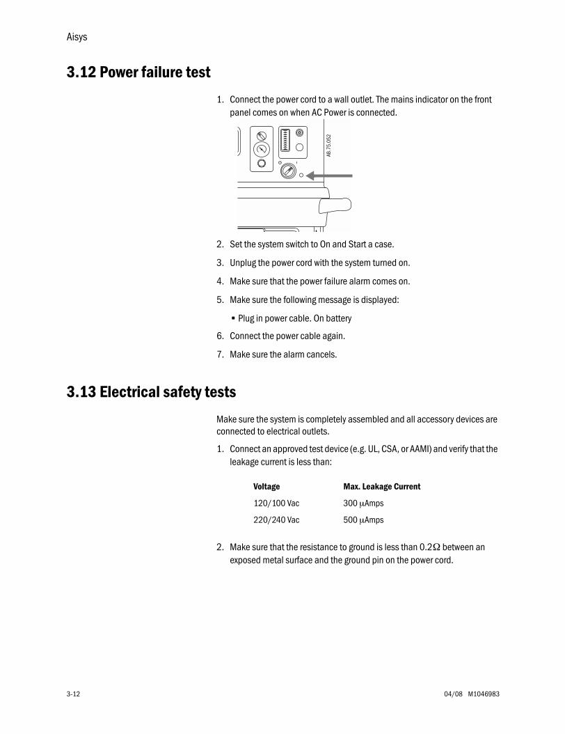
Aisys
3-12 04/08 M1046983
3.12 Power failure test
1. Connect the power cord to a wall outlet. The mains indicator on the front panel comes on when AC Power is connected.
2. Set the system switch to On and Start a case.
3. Unplug the power cord with the system turned on.
4. Make sure that the power failure alarm comes on.
5. Make sure the following message is displayed:
• Plug in power cable. On battery
6. Connect the power cable again.
7. Make sure the alarm cancels.
3.13 Electrical safety tests
Make sure the system is completely assembled and all accessory devices are connected to electrical outlets.
1. Connect an approved test device (e.g. UL, CSA, or AAMI) and verify that the leakage current is less than:
2. Make sure that the resistance to ground is less than 0.2Ω between an exposed metal surface and the ground pin on the power cord.
AB.7
5.05
2
Voltage Max. Leakage Current
120/100 Vac 300 µAmps
220/240 Vac 500 µAmps
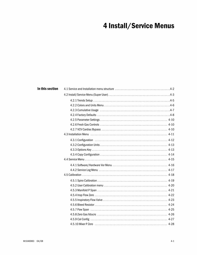
M1046983 04/08 4-1
4 Install/Service Menus
In this section 4.1 Service and Installation menu structure . . . . . . . . . . . . . . . . . . . . . . . . . . . . . . . . . . . . . . . .4-2
4.2 Install/Service Menu (Super User) . . . . . . . . . . . . . . . . . . . . . . . . . . . . . . . . . . . . . . . . . . . . .4-3
4.2.1 Trends Setup . . . . . . . . . . . . . . . . . . . . . . . . . . . . . . . . . . . . . . . . . . . . . . . . . . . . . . . .4-5
4.2.2 Colors and Units Menu . . . . . . . . . . . . . . . . . . . . . . . . . . . . . . . . . . . . . . . . . . . . . . . .4-6
4.2.3 Cumulative Usage . . . . . . . . . . . . . . . . . . . . . . . . . . . . . . . . . . . . . . . . . . . . . . . . . . .4-7
4.2.4 Factory Defaults . . . . . . . . . . . . . . . . . . . . . . . . . . . . . . . . . . . . . . . . . . . . . . . . . . . . .4-8
4.2.5 Parameter Settings . . . . . . . . . . . . . . . . . . . . . . . . . . . . . . . . . . . . . . . . . . . . . . . . . 4-10
4.2.6 Fresh Gas Controls . . . . . . . . . . . . . . . . . . . . . . . . . . . . . . . . . . . . . . . . . . . . . . . . . 4-10
4.2.7 VCV Cardiac Bypass . . . . . . . . . . . . . . . . . . . . . . . . . . . . . . . . . . . . . . . . . . . . . . . . 4-10
4.3 Installation Menu . . . . . . . . . . . . . . . . . . . . . . . . . . . . . . . . . . . . . . . . . . . . . . . . . . . . . . . . 4-11
4.3.1 Configuration . . . . . . . . . . . . . . . . . . . . . . . . . . . . . . . . . . . . . . . . . . . . . . . . . . . . . 4-12
4.3.2 Configuration Units . . . . . . . . . . . . . . . . . . . . . . . . . . . . . . . . . . . . . . . . . . . . . . . . . 4-13
4.3.3 Options Key . . . . . . . . . . . . . . . . . . . . . . . . . . . . . . . . . . . . . . . . . . . . . . . . . . . . . . . 4-13
4.3.4 Copy Configuration . . . . . . . . . . . . . . . . . . . . . . . . . . . . . . . . . . . . . . . . . . . . . . . . . 4-14
4.4 Service Menu . . . . . . . . . . . . . . . . . . . . . . . . . . . . . . . . . . . . . . . . . . . . . . . . . . . . . . . . . . . . 4-15
4.4.1 Software/Hardware Ver Menu . . . . . . . . . . . . . . . . . . . . . . . . . . . . . . . . . . . . . . . . 4-16
4.4.2 Service Log Menu . . . . . . . . . . . . . . . . . . . . . . . . . . . . . . . . . . . . . . . . . . . . . . . . . . 4-17
4.5 Calibration . . . . . . . . . . . . . . . . . . . . . . . . . . . . . . . . . . . . . . . . . . . . . . . . . . . . . . . . . . . . . . 4-18
4.5.1 Spiro Calibration . . . . . . . . . . . . . . . . . . . . . . . . . . . . . . . . . . . . . . . . . . . . . . . . . . . 4-19
4.5.2 User Calibration menu . . . . . . . . . . . . . . . . . . . . . . . . . . . . . . . . . . . . . . . . . . . . . . 4-20
4.5.3 Manifold P Span . . . . . . . . . . . . . . . . . . . . . . . . . . . . . . . . . . . . . . . . . . . . . . . . . . . 4-21
4.5.4 Insp Flow Zero . . . . . . . . . . . . . . . . . . . . . . . . . . . . . . . . . . . . . . . . . . . . . . . . . . . . . 4-22
4.5.5 Inspiratory Flow Valve . . . . . . . . . . . . . . . . . . . . . . . . . . . . . . . . . . . . . . . . . . . . . . . 4-23
4.5.6 Bleed Resistor . . . . . . . . . . . . . . . . . . . . . . . . . . . . . . . . . . . . . . . . . . . . . . . . . . . . . 4-24
4.5.7 Paw Span . . . . . . . . . . . . . . . . . . . . . . . . . . . . . . . . . . . . . . . . . . . . . . . . . . . . . . . . 4-25
4.5.8 Zero Gas Xducrs . . . . . . . . . . . . . . . . . . . . . . . . . . . . . . . . . . . . . . . . . . . . . . . . . . . 4-26
4.5.9 Cal Config . . . . . . . . . . . . . . . . . . . . . . . . . . . . . . . . . . . . . . . . . . . . . . . . . . . . . . . . 4-27
4.5.10 Mixer P Zero . . . . . . . . . . . . . . . . . . . . . . . . . . . . . . . . . . . . . . . . . . . . . . . . . . . . . 4-28
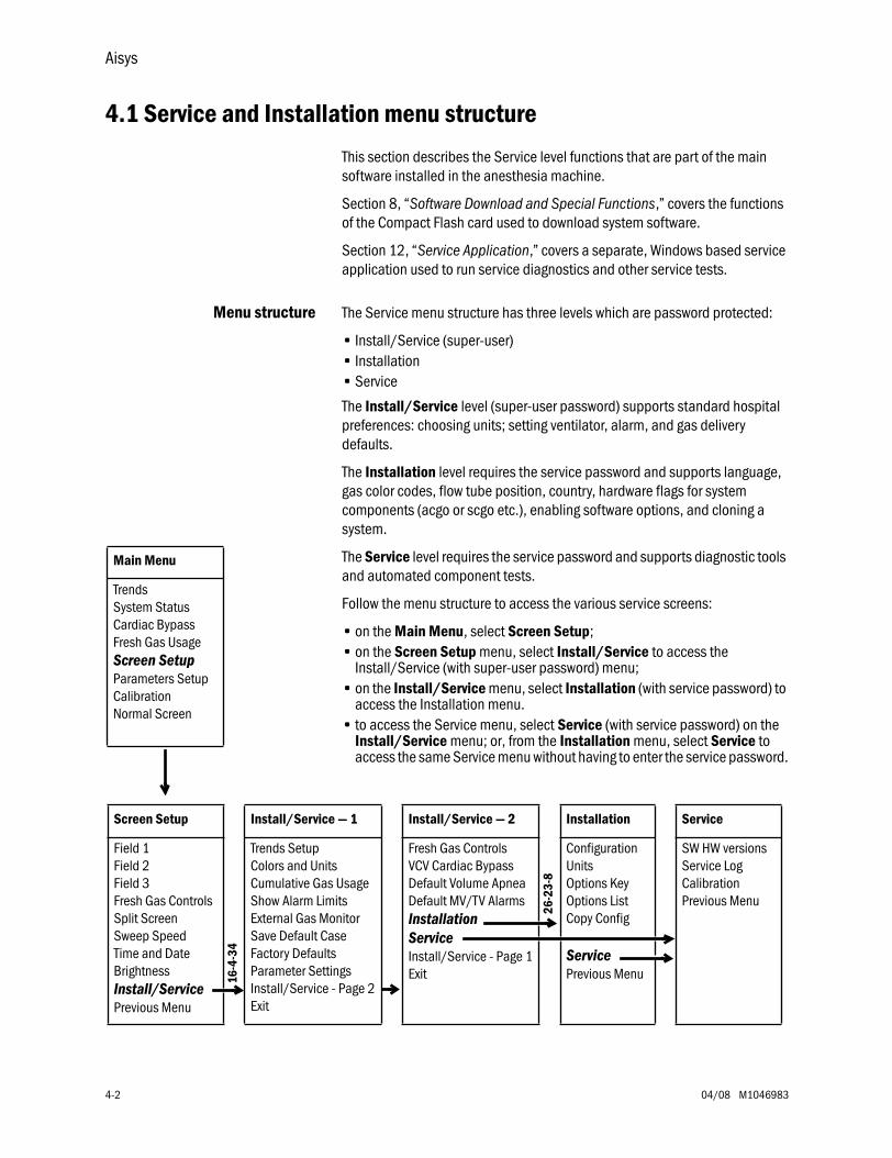
Aisys
4-2 04/08 M1046983
4.1 Service and Installation menu structure
This section describes the Service level functions that are part of the main software installed in the anesthesia machine.
Section 8, “Software Download and Special Functions,” covers the functions of the Compact Flash card used to download system software.
Section 12, “Service Application,” covers a separate, Windows based service application used to run service diagnostics and other service tests.
Menu structure The Service menu structure has three levels which are password protected:
• Install/Service (super-user)• Installation• Service
The Install/Service level (super-user password) supports standard hospital preferences: choosing units; setting ventilator, alarm, and gas delivery defaults.
The Installation level requires the service password and supports language, gas color codes, flow tube position, country, hardware flags for system components (acgo or scgo etc.), enabling software options, and cloning a system.
The Service level requires the service password and supports diagnostic tools and automated component tests.
Follow the menu structure to access the various service screens:
• on the Main Menu, select Screen Setup;• on the Screen Setup menu, select Install/Service to access the
Install/Service (with super-user password) menu;• on the Install/Service menu, select Installation (with service password) to
access the Installation menu.• to access the Service menu, select Service (with service password) on the
Install/Service menu; or, from the Installation menu, select Service to access the same Service menu without having to enter the service password.
Main Menu
TrendsSystem StatusCardiac BypassFresh Gas UsageScreen SetupParameters SetupCalibrationNormal Screen
Screen Setup Install/Service — 1 Install/Service — 2 Installation Service
Field 1Field 2Field 3Fresh Gas ControlsSplit ScreenSweep SpeedTime and DateBrightnessInstall/ServicePrevious Menu
Trends SetupColors and UnitsCumulative Gas UsageShow Alarm LimitsExternal Gas MonitorSave Default CaseFactory DefaultsParameter SettingsInstall/Service - Page 2Exit
Fresh Gas ControlsVCV Cardiac BypassDefault Volume ApneaDefault MV/TV AlarmsInstallationServiceInstall/Service - Page 1Exit
ConfigurationUnitsOptions KeyOptions ListCopy Config
ServicePrevious Menu
SW HW versionsService LogCalibrationPrevious Menu
16-4
-34
26-2
3-8
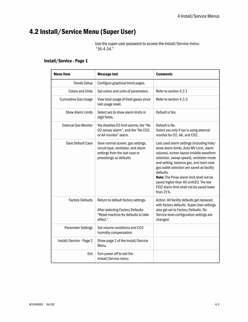
4 Install/Service Menus
M1046983 04/08 4-3
4.2 Install/Service Menu (Super User)
Use the super-user password to access the Install/Service menu: “16-4-34.”
Install/Service - Page 1
Menu Item Message text Comments
Trends Setup Configure graphical trend pages.
Colors and Units Set colors and units of parameters. Refer to section 4.2.1
Cumulative Gas Usage View total usage of fresh gases since last usage reset.
Refer to section 4.2.3
Show Alarm Limits Select yes to show alarm limits in digit fields.
Default is Yes.
External Gas Monitor Yes disables O2 limit alarms, the “No O2 sensor alarm”, and the “No CO2 or AA monitor” alarm.
Default is No.Select yes only if sys is using external monitor for O2, AA, and CO2.
Save Default Case Save normal screen, gas settings, circuit type, ventilator, and alarm settings from the last case or presettings as defaults
Last used alarm settings (including hide/show alarm limits, Auto MV Limit, alarm volume), screen layout (middle waveform selection, sweep speed), ventilator mode and setting, balance gas, and start case gas outlet selection are saved as facility defaults.Note: The Pmax alarm limit shall not be saved higher than 40 cmH2O. The low FiO2 alarm limit shall not be saved lower than 21%.
Factory Defaults Return to default factory settings.
After selecting Factory Defaults: “Reset machine for defaults to take effect.”
Action: All facility defaults get replaced with factory defaults. Super User settings also get set to Factory Defaults. No Service level configuration settings are changed.
Parameter Settings Set volume conditions and CO2 humidity compensation.
Install/Service - Page 2 Show page 2 of the Install/Service Menu.
Exit Turn power off to exit the Install/Service menu.
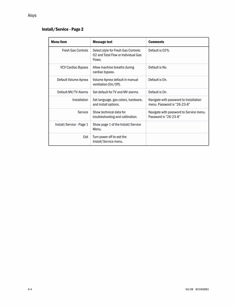
Aisys
4-4 04/08 M1046983
Install/Service - Page 2
Menu Item Message text Comments
Fresh Gas Controls Select style for Fresh Gas Controls: O2 and Total Flow or Individual Gas Flows.
Default is O2%.
VCV Cardiac Bypass Allow machine breaths during cardiac bypass.
Default is No.
Default Volume Apnea Volume Apnea default in manual ventilation (On/Off).
Default is On.
Default MV/TV Alarms Set default for TV and MV alarms. Default is On.
Installation Set language, gas colors, hardware, and install options.
Navigate with password to Installation menu. Password is “26-23-8”
Service Show technical data for troubleshooting and calibration.
Navigate with password to Service menu. Password is “26-23-8”
Install/Service - Page 1 Show page 1 of the Install/Service Menu.
Exit Turn power off to exit the Install/Service menu.
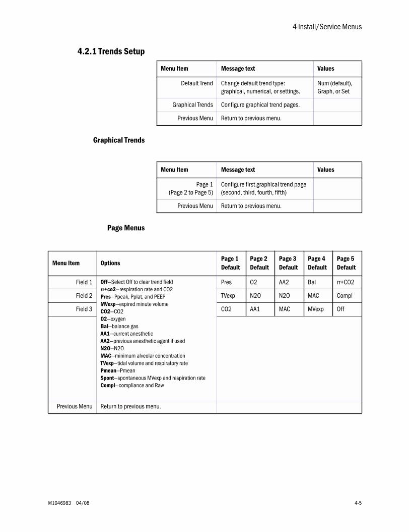
4 Install/Service Menus
M1046983 04/08 4-5
4.2.1 Trends Setup
Graphical Trends
Page Menus
Menu Item Message text Values
Default Trend Change default trend type: graphical, numerical, or settings.
Num (default), Graph, or Set
Graphical Trends Configure graphical trend pages.
Previous Menu Return to previous menu.
Menu Item Message text Values
Page 1(Page 2 to Page 5)
Configure first graphical trend page(second, third, fourth, fifth)
Previous Menu Return to previous menu.
Menu Item OptionsPage 1Default
Page 2Default
Page 3Default
Page 4Default
Page 5Default
Field 1 Off—Select Off to clear trend fieldrr+co2—respiration rate and CO2Pres—Ppeak, Pplat, and PEEPMVexp—expired minute volumeCO2—CO2O2—oxygenBal—balance gasAA1—current anestheticAA2—previous anesthetic agent if usedN2O—N2OMAC—minimum alveolar concentrationTVexp—tidal volume and respiratory ratePmean—PmeanSpont—spontaneous MVexp and respiration rateCompl—compliance and Raw
Pres O2 AA2 Bal rr+CO2
Field 2 TVexp N2O N2O MAC Compl
Field 3 CO2 AA1 MAC MVexp Off
Previous Menu Return to previous menu.
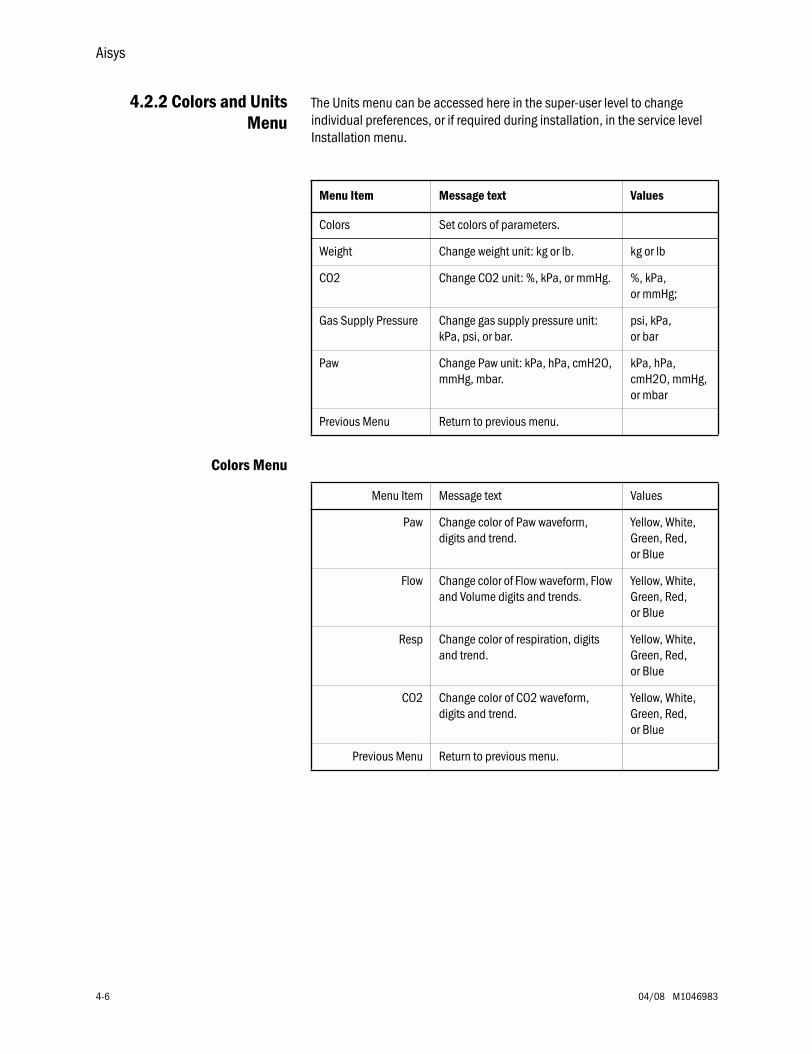
Aisys
4-6 04/08 M1046983
4.2.2 Colors and UnitsMenu
The Units menu can be accessed here in the super-user level to change individual preferences, or if required during installation, in the service level Installation menu.
Colors Menu
Menu Item Message text Values
Colors Set colors of parameters.
Weight Change weight unit: kg or lb. kg or lb
CO2 Change CO2 unit: %, kPa, or mmHg. %, kPa, or mmHg;
Gas Supply Pressure Change gas supply pressure unit: kPa, psi, or bar.
psi, kPa,or bar
Paw Change Paw unit: kPa, hPa, cmH2O, mmHg, mbar.
kPa, hPa, cmH2O, mmHg, or mbar
Previous Menu Return to previous menu.
Menu Item Message text Values
Paw Change color of Paw waveform, digits and trend.
Yellow, White, Green, Red, or Blue
Flow Change color of Flow waveform, Flow and Volume digits and trends.
Yellow, White, Green, Red, or Blue
Resp Change color of respiration, digits and trend.
Yellow, White, Green, Red,or Blue
CO2 Change color of CO2 waveform, digits and trend.
Yellow, White, Green, Red,or Blue
Previous Menu Return to previous menu.
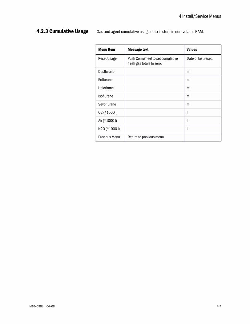
4 Install/Service Menus
M1046983 04/08 4-7
4.2.3 Cumulative Usage Gas and agent cumulative usage data is store in non-volatile RAM.
Menu Item Message text Values
Reset Usage Push ComWheel to set cumulative fresh gas totals to zero.
Date of last reset.
Desflurane ml
Enflurane ml
Halothane ml
Isoflurane ml
Sevoflurane ml
O2 (*1000 l) l
Air (*1000 l) l
N2O (*1000 l) l
Previous Menu Return to previous menu.
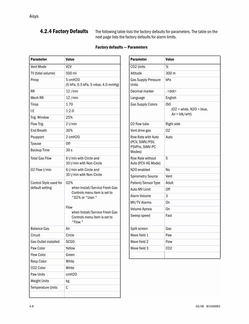
Aisys
4-8 04/08 M1046983
4.2.4 Factory Defaults The following table lists the factory defaults for parameters. The table on the next page lists the factory defaults for alarm limits.
Factory defaults — Parameters
Parameter Value Parameter Value
Vent Mode VCV CO2 Units %
TV (tidal volume) 500 ml Altitude 300 m
Pinsp 5 cmH2O(5 hPa, 0.5 kPa, 5 mbar, 4.0 mmHg)
Gas Supply Pressure Units
kPa
RR 12 /min Decimal marker . <dot>
Mech RR 12 /min Language English
Tinsp 1.70 Gas Supply Colors ISO (O2 = white, N2O = blue, Air = blk/wht)
I:E 1:2.0
Trig. Window 25%
Flow Trig. 2 l/min O2 flow tube Right side
End Breath 30% Vent drive gas O2
Psupport 2 cmH2O Rise Rate with Auto (PCV, SIMV/PSV, PSVPro, SIMV-PC Modes)
Auto
Tpause Off
Backup Time 30 s
Total Gas Flow 6 l/min with Circle and 10 l/min with Non-Circle
Rise Rate without Auto (PCV-VG Mode)
5
O2 Flow l/min 6 l/min with Circle and 10 l/min with Non-Circle
N2O enabled No
Spirometry Source Vent
Control Style used for default setting
O2% when Install/Service Fresh Gas Controls menu item is set to "O2% or "User."
Flow when Install/Service Fresh Gas Controls menu item is set to "Flow."
Patient/Sensor Type Adult
Auto MV Limit Off
Alarm Volume 3
MV/TV Alarms On
Volume Apnea On
Sweep speed Fast
Balance Gas Air Split screen Gas
Circuit Circle Wave field 1 Paw
Gas Outlet installed SCGO Wave field 2 Flow
Paw Color Yellow Wave field 3 CO2
Flow Color Green
Resp Color White
CO2 Color White
Paw Units cmH2O
Weight Units kg
Temperature Units C
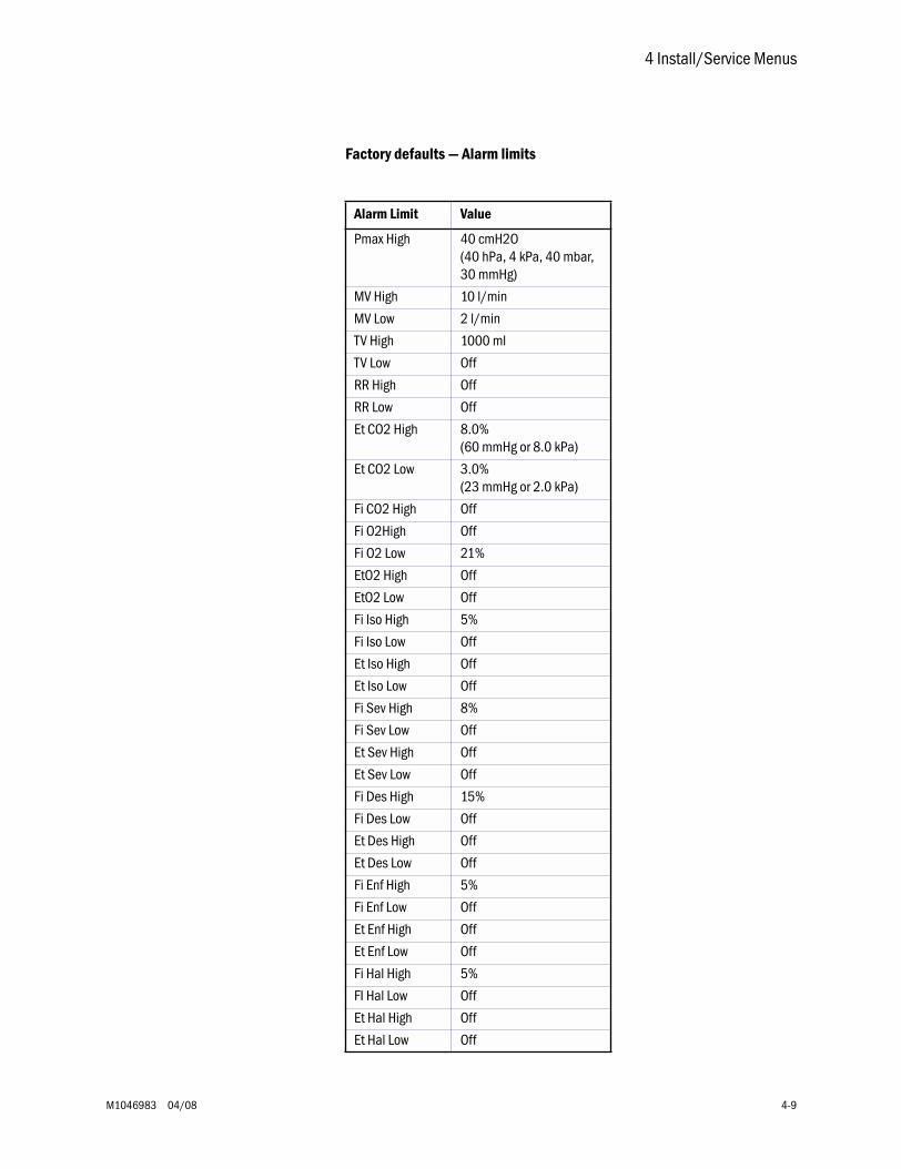
4 Install/Service Menus
M1046983 04/08 4-9
Factory defaults — Alarm limits
Alarm Limit Value
Pmax High 40 cmH2O(40 hPa, 4 kPa, 40 mbar, 30 mmHg)
MV High 10 l/min
MV Low 2 l/min
TV High 1000 ml
TV Low Off
RR High Off
RR Low Off
Et CO2 High 8.0%(60 mmHg or 8.0 kPa)
Et CO2 Low 3.0%(23 mmHg or 2.0 kPa)
Fi CO2 High Off
Fi O2High Off
Fi O2 Low 21%
EtO2 High Off
EtO2 Low Off
Fi Iso High 5%
Fi Iso Low Off
Et Iso High Off
Et Iso Low Off
Fi Sev High 8%
Fi Sev Low Off
Et Sev High Off
Et Sev Low Off
Fi Des High 15%
Fi Des Low Off
Et Des High Off
Et Des Low Off
Fi Enf High 5%
Fi Enf Low Off
Et Enf High Off
Et Enf Low Off
Fi Hal High 5%
FI Hal Low Off
Et Hal High Off
Et Hal Low Off
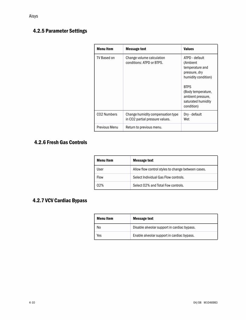
Aisys
4-10 04/08 M1046983
4.2.5 Parameter Settings
4.2.6 Fresh Gas Controls
4.2.7 VCV Cardiac Bypass
Menu Item Message text Values
TV Based on Change volume calculation conditions: ATPD or BTPS.
ATPD - default(Ambient temperature and pressure, dry humidity condition)
BTPS(Body temperature, ambient pressure, saturated humidity condition)
CO2 Numbers Change humidity compensation type in CO2 partial pressure values.
Dry - defaultWet
Previous Menu Return to previous menu.
Menu Item Message text
User Allow flow control styles to change between cases.
Flow Select Individual Gas Flow controls.
O2% Select O2% and Total Fow controls.
Menu Item Message text
No Disable alveolar support in cardiac bypass.
Yes Enable alveolar support in cardiac bypass.
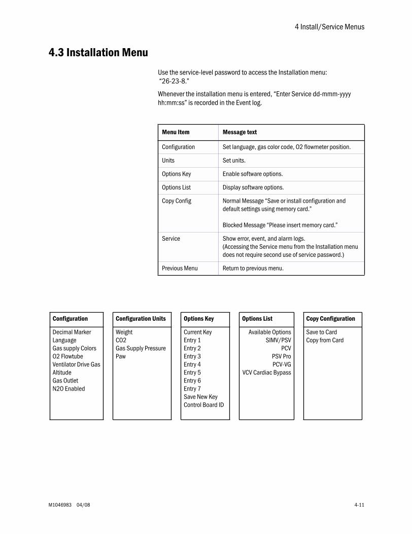
4 Install/Service Menus
M1046983 04/08 4-11
4.3 Installation Menu
Use the service-level password to access the Installation menu: “26-23-8.”
Whenever the installation menu is entered, “Enter Service dd-mmm-yyyy hh:mm:ss” is recorded in the Event log.
Menu Item Message text
Configuration Set language, gas color code, O2 flowmeter position.
Units Set units.
Options Key Enable software options.
Options List Display software options.
Copy Config Normal Message “Save or install configuration and default settings using memory card.”
Blocked Message “Please insert memory card.”
Service Show error, event, and alarm logs. (Accessing the Service menu from the Installation menu does not require second use of service password.)
Previous Menu Return to previous menu.
Configuration Configuration Units Options Key Options List Copy Configuration
Decimal MarkerLanguageGas supply ColorsO2 FlowtubeVentilator Drive GasAltitudeGas OutletN2O Enabled
WeightCO2Gas Supply PressurePaw
Current KeyEntry 1Entry 2Entry 3Entry 4Entry 5Entry 6Entry 7Save New KeyControl Board ID
Available OptionsSIMV/PSV
PCVPSV ProPCV-VG
VCV Cardiac Bypass
Save to CardCopy from Card
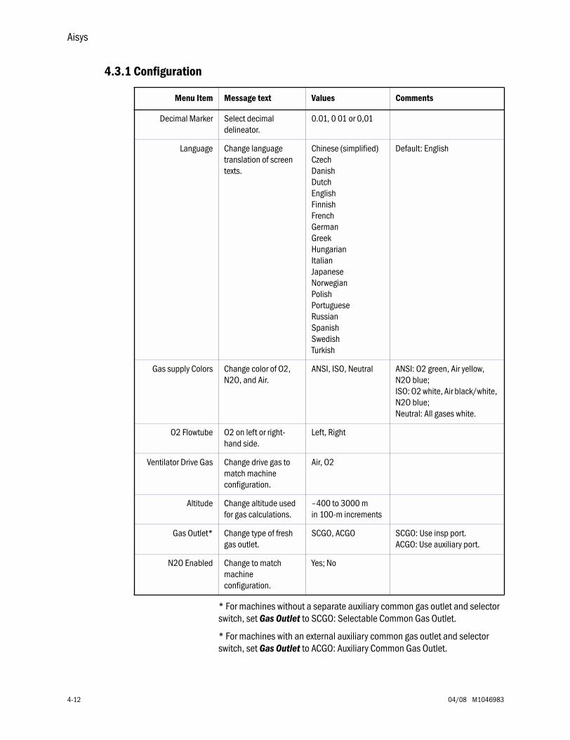
Aisys
4-12 04/08 M1046983
4.3.1 Configuration
* For machines without a separate auxiliary common gas outlet and selector switch, set Gas Outlet to SCGO: Selectable Common Gas Outlet.
* For machines with an external auxiliary common gas outlet and selector switch, set Gas Outlet to ACGO: Auxiliary Common Gas Outlet.
Menu Item Message text Values Comments
Decimal Marker Select decimal delineator.
0.01, 0 01 or 0,01
Language Change language translation of screen texts.
Chinese (simplified)CzechDanishDutchEnglishFinnishFrenchGermanGreekHungarianItalianJapaneseNorwegianPolishPortugueseRussianSpanishSwedishTurkish
Default: English
Gas supply Colors Change color of O2, N2O, and Air.
ANSI, ISO, Neutral ANSI: O2 green, Air yellow, N2O blue; ISO: O2 white, Air black/white, N2O blue; Neutral: All gases white.
O2 Flowtube O2 on left or right-hand side.
Left, Right
Ventilator Drive Gas Change drive gas to match machine configuration.
Air, O2
Altitude Change altitude used for gas calculations.
–400 to 3000 m in 100-m increments
Gas Outlet* Change type of fresh gas outlet.
SCGO, ACGO SCGO: Use insp port.ACGO: Use auxiliary port.
N2O Enabled Change to match machine configuration.
Yes; No
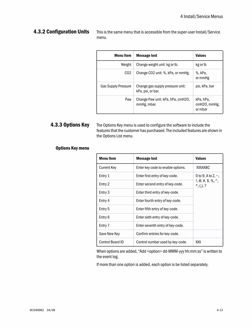
4 Install/Service Menus
M1046983 04/08 4-13
4.3.2 Configuration Units This is the same menu that is accessible from the super-user Install/Service menu.
4.3.3 Options Key The Options Key menu is used to configure the software to include the features that the customer has purchased. The included features are shown in the Options List menu.
Options Key menu
When options are added, “Add <option> dd-MMM-yyy hh:mm:ss” is written to the event log.
If more than one option is added, each option is be listed separately.
Menu Item Message text Values
Weight Change weight unit: kg or lb. kg or lb
CO2 Change CO2 unit: %, kPa, or mmHg. %, kPa, or mmHg
Gas Supply Pressure Change gas supply pressure unit: kPa, psi, or bar.
psi, kPa, bar
Paw Change Paw unit: kPa, hPa, cmH2O, mmHg, mbar.
kPa, hPa, cmH2O, mmHg, or mbar
Menu Item Message text Values
Current Key Enter key code to enable options. XXXAXBC
Entry 1 Enter first entry of key-code. 0 to 9, A to Z, ~, !, @, #, $, %, ^, *, (,), ?Entry 2 Enter second entry of key-code.
Entry 3 Enter third entry of key-code.
Entry 4 Enter fourth entry of key-code.
Entry 5 Enter fifth entry of key-code.
Entry 6 Enter sixth entry of key-code.
Entry 7 Enter seventh entry of key-code.
Save New Key Confirm entries for key-code.
Control Board ID Control number used by key-code. XXX
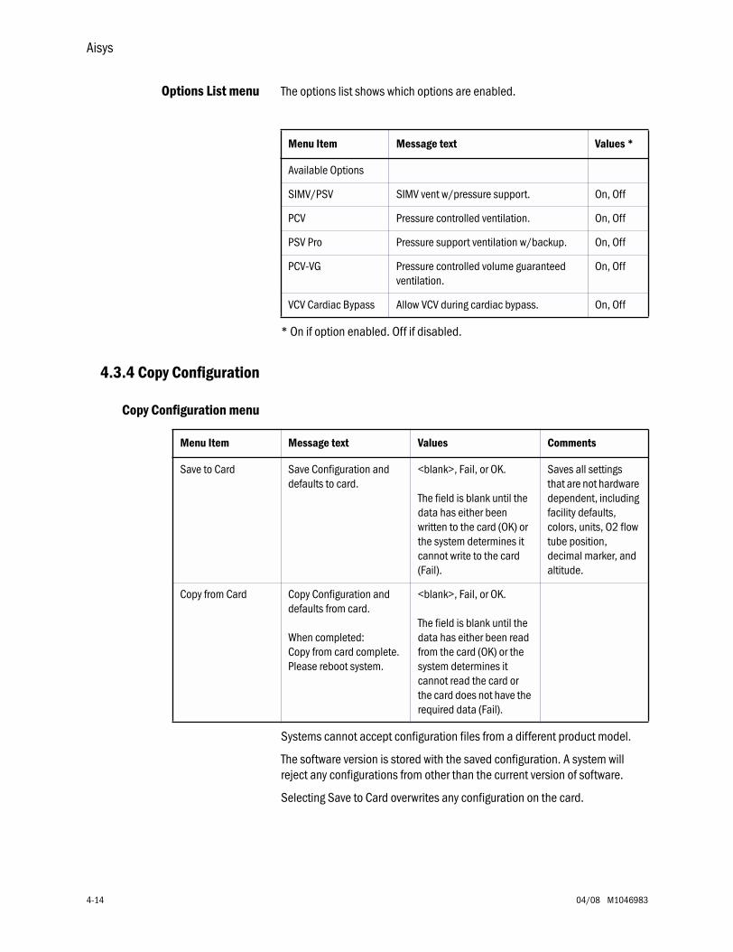
Aisys
4-14 04/08 M1046983
Options List menu The options list shows which options are enabled.
* On if option enabled. Off if disabled.
4.3.4 Copy Configuration
Copy Configuration menu
Systems cannot accept configuration files from a different product model.
The software version is stored with the saved configuration. A system will reject any configurations from other than the current version of software.
Selecting Save to Card overwrites any configuration on the card.
Menu Item Message text Values *
Available Options
SIMV/PSV SIMV vent w/pressure support. On, Off
PCV Pressure controlled ventilation. On, Off
PSV Pro Pressure support ventilation w/backup. On, Off
PCV-VG Pressure controlled volume guaranteed ventilation.
On, Off
VCV Cardiac Bypass Allow VCV during cardiac bypass. On, Off
Menu Item Message text Values Comments
Save to Card Save Configuration and defaults to card.
<blank>, Fail, or OK.
The field is blank until the data has either been written to the card (OK) or the system determines it cannot write to the card (Fail).
Saves all settings that are not hardware dependent, including facility defaults, colors, units, O2 flow tube position, decimal marker, and altitude.
Copy from Card Copy Configuration and defaults from card.
When completed:Copy from card complete. Please reboot system.
<blank>, Fail, or OK.
The field is blank until the data has either been read from the card (OK) or the system determines it cannot read the card or the card does not have the required data (Fail).
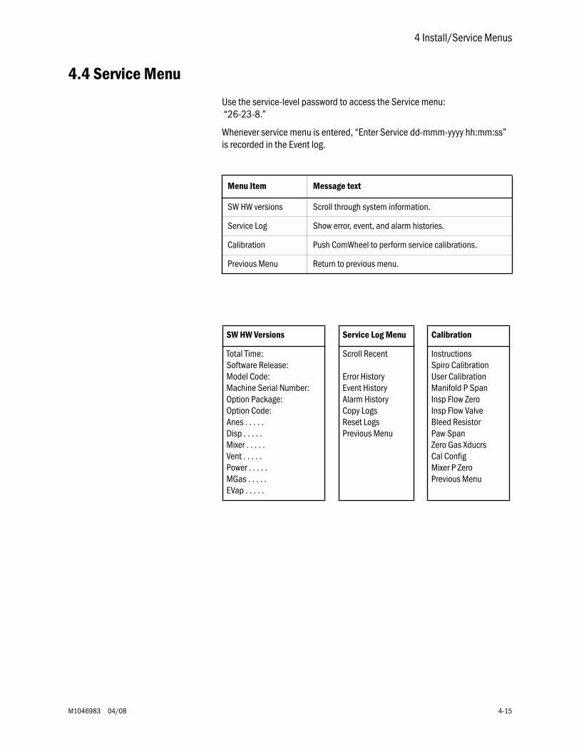
4 Install/Service Menus
M1046983 04/08 4-15
4.4 Service Menu
Use the service-level password to access the Service menu: “26-23-8.”
Whenever service menu is entered, “Enter Service dd-mmm-yyyy hh:mm:ss” is recorded in the Event log.
Menu Item Message text
SW HW versions Scroll through system information.
Service Log Show error, event, and alarm histories.
Calibration Push ComWheel to perform service calibrations.
Previous Menu Return to previous menu.
SW HW Versions Service Log Menu Calibration
Total Time:Software Release:Model Code:Machine Serial Number:Option Package:Option Code:Anes . . . . . Disp . . . . .Mixer . . . . .Vent . . . . .Power . . . . .MGas . . . . .EVap . . . . .
Scroll Recent
Error HistoryEvent HistoryAlarm HistoryCopy LogsReset LogsPrevious Menu
InstructionsSpiro CalibrationUser CalibrationManifold P SpanInsp Flow ZeroInsp Flow Valve Bleed ResistorPaw SpanZero Gas XducrsCal ConfigMixer P ZeroPrevious Menu
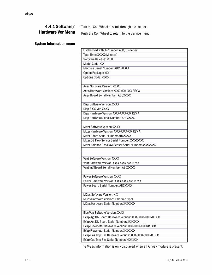
Aisys
4-16 04/08 M1046983
4.4.1 Software/Hardware Ver Menu
Turn the ComWheel to scroll through the list box.
Push the ComWheel to return to the Service menu.
System Information menu
The MGas information is only displayed when an Airway module is present.
List box text with X=Number, A, B, C = letterTotal Time: XXXXX (Minutes)Software Release: XX.XXModel Code: XXXMachine Serial Number: ABCDXXXXXOption Package: XXXOptions Code: XXXXX
Anes Software Version: XX.XXAnes Hardware Version: XXXX-XXXX-XXX REV AAnes Board Serial Number: ABCXXXXX
Disp Software Version: XX.XXDisp BIOS Ver: XX.XXDisp Hardware Version: XXXX-XXXX-XXX REV ADisp Hardware Serial Number: ABCXXXXX
Mixer Software Version: XX.XX Mixer Hardware Version: XXXX-XXXX-XXX REV AMixer Board Serial Number: ABCXXXXXMixer O2 Flow Sensor Serial Number: XXXXXXXXXMixer Balance Gas Flow Sensor Serial Number: XXXXXXXXX
Vent Software Version: XX.XXVent Hardware Version: XXXX-XXXX-XXX REV AVent Intf Board Serial Number: ABCXXXXX
Power Software Version: XX.XXPower Hardware Version: XXXX-XXXX-XXX REV APower Board Serial Number: ABCXXXXX
MGas Software Version: X.XMGas Hardware Version: <module type>MGas Hardware Serial Number: XXXXXXXX
Elec Vap Software Version: XX.XXEVap Agt Dlv Board Hardware Version: XXXX-XXXX-XXX RR CCCEVap Agt Dlv Board Serial Number: XXXXXXXXEVap Flowmeter Hardware Version: XXXX-XXXX-XXX RR CCCEVap Flowmeter Serial Number: XXXXXXXXEVap Cas Tmp Sns Hardware Version: XXXX-XXXX-XXX RR CCCEVap Cas Tmp Sns Serial Number: XXXXXXXX
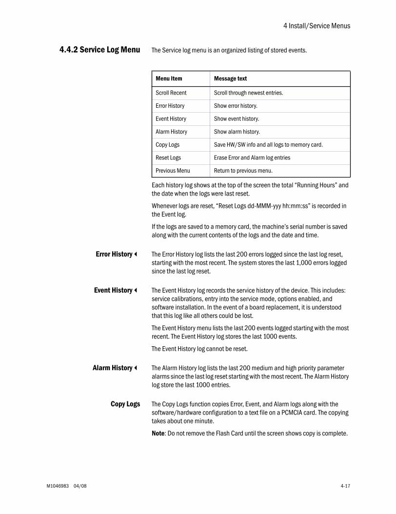
4 Install/Service Menus
M1046983 04/08 4-17
4.4.2 Service Log Menu The Service log menu is an organized listing of stored events.
Each history log shows at the top of the screen the total “Running Hours” and the date when the logs were last reset.
Whenever logs are reset, “Reset Logs dd-MMM-yyy hh:mm:ss” is recorded in the Event log.
If the logs are saved to a memory card, the machine’s serial number is saved along with the current contents of the logs and the date and time.
Error History The Error History log lists the last 200 errors logged since the last log reset, starting with the most recent. The system stores the last 1,000 errors logged since the last log reset.
Event History The Event History log records the service history of the device. This includes: service calibrations, entry into the service mode, options enabled, and software installation. In the event of a board replacement, it is understood that this log like all others could be lost.
The Event History menu lists the last 200 events logged starting with the most recent. The Event History log stores the last 1000 events.
The Event History log cannot be reset.
Alarm History The Alarm History log lists the last 200 medium and high priority parameter alarms since the last log reset starting with the most recent. The Alarm History log store the last 1000 entries.
Copy Logs The Copy Logs function copies Error, Event, and Alarm logs along with the software/hardware configuration to a text file on a PCMCIA card. The copying takes about one minute.
Note: Do not remove the Flash Card until the screen shows copy is complete.
Menu Item Message text
Scroll Recent Scroll through newest entries.
Error History Show error history.
Event History Show event history.
Alarm History Show alarm history.
Copy Logs Save HW/SW info and all logs to memory card.
Reset Logs Erase Error and Alarm log entries
Previous Menu Return to previous menu.

Aisys
4-18 04/08 M1046983
4.5 Calibration
For step-by-step instruction, refer to Section 5.4, “Ventilator Calibrations.”
Menu Item Message text
Instructions These values are used for calibration:Ventilator drive gas - Air or O2Altitude - XXXX mChange these values on the Cal Config menu
Spiro Calibration Check gas module spirometry gains.
Blocking message:Insert gas module with spirometry
User Calibration Show the normal user calibration menu.
Manifold P Span Calibrate manifold pressure transducer.
<*> Insp Flow Valve Calibrate inspiratory flow valve.
Insp Flow Zero Zero inspiratory flow valve.
Bleed Resistor Calibrate bleed resister flow.
Paw Span Calibrate the airway pressure transducer.
Zero Gas Xducrs Calibrate the gas supply transducers.
Cal Config Set vent drive gas and altitude.
Mixer P Zero Zero mixer pres transducer.
Previous Menu Return to previous menu.
<*> Not present in System Software 4.X of greater.
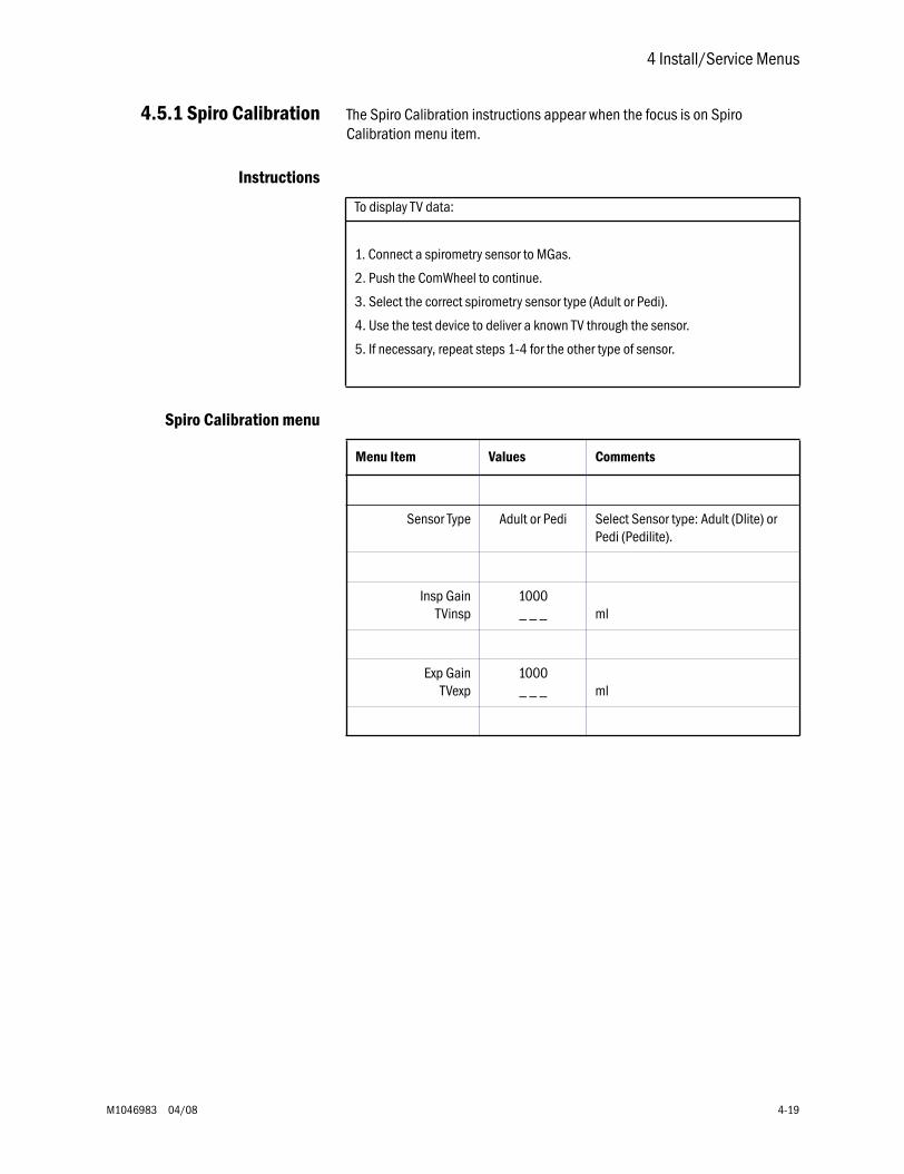
4 Install/Service Menus
M1046983 04/08 4-19
4.5.1 Spiro Calibration The Spiro Calibration instructions appear when the focus is on Spiro Calibration menu item.
Instructions
Spiro Calibration menu
To display TV data:
1. Connect a spirometry sensor to MGas.
2. Push the ComWheel to continue.
3. Select the correct spirometry sensor type (Adult or Pedi).
4. Use the test device to deliver a known TV through the sensor.
5. If necessary, repeat steps 1-4 for the other type of sensor.
Menu Item Values Comments
Sensor Type Adult or Pedi Select Sensor type: Adult (Dlite) or Pedi (Pedilite).
Insp GainTVinsp
1000_ _ _ ml
Exp GainTVexp
1000_ _ _ ml
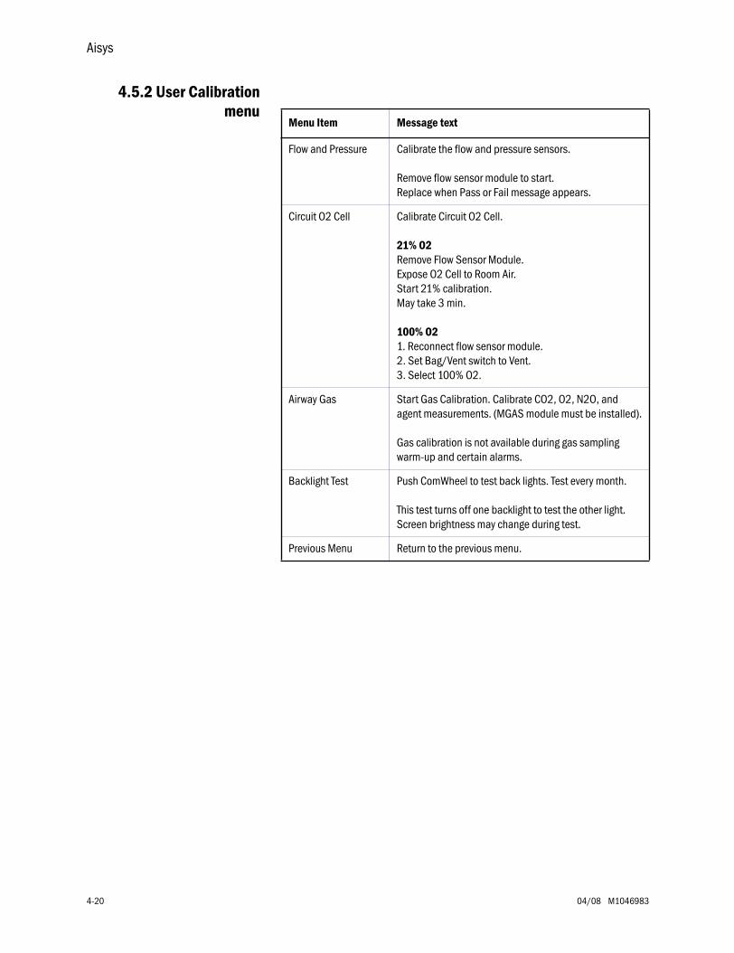
Aisys
4-20 04/08 M1046983
4.5.2 User Calibrationmenu
Menu Item Message text
Flow and Pressure Calibrate the flow and pressure sensors.
Remove flow sensor module to start.Replace when Pass or Fail message appears.
Circuit O2 Cell Calibrate Circuit O2 Cell.
21% O2Remove Flow Sensor Module.Expose O2 Cell to Room Air.Start 21% calibration.May take 3 min.
100% O21. Reconnect flow sensor module.2. Set Bag/Vent switch to Vent.3. Select 100% O2.
Airway Gas Start Gas Calibration. Calibrate CO2, O2, N2O, and agent measurements. (MGAS module must be installed).
Gas calibration is not available during gas sampling warm-up and certain alarms.
Backlight Test Push ComWheel to test back lights. Test every month.
This test turns off one backlight to test the other light. Screen brightness may change during test.
Previous Menu Return to the previous menu.
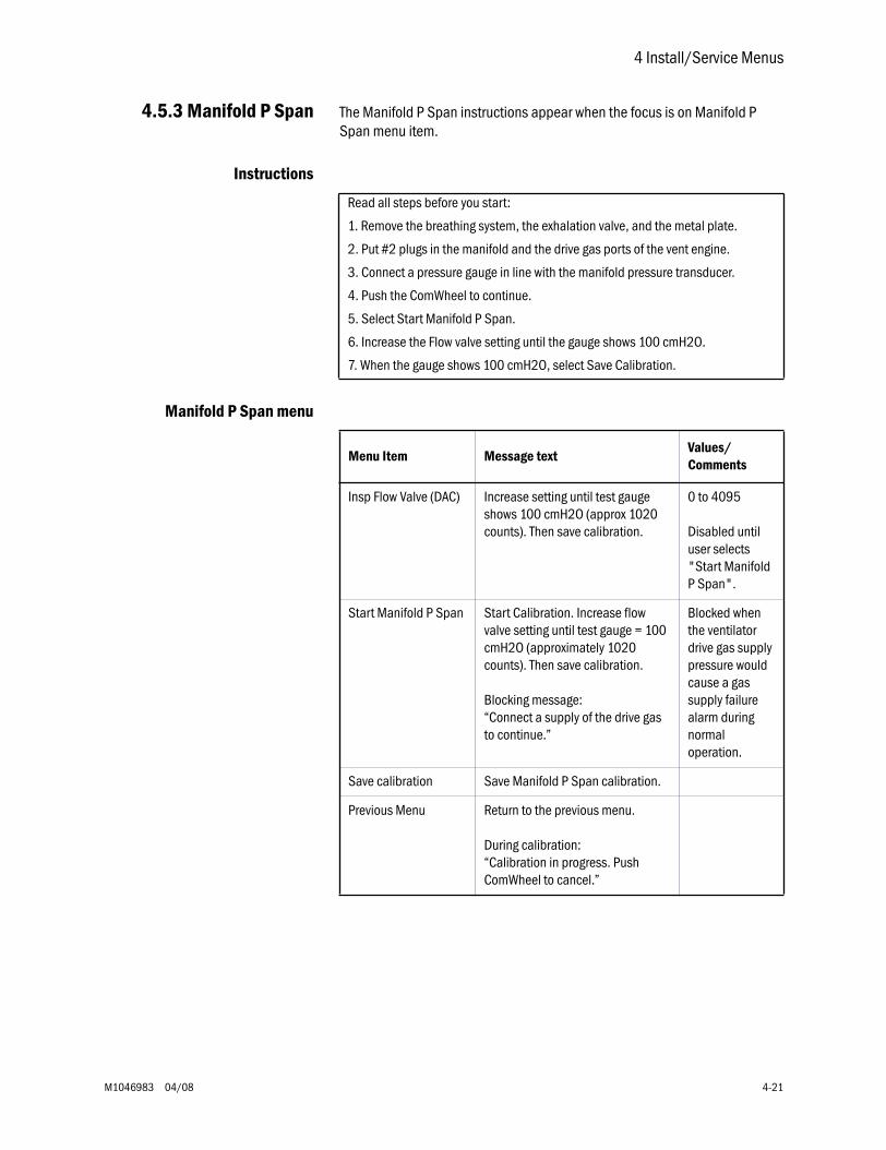
4 Install/Service Menus
M1046983 04/08 4-21
4.5.3 Manifold P Span The Manifold P Span instructions appear when the focus is on Manifold P Span menu item.
Instructions
Manifold P Span menu
Read all steps before you start:
1. Remove the breathing system, the exhalation valve, and the metal plate.
2. Put #2 plugs in the manifold and the drive gas ports of the vent engine.
3. Connect a pressure gauge in line with the manifold pressure transducer.
4. Push the ComWheel to continue.
5. Select Start Manifold P Span.
6. Increase the Flow valve setting until the gauge shows 100 cmH2O.
7. When the gauge shows 100 cmH2O, select Save Calibration.
Menu Item Message textValues/Comments
Insp Flow Valve (DAC) Increase setting until test gauge shows 100 cmH2O (approx 1020 counts). Then save calibration.
0 to 4095
Disabled until user selects "Start Manifold P Span".
Start Manifold P Span Start Calibration. Increase flow valve setting until test gauge = 100 cmH2O (approximately 1020 counts). Then save calibration.
Blocking message:“Connect a supply of the drive gas to continue.”
Blocked when the ventilator drive gas supply pressure would cause a gas supply failure alarm during normal operation.
Save calibration Save Manifold P Span calibration.
Previous Menu Return to the previous menu.
During calibration: “Calibration in progress. Push ComWheel to cancel.”
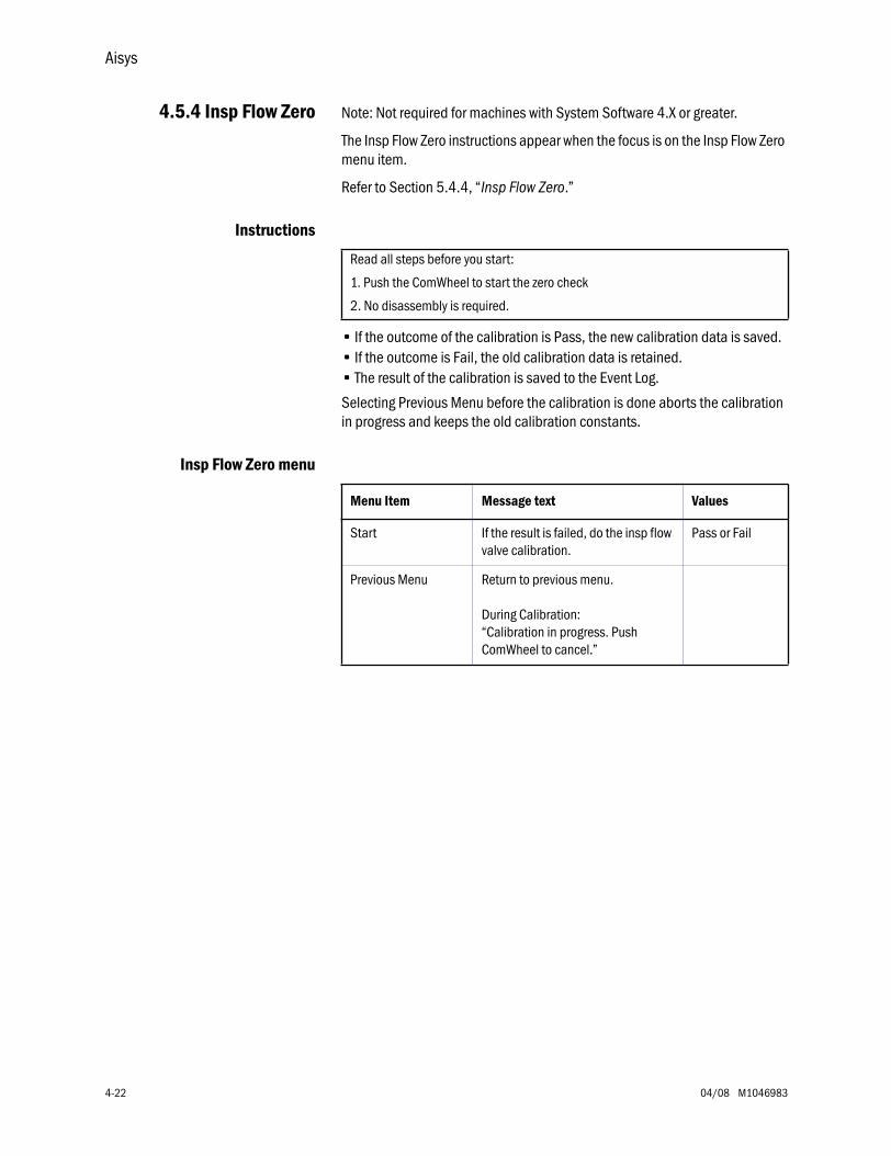
Aisys
4-22 04/08 M1046983
4.5.4 Insp Flow Zero Note: Not required for machines with System Software 4.X or greater.
The Insp Flow Zero instructions appear when the focus is on the Insp Flow Zero menu item.
Refer to Section 5.4.4, “Insp Flow Zero.”
Instructions
• If the outcome of the calibration is Pass, the new calibration data is saved. • If the outcome is Fail, the old calibration data is retained. • The result of the calibration is saved to the Event Log.
Selecting Previous Menu before the calibration is done aborts the calibration in progress and keeps the old calibration constants.
Insp Flow Zero menu
Read all steps before you start:
1. Push the ComWheel to start the zero check
2. No disassembly is required.
Menu Item Message text Values
Start If the result is failed, do the insp flow valve calibration.
Pass or Fail
Previous Menu Return to previous menu.
During Calibration:“Calibration in progress. Push ComWheel to cancel.”
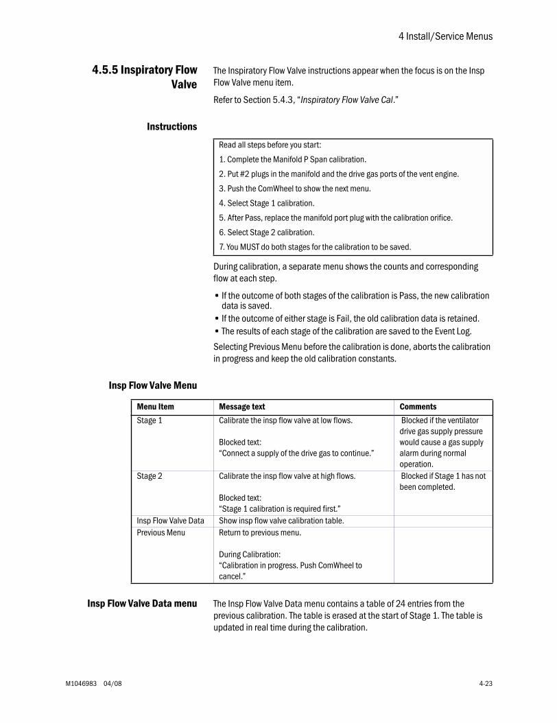
4 Install/Service Menus
M1046983 04/08 4-23
4.5.5 Inspiratory FlowValve
The Inspiratory Flow Valve instructions appear when the focus is on the Insp Flow Valve menu item.
Refer to Section 5.4.3, “Inspiratory Flow Valve Cal.”
Instructions
During calibration, a separate menu shows the counts and corresponding flow at each step.
• If the outcome of both stages of the calibration is Pass, the new calibration data is saved.
• If the outcome of either stage is Fail, the old calibration data is retained. • The results of each stage of the calibration are saved to the Event Log.
Selecting Previous Menu before the calibration is done, aborts the calibration in progress and keep the old calibration constants.
Insp Flow Valve Menu
Insp Flow Valve Data menu The Insp Flow Valve Data menu contains a table of 24 entries from the previous calibration. The table is erased at the start of Stage 1. The table is updated in real time during the calibration.
Read all steps before you start:
1. Complete the Manifold P Span calibration.
2. Put #2 plugs in the manifold and the drive gas ports of the vent engine.
3. Push the ComWheel to show the next menu.
4. Select Stage 1 calibration.
5. After Pass, replace the manifold port plug with the calibration orifice.
6. Select Stage 2 calibration.
7. You MUST do both stages for the calibration to be saved.
Menu Item Message text Comments
Stage 1 Calibrate the insp flow valve at low flows.
Blocked text:“Connect a supply of the drive gas to continue.”
Blocked if the ventilator drive gas supply pressure would cause a gas supply alarm during normal operation.
Stage 2 Calibrate the insp flow valve at high flows.
Blocked text:“Stage 1 calibration is required first.”
Blocked if Stage 1 has not been completed.
Insp Flow Valve Data Show insp flow valve calibration table.Previous Menu Return to previous menu.
During Calibration:“Calibration in progress. Push ComWheel to cancel.”
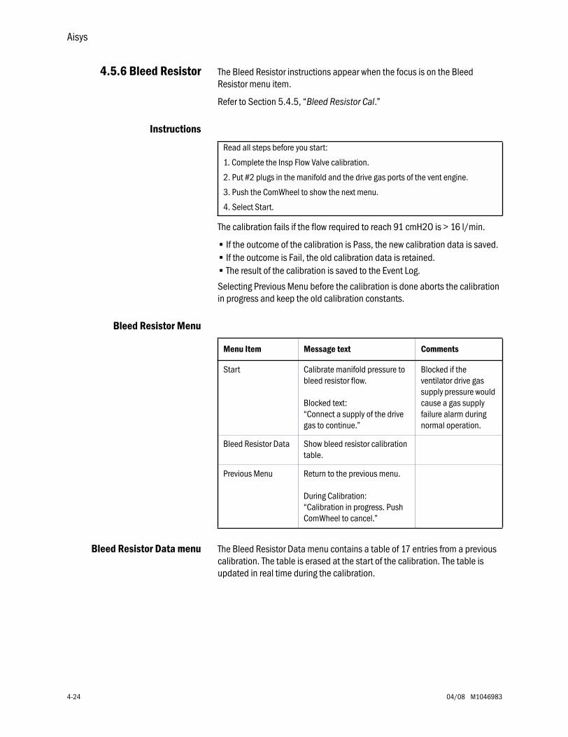
Aisys
4-24 04/08 M1046983
4.5.6 Bleed Resistor The Bleed Resistor instructions appear when the focus is on the Bleed Resistor menu item.
Refer to Section 5.4.5, “Bleed Resistor Cal.”
Instructions
The calibration fails if the flow required to reach 91 cmH2O is > 16 l/min.
• If the outcome of the calibration is Pass, the new calibration data is saved. • If the outcome is Fail, the old calibration data is retained. • The result of the calibration is saved to the Event Log.
Selecting Previous Menu before the calibration is done aborts the calibration in progress and keep the old calibration constants.
Bleed Resistor Menu
Bleed Resistor Data menu The Bleed Resistor Data menu contains a table of 17 entries from a previous calibration. The table is erased at the start of the calibration. The table is updated in real time during the calibration.
Read all steps before you start:
1. Complete the Insp Flow Valve calibration.
2. Put #2 plugs in the manifold and the drive gas ports of the vent engine.
3. Push the ComWheel to show the next menu.
4. Select Start.
Menu Item Message text Comments
Start Calibrate manifold pressure to bleed resistor flow.
Blocked text:“Connect a supply of the drive gas to continue.”
Blocked if the ventilator drive gas supply pressure would cause a gas supply failure alarm during normal operation.
Bleed Resistor Data Show bleed resistor calibration table.
Previous Menu Return to the previous menu.
During Calibration:“Calibration in progress. Push ComWheel to cancel.”
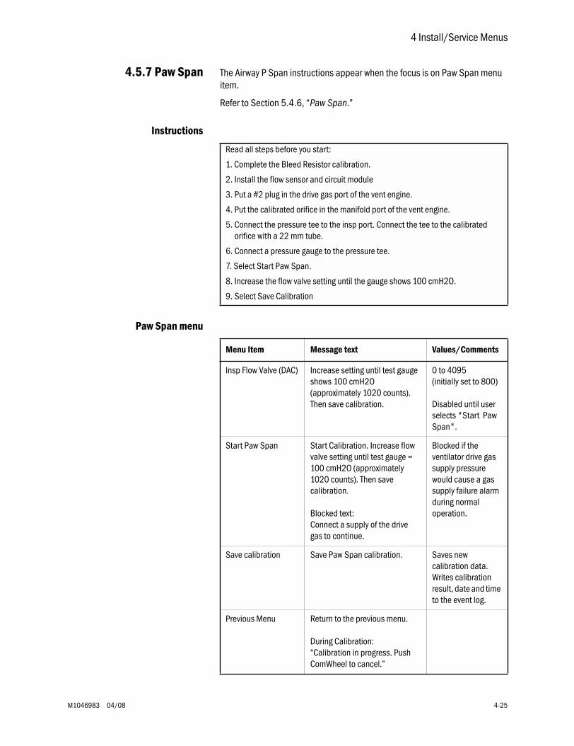
4 Install/Service Menus
M1046983 04/08 4-25
4.5.7 Paw Span The Airway P Span instructions appear when the focus is on Paw Span menu item.
Refer to Section 5.4.6, “Paw Span.”
Instructions
Paw Span menu
Read all steps before you start:
1. Complete the Bleed Resistor calibration.
2. Install the flow sensor and circuit module
3. Put a #2 plug in the drive gas port of the vent engine.
4. Put the calibrated orifice in the manifold port of the vent engine.
5. Connect the pressure tee to the insp port. Connect the tee to the calibrated orifice with a 22 mm tube.
6. Connect a pressure gauge to the pressure tee.
7. Select Start Paw Span.
8. Increase the flow valve setting until the gauge shows 100 cmH2O.
9. Select Save Calibration
Menu Item Message text Values/Comments
Insp Flow Valve (DAC) Increase setting until test gauge shows 100 cmH2O (approximately 1020 counts). Then save calibration.
0 to 4095 (initially set to 800)
Disabled until user selects "Start Paw Span".
Start Paw Span Start Calibration. Increase flow valve setting until test gauge = 100 cmH2O (approximately 1020 counts). Then save calibration.
Blocked text:Connect a supply of the drive gas to continue.
Blocked if the ventilator drive gas supply pressure would cause a gas supply failure alarm during normal operation.
Save calibration Save Paw Span calibration. Saves new calibration data. Writes calibration result, date and time to the event log.
Previous Menu Return to the previous menu.
During Calibration:“Calibration in progress. Push ComWheel to cancel.”
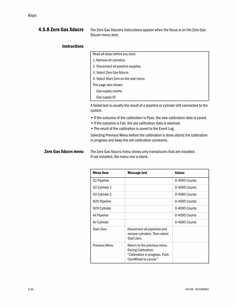
Aisys
4-26 04/08 M1046983
4.5.8 Zero Gas Xducrs The Zero Gas Xducers instructions appear when the focus is on the Zero Gas Xducer menu item.
Instructions
A failed test is usually the result of a pipeline or cylinder still connected to the system.
• If the outcome of the calibration is Pass, the new calibration data is saved. • If the outcome is Fail, the old calibration data is retained. • The result of the calibration is saved to the Event Log.
Selecting Previous Menu before the calibration is done aborts the calibration in progress and keep the old calibration constants.
Zero Gas Xducrs menu The Zero Gas Xducrs menu shows only transducers that are installed. If not installed, the menu row is blank.
Read all steps before you start:
1. Remove all cylinders.
2. Disconnect all pipeline supplies.
3. Select Zero Gas Xducrs.
4. Select Start Zero on the next menu.
This page also shows:
Gas supply counts
Gas supply ID
Menu Item Message text Values
O2 Pipeline 0-4095 Counts
O2 Cylinder 1 0-4095 Counts
O2 Cylinder 2 0-4095 Counts
N2O Pipeline 0-4095 Counts
N2O Cylinder 0-4095 Counts
Air Pipeline 0-4095 Counts
Air Cylinder 0-4095 Counts
Start Zero Disconnect all pipelines and remove cylinders. Then select Start Zero.
Previous Menu Return to the previous menu.During Calibration:“Calibration in progress. Push ComWheel to cancel.”
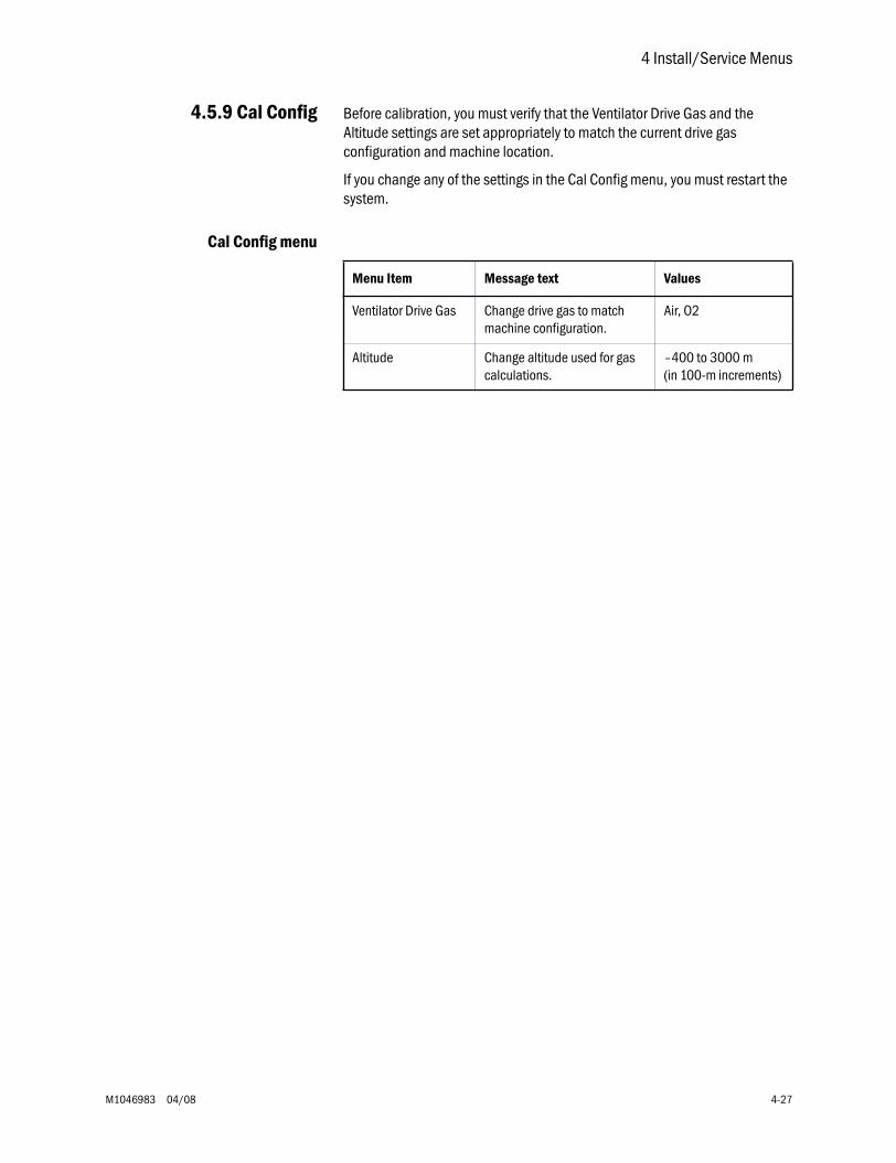
4 Install/Service Menus
M1046983 04/08 4-27
4.5.9 Cal Config Before calibration, you must verify that the Ventilator Drive Gas and the Altitude settings are set appropriately to match the current drive gas configuration and machine location.
If you change any of the settings in the Cal Config menu, you must restart the system.
Cal Config menu
Menu Item Message text Values
Ventilator Drive Gas Change drive gas to match machine configuration.
Air, O2
Altitude Change altitude used for gas calculations.
–400 to 3000 m (in 100-m increments)
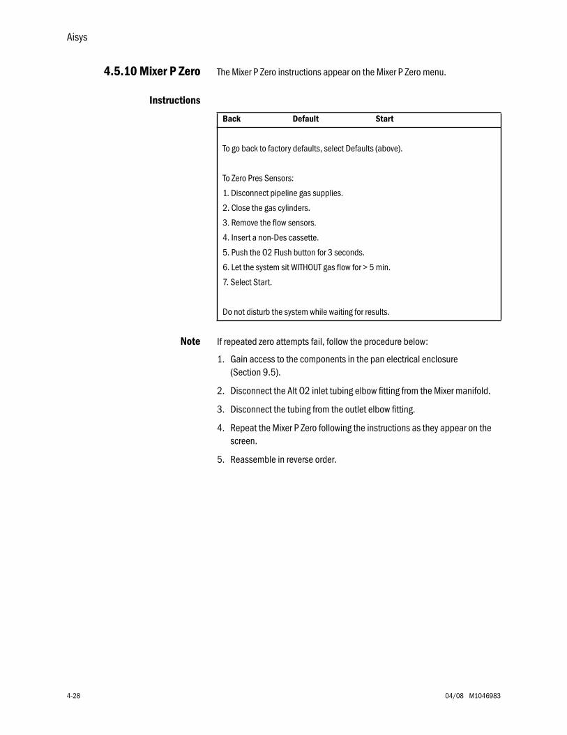
Aisys
4-28 04/08 M1046983
4.5.10 Mixer P Zero
The Mixer P Zero instructions appear on the Mixer P Zero menu.
Instructions
Note
If repeated zero attempts fail, follow the procedure below:
1. Gain access to the components in the pan electrical enclosure (Section 9.5).
2. Disconnect the Alt O2 inlet tubing elbow fitting from the Mixer manifold.
3. Disconnect the tubing from the outlet elbow fitting.
4. Repeat the Mixer P Zero following the instructions as they appear on the screen.
5. Reassemble in reverse order.
Back Default Start
To go back to factory defaults, select Defaults (above).
To Zero Pres Sensors:
1. Disconnect pipeline gas supplies.
2. Close the gas cylinders.
3. Remove the flow sensors.
4. Insert a non-Des cassette.
5. Push the O2 Flush button for 3 seconds.
6. Let the system sit WITHOUT gas flow for > 5 min.
7. Select Start.
Do not disturb the system while waiting for results.
M1046983 04/08 5-1
5 Calibration
w WARNING After adjustments and calibration are completed, always perform the checkout procedure. Refer to Section 3 of this manual.
In this section 5.1 Primary Regulators . . . . . . . . . . . . . . . . . . . . . . . . . . . . . . . . . . . . . . . . . . . . . . . . . . . . . . . . .5-2
5.1.1 Test setup . . . . . . . . . . . . . . . . . . . . . . . . . . . . . . . . . . . . . . . . . . . . . . . . . . . . . . . . . .5-3
5.1.2 Testing Primary Regulators . . . . . . . . . . . . . . . . . . . . . . . . . . . . . . . . . . . . . . . . . . . .5-3
5.1.3 Adjusting Primary Regulators . . . . . . . . . . . . . . . . . . . . . . . . . . . . . . . . . . . . . . . . . . .5-8
5.2 O2 Flush Regulator . . . . . . . . . . . . . . . . . . . . . . . . . . . . . . . . . . . . . . . . . . . . . . . . . . . . . . . . .5-9
5.3 Adjust Drive Gas Regulator . . . . . . . . . . . . . . . . . . . . . . . . . . . . . . . . . . . . . . . . . . . . . . . . . 5-10
5.4 Ventilator Calibrations . . . . . . . . . . . . . . . . . . . . . . . . . . . . . . . . . . . . . . . . . . . . . . . . . . . . 5-11
5.4.1 Cal Config . . . . . . . . . . . . . . . . . . . . . . . . . . . . . . . . . . . . . . . . . . . . . . . . . . . . . . . . 5-12
5.4.2 Manifold P Span . . . . . . . . . . . . . . . . . . . . . . . . . . . . . . . . . . . . . . . . . . . . . . . . . . . 5-13
5.4.3 Inspiratory Flow Valve Cal . . . . . . . . . . . . . . . . . . . . . . . . . . . . . . . . . . . . . . . . . . . . 5-14
5.4.4 Insp Flow Zero . . . . . . . . . . . . . . . . . . . . . . . . . . . . . . . . . . . . . . . . . . . . . . . . . . . . . 5-16
5.4.5 Bleed Resistor Cal . . . . . . . . . . . . . . . . . . . . . . . . . . . . . . . . . . . . . . . . . . . . . . . . . . 5-17
5.4.6 Paw Span . . . . . . . . . . . . . . . . . . . . . . . . . . . . . . . . . . . . . . . . . . . . . . . . . . . . . . . . . 5-18
Aisys
5-2 04/08 M1046983
5.1 Primary Regulators
First, follow the procedure in Section 5.1.1 to gain access to the regulators.
Then, in Section 5.1.2, select the test that is appropriate for the regulator you are testing.
wwww WARNING When testing/adjusting N2O regulators, nitrous oxide flows through the system. Use a safe and approved procedure to collect and remove it.
Note To test or calibrate the primary regulators, you must set the system to the Install/Service mode and use the PC based Service Application to control flow through the regulator.
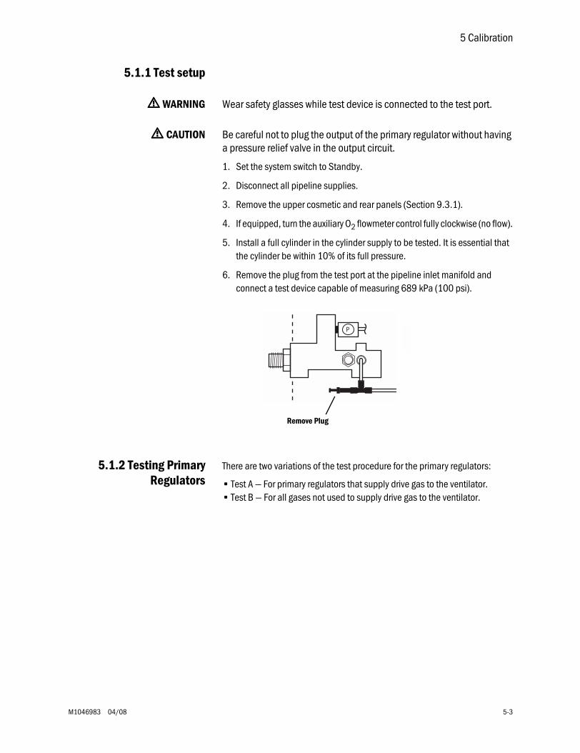
5 Calibration
M1046983 04/08 5-3
5.1.1 Test setup
wwww WARNING Wear safety glasses while test device is connected to the test port.
wwww CAUTION Be careful not to plug the output of the primary regulator without having a pressure relief valve in the output circuit.
1. Set the system switch to Standby.
2. Disconnect all pipeline supplies.
3. Remove the upper cosmetic and rear panels (Section 9.3.1).
4. If equipped, turn the auxiliary O2 flowmeter control fully clockwise (no flow).
5. Install a full cylinder in the cylinder supply to be tested. It is essential that the cylinder be within 10% of its full pressure.
6. Remove the plug from the test port at the pipeline inlet manifold and connect a test device capable of measuring 689 kPa (100 psi).
5.1.2 Testing PrimaryRegulators
There are two variations of the test procedure for the primary regulators:
• Test A — For primary regulators that supply drive gas to the ventilator.• Test B — For all gases not used to supply drive gas to the ventilator.
N2O
P
Remove Plug
Aisys
5-4 04/08 M1046983
Test A For primary regulators that supply drive gas to the ventilator (O2 or Air):
Under low flow conditions, the output pressure of a properly adjusted/functioning regulator should fall within specifications listed in step 5d.
Under high flow conditions, the output pressure should not drop below the specifications listed in step 6f.
1. Access the Gas Delivery Schematic (Section 12.3.2) of the Service Application.
2. If required,
• set Gas Delivery Mode to Fresh Gas.
• set Balance Gas to Air.
3. Adjust the O2 Concentration so that 100% of the gas flow will be through the regulator being tested (100% for O2; 0% for Air).
4. Slowly open the cylinder valve for the regulator being tested and observe the pressure reading for the cylinder.
5. Low Flow Test:
a. Set Total Flow of the tested gas to 0.5 l/min.
b. Close the cylinder valve and allow the pressure to decay to 2068 kPa (300 psi) as indicated on the cylinder pressure display.
c. At the time that the cylinder pressure reaches 2068 kPa (300 psi), set Total Flow to 0.00 l/min to turn off gas flow.
d. Within one minute, the test device reading must stabilize between:
(60) DIN 372–400 kPa (54–58 psi)
(50) Pin Indexed 310–341 kPa (45.0–49.5 psi).
- If the test device pressure does not stabilize within one minute, replace the cylinder supply.
- If the test device stabilizes within one minute, but the readings are not within specifications, readjust the regulator (Section 5.1.3).
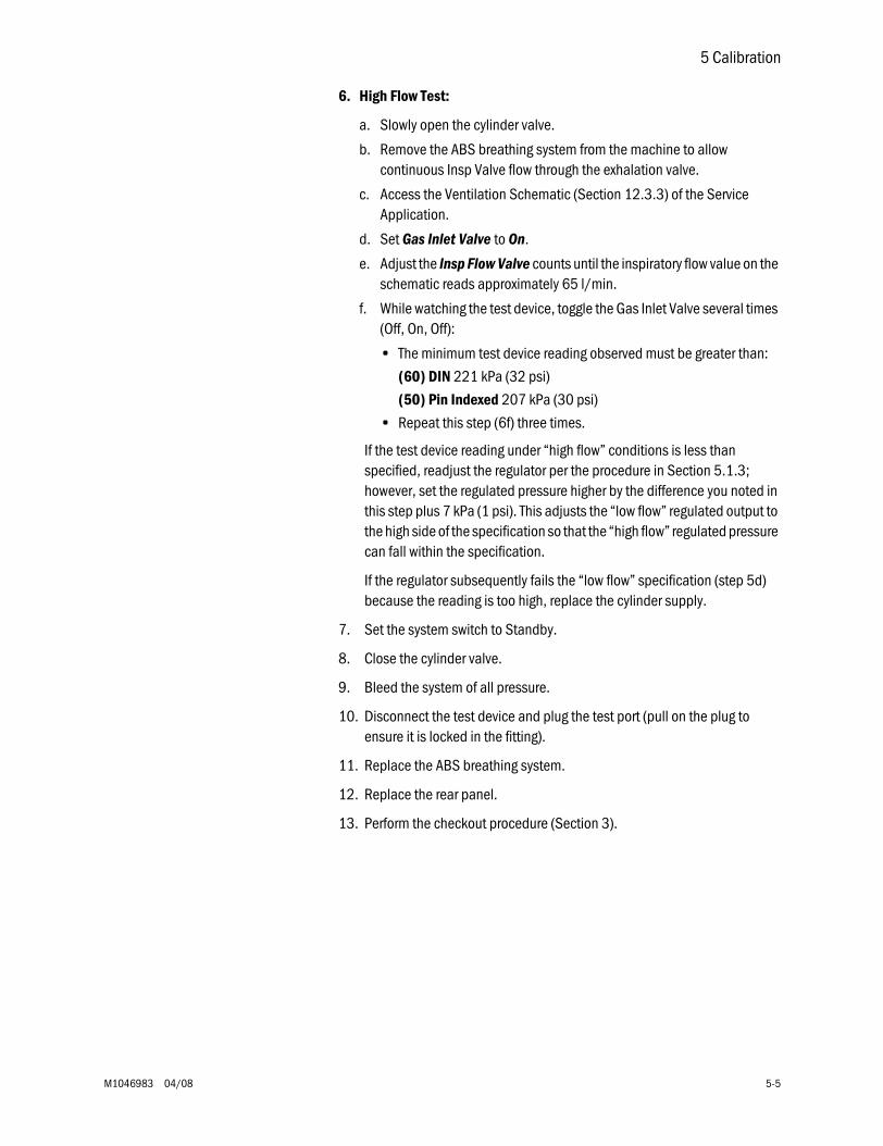
5 Calibration
M1046983 04/08 5-5
6. High Flow Test:
a. Slowly open the cylinder valve.
b. Remove the ABS breathing system from the machine to allow continuous Insp Valve flow through the exhalation valve.
c. Access the Ventilation Schematic (Section 12.3.3) of the Service Application.
d. Set Gas Inlet Valve to On.
e. Adjust the Insp Flow Valve counts until the inspiratory flow value on the schematic reads approximately 65 l/min.
f. While watching the test device, toggle the Gas Inlet Valve several times (Off, On, Off):
• The minimum test device reading observed must be greater than:
(60) DIN 221 kPa (32 psi)
(50) Pin Indexed 207 kPa (30 psi)
• Repeat this step (6f) three times.
If the test device reading under “high flow” conditions is less than specified, readjust the regulator per the procedure in Section 5.1.3; however, set the regulated pressure higher by the difference you noted in this step plus 7 kPa (1 psi). This adjusts the “low flow” regulated output to the high side of the specification so that the “high flow” regulated pressure can fall within the specification.
If the regulator subsequently fails the “low flow” specification (step 5d) because the reading is too high, replace the cylinder supply.
7. Set the system switch to Standby.
8. Close the cylinder valve.
9. Bleed the system of all pressure.
10. Disconnect the test device and plug the test port (pull on the plug to ensure it is locked in the fitting).
11. Replace the ABS breathing system.
12. Replace the rear panel.
13. Perform the checkout procedure (Section 3).
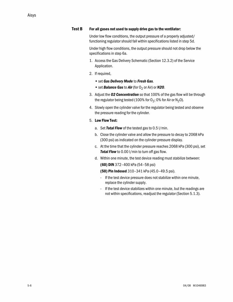
Aisys
5-6 04/08 M1046983
Test B For all gases not used to supply drive gas to the ventilator:
Under low flow conditions, the output pressure of a properly adjusted/functioning regulator should fall within specifications listed in step 5d.
Under high flow conditions, the output pressure should not drop below the specifications in step 6a.
1. Access the Gas Delivery Schematic (Section 12.3.2) of the Service Application.
2. If required,
• set Gas Delivery Mode to Fresh Gas.
• set Balance Gas to Air (for O2 or Air) or N2O.
3. Adjust the O2 Concentration so that 100% of the gas flow will be through the regulator being tested (100% for O2; 0% for Air or N2O).
4. Slowly open the cylinder valve for the regulator being tested and observe the pressure reading for the cylinder.
5. Low Flow Test:
a. Set Total Flow of the tested gas to 0.5 l/min.
b. Close the cylinder valve and allow the pressure to decay to 2068 kPa (300 psi) as indicated on the cylinder pressure display.
c. At the time that the cylinder pressure reaches 2068 kPa (300 psi), set Total Flow to 0.00 l/min to turn off gas flow.
d. Within one minute, the test device reading must stabilize between:
(60) DIN 372–400 kPa (54–58 psi)
(50) Pin Indexed 310–341 kPa (45.0–49.5 psi).
- If the test device pressure does not stabilize within one minute, replace the cylinder supply.
- If the test device stabilizes within one minute, but the readings are not within specifications, readjust the regulator (Section 5.1.3).
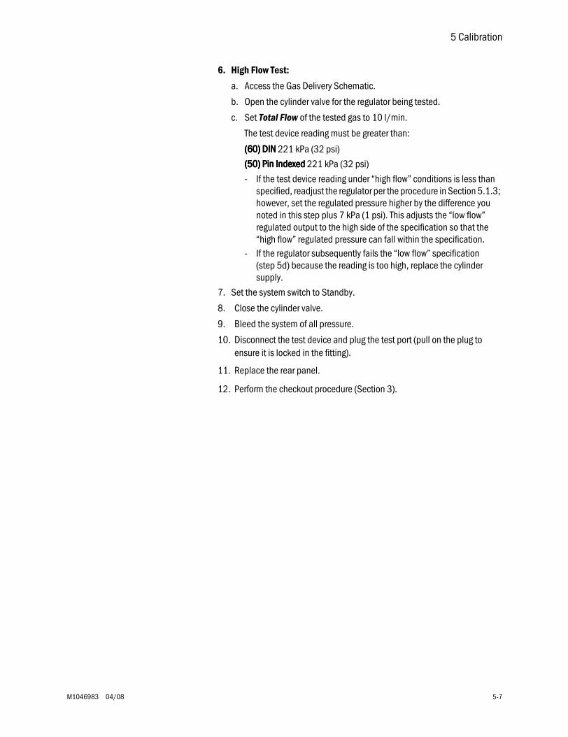
5 Calibration
M1046983 04/08 5-7
6. High Flow Test:
a. Access the Gas Delivery Schematic.
b. Open the cylinder valve for the regulator being tested.
c. Set Total Flow of the tested gas to 10 l/min.
The test device reading must be greater than:
((((66660000)))) DDDDIIIINNNN 221 kPa (32 psi)
((((55550000)))) PPPPiiiinnnn IIIInnnnddddeeeexxxxeeeedddd 221 kPa (32 psi)
- If the test device reading under “high flow” conditions is less than specified, readjust the regulator per the procedure in Section 5.1.3; however, set the regulated pressure higher by the difference you noted in this step plus 7 kPa (1 psi). This adjusts the “low flow” regulated output to the high side of the specification so that the “high flow” regulated pressure can fall within the specification.
- If the regulator subsequently fails the “low flow” specification (step 5d) because the reading is too high, replace the cylinder supply.
7. Set the system switch to Standby.
8. Close the cylinder valve.
9. Bleed the system of all pressure.
10. Disconnect the test device and plug the test port (pull on the plug to ensure it is locked in the fitting).
11. Replace the rear panel.
12. Perform the checkout procedure (Section 3).
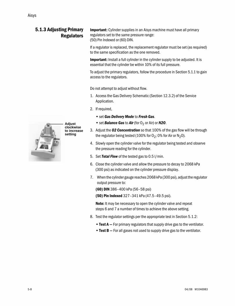
Aisys
5-8 04/08 M1046983
5.1.3 Adjusting PrimaryRegulators
Important: Cylinder supplies in an Aisys machine must have all primary regulators set to the same pressure range: (50) Pin Indexed or (60) DIN.
If a regulator is replaced, the replacement regulator must be set (as required) to the same specification as the one removed.
Important: Install a full cylinder in the cylinder supply to be adjusted. It is essential that the cylinder be within 10% of its full pressure.
To adjust the primary regulators, follow the procedure in Section 5.1.1 to gain access to the regulators.
Do not attempt to adjust without flow.
1. Access the Gas Delivery Schematic (Section 12.3.2) of the Service Application.
2. If required,
• set Gas Delivery Mode to Fresh Gas.
• set Balance Gas to Air (for O2 or Air) or N2O.
3. Adjust the O2 Concentration so that 100% of the gas flow will be through the regulator being tested (100% for O2; 0% for Air or N2O).
4. Slowly open the cylinder valve for the regulator being tested and observe the pressure reading for the cylinder.
5. Set Total Flow of the tested gas to 0.5 l/min.
6. Close the cylinder valve and allow the pressure to decay to 2068 kPa (300 psi) as indicated on the cylinder pressure display.
7. When the cylinder gauge reaches 2068 kPa (300 psi), adjust the regulator output pressure to:
(60) DIN 386–400 kPa (56–58 psi)
(50) Pin Indexed 327–341 kPa (47.5–49.5 psi).
Note: It may be necessary to open the cylinder valve and repeat steps 6 and 7 a number of times to achieve the above setting.
8. Test the regulator settings per the appropriate test in Section 5.1.2:
• Test A — For primary regulators that supply drive gas to the ventilator.
• Test B — For all gases not used to supply drive gas to the ventilator.
Adjustclockwiseto increasesetting
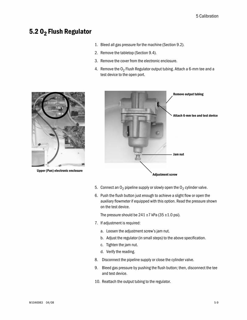
5 Calibration
M1046983 04/08 5-9
5.2 O2 Flush Regulator
1. Bleed all gas pressure for the machine (Section 9.2).
2. Remove the tabletop (Section 9.4).
3. Remove the cover from the electronic enclosure.
4. Remove the O2 Flush Regulator output tubing. Attach a 6-mm tee and a test device to the open port.
5. Connect an O2 pipeline supply or slowly open the O2 cylinder valve.
6. Push the flush button just enough to achieve a slight flow or open the auxiliary flowmeter if equipped with this option. Read the pressure shown on the test device.
The pressure should be 241 ±7 kPa (35 ±1.0 psi).
7. If adjustment is required:
a. Loosen the adjustment screw’s jam nut.
b. Adjust the regulator (in small steps) to the above specification.
c. Tighten the jam nut.
d. Verify the reading.
8. Disconnect the pipeline supply or close the cylinder valve.
9. Bleed gas pressure by pushing the flush button; then, disconnect the tee and test device.
10. Reattach the output tubing to the regulator.
Upper (Pan) electronic enclosure
Remove output tubing
Attach 6-mm tee and test device
Jam nut
Adjustment screw
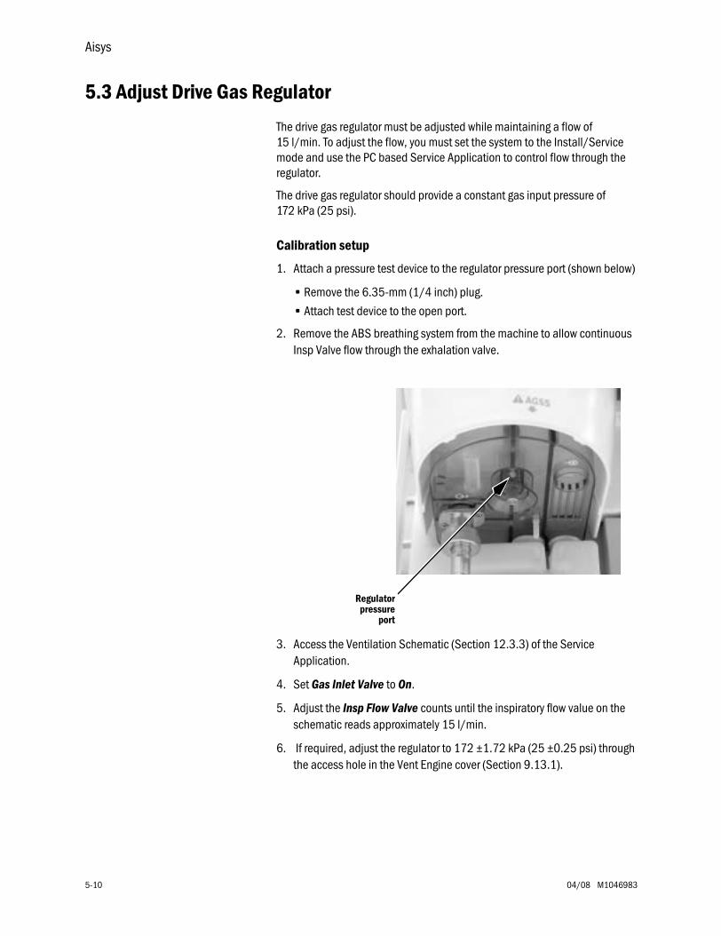
Aisys
5-10 04/08 M1046983
5.3 Adjust Drive Gas Regulator
The drive gas regulator must be adjusted while maintaining a flow of 15 l/min. To adjust the flow, you must set the system to the Install/Service mode and use the PC based Service Application to control flow through the regulator.
The drive gas regulator should provide a constant gas input pressure of 172 kPa (25 psi).
Calibration setup
1. Attach a pressure test device to the regulator pressure port (shown below)
• Remove the 6.35-mm (1/4 inch) plug.
• Attach test device to the open port.
2. Remove the ABS breathing system from the machine to allow continuous Insp Valve flow through the exhalation valve.
3. Access the Ventilation Schematic (Section 12.3.3) of the Service Application.
4. Set Gas Inlet Valve to On.
5. Adjust the Insp Flow Valve counts until the inspiratory flow value on the schematic reads approximately 15 l/min.
6. If required, adjust the regulator to 172 ±1.72 kPa (25 ±0.25 psi) through the access hole in the Vent Engine cover (Section 9.13.1).
Regulatorpressure
port
5 Calibration
M1046983 04/08 5-11
5.4 Ventilator Calibrations
Before performing the ventilator calibrations, verify that the drive gas regulator is adjusted to specifications (Section 5.3).
The Service menu structure is detailed in Section 4. To access the Ventilator Calibrations menu:
1. Turn on the system.
2. Navigate the menu selections to the Calibration menu.
• On the Checkout menu, select Bypass Checks.• On the Start Case menu, press the Main Menu button.• On the Main Menu, select Screen Setup.• On the Screen Setup menu, select Install/Service (dial in 16 - 4 - 34).• On the Install/Service menu, select Service (dial in 26 - 23 - 8).• On the Service menu, select Calibration.
Unless otherwise specified, perform the ventilator calibrations in the order that they appear on the Calibration menu.
• User Calibration• Manifold P Span• Insp Flow Valve (not required for machines with Software 4.X or greater)• Bleed Resistor• Paw Span
The following calibrations should be performed as required:
• Zero Gas Xducer: • The pipeline and cylinder pressure transducer should be “zeroed” at
least once a year.
• Whenever a pipeline or cylinder pressure transducer is replaced.
• Cal Config:• Reset the Ventilator Drive Gas to match the machine configuration.
• Reset the Altitude whenever the machine is moved to a new location that differs by more than 100 meters.
• Mixer P Zero:
Aisys
5-12 04/08 M1046983
5.4.1 Cal Config Before calibration, you must verify that the Ventilator Drive Gas and the Altitude settings are set appropriately to match the current drive gas configuration and machine location.
If you change any of the settings in the Cal Config menu, you must restart the system.
3. On the Installation menu, select Configuration.
4. On the Configuration menu, verify the Ventilator Drive Gas and the Altitude setting; adjust as necessary.
5. When done, reboot the system (System switch to Standby; then On).
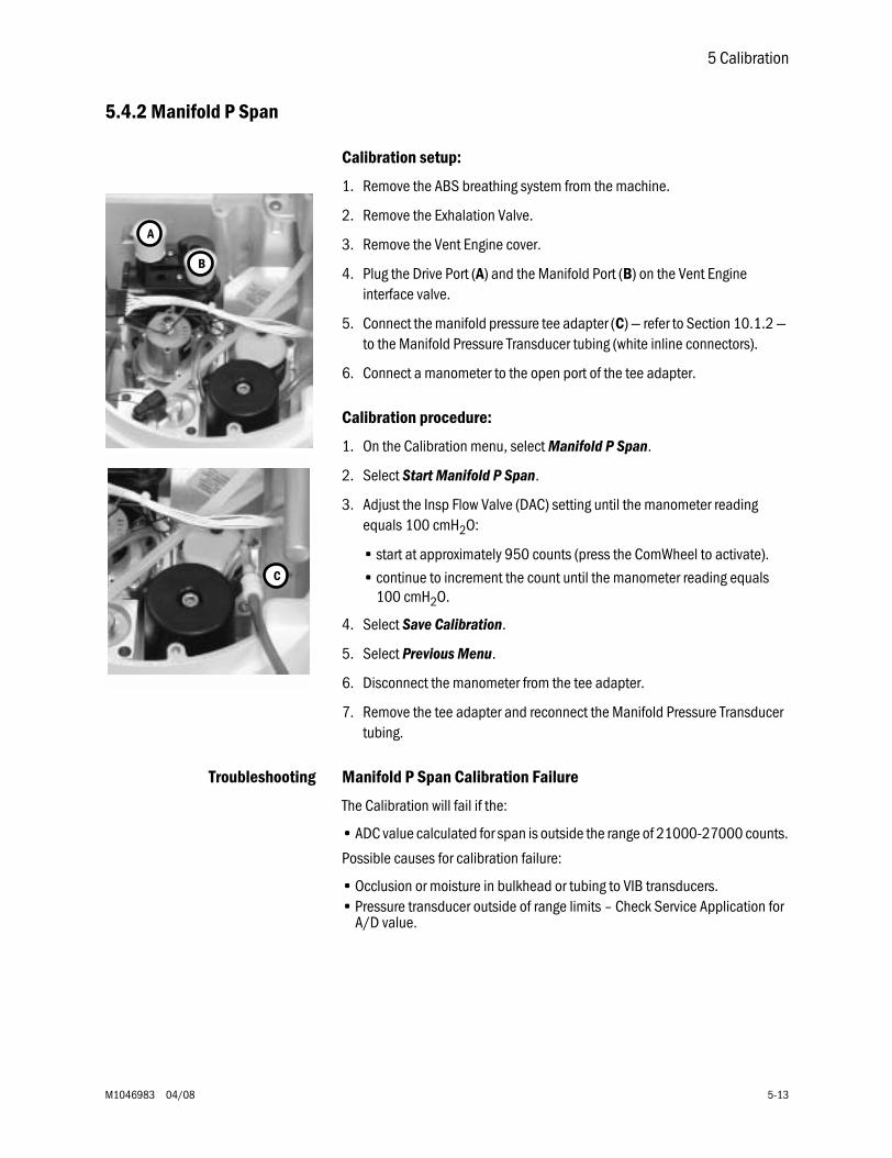
5 Calibration
M1046983 04/08 5-13
5.4.2 Manifold P Span
Calibration setup:
1. Remove the ABS breathing system from the machine.
2. Remove the Exhalation Valve.
3. Remove the Vent Engine cover.
4. Plug the Drive Port (A) and the Manifold Port (B) on the Vent Engine interface valve.
5. Connect the manifold pressure tee adapter (C) — refer to Section 10.1.2 — to the Manifold Pressure Transducer tubing (white inline connectors).
6. Connect a manometer to the open port of the tee adapter.
Calibration procedure:
1. On the Calibration menu, select Manifold P Span.
2. Select Start Manifold P Span.
3. Adjust the Insp Flow Valve (DAC) setting until the manometer reading equals 100 cmH2O:
• start at approximately 950 counts (press the ComWheel to activate).
• continue to increment the count until the manometer reading equals 100 cmH2O.
4. Select Save Calibration.
5. Select Previous Menu.
6. Disconnect the manometer from the tee adapter.
7. Remove the tee adapter and reconnect the Manifold Pressure Transducer tubing.
Troubleshooting Manifold P Span Calibration Failure
The Calibration will fail if the:
• ADC value calculated for span is outside the range of 21000-27000 counts.
Possible causes for calibration failure:
• Occlusion or moisture in bulkhead or tubing to VIB transducers.• Pressure transducer outside of range limits – Check Service Application for
A/D value.
A
B
C
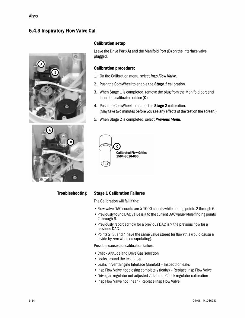
Aisys
5-14 04/08 M1046983
5.4.3 Inspiratory Flow Valve Cal
Calibration setup
Leave the Drive Port (A) and the Manifold Port (B) on the interface valve plugged.
Calibration procedure:
1. On the Calibration menu, select Insp Flow Valve.
2. Push the ComWheel to enable the Stage 1 calibration.
3. When Stage 1 is completed, remove the plug from the Manifold port and insert the calibrated orifice (C)
4. Push the ComWheel to enable the Stage 2 calibration.(May take two minutes before you see any effects of the test on the screen.)
5. When Stage 2 is completed, select Previous Menu.
Troubleshooting Stage 1 Calibration Failures
The Calibration will fail if the:
• Flow valve DAC counts are ≥ 1000 counts while finding points 2 through 6.• Previously found DAC value is ≥ to the current DAC value while finding points
2 through 6.• Previously recorded flow for a previous DAC is > the previous flow for a
previous DAC.• Points 2, 3, and 4 have the same value stored for flow (this would cause a
divide by zero when extrapolating).
Possible causes for calibration failure:
• Check Altitude and Drive Gas selection• Leaks around the test plugs• Leaks in Vent Engine Interface Manifold – Inspect for leaks• Insp Flow Valve not closing completely (leaky) – Replace Insp Flow Valve• Drive gas regulator not adjusted / stable – Check regulator calibration• Insp Flow Valve not linear – Replace Insp Flow Valve
A
B
A
CC
Calibrated Flow Orifice1504-3016-000
5 Calibration
M1046983 04/08 5-15
Troubleshooting Stage 2 Calibration Failures
The Calibration will fail if the:
• Flow valve DAC reaches 4095 before determining the Lift-Off Point.• Previously found DAC value is ≥ to the current DAC value while finding points
7 through 24.• Previously recorded flow for a previous DAC is > the previous flow for a
previous DAC.• End point DAC of 4095 does not give a flow > 100 l/min.
Possible causes for calibration failure:
• Check Altitude and Drive Gas selection.• Leaks around the test plug or Calibration Flow Orifice.• Leaks in Vent Engine Interface Manifold – Inspect for leaks.• Inadequate drive gas supply (cannot deliver > 100 l/min).• Drive gas regulator not adjusted / stable – Check regulator calibration.• Insp Flow Valve not linear – Replace Insp Flow Valve.
Aisys
5-16 04/08 M1046983
5.4.4 Insp Flow Zero Note: Not required for machines with System Software 4.X or greater.
Calibration setup
1. Remove the Calibration Orifice from the Manifold port.
2. Plug the Manifold (B) port.
3. Leave the Drive Gas (A) port plugged.
Calibration procedure:
1. On the Calibration menu, select Insp Flow Zero.
2. Select Start.
3. Select Previous Menu.
Troubleshooting Insp Flow Zero Calibration Failures
The Calibration will fail if the:
• Inspiratory Valve Calibration (stage 1 and stage 2) has not been performed.• Corresponding flow is not between the 2nd and 5th point in the Inspiratory
valve calibration table.
Possible causes for calibration failure:
• Inspiratory Valve Calibration not complete – Perform Calibration.• Insp Flow Valve not closing completely (leaky) – Replace Insp Flow Valve.• Insp Flow Valve not linear – Replace Insp Flow Valve.
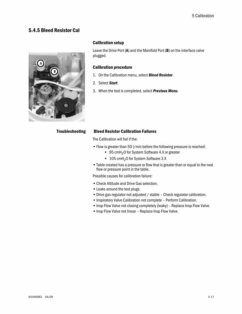
5 Calibration
M1046983 04/08 5-17
5.4.5 Bleed Resistor Cal
Calibration setup
Leave the Drive Port (A) and the Manifold Port (B) on the interface valve plugged.
Calibration procedure
1. On the Calibration menu, select Bleed Resistor.
2. Select Start.
3. When the test is completed, select Previous Menu.
Troubleshooting Bleed Resistor Calibration Failures
The Calibration will fail if the:
• Flow is greater than 50 l/min before the following pressure is reached:• 95 cmH2O for System Software 4.X or greater
• 105 cmH2O for System Software 3.X
• Table created has a pressure or flow that is greater than or equal to the next flow or pressure point in the table.
Possible causes for calibration failure:
• Check Altitude and Drive Gas selection.• Leaks around the test plugs.• Drive gas regulator not adjusted / stable – Check regulator calibration.• Inspiratory Valve Calibration not complete – Perform Calibration.• Insp Flow Valve not closing completely (leaky) – Replace Insp Flow Valve.• Insp Flow Valve not linear – Replace Insp Flow Valve.
A
B
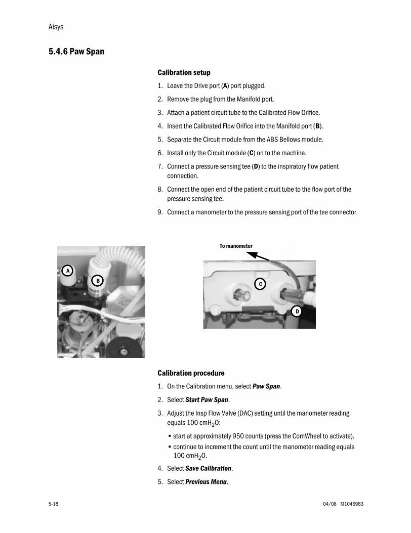
Aisys
5-18 04/08 M1046983
5.4.6 Paw Span
Calibration setup
1. Leave the Drive port (A) port plugged.
2. Remove the plug from the Manifold port.
3. Attach a patient circuit tube to the Calibrated Flow Orifice.
4. Insert the Calibrated Flow Orifice into the Manifold port (B).
5. Separate the Circuit module from the ABS Bellows module.
6. Install only the Circuit module (C) on to the machine.
7. Connect a pressure sensing tee (D) to the inspiratory flow patient connection.
8. Connect the open end of the patient circuit tube to the flow port of the pressure sensing tee.
9. Connect a manometer to the pressure sensing port of the tee connector.
Calibration procedure
1. On the Calibration menu, select Paw Span.
2. Select Start Paw Span.
3. Adjust the Insp Flow Valve (DAC) setting until the manometer reading equals 100 cmH2O:
• start at approximately 950 counts (press the ComWheel to activate).
• continue to increment the count until the manometer reading equals 100 cmH2O.
4. Select Save Calibration.
5. Select Previous Menu.
A
B C
D
To manometer

5 Calibration
M1046983 04/08 5-19
Troubleshooting Paw Span Calibration Failure
The Calibration will fail if the:
• ADC value calculated for span is outside the range of 21000-27000 counts.
Possible causes for calibration failure:
• Occlusion or moisture in bulkhead or tubing to VIB transducers.• Pressure transducer outside of range limits – Check Service Application for
A/D value.

Notes
5-20 04/08 M1046983
M1046983 04/08 6-1
6 Installation and Maintenance
In this section This section covers the regular maintenance procedures (minimum requirements) needed to make sure that the Aisys anesthesia machine operates to specifications.
6.1 Aisys Installation Checklist . . . . . . . . . . . . . . . . . . . . . . . . . . . . . . . . . . . . . . . . . . . . . . . . . . .6-26.2 Aisys Planned Maintenance . . . . . . . . . . . . . . . . . . . . . . . . . . . . . . . . . . . . . . . . . . . . . . . . . .6-4
6.2.1 Every twelve (12) months . . . . . . . . . . . . . . . . . . . . . . . . . . . . . . . . . . . . . . . . . . . . . .6-46.2.2 Every twenty-four (24) months . . . . . . . . . . . . . . . . . . . . . . . . . . . . . . . . . . . . . . . . .6-56.2.3 Every forty-eight (48) months . . . . . . . . . . . . . . . . . . . . . . . . . . . . . . . . . . . . . . . . . .6-5
6.3 Free breathing valve maintenance . . . . . . . . . . . . . . . . . . . . . . . . . . . . . . . . . . . . . . . . . . . . .6-66.4 MOPV pressure relief valve test . . . . . . . . . . . . . . . . . . . . . . . . . . . . . . . . . . . . . . . . . . . . . . .6-7
6.4.1 Test setup . . . . . . . . . . . . . . . . . . . . . . . . . . . . . . . . . . . . . . . . . . . . . . . . . . . . . . . . . .6-76.4.2 Test procedure . . . . . . . . . . . . . . . . . . . . . . . . . . . . . . . . . . . . . . . . . . . . . . . . . . . . . .6-7
6.5 Pressure Limit Circuit test . . . . . . . . . . . . . . . . . . . . . . . . . . . . . . . . . . . . . . . . . . . . . . . . . . . .6-86.6 Mixer test . . . . . . . . . . . . . . . . . . . . . . . . . . . . . . . . . . . . . . . . . . . . . . . . . . . . . . . . . . . . . . . 6-10
6.6.1 Mixer outlet check valve leak test . . . . . . . . . . . . . . . . . . . . . . . . . . . . . . . . . . . . . 6-106.6.2 Mixer flow verification . . . . . . . . . . . . . . . . . . . . . . . . . . . . . . . . . . . . . . . . . . . . . . . 6-10
6.7 Alternate O2 flowmeter tests . . . . . . . . . . . . . . . . . . . . . . . . . . . . . . . . . . . . . . . . . . . . . . . 6-116.8 Auxiliary O2 flowmeter tests . . . . . . . . . . . . . . . . . . . . . . . . . . . . . . . . . . . . . . . . . . . . . . . . 6-126.9 Integrated Suction Regulator tests . . . . . . . . . . . . . . . . . . . . . . . . . . . . . . . . . . . . . . . . . . 6-136.10 Battery capacity test . . . . . . . . . . . . . . . . . . . . . . . . . . . . . . . . . . . . . . . . . . . . . . . . . . . . . 6-156.11 Cable routing, upper module rack . . . . . . . . . . . . . . . . . . . . . . . . . . . . . . . . . . . . . . . . . . 6-16
6.11.1 Display Unit and Anesthesia Monitor . . . . . . . . . . . . . . . . . . . . . . . . . . . . . . . . . 6-176.11.2 Display arm . . . . . . . . . . . . . . . . . . . . . . . . . . . . . . . . . . . . . . . . . . . . . . . . . . . . . . 6-176.11.3 Left-side cable route. . . . . . . . . . . . . . . . . . . . . . . . . . . . . . . . . . . . . . . . . . . . . . . 6-186.11.4 Upper left-side cable route. . . . . . . . . . . . . . . . . . . . . . . . . . . . . . . . . . . . . . . . . . 6-186.11.5 Front side of Display Connector Board . . . . . . . . . . . . . . . . . . . . . . . . . . . . . . . . 6-186.11.6 Upper module rack . . . . . . . . . . . . . . . . . . . . . . . . . . . . . . . . . . . . . . . . . . . . . . . . 6-196.11.7 Rear cosmetic panel . . . . . . . . . . . . . . . . . . . . . . . . . . . . . . . . . . . . . . . . . . . . . . . 6-196.11.8 Additional cable access points to upper chassis . . . . . . . . . . . . . . . . . . . . . . . . 6-19
6.12 Cable routing, lower module rack . . . . . . . . . . . . . . . . . . . . . . . . . . . . . . . . . . . . . . . . . . 6-206.12.1 Display Unit and Anesthesia Monitor . . . . . . . . . . . . . . . . . . . . . . . . . . . . . . . . . 6-216.12.2 Display arm . . . . . . . . . . . . . . . . . . . . . . . . . . . . . . . . . . . . . . . . . . . . . . . . . . . . . . 6-216.12.3 Left-side cable route. . . . . . . . . . . . . . . . . . . . . . . . . . . . . . . . . . . . . . . . . . . . . . . 6-226.12.4 Front side of Display Connector Board and lower module rack. . . . . . . . . . . . . 6-226.12.5 Rear cable route . . . . . . . . . . . . . . . . . . . . . . . . . . . . . . . . . . . . . . . . . . . . . . . . . . 6-236.12.6 Right-side cable route . . . . . . . . . . . . . . . . . . . . . . . . . . . . . . . . . . . . . . . . . . . . . 6-24
wwww WARNINGS Do not perform testing or maintenance on the Aisys anesthesia machine while it is being used on a patient. Possible injury can result.
Items can be contaminated due to infectious patients. Wear sterile rubber gloves. Contamination can spread to you and others.
Obey infection control and safety procedures. Used equipment may contain blood and body fluids.
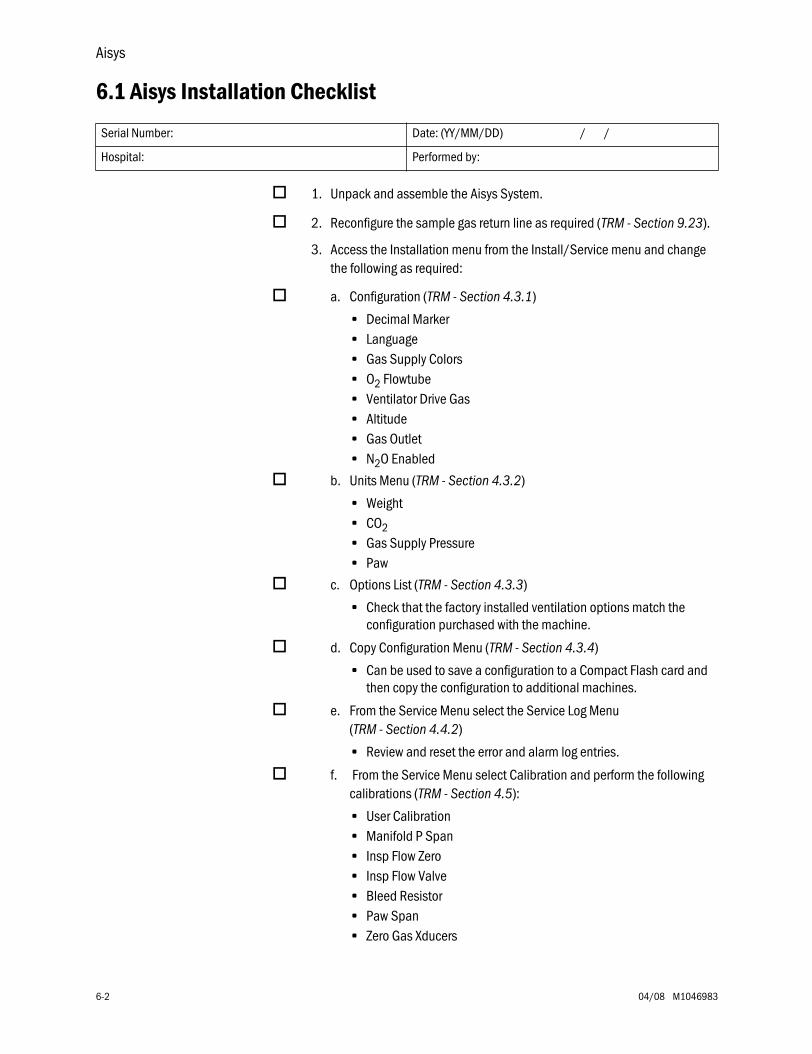
Aisys
6-2 04/08 M1046983
6.1 Aisys Installation Checklist
1. Unpack and assemble the Aisys System.
2. Reconfigure the sample gas return line as required (TRM - Section 9.23).
3. Access the Installation menu from the Install/Service menu and change the following as required:
a. Configuration (TRM - Section 4.3.1)
• Decimal Marker• Language• Gas Supply Colors• O2 Flowtube• Ventilator Drive Gas• Altitude• Gas Outlet• N2O Enabled
b. Units Menu (TRM - Section 4.3.2)
• Weight• CO2• Gas Supply Pressure• Paw
c. Options List (TRM - Section 4.3.3)
• Check that the factory installed ventilation options match the configuration purchased with the machine.
d. Copy Configuration Menu (TRM - Section 4.3.4)
• Can be used to save a configuration to a Compact Flash card and then copy the configuration to additional machines.
e. From the Service Menu select the Service Log Menu (TRM - Section 4.4.2)
• Review and reset the error and alarm log entries.
f. From the Service Menu select Calibration and perform the following calibrations (TRM - Section 4.5):
• User Calibration• Manifold P Span• Insp Flow Zero• Insp Flow Valve• Bleed Resistor• Paw Span• Zero Gas Xducers
Serial Number: Date: (YY/MM/DD) / /
Hospital: Performed by:
6 Installation and Maintenance
M1046983 04/08 6-3
4. Verify the “Schedule Service Calibration” message is not present in the normal display.
5. Complete the System Checkout by performing the following steps:
a. Inspect the system (TRM - Section 3.1)
b. System checkout (TRM - Section 3.2)
Note: You must insert a Test Cassette for the Machine Check - System Agent Delivery Test to run the extended diagnostic Vaporizer Test.
c. Pipeline and Cylinder tests (TRM - Section 3.6)
d. Flush Flow test (TRM - Section 3.7)
e. Alarm tests (TRM - Section 3.8)
f. Alternate O2 flowmeter tests (TRM - Section 3.9)
g. Auxiliary O2 flowmeter tests, if equipped with option (TRM - Section 3.10)
h. Integrated suction regulator tests, if equipped with option (TRM - Section 3.11)
i. Power failure test (TRM - Section 3.12)
j. Electrical safety tests (TRM - Section 3.13)
Aisys
6-4 04/08 M1046983
6.2 Aisys Planned Maintenance
6.2.1 Every twelve(12) months
Perform the following steps every 12 months.For details, refer to the sections listed.
• Sections marked URM are found in the User’s Reference manuals for the Aisys anesthesia system.
• Sections marked TRM are found in this Technical Reference manual.
Parts Replacement Refer to TRM - Section 9.7.2; perform the following:
Replace the eVap backpressure valve (Stock Number 1011-3983-000).
Checks and Tests
1. AGSS Maintenance (URM - Part 2, Section 2):
• Empty any condensate from the reservoir (disposable item).• Inspect air brake for occlusion on active AGSS.• Inspect, clean or replace filter on active AGSS.
2. Breathing System Maintenance (URM - Part 2, Section 2)
• Disassemble the breathing system modules and inspect components. Replace any parts that are physically damaged or worn.
3. Bellows Assembly Maintenance (URM - Part 2, Section 2)
• Disassemble the bellows assembly and inspect components. Replace any parts that are physically damaged or worn.
4. Bellows Assembly Tests (URM - Part 2, Section 2)
5. Perform the checkout procedures in Section 3.
• Inspect the system (TRM - Section 3.1)• Pipeline and cylinder tests (TRM - Section 3.6)• O2 supply alarm test (TRM - Section 3.6.1)• Flush Flow Test (TRM - Section 3.7)• Alarm tests (TRM - Section 3.8)• Power failure test (TRM - Section 3.12)
6. Mixer outlet check valve leak test (TRM - Section 6.6.1)
7. Zero the Mixer (TRM - Section 4.5.10)
8. Mixer flow verification test (TRM - Section 6.6.2)
9. Alternate O2 flowmeter tests (TRM - Section 6.7)
10.Auxiliary O2 flowmeter tests (TRM - Section 6.8)
11.Integrated Suction Regulator tests (TRM - Section 6.9)
Serial Number: Date: (YY/MM/DD) / /Hospital: Performed by: 12 months 24 month 48 month ______________________
6 Installation and Maintenance
M1046983 04/08 6-5
12. Perform the following diagnostics using the Compact Flash Special Functions.
• Display Diagnostics (TRM - Section 8.3.1).
13. Perform the following diagnostics using the PC Service Application.
• Vaporizer Test with a Test Cassette inserted (TRM - Section 12.10.2).• MOPV pressure relief valve test (TRM - Section 6.4).• Pressure Limit Circuit test (TRM - Section 6.5).• Adjust Drive Gas Regulator (TRM - Section 5.3).• eVap Therapy Cassette Leak Test (TRM - Section 7.11).
14. From the Service Calibration menu (TRM - Section 4.5), perform the following (refer to TRM - Section 5.4 for details):
• User Calibration• Manifold P Span • Inspiratory flow zero• Inspiratory flow valve• Bleed resistor• Paw Span• Zero Gas Transducers
15. From the Service Log menu (TRM - Section 4.4.2), perform the following:
• Access the Error History log. If any error codes have been logged, follow the appropriate troubleshooting procedures. Clear the error log.
16. Perform the system “Checkout” (TRM - Section 3.2).
17. Perform the “Low P Leak” test (TRM - Section 3.3.4).
18. Electrical safety tests (TRM - Section 3.13).
6.2.2 Every twenty-four (24) months
In addition to the 12-month requirements, replace the following parts every 24 months. All parts should be replaced before performing the checks, tests, and calibrations.
Parts Replacement Refer to TRM - Section 6.3; perform the following:
Replace the free breathing flapper valve (Stock Number 0211-1454-100).
Replace the free breathing valve o-ring (Stock Number 1503-3208-000).
6.2.3 Every forty-eight (48) months
In addition to the 24-month requirements, replace the following parts every 48 months. All parts should be replaced before performing the checks, tests, and calibrations.
Parts Replacement Refer to TRM - Section 9.11.2; perform the following:
Replace the Display Unit battery (Stock Number 1009-5800-000).
Refer to TRM - Section 9.12.4; perform the following step:
Replace the system batteries* (Stock Number 1011-3557-000).
*Note: Refer to the “Battery capacity test” in TRM - Section 6.10.
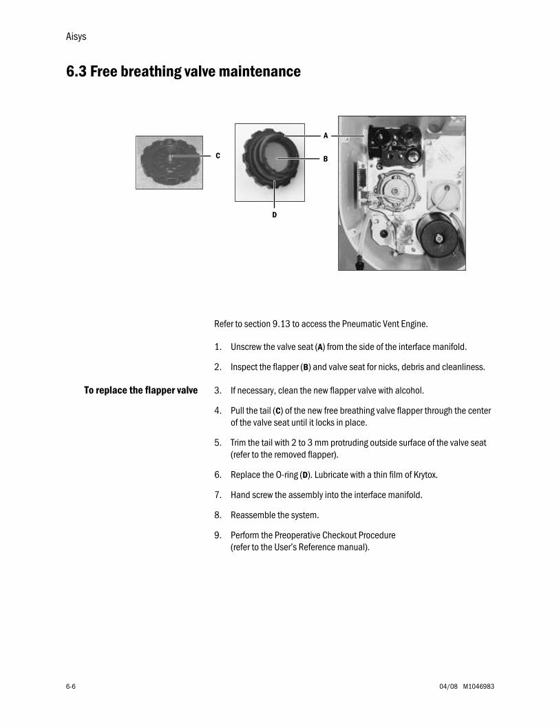
Aisys
6-6 04/08 M1046983
6.3 Free breathing valve maintenance
Refer to section 9.13 to access the Pneumatic Vent Engine.
1. Unscrew the valve seat (A) from the side of the interface manifold.
2. Inspect the flapper (B) and valve seat for nicks, debris and cleanliness.
To replace the flapper valve 3. If necessary, clean the new flapper valve with alcohol.
4. Pull the tail (C) of the new free breathing valve flapper through the center of the valve seat until it locks in place.
5. Trim the tail with 2 to 3 mm protruding outside surface of the valve seat (refer to the removed flapper).
6. Replace the O-ring (D). Lubricate with a thin film of Krytox.
7. Hand screw the assembly into the interface manifold.
8. Reassemble the system.
9. Perform the Preoperative Checkout Procedure (refer to the User’s Reference manual).
D
BC
A
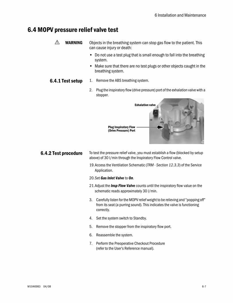
6 Installation and Maintenance
M1046983 04/08 6-7
6.4 MOPV pressure relief valve test
w WARNING Objects in the breathing system can stop gas flow to the patient. This can cause injury or death:
• Do not use a test plug that is small enough to fall into the breathing system.
• Make sure that there are no test plugs or other objects caught in the breathing system.
6.4.1 Test setup 1. Remove the ABS breathing system.
2. Plug the inspiratory flow (drive pressure) port of the exhalation valve with a stopper.
6.4.2 Test procedure To test the pressure relief valve, you must establish a flow (blocked by setup above) of 30 l/min through the Inspiratory Flow Control valve.
19.Access the Ventilation Schematic (TRM - Section 12.3.3) of the Service Application.
20.Set Gas Inlet Valve to On.
21.Adjust the Insp Flow Valve counts until the inspiratory flow value on the schematic reads approximately 30 l/min.
3. Carefully listen for the MOPV relief weight to be relieving and “popping off” from its seat (a purring sound). This indicates the valve is functioning correctly.
4. Set the system switch to Standby.
5. Remove the stopper from the inspiratory flow port.
6. Reassemble the system.
7. Perform the Preoperative Checkout Procedure (refer to the User’s Reference manual).
Plug Inspiratory Flow (Drive Pressure) Port
Exhalation valve
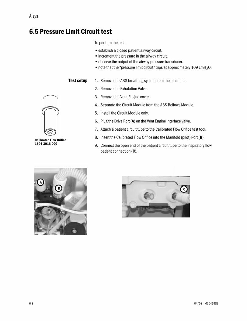
Aisys
6-8 04/08 M1046983
6.5 Pressure Limit Circuit testTo perform the test:
• establish a closed patient airway circuit.• increment the pressure in the airway circuit.• observe the output of the airway pressure transducer.• note that the “pressure limit circuit” trips at approximately 109 cmH2O.
Test setup 1. Remove the ABS breathing system from the machine.
2. Remove the Exhalation Valve.
3. Remove the Vent Engine cover.
4. Separate the Circuit Module from the ABS Bellows Module.
5. Install the Circuit Module only.
6. Plug the Drive Port (A) on the Vent Engine interface valve.
7. Attach a patient circuit tube to the Calibrated Flow Orifice test tool.
8. Insert the Calibrated Flow Orifice into the Manifold (pilot) Port (B).
9. Connect the open end of the patient circuit tube to the inspiratory flow patient connection (C).
Calibrated Flow Orifice1504-3016-000
C
A
B
6 Installation and Maintenance
M1046983 04/08 6-9
Test Procedure 10.Access the Ventilation Schematic (TRM - Section 12.3.3) of the Service Application.
11.Select Vent Status and verify that Over Pressure Circuit reads OK.
12.Select Gas Inlet Valve to ON.
13.Adjust the Insp Flow Valve counts to approximately 1000 counts and observe the Airway Pressure reading on the Ventilator Schematic.
14.Increase the flow count slowly until the Airway Pressure reading reaches approximately 109 cmH2O.
15.Continue to increase the flow by one count and observe the airway pressure until gas flow stops.
16.On the Status page, verify that:
• Over Pressure Circuit reads High Pressure.
• Gas Inlet Valve Feedback reads Closed.
8. Reassemble the system.
9. Perform the Preoperative Checkout Procedure (refer to the User’s Reference manual).
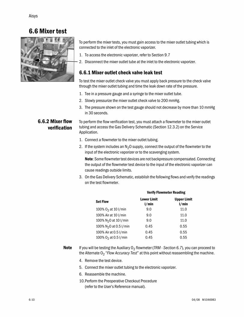
Aisys
6-10 04/08 M1046983
6.6 Mixer testTo perform the mixer tests, you must gain access to the mixer outlet tubing which is connected to the inlet of the electronic vaporizer.
1. To access the electronic vaporizer, refer to Section 9.7
2. Disconnect the mixer outlet tube at the inlet to the electronic vaporizer.
6.6.1 Mixer outlet check valve leak testTo test the mixer outlet check valve you must apply back pressure to the check valve through the mixer outlet tubing and time the leak down rate of the pressure.
1. Tee in a pressure gauge and a syringe to the mixer outlet tube.
2. Slowly pressurize the mixer outlet check valve to 200 mmHg.
3. The pressure shown on the test gauge should not decrease by more than 10 mmHg in 30 seconds.
6.6.2 Mixer flowverification
To perform the flow verification test, you must attach a flowmeter to the mixer outlet tubing and access the Gas Delivery Schematic (Section 12.3.2) on the Service Application.
1. Connect a flowmeter to the mixer outlet tubing.
2. If the system includes an N2O supply, connect the output of the flowmeter to the input of the electronic vaporizer or to the scavenging system.
Note: Some flowmeter test devices are not backpressure compensated. Connecting the output of the flowmeter test device to the input of the electronic vaporizer can cause readings outside limits.
3. On the Gas Delivery Schematic, establish the following flows and verify the readings on the test flowmeter.
Note If you will be testing the Auxiliary O2 flowmeter (TRM - Section 6.7), you can proceed to the Alternate O2 “Flow Accuracy Test” at this point without reassembling the machine.
4. Remove the test device.
5. Connect the mixer outlet tubing to the electronic vaporizer.
6. Reassemble the machine.
10.Perform the Preoperative Checkout Procedure (refer to the User’s Reference manual).
Verify Flowmeter Reading
Set FlowLower Limit
l/minUpper Limit
l/min100% O2 at 10 l/min 9.0 11.0
100% Air at 10 l/min 9.0 11.0100% N2O at 10 l/min 9.0 11.0
100% N2O at 0.5 l/min 0.45 0.55
100% Air at 0.5 l/min 0.45 0.55100% O2 at 0.5 l/min 0.45 0.55
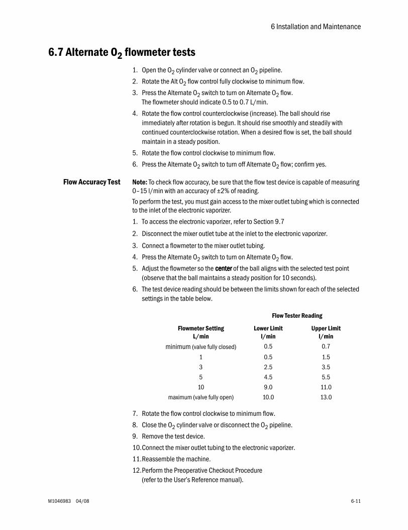
6 Installation and Maintenance
M1046983 04/08 6-11
6.7 Alternate O2 flowmeter tests1. Open the O2 cylinder valve or connect an O2 pipeline.
2. Rotate the Alt O2 flow control fully clockwise to minimum flow.
3. Press the Alternate O2 switch to turn on Alternate O2 flow. The flowmeter should indicate 0.5 to 0.7 L/min.
4. Rotate the flow control counterclockwise (increase). The ball should rise immediately after rotation is begun. It should rise smoothly and steadily with continued counterclockwise rotation. When a desired flow is set, the ball should maintain in a steady position.
5. Rotate the flow control clockwise to minimum flow.
6. Press the Alternate O2 switch to turn off Alternate O2 flow; confirm yes.
Flow Accuracy Test Note: To check flow accuracy, be sure that the flow test device is capable of measuring 0–15 l/min with an accuracy of ±2% of reading.
To perform the test, you must gain access to the mixer outlet tubing which is connected to the inlet of the electronic vaporizer.
1. To access the electronic vaporizer, refer to Section 9.7
2. Disconnect the mixer outlet tube at the inlet to the electronic vaporizer.
3. Connect a flowmeter to the mixer outlet tubing.
4. Press the Alternate O2 switch to turn on Alternate O2 flow.
5. Adjust the flowmeter so the cccceeeennnntttteeeerrrr of the ball aligns with the selected test point (observe that the ball maintains a steady position for 10 seconds).
6. The test device reading should be between the limits shown for each of the selected settings in the table below.
7. Rotate the flow control clockwise to minimum flow.
8. Close the O2 cylinder valve or disconnect the O2 pipeline.
9. Remove the test device.
10.Connect the mixer outlet tubing to the electronic vaporizer.
11.Reassemble the machine.
12.Perform the Preoperative Checkout Procedure (refer to the User’s Reference manual).
Flow Tester Reading
Flowmeter SettingL/min
Lower Limitl/min
Upper Limitl/min
minimum (valve fully closed) 0.5 0.7
1 0.5 1.5
3 2.5 3.5
5 4.5 5.5
10 9.0 11.0
maximum (valve fully open) 10.0 13.0
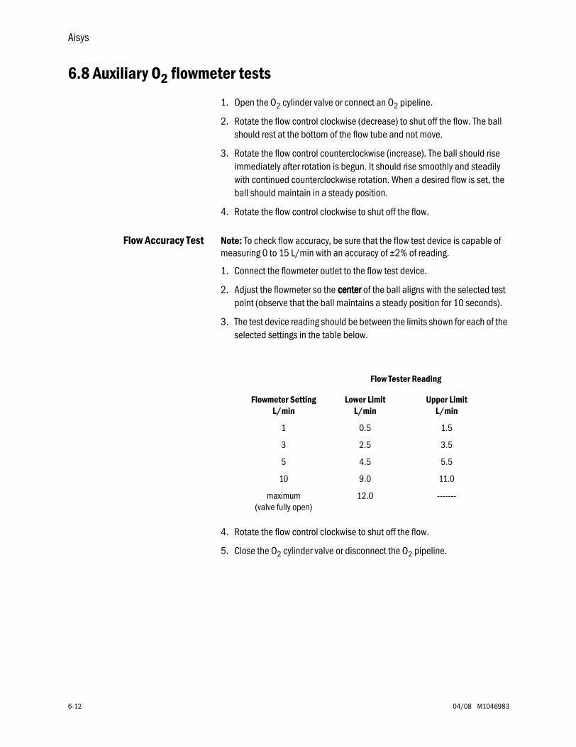
Aisys
6-12 04/08 M1046983
6.8 Auxiliary O2 flowmeter tests
1. Open the O2 cylinder valve or connect an O2 pipeline.
2. Rotate the flow control clockwise (decrease) to shut off the flow. The ball should rest at the bottom of the flow tube and not move.
3. Rotate the flow control counterclockwise (increase). The ball should rise immediately after rotation is begun. It should rise smoothly and steadily with continued counterclockwise rotation. When a desired flow is set, the ball should maintain in a steady position.
4. Rotate the flow control clockwise to shut off the flow.
Flow Accuracy Test Note: To check flow accuracy, be sure that the flow test device is capable of measuring 0 to 15 L/min with an accuracy of ±2% of reading.
1. Connect the flowmeter outlet to the flow test device.
2. Adjust the flowmeter so the cccceeeennnntttteeeerrrr of the ball aligns with the selected test point (observe that the ball maintains a steady position for 10 seconds).
3. The test device reading should be between the limits shown for each of the selected settings in the table below.
4. Rotate the flow control clockwise to shut off the flow.
5. Close the O2 cylinder valve or disconnect the O2 pipeline.
Flow Tester Reading
Flowmeter SettingL/min
Lower LimitL/min
Upper LimitL/min
1 0.5 1.5
3 2.5 3.5
5 4.5 5.5
10 9.0 11.0
maximum(valve fully open)
12.0 -------
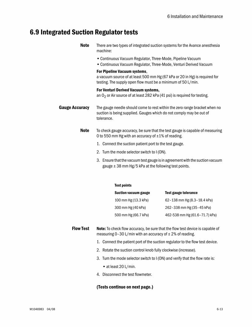
6 Installation and Maintenance
M1046983 04/08 6-13
6.9 Integrated Suction Regulator tests
Note There are two types of integrated suction systems for the Avance anesthesia machine:
• Continuous Vacuum Regulator, Three-Mode, Pipeline Vacuum• Continuous Vacuum Regulator, Three-Mode, Venturi Derived Vacuum
For Pipeline Vacuum systems, a vacuum source of at least 500 mm Hg (67 kPa or 20 in Hg) is required for testing. The supply open flow must be a minimum of 50 L/min.
For Venturi Derived Vacuum systems,an O2 or Air source of at least 282 kPa (41 psi) is required for testing.
Gauge Accuracy The gauge needle should come to rest within the zero range bracket when no suction is being supplied. Gauges which do not comply may be out of tolerance.
Note To check gauge accuracy, be sure that the test gauge is capable of measuring 0 to 550 mm Hg with an accuracy of ±1% of reading.
1. Connect the suction patient port to the test gauge.
2. Turn the mode selector switch to I (ON).
3. Ensure that the vacuum test gauge is in agreement with the suction vacuum gauge ± 38 mm Hg/5 kPa at the following test points.
Flow Test Note: To check flow accuracy, be sure that the flow test device is capable of measuring 0–30 L/min with an accuracy of ± 2% of reading.
1. Connect the patient port of the suction regulator to the flow test device.
2. Rotate the suction control knob fully clockwise (increase).
3. Turn the mode selector switch to I (ON) and verify that the flow rate is:
• at least 20 L/min.
4. Disconnect the test flowmeter.
(Tests continue on next page.)
Test points
Suction vacuum gauge Test gauge tolerance
100 mm Hg (13.3 kPa) 62–138 mm Hg (8.3–18.4 kPa)
300 mm Hg (40 kPa) 262–338 mm Hg (35–45 kPa)
500 mm Hg (66.7 kPa) 462-538 mm Hg (61.6–71.7) kPa)
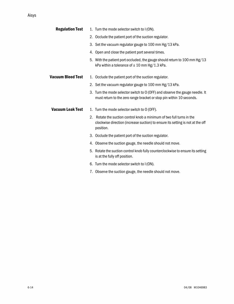
Aisys
6-14 04/08 M1046983
Regulation Test 1. Turn the mode selector switch to I (ON).
2. Occlude the patient port of the suction regulator.
3. Set the vacuum regulator gauge to 100 mm Hg/13 kPa.
4. Open and close the patient port several times.
5. With the patient port occluded, the gauge should return to 100 mm Hg/13 kPa within a tolerance of ± 10 mm Hg/1.3 kPa.
Vacuum Bleed Test 1. Occlude the patient port of the suction regulator.
2. Set the vacuum regulator gauge to 100 mm Hg/13 kPa.
3. Turn the mode selector switch to O (OFF) and observe the gauge needle. It must return to the zero range bracket or stop pin within 10 seconds.
Vacuum Leak Test 1. Turn the mode selector switch to O (OFF).
2. Rotate the suction control knob a minimum of two full turns in the clockwise direction (increase suction) to ensure its setting is not at the off position.
3. Occlude the patient port of the suction regulator.
4. Observe the suction gauge, the needle should not move.
5. Rotate the suction control knob fully counterclockwise to ensure its setting is at the fully off position.
6. Turn the mode selector switch to I (ON).
7. Observe the suction gauge, the needle should not move.
6 Installation and Maintenance
M1046983 04/08 6-15
6.10 Battery capacity testAlthough replacement of the backup batteries is recommended at the end of 4 years, batteries that pass the capacity test can be considered viable for battery backup of the system for up to 6 years at the discretion of the hospital.
Before testing the batteries, ensure that they are fully charged.
Test procedure 1. Turn the system on and start a case (simulated).
2. Turn off the mains system breaker on the AC Inlet.
3. Allow the system to run on battery until it does an orderly shutdown and powers off (can be in excess of 90 minutes).
4. Set the system switch to Standby and turn on the mains system breaker.
5. Set the system switch to On and enter the Service Mode.
6. Launch the Service Application.
7. On the Power Diagnostics menu (Section 12.7) select Power Board.
8. The Power Board window (Section 12.7.1) shows the Date battery Tested (the last full battery discharge) and the Last Full Discharge time.
• If the Last Full Discharge time is greater than 45 minutes, the batteries can be left in service for one more year.
• If the Last Full Discharge time is less than 45 minutes, both batteries should be replaced.
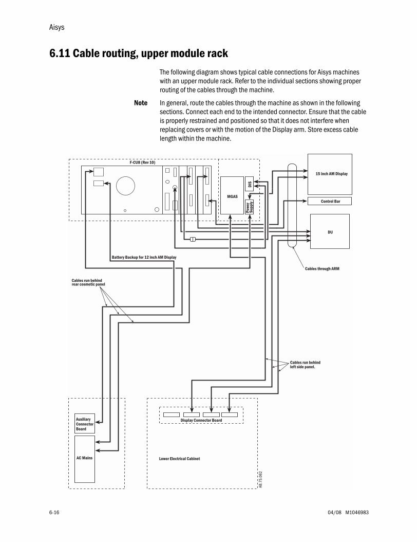
Aisys
6-16 04/08 M1046983
6.11 Cable routing, upper module rackThe following diagram shows typical cable connections for Aisys machines with an upper module rack. Refer to the individual sections showing proper routing of the cables through the machine.
Note In general, route the cables through the machine as shown in the following sections. Connect each end to the intended connector. Ensure that the cable is properly restrained and positioned so that it does not interfere when replacing covers or with the motion of the Display arm. Store excess cable length within the machine.
Lower Electrical Cabinet
Display Connector Board
AC Mains
AuxiliaryConnectorBoard
Cables run behindleft side panel.
Cables run behindrear cosmetic panel
15 inch AM Display
Control Bar
Cables through ARM
DU
Pow
erSu
pply
MGAS
DIS
F-CU8 (Rev 10)
Battery Backup for 12 inch AM DisplayAB
.75.
062
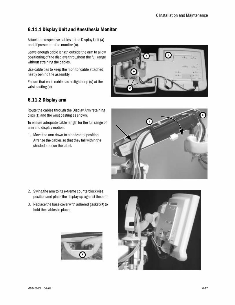
6 Installation and Maintenance
M1046983 04/08 6-17
6.11.1 Display Unit and Anesthesia Monitor
Attach the respective cables to the Display Unit (A) and, if present, to the monitor (B).
Leave enough cable length outside the arm to allow positioning of the displays throughout the full range without straining the cables.
Use cable ties to keep the monitor cable attached neatly behind the assembly.
Ensure that each cable has a slight loop (C) at the wrist casting (D).
6.11.2 Display arm
Route the cables through the Display Arm retaining clips (E) and the wrist casting as shown.
To ensure adequate cable length for the full range of arm and display motion:
1. Move the arm down to a horizontal position. Arrange the cables so that they fall within the shaded area on the label.
2. Swing the arm to its extreme counterclockwise position and place the display up against the arm.
3. Replace the base cover with adhered gasket (F) to hold the cables in place.
B
C
A
D
E
E
F
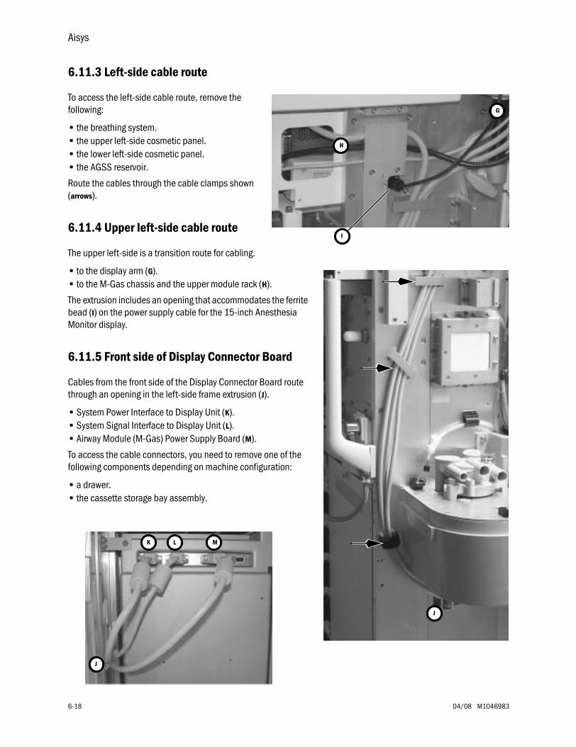
Aisys
6-18 04/08 M1046983
6.11.3 Left-side cable route
To access the left-side cable route, remove the following:
• the breathing system.• the upper left-side cosmetic panel.• the lower left-side cosmetic panel.• the AGSS reservoir.
Route the cables through the cable clamps shown (arrows).
6.11.4 Upper left-side cable route
The upper left-side is a transition route for cabling.
• to the display arm (G).• to the M-Gas chassis and the upper module rack (H).
The extrusion includes an opening that accommodates the ferrite bead (I) on the power supply cable for the 15-inch Anesthesia Monitor display.
6.11.5 Front side of Display Connector Board
Cables from the front side of the Display Connector Board route through an opening in the left-side frame extrusion (J).
• System Power Interface to Display Unit (K).• System Signal Interface to Display Unit (L).• Airway Module (M-Gas) Power Supply Board (M).
To access the cable connectors, you need to remove one of the following components depending on machine configuration:
• a drawer.• the cassette storage bay assembly.
G
H
I
J
K L M
J
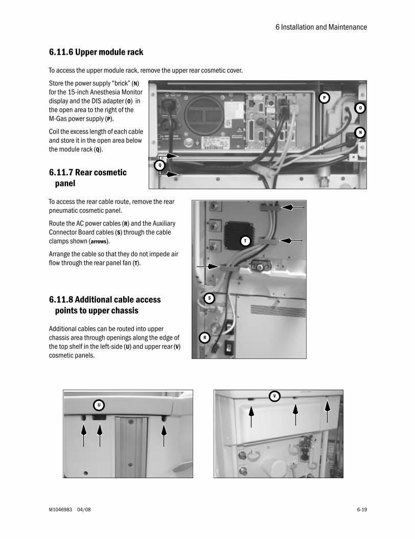
6 Installation and Maintenance
M1046983 04/08 6-19
6.11.6 Upper module rack
To access the upper module rack, remove the upper rear cosmetic cover.
Store the power supply “brick” (N) for the 15-inch Anesthesia Monitor display and the DIS adapter (O) in the open area to the right of the M-Gas power supply (P).
Coil the excess length of each cable and store it in the open area below the module rack (Q).
6.11.7 Rear cosmetic panel
To access the rear cable route, remove the rear pneumatic cosmetic panel.
Route the AC power cables (R) and the Auxiliary Connector Board cables (S) through the cable clamps shown (arrows).
Arrange the cable so that they do not impede air flow through the rear panel fan (T).
6.11.8 Additional cable access points to upper chassis
Additional cables can be routed into upper chassis area through openings along the edge of the top shelf in the left-side (U) and upper rear (V) cosmetic panels.
N
P
Q
O
R
S
T
U
V
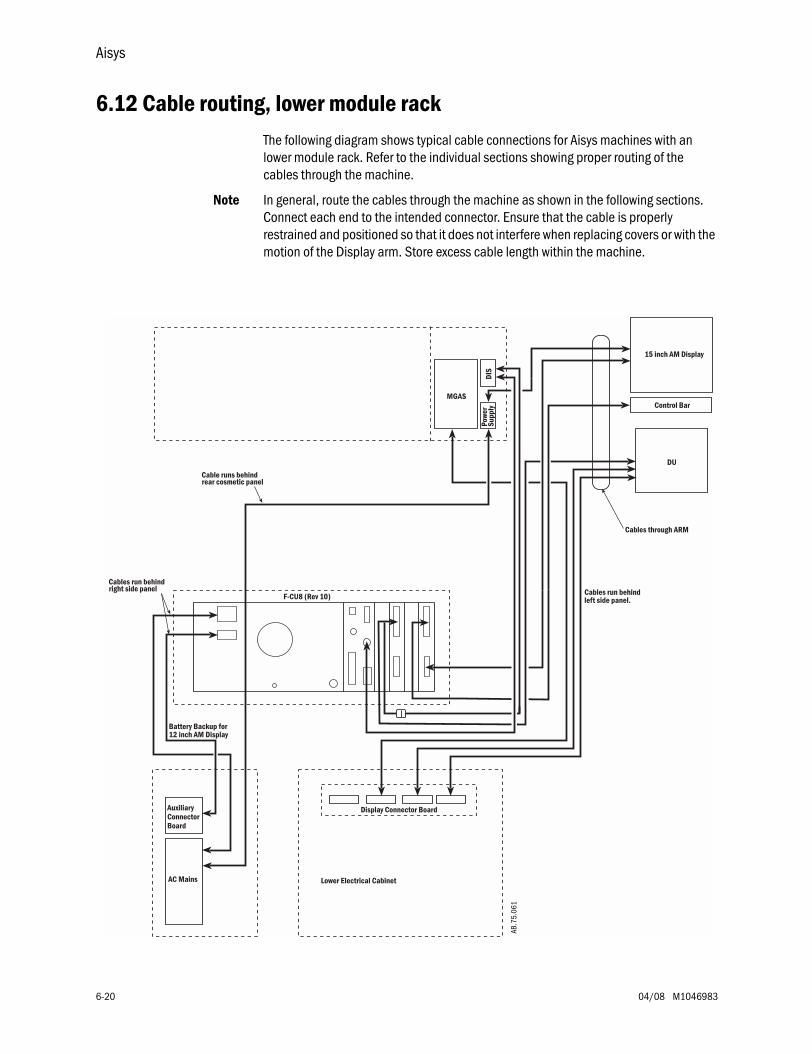
Aisys
6-20 04/08 M1046983
6.12 Cable routing, lower module rackThe following diagram shows typical cable connections for Aisys machines with an lower module rack. Refer to the individual sections showing proper routing of the cables through the machine.
Note In general, route the cables through the machine as shown in the following sections. Connect each end to the intended connector. Ensure that the cable is properly restrained and positioned so that it does not interfere when replacing covers or with the motion of the Display arm. Store excess cable length within the machine.
Pow
erSu
pply
MGAS
Lower Electrical Cabinet
Display Connector Board
AC Mains
AuxiliaryConnectorBoard
Cables run behindleft side panel.
Cables run behindright side panel
15 inch AM Display
Control Bar
Cables through ARM
DU
F-CU8 (Rev 10)
Cable runs behindrear cosmetic panel
DIS
Battery Backup for12 inch AM Display
AB.7
5.06
1

6 Installation and Maintenance
M1046983 04/08 6-21
6.12.1 Display Unit and Anesthesia Monitor
Attach the respective cables to the Display Unit (A) and, if present, to the monitor (B).
Leave enough cable length outside the arm to allow positioning of the displays throughout the full range without straining the cables.
Use cable ties to keep the monitor cable attached neatly behind the assembly.
Ensure that each cable has a slight loop (C) at the wrist casting (D).
6.12.2 Display arm
Route the cables through the Display Arm retaining clips (E) and the wrist casting as shown.
To ensure adequate cable length for the full range of arm and display motion:
1. Move the arm down to a horizontal position. Arrange the cables so that they fall within the shaded area on the label.
2. Swing the arm to its extreme counterclockwise position and place the display up against the arm.
3. Replace the base cover with adhered gasket (F) to hold the cables in place.
B
C
A
D
E
E
F
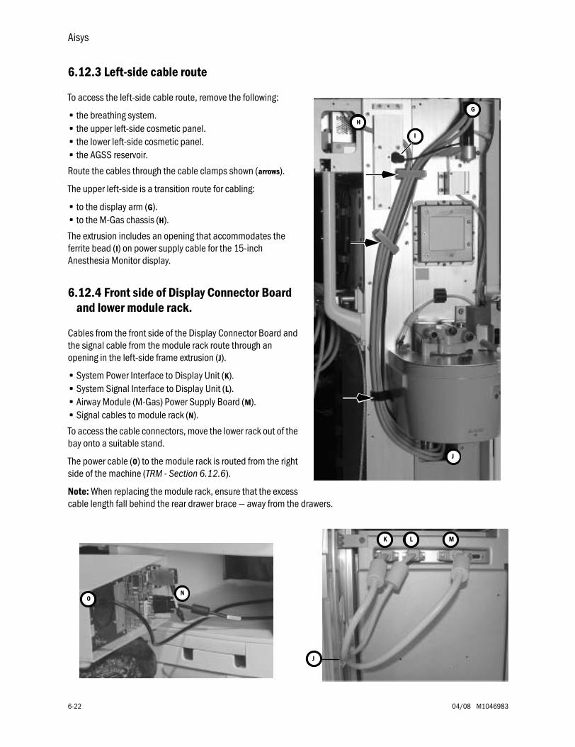
Aisys
6-22 04/08 M1046983
6.12.3 Left-side cable route
To access the left-side cable route, remove the following:
• the breathing system.• the upper left-side cosmetic panel.• the lower left-side cosmetic panel.• the AGSS reservoir.
Route the cables through the cable clamps shown (arrows).
The upper left-side is a transition route for cabling:
• to the display arm (G).• to the M-Gas chassis (H).
The extrusion includes an opening that accommodates the ferrite bead (I) on power supply cable for the 15-inch Anesthesia Monitor display.
6.12.4 Front side of Display Connector Board and lower module rack.
Cables from the front side of the Display Connector Board and the signal cable from the module rack route through an opening in the left-side frame extrusion (J).
• System Power Interface to Display Unit (K).• System Signal Interface to Display Unit (L).• Airway Module (M-Gas) Power Supply Board (M).• Signal cables to module rack (N).
To access the cable connectors, move the lower rack out of the bay onto a suitable stand.
The power cable (O) to the module rack is routed from the right side of the machine (TRM - Section 6.12.6).
Note: When replacing the module rack, ensure that the excess cable length fall behind the rear drawer brace — away from the drawers.
G
H
I
J
K L M
J
NO
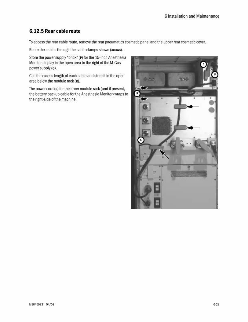
6 Installation and Maintenance
M1046983 04/08 6-23
6.12.5 Rear cable route
To access the rear cable route, remove the rear pneumatics cosmetic panel and the upper rear cosmetic cover.
Route the cables through the cable clamps shown (arrows).
Store the power supply “brick” (P) for the 15-inch Anesthesia Monitor display in the open area to the right of the M-Gas power supply (Q).
Coil the excess length of each cable and store it in the open area below the module rack (R).
The power cord (S) for the lower module rack (and if present, the battery backup cable for the Anesthesia Monitor) wraps to the right-side of the machine.
P
Q
S
R
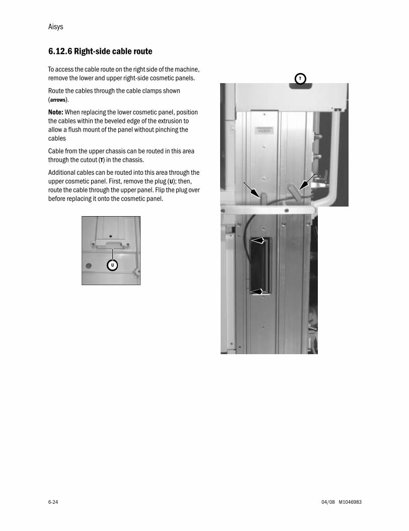
Aisys
6-24 04/08 M1046983
6.12.6 Right-side cable route
To access the cable route on the right side of the machine, remove the lower and upper right-side cosmetic panels.
Route the cables through the cable clamps shown (arrows).
Note: When replacing the lower cosmetic panel, position the cables within the beveled edge of the extrusion to allow a flush mount of the panel without pinching the cables
Cable from the upper chassis can be routed in this area through the cutout (T) in the chassis.
Additional cables can be routed into this area through the upper cosmetic panel. First, remove the plug (U); then, route the cable through the upper panel. Flip the plug over before replacing it onto the cosmetic panel.
T
U
M1046983 04/08 7-1
7 Troubleshooting
In this section 7.1 Troubleshooting Guidelines . . . . . . . . . . . . . . . . . . . . . . . . . . . . . . . . . . . . . . . . . . . . . . . . . .7-2
7.2 Troubleshooting high pressure and low pressure leaks . . . . . . . . . . . . . . . . . . . . . . . . . . . .7-3
7.3 Troubleshooting Startup Screen (POST) messages - for HPDU . . . . . . . . . . . . . . . . . . . . . .7-4
7.4 Troubleshooting the HPDU Display . . . . . . . . . . . . . . . . . . . . . . . . . . . . . . . . . . . . . . . . . . . .7-5
7.5 Troubleshooting System Malfunction (safe-state) screen . . . . . . . . . . . . . . . . . . . . . . . . . .7-6
7.6 Breathing System Leak Test Guide . . . . . . . . . . . . . . . . . . . . . . . . . . . . . . . . . . . . . . . . . . . . .7-7
7.6.1 Check Valves . . . . . . . . . . . . . . . . . . . . . . . . . . . . . . . . . . . . . . . . . . . . . . . . . . . . . . . .7-8
7.6.2 Breathing System Troubleshooting Flowcharts . . . . . . . . . . . . . . . . . . . . . . . . . . . . 7-9
7.6.3 Leak Isolation Tests . . . . . . . . . . . . . . . . . . . . . . . . . . . . . . . . . . . . . . . . . . . . . . . . 7-14
7.7 System Troubleshooting Flowcharts . . . . . . . . . . . . . . . . . . . . . . . . . . . . . . . . . . . . . . . . . 7-29
7.8 System Malfunction and Alt O2 Flowchart Table . . . . . . . . . . . . . . . . . . . . . . . . . . . . . . . 7-41
7.9 Technical Alarms . . . . . . . . . . . . . . . . . . . . . . . . . . . . . . . . . . . . . . . . . . . . . . . . . . . . . . . . . 7-43
7.10 Electronic Vaporizer (eVap) Troubleshooting . . . . . . . . . . . . . . . . . . . . . . . . . . . . . . . . . 7-78
7.10.1 Vaporizer Test Results . . . . . . . . . . . . . . . . . . . . . . . . . . . . . . . . . . . . . . . . . . . . . 7-78
7.10.2 Vaporizer Test Results troubleshooting procedures . . . . . . . . . . . . . . . . . . . . . . 7-79
7.10.3 eVap Troubleshooting Flowchart . . . . . . . . . . . . . . . . . . . . . . . . . . . . . . . . . . . . . 7-83
7.10.4 eVap Error Log table . . . . . . . . . . . . . . . . . . . . . . . . . . . . . . . . . . . . . . . . . . . . . . . 7-84
7.10.5 eVap Flow and Zero troubleshooting . . . . . . . . . . . . . . . . . . . . . . . . . . . . . . . . . . 7-85
7.10.6 eVap Pressure troubleshooting . . . . . . . . . . . . . . . . . . . . . . . . . . . . . . . . . . . . . . 7-86
7.10.7 eVap Leak and Cassette troubleshooting . . . . . . . . . . . . . . . . . . . . . . . . . . . . . . 7-87
7.10.8 eVap Communication troubleshooting . . . . . . . . . . . . . . . . . . . . . . . . . . . . . . . . 7-88
7.10.9 eVap ADB troubleshooting . . . . . . . . . . . . . . . . . . . . . . . . . . . . . . . . . . . . . . . . . . 7-89
7.10.10 eVap Temperature troubleshooting. . . . . . . . . . . . . . . . . . . . . . . . . . . . . . . . . . 7-90
7.10.11 eVap Power and Valves troubleshooting. . . . . . . . . . . . . . . . . . . . . . . . . . . . . . 7-91
7.10.12 Electronic vaporizer 10VA power interconnect fault isolation . . . . . . . . . . . . 7-92
7.10.13 Vaporizer Checkout Troubleshooting. . . . . . . . . . . . . . . . . . . . . . . . . . . . . . . . . 7-93
7.11 eVap Therapy Cassette Leak Test . . . . . . . . . . . . . . . . . . . . . . . . . . . . . . . . . . . . . . . . . . 7-97
7.12 eVap Backpressure Valve Test . . . . . . . . . . . . . . . . . . . . . . . . . . . . . . . . . . . . . . . . . . . . . 7-98
7.13 eVap Inflow Check Valve Test . . . . . . . . . . . . . . . . . . . . . . . . . . . . . . . . . . . . . . . . . . . . . 7-100
7.14 eVap Scavenger Path Testing . . . . . . . . . . . . . . . . . . . . . . . . . . . . . . . . . . . . . . . . . . . . . 7-102
7.15 Steps and Messages displayed during the System Checkout . . . . . . . . . . . . . . . . . . . 7-103
Aisys
7-2 04/08 M1046983
7.1 Troubleshooting Guidelines
Review system error logs using the Service Log menu (Section 4.4.2) or download the logs to PC files using the PC Service Application (Section 12.6.3). Review the logs to identify issues and follow the appropriate subsystem troubleshooting procedures.
Troubleshooting high pressure and low pressure leaks . . . . . . . . . . . . . . Section 7.2 on page 7-3
Troubleshooting Startup Screen (POST) messages - for HPDU . . . . . . . . Section 7.3 on page 7-4
Troubleshooting the HPDU Display . . . . . . . . . . . . . . . . . . . . . . . . . . . . . . Section 7.4 on page 7-5
Troubleshooting System Malfunction (safe-state) screen . . . . . . . . . . . . Section 7.5 on page 7-6
Breathing System Leak Test Guide . . . . . . . . . . . . . . . . . . . . . . . . . . . . . . Section 7.6 on page 7-7
System Troubleshooting Flowcharts . . . . . . . . . . . . . . . . . . . . . . . . . . . . Section 7.7 on page 7-29
System Malfunction and Alt O2 Flowchart Table . . . . . . . . . . . . . . . . . . Section 7.8 on page 7-41
Technical Alarms. . . . . . . . . . . . . . . . . . . . . . . . . . . . . . . . . . . . . . . . . . . . Section 7.9 on page 7-43
Electronic Vaporizer (eVap) Troubleshooting . . . . . . . . . . . . . . . . . . . .Section 7.10 on page 7-78
eVap Therapy Cassette Leak Test. . . . . . . . . . . . . . . . . . . . . . . . . . . . . .Section 7.11 on page 7-97
eVap Backpressure Valve Test . . . . . . . . . . . . . . . . . . . . . . . . . . . . . . . .Section 7.12 on page 7-98
eVap Inflow Check Valve Test . . . . . . . . . . . . . . . . . . . . . . . . . . . . . . . Section 7.13 on page 7-100
eVap Scavenger Path Testing. . . . . . . . . . . . . . . . . . . . . . . . . . . . . . . Section 7.14 on page 7-102
Steps and Messages displayed during the System Checkout. . . . . Section 7.15 on page 7-103
w WARNING Objects in the breathing system can stop gas flow to the patient. This can cause injury or death:
• Do not use a test plug that is small enough to fall into the breathing system.
• Make sure that there are no test plugs or other objects caught in the breathing system.
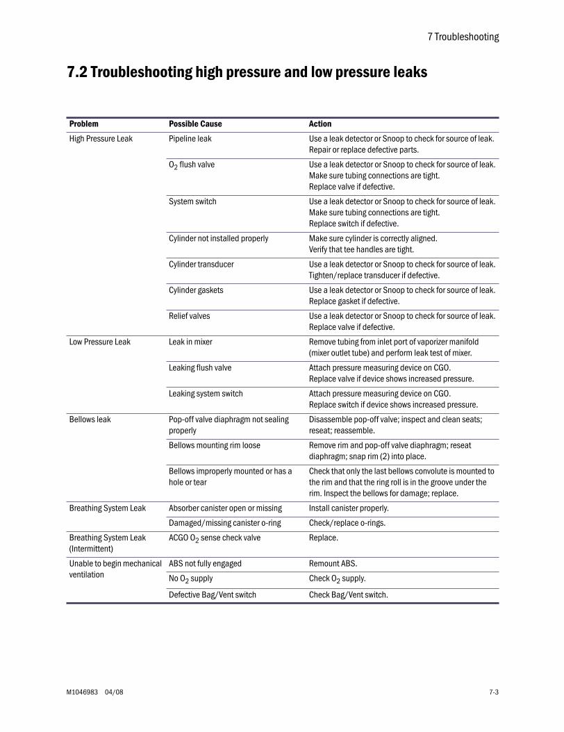
7 Troubleshooting
M1046983 04/08 7-3
7.2 Troubleshooting high pressure and low pressure leaks
Problem Possible Cause Action
High Pressure Leak Pipeline leak Use a leak detector or Snoop to check for source of leak. Repair or replace defective parts.
O2 flush valve Use a leak detector or Snoop to check for source of leak.Make sure tubing connections are tight.Replace valve if defective.
System switch Use a leak detector or Snoop to check for source of leak.Make sure tubing connections are tight.Replace switch if defective.
Cylinder not installed properly Make sure cylinder is correctly aligned.Verify that tee handles are tight.
Cylinder transducer Use a leak detector or Snoop to check for source of leak.Tighten/replace transducer if defective.
Cylinder gaskets Use a leak detector or Snoop to check for source of leak.Replace gasket if defective.
Relief valves Use a leak detector or Snoop to check for source of leak.Replace valve if defective.
Low Pressure Leak Leak in mixer Remove tubing from inlet port of vaporizer manifold (mixer outlet tube) and perform leak test of mixer.
Leaking flush valve Attach pressure measuring device on CGO.Replace valve if device shows increased pressure.
Leaking system switch Attach pressure measuring device on CGO.Replace switch if device shows increased pressure.
Bellows leak Pop-off valve diaphragm not sealing properly
Disassemble pop-off valve; inspect and clean seats; reseat; reassemble.
Bellows mounting rim loose Remove rim and pop-off valve diaphragm; reseat diaphragm; snap rim (2) into place.
Bellows improperly mounted or has a hole or tear
Check that only the last bellows convolute is mounted to the rim and that the ring roll is in the groove under the rim. Inspect the bellows for damage; replace.
Breathing System Leak Absorber canister open or missing Install canister properly.
Damaged/missing canister o-ring Check/replace o-rings.
Breathing System Leak(Intermittent)
ACGO O2 sense check valve Replace.
Unable to begin mechanical ventilation
ABS not fully engaged Remount ABS.
No O2 supply Check O2 supply.
Defective Bag/Vent switch Check Bag/Vent switch.
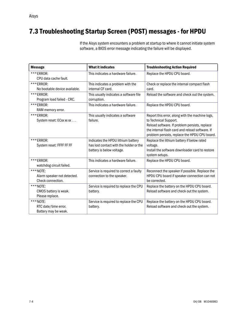
Aisys
7-4 04/08 M1046983
7.3 Troubleshooting Startup Screen (POST) messages - for HPDU
If the Aisys system encounters a problem at startup to where it cannot initiate system software, a BIOS error message indicating the failure will be displayed.
Message What it indicates Troubleshooting Action Required
***ERROR: CPU data cache fault.
This indicates a hardware failure. Replace the HPDU CPU board.
***ERROR: No bootable device available.
This indicates a problem with the internal CF card.
Check or replace the internal compact flash card.
***ERROR: Program load failed - CRC.
This usually indicates a software file corruption.
Reload the software and check out the system.
***ERROR: RAM memory error.
This indicates a hardware failure. Replace the HPDU CPU board.
***ERROR: System reset: ECxx xx xx . . .
This usually indicates a software failure.
Report this error, along with the machine logs, to Technical Support.Reload software. If problem persists, replace the internal flash card and reload software. If problem persists, replace the HPDU CPU board.
***ERROR: System reset: FFFF FF FF
Indicates the HPDU lithium battery has lost contact with the holder or the battery is below voltage.
Replace the lithium battery if below rated voltage.Install the software downloader card to restore system setups.
***ERROR: watchdog circuit failed.
This indicates a hardware failure. Replace the HPDU CPU board.
***NOTE: Alarm speaker not detected. Check connection.
Service is required to correct a faulty connection to the speaker.
Reconnect the speaker if possible. Replace the HPDU CPU board if speaker connection can not be corrected.
***NOTE: CMOS battery is weak. Please replace.
Service is required to replace the CPU battery.
Replace the battery on the HPDU CPU board. Reload software and check out the system.
***NOTE: RTC date/time error. Battery may be weak.
Service is required to replace the CPU battery.
Replace the battery on the HPDU CPU board. Reload software and check out the system.
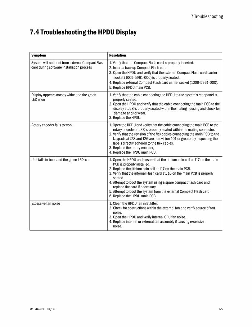
7 Troubleshooting
M1046983 04/08 7-5
7.4 Troubleshooting the HPDU Display
Symptom Resolution
System will not boot from external Compact Flash card during software installation process
1. Verify that the Compact Flash card is properly inserted.2. Insert a backup Compact Flash card.3. Open the HPDU and verify that the external Compact Flash card carrier
socket (1009-5961-000) is properly seated.4. Replace external Compact Flash card carrier socket (1009-5961-000).5. Replace HPDU main PCB.
Display appears mostly white and the green LED is on
1. Verify that the cable connecting the HPDU to the system’s rear panel is properly seated.2. Open the HPDU and verify that the cable connecting the main PCB to the display at J28 is properly seated within the mating housing and check for damage and/or wear.3. Replace the HPDU.
Rotary encoder fails to work 1. Open the HPDU and verify that the cable connecting the main PCB to the rotary encoder at J38 is properly seated within the mating connector.2. Verify that the revision of the flex cables connecting the main PCB to the keypads at J23 and J26 are at revision 101 or greater by inspecting the labels directly adhered to the flex cables.3. Replace the rotary encoder,4. Replace the HPDU main PCB.
Unit fails to boot and the green LED is on 1. Open the HPDU and ensure that the lithium coin cell at J17 on the main PCB is properly installed.2. Replace the lithium coin cell at J17 on the main PCB.3. Verify that the internal Flash card at J10 on the main PCB is properly seated.4. Attempt to boot the system using a spare compact flash card and replace the card if necessary.5. Attempt to boot the system from the external Compact Flash card.6. Replace the HPDU main PCB.
Excessive fan noise 1. Clean the HPDU fan inlet filter.2. Check for obstructions within the external fan and verify source of fan noise.3. Open the HPDU and verify internal CPU fan noise.4. Replace internal or external fan assembly if causing excessive noise.
Aisys
7-6 04/08 M1046983
7.5 Troubleshooting System Malfunction (safe-state) screen
Machine logs • Compatibility incomplete: No versions received from Vent SIB
• System Self-tests failed
The above error log entries are due to the Ventilator failing its Power-On Self Test (Post).
When the ventilator fails its self-test, the system enters the safe-state.
The likely cause is a Gas Inlet Valve Solenoid that is not transitioning to the de-energized state when valve drive power is removed.
Troubleshooting above stated condition:• Replace the Gas Inlet Valve Solenoid (Section 9.13.2).
• If problem continues, replace the Gas Inlet Valve components (Section 9.13.3).
7 Troubleshooting
M1046983 04/08 7-7
7.6 Breathing System Leak Test Guide
Note Always do the System “Checkout” (Section 3.2) on the machine before proceeding with these breathing system leak tests.
Follow the troubleshooting flowcharts in Section 7.6.2 to determine the best sequence of tests for locating a breathing system leak.
The procedures in Section 7.6.3 test specific components of the breathing system for leaks.
wwww WARNING Objects in the breathing system can stop gas flow to the patient. This can cause injury or death:
• Do not use a test plug that is small enough to fall into the breathing system.
• Make sure that there are no test plugs or other objects caught in the breathing system.
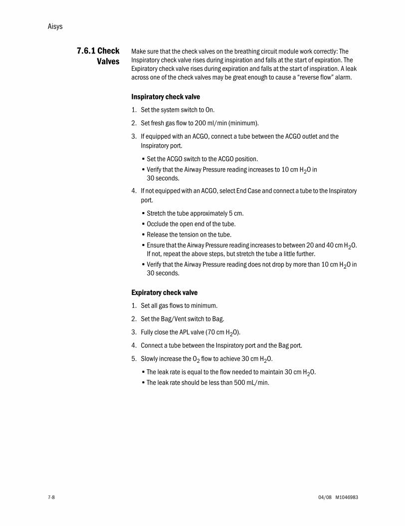
Aisys
7-8 04/08 M1046983
7.6.1 CheckValves
Make sure that the check valves on the breathing circuit module work correctly: The Inspiratory check valve rises during inspiration and falls at the start of expiration. The Expiratory check valve rises during expiration and falls at the start of inspiration. A leak across one of the check valves may be great enough to cause a “reverse flow” alarm.
Inspiratory check valve
1. Set the system switch to On.
2. Set fresh gas flow to 200 ml/min (minimum).
3. If equipped with an ACGO, connect a tube between the ACGO outlet and the Inspiratory port.
• Set the ACGO switch to the ACGO position.
• Verify that the Airway Pressure reading increases to 10 cm H2O in 30 seconds.
4. If not equipped with an ACGO, select End Case and connect a tube to the Inspiratory port.
• Stretch the tube approximately 5 cm.
• Occlude the open end of the tube.
• Release the tension on the tube.
• Ensure that the Airway Pressure reading increases to between 20 and 40 cm H2O. If not, repeat the above steps, but stretch the tube a little further.
• Verify that the Airway Pressure reading does not drop by more than 10 cm H2O in 30 seconds.
Expiratory check valve
1. Set all gas flows to minimum.
2. Set the Bag/Vent switch to Bag.
3. Fully close the APL valve (70 cm H2O).
4. Connect a tube between the Inspiratory port and the Bag port.
5. Slowly increase the O2 flow to achieve 30 cm H2O.
• The leak rate is equal to the flow needed to maintain 30 cm H2O.
• The leak rate should be less than 500 mL/min.

7 Troubleshooting
M1046983 04/08 7-9
7.6.2 Breathing System Troubleshooting Flowcharts
Flowchart 1
Start
Perform Leak Test 1Verifying the integrity
of test tools
Perform Test 2Low-pressure leaktesting the machine
Repair leak inmachine
Pass
Fail
Pass
Inspect/Replace tubing toairway pressure transducer;
Replace U-Cup sealsFail
Leak inBag Mode,Vent Mode,
or Both?Go to Flowchart 2
BagModeonly
Both Bag andVent Mode
Perform Test 3Testing the
airway pressure transducerand port U-cup seals
VentModeonly
Go to Flowchart 3
Review Leak Test Guide
• Do System checkout
• Isolate breathing system leak toBag Mode,Vent Mode, or Both
Go to Flowchart 4
AB.7
5.16
8
(Section 7.6)
(Section 3.2)
Vent Mode Bag Mode
Software ≥ 3.00 Machine Check - System
Machine Check - Circuit
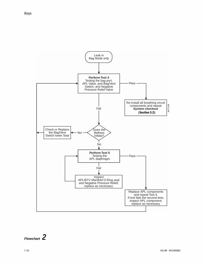
Aisys
7-10 04/08 M1046983
Flowchart 2
Leak inBag Mode only
Perform Test 4Testing the bag port,
APL Valve, and Bag/VentSwitch, and NegativePressure Relief Valve
Check or Replacethe Bag/Vent
Switch lower Seal
Does theBellowsInflate?
Yes
No
Perform Test 5Testing the
APL diaphragm
InspectAPL/BTV Manifold O-Ring sealand Negative Pressure Relief;
replace as necessary.
Fail
Re-Install all breathing circuitcomponents and repeat
System checkout
Replace APL componentsand repeat Test 4.
If test fails the second time,inspect APL component;
replace as necessary.
Fail
Pass
Pass
AB.7
5.16
9
(Section 3.2)
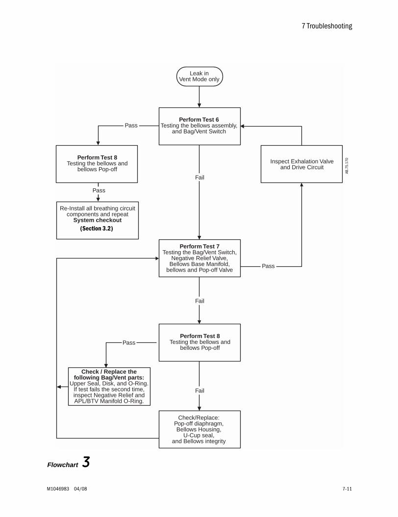
7 Troubleshooting
M1046983 04/08 7-11
Flowchart 3
Leak inVent Mode only
Perform Test 6Testing the bellows assembly,
and Bag/Vent Switch
Fail
Re-Install all breathing circuitcomponents and repeat
System checkout
Perform Test 7Testing the Bag/Vent Switch,
Negative Relief Valve,Bellows Base Manifold,
bellows and Pop-off Valve
Check/Replace:Pop-off diaphragm,Bellows Housing,
U-Cup seal,and Bellows integrity
Perform Test 8Testing the bellows and
bellows Pop-off
Fail
Check / Replace thefollowing Bag/Vent parts:
Upper Seal, Disk, and O-Ring.If test fails the second time,inspect Negative Relief andAPL/BTV Manifold O-Ring.
Inspect Exhalation Valveand Drive Circuit
Pass
Fail
Pass
Pass
Perform Test 8Testing the bellows and
bellows Pop-off
Pass
AB.7
5.17
0
(Section 3.2)
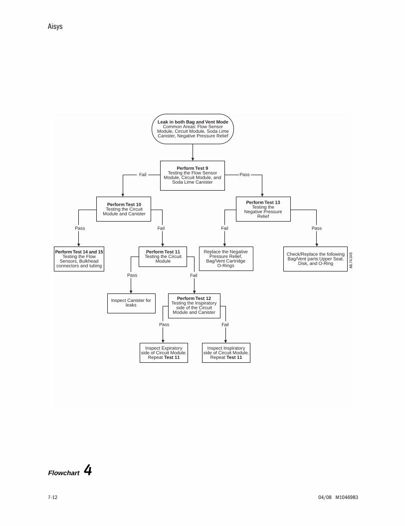
Aisys
7-12 04/08 M1046983
Flowchart 4
Leak in both Bag and Vent ModeCommon Areas: Flow Sensor
Module, Circuit Module, Soda LimeCanister, Negative Pressure Relief
Perform Test 9Testing the Flow Sensor
Module, Circuit Module, andSoda Lime Canister
Replace the NegativePressure Relief,
Bag/Vent CartridgeO-Rings
Perform Test 13Testing the
Negative PressureRelief
Check/Replace the followingBag/Vent parts:Upper Seal,
Disk, and O-Ring
Perform Test 14 and 15Testing the Flow
Sensors, Bulkheadconnectors and tubing
Perform Test 10Testing the Circuit
Module and Canister
Perform Test 12Testing the Inspiratory
side of the CircuitModule and Canister
Inspect Expiratoryside of Circuit Module.
Repeat Test 11
Perform Test 11Testing the Circuit
Module
Inspect Canister forleaks
PassFailFailPass
Pass Fail
Pass Fail
Inspect Inspiratoryside of Circuit Module.
Repeat Test 11
Fail Pass
AB.7
4.04
5
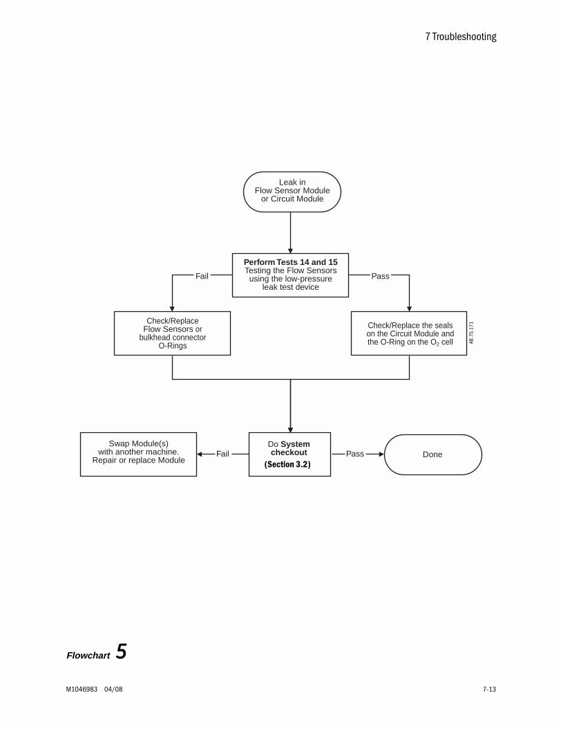
7 Troubleshooting
M1046983 04/08 7-13
Leak inFlow Sensor Module
or Circuit Module
Perform Tests 14 and 15Testing the Flow Sensorsusing the low-pressure
leak test device
Check/Replace the sealson the Circuit Module andthe O-Ring on the O2 cell
Pass
DoneSwap Module(s)
with another machine.Repair or replace Module
Do Systemcheckout PassFail
Fail
Check/ReplaceFlow Sensors or
bulkhead connectorO-Rings
Flowchart 5
AB.7
5.17
1(Section 3.2)
Aisys
7-14 04/08 M1046983
7.6.3 LeakIsolation Tests
The previous flowcharts refer you to the following tests.
These tests require the use of the Low Pressure Leak Test Device and the Leak Test Tool Kit (refer to Section 10.1, "Service tools").
The Leak Test Tool Kit includes:• the Machine Test Tool• the Circuit Test Tool• and various Test Plugs
When performing these tests on machines with an ACGO outlet, ensure that the ACGO selector switch is set to the ABS (Circle circuit) position.
Note To perform most of these tests, you must boot the system with the PC Service Application and access the diagnostics functions as described in the test.
Test 1: Verifying the integrity of the test tools. . . . . . . . . . . . . . . . . . . . . . . . . . . . . . . . . . . . . . . . . . . . . . . . . . . . . . . . . . . . . . . 7-15
Test 2: Low-pressure leak testing the machine . . . . . . . . . . . . . . . . . . . . . . . . . . . . . . . . . . . . . . . . . . . . . . . . . . . . . . . . . . . . . 7-16
Test 3: Testing the airway pressure transducer, and Port 1 and Port 3 u-cup seals . . . . . . . . . . . . . . . . . . . . . . . . . . . . . . . . 7-17
Test 4: Testing the bag port cover, the APL valve, the Bag/Vent switch, and the negative pressure relief valve . . . . . . . . . 7-18
Test 5: Testing the APL diaphragm . . . . . . . . . . . . . . . . . . . . . . . . . . . . . . . . . . . . . . . . . . . . . . . . . . . . . . . . . . . . . . . . . . . . . . . 7-19
Test 6: Testing the bellows module and the Bag/Vent switch . . . . . . . . . . . . . . . . . . . . . . . . . . . . . . . . . . . . . . . . . . . . . . . . . 7-20
Test 7: Testing the bellows, the bellows pop-off valve, the bellows base manifold, and the Bag/Vent switch. . . . . . . . . . . 7-21
Test 8: Testing the bellows assembly . . . . . . . . . . . . . . . . . . . . . . . . . . . . . . . . . . . . . . . . . . . . . . . . . . . . . . . . . . . . . . . . . . . . . 7-22
Test 9: Testing the flow sensor module, the circuit module, and the soda lime canister . . . . . . . . . . . . . . . . . . . . . . . . . . . . 7-23
Test 10: Testing the circuit module and the canister . . . . . . . . . . . . . . . . . . . . . . . . . . . . . . . . . . . . . . . . . . . . . . . . . . . . . . . . . . 7-24
Test 11: Testing the circuit module . . . . . . . . . . . . . . . . . . . . . . . . . . . . . . . . . . . . . . . . . . . . . . . . . . . . . . . . . . . . . . . . . . . . . . . . 7-24
Test 12: Testing the inspiratory side of the circuit module . . . . . . . . . . . . . . . . . . . . . . . . . . . . . . . . . . . . . . . . . . . . . . . . . . . . . 7-25
Test 13: Testing the negative pressure relief valve. . . . . . . . . . . . . . . . . . . . . . . . . . . . . . . . . . . . . . . . . . . . . . . . . . . . . . . . . . . . 7-26
Test 14: Testing the flow sensors only. . . . . . . . . . . . . . . . . . . . . . . . . . . . . . . . . . . . . . . . . . . . . . . . . . . . . . . . . . . . . . . . . . . . . . 7-27
Test 15: Testing a flow sensor including the Ventilator Monitoring Assembly and interfacing components . . . . . . . . . . . . . . 7-28
wwww WARNING Objects in the breathing system can stop gas flow to the patient. This can cause injury or death:
• Do not use a test plug that is small enough to fall into the breathing system.
• Make sure that there are no test plugs or other objects caught in the breathing system.
wwww CAUTION Do not use O2 Flush for leak isolation tests. Do not leave pressurized systems unattended. High pressure and equipment damage may result.
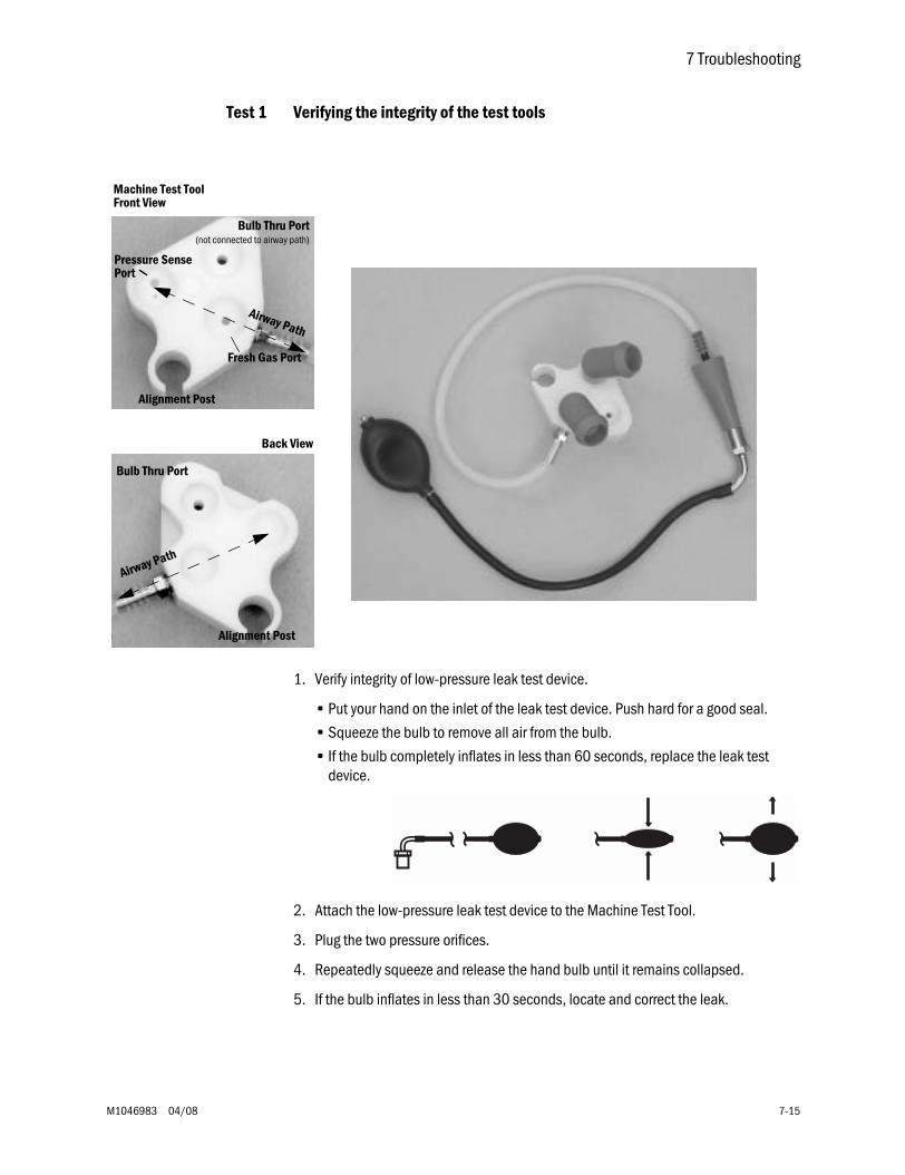
7 Troubleshooting
M1046983 04/08 7-15
Test 1 Verifying the integrity of the test tools
1. Verify integrity of low-pressure leak test device.
• Put your hand on the inlet of the leak test device. Push hard for a good seal.
• Squeeze the bulb to remove all air from the bulb.
• If the bulb completely inflates in less than 60 seconds, replace the leak test device.
2. Attach the low-pressure leak test device to the Machine Test Tool.
3. Plug the two pressure orifices.
4. Repeatedly squeeze and release the hand bulb until it remains collapsed.
5. If the bulb inflates in less than 30 seconds, locate and correct the leak.
Bulb Thru Port(not connected to airway path)
Alignment Post
Fresh Gas Port
Pressure SensePort
Airway Path
Bulb Thru Port
Alignment Post
Airway Path
Machine Test Tool
Back View
Front View
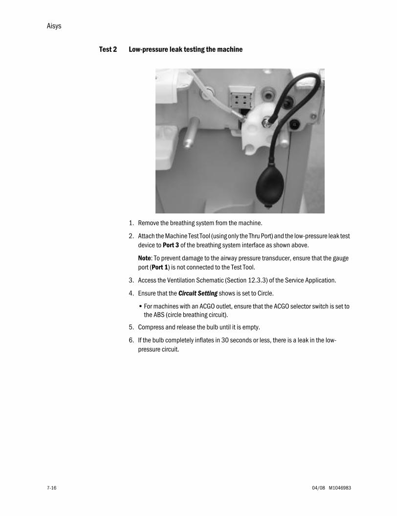
Aisys
7-16 04/08 M1046983
Test 2 Low-pressure leak testing the machine
1. Remove the breathing system from the machine.
2. Attach the Machine Test Tool (using only the Thru Port) and the low-pressure leak test device to Port 3 of the breathing system interface as shown above.
Note: To prevent damage to the airway pressure transducer, ensure that the gauge port (Port 1) is not connected to the Test Tool.
3. Access the Ventilation Schematic (Section 12.3.3) of the Service Application.
4. Ensure that the Circuit Setting shows is set to Circle.
• For machines with an ACGO outlet, ensure that the ACGO selector switch is set to the ABS (circle breathing circuit).
5. Compress and release the bulb until it is empty.
6. If the bulb completely inflates in 30 seconds or less, there is a leak in the low-pressure circuit.
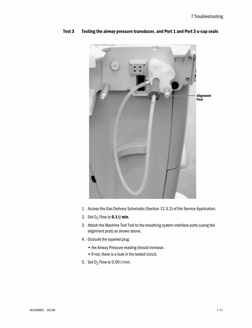
7 Troubleshooting
M1046983 04/08 7-17
Test 3 Testing the airway pressure transducer, and Port 1 and Port 3 u-cup seals
1. Access the Gas Delivery Schematic (Section 12.3.2) of the Service Application.
2. Set O2 Flow to 0.1 l/min.
3. Attach the Machine Test Tool to the breathing system interface ports (using the alignment post) as shown above.
4. Occlude the tapered plug.
• the Airway Pressure reading should increase.
• If not, there is a leak in the tested circuit.
5. Set O2 Flow to 0.00 l/min.
AlignmentPost
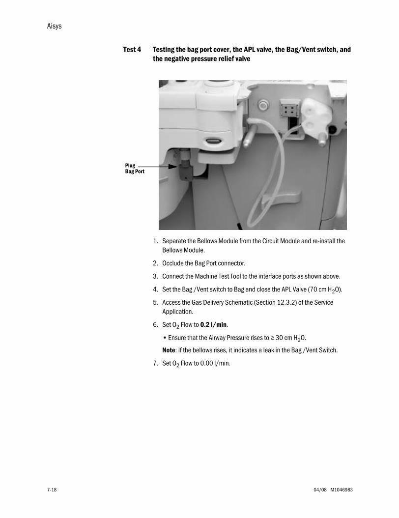
Aisys
7-18 04/08 M1046983
Test 4 Testing the bag port cover, the APL valve, the Bag/Vent switch, and the negative pressure relief valve
1. Separate the Bellows Module from the Circuit Module and re-install the Bellows Module.
2. Occlude the Bag Port connector.
3. Connect the Machine Test Tool to the interface ports as shown above.
4. Set the Bag /Vent switch to Bag and close the APL Valve (70 cm H2O).
5. Access the Gas Delivery Schematic (Section 12.3.2) of the Service Application.
6. Set O2 Flow to 0.2 l/min.
• Ensure that the Airway Pressure rises to ≥ 30 cm H2O.
Note: If the bellows rises, it indicates a leak in the Bag /Vent Switch.
7. Set O2 Flow to 0.00 l/min.
PlugBag Port
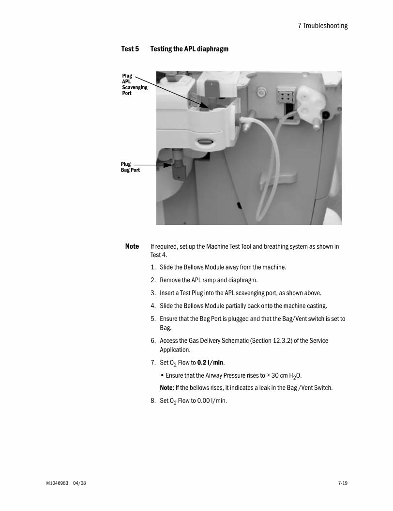
7 Troubleshooting
M1046983 04/08 7-19
Test 5 Testing the APL diaphragm
Note If required, set up the Machine Test Tool and breathing system as shown in Test 4.
1. Slide the Bellows Module away from the machine.
2. Remove the APL ramp and diaphragm.
3. Insert a Test Plug into the APL scavenging port, as shown above.
4. Slide the Bellows Module partially back onto the machine casting.
5. Ensure that the Bag Port is plugged and that the Bag/Vent switch is set to Bag.
6. Access the Gas Delivery Schematic (Section 12.3.2) of the Service Application.
7. Set O2 Flow to 0.2 l/min.
• Ensure that the Airway Pressure rises to ≥ 30 cm H2O.
Note: If the bellows rises, it indicates a leak in the Bag /Vent Switch.
8. Set O2 Flow to 0.00 l/min.
PlugBag Port
PlugAPLScavengingPort
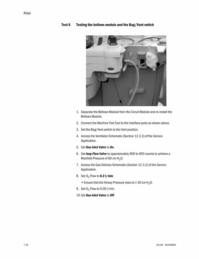
Aisys
7-20 04/08 M1046983
Test 6 Testing the bellows module and the Bag/Vent switch
1. Separate the Bellows Module from the Circuit Module and re-install the Bellows Module.
2. Connect the Machine Test Tool to the interface ports as shown above.
3. Set the Bag/Vent switch to the Vent position.
4. Access the Ventilator Schematic (Section 12.3.3) of the Service Application.
5. Set Gas Inlet Valve to On.
6. Set Insp Flow Valve to approximately 900 to 950 counts to achieve a Manifold Pressure of 60 cm H2O.
7. Access the Gas Delivery Schematic (Section 12.3.2) of the Service Application.
8. Set O2 Flow to 0.2 l/min.
• Ensure that the Airway Pressure rises to ≥ 30 cm H2O.
9. Set O2 Flow to 0.00 l/min.
10.Set Gas Inlet Valve to Off.
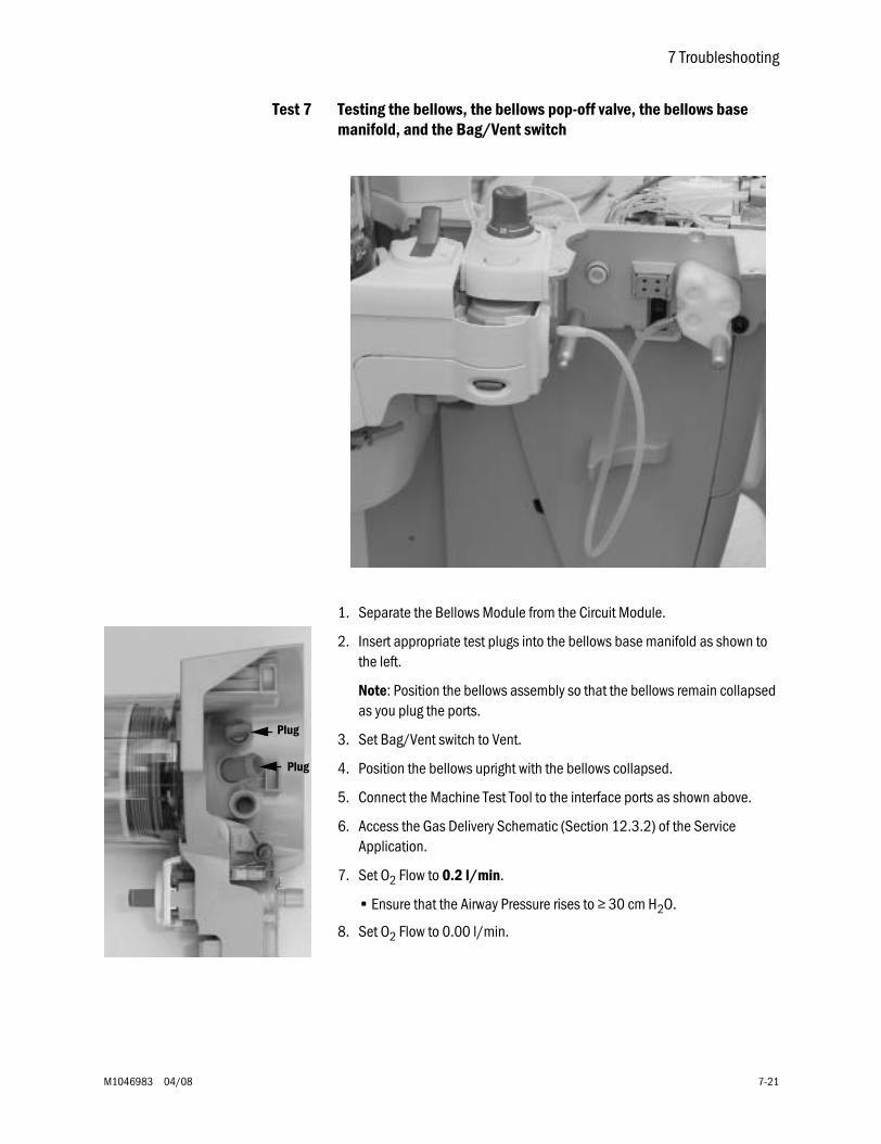
7 Troubleshooting
M1046983 04/08 7-21
Test 7 Testing the bellows, the bellows pop-off valve, the bellows base manifold, and the Bag/Vent switch
1. Separate the Bellows Module from the Circuit Module.
2. Insert appropriate test plugs into the bellows base manifold as shown to the left.
Note: Position the bellows assembly so that the bellows remain collapsed as you plug the ports.
3. Set Bag/Vent switch to Vent.
4. Position the bellows upright with the bellows collapsed.
5. Connect the Machine Test Tool to the interface ports as shown above.
6. Access the Gas Delivery Schematic (Section 12.3.2) of the Service Application.
7. Set O2 Flow to 0.2 l/min.
• Ensure that the Airway Pressure rises to ≥ 30 cm H2O.
8. Set O2 Flow to 0.00 l/min.
Plug
Plug
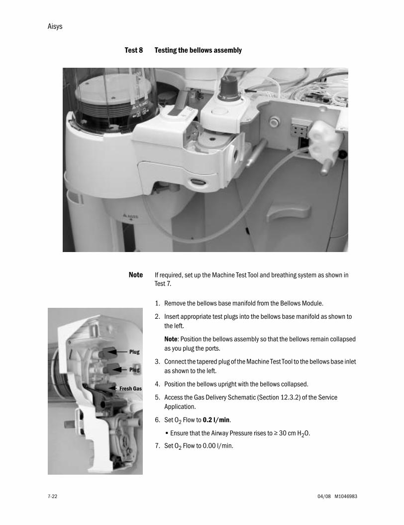
Aisys
7-22 04/08 M1046983
Test 8 Testing the bellows assembly
Note If required, set up the Machine Test Tool and breathing system as shown in Test 7.
1. Remove the bellows base manifold from the Bellows Module.
2. Insert appropriate test plugs into the bellows base manifold as shown to the left.
Note: Position the bellows assembly so that the bellows remain collapsed as you plug the ports.
3. Connect the tapered plug of the Machine Test Tool to the bellows base inlet as shown to the left.
4. Position the bellows upright with the bellows collapsed.
5. Access the Gas Delivery Schematic (Section 12.3.2) of the Service Application.
6. Set O2 Flow to 0.2 l/min.
• Ensure that the Airway Pressure rises to ≥ 30 cm H2O.
7. Set O2 Flow to 0.00 l/min.
Plug
Plug
Fresh Gas
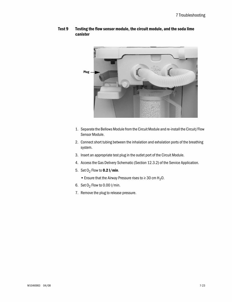
7 Troubleshooting
M1046983 04/08 7-23
Test 9 Testing the flow sensor module, the circuit module, and the soda lime canister
1. Separate the Bellows Module from the Circuit Module and re-install the Circuit/Flow Sensor Module.
2. Connect short tubing between the inhalation and exhalation ports of the breathing system.
3. Insert an appropriate test plug in the outlet port of the Circuit Module.
4. Access the Gas Delivery Schematic (Section 12.3.2) of the Service Application.
5. Set O2 Flow to 0.2 l/min.
• Ensure that the Airway Pressure rises to ≥ 30 cm H2O.
6. Set O2 Flow to 0.00 l/min.
7. Remove the plug to release pressure.
Plug
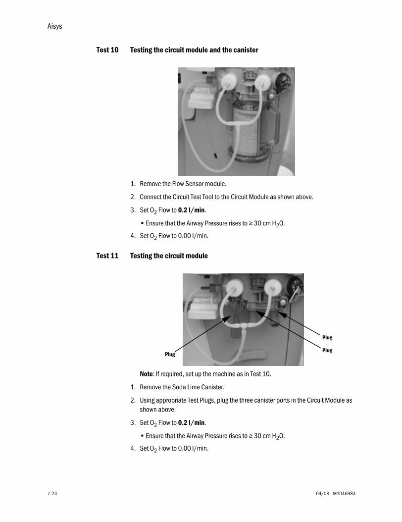
Aisys
7-24 04/08 M1046983
Test 10 Testing the circuit module and the canister
1. Remove the Flow Sensor module.
2. Connect the Circuit Test Tool to the Circuit Module as shown above.
3. Set O2 Flow to 0.2 l/min.
• Ensure that the Airway Pressure rises to ≥ 30 cm H2O.
4. Set O2 Flow to 0.00 l/min.
Test 11 Testing the circuit module
Note: If required, set up the machine as in Test 10.
1. Remove the Soda Lime Canister.
2. Using appropriate Test Plugs, plug the three canister ports in the Circuit Module as shown above.
3. Set O2 Flow to 0.2 l/min.
• Ensure that the Airway Pressure rises to ≥ 30 cm H2O.
4. Set O2 Flow to 0.00 l/min.
Plug
Plug
Plug
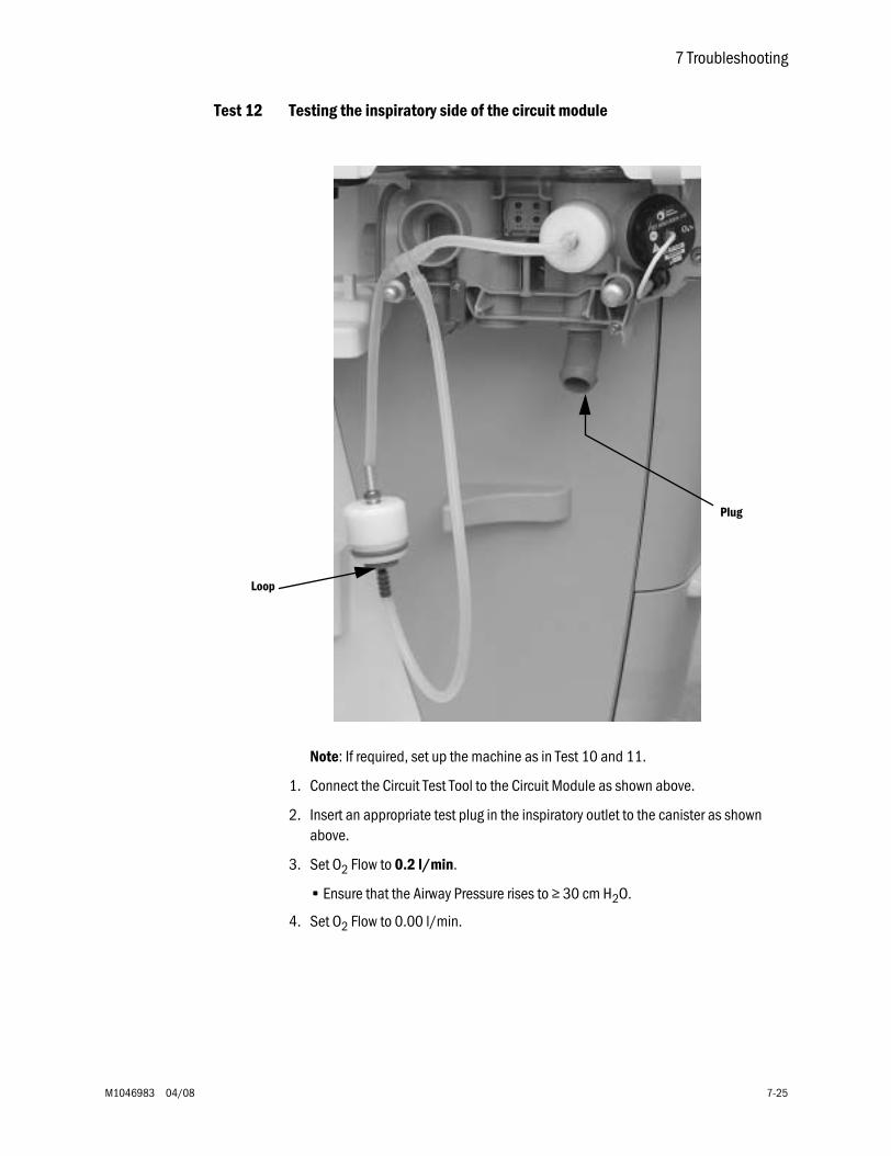
7 Troubleshooting
M1046983 04/08 7-25
Test 12 Testing the inspiratory side of the circuit module
Note: If required, set up the machine as in Test 10 and 11.
1. Connect the Circuit Test Tool to the Circuit Module as shown above.
2. Insert an appropriate test plug in the inspiratory outlet to the canister as shown above.
3. Set O2 Flow to 0.2 l/min.
• Ensure that the Airway Pressure rises to ≥ 30 cm H2O.
4. Set O2 Flow to 0.00 l/min.
Loop
Plug
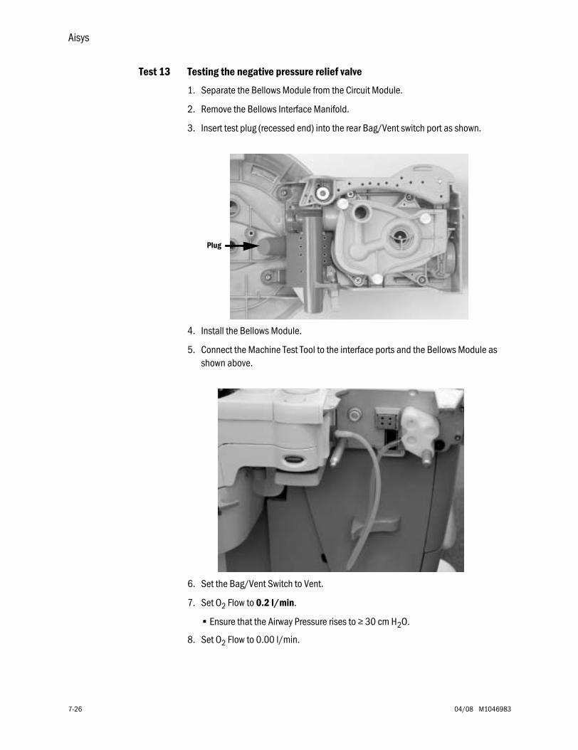
Aisys
7-26 04/08 M1046983
Test 13 Testing the negative pressure relief valve
1. Separate the Bellows Module from the Circuit Module.
2. Remove the Bellows Interface Manifold.
3. Insert test plug (recessed end) into the rear Bag/Vent switch port as shown.
4. Install the Bellows Module.
5. Connect the Machine Test Tool to the interface ports and the Bellows Module as shown above.
6. Set the Bag/Vent Switch to Vent.
7. Set O2 Flow to 0.2 l/min.
• Ensure that the Airway Pressure rises to ≥ 30 cm H2O.
8. Set O2 Flow to 0.00 l/min.
Plug
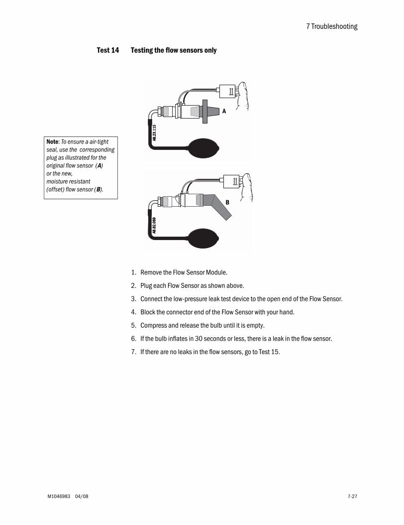
7 Troubleshooting
M1046983 04/08 7-27
Test 14 Testing the flow sensors only
1. Remove the Flow Sensor Module.
2. Plug each Flow Sensor as shown above.
3. Connect the low-pressure leak test device to the open end of the Flow Sensor.
4. Block the connector end of the Flow Sensor with your hand.
5. Compress and release the bulb until it is empty.
6. If the bulb inflates in 30 seconds or less, there is a leak in the flow sensor.
7. If there are no leaks in the flow sensors, go to Test 15.
Note: To ensure a air-tight seal, use the corresponding plug as illustrated for the original flow sensor (A) or the new, moisture resistant (offset) flow sensor (B).
A
AAAA BBBB.... 2222
3333 ....1111 1111
5555
B
AAAA BBBB.... 8888
2222 ....0000 6666
9999
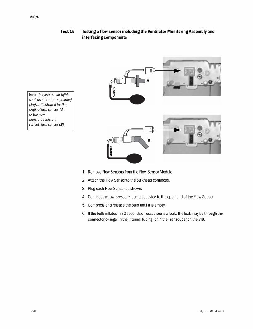
Aisys
7-28 04/08 M1046983
Test 15 Testing a flow sensor including the Ventilator Monitoring Assembly and interfacing components
1. Remove Flow Sensors from the Flow Sensor Module.
2. Attach the Flow Sensor to the bulkhead connector.
3. Plug each Flow Sensor as shown.
4. Connect the low-pressure leak test device to the open end of the Flow Sensor.
5. Compress and release the bulb until it is empty.
6. If the bulb inflates in 30 seconds or less, there is a leak. The leak may be through the connector o-rings, in the internal tubing, or in the Transducer on the VIB.
Note: To ensure a air-tight seal, use the corresponding plug as illustrated for the original flow sensor (A) or the new, moisture resistant (offset) flow sensor (B).
AAAA BBBB.... 8888
2222 ....0000 7777
0000
A
AAAA BBBB.... 8888
2222 ....0000 6666
8888
B
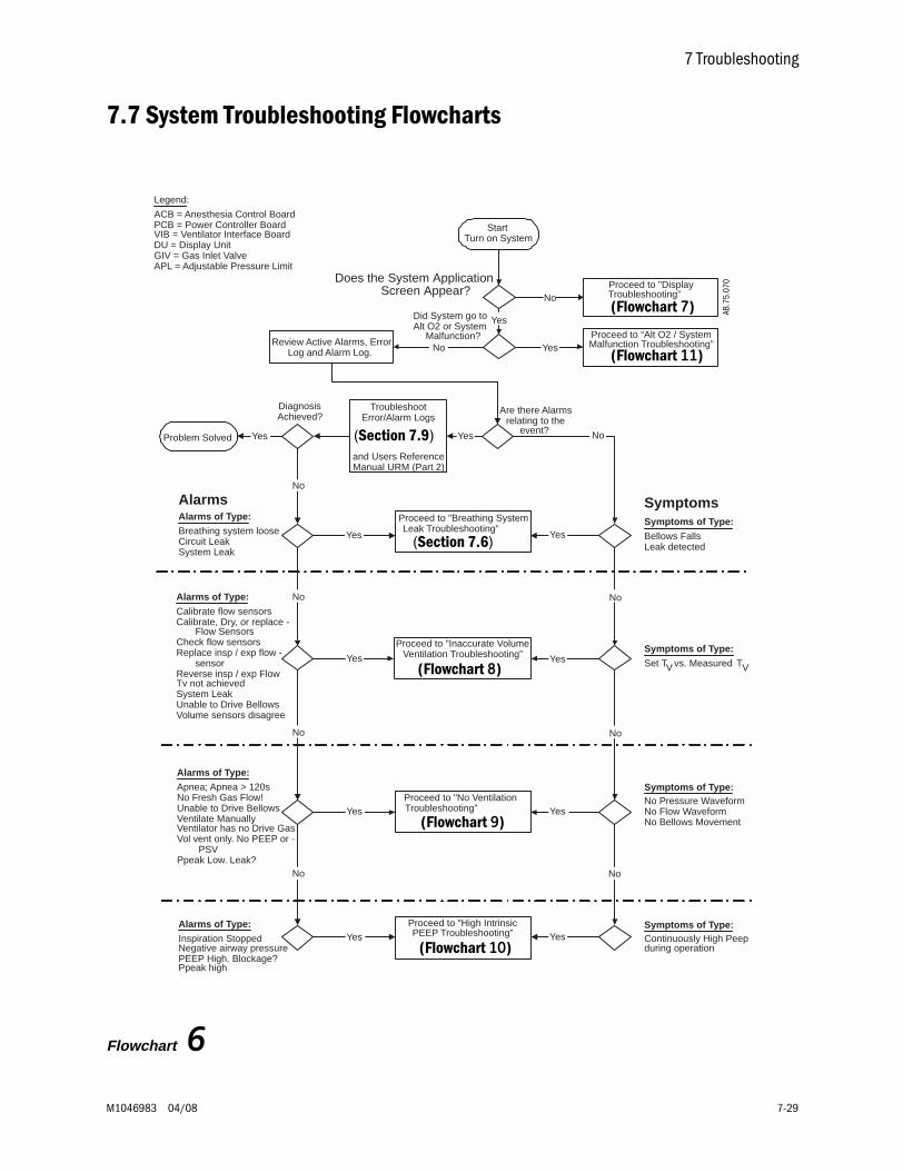
7 Troubleshooting
M1046983 04/08 7-29
7.7 System Troubleshooting Flowcharts
Flowchart 6
AB.9
1.01
3
StartTurn on System
Review Active Alarms, ErrorLog and Alarm Log.
Proceed to "DisplayTroubleshooting”
Yes
No
Does the System Application Screen Appear?
Are there Alarmsrelating to the
event?
TroubleshootError/Alarm Logs
and Users ReferenceManual URM (Part 2)
YesYes
DiagnosisAchieved?
No
Proceed to "Breathing SystemLeak Troubleshooting”
Proceed to "Inaccurate VolumeVentilation Troubleshooting”
Proceed to "No VentilationTroubleshooting”
Yes Yes
Yes Yes
YesYes
No
No
No
No
Proceed to "High IntrinsicPEEP Troubleshooting” YesYes
No No
AlarmsAlarms of Type:Breathing system looseCircuit LeakSystem Leak
Alarms of Type:
Calibrate flow sensorsCalibrate, Dry, or replace - Flow SensorsCheck flow sensorsReplace insp / exp flow - sensorReverse insp / exp FlowTv not achievedSystem LeakUnable to Drive BellowsVolume sensors disagree
Alarms of Type:Apnea; Apnea > 120sNo Fresh Gas Flow!Unable to Drive BellowsVentilate ManuallyVentilator has no Drive GasVol vent only. No PEEP or - PSVPpeak Low. Leak?
Alarms of Type:
Inspiration StoppedNegative airway pressurePEEP High. Blockage?Ppeak high
Symptoms of Type:Continuously High Peepduring operation
Symptoms
Symptoms of Type:No Pressure WaveformNo Flow WaveformNo Bellows Movement
Symptoms of Type:
Set TV vs. Measured TV
Symptoms of Type:
Bellows FallsLeak detected
No
Did System go toAlt O2 or System
Malfunction? Proceed to “Alt O2 / SystemMalfunction Troubleshooting”YesNo
Problem Solved
Legend:
ACB = Anesthesia Control BoardPCB = Power Controller BoardVIB = Ventilator Interface BoardDU = Display UnitGIV = Gas Inlet ValveAPL = Adjustable Pressure Limit
(Flowchart 7)
(Flowchart 11)
(Flowchart 8)
(Flowchart 9)
(Flowchart 10)
(Section 7.9)
(Section 7.6)
AB.7
5.07
0
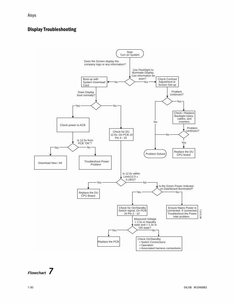
Aisys
7-30 04/08 M1046983
Display Troubleshooting
Flowchart 7
AB.9
1.01
3
StartTurn on System
Check ContrastAdjustment inScreen Set-up
No Yes
Check / ReplaceBacklight tubes,
cables, andinverters
Replace the DUCPU board
Use Flashlight toIlluminate Display.Can information be
seen?
Problemcontinues?
Yes
No
Problemcontinues?
No
Yes
Boot-up withSystem DownloadCard
Does Displayboot normally?
Check power to ACB
Yes No
Check for DU12.5v; On PCB J3
Pin 4 - 15
Is 12.5v withinLimit(12.5 ±
0.18V)?Yes
Replace the DUCPU Board
No
Check for On/StandbySwitch signal; On PCB
J4 Pin 2 - 10
Measured Voltage> 2.5v in Standbystate and < 1.3v in
ON state?Yes
Replace the PCB
No
Check On/Standby• Switch Connections• Operation• Associated harness connections
Troubleshoot PowerProblemDownload New / All
Yes No
Is 12.5v fromPCB “OK”?
Problem Solved
Is the Green Power Indicatoron Dashboard illuminated?
Yes No
Ensure Mains Power isconnected. If connected,Troubleshoot the Power
Inlet problem.
Does the Screen display thecompany logo or any information?
AB.7
5.07
1
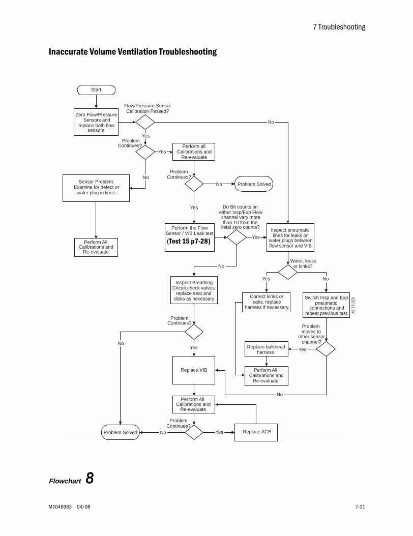
7 Troubleshooting
M1046983 04/08 7-31
Inaccurate Volume Ventilation Troubleshooting
Flowchart 8
AB.9
1.01
3
Start
Zero Flow/PressureSensors and
replace both flowsensors
ProblemContinues?
Sensor Problem:Examine for defect or
water plug in lines.
No
Perform the FlowSensor / VIB Leak test
Yes
Do Bit counts oneither Insp/Exp Flowchannel vary morethan 10 from the
inital zero counts?
No
Inspect pneumaticlines for leaks or
water plugs betweenflow sensor and VIB
Yes
Inspect BreathingCircuit check valves:
replace seat anddisks as necessary
Water, leaksor kinks?
Yes
Correct kinks orleaks, replace
harness if necessary.
No
Switch Insp and Exppneumatic
connections andrepeat previous test.
Problemmoves to
other sensorchannel?
Replace bulkheadharness
Perform AllCalibrations and
Re-evaluate
Yes
Replace VIB
No
Replace ACB
ProblemContinues?
Perform AllCalibrations and
Re-evaluate
NoYes
Perform allCalibrations and
Re-evaluate
ProblemContinues?
Yes
No
Flow/Pressure SensorCalibration Passed?
Yes
No
ProblemContinues?
Yes
Perform AllCalibrations and
Re-evaluate
Problem Solved No
Problem Solved
(Test 15 p7-28)
AB.7
5.07
2
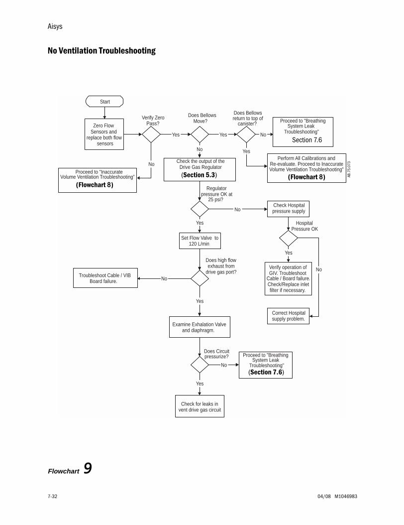
Aisys
7-32 04/08 M1046983
No Ventilation Troubleshooting
Flowchart 9
AB.9
1.01
3
Start
Zero FlowSensors and
replace both flowsensors
Verify ZeroPass?
Proceed to "InaccurateNo
Yes
Perform All Calibrations andRe-evaluate. Proceed to InaccurateVolume Ventilation Troubleshooting”
Does BellowsMove?
Yes
Check the output of theDrive Gas Regulator
Regulatorpressure OK at
25 psi?
Set Flow Valve to120 L/min
No
Yes
Does high flowexhaust from
drive gas port?Troubleshoot Cable / VIB
Board failure. No
Proceed to "BreathingSystem Leak
Troubleshooting”No
Does Bellowsreturn to top of
canister?
Yes
Check Hospitalpressure supplyNo
HospitalPressure OK
Verify operation ofGIV. Troubleshoot
Cable / Board failure.Check/Replace inletfilter if necessary.
Yes
Correct Hospitalsupply problem.
No
Examine Exhalation Valveand diaphragm.
Yes
Does Circuitpressurize?
No
Check for leaks invent drive gas circuit
Yes
Proceed to "BreathingSystem Leak
Troubleshooting”
Volume Ventilation Troubleshooting” (Section 5.3)
Section 7.6
(Section 7.6)
(Flowchart 8)(Flowchart 8)
AB.7
5.07
3
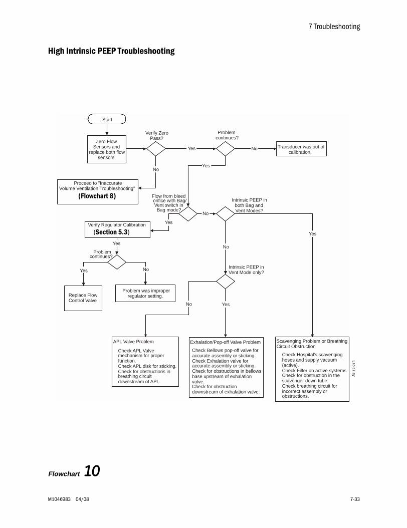
7 Troubleshooting
M1046983 04/08 7-33
High Intrinsic PEEP Troubleshooting
Flowchart 10
AB.9
1.01
3
Start
Zero FlowSensors and
replace both flowsensors
Verify ZeroPass?
Proceed to "Inaccurate
No
Yes
Problemcontinues?
Transducer was out ofcalibration.
No
Yes
Intrinsic PEEP inboth Bag andVent Modes?
No
Intrinsic PEEP inVent Mode only?
APL Valve Problem
Check APL Valvemechanism for properfunction.
Check APL disk for sticking. Check for obstructions in
breathing circuitdownstream of APL.
No
Problemcontinues?
Exhalation/Pop-off Valve Problem
Check Bellows pop-off valve foraccurate assembly or sticking.
Check Exhalation valve foraccurate assembly or sticking.
Check for obstructions in bellowsbase upstream of exhalationvalve.
Check for obstructiondownstream of exhalation valve.
Scavenging Problem or BreathingCircuit Obstruction
Check Hospital's scavenginghoses and supply vacuum(active).
Check Filter on active systems Check for obstruction in the
scavenger down tube. Check breathing circuit for
incorrect assembly orobstructions.
Yes
Yes
Flow from bleedorifice with Bag/Vent switch inBag mode?
No
Verify Regulator Calibration
Problem was improperregulator setting.
Yes
Yes
Replace FlowControl Valve
NoYes
Volume Ventilation Troubleshooting”
(Flowchart 8)
(Section 5.3)
AB.7
5.07
4
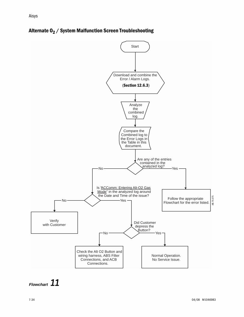
Aisys
7-34 04/08 M1046983
Alternate O2 / System Malfunction Screen Troubleshooting
Flowchart 11
AB.9
1.01
3
Did Customerdepress the
Button?
Are any of the entriescontained in the
analyzed log?
Start
Compare theCombined log tothe Error Logs inthe Table in this
document.
No Yes
Follow the appropriateFlowchart for the error listed.
Check the Alt O2 Button andwiring harness, ABS Filter
Connections, and ACBConnections.
Is “ACComm: Entering Alt-O2 GasMode” in the analyzed log aroundthe Date and Time of the issue?
Verifywith Customer
No Yes
No
Normal Operation.No Service Issue.
Yes
Analyzethe
combinedlog.
Download and combine theError / Alarm Logs.
(Section 12.6.3)
AB.7
5.07
5
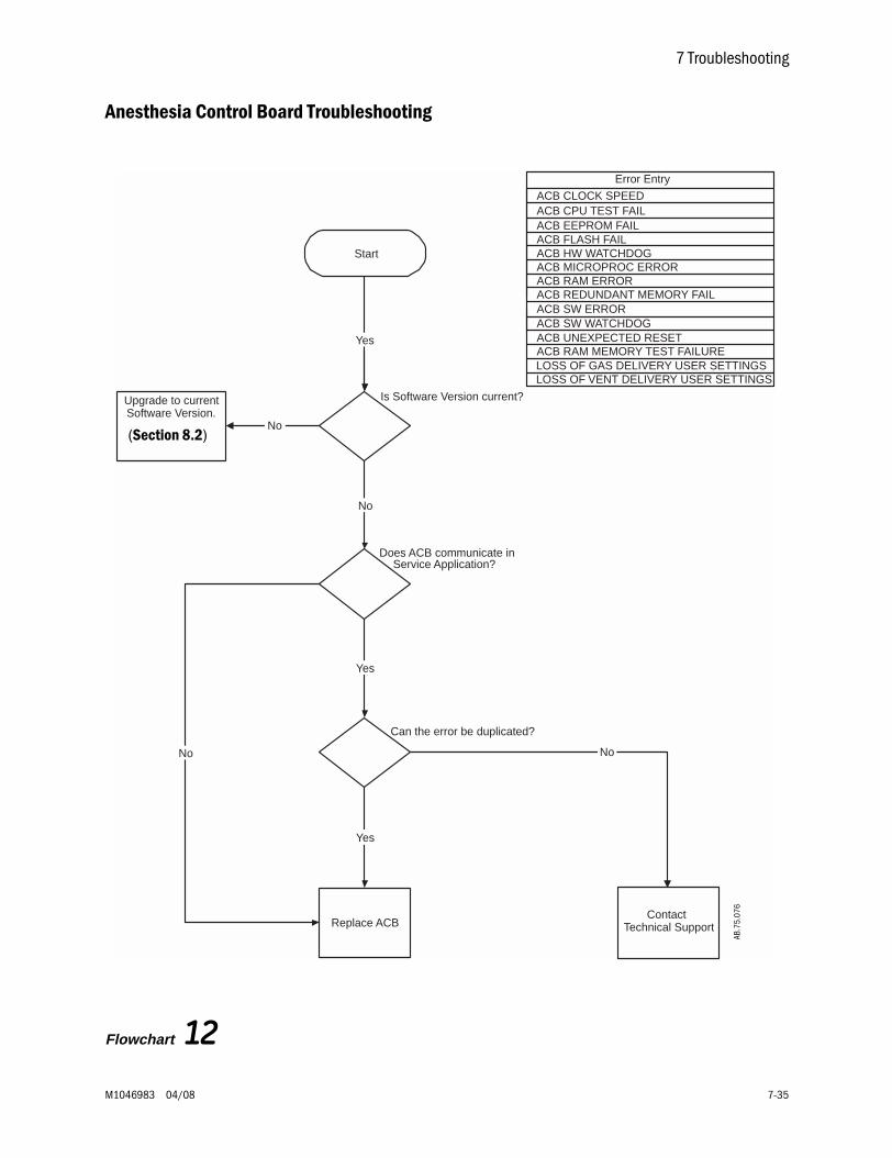
7 Troubleshooting
M1046983 04/08 7-35
Anesthesia Control Board Troubleshooting
Flowchart 12
AB.9
1.01
3
Can the error be duplicated?
Does ACB communicate inService Application?
Start
No
Replace ACB
Yes
Yes
ContactTechnical Support
No
Error Entry
ACB CLOCK SPEED ACB CPU TEST FAIL ACB EEPROM FAIL ACB FLASH FAIL ACB HW WATCHDOG ACB MICROPROC ERROR ACB RAM ERROR ACB REDUNDANT MEMORY FAIL
ACB UNEXPECTED RESET ACB RAM MEMORY TEST FAILURE
ACB SW WATCHDOG ACB SW ERROR
Is Software Version current?
Yes
No
Upgrade to currentSoftware Version.
No
LOSS OF GAS DELIVERY USER SETTINGS LOSS OF VENT DELIVERY USER SETTINGS
(Section 8.2)
AB.7
5.07
6
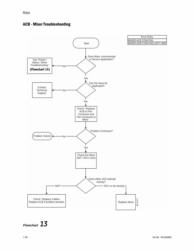
Aisys
7-36 04/08 M1046983
ACB - Mixer Troubleshooting
Flowchart 13
AB.9
1.01
3
Problem Continues?
Does either LED indicateActivity?
Does Mixer communicatein Service Application?
Error EntryMIXER ACB COM FAILMIXER ACB COM FAILLOST CMDStart
No
See “Power /Valves / Mixer
Troubleshooting”
Check the MixerXMT / RCV LEDs
Can the issue beduplicated?
Yes
Yes
XMT RCV or No Activity
NoContact
TechnicalSupport
No
Check / ReplaceACB to Pan
Connector andPan Connector to
Mixer
Problem Solved
Yes
Check / Replace Cables.Replace ACB if problem persists. Replace Mixer
(Flowchart 16)
AB.7
5.07
7

7 Troubleshooting
M1046983 04/08 7-37
DU - ACB Communication Troubleshooting
Flowchart 14
AB.9
1.01
3
Does M-GAS communicate inService mode?
Follow the appropriate pathbased on Error Entry
Does ACB communicate inService Application?
Error Entry DCB RAM ERROR ACB COM FAIL ACB DCB COM FAIL LOSS OF GAS DELIVERY USER SETTINGS
Start
No
DCB / ACB Comm Related ErrorsACB COM FAILACB DCB COM FAIL
Display Controller Related ErrorsDCB RAM ERROR
Yes
Replace DisplayController Board
Replace ACB Replace DU CPU
NoYes
Which LED indicatesActivity?
Check the ACBTXD / RXD LED’s
TXD RXD
Replace DU CPU Replace ACB
LOSS OF VENT DELIVERY USER SETTINGS
AB.7
5.07
8
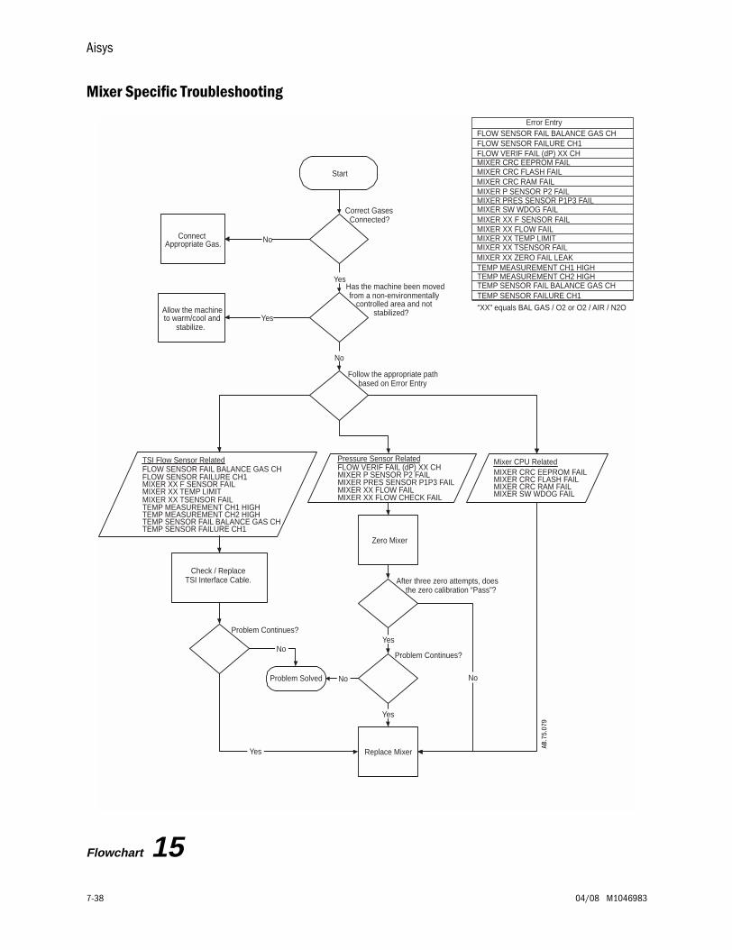
Aisys
7-38 04/08 M1046983
Mixer Specific Troubleshooting
Flowchart 15
AB.9
1.01
3
“XX” equals BAL GAS / O2 or O2 / AIR / N2O
Problem Continues?
After three zero attempts, doesthe zero calibration “Pass”?
Has the machine been movedfrom a non-environmentally
controlled area and notstabilized?
Correct GasesConnected?
Start
ConnectAppropriate Gas. No
Allow the machineto warm/cool and
stabilize.Yes
Yes
Zero Mixer
Replace Mixer
No
No
Yes
Problem Solved No
FLOW SENSOR FAIL BALANCE GAS CH FLOW SENSOR FAILURE CH1 FLOW VERIF FAIL (dP) XX CH MIXER CRC EEPROM FAIL MIXER CRC FLASH FAIL MIXER CRC RAM FAIL MIXER P SENSOR P2 FAIL MIXER PRES SENSOR P1P3 FAIL MIXER SW WDOG FAIL MIXER XX F SENSOR FAIL
MIXER XX TEMP LIMIT MIXER XX TSENSOR FAIL MIXER XX ZERO FAIL LEAK
TEMP SENSOR FAIL BALANCE GAS CH TEMP MEASUREMENT CH2 HIGH TEMP MEASUREMENT CH1 HIGH
TEMP SENSOR FAILURE CH1
MIXER XX FLOW FAIL
MIXER CRC EEPROM FAIL
TSI Flow Sensor RelatedFLOW SENSOR FAIL BALANCE GAS CHFLOW SENSOR FAILURE CH1MIXER XX F SENSOR FAILMIXER XX TEMP LIMITMIXER XX TSENSOR FAILTEMP MEASUREMENT CH1 HIGHTEMP MEASUREMENT CH2 HIGHTEMP SENSOR FAIL BALANCE GAS CHTEMP SENSOR FAILURE CH1
Check / ReplaceTSI Interface Cable.
Follow the appropriate path based on Error Entry
Problem Continues?
Pressure Sensor RelatedFLOW VERIF FAIL (dP) XX CHMIXER P SENSOR P2 FAILMIXER PRES SENSOR P1P3 FAILMIXER XX FLOW FAILMIXER XX FLOW CHECK FAIL
Mixer CPU RelatedMIXER CRC EEPROM FAILMIXER CRC FLASH FAILMIXER CRC RAM FAILMIXER SW WDOG FAIL
No
Yes
Yes
Error Entry
AB.7
5.07
9
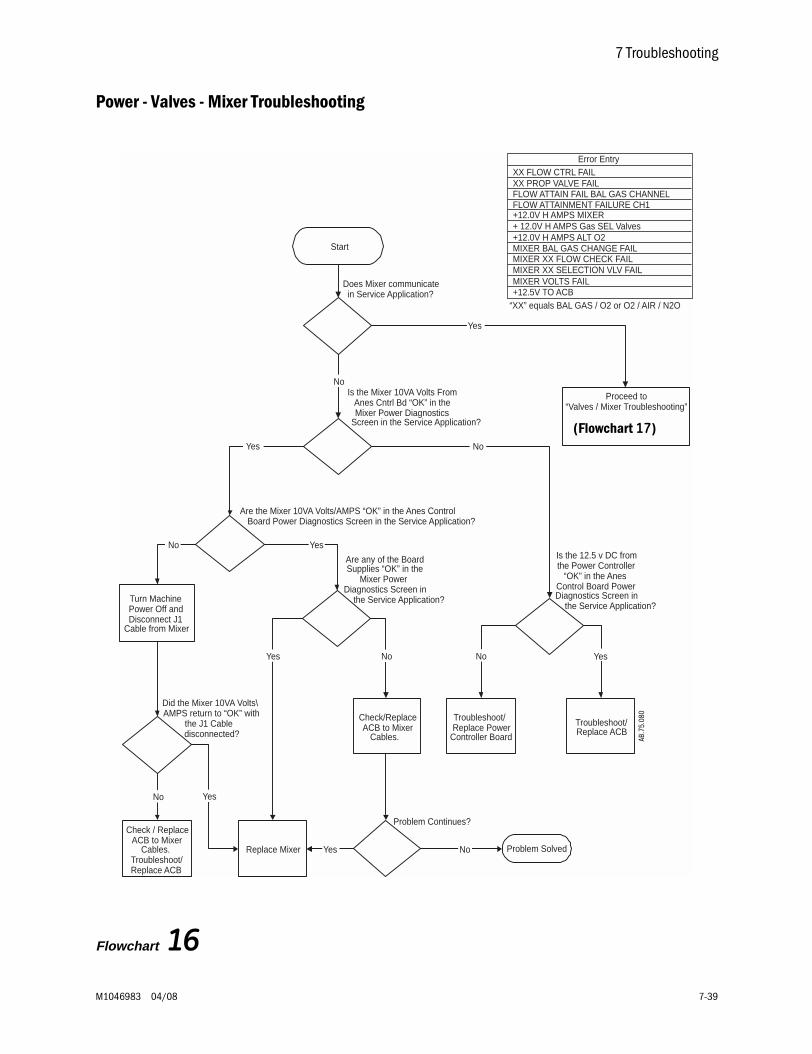
7 Troubleshooting
M1046983 04/08 7-39
Power - Valves - Mixer Troubleshooting
Flowchart 16
AB.9
1.01
3
Did the Mixer 10VA Volts\AMPS return to “OK” with
the J1 Cabledisconnected?
Are any of the BoardSupplies “OK” in the
Mixer PowerDiagnostics Screen in
the Service Application?
Is the 12.5 v DC fromthe Power Controller
“OK” in the AnesControl Board PowerDiagnostics Screen in
the Service Application?
Are the Mixer 10VA Volts/AMPS “OK” in the Anes ControlBoard Power Diagnostics Screen in the Service Application?
Is the Mixer 10VA Volts FromAnes Cntrl Bd “OK” in theMixer Power Diagnostics
Screen in the Service Application?
Start
Does Mixer communicatein Service Application?
Replace Mixer
No
Yes
Check/ReplaceACB to Mixer
Cables.
No
Problem Continues?
Yes Problem SolvedNo
Troubleshoot/Replace ACB
No
Yes
Turn MachinePower Off andDisconnect J1
Cable from Mixer
No Yes
Yes
Troubleshoot/Replace Power
Controller Board
No Yes
YesNo
Check / ReplaceACB to Mixer
Cables.Troubleshoot/Replace ACB
Proceed to“Valves / Mixer Troubleshooting”
Error Entry XX FLOW CTRL FAIL XX PROP VALVE FAIL FLOW ATTAIN FAIL BAL GAS CHANNEL FLOW ATTAINMENT FAILURE CH1 +12.0V H AMPS MIXER + 12.0V H AMPS Gas SEL Valves +12.0V H AMPS ALT O2 MIXER BAL GAS CHANGE FAIL
MIXER XX SELECTION VLV FAIL MIXER VOLTS FAIL +12.5V TO ACB
MIXER XX FLOW CHECK FAIL
“XX” equals BAL GAS / O2 or O2 / AIR / N2O
(Flowchart 17)
AB.7
5.08
0
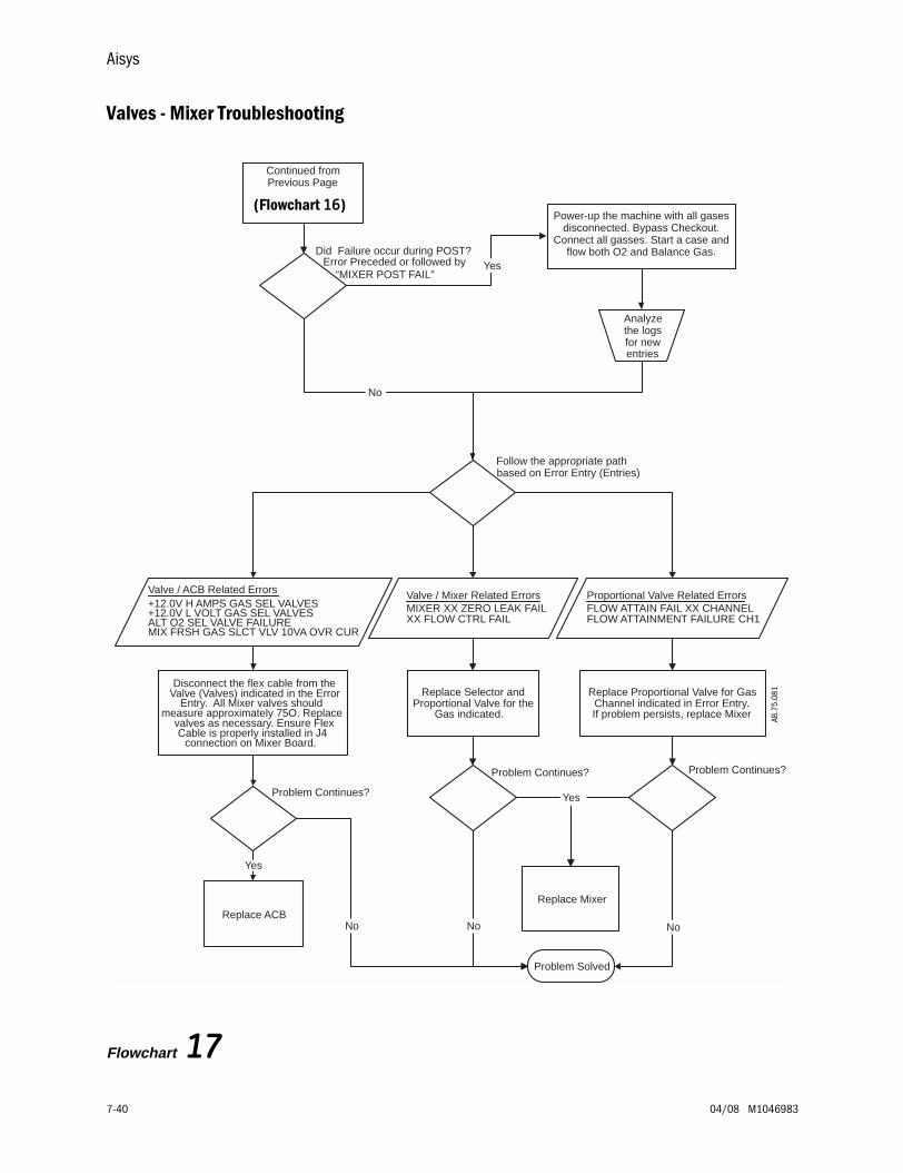
Aisys
7-40 04/08 M1046983
Valves - Mixer Troubleshooting
Flowchart 17
AB.9
1.01
3
Problem Continues?
Follow the appropriate pathbased on Error Entry (Entries)
Did Failure occur during POST?Error Preceded or followed by
“MIXER POST FAIL”
Continued fromPrevious Page
Valve / ACB Related Errors+12.0V H AMPS GAS SEL VALVES+12.0V L VOLT GAS SEL VALVESALT O2 SEL VALVE FAILUREMIX FRSH GAS SLCT VLV 10VA OVR CUR
Disconnect the flex cable from theValve (Valves) indicated in the Error
Entry. All Mixer valves shouldmeasure approximately 75O. Replace
valves as necessary. Ensure FlexCable is properly installed in J4
connection on Mixer Board.
Proportional Valve Related ErrorsFLOW ATTAIN FAIL XX CHANNELFLOW ATTAINMENT FAILURE CH1
Replace Proportional Valve for GasChannel indicated in Error Entry.If problem persists, replace Mixer
Replace ACB
Yes
Power-up the machine with all gasesdisconnected. Bypass Checkout.
Connect all gasses. Start a case andflow both O2 and Balance Gas.
No
Valve / Mixer Related ErrorsMIXER XX ZERO LEAK FAILXX FLOW CTRL FAIL
Replace Selector andProportional Valve for the
Gas indicated.
Replace Mixer
Problem Continues?
Yes
Problem Solved
No No
Problem Continues?
No
Yes
Analyzethe logsfor newentries
(Flowchart 16)
AB.7
5.08
1
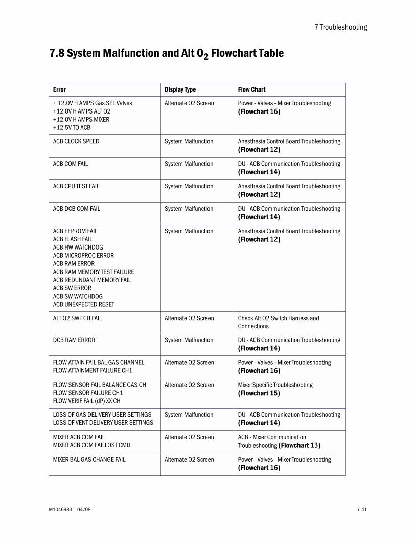
7 Troubleshooting
M1046983 04/08 7-41
7.8 System Malfunction and Alt O2 Flowchart Table
Error Display Type Flow Chart
+ 12.0V H AMPS Gas SEL Valves+12.0V H AMPS ALT O2+12.0V H AMPS MIXER+12.5V TO ACB
Alternate O2 Screen Power - Valves - Mixer Troubleshooting (Flowchart 16)
ACB CLOCK SPEED System Malfunction Anesthesia Control Board Troubleshooting (Flowchart 12)
ACB COM FAIL System Malfunction DU - ACB Communication Troubleshooting (Flowchart 14)
ACB CPU TEST FAIL System Malfunction Anesthesia Control Board Troubleshooting (Flowchart 12)
ACB DCB COM FAIL System Malfunction DU - ACB Communication Troubleshooting (Flowchart 14)
ACB EEPROM FAILACB FLASH FAILACB HW WATCHDOGACB MICROPROC ERRORACB RAM ERRORACB RAM MEMORY TEST FAILUREACB REDUNDANT MEMORY FAILACB SW ERRORACB SW WATCHDOGACB UNEXPECTED RESET
System Malfunction Anesthesia Control Board Troubleshooting (Flowchart 12)
ALT O2 SWITCH FAIL Alternate O2 Screen Check Alt O2 Switch Harness and Connections
DCB RAM ERROR System Malfunction DU - ACB Communication Troubleshooting (Flowchart 14)
FLOW ATTAIN FAIL BAL GAS CHANNELFLOW ATTAINMENT FAILURE CH1
Alternate O2 Screen Power - Valves - Mixer Troubleshooting (Flowchart 16)
FLOW SENSOR FAIL BALANCE GAS CHFLOW SENSOR FAILURE CH1FLOW VERIF FAIL (dP) XX CH
Alternate O2 Screen Mixer Specific Troubleshooting (Flowchart 15)
LOSS OF GAS DELIVERY USER SETTINGSLOSS OF VENT DELIVERY USER SETTINGS
System Malfunction DU - ACB Communication Troubleshooting (Flowchart 14)
MIXER ACB COM FAILMIXER ACB COM FAILLOST CMD
Alternate O2 Screen ACB - Mixer Communication Troubleshooting (Flowchart 13)
MIXER BAL GAS CHANGE FAIL Alternate O2 Screen Power - Valves - Mixer Troubleshooting (Flowchart 16)
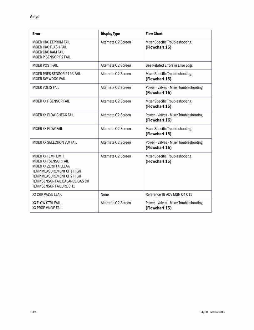
Aisys
7-42 04/08 M1046983
Error Display Type Flow Chart
MIXER CRC EEPROM FAILMIXER CRC FLASH FAILMIXER CRC RAM FAILMIXER P SENSOR P2 FAIL
Alternate O2 Screen Mixer Specific Troubleshooting (Flowchart 15)
MIXER POST FAIL Alternate O2 Screen See Related Errors in Error Logs
MIXER PRES SENSOR P1P3 FAILMIXER SW WDOG FAIL
Alternate O2 Screen Mixer Specific Troubleshooting (Flowchart 15)
MIXER VOLTS FAIL Alternate O2 Screen Power - Valves - Mixer Troubleshooting (Flowchart 16)
MIXER XX F SENSOR FAIL Alternate O2 Screen Mixer Specific Troubleshooting (Flowchart 15)
MIXER XX FLOW CHECK FAIL Alternate O2 Screen Power - Valves - Mixer Troubleshooting (Flowchart 16)
MIXER XX FLOW FAIL Alternate O2 Screen Mixer Specific Troubleshooting (Flowchart 15)
MIXER XX SELECTION VLV FAIL Alternate O2 Screen Power - Valves - Mixer Troubleshooting (Flowchart 16)
MIXER XX TEMP LIMITMIXER XX TSENSOR FAILMIXER XX ZERO FAILLEAKTEMP MEASUREMENT CH1 HIGHTEMP MEASUREMENT CH2 HIGHTEMP SENSOR FAIL BALANCE GAS CHTEMP SENSOR FAILURE CH1
Alternate O2 Screen Mixer Specific Troubleshooting (Flowchart 15)
XX CHK VALVE LEAK None Reference TB ADV MSN 04 011
XX FLOW CTRL FAILXX PROP VALVE FAIL
Alternate O2 Screen Power - Valves - Mixer Troubleshooting (Flowchart 13)
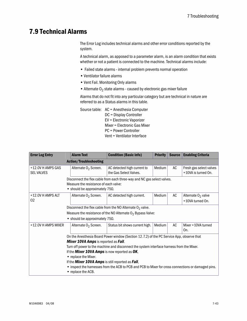
7 Troubleshooting
M1046983 04/08 7-43
7.9 Technical Alarms
The Error Log includes technical alarms and other error conditions reported by the system.
A technical alarm, as apposed to a parameter alarm, is an alarm condition that exists whether or not a patient is connected to the machine. Technical alarms include:
• Failed state alarms - internal problem prevents normal operation
• Ventilator failure alarms
• Vent Fail. Monitoring Only alarms
• Alternate O2 state alarms - caused by electronic gas mixer failure
Alarms that do not fit into any particular category but are technical in nature are referred to as a Status alarms in this table.
Source table: AC = Anesthesia ComputerDC = Display ControllerEV = Electronic VaporizerMixer = Electronic Gas MixerPC = Power ControllerVent = Ventilator Interface
Error Log Entry Alarm Text Condition (Basic info) Priority Source Enabling Criteria
Action/Troubleshooting
+12.0V H AMPS GAS SEL VALVES
Alternate O2 Screen. AC detected high current to the Gas Select Valves.
Medium AC Fresh gas select valves +10VA is turned On.
Disconnect the flex cable from each three-way and NC gas select valves. Measure the resistance of each valve: • should be approximately 75Ω.
+12.0V H AMPS ALT O2
Alternate O2 Screen. AC detected high current. Medium AC Alternate O2 valve +10VA turned On.
Disconnect the flex cable from the NO Alternate O2 valve. Measure the resistance of the NO Alternate O2 Bypass Valve: • should be approximately 75Ω.
+12.0V H AMPS MIXER Alternate O2 Screen. Status bit shows current high. Medium AC Mixer +10VA turned On.
On the Anesthesia Board Power window (Section 12.7.2) of the PC Service App, observe that Mixer 10VA Amps is reported as Fail.Turn off power to the machine and disconnect the system interface harness from the Mixer.If the Mixer 10VA Amps is now reported as OK,• replace the Mixer.If the Mixer 10VA Amps is still reported as Fail,• inspect the harnesses from the ACB to PCB and PCB to Mixer for cross connections or damaged pins.• replace the ACB.
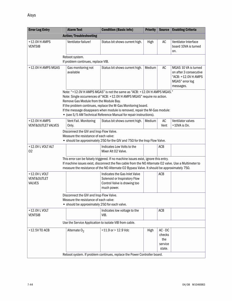
Aisys
7-44 04/08 M1046983
+12.0V H AMPS VENTSIB
Ventilator failure! Status bit shows current high. High AC Ventilator Interface board 10VA is turned on.
Reboot system. If problem continues, replace VIB.
+12.0V H AMPS MGAS Gas monitoring not available
Status bit shows current high. Medium AC MGAS 10 VA is turned on after 3 consecutive “ACB: +12.0V H AMPS MGAS” error log messages.
Note: “+12.0V H AMPS MGAS” is not the same as “ACB: +12.0V H AMPS MGAS.”Note: Single occurrences of “ACB: +12.0V H AMPS MGAS” require no action.Remove Gas Module from the Module Bay. If the problem continues, replace the M-Gas Monitoring board. If the message disappears when module is removed, repair the M-Gas module: • (see S/5 AM Technical Reference Manual for repair instructions).
+12.0V H AMPS VENT&OUTLET VALVES
Vent Fail. Monitoring Only.
Status bit shows current high. Medium ACVent
Ventilator valves +10VA is On.
Disconnect the GIV and Insp Flow Valve. Measure the resistance of each valve:• should be approximately 25Ω for the GIV and 75Ω for the Insp Flow Valve.
+12.0V L VOLT ALT O2
Indicates Low Volts to the Mixer Alt O2 Valve.
ACB
This error can be falsely triggered. If no machine issues exist, ignore this entry. If machine issues exist, disconnect the flex cable from the NO Alternate O2 valve. Use a Multimeter to measure the resistance of the NO Alternate O2 Bypass Valve. It should be approximately 75Ω.
+12.0V L VOLT VENT&OUTLET VALVES
Indicates the Gas Inlet Valve Solenoid or Inspiratory Flow Control Valve is drawing too much power.
ACB
Disconnect the GIV and Insp Flow Valve.Measure the resistance of each valve:• should be approximately 25Ω for each valve.
+12.0V L VOLT VENTSIB
Indicates low voltage to the VIB.
ACB
Use the Service Application to isolate VIB from cable.
+12.5V TO ACB Alternate O2 <11.9 or > 12.9 Vdc High AC - DC checks
the service state.
Reboot system. If problem continues, replace the Power Controller board.
Error Log Entry Alarm Text Condition (Basic info) Priority Source Enabling Criteria
Action/Troubleshooting
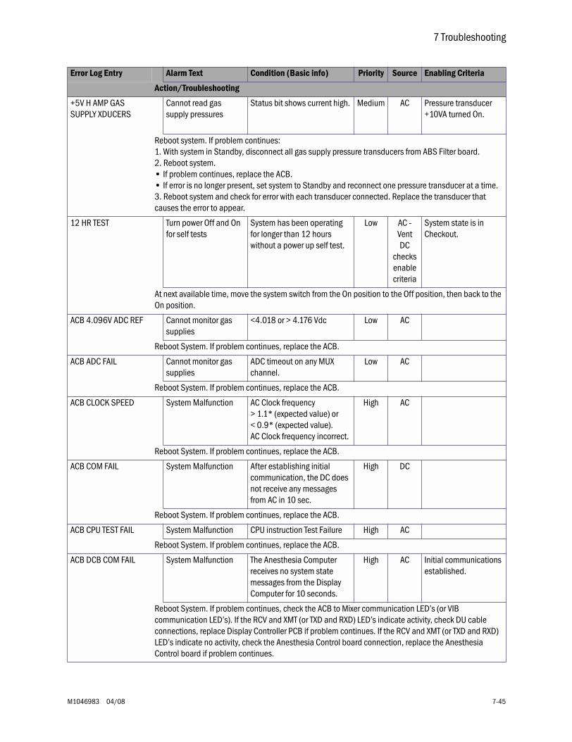
7 Troubleshooting
M1046983 04/08 7-45
+5V H AMP GAS SUPPLY XDUCERS
Cannot read gas supply pressures
Status bit shows current high. Medium AC Pressure transducer +10VA turned On.
Reboot system. If problem continues:1. With system in Standby, disconnect all gas supply pressure transducers from ABS Filter board.2. Reboot system.• If problem continues, replace the ACB.• If error is no longer present, set system to Standby and reconnect one pressure transducer at a time.3. Reboot system and check for error with each transducer connected. Replace the transducer that causes the error to appear.
12 HR TEST Turn power Off and On for self tests
System has been operating for longer than 12 hours without a power up self test.
Low AC - VentDC
checks enable criteria
System state is in Checkout.
At next available time, move the system switch from the On position to the Off position, then back to the On position.
ACB 4.096V ADC REF Cannot monitor gas supplies
<4.018 or > 4.176 Vdc Low AC
Reboot System. If problem continues, replace the ACB.
ACB ADC FAIL Cannot monitor gas supplies
ADC timeout on any MUX channel.
Low AC
Reboot System. If problem continues, replace the ACB.
ACB CLOCK SPEED System Malfunction AC Clock frequency > 1.1* (expected value) or < 0.9* (expected value). AC Clock frequency incorrect.
High AC
Reboot System. If problem continues, replace the ACB.
ACB COM FAIL System Malfunction After establishing initial communication, the DC does not receive any messages from AC in 10 sec.
High DC
Reboot System. If problem continues, replace the ACB.
ACB CPU TEST FAIL System Malfunction CPU instruction Test Failure High AC
Reboot System. If problem continues, replace the ACB.
ACB DCB COM FAIL System Malfunction The Anesthesia Computer receives no system state messages from the Display Computer for 10 seconds.
High AC Initial communications established.
Reboot System. If problem continues, check the ACB to Mixer communication LED’s (or VIB communication LED’s). If the RCV and XMT (or TXD and RXD) LED’s indicate activity, check DU cable connections, replace Display Controller PCB if problem continues. If the RCV and XMT (or TXD and RXD) LED’s indicate no activity, check the Anesthesia Control board connection, replace the Anesthesia Control board if problem continues.
Error Log Entry Alarm Text Condition (Basic info) Priority Source Enabling Criteria
Action/Troubleshooting
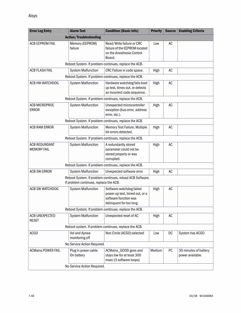
Aisys
7-46 04/08 M1046983
ACB EEPROM FAIL Memory (EEPROM) failure
Read/Write failure or CRC failure of the EEPROM located on the Anesthesia Control Board.
Low AC
Reboot System. If problem continues, replace the ACB.
ACB FLASH FAIL System Malfunction CRC Failure in code space. High AC
Reboot System. If problem continues, replace the ACB.
ACB HW WATCHDOG System Malfunction Hardware watchdog fails boot up test, times out, or detects an incorrect code sequence.
High AC
Reboot System. If problem continues, replace the ACB.
ACB MICROPROC ERROR
System Malfunction Unexpected microcontroller exception (bus error, address error, etc.).
High AC
Reboot System. If problem continues, replace the ACB.
ACB RAM ERROR System Malfunction Memory Test Failure, Multiple bit errors detected.
High AC
Reboot System. If problem continues, replace the ACB.
ACB REDUNDANT MEMORY FAIL
System Malfunction A redundantly stored parameter could not be stored properly or was corrupted.
High AC
Reboot System. If problem continues, replace the ACB.
ACB SW ERROR System Malfunction Unexpected software error High AC
Reboot System. If problem continues, reload ACB Software. If problem continues, replace the ACB.
ACB SW WATCHDOG System Malfunction Software watchdog failed power-up test, timed out, or a software function was delinquent for too long.
High AC
Reboot System. If problem continues, replace the ACB.
ACB UNEXPECTED RESET
System Malfunction Unexpected reset of AC High AC
Reboot system. If problem continues, replace the ACB.
ACGO Vol and Apnea monitoring off
Non Circle (ACGO) selected Low DC System has ACGO
No Service Action Required.
ACMains POWER FAIL Plug in power cable. On battery
ACMains_GOOD goes and stays low for at least 300 msec (3 software loops)
Medium PC 30 minutes of battery power available.
No Service Action Required.
Error Log Entry Alarm Text Condition (Basic info) Priority Source Enabling Criteria
Action/Troubleshooting
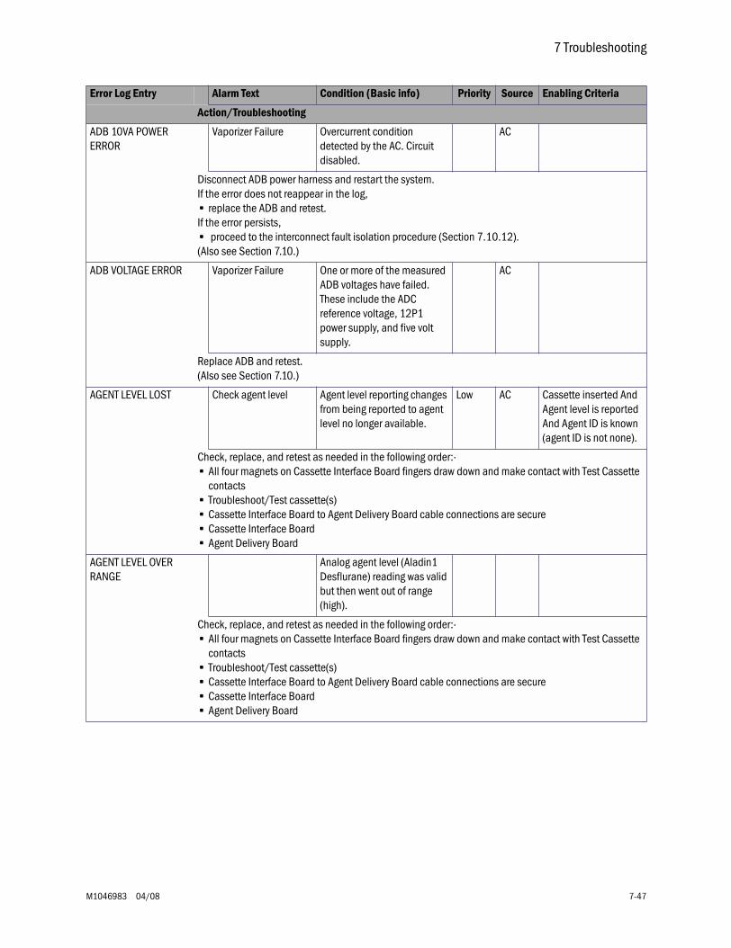
7 Troubleshooting
M1046983 04/08 7-47
ADB 10VA POWER ERROR
Vaporizer Failure Overcurrent condition detected by the AC. Circuit disabled.
AC
Disconnect ADB power harness and restart the system. If the error does not reappear in the log, • replace the ADB and retest.If the error persists,• proceed to the interconnect fault isolation procedure (Section 7.10.12).(Also see Section 7.10.)
ADB VOLTAGE ERROR Vaporizer Failure One or more of the measured ADB voltages have failed. These include the ADC reference voltage, 12P1 power supply, and five volt supply.
AC
Replace ADB and retest. (Also see Section 7.10.)
AGENT LEVEL LOST Check agent level Agent level reporting changes from being reported to agent level no longer available.
Low AC Cassette inserted And Agent level is reported And Agent ID is known (agent ID is not none).
Check, replace, and retest as needed in the following order:·• All four magnets on Cassette Interface Board fingers draw down and make contact with Test Cassette
contacts• Troubleshoot/Test cassette(s)• Cassette Interface Board to Agent Delivery Board cable connections are secure• Cassette Interface Board• Agent Delivery Board
AGENT LEVEL OVER RANGE
Analog agent level (Aladin1 Desflurane) reading was valid but then went out of range (high).
Check, replace, and retest as needed in the following order:·• All four magnets on Cassette Interface Board fingers draw down and make contact with Test Cassette
contacts• Troubleshoot/Test cassette(s)• Cassette Interface Board to Agent Delivery Board cable connections are secure• Cassette Interface Board• Agent Delivery Board
Error Log Entry Alarm Text Condition (Basic info) Priority Source Enabling Criteria
Action/Troubleshooting

Aisys
7-48 04/08 M1046983
AGENT LEVEL UNDER RANGE
Analog agent level (Aladin1 Desflurane) reading was valid but then went out of range (low).
Check, replace, and retest as needed in the following order:·• All four magnets on Cassette Interface Board fingers draw down and make contact with Test Cassette
contacts• Troubleshoot/Test cassette(s)• Cassette Interface Board to Agent Delivery Board cable connections are secure• Cassette Interface Board• Agent Delivery Board
AIR PIPE INVALID Cannot monitor Air pipeline
Air Pipeline pressure is invalid.
Medium DC
Check Air Pipeline Supply. Check/Replace Air Pipeline Pressure Transducer.
AIR PRESS LOW Air supply pressure low Air pipeline pressure is less than 252 kPa and the air cylinder has a pressure less than 2633 kPa for one second.
Medium AC,DC
Air is selected as the balance gas with a non zero flow of air or the ventilator uses air as the drive gas and mechanical ventilation is ON
Check Air Supply.Check/Replace Air Pipeline/Cylinder Pressure Transducer.
AIR PRESS LOW DURING 21% O2
Air pressure low. Increase O2%.
Air pipeline pressure is less than 252 kPa and the air cylinder has a pressure less than 2633 kPa for one second.
High ACDC
21% O2 (Air) is selected for fresh gas flow
Check Air Supply.Check/Replace Air Pipeline/Cylinder Pressure Transducer.
AIRWAY SENSOR CAL ERROR
Calibrate flow sensors Airway Pressure Sensor zero offset out of range
Low AC,Vent
Flow sensor detected
In the Service Software, "Ventilation Flow and Pressure" (Section 12.9.2), verify the Airway Pressure counts is 800 ± 250.Disconnect the Black in-line connector in the Patient Airway. If the counts return within specified range, check for occlusions in the Bulkhead harness.If the counts do not return within the specified range, replace the VIB.
ALT O2 SWITCH FAIL Alternate O2 switch status indicates Alt O2 switch fault. The fault detection condition must persist for 1 second.
Medium AC
Replace the Alt O2 Switch.
Error Log Entry Alarm Text Condition (Basic info) Priority Source Enabling Criteria
Action/Troubleshooting
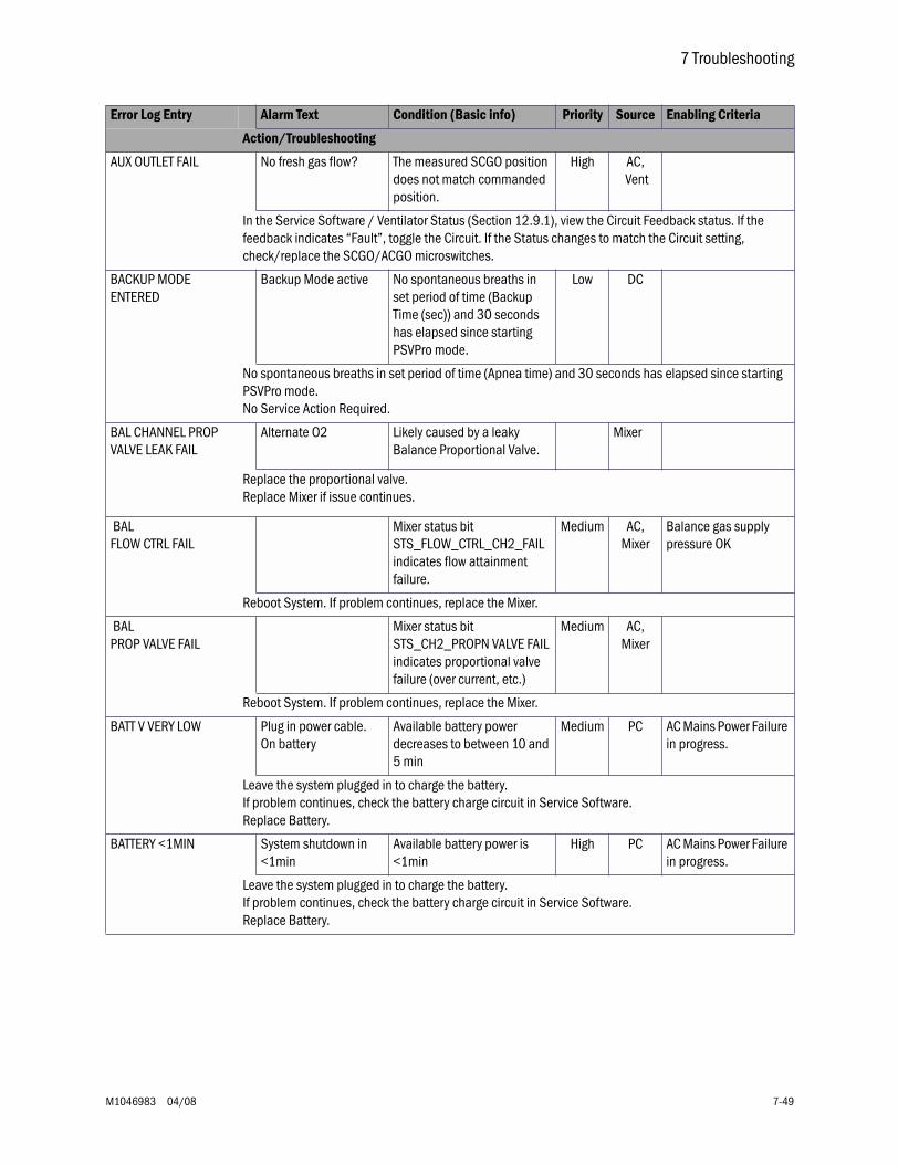
7 Troubleshooting
M1046983 04/08 7-49
AUX OUTLET FAIL No fresh gas flow? The measured SCGO position does not match commanded position.
High AC, Vent
In the Service Software / Ventilator Status (Section 12.9.1), view the Circuit Feedback status. If the feedback indicates “Fault”, toggle the Circuit. If the Status changes to match the Circuit setting, check/replace the SCGO/ACGO microswitches.
BACKUP MODE ENTERED
Backup Mode active No spontaneous breaths in set period of time (Backup Time (sec)) and 30 seconds has elapsed since starting PSVPro mode.
Low DC
No spontaneous breaths in set period of time (Apnea time) and 30 seconds has elapsed since starting PSVPro mode. No Service Action Required.
BAL CHANNEL PROP VALVE LEAK FAIL
Alternate O2 Likely caused by a leaky Balance Proportional Valve.
Mixer
Replace the proportional valve.Replace Mixer if issue continues.
BAL FLOW CTRL FAIL
Mixer status bit STS_FLOW_CTRL_CH2_FAIL indicates flow attainment failure.
Medium AC,Mixer
Balance gas supply pressure OK
Reboot System. If problem continues, replace the Mixer.
BAL PROP VALVE FAIL
Mixer status bit STS_CH2_PROPN VALVE FAIL indicates proportional valve failure (over current, etc.)
Medium AC,Mixer
Reboot System. If problem continues, replace the Mixer.
BATT V VERY LOW Plug in power cable.On battery
Available battery power decreases to between 10 and 5 min
Medium PC AC Mains Power Failure in progress.
Leave the system plugged in to charge the battery. If problem continues, check the battery charge circuit in Service Software. Replace Battery.
BATTERY <1MIN System shutdown in <1min
Available battery power is <1min
High PC AC Mains Power Failure in progress.
Leave the system plugged in to charge the battery. If problem continues, check the battery charge circuit in Service Software. Replace Battery.
Error Log Entry Alarm Text Condition (Basic info) Priority Source Enabling Criteria
Action/Troubleshooting
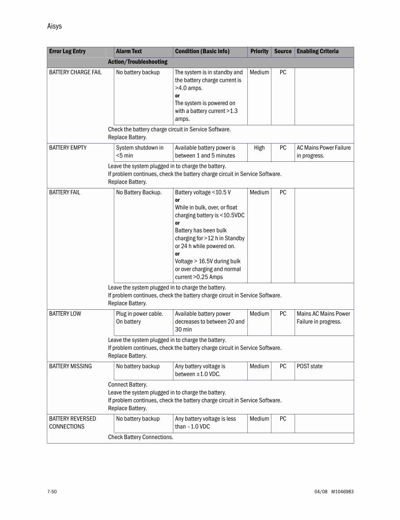
Aisys
7-50 04/08 M1046983
BATTERY CHARGE FAIL No battery backup The system is in standby and the battery charge current is >4.0 amps.or The system is powered on with a battery current >1.3 amps.
Medium PC
Check the battery charge circuit in Service Software. Replace Battery.
BATTERY EMPTY System shutdown in <5 min
Available battery power is between 1 and 5 minutes
High PC AC Mains Power Failure in progress.
Leave the system plugged in to charge the battery. If problem continues, check the battery charge circuit in Service Software. Replace Battery.
BATTERY FAIL No Battery Backup. Battery voltage <10.5 V or While in bulk, over, or float charging battery is <10.5VDCor Battery has been bulk charging for >12 h in Standby or 24 h while powered on.orVoltage > 16.5V during bulk or over charging and normal current >0.25 Amps
Medium PC
Leave the system plugged in to charge the battery. If problem continues, check the battery charge circuit in Service Software. Replace Battery.
BATTERY LOW Plug in power cable. On battery
Available battery power decreases to between 20 and 30 min
Medium PC Mains AC Mains Power Failure in progress.
Leave the system plugged in to charge the battery. If problem continues, check the battery charge circuit in Service Software. Replace Battery.
BATTERY MISSING No battery backup Any battery voltage is between ±1.0 VDC.
Medium PC POST state
Connect Battery.Leave the system plugged in to charge the battery. If problem continues, check the battery charge circuit in Service Software. Replace Battery.
BATTERY REVERSED CONNECTIONS
No battery backup Any battery voltage is less than –1.0 VDC
Medium PC
Check Battery Connections.
Error Log Entry Alarm Text Condition (Basic info) Priority Source Enabling Criteria
Action/Troubleshooting
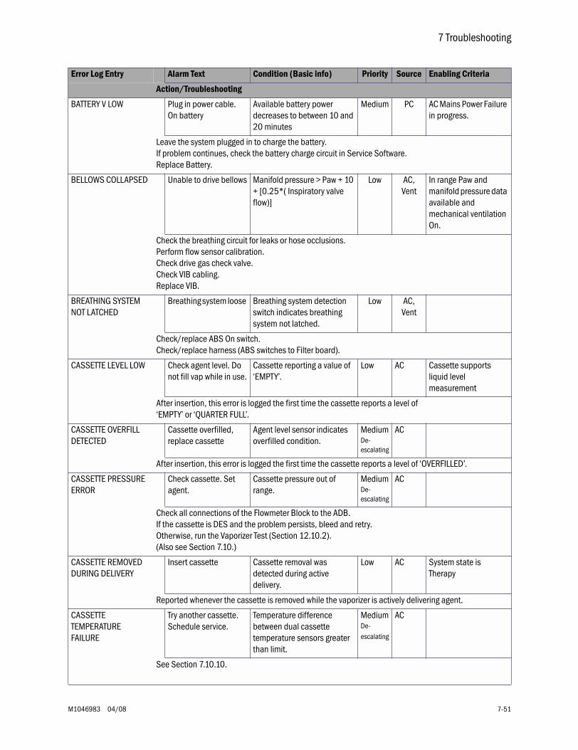
7 Troubleshooting
M1046983 04/08 7-51
BATTERY V LOW Plug in power cable. On battery
Available battery power decreases to between 10 and 20 minutes
Medium PC AC Mains Power Failure in progress.
Leave the system plugged in to charge the battery. If problem continues, check the battery charge circuit in Service Software. Replace Battery.
BELLOWS COLLAPSED Unable to drive bellows Manifold pressure > Paw + 10 + [0.25*( Inspiratory valve flow)]
Low AC,Vent
In range Paw and manifold pressure data available and mechanical ventilation On.
Check the breathing circuit for leaks or hose occlusions.Perform flow sensor calibration.Check drive gas check valve.Check VIB cabling.Replace VIB.
BREATHING SYSTEM NOT LATCHED
Breathing system loose Breathing system detection switch indicates breathing system not latched.
Low AC,Vent
Check/replace ABS On switch.Check/replace harness (ABS switches to Filter board).
CASSETTE LEVEL LOW Check agent level. Do not fill vap while in use.
Cassette reporting a value of ‘EMPTY’.
Low AC Cassette supports liquid level measurement
After insertion, this error is logged the first time the cassette reports a level of ‘EMPTY’ or ‘QUARTER FULL’.
CASSETTE OVERFILL DETECTED
Cassette overfilled, replace cassette
Agent level sensor indicates overfilled condition.
Medium De-escalating
AC
After insertion, this error is logged the first time the cassette reports a level of ‘OVERFILLED’.
CASSETTE PRESSURE ERROR
Check cassette. Set agent.
Cassette pressure out of range.
Medium De-escalating
AC
Check all connections of the Flowmeter Block to the ADB. If the cassette is DES and the problem persists, bleed and retry.Otherwise, run the Vaporizer Test (Section 12.10.2). (Also see Section 7.10.)
CASSETTE REMOVED DURING DELIVERY
Insert cassette Cassette removal was detected during active delivery.
Low AC System state is Therapy
Reported whenever the cassette is removed while the vaporizer is actively delivering agent.
CASSETTE TEMPERATURE FAILURE
Try another cassette. Schedule service.
Temperature difference between dual cassette temperature sensors greater than limit.
MediumDe-escalating
AC
See Section 7.10.10.
Error Log Entry Alarm Text Condition (Basic info) Priority Source Enabling Criteria
Action/Troubleshooting
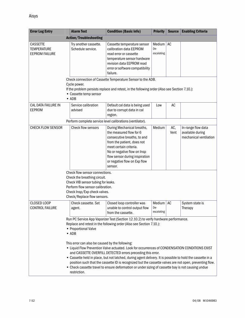
Aisys
7-52 04/08 M1046983
CASSETTE TEMPERATURE EEPROM FAILURE
Try another cassette. Schedule service.
Cassette temperature sensor calibration data EEPROM read error or cassette temperature sensor hardware revision data EEPROM read error or software compatibility failure.
MediumDe-escalating
AC
Check connection of Cassette Temperature Sensor to the ADB. Cycle power.If the problem persists replace and retest, in the following order (Also see Section 7.10.):• Cassette temp sensor• ADB
CAL DATA FAILURE IN EEPROM
Service calibration advised
Default cal data is being used due to corrupt data in cal region.
Low AC
Perform complete service level calibrations (ventilator).
CHECK FLOW SENSOR Check flow sensors During Mechanical breaths, the measured flow for 6 consecutive breaths, to and from the patient, does not meet certain criteria.No or negative flow on Insp flow sensor during inspiration or negative flow on Exp flow sensor.
Medium AC,Vent
In-range flow data available during mechanical ventilation
Check flow sensor connections.Check the breathing circuit.Check VIB sensor tubing for leaks.Perform flow sensor calibration.Check Insp/Exp check valves.Check/Replace flow sensors.
CLOSED LOOP CONTROL FAILURE
Check cassette. Set agent.
Closed loop controller was unable to control output flow from the cassette.
MediumDe-escalating
AC System state is Therapy
Run PC Service App Vaporizer Test (Section 12.10.2) to verify hardware performance. Replace and retest in the following order (Also see Section 7.10.):• Proportional Valve• ADB
This error can also be caused by the following:• Liquid Flow Prevention Valve actuated. Look for occurrences of CONDENSATION CONDITIONS EXIST
and CASSETTE OVERFILL DETECTED errors preceding this error.• Cassette held in place, but not latched, during agent delivery. It is possible to hold the cassette in a
position such that the cassette ID is recognized but the cassette valves are not open, preventing flow.• Check cassette travel to ensure deformation or under sizing of cassette bay is not causing undue
restriction.
Error Log Entry Alarm Text Condition (Basic info) Priority Source Enabling Criteria
Action/Troubleshooting
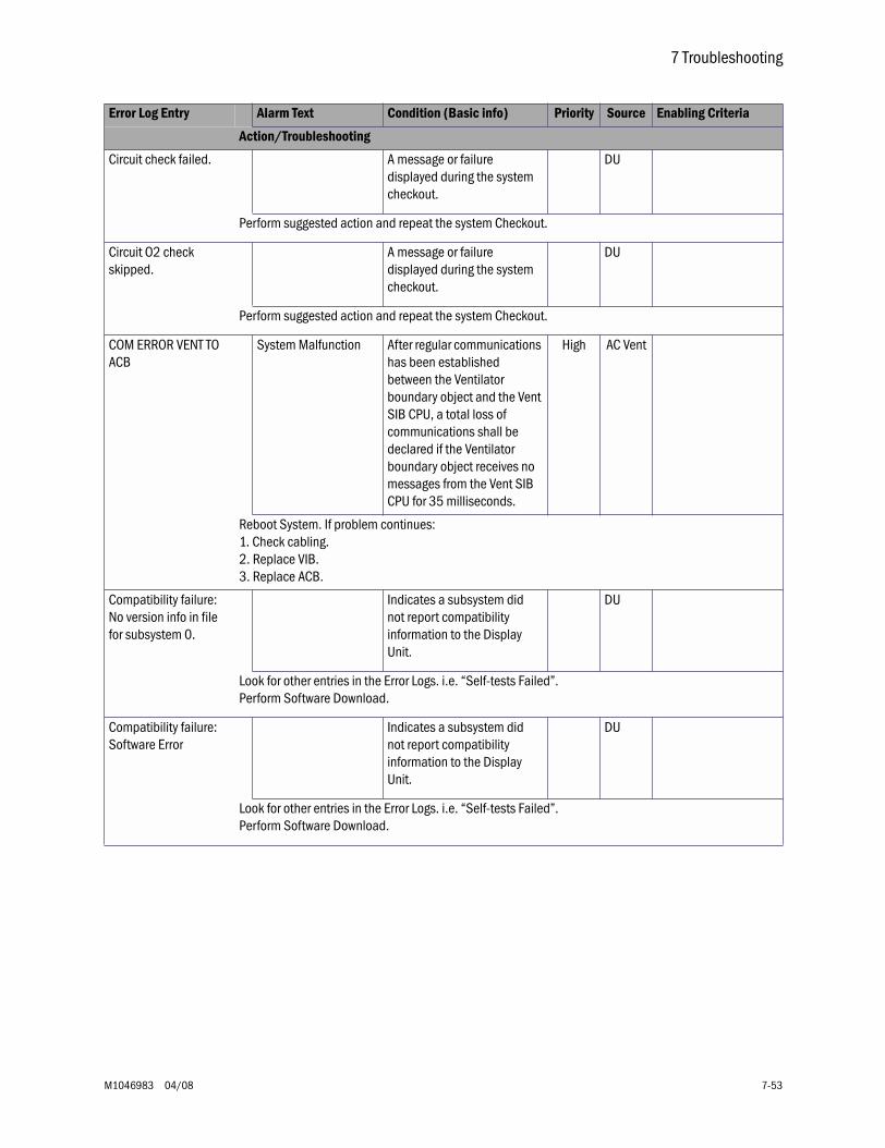
7 Troubleshooting
M1046983 04/08 7-53
Circuit check failed. A message or failure displayed during the system checkout.
DU
Perform suggested action and repeat the system Checkout.
Circuit O2 check skipped.
A message or failure displayed during the system checkout.
DU
Perform suggested action and repeat the system Checkout.
COM ERROR VENT TO ACB
System Malfunction After regular communications has been established between the Ventilator boundary object and the Vent SIB CPU, a total loss of communications shall be declared if the Ventilator boundary object receives no messages from the Vent SIB CPU for 35 milliseconds.
High AC Vent
Reboot System. If problem continues:1. Check cabling.2. Replace VIB.3. Replace ACB.
Compatibility failure: No version info in file for subsystem 0.
Indicates a subsystem did not report compatibility information to the Display Unit.
DU
Look for other entries in the Error Logs. i.e. “Self-tests Failed”.Perform Software Download.
Compatibility failure: Software Error
Indicates a subsystem did not report compatibility information to the Display Unit.
DU
Look for other entries in the Error Logs. i.e. “Self-tests Failed”. Perform Software Download.
Error Log Entry Alarm Text Condition (Basic info) Priority Source Enabling Criteria
Action/Troubleshooting
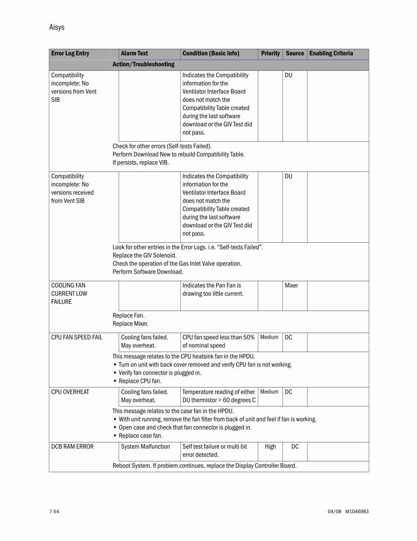
Aisys
7-54 04/08 M1046983
Compatibility incomplete: No versions from Vent SIB
Indicates the Compatibility information for the Ventilator Interface Board does not match the Compatibility Table created during the last software download or the GIV Test did not pass.
DU
Check for other errors (Self-tests Failed).Perform Download New to rebuild Compatibility Table.If persists, replace VIB.
Compatibility incomplete: No versions received from Vent SIB
Indicates the Compatibility information for the Ventilator Interface Board does not match the Compatibility Table created during the last software download or the GIV Test did not pass.
DU
Look for other entries in the Error Logs. i.e. “Self-tests Failed”.Replace the GIV Solenoid.Check the operation of the Gas Inlet Valve operation.Perform Software Download.
COOLING FAN CURRENT LOW FAILURE
Indicates the Pan Fan is drawing too little current.
Mixer
Replace Fan.Replace Mixer.
CPU FAN SPEED FAIL Cooling fans failed. May overheat.
CPU fan speed less than 50% of nominal speed
Medium DC
This message relates to the CPU heatsink fan in the HPDU.• Turn on unit with back cover removed and verify CPU fan is not working.• Verify fan connector is plugged in.• Replace CPU fan.
CPU OVERHEAT Cooling fans failed. May overheat.
Temperature reading of either DU thermistor > 60 degrees C
Medium DC
This message relates to the case fan in the HPDU.• With unit running, remove the fan filter from back of unit and feel if fan is working.• Open case and check that fan connector is plugged in.• Replace case fan.
DCB RAM ERROR System Malfunction Self test failure or multi bit error detected.
High DC
Reboot System. If problem continues, replace the Display Controller Board.
Error Log Entry Alarm Text Condition (Basic info) Priority Source Enabling Criteria
Action/Troubleshooting
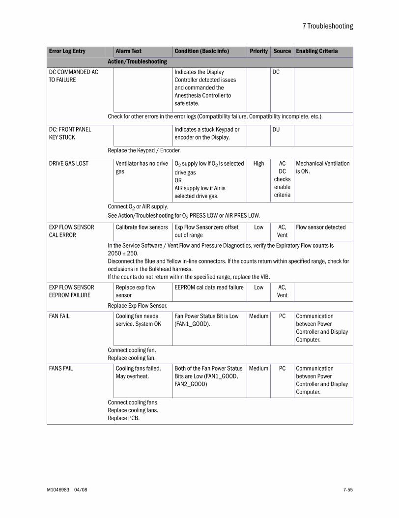
7 Troubleshooting
M1046983 04/08 7-55
DC COMMANDED AC TO FAILURE
Indicates the Display Controller detected issues and commanded the Anesthesia Controller to safe state.
DC
Check for other errors in the error logs (Compatibility failure, Compatibility incomplete, etc.).
DC: FRONT PANEL KEY STUCK
Indicates a stuck Keypad or encoder on the Display.
DU
Replace the Keypad / Encoder.
DRIVE GAS LOST Ventilator has no drive gas
O2 supply low if O2 is selected drive gas ORAIR supply low if Air is selected drive gas.
High ACDC
checks enable criteria
Mechanical Ventilation is ON.
Connect O2 or AIR supply.See Action/Troubleshooting for O2 PRESS LOW or AIR PRES LOW.
EXP FLOW SENSOR CAL ERROR
Calibrate flow sensors Exp Flow Sensor zero offset out of range
Low AC,Vent
Flow sensor detected
In the Service Software / Vent Flow and Pressure Diagnostics, verify the Expiratory Flow counts is 2050 ± 250.Disconnect the Blue and Yellow in-line connectors. If the counts return within specified range, check for occlusions in the Bulkhead harness.If the counts do not return within the specified range, replace the VIB.
EXP FLOW SENSOR EEPROM FAILURE
Replace exp flow sensor
EEPROM cal data read failure Low AC,Vent
Replace Exp Flow Sensor.
FAN FAIL Cooling fan needs service. System OK
Fan Power Status Bit is Low (FAN1_GOOD).
Medium PC Communication between Power Controller and Display Computer.
Connect cooling fan.Replace cooling fan.
FANS FAIL Cooling fans failed. May overheat.
Both of the Fan Power Status Bits are Low (FAN1_GOOD, FAN2_GOOD)
Medium PC Communication between Power Controller and Display Computer.
Connect cooling fans.Replace cooling fans.Replace PCB.
Error Log Entry Alarm Text Condition (Basic info) Priority Source Enabling Criteria
Action/Troubleshooting
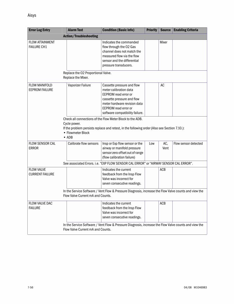
Aisys
7-56 04/08 M1046983
FLOW ATTAINMENT FAILURE CH1
Indicates the commanded flow through the O2 Gas channel does not match the measured flow via the flow sensor and the differential pressure transducers.
Mixer
Replace the O2 Proportional Valve.Replace the Mixer.
FLOW MANIFOLD EEPROM FAILURE
Vaporizer Failure Cassette pressure and flow meter calibration data EEPROM read error or cassette pressure and flow meter hardware revision data EEPROM read error or software compatibility failure.
AC
Check all connections of the Flow Meter Block to the ADB.Cycle power.If the problem persists replace and retest, in the following order (Also see Section 7.10.):• Flowmeter Block• ADB
FLOW SENSOR CAL ERROR
Calibrate flow sensors Insp or Exp flow sensor or the airway or manifold pressure sensor zero offset out of range (flow calibration failure)
Low AC,Vent
Flow sensor detected
See associated Errors. i.e. “EXP FLOW SENSOR CAL ERROR” or “AIRWAY SENSOR CAL ERROR”.
FLOW VALVE CURRENT FAILURE
Indicates the current feedback from the Insp Flow Valve was incorrect for seven consecutive readings.
ACB
In the Service Software / Vent Flow & Pressure Diagnosis, increase the Flow Valve counts and view the Flow Valve Current mA and Counts.
FLOW VALVE DAC FAILURE
Indicates the current feedback from the Insp Flow Valve was incorrect for seven consecutive readings.
ACB
In the Service Software / Vent Flow & Pressure Diagnosis, increase the Flow Valve counts and view the Flow Valve Current mA and Counts.
Error Log Entry Alarm Text Condition (Basic info) Priority Source Enabling Criteria
Action/Troubleshooting

7 Troubleshooting
M1046983 04/08 7-57
FLOW VERIFICATION FAILURE (dP) CH1
Indicates the commanded flow through the O2 Gas Channel and the flow measured by the Hot-wire anemometer agrees but the flow as measured by the pressure transducers does not agree.
Mixer
Perform the Mixer zero.Replace Mixer.
FRONT PANEL COM FAIL
Display panel controls failure
Key pad controller fails to send “life tick” for greater than 10 Sec.
Medium(Yellow)
DC
Reboot system. If problem continues, replace Display Controller Board.
GAS INLET VALVE BOOTUP TEST FAIL
Vent Fail. Monitoring Only
Boot-up test failed. High AC,Vent
1. Check GIV solenoid connection.2. Replace GIV.3. Rebuild the GIV components.4. Replace VIB.
INFLOW CHECK VALVE FAILURE
Vaporizer Failure Negative flow in the cassette inflow limb greater than limit.
AC
Replace Inflow check valve. (Also see Section 7.10.)
INFLOW OUTFLOW CROSSCHECK FAILURE
INFLOW OUTFLOW CROSSCHECK FAILURE RECOVERABLE
Vaporizer Failure Output concentration measured by the output and input flowmeter disagree by more than limit.
AC
Check eVap and cassettes used with the machine for leaks.Replace and retest in the following order (Also see Section 7.10.):• Zero Valve (Inflow or Outflow depending on Vaporizer Test results).• Flowmeter Block• ADB
INSP FLOW SENSOR CAL ERROR
Calibrate flow sensors Insp Flow Sensor zero offset out of range.
Low AC,Vent
Flow sensor detected
In the Service Software / Vent Flow and Pressure Diagnostics, verify the Inspiratory Pressure counts is2050 ± 250.Disconnect the Black and White in-line connectors. If the counts return within specified range, check for occlusions in the Bulkhead harness.If the counts do not return within the specified range, replace the VIB.
Error Log Entry Alarm Text Condition (Basic info) Priority Source Enabling Criteria
Action/Troubleshooting
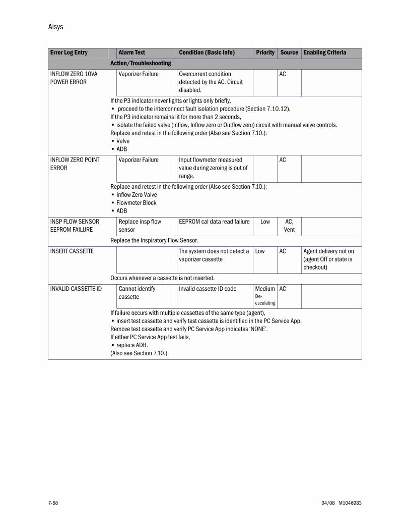
Aisys
7-58 04/08 M1046983
INFLOW ZERO 10VA POWER ERROR
Vaporizer Failure Overcurrent condition detected by the AC. Circuit disabled.
AC
If the P3 indicator never lights or lights only briefly,• proceed to the interconnect fault isolation procedure (Section 7.10.12).If the P3 indicator remains lit for more than 2 seconds, • isolate the failed valve (Inflow, Inflow zero or Outflow zero) circuit with manual valve controls. Replace and retest in the following order (Also see Section 7.10.):• Valve• ADB
INFLOW ZERO POINT ERROR
Vaporizer Failure Input flowmeter measured value during zeroing is out of range.
AC
Replace and retest in the following order (Also see Section 7.10.):• Inflow Zero Valve• Flowmeter Block• ADB
INSP FLOW SENSOR EEPROM FAILURE
Replace insp flow sensor
EEPROM cal data read failure Low AC,Vent
Replace the Inspiratory Flow Sensor.
INSERT CASSETTE The system does not detect a vaporizer cassette
Low AC Agent delivery not on (agent Off or state is checkout)
Occurs whenever a cassette is not inserted.
INVALID CASSETTE ID Cannot identify cassette
Invalid cassette ID code Medium De-escalating
AC
If failure occurs with multiple cassettes of the same type (agent),• insert test cassette and verify test cassette is identified in the PC Service App. Remove test cassette and verify PC Service App indicates ‘NONE’. If either PC Service App test fails,• replace ADB.(Also see Section 7.10.)
Error Log Entry Alarm Text Condition (Basic info) Priority Source Enabling Criteria
Action/Troubleshooting
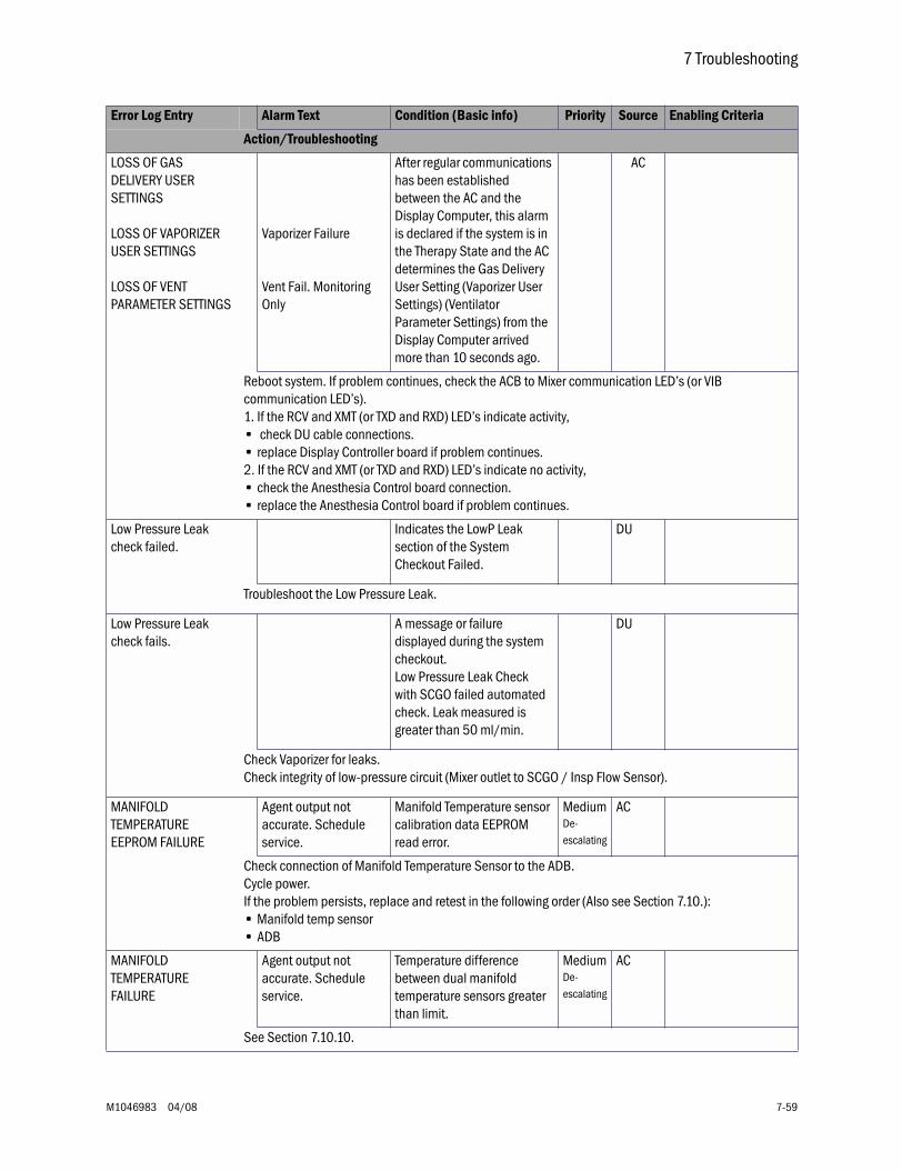
7 Troubleshooting
M1046983 04/08 7-59
LOSS OF GAS DELIVERY USER SETTINGS
LOSS OF VAPORIZER USER SETTINGS
LOSS OF VENT PARAMETER SETTINGS
Vaporizer Failure
Vent Fail. Monitoring Only
After regular communications has been established between the AC and the Display Computer, this alarm is declared if the system is in the Therapy State and the AC determines the Gas Delivery User Setting (Vaporizer User Settings) (Ventilator Parameter Settings) from the Display Computer arrived more than 10 seconds ago.
AC
Reboot system. If problem continues, check the ACB to Mixer communication LED’s (or VIB communication LED’s). 1. If the RCV and XMT (or TXD and RXD) LED’s indicate activity,• check DU cable connections. • replace Display Controller board if problem continues. 2. If the RCV and XMT (or TXD and RXD) LED’s indicate no activity, • check the Anesthesia Control board connection. • replace the Anesthesia Control board if problem continues.
Low Pressure Leak check failed.
Indicates the LowP Leak section of the System Checkout Failed.
DU
Troubleshoot the Low Pressure Leak.
Low Pressure Leak check fails.
A message or failure displayed during the system checkout.Low Pressure Leak Check with SCGO failed automated check. Leak measured is greater than 50 ml/min.
DU
Check Vaporizer for leaks.Check integrity of low-pressure circuit (Mixer outlet to SCGO / Insp Flow Sensor).
MANIFOLD TEMPERATURE EEPROM FAILURE
Agent output not accurate. Schedule service.
Manifold Temperature sensor calibration data EEPROM read error.
MediumDe-escalating
AC
Check connection of Manifold Temperature Sensor to the ADB.Cycle power.If the problem persists, replace and retest in the following order (Also see Section 7.10.):• Manifold temp sensor• ADB
MANIFOLD TEMPERATURE FAILURE
Agent output not accurate. Schedule service.
Temperature difference between dual manifold temperature sensors greater than limit.
MediumDe-escalating
AC
See Section 7.10.10.
Error Log Entry Alarm Text Condition (Basic info) Priority Source Enabling Criteria
Action/Troubleshooting
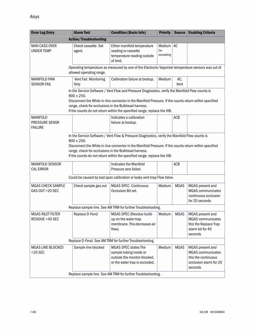
Aisys
7-60 04/08 M1046983
MAN CASS OVER UNDER TEMP
Check cassette. Set agent.
Either manifold temperature reading or cassette temperature reading outside of limit.
MediumDe-escalating
AC
Operating temperature as measured by one of the Electronic Vaporizer temperature sensors was out of allowed operating range.
MANIFOLD PAW SENSOR FAIL
Vent Fail. Monitoring Only
Calibration failure at bootup. Medium AC,Vent
In the Service Software / Vent Flow and Pressure Diagnostics, verify the Manifold Flow counts is 800 ± 250.Disconnect the White in-line connector in the Manifold Pressure. If the counts return within specified range, check for occlusions in the Bulkhead harness.If the counts do not return within the specified range, replace the VIB.
MANIFOLD PRESSURE SENSR FAILURE
Indicates a calibration failure at bootup.
ACB
In the Service Software / Vent Flow & Pressure Diagnostics, verify the Manifold Flow counts is 800 ± 250.Disconnect the White in-line connector in the Manifold Pressure. If the counts return within specified range, check for occlusions in the Bulkhead harness.If the counts do not return within the specified range, replace the VIB.
MANIFOLD SENSOR CAL ERROR
Indicates the Manifold Pressure zero failed.
ACB
Could be caused by bad span calibration or leaky vent Insp Flow Valve.
MGAS CHECK SAMPLE GAS OUT >20 SEC
Check sample gas out MGAS SPEC. Continuous Occlusion Bit set.
Medium MGAS MGAS present and MGAS communicates continuous occlusion for 20 seconds
Replace sample line. See AM TRM for further Troubleshooting.
MGAS INLET FILTER RESIDUE >40 SEC
Replace D-Fend MGAS SPEC (Residue build-up on the water trap membrane. This decreases air flow).
Medium MGAS MGAS present and MGAS communicates this the Replace Trap alarm bit for 40 seconds
Replace D-Fend. See AM TRM for further Troubleshooting.
MGAS LINE BLOCKED >20 SEC
Sample line blocked MGAS SPEC states The sample tubing inside or outside the monitor blocked, or the water trap is occluded.
Medium MGAS MGAS present and MGAS communicates this the continuous occlusion alarm for 20 seconds
Replace sample line. See AM TRM for further Troubleshooting.
Error Log Entry Alarm Text Condition (Basic info) Priority Source Enabling Criteria
Action/Troubleshooting
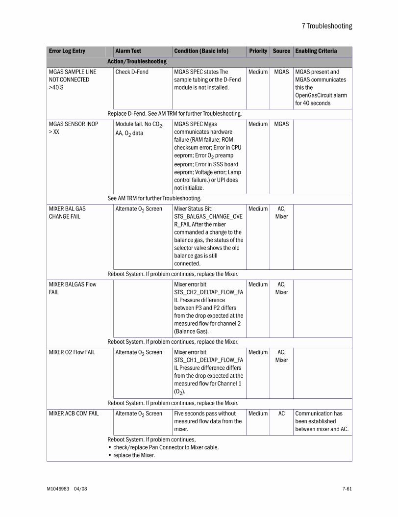
7 Troubleshooting
M1046983 04/08 7-61
MGAS SAMPLE LINE NOT CONNECTED >40 S
Check D-Fend MGAS SPEC states The sample tubing or the D-Fend module is not installed.
Medium MGAS MGAS present and MGAS communicates this the OpenGasCircuit alarm for 40 seconds
Replace D-Fend. See AM TRM for further Troubleshooting.
MGAS SENSOR INOP > XX
Module fail. No CO2, AA, O2 data
MGAS SPEC Mgas communicates hardware failure (RAM failure; ROM checksum error; Error in CPU eeprom; Error O2 preamp eeprom; Error in SSS board eeprom; Voltage error; Lamp control failure.) or UPI does not initialize.
Medium MGAS
See AM TRM for further Troubleshooting.
MIXER BAL GAS CHANGE FAIL
Alternate O2 Screen Mixer Status Bit: STS_BALGAS_CHANGE_OVER_FAIL After the mixer commanded a change to the balance gas, the status of the selector valve shows the old balance gas is still connected.
Medium AC,Mixer
Reboot System. If problem continues, replace the Mixer.
MIXER BALGAS Flow FAIL
Mixer error bit STS_CH2_DELTAP_FLOW_FAIL Pressure difference between P3 and P2 differs from the drop expected at the measured flow for channel 2 (Balance Gas).
Medium AC,Mixer
Reboot System. If problem continues, replace the Mixer.
MIXER O2 Flow FAIL Alternate O2 Screen Mixer error bit STS_CH1_DELTAP_FLOW_FAIL Pressure difference differs from the drop expected at the measured flow for Channel 1 (O2).
Medium AC,Mixer
Reboot System. If problem continues, replace the Mixer.
MIXER ACB COM FAIL Alternate O2 Screen Five seconds pass without measured flow data from the mixer.
Medium AC Communication has been established between mixer and AC.
Reboot System. If problem continues, • check/replace Pan Connector to Mixer cable.• replace the Mixer.
Error Log Entry Alarm Text Condition (Basic info) Priority Source Enabling Criteria
Action/Troubleshooting
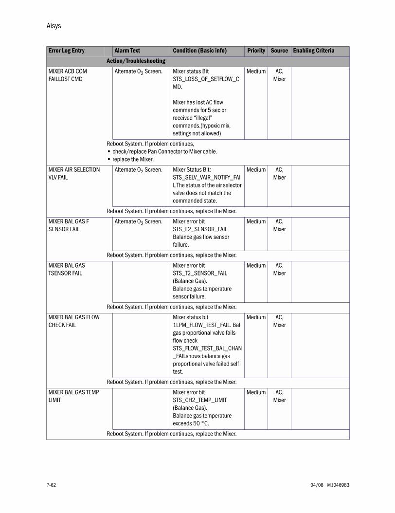
Aisys
7-62 04/08 M1046983
MIXER ACB COM FAILLOST CMD
Alternate O2 Screen. Mixer status Bit STS_LOSS_OF_SETFLOW_CMD.
Mixer has lost AC flow commands for 5 sec or received “illegal” commands.(hypoxic mix, settings not allowed)
Medium AC,Mixer
Reboot System. If problem continues,• check/replace Pan Connector to Mixer cable.• replace the Mixer.
MIXER AIR SELECTION VLV FAIL
Alternate O2 Screen. Mixer Status Bit: STS_SELV_VAIR_NOTIFY_FAIL The status of the air selector valve does not match the commanded state.
Medium AC,Mixer
Reboot System. If problem continues, replace the Mixer.
MIXER BAL GAS F SENSOR FAIL
Alternate O2 Screen. Mixer error bit STS_F2_SENSOR_FAILBalance gas flow sensor failure.
Medium AC,Mixer
Reboot System. If problem continues, replace the Mixer.
MIXER BAL GAS TSENSOR FAIL
Mixer error bit STS_T2_SENSOR_FAIL (Balance Gas).Balance gas temperature sensor failure.
Medium AC,Mixer
Reboot System. If problem continues, replace the Mixer.
MIXER BAL GAS FLOW CHECK FAIL
Mixer status bit 1LPM_FLOW_TEST_FAIL. Bal gas proportional valve fails flow check STS_FLOW_TEST_BAL_CHAN_FAILshows balance gas proportional valve failed self test.
Medium AC,Mixer
Reboot System. If problem continues, replace the Mixer.
MIXER BAL GAS TEMP LIMIT
Mixer error bit STS_CH2_TEMP_LIMIT (Balance Gas).Balance gas temperature exceeds 50 °C.
Medium AC,Mixer
Reboot System. If problem continues, replace the Mixer.
Error Log Entry Alarm Text Condition (Basic info) Priority Source Enabling Criteria
Action/Troubleshooting
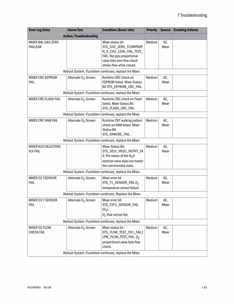
7 Troubleshooting
M1046983 04/08 7-63
MIXER BAL GAS ZERO FAILLEAK
Mixer status bit STS_CH2_ZERO_FLOWPROPN_V_CH2_LEAK_FAIL_TEST_FAIL. Bal gas proportional valve fails zero flow check shows flow while closed.
Medium AC,Mixer
Reboot System. If problem continues, replace the Mixer.
MIXER CRC EEPROM FAIL
Alternate O2 Screen Runtime CRC check on EEPROM failed. Mixer Status Bit STS_EEPROM_CRC_FAIL.
Medium AC,Mixer
Reboot System. If problem continues, replace the Mixer.
MIXER CRC FLASH FAIL Alternate O2 Screen Runtime CRC check on Flash failed. Mixer Status Bit STS_FLASH_CRC_FAIL
Medium AC,Mixer
Reboot System. If problem continues, replace the Mixer.
MIXER CRC RAM FAIL Alternate O2 Screen Runtime CRC walking pattern check on RAM failed. Mixer Status Bit STS_RAMCRC_FAIL.
Medium AC,Mixer
Reboot System. If problem continues, replace the Mixer.
MIXER N2O SELECTION VLV FAIL
Mixer Status Bit: STS_SELV_VN2O_NOTIFY_FAIL The status of the N2O selector valve does not match the commanded state.
Medium AC,Mixer
Reboot System. If problem continues, replace the Mixer.
MIXER O2 TSENSOR FAIL
Alternate O2 Screen. Mixer error bit STS_T1_SENSOR_FAIL O2 temperature sensor failure
Medium AC,Mixer
Reboot System. If problem continues, Replace the Mixer.
MIXER O2 F SENSOR FAIL
Alternate O2 Screen Mixer error bit STS_F2F1_SENSOR_FAIL (O2).O2 flow sensor fail.
Medium AC,Mixer
Reboot System. If problem continues, replace the Mixer.
MIXER O2 FLOW CHECK FAIL
Alternate O2 Screen Mixer status bit STS_FLOW_TEST_CH1_FAIL1LPM_FLOW_TEST_FAIL. O2 proportional valve fails flow check.
Medium AC,Mixer
Reboot System. If problem continues, replace the Mixer.
Error Log Entry Alarm Text Condition (Basic info) Priority Source Enabling Criteria
Action/Troubleshooting
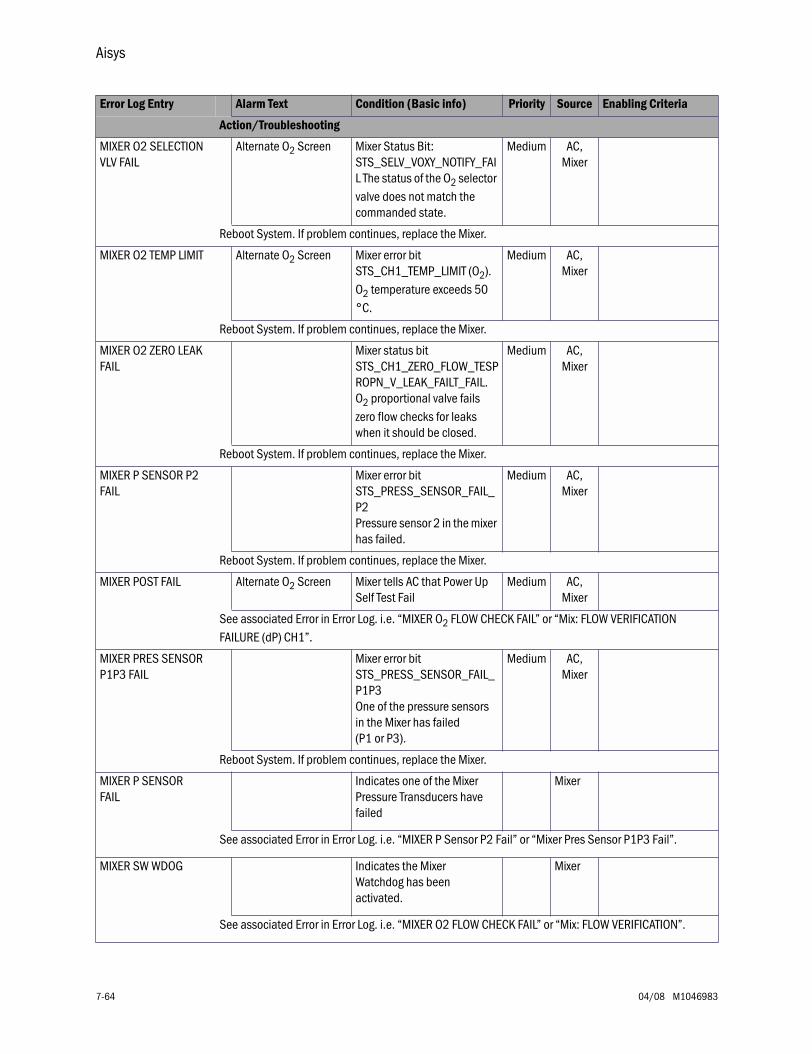
Aisys
7-64 04/08 M1046983
MIXER O2 SELECTION VLV FAIL
Alternate O2 Screen Mixer Status Bit: STS_SELV_VOXY_NOTIFY_FAIL The status of the O2 selector valve does not match the commanded state.
Medium AC,Mixer
Reboot System. If problem continues, replace the Mixer.
MIXER O2 TEMP LIMIT Alternate O2 Screen Mixer error bit STS_CH1_TEMP_LIMIT (O2).O2 temperature exceeds 50 °C.
Medium AC,Mixer
Reboot System. If problem continues, replace the Mixer.
MIXER O2 ZERO LEAK FAIL
Mixer status bit STS_CH1_ZERO_FLOW_TESPROPN_V_LEAK_FAILT_FAIL. O2 proportional valve fails zero flow checks for leaks when it should be closed.
Medium AC,Mixer
Reboot System. If problem continues, replace the Mixer.
MIXER P SENSOR P2 FAIL
Mixer error bit STS_PRESS_SENSOR_FAIL_P2Pressure sensor 2 in the mixer has failed.
Medium AC,Mixer
Reboot System. If problem continues, replace the Mixer.
MIXER POST FAIL Alternate O2 Screen Mixer tells AC that Power Up Self Test Fail
Medium AC,Mixer
See associated Error in Error Log. i.e. “MIXER O2 FLOW CHECK FAIL” or “Mix: FLOW VERIFICATION FAILURE (dP) CH1”.
MIXER PRES SENSOR P1P3 FAIL
Mixer error bit STS_PRESS_SENSOR_FAIL_P1P3One of the pressure sensors in the Mixer has failed (P1 or P3).
Medium AC,Mixer
Reboot System. If problem continues, replace the Mixer.
MIXER P SENSOR FAIL
Indicates one of the Mixer Pressure Transducers have failed
Mixer
See associated Error in Error Log. i.e. “MIXER P Sensor P2 Fail” or “Mixer Pres Sensor P1P3 Fail”.
MIXER SW WDOG Indicates the Mixer Watchdog has been activated.
Mixer
See associated Error in Error Log. i.e. “MIXER O2 FLOW CHECK FAIL” or “Mix: FLOW VERIFICATION”.
Error Log Entry Alarm Text Condition (Basic info) Priority Source Enabling Criteria
Action/Troubleshooting
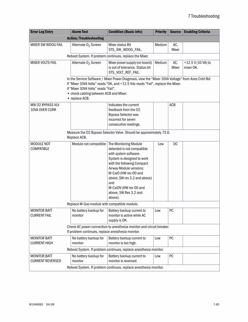
7 Troubleshooting
M1046983 04/08 7-65
MIXER SW WDOG FAIL Alternate O2 Screen Mixer status Bit STS_SW_WDOG_FAIL.
Medium AC,Mixer
Reboot System. If problem continues, replace the Mixer.
MIXER VOLTS FAIL Alternate O2 Screen Mixer power supply (on board) is out of tolerance. Status bit STS_VOLT_REF_FAIL.
Medium AC,Mixer
+12.5 V (10 VA) to mixer OK.
In the Service Software / Mixer Power Diagnosis, view the “Mixer 10VA Voltage” from Anes Cntrl Bd:If “Mixer 10VA Volts” reads “OK, and +12.5 Vdc reads “Fail”, replace the Mixer. If “Mixer 10VA Volts” reads “Fail”, • check cabling between ACB and Mixer.• replace ACB.
MIX O2 BYPASS VLV 10VA OVER CURR
Indicates the current feedback from the O2 Bypass Selector was incorrect for seven consecutive readings.
ACB
Measure the O2 Bypass Selector Valve. Should be approximately 75 Ω. Replace ACB.
MODULE NOT COMPATIBLE
Module not compatible The Monitoring Module detected is not compatible with system software.System is designed to work with the following Compact Airway Module versions: M-CaiO (HW rev 00 and above, SW rev 3.2 and above) and M-CaiOV (HW rev 00 and above, SW Rev 3.2 and above).
Low DC
Replace M-Gas module with compatible module.
MONITOR BATT CURRENT FAIL
No battery backup for monitor
Battery backup current to monitor is active while AC supply is OK.
Low PC
Check AC power connection to anesthesia monitor and circuit breaker.If problem continues, replace anesthesia monitor.
MONITOR BATT CURRENT HIGH
No battery backup for monitor
Battery backup current to monitor is too high.
Low PC
Reboot System. If problem continues, replace anesthesia monitor.
MONITOR BATT CURRENT REVERSED
No battery backup for monitor
Battery backup current to monitor is reversed.
Low PC
Reboot System. If problem continues, replace anesthesia monitor.
Error Log Entry Alarm Text Condition (Basic info) Priority Source Enabling Criteria
Action/Troubleshooting
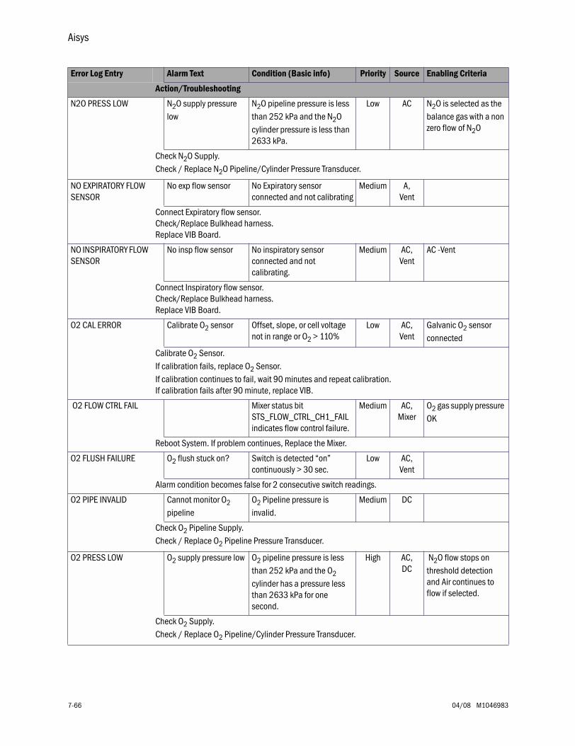
Aisys
7-66 04/08 M1046983
N2O PRESS LOW N2O supply pressure low
N2O pipeline pressure is less than 252 kPa and the N2O cylinder pressure is less than 2633 kPa.
Low AC N2O is selected as the balance gas with a non zero flow of N2O
Check N2O Supply.Check / Replace N2O Pipeline/Cylinder Pressure Transducer.
NO EXPIRATORY FLOW SENSOR
No exp flow sensor No Expiratory sensor connected and not calibrating
Medium A,Vent
Connect Expiratory flow sensor.Check/Replace Bulkhead harness.Replace VIB Board.
NO INSPIRATORY FLOW SENSOR
No insp flow sensor No inspiratory sensor connected and not calibrating.
Medium AC,Vent
AC -Vent
Connect Inspiratory flow sensor.Check/Replace Bulkhead harness.Replace VIB Board.
O2 CAL ERROR Calibrate O2 sensor Offset, slope, or cell voltage not in range or O2 > 110%
Low AC,Vent
Galvanic O2 sensor connected
Calibrate O2 Sensor.If calibration fails, replace O2 Sensor.If calibration continues to fail, wait 90 minutes and repeat calibration.If calibration fails after 90 minute, replace VIB.
O2 FLOW CTRL FAIL Mixer status bit STS_FLOW_CTRL_CH1_FAIL indicates flow control failure.
Medium AC,Mixer
O2 gas supply pressure OK
Reboot System. If problem continues, Replace the Mixer.
O2 FLUSH FAILURE O2 flush stuck on? Switch is detected “on” continuously > 30 sec.
Low AC,Vent
Alarm condition becomes false for 2 consecutive switch readings.
O2 PIPE INVALID Cannot monitor O2 pipeline
O2 Pipeline pressure is invalid.
Medium DC
Check O2 Pipeline Supply. Check / Replace O2 Pipeline Pressure Transducer.
O2 PRESS LOW O2 supply pressure low O2 pipeline pressure is less than 252 kPa and the O2 cylinder has a pressure less than 2633 kPa for one second.
High AC,DC
N2O flow stops on threshold detection and Air continues to flow if selected.
Check O2 Supply.Check / Replace O2 Pipeline/Cylinder Pressure Transducer.
Error Log Entry Alarm Text Condition (Basic info) Priority Source Enabling Criteria
Action/Troubleshooting
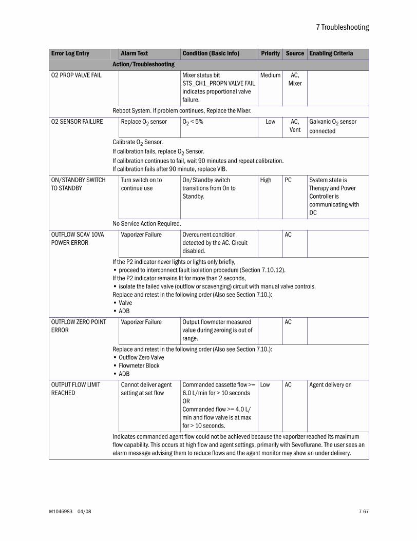
7 Troubleshooting
M1046983 04/08 7-67
O2 PROP VALVE FAIL Mixer status bit STS_CH1_PROPN VALVE FAIL indicates proportional valve failure.
Medium AC,Mixer
Reboot System. If problem continues, Replace the Mixer.
O2 SENSOR FAILURE Replace O2 sensor O2 < 5% Low AC,Vent
Galvanic O2 sensor connected
Calibrate O2 Sensor.If calibration fails, replace O2 Sensor.If calibration continues to fail, wait 90 minutes and repeat calibration.If calibration fails after 90 minute, replace VIB.
ON/STANDBY SWITCH TO STANDBY
Turn switch on to continue use
On/Standby switch transitions from On to Standby.
High PC System state is Therapy and Power Controller is communicating with DC
No Service Action Required.
OUTFLOW SCAV 10VA POWER ERROR
Vaporizer Failure Overcurrent condition detected by the AC. Circuit disabled.
AC
If the P2 indicator never lights or lights only briefly,• proceed to interconnect fault isolation procedure (Section 7.10.12).If the P2 indicator remains lit for more than 2 seconds,• isolate the failed valve (outflow or scavenging) circuit with manual valve controls.Replace and retest in the following order (Also see Section 7.10.):• Valve• ADB
OUTFLOW ZERO POINT ERROR
Vaporizer Failure Output flowmeter measured value during zeroing is out of range.
AC
Replace and retest in the following order (Also see Section 7.10.):• Outflow Zero Valve• Flowmeter Block• ADB
OUTPUT FLOW LIMIT REACHED
Cannot deliver agent setting at set flow
Commanded cassette flow >= 6.0 L/min for > 10 seconds ORCommanded flow >= 4.0 L/min and flow valve is at max for > 10 seconds.
Low AC Agent delivery on
Indicates commanded agent flow could not be achieved because the vaporizer reached its maximum flow capability. This occurs at high flow and agent settings, primarily with Sevoflurane. The user sees an alarm message advising them to reduce flows and the agent monitor may show an under delivery.
Error Log Entry Alarm Text Condition (Basic info) Priority Source Enabling Criteria
Action/Troubleshooting
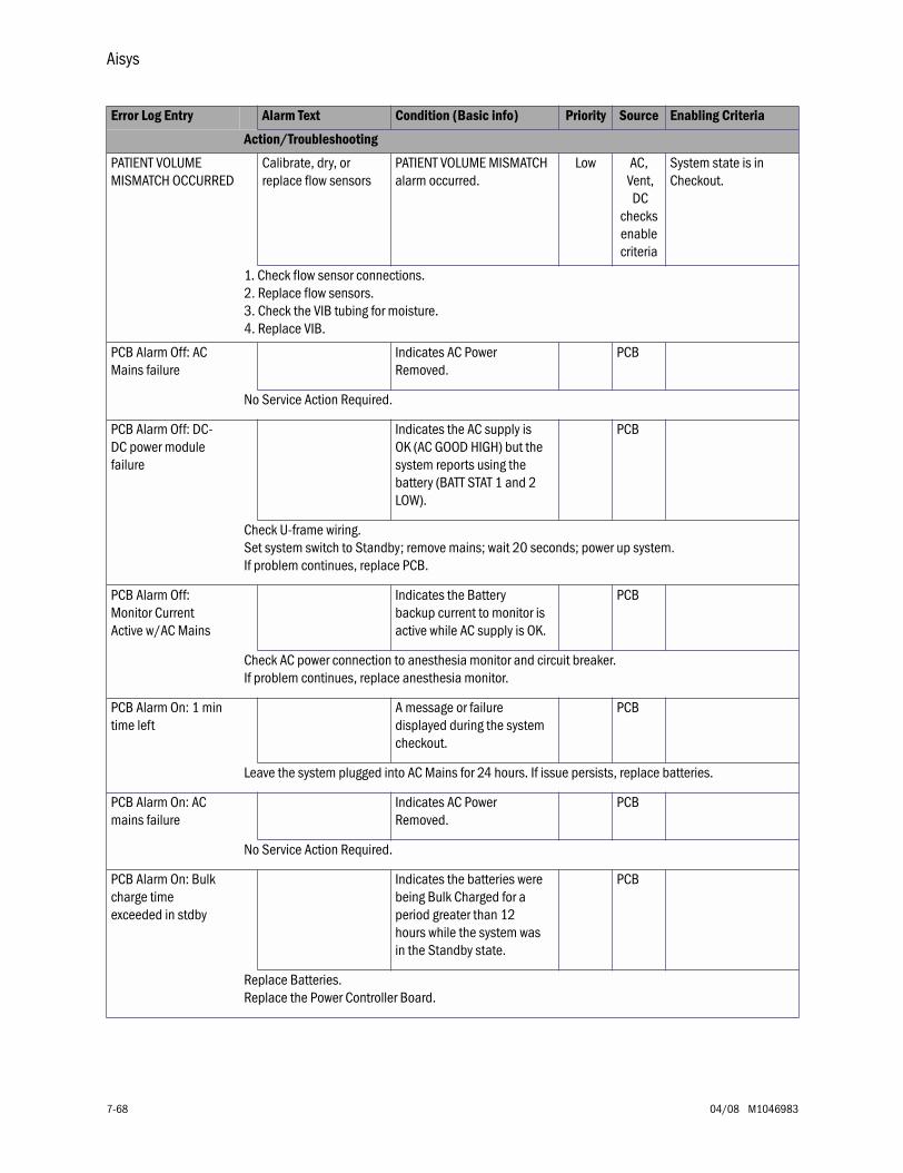
Aisys
7-68 04/08 M1046983
PATIENT VOLUME MISMATCH OCCURRED
Calibrate, dry, or replace flow sensors
PATIENT VOLUME MISMATCH alarm occurred.
Low AC, Vent,
DC checks enable criteria
System state is in Checkout.
1. Check flow sensor connections.2. Replace flow sensors.3. Check the VIB tubing for moisture.4. Replace VIB.
PCB Alarm Off: AC Mains failure
Indicates AC Power Removed.
PCB
No Service Action Required.
PCB Alarm Off: DC-DC power module failure
Indicates the AC supply is OK (AC GOOD HIGH) but the system reports using the battery (BATT STAT 1 and 2 LOW).
PCB
Check U-frame wiring.Set system switch to Standby; remove mains; wait 20 seconds; power up system.If problem continues, replace PCB.
PCB Alarm Off: Monitor Current Active w/AC Mains
Indicates the Battery backup current to monitor is active while AC supply is OK.
PCB
Check AC power connection to anesthesia monitor and circuit breaker.If problem continues, replace anesthesia monitor.
PCB Alarm On: 1 min time left
A message or failure displayed during the system checkout.
PCB
Leave the system plugged into AC Mains for 24 hours. If issue persists, replace batteries.
PCB Alarm On: AC mains failure
Indicates AC Power Removed.
PCB
No Service Action Required.
PCB Alarm On: Bulk charge time exceeded in stdby
Indicates the batteries were being Bulk Charged for a period greater than 12 hours while the system was in the Standby state.
PCB
Replace Batteries.Replace the Power Controller Board.
Error Log Entry Alarm Text Condition (Basic info) Priority Source Enabling Criteria
Action/Troubleshooting
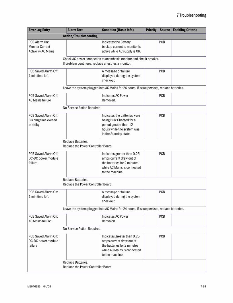
7 Troubleshooting
M1046983 04/08 7-69
PCB Alarm On: Monitor Current Active w/AC Mains
Indicates the Battery backup current to monitor is active while AC supply is OK.
PCB
Check AC power connection to anesthesia monitor and circuit breaker.If problem continues, replace anesthesia monitor.
PCB Saved Alarm Off: 1 min time left
A message or failure displayed during the system checkout.
PCB
Leave the system plugged into AC Mains for 24 hours. If issue persists, replace batteries.
PCB Saved Alarm Off: AC Mains failure
Indicates AC Power Removed.
PCB
No Service Action Required.
PCB Saved Alarm Off: Blk chrg time exceed in stdby
Indicates the batteries were being Bulk Charged for a period greater than 12 hours while the system was in the Standby state.
PCB
Replace Batteries.Replace the Power Controller Board.
PCB Saved Alarm Off: DC-DC power module failure
Indicates greater than 0.25 amps current draw out of the batteries for 2 minutes while AC Mains is connected to the machine.
PCB
Replace Batteries.Replace the Power Controller Board.
PCB Saved Alarm On: 1 min time left
A message or failure displayed during the system checkout.
PCB
Leave the system plugged into AC Mains for 24 hours. If issue persists, replace batteries.
PCB Saved Alarm On: AC Mains failure
Indicates AC Power Removed.
PCB
No Service Action Required.
PCB Saved Alarm On: DC-DC power module failure
Indicates greater than 0.25 amps current draw out of the batteries for 2 minutes while AC Mains is connected to the machine.
PCB
Replace Batteries.Replace the Power Controller Board.
Error Log Entry Alarm Text Condition (Basic info) Priority Source Enabling Criteria
Action/Troubleshooting
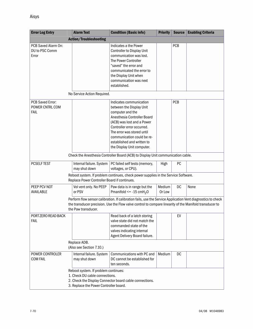
Aisys
7-70 04/08 M1046983
PCB Saved Alarm On: DU to PSC Comm Error
Indicates a the Power Controller to Display Unit communication was lost. The Power Controller “saved” the error and communicated the error to the Display Unit when communication was next established.
PCB
No Service Action Required.
PCB Saved Error: POWER CNTRL COM FAIL
Indicates communication between the Display Unit computer and the Anesthesia Controller Board (ACB) was lost and a Power Controller error occurred. The error was stored until communication could be re-established and written to the Display Unit computer.
PCB
Check the Anesthesia Controller Board (ACB) to Display Unit communication cable.
PCSELF TEST Internal failure. System may shut down
PC failed self tests (memory, voltages, or CPU).
High PC
Reboot system. If problem continues, check power supplies in the Service Software. Replace Power Controller Board if continues.
PEEP PCV NOT AVAILABLE
Vol vent only. No PEEP or PSV
Paw data is in range but the Pmanifold <= -15 cmH2O
Medium Or Low
DC None
Perform flow sensor calibration. If calibration fails, use the Service Application Vent diagnostics to check the transducer precision. Use the Flow valve control to compare linearity of the Manifold transducer to the Paw transducer.
PORT ZERO READ BACK FAIL
Read back of a latch storing valve state did not match the commanded state of the valves indicating internal Agent Delivery Board failure.
EV
Replace ADB.(Also see Section 7.10.)
POWER CONTROLER COM FAIL
Internal failure. System may shut down
Communications with PC and DC cannot be established for ten seconds.
Medium DC
Reboot system. If problem continues:1. Check DU cable connections.2. Check the Display Connector board cable connections.3. Replace the Power Controller board.
Error Log Entry Alarm Text Condition (Basic info) Priority Source Enabling Criteria
Action/Troubleshooting
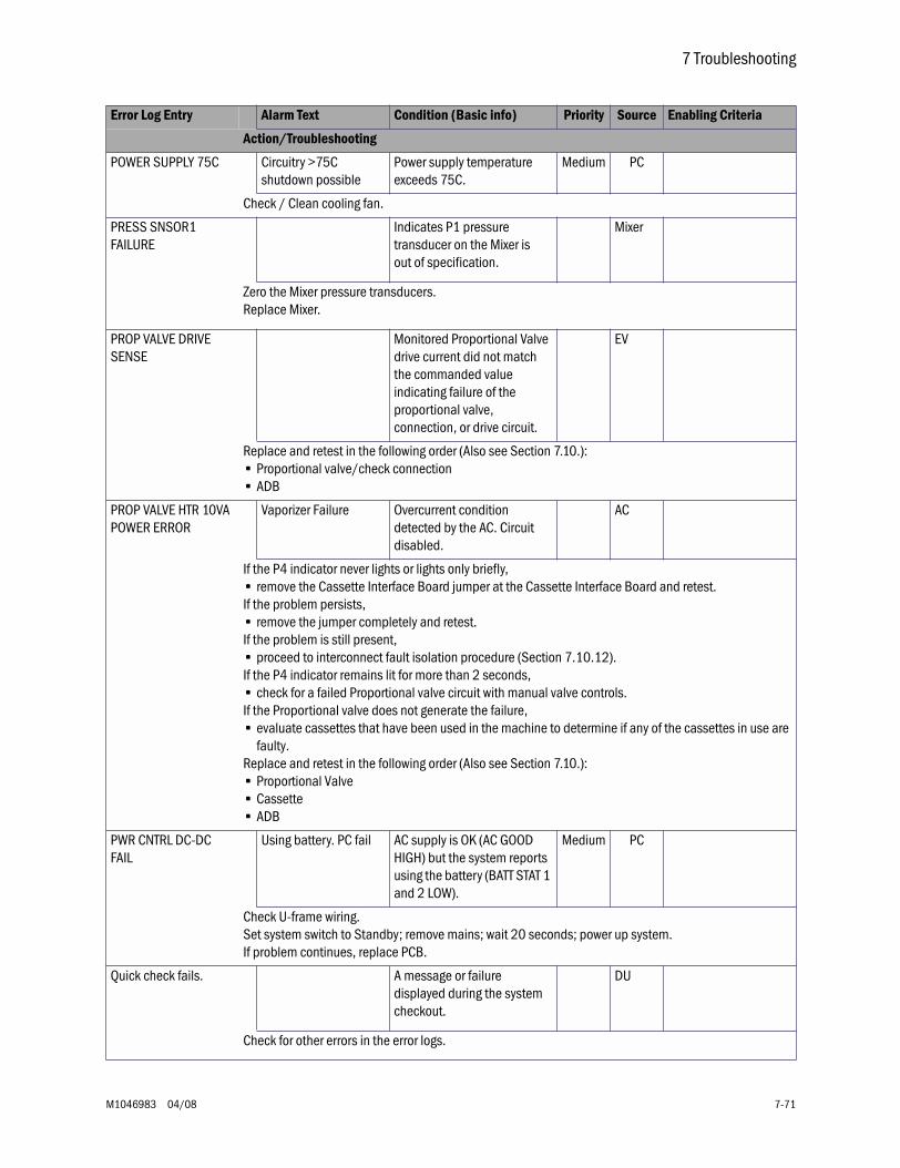
7 Troubleshooting
M1046983 04/08 7-71
POWER SUPPLY 75C Circuitry >75C shutdown possible
Power supply temperature exceeds 75C.
Medium PC
Check / Clean cooling fan.
PRESS SNSOR1 FAILURE
Indicates P1 pressure transducer on the Mixer is out of specification.
Mixer
Zero the Mixer pressure transducers.Replace Mixer.
PROP VALVE DRIVE SENSE
Monitored Proportional Valve drive current did not match the commanded value indicating failure of the proportional valve, connection, or drive circuit.
EV
Replace and retest in the following order (Also see Section 7.10.):• Proportional valve/check connection• ADB
PROP VALVE HTR 10VA POWER ERROR
Vaporizer Failure Overcurrent condition detected by the AC. Circuit disabled.
AC
If the P4 indicator never lights or lights only briefly,• remove the Cassette Interface Board jumper at the Cassette Interface Board and retest.If the problem persists,• remove the jumper completely and retest.If the problem is still present,• proceed to interconnect fault isolation procedure (Section 7.10.12).If the P4 indicator remains lit for more than 2 seconds,• check for a failed Proportional valve circuit with manual valve controls.If the Proportional valve does not generate the failure,• evaluate cassettes that have been used in the machine to determine if any of the cassettes in use are
faulty.Replace and retest in the following order (Also see Section 7.10.):• Proportional Valve• Cassette• ADB
PWR CNTRL DC-DC FAIL
Using battery. PC fail AC supply is OK (AC GOOD HIGH) but the system reports using the battery (BATT STAT 1 and 2 LOW).
Medium PC
Check U-frame wiring.Set system switch to Standby; remove mains; wait 20 seconds; power up system.If problem continues, replace PCB.
Quick check fails. A message or failure displayed during the system checkout.
DU
Check for other errors in the error logs.
Error Log Entry Alarm Text Condition (Basic info) Priority Source Enabling Criteria
Action/Troubleshooting
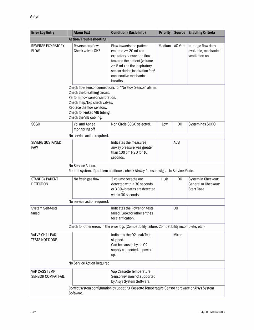
Aisys
7-72 04/08 M1046983
REVERSE EXPIRATORY FLOW
Reverse exp flow. Check valves OK?
Flow towards the patient (volume >= 20 mL) on expiratory sensor and flow towards the patient (volume >= 5 mL) on the inspiratory sensor during inspiration for 6 consecutive mechanical breaths.
Medium AC Vent In-range flow data available, mechanical ventilation on
Check flow sensor connections for “No Flow Sensor” alarm.Check the breathing circuit.Perform flow sensor calibration.Check Insp/Exp check valves.Replace the flow sensors.Check for kinked VIB tubing.Check the VIB cabling.
SCGO Vol and Apnea monitoring off
Non Circle SCGO selected. Low DC System has SCGO
No service action required.
SEVERE SUSTAINED PAW
Indicates the measures airway pressure was greater than 100 cm H2O for 10 seconds.
ACB
No Service Action.Reboot system. If problem continues, check Airway Pressure signal in Service Mode.
STANDBY PATIENT DETECTION
No fresh gas flow! 3 volume breaths are detected within 30 seconds or 3 CO2 breaths are detected within 30 seconds
High DC System in Checkout: General or Checkout: Start Case
No service action required.
System Self-tests failed
Indicates the Power-on tests failed. Look for other entries for clarification.
DU
Check for other errors in the error logs (Compatibility failure, Compatibility incomplete, etc.).
VALVE CH1 LEAK TESTS NOT DONE
Indicates the O2 Leak Test skipped.Can be caused by no O2 supply connected at power-up.
Mixer
No Service Action Required.
VAP CASS TEMP SENSOR COMPAT FAIL
Vap Cassette Temperature Sensor revision not supported by Aisys System Software.
Correct system configuration by updating Cassette Temperature Sensor hardware or Aisys System Software.
Error Log Entry Alarm Text Condition (Basic info) Priority Source Enabling Criteria
Action/Troubleshooting
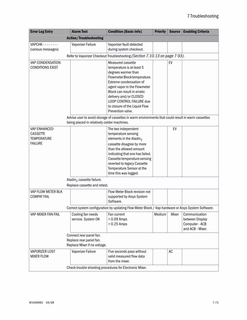
7 Troubleshooting
M1046983 04/08 7-73
VAPCHK - - - - - - - -(various messages)
Vaporizer Failure Vaporizer fault detected during system checkout.
Refer to Vaporizer Checkout Troubleshooting (Section 7.10.13 on page 7-93).
VAP CONDENSATION CONDITIONS EXIST
Measured cassette temperature is at least 5 degrees warmer than Flowmeter Block temperature. Extreme condensation of agent vapor in the Flowmeter Block can result in erratic delivery and/or CLOSED LOOP CONTROL FAILURE due to closure of the Liquid Flow Prevention valve.
EV
Advise user to avoid storage of cassettes in warm environments that could result in warm cassettes being placed in relatively colder machines.
VAP ENHANCED CASSETTE TEMPERATURE FAILURE
The two independent temperature sensing elements in the Aladin2 cassette disagree by more than the allowed amount indicating that one has failed. Cassette temperature sensing reverted to legacy Cassette Temperature Sensor at the time this was logged.
EV
Aladin2 cassette failure. Replace cassette and retest.
VAP FLOW METER BLK COMPAT FAIL
Flow Meter Block revision not supported by Aisys System Software.
Correct system configuration by updating Flow Meter Block / Vap hardware or Aisys System Software.
VAP-MIXER FAN FAIL Cooling fan needs service. System OK
Fan current < 0.09 Amps> 0.25 Amps
Medium Mixer Communication between Display Computer - ACBand ACB - Mixer.
Connect rear panel fan.Replace rear panel fan.Replace Mixer if no voltage.
VAPORIZER LOST MIXER FLOW
Vaporizer Failure Five seconds pass without valid measured flow data from the mixer.
AC
Check trouble shooting procedures for Electronic Mixer.
Error Log Entry Alarm Text Condition (Basic info) Priority Source Enabling Criteria
Action/Troubleshooting
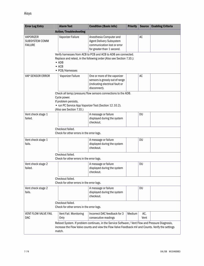
Aisys
7-74 04/08 M1046983
VAPORIZER SUBSYSTEM COMM FAILURE
Vaporizer Failure Anesthesia Computer and Agent Delivery Subsystem communication lost or error for greater than 1 second.
AC
Verify harnesses from ACB to PCB and ACB to ADB are connected.Replace and retest, in the following order (Also see Section 7.10.):• ADB• ACB• PCB/Harnesses
VAP SENSOR ERROR Vaporizer Failure One or more of the vaporizer sensors is grossly out of range (indicating electrical fault or disconnect).
AC
Check all temp/pressure/flow sensors connections to the ADB.Cycle power.If problem persists,• run PC Service App Vaporizer Test (Section 12.10.2).(Also see Section 7.10.)
Vent check stage 1 failed.
A message or failure displayed during the system checkout.
DU
Checkout failed.Check for other errors in the error logs.
Vent check stage 1 fails.
A message or failure displayed during the system checkout.
DU
Checkout failed.Check for other errors in the error logs.
Vent check stage 2 failed.
A message or failure displayed during the system checkout.
DU
Checkout failed.Check for other errors in the error logs.
Vent check stage 2 fails.
A message or failure displayed during the system checkout.
DU
Checkout failed.Check for other errors in the error logs.
VENT FLOW VALVE FAIL DAC
Vent Fail. Monitoring Only
Incorrect DAC feedback for 3 consecutive readings
Medium AC,Vent
Reboot System. If problem continues, in the Service Software / Vent Flow and Pressure Diagnosis, increase the Flow Valve counts and view the Flow Valve Feedback mV and Counts. Verify the settings match.
Error Log Entry Alarm Text Condition (Basic info) Priority Source Enabling Criteria
Action/Troubleshooting
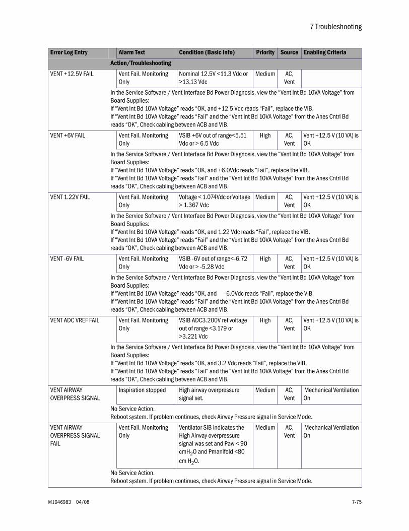
7 Troubleshooting
M1046983 04/08 7-75
VENT +12.5V FAIL Vent Fail. Monitoring Only
Nominal 12.5V <11.3 Vdc or >13.13 Vdc
Medium AC,Vent
In the Service Software / Vent Interface Bd Power Diagnosis, view the “Vent Int Bd 10VA Voltage” from Board Supplies:If “Vent Int Bd 10VA Voltage” reads “OK, and +12.5 Vdc reads “Fail”, replace the VIB. If “Vent Int Bd 10VA Voltage” reads “Fail” and the “Vent Int Bd 10VA Voltage” from the Anes Cntrl Bd reads “OK”, Check cabling between ACB and VIB.
VENT +6V FAIL Vent Fail. Monitoring Only
VSIB +6V out of range<5.51 Vdc or > 6.5 Vdc
High AC,Vent
Vent +12.5 V (10 VA) is OK
In the Service Software / Vent Interface Bd Power Diagnosis, view the “Vent Int Bd 10VA Voltage” from Board Supplies:If “Vent Int Bd 10VA Voltage” reads “OK, and +6.0Vdc reads “Fail”, replace the VIB. If “Vent Int Bd 10VA Voltage” reads “Fail” and the “Vent Int Bd 10VA Voltage” from the Anes Cntrl Bd reads “OK”, Check cabling between ACB and VIB.
VENT 1.22V FAIL Vent Fail. Monitoring Only
Voltage < 1.074Vdc or Voltage > 1.367 Vdc
Medium AC,Vent
Vent +12.5 V (10 VA) is OK
In the Service Software / Vent Interface Bd Power Diagnosis, view the “Vent Int Bd 10VA Voltage” from Board Supplies:If “Vent Int Bd 10VA Voltage” reads “OK, and 1.22 Vdc reads “Fail”, replace the VIB. If “Vent Int Bd 10VA Voltage” reads “Fail” and the “Vent Int Bd 10VA Voltage” from the Anes Cntrl Bd reads “OK”, Check cabling between ACB and VIB.
VENT -6V FAIL Vent Fail. Monitoring Only
VSIB -6V out of range<-6.72 Vdc or > -5.28 Vdc
High AC,Vent
Vent +12.5 V (10 VA) is OK
In the Service Software / Vent Interface Bd Power Diagnosis, view the “Vent Int Bd 10VA Voltage” from Board Supplies:If “Vent Int Bd 10VA Voltage” reads “OK, and -6.0Vdc reads “Fail”, replace the VIB. If “Vent Int Bd 10VA Voltage” reads “Fail” and the “Vent Int Bd 10VA Voltage” from the Anes Cntrl Bd reads “OK”, Check cabling between ACB and VIB.
VENT ADC VREF FAIL Vent Fail. Monitoring Only
VSIB ADC3.200V ref voltage out of range <3.179 or >3.221 Vdc
High AC,Vent
Vent +12.5 V (10 VA) is OK
In the Service Software / Vent Interface Bd Power Diagnosis, view the “Vent Int Bd 10VA Voltage” from Board Supplies:If “Vent Int Bd 10VA Voltage” reads “OK, and 3.2 Vdc reads “Fail”, replace the VIB. If “Vent Int Bd 10VA Voltage” reads “Fail” and the “Vent Int Bd 10VA Voltage” from the Anes Cntrl Bd reads “OK”, Check cabling between ACB and VIB.
VENT AIRWAY OVERPRESS SIGNAL
Inspiration stopped High airway overpressure signal set.
Medium AC,Vent
Mechanical Ventilation On
No Service Action.Reboot system. If problem continues, check Airway Pressure signal in Service Mode.
VENT AIRWAY OVERPRESS SIGNAL FAIL
Vent Fail. Monitoring Only
Ventilator SIB indicates the High Airway overpressure signal was set and Paw < 90 cmH2O and Pmanifold <80 cm H2O.
Medium AC,Vent
Mechanical Ventilation On
No Service Action.Reboot system. If problem continues, check Airway Pressure signal in Service Mode.
Error Log Entry Alarm Text Condition (Basic info) Priority Source Enabling Criteria
Action/Troubleshooting
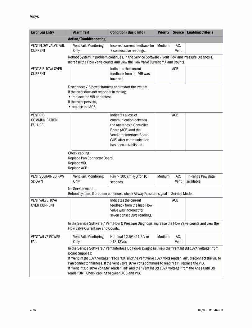
Aisys
7-76 04/08 M1046983
VENT FLOW VALVE FAIL CURRENT
Vent Fail. Monitoring Only
Incorrect current feedback for 7 consecutive readings.
Medium AC,Vent
Reboot System. If problem continues, in the Service Software / Vent Flow and Pressure Diagnosis, increase the Flow Valve counts and view the Flow Valve Current mA and Counts.
VENT SIB 10VA OVER CURRENT
Indicates the current feedback from the VIB was incorrect.
ACB
Disconnect VIB power harness and restart the system.If the error does not reappear in the log,• replace the VIB and retest.If the error persists,• replace the ACB.
VENT SIB COMMUNICATION FAILURE
Indicates a loss of communication between the Anesthesia Controller Board (ACB) and the Ventilator Interface Board (VIB) after communication has been established.
ACB
Check cabling.Replace Pan Connector Board.Replace VIB.Replace ACB.
VENT SUSTAINED PAW SDOWN
Vent Fail. Monitoring Only
Paw > 100 cmH2O for 10 seconds.
Medium AC,Vent
In-range Paw data available
No Service Action.Reboot system. If problem continues, check Airway Pressure signal in Service Mode.
VENT VALVE 10VA OVER CURRENT
Indicates the current feedback from the Insp Flow Valve was incorrect for seven consecutive readings.
ACB
In the Service Software / Vent Flow & Pressure Diagnosis, increase the Flow Valve counts and view the Flow Valve Current mA and Counts.
VENT VALVE POWER FAIL
Vent Fail. Monitoring Only
Nominal 12.5V <11.3 V or >13.13Vdc
Medium AC,Vent
In the Service Software / Vent Interface Bd Power Diagnosis, view the “Vent Int Bd 10VA Voltage” from Board Supplies:If “Vent Int Bd 10VA Voltage” reads “OK, and the Vent Valve 10VA Volts reads “Fail”, disconnect the VIB to Pan connector harness. If the Vent Valve 10VA Volts continues to read “Fail”, replace the VIB. If “Vent Int Bd 10VA Voltage” reads “Fail” and the “Vent Int Bd 10VA Voltage” from the Anes Cntrl Bd reads “OK”, Check cabling between ACB and VIB.
Error Log Entry Alarm Text Condition (Basic info) Priority Source Enabling Criteria
Action/Troubleshooting

7 Troubleshooting
M1046983 04/08 7-77
VLV BAL GAS CH LEAK TESTS NOT DONE
Indicates the Bal Gas Leak Test skipped.Can be caused by no Bal Gas connected at power-up.
Mixer
No Service Action Required.
Error Log Entry Alarm Text Condition (Basic info) Priority Source Enabling Criteria
Action/Troubleshooting
Aisys
7-78 04/08 M1046983
7.10 Electronic Vaporizer (eVap) Troubleshooting
As a general rule, proceed with electronic vaporizer fault isolation as follows:
1. Review the system error logs for vaporizer specific entries.
• Refer to Section 7.9 for procedures related to the system error log entries.
2. Within the PC service application, perform the Vaporizer Test (Section 12.10.2).
• Follow procedures below as directed by the vaporizer test results.
3. After servicing the vaporizer, rerun the Vaporizer Test to confirm any repairs made were successful.
7.10.1 VaporizerTest Results
The Vaporizer Test will display extended diagnostic information upon completion.
If the test passes, the message PASSED: Electronic Vaporizer Subsystem Check is displayed along with the data used during the check. This indicates that the vaporizer is ready for use.
If the check encounters a problem, it will perform an automated fault isolation procedure. With most single fault failures the automated procedure will identify the failed component or a small set of possibilities.
In the event of a failure, a variety of messages are possible:
• Refer to the table in Section 7.10.2 for corrective actions.
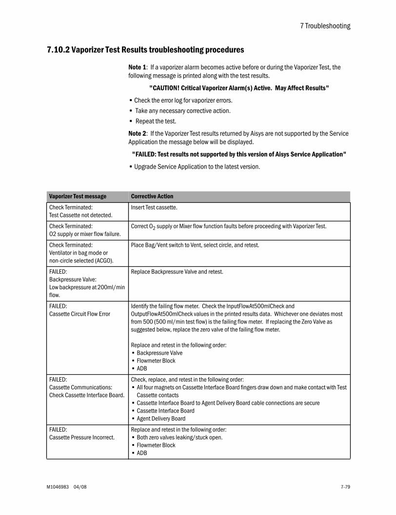
7 Troubleshooting
M1046983 04/08 7-79
7.10.2 Vaporizer Test Results troubleshooting procedures
Note 1: If a vaporizer alarm becomes active before or during the Vaporizer Test, the following message is printed along with the test results.
"CAUTION! Critical Vaporizer Alarm(s) Active. May Affect Results"
• Check the error log for vaporizer errors.
• Take any necessary corrective action.
• Repeat the test.
Note 2: If the Vaporizer Test results returned by Aisys are not supported by the Service Application the message below will be displayed.
"FAILED: Test results not supported by this version of Aisys Service Application"
• Upgrade Service Application to the latest version.
Vaporizer Test message Corrective Action
Check Terminated: Test Cassette not detected.
Insert Test cassette.
Check Terminated: O2 supply or mixer flow failure.
Correct O2 supply or Mixer flow function faults before proceeding with Vaporizer Test.
Check Terminated: Ventilator in bag mode ornon-circle selected (ACGO).
Place Bag/Vent switch to Vent, select circle, and retest.
FAILED: Backpressure Valve: Low backpressure at 200ml/min flow.
Replace Backpressure Valve and retest.
FAILED: Cassette Circuit Flow Error
Identify the failing flow meter. Check the InputFlowAt500mlCheck and OutputFlowAt500mlCheck values in the printed results data. Whichever one deviates most from 500 (500 ml/min test flow) is the failing flow meter. If replacing the Zero Valve as suggested below, replace the zero valve of the failing flow meter.
Replace and retest in the following order:• Backpressure Valve• Flowmeter Block• ADB
FAILED: Cassette Communications: Check Cassette Interface Board.
Check, replace, and retest in the following order:• All four magnets on Cassette Interface Board fingers draw down and make contact with Test
Cassette contacts• Cassette Interface Board to Agent Delivery Board cable connections are secure• Cassette Interface Board• Agent Delivery Board
FAILED: Cassette Pressure Incorrect.
Replace and retest in the following order:• Both zero valves leaking/stuck open.• Flowmeter Block• ADB
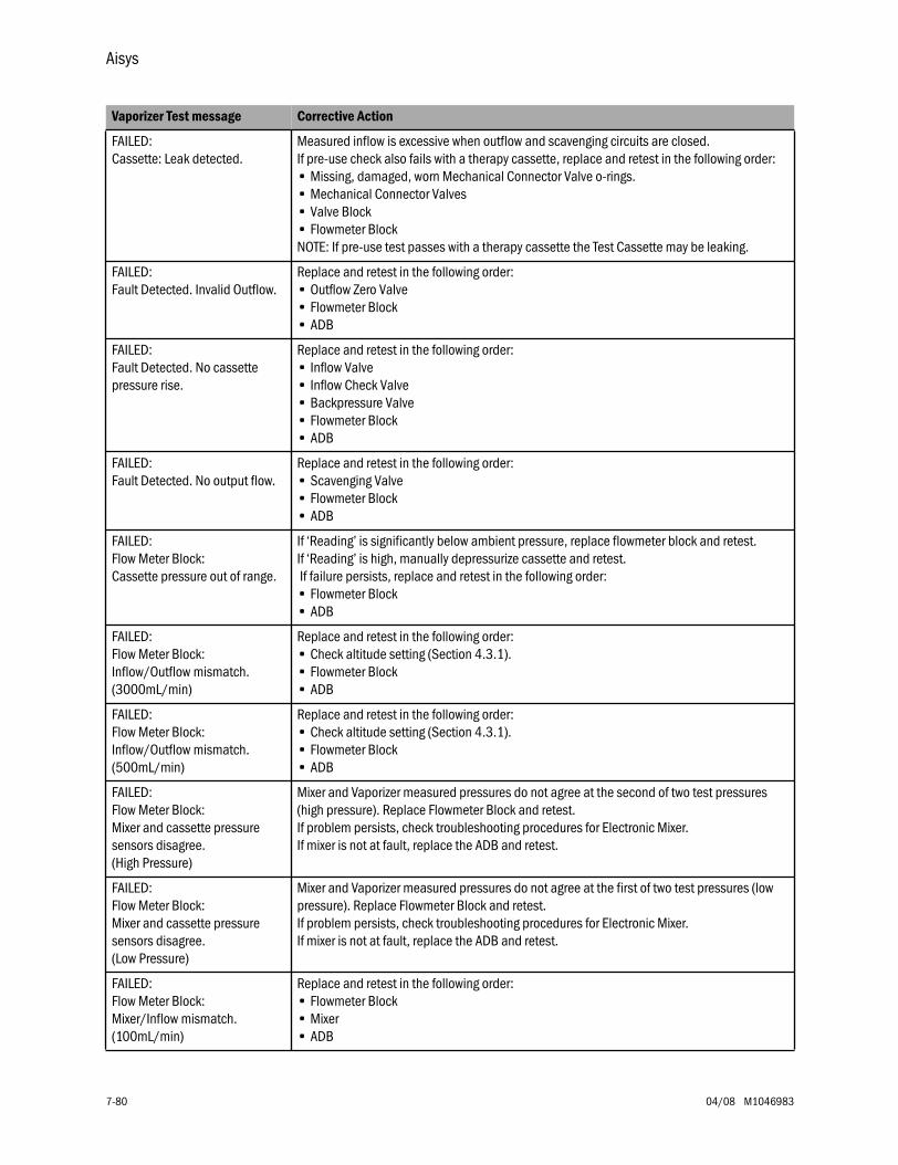
Aisys
7-80 04/08 M1046983
FAILED: Cassette: Leak detected.
Measured inflow is excessive when outflow and scavenging circuits are closed. If pre-use check also fails with a therapy cassette, replace and retest in the following order:• Missing, damaged, worn Mechanical Connector Valve o-rings.• Mechanical Connector Valves• Valve Block• Flowmeter BlockNOTE: If pre-use test passes with a therapy cassette the Test Cassette may be leaking.
FAILED: Fault Detected. Invalid Outflow.
Replace and retest in the following order:• Outflow Zero Valve• Flowmeter Block• ADB
FAILED: Fault Detected. No cassette pressure rise.
Replace and retest in the following order:• Inflow Valve• Inflow Check Valve • Backpressure Valve• Flowmeter Block• ADB
FAILED: Fault Detected. No output flow.
Replace and retest in the following order:• Scavenging Valve • Flowmeter Block• ADB
FAILED: Flow Meter Block: Cassette pressure out of range.
If ‘Reading’ is significantly below ambient pressure, replace flowmeter block and retest. If ‘Reading’ is high, manually depressurize cassette and retest. If failure persists, replace and retest in the following order:• Flowmeter Block• ADB
FAILED: Flow Meter Block: Inflow/Outflow mismatch. (3000mL/min)
Replace and retest in the following order:• Check altitude setting (Section 4.3.1).• Flowmeter Block• ADB
FAILED: Flow Meter Block: Inflow/Outflow mismatch. (500mL/min)
Replace and retest in the following order:• Check altitude setting (Section 4.3.1).• Flowmeter Block• ADB
FAILED: Flow Meter Block: Mixer and cassette pressure sensors disagree. (High Pressure)
Mixer and Vaporizer measured pressures do not agree at the second of two test pressures (high pressure). Replace Flowmeter Block and retest. If problem persists, check troubleshooting procedures for Electronic Mixer. If mixer is not at fault, replace the ADB and retest.
FAILED: Flow Meter Block: Mixer and cassette pressure sensors disagree. (Low Pressure)
Mixer and Vaporizer measured pressures do not agree at the first of two test pressures (low pressure). Replace Flowmeter Block and retest. If problem persists, check troubleshooting procedures for Electronic Mixer. If mixer is not at fault, replace the ADB and retest.
FAILED: Flow Meter Block: Mixer/Inflow mismatch. (100mL/min)
Replace and retest in the following order:• Flowmeter Block• Mixer• ADB
Vaporizer Test message Corrective Action
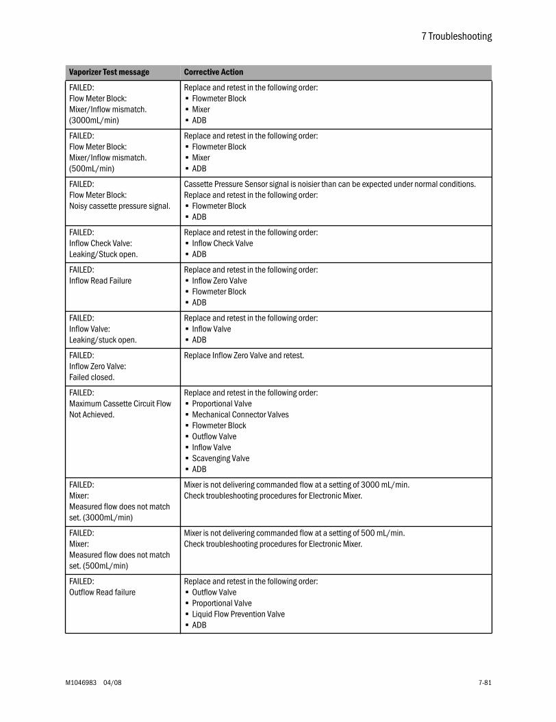
7 Troubleshooting
M1046983 04/08 7-81
FAILED: Flow Meter Block: Mixer/Inflow mismatch. (3000mL/min)
Replace and retest in the following order:• Flowmeter Block• Mixer• ADB
FAILED: Flow Meter Block: Mixer/Inflow mismatch. (500mL/min)
Replace and retest in the following order:• Flowmeter Block• Mixer• ADB
FAILED: Flow Meter Block: Noisy cassette pressure signal.
Cassette Pressure Sensor signal is noisier than can be expected under normal conditions. Replace and retest in the following order:• Flowmeter Block• ADB
FAILED: Inflow Check Valve: Leaking/Stuck open.
Replace and retest in the following order:• Inflow Check Valve• ADB
FAILED: Inflow Read Failure
Replace and retest in the following order:• Inflow Zero Valve• Flowmeter Block• ADB
FAILED: Inflow Valve: Leaking/stuck open.
Replace and retest in the following order:• Inflow Valve• ADB
FAILED: Inflow Zero Valve: Failed closed.
Replace Inflow Zero Valve and retest.
FAILED: Maximum Cassette Circuit Flow Not Achieved.
Replace and retest in the following order:• Proportional Valve• Mechanical Connector Valves• Flowmeter Block• Outflow Valve• Inflow Valve• Scavenging Valve• ADB
FAILED: Mixer: Measured flow does not match set. (3000mL/min)
Mixer is not delivering commanded flow at a setting of 3000 mL/min. Check troubleshooting procedures for Electronic Mixer.
FAILED: Mixer: Measured flow does not match set. (500mL/min)
Mixer is not delivering commanded flow at a setting of 500 mL/min. Check troubleshooting procedures for Electronic Mixer.
FAILED: Outflow Read failure
Replace and retest in the following order:• Outflow Valve• Proportional Valve• Liquid Flow Prevention Valve• ADB
Vaporizer Test message Corrective Action
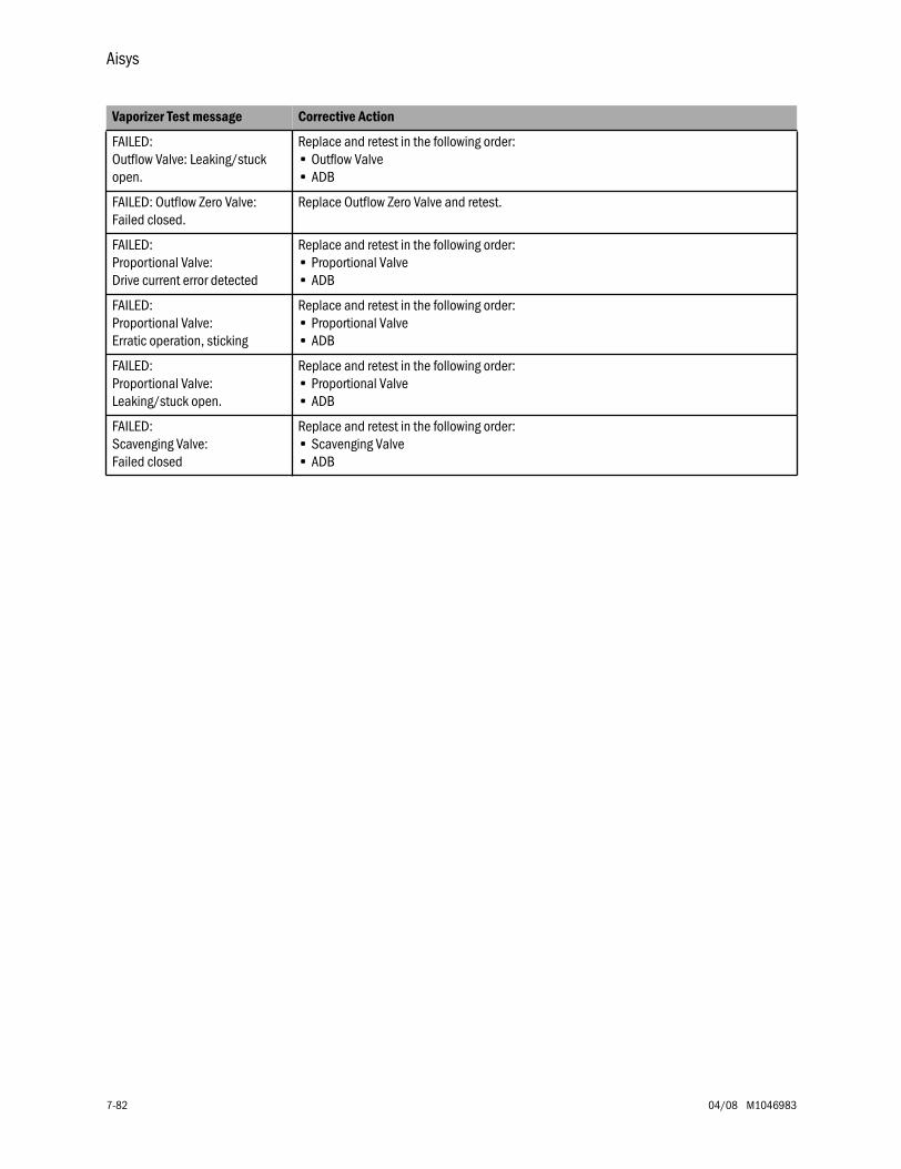
Aisys
7-82 04/08 M1046983
FAILED: Outflow Valve: Leaking/stuck open.
Replace and retest in the following order:• Outflow Valve• ADB
FAILED: Outflow Zero Valve: Failed closed.
Replace Outflow Zero Valve and retest.
FAILED: Proportional Valve: Drive current error detected
Replace and retest in the following order:• Proportional Valve• ADB
FAILED: Proportional Valve: Erratic operation, sticking
Replace and retest in the following order:• Proportional Valve• ADB
FAILED: Proportional Valve: Leaking/stuck open.
Replace and retest in the following order:• Proportional Valve• ADB
FAILED: Scavenging Valve: Failed closed
Replace and retest in the following order:• Scavenging Valve• ADB
Vaporizer Test message Corrective Action

7 Troubleshooting
M1046983 04/08 7-83
7.10.3 eVap Troubleshooting Flowchart
Flowchart 19
Checkout Troubleshooting.
the logs.
Is the Error prefix“VAPCHK”?
Within the PC Service Application,perform the Vaporizer Test.
Start
Yes No
Follow the CorrectiveAction in the Vaporizer
Test Resultstroubleshooting procedures.
Analyze
Download and combine theMachine Logs or review the
logs in Service Mode.Refer to Transfer Logs.
Compare theCombined log to the
Error Logs in the“Electronic Vaporizer Table”.
Proceed to the appropriatetroubleshooting flowchart.
Save theTest
CassetteResults for
futurereference.
Yes
No
Follow the CorrectiveAction in the Vaporizer
Does theVaporizer Test pass?
(Section 12.10.2)
(Section 7.10.2)
(Section 12.6.3)
(Section 7.10.4)
(Section 7.10.13)AB
.75.
176
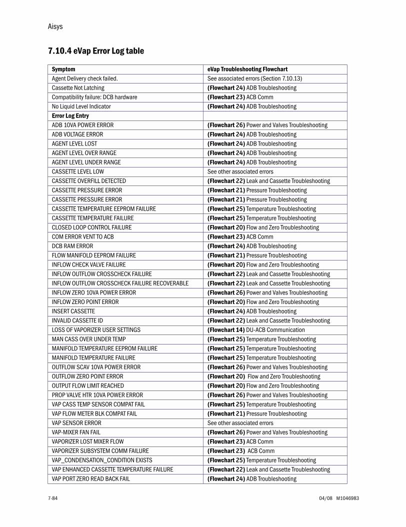
Aisys
7-84 04/08 M1046983
7.10.4 eVap Error Log table
Symptom eVap Troubleshooting FlowchartAgent Delivery check failed. See associated errors (Section 7.10.13)Cassette Not Latching (Flowchart 24) ADB TroubleshootingCompatibility failure: DCB hardware (Flowchart 23) ACB CommNo Liquid Level Indicator (Flowchart 24) ADB TroubleshootingError Log EntryADB 10VA POWER ERROR (Flowchart 26) Power and Valves Troubleshooting ADB VOLTAGE ERROR (Flowchart 24) ADB TroubleshootingAGENT LEVEL LOST (Flowchart 24) ADB TroubleshootingAGENT LEVEL OVER RANGE (Flowchart 24) ADB TroubleshootingAGENT LEVEL UNDER RANGE (Flowchart 24) ADB TroubleshootingCASSETTE LEVEL LOW See other associated errorsCASSETTE OVERFILL DETECTED (Flowchart 22) Leak and Cassette TroubleshootingCASSETTE PRESSURE ERROR (Flowchart 21) Pressure TroubleshootingCASSETTE PRESSURE ERROR (Flowchart 21) Pressure TroubleshootingCASSETTE TEMPERATURE EEPROM FAILURE (Flowchart 25) Temperature TroubleshootingCASSETTE TEMPERATURE FAILURE (Flowchart 25) Temperature TroubleshootingCLOSED LOOP CONTROL FAILURE (Flowchart 20) Flow and Zero TroubleshootingCOM ERROR VENT TO ACB (Flowchart 23) ACB CommDCB RAM ERROR (Flowchart 24) ADB TroubleshootingFLOW MANIFOLD EEPROM FAILURE (Flowchart 21) Pressure TroubleshootingINFLOW CHECK VALVE FAILURE (Flowchart 20) Flow and Zero TroubleshootingINFLOW OUTFLOW CROSSCHECK FAILURE (Flowchart 22) Leak and Cassette TroubleshootingINFLOW OUTFLOW CROSSCHECK FAILURE RECOVERABLE (Flowchart 22) Leak and Cassette TroubleshootingINFLOW ZERO 10VA POWER ERROR (Flowchart 26) Power and Valves TroubleshootingINFLOW ZERO POINT ERROR (Flowchart 20) Flow and Zero TroubleshootingINSERT CASSETTE (Flowchart 24) ADB TroubleshootingINVALID CASSETTE ID (Flowchart 22) Leak and Cassette TroubleshootingLOSS OF VAPORIZER USER SETTINGS (Flowchart 14) DU-ACB Communication MAN CASS OVER UNDER TEMP (Flowchart 25) Temperature TroubleshootingMANIFOLD TEMPERATURE EEPROM FAILURE (Flowchart 25) Temperature TroubleshootingMANIFOLD TEMPERATURE FAILURE (Flowchart 25) Temperature TroubleshootingOUTFLOW SCAV 10VA POWER ERROR (Flowchart 26) Power and Valves TroubleshootingOUTFLOW ZERO POINT ERROR (Flowchart 20) Flow and Zero TroubleshootingOUTPUT FLOW LIMIT REACHED (Flowchart 20) Flow and Zero TroubleshootingPROP VALVE HTR 10VA POWER ERROR (Flowchart 26) Power and Valves TroubleshootingVAP CASS TEMP SENSOR COMPAT FAIL (Flowchart 25) Temperature TroubleshootingVAP FLOW METER BLK COMPAT FAIL (Flowchart 21) Pressure TroubleshootingVAP SENSOR ERROR See other associated errorsVAP-MIXER FAN FAIL (Flowchart 26) Power and Valves TroubleshootingVAPORIZER LOST MIXER FLOW (Flowchart 23) ACB CommVAPORIZER SUBSYSTEM COMM FAILURE (Flowchart 23) ACB CommVAP_CONDENSATION_CONDITION EXISTS (Flowchart 25) Temperature TroubleshootingVAP ENHANCED CASSETTE TEMPERATURE FAILURE (Flowchart 22) Leak and Cassette TroubleshootingVAP PORT ZERO READ BACK FAIL (Flowchart 24) ADB Troubleshooting
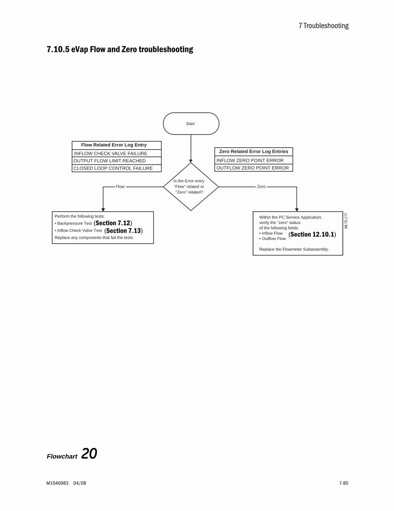
7 Troubleshooting
M1046983 04/08 7-85
7.10.5 eVap Flow and Zero troubleshooting
Flowchart 20
Start
Is the Error entry“Flow” related or“Zero” related?
Flow Zero
Flow Related Error Log Entry
INFLOW CHECK VALVE FAILURE
OUTPUT FLOW LIMIT REACHED
CLOSED LOOP CONTROL FAILURE
Zero Related Error Log Entries
INFLOW ZERO POINT ERROR
OUTFLOW ZERO POINT ERROR
Perform the following tests:
• Backpressure Test
• Inflow Check Valve Test
Replace any components that fail the tests.
Within the PC Service Application,verify the “zero” statusof the following fields:• Inflow Flow• Outflow Flow
Replace the Flowmeter Subassembly.
(Section 7.13)(Section 7.12)
AB.7
5.17
7
(Section 12.10.1)
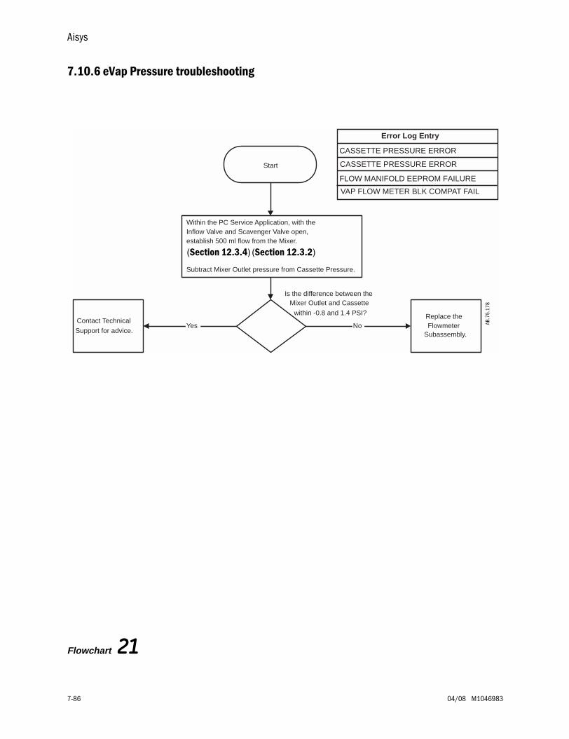
Aisys
7-86 04/08 M1046983
7.10.6 eVap Pressure troubleshooting
Flowchart 21
Subassembly.
Is the difference between theMixer Outlet and Cassette
within -0.8 and 1.4 PSI?
Error Log Entry
CASSETTE PRESSURE ERROR
FLOW MANIFOLD EEPROM FAILURE
CASSETTE PRESSURE ERRORStart
Within the PC Service Application, with theInflow Valve and Scavenger Valve open,establish 500 ml flow from the Mixer
Subtract Mixer Outlet pressure from Cassette Pressure.
.
Replace theFlowmeterNo
Contact Technical
Support for advice.Yes
VAP FLOW METER BLK COMPAT FAIL
AB.7
5.17
8
(Section 12.3.4) (Section 12.3.2)
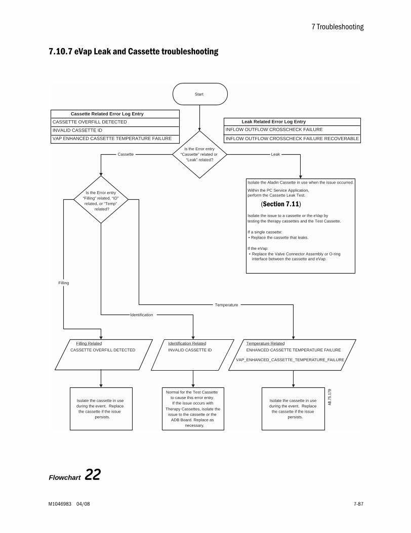
7 Troubleshooting
M1046983 04/08 7-87
7.10.7 eVap Leak and Cassette troubleshooting
Flowchart 22
Start
Is the Error entry“Cassette” related or
“Leak” related?Cassette Leak
Isolate the Aladin Cassette in use when the issue occurred.
Within the PC Service Application,perform the Cassette Leak Test.
Isolate the issue to a cassette or the eVap bytesting the therapy cassettes and the Test Cassette.
If a single cassette:• Replace the cassette that leaks.
If the eVap:• Replace the Valve Connector Assembly or O-ring
interface between the cassette and eVap.
Leak Related Error Log Entry
INFLOW OUTFLOW CROSSCHECK FAILURE
Is the Error entry“Filling” related, “ID”related, or “Temp”
related?
Filling Related
CASSETTE OVERFILL DETECTED
Identification Related
INVALID CASSETTE ID ENHANCED CASSETTE TEMPERATURE FAILURE
Temperature Related
VAP_ENHANCED_CASSETTE_TEMPERATURE_FAILURE
Filling
Identification
Temperature
Normal for the Test Cassetteto cause this error entry.If the issue occurs with
Therapy Cassettes, isolate theissue to the cassette or the
ADB Board. Replace asnecessary.
Isolate the cassette in useduring the event. Replace
the cassette if the issuepersists.
Isolate the cassette in useduring the event. Replacethe cassette if the issue
persists.
Cassette Related Error Log Entry
CASSETTE OVERFILL DETECTED
INVALID CASSETTE ID
VAP ENHANCED CASSETTE TEMPERATURE FAILURE INFLOW OUTFLOW CROSSCHECK FAILURE RECOVERABLE
(Section 7.11)
AB.7
5.17
9
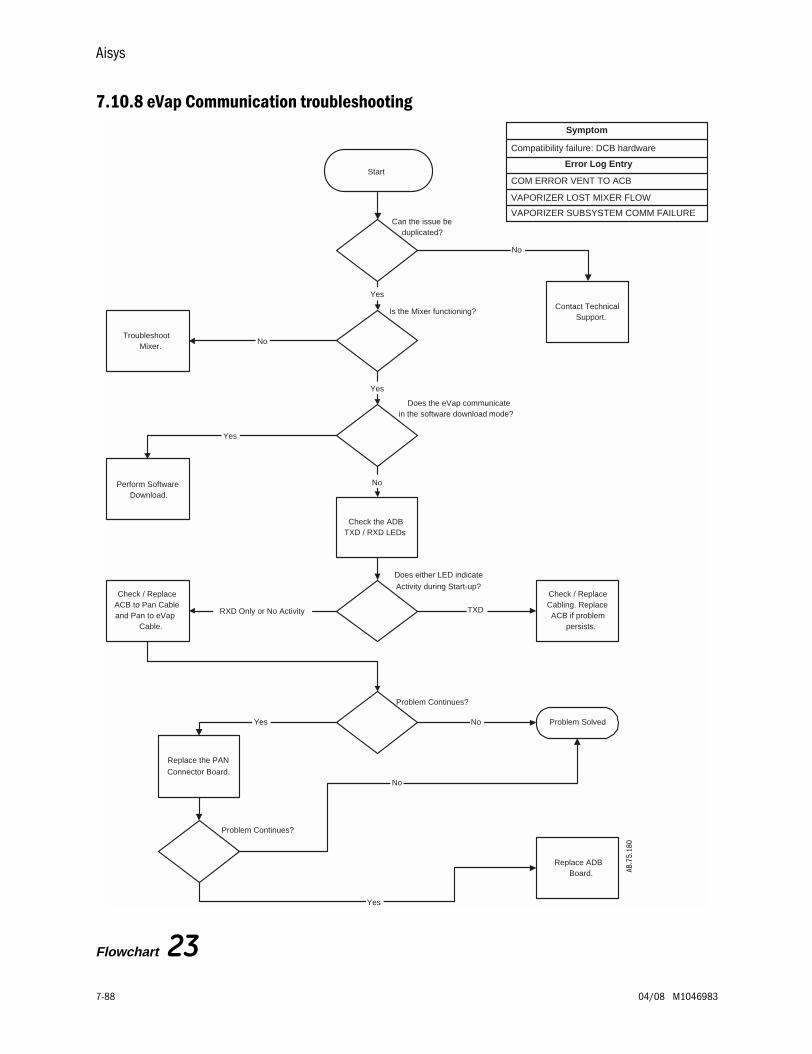
Aisys
7-88 04/08 M1046983
7.10.8 eVap Communication troubleshooting
Flowchart 23
Problem Continues?
Does either LED indicate
Activity during Start-up?
Does the eVap communicatein the software download mode?
Start
Yes
Perform SoftwareDownload.
Check the ADBTXD / RXD LEDs
Can the issue beduplicated?
TXDRXD Only or No Activity
No
Contact TechnicalSupport.
No
Check / ReplaceACB to Pan Cableand Pan to eVap
Cable.
Problem Solved
Yes
Check / ReplaceCabling. ReplaceACB if problem
persists.
Replace ADBBoard.
Is the Mixer functioning?
NoTroubleshoot
Mixer.
Yes
No
Problem Continues?
Replace the PAN
Connector Board.
Yes
No
Error Log Entry
COM ERROR VENT TO ACB
Compatibility failure: DCB hardware
VAPORIZER LOST MIXER FLOW
VAPORIZER SUBSYSTEM COMM FAILURE
Yes
Symptom
AB.7
5.18
0
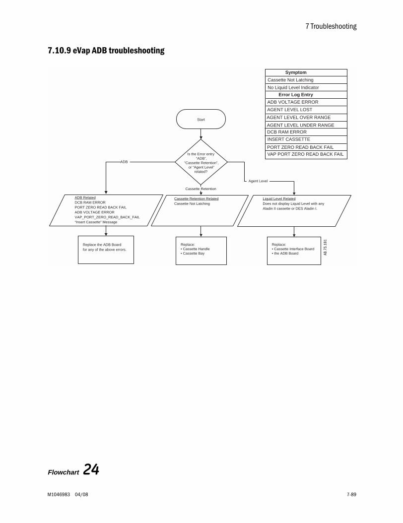
7 Troubleshooting
M1046983 04/08 7-89
7.10.9 eVap ADB troubleshooting
Flowchart 24
Start
Replace the ADB Boardfor any of the above errors.
Is the Error entry “ADB”,
“Cassette Retention”, or “Agent Level”
related?
Liquid Level RelatedDoes not display Liquid Level with anyAladin II cassette or DES Aladin I.
Cassette Retention RelatedCassette Not Latching
ADB RelatedDCB RAM ERRORPORT ZERO READ BACK FAILADB VOLTAGE ERRORVAP_PORT_ZERO_READ_BACK_FAIL“Insert Cassette” Message
ADB
Cassette Retention
Agent Level
DCB RAM ERROR
PORT ZERO READ BACK FAIL
VAP PORT ZERO READ BACK FAIL
ADB VOLTAGE ERROR
No Liquid Level Indicator
Cassette Not Latching
INSERT CASSETTE
Replace:• Cassette Handle• Cassette Bay
Replace:• Cassette Interface Board• the ADB Board
AGENT LEVEL LOST
AGENT LEVEL OVER RANGE
AGENT LEVEL UNDER RANGE
Symptom
Error Log Entry
AB.7
5.18
1
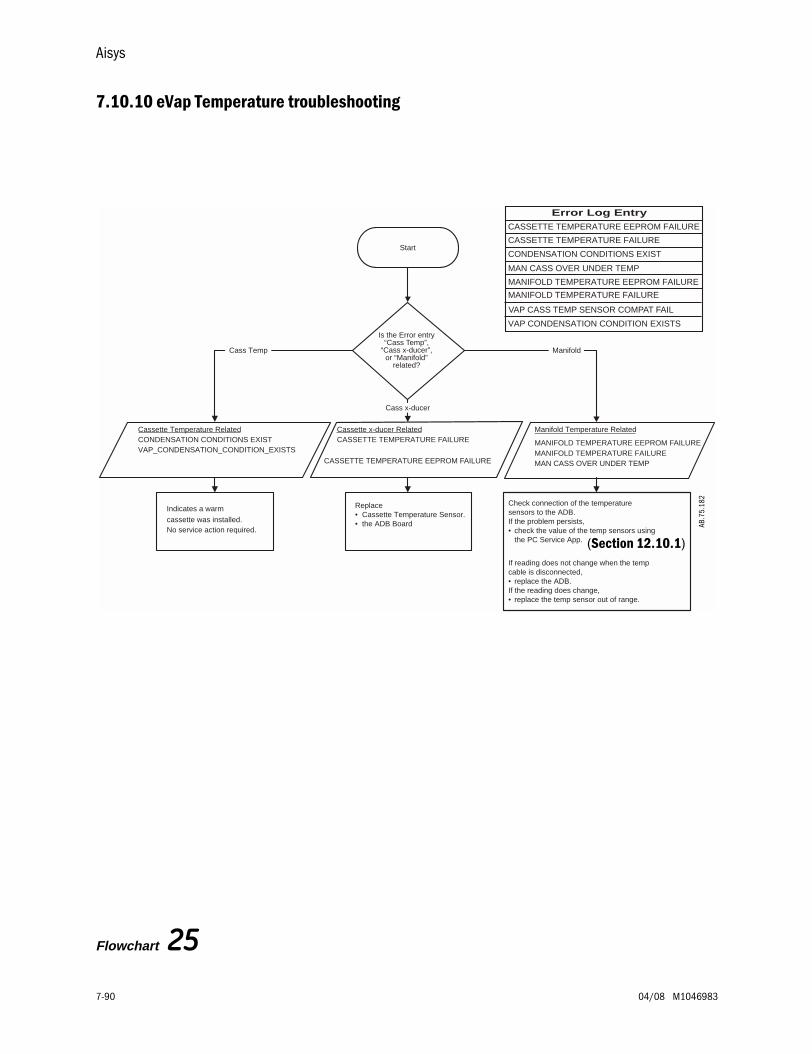
Aisys
7-90 04/08 M1046983
7.10.10 eVap Temperature troubleshooting
Flowchart 25
Is the Error entry“Cass Temp”,
“Cass x-ducer”,or “Manifold”
related?
Start
Error Log Entry
CONDENSATION CONDITIONS EXIST
VAP CONDENSATION CONDITION EXISTS
CASSETTE TEMPERATURE EEPROM FAILURE
CASSETTE TEMPERATURE FAILURE
MAN CASS OVER UNDER TEMP
MANIFOLD TEMPERATURE EEPROM FAILURE
MANIFOLD TEMPERATURE FAILURE
Cassette Temperature RelatedCONDENSATION CONDITIONS EXISTVAP_CONDENSATION_CONDITION_EXISTS
Cassette x-ducer RelatedCASSETTE TEMPERATURE FAILURE
CASSETTE TEMPERATURE EEPROM FAILURE
MANIFOLD TEMPERATURE EEPROM FAILURE
Manifold Temperature Related
MANIFOLD TEMPERATURE FAILUREMAN CASS OVER UNDER TEMP
Cass Temp
Cass x-ducer
Manifold
Indicates a warm
cassette was installed.No service action required.
Replace• Cassette Temperature Sensor.• the ADB Board
Check connection of the temperaturesensors to the ADB.If the problem persists,• check the value of the temp sensors using the PC Service App.
If reading does not change when the tempcable is disconnected,• replace the ADB.If the reading does change,• replace the temp sensor out of range.
VAP CASS TEMP SENSOR COMPAT FAIL
(Section 12.10.1)
AB.7
5.18
2
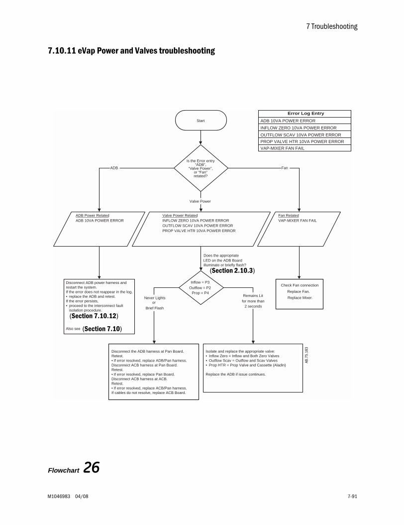
7 Troubleshooting
M1046983 04/08 7-91
7.10.11 eVap Power and Valves troubleshooting
Flowchart 26
Is the Error entry“ADB”,
“Valve Power”,or “Fan”retated?
Does the appropriateLED on the ADB Boardilluminate or briefly flash?
Start
Error Log Entry
ADB 10VA POWER ERROR
INFLOW ZERO 10VA POWER ERROR
OUTFLOW SCAV 10VA POWER ERROR
PROP VALVE HTR 10VA POWER ERROR
VAP-MIXER FAN FAIL
ADB Power RelatedADB 10VA POWER ERROR
Fan RelatedVAP-MIXER FAN FAIL
Valve Power RelatedINFLOW ZERO 10VA POWER ERROROUTFLOW SCAV 10VA POWER ERRORPROP VALVE HTR 10VA POWER ERROR
Disconnect ADB power harness andrestart the system.If the error does not reappear in the log,• replace the ADB and retest.If the error persists,• proceed to the interconnect fault
isolation procedure.
Also see
Disconnect the ADB harness at Pan Board.Retest.• If error resolved, replace ADB/Pan harness.Disconnect ACB harness at Pan Board.Retest.• If error resolved, replace Pan Board.Disconnect ACB harness at ACB.Retest.• If error resolved, replace ACB/Pan harness.If cables do not resolve, replace ACB Board.
Check Fan connection
Replace Fan.
Replace Mixer.
Inflow = P3
Outflow = P2Prop = P4
Never Lightsor
Brief Flash
Remains Lit
for more than2 seconds
Isolate and replace the appropriate valve:• Inflow Zero = Inflow and Both Zero Valves• Outflow Scav = Outflow and Scav Valves• Prop HTR = Prop Valve and Cassette (Aladin)
Replace the ADB if issue continues.
ADB
Valve Power
Fan
(Section 2.10.3)
(Section 7.10.12)
(Section 7.10)
AB.7
5.18
3

Aisys
7-92 04/08 M1046983
7.10.12Electronic
vaporizer 10VApower
interconnect faultisolation
Troubleshooting of the following Error Log Entries may lead you to further troubleshoot the problem as detailed below:
• ADB 10VA POWER ERROR
• INFLOW ZERO 10VA POWER ERROR
• OUTFLOW SCAV 10VA POWER ERROR
• PROP VALVE HTR 10VA POWER ERROR
10VA power interconnect fault isolation procedure:
Continue to disconnect harnesses in the following order and retest until problem resolved:
1. Disconnect the ADB harness at PCB.
• If problem goes away, replace ADB-PCB harness.
2. Disconnect the ACB harness at PCB.
• If problem goes away, replace PCB.
3. Disconnect the ACB harness at ACB.
• If problem goes away, replace ACB-PCB harness.
4. If cable disconnects do not eliminate the failure, replace ACB and retest.
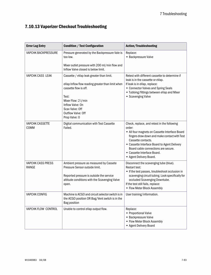
7 Troubleshooting
M1046983 04/08 7-93
7.10.13 Vaporizer Checkout Troubleshooting
Error Log Entry Condition / Test Configuration Action/Troubleshooting
VAPCHK BACKPRESSURE Pressure generated by the Backpressure Vale is too low.
Mixer outlet pressure with 200 ml/min flow and Inflow Valve closed is below limit.
Replace:• Backpressure Valve
VAPCHK CASS LEAK Cassette / eVap leak greater than limit.
eVap Inflow flow reading greater than limit when cassette flow is off.
Test:Mixer Flow: 2 l/minInflow Valve: OnScav Valve: OffOutflow Valve: OffProp Valve: 0
Retest with different cassette to determine if leak is in the cassette or eVap.If leak is in eVap, replace:• Connector Valves and Spring Seals • Tubbing/fittings between eVap and Mixer• Scavenging Valve
VAPCHK CASSETTE COMM
Digital communication with Test Cassette Failed.
Check, replace, and retest in the following order:• All four magnets on Cassette Interface Board
fingers draw down and make contact with Test Cassette contacts.
• Cassette Interface Board to Agent Delivery Board cable connections are secure.
• Cassette Interface Board.• Agent Delivery Board.
VAPCHK CASS PRESS RANGE
Ambient pressure as measured by Cassete Pressure Sensor outside limit.
Reported pressure is outside the service altitude conditions with the Scavenging Valve open.
Disconnect the scavenging tube (blue).Restart test:• If the test passes, troubleshoot occlusion in
scavenging circuit tubing. Look specifically for occluded Scavenging Downtube.
If the test still fails, replace:• Flow Meter Block Assembly
VAPCHK CONFIG Machine is ACGO and circuit selector switch is in the ACGO position OR Bag/Vent switch is in the Bag position
User training/information.
VAPCHK FLOW CONTROL Unable to control eVap output flow. Replace:• Proportional Valve• Backpressure Valve• Flow Meter Block Assembly• Agent Delivery Board
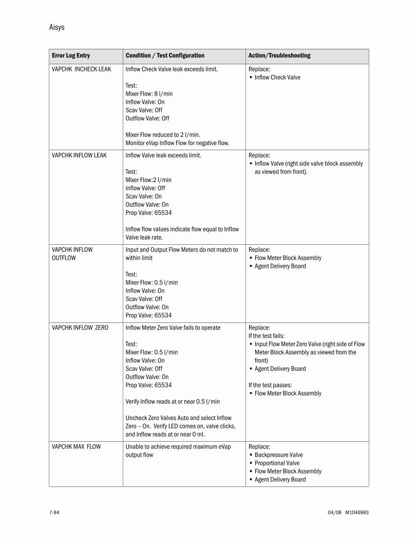
Aisys
7-94 04/08 M1046983
VAPCHK INCHECK LEAK Inflow Check Valve leak exceeds limit.
Test:Mixer Flow: 8 l/minInflow Valve: OnScav Valve: OffOutflow Valve: Off
Mixer Flow reduced to 2 l/min. Monitor eVap Inflow Flow for negative flow.
Replace:• Inflow Check Valve
VAPCHK INFLOW LEAK Inflow Valve leak exceeds limit.
Test:Mixer Flow:2 l/minInflow Valve: OffScav Valve: OnOutflow Valve: OnProp Valve: 65534
Inflow flow values indicate flow equal to Inflow Valve leak rate.
Replace:• Inflow Valve (right side valve block assembly
as viewed from front).
VAPCHK INFLOW OUTFLOW
Input and Output Flow Meters do not match to within limit
Test:Mixer Flow: 0.5 l/minInflow Valve: OnScav Valve: OffOutflow Valve: OnProp Valve: 65534
Replace:• Flow Meter Block Assembly• Agent Delivery Board
VAPCHK INFLOW ZERO Inflow Meter Zero Valve fails to operate
Test:Mixer Flow: 0.5 l/minInflow Valve: OnScav Valve: OffOutflow Valve: OnProp Valve: 65534
Verify Inflow reads at or near 0.5 l/min
Uncheck Zero Valves Auto and select Inflow Zero – On. Verify LED comes on, valve clicks, and Inflow reads at or near 0 ml.
Replace:If the test fails:• Input Flow Meter Zero Valve (right side of Flow
Meter Block Assembly as viewed from the front)
• Agent Delivery Board
If the test passes:• Flow Meter Block Assembly
VAPCHK MAX FLOW Unable to achieve required maximum eVap output flow
Replace:• Backpressure Valve• Proportional Valve• Flow Meter Block Assembly• Agent Delivery Board
Error Log Entry Condition / Test Configuration Action/Troubleshooting
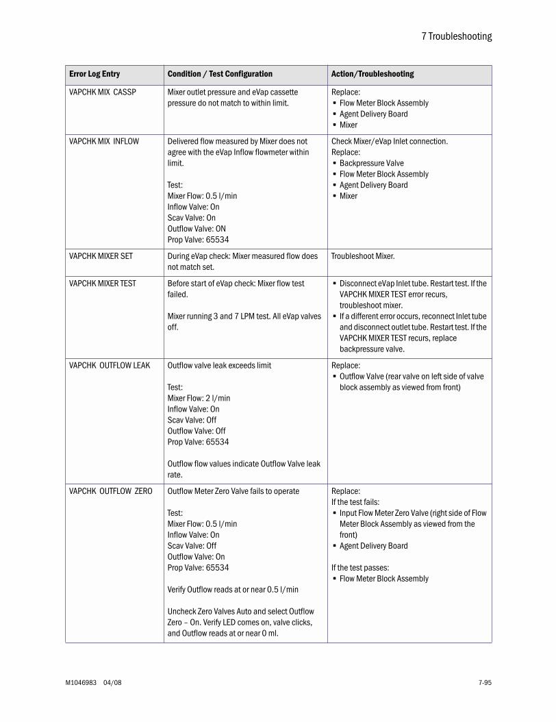
7 Troubleshooting
M1046983 04/08 7-95
VAPCHK MIX CASSP Mixer outlet pressure and eVap cassette pressure do not match to within limit.
Replace:• Flow Meter Block Assembly• Agent Delivery Board• Mixer
VAPCHK MIX INFLOW Delivered flow measured by Mixer does not agree with the eVap Inflow flowmeter within limit.
Test:Mixer Flow: 0.5 l/minInflow Valve: OnScav Valve: OnOutflow Valve: ONProp Valve: 65534
Check Mixer/eVap Inlet connection.Replace:• Backpressure Valve• Flow Meter Block Assembly• Agent Delivery Board• Mixer
VAPCHK MIXER SET During eVap check: Mixer measured flow does not match set.
Troubleshoot Mixer.
VAPCHK MIXER TEST Before start of eVap check: Mixer flow test failed.
Mixer running 3 and 7 LPM test. All eVap valves off.
• Disconnect eVap Inlet tube. Restart test. If the VAPCHK MIXER TEST error recurs, troubleshoot mixer.
• If a different error occurs, reconnect Inlet tube and disconnect outlet tube. Restart test. If the VAPCHK MIXER TEST recurs, replace backpressure valve.
VAPCHK OUTFLOW LEAK Outflow valve leak exceeds limit
Test:Mixer Flow: 2 l/minInflow Valve: OnScav Valve: OffOutflow Valve: OffProp Valve: 65534
Outflow flow values indicate Outflow Valve leak rate.
Replace:• Outflow Valve (rear valve on left side of valve
block assembly as viewed from front)
VAPCHK OUTFLOW ZERO Outflow Meter Zero Valve fails to operate
Test:Mixer Flow: 0.5 l/minInflow Valve: OnScav Valve: OffOutflow Valve: OnProp Valve: 65534
Verify Outflow reads at or near 0.5 l/min
Uncheck Zero Valves Auto and select Outflow Zero – On. Verify LED comes on, valve clicks, and Outflow reads at or near 0 ml.
Replace:If the test fails:• Input Flow Meter Zero Valve (right side of Flow
Meter Block Assembly as viewed from the front)
• Agent Delivery Board
If the test passes:• Flow Meter Block Assembly
Error Log Entry Condition / Test Configuration Action/Troubleshooting
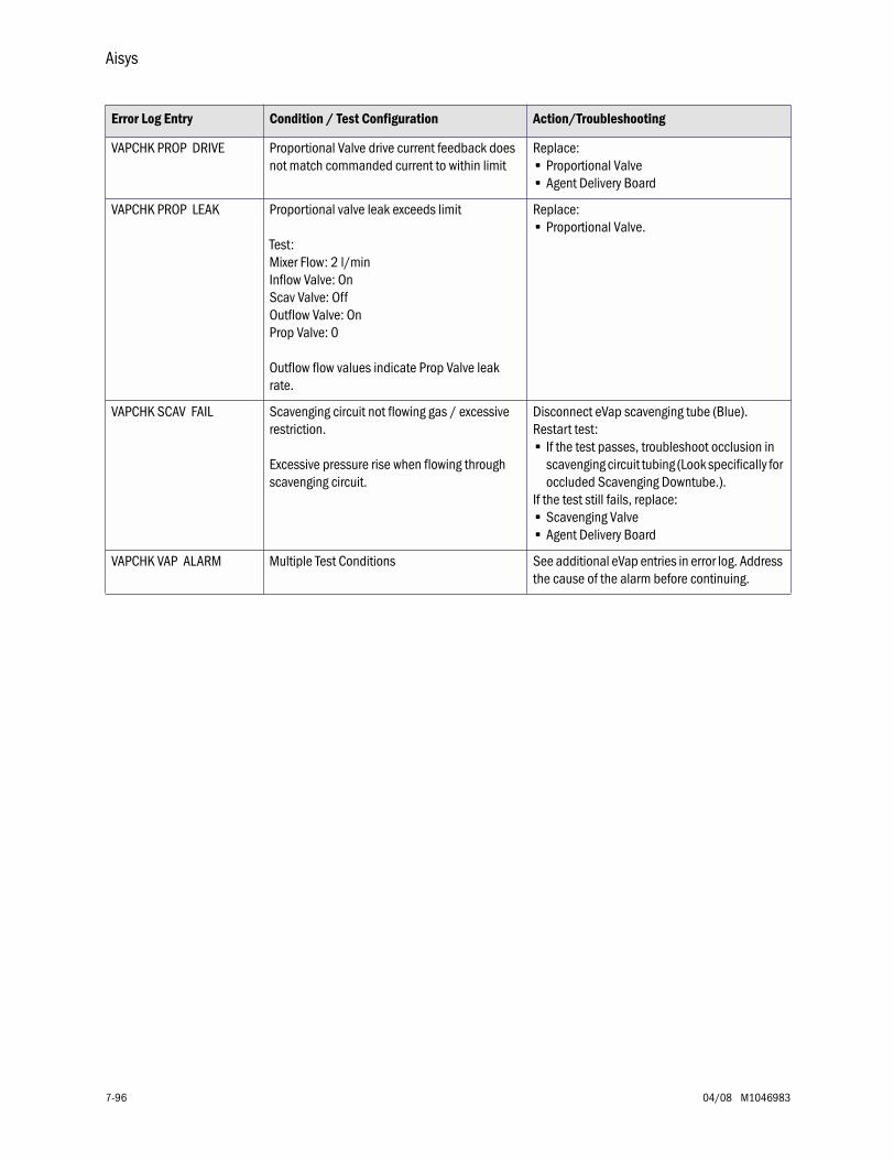
Aisys
7-96 04/08 M1046983
VAPCHK PROP DRIVE Proportional Valve drive current feedback does not match commanded current to within limit
Replace:• Proportional Valve• Agent Delivery Board
VAPCHK PROP LEAK Proportional valve leak exceeds limit
Test:Mixer Flow: 2 l/minInflow Valve: OnScav Valve: OffOutflow Valve: OnProp Valve: 0
Outflow flow values indicate Prop Valve leak rate.
Replace:• Proportional Valve.
VAPCHK SCAV FAIL Scavenging circuit not flowing gas / excessive restriction.
Excessive pressure rise when flowing through scavenging circuit.
Disconnect eVap scavenging tube (Blue).Restart test:• If the test passes, troubleshoot occlusion in
scavenging circuit tubing (Look specifically for occluded Scavenging Downtube.).
If the test still fails, replace:• Scavenging Valve• Agent Delivery Board
VAPCHK VAP ALARM Multiple Test Conditions See additional eVap entries in error log. Address the cause of the alarm before continuing.
Error Log Entry Condition / Test Configuration Action/Troubleshooting
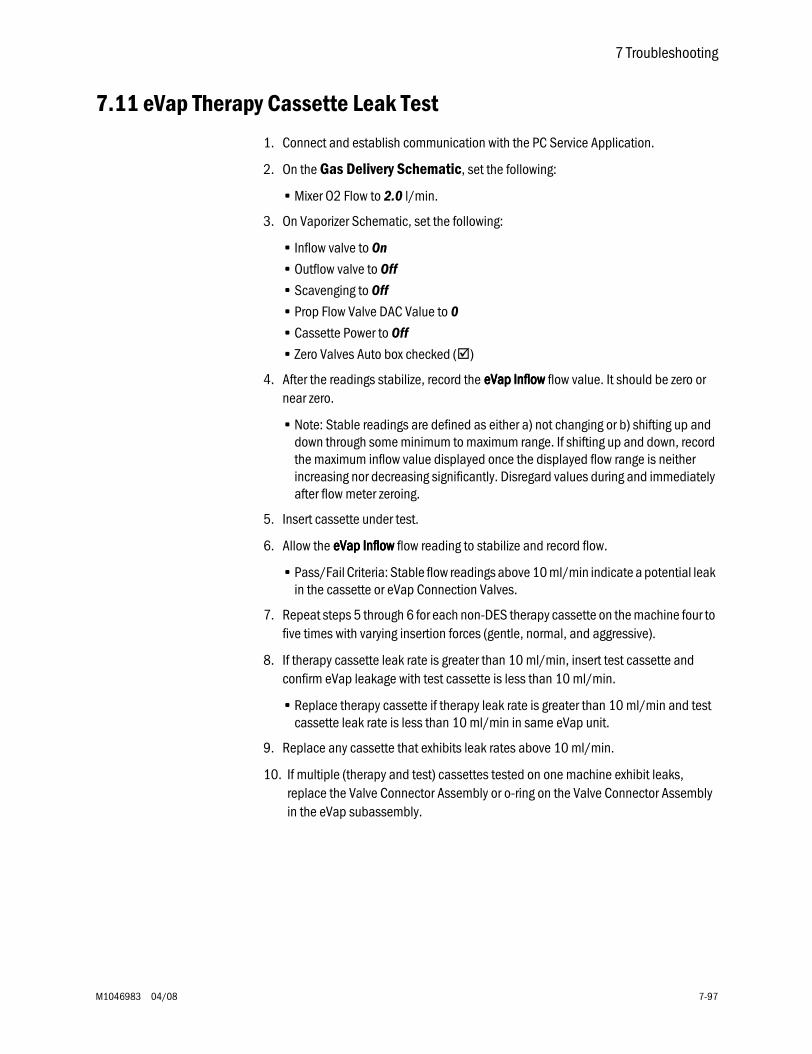
7 Troubleshooting
M1046983 04/08 7-97
7.11 eVap Therapy Cassette Leak Test
1. Connect and establish communication with the PC Service Application.
2. On the Gas Delivery Schematic, set the following:
• Mixer O2 Flow to 2.0 l/min.
3. On Vaporizer Schematic, set the following:
• Inflow valve to On
• Outflow valve to Off
• Scavenging to Off
• Prop Flow Valve DAC Value to 0
• Cassette Power to Off
• Zero Valves Auto box checked ()
4. After the readings stabilize, record the eeeeVVVVaaaapppp IIIInnnnfffflllloooowwww flow value. It should be zero or near zero.
• Note: Stable readings are defined as either a) not changing or b) shifting up and down through some minimum to maximum range. If shifting up and down, record the maximum inflow value displayed once the displayed flow range is neither increasing nor decreasing significantly. Disregard values during and immediately after flow meter zeroing.
5. Insert cassette under test.
6. Allow the eeeeVVVVaaaapppp IIIInnnnfffflllloooowwww flow reading to stabilize and record flow.
• Pass/Fail Criteria: Stable flow readings above 10 ml/min indicate a potential leak in the cassette or eVap Connection Valves.
7. Repeat steps 5 through 6 for each non-DES therapy cassette on the machine four to five times with varying insertion forces (gentle, normal, and aggressive).
8. If therapy cassette leak rate is greater than 10 ml/min, insert test cassette and confirm eVap leakage with test cassette is less than 10 ml/min.
• Replace therapy cassette if therapy leak rate is greater than 10 ml/min and test cassette leak rate is less than 10 ml/min in same eVap unit.
9. Replace any cassette that exhibits leak rates above 10 ml/min.
10. If multiple (therapy and test) cassettes tested on one machine exhibit leaks, replace the Valve Connector Assembly or o-ring on the Valve Connector Assembly in the eVap subassembly.
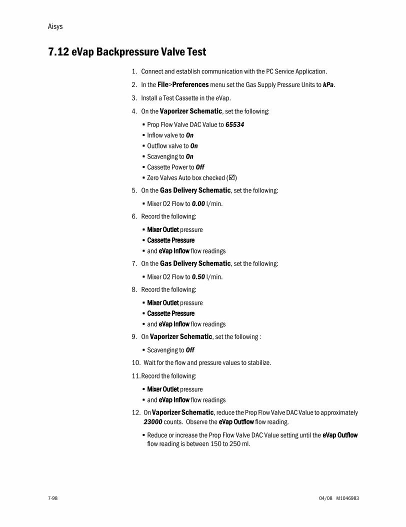
Aisys
7-98 04/08 M1046983
7.12 eVap Backpressure Valve Test
1. Connect and establish communication with the PC Service Application.
2. In the File>Preferences menu set the Gas Supply Pressure Units to kPa.
3. Install a Test Cassette in the eVap.
4. On the Vaporizer Schematic, set the following:
• Prop Flow Valve DAC Value to 65534
• Inflow valve to On
• Outflow valve to On
• Scavenging to On
• Cassette Power to Off
• Zero Valves Auto box checked ()
5. On the Gas Delivery Schematic, set the following:
• Mixer O2 Flow to 0.00 l/min.
6. Record the following:
• MMMMiiiixxxxeeeerrrr OOOOuuuuttttlllleeeetttt pressure
• CCCCaaaasssssssseeeetttttttteeee PPPPrrrreeeessssssssuuuurrrreeee
• and eeeeVVVVaaaapppp IIIInnnnfffflllloooowwww flow readings
7. On the Gas Delivery Schematic, set the following:
• Mixer O2 Flow to 0.50 l/min.
8. Record the following:
• MMMMiiiixxxxeeeerrrr OOOOuuuuttttlllleeeetttt pressure
• CCCCaaaasssssssseeeetttttttteeee PPPPrrrreeeessssssssuuuurrrreeee
• and eeeeVVVVaaaapppp IIIInnnnfffflllloooowwww flow readings
9. On Vaporizer Schematic, set the following :
• Scavenging to Off
10. Wait for the flow and pressure values to stabilize.
11.Record the following:
• MMMMiiiixxxxeeeerrrr OOOOuuuuttttlllleeeetttt pressure
• and eeeeVVVVaaaapppp IIIInnnnfffflllloooowwww flow readings
12. On Vaporizer Schematic, reduce the Prop Flow Valve DAC Value to approximately 23000 counts. Observe the eeeeVVVVaaaapppp OOOOuuuuttttfffflllloooowwww flow reading.
• Reduce or increase the Prop Flow Valve DAC Value setting until the eeeeVVVVaaaapppp OOOOuuuuttttfffflllloooowwww flow reading is between 150 to 250 ml.
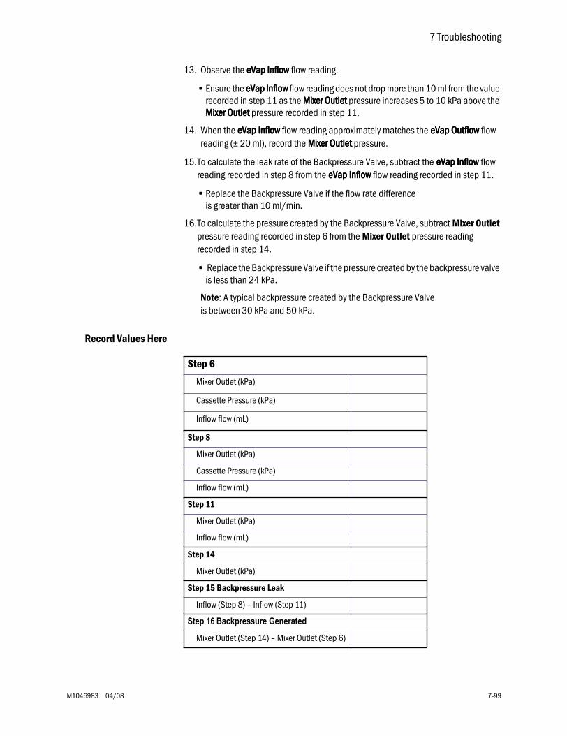
7 Troubleshooting
M1046983 04/08 7-99
13. Observe the eeeeVVVVaaaapppp IIIInnnnfffflllloooowwww flow reading.
• Ensure the eeeeVVVVaaaapppp IIIInnnnfffflllloooowwww flow reading does not drop more than 10 ml from the value recorded in step 11 as the MMMMiiiixxxxeeeerrrr OOOOuuuuttttlllleeeetttt pressure increases 5 to 10 kPa above the MMMMiiiixxxxeeeerrrr OOOOuuuuttttlllleeeetttt pressure recorded in step 11.
14. When the eeeeVVVVaaaapppp IIIInnnnfffflllloooowwww flow reading approximately matches the eeeeVVVVaaaapppp OOOOuuuuttttfffflllloooowwww flow reading (± 20 ml), record the MMMMiiiixxxxeeeerrrr OOOOuuuuttttlllleeeetttt pressure.
15.To calculate the leak rate of the Backpressure Valve, subtract the eeeeVVVVaaaapppp IIIInnnnfffflllloooowwww flow reading recorded in step 8 from the eeeeVVVVaaaapppp IIIInnnnfffflllloooowwww flow reading recorded in step 11.
• Replace the Backpressure Valve if the flow rate difference is greater than 10 ml/min.
16.To calculate the pressure created by the Backpressure Valve, subtract Mixer Outlet pressure reading recorded in step 6 from the Mixer Outlet pressure reading recorded in step 14.
• Replace the Backpressure Valve if the pressure created by the backpressure valve is less than 24 kPa.
Note: A typical backpressure created by the Backpressure Valve is between 30 kPa and 50 kPa.
Record Values Here
Step 6
Mixer Outlet (kPa)
Cassette Pressure (kPa)
Inflow flow (mL)
Step 8
Mixer Outlet (kPa)
Cassette Pressure (kPa)
Inflow flow (mL)
Step 11
Mixer Outlet (kPa)
Inflow flow (mL)
Step 14
Mixer Outlet (kPa)
Step 15 Backpressure Leak
Inflow (Step 8) – Inflow (Step 11)
Step 16 Backpressure Generated
Mixer Outlet (Step 14) – Mixer Outlet (Step 6)
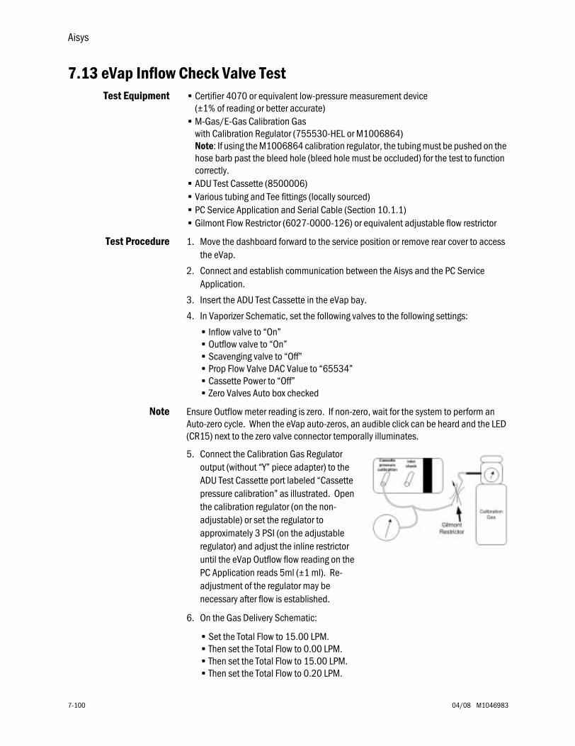
Aisys
7-100 04/08 M1046983
7.13 eVap Inflow Check Valve TestTest Equipment • Certifier 4070 or equivalent low-pressure measurement device
(±1% of reading or better accurate)• M-Gas/E-Gas Calibration Gas
with Calibration Regulator (755530-HEL or M1006864)Note: If using the M1006864 calibration regulator, the tubing must be pushed on the hose barb past the bleed hole (bleed hole must be occluded) for the test to function correctly.
• ADU Test Cassette (8500006)• Various tubing and Tee fittings (locally sourced)• PC Service Application and Serial Cable (Section 10.1.1)• Gilmont Flow Restrictor (6027-0000-126) or equivalent adjustable flow restrictor
Test Procedure 1. Move the dashboard forward to the service position or remove rear cover to access the eVap.
2. Connect and establish communication between the Aisys and the PC Service Application.
3. Insert the ADU Test Cassette in the eVap bay.
4. In Vaporizer Schematic, set the following valves to the following settings:
• Inflow valve to “On”• Outflow valve to “On”• Scavenging valve to “Off”• Prop Flow Valve DAC Value to “65534”• Cassette Power to “Off”• Zero Valves Auto box checked
Note Ensure Outflow meter reading is zero. If non-zero, wait for the system to perform an Auto-zero cycle. When the eVap auto-zeros, an audible click can be heard and the LED (CR15) next to the zero valve connector temporally illuminates.
5. Connect the Calibration Gas Regulator output (without “Y” piece adapter) to the ADU Test Cassette port labeled “Cassette pressure calibration” as illustrated. Open the calibration regulator (on the non-adjustable) or set the regulator to approximately 3 PSI (on the adjustable regulator) and adjust the inline restrictor until the eVap Outflow flow reading on the PC Application reads 5ml (±1 ml). Re-adjustment of the regulator may be necessary after flow is established.
6. On the Gas Delivery Schematic:
• Set the Total Flow to 15.00 LPM. • Then set the Total Flow to 0.00 LPM. • Then set the Total Flow to 15.00 LPM. • Then set the Total Flow to 0.20 LPM.
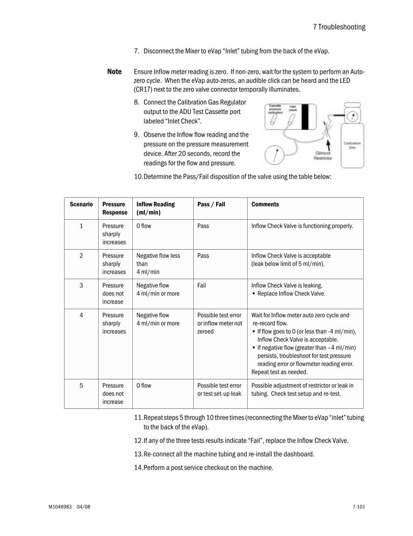
7 Troubleshooting
M1046983 04/08 7-101
7. Disconnect the Mixer to eVap “Inlet” tubing from the back of the eVap.
Note Ensure Inflow meter reading is zero. If non-zero, wait for the system to perform an Auto-zero cycle. When the eVap auto-zeros, an audible click can be heard and the LED (CR17) next to the zero valve connector temporally illuminates.
8. Connect the Calibration Gas Regulator output to the ADU Test Cassette port labeled “Inlet Check”.
9. Observe the Inflow flow reading and the pressure on the pressure measurement device. After 20 seconds, record the readings for the flow and pressure.
10.Determine the Pass/Fail disposition of the valve using the table below:
11.Repeat steps 5 through 10 three times (reconnecting the Mixer to eVap “inlet” tubing to the back of the eVap).
12.If any of the three tests results indicate “Fail”, replace the Inflow Check Valve.
13.Re-connect all the machine tubing and re-install the dashboard.
14.Perform a post service checkout on the machine.
Scenario Pressure Response
Inflow Reading (ml/min)
Pass / Fail Comments
1 Pressure sharply increases
0 flow Pass Inflow Check Valve is functioning properly.
2 Pressure sharply increases
Negative flow less than 4 ml/min
Pass Inflow Check Valve is acceptable (leak below limit of 5 ml/min).
3 Pressure does not increase
Negative flow 4 ml/min or more
Fail Inflow Check Valve is leaking. • Replace Inflow Check Valve.
4 Pressure sharply increases
Negative flow 4 ml/min or more
Possible test error or inflow meter not zeroed
Wait for Inflow meter auto zero cycle and re-record flow.• If flow goes to 0 (or less than -4 ml/min),
Inflow Check Valve is acceptable.• If negative flow (greater than –4 ml/min)
persists, troubleshoot for test pressure reading error or flowmeter reading error.
Repeat test as needed.
5 Pressure does not increase
0 flow Possible test error or test set-up leak
Possible adjustment of restrictor or leak in tubing. Check test setup and re-test.
Aisys
7-102 04/08 M1046983
7.14 eVap Scavenger Path Testing
1. Connect and establish communication with the PC Service Application.
2. In the File>Preferences menu set the Gas Supply Pressure Units to kPa.
3. On the Gas Delivery Schematic, set the following:
• Mixer O2 Flow to 0.50 l/min.
4. Insert a de-pressurized Test Cassette.
5. On the Vaporizer Schematic, set the following:
• Inflow valve to Off
• Outflow valve to Off
• Scavenging to On
• Prop Flow Valve DAC Value to 0
• Cassette Power to Off
• Zero Valves Auto box checked ()
6. Record the CCCCaaaasssssssseeeetttttttteeee PPPPrrrreeeessssssssuuuurrrreeee value.
7. Set the Inflow valve to On.
8. After the reading stabilizes, re-record the CCCCaaaasssssssseeeetttttttteeee PPPPrrrreeeessssssssuuuurrrreeee.
9. Subtract the second reading from the first reading.
a. If the difference between the two readings is less than or equal to 1.00 kPa, there is no restriction in the scavenger path. No action is required.
b. If the difference between the two readings is greater than 1.00 kPa, disconnect the eVap scavenger tubing (blue tubing) and repeat the test.
c. With the scavenger tubing disconnected, if the pressure difference is less than 1.00 kPa, inspect the scavenger tubing for kinks and replace as necessary. If no kinks or restrictions are noted, inspect the Scavenger Downtube (1407-3904-000) for restrictions, replace as necessary.
d. If the pressure gradient remains greater than 1.00 kPa, troubleshoot or replace the eVap.
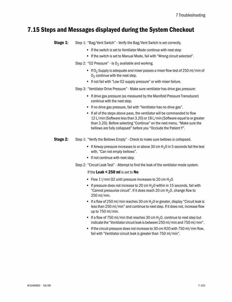
7 Troubleshooting
M1046983 04/08 7-103
7.15 Steps and Messages displayed during the System Checkout
Stage 1: Step 1: “Bag/Vent Switch” - Verify the Bag/Vent Switch is set correctly.
• If the switch is set to Ventilator Mode continue with next step
• If the switch is set to Manual Mode, fail with “Wrong circuit selected”.
Step 2: “O2 Pressure” - Is O2 available and working.
• If O2 Supply is adequate and mixer passes a mixer flow test of 250 ml/min of O2 continue with the next step.
• If not fail with “Low O2 supply pressure” or with mixer failure.
Step 3: “Ventilator Drive Pressure” - Make sure ventilator has drive gas pressure:
• If drive gas pressure (as measured by the Manifold Pressure Transducer) continue with the next step.
• If no drive gas pressure, fail with “Ventilator has no drive gas”.
• If all of the steps above pass, the ventilator will be commanded to flow 12 L/min (Software less than 3.20) or 18 L/min (Software equal to or greater than 3.20). Before selecting “Continue” on the next menu, “Make sure the bellows are fully collapsed” before you “Occlude the Patient Y”.
Stage 2: Step 1: “Verify the Bellows Empty” - Check to make sure bellows is collapsed.
• If Airway pressure increases to or above 30 cm H20 in 5 seconds fail the test with, “Can not empty bellows”.
• If not continue with next step.
Step 2: “Circuit Leak Test” - Attempt to find the leak of the ventilator mode system.
If the Leak < 250 ml is set to No:
• Flow 1 l/min O2 until pressure increases to 20 cm H20.
• If pressure does not increase to 20 cm H20 within in 15 seconds, fail with “Cannot pressurize circuit”. If it does reach 20 cm H20, change flow to 250 ml/min.
• If a flow of 250 ml/min reaches 30 cm H20 or greater, display “Circuit leak is less than 250 ml/min” and continue to next step. If it does not, increase flow up to 750 ml/min.
• If a flow of 750 ml/min that reaches 30 cm H20, continue to next step but indicate the “Ventilator circuit leak is between 250 ml/min and 750 ml/min”.
• If the circuit pressure does not increase to 30 cm H2O with 750 ml/min flow, fail with “Ventilator circuit leak is greater than 750 ml/min”.
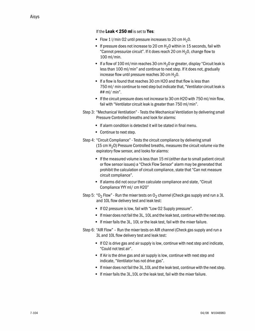
Aisys
7-104 04/08 M1046983
If the Leak < 250 ml is set to Yes:
• Flow 1 l/min O2 until pressure increases to 20 cm H20.
• If pressure does not increase to 20 cm H20 within in 15 seconds, fail with “Cannot pressurize circuit”. If it does reach 20 cm H20, change flow to 100 ml/min.
• If a flow of 100 ml/min reaches 30 cm H20 or greater, display “Circuit leak is less than 100 ml/min” and continue to next step. If it does not, gradually increase flow until pressure reaches 30 cm H20.
• If a flow is found that reaches 30 cm H20 and that flow is less than 750 ml/ min continue to next step but indicate that, “Ventilator circuit leak is ## ml/ min”.
• If the circuit pressure does not increase to 30 cm H2O with 750 ml/min flow, fail with “Ventilator circuit leak is greater than 750 ml/min”.
Step 3: “Mechanical Ventilation” - Tests the Mechanical Ventilation by delivering small Pressure Controlled breaths and look for alarms:
• If alarm condition is detected it will be stated in final menu.
• Continue to next step.
Step 4: “Circuit Compliance” - Tests the circuit compliance by delivering small (15 cm H2O) Pressure Controlled breaths, measures the circuit volume via the expiratory flow sensor, and looks for alarms:
• If the measured volume is less than 15 ml (either due to small patient circuit or flow sensor issues) a “Check Flow Sensor” alarm may be generated that prohibit the calculation of circuit compliance, state that “Can not measure circuit compliance”.
• If alarms did not occur then calculate compliance and state, “Circuit Compliance YYY ml/ cm H20”
Step 5: “O2 Flow” - Run the mixer tests on O2 channel (Check gas supply and run a 3L and 10L flow delivery test and leak test:
• If O2 pressure is low, fail with “Low O2 Supply pressure”.
• If mixer does not fail the 3L, 10L and the leak test, continue with the next step.
• If mixer fails the 3L, 10L or the leak test, fail with the mixer failure.
Step 6: “AIR Flow” – Run the mixer tests on AIR channel (Check gas supply and run a 3L and 10L flow delivery test and leak test:
• If O2 is drive gas and air supply is low, continue with next step and indicate, “Could not test air”.
• If Air is the drive gas and air supply is low, continue with next step and indicate, “Ventilator has not drive gas”.
• If mixer does not fail the 3L,10L and the leak test, continue with the next step.
• If mixer fails the 3L,10L or the leak test, fail with the mixer failure.
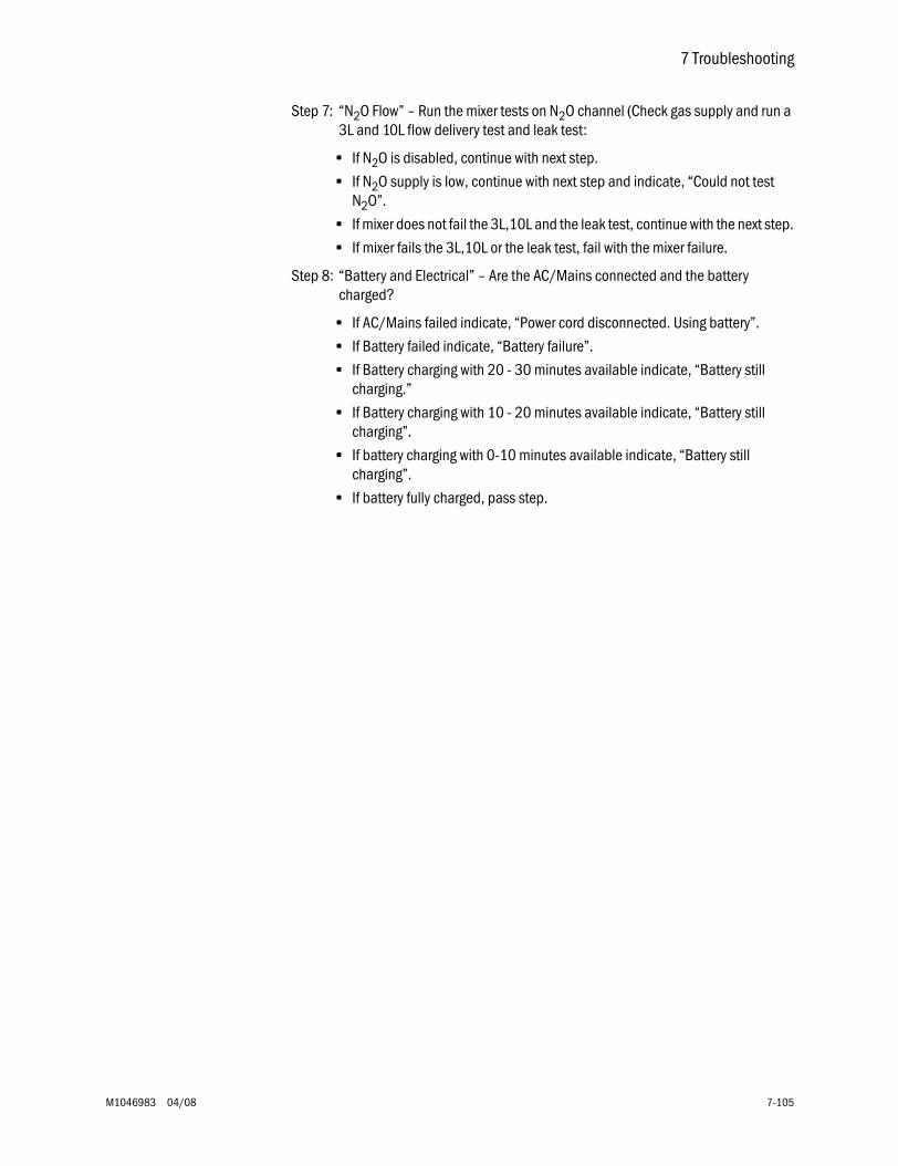
7 Troubleshooting
M1046983 04/08 7-105
Step 7: “N2O Flow” – Run the mixer tests on N2O channel (Check gas supply and run a 3L and 10L flow delivery test and leak test:
• If N2O is disabled, continue with next step.
• If N2O supply is low, continue with next step and indicate, “Could not test N2O”.
• If mixer does not fail the 3L,10L and the leak test, continue with the next step.
• If mixer fails the 3L,10L or the leak test, fail with the mixer failure.
Step 8: “Battery and Electrical” – Are the AC/Mains connected and the battery charged?
• If AC/Mains failed indicate, “Power cord disconnected. Using battery”.
• If Battery failed indicate, “Battery failure”.
• If Battery charging with 20 - 30 minutes available indicate, “Battery still charging.”
• If Battery charging with 10 - 20 minutes available indicate, “Battery still charging”.
• If battery charging with 0-10 minutes available indicate, “Battery still charging”.
• If battery fully charged, pass step.

Notes
7-106 04/08 M1046983
M1046983 04/08 8-1
8 Software Download and Special Functions
In this section 8.1 Overview . . . . . . . . . . . . . . . . . . . . . . . . . . . . . . . . . . . . . . . . . . . . . . . . . . . . . . . . . . . . . . . . . .8-2
8.1.1 Main Menu and System Information . . . . . . . . . . . . . . . . . . . . . . . . . . . . . . . . . . . . .8-2
8.2 Software Download . . . . . . . . . . . . . . . . . . . . . . . . . . . . . . . . . . . . . . . . . . . . . . . . . . . . . . . . .8-3
8.3 Special Functions . . . . . . . . . . . . . . . . . . . . . . . . . . . . . . . . . . . . . . . . . . . . . . . . . . . . . . . . . .8-5
8.3.1 Display Diagnostics . . . . . . . . . . . . . . . . . . . . . . . . . . . . . . . . . . . . . . . . . . . . . . . . . .8-6
8.3.2 Test Keys and Battery . . . . . . . . . . . . . . . . . . . . . . . . . . . . . . . . . . . . . . . . . . . . . . . . .8-7
8.3.3 System Download Log . . . . . . . . . . . . . . . . . . . . . . . . . . . . . . . . . . . . . . . . . . . . . . . .8-8

Aisys
8-2 04/08 M1046983
8.1 Overview
This section covers the functions of the Compact Flash card used to download system software or to access logs (Special Functions) from the High Performance Display Unit.
To run the application, first set the system switch to Standby and set the AC Inlet power switch to Off. Insert the Compact Flash card into the interface slot of the display unit (behind left side door), then set the AC Inlet power switch and the system switch to On. The application will load and display the Main Menu along with the System Information page.
8.1.1 Main Menu andSystem Information
The Main Menu appears on the left-hand side of the screen and includes the following selections as shown in the table below:
Note You can not return to the Special Functions section of the CF application after entering the software download section. You must reboot the system to exit Software Download.
The System Information page appears on the right-hand side of the screen and displays the following system information as shown in the table below:
Main Menu Remarks
Software Download Access to the Software Download function.
Special Functions Access to logs from the Display Unit.
System Serial NumberABCXXXXX
A i s y s S y s t e m I n f o r m a t i o n
__________Currently Installed__________
Main Menu Subsystem HW Rev Serial # SW Ver BootVer
Software Download Front Panel Cntl n/a n/a XX.XX XXaXX
Special Functions Power Controller XXXX/A/XXX ABCXXXXX XX.XX XX.XX
Electronic Mixer XXXX/A/XXX ABCXXXXX XX.XX XX.XX
Vent Intface Bd XXXX/A/XXX ABCXXXXX XX.XX XX.XX
Vaporizer XXXX/A/XXX ABCXXXXX XX.XX XX.XX
Vap Flow Meter XXXX/A/XXX ABCXXXXX n/a n/a
Vap Temp Sensor XXXX/A/XXX ABCXXXXX n/a n/a
Anes Control Bd XXXX/A/XXX ABCXXXXX XX.XX XX.XX
Dsply Unit BIOS XXXX/A/XXX ABCXXXXX XX.XX n/a
Dsply Unit App XXX/A/XXX ABCXXXXX XX.XX n/a
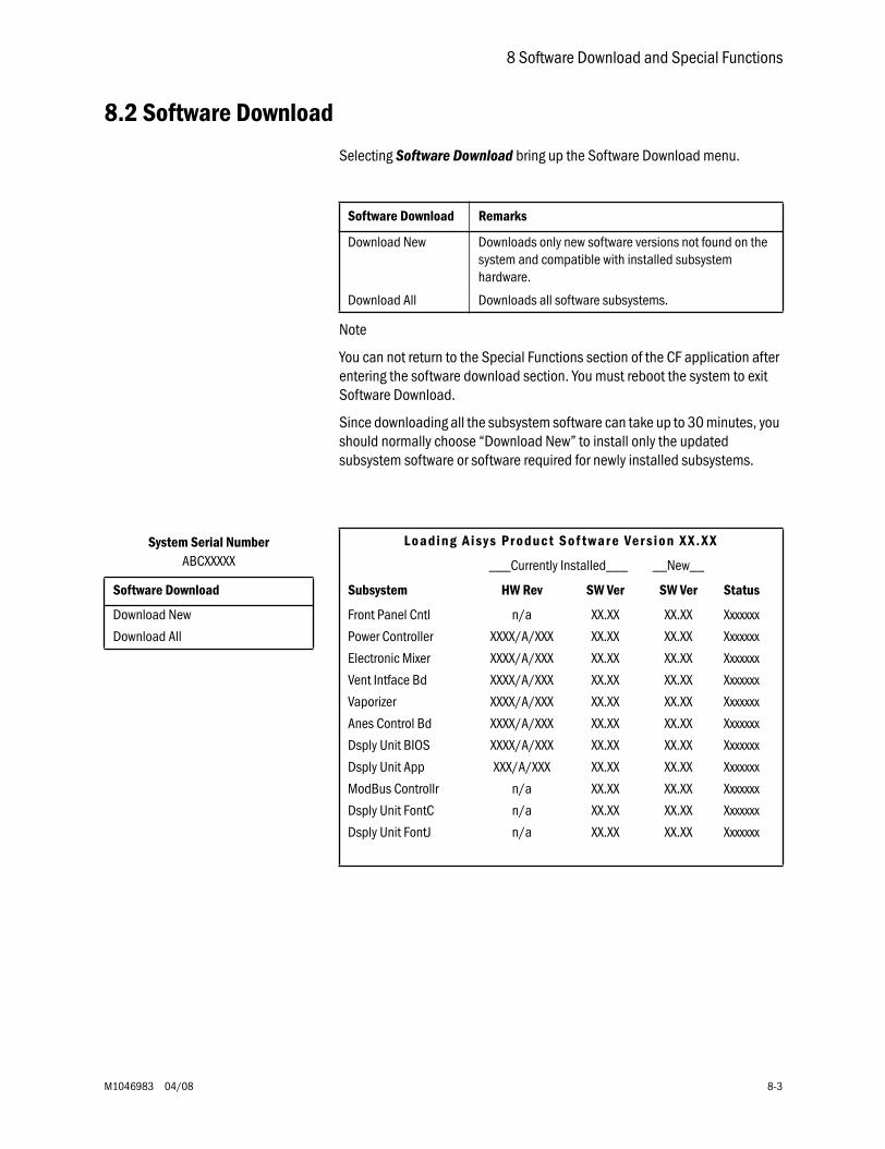
8 Software Download and Special Functions
M1046983 04/08 8-3
8.2 Software Download
Selecting Software Download bring up the Software Download menu.
Note
You can not return to the Special Functions section of the CF application after entering the software download section. You must reboot the system to exit Software Download.
Since downloading all the subsystem software can take up to 30 minutes, you should normally choose “Download New” to install only the updated subsystem software or software required for newly installed subsystems.
Software Download Remarks
Download New Downloads only new software versions not found on the system and compatible with installed subsystem hardware.
Download All Downloads all software subsystems.
System Serial NumberABCXXXXX
L o a d i n g A i s y s P r o d u c t S o f t w a r e Ve r s i o n X X . X X
___Currently Installed___ __New__
Software Download Subsystem HW Rev SW Ver SW Ver Status
Download New Front Panel Cntl n/a XX.XX XX.XX Xxxxxxx
Download All Power Controller XXXX/A/XXX XX.XX XX.XX Xxxxxxx
Electronic Mixer XXXX/A/XXX XX.XX XX.XX Xxxxxxx
Vent Intface Bd XXXX/A/XXX XX.XX XX.XX Xxxxxxx
Vaporizer XXXX/A/XXX XX.XX XX.XX Xxxxxxx
Anes Control Bd XXXX/A/XXX XX.XX XX.XX Xxxxxxx
Dsply Unit BIOS XXXX/A/XXX XX.XX XX.XX Xxxxxxx
Dsply Unit App XXX/A/XXX XX.XX XX.XX Xxxxxxx
ModBus Controllr n/a XX.XX XX.XX Xxxxxxx
Dsply Unit FontC n/a XX.XX XX.XX Xxxxxxx
Dsply Unit FontJ n/a XX.XX XX.XX Xxxxxxx
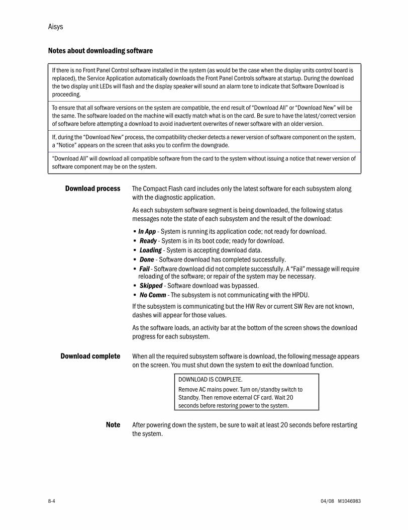
Aisys
8-4 04/08 M1046983
Notes about downloading software
Download process The Compact Flash card includes only the latest software for each subsystem along with the diagnostic application.
As each subsystem software segment is being downloaded, the following status messages note the state of each subsystem and the result of the download:
• In App - System is running its application code; not ready for download.• Ready - System is in its boot code; ready for download.• Loading - System is accepting download data.• Done - Software download has completed successfully.• Fail - Software download did not complete successfully. A “Fail” message will require
reloading of the software; or repair of the system may be necessary.• Skipped - Software download was bypassed.• No Comm - The subsystem is not communicating with the HPDU.
If the subsystem is communicating but the HW Rev or current SW Rev are not known, dashes will appear for those values.
As the software loads, an activity bar at the bottom of the screen shows the download progress for each subsystem.
Download complete When all the required subsystem software is download, the following message appears on the screen. You must shut down the system to exit the download function.
Note After powering down the system, be sure to wait at least 20 seconds before restarting the system.
If there is no Front Panel Control software installed in the system (as would be the case when the display units control board is replaced), the Service Application automatically downloads the Front Panel Controls software at startup. During the download the two display unit LEDs will flash and the display speaker will sound an alarm tone to indicate that Software Download is proceeding.
To ensure that all software versions on the system are compatible, the end result of “Download All” or “Download New” will be the same. The software loaded on the machine will exactly match what is on the card. Be sure to have the latest/correct version of software before attempting a download to avoid inadvertent overwrites of newer software with an older version.
If, during the “Download New” process, the compatibility checker detects a newer version of software component on the system, a “Notice” appears on the screen that asks you to confirm the downgrade.
“Download All” will download all compatible software from the card to the system without issuing a notice that newer version of software component may be on the system.
DOWNLOAD IS COMPLETE.
Remove AC mains power. Turn on/standby switch toStandby. Then remove external CF card. Wait 20seconds before restoring power to the system.
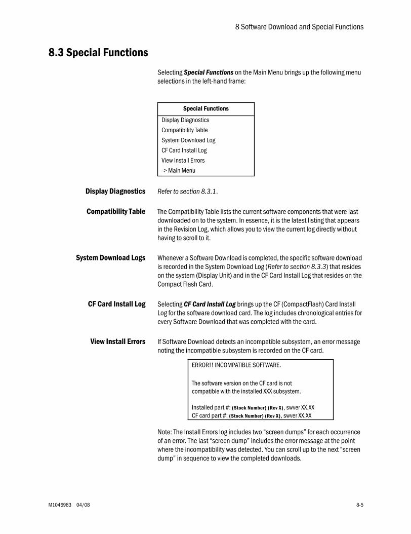
8 Software Download and Special Functions
M1046983 04/08 8-5
8.3 Special Functions
Selecting Special Functions on the Main Menu brings up the following menu selections in the left-hand frame:
Display Diagnostics Refer to section 8.3.1.
Compatibility Table The Compatibility Table lists the current software components that were last downloaded on to the system. In essence, it is the latest listing that appears in the Revision Log, which allows you to view the current log directly without having to scroll to it.
System Download Logs Whenever a Software Download is completed, the specific software download is recorded in the System Download Log (Refer to section 8.3.3) that resides on the system (Display Unit) and in the CF Card Install Log that resides on the Compact Flash Card.
CF Card Install Log Selecting CF Card Install Log brings up the CF (CompactFlash) Card Install Log for the software download card. The log includes chronological entries for every Software Download that was completed with the card.
View Install Errors If Software Download detects an incompatible subsystem, an error message noting the incompatible subsystem is recorded on the CF card.
Note: The Install Errors log includes two “screen dumps” for each occurrence of an error. The last “screen dump” includes the error message at the point where the incompatibility was detected. You can scroll up to the next “screen dump” in sequence to view the completed downloads.
Special Functions
Display Diagnostics
Compatibility Table
System Download Log
CF Card Install Log
View Install Errors
-> Main Menu
ERROR!! INCOMPATIBLE SOFTWARE.
The software version on the CF card is notcompatible with the installed XXX subsystem.
Installed part #: (Stock Number) (Rev X), swver XX.XXCF card part #: (Stock Number) (Rev X), swver XX.XX
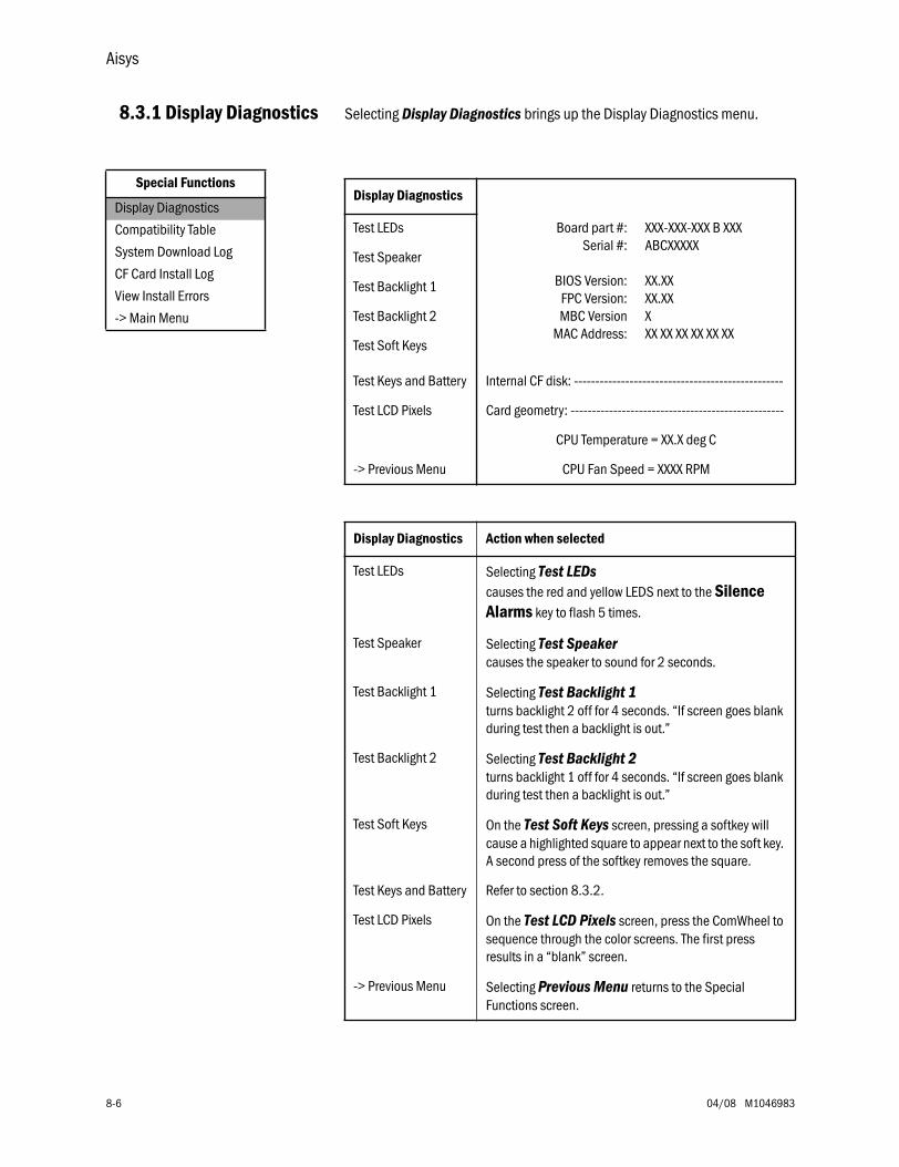
Aisys
8-6 04/08 M1046983
8.3.1 Display Diagnostics Selecting Display Diagnostics brings up the Display Diagnostics menu.
Special Functions
Display Diagnostics
Compatibility Table
System Download Log
CF Card Install Log
View Install Errors
-> Main Menu
Display Diagnostics
Test LEDs Board part #:Serial #:
BIOS Version:FPC Version:MBC Version
MAC Address:
XXX-XXX-XXX B XXXABCXXXXX
XX.XXXX.XXXXX XX XX XX XX XX
Test Speaker
Test Backlight 1
Test Backlight 2
Test Soft Keys
Test Keys and Battery Internal CF disk: -------------------------------------------------
Test LCD Pixels Card geometry: --------------------------------------------------
CPU Temperature = XX.X deg C
-> Previous Menu CPU Fan Speed = XXXX RPM
Display Diagnostics Action when selected
Test LEDs Selecting Test LEDs causes the red and yellow LEDS next to the Silence Alarms key to flash 5 times.
Test Speaker Selecting Test Speaker causes the speaker to sound for 2 seconds.
Test Backlight 1 Selecting Test Backlight 1 turns backlight 2 off for 4 seconds. “If screen goes blank during test then a backlight is out.”
Test Backlight 2 Selecting Test Backlight 2 turns backlight 1 off for 4 seconds. “If screen goes blank during test then a backlight is out.”
Test Soft Keys On the Test Soft Keys screen, pressing a softkey will cause a highlighted square to appear next to the soft key. A second press of the softkey removes the square.
Test Keys and Battery Refer to section 8.3.2.
Test LCD Pixels On the Test LCD Pixels screen, press the ComWheel to sequence through the color screens. The first press results in a “blank” screen.
-> Previous Menu Selecting Previous Menu returns to the Special Functions screen.
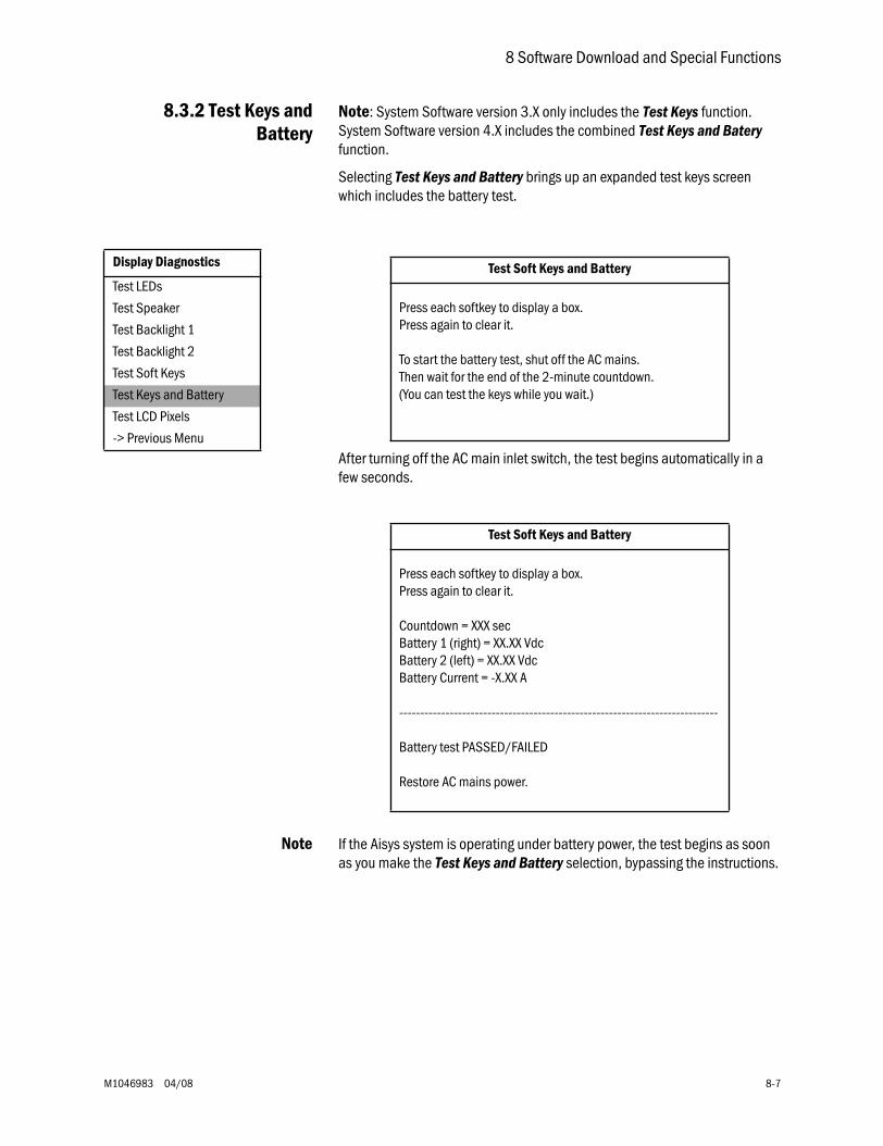
8 Software Download and Special Functions
M1046983 04/08 8-7
8.3.2 Test Keys andBattery
Note: System Software version 3.X only includes the Test Keys function. System Software version 4.X includes the combined Test Keys and Batery function.
Selecting Test Keys and Battery brings up an expanded test keys screen which includes the battery test.
After turning off the AC main inlet switch, the test begins automatically in a few seconds.
Note If the Aisys system is operating under battery power, the test begins as soon as you make the Test Keys and Battery selection, bypassing the instructions.
Display Diagnostics
Test LEDs
Test Speaker
Test Backlight 1
Test Backlight 2
Test Soft Keys
Test Keys and Battery
Test LCD Pixels
-> Previous Menu
Test Soft Keys and Battery
Press each softkey to display a box.Press again to clear it.
To start the battery test, shut off the AC mains.Then wait for the end of the 2-minute countdown.(You can test the keys while you wait.)
Test Soft Keys and Battery
Press each softkey to display a box.Press again to clear it.
Countdown = XXX secBattery 1 (right) = XX.XX VdcBattery 2 (left) = XX.XX VdcBattery Current = -X.XX A
----------------------------------------------------------------------------
Battery test PASSED/FAILED
Restore AC mains power.
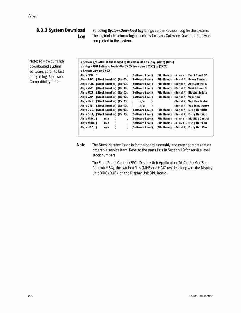
Aisys
8-8 04/08 M1046983
8.3.3 System DownloadLog
Selecting System Download Log brings up the Revision Log for the system. The log includes chronological entries for every Software Download that was completed to the system.
Note The Stock Number listed is for the board assembly and may not represent an orderable service item. Refer to the parts lists in Section 10 for service level stock numbers.
The Front Panel Control (FPC), Display Unit Application (DUA), the ModBus Control (MBC), the two font files (MHB and HGG) reside, along with the Display Unit BIOS (DUB), on the Display Unit CPU board.
Note: To view currently downloaded system software, scroll to last entry in log. Also, see Compatibility Table.
# System s/n ABCDXXXXX loaded by Download XXX on (day) (date) (time)# using HPDU Software Loader Ver XX.XX from card [XXXX] to [XXXX# System Version XX.XXAisys FPC, * , (Software Level), (File Name) (# n/a ) Front Panel CNAisys PSC, (Stock Number) (Rev X), (Software Level), (File Name) (Serial #) Power ControllAisys ACB, (Stock Number) (Rev X), (Software Level), (File Name) (Serial #) AnesControl BAisys VNT, (Stock Number) (Rev X), (Software Level), (File Name) (Serial #) Vent Intface BAisys MXR, (Stock Number) (Rev X), (Software Level), (File Name) (Serial #) Electronic MixAisys VAP, (Stock Number) (Rev X), (Software Level), (File Name) (Serial #) VaporizerAisys FMB, (Stock Number) (Rev X), ( n/a ), (Serial #) Vap Flow MeterAisys CTS, (Stock Number) (Rev X), ( n/a ), (Serial #) Vap Temp SensoAisys DUB, (Stock Number) (Rev X), (Software Level), (File Name) (Serial #) Dsply Unit BIOAisys DUA, (Stock Number) (Rev X), (Software Level), (File Name) (Serial #) Dsply Unit AppAisys MBC, ( n/a ) , (Software Level), (File Name) (# n/a ) ModBus ControlAisys MHB, ( n/a ) , (Software Level), (File Name) (# n/a ) Dsply Unit FonAisys HGG, ( n/a ) , (Software Level), (File Name) (Serial #) Dsply Unit Fon
M1046983 04/08 9-1
9 Repair Procedures
In this section 9.1 Circuit board replacement precautions . . . . . . . . . . . . . . . . . . . . . . . . . . . . . . . . . . . . . . . . .9-4
9.2 How to bleed gas pressure from the machine . . . . . . . . . . . . . . . . . . . . . . . . . . . . . . . . . . . .9-5
9.3 How to remove the rear panels . . . . . . . . . . . . . . . . . . . . . . . . . . . . . . . . . . . . . . . . . . . . . . . .9-6
9.3.1 To remove the rear upper panels . . . . . . . . . . . . . . . . . . . . . . . . . . . . . . . . . . . . . . . .9-6
9.3.2 To remove the lower access panels . . . . . . . . . . . . . . . . . . . . . . . . . . . . . . . . . . . . . .9-6
9.4 How to remove the tabletop . . . . . . . . . . . . . . . . . . . . . . . . . . . . . . . . . . . . . . . . . . . . . . . . . .9-7
9.5 Servicing the pan electrical enclosure components . . . . . . . . . . . . . . . . . . . . . . . . . . . . . . .9-8
9.5.1 Ventilator Interface board . . . . . . . . . . . . . . . . . . . . . . . . . . . . . . . . . . . . . . . . . . . . .9-8
9.5.2 Electronic Gas Mixer assembly . . . . . . . . . . . . . . . . . . . . . . . . . . . . . . . . . . . . . . . . .9-9
9.6 How to access dashboard components . . . . . . . . . . . . . . . . . . . . . . . . . . . . . . . . . . . . . . 9-10
9.7 Replace electronic vaporizer and components . . . . . . . . . . . . . . . . . . . . . . . . . . . . . . . . . 9-11
9.7.1 Remove the electronic vaporizer . . . . . . . . . . . . . . . . . . . . . . . . . . . . . . . . . . . . . . 9-12
9.7.2 Replacing eVap components . . . . . . . . . . . . . . . . . . . . . . . . . . . . . . . . . . . . . . . . . 9-13
9.8 Servicing Aladin2 cassettes . . . . . . . . . . . . . . . . . . . . . . . . . . . . . . . . . . . . . . . . . . . . . . . . 9-16
9.8.1 Emptying an Aladin2 cassette . . . . . . . . . . . . . . . . . . . . . . . . . . . . . . . . . . . . . . . . 9-16
9.8.2 Aladin2 cassette parts replacement . . . . . . . . . . . . . . . . . . . . . . . . . . . . . . . . . . . 9-17
9.9 Replace Alt O2 components . . . . . . . . . . . . . . . . . . . . . . . . . . . . . . . . . . . . . . . . . . . . . . . . 9-20
9.10 Replace system switch assembly . . . . . . . . . . . . . . . . . . . . . . . . . . . . . . . . . . . . . . . . . . 9-21
9.11 Servicing the High Performance Display Unit . . . . . . . . . . . . . . . . . . . . . . . . . . . . . . . . . 9-23
9.11.1 Remove the Display Unit . . . . . . . . . . . . . . . . . . . . . . . . . . . . . . . . . . . . . . . . . . . 9-23
9.11.2 Disassemble the Display Unit . . . . . . . . . . . . . . . . . . . . . . . . . . . . . . . . . . . . . . . 9-24
9.11.3 CPU Fan . . . . . . . . . . . . . . . . . . . . . . . . . . . . . . . . . . . . . . . . . . . . . . . . . . . . . . . . 9-24
9.11.4 To replace the CPU board . . . . . . . . . . . . . . . . . . . . . . . . . . . . . . . . . . . . . . . . . . 9-25
9.11.5 To replace the LCD display . . . . . . . . . . . . . . . . . . . . . . . . . . . . . . . . . . . . . . . . . 9-26
9.11.6 To replace the backlights . . . . . . . . . . . . . . . . . . . . . . . . . . . . . . . . . . . . . . . . . . . 9-28
9.11.7 To replace the Inverters . . . . . . . . . . . . . . . . . . . . . . . . . . . . . . . . . . . . . . . . . . . . 9-28
9.11.8 To replace the front enclosure or components . . . . . . . . . . . . . . . . . . . . . . . . . . 9-30
9.12 Servicing the lower electrical enclosure components . . . . . . . . . . . . . . . . . . . . . . . . . . 9-32
9.12.1 Power Controller board . . . . . . . . . . . . . . . . . . . . . . . . . . . . . . . . . . . . . . . . . . . . 9-32
9.12.2 Power Supply . . . . . . . . . . . . . . . . . . . . . . . . . . . . . . . . . . . . . . . . . . . . . . . . . . . . 9-33
9.12.3 Anesthesia Control board . . . . . . . . . . . . . . . . . . . . . . . . . . . . . . . . . . . . . . . . . . 9-34
9.12.4 Backup batteries . . . . . . . . . . . . . . . . . . . . . . . . . . . . . . . . . . . . . . . . . . . . . . . . . 9-35
Aisys
9-2 04/08 M1046983
9.13 Servicing the Vent Engine . . . . . . . . . . . . . . . . . . . . . . . . . . . . . . . . . . . . . . . . . . . . . . . . . 9-36
9.13.1 To remove the Vent Engine . . . . . . . . . . . . . . . . . . . . . . . . . . . . . . . . . . . . . . . . . 9-37
9.13.2 Replacing Vent Engine components . . . . . . . . . . . . . . . . . . . . . . . . . . . . . . . . . . 9-38
9.13.3 Replacing GIV components . . . . . . . . . . . . . . . . . . . . . . . . . . . . . . . . . . . . . . . . . 9-39
9.14 Servicing the pipeline inlet manifold components . . . . . . . . . . . . . . . . . . . . . . . . . . . . . 9-40
9.14.1 Replace pipeline inlet filter . . . . . . . . . . . . . . . . . . . . . . . . . . . . . . . . . . . . . . . . . 9-40
9.14.2 Replace pipeline inlet check valve . . . . . . . . . . . . . . . . . . . . . . . . . . . . . . . . . . . 9-40
9.14.3 Replace the inlet manifold . . . . . . . . . . . . . . . . . . . . . . . . . . . . . . . . . . . . . . . . . 9-41
9.15 Service the cylinder supply modules . . . . . . . . . . . . . . . . . . . . . . . . . . . . . . . . . . . . . . . . 9-42
9.15.1 Tightening procedure for high-pressure tube fittings . . . . . . . . . . . . . . . . . . . . . 9-42
9.15.2 Replace primary regulator module (complete replacement) . . . . . . . . . . . . . . 9-42
9.15.3 Replace cylinder inlet filter . . . . . . . . . . . . . . . . . . . . . . . . . . . . . . . . . . . . . . . . . 9-43
9.15.4 Replace cylinder check valve . . . . . . . . . . . . . . . . . . . . . . . . . . . . . . . . . . . . . . . 9-43
9.16 Replace gas-supply pressure transducers . . . . . . . . . . . . . . . . . . . . . . . . . . . . . . . . . . . 9-44
9.17 Replace ACGO selector switch . . . . . . . . . . . . . . . . . . . . . . . . . . . . . . . . . . . . . . . . . . . . . 9-45
9.18 Clean or replace ACGO port flapper valve . . . . . . . . . . . . . . . . . . . . . . . . . . . . . . . . . . . . 9-47
9.19 Replace the APL valve . . . . . . . . . . . . . . . . . . . . . . . . . . . . . . . . . . . . . . . . . . . . . . . . . . . 9-48
9.20 Replace the bag support arm . . . . . . . . . . . . . . . . . . . . . . . . . . . . . . . . . . . . . . . . . . . . . . 9-49
9.20.1 Servicing the bag support arm . . . . . . . . . . . . . . . . . . . . . . . . . . . . . . . . . . . . . . 9-50
9.20.2 Replace bag port housing . . . . . . . . . . . . . . . . . . . . . . . . . . . . . . . . . . . . . . . . . . 9-51
9.21 Replace ABS breathing system components . . . . . . . . . . . . . . . . . . . . . . . . . . . . . . . . . 9-52
9.21.1 Replace Bag/Vent switch assembly . . . . . . . . . . . . . . . . . . . . . . . . . . . . . . . . . . 9-52
9.21.2 Replace bellows base latch assembly . . . . . . . . . . . . . . . . . . . . . . . . . . . . . . . . 9-53
9.21.3 EZchange Canister spring replacement. . . . . . . . . . . . . . . . . . . . . . . . . . . . . . . . 9-54
9.22 Replace casters . . . . . . . . . . . . . . . . . . . . . . . . . . . . . . . . . . . . . . . . . . . . . . . . . . . . . . . . . 9-55
9.23 Reconfigure sample gas return line . . . . . . . . . . . . . . . . . . . . . . . . . . . . . . . . . . . . . . . . . 9-56
9.24 Change drive gas . . . . . . . . . . . . . . . . . . . . . . . . . . . . . . . . . . . . . . . . . . . . . . . . . . . . . . . . 9-57
9.25 Display arm adjustments . . . . . . . . . . . . . . . . . . . . . . . . . . . . . . . . . . . . . . . . . . . . . . . . . 9-58
9.25.1 Display arm counterbalance adjustment . . . . . . . . . . . . . . . . . . . . . . . . . . . . . . 9-58
9.25.2 Wrist Casting adjustment . . . . . . . . . . . . . . . . . . . . . . . . . . . . . . . . . . . . . . . . . . 9-59
9.25.3 Clutch bearing adjustment . . . . . . . . . . . . . . . . . . . . . . . . . . . . . . . . . . . . . . . . . 9-59
9 Repair Procedures
M1046983 04/08 9-3
w WARNING To prevent fires:
• Use lubricants approved for anesthesia or O2 equipment, such as Krytox.
• Do not use lubricants that contain oil or grease; they burn or explode in high O2 concentrations.
• All covers used on the system must be made from antistatic (conductive) materials. Static electricity can cause fires.
w Obey infection control and safety procedures. Used equipment may contain blood and body fluids.
w A movable part or a removable component may present a pinch or a crush hazard. Use care when moving or replacing system parts and components.
w Some internal parts have sharp edges and can cause cuts or abrasions. Use care when servicing internal components.
w After repairs are completed, always perform the checkout procedure. Refer to Section 3 of this manual.
w CAUTION Electrostatic discharge through circuit boards may damage the components on them. Wear a static control wrist strap before touching the circuit boards. Handle all circuit boards by their non-conductive edges. Use anti-static containers when transporting them.
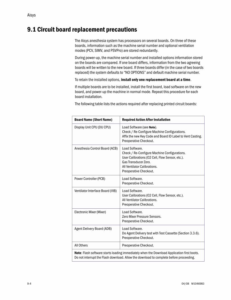
Aisys
9-4 04/08 M1046983
9.1 Circuit board replacement precautions
The Aisys anesthesia system has processors on several boards. On three of these boards, information such as the machine serial number and optional ventilation modes (PCV, SIMV, and PSVPro) are stored redundantly.
During power-up, the machine serial number and installed options information stored on the boards are compared. If one board differs, information from the two agreeing boards will be written to the new board. If three boards differ (in the case of two boards replaced) the system defaults to “NO OPTIONS” and default machine serial number.
To retain the installed options, install only one replacement board at a time.
If multiple boards are to be installed, install the first board, load software on the new board, and power-up the machine in normal mode. Repeat this procedure for each board installation.
The following table lists the actions required after replacing printed circuit boards:
Board Name (Short Name) Required Action After Installation
Display Unit CPU (DU CPU) Load Software (see Note).Check / Re-Configure Machine Configurations.Affix the new Key Code and Board ID Label to Vent Casting.Preoperative Checkout.
Anesthesia Control Board (ACB) Load Software.Check / Re-Configure Machine Configurations.User Calibrations (O2 Cell, Flow Sensor, etc.).Gas Transducer Zero.All Ventilator Calibrations.Preoperative Checkout.
Power Controller (PCB) Load Software.Preoperative Checkout.
Ventilator Interface Board (VIB) Load Software.User Calibrations (O2 Cell, Flow Sensor, etc.).All Ventilator Calibrations.Preoperative Checkout.
Electronic Mixer (Mixer) Load Software.Zero Mixer Pressure Sensors.Preoperative Checkout.
Agent Delivery Board (ADB) Load Software.Do Agent Delivery test with Test Cassette (Section 3.3.6).Preoperative Checkout.
All Others Preoperative Checkout.
Note: Flash software starts loading immediately when the Download Application first boots. Do not interrupt the Flash download. Allow the download to complete before proceeding.

9 Repair Procedures
M1046983 04/08 9-5
9.2 How to bleed gas pressure from the machine
Before disconnecting pneumatic fittings, bleed all gas pressure from the machine.
1. Close all cylinder valves and disconnect all pipeline supplies from the source.
2. Set the system switch to On.
3. Ensure that all cylinder and pipeline pressures read zero.
4. Establish a flow for the affected gas to bleed down the pressure.
5. Set the system switch to Standby.
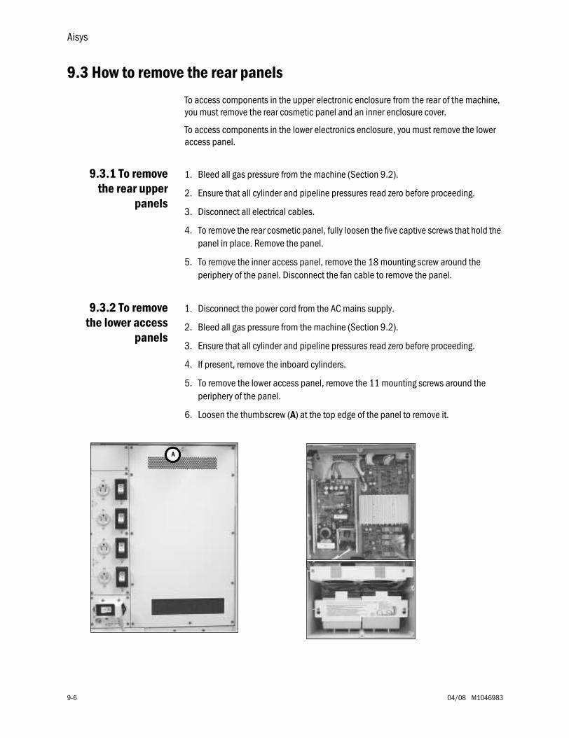
Aisys
9-6 04/08 M1046983
9.3 How to remove the rear panels
To access components in the upper electronic enclosure from the rear of the machine, you must remove the rear cosmetic panel and an inner enclosure cover.
To access components in the lower electronics enclosure, you must remove the lower access panel.
9.3.1 To removethe rear upper
panels
1. Bleed all gas pressure from the machine (Section 9.2).
2. Ensure that all cylinder and pipeline pressures read zero before proceeding.
3. Disconnect all electrical cables.
4. To remove the rear cosmetic panel, fully loosen the five captive screws that hold the panel in place. Remove the panel.
5. To remove the inner access panel, remove the 18 mounting screw around the periphery of the panel. Disconnect the fan cable to remove the panel.
9.3.2 To removethe lower access
panels
1. Disconnect the power cord from the AC mains supply.
2. Bleed all gas pressure from the machine (Section 9.2).
3. Ensure that all cylinder and pipeline pressures read zero before proceeding.
4. If present, remove the inboard cylinders.
5. To remove the lower access panel, remove the 11 mounting screws around the periphery of the panel.
6. Loosen the thumbscrew (A) at the top edge of the panel to remove it.
A
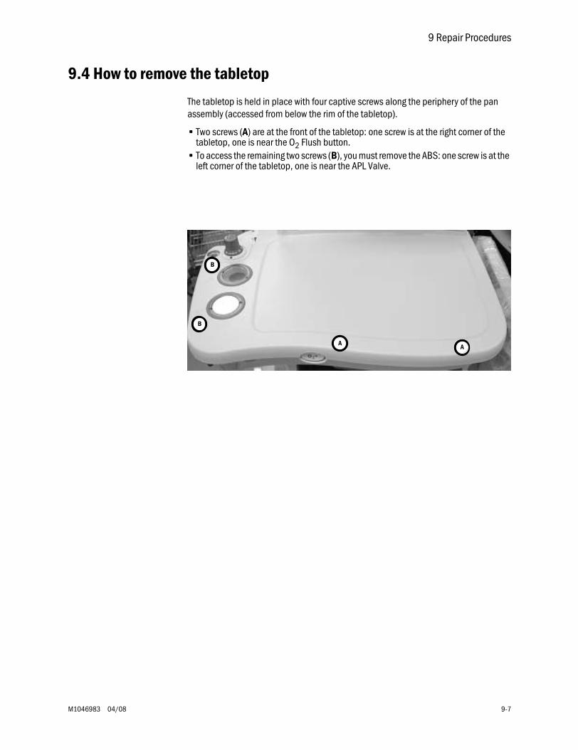
9 Repair Procedures
M1046983 04/08 9-7
9.4 How to remove the tabletop
The tabletop is held in place with four captive screws along the periphery of the pan assembly (accessed from below the rim of the tabletop).
• Two screws (A) are at the front of the tabletop: one screw is at the right corner of the tabletop, one is near the O2 Flush button.
• To access the remaining two screws (B), you must remove the ABS: one screw is at the left corner of the tabletop, one is near the APL Valve.
AA
B
B
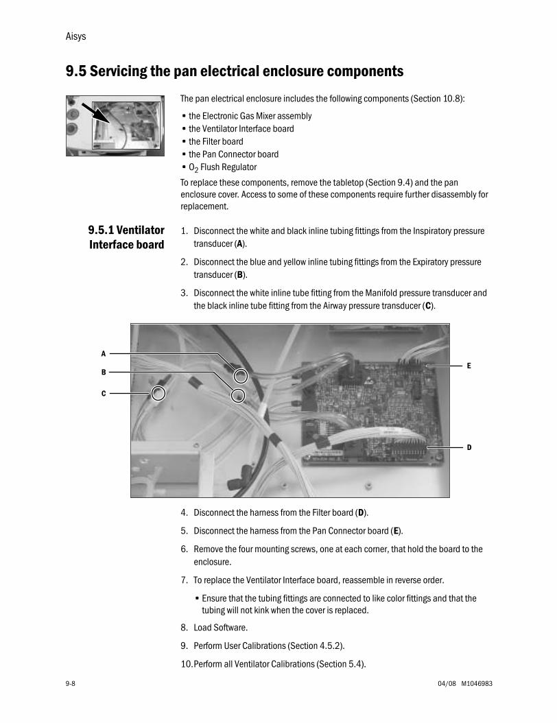
Aisys
9-8 04/08 M1046983
9.5 Servicing the pan electrical enclosure components
The pan electrical enclosure includes the following components (Section 10.8):
• the Electronic Gas Mixer assembly• the Ventilator Interface board• the Filter board• the Pan Connector board• O2 Flush Regulator
To replace these components, remove the tabletop (Section 9.4) and the pan enclosure cover. Access to some of these components require further disassembly for replacement.
9.5.1 VentilatorInterface board
1. Disconnect the white and black inline tubing fittings from the Inspiratory pressure transducer (A).
2. Disconnect the blue and yellow inline tubing fittings from the Expiratory pressure transducer (B).
3. Disconnect the white inline tube fitting from the Manifold pressure transducer and the black inline tube fitting from the Airway pressure transducer (C).
4. Disconnect the harness from the Filter board (D).
5. Disconnect the harness from the Pan Connector board (E).
6. Remove the four mounting screws, one at each corner, that hold the board to the enclosure.
7. To replace the Ventilator Interface board, reassemble in reverse order.
• Ensure that the tubing fittings are connected to like color fittings and that the tubing will not kink when the cover is replaced.
8. Load Software.
9. Perform User Calibrations (Section 4.5.2).
10.Perform all Ventilator Calibrations (Section 5.4).
C
A
B
D
E
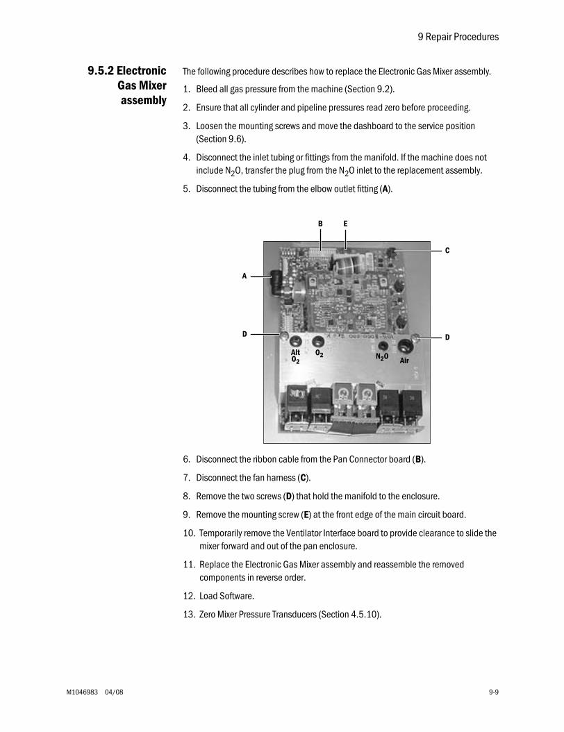
9 Repair Procedures
M1046983 04/08 9-9
9.5.2 ElectronicGas Mixerassembly
The following procedure describes how to replace the Electronic Gas Mixer assembly.
1. Bleed all gas pressure from the machine (Section 9.2).
2. Ensure that all cylinder and pipeline pressures read zero before proceeding.
3. Loosen the mounting screws and move the dashboard to the service position (Section 9.6).
4. Disconnect the inlet tubing or fittings from the manifold. If the machine does not include N2O, transfer the plug from the N2O inlet to the replacement assembly.
5. Disconnect the tubing from the elbow outlet fitting (A).
6. Disconnect the ribbon cable from the Pan Connector board (B).
7. Disconnect the fan harness (C).
8. Remove the two screws (D) that hold the manifold to the enclosure.
9. Remove the mounting screw (E) at the front edge of the main circuit board.
10. Temporarily remove the Ventilator Interface board to provide clearance to slide the mixer forward and out of the pan enclosure.
11. Replace the Electronic Gas Mixer assembly and reassemble the removed components in reverse order.
12. Load Software.
13. Zero Mixer Pressure Transducers (Section 4.5.10).
AirN2OO2AltO2
B
C
D D
A
E
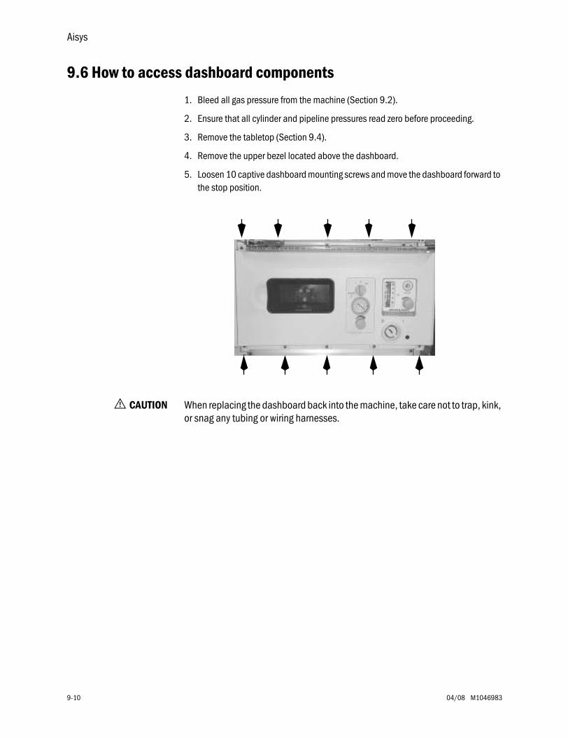
Aisys
9-10 04/08 M1046983
9.6 How to access dashboard components
1. Bleed all gas pressure from the machine (Section 9.2).
2. Ensure that all cylinder and pipeline pressures read zero before proceeding.
3. Remove the tabletop (Section 9.4).
4. Remove the upper bezel located above the dashboard.
5. Loosen 10 captive dashboard mounting screws and move the dashboard forward to the stop position.
w CAUTION When replacing the dashboard back into the machine, take care not to trap, kink, or snag any tubing or wiring harnesses.
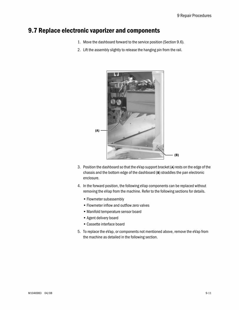
9 Repair Procedures
M1046983 04/08 9-11
9.7 Replace electronic vaporizer and components
1. Move the dashboard forward to the service position (Section 9.6).
2. Lift the assembly slightly to release the hanging pin from the rail.
3. Position the dashboard so that the eVap support bracket (A) rests on the edge of the chassis and the bottom edge of the dashboard (B) straddles the pan electronic enclosure.
4. In the forward position, the following eVap components can be replaced without removing the eVap from the machine. Refer to the following sections for details.
• Flowmeter subassembly
• Flowmeter inflow and outflow zero valves
• Manifold temperature sensor board
• Agent delivery board
• Cassette interface board
5. To replace the eVap, or components not mentioned above, remove the eVap from the machine as detailed in the following section.
(B)
(A)
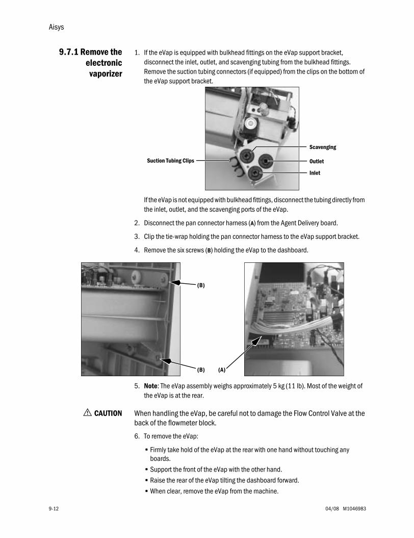
Aisys
9-12 04/08 M1046983
9.7.1 Remove theelectronic
vaporizer
1. If the eVap is equipped with bulkhead fittings on the eVap support bracket, disconnect the inlet, outlet, and scavenging tubing from the bulkhead fittings. Remove the suction tubing connectors (if equipped) from the clips on the bottom of the eVap support bracket.
If the eVap is not equipped with bulkhead fittings, disconnect the tubing directly from the inlet, outlet, and the scavenging ports of the eVap.
2. Disconnect the pan connector harness (A) from the Agent Delivery board.
3. Clip the tie-wrap holding the pan connector harness to the eVap support bracket.
4. Remove the six screws (B) holding the eVap to the dashboard.
5. Note: The eVap assembly weighs approximately 5 kg (11 lb). Most of the weight of the eVap is at the rear.
w CAUTION When handling the eVap, be careful not to damage the Flow Control Valve at the back of the flowmeter block.
6. To remove the eVap:
• Firmly take hold of the eVap at the rear with one hand without touching any boards.
• Support the front of the eVap with the other hand.
• Raise the rear of the eVap tilting the dashboard forward.
• When clear, remove the eVap from the machine.
Scavenging
Outlet
Inlet
Suction Tubing Clips
(A)
(B)
(B)
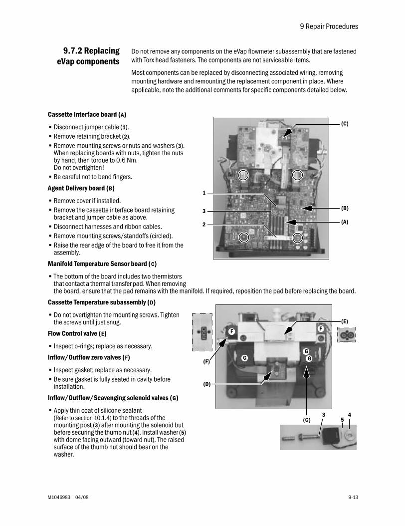
9 Repair Procedures
M1046983 04/08 9-13
9.7.2 ReplacingeVap components
Do not remove any components on the eVap flowmeter subassembly that are fastened with Torx head fasteners. The components are not serviceable items.
Most components can be replaced by disconnecting associated wiring, removing mounting hardware and remounting the replacement component in place. Where applicable, note the additional comments for specific components detailed below.
Cassette Interface board (A)
• Disconnect jumper cable (1).• Remove retaining bracket (2).• Remove mounting screws or nuts and washers (3).
When replacing boards with nuts, tighten the nuts by hand, then torque to 0.6 Nm.Do not overtighten!
• Be careful not to bend fingers.
Agent Delivery board (B)
• Remove cover if installed.• Remove the cassette interface board retaining
bracket and jumper cable as above.• Disconnect harnesses and ribbon cables.• Remove mounting screws/standoffs (circled).• Raise the rear edge of the board to free it from the
assembly.
Manifold Temperature Sensor board (C)
• The bottom of the board includes two thermistors that contact a thermal transfer pad. When removing the board, ensure that the pad remains with the manifold. If required, reposition the pad before replacing the board.
Cassette Temperature subassembly (D)
• Do not overtighten the mounting screws. Tighten the screws until just snug.
Flow Control valve (E)
• Inspect o-rings; replace as necessary.
Inflow/Outflow zero valves (F)
• Inspect gasket; replace as necessary.• Be sure gasket is fully seated in cavity before
installation.
Inflow/Outflow/Scavenging solenoid valves (G)
• Apply thin coat of silicone sealant(Refer to section 10.1.4) to the threads of the mounting post (3) after mounting the solenoid but before securing the thumb nut (4). Install washer (5) with dome facing outward (toward nut). The raised surface of the thumb nut should bear on the washer.
(A)
(B)
1
2
(C)
3
F F
GGG
(F)
(G)
(E)
(D)
3 45
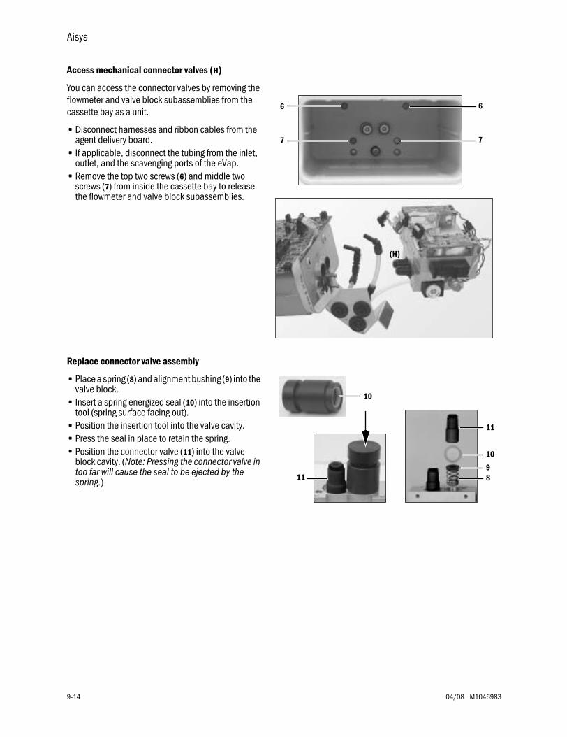
Aisys
9-14 04/08 M1046983
Access mechanical connector valves (H)
You can access the connector valves by removing the flowmeter and valve block subassemblies from the cassette bay as a unit.
• Disconnect harnesses and ribbon cables from the agent delivery board.
• If applicable, disconnect the tubing from the inlet, outlet, and the scavenging ports of the eVap.
• Remove the top two screws (6) and middle two screws (7) from inside the cassette bay to release the flowmeter and valve block subassemblies.
Replace connector valve assembly
• Place a spring (8) and alignment bushing (9) into the valve block.
• Insert a spring energized seal (10) into the insertion tool (spring surface facing out).
• Position the insertion tool into the valve cavity.• Press the seal in place to retain the spring.• Position the connector valve (11) into the valve
block cavity. (Note: Pressing the connector valve in too far will cause the seal to be ejected by the spring.)
(H)
6 6
7 7
8
10
11
10
119
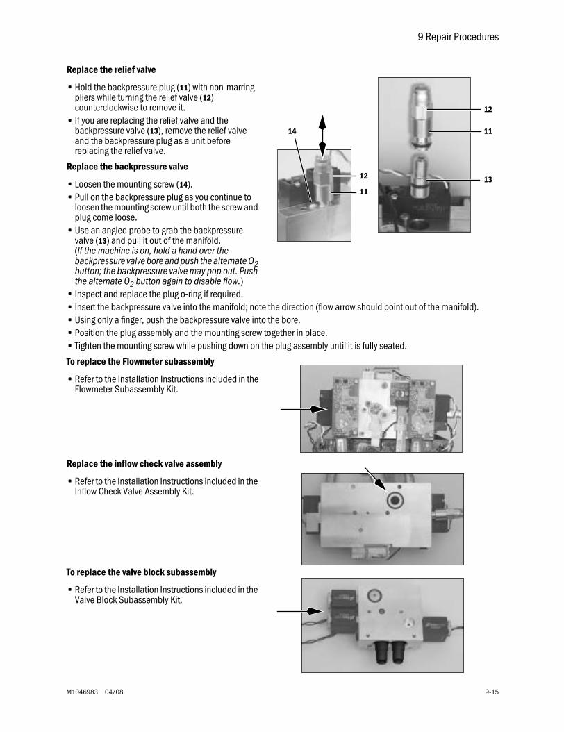
9 Repair Procedures
M1046983 04/08 9-15
Replace the relief valve
• Hold the backpressure plug (11) with non-marring pliers while turning the relief valve (12) counterclockwise to remove it.
• If you are replacing the relief valve and the backpressure valve (13), remove the relief valve and the backpressure plug as a unit before replacing the relief valve.
Replace the backpressure valve
• Loosen the mounting screw (14).• Pull on the backpressure plug as you continue to
loosen the mounting screw until both the screw and plug come loose.
• Use an angled probe to grab the backpressure valve (13) and pull it out of the manifold.(If the machine is on, hold a hand over the backpressure valve bore and push the alternate O2 button; the backpressure valve may pop out. Push the alternate O2 button again to disable flow.)
• Inspect and replace the plug o-ring if required.• Insert the backpressure valve into the manifold; note the direction (flow arrow should point out of the manifold). • Using only a finger, push the backpressure valve into the bore.• Position the plug assembly and the mounting screw together in place.• Tighten the mounting screw while pushing down on the plug assembly until it is fully seated.
To replace the Flowmeter subassembly
• Refer to the Installation Instructions included in the Flowmeter Subassembly Kit.
Replace the inflow check valve assembly
• Refer to the Installation Instructions included in the Inflow Check Valve Assembly Kit.
To replace the valve block subassembly
• Refer to the Installation Instructions included in the Valve Block Subassembly Kit.
11
14
12
11
13
12
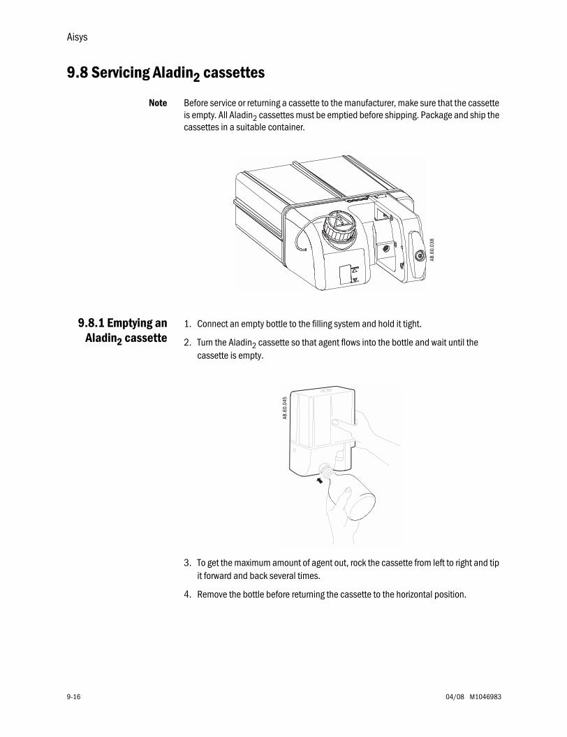
Aisys
9-16 04/08 M1046983
9.8 Servicing Aladin2 cassettes
Note Before service or returning a cassette to the manufacturer, make sure that the cassette is empty. All Aladin2 cassettes must be emptied before shipping. Package and ship the cassettes in a suitable container.
9.8.1 Emptying anAladin2 cassette
1. Connect an empty bottle to the filling system and hold it tight.
2. Turn the Aladin2 cassette so that agent flows into the bottle and wait until the cassette is empty.
3. To get the maximum amount of agent out, rock the cassette from left to right and tip it forward and back several times.
4. Remove the bottle before returning the cassette to the horizontal position.
AB.6
0.03
8
AB.6
0.04
5
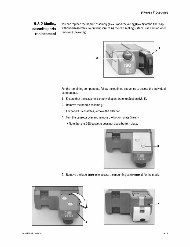
9 Repair Procedures
M1046983 04/08 9-17
9.8.2 Aladin2cassette parts
replacement
You can replace the handle assembly (Item 1) and the o-ring (Item 2) for the filler cap without disassembly. To prevent scratching the cap sealing surface, use caution when removing the o-ring.
For the remaining components, follow the outlined sequence to access the individual components.
1. Ensure that the cassette is empty of agent (refer to Section 9.8.1).
2. Remove the handle assembly.
3. For non-DES cassettes, remove the filler cap.
4. Turn the cassette over and remove the bottom plate (Item 3).
• Note that the DES cassette does not use a bottom plate.
5. Remove the label (Item 4) to access the mounting screw (Item 5) for the mask.
1
2
3
4
5
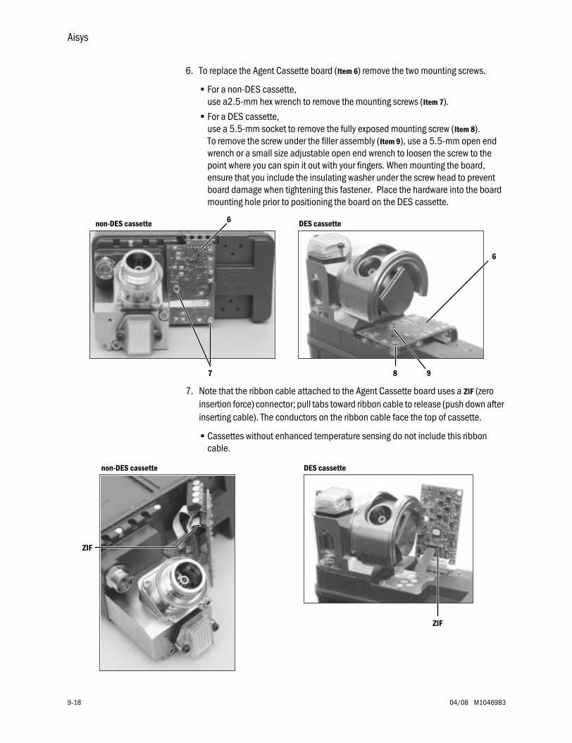
Aisys
9-18 04/08 M1046983
6. To replace the Agent Cassette board (Item 6) remove the two mounting screws.
• For a non-DES cassette, use a2.5-mm hex wrench to remove the mounting screws (Item 7).
• For a DES cassette, use a 5.5-mm socket to remove the fully exposed mounting screw (Item 8). To remove the screw under the filler assembly (Item 9), use a 5.5-mm open end wrench or a small size adjustable open end wrench to loosen the screw to the point where you can spin it out with your fingers. When mounting the board, ensure that you include the insulating washer under the screw head to prevent board damage when tightening this fastener. Place the hardware into the board mounting hole prior to positioning the board on the DES cassette.
7. Note that the ribbon cable attached to the Agent Cassette board uses a ZIF (zero insertion force) connector; pull tabs toward ribbon cable to release (push down after inserting cable). The conductors on the ribbon cable face the top of cassette.
• Cassettes without enhanced temperature sensing do not include this ribbon cable.
6
7
non-DES cassette DES cassette
6
8 9
ZIF
ZIF
non-DES cassette DES cassette
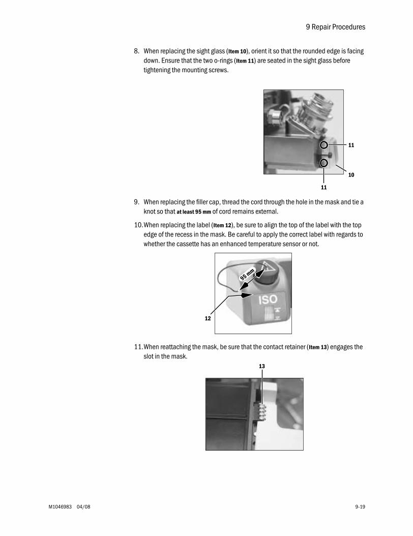
9 Repair Procedures
M1046983 04/08 9-19
8. When replacing the sight glass (Item 10), orient it so that the rounded edge is facing down. Ensure that the two o-rings (Item 11) are seated in the sight glass before tightening the mounting screws.
9. When replacing the filler cap, thread the cord through the hole in the mask and tie a knot so that at least 95 mm of cord remains external.
10.When replacing the label (Item 12), be sure to align the top of the label with the top edge of the recess in the mask. Be careful to apply the correct label with regards to whether the cassette has an enhanced temperature sensor or not.
11.When reattaching the mask, be sure that the contact retainer (Item 13) engages the slot in the mask.
11
11
10
95 mm
12
13
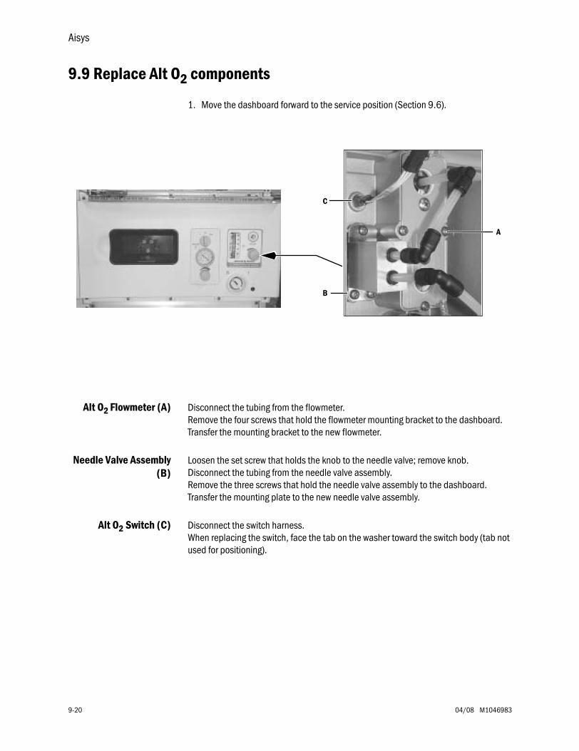
Aisys
9-20 04/08 M1046983
9.9 Replace Alt O2 components
1. Move the dashboard forward to the service position (Section 9.6).
Alt O2 Flowmeter (A) Disconnect the tubing from the flowmeter. Remove the four screws that hold the flowmeter mounting bracket to the dashboard.Transfer the mounting bracket to the new flowmeter.
Needle Valve Assembly(B)
Loosen the set screw that holds the knob to the needle valve; remove knob. Disconnect the tubing from the needle valve assembly. Remove the three screws that hold the needle valve assembly to the dashboard. Transfer the mounting plate to the new needle valve assembly.
Alt O2 Switch (C) Disconnect the switch harness. When replacing the switch, face the tab on the washer toward the switch body (tab not used for positioning).
A
C
B
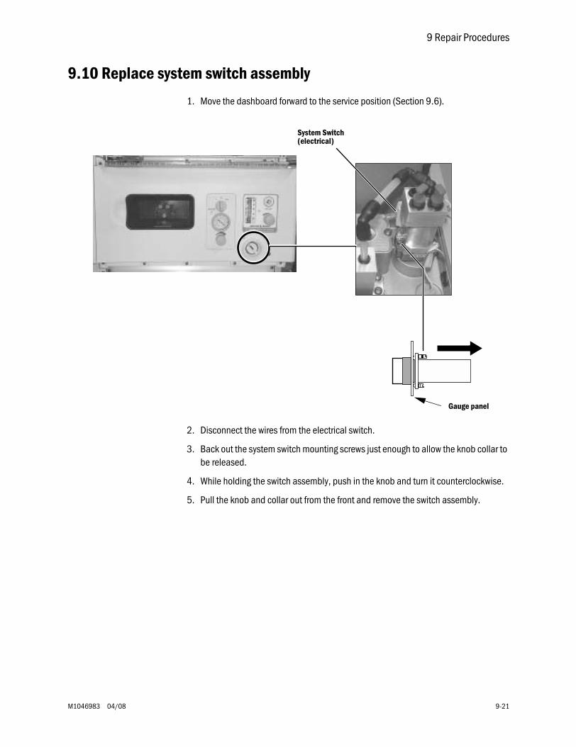
9 Repair Procedures
M1046983 04/08 9-21
9.10 Replace system switch assembly
1. Move the dashboard forward to the service position (Section 9.6).
2. Disconnect the wires from the electrical switch.
3. Back out the system switch mounting screws just enough to allow the knob collar to be released.
4. While holding the switch assembly, push in the knob and turn it counterclockwise.
5. Pull the knob and collar out from the front and remove the switch assembly.
System Switch(electrical)
Gauge panel
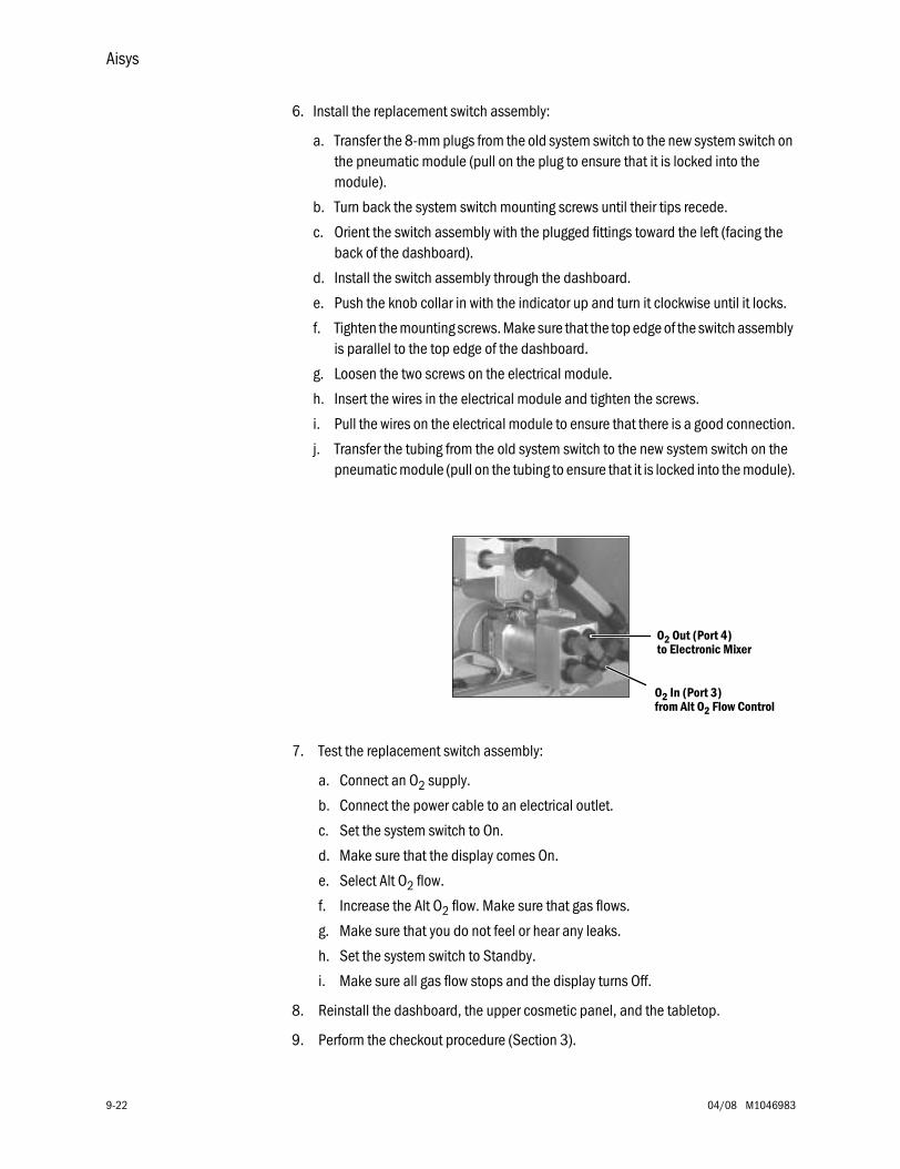
Aisys
9-22 04/08 M1046983
6. Install the replacement switch assembly:
a. Transfer the 8-mm plugs from the old system switch to the new system switch on the pneumatic module (pull on the plug to ensure that it is locked into the module).
b. Turn back the system switch mounting screws until their tips recede.
c. Orient the switch assembly with the plugged fittings toward the left (facing the back of the dashboard).
d. Install the switch assembly through the dashboard.
e. Push the knob collar in with the indicator up and turn it clockwise until it locks.
f. Tighten the mounting screws. Make sure that the top edge of the switch assembly is parallel to the top edge of the dashboard.
g. Loosen the two screws on the electrical module.
h. Insert the wires in the electrical module and tighten the screws.
i. Pull the wires on the electrical module to ensure that there is a good connection.
j. Transfer the tubing from the old system switch to the new system switch on the pneumatic module (pull on the tubing to ensure that it is locked into the module).
7. Test the replacement switch assembly:
a. Connect an O2 supply.
b. Connect the power cable to an electrical outlet.
c. Set the system switch to On.
d. Make sure that the display comes On.
e. Select Alt O2 flow.
f. Increase the Alt O2 flow. Make sure that gas flows.
g. Make sure that you do not feel or hear any leaks.
h. Set the system switch to Standby.
i. Make sure all gas flow stops and the display turns Off.
8. Reinstall the dashboard, the upper cosmetic panel, and the tabletop.
9. Perform the checkout procedure (Section 3).
O2 Out (Port 4)
O2 In (Port 3)
to Electronic Mixer
from Alt O2 Flow Control
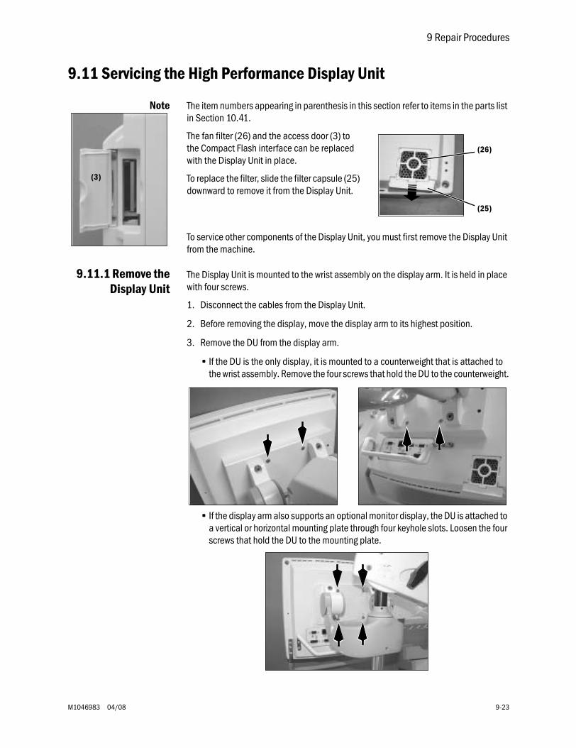
9 Repair Procedures
M1046983 04/08 9-23
9.11 Servicing the High Performance Display Unit
Note The item numbers appearing in parenthesis in this section refer to items in the parts list in Section 10.41.
The fan filter (26) and the access door (3) to the Compact Flash interface can be replaced with the Display Unit in place.
To replace the filter, slide the filter capsule (25) downward to remove it from the Display Unit.
To service other components of the Display Unit, you must first remove the Display Unit from the machine.
9.11.1 Remove theDisplay Unit
The Display Unit is mounted to the wrist assembly on the display arm. It is held in place with four screws.
1. Disconnect the cables from the Display Unit.
2. Before removing the display, move the display arm to its highest position.
3. Remove the DU from the display arm.
• If the DU is the only display, it is mounted to a counterweight that is attached to the wrist assembly. Remove the four screws that hold the DU to the counterweight.
• If the display arm also supports an optional monitor display, the DU is attached to a vertical or horizontal mounting plate through four keyhole slots. Loosen the four screws that hold the DU to the mounting plate.
(3)
(26)
(25)
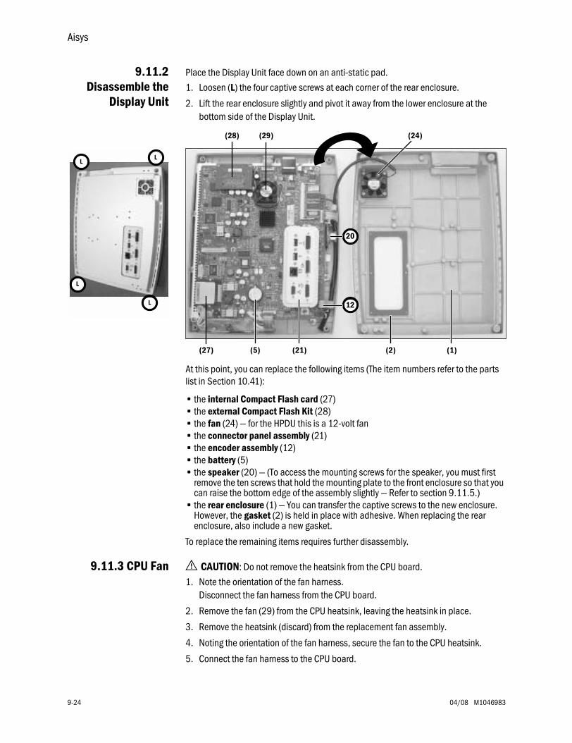
Aisys
9-24 04/08 M1046983
9.11.2Disassemble the
Display Unit
Place the Display Unit face down on an anti-static pad.
1. Loosen (L) the four captive screws at each corner of the rear enclosure.
2. Lift the rear enclosure slightly and pivot it away from the lower enclosure at the bottom side of the Display Unit.
At this point, you can replace the following items (The item numbers refer to the parts list in Section 10.41):
• the internal Compact Flash card (27)• the external Compact Flash Kit (28)• the fan (24) — for the HPDU this is a 12-volt fan• the connector panel assembly (21)• the encoder assembly (12)• the battery (5)• the speaker (20) — (To access the mounting screws for the speaker, you must first
remove the ten screws that hold the mounting plate to the front enclosure so that you can raise the bottom edge of the assembly slightly — Refer to section 9.11.5.)
• the rear enclosure (1) — You can transfer the captive screws to the new enclosure. However, the gasket (2) is held in place with adhesive. When replacing the rear enclosure, also include a new gasket.
To replace the remaining items requires further disassembly.
9.11.3 CPU Fan w CAUTION: Do not remove the heatsink from the CPU board.
1. Note the orientation of the fan harness. Disconnect the fan harness from the CPU board.
2. Remove the fan (29) from the CPU heatsink, leaving the heatsink in place.
3. Remove the heatsink (discard) from the replacement fan assembly.
4. Noting the orientation of the fan harness, secure the fan to the CPU heatsink.
5. Connect the fan harness to the CPU board.
20
12
L
L
L
L
(24)
(21) (2) (1)(5)(27)
(29)(28)
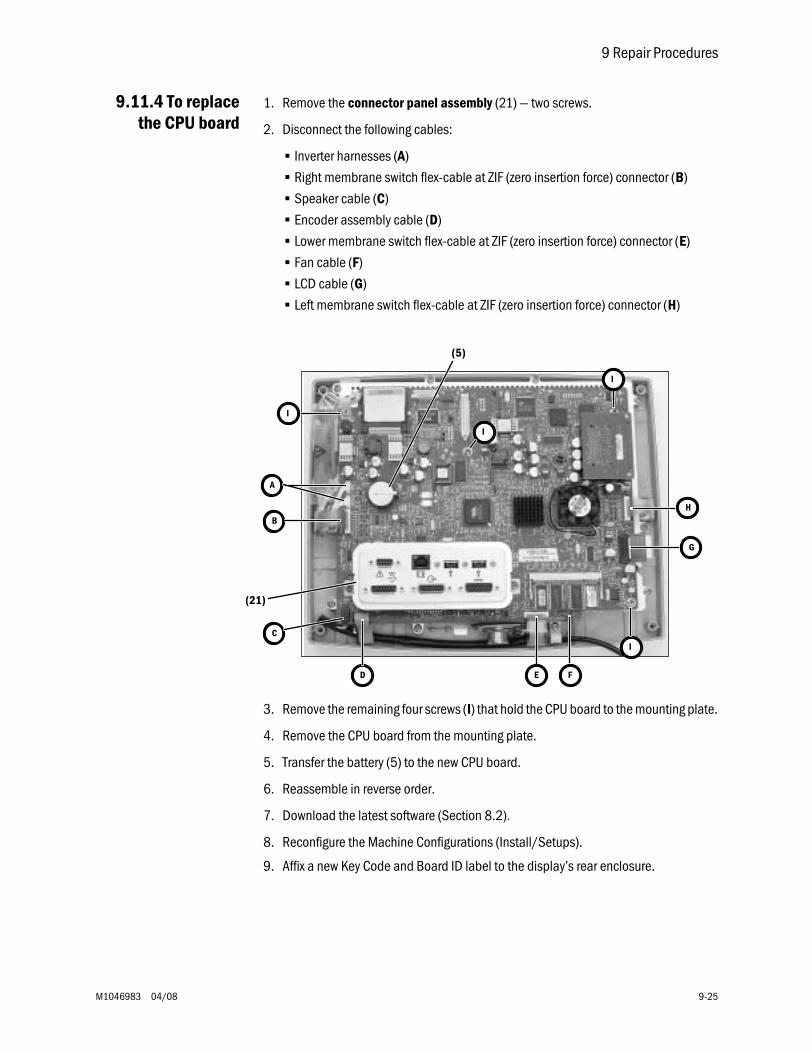
9 Repair Procedures
M1046983 04/08 9-25
9.11.4 To replacethe CPU board
1. Remove the connector panel assembly (21) — two screws.
2. Disconnect the following cables:
• Inverter harnesses (A)
• Right membrane switch flex-cable at ZIF (zero insertion force) connector (B)
• Speaker cable (C)
• Encoder assembly cable (D)
• Lower membrane switch flex-cable at ZIF (zero insertion force) connector (E)
• Fan cable (F)
• LCD cable (G)
• Left membrane switch flex-cable at ZIF (zero insertion force) connector (H)
3. Remove the remaining four screws (I) that hold the CPU board to the mounting plate.
4. Remove the CPU board from the mounting plate.
5. Transfer the battery (5) to the new CPU board.
6. Reassemble in reverse order.
7. Download the latest software (Section 8.2).
8. Reconfigure the Machine Configurations (Install/Setups).
9. Affix a new Key Code and Board ID label to the display’s rear enclosure.
B
I
C
D F
G
(21)
I
(5)
I
I
A
E
H
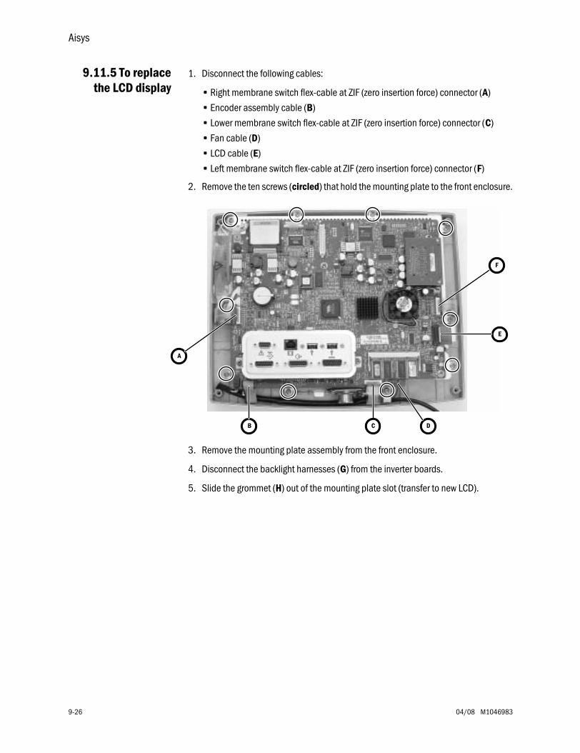
Aisys
9-26 04/08 M1046983
9.11.5 To replacethe LCD display
1. Disconnect the following cables:
• Right membrane switch flex-cable at ZIF (zero insertion force) connector (A)
• Encoder assembly cable (B)
• Lower membrane switch flex-cable at ZIF (zero insertion force) connector (C)
• Fan cable (D)
• LCD cable (E)
• Left membrane switch flex-cable at ZIF (zero insertion force) connector (F)
2. Remove the ten screws (circled) that hold the mounting plate to the front enclosure.
3. Remove the mounting plate assembly from the front enclosure.
4. Disconnect the backlight harnesses (G) from the inverter boards.
5. Slide the grommet (H) out of the mounting plate slot (transfer to new LCD).
A
B D
E
C
F
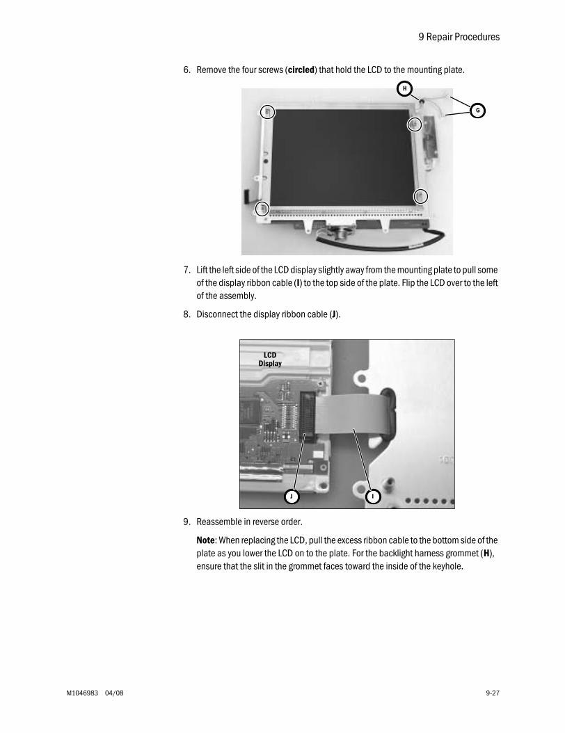
9 Repair Procedures
M1046983 04/08 9-27
6. Remove the four screws (circled) that hold the LCD to the mounting plate.
7. Lift the left side of the LCD display slightly away from the mounting plate to pull some of the display ribbon cable (I) to the top side of the plate. Flip the LCD over to the left of the assembly.
8. Disconnect the display ribbon cable (J).
9. Reassemble in reverse order.
Note: When replacing the LCD, pull the excess ribbon cable to the bottom side of the plate as you lower the LCD on to the plate. For the backlight harness grommet (H), ensure that the slit in the grommet faces toward the inside of the keyhole.
G
H
J
LCDDisplay
I
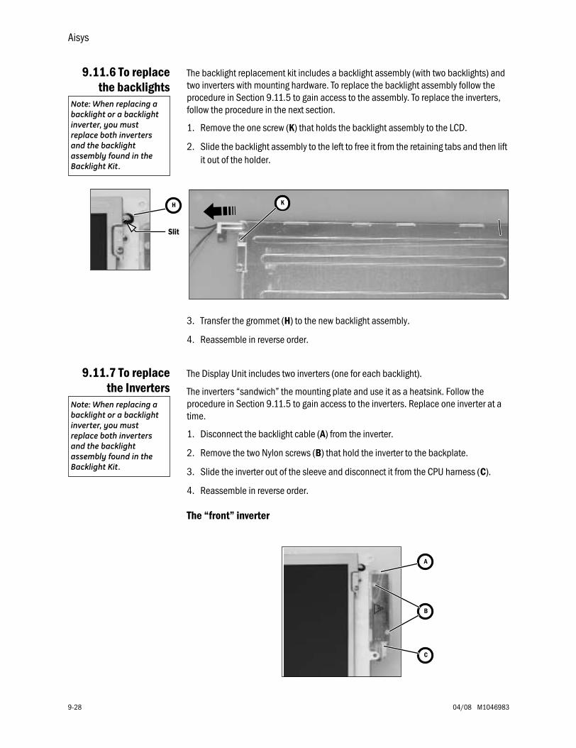
Aisys
9-28 04/08 M1046983
9.11.6 To replacethe backlights
The backlight replacement kit includes a backlight assembly (with two backlights) and two inverters with mounting hardware. To replace the backlight assembly follow the procedure in Section 9.11.5 to gain access to the assembly. To replace the inverters, follow the procedure in the next section.
1. Remove the one screw (K) that holds the backlight assembly to the LCD.
2. Slide the backlight assembly to the left to free it from the retaining tabs and then lift it out of the holder.
3. Transfer the grommet (H) to the new backlight assembly.
4. Reassemble in reverse order.
9.11.7 To replacethe Inverters
The Display Unit includes two inverters (one for each backlight).
The inverters “sandwich” the mounting plate and use it as a heatsink. Follow the procedure in Section 9.11.5 to gain access to the inverters. Replace one inverter at a time.
1. Disconnect the backlight cable (A) from the inverter.
2. Remove the two Nylon screws (B) that hold the inverter to the backplate.
3. Slide the inverter out of the sleeve and disconnect it from the CPU harness (C).
4. Reassemble in reverse order.
The “front” inverter
Note: When replacing a backlight or a backlight inverter, you must replace both inverters and the backlight assembly found in the Backlight Kit.
K
Slit
H
Note: When replacing a backlight or a backlight inverter, you must replace both inverters and the backlight assembly found in the Backlight Kit.
A
B
C
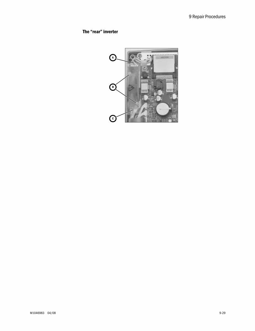
9 Repair Procedures
M1046983 04/08 9-29
The “rear” inverter
A
B
C
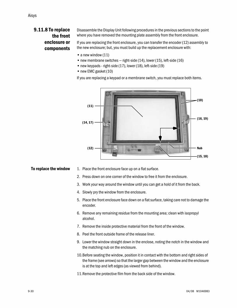
Aisys
9-30 04/08 M1046983
9.11.8 To replacethe front
enclosure orcomponents
Disassemble the Display Unit following procedures in the previous sections to the point where you have removed the mounting plate assembly from the front enclosure.
If you are replacing the front enclosure, you can transfer the encoder (12) assembly to the new enclosure; but, you must build up the replacement enclosure with:
• a new window (11)• new membrane switches — right-side (14), lower (15), left-side (16) • new keypads - right-side (17), lower (18), left-side (19)• new EMC gasket (10)
If you are replacing a keypad or a membrane switch, you must replace both items.
To replace the window 1. Place the front enclosure face up on a flat surface.
2. Press down on one corner of the window to free it from the enclosure.
3. Work your way around the window until you can get a hold of it from the back.
4. Slowly pry the window from the enclosure.
5. Place the front enclosure face down on a flat surface, taking care not to damage the encoder.
6. Remove any remaining residue from the mounting area; clean with isopropyl alcohol.
7. Remove the inside protective material from the front of the window.
8. Peel the front outside frame of the release liner.
9. Lower the window straight down in the enclose, noting the notch in the window and the matching nub on the enclosure.
10.Before seating the window, position it in contact with the bottom and right sides of the frame (see arrows) so that the larger gap between the window and the enclosure is at the top and left edges (as viewed from behind).
11.Remove the protective film from the back side of the window.
(11)
(14, 17)
(12)
(15, 18)
(16, 19)
Nub
(10)
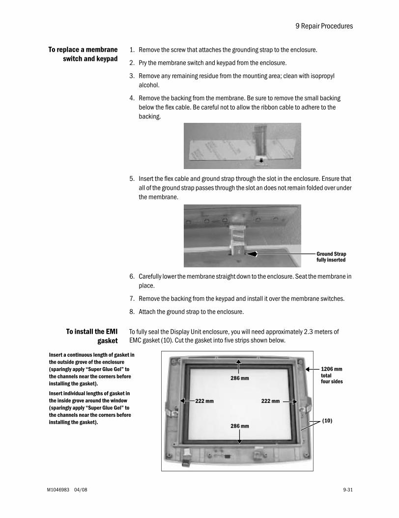
9 Repair Procedures
M1046983 04/08 9-31
To replace a membraneswitch and keypad
1. Remove the screw that attaches the grounding strap to the enclosure.
2. Pry the membrane switch and keypad from the enclosure.
3. Remove any remaining residue from the mounting area; clean with isopropyl alcohol.
4. Remove the backing from the membrane. Be sure to remove the small backing below the flex cable. Be careful not to allow the ribbon cable to adhere to the backing.
5. Insert the flex cable and ground strap through the slot in the enclosure. Ensure that all of the ground strap passes through the slot an does not remain folded over under the membrane.
6. Carefully lower the membrane straight down to the enclosure. Seat the membrane in place.
7. Remove the backing from the keypad and install it over the membrane switches.
8. Attach the ground strap to the enclosure.
To install the EMIgasket
To fully seal the Display Unit enclosure, you will need approximately 2.3 meters of EMC gasket (10). Cut the gasket into five strips shown below.
Ground Strapfully inserted
286 mm
286 mm
222 mm 222 mm
Insert a continuous length of gasket in the outside grove of the enclosure (sparingly apply “Super Glue Gel” to the channels near the corners before installing the gasket).
Insert individual lengths of gasket in the inside grove around the window (sparingly apply “Super Glue Gel” to the channels near the corners before installing the gasket).
1206 mm
(10)
totalfour sides
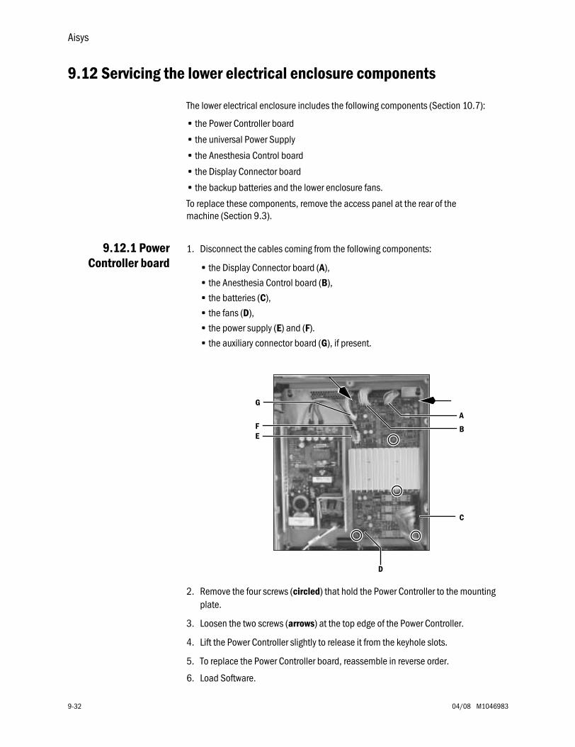
Aisys
9-32 04/08 M1046983
9.12 Servicing the lower electrical enclosure components
The lower electrical enclosure includes the following components (Section 10.7):
• the Power Controller board
• the universal Power Supply
• the Anesthesia Control board
• the Display Connector board
• the backup batteries and the lower enclosure fans.
To replace these components, remove the access panel at the rear of the machine (Section 9.3).
9.12.1 PowerController board
1. Disconnect the cables coming from the following components:
• the Display Connector board (A),
• the Anesthesia Control board (B),
• the batteries (C),
• the fans (D),
• the power supply (E) and (F).
• the auxiliary connector board (G), if present.
2. Remove the four screws (circled) that hold the Power Controller to the mounting plate.
3. Loosen the two screws (arrows) at the top edge of the Power Controller.
4. Lift the Power Controller slightly to release it from the keyhole slots.
5. To replace the Power Controller board, reassemble in reverse order.
6. Load Software.
B
A
C
D
EF
G
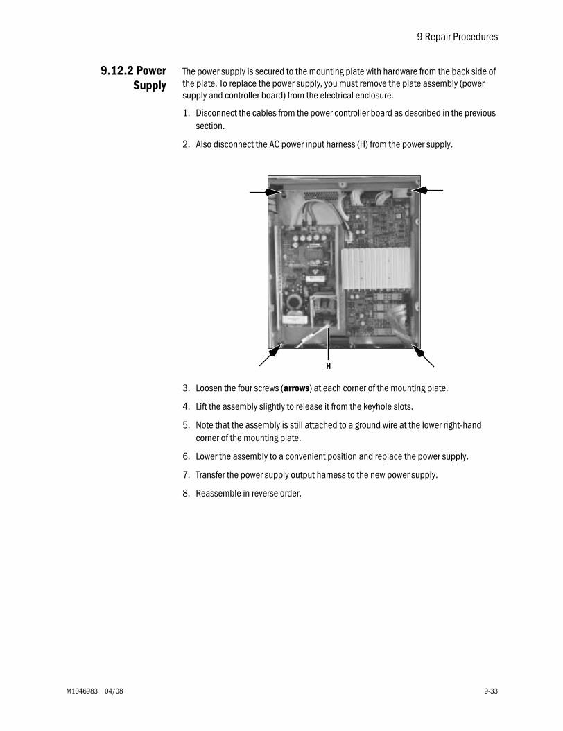
9 Repair Procedures
M1046983 04/08 9-33
9.12.2 PowerSupply
The power supply is secured to the mounting plate with hardware from the back side of the plate. To replace the power supply, you must remove the plate assembly (power supply and controller board) from the electrical enclosure.
1. Disconnect the cables from the power controller board as described in the previous section.
2. Also disconnect the AC power input harness (H) from the power supply.
3. Loosen the four screws (arrows) at each corner of the mounting plate.
4. Lift the assembly slightly to release it from the keyhole slots.
5. Note that the assembly is still attached to a ground wire at the lower right-hand corner of the mounting plate.
6. Lower the assembly to a convenient position and replace the power supply.
7. Transfer the power supply output harness to the new power supply.
8. Reassemble in reverse order.
H
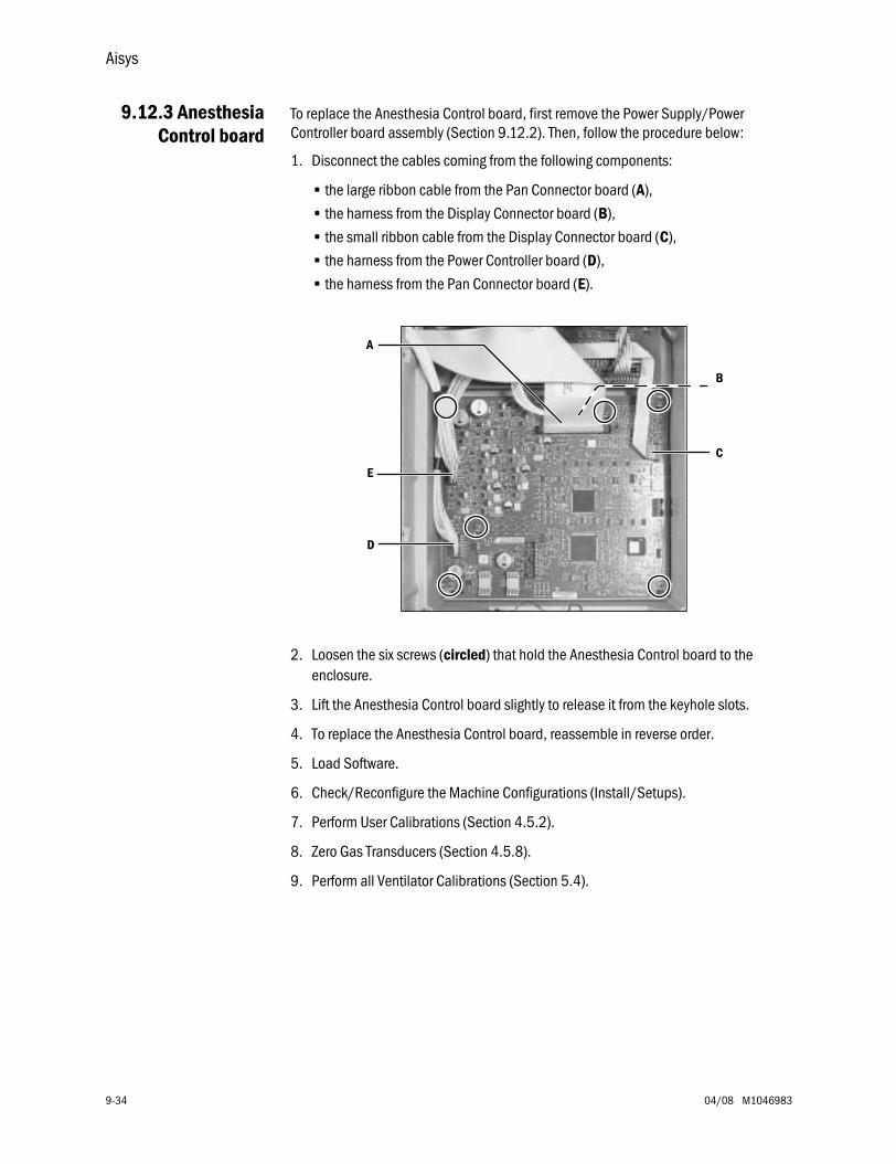
Aisys
9-34 04/08 M1046983
9.12.3 AnesthesiaControl board
To replace the Anesthesia Control board, first remove the Power Supply/Power Controller board assembly (Section 9.12.2). Then, follow the procedure below:
1. Disconnect the cables coming from the following components:
• the large ribbon cable from the Pan Connector board (A),
• the harness from the Display Connector board (B),
• the small ribbon cable from the Display Connector board (C),
• the harness from the Power Controller board (D),
• the harness from the Pan Connector board (E).
2. Loosen the six screws (circled) that hold the Anesthesia Control board to the enclosure.
3. Lift the Anesthesia Control board slightly to release it from the keyhole slots.
4. To replace the Anesthesia Control board, reassemble in reverse order.
5. Load Software.
6. Check/Reconfigure the Machine Configurations (Install/Setups).
7. Perform User Calibrations (Section 4.5.2).
8. Zero Gas Transducers (Section 4.5.8).
9. Perform all Ventilator Calibrations (Section 5.4).
B
C
A
E
D
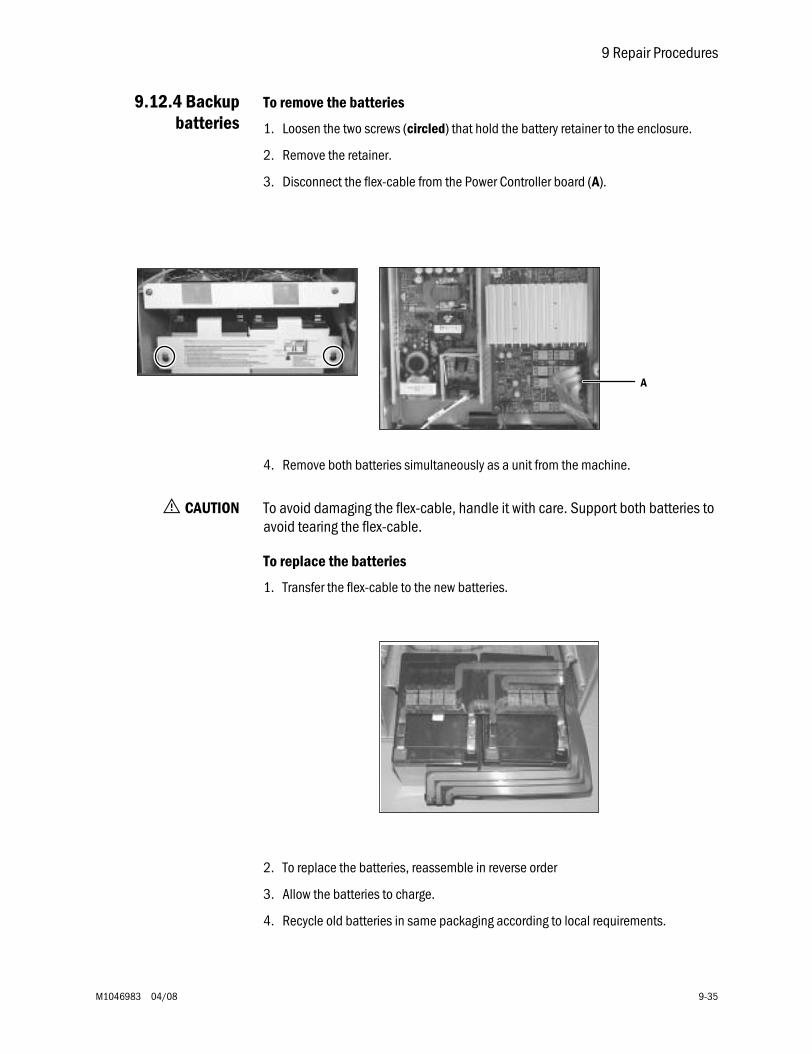
9 Repair Procedures
M1046983 04/08 9-35
9.12.4 Backupbatteries
To remove the batteries
1. Loosen the two screws (circled) that hold the battery retainer to the enclosure.
2. Remove the retainer.
3. Disconnect the flex-cable from the Power Controller board (A).
4. Remove both batteries simultaneously as a unit from the machine.
w CAUTION To avoid damaging the flex-cable, handle it with care. Support both batteries to avoid tearing the flex-cable.
To replace the batteries
1. Transfer the flex-cable to the new batteries.
2. To replace the batteries, reassemble in reverse order
3. Allow the batteries to charge.
4. Recycle old batteries in same packaging according to local requirements.
A
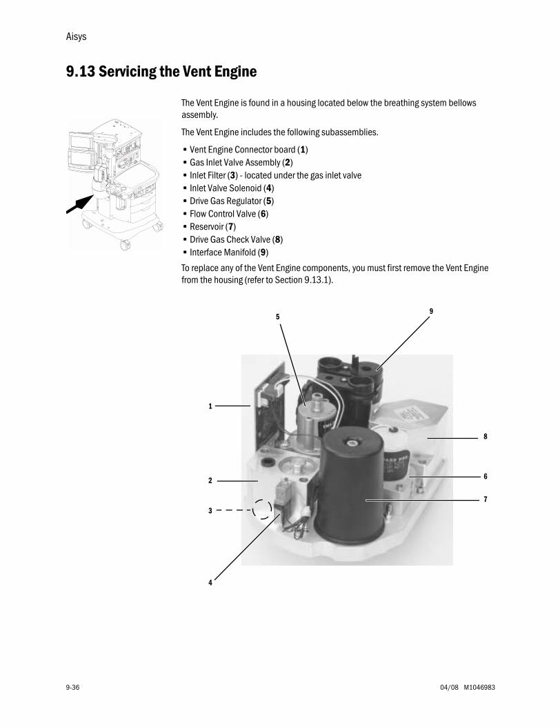
Aisys
9-36 04/08 M1046983
9.13 Servicing the Vent Engine
The Vent Engine is found in a housing located below the breathing system bellows assembly.
The Vent Engine includes the following subassemblies.
• Vent Engine Connector board (1)• Gas Inlet Valve Assembly (2)• Inlet Filter (3) - located under the gas inlet valve• Inlet Valve Solenoid (4)• Drive Gas Regulator (5)• Flow Control Valve (6)• Reservoir (7)• Drive Gas Check Valve (8)• Interface Manifold (9)
To replace any of the Vent Engine components, you must first remove the Vent Engine from the housing (refer to Section 9.13.1).
1
2
7
6
8
59
4
3
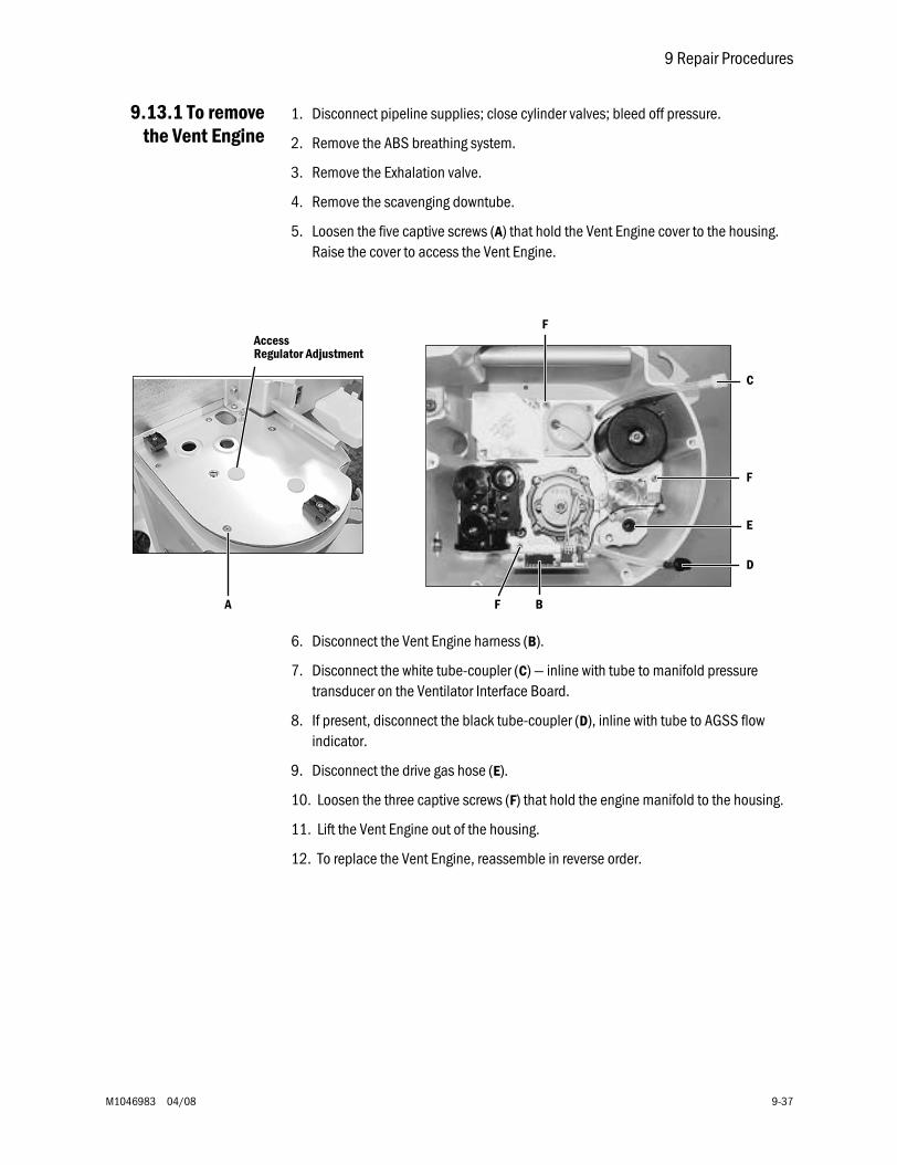
9 Repair Procedures
M1046983 04/08 9-37
9.13.1 To removethe Vent Engine
1. Disconnect pipeline supplies; close cylinder valves; bleed off pressure.
2. Remove the ABS breathing system.
3. Remove the Exhalation valve.
4. Remove the scavenging downtube.
5. Loosen the five captive screws (A) that hold the Vent Engine cover to the housing. Raise the cover to access the Vent Engine.
6. Disconnect the Vent Engine harness (B).
7. Disconnect the white tube-coupler (C) — inline with tube to manifold pressure transducer on the Ventilator Interface Board.
8. If present, disconnect the black tube-coupler (D), inline with tube to AGSS flow indicator.
9. Disconnect the drive gas hose (E).
10. Loosen the three captive screws (F) that hold the engine manifold to the housing.
11. Lift the Vent Engine out of the housing.
12. To replace the Vent Engine, reassemble in reverse order.
A B
C
D
E
F
F
F
AccessRegulator Adjustment
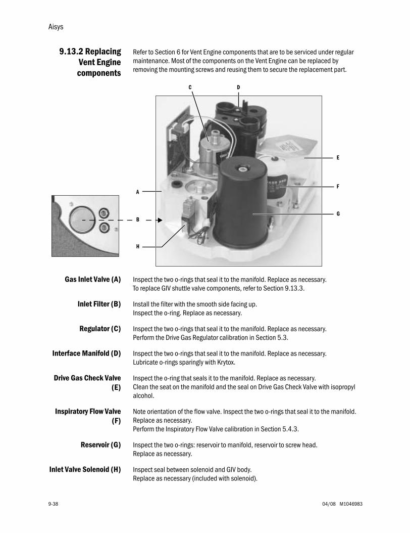
Aisys
9-38 04/08 M1046983
9.13.2 ReplacingVent Engine
components
Refer to Section 6 for Vent Engine components that are to be serviced under regular maintenance. Most of the components on the Vent Engine can be replaced by removing the mounting screws and reusing them to secure the replacement part.
Gas Inlet Valve (A) Inspect the two o-rings that seal it to the manifold. Replace as necessary.To replace GIV shuttle valve components, refer to Section 9.13.3.
Inlet Filter (B) Install the filter with the smooth side facing up. Inspect the o-ring. Replace as necessary.
Regulator (C) Inspect the two o-rings that seal it to the manifold. Replace as necessary.Perform the Drive Gas Regulator calibration in Section 5.3.
Interface Manifold (D) Inspect the two o-rings that seal it to the manifold. Replace as necessary.Lubricate o-rings sparingly with Krytox.
Drive Gas Check Valve(E)
Inspect the o-ring that seals it to the manifold. Replace as necessary.Clean the seat on the manifold and the seal on Drive Gas Check Valve with isopropyl alcohol.
Inspiratory Flow Valve(F)
Note orientation of the flow valve. Inspect the two o-rings that seal it to the manifold. Replace as necessary.Perform the Inspiratory Flow Valve calibration in Section 5.4.3.
Reservoir (G) Inspect the two o-rings: reservoir to manifold, reservoir to screw head.Replace as necessary.
Inlet Valve Solenoid (H) Inspect seal between solenoid and GIV body.Replace as necessary (included with solenoid).
A
E
B
C D
F
G
H
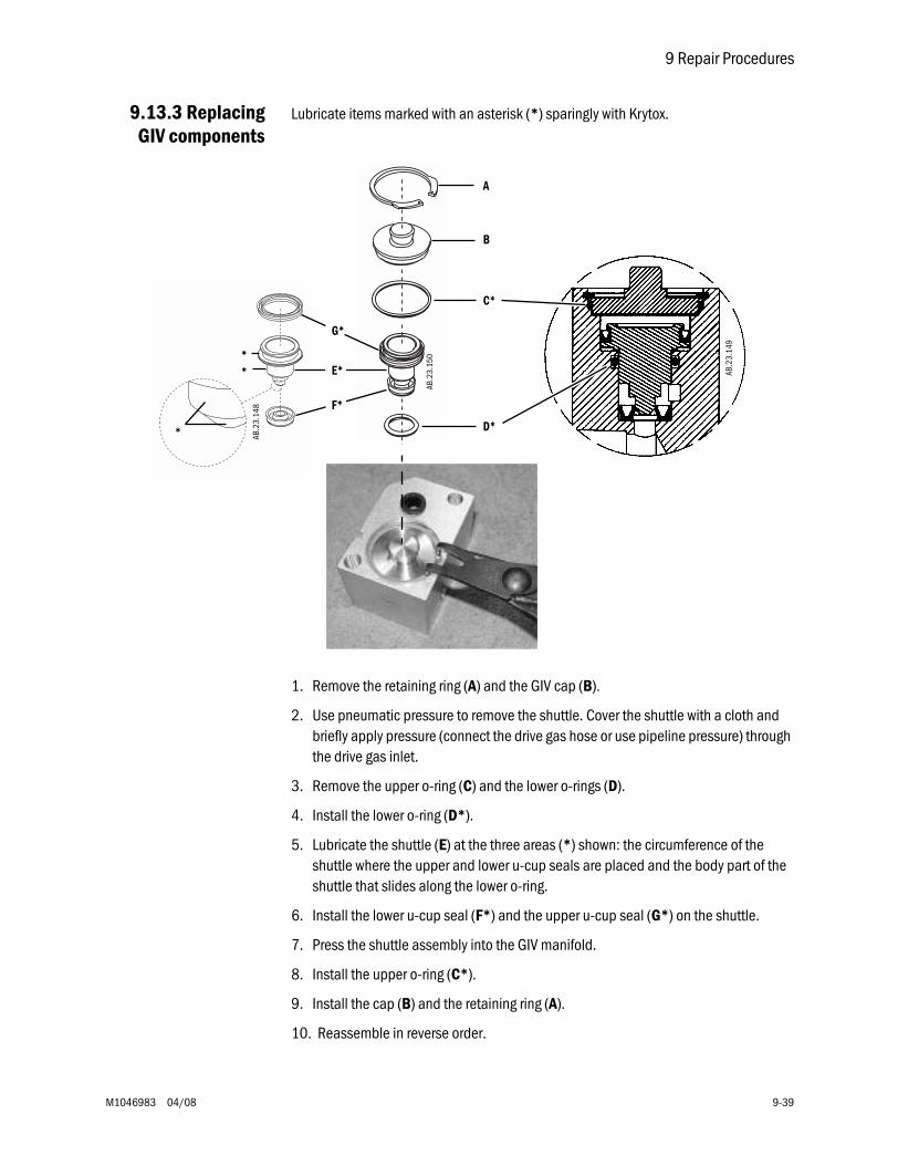
9 Repair Procedures
M1046983 04/08 9-39
9.13.3 ReplacingGIV components
Lubricate items marked with an asterisk (*) sparingly with Krytox.
1. Remove the retaining ring (A) and the GIV cap (B).
2. Use pneumatic pressure to remove the shuttle. Cover the shuttle with a cloth and briefly apply pressure (connect the drive gas hose or use pipeline pressure) through the drive gas inlet.
3. Remove the upper o-ring (C) and the lower o-rings (D).
4. Install the lower o-ring (D*).
5. Lubricate the shuttle (E) at the three areas (*) shown: the circumference of the shuttle where the upper and lower u-cup seals are placed and the body part of the shuttle that slides along the lower o-ring.
6. Install the lower u-cup seal (F*) and the upper u-cup seal (G*) on the shuttle.
7. Press the shuttle assembly into the GIV manifold.
8. Install the upper o-ring (C*).
9. Install the cap (B) and the retaining ring (A).
10. Reassemble in reverse order.
AB.2
3.15
0
AB.2
3.14
9
A
*
*
*
AB.2
3.14
8
D*
B
E*
F*
G*
C*
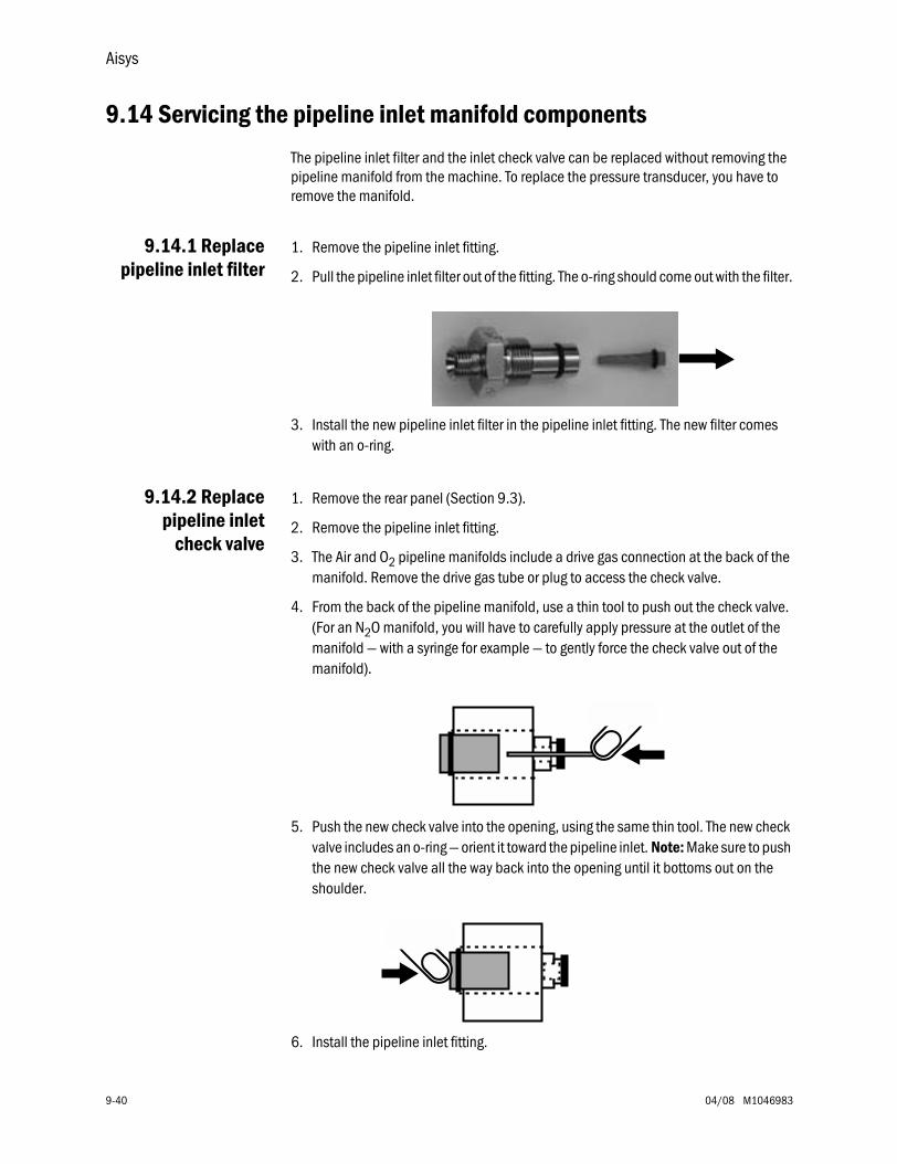
Aisys
9-40 04/08 M1046983
9.14 Servicing the pipeline inlet manifold components
The pipeline inlet filter and the inlet check valve can be replaced without removing the pipeline manifold from the machine. To replace the pressure transducer, you have to remove the manifold.
9.14.1 Replacepipeline inlet filter
1. Remove the pipeline inlet fitting.
2. Pull the pipeline inlet filter out of the fitting. The o-ring should come out with the filter.
3. Install the new pipeline inlet filter in the pipeline inlet fitting. The new filter comes with an o-ring.
9.14.2 Replacepipeline inlet
check valve
1. Remove the rear panel (Section 9.3).
2. Remove the pipeline inlet fitting.
3. The Air and O2 pipeline manifolds include a drive gas connection at the back of the manifold. Remove the drive gas tube or plug to access the check valve.
4. From the back of the pipeline manifold, use a thin tool to push out the check valve. (For an N2O manifold, you will have to carefully apply pressure at the outlet of the manifold — with a syringe for example — to gently force the check valve out of the manifold).
5. Push the new check valve into the opening, using the same thin tool. The new check valve includes an o-ring — orient it toward the pipeline inlet. Note: Make sure to push the new check valve all the way back into the opening until it bottoms out on the shoulder.
6. Install the pipeline inlet fitting.
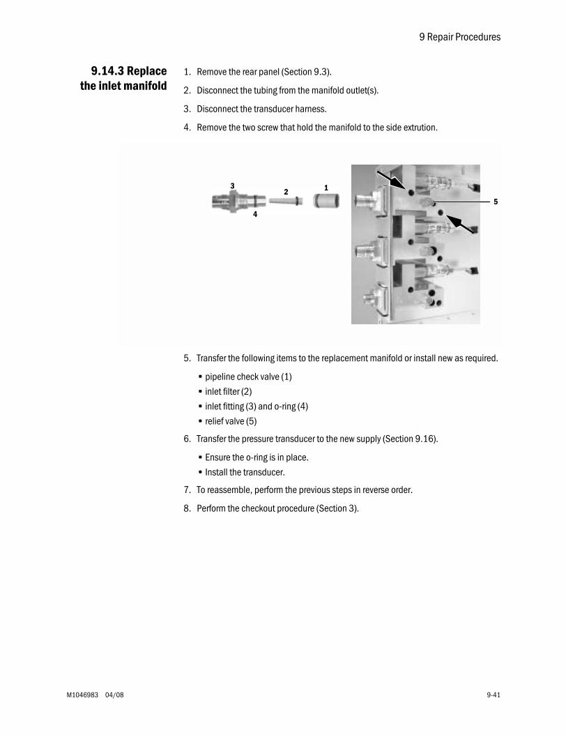
9 Repair Procedures
M1046983 04/08 9-41
9.14.3 Replacethe inlet manifold
1. Remove the rear panel (Section 9.3).
2. Disconnect the tubing from the manifold outlet(s).
3. Disconnect the transducer harness.
4. Remove the two screw that hold the manifold to the side extrution.
5. Transfer the following items to the replacement manifold or install new as required.
• pipeline check valve (1)
• inlet filter (2)
• inlet fitting (3) and o-ring (4)
• relief valve (5)
6. Transfer the pressure transducer to the new supply (Section 9.16).
• Ensure the o-ring is in place.
• Install the transducer.
7. To reassemble, perform the previous steps in reverse order.
8. Perform the checkout procedure (Section 3).
5
4
3 12
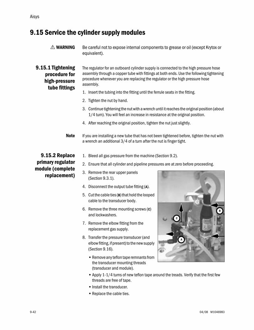
Aisys
9-42 04/08 M1046983
9.15 Service the cylinder supply modules
w WARNING Be careful not to expose internal components to grease or oil (except Krytox or equivalent).
9.15.1 Tighteningprocedure forhigh-pressure
tube fittings
The regulator for an outboard cylinder supply is connected to the high pressure hose assembly through a copper tube with fittings at both ends. Use the following tightening procedure whenever you are replacing the regulator or the high pressure hose assembly.
1. Insert the tubing into the fitting until the ferrule seats in the fitting.
2. Tighten the nut by hand.
3. Continue tightening the nut with a wrench until it reaches the original position (about 1/4 turn). You will feel an increase in resistance at the original position.
4. After reaching the original position, tighten the nut just slightly.
Note If you are installing a new tube that has not been tightened before, tighten the nut with a wrench an additional 3/4 of a turn after the nut is finger tight.
9.15.2 Replaceprimary regulator
module (completereplacement)
1. Bleed all gas pressure from the machine (Section 9.2).
2. Ensure that all cylinder and pipeline pressures are at zero before proceeding.
3. Remove the rear upper panels (Section 9.3.1).
4. Disconnect the output tube fitting (A).
5. Cut the cable ties (B) that hold the looped cable to the transducer body.
6. Remove the three mounting screws (C) and lockwashers.
7. Remove the elbow fitting from the replacement gas supply.
8. Transfer the pressure transducer (and elbow fitting, if present) to the new supply (Section 9.16).
• Remove any teflon tape remnants from the transducer mounting threads (transducer and module).
• Apply 1-1/4 turns of new teflon tape around the treads. Verify that the first few threads are free of tape.
• Install the transducer.
• Replace the cable ties.
A
C
B
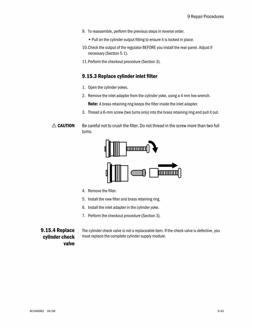
9 Repair Procedures
M1046983 04/08 9-43
9. To reassemble, perform the previous steps in reverse order.
• Pull on the cylinder output fitting to ensure it is locked in place.
10.Check the output of the regulator BEFORE you install the rear panel. Adjust if necessary (Section 5.1).
11.Perform the checkout procedure (Section 3).
9.15.3 Replace cylinder inlet filter
1. Open the cylinder yokes.
2. Remove the inlet adapter from the cylinder yoke, using a 4 mm hex wrench.
Note: A brass retaining ring keeps the filter inside the inlet adapter.
3. Thread a 6-mm screw (two turns only) into the brass retaining ring and pull it out.
w CAUTION Be careful not to crush the filter. Do not thread in the screw more than two full turns.
4. Remove the filter.
5. Install the new filter and brass retaining ring.
6. Install the inlet adapter in the cylinder yoke.
7. Perform the checkout procedure (Section 3).
9.15.4 Replacecylinder check
valve
The cylinder check valve is not a replaceable item. If the check valve is defective, you must replace the complete cylinder supply module.
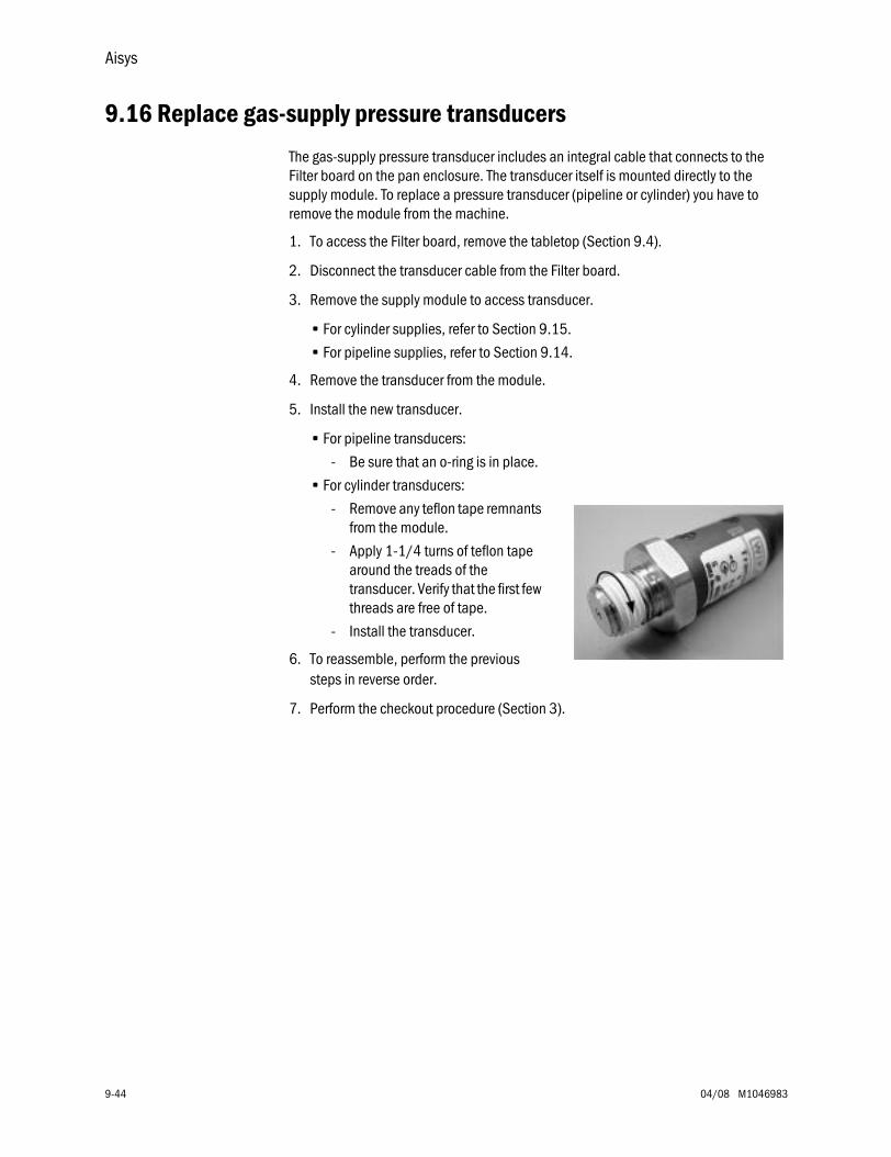
Aisys
9-44 04/08 M1046983
9.16 Replace gas-supply pressure transducers
The gas-supply pressure transducer includes an integral cable that connects to the Filter board on the pan enclosure. The transducer itself is mounted directly to the supply module. To replace a pressure transducer (pipeline or cylinder) you have to remove the module from the machine.
1. To access the Filter board, remove the tabletop (Section 9.4).
2. Disconnect the transducer cable from the Filter board.
3. Remove the supply module to access transducer.
• For cylinder supplies, refer to Section 9.15.
• For pipeline supplies, refer to Section 9.14.
4. Remove the transducer from the module.
5. Install the new transducer.
• For pipeline transducers:
- Be sure that an o-ring is in place.
• For cylinder transducers:
- Remove any teflon tape remnants from the module.
- Apply 1-1/4 turns of teflon tape around the treads of the transducer. Verify that the first few threads are free of tape.
- Install the transducer.
6. To reassemble, perform the previous steps in reverse order.
7. Perform the checkout procedure (Section 3).
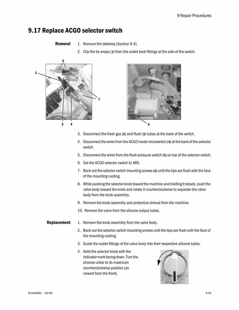
9 Repair Procedures
M1046983 04/08 9-45
9.17 Replace ACGO selector switch
Removal 1. Remove the tabletop (Section 9.4).
2. Clip the tie wraps (1) from the outlet barb fittings at the side of the switch.
3. Disconnect the fresh gas (2) and flush (3) tubes at the back of the switch.
4. Disconnect the wires from the ACGO mode microswitch (4) at the back of the selector switch.
5. Disconnect the wires from the flush pressure switch (5) on top of the selector switch.
6. Set the ACGO selector switch to ABS.
7. Back out the selector switch mounting screws (6) until the tips are flush with the face of the mounting casting.
8. While pushing the selector knob toward the machine and holding it steady, push the valve body toward the knob and rotate it counterclockwise to separate the valve body from the knob assembly.
9. Remove the knob assembly and protective shroud from the machine.
10. Remove the valve from the silicone output tubes.
Replacement 1. Remove the knob assembly from the valve body.
2. Back out the selector switch mounting screws until the tips are flush with the face of the mounting casting.
3. Guide the outlet fittings of the valve body into their respective silicone tubes.
4. Hold the selector knob with the indicator mark facing down. Turn the chrome collar to its maximum counterclockwise position (as viewed from the front).
3
2 4
1
6
5

Aisys
9-46 04/08 M1046983
5. Place the shroud over the knob and guide the assembly into the pan opening.
6. Ensure that the indicators on the shroud align with label on the pan and the alignment tab mates with the alignment hole in the pan.
7. While holding the knob assembly steady against the pan, place the valve assembly over the knob actuator. Using moderate force press the two assemblies together. The knob should rotate to the ACGO position.
8. While continuing to force the assemblies together, rotate the knob assembly to the ABS position. The assemblies should snap into place.
9. Verify proper alignment of the knob with the setting indicators. Tighten the mounting screws evenly to secure the switch assembly to the pan.
10. Secure the outlet tubing with tie wraps.
11. Connect the fresh gas and flush gas tubing. Pull on the tubing to ensure that it is locked in the fitting.
12. Reconnect the wires to the ACGO mode microswitch at the back of the valve (top two terminals).
13. Reconnect the wires to the flush pressure switch at the top of the valve(upper and lower terminals).
14. Replace the tabletop.
Test procedure 1. Confirm that flush flow and 5 L/min fresh gas flow are diverted to the ACGO port and the ABS in the respective knob positions.
2. Confirm that the ventilator display indicates ACGO mode when the valve is set in the ACGO position.
3. Test the function of the flush pressure switch (Service Application - “Ventilation Status” — Section 12.9.1).
4. Perform the low-pressure leak test (Section 3.3.5).
5. Perform the checkout procedure (Section 3)
Actuator
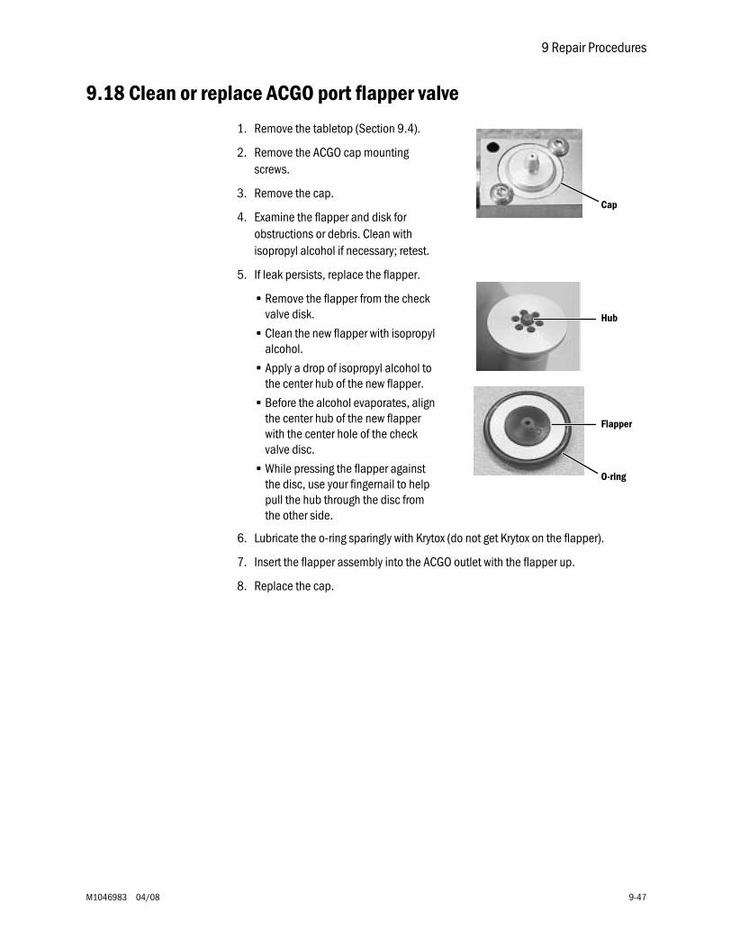
9 Repair Procedures
M1046983 04/08 9-47
9.18 Clean or replace ACGO port flapper valve
1. Remove the tabletop (Section 9.4).
2. Remove the ACGO cap mounting screws.
3. Remove the cap.
4. Examine the flapper and disk for obstructions or debris. Clean with isopropyl alcohol if necessary; retest.
5. If leak persists, replace the flapper.
• Remove the flapper from the check valve disk.
• Clean the new flapper with isopropyl alcohol.
• Apply a drop of isopropyl alcohol to the center hub of the new flapper.
• Before the alcohol evaporates, align the center hub of the new flapper with the center hole of the check valve disc.
• While pressing the flapper against the disc, use your fingernail to help pull the hub through the disc from the other side.
6. Lubricate the o-ring sparingly with Krytox (do not get Krytox on the flapper).
7. Insert the flapper assembly into the ACGO outlet with the flapper up.
8. Replace the cap.
Cap
Hub
Flapper
O-ring
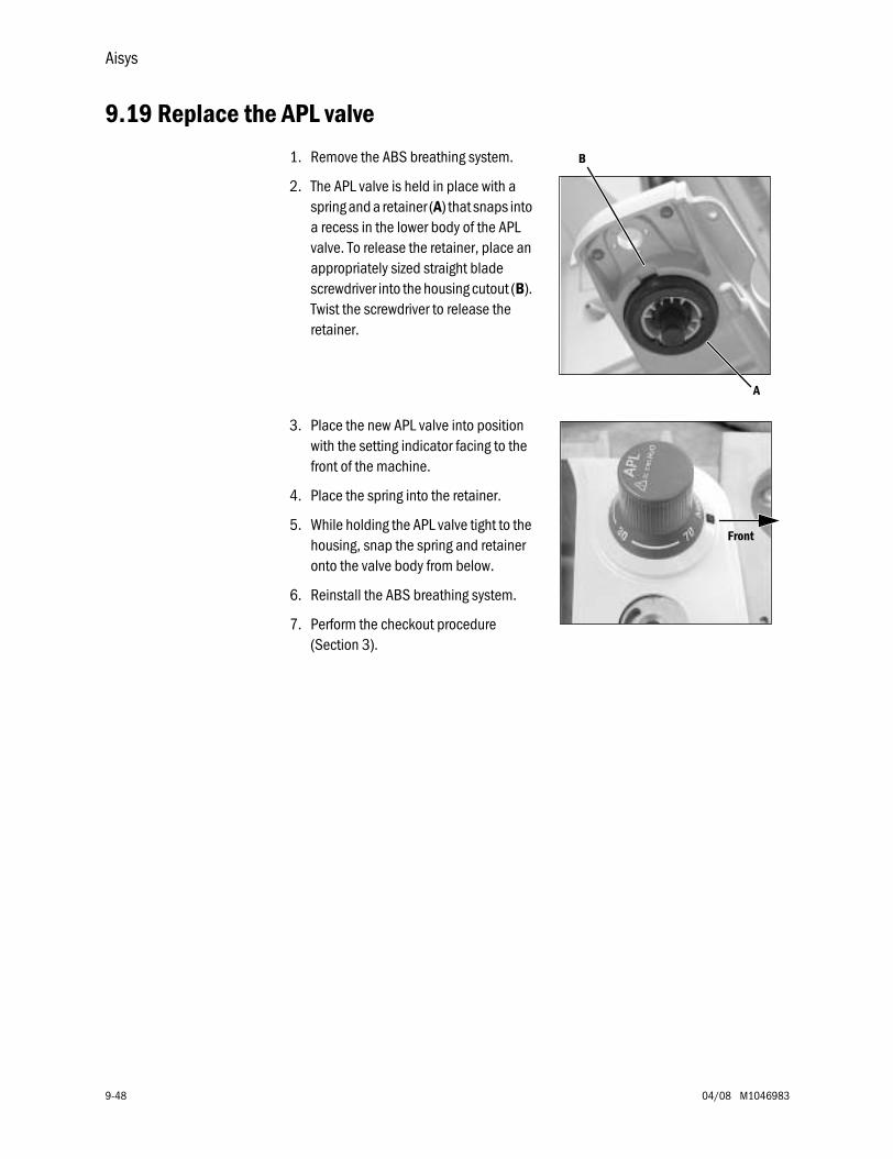
Aisys
9-48 04/08 M1046983
9.19 Replace the APL valve
1. Remove the ABS breathing system.
2. The APL valve is held in place with a spring and a retainer (A) that snaps into a recess in the lower body of the APL valve. To release the retainer, place an appropriately sized straight blade screwdriver into the housing cutout (B). Twist the screwdriver to release the retainer.
3. Place the new APL valve into position with the setting indicator facing to the front of the machine.
4. Place the spring into the retainer.
5. While holding the APL valve tight to the housing, snap the spring and retainer onto the valve body from below.
6. Reinstall the ABS breathing system.
7. Perform the checkout procedure (Section 3).
A
B
Front
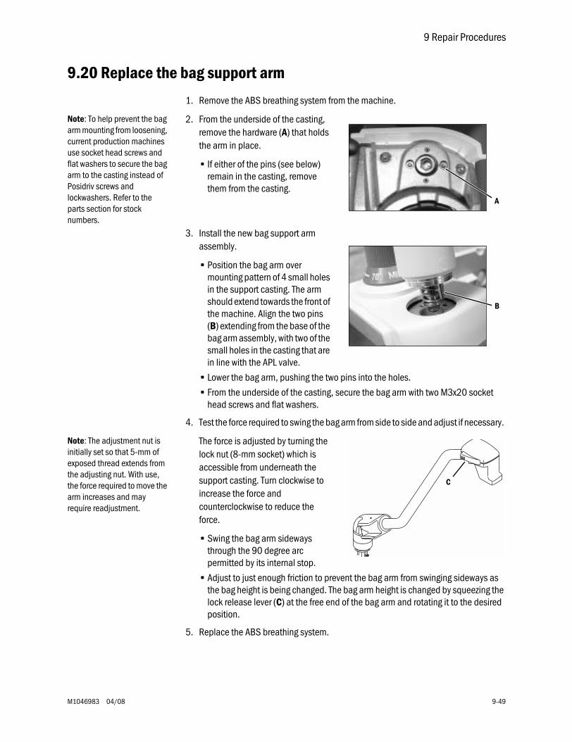
9 Repair Procedures
M1046983 04/08 9-49
9.20 Replace the bag support arm
1. Remove the ABS breathing system from the machine.
Note: To help prevent the bag arm mounting from loosening, current production machines use socket head screws and flat washers to secure the bag arm to the casting instead of Posidriv screws and lockwashers. Refer to the parts section for stock numbers.
2. From the underside of the casting, remove the hardware (A) that holds the arm in place.
• If either of the pins (see below) remain in the casting, remove them from the casting.
3. Install the new bag support arm assembly.
• Position the bag arm over mounting pattern of 4 small holes in the support casting. The arm should extend towards the front of the machine. Align the two pins (B) extending from the base of the bag arm assembly, with two of the small holes in the casting that are in line with the APL valve.
• Lower the bag arm, pushing the two pins into the holes.
• From the underside of the casting, secure the bag arm with two M3x20 socket head screws and flat washers.
4. Test the force required to swing the bag arm from side to side and adjust if necessary.
Note: The adjustment nut is initially set so that 5-mm of exposed thread extends from the adjusting nut. With use, the force required to move the arm increases and may require readjustment.
The force is adjusted by turning the lock nut (8-mm socket) which is accessible from underneath the support casting. Turn clockwise to increase the force and counterclockwise to reduce the force.
• Swing the bag arm sideways through the 90 degree arc permitted by its internal stop.
• Adjust to just enough friction to prevent the bag arm from swinging sideways as the bag height is being changed. The bag arm height is changed by squeezing the lock release lever (C) at the free end of the bag arm and rotating it to the desired position.
5. Replace the ABS breathing system.
A
B
C
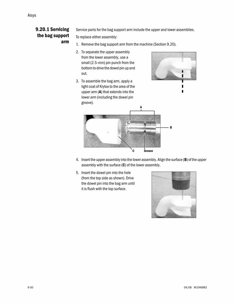
Aisys
9-50 04/08 M1046983
9.20.1 Servicingthe bag support
arm
Service parts for the bag support arm include the upper and lower assemblies.
To replace either assembly:
1. Remove the bag support arm from the machine (Section 9.20).
2. To separate the upper assembly from the lower assembly, use a small (2.5-mm) pin punch from the bottom to drive the dowel pin up and out.
3. To assemble the bag arm, apply a light coat of Krytox to the area of the upper arm (A) that extends into the lower arm (including the dowel pin groove).
4. Insert the upper assembly into the lower assembly. Align the surface (B) of the upper assembly with the surface (C) of the lower assembly.
5. Insert the dowel pin into the hole (from the top side as shown). Drive the dowel pin into the bag arm until it is flush with the top surface.
A
GrooveC
B
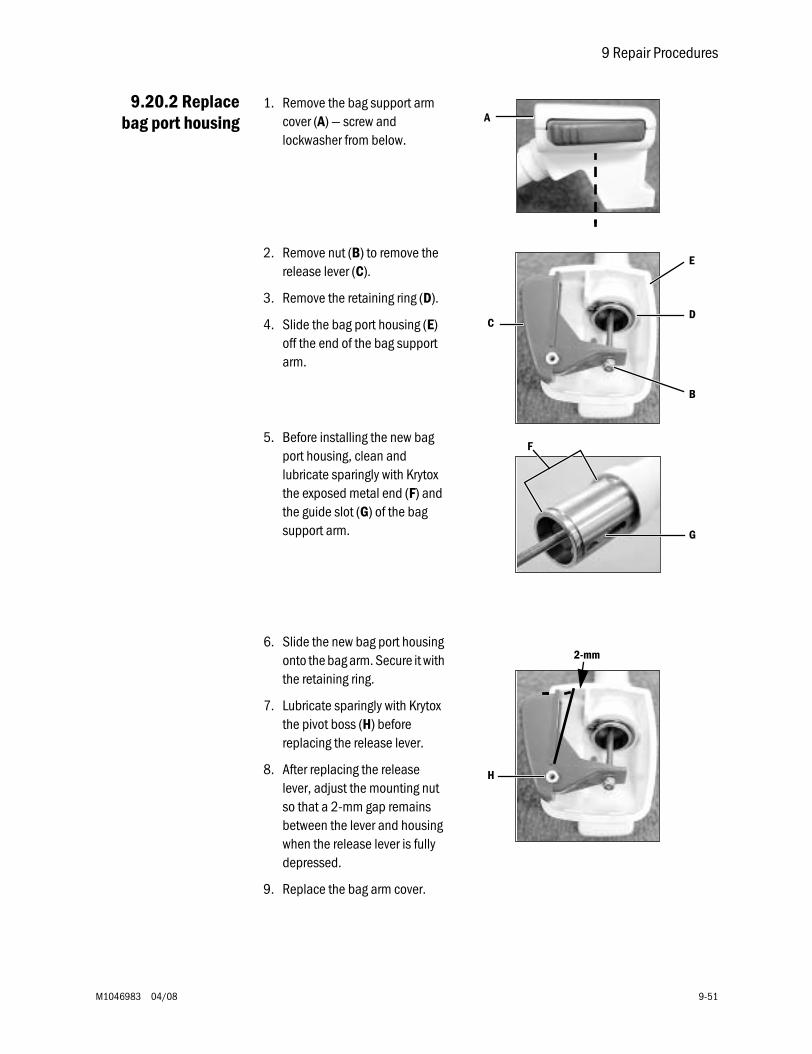
9 Repair Procedures
M1046983 04/08 9-51
9.20.2 Replacebag port housing
1. Remove the bag support arm cover (A) — screw and lockwasher from below.
2. Remove nut (B) to remove the release lever (C).
3. Remove the retaining ring (D).
4. Slide the bag port housing (E) off the end of the bag support arm.
5. Before installing the new bag port housing, clean and lubricate sparingly with Krytox the exposed metal end (F) and the guide slot (G) of the bag support arm.
6. Slide the new bag port housing onto the bag arm. Secure it with the retaining ring.
7. Lubricate sparingly with Krytox the pivot boss (H) before replacing the release lever.
8. After replacing the release lever, adjust the mounting nut so that a 2-mm gap remains between the lever and housing when the release lever is fully depressed.
9. Replace the bag arm cover.
A
B
CD
E
F
G
H
2-mm
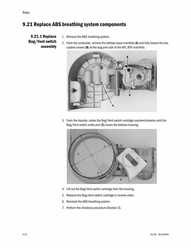
Aisys
9-52 04/08 M1046983
9.21 Replace ABS breathing system components
9.21.1 ReplaceBag/Vent switch
assembly
1. Remove the ABS breathing system.
2. From the underside, remove the bellows base manifold (A) and fully loosen the two captive screws (B) at the bag port side of the APL/BTV manifold.
3. From the topside, rotate the Bag/Vent switch cartridge counterclockwise until the Bag/Vent switch outlet port (C) clears the bellows housing.
4. Lift out the Bag/Vent switch cartridge from the housing.
5. Replace the Bag/Vent switch cartridge in reverse order.
6. Reinstall the ABS breathing system.
7. Perform the checkout procedure (Section 3).
A
B
B
C
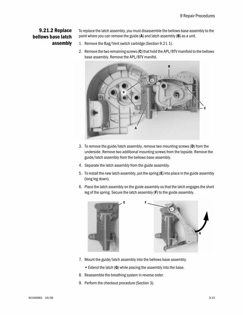
9 Repair Procedures
M1046983 04/08 9-53
9.21.2 Replacebellows base latch
assembly
To replace the latch assembly, you must disassemble the bellows base assembly to the point where you can remove the guide (A) and latch assembly (B) as a unit.
1. Remove the Bag/Vent switch cartridge (Section 9.21.1).
2. Remove the two remaining screws (C) that hold the APL/BTV manifold to the bellows base assembly. Remove the APL/BTV manifol.
3. To remove the guide/latch assembly, remove two mounting screws (D) from the underside. Remove two additional mounting screws from the topside. Remove the guide/latch assembly from the bellows base assembly.
4. Separate the latch assembly from the guide assembly.
5. To install the new latch assembly, put the spring (E) into place in the guide assembly (long leg down).
6. Place the latch assembly on the guide assembly so that the latch engages the short leg of the spring. Secure the latch assembly (F) to the guide assembly.
7. Mount the guide/latch assembly into the bellows base assembly.
• Extend the latch (G) while placing the assembly into the base.
8. Reassemble the breathing system in reverse order.
9. Perform the checkout procedure (Section 3).
A
C
B
D
E
G
F
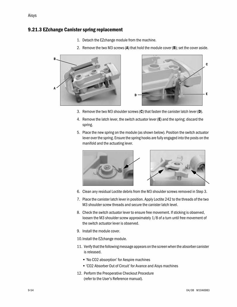
Aisys
9-54 04/08 M1046983
9.21.3 EZchange Canister spring replacement
1. Detach the EZchange module from the machine.
2. Remove the two M3 screws (A) that hold the module cover (B); set the cover aside.
3. Remove the two M3 shoulder screws (C) that fasten the canister latch lever (D).
4. Remove the latch lever, the switch actuator lever (E) and the spring; discard the spring.
5. Place the new spring on the module (as shown below). Position the switch actuator lever over the spring. Ensure the spring hooks are fully engaged into the posts on the manifold and the actuating lever.
6. Clean any residual Loctite debris from the M3 shoulder screws removed in Step 3.
7. Place the canister latch lever in position. Apply Loctite 242 to the threads of the two M3 shoulder screw threads and secure the canister latch level.
8. Check the switch actuator lever to ensure free movement. If sticking is observed, loosen the M3 shoulder screw approximately 1/8 of a turn until free movement of the switch actuator lever is observed.
9. Install the module cover.
10.Install the EZchange module.
11. Verify that the following message appears on the screen when the absorber canister is released.
• ‘No CO2 absorption’ for Aespire machines
• ‘CO2 Absorber Out of Circuit’ for Avance and Aisys machines
12. Perform the Preoperative Checkout Procedure (refer to the User’s Reference manual).
A
B
ED
C
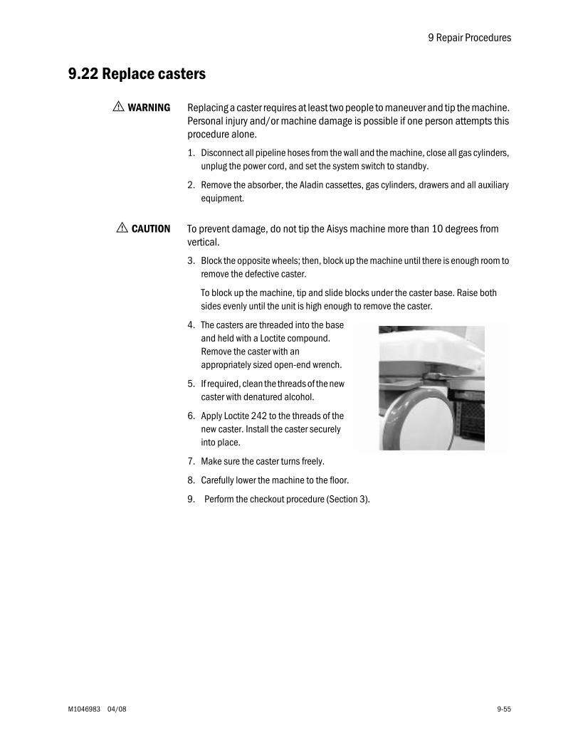
9 Repair Procedures
M1046983 04/08 9-55
9.22 Replace casters
w WARNING Replacing a caster requires at least two people to maneuver and tip the machine. Personal injury and/or machine damage is possible if one person attempts this procedure alone.
1. Disconnect all pipeline hoses from the wall and the machine, close all gas cylinders, unplug the power cord, and set the system switch to standby.
2. Remove the absorber, the Aladin cassettes, gas cylinders, drawers and all auxiliary equipment.
w CAUTION To prevent damage, do not tip the Aisys machine more than 10 degrees from vertical.
3. Block the opposite wheels; then, block up the machine until there is enough room to remove the defective caster.
To block up the machine, tip and slide blocks under the caster base. Raise both sides evenly until the unit is high enough to remove the caster.
4. The casters are threaded into the base and held with a Loctite compound. Remove the caster with an appropriately sized open-end wrench.
5. If required, clean the threads of the new caster with denatured alcohol.
6. Apply Loctite 242 to the threads of the new caster. Install the caster securely into place.
7. Make sure the caster turns freely.
8. Carefully lower the machine to the floor.
9. Perform the checkout procedure (Section 3).
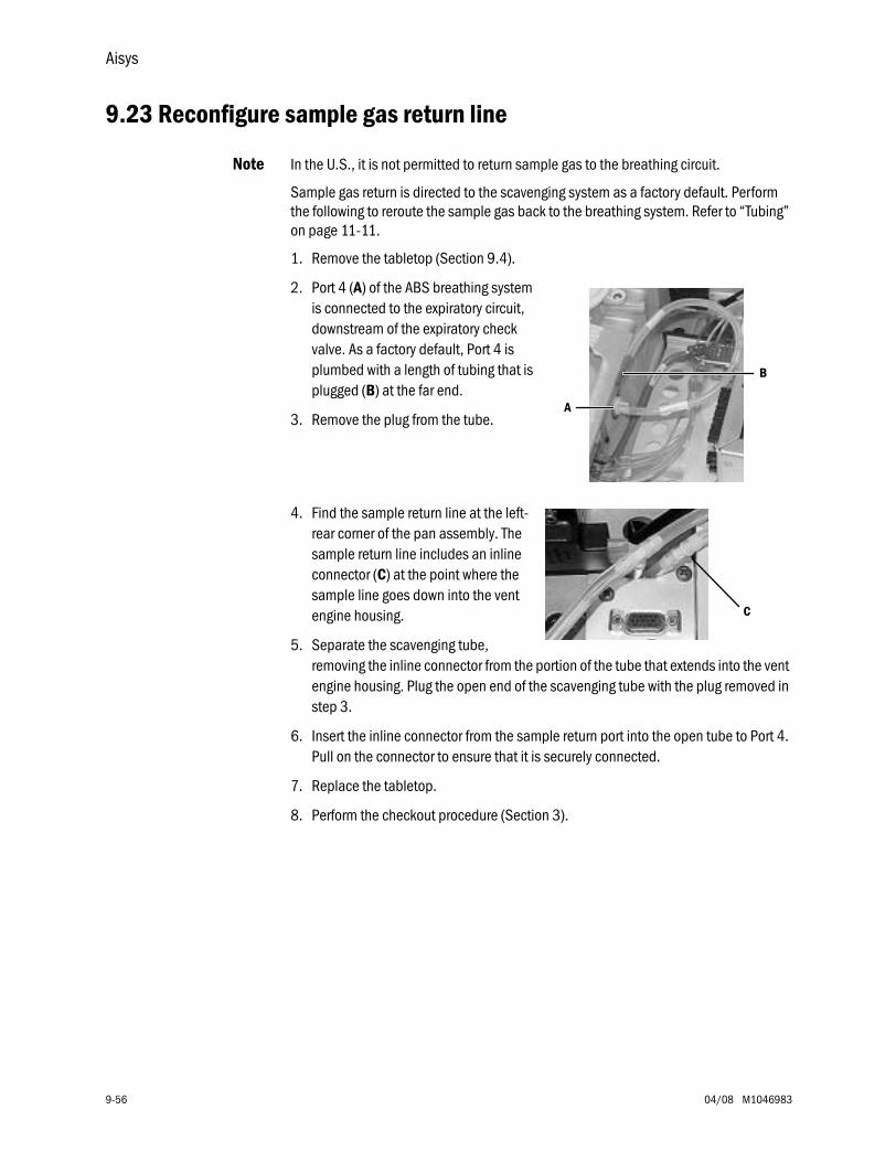
Aisys
9-56 04/08 M1046983
9.23 Reconfigure sample gas return line
Note In the U.S., it is not permitted to return sample gas to the breathing circuit.
Sample gas return is directed to the scavenging system as a factory default. Perform the following to reroute the sample gas back to the breathing system. Refer to “Tubing” on page 11-11.
1. Remove the tabletop (Section 9.4).
2. Port 4 (A) of the ABS breathing system is connected to the expiratory circuit, downstream of the expiratory check valve. As a factory default, Port 4 is plumbed with a length of tubing that is plugged (B) at the far end.
3. Remove the plug from the tube.
4. Find the sample return line at the left-rear corner of the pan assembly. The sample return line includes an inline connector (C) at the point where the sample line goes down into the vent engine housing.
5. Separate the scavenging tube, removing the inline connector from the portion of the tube that extends into the vent engine housing. Plug the open end of the scavenging tube with the plug removed in step 3.
6. Insert the inline connector from the sample return port into the open tube to Port 4. Pull on the connector to ensure that it is securely connected.
7. Replace the tabletop.
8. Perform the checkout procedure (Section 3).
B
A
C
9 Repair Procedures
M1046983 04/08 9-57
9.24 Change drive gas
w CAUTION If you change the drive gas, you must also change the drive gas selection on the ventilator service setup screen. Refer to Section 4 of the ventilator Technical Reference manual.
• If the drive gas selection and the actual drive gas do not agree, volumes will not be correct.
The ventilator will alarm with the message “Low Drive Gas Press” if the selected drive gas pressure, either O2 or Air, is lost.
1. Remove the rear panel (Section 9.3).
Note: The O2 and Air pipeline manifolds have a drive gas connection at the back. The connection not in use is plugged.
2. Remove the plug from the new connection.
3. Disconnect the drive gas hose from the present connection.
4. Install the plug in this connection (pull on the plug to ensure that it is locked into the fitting).
5. Reroute the drive gas hose so that it does not cause kinks in other tubing.
6. Connect the drive gas hose to the new connection (pull on the hose connector to ensure that it is locked into the fitting).
7. Do a high-pressure leak test (Section 3.6).
8. Enter the service mode and select the correct drive gas.
9. Test the primary regulator. Verify that it functions within specifications now that it will be supplying drive gas to the ventilator (Section 5.1).
10. Perform the checkout procedure (Section 3).
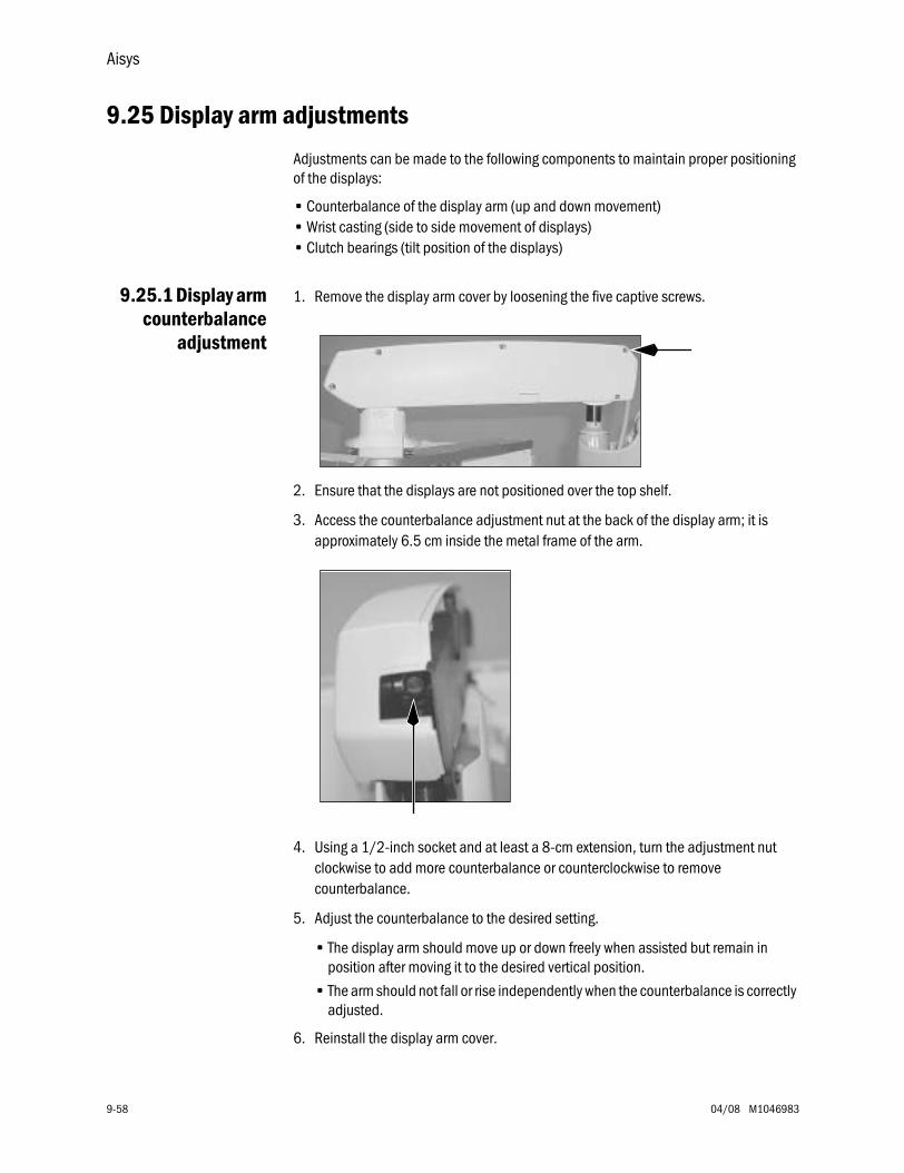
Aisys
9-58 04/08 M1046983
9.25 Display arm adjustments
Adjustments can be made to the following components to maintain proper positioning of the displays:
• Counterbalance of the display arm (up and down movement)• Wrist casting (side to side movement of displays)• Clutch bearings (tilt position of the displays)
9.25.1 Display armcounterbalance
adjustment
1. Remove the display arm cover by loosening the five captive screws.
2. Ensure that the displays are not positioned over the top shelf.
3. Access the counterbalance adjustment nut at the back of the display arm; it is approximately 6.5 cm inside the metal frame of the arm.
4. Using a 1/2-inch socket and at least a 8-cm extension, turn the adjustment nut clockwise to add more counterbalance or counterclockwise to remove counterbalance.
5. Adjust the counterbalance to the desired setting.
• The display arm should move up or down freely when assisted but remain in position after moving it to the desired vertical position.
• The arm should not fall or rise independently when the counterbalance is correctly adjusted.
6. Reinstall the display arm cover.
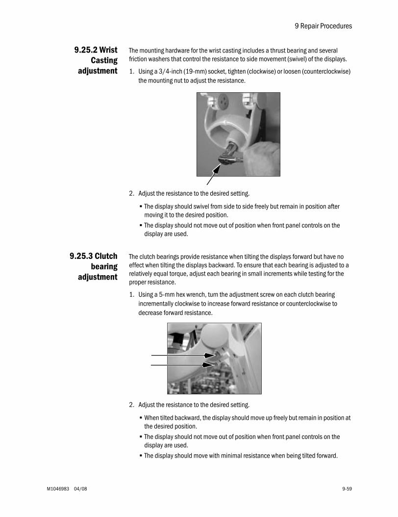
9 Repair Procedures
M1046983 04/08 9-59
9.25.2 WristCasting
adjustment
The mounting hardware for the wrist casting includes a thrust bearing and several friction washers that control the resistance to side movement (swivel) of the displays.
1. Using a 3/4-inch (19-mm) socket, tighten (clockwise) or loosen (counterclockwise) the mounting nut to adjust the resistance.
2. Adjust the resistance to the desired setting.
• The display should swivel from side to side freely but remain in position after moving it to the desired position.
• The display should not move out of position when front panel controls on the display are used.
9.25.3 Clutchbearing
adjustment
The clutch bearings provide resistance when tilting the displays forward but have no effect when tilting the displays backward. To ensure that each bearing is adjusted to a relatively equal torque, adjust each bearing in small increments while testing for the proper resistance.
1. Using a 5-mm hex wrench, turn the adjustment screw on each clutch bearing incrementally clockwise to increase forward resistance or counterclockwise to decrease forward resistance.
2. Adjust the resistance to the desired setting.
• When tilted backward, the display should move up freely but remain in position at the desired position.
• The display should not move out of position when front panel controls on the display are used.
• The display should move with minimal resistance when being tilted forward.

Notes
9-60 04/08 M1046983
M1046983 04/08 10-1
10 Illustrated PartsIn this section 10.1 Service tools . . . . . . . . . . . . . . . . . . . . . . . . . . . . . . . . . . . . . . . . . . . . . . . . . . . . . . . . . . . 10-3
10.1.1 Software tools . . . . . . . . . . . . . . . . . . . . . . . . . . . . . . . . . . . . . . . . . . . . . . . . . . . . 10-310.1.2 Manifold pressure test adapter . . . . . . . . . . . . . . . . . . . . . . . . . . . . . . . . . . . . . . 10-310.1.3 Test Devices and service tools . . . . . . . . . . . . . . . . . . . . . . . . . . . . . . . . . . . . . . . 10-410.1.4 Lubricants and Adhesives . . . . . . . . . . . . . . . . . . . . . . . . . . . . . . . . . . . . . . . . . . 10-410.1.5 Test Tools . . . . . . . . . . . . . . . . . . . . . . . . . . . . . . . . . . . . . . . . . . . . . . . . . . . . . . . . 10-5
10.2 Components - front view . . . . . . . . . . . . . . . . . . . . . . . . . . . . . . . . . . . . . . . . . . . . . . . . . . 10-610.3 Components - front view references . . . . . . . . . . . . . . . . . . . . . . . . . . . . . . . . . . . . . . . . 10-710.4 Components - rear view . . . . . . . . . . . . . . . . . . . . . . . . . . . . . . . . . . . . . . . . . . . . . . . . . . 10-810.5 AC Power cords and AC Inlet . . . . . . . . . . . . . . . . . . . . . . . . . . . . . . . . . . . . . . . . . . . . . . 10-910.6 AC Inlet/Outlet Components . . . . . . . . . . . . . . . . . . . . . . . . . . . . . . . . . . . . . . . . . . . . . 10-1010.7 Lower electronic enclosure components . . . . . . . . . . . . . . . . . . . . . . . . . . . . . . . . . . . . 10-1210.8 Upper (pan) electronic enclosure components . . . . . . . . . . . . . . . . . . . . . . . . . . . . . . 10-1310.9 Electronic Gas Mixer . . . . . . . . . . . . . . . . . . . . . . . . . . . . . . . . . . . . . . . . . . . . . . . . . . . . 10-1410.10 Pipeline inlet fittings . . . . . . . . . . . . . . . . . . . . . . . . . . . . . . . . . . . . . . . . . . . . . . . . . . . 10-1510.11 Cylinder Gas Supplies . . . . . . . . . . . . . . . . . . . . . . . . . . . . . . . . . . . . . . . . . . . . . . . . . 10-16
10.11.1 Power outlets and third cylinder high-pressure hoses . . . . . . . . . . . . . . . . . . 10-1710.11.2 Cylinder inlet fittings. . . . . . . . . . . . . . . . . . . . . . . . . . . . . . . . . . . . . . . . . . . . . 10-18
10.12 ABS to machine Interface Components (SCGO) . . . . . . . . . . . . . . . . . . . . . . . . . . . . 10-1910.13 ABS to machine Interface Components (ACGO) . . . . . . . . . . . . . . . . . . . . . . . . . . . . 10-2010.14 O2 Flush Valve . . . . . . . . . . . . . . . . . . . . . . . . . . . . . . . . . . . . . . . . . . . . . . . . . . . . . . . . 10-2110.15 Front panel, Alt O2, and system switch . . . . . . . . . . . . . . . . . . . . . . . . . . . . . . . . . . . . 10-2210.16 Vent Engine Housing . . . . . . . . . . . . . . . . . . . . . . . . . . . . . . . . . . . . . . . . . . . . . . . . . . 10-2310.17 Vent Engine . . . . . . . . . . . . . . . . . . . . . . . . . . . . . . . . . . . . . . . . . . . . . . . . . . . . . . . . . . 10-24
10.17.1 Vent Engine - under side . . . . . . . . . . . . . . . . . . . . . . . . . . . . . . . . . . . . . . . . . 10-2510.18 Integrated Suction Regulator . . . . . . . . . . . . . . . . . . . . . . . . . . . . . . . . . . . . . . . . . . . . 10-26
10.18.1 Components . . . . . . . . . . . . . . . . . . . . . . . . . . . . . . . . . . . . . . . . . . . . . . . . . . . 10-2610.18.2 Suction Control Module . . . . . . . . . . . . . . . . . . . . . . . . . . . . . . . . . . . . . . . . . . 10-2710.18.3 Venturi assembly . . . . . . . . . . . . . . . . . . . . . . . . . . . . . . . . . . . . . . . . . . . . . . . 10-28
10.19 Auxiliary O2 Flowmeter and Sample Gas Return . . . . . . . . . . . . . . . . . . . . . . . . . . . . 10-2910.20 Rear panel components . . . . . . . . . . . . . . . . . . . . . . . . . . . . . . . . . . . . . . . . . . . . . . . . 10-3010.21 Panels, rear . . . . . . . . . . . . . . . . . . . . . . . . . . . . . . . . . . . . . . . . . . . . . . . . . . . . . . . . . . 10-3110.22 Panel, cosmetic upper right-side . . . . . . . . . . . . . . . . . . . . . . . . . . . . . . . . . . . . . . . . 10-3210.23 Panel, cosmetic lower right-side . . . . . . . . . . . . . . . . . . . . . . . . . . . . . . . . . . . . . . . . . 10-3310.24 Panel, cosmetic upper left-side . . . . . . . . . . . . . . . . . . . . . . . . . . . . . . . . . . . . . . . . . . 10-3410.25 Panel, cosmetic lower left-side . . . . . . . . . . . . . . . . . . . . . . . . . . . . . . . . . . . . . . . . . . 10-3510.26 Electronic Vaporizer . . . . . . . . . . . . . . . . . . . . . . . . . . . . . . . . . . . . . . . . . . . . . . . . . . . 10-36
10.26.1 Electronic Vaporizer Agent Delivery . . . . . . . . . . . . . . . . . . . . . . . . . . . . . . . . . 10-3710.26.2 Electronic Vaporizer - Valve Block . . . . . . . . . . . . . . . . . . . . . . . . . . . . . . . . . . 10-3810.26.3 Electronic Vaporizer - Flowmeter Assembly . . . . . . . . . . . . . . . . . . . . . . . . . . 10-39
10.27 Aladin2 Cassette Components . . . . . . . . . . . . . . . . . . . . . . . . . . . . . . . . . . . . . . . . . . 10-40
Aisys
10-2 04/08 M1046983
10.28 Anesthetic Gas Scavenging System — AGSS . . . . . . . . . . . . . . . . . . . . . . . . . . . . . . . 10-4210.28.1 Passive AGSS . . . . . . . . . . . . . . . . . . . . . . . . . . . . . . . . . . . . . . . . . . . . . . . . . . 10-4210.28.2 Adjustable AGSS . . . . . . . . . . . . . . . . . . . . . . . . . . . . . . . . . . . . . . . . . . . . . . . 10-4410.28.3 Active AGSS . . . . . . . . . . . . . . . . . . . . . . . . . . . . . . . . . . . . . . . . . . . . . . . . . . . 10-46
10.29 Tabletop components . . . . . . . . . . . . . . . . . . . . . . . . . . . . . . . . . . . . . . . . . . . . . . . . . 10-4810.30 Legris quick-release fittings . . . . . . . . . . . . . . . . . . . . . . . . . . . . . . . . . . . . . . . . . . . . . 10-4910.31 Vent Drive and low-pressure tubing . . . . . . . . . . . . . . . . . . . . . . . . . . . . . . . . . . . . . . 10-5010.32 Tubing for use with Legris fittings (O2 supplies) . . . . . . . . . . . . . . . . . . . . . . . . . . . . . 10-5210.33 Tubing for use with Legris fittings (3rd cylinder) . . . . . . . . . . . . . . . . . . . . . . . . . . . . . 10-5410.34 Tubing for use with Legris fittings (Air and N2O supplies) . . . . . . . . . . . . . . . . . . . . . 10-5610.35 Cables and harnesses . . . . . . . . . . . . . . . . . . . . . . . . . . . . . . . . . . . . . . . . . . . . . . . . . 10-5810.36 Cables and harnesses in lower electronic enclosure . . . . . . . . . . . . . . . . . . . . . . . . . 10-6010.37 Cables and harnesses in Pan enclosure . . . . . . . . . . . . . . . . . . . . . . . . . . . . . . . . . . . 10-6210.38 Airway module (M-Gas) components . . . . . . . . . . . . . . . . . . . . . . . . . . . . . . . . . . . . . 10-6410.39 Breathing system interface . . . . . . . . . . . . . . . . . . . . . . . . . . . . . . . . . . . . . . . . . . . . . 10-6510.40 Breathing System . . . . . . . . . . . . . . . . . . . . . . . . . . . . . . . . . . . . . . . . . . . . . . . . . . . . . 10-66
10.40.1 APL Valve . . . . . . . . . . . . . . . . . . . . . . . . . . . . . . . . . . . . . . . . . . . . . . . . . . . . . 10-6610.40.2 Bag/Vent Switch . . . . . . . . . . . . . . . . . . . . . . . . . . . . . . . . . . . . . . . . . . . . . . . 10-6710.40.3 Absorber canister . . . . . . . . . . . . . . . . . . . . . . . . . . . . . . . . . . . . . . . . . . . . . . . 10-6810.40.4 Flow Sensor Module . . . . . . . . . . . . . . . . . . . . . . . . . . . . . . . . . . . . . . . . . . . . . 10-6910.40.5 Breathing Circuit Module . . . . . . . . . . . . . . . . . . . . . . . . . . . . . . . . . . . . . . . . . 10-7010.40.6 Exhalation valve . . . . . . . . . . . . . . . . . . . . . . . . . . . . . . . . . . . . . . . . . . . . . . . . 10-7110.40.7 Bellows . . . . . . . . . . . . . . . . . . . . . . . . . . . . . . . . . . . . . . . . . . . . . . . . . . . . . . . 10-7210.40.8 Bellow base. . . . . . . . . . . . . . . . . . . . . . . . . . . . . . . . . . . . . . . . . . . . . . . . . . . . 10-7310.40.9 Bag Arms . . . . . . . . . . . . . . . . . . . . . . . . . . . . . . . . . . . . . . . . . . . . . . . . . . . . . . 10-7410.40.10 EZchange Canister system (CO2 Bypass) . . . . . . . . . . . . . . . . . . . . . . . . . . . 10-7510.40.11 Condenser . . . . . . . . . . . . . . . . . . . . . . . . . . . . . . . . . . . . . . . . . . . . . . . . . . . 10-76
10.41 High Performance Display Unit (HPDU) . . . . . . . . . . . . . . . . . . . . . . . . . . . . . . . . . . . 10-7810.42 Display arm . . . . . . . . . . . . . . . . . . . . . . . . . . . . . . . . . . . . . . . . . . . . . . . . . . . . . . . . . . 10-80
10.42.1 Display arm shroud and covers . . . . . . . . . . . . . . . . . . . . . . . . . . . . . . . . . . . . 10-8110.43 Wrist casting assembly mounting . . . . . . . . . . . . . . . . . . . . . . . . . . . . . . . . . . . . . . . . 10-82
10.43.1 Wrist casting assembly. . . . . . . . . . . . . . . . . . . . . . . . . . . . . . . . . . . . . . . . . . . 10-8310.43.2 Wrist casting bearing caps. . . . . . . . . . . . . . . . . . . . . . . . . . . . . . . . . . . . . . . . 10-84
10.44 Display mounting solutions . . . . . . . . . . . . . . . . . . . . . . . . . . . . . . . . . . . . . . . . . . . . . 10-8510.44.1 Default mounting (DU only — no monitors). . . . . . . . . . . . . . . . . . . . . . . . . . . 10-8510.44.2 DU with 12-inch monitor (horizontal) option 1011-8361-000 . . . . . . . . . . 10-8510.44.3 DU with 15- or 17-inch monitor (horizontal) option 1011-8363-000 . . . . . 10-8610.44.4 DU with 12-, 15-, or 17-inch monitor (vertical) option 1011-8367-000 . . 10-86
10.45 Components - upper bay . . . . . . . . . . . . . . . . . . . . . . . . . . . . . . . . . . . . . . . . . . . . . . . 10-8710.46 Drawer packs . . . . . . . . . . . . . . . . . . . . . . . . . . . . . . . . . . . . . . . . . . . . . . . . . . . . . . . . 10-88
10.46.1 Drawer pack hardware . . . . . . . . . . . . . . . . . . . . . . . . . . . . . . . . . . . . . . . . . . . 10-8910.46.2 Drawers . . . . . . . . . . . . . . . . . . . . . . . . . . . . . . . . . . . . . . . . . . . . . . . . . . . . . . . 10-9010.46.3 Storage bay and lower rack . . . . . . . . . . . . . . . . . . . . . . . . . . . . . . . . . . . . . . . 10-9110.46.4 Clipboard. . . . . . . . . . . . . . . . . . . . . . . . . . . . . . . . . . . . . . . . . . . . . . . . . . . . . . 10-9210.46.5 Cable raceway. . . . . . . . . . . . . . . . . . . . . . . . . . . . . . . . . . . . . . . . . . . . . . . . . . 10-93
10.47 Side handle and flip-up shelf. . . . . . . . . . . . . . . . . . . . . . . . . . . . . . . . . . . . . . . . . . . . 10-9410.48 Outboard cylinder mount . . . . . . . . . . . . . . . . . . . . . . . . . . . . . . . . . . . . . . . . . . . . . . . 10-95
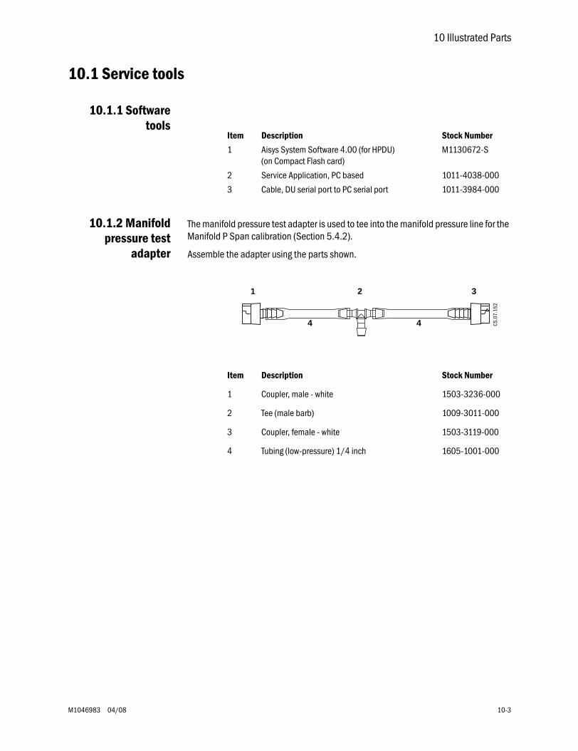
10 Illustrated Parts
M1046983 04/08 10-3
10.1 Service tools
10.1.1 Softwaretools
10.1.2 Manifoldpressure test
adapter
The manifold pressure test adapter is used to tee into the manifold pressure line for the Manifold P Span calibration (Section 5.4.2).
Assemble the adapter using the parts shown.
Item Description Stock Number
1 Aisys System Software 4.00 (for HPDU)(on Compact Flash card)
M1130672-S
2 Service Application, PC based 1011-4038-000
3 Cable, DU serial port to PC serial port 1011-3984-000
Item Description Stock Number
1 Coupler, male - white 1503-3236-000
2 Tee (male barb) 1009-3011-000
3 Coupler, female - white 1503-3119-000
4 Tubing (low-pressure) 1/4 inch 1605-1001-000
3
4 4
1 2
CS.0
7.15
2
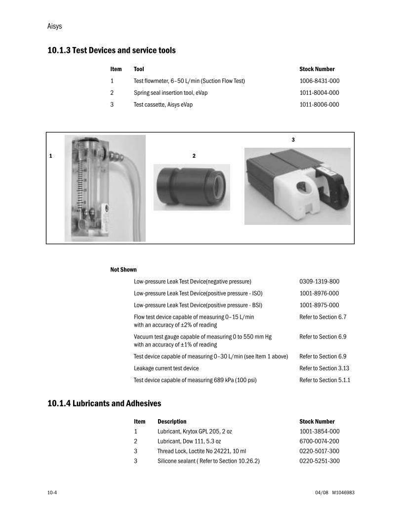
Aisys
10-4 04/08 M1046983
10.1.3 Test Devices and service tools
10.1.4 Lubricants and Adhesives
Item Tool Stock Number
1 Test flowmeter, 6–50 L/min (Suction Flow Test) 1006-8431-000
2 Spring seal insertion tool, eVap 1011-8004-000
3 Test cassette, Aisys eVap 1011-8006-000
21
3
Not Shown
Low-pressure Leak Test Device(negative pressure) 0309-1319-800
Low-pressure Leak Test Device(positive pressure - ISO) 1001-8976-000
Low-pressure Leak Test Device(positive pressure - BSI) 1001-8975-000
Flow test device capable of measuring 0–15 L/min with an accuracy of ±2% of reading
Refer to Section 6.7
Vacuum test gauge capable of measuring 0 to 550 mm Hg with an accuracy of ±1% of reading
Refer to Section 6.9
Test device capable of measuring 0–30 L/min (see Item 1 above) Refer to Section 6.9
Leakage current test device Refer to Section 3.13
Test device capable of measuring 689 kPa (100 psi) Refer to Section 5.1.1
Item Description Stock Number
1 Lubricant, Krytox GPL 205, 2 oz 1001-3854-000
2 Lubricant, Dow 111, 5.3 oz 6700-0074-200
3 Thread Lock, Loctite No 24221, 10 ml 0220-5017-300
3 Silicone sealant ( Refer to Section 10.26.2) 0220-5251-300
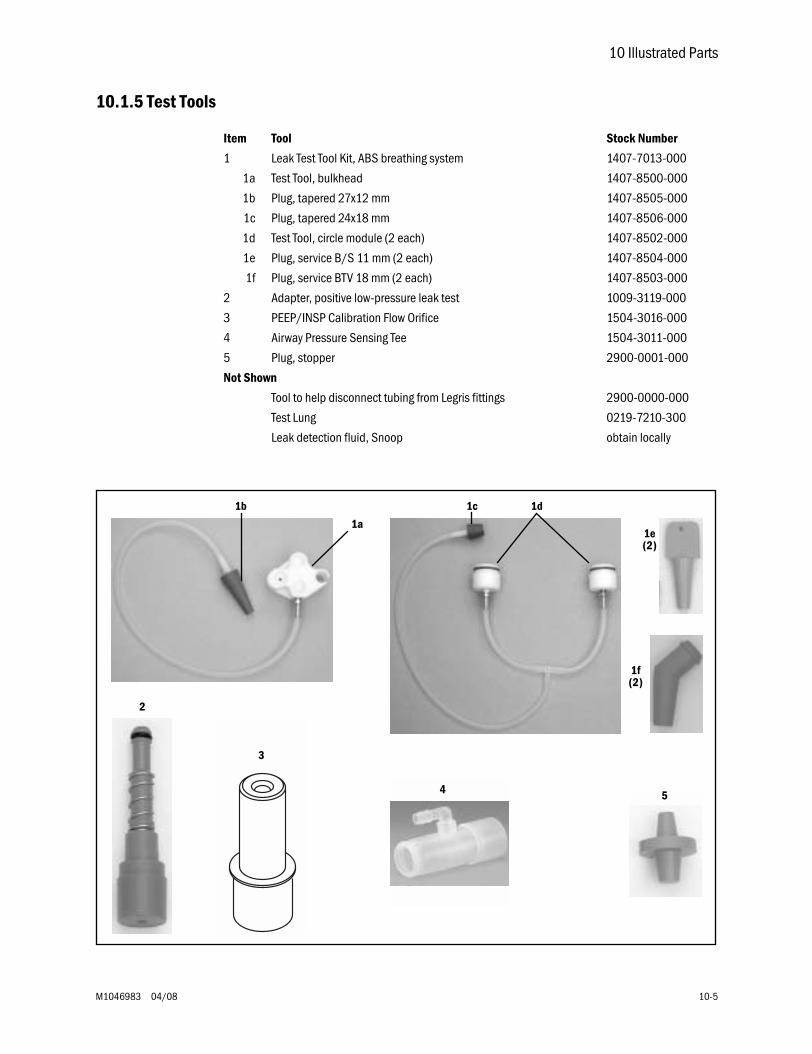
10 Illustrated Parts
M1046983 04/08 10-5
10.1.5 Test Tools
Item Tool Stock Number
1 Leak Test Tool Kit, ABS breathing system 1407-7013-000
1a Test Tool, bulkhead 1407-8500-000
1b Plug, tapered 27x12 mm 1407-8505-000
1c Plug, tapered 24x18 mm 1407-8506-000
1d Test Tool, circle module (2 each) 1407-8502-000
1e Plug, service B/S 11 mm (2 each) 1407-8504-000
1f Plug, service BTV 18 mm (2 each) 1407-8503-000
2 Adapter, positive low-pressure leak test 1009-3119-000
3 PEEP/INSP Calibration Flow Orifice 1504-3016-000
4 Airway Pressure Sensing Tee 1504-3011-000
5 Plug, stopper 2900-0001-000
Not Shown
Tool to help disconnect tubing from Legris fittings 2900-0000-000
Test Lung 0219-7210-300
Leak detection fluid, Snoop obtain locally
1a
1b 1c 1d
5
1e(2)
1f(2)
3
4
2
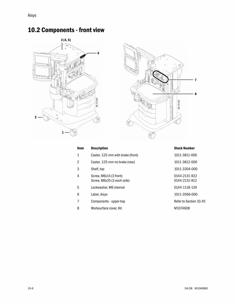
Aisys
10-6 04/08 M1046983
10.2 Components - front view
Item Description Stock Number
1 Caster, 125-mm with brake (front) 1011-3811-000
2 Caster, 125-mm no brake (rear) 1011-3812-000
3 Shelf, top 1011-3304-000
4 Screw, M6x14 (3 front)Screw, M6x35 (3 each side)
0144-2131-9220144-2131-912
5 Lockwasher, M6 internal 0144-1118-130
6 Label, Aisys 1011-3566-000
7 Components - upper bay Refer to Section 10.45
8 Worksurface cover, Kit M1074608
AB.7
5.04
5
AB.7
5.05
0
1
2
6
3 (4, 5)
7
8
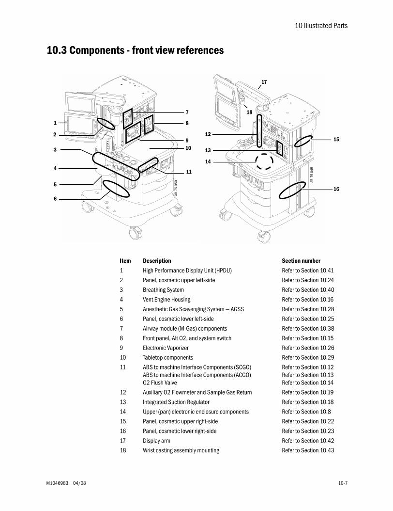
10 Illustrated Parts
M1046983 04/08 10-7
10.3 Components - front view references
Item Description Section number
1 High Performance Display Unit (HPDU) Refer to Section 10.41
2 Panel, cosmetic upper left-side Refer to Section 10.24
3 Breathing System Refer to Section 10.40
4 Vent Engine Housing Refer to Section 10.16
5 Anesthetic Gas Scavenging System — AGSS Refer to Section 10.28
6 Panel, cosmetic lower left-side Refer to Section 10.25
7 Airway module (M-Gas) components Refer to Section 10.38
8 Front panel, Alt O2, and system switch Refer to Section 10.15
9 Electronic Vaporizer Refer to Section 10.26
10 Tabletop components Refer to Section 10.29
11 ABS to machine Interface Components (SCGO)ABS to machine Interface Components (ACGO)O2 Flush Valve
Refer to Section 10.12Refer to Section 10.13Refer to Section 10.14
12 Auxiliary O2 Flowmeter and Sample Gas Return Refer to Section 10.19
13 Integrated Suction Regulator Refer to Section 10.18
14 Upper (pan) electronic enclosure components Refer to Section 10.8
15 Panel, cosmetic upper right-side Refer to Section 10.22
16 Panel, cosmetic lower right-side Refer to Section 10.23
17 Display arm Refer to Section 10.42
18 Wrist casting assembly mounting Refer to Section 10.43
AB.7
5.04
5
12
14
13
17
187
8
AB.7
5.05
011
9
3
15
10
4
5
1
16
6
2
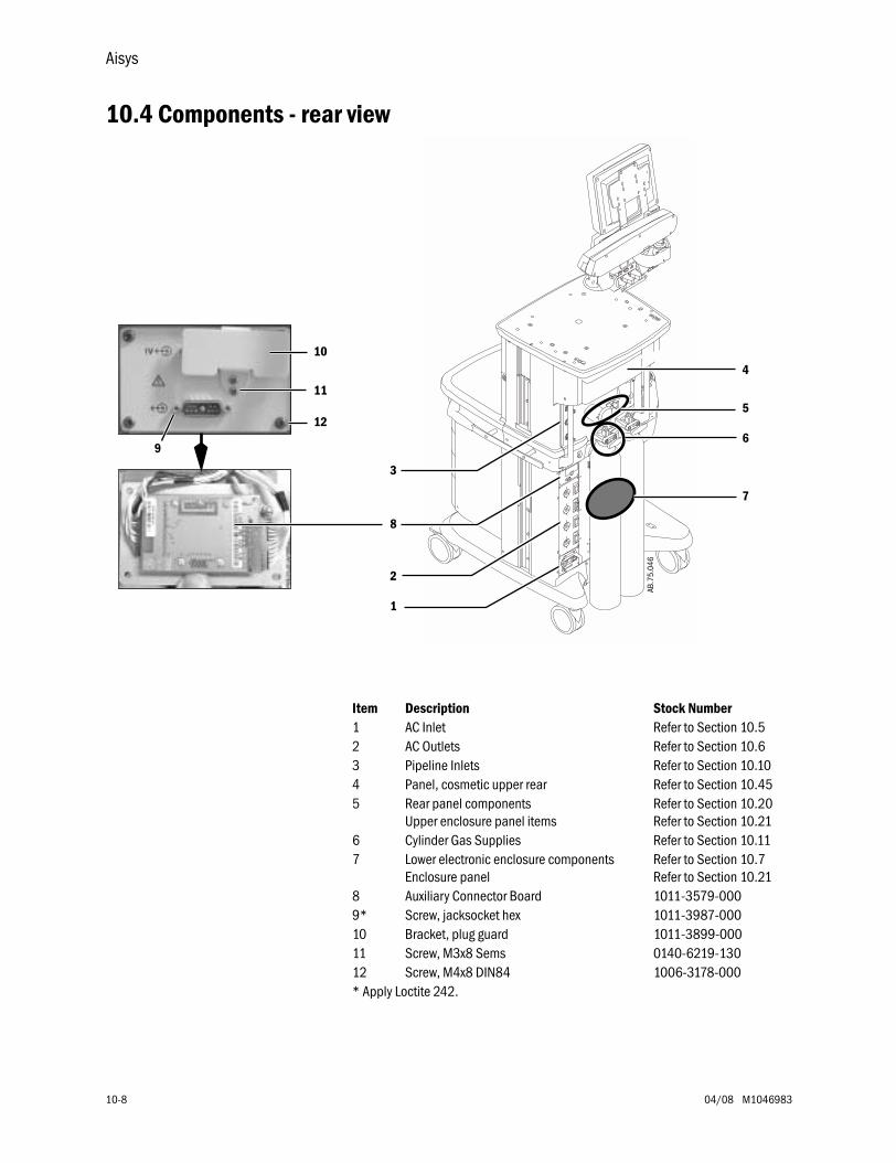
Aisys
10-8 04/08 M1046983
10.4 Components - rear view
AB.7
5.04
6
4
2
1
3
5
7
6
8
9
10
11
12
Item Description Stock Number1 AC Inlet Refer to Section 10.52 AC Outlets Refer to Section 10.63 Pipeline Inlets Refer to Section 10.104 Panel, cosmetic upper rear Refer to Section 10.455 Rear panel components
Upper enclosure panel itemsRefer to Section 10.20Refer to Section 10.21
6 Cylinder Gas Supplies Refer to Section 10.117 Lower electronic enclosure components
Enclosure panelRefer to Section 10.7Refer to Section 10.21
8 Auxiliary Connector Board 1011-3579-0009* Screw, jacksocket hex 1011-3987-00010 Bracket, plug guard 1011-3899-00011 Screw, M3x8 Sems 0140-6219-13012 Screw, M4x8 DIN84 1006-3178-000* Apply Loctite 242.
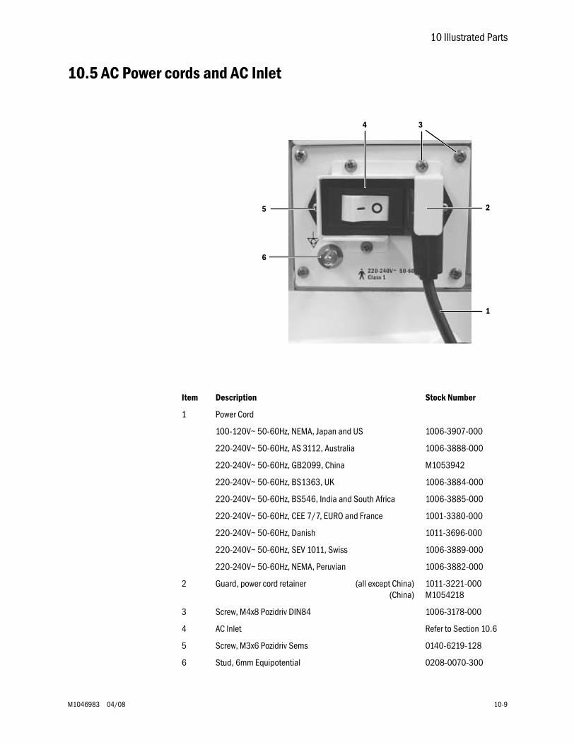
10 Illustrated Parts
M1046983 04/08 10-9
10.5 AC Power cords and AC Inlet
1
2
34
6
5
Item Description Stock Number
1 Power Cord
100-120V~ 50-60Hz, NEMA, Japan and US 1006-3907-000
220-240V~ 50-60Hz, AS 3112, Australia 1006-3888-000
220-240V~ 50-60Hz, GB2099, China M1053942
220-240V~ 50-60Hz, BS1363, UK 1006-3884-000
220-240V~ 50-60Hz, BS546, India and South Africa 1006-3885-000
220-240V~ 50-60Hz, CEE 7/7, EURO and France 1001-3380-000
220-240V~ 50-60Hz, Danish 1011-3696-000
220-240V~ 50-60Hz, SEV 1011, Swiss 1006-3889-000
220-240V~ 50-60Hz, NEMA, Peruvian 1006-3882-000
2 Guard, power cord retainer (all except China)(China)
1011-3221-000M1054218
3 Screw, M4x8 Pozidriv DIN84 1006-3178-000
4 AC Inlet Refer to Section 10.6
5 Screw, M3x6 Pozidriv Sems 0140-6219-128
6 Stud, 6mm Equipotential 0208-0070-300

Aisys
10-10 04/08 M1046983
10.6 AC Inlet/Outlet Components
Item Description Stock Number
1 Circuit Breaker, 1A, Rocker 1009-5722-000
Circuit Breaker, 2A Rocker 1009-5721-000
Circuit Breaker, 3A Rocker 1009-5720-000
Circuit Breaker, 4A Rocker 1009-5719-000
2 Outlet Receptacle, Australia, AS 3112 1001-3305-000
Outlet Receptacle, China, AS 3112 (CCC) M1061131
Outlet Receptacle, Danish, AFSNIT 107-2-D1 1011-3910-000
Outlet Receptacle, EURO, CEE 7/7 1202-3551-000
Outlet Receptacle, France, CEE 7/4Support Frame, snap in
1006-4421-0001006-4422-000
Outlet Receptacle, India and South Africa, BS 546 1006-3805-000
Outlet Receptacle, Japanese 1006-3578-000
Outlet Receptacle, NA, Nema 5-15 1006-3555-000
Outlet Receptacle, Swiss, SEV 1011 1006-3807-000
Outlet Receptacle, UK, BS1363 1001-3309-000
3 Circuit board, Inrush, 100-120VCircuit board, Inrush, 220-240V
1006-3245-0001006-3246-000
4 Screw, M4x8 Pozidriv Sems 0140-6226-113
5 Harnesses Refer to Section 10.35
6 Toroid, 100-240V 1009-5692-000
7* Screw, M8x70Lockwasher, M8 externalWasher, M8
1006-3905-0000144-1118-2259213-0180-006
8 Fuse, 5A - 5x20mmFuse holderScrew, M2x6
1202-3345-0001009-5674-0000140-6712-102
9 Guard, fuse holder 1011-3622-000
10 Screw, M3x6 Pozidriv Sems 0140-6219-128
11 Screw, M4x8 DIN84 1006-3178-000
12 Cover, transformer 1011-3371-000
13 Screw, M4x8 FLAT HD 0140-6226-107
14 Inlet, 100-120A~, with line filter and 15 A circuit breakerInlet, 220-240A~, with line filter and 8 A circuit breaker
1009-5698-0001009-5757-000
* Apply Loctite 242.
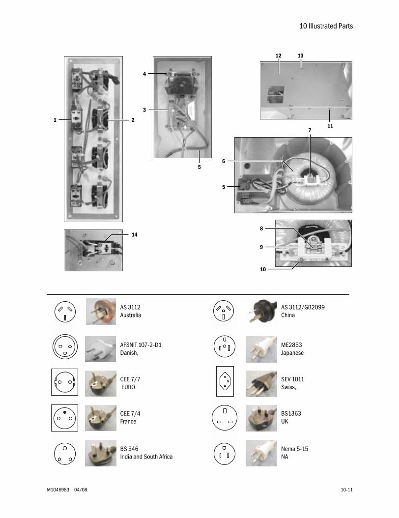
10 Illustrated Parts
M1046983 04/08 10-11
1 2
3
4
6
5
5
7
8
9
10
11
12 13
14
AS 3112Australia
AS 3112/GB2099China
AFSNIT 107-2-D1Danish,
ME2853Japanese
CEE 7/7 EURO
SEV 1011Swiss,
CEE 7/4France
BS1363UK
BS 546India and South Africa
Nema 5-15NA
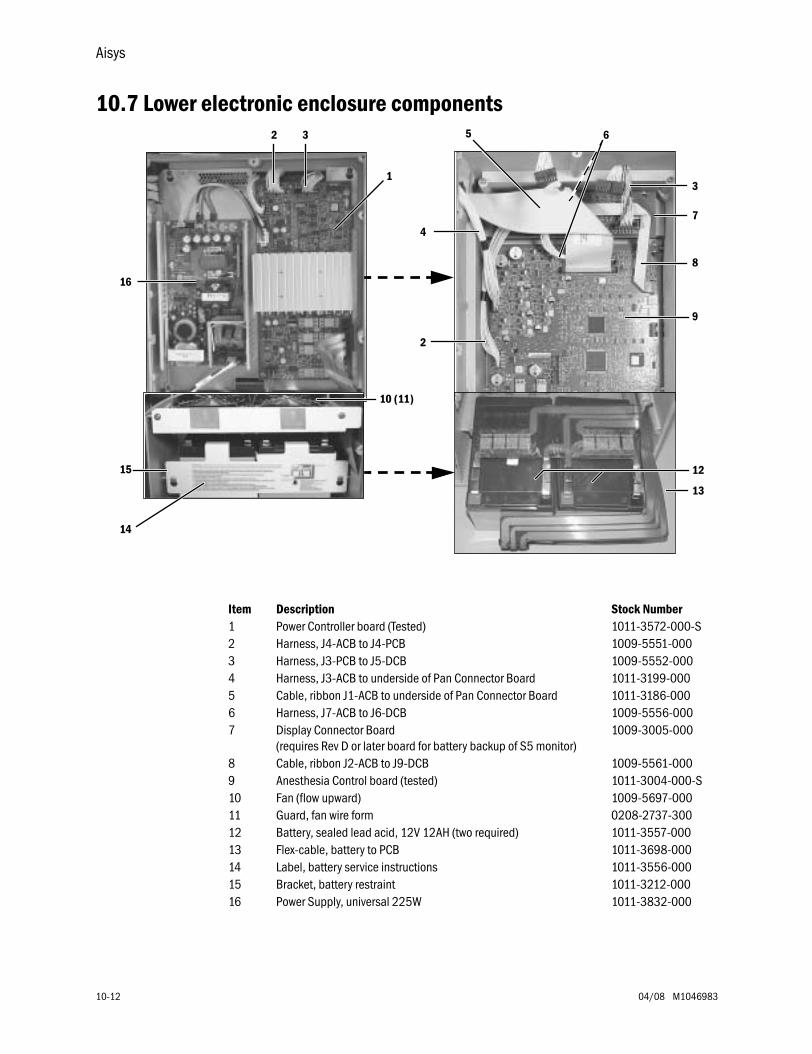
Aisys
10-12 04/08 M1046983
10.7 Lower electronic enclosure components2 3
4
5 6
3
7
8
9
10 (11)
12
13
15
14
2
1
16
Item Description Stock Number1 Power Controller board (Tested) 1011-3572-000-S2 Harness, J4-ACB to J4-PCB 1009-5551-0003 Harness, J3-PCB to J5-DCB 1009-5552-0004 Harness, J3-ACB to underside of Pan Connector Board 1011-3199-0005 Cable, ribbon J1-ACB to underside of Pan Connector Board 1011-3186-0006 Harness, J7-ACB to J6-DCB 1009-5556-0007 Display Connector Board
(requires Rev D or later board for battery backup of S5 monitor)1009-3005-000
8 Cable, ribbon J2-ACB to J9-DCB 1009-5561-0009 Anesthesia Control board (tested) 1011-3004-000-S10 Fan (flow upward) 1009-5697-00011 Guard, fan wire form 0208-2737-30012 Battery, sealed lead acid, 12V 12AH (two required) 1011-3557-00013 Flex-cable, battery to PCB 1011-3698-00014 Label, battery service instructions 1011-3556-00015 Bracket, battery restraint 1011-3212-00016 Power Supply, universal 225W 1011-3832-000
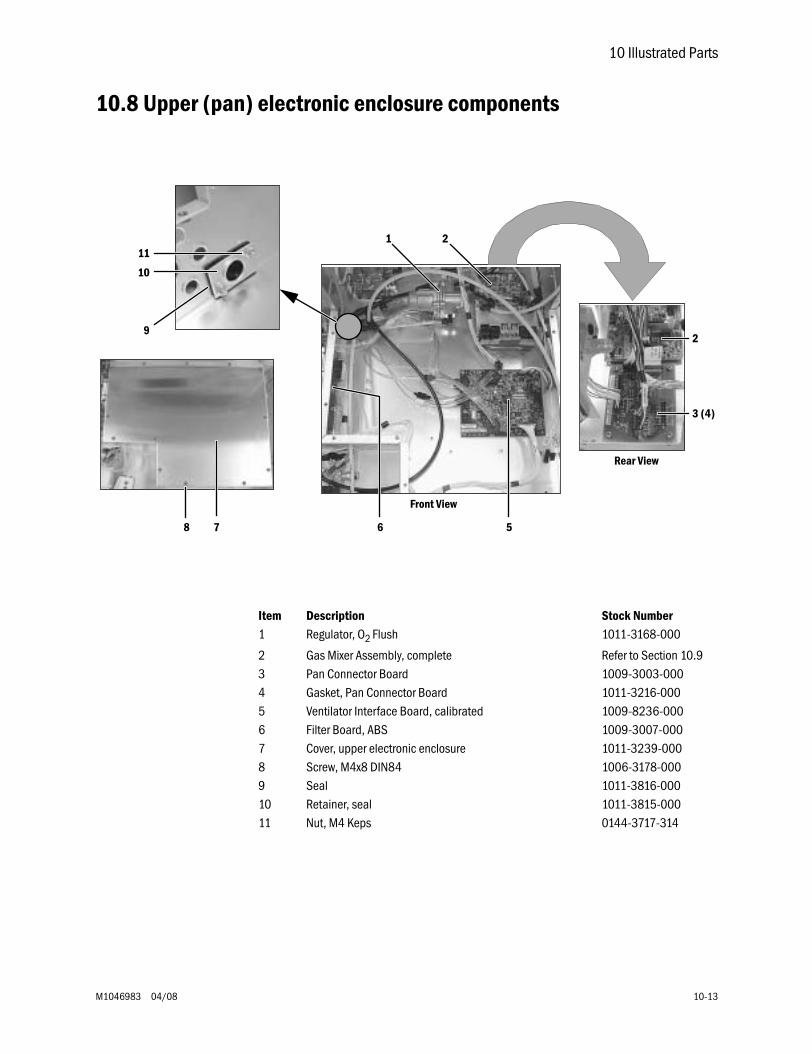
10 Illustrated Parts
M1046983 04/08 10-13
10.8 Upper (pan) electronic enclosure components
Front View
Rear View
21
2
3 (4)
56
9
7
10
11
8
Item Description Stock Number1 Regulator, O2 Flush 1011-3168-000
2 Gas Mixer Assembly, complete Refer to Section 10.93 Pan Connector Board 1009-3003-0004 Gasket, Pan Connector Board 1011-3216-0005 Ventilator Interface Board, calibrated 1009-8236-0006 Filter Board, ABS 1009-3007-0007 Cover, upper electronic enclosure 1011-3239-0008 Screw, M4x8 DIN84 1006-3178-0009 Seal 1011-3816-00010 Retainer, seal 1011-3815-00011 Nut, M4 Keps 0144-3717-314
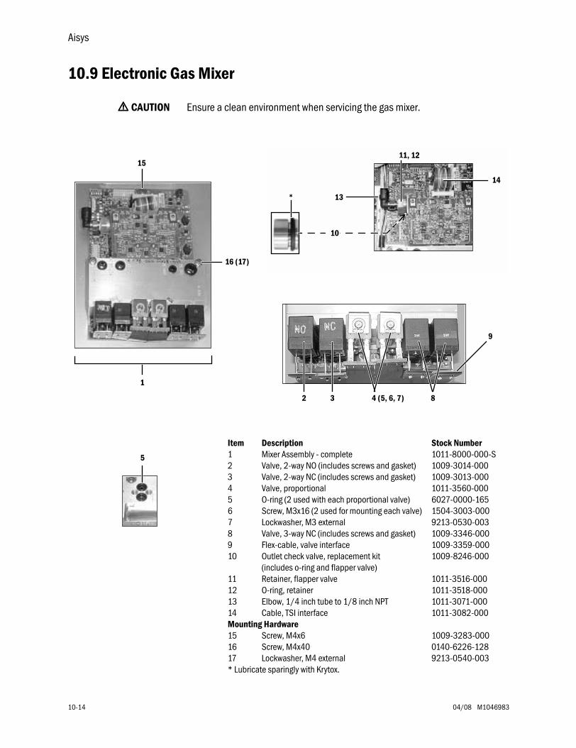
Aisys
10-14 04/08 M1046983
10.9 Electronic Gas Mixer
wwww CAUTION Ensure a clean environment when servicing the gas mixer.
14
10
*
11, 12
13
2 3 4 (5, 6, 7) 8
9
15
16 (17)
1
Item Description Stock Number1 Mixer Assembly - complete 1011-8000-000-S2 Valve, 2-way NO (includes screws and gasket) 1009-3014-0003 Valve, 2-way NC (includes screws and gasket) 1009-3013-0004 Valve, proportional 1011-3560-0005 O-ring (2 used with each proportional valve) 6027-0000-1656 Screw, M3x16 (2 used for mounting each valve) 1504-3003-0007 Lockwasher, M3 external 9213-0530-0038 Valve, 3-way NC (includes screws and gasket) 1009-3346-0009 Flex-cable, valve interface 1009-3359-00010 Outlet check valve, replacement kit
(includes o-ring and flapper valve)1009-8246-000
11 Retainer, flapper valve 1011-3516-00012 O-ring, retainer 1011-3518-00013 Elbow, 1/4 inch tube to 1/8 inch NPT 1011-3071-00014 Cable, TSI interface 1011-3082-000Mounting Hardware15 Screw, M4x6 1009-3283-00016 Screw, M4x40 0140-6226-12817 Lockwasher, M4 external 9213-0540-003* Lubricate sparingly with Krytox.
5
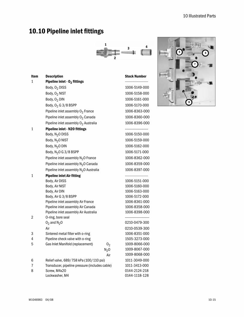
10 Illustrated Parts
M1046983 04/08 10-15
10.10 Pipeline inlet fittings
7
5 6
8
Item Description Stock Number1 Pipeline inlet - O2 fittings --------------------
Body, O2 DISS 1006-5149-000
Body, O2 NIST 1006-5158-000
Body, O2 DIN 1006-5161-000
Body, O2 G 3/8 BSPP 1006-5170-000
Pipeline inlet assembly O2 France 1006-8363-000
Pipeline inlet assembly O2 Canada 1006-8360-000
Pipeline inlet assembly O2 Australia 1006-8396-000
1 Pipeline inlet - N2O fittings --------------------Body, N2O DISS 1006-5150-000
Body, N2O NIST 1006-5159-000
Body, N2O DIN 1006-5162-000
Body, N2O G 3/8 BSPP 1006-5171-000
Pipeline inlet assembly N2O France 1006-8362-000
Pipeline inlet assembly N2O Canada 1006-8359-000
Pipeline inlet assembly N2O Australia 1006-8397-000
1 Pipeline inlet Air fitting --------------------Body, Air DISS 1006-5151-000Body, Air NIST 1006-5160-000Body, Air DIN 1006-5163-000Body, Air G 3/8 BSPP 1006-5172-000Pipeline inlet assembly Air France 1006-8361-000Pipeline inlet assembly Air Canada 1006-8358-000Pipeline inlet assembly Air Australia 1006-8398-000
2 O-ring, bore seal ---------------------O2 and N2O 0210-0479-300
Air 0210-0539-3003 Sintered metal filter with o-ring 1006-8351-0004 Pipeline check valve with o-ring 1505-3273-0005 Gas Inlet Manifold (replacement) O2
N2OAir
1009-8066-0001009-8067-0001009-8068-000
6 Relief valve, 689/758 kPa (100/110 psi) 1011-3049-0007 Transducer, pipeline pressure (includes cable) 1011-3413-0008 Screw, M4x20
Lockwasher, M40144-2124-2180144-1118-128
1
2
3 4
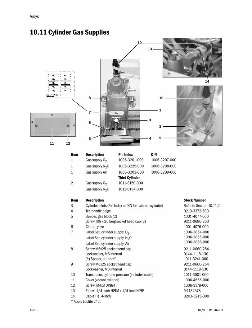
Aisys
10-16 04/08 M1046983
10.11 Cylinder Gas Supplies
Item Description Pin Index DIN1 Gas supply O2 1006-3201-000 1006-3207-000
1 Gas supply N2O 1006-3225-000 1006-3208-000
1 Gas supply Air 1006-3203-000 1006-3209-000Third Cylinder
2 Gas supply O2 1011-8150-000
Gas supply N2O 1011-8154-000
Item Description Stock Number3 Cylinder inlets (Pin Index or DIN for external cylinder) Refer to Section 10.11.24 Tee handle beige 0219-3372-6005 Spacer, gas block (2)
Screw, M8 x 25 long socket head cap (2)1001-4077-0009211-0680-253
6 Clamp, yoke 1001-4076-0007 Label Set, cylinder supply, O2
Label Set, cylinder supply, N2OLabel Set, cylinder supply, Air
1006-3854-0001006-3855-0001006-3856-000
8 Screw M6x25 socket head capLockwasher, M6 internal(*) Spacer, standoff
9211-0660-2540144-1118-1301011-3241-000
9 Screw M6x25 socket head capLockwasher, M6 internal
9211-0660-2540144-1118-130
10 Transducer, cylinder pressure (includes cable) 1011-3001-00011 Cover (vacant cylinder) 1006-4655-00012 Screw, M4x8 DIN84 1006-3178-00013 Elbow, 1/4-inch NPTM x 1/4-inch NPTF M113237814 Cable Tie, 4-inch 0203-5915-300* Apply Loctite 242.
4
3
1
8
5
6
7
2
10
11 129
10
13
14
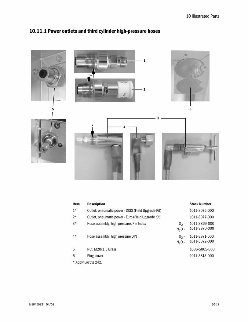
10 Illustrated Parts
M1046983 04/08 10-17
10.11.1 Power outlets and third cylinder high-pressure hoses
1
2
5
*
*
3
4
6
Item Description Stock Number
1* Outlet, pneumatic power - DISS (Field Upgrade Kit) 1011-8075-000
2* Outlet, pneumatic power - Euro (Field Upgrade Kit) 1011-8077-000
3* Hose assembly, high pressure, Pin Index O2 -N2O -
1011-3869-0001011-3870-000
4* Hose assembly, high pressure DIN O2 -N2O -
1011-3871-0001011-3872-000
5 Nut, M20x1.5 Brass 1006-5065-000
6 Plug, cover 1011-3813-000
* Apply Loctite 242.
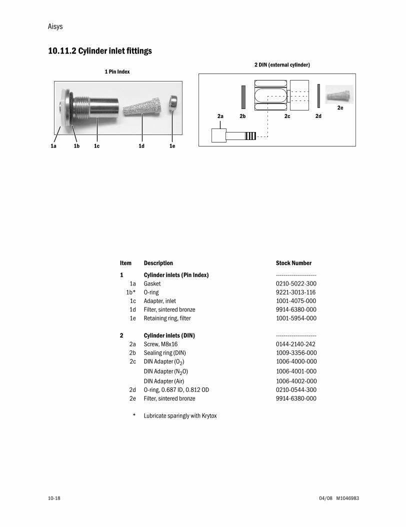
Aisys
10-18 04/08 M1046983
10.11.2 Cylinder inlet fittings
2b 2c 2d
1 Pin Index
2e
2 DIN (external cylinder)
1a 1b 1c 1d 1e
2a
Item Description Stock Number
1 Cylinder inlets (Pin Index) ---------------------1a Gasket 0210-5022-300
1b* O-ring 9221-3013-1161c Adapter, inlet 1001-4075-0001d Filter, sintered bronze 9914-6380-0001e Retaining ring, filter 1001-5954-000
2 Cylinder inlets (DIN) ---------------------2a Screw, M8x16 0144-2140-2422b Sealing ring (DIN) 1009-3356-0002c DIN Adapter (O2) 1006-4000-000
DIN Adapter (N2O) 1006-4001-000
DIN Adapter (Air) 1006-4002-0002d O-ring, 0.687 ID, 0.812 OD 0210-0544-3002e Filter, sintered bronze 9914-6380-000
* Lubricate sparingly with Krytox
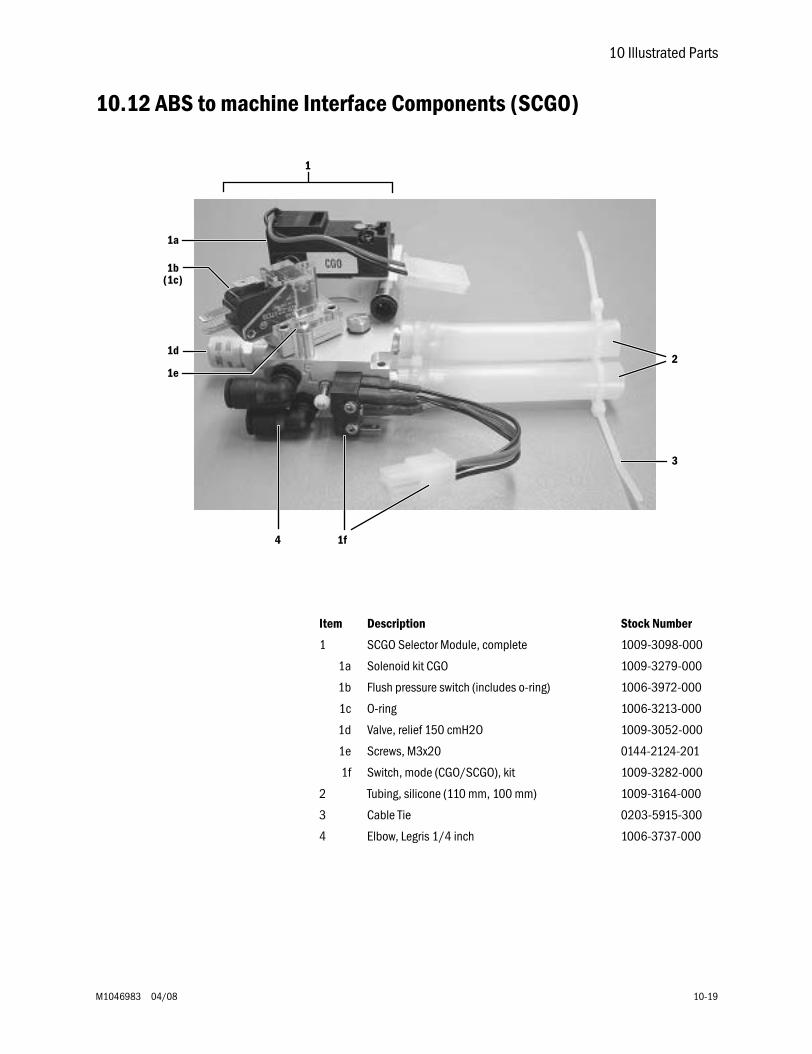
10 Illustrated Parts
M1046983 04/08 10-19
10.12 ABS to machine Interface Components (SCGO)
1a
1b
1f
(1c)
1e
1
3
2
4
1d
Item Description Stock Number
1 SCGO Selector Module, complete 1009-3098-000
1a Solenoid kit CGO 1009-3279-000
1b Flush pressure switch (includes o-ring) 1006-3972-000
1c O-ring 1006-3213-000
1d Valve, relief 150 cmH2O 1009-3052-000
1e Screws, M3x20 0144-2124-201
1f Switch, mode (CGO/SCGO), kit 1009-3282-000
2 Tubing, silicone (110 mm, 100 mm) 1009-3164-000
3 Cable Tie 0203-5915-300
4 Elbow, Legris 1/4 inch 1006-3737-000
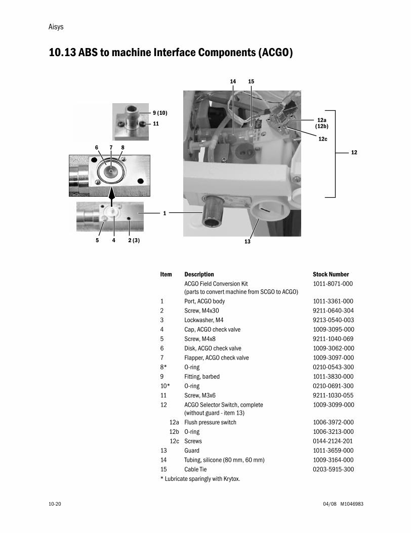
Aisys
10-20 04/08 M1046983
10.13 ABS to machine Interface Components (ACGO)
12
12a(12b)
12c
14
132 (3)45
6 7 8
11
1
15
9 (10)
Item Description Stock NumberACGO Field Conversion Kit(parts to convert machine from SCGO to ACGO)
1011-8071-000
1 Port, ACGO body 1011-3361-0002 Screw, M4x30 9211-0640-3043 Lockwasher, M4 9213-0540-0034 Cap, ACGO check valve 1009-3095-0005 Screw, M4x8 9211-1040-0696 Disk, ACGO check valve 1009-3062-0007 Flapper, ACGO check valve 1009-3097-0008* O-ring 0210-0543-3009 Fitting, barbed 1011-3830-00010* O-ring 0210-0691-30011 Screw, M3x6 9211-1030-05512 ACGO Selector Switch, complete
(without guard - item 13)1009-3099-000
12a Flush pressure switch 1006-3972-00012b O-ring 1006-3213-00012c Screws 0144-2124-201
13 Guard 1011-3659-00014 Tubing, silicone (80 mm, 60 mm) 1009-3164-00015 Cable Tie 0203-5915-300* Lubricate sparingly with Krytox.
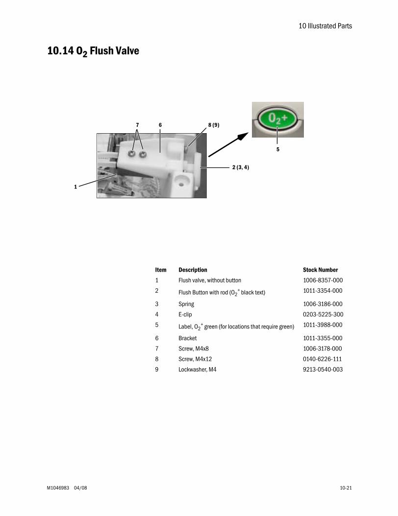
10 Illustrated Parts
M1046983 04/08 10-21
10.14 O2 Flush Valve
1
2 (3, 4)
67 8 (9)
5
Item Description Stock Number
1 Flush valve, without button 1006-8357-000
2 Flush Button with rod (O2+ black text) 1011-3354-000
3 Spring 1006-3186-000
4 E-clip 0203-5225-300
5 Label, O2+ green (for locations that require green) 1011-3988-000
6 Bracket 1011-3355-000
7 Screw, M4x8 1006-3178-000
8 Screw, M4x12 0140-6226-111
9 Lockwasher, M4 9213-0540-003
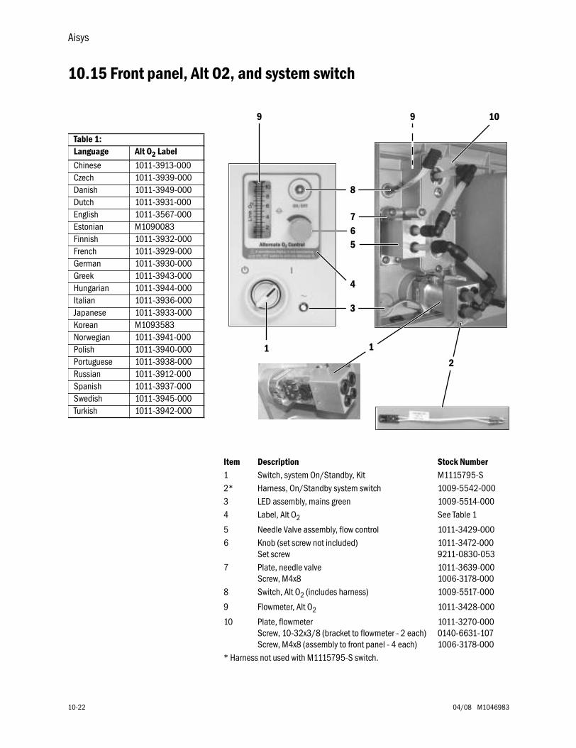
Aisys
10-22 04/08 M1046983
10.15 Front panel, Alt O2, and system switch
Table 1: Language Alt O2 Label
Chinese 1011-3913-000Czech 1011-3939-000Danish 1011-3949-000Dutch 1011-3931-000English 1011-3567-000Estonian M1090083Finnish 1011-3932-000French 1011-3929-000German 1011-3930-000Greek 1011-3943-000Hungarian 1011-3944-000Italian 1011-3936-000Japanese 1011-3933-000Korean M1093583Norwegian 1011-3941-000Polish 1011-3940-000Portuguese 1011-3938-000Russian 1011-3912-000Spanish 1011-3937-000Swedish 1011-3945-000Turkish 1011-3942-000
1
567
4
9 9 10
8
3
1
2
Item Description Stock Number1 Switch, system On/Standby, Kit M1115795-S2* Harness, On/Standby system switch 1009-5542-0003 LED assembly, mains green 1009-5514-0004 Label, Alt O2 See Table 1
5 Needle Valve assembly, flow control 1011-3429-0006 Knob (set screw not included)
Set screw1011-3472-0009211-0830-053
7 Plate, needle valveScrew, M4x8
1011-3639-0001006-3178-000
8 Switch, Alt O2 (includes harness) 1009-5517-000
9 Flowmeter, Alt O2 1011-3428-000
10 Plate, flowmeterScrew, 10-32x3/8 (bracket to flowmeter - 2 each)Screw, M4x8 (assembly to front panel - 4 each)
1011-3270-0000140-6631-1071006-3178-000
* Harness not used with M1115795-S switch.
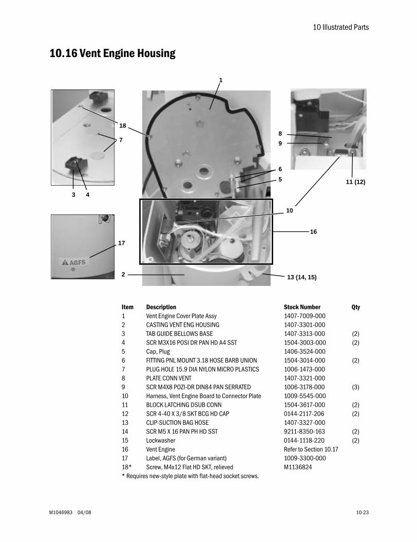
10 Illustrated Parts
M1046983 04/08 10-23
10.16 Vent Engine Housing
Item Description Stock Number Qty1 Vent Engine Cover Plate Assy 1407-7009-0002 CASTING VENT ENG HOUSING 1407-3301-0003 TAB GUIDE BELLOWS BASE 1407-3313-000 (2)4 SCR M3X16 POSI DR PAN HD A4 SST 1504-3003-000 (2)5 Cap, Plug 1406-3524-0006 FITTING PNL MOUNT 3.18 HOSE BARB UNION 1504-3014-000 (2)7 PLUG HOLE 15.9 DIA NYLON MICRO PLASTICS 1006-1473-0008 PLATE CONN VENT 1407-3321-0009 SCR M4X8 POZI-DR DIN84 PAN SERRATED 1006-3178-000 (3)10 Harness, Vent Engine Board to Connector Plate 1009-5545-00011 BLOCK LATCHING DSUB CONN 1504-3617-000 (2)12 SCR 4-40 X 3/8 SKT BCG HD CAP 0144-2117-206 (2)13 CLIP-SUCTION BAG HOSE 1407-3327-00014 SCR M5 X 16 PAN PH HD SST 9211-8350-163 (2)15 Lockwasher 0144-1118-220 (2)16 Vent Engine Refer to Section 10.1717 Label, AGFS (for German variant) 1009-3300-00018* Screw, M4x12 Flat HD SKT, relieved M1136824* Requires new-style plate with flat-head socket screws.
3 4
1
2 13 (14, 15)
10
9
8
11 (12)
6
7
5
16
17
18
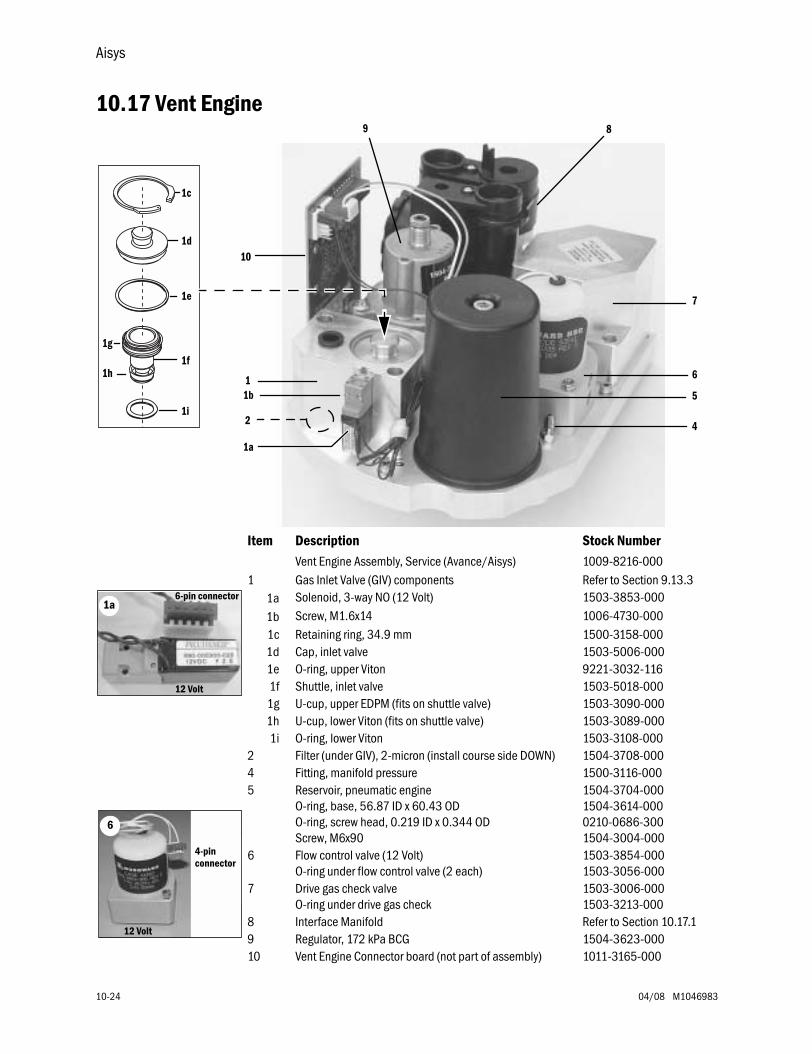
Aisys
10-24 04/08 M1046983
10.17 Vent Engine
Item Description Stock NumberVent Engine Assembly, Service (Avance/Aisys) 1009-8216-000
1 Gas Inlet Valve (GIV) components Refer to Section 9.13.31a Solenoid, 3-way NO (12 Volt) 1503-3853-000
1b Screw, M1.6x14 1006-4730-0001c Retaining ring, 34.9 mm 1500-3158-0001d Cap, inlet valve 1503-5006-0001e O-ring, upper Viton 9221-3032-1161f Shuttle, inlet valve 1503-5018-000
1g U-cup, upper EDPM (fits on shuttle valve) 1503-3090-0001h U-cup, lower Viton (fits on shuttle valve) 1503-3089-0001i O-ring, lower Viton 1503-3108-000
2 Filter (under GIV), 2-micron (install course side DOWN) 1504-3708-0004 Fitting, manifold pressure 1500-3116-0005 Reservoir, pneumatic engine
O-ring, base, 56.87 ID x 60.43 ODO-ring, screw head, 0.219 ID x 0.344 ODScrew, M6x90
1504-3704-0001504-3614-0000210-0686-3001504-3004-000
6 Flow control valve (12 Volt)O-ring under flow control valve (2 each)
1503-3854-0001503-3056-000
7 Drive gas check valveO-ring under drive gas check
1503-3006-0001503-3213-000
8 Interface Manifold Refer to Section 10.17.19 Regulator, 172 kPa BCG 1504-3623-00010 Vent Engine Connector board (not part of assembly) 1011-3165-000
10
15
6
7
9 8
1a
42
AB.2
3.15
0
1g
1h
1c
1d
1e
1i
1f
1b
12 Volt
6-pin connector 1a
12 Volt
4-pin connector
6
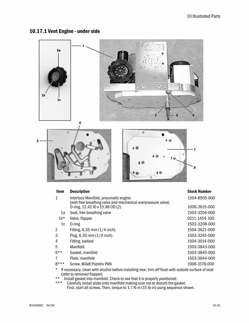
10 Illustrated Parts
M1046983 04/08 10-25
10.17.1 Vent Engine - under side
Item Description Stock Number
1 Interface Manifold, pneumatic engine (with free breathing valve and mechanical overpressure valve)O-ring, 12.42 ID x 15.98 OD (2)
1504-8505-000
1006-3615-0001a Seat, free breathing valve 1503-3204-000
1b* Valve, flapper 0211-1454-1001c O-ring 1503-3208-000
2 Fitting, 6.35-mm (1/4-inch) 1504-3621-0003 Plug, 6.35-mm (1/4-inch) 1503-3245-0004 Fitting, barbed 1504-3014-0005 Manifold 1503-3843-0006** Gasket, manifold 1503-3845-0007 Plate, manifold 1503-3844-0008*** Screw, M4x8 Pozidriv PAN 1006-3178-000* If necessary, clean with alcohol before installing new; trim off flush with outside surface of seat
(refer to removed flapper).** Install gasket into manifold. Check to see that it is properly positioned.*** Carefully install plate onto manifold making sure not to disturb the gasket.
First, start all screws. Then, torque to 1.7 N-m (15 lb-in) using sequence shown.
2 43
1a
1b1c
1a1
b
a
d
c
e
fg
6
5
7
8
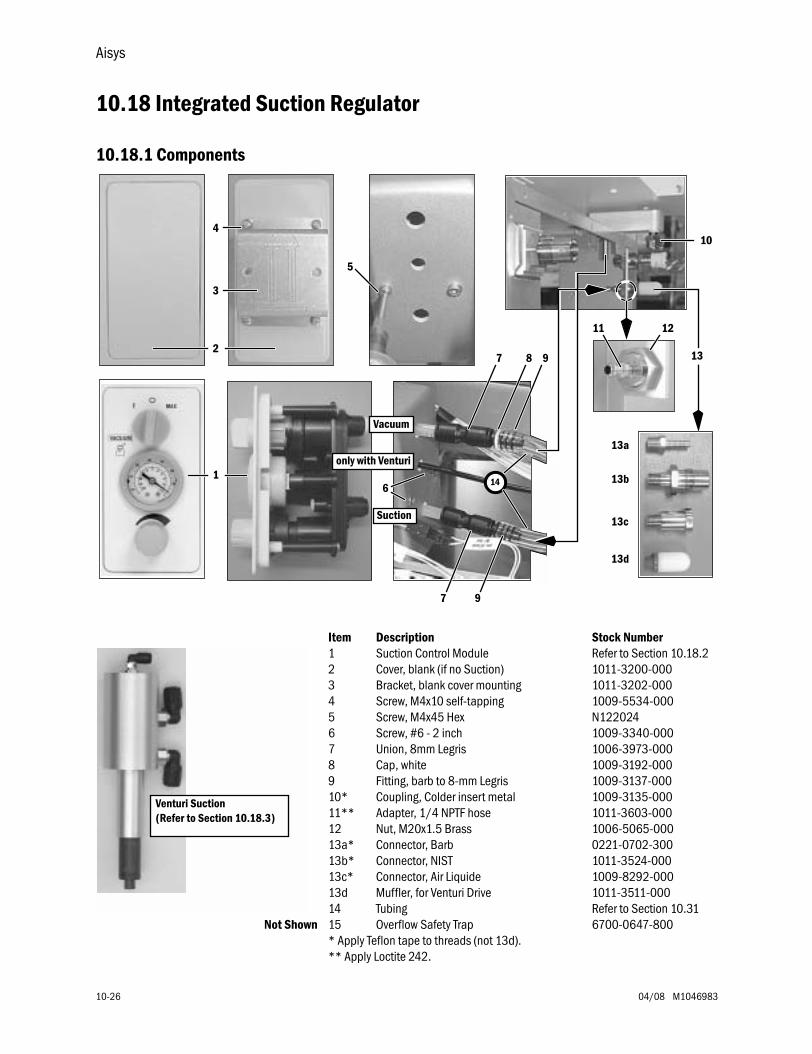
Aisys
10-26 04/08 M1046983
10.18 Integrated Suction Regulator
10.18.1 Components
Item Description Stock Number1 Suction Control Module Refer to Section 10.18.22 Cover, blank (if no Suction) 1011-3200-0003 Bracket, blank cover mounting 1011-3202-0004 Screw, M4x10 self-tapping 1009-5534-0005 Screw, M4x45 Hex N1220246 Screw, #6 - 2 inch 1009-3340-0007 Union, 8mm Legris 1006-3973-0008 Cap, white 1009-3192-0009 Fitting, barb to 8-mm Legris 1009-3137-00010* Coupling, Colder insert metal 1009-3135-00011** Adapter, 1/4 NPTF hose 1011-3603-00012 Nut, M20x1.5 Brass 1006-5065-00013a* Connector, Barb 0221-0702-30013b* Connector, NIST 1011-3524-00013c* Connector, Air Liquide 1009-8292-00013d Muffler, for Venturi Drive 1011-3511-00014 Tubing Refer to Section 10.31
Not Shown 15 Overflow Safety Trap 6700-0647-800* Apply Teflon tape to threads (not 13d).** Apply Loctite 242.
14
only with Venturi
Vacuum
Suction
10
3
4
5
6
1211
7 8 13
13a
13b
13c
13d
2
1
9
97
Venturi Suction(Refer to Section 10.18.3)
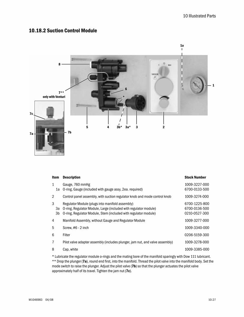
10 Illustrated Parts
M1046983 04/08 10-27
10.18.2 Suction Control Module
Item Description Stock Number
11a
Gauge, 760 mmHgO-ring, Gauge (included with gauge assy, 2ea. required)
1009-3227-0006700-0133-500
2 Control panel assembly, with suction regulator knob and mode control knob 1009-3274-000
33a3b
Regulator Module (plugs into manifold assembly)O-ring, Regulator Module, Large (included with regulator module)O-ring, Regulator Module, Stem (included with regulator module)
6700-1225-8006700-0136-5000210-0527-300
4 Manifold Assembly, without Gauge and Regulator Module 1009-3277-000
5 Screw, #6 - 2 inch 1009-3340-000
6 Filter 0206-5159-300
7 Pilot valve adapter assembly (includes plunger, jam nut, and valve assembly) 1009-3278-000
8 Cap, white 1009-3385-000
* Lubricate the regulator module o-rings and the mating bore of the manifold sparingly with Dow 111 lubricant.** Drop the plunger (7a), round end first, into the manifold. Thread the pilot valve into the manifold body. Set the mode switch to raise the plunger. Adjust the pilot valve (7b) so that the plunger actuates the pilot valve approximately half of its travel. Tighten the jam nut (7c).
6
only with Venturi7**
*
7c
8
1
1a
3a*
7a 7b
3b* 3 245
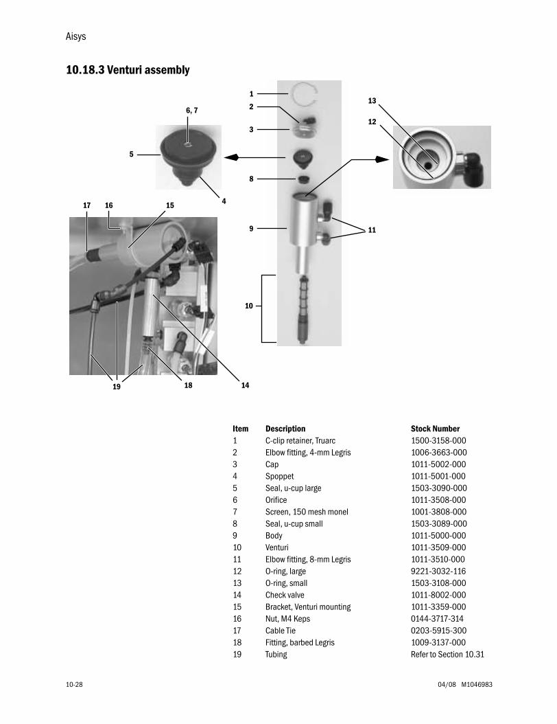
Aisys
10-28 04/08 M1046983
10.18.3 Venturi assembly
1
2
3
8
9 11
4
5
6, 712
13
10
18 14
151617
19
Item Description Stock Number1 C-clip retainer, Truarc 1500-3158-0002 Elbow fitting, 4-mm Legris 1006-3663-0003 Cap 1011-5002-0004 Spoppet 1011-5001-0005 Seal, u-cup large 1503-3090-0006 Orifice 1011-3508-0007 Screen, 150 mesh monel 1001-3808-0008 Seal, u-cup small 1503-3089-0009 Body 1011-5000-00010 Venturi 1011-3509-00011 Elbow fitting, 8-mm Legris 1011-3510-00012 O-ring, large 9221-3032-11613 O-ring, small 1503-3108-00014 Check valve 1011-8002-00015 Bracket, Venturi mounting 1011-3359-00016 Nut, M4 Keps 0144-3717-31417 Cable Tie 0203-5915-30018 Fitting, barbed Legris 1009-3137-00019 Tubing Refer to Section 10.31
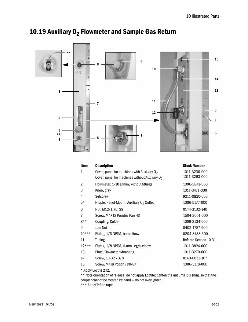
10 Illustrated Parts
M1046983 04/08 10-29
10.19 Auxiliary O2 Flowmeter and Sample Gas Return
Item Description Stock Number
1 Cover, panel for machines with Auxiliary O2Cover, panel for machines without Auxiliary O2
1011-3230-0001011-3263-000
2 Flowmeter, 1-10 L/min, without fittings 1006-3841-000
3 Knob, gray 1011-3471-000
4 Setscrew 9211-0830-053
5* Nipple, Panel-Mount, Auxiliary O2 Outlet 1006-5177-000
6 Nut, M12x1.75, SST 0144-3132-140
7 Screw, M4X12 Pozidriv Pan HD 1504-3001-000
8** Coupling, Colder 1009-3134-000
9 Jam Nut 0402-1787-500
10*** Fitting, 1/8 NPTM, barb elbow 0204-8788-300
11 Tubing Refer to Section 10.31
12*** Fitting, 1/8 NPTM, 6-mm Legris elbow 1011-3824-000
13 Plate, Flowmeter Mounting 1011-3270-000
14 Screw, 10-32 x 3/8 0140-6631-107
15 Screw, M4x8 Pozidriv DIN84 1006-3178-000
* Apply Loctite 242.** Note orientation of release; do not apply Loctite; tighten the nut until it is snug, so that the coupler cannot be rotated by hand — do not overtighten.*** Apply Teflon tape.
1
**
2
3
5
9
6
10
11
12
5
3
4
13
14
15
(4)
8
7
5
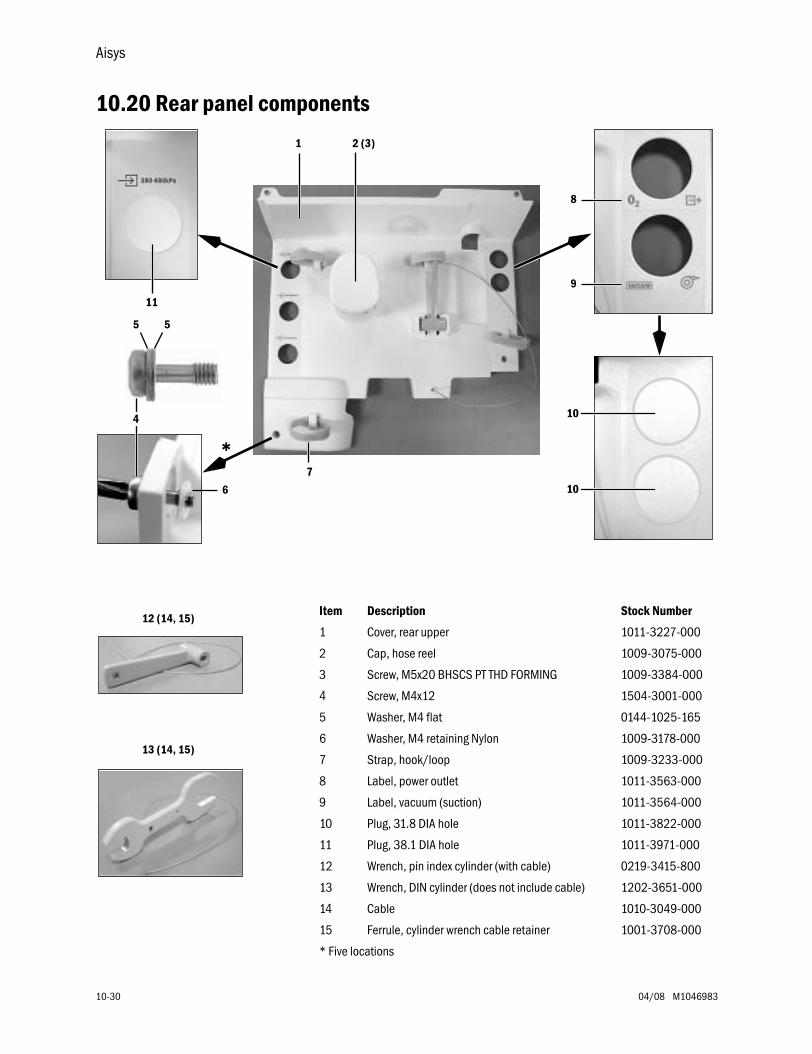
Aisys
10-30 04/08 M1046983
10.20 Rear panel components
1 2 (3)
8
9
7
11
10
10
5
*
5
6
4
13 (14, 15)
12 (14, 15)Item Description Stock Number
1 Cover, rear upper 1011-3227-000
2 Cap, hose reel 1009-3075-000
3 Screw, M5x20 BHSCS PT THD FORMING 1009-3384-000
4 Screw, M4x12 1504-3001-000
5 Washer, M4 flat 0144-1025-165
6 Washer, M4 retaining Nylon 1009-3178-000
7 Strap, hook/loop 1009-3233-000
8 Label, power outlet 1011-3563-000
9 Label, vacuum (suction) 1011-3564-000
10 Plug, 31.8 DIA hole 1011-3822-000
11 Plug, 38.1 DIA hole 1011-3971-000
12 Wrench, pin index cylinder (with cable) 0219-3415-800
13 Wrench, DIN cylinder (does not include cable) 1202-3651-000
14 Cable 1010-3049-000
15 Ferrule, cylinder wrench cable retainer 1001-3708-000
* Five locations
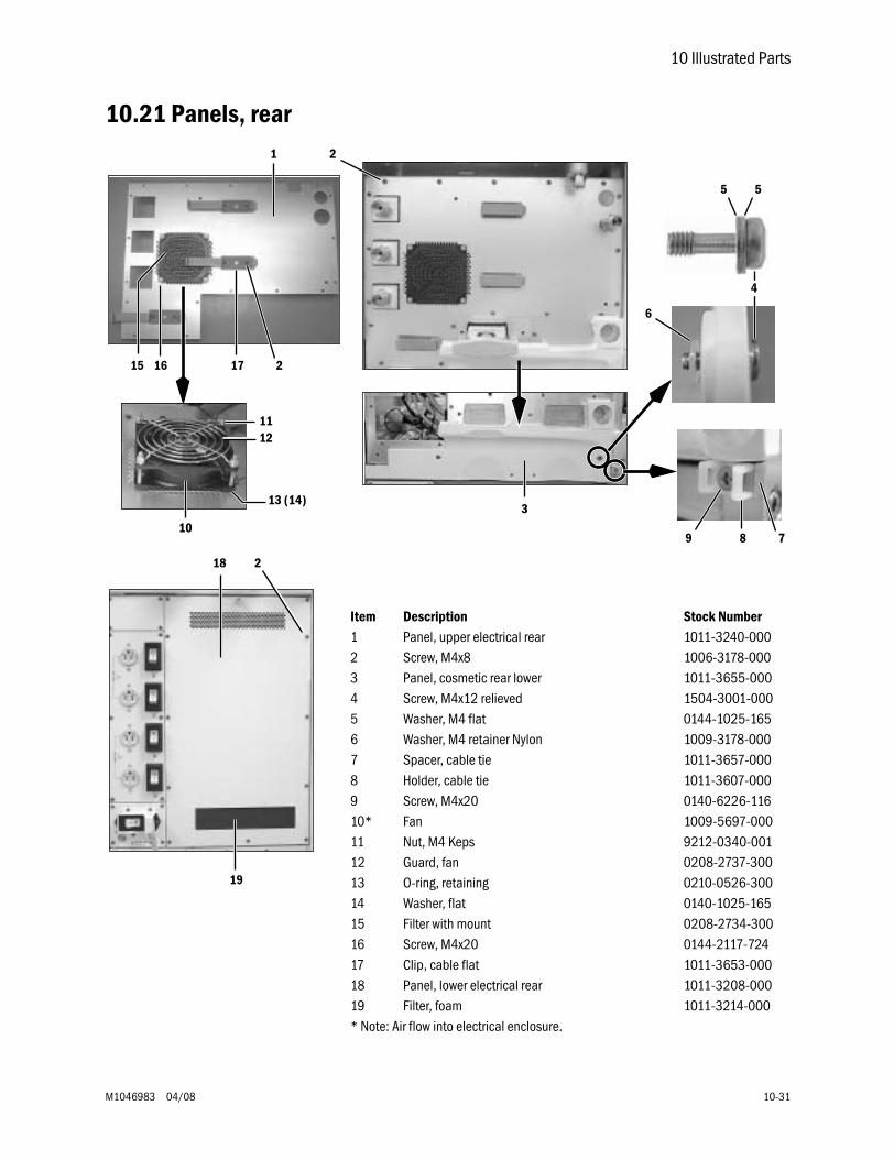
10 Illustrated Parts
M1046983 04/08 10-31
10.21 Panels, rear1 2
3
6
78910
12
13 (14)
15 16
11
17 2
5 5
4
18 2
19
Item Description Stock Number1 Panel, upper electrical rear 1011-3240-0002 Screw, M4x8 1006-3178-0003 Panel, cosmetic rear lower 1011-3655-0004 Screw, M4x12 relieved 1504-3001-0005 Washer, M4 flat 0144-1025-1656 Washer, M4 retainer Nylon 1009-3178-0007 Spacer, cable tie 1011-3657-0008 Holder, cable tie 1011-3607-0009 Screw, M4x20 0140-6226-11610* Fan 1009-5697-00011 Nut, M4 Keps 9212-0340-00112 Guard, fan 0208-2737-30013 O-ring, retaining 0210-0526-30014 Washer, flat 0140-1025-16515 Filter with mount 0208-2734-30016 Screw, M4x20 0144-2117-72417 Clip, cable flat 1011-3653-00018 Panel, lower electrical rear 1011-3208-00019 Filter, foam 1011-3214-000* Note: Air flow into electrical enclosure.
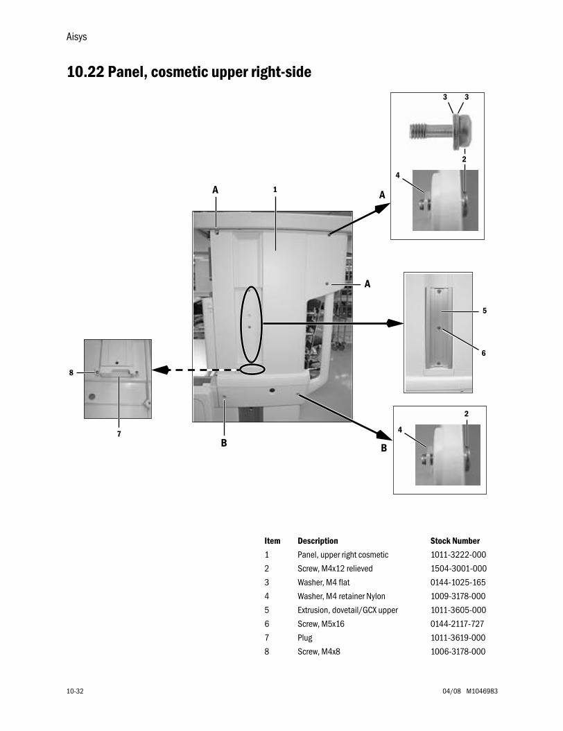
Aisys
10-32 04/08 M1046983
10.22 Panel, cosmetic upper right-side
Item Description Stock Number
1 Panel, upper right cosmetic 1011-3222-000
2 Screw, M4x12 relieved 1504-3001-000
3 Washer, M4 flat 0144-1025-165
4 Washer, M4 retainer Nylon 1009-3178-000
5 Extrusion, dovetail/GCX upper 1011-3605-000
6 Screw, M5x16 0144-2117-727
7 Plug 1011-3619-000
8 Screw, M4x8 1006-3178-000
1
5
6
7
8
4
3 3
2
4
2
BB
A
AA
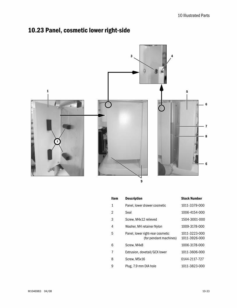
10 Illustrated Parts
M1046983 04/08 10-33
10.23 Panel, cosmetic lower right-side
Item Description Stock Number
1 Panel, lower drawer cosmetic 1011-3379-000
2 Seal 1006-4154-000
3 Screw, M4x12 relieved 1504-3001-000
4 Washer, M4 retainer Nylon 1009-3178-000
5 Panel, lower right-rear cosmetic(for pendant machines)
1011-3223-0001011-3926-000
6 Screw, M4x8 1006-3178-000
7 Extrusion, dovetail/GCX lower 1011-3606-000
8 Screw, M5x16 0144-2117-727
9 Plug, 7.9 mm DIA hole 1011-3823-000
1
2
3 4
5
6
7
8
6
9
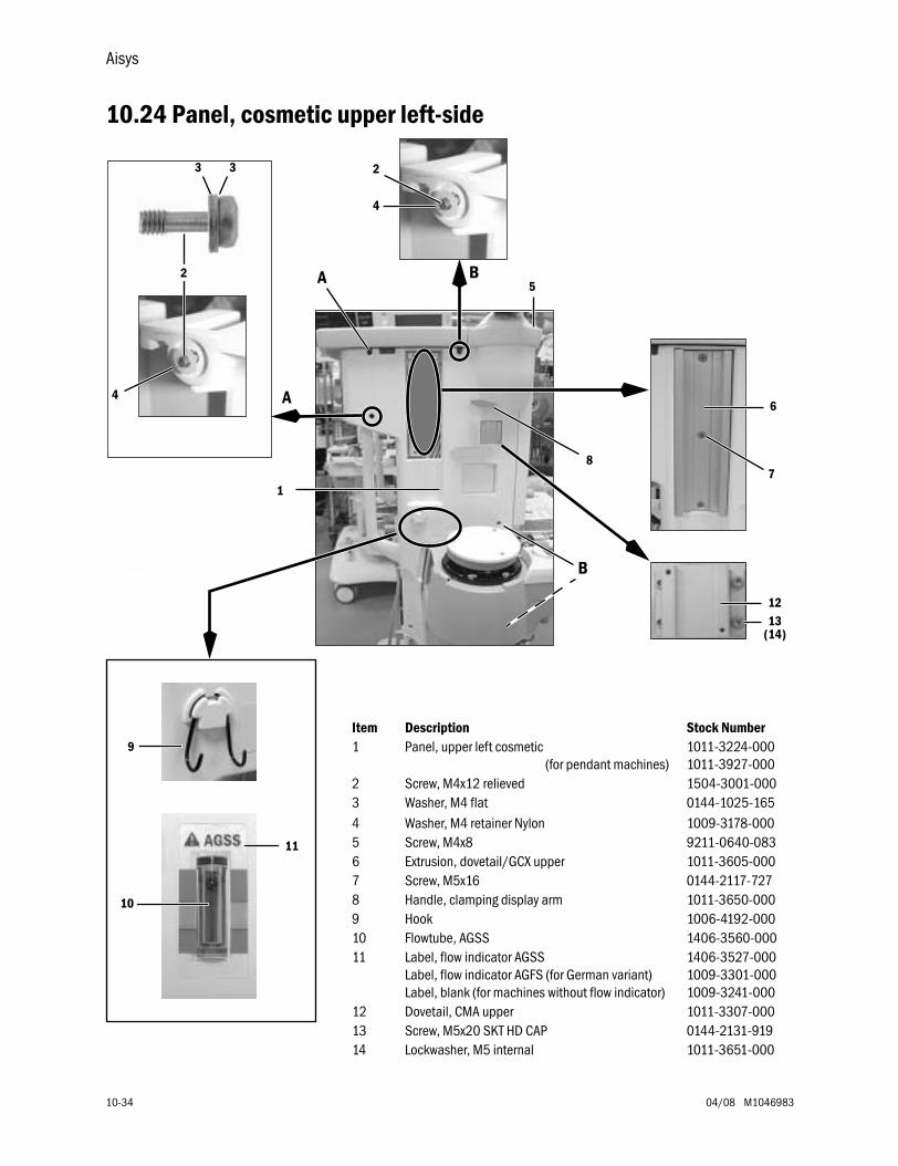
Aisys
10-34 04/08 M1046983
10.24 Panel, cosmetic upper left-side
1
6
7
5
8
1213
(14)
3 3
4
2
A
A B
B
4
2
9
10
11
Item Description Stock Number1 Panel, upper left cosmetic
(for pendant machines)1011-3224-0001011-3927-000
2 Screw, M4x12 relieved 1504-3001-0003 Washer, M4 flat 0144-1025-1654 Washer, M4 retainer Nylon 1009-3178-0005 Screw, M4x8 9211-0640-0836 Extrusion, dovetail/GCX upper 1011-3605-0007 Screw, M5x16 0144-2117-7278 Handle, clamping display arm 1011-3650-0009 Hook 1006-4192-00010 Flowtube, AGSS 1406-3560-00011 Label, flow indicator AGSS
Label, flow indicator AGFS (for German variant)Label, blank (for machines without flow indicator)
1406-3527-0001009-3301-0001009-3241-000
12 Dovetail, CMA upper 1011-3307-00013 Screw, M5x20 SKT HD CAP 0144-2131-91914 Lockwasher, M5 internal 1011-3651-000
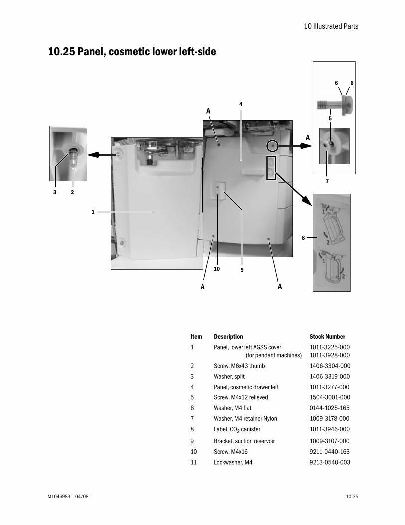
10 Illustrated Parts
M1046983 04/08 10-35
10.25 Panel, cosmetic lower left-side
4
6 6
5
1
23
7
8
910
A
A
A A
Item Description Stock Number
1 Panel, lower left AGSS cover(for pendant machines)
1011-3225-0001011-3928-000
2 Screw, M6x43 thumb 1406-3304-000
3 Washer, split 1406-3319-000
4 Panel, cosmetic drawer left 1011-3277-000
5 Screw, M4x12 relieved 1504-3001-000
6 Washer, M4 flat 0144-1025-165
7 Washer, M4 retainer Nylon 1009-3178-000
8 Label, CO2 canister 1011-3946-000
9 Bracket, suction reservoir 1009-3107-000
10 Screw, M4x16 9211-0440-163
11 Lockwasher, M4 9213-0540-003
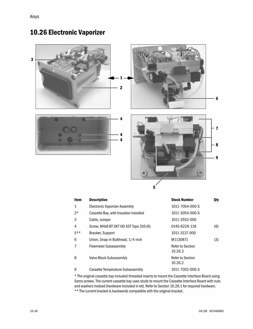
Aisys
10-36 04/08 M1046983
10.26 Electronic Vaporizer
Item Description Stock Number Qty
1 Electronic Vaporizer Assembly 1011-7004-000-S
2* Cassette Bay, with Insulator installed 1011-3054-000-S
3 Cable, Jumper 1011-3552-000
4 Screw, M4x8 BT SKT HD SST Type 316 (6) 0140-6226-118 (6)
5** Bracket, Support 1011-3137-000
6 Union, Snap-in Bulkhead, 1/4-inch M1130871 (3)
7 Flowmeter Subassembly Refer to Section 10.26.3
8 Valve Block Subassembly Refer to Section 10.26.2
9 Cassette Temperature Subassembly 1011-7002-000-S
* The original cassette bay included threaded inserts to mount the Cassette Interface Board using Sems screws. The current cassette bay uses studs to mount the Cassette Interface Board with nuts and washers instead (hardware included in kit). Refer to Section 10.26.1 for required hardware.** The current bracket is backwards compatible with the original bracket.
1
2
5
4
44
3
7
8
6
9
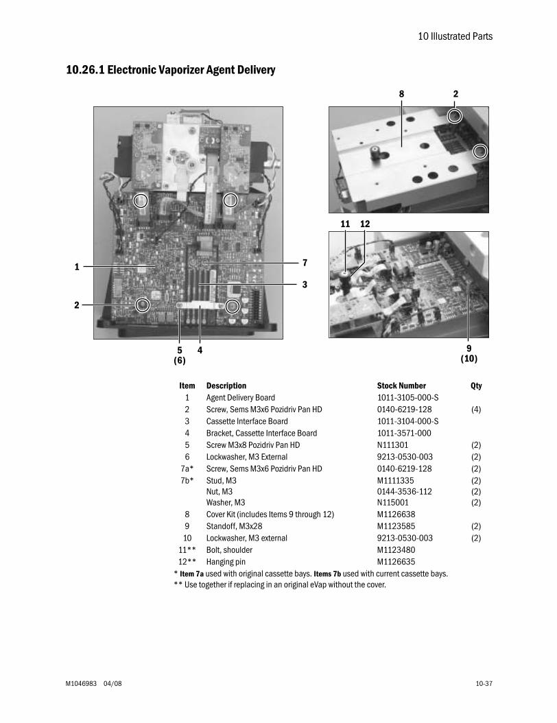
10 Illustrated Parts
M1046983 04/08 10-37
10.26.1 Electronic Vaporizer Agent Delivery
Item Description Stock Number Qty1 Agent Delivery Board 1011-3105-000-S2 Screw, Sems M3x6 Pozidriv Pan HD 0140-6219-128 (4)3 Cassette Interface Board 1011-3104-000-S4 Bracket, Cassette Interface Board 1011-3571-0005 Screw M3x8 Pozidriv Pan HD N111301 (2)6 Lockwasher, M3 External 9213-0530-003 (2)
7a* Screw, Sems M3x6 Pozidriv Pan HD 0140-6219-128 (2)7b* Stud, M3
Nut, M3Washer, M3
M11113350144-3536-112N115001
(2)(2)(2)
8 Cover Kit (includes Items 9 through 12) M11266389 Standoff, M3x28 M1123585 (2)
10 Lockwasher, M3 external 9213-0530-003 (2)11** Bolt, shoulder M112348012** Hanging pin M1126635
* Item 7a used with original cassette bays. Items 7b used with current cassette bays.** Use together if replacing in an original eVap without the cover.
3
1
2
7
45(6)
8 2
9(10)
11 12
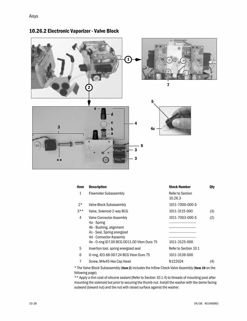
Aisys
10-38 04/08 M1046983
10.26.2 Electronic Vaporizer - Valve Block
ab
c3
**
de
7
1
4
3
3
4c
5
2
6
Item Description Stock Number Qty
1 Flowmeter Subassembly Refer to Section 10.26.3
2* Valve Block Subassembly 1011-7000-000-S
3** Valve, Solenoid 2-way BCG 1011-3115-000 (3)
4 Valve Connector Assembly4a - Spring4b - Bushing, alignment4c - Seal, Spring energized4d - Connector Asssemly4e - O-ring ID7.00 BCG OD11.00 Viton Duro 75
1011-7003-000-S--------------------------------------------------------------------------------------------1011-3125-000
(2)
5 Insertion tool, spring energized seal Refer to Section 10.1
6 O-ring, ID3.68 OD7.24 BCG Viton Duro 75 1011-3139-000
7 Screw, M4x45 Hex Cap Head N122024 (4)
* The Valve Block Subassembly (Item 2) includes the Inflow Check Valve Assembly (Item 10 on the following page).** Apply a thin coat of silicone sealant (Refer to Section 10.1.4) to threads of mounting post after mounting the solenoid but prior to securing the thumb nut. Install the washer with the dome facing outward (toward nut) and the nut with raised surface against the washer.
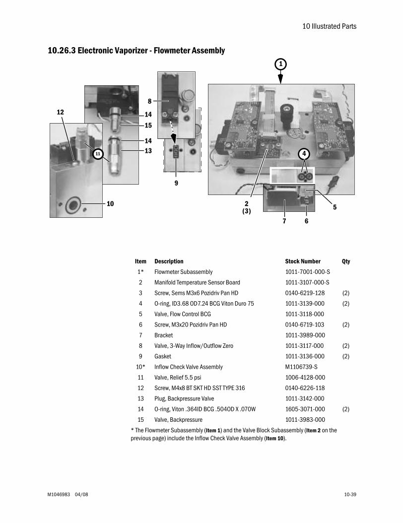
10 Illustrated Parts
M1046983 04/08 10-39
10.26.3 Electronic Vaporizer - Flowmeter Assembly
4
1
5
6
9
8
12
10 2(3)
11
14
7
14
13
15
Item Description Stock Number Qty
1* Flowmeter Subassembly 1011-7001-000-S
2 Manifold Temperature Sensor Board 1011-3107-000-S
3 Screw, Sems M3x6 Pozidriv Pan HD 0140-6219-128 (2)
4 O-ring, ID3.68 OD7.24 BCG Viton Duro 75 1011-3139-000 (2)
5 Valve, Flow Control BCG 1011-3118-000
6 Screw, M3x20 Pozidriv Pan HD 0140-6719-103 (2)
7 Bracket 1011-3989-000
8 Valve, 3-Way Inflow/Outflow Zero 1011-3117-000 (2)
9 Gasket 1011-3136-000 (2)
10* Inflow Check Valve Assembly M1106739-S
11 Valve, Relief 5.5 psi 1006-4128-000
12 Screw, M4x8 BT SKT HD SST TYPE 316 0140-6226-118
13 Plug, Backpressure Valve 1011-3142-000
14 O-ring, Viton .364ID BCG .504OD X .070W 1605-3071-000 (2)
15 Valve, Backpressure 1011-3983-000
* The Flowmeter Subassembly (Item 1) and the Valve Block Subassembly (Item 2 on the previous page) include the Inflow Check Valve Assembly (Item 10).
Aisys
10-40 04/08 M1046983
10.27 Aladin2 Cassette Components
Item Description Stock Number Qty
1 Filler cap (includes O-ring and tether) 1100-3043-000
2 O-ring, filler cap 1100-3135-000
3 Handle 1100-8001-000
4 Screw, handle 1100-3134-000 (2)
5 Agent Cassette board 1011-3170-000
6 Screw, M3x10 with Nylon, SKT HD CAP non-DES M1059773 (2)
7 Screw, M3x10 with Nylon, HEX HD CAP DES M1083995 (2)
8 Washer, insulating DES N115003 (2)
9 Relief Valve, DES cassette only DES 1100-3077-000
10 Sight glass, with two o-rings 1100-3083-000
11 O-ring, sight glass 1100-3114-000 (2)
12 Screw, sight glass 1100-3134-000 (2)
13 Contact retainer 1100-3044-000
14 Front labels, with Enhanced Temperature Sensing
DES 1100-3052-000
ENF M1127133
ISO M1127135
SEV M1127137
Front labels, without Enhanced Temperatur Sensing
ENF 1100-3053-000
ISO 1100-3055-000
SEV 1100-3056-000
15 Masks
DES 1100-3058-000
ENF 1100-3059-000
ISO 1100-3061-000
SEV 1100-3062-000
Test 1011-3920-000
16 Screw, M3x10 with Nylon, SKT HD CAP M1059773
17 Screw, bottom plate 6019-5404-301 (2)
18 Label, OEM
Baxter 1100-3140-000
Abbott SEVO 1100-3139-000
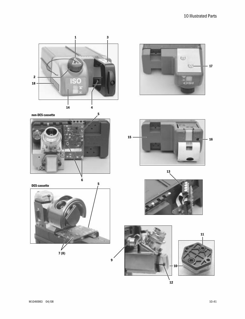
10 Illustrated Parts
M1046983 04/08 10-41
1 3
4
2
17
1516
5
6
13
non-DES cassette
DES cassette
7 (8)
11
12
10
5
14
18
9
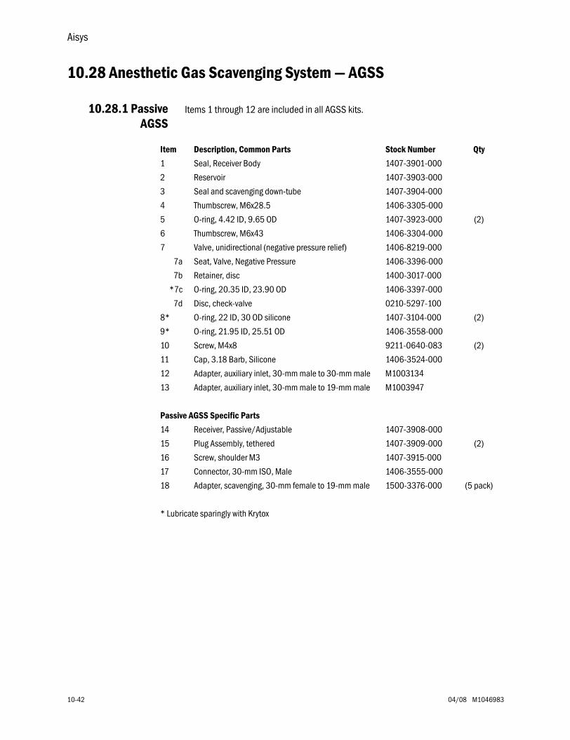
Aisys
10-42 04/08 M1046983
10.28 Anesthetic Gas Scavenging System — AGSS
10.28.1 PassiveAGSS
Items 1 through 12 are included in all AGSS kits.
Item Description, Common Parts Stock Number Qty
1 Seal, Receiver Body 1407-3901-000
2 Reservoir 1407-3903-000
3 Seal and scavenging down-tube 1407-3904-000
4 Thumbscrew, M6x28.5 1406-3305-000
5 O-ring, 4.42 ID, 9.65 OD 1407-3923-000 (2)
6 Thumbscrew, M6x43 1406-3304-000
7 Valve, unidirectional (negative pressure relief) 1406-8219-000
7a Seat, Valve, Negative Pressure 1406-3396-000
7b Retainer, disc 1400-3017-000
*7c O-ring, 20.35 ID, 23.90 OD 1406-3397-000
7d Disc, check-valve 0210-5297-100
8* O-ring, 22 ID, 30 OD silicone 1407-3104-000 (2)
9* O-ring, 21.95 ID, 25.51 OD 1406-3558-000
10 Screw, M4x8 9211-0640-083 (2)
11 Cap, 3.18 Barb, Silicone 1406-3524-000
12 Adapter, auxiliary inlet, 30-mm male to 30-mm male M1003134
13 Adapter, auxiliary inlet, 30-mm male to 19-mm male M1003947
Passive AGSS Specific Parts
14 Receiver, Passive/Adjustable 1407-3908-000
15 Plug Assembly, tethered 1407-3909-000 (2)
16 Screw, shoulder M3 1407-3915-000
17 Connector, 30-mm ISO, Male 1406-3555-000
18 Adapter, scavenging, 30-mm female to 19-mm male 1500-3376-000 (5 pack)
* Lubricate sparingly with Krytox
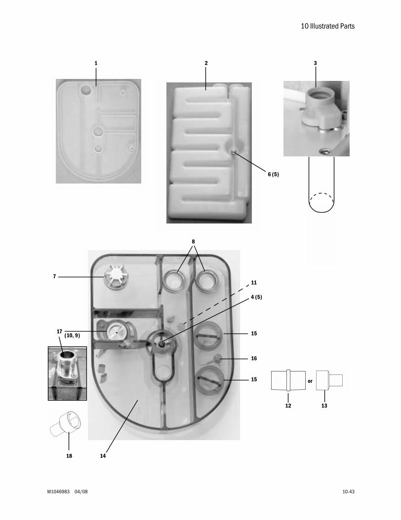
10 Illustrated Parts
M1046983 04/08 10-43
14
1 2 3
6 (5)
4 (5)
8
7
15
16
15
12
17 (10, 9)
11
13
or
18
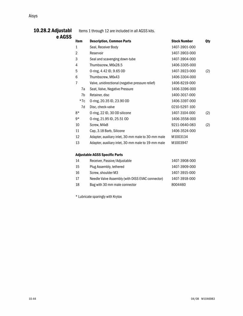
Aisys
10-44 04/08 M1046983
10.28.2 Adjustable AGSS
Items 1 through 12 are included in all AGSS kits.
Item Description, Common Parts Stock Number Qty
1 Seal, Receiver Body 1407-3901-000
2 Reservoir 1407-3903-000
3 Seal and scavenging down-tube 1407-3904-000
4 Thumbscrew, M6x28.5 1406-3305-000
5 O-ring, 4.42 ID, 9.65 OD 1407-3923-000 (2)
6 Thumbscrew, M6x43 1406-3304-000
7 Valve, unidirectional (negative pressure relief) 1406-8219-000
7a Seat, Valve, Negative Pressure 1406-3396-000
7b Retainer, disc 1400-3017-000
*7c O-ring, 20.35 ID, 23.90 OD 1406-3397-000
7d Disc, check-valve 0210-5297-100
8* O-ring, 22 ID, 30 OD silicone 1407-3104-000 (2)
9* O-ring, 21.95 ID, 25.51 OD 1406-3558-000
10 Screw, M4x8 9211-0640-083 (2)
11 Cap, 3.18 Barb, Silicone 1406-3524-000
12 Adapter, auxiliary inlet, 30-mm male to 30-mm male M1003134
13 Adapter, auxiliary inlet, 30-mm male to 19-mm male M1003947
Adjustable AGSS Specific Parts
14 Receiver, Passive/Adjustable 1407-3908-000
15 Plug Assembly, tethered 1407-3909-000
16 Screw, shoulder M3 1407-3915-000
17 Needle Valve Assembly (with DISS EVAC connector) 1407-3918-000
18 Bag with 30 mm male connector 8004460
* Lubricate sparingly with Krytox
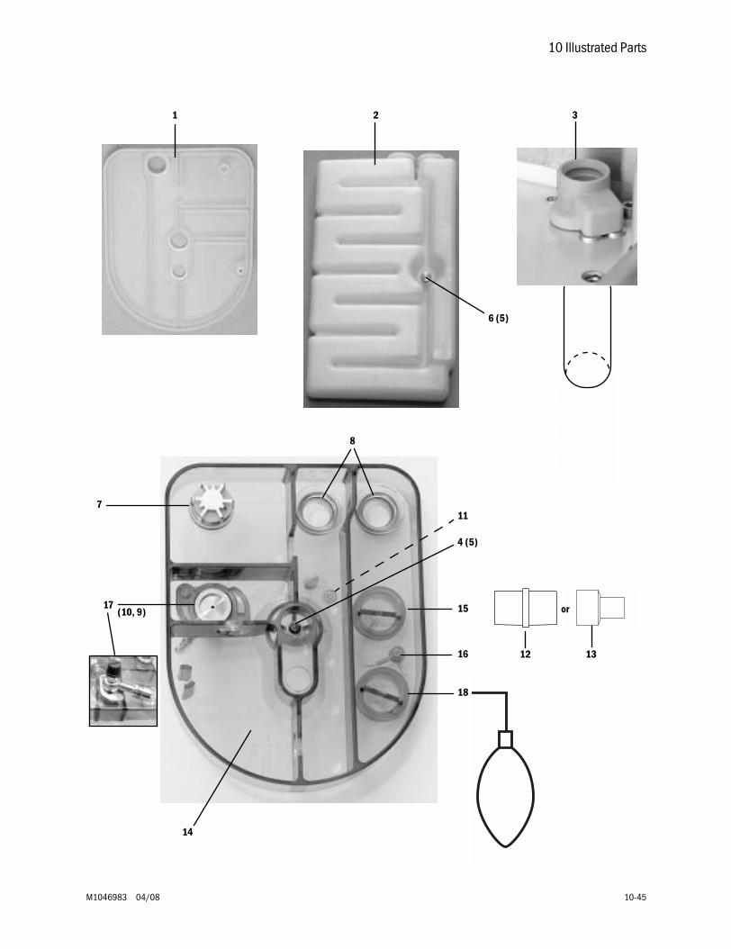
10 Illustrated Parts
M1046983 04/08 10-45
14
1 2 3
6 (5)
4 (5)
8
7
15
16
18
17 (10, 9)
11
12 13
or
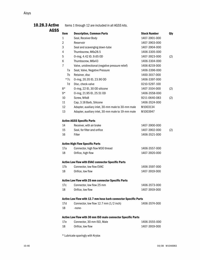
Aisys
10-46 04/08 M1046983
10.28.3 ActiveAGSS
Items 1 through 12 are included in all AGSS kits.
Item Description, Common Parts Stock Number Qty1 Seal, Receiver Body 1407-3901-0002 Reservoir 1407-3903-0003 Seal and scavenging down-tube 1407-3904-0004 Thumbscrew, M6x28.5 1406-3305-0005 O-ring, 4.42 ID, 9.65 OD 1407-3923-000 (2)6 Thumbscrew, M6x43 1406-3304-0007 Valve, unidirectional (negative pressure relief) 1406-8219-000
7a Seat, Valve, Negative Pressure 1406-3396-0007b Retainer, disc 1400-3017-000
*7c O-ring, 20.35 ID, 23.90 OD 1406-3397-0007d Disc, check-valve 0210-5297-100
8* O-ring, 22 ID, 30 OD silicone 1407-3104-000 (2)9* O-ring, 21.95 ID, 25.51 OD 1406-3558-00010 Screw, M4x8 9211-0640-083 (2)11 Cap, 3.18 Barb, Silicone 1406-3524-00012 Adapter, auxiliary inlet, 30-mm male to 30-mm male M100313413 Adapter, auxiliary inlet, 30-mm male to 19-mm male M1003947
Active AGSS Specific Parts14 Receiver, with air brake 1407-3900-00015 Seal, for filter and orifice 1407-3902-000 (2)16 Filter 1406-3521-000
Active High Flow Specific Parts17a Connector, high flow M30 thread 1406-3557-00018 Orifice, high flow 1407-3920-000
Active Low Flow with EVAC connector Specific Parts17b Connector, low flow EVAC 1406-3597-00018 Orifice, low flow 1407-3919-000
Active Low Flow with 25 mm connector Specific Parts17c Connector, low flow 25 mm 1406-3573-00018 Orifice, low flow 1407-3919-000
Active Low Flow with 12.7 mm hose barb connector Specific Parts17d Connector, low flow 12.7 mm (1/2 inch) 1406-3574-00018 -none-
Active Low Flow with 30 mm ISO male connector Specific Parts17e Connector, 30 mm ISO, Male 1406-3555-00018 Orifice, low flow 1407-3919-000
* Lubricate sparingly with Krytox
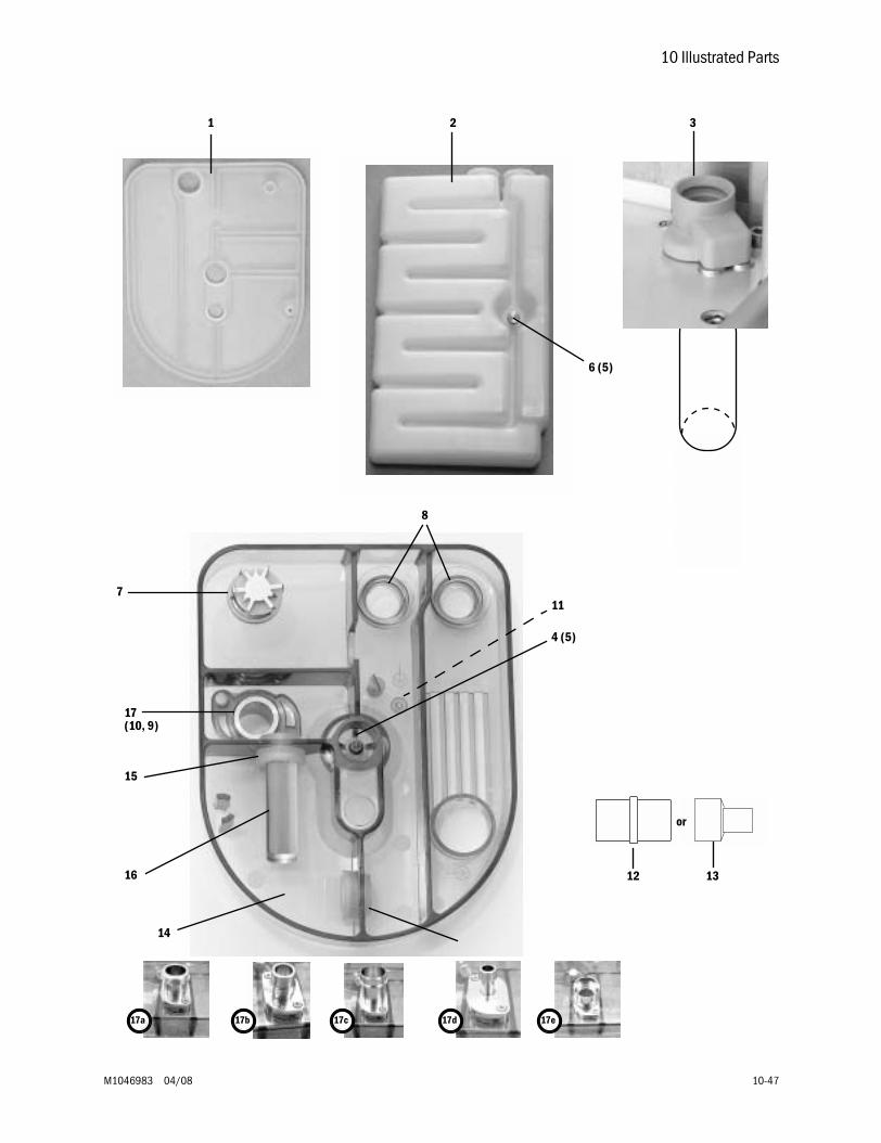
10 Illustrated Parts
M1046983 04/08 10-47
1415, 18
1 2 3
6 (5)
4 (5)
8
7
17 (10, 9)
11
15
16 12 13
or
17a 17c 17d17b 17e
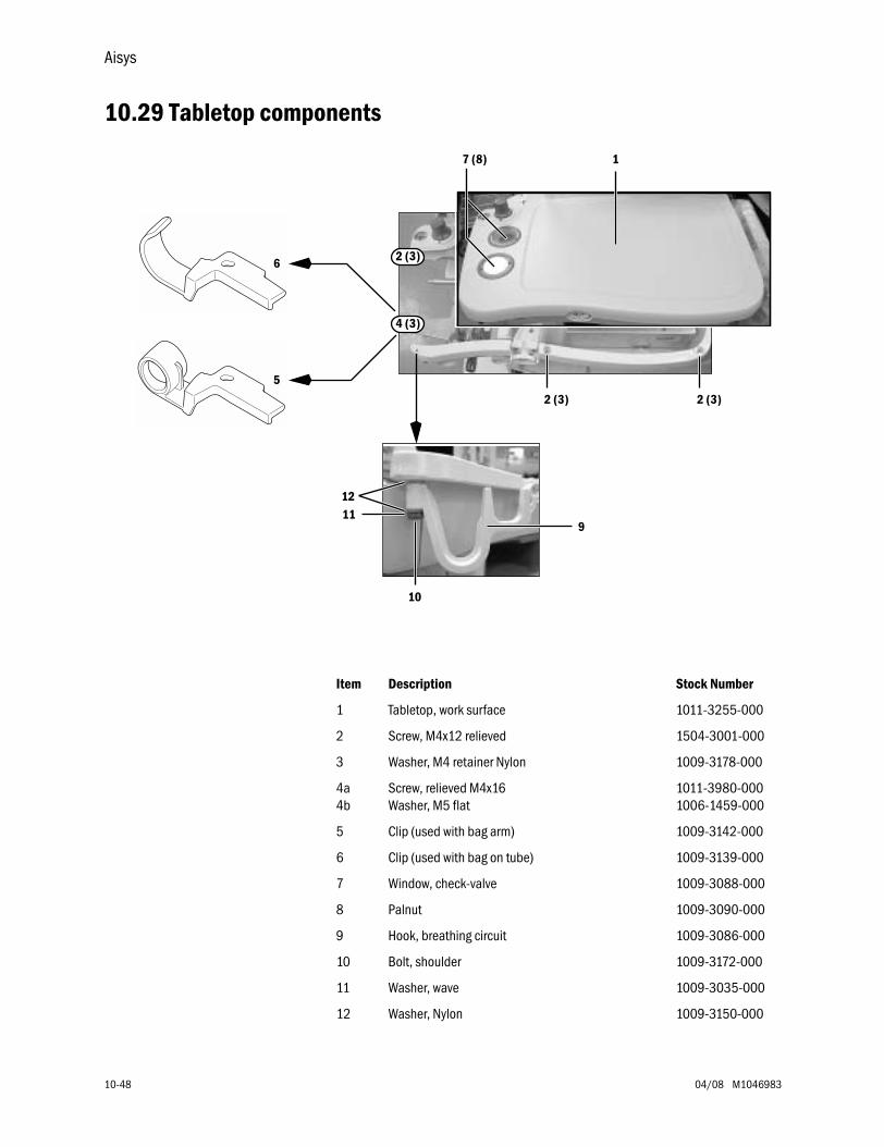
Aisys
10-48 04/08 M1046983
10.29 Tabletop components
Item Description Stock Number
1 Tabletop, work surface 1011-3255-000
2 Screw, M4x12 relieved 1504-3001-000
3 Washer, M4 retainer Nylon 1009-3178-000
4a4b
Screw, relieved M4x16Washer, M5 flat
1011-3980-0001006-1459-000
5 Clip (used with bag arm) 1009-3142-000
6 Clip (used with bag on tube) 1009-3139-000
7 Window, check-valve 1009-3088-000
8 Palnut 1009-3090-000
9 Hook, breathing circuit 1009-3086-000
10 Bolt, shoulder 1009-3172-000
11 Washer, wave 1009-3035-000
12 Washer, Nylon 1009-3150-000
1
2 (3)2 (3)
9
10
1112
6
5
4 (3)
2 (3)
7 (8)
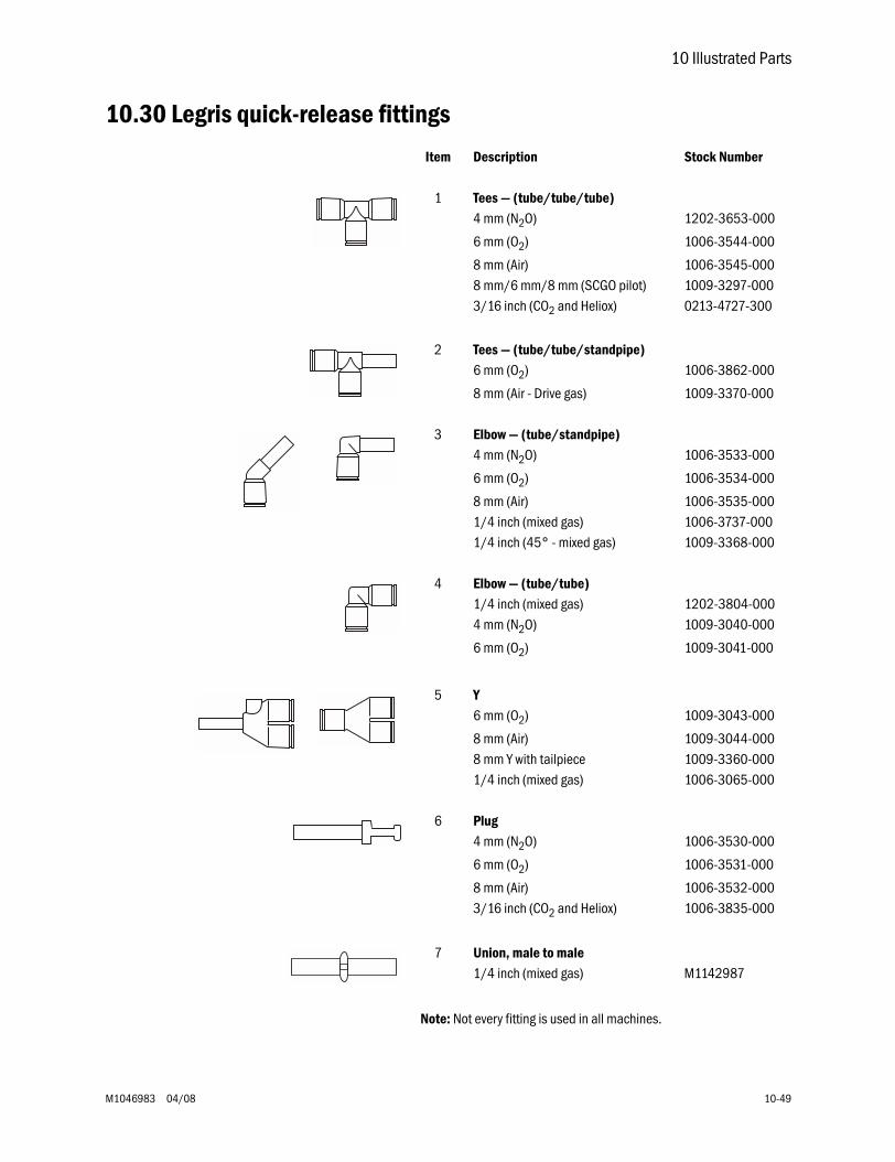
10 Illustrated Parts
M1046983 04/08 10-49
10.30 Legris quick-release fittings
Item Description Stock Number
1 Tees — (tube/tube/tube)4 mm (N2O) 1202-3653-000
6 mm (O2) 1006-3544-000
8 mm (Air) 1006-3545-0008 mm/6 mm/8 mm (SCGO pilot) 1009-3297-0003/16 inch (CO2 and Heliox) 0213-4727-300
2 Tees — (tube/tube/standpipe)6 mm (O2) 1006-3862-000
8 mm (Air - Drive gas) 1009-3370-000
3 Elbow — (tube/standpipe)4 mm (N2O) 1006-3533-000
6 mm (O2) 1006-3534-000
8 mm (Air) 1006-3535-0001/4 inch (mixed gas) 1006-3737-0001/4 inch (45° - mixed gas) 1009-3368-000
4 Elbow — (tube/tube)1/4 inch (mixed gas) 1202-3804-0004 mm (N2O) 1009-3040-000
6 mm (O2) 1009-3041-000
5 Y6 mm (O2) 1009-3043-000
8 mm (Air) 1009-3044-0008 mm Y with tailpiece 1009-3360-0001/4 inch (mixed gas) 1006-3065-000
6 Plug4 mm (N2O) 1006-3530-000
6 mm (O2) 1006-3531-000
8 mm (Air) 1006-3532-0003/16 inch (CO2 and Heliox) 1006-3835-000
7 Union, male to male1/4 inch (mixed gas) M1142987
Note: Not every fitting is used in all machines.
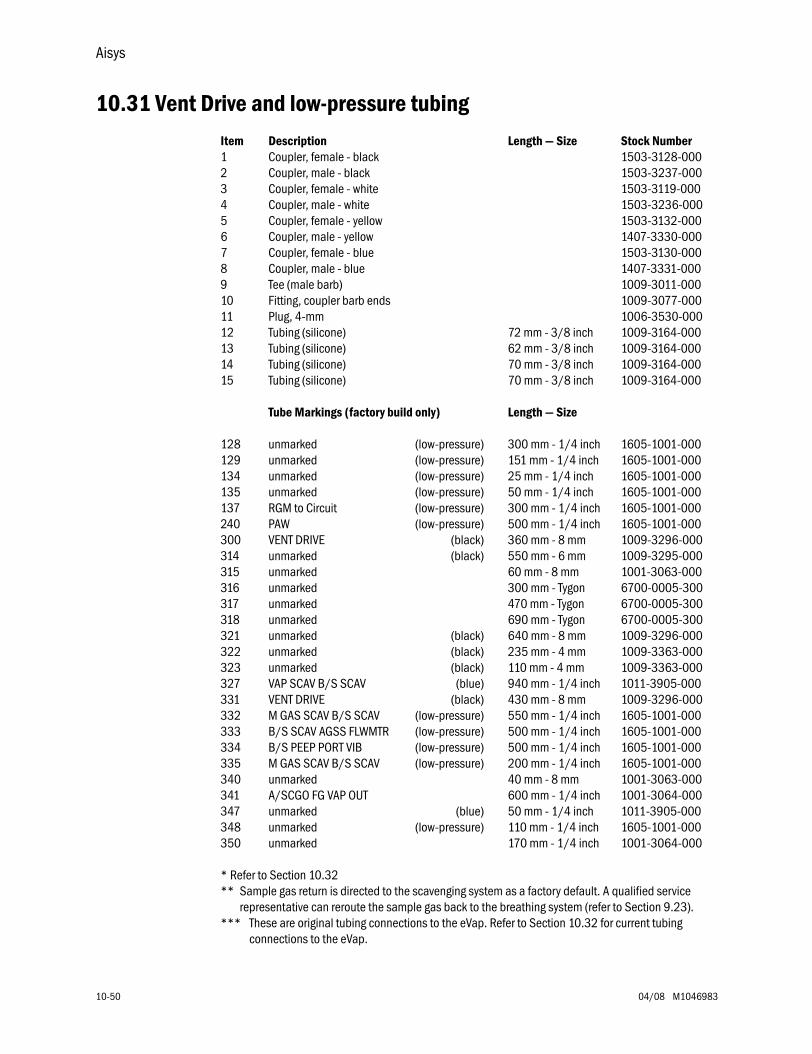
Aisys
10-50 04/08 M1046983
10.31 Vent Drive and low-pressure tubingItem Description Length — Size Stock Number1 Coupler, female - black 1503-3128-0002 Coupler, male - black 1503-3237-0003 Coupler, female - white 1503-3119-0004 Coupler, male - white 1503-3236-0005 Coupler, female - yellow 1503-3132-0006 Coupler, male - yellow 1407-3330-0007 Coupler, female - blue 1503-3130-0008 Coupler, male - blue 1407-3331-0009 Tee (male barb) 1009-3011-00010 Fitting, coupler barb ends 1009-3077-00011 Plug, 4-mm 1006-3530-00012 Tubing (silicone) 72 mm - 3/8 inch 1009-3164-00013 Tubing (silicone) 62 mm - 3/8 inch 1009-3164-00014 Tubing (silicone) 70 mm - 3/8 inch 1009-3164-00015 Tubing (silicone) 70 mm - 3/8 inch 1009-3164-000
Tube Markings (factory build only) Length — Size
128 unmarked (low-pressure) 300 mm - 1/4 inch 1605-1001-000129 unmarked (low-pressure) 151 mm - 1/4 inch 1605-1001-000134 unmarked (low-pressure) 25 mm - 1/4 inch 1605-1001-000135 unmarked (low-pressure) 50 mm - 1/4 inch 1605-1001-000137 RGM to Circuit (low-pressure) 300 mm - 1/4 inch 1605-1001-000240 PAW (low-pressure) 500 mm - 1/4 inch 1605-1001-000300 VENT DRIVE (black) 360 mm - 8 mm 1009-3296-000314 unmarked (black) 550 mm - 6 mm 1009-3295-000315 unmarked 60 mm - 8 mm 1001-3063-000316 unmarked 300 mm - Tygon 6700-0005-300317 unmarked 470 mm - Tygon 6700-0005-300318 unmarked 690 mm - Tygon 6700-0005-300321 unmarked (black) 640 mm - 8 mm 1009-3296-000322 unmarked (black) 235 mm - 4 mm 1009-3363-000323 unmarked (black) 110 mm - 4 mm 1009-3363-000327 VAP SCAV B/S SCAV (blue) 940 mm - 1/4 inch 1011-3905-000331 VENT DRIVE (black) 430 mm - 8 mm 1009-3296-000332 M GAS SCAV B/S SCAV (low-pressure) 550 mm - 1/4 inch 1605-1001-000333 B/S SCAV AGSS FLWMTR (low-pressure) 500 mm - 1/4 inch 1605-1001-000334 B/S PEEP PORT VIB (low-pressure) 500 mm - 1/4 inch 1605-1001-000335 M GAS SCAV B/S SCAV (low-pressure) 200 mm - 1/4 inch 1605-1001-000340 unmarked 40 mm - 8 mm 1001-3063-000341 A/SCGO FG VAP OUT 600 mm - 1/4 inch 1001-3064-000347 unmarked (blue) 50 mm - 1/4 inch 1011-3905-000348 unmarked (low-pressure) 110 mm - 1/4 inch 1605-1001-000350 unmarked 170 mm - 1/4 inch 1001-3064-000
* Refer to Section 10.32** Sample gas return is directed to the scavenging system as a factory default. A qualified service
representative can reroute the sample gas back to the breathing system (refer to Section 9.23).*** These are original tubing connections to the eVap. Refer to Section 10.32 for current tubing
connections to the eVap.
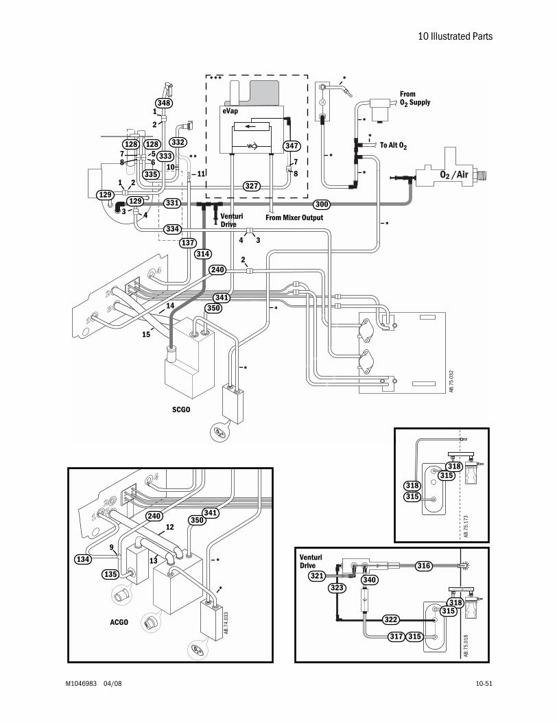
10 Illustrated Parts
M1046983 04/08 10-51
300
332
333
128
129
240
334
*
*
*
21
34
56
**
335
137
1011
134
135
9
12
13
*
*
240
AB.7
4.03
3
ACGO
350341
331
314
129
*
2
43
*
SCGO
*
14
15
To Alt O2
FromO2 Supply
From Mixer Output
Venturi
AB.7
5.01
8
322
317
316
323
Drive321
315
318315
340
AB.7
5.17
3
315318
315318
Venturi Drive
*
128 347
327
1
78
AB.7
5.03
2
8
7
2
348
***
350341
*
eVap
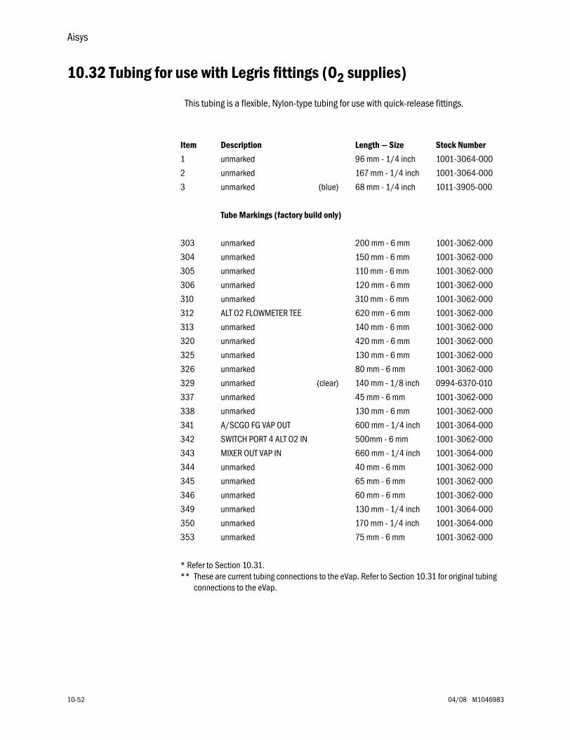
Aisys
10-52 04/08 M1046983
10.32 Tubing for use with Legris fittings (O2 supplies)
This tubing is a flexible, Nylon-type tubing for use with quick-release fittings.
Item Description Length — Size Stock Number
1 unmarked 96 mm - 1/4 inch 1001-3064-000
2 unmarked 167 mm - 1/4 inch 1001-3064-000
3 unmarked (blue) 68 mm - 1/4 inch 1011-3905-000
Tube Markings (factory build only)
303 unmarked 200 mm - 6 mm 1001-3062-000
304 unmarked 150 mm - 6 mm 1001-3062-000
305 unmarked 110 mm - 6 mm 1001-3062-000
306 unmarked 120 mm - 6 mm 1001-3062-000
310 unmarked 310 mm - 6 mm 1001-3062-000
312 ALT O2 FLOWMETER TEE 620 mm - 6 mm 1001-3062-000
313 unmarked 140 mm - 6 mm 1001-3062-000
320 unmarked 420 mm - 6 mm 1001-3062-000
325 unmarked 130 mm - 6 mm 1001-3062-000
326 unmarked 80 mm - 6 mm 1001-3062-000
329 unmarked (clear) 140 mm - 1/8 inch 0994-6370-010
337 unmarked 45 mm - 6 mm 1001-3062-000
338 unmarked 130 mm - 6 mm 1001-3062-000
341 A/SCGO FG VAP OUT 600 mm - 1/4 inch 1001-3064-000
342 SWITCH PORT 4 ALT O2 IN 500mm - 6 mm 1001-3062-000
343 MIXER OUT VAP IN 660 mm - 1/4 inch 1001-3064-000
344 unmarked 40 mm - 6 mm 1001-3062-000
345 unmarked 65 mm - 6 mm 1001-3062-000
346 unmarked 60 mm - 6 mm 1001-3062-000
349 unmarked 130 mm - 1/4 inch 1001-3064-000
350 unmarked 170 mm - 1/4 inch 1001-3064-000
353 unmarked 75 mm - 6 mm 1001-3062-000
* Refer to Section 10.31.** These are current tubing connections to the eVap. Refer to Section 10.31 for original tubing
connections to the eVap.
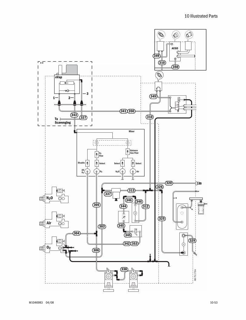
10 Illustrated Parts
M1046983 04/08 10-53
P
Air
N2O
O2
N2OAltO2
O2 Air
P
P
SelectDisable
BalanceGas Flow
SelectSelect
O2Flow
PP
Mixer
ACGO
310350
341 350
349
349
310327
342
320
337313
326
325
312344346
345
345304
303
306
338
346305
353
AB.7
5.17
3m
*
*
343
329
eVap
ToScavenging
**
1 23
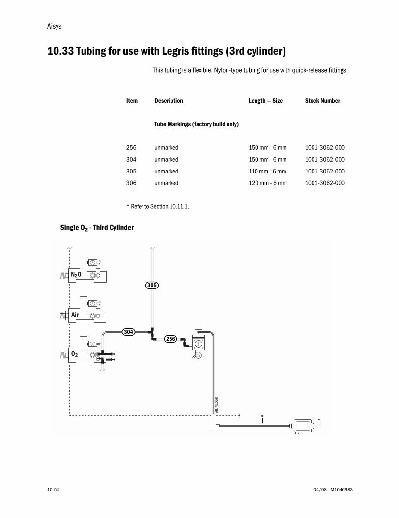
Aisys
10-54 04/08 M1046983
10.33 Tubing for use with Legris fittings (3rd cylinder)
This tubing is a flexible, Nylon-type tubing for use with quick-release fittings.
Single O2 - Third Cylinder
Item Description Length — Size Stock Number
Tube Markings (factory build only)
256 unmarked 150 mm - 6 mm 1001-3062-000
304 unmarked 150 mm - 6 mm 1001-3062-000
305 unmarked 110 mm - 6 mm 1001-3062-000
306 unmarked 120 mm - 6 mm 1001-3062-000
* Refer to Section 10.11.1.
AB.7
5.01
7
Air
N2O
O2
P
P
P
P
Air
N2O
O2
P
P
P
P
Air
N2O
O2
P
P
P
P
305
304256
AB.7
5.05
8
*
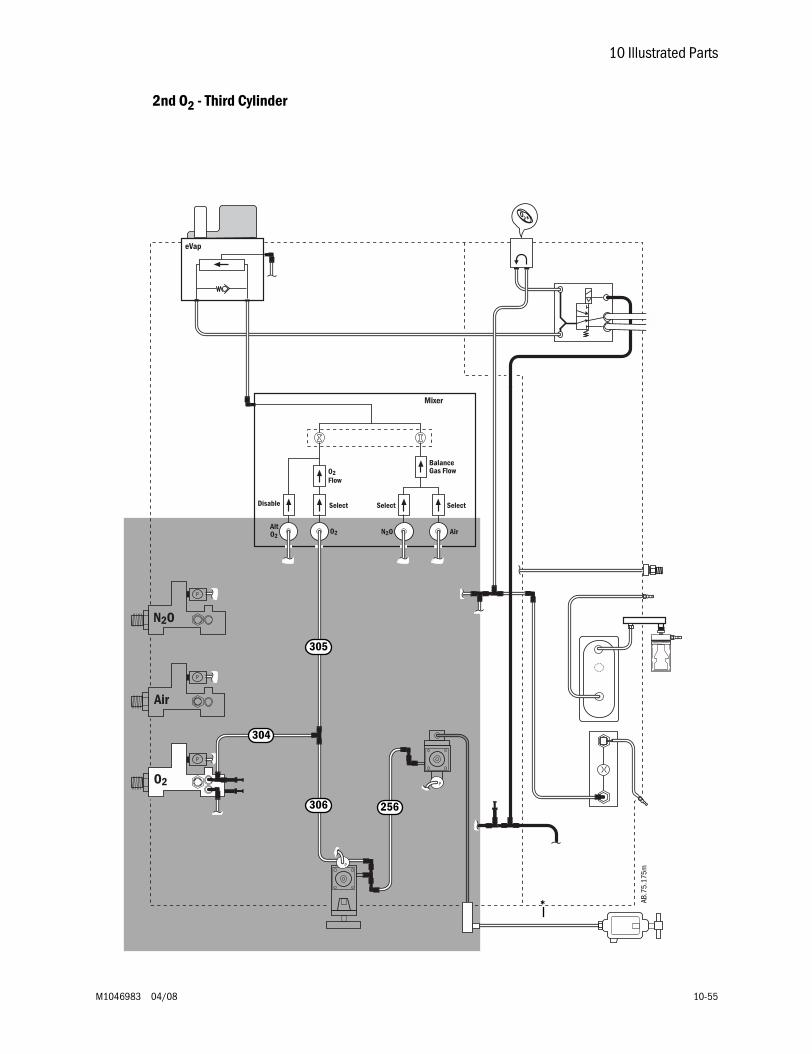
10 Illustrated Parts
M1046983 04/08 10-55
2nd O2 - Third Cylinder
Air
N2O
O2
P
P
N2OAltO2
O2 Air
O2Flow
SelectDisable
BalanceGas Flow
SelectSelect
P
P
P
eVap
Mixer
AB.7
5.17
5m305
304
306 256
*
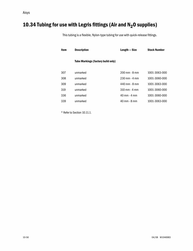
Aisys
10-56 04/08 M1046983
10.34 Tubing for use with Legris fittings (Air and N2O supplies)
This tubing is a flexible, Nylon-type tubing for use with quick-release fittings.
Item Description Length — Size Stock Number
Tube Markings (factory build only)
307 unmarked 200 mm - 8 mm 1001-3063-000
308 unmarked 230 mm - 4 mm 1001-3060-000
309 unmarked 440 mm - 8 mm 1001-3063-000
319 unmarked 310 mm - 4 mm 1001-3060-000
336 unmarked 40 mm - 4 mm 1001-3060-000
339 unmarked 40 mm - 8 mm 1001-3063-000
* Refer to Section 10.11.1.
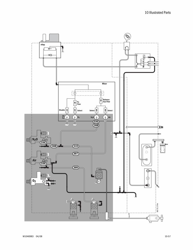
10 Illustrated Parts
M1046983 04/08 10-57
Air
N2O
O2
P
P
N2OAltO2
O2 Air
O2Flow
SelectDisable
BalanceGas Flow
SelectSelect
P
P
P P
eVap
Mixer
AB.7
5.17
4m
336308
336
339
319
307
308
309
*
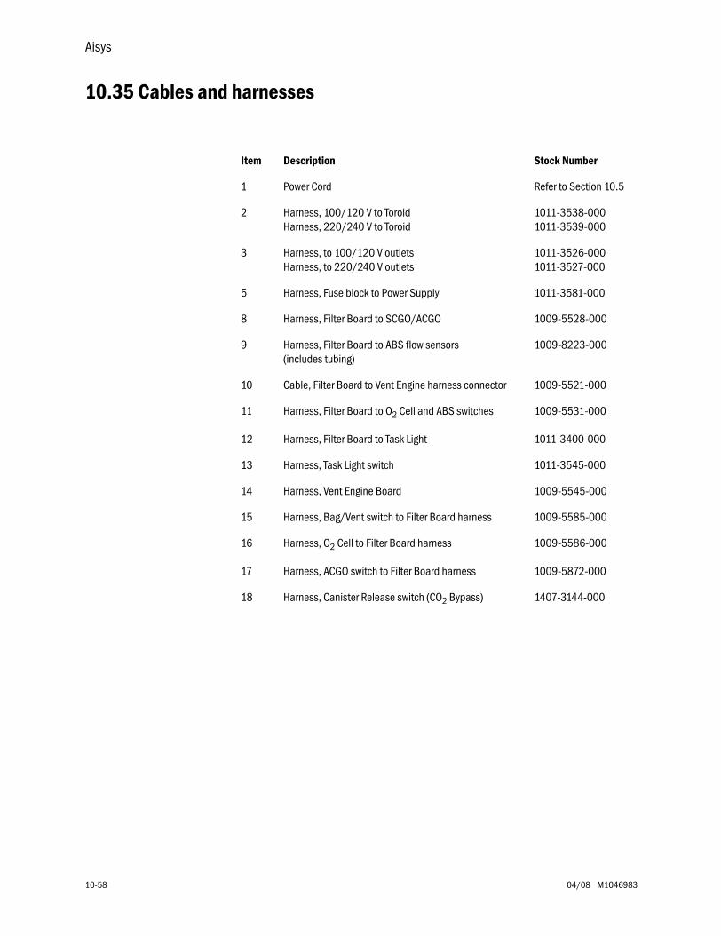
Aisys
10-58 04/08 M1046983
10.35 Cables and harnesses
Item Description Stock Number
1 Power Cord Refer to Section 10.5
2 Harness, 100/120 V to ToroidHarness, 220/240 V to Toroid
1011-3538-0001011-3539-000
3 Harness, to 100/120 V outletsHarness, to 220/240 V outlets
1011-3526-0001011-3527-000
5 Harness, Fuse block to Power Supply 1011-3581-000
8 Harness, Filter Board to SCGO/ACGO 1009-5528-000
9 Harness, Filter Board to ABS flow sensors (includes tubing)
1009-8223-000
10 Cable, Filter Board to Vent Engine harness connector 1009-5521-000
11 Harness, Filter Board to O2 Cell and ABS switches 1009-5531-000
12 Harness, Filter Board to Task Light 1011-3400-000
13 Harness, Task Light switch 1011-3545-000
14 Harness, Vent Engine Board 1009-5545-000
15 Harness, Bag/Vent switch to Filter Board harness 1009-5585-000
16 Harness, O2 Cell to Filter Board harness 1009-5586-000
17 Harness, ACGO switch to Filter Board harness 1009-5872-000
18 Harness, Canister Release switch (CO2 Bypass) 1407-3144-000
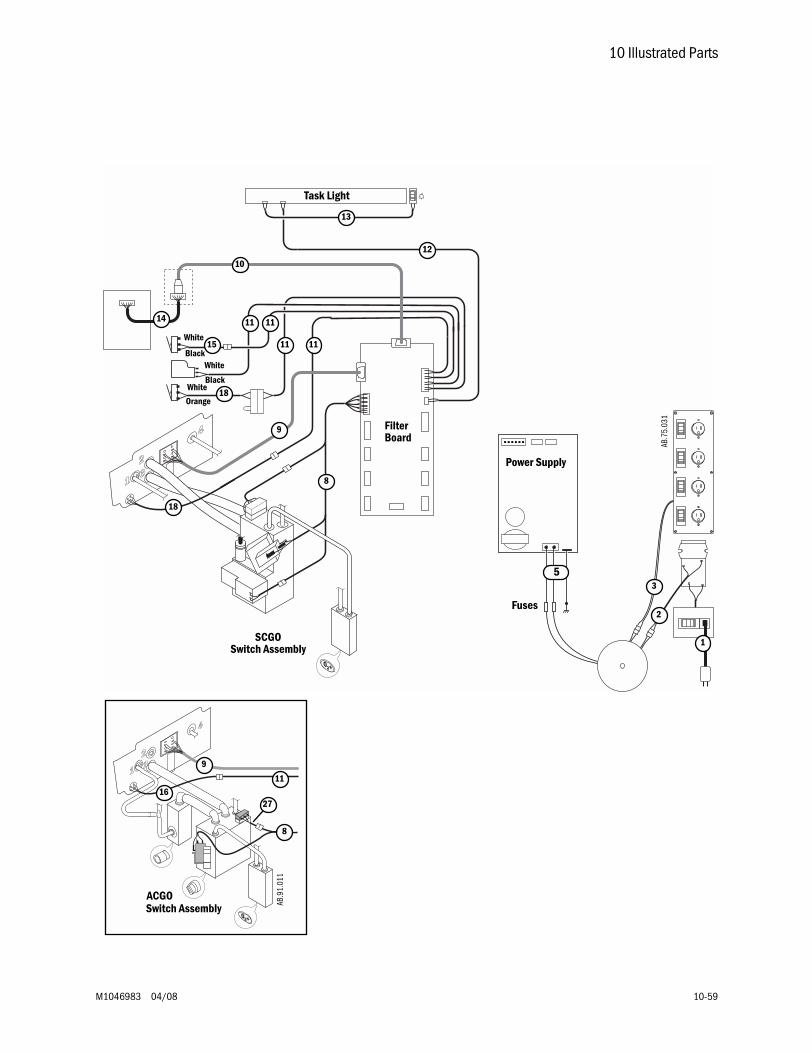
10 Illustrated Parts
M1046983 04/08 10-59
3
8
9
2
12
13
1
AB.7
5.03
1
14
15
18
Power Supply
SCGOSwitch Assembly
FilterBoard
Fuses
8
16
9
Switch AssemblyACGO
11
27
AB.9
1.01
1
11
10
Task Light
11 11
5
11
18
White
WhiteBlack
WhiteBlack
Orange
Aisys
10-60 04/08 M1046983
10.36 Cables and harnesses in lower electronic enclosure
Item Description Stock Number
1 Cable, to M-Gas (Airway module) power supply 1011-3549-000
2 Cable, to Display Unit system power interface 1011-3547-000
3 Cable, to Display Unit system signal interface 1011-3548-000
4 Harness, J3-PCB to J5-DCB 1009-5552-000
5 Cable, ribbon J2-ACB to J9-DCB 1009-5561-000
6 Harness, J7-ACB to J6-DCB 1009-5556-000
7 Cable, ribbon J1-ACB to underside of Pan Connector Board 1011-3186-000
8 Harness, J3-ACB to underside of Pan Connector Board 1011-3199-000
9 Harness, J6-ACB to J4-PCB 1009-5551-000
10 Harness, (flex cable) battery 1011-3698-000
11 Harness, Power Supply to PCB 1011-3591-000
12 Harness, PCB to AuxCB 1011-3590-000
13 Harness, DCB to AuxCB 1011-3582-000
14 Cable, S/5 AM Pwr Comm(F-CU8, Rev 10 or greater, required for battery backup of 12 inch AM Display)
1011-3593-000
15 Cable, On-Standby RS232 1009-5935-000
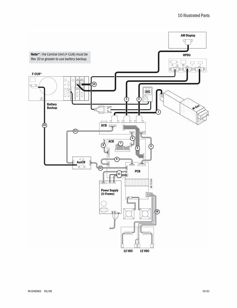
10 Illustrated Parts
M1046983 04/08 10-61
5
3
6
78 4
2
10
9
AB.7
5.03
4
M-Gas
HPDU
ACB
PCB
DCB
1
AuxCB
Power Supply
11
12
13
14
15
F-CU8*
12 VDC 12 VDC
Note*: The Central Unit (F-CU8) must be Rev 10 or greater to use battery backup.
BatteryBackup
(U-Frame)
DIS
AM Display
Aisys
10-62 04/08 M1046983
10.37 Cables and harnesses in Pan enclosure
Item Description Stock Number
1 Cable, ribbon J1-ACB to underside of Pan Connector board 1011-3186-000
2 Harness, J3-ACB to underside of Pan Connector board 1011-3199-000
3 Harness, Filter board to VIB 1011-3408-000
4 Harness, Pan Connector board to VIB 1009-5547-000
5 Cable, ribbon, Pan Connector board to Mixer 1011-3195-000
6 Harness, Pan Fan extension 1011-3561-000
7 Harness, On/Standby (System) switch(not used with new System switch - Refer to Section 10.15)
1009-5542-000
8 Harness, Pan Connector board to gas supply transducers 1011-3404-000
9 Harness, Pan Connector board to Alt O2 and System switch 1011-3403-000
10 Harness, Pan Connector board to EV 1011-3108-000
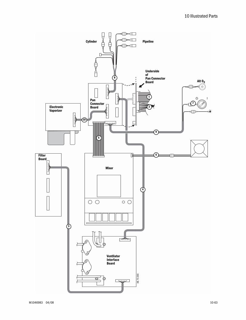
10 Illustrated Parts
M1046983 04/08 10-63
P
P
P
PP
P
1
2
5
7
3
4
Mixer
VentilatorInterfaceBoard
PanConnectorBoard
FilterBoard
UndersideofPan ConnectorBoard
AB.7
5.06
6
10
6
PipelineCylinder
ElectronicVaporizer
Alt O2
9
8
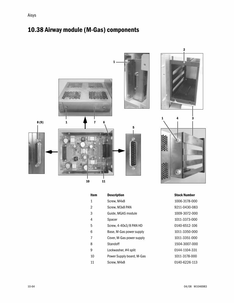
Aisys
10-64 04/08 M1046983
10.38 Airway module (M-Gas) components
Item Description Stock Number
1 Screw, M4x8 1006-3178-000
2 Screw, M3x8 PAN 9211-0430-083
3 Guide, MGAS module 1009-3072-000
4 Spacer 1011-3373-000
5 Screw, 4-40x3/8 PAN HD 0140-6512-106
6 Base, M-Gas power supply 1011-3350-000
7 Cover, M-Gas power supply 1011-3351-000
8 Standoff 1504-3007-000
9 Lockwasher, #4 split 0144-1104-331
10 Power Supply board, M-Gas 1011-3178-000
11 Screw, M4x8 0140-6226-113
1
2
341
5
10
6718 (9)
11
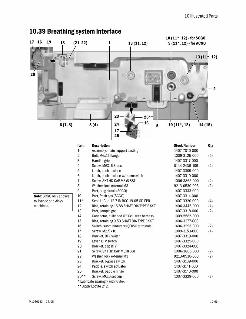
10 Illustrated Parts
M1046983 04/08 10-65
10.39 Breathing system interface
Item Description Stock Number Qty1 Assembly, main support casting 1407-7010-0002 Bolt, M6x16 flange 1009-3125-000 (5)3 Handle, grip 1407-3317-0004 Screw, M6X16 Sems 0144-2436-109 (2)5 Latch, push to close 1407-3309-0006 Latch, push to close w/microswitch 1407-3310-0007 Screw, SKT HD CAP M3x8 SST 1006-3865-000 (2)8 Washer, lock external M3 9213-0530-003 (2)9 Port, plug circuit (ACGO) 1407-3333-00010 Port, fresh gas (SCGO) 1407-3314-00011* Seal, U-Cup 12.7 ID BCG 19.05 OD EPR 1407-3320-000 (4)12 Ring, retaining 15.88 SHAFT DIA TYPE E SST 1406-3446-000 (4)13 Port, sample gas 1407-3318-000 (2)14 Connector, bulkhead O2 Cell, with harness 1009-5586-00015 Ring, retaining 9.53 SHAFT DIA TYPE E SST 1406-3277-00016 Switch, subminiature w/QDISC terminals 1406-3296-000 (2)17 Screw, M2.5 x10 1009-3153-000 (4)18 Bracket, BTV switch 1407-3319-00019 Lever, BTV switch 1407-3325-00020 Bracket, cap BTV 1407-3324-00021 Screw, SKT HD CAP M3x8 SST 1006-3865-000 (2)22 Washer, lock external M3 9213-0530-003 (2)23 Bracket, bypass switch 1407-3139-00024 Paddle, switch actuator 1407-3141-00025 Bracket, paddle hinge 1407-3140-00026** Screw, M6x6 set cup 1007-3329-000 (2)* Lubricate sparingly with Krytox.** Apply Loctite 242.
9 (11*, 12) - for ACGO
13 (11*, 12)
10 (11*, 12) 14 (15)3 (4)
13 (11, 12)
56 (7, 8)
18 (21, 22) 16 19
20
17
2
1
23
24
2517
1626**
10 (11*, 12) - for SCGO
Note: SCGO only applies to Avance and Aisys machines.
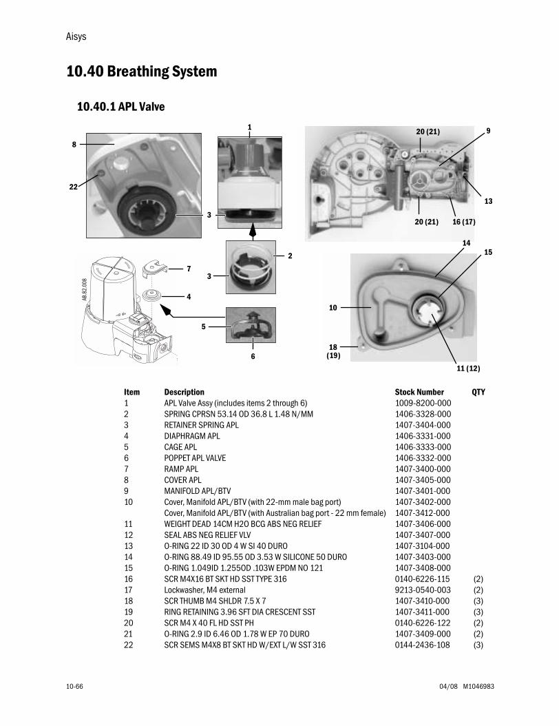
Aisys
10-66 04/08 M1046983
10.40 Breathing System
10.40.1 APL Valve
Item Description Stock Number QTY1 APL Valve Assy (includes items 2 through 6) 1009-8200-0002 SPRING CPRSN 53.14 OD 36.8 L 1.48 N/MM 1406-3328-0003 RETAINER SPRING APL 1407-3404-0004 DIAPHRAGM APL 1406-3331-0005 CAGE APL 1406-3333-0006 POPPET APL VALVE 1406-3332-0007 RAMP APL 1407-3400-0008 COVER APL 1407-3405-0009 MANIFOLD APL/BTV 1407-3401-00010 Cover, Manifold APL/BTV (with 22-mm male bag port)
Cover, Manifold APL/BTV (with Australian bag port - 22 mm female)1407-3402-0001407-3412-000
11 WEIGHT DEAD 14CM H2O BCG ABS NEG RELIEF 1407-3406-00012 SEAL ABS NEG RELIEF VLV 1407-3407-00013 O-RING 22 ID 30 OD 4 W SI 40 DURO 1407-3104-00014 O-RING 88.49 ID 95.55 OD 3.53 W SILICONE 50 DURO 1407-3403-00015 O-RING 1.049ID 1.255OD .103W EPDM NO 121 1407-3408-00016 SCR M4X16 BT SKT HD SST TYPE 316 0140-6226-115 (2)17 Lockwasher, M4 external 9213-0540-003 (2)18 SCR THUMB M4 SHLDR 7.5 X 7 1407-3410-000 (3)19 RING RETAINING 3.96 SFT DIA CRESCENT SST 1407-3411-000 (3)20 SCR M4 X 40 FL HD SST PH 0140-6226-122 (2)21 O-RING 2.9 ID 6.46 OD 1.78 W EP 70 DURO 1407-3409-000 (2)22 SCR SEMS M4X8 BT SKT HD W/EXT L/W SST 316 0144-2436-108 (3)
AB.8
2.00
8
8
18(19)
10
20 (21) 16 (17)
20 (21)
22
2
7
4
9
14
11 (12)
15
13
1
5
6
3
3
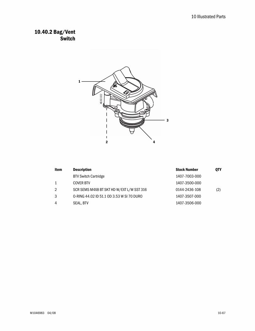
10 Illustrated Parts
M1046983 04/08 10-67
10.40.2 Bag/VentSwitch
Item Description Stock Number QTY
BTV Switch Cartridge 1407-7003-000
1 COVER BTV 1407-3500-000
2 SCR SEMS M4X8 BT SKT HD W/EXT L/W SST 316 0144-2436-108 (2)
3 O-RING 44.02 ID 51.1 OD 3.53 W SI 70 DURO 1407-3507-000
4 SEAL, BTV 1407-3506-000
AB.8
2.02
2
2
1
3
4
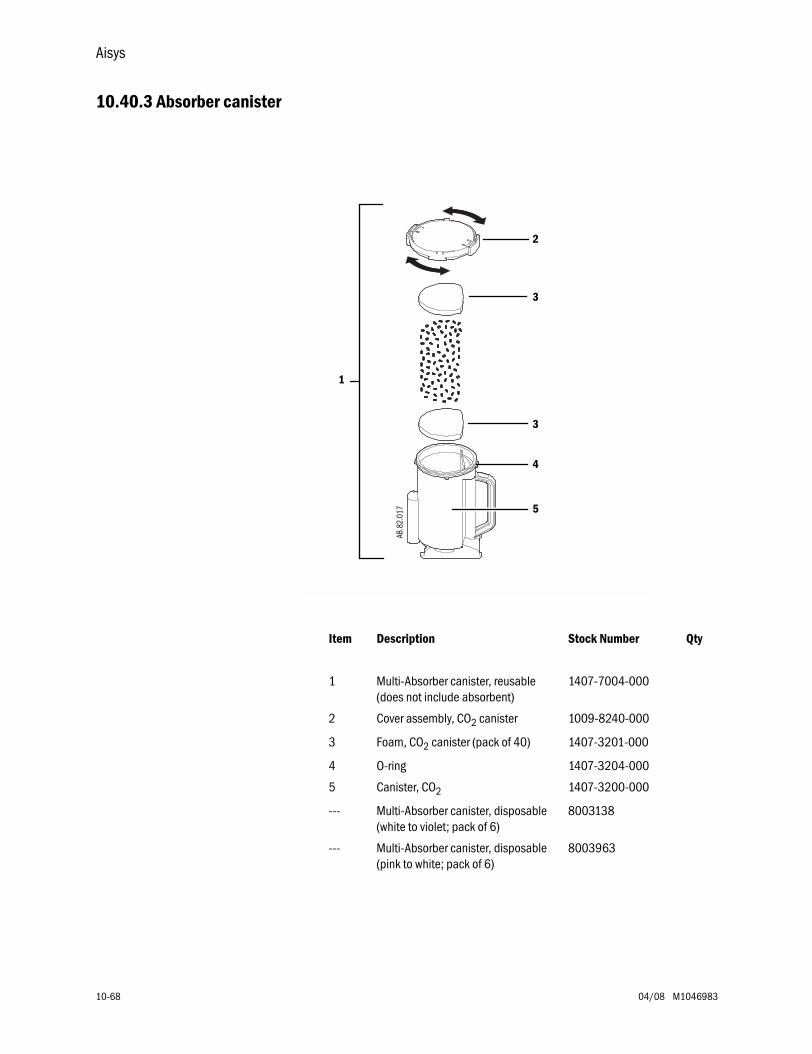
Aisys
10-68 04/08 M1046983
10.40.3 Absorber canister
Item Description Stock Number Qty
1 Multi-Absorber canister, reusable(does not include absorbent)
1407-7004-000
2 Cover assembly, CO2 canister 1009-8240-000
3 Foam, CO2 canister (pack of 40) 1407-3201-000
4 O-ring 1407-3204-000
5 Canister, CO2 1407-3200-000
--- Multi-Absorber canister, disposable(white to violet; pack of 6)
8003138
--- Multi-Absorber canister, disposable(pink to white; pack of 6)
8003963
1
5
3
3
2
AB.8
2.01
7
4
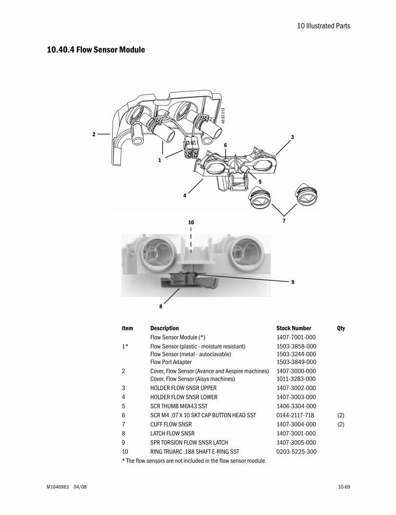
10 Illustrated Parts
M1046983 04/08 10-69
10.40.4 Flow Sensor Module
Item Description Stock Number QtyFlow Sensor Module (*) 1407-7001-000
1* Flow Sensor (plastic - moisture resistant)Flow Sensor (metal - autoclavable)Flow Port Adapter
1503-3858-0001503-3244-0001503-3849-000
2 Cover, Flow Sensor (Avance and Aespire machines)Cover, Flow Sensor (Aisys machines)
1407-3000-0001011-3283-000
3 HOLDER FLOW SNSR UPPER 1407-3002-0004 HOLDER FLOW SNSR LOWER 1407-3003-0005 SCR THUMB M6X43 SST 1406-3304-0006 SCR M4 .07 X 10 SKT CAP BUTTON HEAD SST 0144-2117-718 (2)7 CUFF FLOW SNSR 1407-3004-000 (2)8 LATCH FLOW SNSR 1407-3001-0009 SPR TORSION FLOW SNSR LATCH 1407-3005-00010 RING TRUARC .188 SHAFT E-RING SST 0203-5225-300* The flow sensors are not included in the flow sensor module.
1
3
4
5
6
AB.8
2.01
9
9
2
7
8
10
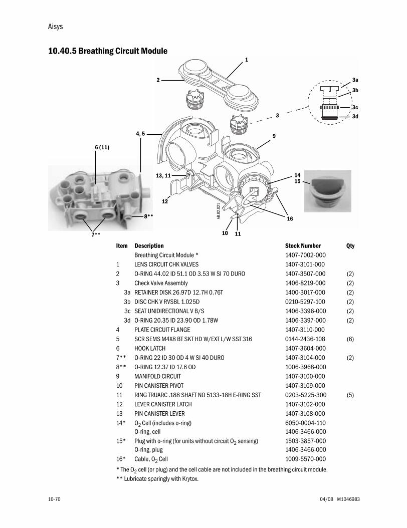
Aisys
10-70 04/08 M1046983
10.40.5 Breathing Circuit Module
Item Description Stock Number QtyBreathing Circuit Module * 1407-7002-000
1 LENS CIRCUIT CHK VALVES 1407-3101-0002 O-RING 44.02 ID 51.1 OD 3.53 W SI 70 DURO 1407-3507-000 (2)3 Check Valve Assembly 1406-8219-000 (2)
3a RETAINER DISK 26.97D 12.7H 0.76T 1400-3017-000 (2)3b DISC CHK V RVSBL 1.025D 0210-5297-100 (2)3c SEAT UNIDIRECTIONAL V B/S 1406-3396-000 (2)3d O-RING 20.35 ID 23.90 OD 1.78W 1406-3397-000 (2)
4 PLATE CIRCUIT FLANGE 1407-3110-0005 SCR SEMS M4X8 BT SKT HD W/EXT L/W SST 316 0144-2436-108 (6)6 HOOK LATCH 1407-3604-0007** O-RING 22 ID 30 OD 4 W SI 40 DURO 1407-3104-000 (2)8** O-RING 12.37 ID 17.6 OD 1006-3968-0009 MANIFOLD CIRCUIT 1407-3100-00010 PIN CANISTER PIVOT 1407-3109-00011 RING TRUARC .188 SHAFT NO 5133-18H E-RING SST 0203-5225-300 (5)12 LEVER CANISTER LATCH 1407-3102-00013 PIN CANISTER LEVER 1407-3108-00014* O2 Cell (includes o-ring)
O-ring, cell6050-0004-1101406-3466-000
15* Plug with o-ring (for units without circuit O2 sensing)O-ring, plug
1503-3857-0001406-3466-000
16* Cable, O2 Cell 1009-5570-000
* The O2 cell (or plug) and the cell cable are not included in the breathing circuit module.** Lubricate sparingly with Krytox.
1
2
9
14
16
12
13, 11
3
15
AB.8
2.02
1
3a
3b
3c
3d
8**
11107**
6 (11)
4, 5
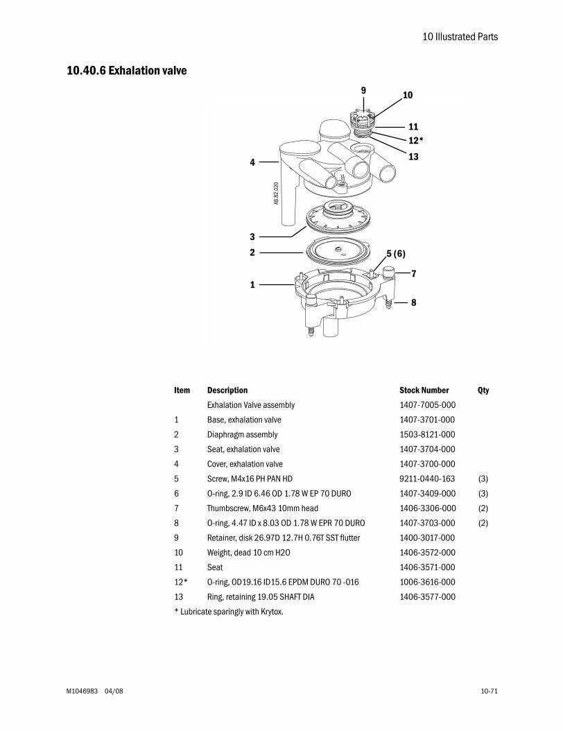
10 Illustrated Parts
M1046983 04/08 10-71
10.40.6 Exhalation valve
1
2
3
4
5 (6)
8
11
7
12*
13
AB.8
2.02
0
9 10
Item Description Stock Number Qty
Exhalation Valve assembly 1407-7005-000
1 Base, exhalation valve 1407-3701-000
2 Diaphragm assembly 1503-8121-000
3 Seat, exhalation valve 1407-3704-000
4 Cover, exhalation valve 1407-3700-000
5 Screw, M4x16 PH PAN HD 9211-0440-163 (3)
6 O-ring, 2.9 ID 6.46 OD 1.78 W EP 70 DURO 1407-3409-000 (3)
7 Thumbscrew, M6x43 10mm head 1406-3306-000 (2)
8 O-ring, 4.47 ID x 8.03 OD 1.78 W EPR 70 DURO 1407-3703-000 (2)
9 Retainer, disk 26.97D 12.7H 0.76T SST flutter 1400-3017-000
10 Weight, dead 10 cm H2O 1406-3572-000
11 Seat 1406-3571-000
12* O-ring, OD19.16 ID15.6 EPDM DURO 70 -016 1006-3616-000
13 Ring, retaining 19.05 SHAFT DIA 1406-3577-000
* Lubricate sparingly with Krytox.
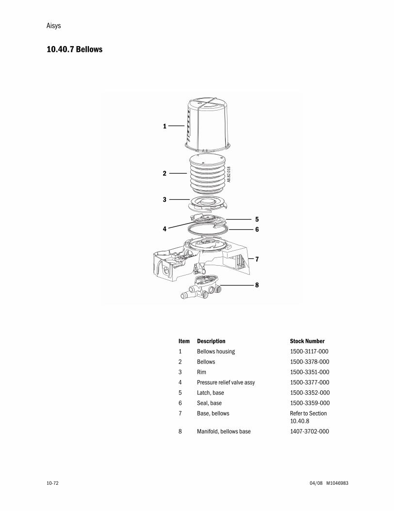
Aisys
10-72 04/08 M1046983
10.40.7 Bellows
1
2
3
456
7
8
AB.8
2.01
8
Item Description Stock Number
1 Bellows housing 1500-3117-000
2 Bellows 1500-3378-000
3 Rim 1500-3351-000
4 Pressure relief valve assy 1500-3377-000
5 Latch, base 1500-3352-000
6 Seal, base 1500-3359-000
7 Base, bellows Refer to Section 10.40.8
8 Manifold, bellows base 1407-3702-000
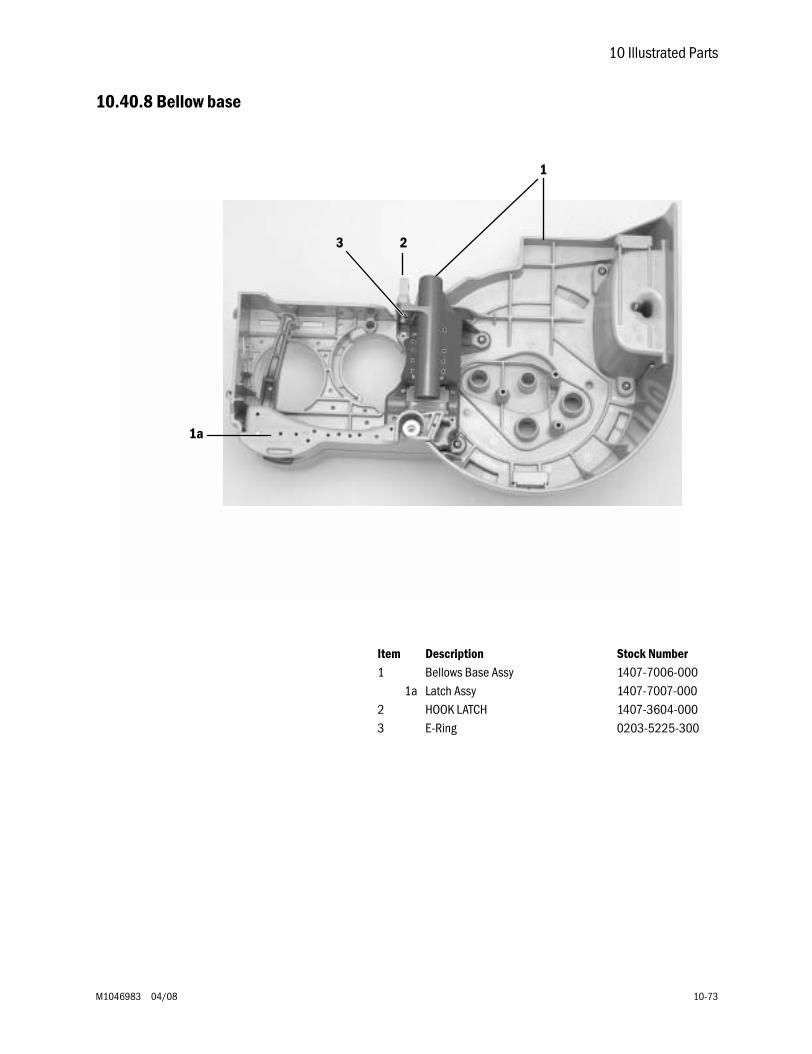
10 Illustrated Parts
M1046983 04/08 10-73
10.40.8 Bellow base
1a
23
1
Item Description Stock Number1 Bellows Base Assy 1407-7006-000
1a Latch Assy 1407-7007-0002 HOOK LATCH 1407-3604-0003 E-Ring 0203-5225-300
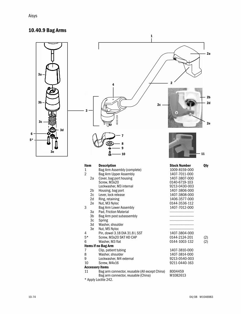
Aisys
10-74 04/08 M1046983
10.40.9 Bag Arms
Item Description Stock Number Qty1 Bag Arm Assembly (complete) 1009-8159-0002 Bag Arm Upper Assembly 1407-7011-000
2a Cover, bag port housingScrew, M3x20Lockwasher, M3 internal
1407-3807-0000140-6719-1039213-0430-003
2b Housing, bag port 1407-3806-0002c Lever, lock release 1407-3808-0002d Ring, retaining 1406-3577-0002e Nut, M3 Nyloc 0144-3536-112
3 Bag Arm Lower Assembly 1407-7012-0003a Pad, Friction Material ---------------------3b Bag Arm post subassembly ---------------------3c Spring ---------------------3d Washer, shoulder ---------------------3e Nut, M5 Nyloc ---------------------
4 Pin, dowel 3.18 DIA 31.8 L SST 1407-3804-0005* Screw, M3x20 SKT HD CAP 0144-2124-201 (2)6 Washer, M3 flat 0144-1003-132 (2)Items if no Bag Arm7 Clip, patient tubing 1407-3810-0008 Washer, shoulder 1407-3814-0009 Lockwasher, M4 external 9213-0540-00310 Screw, M4x16 9211-0440-163Accessory items11 Bag arm connector, reusable (All except China)
Bag arm connector, reusable (China)8004459M1082613
* Apply Loctite 242.
4 2
AB.8
2.03
4
2c
1
3c
3e
3d
3a
3b
7
89
10
3
2a
2b
2d
2e
6
5*
11
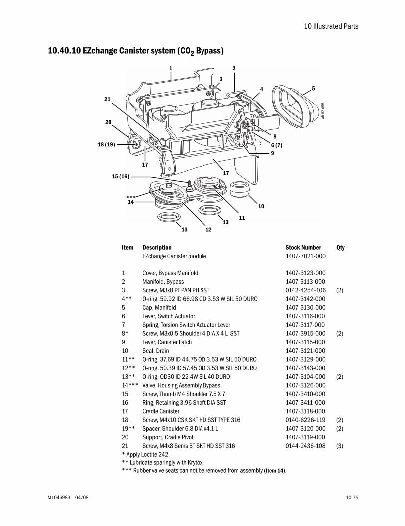
10 Illustrated Parts
M1046983 04/08 10-75
10.40.10 EZchange Canister system (CO2 Bypass)
Item Description Stock Number QtyEZchange Canister module 1407-7021-000
1 Cover, Bypass Manifold 1407-3123-0002 Manifold, Bypass 1407-3113-0003 Screw, M3x8 PT PAN PH SST 0142-4254-106 (2)4** O-ring, 59.92 ID 66.98 OD 3.53 W SIL 50 DURO 1407-3142-0005 Cap, Manifold 1407-3130-0006 Lever, Switch Actuator 1407-3116-0007 Spring, Torsion Switch Actuator Lever 1407-3117-0008* Screw, M3x0.5 Shoulder 4 DIA X 4 L SST 1407-3915-000 (2)9 Lever, Canister Latch 1407-3115-00010 Seal, Drain 1407-3121-00011** O-ring, 37.69 ID 44.75 OD 3.53 W SIL 50 DURO 1407-3129-00012** O-ring, 50.39 ID 57.45 OD 3.53 W SIL 50 DURO 1407-3143-00013** O-ring, OD30 ID 22 4W SIL 40 DURO 1407-3104-000 (2)14*** Valve, Housing Assembly Bypass 1407-3126-00015 Screw, Thumb M4 Shoulder 7.5 X 7 1407-3410-00016 Ring, Retaining 3.96 Shaft DIA SST 1407-3411-00017 Cradle Canister 1407-3118-00018 Screw, M4x10 CSK SKT HD SST TYPE 316 0140-6226-119 (2)19** Spacer, Shoulder 6.8 DIA x4.1 L 1407-3120-000 (2)20 Support, Cradle Pivot 1407-3119-00021 Screw, M4x8 Sems BT SKT HD SST 316 0144-2436-108 (3)* Apply Loctite 242.** Lubricate sparingly with Krytox.*** Rubber valve seats can not be removed from assembly (Item 14).
AB.8
2.05
5
2
1
1
3
2
4 5
6 (7)
8
9
10
13 1213
11
14***
15 (16)
1717
18 (19)
20
21
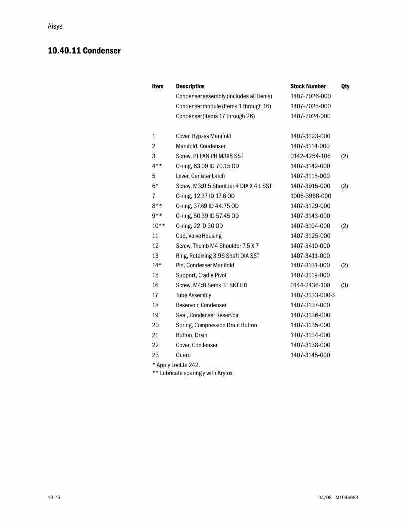
Aisys
10-76 04/08 M1046983
10.40.11 Condenser
Item Description Stock Number Qty
Condenser assembly (includes all Items) 1407-7026-000
Condenser module (Items 1 through 16) 1407-7025-000
Condenser (Items 17 through 26) 1407-7024-000
1 Cover, Bypass Manifold 1407-3123-000
2 Manifold, Condenser 1407-3114-000
3 Screw, PT PAN PH M3X8 SST 0142-4254-106 (2)
4** O-ring, 63.09 ID 70.15 OD 1407-3142-000
5 Lever, Canister Latch 1407-3115-000
6* Screw, M3x0.5 Shoulder 4 DIA X 4 L SST 1407-3915-000 (2)
7 O-ring, 12.37 ID 17.6 OD 1006-3968-000
8** O-ring, 37.69 ID 44.75 OD 1407-3129-000
9** O-ring, 50.39 ID 57.45 OD 1407-3143-000
10** O-ring, 22 ID 30 OD 1407-3104-000 (2)
11 Cap, Valve Housing 1407-3125-000
12 Screw, Thumb M4 Shoulder 7.5 X 7 1407-3410-000
13 Ring, Retaining 3.96 Shaft DIA SST 1407-3411-000
14* Pin, Condenser Manifold 1407-3131-000 (2)
15 Support, Cradle Pivot 1407-3119-000
16 Screw, M4x8 Sems BT SKT HD 0144-2436-108 (3)
17 Tube Assembly 1407-3133-000-S
18 Reservoir, Condenser 1407-3137-000
19 Seal, Condenser Reservoir 1407-3136-000
20 Spring, Compression Drain Button 1407-3135-000
21 Button, Drain 1407-3134-000
22 Cover, Condenser 1407-3138-000
23 Guard 1407-3145-000
* Apply Loctite 242.** Lubricate sparingly with Krytox.
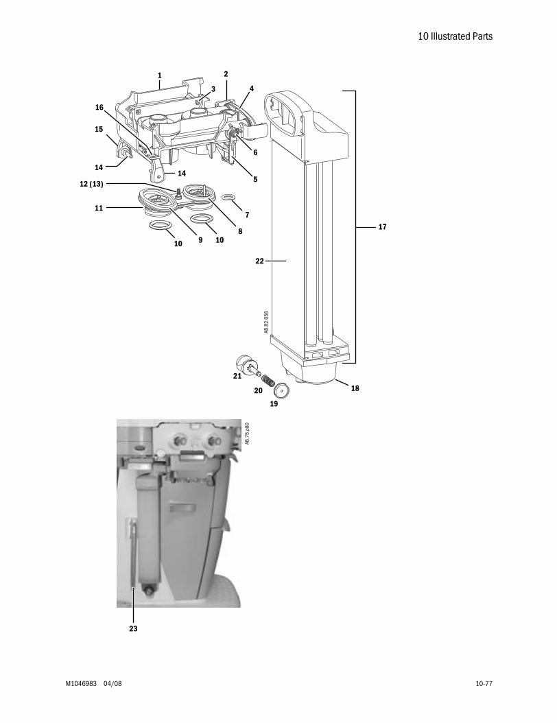
10 Illustrated Parts
M1046983 04/08 10-77
AB.8
2.05
6
1
22
3 4
6
5
7
81010
11
12 (13)
14
15
16
9
14
17
18
19
21
20
23
AB.7
5.p8
0
2
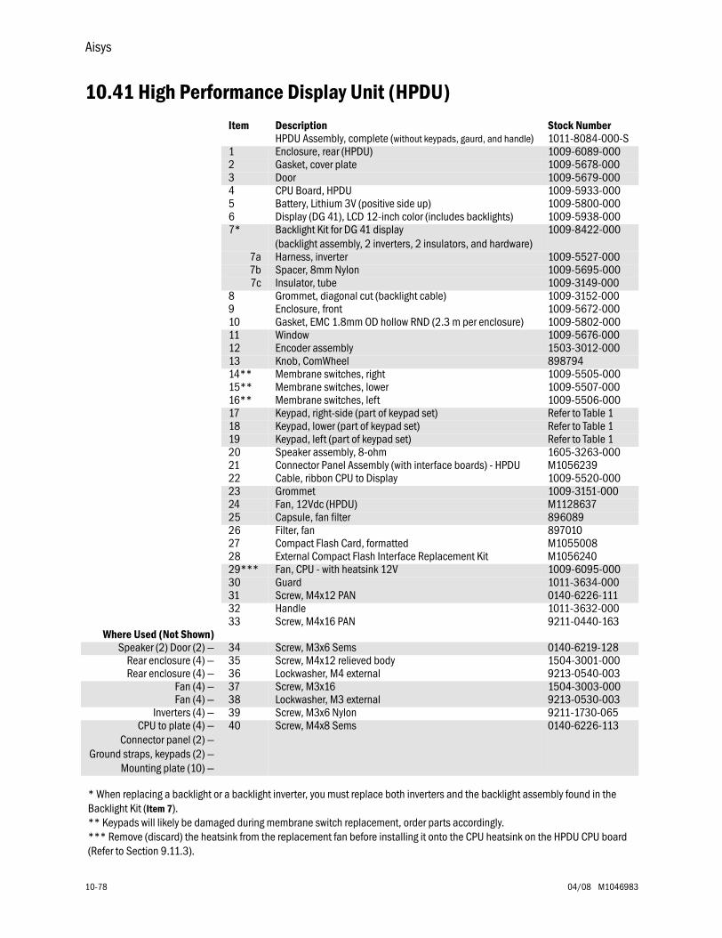
Aisys
10-78 04/08 M1046983
10.41 High Performance Display Unit (HPDU)Item Description Stock Number
HPDU Assembly, complete (without keypads, gaurd, and handle) 1011-8084-000-S1 Enclosure, rear (HPDU) 1009-6089-0002 Gasket, cover plate 1009-5678-0003 Door 1009-5679-0004 CPU Board, HPDU 1009-5933-0005 Battery, Lithium 3V (positive side up) 1009-5800-0006 Display (DG 41), LCD 12-inch color (includes backlights) 1009-5938-0007* Backlight Kit for DG 41 display
(backlight assembly, 2 inverters, 2 insulators, and hardware)1009-8422-000
7a Harness, inverter 1009-5527-0007b Spacer, 8mm Nylon 1009-5695-0007c Insulator, tube 1009-3149-000
8 Grommet, diagonal cut (backlight cable) 1009-3152-0009 Enclosure, front 1009-5672-00010 Gasket, EMC 1.8mm OD hollow RND (2.3 m per enclosure) 1009-5802-00011 Window 1009-5676-00012 Encoder assembly 1503-3012-00013 Knob, ComWheel 89879414** Membrane switches, right 1009-5505-00015** Membrane switches, lower 1009-5507-00016** Membrane switches, left 1009-5506-00017 Keypad, right-side (part of keypad set) Refer to Table 118 Keypad, lower (part of keypad set) Refer to Table 119 Keypad, left (part of keypad set) Refer to Table 120 Speaker assembly, 8-ohm 1605-3263-00021 Connector Panel Assembly (with interface boards) - HPDU M105623922 Cable, ribbon CPU to Display 1009-5520-00023 Grommet 1009-3151-00024 Fan, 12Vdc (HPDU) M112863725 Capsule, fan filter 89608926 Filter, fan 89701027 Compact Flash Card, formatted M105500828 External Compact Flash Interface Replacement Kit M105624029*** Fan, CPU - with heatsink 12V 1009-6095-00030 Guard 1011-3634-00031 Screw, M4x12 PAN 0140-6226-11132 Handle 1011-3632-00033 Screw, M4x16 PAN 9211-0440-163
Where Used (Not Shown)Speaker (2) Door (2) — 34 Screw, M3x6 Sems 0140-6219-128
Rear enclosure (4) — 35 Screw, M4x12 relieved body 1504-3001-000Rear enclosure (4) — 36 Lockwasher, M4 external 9213-0540-003
Fan (4) — 37 Screw, M3x16 1504-3003-000Fan (4) — 38 Lockwasher, M3 external 9213-0530-003
Inverters (4) — 39 Screw, M3x6 Nylon 9211-1730-065CPU to plate (4) —
Connector panel (2) —Ground straps, keypads (2) —
Mounting plate (10) —
40 Screw, M4x8 Sems 0140-6226-113
* When replacing a backlight or a backlight inverter, you must replace both inverters and the backlight assembly found in the Backlight Kit (Item 7).** Keypads will likely be damaged during membrane switch replacement, order parts accordingly.*** Remove (discard) the heatsink from the replacement fan before installing it onto the CPU heatsink on the HPDU CPU board (Refer to Section 9.11.3).
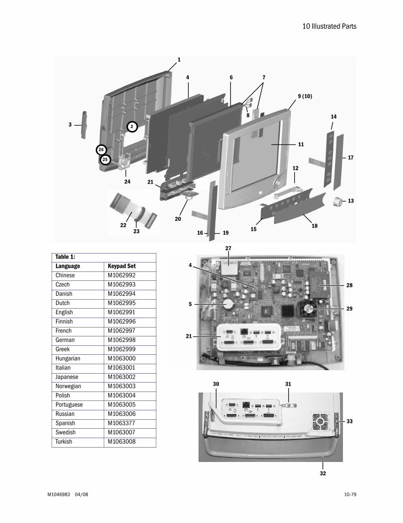
10 Illustrated Parts
M1046983 04/08 10-79
1
4 6 7
14
9 (10)
17
13
1815
12
19
20
21
2
24
26
25
3
8
11
162322
Table 1: Language Keypad SetChinese M1062992Czech M1062993Danish M1062994Dutch M1062995English M1062991Finnish M1062996French M1062997German M1062998Greek M1062999Hungarian M1063000Italian M1063001Japanese M1063002Norwegian M1063003Polish M1063004Portuguese M1063005Russian M1063006Spanish M1063377Swedish M1063007Turkish M1063008
5
4
21
28
29
32
30
33
31
27
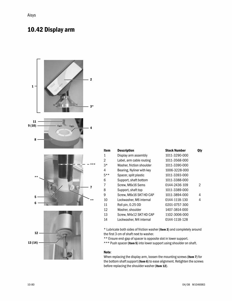
Aisys
10-80 04/08 M1046983
10.42 Display arm
Item Description Stock Number Qty1 Display arm assembly 1011-3290-0002 Label, arm cable routing 1011-3568-0003* Washer, friction shoulder 1011-3390-0004 Bearing, Nyliner with key 1006-3228-0005** Spacer, split plastic 1011-3393-0006 Support, shaft bottom 1011-3388-0007 Screw, M6x16 Sems 0144-2436-109 2 8 Support, shaft top 1011-3389-0009 Screw, M6x16 SKT HD CAP 1011-3894-000 410 Lockwasher, M6 internal 0144-1118-130 411 Roll pin, 0.25 OD 0201-0757-30012 Washer, shoulder 1407-3814-00013 Screw, M4x12 SKT HD CAP 1102-3006-00014 Lockwasher, M4 internal 0144-1118-128
* Lubricate both sides of friction washer (Item 3) and completely around the first 3 cm of shaft next to washer.** Ensure end-gap of spacer is opposite slot in lower support.*** Push spacer (Item 5) into lower support using shoulder on shaft.
Note: When replacing the display arm, loosen the mounting screws (Item 7) for the bottom shaft support (Item 6) to ease alignment. Retighten the screws before replacing the shoulder washer (Item 12).
1
2
3*
4
**5
**
6
7
8
9 (10)11
***
12
13 (14)
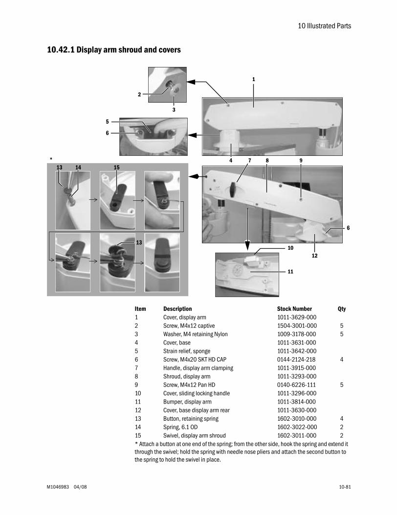
10 Illustrated Parts
M1046983 04/08 10-81
10.42.1 Display arm shroud and covers
Item Description Stock Number Qty1 Cover, display arm 1011-3629-0002 Screw, M4x12 captive 1504-3001-000 53 Washer, M4 retaining Nylon 1009-3178-000 54 Cover, base 1011-3631-0005 Strain relief, sponge 1011-3642-0006 Screw, M4x20 SKT HD CAP 0144-2124-218 47 Handle, display arm clamping 1011-3915-0008 Shroud, display arm 1011-3293-0009 Screw, M4x12 Pan HD 0140-6226-111 510 Cover, sliding locking handle 1011-3296-00011 Bumper, display arm 1011-3814-00012 Cover, base display arm rear 1011-3630-00013 Button, retaining spring 1602-3010-000 414 Spring, 6.1 OD 1602-3022-000 215 Swivel, display arm shroud 1602-3011-000 2* Attach a button at one end of the spring; from the other side, hook the spring and extend it through the swivel; hold the spring with needle nose pliers and attach the second button to the spring to hold the swivel in place.
1
2
3
4
6
5
7 8 9
10
11
12
6
*14 15
13
13
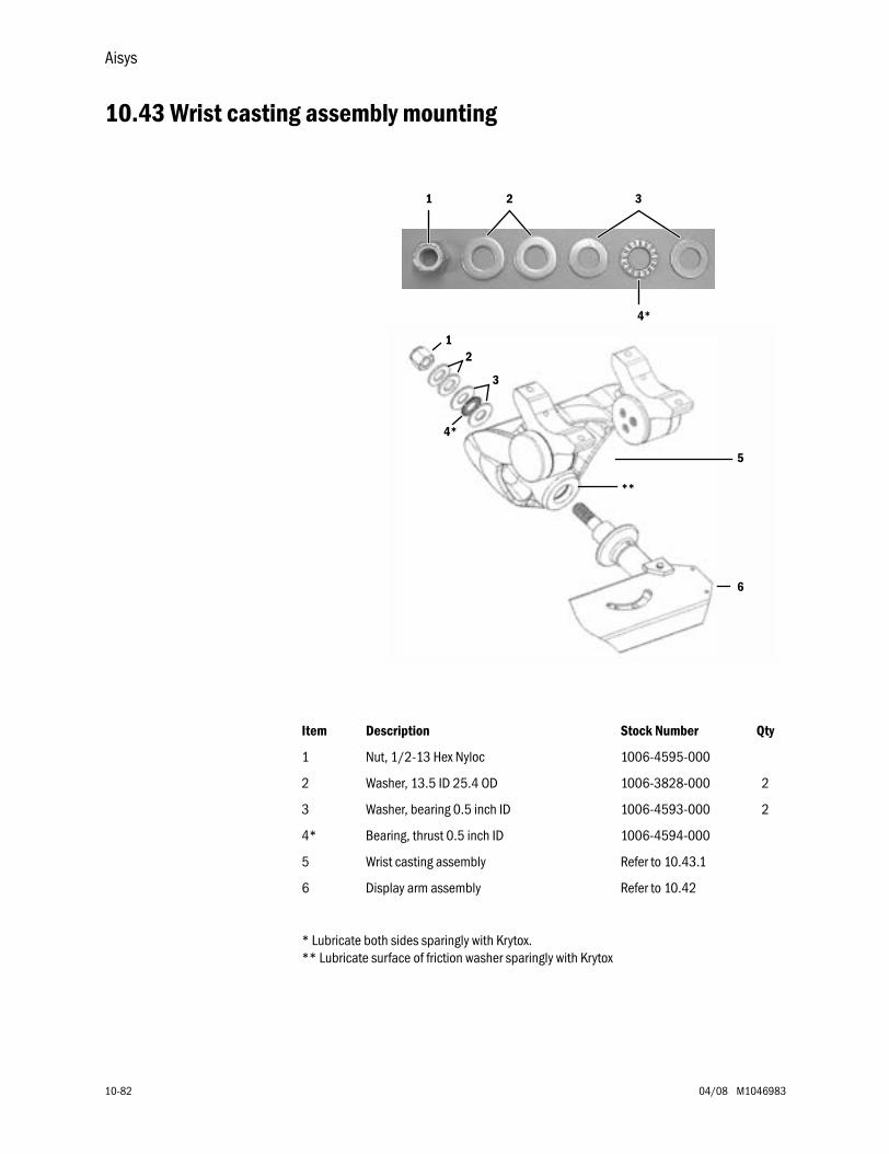
Aisys
10-82 04/08 M1046983
10.43 Wrist casting assembly mounting
Item Description Stock Number Qty
1 Nut, 1/2-13 Hex Nyloc 1006-4595-000
2 Washer, 13.5 ID 25.4 OD 1006-3828-000 2
3 Washer, bearing 0.5 inch ID 1006-4593-000 2
4* Bearing, thrust 0.5 inch ID 1006-4594-000
5 Wrist casting assembly Refer to 10.43.1
6 Display arm assembly Refer to 10.42
* Lubricate both sides sparingly with Krytox.** Lubricate surface of friction washer sparingly with Krytox
12
3
4*
5
6
**
1
4*
2 3
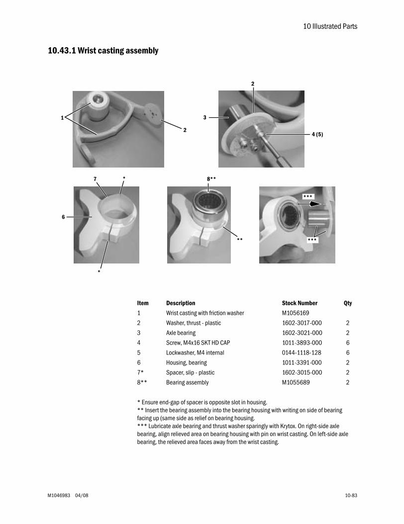
10 Illustrated Parts
M1046983 04/08 10-83
10.43.1 Wrist casting assembly
Item Description Stock Number Qty
1 Wrist casting with friction washer M1056169
2 Washer, thrust - plastic 1602-3017-000 2
3 Axle bearing 1602-3021-000 2
4 Screw, M4x16 SKT HD CAP 1011-3893-000 6
5 Lockwasher, M4 internal 0144-1118-128 6
6 Housing, bearing 1011-3391-000 2
7* Spacer, slip - plastic 1602-3015-000 2
8** Bearing assembly M1055689 2
* Ensure end-gap of spacer is opposite slot in housing.** Insert the bearing assembly into the bearing housing with writing on side of bearing facing up (same side as relief on bearing housing.*** Lubricate axle bearing and thrust washer sparingly with Krytox. On right-side axle bearing, align relieved area on bearing housing with pin on wrist casting. On left-side axle bearing, the relieved area faces away from the wrist casting.
2
***
***
3
2
4 (5)
1
6
7 *
*
8**
**
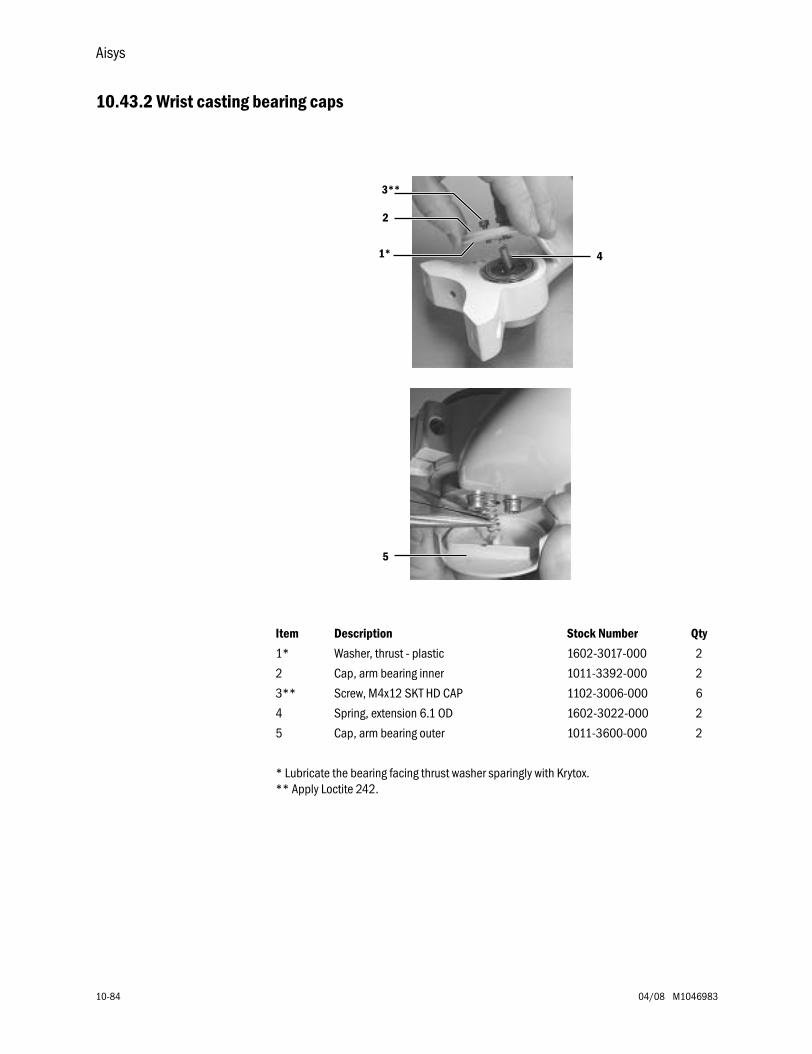
Aisys
10-84 04/08 M1046983
10.43.2 Wrist casting bearing caps
Item Description Stock Number Qty
1* Washer, thrust - plastic 1602-3017-000 2
2 Cap, arm bearing inner 1011-3392-000 2
3** Screw, M4x12 SKT HD CAP 1102-3006-000 6
4 Spring, extension 6.1 OD 1602-3022-000 2
5 Cap, arm bearing outer 1011-3600-000 2
* Lubricate the bearing facing thrust washer sparingly with Krytox.** Apply Loctite 242.
1*
2
3**
4
5
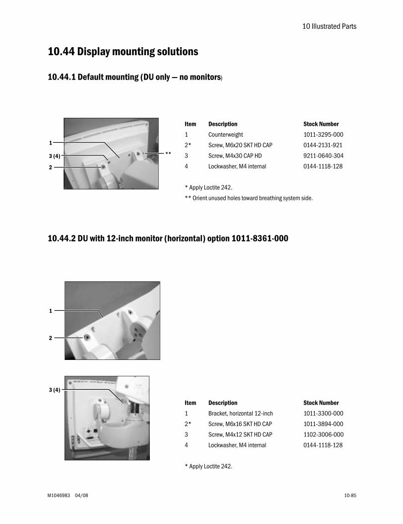
10 Illustrated Parts
M1046983 04/08 10-85
10.44 Display mounting solutions
10.44.1 Default mounting (DU only — no monitors)
10.44.2 DU with 12-inch monitor (horizontal) option 1011-8361-000
Item Description Stock Number
1 Counterweight 1011-3295-000
2* Screw, M6x20 SKT HD CAP 0144-2131-921
3 Screw, M4x30 CAP HD 9211-0640-304
4 Lockwasher, M4 internal 0144-1118-128
* Apply Loctite 242.
** Orient unused holes toward breathing system side.
1
2
3 (4) **
Item Description Stock Number
1 Bracket, horizontal 12-inch 1011-3300-000
2* Screw, M6x16 SKT HD CAP 1011-3894-000
3 Screw, M4x12 SKT HD CAP 1102-3006-000
4 Lockwasher, M4 internal 0144-1118-128
* Apply Loctite 242.
1
2
3 (4)
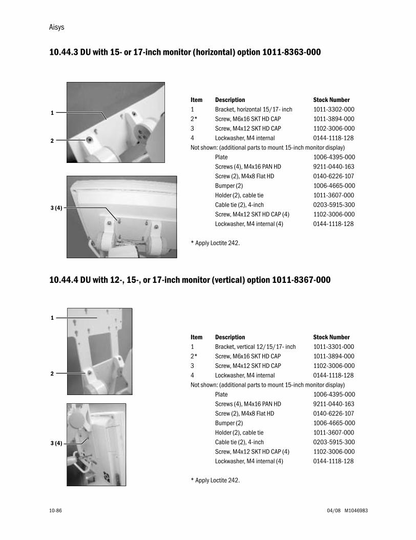
Aisys
10-86 04/08 M1046983
10.44.3 DU with 15- or 17-inch monitor (horizontal) option 1011-8363-000
10.44.4 DU with 12-, 15-, or 17-inch monitor (vertical) option 1011-8367-000
Item Description Stock Number1 Bracket, horizontal 15/17- inch 1011-3302-0002* Screw, M6x16 SKT HD CAP 1011-3894-0003 Screw, M4x12 SKT HD CAP 1102-3006-0004 Lockwasher, M4 internal 0144-1118-128Not shown: (additional parts to mount 15-inch monitor display)
Plate 1006-4395-000Screws (4), M4x16 PAN HD 9211-0440-163Screw (2), M4x8 Flat HD 0140-6226-107Bumper (2) 1006-4665-000Holder (2), cable tie 1011-3607-000Cable tie (2), 4-inch 0203-5915-300Screw, M4x12 SKT HD CAP (4) 1102-3006-000Lockwasher, M4 internal (4) 0144-1118-128
* Apply Loctite 242.
1
2
3 (4)
Item Description Stock Number1 Bracket, vertical 12/15/17- inch 1011-3301-0002* Screw, M6x16 SKT HD CAP 1011-3894-0003 Screw, M4x12 SKT HD CAP 1102-3006-0004 Lockwasher, M4 internal 0144-1118-128Not shown: (additional parts to mount 15-inch monitor display)
Plate 1006-4395-000Screws (4), M4x16 PAN HD 9211-0440-163Screw (2), M4x8 Flat HD 0140-6226-107Bumper (2) 1006-4665-000Holder (2), cable tie 1011-3607-000Cable tie (2), 4-inch 0203-5915-300Screw, M4x12 SKT HD CAP (4) 1102-3006-000Lockwasher, M4 internal (4) 0144-1118-128
* Apply Loctite 242.
1
2
3 (4)
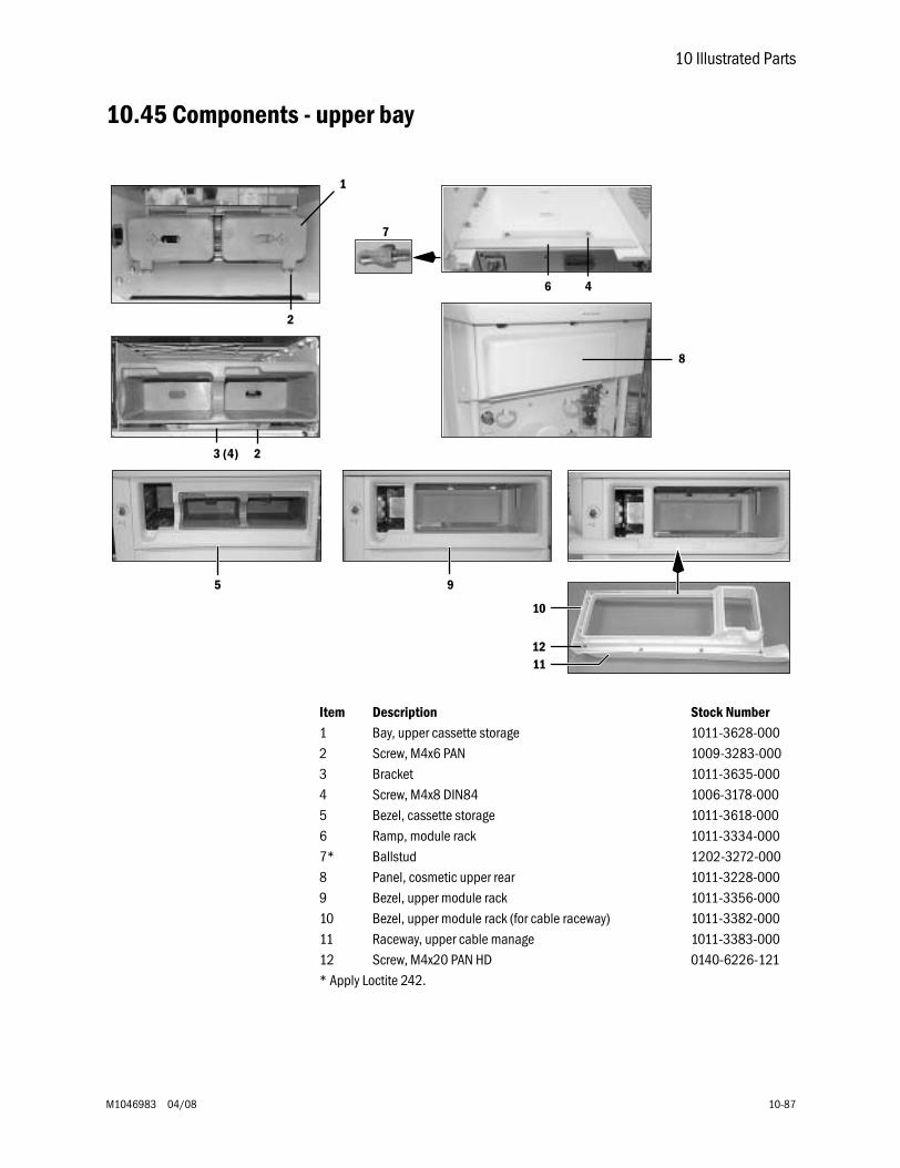
10 Illustrated Parts
M1046983 04/08 10-87
10.45 Components - upper bay
5 9
10
1211
1
2
3 (4)
6 4
7
8
2
Item Description Stock Number1 Bay, upper cassette storage 1011-3628-0002 Screw, M4x6 PAN 1009-3283-0003 Bracket 1011-3635-0004 Screw, M4x8 DIN84 1006-3178-0005 Bezel, cassette storage 1011-3618-0006 Ramp, module rack 1011-3334-0007* Ballstud 1202-3272-0008 Panel, cosmetic upper rear 1011-3228-0009 Bezel, upper module rack 1011-3356-00010 Bezel, upper module rack (for cable raceway) 1011-3382-00011 Raceway, upper cable manage 1011-3383-00012 Screw, M4x20 PAN HD 0140-6226-121* Apply Loctite 242.
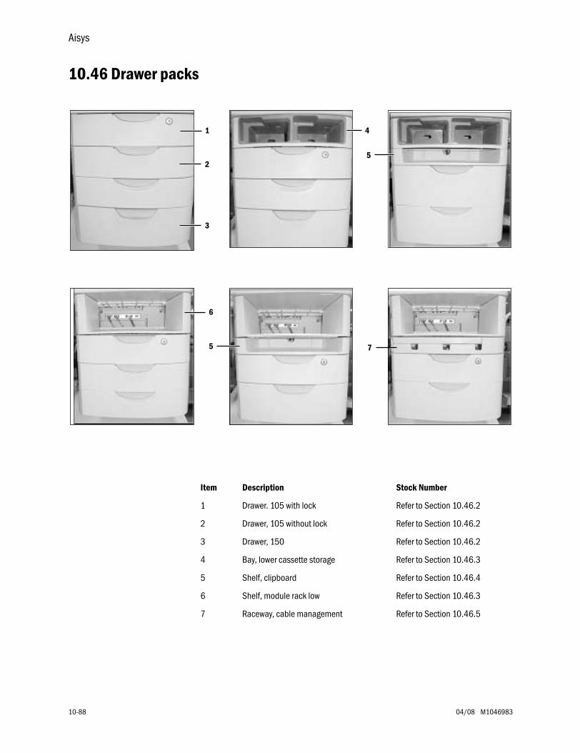
Aisys
10-88 04/08 M1046983
10.46 Drawer packs
Item Description Stock Number
1 Drawer. 105 with lock Refer to Section 10.46.2
2 Drawer, 105 without lock Refer to Section 10.46.2
3 Drawer, 150 Refer to Section 10.46.2
4 Bay, lower cassette storage Refer to Section 10.46.3
5 Shelf, clipboard Refer to Section 10.46.4
6 Shelf, module rack low Refer to Section 10.46.3
7 Raceway, cable management Refer to Section 10.46.5
1
2
3
4
5
6
5 7
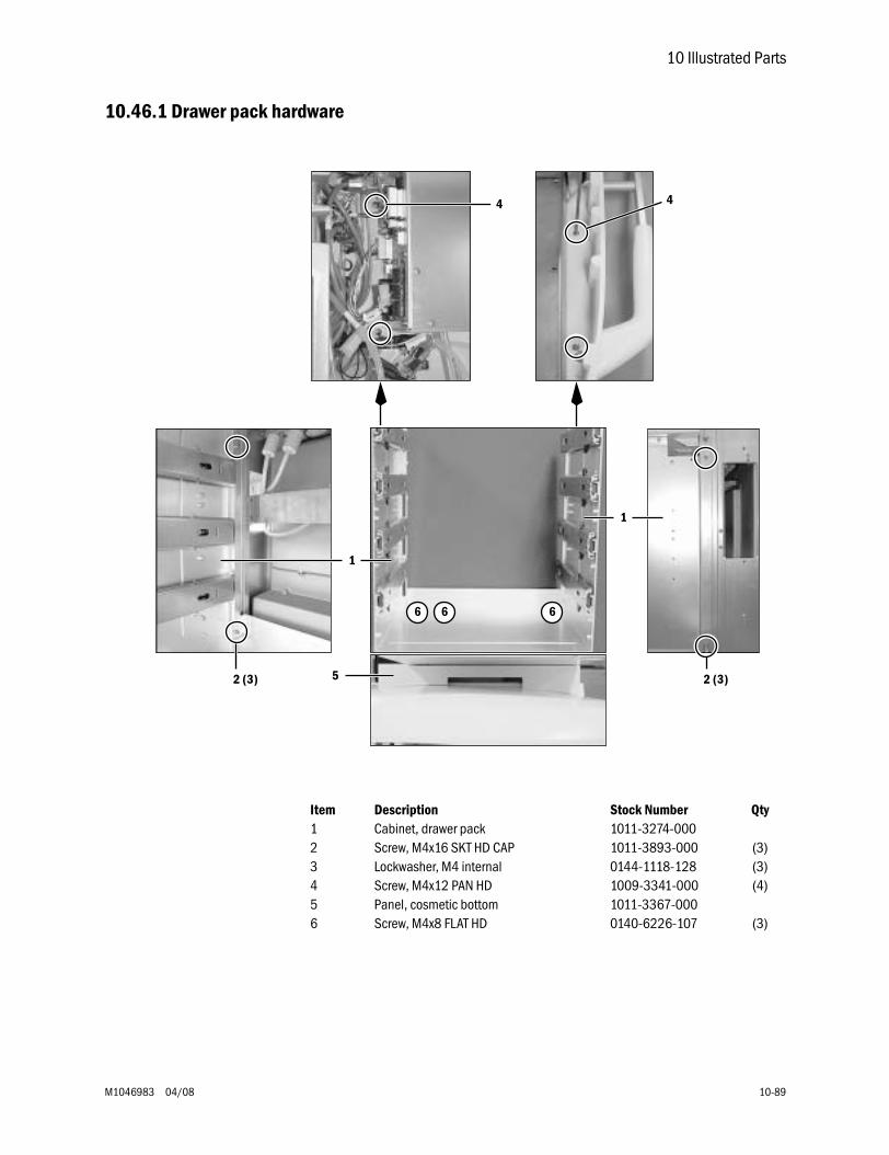
10 Illustrated Parts
M1046983 04/08 10-89
10.46.1 Drawer pack hardware
Item Description Stock Number Qty1 Cabinet, drawer pack 1011-3274-0002 Screw, M4x16 SKT HD CAP 1011-3893-000 (3)3 Lockwasher, M4 internal 0144-1118-128 (3)4 Screw, M4x12 PAN HD 1009-3341-000 (4)5 Panel, cosmetic bottom 1011-3367-0006 Screw, M4x8 FLAT HD 0140-6226-107 (3)
6 6 6
1
2 (3)
44
5
1
2 (3)
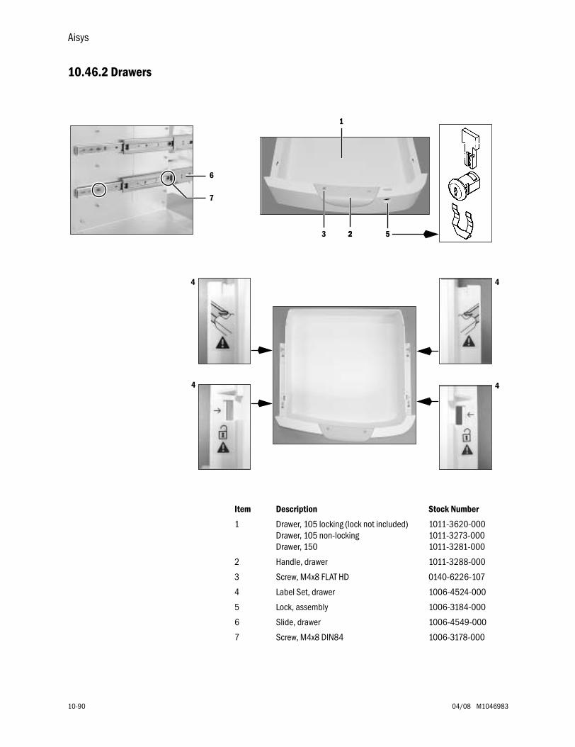
Aisys
10-90 04/08 M1046983
10.46.2 Drawers
1
23
44
4 4
2 5
6
7
Item Description Stock Number
1 Drawer, 105 locking (lock not included)Drawer, 105 non-lockingDrawer, 150
1011-3620-0001011-3273-0001011-3281-000
2 Handle, drawer 1011-3288-000
3 Screw, M4x8 FLAT HD 0140-6226-107
4 Label Set, drawer 1006-4524-000
5 Lock, assembly 1006-3184-000
6 Slide, drawer 1006-4549-000
7 Screw, M4x8 DIN84 1006-3178-000
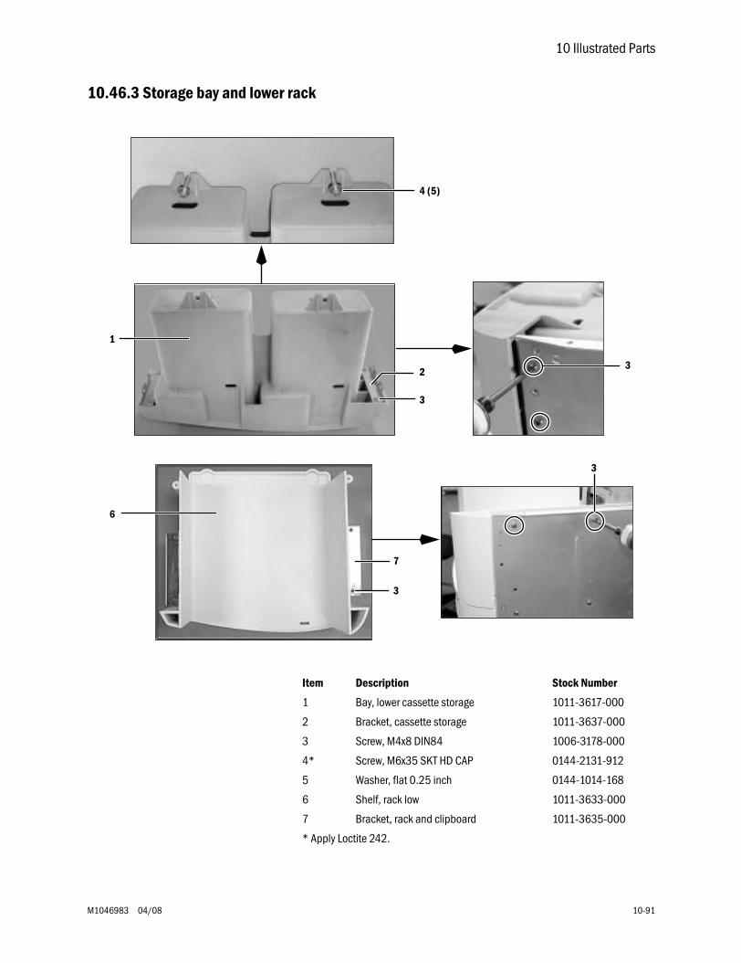
10 Illustrated Parts
M1046983 04/08 10-91
10.46.3 Storage bay and lower rack
Item Description Stock Number
1 Bay, lower cassette storage 1011-3617-000
2 Bracket, cassette storage 1011-3637-000
3 Screw, M4x8 DIN84 1006-3178-000
4* Screw, M6x35 SKT HD CAP 0144-2131-912
5 Washer, flat 0.25 inch 0144-1014-168
6 Shelf, rack low 1011-3633-000
7 Bracket, rack and clipboard 1011-3635-000
* Apply Loctite 242.
4 (5)
1
6
2
3
7
3
3
3
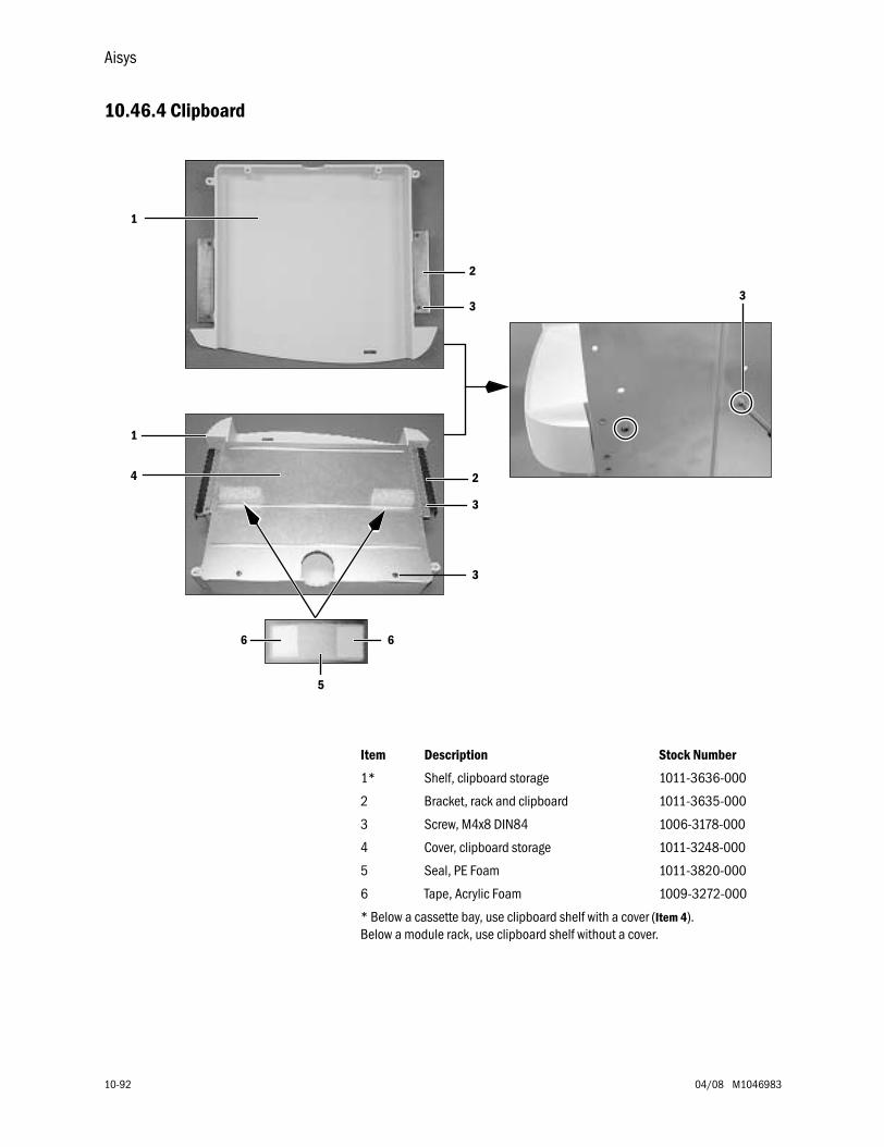
Aisys
10-92 04/08 M1046983
10.46.4 Clipboard
Item Description Stock Number
1* Shelf, clipboard storage 1011-3636-000
2 Bracket, rack and clipboard 1011-3635-000
3 Screw, M4x8 DIN84 1006-3178-000
4 Cover, clipboard storage 1011-3248-000
5 Seal, PE Foam 1011-3820-000
6 Tape, Acrylic Foam 1009-3272-000
* Below a cassette bay, use clipboard shelf with a cover (Item 4).Below a module rack, use clipboard shelf without a cover.
1
2
33
1
4 2
3
5
66
3
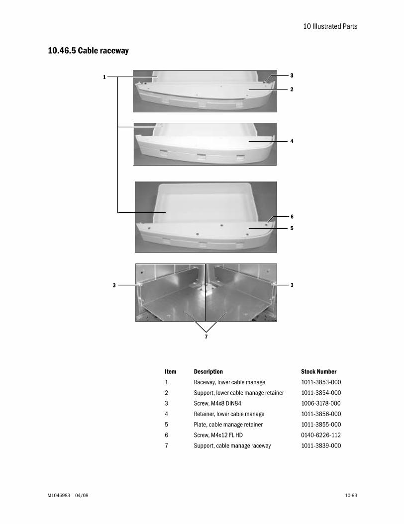
10 Illustrated Parts
M1046983 04/08 10-93
10.46.5 Cable raceway
Item Description Stock Number
1 Raceway, lower cable manage 1011-3853-000
2 Support, lower cable manage retainer 1011-3854-000
3 Screw, M4x8 DIN84 1006-3178-000
4 Retainer, lower cable manage 1011-3856-000
5 Plate, cable manage retainer 1011-3855-000
6 Screw, M4x12 FL HD 0140-6226-112
7 Support, cable manage raceway 1011-3839-000
2
1 3
4
5
6
7
3 3
3
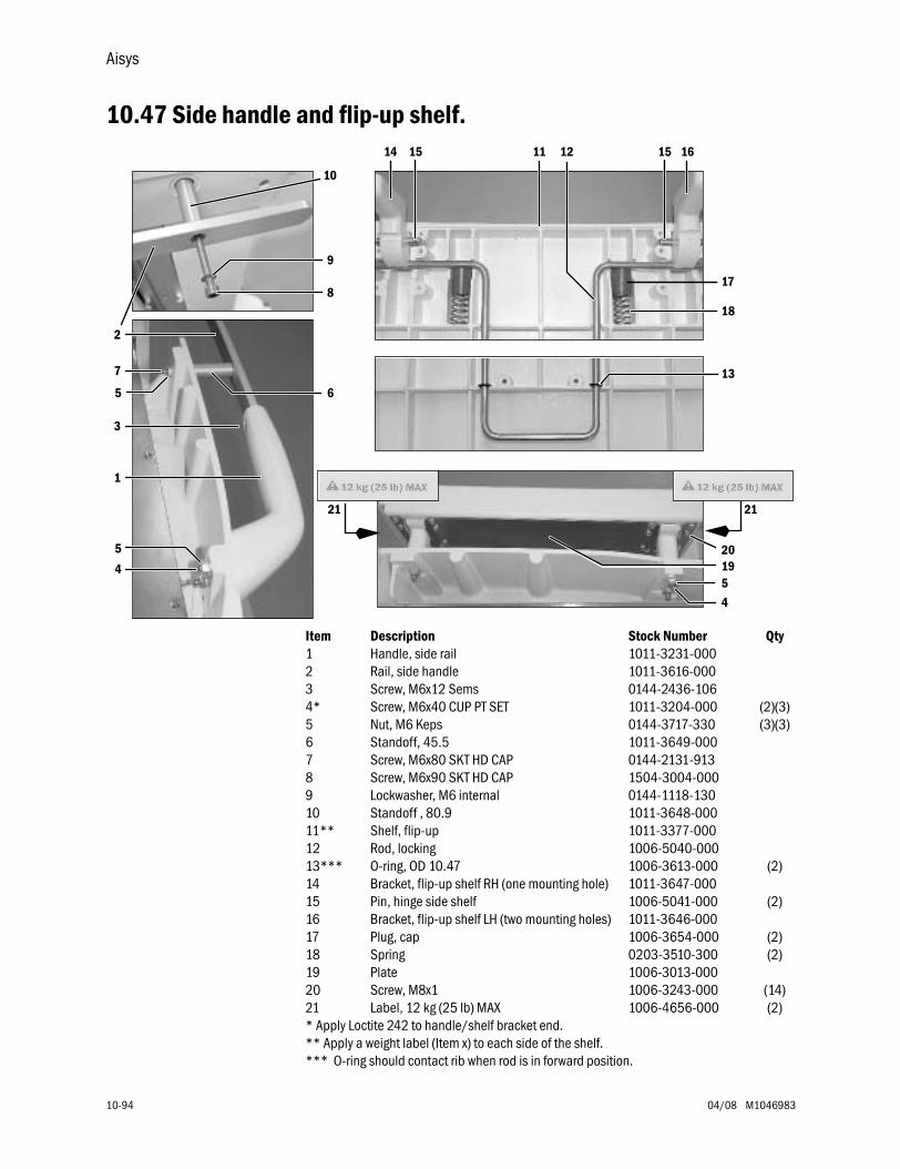
Aisys
10-94 04/08 M1046983
10.47 Side handle and flip-up shelf.
Item Description Stock Number Qty1 Handle, side rail 1011-3231-0002 Rail, side handle 1011-3616-0003 Screw, M6x12 Sems 0144-2436-1064* Screw, M6x40 CUP PT SET 1011-3204-000 (2)(3)5 Nut, M6 Keps 0144-3717-330 (3)(3)6 Standoff, 45.5 1011-3649-0007 Screw, M6x80 SKT HD CAP 0144-2131-9138 Screw, M6x90 SKT HD CAP 1504-3004-0009 Lockwasher, M6 internal 0144-1118-13010 Standoff , 80.9 1011-3648-00011** Shelf, flip-up 1011-3377-00012 Rod, locking 1006-5040-00013*** O-ring, OD 10.47 1006-3613-000 (2)14 Bracket, flip-up shelf RH (one mounting hole) 1011-3647-00015 Pin, hinge side shelf 1006-5041-000 (2)16 Bracket, flip-up shelf LH (two mounting holes) 1011-3646-00017 Plug, cap 1006-3654-000 (2)18 Spring 0203-3510-300 (2)19 Plate 1006-3013-00020 Screw, M8x1 1006-3243-000 (14)21 Label, 12 kg (25 lb) MAX 1006-4656-000 (2)* Apply Loctite 242 to handle/shelf bracket end.** Apply a weight label (Item x) to each side of the shelf.*** O-ring should contact rib when rod is in forward position.
4
1
2
3
5
5 6
7
8
9
10
11
2121
12
13
14 15 1615
17
18
1920
5
4
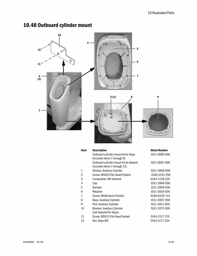
10 Illustrated Parts
M1046983 04/08 10-95
10.48 Outboard cylinder mount
Item Description Stock NumberOutboard cylinder mount kit for Aisys(includes items 1 through 9)
1011-8090-000
Outboard cylinder mount kit for Aespire(includes items 1 through 12)
1011-8091-000
1 Shroud, Auxiliary Cylinder 1011-3908-0002 Screw, M5X25 Pan Head Pozidriv 0144-2531-9163 Lockwasher, M5 External 0144-1118-2204 Cap 1011-3906-0005 Bumper 1011-3909-0006 Retainer 1011-3924-0007 Screw, M4x8 Sems Pozidriv 0140-6226-1138 Base, Auxiliary Cylinder 1011-3907-0009 Pad, Auxiliary Cylinder 1011-3911-00010 Bracket, Auxiliary Cylinder
(not required for Aisys)1011-3372-000
11 Screw, M5X12 Flat Head Socket 0144-2117-72512 Nut, Keps M5 0144-3717-324
1
10
2
12
11
4
5
6
7
8
(3)
2 (3) 9

Notes
10-96 04/08 M1046983
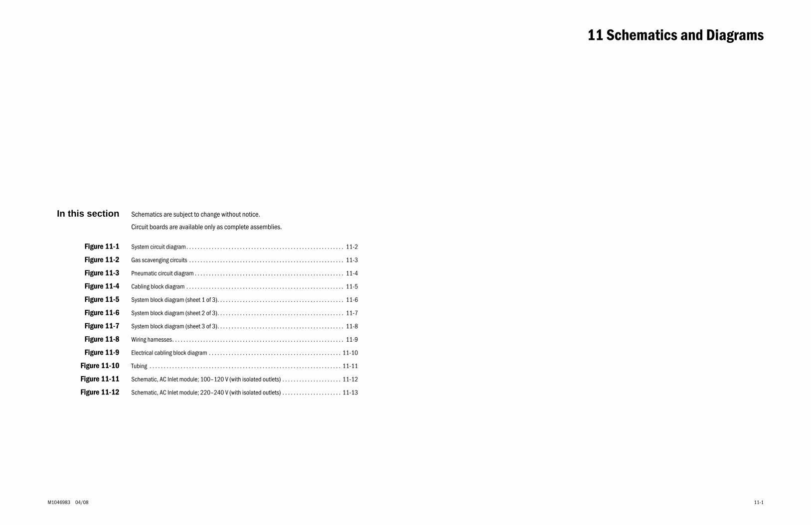
M1046983 04/08 11-1
11 Schematics and Diagrams
In this section Schematics are subject to change without notice.
Circuit boards are available only as complete assemblies.
Figure 11-1 System circuit diagram. . . . . . . . . . . . . . . . . . . . . . . . . . . . . . . . . . . . . . . . . . . . . . . . . . . . . . . . 11-2
Figure 11-2 Gas scavenging circuits . . . . . . . . . . . . . . . . . . . . . . . . . . . . . . . . . . . . . . . . . . . . . . . . . . . . . . . 11-3
Figure 11-3 Pneumatic circuit diagram . . . . . . . . . . . . . . . . . . . . . . . . . . . . . . . . . . . . . . . . . . . . . . . . . . . . . 11-4
Figure 11-4 Cabling block diagram . . . . . . . . . . . . . . . . . . . . . . . . . . . . . . . . . . . . . . . . . . . . . . . . . . . . . . . . 11-5
Figure 11-5 System block diagram (sheet 1 of 3). . . . . . . . . . . . . . . . . . . . . . . . . . . . . . . . . . . . . . . . . . . . . 11-6
Figure 11-6 System block diagram (sheet 2 of 3). . . . . . . . . . . . . . . . . . . . . . . . . . . . . . . . . . . . . . . . . . . . . 11-7
Figure 11-7 System block diagram (sheet 3 of 3). . . . . . . . . . . . . . . . . . . . . . . . . . . . . . . . . . . . . . . . . . . . . 11-8
Figure 11-8 Wiring harnesses. . . . . . . . . . . . . . . . . . . . . . . . . . . . . . . . . . . . . . . . . . . . . . . . . . . . . . . . . . . . . 11-9
Figure 11-9 Electrical cabling block diagram . . . . . . . . . . . . . . . . . . . . . . . . . . . . . . . . . . . . . . . . . . . . . . . 11-10
Figure 11-10 Tubing . . . . . . . . . . . . . . . . . . . . . . . . . . . . . . . . . . . . . . . . . . . . . . . . . . . . . . . . . . . . . . . . . . . . 11-11
Figure 11-11 Schematic, AC Inlet module; 100–120 V (with isolated outlets) . . . . . . . . . . . . . . . . . . . . . 11-12
Figure 11-12 Schematic, AC Inlet module; 220–240 V (with isolated outlets) . . . . . . . . . . . . . . . . . . . . . 11-13
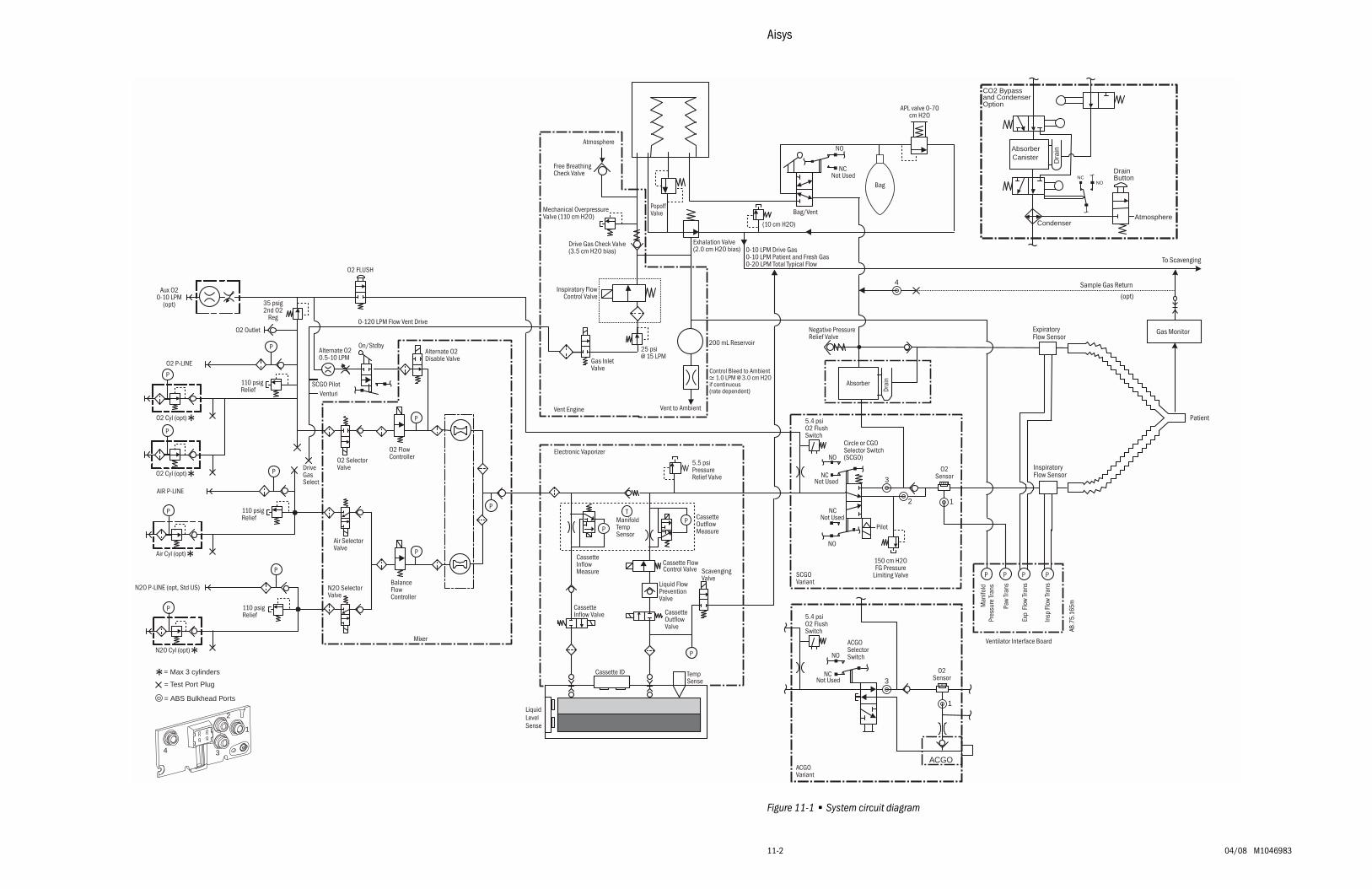
Aisys
11-2 04/08 M1046983
Figure 11-1 • System circuit diagram
Bag
Vent to Ambient
Bag/Vent
Exhalation Valve(2.0 cm H2O bias) 0-10 LPM Drive Gas
0-10 LPM Patient and Fresh Gas0-20 LPM Total Typical Flow
PopoffValve
200 mL Reservoir
APL valve 0-70cm H2O
Absorber
Drai
n
Negative PressureRelief Valve
(10 cm H2O)
Atmosphere
25 psi@ 15 LPM
Drive Gas Check Valve(3.5 cm H2O bias)
Free BreathingCheck Valve
Mechanical OverpressureValve (110 cm H2O)
Inspiratory FlowControl Valve
Gas InletValve
NO
NCNot Used
Circle or CGOSelector Switch(SCGO)
150 cm H2OFG Pressure
Limiting ValveSCGOVariant
Pilot
NO
NCNot Used
NO
NCNot Used
Man
ifold
Pres
sure
Tran
s
Exp
Flo
w Tr
ans
Paw
Tran
s
Ventilator Interface Board
Insp
Flo
w Tr
ans
P PPP
Patient
ExpiratoryFlow Sensor
Gas Monitor
To Scavenging
InspiratoryFlow Sensor
Control Bleed to Ambient 1.0 LPM @ 3.0 cm H2Oif continuous(rate dependent)
Vent Engine
Liquid FlowPreventionValve
TempSense
Cassette ID
CassetteOutflowMeasure
Cassette FlowControl Valve
CassetteOutflowValve
ScavengingValve
5.5 psiPressureRelief Valve
P
PP
T
CassetteInflowMeasure
P
P
O2 Cyl (opt)*
P
Aux O20-10 LPM
(opt)
O2 FLUSH
O2 P-LINE
AIR P-LINE
N2O P-LINE (opt, Std US)
110 psigRelief
N2O Cyl (opt)*
On/StdbyAlternate O20.5-10 LPM
0-120 LPM Flow Vent Drive
Air Cyl (opt)*
DriveGasSelect
35 psig2nd O2
Reg
110 psigRelief
110 psigRelief
O2 Cyl (opt)*
SCGO PilotVenturi
P
P
P
P
Electronic Vaporizer
CassetteInflow Valve
LiquidLevelSense
AbsorberCanister
Atmosphere
NO
Condenser
CO2 Bypassand CondenserOption
DrainButtonNC
Dra
in
O2 Outlet
ManifoldTempSensor
(opt)
4 Sample Gas Return
ACGOSelectorSwitch
ACGOVariant
O2Sensor
NO
NCNot Used 3
1
ACGO
3
2 1
O2Sensor
*= Max 3 cylinders
= Test Port Plug
= ABS Bulkhead Ports
2
4 3
1
5.4 psiO2 FlushSwitch
5.4 psiO2 FlushSwitch
BalanceFlowController
Air SelectorValve
N2O SelectorValve
O2 FlowController
Alternate O2Disable Valve
O2 SelectorValve
P
P
P
Mixer
AB.7
5.16
5m
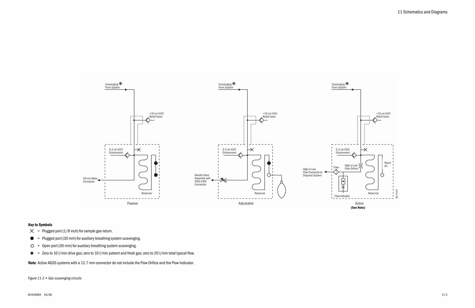
11 Schematics and Diagrams
M1046983 04/08 11-3
Figure 11-2 • Gas scavenging circuits
+10 cm H2ORelief Valve
Passive
0.3 cm H2OEntrainment
30 mm MaleConnector
+10 cm H2ORelief Valve
Adjustable
0.3 cm H2OEntrainment
Needle ValveAssembly withDISS EVACConnector
Active
0.3 cm H2OEntrainment
High or LowFlow Connector toDisposal System
Flow Indicator
FilterHigh or LowFlow Orifice
Scavenging*From System
+10 cm H2ORelief Valve
Reservoir Reservoir Reservoir
RoomAir
Scavenging*From SystemScavenging*From System
Key to Symbols
= Plugged port (1/8 inch) for sample gas return.
= Plugged port (30 mm) for auxiliary breathing system scavenging.
= Open port (30 mm) for auxiliary breathing system scavenging.
= Zero to 10 l/min drive gas; zero to 10 l/min patient and fresh gas; zero to 20 l/min total typical flow.
Note: Active AGSS systems with a 12.7 mm connector do not include the Flow Orifice and the Flow Indicator.
*
AB.7
4.03
1
(See Note)
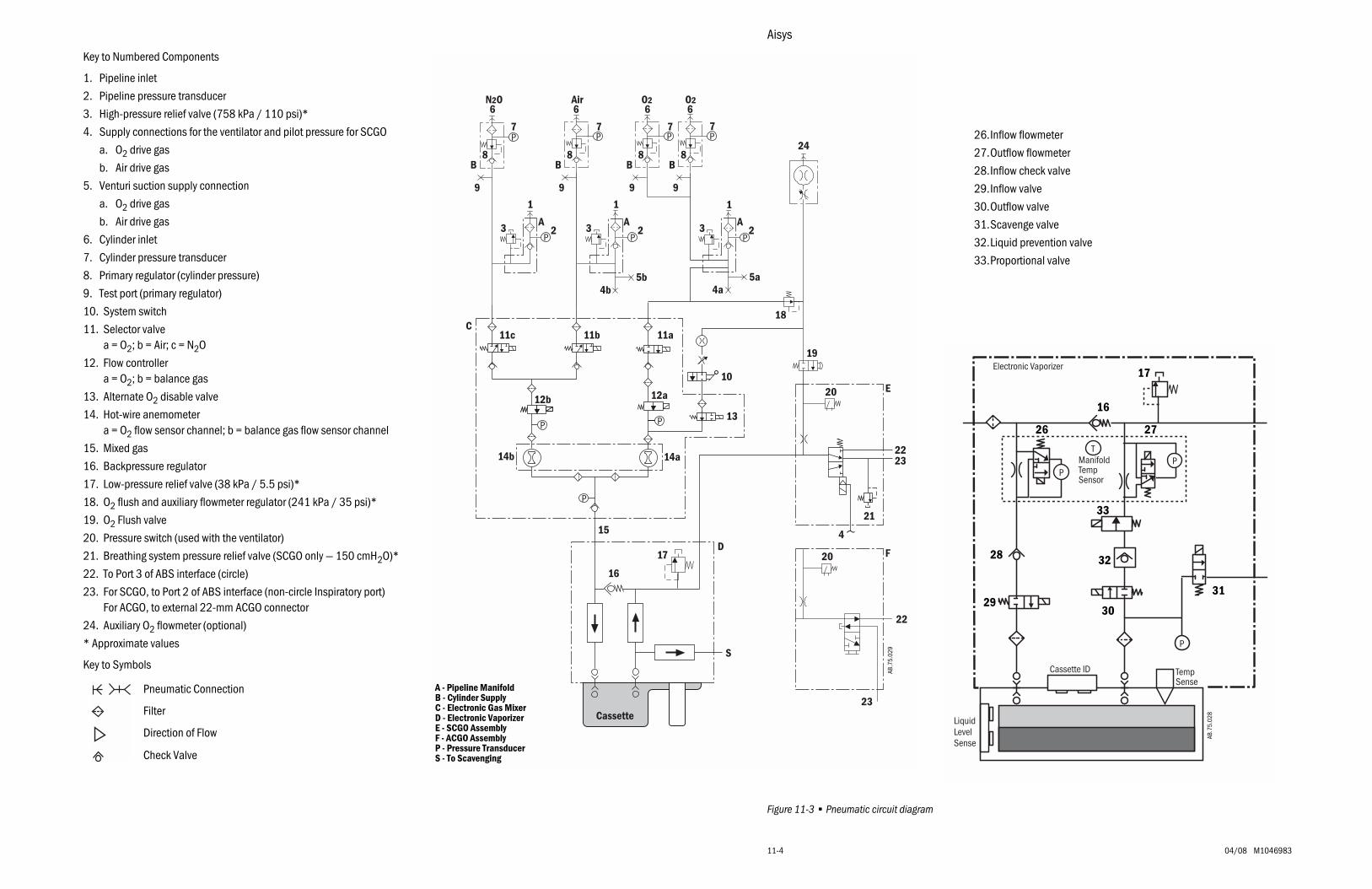
Aisys
11-4 04/08 M1046983
Figure 11-3 • Pneumatic circuit diagram
N2O
9 9 9 9
Air O2 O2
24
7 77 7
8B
8B
8B
8B
3 A2
1
3 A2
1
3 A2
18
19
4b 4a
17D
6 6 6 6
1
5a5b
11c 11b 11a
12b 12a
10
13
20
14a14b 2223
21
C
4
E
20
22
23
F
Cassette
S
16
15
AB.7
5.02
9
A - Pipeline ManifoldB - Cylinder SupplyC - Electronic Gas MixerD - Electronic VaporizerE - SCGO Assembly
P - Pressure TransducerF - ACGO Assembly
S - To Scavenging
Key to Numbered Components
1. Pipeline inlet
2. Pipeline pressure transducer
3. High-pressure relief valve (758 kPa / 110 psi)*
4. Supply connections for the ventilator and pilot pressure for SCGO
a. O2 drive gas
b. Air drive gas
5. Venturi suction supply connection
a. O2 drive gas
b. Air drive gas
6. Cylinder inlet
7. Cylinder pressure transducer
8. Primary regulator (cylinder pressure)
9. Test port (primary regulator)
10. System switch
11. Selector valvea = O2; b = Air; c = N2O
12. Flow controllera = O2; b = balance gas
13. Alternate O2 disable valve
14. Hot-wire anemometera = O2 flow sensor channel; b = balance gas flow sensor channel
15. Mixed gas
16. Backpressure regulator
17. Low-pressure relief valve (38 kPa / 5.5 psi)*
18. O2 flush and auxiliary flowmeter regulator (241 kPa / 35 psi)*
19. O2 Flush valve
20. Pressure switch (used with the ventilator)
21. Breathing system pressure relief valve (SCGO only — 150 cmH2O)*
22. To Port 3 of ABS interface (circle)
23. For SCGO, to Port 2 of ABS interface (non-circle Inspiratory port)For ACGO, to external 22-mm ACGO connector
24. Auxiliary O2 flowmeter (optional)
* Approximate values
Key to Symbols
Pneumatic Connection
Direction of Flow
Check Valve
Filter
TempSense
Cassette ID
P
PP
T
Electronic Vaporizer
LiquidLevelSense
ManifoldTempSensor
17
26
16
27
28
2930
31
32
33
AB.7
5.02
8
26.Inflow flowmeter
27.Outflow flowmeter
28.Inflow check valve
29.Inflow valve
30.Outflow valve
31.Scavenge valve
32.Liquid prevention valve
33.Proportional valve
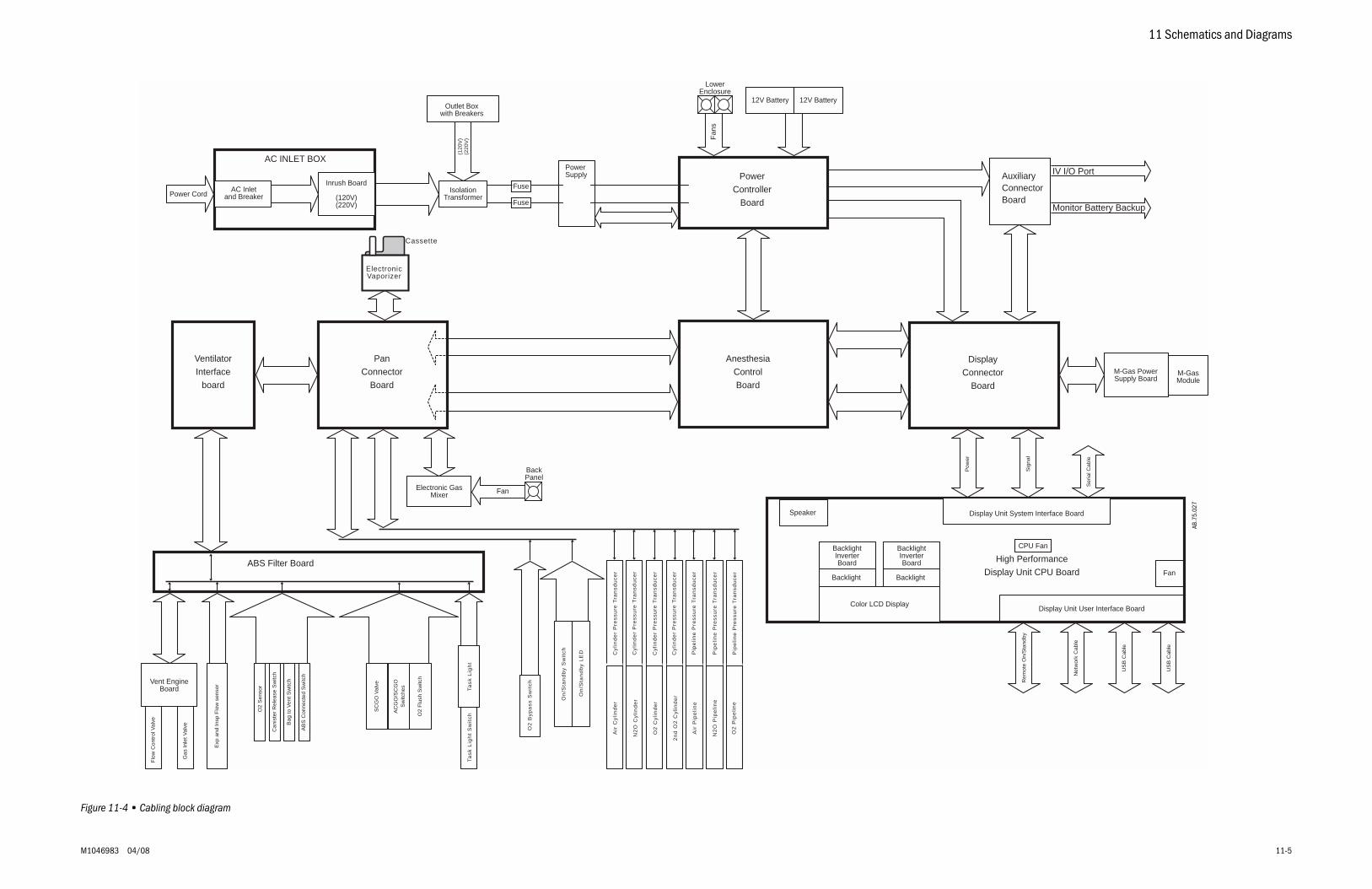
11 Schematics and Diagrams
M1046983 04/08 11-5
Figure 11-4 • Cabling block diagram
AC INLET BOX
AC Inletand Breaker
Inrush Board
(120V)(220V)
IsolationTransformerPower Cord
Outlet Boxwith Breakers
PowerController
Board
12V Battery 12V Battery
AnesthesiaControlBoard
DisplayConnector
Board
M-Gas PowerSupply Board
M-GasModule
High PerformanceDisplay Unit CPU Board
Display Unit User Interface Board
Fan
Display Unit System Interface BoardSpeaker
Color LCD Display
Backlight Backlight
BacklightInverterBoard
PanConnector
Board
VentilatorInterface
board
Electronic GasMixer
ABS Filter Board
Fan
s
Vent EngineBoard
Ta
sk
Lig
ht
Sw
itc
hT
as
k L
igh
t
Pow
er
Sig
nal
Ser
ial C
able
(120
V)
(220
V)
Net
wor
k C
able
Rem
ote
On/
Sta
ndby
US
B C
able
Flo
w C
ontr
ol V
alve
Gas
Inle
t Val
ve
Exp
and
Insp
Flo
w s
enso
r
O2
Sen
sor
Can
iste
r R
elea
se S
witc
h
AB
S C
onne
cted
Sw
itch
SC
GO
Val
ve
AC
GO
/SC
GO
Sw
itche
s
O2
Flu
sh S
witc
h
O2
By
pa
ss
Sw
itc
h
On
/Sta
nd
by
Sw
itc
h
On
/Sta
nd
by
LE
D
Air
Cy
lin
de
r
N2
O C
yli
nd
er
O2
Cy
lin
de
r
2n
d O
2 C
yli
nd
er
Cy
lin
de
r P
res
su
re T
ran
sd
uc
er
Cy
lin
de
r P
res
su
re T
ran
sd
uc
er
Cy
lin
de
r P
res
su
re T
ran
sd
uc
er
Cy
lin
de
r P
res
su
re T
ran
sd
uc
er
Pip
eli
ne
Pre
ss
ure
Tra
ns
du
ce
r
Pip
eli
ne
Pre
ss
ure
Tra
ns
du
ce
r
Pip
eli
ne
Pre
ss
ure
Tra
ns
du
ce
r
Air
Pip
eli
ne
N2
O P
ipe
lin
e
O2
Pip
eli
ne
BacklightInverterBoard
ElectronicVaporizer
LowerEnclosure
Fan
BackPanel
Fuse
Fuse
PowerSupply Auxiliary
ConnectorBoard
IV I/O Port
Monitor Battery Backup
US
B C
able
Bag
to V
ent S
witc
h
CPU Fan
Cassette
AB.7
5.02
7
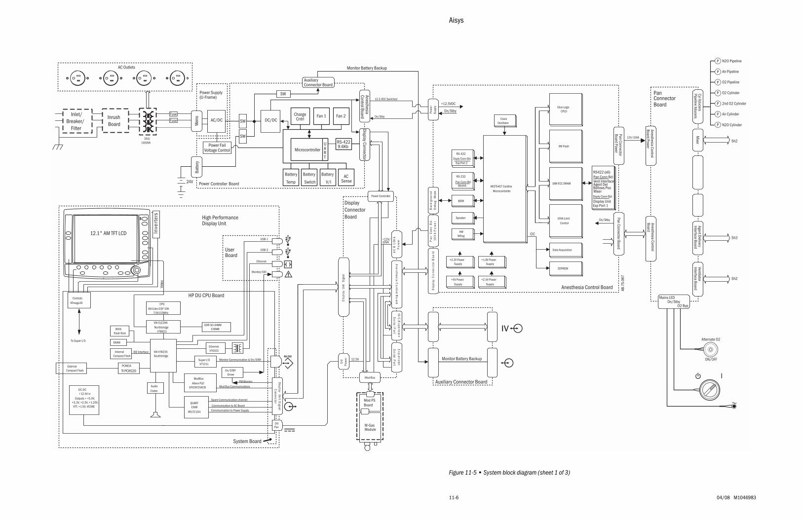
Aisys
11-6 04/08 M1046983
Figure 11-5 • System block diagram (sheet 1 of 3)
PanConnectorBoard
On/StbyMains LED
O2 Byp
Sh2
Anesthesia ControlBoard Power
Cyl XducersPipeline Xducers
Mixer
Anesthesia ControlBoard
N2O PipelineP
Air Pipeline
O2 Pipeline
O2 Cylinder
2nd O2 Cylinder
Air Cylinder
N2O Cylinder
Sh3
Agent DeliveryInterface Board
Alternate O2
ON/OFF
P
P
P
P
P
P
Mod PSBoard
M-GasModule
Power Controller Board
Microcontroller
Fan 1ChargeCntrl
Battery
Temp
Battery
SwitchAC
SenseBattery
V/I
UART
RS-4229.6Kb
Fan 2AC/DC
24V
DC/DC
Mai
nsBa
ttery
Display ConnectorAnesthesiaControl Board
Power Supply(U-Frame)
Power FailVoltage Control
AuxiliaryConnector Board
SW
SW
SW
Monitor Battery Backup
Monitor Battery Backup
Inlet/Breaker/
Filter
350/1400VA
InrushBoard
AC Outlets
12.5 VDC Switched
Exp
ansion
Se
rialP
ort
IGC
/Expa
nsion
Se
rialP
ort
Mod Bus
DU
Pow
erD
ispl
ayUn
itS
igna
l
Ane
sthesiaC
ontrolB
oard
12V/10VA
Anesthesia Control BoardDis
play
Co
nne
ctor
Boa
rd
MCF5407 Coldfire
Microcontroller
Glue LogicCPLD
16M ECC DRAM
RS-232
Pan Conn Bd:MiniAA
10VA Limit
Control
+2.5V Power
Supply
+5V Power
Supply
Data Acquisition
ClockOscillator
Pow
erSu
pply
RS-422
Dsply Conn Bd:Exp Port 2
4M Flash
BDM
Power Controller
Bac
kgr
ound
Deb
ugM
ode
On/Stby
Speaker
ModBus
Altera PLDEPIC6F256C8
DC-DC+12.5V in
Outputs = +5.0V,+3.3V, +2.5V, +1.25V,VTT, +1.5V, VCORE
Controls
ATmega16
High PerformanceDisplay Unit
HP DU CPU Board
12.5V
+12.5VDC
USB-2
Monitor/SIO
USB-1
Spare Communication channel
Mod Bus Communications
DisplayConnectorBoard
Display
Unit
Signa
lC
onnector
+12V/10VA
Inve
rter
EthernetVT6103
Ethernet
12.1" AM TFT LCD
DUPwr
CPU
VIA Eden ESP 10K7.5X133MHz
VIA CLE266
NorthbridgeVT8623
VIA VT8235Southbridge
Vide
o
DDR SO-DIMM128MB
QUARTEXAR
XR17C154
Super I/OVT1211
ExternalCompact Flash
InternalCompact Flash
PCMCIA
TI PCII520
IDE Interface
Communication to Power Supply
Communication to AC Board
Monitor Communication & On/STBY
Audio
Codec
BIOSFlash Rom
SRAM
On/STBYDriver
PM Monitor
System Board
EEPROM
I2C
+1.8V PowerSupply
+3.3V PowerSupply
HWWDog
On/Stby
Pan
Con
nB
d.10
VA
Po
we
r
AC
B1
0VA
Po
wer
To Super I/O
On/Stby
s
UserBoard
Auxiliary Connector Board
Fuse
Fuse
Pan Connector BoardPan ConnectorBoard Power
RS422 (x6)Pan Conn Bd:Vent InterfaceAgent DelBellows PosMixerDsply Conn Bd:
Display UnitExp Port 1
Sh2
VentilatorInterface Board
AB.7
5.06
7
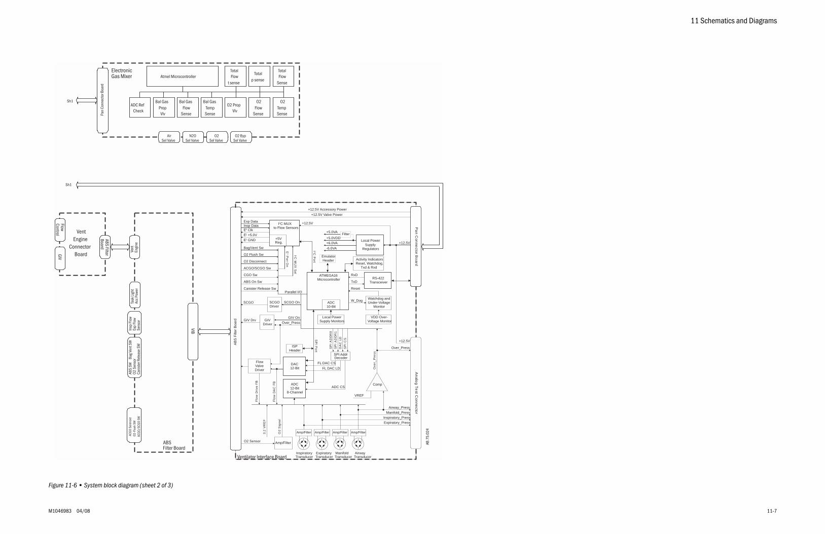
11 Schematics and Diagrams
M1046983 04/08 11-7
Figure 11-6 • System block diagram (sheet 2 of 3)
ElectronicGas Mixer
O2TempSense
O2Flow
Sense
O2 PropVlv
Bal GasTempSense
Bal GasFlow
Sense
Bal GasPropVlv
TotalFlow
Sense
Totalp sense
TotalFlow
t senseAtmel Microcontroller
ADC RefCheck
O2Sel Valve
N2OSel Valve
AirSel Valve
O2 BypSel Valve
ABSFilter Board
ACGO
Sol
enoi
dO2
-Flu
sh S
WAC
GO/S
CGO
SW
VentEngine
ConnectorBoard
Sh1
Sh1
FlowControl
GIV
ABS FilterBoard
Vent
Engi
neAB
S SW
Ba
g Ve
nt S
WO2
Sen
sor
Cani
ster
Rel
ease
SW
Insp
Flo
wEx
p Fl
owSe
nsor
Task
Lig
htAc
c Po
wer
VIB
Pan
Conn
ecto
r Boa
rd
Amp/Filter Amp/Filter Amp/Filter Amp/Filter
RS-422Transceiver
Pa
nC
onne
ctorB
oard
+6.0VA
-6.0VA
ATMEGA16Microcontroller
+5.0VDD
+5.0VA
ADC12-Bit
8-Channel
Local PowerSupply
Regulators
+12.5V
I2C MUX to Flow Sensors
Insp Data
Bag/Vent Sw
O2 Disconnect
O2 Flush Sw
DAC12-Bit
SCGO On
GIV On
I 2CM
UX
Sel
E2
Pw
rO
n
Amp/Filter
Flo
wD
AC
FB
VDD Over-Voltage Monitor
RxD
TxDO
2S
igna
l
E2 +5.0V
Watchdog andUnder-Voltage
MonitorADC10-Bit
SP
IP
ort
Parallel I/O
FlowValveDriver
GIVDriver
SCGODriver
Exp Data
I2C
Port
ACGO/SCGO Sw
ABS On Sw
Comp
3.2
VR
EF
VREF
Ove
r_P
ress
Over_Press
O2 Sensor
E2 Clk
+12.5V Accessory Power
+12.5V Valve Power
Flo
wD
rive
FB
SPI AddrDecoder
FL DAC CS
FL DAC LD
ADC CS
SP
IA
DD
R0
SP
IA
DD
R1
DA
CLD
SP
IC
SISP
Header
EmulatorHeader
E2 GND
CGO Sw
Filter
Local PowerSupply Monitors
+12.5V
Reset
An
alog
Te
stC
onne
ctor
InspiratoryTransducer
ExpiratoryTransducer
ManifoldTransducer
AirwayTransducer
Over_Press
+12.5V
Airway_Press
Manifold_Press
Inspiratory_Press
Expiratory_Press
GIV Drv
SCGO
Activity IndicatorsReset, Watchdog,
Txd & Rxd
W_Dog
+5VReg.
Ventilator Interface Board
AB
S F
ilter
Boa
rd
Canister Release Sw
AB.7
5.02
4
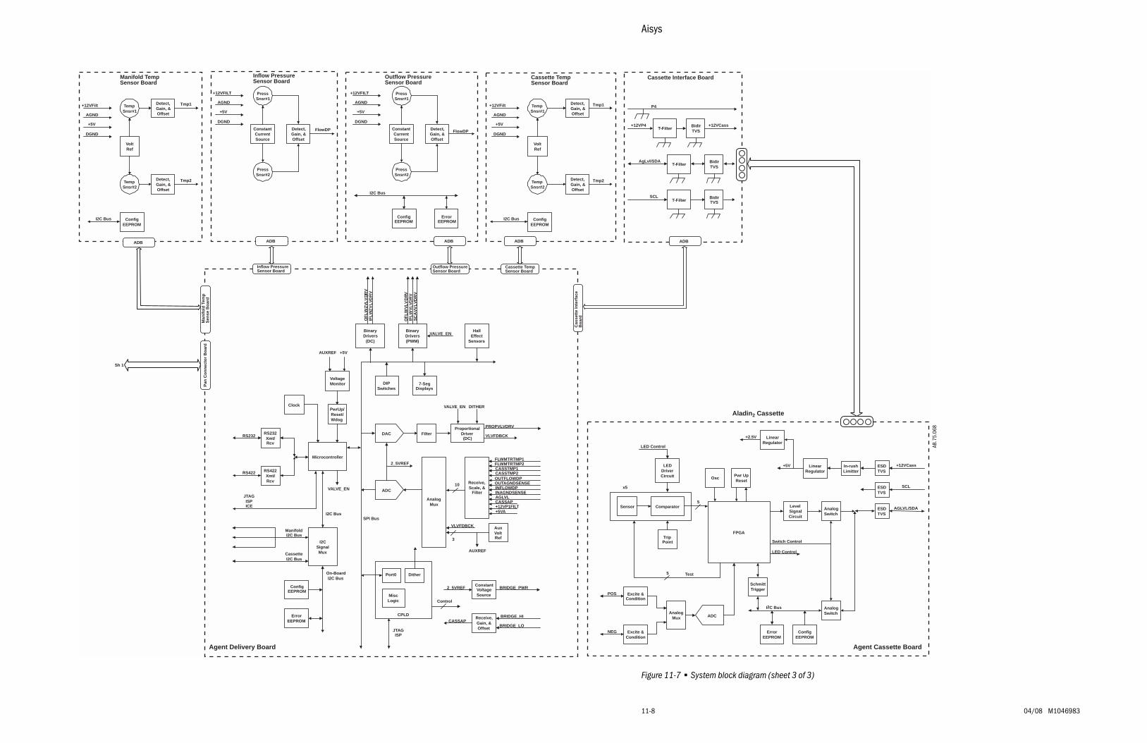
Aisys
11-8 04/08 M1046983
Figure 11-7 • System block diagram (sheet 3 of 3)
Agent Delivery Board
Inflow PressureSensor Board
Outflow PressureSensor Board
Manifold TempSensor Board
Cassette TempSensor Board
Cassette Interface Board
+5V
I2C Bus
LevelSignalCircuit
AnalogSwitch
AnalogSwitch
Osc
Sensor
x5
Comparator AGLVL/SDA
SCL
+12VCass
LED Control
Switch Control
LEDDriverCircuit Pwr Up
Reset
TripPoint
LED Control
SchmittTrigger
ErrorEEPROM
ConfigEEPROM
LinearRegulator
ESDTVS
In-rushLimitter
ESDTVS
ESDTVS
Test5
FPGA
5
LinearRegulator
+2.5V
ADCAnalog
Mux
Excite &Condition
Excite &Condition
POS
NEG
RS232Xmt/Rcv
Filter
RS422Xmt/Rcv
ProportionalDriver(DC)
BinaryDrivers
(DC)
PwrUp/Reset/Wdog
BinaryDrivers(PWM)
SC
AV
VL
VD
RV
OF
LW
ZV
LV
DR
VIF
LW
ZV
LV
DR
V
OF
LW
VL
VD
RV
IFL
WV
LV
DR
V
PROPVLVDRV
HallEffect
Sensors
FLWMTRTMP1FLWMTRTMP2CASSTMP1
OUTFLOWDP
INFLOWDP
CASSAPAGLVL
CASSTMP2
BRIDGE_PWR
I2C Bus
RS232
+5V
RS422
SPI Bus
2_5VREF
I2CSignalMux
On-BoardI2C Bus
ManifoldI2C Bus
CassetteI2C Bus
ConfigEEPROM
ErrorEEPROM
Clock
VoltageMonitor DIP
Switches7-Seg
Displays
ADC
+12VP1FILT+5VA
VLVFDBCK
AnalogMux
10
2_5VREF
CASSAPBRIDGE_HI
VLVFDBCK
CPLD
Control
JTAGISP
JTAGISPICE
AuxVoltRef
AUXREF
AUXREF
Microcontroller
VALVE_EN
DITHERVALVE_EN
VALVE_EN
DAC
OUTAGNDSENSE
INAGNDSENSE
ConstantVoltageSource
Receive,Scale, &
Filter
Receive,Gain, &Offset
BRIDGE_LO
DitherPort0
MiscLogic
3
I2C Bus
TempSnsr#1
Tmp1
TempSnsr#2
Tmp2Detect,Gain, &Offset
Detect,Gain, &Offset
VoltRef
ConfigEEPROM
+12VFilt
AGND
+5V
DGND
PressSnsr#1
PressSnsr#2
FlowDPDetect,Gain, &Offset
+12VFILT
AGND
+5V
DGND
ConstantCurrentSource
I2C Bus
PressSnsr#1
PressSnsr#2
FlowDPDetect,Gain, &Offset
ConfigEEPROM
+12VFILT
AGND
+5V
DGND
ConstantCurrentSource
ErrorEEPROM
I2C Bus
TempSnsr#1
Tmp1
TempSnsr#2
Tmp2Detect,Gain, &Offset
Detect,Gain, &Offset
VoltRef
ConfigEEPROM
+12VFilt
AGND
+5V
DGND
+12VP4T-Filter
BidirTVS
AgLvl/SDAT-Filter
BidirTVS
SCLT-Filter
BidirTVS
P4
+12VCass
ADB ADB ADB ADB ADB
Cas
sett
e In
terf
ace
Bo
ard
Pan
Co
nn
ecto
r B
oar
d
Agent Cassette Board
Aladin2 Cassette
Sh 1
Man
ifo
ld T
emp
Sen
se B
oar
d
Inflow PressureSensor Board
Outflow PressureSensor Board
Cassette TempSensor Board
AB.7
5.06
8
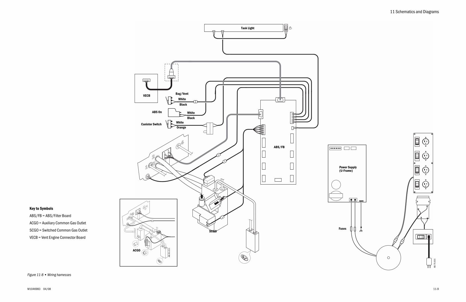
11 Schematics and Diagrams
M1046983 04/08 11-9
Figure 11-8 • Wiring harnesses
Task Light
VECB
ABS/FB
SCGO
Key to Symbols
ABS/FB = ABS/Filter Board
ACGO = Auxiliary Common Gas Outlet
SCGO = Switched Common Gas Outlet
VECB = Vent Engine Connector Board
Bag/Vent
ABS On
Fuses
AB.7
5.03
1
ACGO
AB.9
1.01
1
Canister Switch
Power Supply(U-Frame)
White
White
White
Black
Black
Orange
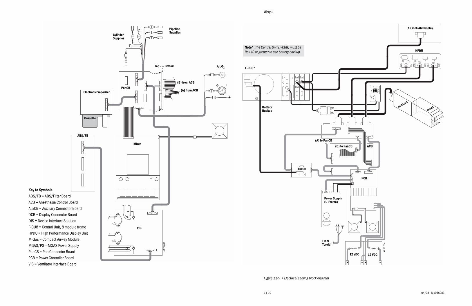
Aisys
11-10 04/08 M1046983
Figure 11-9 • Electrical cabling block diagram
P
P
P
PP
P
AB.7
5.06
6
ABS/FB
Mixer
VIB
PanCB(A) from ACB
(B) from ACB
Electronic Vaporizer
PipelineSupplies
CylinderSupplies
Alt O2Top - - Bottom
Cassette
AB.7
5.03
4
Key to Symbols
ABS/FB = ABS/Filter Board
ACB = Anesthesia Control Board
AuxCB = Auxiliary Connector Board
DCB = Display Connector Board
DIS = Device Interface Solution
F-CU8 = Central Unit, 8 module frame
HPDU = High Performance Display Unit
M-Gas = Compact Airway Module
MGAS/PS = MGAS Power Supply
PanCB = Pan Connector Board
PCB = Power Controller Board
VIB = Ventilator Interface Board
M-GAS
HPDU
F-CU8*
PCB
ACB
12 VDC 12 VDC
Power Supply(U-Frame)
(A) to PanCB
(B) to PanCB
MGAS/PS
+ +– –
AuxCB
FromToroid
Note*: The Central Unit (F-CU8) must be Rev 10 or greater to use battery backup.
BatteryBackup
12 inch AM Display
DIS
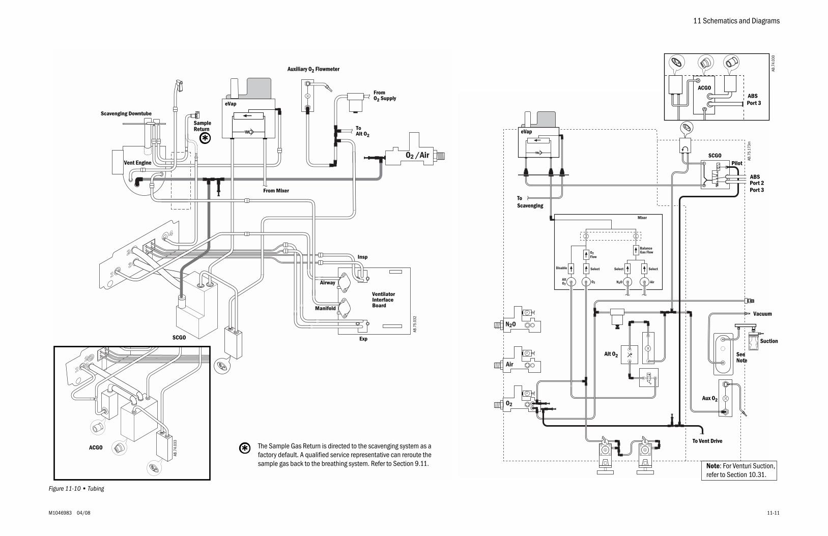
11 Schematics and Diagrams
M1046983 04/08 11-11
Figure 11-10 • Tubing
AB.7
5.03
2
eVap
From Mixer
ToAlt O2
Vent Engine
Scavenging Downtube
Auxiliary O2 Flowmeter
FromO2 Supply
VentilatorInterfaceBoard
SCGO
AB.7
4.03
3
ACGO
Exp
Insp
Manifold
Airway
Sample Return
*
The Sample Gas Return is directed to the scavenging system as a factory default. A qualified service representative can reroute the sample gas back to the breathing system. Refer to Section 9.11.
*
P
Air
N2O
O2
N2OAltO2
O2 Air
P
P
SelectDisable
BalanceGas Flow
SelectSelect
O2Flow
PP
Mixer
SCGO
ABSPort 2Port 3
Pilot
To Vent Drive
AB.7
5.17
3m
Aux O2
SeeNote
Alt O2
ToScavenging
eVap
ACGOABSPort 3
Vacuum
Suction
Note: For Venturi Suction, refer to Section 10.31.
AB.7
4.03
0
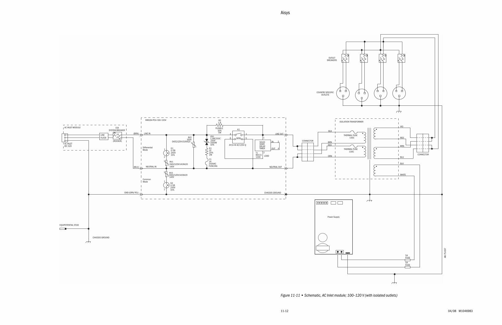
Aisys
11-12 04/08 M1046983
Figure 11-11 • Schematic, AC Inlet module; 100–120 V (with isolated outlets)
AB.7
5.03
7
LOAD
FUSIBLE
FUSE2AG250VAC1AF1
20%2W
R110
140V
RV1D6521ZOV141RA20
15%250V
G2U-5B
15%250V
G1U-5B
150VD6521ZOV151RA20
RV2
120VKH111T1
10%5W
1.8R2
K1
JH1A-W-AC120V-Q10%1500W250V1.5KE250CCR1
140V
RV3D6521ZOV141RA20
1
2
1
2
TIMERDELAYSTATESOLID 3
4
1
2
14
56
DifferentialMode
LINE OUT
NEUTRAL OUT
CHASSIS GROUND
LINE IN
NEUTRAL IN
CommonMode
INRUSH PCA 100-120V
(BLU)
(BRN)
AC INLETIEC 320
SYSTEM BREAKER
(ROCKER)
15A
GND (GRN/YEL)
IN
OUT
CHASSIS GROUND
EQUIPOTENTIAL STUD
AC INLET MODULE
LINEFILTER
130C
BRN
BLU
BRN
BLK
THERMAL FUSE130C
THERMAL FUSE
ISOLATION TRANSFORMER
RED
ORN
RED
VIO
CONNECTOR
BLK
WHITE
CONNECTOR
COUNTRY SPECIFICOUTLETS
OUTLETBREAKERS
5AFUSE
5AFUSE
Power Supply
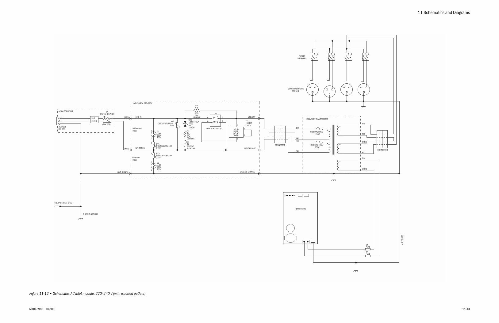
11 Schematics and Diagrams
M1046983 04/08 11-13
Figure 11-12 • Schematic, AC Inlet module; 220–240 V (with isolated outlets)
CHASSIS GROUND
1AF1
250VACFUSE2AG
CERAMIC
2W10R1
20%
1.5KE440CACR1
440V
1500W5%
RV1D65ZOV271RA140275V
JH1A-W-AC240V-Q
K1
KH115T1
240V
R2
10%
6.8
7WFUSIBLE
G1
470V15%
U-9B
RV3D65ZOV271RA140275V
D65ZOV271RA140RV2
275V
G2
470V15%
U-9B
14
56
TIMERDELAYSTATESOLID
4
1
2
3
2
1
2
1
Mode
LINE OUT
NEUTRAL OUT
ModeCommon
LINE IN
NEUTRAL IN
CHASSIS GROUND
Differential
(BLU)
(BRN)
GND (GRN/Y)
AC INLETIEC 320
SYSTEM BREAKER
(ROCKER)
8A
INRUSH PCA 220-240V
EQUIPOTENTIAL STUD
AC INLET MODULE
LINEFILTER
COUNTRY SPECIFICOUTLETS
CONNECTOR130C
BRN
BLU
BRN
BLK
THERMAL FUSE130C
THERMAL FUSE
ISOLATION TRANSFORMER
RED
ORN
RED
VIO
CONNECTOR
BLK
WHITE
OUTLETBREAKERS
Power Supply
5AFUSE
5AFUSE
AB.7
5.03
8

11-14 04/08 M1046983
Notes
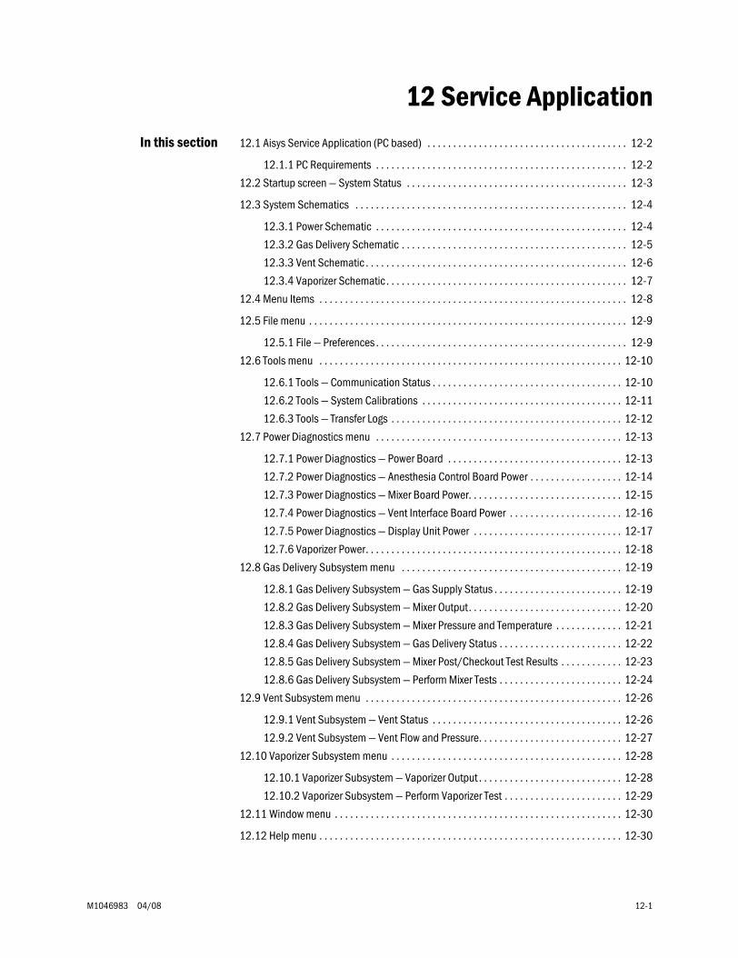
M1046983 04/08 12-1
12 Service ApplicationIn this section 12.1 Aisys Service Application (PC based) . . . . . . . . . . . . . . . . . . . . . . . . . . . . . . . . . . . . . . . 12-2
12.1.1 PC Requirements . . . . . . . . . . . . . . . . . . . . . . . . . . . . . . . . . . . . . . . . . . . . . . . . . 12-2
12.2 Startup screen — System Status . . . . . . . . . . . . . . . . . . . . . . . . . . . . . . . . . . . . . . . . . . . 12-3
12.3 System Schematics . . . . . . . . . . . . . . . . . . . . . . . . . . . . . . . . . . . . . . . . . . . . . . . . . . . . . 12-4
12.3.1 Power Schematic . . . . . . . . . . . . . . . . . . . . . . . . . . . . . . . . . . . . . . . . . . . . . . . . . 12-4
12.3.2 Gas Delivery Schematic . . . . . . . . . . . . . . . . . . . . . . . . . . . . . . . . . . . . . . . . . . . . 12-5
12.3.3 Vent Schematic . . . . . . . . . . . . . . . . . . . . . . . . . . . . . . . . . . . . . . . . . . . . . . . . . . . 12-6
12.3.4 Vaporizer Schematic. . . . . . . . . . . . . . . . . . . . . . . . . . . . . . . . . . . . . . . . . . . . . . . 12-7
12.4 Menu Items . . . . . . . . . . . . . . . . . . . . . . . . . . . . . . . . . . . . . . . . . . . . . . . . . . . . . . . . . . . . 12-8
12.5 File menu . . . . . . . . . . . . . . . . . . . . . . . . . . . . . . . . . . . . . . . . . . . . . . . . . . . . . . . . . . . . . . 12-9
12.5.1 File — Preferences . . . . . . . . . . . . . . . . . . . . . . . . . . . . . . . . . . . . . . . . . . . . . . . . . 12-9
12.6 Tools menu . . . . . . . . . . . . . . . . . . . . . . . . . . . . . . . . . . . . . . . . . . . . . . . . . . . . . . . . . . . 12-10
12.6.1 Tools — Communication Status . . . . . . . . . . . . . . . . . . . . . . . . . . . . . . . . . . . . . 12-10
12.6.2 Tools — System Calibrations . . . . . . . . . . . . . . . . . . . . . . . . . . . . . . . . . . . . . . . 12-11
12.6.3 Tools — Transfer Logs . . . . . . . . . . . . . . . . . . . . . . . . . . . . . . . . . . . . . . . . . . . . . 12-12
12.7 Power Diagnostics menu . . . . . . . . . . . . . . . . . . . . . . . . . . . . . . . . . . . . . . . . . . . . . . . . 12-13
12.7.1 Power Diagnostics — Power Board . . . . . . . . . . . . . . . . . . . . . . . . . . . . . . . . . . 12-13
12.7.2 Power Diagnostics — Anesthesia Control Board Power . . . . . . . . . . . . . . . . . . 12-14
12.7.3 Power Diagnostics — Mixer Board Power. . . . . . . . . . . . . . . . . . . . . . . . . . . . . . 12-15
12.7.4 Power Diagnostics — Vent Interface Board Power . . . . . . . . . . . . . . . . . . . . . . 12-16
12.7.5 Power Diagnostics — Display Unit Power . . . . . . . . . . . . . . . . . . . . . . . . . . . . . 12-17
12.7.6 Vaporizer Power. . . . . . . . . . . . . . . . . . . . . . . . . . . . . . . . . . . . . . . . . . . . . . . . . . 12-18
12.8 Gas Delivery Subsystem menu . . . . . . . . . . . . . . . . . . . . . . . . . . . . . . . . . . . . . . . . . . . 12-19
12.8.1 Gas Delivery Subsystem — Gas Supply Status . . . . . . . . . . . . . . . . . . . . . . . . . 12-19
12.8.2 Gas Delivery Subsystem — Mixer Output. . . . . . . . . . . . . . . . . . . . . . . . . . . . . . 12-20
12.8.3 Gas Delivery Subsystem — Mixer Pressure and Temperature . . . . . . . . . . . . . 12-21
12.8.4 Gas Delivery Subsystem — Gas Delivery Status . . . . . . . . . . . . . . . . . . . . . . . . 12-22
12.8.5 Gas Delivery Subsystem — Mixer Post/Checkout Test Results . . . . . . . . . . . . 12-23
12.8.6 Gas Delivery Subsystem — Perform Mixer Tests . . . . . . . . . . . . . . . . . . . . . . . . 12-24
12.9 Vent Subsystem menu . . . . . . . . . . . . . . . . . . . . . . . . . . . . . . . . . . . . . . . . . . . . . . . . . . 12-26
12.9.1 Vent Subsystem — Vent Status . . . . . . . . . . . . . . . . . . . . . . . . . . . . . . . . . . . . . 12-26
12.9.2 Vent Subsystem — Vent Flow and Pressure. . . . . . . . . . . . . . . . . . . . . . . . . . . . 12-27
12.10 Vaporizer Subsystem menu . . . . . . . . . . . . . . . . . . . . . . . . . . . . . . . . . . . . . . . . . . . . . 12-28
12.10.1 Vaporizer Subsystem — Vaporizer Output . . . . . . . . . . . . . . . . . . . . . . . . . . . . 12-28
12.10.2 Vaporizer Subsystem — Perform Vaporizer Test . . . . . . . . . . . . . . . . . . . . . . . 12-29
12.11 Window menu . . . . . . . . . . . . . . . . . . . . . . . . . . . . . . . . . . . . . . . . . . . . . . . . . . . . . . . . 12-30
12.12 Help menu . . . . . . . . . . . . . . . . . . . . . . . . . . . . . . . . . . . . . . . . . . . . . . . . . . . . . . . . . . . 12-30
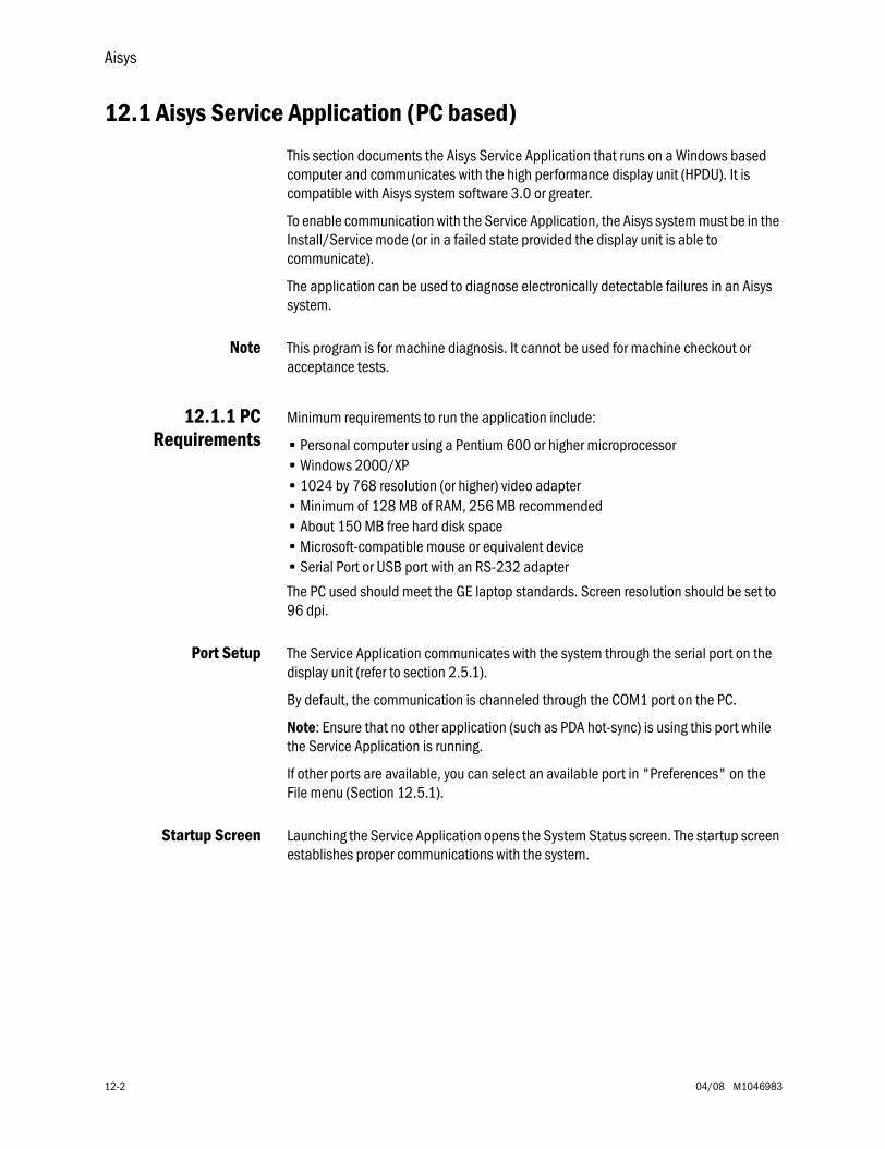
Aisys
12-2 04/08 M1046983
12.1 Aisys Service Application (PC based)
This section documents the Aisys Service Application that runs on a Windows based computer and communicates with the high performance display unit (HPDU). It is compatible with Aisys system software 3.0 or greater.
To enable communication with the Service Application, the Aisys system must be in the Install/Service mode (or in a failed state provided the display unit is able to communicate).
The application can be used to diagnose electronically detectable failures in an Aisys system.
Note This program is for machine diagnosis. It cannot be used for machine checkout or acceptance tests.
12.1.1 PCRequirements
Minimum requirements to run the application include:
• Personal computer using a Pentium 600 or higher microprocessor• Windows 2000/XP• 1024 by 768 resolution (or higher) video adapter• Minimum of 128 MB of RAM, 256 MB recommended• About 150 MB free hard disk space• Microsoft-compatible mouse or equivalent device• Serial Port or USB port with an RS-232 adapter
The PC used should meet the GE laptop standards. Screen resolution should be set to 96 dpi.
Port Setup The Service Application communicates with the system through the serial port on the display unit (refer to section 2.5.1).
By default, the communication is channeled through the COM1 port on the PC.
Note: Ensure that no other application (such as PDA hot-sync) is using this port while the Service Application is running.
If other ports are available, you can select an available port in "Preferences" on the File menu (Section 12.5.1).
Startup Screen Launching the Service Application opens the System Status screen. The startup screen establishes proper communications with the system.
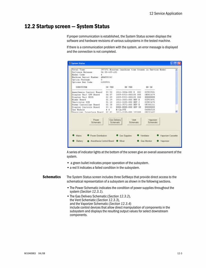
12 Service Application
M1046983 04/08 12-3
12.2 Startup screen — System Status
If proper communication is established, the System Status screen displays the software and hardware revisions of various subsystems in the tested machine.
If there is a communication problem with the system, an error message is displayed and the connection is not completed.
A series of indicator lights at the bottom of the screen give an overall assessment of the system.
• a green bullet indicates proper operation of the subsystem.• a red X indicates a failed condition in the subsystem.
Schematics The System Status screen includes three Softkeys that provide direct access to the schematical representation of a subsystem as shown in the following sections.
• The Power Schematic indicates the condition of power supplies throughout the system (Section 12.3.1).
• The Gas Delivery Schematic (Section 12.3.2), the Vent Schematic (Section 12.3.3), and the Vaporizer Schematic (Section 12.3.4) include control devices that allow direct manipulation of components in the subsystem and displays the resulting output values for select downstream components.
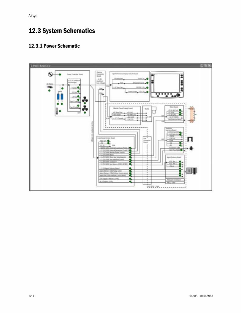
Aisys
12-4 04/08 M1046983
12.3 System Schematics
12.3.1 Power Schematic
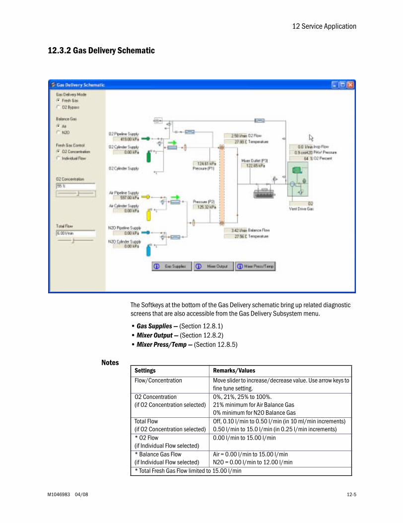
12 Service Application
M1046983 04/08 12-5
12.3.2 Gas Delivery Schematic
The Softkeys at the bottom of the Gas Delivery schematic bring up related diagnostic screens that are also accessible from the Gas Delivery Subsystem menu.
• Gas Supplies — (Section 12.8.1)• Mixer Output — (Section 12.8.2)• Mixer Press/Temp — (Section 12.8.5)
NotesSettings Remarks/Values
Flow/Concentration Move slider to increase/decrease value. Use arrow keys to fine tune setting.
O2 Concentration(if O2 Concentration selected)
0%, 21%, 25% to 100%.21% minimum for Air Balance Gas0% minimum for N2O Balance Gas
Total Flow(if O2 Concentration selected)
Off, 0.10 l/min to 0.50 l/min (in 10 ml/min increments)0.50 l/min to 15.0 l/min (in 0.25 l/min increments)
* O2 Flow(if Individual Flow selected)
0.00 l/min to 15.00 l/min
* Balance Gas Flow(if Individual Flow selected)
Air = 0.00 l/min to 15.00 l/minN2O = 0.00 l/min to 12.00 l/min
* Total Fresh Gas Flow limited to 15.00 l/min
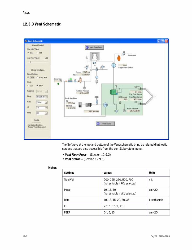
Aisys
12-6 04/08 M1046983
12.3.3 Vent Schematic
The Softkeys at the top and bottom of the Vent schematic bring up related diagnostic screens that are also accessible from the Vent Subsystem menu.
• Vent Flow/Press — (Section 12.9.2)• Vent Status — (Section 12.9.1)
NotesSettings Values Units
Tidal Vol 200, 225, 250, 500, 700(not settable if PCV selected)
mL
Pinsp 10, 15, 30(not settable if VCV selected)
cmH2O
Rate 10, 13, 15, 20, 30, 35 breaths/min
I:E 2:1, 1:1, 1:2, 1:3
PEEP Off, 5, 10 cmH2O

12 Service Application
M1046983 04/08 12-7
12.3.4 Vaporizer Schematic
The Softkey at the bottom of the Vaporizer schematic brings up a related diagnostic screen that is also accessible from the Vaporizer Subsystem menu.
• Vaporizer Output — (Section 12.10.1)
NotesSettings Remarks
Manual Control Set “Agent Concentration” to “Off” to enable Manual Control
Agent ConcentrationorProp Flow Valve DAC Value
Move slider to increase/decrease value. Use arrow keys to fine tune setting.
Zero Valves Auto Select “Zero Valves Auto” for best accuracy flow measurements.
Inflow ZeroOutflow Zero
Not settable if “Zero Valves Auto” is checked.
Outflow Meter reading are compensated by ambient pressure stored at machine start-up.
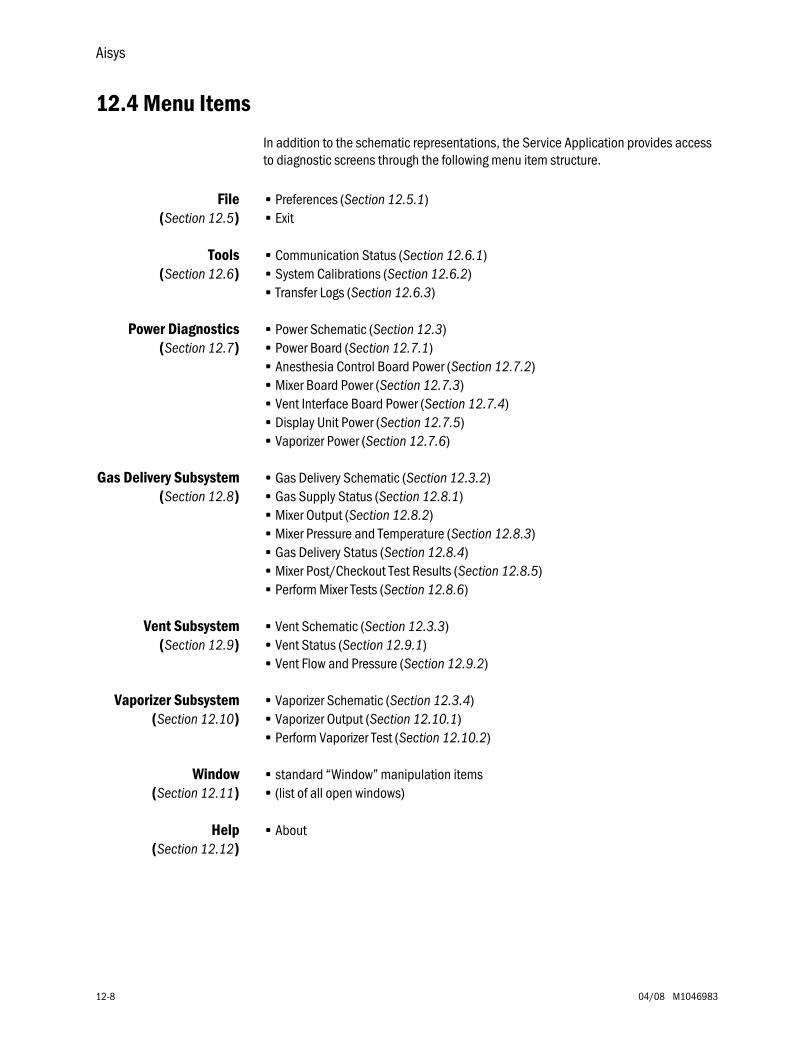
Aisys
12-8 04/08 M1046983
12.4 Menu Items
In addition to the schematic representations, the Service Application provides access to diagnostic screens through the following menu item structure.
File(Section 12.5)
• Preferences (Section 12.5.1)• Exit
Tools(Section 12.6)
• Communication Status (Section 12.6.1)• System Calibrations (Section 12.6.2)• Transfer Logs (Section 12.6.3)
Power Diagnostics(Section 12.7)
• Power Schematic (Section 12.3)• Power Board (Section 12.7.1)• Anesthesia Control Board Power (Section 12.7.2)• Mixer Board Power (Section 12.7.3)• Vent Interface Board Power (Section 12.7.4)• Display Unit Power (Section 12.7.5)• Vaporizer Power (Section 12.7.6)
Gas Delivery Subsystem(Section 12.8)
• Gas Delivery Schematic (Section 12.3.2)• Gas Supply Status (Section 12.8.1)• Mixer Output (Section 12.8.2)• Mixer Pressure and Temperature (Section 12.8.3)• Gas Delivery Status (Section 12.8.4)• Mixer Post/Checkout Test Results (Section 12.8.5)• Perform Mixer Tests (Section 12.8.6)
Vent Subsystem(Section 12.9)
• Vent Schematic (Section 12.3.3)• Vent Status (Section 12.9.1)• Vent Flow and Pressure (Section 12.9.2)
Vaporizer Subsystem(Section 12.10)
• Vaporizer Schematic (Section 12.3.4)• Vaporizer Output (Section 12.10.1)• Perform Vaporizer Test (Section 12.10.2)
Window(Section 12.11)
• standard “Window” manipulation items• (list of all open windows)
Help(Section 12.12)
• About
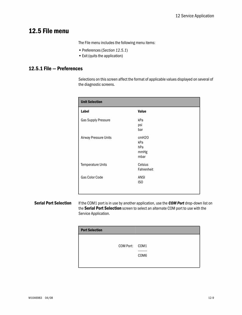
12 Service Application
M1046983 04/08 12-9
12.5 File menu
The File menu includes the following menu items:
• Preferences (Section 12.5.1)• Exit (quits the application)
12.5.1 File — Preferences
Selections on this screen affect the format of applicable values displayed on several of the diagnostic screens.
Serial Port Selection If the COM1 port is in use by another application, use the COM Port drop-down list on the Serial Port Selection screen to select an alternate COM port to use with the Service Application.
Unit Selection
Label Value
Gas Supply Pressure kPapsibar
Airway Pressure Units cmH2OkPahPammHgmbar
Temperature Units CelsiusFahrenheit
Gas Color Code ANSIISO
Port Selection
COM Port: COM1--------COM6
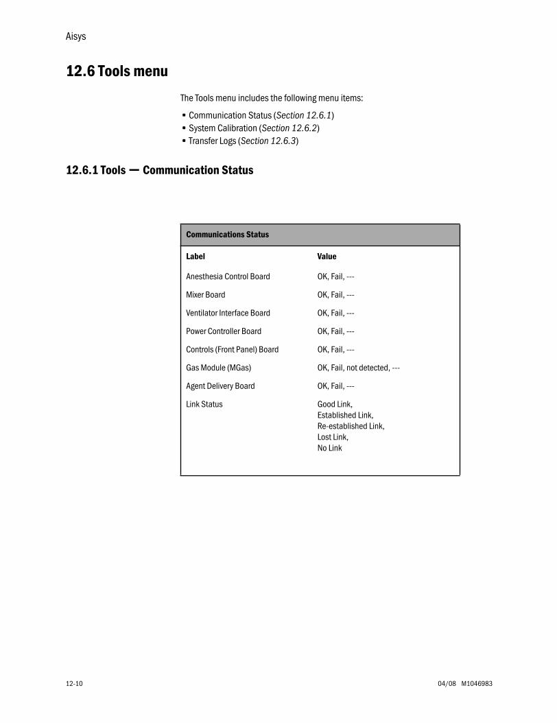
Aisys
12-10 04/08 M1046983
12.6 Tools menu
The Tools menu includes the following menu items:
• Communication Status (Section 12.6.1)• System Calibration (Section 12.6.2)• Transfer Logs (Section 12.6.3)
12.6.1 Tools — Communication Status
Communications Status
Label Value
Anesthesia Control Board OK, Fail, ---
Mixer Board OK, Fail, ---
Ventilator Interface Board OK, Fail, ---
Power Controller Board OK, Fail, ---
Controls (Front Panel) Board OK, Fail, ---
Gas Module (MGas) OK, Fail, not detected, ---
Agent Delivery Board OK, Fail, ---
Link Status Good Link, Established Link, Re-established Link, Lost Link, No Link
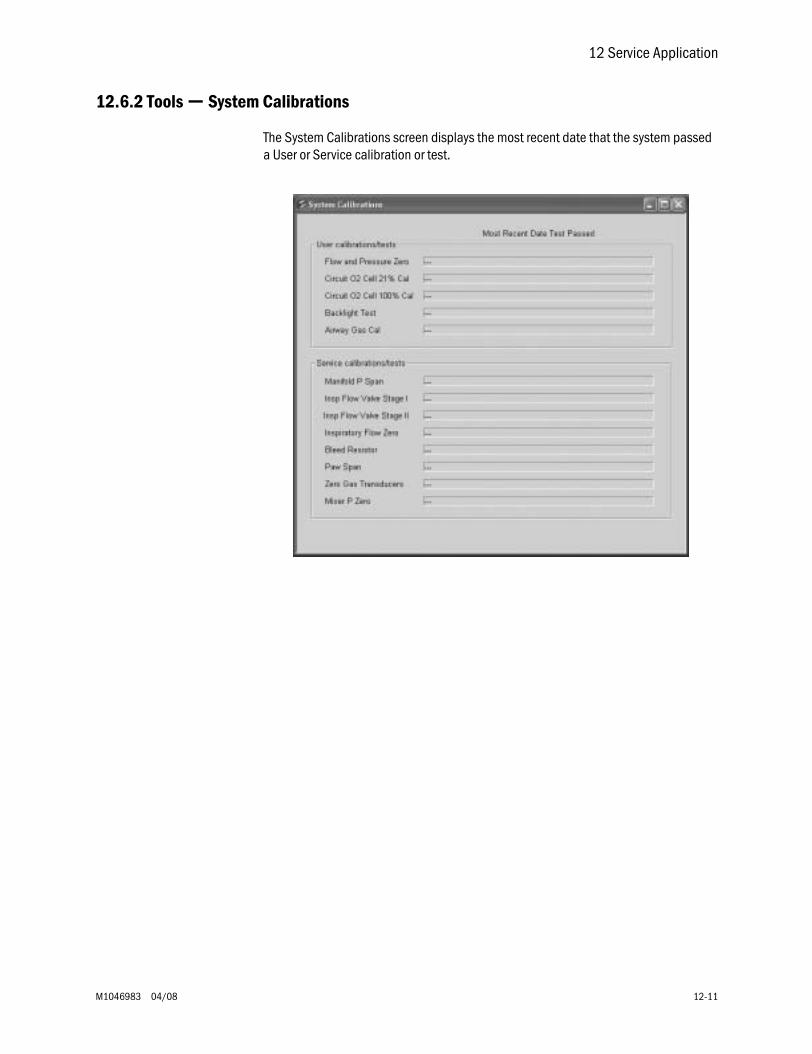
12 Service Application
M1046983 04/08 12-11
12.6.2 Tools — System Calibrations
The System Calibrations screen displays the most recent date that the system passed a User or Service calibration or test.
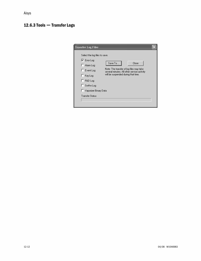
Aisys
12-12 04/08 M1046983
12.6.3 Tools — Transfer Logs
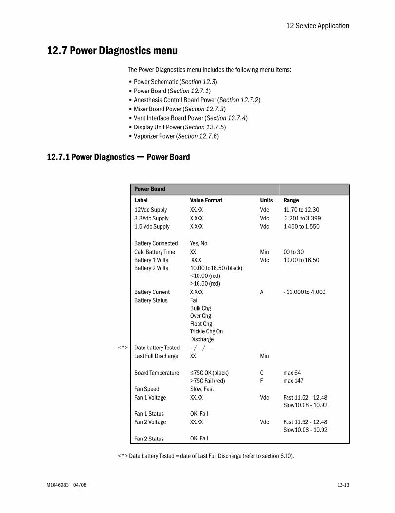
12 Service Application
M1046983 04/08 12-13
12.7 Power Diagnostics menu
The Power Diagnostics menu includes the following menu items:
• Power Schematic (Section 12.3)• Power Board (Section 12.7.1)• Anesthesia Control Board Power (Section 12.7.2)• Mixer Board Power (Section 12.7.3)• Vent Interface Board Power (Section 12.7.4)• Display Unit Power (Section 12.7.5)• Vaporizer Power (Section 12.7.6)
12.7.1 Power Diagnostics — Power Board
Power Board
Label Value Format Units Range
12Vdc Supply XX.XX Vdc 11.70 to 12.303.3Vdc Supply X.XXX Vdc 3.201 to 3.3991.5 Vdc Supply X.XXX Vdc 1.450 to 1.550
Battery Connected Yes, NoCalc Battery Time XX Min 00 to 30Battery 1 VoltsBattery 2 Volts
XX.X10.00 to16.50 (black)<10.00 (red)>16.50 (red)
Vdc 10.00 to 16.50
Battery Current X.XXX A - 11.000 to 4.000Battery Status Fail
Bulk ChgOver ChgFloat ChgTrickle Chg OnDischarge
<*> Date battery Tested --/---/----Last Full Discharge XX Min
Board Temperature ≤75C OK (black)>75C Fail (red)
C F
max 64max 147
Fan Speed Slow, FastFan 1 Voltage XX.XX Vdc Fast 11.52 - 12.48
Slow10.08 - 10.92Fan 1 Status OK, FailFan 2 Voltage XX.XX Vdc Fast 11.52 - 12.48
Slow10.08 - 10.92Fan 2 Status OK, Fail
<*> Date battery Tested = date of Last Full Discharge (refer to section 6.10).
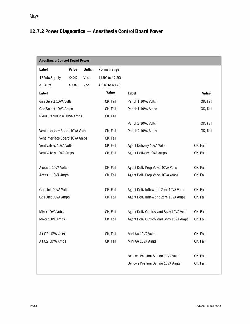
Aisys
12-14 04/08 M1046983
12.7.2 Power Diagnostics — Anesthesia Control Board Power
Anesthesia Control Board Power
Label Value Units Normal range
12 Vdc Supply XX.XX Vdc 11.90 to 12.90
ADC Ref X.XXX Vdc 4.018 to 4.176
Label Value Label Value
Gas Select 10VA Volts OK, Fail Periph1 10VA Volts OK, Fail
Gas Select 10VA Amps OK, Fail Periph1 10VA Amps OK, Fail
Press Transducer 10VA Amps OK, Fail
Periph2 10VA Volts OK, Fail
Vent Interface Board 10VA Volts OK, Fail Periph2 10VA Amps OK, Fail
Vent Interface Board 10VA Amps OK, Fail
Vent Valves 10VA Volts OK, Fail Agent Delivery 10VA Volts OK, Fail
Vent Valves 10VA Amps OK, Fail Agent Delivery 10VA Amps OK, Fail
Acces 1 10VA Volts OK, Fail Agent Deliv Prop Valve 10VA Volts OK, Fail
Acces 1 10VA Amps OK, Fail Agent Deliv Prop Valve 10VA Amps OK, Fail
Gas Unit 10VA Volts OK, Fail Agent Deliv Inflow and Zero 10VA Volts OK, Fail
Gas Unit 10VA Amps OK, Fail Agent Deliv Inflow and Zero 10VA Amps OK, Fail
Mixer 10VA Volts OK, Fail Agent Deliv Outflow and Scav 10VA Volts OK, Fail
Mixer 10VA Amps OK, Fail Agent Deliv Outflow and Scav 10VA Amps OK, Fail
Alt O2 10VA Volts OK, Fail Mini AA 10VA Volts OK, Fail
Alt O2 10VA Amps OK, Fail Mini AA 10VA Amps OK, Fail
Bellows Position Sensor 10VA Volts OK, Fail
Bellows Position Sensor 10VA Amps OK, Fail
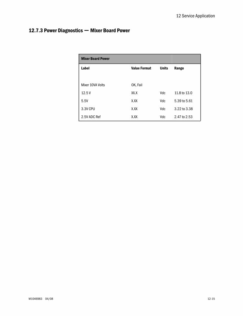
12 Service Application
M1046983 04/08 12-15
12.7.3 Power Diagnostics — Mixer Board Power
Mixer Board Power
Label Value Format Units Range
Mixer 10VA Volts OK, Fail
12.5 V XX.X Vdc 11.8 to 13.0
5.5V X.XX Vdc 5.39 to 5.61
3.3V CPU X.XX Vdc 3.22 to 3.38
2.5V ADC Ref X.XX Vdc 2.47 to 2.53
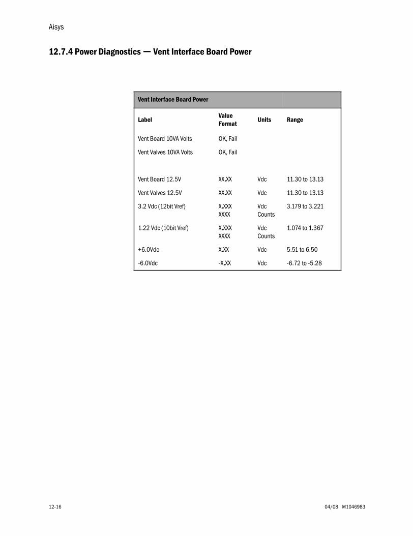
Aisys
12-16 04/08 M1046983
12.7.4 Power Diagnostics — Vent Interface Board Power
Vent Interface Board Power
LabelValue Format
Units Range
Vent Board 10VA Volts OK, Fail
Vent Valves 10VA Volts OK, Fail
Vent Board 12.5V XX....XX Vdc 11.30 to 13.13
Vent Valves 12.5V XX....XX Vdc 11.30 to 13.13
3.2 Vdc (12bit Vref) X....XXXXXXX
VdcCounts
3.179 to 3.221
1.22 Vdc (10bit Vref) X....XXXXXXX
VdcCounts
1.074 to 1.367
+6.0Vdc X....XX Vdc 5.51 to 6.50
-6.0Vdc -X....XX Vdc -6.72 to -5.28

12 Service Application
M1046983 04/08 12-17
12.7.5 Power Diagnostics — Display Unit Power
High PerformanceDisplay Unit
(HPDU) Display Unit Power
Label Value Format Units Range
LCD backlight 12.5V XX.XX Vdc 10.54 to 14.87
Audio 5V X.XX Vdc 4.39 to 5.72
Digital 3.3V X.XX Vdc 2.86 to 3.81
LCD 3.3V X.XX Vdc 2.86 to 3.81
LCD Inverter B output X.XX Vdc 0.00 to 1.09
LCD Inverter A output XX.XX Vdc 0.00 to 1.09
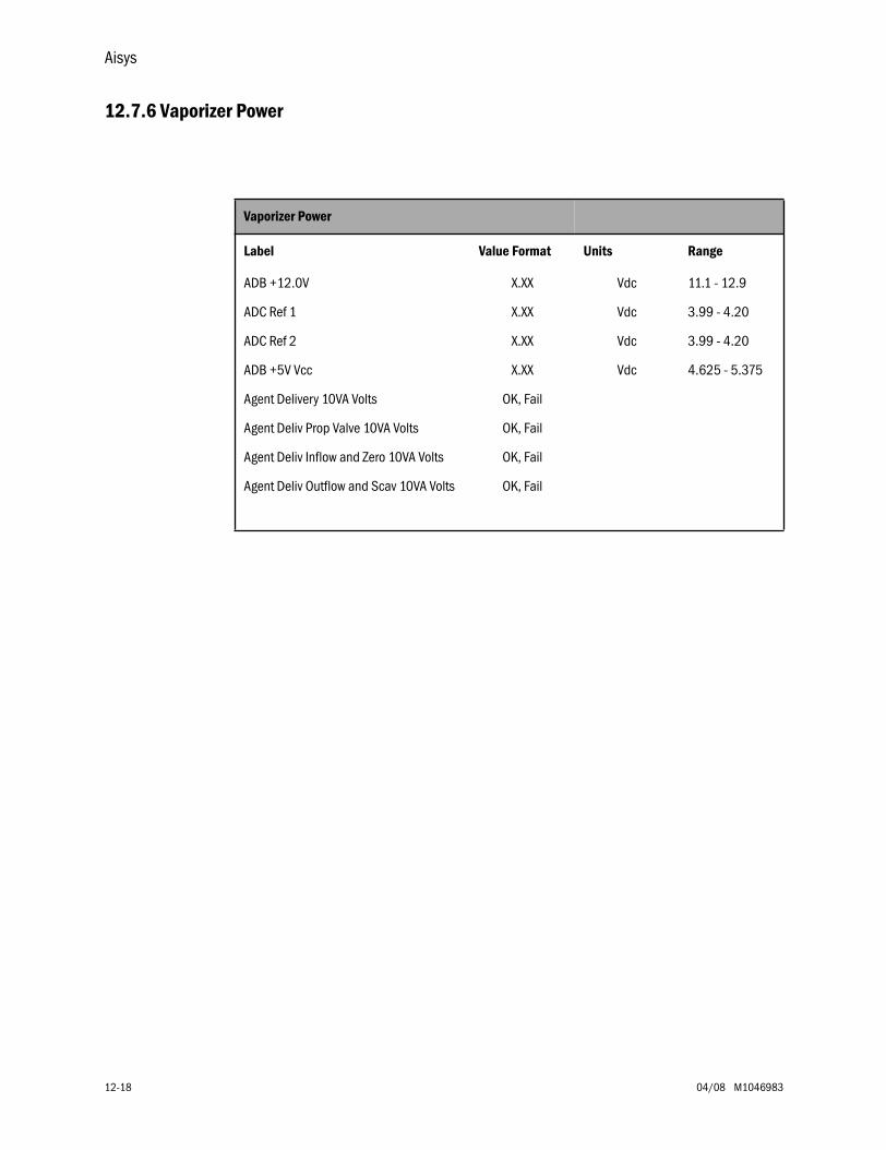
Aisys
12-18 04/08 M1046983
12.7.6 Vaporizer Power
Vaporizer Power
Label Value Format Units Range
ADB +12.0V X.XX Vdc 11.1 - 12.9
ADC Ref 1 X.XX Vdc 3.99 - 4.20
ADC Ref 2 X.XX Vdc 3.99 - 4.20
ADB +5V Vcc X.XX Vdc 4.625 - 5.375
Agent Delivery 10VA Volts OK, Fail
Agent Deliv Prop Valve 10VA Volts OK, Fail
Agent Deliv Inflow and Zero 10VA Volts OK, Fail
Agent Deliv Outflow and Scav 10VA Volts OK, Fail
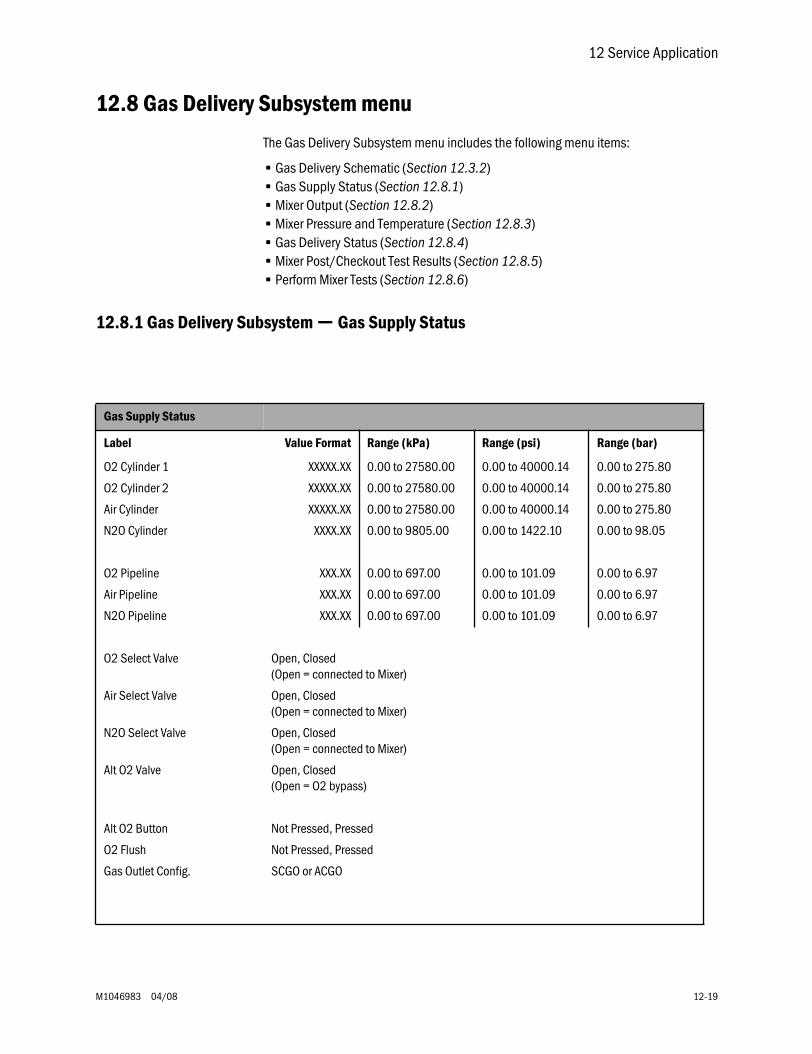
12 Service Application
M1046983 04/08 12-19
12.8 Gas Delivery Subsystem menu
The Gas Delivery Subsystem menu includes the following menu items:
• Gas Delivery Schematic (Section 12.3.2)• Gas Supply Status (Section 12.8.1)• Mixer Output (Section 12.8.2)• Mixer Pressure and Temperature (Section 12.8.3)• Gas Delivery Status (Section 12.8.4)• Mixer Post/Checkout Test Results (Section 12.8.5)• Perform Mixer Tests (Section 12.8.6)
12.8.1 Gas Delivery Subsystem — Gas Supply Status
Gas Supply Status
Label Value Format Range (kPa) Range (psi) Range (bar)
O2 Cylinder 1 XXXXX.XX 0.00 to 27580.00 0.00 to 40000.14 0.00 to 275.80
O2 Cylinder 2 XXXXX.XX 0.00 to 27580.00 0.00 to 40000.14 0.00 to 275.80
Air Cylinder XXXXX.XX 0.00 to 27580.00 0.00 to 40000.14 0.00 to 275.80
N2O Cylinder XXXX.XX 0.00 to 9805.00 0.00 to 1422.10 0.00 to 98.05
O2 Pipeline XXX.XX 0.00 to 697.00 0.00 to 101.09 0.00 to 6.97
Air Pipeline XXX.XX 0.00 to 697.00 0.00 to 101.09 0.00 to 6.97
N2O Pipeline XXX.XX 0.00 to 697.00 0.00 to 101.09 0.00 to 6.97
O2 Select Valve Open, Closed(Open = connected to Mixer)
Air Select Valve Open, Closed(Open = connected to Mixer)
N2O Select Valve Open, Closed(Open = connected to Mixer)
Alt O2 Valve Open, Closed(Open = O2 bypass)
Alt O2 Button Not Pressed, Pressed
O2 Flush Not Pressed, Pressed
Gas Outlet Config. SCGO or ACGO
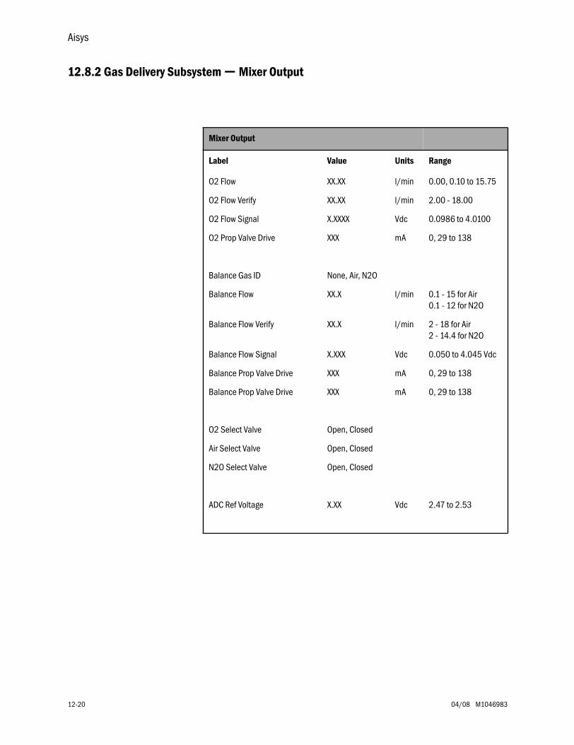
Aisys
12-20 04/08 M1046983
12.8.2 Gas Delivery Subsystem — Mixer Output
Mixer Output
Label Value Units Range
O2 Flow XX.XX l/min 0.00, 0.10 to 15.75
O2 Flow Verify XX.XX l/min 2.00 - 18.00
O2 Flow Signal X.XXXX Vdc 0.0986 to 4.0100
O2 Prop Valve Drive XXX mA 0, 29 to 138
Balance Gas ID None, Air, N2O
Balance Flow XX.X l/min 0.1 - 15 for Air0.1 - 12 for N2O
Balance Flow Verify XX.X l/min 2 - 18 for Air2 - 14.4 for N2O
Balance Flow Signal X.XXX Vdc 0.050 to 4.045 Vdc
Balance Prop Valve Drive XXX mA 0, 29 to 138
Balance Prop Valve Drive XXX mA 0, 29 to 138
O2 Select Valve Open, Closed
Air Select Valve Open, Closed
N2O Select Valve Open, Closed
ADC Ref Voltage X.XX Vdc 2.47 to 2.53
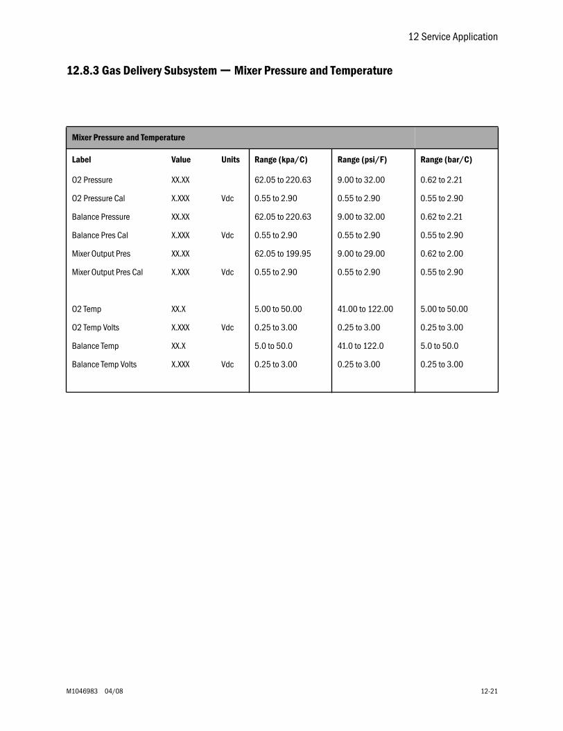
12 Service Application
M1046983 04/08 12-21
12.8.3 Gas Delivery Subsystem — Mixer Pressure and Temperature
Mixer Pressure and Temperature
Label Value Units Range (kpa/C) Range (psi/F) Range (bar/C)
O2 Pressure XX.XX 62.05 to 220.63 9.00 to 32.00 0.62 to 2.21
O2 Pressure Cal X.XXX Vdc 0.55 to 2.90 0.55 to 2.90 0.55 to 2.90
Balance Pressure XX.XX 62.05 to 220.63 9.00 to 32.00 0.62 to 2.21
Balance Pres Cal X.XXX Vdc 0.55 to 2.90 0.55 to 2.90 0.55 to 2.90
Mixer Output Pres XX.XX 62.05 to 199.95 9.00 to 29.00 0.62 to 2.00
Mixer Output Pres Cal X.XXX Vdc 0.55 to 2.90 0.55 to 2.90 0.55 to 2.90
O2 Temp XX.X 5.00 to 50.00 41.00 to 122.00 5.00 to 50.00
O2 Temp Volts X.XXX Vdc 0.25 to 3.00 0.25 to 3.00 0.25 to 3.00
Balance Temp XX.X 5.0 to 50.0 41.0 to 122.0 5.0 to 50.0
Balance Temp Volts X.XXX Vdc 0.25 to 3.00 0.25 to 3.00 0.25 to 3.00
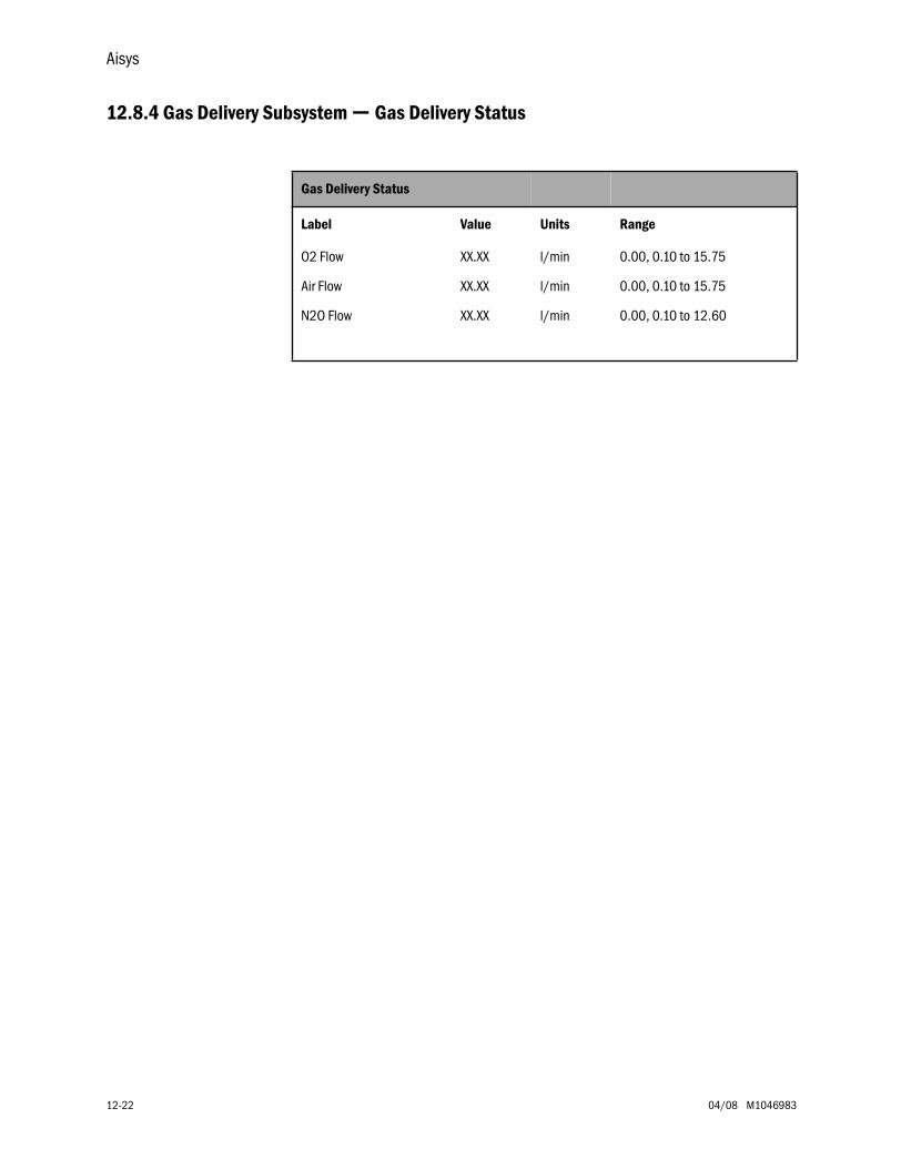
Aisys
12-22 04/08 M1046983
12.8.4 Gas Delivery Subsystem — Gas Delivery Status
Gas Delivery Status
Label Value Units Range
O2 Flow XX.XX l/min 0.00, 0.10 to 15.75
Air Flow XX.XX l/min 0.00, 0.10 to 15.75
N2O Flow XX.XX l/min 0.00, 0.10 to 12.60
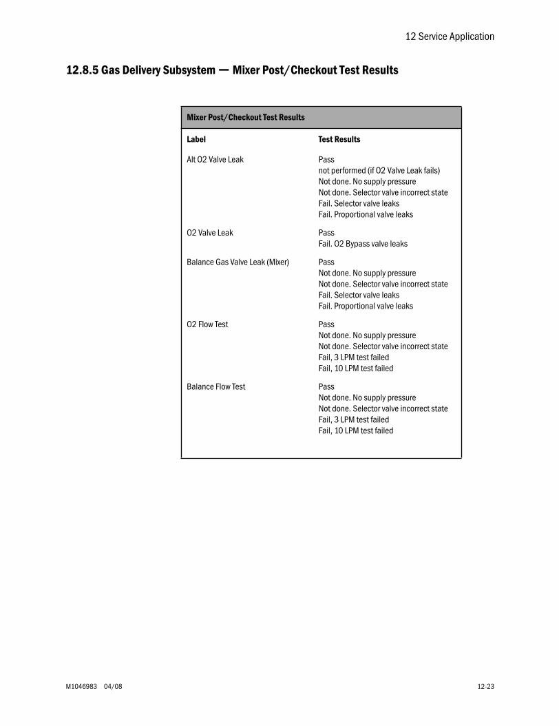
12 Service Application
M1046983 04/08 12-23
12.8.5 Gas Delivery Subsystem — Mixer Post/Checkout Test Results
Mixer Post/Checkout Test Results
Label Test Results
Alt O2 Valve Leak Passnot performed (if O2 Valve Leak fails)Not done. No supply pressureNot done. Selector valve incorrect state Fail. Selector valve leaksFail. Proportional valve leaks
O2 Valve Leak PassFail. O2 Bypass valve leaks
Balance Gas Valve Leak (Mixer) PassNot done. No supply pressureNot done. Selector valve incorrect state Fail. Selector valve leaksFail. Proportional valve leaks
O2 Flow Test PassNot done. No supply pressureNot done. Selector valve incorrect stateFail, 3 LPM test failedFail, 10 LPM test failed
Balance Flow Test PassNot done. No supply pressureNot done. Selector valve incorrect stateFail, 3 LPM test failedFail, 10 LPM test failed
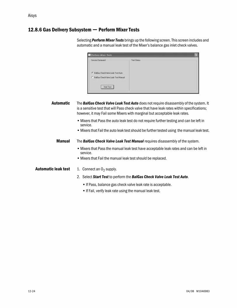
Aisys
12-24 04/08 M1046983
12.8.6 Gas Delivery Subsystem — Perform Mixer Tests
Selecting Perform Mixer Tests brings up the following screen. This screen includes and automatic and a manual leak test of the Mixer’s balance gas inlet check valves.
Automatic The BalGas Check Valve Leak Test Auto does not require disassembly of the system. It is a sensitive test that will Pass check valve that have leak rates within specifications; however, it may Fail some Mixers with marginal but acceptable leak rates.
• Mixers that Pass the auto leak test do not require further testing and can be left in service.
• Mixers that Fail the auto leak test should be further tested using the manual leak test.
Manual The BalGas Check Valve Leak Test Manual requires disassembly of the system.
• Mixers that Pass the manual leak test have acceptable leak rates and can be left in service.
• Mixers that Fail the manual leak test should be replaced.
Automatic leak test 1. Connect an O2 supply.
2. Select Start Test to perform the BalGas Check Valve Leak Test Auto.
• If Pass, balance gas check valve leak rate is acceptable.
• If Fail, verify leak rate using the manual leak test.
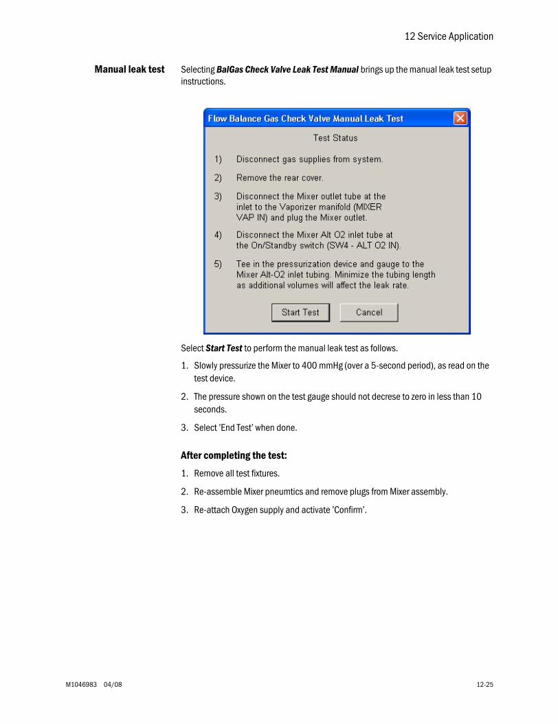
12 Service Application
M1046983 04/08 12-25
Manual leak test Selecting BalGas Check Valve Leak Test Manual brings up the manual leak test setup instructions.
Select Start Test to perform the manual leak test as follows.
1. Slowly pressurize the Mixer to 400 mmHg (over a 5-second period), as read on the test device.
2. The pressure shown on the test gauge should not decrese to zero in less than 10 seconds.
3. Select ’End Test’ when done.
After completing the test:
1. Remove all test fixtures.
2. Re-assemble Mixer pneumtics and remove plugs from Mixer assembly.
3. Re-attach Oxygen supply and activate ’Confirm’.
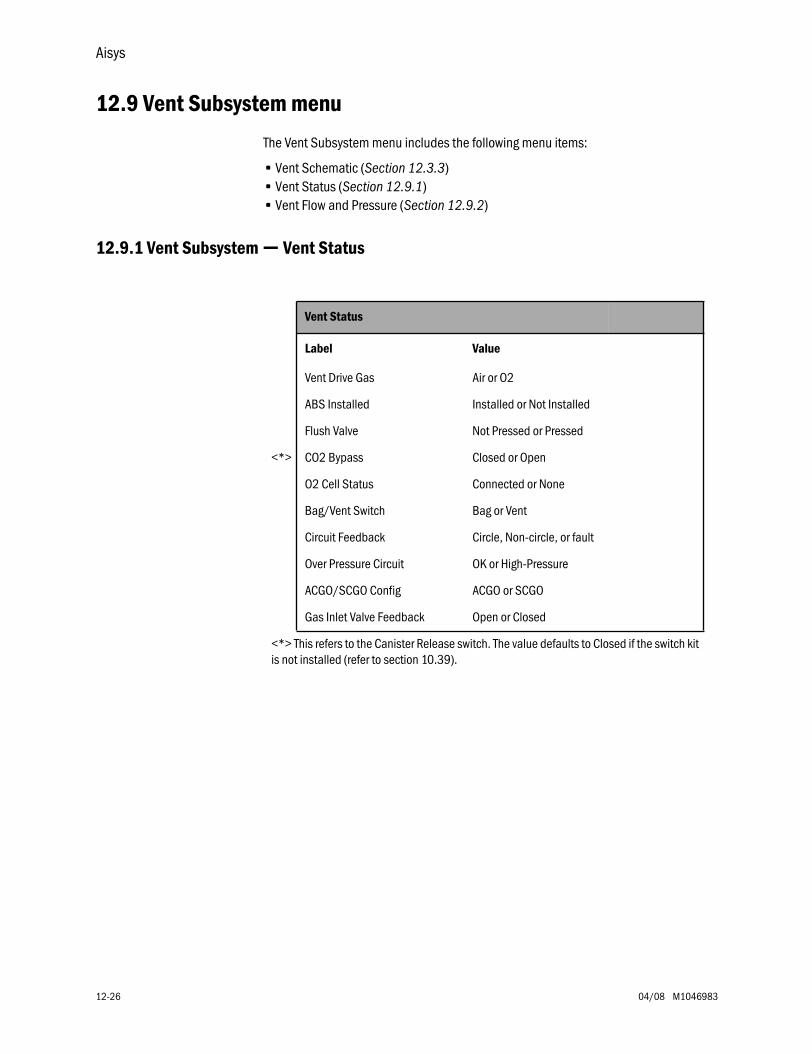
Aisys
12-26 04/08 M1046983
12.9 Vent Subsystem menu
The Vent Subsystem menu includes the following menu items:
• Vent Schematic (Section 12.3.3)• Vent Status (Section 12.9.1)• Vent Flow and Pressure (Section 12.9.2)
12.9.1 Vent Subsystem — Vent Status
Vent Status
Label Value
Vent Drive Gas Air or O2
ABS Installed Installed or Not Installed
Flush Valve Not Pressed or Pressed
<*> CO2 Bypass Closed or Open
O2 Cell Status Connected or None
Bag/Vent Switch Bag or Vent
Circuit Feedback Circle, Non-circle, or fault
Over Pressure Circuit OK or High-Pressure
ACGO/SCGO Config ACGO or SCGO
Gas Inlet Valve Feedback Open or Closed
<*> This refers to the Canister Release switch. The value defaults to Closed if the switch kit is not installed (refer to section 10.39).
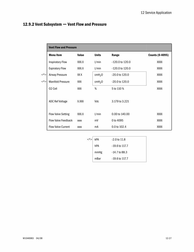
12 Service Application
M1046983 04/08 12-27
12.9.2 Vent Subsystem — Vent Flow and Pressure
Vent Flow and Pressure
Menu Item Value Units Range Counts (0-4095)
Inspiratory Flow XXX.X l/min -120.0 to 120.0 XXXX
Expiratory Flow XXX.X l/min -120.0 to 120.0 XXXX
<*> Airway Pressure XX X cmH2O -20.0 to 120.0 XXXX
<*> Manifold Pressure XXX cmH2O -20.0 to 120.0 XXXX
O2 Cell XXX % 5 to 110 % XXXX
ADC Ref Voltage X.XXX Vdc 3.179 to 3.221
Flow Valve Setting XXX.X l/min 0.00 to 140.00 XXXX
Flow Valve Feedback xxxx mV 0 to 4095 XXXX
Flow Valve Current xxxx mA 0.0 to 102.4 XXXX
<*> kPA -2.0 to 11.8
hPA -19.6 to 117.7
mmHg -14.7 to 88.3
mBar -19.6 to 117.7
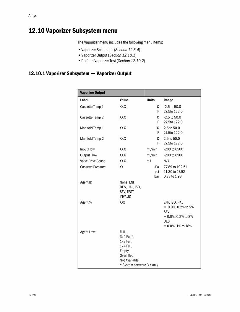
Aisys
12-28 04/08 M1046983
12.10 Vaporizer Subsystem menu
The Vaporizer menu includes the following menu items:
• Vaporizer Schematic (Section 12.3.4)• Vaporizer Output (Section 12.10.1)• Perform Vaporizer Test (Section 12.10.2)
12.10.1 Vaporizer Subsystem — Vaporizer Output
Vaporizer Output
Label Value Units Range
Cassette Temp 1 XX.X CF
-2.5 to 50.027.5to 122.0
Cassette Temp 2 XX.X CF
-2.5 to 50.027.5to 122.0
Manifold Temp 1 XX.X CF
2.5 to 50.027.5to 122.0
Manifold Temp 2 XX.X CF
2.5 to 50.027.5to 122.0
Input Flow XX.X ml/min -200 to 6500
Output Flow XX.X ml/min -200 to 6500
Valve Drive Sense XX.X mA N/A
Cassette Pressure XX kPapsibar
77.89 to 192.5111.30 to 27.920.78 to 1.93
Agent ID None, ENF, DES, HAL, ISO, SEV, TEST, INVALID
Agent % XXX ENF, ISO, HAL• 0.0%, 0.2% to 5%SEV• 0.0%, 0.2% to 8%DES• 0.0%, 1% to 18%
Agent Level Full,3/4 Full*,1/2 Full,1/4 Full,Empty,Overfilled,Not Available* System software 3.X only
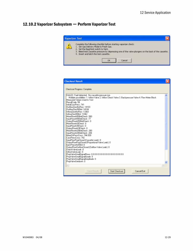
12 Service Application
M1046983 04/08 12-29
12.10.2 Vaporizer Subsystem — Perform Vaporizer Test
Aisys
12-30 04/08 M1046983
12.11 Window menu
The Window menu includes the following menu items:
• Cascade• Tile Horizontal• Tile Vertical• Close• Close All• (list of all open windows)
12.12 Help menu
The Help menu includes the following menu items:
About...
About
2.XXvXX


Aisys Anesthesia SystemTechnical Reference Manual
M104698304 08 004 01 01 02Printed in USA©Datex-Ohmeda, Inc.
All rights reserved