lmproving Microcontroller and Computer Architecture ...
185
Western University Western University Scholarship@Western Scholarship@Western Electronic Thesis and Dissertation Repository 8-28-2017 12:00 AM lmproving Microcontroller and Computer Architecture Education lmproving Microcontroller and Computer Architecture Education through Software Simulation through Software Simulation Kevin Brightwell, The University of Western Ontario Supervisor: McIsaac, Kenneth, The University of Western Ontario A thesis submitted in partial fulfillment of the requirements for the Master of Engineering Science degree in Electrical and Computer Engineering © Kevin Brightwell 2017 Follow this and additional works at: https://ir.lib.uwo.ca/etd Part of the Computer and Systems Architecture Commons, Digital Circuits Commons, and the Engineering Education Commons Recommended Citation Recommended Citation Brightwell, Kevin, "lmproving Microcontroller and Computer Architecture Education through Software Simulation" (2017). Electronic Thesis and Dissertation Repository. 4886. https://ir.lib.uwo.ca/etd/4886 This Dissertation/Thesis is brought to you for free and open access by Scholarship@Western. It has been accepted for inclusion in Electronic Thesis and Dissertation Repository by an authorized administrator of Scholarship@Western. For more information, please contact [email protected].
-
Upload
khangminh22 -
Category
Documents
-
view
1 -
download
0
Transcript of lmproving Microcontroller and Computer Architecture ...

Western University Western University
Scholarship@Western Scholarship@Western
Electronic Thesis and Dissertation Repository
8-28-2017 12:00 AM
lmproving Microcontroller and Computer Architecture Education lmproving Microcontroller and Computer Architecture Education
through Software Simulation through Software Simulation
Kevin Brightwell, The University of Western Ontario
Supervisor: McIsaac, Kenneth, The University of Western Ontario
A thesis submitted in partial fulfillment of the requirements for the Master of Engineering
Science degree in Electrical and Computer Engineering
© Kevin Brightwell 2017
Follow this and additional works at: https://ir.lib.uwo.ca/etd
Part of the Computer and Systems Architecture Commons, Digital Circuits Commons, and the
Engineering Education Commons
Recommended Citation Recommended Citation Brightwell, Kevin, "lmproving Microcontroller and Computer Architecture Education through Software Simulation" (2017). Electronic Thesis and Dissertation Repository. 4886. https://ir.lib.uwo.ca/etd/4886
This Dissertation/Thesis is brought to you for free and open access by Scholarship@Western. It has been accepted for inclusion in Electronic Thesis and Dissertation Repository by an authorized administrator of Scholarship@Western. For more information, please contact [email protected].

Abstract
In this thesis, we aim to improve the outcomes of students learning Computer Architecture
and Embedded Systems topics within Software and Computer Engineering programs. We de-
velop a simulation of processors that attempts to improve the visibility of hardware within the
simulation environment and replace existing solutions in use within the classroom. We desig-
nate a series of requirements of a successful simulation suite based on current state-of-the-art
simulations within literature. Provided these requirements, we build a quantitative rating of
the same set of simulations. Additionally, we rate our previously implemented tool, hc12sim,
with current solutions. Using the gaps in implementations from our state-of-the-art survey, we
develop two solutions. First, we developed a web-based solution using the Scala.js compiler
for Scala with an event-driven simulation engine through Akka. This Scala model implements
a VHDL-like DSL for instruction control definition. Next we propose tools for developing
cross-platform native applications through a project-based build system within CMake and
a continuous integration pipeline using Vagrant, Oracle VirtualBox and Jenkins. Lastly, we
propose a configuration-driven processor simulation built from the original hc12sim project
that utilizes a Lua-based scripting interface for processor configuration. While we considered
other high-level languages, Lua best fit our requirements allowing students to use a modern
high-level programming language for processor configuration. Instruction controls are defined
through Lua functions using high-level constructs that implicitly trigger low-level simulation
events. Lastly, we conclude with suggestions for building a new solution that would better
meet requirements set forth in our research question building from successful aspects from this
work.
Keywords: Embedded systems, computer architecture, computer architecture simulation,
pedagogy, cross-platform application development
i

Acknowledgements
I would like to acknowledge my advisor Dr. Kenneth McIsaac for his continued support
and mentorship throughout my undergraduate and graduate works. Thank you for taking the
time to debug, construct, and destruct ideas from all angles. Your direction has allowed me to
grow as a research, engineer and academic.
I would like to thank my peers in Dr. McIsaac’s lab for providing laughs and support over
the course of this work. I would like to extend the same thanks to those in Dr. Xianbin Wang
and Dr. Roy Eagleson’s labs for being supportive peers through forced geographic association.
I would like to thank my father and step mother, John and Amy Brightwell, and my mother
and step father, Kyra Hanson and Wilf Wityshyn, for listening to my complaints, failures and
successes throughout this work and never batting an eye of support. I would like to thank Mr.
Brad de Vlugt, Mr. Kyle Fricke, and Ms. Trinette Wright for their continued support over the
course of this work providing friendship and a talking post repeatedly. Lastly, I would like
to thank my boyfriend Eric Pattara for his love, continuous support and delightful immaturity
when I needed that most.
To any and all of my colleagues, peers, family and friends thank you for your support.
ii

Contents
Abstract i
Acknowledgements ii
List of Figures vi
List of Tables viii
List of Listings ix
List of Definitions xi
List of Appendices xiii
1 Introduction 1
1.1 Research Question . . . . . . . . . . . . . . . . . . . . . . . . . . . . . . . . . 2
1.2 Motivation . . . . . . . . . . . . . . . . . . . . . . . . . . . . . . . . . . . . . 2
1.3 Problem Statement . . . . . . . . . . . . . . . . . . . . . . . . . . . . . . . . 9
1.3.1 Software versus Hardware . . . . . . . . . . . . . . . . . . . . . . . . 14
1.4 Contributions . . . . . . . . . . . . . . . . . . . . . . . . . . . . . . . . . . . 14
2 Survey of other and previously completed works 17
2.1 Previous Work: hc12sim . . . . . . . . . . . . . . . . . . . . . . . . . . . . . 17
2.1.1 Software Design . . . . . . . . . . . . . . . . . . . . . . . . . . . . . 18
Instructions . . . . . . . . . . . . . . . . . . . . . . . . . . . . . . . . 19
Hardware Simulation . . . . . . . . . . . . . . . . . . . . . . . . . . . 21
2.2 Evaluation of existing simulation technologies . . . . . . . . . . . . . . . . . . 23
iii

2.2.1 Methodology . . . . . . . . . . . . . . . . . . . . . . . . . . . . . . . 23
2.2.2 hc12sim . . . . . . . . . . . . . . . . . . . . . . . . . . . . . . . . . . 24
2.2.3 ShelbySim . . . . . . . . . . . . . . . . . . . . . . . . . . . . . . . . . 25
2.2.4 EDCOMP: Flexible Web-Based Educational System . . . . . . . . . . 27
2.2.5 p88110: A Graphical Simulator for Computer Architecture and Orga-
nization Courses . . . . . . . . . . . . . . . . . . . . . . . . . . . . . 29
2.2.6 EASE - An Extensible Architecture Simulation Engine . . . . . . . . . 31
2.2.7 TinyCPU and TinyCSE: Hardware simulations for education . . . . . . 32
2.2.8 CPU Sim . . . . . . . . . . . . . . . . . . . . . . . . . . . . . . . . . 35
2.2.9 Emumaker86: A Hardware Simulator for Teaching CPU Design . . . . 40
2.3 Summary . . . . . . . . . . . . . . . . . . . . . . . . . . . . . . . . . . . . . 42
3 procsim.scala: Scala-based event-driven processor simulation for the web 45
3.1 Introduction to Scala and Akka . . . . . . . . . . . . . . . . . . . . . . . . . . 45
3.2 Event- and Message-driven Simulation . . . . . . . . . . . . . . . . . . . . . . 48
3.3 Scala.js - Scala transpiler for JavaScript . . . . . . . . . . . . . . . . . . . . . 49
3.4 Implementation of procsim.scala . . . . . . . . . . . . . . . . . . . . . . . . . 50
3.4.1 VHDL-like DSL configuration and runtime-based instructions . . . . . 50
3.4.2 Akka-based Components . . . . . . . . . . . . . . . . . . . . . . . . . 52
3.5 Technology Challenges . . . . . . . . . . . . . . . . . . . . . . . . . . . . . . 54
3.6 Analysis of Requirements . . . . . . . . . . . . . . . . . . . . . . . . . . . . . 56
4 Developing cross-platform C++ applications 59
4.1 Modernizing hc12sim . . . . . . . . . . . . . . . . . . . . . . . . . . . . . . . 60
4.2 Cross-platform development . . . . . . . . . . . . . . . . . . . . . . . . . . . 60
4.2.1 Access to multiple platforms within a single host platform . . . . . . . 62
4.2.2 Building with cross-platform tools . . . . . . . . . . . . . . . . . . . . 64
4.3 Testing Infrastructure . . . . . . . . . . . . . . . . . . . . . . . . . . . . . . . 66
4.4 Improving developer work flows within CMake . . . . . . . . . . . . . . . . . 68
5 Lua-based configuration-driven processor simulation 76
iv

5.1 Utilizing runtime configurations through scripting . . . . . . . . . . . . . . . . 77
5.1.1 Scripting language selection . . . . . . . . . . . . . . . . . . . . . . . 77
Python . . . . . . . . . . . . . . . . . . . . . . . . . . . . . . . . . . . 77
JavaScript . . . . . . . . . . . . . . . . . . . . . . . . . . . . . . . . . 78
Java and Scala . . . . . . . . . . . . . . . . . . . . . . . . . . . . . . . 81
Lua . . . . . . . . . . . . . . . . . . . . . . . . . . . . . . . . . . . . 82
Scripting language decision . . . . . . . . . . . . . . . . . . . . . . . . 84
5.1.2 Lua integration . . . . . . . . . . . . . . . . . . . . . . . . . . . . . . 85
5.1.3 Configuration versus Simulation entities . . . . . . . . . . . . . . . . . 90
5.2 Lua-based Configuration . . . . . . . . . . . . . . . . . . . . . . . . . . . . . 91
5.3 Instruction definition . . . . . . . . . . . . . . . . . . . . . . . . . . . . . . . 99
5.3.1 Opcode and Operand encoding . . . . . . . . . . . . . . . . . . . . . . 99
5.3.2 Instruction execution: Side-effect-based compilation . . . . . . . . . . 102
5.4 Project design and technical flaws . . . . . . . . . . . . . . . . . . . . . . . . 109
5.4.1 Compiler strain . . . . . . . . . . . . . . . . . . . . . . . . . . . . . . 109
5.4.2 Loss of pedagogical gains for high- versus low-level constructs . . . . . 110
5.5 Analysis of Requirements . . . . . . . . . . . . . . . . . . . . . . . . . . . . . 112
6 Conclusion 114
6.1 Contributions . . . . . . . . . . . . . . . . . . . . . . . . . . . . . . . . . . . 115
6.2 Recommendations . . . . . . . . . . . . . . . . . . . . . . . . . . . . . . . . . 116
6.3 Future Work . . . . . . . . . . . . . . . . . . . . . . . . . . . . . . . . . . . . 119
Bibliography 120
A Procsim headers 132
A.1 Memory Components . . . . . . . . . . . . . . . . . . . . . . . . . . . . . . . 132
A.2 Time . . . . . . . . . . . . . . . . . . . . . . . . . . . . . . . . . . . . . . . . 143
A.3 Encoding . . . . . . . . . . . . . . . . . . . . . . . . . . . . . . . . . . . . . 155
A.4 Core . . . . . . . . . . . . . . . . . . . . . . . . . . . . . . . . . . . . . . . . 164
Curriculum Vitae 171
v

List of Figures
1.1 ECE 3375 - Course Sentiment Analysis Results [24], [25] . . . . . . . . . . . . 4
1.2 WinIDE12Z Integrated Development Environment [26] . . . . . . . . . . . . . 6
1.3 Freescale M68HC12 development board built by Western Engineering Elec-
tronics Shop for use in ECE 3375 . . . . . . . . . . . . . . . . . . . . . . . . . 6
1.4 StackOverflow 2016 developer survey results for desktop operating systems
[36, Sec. VIII. Desktop Operating System] . . . . . . . . . . . . . . . . . . . . 12
2.1 hc12ide Integrated Development Environment showing a student error in an
incorrect specification of an instruction mnemonic. . . . . . . . . . . . . . . . 18
2.2 hc12sim Instruction Generator showing the meta information for addressing
modes, execution, and output. . . . . . . . . . . . . . . . . . . . . . . . . . . . 20
2.3 Block diagram of TinyCPU showing the internal architecture [29, p. 869] . . . 33
2.4 State chart of TinyCPU execution path [29, p. 869] . . . . . . . . . . . . . . . 33
2.5 TinyCSE execution state diagram modified from Figure 2.4 to include inter-
rupts (broken lines show changes from TinyCPU [29]) [28, p. 640] . . . . . . . 34
2.6 CPU Sim 4.0.0 IDE during debugging with Assembly Editor open [52] . . . . . 37
2.7 CPU Sim Machine Instruction configuration interface showing combination of
fields to create a microcode and an assembly instruction. . . . . . . . . . . . . 38
2.8 CPU Sim 4.0.0 IDE module specification dialog showing modification of Trans-
fer Register to Register Array microinstruction [52] . . . . . . . . . . . . . . . 39
2.9 Emubuilder86 Control Builder: State machine definition [56, p. 325] . . . . . . 41
3.1 Graphical representation of three Actors sending bi-directional messages [70]. . 48
5.1 URISC hardware architecture with microcodes [6]. . . . . . . . . . . . . . . . 92
vi

5.2 Control unit for the 16-bit URISC architecture from [6, p. 331]. . . . . . . . . . 111
vii

List of Tables
1.1 ECE 3375 Course “Level of enthusiasm before taking the course” as reported
by undergraduate students following course completion [24], [25]. . . . . . . . 5
2.1 Qualitative requirement rating of hc12sim [40] . . . . . . . . . . . . . . . . . . 25
2.2 Qualitative requirement rating of ShelbySim [35], [45] . . . . . . . . . . . . . 27
2.3 Qualitative requirement rating of EDCOMP [30] . . . . . . . . . . . . . . . . . 29
2.4 Qualitative requirement rating of p88110 [31] . . . . . . . . . . . . . . . . . . 31
2.5 Qualitative requirement rating of EASE [34] . . . . . . . . . . . . . . . . . . . 32
2.6 Qualitative requirement rating of TinyCPU/TinyCSE [28], [29] . . . . . . . . . 35
2.7 Qualitative requirement rating of CPU Sim [39] . . . . . . . . . . . . . . . . . 40
2.8 Qualitative requirement rating of Emumaker86 [56] . . . . . . . . . . . . . . . 42
2.9 Summary of Evaluation for Simulators . . . . . . . . . . . . . . . . . . . . . . 43
3.1 Summary of requirement matching for procsim.scala. . . . . . . . . . . . . . . 58
5.1 Summary of requirement matching for procsim. . . . . . . . . . . . . . . . . . 113
viii

List of Listings
2.1 Sample of the JSON output used to generate code within hc12sim. BEQ per-
forms a branch if two values were equal. . . . . . . . . . . . . . . . . . . . . . 21
3.1 An example DSL source written in Scala to emulate BASIC called “Baysick” [1] 47
3.2 Normal definition of Instruction. . . . . . . . . . . . . . . . . . . . . . . . . . 52
3.3 Reified definition of Instruction. . . . . . . . . . . . . . . . . . . . . . . . . . 52
3.4 Clock pulse message for Akka . . . . . . . . . . . . . . . . . . . . . . . . . . 54
3.5 Actor that listens for ClockPulse messages and prints the time. . . . . . . . . 55
4.1 Vagrant file that describes a Ubuntu 14.04 box with modern GCC 5.X and
LLVM Clang 3.7 compilers installed. . . . . . . . . . . . . . . . . . . . . . . 65
4.2 CMake script showing how two test suites, time and encoding, are defined
as part of a project, core . . . . . . . . . . . . . . . . . . . . . . . . . . . . . 71
4.3 Test output from CTest [2] from Microsoft Visual Studio Community 2015 for
procsim showing organization provided by CMake configuration. . . . . . . . . 75
5.1 Example of exposing a C++ class to Python [3]. . . . . . . . . . . . . . . . . . 79
5.2 Table used to describe project information for the Lua.org site [4] . . . . . . . 84
5.3 class player that holds two fields, one for hitpoints (hp) and one for bullets
a player has (adapted from [5]). . . . . . . . . . . . . . . . . . . . . . . . . . . 87
5.4 Utilize the class player within a Lua script (adapted from [5]). . . . . . . . 88
5.5 Required bindings to allow utilization of class player from Lua (adapted
from [5]). . . . . . . . . . . . . . . . . . . . . . . . . . . . . . . . . . . . . . 89
5.6 Configuration of Figure 5.1 for the URISC processor [6]. . . . . . . . . . . . . 93
5.7 (Continued) Configuration of Figure 5.1 for the URISC processor [6]. . . . . . 94
5.8 Clock configuration for the processors main clock (cut from Listing 5.6). . . . 96
ix

5.9 Register configuration for the program counter (cut from Listing 5.6). . . . . 97
5.10 Memory unit configuration for the program counter (cut from Listing 5.6). . . . 98
5.11 Processor utilizing memory mapping functionality. . . . . . . . . . . . . . . . 100
5.12 Encoding of the opcode and operands of the SUBLEQ Instruction (cut from
Listing 5.6). . . . . . . . . . . . . . . . . . . . . . . . . . . . . . . . . . . . . 101
5.13 Execution definition for the SUBLEQ Instruction (cut from Listing 5.6). . . . 104
5.14 Local variable definitions within an Instruction:exec() method. . . . . . . 106
A.1 Source for procsim/memory/MemoryUnit.hpp. . . . . . . . . . . . . . . . . 132
A.2 Source for procsim/memory/Register.hpp. . . . . . . . . . . . . . . . . . 140
A.3 Source for procsim/time/Clock.hpp. . . . . . . . . . . . . . . . . . . . . . 143
A.4 Source for procsim/time/AsyncTimerReceiver.hpp. . . . . . . . . . . . . 146
A.5 Source for procsim/time/Timer.hpp. . . . . . . . . . . . . . . . . . . . . . 148
A.6 Source for procsim/encoding/Algorithm.hpp. . . . . . . . . . . . . . . . 155
A.7 Source for procsim/encoding/Code.hpp. . . . . . . . . . . . . . . . . . . . 158
A.8 Source for procsim/encoding/Operand.hpp. . . . . . . . . . . . . . . . . . 162
A.9 Source for procsim/core/Instruction.hpp. . . . . . . . . . . . . . . . . . 164
A.10 Source for procsim/core/Proc.hpp. . . . . . . . . . . . . . . . . . . . . . 168
x

List of Definitions
Application Programming Interface (API) A software layer between a developer that uti-
lizes a library or program and the library or program itself. APIs are designed to hide imple-
mentation details and ease developer usage.
Arithmetic Logic Unit (ALU) In a computer system, ALUs are responsible for performing
arithmetic operations on binary input such as addition, shifts, multiplication, division.
Complex Instruction Set Computer (CISC) A type of microprocessor architecture that uti-
lizes larger, instructions aiming to reduce the software instructions required to complete a task
[7], [8]. CISC architectures are used in most general applications based on Intel® x86 ISA [9].
Domain-Specific Language (DSL) A computer programming language that is specialized to
a particular application space (domain). For example, HTML is a DSL used to layout websites
but could not be used to program an embedded device. Similarly, C++ is an excellent language
for creating applications but is very poor at describing layout for a webpage.
Embedded Systems Topics involving characteristics of embedded systems, techniques for
embedded applications, parallel input and output, synchronous and asynchronous serial com-
munication, interrupt handling, applications involving data acquisition, control, sensors, and
actuators, implementation strategies for complex embedded systems [10, p. 118]
Computer Architectures Topics involving computer organization and architecture. Includ-
ing, but not limited to processor organization, instruction set architecture, memory system
organization, performance, and interfacing fundamentals [10, p. 118]
Graphical User Interface (GUI) Any interface based on rendering graphically, for example
a window with buttons.
xi

Hardware Description Language (HDL) A programming language used to describe the struc-
ture and behaviour of electronic circuits. These languages are used to synthesize simulated and
physical circuit layout from the gate and register transfer level [11].
Instruction Set Architecture (ISA) The design of an interface between software and hard-
ware designs in a computing environment. Including but not limited to assembly language and
microcode design. Once realized, an ISA is referred to as an Instruction Set Implementation.
Integrated Development Environment (IDE) A tool used for developing hardware and soft-
ware components that provides integrated tools for the current development context. For ex-
ample, Xilinx ISE [12], JetBrains IntelliJ IDEA1, or Eclipse2.
Just-in-Time Compiler (JIT) A traditional compiler that operates at runtime to perform op-
timization on running code. JITs are typically found in interpreted languages such as on the
JVM or in JavaScript. JITs vastly improve the runtime of the code they compile as they often
utilize semantics such as code path tracing and known constant analysis that is not necessarily
available at compile-time.
Reduced Instruction Set Computer (RISC) A type of microprocessor architecture that uti-
lizes small, highly-optimized set of instructions used to reduce power and improve instruction
performance [7], [8]. These architectures are commonly used in embedded, mobile (ARM),
and high-performance server applications (IBM POWER).
Reification The process by which an abstraction (usually a String representation) of software
is converted into an explicit object. For example, JavaScript’s eval(script) compiles and
executes the content of the script passed and any state changes within the script are applied
to the global scope.
Transpiler A compiler that compiles one language to another. Typical transpilers convert one
language to JavaScript to allow use in web applications. For example, Scala.js and TypeScript
both compile their respective language to JavaScript.
1Available: https://www.jetbrains.com/idea/2Available: http://www.eclipse.org
xii

List of Appendices
Appendix A Procsim headers . . . . . . . . . . . . . . . . . . . . . . . . . . . . . . . . 132
xiii

Chapter 1
Introduction
Embedded systems and computer architectures are a critical part of both computer and software
engineering undergraduate programs [10], [13]–[16]. Over time, it is expected that knowledge
of embedded systems and computer architectures will be required given projections of rapid
growth of positions in both systems software developers (+13%) and computer occupations
(+12.5%) for 2020 [17]. At our institution, Western University, four courses cover embedded
systems and computer architectures, ECE 3375 - Microprocessors and Microcomputers, ECE
3389 - Computer System Design, ECE 3390 - Hardware/Software Co-Design and ECE 4460
- Real-time and Embedded Systems [18]. These topics are taught through the use of industry
focused software such as Intel Quartus Prime (formerly Altera Quartus II) [19], Xilinx ISE
WebPACK [12] or WinIDE [20]. These established industry tools are complex and powerful
for industry but we have anecdotally found students often feel overwhelmed during use. Ad-
ditionally with the prevalence of high-level programming languages, embedded systems work
has become increasingly difficult for students. Students are troubled connecting high-level
concepts to low-level details in computer architectures largely due to theoretical discontinu-
1

2 Chapter 1. Introduction
ities between lecture materials and the “black box” of hardware.
1.1 Research Question
This thesis attempts to answer the following research question:
Can improvements and increased usage of software simulation technologies within
laboratory exercises in undergraduate embedded system and computer architecture
courses improve student engagement in laboratory and assignment exercises?
Given the overall research question, there exist sub-questions:
1. Are simulation software beneficial to improvements in student outcomes in computer
and software engineering programs?
2. What elements of simulation software should be required for successful implementation
within an undergraduate course?
Each of these questions are elaborated in further sections.
1.2 Motivation
Students in computer engineering have a growing requirement to have strong knowledge of
both embedded systems and computer architectures due to increases in computer engineering
careers [10], [17]. Unfortunately, many students do not show enthusiasm for subjects surround-
ing computer architecture and embedded systems [16], [21]. This lowered enthusiasm reduces
student achievements and creates implicit barriers for learning new material [15], [21].

1.2. Motivation 3
At Western University, students in all students in Electrical & Computer Engineering de-
gree programs must take the course ECE 3375 - Microprocessors and Microcomputers [22],
[23]. We utilized the feedback students provide through end-of-semester course evaluations to
gauge student enthusiasm and sentiment regarding ECE 3375. In order to extract sentiment,
we applied a simplistic approach. If a comment was overtly positive or negative, we stated it
was positive or negative respectively. If a comment was indistinguishable, we erred to neu-
tral to try and remove our own biases. Unfortunately due to confidentiality, we are unable to
provide these comments directly. As seen in Table 1.1, student enthusiasm for ECE 3375 at
Western University is mixed. Unfortunately, our collected data is not broken down between
computer and software engineering – both are required to take this course. Additionally, with
primitive sentiment analysis applied to results from 2013 and 2014 [24], [25], shown in Fig-
ure 1.1a, we can see that after completion of the course, students are pleased overall with the
course content itself as approximately 73% of students found the experience positive. How-
ever, by filtering comments regarding the laboratory sessions and applying the same technique
for sentiment as the course, shown in Figure 1.1b, we find that students are likely very unhappy
with the lab components as approximately 33% stated negative reviews and only 24% stated
positive reviews. Due to time constraints, we were unable to compile a formal survey due to
time required for ethics approvals and program duration.
Researchers have found that there are concerns with low-level hardware constructs being
taught to high-level Computer Science, Software Engineering and Computer Engineering grad-
uates [15], [16]. Additionally, we can corroborate the following claims by Ristov et. al. [15]
regarding student’s opinions on microprocessor courses:
Observation 1. Disjointed material between lectures, theoretical and practical ex-
4 Chapter 1. Introduction
(a) Course Sentiment
(b) Lab Sentiment
Figure 1.1: ECE 3375 - Course Sentiment Analysis Results [24], [25]

1.2. Motivation 5
ercises. Students could not transfer knowledge gained from either lectures or the-
oretical exercises to practical exercises [. . . ]
Observation 2. Inappropriate programming and simulation environment. Students
faced installation problems [. . . ] leading to aversion to presented material and
exercises.
Observation 3. No “real world” application. [. . . ] Students [raise] the main ques-
tion: Why we are learning this, and how and where shall I use it?
([15, p. 340])
Given our first-hand experiences in both taking and assisting in the instruction of ECE 3375
and ECE 3390, these claims are repeated by students during laboratory exercises and review
sessions creating hostility towards the subject matter. In a direct example supporting observa-
tion 2, students in ECE 3375 use the WinIDE12Z Integrated Development Environment [20],
shown in Figure 1.2, for completing laboratory work ranging from simple “hello world” as-
sembly programs to hardware interfacing. In ECE 3375, students found WinIDE complicated,
frustrating and “outdated” [24], [25] directly supporting both observation 2 and observation 3.
Additionally students found it difficult to move from lecture material that presented embedded
systems as “translucent” devices composed of inner components to the literal “black box” of
the physical hardware shown in Figure 1.3.
With sentiment analysis and the comments provided by students in course evaluation feed-
Initial Level of EnthusiasmYear 2013 2014 TotalHigh % 45.6 57.8 53.0Medium % 54.2 33.3 41.6Low % 0.0 8.9 5.4Total # 59 90 149
Table 1.1: ECE 3375 Course “Level of enthusiasm before taking the course” as reported byundergraduate students following course completion [24], [25].

6 Chapter 1. Introduction
Figure 1.2: WinIDE12Z Integrated Development Environment [26]
Figure 1.3: Freescale M68HC12 development board built by Western Engineering ElectronicsShop for use in ECE 3375

1.2. Motivation 7
back [24], [25], we extracted several common propositions for improving laboratory sessions:
Proposition 1. Increase the number of laboratory sessions
Proposition 2. Add tutorial sessions to course schedule
Proposition 3. Change course material to use modern processors
Proposition 4. Replace laboratory microcontrollers with different hardware
Proposition 5. Improve and/or replace software within laboratory
All of these considerations were brought to the course instructor and limitations were noted
for each. For Propositions 1 and 2, while the addition of more hands-on experience has been
shown to improve student outcomes [15], [16], due to the large amount of financial resources
required to add more laboratory sessions, this option is likely unavailable for many programs.
In addition, due to the layout of the current course laboratory sessions, there does not exist
enough weeks in the 12-week course to add more sessions given current staffing resources. It
is reasonable to assume that these issues are prevalent at other institutions. Thus, both Propo-
sitions 1 and 2 can not be implemented given financial and temporal restrictions.
Proposition 3 asks the instructor to change the current course material to use more modern
hardware and software architecture. There are several reasons why this is not beneficial to the
improvement of learning outcomes. The current architecture used is the Freescale M68HC12.
This architecture provides a simple Complex Instruction Set Computer (CISC) Instruction Set
Architecture (ISA) with only four 16-bit addressable registers (SP, PC, X, Y); two eight-bit accu-
mulators (A, B) and multiple addressing modes [27]. The software abstractions of the Freescale

8 Chapter 1. Introduction
M68HC12 assembly is similar to current Intel® x86 processors [9]. Parallels between ar-
chitectures allows instructors to use more simple architectures that still allow students to apply
concepts to newer architectures while simultaneously reducing the cognitive “base knowledge”
required to succeed. Using simpler architectures like the Ultimate Reduced Instruction Set
Computer (URISC, [6]) has been shown to be very beneficial to improving student outcomes
[6], [28]–[31]. Additionally, by changing course materials, it leads into changing the labora-
tory hardware which Proposition 4 discusses. Unfortunately, replacing laboratory equipment
requires significant investment and with justifications for Proposition 3 showcasing that there
is not noticeable improvements in learning outcomes, the cost-benefit analysis does not prove
worthwhile to adjust both Propositions 3 and 4.
The last proposition, Proposition 5 is the most attainable. Researchers have found that
improving software technology in the classroom and laboratory can vastly improve the learn-
ing outcomes of students while improving engagement [10], [15], [16], [21], [30], [32]–[35].
Students within ECE3375 are immediately presented with the interfaces shown in Figure 1.2.
Students have expressed immense frustrations with the software when used in the laboratory
exercises and often encounter hardware issues that are not caused by their own work [24], [25].
Other researchers have found hardware solutions problematic with hardware-specific problems
common such as broken peripherals and unconnected pins [21]. These errors are hard to de-
bug, if not impossible for students with no prior knowledge. Teaching assistants and instructors
are often unable to debug these issues without the aid of technicians. These hard-to-diagnose
hardware issues lead to strained teaching resources and frustrations, supporting a large poten-
tial gain by replacing this ageing software with new tooling. Given these justifications, this
thesis looks to investigate the requirements surrounding replacing the current software in use

1.3. Problem Statement 9
within the ECE 3375 course and propose a configurable solution for others to utilize in other
courses.
1.3 Problem Statement
Our analysis of the current state of the ECE 3375 course showcased the pervasive dislike and
discomfort with the current laboratory exercises [24], [25]. Given previous analysis, we chose
to improve the current software used within the laboratory exercises and the classroom. To do
this, a current survey of known technologies is completed to ascertain whether a new solution
should be created or an existing solution will provide the requirements. Therein the formal
problem becomes:
Can a solution be provided to students that is configurable for hardware and soft-
ware interfaces and showcases the connection between hardware and software
while focusing on pedagogy rather than industry performance?
While the formalization is accurate, “striking the right balance between teaching sufficient
details of hardware components and their working principles, and important theoretical con-
cepts useful for programming the computer is always a challenge.” ([34]) From reviewing
many existing software solutions to this problem, we propose the following requirements for a
successful solution:
Requirement 1. Must be available for use outside of the laboratory on personal computers
including all major desktop platforms (e.g. Windows, macOS and Linux)
Requirement 2. Provide a student configurable system for different ISAs including configura-
tion of:
10 Chapter 1. Introduction
2.a. microcode and assembly instructions
2.b. execution semantics (i.e. how a processor executes code)
2.c. internal hardware components and connections
2.d. external peripherals
Requirement 3. Focus on pedagogy over simulation accuracy as best as reasonable
Requirement 4. Simulations must allow:
4.a. viewing of the current state of hardware components
4.b. stepping at the assembly and microcode level
4.c. setting of breakpoints to ease debugging
4.d. connecting “external” peripheral components
Requirement 5. Provide a modern user interface that is similar to current high-level program-
ming IDEs
Requirement 1: Personal computer usage. Requirement 1 outlines that any software must
be cross-platform. StackOverflow’s Developer survey [36] found that approximately 47.9% of
those surveyed used a non-Microsoft Windows environment (macOS or Linux). The metrics
recorded for 2016 desktop operating systems are shown in Figure 1.4. While other metrics
show that over 80% of computers are Microsoft Windows [37], we believe the StackOverflow
survey is better given students in computer and software engineering programs likely go on to
become hardware or software developers [36, Sec. II. Developer Profiles]. Further, StackOver-
flow has found the year-over-year change to show a decrease in Microsoft Windows-based op-

1.3. Problem Statement 11
erating systems between 2013 and 2016 [36]. StackOverflow’s results imply that this project’s
solution must run on all three major operating systems with minimal effort to allow students to
perform out-of-classroom exercises.
Requirement 2: Expanded hardware / software configuration. As stated within the Com-
puter Engineering Curricula 2016:
One area of concern to the computer engineer is the software/hardware interface,
where difficult trade-off decisions often provide engineering challenges. Consid-
erations on this interface or boundary lead to an appreciation of and insights into
computer architecture and the importance of a computers machine code. At this
boundary, difficult decisions regarding hardware/software trade-offs can occur, and
they lead naturally to the design of special-purpose computers and systems. ([10,
p. 32])
Requirement 2 enables students to design and configure all of the hardware/software compo-
nent interactions. This enables students to have a stronger understanding of ISA design. While
many tools have this flexibility (discussed later in Section 2.2), many of the currently used,
industry-grade solutions provide over-complicated and powerful options that are overwhelm-
ing for students. It is expected that disorientation by complication of user interfaces for users
may have an impact on performance, production, motivation and morale of users [38]. This
“user hostility” must be reduced for students as they are less likely to have the motivation that
an industry professional may have [30]. As the focus of this thesis is to improve student learn-
ing outcomes, the amount of irrelevant options for learning must be reduced as a trade-off in
favour of pedagogical improvement instead of accuracy as listed in Requirement 3.

12 Chapter 1. Introduction
Operating System
Lin
ux
Ubuntu 12.3
App
le
macOS 26.2
Win
dow
s
7 22.5Debian 1.9 10 20.8Fedora 1.4 8 8.4Mint 1.7 Vista 0.1Other 4.4 XP 0.4Total 21.7 Total 26.2 Total 52.1
Figure 1.4: StackOverflow 2016 developer survey results for desktop operating systems [36,Sec. VIII. Desktop Operating System]

1.3. Problem Statement 13
Requirement 3: Pedagogical versus accuracy trade-offs. While pedagogy is the most im-
portant aspect of a teaching simulation, we also acknowledge that it is not a binary scenario.
Any such solution must be accurate enough for students to understand underlying concepts
while being high-level enough to not inhibit their learning outcomes by overwhelming them.
Requirement 4 outlines the software requirements that simulations must meet while still re-
specting Requirement 3. Simulations are an important practical tool for students to see the
inner workings of hardware components and attempts to increase the transparency into the
long-standing “black-box” of hardware for embedded systems courses. For computer architec-
ture courses, simulation tools are required for debugging and implementing ISAs.
Requirement 4: Run-time simulation features. We believe students best learn from fully
understanding concepts from a bottom-up approach. With the ubiquitous nature of debugging
facilities in modern software environments, we assert any successful software simulation must
have similar capabilities for the hardware it is simulating. This includes breakpoints and view-
ing of registers as “variables” within the context. These features give students a familiarity and
a view inside the workings of a simulation.
Requirement 5: Modern interface. Requirement 5 attempts to reduce the overhead gap of
working with new tools by reducing differences in features for students. Decreasing the overall
cognitive load by integrating similar styles and controls to existing tools within interfaces will
lower the cognitive load for students which should in turn improve learning outcomes [6], [38].

14 Chapter 1. Introduction
1.3.1 Software versus Hardware
While providing a solution in software that emulates hardware we would like to discuss how
the hardware itself comes into teaching contexts. Some would argue that a “simulator may
perform the same actions as a hardware device, therein deprecating the use of hardware.” We
believe this is false. Students require the use of hardware to understand the physical nature
of the device being used. Many defects found in embedded systems projects are only found
by probing and testing hardware directly. By providing a better software simulation, we can
provide students with a home experience that is similar but not equivalent to working directly
with hardware. This new experience allows students to spend less time learning in the moment
on the hardware and more time understanding the physical nature of the devices [32], [39].
1.4 Contributions
This thesis is presented in an additional five chapters. This thesis discusses technical topics
regarding: existing and future pedagogical simulation technologies; development of web ap-
plications on modern platforms; building cross-platform native applications; and integration of
scripting languages as configuration engines within a native application. We summarize the
contributions to each in the following sections.
Survey of other and previously completed works Within this chapter, we provide a quanti-
tative survey of existing simulator technologies in use today analysed against the requirements
outlined in Section 1.3.

1.4. Contributions 15
procsim.scala: Scala-based event-driven processor simulation for the web We investi-
gate utilizing Scala and its compiler back-end Scala.js to build a parallel component-based
processor simulator for the modern web. Within this investigation, we showcase the following
contributions:
• A design for an asynchronous actor-based model for simulation of a custom processor
architecture using distributed computing framework Akka
• A runtime, compiled VHDL-like DSL for specification of instructions within a custom
ISA on top of Scala in the Java Virtual Machine and Scala.js
Developing cross-platform C++ applications We discuss an anecdotal account of refactor-
ing the hc12sim project into a modern C++ environment. We discuss topics involving: devel-
oping a multi-platform project and providing adequate quality assurance, improving CMake
through custom build scripts, and improving application build times through optimization of
build artefact selection. The contributions outlined within this section are:
• An automated platform-specific testing infrastructure using Virtual Machines provisioned
with Vagrant and Oracle VirtualBox automated with Jenkins’ Pipeline architecture
• A collection of project-based CMake scripts to isolate build targets while improving
build times, reducing manual configuration and modularizing test specification
Lua-based configuration-driven processor simulation We discuss the use of scripting en-
gines in a native C++ application and their integration points; utilizing Lua as a scripting
language within an application; implementation of an application while developing integra-

16 Chapter 1. Introduction
tion tools in parallel; and the pedagogical gains of a high-level language utilized for teaching
low-level concepts. We provide the following contributions:
• A design for a runtime configuration specification for custom processor architectures
through Lua scripts
• A state-machine-like representation of a processor instruction execution specified through
“compiling” a Lua function to microinstruction events

Chapter 2
Survey of other and previously completed
works
2.1 Previous Work: hc12sim
In 2013, we worked collaboratively with colleague and fellow student Ramesh Raj to build a
behaviourally accurate simulator for the Freescale M68HC12 processor. This work was com-
pleted as part of our capstone project for a Computer Engineering degree from Western Uni-
versity [40]. This software was produced over 2013-2014 and had the following features:
1. Included memory element simulation for the Freescale M68HC12 architecture (e.g. reg-
isters, RAM, ROM)
2. Compile-time configurable microinstructions (addressing modes were not configurable)
3. Real-time simulation speeds for the Freescale M68HC12
4. Debugging of assembly code with runtime viewing of internal hardware components
17

18 Chapter 2. Survey of other and previously completed works
5. Accurate CISC addressing modes as specified by Freescale M68HC12
6. Feature complete assembler creating exact machine code
7. Simple IDE for writing Freescale M68HC12 assembly code, compiling and simulating
it (shown in Figure 2.1)
Figure 2.1: hc12ide Integrated Development Environment showing a student error in an incor-rect specification of an instruction mnemonic.
2.1.1 Software Design
This project was written in C++ utilizing modern C++11 features such as lambdas, closures
and cross-platform libraries (e.g. Qt and Boost1). The primary design goals for the hc12sim
project were:
1. Support all three major platforms: Microsoft Windows, macOS, and GNU/Linux1Available: Qt (https://www.qt.io) and Boost (https://boost.org/)

2.1. PreviousWork: hc12sim 19
2. Separate compiler and simulation components
3. Completely decouple any IDE from the simulation engine
4. Heavily unit-test all software components for validity confirmation
The goals set for the hc12sim project closely mimic the requirements set in Section 1.3. Given
these design goals, supporting technologies were assessed against the following requirements
(in order of priority):
1. User interface library available
2. Access to low-level types
3. Fast enough for simulation
While initially writing the software in Java utilizing Java’s Swing Toolkit and the Java Standard
Library, it was rewritten in C++ due to access of low-level unsigned types, method references
and multithreading capabilities. Java’s current Java 8 release added these features, however the
Java 8 release was not available at the time of creation outside of “beta” environments.
Instructions
Due to the Freescale M68HC12 having over 200 instructions with multiple addressing modes
for each [27], the simulation and assembler libraries put heavy emphasis on generating code
to simplify writing and adding instructions. This allowed for generating multiple classes that
had all of the meta-information required for all stages of a program (writing, assembly, pro-
gramming, execution). In order to configure and ensure the quality of the large amount of
20 Chapter 2. Survey of other and previously completed works
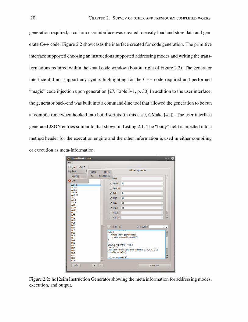
generation required, a custom user interface was created to easily load and store data and gen-
erate C++ code. Figure 2.2 showcases the interface created for code generation. The primitive
interface supported choosing an instructions supported addressing modes and writing the trans-
formations required within the small code window (bottom right of Figure 2.2). The generator
interface did not support any syntax highlighting for the C++ code required and performed
“magic” code injection upon generation [27, Table 3-1, p. 30] In addition to the user interface,
the generator back-end was built into a command-line tool that allowed the generation to be run
at compile time when hooked into build scripts (in this case, CMake [41]). The user interface
generated JSON entries similar to that shown in Listing 2.1. The “body” field is injected into a
method header for the execution engine and the other information is used in either compiling
or execution as meta-information.
Figure 2.2: hc12sim Instruction Generator showing the meta information for addressing modes,execution, and output.

2.1. PreviousWork: hc12sim 21
1 {
2 "BEQ": {3 "body": "4 auto ccr = cpu->CCR();
5 bool _Z = ccr->get(Z);
6 if ( _Z ) {
7 int8_t rel = math::toSys<int8_t>(resbytes[0]);
8 cpu->PC()->inc(rel);
9 }
10 ",
11 "cycles": 1,12 "handlePC": false,13 "types": {14 "REL8": "27"15 }
16 },
17 }
Listing 2.1: Sample of the JSON output used to generate code within hc12sim. BEQ performsa branch if two values were equal.
Hardware Simulation
Physical modules within the simulation model were all individual custom classes. For example,
the A and B registers were of class Register<size_t width> where the width template
parameter defined the bit width of the Register. Regrettably, any special behaviours were
“decorated” on top of the base type creating many different types depending on how the un-
derlying component was used. Using the pattern of “compile-time constant templates” created
issues when trying to use these types in polymorphic aggregate containers. For example, if a
Register<8> A is defined and a Register<16> X typeof A is not the equal to typeof X
as templated types are created at instantiation time making the type of a variable a “new” type
(reuse happens when available) [42]. This created confusing class hierarchies and directly con-
tradicts advice of the Decorator pattern [43, p. 175] creating large concerns for maintainabil-

22 Chapter 2. Survey of other and previously completed works
ity. Of particular interest was the design of the class Timer and class TimerDependant
types which allowed for completely concurrent, event-based timing. While these concurrent
timing modules were fast and well designed, it created problems with discrete execution as
each component operates concurrently in separate thread contexts and can not be “stepped”
through without executing all of the threaded operations simultaneously. In addition, each
TimerDependant added a thread of execution adding runtime overhead to simulation while
reducing functionality of the simulation. Due to our ignorance at the time, neither thread
nor fork-join pools were used to reduce the thread “spin-up” performance penalty. Further,
the synchronization properties of this scheme reduced to near-synchronous execution with the
time taken to check locks and mutexes likely costing more time than the savings of parallelism
afforded – not to mention the required knowledge of maintaining a highly parallel code base.
Execution
The simulator implemented execution through an class Executor that asynchronously ex-
ecutes the execution scheme specified by the Freescale M68HC12 [27, Sec. 4, p. 47] which
was implemented in terms of [44, p. 59]. The Executor utilized a fetch, decode, fetch (if
needed), execute loop for executing all instructions. The actual execution of an instruction was
completed directly by static code written in the instruction generation step (see Section 2.1.1
for more information). However, the generated code is run within a separate thread context to
keep the “clock” of the system running at a consistent speed. Of particular note, this simula-
tion could not handle interrupts or pipe-lining. Due to the reliance on the timing mechanisms
discussed in Section 2.1.1, the execution engine suffered from the same “synchronous” paral-
lelism. Further, if the clock speed was too fast and execution actions moved too slowly, the

2.2. Evaluation of existing simulation technologies 23
result was an non-determinant clock skew over time.
2.2 Evaluation of existing simulation technologies
Presented in the following sections are a series of similar projects attempting to tackle the
same solution space as the work of this thesis. Each software tool is evaluated against the
requirements from Section 1.3. The intention of this evaluation is dual:
1. Find previous works that could be expanded upon and improved to match this thesis’
requirements rather than building a new solution in a “green field”
2. Extract features from other simulation technologies that are beneficial to future technol-
ogy
Each simulation project is rated based on the requirements out of five and totalled to create a
quantitative matrix of requirements. Each rating contains justifications for the rating assigned
following Section 2.2.2.
2.2.1 Methodology
Holistically, we attempted to find the best solution for each requirement outlined in Section 1.3.
To do this we created a ranking of each of our considered software and applied a rating of zero
to five with zero being the worst, and five being the best matching of each requirement. Within
this specification, we believe some requirements were not met by any of the software evaluated.
For example, there is no “best” software in our opinion that met Requirement 5 perfectly with

24 Chapter 2. Survey of other and previously completed works
having a modern user interface. Our methodology allows for a relative, though opinion-based,
approach to contrasting existing solutions.
2.2.2 hc12sim
The hc12sim project was very immature and not well implemented in the presented state.
hc12sim managed to provide a solution for all of the required platforms when distributed as
individual platform specific binaries. The hc12ide was a desktop application and bound to the
technology choice of C++, there is no possibility of using the software outside the desktop
without large software porting efforts. Unfortunately, building C++ applications such that they
can be distributed to cross-platform targets is labour intensive and very difficult without the
correct amount of knowledge – knowledge that was lacking at the time of authorship. Bina-
ries worked for some and often only worked with specific unknown environmental state re-
quirements (particularly with Windows environments). Regarding Requirement 1, the project
meets the requirement adequately, but does not do enough. Configuration of the ISA is pro-
vided through the JSON-driven mechanism for instruction generation but this mechanism only
worked as a compile-time configuration. If students wanted to change the ISA for their proces-
sor, it required rebuilding the entire project and testing to see that it worked manually. This was
aided by the use of the “Instruction Generator” described in Section 2.1.1 but does not remove
the requirement of building requiring a large compiler tool-chain. Further, without any support
for hardware configuration the project did not meet Requirement 2. hc12sim heavily favoured
Requirement 3 as it was intended to create a simulator that was behaviourally accurate to the
Freescale M68HC12, but only if it allowed students to better understand how the processor

2.2. Evaluation of existing simulation technologies 25
works.
The simulation interface allowed for debugging at an instruction level and setting break
points within execution contexts. During an execution, all component states could be viewed
– except for the memory. The project also assembled fully compliant machine code that could
potentially be programmed to a real machine. Unfortunately, peripherals and interrupts were
not supported. While including these flaws, the hc12sim project provides a poor match for
Requirement 4. Lastly, while the user interface does not have all of the features of a full IDE,
it did provide syntax highlighting, and assembler plus simulation controls in an easy to use
interface. Requirement 5 is adequately met, however it requires updates to the editor interface
to improve modern facilities.
Requirements R1 R2 R3 R4 R5 Totalhc12sim [40] 3 1 4 2 3 15
Table 2.1: Qualitative requirement rating of hc12sim [40]
2.2.3 ShelbySim
ShelbySim is an education-oriented software system for designing, simulating, and evaluating
computer-engineering based applications [35], [45]. ShelbySim was designed surrounding a
new Java-like programming language including a compiler explicitly built around providing
extensive diagnostic information such as logging, tracing, and inspection capabilities. These
tools provide students with raw data for quantitative analysis, evaluation and reporting of their
designs. The software is open-source, though unavailable, and is written using Java allowing
full operating system independent support. Additionally, graphical visualizations of results are
provided for viewing developed components. ShelbySim is broken down into three subcompo-

26 Chapter 2. Survey of other and previously completed works
nents:
1. Software component - a custom programming language (Shelby), a compiler, and an
interpretation runtime
2. Hardware component - filling a similar niche to MultiSim, but with tight integration
with Shelby and its underlying tracing. Additional support exists for external component
integration
3. Simulation component - providing a deterministic and stochastic approach for recording
inputs and outputs to custom hardware simulations
ShelbySim provides evaluation criterion for students’ components and their underlying sys-
tems to aid in marking. The simulated components have parameters that are modifiable through
switches and sliders (e.g. {on, off} or a range from 0 - 100%). This gives students metrics to
evaluate their designs. Additionally, outputs are exported at runtime to Comma Separated
Value (CSV) files allowing for more in-depth analysis with external programs such as Mi-
crosoft Excel or MATLAB. This gives a flexible and realistic testing environment for student
learning.
Analysis of Requirements
For Requirement 1, ShelbySim is open-source and claims to run on all major platforms that
the Java Virtual Machine runs on, thus it should work on Windows, macOS and GNU/Linux.
ShelbySim is built as a custom programming language which is similar to Java but is used
as an HDL. Given the inherent flexibility of HDL languages, Requirement 2 is met, however
these languages fall under a more complicated model than required for this thesis’ use case,

2.2. Evaluation of existing simulation technologies 27
therein hurting Requirement 3. Further, ShelbySim focuses on compiler semantics and hard-
ware configuration over ISA and embedded systems knowledge. ShelbySim works well to
provide quality simulations as required by Requirement 4. Additionally, ShelbySim produces
comma-separated values of events which is useful for later analysis. Lastly, there does not ap-
pear to descriptions of a user interface component outside of graphical drawings. This does not
concretely fail the modern interface component for Requirement 5, but it does call into ques-
tion how students may react to a lack of a proper programming environment. Additionally,
there does not appear to be compiler features in place to utilize the custom ISA that a student
creates (e.g. assembler).
Requirements R1 R2 R3 R4 R5 TotalShelbySim [35], [45] 4 4 3 4 0 15
Table 2.2: Qualitative requirement rating of ShelbySim [35], [45]
2.2.4 EDCOMP: Flexible Web-Based Educational System
EDCOMP is an educational computer system and a web-based simulator that can be used to
cover computer architecture fundamentals; computer organization; computer arithmetic; mem-
ory hierarchies and organization; and simple input/output relations [30]. EDCOMP is written
in Java and runs inside of a Java applet within a web browser. The simulator supports an-
imation of instruction execution and allows students to write their own assembly programs,
compile them and view the status of the machine components. All parts have visual compo-
nents at multiple levels (i.e. module, combinational and sequential circuits). The simulation
can be run at several levels per clock cycle, per instruction and for the entire program. Further,
the simulation supports advanced topics such as interrupts and parallel I/O units. Lastly, tim-

28 Chapter 2. Survey of other and previously completed works
ing diagrams allow students to see how components are interacting at a lower, discrete level.
This software aims to create a system that focuses on pedagogical learning rather than on in-
dustrial accuracy and lower complexity of the system. EDCOMP focuses heavily on graphical
representation to aid in student learning.
Analysis of Requirements
For Requirement 1, EDCOMP is written in Java and was previously run within a web browser
inside of a Java applet intending to open access to students with a low barrier to entry. However,
due to the deprecation of NPAPI2 in Google Chrome, Chromium-based browsers, and Firefox,
this means that likely over 80% of students would not be able to use this software [46]–[51].
In addition to being unusable with today’s browsers, the system is also dated by the use of
applets and does not have modern editor features creating a gap between modern technology
and students therein failing to meet Requirement 5. The EDCOMP system is not completely
configurable as it is bound by purposeful reductions in features for pedagogical reasons. It
features a CISC-based architecture with configurable components, however the internal con-
nections can not be configured–only the size and “shape” of components. Thus, EDCOMP
does not meet Requirement 2. EDCOMP heavily focuses on learning and teaching and show-
cases the use of a user interface to improve simulation triggers in a pedagogically focused way.
The authors showcased the software by utilizing it within classrooms meeting Requirement 3.
Finally, the simulations described are extremely useful and thorough. These simulations show-
case powerful techniques in stepping and debugging and also triggering signals in meaningful
ways to show students how different components can interact. The quality of these simulations2NPAPI: Netscape Plug-in API. Due to deprecation, documentation for this API does not exist, for a non-
academic historical description see: https://en.wikipedia.org/wiki/NPAPI.

2.2. Evaluation of existing simulation technologies 29
strongly meets Requirement 4.
Requirements R1 R2 R3 R4 R5 TotalEDCOMP [30] 3 3 4 4 0 14
Table 2.3: Qualitative requirement rating of EDCOMP [30]
2.2.5 p88110: A Graphical Simulator for Computer Architecture and
Organization Courses
The p88110 attempts to cover many core topics in Computer Architecture and Organization
[31]. The authors reflected and have created a “one-size fits all” solution to try and replace
many heterogeneous simulators used in practice at the time. This software emulates the ISA
for the MC88110 microprocessor specifically – a RISC architecture. The authors intentionally
removed components to alleviate the amount of information for students to learn. The user
interface includes a view for the current simulation of components, and a simplistic, built-in
editor and simulation stepping at the instruction level and adding debugging breakpoints. The
simulator can be modified to execute in serial or parallel (super-scalar) modes. In parallel
mode, the four-stage pipeline of the MC88110 is implemented with static branch prediction
and delays. A unique feature is the use of built-in caches for instructions and memory. These
include configuration for time-to-read and write. During simulation, cache and branch pre-
diction hit and miss statistics are recorded for student analysis purposes. The authors have
implemented this simulator in class assignments and created an automated evaluation tool for
reducing overhead for instructors.

30 Chapter 2. Survey of other and previously completed works
Analysis of Requirements
The authors claim that the p88110 simulator may be run on personal computers, however given
changing technologies and a lack of software description, we could not validate the software is
still able to run on current operating systems implying the system does not meet Requirement 1.
p88110 directly emulates the MC88110 system which is a similar system to the Freescale
M68HC12 and has been shown to be an excellent candidate for pedagogical purposes. Re-
quirement 2 states that a software must be able to be configured for multiple architectures
and while the MC88110 is a great candidate architecture specifically, p88110 is too limited to
meet this requirement. However, the engine configuration features presented by p88110 are
extremely powerful and useful. p88110 was developed for use within a classroom meeting
Requirement 3. Further, p88110 reduced realism to create a simpler architecture for students
to learn from – favouring pedagogy over accuracy. Additionally, the use of an automatic mark-
ing tool would reduce the overhead for teaching students and give students instant feedback
without requiring instructor interaction. The simulations provided by p81100 are thorough
and provide insight into statistical modelling of pipelined and cached architectures. This in-
formation is extremely relevant to computer architecture courses. However, the p88110 does
not support the use of peripherals or interrupts. Requirement 4 is not met due to lacking fea-
tures, though the statistical feedback provides an interesting insight for students to learn from.
Lastly, the interface is not modern and supports only simple features found in most editors.
The amount of dialogs created shows concern for focus when working with p88110 and does
not reduce students cognitive workload therein failing to meet Requirement 5.

2.2. Evaluation of existing simulation technologies 31
Requirements R1 R2 R3 R4 R5 Totalp88110 [31] 1 1 4 3 1 10
Table 2.4: Qualitative requirement rating of p88110 [31]
2.2.6 EASE - An Extensible Architecture Simulation Engine
Extensible Architecture Simulation Engine (EASE) is a simulation engine focused on custom
simulations for classroom use [34]. EASE attempts to provide the following features:
• Support for multiple architecture types: RISC, CISC and URISC
• Provide a modular mechanism for simple extension
• Open-source software
• Portable to different platforms
The authors [34] reviewed the survey of simulation tools found in [33] and found the suggested
tools were inadequate for teaching simulation architecture courses based on their requirements.
Many put too much emphasis on RTL descriptions of the hardware and too little on ISA. EASE
provides three ISAs for use, a CISC, RISC and URISC within the project. EASE is written in
Java making it cross-platform. It comes with a very simple user interface written in Java Swing.
Analysis of Requirements
EASE is a very immature project without a lot of proven use–this makes it difficult to gauge
how effective it is. EASE focuses on pedagogy as it’s major requirement meeting Require-
ment 3. While the authors mention new architectures may be added through implementation of
their interface Arch, students have no way to do this themselves and forces a recompiling

32 Chapter 2. Survey of other and previously completed works
of the application to create a new architecture therein failing to meet Requirement 2. Given
that EASE is written with Java, all that is required to run the software is a Java runtime mak-
ing it cross-platform. However, [34] stated the software was available under the GNU Public
License v3, but the software is not currently available for consumption. Theoretically EASE
meets Requirement 1 through using the Java Virtual Machine for it’s environment but we could
not verify this. EASE does support step-based execution, however it has no support for debug
breakpoints. Further, there is no reference to stepping at the microcode level. Runtime viewing
of registers is available, however there is no way to view the memory. These outlined features
do not meet Requirement 4. Lastly, the user interface provided is very simple providing syntax
highlighting for a single file and simple debugging controls. The interface does not provide
modern editing features that students are accustomed to with most editors – failing to meet
Requirement 5.
Requirements R1 R2 R3 R4 R5 TotalEASE [34] 4 2 5 3 2 16
Table 2.5: Qualitative requirement rating of EASE [34]
2.2.7 TinyCPU and TinyCSE: Hardware simulations for education
TinyCPU is a teaching assignment designed to be used in a Masters of Science program in em-
bedded systems to teach students about computer architectures by having them incrementally
design a CPU (TinyCPU) [29]. TinyCPU has been used in a program described to be very
similar to Western University’s computer engineering program. TinyCPU runs in Verlilog and
is a simple stack-based machine. The full block diagram for TinyCPU is shown in Figure 2.3.
The architecture is meant to be extremely simple to mitigate extra information for students to

2.2. Evaluation of existing simulation technologies 33
Figure 2.3: Block diagram of TinyCPU showing the internal architecture [29, p. 869]
Figure 2.4: State chart of TinyCPU execution path [29, p. 869]
consume. The entire CPU configuration is rigidly bound with:
• 16-bit word size
• 12-bit address space
• A single ALU
• Dual bus structure with a data bus (dbus) and address bus (abus)
The CPU is compiled with a Verlilog tool chain (e.g. Xilinx ISE) and loaded onto either a hard-
ware or software-simulated FPGA to run. The execution model is intentionally simplistic for
improving ease of learning (shown in Figure 2.4). Given that TinyCPU is written in Verlilog,
it works well with existing industry tools such as ModelSim. Lastly, there exists a C compiler
and assembler for TinyCPU making a very strong case for modern programming interactions.

34 Chapter 2. Survey of other and previously completed works
TinyCSE is an extension to TinyCPU that provides a full system supporting hardware in-
terrupts that can interact with peripheral components like mice and keyboards [28]. TinyCSE
adds an I/O space memory mapping controller for interacting with peripherals. This allows I/O
components to “register” themselves into a position and programs in TinyCSE can read/write
to I/O components through memory mapping. Further, TinyCSE adds an interrupt flag that the
state machine utilizes to allow for hardware interrupts. These interrupts are extremely impor-
tant as this is how most hardware devices interact with a CPU. The modified state diagram is
shown in Figure 2.5. At an architectural level, interrupts are supported via CALL and RETURN
instructions which branch to an interrupt routine and return from an interrupt routine respec-
tively while maintaining the stack.
Analysis of Requirements
For the purposes of analysis, this section will only consider TinyCSE as it is a super-set of
TinyCPU functionality. TinyCSE focuses on pedagogy first and foremost, but also focuses on
a hardware descriptor language, Verlilog. While Verlilog is a very powerful tool, it requires a
complicated tool-chain creating complications for the purpose of teaching introductory courses
Figure 2.5: TinyCSE execution state diagram modified from Figure 2.4 to include interrupts(broken lines show changes from TinyCPU [29]) [28, p. 640]

2.2. Evaluation of existing simulation technologies 35
– we do acknowledge the authors intended on utilizing TinyCSE for Masters of Science stu-
dents. Additionally, the software required for typical Verlilog environments is very expensive
and not accessible to the average student. This does not fully meet the requirements of Require-
ments 1 and 3. The simulations provided by TinyCSE provide more information than any other
simulator evaluated at the expense of complexity for the system and a high barrier of entry to
configure the simulator. This barrier creates a large enough gap that TinyCSE does not meet
Requirement 2 (see the discussion in Section 1.2 for a discussion on existing hardware IDEs).
While failing to meet Requirement 2, due to the level of simulation granularity Requirement 4
is easily met given existing industry tools. Lastly, the software provides no user interface of it’s
own and requires the use of a Verlilog IDE and FPGA programming software. These tools are
modern and updated regularly, however they often fail to have the editor/IDE features students
are used to not meeting Requirement 5.
Requirements R1 R2 R3 R4 R5 TotalTinyCPU/TinyCSE [28], [29] 2 3 3 4 3 15
Table 2.6: Qualitative requirement rating of TinyCPU/TinyCSE [28], [29]
2.2.8 CPU Sim
CPU Sim is a Java CPU simulator written for use within a classroom environment [39]. CPU
Sim allows students to design, modify, and compare various computer architectures at the
register-transfer level and higher. Additionally, students may write and debug assembly code
for custom architectures. The simulator and IDE are written in Java, with the latter utilizing
Oracle’s JavaFX user interface. The software is currently available from [52] as “freeware.” In
conversations with Dr. Skrien, he expressed the want to open source CPU Sim in the future

36 Chapter 2. Survey of other and previously completed works
to increase availability [53]. The user interface is feature rich allowing students to configure a
processor with:
• Hardware specifications (e.g. RAM word size, length),
• Hardware inter-connections,
• Processor microcodes,
• Assembly instructions,
These specifications gives students the ability to configure a nearly custom processor. How-
ever, using the current 4.0.10 release, configuration options are missing: clock speed changes,
CISC-like addressing modes, and peripheral support [52]. Using Java technologies allows CPU
Sim to work with the three major platforms as a desktop application. CPU Sim’s IDE provides
a modern assembly editor for custom architectures providing syntax highlighting, tabbed ed-
itor panes and simple editor commands like find-and-replace. During a simulation, CPU Sim
allows students to view memory and register states. Figure 2.6 shows the IDE during a simple
simulation with a program written in a custom ISA open for editing. CPU Sim fully supports
debug points and step-based execution in it’s engine. Unfortunately the execution engine is
very simplistic and does not provide any configuration points outside of changing the instruc-
tion fetch microcode sequence.
CPU Sim supports creating custom assembly languages to “compile” to the a custom ISA.
Assembly or “microinstructions” in the context of CPU Sim are specified as sequences of “ma-
chine instructions.” Each “microinstruction” is a single transfer or operation within the CPU.
For example, “transfer between registers,” “read from memory” or “branch if condition bit.”

2.2. Evaluation of existing simulation technologies 37
Figure 2.6: CPU Sim 4.0.0 IDE during debugging with Assembly Editor open [52]
These microinstructions are configured based on hardware specifications. When designing an
assembly instruction, the microcode is laid out with a drag-and-drop interface placing “fields.”
The drag and drop interface is shown in Figure 2.7. The top layout shows the microcode, the
bottom is the “assembly” layout which designates how the instruction is written in an assembly
program. These values can be rearranged independent of each other, though relative ordering of
repeated values is maintained. These interfaces allow for adding punctuation and non-encoded
values to the assembly layout. This is a very powerful feature as the assembler provided will
parse the custom assembly layouts to produce compliant microcode.
Lastly, CPU Sim contains excellent documentation within it’s internal help program. The
help documentation is very deep and has many images and “tutorial style” documentation
embedded internally. The author used this documentation exclusively to learn how to use CPU
Sim and found it very useful. This documentation in particular makes CPU Sim attractive to

38 Chapter 2. Survey of other and previously completed works
Figure 2.7: CPU Sim Machine Instruction configuration interface showing combination offields to create a microcode and an assembly instruction.
prospective instructors due to the reduction in student inquiries as most questions may be found
in the program itself.
Analysis of Requirements
CPU Sim is readily available for use by downloading it from [52]. The software runs well
on Microsoft Windows and Linux. macOS support is available, however it has some non-
critical user interface bugs that make it feel slightly “foreign” on macOS (e.g. the menu bar
does not reside in the operating system menu bar). This strongly meets Requirement 1 as
it runs well on the three major platforms. The assembly editor has many modern features
which leads well to having students feel as though they are using a modern software. However
when configuring hardware modules, the user interface is difficult to navigate and does not
always use suitable user interface components to better utilize the available space. Figure 2.8
shows the module modification interface for the Transfer Register to Register Array interface.
The interface presented does not scale and for different modules, there exists many disjointed

2.2. Evaluation of existing simulation technologies 39
user interface components where the same “expected action” between two different dialogs is
completed a different way. In our experience, this lead to confusing amongst those using the
software. Unfortunately, these usability concerns hinder both Requirements 3 and 5 severely.
Figure 2.8: CPU Sim 4.0.0 IDE module specification dialog showing modification of TransferRegister to Register Array microinstruction [52]
While usability is impacted, the simplicity of these interfaces improves the pedagogical
outcomes by removing non-essential information which supports Requirement 3. Dr. Skrien’s
intention to open source CPU Sim should improve student learning by allowing students to
investigate the source code within [53]–[55]. The large amount of configuration available
strongly supports Requirement 2; however due to missing features such as changing how the
simulator executes code and the addition of external peripherals CPU Sim is not a perfect match
for Requirement 2. Lastly, CPU Sim’s simulations are very accurate and the user interface
makes it simple to watch modules within the simulated engine partially meeting Requirement 4

40 Chapter 2. Survey of other and previously completed works
– though external peripherals are missing.
Requirements R1 R2 R3 R4 R5 TotalCPU Sim [39] 5 4 4 2 3 18
Table 2.7: Qualitative requirement rating of CPU Sim [39]
2.2.9 Emumaker86: A Hardware Simulator for Teaching CPU Design
Emumaker86 is an entirely GUI-based hardware simulator for designing CPUs in a Computer
Organization course [56]. Emumaker86 is written in Java and is a desktop-based applica-
tion. Emumaker86 is integrated on top of an existing personal computer simulator giving
Emumaker86 full access to PC-compatible peripherals (e.g. video controller, CD drive). Emu-
maker86 attempts to keep students at a higher level than digital circuit simulators, abstracting
away flip-flops and logic gates into registers and ALUs respectively. Emumaker86 breaks CPU
design into two main components, 1. Datapath and 2. Control unit. These two are built inde-
pendently from each other in custom user interfaces.
The Datapath builder works by students specifying RTL-like structures with digital com-
ponents. Each of these components are laid out and connected through wires and buses. Any
clocked component is connected to the “system” clock by design to simplify requirements for
students. There are interrupt and I/O ports available to enable peripheral connections. These
components can be combined to create sub-components as an abstraction. Each component
runs in parallel within the device. All of these components and datapath entities are serialized
as XML so they can be saved, distributed and reloaded.
The control builder is an interface used to specify a state machine with transitions and
control unit states. The interface is shown in Figure 2.9. Each colour corresponds to a different

2.2. Evaluation of existing simulation technologies 41
Figure 2.9: Emubuilder86 Control Builder: State machine definition [56, p. 325]
field, for example blue is the current state label, below it yellow are microcode rows and green
are “Next States.” State transitions are based on “conditional bits” such as “opcode,” “zero,”
or “shortopcode.” This represents the control unit as a finite state machine, a common topic in
Computer Science and Engineering curricula [10].
Analysis of Requirements
Enumaker86 meets most of the requirements outlined in Section 1.3. However, it is not without
issue. For Requirement 1, a minor concern is that the software runs on Java requiring a desktop
environment. Similar to [28], [29], Emumaker86 uses state machines to represent the control
unit. The largest difference is that Emumaker86 allows for the state machine to be changed by
users. Allowing students to change how the control unit functions is essential to give students
experience designing a controller. Additionally, the “Datapath” creation mechanism uses a
graphical way of designing the hardware controls while still hiding the internals of supplied
components. Emumaker86 meets Requirement 3. There does not appear to be any assembler

42 Chapter 2. Survey of other and previously completed works
mechanism requiring code to be hand-compiled to work on any architecture created (barring
an existing architectural tool chain). Given the lack of an assembler, there is no assembly-level
debugging – failing to meet Requirement 4. Lastly, the largest concern is the need for modern
features. The interface provided for working with the state machine is extremely hard to read
as it utilizes a table-like structure relying on colour coding over modern user interface design
paradigms.
Requirements R1 R2 R3 R4 R5 TotalEmumaker86 [56] 4 5 5 2 2 18
Table 2.8: Qualitative requirement rating of Emumaker86 [56]
2.3 Summary
Given the results accumulated through our best effort objective comparison in Section 2.2, the
results were tabulated into Table 2.9. Naively, out of the simulations, CPU Sim [39], [52]
and Emumaker86 [56] have the largest total match for the requirements. This information was
considered when selecting a trajectory for the thesis’ project, however the raw numbers do not
extract enough information. Each simulator project has design ideas that can be combined into
a better software to meet the requirements from Section 1.3.
The hc12sim project provided a very fast, cross-platform system, but similar to EASE, it
was bound to compile-time configuration. Work completed on the hc12sim project lead us to
develop the idea of runtime-configurable simulations (a known entity in other projects, e.g.
CPU Sim [39] and Emumaker86 [56]). This runtime-configurable feature is paramount in any
project moving forward. Further, several other projects had distinguishing features that should

2.3. Summary 43
Requirements R1 R2 R3 R4 R5 Totalhc12sim [40] 3 1 4 2 3 13ShelbySim [35], [45] 4 4 3 4 0 15EDCOMP [30] 3 3 4 4 0 14p88110 [31] 1 1 4 3 1 10EASE [34] 4 2 5 3 2 16TinyCPU/TinyCSE [28], [29] 2 3 3 4 3 15CPU Sim [39], [52] 5 4 4 2 3 18Emumaker86 [56] 4 5 5 2 2 18
Table 2.9: Summary of Evaluation for Simulators
be included future projects.
The first significant feature is the use of “event-driven” simulation that TinyCSE [28], [29]
and p88110 [31] suggested. Event-driven simulation allows for a simpler approach to main-
taining state within a simulation. Event-driven simulation models are further discussed in both
Chapters 3 and 5. Another feature found to be extremely useful is the use of stochastic model
outputs that can be integrated with existing tools. All of EDCOMP [30], ShelbySim [35],
[45], TinyCSE [28], [29] and p88110 [31] provide tooling to integrate with existing tools such
as ModelSim, Excel or MATLAB. While dependence on industry tools can create problems
for pedagogical reasons, allowing for integration points with these tools gives students more
experience with industry prevalent tools – particularly ModelSim and Excel.
A feature only provided by TinyCSE [28], [29] and Emumaker86 [56] is the ability to con-
figure the entire execution loop. TinyCSE [28], [29] does this by utilizing Verlilog and having
students adjust the state machine directly. Emumaker86 [56] takes an entirely different ap-
proach having students specify a state machine based on input signals and state of components.
Emumaker86 [56]’s approach gives student’s the most power in configuring a machine and
uses a familiar concept of finite state machines [10]. The implementation falls flat due to the

44 Chapter 2. Survey of other and previously completed works
hard-to-use user interface (shown in Figure 2.9). Students are used to seeing machines as Fig-
ure 2.5 displays. A system that gives the power of the “table-based” approach of Emumaker86
with the visual queues from the state chart would give both familiarity and power to students.
Lastly, CPU Sim [39] provides two features that appear to be distinct: 1. Strong accom-
panying documentation, 2. Assembler configuration. Documentation is important for any
software to be heavily utilized, particularly if it is to be used by novice users. CPU Sim’s
assembler configuration allows students to create their own assembly-level language tied into
their custom ISA.

Chapter 3
procsim.scala: Scala-based event-driven
processor simulation for the web
In the following chapter we present an event-driven processor simulation written in Scala utiliz-
ing the actor model with Akka. We aim to provide a configurable digital processor simulation
that could be utilized as a web application within a classroom environment such as ECE 3375.
In addition, we aim to provide a configurable enough solution through a Domain Specific Lan-
guage (DSL) for specification that this project could be utilized within other courses such as
ECE 3390.
3.1 Introduction to Scala and Akka
procsim.scala attempted to port work of hc12sim to Scala and Akka while providing incremen-
tal feature improvements surfaced by reviewing other projects in Section 2.2.1 In recent years,
1See Section 2.1 for an extended discussion on the original hc12sim
45

46 Chapter 3. procsim.scala: Scala-based event-driven processor simulation for the web
Scala has emerged as a powerful language used in big data and scalable web applications thanks
to Apache Spark2 and Lightbend Akka3 [57]–[59]. Scala is a multi-paradigm programming
language supporting functional and object-oriented style programming on both the Java Vir-
tual Machine (JVM) and within a JavaScript environment such as a web browser [60]. On the
JVM, Scala can interoperate with Java programs without any code changes and in a JavaScript
environment most Java functionality is available [61], [62]. One of Scala’s original use-cases
was as a less verbose and more functional version of Java that runs within the same Java in-
frastructure. Thanks to Scala’s implicit parameters [63], custom operator overloading [64] and
optional post-fix notation [65] developers can create Domain-Specific Languages within Scala
with ease. For example, Listing 3.1 is a DSL that was written to emulate BASIC (a 50 year-old
language) showcasing how flexible Scala’s syntax can be. In regards to processor simulation,
all of the simulators surveyed provide at least one mechanism for loading and saving machine
state to a persistent storage (e.g. XML files for [39], [56]). A DSL-based configuration allows
specification of a system without extraneous syntax designed specifically for this purpose. Uti-
lizing a DSL could allow students to specify their machines programmatically in addition to a
graphical user interface improving the amount of configuration, reuse and flexibility available.
This provides an excellent approach to improving Requirement 2’s configuration requirements.
Akka is a Scala framework that provides an implementation of the Actor model [66] that
was originally written by Haller and Odersky in [67] for the Scala Library. Haller’s [67] orig-
inal implementation makes use of an event- and message-driven programming model to lower
thread counts and alleviate lock contentions compared to traditional threading models. Fig-
2Apache Spark is available at: https://spark.apache.org/3Lightbend was formerly known as Typesafe. Akka is available at: https://akka.io

3.1. Introduction to Scala and Akka 47
ure 3.1 shows a simple diagram of actors sending messages bi-directionally between each other.
Each actor has a conceptual “mailbox” that they can store and process messages from. The ini-
tial actor implementation by Haller ([67]) was expanded to become Akka which is now spon-
sored by Lightbend. Akka’s major revisions to Haller ([67]) includes additional abstractions
to remove locational knowledge such that actors “live” wherever they are best suited. Addi-
tionally, Akka’s scheduling mechanisms control Actor execution patterns in an idealistic and
a deterministic way [68]. For example, two Actor instances can communicate with each other
regardless of their physical location on the same node of a distributed system or completely
geographically separated by a network – an individual actor neither knows nor cares where a
message comes from or is sent to. Akka provides fault tolerance through supervisor semantics
utilizing the “let-it-crash” paradigm for faults popularized by the Erlang programming lan-
guage in telecommunication systems since 1985 [69]. These features on top of the actor model
create a very scalable technology that maps simply to microservice-driven architectures. While
Akka’s main goal is to create microservice architectures and scalable applications, we intended
to utilize this model to instead implement an event-driven simulation model.
1 object SquareRoot extends Baysick {2 def main(args:Array[String]) = {3 10 PRINT "Enter a number"4 20 INPUT 'n5 30 PRINT "Square root of " % "'n is " % SQRT('n)6 40 END7
8 RUN9 }
10 }
Listing 3.1: An example DSL source written in Scala to emulate BASIC called “Baysick” [1]

48 Chapter 3. procsim.scala: Scala-based event-driven processor simulation for the web
Figure 3.1: Graphical representation of three Actors sending bi-directional messages [70].
3.2 Event- and Message-driven Simulation
Several projects surveyed utilized event-driven models of simulation [28], [29], [31]. As dis-
cussed in Section 2.3, event-driven models provide a simplification to maintenance of state
within an application. In a traditional object-oriented application, each object maintains its
own state performing create, read, update and delete operations on itself and acts on other ob-
jects to trigger their state changes. By contrast in a traditional event-driven model, the “owner”
of state still remains with components, but program flow is dictated by utilization of an event
loop that processes events and asks components to “react” to these events further creating more
events. This model is traditionally found in graphical user interface applications as it simplifies
flow of a user-driven system. Lightbend coined the phrase “reactive” in regards to software by
creating a manifesto known as the “Reactive Manifesto” that states the qualities of a “reactive”
application [71]. The “Reactive Manifesto” details message-driven applications as:
Reactive [systems] rely on asynchronous message-passing to establish a bound-

3.3. Scala.js - Scala transpiler for JavaScript 49
ary between components that ensures loose coupling, isolation and location trans-
parency. This boundary also provides the means to delegate failures as messages.
[...] Location transparent messaging as a means of communication makes it possi-
ble for the management of failure to work with the same constructs and semantics
across a cluster or within a single host. Non-blocking communication allows re-
cipients to only consume resources while active, leading to less system overhead.
[71]
While the majority of this definition deals with distributed systems, the same benefits are gained
with local applications. A processor simulator does not require elasticity or load management;
it does however require the ability to process messages quickly and in such a way that modules
do not block each other as electronics all operate in parallel. These ideals were transcribed into
a model of a processor in which all components interact through “signal” messages between
each other rather than direct interactions. This opens up the opportunity for much more accu-
rate simulations while simultaneously reducing the effort to interact between modules. These
relationships allow simulations to have higher fidelity and ease the time required to implement
features lending well to both Requirements 3 and 4.
3.3 Scala.js - Scala transpiler for JavaScript
Scala.js is a “compiler back-end” for the Scala compiler that transpiles Scala code to JavaScript
so that it can execute within a web browser. At the time of creating the procsim.scala project,
the most recent release of the Scala.js transpiler was version 0.6.5 [61]. Version 0.6.5 allowed
for most Scala applications to be cross-compiled to the Java Virtual Machine and JavaScript
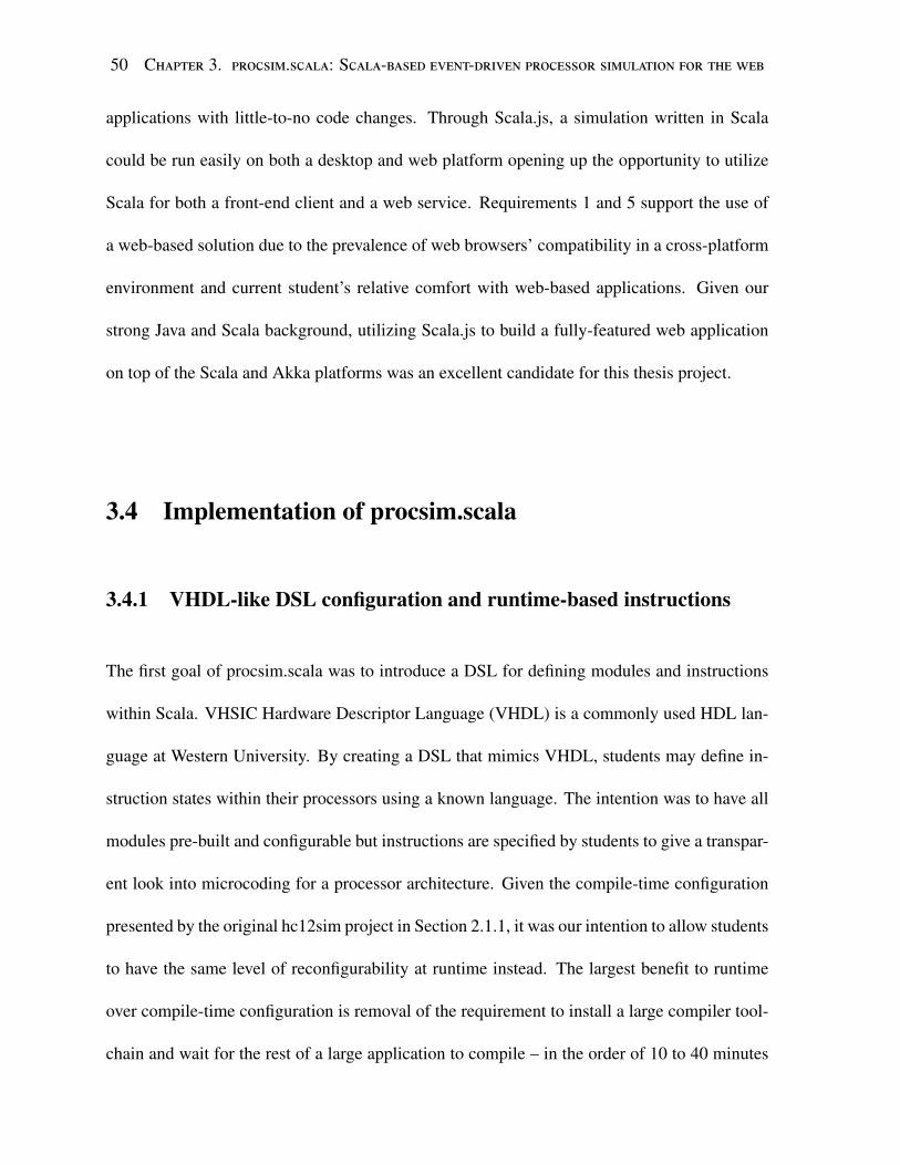
50 Chapter 3. procsim.scala: Scala-based event-driven processor simulation for the web
applications with little-to-no code changes. Through Scala.js, a simulation written in Scala
could be run easily on both a desktop and web platform opening up the opportunity to utilize
Scala for both a front-end client and a web service. Requirements 1 and 5 support the use of
a web-based solution due to the prevalence of web browsers’ compatibility in a cross-platform
environment and current student’s relative comfort with web-based applications. Given our
strong Java and Scala background, utilizing Scala.js to build a fully-featured web application
on top of the Scala and Akka platforms was an excellent candidate for this thesis project.
3.4 Implementation of procsim.scala
3.4.1 VHDL-like DSL configuration and runtime-based instructions
The first goal of procsim.scala was to introduce a DSL for defining modules and instructions
within Scala. VHSIC Hardware Descriptor Language (VHDL) is a commonly used HDL lan-
guage at Western University. By creating a DSL that mimics VHDL, students may define in-
struction states within their processors using a known language. The intention was to have all
modules pre-built and configurable but instructions are specified by students to give a transpar-
ent look into microcoding for a processor architecture. Given the compile-time configuration
presented by the original hc12sim project in Section 2.1.1, it was our intention to allow students
to have the same level of reconfigurability at runtime instead. The largest benefit to runtime
over compile-time configuration is removal of the requirement to install a large compiler tool-
chain and wait for the rest of a large application to compile – in the order of 10 to 40 minutes

3.4. Implementation of procsim.scala 51
depending on hardware utilized4.
The author achieved runtime-configuration of a system by utilizing Scala’s built-in reflec-
tion toolbox [72]. Scala defines reflection as “the ability of a program to inspect, and possibly
even modify itself.” ([72]) Self modification of running code is the primary feature required
for runtime configuration of a model without utilizing separate compiler tool-chains and pro-
cesses. Scala’s reflection tools allow for a developer to write code as a String and execute the
result, storing any and all state produced by the “sub-program.” This feature allows students
to specify code in a configuration editor interface and have the software provide Scala-based
compilation feedback and JVM-level performance. Two listings are provided: Listings 3.2
and 3.3, each showing the definition of the same simple instruction. The syntax used for as-
signment is meant to mimic the syntax used in VHDL to “connect” two modules. Listing 3.2
utilizes a normal Scala class to define these operations, but Listing 3.3 uses runtime-reification
to parse a String, producing a result with the same functionality as Listing 3.2. In small
micro-benchmarks, an initial overhead for parsing the String and compiling it to run within
the JVM at runtime was found, however there appears to be no performance penalty to execute
code found within a reified construct. These test benches utilized primitive timing mechanisms
and accounted for the JVM’s JIT warm-up time. Micro-benchmarks proved that it is possi-
ble to have complete runtime-based, and compiled configurations within a Scala application
without utilizing a secondary compiler tool-chain. The examples shown have the ability to
be expanded to mimic the capabilities found in simulators like TinyCSE [28], [29], reducing
the overall knowledge required but still giving students the feeling of “hands-on” instruction
4On an Intel® i7-3770k, a clean build of the hc12sim project takes approximately 10 minutes, incrementalbuilds were faster depending on the files modified.

52 Chapter 3. procsim.scala: Scala-based event-driven processor simulation for the web
modification meeting configuration Requirement 2.
1 import net.navatwo._2
3
4
5
6 class Concrete extends Instruction{↪→
7 def exec(cpu: CPU) = {8 import cpu._9 A <= 5
10 B <= A + 1
11 }
12 }
13 val cIns = new Concrete
Listing 3.2: Normal definition of Instruction.
import scala.reflect.runtime.{universe => u }↪→
val tb = mirror.mkToolBox()val tree = tb.parse(
"import net.navatwo._;" +
"new Instruction {" +
"def exec(cpu: CPU) = {" +
"import cpu._;" +
"A <= 5;" +
"B <= A + 1;" +
"}" +
"};")
val sIns = tb.eval(tree). casInstanceOf[Instruction]↪→
Listing 3.3: Reified definition of Instruction.
3.4.2 Akka-based Components
The second challenge was utilizing the Akka framework to produce hardware modules that
based on Akka’s Actor model. Within the original description of the Actor model, Agha
states:
A processor is a physical machine while a process is an abstract computation.
From operating systems, we know that we may improve over-all performance of a
processor by executing several processes concurrently instead of sequentially. [66]
This quote is both ironic and informative as when considering hardware simulation, each mod-
ule should be developed as an individual asynchronous entity. Each has input and output con-
nections and only cares about signals on input connections. Instead of considering the system

3.4. Implementation of procsim.scala 53
sequentially, we consider the system as a massively parallel system in which all modules pro-
cesses signals concurrently. In Akka, all messages are passed to all Actor instances and it
becomes a design problem of filtering and producing data for other Actor instances within an
Actor’s system. The author considered all hardware modules as Actor instances and in doing
so, all modules can process information asynchronously within an Akka scheduler provided.
Akka’s schedulers may run sequentially or concurrently, it is decided by the scheduling algo-
rithm but Akka forces developers to treat everything as asynchronous to improve performance
and reduce changes required should an Actor move to a distributed environment later [68].
While there is no intention of ever moving a hardware simulation to multiple distributed nodes,
the concepts of immutable messaging and decoupling mutability and behaviour into Actor
instances reduces the development choices in a positive way.
Akka’s Actor works by sending messages between Actor instances. In the context of
Akka, a message is an envelope around state. Most often, this is a case class in Scala.
As stated previously, a message has only immutable state. In the context of hardware simu-
lation, a clock pulse might be represented as a message shown in Listing 3.4. This message
only contains the time that the message occurred, represented as a Instant5. In order for
another module to listen for this pulse, it must implement the Actor.receive method which
is a PartialFunction[Any, Unit]. The def receive method is usually implemented as
a PartialFunction[] using pattern matching [73] on message classes like Listing 3.4. List-
ing 3.5 shows a Actor that listens for our previously defined ClockPulse message. In order
to send a message to an Actor, once an Actor is created the ! operator sends the message:
5Instant is part of the java.time library: https://docs.oracle.com/javase/8/docs/api/java/time/Instant.html

54 Chapter 3. procsim.scala: Scala-based event-driven processor simulation for the web
actor ! ClockPulse(Instant.now()). With no other interaction required, the message
is sent to actor regardless of where actor is found within the actor system. The simplicity
of these interactions allowed for very straightforward communication protocols between mod-
ules and the paradigms enforced by Akka eased development efforts for new modules directly
improving development agility.
3.5 Technology Challenges
This project progressed well while utilizing Akka on a local machine. However, in order
to utilize Akka in the browser, much of Akka needed to be rewritten to utilize the browser
concurrency semantics. A primary concern is that web browsers do not provide threading in
the traditional operating system context, but they provide threading through the Web Workers
specification [74]. Web Workers are not compatible with JVM threading as it is impossible to
accomplish the full specification of JVM threads which include shared memory and sleeping
under the current specification standard [62], [74]. As such, Scala.js has no means to imple-
ment Java’s threading model natively within a JavaScript environment. Without a supported
JVM threading library, Scala.js does not have the ability to compile Akka to run within the
browser directly. Conversely JavaScript’s programming model is heavily focused on asyn-
chronous single-threaded programming paradigm through callbacks and surprisingly its model
lends well to the actor model from [66]. As [75] eloquently explains:
1 case class ClockPulse(time: Instant)
Listing 3.4: Clock pulse message for Akka
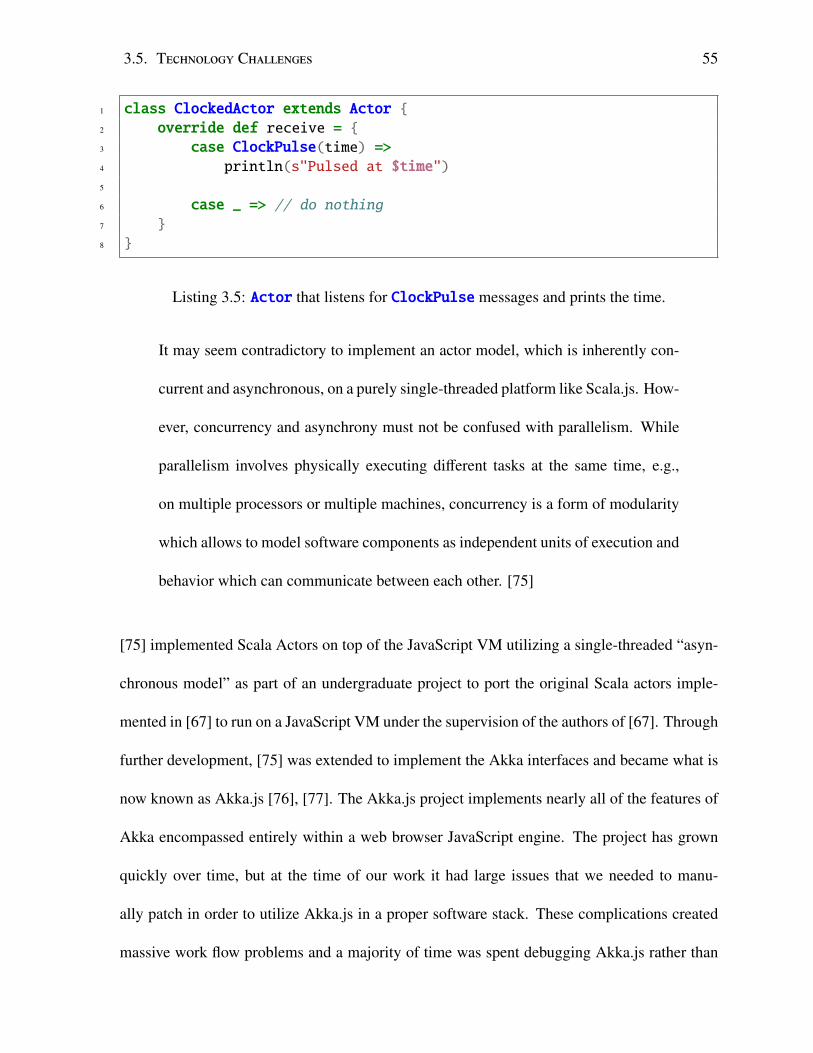
3.5. Technology Challenges 55
1 class ClockedActor extends Actor {2 override def receive = {3 case ClockPulse(time) =>4 println(s"Pulsed at $time")5
6 case _ => // do nothing7 }
8 }
Listing 3.5: Actor that listens for ClockPulse messages and prints the time.
It may seem contradictory to implement an actor model, which is inherently con-
current and asynchronous, on a purely single-threaded platform like Scala.js. How-
ever, concurrency and asynchrony must not be confused with parallelism. While
parallelism involves physically executing different tasks at the same time, e.g.,
on multiple processors or multiple machines, concurrency is a form of modularity
which allows to model software components as independent units of execution and
behavior which can communicate between each other. [75]
[75] implemented Scala Actors on top of the JavaScript VM utilizing a single-threaded “asyn-
chronous model” as part of an undergraduate project to port the original Scala actors imple-
mented in [67] to run on a JavaScript VM under the supervision of the authors of [67]. Through
further development, [75] was extended to implement the Akka interfaces and became what is
now known as Akka.js [76], [77]. The Akka.js project implements nearly all of the features of
Akka encompassed entirely within a web browser JavaScript engine. The project has grown
quickly over time, but at the time of our work it had large issues that we needed to manu-
ally patch in order to utilize Akka.js in a proper software stack. These complications created
massive work flow problems and a majority of time was spent debugging Akka.js rather than

56 Chapter 3. procsim.scala: Scala-based event-driven processor simulation for the web
working on the procsim.scala project itself.
In addition to its immaturity, Akka.js could not keep up with simulation requirements (Re-
quirement 4) as it did not support small discrete times due to relying on JavaScript’s Date
implementation’s millisecond clock resolution and network latency [78]. Naively at this time,
we intended accomplish real-time simulation speeds. Given that we achieved message pass-
ing with approximately 50ms of latency between the sender and receiver, the latency and lack
of precise clocks meant that real-time simulation was completely unattainable. Additionally,
this resolution was not acceptable in the intended parallel simulation environment as multiple
operations happened concurrently at any given moment of time.
Another fault of ecosystem immaturity was that Scala.js created applications that were too
heavy by default. At the time, the Scala.js compiler did not perform dead code elimination
to an acceptable level leaving large applications to be distributed from a web server6. This
meant that even small applications were in the order of mebibytes of minified JavaScript data
to serve as part of an application compared to the kibibytes of information from other modern
web frameworks. This size was unacceptable from an application distribution and usage stance
(not adequately meeting Requirement 1).
3.6 Analysis of Requirements
Unfortunately, due to the immaturity of Scala.js, Akka.js and the ecosystem at the time, the
procsim.scala project was ultimately discarded. The procsim.scala project had two contri-
butions that should be addressed by future projects. First, using an “always asynchronous”
6As of July 2017, the Scala.js compiler has significantly improved since the procsim.scala project and containsa powerful optimization tool-chain on top of Google’s Closure Compiler [79]
3.6. Analysis of Requirements 57
approach to modelling components was very simple to reason about and eased implementation
details significantly. Within Akka, all actors within an actor system are “connected” imply-
ing communication algorithms changed from a problem of “where to send data?” to “which
data does each module care about?” This filtering was non-trivial and often meant that Actor
instances were spending more time filtering messages than performing actions. This author
believes the question of “which” provides a simpler model than the direct connection model
with the same power implying a need for future investigation.
The second contribution is using a runtime DSL to configure the system gives students the
ability to modify components behaviour similar to the hc12sim’s instruction generation scheme
discussed in Section 2.1.1. The massive benefit over the previous project was in runtime con-
figuration instead of compile-time significantly reducing the required effort for students and
providing a foundation for both pedagogical gains and configuration capabilities (Require-
ments 2 and 3). As a qualification for any future DSL proposals, the DSL must feel familiar
to students so that they do not need to learn entirely new syntaxes or paradigms (in the case of
procsim.scala, this was using a VHDL-like syntax over Scala’s typical syntax).
Looking objectively at proscim.scala, it does not adequately meet many of the requirements
outlined by Section 1.3. Many of the following justifications are based on a theoretical prod-
uct as it was not implemented to completion due to concerns raised in Section 3.5. Utilizing
procsim.scala within a web browser allows students significant ease of use on their personal
computers meeting Requirement 1. Though, regrettably due to the speed at which Akka.js
performed in the JavaScript environment, its simulations were not fast enough to provide rea-
sonable experiences making the simulations feel unresponsive. It is difficult to say how flexible
the exposed interface for interacting with simulations would be without a full implementation.

58 Chapter 3. procsim.scala: Scala-based event-driven processor simulation for the web
Most modern web application frameworks work heavily on asynchronous paradigms, thus they
should be able to handle a slower model but may integrate poorly (Requirement 5). Require-
ment 2 is aided by the use of the VHDL-like DSL language. For a pedagogical simulator
procsim.scala is built to be simpler than a traditional fully behaviourally accurate simulator
system. Lastly, procsim.scala was not completed far enough to showcase the functionality for
simulation of modules for Requirement 4. One can assume that utilizing Akka actors, listening
for signal messages would allow for collection of large amounts of state information.
Requirements R1 R2 R3 R4 R5 Totalprocsim.scala 3 4 3 ? 5 15
Table 3.1: Summary of requirement matching for procsim.scala.

Chapter 4
Developing cross-platform C++
applications
After concluding work on procsim.scala, we applied lessons learned from procsim.scala and
applied them to the original hc12sim project discussed in Section 2.1. Unfortunately, the
hc12sim simulator was dated, poorly designed and poorly organized due to inexperienced stu-
dent work. A large effort was placed in modernizing and correcting the hc12sim software to
be well tested, build in a cross-platform environment, reduce feature development time and re-
duce the amount of time required for maintenance. The hc12sim project was renamed procsim
as it was intended to be a general purpose simulation framework rather than a single purpose
Freescale M68HC12 simulator. In an effort to improve modernize procsim, we designed and
set up continuous integration infrastructure to effectively develop a new procsim suite. This
chapter discusses changes required to an aged code base to bring support the C++14 stan-
dard, upgrading existing CMake [41] build script infrastructure and developing multi-platform
environments for automated platform testing.
59

60 Chapter 4. Developing cross-platform C++ applications
4.1 Modernizing hc12sim
The hc12sim project that was showcased in [40] was modern at the time of development.
Since 2013, the C++ community has progressed thoroughly and many of the libraries in
use within the project were superseded by the Standard Template Library (STL) on most
compiler platforms. The hc12sim project utilized many poor practices such as excessive
use of typedef statements, over use of threads or abuse of operator overloading facilities.
hc12sim heavily relied on Boost’s non-standard implementations of tr1 structures such as
boost::shared_ptr<T> [80] (now superseded by C++11’s STL std::shared_ptr<T> [81])
and the boost::threadwith it’s associated tooling [82] (superseded by C++11’s STL <thread>
[83]). The insidious nature of threading and smart pointer usage throughout the hc12sim soft-
ware made this effort a large task. When writing C++ software, distribution of binary files
is a common concern when working in cross-platform environments. Thus a concious effort
was made to remove all large binary-based libraries in favour of simple-to-build or header-only
libraries to remove concerns of finding pre-installed development packages on multiple plat-
forms. After replacing existing Boost implementations with STL equivalents, these changes
needed to be cross-platform tested to validate that the implementations by different compiler
vendors on varied operating system configurations behaved as expected.
4.2 Cross-platform development
The C++ language has unofficially always tried to follow the motto: “write once, compile any-
where.” With any compiled language, when moving between platforms it is often non-trivial
to assure compiled code runs between any two platforms. Given that Requirement 1 requires

4.2. Cross-platform development 61
any solution must run on student’s personal computers, we required procsim run on modern1
versions of the three major platforms, Microsoft Windows, macOS and GNU/Linux. Within
the C++ ecosystem, the ubiquitous way to maintain cross-platform support is to utilize only
commonly used tools and depend on the Standard Template Library (STL) as much as pos-
sible. That is not to say there are not powerful cross platform libraries (e.g. Boost [84], Qt
[85]), these libraries provide excellent tools but often introduce complex build requirements
and add large binary files into any distributed application. An artefact of 2013, Microsoft’s
Visual C++ (MSVC) 2011 compiler and accompanying STL were not completely standards
compliant with C++11 and thus to use modern C++11 STL features hc12sim required the
use of Boost to get non-standard but similar implementations [86]. Easing refactoring efforts
was many of the C++11 STL additions were modelled after Boost’s implementations [87]. For
procsim Boost’s STL implementation dependency were mostly removed by upgrading the low-
est supported compiler to MSVC 2015. MSVC 2015 fully supports C++11 in both compiler
semantics and STL compatibility [88]. This allowed us to fully remove the main Boost depen-
dencies on Boost.Memory and Boost.Thread by effectively renaming the boost:: namespace
to use std:: namespace for the components in <memory> and <thread>. By removing these
library dependencies, it eased cross-platform development as only the Boost C++ headers were
required to compile procsim’s core library. However, the unit test platform for hc12sim was
based on Boost.Test [89] – a problem addressed later.
1“Modern” in this context implies most recent stable long-term release.

62 Chapter 4. Developing cross-platform C++ applications
4.2.1 Access to multiple platforms within a single host platform
Once procsim utilized the C++11 STL over Boost, the next task was configuring mechanisms
to ensure each platform performed correctly. It was found multiple times that different com-
piler’s STL implementations behaved differently depending on different versions and the com-
pilation target in use. For example, we found that the GNU Compiler Collection (GCC) [90]
5.X C++ STL shipped with a broken version of the C++11 <regex> library [91]. But the
GCC front-end found on macOS had no such issues as it uses libc++ provided by LLVM
with a GCC compliant compiler command-line interface that runs Xcode’s version of LLVM
clang [92]. This bug was found well after feature implementation due to testing on Xcode
8.3 and MSVC 2015 passing successfully (our two main platforms). Building on Linux was
tested and the issue was found through unit tests checking a feature that utilized regex search-
ing functionality. This small but frustrating issue opened up a question: How can the software
be verified working on three major platforms while not having native access to each platform?
The original approach was to change physical devices to access the different major operating
systems. For each machine, we downloaded the software from the development repository and
ran tests manually. It became difficult to maintain build environment changes made over time to
successfully build the project as little records were maintained and compiling system projects
heavily depend on environment variables. This meant sharing the software development envi-
ronment became difficult and near impossible to replicate. Further, if a developer did not have
access to Apple hardware, macOS software could not be tested. In previous works, we utilized
VMWare vSphere [93] technologies to create common developer environments through Virtual
Machines that could be used for consistent development and testing.

4.2. Cross-platform development 63
Given that vSphere is a proprietary and expensive software, we researched other tools that
provided virtualized environments. Oracle’s VirtualBox [94] provides virtual machine provi-
sioning through open source tools. Building on the idea of “cloning” common configurations
between development environments through VirtualBox, we eventually found HashiCorp’s
Vagrant [95]. Vagrant provides a consistent declarative configuration for defining a virtual
machine environments through Ruby scripts. Vagrant’s parent company, HashiCorp, hosts
“boxes” that are preconfigured virtual machines ranging from Ubuntu Linux to FreeBSD to
macOS El Capitain [96]. Boxes provide a base VM image that users configure to match the
environment requirements for a project. When a configuration is settled, developers commit
the configuration file, known as a Vagrantfile, to their repository to live directly beside the
software being developed. The intention of storing environment configuration within soft-
ware repositories is to attempt to merge “build” teams and development teams as these are
no longer distinct processes. For example, Listing 4.1 show cases a simple configuration that
installs both GCC 5.X and LLVM Clang [97] 3.7 – two fully C++11 compliant compiler tool-
chains into a Ubuntu Trusty 14.04 box. Due to Vagrantfiles being Ruby programs, they have
full access to Ruby’s gem ecosystem. We used Vagrant and VirtualBox to create three envi-
ronments for Microsoft Windows 10, macOS El Capitain, Ubuntu 14.04 Precise and Ubuntu
16.04 Xenial. These configurations allowed instantiating virtual machines quickly and con-
sistently on any platform to build and run test configurations. Vagrant allows users to cre-
ate their own boxes and we created a box for each base configuration for distribution that
would save time for setting up a machine. Our Vagrant box configurations are available at
https://github.com/Nava2/procsim-bld available under the MIT Open-source License.
With the three major platforms easily accessible, it became necessary to improve the build

64 Chapter 4. Developing cross-platform C++ applications
infrastructure to be consistent across these platforms.
4.2.2 Building with cross-platform tools
CMake [41] is a cross-platform meta-build system. A meta-build system provides a “front-
end” language for defining a project’s build and generates build scripts for other build systems
to consume. CMake provides support for many different build systems, each is supported
through a CMake “generator.” The generators we chose to build on the Windows, macOS and
Linux were “Unix Makefiles” for GNU make [98] on Linux and macOS, “Xcode” for ma-
cOS’s IDE Xcode [99], and “Visual Studio 14 2015 [Win64]” for MSVC 2015 [100]. On Unix
environments, make is generally available however and a newer build tool, ninja [101], is
preferred as builds are faster and provides the same familiar behaviours as make. As stated,
CMake provides a cross-platform meta-build system, CMake can not abstract direct interac-
tions with compilers due to tool-chain and operating system specific options. For example,
turning on optimization flags on GCC/clang differs from the MSVC platform. The original
hc12sim project utilized CMake, but it was poorly organized and added large build crippling
file dependencies. Changing a single file likely caused the entire build to trigger as if running a
clean build rather than running an incremental build. At first, this was thought to be caused by
CMake not properly structuring inter-file dependencies, however it was soon found to be due
to poor header isolation and deep nested coupling. We separated all headers to try and isolate
concerns of what a header defines – often breaking headers into multiple smaller single purpose
headers. These efforts attempted to remove inter-dependencies as much as possible. Reorga-
nization of the procsim library coupled with improved build tools and the addition of OBJECT

4.2. Cross-platform development 65
1 Vagrant.configure("2") do |config|2 # Utilize the ubuntu/trusty64 box to give a 14.04 environment
3 config.vm.box = "ubuntu/trusty64"
4
5 config.vm.provider "virtualbox" do |vb|6 vb.cpus = 2
7 vb.memory = 2048
8 end9
10 # Install/update prerequisite software:
11 config.vm.provision "shell", privileged: true, inline: <<-EOF12 echo "Installing build prequisisites: git, compiler ppas"
13 apt-get install -q -y git
14 # Compiler tool-chains
15 apt-add-repository -y ppa:ubuntu-toolchain-r/test
16 apt-add-repository -y ppa:adrozdoff/llvm-backport
17 apt-get update -qq
18 EOF
19
20 config.vm.provision "shell", privileged: true, inline: <<-EOF21 echo "Installing build compiler toolchains"
22 apt-get install -q -y clang-3.7 \
23 gcc-5 g++-5 \
24 --force-yes
25 EOF
26
27 # Update all existing packages last
28 config.vm.provision "shell", privileged: true, inline: "apt-getdist-upgrade -y ; apt-get autoremove --purge -y"↪→
29 end # end vagrant file
Listing 4.1: Vagrant file that describes a Ubuntu 14.04 box with modern GCC 5.X and LLVMClang 3.7 compilers installed.

66 Chapter 4. Developing cross-platform C++ applications
library files [102] significantly reduced build time and allowed for less time spent compiling
procsim.
As previously discussed, compilers come with consequential differences in support for new
and current standards. In order to try and utilize features appropriately it is often helpful
to “test” compilers support of features. CMake provides this functionality through cmake-
compiler-features [103] but CMake’s built-in support lags heavily behind current C++ stan-
dards (including C++14 and 17 at the time of writing). Fortunately, compatibility [104] is
a library used to enhance compiler and STL feature detection within CMake projects. We
worked with Muller to improve compatibility features and generation of header files that will
include a “shim” on top of the current STL to add features where possible. “Shims” can only
be added for STL features as syntax elements are not extensible in C++. To counter a lack
of syntax tokens in some compilers, compatibility scripts also automatically generated C-style
macros for keywords that are only available in certain C++ tool-chains (e.g. constexpr or
override). These macros were used to add extra meta-information for the compiler where
available to improve code generation. The use of compatibility allowed procsim to build more
easily on the heterogeneous compiler platforms required to work on most personal computers
for Requirement 1 while simultaneously improving the software’s performance where possible.
4.3 Testing Infrastructure
Testing a multi-platform compiled systems project is very difficult and relies on many tools
to be successful. Through utilization of Vagrant and better build infrastructure within CMake
scripts, procsim was able to be automatically tested on multiple platforms through continuous

4.3. Testing Infrastructure 67
integration software. Continuous integration describes a process of building, testing and de-
ploying software as rapidly as possible to reduce time-to-market for software projects [105].
Idealistically, by utilizing continuous integration, developers receive near-instantaneous feed-
back on whether or not a particular change set breaks the product in unforeseen ways – this
heavily depends on the level of testing and environments available. For procsim, we configured
a small “micro-PC” with an Intel® i5-4590T and 4 GB of RAM to run a Jenkins [106] contin-
uous integration server running Jenkins. The device was chosen due having CPU accelerated
virtualization to aid in running Oracle VirtualBox through Intel VT-X.
Within Jenkins, Vagrant was used to create a new virtual machine for each test platform
which registered as “slaves” to the “master” Jenkins service provided by Jenkins’ distributed
build infrastructure [107]. Each virtual machine spawned from a separate base box to test proc-
sim’s software test suites consistently. For example, one machine spawned a Ubuntu 14.04
machine with manually installed compiler tool-chains and a second machine spawned a ma-
cOS instance with Xcode 8. Each machine ran the exact same unit tests after configuration of
the virtual machine and selection of a CMake generator. This was achieved through a Jenk-
ins Pipeline [108] specified in a Jenkinsfile script [109]. Jenkins Pipelines allow for parallel
execution of “tasks,” dependent and independent, for a continuous integration task graph. For
procsim, due to its immaturity, the pipeline only included stages for building the software and
running unit tests within the multiple operating system platforms required by Requirement 1 –
deployment tasks were unused due to project maturity. While not strictly related to simulation
Requirement 4, the addition of a continuous integration solution allowed us to maintain a rapid
pace of development and provide confidence that changes made worked across all platforms
without time consuming manual confirmation.

68 Chapter 4. Developing cross-platform C++ applications
Over the course of developing procsim, the build process became more and more com-
plicated requiring improvements in automating build script writing. When writing unit tests,
the original hc12sim project utilized Boost.Test [89] for creating and running unit tests. Un-
fortunately, Boost.Test required library distribution which made working on platforms without
official software distribution systems difficult (e.g. Windows or macOS). In order to remove the
final thread of Boost binary dependence, we replaced Boost.Test with Catch [110]. Catch is a
header-only C++ testing framework built on top of modern C++. Catch provides a Behaviour-
Driven Development (BDD) interface that allows developers to describe the behaviour of their
system within their tests creating easily understandable and clearly organized tests [111]. Catch
improved the mechanisms used to test and provided an easier to maintain testing suite. Catch’s
test runner requires that all tests are defined through C-style macros and the executable must
include Catch’s main once per test suite through the CATCH_CONFIG_MAINmacro [112]. When
defining many tests, it is often useful to organize them in meaningful “suites” of test executa-
bles. With any testing framework, when creating multiple executables it is advantageous to
share object resources to reduce compiling time – particularly in template or constexpr
heavy software which procsim rapidly became.
4.4 Improving developer work flows within CMake
In Section 4.2, CMake was discussed as the build tool for procsim. CMake utilizes OBJECT
libraries to allow multiple “targets” to share compiled object files and statically link against the
same objects as required [102]. These OBJECT libraries are not the same as shared objects or
DLLs and should not be treated as such. An OBJECT library is a CMake abstraction on top of

4.4. Improving developer work flows within CMake 69
compilation units that must be statically linked into some other object. These shared OBJECT
libraries were very useful in unit test files as a common object used between each executable
“suite” is the main test runner. They provide a faster compiling but unportable binary object
similar to a static library. Manually specifying all of these suite instances to get individual
suites and manually maintain a global “test all” suite created significant time investment and
manual adjustments whenever files were added or removed from the project. We developed
a series of CMake macros and functions to reduce the required commands to define tests and
library files in a “project-based” work flow [113], [114]. Within CMake, any action that has a
side-effect or result is considered a target. When CMake executes a build script, it creates a
graph of inter-target dependencies. From the target graph, CMake calculates a topological
sort for a dependency resolution scheme used to build the project. Listing 4.2 shows a simple
shared library defined utilizing the build infrastructure described. Three functions are used to
define four distinct targets:
1. new_project() defines a “project” that logically groups libraries, executables and tests;
2. A library, procsim with headers, sources and external dependencies;
3. Two test “groups” of logically packaged tests for the library from (1) and adds a depen-
dency on (1) and a common test harness;
4. An aggregate PROJECT suite that combines all the tests from each group into a suite for
the current project;
Within these functions, each performs many tasks to try and simplify definition of build com-
ponents to form a completed program build. This could include setting common compiler

70 Chapter 4. Developing cross-platform C++ applications
flags, introduce dependencies on vendor libraries or generating build-time code required for
the target.
The function, new_project() defines a set of “global” variables within the build that are
named after the directory that the current defined CMake script is found. For example, if
Listing 4.2 was found in “procsim/core” the project would be called “core.” This behaviour is
meant to be consistent and simplistic between project definitions. This project model is based
on the idea of “convention over configuration” which was popularized by tools and frameworks
like Apache Maven and Ruby on Rails [115], [116]. For example, new_project() defines the
following configurable global variables:
• SOURCE DIR: Implementation files directory, defaulting to “core/src”
• INCLUDE DIR: Header include directory, defaulting to “core/include”
• TEST DIR: Test implementation directory, defaulting to “core/test”
The * DIR properties allow for inner-project commands to use relative paths to simplify dec-
laration of their file dependencies. These properties are used to generate “namespaced” build
targets and variables allowing for use in specification within CMake’s dependency graph. To
simplify, if you define two projects, a and b, you can set b to depend on a being built first. In
Listing 4.2, all of the files are specified relative to the “project directory” removing repeated
values required in standard CMake scripts. Once the new_project() function is called within
a cmake script hierarchy, all further functions from the build tools will utilize the state set by
the project.
The function new_library() creates a new library target that compiles all of the speci-
fied files to create a library. The function accepts SHARED, STATIC, OBJECT, etc. to mimic

4.4. Improving developer work flows within CMake 71
1 new_project()
2
3 # Define a new library called ``procsim''4 new_library(procsim
5 HEADERS procsim/encoding/Algorithm.hpp
6 procsim/encoding/Code.hpp
7 procsim/encoding/Operand.hpp
8 procsim/encoding/Primitives.hpp
9 procsim/encoding/Utility.hpp
10
11 procsim/time/Clock.hpp
12 procsim/time/Timer.hpp
13 procsim/time/AsyncTimerReceiver.hpp
14
15 SOURCES encoding/Algorithm.cpp
16 encoding/Code.cpp
17 encoding/Operand.cpp
18 encoding/Primitives.cpp
19
20 time/Clock.cpp
21 time/Timer.cpp
22 time/AsyncTimerReceiver.cpp
23
24 GENERATED_HEADERS ${PROCSIM_EXPORT_HEADER}
25 ${PROCSIM_COMPILER_HEADER}
26 VENDORS cpp17_libs fmtlib # non-builtin
27 INCLUDE_DIRECTORIES ${Boost_INCLUDE_DIRS}
28 LIBS ${CMAKE_THREAD_LIBS_INIT}) # builtin libs
29
30 # Create two test suites utilizing the new library
31 create_test(time SOURCES time/ClockTest.cpp
32 time/TimerTests.cpp
33 LIBS procsim test-harness)
34
35 create_test(encoding SOURCES encoding/CodeTest.cpp
36 encoding/OperandTest.cpp
37 encoding/PrimitivesTest.cpp
38 encoding/UtilityTest.cpp
39 LIBS procsim test-harness)
40 # Create a test for the whole project
41 create_test(core PROJECT)
Listing 4.2: CMake script showing how two test suites, time and encoding, are defined aspart of a project, core

72 Chapter 4. Developing cross-platform C++ applications
add_library()’s syntax [102] – an attempt to remove some discontinuity between the two
functions. As shown in Listing 4.2, there are several other parameters used:
• HEADERS Header files
• SOURCES Implementation files
• GENERATED SOURCES Source files that are generated at build time by another target
• GENERATED HEADERS Same as GENERATED SOURCES except for header files
• VENDORS These are external dependencies that are built within the build chain after
downloading from an external source. This forces the library to depend on their down-
load and build
• LIBS These are internal CMake libraries or other targets that are built in a multi-project
configuration
Utilizing these parameters, the function creates an appropriate CMake target using
add_library() and adds the required dependencies to the new library target. In addition, it
performs platform-specific compiler adjustments to try and reduce the amount of configura-
tions required per target. For example, many flags for MSVC to not apply to Clang which do
not apply to GCC. This torrent of compiler-specific option configuration is eased by the use of
CMake’s generator expressions [117] but many compilers do not properly identify to CMake’s
internal infrastructure so manual adjustments must be made for newer tool-chains. By utilizing
our own mechanism, the targets created have “localised” properties such as include directo-
ries and target_properties() added in reproducible ways that do not accidentally pollute

4.4. Improving developer work flows within CMake 73
other targets or the global variable space. For example, if two targets require different versions
of the same files, the built-in include_directories() command could cause these targets
to “collide” and fail to compile [118]. new_library() appropriately applies the SYSTEM op-
tion to all includes that are outside of the multi-project build so any warnings generated are
not applied. Lastly, install targets are created that install headers and compiled binaries to
appropriate locations depending on the type of library and the platform in use. For example, on
Microsoft Windows requires libraries be beside their executables, where UNIX utilizes PATH
resolution mechanics.
The last function used in Listing 4.2 is create_test() which has three distinct incanta-
tions. The first creates a single test suite from Catch-based test sources [110]. These sources
are aggregated and compiled to an OBJECT library [102]. The test objects are aggregated for fu-
ture linking into the current PROJECT’s test executable. By generating OBJECT libraries, these
smaller units of compilation can be combined and reused intelligently saving large amounts of
compile time as previously discussed. The second pattern as create_test(test PROJECT)
generates a PROJECT-based test executable and “check” target that runs the PROJECT test ex-
ecutable. This test executable includes all previously defined OBJECT libraries in the current
“project.” This executable is used to debug and execute tests for the given project, it is cur-
rently not possible to run a smaller test individually without utilizing the selected test runner’s
(Catch) command-line interface manually. Additionally, the generated executable is registered
with CMake’s CTest which creates build-script targets to run test executables providing dash-
boards and other useful tools [2].
The last use case is create_test(target ALL), not included in Listing 4.2. The ALL
request generates a test executable that includes every test suite created in a multi-project build

74 Chapter 4. Developing cross-platform C++ applications
into a single executable – a convenience executable. As multi-project programs develop, it is
useful to be more or less granular with the scope of tests executed depending on the context
required at the time of use. While intuitively it appears as though large amounts of executables
create large amounts of compilation units creating a very slow build time, due to the use of
OBJECT libraries created at definition, adding more test executables only adds incremental link
time due to linking static objects – a marginal increase of time for the convenience provided.
Summarized test output from procsim’s generated ctest command is shown in Listing 4.3.
The output is easy to read and, should errors occur, Catch provides assertion errors and suites
will continue summarizing all errors after a suite completes.
All of these build improvements worked towards improving software maintainability of
the simulation suite. Whilst these changes do not directly contribute to the Problem State-
ment in Section 1.3, it is patently obvious that improvements in developer work flow have a
direct consequence in improvements to developer time utilization and reduces the likelihood
of poor software being produced. Given improvements to developer productivity, one may ar-
gue simply that this improves the validity of producing modern software (Requirement 5) and
any software produced will more accurately meet requirements specified [111]. As such, these
improvements allowed us to develop procsim more rapidly and reduced time spent fighting
against compilers and cross-platform development issues.

4.4. Improving developer work flows within CMake 75
1>--- Build started: Project: RUN_TESTS, Configuration: Debug x64 ---
1> Test project S:/research/procsim/build-windows
1> Start 1: core-components
1> 1/11 Test #1: core-components ............ Passed 0.09 sec
1> Start 2: core-encoding
1> 2/11 Test #2: core-encoding .............. Passed 0.06 sec
1> Start 3: core-time
1> 3/11 Test #3: core-time .................. Passed 4.46 sec
1> Start 4: core-misc
1> 4/11 Test #4: core-misc .................. Passed 0.09 sec
1> Start 5: conf-encoding
1> 5/11 Test #5: conf-encoding .............. Passed 0.20 sec
1> Start 6: conf-loader
1> 6/11 Test #6: conf-loader ................ Passed 0.06 sec
1> Start 7: conf-arch
1> 7/11 Test #7: conf-arch .................. Passed 0.07 sec
1> Start 8: conf-components
1> 8/11 Test #8: conf-components ............ Passed 0.13 sec
1> Start 9: conf-proc
1> 9/11 Test #9: conf-proc .................. Passed 0.18 sec
1> Start 10: conf-time
1> 10/11 Test #10: conf-time .................. Passed 0.07 sec
1> Start 11: conf-env
1> 11/11 Test #11: conf-env ................... Passed 0.04 sec
1>
1> 100% tests passed, 0 tests failed out of 11
1>
1> Total Test time (real) = 5.50 sec
======= Build: 1 succeeded, 0 failed, 1 up-to-date, 0 skipped =======
Listing 4.3: Test output from CTest [2] from Microsoft Visual Studio Community 2015 forprocsim showing organization provided by CMake configuration.

Chapter 5
Lua-based configuration-driven processor
simulation
From working with Scala-based configurations in Section 3.4.1, we believed that runtime-
configuration was extremely important in encouraging students to try and manipulate proces-
sor designs. The author chose to expand the hc12sim project’s the JSON-based, compile-time
configuration capabilities replacing the mechanism with runtime-based configurations utiliz-
ing an embedded scripting language. Within the C++ programming ecosystem, there exists
many different scripting environments that can be embedded with varying degrees of difficulty,
feature capabilities and execution speeds. The author investigated utilization of several script-
ing environments before settling on utilizing Lua [119] with bindings provided through sol2, a
wrapper between C++ and Lua API calls [120]. Once Lua was selected, the author designed
configuration schemas built to execute in a Lua sandbox with timing and other hardware-level
considerations abstracted away from the configuration definitions as much as possible.
76

5.1. Utilizing runtime configurations through scripting 77
5.1 Utilizing runtime configurations through scripting
procsim.scala had a VHDL-like syntax for defining instructions within a processor simula-
tion. Providing the same facilities within a non-managed language like C++ is not possible
without the use of a scripting engine. When researching possible solutions to this problem,
several scripting languages stood out: Python [121], JavaScript through Google’s V8 [122] or
Mozilla’s SpiderMonkey [123], Lua [119], or reusing Scala through the Java Native Interface
(JNI) [124].
5.1.1 Scripting language selection
Python
Several scripting languages were evaluated against each other for candidacy as the configura-
tion specification language. First, Python was considered [121]. Python is a mature, stable,
dynamically typed language with wide use in industry, scientific and academic communities
[36]. Python was considered due to its exposed foreign function interface (FFI) which allows
for C functions to be called from Python or C functions to call into Python. Python’s syntax
supports overriding operators [125], object-oriented programming [126] and low-level bitwise
operations [127] – features excellent for implementing low-level hardware simulations and
configurations. For working with the Python VM, the Python community provides a library
called CFFI that wraps python’s FFI interface to call into and from Python. CFFI’s purpose is
to provide a bridge layer between Python and C easing the effort required. Any library wish-
ing to utilize CFFI for interacting with the Python engine requires all exposed functions in
the foreign library are externalized as C functions. procsim heavily employed C++11 syntax

78 Chapter 5. Lua-based configuration-driven processor simulation
and does easily extend to a C-based API through its use of template, inline functions and
constexpr values or functions. Thus porting procsim’s API as a C API to utilize CFFI would
become tedious.
An alternate to the CFFI library is Boost.Python which provides binding mechanisms for
working with complex classes in C++ and having them work within the Python virtual ma-
chine [3]. Boost.Python provides a very simple and easy to use syntax for defining types.
Further, Boost.Python respects constructor and destructor semantics of any types passed
into Python. Listing 5.1 showcases a simple type exposed into Python. Given the simplicity
of exposing data into Python, and the ubiquitous nature of the language, it lends itself well
to a pedagogical application (Requirement 3) and will feel modern to students coming from
Software Engineering contexts (Requirement 5). Regrettably, the largest compelling argument
against Python is that to run Python scripts, one must install a Python virtual machine adding
an extra dependency that is external to the project. This makes distribution more difficult for
personal computers, though not all as some operating systems come with python pre-installed
(e.g. most Linux distributions and macOS).
JavaScript
JavaScript is by far the most popular language in use in modern applications [36]. JavaScript
provides many of the same features as Python, but does not have as “strong” of a type system.
JavaScript provides many coercions of types into other types making it difficult to reason at
times compared to Python (e.g. {} + [] === 0 for reasons outside the scope of this doc-
ument). While providing a modern interface for students (Requirement 5), it also creates a
regrettable pedagogical experience due to the extremely high-level nature of the language for

5.1. Utilizing runtime configurations through scripting 79
1 // Simple Structure
2 struct World3 {
4 World(std::string msg): msg(msg) {}
5 void set(std::string msg) { this->msg = msg; }6 std::string greet() { return msg; }7 std::string msg;
8 };
1 #include <boost/python.hpp>
2 using namespace boost::python;3
4 // Define a python module
5 BOOST_PYTHON_MODULE(hello)
6 {
7 class_<World>("World", init<std::string>())
8 .def("greet", &World::greet)
9 .def("set", &World::set)
10 ;
11 }
1 >>> import hello2 >>> planet = hello.World('hello')3 >>> planet.greet()
4 'hello'5 >>> planet.set('howdy')6 >>> planet.greet()
7 'howdy'
Listing 5.1: Example of exposing a C++ class to Python [3].
80 Chapter 5. Lua-based configuration-driven processor simulation
low-level implementations (Requirement 3). In order to embed JavaScript within an appli-
cation, it requires a JavaScript Virtual Machine to be embedded. The two current leading
JavaScript engines are Google’s V8 [122] powering Google Chrome and Mozilla’s Spider-
Monkey [123] for Mozilla Firefox. SpiderMonkey provides a C++ API to embed functions
and values into the engine. This C++ API is very similar to the API provided by Python’s
CFFI, however it provides slightly stronger type safety than a traditional C API utilizing void*
arguments. When investigating to integrate the SpiderMonkey VM into procsim, an adverse
design of SpiderMonkey is that the VM’s entire state is bound to a single thread of execution
[128]. JavaScript itself is a single-threaded language which is largely inconsequential for con-
figuration declaration. Though due to SpiderMonkey itself being bound to a single thread, it
may become too difficult to efficiently produce multi-threaded software when accessing Spi-
derMonkey JavaScript code at runtime.
Google’s V8 JavaScript engine is the most commonly used JavaScript engine as it powers
Node.js, all Chromium-based browsers and Electron-based applications [122]. Embedding V8
is a difficult task requiring large amounts of “glue” code to bind components [129]. Unlike
SpiderMonkey, Simplified Wrapper Interface Generator (SWIG) provides a V8 wrapper [130].
However, direct utilization of the V8 API is recommended. To use V8 in an application, it
must be built and the library contains non-trivial build process per platform. Removal of non-
trivial built libraries were removed as part of the work for Section 4.1, thus adding a new
complicated library proves contradictory to efforts previously made. To avoid the complicated
build steps, for users to utilize V8 within procsim the entire engine would need to be shipped
with the application or installed by users. Providing a working “drop-in” source for V8 or
SpiderMonkey is unfortunately not feasible. As such, utilizing V8 or SpiderMonkey is not

5.1. Utilizing runtime configurations through scripting 81
advantageous for procsim as an JavaScript is too high-level and the available engines are too
large with large build dependencies.
Java and Scala
Java and Scala both require the Java Virtual Machine to execute software. Any application
that has a JVM requirement involves either 1) packaging and shipping the entire JVM with
the application or 2) expecting the user has a correctly installed JVM in default location. Both
of these dependency resolution schemes for the JVM are difficult to complete with absolute
certainty, but are not impossible. The JVM itself is also several hundred mebibytes in size
with a large runtime overhead. We considered integration with the JVM because we had the
existing DSL created within the procsim.scala project with a VHDL-like syntax that we could
reuse. In order to access Scala or Java libraries outside the JVM, software wrappers must
be written to utilize the Java Native Interface (JNI) [124]. The JNI is notoriously frustrating
to write software for because C/C++ is not a managed language and the JVM is a managed
VM making memory guarantees frustrating to correctly implement. Additionally, the JNI was
developed to be efficient for software to communicate between two environments, it was not
written to allow the process to be easy. Java developers are now discouraged from writing
native libraries that interact with Java where possible as the JVM has significantly improved
performance characteristics eliminating the largest use case for native libraries. SWIG provides
an excellent wrapper definition tool to generate bindings for C++ classes into the JNI [130]
allowing developers to write generator files using a C++-like syntax which includes extra meta-
information that is added to appease the Java Virtual Machine [131]. SWIG uses “directives”
to annotate existing C/C++ code to generate efficient JNI code that can then be compiled into a

82 Chapter 5. Lua-based configuration-driven processor simulation
C/C++ application as any other software. SWIG does not support method references or lambda
expressions which proved problematic when developing a communication layer. In addition,
working with SWIG wrappers it non-trivial as classes become more complicated. SWIG has
not updated over time to keep up with C++ standards and does not directly support many
semantics such as std::unique_ptr and lambda expressions. With the additional overhead
of utilizing the JVM, reusing the older procsim.scala DSL is not feasible as an embedded
scripting language. Java is not designed to be embedded. Java was designed to be it’s own
managed runtime and have foreign native code be given selective access to run within the
JVM. Due to large overhead costs at both build and runtime, we discarded Java as a viable
scripting language.
Lua
Lastly, the Lua programming language was considered as it is by design an embedded scripting
language [119]. The Lua Programming Language home page directly states:
Lua is a powerful, efficient, lightweight, embeddable scripting language. It sup-
ports procedural programming, object-oriented programming, functional program-
ming, data-driven programming, and data description. [119]
These features fully encompass those features previously provided by Python while adding
additional simplicity. Lua places data description as a first order citizen allowing for extremely
descriptive dictionaries of heterogeneous data [4]. Similar to JavaScript’s Object, Lua provides
traditional object-oriented programming through an associative arrays known as tables [4],
[132]. Listing 5.2 shows a simple dictionary-like description of a “project entry” that the Lua

5.1. Utilizing runtime configurations through scripting 83
community uses to display known projects that use Lua [133]. Creating tables in Lua are a
trivial task and through external libraries, such as tableshape, the schema or “shape” of a table
can be quickly validated [134].
Lua’s design is first and foremost an embedded scripting language. Interaction with Lua’s
VM is through direct calls to Lua’s C API. Many wrapper generation tools exist to allow
higher-level binding than hand-written C API calls. SWIG provides a wrapper for Lua, but
it has the same concerns as the Java generator discussed previously. For wrapping the procsim
library, we considered sol [135] and luacppinterface [136] as they provided the best integration
with C++ at the time. Both sol and luacppinterface provided tested interfaces for working
with the Lua VM from C++, however sol provided more modern bindings for emerging C++
standards. Lua’s syntax is very similar to other C-style languages and is commonly utilized
in games world-wide showcasing the modern nature and performance characteristics of Lua
(Requirement 5). In addition to the traditional Lua engine, there is a hand-written JIT version
of Lua known as LuaJIT. LuaJIT is extremely fast and provides machine-compiled Lua scripts
at execution. Further, LuaJIT’s C API is a superset of Lua’s meaning it is fully compatible.
Lua’s syntax is extremely simple but provides flexibility with the ability to override all
operators. This meant that the style of configuration intended for use with procsim.scala could
be roughly ported to use within a Lua environment. When defining configurations, Lua is still a
full programming environment with all of the power of a programming language adding a new
layer to configuration capabilities for Requirement 2. Lastly, through LuaJIT, Lua is the near
best performing scripting language after JavaScript. Lua provides a very simple interaction
point thanks to wrapping libraries and Lua’s embedding first design philosophy leaves it small,
unbloated and easy to compile and package.

84 Chapter 5. Lua-based configuration-driven processor simulation
1 entry {
2 title = "Tecgraf",
3 org = "Computer Graphics Technology Group, PUC-Rio",
4 url = "http://www.tecgraf.puc-rio.br/",
5 contact = "Waldemar Celes",
6 description = [[
7 TeCGraf is Lua's birthplace,8 and the language has been used there since 1993.
9 Currently, more than thirty programmers in TeCGraf use
10 Lua regularly; they have written more than two hundred
11 thousand lines of code, distributed among dozens of
12 final products.]]
13 }
Listing 5.2: Table used to describe project information for the Lua.org site [4]
Scripting language decision
After consideration of the four different scripting languages, it was narrowed to a choice be-
tween Lua and Python. Boost.Python’s long history of use coupled with existing Boost usage
in procsim made Python an enticing option. In addition, Python’s feature set is very complete
for most of the known use cases for procsim’s configuration design requirements. A large issue
with Python was that Boost.Python proved to be non-trivial to cross-compile on multiple plat-
forms and imposed a direct coupling to the sizeable Python runtime. Further, to have simple
configurations dict literals are required which provides less type safety guarantees than Lua’s
equivalent through tables validated with tableshape [4], [127], [134]. Lastly, Python’s garbage
collection can become difficult to work with in a non-managed language as it was not built
with embedding in mind. Lua’s focus on embedded scripting interfaces; its wide-spread use
in games and industrial software as a scripting interface; the simplicity to build the C-based
JIT or interpreted VM; and data description capabilities drove the decision to utilize Lua for
configuration within procsim.

5.1. Utilizing runtime configurations through scripting 85
5.1.2 Lua integration
Once Lua was chosen as a scripting language, the task of integrating the language into proc-
sim’s existing object model arose. As stated previously, there existed two main projects under
consideration for wrapping C++ API into a scripting engine: luacppinterface and sol [135],
[136]. When first attempting to implement a scripting interface, luacppinterface was chosen
because it was simpler than sol. However due to the simple features available and the API de-
sign of luacppinterface, binding large class instances became overly complicated and runtime
performance severely degratted. Thus, we migrated the software to sol. sol provided an elegant
and still relatively simple C++11-based interface to wrap classes and functions to expose them
to a Lua environment without the use of problematic C-style macros at zero runtime overhead
cost [135].
When working with sol, several bugs were found in the implementation of the wrapper. Of
significant importance was in sol’s current state, it could not pass a table to a C++ constructor
[137] – a feature we planned on utilizing heavily. This author raised the issue and after sev-
eral weeks of remaining open, the author of sol never responded. However, another GitHub
user by the name of “ThePhD” revived the project under a new name, sol2 (herein referred to
as sol) [120]. sol was updated to include support for C++14 features and heavily relied on
inline variadic template functions and SFINAE structures [138] to provide extremely efficient
zero-cost bindings to Lua in a clean elegant syntax [5], [139]. In Listings 5.3, 5.4 and 5.5
sol2’s capabilities are shown to simply bind the class player into Lua and utilize it within
a simple toy script. Binding class properties is provided by utilizing sol::property(...)
and sol::readonly(...) allowing a pattern very similar to Java Bean properties [140]. The

86 Chapter 5. Lua-based configuration-driven processor simulation
flexibility of overriding the operations allows for the creation of new “syntax-like” changes
that alter the traditional behaviour of Lua operations as done with procsim.scala. While over-
loading operators is something heavily debated, the intention of changing “typical” behaviours
is to reduce the amount of effort required by students. If the reading context remains consistent
with traditional behaviour, a transparent side-effect should not increase the amount of knowl-
edge required to use the system. The Java-bean style “getter” and “setters” let developers add
or change side-effects of how an action works transparently to users. Without the wrappers
provided by sol, this task is very difficult as it involves manually modifying Lua’s meta-tables
[141].
Working with sol was not entirely without problems. Because sol was actively developing,
we worked closely with the new author of sol, “ThePhD,” to implement features and verify
behaviours across multiple platforms (a requirement deeply discussed within Section 4.2). We
implemented tests and benchmarks on the macOS platform as “ThePhD” did not have access
to the platform. We worked to add continuous integration support for sol through Travis-CI
[142] to confirm the libraries support on platforms required for procsim [143], [144]. The con-
tributions surrounding continuous integration improvements were re-purposed configurations
from procsim provided as open-source contribution to sol. Within procsim, the development
heavily tracked the cutting-edge of sol development. By tracking sol closely, performance fixes
and improvements were rapidly integrated into our implementation. Problematic ergonomics
were discussed and often implemented and a symbiotic relationship was built that benefited
implementation of procsim and sol.

5.1. Utilizing runtime configurations through scripting 87
1 class player {2 public:3 int bullets;4
5 player(): player(3)
6 { }
7
8 player(int ammo)9 : bullets(ammo), hp(10)
10 { }
11
12 bool shoot () {13 if (bullets < 1)14 return false;15
16 --bullets;
17 return true;18 }
19
20 void set_hp(int value) {21 hp = value;
22 }
23
24 int get_hp() const {25 return hp;26 }
27
28 private:29 int hp;30 };
Listing 5.3: class player that holds two fields, one for hitpoints (hp) and one for bullets aplayer has (adapted from [5]).

88 Chapter 5. Lua-based configuration-driven processor simulation
1 -- player_script.lua
2
3 -- call single argument integer constructor
4 p1 = player.new(2)
5
6 -- p2 is still here from being
7 -- set with lua["p2"] = std::make_shared<player>(0);
8 -- in cpp file
9 local p2shoots = p2:shoot()10 assert(not p2shoots) -- had 0 ammo11
12 -- set variable property setter
13 p1.hp = 545;
14 -- get variable through property getter
15 print(p1.hp);
16
17 local did_shoot_1 = p1:shoot()18 print(did_shoot_1)
19 print(p1.bullets)
20 local did_shoot_2 = p1:shoot()21 print(did_shoot_2)
22 print(p1.bullets)
23 local did_shoot_3 = p1:shoot()24 print(did_shoot_3)
25
26 -- can read
27 print(p1.bullets)
28 -- would error: is a readonly variable, cannot write
29 -- p1.bullets = 20
Listing 5.4: Utilize the class player within a Lua script (adapted from [5]).

5.1. Utilizing runtime configurations through scripting 89
1 #include <sol.hpp>
2
3 int main () {4 sol::state lua;
5
6 // Register usertype metatable
7 lua.new_usertype<player>( "player",
8 // 2 constructors
9 sol::constructors<player(), player(int)>(),10
11 // member function that returns a variable
12 "shoot", &player::shoot,
13
14 // gets or set the value using member variable syntax
15 "hp", sol::property(&player::get_hp, &player::set_hp),
16
17 // can only read from, not write to
18 "bullets", sol::readonly( &player::bullets )
19 );
20
21 // set a variable "p2" with a new "player" with 0 ammo
22 // using an std::shared_ptr<>
23 lua["p2"] = std::make_shared<player>(0);
24
25 // run the example script
26 lua.script_file("player_script.lua");
27
28 const std::shared_ptr<player> p1 = lua["p1"];29 std::cout << p1->hp << std::endl; // prints 545
30 }
Listing 5.5: Required bindings to allow utilization of class player from Lua (adapted from[5]).

90 Chapter 5. Lua-based configuration-driven processor simulation
5.1.3 Configuration versus Simulation entities
The original hc12sim project shared all modules between both configuration and simulation.
This meant less lines of code to understand and generally made the software “easier” to write
for novice developers. However as modules grow in size, they become more complicated to
maintain. Something found in work for Chapter 3 was that immutable objects produce easier to
reason and better performing software. In developing configuration entities to specify simula-
tion entities, it was found that a lot of meta-information required to make configurations easier
to specify could be removed once the system was fully specified. The meta-information was
provided to students to reduce their cognitive load but does not provide value to a simulation.
Most values within the configuration entity need to be mutable within a configuration file, but
within the simulation these values are immutable allowing for simpler testing of a simulation
engine.
For example, when defining a Register component, there are a several values that are
required when configuring an instance:
• name - A logical name
• clock - The clock that this Register is bound to (Registers are sequential)
• readCount - Number of clock ticks this takes to read a value (required to “slow” down
execution)
• writeCount - Number of clock ticks to write a value to the Register
• access - What type of access this register supports, i.e. read or write

5.2. Lua-based Configuration 91
When writing a configuration, the it is easier to define a clock by its name, a literal definition
or by utilizing a local value. By contrast, at simulation time the clock must be a refer-
ence to an existing instance from somewhere. This idea of “higher-level configuration” that is
transformed into a “lower-level” representation directly mimics a compiler’s approach when
compiling high-level code to the compiler’s intermediate representation. The intermediate rep-
resentation removes superfluous information in exchange for a smaller but easier to optimize
representation of the programs state which is how simulation entities are represented. We have
included most of the class definitions for simulation entities in Appendix A.
5.2 Lua-based Configuration
To limit the scope of a system’s configuration, procsim only exposes the following components:
registers, memory banks (ROM, RAM), clocks, and arithmetic operations. Simplification of the
model allows for reduction of complexity in an attempt to reduce the cognitive load for students
when creating their own processors, similar to the approach taken by [39] and [31]. This
trade-off removes excessive modules in favour of simplifying interfaces to improve pedagogical
outcomes (Requirement 3). The minimal canonical example of a Turing-complete machine is
URISC, popularized by [6] and Figure 5.1 shows the hardware architecture of URSIC which
Listings 5.6 and 5.7 was based off of which we use as a referential base for configuration
specifications.
Because procsim’s configurations are written in Lua, they are fully Lua compliant scripts
in every aspect. In Listing 5.6 on line 4, a local variable is defined that is used throughout
the processor definition. While defining a numerical value of four is trivial, this potential

92 Chapter 5. Lua-based configuration-driven processor simulation
Figure 5.1: URISC hardware architecture with microcodes [6].

5.2. Lua-based Configuration 93
1 -- URISC [6] Machine defined in procsim
2
3 -- variable defined for convenience
4 local wordWidth = 165
6 return {7 proc = Proc.new {
8 name = "urisc",
9 clock = Clock.new {
10 name = "cpu",
11 period = millis(1),
12 },
13
14 -- Registers within the CPU
15 registers = {
16 PC = Register.new {
17 width = wordWidth,
18 access = Access.ReadWrite,
19 clock = "cpu", -- Previously defined
20 readCount = 1,
21 writeCount = 1
22 },
23 -- Buffer for ALU results
24 R = Register.new {
25 width = wordWidth,
26 access = Access.ReadWrite,
27 clock = "cpu",
28 readCount = 1,
29 writeCount = 1
30 },
31 },
32 -- Define a memory mapping
33 memory = {
34 0x0000 = Memory.new {
35 width = wordWidth,
36 length = 16 * 1024, -- 16Ki
37 access = Access.ReadWrite,
38 clock = "cpu",
39 readCount = 1,
40 writeCount = 1
41 },
42 }
Listing 5.6: Configuration of Figure 5.1 for the URISC processor [6].

94 Chapter 5. Lua-based configuration-driven processor simulation
43 -- Instruction table specification
44 instructions = {
45 -- SUBLEQ
46 SUBLEQ = Instruction.new {
47 -- AAAA BBBB PPPP
48 code = Code.new(0, -- no constant values
49 {
50 A = u16(15), -- A operand
51 }),
52
53 -- Word width is 16, so operands need to be
54 -- defined outside the opcode
55 op = {
56 B = u16(31), -- B operand
57 P = u16(15) -- JUMP address
58 },
59
60 -- Function to execute
61 exec = function (proc, operand)62 local B = operand:B -- alias63
64 -- Store A into "rhs" of operation
65 proc:R = operand:A
66 proc:memory[B] = B - proc:R -- *B <- B - A
67 if (proc:N) { -- Negative val from ALU68 proc:PC = operand:P -- Jump as result was < 0
69 } else {70 proc:PC++ -- Next ins
71 }
72 end73 }
74 }
75 } -- end Proc.new{}
76 }
Listing 5.7: (Continued) Configuration of Figure 5.1 for the URISC processor [6].

5.2. Lua-based Configuration 95
expands to allow for definitions that include loops and other control flow statements to simplify
definitions of large or iteratively built module configurations. This mechanic defines why these
configurations are so powerful, the example of a variable declaration is a shamefully inadequate
description. The idea to utilize Lua as a means of “configuration as code” was inspired by
previous work with Google Guice through its Module<T> syntax [145] and annotation driven
serialization with Jackson Annotations [146].
We use the Lua scripting engine to directly execute a specified configuration as a Lua script.
When the script executes, it must create and return a Proc instance. While the script executes,
any instantiations of types are projected through Lua into the C++ configuration entities as
described in Section 5.1.3. These entities have properties that can be easily read and reused
within a configuration script. Once the full configuration is returned, the Proc and it’s children
must be converted into near-immutable simulation entities. We have included the definitions
of the simulation classes within Appendix A. We elaborate on how each of these configuration
entities are defined within configurations in further discussions.
Moving further into the URISC example in Listings 5.6 and 5.7, all objects use a static new
method that accepts a Lua table of configuration values. This approach was utilized to mimic
JavaScript’s colloquially named “option object” of parameters to make parameter values as
obvious as possible by using explicit keys. For each table-based function, the keys and values
are validated against an expected schema – invalid or missing keys or bad value types throw
informative exceptions for students to recover from. All instances within the configuration
schema inherit from class ConfObj which defines that every instance must have a name.
These names are utilized to lookup references in other referenced modules. From these names,
the “compilation” of the configuration utilizes a two-phase compilation pattern inspired by a

96 Chapter 5. Lua-based configuration-driven processor simulation
typical assembler pattern. The first phase runs across the entire structure and creates a list of
required references attempting to verify any named reference has an associated configuration
object. This table of references are sorted using a topological ordering such that every module
is built before it is required. Each configuration value is converted through sol2 bindings to
create non-configuration entities
Clock. Breaking down each component type, first is definition of a Clock, repeated in List-
ing 5.8. Clock modules must have a :period or :frequency1 – defining one implies the
other. These each have useful “helper” functions that allow for defining relative values. For
:period, the helper functions: seconds(), millis(), micros() and nanos() define times
relative to nanoseconds. For :frequency the style of functions exist based on Hertz (e.g.
MHz(), or KHz()). These Clock modules generate instances that produce “tick” operations
based on the :period and allow synchronous modules to listen for events.
10 name = "cpu",
11 period = millis(1),
12 },
13
Listing 5.8: Clock configuration for the processors main clock (cut from Listing 5.6).
Register. In procsim, a Register is a simple memory unit that stores a single value. The
PC definition is shown in Listing 5.9. The :width parameter represents the bit-width of
the Register’s stored value. access is a set of enumeration values that are used to define
“getter” and “getter” methods for the “value” of a Register. If the :access parameter is
1In Lua, the object method invocation syntax is: object:methodwhich passes object as the this parameter.For the remainder of this document, the this parameter is omitted for brevity and is implied when prefaced by :.

5.2. Lua-based Configuration 97
Access.ReadWrite then the value may be set or read. Alternately if the access for an
example Register R is Access.Write then the following instruction code will not com-
pile in the Lua interpreter: local r_plus_1 = proc.R + 1. By setting the :access to
Access.Write the value can not be read from the register – effectively disconnecting the Q
signal in traditional Register diagrams. procsim achieves this behaviour by not binding a
“setter” or any arithmetic operations for the Register type bound through sol to the property
for proc.R parameter utilized when defining an Instruction execution (see Section 5.3.2).
The :readCount and :writeCount parameters define how many clock “ticks” it takes to
read or write to the Register respectively. These values are utilized by the execution engine
to schedule the triggering of events.
17 width = wordWidth,
18 access = Access.ReadWrite,
19 clock = "cpu", -- Previously defined
20 readCount = 1,
21 writeCount = 1
22 },
23 -- Buffer for ALU results
Listing 5.9: Register configuration for the program counter (cut from Listing 5.6).
Memory. The second last module type available are Memory units. Memory are either read-
only or read-write like Register values. Listing 5.10 shows the RAM definition for the
URISC architecture. Parameters are identical to a Register except that they additionally
have a :length parameter that defines the length of a Memory in units of :width (the word
width). In the sample, the memory is 16KiB “words” wide. With a RAM, depending on the
type of memory being modelled, it is often useful to have the :clock parameter be slower

98 Chapter 5. Lua-based configuration-driven processor simulation
than the processor clock. This models the exponentially different time taken to read from a
Register rather than cache or off-chip memory.
35 width = wordWidth,
36 length = 16 * 1024, -- 16Ki
37 access = Access.ReadWrite,
38 clock = "cpu",
39 readCount = 1,
40 writeCount = 1
41 },
42 }
Listing 5.10: Memory unit configuration for the program counter (cut from Listing 5.6).
Proc. The second last module defined is the processor itself through the Proc.new() func-
tion. The :clock parameter defines the clock utilized by the processor itself. This value is not
shared amongst internal modules unless explicitly named by another module. The :registers
table defines Register values that live “on-chip” within the created Proc. The :memory table
defines a sparse-matrix representation of the processor’s memory mapping. Any inline defined
Memory or Register components are given the name of the key in the table they are specified
in. This is a small convenience for students to not replicate information which risks typographic
mistakes. Within the :memorymap, any memory unit may be defined at an “address” specified.
In the URISC machine, there are no memory mapped registers, however Listing 5.11 displays
a small processor with three Register values mapped to the first three addresses and a RAM
mapped starting at address 0x0004. Specification of :memory mappings take into account the
width of the memory elements specified and will do partial reads or writes depending on what
is required. The current implementation does not support memory elements smaller than the
word size. The :instructions table provides a look-up table of instruction information in-

5.3. Instruction definition 99
cluding execution patterns for an Instruction. Instruction definitions are discussed in
the next section, Section 5.3.
5.3 Instruction definition
The Instruction definition is more complicated than any other module and where the best
benefits are found from a programmatic configuration. Within the proc:instructions table,
the :name of the Instruction is calculated based on the value of the key an Instruction is
assigned to, mimicking the proc:registers table.
5.3.1 Opcode and Operand encoding
procsim allows for easily defining complex encodings for opcode and operand values.
Instruction:code specifies the opcode of an Instruction. A Code definition describes
values encoded within an opcode a traditional microarchitecture. Listing 5.12 shows a cut of
the encoding definition for the URISC SUBLEQ Instruction. Within the :code parameter,
the Code construct defines an opcode. The first parameter of Code’s constructor is a constant
value with bits that remain constant in all encodings of the current instruction – both high and
low values are. The second parameter is a table of “fields” that are encoded within the opcode
when compiled. Any key passed into the table will be extracted from the opcode at decod-
ing time and passed into the execution handler attached as an “operand field.” With both the
constant opcode and the table of fields, Code.new{} calculates the constant bits of the op-
code encoding. Once all Instruction values are defined for a Proc, the configuration engine
computes a discriminant decoding schema for runtime. When defining a field, there are several

100 Chapter 5. Lua-based configuration-driven processor simulation
1 -- Memory mapped machine
2
3 -- Many irrelevant configuration parameters are
4 -- ommitted to reduce this listing size.
5
6 local A = Register.new {7 width = 8,
8 };
9
10 local B = Register.new {11 width = 8,
12 };
13
14 local X = Register.new {15 width = 16,
16 };
17
18 return {19 proc = Proc.new {
20 name = "memory-mapped",
21 clock = Clock.new {
22 name = "cpu",
23 period = millis(1),
24 },
25
26 -- Registers within the CPU
27 registers = {
28 A = A,
29 B = B,
30 X = X
31 },
32
33 -- Memory map for addressable registers
34 memory = {
35 0x0000 = A,
36 0x0001 = B,
37 0x0002 = X, -- two words wide
38 0x0004 = Memory.new {
39 width = 8,
40 length = 16 * 1024, -- 16k
41 },
42 }
43 }
44 }
Listing 5.11: Processor utilizing memory mapping functionality.

5.3. Instruction definition 101
helper functions in use. Line 51 of Listing 5.12 includes the helper function, u16(15) which
creates an unsigned 16-bit field at index 152–indexed from the least-significant bit to the most-
significant bit. The naming scheme for the primitive field helper functions are named using the
Rust programming language’s names for primitive types as they are short and unambiguous in
their context [147].
48 code = Code.new(0, -- no constant values
49 {
50 A = u16(15), -- A operand
51 }),
52
53 -- Word width is 16, so operands need to be
54 -- defined outside the opcode
55 op = {
56 B = u16(31), -- B operand
57 P = u16(15) -- JUMP address
58 },
59
Listing 5.12: Encoding of the opcode and operands of the SUBLEQ Instruction (cut fromListing 5.6).
The decoding scheme for a processor specification is computed from the table of
Instructions in Proc:instructions by computing individual discriminants per instruction
and then cross-checking each discriminant against other instructions in a pair-wise fashion. To
check if two discriminants are ambiguous, mask each “constant” opcode with another’s “con-
stant mask” and vice versa and if the resultant values are equal, the constant values are equal
implying there is an ambiguous opcode specified. Algorithm 1 details the full computation
used to verify ambiguous opcode specifications. If an ambiguous opcode is found within the
instruction table an exception is thrown alerting the user which instructions have ambiguous2While Lua uses a 1-based indexing scheme like MATLAB or FORTRAN, procsim uses zero-based indexes
to match C.

102 Chapter 5. Lua-based configuration-driven processor simulation
conflicts and which constant bit values are shared. Unfortunately, this verification algorithm
operates in a O(n2) complexity as each operation must be compared to another. A solution uti-
lizing a radix-based sort could reduce the search space for each constant operand to make the
algorithm O(n log n) [148] – though the complexity of each step within this computation is of
trivial time due to consisting of two bitwise operations, making the trade-off between readable
and fast code inconsequential. This specification scheme for encoding allows for extremely
flexible ISA design but also provides a mechanism to allow students to find and recover from
mistakes. By using this simplistic specification system and providing feedback for students,
students will have an easier time learning why certain ISA design schemes do not work.
Operands for an Instruction are specified within the :op parameter table. :op ac-
cepts a table of key to field specifications that behaves identically to the second parameter
of Code.new(). Unlike the :code parameter, there is no verification for operand values. Keys
within the :code and :op tables are checked for uniqueness and Lua failed to compile if a
table has non-unique keys. The table values are unioned and their widths are computed, stor-
ing the total size of the operand for encoding into machine code. As with :code, the keys are
extracted and from the compiled encodings and passed to the execution function.
5.3.2 Instruction execution: Side-effect-based compilation
The intention of the Instruction:exec() function is to provide the schema for how an
Instruction executes within the context of a simulated processor and operands passed. When
students provide a :exec() method, they are not writing the function that will directly exe-
cute within the engine. procsim.scala discussed utilizing an event-based execution schema that

5.3. Instruction definition 103
Algorithm 1 ISA opcode verification algorithm to find ambiguous opcode definitionsInput: ins = Array of Instruction definitionsOutput: Array of Instruction definition pairs with ambiguous opcode values.Step 1: Compute a discriminant mask for each Instruction
1: Define a buffer for computed discriminants and masks2: insBu f f er ← []3: for all i ∈ ins do4: Build a mask for field location in the opcode5: f ieldMask ← 06:7: for all f ield ∈ i. f ields do8: Compute the field’s bit mask9: currentMask ← (mask ( f ield.width) � f ield.index)
10:11: Mask the current field’s mask with the overall field mask12: f ieldMask ← f ield.mask | currentMask13: end for14:15: Compute the constant bits of the opcode, bits that are not part of fields16: opcodeMask ← not f ieldMask17: discriminant ← ins.opcode18:19: Store the discriminant and mask20: insBu f f er.push
([ins, disciminant, opcodeMask
])21: end for
Step 2: Use the computed masks to search for ambiguities22: ambiguous← []23: Perform a cross-validation of Instruction values24: for all [computed1, index] ∈ insBu f f er do25: for all computed2 ∈ insBu f f er [index + 1 :] do26: Unpack the computed values27: [ins1, discriminant1, opcodeMask1]← computed128: [ins2, discriminant2, opcodeMask2]← computed229:30: Compute a combined opcode mask31: cMask ← opcodeMask1 & opcodeMask232: if (discriminant1 & cMask) = (discriminant2 & cMask) then33: The two opcodes are ambiguous if equal34: ambiguous.push ([ins1, ins2, cMask])35: end if36: end for37: end for
return ambiguous

104 Chapter 5. Lua-based configuration-driven processor simulation
behaved through message passing; the :exec() method describes a sequence of events that
will register within an event queue when the Instruction is called. When defining the syn-
tax, we attempted to simplify the logic behind defining Instructions by converting normal
Lua-operations (e.g. arithmetic) into sequences of events instead. Listing 5.13 defines the ex-
ecution of the very simple SUBLEQ instruction used in the URISC architecture. Executing the
:exec() function performs a process akin to compilation using the state changes defined by
the function itself and utilizing side-effect operations to “collect” the sequence of state changes
within the function definition. This process allows the engine to compile the execution events
through a sequential mechanism and create a state machine that behaves as a student describes
it. This does not provide a fully-asynchronous behaviour like VHDL’s connection syntax, but
does allow an execution engine to decide how state changes are scheduled. The following
sub-sections describe the Lua statements found within Listing 5.13 and how they compile to
scheduled events within procsim.
61 exec = function (proc, operand)62 local B = operand:B -- alias63
64 -- Store A into "rhs" of operation
65 proc:R = operand:A
66 proc:memory[B] = B - proc:R -- *B <- B - A
67 if (proc:N) { -- Negative val from ALU68 proc:PC = operand:P -- Jump as result was < 0
69 } else {70 proc:PC++ -- Next ins
71 }
72 end73 }
74 }
Listing 5.13: Execution definition for the SUBLEQ Instruction (cut from Listing 5.6).

5.3. Instruction definition 105
Assignment
An assignment statement, e.g. proc.R = operand.A is scheduled using Algorithm 2. The
right-hand side arguments is known as the rval which is treated as an rvalue in C++ ter-
minology [149]. The left-hand size argument is the value assigned to and is known as lval
mimicking lvalue in C++ [149]. When working with assignments, this event-based architec-
ture allows a simulation engine to reorder assignments depending on how the execution will
progress. This flexibility allows for implementations of optimization patterns at a future time.
Algorithm 2 Assignment statement compilationInput: rval = rvalue read fromInput: lval = lvalue assigned toInput: bus = Bus for data pathSide-effect: Bus contains the value from rval
1: if rval is an operand then2: Read the bit pattern from the decoded operands3: bus← operand4: else5: Value is a module within the machine6: bus← rval7: end if8:9: lval← bus
Lua’s local variables are handled utilizing the result of any operations or assignments as a
“BusValue” representing the state of the Bus in use rather than traditional integer values.
For example, after an assignment, the result of an operation is a “BusValue” that states what
is currently on the data bus if and only if the assignment is not a direct module lookup. For
example, consider the following local assignments:
Implicitly created “BusValue” semantics allow for code reuse within implementation defini-
tions while remaining behaviourally accurate. local defined variables provide a simple way

106 Chapter 5. Lua-based configuration-driven processor simulation
1 -- Create an alias, B is proc:B
2 local B = proc:B3
4 -- Create a `BusValue' that has the value of the operation B + A5 local C = proc:B + proc:A6
7 -- Use the value on the databus as the address into memory
8 -- And store the value of that address in that location
9 proc:memory[C] = C -- 'result' of this is a `BusValue' of C, still10 proc:X = proc:A + proc:B -- 'result' of this is a `BusValue'11 -- with value proc:X
Listing 5.14: Local variable definitions within an Instruction:exec() method.
for students to write “high-level” code to simplify their implementations.
Memory Access
Memory accesses, proc.memory[B], read a memory location or write to it depending on
whether the access is an lvalue or rvalue. In Listing 5.13 on line 65, the memory access is used
as an lvalue, and we utilize Algorithm 3 to schedule the events.
Alternately, Algorithm 4 showcases the events triggered on writing a value to a location in
memory such as proc.memory[0x04] = proc.B.
Once the memory access completes, the bus mechanics reuse the semantics outlined in the
previous Assignment Section 5.3.2.
Arithmetic Operations
Arithmetic operations, e.g. operand.B - proc.R, happen through a single ALU within proc-
sim’s model. In the context of Listing 5.13 line 65, when performing the subtraction ALU
conditional bit flags based on the Freescale M68HC12 condition code flags are assigned by de-

5.3. Instruction definition 107
Algorithm 3 Memory read compilationInput: memory = Memory unit to read from or write toInput: address = address within memoryInput: abus = Bus for address pathInput: dbus = Bus for data pathSide-effect: abus contains addressSide-effect: dbus contains the value from memory [address]
Write the address to abus1: abus← address
Set memory.readWrite to READ2: memory.readWrite← READ3:
Memory buffer register gets the value at memory [address] on memory clock pulse4: memory.bu f f er ← memory [address]5:
Write result of read to dbus on dbus clock pulse6: dbus← memory.bu f f er
Algorithm 4 Memory write compilationInput: memory = Memory unit to read from or write toInput: address = address within memoryInput: value = Value to write to memoryInput: abus = Bus for address pathInput: dbus = Bus for data pathSide-effect: abus contains addressSide-effect: dbus contains valueSide-effect: memory [address] contains value
Write the address to abus1: abus← address
Write value to dbus2: dbus← value
Set memory.readWrite to WRIT E3: memory.readWrite← WRIT E4:
memory.bu f f er register gets the value from dbus on the dbus clock pulse5: memory.bu f f er ← dbus6:
memory writes value to address on memory clock pulse7: memory [address]← memory.bu f f er

108 Chapter 5. Lua-based configuration-driven processor simulation
fault to the proc:C, proc:N, and proc:Z. For multiplication or division operations, proc:O
is also set. In the case of URISC, a manual “buffer” register of proc:R is utilized as the “right-
hand side” of it’s adder. In the ALU for procsim, both left and right side of a binary operation
have “buffer” inputs that can be assigned. Algorithm 5 shows the compilation steps for any
ALU-based operation. The arithmetic application reuses the previously defined assignment
semantics and memory access where required.
Algorithm 5 Arithmetic operation compilationInput: lhs = Left-hand side argumentInput: rhs = Right-hand side argumentInput: operation = Arithmetic operation, e.g. S UBTRACTInput: result = Result locationInput: dbus = Bus for data pathInput: alu = ALU module with condition bit flagsSide-effect: dbus and result contain result of arithmetic operationSide-effect: alu condition flags are set as appropriate
Using assignment semantics:1: alu.lhs← lhs2: alu.rhs← lhs3: alu.operation← operation4:
Start operation5: alu.start ← S T ART6:7: Spin until operation completes, signalled via alu.done8: alu condition bits are set to appropriate values per the operation9: result ← alu.result

5.4. Project design and technical flaws 109
5.4 Project design and technical flaws
5.4.1 Compiler strain
While utilizing Lua gave a massive boost in power, speed and functionality of runtime con-
figuration over the previous hc12sim project and procsim.scala, it has large costs to developer
productivity. With the amount of software bugs found in the sol library and time spent fixing
them, it was a slow process to implement features within the library. Given that sol utilizes
high-level variadic template functions and SFINAE compile-time calculations and method res-
olution techniques [138] to implement most of its features, sol causes most compilers to begin
to exponentially increase the time taken to compile [150]–[152]. sol’s inherent compilation
growth caused compilation times for procsim to grow from under 10 minute for a clean build
to over 40 minutes as more Lua wrapped functionality was added. More over, the use of tem-
plated and SFINAE mechanics caused compiler errors that were near impossible to decipher
due to the raw amount of template instantiations present making small errors take massive
amounts of time to decipher often resulting in a “try it and see” approach to fixing compiler
errors. The work completed in Section 4.4 was started with the goal to try and appease these
compiler constraints as reductions in objects to compile would reduce the over-all compiling
times – linking times were inconsequentially affected by sol’s combinatorial explosion. In ad-
dition to changing how the software was built, as little information was placed into headers as
possible when declaring Lua wrappers. This approach allowed for hiding implementations and
forcing the compilers to reuse template instantiations as best as possible. However, the times
were still unable to lowered below approximately 20 minutes for a clean build. “ThePhD” has
since created a feature known as simple_usertype<T> which provides a runtime-binding

110 Chapter 5. Lua-based configuration-driven processor simulation
mechanism that severely reduces code size and memory contention in most compilers [153].
At the time, the simple_usertype<T> had significant performance penalties at runtime that
have since been removed. The performance penalties of simple_usertype<T> were severe
enough to impede use within the procsim library.
5.4.2 Loss of pedagogical gains for high- versus low-level constructs
As the features were developed, it became obvious that the “high-level” software approach pro-
duced a significant hiding of underlying hardware design – an original concern this approach
was meant to combat. In revisiting other tools such as CPU Sim [39], we realized that in-
stead of “lifting the black box,” the Lua configurations only shaved several layers off leaving
a largely opaque sheet across the model. The model of side-effect-based compilation is ex-
tremely powerful and useful as a productivity tool, but it does not benefit students as it hides a
lot of wiring details from students. The side-effect based approach to state machine definition
provided a higher level approach than projects like [56] but also hid too much of the imple-
mentation details from students reducing their hands-on design experience. This “high-level”
synthesis of a control unit causes students to ignore design considerations surrounding control
signals or control unit algorithms. This is particularly evidenced by comparing the control unit
for the URISC ISA in Figure 5.2 to the instruction definition from Listing 5.7 coupled with
the implicit fetch-decode cycle for execution. While the control unit displayed by Figure 5.2
is not inherently complicated, but it provides a significant design challenge for students to im-
plement it themselves. The procsim configuration does not have any of these signals included
and implicitly provides most of them. We believed this to be a direct counter to the pedagog-

5.4. Project design and technical flaws 111
Figure 5.2: Control unit for the 16-bit URISC architecture from [6, p. 331].
ical Requirement 3. The ease of use and agility provided by procsim’s configurations is very
powerful but costs students learning opportunities. We believed there to be a dissection point
between the Lua synthesis of control unit logic and [56]’s approach using a state table. Stu-
dents require the ability to get their “hands dirty” and unfortunately procsim’s configurations
could not provide enough dirt [21], [31], [39], [56].

112 Chapter 5. Lua-based configuration-driven processor simulation
5.5 Analysis of Requirements
procsim provided a powerful simulation framework design and a lot of extremely strong ideas
on how to develop a proper cross-platform, high-performance solution to education of embed-
ded systems and computer architectures. procsim was proven to run on most major operating
systems as required by Requirement 1 but required the installation of a program putting it a
step behind a purely web-based application. The configurations available were not so deep as
to provide complete circuit-level simulation like ShelbySim, CPU Sim or Emumaker86, but it
intentionally left out mechanics to try and alleviate the overwhelming nature of a full-blown
circuit simulation. Thus procsim met most of the configuration requirements for Require-
ment 2. In trading off configuration for pedagogy, procsim provided a solid base for improving
students outcomes. But due to the level of information implicitly provided by the side-effect
based execution, or outright hidden, it encroached and passed the requirement into becoming
detrimental to pedagogy compared to competing projects (Requirement 3).
Simulations within procsim were fast and provided hooks for all information within compo-
nents. It did not however provide support for reading signals within the system or investigation
of microcode execution. It had support for event-based execution implying different gran-
ularities of debugging could be implemented on top of the simulation engine. These features
provide most of the requirements for Requirement 4 but procsim had no capabilities for periph-
eral support at the time. The event-based execution engine would have allowed for granular
debugging. Lastly, the IDE provided by the original hc12sim project was more modern than
most projects surveyed, but it did not have the features required to keep up with major IDEs.
It was our intention to integrate procsim into Eclipse and utilize the Lua Development Toolkit

5.5. Analysis of Requirements 113
to provide the procsim simulator as an Eclipse-based IDE [154]. This would make procsim
extremely modern as a fully-featured IDE thanks to Eclipse’s plugin architecture. Addition-
ally, procsim utilized cutting edge technologies through Lua and C++11 / C++14 to produce
powerful and easy to use software familiar to students. This modern tool set combined with
a current IDE would create a modern feeling experience for students alleviating concerns of
“dated” technologies for Requirement 5.
Requirements R1 R2 R3 R4 R5 Totalprocsim 4 3 3 3 4 17
Table 5.1: Summary of requirement matching for procsim.

Chapter 6
Conclusion
This thesis examined the topic of education for Computer and Software Engineering students
on the subject of embedded systems and Instruction Set Architectures. While ultimately un-
successful in developing a working solution, we have provided a series of known working and
invalid approaches to solving the problem outlined in Section 1.3. We proposed a framework
of requirements for a solution to work in the modern laboratory and investigated two major
solutions. The first implementation used Scala and the distributed framework Akka to develop
a massively asynchronous solution to representing an ISA. In addition, this project investi-
gated the use of a Scala program as a configuration definition. We then implemented a set of
novel test and build infrastructure components to better build cross-platform C++ applications.
Lastly, we used the knowledge gained from the first and second projects to iterate on an existing
project and create a Lua-based configuration system for the desktop. The last chapter included
a “compiler”-like implementation of state-machine representations of a microinstruction and
showcased a configuration language capable of defining a full Turing-complete machine. In
this chapter, we will summarize the main contributions from each chapter and use the lessons
114

6.1. Contributions 115
learned to propose future goals for this research question.
In the following sections, we reiterate our contributions and provide recommendations for
future work based on post-mortem analysis of our projects discuss in previous chapters.
6.1 Contributions
Survey of other and previously completed works We provided a quantitative application
of the requirements outlined in the Problem Statement within Section 1.3 with previous works
in use today. From these existing technologies, we also extracted key features that should be
built into new solutions going forward. Many of the existing simulations technologies surveyed
use dated software tools to build them and do not provide ample interfaces focused on human
computer interaction concepts from the student’s perspective.
procsim.scala: Scala-based event-driven processor simulation for the web Chapter 3 pro-
posed a web application known as procsim.scala built on the Scala.js platform using Akka and
Akka.js to simulate a custom, massively parallel processor in a synchronous JavaScript envi-
ronment. We outlined a DSL language for specifying a microinstruction’s execution within
a Scala script. We also pushed the envelope for state-of-the-art utilizing emerging tools in a
novel environment. Regrettably, these emerging tools could not maintain a high performing
application at the time.
Developing cross-platform C++ applications We discussed an anecdotal account of refac-
toring the hc12sim project into a modern C++ environment. Through the recount, we proposed
infrastructure improvements to test large native applications within multiple platforms while

116 Chapter 6. Conclusion
on a single host platform through Vagrant and Oracle’s VirtualBox. Further, we developed
a project-based CMake pattern to better organize build scripts and ease application develop-
ment improving agility through build improvements. The improvements for CMake allowed
for faster build times and over-all less time spent in compilation. Lastly, implementing a proper
continuous integration work flow through the previous developments and Jenkins we provide
a simple mechanism for validation within the context of developing a cross-platform C++ ap-
plication.
Lua-based configuration-driven processor simulation We evaluated the use of four script-
ing languages within a C++ application as an embedded language runtime. Each of these
languages were evaluated and Lua was selected as the optimal choice due to proved use in
high-performance applications, ease of embedding and data-description capabilities. We im-
plemented a processor description within Lua that allowed for fully Lua-compliant scripts to
describe the modules of a simple architecture. Within this definition, we provided a design for
instruction state change microcoding through unintrusive side-effect-based execution which
was compiled to events within a simulation engine. This representation hid a lot of implemen-
tation details hoping to improve student outcomes, however we realized that through utilizing
such high-level constructs to teach low-level hardware design we lost a lot of necessary context.
6.2 Recommendations
While our work in this thesis did not produce a fully working prototype, we developed many
contributions towards future work in developing teaching simulation tools for embedded sys-

6.2. Recommendations 117
tems and hardware-software co-design. Through our work, we hope others can improve their
tooling to close the open problem of improving teaching of a difficult subject for many students.
We recommend the following improvements to our models and existing software.
Remove the requirement for real-time simulations. Naively, we intended to implement
simulations at real-time speeds of older architectures. When implementing the hc12sim project
in Section 2.1, we produced a real-time simulation of the Freescale M68HC12. This was an
admirable goal, but the cost of this meant utilizing native tools and imposing design require-
ments that proved undesirable to the pedagogical outcome of the simulations. Maintaining a
behaviourally accurate simulation at the cost of speed of execution is a valid if not beneficial
trade-off. When implementing Akka.js, [75] showcased that asynchronous software does not
necessitate parallelism. By removing parallelism, it opens technology choices we could not
previously utilize and allows for a more simplistic simulation engine implementation.
Investigate functional style component development through reactive frameworks. Akka’s
model for distributed systems is necessary when dealing with bidirectional data flow within an
application. We have realized that for circuits and hardware simulation, data flow is gener-
ally unidirectional in that signals are passed onto a connection. This is evidenced by how
HDL languages like VHDL often treat hardware specifications as input-output connected black
boxes. Since developing the procsim.scala project, there has been a movement within the reac-
tive community to produce a series of libraries known as ReactiveX that utilize unidirectional
program flow to reduce software complexity within asynchronous applications [155]. With
processor simulation being an asynchronous system, these libraries could simplify applica-

118 Chapter 6. Conclusion
tion development significantly. Further, the ReactiveX community provides implementations
for most major programming environments including Java [156], Scala [157] and JavaScript
[158].
Use a bisecting design between Lua-based control units and Emumaker86’s ([56]) state-
table. The process of compiling the Lua specifications of instruction microcode, we acci-
dentally hid a lot of information to students. We allowed them to quickly define designs, but
as others found [21], [28]–[30], [56] students benefit from getting into the deeper design of a
hardware architecture. We believe the work completed by [56] to provide a distinction between
hardware data paths and the control unit provides a “deep enough” philosophy for students to
learn how these concepts work without holding them back. We suggest improvements on their
model by utilizing state charts over state tables and developing mechanisms to better organize
the information into “modules” of state for repeatability – something our Lua configurations
allowed through variable declarations.
Utilize modern web technologies over desktop applications. While a large component of
our work completed in Chapters 4 and 5 involved native applications, we believe the best envi-
ronment for students in a modern classroom is through web applications. With the performance
of modern JavaScript in the browser, we believe students are more likely to enjoy computer
architecture discussions if the tools they utilize are within comfortable environments. Addi-
tionally, we found much higher productivity when working with Scala.js than with our C++
applications. While improving the developer work flow for C++, we continually fought with
multiple platforms and massive tool-chain differentiation. We believe JavaScript and modern

6.3. FutureWork 119
web technologies give the best of developer productivity and modern applications to reduce the
time taken to develop and iterate on these tools.
6.3 Future Work
For any work going forwards, we believe the lessons learned in this thesis provide a through
starting point for a project. We expect future work would include a web-based solution that
takes advantage of reactive components to provide an accurate and easy to develop and iterate
solution. By utilizing these modern tools, paradigms, and testing knowledge we firmly believe
a solution could be created that caters to all of our requirements outlined in Section 1.3.

Bibliography
[1] M. Fogus. (May 23, 2014). Baysick, [Online]. Available: https://github.com/fogus/baysick/blob/6e6106/README.markdown (visited on 07/18/2017).
[2] (2015). ctest(1) - CMake Documentation, CMake, [Online]. Available: https : / /cmake.org/cmake/help/v3.2/manual/ctest.1.html (visited on 07/24/2017).
[3] (Dec. 26, 2011). Boost Python - 1.53.0, Boost C++ Libraries, [Online]. Available:http://www.boost.org/doc/libs/1_53_0/libs/python/doc/index.html
(visited on 07/24/2017).
[4] R. Ierusalimschy, Programming in Lua, Fourth Edition. Lua.Org, 2016, isbn: 8590379868.
[5] (2017). Sol 2.17.5 documentation, C++ in Lua, [Online]. Available: http://sol2.readthedocs.io/en/latest/tutorial/cxx-in-lua.html (visited on 07/25/2017).
[6] F. Mavaddat and B. Parhami, “URISC: The Ultimate Reduced Instruction Set Com-puter,” International Journal of Electrical Engineering Education, vol. 25, no. 4, pp. 327–334, Oct. 1988, issn: 0020-7209. doi: 10 . 1177 / 002072098802500408. [Online].Available: http://journals.sagepub.com/doi/10.1177/002072098802500408.
[7] S. O. Aletan, “An overview of RISC architecture,” in Proceedings of the 1992 ACM/SIGAPPSymposium on Applied Computing: Technological Challenges of the 1990’s, ser. SAC’92, Kansas City, Missouri, USA: ACM, 1992, pp. 11–20, isbn: 0-89791-502-X. doi:http://doi.acm.org/10.1145/143559.143570. [Online]. Available: http://portal.acm.org/citation.cfm?doid=143559.143570.
[8] J. Stokes. (Oct. 1999). RISC vs. CISC: the Post-RISC Era, A historical approach tothe debate, Arstechnica, Inc., [Online]. Available: http://archive.arstechnica.com/cpu/4q99/risc-cisc/rvc-1.html (visited on 06/14/2017).
[9] Intel® Corporation, Intel® 64 and IA-32 Architectures Software Developer’s Man-ual, 325462-062. [Online]. Available: https://software.intel.com/sites/default/files/managed/39/c5/325462- sdm- vol- 1- 2abcd- 3abcd.pdf
(visited on 06/12/2017).
[10] Association for Computing Machinery (ACM) and IEEE Computing Society (CS),“Computer Engineering Curricula 2016,” Association for Computing Machinery (ACM)/IEEEComputer Society, USA, Tech. Rep., 2016. doi: 10.1145/3025098. [Online]. Avail-able: http://www.acm.org/binaries/content/assets/education/ce2016-final-report.pdf.
120

BIBLIOGRAPHY 121
[11] P. P. Chu, RTL Hardware Design using VHDL, Coding for Efficiency, Portability, andScalability. Hoboken, New Jersey: Wiley, Apr. 2006, 694 pp., isbn: 978-0-471-72092-8.
[12] (2017). Xilinx ISE WebPACK Design Software, Overview, Xilinx Inc., [Online]. Avail-able: https://www.xilinx.com/products/design- tools/ise- design-suite/ise-webpack.html (visited on 06/07/2017).
[13] A. Sobel, T. C. Lethbridge, J. L. Dıaz-Herrera, and J. Barrie Thompson, “SoftwareEngineering 2014 Curriculum Guidelines for Undergraduate Degree Programs in Soft-ware Engineering,” IEEE Computer Society; ACM, Tech. Rep., 2015. [Online]. Avail-able: http://www.acm.org/binaries/content/assets/education/se2014.pdf.
[14] (2016). Academic Calendar 2016, Electronic devices for ubiquitous computing, Elec-trical & Computer Engineering, [Online]. Available: http://westerncalendar.uwo.ca/2016/pg1768.html (visited on 06/10/2017).
[15] S. Ristov, M. Stolikj, and N. Ackovska, “Awakening curiosity - Hardware educationfor Computer science students,” pp. 1275–1280, 2011.
[16] M. Stolikj, S. Ristov, and N. Ackovska, “Challenging students software skills to learnhardware based courses,” pp. 339–344, 2011, issn: 13301012. [Online]. Available:http://www.scopus.com/inward/record.url?eid=2-s2.0-84859054108%
7B%5C&%7DpartnerID=40%7B%5C&%7Dmd5=.
[17] (Apr. 18, 2016). Employment by detailed occupation, U.S. Bureau of Labor Statistics,[Online]. Available: https://www.bls.gov/emp/ep_table_102.htm (visited on06/07/2017).
[18] (2017). Course Outlines - Electrical and Computer Engineering, Western Engineering,[Online]. Available: http://www.eng.uwo.ca/electrical/undergraduate/course_outlines.html (visited on 06/07/2017).
[19] (2017). Quartus prime, Overview, Intel Corporation, [Online]. Available: https://www . altera . com / products / design - software / fpga - design / quartus -
prime/overview.html (visited on 06/07/2017).
[20] (Jun. 10, 2017). WINIDE12Z, 68HC(S)12 Windows Integrated Development Envi-ronment, P&E Microcomputer Systems Inc., [Online]. Available: https : / / www .pemicro . com / products / product _ viewDetails . cfm ? product _ id = 52 &
productTab=1 (visited on 06/10/2017).
[21] N. Ackovska and S. Ristov, “OER Approach for Specific Student Groups in Hardware-Based Courses,” IEEE Transactions on Education, vol. 57, no. 4, pp. 242–247, 2014,issn: 0018-9359. doi: 10.1109/TE.2014.2327007. [Online]. Available: http://apps.webofknowledge.com/full%7B%5C_%7Drecord.do?product=WOS%7B%
5C&%7Dsearch%7B%5C_%7Dmode=AdvancedSearch%7B%5C&%7Dqid=1%7B%5C&
%7DSID=Y1JdzW6fSv1UEknj6hV%7B%5C&%7Dpage=1%7B%5C&%7Ddoc=6.
[22] (2016). What do I take next? Western Engineering, [Online]. Available: http://www.eng.uwo.ca/undergraduate/upper_year/next.html (visited on 06/09/2017).

122 BIBLIOGRAPHY
[23] (Nov. 2016). Microprocessors and Microcomputers (ECE 3375b), Course outline 2016-2017, Electrical & Computer Engineering, [Online]. Available: http://www.eng.uwo.ca/electrical/pdf/course_outlines/Winter/ECE/ECE%2033751.pdf#
ECE_3375 (visited on 06/04/2017).
[24] 2013-2014 Undergraduate Course and Instructor Evaluations, Electrical & ComputerEngineering 3375B - 001/002, London, Ontario: Office of Institutional Planning andBudgeting, The University of Western Ontario, Jun. 2014.
[25] 2014-2015 Undergraduate Course and Instructor Evaluations, Electrical & ComputerEngineering 3375B - 001/002, London, Ontario: Office of Institutional Planning andBudgeting, The University of Western Ontario, Jun. 2015.
[26] (Jul. 9, 2006). WINIDE12Z, p 52 L.gif, P&E Microcomputer Systems Inc., [Online].Available: https://www.pemicro.com/images/products/_auto/p_52_L.gif(visited on 06/10/2017).
[27] S12CPUV2, Reference Manual, 4.0. Freescale Semiconductor, Inc., Mar. 2006.
[28] R. Nakamura, Y. Ito, and K. Nakano, “TinyCSE: Tiny Computer System for Educa-tion,” in 2013 First International Symposium on Computing and Networking, Mat-suyama, Japan: IEEE, Dec. 2013, pp. 639–641, isbn: 978-1-4799-2796-8. doi: 10 .1109/CANDAR.2013.117. [Online]. Available: http://ieeexplore.ieee.org/document/6726979/.
[29] I. McLoughlin and K. Nakano, “A Perspective on the Experiential Learning of Com-puter Architecture,” in 2010 IEEE/ACM Int’l Conference on Green Computing andCommunications & Int’l Conference on Cyber, Physical and Social Computing, Hangzhou,China: IEEE, Dec. 2010, pp. 868–872, isbn: 978-1-4244-9779-9. doi: 10.1109/GreenCom-CPSCom.2010.71. [Online]. Available: http://ieeexplore.ieee.org/document/5724933/.
[30] J. Djordjevic, B. Nikolic, and A. Milenkovic, “Flexible Web-Based Educational Systemfor Teaching Computer Architecture and Organization,” vol. 48, no. 2, pp. 264–273,2005.
[31] M. I. Garcia, S. Rodriguez, A. Perez, and A. Garcia, “P88110: A graphical simulatorfor computer architecture and organization courses,” IEEE Transactions on Education,vol. 52, no. 2, pp. 248–256, May 2009, issn: 0018-9359. doi: 10.1109/TE.2008.927690.
[32] S. Ristov, N. Ackovska, V. Kirandziska, and D. Martinovikj, “The significant progressof the Microprocessors and Microcontrollers course for computer science students,” in2014 37th International Convention on Information and Communication Technology,Electronics and Microelectronics, MIPRO 2014 - Proceedings, Opatija, Croatia, May2014, pp. 818–823, isbn: 9789532330816. doi: 10.1109/MIPRO.2014.6859679.
[33] B. Nikolic, Z. Radivojevic, J. Djordjevic, and V. Milutinovic, “A survey and evaluationof simulators suitable for teaching courses in computer architecture and organization,”IEEE Transactions on Education, vol. 52, no. 4, pp. 449–458, 2009, issn: 00189359.doi: 10.1109/TE.2008.930097.

BIBLIOGRAPHY 123
[34] N. Skillen, V. Manickam, A. Aravind, P. George, and B. Columbia, “EASE: An Exten-sible Architecture Simulation Engine,” in Proceedings of the 16th Western CanadianConference on Computing Education, ser. WCCCE ’11, New York, NY, USA: ACM,2011, pp. 23–27, isbn: 978-1-4503-0792-5. doi: 10.1145/1989622.1989629. [On-line]. Available: http://doi.acm.org.proxy1.lib.uwo.ca/10.1145/1989622.1989629.
[35] D. Tappan, “ShelbySim: A transparent, pedagogy-oriented simulator for computer-based systems,” International Journal of Engineering Education, vol. 25, no. 4, pp. 755–762, 2009, issn: 0949149X. [Online]. Available: http://www.scopus.com/inward/record.url?eid=2-s2.0-69949156539%7B%5C&%7DpartnerID=tZOtx3y1.
[36] (2017). Developer Survey Results - 2016, Desktop Operating Systems, stackoverflow,[Online]. Available: https://insights.stackoverflow.com/survey/2016#technology-desktop-operating-system (visited on 06/15/2017).
[37] (May 2017). Desktop Operating System Market Share Worldwide, May 2016 to may2017, statcounter.com, [Online]. Available: http://gs.statcounter.com/os-market-share/desktop/worldwide (visited on 06/14/2017).
[38] P. A. Chalmers, “The role of cognitive theory in human-computer interface,” Comput-ers in Human Behavior, vol. 19, no. 5, pp. 593–607, 2003, issn: 0747-5632. doi: 10.1016/S0747-56320200086-9. [Online]. Available: http://www.sciencedirect.com/science/article/pii/S0747563202000869 (visited on 06/19/2017).
[39] D. Skrien, “CPU Sim 3.1: A tool for simulating computer architectures for computerorganization classes,” Journal of Educational Resources in Computing, vol. 1, no. 4,pp. 46–59, 2001, issn: 15314278. doi: 10.1145/514144.514731. [Online]. Available:http://portal.acm.org/citation.cfm?doid=514144.514731.
[40] K. A. Brightwell, “Simulating the 68hc12 for teaching and learning,” The Universityof Western Ontario, London, Ontario, Apr. 1, 2013, 68 pp.
[41] (2017). CMake, Kitware, [Online]. Available: https : / / cmake . org (visited on07/23/2017).
[42] (Apr. 17, 2017). Class template, cppreference.com, [Online]. Available: http : / /en.cppreference.com/mwiki/index.php?title=cpp/language/class_
template&oldid=92365 (visited on 07/13/2017).
[43] E. Gamma, R. Helm, R. Johnson, and J. Vlissides, Design Patterns, Elements of ReusableObject-Oriented Software, English, with a forew. by G. Booch. Westford, Massach-esetts: Addison-Wesley, 1995, 395 pp., isbn: 0-201-63361-2.
[44] F. Vahid and T. Givargis, Embedded System Design, A Unified Hardware/Software In-troduction, C. Zobrist Bill; Sieg, Ed. New York, NY: Wiley, 2002, 324 pp., isbn: 0-471-38678-2.
[45] D. Tappan, “Work in Progress - ShelbySim : A Holistic Pedagogy-Oriented Simulatorfor Computer Systems,” pp. 4–5, 2009.

124 BIBLIOGRAPHY
[46] (2017). Desktop Browser Market Share Worldwide, StatCounter, [Online]. Available:http://gs.statcounter.com/browser-market-share/desktop/worldwide
(visited on 06/27/2017).
[47] (2017). Browser Statistics, W3Schools, [Online]. Available: https://www.w3schools.com/Browsers/default.asp (visited on 06/27/2017).
[48] (2017). How do i enable java in my web browser? Oracle, [Online]. Available: https://java.com/en/download/help/enable_browser.xml (visited on 06/27/2017).
[49] J. Schuh. (Sep. 23, 2013). Saying Goodbye to Our Old Friend NPAPI, Chromium,[Online]. Available: https://blog.chromium.org/2013/09/saying-goodbye-to-our-old-friend-npapi.html (visited on 06/27/2017).
[50] B. Smedberg. (Oct. 8, 2015). NPAPI Plugins in Firefox, Mozilla, [Online]. Available:https://blog.mozilla.org/futurereleases/2015/10/08/npapi-plugins-
in-firefox/ (visited on 06/27/2017).
[51] S. Dee. (Aug. 27, 2015). Chrome support for NPAPI plugins no longer available,Google, [Online]. Available: https://support.google.com/chrome/forum/AAAAP1KN0B0TYbj21PkcAQ (visited on 06/27/2017).
[52] D. Skrien. (Jun. 2017). Cpu sim home page, [Online]. Available: http://www.cs.colby.edu/djskrien/CPUSim/ (visited on 06/28/2017).
[53] ——, Personal Communication, Sep. 2015.
[54] C. Coppola and E. Neelley, “Open source - opens learning: Why open source makessense for education,” 2004, This white paper from the r-smart group discusses opensource software and it’s benefits in education. [Online]. Available: http://hdl.handle.net/10150/106028.
[55] A. Koohang and K. Harman, “Open source: A metaphor for e-learning.,” InformingScience, vol. 8, 2005.
[56] M. Black and N. Waggoner, “Emumaker86,” in Proceeding of the 44th ACM technicalsymposium on Computer science education - SIGCSE ’13, New York, New York, USA:ACM Press, 2013, p. 323, isbn: 9781450318686. doi: 10.1145/2445196.2445294.[Online]. Available: http : / / dl . acm . org / citation . cfm ? doid = 2445196 .2445294.
[57] H. Karau, A. Konwinski, P. Wendell, and M. Zaharia, Learning Spark: Lightning-FastBig Data Analysis. O’Reilly Media, 2015, isbn: 9781449359065.
[58] A. Alexandrov, R. Bergmann, S. Ewen, J.-C. Freytag, F. Hueske, A. Heise, O. Kao,M. Leich, U. Leser, V. Markl, F. Naumann, M. Peters, A. Rheinlander, M. J. Sax, S.Schelter, M. Hoger, K. Tzoumas, and D. Warneke, “The Stratosphere platform for bigdata analytics,” The VLDB Journal, vol. 23, no. 6, pp. 939–964, Dec. 2014, issn: 1066-8888. doi: 10.1007/s00778-014-0357-y. [Online]. Available: http://link.springer.com/10.1007/s00778-014-0357-y.

BIBLIOGRAPHY 125
[59] D. Singh and C. K. Reddy, “A survey on platforms for big data analytics,” Journal ofBig Data, vol. 2, no. 1, p. 8, Dec. 2015, issn: 2196-1115. doi: 10.1186/s40537-014-0008-6. [Online]. Available: http://www.journalofbigdata.com/content/2/1/8.
[60] (2016). The Scala Programming Language, Ecole Polytechnique Federale Lausanne(EPFL), [Online]. Available: https://scala-lang.org (visited on 07/18/2017).
[61] (Aug. 31, 2015). Announcing scala.js 0.6.5, Scala.js, [Online]. Available: http://www.scala-js.org/news/2015/08/31/announcing-scalajs-0.6.5/ (visitedon 09/14/2015).
[62] S. Doeraene, Personal Communication, Ecole Polytechnique Federale Lausanne (EPFL),Mar. 4, 2017. [Online]. Available: https://github.com/scala- js/scala-js/issues/1898#issuecomment-284202651 (visited on 07/19/2017).
[63] (2017). Implicit parameters - scala documentation, Ecole Polytechnique Federale Lau-sanne (EPFL), [Online]. Available: http://docs.scala-lang.org/tutorials/tour/implicit-parameters.html (visited on 07/18/2017).
[64] (2017). Operators - scala documentation, Ecole Polytechnique Federale Lausanne (EPFL),[Online]. Available: http://docs.scala-lang.org/tutorials/tour/operators.html#defining-and-using-operators (visited on 07/18/2017).
[65] (2017). Method invocation - scala documentation, Ecole Polytechnique Federale Lau-sanne (EPFL), [Online]. Available: http : / / docs . scala - lang . org / style /method-invocation.html#postfix-notation (visited on 07/18/2017).
[66] G. A. Agha, “Actors: A model of concurrent computation in distributed systems.,” Uni-versity of Michigan, Cambridge, Massachusetts, Jun. 1, 1985, p. 190, 209 pp. [Online].Available: http://www.dtic.mil/docs/citations/ADA157917.
[67] P. Haller and M. Odersky, “Scala Actors: Unifying thread-based and event-based pro-gramming,” Theoretical Computer Science, vol. 410, no. 2-3, pp. 202–220, Feb. 2009,issn: 03043975. doi: 10.1016/j.tcs.2008.09.019. [Online]. Available: http://ac.els- cdn.com/S0304397508006695/1- s2.0- S0304397508006695-
main.pdf.
[68] “Akka Scala Documentation,” Tech. Rep., Sep. 16, 2015, p. 387. [Online]. Available:http://doc.akka.io/docs/akka/2.3.14/AkkaScala.pdf.
[69] J. Armstrong, “Erlang,” Commun. ACM, vol. 53, no. 9, pp. 68–75, Sep. 2010, issn:0001-0782. doi: 10.1145/1810891.1810910. [Online]. Available: http://doi.acm.org/10.1145/1810891.1810910.
[70] R. Doyle. (Aug. 15, 2014). Using Akka and Scala to render a Mandelbrot set, [Online].Available: http://blog.scottlogic.com/2014/08/15/using-akka-and-scala-to-render-a-mandelbrot-set.html (visited on 07/20/2017).
[71] (Sep. 16, 2014). The Reactive Manifesto, [Online]. Available: http://www.reactivemanifesto.org/pdf/the-reactive-manifesto-2.0.pdf.

126 BIBLIOGRAPHY
[72] (2017). Reflection - scala documentation, Ecole Polytechnique Federale Lausanne (EPFL),[Online]. Available: http://docs.scala-lang.org/overviews/reflection/overview.html (visited on 07/19/2017).
[73] (2017). Reflection - scala documentation, Ecole Polytechnique Federale Lausanne (EPFL),[Online]. Available: http://docs.scala-lang.org/tutorials/tour/pattern-matching.html (visited on 07/19/2017).
[74] (Jul. 14, 2017). Web Workers API, Mozilla Developer Network, [Online]. Available:https://developer.mozilla.org/en-US/docs/Web/API/Web_Workers_API
(visited on 07/19/2017).
[75] S. Doeraene, “An actor system for scala.js, Semester project, fall 2013,” Ecole Poly-technique Federale Lausanne (EPFL), Jan. 31, 2014. [Online]. Available: http://lampwww.epfl.ch/˜doeraene/scalajs-actors-design.pdf.
[76] G. Stivan, A. Peruffo, and P. Haller, “Akka.js: towards a portable actor runtime envi-ronment,” in Proceedings of the 5th International Workshop on Programming Basedon Actors, Agents, and Decentralized Control - AGERE! 2015, New York, New York,USA: ACM Press, 2015, pp. 57–64, isbn: 9781450339018. doi: 10.1145/2824815.2824821. [Online]. Available: http : / / dl . acm . org / citation . cfm ? doid =2824815.2824821.
[77] (Jul. 21, 2015). Akka-js / akka.js, Akka.js, [Online]. Available: https://github.com/akka-js/akka.js/tree/d5c25bf614.
[78] (Jun. 24, 2017). Date - JavaScript — MDN, Mozilla Developer Network, [Online].Available: https://developer.mozilla.org/en/docs/Web/JavaScript/Reference/Global_Objects/Date#Description (visited on 07/29/2017).
[79] (2017). Compilation and optimization pipeline, Scala.js, [Online]. Available: https://www.scala-js.org/doc/internals/compile-opt-pipeline.html (visitedon 07/20/2017).
[80] (Nov. 21, 2012). Smart Pointers - 1.53.0, Boost C++ Libraries, [Online]. Available:http://www.boost.org/doc/libs/1_53_0/libs/smart_ptr/smart_ptr.htm
(visited on 07/22/2017).
[81] (Apr. 12, 2017). std::shared ptr, cppreference.com, [Online]. Available: http://en.cppreference.com/mwiki/index.php?title=cpp/memory/shared_ptr&
oldid=92205 (visited on 07/22/2017).
[82] (Feb. 4, 2013). Chapter 30. Thread - 1.53.0, Boost C++ Libraries, [Online]. Available:http://www.boost.org/doc/libs/1_53_0/doc/html/thread.html (visited on07/22/2017).
[83] (Dec. 22, 2016). Thread support library, cppreference.com, [Online]. Available: http://en.cppreference.com/mwiki/index.php?title=cpp/thread&oldid=
89035 (visited on 07/22/2017).
[84] (Apr. 19, 2017). Boost Version 1.53.0, Boost C++ Libraries, [Online]. Available: http://www.boost.org (visited on 07/22/2017).

BIBLIOGRAPHY 127
[85] (2017). Qt - Cross-platform development for embedded & desktop, The Qt Company,[Online]. Available: https://www.qt.io (visited on 07/22/2017).
[86] (2011). C++11 Features (Modern C++), Microsoft Developer Network, [Online]. Avail-able: https://msdn.microsoft.com/en-us/library/hh567368(v=vs.110).aspx (visited on 07/22/2017).
[87] S. Meyers, Effective C++, 55 Specific Ways to Improve Your Programs and Designs,3rd ed. Boston, MA: Pearson Education, 2005, isbn: 0-321-33487-6.
[88] (2017). Support for C++11/14/17 Features (Modern C++), Microsoft Developer Net-work, [Online]. Available: https://msdn.microsoft.com/en- us/library/hh567368.aspx (visited on 07/22/2017).
[89] G. Rozental. (Feb. 4, 2013). Boost Test Library - 1.53.0, Boost C++ Libraries, [Online].Available: http://www.boost.org/doc/libs/1_53_0/libs/test/doc/html/index.html (visited on 07/23/2017).
[90] (2017). GCC, the GNU Compiler Collection, Free Software Foundation, Inc., [Online].Available: https://gcc.gnu.org (visited on 07/23/2017).
[91] J. Wakely, Is gcc 4.8 or earlier buggy about regular expressions? Personal Commu-nication, Sep. 28, 2015. [Online]. Available: https://stackoverflow.com/a/12665408/1748595 (visited on 07/28/2017).
[92] (Oct. 26, 2016). Apple Developer Downloads, Apple Inc., [Online]. Available: https://developer.apple.com/download/more/ (visited on 07/27/2017).
[93] (2017). Server optimization with vmware vsphere, VMWare Inc., [Online]. Available:https://www.vmware.com/ca/products/vsphere.html (visited on 07/23/2017).
[94] (2017). Oracle VM VirtualBox, Oracle, [Online]. Available: https://www.virtualbox.org (visited on 07/23/2017).
[95] (Jun. 27, 2017). Vagrant by hashicorp, HashiCorp, [Online]. Available: https://www.vagrantup.com (visited on 07/23/2017).
[96] (2017). Discover vagrant boxes - vagrant cloud, HashiCorp Vagrant Cloud, [Online].Available: https://app.vagrantup.com/boxes/search (visited on 07/23/2017).
[97] (2016). clang, a C language family frontend for LLVM, LLVM, [Online]. Available:http://clang.llvm.org (visited on 07/23/2017).
[98] (May 22, 2016). Make - GNU Project - Free Software Foundation, GNU, [Online].Available: https://www.gnu.org/software/make/ (visited on 07/23/2017).
[99] (2017). Xcode - Apple Developer, Apple Inc., [Online]. Available: https://developer.apple.com/xcode/ (visited on 07/23/2017).
[100] (2015). cmake-generators, CMake, [Online]. Available: https://cmake.org/cmake/help/v3.2/manual/cmake-generators.7.html (visited on 07/23/2017).
[101] (2016). Ninja, A small build system with a focus on speed, Ninja, [Online]. Available:https://ninja-build.org (visited on 07/23/2017).

128 BIBLIOGRAPHY
[102] (2015). add library - CMake Documentation, CMake, [Online]. Available: https ://cmake.org/cmake/help/v3.2/command/add_library.html (visited on07/23/2017).
[103] (2015). cmake-compile-features - CMake Documentation, CMake, [Online]. Available:https://cmake.org/cmake/help/v3.2/manual/cmake-compile-features.
7.html (visited on 07/23/2017).
[104] (Sep. 6, 2016). foonathan / compatibility, Cmake module to activate certain c++ stan-dard, feature checks and appropriate automated workarounds, [Online]. Available: https://github.com/foonathan/compatibility/tree/cf13bff2 (visited on 07/23/2017).
[105] S. Stolberg, “Enabling Agile Testing through Continuous Integration,” in 2009 AgileConference, IEEE, Aug. 2009, pp. 369–374, isbn: 978-0-7695-3768-9. doi: 10.1109/AGILE.2009.16. [Online]. Available: http://ieeexplore.ieee.org/document/5261055/.
[106] (May 8, 2017). Jenkins, Jenkins, [Online]. Available: https://jenkins.io (visitedon 07/23/2017).
[107] (Nov. 11, 2016). Distributed builds - jenkins wiki, Jenkins, [Online]. Available: https://wiki.jenkins.io/pages/viewpage.action?pageId=753710 (visited on07/23/2017).
[108] (Apr. 19, 2017). Pipeline, Jenkins, [Online]. Available: https://jenkins.io/doc/book/pipeline/ (visited on 07/23/2017).
[109] (Mar. 17, 2017). Using a jenkinsfile, Jenkins, [Online]. Available: https://jenkins.io/doc/book/pipeline/jenkinsfile/ (visited on 07/23/2017).
[110] (2017). Philsquared / Catch, A modern, C++-native, header-only, test framework forunit-tests, TDD and BDD - using C++98, C++03, C++11, C++14 and later, [Online].Available: https://github.com/philsquared/Catch (visited on 07/23/2017).
[111] C. Solis and X. Wang, “A Study of the Characteristics of Behaviour Driven Devel-opment,” in 2011 37th EUROMICRO Conference on Software Engineering and Ad-vanced Applications, IEEE, Aug. 2011, pp. 383–387, isbn: 978-1-4577-1027-8. doi:10.1109/SEAA.2011.76. [Online]. Available: http://ieeexplore.ieee.org/document/6068372/.
[112] (Jun. 28, 2017). Philsquared / Catch, Tutorial, [Online]. Available: https://github.com/philsquared/Catch/blob/d65091fa06b02bac5969e44ca877b3ab0c73734d/
docs/tutorial.md (visited on 07/23/2017).
[113] (2015). macro - CMake Documentation, CMake, [Online]. Available: https://cmake.org/cmake/help/v3.2/command/macro.html (visited on 07/23/2017).
[114] (2015). function - CMake Documentation, CMake, [Online]. Available: https://cmake.org/cmake/help/v3.2/command/function.html (visited on 07/23/2017).
[115] (Jul. 21, 2017). Maven - introduction to standard directory layout, The Apache Soft-ware Foundation, [Online]. Available: https://maven.apache.org/guides/introduction/introduction-to-the-standard-directory-layout.html
(visited on 07/24/2017).
BIBLIOGRAPHY 129
[116] D. H. Hansson. (Jan. 2016), [Online]. Available: http://rubyonrails.org/doctrine/#convention-over-configuration (visited on 07/24/2017).
[117] (2015). cmake-generator-expressions - CMake Documentation, CMake, [Online]. Avail-able: https://cmake.org/cmake/help/v3.2/manual/cmake-generator-expressions.7.html (visited on 07/24/2017).
[118] (2015). include directories - CMake Documentation, CMake, [Online]. Available: https://cmake.org/cmake/help/v3.2/command/include_directories.html (vis-ited on 07/24/2017).
[119] (Jan. 12, 2017). The lua programming language, [Online]. Available: https://www.lua.org (visited on 07/22/2017).
[120] (Aug. 22, 2016). ThePhD / sol2, A bi-directional C++ to lua api wrapper with advancedfeatures and top-notch performance, [Online]. Available: https://github.com/ThePhD/sol2/tree/ffe6e79f97 (visited on 07/22/2017).
[121] (2017). Welcome to python.org, Python Software Foundation, [Online]. Available: https://www.python.org (visited on 07/24/2017).
[122] (). Chrome v8, Google, [Online]. Available: https://developers.google.com/v8/ (visited on 07/24/2017).
[123] (Jun. 9, 2017). Spidermonkey, Mozilla Developer Network, [Online]. Available: https://developer.mozilla.org/en-US/docs/Mozilla/Projects/SpiderMonkey
(visited on 07/24/2017).
[124] (2016). Introduction, Oracle, [Online]. Available: http : / / docs . oracle . com /javase/8/docs/technotes/guides/jni/spec/intro.html#wp9502 (visited on07/24/2017).
[125] (2017). Operator - standard operators as functions, Python Software Foundation, [On-line]. Available: https://docs.python.org/3/library/operator.html (visitedon 07/24/2017).
[126] (2017). Classes, Python Software Foundation, [Online]. Available: https://docs.python.org/3/tutorial/classes.html (visited on 07/24/2017).
[127] (2017). Built-in Types, Python Software Foundation, [Online]. Available: https://docs.python.org/3/library/stdtypes.html#bitwise-operations-on-
integer-types (visited on 07/24/2017).
[128] (Nov. 1, 2016). JSAPI User Guide - Mozilla, Mozilla Developer Network, [Online].Available: https://developer.mozilla.org/en-US/docs/Mozilla/Projects/SpiderMonkey/JSAPI_User_Guide#The_SpiderMonkey_universe (visited on07/24/2017).
[129] (Apr. 5, 2017). Getting Started with Embedding - v8 / v8 Wiki, Google, [Online]. Avail-able: https://developers.google.com/v8/ (visited on 07/24/2017).
[130] (May 13, 2017). Simplified wrapper and interface generator, SWIG, [Online]. Avail-able: http://www.swig.org (visited on 07/24/2017).

130 BIBLIOGRAPHY
[131] (Jan. 27, 2017). Swig and java, SWIG, [Online]. Available: http://www.swig.org/Doc3.0/Java.html#Java (visited on 07/24/2017).
[132] (Jun. 7, 2017). Working with objects - JavaScript — MDN, Mozilla Developer Net-work, [Online]. Available: https://developer.mozilla.org/en-US/docs/Web/JavaScript/Guide/Working_with_Objects#Using_object_initializers
(visited on 07/29/2017).
[133] P. E. Merrell. (Sep. 1, 2013). Where is Lua used? - marbux, [Online]. Available: https://sites.google.com/site/marbux/home/where-lua-is-used (visited on07/27/2017).
[134] (2016). tableshape, Test the shape or structure of a Lua table, inspired by React.PropTypes,[Online]. Available: https://github.com/leafo/tableshape/tree/f7a0ee2(visited on 07/25/2017).
[135] (2015). sol, A C++11 Lua wrapper, [Online]. Available: https://github.com/Rapptz/sol/tree/f6fb0fd (visited on 07/25/2017).
[136] (May 18, 2016). luacppinterface, A Simple C++ Interface to Lua, [Online]. Available:https://github.com/davidsiaw/luacppinterface/tree/db95418 (visited on07/25/2017).
[137] (Feb. 17, 2016). Rapptz / sol, Passing a ‘sol::table‘ fails as a parameter for ‘usertype‘ctor, [Online]. Available: https://github.com/Rapptz/sol/issues/74 (visitedon 07/25/2017).
[138] (Jul. 24, 2017). SFINAE, Substitution Failure Is Not An Error, cppreference.com, [On-line]. Available: http://en.cppreference.com/mwiki/index.php?title=cpp/language/sfinae&oldid=94788 (visited on 07/27/2017).
[139] (2017). Sol 2.17.5 documentation, Benchmarks, [Online]. Available: http://sol2.readthedocs.io/en/latest/benchmarks.html (visited on 07/25/2017).
[140] (2015). The java tutorials, Java beans - properties, Oracle, [Online]. Available: https://docs.oracle.com/javase/tutorial/javabeans/writing/properties.
html (visited on 07/25/2017).
[141] (2017). Sol documentation, usertype¡T¿, [Online]. Available: http://sol2.readthedocs.io/en/latest/api/usertype.html (visited on 07/27/2017).
[142] (2017). Travis CI Dashboard, Travis CI, [Online]. Available: https://travis-ci.org (visited on 07/25/2017).
[143] (Feb. 25, 2016). ThePhD / sol2, Improve build support for Travis CI - #17, [Online].Available: https://github.com/ThePhD/sol2/pull/17 (visited on 07/25/2017).
[144] (Feb. 25, 2016). ThePhD / sol2, Add usage of LUA VERSION variable when using –ci- #18, [Online]. Available: https://github.com/ThePhD/sol2/pull/18 (visitedon 07/25/2017).
[145] (Apr. 20, 2015). Motiviation - google / guice Wiki, Google, [Online]. Available: https://github.com/google/guice/wiki/Motivation#dependency-injection-
with-guice (visited on 07/27/2017).

BIBLIOGRAPHY 131
[146] (2017-07-24). jackson-annotations, Core annotations (annotations that only depend onjackson-core) for Jackson data processor, [Online]. Available: https://github.com/FasterXML/jackson-annotations/tree/389223b (visited on 07/27/2017).
[147] (2017). Primitive Types, Numeric types, [Online]. Available: https://doc.rust-lang.org/book/first-edition/primitive-types.html#numeric-types
(visited on 07/27/2017).
[148] M. T. Goodrich, R. Tamassia, and M. H. Goldwasser, Data Structures and Algorithmsin Java, 6th Edition. Wiley, 2014, isbn: 978-1-118-77133-4.
[149] (May 23, 2017). Value Categories, cppreference.com, [Online]. Available: http://en.cppreference.com/mwiki/index.php?title=cpp/language/value_
category&oldid=93538 (visited on 07/26/2017).
[150] (Jun. 22, 2016). ThePhD / sol2, Long compilation times when registering usertype withlots (¿50) of member functions. - #126, [Online]. Available: https://github.com/ThePhD/sol2/issues/126 (visited on 07/26/2017).
[151] (Dec. 8, 2016). ThePhD / sol2, Compile too slow and the size of generated so is toolarge. - #295, [Online]. Available: https://github.com/ThePhD/sol2/issues/295 (visited on 07/26/2017).
[152] (2017). Sol documentation, compilation, [Online]. Available: http://sol2.readthedocs.io/en/latest/compilation.html (visited on 07/26/2017).
[153] (2017). Sol documentation, simple usertype¡T¿, [Online]. Available: http://sol2.readthedocs.io/en/latest/api/simple_usertype.html (visited on 07/26/2017).
[154] (2017). Lua Development Tools, Eclipse Foundation, [Online]. Available: https://eclipse.org/ldt/ (visited on 07/30/2017).
[155] (). ReactiveX, ReactiveX, [Online]. Available: http://reactivex.io (visited on07/31/2017).
[156] (Jul. 25, 2017). RxJava, ReactiveX, [Online]. Available: https://github.com/ReactiveX/RxJava/tree/e92822 (visited on 07/31/2017).
[157] (). RxScala, ReactiveX, [Online]. Available: http://reactivex.io/rxscala/(visited on 07/31/2017).
[158] (Jul. 31, 2017). Rxjs, ReactiveX, [Online]. Available: https://github.com/ReactiveX/rxjs/tree/b8a324 (visited on 07/31/2017).

Appendix A
Procsim headers
The following listings contain headers describing the core model that is assembled from a
Lua configuration such as Listings 5.6 and 5.7. These headers are supplied to showcase the
state produced from Lua configurations. Implementation files are not provided. We have only
included the simulation entities for brevity as outlined in Section 5.1.3.
A.1 Memory Components
Listing A.1: Source for procsim/memory/MemoryUnit.hpp.1 #pragma once
2 #ifndef PROCSIM_MEMORY_MEMORYUNIT_HPP_
3 #define PROCSIM_MEMORY_MEMORYUNIT_HPP_
4
5 /*!
6 * The following is part of the Procsim Library written and developed
7 * by Kevin Brightwell and Ramesh Raj under the supervision of
8 * Dr. Kenneth McIssac at Western University, Canada.
9 *
10 * \author Kevin Brightwell
11 *
12 * This software is provided as is and all rights are maintained by
13 * Kevin Brightwell
132

A.1. Memory Components 133
14 */
15
16 #include "procsim/Types.hpp"
17
18 #include "procsim/util/StringIO.hpp"
19
20 #include <memory>
21 #include <set>
22 #include <string>
23
24 #include <boost/variant.hpp>
25
26 PROCSIM_NAMESPACE_START
27
28 namespace time29 {
30 class Clock;31 }
32
33 namespace memory34 {
35
36 /*!
37 * \brief Simple marker class for how to access memory
38 * Memory and register access is completed by using an `unordered_set`of `Access::Value`s.↪→
39 */
40 struct Access41 {
42
43 public:44 /*!
45 * Marker for Access Types
46 */
47 enum Value48 {
49 _MIN = 0,
50
51 READ = 1, /// Readable
52 WRITE = 2, /// Writable
53
54 _MAX = 3
55 };
56
57 /// Shortcut typedef for a set of `Access::Value`s.

134 Chapter A. Procsim headers
58 typedef std::set<Value> Set;59
60 // signifies Read ability
61 static const Access::Set Read;62
63 // Write ability
64 static const Access::Set Write;65
66 /// Shorcut member for Read+Write
67 static const Access::Set ReadWrite;68
69 private:70 Access() = delete;71 ˜Access() = delete;72
73 }; // end struct Access
74
75 /// Stream the \t Access::Value enumeration
76 inline std::ostream& operator<<(std::ostream& os, const Access::Valuev)↪→
77 {
78 switch (v)79 {
80 case Access::READ:81 os << "Access::Read";
82 break;83 case Access::WRITE:84 os << "Access::Write";
85 break;86 default:87 os << "Access::UNKNOWN{" << static_cast<int32_t>(v) << "}";88 break;89 }
90
91 return os;92 }
93
94 /// Stream the \t Access::Value enumeration
95 inline std::ostream& operator<<(std::ostream& os, const Access::Set&v)↪→
96 {
97 if (v == Access::ReadWrite)98 {
99 os << "Access::ReadWrite";
100 }

A.1. Memory Components 135
101 else if (v.size() == 1)102 {
103 os << *v.begin();
104 }
105 else106 { // this doesn't make much sense107 stringio::join(os, v, ", ", '{', '}');108 }
109
110 return os;111 }
112
113 /*!
114 * \brief Describes a unit of memory, for example a ROM or RAM
115 */
116 class PROCSIM_EXPORT MemoryUnit117 {
118
119 public:120 /// Simple struct for memory parameters, there's too many for
function calls.↪→
121 struct PROCSIM_EXPORT Parameters122 {
123 /// Name for the parameters
124 optional<std::string> name;
125
126 /// A name of a \c conf::Clock that will be found outside or a
definition↪→
127 boost::variant<std::shared_ptr<time::Clock>, std::string>
clock;↪→
128
129 /// Cycle count before returning a read value
130 size_t readCount;131
132 /// Cycle count before writing a value
133 size_t writeCount;134
135 /// Offset into processor memory
136 optional<size_t> offset;137
138 /// Size of this memory unit in bytes
139 optional<size_t> size;140
141 /// Access pattern for this memory
142 Access::Set access;

136 Chapter A. Procsim headers
143 };
144
145 /// Name of `this` type, all subclasses of `ConfObj` must have this.146 static PROCSIM_CONSTEXPR const char TYPE_NAME[] = "MemoryUnit";147
148 /// Base constructor
149 MemoryUnit(const Parameters&& params);150
151 MemoryUnit(MemoryUnit&&) = default;152 MemoryUnit(const MemoryUnit&) = default;153 MemoryUnit& operator=(const MemoryUnit&) = default;154 virtual ˜MemoryUnit() = default;155
156 /// Check for equality
157 bool operator==(const MemoryUnit& other) const;158
159 inline const std::string name() const { return *_name; }160
161 inline const optional<std::string> name_opt() constPROCSIM_NOEXCEPT { return _name; }↪→
162 inline void set_name(const std::string& name) { _name = name; }163
164 /// Get the clock value this will crash if the clock value has not
been resolved↪→
165 inline const std::shared_ptr<time::Clock> clock() const { returnboost::get<std::shared_ptr<time::Clock>>(_clock); }↪→
166
167 /// Get the clock value, will either be a \c conf::Clock or a
path.↪→
168 inline const boost::variant<std::shared_ptr<time::Clock>,std::string> clock_var() const PROCSIM_NOEXCEPT↪→
169 {
170 return _clock;171 }
172
173 /// Get the read count for this instance.
174 inline const size_t readCount() const PROCSIM_NOEXCEPT { return_readCount; }↪→
175
176 /// How many cycles to write a value
177 inline const size_t writeCount() const PROCSIM_NOEXCEPT { return_writeCount; }↪→
178
179 /// The offset this memory lives at in processor memory (in bytes)

A.1. Memory Components 137
180 inline const optional<size_t> offset() const PROCSIM_NOEXCEPT {return _offset; }↪→
181
182 /// The size of this memory in bytes
183 inline const optional<size_t> size() const PROCSIM_NOEXCEPT {return _size; }↪→
184
185 /// The Access pattern for this memory
186 inline const Access::Set& access() const PROCSIM_NOEXCEPT { return_access; }↪→
187
188 /*!
189 * Set the clock instance.
190 * \param pclock \c conf::Clock instance to set
191 */
192 void set_clock(const std::shared_ptr<time::Clock>& pclock);193
194 protected:195 /// Name of the memory unit
196 optional<std::string> _name;
197
198 /// How many cycles to read a value
199 size_t _readCount;200
201 /// How many cycles to write a value
202 size_t _writeCount;203
204 /// The offset this memory lives at in processor memory (in bytes)
205 const optional<size_t> _offset;206
207 /// The size of this memory in bytes
208 optional<size_t> _size;209
210 /// The Access pattern for this memory
211 Access::Set _access;
212
213 private:214 /// Clock configuration
215 boost::variant<std::shared_ptr<time::Clock>, std::string> _clock;
216
217 friend std::ostream& operator<<(std::ostream& os, constMemoryUnit& mu);↪→
218 };
219
220 export_smart_ptrs(MemoryUnit)

138 Chapter A. Procsim headers
221
222 /*!
223 * \brief Describes a unit of RAM memory
224 */
225 class PROCSIM_EXPORT RAM PROCSIM_FINAL : public MemoryUnit226 {
227
228 public:229 /// Name of `this` type, all subclasses of `ConfObj` must have this.230 static PROCSIM_CONSTEXPR const char TYPE_NAME[] = "RAM";231
232 /// Base constructor
233 RAM(const MemoryUnit::Parameters& params);234
235 RAM(RAM&&) = default;236 RAM(const RAM&) = default;237 RAM& operator=(const RAM&) = default;238 virtual ˜RAM() = default;239
240 /// Check for equality
241 inline bool operator==(const RAM& other) const242 {
243 return _access == other.access() &&MemoryUnit::operator==(other);↪→
244 }
245 inline bool check_eq(const MemoryUnit& other) const246 {
247 return _access == other.access() &&MemoryUnit::operator==(other);↪→
248 }
249 };
250
251 export_smart_ptrs(RAM)
252
253 /*!
254 * \brief Describes a unit of ROM memory
255 */
256 class PROCSIM_EXPORT ROM PROCSIM_FINAL : public MemoryUnit257 {
258
259 public:260 /// Name of `this` type, all subclasses of `ConfObj` must have this.261 static PROCSIM_CONSTEXPR const char TYPE_NAME[] = "ROM";262
263 /// Base constructor

A.1. Memory Components 139
264 ROM(const MemoryUnit::Parameters& params);265
266 ROM(ROM&&) = default;267 ROM(const ROM&) = default;268 ROM& operator=(const ROM&) = default;269 virtual ˜ROM() = default;270
271 /// Check for equality
272 inline bool operator==(const ROM& other) const273 {
274 return _access == other.access() &&MemoryUnit::operator==(other);↪→
275 }
276 inline bool check_eq(const MemoryUnit& other) const277 {
278 return _access == other.access() &&MemoryUnit::operator==(other);↪→
279 }
280 };
281
282 export_smart_ptrs(ROM)
283
284 // Out of line operators
285 bool operator==(const RAM& lhs, const MemoryUnit& rhs);286 bool operator==(const MemoryUnit& lhs, const RAM& rhs);287
288 bool operator==(const ROM& lhs, const MemoryUnit& rhs);289 bool operator==(const MemoryUnit& lhs, const ROM& rhs);290
291 } // end namespace memory
292
293 PROCSIM_NAMESPACE_END
294
295 #endif // PROCSIM_MEMORY_MEMORYUNIT_HPP_

140 Chapter A. Procsim headers
Listing A.2: Source for procsim/memory/Register.hpp.
1 #ifndef CONF_REGISTER_HPP_
2 #define CONF_REGISTER_HPP_
3
4 /*!
5 * The following is part of the Procsim Library written and developed
6 * by Kevin Brightwell and Ramesh Raj under the supervision of
7 * Dr. Kenneth McIssac at Western University, Canada.
8 *
9 * \author Kevin Brightwell
10 *
11 * This software is provided as is and all rights are maintained by
12 * Kevin Brightwell
13 */
14
15 #include "MemoryUnit.hpp"
16
17 #include "procsim/Types.hpp"
18
19 #include <map>
20 #include <set>
21 #include <string>
22 #include <vector>
23
24 #include <boost/variant.hpp>
25
26 PROCSIM_NAMESPACE_START
27
28 namespace memory29 {
30
31 class Register : public MemoryUnit32 {
33
34 public:35 // FIXME Make this actually work
36 /// Location map for joined registers
37 typedef std::map<size_t, boost::variant<std::shared_ptr<Register>,std::string>> joined_map_t;↪→
38
39 /// Name of the class "Register"
40 static const std::string TYPE_NAME;41

A.1. Memory Components 141
42 /*!
43 * \brief Base ctor for memory units, this ctor is a convenience
function↪→
44 * \param name Name of the Register
45 * \param params Basic \c MemoryUnit::Parameters for a MemoryUnit
46 * \param joined Optional joined parameter
47 */
48 Register(const MemoryUnit::Parameters&& params, constoptional<joined_map_t>& joined = nullopt);↪→
49
50 /*!
51 * \brief Creates a mapped register based on offsets and
underlying registers.↪→
52 *
53 * Creates a Register configured to be overlapping or a
combination. For example, in the PROCSIM,↪→
54 * A + B = D where the map would be `{ 0 = A, 8 = B }`.55 *
56 * The `readCount` and `writeCount` are calculated from theunderlying `Register`s as the `max()`↪→
57 * of them.
58 *
59 * If no `access` is set, the default setting is to calculate thegcd of the access patterns of↪→
60 * the underlying registers. If the underlying set is empty, this
is an `Error` as is an illegal↪→
61 * specification.
62 *
63 * The `size` of the register is calculated by adding the first bitindex + last index + last↪→
64 * `Register`'s `size` to get the minimum size required which isthen mapped to a valid `uint*`↪→
65 * type.
66 *
67 * There is no way to memory map a joined register, if the
underlying components are valid, it↪→
68 * will "just work".
69 *
70 * \param joined Mapping of index to `conf::Register` where theunderlying Registers are↪→
71 * verified to be in valid positions. They may
overlap or be separated.↪→
72 * \param access The access pattern for this shared register.
`Access::Write` must be↪→

142 Chapter A. Procsim headers
73 * transitive, that is, you can not have underlying
read-only registers and have↪→
74 * write access. This applies for `Access::Read` butconversely.↪→
75 */
76 static Register77 make_joined(const std::string& name, const joined_map_t& joined,
const Access::Set& access = Access::Set());↪→
78
79 Register(Register&&) = default;80 Register(Register&) = default;81
82 virtual ˜Register() = default;83
84 inline bool operator==(const Register& other) const85 {
86 return (this == &other || (MemoryUnit::operator==(other) &&_joined == other._joined));↪→
87 }
88
89 /// Get the width of the \c Register in bits.
90 inline const size_t bitWidth() const { return (*_size) * 8; }91
92 /// Get the joined mapping if it exists
93 const optional<joined_map_t>& joined() const { return _joined; }94
95 protected:96 void joinedRegister(const std::shared_ptr<Register> pregister);97
98 private:99 optional<joined_map_t> _joined;
100
101 friend std::ostream& operator<<(std::ostream&, const Register&);102 };
103
104 export_smart_ptrs(Register)
105
106 } // end namespace memory
107
108 PROCSIM_NAMESPACE_END
109
110 #endif // CONF_REGISTER_HPP_

A.2. Time 143
A.2 Time
Listing A.3: Source for procsim/time/Clock.hpp.1 #pragma once
2 #ifndef PROCSIM_TIME_CLOCK_HPP_
3 #define PROCSIM_TIME_CLOCK_HPP_
4
5 /*!
6 * The following is part of the Procsim Library written and developed
7 * by Kevin Brightwell and Ramesh Raj under the supervision of
8 * Dr. Kenneth McIssac at Western University, Canada.
9 *
10 * \author Kevin Brightwell
11 *
12 * This software is provided as is and all rights are maintained by
13 * Kevin Brightwell
14 */
15
16 #include "procsim/Macros.hpp"
17 #include "procsim/Types.hpp"
18
19 #include <chrono>
20 #include <iostream>
21 #include <memory>
22 #include <string>
23 #include <tuple>
24
25 PROCSIM_NAMESPACE_START
26
27 namespace time28 {
29
30 class Clock PROCSIM_FINAL31 {
32
33 public:34 enum class PulseType35 {
36 SQUARE = 0,
37 PULSE = 1,
38 INV_PULSE = 2
39 };
40
41 //!< Name of `this` type

144 Chapter A. Procsim headers
42 static PROCSIM_CONSTEXPR const char TYPE_NAME[] = "Clock";43
44 //!< Minimum allowable clock speed
45 static const std::chrono::nanoseconds MINIMUM_CLOCK_TIME;46
47 /*!
48 * Constructs a new instance <i>outside</i> of Lua
49 * \param name Name of this instance (used with path)
50 * \param parent A pointer to the parent
51 */
52 Clock(const optional<std::string>& name, conststd::chrono::nanoseconds& period, const PulseType pulseType);↪→
53
54 Clock(Clock&&) = default;55 Clock(const Clock&) = default;56
57 virtual ˜Clock() = default;58
59 inline bool operator==(const Clock& other) const60 {
61 return (this == &other || (_name == other._name && _pulseType== other._pulseType && _period == other._period));↪→
62 }
63
64 inline const std::string& name() const { return *_name; }65
66 inline const optional<std::string>& name_opt() constPROCSIM_NOEXCEPT { return _name; }↪→
67 inline void set_name(const std::string& name) { _name = name; }68
69 //!< Name of the current node
70 template <class TimeUnit = std::chrono::nanoseconds>71 inline const TimeUnit period() const PROCSIM_NOEXCEPT72 {
73 return _period;74 }
75
76 inline const PulseType pulseType() const PROCSIM_NOEXCEPT { return_pulseType; }↪→
77
78 private:79 optional<std::string> _name;
80
81 //!< Name of the current node
82 const std::chrono::nanoseconds _period;

A.2. Time 145
83 const PulseType _pulseType;84
85 friend std::ostream& operator<<(std::ostream&, const Clock&);86 };
87
88 const std::shared_ptr<Clock>& inherit_clock();89
90 template <>91 inline const uint64_t Clock::period<uint64_t>() const PROCSIM_NOEXCEPT92 {
93 return _period.count();94 }
95
96 inline std::ostream& operator<<(std::ostream& os, constClock::PulseType pt)↪→
97 {
98 os << "PulseType::";
99 switch (pt)100 {
101 case Clock::PulseType::PULSE:102 os << "PULSE";
103 break;104
105 case Clock::PulseType::INV_PULSE:106 os << "INV_PULSE";
107 break;108
109 case Clock::PulseType::SQUARE:110 os << "SQUARE";
111 break;112
113 default:114 break;115 }
116
117 return os;118 }
119
120 } // end namespace time
121
122 PROCSIM_NAMESPACE_END
123
124 #endif // PROCSIM_TIME_CLOCK_HPP_

146 Chapter A. Procsim headers
Listing A.4: Source for procsim/time/AsyncTimerReceiver.hpp.
1 #pragma once
2 #ifndef PROCSIM_TIME_ASYNCTIMERRECEIVER_HPP_
3 #define PROCSIM_TIME_ASYNCTIMERRECEIVER_HPP_
4
5 #include "procsim/time/Timer.hpp"
6
7 #include "procsim/Types.hpp"
8
9 #include <memory>
10 #include <thread>
11
12 #include <boost/signals2.hpp>
13
14 PROCSIM_NAMESPACE_START
15
16 /**
17 * An object which relies on an external timer to execute. This is
done to↪→
18 * better simulate and possibly underclock some operations within the
19 * simulator. Most objects will be bound to the main CPU, but may have
other↪→
20 * clocks associated.
21 */
22 class PROCSIM_EXPORT AsyncTimerReceiver23 {
24 public:25 /**
26 * \brief Creates a new AsyncTimerReceiver object.
27 * The slot format must be void(void);.
28 * \warning The Timer object must be bound after constructing. Use
29 * `get_ptr()`.30 */
31 AsyncTimerReceiver(const std::shared_ptr<PROCSIM_N::Timer> timer,const Timer::OnSignalChange& tickFunc);↪→
32
33 virtual ˜AsyncTimerReceiver();34
35 void start();36
37 void stop();38
39 inline const bool running() const { return _active; }

A.2. Time 147
40
41 private:42 /** \brief Executes a smart waiting loop while waiting for the
next `tick`↪→
43 * to arrive to execute the next action.
44 */
45 void _thread_run();46
47 std::mutex mtx_Tick; //!< Mutex for locking and unlocking a timer,
locked while waiting for a tick↪→
48
49 std::unique_ptr<std::thread> _thread;50
51 const std::shared_ptr<Timer> _timer; //!< Reference to the Timer52
53 const Timer::OnSignalChange _onSignal;54
55 std::atomic_bool _active;
56 };
57
58 PROCSIM_NAMESPACE_END
59
60 #endif // PROCSIM_TIME_ASYNCTIMERRECEIVER_HPP_

148 Chapter A. Procsim headers
Listing A.5: Source for procsim/time/Timer.hpp.
1 #pragma once
2 #ifndef PROCSIM_TIMER_HPP_
3 #define PROCSIM_TIMER_HPP_
4
5 #include "procsim/Macros.hpp"
6 #include "procsim/Types.hpp"
7
8 #include <atomic>
9 #include <chrono>
10 #include <condition_variable>
11 #include <functional>
12 #include <mutex>
13 #include <set>
14 #include <shared_mutex>
15 #include <thread>
16 #include <vector>
17
18 #include <boost/signals2.hpp>
19
20 PROCSIM_NAMESPACE_START
21
22 // Forward dependancies
23
24 class AsyncTimerReceiver;25
26 /**
27 * A top level class which allows an object to maintain the time cycle
of other↪→
28 * AsyncTimerReceiver objects. The Timer will asynchronously update
the↪→
29 * AsyncTimerReceiver objects it has bound. These objects will then
work in their↪→
30 * own thread space to execute then wait for the next "tick."
31 */
32 class PROCSIM_EXPORT Timer : publicstd::enable_shared_from_this<Timer>↪→
33 {
34
35 public:36 typedef std::chrono::nanoseconds res_type;37 typedef uint64_t tick_count_t;38

A.2. Time 149
39 // FIXME Docs
40 enum class SignalState : int16_t41 {
42 X = std::numeric_limits<int16_t>::min(), // lowest neg43 Z = std::numeric_limits<int16_t>::max(), // highest pos44 LOW = 0,
45 HIGH = 5
46 };
47
48 // FIXME Docs
49 typedef std::function<void(const SignalState, const tick_count_t)>OnSignalChange;↪→
50
51 /**
52 * \brief Creates a Timer object with the specified resolution.
53 * \param resolution The period of the `Timer`54 */
55 Timer(const res_type& resolution);56
57 /** \brief Deallocates resources, forcibly stops all related
threads if↪→
58 * necessary
59 */
60 virtual ˜Timer();61
62 void start();63
64 /*!
65 * \brief Pauses the timer after the current `tick` completes.66 */
67 void pause();68
69 /*!
70 * \brief Returns true if paused.
71 */
72 bool isPaused() const;73
74 void setStepFor(const int32_t steps = 1);75
76 int32_t stepFor() const;77
78 /*!
79 * \brief Attempts to elequently stop all attached objects by
setting them↪→

150 Chapter A. Procsim headers
80 * inactive followed by std::thread::join. It then joins it'sinacting↪→
81 * thread.
82 */
83 void stop();84
85 // tick
86 void tick();87
88 /**
89 * \brief Returns the period of the `Timer` object.90 * \return The period of the `Timer`.91 */
92 res_type resolution() const;93
94 /*!
95 * \brief Get the number of ticks that have occured.
96 * \returns Count of ticks, total running time is `˜(tickCount() *resolution())`↪→
97 */
98 const tick_count_t tickCount() const;99
100 /*!
101 * \brief Gets the current running time, accurate with pausing.
102 * \returns `std::chrono::duration` based on the templatedparameter.↪→
103 */
104 template <class DurType>105 DurType runningTime() const106 {
107 // FIXME This only lets you pause once...
108 if (_active)109 {
110 auto now = std::chrono::system_clock::now();111 DurType dur;
112 if (_paused)113 {
114 dur = std::chrono::duration_cast<DurType>(_tpPauseMod
- _tpRunning);↪→
115 }
116 else117 {
118 dur = std::chrono::duration_cast<DurType>(now -
_tpRunning);↪→
119 }

A.2. Time 151
120 return dur;121 }
122 else123 {
124 return DurType(0);125 }
126 }
127
128 template <class TD>129 std::shared_ptr<TD> makeDependant(const Timer::OnSignalChange&&
tickFunc)↪→
130 {
131 auto ptr = std::make_shared<TD>(shared_from_this(), tickFunc);132
133 bindDep(ptr);
134
135 return ptr;136 }
137
138 template <class TD, class... U>139 std::shared_ptr<TD> makeDependant(const Timer::OnSignalChange&&
tickFunc, U&&... u)↪→
140 {
141 auto ptr = std::make_shared<TD>(shared_from_this(), tickFunc,std::forward<U>(u)...);↪→
142
143 bindDep(ptr);
144
145 return ptr;146 }
147
148 /*!
149 * \brief Get the signal state of the timer.
150 * \return Current signal state
151 */
152 const SignalState signalState() const;153
154 /*!
155 * \brief Causes the currently executing thread to wait for the
next↪→
156 * notification from the `std::condition_variable` storedwithin↪→
157 * the Timer.
158 * \param lock The lock to wait on
159 * \param LockType The class of the lock, not necessary to specify

152 Chapter A. Procsim headers
160 */
161 template <class Mutex>162 std::tuple<const SignalState, tick_count_t>
waitForTick(std::unique_lock<Mutex>& lock)↪→
163 {
164 // Get the current amount of ticks
165 uint64_t tc = tickCount();166
167 while (_active && tc == tickCount())168 {
169 // it should *never* take longer than `resolution()`170 _cvTick.wait_for(lock, resolution());
171 }
172
173 return std::make_tuple(signalState(), tickCount());174 }
175
176 /*!
177 * \brief Get the number of dependants currently bound to this \c
Timer.↪→
178 * \return Count of dependants.
179 */
180 inline const size_t dependantCount()181 {
182 std::lock_guard<std::recursive_mutex> lock(mtx_depObjs);
183
184 cleanDeps();
185 return _depObjs.size();186 }
187
188 private:189 /*!
190 * \brief Binds a AsyncTimerReceiver object to this Timer. It will
be called↪→
191 * to run when necessary.
192 * \param dep AsyncTimerReceiver object to run on Tick
193 */
194 inline void bindDep(conststd::weak_ptr<PROCSIM_N::AsyncTimerReceiver> dep)↪→
195 {
196 std::lock_guard<std::recursive_mutex> lock(mtx_depObjs);
197
198 if (!dep.expired())199 {
200 // Don't worry about multiple inserts, it's a set

A.2. Time 153
201 _depObjs.insert(dep);
202 }
203
204 cleanDeps();
205 }
206
207 /*!
208 * \brief Removes a AsyncTimerReceiver object from the timer. This
stops its↪→
209 * execution until re-added. Additionally, any weak_ptrs that are
expired are removed.↪→
210 */
211 inline void removeDep(conststd::weak_ptr<PROCSIM_N::AsyncTimerReceiver> dep)↪→
212 {
213 std::lock_guard<std::recursive_mutex> lock(mtx_depObjs);
214
215 _depObjs.erase(dep);
216 cleanDeps();
217 }
218
219 /*!
220 * \brief Remove any "dead" dependant weak_ptrs.
221 */
222 inline void cleanDeps()223 {
224 std::lock_guard<std::recursive_mutex> lock(mtx_depObjs);
225
226 for (auto it = _depObjs.begin(); it != _depObjs.end();)227 {
228 if (!it->lock())229 {
230 it = _depObjs.erase(it);
231 }
232 else233 {
234 ++it;
235 }
236 }
237 }
238
239 std::atomic_bool _active; //!< If set to false, the thread will
stop at its ideal point↪→
240

154 Chapter A. Procsim headers
241 std::unique_ptr<std::thread> _tickThread; //!< "Main" threadexecuting to "tick" on its objects↪→
242
243 res_type _resolution; //!< Time between consecutive ticks
244
245 // TIME RUNNING INFORMATION
246 std::chrono::system_clock::time_point _tpRunning; //!< Used for
accurate time running metric↪→
247 std::chrono::system_clock::time_point _tpPauseMod; //!< Used to
compute accurate pausing↪→
248
249 // mutable keyword used because there is no reason to not be able
to make waitForTick const.↪→
250 mutable std::condition_variable _cvTick; // no need to have lockbecause it's already synchronized↪→
251
252 std::atomic<tick_count_t> _tickCount; // The number of ticks since
starting↪→
253
254 mutable std::shared_mutex mtx_signalState;255 SignalState _signalState;
256
257 mutable std::recursive_mutex mtx_depObjs; //!< Used to lock the`depObjs` vector↪→
258 std::set<std::weak_ptr<AsyncTimerReceiver>,
std::owner_less<std::weak_ptr<AsyncTimerReceiver>>>↪→
259 _depObjs; //!< The timer depenant objects
260
261 mutable std::mutex mtx_Step;262 int32_t _step;263
264 std::condition_variable _cvPause;
265 std::mutex mtx_Pause, mtx_PauseWait; //!< Needed for
condition_variable↪→
266 bool _paused; //!< If true, the timer will
wait↪→
267 };
268
269 PROCSIM_NAMESPACE_END
270
271 #endif /* PROCSIM_TIMER_HPP_ */

A.3. Encoding 155
A.3 Encoding
Listing A.6: Source for procsim/encoding/Algorithm.hpp.1 #pragma once
2 #ifndef PROCSIM_ENCODING_ALGORITHM_HPP_
3 #define PROCSIM_ENCODING_ALGORITHM_HPP_
4
5 /*!
6 * The following is part of the Procsim Library written and developed
7 * by Kevin Brightwell and Ramesh Raj under the supervision of
8 * Dr. Kenneth McIssac at Western University, Canada.
9 *
10 * \author Kevin Brightwell
11 *
12 * This software is provided as is and all rights are maintained by
13 * Kevin Brightwell
14 */
15
16 #include "Primitives.hpp"
17
18 #include "procsim/Macros.hpp"
19 #include "procsim/Types.hpp"
20 #include "procsim/util/Math.hpp"
21
22 #include <cstdint>
23 #include <memory>
24 #include <unordered_map>
25
26 PROCSIM_NAMESPACE_START
27
28 namespace encoding29 {
30
31 /// Definition of how to encode variables
32 typedef std::unordered_map<std::string, TypedIndexedNumber>Definition;↪→
33
34 /// Extracted variables from an encoding
35 typedef std::unordered_map<std::string, TypedValue> Extraction;36
37 class PROCSIM_EXPORT Algorithm38 {
39
40 public:

156 Chapter A. Procsim headers
41 inline Algorithm(const Definition& definition) :_encodeDefinition(new Definition(definition)) {}↪→
42
43 inline Algorithm() : _encodeDefinition(nullptr) {}44
45 inline Algorithm(const Algorithm&) = default;46 virtual ˜Algorithm()47 {
48 if (_encodeDefinition)49 {
50 delete _encodeDefinition;51 }
52 }
53
54 inline bool operator==(const Algorithm& other) constPROCSIM_NOEXCEPT↪→
55 {
56 if (this == &other)57 {
58 return true;59 }
60
61 // Check that the pointers are valid or invalid
62 return ptr_eq(this->_encodeDefinition,other._encodeDefinition);↪→
63 }
64
65 /// Calculate the minimum width required to represent all of the
encoded values. This↪→
66 /// calculation finds the minimum number of bytes
67 inline virtual const bytes minRep() const68 {
69 if (!this->_encodeDefinition)70 {
71 return bytes{ 0 };72 }
73
74 uint64_t v = 0;75 for (const auto& p : *_encodeDefinition)76 {
77 v |= p.second.mask;
78 }
79
80 return math::min_rep_width<bytes>(v);81 }

A.3. Encoding 157
82
83 /// Compute a mask for this encoding that hits all of the encoded
positions.↪→
84 inline virtual const uint64_t mask() const { returnmath::build_mask<uint64_t>(minRep()); }↪→
85
86 /// Decodes a value into a map with all of the values by name with
their types↪→
87 virtual const Extraction decode(const uint64_t value) const;88
89 protected:90 /// Defines the encoded variables
91 const Definition* const _encodeDefinition;92 };
93
94 } // end namespace encoding
95
96 PROCSIM_NAMESPACE_END
97
98 #endif // PROCSIM_ENCODING_ALGORITHM_HPP_

158 Chapter A. Procsim headers
Listing A.7: Source for procsim/encoding/Code.hpp.
1 #pragma once
2 #ifndef PROCSIM_ENCODING_CODE_HPP_
3 #define PROCSIM_ENCODING_CODE_HPP_
4
5 /*!
6 * The following is part of the Procsim Library written and developed
7 * by Kevin Brightwell and Ramesh Raj under the supervision of
8 * Dr. Kenneth McIssac at Western University, Canada.
9 *
10 * \author Kevin Brightwell
11 *
12 * This software is provided as is and all rights are maintained by
13 * Kevin Brightwell
14 */
15
16 #include "Algorithm.hpp"
17
18 #include "procsim/Macros.hpp"
19 #include "procsim/Types.hpp"
20
21 #include <cstdint>
22 #include <iostream>
23 #include <memory>
24 #include <unordered_map>
25 #include <unordered_set>
26
27 PROCSIM_NAMESPACE_START
28
29 namespace encoding30 {
31
32 class Code;33
34 namespace Code_details_35 {
36 // The following classes allow Encoding::Code to be a pimpl
implementation, making the interface faster and↪→
37 // much more clean
38
39 class PROCSIM_EXPORT CodeImpl : public Algorithm40 {
41

A.3. Encoding 159
42 public:43 inline CodeImpl(const std::unordered_map<std::string,
uint64_t>& values, const Definition& encodingDefinition)↪→
44 : Algorithm(encodingDefinition), _values(values)
45 {
46 _valueSet.reserve(_values.size());
47
48 for (const auto& p : _values)49 {
50 _valueSet.insert(p.second);
51 }
52 }
53
54 virtual ˜CodeImpl() = default;55
56 inline virtual const bool operator==(const CodeImpl& other)const PROCSIM_NOEXCEPT↪→
57 {
58 return (this == &other) || (Algorithm::operator==(other)&& _values == other._values);↪→
59 }
60
61 virtual const bool check(const uint64_t code) constPROCSIM_NOEXCEPT = 0;↪→
62
63 inline const std::unordered_set<uint64_t> values() const {return _valueSet; }↪→
64
65 inline const std::unordered_map<std::string, uint64_t> pairs()const { return _values; }↪→
66
67 virtual std::ostream& stream(std::ostream& os) const = 0;68
69 protected:70 virtual const uint8_t tag() const = 0;71
72 friend class Code;73
74 private:75 const std::unordered_map<std::string, uint64_t> _values;76
77 std::unordered_set<uint64_t> _valueSet;78 };
79 }
80

160 Chapter A. Procsim headers
81 /// Encoding for constant codes and multi-valued codes
82 class PROCSIM_EXPORT Code PROCSIM_FINAL : public Algorithm83 {
84 public:85 static const std::string TYPE_NAME;86
87 Code(const uint64_t constant);88 Code(const std::unordered_map<std::string, uint64_t>& alternates,
const Definition& encodedVars = {});↪→
89 Code(const uint64_t constant, const Definition& encodedVars);90
91 Code(Code&&) = default;92 Code(const Code&) = default;93 Code& operator=(const Code&) = default;94 virtual ˜Code()95 {
96 if (_impl)97 {
98 delete _impl;99 }
100 }
101
102 const bool operator==(const Code& other) const PROCSIM_NOEXCEPT;103
104 virtual const bytes minRep() const override final;105
106 /// Compute a mask for this encoding that hits all of the encoded
positions.↪→
107 virtual const uint64_t mask() const override final;108
109 /// Decodes a value into a map with all of the values by name with
their types↪→
110 const Extraction decode(const uint64_t value) const overridefinal;↪→
111
112 const bool check(const uint64_t code) const PROCSIM_NOEXCEPT;113
114 const std::unordered_set<uint64_t> values() const;115
116 const std::unordered_map<std::string, uint64_t> pairs() const;117
118 private:119 // use pimpl to improve performance
120 const Code_details_::CodeImpl* const _impl;121

A.3. Encoding 161
122 friend std::ostream& operator<<(std::ostream& os, const Code&code);↪→
123 };
124
125 export_smart_ptrs(Code)
126
127 } // end namespace Encoding
128
129 PROCSIM_NAMESPACE_END
130
131 #endif // PROCSIM_ENCODING_CODE_HPP_

162 Chapter A. Procsim headers
Listing A.8: Source for procsim/encoding/Operand.hpp.
1 #pragma once
2 #ifndef PROCSIM_ENCODING_OPERAND_HPP_
3 #define PROCSIM_ENCODING_OPERAND_HPP_
4
5 /*!
6 * The following is part of the Procsim Library written and developed
7 * by Kevin Brightwell and Ramesh Raj under the supervision of
8 * Dr. Kenneth McIssac at Western University, Canada.
9 *
10 * \author Kevin Brightwell
11 *
12 * This software is provided as is and all rights are maintained by
13 * Kevin Brightwell
14 */
15
16 #include "Algorithm.hpp"
17
18 #include "procsim/Macros.hpp"
19 #include "procsim/util/Math.hpp"
20
21 #include <cstdint>
22 #include <iostream>
23 #include <memory>
24
25 PROCSIM_NAMESPACE_START
26
27 namespace encoding28 {
29
30 /// Used as a marker for an Algorithm as an Operand
31 class PROCSIM_EXPORT Operand PROCSIM_FINAL : public Algorithm32 {
33 public:34 static PROCSIM_CONSTEXPR const char TYPE_NAME[] = "Operand";35
36 inline Operand(const bits bit_width, const Definition& definition): Algorithm(definition), _bit_width(bit_width) {}↪→
37
38 inline Operand(const Operand&) = default;39 virtual ˜Operand() = default;40
41 const bool operator==(const Operand& other) const;

A.3. Encoding 163
42
43 /// Return the *bit* width of the operand
44 inline const bits width() const PROCSIM_NOEXCEPT { return_bit_width; }↪→
45
46 /// Return the *byte* width of the operand
47 inline const bytes byteWidth() const PROCSIM_NOEXCEPT { return_bit_width; }↪→
48
49 private:50 friend std::ostream& operator<<(std::ostream& os, const Operand&
enc);↪→
51
52 /// Width of the encoded operand
53 const bits _bit_width;54 };
55
56 export_smart_ptrs(Operand)
57
58 } // end namespace encoding
59
60 PROCSIM_NAMESPACE_END
61
62 #endif // PROCSIM_ENCODING_OPERAND_HPP_

164 Chapter A. Procsim headers
A.4 Core
Listing A.9: Source for procsim/core/Instruction.hpp.1 #pragma once
2 #ifndef PROCSIM_INSTRUCTION_HPP_
3 #define PROCSIM_INSTRUCTION_HPP_
4
5 /*!
6 * The following is part of the Procsim Library written and developed
7 * by Kevin Brightwell and Ramesh Raj under the supervision of
8 * Dr. Kenneth McIssac at Western University, Canada.
9 *
10 * \author Kevin Brightwell
11 *
12 * This software is provided as is and all rights are maintained by
13 * Kevin Brightwell
14 */
15
16 #include "procsim/Macros.hpp"
17 #include "procsim/Types.hpp"
18
19 #include "procsim/util/Units.hpp"
20
21 #include <functional>
22 #include <iostream>
23 #include <memory>
24 #include <string>
25 #include <unordered_map>
26
27 #include <boost/assert.hpp>
28 #include <boost/variant.hpp>
29
30 PROCSIM_NAMESPACE_START
31
32 // forwards:
33 namespace encoding34 {
35
36 class Code;37 class Operand;38 }
39
40 class Proc;41
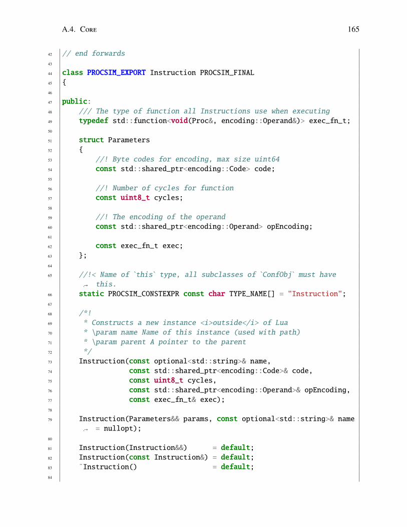
A.4. Core 165
42 // end forwards
43
44 class PROCSIM_EXPORT Instruction PROCSIM_FINAL45 {
46
47 public:48 /// The type of function all Instructions use when executing
49 typedef std::function<void(Proc&, encoding::Operand&)> exec_fn_t;50
51 struct Parameters52 {
53 //! Byte codes for encoding, max size uint64
54 const std::shared_ptr<encoding::Code> code;55
56 //! Number of cycles for function
57 const uint8_t cycles;58
59 //! The encoding of the operand
60 const std::shared_ptr<encoding::Operand> opEncoding;61
62 const exec_fn_t exec;63 };
64
65 //!< Name of `this` type, all subclasses of `ConfObj` must havethis.↪→
66 static PROCSIM_CONSTEXPR const char TYPE_NAME[] = "Instruction";67
68 /*!
69 * Constructs a new instance <i>outside</i> of Lua
70 * \param name Name of this instance (used with path)
71 * \param parent A pointer to the parent
72 */
73 Instruction(const optional<std::string>& name,74 const std::shared_ptr<encoding::Code>& code,75 const uint8_t cycles,76 const std::shared_ptr<encoding::Operand>& opEncoding,77 const exec_fn_t& exec);78
79 Instruction(Parameters&& params, const optional<std::string>& name= nullopt);↪→
80
81 Instruction(Instruction&&) = default;82 Instruction(const Instruction&) = default;83 ˜Instruction() = default;84

166 Chapter A. Procsim headers
85 bool operator==(const Instruction& other) const;86
87 /// Name (mnemonic) for this instruction
88 inline const std::string& name() const { return *_name; }89 inline void set_name(const std::string& name) { _name = name; }90
91 inline const optional<std::string> name_opt() const { return_name; }↪→
92
93 inline const std::shared_ptr<encoding::Code> code() const { return_code; }↪→
94
95 /// Get the width of the code
96 const bytes codeWidth() const;97
98 /// Get the cycles per instruction call
99 inline const uint8_t cycles() const { return _cycles; }100
101 /// Get the encoding of the operand, if it exists
102 inline const std::shared_ptr<encoding::Operand> opEncoding() const{ return _opEncoding; }↪→
103
104 /// Get the execution function
105 inline exec_fn_t& exec() { return _exec; }106
107 private:108 optional<std::string> _name;
109
110 /// Byte codes for encoding, max size uint64
111 std::shared_ptr<encoding::Code> _code;
112
113 //! Number of cycles for function
114 const uint8_t _cycles;115
116 const std::shared_ptr<encoding::Operand> _opEncoding;117
118 exec_fn_t _exec;
119
120 friend std::ostream& operator<<(std::ostream& os, constInstruction& ins);↪→
121 };
122
123 export_smart_ptrs(Instruction)
124
125 PROCSIM_NAMESPACE_END

A.4. Core 167
126
127 #endif // PROCSIM_INSTRUCTION_HPP_

168 Chapter A. Procsim headers
Listing A.10: Source for procsim/core/Proc.hpp.
1 #pragma once
2 #ifndef PROCSIM_CORE_PROC_HPP_
3 #define PROCSIM_CORE_PROC_HPP_
4
5 /*!
6 * The following is part of the Procsim Library written and developed
7 * by Kevin Brightwell and Ramesh Raj under the supervision of
8 * Dr. Kenneth McIssac at Western University, Canada.
9 *
10 * \author Kevin Brightwell
11 *
12 * This software is provided as is and all rights are maintained by
13 * Kevin Brightwell
14 */
15
16 #include "procsim/Macros.hpp"
17 #include "procsim/Types.hpp"
18
19 #include <memory>
20 #include <string>
21 #include <unordered_map>
22 #include <unordered_set>
23
24 PROCSIM_NAMESPACE_START
25
26 // Forwards:
27 namespace time28 {
29 class Clock;30 } // time
31
32 namespace memory33 {
34 class MemoryUnit;35 class Register;36 } // memory
37
38 class Instruction;39
40 namespace conf41 {
42 class ProcBuilder;

A.4. Core 169
43 } // conf
44
45 // end forwards
46
47 class PROCSIM_EXPORT Proc PROCSIM_FINAL48 {
49
50 public:51 //!< Name of `this` type, all subclasses of `ConfObj` must have
this.↪→
52 static PROCSIM_CONSTEXPR const char TYPE_NAME[] = "Proc";53
54 /*!
55 * Constructs a new instance <i>outside</i> of Lua
56 * \param name Name of this instance (used with path)
57 * \param parent A pointer to the parent
58 */
59 Proc(const std::shared_ptr<time::Clock>& procClock,60 const std::string& name,61 const named_map<time::Clock>& clocks,62 const named_map<Instruction>& instructions,63 const named_map<memory::Register>& registers,64 const
std::unordered_set<std::shared_ptr<memory::MemoryUnit>>&
memory);
↪→
↪→
65
66 Proc(Proc&&) = default;67 Proc(const Proc&) = default;68
69 ˜Proc() = default;70
71 bool operator==(const Proc& other) const;72
73 const std::string& name() const PROCSIM_NOEXCEPT;74
75 const std::shared_ptr<time::Clock>& procClock() constPROCSIM_NOEXCEPT;↪→
76
77 const named_map<time::Clock>& clocks() const PROCSIM_NOEXCEPT;78
79 const named_map<Instruction>& instructions() constPROCSIM_NOEXCEPT;↪→
80
81 const named_map<memory::Register>& registers() constPROCSIM_NOEXCEPT;↪→

170 Chapter A. Procsim headers
82
83 const std::unordered_set<std::shared_ptr<memory::MemoryUnit>>&memory() const PROCSIM_NOEXCEPT;↪→
84
85 private:86 const std::string _name;87
88 const std::shared_ptr<time::Clock> _procClock;89
90 /// all known clocks
91 const named_map<time::Clock> _clocks;92 const named_map<Instruction> _instructions;93 const named_map<memory::Register> _registers;94 const std::unordered_set<std::shared_ptr<memory::MemoryUnit>>
_memory;↪→
95
96 friend class conf::ProcBuilder;97 friend std::ostream& operator<<(std::ostream& os, const Proc&
proc);↪→
98 };
99
100 PROCSIM_NAMESPACE_END
101
102 #endif // PROCSIM_CORE_PROC_HPP_

Curriculum Vitae
Name: Kevin Brightwell
Post-Secondary The University of Western OntarioEducation and London, ON
Degrees: 2009 - 2015 BESc. Computer EngineeringBSc. Computer Science
The University of Western OntarioLondon, ON2015 - 2017 MESc.
Honours and Ontario Graduate ScholarshipAwards: 2015-2016
Best Presentation - Software EngineeringElectrical and Computer Engineering Graduate SymposiumSpring 2016
Related Work Limited Duties InstructorExperience: Data Structures and Algorithms for Software Engineering
The University of Western OntarioWinter 2017
Teaching AssistantThe University of Western Ontario2015 - 2016
171