IoT Smart Room Temperature Based Microcontroller
13
Progress in Engineering Application and Technology Vol. 2 No. 2 (2021) 1169-1181 © Universiti Tun Hussein Onn Malaysia Publisher’s Office PEAT Homepage: http://penerbit.uthm.edu.my/periodicals/index.php/peat e-ISSN : 2773-5303 *Corresponding author: [email protected] 2021 UTHM Publisher. All right reserved. penerbit.uthm.edu.my/periodicals/index.php/peat IoT Smart Room Temperature Based Microcontroller Nurain Hidayah Md. Nasir 1 , Dalila Misman 1 * 1 Department of Electrical Engineering Technology, Faculty of Engineering Technology, Universiti Tun Hussein Onn Malaysia, 84600 Pagoh, Johor, MALAYSIA *Corresponding Author Designation DOI: https://doi.org/10.30880/peat.2021.02.02.105 Received 02 January 2021; Accepted 01 March 2021; Available online 02 December 2021 Abstract: This project describe about the temperature control system that applied in the Smart Room Temperature. This Smart Room Temperature uses a microcontroller to produce an automation function. This project uses a microcontroller as it is the main component. The PIC18F45K22 is used where it able to control the heater and cooler that it received the command from the coding that burn into the microcontroller. The system is equipped with the real time monitoring which is use a Bluetooth technology where the Bluetooth will send the data to the user. This can be consider as one of the IoT platform that the technology rising rapidly in this century. IoT is a network of physical objects or items embedded in electronic devices, sensors and network communication that allows data collection and sharing of these object. In this project, bulb and DC cooling fan were used as heater and cooler and the temperature sensor was used to measure the environment temperature. Heater and cooler will switch on depends on the current temperature. If the temperature is beyond the preset temperature, cooler will turn on while heater will turn on when the temperature below than preset temperature. Keywords: IoT, Microcontroller, Room Temperature, Monitoring 1. Introduction Malaysia is a country that is situated near the equator that has an average temperature about 27 °C and is rated as hot and humid all year round. Temperature rises above 30 °C and drop rarely below 20 °C in the night.[1] Due to this problem, a room maybe can reach the temperature equal with the outside temperature and this can be solved by design and implement a microcontroller based room temperature where the temperature sensor is use to detect the temperature of the room. User will receive a notification about the real time temperature at the moment via a mobile phone. The system will alert the room user if the room temperatures are below or above the limit that set into the system. A heater and cooler will turn off depends on the temperature surrounding and it also depends on the temperature that user decide to be the desire temperature. There will be an alarm for this system as it is the warning for the user. This alarm will alert the user as the surrounding temperature is surpassing the maximum
-
Upload
khangminh22 -
Category
Documents
-
view
2 -
download
0
Transcript of IoT Smart Room Temperature Based Microcontroller

Progress in Engineering Application and Technology Vol. 2 No. 2 (2021) 1169-1181
© Universiti Tun Hussein Onn Malaysia Publisher’s Office
PEAT
Homepage: http://penerbit.uthm.edu.my/periodicals/index.php/peat
e-ISSN : 2773-5303
*Corresponding author: [email protected] 2021 UTHM Publisher. All right reserved. penerbit.uthm.edu.my/periodicals/index.php/peat
IoT Smart Room Temperature Based Microcontroller
Nurain Hidayah Md. Nasir1, Dalila Misman1*
1Department of Electrical Engineering Technology, Faculty of Engineering
Technology,
Universiti Tun Hussein Onn Malaysia, 84600 Pagoh, Johor, MALAYSIA
*Corresponding Author Designation
DOI: https://doi.org/10.30880/peat.2021.02.02.105
Received 02 January 2021; Accepted 01 March 2021; Available online 02 December 2021
Abstract: This project describe about the temperature control system that applied
in the Smart Room Temperature. This Smart Room Temperature uses a
microcontroller to produce an automation function. This project uses a
microcontroller as it is the main component. The PIC18F45K22 is used where it able to
control the heater and cooler that it received the command from the coding that burn into
the microcontroller. The system is equipped with the real time monitoring which is
use a Bluetooth technology where the Bluetooth will send the data to the user.
This can be consider as one of the IoT platform that the technology rising rapidly
in this century. IoT is a network of physical objects or items embedded in electronic
devices, sensors and network communication that allows data collection and
sharing of these object. In this project, bulb and DC cooling fan were used as
heater and cooler and the temperature sensor was used to measure the
environment temperature. Heater and cooler will switch on depends on the current
temperature. If the temperature is beyond the preset temperature, cooler will turn
on while heater will turn on when the temperature below than preset temperature.
Keywords: IoT, Microcontroller, Room Temperature, Monitoring
1. Introduction
Malaysia is a country that is situated near the equator that has an average temperature about 27 °C
and is rated as hot and humid all year round. Temperature rises above 30 °C and drop rarely below 20
°C in the night.[1] Due to this problem, a room maybe can reach the temperature equal with the outside
temperature and this can be solved by design and implement a microcontroller based room temperature
where the temperature sensor is use to detect the temperature of the room. User will receive a
notification about the real time temperature at the moment via a mobile phone. The system will alert
the room user if the room temperatures are below or above the limit that set into the system. A heater
and cooler will turn off depends on the temperature surrounding and it also depends on the temperature
that user decide to be the desire temperature. There will be an alarm for this system as it is the warning
for the user. This alarm will alert the user as the surrounding temperature is surpassing the maximum
Nasir et al., Progress in Engineering Application and Technology Vol. 2 No. 2 (2021) p. 670-684
1170
temperature that user decide. User also will receive a notification about it where they can check it
through the mobile phone.
2. Literature Review
IoT refers to the networked links between everyday things, often fitted with global intelligence. IoT
would increase the size of the Internet by incorporating all objects for interaction through an embedded
system, leading to a massively distributed network of devices that connect with human and other devices.
[2] This concept of IoT the focus of this Internet is to make it universal. The internet is one way to grow
from an automation platform, through which new advances are made through which the system can be
easily monitored and controlled using internet. Next, temperature sensing is use as it is very important
in this project. Temperature detector is a devices and technology that able to detect the temperature
surrounding. A temperature detector is a temperature sensor that design to measures the temperature of
its environment and become an input data in which it can be record or give signal. Besides, temperature
in this study is important as the smart room temperature needs to provide a suitable temperature for
everyone and also it depends on compatibility of the user. Temperature is the degree or strength of heat
that present in a material or object , particularly that measured on a scale that has been modified and can
indicated by using a tool for example a thermometer and can be felt by touching the skin directly. For
human body health, it can be indicated about someone’s health that is their body temperature [3]
(embedded non-contact body [6]).
Microcontroller is use in this project as it is the main component in this system where PIC
microcontroller that use in this project is PIC18F45K22. PIC microcontroller is used as it can be
configured to perform a large range of tasks and can be programmed as a timer or as production line
control. When use PIC microcontroller, it has the capability to track and regulated defined space
temperature without any human interference. Also, it able to control the temperature of an area
automatically where the temperature sensor can detect the temperature surrounding and the PIC
controller will give instruction to the other system about what to do.
For microcontroller, it is important to look at each of the pin. This microcontroller has 40 pins
where each of the pin has its own function and some of the pins are input while some is output [4]. It
introduces the design that improve this microcontroller to logical choice for a lot of performance.
During the operation, it can be include in a range of features that important to lessen the consumption
of power. The data EEPROM can be up to 1024 Bytes and the memory of program can stand for a lot
of thousand erase and write cycles. Under the internal software control, this device able to write its own
program memory space [5].
Bluetooth technology is use in this project as it can send notification to the user. Bluetooth is a
standard in wireless technology which connects devices together and exchanges data over a certain
distance. A Bluetooth device uses radio waves to connect to a computer or phone instead of wires or
cables. The concept for this Smart Room Temperature is similar with the automatic temperature control
system in which the temperature control system is need the temperature of a material be controlled to
produce an acceptable product. The controlled variable, ‘temperature’ in this case is measured by an
appropriate sensor and will converted to a signal suitable to the controller. The controller compared the
temperature signal to the desired temperature that is the setpoint and the final control unit is controlled.
The temperature can be control more efficiently that it can achieve it maximum productivity by using a
sensor that is temperature sensor. The microcontroller will take millisecond to respond and with the
increasing temperature, the temperature sensor will produce linear voltage signal. This is because the
microcontroller received signal from the temperature sensor that is L35 to compare the temperature of
pre-set value. By doing that, it will determined which devices should be switch on either the heater or
cooler.
The concept for this Smart Room Temperature is similar with the automatic temperature control
Nasir et al., Progress in Engineering Application and Technology Vol. 2 No. 2 (2021) p. 670-684
1171
system in which the temperature control system is need the temperature of a material be controlled to
produce an acceptable product. The controlled variable, ‘temperature’ in this case is measured by an
appropriate sensor and will converted to a signal suitable to the controller. The controller compared the
temperature signal to the desired temperature that is the setpoint and the final control unit is controlled.
The temperature can be control more efficiently that it can achieve it maximum productivity by using a
sensor that is temperature sensor. The microcontroller will take millisecond to respond and with the
increasing temperature, the temperature sensor will produce linear voltage signal. This is because the
microcontroller received signal from the temperature sensor that is L35 to compare the temperature of
pre-set value. By doing that, it will determine which devices should be switch on either the heater or
cooler.
2.1 Previous project related to the smart room
The previous automatic temperature control system project shows the similar characteristic with
this project and is used in the literature reviews.
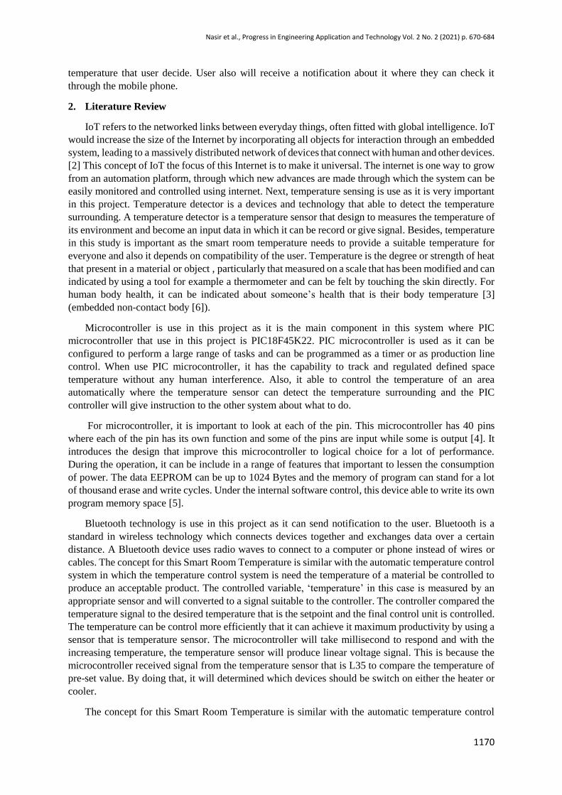
2.1.1 Development of a Microcontroller Based Smart Temperature Controller by Md Nahid Hassan
In this project, he develop a microcontroller based smart temperature controller where he use
microcontroller based embedded system According to him, this project can be used for the temperature
automation control system for example in chemical industry or a place to manufacturing papers. Based
on this project, he also make a prototype for the smart temperature controller. The input to the
comparator is the set temperature which the comparator will decide the output whether to turn on or off
the heater and cooler whereas the cooler and heater connected to the comparator. As for his project, one
of the components that he used is PIC microcontroller. The result that he got is according to his objective
where to develop software for the proposed system and also to develop a hardware circuit use
microcontroller.[6]
Figure 1: The circuit for the prototype by Mohd Nahid Hasan
2.1.2 Design an Automatic Temperature Control System for Smart Electric Fan Using PIC by Zairi
Ismael Rizman, Kim Ho Yeap, Nuraiza Ismail, Norizan Mohamad, Nur Hafizah Rabi’ah Husin
For this project, the authors wrote about the automatic temperature control system but only using a
smart electric fan. Microcontroller is used where the control system has an automatic operation. The
system also can be an alarm if emergency case happen and the alarm will be activated if fire is detected.
Nasir et al., Progress in Engineering Application and Technology Vol. 2 No. 2 (2021) p. 670-684
1172
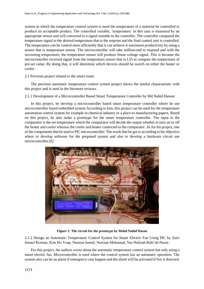
The automatic fan will turn on depends on the surrounding temperature changes especially when the
temperature is beyond the preset temperature. The LEDs and fans depends on each of the temperature
where it has two temperature sensor that is temperature sensor A and temperature sensor B. For
example, if the temperature sensor A detect higher temperature than the preset whilst the temperature
sensor B detect lower than the preset, the LED and fan A will on while nothing happen on the other [7].
Table 1: The table for the condition of Smart Electric Fan
2.1.3 A microcontroller-based Room Temperature Monitorinng System by Theophilus Wellem, Bhudi
Setiawan
Microcontroller based room temperature monitoring system was implemented using a
microcontroller, Atmel Atmega8535 microcontroller to be precise. This project can send and receive
text message because the system equipped with a Waveform GSM modem and also to control the
equipment of the electronic relay is used. The temperature that in the system set is 28°C which the alarm
will turn on and alert message will be send to the administer. To control electronic equipment that is
limited to certain control, on and off control where the administrator can send text message to it where
the equipment connected to the relay board and the administrator can get a feedback or status about it
either on or off. With this, the administrator able to monitor the server room temperature and also can
control the appliances of the electronic in real-time via text message [8].
2.1.4 Design and Simulation of Automatic Temperature Control and Alert System Based PIC16F887
by Jabbar Shaati Jahlool
In this project, micrcocontroller PIC16F887 was used where the ventilation, cooling, heating and
alarm system were controlled by the microcontroller. The speed of fan depends on the temperature
where if the temperature is high, the fan will operate at high speed. This system equipped with a
monitoring server room where GSM modem is implemented and able to send the text to the user by
displaying the temperature of the room. Also, this system also has an alert system where it give warning
to the user if certain temperature rises and enter a danger zone. This system is simulated by using Proteus
software and mikroc PRO FOR PIC.[9]

Nasir et al., Progress in Engineering Application and Technology Vol. 2 No. 2 (2021) p. 670-684
1173
Figure 2: Simulation circuit by using Proteus Software
3. Methodology
This project presents the concept and the system design of this project. The plan of the project is
need to be done to defining the details and specification such as hardware and software. The objective,
scope project and problem statement are analyses and listing out. Literature review then is the next step
where referred to the previous researches that have topic related to this project. Literature review
basically is the summary about the related previous researches. After that, methodology is implemented
and solve about the hardware and software. If the testing and troubleshoot working well the process
come to the end but if there is a problem happen, it will back to the interface of the hardware and
software.
3.1 Block Diagram of Control System
Figure 1 shows the block diagram of the control system for this project that have three part consist
of input, process and output. The input for this project has two that are power supply unit and
temperature sensor unit. It has two controller that are automatic controller and manual controller where
the automatic controller is the simulation while the manual controller is the hardware setup. Both of the
controller need a power source to activate the project and the user need to decide which one need to use
either manual or automatic. Tempearture sensor that is LM35 also an input which it detect the
temperature around it.
For the automatic controller, it will run the program automatically where the PIC microcontroller
receive the signal from the software where the coding is program into the microcontroller and will
control the outcome of it that is the output which are LCD, alert system, heater and cooler. For
temperature sensor, as soon as it detect the temperature, the output will turn on and off depends on the
preset temperature that the user set. As for the manual controller, the program run manuually where the
process almost the same as the automatic controller except it has a bluetooth module. The bluetooth
module will receive the signal from the microcontroller and it will alert user by sending notification via
the mobile phone.

Nasir et al., Progress in Engineering Application and Technology Vol. 2 No. 2 (2021) p. 670-684
1174
In Figure 4 shows a flowchart of smart room temperature with the notification to the user. The
operation of the smart room clearly shows in the flowchart below where after all the port initialize, the
sensor will detect the temperature and with that the user will get a notification. The notification that
user received is from the mobile phone where the user can receive it via a pop-up message. Next, after
the temperature is taken, the system will decide what should be turn on and switch off according to the
temperature that just has taken. There are three condition for this which are less than preset temperature
and more than preset temperature and maximum temperature.
However, if the temperature goes more than maximum temperature to be exact whereas consider it
as critical temperature. If the temperature lower than preset temperature or the setting temperature,
heater will be turn on as the cooler will be turn off. By this, the user will receive notification through
the mobile phone where message will be the interface for it. If the temperature higher than the setting
temperature or more than preset temperature, the cooler will be turn on as the temperature surrounding
is getting hotter. Whilst the cooler is turn on, the heater will be turn on and this also make sure that the
user get the notification via mobile phone. Anyhow, if the temperature reaches a critical point of the
temperature for example we set at 29 °C, so, the system will make the buzzer switch on while the LED
will blink continuously. Buzzer and LED will act as an alarm as they would give a warning to the user.
As for this, the notification also will sent to the user to make them alert with what is happening.
Figure 3: Block diagram of the project
Temperature sensor unit
Power Supply
Unit
Drivers and
Relays
Alert
system
(buzzer
and LED)
Manual
Controller
Automatic
controller
Alert
system
(buzzer
and LED)
Cooling
appliance:
Fan
Heater
appliance:
Bulb
Heater
appliance:
Bulb
Drivers and
Relays
Cooling
appliance:
Fan
PIC UNIT
PIC UNIT
Bluetooth module
Display
unit LCD
Display
unit LCD
OUTPUT PROCESS
OUTPUT PROCESS INPUT

Nasir et al., Progress in Engineering Application and Technology Vol. 2 No. 2 (2021) p. 670-684
1175
Figure 4: Flowchart
4. Result and Discussion
4.1 Software Layout
The circuit was sketch in the Proteus just like in the Figure 2 where the main component that we
focus on is PIC microcontroller that is PIC18F45K22. The microcontroller will read the temperature
continuously as we have the temperature sensor that connect with it and it will compare the current
temperature with the desired value of the temperature that we set. All the pin connection is important
as it can affect the result of our project. LCD display the desired value that we set and the temperature
and it is connect to the PORTC at the microcontroller while the temperature sensor is connect to the
analog input pin AN0/ RA0.[10] At the PORTB the keypad is connect to it. Relay and transistor is
important as it can control the heater and the cooler. It connected to the microcontroller at the pin RD0
and also RD. To set the preset temperature, user must press the number according to the temperature
that they desired by using the keypad in the simulation. After entering the desired number, user must
press “#” as it act as the button enter. Bulb in this simulation will act as the heater while the fan will act
as the cooler.
END
Initialize port
>maximum
temperature
>preset
temperature
<preset
temperature
Read temperature
Sent notification to the
user
1. Heater ON 2. Cooler OFF
3. Notification to user
1. Cooler ON 2. Heater OFF 3. Notification to user
1. Buzzer ON 2. LED blink
3. Notification to user
Figure 4: Flowchart of Smart Room
Temperature
START

Nasir et al., Progress in Engineering Application and Technology Vol. 2 No. 2 (2021) p. 670-684
1176
Figure 5: A circuit design of the project in the Proteus
Figure 3 is the simulation for the heater where the heater is switch ON when the temperature is
lower than the preset temperature. In this simulation, the preset temperature is 12 °C where any
temperature that lower than the preset temperature the heater will switch ON while the cooler will
OFF for the entire simulation. LED and buzzer also will switch ON if the temperature is lower than
the preset temperature. Next, for the Figure 4 is the simulation for the fan where the fan was switch
ON due to the temperature that higher than the preset temperature. As for this simulation, the heater
was switch OFF likewise the buzzer and LED. However, buzzer and LED will turn ON if the
temperature reach or surpass the maximum temperature. In this condition where the temperature is
same or higher than the maximum temperature, the fan will also turn on while the heater is turn ON.
This can be shown in Figure 5.
Figure 6: Simulation of the heater

Nasir et al., Progress in Engineering Application and Technology Vol. 2 No. 2 (2021) p. 670-684
1177
Figure 7: Simulation of fan
Figure 8: Simulation of the alarm system that are the buzzer and LED
To get the simulation result in the Proteus, MicroC Software was used in this project as the coding
need to program into the microcontroller in the Proteus. When the coding is uploaded in the
microcontroller, the system in the Proteus will run as the command and instruction in the coding that
build through MicroC. Figure 9 shows the parts of the coding in the MicroC programming where it
showed which pin of the microcontroller that act as the input and output. PORTC, PORTB and PORT
D as an input. AN0 (RA0) is the analog input pin. As for the output is the RD0 output for the heater,
RD1 is the output for the fan, RD3 is output for the LED. For the right figure, it shows about the coding
for the maximum value temperature. In this coding, user can set any number for the maximum
temperature depends on their preference. For example, in this simulation, we set 29° C as the maximum
or critical value.

Nasir et al., Progress in Engineering Application and Technology Vol. 2 No. 2 (2021) p. 670-684
1178
Figure 9: Coding in the MicroC software that shows the input and output
The coding must be built to check any error in the coding. If any errors happen, all the commands
and instruction need to recheck. After running the program once again and there is no error, it will show
the message at the bottom of the coding where it states the coding is built successfully. After the coding
has no error, the hex file then will upload in the microcontroller in the Proteus software.
4.2 Hardware layout
The coding needs to upload and burn into the real microcontroller. Thus, MicroC suite programming
is used in this project as it able to program the coding into the microcontroller by using the USB. Figure
10 shows the MicroC Suite that used in this project. By using that, we can choose microcontroller that
we use so it able to burn the coding successfully.
Figure 10: The MicroC Suite
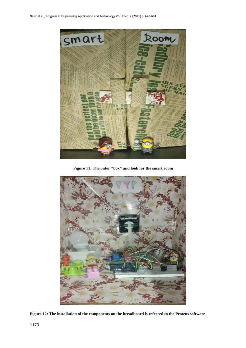
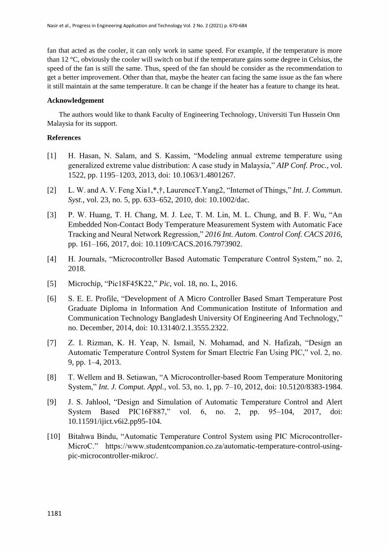
Figure 11 shows outer box and view of the smart room temperature where it can contemplate as the
smart room temperature. As for the Figure 12 it shows the installation of the components on the
breadboard that referred to the Proteus circuit. Each of the components need to position same as the
circuit in the Proteus. Each pin of the components are important as some of the components have
polarity of positive and negative and some of it must connect to the power supply and ground. The most
important thing is the pin configuration of the PIC18F45K22 microcontroller. The connection of each
components on the breadboard will determine the result of the project. Table 2 shows the result of this
project where it clearly shows which of the output turn are ON or turn OFF depends on the temperature.
Nasir et al., Progress in Engineering Application and Technology Vol. 2 No. 2 (2021) p. 670-684
1179
Figure 11: The outer "box" and look for the smart room
Figure 12: The installation of the components on the breadboard is referred to the Proteus software

Nasir et al., Progress in Engineering Application and Technology Vol. 2 No. 2 (2021) p. 670-684
1180
Table 2: The result from the project
Temperature (°
C)
Heater
Cooler
Alarm(buzzer
& LED)
<Preset
temperature
11° C
ON OFF OFF
Preset
temperature
12° C
OFF ON OFF
>Preset
temperature
24° C
OFF ON OFF
Maximum
temperature
29° C
OFF ON ON
>Maximum
temperature
30° C
OFF ON ON
5. Conclusion and Recommendation
5.1 Conclusion
The objective of this project is to design a smart room that can control its temperature depends on
the surrounding where the user can monitor the temperature through real time monitoring which the
microcontroller-based control system that able to modulate the temperature within a specific range.
Research through the microcontroller is done to make sure the microcontroller is suit for the project. A
suitable sensor is choose for this project where it is suitable with the surrounding temperature. The
microcontroller and sensor then were installed in this project as both of it are the important input to get
the outcome for this project. Then, the user can evaluate the performance by observing the control
system by using a Bluetooth that has connect with the mobile phone. By this, the user can check whether
the heater or cooler will be switch on depends on the temperature. In order to make the mobile phone
able to connect with the Bluetooth, Bluetooth module is used in this project. This is the part of the IoT
where we can collect the data with a wireless network. The prototype that was design in this project
able to switch on the DC cooling fan and bulb that depends on the temperature.
However, there are some problem that I have to face when conducted this project which is the main
problem is the surrounding. Since the current weather is very unpredictable with the sudden rain that
make the surrounding temperature to drop. Sometime, the weather get quite hot the temperature
surrounding increase a few bit. Besides, there are some issue in this process where it involved the
component microcontroller itself. Since it is not widely used nowadays, it was quite hard to find some
of the important part that can make the microcontroller to functioning well and had to take a lot of
precaution for this microcontroller to avoid it from burn.
To summarize this project has achieved the objectives and the whole process and project was
successfully implemented where the simulation that is the software and the prototype that is hardware
able to run smoothly.
5.2 Recommendation
Even though this project progress can be counted as successful, it still needs some upgrade for the
future references. There are some issues and problem that can be improve to enhance the next related
project. To get a better system in future uses, some improvement can be introduce. For this project, it
would be great if it has a user friendly feature such as user able to change style and size of the font, has
a great design to make it interesting and something that user easy to understand. Next, the temperature
sensor selection for detect the temperature with high sensitivity is also recommended. Besides, for the
Nasir et al., Progress in Engineering Application and Technology Vol. 2 No. 2 (2021) p. 670-684
1181
fan that acted as the cooler, it can only work in same speed. For example, if the temperature is more
than 12 °C, obviously the cooler will switch on but if the temperature gains some degree in Celsius, the
speed of the fan is still the same. Thus, speed of the fan should be consider as the recommendation to
get a better improvement. Other than that, maybe the heater can facing the same issue as the fan where
it still maintain at the same temperature. It can be change if the heater has a feature to change its heat.
Acknowledgement
The authors would like to thank Faculty of Engineering Technology, Universiti Tun Hussein Onn
Malaysia for its support.
References
[1] H. Hasan, N. Salam, and S. Kassim, “Modeling annual extreme temperature using
generalized extreme value distribution: A case study in Malaysia,” AIP Conf. Proc., vol.
1522, pp. 1195–1203, 2013, doi: 10.1063/1.4801267.
[2] L. W. and A. V. Feng Xia1,*,†, LaurenceT.Yang2, “Internet of Things,” Int. J. Commun.
Syst., vol. 23, no. 5, pp. 633–652, 2010, doi: 10.1002/dac.
[3] P. W. Huang, T. H. Chang, M. J. Lee, T. M. Lin, M. L. Chung, and B. F. Wu, “An
Embedded Non-Contact Body Temperature Measurement System with Automatic Face
Tracking and Neural Network Regression,” 2016 Int. Autom. Control Conf. CACS 2016,
pp. 161–166, 2017, doi: 10.1109/CACS.2016.7973902.
[4] H. Journals, “Microcontroller Based Automatic Temperature Control System,” no. 2,
2018.
[5] Microchip, “Pic18F45K22,” Pic, vol. 18, no. L, 2016.
[6] S. E. E. Profile, “Development of A Micro Controller Based Smart Temperature Post
Graduate Diploma in Information And Communication Institute of Information and
Communication Technology Bangladesh University Of Engineering And Technology,”
no. December, 2014, doi: 10.13140/2.1.3555.2322.
[7] Z. I. Rizman, K. H. Yeap, N. Ismail, N. Mohamad, and N. Hafizah, “Design an
Automatic Temperature Control System for Smart Electric Fan Using PIC,” vol. 2, no.
9, pp. 1–4, 2013.
[8] T. Wellem and B. Setiawan, “A Microcontroller-based Room Temperature Monitoring
System,” Int. J. Comput. Appl., vol. 53, no. 1, pp. 7–10, 2012, doi: 10.5120/8383-1984.
[9] J. S. Jahlool, “Design and Simulation of Automatic Temperature Control and Alert
System Based PIC16F887,” vol. 6, no. 2, pp. 95–104, 2017, doi:
10.11591/ijict.v6i2.pp95-104.
[10] Bitahwa Bindu, “Automatic Temperature Control System using PIC Microcontroller-
MicroC.” https://www.studentcompanion.co.za/automatic-temperature-control-using-
pic-microcontroller-mikroc/.