A neural-network appearance-based 3-D object recognition using independent component analysis
Upload
khangminh22Category
view
4download
0
University of Pennsylvania University of Pennsylvania
ScholarlyCommons ScholarlyCommons
Technical Reports (CIS) Department of Computer & Information Science
December 1980
Computer Architecture for Object Recognition and Sensing Computer Architecture for Object Recognition and Sensing
David James Brown University of Pennsylvania
Follow this and additional works at: https://repository.upenn.edu/cis_reports
Recommended Citation Recommended Citation David James Brown, "Computer Architecture for Object Recognition and Sensing", . December 1980.
University of Pennsylvania Department of Computer and Information Science Technical Report No. MS-CIS-80-22.
This paper is posted at ScholarlyCommons. https://repository.upenn.edu/cis_reports/724 For more information, please contact [email protected].

Computer Architecture for Object Recognition and Sensing Computer Architecture for Object Recognition and Sensing
Abstract Abstract The notion of using many, most likely different, sensory subsystems in a computer object recognition system immediately provokes several questions:
- How will multiple sensors be used in conjunction?
- What object qualities are best described by which sensor, and how is sensor utilization optimized?
- To what extent does the information provided by each sensor overlap with that provided by others, and how then is this used?
Comments Comments University of Pennsylvania Department of Computer and Information Science Technical Report No. MS-CIS-80-22.
This technical report is available at ScholarlyCommons: https://repository.upenn.edu/cis_reports/724

University of Pennsylvania
The Moore School of E lec t r ica l Engineering
Computer Architecture f o r Object Recognition and Sensing
David James Brown
Presented to the Faculty of the Department of Computer and Information Science i n the College of Engineering and Applied Science, in p a r t i a l fulf i l lment of the requirements f o r the degree of Master of Science in Engineering.
Philadelphia, Pennsylvania
December, 1980
Thesis Supervisor /
Graduate Group C h a i m n

Ccmputer Architecture for Object Recognition and Sensing
David James Brown
December 1980
Table of Contents -- I. Abstract
Pa r t I -- Introduction
1.1 Unifying Issues
11. Hierarchical Systems - A Central Theme
2.1 Relevance to Object Recognition Gystems 2.2 S t r a t i f i e d Architecture - Vir tua l Machines 2.3 Beneficial Consequences of S t r a t i f i e d Architecture
111. The Design of an Object Recognition System
3.1 Fundamental Objectives 3.2 Description 3.3 &cognition
3.3.1 Production Systems
3.4 Control, Cmun ica t i on and Representation 3*4.1 Representational Structures 3.4.2 Fuzzy Automata
3.5 m u t e r Architecture of an Object Recognition System 3.6 Per t inent Pr inciples
P a r t I1 -- The Design and Implementation of a Tac t i l e sensing' System - - --
I. Overview
1.1 Ihe Tact i l e Sensing System Placed i n Perspective 1.2 Organization of Control 1,3 Prescr ip t to the Technical Discussion
11. me Control Unit
2.1 Inside the Control Unit 2.1.1 The 2-80 Microprocessor 2.1.2 Control Unit Interprocessor Interface
2.2 Interface to MIU and TIU 2.2.1 MB to MIU in te r face 2.2.2 TSP to TIU in te r face
2.3 Interface to 'host ' Recognition System 2.3.1 MB to H o s t 2.3.2 TSP to Host . 2.3.3 m>P 11 Am and Host Interface Enhancement
111. The Motor In te r face Unit ( M I U )
3.1 The M I U Main Board 3.1.1 Stepping Motors - A Brief Introduction
to Function and U s e
3.2 !Ihe Auxiliary Board 3.3 Front Panel Display 3.4 Power Supply
N. The T a c t i l e In te r face Unit (TIU)
V. The Mechanical Posi t ioning System
5.1 Mechanical Provision f o r Movement 5.2 A m and Sensor 5.3 m a n c e d T a c t i l e Control
VI. Sunanary and Results
6.1 Sumnary of the Work 6.2 Results
Appendix - A
(Technical Information from L.A.A.S. - Touiouse, France)

Introduction
?he notion of using many, most l i k e l y d i f f e r en t , sensory subsystems i n
a computer ob jec t recognition system imnediately provokes several
questions :
- Haw w i l l multiple sensors be used i n conjunction?
- What ob jec t q u a l i t i e s are bes t described by which sensor, and how is sensor u t i l i z a t i o n optimized?
- To what ex ten t does the information provided by each sensor overlap with that provided by others , and how then is t h i s used?
1.1 Unifying Issues -
Several of these topics have c o m n a l i t y with analogous problems i n
the areas of manipulator control , control theory, dis t r ibu ted computer
archi tecture , and generally, robotics. We have attempted to draw w e t h e r ,
compactly and concisely, a sumnary of the major unifying issues involved i n
this type of coordinated subsystem control:
Plann i ncr
- How do we evolve act ions which approach the so lu t ion of system goals.
Control
- How is sensor control ca r r ied o u t - how a r e sensory subsystems orchestrated - W i l l susbsystems be mostly autonomus, or receive a g r ea t deal of d i r ec t i on from a higher l eve l - How is control par t i t ioned ulroughout the various l eve l s of the system

Representation - and Knowledge
- How is knowledge incorporated, and a t what l eve ls of the system - Haw does knowledge r e l a t e to planning and control issues - How is information (object character is t ics , perceived sensory features) described. Ibes t h i s vary as it moves through the system, and i f so how?
Ccmnunica t ion
- What a r e the paths of knowledge t ransfer . - Does information t ransfer imply a representational t ransi t ion? - Haw is compatibility of sensor-derived information achieved a s it w e s toward, and is ultimately incorporated into , high-level descriptions?
Many, if no t a l l , of the above issues a r e d i f f i c u l t t o resolve. It is
cer ta in t h a t they w i l l remain within research i n t e r e s t f o r some time to
come. Secondly, it is highly important to r ea l i ze the in te r re la t ion of
each of the above issues and categories. While we may approach solutions
the problem of designing such a system by giving consideration to these
issues separately, it is qu i t e clear that decisions made i n any category
have inmediate consequence i n others. For example, i f we decide to enact a
par t icular control s t ructure , t h i s w i l l mandate cer ta in paths of
ccmmunication. Similarly, planning and control are closely interrela ted,
Planning s t r a t eg i e s imply that ce r t a in control be available to carry ou t
these plans. Most generally, we can say t h a t it is important to consider
the solution to such a design problem as being a cooperative one - one
which e f fec t ive ly incorporates solutions to a l l problems : planning,
control, representation, and comunication, in to an integrated unified
system.

Hierarchical Systems - A Central Theme --
A s may be intuited from what has already transpired in t h i s
discussion, a notion of 'llevels" is h p r t a n t to a system of the type we
are designing. In fact , hierarchy is a central theme in almost a l l
computer systems tha t presently exist. It is 03m practice to place such
levels of software a s are necessary to bring that p i l e of sol id state
semiconductor devices, amrously termed "computer", "up to the leveln where
it can be used effectively. Namely, said machine can execute instructions
that require a minimal (or "reasonable") amount of e f f o r t on the pa r t of
same operator (usually human) to specify some requisite task. Plainly, we
a re discussing "power of instruction set". The aim of a r t i f i c i a l
intelligence proponents is to make a task description for computer system
be as close a s possible to the manner of specifying it to another human.
2.1 Felevance t o Object Recognition Systems - -
Let us now discuss the importance of hierarchical systems as it
relates t o performance of object recognition. It is generally agreed that
systems of the type proposed - namely recognition systems based on
multisensing, w i l l be multilevel ones. That is, we may consider our system
to have a fundamentally hierarchical structure about it. Winston s t a t es
tha t "Intelligent programs are b u i l t upon many layers of information
processing". Why is th i s the case? There are goals which re la te to the
description and recognition of objects or scenes i n our systems, but these
ultimately reside a t a "level" above many underlying levels of subgoals and
actions. It is c lear that, a t the lowest level, very primitive operators

gather raw data from sensors by means of very low level opra t ions . I t is
the selective use and/or processing of th i s raw data that yields useful
information a t the next higher level. Processing is a term yet to be ful ly
exposed to l ight . What does processing of sensory information en ta i l , such
that it is relevant to the goal of object recognition? Primarily,
processing involves refinement (i.e. noise reduction, f i l te r ing , or
enhancement) a t the lowest level? This is incorporated with b l e d g e that
is a t f i r s t sensor specific, and progressively higher-level representation
or description specific. Knowledge, or more importantly, its incorporation
into the descriptive process (along with information derived from selected
raw data), is contextual i n t h i s regard. In the process of recognition, it
is through successive refinement, collaboration by other information
sources, and abstraction, that we ultimately "describe" the observed
object.
2.2 Strat i f ied Architecture - Virtual Machines - -
In the architectural context we may regard our system as a hierarchy
of vir tual machines [ l ] , each one more powerful than the one(s) below.
What do we mean by "powerful"? Simply, we can define the power of a
vir tual machine as the extent to which one of its primitives encompasses
the operative and/or descriptive capabil i t ies of primitives on lower level
vir tual machines. PaJer is a relat ive term. In a t radi t ional architecture
which supports one or several high level progranrning languages, several
levels are described:

-- Hardware - Level
0: (electronic devices) t ransis tors and sol id s t a t e devices
1: (logical en t i t i e s ) latches and gates
2: (Register Transfer Level) registers and processing elements
= Software = Level
3: (Machine Level) Machine language programs
4: (Assenbly Language Level) Assembly language programs
5: (Campilers and- Interpreters)
6 : (Righer Level '~rogramnin~ . . . ~ a n g k i ~ e s )
7 & above: Systems building upon Levels 0-6 (DBMS, A.I. systems, Mathematical and Sta t i s t i ca l Models etc.)
Everything below level 3 is f a i r l y r igidly fixed "hardware" in tha t it is
implemented in actual electronic devices and their composition. It is very
interesting to note the overwhelming importance of these low levels in
determining to a large extent the limitations, and ease of implementation
of hierarchically superior v i r tua l machines. Classically, all tha t
transpires a t and above level 3 is carried out in "software" - programs
which are mre eas i ly subject t o change. Ostensibly, levels 3, 4, and 5
are f a i r ly firm in a general purpose computer. I t is above the level of
higher level programning languages that special p r p o s e systems are
developed, and reside.
It is important t o real ize one point here, which w i l l be central t o
subsequent discussion: The progression from level 0 level k involves two
main trends tha t are of great importance. F i rs t , and motivational to the

1
developnent of higher l eve l machines, is that , ak w e m v e higher up the
archi tectural hierarchy, we gain f a c i l i t y i n the specif icat ion of tasks - power. Why then is not everything done a t the highest possible level , and
why i f t h i s is possible do we not continually evolve mre pawerful v i r t u a l
machines? While high l eve l v i r t u a l machines are increasingly powerful, the
pr ice is paid i n two ways: Abstraction from lower l eve l s occurs - we lose
the spec i f i c i t y of the lower levels . And specialization is inevitable
a f t e r l eve l 6 - systems are developed with spec i f ic intention; general i ty
must be lost. I n fac t , the observation can be made t h a t ce r t a in high leve l
(problem oriented) languages favor cer ta in applications m r e than others.
I f t h i s were not the case, f a r fewer such languages would ex is t .
2.3 Beneficial Consequences of S t r a t i f i ed Architecture - -
kt u s now examine the consequences of such an a rch i tec tura l schene
in so far as it is relevant to the design of an- object recogntion system.
One of the chief advantages of a hierarchical system is the increasing
power of operators as w e progress toward higher l eve l v i r t u a l machines.
These v i r tua l machines gain power by defining new primitives which explo i t
the capabi l i t i es of lower leve l v i r t u a l machines, i n conjunction with
processing. Other benef i ts are a s follows:
Benefits
1) Higher leve l v i r t u a l machines support operations which encompass g rea t e r scope.
2) Higher leve ls organize the use of lower l eve l systems, and hence -- reduce t h e i r complexity of use.
3) Distributed archi tecture affords the potent ia l exploitation of concurrent execution of low l eve l operations and tasks.

Interestingly, some of the af orementioned disadvantages tha t ex i s t in
l ight of hierarchical structure may also be of advantage in a system
performing recognition.
Further Benefits
1) High level control loses touch with the specif ic nature and de ta i l of l o w level tasks. This is beneficial i n tha t it ABSTRACTS from the l o w level detai ls .
2) Overhead for organization and coordination of the components of a distributed system is well invested. That is, it ultimately implements the basis of our control and comnunication structure.
Beside the clear advantages of hierarchical system structure i n
certain instances, we can point to several reasons why a such a scheme is
necessary i n t h i s instance. F i rs t , the complexity of a system employing
many diverse sensing devices, many representational schemes, and various
types of knowledge (knowledge relevant to sensing, relation between sensory
information, and ultimately high level descriptive Wwledge), w i l l be
great. In order to handle t h i s wrnplexity, a w e l l defined architectural
and organizational structure w i l l be required. The apparent multi-level
nature of the problem a t hand, is indicative that a likewise hierarchical
architecture and organization is called for. Second, there are tasks
within the scope of our system that are intr insical ly resident a t a given
conceptual level. For example, the control of sensors is one such case.
W e do not want t o burden the processor associated w i t h high level goals,
with such low-level sensor control tasks. W e would rather provide a
8
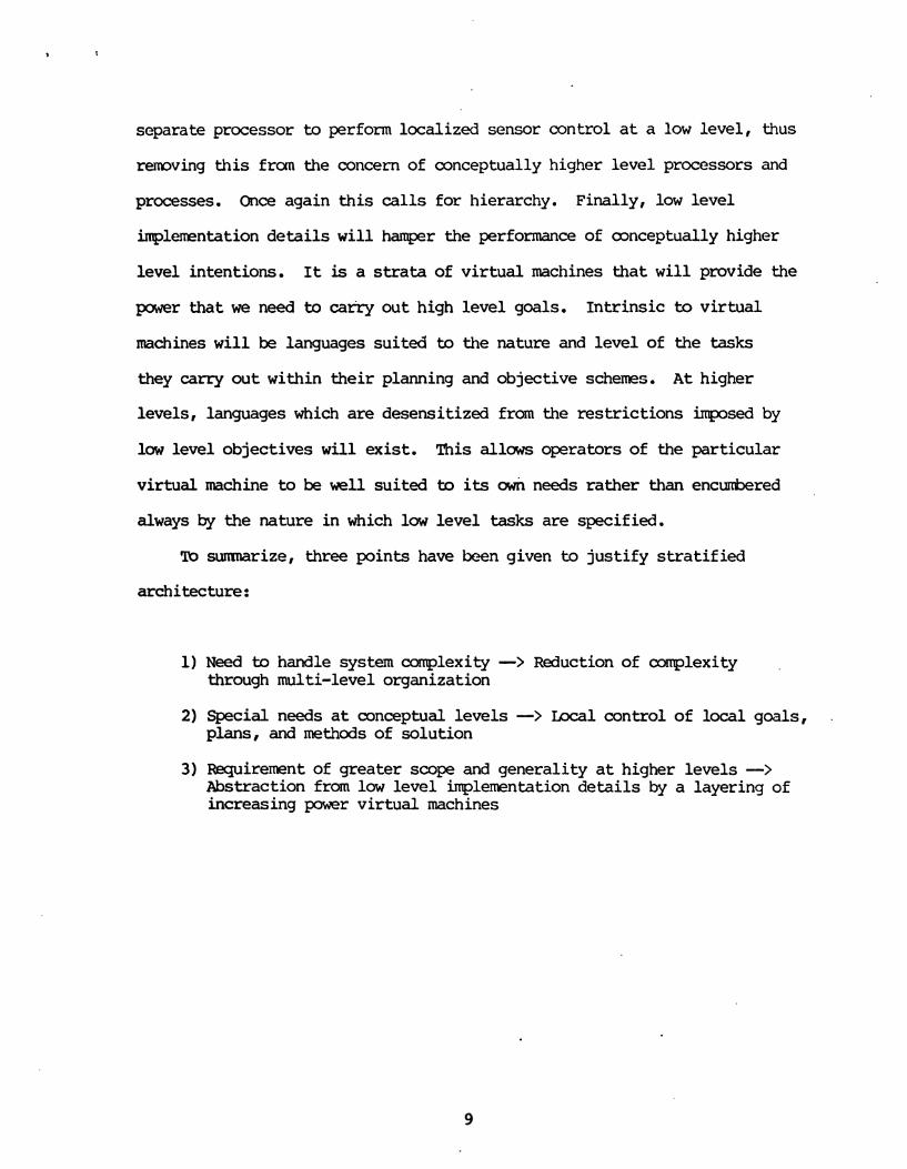
separate processor t o perform localized sensor control a t a l o w level, t h u s
remving t h i s from the concern of conceptually higher level processors and
processes. Once again t h i s c a l l s for hierarchy. Finally, low level
implementation de ta i l s w i l l hamper the performance of mnceptually higher
level intentions. It is a s t r a t a of v i r tua l machines that w i l l provide the
power that we need to carry out high level goals. Intr insic to vi r tua l
machines w i l l be languages suited to the nature and level of the tasks
they carry out within their planning and objective schemes. A t higher
levels, languages which are desensitized from the restr ict ions imposed by
low level objectives w i l l exist . This all- operators of the particular
vir tual machine to be we11 suited to its cmh needs rather than encurbered
always by the nature in which l o w level tasks are specified.
To sumnarize, three points have been given to just i fy s t r a t i f i ed
architecture:
1) Need b handle system complexity -> Reduction of complexity through multi-level organization
2) Special needs a t conceptual levels -> Local control of local goals, plans, and methods of solution
3) Requirement of greater scope and generality a t higher levels -> Abstraction from low level implementation de ta i l s by a layering of increasing power vi r tua l machines
111. fie Design of Object Recgnition Systems -- - -
Preliminary sections of this treatment have attempted to sensitize
some important issues (in particular, planning, the use and representation
of knowledge, control and comnunication) and intimated the importance of
multi-level system. It is now time to draw issues and inclinations
together, and elucidate that which we anticipate and aspire to, in the
design of a computer recognition system. In the section following this
one, strategies for carrying out the ideas contained in this one are
developed.
3.1 Fundamental Objectives -
A coa~lputer system for object recognition (herein after referred to as
an ORS), has as its functional objective the description and recognition of
objects, and to extend this, the description and, recognition of the
perceived environment. While the preceding statement sounds almost
tautological, the terms 'description' and 'recognition' are somewhat
unclear. We will need to elucidate the ideas of 'means' and 'level' of
description - the how and what of it, before we extend this by considering the notion of 'recognition'.
Description
In order to perform 'description' of an object, we would like to
provide a means of access to high-level properties or descriptors which
serve this function. This is to say, that while we may 'describe' an
obsenred object by specifying its locus of points in the region of

observation (or observation world), as a list of coordinate n-tuples
( t r ip les i n three-space), this , along with such other low-level information
as may be obtained, is not what we ultimately desire. For example, in the
diagram below (see figure #I), which is an object in a two-dimensional
observation w r l d , we may 'describe1 it as follows:
(111) (212) (313) (414) (413) (4t2) (411) (311) ( 2 1 1 ) *
This is acllieved as a resul t of applying orthogonal coordinate axes to the
observation region, and then p~mviding a list ( i n t h i s case ordered) which
provides the locus of points a t which the object resides in t h i s world,
with scene f i n i t e resolution (see figure #2).
A s the reader no doubt observes, the description given in th i s low-
level form is not the one which imnediately comes t o mind when one f i r s t
observes figure 1. W e would much rather receive the description
'.triangle, ' or sane other appropriate higher-level one. What we are
observing by t h i s example is the difference between a description which is
likely to be provided by a l o w level processor of the OS, and the m e
desirable high-level resul t which is convenient t o the human recognition
system. It is the application of generalization, categorization, and
knowledge association tha t achieves th i s recognition (as yet undefined),
that in turn yields the high level description which we desire. What is
m r e important here, is tha t raw data received from a potential low-level
ORS processor does not constitute a l l tha t w e desire in tha t object 's
description.
A s a second example, consider a list of coordinate t r ip les
'describingt an object in a three dimensional object world, with a
caponent-wise resolution of Irmr ( tha t is x,y,and z coordinates which are
components of t r ip les are specified to one m i l l i m e t e r precision) . The
object is a roughly spherical blob with granular surface (granules much
larger than lmn deep), and having approximate volume of 1000 cubic
centimeters. You can imagine that these t r ip les , whose resul tant
conglomeration enumerates a list of over one hundred thousand, is of
questionable worth i n so f a r a s giving an imnediate and clear understanding
of the object. There can be l i t t le debate, however, tha t such a list does
convey a rather expl ic i t detailed specification of the object - in fac t , a
description.
The problem w i t h this list is twofold: F i r s t , the description is a t
too l o w a level. Second, the resolution may be excessive, and hence the

work done by the sensory acquisit ion processor, which is roughly
quadratically re la ted i n giving the surface description, is f a r more
excessive. Consider a cube i n the same region which may be processed fo r
description i n the same fashion (Imn pointwise resolution with external
surface description of the cube). The resu l tan t list is c l ea r ly a gross
waste, as the cube may be equally w e l l described by specifying only two
points (any pair of diagonally opposed corners). I
What we must do to acceptably describe an object involves several
things alluded to by the words 'approximate velum', ' ra ther granular
surface', and 'roughly spherical blob', given i n the e a r l i e r decription of
that object. W e w i l l without doubt, however, invoke plans a t a l o w leve l
to perform raw da ta acquisition. Tnese plans and t h e i r inherent actions
underlie higher leve l plans which intend to perform several operations on
this retrieved l o w l e v e l informtion, in order to raise the l eve l of the
description.
* Associate pre-existing system knowledge with what is observed
Onit unnecessary low leve l da ta i n order to generalize
* &proximate where necessary by applying pre-existing 'means of description' (categorization or parameterized descriptions such as volume, texture, or other morphological or conceptual notions).
Stme of what is being suggested here incorporates the use of general
mans by which da ta is composed i n to less specif ic 'descr ipt ions a t a higher
system level . These descriptions may be somewhat vague ( tha t is, less
precise and de t a i l ed ) , but this is one means by which we gain
aforementioned power, and progress toward the real izat ion of higher leve l
descriptions i n higher leve l v i r t u a l machines. W e a r e performing

abstraction, which consists of a reduction, o r stripping away of some of
the detailed l o w level information. ' This m y be achieved by association of
knowledge to observation and inference of set menkership. Or, observed
de ta i l may be compacted by excepting description-irrelevant low level
informa tion.
Goals, and to implement them, must enact these ideas. Further,
multilevel planning seems essential in the accomplishmnt of these goals.
rxlw level system components w i l l have different goals than those of high
level components. The types of descriptions they deal with, and the manner
of handling these -- the i r s t rategies fo r accomplishment of objectives fo r
them, w i l l a l so be different. Figure #3 i l lus t ra tes a preliminary
breakdown of some of this intended planning hierarchy.
3.3 Recognition -
A s yet, we have not explained our understanding of 'recognition.'
What is it? Recognition, we think, involves the notion of set mnbership,
or classification. In other words, the ab i l i ty to perceive, followed by
generalization by relating pre-existing system knowledge to what has been
observed. Knowledge may be used in one of two important ways:
Classically, knowledge has been used to classify objects based on
properties derived from the various sensory data acquisition devices of the
system [ l l . Knowledge may also be applied to relationships between objects i n
the observed world.
We have seen so fa r , tha t while we may provide a l o w level description
of an observed object simply by enumerating its properties a s observed by
low level sensory processors, th i s does not provide a l l tha t we desire.
Higher level descriptions are what we rea l ly desire, and it is recognition

-that applies to the derivation of these. Recognition in turn is
accomplished via the incorporation of knowledge with that which has been
perceived. We must combine basic features into conclusions in order to
achieve higher level descriptions.
3.3.1 Production Systems
Systems which prescribe to these goals have been referred b as
production systems. Production systems consist of three computational
components: a global database, a set of rules called productions, and a
control system. The database contains the system's knowledge, and the
production rules describe the manner in which this kmwledge is applied and
changed, based on the situation at hand. The control system in a deductive
system such as ours - one which intends to draw conclusions abut observed objects, applies productions to derive -facts. Productions are situation-
valid, and may be considered to be premise-conclusion pairs. For example,
"If I obsenre texture x, shape y," and so on, "I may conclude that I have a
l z 8 a . LaJ level information is thus composed under the governance of the production system to draw conclusions which yield higher level
descriptions.
King and Davis [ 4 ] m n g many others describe production systems at
greater length. These ideas will certainly be consequential in the
realization of an effective ORS.
3.4 Control, Cmunication, and Representation - -
Now that same insight has been provided about description and
recognition, a few words must be said about control, comnunication, and
representation. Representation is an issue central to our system. It
refers to the manner in which information will be conveyed or described.

~ i g u r e #3 - Preliminary Planning Hierarchy
(High Level Descriptors)
Environment Information
Object Definitions
Object Level 4 pro2erties and names structural
Define and Name Objects based on structure
(Intermediate Level Descriptors) T + lology Level 3
(Relational Level)
\ relevant
Infer Structure, based descriptors on sensor-derived
(Low Level Descriptors) I 1 . J
sensor Level 2 acquire re! evmt (Sigxal Processing) sensor knowledge Describe whzt is
PerceiveZ by Sensors
Q (Rhw Data)
Level 1 (Sensor Level)
Provoke Responses from
I the environment
Winston defines representation a s "a set of conventions about how to
describe things. " (p. 15 i n [3] ) . A control system a c t s u r n perceived
s i tuat ions within the framework of the representation we have chosen. It
is important f o r t h i s reason t h a t we choose an "appropriate" one; one which
makes the goal of the system as easy to achieve a s possible. Nilsson
states: "Eff ic ient problem solut ion requires mre than an e f f i c i e n t control
strategy. I t requires select ing g o d representations f o r problem states,
moves, and goal conditions." (p. 27 [2] ) . Since our goal i n proposing an
OIZS design is U decompose our problem into a hierarchy of subproblems,
each having relevance to a d i f f e r en t sensory environment, we must consider
how we w i l l represent states, knowledge and goals a t each of these levels.
Control i n our system w i l l implement the application of ru l e s to
perceived information. And, importantly, it w i l l e f f e c t the conveyance of
low level descriptions to higher l eve l ORS processors. Tb accomplish th i s ,
control involves comunication, and one or both of oontrol and
ccmnunication are responsible fo r the possible t ransla t ion t h a t occurs
between system levels. Such a t ranslat ion applies to the manner of
representation a t the interface between system levels , and only between
such leve ls a t which the respective manner of describing is d i f fe ren t .
Such transformations are necessary, and can be jus t i f ied in a general way
as follows: A t a low level , acquired information is sensor specif ic , and
most l ike ly , the representations a t such l o w system leve ls w i l l c a t e r to
the spec i f ic problems and goals associated with the sensors. This is i n
order t ha t these processors be mst ef fec t ive i n solving these sensor-
specif ic problems. In order t o compse the information re t r ieved from
d i f fe ren t sensors however, a compatible representation must be realized a t
some level. I t must be one which allows the interaction of , and comparison
m n g , these d i f f e r en t 1-r leve l frames of reference.

3.4.1 &presentational Structures
Consideration has been given to the topic of representation by
several researchers. (Minsky 1975, [6]). Such structures a s frames,
semantic networks, and property lists have been proposed as
representational schemcs. Property lists, while mst concrete, are mst
specific to the nature of the pre-existing knowledge of the system.
Recognition may be performed based on the joint sat isfact ion of property
lists known to be associated with a particular object. Property lists
have problems however, in s i tuat ions where loose association, or pa r t i a l '
satisfaction of properties exist . Specifically, th i s is l ike ly to be the
case i n an instance where the ORS encounters a new object (one for which
the ORS has as y e t l i t t le or no knowledge). While Minsky's frames ideas
seem much mre flexible i n t h i s regard, it is much less cleaii how kj
implement a system embodying them. They are presently mre of an abstract
notion on how to handle the process of combining information derived from
many different contexts of reference.
3.4.2 mzzy Automata
1t is possible tha t w e m y integrate these ideas in an implementation
which allows the aforementioned loose association with, or pa r t i a l
satisfaction of properties, using the ideas proposed by Zadeh . ( [7] -Zadeh) . Recognition may be represented as fuzzy set membership, which is based on a
closeness of association with set properties. 'Stronger set membership is
established f o r an observed object, based on the extent to which l o w level
observed properties concur with s e t properties a s knowledge is applied a t
successively higher levels in the system. When knowledge applied to
18

observations provides a discrepancy, or less extensive associations e x i s t
w i t h s e t properties, weaker set me~nbership exis ts . The r e s u l t m y then be
. expressed as weak membership i n several sets, or rather , tha t the object
lies in a region of fuzzy association with one or several sets.
There is tremendous power i n the application of fuzzy sets, fuzzy
algebra, and mre generally, fuzzy automata, to the recognition process.
The pwer of Zadeh's notion is t h a t the progression from set mmbership to
non h r s h i p is not abrupt, as i n c l a s s i ca l set theory, but ra ther a
gradual progression. me intention of ours i n t h i s regard is t h a t close
association may be achieved with system-known e n t i t i e s without strict
success or f a i l u r e i n identifying what has been observed with an e x p l i c i t
element of the knowledge base. me concept of fuzzy sets is par t icu la r ly
valuable in t h a t it allows f o r nearness measures f o r association of
observed instance with exis t ing knowledge. For t h i s reason, it seems
part icular ly applicable i n s i tua t ions where there is a limited knowledge
base - a s i t ua t ion which is necessitated due to the bounded capacity of
compl ter sys terns.
An example of the use of nfuzzyismll can be obtained by observing a
human performing the description/recognition process f o r some objec t with
which he is unfamiliar, t h a t is, an object f o r which he lacks a spec i f ic
high leve l term - the object is not i n h i s knowledge base. What is mst
l ike ly observed i n t h i s s i tua t ion , is a description based on consti tuent
components of the object - lower leve l descriptions, along with s t a t e r en t s
about the closeness of association of the new object with those t h a t a r e
known. Descriptions l i k e "predccninantly sphericaln, or "largen, or
"rough", are examples of this. These t e r n a re applied to attempt to put
the object i n t o re la t ive perspective with the rest of the knowledge base.
This is one important application of fuzzy automata.

Thus fa r , t h i s section has attempted to c lar i fy the intention of the
terms 'description' and 'recognition', and provide insights in to possible
representational approaches which may be incorporated into an effective
ORS. In l i g h t of these ideas, let us now consider what we desire i n an
architecture, such tha t it w i l l be supportive both of the notions discussed
in preceeding sections, and supportive of various possible vehicles of
solving the r e c g n i tion problem.
Canputer Architecture fo r - an Object Recognition System -
We have stated several major conceptual desires fo r our ORS:
- Stra t i f ica t ion - Mu1 t i l eve l Planning - Goals provoking Subgoals - Local Control of local plans, goals, and descriptions - Accamodation of various representational schemes - Inter-level and same-level q t i b i l i t y between processes
The hierarchical nature of the system provides a natural part i t ion - a s t ra t i f ica t ion which encompasses several levels of processing ( refer back
to figure # 3 ) . This s t r a t i f i ca t ion may be carried out in software, all
residing within one' powerful general purpose computer, as has been done for
e x q l e i n implementing v i r tua l machines for problem oriented languages.
The alternative to t h i s solution is that w e can al locate limited capacity
dedicated hardware processors a t some or a l l of these system levels. This
is a wise decision, as it allows us td make the nature of the hardware in
each instance, as close a possible to the nature of the v i r tua l machine
that the level intends. This implementation can be carried out in
microcode and/or i n f i m a r e which caters to the respective levels ' goals,
plans and representations.
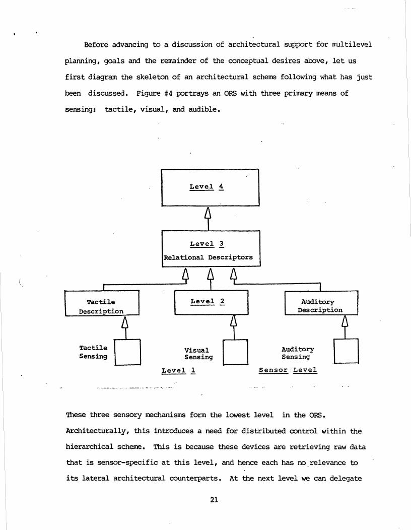
Before advancing to a discussion of archi tectural support f o r multilevel I I
planning, goals and the remainder of the conceptual des i res above, l e t us I I
I
f i r s t diagram the skeleton of an archi tectural scheme following what has just 1 I
been discussed. Figure #4 portrays an ORS w i t h three primary means of I I
sensing : tactile, visual, and audible. I I
Level 4 A I Level 5 I l~elational Descriptors I
Level 1 Sensor L e v e l
. 1 1
These three sensory mechanisms form the lowest l eve l i n the 0s.
Tactile Level 2 Description , L
Architecturally, this introduces a need f o r dis t r ibuted control within the
Auditory Description
hierarchical scheme. This is because these devices a r e re t r ieving raw data
Tactile A visual
Auditory Sensing Sensing Sensinl;
4
t h a t is sensor-specific a t t h i s level , and hence each has no relevance to
its l a t e r a l a rch i tec tura l counterparts. A t the next l eve l we can delegate

one hardware processor to each of these sensing units, each catering i n
function to the nature of its respective sensor. A t the Relational
(mrphological) l eve l , w e have only one hardware processor. This choice
sea% reasonable s ince t h i s is the f i r s t stage a t which sensor descriptions
are related to der ive s t ructure . It seem unwise to r e t a i n separate
control a t or above t h i s point i n tern of hardware processors, since an
integrated, sensor independent descr ipt ive leve l has been achieved a t t h i s
stage. The succeeding l eve l ( s ) cons is t of one hardware processor ch ie f ly
dedicated to the performance of a knowledge association task to derive
representation-relevant descriptions of t h a t level.
Naw let us continue our discussion of the other conceptual desires ,
seeing how they are supported by, and fur ther qualify, the archi tecture
thus f a r described. Multilevel Planning can be supported as strata of
plans. The goal of recognition a t the highest l eve l and the plan(s ) to
achieve it provoke actions a t the next lower level. This 'may be considered
as a sub-plan of the high leve l system, to carry out a subgoa l , or a s a
concurrent lower l eve l plan and goal. I n t h i s fashion plans a t high leve ls
propagate to plan enactment a t lower levels. This should be structured so
that plans invoked a t a given l eve l are those which are sui ted to the
temporal needs of the imnediately superior processor i n the hierarchy.
This s i tuat ion, it seems, should be a dynamic one, in which plans a re
enacted, cancelled, replaced, and possibly even developed autonomously
based on the demands posed by higher levels . This demands a rch i tec tura l ly
t h a t there be carnmunication of planning needs and goals downward to lower
levels from higher ones (see f igure #4a). There is much room fo r research
in to the deve lopent of ideas f o r multi level planning and implementation of
such ideas a s propagation of planning such tha t plan generation within

Leve l 4 1
Level 3 -
I b
I
Level 2
d. s - '7
Tactil e
&
Visual n Auditory Effector Effector Effector
~ , y , z position Pan, Tilt , Zoom Focus, Aperture
Gain, Filter Bandwidth
Microphone Inclination
., - - . . . lower leve l s is near-autononous and responsive a dynamic system (one i n
which they must accommdate changes i n high leve l plans and/or demands).
lhxl control of local plans, goals and descriptions f a l l s neatly i n to
what has so f a r been described, as does acconmdation of' various
representational schemes. This is t rue, because we have s t r a t i f i e d the
architecture and the planning scheme. Thus, plans which a re loca l , t ha t is
re l a t e to a spec i f i c sensor, goal, representation or other issue, have a
position i n the planning hierarchy. me thing, which has perhaps been
s k W over, is that there w i l l be provision fo r the enactrent of mre
than one process, goal, or plan a t one leve l , and more spec i f ica l ly , t h i s
should a l s o be t rue fo r one hardware processor. m a t is, plans and goals
23

should be able to be added o r remved within om archi tectural mode. This
means t h a t one processor s h a l l be able to dynamically start or terminate
tasks, i n addit ion to those already running i n order to support addit ional
plans o r goals, as a need f o r these becomes apparent. This s t ruc ture has
been incorporated within the tactile sensing system' s implementation, as
w i l l be touched upon i n Par t 11, and is given f u l l d e t a i l i n Wolfeld
(1981). This idea does not r e f l e c t i t s e l f diagramatically, but may be
h g i n e d by the reader, as the robustness of the processing mode in
question - the ex ten t to which it is being used, and the n d r of tasks it
is running to support plans or goals. %is stra tegy is very important i n
so f a r as it supports the idea of allowing higher leve l processes to re ly
more heavily upon some subsystems than on others. In practical
application, t h i s may be an instance i n which high leve l recognition goals
are supported b e t t e r by visual information, during cer ta in ~ r t s of plan
enactment, than by other sensory information. In t h i s regard, as has
previously been mentioned, sensory subsystems a c t as l o w l eve l spec ia l i s t s .
It is natural t h a t i n cer ta in instances - cer ta in objects or s i tua t ions ,
there is mre call f o r one s p e c i a l i s t than another.
Inter-level information has been explained to a major extent. This
consists of upward carranunication of descr ipt ive information on the one
hand, and downward comunication of plans and goals on the other hand.
What of the exchange of information between processors a t the saw stratum
then? Such paths are extremely important i n t h a t they provide routes by
which control and recognition process loops may be closed. U s e of control
loops is highly important to the ORS. A t a l o w level , t h i s is observed i n
servoing of sensors - in teract ion between e f fec tor paths and sensor paths.
Examples of this a r e pan, tilt, zoam, aperture and focus of camera in
conjunction with what the camera observes, or gain and/or bandwidth
adjustment of filters in conjunction with auditory response. Tnese control
loops provide response paths for sensor control at a low level, to perform
such functions as automatic focus and aperture adjustment of the visual
unit, autamatic gain and filter range adjustment of acoustic sensor, and
motor control to maintain proper pressure between tactile sensor and the
object contacted. A conplete system diagram is shown in figure #4b.
Beside the obvious need for control loops where low level servoing is
performed, there is also merit for lateral comnunication between higher
level processors. Such communication will be necessary to facilitate loops
within the description/recognition process.

M Control Plans Goals u
Tactile Tactile Visual visual ~ u d i tory Effectors Sensors Effectors Sesnors Effectors Sensors
High Level Description
Object Names, and Interrelations
v n
Closed Loop Verification
Collaboration
Integrated Sensory ~ e s c r i p tion (Structural)
Figure #4b
Descriptions
W D
- -
v -
n
0 r
Q i> Q
Visual Description
Tactile Des tription a D (1 D
Auditory Description
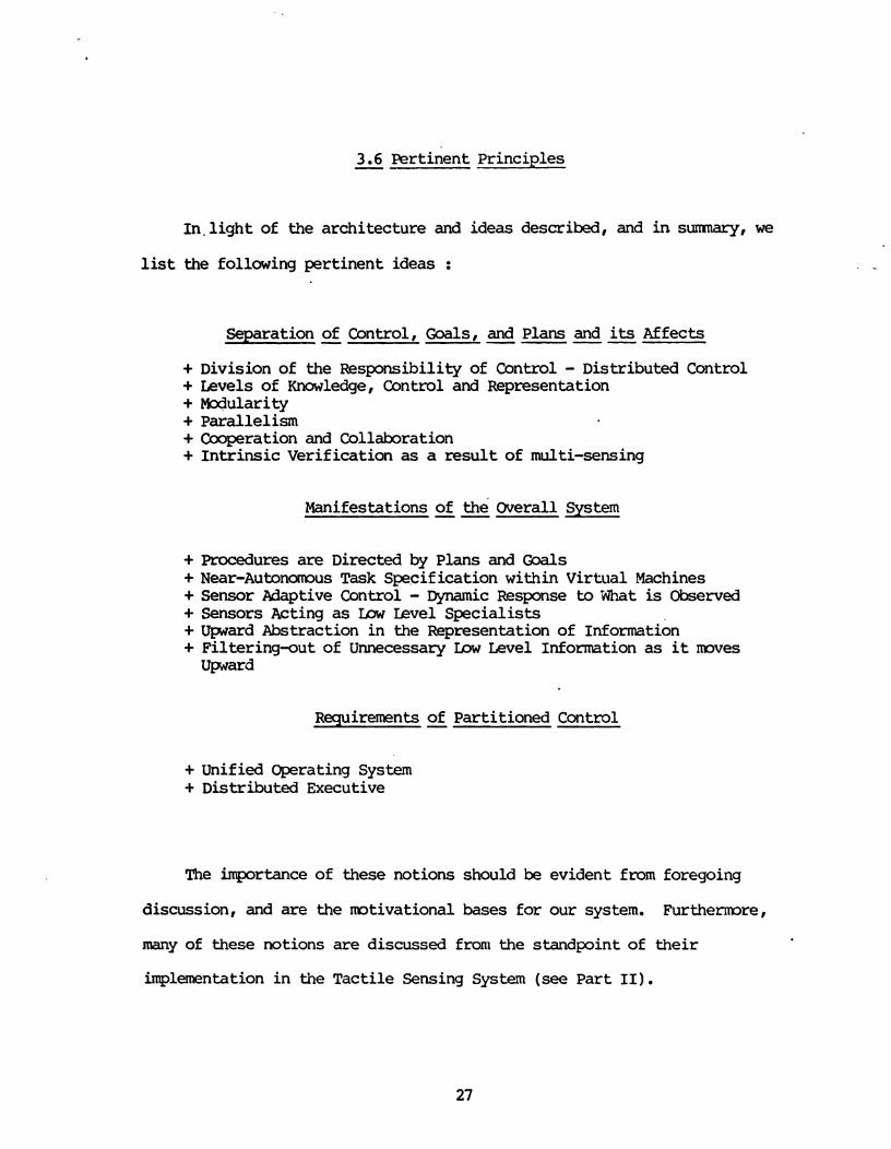
3.6 Pertinent Principles -
1n.light of the architecture and ideas described, and in sumnary, we
list the following pertinent ideas :
Separation - of Control, Goals, ---- and Plans and its Affects
+ Division of the Responsibility of Control - Distributed Control + Levels of Knowledge, Control and Representation + Mocjularity + Parallelism + Cooperation and Collaboration + Intrinsic Verification as a result of multi-sensing
Manifestations of the' Overall Sys tern --
+ Procedures are Directed by Plans and Goals + Near-Autonomus Task Specification within Virtual Machines + Sensor Adaptive Control - Dynamic Response to 'ht is Observed + Sensors Acting as Ux kvel Specialists + ward Abstraction in the Representation of Information + Filtering-out of Unnecessary b w Level Information as it moves ward
Requirements - of Partitioned Control
+ Unified Operating System + Distributed Executive
The importance of these notions should be evident from foregoing
discussion, and are the motivational bases for our system. Furthemre,
many of these notions are discussed front the standpoint of their
implementation in the Tactile Sensing System (see Part 11).

Part I1 -- Implementation of the Tactile Sensing System --
Now that an exposition of general motivations and design strategies
has been given, we turn our attention to the implementation of the tactile
sensing system i t s e l f . A s has been previously discussed, one thematic
strategy i n our design is ta implement a hierarchy of v i r tua l machines
which i n conjunction form a system that performs object recognition. The
tac t i le sensing system implements one such v i r tua l machine.
I. Overview --
The block diagram fo r the Tactile Sensing System is given within the
dotted box of figure #l. It shows the major logical units of the system.
i recognition ,/' systan
I ,' -
1, , ----- ----- --------------
I data data control in
1 I
I b 7 i
I control A I I
C % unit limit I ' I I
sensor . mtor switches C
I select data control + in , out . .
I I
I 7 I I I I ml tiplexed I
mtor
I @ interface
~ z ~ . ' = ~ S L o ~ I I
I t a A I
I /-\" 133 malog o r mtc r I I Sensorj 1 2 1
limit 1 I I I switches I I b n z d ~ ~ s i = i z y - q ~ , z s t m L I - I I 0 I
I
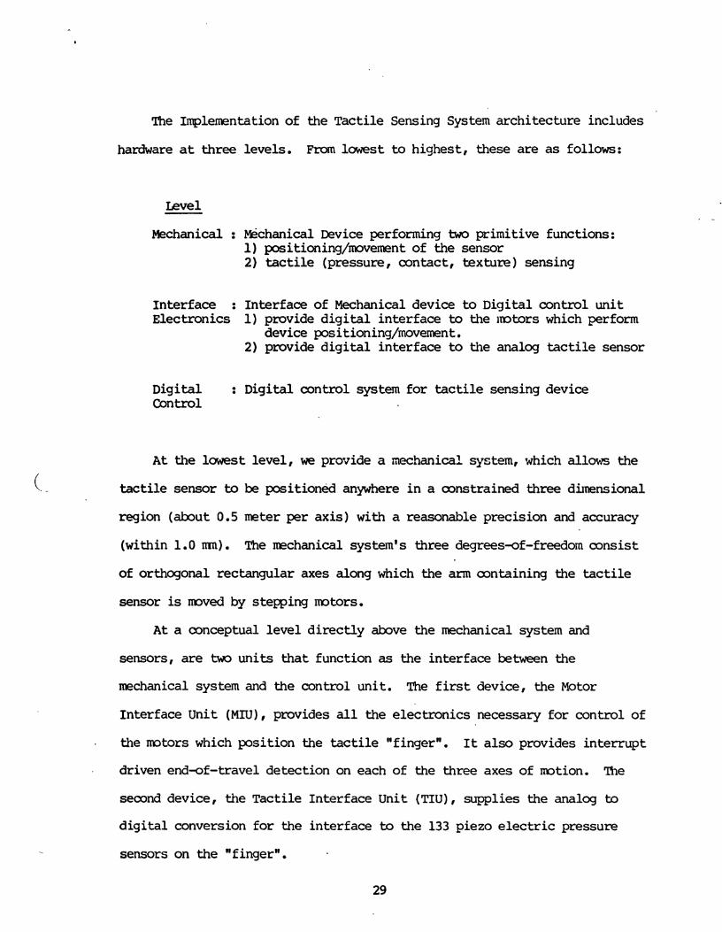
The ~mplenuentation of the ~ac t i l e Sensing System architecture includes
hardware a t three levels. From lowest to highest, these are as follows:
Mechanical : MSchanical Device performing two primitive functions: 1) positioning/mvement of the sensor 2) tactile (pressure, contact, texture) sensing
Interface : Interface of Mechanical device to Digi ta l control un i t Electronics 1) provide d i g i t a l in terface to the ~mtolrs which perform
device positioning/movement. 2) provide d i g i t a l in terface to the analog tactile sensor
Digi ta l : Digital control system f o r tactile sensing device Control
A t the lawest level , we provide a mechanical system, which allows the
(. - tactile sensor to be p o s i t i o n d anywhere i n a constrained three dimensional
region (about 0.5 meter per ax is ) with a reasonable precision and accuracy
(within 1.0 m). The mchanical system's three degrees-of-freedom consis t
of orthogonal rectangular axes along which the arm containing the tactile
sensor is moved by stepping motors.
A t a conceptual l eve l d i r ec t ly above the mechanical system and
sensors, are two uni t s t ha t function as the interface between the
mechanical system and the control unit . The f i r s t device, the Motor
Interface Unit (MIU), provides all the e lectronics necessary f o r control of
. the mtors which posit ion the tactile "fingern. It also provides in te r rup t
driven end-of-travel detection on each of the three axes of mt ion . The
second device, the Tact i le Interface Unit (TIU), supplies the analog to
d i g i t a l conversion f o r the interface to the 133 piezo electric pressure
sensors on the "f ingerw .
Finally, a t the archi tectural apex of the Tactile Sensing System, is
the Contol Unit. It provides the d i g i t a l control of a l l that is below it
i n the system hierarchy. It is corrrprised of two processors, one dedicated
to each of the subsystems jus t described, with internal interpmesor
oomnunication f o r closed loop operations between motor control and tactile
sensing. The Control Unit a l so provides f o r the Tact i le Sensing System's
interface to a higher level system. Plates 1 through 3 are various
photographs of the TSS elements.
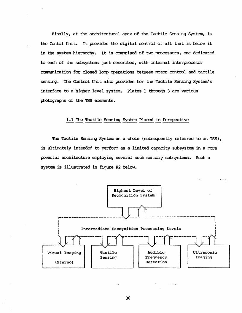
1.1 The Tactile Sensina Svstem Placed i n P e r s m t i v e
me Tact i le Sensing System a s a whole (subsequently referred to as TSS),
is ultimately intended to perform as a limited capacity subsystem in a more
powerful architecture employing several such sensory subsystems. Such a
system is i l lu s t r a t ed i n figure #2 below.
Highest Level of Recognition System
h
r"'-"'-""-"-'. ------ ------------ v 7 I I
b t I I 1ntermediate'Recognition Processing Levels I I I
Visual Imaging
(Stereo)
*-----
Tactile Sensing
Audible Frequency Detection
Ultrasonic Imaging

PLATE I - The Tacti le Sensing System
PLATE I1 - The Control Unit

PLATE I11 - The Motor Interface Unit

With respect to its position a s a specialized subsystem of a larger ORS,
the design of the TSS intends to afford limited device-relevant
intelligence. The TSS w i l l perform the en t i r e control task associated with
the sensor, and w i l l thus eliminate this responsibility in higher level
vir tual machines, but it w i l l not be used to perform any of the recognition
task of the higher level system. It should be clar i f ied therefore, that i n
its intended functions of device associated control and sensory information
acquisition, these two main objectives are served as follows:
1) L m level s e w i n g of the sensor is performed. Namely, the tactile sensor is moved and positioned in'accordance with the sensor's pressure response. This maintains an appropriate force of contact between the sensor and the object surface.
2) Primitives for both extraction of raw sensor data and c o m i c a t i o n of descriptive information are provided.
The f i r s t objective allows the TSS m autonomously .perform such
functions a s tracing cross sectional contours, following edges, and the
like. This is done by maintaining reasonable pressure of surface contact.
The second f a c i l i t y serves the intention of gathering and f i l t e r ing
(refining, enhancing or noise-reducing) the raw data from the sensor, and
camunicating tha t information t o its architectural superior i n the
recognition system.
1.2 Organization of Control - -
An additional point of architectural in teres t concerning the TSS, is
the manner i n which control is established.. A t the lowest level, control
is carried out by actual hardware devices: Motors fo r positioning,

electronics f o r p e r amplification to dr ive these, based on
'ITL level input signals, piezo electric pressure sensors, hardware to
perform analog to d i g i t a l conversion, and so on. A t the next l eve l is
firmware i n which res ide the wst fundamental control routines associated
with the hardware justmentioned. (Read - - Only - Memory) res ident routines
include such functions as m v e n t algorithms and r a t e determinations f o r
mbr control , and s imilar low leve l routines f o r the tactile sensor. Also
firmware-resident are primitives f o r comnunication, both to higher l eve l
processors, and f o r inter-task mmunicat ion between tactile and mtor
related processes. The firmware may be considered as the microcode which
hplements the v i r t u a l machine (VM) a t the sensor and sensor control l eve l
(the lowest l eve l s depicted i n f igure #3 'of Pa r t I). The remaining ROM-
resident routines implement remaining operating system components, such as
conventions f o r task start-up, termination, and synchronization within the
sensory l eve l VM. A t the highest level , the TSS maintains dynamic
variables i n RAM (Random - Access read/write - Memory). Dynamic variables a r e
the basis f o r handling of interrupts , context switching, task
synchronization (semaphores), and interprocess mmnunication.
Prescr ipt -- to the Technical Discussion
I n the subsequent sect ions of Par t 11, a top down approach is taken i n . order to describe the major un i t s of the system and their respective
technical aspects. In succeeding sections, g rea t e f f o r t is made to
elucidate the functional behavior of the TSS i n l i g h t of its archi tecture
and organization, and the design aspirat ions of Par t I. Care is taken to
give su f f i c i en t a t ten t ion to important pr inciples without dragging the
reader's wse through extensively detai led technical muck. 'Ib t h i s end,
diagrams, embcdied by textual commentary, a r e central . Lacking throughout
w i l l be jumper names and pin numbers, wire colors and connector names.
Section 2 debcribes the Control Unit; section 3 ard 4
describe the Motor Interface Unit (MIU) and analog sensor interface (TIU)
respectively; and section 5 d e t a i l s the mechanical system, mtors, and
sensors. In sumnary:
Section 2 Control Unit
Section 3 Motor Interface Unit Section 4 Tact i le Interface Unit
Section 5 Sensing and ~ e c h a h i c a l Positioning Sys tern

2. The Control Unit -- . -
The Control Unit, a rch i tec tura l pinnacle of the TSS, manages all lower
level TSS uni t s and t h e i r ac t iv i t i e s . Additionally, it conducts sensor-
derived information to higher leve l processors i n the Object recognition
system of which the TSS is a par t . I n arder to ef fec t ive ly describe the
Control Unit, w e must describe its interact ion w i t h the external
archi tectural e n v i r o m n t as w e l l as its in te rna l nature. This w i l l be
done by describing the following Control Unit features:
- Internal Nature of the Control Unit - Interface to Higher Level "Host" Processor - Interface to Lrrwer Level TSS Units
2.1 Inside the Control Unit - -
Internal ly , the CU is comprised of two log ica l ly d i s t i n c t processors.
The specif ic intent ion of t h i s dual processor real izat ion was to a l loca te
independent control to the two TSS subfunctions of motor control (movement
and positioning of the sensor), and sensor control ( r e t r i eva l and l o w level
processing of the sensor data) . It was decided tha t there was both
suf f ic ien t work associated w i t h each of these subfunctions to allow each
its own processor, and t h a t these subprocesses were su f f i c i en t ly
independent to make decentralized control a prac t ica l choice.
Architecturally, the CU may be described as a loosely linked system of
two 2-80 based microcomputers. Each computer has an individual l oca l bus
along which its local memory and input/output devices reside.
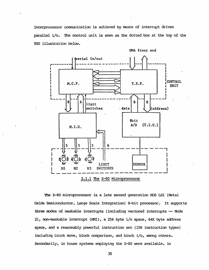
Interprocessor comunication is achieved by means of interrupt driven
parallel i/o. The control uni t is seen a s the dotted box a t the top of the
TSS i l lus t ra t ion below.
DMA f r o n t end
The 2-80 microprocessor is a l a t e second generation NOS LSI (Metal
Oxide Semiconductor, Large Scale Integration) 8-bit processor. It supports
three mdes of maskable interrupts (including vectored interrupts - Mode
2) , mn-maskable interrupt (NMI) , a 256 byte i/o space, 64K byte address
space, and a reasonably p a ~ e r f u l instruction set (158 instruction types)
including block mve, block comparison, and block i/o, amng others,
Secondarily, in house systems employing the 2-80 were available, in
35
weria l in/out ,-""-'"'. """"" ------ -- --------
I I v I I I I I I I I 8
1 I i
M.C.P. T.S.P. (CONTROL I UNIT t
I i
4 I ,---- --- \ ---------------- -- - - -1
l i n i t 8 8
switches . data d a d d r e s s )
8
1 2
8bit
M.I.U. A/D (T.I.u.)
5 5 5 --1
I I ?if 'm LIXIT SEMSOR
1 I .
I M1 M2 1!3 SWITCHES I L, ------------------A
2.1.1 me 2-80 Microprocessor ---
ti
v

addition to a vast quantity of proven-quality software usable fo r TSS
system development work. These were the bases of the choice of the 2-80,
I t is possible tha t a third generation microprocessor such as the
In te l 8086, Zilog 2-8000, o r Motorola 68000 would have been architecturally
sa l ient choices also. We selected not to use these for several reasons
however. F i r s t , sane of ' these are presently leading edge components, or
close to it (ea r l i e s t of these WAS the 8086 released in 1978). This means
that the use of one of these elements w i l l l ikely bring the usual demise
associated with state-of-the-art design. These problems typically include
potential short supply of support faniily components (e.g. the 2-8000
family MMU, and the re la t ive non-availability of any of the 68000 series
elements), and component design flaws which have not yet been to ta l ly
resolved. More importantly, developrent systems, pre-built boards
mploying these elements, and especially good quality software suited to
developnent needs, often lag parts avai labi l i ty by quite same t ime. As a
te r t ia ry concern there is the increased d i r e c t m s t ( that not associated
with the above problems) of these components.
The 2-80 has adequate capability to handle the requisite tasks of th is
system, and does not require extensive support hardware for a small or
near-minimum s ize system (limited memry and i/o) f o r the type of dedicated
control application intended i n our Control Unit . Two Single Card Cclmputer (SCC) b a r d s were procured from Cranemco Inc.
to serve a s the two Control Unit processing elements. The C- SCC has
1 K bytes of RAM, space for up to 8K bytes of R3M, PEOM or EPmM ( In te l 2716
compatible), input/output consisting of one se r i a l and three 8-bit para l le l
ports, surrounding a 2-80 processor. Also available are 5 settable
interrupting timers within an on board LSI component ('IMS-5501). Figures

#4 is the functional block diagram of the SCC
2.1.2 Control - Unit Interprocessor Interface
Although the Cmmmco SCC provides an S-100 bus interface, and it
would have been possible to es tab l i sh interprocessor comnunication v i a a
shared memory along t h i s bus, t h i s was not done. Rather, in terrupt driven
para l le l i/o was chosen. This choice was made so t h a t the S-100 bus would
be not become a bottleneck. This would be the case when the two processors
also use the S-100 to access other i/o and memory devices residing there,
in the performance of t h e i r local tasks. Presently, no such f a c i l i t i e s a r e
used on the S-100 by the processors i n the performance of t h e i r local
oontrol tasks, but i n case of a future memry or i/o expansion need, a
private $100 is now available to each and there is no concern of
contention over a shared S-100 bus. Secondly, the nature of the inter-
processor comnunication was such that a shared memy was not necessary.
Large blocks of information are not passed i n a s ing le comnunication, and
further, the messages passed between Tac t i le Sensing Processor (TSP), and
Motor Control Processor (MCP) require high p r i o r i t y service. Interrupt
driven p a r a l l e l i/o is well sui ted the type of messages i n t h i s
canmunication path - namely, sho r t ones requiring nea r - imd ia t e (high
pr ior i ty ) service.
The es sen t i a l i t y of cormmication between CU processors is mt iva t ed
by a reed to convey sensor pressure information from the Tac t i le Sensor
Processor (TSP) to the Motor Control Processor (MCP). The TSP must convey
pressure sensor values so t h a t closed loop control may be carr ied ou t f o r
positioning of the sensor. With t h i s comunication, the MCP may adapt to

E X T E R N A L TERMINAL
D E V I C E S
8 KmVTE 2 T t 8 EPROM UEUODY
EXTERNAL 5-130 COMDATIBLE
SUBSYSTEM No. 1
EXTERNAL S - I 0 0 COUPATI ILE
SUlSVSTLM N O 2
Figure 4 SCC FUNCTIONAL BLOCK DIAGRAM

responses from the TSP, moving the sensor in to the object surface when
pressure f a l l s too low, and away from the surface when pressure rises too
high. In this fashion, proper intimate contact is kept with the object
surface a s it is k i n g examined by the sensor. A scheme has been devised
involving pressure threshold reports by the TSP which.allow the MCP to make
appropriate sensor posit ion adjustments. The scheme is diagramed in
figure 85.
--
S t a t u s 3 : Out o f Range ( I n s u f f i c i e n t Pressure )
6
S t a t u s 1 : Out of Range (Excess P r e s s u r e ) 8 4". 4
f\ Pressure
LI
The scheme involves a three-valued system which indicates out-of-range
(pressure i n excess), in range (proper intimate pressure), or out-of-range
(pressure is insuf f ic ien t ) . Notice tha t there are four boundary
t ransi t ions however, rather than the two which might have been expected a t
f i r s t . This is as a r e s u l t of a hysteresis region which has been b u i l t
in to the scheme. The hysteresis is intended to prevent a large amount of
reports from being sen t by the TSP while the sensor pressure is near a
threshold.
lb see b r i e f l y how t h i s works, l e t us examine t rans i t ions (1) and (2)
h y s t e r e s i . ~ r e g i o n \LC v
S t a t u s 2 : In Range (Appropriate 8 P r e s s u r e ) a
- 8 A A h y s t e r e s i s r e i o n v b 9

f m f igure #5. The TSP does not report s t a t u s (1) - pressure excess,
u n t i l pressure exceeds threshold (1). Now the MCP compensates with a
mvement of the sensor away from the object's surface. A s the sensor mves
away, pressure drops, but s t a t u s (2) - pressure i n range is not reported
u n t i l pressure f a l l s below threshold (2) . This response w i l l prevent a
j i t t e r ing of the pressure value near boundaries (where no hysteresis region
ex i s t s ) from causing a flood of reports: excess pressure; in-range; excess
pressure; in range; ... and so on, as the sensor vac i l la tes a t the
boundary. Rather than delimiting the boundary with a l ine , we give the
boundary a width su f f i c i en t to eliminate t h i s "noise" (see f igure #6).
Status 1
hysteresis region .
Pressure Status 2
Time
If P1 were the boundary between Status 1 and Status 2, a report would
occur from the TSP a t each crossing of the boundary. This m u l d occur
frequently as the pressure value j i t t e red" during the in te rva l tl to t2.
With the hysteresis region however, a s l i g h t sensor noise is prevented f r o m
causing this constant reporting, and it is not u n t i l pressure f a l l s below
P2 tha t s t a t u s 2 is reported.
2.2 Interface to MIU and TIU - ----
A s previously introduced, the Control Unit d i r e c t s the function of
lower l eve l TSS uni t s i n order to carry ou t the system's functions. The
ICP is d i r e c t l y responsible f o r the control of sensor movement and
position, and as such it sends comands to the Motor Interface Unit (MIU).
The TSP, which has responsibi l i ty f o r information acquisit ion from the
tactile sensor, performs a similar task through association with the
Tact i le Interface Unit (TIU).
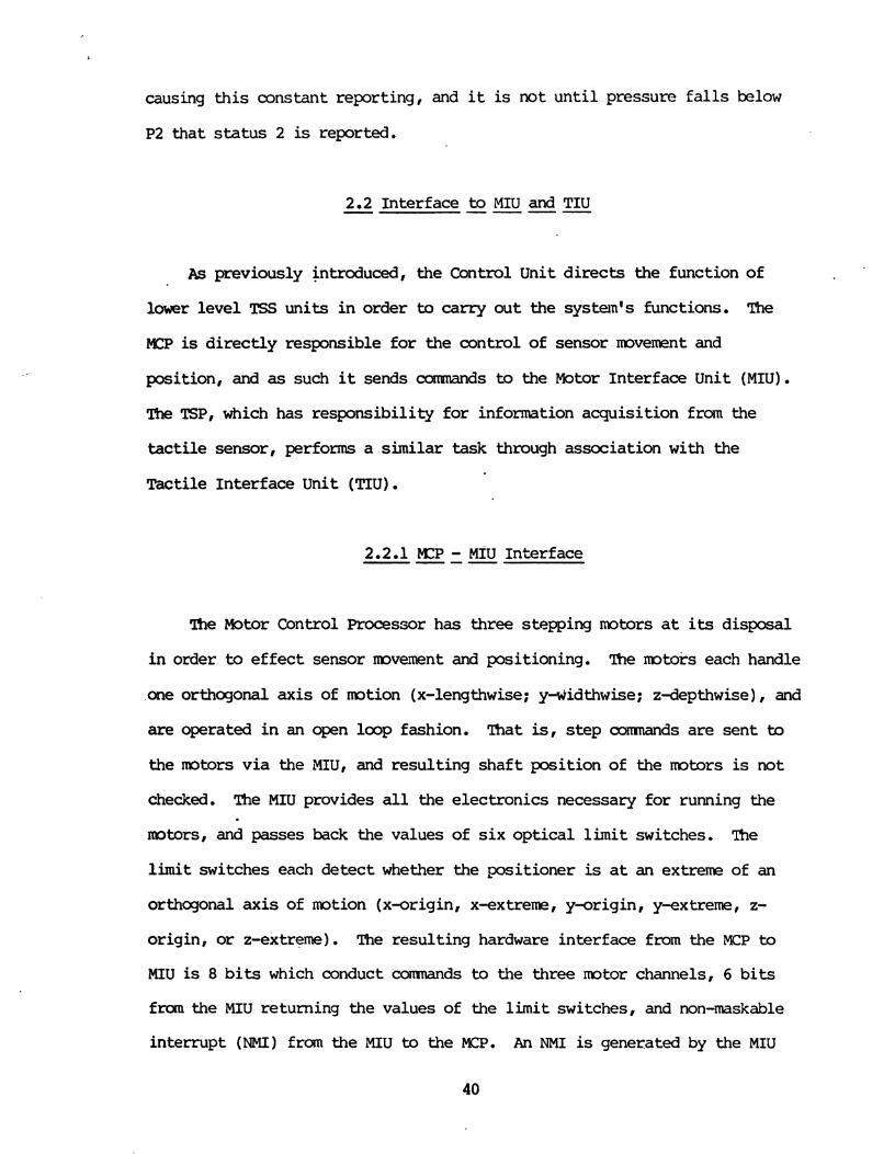
2.2.1 MZP - MIU Interface ----
The Motor Control Processor has three stepping motors a t its disposal
i n order to e f f e c t sensor movement and positioning. me motors each handle
one orthogonal ax i s of m t i o n (x-lengthwise; y-viidthwise ; z-depthwise ) , and
are operated i n an open loop fashion. That is, s t e p axminds a r e sen t to
the mtors v i a the XIU, and resul t ing s h a f t posit ion of the motors is not
checked. The MIU provides a l l the electronics necessary fo r running the
motors, and passes back the values of s i x op t i ca l l i m i t switches. me l i m i t switches each de tec t whether the posit ioner is a t an extreme of an
orthogonal a x i s of m t i o n (x-origin, x-extreme, y-origin, y-extreme, z-
origin, or z-extreme). The resul t ing hardware interface from the MCP to
MIU is 8 b i t s which conduct conmnds to the three m t o r channels, 6 b i t s
from the MIU returning the values of the limit switches, and non-maskable
interrupt ( N M I ) £ram the MIU to the MCP. An NMI is generated by the MIU

whenever any l i m i t switch changes value. This forces the MCP t o examine
the switches and take the appropriate ac t ion when a mechanical boundary is
reached. Figure #7 i l l u s t r a t e s the in terface .
Motor Control Processor
I Motor Interface Unit I
2.2.2 TSP - TIU Interface ----
Similar to the foregoing discussion, the TSP con t ro l s t he sensor 's
response v i a the Tac t i l e In te r face Unit (TIU). The TIU is simply a
multiplexed analog to d i g i t a l converter , allowing the TSP to select any one
of the 133 sensors on the 'fingern and d i g i t i z e the analog pressure

reading. The resul t ing hardware interface c o ~ ~ s i s t s of 8 bi ts to tile TIU
for sensor select ion, and 8 b i t s from the TIU, which return the digi t ized
-. pressure value of the sensor selected. The interface is diagra~~med i n
figure #8. -. . .
2.3 Interface to the * H o s t n Recognition System - --
f ie TSS, as intended, is an in t e l l i gen t sensor-dedicated system, to be

used in conjunction with some higher level object recognition system. W e
w i l l term such an ORS, a "Host" system (as w a s shown i n f ig&e #I). A t the
time of this writing, w e have delegated a PDP 11/60 in the capacity of th is
"host". W e have designed that two interfaces ex i s t between the TSS and the
host system, one froin each of the MCP and TSP, in order tha t information
pertinent to the recognition task be conveyed.
Interface to Host System - --
The motor control processor w i l l be the recipient of c o d ~ to move,
scan, trace object cross sections and the l ike , from the host system.
Ccmnunication from the MCP to the host, on the other hand, involves a
reporting of points by the TSS, describing the mvemnt performed i n
response to the carrmand sent by the host.
In order to support th i s interface, a RIM resident comnand interpreter
w i l l exist. This f i m a r e is the work of Wolfeld ( U of P, 1981), and is
described therein. It has been decided that a s e r i a l interface (RS-232)
w i l l e x i s t as the hardware between the MCP and host.
2.3.2 The -- Tactile Sensing Processor to Host Interface --
The Tact i le Sensing Processor is responsible fo r reporting surface
perturbations ( textural information) to the host, as objects a re examined
by the .tactile sensor. Similar to the MCP, the TSP w i l l have a mM-
resident com~nd interpreter, allowing t a c t i l e primitives to be
instantiated by a higher level processor in the 0s. Primitives resident
i n the TSP w i l l be primarily associated with data acquisit ion fo r texture
determination, and various types of f i l t e r i n g or l o w level s ignal
processing routines. This development is a l s o described i n Wolfeld (1981).
In order to support comnunication between TSP and host, it has keen
decided t h a t a DMA un i t w i l l be used on the PDP 11/60. This was chosen i n
order to support the large m u n t of information tha t is expected to move
across t h i s path. Without I3MA, a la rge demand would be placed on the 11/60
processor i n order to handle incoming data , and the machine w i l l be 1/0
bound.
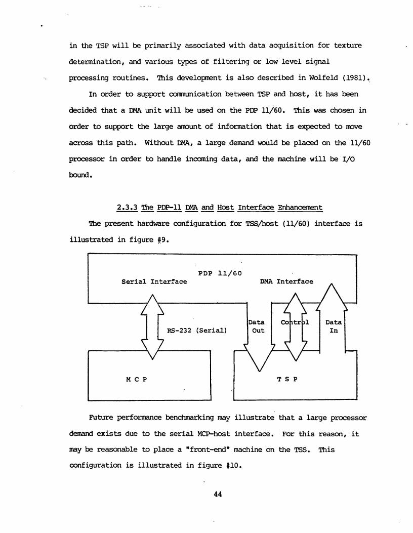
2.3.3 The PDP-11 DMA and Host Interface Enhancement -- --- The present hardware configuration f o r TSS/host (11/60) interface is
i l lus t ra ted i n f igure 89.
Future performance benchmarking may i l l u s t r a t e t h a t a large processor
demand e x i s t s due to the serial KP-host interface. For this reason, it
may be reasonable t o place a "front-endn machine on the TSS. This
configuration is i l l u s t r a t ed i n f igure #lo.

PDP 11/60
8
DMA I n t e r f a c e
Front End Processor
1
Parallel Interface
The f r o n t end machine w i l l be a channel, handling 1/0 between TSS
and host. The advantage of such a f ron t end is t h a t the 11/60 IIW may be
shared by both MCP and TSP, i n the sense t h a t both w i l l i n t e r ac t with the
host ind i rec t ly (through the channel).
W i t h the proposed front end, the MCP w i l l place no dernand on the
11/60, and the TSS 1/0 is ef fec t ive ly "transparentn to the host machine.
The CElA accomplishes amtunicat ion by d i r e c t access to the 11/60 m m r y ,
and is -resident w i t h the processor on the 11/60 bus. The DMA is thus
sharing the bus with the processor. Processor and DMA have interleaved bus
access, w i t h one locking-out the other when there is confl ic t ing demand f o r
access. The IYIA gains access during the processor's instruction-decode and
other CPU in te rna l periods, cycle s tea l ing a s necessary to complete a
memory read or write operation. This is given f u l l d e t a i l i n the DEC PDP-
11 DR11-B/DS11-B reference manual, theory of operation.

3. The Motor Interface Unit --- -
The mdtor in terface un i t is one of the two uni ts providing interface
between the control un i t above it ( d i g i t a l control l eve l of the TSS) and
the electro-mechanical and sensor leve l below it. The MIU is d i r ec t ly
responsible f o r the-control of motor operations ( m e m e n t and positioning)
going on a t the mechanical assembly level . It contains a pcwer supply and
all the e lectronics necessary to accept d i g i t a l (ITL compatible) mtor
control commands from the CU. The MIU also monitors 6 op t i ca l l i m i t
switches which de tec t the end-of-travel of e i the r the x, y or z carriages.
A change of s t a t u s on any of the s i x l i m i t switches de tec t s a mechanical
end of t rave l , and the MIU generates a npn-maskable in te r rup t to the
control u n i t ' s PCP, thus s ignal l ing the MCP to bring the mechanical
assenbly back i n t o the constrained sensing region.
The MIU contains four physical uni ts , which accomplish the afore-
mentioned functions. They are:
* m i n board ( three channels to mtors) * auxi l iary board (limit switch monitoring and NMI generation) * f r o n t panel ( indicators f o r mtor s t a tu s ) * power supply (power source f o r motors and MIU d i g i t a l e lectronics)
A macroscopic diagram of the MIU, giving a t ten t ion to topend (control
uni t ) and bottowend (mchanical assembly) interfaces is shown in figure
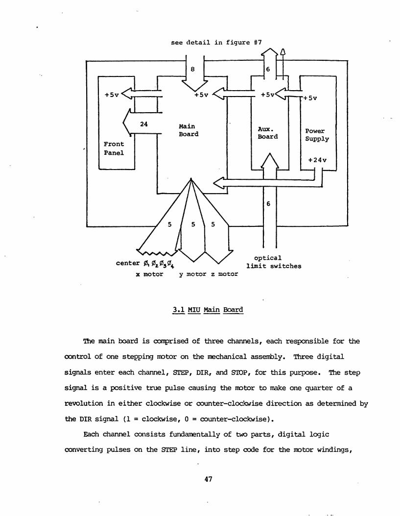
see de ta i l in figure #7
x motor y notor z motor
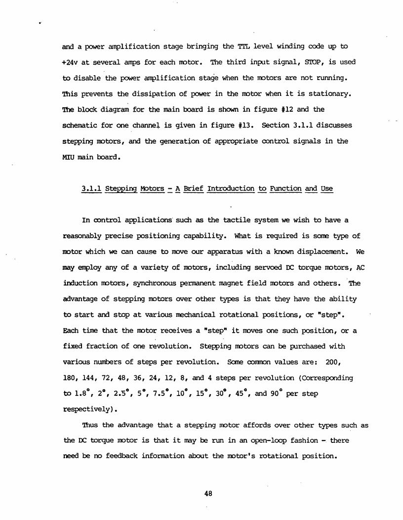
3.1 MIU Main Board ----
The main board is comprised of three channels, each responsible for the
control of one stepping mtor on the mechanical assembly. Three digital
signals enter each channel, STEP, DIR, and STOP, for this purpose. The step
signal is a positive true pulse causing the mtor to make one quarter of a
revolution in either clockwise or counter-clockwise direction as determined by
the DIR signal (1 = clockwise, 0 = counter-clockwise).
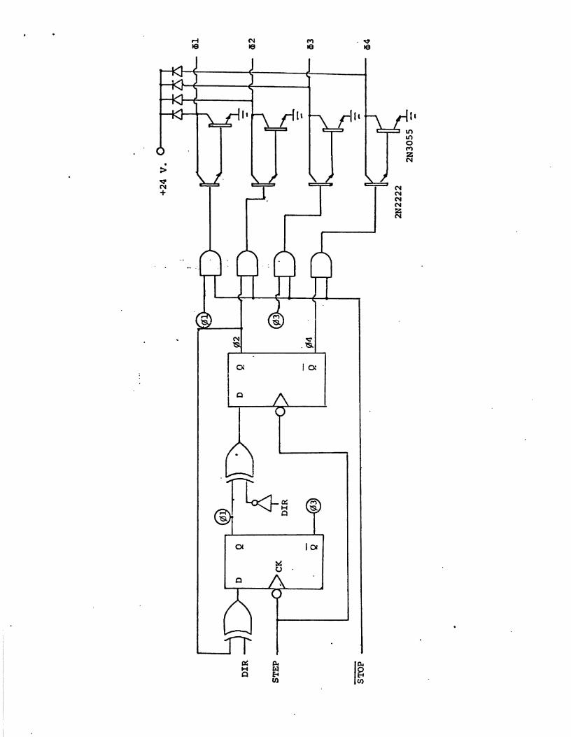
Each channel consists fundamentally of two parts, digital logic
converting pulses on the STEP line, into step code for the mtor windings,
and a power anp l i f i ca t ion s tage bringing the TI'L l eve l winding code up to
+24v a t several amps f o r each mtor. The t h i rd input s ignal , STOP, is used
to disable the pwer amplification s tage when the rotors are not running.
This prevents the d i ss ipa t ion of power i n the mtor when it is s ta t ionary.
The block diagram f o r the main board is shown in f igure #12 and the
schematic f o r one channel is given i n f igure #13. Section 3.1.1 discusses
s t e s i n g mtors, and the generation of appropriate control s igna l s i n the
MIU main b a r d .
3.1.1 Stepping Motors --- - A Brief Introduction - to Function and Use --
I n oontrol applications 'such as the tactile system we wish to have a
reasonably precise posit ioning capabi l i ty . What is required is some type of
notor which we can cause to move our apparatus with a known displacement. W e
may enrploy any of a var ie ty of mtors, including servoed DC torque mtors, AC
induction mtors, synchronous permanent magnet f i e l d mtors and others . The
advantage of stepping mtors over other types is t h a t they have the a b i l i t y
to start and s t o p a t various mechanical ro ta t iona l posi t ions , or "step".
Each time that the mtor receives a "step" it m v e s one such posit ion, o r a
fixed f rac t ion of one revolution. Stepping mtors can be purchased with
various numbers of s t eps per revolution. Same c o m n values are: 200,
180, 144, 72, 48, 36, 24, 12, 8, and 4 s teps per revolution (Corresponding
to 1.8', 2', 2.5', 5', 7.5', l o0 , 15', 30°, 45', and 90' per s t e p
respectively ) . Thus the advantage t h a t a stepping mtor af fords over o ther types such as
the DC torque motor is that it m y be run i n an open-loop fashion - there
need be no feedback information about the motor's rotational posit ion.

(figure #12 - Main Bd block)
- STEP D I R STOP
Channel TWO m Channel Three m

Tb give a br ief description of the manner i n which stepping motors work,
we can examine f igure #14:
OFF
OFF
OFF
Figure #14 shows a four phase mtor with four steps per revolution. Note
tha t when current is run through a winding, the rotor is drawn in to a posit ion
which brings the rotor's permanent magnet in^ magnetic equilibrium with an
e l ec t r i ca l ly induced f i e l d i n the energized winding. I f we wish to cause the
mtor to step i n the clockwise direct ion, we s inply energize the next winding
i n clockwise sequence (here # 4 and turn of f @z ) ,
A pulse t r a i n which would cause the occurrence of one clockwise
revolution then would look like Figure #4Sts i l l u s t r a t i on ,
Notice similar ly , t h a t to run the mtor in a counter-clochise rotat ion
we must simply reverse the sequence i n which windings are energized. To mve
f ran posit ion 3 , back to posit ion 2 , fo r example, we simply de-energize &+
and energize #2.
Figure #16 i l l u s t r a t e s a pulse t r a i n which dr ives the mobr i n
crxmter-clockwise rotation.

What hasasbeen discussed here describes only. a res t r ic t ive subset of a
much wider range of sa l i en t features of'stepping mtors. Specifically, we
have discussed full-step node fo r a four phase PM stepper with 90 degrees
per step. For the reader w i t h more extensive curiosity, a short list of
reasonably comprehensive a r t i c l e s describing stepping m t o r s is given i n
the bibliography.
3.2 The Auxiliary Board
Beside the main board, which is the effector path to the mtors, is an
auxiliary board, It contains d ig i t a l logic to return the values of the s i x
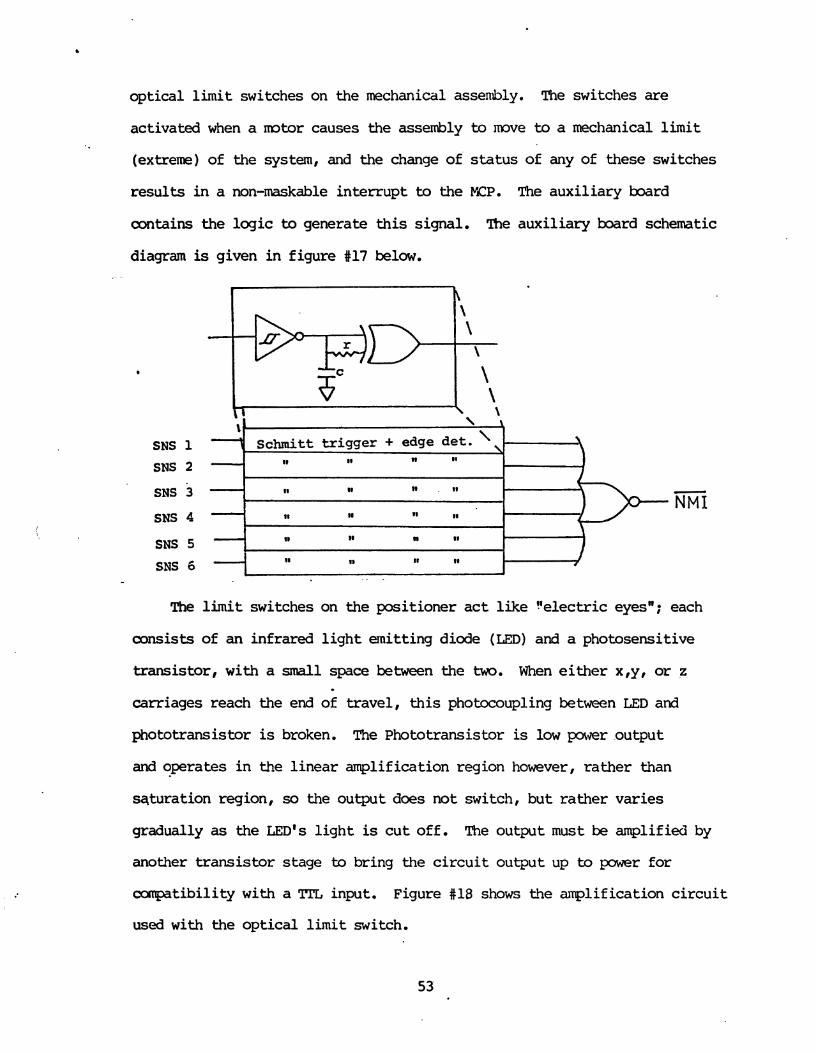
opt ical l i m i t switches on the mechanical assembly. The switches a r e
activated when a mtor causes the assembly to mve to a mechanical limit
(extreme) of the system, and the change of s t a t u s of any of these switches
r e su l t s i n a non-maskable in te r rup t to the YIP. The auxi l i a ry board
oontains the log ic to generate this signal. The auxi l i a ry b a r d schematic
diagram is given i n f igure #17 below.
SNS 1
SNS 2
SNS 3
SNS 4
SNS 5
SNS 6
w . I1 - N M I
The l i m i t switches on the posi t ioner act l i k e !'electric eyesn; each
consists of an infrared l i g h t emitting diode (LED) and a photosensitive
transistor, with a small space between the two. When either x,y, or z
carriages reach the end of t ravel , t h i s photocoupling between LED and
phototransistor is broken. The ~ h o t o t r a n s i s t o r is l o w power output
and operates i n the l i n e a r amplification region however, ra ther than
sqturation region, so the output does not switch, bu t ra ther var ies
gradually as the LED'S l i g h t is c u t o f f . The output must be amplified by
another transistor stage b bring the c i r c u i t output up to power for
compatibility with a Tl!L input. Figure #18 shows the amplification c i r c u i t
used w i t h the op t i ca l l i m i t switch.

I
100
- ----- OUT
The output response of Q2, the output transistor, is rather a slow
transi t ion when the photocoupling is broken.. This is i l l u s t r a t ed in f igure
Since there is qu i t e a slow rise time on the signal from the sense
switch c i r cu i t s , and since we would l i k e a much more rapid switching
response a s input to the NMI generator (a few microseconds ra ther than
milliseconds), a schmitt t r igger has been used between Q2 and subsequent
c i rcu i t ry on the auxi l iary board. The schmitt t r igger is par t icu la r ly
sui table i n s i tua t ions where there is a slow input s ignal rise time since
it has hysteresis. The input voltage of the schmitt t r igger must exceed
sane level v2 before the output voltzge goes high, but it m u q t f a l l below a
voltage v l << v2 before the output goes l o w again, This is i l l u s t r a t ed i n
54

< - .- I the figure below:
Subsequent c i rcui t ry of the auxiliary boar; oonsists of edge ie&ctors
for each l imi t switch, implemented by routing the switch's output into both
inputs of a two-input exclusive OR gate with one l i n e delayed. An RC
e l m t provides the delay l ine i n t h i s instance, and decides the output
pllse width of the edge detector. NMI is the negated sum of a l l the edge
detector outputs. This provides tha t when any sense switcil transition is
detected, a short negative pulse is generated on the NMI l ine (going to the
Mator Control Processor).
3.3 MIU Fmnt Panel Display . ----
The f ront panel of the VItJ is a d ig i t a l ly generated display which
provides visual access to rotor s ta tus information. Figure #21 shows the
. panel's layout.
Each channel has a s e t of LED'S indicating the s ta tus of the mtor
controlled by tha t channel. Four green LED'S arranged in a circle indicate
the two presently active windings of the mtor (present mtor shaf t
position). T w yellow l ights indicate the s ta tus of the DIR l ine for the
respective channel ( '-' is associated w i t h clockwise rotation and '+I is
counterclockwise). The red "Active" l igh t indicates the s ta tus of the STOP
signal fo r tha t channel. Recall tha t SLOP = low means tha t the power

1
amplification darlingtons to the motor are deactivated; SrOP = high implies
v
that current is flowing through the windings indicated by the green l ights .
The red "Readyn LED'S are intended to indicate tha t p e r is available to
2
PI1 a i Q11
0 I I. -
g4 0 Oaz 04 n 0 g2 0 4 1 002. 0 0 0 p13 83 a3
8 0 l - q E I f l ~I..y.l..tIfl =annel 1 Channel 2 Channel 3
i
the respective motor channel.
The MIU contains a 24 vol t power supply for the stepping mtors, and a
5 volt supply fo r the internal d i g i t a l logic and.front panel LED'S. The 24
vo l t supply is a simple unregulated DC supply capable of sourcing at l eas t
12 amperes. I t is i l lustrated below:
VAC 24 VDC
15000 ME'D
me f ive vol t supply fo r on board logic and LED'S is regulated DC
capabable of sourcing 3 amperes. I t is i l lustrated below:

110 VAC 6 VAC
8 V D C SV (reg). 5 v
2000 200 MFD MFD
- L.

4. The Tactile Interface Unit (TIU) -- --
The TIU tha t is proposed, consists of an 8 b i t analog, to d i g i t a l
converter, capable of rapid conversion (about 200 ns) of any of 133 sampled
analog input on the "fingern. An 8 b i t address selects the sensor to be
sampled. This tactile interface w i l l arr ive in conjunction with the
"fingern being developed a t L.A.A.S. in Toulouse France, by J. Clot (see
Appendix A).
In l i eu of the ar r iva l of the multisensing finger of C l o t , a simpler
verion has been used to demnstrate the v iabi l i ty of the TSS. A t the
present time, a high precision jaystick has been placed a t the end of the
z-axis arm of the mechanical positioner i n inverted (upside down) position.
Thc.joystick has springs which cause a return to center (x,y origin) a f t e r . .
joystick deflection. In th is fashion, the joystick ac t s as a simple single
d i g i t ( f inger) , providing two analog inputs (x and y axis deflection).
!l!he joystick may be used for both contour description and even limited
texture decription. Once the joystick is in oontact with a surface, it is
mved along the surface. Surface contour can be described based on the
degree of deflection of the joystick a s it is mved over the surface.
Limited textural analysis can also be performed based on the less
macroscopic perturbation of the joystick as it is mved along a suface.
It should be possible to distinguish between reasonably m t h surfaces,
finely grained surfaces, and several other gradations of ooarseness, by
observing the extent to which the joystick is deflected (jitters) and the
ra te a t which t h i s occurs.
The A to D uni t presently being used in conjunction w i t h the joystick
finger is a Cromemco Dt7A I/O board. This board contains seven 8 b i t A to
D channels, seven D to A, and one d i g i t a l b idirect ional 8 b i t pa ra l l e l
port, and is S-100 bus compatible. Two of the A to D inputs a r e used for
d ig i t i za t ion of the joystick x and y deflection. The Dt7A 1/0 is neatly
interfaced to the Tac t i le Sensing Processor along its local S-100 bus.
This allows the TSP- to gain access to the digi t ized x and y joystick values
through two i/o por t s along the S-100 bus, The Schematic diagram of the
Dt7A 1/0 is f igure 1125, and f u l l d e t a i l of t h i s device is given i n the
Cromemco IW7A 1/0 Reference Manual,


5. Mechanical Posit j.oning Sys tern -
The mechanical positioning system resides a t the lowest level of the
TSS. I t provides the mechanical hardware necessary to manipulate the
sensor in a constrained observation region.
5.1 Mechanical Provision for Movement - -
The mchanical assembly is a three axis, rect i l inear system employing
stepper motors to drive x,y and z carriages. The carriages each move along
a linear track established by two para l le l guides. Guides consist of
ei ther a Unislide mechanical s l ide and case hardened guide rod, or two
guide rods. Carriages are munted on ba l l bushing which s l ide with limited
fr ict ion along guide rods. Stepping m t o r s each rotate a worm gear (lead
screw), clockwise or counterclockwise in order to drive the carriage back
and forth along the track. Lead screws are 7-mm. i n diameter, with 1 mn.
thread pitch, and are each roughly one half a meter in length. Since the
stepping mtors has 90 degree s tep resolution, the precision of the system
is 0.25 mn, or one step. However the physical f lexib l i ty of the mechanism
exceeds t h i s precision, allowing only about a 1 mm. accuracy (1 shaft
revolution or 4 steps) .
5.2 Arm and Sensor ---
Along the z carriage (depthwise degree of freedom) is a tubular shaft.
It is a t the end of t h i s shaf t or "arm" tha t the sensing "finger" resides.
Figure #26, below i l lus t ra tes t h i s apparatus.
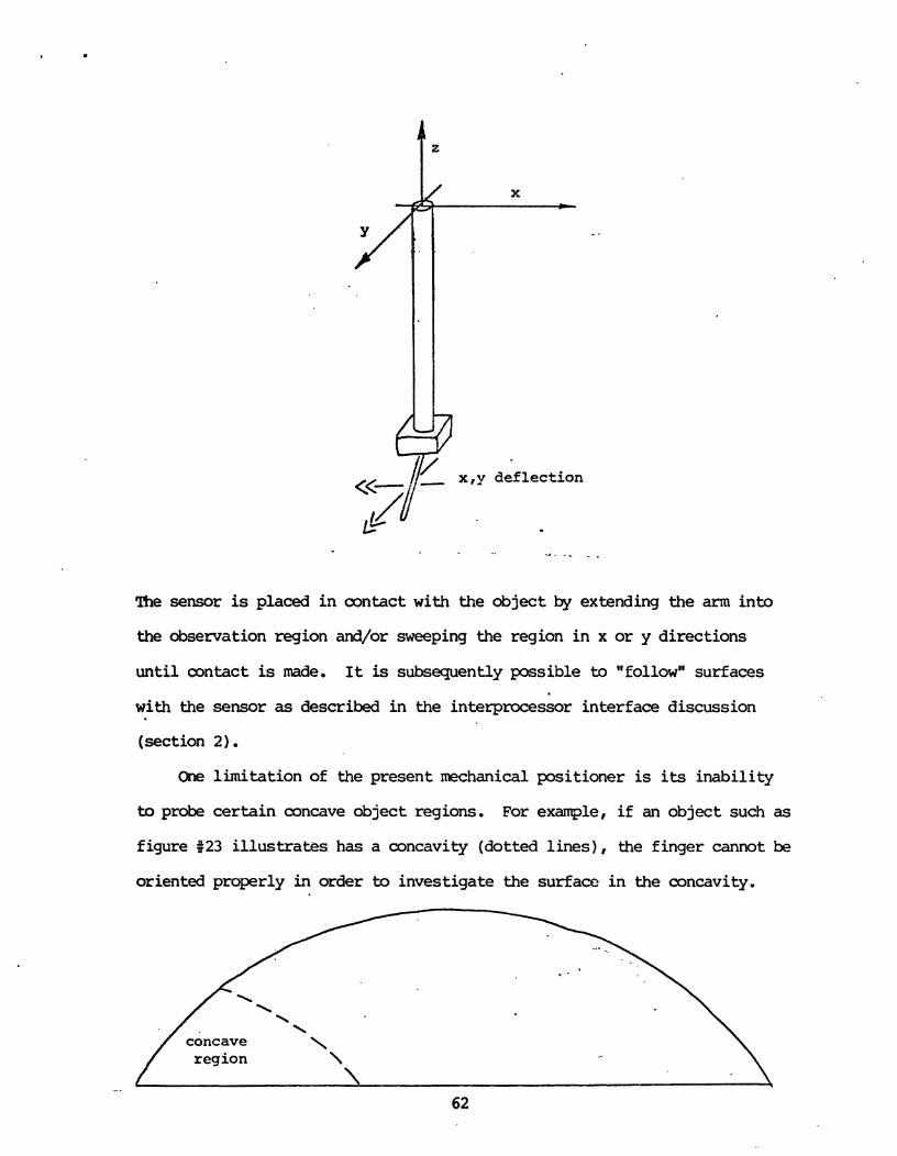
X
x, y deflection
The sensor is placed i n contact with the object by extending the arm into
the observation region and/or sweeping the region i n x or y directions
unt i l contact is made. It is subsequently possible to "follown surfaces
with the sensor as described i n the interprocessor interface discussion
(section 2).
Ckme l imitation of the present mechanical positioner is its inabil i ty
to probe certain concave object regions. For example, i f an object such as
figure $23 i l lus t ra tes has a concavity (dotted l i n e s ) , the finger cannot be
oriented properly in order to investigate the surface i n the concavity.
concave \ region \
\

A device capable of probing concave regions requires the a b i l i t y to
orient a s w e l l a s position the sensor. Orientation of the sensor requires
three additional degrees of freedom: pitch, r o l l and yaw. These are the
respective rotations about the three positioning axes: x, y and z.
I/ pitch . n X
5.3 Enhanced Tacti le Control -
Presently it is not intended tha t the TSS af fec t the environmrnt that
it observes. Ultimately, however, it may be desirable to grasp objects t o
help identify them. lb th i s extent a multi-digit t a c t i l e "hand" is
requisite. Such a Tactile Manipulator'can r-rient objects i n order to
acquire additional information about them. Fur themre , multiple d ig i t s
afford the a b i l i t y to test object compliance. This can be performed by
"squeezing" the object between two o r & digi t s , and measuring force
required as d i g i t s get closer together.

Ultimately one or mre multijointed arms such as the Uniination puma
500 should be used in conjunction with multidigit hands. Ir?portant to the
extended tactile process are the ability to grasp and manipulate objects,
and garner tensile strength and compliance information based on forces
applied by a hand or hands. Tensility may be examined by pulling or
stretching between two arms as apposed to the former pressing or squeezing
for conp?liance measurement. Investigation into mipulators and their
control has been going on for several years. However, the realization of
aspirations for such an extended capability tactile manipulation system is
still a distant objective.
6. Sumnary and Results 7 -
The general intention of th i s work has been t o consider the design of
cclmputer object recognition systems. In particular, attention has been
focused upon the archi t ictural and organizational aspects of a system which
effectively real izes the following needs and desires:
* The integration of responses £ram m y different sensors in the recognition process
* Multilevel Planning and Goal Oriented Processing
* Sensor Adaptive Control
* Cooperation between distributed processes to achieve commn higher level goals.
The notion of a s t r a t i f i ed architecture enbdying many levels of
vir tual machines, was asserted to be an important conceptual framework for
the solution of these needs and desires. Such a hierarchical and/or
distributed system was said to afford the advantages of:
* multiple localized independent control of plans and goals * vir tua l machines specialized to the i r task * d u l a r design
in t r ins ic verification through multisensing * exploitation of concurrent operation of low level tasks
An architecture of s t r a t i f i ed nature was proposed for an object recognition
system embodying the above intentions.
The specific result of this work was the design and implementation of
a system for tactile sensing which is congruous with,the considerations
we have given to the design of an object recognition system. The I S S was
designed and implemented, embodying these fundamental principles, to which
extent it is a subsystem which epitomizes the mre general aspirations for
the object recognition system. It includes the notions of multilevel
control, concurrent low level operations, and interprocessor cooperation
for sensor adaptive control and object description, within a stratified
architecture.
Preliminary results frm the associated work of Wolfeld include the
completion of mtor control routines within the MCP for positioning and
movement of the sensor, and the.developnent of primitives for
interprocessor amtunication between the IKP and TSP within the Contml
Unit .
Bib1 iography
111 Tanenbaum, Andrew S. : Structured Computer Organization, Prentice Hall, New Jersey 1976.
[2] Nilsson, Nils J.: Principles of Artificial Intelligence, Tioga Publishing Canpany, Palo Alto, Ca. 1979.
[31 Winston, Patrick Henry: Artificial Intelligence, Pddison Wesley, Reading, Ma. 1977.
[4] W a l l Davis and Jonathan King, "An Ovenriew of Production Systems," AIM-271, The Artificial Intelligence Laboratory, Stanford University, Stanford, Ca., 1975.
[5] Eman L. D., and Lesser, V. R.: "A Multi-level Organization for Problem Solving Using Many, Diverse, Cooperating Sources of Knowledge", Advance papers of the Fourth Joint Conference on A. I., M.I.T. Artificial Intelligence Laboratory, Cambridge Ma., 1975.
[6] Minsky, Marvin: "A Framework for Representing Knowledgen, in - The psychology - of Cc~trputer Vision, McGraw Hill, New York, 1975.
[71 Zadeh, mtfi A.: 'Fuzzy Algorithms", Information and Control, 8, 338-353, 1968.
[8] Gupta, M. M., Saridis, G. N., and Gaines, B. R. (eds),: Fuzzy Automata North Holland Publishing, New York,1977.
[9] Wdlker, Michael William: "Manipulator Controln, Ph.D. Dissertation, Purdue University, 1978.
[lo] Geschke, Clifford C.: "A System for Programning and Controlling Sensor-Based Robot ~blanipulators", Ph.D. Dissertation, University of Illinois at Champaign-Urbana, 1979.
[ll] Sacerdoti, Earl J. : "Plan Generation and Execution for Fcbtics", Proceedings of the Workshop on W t i c s Research, Newport, R.I. April 1980.
[121 Agin , Gerald J. : "Issues Involving Sensory Controln, Proceedings of the Workshop on Robotics Research, Newport, R.I., April 1980.
[13] Nitzan, David: "Assesment of Robotic Sensors", Proceedings of the Workshop on Robotics Research, Newport, R.I., April 1980.
[141 Takase , Kunikatsu: "Skill of Intelligent F!&otsn Interantional Joint Werence on Artificial Intelligence, mQo, 1979.
[15] Okada, Tokiju: "Ccanputer Control of a Multijointed Finger Systemn Proceedings of the Workshop on Robotics Research, Newport, R.I., April 1980.
[16] Nii, H.P., and Aiello, N. : "AGE, A Knowledge-Based Program for Building Knowledge-Based Ewqrams, Proceedings of the Workshop on Robotics Research, Newport, R.I., April 1980.
[17] Lesser, V. R., and Corkill, D. D.: "The Application of Artificial Intelligence Techniques to Cooperative Distributed Processingn Proceedings of the Workshop on Robotics Research, Newport,.R.I., April 1980.
[18] Hill, J. W., and Sword, A. J.: "Tbuch Sensors and Control", Stanford Research Institute, Menlo Park, Ca. 1972.
[19] Margolin, Bob: "Stepping Motors, the Precision Positionersn, Electonic Product Magazine, Septerrber 1979.
[20] Giaoomo, Paul: nA Stepping Motor Primern Byte Magazine, February and March 1979.
[21] Wolfeld, J.: Forthcaning Master's Thesis, University of Pennsylvania, 1981.

APPENDIX A
A FBI COMENTS ABOUT INSTRWENTATION
PROBLEMS IN THE FIELD OF TACTILE SENSING
(WITH OR WITHOUT VISION)
.To recognize an object by mtouchingn supposes that the main
objective is basically the determination of its surface texture. If one
adds to th i s parameter the measure of thermal conductibility, acoustic
Impedance, etc... it is then possible to determine the structural nature
of the object (wood, steel , ....., rough, smooth. .. , I .
However, i f the only objective is pattern recognition,
the concept of "contactN seems to be sufficient,
The difference between "touchingm and "contact" can easily be
shown i n figure 1. Indeed, two planes A and B can be separated by contact
only i f the value of"hwis superior to the resolution of the mechanical
measuring system. I f h is inferior to that limit, it is necessary to
use methods involving the "touching" concept.
- Figure 1 -

- The problem of estimating a surface texture may obviously
be solved by using the a r t i f i c i a l skin.
The major drawback of such a method is to involve a relati-
vely large area for just one measure. I
So, the conventional magnetic cartridge is generally prefered,
and that i s right. The cartridge method is far more sensitive but perhaps
gives unfortunately a "pin-point informationa, and is quite fragile.
A l l the above concepts are not really interesting for mbotics.
They are studied in our Laboratory in the domain of Biomedical Engineering
following two different kinds of application :
lo) After surgery, one is interested in determining the recovering of
t ac t i l e sensations by the patient, The method consistsin making several
s3cins with different surface texture, as shown i n figure 2.
- Figure 2 -
2') For persons having los t all sensations of touching and force
feedback, they can only see the object and determine its volume and
roughly its weight. There is, in that case, a clear relationsfrip between
vision, touching and forces. The objective of the study is then, to replace
the force feedback by the pitch of a musical sound. The goal is to give
the person a training in order he/she la te r adapts automatically the force
to the object he/she recognizes.
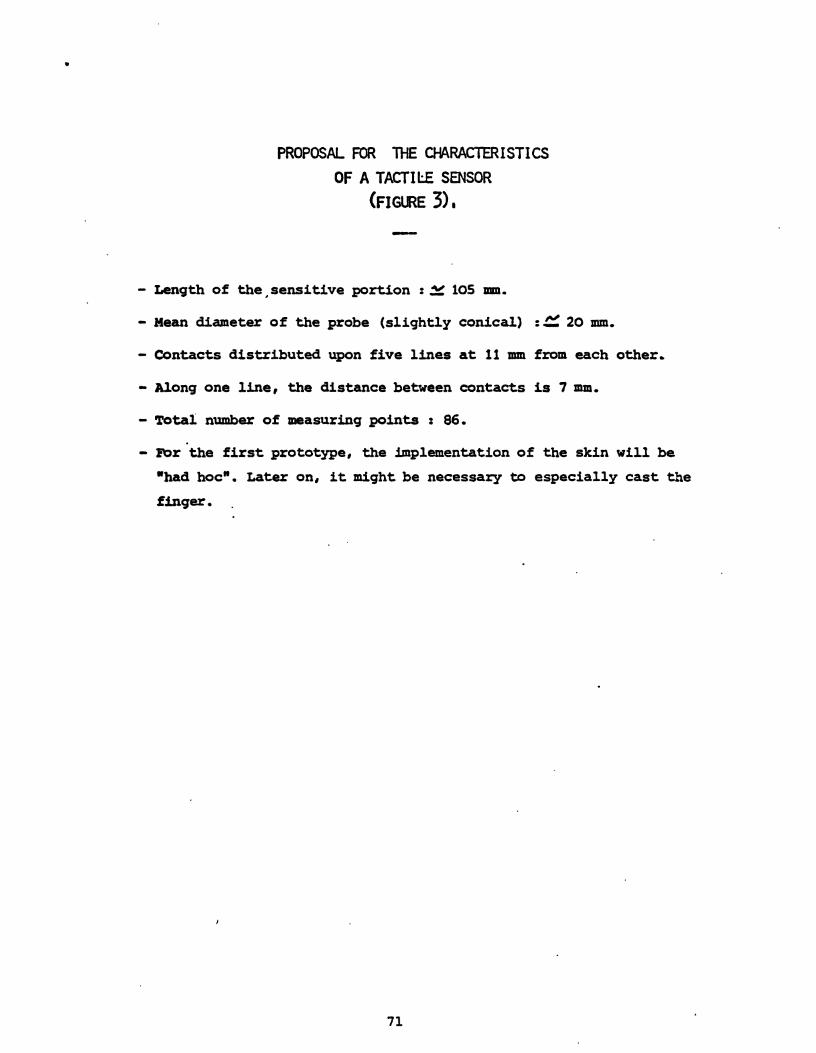

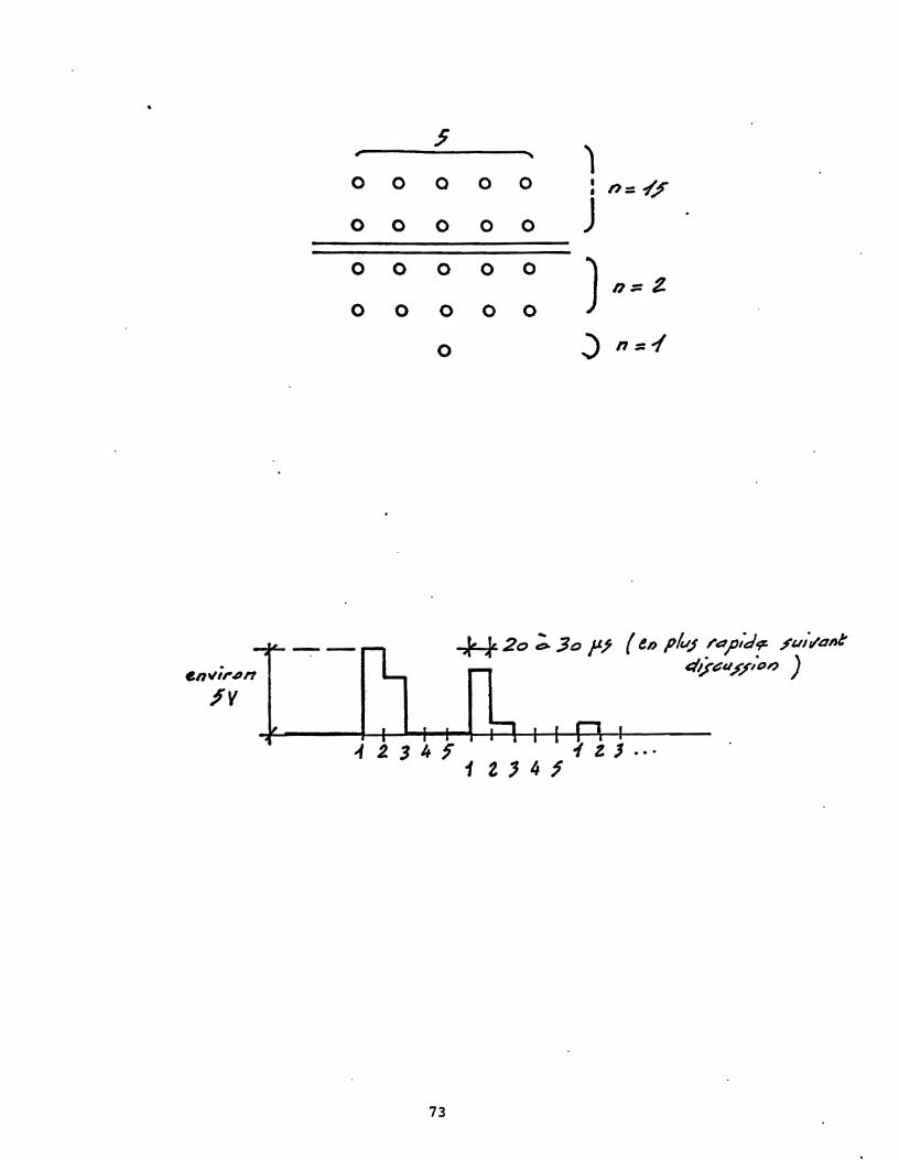

Copyright © 2022 FDOKUMEN