Second Chambers: Bicameralism Today, 2002 edition - Rajya ...
Upload
khangminh22Category
view
1download
0
1
VALVE CHAMBERS AND WELLS
Product range, pg 4Technical characteristics, pg 5Installation, pg 6
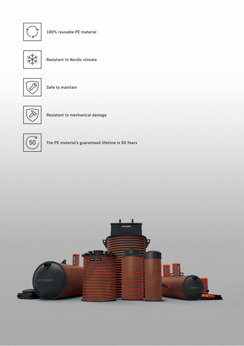
100% reusable PE material
Resistant to Nordic climate
Safe to maintain
Resistant to mechanical damage
The PE material’s guaranteed lifetime is 50 years

3
Thank you for taking time review our catalogue of valve chambers and wells!
Here you will find information about valve chambers and wells, choices, how to install them and maintenance tips.
During developing valve chambers and wells the focus has been their long-term durability and comfortable and safe use.
STRONG valve chambers and wells are used to solve pressure pipeline node points. Even the most demanding customer will find the suitable valve chamber or well from us.
In addition to STRONG valve chambers and wells, our prod-uct range includes also pumping stations with submersible pumps, booster pumping stations, tanks, septic tanks and other products of the same brand
Detailed information about all our products is available atthe address www.iwsgroup.ee/en.
Dear customer!
4
5
6
10
11
11
CONTENT
PRODUCT RANGE
SAFETY
WARRANTY
TECHNICALCHARACTERISTICS
INSTALLATION
MAINTENANCE

IWS STRONG CHAMBERS
4
HYDRANT WELLS
Hydrant wells are intended for underground installation of fi re hydrants. It is a compact well equipped with a fi re hydrant and a drain pipe.
• Inside diameter of well: ID1000 mm• Pressure piping: D110 mm• Drain pipe: D50 mm• Service opening: Plastic cover DN700 mm, cast iron cover DN600 mm (40T)
AIR RELEASE WELLS
Air release wells are used to remove excessive air from the pressure pipes. Generally, air release valves are installed at the highest points of the pipeline profi le. The diameter of the air release well is selected depending on the diameter of the pipelines, the number and dimensions of air release valves. This is a complete well with internal piping and suitable air release valve.
• Inside diameter of well: ID1000, 1200, 1400, 1600, 2000, 2400 mm• Pressure piping: D32 up to 630 mm• Service opening: Plastic cover DN700 mm, rectangular plastic cover, cast iron cover (40T) DN600 mm, rectangular 600x1200 mm
VALVE CHAMBERS
Valve chambers are used to open and close water supply and sewerage pipelines. The diameter of the valve cham-ber is selected depending on the diameter of the pipelines, the number and dimensions of valves. This is a complete chamber with internal piping and suitable valves. For the production of the chamber and the production drawing, the data are determined according to the project.
• Inside diameter of chamber: ID1000, 1200, 1400, 1600, 2000, 2400 mm• Pressure piping: D32 up to 630 mm• Service opening: Plastic cover DN700 mm, rectangu- lar plastic cover, cast iron cover (40T) DN600 mm, rectangular 600x1200 mm
PRODUCT RANGE
WATERMETER WELLS
Watermeter wells are used to measure the amount of water fl owing through pressure pipes. The diameter of the watermeter well is selected depending on the diameter of the pipelines, the number and dimensions of watermeters. This is a complete well with internal piping and suitable watermeter. For the production of the watermeter well and the production drawing, the data are determined according to the project.
• Inside diameter of well: ID1000, 1200, 1400, 1600, 2000, 2400 mm• Pressure piping: D32 up to 630 mm• Service opening: Plastic cover DN700 mm, rectangular plastic cover, cast iron cover (40T) DN600 mm, rectangular 600x1200 mm

IWS STRONG CHAMBERS
5
TECHNICAL CHARACTERISTICS
TRONG valve chambers and wells are made of PE-HD (high-density polyeth-ylene), which is an elastic and durable type of plastic. Nowadays, PE is a common material used for manufactur-ing pumping stations, chambers, tanks, wells and pressure pipes, because it is
particularly durable in Nordic climate. The tank cylinder of STRONG valve chambers and wells are strong, made with ring stiff ness of at least SN2 (2 kN/m²), so they resist mechanical damage that may occur when installing or using the system. This is important
for preventing wastewater leakage into soil or soil water penetration into the valve chamber or well. Additionally, the valve chambers or well tank cylinder has double wall, making it absolutely leak-proof.
Cover: PE, 50mm of thermal insulation
Service opening: PE, 50mm of thermal insulation
Tank cylinder: PE, double wall and ring stiff ness SN2 kN/m²
Ladder: A4, non-slippery
Plastic cover DN 700
ID1000 ID1200
650x835
ID1400
680x940
ID1600
755x1155
ID2000
945x1535
ID2400
945x1535
Cast iron cover DN 600
Rectangular plastic coverDimensions of service opening [mm]
Rectangular cast iron cover600x1200 mm
PRODUCT RANGE

IWS STRONG CHAMBERS
6
INSTALLATION
LIFTING OF VALVE CHAMBERS OR WELLS
Use lift belts to lift a valve chambers or wells. If necessary, use a spreader bar. It is important to make sure that the lift belts do not damage any protruding parts. Do not put steel cables or chains around the valve chamber or well. When lifting the valve chamber or well use all available lifting eyes and guide ropes.
INSTALLATION OF VALVE CHAMBERS OR WELLS
1. A trench for the installation of a valve chamber or well shall be dug with a diameter of at least 1.2 meters larger than the diameter of the valve chamber or well. This is because there is enough space around the valve chamber or well installed in the trench to compact the backfi ll material.
2. The bottom of the trench is fi lled with sand with a thickness of 300 mm and compacted.
3. When anchoring a valve chamber or well, proceed as described in the chapter: Anchoring.
4. Lift the valve chamber or well into the trench and make sure that the valve chamber or well is not inclined vertically.
5. Next, start backfi lling the trench as described in Chapter: Backfi ll.
6. When the backfi ll reaches the inlet pipe height, connect the valve cham-ber or well to the water pressure pipes and carefully seal around the pipes.
After the concrete base plate has been installed, the valve chamber or well must not be lifted by its lift hooks but only by the base plate or the base plate’s hooks.
!
300 mm
D
D + min 1200 mm
min 600 mm

IWS STRONG CHAMBERS
7
INSTALLATION
ANCHORING
Lifting force of surface water in order to neutralize the lifting force of surface water and to ensure that the valve chamber or well remains securely in place, the valve chamber or well must be anchored. The anchoring base plate weight plus the valve chambers or wells weight and the weight of the soil on the base plate edges extending beyond the valve chambers or wells edges must be at least equal to the lifting force. Friction between the valve chambers or wells outer wall and the soli is usually not taken into account (it is left as a reserve). Calculated coun-terweight depends on maximum soil water level (the safest bet is to con-sider soil water level up to the ground surface as the maximum level) and the weight of an empty valve chamber or well. Then the lifting force equals to the valve chamber or well volume.
Concrete anchoring base plateIf an anchoring base slab is needed, it must consist of at least 200 mm thick reinforced concrete containing a layer of lightweight, strengthened rebar (step 200 x 200, bar diameter 7 mm, 3.02 kg/m²), minimum strength 21 N/mm² (28 days later). The anchoring base slab must be installed on a 300 mm thick level sand base, mechanically compacted to at least 95% of standard density. Sulphate resisting concrete must be used if so required by soil conditions. The width and length of the anchoring base slab must exceed the valve chambers or well outer diameter by at least 600 mm (300 mm from every edge of the valve chamber or well); this is sufficient to anchor a valve chamber or well with a diameter of up to 2,000 mm. To anchor a 2,400 mm diameter valve chamber or well, use a rectangular anchoring base slab of 3.2 x 3.2 m. Concrete valve chamber or well bottoms of sufficient size may also be used. The anchoring base slabs dimensions may be reduced according to the local situation, in consultation with the designer.
A valve chambers or wells sideways deviation from the vertical must not be corrected with wedges between the anchoring base slab and the valve chambers or wells bottom. The anchoring base slab must be smooth and flat.
!
REQUIREMENTS FOR THE FILLING MATERIAL
Sand, gravel, and crushed stone are suitable filler materials. The filler must be clean, freely flowing, and must not contain ice, snow, clay, organic sub-stances, or too large or heavy objects that may damage chamber. Minimum required bulk density is 1,500 kg/m³.
GravelGravel particle size must not be less than 3 mm or more than 20 mm.
Crushed stoneCrushed stone particle size must not be less than 3 mm or more than 16 mm.
SandThe particle size must not exceed 3 mm.
Sand/gravel mixturesSand and gravel mixtures can be used if the components comply with the above requirements for gravel, crushed stone, and sand. Sand and gravel mixtures must be compacted as instructed below.
IWS STRONG CHAMBERS
8
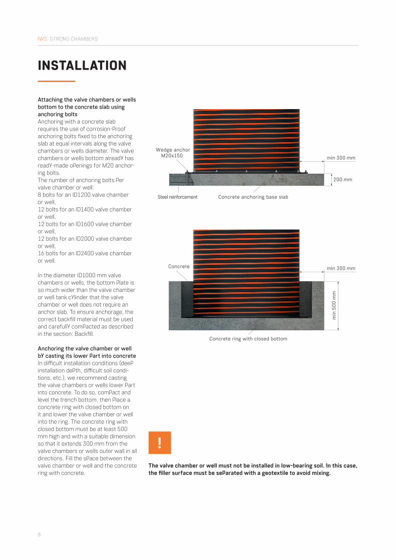
The valve chamber or well must not be installed in low-bearing soil. In this case, the fi ller surface must be separated with a geotextile to avoid mixing.
!
Attaching the valve chambers or wells bottom to the concrete slab using anchoring boltsAnchoring with a concrete slab requires the use of corrosion-proof anchoring bolts fi xed to the anchoring slab at equal intervals along the valve chambers or wells diameter. The valve chambers or wells bottom already has ready-made openings for M20 anchor-ing bolts.The number of anchoring bolts per valve chamber or well: 8 bolts for an ID1200 valve chamber or well,12 bolts for an ID1400 valve chamber or well,12 bolts for an ID1600 valve chamber or well,12 bolts for an ID2000 valve chamber or well,16 bolts for an ID2400 valve chamber or well.
In the diameter ID1000 mm valve chambers or wells, the bottom plate is so much wider than the valve chamber or well tank cylinder that the valve chamber or well does not require an anchor slab. To ensure anchorage, the correct backfi ll material must be used and carefully compacted as described in the section: Backfi ll.
Anchoring the valve chamber or well by casting its lower part into concreteIn diffi cult installation conditions (deep installation depth, diffi cult soil condi-tions, etc.), we recommend casting the valve chambers or wells lower part into concrete. To do so, compact and level the trench bottom, then place a concrete ring with closed bottom on it and lower the valve chamber or well into the ring. The concrete ring with closed bottom must be at least 500 mm high and with a suitable dimension so that it extends 300 mm from the valve chambers or wells outer wall in all directions. Fill the space between the valve chamber or well and the concrete ring with concrete.
200 mm
Wedge anchor M20x150
Steel reinforcement Concrete anchoring base slab
min
500
mm
min 300 mm
min 300 mm
Concrete
Concrete ring with closed bottom
INSTALLATION

IWS STRONG CHAMBERS
9
A valve chamber or well installed without full backfilled topsoil layer may shift due to the impact of soil water. Therefore, in the event of interruption of the trench filling, it must be ensured that the ground water does not get into the trench!
!
BACKFILLING
The valve chamber or well trench is filled on all sides in 300 mm thick layers of gravel, crushed stone or sand, com-pacting each layer to 95% of the soil’s natural density. In case of high soil water level or otherwise wet and heavy soil (e.g. clay soil), use only gravel or crushed stone as backfill material. Take special care when compacting
near the valve chambers or wells pipe connections to avoid any empty spaces remaining there.
When installing the valve chamber or well to a green area, make sure the cover reaches at least 100 mm above the ground in order to prevent storm- water from entering the chamber.
INSTALLATION
300 mm
300 mm
300 mm
300 mm
300 mm
300 mm
300 mm
300 mm
300 mm
300 mm
100 mm
Trench bottom

IWS STRONG CHAMBERS
10
INSTALLATION
INSTALLATION UNDERTRAFFIC AREA
To avoid traffi c load on a valve chamber or well installed under traffi c area, the valve chamber or well must be covered by a 150 mm thick load balancing plate. The plate must extend at least 300 mm beyond the valve chamber or well in all directions.
In a traffi c areas, the valve chamber or well must always be equipped with a cast iron cover connected to the service opening (Fig. A.) by means of a telescopic pipe or supported on a concrete load balanching plate (Fig. B). This prevents traffi c load on the valve chamber or well service opening.
150
mm
min 300 mm
Filler
Road pavementCast iron cover 40T
Concrete loadbalancing plate
150
mm
min 300 mm
Filler
Road pavementCast iron cover 40T
Concrete load balancing plate
Fig A.
Fig. B.
Reinforced concrete load balancing plate shall not remain lie to the service opening of valve chamber or well.
!Before pressurizing the valve cham-ber or well for the fi rst time, the bolt connections to the pressure pipeline inside the valve chamber or well must be checked and, if necessary, retightened.
!

IWS STRONG CHAMBERS
11
SAFETY
1. The employer of the valve chambers or wells maintenance personnel shall instruct the maintenance employees on the dangers of electric and toxic exhaust gases and shall provide the necessary protective equipment.
2. Before entering a valve chamber or well, the valve chamber or well must be ventilated!
3. Only one person at a time may stand on the valve chambers or wells service ladder and a single person must not carry along any items that are not lightweight and easy to use.
4. It is strictly prohibited to perform any works inside the valve chamber or well alone.
5. If safety requirements are ignored, no damage claims will be accepted.
MAINTENANCE
1. If the valve chamber or well is equipped with gate valves, air release valve, watermeter or other device, maintenance must be performed in accordance with the device manufacturer’s maintenance requirements.
2. If necessary, wash the inner walls of the valve chamber or well with pressurized water and clean the bottom sediment.
3. Repair or replace faulty parts!
Generally, the valve chamber or well tank cylinder and interior structures do not require any special maintenance.
WARRANTY
Innovative Water Systems undertakes the responsibility for the equipment’s properties and for elimination of short- comings becoming apparent during the equipment’s use. The warranty terms stem from the legislation of the Republic of Estonia, and the warranty is first and foremost based on the manufacturers’ warranties as long as they do not conflict with the laws of the Republic of Estonia. The warranty includes short- comings of the equipment’s or its individual elements’ manufacture, materials or design.
1. General terms of warranty 1.1. The warranty is valid for 2 years i.e. 24 months in case of the product’s purposeful use. 1.2. The warranty period starts from the product’s handover date.
2. Warranty’s validity terms 2.1. The prerequisite is the regulations in force and the installation and operation manuals required to be followed upon installation, use and maintenance of the equipment. The warranty will be valid if the equipment has been maintained regularly and used according to the manufacturer’s instructions. 2.2. The warranty does not include damage caused to third parties
because of a faulty product; it also does not include loss of revenue or any other similar loss. 2.3. In case of a fault becoming apparent, the equipment shall be repaired, not replaced as a whole.
3. The warranty does not include: 3.1. training for installation, mainte nance and use of the equipment; 3.2. repairs of transport damage and other mechanical damage (caused by vandalism, lightning, fire, etc.).
The warranty does not cover shortcom-ings caused by insufficient maintenance, incorrect installation and repairs, or normal wear. The warranty is also void if the equipment has been reconstructed.

www.iwsgroup.ee
Copyright © 2022 FDOKUMEN