Diaphragm Valve, Metal - Fortek.it
11
698 Diaphragm Valve, Metal Construction The GEMÜ 698 motorized 2/2-way diaphragm valve has a low maintenance electric actuator with a toothed belt drive and a reversible synchronous motor. A manual override and an optical position indicator are standard. Features • Suitable for inert and corrosive* liquid and gaseous media • Chemical resistance of actuator • Stainless steel body with CIP/SIP cleaning and sterilizing capabilities • Insensitive to particulate media • Valve body and diaphragm available in various materials and designs • The valve stroke can be limited by means of adjustable limit switches • Suitable for use as a control valve (with GEMÜ 1283) Advantages • Hermetic separation between medium and actuator • Optional flow direction • Installation for an optimized draining is possible • Consistent control system and reliable opening and closing action • Direct 0/4 - 20 mA signal processing using the additional module GEMÜ 1283 • Electrical position feedback by means of a potentiometer available as an option Sectional drawing *see information on working medium on page 2
-
Upload
khangminh22 -
Category
Documents
-
view
3 -
download
0
Transcript of Diaphragm Valve, Metal - Fortek.it

698
Diaphragm Valve,Metal
Construction The GEMÜ 698 motorized 2/2-way diaphragm valve has a low maintenance electric actuator with a toothed belt drive and a reversible synchronous motor. A manual override and an optical position indicator are standard.
Features• Suitable for inert and corrosive* liquid and gaseous media• Chemical resistance of actuator• Stainless steel body with CIP/SIP cleaning and sterilizing capabilities • Insensitive to particulate media• Valve body and diaphragm available in various materials and designs• The valve stroke can be limited by means of adjustable limit switches• Suitable for use as a control valve (with GEMÜ 1283)
Advantages• Hermetic separation between medium and actuator• Optional flow direction• Installation for an optimized draining is possible• Consistent control system and reliable opening and closing action• Direct 0/4 - 20 mA signal processing using the additional module
GEMÜ 1283• Electrical position feedback by means of a potentiometer available as
an option
Sectional drawing
*see information on working medium on page 2

698 2
Technical data
Working mediumCorrosive, inert, gaseous and liquid media which have no negative impact on the physical and chemical properties of the body and diaphragm material.
Kv values [m³/h]
MG DNDIN
Code 0
DIN 11850 Series 1 Code 16
DIN 11850 Series 2 Code 17
DIN 11850 Series 3 Code 18
SMS 3008
Code 37
ASME BPE
Code 59
EN ISO 1127
Code 60
2515 4.1 4.7 4.7 4.7 - - 7.420 6.3 7.0 7.0 7.0 - 4.4 13.225 13.9 15.0 15.0 15.0 12.6 12.2 16.2
4032 25.3 27.0 27.0 27.0 26.2 - 30.040 29.3 30.9 30.9 30.9 30.2 29.5 32.8
50 50 46.5 48.4 48.4 48.4 51.7 50.6 55.2Kvvaluesdeterminedacc.toIEC534standard,inletpressure6bar,∆p1bar,stainlesssteelvalvebodyandsoftelastomerdiaphragm. MG = diaphragm size
Optional position feedbackActual value potentiometer (functional module AP) 10 kW
Operating pressure [bar] Diaphragm size DN EPDM / FPM PTFE
25 15, 20, 25 0 - 10 0 - 640 32, 40 0 - 6 0 - 650 50 0 - 6 0 - 4
All pressures are gauge pressures. Operating pressure values were determined with static operating pressure applied on one side of a closed valve. Sealing at the valve seat and atmospheric sealing is ensured for the given values. Information on operating pressures applied on both sides and for high purity media on request.
Power consumption10 VA
Operating timeStandard version approx. 20 s
Protection classIP 65 acc. to DIN 40050
Cable gland2 x PG 13.5
RatingContinuously rated
TemperaturesMedium temperature
FPM (code 4) -10 ... 90 °CEPDM (code 13) -10 ... 100 °CEPDM (code 14) -10 ... 90 °CEPDM (code 17) -10 ... 100 °CPTFE (code 5E) -10 ... 100 °C
Sterilisation temperatureFPM (code 4) not applicableEPDM (code 13) 150 °C, max. 60 minEPDM (code 14) not applicableEPDM (code 17) 150 °C, max. 180 minPTFE (code 5E) Constant temperature* 150 °C
The sterilisation temperature is valid for steam or superheated water.* The valves concerned must be serviced regularly if steam is applied continuously.
Ambient temperatureAmbient temperature -10 ... +55 °CStorage temperature -15 ... +55 °C

6983
Order data
Connection CodeButt weld spigotsSpigots DIN 0Spigots DIN 11850, series 1 16Spigots DIN 11850, series 2 17Spigots DIN 11850, series 3 18Spigots DIN 11866, series A 1ASpigots DIN 11866, series B 1BSpigots JIS-G 3447 35Spigots JIS-G 3459 36Spigots SMS 3008 37Spigots BS 4825, part 1 55Spigots ASME BPE 59Spigots EN ISO 1127 60Spigots ANSI/ASME B36.19M, Schedule 10s 63Spigots ANSI/ASME B36.19M, Schedule 40s 65Threaded connectionsThreaded sockets DIN ISO 228 1Threaded sockets NPT 31Threaded spigots DIN 11851 6One side threaded spigot, other side cone spigot and union nut, DIN 11851 62Aseptic unions on requestFlangesFlanges EN 1092 / PN16 / form B, length EN 558, series 1, ISO 5752, basic series 1 8Flanges ANSI CLASS 150 RF length MSS SP-88 38Flanges ANSI CLASS 125/150 RF length EN 558, series 1 ISO 5752, basic series 1 39Clamp connectionsClamps ASME BPE for pipe ASME BPE, length ASME BPE 80Clamps DIN 32676 series B for pipe EN ISO 1127, length EN 558, series 7 82Clamps ASME BPE for pipe ASME BPE, length EN 558, series 7 88Clamps DIN 32676 series A for pipe DIN 11850, length EN 558, series 7 8AClamps SMS 3017 for pipe SMS 3008, length EN 558, series 7 8EAseptic clamps on requestFor overview of available valve bodies see page 10
Functional module CodeOPEN / CLOSE controlwith additional end position feedback AEOPEN / CLOSE controlwith potentiometer output AP
Body configuration CodeTank valve body B**2/2-way body DMulti-port design M**T body T** For dimensions see T Valves brochure** Dimensions and versions on request or according to customer requirements
Diaphragm material CodeFPM 4EPDM 13EPDM 14EPDM 17PTFE/EPDM convex, PTFE loose 5EMaterial complies with FDA requirements, except codes 4 and 14
Supply voltage Code 24 V ± 10% C120 V ± 10% G230 V ± 10% L
Mains frequency Code 50/60 Hz 4
For further order data see page 4
Valve body material CodeEN-GJL-250, (GG25) (Cast iron) 8EN-GJS-400-18-LT (S.G. Iron 40.3), PFA lined 17EN-GJS-400-18-LT (S.G. Iron 40.3), PP lined 181.4435 - BN2 (CF3M), investment casting Fe<0.5% 321.4435 (ASTM A 351 CF3M 316L), investment casting 341.4408, investment casting 371.4408, PFA lined 391.4435 (316L), forged body 401.4435 (BN2), forged body Fe<0.5% 42EN-GJS-400-18-LT (S.G. Iron 40.3), hard rubber lined 83

6984
B
ACT
*
A1
Dimensions [mm]
* CT = A + H1 (see body dimensions)
Order example 698 25 D 60 34 13 L 4 AE 1500Type 698Nominal size 25Bodyconfiguration(code) DConnection (code) 60Valve body material (code) 34Diaphragm material (code) 13Supply voltage (code) LMains frequency (code) 4Functional module (code) AESurfacefinish(code) 1500
Order data
Valve body surface finish, internal contourForged body Code 40, 42
Investment casting Code 32, 34 Code
Ra≤6.3µm blasted internal/external - X 1500Ra≤6.3µm optical electropolishing - X 1509Ra≤0.8µm mechanically polished internal, blasted external X X 1502Ra≤0.8µm electropolished internal/external X - 1503Ra≤0.6µm mechanically polished internal, blasted external X X 1507Ra≤0.6µm electropolished internal/external X - 1508Ra≤0.4µm mechanically polished internal, blasted external X - 1536Ra≤0.4µm electropolished internal/external X - 1537Ra≤0.25µm mechanically polished internal, blasted external X - 1527Ra≤0.25µm electropolished internal/external X - 1516
Ra acc. to DIN 4768; at defined reference points Surface finish data refer to medium wetted surfaces
Actuator dimensionsDiaphragm
size DN ▭B A A1 Weight[kg]
25 15 - 25 169 x 135 222 82 2.3540 32 - 40 169 x 135 271 131 2.9050 50 169 x 135 278 138 3.30

6985
R
Lt
SW2
H
H1
Body dimensions [mm]
Threaded sockets, connection code 31 Valve body material: investment casting (code 37)
MG DN R L H H1 t SW2 Number of flats
Weight[kg]
2515 NPT 1/2 85 29 16 14 27 6 0.3220 NPT 3/4 85 32 16 14 32 6 0.3425 NPT 1 110 42 21 17 41 6 0.39
4032 NPT 11/4 120 49 24 17 50 8 0.8840 NPT 11/2 140 52 24 17 55 8 0.93
50 50 NPT 2 165 68 33 18 70 8 1.56MG = diaphragm size
Threaded sockets, connection code 1 Valve body material: GG25 (code 8), investment casting (code 37)
MG DN R LMaterial code 8 Material code 37 Weight
[kg]H H1 t SW2 Number of flats H H1 t SW2 Number
of flats
2515 G 1/2 85 35 19 12 32 6 29 16 15 27 6 0.3220 G 3/4 85 40 19 13 41 6 32 16 16 32 6 0.3425 G 1 110 42 19 16 46 6 37 16 13 41 6 0.39
4032 G 11/4 120 56 28 16 55 6 49 24 20 50 8 0.8840 G 11/2 140 61 28 18 65 6 52 24 18 55 8 0.93
50 50 G 2 165 73 35 18 75 6 68 33 26 70 8 1.56MG = diaphragm size For materials see overview on page 10

6698
Body dimensions [mm]
Butt weld spigots, connection code 1A, 1B, 60 Valve body material: Investment casting (code 34), forged body (code 40)
DIN 11866 Series A Code 1A
DIN 11866 Series B Code 1B
EN ISO 1127
Code 60Weight
[kg]MG DN NPS f* øg* L c H1* H1** ød s ød s ød s
2515 1/2” 40 13.5 120 25 13.0 19.0 19 1.5 21.3 1.6 21.3 1.6 0.6220 3/4” 40 13.5 120 25 16.0 19.0 23 1.5 26.9 1.6 26.9 1.6 0.5825 1” 40 13.5 120 25 19.0 19.0 29 1.5 33.7 2.0 33.7 2.0 0.55
4032 11/4” 68 13.5 153 25 24.0 26.0 35 1.5 42.4 2.0 42.4 2.0 1.4540 11/2” 75 13.5 153 25 26.0 26.0 41 1.5 48.3 2.0 48.3 2.0 1.32
50 50 2” 90 13.5 173 30 32.0 32.0 53 1.5 60.3 2.0 60.3 2.0 2.25* only for investment cast design ** only for forged design MG = diaphragm size For materials see overview on page 10
Butt weld spigots, connection code 0, 16, 17, 18 Valve body material: Investment casting (code 34), forged body (code 40)
DIN Series 0 Code 0
DIN 11850 Series 1 Code 16
DIN 11850 Series 2 Code 17
DIN 11850 Series 3 Code 18
Weight [kg]
MG DN NPS f* øg* L c H1* H1** ød s ød s ød s ød s
2515 1/2” 40 13.5 120 25 13.0 19.0 18 1.5 18 1.0 19 1.5 20 2.0 0.6220 3/4” 40 13.5 120 25 16.0 19.0 22 1.5 22 1.0 23 1.5 24 2.0 0.5825 1” 40 13.5 120 25 19.0 19.0 28 1.5 28 1.0 29 1.5 30 2.0 0.55
4032 11/4” 68 13.5 153 25 24.0 26.0 34 1.5 34 1.0 35 1.5 36 2.0 1.4540 11/2” 75 13.5 153 25 26.0 26.0 40 1.5 40 1.0 41 1.5 42 2.0 1.32
50 50 2” 90 13.5 173 30 32.0 32.0 52 1.5 52 1.0 53 1.5 54 2.0 2.25* only for investment cast design ** only for forged design MG = diaphragm size For materials see overview on page 10

7698
Body dimensions [mm]
Butt weld spigots, connection code 35, 36, 37 Valve body material: Investment casting (code 34), forged body (code 40)
JIS-G 3447
Code 35
JIS-G 3459
Code 36
SMS 3008
Code 37Weight
[kg]MG DN NPS f* øg* L c H1* H1** ød s ød s ød s
2515 1/2” 40 13.5 120 25 13.0 19.0 - - 21.7 2.10 - - 0.6220 3/4” 40 13.5 120 25 16.0 19.0 - - 27.2 2.10 - - 0.5825 1” 40 13.5 120 25 19.0 19.0 25.4 1.2 34.0 2.80 25.0 1.2 0.55
4032 11/4” 68 13.5 153 25 24.0 26.0 31.8 1.2 42.7 2.80 33.7 1.2 1.4540 11/2” 75 13.5 153 25 26.0 26.0 38.1 1.2 48.6 2.80 38.0 1.2 1.32
50 50 2” 90 13.5 173 30 32.0 32.0 50.8 1.5 60.5 2.80 51.0 1.2 2.25* only for investment cast design ** only for forged design MG = diaphragm size For materials see overview on page 10
Butt weld spigots, connection code 55, 59, 63, 65 Valve body material: Investment casting (code 34), forged body (code 40)
BS 4825 Code 55
ASME BPE Code 59
ANSI/ASME B36.19M 10s
Code 63
ANSI/ASME B36.19M 40s
Code 65Weight
[kg]MG DN NPS f* øg* L c H1* H1** ød s ød s ød s ød s
2515 1/2” 40 13.5 120 25 13.0 19.0 - - - - 21.3 2.11 21.3 2.77 0.6220 3/4” 40 13.5 120 25 16.0 19.0 19.05 1.2 19.05 1.65 26.7 2.11 26.7 2.87 0.5825 1” 40 13.5 120 25 19.0 19.0 - - 25.40 1.65 33.4 2.77 33.4 3.38 0.55
4032 11/4” 68 13.5 153 25 24.0 26.0 - - - - 42.2 2.77 42.2 3.56 1.4540 11/2” 75 13.5 153 25 26.0 26.0 - - 38.10 1.65 48.3 2.77 48.3 3.68 1.32
50 50 2” 90 13.5 173 30 32.0 32.0 - - 50.80 1.65 60.3 2.77 60.3 3.91 2.25* only for investment cast design ** only for forged design MG = diaphragm size For materials see overview on page 10

8698
L
k
H1
D
FTF
Body dimensions [mm]
Flanges - DIN EN 1092, connection code 8Valve body material: GG25 (code 8), S.G. Iron 40.3 (code 17, 18, 83),
1.4435 (code 34, 40), 1.4408 (code 39)H1
FTF Weight[kg]MG DN øD øk øL Number
of boltMaterial code 8
Material code 17
18, 39, 83Material code 34
Material code 40
2515 95 65 14 4 19.0 18.0 13.0 19.0 130* 1.8520 105 75 14 4 19.0 20.5 16.0 19.0 150 2.3525 115 85 14 4 19.0 23.0 19.0 19.0 160 2.85
4032 140 100 18 4 28.0 28.7 24.0 26.0 180 4.9040 150 110 18 4 28.0 33.0 26.0 26.0 200 5.65
50 50 165 125 18 4 35.0 39.0 32.0 32.0 230 7.45*Material code 34, 40 FTF = 150 (no DIN length) MG = diaphragm size For materials see overview on page 10
Flanges - ANSI CLASS 125/150 RF, connection code 38, 39Valve body material: GG25 (code 8), S.G. Iron 40.3 (code 17, 18, 83),
1.4435 (code 34, 40), 1.4408 (code 39)
H1 FTF
Connection code 38, 39MSS Sp-88
Connection- code 38
EN 558 Series 1
Connection- code 39
MG DN øD øk øL Number of bolt
Material code 8
Material code 17, 18, 39, 83
Material code 34
Material code 40
Material code
Material code 8, 17, 18, 34, 39, 40, 83
Weight[kg]
2515 90 60.3 15.9 4 19.0 18.0 13.0 19.0 - - 130 1.8520 100 69.9 15.9 4 19.0 20.5 16.0 19.0 146 146.4 150 2.3525 110 79.4 15.9 4 19.0 23.0 19.0 19.0 146 146.4 160 2.85
4032 115 88.9 15.9 4 28.0 28.7 24.0 26.0 - - 180 4.9040 125 98.4 15.9 4 28.0 33.0 26.0 26.0 175 171.4 200 5.65
50 50 150 120.7 19.0 4 35.0 39.0 32.0 32.0 200 197.4 230 7.45MG = diaphragm size For materials see overview on page 10
17, 18, 39 83

9698
Rd1
g*
f*
L
H1
L
R
f*
øg*
ød1R
H1
Body dimensions [mm]
Code 62Code 6
Threaded connections, connection code 6, 62Valve body material: investment casting (code 34), forged body (code 40)
MG DN H1* H1** f* øg* ød1 Thread to DIN 405 R
Code 6L
Code 62L
Weight[kg]
2515 13.0 19 40.0 13.5 16.0 RD 34 x 1/8 118 116 0.7120 16.0 19 40.0 13.5 20.0 RD 44 x 1/6 118 114 0.7825 19.0 19 40.0 13.5 26.0 RD 52 x 1/6 128 127 0.79
4032 24.0 26 68.0 13.5 32.0 RD 58 x 1/6 147 147 1.6640 26.0 26 75.0 13.5 38.0 RD 65 x 1/6 160 160 1.62
50 50 32.0 32 90.0 13.5 50.0 RD 78 x 1/6 191 191 2.70* only for investment cast design ** only for forged design MG = diaphragm size For materials see overview on page 10
Clamp connections, connection code 80, 82, 88, 8A, 8EValve body material: forged body (code 40)
for pipe ASME BPE
Code 80
for pipe EN ISO 1127
Code 82
for pipe ASME BPE
Code 88
for pipe DIN 11850Code 8A
for pipe SMS 3008Code 8E
Weight[kg]
MG DN NPS H1 ød1 ød3 L ød1 ød3 L ød1 ød3 L ød1 ød3 L ød1 ød3 L
2515 1/2” 19.0 - - - 18.1 50.5 108.0 - - - 16 34.0 108.0 - - - 0.7520 3/4” 19.0 15.75 25.0 101.6 23.7 50.5 117.0 15.75 25.0 117 20 34.0 117.0 - - - 0.7125 1” 19.0 22.10 50.5 114.3 29.7 50.5 127.0 22.10 50.5 127 26 50.5 127.0 22.6 50.5 127 0.63
4032 1 1/4” 26.0 - - - 38.4 64.0 146.0 - - - 32 50.5 146.0 31.3 50.5 146 1.6240 1 1/2” 26.0 34.80 50.5 139.7 44.3 64.0 159.0 34.80 50.5 159 38 50.5 159.0 35.6 50.5 159 1.50
50 50 2” 32.0 47.50 64.0 158.8 56.3 77.5 190.0 47.50 64.0 190 50 64.0 190.0 48.6 64.0 190 2.50MG = diaphragm size

10698
Overview of valve bodies for GEMÜ 698
SpigotsConnection code 0 16 17 18 1A 1B 35 36 37 55 59 60 63 65
Material code 34 40 34 40 34 40 34 40 40 40 34 40 40 34 40 34 40 34 40 34 40 40 40MG DN
2515 X X X X X X - X X X - - X - - - - - - X X X X20 X X X X X X - X X X - - X - - X X X X X X X X25 X X X X X X X X X X X X X X X - - X X X X X X
4032 X X X X X X X X X X X X X X X - - - - X X X X40 X X X X X X X X X X X X X X X - - X X X X X X
50 50 X X X X X X X X X X X X X X X - - X X X X X X*Valve bodies are not suitable for use with diaphragms code 5EX = Standard W = Welded construction MG = diaphragm size
Threaded connections Clamps FlangesConnection
code 1 31 6 62 80 82 88 8A 8E 8 38 39Material
code 8 37 37 34 40 34 40 40 40 40 40 40 8 17 18 34 39 40 83 17 18 39 83 8 17 18 34 39 40 83
MG DN
2515 X X X W W W W - W - K - X* X X W X W X - - - - X* X X W X W X*20 X X X W W W W K K K K - X* X X W X W X X X X X* X* X X W X W X*25 X X X W W W W K K K K K X* X X W X W X X X X X* X* X X W X W X*
4032 X X X W W W W - W - K K X* X X W X W X - - - - X* X X W X W X*40 X X X W W W W K W K K K X* X X W X W X X X X X* X* X X W X W X*
50 50 X X X W W W W K W K K K X* X X W X W X X X X X* X* X X W X W X**Valve bodies are not suitable for use with diaphragms code 5E X = Standard K = Connections completely machined (not welded)W = Welded construction MG = diaphragm size
Connection code 38 / material code 18 on request Availability of material code 32 same as code 34, code 42 same as code 40
1 23
456
1 23
456
For further metal diaphragm valves, accessories and other products, please see our Product Range catalogue and Price List. Contact GEMÜ.
VALVES, MEASUREMENTAND CONTROL SYSTEMS
GEMÜ Gebr.Müller · Apparatebau GmbH & Co.KG · Fritz-Müller-Str. 6-8 · D-74653 Ingelfingen-Criesbach · Telefon +49(0)7940/123-0 · Telefax +49(0)7940/[email protected] · www.gemu-group.com
Subj
ect t
o al
tera
tion
· 10/
2014
· 88
0487
69Sh
ould
ther
e be
any
dou
bts o
r misu
nder
stan
ding
s, th
e G
erm
anve
rsio
n of
this
data
shee
t is th
e au
thor
itativ
e do
cum
ent!
All r
ight
s in
clud
ing
copy
right
and
indu
stria
l pr
oper
ty ri
ghts
are
exp
ress
ly re
serv
ed.
Connection diagram GEMÜ 693
Functional module AE Functional module AP
S1 S2
M~
1 2 876543
C
VDR VDRW
open closedSynchronousmotor
N PEopen
clos
ed
S1 S2
M~
1 2 876543
C
VDR VDRW
Actual valuepotentiometer10 K Ω
linear
open closedSynchronousmotor
N PEopen
clos
ed
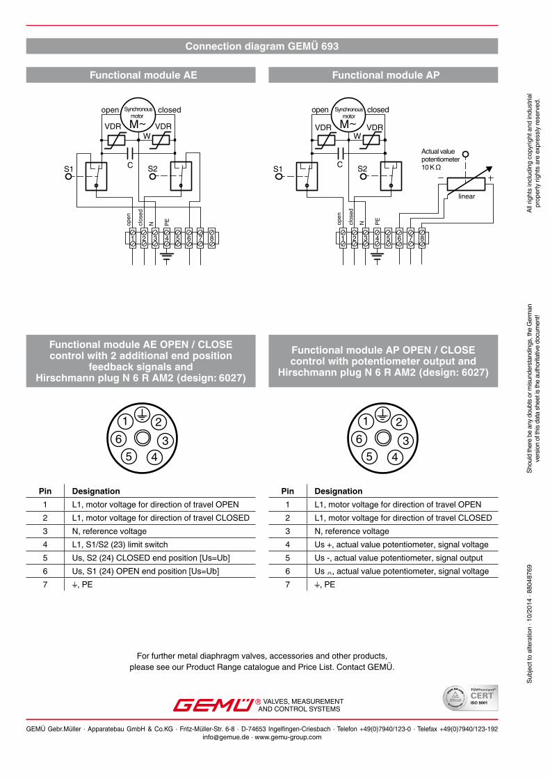
Pin Designation1 L1, motor voltage for direction of travel OPEN2 L1, motor voltage for direction of travel CLOSED3 N, reference voltage4 Us +, actual value potentiometer, signal voltage5 Us -, actual value potentiometer, signal output6 Us , actual value potentiometer, signal voltage7 , PE
Functional module AE OPEN / CLOSE control with 2 additional end position
feedback signals and Hirschmann plug N 6 R AM2 (design: 6027)
Functional module AP OPEN / CLOSE control with potentiometer output and
Hirschmann plug N 6 R AM2 (design: 6027)
Pin Designation1 L1, motor voltage for direction of travel OPEN2 L1, motor voltage for direction of travel CLOSED3 N, reference voltage4 L1, S1/S2 (23) limit switch5 Us, S2 (24) CLOSED end position [Us=Ub]6 Us, S1 (24) OPEN end position [Us=Ub]7 , PE