Development of a ball valve with pvD-coateD metal-to-metal sealing mechanism
15
* For correspondence. 390 Journal of the Balkan Tribological Association Vol. 18, No 3, 390–404 ( 2012) Coatings DEVELOPMENT OF A BALL VALVE WITH PVD-COATED METAL-TO-METAL SEALING MECHANISM K.-D. BOUZAKIS a,b *, F. KLOCKE b,c , A. TSOUKNIDAS a,b , S. KOMBOGIANNIS a,b , D. MISSIRLIS d , Z. VLAHOSTERGIOS d , A. SIDERIDIS d , K. YAKINTHOS d , A. TZEVELEKIS e , G. STABILIEV e , S. BOLZ f a Laboratory for Machine Tools and Manufacturing Engineering, Mechanical Engineering Department, Aristoteles University of Thessaloniki, GR 54 124 Thessaloniki, Greece E-mail: [email protected] b Fraunhofer Project Center Coatings in Manufacturing, in Centre for Research and Technology Hellas (CERTH), Thessaloniki, Greece and in the Fraunhofer Institute for Production Technology (IPT), Aachen, Germany c Laboratory for Machine Tools and Production Engineering, RWTH Aachen University, Aachen, Germany d Laboratory of Fluid Mechanics and Turbomachinery, Mechanical Engineering Department, Aristoteles University of Thessaloniki, Thessaloniki, Greece e ENIMEX S.A., Industrial Area of Kilkis, Greece f CemeCon A.G., Würselen, Germany ABSTRACT Conventional ball valves are based on elastomeric sealing technologies which exhibit restricted wear resistance in the presence of network impurities while re- quiring high operating torques. In the described investigations, the elastomeric sealing of a 2-inch floating ball valve was replaced by a metal-to-metal seating for attaining specific application requirements, without major dimensional changes. In order to avoid the use of elastomerics and achieve a high performance rating of the valve (Class VI shut-off), computational fluid dynamics (CFD) simulations were employed to predict the optimum contact geometry of ball/seating. A high accuracy contact was obtained through precision turning of the hard- ened metal shell (ball seating) and by grinding of its counter ball body. Both com- ponents, ball and seating, were appropriately heat treated and subsequently coated with a nanostructured diamond like carbon (DLC) coating, applied by physical vapour deposition (PVD) techniques, providing superior surface strength charac- teristics and nearly frictionless operation.
-
Upload
independent -
Category
Documents
-
view
5 -
download
0
Transcript of Development of a ball valve with pvD-coateD metal-to-metal sealing mechanism

* For correspondence.
390
Journal of the Balkan Tribological Association Vol. 18, No 3, 390–404 (2012)
Coatings
Development of a ball valve with pvD-coateDmetal-to-metal sealing mechanism
K.-D. BouzaKisa,b*, F. KlocKeb,c, a. TsouKniDasa,b,s. KomBogiannisa,b, D. missirlisd, z. VlahosTergiosd,a. siDeriDisd, K. YaKinThosd, a. TzeVeleKise, g. sTaBilieVe,s. Bolzf
a Laboratory for Machine Tools and Manufacturing Engineering, Mechanical Engineering Department, Aristoteles University of Thessaloniki,GR 54 124 Thessaloniki, GreeceE-mail: [email protected] Fraunhofer Project Center Coatings in Manufacturing, in Centre for Research and Technology Hellas (CERTH), Thessaloniki, Greece and in the Fraunhofer Institute for Production Technology (IPT), Aachen, Germanyc Laboratory for Machine Tools and Production Engineering, RWTH Aachen University, Aachen, Germanyd Laboratory of Fluid Mechanics and Turbomachinery, Mechanical Engineering Department, Aristoteles University of Thessaloniki, Thessaloniki, Greecee ENIMEX S.A., Industrial Area of Kilkis, Greecef CemeCon A.G., Würselen, Germany
aBsTracT
conventional ball valves are based on elastomeric sealing technologies which exhibit restricted wear resistance in the presence of network impurities while re-quiring high operating torques. in the described investigations, the elastomeric sealing of a 2-inch floating ball valve was replaced by a metal-to-metal seating for attaining specific application requirements, without major dimensional changes. in order to avoid the use of elastomerics and achieve a high performance rating of the valve (Class VI shut-off), computational fluid dynamics (CFD) simulations were employed to predict the optimum contact geometry of ball/seating.
A high accuracy contact was obtained through precision turning of the hard-ened metal shell (ball seating) and by grinding of its counter ball body. Both com-ponents, ball and seating, were appropriately heat treated and subsequently coated with a nanostructured diamond like carbon (DLC) coating, applied by physical vapour deposition (PVD) techniques, providing superior surface strength charac-teristics and nearly frictionless operation.

391
nanoindentations provided information regarding the coatings properties, while nanoimpacts were employed to determine the impact abrasive wear of the developed components.
Keywords: crude gas, ball valve, manufacturing process development, PVD coating.
aims anD BacKgrounD
Pipelines are the favoured mode of transportation for crude gas and oil, as they sustain the safe transportation of these media in large quantities in a cost-efficient and environmentally friendly manner. According to P&GJ latest international survey1, 39 042 km of pipelines were under construction in early 2010, increasing by more than 35% compared to 2009, while the planned projects at that point ac-counted for roughly 106 802 km, affirming the global importance of this rapidly growing sector.
Pipeline infrastructures have to consider several international legislations, concerning hazards and pipeline integrity2, not only arising from the life threat-ening nature of possible failure, but also in view of the enormous capital invest-ments associated to these networks. in these terms, it is crucial to maintain relia-ble operational characteristics over a long period of time or ease the replacement of degenerated network parts. even though several proactive inspection proce-dures have been developed to detect pipeline defects3,4, their restoration might prove problematic due to the restricted accessibility of the majority of installed pipelines, as approximately half of them are not conventionally piggable5.
The foregoing facts, can note the necessity of long-term leak-free perfor-mance of network parts, especially those controlling the gas or oil flow, like cut-off valves. The use of the term valve leakage can be twofold, referring to its seal-ing tightness (internal leakage across the seat from upstream to downstream) and fugitive emissions, concerning external losses towards the environment. Fugitive emissions can be contained easily through proper valve design and material selec-tion6, while long-term sealing tightness poses a significant problem.
even though elastomeric sealing technologies provide leakage-free opera-tion, the presence of abrasive media within the gas/oil flow rapidly deteriorates the contact geometry through repeated impact of these particles thus impairing the valves sealing tightness. This phenomenon is crucial in aggressive applications, where conventional sealing technologies are replaced by metal-to-metal seatings.
In the described investigations, an efficient production technique of a PVD-coated metal-to-metal ball valve is introduced, achieving class Vi shutoff up to 100 bar. The selection of PVD technologies facilitates the deposition of a low friction coating with improved wear resistance, providing superior operation-al characteristics when compared to other sealing technologies.

392
conVenTional sealing Technologies
Industrial cut-off valves, used to control the flow of crude gas or oil through net-works, are in their majority ball valves ranging from 2 up to 60″ (Fig. 1). The seal-ing technology of these valves is predominantly based on a ball with an axial hole seated on the housing of the valve while the leakage free operation of the valve is commonly ensured by an elastomeric ring inserted between ball and seating.
The main obstacle imposed on the working principle of these conventional elastomeric valves is associated with the presence of abrasive particles within the transported medium. Crude gas/oil generally contain micro- and nano-particles which are considered as impurities and are gathered by filters within the network. it is, however, inevitable that some of these abrasive particles are present in the pipelines, causing a degeneration of its components. conventional elastomeric ball valves are inclined to drastic debilitation of their sealing capacity due to the continuous impact of these particles on the elastomeric sealing while abrasive elements are also jammed in the ball-sealing interface piercing the elastomeric during its operation (opening closing cycle). This results in leakages after only a few operating cycles of the valve. A further limitation of elastomeric seating is associated with the operating temperature of the valve which must be limited to a certain range in order to ensure the unhindered function of the elastomeric sealing.
These restrictions lead to the construction of metal-to-metal valves, based on high-alloyed steels and coatings, exhibiting increased wear resistance. Even those, however, fail to maintain their structural integrity over a long period of time, while resulting in enormous operating (opening-closing) torques due to the pretension required to ensure proper sealing.
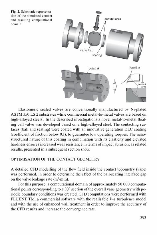
The set-up and working principle of a floating metal-to-metal ball valve are schematically presented in Fig. 2.
fig. 1. characteristic examples of crude gas/ oil ball valvesfront view
front view
393
Elastomeric sealed valves are conventionally manufactured by Ni-plated ASTM 350 LS 2 substrates while commercial metal-to-metal valves are based on high-alloyed steels7. In the described investigations a novel metal-to-metal float-ing ball valve was developed based on a high-alloyed steel. The contacting sur-faces (ball and seating) were coated with an innovative generation Dlc coating (coefficient of friction below 0.1), to guarantee low operating torques. The nano-structured nature of this coating in combination with its elasticity and elevated hardness ensures increased wear resistance in terms of impact abrasion, as related results, presented in a subsequent section show.
oPTimisaTion oF The conTacT geomeTrY
A detailed CFD modelling of the flow field inside the contact topometry (vane) was performed, in order to determine the effect of the ball-seating interface gap on the valve leakage rate (m3/min).
For this purpose, a computational domain of approximately 50 000 computa-tional points corresponding to a 30° section of the overall vane geometry with pe-riodic boundary conditions was created. CFD computations were performed with FluenT Tm, a commercial software with the realisable k–ε turbulence model and with the use of enhanced wall treatment in order to improve the accuracy of the cFD results and increase the convergence rate.
fig. 2. schematic representa-tion of the simulated contact and resulting computational domain
contact area
contactarea
valve ballseating
detail Adetail A
flow

394
During the cFD computations the following parameters were considered as variables:
• minimum gap width within the vane (4 cases were examined correspond-ing to 1,5, 30 and 50 μm);
• vane contact length (2 cases were examined corresponding to 2.5 and 3.5 mm);• pressure inlet conditions (5 cases were examined corresponding to a rela-
tive inlet static pressure of 1, 6, 20, 50 and 100 bar);• the ‘vane leakage’ was also calculated as a function of the gas flow rate
(corresponding to the inlet pressure) passing though the vane. The computational domain together with the imposed boundary conditions
are demonstrated in Fig. 3 and represent a 30° section of the overall vane ge-ometry. Details of vane geometry from a perspective view are also presented along with the corresponding computational grid. The flow field was computed as steady and compressible, with methane being the working fluid.
fig. 3. Vane geometry de-tails (perspective and side view) and corresponding computational grid
Simulated vane geometry
gapwidth
contactlength
fig. 4. Typical velocity and pressure field, developing at a 50 μm gap width and a 2.5 mm vane length at 100 bar
velocity (m/s) static pressure (bar)
leakage
contactlength
stooped gas flow 3.36×10⁶
1.68×10⁶
-7×10⁴
4.14×10⁶
1×10⁷
6.72×10⁶
8.39×106775930
6204653101550

395
A typical plot of the developing velocity and pressure field is presented in Fig. 4 (case: 50 μm – 2.5 mm – 100 bar). As it can be seen, the static pressure drops rap-idly throughout the vane contact length and the overall vane geometry is acting in a similar manner as a converging and diverging nozzle. Thus, due to the high pressure difference between the inlet and the outlet of the vane geometry, the flow becomes supersonic after the end of the vane minimum distance. This effect is even more evident as the pressure difference between the inlet and the outlet increases. in addition, due to the highly compressible nature of the flow field, the maximum mass flow that can pass though the vane geometry is each time defined by the inlet total conditions, the minimum area in the vane geometry and the total pressure losses.
The cFD computed results are summarised in Fig. 5 (in a logarithmic scale) as a function of the vane gab width. The contact length did not significantly affect the leakage and thus the solved cases are not represented in the graph.
it is evident that the decrease of the minimum vane gap is the most important parameter regarding the methane flow passing through the vane. More specifical-ly, as the minimum vane distance reduces from 50 to 1 μm the mass flow passing through the vane is significantly reduced and thus, increasing the vane efficiency.
Finally, the increase of the inlet pressure produces an increase in the fluid quantity passing through the vane geometry and for all cases under investigation the maximum flow rate through the vane was presented for the maximum inlet pressure value of 100 bar. however, the effect of the inlet pressure is reduced as the inlet pressure increases and after approximately 20 bars no significant chang-es are presented.
it must, however, be stressed that these simulations consider a zero surface roughness, thus being purely theoretical. The calculated volume flow rate of Fig. 5 considers a worst case scenario, as the surface roughness of the interacting metal-lic parts creates a labyrinth like structure providing further sealing.
fig. 5. Valve leakage as a function of the vane gap width (at a contact length of 2.5 mm)
volu
me
flow
rate
(m3 /m
in)
volume flow
rate (m3/m
in)
10-6
10-5
10-4
10-3
10-1
10-2
10-3
10-4
10-5
10-6
00 10 20 30 40 50
5 vane gap width (µm)
1
6 bar50 bar100 bar
gapwidth
contactlength

396
manuFacTuring ProceDures For aTTaining high accuracY Balls anD seaTings
The objective of this investigation was to develop a high-precision manufacturing process for the metal-to-metal sealing components, as the flow simulation pre-sumed ideal surfaces without any roughness, the related manufacturing process of both, ball and seating, ought to be of high accuracy.
Based on the requirements of the introduced manufacturing process (hard-ness, thermal stability, etc.), a high-alloyed cold work steel was chosen. The high carbon content of this steel ensures optimum through-hardening properties and high thermal stability, facilitating the processing of the ball and the rings within narrow tolerances. After the pre-machining of the ball and the rings, they were heat-treated for 60 min at 1020°C and quenched in oil. Following this, the compo-nents were tempered at 530°C for 2 h reaching a hardness of 61.3 HRC.
The finishing of the ball was conducted with a specially developed corundum (al2o3) grinding tool wheel. This wheel was shaped to the desired geometry by a developed tool with diamond grains on a ball body for shaping and resharpening the grinding wheel, as demonstrated in Fig. 6.
fig. 6. Developed grinding process of the valve balls
Workpiece Grinding wheel
Grinding wheel shaping Grinding of the valve ball
Grinding wheel shapingand resharpening tool
holdercontactarea

397
The developed grinding mechanism leads to a surface roughness of the ball within Ra = 0.1 μm, while securing optimum of accuracy. All balls were sub-jected to a thorough quality control and their surfaces scanned with a coordinate measuring machine (CMM), the resulting surface accuracy and roughness are illustrated in the upper part of Fig. 7. The lower part of the same figure indicates the measured area of the ball.
fig. 7. Measured surface roughness and accuracy of the valve ball
(µm
)
28.5 29.0 29.5 30.0 30.5 31.0 31.5 32.0 32.5 33.0 33.5 34.0 28.5 28.5 28.5 28.5
-0.6
-0.4
-0.2
0.0
0.2
0.4
0.6
-0.6
-0.4
-0.2
0.0
0.2
0.4
0.6
±0.5
CMM accuracy measurement on the valve ball
fig. 8. Measured surface roughness and accuracy of the valve seating
CMM accuracy measurement on the valve seating
3
2
1
0
-1
-2
-3
3
2
1
0
-1
-2
-325 30 35 40 45 50 55 60 65 70 75 80 85 90 95 100 105
±1.5
(mm)
(µm
)
±1.5
(µm
)

398
Due to geometrical restrictions of the seating, its finishing was conducted through high precision hard turning at a CNC machine tool of high rigidity. This procedure was capable to generate a surface form accuracy of ±1.5 and ±0.5 μm for the seating and the ball, respectively, as presented in Fig. 8.
coaTing characTerisaTion
Following their manufacturing process, the working surfaces of the balls and seatings were coated via a PVD process, depositing a low friction Dlc coating. an uncoated seating along with a coated one can be seen in Fig. 9. The coating
deposition step enhanced the smooth operation of the valves and improved their wear resistance in abrasive en-vironments. The final valve ball along with it counter-body (seating) is pictured in Fig. 10. The dark shad-ed surface of the ball and seating rep-resents the coated area, whereas the grey parts are areas machined after the coating process to minimise the contact surface and suite the geomet-rical characteristics of the seating.
Strength properties by nanoindenta-tions determined. The precise know-ledge of coatings mechanical proper-ties is always a core issue in technical applications. The constitutive law of the investigated coatings, in terms of stress–strain curves, was obtained by an experimental-analytical proce-dure based on nanoindentations and a Fem-based algorithm. The experi-mental load-displacement indenta-tion diagram is used as input data to a Fem model which determines the stress–strain curve of the examined material. in order to proceed with the simulation procedure, this curve is digitized in small steps. The very first region of the examined curve corre-sponds to the elastic behaviour of the
fig. 9. substrate material and Dlc-coated seat-ings
fig. 10. Dlc-coated ball and seating

399
material, where only elastic deformations occur during the indenter penetration. Further penetration leads to the elastoplastic flow of the examined material at the contact area beneath the indenter. a diamond Berkovich intender was applied for all nanoindentation measurements, while the maximum applied penetration load was limited to 15 mN. Nano- and Vickers-hardness results on low alloyed and high alloyed steel, before and after coating, are demonstrated in Fig. 11.
nanoindentations were also applied to determine the elastic properties of the Dlc-coated seatings and compare them to the ni-plated seatings. The maximum applied penetration load was limited to 15 mN in order to evaluate the coating and circumvent interference of the substrate material. a comparison of the achieved maximum indentation depths on the Dlc-coated and ni-plated seatings indicates a significantly increased hardness of the newly developed film as illustrated in Fig. 12. a similar response to the Dlc-coated specimen is observed in the case of
00 5
indentation load (mN)
Resulting propertiesProperty
Substrate the Vickershardness
158 –
61.3
HRC
61.4
733
729
Steel
High-alloyedsteel
(before PVD)
High-alloyedsteel
(after PVD)
inde
ntat
ion
dept
h (µ
m)
10 15
1
2
3
4
high-alloyed steel(after coatingdeposition)
high-alloyed steel(before coating deposition)
steel
fig. 11. nanoindentation results of the conventional valve materials
00 5
indentation load (mN)
Resulting propertiesProperty
Substrate
Ni
E (GPa) HV (MPa)
568
1738
209
194DLCinde
ntat
ion
dept
h (µ
m)
10 15
1
2
3
4
DLC
Ni
fig. 12. nanoindentation results of ni-plated and Dlc-coated materials

400
the high-alloyed steel rich in hard carbides, applied to improve the ball resistance against impact abrasive wear.
The nanoindentation results of the examined materials were evaluated by the sscuBoni algorithm8 and although the determined penetration depths hmax (at a 15 mN load) demonstrate small deviations, when comparing the DLC and high-alloyed steel properties, both compared favourably to the Ni material of the electrolytically coated balls.
Impact abrasion by nanoimpacts determined. a further pivotal parameter is the developing ball wear of the contacting surfaces during the valve operation. in conventional elastomeric valves, with ni-plated balls, the wear increases due to high velocity impacts of small hard particles.
Even though, the metal-to-metal lay out of the introduced valve obviates the use of elastomerics, the surfaces of both valve and seating are exposed to the network impurities. Nanoimpact experiments were employed to investigate the brittleness of the examined materials9 for assessing the effect of small particles impact on the ball surfaces. Nanoimpact tests were carried out by a microma-Terials nanoTest Tm device, using a sharp cube corner diamond indenter. in nanoimpact test, a solenoid is used to pull the indenter off the surface and to re-accelerate it from a small distance against the film10. an appropriate automa-tion enables repetitive impacts at the same position on the sample surface at a set
fig. 13. nanoimpact re-sults at different impact forces on Dlc coating and high-alloyed steel
800
600
400
200
0
800
600
400
200
00 300 600 900 1200 1500 1800
DLC coatingcoatingimpact
force F
indentersubstrate 100
50F=30mN
100
impa
ct d
epth
(nm
)
50F=30mN
High-alloyed steel
number of impactsDiamond cube corner indenter, impact frequency: 1Hz

401
frequency. The evolution of the indentation depth, due to the progressing film damage during the repetitive impacts, is continuously monitored.
The courses of the maximum attained impact depths versus the number of impacts, on the high-alloyed steel and on the DLC-coated components are indi-cated in Fig. 13 at various impact loads.
The wear progress (up to 800 impacts) of all examined materials versus the impact load, is presented in Fig. 14. The displayed results confirm the superior-ity both of the high-alloyed steel and DLC coating. A comparison of the attained results stipulates that the steel with high carbide content wears more intensively compared to the Dlc-coated surface, due to its higher brittleness.
oPeraTional TesTs
Operating torque (opening-closing). The selected heat treatment of the ball and seating material provided thermal/structural stability of the components up to 400°c (ref. 7). This approach provided similar thermal expansion characteristics of the valves functioning parts, maintaining the essential contact geometry and thus fostering a class Vi sealing tightness up to these temperatures. The applied coating exhibited a coefficient of friction less than 0.1 resulting in a substantially decreased operating torque when compared to an uncoated bal valve without dimensional modification and an conventional elastomeric seating (for a line pressure of 6 bar). The experimental set up, employed to measure the operation torque over repeated open-close cycles is illustrated in Fig. 15.
fig. 14. measured wear progression on Dlc, Wc and ni-coated substrates up to 800 impacts
800 impacts
rising up to 1700 nmat 100 mN
Ni-plated
DLC-coated
impact load (mN)
impa
ct d
epth
(nm
)
00
200
400
600
800
20 40 60 80 100
high-alloyed steelrich in carbides

402
in the case of the conventional valve with elastomeric sealing, a gradual in-crease in the required torque was observed over the 500 successive operational cycles, which can be attributed to the friction-based temperature increase of the sliding surfaces (ball material A350 LS2 with an EMP 30 μm ni coating and elastomeric sealing). Thermal effects were rather insignificant in the case of the coated metal-to-metal counter bodies, which due to the low coefficient of friction are less prone to thermal phenomena.
This device enabled the consecutive operation of the valve while registering the deviations in the actuating torque. Figure 16 demonstrates the recorded values over 500 open-close cycles both for an elastomeric sealing and the newly devel-oped metal-to-metal concept.
fig. 15. experimental device measuring the operation torque over repeated open-close cycles
double acting pneumatic valve
open
force transducer
actuatorrelaycounter-rele
pressure inlet
close
fig. 16. Decrease in the operating torque of the developed metal-to-metal seating for network pres-sure of 6 bar
elastomeric sealing
DLC-coated
30
25
20
15
10
oper
atin
g ro
rque
(Nm
)
0 100 200 300 400 500operating cycles (open–close)

403
Leakage free operation. The sealing tightness of the developed valve was tested with air, water and argon up to 100 bar. The results indicated a leak-free sealing of the valve in all examined scenarios while the operating torque was well below the one of a conventionally seated valve. Figure 17 demonstrates the sealing tightness of the valve for all examined scenarios along with the corresponding testing unit.
conclusions
in the described investigations an innovative ball valve with a PVD-coated metal-to-metal sealing was developed. The developed valve is based on a conventional ball valve design with slight dimensional modifications. This approach simpli-fies its manufacturing, while the metal-to-metal concept meets impact abrasion requirements, set by the valves operational needs, decreases the opening-closing torque and enhances its life time, compared to valves with elastomeric sealing rings and to metal-to-metal seating with high carbide content.
CFD simulations of the contact ball-seating geometry predicted the required level of dimensional accuracy which was achieved by form grinding of the ball and hard turning of the seating. Both components were subjected to thorough quality control and were coated with an innovative Dlc coating via a PVD process.
The performance characteristics of the developed floating ball valve were examined by nanoindentations, nanoimpacts and operational tests, leading to the following results:
• The application of grinding and hard turning of the heat-treated balls and seatings respectively ensured a high sealing performance of the valve (Class VI leakage) up to 100 bar.
fig. 17. leakage testing unit and valve tightness depending on medium and pressure
Leakage free operation
pressure inlet
0–100 bar
Medium
PressureWater NitrogenAir
6 bar
50 bar
100 bar
� � �
� � �
� � �

404
• The introduced sealing is improved in terms of wear resistance to network impurities, not only compared to conventional elastomeric sealings, but also to existing metal-to-metal concepts (high-alloyed steels with high carbide content).
• The nano-structured Dlc coating increased the wear resistance allowing an almost frictionless operation of metal-to-metal contact, decreasing the operat-ing torque by more than 20%. This torque remains almost constant compared to the corresponding one of valves with elastomeric sealing.
acKnoWleDgemenTs
The present work was conducted in the frame of the EUREKA-EUROSTARS E!4389 project. The authors would also like to acknowledge the support of Saint-Gobain in the development of the grinding and sharpening tools.
reFerences
1. r. TuBB: Pipeline & Gas Journal’s International Pipeline construction Report. Pipeline & Gas J., 237 (2010).
2. g. B. DeWolF: Process safety management in the Pipeline industry: Parallels and Differ-ences between the Pipeline integrity management (imP) rule of the Office of Pipeline Safety and the PSM/RMP approach for Process Facilities. J. of Hazardous Materials, 104 (1–3), 169 (2003).
3. e. W. KlechKa: Pipeline integrity management and corrosion control. materials Perfor-mance, 24 (2002).
4. m. T. van os, P. van masTrigT, a. Francis: an external corrosion Direct assessment Module for a Pipeline Integrity Management System. In: 6th International Pipeline Confer-ence, September 25–29, 2006, Calgary, Alberta, Canada.
5. H. A. KISHAwy, H. A. GABBAR: review of Pipeline integrity management Practices. in-ternational J. of Pressure Vessels and Piping, 87, 373 (2010).
6. S. lairD: choosing a Ball Valve that lowers emissions. World Pumps, 11, 28 (2008). 7. Stahlschlüssel-Key to Steel. Verlag Stahlschlüssel wegst GmbH, Marbach, Germany. 8. K.-D. BOUzAKIS, N. MICHAILIDIS, G. ERKENS: Thin hard coatings stress–strain curve
Determination through a Fem supported evaluation of nanoindentation Test results. surface and Coatings Technology, 142–144, 102 (2001).
9. K.-D. BouzaKis, n. michailiDis, s. HADJIyIANNIS, g. sKorDaris, g. erKens: The effect of specimen roughness and indenter Tip geometry on the Determination accu-racy of Thin hard coatings stress–strain laws by nanoindentation. materials characteriza-tion, 49, 149 (2003).
10. B. D. BeaKe, g. s. Fox-raBinoVich, s. c. VelDhuis, s. r. gooDes: coating opti-misation for high speed machining with advanced nanomechanical Test methods. surface and Coatings Technology, 203, 1919 (2009).
Received 17 November 2011Revised 12 January 2012