Bituminous Sealing of Low Volume Roads using Labour ... - ILO
148
-
Upload
khangminh22 -
Category
Documents
-
view
3 -
download
0
Transcript of Bituminous Sealing of Low Volume Roads using Labour ... - ILO


Ethiopian Roads Authority
Bituminous Sealing of Low Volume Roads using Labour Based Methods
Training Manual
International Labour OfficeCountry Office for Ethiopia and Somalia
Addis Ababa, Ethiopia June 2013

II
Bituminous Sealing of Low Volume Roads using Labour Based Methods
Copyright © International Labour Organization 2013 First published 2013
Publications of the International Labour Office enjoy copyright under Protocol 2 of the Universal Copyright Convention. Nevertheless, short excerpts from them may be reproduced without authorization, on condition that the source is indicated. For rights of reproduction or translation, application should be made to ILO Publications (Rights and Permissions), International Labour Office, CH-1211 Geneva 22, Switzerland, or by email:[email protected]. The International Labour Office welcomes such applications.
Libraries, institutions and other users registered with reproduction rights organizations may make copies in accordance with the licences issued to them for this purpose. Visit www.ifrro.org to find the reproduction rights organization in your country.
ISBN print: 978-92-2-128275-4 ISBN web pdf: 978-92-2-128276-1 ISBN CD ROM: 978-92-2-128279-2
International Labour Office;
The designations employed in ILO publications, which are in conformity with United Nations practice, and the presentation of material therein do not imply the expression of any opinion whatsoever on the part of the International Labour Office concerning the legal status of any country, area or territory or of its authorities, or concerning the delimitation of its frontiers.
The responsibility for opinions expressed in signed articles, studies and other contributions rests solely with their authors, and publication does not constitute an endorsement by the International Labour Office of the opinions expressed in them.
Reference to names of firms and commercial products and processes does not imply their endorsement by the International Labour Office, and any failure to mention a particular firm, commercial product or process is not a sign of disapproval.
ILO publications and electronic products can be obtained through major booksellers or ILO local office s in many countries, or direct from ILO Publications, International Labour Office, CH-1211 Geneva 22, Switzerland.
Catalogues or lists of new publications are available free of charge from the above address, or by email: [email protected]
Visit our web site: www.ilo.org/publns Printed in [Ethiopia]

III
Training Manual
Table of Contents
Preface ................................................................................................................................... VIIList of Abbreviations and Acronyms ....................................................................... VIIITraining Modules ............................................................................................... 11. Introduction to bituminous sealing .................................................... 1
1.1. Purpose of sealing .......................................................................................... 11.2. Design of Low Volume Sealed Road (LVSR) ........................................ 21.3. Construction quality standards ................................................................ 31.4. Construction methods .................................................................................. 41.5. Choice of seal .................................................................................................... 91.6. Labour based sealing options ................................................................... 101.7. Types of bituminous binders .................................................................... 12
1.7.1. Penetration grade and cut-back bitumen ............................... 121.7.2. Bitumen emulsions ........................................................................... 141.7.3. Prime ...................................................................................................... 22
2. Preparations for sealing operations ................................................... 252.1. Work Planning and Preparations ............................................................ 25
2.1.1. Procurement of materials .............................................................. 252.1.2. Site organization ................................................................................ 252.1.3. Base preparations ............................................................................. 262.1.4. Cleaning the base ............................................................................... 272.1.5. Dampening of the base .................................................................... 282.1.6. Protection of road furniture ......................................................... 282.1.7. Hand tools and equipment ............................................................ 292.1.8. Consumable items ............................................................................. 29
2.2. Operation of the Motorized Bitumen Sprayer.................................... 292.3. The spray procedure ..................................................................................... 322.4. Achieving uniform spray rates .................................................................. 33
2.4.1. Delivery rate of the pump .............................................................. 332.4.2. Time control of spray rates ........................................................... 342.4.3. Training of spray equipment operators and team .............. 342.4.4. The spray lance................................................................................... 36
2.5. Application of binder .................................................................................... 383. Quality Assurance and Control ............................................................. 43
3.1. Definitions ......................................................................................................... 433.2. Quality Assurance .......................................................................................... 43

IV
Bituminous Sealing of Low Volume Roads using Labour Based Methods
3.3. Quality Control ................................................................................................ 463.4. Relaxation of Standards .............................................................................. 48
4. Sealing operations ..................................................................................... 494.1. General ................................................................................................................ 494.2. Site preparations ............................................................................................ 504.3. Testing of materials ....................................................................................... 51
4.3.1. Determination of the Average Least Dimension (ALD) of seal aggregates .................................................................. 524.3.1.1. Determination of the aggregate
application rate ................................................................... 524.4. Spotting and spreading of aggregates ................................................... 544.5. Weather constraints ...................................................................................... 574.6. Traffic control .................................................................................................. 574.7. Occupational Health and Safety ............................................................... 58
4.7.1. Traffic control...................................................................................... 584.7.2. Safe storing, handling and spraying of hot bitumen
products .................................................................................................. 584.7.3. Personal Protective Equipment (PPE) ..................................... 594.7.4. First Aid ................................................................................................. 604.7.5. Firefighting equipment ................................................................... 60
4.8. Prime ...................................................................................................................... 604.8.1. Design ..................................................................................................... 60
4.8.1.1. Materials ................................................................................ 604.8.1.2. Prime application rates ................................................... 614.8.1.3. Construction Plant and Equipment ............................ 614.8.1.4. Construction ......................................................................... 62
4.8.2. Weather constraints ......................................................................... 644.8.3. Quality control .................................................................................... 64
4.9. Hot bitumen seals ............................................................................................. 654.9.1. Otta Seal ................................................................................................. 65
4.9.1.1. Description ............................................................................ 654.9.1.2. Design ...................................................................................... 664.9.1.3. Materials ................................................................................ 674.9.1.4. Construction plant and equipment ............................ 694.9.1.5. Screening of aggregates ................................................... 694.9.1.6. Construction ......................................................................... 704.9.1.7. Quality Control and Aftercare ....................................... 74

V
Training Manual
4.10. Emulsion based seals ................................................................................... 764.10.1. Sand Seal ............................................................................................. 76
4.10.1.1. Description ......................................................................... 764.10.1.2. Design ................................................................................... 774.10.1.3. Construction Plant and Equipment ......................... 774.10.1.4. Materials ............................................................................. 774.10.1.5. Application rates ............................................................. 774.10.1.6. Construction ...................................................................... 784.10.1.7. Quality control .................................................................. 79
4.10.2. Slurry Seal .......................................................................................... 804.10.2.1. Description ......................................................................... 804.10.2.2. Design ................................................................................... 804.10.2.3. Materials ............................................................................. 804.10.2.4. Construction Plant and Equipment ......................... 814.10.2.5. Construction ...................................................................... 824.10.2.6. Weather constraints ....................................................... 844.10.2.7. Traffic control ................................................................... 844.10.2.8. Quality control .................................................................. 84
4.10.3. Surface dressing .............................................................................. 854.10.3.1. Description ......................................................................... 854.10.3.2. Design ................................................................................... 854.10.3.3. Materials ............................................................................. 854.10.3.4. Aggregate application rate .......................................... 874.10.3.5. Binder application rate ................................................. 874.10.3.6. Construction Plant and Equipment ......................... 894.10.3.7. Construction ...................................................................... 894.10.3.8. Constructing a Double Surface Dressing ............... 944.10.3.9. Weather constraints ....................................................... 944.10.3.10. Traffic control ................................................................. 954.10.3.11. Quality control ............................................................... 95
4.10.4. Cape Seal ............................................................................................. 964.10.4.1. Description ......................................................................... 964.10.4.2. Design ................................................................................... 964.10.4.3. Materials ............................................................................. 974.10.4.4. Aggregate application rate .......................................... 974.10.4.5. Binder application rate ................................................. 974.10.4.6. Construction Plant and Equipment ......................... 984.10.4.7. Construction ...................................................................... 984.10.4.8. Weather constraints ....................................................... 1024.10.4.9. Traffic control ................................................................... 1024.10.4.10. Quality control ............................................................... 102
4.10.5. Modified Otta Seal or Penetration Seal.................................. 1034.10.5.1. Description ......................................................................... 103

VI
Bituminous Sealing of Low Volume Roads using Labour Based Methods
4.10.5.2. Design ................................................................................... 1034.10.5.3. Materials ............................................................................. 1034.10.5.4. Construction Plant and Equipment ......................... 1054.10.5.5. Construction ...................................................................... 1064.10.5.6. Weather constraints ....................................................... 1074.10.5.7. Traffic control ................................................................... 1074.10.5.8. Quality control .................................................................. 107
4.10.6. Cold mix asphalt .............................................................................. 1094.10.6.1. Description ......................................................................... 1094.10.6.2. Design ................................................................................... 1094.10.6.3. Materials ............................................................................. 1094.10.6.4. Construction Plant and Equipment ......................... 1114.10.6.5. Construction ...................................................................... 1124.10.6.6. Weather constraints ....................................................... 1214.10.6.7. Traffic control ................................................................... 1224.10.6.8. Quality control .................................................................. 122
5. Maintenance of thin bituminous seals ............................................... 1245.1. Definitions ........................................................................................................... 1245.2. Routine Maintenance of thin bituminous seals ................................... 124
5.2.1. Repair of minor ruts and depressions ..................................... 1255.2.2. Local Sealing ........................................................................................ 1265.2.3. Crack sealing ........................................................................................ 1275.2.4. Improvement of surface texture ................................................. 1285.2.5. Patching ................................................................................................. 1295.2.6. Repair of edge breaks ...................................................................... 1305.2.7. Slurry Sealing ...................................................................................... 131
5.3. Periodic Maintenance ..................................................................................... 1325.3.1. Fog spray / rejuvenation spray .................................................... 1325.3.2. Reseal ...................................................................................................... 133
6. Productivity guide ..................................................................................... 135References ............................................................................................................................ 136

VII
Training Manual
PrefaceThe International Labour organization (ILO) and Government of Ethiopia (GoE) have collaborated since the 1980s in the area of Employment Intensive Investment Programmes (EIIP). ILO has supported the government in introducing the application of employment intensive approaches (EIA), developing planning and implementation tools, capacity building interventions and most recently the introduction of emerging entrepreneurs to partner the government in the delivery process.
In 2011, the Government launched a national initiative called the Universal Rural Roads Access Program (URRAP) with the objective of connecting each Woreda and Kebele to an all-weather road. The program is running over five years from 2011 to 2015, and it is one of the components of the 4th Road Sector Development Program (RSDP IV) for the period 2011-15. Under URRAP, the government plans to construct over 72,000 km of all-weather access roads mainly using local resources. Emerging local entrepreneurs, i.e. both contractors and consultants, will implement the planned work under URRAP. Labour based techniques have been identified as the preferred methods of delivery.
URRAP is primarily designed to construct gravel-surfaced roads. However, increasingly scarce gravel deposits coupled with high cost of routine maintenance and environmental degradation have caused the Ethiopian Roads Authority (ERA) to seek alternative surfacing solutions for low volume roads that supports delivery of URRAP and road infrastructure development in urban and peri-urban environments as part of the government’s development agenda for reduction of unemployment and poverty.
To this end ERA has constructed trial sections of Single Surface Dressing using labour based methods as well as two Otta Seal sections using a variety of natural and crushed aggregates with good results.
The ILO is promoting the extensive use of local resources as it optimizes the creation of employment opportunities to the unemployed, creates conducive environment for wider skills development and encourages the participation of emerging entrepreneurs in the local development process. In this regard, the ILO has widened the application of labour-based methods and accumulated a wealth of knowledge on the construction and sealing techniques of low volume roads.
In order to build local capacity for constructing Low Volume Sealed Roads (LVSR) using labour based methods, GoE has requested ILO to assist with the production of training material aimed at local contractors and consultants building on the in-country as well as extensive regional and international experience in the field.

VIII
Bituminous Sealing of Low Volume Roads using Labour Based Methods
List of Abbreviations and Acronyms AADT Average Annual Daily Traffic
AASHTO American Association of State Highway and Transportation Officials
ACV Aggregate Crushing Value
ADT Average Daily Traffic
AIV Aggregate Impact Value
ALD Average Least Dimension
ASTM American Society for Testing and Materials
BS British Standard
CBR California Bearing Ratio
CIDB Construction Industry Development Board
CMA Cold Mix Asphalt
COLTO Committee on Land and Transport Officials
CS Cape Seal
CSIR Council for Scientific and Industrial Research
DCP Dynamic Cone Penetrometer
DSD Double Surface Dressing
DOS Double Otta Seal
EIA Employment Intensive Approaches
EIIP Employment Intensive Investment Programme(s)
EPWP Expanded Public Works Programme
ERA Ethiopian Roads Authority
ETB Emulsion Treated Base
FI Flakiness Index
GoE Government of Ethiopia
ILO International Labour Organization
LAA Loa Angeles Abrasion Value
LBC Labour Based Construction
LBM Labour Based Methods
LBS Labour Based Sealing
LBT Labour Based Technology
LDPW Limpopo Department of Public Works
LIC Labour Intensive Construction
LVSR Low Volume Sealed Road
OMC Optimum Moisture Content
OPC Ordinary Portland Cement

IX
Training Manual
O/W Oil in Water (emulsion)
PI Plasticity Index
PPE Personal Protective Equipment
PTR Pneumatic Tyre Roller
QA Quality Assurance
QC Quality Control
RSDP Road Sector Development Programme
SA South Africa
SABS South African Bureau of Standards
SABITA South African Bitumen Association
SANS South African National Standards
SLS Slurry Seal
SOS(+SS) Single Otta Seal (+Sand Seal)
SS Sand Seal
SSD Single Surface Dressing
STM Standard Test Method
TRH Technical Report for Highways
TRL Transport Research Laboratory
URRAP Universal Rural Roads Access Programme
VOC Vehicle Operating Costs
VPD Vehicles per day
W/O Water in Oil (inverted emulsion)
10% FACT 10% Fines (aggregate crushing) value

X
Bituminous Sealing of Low Volume Roads using Labour Based Methods

1
Training Manual
1. In
trod
ucti
on to
bi
tum
inou
s se
alin
g
Training Modules1. Introduction to bituminous sealingLearning objective:
• General knowledge about reasons for sealing, design of LVSR, construction methods, choice of seals and bituminous materials
1.1. Purpose of sealing
Unsealed earth and gravel roads are subject to rapid deterioration mainly due to non-traffic-related factors such as climate, terrain, soil conditions and ineffective maintenance thus resulting in huge annual maintenance costs. Furthermore dust pollution created by these roads cause adverse environmental degradation and health hazards. The fast depletion of the non-renewable gravel sources makes the rehabilitation and maintenance of the expanding road network unsustainable.
Sealing of gravel roads using appropriate designs conducive to labour-based work methods can reduce maintenance requirements while at the same time increase benefits to local economies. Regional research has shown that it can be economically justified in the long term to seal gravel roads, considering life cycle costs, even at traffic levels significantly less than 100 vehicles per day (vpd). 1
The sealing of these roads serves many purposes:
• Provide safe and reliable all weather access
• Provide a smooth running surface for the motorized traffic and thus reduce the Vehicle Operating Costs (VOC)
• Provide good skid resistance for safe driving at the designated speed limit and for breaking and stopping at safe distance for obstacles in the road. The importance of good skid resistance increases with higher traffic volumes and higher speed limits.
• Protect the pavement structure from wear and tear by traffic (wearing course)
• Protect the pavement structure from deterioration due to ingress of moisture in the pavement layers (waterproofing)
1 SADC Guideline on Low Volume Sealed Roads (July 2003)

2
Bituminous Sealing of Low Volume Roads using Labour Based Methods
1.2. Design of Low Volume Sealed Road (LVSR)
As shown in Figure 1 the deterioration LVSR is more influenced by environmental factors than by traffic.
Figure 1: Contribution of traffic and environment on pavement deterioration according to traffic levels
The lower traffic loading on LVSRs allows for use of non-standard, natural materials that would normally not be considered for use in the pavement layers. The most important aspect of LVSR construction and design is to achieve maximum possible density of the pavement layers and to provide a functional drainage system and an impervious seal to prevent moisture ingress into the pavement.
The pavement is particularly vulnerable to wetting up and loss of strength near to the outer edge of the seal. Sealing of the shoulders will minimize the influence of moisture in the zone of seasonal moisture variation, see Figure 2, and reduce the risk of pavement failure in the outer wheel path.

3
Training Manual
1. In
trod
ucti
on to
bi
tum
inou
s se
alin
g
Figure 2: Moisture zones in a typical low volume road
1.3. Construction quality standards
For optimal long term performance of LVSRs, the adherence to sound construction practices is vital.
For the sub-grade formation and pavement layers, see Figure 3 below, compaction must be done at Optimum Moisture Content (OMC) “to refusal” with the heaviest compaction plant available, i.e. to the point where the material no longer moves under the roller. Good control of the construction process is therefore vital.
Bituminous Sealing of Low Volume Roads using Labour Based Methods Training Manual
9
The lower traffic loading on LVSRs allows for use of non-standard, natural materials that would normally not be considered for use in the pavement layers. The most important aspect of LVSR construction and design is to achieve maximum possible density of the pavement layers and to provide a functional drainage system and an impervious seal to prevent moisture ingress into the pavement.
The pavement is particularly vulnerable to wetting up and loss of strength near to the outer edge of the seal. Sealing of the shoulders will minimize the influence of moisture in the zone of seasonal moisture variation, see Figure 2, and reduce the risk of pavement failure in the outer wheel path.
Figure 2: Moisture zones in a typical low volume road
1.3 Construction quality standards For optimal long term performance of LVSRs, the adherence to sound construction practices is vital.
For the sub-grade formation and pavement layers, see Figure 3 below, compaction must be done at Optimum Moisture Content (OMC) “to refusal” with the heaviest compaction plant available, i.e. to the point where the material no longer moves under the roller. Good control of the construction process is therefore vital.
Figure 3: Typical road cross-section
Figure 3: Typical road cross-section

4
Bituminous Sealing of Low Volume Roads using Labour Based Methods
The effect of compaction to refusal is illustrated in Figure 4 and Figure 4 below:
Figure 5: Deflection / pavement life to refusal” relationship and benefits of “compaction to refusal”
Figure 4: Illustration of effect of “compacting
LVSRs should have a camber (or crossfall) of minimum 3.5%. This will ensure that water drains off the road quickly and prevent excessive moisture ingress into the pavement through minor cracks and other failures.
Thin bituminous seals are seldom 100% waterproof and a 3.5% camber will give a safety factor against water ponding on the road due to minor construction irregularities. Where ponding occurs, the force of the vehicle tyres will force some of the water to penetrate the seal and wet up the base layer with the risk of the base eventually failing.
1.4. Construction methods
Depending on the project objectives and circumstances for the particular project (e.g. location, availability of labour, equipment and materials), different construction approaches can be used:
• Conventional equipment based construction methods using heavy construction plant (graders, dozers, excavators, tippers, water bowsers, heavy vibrating rollers etc.). In this case labour will only be used where the equipment cannot access, for tasks that can only be performed by labour, traffic management, supporting activities etc.
• A mix approach using heavy equipment for the roadbed and subgrade formation and labour for the upper pavement layer(s), sealing and drainage works. This approach has been successfully used elsewhere and ensures good progress and a solid foundation for the road and at the same time gives ample opportunities for employment of local labour.
• Labour based methods for all construction activities supported by equipment, mainly for haulage and compaction.

5
Training Manual
1. In
trod
ucti
on to
bi
tum
inou
s se
alin
g
As shown in the Table 1 below the increase in labour content going from plant based to labour based construction methods for different types of roads, is quite considerable. The mixed approach will of course lie somewhere in between the figures shown.
Bituminous Sealing of Low Volume Roads using Labour Based Methods Training Manual
11
Road type WidthConstruction technology
Labour input / km (worker-days)
% increase in labour content
Plant-based 309 Labour-based 2 294 Plant-based 864 Labour-based 2 610 Plant-based 1 246 Labour-based 3 956 Plant-based 1 586 Labour-based 5 693 Plant-based 819 Labour-based 2 558 Plant-based 1 103 Labour-based 3 763 Plant-based 1 509 Labour-based 6 143
Class D Gravel Road 5 m 742 %
Class D Asphalt Road
3 m 302 %
5 m 317 %
6 m 359 %
Source: Construction Industry Development Board (CIDB) Best Practice Guideline Part 1
Class D Concrete Block Road
3 m 312 %
5 m 341 %
6 m 407 %
Table 1: Approximate comparison of labour inputs with labour- and plant based construction As shown in the pictures below construction of the sub-base, if required, and base in the mixed and labour based approaches can be done to great accuracy and quality using a shutter system which controls the layer thickness and enables the labourers to construct the base to within the tolerances for density, camber or crossfall and surface regularity.
Picture 1: Setting out shutters on prepared sub-base to accurate camber
Table 1: Approximate comparison of labour inputs with labour- and plant based construction
As shown in the pictures below construction of the sub-base, if required, and base in the mixed and labour based approaches can be done to great accuracy and quality using a shutter system which controls the layer thickness and enables the labourers to construct the base to within the tolerances for density, camber or crossfall and surface regularity.
Picture 1: Setting out shutters on prepared sub-base to accurate camber

6
Bituminous Sealing of Low Volume Roads using Labour Based Methods
Picture 2: Placing base material in between the shutters
Picture 3: Screeding off the base material to a level surface before compaction

7
Training Manual
1. In
trod
ucti
on to
bi
tum
inou
s se
alin
g
Picture 4: Base ready for compaction
Picture 5: Compaction of the base

8
Bituminous Sealing of Low Volume Roads using Labour Based Methods
Picture 6: Completed base being swept prior to sealing
Construction of an Emulsion Treated Base (ETB) has proven to be a great benefit to the small and inexperienced contractor. The emulsion treatment can be to the full depth of the base layer or only in the upper 1/3 of the base. In the latter case it’s termed a Composite ETB and it is constructed and compacted as one layer to prevent de-lamination of the treated layer from the rest of the base.
Emulsion treatment will increase the strength of the material and hence permit use of otherwise sub-standard material for the base. Design and construction of ETB is described in CIDB Best Practice Guideline Part 4, Section 4.6 and CIDB Practice Manual 3, Module 5.1 and 5.2.
The greatest advantage to contractors in labour based road construction is of a practical nature. An emulsion treated base stands up well for an extended period under traffic and inclement weather without damage until the contractor is ready to start the sealing operation. Although cement and lime may be incorporated in the ETB (cement as a catalyst to the curing and lime to reduce the PI of plastic materials), the ETB does not require watering for curing unlike cement or lime stabilized layers.
The emulsion treatment also makes priming of the base unnecessary and it ensures good bonding between the base and the seal.
The ETB is in itself more resilient to moisture than natural or cement/lime stabilized layers and will retard the development of potholes in case of seal failures.

9
Training Manual
1. In
trod
ucti
on to
bi
tum
inou
s se
alin
g
Picture 7: Compacted Composite ETB Base
Further reference material on labour based construction methods can be found in:
• Ethiopian TVET System – Summarized version of sample handout on labour based road construction and maintenance, Part 1
• Design Manual for Low Volume Roads – Part D (ERA 2011)
• Construction of Low Volume Sealed Roads – A Good Practice Guide to Labour-based Methods (ILO, 2013)
• CIDB Practice Manual 3 (CIDB, 2007)
1.5. Choice of seal
The choice of seal type depends on a number of factors such as:
• Type of pavement (strength, flexural properties)
• Economic and financial factors (funds available, life cycle costs)
• Required riding quality
• Operational factors (traffic, surface stresses, geometry)

10
Bituminous Sealing of Low Volume Roads using Labour Based Methods
• Safety (surface texture, interference with traffic)
• Environmental considerations (climate, noise)
• Construction and maintenance strategies
• Characteristics of available materials (aggregate, binder)
A Life Cycle Cost comparison of alternative surfacing types needs to be carried out in order to determine the most cost-effective solution. Such comparisons should consider not only initial construction costs, but also include maintenance and vehicle operating costs.
1.6. Labour based sealing options
The common types of bituminous seals for LVSRs are shown in Figure 6.
Figure 6: Common types of bituminous seals for LVSRs
None of these thin bituminous seals provide any additional structural strength to the pavement.
The seal types differ in their performance characteristics:
• In surface dressings the aggregates are glued to the base. The performance relies on good bonding between the aggregates and the base
• In Cape Seals the aggregates are glued to the base similar to Surface Dressings, but the retention of the aggregates is improved by the Slurry Seal filling the gaps between the aggregates

11
Training Manual
1. In
trod
ucti
on to
bi
tum
inou
s se
alin
g
• Both Surface Dressings and Cape Seals relies of good quality, high strength aggregates for good performance
• The Otta Seals and Cold Mix Asphalt perform more like Hot Mix Asphalt and rely on particle interlock and bonding between the graded aggregate particles more than the strength of the aggregates. Otta Seal and Cold Mix Asphalt therefore permit use of lower quality aggregates. These options therefore have the potential for cost savings when good quality aggregates are hard to come by.
• Sand Seals use graded aggregates up to 6.7 mm and perform like a “mini” Otta Seal. Crusher dust (grit) and natural river sands can be used. For good long term performance at least a Double Sand Seal is required. Single Sand Seals can be a useful option for temporary deviations.
• Slurry Seals also use graded aggregate, but are thicker than Sand Seals. Slurry Seal is not normally used a first seal on new construction, but is a useful option as a maintenance seal.
A guide to the selection of bituminous seal is shown in Table 2:
SS SLS SSD DSD CS SOS+SS DOS CMAShortMediumLongLightMediumHeavyLowMediumHighMildModerateSteepPoorModerateGoodPoorModerateGood
LowModerateHighLowModerateHigh
Key:
Suitable/preferred Less suitable/not preferred Not suitable/not applicable
Impact of traffic turning
action
Parameter DegreeType of Seal
Service life required
Traffic level
SS - Sand Seal, SLS - Slurry Seal, SSD - Single Surface Dressing, DSD - Double Surface Dressing, CS - Cape Seal, SOS+SS - Single Otta Seal + Sand Seal, DOS - Double Otta Seal, CMA - Cold Mix Asphalt
Gradient
Material quality
Pavement and base quality
Contractor experience /
capability
Maitenance capability
Suitability for LBM
Table 2: Guide to selection of bituminous seals for LVSRs

12
Bituminous Sealing of Low Volume Roads using Labour Based Methods
1.7. Types of bituminous binders
Bituminous binders for seals come either in the form of straight penetration grade bitumen, cut-back bitumen or bitumen emulsions. All of these can be modified with for instance crumbed rubber or latex to improve their properties. For this manual only un-modified bitumen emulsion binders will be discussed, but may be expanded later as the emulsion technology in Ethiopia evolves.
1.7.1. Penetration grade and cut-back bitumen
Use of straight penetration grade bitumen or cut-back bitumen (using solvents like kerosene and/or diesel) is not well suited for labour based operations due to the following:
• The bitumen must be heated to between 130 and 190oC before use. At these temperatures the bitumen is extremely flammable and can easily cause severe damage and injuries to personnel if not handled carefully and in accordance with safety regulations.
• Toxic fumes from hot bitumen pose health risks to labourers
Picture 8: Toxic fumes from hot bitumen spray
• For cost-effectiveness hot bitumen must be delivered in substantial quantities, sometimes over long hauling distances and preferably be sprayed in one continuous operation. This does not match well with the pace of labour based construction.

13
Training Manual
1. In
trod
ucti
on to
bi
tum
inou
s se
alin
g
• The pace of application of aggregate by labour is not commensurate with the fast spraying pace of a motorized bitumen distributor. Hence spraying of
•
•
•
•
• bitumen by the distributor is done in small sections at a time. Whilst waiting for the aggregate spreading before spraying the next section, the nozzles of the sprayer may get clogged leading to uneven spraying and low quality of the finished seal.
Picture 9: Slow manual spreading of aggregates
• Mobilization of bitumen distributors to remote sites is costly and may be difficult due to the condition of the transport route.
• Breakdown or malfunctioning of the distributor during the spraying operations will cause severe problems for the contractor who has mobilized a large work force for spreading the aggregates
• Successful spraying operations demands well trained operators, facilities for calibration of the equipment and equipment in impeccable working order, which experience has shown is not always the case
Cut-back bitumen is also commonly used as Prime, but is then heated only to 50-70 oC and can be sprayed on the road by means of small motorized bitumen sprayers. Care must still be taken when handling the bitumen at these temperatures, but this is deemed to be within the capabilities of the small and inexperienced. However, for Prime there are emulsion based alternatives that are more environmental- and labour friendly.
Currently, the general trend in the industry is to move away from use of hot bitumen for reasons mentioned above. The use of cold bitumen emulsions eliminates the health risks and the need for careful monitoring of the bitumen temperature, which is always a major challenge.

14
Bituminous Sealing of Low Volume Roads using Labour Based Methods
1.7.2. Bitumen emulsions
An emulsion is a dispersion of small droplets of one liquid in another liquid. Typical examples include such everyday products as milk, butter, mayonnaise, and cosmetic creams.
Bitumen emulsions come in three different types:
Oil in water Water in oil Multiple
Figure 7: Three types of bitumen emulsion
Standard bitumen emulsions are normally considered to be of the O/W type, i.e. it has tiny droplets of bitumen dispersed in the water phase, and contain from 40% to 75% bitumen, 0.1% to 2.5% emulsifier, 25% to 60% water plus some minor components. The “water-in-oil” or W/O emulsion is called inverted emulsion, i.e. it has tiny droplets of water dispersed in the bitumen. A type of inverted emulsion is used as prime.
The advantage of bitumen emulsions is that they can most of the time be used at ambient temperatures. Low temperature techniques for construction and maintenance reduce emissions, reduce energy consumption, avoid oxidation of the asphalt, and are less hazardous than techniques using hot bitumen. They are also more economical and environmentally friendly than cold techniques using cut back asphalts. The environmental benefit of asphalt emulsion is particularly positive when used for in-place or on-site techniques which avoid the energy usage and emissions associated with heating, drying, and haulage of aggregate.

15
Training Manual
1. In
trod
ucti
on to
bi
tum
inou
s se
alin
g
Picture 10: Microscope picture of bitumen emulsion
The appearance of bitumen emulsion is like a dark brown soup. The viscosity depends on the bitumen content, the higher the bitumen content, the higher the viscosity (or the thicker the soup).
Picture 11: Appearance of bitumen emulsion

16
Bituminous Sealing of Low Volume Roads using Labour Based Methods
Bitumen emulsion are manufactured by running the base penetration grade bitumen, normally 60/70 or 80/100 pen grade, through a mill to produce the tiny bitumen droplets, adding the emulsifier (soap) that attaches to the surface of the droplets and mixing the droplets with water. The emulsifier enables the droplets to stay in suspension without coalescing for an extended period. See the illustration below.
Depending on the type of emulsifier being used, the droplets can be given a negative or positive electrical charge or no charge at all. The electrical charge causes the droplets to expel each other thereby enabling them to stay in suspension.
Bituminous Sealing of Low Volume Roads using Labour Based Methods Training Manual
21
Bitumen emulsion are manufactured by running the base penetration grade bitumen, normally 60/70 or 80/100 pen grade, through a mill to produce the tiny bitumen droplets, adding the emulsifier (soap) that attaches to the surface of the droplets and mixing the droplets with water. The emulsifier enables the droplets to stay in suspension without coalescing for an extended period. See the illustration below.
Depending on the type of emulsifier being used, the droplets can be given a negative or positive electrical charge or no charge at all. The electrical charge causes the droplets to expel each other thereby enabling them to stay in suspension.
Figure 8: Schematic illustration of emulsion manufacturing process
There are three categories of bitumen emulsion used for road works:
Anionic emulsion (negatively charged) Cationic emulsion (positively charged) Non-ionic emulsion (no charge)
Bitumen
Emulsion
Figure 8: Schematic illustration of emulsion manufacturing process
There are three categories of bitumen emulsion used for road works:
• Anionic emulsion (negatively charged)
• Cationic emulsion (positively charged)
• Non-ionic emulsion (no charge)

17
Training Manual
1. In
trod
ucti
on to
bi
tum
inou
s se
alin
g
22
Figure 9: Anionic emulsion droplet
+
+ ++
+
+
+
++++
++
+
++
+
Cationic Emulsions Amines + Hydrochloric Acid = RNH3+
Bitumen droplet
pH < 4
+
Figure 10: Cationic emulsion droplet
Figure 9: Anionic emulsion droplet
22
Figure 9: Anionic emulsion droplet
+
+ ++
+
+
+
++++
++
+
++
+
Cationic Emulsions Amines + Hydrochloric Acid = RNH3+
Bitumen droplet
pH < 4
+
Figure 10: Cationic emulsion droplet
Figure 10: Cationic emulsion droplet

18
Bituminous Sealing of Low Volume Roads using Labour Based Methods
Bitumen emulsions are classified by the different setting times (time taken for the bitumen droplets to coalesce after application and the water to evaporate) and the stability of the emulsion (ability of the droplets to stay in suspension).
Both Anionic and Cationic emulsions can be:
• Rapid Setting (RS)
• Medium Setting (MS)
• Slow Setting (SS)
The grades of bitumen emulsions are determined by the amount of emulsifier being used in the manufacturing process, hence the amount of the electrical charge on each droplet. The higher the charge, the higher the stability of the emulsion. See the illustrations below.
The emulsion grades are:
• Spray grade
• Pre-mix grade
• Stable grade
Bituminous Sealing of Low Volume Roads using Labour Based Methods Training Manual
23
Bitumen emulsions are classified by the different setting times (time taken for the bitumen droplets to coalesce after application and the water to evaporate) and the stability of the emulsion (ability of the droplets to stay in suspension).
Both Anionic and Cationic emulsions can be:
Rapid Setting (RS) Medium Setting (MS) Slow Setting (SS)
The grades of bitumen emulsions are determined by the amount of emulsifier being used in the manufacturing process, hence the amount of the electrical charge on each droplet. The higher the charge, the higher the stability of the emulsion. See the illustrations below.
The emulsion grades are:
Spray grade Pre-mix grade Stable grade
+
+ ++
+
+
+
++++
+
+
+
++
+
Cationic Spray Grade
Bitumen droplet
0,25% emulsifier
Figure 11: Spray grade cationic droplet
Figure 11: Spray grade cationic droplet

19
Training Manual
1. In
trod
ucti
on to
bi
tum
inou
s se
alin
g
24
+
++
+
+
+
+
++++
++
+
+
++
Cationic Premix Grade
+
+
+
+
+
++
+ + ++
+
+
+++
0,5% emulsifier
Figure 12: Premix grade cationic droplet
+
+ ++
+
+
+
++++
++
+
+
++
Cationic Stable Grade
+
+
+
+
+
++
+ ++
+
+
+
+
+ +
+
++
++
1,0 to 1,5% emulsifier
Figure 13: Stable grade cationic droplet
Figure 12: Premix grade cationic droplet
24
+
++
+
+
+
+
++++
++
+
+
++
Cationic Premix Grade
+
+
+
+
+
++
+ + ++
+
+
+++
0,5% emulsifier
Figure 12: Premix grade cationic droplet
+
+ ++
+
+
+
++++
++
+
+
++
Cationic Stable Grade
+
+
+
+
+
++
+ ++
+
+
+
+
+ +
+
++
++
1,0 to 1,5% emulsifier
Figure 13: Stable grade cationic droplet
Figure 13: Stable grade cationic droplet

20
Bituminous Sealing of Low Volume Roads using Labour Based Methods
When the emulsion breaks (i.e. when the separation of the bitumen from the water phase starts) the colour turns from brown to black. The time it takes for this to happen depends on the type of emulsion used (Slow Setting, Medium Setting of Rapid Setting). Different processes are involved in the breaking and curing of emulsions:
• Chemical action (cationic)
• Water evaporation
• Mechanical action (rolling)
Bituminous Sealing of Low Volume Roads using Labour Based Methods Training Manual
25
When the emulsion breaks (i.e. when the separation of the bitumen from the water phase starts) the colour turns from brown to black. The time it takes for this to happen depends on the type of emulsion used (Slow Setting, Medium Setting of Rapid Setting). Different processes are involved in the breaking and curing of emulsions:
Chemical action (cationic) Water evaporation Mechanical action (rolling)
Figure 14: Curing of slow set emulsion
Figure 15: Curing of cationic emulsion by strong electrostatic/chemical attraction
Water evaporation
Water evaporation
Figure 14: Curing of slow set emulsion
Bituminous Sealing of Low Volume Roads using Labour Based Methods Training Manual
25
When the emulsion breaks (i.e. when the separation of the bitumen from the water phase starts) the colour turns from brown to black. The time it takes for this to happen depends on the type of emulsion used (Slow Setting, Medium Setting of Rapid Setting). Different processes are involved in the breaking and curing of emulsions:
Chemical action (cationic) Water evaporation Mechanical action (rolling)
Figure 14: Curing of slow set emulsion
Figure 15: Curing of cationic emulsion by strong electrostatic/chemical attraction
Water evaporation
Water evaporation
Figure 15: Curing of cationic emulsion by strong electrostatic/chemical attraction

21
Training Manual
1. In
trod
ucti
on to
bi
tum
inou
s se
alin
g
Emulsions also differ in the amount of bitumen they contain expressed as a percentage of the total volume. For surfacing applications this percentage is normally in the range of 60 – 70%
Different notifications are used for the emulsion classification:
Table 3: Classification of commonly available emulsions
In the ASTM classification system the letters (RS, CMS etc) denotes the rate of setting. The trailing number denotes the viscosity of the emulsion, the higher the number the higher the viscosity (higher bitumen content). The letters s or h denotes the hardness (penetration grade) of the base bitumen used for the emulsion, but the s is usually omitted when using 80/100 Pen Grade base bitumen. RS1 (or RS1-s) thus means a rapid setting anionic emulsion of low viscosity with a soft base bitumen, CMS2-h means a medium setting cationic emulsion of higher viscosity with a hard base bitumen.
• Soft base bitumen is of penetration grade 80/100
• Hard base bitumen is of penetration grade 60/70
In the more commonly used denotation CMS 65 or similar K2- 65 means a medium setting cationic emulsion with 65% bitumen content.
Typical surfacing applications of the various emulsion grades are shown below:
26
Emulsions also differ in the amount of bitumen they contain expressed as a percentage of the total volume. For surfacing applications this percentage is normally in the range of 60 – 70%
Different notifications are used for the emulsion classification:
Pen 80/100 Pen 60/70RS 60 A1-60 RS1 RS1-h
A1-55A1-40
MS 60 A2-57 MS1 MS1-hA2-50A3-57
SS 60 A4-60 SS1 SS1-hCRS 60 K1-60 CRS1 CRS1-hCRS 65 K1-65 CRS2 CRS2-hCRS 70 K1-70 CRS3 CRS3-hCMS 60 K2-60 CMS1 CMS1-hCMS 65 K2-65 CMS2 CMS2-hCSS 60 K3-60 CSS1 CSS1-hCSS 65 K3-65 CSS2 CSS2-h
ASTM classificationEmulsion GradesType of emulsion
Anionic emulsions
Cationic emulsions
Table 3: Classification of commonly available emulsions
In the ASTM classification system the letters (RS, CMS etc) denotes the rate of setting. The trailing number denotes the viscosity of the emulsion, the higher the number the higher the viscosity (higher bitumen content). The letters s or h denotes the hardness (penetration grade) of the base bitumen used for the emulsion, but the s is usually omitted when using 80/100 Pen Grade base bitumen. RS1 (or RS1-s) thus means a rapid setting anionic emulsion of low viscosity with a soft base bitumen, CMS2-h means a medium setting cationic emulsion of higher viscosity with a hard base bitumen.
Soft base bitumen is of penetration grade 80/100 Hard base bitumen is of penetration grade 60/70
In the more commonly used denotation CMS 65 or similar K2- 65 means a medium setting cationic emulsion with 65% bitumen content.
Typical surfacing applications of the various emulsion grades are shown below:
RS MS SS RS MS SSSand Seal √Slurry (for Cape) Seal √ √Surface dressing √ √Cape Seal √ √Modified Otta Seal √Cold Mix Asphalt √Fog spray √ √ √Tack coat √ √ √ √
Application Anionic Cationic
Table 4: Typical emulsion applications

22
Bituminous Sealing of Low Volume Roads using Labour Based Methods
26
Emulsions also differ in the amount of bitumen they contain expressed as a percentage of the total volume. For surfacing applications this percentage is normally in the range of 60 – 70%
Different notifications are used for the emulsion classification:
Pen 80/100 Pen 60/70RS 60 A1-60 RS1 RS1-h
A1-55A1-40
MS 60 A2-57 MS1 MS1-hA2-50A3-57
SS 60 A4-60 SS1 SS1-hCRS 60 K1-60 CRS1 CRS1-hCRS 65 K1-65 CRS2 CRS2-hCRS 70 K1-70 CRS3 CRS3-hCMS 60 K2-60 CMS1 CMS1-hCMS 65 K2-65 CMS2 CMS2-hCSS 60 K3-60 CSS1 CSS1-hCSS 65 K3-65 CSS2 CSS2-h
ASTM classificationEmulsion GradesType of emulsion
Anionic emulsions
Cationic emulsions
Table 3: Classification of commonly available emulsions
In the ASTM classification system the letters (RS, CMS etc) denotes the rate of setting. The trailing number denotes the viscosity of the emulsion, the higher the number the higher the viscosity (higher bitumen content). The letters s or h denotes the hardness (penetration grade) of the base bitumen used for the emulsion, but the s is usually omitted when using 80/100 Pen Grade base bitumen. RS1 (or RS1-s) thus means a rapid setting anionic emulsion of low viscosity with a soft base bitumen, CMS2-h means a medium setting cationic emulsion of higher viscosity with a hard base bitumen.
Soft base bitumen is of penetration grade 80/100 Hard base bitumen is of penetration grade 60/70
In the more commonly used denotation CMS 65 or similar K2- 65 means a medium setting cationic emulsion with 65% bitumen content.
Typical surfacing applications of the various emulsion grades are shown below:
RS MS SS RS MS SSSand Seal √Slurry (for Cape) Seal √ √Surface dressing √ √Cape Seal √ √Modified Otta Seal √Cold Mix Asphalt √Fog spray √ √ √Tack coat √ √ √ √
Application Anionic Cationic
Table 4: Typical emulsion applications
Table 4: Typical emulsion applications
1.7.3. Prime
The reasons for priming the base are:
• Assists in promoting adhesion between the base and the newly applied bituminous seal
• Inhibit ingress of water into the base, whilst not hampering the migration of water vapour from the base
• Limit the absorption of binder from the next spray application
• Bind the upper 4-10 mm of the base to accommodate light construction traffic
The effect of the priming depends on:
• The porosity of the base material
• Viscosity of the priming material
• Base temperature
• Moisture content of the base
Typical primes are:
• Bitumen primes
o Low viscosity, medium curing cutback bitumen such as MC-30, MC-70, or in rare circumstances, MC-250.
• Emulsion primes
o Inverted emulsion prime is typically manufactured from MC 30, slightly cut back further and then water added.

23
Training Manual
1. In
trod
ucti
on to
bi
tum
inou
s se
alin
g
o Special emulsion primes, e.g. Colprime E from Colas
Table 5 shows approximate composition of primes (by mass).
Bituminous Sealing of Low Volume Roads using Labour Based Methods Training Manual
27
1.7.3 Prime The reasons for priming the base are:
Assists in promoting adhesion between the base and the newly applied bituminous seal Inhibit ingress of water into the base, whilst not hampering the migration of water vapour
from the base Limit the absorption of binder from the next spray application Bind the upper 4-10 mm of the base to accommodate light construction traffic
The effect of the priming depends on:
The porosity of the base material Viscosity of the priming material Base temperature Moisture content of the base
Typical primes are: Bitumen primes
o Low viscosity, medium curing cutback bitumen such as MC-30, MC-70, or in rare circumstances, MC-250.
Emulsion primes o Inverted emulsion prime is typically manufactured from MC 30, slightly cut back
further and then water added. o Special emulsion primes, e.g. Colprime E from Colas
Table 5 shows approximate composition of primes (by mass).
Product BitumenSolvent
(paraffin) Water
MC10 56 44 -MC30 62 38 -MC70 71 29 -Inverted emulsion prime 45 40 15-20Special Emulsion Prime (Colprime E) 30-35 20-25 40-45
Table 5: Approximate composition of primes (by mass) The choice of prime depends primarily on the texture and density of the surface being primed. Low viscosity primes are necessary for dense cement or lime stabilized surfaces while higher viscosity primes are used for untreated, coarse-textured surfaces. Emulsion primes are not recommended for saline base courses.
Bitumen primes must be heated before use. With the amount of solvent in these primes, heating must be done with care. Spraying temperatures using a bitumen hand sprayer are :
o MC10/MC 30 40-50 oC o MC70 55-70 oC
Inverted and special emulsion primes can be sprayed at ambient temperatures.
Table 5: Approximate composition of primes (by mass)
The choice of prime depends primarily on the texture and density of the surface being primed. Low viscosity primes are necessary for dense cement or lime stabilized surfaces while higher viscosity primes are used for untreated, coarse-textured surfaces. Emulsion primes are not recommended for saline base courses.
Bitumen primes must be heated before use. With the amount of solvent in these primes, heating must be done with care. Spraying temperatures using a bitumen hand sprayer are :
o MC10/MC 30 40-50 oC
o MC70 55-70 oC
Inverted and special emulsion primes can be sprayed at ambient temperatures.
Normal bitumen emulsions (e.g. diluted Anionic Emulsion SS60) are not recommended for priming, particularly stabilized bases, as they do not penetrate the surface and tend to form a skin on the top.
28
Normal bitumen emulsions (e.g. diluted Anionic Emulsion SS60) are not recommended for priming, particularly stabilized bases, as they do not penetrate the surface and tend to form a skin on the top.
Figure 16: Priming with conventional bitumen emulsion Special Emulsion Primes like Colprime E claim to overcome this problem and have several advantages over bitumen primes:
Viscosity is low and independent of ambient temperature (see diagram below) The use of paraffin as primary solvent is radically reduced Less pollution and reduced environmental impact Can be applied at ambient temperatures Non-flammable. Therefore guaranteed worker safety Reduced drying time Surfactants cause improved wetting/penetration
Viscosity vs Temperature(various primes)
0100200300400500600700800900
1000
5 10 15 20 25 30 35 40 45 50 55 60
MC 30
MSP 1
MC 10
Colprime
Degrees Centigrade
Figure 17: Viscosity vs Temperature for commonly used primes
Figure 16: Priming with conventional bitumen emulsion
Special Emulsion Primes like Colprime E claim to overcome this problem and have several advantages over bitumen primes:

24
Bituminous Sealing of Low Volume Roads using Labour Based Methods
• Viscosity is low and independent of ambient temperature (see diagram below)
• The use of paraffin as primary solvent is radically reduced
• Less pollution and reduced environmental impact
• Can be applied at ambient temperatures
• Non-flammable. Therefore guaranteed worker safety
• Reduced drying time
• Surfactants cause improved wetting/penetration
28
Normal bitumen emulsions (e.g. diluted Anionic Emulsion SS60) are not recommended for priming, particularly stabilized bases, as they do not penetrate the surface and tend to form a skin on the top.
Figure 16: Priming with conventional bitumen emulsion Special Emulsion Primes like Colprime E claim to overcome this problem and have several advantages over bitumen primes:
Viscosity is low and independent of ambient temperature (see diagram below) The use of paraffin as primary solvent is radically reduced Less pollution and reduced environmental impact Can be applied at ambient temperatures Non-flammable. Therefore guaranteed worker safety Reduced drying time Surfactants cause improved wetting/penetration
Viscosity vs Temperature(various primes)
0100200300400500600700800900
1000
5 10 15 20 25 30 35 40 45 50 55 60
MC 30
MSP 1
MC 10
Colprime
Degrees Centigrade
Figure 17: Viscosity vs Temperature for commonly used primes
Figure 17: Viscosity vs Temperature for commonly used primes

25
Training Manual
2. P
repa
rati
ons
for
seal
ing
oper
atio
ns
2. Preparations for sealing operationsLearning objective:
• Knowledge about work planning, site organization and preparations for the work.
• Knowing how to operate the motorized bitumen sprayer and how to achieve uniform spray rates
2.1. Work Planning and Preparations
The project managers must factor in the lead times to get everything ready before the sealing operations can commence. This involves mobilising all the resources (materials, tools and equipment, personnel) and preparing the site so that work can progress without unnecessary interruptions once operations are underway.
2.1.1. Procurement of materials
• The bitumen products to be used. Management needs to place orders in good time before the planned starting date for the sealing operations. Bitumen should be stored in a safe and easy to use manner. Emulsion drums should be stored horizontally so that they can be rolled at least twice a week until they are used to avoid settlement and coalescing of the bitumen. Normally storage time should not exceed three months.
• The aggregate to be used. It can sometimes be difficult to get the correct grading of aggregate from the nearest crusher. A special production run may have to be made for the required aggregate grading and time must also be set aside for testing the aggregate and transport to site. It is therefore important to secure a guarantee from suppliers to deliver the products in good time. Allowance for possible wastage must be made when ordering aggregate.
2.1.2. Site organization
The Site Agent must have a clear plan for how the work is to be organized in order to achieve good progress and high standard of workmanship. This will involve:
• Keeping the site tidy by removing all rubbish, debris, tools and equipment that are not required to ensure that there are no obstacles in the way for the free movement of the work force and the plant and equipment to be used
• Making sure the aggregates are kept clean and not overly wet. If the stockpile has become soaked, measures must be taken to dry it out before it can be used.
• Stockpile the materials for the daily production near to the work site to minimize handling and haulage

26
Bituminous Sealing of Low Volume Roads using Labour Based Methods
• Making sure hand tools and ancillary equipment are clean, in good working order and in sufficient numbers for the planned output.
• Making sure all the required consumable items are in stock in sufficient quantities.
• Making sure the right type and sufficient quantities of Personal Protective Equipment (PPE) are in stock.
2.1.3. Base preparations
As a general rule, no part of the works should be covered up by another pavement layer before it has been tested and approved. Therefore, before the prime or seal is applied the base needs to meet all specifications in terms of:
• Compaction (or density). The required density of the base should be confirmed by Sand Replacement Tests.
Weak spots must be repaired with the same material as used for the base and to the same quality as the rest of the base. It may be required to repair such spots as one would repair a pothole, i.e. by squaring up the defect and remove the material down to a sound layer, then backfilling with approved material and compacting to achieve the required density. The top of the finished repair should be level with the base.
• Level. Constructing to fixed levels generated from a computer based design may not be required on rural access roads. The levels are more important to confirm layer thickness, an appropriate vertical alignment and relative level above the drain inverts. Surveying instruments may be used as required by the particular project.
• Surface texture. The surface of the base should have a tightly knit structure with sufficient fines to bind the coarse particles.

27
Training Manual
2. P
repa
rati
ons
for
seal
ing
oper
atio
ns
Picture 12: Example of good base surface texture
• Surface regularity. The base should be checked with a 3 m straight edge both across and parallel to the centre line. Irregularities greater than +/- 6 mm should be corrected. High spots should be removed without loosening the base. Low spots less than 10 mm deep may be corrected with slurry, which must be allowed to cure before the seal is applied. Low spots deeper than 10 mm must be reconstructed as a pothole repair.
2.1.4. Cleaning the base
Before the prime and seal is applied, the base must be cleaned of all foreign matter (debris, animal droppings, rubbish) and thoroughly swept to remove all dust from the surface. Dust will prevent proper bonding between the base and the seal.

28
Bituminous Sealing of Low Volume Roads using Labour Based Methods
Picture 13: Good quality base being swept before sealing
2.1.5. Dampening of the base
The prime will not penetrate into and bond properly to the base if the surface is completely dry. This is because of the surface tension of the base material that causes the material to repel the bitumen. In order to break this surface tension, the base is therefore lightly sprayed with water just prior to the application of the bitumen. A fine mist spray applied with a hose pipe and spray nozzle is best in order to avoid over application and soaking of the base. Watering cans with spray nozzles can also be used. If for some reason the bitumen application is delayed and the base has dried out, water should again be applied before the bitumen is sprayed. Failure to break the surface tension will result in “fish-eyes”, i.e. bubbles in the bitumen with no coverage and bonding to the underlying base. These are potential weak spots, which, if not rectified, will result in premature localized failure of the seal and the early development of potholes.
2.1.6. Protection of road furniture
All road furniture, kerbs, lined drains etc. must be protected from being covered with bitumen. This can be done by covering the furniture with sand or other suitable covers.

29
Training Manual
2. P
repa
rati
ons
for
seal
ing
oper
atio
ns
2.1.7. Hand tools and equipment
Hand tools and equipment must be in good working order, clean and be stocked on site in sufficient numbers to cover all activities. Tools and equipment required for the various sealing operations are listed in the relevant sections.
2.1.8. Consumable items
Consumables are normally readily available from shops (diesel, paraffin, tar solve, twine, mutton cloth, pegs, buckets etc.) and must be acquired and stocked on site in sufficient quantities on at all times.
2.2. Operation of the Motorized Bitumen Sprayer
For seals that require spraying of bitumen, a motorized bitumen sprayer must be acquired. There are different types of sprayers on the market, but they all have the same basic function.
The following description is based on the Ian Dickie model produced in South Africa.
Picture 14: The Ian Dickie sprayer with a burner to heat the emulsion
The sprayer must be checked to be in good working order. If any part is defective, there may be a considerable lead time to get it delivered and fitted. A spare set of fast moving parts should always be kept in stock (spark plugs, belts, filters etc.).

30
Bituminous Sealing of Low Volume Roads using Labour Based MethodsBituminous Sealing of Low Volume Roads using Labour Based Methods Training Manual
33
Parts SpecificationEngine 5 kW diesel engine (also available with 3,7 kW petrol engine)
PumpGear type pump, direct drive from the output shaft of the engine reduction gear through a flexible coupling. The output when spraying is approximately 17 – 18 litres/minute.
Lance5 metre oil resistant delivery hose fitted to a 1 metre lance including handle grip, shut off valve and two 65-degree flat spray adjustable nozzles.
Heating equipment
Ideally sized burner ring, gas regulator, air control valve, heat deflector shield and gas bottle carrying bracket.
Table 6: Specifications for the Ian Dickie bitumen sprayer
The following are some steps involved in operating the sprayer:
Before starting the engine check the oil levels by unscrewing the two oil plugs at the bottom of the engine. The oil level should always be flush with the bottom rim of the oil plugs.
Check whether there is enough fuel in the tank before starting the machine. Never let the tank run dry as this will lead to the engine having to be “bled”. Before starting the engine, the intake pipe/sump of the spray machine must be placed in the 210
litre drum of emulsion and the control valve on the spray lance must be open. Start the engine by switching it to the on position, opening the choke and pulling the starter
rope. The sprayer pump takes approximately one minute to prime. The sprayer pump is self-priming, however if the machine has not been used for several weeks
the sprayer pump must be primed. This is done by removing the filter and adding just sufficient oil in the filter cap so that it will not spill when fixing it back in place on the engine.
Once primed the control valve on the spray lance can be set to the off position. The engine can be left running as the sprayer normally has an automatic bypass system built into it.
Figure 18 : Schematic layout of the bitumen sprayer (Source CIDB Practice Manual 4)
Table 6: Specifications for the Ian Dickie bitumen sprayer
The following are some steps involved in operating the sprayer:
• Before starting the engine check the oil levels by unscrewing the two oil plugs at the bottom of the engine. The oil level should always be flush with the bottom rim of the oil plugs.
• Check whether there is enough fuel in the tank before starting the machine.
• Never let the tank run dry as this will lead to the engine having to be “bled”.
• Before starting the engine, the intake pipe/sump of the spray machine must be placed in the 210 litre drum of emulsion and the control valve on the spray lance must be open.
• Start the engine by switching it to the on position, opening the choke and pulling the starter rope. The sprayer pump takes approximately one minute to prime.
• The sprayer pump is self-priming, however if the machine has not been used for several weeks the sprayer pump must be primed. This is done by removing the filter and adding just sufficient oil in the filter cap so that it will not spill when fixing it back in place on the engine.
• Once primed the control valve on the spray lance can be set to the off position. The engine can be left running as the sprayer normally has an automatic bypass system built into it.

31
Training Manual
2. P
repa
rati
ons
for
seal
ing
oper
atio
ns
Figure 18 : Schematic layout of the bitumen sprayer (Source CIDB Practice Manual 4)
• In cold weather, when it is difficult to start the engine, remove the rubber cap on the top of the engine, put 5ml of oil in the tube and replace the rubber cap.
• Some motorized hand sprayers have a gas heating system attached for the purposes of heating the emulsion drum as and when required.
• Caution must be exercised every time the sprayer is used to ensure the safety of workers and property. The following safety precautions must be observed:
o Use the flint to light the burner. Do not use matches. If flint is not available, use a rolled up length of paper. Never light the burner with the drum on the machine.
o First light the burner then place the drum in position.
o Never leave the drum being heated unattended – always have someone checking the temperature and gently stirring the emulsion to prevent the emulsion from boiling over.
o Always keep the machine in a clean condition – not only externally but internally. By using “Tar Solve” with diluted paraffin (4 parts paraffin to 1 part Tar Solve) applied with a brush or spray, the equipment can be washed off with a hose. The process should be done at the end of each shift to keep the equipment clean.
o Always use protective clothing when operating spray equipment, i.e. gloves, boots and overalls.
o Make sure all valves are closed on the gas cylinder when finished heating the drum to the specified temperature.

32
Bituminous Sealing of Low Volume Roads using Labour Based Methods
o Store the gas cylinder in a safe place on completion of spraying.
o Do not use diesel for cleaning spray equipment or hands.
2.3. The spray procedure
The spray procedure involves the following:
• Before commencing any spraying of emulsion, it is essential to have three clean half drums (105 litres) available on site. Half fill one drum with water and fill the second half full with paraffin.
• Before using any drums of emulsion for spray work, it is essential to check their contents to establish if there has been any settlement of the bitumen in the bottom of the drum. Open the drum and dip a broom handle (stick) into the drum and test the bottom of the drum for settlement. When extracting the stick “dipper” the consistency of the emulsion coating can be visually gauged. Settlement in the drums is a problem and a drum must not be used until the problem has been rectified. This is achieved by cutting open the drum and stirring the contents until a uniform consistency is obtained and pumping the contents into a clean drum. The suction of the thick sludge into the sprayer can cause severe delays and problems.
• Once the machine has been primed with the sump/intake pipe in the drum spraying can commence.
• When the contents of one drum have been depleted, switch the engine off and replace the empty drum with a full drum of tested emulsion. Start the engine and continue spraying.
• At the end of a shift or at a lunch break, remove the pump intake pipe from the drum and empty the emulsion in the system and immediately place the sump in the ½ drum of water and continue to re-circulate the clean water through the system until there is “clear water” flowing through the system.
• Once the flow of water is clear, place the pump intake pipe in the half drum of paraffin and circulate the paraffin through the system back into the drum.
• Note that you have only a maximum of two minutes to move the pump intake pipe from the water into the drum of paraffin.
• If the containers of water and paraffin are not ready switch off the engine until the containers are ready. Under no circumstances should the engine run for more than two minutes without “feeding” the pump with emulsion, water or paraffin.
• The same paraffin should be used as long as it is sufficiently clean. – this paraffin cannot be used for fuel.
• The water should be replaced for each daily shift.

33
Training Manual
2. P
repa
rati
ons
for
seal
ing
oper
atio
ns
• When spraying ceases and after cleaning, the spray lance should not be placed on the ground with the nozzles in the dirt. Two “saddles” fitted to a half drum are usually provided to overcome the problem - as shown below:
Figure 19: Rack for spray lance (Source: CIDB Practice Manual 4)
• The third half drum is used for checking the rate of delivery of the pump. The rate of delivery of the pump must be determined before surfacing work commences.
2.4. Achieving uniform spray rates
2.4.1. Delivery rate of the pump
Before the spray is applied, it is essential to check the delivery rate of the sprayer against the manufacturer’s specification. For the sample sprayer shown in the previous section the nominal spray rate is 17 litres per minute. The rate of delivery varies depending on the binder viscosity, which will also vary according to the temperature at which the binder is sprayed. The methods for testing the delivery of the pump are as follows:
Method 1:
• Spray the binder to be used into a clean standard emulsion half drum (105 litres) for one or two minutes, with the emulsion binder drum in position on the motorized hand sprayer chassis and the empty half drum on the road surface;
• With a calibrated dipstick measure the quantity of binder sprayed in the one or two minutes
• This will then indicate the delivery of the pump in litres per minute. This can be compared with the manufacturer’s specification which is normally 17-18 litres/min.
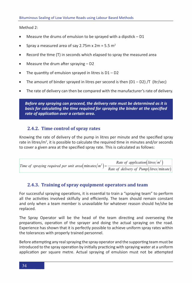
34
Bituminous Sealing of Low Volume Roads using Labour Based Methods
Method 2:
• Measure the drums of emulsion to be sprayed with a dipstick – D1
• Spray a measured area of say 2.75m x 2m = 5.5 m2
• Record the time (T) in seconds which elapsed to spray the measured area
• Measure the drum after spraying – D2
• The quantity of emulsion sprayed in litres is D1 – D2
• The amount of binder sprayed in litres per second is then (D1 – D2) /T (ltr/sec)
• The rate of delivery can then be compared with the manufacturer’s rate of delivery.
Before any spraying can proceed, the delivery rate must be determined as it is basis for calculating the time required for spraying the binder at the specified rate of application over a certain area.
2.4.2. Time control of spray rates
Knowing the rate of delivery of the pump in litres per minute and the specified spray rate in litres/m2, it is possible to calculate the required time in minutes and/or seconds to cover a given area at the specified spray rate. This is calculated as follows:
( ) ( )( )
22
min
min
Rate of application litres mTime of spraying required per unit area utes m
Rate of delivery of Pump litres ute=
2.4.3. Training of spray equipment operators and team
For successful spraying operations, it is essential to train a “spraying team” to perform all the activities involved skilfully and efficiently. The team should remain constant and only when a team member is unavailable for whatever reason should he/she be replaced.
The Spray Operator will be the head of the team directing and overseeing the preparations, operation of the sprayer and doing the actual spraying on the road. Experience has shown that it is perfectly possible to achieve uniform spray rates within the tolerances with properly trained personnel.
Before attempting any real spraying the spray operator and the supporting team must be introduced to the spray operation by initially practicing with spraying water at a uniform application per square metre. Actual spraying of emulsion must not be attempted

35
Training Manual
2. P
repa
rati
ons
for
seal
ing
oper
atio
ns
until the operator and team are fully conversant with all aspects of the operation and confident in applying a uniform application of water.
Practicing the spraying operation normally involves:
• Initiating the burners (if required)
• Starting the spray machine
• Checking the delivery of the pump
• Practicing the movement of the protective screens while spraying
• Practicing the initiating of the spraying by a stop watch operator
• Checking the rate of application for 2m, 3m and 4m control sections
• Practicing keeping the spray lance at a constant and correct height above the surface
• Recording the results of the times and dipstick readings and doing the calculation to check the actual application rate. If it’s too high, the Spray Operator must move quicker, if it’s too low he/she must move slower.
Once the team is comfortable in all the phases and aspects of the spray operation, they can start spraying emulsion. First time it is advisable to start spraying prime since this is less critical in terms of application rate than is the tack coat of first spray for a surface dressing. The workers should practice the systematic movement of the screens along the edge of the area to be surfaced, slightly ahead of the binder application. The use of screens is essential for a clean and safe operation. The use of reinforced brown paper also ensures clean trimmed sprayed joints.

36
Bituminous Sealing of Low Volume Roads using Labour Based Methods
Picture 15: Spraying prime. Note the brown paper for neat joint
Picture 16: Spraying binder on a primed base. Note the movement of the Spray Operator
2.4.4. The spray lance
The model shown has a spray lance with two spray nozzles. Other models come with only one. The following instructions are based on the lance with two nozzles.
The ideal height (H) of the spray lance is such that to obtain an overlap of approximately half the width of one jet as illustrated below. It is better to use a slightly higher than lower height.

37
Training Manual
2. P
repa
rati
ons
for
seal
ing
oper
atio
ns
Figure 20: Spray overlap with two-nozzle spray lance
Once the correct spraying height (H) has been determined, a chain or a wire with the correct length can be attached to the spray lance to assist the Spray Operator to maintain the correct height during the spraying.
Figure 21: Maintaining correct height of lance during spraying
In order for the two spray fans not to “collide” or interfere with each other and thus produce an uneven application, the valves should be set at a slight angle from the centre line of the lance as shown below.

38
Bituminous Sealing of Low Volume Roads using Labour Based Methods
Figure 22: Valves set at a slight angle from centre line of the spray lance
A common mistake in the spray operation is that the operator stays almost stationary in the centre of the road and moves the lance in an arc (or semi-circle)from side to side. The Spray Operator must instead move the lance directly across the road by walking sideways holding the lance parallel to the centre of the road as shown below.
Figure 23: Direction for movement of the spray lance
2.5. Application of binder
Before spraying commences the following checks must be done:
• Ensure that there is sufficient emulsion, aggregate, fuel and paraffin on site to complete the work. To do this the area to be surfaced and the rate of application of the binder and aggregate must be established;
• The delivery rate of the pump should be determined as described;
• Check that the aggregate has been correctly supplied and spotted;

39
Training Manual
2. P
repa
rati
ons
for
seal
ing
oper
atio
ns
• Make sure that the surface to be sealed is clean and any repairs properly attended to;
• Verify that the area to be sealed has been correctly set out;
• Ensure that arrangements to protect the kerbs etc. are in place;
• Reinforced paper has been placed at the start and finish joints;
• Finally check that all members of the team are at their posts and ready for action, i.e. that the recording operators and workers for spreading the aggregates and moving the spray screens are in position.
Picture 17: Well executed binder application
2.5.1. Control of application using a trial/control section
Having done all the training and practiced spaying prime, it is advisable to do a small trial section for the binder application since the correct application rate critical to the performance of the seal.
During the spraying it is recommended that two metre control sections are set out and the time taken to spray each section recorded and compared to the time for spraying at the correct application rate, which is calculated in advance. Before a trial section can be done the following information needs to be established:

40
Bituminous Sealing of Low Volume Roads using Labour Based Methods
• The rate of delivery of the pump (ltr/min);
• The rate of application of the binder (ltr/m2);
• The area of the trial section (2m long x width) (m2);
• The volume to be sprayed must be calculated in litres (ltr);
• The time for spraying the volume must be determined (min or seconds)
For the accurate application the work must be controlled by a separate operator using a stop watch and calling out the seconds as the work progresses so that the Spray Operator can control the pace of the work. The time keeper needs to record the time taken to spray each of 4 or 5 control sections and guide the operator time-wise, either to speed up or slow down the coverage of the area.
Bituminous Sealing of Low Volume Roads using Labour Based Methods Training Manual
41
The rate of delivery of the pump (ltr/min); The rate of application of the binder (ltr/m2); The area of the trial section (2m long x width) (m2); The volume to be sprayed must be calculated in litres (ltr); The time for spraying the volume must be determined (min or seconds) For the accurate application the work must be controlled by a separate operator using a stop watch and calling out the seconds as the work progresses so that the Spray Operator can control the pace of the work. The time keeper needs to record the time taken to spray each of 4 or 5 control sections and guide the operator time-wise, either to speed up or slow down the coverage of the area.
Control section (metres)
Calculated Time for Spraying
2 21 sec4 42 sec6 1 min 24 sec8 2 min 06 sec10 2 min 48 sec
Table 7: Example of time control of spray operation
Description ValueDelivery rate of sprayer 0.283 ltr/sec (17 ltr/min divided by 60)Spray application rate of penetration coat
1.7 ltr/m2 (tack coat of 0.7 ltr/m2 subtracted from total requirement of 2.4 ltr/m2 ).
Width of road 3.5 mControl length 2 mArea of control section 7m2 (2m x 3.5m)Amount to be applied to control section
7 x 1.7 = 11.9 ltr
Time to apply 11.9 ltr over control section 11.9/0.283 = 42 sec
Table 8: Sample application of penetration spray Each time the spraying stops at the end of the control section(s) and at the end of the spraying operation, dipstick readings needs to be taken and recorded. The actual average rate of binder application can then be checked against the calculated rate using the stop watch and delivery rate of the sprayer described above.
Table 7: Example of time control of spray operation
Bituminous Sealing of Low Volume Roads using Labour Based Methods Training Manual
41
The rate of delivery of the pump (ltr/min); The rate of application of the binder (ltr/m2); The area of the trial section (2m long x width) (m2); The volume to be sprayed must be calculated in litres (ltr); The time for spraying the volume must be determined (min or seconds) For the accurate application the work must be controlled by a separate operator using a stop watch and calling out the seconds as the work progresses so that the Spray Operator can control the pace of the work. The time keeper needs to record the time taken to spray each of 4 or 5 control sections and guide the operator time-wise, either to speed up or slow down the coverage of the area.
Control section (metres)
Calculated Time for Spraying
2 21 sec4 42 sec6 1 min 24 sec8 2 min 06 sec10 2 min 48 sec
Table 7: Example of time control of spray operation
Description ValueDelivery rate of sprayer 0.283 ltr/sec (17 ltr/min divided by 60)Spray application rate of penetration coat
1.7 ltr/m2 (tack coat of 0.7 ltr/m2 subtracted from total requirement of 2.4 ltr/m2 ).
Width of road 3.5 mControl length 2 mArea of control section 7m2 (2m x 3.5m)Amount to be applied to control section
7 x 1.7 = 11.9 ltr
Time to apply 11.9 ltr over control section 11.9/0.283 = 42 sec
Table 8: Sample application of penetration spray Each time the spraying stops at the end of the control section(s) and at the end of the spraying operation, dipstick readings needs to be taken and recorded. The actual average rate of binder application can then be checked against the calculated rate using the stop watch and delivery rate of the sprayer described above.
Table 8: Sample application of penetration spray
Each time the spraying stops at the end of the control section(s) and at the end of the spraying operation, dipstick readings needs to be taken and recorded. The actual average rate of binder application can then be checked against the calculated rate using the stop watch and delivery rate of the sprayer described above.

41
Training Manual
2. P
repa
rati
ons
for
seal
ing
oper
atio
ns
42
Calculated time of spray
Actual time of spray
Volume of spray applied
Rate of application
Dip before spray
Dip after spray
Volume of spray applied
Rate of application
A (m2) TC (sec) TA (sec) V1 (ltr) R1 (ltr/m2) D1 (ltr) D2 (ltr) V2 (ltr) R2 (ltr/m2)
A 0
A 1
A 2
A 3
..
..
..
Application rate using pump delivery rate D and time T Check using “dips” before and after sprayingArea to be sprayed
Table 9: Check using dipstick readings Key to Table 9:
R Required application rate (ltr/m2) D Pump delivery rate (ltr/sec) TC Calculated time for spraying control section and subsequent sections A x R/D (sec) TA Actual time taken for spraying control sections and subsequent sections (sec) V1 Volume of binder applied to each section from pump delivery rate and time TA x D (ltr) R1 Actual rate of application based on pump delivery rate and time (ltr/ m2) D1/D2 Volume in drum before and after spray from dip readings (ltr) V2 Volume of binder applied to each section from dip readings D1 - D2 (ltr) R2 Actual rate of application based on dip readings V2/A
After spraying the first control section, the actual application rate must be compared to the theoretical application rate and the Spray Operator adjust the speed up or down as required before spraying the subsequent control sections. By the end of the trial section, the Spray Operator will have calibrated the speed of the spraying to be consistently within the tolerances for the binder application rate.
The recording of the spraying times must be done by a separate operator (recording operator) as it cannot be done by the time controller.
The dipstick readings are undertaken using a steel rod calibrated/graduated in 5 or 10 litre intervals up to 210 litres. The amount of emulsion sprayed for each cycle of spraying is recorded in litres. The time controller, recording operator and spray operator must work very closely together.
The recording operator will mark the separate sections for checking at 2m intervals and record the time at the end of each 2m section that is sprayed. From these readings a double check of the accuracy of the work can be established by multiplying the pump delivery D by the time taken to spray each section. The spray operator controls the rate of moving the spray lance by listening to the time controller calling out the seconds required for each 2m section using his wristwatch (or preferably a stopwatch), bearing in mind the number of seconds he/she has to cover for each 2 m section of road.
The above may appear complicated but if the operators are given ample time to practice a few times initially with water, and then with diluted emulsion, it becomes a simple exercise.
Table 9: Check using dipstick readings
Key to Table 9:
R Required application rate (ltr/m2)
D Pump delivery rate (ltr/sec)
TC Calculated time for spraying control section and subsequent sections A x R/D (sec)
TA Actual time taken for spraying control sections and subsequent sections (sec)
V1 Volume of binder applied to each section from pump delivery rate and time TA x D (ltr)
R1 Actual rate of application based on pump delivery rate and time (ltr/ m2)
D1/D2 Volume in drum before and after spray from dip readings (ltr)
V2 Volume of binder applied to each section from dip readings D1 - D2 (ltr)
R2 Actual rate of application based on dip readings V2/A
After spraying the first control section, the actual application rate must be compared to the theoretical application rate and the Spray Operator adjust the speed up or down as required before spraying the subsequent control sections. By the end of the trial section, the Spray Operator will have calibrated the speed of the spraying to be consistently within the tolerances for the binder application rate.
The recording of the spraying times must be done by a separate operator (recording operator) as it cannot be done by the time controller.
The dipstick readings are undertaken using a steel rod calibrated/graduated in 5 or 10 litre intervals up to 210 litres. The amount of emulsion sprayed for each cycle of

42
Bituminous Sealing of Low Volume Roads using Labour Based Methods
spraying is recorded in litres. The time controller, recording operator and spray operator must work very closely together.
The recording operator will mark the separate sections for checking at 2m intervals and record the time at the end of each 2m section that is sprayed. From these readings a double check of the accuracy of the work can be established by multiplying the pump delivery D by the time taken to spray each section. The spray operator controls the rate of moving the spray lance by listening to the time controller calling out the seconds required for each 2m section using his wristwatch (or preferably a stopwatch), bearing in mind the number of seconds he/she has to cover for each 2 m section of road.
The above may appear complicated but if the operators are given ample time to practice a few times initially with water, and then with diluted emulsion, it becomes a simple exercise.

43
Training Manual
3. Q
ualit
y A
ssur
ance
an
d Co
ntro
l
3. Quality Assurance and ControlLearning objective:
• Knowledge about Quality Assurance through each step of the process from planning and design to finishing the works.
• Knowledge about typical Quality Control tests and measures prior to and during construction
3.1. Definitions
Quality Assurance Quality Control
Focus on
QA aims to prevent defects with a focus on the process used to make the product including the design. It is a proactive quality process.
QC aims to identify defects in the finished product or the parts or materials used for the production of the product. Quality control, therefore, is a reactive process.
WhatPrevention of quality problems through planned and systematic activities including documentation.
The activities or techniques used to achieve and maintain the product quality, process and service.
HowEstablish a good quality management system and the assessment of its adequacy including review of the system itself.
Finding & eliminating causes of quality problems so that the quality requirements are continually met.
Table 10: Definitions of Quality Assurance and Quality Control
3.2. Quality Assurance
From the definitions above it is clear that QA of sealing operations goes through the whole process from planning and design to the executing the works.
An overview of QA issues in the project development phases is shown in Table 10.
The list is not exhaustive, but identifies key issues that in one way or another may eventually affect the quality of the end product, even if that is not immediately evident.
Examples:
• If the choice of seal is beyond the capability of the contractor, say for lack of experience or lack of the appropriate equipment, the end result may not be to the expectations of the client
• If the project finances cannot sustain operation, unwarranted stoppages in the work may likewise affect the quality
• If the tools and equipment are not suited to the job, the workmanship will not be up to standard
• If aggregates are of bad quality or dirty the life of the completed seal will be

44
Bituminous Sealing of Low Volume Roads using Labour Based Methods
shorter than expected and make maintenance more extensive and expensive than planned
• If labourers are not treated fairly and paid in full and on time, they will not perform like they should and do substandard work
• Results of regular Quality Controls must be recorded and filed for reference and review by the Engineer so that corrective measures can be taken if results are not within the accepted tolerances. Without Quality Controls, bad habits may develop and quality standards not be upheld.

45
Training Manual
3. Q
ualit
y A
ssur
ance
an
d Co
ntro
l
Responsible
Traffic levels and compositionTopograhyClimateCost / Life Cycle CostMaintenance capabilityAvailability / cost of materialsAvailability of plant and equipmentCapability of local contractorsCommunity awarenessMethod of constructionCorrectClear and understandable
Contract period
Sufficient time allowed, seasonal weather patterns
Project finances
Bank guarantee, credit arrangements, own funds
Ensure sufficient cash flow to sustain operations
Contractor
Site inspectionIdentify all issues that will affect contract performance
Location, hauling distances, site conditions, site establishment, availability of labour, sources of materials
Identify sourceTest qualityCalculate volumesNegotiate price and place orderInspect aggregates before transport to siteIdentify sourceTest quality and/or check manufacturer's certificate against specifications and orderCalculate volumesNegotiate price and place order
Identify sourceInspect qualityCalculate quantitiesNegotiate priceIdentify sourceInspect quality (prototype)Calculate quantitiesNegotiate price and place orderPurchase or hireRecruit / train operatorsProcure sparesMaintenance arrangementsOff-the-shelf items normally readily available from local shopsEstimate quantitiesPurchase and bring to site
Community consultationFairness in selection process, eligibility of women, skills, training, labour recruitment
Site establishmentSuitable location, hire of stores, office and accommodation facilities
RecruitmentAdmin staff, skilled labourers, unskilled labourersStores controlPayment systemsLabour regulations, dispute resolution procedures
Waste management Waste storage and removal
Quality Assurance through the Project Development phases
Preparations
Site establishment
Contract documents
Plannig and Design
Designer / Client
Procurement
Construction materials
Check all factors that will affect seal performance and contractor's conditions for delivery of a quality end product
Choice of seal
Feasibility
Specifications
Aggregates
Binders and prime
Hand tools
Equipment for local manufacture
Construction plant
Consumables, stationary, PPE, First Aid Kit(s)
Contractor / Site Agent
Tools and equipment
Administrative procedures
Table 11: Quality Assurance through the Project Development phases

46
Bituminous Sealing of Low Volume Roads using Labour Based Methods
Responsible
Work assignmentsJob decriptionsLogistics
Work plan Overall, monthly, weekly, daily
As required to plan and execute the work in the most cost efficient manner without sacrificing high workmanship standards
Reporting system
Monthly, weekly, daily
As required to capture and summarise activities, outputs, labour input, materials consumption, use of plant and equipment
Training Trial section(s)Initial training of operators and labour teams in correctand safe work procedures
Quality of base Base repairsContamination and dust, washing as requiredApplication ratesGrading (mixing of fractions for graded aggregates)Check for settlement in drumsCorrect type and gradeApplication ratesProper mixing for pre-mix applicationsLine and levelCompactionSpray procedureConstruction jointsSpillage
Execution
Quality Assurance through the Project Development phases (continued)
Workmanship
Site Agent / Team Leaders
Quality control(s) Binders and prime
Aggregates
Site organisation
Team setup
Table 11 (continued): Quality Assurance through the Project Development phases
Development of Checklists is a good way of ensuring that all aspects that need to be controlled are actually checked and any problems resolved. From the above, the Contractor can develop more detailed checklists for each Phase or construction activity.
3.3. Quality Control
As shown above Quality Control is part and parcel of the Quality Assurance system, but Quality Control is done as specific tests on materials, components and workmanship standards that go into the final product to check that these meet the project specifications.
Example of the distinction between QA and QC:
• The quality of the hand tools used may affect the quality of the seal, but the hand tools are not part of the end product, merely a means of production. Checking the quality of the hand tools is therefore not a Quality Control aspect as such, but part of the Quality Assurance system by the contractor which will ensure that he/she can deliver a quality product within the estimated time and cost and hopefully with a reasonable profit margin.

47
Training Manual
3. Q
ualit
y A
ssur
ance
an
d Co
ntro
l
• The quality of the seal aggregates on the other hand must be subjected to stringent tests since these will be part of the finished product and will affect the quality and life span of the seal.
One of the most critical aspects to the success of a bituminous seal is effective quality control. Lack of quality control during construction is often the reason for failure in a surfacing, rather than defective design.
Approval and acceptance of the surfacing work can be divided into the following steps:
• Approval of the bitumen and aggregate supplied.
• Approval of aggregate pre-coating, if applicable.
• Approval of prime coating, if applicable.
• Checking and approval of binder spread rates.
• Checking and approval of aggregate spread rates.
• Approval of brooming and rolling.
• Checking and approval of construction lines
• Approval of handling of joints, transverse and longitudinal
• Checking general quality of workmanship
• Traffic management on the new seal
For approval of the bitumen and aggregates the following tests may have to be carried out at a reputable laboratory:
Seal aggregates:
• Hardness and durability
o Los Angeles Abrasion Value (LAA)
o Aggregate Crushing Value (ACV)
o Aggregate Impact Value (AIV)
o 10% Fines (aggregate crushing) Value (10% FACT)
o Sodium Sulphate Soundness
• Shape
o Flakiness Index (FI)o Average Least Dimension (ALD)
• Size and grading
o Nominal sizeo Sieve analysis (Particle Size Distribution)

48
Bituminous Sealing of Low Volume Roads using Labour Based Methods
o Plasticity Index (PI)Binders and primes:
• Penetration grade and cut-back bitumen
o Penetration at 25 °C.o Ring and ball softening point.o Viscosity.o Distillation to 190, 225, 260 and 316 °C.
• Emulsions
o Saybolt Furol viscosity.o Storage stability.o Coating ability.o Distillation and tests on the residue.
For bitumen products the contractor may have to rely on the manufacturer’s certificate which should accompany all deliveries from factory to site.
3.4. Relaxation of Standards
The performance of thin bituminous seals is highly dependent on the quality of construction. Experience has shown that the main causes of failure in thin seals are related to the construction processes rather than the design or climatic influences. It is for this reason that strict specifications for construction equipment, processes and material conformance have been developed
High quality aggregates are becoming increasingly difficult to obtain, with increasing costs of haulage and crushing. If high quality aggregate is prohibitively expensive to obtain, slight relaxation of standards can be applied for lightly trafficked road. As the design of bituminous seals is based on the aggregate size, ALD and grading, the standards for these properties cannot be reduced. However, on lightly trafficked roads, requirements for crushing strength can be relaxed. Whereas a maximum ACV of 21 is preferred, satisfactory results can be achieved with an ACV of 30 on lightly trafficked roads, or as high as 40 on very lightly trafficked roads.

49
Training Manual
4. S
ealin
g op
erat
ions
4. Sealing operationsLearning objective:
• Knowledge and practical skills in applying the different sealing options• Quality control of the sealing operations
4.1. General
The operation of the bitumen hand sprayer, the spraying procedure and correct technique to achieve the correct and uniform spray rate common to all bitumen spray applications, is covered in sections 2.2, 2.3 and 2.4.
All sprayed bitumen should be contained within the construction lines, i.e. within the edge of the area to be sealed such that after the spray operation the site looks neat and tidy. Use of spray screens is a must and road furniture should be covered up by a layer of sand, plastic or other suitable means. This is particularly important when spraying low viscosity binders.
The area to be sprayed or sealed should be staked out and demarcated with a 6 mm rope secured with steel pegs or nails.
The 6 mm rope placed along the edge of the spray area guides the spray operation and the movement of the spray screens and will help to stop runoff into the drains. A small windrow of sand just outside the rope will soak up any bitumen escaping under the rope.
Picture 18: Placing a small windrow of sand along the edge of the road to prevent bitumen run-off into the lined drain

50
Bituminous Sealing of Low Volume Roads using Labour Based MethodsBituminous Sealing of Low Volume Roads using Labour Based Methods Training Manual
49
Picture 19: Bad example of prime flowing past the edge of the seal
4.2 Site preparations As a general rule, no construction elements shall be covered up before it is inspected and approved by the Engineer. The inspection and repairs, if required, is described in section 2.1.3.
Kerbing and channels and other road furniture, if present, will need to be covered and protected with black plastic, sand or other suitable material. Use of spray screens during spraying operations is mandatory.
The surface to be primed or sealed must be swept free of dust and debris. Sweeping should be done in a down-wind direction so as to aid the removal of dust from the surface.
Animal droppings can be a huge problem in rural areas and must be removed carefully using a spade and stiff brush taking care not to damage the prepared surface.
Picture 19: Bad example of prime flowing past the edge of the seal
4.2. Site preparations
As a general rule, no construction elements shall be covered up before it is inspected and approved by the Engineer. The inspection and repairs, if required, is described in section 2.1.3.
Kerbing and channels and other road furniture, if present, will need to be covered and protected with black plastic, sand or other suitable material. Use of spray screens during spraying operations is mandatory.
The surface to be primed or sealed must be swept free of dust and debris. Sweeping should be done in a down-wind direction so as to aid the removal of dust from the surface.
Animal droppings can be a huge problem in rural areas and must be removed carefully using a spade and stiff brush taking care not to damage the prepared surface.

51
Training Manual
4. S
ealin
g op
erat
ions
Picture 20: Sweeping the base
4.3. Testing of materials
The specifications for the materials to be used are given in the contract documents.
For the bitumen products each delivery should be accompanied with a Manufacturer’s Certificate proving that the product complies with the contract specifications and the purchasing order.
Once a supplier of aggregates has been identified, the tests for the material quality should be carried out. All materials testing should be done by a reputable laboratory to confirm that they meet the minimum specifications given in the Best Practice Manual for Thin Bituminous Surfacing, Sections 4.2.2 and 4.2.3. The quality of the stone will generally not vary much for aggregates coming from the same quarry, but regular checks should still be carried out taking representative samples from the stockpiles.
The shape, grading and cleanliness of the aggregates may however vary considerably with each delivery to site, depending on the operations in the quarry. Ideally the aggregates should be tested and approved before transport to site in order to avoid rejection of materials, double handling and unnecessary stoppages of the sealing operations.

52
Bituminous Sealing of Low Volume Roads using Labour Based Methods
The binder and aggregate application rate for Surface Dressing, Modified Otta Seal and Cape Seal depends on the shape of the aggregate. The Average Least Dimension (ALD) of the aggregate must therefore be determined. This can be done by three different methods explained below.
4.3.1. Determination of the Average Least Dimension (ALD) of seal aggregates
The average least dimension (ALD) is the average thickness of the chippings when laid flat, the vertical thickness being the ‘least’ or the smallest dimension of each chip. The ALD is required to determine the application rate of the bitumen and can be determined in three ways:
1. A representative sample of approximately 200 chippings is taken and the least dimension of each is measured manually by means of calipers. The average value is then taken as the ALD.
2. The second method uses a grading analysis of a representative sample of chippings to determine the median size of the sample (the particle size indicated by the sieve through which 50% of the sample passes). The flakiness index is then also determined. The median size and the Flakiness Index are used in the nomograph in Figure 24 to determine the ALD.
3. The third method uses a “Pan and Cylinder” apparatus shown in Error! Reference source not found.. A representative sample of the aggregates are placed in the pan to obtain the visually desired texture:
a. For Surface Dressing the aggregates should lie shoulder-to-shoulder
b. For Cape Seal there should be a gap of 4-5 mm between the aggregates
c. For Modified Otta or Penetration Seal using graded aggregate, the thickness of the seal is defined by the larger fractions with the fine fractions filling in the voids.
When the desired texture has been achieved, the amount of aggregate in the pan is poured into the cylinder and the theoretical ALD read off the gauge.
4.3.1.1. Determination of the aggregate application rate
The aggregate application rate in m3/m2 can be estimated by three different methods:
• By dividing the theoretical ALD by 1000. For Cape Seal this figure must be reduced by 10-15% to cater for the spacing between the aggregates.

53
Training Manual
4. S
ealin
g op
erat
ions
Example:
ALD = 8,3mm.
Aggregate application rate = 8.3 /1000 = 0.0083 m3/m2 (Surface Dressing)
Reduction for Cape Seal 10-15%:
Aggregate application rate = 0.00706 - 0.00747m3/m2 (Cape Seal)
When ordering aggregates, at least a 5% allowance must be made for wastage.
• An estimate of the aggregate application rate for Surface Dressing can also be obtained from the equation:
Chipping application rate (kg/m2) = 1 .364 x ALD
This equation assumes that the aggregates have a loose density of 1.35 Mg/m3.
52
Figure 24: Nomograph for determination of ALD
By using the grading analysis of a representative sample of chippings to determine the median size of the sample (the particle size indicated by the sieve through which 50% of the sample passes) and the flakiness index of the aggregates. By drawing a line from the Median Size on the left in Figure 24 to the Flakiness Index on the right, the ALD is read of the scale in the middle.
Figure 24: Nomograph for determination of ALD

54
Bituminous Sealing of Low Volume Roads using Labour Based Methods
• By using the grading analysis of a representative sample of chippings to determine the median size of the sample (the particle size indicated by the sieve through which 50% of the sample passes) and the flakiness index of the aggregates. By drawing a line from the Median Size on the left in Figure 24 to the Flakiness Index on the right, the ALD is read of the scale in the middle.
4.4. Spotting and spreading of aggregates
Spotting is a technique used on labour based sealing operations to aid in the achievement of uniform aggregate application rate. A half drum (volume 105 ltr or 0.105 m3) open in both ends and with lifting handles is used for the spotting.
Picture 21: Spotting of aggregates
Once the aggregate application rate is known, the spotting distance or distance between the aggregate heaps can be calculated.

55
Training Manual
4. S
ealin
g op
erat
ions
Example:
Aggregate application rate = 0.0083 m3/m2
Area covered by a half drum = 0.105 m3 / 0.0083 m3/m2 = 12.65 m2
Lane width to be sealed = 3.15 m (in case of half width construction)
Spotting distance = 12.65 m2 / 3.15 m = 4.02 m
A heap of aggregate must be placed at 4 m intervals along the road. The heaps should be placed on 1.5 m x 1.5 m sheets of heavy duty plastic to avoid wastage and contamination. The section to be covered by each heap must be demarcated using chalk lines or larger stones. The aggregates must be spread as uniformly as possible within the demarcated section using shovels and brooms
Picture 22: Aggregates spotted on plastic sheets
When placing the aggregates on the sprayed surface, a shovel of aggregate is taken and pitched into the air and in the process the shovel twisted rapidly. In so doing the chips are sprayed uniformly over the area to be covered and the stones will fall onto the wet

56
Bituminous Sealing of Low Volume Roads using Labour Based Methods
tack coat while the dust, if any, will fall onto the top of the stone or, if there is a breeze, will be blown across the road away from the surface.
Labourers should be assigned to spread two heaps each. After covering the area so that it can be walked on without picking up bitumen, extra aggregates must be thrown onto remaining bare spot. Finally the surface should be broomed to obtain a uniform coverage and to remove double layers of stone.
Spreading of coarse aggregates (Surface Dressing, Modified Otta Seal, Cape Seal) can alternatively by done by means of a manually operated chip spreader or “Chippy”, if available.
The “Chippy” is produced in South Africa. It will facilitate more efficient spreading and uniform application of aggregate, thereby reducing the amount of brooming required.
It has a capacity of three wheelbarrow loads of aggregate and is operated by four people – one to steer the “Chippy” and three to push it. The “Chippy” starts with a full load and spreads chips at a width of 1.2 meters.
Before any sealing is done with the “Chippy” it must be adjusted for correct application by first doing “dry” runs on an unsprayed surface.
Arrangements should be made with the manufactures to train the operators of the “Chippy” in the correct method of operation during the trial run and first operation on the bitumen binder.
As with the spreading of the aggregate by hand predetermined quantities of the aggregate are spotted along the side of the road, using 105 litre half drums, at distances, determined by the engineer, depending on the ALD and the application rate of the aggregate.
When “Chippy’s” are used for spreading aggregate, the spotting of stone must be based on 2 x 10⁵ litres of stone per stockpile. This conveniently is the capacity of 3 wheelbarrows which also equals one fully loaded “Chippy”

57
Training Manual
4. S
ealin
g op
erat
ions
Picture 23: Spreading aggregates with a Chippy
4.5. Weather constraints
Spray applications should only be applied during the day and only in good weather conditions and when rain is not imminent. The road surface temperature should be above 10 oC. Spraying in the late afternoon is not advisable as the reduction in air temperature by dusk will influence the setting and curing of the prime or binder.
Care should be taken when spraying on a windy day as the spray may be carried some distance and damage property or passing vehicles down-wind of the operation.
4.6. Traffic control
Provision of bypasses is costly and is seldom done on labour based construction projects.
Due to the risk from traffic adjacent to the works, measures must be taken to warn and protect both road users and the road workers. Road signs must be placed on both sides of the road works in order to warn traffic coming from both directions of the obstruction ahead. The warning signs should alert traffic to the presence of men working, a closed lane, loose chippings and speed restrictions at the site. These signs must be placed ahead of the road works to give advance warning of the danger to traffic, along the length of the road works to protect the site from traffic, and at the end of the road

58
Bituminous Sealing of Low Volume Roads using Labour Based Methods
works in order to indicate that there is no further restriction to traffic. Traffic cones should be used to mark the boundary of the work site, as shown in Picture 24. Traffic control measures are necessary if there is only one lane remaining open so that only one vehicle can pass the work site at a time. Either a temporary traffic light system should be used, or a traffic operator using a reversible ‘stop/go’ sign.
Traffic accommodation needs to be well managed as it places the entire workforce at risk. Temporary speed bumps may be needed to slow down passing traffic. Training in the correct operation of traffic accommodation at road works is vital for the safety of the workmen team as well as allowing safe, free flowing traffic.
Picture 24: Traffic control by traffic cones and stop-go sign
4.7. Occupational Health and Safety
The welfare of the workforce is key to achieving good productivity and a quality end product. The health and safety of the workers is governed by the national labour laws and regulations and must be adhered to. Occupational Health and Safety measures include the following:
4.7.1. Traffic control
See above. Traffic is perhaps the greatest risk to worker safety on the work site. All labourers working on or in the vicinity on the road must wear high visibility safety vests.
4.7.2. Safe storing, handling and spraying of hot bitumen products
Hot bitumen products and cut-back bitumen, which are heated to between 130 oC and 180 oC, are extremely flammable and must be stored, handled and sprayed with extreme

59
Training Manual
4. S
ealin
g op
erat
ions
care to avoid injuries and damage to personnel and equipment. For this reason the use of hot bitumen products is not recommended on labour based sites, often managed by inexperienced contractors.
Even cutback bitumen primes like MC 30 or MC 70 that are heated to 50 oC and 70 oC respectively, can easily ignite and cause injuries if the heating is not controlled properly.
Smoking or use of open flames near hot bitumen is not allowed.
4.7.3. Personal Protective Equipment (PPE)
The following PPE must be issued to the labourers in accordance with their work assignments:
• Overalls
• Safety vests
• Boots (for bitumen works)
• Dust masks (for spray operations and handling of dusty aggregates)
• Gloves
• Goggles or face shield if handling hot bitumen
• Respiratory equipment if workers are exposed to toxic fumes
• Containers of clean water for flushing eyes and rinsing wounds
Picture 25: Spray team wearing appropriate PPE. Safety vests not required since there was no traffic.

60
Bituminous Sealing of Low Volume Roads using Labour Based Methods
4.7.4. First Aid
Any victim of a burn or other serious injury should be evacuated to a medical centre immediately rather than be treated on site. However, suitable first-aid equipment for dealing with bitumen burns must be provided on site. Recommendations are provided in the Sabita Manual 8: Guidelines for the safe and responsible handling of bituminous products. In the case of a burn injury from hot bitumen falling onto exposed skin, cooling of the burn area should be carried out by applying cold water or an ice pack. Firmly adhering bitumen should not be removed from the skin; it must either be allowed to fall off gradually or it may be removed by warm medicinal paraffin. A standard bandage must not be applied to burnt skin, as this will stick to the burnt area. If eyes are affected they should be washed for fifteen minutes. In the case of ingested bitumen, vomiting must not be induced. If vomiting is unavoidable, breathing should be monitored. In the case of inhalation of bituminous fumes, the victim must be moved to an uncontaminated area. Trained personnel should administer artificial respiration if breathing stops, or CPR if the heart stops. In all cases of direct exposure to hot bitumen or bitumen fumes, medical attention must be sought immediately.
For treatment of other injuries on site, at least one person should have undergone training in First Aid. A well stocked First Aid kit should always be present on site and be replenished as the various items are being used.
4.7.5. Firefighting equipment
Suitable firefighting equipment for dealing with bitumen fires must be provided at the site of sealing operations. Water must not be used to extinguish a bitumen fire, as bitumen will react violently with it. Appropriate extinguishing media for a bitumen fire includes foam, carbon dioxide, dry chemicals or water fog.
Containers exposed to intense heat from fires should be cooled with water to prevent vapor pressure build-up, which could result in container rupture. Containers exposed directly to flames should be cooled with large quantities of water.
4.8. Prime
4.8.1. Design
There is no design procedure for the prime. The contract specification will give the nominal application rate and type of prime to be used.
4.8.1.1. Materials
Bitumen products used for priming include:
• Invert Bitumen Emulsion - complying with SANS 1260 (e.g. MSP1)
• Special Emulsion Prime (e.g. Colprime E)

61
Training Manual
4. S
ealin
g op
erat
ions
• Cutback Bitumen: - MC30 or MC70, complying with SANS 308
The benefits of using invert bitumen or special emulsion primes are:
• They are very suitable for labour based applications as it can be sprayed at ambient temperatures
• They have relatively quick drying times compared to cutback bitumen
• Their use has less impact on the environment through less heating and solvent emissions.
All of these products can be supplied in 210 ltr drums or in bulk.
4.8.1.2. Prime application rates
The application rate for prime will be specified by the client or his agent based on the condition of the road surface.
• Invert emulsion prime is generally applied at 0.95 ltr/ m2 with the net quantity of bitumen residue in the region of 0.35 ltr/ m2.
o For open graded or coarse layers the spray rate can be increased by 0.15 ltr/ m2.
o For fine, very dense layers the spray rate can be decreased by 0.15 ltr/ m2.
• MC 30 is generally applied at 0.8 – 1.1 ltr/ m2
• MC 70 is generally applied at 0.6 – 0.7 ltr/ m2
It is recommended that a “paint” test be carried out to verify the application rate of the prime. This is done by applying the prime by brush at various application rates to 1 m2 of prepared base to determine the ideal application rate.
4.8.1.3. Construction Plant and Equipment
The following plant and equipment is required for priming by labour based methods:
• Hammer
• 6 mm rope, 2 x 50m rolls
• Reinforced paper, 4 rolls x 1 m wide
• Steel pegs, 300mm x 9mm
• Steel tapes, 5 m and 50m

62
Bituminous Sealing of Low Volume Roads using Labour Based Methods
• Motorized bitumen sprayer
• 105 ltr drums for checking spray rates and cleaning spray equipment
• Calibrated dip stick
• Spray screens
• Drum lifter for lifting full drums of binder
4.8.1.4. Construction
Site and Base Preparation
Before applying the prime, the base must be inspected for defects and repaired if required as described in section 2.1.3.
Prime may only be applied once the base layer has dried sufficiently. Specifications may vary, but as a general guide, the moisture content in the top 25 mm of the layer should be less than 50% of the Optimum Moisture Content (OMC).
The surface on which the prime is to be applied must be swept free of dust, debris, animal droppings and other unwanted material. An exposed stone matrix as shown in Picture 27 below is required to ensure good bonding with the seal. Sweeping should be done in a down-wind direction so as to aid the removal of dust from the surface.
Picture 26: Sweeping the base

63
Training Manual
4. S
ealin
g op
erat
ions
Dampening the base
The base can be moistened with a light sprinkling of water prior to priming to assist in breaking the surface tension and avoid the formation of “fish eyes” in the primed surface. Using a pump and hosepipe with a nozzle that is capable of delivering a fine mist spray is best, but watering cans with spray nozzles can also be used. Care must be taken not to over-moisten the base as the excess moisture will inhibit penetration of the prime and adversely affect the bonding to the base layer.
Once approved and cleaned of all foreign matter, debris, animal droppings etc., the base must be lightly sprayed with water just prior to priming. Using a pump and hosepipe with a nozzle that is capable of delivering a fine mist spray is best, but watering cans with spray nozzles can also be used, but care must be taken not to over apply water at any point. If for some reason the priming is delayed and the surface of the base has dried up, the procedure must be repeated.
Applying the prime
An experienced Spray Team should be able to spray 400 ltr or 2 drums of prime per hour. The sweeping operation needs to be balanced with the correct number of labourers to ensure the spray operation is not delayed by the sweeping team.
Activity Number of workers
Loading & spraying operation 3
Spray screen assistants 4 (two on each side)
Sweeping of surface (75 m2/labourer/hr) Depending on area to be prepared
The prime should be sprayed direct from the 200 ltr drums using the motorized bitumen sprayer.
The invert emulsion prime does not require heating for hand spraying operations.
MC 30 must be heated to 50 oC and MC70 to 70 oC for to reduce the viscosity of the binder for the pumping and spraying operation. The prime is heated slowly so as not to damage the products and should be stirred during heating using a broomstick to ensure even heating. Heating should not take place for extended periods as the volatiles may evaporate and as a result alter the properties of the prime. As the cutter in the binder is flammable and can ignite, extreme care should be taken during the heating with open flames.

64
Bituminous Sealing of Low Volume Roads using Labour Based Methods
Picture 27: Example of dense surface texture ready for priming
4.8.2. Weather constraints
Priming should only be done during the day and only in good weather conditions and when rain is not imminent. The expected weather conditions for the following 7 days should be dry to allow the prime to penetrate the upper layer and the volatiles to evaporate. This drying and curing period may vary depending on the weather conditions.
4.8.3. Quality control
The prime coat should penetrate 4 to 10 mm. No traffic should be allowed onto a primed surface until the prime has completely dried. If the prime penetrates too quickly the cause should be determined. Usually one will find either the base has been inadequately compacted or the prime is too fluid for the base material. Should the prime be over-applied it can be “blotted” with 6.7 mm stone chips or coarse natural sand. Crusher dust is not advisable as it tends to stick together and is more difficult to remove from the road surface.
Traffic may be allowed onto a primed surface for a limited period after it has dried. This will show up any defects in the base course or layer which has been primed. Such defects may then be immediately rectified at less cost than would otherwise be the case.

65
Training Manual
4. S
ealin
g op
erat
ions
The application rate of the prime coat should fall within the tolerance limits of ± 0.06 ltr/m2. This is difficult to achieve using the hand sprayer. Therefore to be on the safe side it is better to err on the high side rather than applying too little.
Picture 28: Neatly primed surface
4.9. Hot bitumen seals
Seals requiring hot bitumen are normally not recommended for labour based operations. The exception to this is Otta Seal which has a number of potential advantages over other sealing options in that it can be constructed successfully using lower quality aggregates. The Otta Seal also allow for labour based methods for excavation, screening and spreading of natural aggregates thereby contributing to employment creation.
4.9.1. Otta Seal
4.9.1.1. Description
An Otta Seal is a bituminous surfacing that was originally developed in the early 1960’s by the Norwegian Road Research Laboratory. It derives its name from the Otta Valley in Norway where it was first used. Although originally intended to serve as a temporary surface for newly constructed gravel roads, its good performance led to its adoption as

66
Bituminous Sealing of Low Volume Roads using Labour Based Methods
a permanent single or double seal for both new and existing roads. It has been used extensively in Scandinavia as well as in East and Southern Africa and other parts of the world. Trial sections have also been constructed in Ethiopia.
Otta Seals essentially consist of a 16 mm (single) or 32 mm (double) thick bituminous surfacing constituted of an admixture of graded aggregate from natural gravel or crushed rock in combination with relatively soft (low viscosity) binders, with or without a sand seal cover.
The graded aggregate is placed on a relatively thick film of comparatively soft binder which, on rolling and trafficking, works its way upwards through the aggregate interstices. In this manner, the graded aggregate relies both on mechanical interlocking and bitumen binding for its strength, similar to a bituminous premix. Traffic on the seal immediately after rolling is desirable producing its final appearance after 4 - 8 weeks giving it a “premix” like appearance.
Priming of the base is normally not required, but if in doubt, prime.
The Otta Seal contrasts with the conventional Surface Dressings where single sized crushed aggregates are ‘glued’ to the base with a relatively hard (high viscosity) binder.
Some of the factors favouring the use of Otta Seals include situations where:
• Crushed aggregates of adequate quality are beyond economical hauling distances.
• Workmanship may be of indifferent quality;
• Flexibility and durability of the surface require high tolerance to comparatively low quality, low bearing capacity pavements with high deflections;
• There is a low maintenance capability;
• High solar radiation levels prevail.
4.9.1.2. Design
Unlike Surface Dressing, there is no formal design procedure for Otta Seal. The design requires good knowledge and experience with the aggregates and bitumen products to be used in the particular circumstances.
The design and construction of Otta Seals should follow the guidelines in The Design, Construction and Maintenance of Otta Seals, Guideline No. 1, Roads Department, Botswana (June 1999 ).

67
Training Manual
4. S
ealin
g op
erat
ions
4.9.1.3. Materials
The material requirements for Otta Seal are given below:
64
4.9.1.3 Materials The material requirements for Otta Seal are given below:
Material properties RequirementsPlasticity Index Max 10
Flakiness IndexMax 30 (only for crushed
material)
Sieve sizes (mm) % passing19 10016 80 -100
13.2 52 - 1009.5 36 - 986.7 20 - 80
4.75 10 - 702.0 0 - 48
1.18 0 - 380.425 0 - 250.075 0 - 10
Grading
Table 12: Otta Seal material properties and general grading requirements
Figure 25: Otta Seal general grading envelope
Table 12: Otta Seal material properties and general grading requirements
Figure 25: Otta Seal general grading envelope

68
Bituminous Sealing of Low Volume Roads using Labour Based MethodsBituminous Sealing of Low Volume Roads using Labour Based Methods Training Manual
65
Open grading Medium grading Dense grading19 100 100 10016 80 - 100 84 - 100 93 - 100
13.2 52 - 82 68 - 94 84 - 1009.5 36 - 58 44 - 73 70 - 986.7 20 - 40 29 - 54 54 - 804.75 10 - 30 19 - 42 44 - 702.0 0 - 8 3 - 18 20 - 481.18 0 - 5 1 - 14 15 - 38
0.425 0 - 2 0 - 6 7 - 250.075 0 - 1 0 - 2 3 - 10
% passingSieve sizes (mm)
Alternative grading envelopes
Table 13: Otta Seal alternative grading envelopes
Open grading Medium grading Dense grading
> 100 150/200 pen grade150/200 pen grade in cold weather
MC 3000 MC 800 in cold weather
≤ 100 150/200 pen grade MC 3000 MC 800
Choice of bitumen for LVSR based on traffic and gradingType of bitumenAADT at the time of
construction
Table 14: Choice of bitumen for Otta Seal relatied to traffic
AADT ≤ 100 AADT > 100
Double 1st layer* 1.6 1.7 1.8 1.72nd layer 1.5 1.6 2.0 1.91st layer* 1.6 1.7 2.0 1.9Crusher dust or coarse river sand 0.9 0.8 0.7Fine sand 0.7 0.7 0.6
Single 1st layer* 1.7 1.8 2.0 1.91.5 1.6 1.8 1.7
* On a primed base course the spray rate shall be reduced by 0.2 ltr/m2 in the 1st layer
Notes: - When the aggregate has a water absorption of more than 2%, the bitumen spray rate shall be increased by 0.3 ltr/m2
- Binder for the sand cover seal shall be MC 3000 for crusher dust or coarse river sand, MC 800 for fine sand
Hot bitumen spray rates for un-primed base course (ltr/m2)
Open Medium
GradingDense
Single with a sand cover seal
Type of Otta Seal
Maintenance reseal (single)
Table 15: Otta Seal bitumen spray rates
Table 13: Otta Seal alternative grading envelopes
Bituminous Sealing of Low Volume Roads using Labour Based Methods Training Manual
65
Open grading Medium grading Dense grading19 100 100 10016 80 - 100 84 - 100 93 - 100
13.2 52 - 82 68 - 94 84 - 1009.5 36 - 58 44 - 73 70 - 986.7 20 - 40 29 - 54 54 - 804.75 10 - 30 19 - 42 44 - 702.0 0 - 8 3 - 18 20 - 481.18 0 - 5 1 - 14 15 - 38
0.425 0 - 2 0 - 6 7 - 250.075 0 - 1 0 - 2 3 - 10
% passingSieve sizes (mm)
Alternative grading envelopes
Table 13: Otta Seal alternative grading envelopes
Open grading Medium grading Dense grading
> 100 150/200 pen grade150/200 pen grade in cold weather
MC 3000 MC 800 in cold weather
≤ 100 150/200 pen grade MC 3000 MC 800
Choice of bitumen for LVSR based on traffic and gradingType of bitumenAADT at the time of
construction
Table 14: Choice of bitumen for Otta Seal relatied to traffic
AADT ≤ 100 AADT > 100
Double 1st layer* 1.6 1.7 1.8 1.72nd layer 1.5 1.6 2.0 1.91st layer* 1.6 1.7 2.0 1.9Crusher dust or coarse river sand 0.9 0.8 0.7Fine sand 0.7 0.7 0.6
Single 1st layer* 1.7 1.8 2.0 1.91.5 1.6 1.8 1.7
* On a primed base course the spray rate shall be reduced by 0.2 ltr/m2 in the 1st layer
Notes: - When the aggregate has a water absorption of more than 2%, the bitumen spray rate shall be increased by 0.3 ltr/m2
- Binder for the sand cover seal shall be MC 3000 for crusher dust or coarse river sand, MC 800 for fine sand
Hot bitumen spray rates for un-primed base course (ltr/m2)
Open Medium
GradingDense
Single with a sand cover seal
Type of Otta Seal
Maintenance reseal (single)
Table 15: Otta Seal bitumen spray rates
Table 14: Choice of bitumen for Otta Seal relatied to traffic
Bituminous Sealing of Low Volume Roads using Labour Based Methods Training Manual
65
Open grading Medium grading Dense grading19 100 100 10016 80 - 100 84 - 100 93 - 100
13.2 52 - 82 68 - 94 84 - 1009.5 36 - 58 44 - 73 70 - 986.7 20 - 40 29 - 54 54 - 804.75 10 - 30 19 - 42 44 - 702.0 0 - 8 3 - 18 20 - 481.18 0 - 5 1 - 14 15 - 38
0.425 0 - 2 0 - 6 7 - 250.075 0 - 1 0 - 2 3 - 10
% passingSieve sizes (mm)
Alternative grading envelopes
Table 13: Otta Seal alternative grading envelopes
Open grading Medium grading Dense grading
> 100 150/200 pen grade150/200 pen grade in cold weather
MC 3000 MC 800 in cold weather
≤ 100 150/200 pen grade MC 3000 MC 800
Choice of bitumen for LVSR based on traffic and gradingType of bitumenAADT at the time of
construction
Table 14: Choice of bitumen for Otta Seal relatied to traffic
AADT ≤ 100 AADT > 100
Double 1st layer* 1.6 1.7 1.8 1.72nd layer 1.5 1.6 2.0 1.91st layer* 1.6 1.7 2.0 1.9Crusher dust or coarse river sand 0.9 0.8 0.7Fine sand 0.7 0.7 0.6
Single 1st layer* 1.7 1.8 2.0 1.91.5 1.6 1.8 1.7
* On a primed base course the spray rate shall be reduced by 0.2 ltr/m2 in the 1st layer
Notes: - When the aggregate has a water absorption of more than 2%, the bitumen spray rate shall be increased by 0.3 ltr/m2
- Binder for the sand cover seal shall be MC 3000 for crusher dust or coarse river sand, MC 800 for fine sand
Hot bitumen spray rates for un-primed base course (ltr/m2)
Open Medium
GradingDense
Single with a sand cover seal
Type of Otta Seal
Maintenance reseal (single)
Table 15: Otta Seal bitumen spray rates
Table 15: Otta Seal bitumen spray rates

69
Training Manual
4. S
ealin
g op
erat
ions
66
Open grading Medium grading Dense gradingOtta Seals 0.013 - 0.016 0.013 - 0.016 0.016 - 0.019Sand cover sealsIn practice the aggegate appl ication rate wi l l very often be increased in order to reduce the risk of bleeding
Aggregate application ratesAggegate spread rates (m3/m2)Type of seal
0.010 - 0.012
Table 16: Otta Seal aggregate application rates
4.9.1.4 Construction plant and equipment For construction of a conventional Otta Seal, labour may be used for excavation, screening and spreading of aggregates, in which case the following plant and equipment is needed:
Hammer 6 mm rope, 2 x 50m rolls Reinforced paper, 4 rolls x 1 m wide Steel pegs, 300mm x 9mm Steel tapes, 5 m and 50m Wheel barrows Half drum for spotting of aggregates Shovels Brooms Drag broom (optional) 19 mm aperture screen Water bowser Watering cans or pump and spray hose 12 ton PTR Bitumen distributor
For the operation, calibration and spraying with the bitumen distributor, reference is made to Best Practice Manual for Thin Bituminous Surfacing, Sections 3.5, 3.6 and 6.4.1 to 6.4.6.
4.9.1.5 Screening of aggregates If suitable natural gravel is present in the project area, it can be used for Otta Seal aggregates. Manual excavations and stockpiling can be done, but normally these operations are carried out by heavy construction plant like dozers and excavators.
Screening of the material can be done manually by throwing the material through 19 mm aperture screens mounted on frames and positioned at approximately 45o angle to the ground. On a windy day this process will also remove some of the fines.
The screening and stockpiling must be planned carefully with enough screens to produce the required quantity of aggregates and enough labourers with shovels and wheel barrows to remove the aggregates from under the screens and place it in larger stockpiles.
4.9.1.6 Construction The haulage cost for bitumen can make up a significant portion of the total cost of bitumen. To be cost effective the bitumen distributor must carry at least 5000 ltr, which for a 6 m wide road will
Table 16: Otta Seal aggregate application rates
4.9.1.4. Construction plant and equipment
For construction of a conventional Otta Seal, labour may be used for excavation, screening and spreading of aggregates, in which case the following plant and equipment is needed:
• Hammer• 6 mm rope, 2 x 50m rolls• Reinforced paper, 4 rolls x 1 m wide• Steel pegs, 300mm x 9mm• Steel tapes, 5 m and 50m• Wheel barrows• Half drum for spotting of aggregates• Shovels• Brooms• Drag broom (optional)• 19 mm aperture screen• Water bowser• Watering cans or pump and spray hose• 12 ton PTR• Bitumen distributor
For the operation, calibration and spraying with the bitumen distributor, reference is made to Best Practice Manual for Thin Bituminous Surfacing, Sections 3.5, 3.6 and 6.4.1 to 6.4.6.
4.9.1.5. Screening of aggregates
If suitable natural gravel is present in the project area, it can be used for Otta Seal aggregates. Manual excavations and stockpiling can be done, but normally these operations are carried out by heavy construction plant like dozers and excavators.

70
Bituminous Sealing of Low Volume Roads using Labour Based Methods
Screening of the material can be done manually by throwing the material through 19 mm aperture screens mounted on frames and positioned at approximately 45o angle to the ground. On a windy day this process will also remove some of the fines.
The screening and stockpiling must be planned carefully with enough screens to produce the required quantity of aggregates and enough labourers with shovels and wheel barrows to remove the aggregates from under the screens and place it in larger stockpiles.
4.9.1.6. Construction
The haulage cost for bitumen can make up a significant portion of the total cost of bitumen. To be cost effective the bitumen distributor must carry at least 5000 ltr, which for a 6 m wide road will cover a section of about 420 m at an application rate of 2.0 ltr/m2. This implies that a section of about 500 must be prepared for sealing.
Picture 29: Aggregates spotted along the section prepared for sealing
Aggregates must be spotted along the entire section at intervals calculated from the aggregate application rate as shown in Picture 29.
The edge of the seal should be staked out with a 6 mm rope to guide the spraying of the bitumen.
If the base has not been primed, the surface should be broomed free of all dust or any

71
Training Manual
4. S
ealin
g op
erat
ions
other foreign matter before commencing the sealing operations. In order to suppress any dust, and to promote some penetration of the bitumen into the base course, it is necessary to dampen the base just prior to spraying the binder. If the surface dries out due to the slow pace of spraying and applying aggregates the dampening must be repeated.
Picture 30: Sprinkling water on the base course
Due to the time it takes for spreading and brooming the aggregates, each labourer should only spread maximum two heaps each for each spray run. They can then move on to the next section to be sprayed. An appropriate task rate for spreading aggregates is about 2 m3/day. On this basis estimate the required labour force needed to spread the aggregates and provide the workers with the necessary hand tools. Since the bitumen is sprayed at a fast speed using the distributor pump, adequate number of workers should be assigned to the aggregate spreading team to match the spraying rate.
Before starting the spraying, the bitumen distributor needs to be checked to ensure that:
• The temperature of the bitumen is correct
• That none of the nozzles are clogged and that the transverse distribution across the spray bar is within tolerance (Bakkie Test)
The bitumen should be discharged by the distributor at the correct spray rate. If there is no provision for traffic diversion, one half width of the road should be sprayed at a time.

72
Bituminous Sealing of Low Volume Roads using Labour Based Methods
Picture 31: Spraying the bitumen
A section of maximum 300m will allow the aggregate spreading team to keep pace with the spraying. The spreading of aggregates should be completed within 20 minutes after spraying.
With careful organization and brooming of aggregates, an acceptably uniform spreading and smooth surface can be obtained. Use of a Drag Broom will assist in the distribution of aggregates.
Better results and speed is achieved with the use of manually operated chip spreaders (“Chippy”), if available.
Due to the urgency of spreading the aggregates before the bitumen gets too cold, spreading is mostly done as a group task instead of individually assigned tasks. Tools used for spreading are shovels, wheelbarrows, and hard brooms.

73
Training Manual
4. S
ealin
g op
erat
ions
Picture 32: Manual spreading of aggregates
Picture 33: Spreading of aggregates by “Chippy”

74
Bituminous Sealing of Low Volume Roads using Labour Based Methods
Extensive rolling commencing immediately after the spreading of the aggregates is essential for the final quality of the seal. On the day of construction 15 passes over the entire surface area, shoulders included, with a 12 ton Pneumatic Tyre Roller (PTR) is required. This type of roller has the superior ability to knead the binder upwards into the voids between the aggregate particles and to apply pressure over the entire area.
After the initial rolling it may be an advantage to apply one pass with a static tandem steel roller to improve the embedment of the larger aggregate. During this process any weak aggregate will be broken down and will contribute to the production of a dense matrix texture.
The rolling with the 12 ton PTR should continue at the same rate for the following two days.
Picture 34: Compaction with PTR and loaded tipper truck
Rolling can also be done with loaded tipper trucks if PTRs are not available. The driver must be directed so that the entire surface is covered and receives the required number of passes.
Commercial traffic should be allowed on the surfaced area immediately following completion of the initial rolling with the pneumatic roller(s). This provides further kneading of the binder into the aggregate admixture.
4.9.1.7. Quality Control and Aftercare
A critical element to the success of the Otta Seal is to ensure that the bitumen distributor is spraying evenly across the spray bar, and that it is spraying at the correct rate. Unsuccessful sealing will result if the spray rate is too high or too low. Correct functioning and spraying of the bitumen distributor, including calibration and procedures for checking spray rates, is described in Best Practice Manual for Thin Bituminous Surfacing, Sections 6.4.4, 6.4.5 and 6.4.6

75
Training Manual
4. S
ealin
g op
erat
ions
It is essential that follow-up inspections of the Otta Seal are carried out to ensure that any defects that may have occurred during the sealing operation are corrected. An inspection must be made during the first 6 - 7 days following sealing, particularly if there is a major change in the weather conditions, e.g. heavy rain or an extreme change of temperature. A sudden change in traffic loads may also affect the newly constructed seal.
A maximum speed limit of 40 - 50 km/hour should be enforced immediately after construction and sustained for 2 - 3 weeks. During this period aggregates that have been dislodged by traffic must be broomed back onto the surface. This ensures that the maximum amount of aggregates are embedded in the binder
A newly constructed Otta Seal has the appearance of a gravel surface, is dusty and may produce “flying stones”. As the aggregate beds down this danger is gradually reduced and after 2-3 weeks the excess aggregate should be swept off and the speed limit restrictions lifted. If natural gravel with high fines content has been used this period should be prolonged to 6-8 weeks.
Where a double seal or sand cover seal is applied, a minimum period of 8 - 12 weeks should elapse between the construction of the first and the second layers. This is to allow as much traffic as possible to traverse the surface as well as to allow evaporation of the solvent. During this period, the seal becomes more settled and in the wheel paths, where the aggregate has become embedded by traffic, a “premix” like appearance should start to appear.
The initial occurrence of bleeding and isolated fatty spots should not be any cause of concern. These can be blinded off with aggregate and preferably rolled into the surfacing. Signs of slight bleeding confirm that the aggregate/binder ratio has been optimal.
Picture 35: A completed Otta Seal

76
Bituminous Sealing of Low Volume Roads using Labour Based Methods
4.10. Emulsion based seals
Use of bitumen emulsions reduce or eliminate many of the problems with construction of hot bitumen seals. The advantages with emulsion based seals are:
• Energy saving by eliminating or reducing need for heating the binder
• Easier handling and storage of the binder (low viscosity)
• Safe and environmentally friendly
• Low-cost on-site and in-place techniques
• Pace of construction commensurate with labour based operations
A number of options are available that can be constructed with labour supported by light plant and equipment. Unless the base has been constructed as an Emulsion Treated Base (ETB), all the seals require the base to be primed.
In this section only the particular requirements and methods for each seal type including priming will be discussed. The reader must refer to the relevant sections of the manual for the common procedures such as:
• Application of the binder is applied by the Motorized Bitumen Sprayer. The operation of the sprayer and the general requirements for the spraying procedure is discussed in section 2.2.
• The methods for calculation of the aggregate spread rates, which are discussed in section 4.3.1.1 above.
• The method for spotting of aggregates in sufficient quantities along the section to be sealed, which is discussed in section 4.4 above.
4.10.1. Sand Seal
4.10.1.1. Description
A Sand Seal consists of a spray of binder followed by the application of a coarse, clean sand or crusher dust as aggregate. This surfacing is used on low-volume roads, especially in drier regions, but can also be used for maintenance resealing, or for temporary by-passes. For new construction two layers are usually specified, as single layers tend to be not durable. There is an extended curing period (typically 8 – 12 weeks) between the first and second seal applications to ensure complete loss of volatiles from the first seal and thus prevent bleeding.
Single Sand Seals can also be used as a maintenance seal on an existing sealed surface or as a cover seal on Surface Dressing or Otta Seal.

77
Training Manual
4. S
ealin
g op
erat
ions
4.10.1.2. Design
There is no formal design procedure for a Sand Seal. Specifications may vary, but the following guidelines will normally give good results.
4.10.1.3. Construction Plant and Equipment
The following specialized plant and equipment is recommended for labour based construction of a Sand Seal:
• Shovels• Brooms• Builders wheelbarrows• Hammer• 6 mm rope, 2 x 50m rolls• Reinforced paper, 4 rolls x 1 m wide• Steel pegs, 300mm x 9mm• Chalk line equipment• Steel tapes, 5m and 50m• 105 ltr drums open both ends with lifting handles for spotting aggregate• Motorized bitumen sprayer• Calibrated dip stick • 105 ltr drums for checking spray rates and cleaning spray equipment• Spray screens• Drum lifter for lifting full drums of binder• Pedestrian roller (Bomag 75 or similar)
4.10.1.4. Materials
The sand or crusher dust should be clean and coarse. The following grading must be met:
74
4.10.1 Sand Seal
4.10.1.1 Description A Sand Seal consists of a spray of binder followed by the application of a coarse, clean sand or crusher dust as aggregate. This surfacing is used on low-volume roads, especially in drier regions, but can also be used for maintenance resealing, or for temporary by-passes. For new construction two layers are usually specified, as single layers tend to be not durable. There is an extended curing period (typically 8 – 12 weeks) between the first and second seal applications to ensure complete loss of volatiles from the first seal and thus prevent bleeding.
Single Sand Seals can also be used as a maintenance seal on an existing sealed surface or as a cover seal on Surface Dressing or Otta Seal.
4.10.1.2 Design There is no formal design procedure for a Sand Seal. Specifications may vary, but the following guidelines will normally give good results.
4.10.1.3 Construction Plant and Equipment The following specialized plant and equipment is recommended for labour based construction of a Sand Seal:
Shovels Brooms Builders wheelbarrows Hammer 6 mm rope, 2 x 50m rolls Reinforced paper, 4 rolls x 1 m wide Steel pegs, 300mm x 9mm Chalk line equipment Steel tapes, 5m and 50m 105 ltr drums open both ends with lifting handles for spotting aggregate Motorized bitumen sprayer Calibrated dip stick 105 ltr drums for checking spray rates and cleaning spray equipment Spray screens Drum lifter for lifting full drums of binder Pedestrian roller (Bomag 75 or similar)
4.10.1.4 Materials The sand or crusher dust should be clean and coarse. The following grading must be met:
Sieve size (mm) 6.7 0.300 0.150 Sand equivalent% passing by mass 100 0-15 0-2 35 %
Table 17: Grading requirement for Sand Seal
A Rapid Setting Cationic Emulsion CRS 65 or CRS 70 is ideal for Sand Seal.
Table 17: Grading requirement for Sand Seal
A Rapid Setting Cationic Emulsion CRS 65 or CRS 70 is ideal for Sand Seal.
4.10.1.5. Application rates
Residual bitumen should be +/- 1.0 ltr/m2. The emulsion application rate is 1.4 – 1.6 ltr/ m2 depending on the bitumen content of the emulsion being used.

78
Bituminous Sealing of Low Volume Roads using Labour Based Methods
Bituminous Sealing of Low Volume Roads using Labour Based Methods Training Manual
75
4.10.1.5 Application rates Residual bitumen should be +/- 1.0 ltr/m2. The emulsion application rate is 1.4 – 1.6 ltr/ m2 depending on the bitumen content of the emulsion being used.
Emulsion Application rate ltr/m2
Residual bitumen ltr/m2
CRS 65 1.6 1.04
Table 18: Emulsion application rate for Sand Seal Sand should be applied at 0.010 – 0.012 m3/m2 per layer.
4.10.1.6 Construction Site and Base Preparation The base must be swept clean of all dust, debris and foreign matter before the sealing commences. Animal droppings must be carefully removed using a spade and a stiff brush taking care not to damage the prime. Any defects in the prime must be repaired by reapplying prime and letting it cure.
Stake out width of road to be surfaced, marking out the edge of the road with a 6mm sisal rope.
Use reinforced paper for the construction joints at the beginning and end of each spray.
Picture 36: Spraying operation with reinforced paper in place for the construction joint
Table 18: Emulsion application rate for Sand Seal
Sand should be applied at 0.010 – 0.012 m3/m2 per layer.
4.10.1.6. Construction
Site and Base Preparation
The base must be swept clean of all dust, debris and foreign matter before the sealing commences. Animal droppings must be carefully removed using a spade and a stiff brush taking care not to damage the prime. Any defects in the prime must be repaired by reapplying prime and letting it cure.
Stake out width of road to be surfaced, marking out the edge of the road with a 6mm sisal rope.
Use reinforced paper for the construction joints at the beginning and end of each spray.
Picture 36: Spraying operation with reinforced paper in place for the construction joint

79
Training Manual
4. S
ealin
g op
erat
ions
Applying the binder
An experienced Spray Team should be able to spray 400 ltr or 2 drums of emulsion binder per hour. The sweeping operation, if required, needs to be balanced with the correct number of labourers to ensure the spray operation is not delayed by the sweeping team.
Activity Number of workers
Loading & spraying operation 3
Spray screen assistants 4 (two on each side)
Sweeping of surface (75 m2/labourer/hr) Depending on area to be prepared
Spreading/brooming sand Depending on the area to be sealed
The emulsion should be sprayed direct from the 200 ltr drums using the motorized bitumen sprayer.
In cold weather it may be required to heat the emulsion to about 50 oC. The heating can be done on the sprayer if it is equipped with a gas burner, otherwise over a low open fire. During heating the emulsion should be stirred with a broom stick to ensure even heating throughout the drum. Heating must be stopped when the drum is feeling hot to the hand.
Applying the aggregates
To obtain a uniform application of the aggregates, the sand should be spotted along the road as described in section 4.4 above.
The sand should be applied immediately after the emulsion has started to break. As soon as a complete layer has been placed, the sand should be rolled. Ideally a Pneumatic Tyre Roller (PTR) of between 6 and 10 tons should be used. However, keeping a PTR on site may not be economical on a labour based site. Instead a Pedestrian steel drum roller type Bomag 75 or similar must be used.
The entire sand surface should receive 4 passes of the roller. The road should then be opened to traffic.
4.10.1.7. Quality control
The success of a sand seal depends on the quality and finish of the base. The finished surface will follow irregularities if in the base surface.
For 1 to 2 weeks after application, the sand must be swept back towards the wheel paths to prevent the surface from bleeding.

80
Bituminous Sealing of Low Volume Roads using Labour Based Methods
For durability a second sand seal should be constructed after traffic has been allowed onto the first seal for approximately 3 months. Before constructing the second seal, all loose sand from the first seal should be removed and the steps above repeated.
4.10.2. Slurry Seal
4.10.2.1. Description
A Slurry Seal consists of a homogeneous mixture of pre-mixed materials comprising fine aggregate, stable grade emulsion (anionic or cationic) or a modified emulsion, water and filler (cement or lime). The production of slurry can be undertaken in simple concrete mixers and laid by hand, or more sophisticated purpose-designed machines which mix and spread the slurry.
Slurry Seals can be used for treating various defects on an existing road surface carrying relatively low traffic for which the following are typical applications:
• Arrest loss of chippings;
• Restore surface texture;
• Reduce unevenness because of bumps, slacks and/or ruts;
• Rectify low activity surface cracking;
• New construction as a grout seal following a single Chip Seal or in multiple layers directly on the base course of low traffic roads;
• A component of a Cape Seal.
4.10.2.2. Design
The design and construction of Slurry Seals as per the Best Practice Manual for Thin Bituminous Surfacing, Section 4.4, is described below.
4.10.2.3. Materials
Stable grade anionic and cationic emulsions are used to make slurry mixes if they are being laid by hand. If the crusher dust used in the slurry comes from acidic rocks a cationic emulsion is preferred.
Grading specifications for the crusher dust are shown in Table 19. This table shows gradings for fine, general (medium) and coarse slurries. Natural sands should not be used to manufacture slurries because they usually have low stability.
Coarse slurries are used prior to resurfacing to fill depressions and ruts in the surface of roads, removing irregularities and improving drainage. They are also used if a slurry seal is constructed on a new pavement.
General slurries are used for resurfacing roads carrying a light traffic volume.

81
Training Manual
4. S
ealin
g op
erat
ions
Fine slurries are preferred for the single or double slurry layer used in Cape seals. Fine slurries can also be used to obtain texture uniformity before resealing.
The design mix recommended for slurries by the Transport Research Laboratory (TRL) is as follows:
• Crusher dust - 0.69 x mixer volume (ltr)
• Emulsion - 0.17 x mixer volume (ltr)
• Water - 0.11 x mixer volume (ltr)
• Cement - 0.02 x mixer volume (ltr)
78
Fine General Coarse10 - 100 1005 100 90 - 100 70 - 90
2.36 90 - 100 65 - 90 45 - 701.18 65 - 90 45 - 70 28 - 500.6 40 - 60 30 - 50 19 - 340.3 25 - 42 18 - 30 12 - 25
0.15 15 - 30 10 - 21 7 - 180.075 10 - 20 5 - 15 5 - 15
Bitumen content % by mass of dry
aggregate10 - 16 7.5 - 13.5 6.5 - 12.0
% passing by massBS Test sieve (mm)
Table 19: Crusher dust grading envelopes for Slurry Seals
4.10.2.4 Construction Plant and Equipment The following plant and equipment is required for construction of Slurry Seals by labour based methods.
Shovels Brooms Builders wheelbarrows Hammer 6mm rope, 2 x 50m rolls Steel tape, 5m and 50m Guide rails ( 10mm flat bar or wooden baton for controlling thickness) Rubber squeegees 5 x 25 ltr measuring containers with lifting handle 5 x 10 ltr measuring containers Hessian drag Concrete Mixer 150/200 Steel framed stand for emulsion drums with steel or timber ramps 75 mm diameter ball valve for decanting emulsion from drums
4.10.2.5 Construction Site and Base Preparation The base must be swept clean of all dust, debris and foreign matter before the sealing commences. Animal droppings must be carefully removed using a spade and a stiff brush taking care not to damage the underlying surface.
Stake out width of road to be surfaced, marking out the edge of the road with a 6mm sisal rope.
Mixing the slurry The slurry is mixed in a concrete mixer to a creamy consistency. Consistency can be tested using the method in ASTM D3910 or Sabita Manual 28: “Best practice for the design and construction of slurry seals, Appendix A”. Typical values for flow in different applications are shown in Table 20. If two layers of slurry are to be applied, the flow of the slurry for the second layer should be greater than that for the first.
Table 19: Crusher dust grading envelopes for Slurry Seals
4.10.2.4. Construction Plant and Equipment
The following plant and equipment is required for construction of Slurry Seals by labour based methods.
• Shovels
• Brooms
• Builders wheelbarrows
• Hammer
• 6mm rope, 2 x 50m rolls
• Steel tape, 5m and 50m
• Guide rails ( 10mm flat bar or wooden baton for controlling thickness)

82
Bituminous Sealing of Low Volume Roads using Labour Based Methods
• Rubber squeegees
• 5 x 25 ltr measuring containers with lifting handle
• 5 x 10 ltr measuring containers
• Hessian drag
• Concrete Mixer 150/200
• Steel framed stand for emulsion drums with steel or timber ramps
• 75 mm diameter ball valve for decanting emulsion from drums
4.10.2.5. Construction
Site and Base Preparation
The base must be swept clean of all dust, debris and foreign matter before the sealing commences. Animal droppings must be carefully removed using a spade and a stiff brush taking care not to damage the underlying surface.
Stake out width of road to be surfaced, marking out the edge of the road with a 6mm sisal rope.
Mixing the slurry
The slurry is mixed in a concrete mixer to a creamy consistency. Consistency can be tested using the method in ASTM D3910 or Sabita Manual 28: “Best practice for the design and construction of slurry seals, Appendix A”. Typical values for flow in different applications are shown in Table 20. If two layers of slurry are to be applied, the flow of the slurry for the second layer should be greater than that for the first. Bituminous Sealing of Low Volume Roads using Labour Based Methods Training Manual
79
Application FlowSlurry bound Macadam 60 mmTexture treatment or Slurry Seal 30 - 40 mmSlurry Overlay 20 - 30 mmMicro Surfacing 10 - 20 mm
Table 20: Flow for different applications
The mixing of the slurry is carried out as follows:
The correct amount of dry aggregate is placed in the rotating concrete mixer. The cement is slowly added to the aggregate and thoroughly mixed. Some of the water is added. The emulsion is added slowly, to prevent splashing. The remaining water is carefully added, about 2 ltr at a time. The mixture must be inspected after each addition of water, in order to check that the
mixture has the correct, creamy consistency. Care must be taken not to add excess water.
Applying the slurry Slurry mixtures laid manually or by machine. Manual methods are preferred in some places because the quality of the surfacing produced is superior to those produced by machine.
Steel or wooden rails are placed along the edges of the area to be sealed, so that the placing and thickness of the slurry layer can be controlled.
Experimental small sections should be constructed on the road and trafficked in order to test the mix design, and any necessary adjustments made accordingly. Higher crusher dust content increases the percentage of emulsion required. In particularly hot weather, more water may be required to obtain the correct consistency. Emulsion content may also need to be adjusted according to traffic levels.
Several different experimental slurries should be made with adjusted mix proportions, in order to find the optimum mix. The right slurry mixture will not exhibit plastic deformation after trafficking and will have a dark grey to black colour. A dull brown colour indicates that the binder content is too low. The Colas method of producing briquettes can be used to finalise the required emulsion content. For details of this method Sabita Manual 28 should be consulted.
Crusher dust should be used for slurries rather than natural sands, whose rounded particles often produce unstable mixtures. Stable grade cationic or anionic emulsion can be used. The water used must not be excessively acidic or alkali. Water used with anionic emulsion should have a PH between 7 and 9. Water used with cationic emulsion should have a PH between 4 and 7. Water that is fit for drinking is usually suitable for use with either anionic or cationic emulsion. Excess water must be avoided. The cement improves the consistency, the flow and the workability of the mix.
The construction of the slurry is carried out as follows:
The mixture is carried to the location of application using wheel barrows. The wheelbarrows should not be loaded more than half full.
Shovels are used to take the slurry from the wheelbarrow and place it between the guide rails.
Table 20: Flow for different applications
The mixing of the slurry is carried out as follows:
• The correct amount of dry aggregate is placed in the rotating concrete mixer.
• The cement is slowly added to the aggregate and thoroughly mixed.
• Some of the water is added.
• The emulsion is added slowly, to prevent splashing.
• The remaining water is carefully added, about 2 ltr at a time.

83
Training Manual
4. S
ealin
g op
erat
ions
• The mixture must be inspected after each addition of water, in order to check that the mixture has the correct, creamy consistency. Care must be taken not to add excess water.
Applying the slurry
Slurry mixtures laid manually or by machine. Manual methods are preferred in some places because the quality of the surfacing produced is superior to those produced by machine.
Steel or wooden rails are placed along the edges of the area to be sealed, so that the placing and thickness of the slurry layer can be controlled.
Experimental small sections should be constructed on the road and trafficked in order to test the mix design, and any necessary adjustments made accordingly. Higher crusher dust content increases the percentage of emulsion required. In particularly hot weather, more water may be required to obtain the correct consistency. Emulsion content may also need to be adjusted according to traffic levels.
Several different experimental slurries should be made with adjusted mix proportions, in order to find the optimum mix. The right slurry mixture will not exhibit plastic deformation after trafficking and will have a dark grey to black colour. A dull brown colour indicates that the binder content is too low. The Colas method of producing briquettes can be used to finalise the required emulsion content. For details of this method Sabita Manual 28 should be consulted.
Crusher dust should be used for slurries rather than natural sands, whose rounded particles often produce unstable mixtures. Stable grade cationic or anionic emulsion can be used. The water used must not be excessively acidic or alkali. Water used with anionic emulsion should have a PH between 7 and 9. Water used with cationic emulsion should have a PH between 4 and 7. Water that is fit for drinking is usually suitable for use with either anionic or cationic emulsion. Excess water must be avoided. The cement improves the consistency, the flow and the workability of the mix.
The construction of the slurry is carried out as follows:
• The mixture is carried to the location of application using wheel barrows. The wheelbarrows should not be loaded more than half full.
• Shovels are used to take the slurry from the wheelbarrow and place it between the guide rails.
• The mix is spread between the guide rails with rubber squeegees. A spreader is worked back and forth across the rails to ensure the layer has a consistent depth.

84
Bituminous Sealing of Low Volume Roads using Labour Based Methods
Picture 37: Laying the slurry seal
4.10.2.6. Weather constraints
A slurry seal should only be constructed in good weather when rain is not imminent. The slurry should not be applied when the road surface temperature is below 7 °C, as colder weather affects the time taken by the emulsion to break and may cause segregation of the aggregate and movement of emulsion to the surface.
4.10.2.7. Traffic control
The emulsion should normally be allowed to break for 2 to 3 hours and the slurry layer allowed to dry out before traffic is allowed onto it. However, this depends on humidity and temperature and should be determined by inspection. The second slurry layer can be applied on the first layer after traffic has been allowed onto the first layer for at least 24 hours.
4.10.2.8. Quality control
The success of a slurry seal depends on the careful attention to detail when mixing the slurry. When the final mix design has been decided, batching boxes or plastic containers should be marked with the exact volume to be added for the various ingredients.
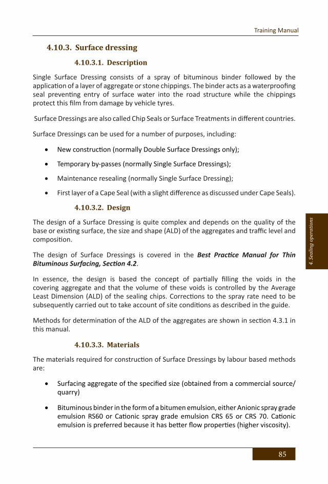
85
Training Manual
4. S
ealin
g op
erat
ions
4.10.3. Surface dressing
4.10.3.1. Description
Single Surface Dressing consists of a spray of bituminous binder followed by the application of a layer of aggregate or stone chippings. The binder acts as a waterproofing seal preventing entry of surface water into the road structure while the chippings protect this film from damage by vehicle tyres.
Surface Dressings are also called Chip Seals or Surface Treatments in different countries.
Surface Dressings can be used for a number of purposes, including:
• New construction (normally Double Surface Dressings only);
• Temporary by-passes (normally Single Surface Dressings);
• Maintenance resealing (normally Single Surface Dressing);
• First layer of a Cape Seal (with a slight difference as discussed under Cape Seals).
4.10.3.2. Design
The design of a Surface Dressing is quite complex and depends on the quality of the base or existing surface, the size and shape (ALD) of the aggregates and traffic level and composition.
The design of Surface Dressings is covered in the Best Practice Manual for Thin Bituminous Surfacing, Section 4.2.
In essence, the design is based the concept of partially filling the voids in the covering aggregate and that the volume of these voids is controlled by the Average Least Dimension (ALD) of the sealing chips. Corrections to the spray rate need to be subsequently carried out to take account of site conditions as described in the guide.
Methods for determination of the ALD of the aggregates are shown in section 4.3.1 in this manual.
4.10.3.3. Materials
The materials required for construction of Surface Dressings by labour based methods are:
• Surfacing aggregate of the specified size (obtained from a commercial source/quarry)
• Bituminous binder in the form of a bitumen emulsion, either Anionic spray grade emulsion RS60 or Cationic spray grade emulsion CRS 65 or CRS 70. Cationic emulsion is preferred because it has better flow properties (higher viscosity).

86
Bituminous Sealing of Low Volume Roads using Labour Based Methods
Aggregate quality
The chippings must have a maximum Los Angeles Abrasion (LAA) value of 30 after 500 revolutions. The ACV is an indication of chipping strength and allowable values usually lie in the range of 20 to 35. Medium to heavily trafficked roads must have chippings with a maximum ACV of 20. On lightly trafficked roads it may be acceptable to have an ACV up to 35 but it is preferable to have chippings with a maximum ACV of 20.
Aggregate size and grading
For low volume roads nominal aggregate sizes of 14, 10 and 6 mm are used. For a Double Surface Dressing typically 14 mm and 6 mm aggregates are used for the first and second layer respectively.
The grading depending on traffic volume is given in Table 21 and Table 22:
82
Aggregate size and grading For low volume roads nominal aggregate sizes of 14, 10 and 6 mm are used. For a Double Surface Dressing typically 14 mm and 6 mm aggregates are used for the first and second layer respectively.
The grading depending on traffic volume is given in Table 21 and Table 22:
20 14 10 6.328 10020 85 - 100 100 - -14 0 - 35 85 - 100 100 -10 0 - 7 0 - 35 85 - 100 1006.3 - 0 - 7 0 - 35 85 - 1005.9 - - 0 - 10 -
3.35 - - - 0 - 352.36 0 - 2 0 - 2 0 - 2 0 - 100.6 - - - 0 - 2
0.075 0 - 1 0 - 1 0 - 1 0 - 1
65 65 65 65
Minimum % by mass retained on BS test sieve
25
Grading limits BS Test Sieve (mm)
Specified size
Max. Flakiness Index
25 25 n/a
Nominal size of aggregates (mm)
Table 21 : Aggregate grading limits for traffic > 100 vpd
20 14 10 6.328 10020 85 - 100 100 - -14 0 - 40 80 - 100 100 -10 0 - 7 0 - 40 85 - 100 1006.3 - 0 - 7 0 - 35 85 - 1005.9 - - 0 - 10 -
3.35 - - - 0 - 352.36 0 - 3 0 - 3 0 - 3 0 - 100.6 0 - 2 0 - 2 0 - 2 0 - 2
0.075 - - - -
60 60 65 65
35 n/a
Nominal size of aggregates (mm)
Minimum % by mass retained on BS test sieve
35
Grading limits BS Test Sieve (mm)
Specified size
Max. Flakiness Index
35
Table 22: Aggregate grading limits for traffic ≤ 100 vpd
Table 21 : Aggregate grading limits for traffic > 100 vpd

87
Training Manual
4. S
ealin
g op
erat
ions
82
Aggregate size and grading For low volume roads nominal aggregate sizes of 14, 10 and 6 mm are used. For a Double Surface Dressing typically 14 mm and 6 mm aggregates are used for the first and second layer respectively.
The grading depending on traffic volume is given in Table 21 and Table 22:
20 14 10 6.328 10020 85 - 100 100 - -14 0 - 35 85 - 100 100 -10 0 - 7 0 - 35 85 - 100 1006.3 - 0 - 7 0 - 35 85 - 1005.9 - - 0 - 10 -
3.35 - - - 0 - 352.36 0 - 2 0 - 2 0 - 2 0 - 100.6 - - - 0 - 2
0.075 0 - 1 0 - 1 0 - 1 0 - 1
65 65 65 65
Minimum % by mass retained on BS test sieve
25
Grading limits BS Test Sieve (mm)
Specified size
Max. Flakiness Index
25 25 n/a
Nominal size of aggregates (mm)
Table 21 : Aggregate grading limits for traffic > 100 vpd
20 14 10 6.328 10020 85 - 100 100 - -14 0 - 40 80 - 100 100 -10 0 - 7 0 - 40 85 - 100 1006.3 - 0 - 7 0 - 35 85 - 1005.9 - - 0 - 10 -
3.35 - - - 0 - 352.36 0 - 3 0 - 3 0 - 3 0 - 100.6 0 - 2 0 - 2 0 - 2 0 - 2
0.075 - - - -
60 60 65 65
35 n/a
Nominal size of aggregates (mm)
Minimum % by mass retained on BS test sieve
35
Grading limits BS Test Sieve (mm)
Specified size
Max. Flakiness Index
35
Table 22: Aggregate grading limits for traffic ≤ 100 vpd
Table 22: Aggregate grading limits for traffic ≤ 100 vpd
4.10.3.4. Aggregate application rate
For planning and tendering purposes the following aggregate application rates can be used:
• 14 mm aggregates 0.012 m3/m2
• 10 mm aggregates 0.010 m3/m2
The determination of the actual aggregate application rate is described in section 4.3.1.1.
4.10.3.5. Binder application rate
Having determined the ALD of the aggregates in accordance with the methods in section 4.3.1, the total binder application rate can be determined from Figure 26 below:

88
Bituminous Sealing of Low Volume Roads using Labour Based Methods
Bituminous Sealing of Low Volume Roads using Labour Based Methods Training Manual
83
4.10.3.4 Aggregate application rate For planning and tendering purposes the following aggregate application rates can be used:
14 mm aggregates 0.012 m3/m2 10 mm aggregates 0.010 m3/m2
The determination of the actual aggregate application rate is described in section 4.3.1.1.
4.10.3.5 Binder application rate Having determined the ALD of the aggregates in accordance with the methods in section 4.3.1, the total binder application rate can be determined from Figure 26 below:
Figure 26: Emulsion binder application rate The application rate determined from Figure 26 is based on traffic exceeding 500 vpd. On low volume roads the seal receives less kneading action from traffic and the bitumen may become oxidized and brittle quicker than on roads with higher traffic. For this reason the binder application rate must be increased in accordance with Table 23 on low volume roads.
Traffic Count (vpd) Adjustment to application rate 500+ No adjustment
500 - 250 Add 2.5 - 5% to calculated binder
250 - 100 Add 5% - 10% to calculated binder≤ 100 Add 10% to calculated binder
Table 23 : Adjustment of binder application rate for Low Volume Roads
Figure 26: Emulsion binder application rate
The application rate determined from Figure 26 is based on traffic exceeding 500 vpd. On low volume roads the seal receives less kneading action from traffic and the bitumen may become oxidized and brittle quicker than on roads with higher traffic. For this reason the binder application rate must be increased in accordance with Table 23 on low volume roads.
Bituminous Sealing of Low Volume Roads using Labour Based Methods Training Manual
83
4.10.3.4 Aggregate application rate For planning and tendering purposes the following aggregate application rates can be used:
14 mm aggregates 0.012 m3/m2 10 mm aggregates 0.010 m3/m2
The determination of the actual aggregate application rate is described in section 4.3.1.1.
4.10.3.5 Binder application rate Having determined the ALD of the aggregates in accordance with the methods in section 4.3.1, the total binder application rate can be determined from Figure 26 below:
Figure 26: Emulsion binder application rate The application rate determined from Figure 26 is based on traffic exceeding 500 vpd. On low volume roads the seal receives less kneading action from traffic and the bitumen may become oxidized and brittle quicker than on roads with higher traffic. For this reason the binder application rate must be increased in accordance with Table 23 on low volume roads.
Traffic Count (vpd) Adjustment to application rate 500+ No adjustment
500 - 250 Add 2.5 - 5% to calculated binder
250 - 100 Add 5% - 10% to calculated binder≤ 100 Add 10% to calculated binder
Table 23 : Adjustment of binder application rate for Low Volume Roads Table 23 : Adjustment of binder application rate for Low Volume Roads

89
Training Manual
4. S
ealin
g op
erat
ions
4.10.3.6. Construction Plant and Equipment
The following specialized plant and equipment is recommended for construction of Surface Dressings by labour based methods:
• Shovels
• Brooms
• Builders wheelbarrows
• Hammer
• 6mm rope, 2 x 50m rolls
• Reinforced paper, 4 rolls x 1 metre wide
• Steel pegs, 300mm x 9mm
• Chalk line equipment
• Steel tape, 5m and 50m
• 5 x 25 ltr measuring containers with lifting handle
• 5 x 10 ltr measuring containers
• 105 ltr drums open both ends with lifting handles for spotting aggregate
• Motorized bitumen sprayer
• Calibrated dip stick
• 105 ltr drums for checking spray rates and cleaning spray equipment
• Spray screens
• Drum lifter for lifting full drums of binder
• Manually operated chip spreader (optional)
• Suitably sized vibratory pedestrian roller (Bomag 75 or equivalent)
4.10.3.7. Construction
Site and Base Preparation
The base must be swept clean of all dust, debris and foreign matter before the sealing commences. Animal droppings must be carefully removed using a spade and a stiff brush taking care not to damage the prime. Any defects in the prime must be repaired by reapplying prime and letting it cure.
Stake out width of road to be surfaced, marking out the edge of the road with a 6mm sisal rope.
Use reinforced paper for the construction joints at the beginning and end of each spray.

90
Bituminous Sealing of Low Volume Roads using Labour Based Methods
Picture 38: Neat joint due to used of reinforced paper
Applying the tack coat
An experienced Spray Team should be able to spray 400 ltr or 2 drums of emulsion binder per hour. The sweeping operation, if required, needs to be balanced with the correct number of labourers to ensure the spray operation is not delayed by the sweeping team.
Activity Number of workers
Loading & spraying operation 3
Spray screen assistants 4 (two on each side)
Sweeping of surface (75 m2/labourer/hr) Depending on area to be prepared
Spreading/brooming aggregates Depending on the area to be sealed
The emulsion should be sprayed direct from the 200 ltr drums using the motorized bitumen sprayer.

91
Training Manual
4. S
ealin
g op
erat
ions
In cold weather it may be required to heat the emulsion to about 50 oC. The heating can be done on the sprayer if it is equipped with a gas burner, otherwise over a low open fire. During heating the emulsion should be stirred with a broom stick to ensure even heating throughout the drum. Heating must be stopped when the drum is feeling hot to the hand.
The heating of emulsion specifically applies when using cationic emulsion. Anionic emulsion can be applied in the warm summer months without heating, but it is advisable to heat it in cool winter weather.
Because of the low viscosity of the emulsion (compared with a penetration bitumen) it is not possible to spray emulsion at more than 0,6 – 0,7 ltr/m2 without the binder tending to flow (even on the “flattest” surfaces). Therefore, to overcome this problem, the tack coat is sprayed at 0,6 – 0,7 ltr/m2 and the balance of the calculated tack coat application is applied as the penetration spray, where the aggregate will inhibit any untoward flow of the binder.
Applying the aggregates
The application of aggregate should follow close after the application of binder, but must only commence after approximately 4m of road has been sprayed to avoid aggregate falling on unsprayed road.
There are two methods of applying the aggregate:
• Spotting of aggregate and spreading by hand
• Application of aggregate by manual chip spreader
Spotting and spreading of aggregates is described in section 4.4 above.
When placing the aggregates on the sprayed surface, a shovel of aggregate is taken and pitched into the air and in the process the shovel twisted rapidly. In so doing the chips are sprayed uniformly over the area to be covered and the stones will fall onto the wet tack coat while the dust, if any, will fall onto the top of the stone or, if there is a breeze, will be blown across the road away from the surface.

92
Bituminous Sealing of Low Volume Roads using Labour Based Methods
Picture 39: Spreading of aggregates by hand
Once sufficient stones have been applied so that one can walk on the surface without coming into contact with the wet binder, the bare spaces are filled with additional aggregates. Gently broom the surface to distribute the aggregate uniformly. An efficient seal can be achieved by simply following the outlined process.
Picture 40: Brooming the surface to achieve uniform cover

93
Training Manual
4. S
ealin
g op
erat
ions
The use of a “Chippy”, if available, will give more even spread rate and uniform surface.
Rolling
As soon as the surface has been covered with the aggregate without bare patches of binder showing, rolling, with a pedestrian roller, can commence. After the surface has been rolled once (i.e. a complete coverage of the roller) attention must be given again to covering bare patches. The first roll must be done without vibration but subsequent rolling, when the aggregate is properly placed with full coverage obtained, can be done with the intermediate vibration of the roller. The rolling carried out in straight lines parallel to the centre line or edges of the road. It is essential that rolling is uniformly done across the width of the road surface. Typically three passes should be sufficient to seat the aggregate.
Picture 41: Rolling the aggregates
Applying the penetration spray
The remainder of the bitumen emulsion that was not applied in the tack coat is now sprayed as a penetration spray. The same precautions regarding joints and protection of kerbs, drains etc. apply as was the case for the tack coat.
It is recommended to apply the penetration spray within 24 hours. If the surface for some reason has been left open for any period before applying the penetration spray,

94
Bituminous Sealing of Low Volume Roads using Labour Based Methods
the following must be attended to:
• Any dust, dirt or sand blown onto the surface voids must be removed/blown out with a compressor
• The surface must be broomed and rolled once to reseat any aggregate that may have been unseated or disturbed by unauthorized traffic. No traffic should be allowed on this surface before the second layer of binder has been applied.
After the application of the penetration spray, crusher dust or sand should be applied to prevent the roller and vehicles from picking up bitumen.
4.10.3.8. Constructing a Double Surface Dressing
Double surface dressings are robust and should be used when:
• A new roadbase is surface dressed.
• Extra ‘cover’ is required on an existing bituminous road surface because of its condition (e.g. when the surface is slightly cracked or patched).
• There is a requirement to maximise durability and minimise the frequency of maintenance and resealing operations.
The quality of a double surface dressing will be greatly enhanced if traffic is allowed to run on the first dressing for a minimum period of 2-3 weeks (and preferably longer) before the second dressing is applied. This allows the chippings of the first dressing to adopt a stable interlocking mosaic which provides a firm foundation for the second dressing. However, traffic and animals may cause contamination of the surface with mud or soil during this period and this must be thoroughly swept off before the second dressing is applied. Such cleaning is sometimes difficult to achieve and the early application of the second seal to prevent such contamination may give a better result.
Applying the second spray
When a Double Surface Dressing is constructed it should be possible to apply sufficient binder in the second spray to give the required total rate of spray for the finished dressing since the first layer of aggregates will prevent run-off of the binder.
Applying the second layers of aggregates
The same procedures are followed as for the first layer.
4.10.3.9. Weather constraints
Spray applications should only be applied during the day and only in good weather conditions and when rain is not imminent. The road surface temperature should be above 10 oC.

95
Training Manual
4. S
ealin
g op
erat
ions
Care should be taken when spraying on a windy day as the spray may be carried some distance and damage property or passing vehicles down-wind of the operation.
4.10.3.10. Traffic control
Once complete, traffic should not be allowed onto the new surfacing until the following morning to allow for the initial curing of the binder. Traffic speeds on the road should be reduced for 2 to 3 days in order to allow the seal to settle.
Traffic accommodation, if required, will require that the entire lane or area being sealed is closed to traffic. If needed, flagmen will be required to assist with stop-go traffic control depending on the area in which the work is being undertaken and the volume of traffic experienced.
Traffic accommodation needs to be well managed as it places the entire workman team at risk. Training in the correct operation of traffic accommodation at road works is vital for the safety of the workmen team as well as allowing safe, free flowing traffic.
4.10.3.11. Quality control
The success of a Surface Dressing depends on the quality and finish of the base. If the base is not well compacted, the chippings will penetrate the top of the base resulting in fattying up or bleeding when the binder rises to the top of and even covering the stones. Such sections become slippery when wet and should be remedied as a matter of priority.
The finished surface of a Surface Dressing will follow irregularities if in the base surface.
The rolling of a surface dressing plays an important part in ensuring the retention of the chippings by assisting in the initial orientation and bedding down of the chippings in the binder. Traditionally, steel-wheeled rollers have been used but these tend to crush weaker aggregates and to crack poorly shaped chippings.
Accordingly, if steel-wheeled rollers are used they should not exceed 8 tonnes in weight and should only be used on chippings which are strong enough. Some steel-wheeled rollers are fitted with rubber sleeves which makes them more suitable for surface dressing work but, as for any roller of this type. they will bridge’ depressions in the existing road surface. In general. pneumatic tyred rollers are preferred because the tyres have a kneading action which tends to manoeuvre the chippings into a tight mosaic without splitting them and they do not ‘bridge’ depressions.
In favourable conditions, adhesion should be well established within 30 minutes of rolling after which considerable benefit can be obtained by allowing slow moving traffic, particularly heavy lorries, to traverse the dressing provided that traffic speed is kept below 20 to 30 km/hr. This is very important and the use of a lead vehicle to ‘convoy’ traffic at slow speed is recommended.

96
Bituminous Sealing of Low Volume Roads using Labour Based Methods
After-care is an essential part of the surfacing process and consists of removing excess chippings within 24 to 48 hours of the construction of a dressing. Some of the excess chippings will have been thrown clear by passing vehicles but some loose chippings will remain on the surface and these are a hazard to windscreens and, hence, a source of public complaint. They can be removed by brooming or by purposed-made suction cleaners. Care must be taken with brooming to avoid damage to the new dressing and it is usually best to do this work in the early morning when the surface dressing binder is still relatively stiff. It is Important to stress that over-chipping can reduce the quality of a dressing, make after-care a more time consuming process and also unnecessarily increase costs.
4.10.4. Cape Seal
4.10.4.1. Description
A Cape Seal consists of a Single Surface Dressing using 13 or 19 mm aggregate, which is penetrated with a binder followed by a slurry seal. If 19 mm aggregate is used, 2 layers of slurry are applied. The first layer of a Cape seal is designed and constructed using the same procedure used for a Single Surface Dressing. A slurry seal is then prepared as described in section 0, and applied in between the seal aggregates to the top of the surface dressing.
The Cape Seal is a very robust seal capable of carrying high traffic. Its high binder content makes it quite costly and it may therefore not be an economical solution for low traffic roads.
4.10.4.2. Design
There are two schools regarding the design and construction of Cape Seals.
• In the one described in the Best Practice Manual for Thin Bituminous Surfacing, the design and construction is similar to that for a Single Surface Dressing and Slurry Seal as described above. In this case a Fine Slurry is applied in one or two applications depending on the size of the stones for the single seal.
• The other school prescribes a gap of +/- 5 mm between the stones in the single seal. In this case a General or Medium Slurry is prescribed.
Since the design and construction in accordance with the first option can follow the guidelines for Surface Dressing and Slurry Seal, the latter option is described in the following. The method of applying the slurry seal is common to both options.

97
Training Manual
4. S
ealin
g op
erat
ions
4.10.4.3. Materials
Materials required for the construction of the Cape seal are:
• Surfacing aggregate of the specified size (obtained from a commercial source/quarry)
• Bituminous binder in the form of a bitumen emulsion (either Anionic spray grade emulsion (60/40) or Cationic spray grade emulsion (65/35)
• Slurry aggregate of the specified grading (obtained from a commercial source/quarry)
• Slurry binder in the form of an Anionic stable grade emulsion (60/40)
Aggregate quality
Specifications for Surface Dressing aggregates nominal sizes 14 and 20 mm apply, see 0.
Aggregate grading
Grading limits for Surface Dressing aggregates nominal sizes 14 and 20 mm apply, see 0.
4.10.4.4. Aggregate application rate
For planning and tendering purposes the following aggregate application rates can be used:
• 14 mm aggregates 0.010 m3/m2
• 20 mm aggregates 0.013 m3/m2
The determination of the actual aggregate application rate is described in section 4.3.1.1.
4.10.4.5. Binder application rate
The total binder application is determined using the same method as for Surface Dressing, but must be reduced by some 10-15% as the stones will not be lying shoulder to shoulder as is the case with a Surface Dressing. This reduction in the rate of application is acceptable in the Cape Seal as the voids will be taken up by the slurry seal.
All that is required of the binder is that there must be sufficient residual bitumen to hold the aggregate in place and also bind the slurry seal to the aggregate. If the residual bitumen is excessive the surface will bleed.

98
Bituminous Sealing of Low Volume Roads using Labour Based Methods
4.10.4.6. Construction Plant and Equipment
The plant and equipment for construction of a Cape Seal is the same as that for construction of a Single Surface Dressing, with the following additions for mixing and applying the Slurry:
• Rubber squeegees
• 5 x 25 litre measuring containers with lifting handle
• 5 x 10 litre measuring containers
• Hessian drag
• Concrete Mixer 150/200
• Steel framed stand for emulsion drums with steel or timber ramps
• 75 mm diameter ball valve for decanting emulsion from drums
4.10.4.7. Construction
Site and Base Preparation
The base must be swept clean of all dust, debris and foreign matter before the sealing commences. Animal droppings must be carefully removed using a spade and a stiff brush taking care not to damage the prime. Any defects in the prime must be repaired by reapplying prime and letting it cure.
Stake out width of road to be surfaced, marking out the edge of the road with a 6mm sisal rope.
Use reinforced paper for the construction joints at the beginning and end of each spray.
Applying the tack coat
An experienced Spray Team should be able to spray 400 ltr or 2 drums of emulsion binder per hour. The sweeping operation, if required, needs to be balanced with the correct number of labourers to ensure the spray operation is not delayed by the sweeping team.
Activity Number of workers
Loading & spraying operation 3
Spray screen assistants 4 (two on each side)
Sweeping of surface (75 m2/labourer/hr) Depending on area to be prepared
Spreading/brooming aggregates Depending on the area to be sealed

99
Training Manual
4. S
ealin
g op
erat
ions
The emulsion should be sprayed direct from the 200 ltr drums using the motorized bitumen sprayer.
In cold weather it may be required to heat the emulsion to about 50 oC. The heating can be done on the sprayer if it is equipped with a gas burner, otherwise over a low open fire. During heating the emulsion should be stirred with a broom stick to ensure even heating throughout the drum. Heating must be stopped when the drum is feeling hot to the hand.
The heating of emulsion specifically applies when using cationic emulsion. Anionic emulsion can be applied in the warm summer months without heating, but it is advisable to heat it in cool winter weather.
Because of the low viscosity of the emulsion (compared with a penetration bitumen) it is not possible to spray emulsion at more than 0,6 – 0,7 ltr/m2 without the binder tending to flow (even on the “flattest” surfaces). Therefore, to overcome this problem, the tack coat is sprayed at 0,6 – 0,7 ltr/m2 and the balance of the calculated tack coat application is applied as the penetration spray, where the aggregate will inhibit any untoward flow of the binder.
Applying the aggregates
For a Cape Seal the aggregates must not be shoulder-to-shoulder as for Surface Dressing aggregates, but must be spaced apart by one third to one quarter of the nominal size of the aggregate being used as indicated in Figure 27.
Figure 27: Cape Seal aggregates should be spaced by +/-5 mm
Methods for determination of the ALD of the aggregates are described in section 4.3.1.
Applying the penetration spray
Once the aggregate has been uniformly applied and is well seated, the remainder of the bitumen emulsion that was not applied in the tack coat is now sprayed as a penetration spray.
The same precautions regarding joints and protection of kerbs, drains etc apply as was the case for the tack coat.

100
Bituminous Sealing of Low Volume Roads using Labour Based Methods
It is advisable to apply the penetration spray as soon as possible after the tack coat has been sprayed. If, however, the surface is left open for any period before applying the penetration spray the following must be attended to:
• Any dust, dirt or sand blown into the surface voids must be removed/blown out with a compressor, and
• The surface must be rolled once to reseat any aggregate that may have been unseated/disturbed by unauthorized traffic.
Mixing and applying the Slurry
The design and mixing of the Slurry is described in section 0. For this Cape Seal design a General or Medium Slurry is preferred.
Before the slurry is applied, all dust and debris must be removed from the voids between the aggregates using brooms or a compressor to blow the dirt out. Animal droppings must be carefully removed using suitable tools able to reach into the voids without dislodging the aggregates.
The slurry is best applied using rubber squeegees in on or two applications depending on the size of the aggregates. The squeegees are effective for working the slurry down in between the aggregates to fill all the voids.
For the finishing touch a wet hessian drag is dragged over the surface.
Picture 42: Applying slurry on a 19 mm Cape Seal

101
Training Manual
4. S
ealin
g op
erat
ions
Picture 43: Completed Cape Seal
Picture 44: New Cape Seal surface texture

102
Bituminous Sealing of Low Volume Roads using Labour Based Methods
4.10.4.8. Weather constraints
Spray applications should only be applied during the day and only in good weather conditions and when rain is not imminent. The road surface temperature should be above 10 oC.
Care should be taken when spraying on a windy day as the spray may be carried some distance and damage property or passing vehicles down-wind of the operation.
The slurry seal should only be constructed in good weather when rain is not imminent. The slurry should not be applied when the road surface temperature is below 7 °C, as colder weather affects the time taken by the emulsion to break and may cause segregation of the aggregate and movement of emulsion to the surface.
4.10.4.9. Traffic control
The emulsion should normally be allowed to break for 2 to 3 hours and the slurry layer allowed to dry out before traffic is allowed onto it. However, this depends on humidity and temperature and should be determined by inspection. The second slurry layer can be applied on the first layer after traffic has been allowed onto the first layer for at least 24 hours.
Traffic accommodation, if required, will require that the entire lane or area being sealed is closed to traffic. If needed, flagmen will be required to assist with stop-go traffic control depending on the area in which the work is being undertaken and the volume of traffic experienced.
Traffic accommodation needs to be well managed as it places the entire workman team at risk. Training in the correct operation of traffic accommodation at road works is vital for the safety of the workmen team as well as allowing safe, free flowing traffic.
4.10.4.10. Quality control
The success of a Cape Seal depends on the quality and finish of the base. If the base is not well compacted, the chippings will penetrate the top of the base resulting in fattying up or bleeding when the binder rises to the top of and even covering the stones. Such sections become slippery when wet and should be remedied as a matter of priority.
The finished surface of a Cape Seal will follow irregularities in the base surface.
The quality of the slurry seal depends on the careful attention to detail when mixing the slurry. When the final mix design has been decided, batching boxes or plastic containers should be marked with the exact volume to be added for the various ingredients.
In the completed Cape Seal the top of the aggregates should be slightly proud of the slurry such that the forces of the vehicle tyres are acting on the aggregates and only to a lesser degree on the slurry.

103
Training Manual
4. S
ealin
g op
erat
ions
4.10.5. Modified Otta Seal or Penetration Seal
4.10.5.1. Description
The penetration seal is a variation of the conventional Otta Seal using graded aggregates and emulsion binder facilitating the construction of the seal entirely by labour based methods.
It comprises placing a graded aggregate on a bituminous emulsion tack coat at the predetermined application rate and then penetrating the aggregate layer with a bituminous emulsion. The thickness of this seal layer is based on the Average Least Dimension (ALD) of the large fraction of the aggregate.
Apart from being more labour based than the Otta Seal, the penetration seal has the following advantages:
• It requires lower quantities of aggregate and binder than the Otta seal as it forms a thinner layer;
• It does not require a tanker to apply hot bitumen;
• It does not pose a threat of damage to vehicles and possible claims due to “flying stones”;
• It does not require the aggregate to be broomed back on the road over an extended period of time, which is a decidedly expensive operation.
4.10.5.2. Design
The amount of emulsion for the Penetration Seal depends on the amount of aggregate applied. The amount of aggregate in turn is determined by the ALD. The same methods used for Surface Dressing to determine the ALD of the aggregates and binder application rate, is used for the Modified Otta Seal, see sections 4.3.1 and 0.
Once the rates of application have been established, it is equally essential to apply them as accurately as physically possible.
The penetration seal normally consists of a graded aggregate of 10 mm and smaller. The grading should fall within the grading envelope in Table 24, below but tends towards the lower limit of the envelope.
4.10.5.3. Materials
Materials required for the construction of the Penetration Seal are:
• Surfacing aggregate of the specified grading (obtained from a commercial source/quarry)
• 60% stable grade anionic bituminous emulsion binder.

104
Bituminous Sealing of Low Volume Roads using Labour Based Methods
The grading of the aggregate shall be within the limits specified below:
98
The grading of the aggregate shall be within the limits specified below:
Upper limit Ideal Lower limit1410 96 90 856,3 82 74 654 70 58 452 50 35 201 30 20 10
0,425 16 10 20,3 10 6 1.8
0,15 8 5 1.50,075 5 3 1
Sieve aperture (mm)
Percentage passing %
100
Table 24: Aggregate grading limits for Penetration Seal
It is critical for the lower fraction material to not exceed the upper limit of the grading envelope as a high percentage of fine material tends to trap the penetration spray in the upper surface of a seal preventing proper penetration of the layer.
For planning and tendering purposes, the following application rates can be used:
Anionic Stable Grade SS60 2.7 ltr/ m2 Graded aggregate 0,0098 m3/m2 or 102 m2/m3
Aggregate quality The Modified Otta Seal emulates the performance of the Otta Seal. However, it cannot tolerate as much fines as the Otta Seal and the 0/6 crusher dust should be fairly clean.
Aggregates from crushing plants that crush mainly for concrete aggregates are sometimes extremely flaky and dusty and are not suitable for the Cold Mix Asphalt although the aggregate strength may be satisfactory. Aggregates must therefore be tested for grading and strength before any order is placed.
The specifications for the coarse 6/10 aggregates similar to those for the Otta Seal can be used:
≤ 100 > 100Min. Dry 10% FACT 90 KN 110 KNMin. Wet/Dry strength ratio 0.60 0.75
Aggregate strength requirements
AADT at time of construction
Max. Flakiness Index 30%
Table 25 : Coarse aggregate specifications for Modified Otta Seal
Table 24: Aggregate grading limits for Penetration Seal
It is critical for the lower fraction material to not exceed the upper limit of the grading envelope as a high percentage of fine material tends to trap the penetration spray in the upper surface of a seal preventing proper penetration of the layer.
For planning and tendering purposes, the following application rates can be used:
• Anionic Stable Grade SS60 2.7 ltr/ m2
• Graded aggregate 0,0098 m3/m2 or 102 m2/m3
Aggregate quality
The Modified Otta Seal emulates the performance of the Otta Seal. However, it cannot tolerate as much fines as the Otta Seal and the 0/6 crusher dust should be fairly clean.
Aggregates from crushing plants that crush mainly for concrete aggregates are sometimes extremely flaky and dusty and are not suitable for the Cold Mix Asphalt although the aggregate strength may be satisfactory. Aggregates must therefore be tested for grading and strength before any order is placed.
The specifications for the coarse 6/10 aggregates similar to those for the Otta Seal can be used:

105
Training Manual
4. S
ealin
g op
erat
ions
98
The grading of the aggregate shall be within the limits specified below:
Upper limit Ideal Lower limit1410 96 90 856,3 82 74 654 70 58 452 50 35 201 30 20 10
0,425 16 10 20,3 10 6 1.8
0,15 8 5 1.50,075 5 3 1
Sieve aperture (mm)
Percentage passing %
100
Table 24: Aggregate grading limits for Penetration Seal
It is critical for the lower fraction material to not exceed the upper limit of the grading envelope as a high percentage of fine material tends to trap the penetration spray in the upper surface of a seal preventing proper penetration of the layer.
For planning and tendering purposes, the following application rates can be used:
Anionic Stable Grade SS60 2.7 ltr/ m2 Graded aggregate 0,0098 m3/m2 or 102 m2/m3
Aggregate quality The Modified Otta Seal emulates the performance of the Otta Seal. However, it cannot tolerate as much fines as the Otta Seal and the 0/6 crusher dust should be fairly clean.
Aggregates from crushing plants that crush mainly for concrete aggregates are sometimes extremely flaky and dusty and are not suitable for the Cold Mix Asphalt although the aggregate strength may be satisfactory. Aggregates must therefore be tested for grading and strength before any order is placed.
The specifications for the coarse 6/10 aggregates similar to those for the Otta Seal can be used:
≤ 100 > 100Min. Dry 10% FACT 90 KN 110 KNMin. Wet/Dry strength ratio 0.60 0.75
Aggregate strength requirements
AADT at time of construction
Max. Flakiness Index 30%
Table 25 : Coarse aggregate specifications for Modified Otta Seal
Table 25 : Coarse aggregate specifications for Modified Otta Seal
4.10.5.4. Construction Plant and Equipment
The following specialized plant and equipment is recommended for the construction of the Penetration Seal by labour based methods:
• Shovels
• Brooms
• Wheelbarrows
• Hammer
• 6mm rope, 2 x 50m rolls
• Reinforced paper, 4 rolls x 1 m wide
• Steel pegs, 300mm x 9mm
• Chalk line equipment
• Steel tapes, 5 m and 50m
• 105 ltr drums open ended with lifting handles for spotting aggregate
• Heavy duty plastic sheet for spotting aggregate (1,5 x 1,5 m)
• 105 ltr drums (checking spray rates and cleaning spray equipment)
• Drum lifter for lifting full drums of binder
• Calibrated dipstick for dipping emulsion in drums
• Motorized bitumen sprayer
• Suitably sized vibratory pedestrian roller (Bomag 75 or equivalent)
• Spray screens

106
Bituminous Sealing of Low Volume Roads using Labour Based Methods
4.10.5.5. Construction
Site and base preparation
The base must be swept clean of all dust, debris and foreign matter before the sealing commences. Animal droppings must be carefully removed using a spade and a stiff brush taking care not to damage the prime. Any defects in the prime must be repaired by reapplying prime and letting it cure.
Stake out the width of road to be surfaced, marking out the edge of the road with a 6mm rope.
Use reinforced paper for the construction joints at the beginning and end of each spray.
Applying the binder
An experienced Spray Team should be able to spray 400 ltr or 2 drums of emulsion binder per hour. The sweeping operation, if required, needs to be balanced with the correct number of labourers to ensure the spray operation is not delayed by the sweeping team.
Activity Number of workers
Loading & spraying operation 3
Spray screen assistants 4 (two on each side)
Sweeping of surface (75 m2/labourer/hr) Depending on area to be prepared
Spreading/brooming aggregates Depending on the area to be sealed
The emulsion should be sprayed direct from the 200 ltr drums using the motorized bitumen sprayer.
In cold weather it may be required to heat the emulsion to about 50 oC. The heating can be done on the sprayer if it is equipped with a gas burner, otherwise over a low open fire. During heating the emulsion should be stirred with a broom stick to ensure even heating throughout the drum. Heating must be stopped when the drum is feeling hot to the hand.
Anionic emulsion can be applied in the warm summer months without heating, but it is advisable to heat it in cold winter weather.
Because of the low viscosity of the emulsion (compared with a penetration bitumen) it is not possible to spray emulsion at more than 0,6 – 0,7 ltr/m2 without the binder tending to flow (even on the “flattest” surfaces). Therefore, to overcome this problem, the tack coat is sprayed at 0,6 – 0,7 ltr/m2 and the balance of the calculated tack coat

107
Training Manual
4. S
ealin
g op
erat
ions
application is applied as the penetration spray, where the aggregate will inhibit any untoward flow of the binder.
Applying the aggregates
Spotting and application of the aggregates is described in section 4.4.
4.10.5.6. Weather constraints
Spray applications should only be applied during the day and only in good weather conditions and when rain is not imminent. The road surface temperature should be above 10 oC.
Care should be taken when spraying on a windy day as the spray may be carried some distance and damage property or passing vehicles down-wind of the operation.
4.10.5.7. Traffic control
Once complete, traffic should not be allowed onto the new surfacing until the following morning to allow for the initial curing of the binder. Traffic speeds on the road should be reduced for 2 to 3 days in order to allow the Modified Otta Seal to settle.
Traffic accommodation, if required, will require that the entire lane or area being sealed is closed to traffic. If needed, flagmen will be required to assist with stop-go traffic control depending on the area in which the work is being undertaken and the volume of traffic experienced.
Traffic accommodation needs to be well managed as it places the entire workman team at risk. Training in the correct operation of traffic accommodation at road works is vital for the safety of the workmen team as well as allowing safe, free flowing traffic.
4.10.5.8. Quality control
The success of a Modified Otta Seal depends on the quality and finish of the base. The finished surface will follow any irregularities in the base surface.
If the binder has been applied at the correct rate, serious bleeding is not likely to occur. However, the seal will in most cases have a slightly patchy appearance due to the small variations in the binder application using the hand sprayer.

108
Bituminous Sealing of Low Volume Roads using Labour Based Methods
Picture 45: Patchy appearance of Modified Otta Seal compared to Cold Mix Asphalt in the following section
If the penetration spray has not penetrated down to and bonded with the tack coat, localized failures as shown in Picture 46 with aggregate loss and forming of potholes can occur.
Picture 46: Localized failure due to inadequate penetration of the penetration spray

109
Training Manual
4. S
ealin
g op
erat
ions
4.10.6. Cold mix asphalt
4.10.6.1. Description
Cold Mix Asphalt is a pre-mix of continuously graded aggregate and cationic mix grade emulsion. It can be mixed and placed by labour using only simple hand tools and purpose made implements, thus eliminating the need for sophisticated and expensive construction plant except for a suitably sized Pedestrian roller type Bomag 75 or similar.
The seal is therefore eminently suited to labour based sealing of low volume roads. It does not require highly skilled supervisors and the techniques for mixing and constructing the seal is easily learnt by the labourers.
4.10.6.2. Design
The design of the Cold Mix Asphalt is based on experience and small trials for every new source of aggregates to determine the optimum mix ratio.
4.10.6.3. Materials
For planning and tendering purposes the following specifications can be used:
Aggregate grading
102
4.10.6 Cold mix asphalt
4.10.6.1 Description Cold Mix Asphalt is a pre-mix of continuously graded aggregate and cationic mix grade emulsion. It can be mixed and placed by labour using only simple hand tools and purpose made implements, thus eliminating the need for sophisticated and expensive construction plant except for a suitably sized Pedestrian roller type Bomag 75 or similar.
The seal is therefore eminently suited to labour based sealing of low volume roads. It does not require highly skilled supervisors and the techniques for mixing and constructing the seal is easily learnt by the labourers.
4.10.6.2 Design The design of the Cold Mix Asphalt is based on experience and small trials for every new source of aggregates to determine the optimum mix ratio.
4.10.6.3 Materials For planning and tendering purposes the following specifications can be used:
Aggregate grading
Table 26: Recommended grading for Cold Mix Asphalt
The relatively tight grading envelope is to ensure a dense mix. It is particularly important to be as close as possible to the upper limit for the finer fractions from 0.3 to 2 mm whereas excessive amounts of dust may cause balling during the mixing.
Min Recomm. Max14 100 100 10010 85 96 1006,3 62 70 784 46 52 602 28 34 401 16 21 26
0,425 7 10 130,3 5 7,5 10
0,15 2 4 60,075 1 2 3
Percentage passingSieve size (mm)
Table 26: Recommended grading for Cold Mix Asphalt
The relatively tight grading envelope is to ensure a dense mix. It is particularly important to be as close as possible to the upper limit for the finer fractions from 0.3 to 2 mm whereas excessive amounts of dust may cause balling during the mixing.

110
Bituminous Sealing of Low Volume Roads using Labour Based Methods
Mix proportions
For planning and tendering purposes the following mix proportions can be used:
Bituminous Sealing of Low Volume Roads using Labour Based Methods Training Manual
103
Mix proportions
For planning and tendering purposes the following mix proportions can be used:
Max batch volume 40 ltr6/10 stone 12 ltr0/6 crusher dust 28 ltr0/2 sand (clean building sand) 0-3 ltr if required to
achieve desired gradingK3 65 cationic emulsion 6 ltrWater 1 ltr if aggregates are dry
Table 27: Typical mix proportions for Cold Mix Asphalt This batch volume will produce about 1.9 m2 at 20mm loose thickness (14 mm compacted).
Aggregate quality The Cold Mix Asphalt emulates the performance of the Otta Seal. However, it cannot tolerate as much fines as the Otta Seal and the 0/6 crusher dust should be fairly clean.
Aggregates from crushing plants that crush mainly for concrete aggregates are sometimes extremely flaky and dusty and are not suitable for the Cold Mix Asphalt although the aggregate strength may be satisfactory. Aggregates must therefore be tested for grading and strength before any order is placed.
The specifications for the coarse 6/10 aggregates similar to those for the Otta Seal can be used:
≤ 100 > 100Min. Dry 10% FACT 90 KN 110 KNMin. Wet/Dry strength ratio 0.60 0.75
Aggregate strength requirements
AADT at time of construction
Max. Flakiness Index 30%
Table 28: Coarse aggregate specifications for Cold Mix Asphalt Emulsion binder A slow setting cationic mix grade emulsion K3-65 has been found to give the best results. The addition of a small amount of non-ionic stabilizer and calcium chloride CaCl2 allows for relatively high fines content without causing balling. The slow setting K3-65 emulsion also gives ample time for spreading and levelling the asphalt before the emulsion breaks and the mix becomes sticky and difficult to spread.
Tack coat Anionic Stable Grade SS60 diluted 1:8 with clean water is used for a thin tack coat prior to sealing. The tack coat should be dry before sealing starts to avoid pick-up of bitumen during the sealing.
Trial mix For every new source of aggregate to be used, small trial mixes should be carried out to establish the optimal mix proportions.
Table 27: Typical mix proportions for Cold Mix Asphalt
This batch volume will produce about 1.9 m2 at 20mm loose thickness (14 mm compacted).
Aggregate quality
The Cold Mix Asphalt emulates the performance of the Otta Seal. However, it cannot tolerate as much fines as the Otta Seal and the 0/6 crusher dust should be fairly clean.
Aggregates from crushing plants that crush mainly for concrete aggregates are sometimes extremely flaky and dusty and are not suitable for the Cold Mix Asphalt although the aggregate strength may be satisfactory. Aggregates must therefore be tested for grading and strength before any order is placed.
The specifications for the coarse 6/10 aggregates similar to those for the Otta Seal can be used:
Bituminous Sealing of Low Volume Roads using Labour Based Methods Training Manual
103
Mix proportions
For planning and tendering purposes the following mix proportions can be used:
Max batch volume 40 ltr6/10 stone 12 ltr0/6 crusher dust 28 ltr0/2 sand (clean building sand) 0-3 ltr if required to
achieve desired gradingK3 65 cationic emulsion 6 ltrWater 1 ltr if aggregates are dry
Table 27: Typical mix proportions for Cold Mix Asphalt This batch volume will produce about 1.9 m2 at 20mm loose thickness (14 mm compacted).
Aggregate quality The Cold Mix Asphalt emulates the performance of the Otta Seal. However, it cannot tolerate as much fines as the Otta Seal and the 0/6 crusher dust should be fairly clean.
Aggregates from crushing plants that crush mainly for concrete aggregates are sometimes extremely flaky and dusty and are not suitable for the Cold Mix Asphalt although the aggregate strength may be satisfactory. Aggregates must therefore be tested for grading and strength before any order is placed.
The specifications for the coarse 6/10 aggregates similar to those for the Otta Seal can be used:
≤ 100 > 100Min. Dry 10% FACT 90 KN 110 KNMin. Wet/Dry strength ratio 0.60 0.75
Aggregate strength requirements
AADT at time of construction
Max. Flakiness Index 30%
Table 28: Coarse aggregate specifications for Cold Mix Asphalt Emulsion binder A slow setting cationic mix grade emulsion K3-65 has been found to give the best results. The addition of a small amount of non-ionic stabilizer and calcium chloride CaCl2 allows for relatively high fines content without causing balling. The slow setting K3-65 emulsion also gives ample time for spreading and levelling the asphalt before the emulsion breaks and the mix becomes sticky and difficult to spread.
Tack coat Anionic Stable Grade SS60 diluted 1:8 with clean water is used for a thin tack coat prior to sealing. The tack coat should be dry before sealing starts to avoid pick-up of bitumen during the sealing.
Trial mix For every new source of aggregate to be used, small trial mixes should be carried out to establish the optimal mix proportions.
Table 28: Coarse aggregate specifications for Cold Mix Asphalt
Emulsion binder
A slow setting cationic mix grade emulsion K3-65 has been found to give the best results. The addition of a small amount of non-ionic stabilizer and calcium chloride CaCl2 allows for relatively high fines content without causing balling. The slow setting K3-65 emulsion also gives ample time for spreading and levelling the asphalt before the

111
Training Manual
4. S
ealin
g op
erat
ions
emulsion breaks and the mix becomes sticky and difficult to spread.
Tack coat
Anionic Stable Grade SS60 diluted 1:8 with clean water is used for a thin tack coat prior to sealing. The tack coat should be dry before sealing starts to avoid pick-up of bitumen during the sealing.
Trial mix
For every new source of aggregate to be used, small trial mixes should be carried out to establish the optimal mix proportions.
For very porous aggregates, the amount of emulsion must be increased. The increase may be established in a laboratory, but practical trials will give a good indication of the required amount of emulsion to be used.
The ready mix should have a wet look and all aggregates should be properly covered.
4.10.6.4. Construction Plant and Equipment
For the construction of Cold Mix Asphalt with labour based methods the following plant and equipment is required:
• Pedestrian vibratory roller (750 kg – 1.5 tonnes);
• Mixing pan(s) constructed of 3mm steel
• Wheelbarrows,
• 6mm rope, 2 x 50m rolls,
• Flat square nosed spades,
• Hard brooms
• Hammer
• 75mm nails for holding down guide rails
• Chalk line equipment
• Steel tapes, 5 m and 50m,
• Steel squeegees
• 20mm steel box sections as guide rails for placing asphalt (four lengths each of 2m and 3m long) with three 4mm diameter nail holes per section
• 6mm x 50mm steel flat bar to accommodate wet to dry asphalt (four lengths each of 2m and 3m long),
• 2m straight edge (Screed)
• 6 No. 20 litre measuring containers,

112
Bituminous Sealing of Low Volume Roads using Labour Based Methods
• 5 No. 10 litre measuring containers,
• 1 No. 5 litre measuring jug,
• Steel framed stand for decanting emulsion drums,
• 50 mm diameter ball valve for decanting emulsion from drums
4.10.6.5. Construction
Site and base preparation
The base must be swept clean of all dust, debris and foreign matter before the sealing commences. Animal droppings must be carefully removed using a spade and a stiff brush taking care not to damage the prime. Any defects in the prime must be repaired by reapplying prime and letting it cure.
Stake out the width of road to be surfaced, marking out the edge of the road with a 6mm rope.
The asphalt should be laid in strips usually not wider than 1.20 m at a time. If the base does not have a perfect camber, i.e. it has a slight dome shape or bulge in between the guide rails, the asphalt will be too thin on top of the bulge if wider strips are set out. This should be checked using the straight edge before sealing work starts.
The strips should be marked out such that the joints do not come in the wheel paths. The number and width of the strips depends on the width of the lane. The strips should also not be too narrow as this will increase the number of longitudinal joints.
Picture 47: Setting out and marking the strips

113
Training Manual
4. S
ealin
g op
erat
ions
A 3.0 m wide lane is then constructed in 3 strips of 1 m width.
Organizing the work
Sufficient material for the day’s work should be stockpiled in the near vicinity of the section to be sealed. The primed base is good for stockpiling since it eliminates contamination of the aggregates.
The emulsion drums, one for tack coat and one for the binder, should be mounted on drum stands next to the section. Containers of water should also be placed in the same location.
Sufficient numbers of wheel barrows for carting aggregates from the stockpile to the mixing pans must be present.
The mixing pans should be placed on the side of the strip to be sealed such that when the mix is ready it can be poured directly onto the surface in between the guide rails.
The spacing in between the pans should be such that the workers on different pans do not interfere with each other.
Example:
One 40 ltr batch will cover about 1.9 m2 in 20 mm loose thickness. For a 1.0 m wide strip, one batch will cover about 1.9 m. A spacing of 3.8 m between the pans will give adequate working space for the mixing teams who will cover two successive lengths of 1.9 m moving their pans into position for every 1.9 m length, before they move on down the production line to the first available 3.8 m section as illustrated in Figure 28.
106
Picture 48: Pouring the mix directly from the mixing pans
Figure 28 : Example of tray spacing and movement
Tray A
Tray B
A first batch
Tray A
A second batch
B first batch
B second batch
A third batch
A fourth batch

114
Bituminous Sealing of Low Volume Roads using Labour Based Methods
Picture 48: Pouring the mix directly from the mixing pans
Setting out guide rails
The guide rails are set out for the first strip and secured with nails, starting at the edge of the road.
Applying the tack coat
Anionic stable grade emulsion SS60 is diluted 1:8 with clean water in a suitable container and applied to the primed surface in between the guide rails using watering cans or a bucket and a mug. The tack coat shall be spread to a very light application using brooms and allowed to set and dry before the sealing operations commence.

115
Training Manual
4. S
ealin
g op
erat
ions
Picture 49: Applying tack coat
Batching and mixing the asphalt
The batching and mixing may be done with Concrete Mixers, but using the purpose made mixing pans is preferred.
The following problems have been experienced with concrete mixers:
• They are basically stationary or difficult to move around and can constitute a capacity constraint
• Caking of fines inside the drum can easily occur and is difficult to clean out. Lengthy stoppages may result as a consequence
Concrete mixers are also more difficult to transport to and from site, use fuel and are noisy, whereas a stack of mixing pans is easy to transport at the back of a pick-up, they are easy to keep clean, do not consume fuel and don’t make noise. Using mixing pans it

116
Bituminous Sealing of Low Volume Roads using Labour Based Methods
is also very easy to scale the production up and down as required by adding or reducing the number of pans used.
In the following therefore only the procedure using mixing pans will be explained.
Picture 50: Purpose made mixing pan for Cold Mix Asphalt
Following the establishment of the optimal mix recipe, batching boxes or containers should be marked with the exact volumes of the various ingredients to be added to the mix.
The mixing sequence is as follows:
• Coarse and fine aggregates are first measured up and poured into the mixing pan. If the aggregates are completely dry some water is added to evenly moist all the aggregates when mixed thoroughly together.
• The aggregates are then spread out evenly in the pan and the emulsion slowly poured over the aggregates when at the same time the mixing starts.
• The mixing continues until all the aggregates are properly covered with emulsion, taking care not to leave any un-mixed material in the corners of the pan. The mixing may take up to a minute before the mix is ready.

117
Training Manual
4. S
ealin
g op
erat
ions
The mix volume should be limited to 40 ltr of aggregates, possibly with the addition of some sand if needed to improve the grading. If the mix volume gets bigger, it becomes much harder for the labourers to mix and the mix may not be done properly. The added advantage of keeping the volume at 40 ltr, is that two labourers can then easily lift or tip the pan as shown in Picture 48, for discharge of the ready mix in between the guide rails without first loading it into wheel barrows.
Picture 51: Mixing the asphalt.
Spreading and leveling the asphalt
As explained above, the most rational setup is with the mixing pans just adjacent to the strip to be sealed and spaced out so that the teams do not interfere with each other. This saves the double handling of loading and carting the asphalt in wheel barrows.
The use of the slow set emulsion allows ample time for spreading and leveling the asphalt.
The asphalt is first spread as evenly as possible with steel spreaders, making sure that no gaps are left against the guide rails.

118
Bituminous Sealing of Low Volume Roads using Labour Based Methods
Rakes must not be used for spreading as this will segregate the coarse aggregates from the fines.
Behind the spreader the asphalt is immediately leveled with a screed using a sawing motion. The screeding team picks up the asphalt that has fallen outside the guide rails and make sure no gaps are left on the surface.
The guide rails ensure that the asphalt is applied in even thickness resulting in a smooth finished surface. Contrary to other thin seals, the asphalt can even out minor irregularities in the base.
Within minutes of the levelling the emulsion starts to break and the colour changes from dark brown to black. The asphalt is then left for the emulsion to break through the whole layer before compaction can start, usually after about half an hour depending on the weather and ambient temperature.
Picture 52: Spreading and leveling the asphalt
Compaction
• The first pass with the pedestrian roller is done in static mode. With careful maneuvering, the guide rails may be left in place for the first pass of the roller. This will ensure a neat edge of the strip when the guide rails are removed for the subsequent passes.

119
Training Manual
4. S
ealin
g op
erat
ions
• Compaction should be done from the edge towards the centre and always in the longitudinal direction of the road.
• Wherever possible at least half the roller drum should be supported on compacted asphalt. Wrong rolling can result in the building in of undulations in the surface of the asphalt.
• After about three subsequent passes, the first one in light vibration mode, the initial 20 mm loose layer has been compacted to a final thickness of approximately 14mm.
• Once rolling has been completed and before proceeding with the construction of the adjacent asphalt strip the edges of the compacted asphalt, against which the new strip will be laid, must be neatly trimmed and squared and any loose material removed.
Picture 53: Compaction with half the drum onto the already compacted asphalt
For construction of the adjacent strip, 20 mm guide rails are placed and secured on the base as for the first strip. A 6 mm thick steel flat bar is placed on top of the compacted asphalt as shown in Figure 29 and Picture 54.
.

120
Bituminous Sealing of Low Volume Roads using Labour Based Methods
Bituminous Sealing of Low Volume Roads using Labour Based Methods Training Manual
111
Picture 53: Compaction with half the drum onto the already compacted asphalt For construction of the adjacent strip, 20 mm guide rails are placed and secured on the base as for the first strip. A 6 mm thick steel flat bar is placed on top of the compacted asphalt as shown in Figure 29 and Picture 54. .
Figure 29: Construction of the adjacent strip of asphalt
6x50 mm flat bar 20 x 20 mm guide rail
Wet asphalt Compacted asphalt
Figure 29: Construction of the adjacent strip of asphalt
Picture 54: Preparation for the adjacent strip of asphalt
Constructing a thicker layer
In certain cases it may be desirable to construct a thicker layer, for example:
• If the base finish is not perfect
• In junctions
• In steep gradients
This can easily be done just by using, say, 25 x 25 mm guide rails which will give a compacted thickness of +/- 19 mm. The difference in the thickness from wet to compacted is about the same as for the thinner layer, so the 6 mm flat bar can still be used for the adjacent strip.

121
Training Manual
4. S
ealin
g op
erat
ions
Picture 55: Compacted asphalt +/- 19 mm thick
Picture 56: A completed daily group task
4.10.6.6. Weather constraints
The asphalt should only be mixed and placed during the day and only in good weather conditions when rain is not imminent. The road surface temperature should be above 10 oC.
The cold mix is not adversely affected if the ground is slightly moist, but it cannot tolerate rain before the emulsion has set as this will wash out the emulsion.

122
Bituminous Sealing of Low Volume Roads using Labour Based Methods
4.10.6.7. Traffic control
Once complete, light traffic may be allowed onto the new surfacing after 2-3 hours, but it is advisable to close the lane until the next morning.
Turning motions by heavy vehicles should preferably be avoided for the first couple of days. However, it is fairly easy to rectify minor damages by vehicle tyres when the emulsion is still fresh.
Traffic accommodation, if required, will require that the entire lane or area being sealed is closed to traffic. If needed, flagmen will be required to assist with stop-go traffic control depending on the area in which the work is being undertaken and the volume of traffic experienced.
Traffic accommodation needs to be well managed as it places the entire workman team at risk. Training in the correct operation of traffic accommodation at road works is vital for the safety of the workmen team as well as allowing safe, free flowing traffic.
4.10.6.8. Quality control
The quality control of the Cold Mix Asphalt sealing operations is greatly simplified compared to the other thin seal options. The mix recipe eliminates the problem of achieving correct and uniform application of binder and aggregates and the method of construction is quickly learnt to perfection by the work force.
Supervisors will with some experience be able to effectively supervise several asphalt teams, each led by a Team Leader who has been trained on site.
The quality control involves the following:
• Checking and preparing the base
• Ensuring that the correct bitumen products are used
• Ensuring that the batching and mixing is done correctly. Batching boxes and measurement containers will ensure correct mix proportions
• Attention to detail with joints
• Making sure the tools and equipment are kept clean and in good working order at all times.
Construction joints, both transverse and longitudinal, are potential weak spots. The joints therefore require special attention as shown in the following:
• The joint face shall be squared up and trimmed neatly. All loose material shall be removed.
• Emulsion shall be applied to all joint faces by means of a watering can or by a

123
Training Manual
4. S
ealin
g op
erat
ions
soft brush by dipping the brush and squirting emulsion on the joint face. This will ensure good bonding with the fresh material applied against the joint face.
• For longitudinal joints, placing the 6 mm flat bar about 10-15 mm from the edge of the compacted asphalt will ensure a tight joint with no gaps after compaction. After the first pass the material lying on top of the already compacted asphalt shall be carefully removed with a spade.
• If the joint is open after compaction, a small amount of emulsion shall be poured carefully into the gaps and crusher dust applied on top.
Picture 57: Open joint
Picture 58: Construction joints properly sealed by emulsion and crusher dust

124
Bituminous Sealing of Low Volume Roads using Labour Based Methods
5. Maintenance of thin bituminous sealsLearning objective:
• Knowledge of Routine and Periodic Maintenance operations
5.1. Definitions
Maintenance of roads is essential to ensure that they remain in a satisfactory condition over their design life. Effective maintenance will reduce the cost to road users and the roads will remain safe for users. Failure to carry out adequate maintenance at the right time can lead to premature deterioration of roads and costly reconstruction work. Inadequate maintenance will also increase costs to road users and reduce safety.
The decision regarding the maintenance methods that are to be used will depend on available resources, costs and policy. Operations are usually grouped according to funding and planning arrangements. Maintenance operations can be classified as routine or periodic.
Routine maintenance operations are those required at least once per year on a section of road. They are typically small scale, simple to carry out and widely dispersed, and can be carried out using skilled or unskilled labour. These operations can be planned and carried out on a regular basis.
Periodic maintenance operations are those occasionally required on a section of road after a number of years. They are usually large scale, requiring specialist equipment and a skilled work force. These operations are costly and require specific identification.
The full range of routine and periodic maintenance activities are well documented in other literature such as:
• Design Manual for Low Volume Roads, Part G (ERA 2011)
• International Road Maintenance, PIARC 1994 and revisions.
• Overseas Road Note 2 Second Edition, TRL 185
The specifications are set out in the ERA Maintenance Technical Specifications.
5.2. Routine Maintenance of thin bituminous seals
Many local failures in the bituminous seals are caused by structural weakness and failures in the pavement, often connected to inadequate drainage. No matter the cause of the failure, whether structural deficiency or in the seal itself, remedial action should be taken to prevent further damage. In the following simple labour based seal maintenance techniques are explained.

125
Training Manual
5. M
aint
enan
ce o
f thi
n bi
tum
inou
s se
als
Typical activities include:
• Repair of minor ruts and depressions
• Local sealing
• Crack sealing
• Improvement of surface texture
• Patching
• Repair of edge breaks
5.2.1. Repair of minor ruts and depressions
Minor ruts and depressions are often associated with cracks in the seal. The ruts and depressions will gather water during rains. Whether cracks are present or not, it is important to remedy the defect to prevent moisture ingress in the pavement which will accelerate the deterioration.
Shallow depressions are repaired with coarse slurry up to a maximum thickness of 10 mm. Deeper depressions are repaired with Cold Mix Asphalt.
Slurry and Cold Mix Asphalt can be produced on site in the quantity required for the job as per the descriptions in the previous sections of this manual. For maintenance repairs it is advisable to mix use a quicker setting emulsion CMS65 (K2-65) for the Cold Mix Asphalt instead of the normal CSS 65 (K3-65).
Picture 59 : Mixing of Cold Mix Asphalt in purpose made steel tray

126
Bituminous Sealing of Low Volume Roads using Labour Based Methods
Activity description
• The depressions must be swept out by hand. The surface of the depression must be clean and dry.
• Mark the surface area of the depression that is to be filled in with chalk. Remove any high spots with a pick axe.
• Use a watering can and a soft broom to apply a thin layer of 1:8 diluted Anionic Stable Grade emulsion making sure the whole area is covered. Allow the tack coat to set and dry.
• For small jobs it is impractical to bring a concrete mixer to site. Both Cold Mix Asphalt and Slurry can be mixed in a purpose made mixing pan.
• Quickly fill the rut or depression with the ready mix.
o If slurry is used, spread it out with rubber squeegees and level it with a straight edge.
o If Cold Mix Asphalt is used, spread it out with a steel squeegee and level it with the straight edge. If the rut or depression is deeper than 25 mm, the fill is best done in two layers. The first layer is filled in the bottom of the depression and compacted with a hand rammer before the final layer is put on top. Allow for final compaction by leaving an excess thickness of about 1/3 of the depth of the final layer in the middle tapering off evenly to each side.
• Allow for setting and curing of the slurry or Cold Mix Asphalt
• Compact the Cold Mix Asphalt with a hand rammer, plate compactor or a small vibrating roller until an even surface is achieved slightly proud of the surrounding surface.
5.2.2. Local Sealing
Local seal failures such as cracking (without rutting), stripping and fretting may be repaired by local sealing. Fatting-up of bitumen over small areas is not a problem unless the bitumen is ‘bleeding’ when it should be repaired by sanding.
Whilst surface dressing is essentially a waterproofing operation, some minor surfacing defects such as loss of texture, fine cracking and fretting can often be corrected by this process. An alternative to surface dressing is slurry sealing. This is almost always carried out by specialist contractors and only brief notes are given on it here. It is usually more costly than surface dressing. Sand sealing is a form of surface dressing, but it should only be used where there is a shortage of aggregate and an abundance of sand. Its use is not recommended in most cases and no notes are given on it here.

127
Training Manual
5. M
aint
enan
ce o
f thi
n bi
tum
inou
s se
als
Local sealing is carried out on small areas of surfacing failure where the size of the works does not justify using a bulk bitumen distributor (e.g. lengths of road less than 100 m long). The method used will need to take account of the equipment, materials and men available to do the work.
Frequently the process relies on the manual application of binder using watering cans, hand-pumps and lances etc. Such considerations automatically limit the range of binders which can be used to bitumen emulsions and low viscosity cut-backs. Control of the bitumen application rate will often be poor and requires careful supervision by an experienced foreman. Uneven distribution of bitumen is a common fault when it is applied using hand lances.
Typical productivities for hand-spraying emulsion are 600-1000 litres per day for a unit of three men with one sprayer.
Cover aggregate should be of a small nominal size such as 6 mm chippings or coarse sand and should be lightly rolled.
Activity description
• The area to be sealed must be thoroughly swept and cleaned of all foreign matter, e.g. animal droppings.
• Mark out the area to be sealed.
• Apply the binder. A cationic rapid setting emulsion CRS 65 or CRS 70 is ideal for this work. Apply the tack coat as evenly as possible at a rate of approx. 0.7 ltr/ m2 by the means available.
• Apply a single layer of aggregates with nominal size 6 mm or 10 mm.
• Lightly roll the aggregates to seat them down in the tack coat.
• Apply the penetration spray at a rate of approx. 1.0 ltr/m2.
• Apply sand or crusher dust to prevent vehicles from picking up bitumen.
• After 2-3 hours open for traffic.
5.2.3. Crack sealing
Reflection cracking sometimes occurs on roads constructed with cement or lime stabilised bases. It is characterised by a regular rectangular crack pattern and is caused by shrinkage of the base. It is not a sign of failure, but the surface should be sealed to keep out water. If the cracks are widely spaced (greater than 1 m), they can be sealed with a bituminous binder. If they are closely spaced, it is probably better to surface dress.

128
Bituminous Sealing of Low Volume Roads using Labour Based Methods
Longitudinal or transverse cracks can also occur as a result of settlement (e.g. around drainage structures, along the shoulders) or seasonal movement of expansive subgrades.
Crocodile cracking is a sign of failure in the pavement layers and would require pavement rehabilitation. In reality this may not always be feasible. Crack sealing can then be applied as a temporary measure to limit or delay further deterioration of the pavement.
The aim is to fill the cracks as completely as possible with bituminous binder to keep out water. The method and materials used will depend on the equipment available for the work.
Activity description
Cracks up to 3 mm that extend below the surfacing should be repaired as follows:
• Clean the crack and remove any debris using a jet of compressed air.
• Remove weeds or any other plant growth seen in the crack and spray the crack with a suitable herbicide. The herbicide should be left for 24 hours before continuing.
• Apply a prime to the sides of the crack.
• Fill the crack with a jet of modified emulsion containing 4 to 5% of net rubber in net bitumen. This can be made on site by blending emulsified rubber with 60 or 70% anionic emulsion. Two or three applications may be necessary.
Cracks greater than 3mm should be repaired as follows:
• Repeat the first three steps above. · Ensure that the surface is even on either side of the crack.
• Fill the crack with a rubber slurry consisting of 8.0 parts (by volume) crumbed rubber, 2.0 parts crusher dust, 4.5 parts 60% stable grade bitumen emulsion, 0.2 parts ordinary cement and 1.1 part of net rubber; water can be added as necessary to improve workability.
• Remove any excess slurry from the surface.
5.2.4. Improvement of surface texture
Localized areas that exhibit bleeding will be slippery when wet and a danger to traffic. Skid resistance can be restored by different methods.
Activity description
• Sanding is the application of coarse sand on areas with mild bleeding of fatting up. Traffic will to embed the sand in the binder. The treatment may have to be repeated.

129
Training Manual
5. M
aint
enan
ce o
f thi
n bi
tum
inou
s se
als
• On areas with excessive bleeding, heated 6 or 10 mm chippings can be spread on the surface. The chippings can be heated in a tray over open fire and must be lightly rolled for proper embedment in the binder.
5.2.5. Patching
The need for patching is usually the first sign of major pavement deterioration. It may be carried out as part of normal routine maintenance or as an emergency operation required to make a road safe.
Patching may also be required prior to the application of a surface dressing or overlay.
The cause of the local failure that requires patching will often be related to problems of on-road or off-road drainage, and it is most important that these defects are identified and remedied before the patching operation begins.
Activity description
• With all patching work, it is important to remove the failed area entirely and to cut the road back to sound material.
• The sides and bottom of the patch should be squared-off to provide a firm coherent surface.
• Where bituminous patching material is to be used, the excavated and trimmed area should be carefully brushed, moistened slightly with water and painted with bitumen emulsion or rapid-curing cut-back so as to provide a good bond with the in-filling material.
• For deep patches appropriate material must be selected for each layer of the patch. The material should be compacted into the hole in 50-70mm layers using hand-rammers or a small vibrating roller.
• For shallow patches, it is more effective to apply a thick layer of one bituminous mixture. Cold Mix Asphalt can be used for this.
• The surface of the completed patch should be slightly higher than the road surface so as to permit final compaction by traffic.

130
Bituminous Sealing of Low Volume Roads using Labour Based Methods
Picture 60: Patching with Cold Mix Asphalt using medium set emulsion CMS 65
5.2.6. Repair of edge breaks
Edge breaks occur where vehicles drive off or onto the road shoulders and can be quite extensive on narrow roads with gravel shoulders. Severe edge breaks effectively narrow the road and is a danger to traffic.
Edge breaks often occur in combination with a rut in the gravel shoulder which collects water that weakens the pavement, particularly under the outer wheel path.
Edge breaks and associated shoulder repair should therefore be carried out routinely to prevent further damage to the pavement and restore the width of the road.

131
Training Manual
5. M
aint
enan
ce o
f thi
n bi
tum
inou
s se
als
Picture 61: Edge break before and after repair
Activity description
• Edge repairs are carried out using the same procedures as for patching described above.
• The failure is squared up and sides trimmed vertical. Any unsound material in the base is removed.
• Cold Mix Asphalt is used for shallow repairs and compacted level with the existing seal.
5.2.7. Slurry Sealing
Slurry seals are mixtures of fine aggregates, bitumen emulsions and additional water. When freshly mixed, they have a thick creamy consistency and can be spread to a thickness of 5 to 10 mm.
The principal application of slurry seals is as a maintenance treatment for old bituminous surfaces. Slurry Seals are also applied prior to Resealing to provide an even textured surface on which to construct the new seal.
Because of their low viscosity, they can readily penetrate surface voids and cracks and hold together surfaces that are starting to fret or ravel. Costs are higher than for surface dressing, but the resulting layer can improve the riding quality of the road which a surface dressing would not. The higher costs may therefore sometimes be justified, particularly for badly cracked or lean bituminous surfacings.

132
Bituminous Sealing of Low Volume Roads using Labour Based Methods
However, a slurry seal will not have such good surface texture as a surface dressing and may therefore be slippery in wet weather.
Mixing and laying of slurry seals for routine maintenance is carried out in the same manner as described above under Sealing Operations.
5.3. Periodic Maintenance
Periodic maintenance of a bituminous seal will extend it’s useful service life, sometimes by many years. It is therefore vital that it is planned, budgeted and executed before the seal has deteriorated to such an extent that it no longer serves it’s purpose of providing safe driving conditions and protection of the pavement structure.
The typical periodic maintenance activities include:
• Fog spray or rejuvenation spray
• Resealing
Periodic maintenance operations are usually large scale, but may be carried out using labour based methods if programmed and planned properly. This will entail spray operations using motorized bitumen sprayer(s). With properly trained and experienced operators, adequate quality (i.e. correct and uniform spray rates) within acceptable tolerances for low volume roads can be achieved.
5.3.1. Fog spray / rejuvenation spray
A fog spray is a diluted emulsion that is sprayed onto an existing surface that is dry or porous (shown by the grey colour of the surface) in order to enrich the surface. A fog spray can be applied to a road surface that is deficient in bitumen in order to bind together chippings that would otherwise be picked off by the action of traffic. Fog sprays can be used to improve retention of chippings on a new surface or to enrich the bitumen in an old surface and make it more mobile. When dealing with enrichment of old surfaces it is important that an emulsion of suitable viscosity is used in order to flow around existing particles and achieve as deep a penetration into the existing seal as possible. With this in mind the following emulsions are available for use with fog sprays:
• Anionic or Cationic Stable Grade 60%
• Unfluxed Cationic Spray Grade 60, 65 or 70%
• Unfluxed Cationic Spray Grade 65 or 70% modified with SBR latex
• Latex modified cationic microsurfacing emulsion.
Maximum penetration into the existing surface is achieved with the low viscosity stable grade, but spray grades exhibit a quicker breaking action which may be desirable. The SBR and latex modified emulsions remain more flexible than the other binders and have the ability to seal fine cracks. The decision on which emulsion to use will depend on the importance of these characteristics for the specific situation and the overall costs.

133
Training Manual
5. M
aint
enan
ce o
f thi
n bi
tum
inou
s se
als
Picture 62: Rejuvenation spray
5.3.2. Reseal
The following visual defects indicate the need for a maintenance reseal of a thin bituminous surfacing:
• Porous surfacing, caused by dry binder or too little binder.
• Surfacing cracks or structural cracks, caused by various mechanisms.
• Loss of stone, caused by dry or inadequate binder.
• Potholes, caused by the growth of structural cracks or by dry binder.
• Smooth surface texture, caused by bleeding or excessive embedment of the aggregate.
• Polishing of the aggregate, caused by tyre abrasion or the use of poor stone.
• Rutting, caused by densification of the base or by pavement failures due to water ingress.
The presence of one or a combination of these factors will affect the choice of maintenance seal. Before a maintenance seal is constructed, excessively damaged sections of the pavement, e.g. from cracking, formation of potholes or with existing patches that are substandard, must be properly repaired.

134
Bituminous Sealing of Low Volume Roads using Labour Based Methods
The design and construction of the new seal is just as complex and follows the same principles as for the first seal. On low volume roads also resealing operations can be done by labour based methods if properly planned and programmed.
Types of maintenance seals include:
Single Surface Dressing
A single surface dressing on low traffic roads can be applied to a defective existing surfacing using 14 mm, 10 mm or 6 mm sized aggregate. A single surface dressing is an effective maintenance tool where the existing surfacing is generally defective, but there are no critical structural problems. Any critical structural problems will need to be corrected before a surface dressing can be effective.
Slurry Seal
A slurry seal is an effective maintenance application where the surface texture of the road varies, for example where the aggregate has been stripped in patches, extensive patching has been carried out, or where the wheel tracks are fatty. Due to their thickness, slurry seals can also even-out small ruts and irregularities. Therefore a slurry seal can provide a uniform surface to which a surface dressing can be applied. Slurry seals should not be placed on smooth surfaces due to the risk of shoving.
Sand Seal
A sand seal is normally only applied on top of an existing sand seal. There are good examples of thick sand seals applied in several layers as periodic maintenance seals.
A Grit Seal using 2 – 6 mm crusher dust can be an effective way of restoring surface texture to improve skid resistance.

135
Training Manual
6. P
rodu
ctiv
ity
guid
e
6. Productivity guideOn labour based construction projects, provision of by-passes is often difficult and not economically justifiable. The sealing operations should ideally follow the pace of the construction of the pavement in order not to leave the base exposed to traffic and weather for a long time.
To accommodate traffic both pavement construction and sealing normally have to be done on half the width at a time. Traffic management then dictates that only short half-width sections can be closed to traffic.
This implies that productivity of the sealing operations for spray seals will not be as high as it theoretically could have been if the road could be completely closed to traffic and long stretches of base were ready for sealing. For Cold Mix Asphalt the productions rates indicated below are for a full working day.
Table 29 gives practical daily production rates for 600 m2 of completed seal, e.g. 200 m of one lane 3.0 m wide.
126
6 Productivity guide On labour based construction projects, provision of by-passes is often difficult and not economically justifiable. The sealing operations should ideally follow the pace of the construction of the pavement in order not to leave the base exposed to traffic and weather for a long time.
To accommodate traffic both pavement construction and sealing normally have to be done on half the width at a time. Traffic management then dictates that only short half-width sections can be closed to traffic.
This implies that productivity of the sealing operations for spray seals will not be as high as it theoretically could have been if the road could be completely closed to traffic and long stretches of base were ready for sealing. For Cold Mix Asphalt the productions rates indicated below are for a full working day.
Table 29 gives practical daily production rates for 600 m2 of completed seal, e.g. 200 m of one lane 3.0 m wide.
Activity Description UnitPractical daily
production rateTeam size Remarks
Construct single seal - Sweep the base - Spot aggregates - Apply tack coat and aggregate - Apply penetration coatConstruct slurry seal (10 mm wet thickness) - Sweep the base - Mix and apply slurryConstruct Cape Seal - Sweep the base - Spot aggregates - Apply tack coat and aggregate - Apply penetration coat - Apply slurry layer
2 x 1 Gang Leader2 x 2 Screed operators2 x 1 Leveller2 x 4 mixers (2 teams of 2)2 x 2 haulers2 x 1 at aggregate stockpile2 x 1 emulsion and water supply
Construct Cold Mix Asphalt m2 600 2 x 12
Sealing operations
60028
(15 + 13)m2
m2 600 15
m2 600 13
Applies to Single Surface Dressing and Modified Otta Seal
- 15 labourers for singel seal - 13 for slurry application Since these activities are following each other, the same team may be used for both applications
Table 29: Practical productivity guide for labour based sealing operations
The theoretical production rate for spray operations are much higher than indicated in this table, but in practice the same team may n be used for all the preparatory activities (sweeping, spotting) as for the spraying and spreading of aggregates. The construction of Cape Seal may have to be done over two days since it is not advisable to start construction of the slurry seal in the afternoon.
Table 29: Practical productivity guide for labour based sealing operations
The theoretical production rate for spray operations are much higher than indicated in this table, but in practice the same team may n be used for all the preparatory activities (sweeping, spotting) as for the spraying and spreading of aggregates.
The construction of Cape Seal may have to be done over two days since it is not advisable to start construction of the slurry seal in the afternoon.

136
Bituminous Sealing of Low Volume Roads using Labour Based Methods
References
• Construction of Low Volume Sealed Roads – A Good Practice Guide to Labour Based Methods (ILO, 2013)
• Best Practice Manual for Thin Bituminous Surfacing (Ethiopian Roads Authority, 2013)
• SADC Guideline on Low Volume Sealed Roads (SADC, July 2003)
• The Design, Construction and Maintenance of Otta Seals, Guideline No. 1, Ministry of Works, Transport, and Communications, Roads Department, Botswana (June 1999 )
• Design Manual for Low Volume Roads, Part D (Ethiopian Roads Authority, 2011)
• Overseas Road Note 3 (Second edition) A Guide to surface dressing in tropical and sub-tropical countries (Transport Research Laboratory, 2000)
• Bitumen Emulsions (Power Point presentation, Colas SA)
• Primes and Precoats (Power Point presentation, Colas SA)
• Asphalt Emulsion Technology (Transportation Research Circular No E-C102 August 2006, Research Board)
• CIDB Practice Manual 4 and 5 (Construction Industry Development Board, March 2007)