DIAPHRAGM PUMPS 01D140 / 01D140E - issuu company logo
61
DIAPHRAGM PUMPS 01D140 / 01D140E II 2 G Ex h IIB T6-T4 Gb X II 2 D Ex h IIIC 85-150°C Db X Equipment references 01D140: 144907010 01D140E: 144907015 User Manual 582115110 2020-05-26 Index C SAMES KREMLIN SAS 13 Chemin de Malacher 38240 Meylan www.sames-kremlin.com 33 (0)4 76 41 60 60
-
Upload
khangminh22 -
Category
Documents
-
view
1 -
download
0
Transcript of DIAPHRAGM PUMPS 01D140 / 01D140E - issuu company logo

DIAPHRAGM PUMPS 01D140 / 01D140E
II 2 G Ex h IIB T6-T4 Gb X
II 2 D Ex h IIIC 85-150°C Db X
Equipment references 01D140: 144907010
01D140E: 144907015
User Manual 582115110
2020-05-26 Index C
SAMES KREMLIN SAS
13 Chemin de Malacher 38240 Meylan
www.sames-kremlin.com
33 (0)4 76 41 60 60

Any communication or reproduction of this document, in any form whatsoever, and any exploitation or communications of its contents are prohibited, except with the express written consent of the manufacturer. The descriptions and features contained in this document are subject to change without notice. copyright by manufacturer

Table of contents
582115110-EN-indC-Pump-01D140-01D140E.docx 26/05/2020 3
Table of contents
TABLE OF CONTENTS ......................................................................................................................................................3
Evolution table of the document ........................................................................................................................... 5 Warranty .............................................................................................................................................................. 6
1 SAFETY INSTRUCTIONS .........................................................................................................................................7
1.1 PERSONAL SAFETY ..............................................................................................................................................7 Overview .............................................................................................................................................................. 7 Personnel qualifications ........................................................................................................................................ 7 Meaning of the pictograms ................................................................................................................................... 8 Security devices .................................................................................................................................................... 9 Danger of pressure ............................................................................................................................................... 9 Injection hazards ................................................................................................................................................ 10 Fire hazards, explosion, electric arc, static electricity .......................................................................................... 10 Hazards of toxic products.................................................................................................................................... 11
1.2 INTEGRITY OF THE MATERIALS ........................................................................................................................... 12 Material recommendations................................................................................................................................. 12 Products implemented........................................................................................................................................ 16
2 ENVIRONMENT ................................................................................................................................................... 18
Material marking ................................................................................................................................................ 19
3 PRESENTATION OF THE EQUIPMENT ............................................................................................................... 20
Context of use .................................................................................................................................................... 20 Non-intended use ............................................................................................................................................... 20 Foreseeable misuse ............................................................................................................................................ 21
4 IDENTIFICATION ................................................................................................................................................. 22
4.1 DESCRIPTION OF THE MARKING OF THE PLATE...................................................................................................... 22 Additional ATEX information ............................................................................................................................... 26
5 GENERAL SPECIFICATIONS................................................................................................................................. 28
5.1 TECHNICAL CHARACTERISTICS............................................................................................................................ 28 01D140 / 01D140E Pumps................................................................................................................................... 28 Wetted parts in contact with the conveyed product ............................................................................................ 28 Dimensions......................................................................................................................................................... 29
5.2 PRINCIPLE OF OPERATION ................................................................................................................................. 30 Diaphragm pump................................................................................................................................................ 30 Functional description ........................................................................................................................................ 30 Advantages......................................................................................................................................................... 30
6 INSTALLATION .................................................................................................................................................... 31
Transport ........................................................................................................................................................... 31 Check the scope of delivery................................................................................................................................. 32 Environment....................................................................................................................................................... 32 Preparation ........................................................................................................................................................ 32 Connections ....................................................................................................................................................... 33 Storage............................................................................................................................................................... 35

Table of contents
26/05/2020 582115110-EN-indC-Pump-01D140-01D140E.docx 4
7 COMMISSIONING ............................................................................................................................................... 36
Commissioning instructions ................................................................................................................................ 38
8 OPERATION ......................................................................................................................................................... 39
8.1 REGULATING THE DELIVERY RATE ....................................................................................................................... 39 8.2 TROUBLESHOOTING ......................................................................................................................................... 40
Rectification of malfunctions............................................................................................................................... 40
9 MAINTENANCE ................................................................................................................................................... 42
Maintenance schedule ....................................................................................................................................... 44
10 DECOMMISSIONING AND CLEANING ............................................................................................................... 45
Damage to the pump due to hardening, crystallising media ................................................................................. 46 Cleaning prior to decommissioning .................................................................................................................... 47
11 REPLACING PUMP COMPONENTS .................................................................................................................... 48
11.1 REPLACING THE DIAPHRAGM ............................................................................................................................. 48 11.2 REPLACEMENT OF THE PNEUMATIC VALVE........................................................................................................... 49 11.2.1 DISMANTLING OF THE PNEUMATIC VALVE....................................................................................................... 50 11.2.2 MOUNTING THE PNEUMATIC VALVE .............................................................................................................. 51 11.3 REPLACING THE BALL VALVES AND SUCTION PIPES ................................................................................................ 53
12 SPARE PARTS....................................................................................................................................................... 55
12.1 EXPLODED VIEW.............................................................................................................................................. 55 12.2 PARTS LIST ..................................................................................................................................................... 56 12.3 SPARE PARTS KITS ........................................................................................................................................... 58
Diaphragm Kit - 01D140 Pump ............................................................................................................................ 58 Diaphragm Kit - 01D140E Pump .......................................................................................................................... 58 Ball valve Kit - 01D140 / 01D140E Pumps ............................................................................................................ 58 Ball valve sealing joints + springs Kit - 01D140 / 01D140E Pumps ......................................................................... 59 Pneumatic valve Kit - 01D140 / 01D140E Pumps.................................................................................................. 59 Pneumatic valve sealing joints Kit - 01D140 / 01D140E Pumps ............................................................................. 60
13 DECLARATION OF CONFORMITY ...................................................................................................................... 61

582115110-EN-indC-Pump-01D140-01D140E.docx 26/05/2020 5
Evolution table of the document
Revision history Writer Object Revision Date Reviewer
E DUMONT /F SEGUIN
01D140 / 01D140E Pumps
A 07/2019 -
E DUMONT /F SEGUIN
01D140 / 01D140E Pumps
B 26/05/2020 -
E DUMONT /F SEGUIN
Pumps 01D140 / 01D140E
C 13/08/ 2019 -
Dear customer, you have just purchased your new equipment and we thank you for it.
We have taken the utmost care, from design to manufacture, so that this equipment gives you complete satisfaction.
For a good use and an optimal availability, we invite you to read this manual carefully before using your equipment.

26/05/2020 582115110-EN-indC-Pump-01D140-01D140E.docx 6
Warranty
We reserve the right to make any changes or improvements even after receipt of an order without being able to attribute a non-compliance to the descriptions contained in the instruction manuals and selection guides.
Our equipment is checked and tested in our workshops before shipment.
To be valid, any complaint concerning a material will have to be formulated to us in writing within 10 days of the delivery.
SAMES KREMLIN equipment, equipped with its original identification plates, has a one-year warranty or 1800H of operation (first term reached) from the date of ex-factory against any defect of material or defect of it is up to us to see and appreciate.
The warranty excludes wear parts, deterioration or wear resulting from abnormal or unscheduled use by SAMES KREMLIN, failure to observe instructions for proper operation or lack of maintenance.
The warranty is limited to the repair or exchange of parts returned to our factory and recognized as defective by us and does not cover the listed wear parts or not.
Any costs resulting from an operating outage can not be charged to us. The costs of return to our workshops are the responsibility of the customer.
An intervention can be carried out on site at the customer's request.
In this case, the transportation and accommodation costs of the technician (s) will remain the responsibility of the applicant.
Any changes made to our equipment without our consent will void the warranty.
Our guarantee is limited to that of the suppliers of materials which enter in the composition of our sets.

Safety instructions
582115110-EN-indC-Pump-01D140-01D140E.docx 26/05/2020 7
1 Safety instructions
1.1 Personal safety
Overview
Read all operating instructions and device labels carefully before putting the equipment into service.
Personnel using this equipment must have been trained in its use.
The workshop manager must ensure that the operators have fully understood all the instructions and safety rules of this equipment and other elements and accessories of the installation.
Misuse or operation can cause serious injury. This material is for professional use only. It must be used only for the purpose for which it was intended.
Do not modify or transform the material. Parts and accessories must only be supplied or approved by the manufacturer.
Never operate the pump while damaged.
The equipment must be checked periodically. Defective or worn parts must be replaced.
Never exceed the maximum working pressures of the equipment components.
Always respect the laws in force regarding security, fire, electricity and explosion protection of the destination country of the equipment.
Only use products or solvents that are compatible with the parts in contact with the equipment (see product manufacturer's technical data sheet).
Personnel qualifications
Tasks on the pump must only be performed in accordance with existing rules and statutory regulations, by personnel who have been instructed and are qualified in this regard, in compliance with due diligence obligations.
The following requirements must be fulfilled:

Safety instructions
26/05/2020 582115110-EN-indC-Pump-01D140-01D140E.docx 8
Personnel must have special skills and experience in the respective technical area. This particularly applies for maintenance and repair tasks on mechanical and pneumatic fixtures of the pump.
Personnel must have knowledge of applicable standards, directives, accident prevention regulations and operating conditions.
Personnel must have been authorised by the person responsible for safety to perform the respectively required tasks.
Personnel must be capable of recognising and avoiding possible dangers.
The required personnel qualifications are subject to different statutory regulations depending on the implementation site. The owner must ensure compliance with the applicable laws.
Meaning of the pictograms
Danger mov ing parts
Danger : high pressure
Risks of product emanation
Danger : hot parts or surfaces
Danger : flammability risks
Danger : electricity
Risk of explosion
Danger (user)
Glasses required
Glov es required
Grounding
Danger pinching, crushing

Safety instructions
582115110-EN-indC-Pump-01D140-01D140E.docx 26/05/2020 9
Security devices
WARNING
Guards (motor cover, coupling guard, housings, ...) are set up for safe use of the equipment.
The manufacturer can not be held responsible for any bodily injury as well as failures and / or damage to the equipment resulting from the destruction, the occultation or the total or partial removal of the protectors.
Never exceed the maximum working pressures of the equipment components.
Stay away from moving parts.
Danger of pressure
Safety requires that a decompressed air shutoff valve be mounted on the pump motor supply circuit to allow trapped air to escape when the supply is shut off.
Without this precaution, the residual air from the engine may cause the motor pump to operate and cause a serious accident.
Similarly, a product purge valve must be installed on the equipment circuit so that it can be purged (after shutting off engine air and decompressing it) before any intervention on the equipment. These valves should remain closed for air and open for the product during the procedure.

Safety instructions
26/05/2020 582115110-EN-indC-Pump-01D140-01D140E.docx 10
Injection hazards
"HIGH PRESSURE" technology requires the utmost care.
Operation can cause dangerous leaks. There is a risk of product injection into exposed parts of the body, which can lead to serious injury and the risk of amputation :
An injection of product into the skin or other parts of the body (eyes, fingers ...) must be treated urgently by appropriate medical care.
Do not look at the gun nozzle when it is under pressure.
Never direct the jet to another person.
Never attempt to stop the jet with the body (hands, fingers ...) or with rags or similar.
Fire hazards, explosion, electric arc, static electricity
Improper grounding, insufficient ventilation, open flames or sparks can cause an explosion or fire which could result in serious injury.
To avoid these risks, especially when using pumps, it is imperative:
To connect the equipment, the parts to be treated, the cans of products and cleaners to the ground,
To ensure good ventilation,
Keep the work area clean and free of rags, papers, solvents,
Do not operate electrical switches in the presence of vapors or during removal,
Immediately stop the application in the presence of arcs,
Store all liquids outside the work areas.
Use products whose flash point is as high as possible to avoid any risk of formation of flammable gases and vapors (consult the product safety data sheets).
To equip the drums with a lid to reduce the diffusion of gases and vapors in the cabin.
It is forbidden to pump explosive materials.
During the assembly and disassembly, during the transport to/from the place of use and during the repair, there is the risk involved of generating sparks, e.g. through friction, impact or grinding processes or through electrostatic charge. Ensure that during this work intervals these hazards

Safety instructions
582115110-EN-indC-Pump-01D140-01D140E.docx 26/05/2020 11
will be reliably prevented or that no explosive atmosphere will exist.
Hazards of toxic products
Toxic products or vapors can cause serious injury through contact with the body, in the eyes, under the skin, but also by ingestion or inhalation. It is imperative :
To know the type of product used and the dangers it represents,
Store the products to be used in appropriate areas,
Contain the product used in the application in a container designed for that purpose,
Evacuate the products in accordance with the legislation of the country where the equipment is used,
To wear protective clothing designed for that purpose,
Wearing goggles, hearing protectors, gloves, shoes, coveralls and masks for the respiratory tract.
WARNING
The use of halogenated hydrocarbon solvents and products containing these solvents in the presence of aluminum or zinc is prohibited.
Failure to follow these instructions exposes the user to the risk of explosion resulting in serious injury or death.

Safety instructions
26/05/2020 582115110-EN-indC-Pump-01D140-01D140E.docx 12
1.2 Integrity of the materials
Material recommendations
Protectors are put in place for safe use of the equipment.
Examples :
Engine hood.
Coupling protector.
Carters.
The manufacturer can not be held responsible in case of:
Bodily injury.
As well as breakdowns and / or damage to the equipment resulting from the destruction, modification, the occultation or the total or partial withdrawal of the protectors.

Safety instructions
582115110-EN-indC-Pump-01D140-01D140E.docx 26/05/2020 13
Pump
Recommendations for pumps :
Never exceed the maximum working pressures of the equipment components.
Do not operate the pump with a product that does not meet the manufacturer's requirements in terms of viscosity, abrasiveness, etc.
The presence of solid residues in the product used can seriously damage the pump and especially the diaphragms.
Keep hands clear of moving parts.
The parts constituting this movement must be kept clean.
Before starting up or using the motor pump, carefully read the DECOMPRESSION PROCEDURE.
Check that the decompression and purge air valves are working properly.
It is forbidden to operate the pump without its protective motor cover - risk of crushing
Only use genuine SAMES KREMLIN accessories and spare parts designed to withstand the pump's operating pressures.
Feeding phase of the pump
Mandatory wearing of PPE (glasses + gloves + safety shoes).
Feeding cycle
The feeding cycle must be carried out at a maximum of :
1 bar / 14.5 psi at the gauge of the air equipment, keeping the gun open. Manually and progressively increase pressure with the air regulator.

Safety instructions
26/05/2020 582115110-EN-indC-Pump-01D140-01D140E.docx 14
Paint phase pump and pressure gun
Mandatory wearing of PPE during this phase of painting where the pump and the gun are under pressure.
Do not look at the gun nozzle when it is under pressure.
Rinse at a maximum of 1 bar / 14.5 psi at the pressure gauge of the air equipment (variable pressure depending on the length of the pipes).
Rinsing the pump
Wearing PPE (glasses + gloves + safety shoes).
Do not look at the gun nozzle when it is under pressure.
Rinse at a maximum of 1 bar / 14.5 psi at the pressure gauge of the air equipment (variable pressure depending on the length of the pipes).
Defusing the pump
PPE port mandatory.
Risk of hydraulic heating during defusing
Risk of overheating of the hydraulics in case of defusing.
Mass cable
It is mandatory to connect the pump to earth. The canes are conductive.

Safety instructions
582115110-EN-indC-Pump-01D140-01D140E.docx 26/05/2020 15
Tubing
Recommendations for pipes.
Keep hoses away from traffic areas, moving parts and hot areas.
Never subject product hoses to temperatures above 60 °C / 140°F or below 0 °C / 32°F.
Do not use hoses to pull or move equipment.
Tighten all connections, hoses and connectors before commissioning the equipment.
Check hoses regularly, replace them if damaged.
Never exceed the maximum working pressure stated on the hose (MWP).
For fitting the hoses and gun: PPE is mandatory.
Tighten to block stop (hoses + gun).
Normal stop
To make a normal stop:
Use the air regulator to gradually decompress the pump.

Safety instructions
26/05/2020 582115110-EN-indC-Pump-01D140-01D140E.docx 16
Products implemented
Given the diversity of the products implemented by the users and the impossibility of listing all the characteristics of the chemical substances, their interactions and their evolution over time SAMES KREMLIN and the manufacturer can not be held responsible:
The poor compatibility of materials in contact.
Inherent risks to staff and the environment.
Wear and tear, maladjustment, malfunction of equipment or machines and the quality of the finished product.
In the event of a diaphragm rupture, a large area of the environment may be contaminated with the pumped medium.
The pump should only be used in environments that do not alter the properties of the products used in a negative way.
Checking the compatibility of materials is the responsibility of the user.
The user will have to identify and prevent the potential dangers inherent to the implemented products such as :
Toxic vapors.
Fire.
Explosions.
It will determine the risks of immediate reactions or due to repeated exposures to the staff.
SAMES KREMLIN and the manufacturer decline any responsibility, in case of:
Bodily or psychic injuries.
Direct or indirect material damage due to the use of chemical substances.
The following points must be observed if the hazard analysis conducted by the operator reveals that a possible leakage of the medium poses an increased risk :
The installation of media shut-off valves at the medium inlets and outlets to shut off the medium flow in case of a leakage on the pump.
The installation of the pump with shut-off valve, 3-way valve and check valve in the compressed air supply line. These 3 components prevent the pumped medium from entering the compressed air system in the case of a diaphragm rupture.

Safety instructions
582115110-EN-indC-Pump-01D140-01D140E.docx 26/05/2020 17
If the diaphragms are completely defective, the fluid can enter the compressed air circuit, damage it and exit via the sound absorber. Depending on the pumped medium, the sound absorber must be replaced by a suitable pipe or hose connection to avoid danger. The outlet is to be removed to a safe place.
If diaphragms are completely defective, the medium to be pumped can react with materials in the compressed air circuit. The operator must evaluate the risk before taking it into operation and take appropriate measures.

Env ironment
26/05/2020 582115110-EN-indC-Pump-01D140-01D140E.docx 18
2 Environment
The equipment must be installed on a horizontal, stable and flat ground (e.g. concrete slab).
Non-moving equipment must be fixed to the ground by suitable fasteners (spit, screws, bolts, ...) to ensure their stability during use.
To avoid risks due to static electricity, the equipment and its components must be grounded.
For pumping equipment (pumps, elevators, chassis, etc.), a 2.5 mm section wire is attached to the equipment. Use this wire to connect the equipment to the general "earth". In severe environments (mechanical protection of the ground wire, vibrations, moving equipment, etc.) where damage to the grounding function is likely, the user will have to replace the wire of 2, 5 mm supplied, by a device more adapted to its environment (wire of greater section, braid of mass, fixing by lug with eyelet ...).
Have the earth continuity checked by a qualified electrician. If earth continuity is not assured, check terminal, wire and grounding point. Never operate the equipment without solving this problem.
The gun must be "grounded" through the air hose or fluid hose. In the case of spraying with a pistol equipped with a bucket, the air hose must be conductive.
The materials to be painted must also be "grounded" by means of clamps with cables or, if they are suspended, by means of hooks which must remain permanently clean.
Note: all objects in the work area must also be grounded.

Env ironment
582115110-EN-indC-Pump-01D140-01D140E.docx 26/05/2020 19
Do not store more flammable products than necessary inside the work area.
These products must be stored in approved containers and grounded.
Use only grounded metal buckets for the use of rinse solvents.
Cartons and papers are to be banned. Indeed they are very bad conductors, even insulators.
Material marking
Each device is equipped with a sign plate with the name of the manufacturer, the reference of the device, important information for the use of the device (pressure, power, ...) and sometimes against the pictogram shown below.
The equipment is designed and manufactured with high quality materials and components that can be recycled and reused.
European Directive 2012/19 / EU applies to all devices marked with this logo (crossed out bin). Find out about the collection systems available for electrical and electronic devices.
Comply with the rules in your area and do not dispose of old appliances with household waste. Proper disposal of this old device will help prevent adverse effects on the environment and human health.

Presentation of the equipment
26/05/2020 582115110-EN-indC-Pump-01D140-01D140E.docx 20
3 Presentation of the equipment
Context of use
The pumps and operating instructions are intended for industrial use only.
The pumps are designed to be installed in a paint booth.
The pump may only be used for the transport of liquid media (see 6.1 "Technical characteristics").
The pump may only be used within the specified limits (see 6.1 "Technical characteristics").
The fluid to be transported must be compatible with the materials used in the construction of the pump (see 6.1 "Technical characteristics").
The choice of the fluid to be transported depends on the company using the pump.
Non-intended use
A use other than the use described in the paragraph, "Intended use" and in this operating manual, and any use that extends beyond the specified intended use, shall apply as non-intended use. The manufacturer shall not be liable damage resulting from non-intended use. This risk is borne solely by the user / owner.
The conveyance of media does not meet the product specification
Modification of the pump in any form is prohibited
The pump is operated while damaged
Operation, maintenance and repair of the system by unauthorised and/or untrained personne
Pump operation without earthing
Pump operation with parameters and/or operating data exceeding the specification
Operating the pump at a location with ignition risk due to source of ignition in the vicinity of the pump
Use or operation of the pump by private users
Pump modification or conversion
Installation on unsuitable grounds or flooring

Presentation of the equipment
582115110-EN-indC-Pump-01D140-01D140E.docx 26/05/2020 21
Attachment of transport aids on the housing
Non-compliance with the specified maintenance intervals
Operating the pump in potentially explosive gas/dust atmospheres of Zone 0
Immersing the pump into the pumped medium
Operation in potentially explosive atmospheres without prior implementation of the requirements of Directive 1999/92/EC and national regulations for explosion protection by the operator
First commissioning without checking the area and the pump through a person qualified for that purpose
The conveyance of media chemically incompatible with the materials used for the construction of the pump - The operator of the pump must check the chemical compatibility of the pumped media
Conveying media with parameters (e.g. ignition temperatures) that are not compatible with the information on the marking of the pump
Operating the pump with bypassed safety devices is prohibited.
Foreseeable misuse
The following points describe foreseeable misuse of the pump:
Installation on unsuitable grounds or flooring.
Attachment of transport aids on the housing.
Failure to comply with the operating data.
Failure to comply with the maintenance intervals.
Operation with unsuitable media.
Operation in the wrong Ex zone.

Identification
26/05/2020 582115110-EN-indC-Pump-01D140-01D140E.docx 22
4 Identification
4.1 Description of the marking of the plate
The nameplate affixed to the pump must not be removed and must be kept in a readable state in all circumstances.
This equipment complies with the following provisions:
Machinery Directive (2006/42 / EC),
ATEX Directive (2014/34 / EU: II 2 G - group II, category 2, gas).
Pump model 01D140

Identification
582115110-EN-indC-Pump-01D140-01D140E.docx 26/05/2020 23
Pump model 01D140E

Identification
26/05/2020 582115110-EN-indC-Pump-01D140-01D140E.docx 24
Description SAMES KREMLIN Distributor's mark
Art. No. : 144907010 / 01D140 144907015 / 01D140E
Article number and distributor’s type
CE European conformity
: Use in explosive area
II 2 G Ex h IIB T6-T4 Gb X
II : group II 2 : category 2 Surface material intended for an environment in which explosive atmospheres due to gases, vapors, mists are likely to occasionally occur during normal operation. G : gas Ex : Marking of conformity with European standards h : Mode of protection for non electrical device IIB : Reference gas for equipment qualification T6-T4 : Temperature class - Maximum surface temperature : 85°C - 135°C / 185°F - 275° F - The actual maximum surface temperature does not depend on the device, but on the operating conditions (medium temperature and compressed air temperature). Gb : Equipment protection level (Gas zone1) X : The following special conditions must be met to ensure the safe operation of the pump in potentially explosive atmospheres. Observe ambient temperature limits. Mechanisms/processes generating charges that are stronger than manual rubbing must be prevented on labels, sound absorber and, if applicable, the diaphragm.

Identification
582115110-EN-indC-Pump-01D140-01D140E.docx 26/05/2020 25
II 2 D Ex h IIIC 85-150°C Db X
II : group II 2 : category 2
Surface material intended for an environment in which explosive atmospheres due to gases, vapors, mists are likely to occasionally occur during normal operation.
D : dust
Ex : Marking of conformity with European standards
h : Mode of protection for non electrical device
IIIC : Reference dust for equipment qualification 85°C-150°C : Maximum surface temperature (185°F - 302°F)
Surface temperature for the explosive dust area. The actual maximum surface temperature does not depend on the device, but on the operating conditions (medium temperature and compressed air temperature).
Db : Equipment protection level (Dust zone1)
X : The following special conditions must be met to ensure the safe operation of the pump in potentially explosive atmospheres.
Observe ambient temperature limits.
Mechanisms/processes generating charges that are stronger than manual rubbing must be prevented on labels, sound absorber and, if applicable, the diaphragm.
Diaphragm pump 1:1 Pressure ratio 1:1
PTI-MEM1060 Pump type
Year Year of manufacture
Serial No. / Bar Code Serial number
Timmer GmbH Manufacturer mark

Identification
26/05/2020 582115110-EN-indC-Pump-01D140-01D140E.docx 26
Additional ATEX information
WARNING
Danger due to highly effective charge-generating processes!
Highly efficient charge-generating processes can cause electrostatically dangerous charging of diaphragms that have a non-dissipative layer (e.g. PTFE) on the media side. Highly efficient charge-generating processes are e.g. the fast conveyance of multiphase liquids and liquids with low conductivity (< 100 pS/m) and the purging of the pump with compressed air.
The operator is responsible for additional protective measures to safely prevent these processes. Possible measures include:
filling the pipes and pump chambers with inert gas during dry operation
slow filling and emptying of the pump
safe avoidance of dry operation (snore mode)
Highly efficient charge-generating processes can cause electrostatic charging of labels/stickers, sound absorbers and ball valve handles. Highly efficient charge-generating processes are e.g. cleaning of the pump with a high-pressure cleaner.
The operator is responsible for additional protective measures to safely prevent these processes. Possible measures include:
the large-scale, permanent sticking of transparent conductive foil on the labels/stickers or the removal of such labels/stickers (rating plates must not be removed).
the replacement of the sound absorber against a conductive/dissipative absorber.

Identification
582115110-EN-indC-Pump-01D140-01D140E.docx 26/05/2020 27
WARNING
Danger of explosion from hot surfaces!
The maximum surface temperature is equal to the max. temperature of the pumped medium and/or the compressed air temperature.
According to national regulations, the medium/compressed air temperature must be safely adjusted with sufficient difference below the ignition temperature of the potentially explosive atmosphere.
Ignition sources in the device
Mechanically generated sparks, chemical reaction and static electricity are potential ignition sources in the pump. By integrating into the equipotential bonding, limiting the operating parameters and ambient conditions, the effectiveness of these ignition sources is reliably prevented even if there are general faults.

General specifications
26/05/2020 582115110-EN-indC-Pump-01D140-01D140E.docx 28
5 General specifications
5.1 Technical characteristics
01D140 / 01D140E Pumps
Capacity 140cc
Fluid pressure ratio 1 : 1
Product hose connections ¾” BSP thread
Air connection ∅6 mm min., inner
Compressed air connector Plug connector ∅8 mm
Suction height, dry 3,50m max.
Maximum conveying output 60 l/mn max. (at 6 bar / 87.02 psi, outlet open, water)
Operating pressure 8 bar max. / 116 psi max. filtered acc. to DIN ISO 8573
Max. viscosity of conveyed product 15,000 mPa.s max.
Weight < 6,2 kg
Operating temperature +5°C < T°C < +40°C (104°F max.) H.R. 80% max.
Temperature of conveyed product +5°C < T°C < +65°C
Noise level < 68 dB(A)
Wetted parts in contact with the conveyed product
01D140 01D140E Diaphragms PTFE EPDM
Valves Stainless steel
Collectors and flanges Stainless steel
Seat seals FEPM

General specifications
582115110-EN-indC-Pump-01D140-01D140E.docx 26/05/2020 29
Dimensions

General specifications
26/05/2020 582115110-EN-indC-Pump-01D140-01D140E.docx 30
5.2 Principle of operation
Diaphragm pump
This pumping technology is a pneumatic pump used for delivering fluid at low pressure.
Functional description
The double diaphragm pump is a self-priming, pneumatically-powered fluid pump. The liquid is pumped through the opposite movement of two diaphragms. A reversing valve ensures that the two diaphragms are alternately charged with compressed air. Each diaphragm comprises a liquid inlet valve and liquid outlet valve.
When the diaphragm is enlarged due to the movement of the pump chamber, the outlet valve closes and the inlet valve opens so that the liquid is sucked into the pump chamber. When the diagram is moving in another direction, the pump chamber becomes smaller, the inlet valve closes, the outlet valve opens and the liquid is sucked out.
When one of the diaphragms reaches its end position during the suction process, the end switch operates the reversing valve so that the other diaphragm is charged with air.
The reversing valve is designed in such a way that it cannot stay in the central position.
Advantages
High movement speed
Allowing to work with several guns.
Full compatibility with most material
Thanks to PTFE diaphragm.
Easy maintenance
With simple conception.
Can be used for Paint Circulating System
Or as transfer pumps.

Installation
582115110-EN-indC-Pump-01D140-01D140E.docx 26/05/2020 31
6 Installation
WARNING
Personnel are in danger due to improper installation!
Connections are to be used whose material is compatible with the pumped medium and with the material of the pump.
The pump has no separate pneumatic shut-off valve. If the pump cannot be switched off by simply, safely disconnecting or switching off the compressed air supply, an additional, easily accessible shut-off valve must be installed in front of the compressed air connection.
The pump must be integrated into the compressed air system so that it can be put out of operation by switching off the compressed air.
Select the assembly location for the pump so as to exclude strokes that may cause ignition.
The compressed air supply (hoses, etc.) must be installed so as to exclude any danger.
Use a pressure relief valve in the compressed air supply if there is a risk of exceeding the operating parameters.
Transport
If possible, only transport the pump in its original packaging to avoid transport damage.

Installation
26/05/2020 582115110-EN-indC-Pump-01D140-01D140E.docx 32
Check the scope of delivery
Remove the transport packaging of the pump.
Dispose of the transport packaging in a proper manner.
Examine the pump for any transport damage.
Transport damage must be immediately communicated to the transport company and SAMES KREMLIN in writing.
Protect the pump from further damage.
Use the packing slip to verify the completeness of the delivery.
Environment
The pumps are designed to be installed in a paint booth.
Preparation
WARNING : Trained personnel with PPE mandatory.
Do not use the pump as a support for the pipework system.
Ensure that the system components are properly supported to prevent an overload on the pump parts.
Ensure that regulations relating to the protective earthing system (equipotential bonding) are observed.
No electrical connection is required, apart from the earth grounding.
The pump is self-priming.

Installation
582115110-EN-indC-Pump-01D140-01D140E.docx 26/05/2020 33
Connections
1. Install the pump on a horizontal and flat surface with the pump base flat. The pump only works in this position.
Fix the pump using suitable fastening screws to ensure its stability. Do not immerse the pump in the medium to be conveyed.
Check if additional shut-off valves need to be installed.
2. Provide a compressed air hose from the compressed air source to the pump.
The plug connector (1) of the pump is ∅8 mm (see “technical characteristics”).
Connections on the pump
3. Provide flexible suction and outlet connections (e.g. hose connections).
The flexible couplings prevent vibrations from being transmitted to the piping system.
4. Pay attention that the connections are compatible with the conveyed medium and are able to withstand high pressures.
Installation
26/05/2020 582115110-EN-indC-Pump-01D140-01D140E.docx 34
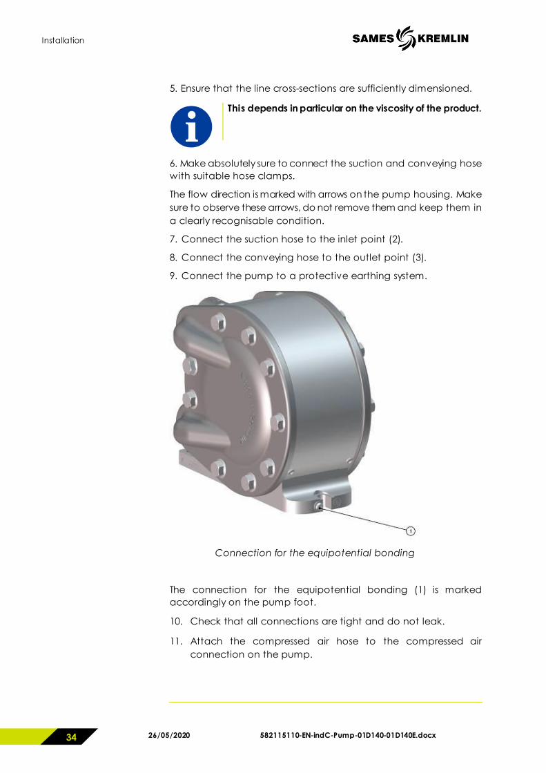
5. Ensure that the line cross-sections are sufficiently dimensioned.
This depends in particular on the viscosity of the product.
6. Make absolutely sure to connect the suction and conveying hose with suitable hose clamps.
The flow direction is marked with arrows on the pump housing. Make sure to observe these arrows, do not remove them and keep them in a clearly recognisable condition.
7. Connect the suction hose to the inlet point (2).
8. Connect the conveying hose to the outlet point (3).
9. Connect the pump to a protective earthing system.
Connection for the equipotential bonding
The connection for the equipotential bonding (1) is marked accordingly on the pump foot.
10. Check that all connections are tight and do not leak.
11. Attach the compressed air hose to the compressed air connection on the pump.

Installation
582115110-EN-indC-Pump-01D140-01D140E.docx 26/05/2020 35
Storage
Protect the unit from moisture after closing the various air inlets and openings.
Storage conditions have a detrimental effect on the service life of the diaphragm.
The pump may only be put away for storage after it has been thoroughly cleaned.
Extreme storage conditions accelerate the ageing process.
We recommend a storage temperature between +10°C / 50°F and +25°C / 77°F.
The diaphragms must not be exposed to sources of heat or direct sunlight.
Exclude the effect of ozone or ionising radiation.
Store the diaphragm such that it is not under tension.
We recommend the replacement of the diaphragm at the latest after one year of storage under the storage conditions stated above.

Commissioning
26/05/2020 582115110-EN-indC-Pump-01D140-01D140E.docx 36
7 Commissioning
WARNING
Risk of explosion due to dust or paint on the pump housing!
Clean the surface of the pump housing regularly and remove the layers of dust or paint.
The pumping of explosive media or gases is prohibited.
WARNING
Danger to life due to conveying explosion-prone media in potentially explosive environments!
The medium to be conveyed can corrode or destroy the pump or cause it to leak. This may lead to the formation of an explosive mixture.
The conveying of explosive media and the employment in an explosion-hazardous area is only permitted according to regulations by Directive 2014/34/EU marked on the rating plate of the pump:
II 2 G Ex h IIB T6-T4 Gb X
II 2 D Ex h IIIC 85-150°C Db X
WARNING
Danger to life due to operating the pump in potentially explosive environments!
The pump may only be used in potentially explosive environments (e.g. paint shops), if this is appropriately marked on the rating plate of the pump.
The company operating the pump is also responsible for compliance with the regulations set out in Directive 1999/92/EC.

Commissioning
582115110-EN-indC-Pump-01D140-01D140E.docx 26/05/2020 37
WARNING
During operation, make sure that the pump is always completely filled with liquid. The permanent pumping of ignitable gas/liquid mixtures leading to a zone 0 inside the pump is prohibited.
The pump medium can exothermically react with the material of the pump. Before pumping the medium, check the suitability of the pump materials for the medium to be pumped.
Operation of the pump above the permissible flow rate and longer dry operation can cause overheating of the pump.
When pumping media in ring systems, the conveying capacity of the pump is converted into heat. In case of short lines, this can lead to dangerous heating of the medium.
Operation of the pump can adiabatically compress potentially explosive gas mixtures in the pump and/or the piping system. This can lead to explosive increases in temperature. The operator has to take appropriate measures. The media outlet must not be closed during operation of the pump.
The special operating conditions of the pump must be kept in mind and adhered to.
WARNING
Destruction of the pump from too high air pressure!
Too high an air pressure can lead to the diaphragm being destroyed and the pump bursting.
Operate the pump with a maximum air pressure of 8 bar / 116 psi.
Make sure that the outlet point of the medium to be conveyed is not clogged or closed.

Commissioning
26/05/2020 582115110-EN-indC-Pump-01D140-01D140E.docx 38
Commissioning instructions
First commissioning of the pump must be conducted through a person qualified for that purpose.
If the pump is not mounted on a horizontal, even surface with the pump foot at the bottom, vent the pump chambers.
Adjust the air pressure to 1 / 14.5 psi ... 8 bar / 116 psi.
The pump is ready for operation.
The pump will start to run as soon as it is charged with compressed air.
Operate the pump with a maximum air pressure of 8 bar / 116 psi.

Operation
582115110-EN-indC-Pump-01D140-01D140E.docx 26/05/2020 39
8 Operation
8.1 Regulating the delivery rate
Note :
If the pump delivery rate is to be regulated, the operating company must install a throttle valve in the compressed air supply or in the conveying line.
To reduce the delivery rate
Reduce the compressed air supply or the medium outflow.
To increase the delivery rate
Increase the compressed air supply or the medium outflow.

Operation
26/05/2020 582115110-EN-indC-Pump-01D140-01D140E.docx 40
8.2 Troubleshooting
Rectification of malfunctions
Malfunction Cause Rectification Pump not running or running too slowly
Compressed air pressure too low
Set the pressure from 4 to 8 bar / 39.2 to 116 psi.
Hose cross-section too small Use hose with a larger cross-section
Control valve leaks Replace spool valve and seals
Blockage on the sound absorber, pump running laboured, seal swollen or piston material damaged
Check material resistance, prevent running dry
Pump runs but does not convey medium or does not stop when the pressure side is isolated
Valves contaminated Flush pump with a cleaning agent
Conveying hose blocked Clean conveying hose
Suction and pressure valves contaminated
Allow the pump to run at maximum speed for approx. 10 to 20 minutes
Leaking connections, possibly sucking in extraneous air, vacuum breaks.
Check connections for leaks, re-seal
Valves contaminated Clean or replace valves
No suction effect on the suction and discharge side
Close the openings by hand and check the suction effect, replace seals as required
Viscosity of the conveyed medium too high
High-viscosity media are not conveyable (for limit value see chapter "Technical characteristics")
Conveying hose split or exhibits pin-sized holes
Replace conveying hose
Operation
582115110-EN-indC-Pump-01D140-01D140E.docx 26/05/2020 41
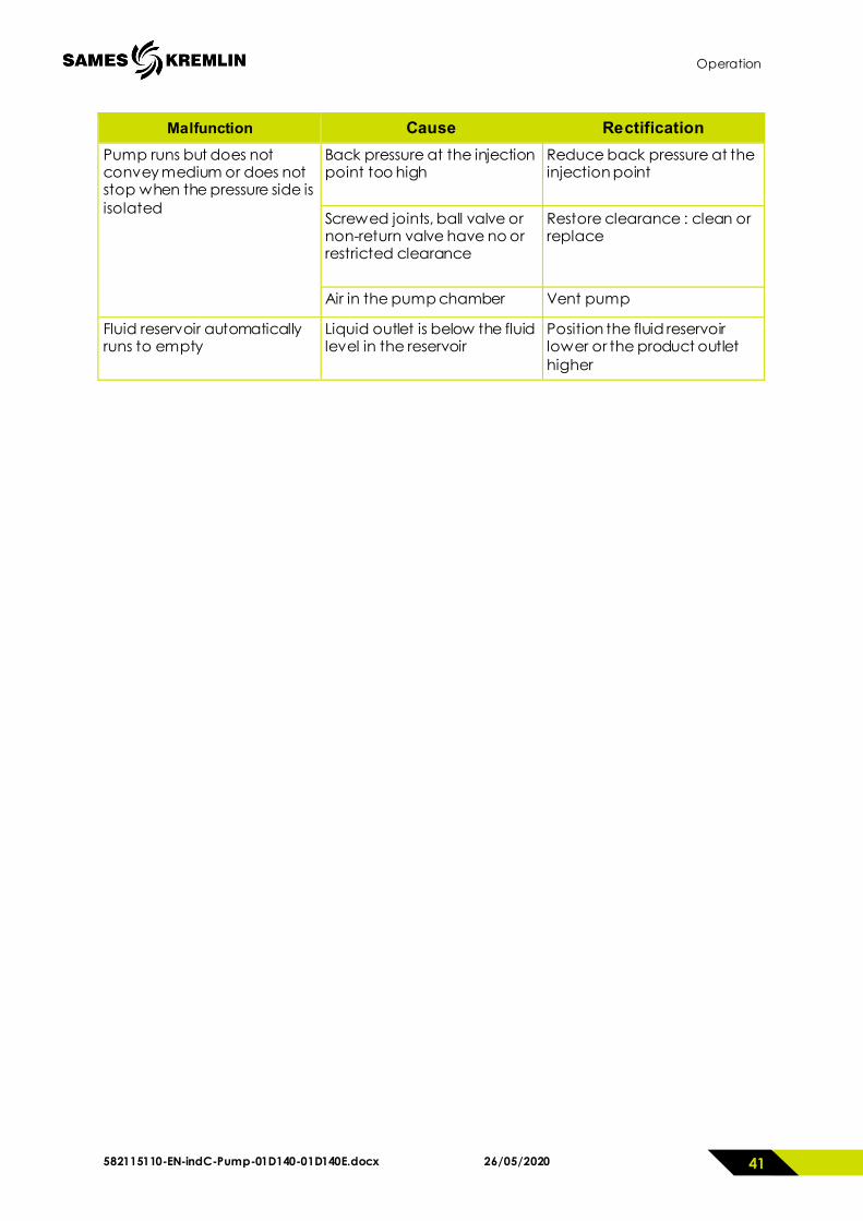
Malfunction Cause Rectification Pump runs but does not convey medium or does not stop when the pressure side is isolated
Back pressure at the injection point too high
Reduce back pressure at the injection point
Screwed joints, ball valve or non-return valve have no or restricted clearance
Restore clearance : clean or replace
Air in the pump chamber Vent pump
Fluid reservoir automatically runs to empty
Liquid outlet is below the fluid level in the reservoir
Position the fluid reservoir lower or the product outlet higher

Maintenance
26/05/2020 582115110-EN-indC-Pump-01D140-01D140E.docx 42
9 Maintenance
WARNING
Before any intervention, it is imperative to follow the pressure relief procedure and safety instructions.
WARNING – Risk of injury
Maintenance operations should only be carried out by qualified personnel.
Wear personal protective equipment (PPE).
WARNING
Hazard to persons due to trapped compressed air and pressurized medium.
Do not maintain or clean the pump, hoses or outlet valve while the system is pressurized.
Depressurize the pneumatic part and the liquid part prior to working on the pump.
Isolate the compressed air supply and wait until the residual pressure has dissipated via the compressed air outlet valve.
Empty the pump before replacing components.

Maintenance
582115110-EN-indC-Pump-01D140-01D140E.docx 43
WARNING
Hazard to persons due to fluids (media) squirting out.
Ensure that the material hoses and other components are able to withstand the hydraulic pressure generated by this pump.
Check the pump regularly for damage or wear.
Ensure that the pneumatic valve, the outlet area for the compressed air and the suction and pressure side for the medium are clean and functioning correctly.
Depressurize the pump before dismantling. Under certain circumstances, a small amount of residual pressure can remain in the pressure chamber causing medium to squirt out.
Please observe the safety data sheets of the previously conveyed chemicals when performing disassembly work on the pump.
Depending on the operating conditions and the operating mode of the pump, fluid may escape from the silencer in the event of a diaphragm failure.
The released product may accumulate inside the pump and be released into the environment during prolonged malfunction.
Therefore, the necessary safety measures must be taken during operation, maintenance and repairs depending on the product.
WARNING
Hazard to persons due to insufficient lighting.
Only carry out installation work on the pump in a sufficiently illuminated and air-conditioned environment.

Maintenance
26/05/2020 582115110-EN-indC-Pump-01D140-01D140E.docx 44
The double diaphragm pump is very resistant to wear, apart from the diaphragm. The quality of the compressed air supply, the properties of the conveyed media (such as e.g. abrasiveness, viscosity, etc.), and the conditions of use can have a negative effect on the service life of the pump.
We therefore recommend regular inspection of the pump and the pneumatic valve.
Should a malfunction nonetheless occur or the conveying output decrease, you can simply carry out the following work:
replace the diaphragm
clean the product valves
replace the seals
clean and grease the pneumatic valve
Maintenance schedule
Draw up a maintenance schedule on the basis of the service life of the pump.
Such a maintenance schedule with maintenance intervals is particularly important for maintaining the perfect function of the pump.

Decommissioning and cleaning
582115110-EN-indC-Pump-01D140-01D140E.docx 45
10 Decommissioning and cleaning
WARNING – Risk of injury
Decommissioning and cleaning operations should only be performed by trained personnel.
Wear personal protective equipment (PPE).
Hazard to persons due to fluids (media) squirting out.
Cleaning, repairs, troubleshooting activities and fault elimination during which contact with the medium is possible, may only be carried out when the relevant personal protective equipment PPE (at least protective clothing, protective gloves, safety glasses) is worn.
The manufacturer's safety data sheets and the national laws and provisions must be observed.
Isolate the compressed air supply line to the pump if the system is not operated for prolonged periods.

Decommissioning and cleaning
26/05/2020 582115110-EN-indC-Pump-01D140-01D140E.docx 46
Damage to the pump due to hardening, crystallising media
- The pump must be cleaned prior to long downtimes if products are conveyed that harden or crystallise, or contain solids, or that may corrode the pump material due to their chemical or physical properties.
- The definition of a long downtime depends on the previously conveyed medium and its change of state from liquid to solid.
- The definition is the responsibility of the operating company and should be adhered to in any case in order to prevent damage to the pump.
1. Clean the pump only with a suitable cleaning agent, depending on the pump material and the conveyed medium.
Water or solvents may be suitable.
Liquid and solid cleaning agents must not be used at temperatures exceeding 65 °C / 149°F.
2. Connect the suction line connection to the cleaning agent.
3. Connect the medium outlet to a suitable container.
4. Pump the cleaning agent until all residues from the pump have been released.
5. Completely empty the pump.
6. For this, pull the suction hose far enough out of the cleaning agent to enable air to be taken in.
7. Completely disconnect the medium outlets of the pump when no more cleaning agent is leaking at the outlet.
8. To empty completely, swivel the pump by 90°, so that the media connections face downwards.
Note
It is necessary to completely empty the pump prior to decommissioning and putting into storage, as the cleaning fluid may possibly accelerate the ageing of the pump diaphragm.
9. Operate the pump at an air pressure of approx. 1 bar / 14.5 psi
10. In doing so, move the pump slightly to and fro until the residual quantity in the pump has fully drained out.
11. Clean the external parts of the pump.

Decommissioning and cleaning
582115110-EN-indC-Pump-01D140-01D140E.docx 47
Cleaning prior to decommissioning
1. Clean and empty the pump as described in the previous section.
2. Renew the pump diaphragm at the latest after one year to ensure safe and reliable function of the pump, as it is subject to normal ageing.
Extreme storage conditions may accelerate the ageing process.

Replacing pump components
26/05/2020 582115110-EN-indC-Pump-01D140-01D140E.docx 48
11 Replacing pump components
WARNING – Read safety instructions p. 7-17 & 42-43
11.1 Replacing the diaphragm
1. Undo the hexagonal head set screws (A) on one of the housing covers (B) and remove the housing cover (B).
2. Remove the diaphragm (1) from the piston rod by turning anticlockwise.
3. Tightly screw the new diaphragm (1) in clockwise direction on to the piston rod.
4. Mount the housing cover (B) using the hexagonal head set screws (A). Make sure the O-rings (23) sit in the groove of the cover.
5. Tighten the hexagonal head set screws diagonally to a torque of 25 Nm.
6. Repeat the procedure on the other diaphragm side.
Replacing pump components
582115110-EN-indC-Pump-01D140-01D140E.docx 49
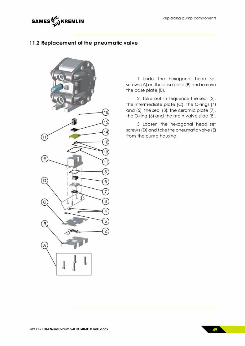
11.2 Replacement of the pneumatic valve
1. Undo the hexagonal head set screws (A) on the base plate (B) and remove the base plate (B).
2. Take out in sequence the seal (2), the intermediate plate (C), the O-rings (4) and (5), the seal (3), the ceramic plate (7), the O-ring (6) and the main valve slide (8).
3. Loosen the hexagonal head set screws (D) and take the pneumatic valve (E) from the pump housing.

Replacing pump components
26/05/2020 582115110-EN-indC-Pump-01D140-01D140E.docx 50
11.2.1 Dismantling of the pneumatic valve
1. Take out the O-rings (11), (12) and (13) from the grooves in the pneumatic valve block (E).
2. Remove the covers (F) and O-rings (9).
3. Take out the slide (G) with the piston seals (10) from the pneumatic valve block (E).
4. Clean the components using a suitable cleaning agent. First check the media compatibility.
5. Check the components, especially the O-rings and replace any defective parts.

Replacing pump components
582115110-EN-indC-Pump-01D140-01D140E.docx 51
11.2.2 Mounting the pneumatic valve
1. Place the O-ring (16) in the groove of the centre piece of the pump.
The O-ring will better maintain its position if coated in grease.
2. Place the control valve slide (15) with the bevelled side forward into the centrepiece of the double diaphragm pump. The groove of the slide must engage in the groove of the carrier (H).
3. Place the ceramic plate (14) in the centrepiece of the pump so that a hole aligns with the O-ring (16) - see Figure A.
Figure A
4. Assemble the pneumatic valve block (E) in reverse order.
Grease the seals and O-rings before assembly (e.g. with Fuchs® Renolit Unitemp 2) and avoid any kind of damage to the seals and O-rings during assembly.
Grease particularly the raceway of the piston seals (10) in the covers (F).
16

Replacing pump components
26/05/2020 582115110-EN-indC-Pump-01D140-01D140E.docx 52
5. Mount the piston seals (10) on the slide (G) as shown in diagram B.
Figure B
6. Place the slide (G) in the pneumatic valve block (E).
7. Place the O-ring (11) into the outer groove in the pneumatic valve block (E).
8. Insert the O-rings (12) and (13) into the groove of the pneumatic valve block (E).
During assembly, pay attention that the O-rings do not jump out of the grooves and are damaged.
9. Insert the mounted pneumatic valve block (E) into the centrepiece of the pump. The mounting direction is clearly shown in figure A.
10. Place the main valve slide (8) with the closed side forward into the pneumatic valve block (E). The main valve slide (8) must be inserted so that slide (G) is able to move it.
11. Place the O-ring (6) in the pneumatic valve block (E).
Pay attention to correct assembly (the side without the O-ring groove first).
12. Place the O-rings (3), (4) and (5) into the grooves provided in the centrepiece of the double diaphragm pump.
Ensure that the O-rings are not damaged and do not pop out.
13. Place the ceramic plate (17) into the pneumatic valve block (F).
Pay attention to correct assembly (the side with the large O-ring (9) first).
14. Place the O-rings (5) and (6) into the grooves provided in the centrepiece of the pump.
Ensure that the O-rings are not damaged and do not pop out.
15. Place the intermediate plate (C) in the centrepiece of the pump.
16. Equip the plate (B) with the seal (2) and place the plate (B) in the centrepiece of the pump.
17. Screw the plate (B) tight using the socket head screws (A).
The socket head screws are to be evenly tightened to a torque of 10 Nm.
10
10

Replacing pump components
582115110-EN-indC-Pump-01D140-01D140E.docx 53
11.3 Replacing the ball valves and suction pipes
1. Undo the hexagonal head set screws (A) on one of the housing covers (B) and remove the housing cover (B).
2. Take out the suction pipe (C) and the discharge pipe (D) with the O-rings (23) from the pump.
3. Remove the suction pipe (C) and discharge pipe (D) as per the drawing.
4. Clean the components using a suitable cleaning agent. First check the media compatibility.
5. Check the components, especially the O-rings, for damage and wear. Replace defective components.
6. Assemble the valve seats with valve ball and O-ring in the reverse order.
WARNING - Do not interchange top and bottom valve.
Observe the mounting direction of the valve seats (17) in accordance with the view. The larger inner bevel of the valve seat (17) must be pointing towards the ball.

Replacing pump components
26/05/2020 582115110-EN-indC-Pump-01D140-01D140E.docx 54
7. Place the O-rings (23) in the grooves of the pump cover (B).
8. Mount the suction pipe (C) and the outlet pipe (D).
Make sure you observe the flow direction marking.
9. Mount the housing cover (B) using the hexagonal head set screws (A). The hexagonal head set screws are to be evenly tightened to a torque of 25 Nm.
The positions of the suction and discharge pipes can be varied by rotating the pipes during assembly. The possible positions are shown on the drawing. Make sure the suction and discharge pipes are correctly positioned. The arrows identify the direction of flow.

Spare parts
582115110-EN-indC-Pump-01D140-01D140E.docx 55
12 Spare parts
12.1 Exploded view

Spare parts
26/05/2020 582115110-EN-indC-Pump-01D140-01D140E.docx 56
12.2 Parts list
Ind. #Reference Description Qty
*1 N.C. Diaphragm 2
*2 N.C. Sealing joint for valve cover 1
*3 N.C. Sealing joint for main valve 1
*4 N.C. Sealing joint 2
*5 N.C. Sealing joint 1
*6 N.C. Sealing joint 1
*7 N.C. Main valve ceramic plate 1
*8 N.C. Main valve obturator 1
*9 N.C. O-ring seal 4
*10 N.C. Piston sealing joint 2
*11 N.C. Sealing joint 1
*12 N.C. Sealing joint 1
*13 N.C. Sealing joint 2
*14 N.C. Control valve ceramic plate 1
*15 N.C. Control valve obturator 1
*16 N.C. O-ring seal 1
*17 N.C. Basket ball lower part 4
*18 N.C. Spring 2
*19 N.C. Ball 4
*20 N.C. Basket ball 2
*21 N.C. O-ring seal 4
*22 N.C. O-ring seal 6
*23 N.C. O-ring seal 4
*24 N.C. Spring 2
25 N.C. Pipe material entry 1
26 N.C. Pipe material exit 1
27 N.C. Straight pipe fitting ∅8 mm 1
28 N.C. Pump housing center part 1
29 N.C. Housing cover 1
30 N.C. Pan head screw 5
31 N.C. Side part 2
32 N.C. Piston latching element 1
33 N.C. Piston driver 1

Spare parts
582115110-EN-indC-Pump-01D140-01D140E.docx 57
34 N.C. Spring 1
35 N.C. Piston main valve 1
36 N.C. Main valve body 1
37 N.C. Caps 2
38 N.C. Valve cover plate 1
39 N.C. Valve cover 1
40 N.C. Guide bushing 2
41 N.C. Piston rod 1
42 N.C. Valve sealing joint 2
43 N.C. Sealing cover 2
44 N.C. Countersunk screw 4
45 N.C. Hexagon screw 18
46 N.C. Cylinder head screw 4
47 N.C. Cylinder head screw 4
48 N.C. Silencer 1
49 N.C. Flat washer 2
50 N.C. Guide bushing 1 * Recommended spare parts N.C. Not Commercially Available

Spare parts
26/05/2020 582115110-EN-indC-Pump-01D140-01D140E.docx 58
12.3 Spare parts Kits
Diaphragm Kit - 01D140 Pump
Ind. #Reference Description Qty
*- 144907011 PTFE Diaphragm Kit 01D140 1
*1 N.C. Diaphragms 2
* Recommended spare parts N.C. Not Commercially Available
Diaphragm Kit - 01D140E Pump
Ind. #Reference Description Qty
*- 144907016 EPDM Diaphragm Kit 01D140E 1
*1 N.C. Diaphragms 2 * Recommended spare parts N.C. Not Commercially Available
Ball valve Kit - 01D140 / 01D140E Pumps
Ind. #Reference Description Qty
*- 144907012 Ball valve Kit 1
*17 N.C. Basket ball lower part 4
*18 N.C. Spring 2
*19 N.C. Ball 4
*20 N.C. Basket ball 2
*21 N.C. O-ring seal 4
*22 N.C. O-ring seal 6
*23 N.C. O-ring seal 4
*24 N.C. Spring 2
* Recommended spare parts N.C. Not Commercially Available

Spare parts
582115110-EN-indC-Pump-01D140-01D140E.docx 59
Ball valve sealing joints + springs Kit - 01D140 / 01D140E Pumps
Ind. #Reference Description Qty
*- 144907013 Ball valve sealing joints + springs Kit 1
*18 N.C. Spring 2
*21 N.C. O-ring seal 4
*22 N.C. O-ring seal 6
*23 N.C. O-ring seal 4
*24 N.C. Spring 2 * Recommended spare parts N.C. Not Commercially Available
Pneumatic valve Kit - 01D140 / 01D140E Pumps
Ind. #Reference Description Qty
*- 144907014 Pneumatic valve Kit 1
*2 N.C. Sealing joint for valve cover 1
*3 N.C. Sealing joint for main valve 1
*4 N.C. Sealing joint 2
*5 N.C. Sealing joint 1
*6 N.C. Sealing joint 1
*7 N.C. Main valve ceramic plate 1
*8 N.C. Main valve obturator 1
*9 N.C. O-ring seal 4
*10 N.C. Piston seal 2
*11 N.C. Sealing joint 1
*12 N.C. Sealing joint 1
*13 N.C. Sealing joint 2
*14 N.C. Control valve ceramic plate 1
*15 N.C. Control valve obturator 1
*16 N.C. O-ring seal 1 * Recommended spare parts N.C. Not Commercially Available

Spare parts
26/05/2020 582115110-EN-indC-Pump-01D140-01D140E.docx 60
Pneumatic valve sealing joints Kit - 01D140 / 01D140E Pumps
Ind. #Reference Description Qty
*- 144907018 Pneumatic valve sealing joints Kit 1
*2 N.C. Sealing joint for valve cover 1
*3 N.C. Sealing joint for main valve 1
*4 N.C. Sealing joint 2
*5 N.C. Sealing joint 1
*6 N.C. Sealing joint 1
*9 N.C. O-ring seal 4
*10 N.C. Piston seal 2
*11 N.C. Sealing joint 1
*12 N.C. Sealing joint 1
*13 N.C. Sealing joint 2
*16 N.C. O-ring seal 1 * Recommended spare parts N.C. Not Commercially Available

Declaration of Conformity
582115110-EN-indC-Pump-01D140-01D140E.docx 61
13 Declaration of Conformity
CATEGORY : DOUBLE DIAPHRAGM PUMP Model: PTI-MEM1060 Distributor model: 01D140 / 01D140E ATEX marking : II2G Ex h IIB T6-T4 Gb X
……… II2D Ex h IIIC 85-150°C Db X This double diaphragm pump has been designed and manufactured in accordance with the following EC/EU Directives: Directive 2006/42/EC EU Gazette L157/24 of 17 May 2006 Directive 2014/34/EU, EU Gazette, L 96/309 of 26 February 2014 Under the sole responsability of (Manufacturer): Timmer GmbH Dieselstraße 37 D-48485 Neuenkirchen www.timmer.de
The following harmonized standards have been applied: EN ISO 12100:2010 Safety of machinery – General principles for design – Risk assesment and risk reduction EN 809:1998+A1:2009 Pumps and pump units for fluids – general safety requirements EN ISO 4414:2010 Fluid technology – General rules and safety requirements for pneumatic systems and their components EN ISO80079-36:2016: Explosive atmospheres - Part 36: Non-electrical equipment for explosive atmospheres – Basic method and requirements (ISO 80079-36:2016) EN ISO80079-37:2016: Explosive atmospheres - Part 37: Non-electrical equipment for explosive atmospheres – Non electrical type of protection constructional safety ‘c’, control of ignition source ‘b’, liquid immersion ‘k’ (ISO 80079-37:2016) Person responsible for documentation: Timmer GmbH Address: see manufacturer
Neuenkirchen, 15.08.2019 Place, date Managing Director (Klaus Gehrmann)