GV-Compact DVR V3 - Logo Tecnosinergia
255
Before attempting to connect or operate this product, please read these instructions carefully and save this manual for future use. User's Manual User's Manual GV-Compact DVR V3 CDVR3-4CHV104-8CHV102-A
-
Upload
khangminh22 -
Category
Documents
-
view
0 -
download
0
Transcript of GV-Compact DVR V3 - Logo Tecnosinergia

Before attempting to connect or operate this product,please read these instructions carefully and save this manual for future use.
User's ManualUser's Manual
GV-Compact DVR V3
CDVR3-4CHV104-8CHV102-A
© 2013 GeoVision, Inc. All rights reserved. Under the copyright laws, this manual may not be copied, in whole or in part, without the written consent of GeoVision. Every effort has been made to ensure that the information in this manual is accurate. GeoVision, Inc. makes no expressed or implied warranty of any kind and assumes no responsibility for errors or omissions. No liability is assumed for incidental or consequential damages arising from the use of the information or products contained herein. Features and specifications are subject to change without notice. GeoVision, Inc. 9F, No. 246, Sec. 1, Neihu Rd., Neihu District, Taipei, Taiwan Tel: +886-2-8797-8377 Fax: +886-2-8797-8335 http://www.geovision.com.tw Trademarks used in this manual: GeoVision, the GeoVision logo and GV series products are trademarks of GeoVision, Inc. Windows and Windows XP are registered trademarks of Microsoft Corporation. November 2013
Preface
Welcome to the GV-Compact DVR V3 User’s Manual.
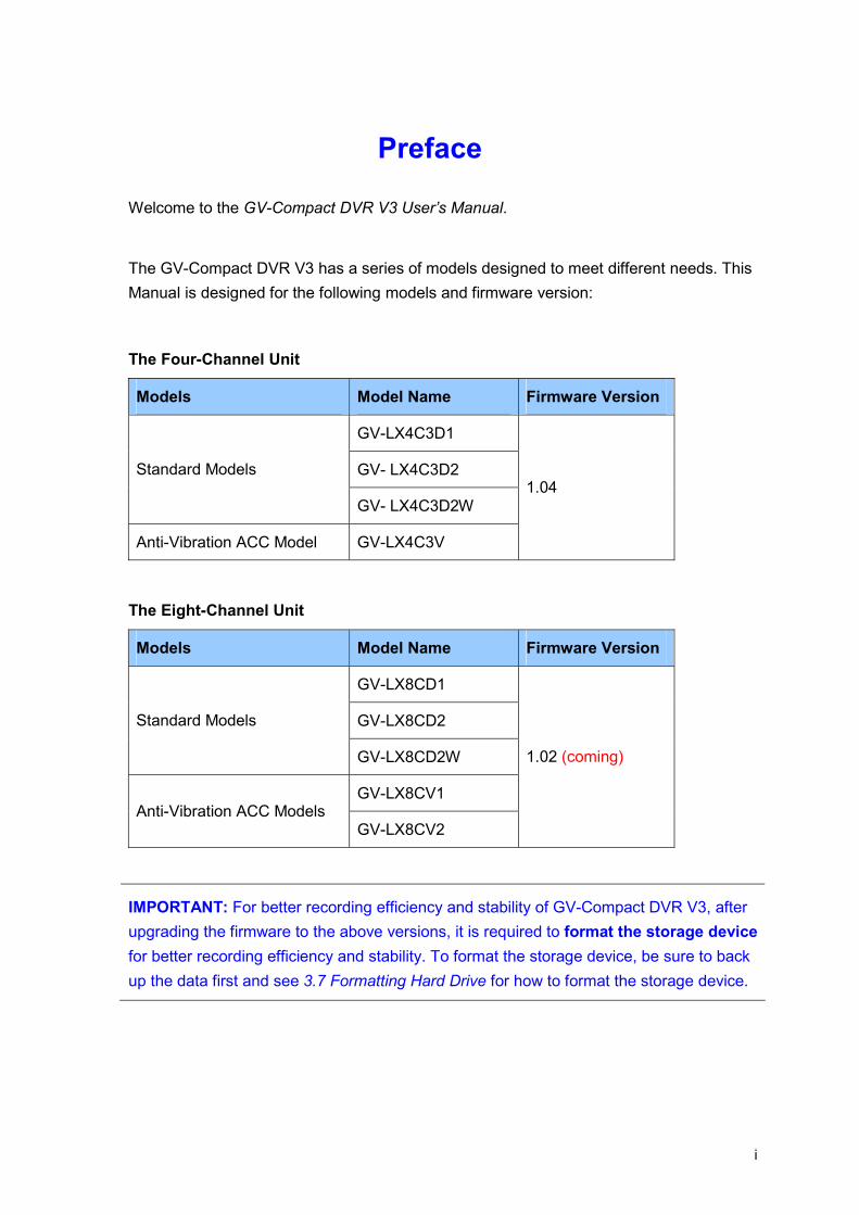
The GV-Compact DVR V3 has a series of models designed to meet different needs. This Manual is designed for the following models and firmware version:
The Four-Channel Unit
Models Model Name Firmware Version
GV-LX4C3D1
GV- LX4C3D2 Standard Models
GV- LX4C3D2W
Anti-Vibration ACC Model GV-LX4C3V
1.04
The Eight-Channel Unit
Models Model Name Firmware Version
GV-LX8CD1
GV-LX8CD2 Standard Models
GV-LX8CD2W
GV-LX8CV1 Anti-Vibration ACC Models
GV-LX8CV2
1.02 (coming)
IMPORTANT: For better recording efficiency and stability of GV-Compact DVR V3, after upgrading the firmware to the above versions, it is required to format the storage device for better recording efficiency and stability. To format the storage device, be sure to back up the data first and see 3.7 Formatting Hard Drive for how to format the storage device.
i
Contents
Chapter 1 Introduction ..........................................................1 1.1 Features............................................................................................................... 2 1.2 Models ................................................................................................................. 3
1.2.1 The Four-Channel Unit ............................................................................. 3 1.2.2 The Eight-Channel Unit ............................................................................ 4
1.3 Packing List......................................................................................................... 5 1.3.1 The Four-Channel Unit ............................................................................. 5 1.3.2 The Eight-Channel Unit ............................................................................ 7
1.4 Options ................................................................................................................ 9 1.5 System Requirement..........................................................................................10
Chapter 2 Physical Description..........................................11 2.1 Front Panel .........................................................................................................11
2.1.1 The Four-Channel Unit ............................................................................11 2.1.2 The Eight-Channel Unit ...........................................................................14
2.2 Rear Panel ..........................................................................................................18 2.2.1 The Four-Channel Unit ............................................................................18 2.2.2 The Eight-Channel Unit ...........................................................................20
2.3 Remote Control ..................................................................................................22 2.3.1 The Four-Channel Unit ............................................................................22 2.3.2 The Eight-Channel Unit ...........................................................................24
Chapter 3 Getting Started ...................................................26 3.1 Basic Connection for Standard Models............................................................27
3.1.1 The Four-Channel Unit ............................................................................27 3.1.2 The Eight-Channel Unit ...........................................................................28
3.2 Basic Connection for Anti-Vibration Models....................................................29 3.2.1 The Four-Channel Unit ............................................................................29 3.2.2 The Eight-Channel Unit ...........................................................................30
3.3 Connecting Anti-Vibration ACC Models ...........................................................31 3.3.1 Connecting and Testing...........................................................................31 3.3.2 Connecting to a vehicle ...........................................................................33
3.4 Connecting Optional Video Output Devices.....................................................38 3.4.1 The Four-Channel Unit ............................................................................38 3.4.2 The Eight-Channel Unit ...........................................................................39
3.5 Installing a Hard Drive .......................................................................................40 3.5.1 The Four-Channel Unit ............................................................................40 3.5.2 The Eight-Channel Unit ...........................................................................43
3.6 Turning On / Off the Power................................................................................45
ii
3.6.1 Turning On the Power..............................................................................45 3.6.2 Turning Off the Power..............................................................................45
3.7 Formatting Hard Drive .......................................................................................46 3.8 Main Screen Overview .......................................................................................47 3.9 Basic Operation..................................................................................................48
3.9.1 Date/Time Adjustment .............................................................................48 3.9.2 Recording Operation................................................................................48 3.9.3 Search/Playback Operation .....................................................................49 3.9.4 PTZ Operation .........................................................................................49 3.9.5 Channel Number and Camera Name.......................................................49 3.9.6 Video Backup ..........................................................................................49
Chapter 4 OSD Menu Configurations ................................50 4.1 Channel Settings................................................................................................52
4.1.1 Channel Name.........................................................................................52 4.1.2 Video/Audio Settings ...............................................................................53 4.1.3 Motion Detection......................................................................................54 4.1.4 Motion Trigger Output Settings ................................................................56 4.1.5 Alarm Settings .........................................................................................57 4.1.6 Camera Settings......................................................................................57 4.1.7 PTZ Settings............................................................................................58 4.1.8 PTZ Control .............................................................................................59 4.1.9 Privacy Mask ...........................................................................................60
4.2 Digital IO Settings ..............................................................................................61 4.2.1 Digital Input Settings................................................................................61 4.2.2 Digital Output Settings .............................................................................62 4.2.3 GPS Settings...........................................................................................63
4.3 Events and Alerts...............................................................................................65 4.3.1 E-mail ......................................................................................................66 4.3.2 FTP .........................................................................................................67 4.3.3 Center V2 ................................................................................................68 4.3.4 VSM.........................................................................................................69 4.3.5 GV-GIS....................................................................................................70 4.3.6 Video Gateway / Recording Server..........................................................71 4.3.7 Remote Playback.....................................................................................72 4.3.8 3GPP.......................................................................................................73
4.4 Monitoring Settings............................................................................................74 4.5 Recording Schedule...........................................................................................76
4.5.1 Specific Day.............................................................................................76 4.5.2 Channel Schedule ...................................................................................77 4.5.3 I/O Monitoring Schedule ..........................................................................78
4.6 Search / Playback...............................................................................................79 4.6.1 Time Map List ..........................................................................................79 4.6.2 List All......................................................................................................80 4.6.3 Manual Recording List .............................................................................80
iii

4.6.4 Alarm Recording List ...............................................................................80 4.6.5 Motion Recording List ..............................................................................80 4.6.6 Time Search ............................................................................................80 4.6.7 Advanced Search ....................................................................................81
4.7 Network...............................................................................................................82 4.7.1 Network Status ........................................................................................82 4.7.2 Connection Settings.................................................................................83 4.7.3 Wireless Settings.....................................................................................84 4.7.4 Advanced TCP/IP ....................................................................................85 4.7.5 UMTS Settings ........................................................................................86 4.7.6 DDNS Settings ........................................................................................87 4.7.7 Multicast Settings ....................................................................................88 4.7.8 Web User Account Info............................................................................89
4.8 Advanced............................................................................................................90 4.8.1 Date and Time .........................................................................................90 4.8.2 Firmware Settings....................................................................................91 4.8.3 Storage Settings ......................................................................................92 4.8.4 Display Settings.......................................................................................93 4.8.5 Spot Monitor Settings ..............................................................................94 4.8.6 Alert Settings ...........................................................................................95 4.8.7 System Settings.......................................................................................96 4.8.8 System Log..............................................................................................97 4.8.9 Backup ....................................................................................................98
Chapter 5 Remote Viewing Using A Web Browser...........99 5.1 Assigning an IP Address ...................................................................................99
5.1.1 Using OSD Menu.....................................................................................99 5.1.2 Connecting with a PC ............................................................................100
5.2 Accessing Your Surveillance Images .............................................................103 5.3 Functions Featured on the Main Page............................................................104
5.3.1 The Live View Window ..........................................................................105 5.3.2 The Control Panel of the Live View Window ..........................................106 5.3.3 Snapshot of a Live Video.......................................................................107 5.3.4 Video Recording ....................................................................................107 5.3.5 Picture-in-Picture and Picture-and-Picture View ....................................108 5.3.6 Alarm Notification...................................................................................110 5.3.7 Video and Audio Configuration ..............................................................111 5.3.8 Remote Configuration............................................................................111 5.3.9 Camera Name Display...........................................................................111 5.3.10 Image Enhancement............................................................................112 5.3.11 PTZ Control .........................................................................................112 5.3.12 Visual PTZ...........................................................................................113 5.3.13 I/O Control ...........................................................................................114 5.3.14 Visual Automation................................................................................115 5.3.15 Multicast ..............................................................................................116
iv

5.3.16 Network Status ....................................................................................117
v
Chapter 6 Remote Configurations ...................................118 6.1 Video & Motion.................................................................................................120
6.1.1 Video Settings .......................................................................................120 6.1.2 Motion Detection....................................................................................124 6.1.3 Text Overlay ..........................................................................................125 6.1.4 Visual Automation..................................................................................126 6.1.5 VGA Output Settings .............................................................................127 6.1.6 Video Channel Source Settings .............................................................127
6.2 Digital I/O & PTZ ...............................................................................................128 6.2.1 I/O Control .............................................................................................128 6.2.2 PTZ Settings..........................................................................................130 6.2.3 GPS ......................................................................................................131 6.2.4 Buzzer ...................................................................................................133 6.2.5 Spot Monitor ..........................................................................................134
6.3 Events & Alerts.................................................................................................135 6.3.1 E-mail ....................................................................................................136 6.3.2 FTP .......................................................................................................137 6.3.3 Center V2 ..............................................................................................139 6.3.4 VSM.......................................................................................................141 6.3.5 GV-GIS..................................................................................................143 6.3.6 Backup Center.......................................................................................145 6.3.7 Video Gateway / Recording Server........................................................147 6.3.8 ViewLog Server .....................................................................................149 6.3.9 RTSP / 3GPP ........................................................................................150
6.4 Monitoring ........................................................................................................151 6.5 Recording Schedule.........................................................................................153
6.5.1 Recording Schedule Settings.................................................................153 6.5.2 I/O Monitoring Settings ..........................................................................154
6.6 Remote ViewLog ..............................................................................................155 6.7 Network.............................................................................................................156
6.7.1 LAN .......................................................................................................156 6.7.2 Wireless-Client Mode.............................................................................159 6.7.3 Advanced TCP/IP ..................................................................................161 6.7.4 UMTS/ZigBee ........................................................................................164 6.7.5 Multicast ................................................................................................166 6.7.6 IP Filtering .............................................................................................168 6.7.7 SNMP Setting ........................................................................................169
6.8 Management .....................................................................................................170 6.8.1 Date & Time Setting...............................................................................170 6.8.2 GPS Maps Settings ...............................................................................172 6.8.3 Storage Settings ....................................................................................173 6.8.4 User Account .........................................................................................175 6.8.5 Log Information......................................................................................176 6.8.6 Tools......................................................................................................177 6.8.7 ACC Settings .........................................................................................179
vi
Chapter 7 Remote Recording and Playback ...................180 7.1 Remote Recording ...........................................................................................180 7.2 Remote Playback .............................................................................................180
7.2.1 Playback of Files Recorded on Hard Drive.............................................181 7.2.2 Playback over Network ..........................................................................185 7.2.3 Access to the Recorded Files through FTP Server ................................186 7.2.4 Playback of Backup Files.......................................................................186 7.2.5 Playback of GPS Tracks........................................................................188
Chapter 8 Advanced Applications ...................................191 8.1 Upgrading System Firmware...........................................................................191
8.1.1 Using the Web Interface ........................................................................192 8.1.2 Using the IP Device Utility......................................................................193
8.2 Backing Up and Restoring Settings................................................................195 8.2.1 Backing Up the Settings.........................................................................195 8.2.2 Restoring the Settings ...........................................................................196
8.3 GPS Tracking....................................................................................................197 8.4 Restoring to Factory Default Settings ............................................................199 8.5 Verifying Watermark ........................................................................................200
8.5.1 Accessing the Recorded Files................................................................200 8.5.2 Running Watermark Proof .....................................................................200 8.5.3 The Watermark Proof Window...............................................................201
Chapter 9 Smart Device Surveillance ..............................202 9.1 Android Smartphones and Tablets .................................................................203
9.1.1 Connecting to GV-Compact DVR V3 .....................................................204 9.2 iPhone iPod Touch and iPad ...........................................................................206
9.2.1 Connecting to GV-Compact DVR V3 .....................................................207
Chapter 10 DVR Configurations .......................................209 10.1 Setting up GV-Compact DVR V3 ...................................................................210 10.2 Remote Monitoring with Multi View ..............................................................214 10.3 Remote Monitoring with E-Map.....................................................................216
Chapter 11 CMS Configurations.......................................218 11.1 Center V2 ........................................................................................................218 11.2 VSM.................................................................................................................220 11.3 Dispatch Server..............................................................................................221 11.4 Control Center ................................................................................................222
vii
viii
Chapter 12 The I/O Terminal Block ..................................224 12.1 Pin Assignment...............................................................................................224
12.1.1 The Four-Channel Unit ..........................................................................224 12.1.2 The Eight-Channel Unit .........................................................................225
12.2 Output Devices................................................................................................226 12.2.1 The Four-Channel Unit ........................................................................226 12.2.2 The Eight-Channel Unit .........................................................................227
12.3 Camera Power Supply ....................................................................................229 12.3.1 The Four-Channel Unit ........................................................................229 12.3.2 The Eight-Channel Unit .........................................................................230
Specifications: The Four-Channel Unit ..............................231
Specifications: The Eight-Channel Unit .............................235 Appendix……........................................................................239 A. Supported Wireless LAN USB Adaptor ...................................................................239 B. Supported Mobile Broadband Device ......................................................................239 C. Settings for Internet Explore 8 or later ....................................................................240 D. The CGI Command....................................................................................................241 E. The RTSP Command .................................................................................................242 F. Supported PTZ Cameras ...........................................................................................243 G. Default Port Value......................................................................................................245

Introduction 1
Chapter 1 Introduction The GV-Compact DVR V3 is a mobile video recorder that comes in the four-channel and eight-channel units. The four-channel unit can simultaneously display real-time images from four cameras, while the eight-channel unit can simultaneously display real-time images from eight cameras. For four-channel unit, the recording frame rate of each channel is adjustable up to 30 / 25 fps at the resolution of 704 x 480 (NTSC) / 704 x 576 (PAL). For eight-channel unit, the recording frame rate of each channel is adjustable up to 15 / 12.5 fps at the resolution of 704 x 480 (NTSC) / 704 x 576 (PAL). The Anti-Vibration ACC model of the GV-Compact DVR V3 has already been tested to withstand severe levels of shock and vibration in mobile environments. It is perfect to be installed in any vehicles, such as buses and vans, for surveillance and recording. The special design of the GV-Compact DVR V3 enables you to link up with TV, VGA and spot monitors simultaneously for direct display. The GV-Compact DVR V3 offers many features that you can expect to have.
1

1.1 Features
• Four-channel / eight-channel video and audio recording
• Up to 120 fps at D1 resolution for four-channel / eight-channel units
• Independent channel resolution, quality and frame rate settings
• VGA output in high resolution (1280 x 1024)
• Simultaneous video display on TV, VGA and Spot Monitor
• Video retrieve by date, time and event
• Remote playback
• GPS Speed Text overlay on live view and recordings
• Continuous, motion detection, schedule and input-triggered recordings
• Buzzer alarm on video lost, input triggered, motion detected and disk full
• Mobile broadband (HSDPA, UMTS, EDGE, EVDO, etc.)
• Mobile Phone Surveillance (Android Smartphone, iPhone, iPad)
• Central monitoring systems Center V2, VSM, Control Center, Recording Server
• Geographic information system GV-GIS
• GPS tracking for the Anti-Vibration ACC models (GPS module required)
• 4 alarm inputs and outputs for the 4-channel unit; 8 alarm inputs and outputs for the 8-channel unit
• Support for 3.5” or 2.5” SATA HDD (3.5” to 2.5” HDD converter required)
• Support for External USB mass storage devices
• DVD-RW Backup
• Backup Center for PC-based storage and backup solution
• Support for 16 languages on Web interface
2

Introduction 1
1.2 Models The GV-Compact DVR V3 comes in the four-channel and eight-channel units. Each unit is available in the Standard models and the Anti-Vibration ACC models as listed below.
IMPORTANT:
1. Standard and Anti-Vibration ACC models have different internal designs. It is forbidden to connect the Standard model to vehicle power supply.
2. For the Anti-vibration ACC models (GV-LX4C3V, GV-LX8CV1 and GV-LX8CV2), it is necessary to use the hard drive especially for notebook, vehicle or surveillance applications, and tightly fasten the unit on the vehicle to prevent vibration and shock hazard.
1.2.1 The Four-Channel Unit Model Name Image Description
GV-LX4C3D1
Equipped with 2 USB ports and 1 hard drive bay.
GV- LX4C3D2
Equipped with 2 USB ports and 2 hard drive bays.
Standard models
GV- LX4C3D2W
Equipped with 2 USB ports, 1 hard drive bay and 1 DVD-RW drive.
Anti-Vibration ACC model
GV-LX4C3V Equipped with vibration absorbers, 2 USB ports and 1 hard drive bay.
3
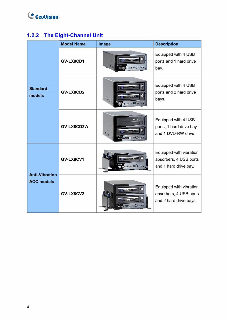
1.2.2 The Eight-Channel Unit Model Name Image Description
GV-LX8CD1
Equipped with 4 USB ports and 1 hard drive bay.
GV-LX8CD2
Equipped with 4 USB ports and 2 hard drive bays.
Standard models
GV-LX8CD2W
Equipped with 4 USB ports, 1 hard drive bay and 1 DVD-RW drive.
GV-LX8CV1 Equipped with vibration absorbers, 4 USB ports and 1 hard drive bay.
Anti-Vibration ACC models
GV-LX8CV2 Equipped with vibration absorbers, 4 USB ports and 2 hard drive bays.
4

Introduction 1
1.3 Packing List
If any of the items are missing or damaged, contact your dealer to arrange a replacement.
Note: The hard disk is not included in the standard package.
1.3.1 The Four-Channel Unit
• Standard Models (GV-LX4C3D1 / GV-LX4C3D2 / GV-LX4C3D2W)
• D-Type Video Cable x 1 • D-Type Audio/TV/Spot Monitor Cable x 1
• Camera Power Cable x 1
• Power Adaptor 12V, 5A x 1
• AC Power Cord x 1
• Lock Key x 2 (1 Bay), x 4 (2 Bays)
• Round Screws x 6 (1 Bay), x 12 (2 Bays)
• T-Cap Screw x 4 (1 Bay), x 8 (2 Bays)
• Remote Control x 1
• GV-Compact DVR Quick Start Guide x 1
• GV-Compact DVR Software CD/DVD x 1
• GV-NVR Quick Start Guide x 1
• GV-NVR Software CD/DVD x 1
5

• Anti-Vibration ACC Model (GV-LX4C3V)
• D-Type Video Cable x 1 • D-Type Audio/TV/Spot Monitor Cable x 1
• Camera Power Cable x 1 • Power Cable x 1
• Shorting Cable x 1
• Lock Key x 2 (1 Bay), x 4 (2 Bays)
• Round Screws x 6 (1 Bay), x 12 (2 Bays)
• T-Cap Screw x 4 (1 Bay), x 8 (2 Bays)
• Remote Control x 1
• GV-Compact DVR Quick Start Guide x 1
• GV- Compact DVR Software CD/DVD x 1
• GV-NVR Quick Start Guide x 1
• GV-NVR Software CD/DVD x 1
6
Introduction 1
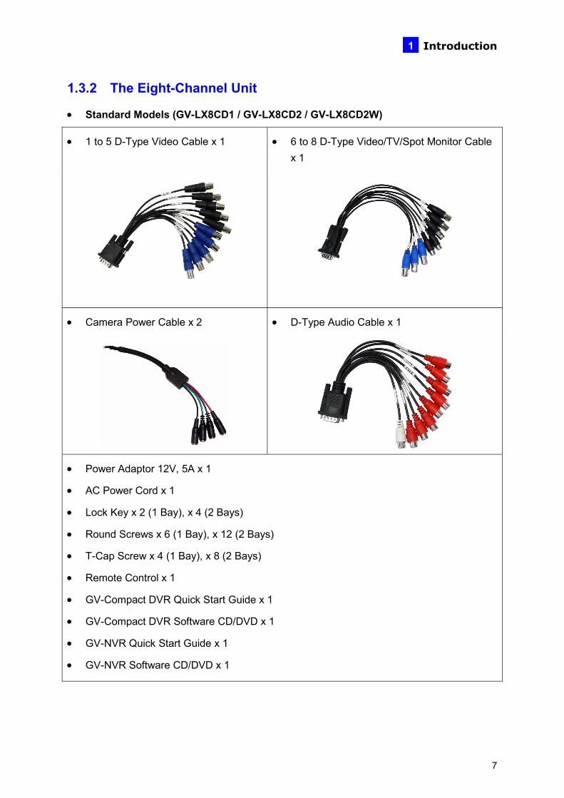
1.3.2 The Eight-Channel Unit
• Standard Models (GV-LX8CD1 / GV-LX8CD2 / GV-LX8CD2W)
• 1 to 5 D-Type Video Cable x 1 • 6 to 8 D-Type Video/TV/Spot Monitor Cable x 1
• Camera Power Cable x 2 • D-Type Audio Cable x 1
• Power Adaptor 12V, 5A x 1
• AC Power Cord x 1
• Lock Key x 2 (1 Bay), x 4 (2 Bays)
• Round Screws x 6 (1 Bay), x 12 (2 Bays)
• T-Cap Screw x 4 (1 Bay), x 8 (2 Bays)
• Remote Control x 1
• GV-Compact DVR Quick Start Guide x 1
• GV-Compact DVR Software CD/DVD x 1
• GV-NVR Quick Start Guide x 1
• GV-NVR Software CD/DVD x 1
7

• Anti-Vibration ACC Models (GV-LX8CV1 / GV-LX8CV2)
• 1 to 5 D-Type Video Cable x 1 • 6 to 8 D-Type Video/ TV/ Spot Monitor Cable x 1
• Camera Power Cable x 2 • D-Type Audio Cable x 1
• Power Cable x 1 • Shorting Cable x 1
• Lock Key x 2 (1 Bay), x 4 (2 Bays)
• Round Screws x 6 (1 Bay), x 12 (2 Bays)
• T-Cap Screw x 4 (1 Bay), x 8 (2 Bays)
• Remote Control x 1
• GV-Compact DVR Quick Start Guide x 1
• GV- Compact DVR Software CD/DVD x 1
• GV-NVR Quick Start Guide x 1
• GV-NVR Software CD/DVD x 1
8
Introduction 1
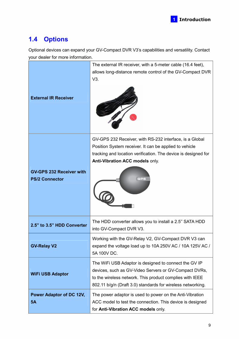
1.4 Options Optional devices can expand your GV-Compact DVR V3’s capabilities and versatility. Contact your dealer for more information.
External IR Receiver
The external IR receiver, with a 5-meter cable (16.4 feet), allows long-distance remote control of the GV-Compact DVR V3.
GV-GPS 232 Receiver with PS/2 Connector
GV-GPS 232 Receiver, with RS-232 interface, is a Global Position System receiver. It can be applied to vehicle tracking and location verification. The device is designed for Anti-Vibration ACC models only.
2.5” to 3.5” HDD Converter The HDD converter allows you to install a 2.5’’ SATA HDD into GV-Compact DVR V3.
GV-Relay V2 Working with the GV-Relay V2, GV-Compact DVR V3 can expand the voltage load up to 10A 250V AC / 10A 125V AC / 5A 100V DC.
WiFi USB Adaptor
The WiFi USB Adaptor is designed to connect the GV IP devices, such as GV-Video Servers or GV-Compact DVRs, to the wireless network. This product complies with IEEE 802.11 b/g/n (Draft 3.0) standards for wireless networking.
Power Adaptor of DC 12V, 5A
The power adaptor is used to power on the Anti-Vibration ACC model to test the connection. This device is designed for Anti-Vibration ACC models only.
9
10
1.5 System Requirement To access the Web interface of the GV-Compact DVR V3, it is required to use Microsoft Internet Explorer 7.x or later.
Note:
1. Internet Explorer 10 is not supported in the all the firmware of GV-Compact DVR V3.
2. If you are using Internet Explorer 8 or later, additional settings are required. See Setting for Internet Explorer 8 or later in Appendix C.
Physical Description 2
Chapter 2 Physical Description This section identifies the various components of the GV-Compact DVR V3, and provides the overview of the remote control.
2.1 Front Panel
2.1.1 The Four-Channel Unit
• Standard Models (GV-LX4C3D1 / GV-LX4C3D2 / GV-LX4C3D2W)
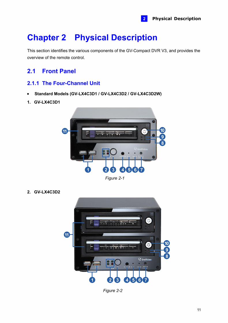
1. GV-LX4C3D1
1
10
2 3 4 5 6 7
89
11
Figure 2-1
2. GV-LX4C3D2
1 2 3 4 5 6 7
10
89
11
Figure 2-2
11
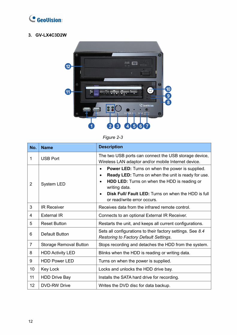
3. GV-LX4C3D2W
1 2 3 4 5 6 7
10
89
11
12
Figure 2-3
No. Name Description
1 USB Port The two USB ports can connect the USB storage device, Wireless LAN adaptor and/or mobile Internet device.
2 System LED
• Power LED: Turns on when the power is supplied. • Ready LED: Turns on when the unit is ready for use.• HDD LED: Turns on when the HDD is reading or
writing data. • Disk Full/ Fault LED: Turns on when the HDD is full
or read/write error occurs.
3 IR Receiver Receives data from the infrared remote control.
4 External IR Connects to an optional External IR Receiver.
5 Reset Button Restarts the unit, and keeps all current configurations.
6 Default Button Sets all configurations to their factory settings. See 8.4 Restoring to Factory Default Settings.
7 Storage Removal Button Stops recording and detaches the HDD from the system.
8 HDD Activity LED Blinks when the HDD is reading or writing data.
9 HDD Power LED Turns on when the power is supplied.
10 Key Lock Locks and unlocks the HDD drive bay.
11 HDD Drive Bay Installs the SATA hard drive for recording.
12 DVD-RW Drive Writes the DVD disc for data backup.
12
Physical Description 2
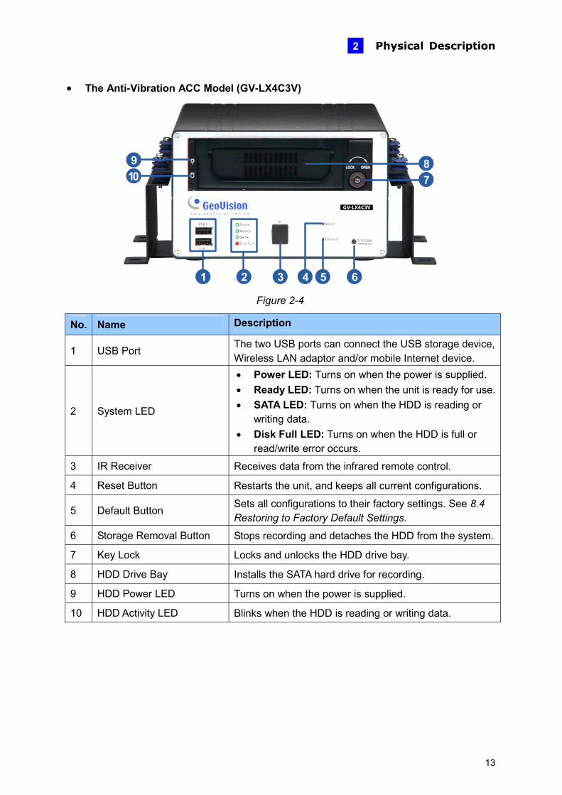
• The Anti-Vibration ACC Model (GV-LX4C3V)
1 4 5 62 3
78
109
Figure 2-4
No. Name Description
1 USB Port The two USB ports can connect the USB storage device, Wireless LAN adaptor and/or mobile Internet device.
2 System LED
• Power LED: Turns on when the power is supplied. • Ready LED: Turns on when the unit is ready for use.• SATA LED: Turns on when the HDD is reading or
writing data. • Disk Full LED: Turns on when the HDD is full or
read/write error occurs.
3 IR Receiver Receives data from the infrared remote control.
4 Reset Button Restarts the unit, and keeps all current configurations.
5 Default Button Sets all configurations to their factory settings. See 8.4 Restoring to Factory Default Settings.
6 Storage Removal Button Stops recording and detaches the HDD from the system.
7 Key Lock Locks and unlocks the HDD drive bay.
8 HDD Drive Bay Installs the SATA hard drive for recording.
9 HDD Power LED Turns on when the power is supplied.
10 HDD Activity LED Blinks when the HDD is reading or writing data.
13
2.1.2 The Eight-Channel Unit
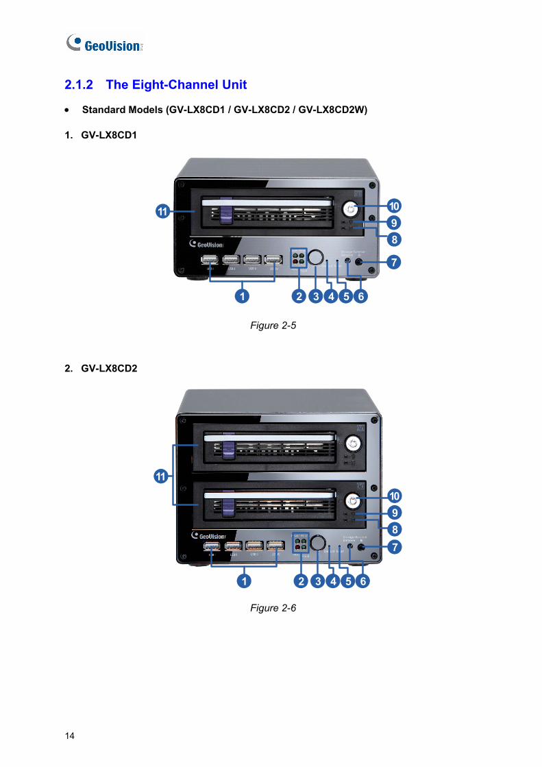
• Standard Models (GV-LX8CD1 / GV-LX8CD2 / GV-LX8CD2W)
1. GV-LX8CD1
1
10
2 3 4 5 6
7
89
11
Figure 2-5
2. GV-LX8CD2
1
10
2 3 4 5 6
789
11
Figure 2-6
14

Physical Description 2
GV-LX8CD2W
1
10
2 3 4 5 6
789
12
11
Figure 2-7
No. Name Description
1 USB Port The four USB ports can connect the USB storage device, Wireless LAN adaptor and/or mobile Internet device.
2 System LED
• Power LED: Turns on when the power is supplied. • Ready LED: Turns on when the unit is ready for use.• HDD LED: Turns on when the HDD is reading or
writing data. • Disk Full / Fault LED: Turns on when the HDD is full
or read/write error occurs.
3 IR Receiver Receives data from the infrared remote control.
4 Default Button Sets all configurations to their factory settings. See 8.4 Restoring to Factory Default Settings.
5 Reset Button Restarts the unit, and keeps all current configurations.
6 Storage Removal Button Stops recording and detaches the HDD from the system.
7 External IR Connects to an optional External IR Receiver.
8 HDD Activity LED Blinks when the HDD is reading or writing data.
9 HDD Power LED Turns on when the power is supplied.
10 Key Lock Locks and unlocks the HDD drive bay.
11 HDD Drive Bay Installs the SATA hard drive for recording.
12 DVD-RW Drive Writes the DVD disc for data backup.
15
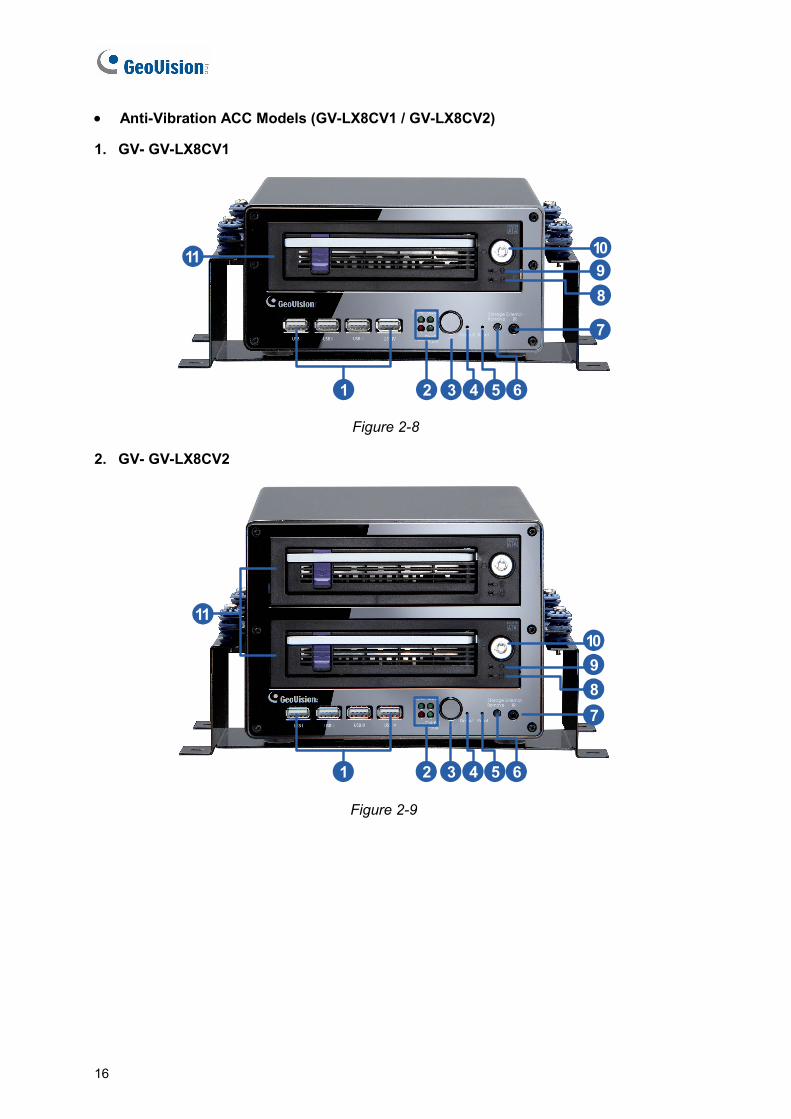
• Anti-Vibration ACC Models (GV-LX8CV1 / GV-LX8CV2)
1. GV- GV-LX8CV1
1
10
2 3 4 5 6
7
89
11
Figure 2-8
2. GV- GV-LX8CV2
1
10
2 3 4 5 6
789
11
Figure 2-9
16

Physical Description 2
No. Name Description
1 USB Port The four USB ports can connect the USB storage device, Wireless LAN adaptor and/or mobile Internet device.
2 System LED
• Power LED: Turns on when the power is supplied. • Ready LED: Turns on when the unit is ready for use.• HDD LED: Turns on when the HDD is reading or
writing data. • Disk Full / Fault LED : Turns on when the HDD is
full or read/write error occurs.
3 IR Receiver Receives data from the infrared remote control.
4 Default Button Sets all configurations to their factory settings. See 8.4 Restoring to Factory Default Settings.
5 Reset Button Restarts the unit, and keeps all current configurations.
6 Storage Removal Button Stops recording and detaches the HDD from the system.
7 External IR Connects to an optional External IR Receiver.
8 HDD Activity LED Blinks when the HDD is reading or writing data.
9 HDD Power LED Turns on when the power is supplied.
10 Key Lock Locks and unlocks the HDD drive bay.
11 HDD Drive Bay Installs the SATA hard drive for recording.
17
2.2 Rear Panel
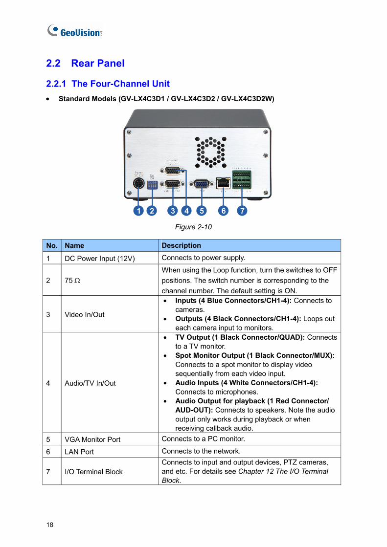
2.2.1 The Four-Channel Unit • Standard Models (GV-LX4C3D1 / GV-LX4C3D2 / GV-LX4C3D2W)
1 2 3 4 5 6 7 Figure 2-10
No. Name Description
1 DC Power Input (12V) Connects to power supply.
2 75 Ω When using the Loop function, turn the switches to OFF positions. The switch number is corresponding to the channel number. The default setting is ON.
3 Video In/Out
• Inputs (4 Blue Connectors/CH1-4): Connects to cameras.
• Outputs (4 Black Connectors/CH1-4): Loops out each camera input to monitors.
4 Audio/TV In/Out
• TV Output (1 Black Connector/QUAD): Connects to a TV monitor.
• Spot Monitor Output (1 Black Connector/MUX): Connects to a spot monitor to display video sequentially from each video input.
• Audio Inputs (4 White Connectors/CH1-4): Connects to microphones.
• Audio Output for playback (1 Red Connector/ AUD-OUT): Connects to speakers. Note the audio output only works during playback or when receiving callback audio.
5 VGA Monitor Port Connects to a PC monitor.
6 LAN Port Connects to the network.
7 I/O Terminal Block Connects to input and output devices, PTZ cameras, and etc. For details see Chapter 12 The I/O Terminal Block.
18

Physical Description 2
• The Anti-Vibration ACC Model (GV-LX4C3V)
1 2 4 5 6 7 83 9
Figure 2-11
No. Name Description
1 DC Power Input (12V) Connects to power supply.
2 75 Ω When using the Loop function, turn the switches to OFF positions. The switch number is corresponding to the channel number. The default setting is ON.
3 External IR Connects to an optional External IR Receiver.
4 Video In/Out
• Inputs (4 Blue Connectors/CH1-4): Connects to cameras.
• Outputs (4 Black Connectors/CH1-4): Loops out each camera input to monitors.
5 Audio/TV In/Out
• TV Output (1 Black Connector/QUAD): Connects to a TV monitor.
• Spot Monitor Output (1 Black Connector/MUX): Connects to a spot monitor to display video sequentially from each video input.
• Audio Inputs (4 White Connectors/CH1-4): Connects to microphones.
• Audio Output for playback (1 Red Connector/ AUD-OUT): Connects to speakers. Note the audio output only works during playback or when receiving callback audio.
6 VGA Monitor Port Connects to a PC monitor.
7 LAN Port Connects to the network.
8 I/O Terminal Block Connects to input and output devices, PTZ cameras and etc. For details see Chapter 12 The I/O Terminal Block.
9 GPS Port (PS/2 Connector) Connects to a GPS 232 receiver.
19
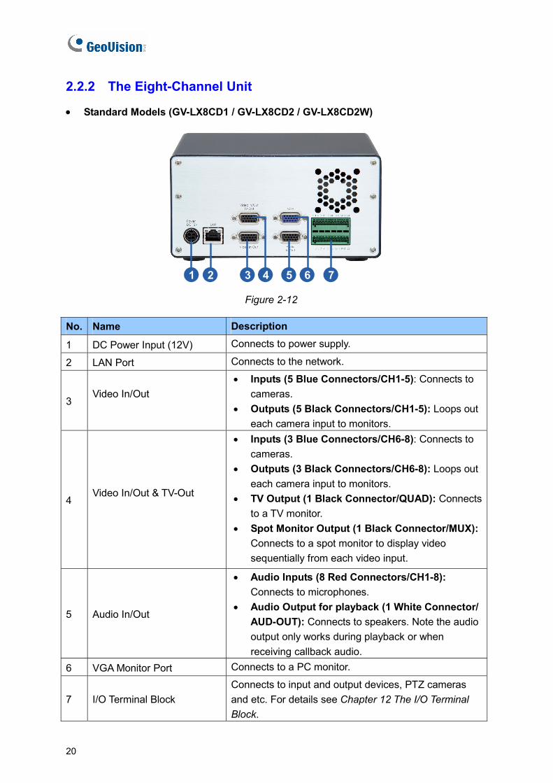
2.2.2 The Eight-Channel Unit
• Standard Models (GV-LX8CD1 / GV-LX8CD2 / GV-LX8CD2W)
1 2 3 4 5 76
Figure 2-12
No. Name Description
1 DC Power Input (12V) Connects to power supply.
2 LAN Port Connects to the network.
3 Video In/Out
• Inputs (5 Blue Connectors/CH1-5): Connects to cameras.
• Outputs (5 Black Connectors/CH1-5): Loops out each camera input to monitors.
4 Video In/Out & TV-Out
• Inputs (3 Blue Connectors/CH6-8): Connects to cameras.
• Outputs (3 Black Connectors/CH6-8): Loops out each camera input to monitors.
• TV Output (1 Black Connector/QUAD): Connects to a TV monitor.
• Spot Monitor Output (1 Black Connector/MUX): Connects to a spot monitor to display video sequentially from each video input.
5 Audio In/Out
• Audio Inputs (8 Red Connectors/CH1-8): Connects to microphones.
• Audio Output for playback (1 White Connector/ AUD-OUT): Connects to speakers. Note the audio output only works during playback or when receiving callback audio.
6 VGA Monitor Port Connects to a PC monitor.
7 I/O Terminal Block Connects to input and output devices, PTZ cameras and etc. For details see Chapter 12 The I/O Terminal Block.
20
Physical Description 2
• Anti-Vibration ACC Models (GV-LX8CV1 / GV-LX8CV2)
1 2 3 4 5 76 8
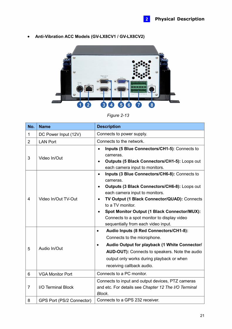
Figure 2-13
No. Name Description
1 DC Power Input (12V) Connects to power supply.
2 LAN Port Connects to the network.
3 Video In/Out
• Inputs (5 Blue Connectors/CH1-5): Connects to cameras.
• Outputs (5 Black Connectors/CH1-5): Loops out each camera input to monitors.
4 Video In/Out TV-Out
• Inputs (3 Blue Connectors/CH6-8): Connects to cameras.
• Outputs (3 Black Connectors/CH6-8): Loops out each camera input to monitors.
• TV Output (1 Black Connector/QUAD): Connects to a TV monitor.
• Spot Monitor Output (1 Black Connector/MUX): Connects to a spot monitor to display video sequentially from each video input.
5 Audio In/Out
• Audio Inputs (8 Red Connectors/CH1-8): Connects to the microphone.
• Audio Output for playback (1 White Connector/ AUD-OUT): Connects to speakers. Note the audio output only works during playback or when receiving callback audio.
6 VGA Monitor Port Connects to a PC monitor.
7 I/O Terminal Block Connects to input and output devices, PTZ cameras and etc. For details see Chapter 12 The I/O Terminal Block.
8 GPS Port (PS/2 Connector) Connects to a GPS 232 receiver.
21
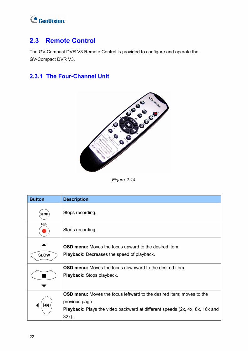
2.3 Remote Control The GV-Compact DVR V3 Remote Control is provided to configure and operate the GV-Compact DVR V3.
2.3.1 The Four-Channel Unit
Figure 2-14
Button Description
Stops recording.
Starts recording.
OSD menu: Moves the focus upward to the desired item. Playback: Decreases the speed of playback.
OSD menu: Moves the focus downward to the desired item. Playback: Stops playback.
OSD menu: Moves the focus leftward to the desired item; moves to the previous page. Playback: Plays the video backward at different speeds (2x, 4x, 8x, 16x and 32x).
22

Physical Description 2
Button Description
OSD menu: Moves the focus rightward to the desired item; moves to the next page. Playback: Plays the video forward at different speeds (2x, 4x, 8x, 16x and 32x).
OSD menu: Enters the menu option and confirms the selection. Playback: Plays or pauses video.
Switches to Channel 1 or I/O device 1.
Switches to Channel 2 or I/O device 2.
Switches to Channel 3 or I/O device 3.
Switches to Channel 4 or I/O device 4.
Switches to the screen of 4 divisions.
Zooms in or out.
Calls up the menu of SEARCH/PLAYBACK.
Confirms the menu selection.
Calls up the main menu.
Quits the menu selection or exits the menu.
A / B / C Device Type
Switches among up to 3 units of GV-Compact DVR V3 for remote control. To set the device type of the GV-Compact DVR V3, see IR TYPE, 4.8.4 Display Settings.
23
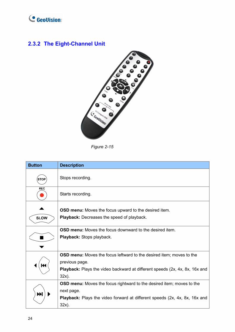
2.3.2 The Eight-Channel Unit
Figure 2-15
Button Description
Stops recording.
Starts recording.
OSD menu: Moves the focus upward to the desired item. Playback: Decreases the speed of playback.
OSD menu: Moves the focus downward to the desired item. Playback: Stops playback.
OSD menu: Moves the focus leftward to the desired item; moves to the previous page. Playback: Plays the video backward at different speeds (2x, 4x, 8x, 16x and 32x).
OSD menu: Moves the focus rightward to the desired item; moves to the next page. Playback: Plays the video forward at different speeds (2x, 4x, 8x, 16x and 32x).
24

Physical Description
25
2
Button Description
OSD menu: Enters the menu option and confirms the selection. Playback: Plays or pauses video.
to Switches to Channel 1 to Channel 8 or I/O device 1 to 8.
Switches to the screen of 4 divisions.
Zooms in or out.
Calls up the menu of SEARCH/PLAYBACK.
Confirms the menu selection.
Calls up the main menu.
Quits the menu selection or exits the menu.
A / B / C Device Type
Switches among up to 3 units of GV-Compact DVR V3 for remote control. To set the device type of the GV-Compact DVR V3, see IR TYPE, 4.8.4 Display Settings.

Chapter 3 Getting Started Getting started with the GV-Compact DVR V3 consists of the following steps:
3.1 Basic Connection for Standard Models
Install the video display devices.
3.2 Basic Connection for Anti-Vibration Models
Connect the unit to the vehicle.
3.3 Connecting Anti-Vibration ACC Models
Describe the ACC connection in detail.
3.4 Connecting Optional Video Output Devices
Connect optional video output devices.
3.5 Installing a Hard Drive
Install a hard drive for video recording.
3.6 Turning on and off the Power
Turn on and off the unit.
3.7 Formatting Hard Drive
Format the hard drive before recording.
3.8 Main Screen Overview
Access the system information on the main screen.
3.9 Basic Operation
26
Getting Started 3
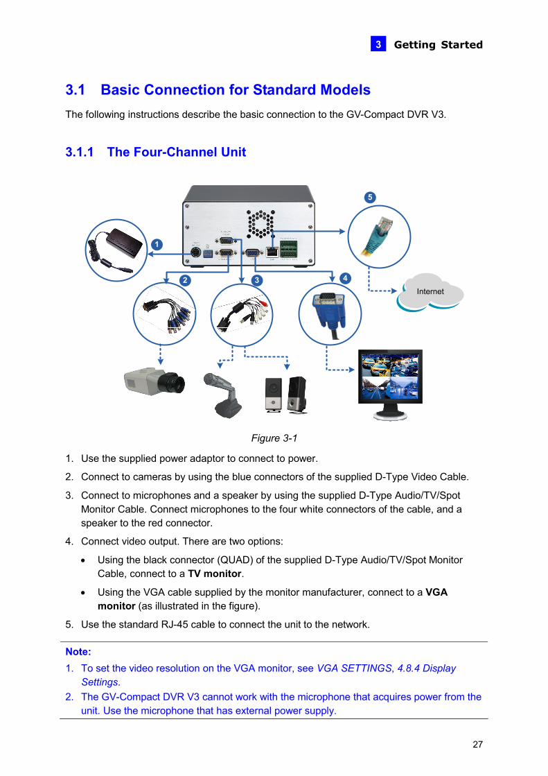
3.1 Basic Connection for Standard Models The following instructions describe the basic connection to the GV-Compact DVR V3.
3.1.1 The Four-Channel Unit
Internet
1
2 3 4
5
Figure 3-1
1. Use the supplied power adaptor to connect to power.
2. Connect to cameras by using the blue connectors of the supplied D-Type Video Cable.
3. Connect to microphones and a speaker by using the supplied D-Type Audio/TV/Spot Monitor Cable. Connect microphones to the four white connectors of the cable, and a speaker to the red connector.
4. Connect video output. There are two options:
• Using the black connector (QUAD) of the supplied D-Type Audio/TV/Spot Monitor Cable, connect to a TV monitor.
• Using the VGA cable supplied by the monitor manufacturer, connect to a VGA monitor (as illustrated in the figure).
5. Use the standard RJ-45 cable to connect the unit to the network.
Note: 1. To set the video resolution on the VGA monitor, see VGA SETTINGS, 4.8.4 Display
Settings. 2. The GV-Compact DVR V3 cannot work with the microphone that acquires power from the
unit. Use the microphone that has external power supply.
27

3.1.2 The Eight-Channel Unit
Figure 3-2
1. Use the supplied power adaptor to connect to power.
2. Connect to cameras (Camera 1 to 5) by using the blue connectors of the supplied 1 to 5 D-Type Video Cable.
3. Connect to cameras (Camera 6 to 8) by using the blue connectors of the supplied 6 to 8 D-Type Video/ TV/Spot Monitor Cable.
4. Connect to microphones and a speaker by using the supplied D-Type Audio Cable. Connect microphones to the eight red connectors of the cable, and a speaker to the white connector.
5. Connect video output. There are two options:
• Using the black connector (QUAD) of the supplied 6 to 8 D-Type Video/TV/Spot Monitor Cable, connect to a TV monitor.
• Using the VGA cable supplied by the monitor manufacturer, connect to a VGA monitor (as illustrated in the figure).
6. Use the standard RJ-45 cable to connect the unit to the network.
Note: 1. To set the video resolution on the VGA monitor, see VGA SETTINGS, 4.8.4 Display
Settings. 2. The GV-Compact DVR V3 cannot work with the microphone that acquires power from the
unit. Use the microphone that has external power supply.
28
Getting Started 3
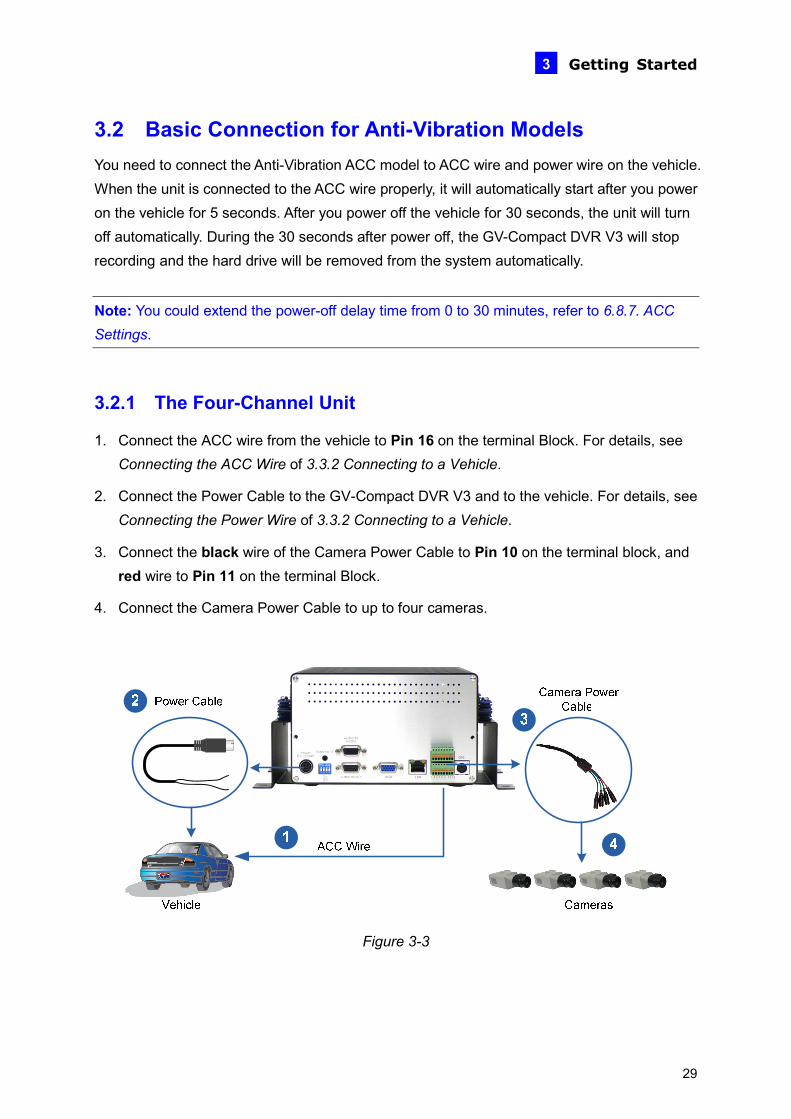
3.2 Basic Connection for Anti-Vibration Models You need to connect the Anti-Vibration ACC model to ACC wire and power wire on the vehicle. When the unit is connected to the ACC wire properly, it will automatically start after you power on the vehicle for 5 seconds. After you power off the vehicle for 30 seconds, the unit will turn off automatically. During the 30 seconds after power off, the GV-Compact DVR V3 will stop recording and the hard drive will be removed from the system automatically.
Note: You could extend the power-off delay time from 0 to 30 minutes, refer to 6.8.7. ACC Settings.
3.2.1 The Four-Channel Unit
1. Connect the ACC wire from the vehicle to Pin 16 on the terminal Block. For details, see Connecting the ACC Wire of 3.3.2 Connecting to a Vehicle.
2. Connect the Power Cable to the GV-Compact DVR V3 and to the vehicle. For details, see Connecting the Power Wire of 3.3.2 Connecting to a Vehicle.
3. Connect the black wire of the Camera Power Cable to Pin 10 on the terminal block, and red wire to Pin 11 on the terminal Block.
4. Connect the Camera Power Cable to up to four cameras.
Figure 3-3
29

3.2.2 The Eight-Channel Unit
1. Connect the ACC wire from the vehicle to Pin 24 on the terminal block. For details, see Connecting the ACC Wire of 3.3.2 Connecting to a Vehicle.
2. Connect the Power Cable to the GV-Compact DVR V3 and to the vehicle. For details, see Connecting the Power Wire of 3.3.2 Connecting to a Vehicle.
3. Connect the black wires of the Camera Power Cables to Pin 18 and Pin 20 on the terminal block; connect the red wires of the Camera Power Cables to Pin 17 and Pin 19 on the terminal block.
4. Connect the Camera Power Cables to up to eight cameras.
Figure 3-4
30
Getting Started 3
3.3 Connecting Anti-Vibration ACC Models You need to connect the Anti-Vibration ACC model to the ACC wire and power wire on the vehicle. Before real deployment, it is suggested to test connection to the ACC wire and set up the unit.
3.3.1 Connecting and Testing Before you connect the Anti-Vibration ACC model to a vehicle, it is recommended to test and set up the unit first by using the supplied Shorting Cable. The Shorting Cable is designed to simulate the ACC wiring between the unit and the vehicle. For the test, you need to prepare a power adaptor (DC 12V, 5.0A) to power on the unit. Follow the steps below. Items required for testing:
Supplied Shorting Cable
Power Adaptor of DC 12V, 5A (which can be purchased from GeoVision)
31

1. Connect the Shorting Cable to Pins 14 and 16 (4-chaneel unit) or Pins 22 and 24 (8-channel unit) on the terminal block.
2 4 6 8 10 12 14 16
1 3 5 7 9 11 13 15
Terminal Block of 4-Channel Unit
Shorting Cable
2 4 6 8 10 12
1 3 5 7 9 11
Terminal Block of 8-Channel Unit
14
13
16
15
18 20 22 24
17 19 21 23
Shorting Cable
Figure 3-5
er adaptor. The unit automatically starts after powering
of the GV-Compact DVR V3, such as storage, images, recording and
power adaptor. The unit turns off immediately after powering off.
2. Power on the unit by using a powup for 5 seconds.
3. Set up the settingsetc through its OSD or Web interface. See 3.7 Formatting Hard Drive and 3.8 Basic Operation.
4. Remove the
32
Getting Started 3
3.3.2 Connecting to a ve icle
PORTANT:
mple of how to connect the Anti-Vibration ACC model to the vehicle. Since
h
IM
Below is an exaeach vehicle differs in design, refer to the owner’s manual of your vehicle for details and carefully follow the safety measures. If you are unsure about how to carry out the instructions, have the installation done by a properly trained technician.
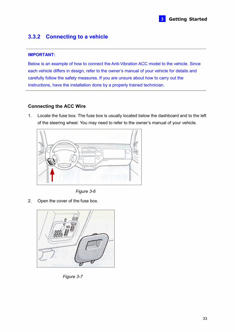
onnecting the ACC Wire
se box is usually located below the dashboard and to the left
C
1. Locate the fuse box. The fuof the steering wheel. You may need to refer to the owner’s manual of your vehicle.
Figure 3-6
2. Open the cover of t
he fuse box.
Figure 3-7
33

3. Find the fuse specification diagram in the owner’s manual, which tells you what each fuse controls. Look for the fuse location of the “cigarette lighter.” The fuse diagram is sometimes located on the back of the fuse box cover.
Figure 3-8
4. Connect the ACC wire from the cigarette lighter fuse to Pin 16 (4-channel unit) or Pin 24 (8-channel unit) on the terminal block.
2 4 6 8 10 12 14 16
1 3 5 7 9 11 13 15
ACC Wire of the Vehicle
Terminal Block of 4-Channel Unit
2 4 6 8 10 12
1 3 5 7 9 11
Terminal Block of 8-Channel Unit
14
13
16
15
18 20 22 24
17 19 21 23
ACC Wire of the Vehicle
Figure 3-9
34
Getting Started 3
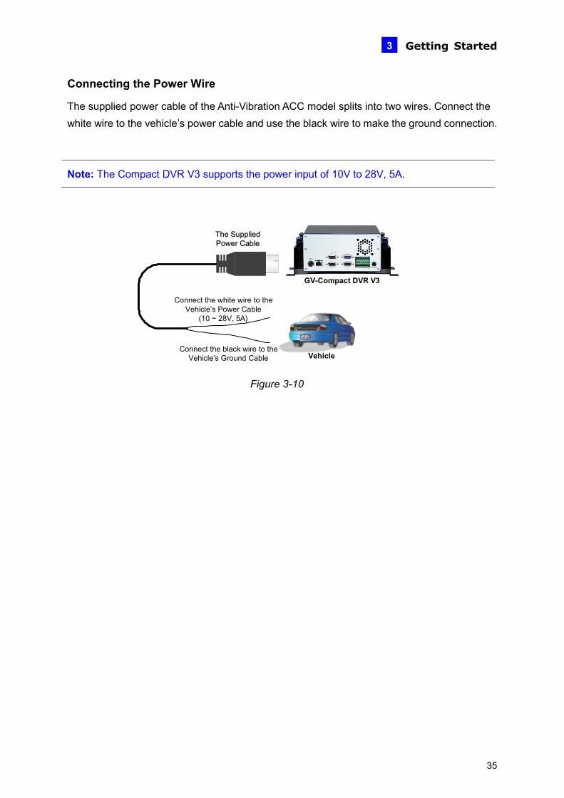
Connecting the Power Wire
The supplied power cable of the Anti-Vibration ACC model splits into two wires. Connect the white wire to the vehicle’s power cable and use the black wire to make the ground connection.
ote: The Compact DVR V3 supports the power input of 10V to 28V, 5A.
N
GV-Compact DVR V3
Connect the black wire to the Vehicle’s Ground
Connect the white wire to the Vehicle’s Power Cable
(10 ~ 28V, 5A)
The Supplied Power Cable
VehicleCable
Figure 3-10
35

1. Using the fuse specification diagram, locate the power cable connecting to the fuse box. Connect the white power wire of the GV-Compact DVR V3 to the positive-voltage power cable. You may need to use a voltmeter to determine which one is the positive voltage.
Figure 3-11
2. Remove the car door scuff plate and wire the power cable along the driver’s door toward the back seat.
Door Scuff Plate
Figure 3-12
3. Use one of the two methods below to connect the black ground wire of the GV-Compact DVR V3.
• Method 1: Connect the black ground wire to the negative-voltage power cable from the fuse box.
Fuse Box
Figure 3-13
36

Getting Started 3
• Method 2: Connect the black ground wire to the vehicle’s chassis so that the wire contacts the bare metal, for example, a metal bolt nearby.
Figure 3-14
Depending on the make and model of your vehicle, sometimes only one method will work. When the black ground wire is connected correctly, GV-Compact DVR V3 will automatically shut down 30 seconds after the car’s power is off. If GV-Compact DVR V3 does not shut down 30 seconds after the car ignition is off, try to connect the black ground wire using the other method.
4. Turn on the car ignition and the GV-Compact DVR V3 should start automatically within 5 seconds. Turn off the car ignition and the GV-Compact DVR V3 should shut down 30 seconds after the car ignition is off.
37

3.4 Connecting Optional Video Output Devices
3.4.1 The Four-Channel Unit The four-channel GV-Compact DVR V3 offers the looping video output for 4 monitors. It also offers the spot monitor output to display video sequentially from each video input. For the settings of the spot monitor, see 4.8.5 Spot Monitor Settings.
Note: To loop out videos, turn the 75 Ω switches to OFF positions. See No. 2, Figure 2-10 / 2-11. The switch number is corresponding to the channel number.
Looping Video Monitors
4 x Black Connector
Spot Monitor
1 x Black Connector
(MUX)
Figure 3-15
38

Getting Started 3
3.4.2 The Eight-Channel Unit The eight-channel GV-Compact DVR V3 offers the looping video output for 8 monitors. It also offers the spot monitor output to display video sequentially from each video input. For the settings of the spot monitor, see 4.8.5 Spot Monitor Settings.
x Black Connector
5 x Black Connector 3 x Black Connector
Spot Monitor
1 (MUX)
Looping Video MonitorsLooping Video Monitors
Figure 3-16
39
3.5 Installing a Hard Drive The GV-Compact DVR V3 comes equipped with one or two 3.5” SATA hard drive bay(s) for video recording. Follow these steps to install the hard drive.
IMPORTANT:
The GV-Compact DVR V3 does not support hot swap. Ensure to power off the unit before removing the hard drive. Also ensure to remove the hard drive only after power was shut off for more than 60 seconds. This would protect and extend the operating life of the hard drive.
For the Anti-vibration ACC models (GV-LX4C3V, GV-LX8CV1 and GV-LX8CV2), it is necessary to use the hard drive especially for notebook, vehicle or surveillance applications, and tightly fasten the unit on the vehicle to prevent vibration and shock hazard.
3.5.1 The Four-Channel Unit • Standard Models (GV-LX4C3D1 / GV-LX4C3D2 / GV-LX4C3D2W)
1. Make sure the unit is powered off.
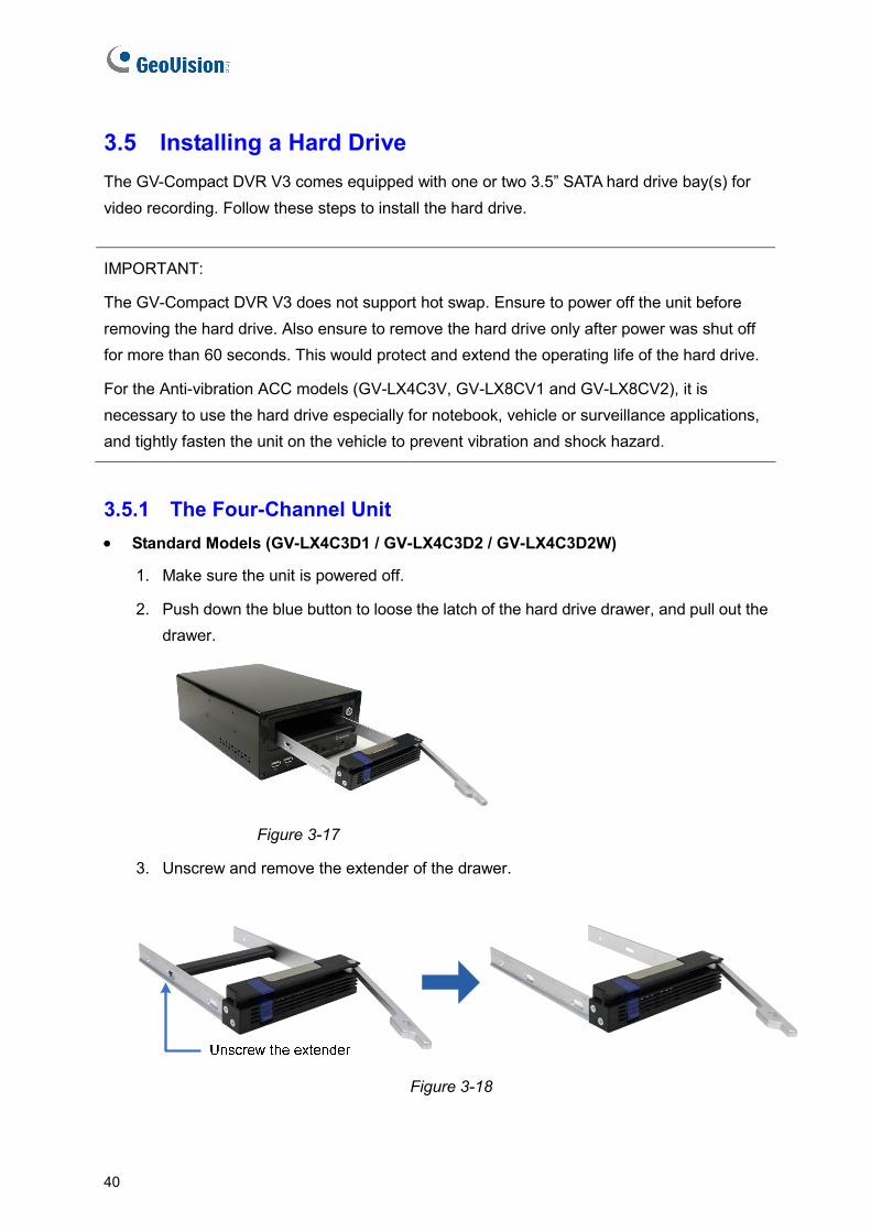
2. Push down the blue button to loose the latch of the hard drive drawer, and pull out the drawer.
Figure 3-17
3. Unscrew and remove the extender of the drawer.
Figure 3-18
40
Getting Started 3
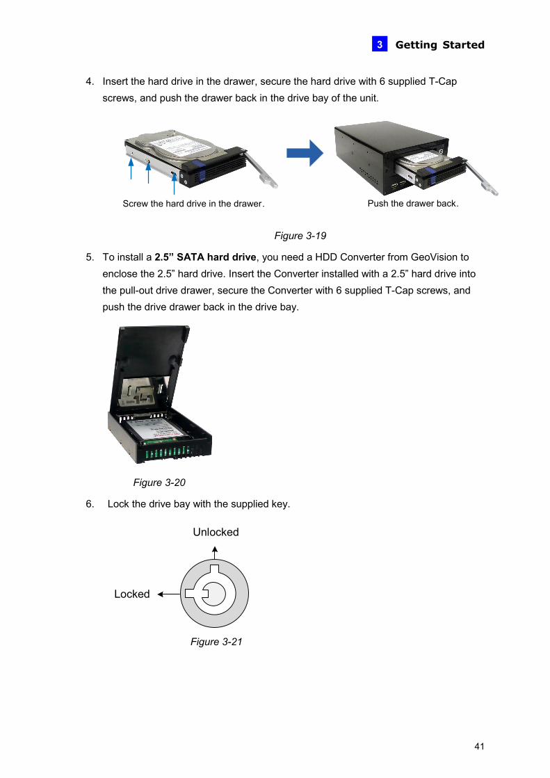
4. Insert the hard drive in the drawer, secure the hard drive with 6 supplied T-Cap screws, and push the drawer back in the drive bay of the unit.
Screw the hard drive in the drawer. Push the drawer back.
Figure 3-19
5. To install a 2.5” SATA hard drive, you need a HDD Converter from GeoVision to enclose the 2.5” hard drive. Insert the Converter installed with a 2.5” hard drive into the pull-out drive drawer, secure the Converter with 6 supplied T-Cap screws, and push the drive drawer back in the drive bay.
Figure 3-20
6. Lock the drive bay with the supplied key.
Locked
Unlocked
Figure 3-21
41
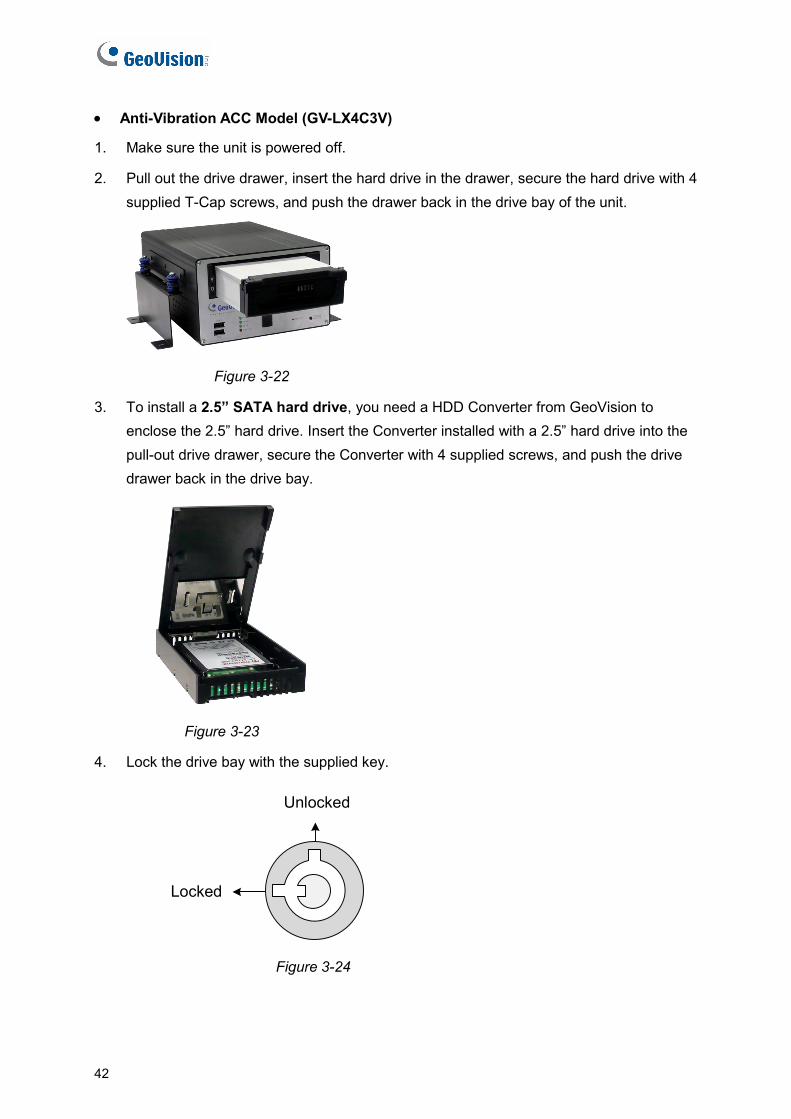
• Anti-Vibration ACC Model (GV-LX4C3V)
1. Make sure the unit is powered off.
2. Pull out the drive drawer, insert the hard drive in the drawer, secure the hard drive with 4 supplied T-Cap screws, and push the drawer back in the drive bay of the unit.
Figure 3-22
3. To install a 2.5” SATA hard drive, you need a HDD Converter from GeoVision to enclose the 2.5” hard drive. Insert the Converter installed with a 2.5” hard drive into the pull-out drive drawer, secure the Converter with 4 supplied screws, and push the drive drawer back in the drive bay.
Figure 3-23
4. Lock the drive bay with the supplied key.
Locked
Unlocked
Figure 3-24
42
Getting Started 3
3.5.2 The Eight-Channel Unit
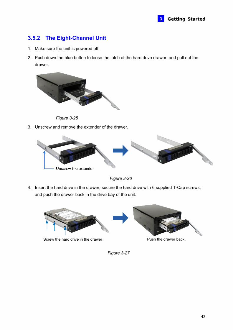
1. Make sure the unit is powered off.
2. Push down the blue button to loose the latch of the hard drive drawer, and pull out the drawer.
Figure 3-25
3. Unscrew and remove the extender of the drawer.
Figure 3-26
4. Insert the hard drive in the drawer, secure the hard drive with 6 supplied T-Cap screws, and push the drawer back in the drive bay of the unit.
Screw the hard drive in the drawer. Push the drawer back.
Figure 3-27
43

5. To install a 2.5” SATA hard drive, you need a HDD Converter from GeoVision to enclose the 2.5” hard drive. Insert the Converter installed with a 2.5” hard drive into the pull-out drive drawer, secure the Converter with 6 supplied T-Cap screws, and push the drive drawer back in the drive bay.
Figure 3-28
6. Lock the drive bay with the supplied key.
Locked
Unlocked
Figure 3-29
3.6 Turning On / Off the Power
44
Getting Started 3
3.6.1 Turning On the Power
1. Connect the GV-Compact DVR V3 to the power, and the Power LED should turn on. If a HDD is installed on the GV-Compact DVR V3, the HDD Power LED should turn on as well.
2. The system starts initializing for several seconds. After this, the Ready LED will turn to green and the main screen will be displayed.
If the GV-Compact DVR V3 is connected to the ACC wire of the vehicle, the unit will automatically start after you power on the vehicle for 5 seconds. Power is supplied to the unit as long as the vehicle ignition is on.
3.6.2 Turning Off the Power
Before unplugging the power cable, ensure both the HDD LED and HDD Activity LED turn off; otherwise, the recorded video may be lost.
If the GV-Compact DVR V3 is installed in a vehicle, the unit will automatically turn off after you power off the vehicle for 30 seconds. During the 30 seconds, the GV-Compact DVR V3 will stop recording and the hard drive will be removed from the system automatically.
Note: You could extend the power-off delay time from 0 to 30 minutes, refer to 6.8.7. ACC Settings.
45
3.7 Formatting Hard Drive The GV-Compact DVR V3 is a Linux-based system. You must follow the steps below to format the hard drive before recording.
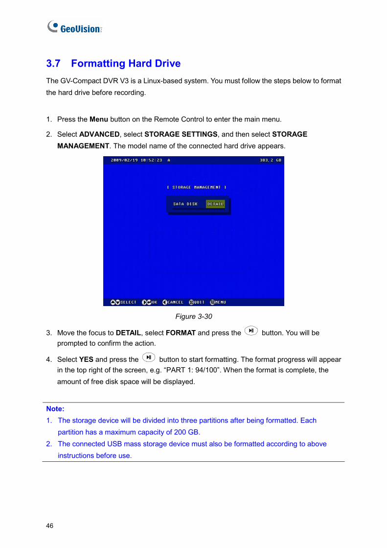
1. Press the Menu button on the Remote Control to enter the main menu.
2. Select ADVANCED, select STORAGE SETTINGS, and then select STORAGE MANAGEMENT. The model name of the connected hard drive appears.
Figure 3-30
3. Move the focus to DETAIL, select FORMAT and press the button. You will be prompted to confirm the action.
4. Select YES and press the button to start formatting. The format progress will appear in the top right of the screen, e.g. “PART 1: 94/100”. When the format is complete, the amount of free disk space will be displayed.
Note: 1. The storage device will be divided into three partitions after being formatted. Each
partition has a maximum capacity of 200 GB. 2. The connected USB mass storage device must also be formatted according to above
instructions before use.
46

Getting Started 3
3.8 Main Screen Overview
7114 53
9 810
21 6
Figure 3-31
1. Date and time: Indicates the current date and time when viewing live video.
2. A / B / C: Indicates the type of device defined for the GV-Compact DVR V3.
3. Monitoring icon : Appears when the monitoring is activated.
4. Manual recording icon or Schedule recording icon : Appears when the
recording is started manually or by schedule.
5. Input icon : Appears when the input device is installed and activated.
6. Channel number/Camera name: Displays the camera number or name.
7. Hard disk status: Indicates the amount of free space on the hard disk. When the disk is
full, the status will turn to red.
8. Motion detection mode icon : Appears when the camera is set to the recording
mode of motion detection.
9. Round-the-clock mode icon : Appears when the camera is set to the recording
mode of round-the-clock.
10. Recording icon : Appears when the monitoring is started. A red icon indicates the
image of the camera is being recorded.
11. Vehicle speed: Indicates the average speed of the vehicle when the GPS function is
enabled. This function is only available for the Anti-Vibration ACC models (GV-LX4C3V,
GV-LX8CV1 and GV-LX8CV2).
47
3.9 Basic Operation This section describes the basic operation of the GV-Compact DVR V3.
3.9.1 Date/Time Adjustment It is recommended that you enter the current date and time before start recording so that the correct date and time is associated with all videos.
• To adjust the date and time, press the Menu button on the Remote Control, select ADVANCED and then select DATE AND TIME. For details, see 4.8.1 Date and Time.
3.9.2 Recording Operation
Before start recording, configure the recording settings properly according to your needs.
• To start recording, press the REC button on the Remote Control to record video onto the hard drive with the corresponding programmed recording settings. The RED recording
icon will appear on the corresponding camera screen. The HDD Power LED and HDD Activity LED lights will be blinking, indicating the GV-Compact DVR V3 is in recording mode.
• To stop recording, press the Stop button on the Remote Control at any time.
To Steps
Set the recording mode Press the Menu button and select MONITORING SETTINGS.
Activate the audio recording
1. Press the Menu button, select CHANNEL SETTINGS, press one Channel button (Ch1 - CH4 for the four-channel unit; CH1 - CH8 for the eight-channel unit), and select VIDEO/AUDIO SETTINGS.
2. Select AUDIO RECORDING, change OFF to ON.
Set the recording schedule
1. Press the Menu button, select RECORDING SCHEDULE, and select one of scheduling methods. See 4.5 Recording Schedule.
2. To start scheduled recording, press the Menu button, select MONITORING SETTINGS, change MONITORING MODE to SCHEDULE, and then select START.
Set the pre-recording and post-recording
Press the Menu button, select CHANNEL SETTINGS, press one Channel button (Ch1 - CH4 for the four-channel unit; CH1 - CH8 for the eight-channel unit), and select ALARM SETTINGS.
48
Getting Started
49
3
3.9.3 Search/Playback Operation To access the recorded video for playback, press the Search button to have several search and playback options. For details, see 4.6 Search / Playback.
3.9.4 PTZ Operation To install the PTZ camera, press the Menu button on the Remote Control, select CHANNEL SETTINGS, press one Channel button (Ch1 - CH4 for the four-channel unit; CH1 - CH8 for the eight-channel unit), and then select PTZ Settings. For details, see 4.1.7 PTZ Settings. To control the PTZ movement, press the Channel button to display the PTZ channel, and use directional buttons to control the PTZ.
3.9.5 Channel Number and Camera Name To display the channel number or camera title, see 4.8.4 Display Settings. To change the camera name, see 4.1.1 Channel Name.
3.9.6 Video Backup To back up data and video on a DVD disc or USB storage device, see 4.8.9 Backup.

Chapter 4 OSD Menu Configurations The GV-Compact DVR V3 is configured through a series of menus on screen by using the Remote Control. This section describes the functions and options in the on-screen display (OSD) menus. To enter the main menu, press the Menu button on the Remote Control. Eight submenus will appear as shown below.
Figure 4-1
Note: A few of functions are only available in Web-based configurations. For the functions of IP filtering, Visual Automation and Backup Center, see Chapter 6 Remote Configurations.
50
OSD Menu Configurations 4
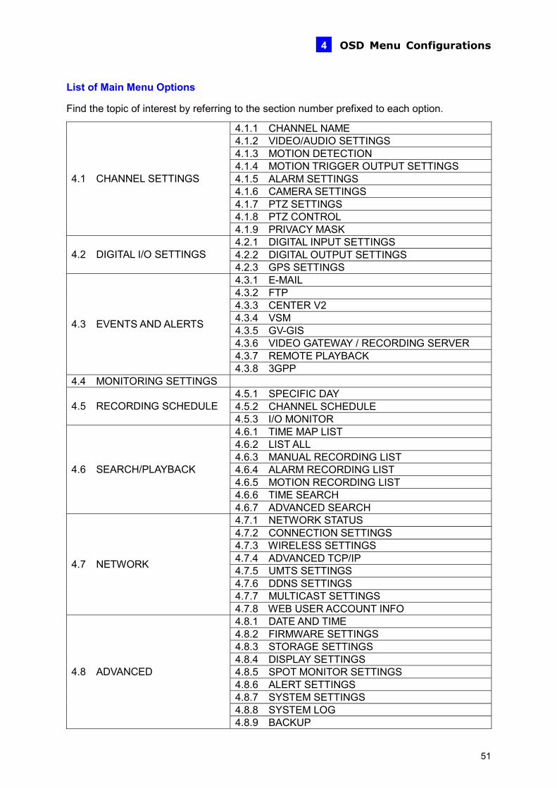
List of Main Menu Options
Find the topic of interest by referring to the section number prefixed to each option.
4.1.1 CHANNEL NAME 4.1.2 VIDEO/AUDIO SETTINGS 4.1.3 MOTION DETECTION 4.1.4 MOTION TRIGGER OUTPUT SETTINGS 4.1.5 ALARM SETTINGS 4.1.6 CAMERA SETTINGS 4.1.7 PTZ SETTINGS 4.1.8 PTZ CONTROL
4.1 CHANNEL SETTINGS
4.1.9 PRIVACY MASK 4.2.1 DIGITAL INPUT SETTINGS 4.2.2 DIGITAL OUTPUT SETTINGS 4.2 DIGITAL I/O SETTINGS 4.2.3 GPS SETTINGS 4.3.1 E-MAIL 4.3.2 FTP 4.3.3 CENTER V2 4.3.4 VSM 4.3.5 GV-GIS 4.3.6 VIDEO GATEWAY / RECORDING SERVER 4.3.7 REMOTE PLAYBACK
4.3 EVENTS AND ALERTS
4.3.8 3GPP 4.4 MONITORING SETTINGS
4.5.1 SPECIFIC DAY 4.5.2 CHANNEL SCHEDULE 4.5 RECORDING SCHEDULE 4.5.3 I/O MONITOR 4.6.1 TIME MAP LIST 4.6.2 LIST ALL 4.6.3 MANUAL RECORDING LIST 4.6.4 ALARM RECORDING LIST 4.6.5 MOTION RECORDING LIST 4.6.6 TIME SEARCH
4.6 SEARCH/PLAYBACK
4.6.7 ADVANCED SEARCH 4.7.1 NETWORK STATUS 4.7.2 CONNECTION SETTINGS 4.7.3 WIRELESS SETTINGS 4.7.4 ADVANCED TCP/IP 4.7.5 UMTS SETTINGS 4.7.6 DDNS SETTINGS 4.7.7 MULTICAST SETTINGS
4.7 NETWORK
4.7.8 WEB USER ACCOUNT INFO 4.8.1 DATE AND TIME 4.8.2 FIRMWARE SETTINGS 4.8.3 STORAGE SETTINGS 4.8.4 DISPLAY SETTINGS 4.8.5 SPOT MONITOR SETTINGS 4.8.6 ALERT SETTINGS 4.8.7 SYSTEM SETTINGS 4.8.8 SYSTEM LOG
4.8 ADVANCED
4.8.9 BACKUP
51

4.1 Channel Settings In Channel Settings, you can adjust the device settings for each channel. To set up a channel, press the Menu button on the Remote Control, select CHANNEL SETTINGS, press one Channel button (CH1 – CH4 for the four-channel unit; CH1 – CH8 for the eight-channel unit), and select one of the setting options. These setting options are described in the following.
4.1.1 Channel Name Enter a descriptive name for the channel by using the on-screen keypad. Select OK from the on-screen keypad to save your settings.
Figure 4-2
52
OSD Menu Configurations 4
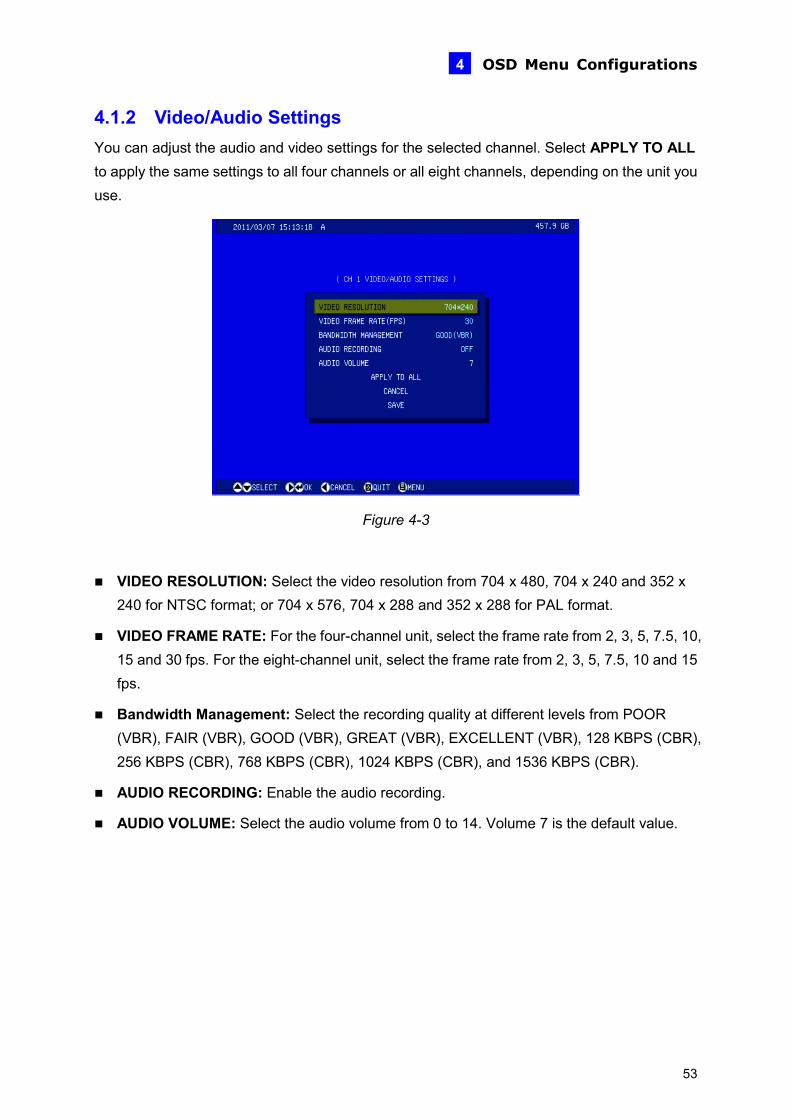
4.1.2 Video/Audio Settings You can adjust the audio and video settings for the selected channel. Select APPLY TO ALL to apply the same settings to all four channels or all eight channels, depending on the unit you use.
Figure 4-3
VIDEO RESOLUTION: Select the video resolution from 704 x 480, 704 x 240 and 352 x 240 for NTSC format; or 704 x 576, 704 x 288 and 352 x 288 for PAL format.
VIDEO FRAME RATE: For the four-channel unit, select the frame rate from 2, 3, 5, 7.5, 10, 15 and 30 fps. For the eight-channel unit, select the frame rate from 2, 3, 5, 7.5, 10 and 15 fps.
Bandwidth Management: Select the recording quality at different levels from POOR (VBR), FAIR (VBR), GOOD (VBR), GREAT (VBR), EXCELLENT (VBR), 128 KBPS (CBR), 256 KBPS (CBR), 768 KBPS (CBR), 1024 KBPS (CBR), and 1536 KBPS (CBR).
AUDIO RECORDING: Enable the audio recording.
AUDIO VOLUME: Select the audio volume from 0 to 14. Volume 7 is the default value.
53
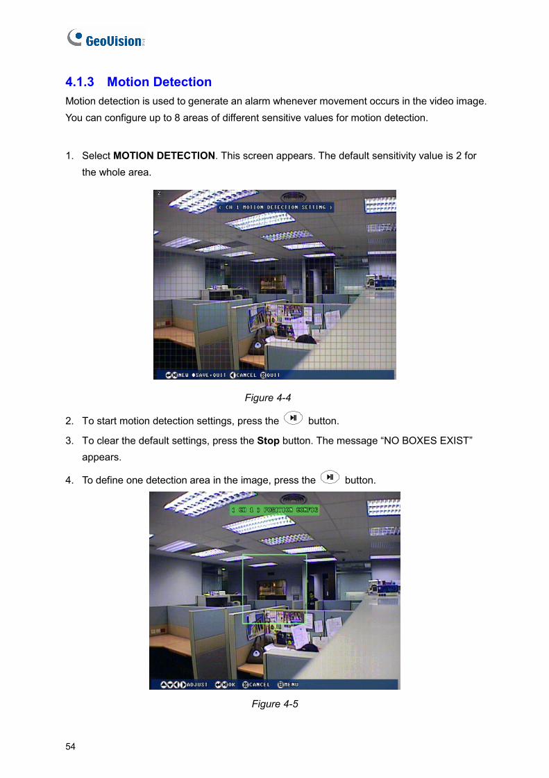
4.1.3 Motion Detection Motion detection is used to generate an alarm whenever movement occurs in the video image. You can configure up to 8 areas of different sensitive values for motion detection.
1. Select MOTION DETECTION. This screen appears. The default sensitivity value is 2 for the whole area.
Figure 4-4
2. To start motion detection settings, press the button.
3. To clear the default settings, press the Stop button. The message “NO BOXES EXIST” appears.
4. To define one detection area in the image, press the button.
Figure 4-5
54
OSD Menu Configurations 4
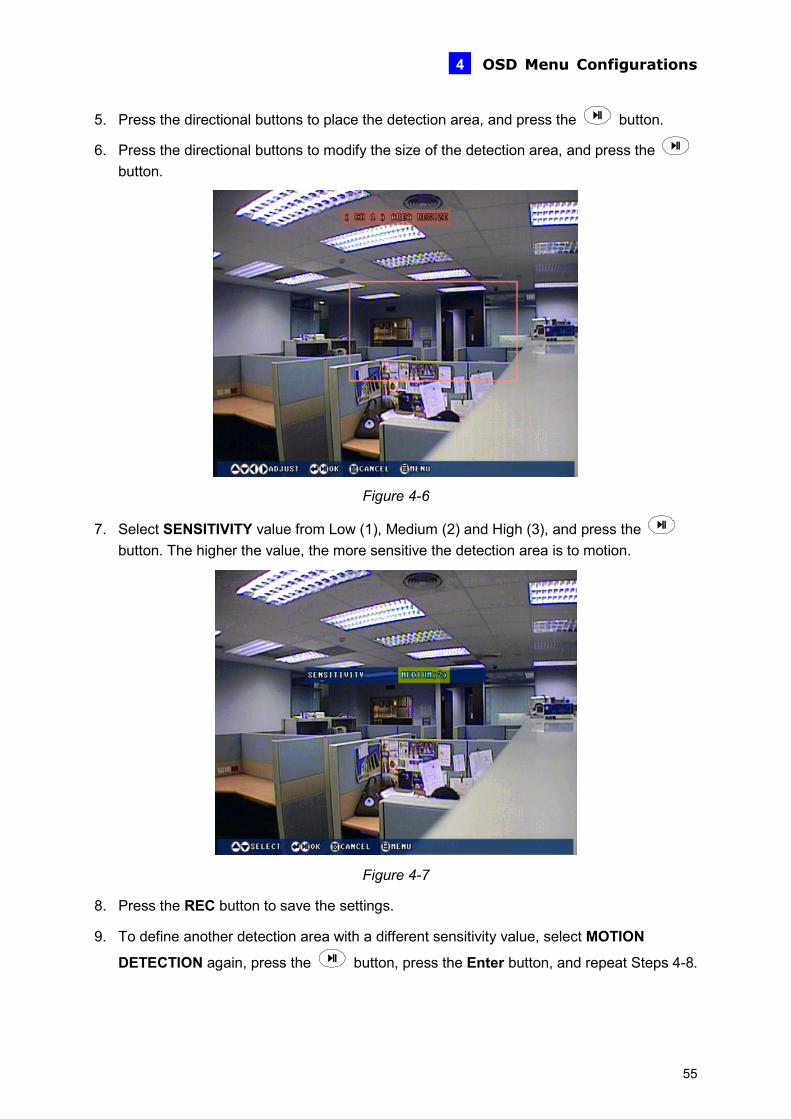
5. Press the directional buttons to place the detection area, and press the button.
6. Press the directional buttons to modify the size of the detection area, and press the button.
Figure 4-6
7. Select SENSITIVITY value from Low (1), Medium (2) and High (3), and press the button. The higher the value, the more sensitive the detection area is to motion.
Figure 4-7
8. Press the REC button to save the settings.
9. To define another detection area with a different sensitivity value, select MOTION
DETECTION again, press the button, press the Enter button, and repeat Steps 4-8.
55
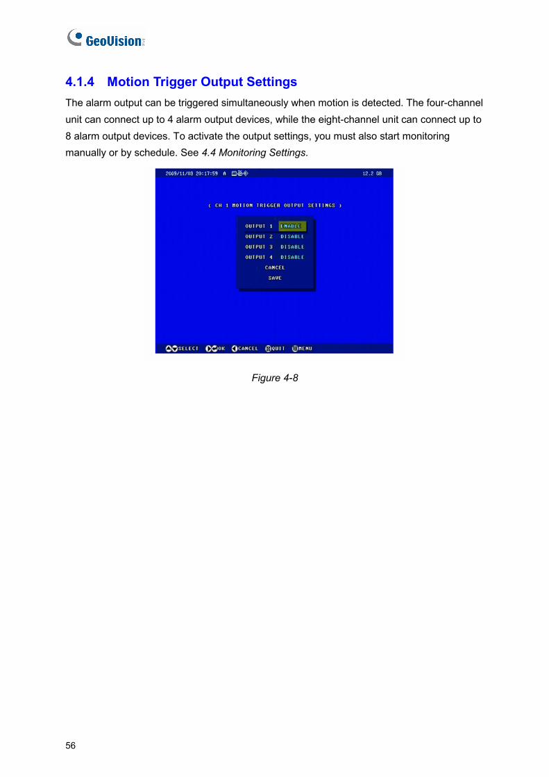
4.1.4 Motion Trigger Output Settings The alarm output can be triggered simultaneously when motion is detected. The four-channel unit can connect up to 4 alarm output devices, while the eight-channel unit can connect up to 8 alarm output devices. To activate the output settings, you must also start monitoring manually or by schedule. See 4.4 Monitoring Settings.
Figure 4-8
56
OSD Menu Configurations 4
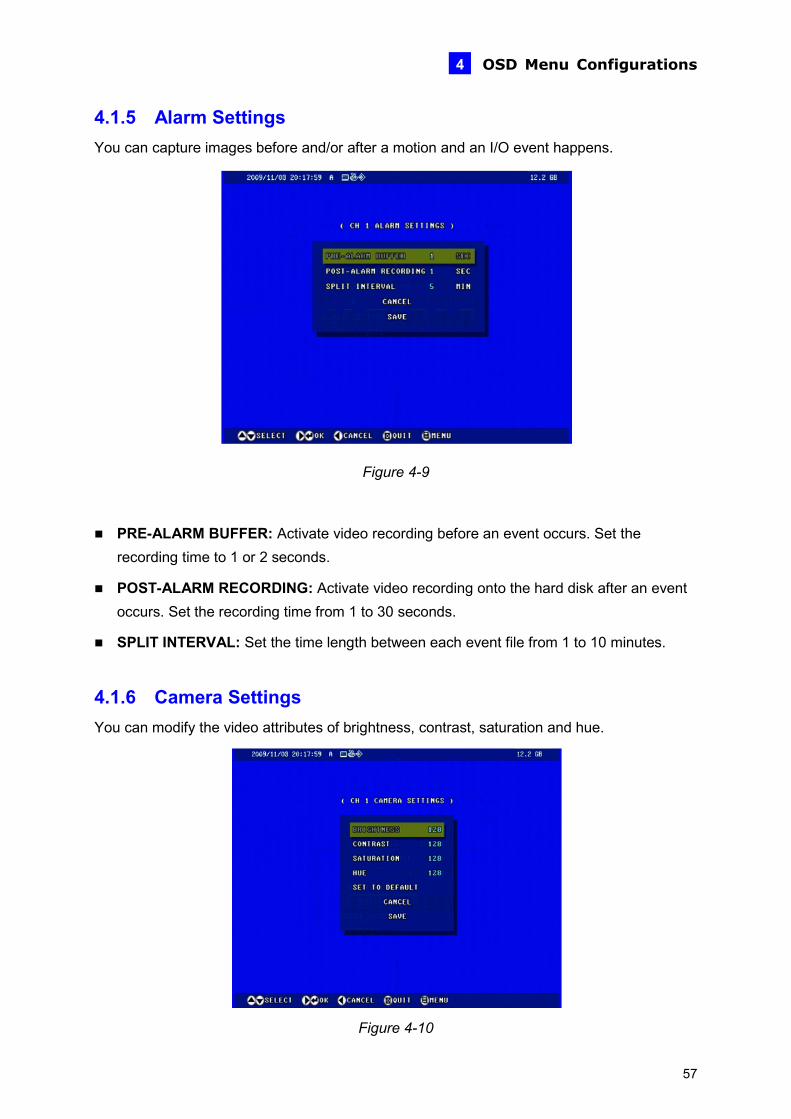
4.1.5 Alarm Settings You can capture images before and/or after a motion and an I/O event happens.
Figure 4-9
PRE-ALARM BUFFER: Activate video recording before an event occurs. Set the recording time to 1 or 2 seconds.
POST-ALARM RECORDING: Activate video recording onto the hard disk after an event occurs. Set the recording time from 1 to 30 seconds.
SPLIT INTERVAL: Set the time length between each event file from 1 to 10 minutes.
4.1.6 Camera Settings You can modify the video attributes of brightness, contrast, saturation and hue.
Figure 4-10
57
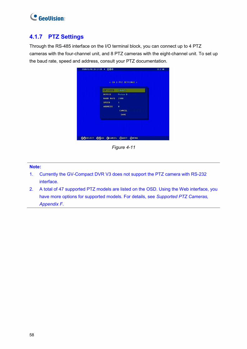
4.1.7 PTZ Settings Through the RS-485 interface on the I/O terminal block, you can connect up to 4 PTZ cameras with the four-channel unit, and 8 PTZ cameras with the eight-channel unit. To set up the baud rate, speed and address, consult your PTZ documentation.
Figure 4-11
Note: 1. Currently the GV-Compact DVR V3 does not support the PTZ camera with RS-232
interface. 2. A total of 47 supported PTZ models are listed on the OSD. Using the Web interface, you
have more options for supported models. For details, see Supported PTZ Cameras, Appendix F.
58

OSD Menu Configurations 4
4.1.8 PTZ Control After setting up the PTZ camera, you can press the Channel button (CH1 - CH4 for the four-channel unit; CH1 – CH8 for the eight-channel unit) on the remote Control to display the PTZ channel. Use the directional buttons to control the PTZ movement. Press the Menu button to access advanced functions. The availability of certain PTZ functions depends on different models. For details, consult your PTZ documentation.
Figure 4-12
59
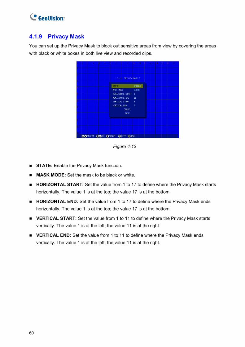
4.1.9 Privacy Mask You can set up the Privacy Mask to block out sensitive areas from view by covering the areas with black or white boxes in both live view and recorded clips.
Figure 4-13
STATE: Enable the Privacy Mask function.
MASK MODE: Set the mask to be black or white.
HORIZONTAL START: Set the value from 1 to 17 to define where the Privacy Mask starts horizontally. The value 1 is at the top; the value 17 is at the bottom.
HORIZONTAL END: Set the value from 1 to 17 to define where the Privacy Mask ends horizontally. The value 1 is at the top; the value 17 is at the bottom.
VERTICAL START: Set the value from 1 to 11 to define where the Privacy Mask starts vertically. The value 1 is at the left; the value 11 is at the right.
VERTICAL END: Set the value from 1 to 11 to define where the Privacy Mask ends vertically. The value 1 is at the left; the value 11 is at the right.
60
OSD Menu Configurations 4
4.2 Digital IO Settings
The I/O terminal block, on the rear panel of the GV-Compact DVR V3, provides the interface for the applications of digital input, relay output and GPS.
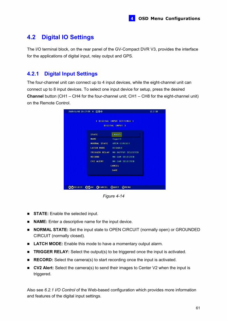
4.2.1 Digital Input Settings The four-channel unit can connect up to 4 input devices, while the eight-channel unit can connect up to 8 input devices. To select one input device for setup, press the desired Channel button (CH1 – CH4 for the four-channel unit; CH1 – CH8 for the eight-channel unit) on the Remote Control.
Figure 4-14
STATE: Enable the selected input.
NAME: Enter a descriptive name for the input device.
NORMAL STATE: Set the input state to OPEN CIRCUIT (normally open) or GROUNDED CIRCUIT (normally closed).
LATCH MODE: Enable this mode to have a momentary output alarm.
TRIGGER RELAY: Select the output(s) to be triggered once the input is activated.
RECORD: Select the camera(s) to start recording once the input is activated.
CV2 Alert: Select the camera(s) to send their images to Center V2 when the input is triggered.
Also see 6.2.1 I/O Control of the Web-based configuration which provides more information and features of the digital input settings.
61
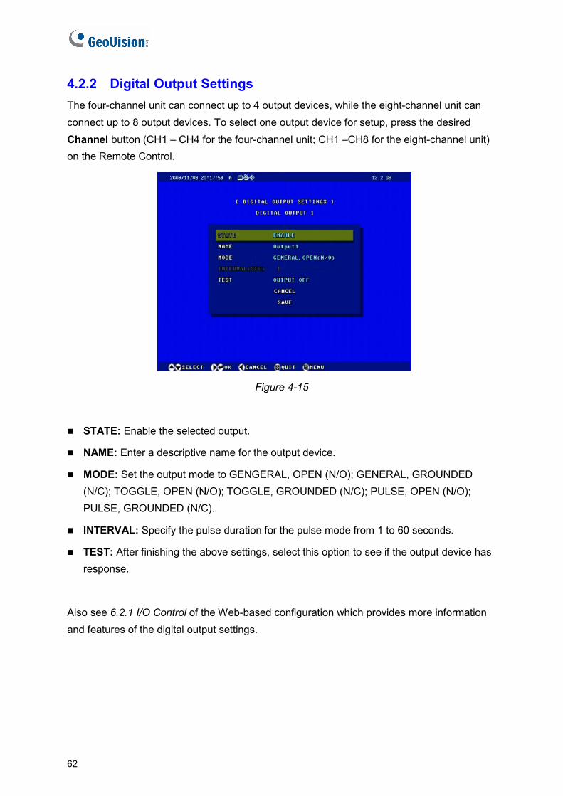
4.2.2 Digital Output Settings The four-channel unit can connect up to 4 output devices, while the eight-channel unit can connect up to 8 output devices. To select one output device for setup, press the desired Channel button (CH1 – CH4 for the four-channel unit; CH1 –CH8 for the eight-channel unit) on the Remote Control.
Figure 4-15
STATE: Enable the selected output.
NAME: Enter a descriptive name for the output device.
MODE: Set the output mode to GENGERAL, OPEN (N/O); GENERAL, GROUNDED (N/C); TOGGLE, OPEN (N/O); TOGGLE, GROUNDED (N/C); PULSE, OPEN (N/O); PULSE, GROUNDED (N/C).
INTERVAL: Specify the pulse duration for the pulse mode from 1 to 60 seconds.
TEST: After finishing the above settings, select this option to see if the output device has response.
Also see 6.2.1 I/O Control of the Web-based configuration which provides more information and features of the digital output settings.
62
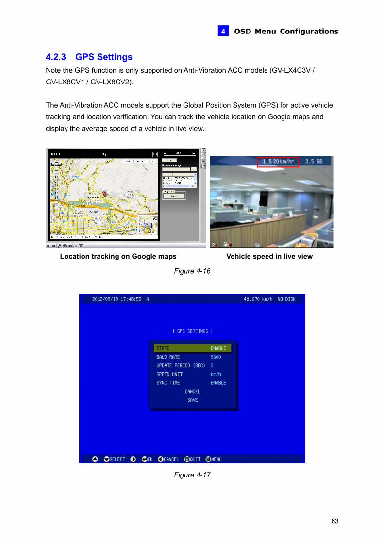
OSD Menu Configurations 4
4.2.3 GPS Settings Note the GPS function is only supported on Anti-Vibration ACC models (GV-LX4C3V / GV-LX8CV1 / GV-LX8CV2). The Anti-Vibration ACC models support the Global Position System (GPS) for active vehicle tracking and location verification. You can track the vehicle location on Google maps and display the average speed of a vehicle in live view.
Location tracking on Google maps Vehicle speed in live view
Figure 4-16
Figure 4-17
63

STATE: Enable the GPS function. After the settings, the vehicle speed will show on the upper-right corner of the main screen.
BAUD RATE: Two baud rate options are available: 4800 and 9600. By default the value is 9600.
UPDATE PERIOD: Set the update frequency in seconds for GPS data.
SPEED UNIT: Two speed unit options are available: km/h and mph. By default the value is km/h.
SYNC TIME: Synchronizes the time of GV-Compact DVR V3 with the GPS time once the unit receives GPS signals. After enabling this function, every time you restart the unit, it will synchronize the time with the GPS time automatically.
To track the location of the GV-Compact DVR V3 on Google Maps, see 8.3 GPS Tracking. If the monitoring is also activated, the GPS tracks will be recorded along with videos. This makes it possible to play back video with GPS tracks on maps using the Remote ViewLog player. See 7.2.5 Playback of GPS Tracks.
Note: The vehicle speed will be recorded with video, but the review of the speed data is not available on OSD. You can retrieve the video with the speed data using the Remote ViewLog player. See 7.2.2 Playback over Network.
64
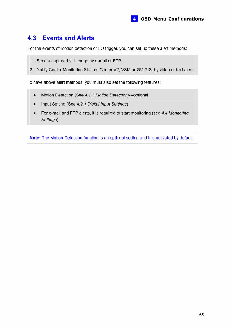
OSD Menu Configurations 4
4.3 Events and Alerts For the events of motion detection or I/O trigger, you can set up these alert methods:
1. Send a captured still image by e-mail or FTP.
2. Notify Center Monitoring Station, Center V2, VSM or GV-GIS, by video or text alerts.
To have above alert methods, you must also set the following features:
• Motion Detection (See 4.1.3 Motion Detection)---optional
• Input Setting (See 4.2.1 Digital Input Settings)
• For e-mail and FTP alerts, it is required to start monitoring (see 4.4 Monitoring Settings)
Note: The Motion Detection function is an optional setting and it is activated by default.
65

4.3.1 E-mail After a trigger event, the GV-Compact DVR V3 can send the e-mail to a remote user containing a captured still image.
Figure 4-18
STATE: Enable the e-mail function.
SERVER URL/IP: Enter the URL or IP address of the SMTP server.
PORT: Enter the SMTP server’s port number. Or keep the default value 25.
FROM: Enter the sender’s e-mail address.
SEND TO: Enter the e-mail address(s) you want to send alerts to.
ALERT INTERVAL: Enter the interval between e-mail alerts. The interval can be between 0 and 60 minutes. The option is useful for the frequent event condition. It will ignore any event triggers during the interval period.
AUTH LOGIN: If the SMTP server needs authentication, enable this option and enter the valid username and password.
Also see 6.3.1 E-mail of the Web-based configuration which provides more information and features of the e-mail settings.
66

OSD Menu Configurations 4
4.3.2 FTP You can also send the captured still image to a remote FTP server for alerts.
Figure 4-19
FTP CLIENT MODE: Enable the FTP function.
SERVER URL/IP: Enter the host name or IP address of the FTP Server.
PORT: Enter the port number of the FTP Server. Or keep the default value 21.
USERNAME: Enter a valid user name to log into the FTP Server.
PASSWORD: Enter a valid password to log into the FTP Server.
REMOTE DIR: Enter the name of the storage folder on the FTP Server.
FTP SERVER MODE: Enable the GV-Compact DVR V3 to act as a FTP Server, allowing users to download the AVI files.
PORT: Modify the port of the built-in FTP Server. Or keep the default value 21.
Also see 6.3.2 FTP of the Web-based configuration which provides more information and features of the FTP settings.
67
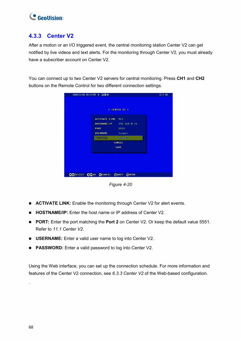
4.3.3 Center V2 After a motion or an I/O triggered event, the central monitoring station Center V2 can get notified by live videos and text alerts. For the monitoring through Center V2, you must already have a subscriber account on Center V2.
You can connect up to two Center V2 servers for central monitoring. Press CH1 and CH2 buttons on the Remote Control for two different connection settings.
Figure 4-20
ACTIVATE LINK: Enable the monitoring through Center V2 for alert events.
HOSTNAME/IP: Enter the host name or IP address of Center V2.
PORT: Enter the port matching the Port 2 on Center V2. Or keep the default value 5551. Refer to 11.1 Center V2.
USERNAME: Enter a valid user name to log into Center V2.
PASSWORD: Enter a valid password to log into Center V2.
Using the Web interface, you can set up the connection schedule. For more information and features of the Center V2 connection, see 6.3.3 Center V2 of the Web-based configuration.
.
68
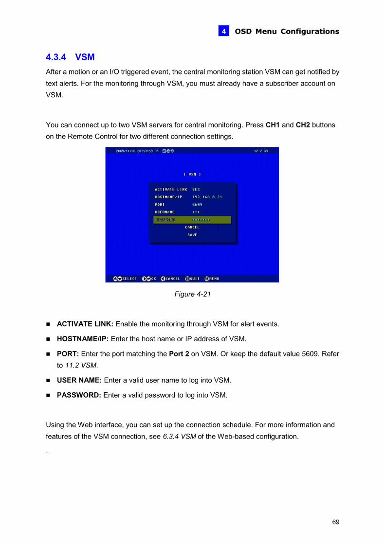
OSD Menu Configurations 4
4.3.4 VSM After a motion or an I/O triggered event, the central monitoring station VSM can get notified by text alerts. For the monitoring through VSM, you must already have a subscriber account on VSM.
You can connect up to two VSM servers for central monitoring. Press CH1 and CH2 buttons on the Remote Control for two different connection settings.
Figure 4-21
ACTIVATE LINK: Enable the monitoring through VSM for alert events.
HOSTNAME/IP: Enter the host name or IP address of VSM.
PORT: Enter the port matching the Port 2 on VSM. Or keep the default value 5609. Refer to 11.2 VSM.
USER NAME: Enter a valid user name to log into VSM.
PASSWORD: Enter a valid password to log into VSM.
Using the Web interface, you can set up the connection schedule. For more information and features of the VSM connection, see 6.3.4 VSM of the Web-based configuration.
.
69
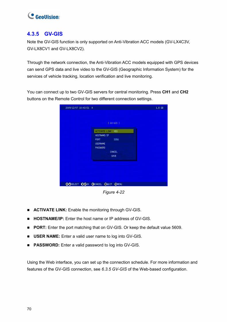
4.3.5 GV-GIS Note the GV-GIS function is only supported on Anti-Vibration ACC models (GV-LX4C3V, GV-LX8CV1 and GV-LX8CV2). Through the network connection, the Anti-Vibration ACC models equipped with GPS devices can send GPS data and live video to the GV-GIS (Geographic Information System) for the services of vehicle tracking, location verification and live monitoring.
You can connect up to two GV-GIS servers for central monitoring. Press CH1 and CH2 buttons on the Remote Control for two different connection settings.
Figure 4-22
ACTIVATE LINK: Enable the monitoring through GV-GIS.
HOSTNAME/IP: Enter the host name or IP address of GV-GIS.
PORT: Enter the port matching that on GV-GIS. Or keep the default value 5609.
USER NAME: Enter a valid user name to log into GV-GIS.
PASSWORD: Enter a valid password to log into GV-GIS.
Using the Web interface, you can set up the connection schedule. For more information and features of the GV-GIS connection, see 6.3.5 GV-GIS of the Web-based configuration.
70
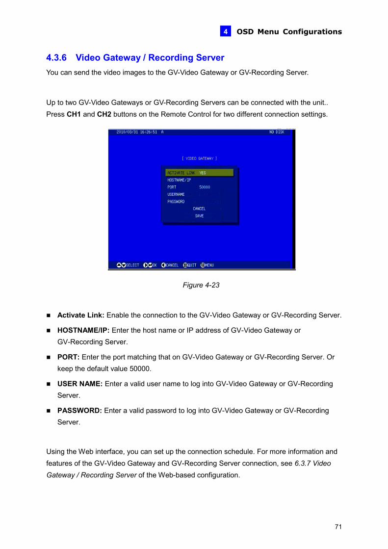
OSD Menu Configurations 4
4.3.6 Video Gateway / Recording Server You can send the video images to the GV-Video Gateway or GV-Recording Server.
Up to two GV-Video Gateways or GV-Recording Servers can be connected with the unit.. Press CH1 and CH2 buttons on the Remote Control for two different connection settings.
Figure 4-23
Activate Link: Enable the connection to the GV-Video Gateway or GV-Recording Server.
HOSTNAME/IP: Enter the host name or IP address of GV-Video Gateway or GV-Recording Server.
PORT: Enter the port matching that on GV-Video Gateway or GV-Recording Server. Or keep the default value 50000.
USER NAME: Enter a valid user name to log into GV-Video Gateway or GV-Recording Server.
PASSWORD: Enter a valid password to log into GV-Video Gateway or GV-Recording Server.
Using the Web interface, you can set up the connection schedule. For more information and features of the GV-Video Gateway and GV-Recording Server connection, see 6.3.7 Video Gateway / Recording Server of the Web-based configuration.
71

4.3.7 Remote Playback You can remotely access and play the recorded files saved on the GV-Compact DVR V3
Select YES to activate the remote playback server built in the unit and to allow playback access. Keep the default port 5552 or modify it if necessary. For details on the remote playback, see 7.2.2 Playback over Network.
Figure 4-24
72
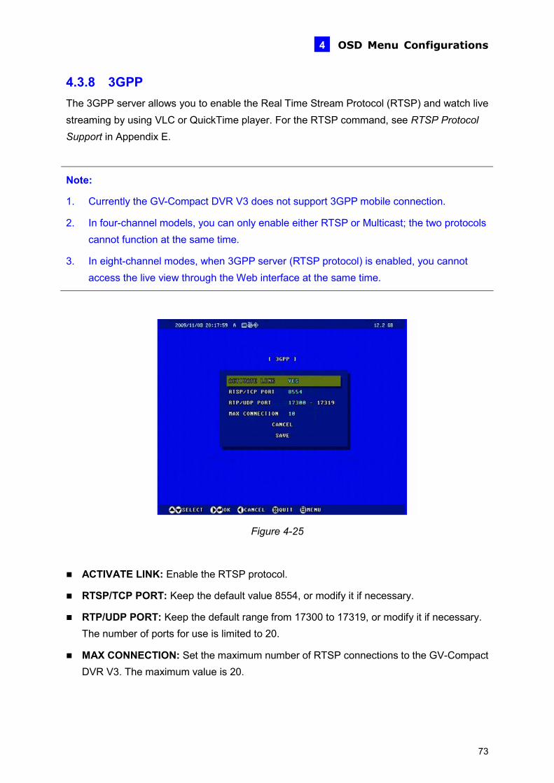
OSD Menu Configurations 4
4.3.8 3GPP The 3GPP server allows you to enable the Real Time Stream Protocol (RTSP) and watch live streaming by using VLC or QuickTime player. For the RTSP command, see RTSP Protocol Support in Appendix E.
Note:
1. Currently the GV-Compact DVR V3 does not support 3GPP mobile connection.
2. In four-channel models, you can only enable either RTSP or Multicast; the two protocols cannot function at the same time.
3. In eight-channel modes, when 3GPP server (RTSP protocol) is enabled, you cannot access the live view through the Web interface at the same time.
Figure 4-25
ACTIVATE LINK: Enable the RTSP protocol.
RTSP/TCP PORT: Keep the default value 8554, or modify it if necessary.
RTP/UDP PORT: Keep the default range from 17300 to 17319, or modify it if necessary. The number of ports for use is limited to 20.
MAX CONNECTION: Set the maximum number of RTSP connections to the GV-Compact DVR V3. The maximum value is 20.
73
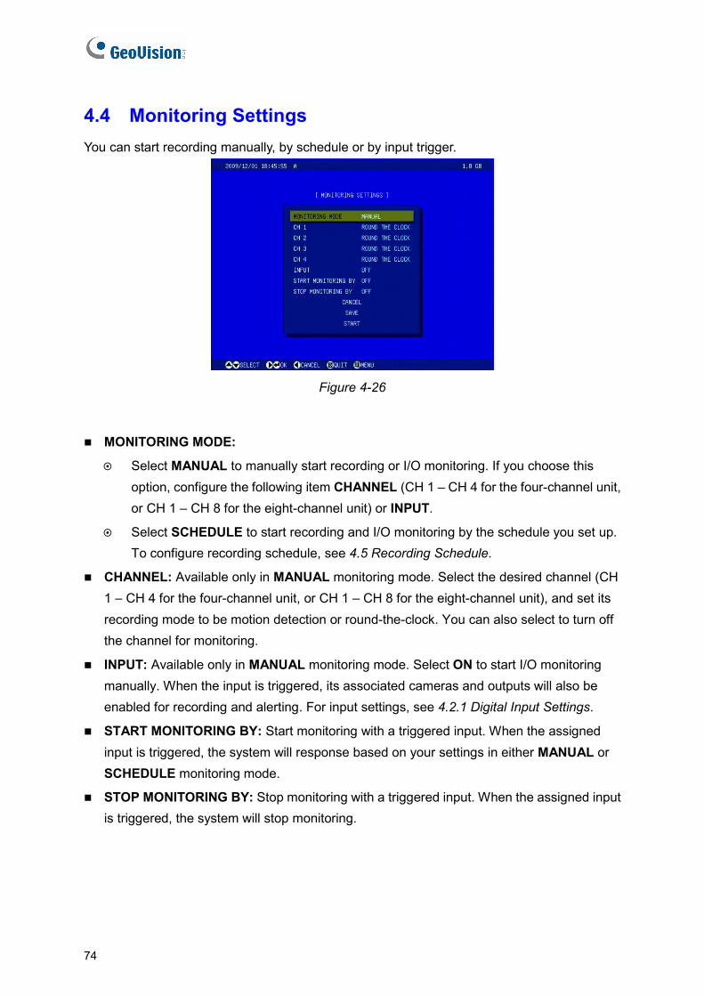
4.4 Monitoring Settings You can start recording manually, by schedule or by input trigger.
Figure 4-26
MONITORING MODE:
Select MANUAL to manually start recording or I/O monitoring. If you choose this option, configure the following item CHANNEL (CH 1 – CH 4 for the four-channel unit, or CH 1 – CH 8 for the eight-channel unit) or INPUT.
Select SCHEDULE to start recording and I/O monitoring by the schedule you set up. To configure recording schedule, see 4.5 Recording Schedule.
CHANNEL: Available only in MANUAL monitoring mode. Select the desired channel (CH 1 – CH 4 for the four-channel unit, or CH 1 – CH 8 for the eight-channel unit), and set its recording mode to be motion detection or round-the-clock. You can also select to turn off the channel for monitoring.
INPUT: Available only in MANUAL monitoring mode. Select ON to start I/O monitoring manually. When the input is triggered, its associated cameras and outputs will also be enabled for recording and alerting. For input settings, see 4.2.1 Digital Input Settings.
START MONITORING BY: Start monitoring with a triggered input. When the assigned input is triggered, the system will response based on your settings in either MANUAL or SCHEDULE monitoring mode.
STOP MONITORING BY: Stop monitoring with a triggered input. When the assigned input is triggered, the system will stop monitoring.
74

OSD Menu Configurations 4
To start monitoring or recording:
• Select START. The unit will start monitoring based on your above settings: record immediately, only record on the scheduled time, or record by an input trigger.
• Select SAVE to save the monitoring settings. Then press the REC button on the Remote Control at any time to start your monitoring settings.
Also see 6.4 Monitoring of the Web-based configuration which provides more information and features of the monitoring settings.
75
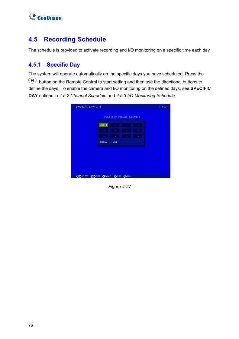
4.5 Recording Schedule The schedule is provided to activate recording and I/O monitoring on a specific time each day.
4.5.1 Specific Day The system will operate automatically on the specific days you have scheduled. Press the
button on the Remote Control to start setting and then use the directional buttons to define the days. To enable the camera and I/O monitoring on the defined days, see SPECIFIC DAY options in 4.5.2 Channel Schedule and 4.5.3 I/O Monitoring Schedule.
Figure 4-27
76
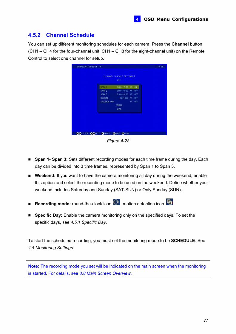
OSD Menu Configurations 4
4.5.2 Channel Schedule You can set up different monitoring schedules for each camera. Press the Channel button (CH1 – CH4 for the four-channel unit; CH1 – CH8 for the eight-channel unit) on the Remote Control to select one channel for setup.
Figure 4-28
Span 1- Span 3: Sets different recording modes for each time frame during the day. Each day can be divided into 3 time frames, represented by Span 1 to Span 3.
Weekend: If you want to have the camera monitoring all day during the weekend, enable this option and select the recording mode to be used on the weekend. Define whether your weekend includes Saturday and Sunday (SAT-SUN) or Only Sunday (SUN).
Recording mode: round-the-clock icon , motion detection icon .
Specific Day: Enable the camera monitoring only on the specified days. To set the specific days, see 4.5.1 Specific Day.
To start the scheduled recording, you must set the monitoring mode to be SCHEDULE. See 4.4 Monitoring Settings.
Note: The recording mode you set will be indicated on the main screen when the monitoring is started. For details, see 3.8 Main Screen Overview.
77
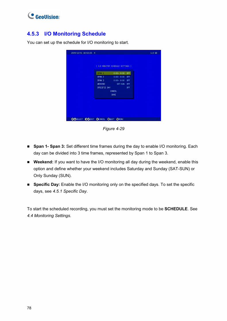
4.5.3 I/O Monitoring Schedule You can set up the schedule for I/O monitoring to start.
Figure 4-29
Span 1- Span 3: Set different time frames during the day to enable I/O monitoring. Each day can be divided into 3 time frames, represented by Span 1 to Span 3.
Weekend: If you want to have the I/O monitoring all day during the weekend, enable this option and define whether your weekend includes Saturday and Sunday (SAT-SUN) or Only Sunday (SUN).
Specific Day: Enable the I/O monitoring only on the specified days. To set the specific days, see 4.5.1 Specific Day.
To start the scheduled recording, you must set the monitoring mode to be SCHEDULE. See 4.4 Monitoring Settings.
78

OSD Menu Configurations 4
4.6 Search / Playback You can retrieve the recorded video by date, time and event. To access the SEARCH/PLAYBACK menu, press the Menu button or the Search button on the Remote Control.
4.6.1 Time Map List The Time Map List provides an overview of the recorded videos in the form of a calendar.
1. On the calendar, dates for which there are recorded videos are green. Use the directional buttons on the Remote Control to move the focus, and select the desired Year, Month and
Day. Then press the button.
Figure 4-30
2. In the HOUR section, hours for which there are recorded videos are green. Each column
represents 1 hour. Select the desired hour and press the button.
Figure 4-31
3. In the MIN section, minutes for which there are recorded videos are green. Each column
represents 2 minutes. Select the desired minute and press the button to start playback.
79

4.6.2 List All The list displays a complete list of recorded videos. To move the list screen up and down one page, press the right and left directional buttons on the Remote Control. To start playback,
highlight the desired video and press the button.
4.6.3 Manual Recording List The list displays a complete list of manually recorded videos. To move the list screen up and down one page, press the right and left directional buttons on the Remote Control. To start
playback, highlight the desired video and press the button.
4.6.4 Alarm Recording List The list displays a complete list of recorded videos on input trigger. To move the list screen up and down one page, press the right and left directional buttons on the Remote Control. To
start playback, highlight the desired video and press the button.
4.6.5 Motion Recording List The list displays a complete list of recorded videos on motion detection. To move the list screen up and down one page, press the right and left directional buttons on the Remote
Control. To start playback, highlight the desired video and press the button.
4.6.6 Time Search You can locate the recorded videos within a certain date and time. Enter START TIME and END TIME for the time search. Then define how to display the found videos. Select LIST to display a list of found videos, or PLAY for immediate playback.
80
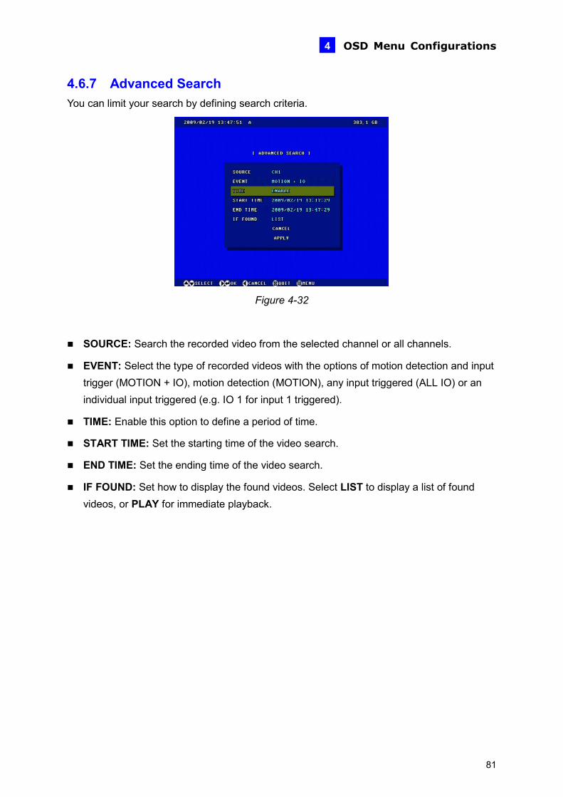
OSD Menu Configurations 4
4.6.7 Advanced Search You can limit your search by defining search criteria.
Figure 4-32
SOURCE: Search the recorded video from the selected channel or all channels.
EVENT: Select the type of recorded videos with the options of motion detection and input trigger (MOTION + IO), motion detection (MOTION), any input triggered (ALL IO) or an individual input triggered (e.g. IO 1 for input 1 triggered).
TIME: Enable this option to define a period of time.
START TIME: Set the starting time of the video search.
END TIME: Set the ending time of the video search.
IF FOUND: Set how to display the found videos. Select LIST to display a list of found videos, or PLAY for immediate playback.
81

4.7 Network The GV-Compact DVR V3 allows you to use a Web browser to remotely view and manage the system. For remote access, configure the related network settings in this section.
4.7.1 Network Status The Network Status displays the current network settings of GV-Compact DVR V3.
Figure 4-33
82
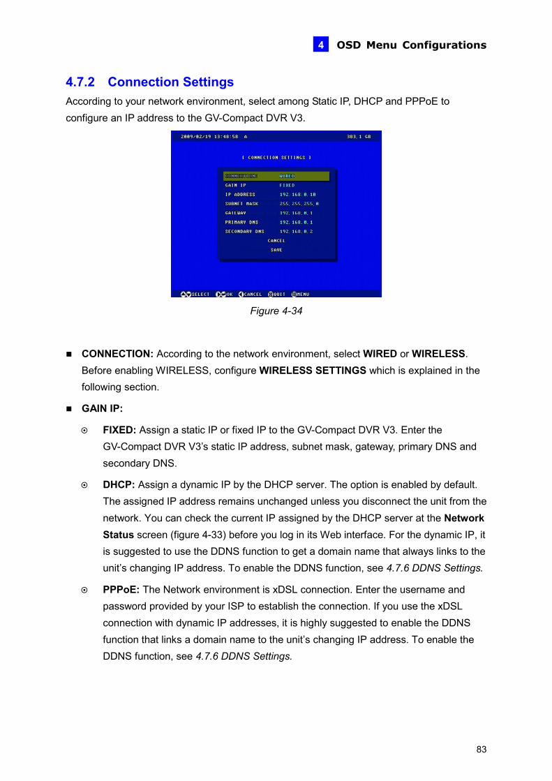
OSD Menu Configurations 4
4.7.2 Connection Settings According to your network environment, select among Static IP, DHCP and PPPoE to configure an IP address to the GV-Compact DVR V3.
Figure 4-34
CONNECTION: According to the network environment, select WIRED or WIRELESS. e
: Assign a static IP or fixed IP to the GV-Compact DVR V3. Enter the S and
ynamic IP by the DHCP server. The option is enabled by default.
Before enabling WIRELESS, configure WIRELESS SETTINGS which is explained in thfollowing section.
GAIN IP:
FIXEDGV-Compact DVR V3’s static IP address, subnet mask, gateway, primary DNsecondary DNS.
DHCP: Assign a dThe assigned IP address remains unchanged unless you disconnect the unit from thenetwork. You can check the current IP assigned by the DHCP server at the Network Status screen (figure 4-33) before you log in its Web interface. For the dynamic IP, it is suggested to use the DDNS function to get a domain name that always links to the unit’s changing IP address. To enable the DDNS function, see 4.7.6 DDNS Settings.
PPPoE: The Network environment is xDSL connection. Enter the username and password provided by your ISP to establish the connection. If you use the xDSL connection with dynamic IP addresses, it is highly suggested to enable the DDNSfunction that links a domain name to the unit’s changing IP address. To enable the DDNS function, see 4.7.6 DDNS Settings.
83

4.7.3 Wireless Settings To use the wireless function, a wireless LAN USB Adaptor is required. For supported wireless LAN adaptors, see Appendix A.
Figure 4-35
NETWORK TYPE: Select AD HOC or INFRASTRUCTURE for the network mode.
AD HOC: A Peer-to-Peer mode. This mode connects to other computer with the WLAN card, and does not need the Access Point to connect to each other.
INFRASTRUCTURE: Via the Access Point to connect to the Internet. This mode further gives wireless access to the Internet or data sharing under a previously wired environment.
ACCESS POINT SURVEY: Search all the available Access Points (Infrastructure mode) and wireless stations (AD-Hoc mode) within the range of your WLAN card.
NAME (SSID): The SSID (Service Set Identity) is a unique name that identifies a particular wireless network. Enter SSID of the Wireless LAN group or Access Point you are going to connect to.
AUTH. TYPE: Select one of these network authentication and data encryption: DISABLE, WEP, WPASPSK-AES, WPA2PSK-TKIP or WPA2PSK-AES.
WEP: Abbreviated for Wired Equivalent Privacy, this is a type of data encryption. Type up to 4 WEP keys in HEX or ASCII format. Note that if you use HEX format, only digits 0-9, letters A-F and a-f are valid.
WPASPSK-AES or WPA2PSK-AES: Type WPA-PSK (Pre-Shared Key) for data encryption.
WPA2PSK-TKIP: Type WPA-PSK (Pre-Shared Key) for data encryption.
Note: 1. Your encryption settings must match those used by the Access Points or wireless
stations with which you want to associate. 2. When you lose the wireless access, you can still access the unit by connecting it to a
LAN and logging in with the default IP address 192.168.0.10.
84
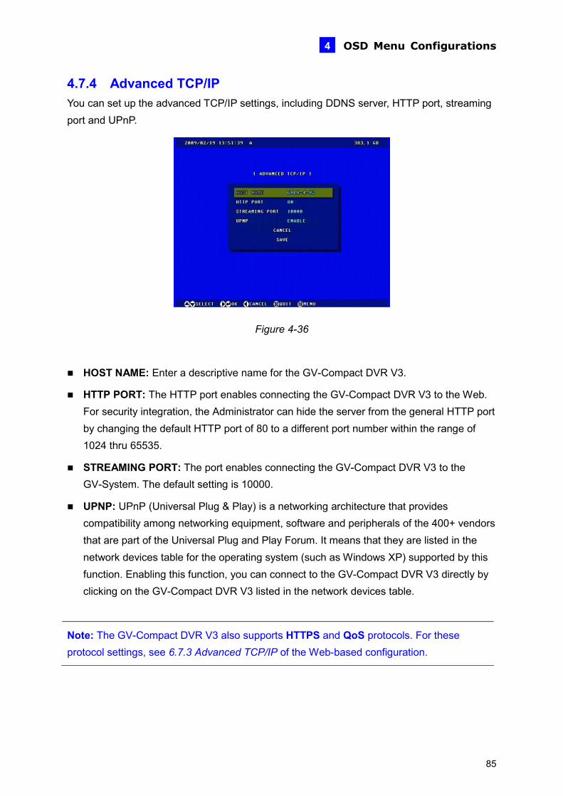
OSD Menu Configurations 4
4.7.4 Advanced TCP/IP You can set up the advanced TCP/IP settings, including DDNS server, HTTP port, streaming port and UPnP.
Figure 4-36
HOST NAME: Enter a descriptive name for the GV-Compact DVR V3.
HTTP PORT: The HTTP port enables connecting the GV-Compact DVR V3 to the Web. For security integration, the Administrator can hide the server from the general HTTP port by changing the default HTTP port of 80 to a different port number within the range of 1024 thru 65535.
STREAMING PORT: The port enables connecting the GV-Compact DVR V3 to the GV-System. The default setting is 10000.
UPNP: UPnP (Universal Plug & Play) is a networking architecture that provides compatibility among networking equipment, software and peripherals of the 400+ vendors that are part of the Universal Plug and Play Forum. It means that they are listed in the network devices table for the operating system (such as Windows XP) supported by this function. Enabling this function, you can connect to the GV-Compact DVR V3 directly by clicking on the GV-Compact DVR V3 listed in the network devices table.
Note: The GV-Compact DVR V3 also supports HTTPS and QoS protocols. For these protocol settings, see 6.7.3 Advanced TCP/IP of the Web-based configuration.
85
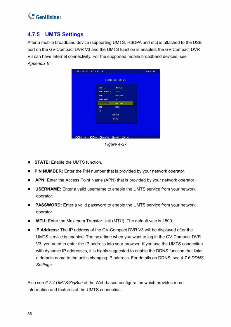
4.7.5 UMTS Settings After a mobile broadband device (supporting UMTS, HSDPA and etc) is attached to the USB port on the GV-Compact DVR V3 and the UMTS function is enabled, the GV-Compact DVR V3 can have Internet connectivity. For the supported mobile broadband devices, see Appendix B.
Figure 4-37
STATE: Enable the UMTS function.
PIN NUMBER: Enter the PIN number that is provided by your network operator.
APN: Enter the Access Point Name (APN) that is provided by your network operator.
USERNAME: Enter a valid username to enable the UMTS service from your network operator.
PASSWORD: Enter a valid password to enable the UMTS service from your network operator.
MTU: Enter the Maximum Transfer Unit (MTU). The default vale is 1500.
IP Address: The IP address of the GV-Compact DVR V3 will be displayed after the UMTS service is enabled. The next time when you want to log in the GV-Compact DVR V3, you need to enter the IP address into your browser. If you use the UMTS connection with dynamic IP addresses, it is highly suggested to enable the DDNS function that links a domain name to the unit’s changing IP address. For details on DDNS, see 4.7.6 DDNS Settings.
Also see 6.7.4 UMTS/ZigBee of the Web-based configuration which provides more information and features of the UMTS connection.
86
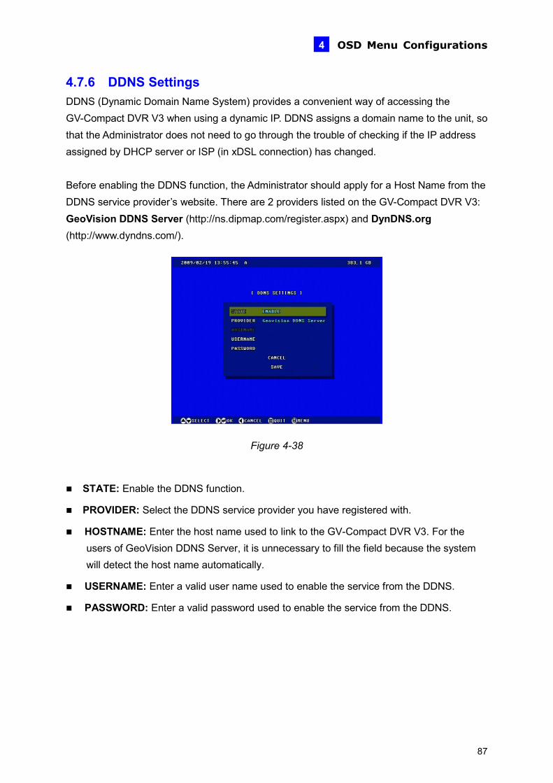
OSD Menu Configurations 4
4.7.6 DDNS Settings DDNS (Dynamic Domain Name System) provides a convenient way of accessing the GV-Compact DVR V3 when using a dynamic IP. DDNS assigns a domain name to the unit, so that the Administrator does not need to go through the trouble of checking if the IP address assigned by DHCP server or ISP (in xDSL connection) has changed. Before enabling the DDNS function, the Administrator should apply for a Host Name from the DDNS service provider’s website. There are 2 providers listed on the GV-Compact DVR V3: GeoVision DDNS Server (http://ns.dipmap.com/register.aspx) and DynDNS.org (http://www.dyndns.com/).
Figur 38
ry to fill the field because the system
PASSWORD: Enter a valid password used to enable the service from the DDNS.
e 4-
STATE: Enable the DDNS function.
PROVIDER: Select the DDNS service provider you have registered with.
HOSTNAME: Enter the host name used to link to the GV-Compact DVR V3. For the users of GeoVision DDNS Server, it is unnecessawill detect the host name automatically.
USERNAME: Enter a valid user name used to enable the service from the DDNS.
87

4.7.7 Multicast Settings Note the Multicast function is only supported on the four-channel GV-Compact DVR V3. You can enable either Multicast or RTSP; the two protocols cannot function at the same time. The multicast provides a mechanism for sending a single video and audio stream to a group of hosts. Only the hosts that have joined a multicast group can send and receive the multicast streams. The multicast streams are only sent to the hosts on a local network.
Figure 4-39
STATE: Enable the Multicast function.
HOST NAME: Name the GV-Compact DVR V3 in a multicast group.
INFO UPDATE PERIOD: Enter the time length between each update of multicast streams.
DATA IP: Enter the IP address used for multicasting. The default IP address is 224.1.1.2.
DATA PORT: Enter the port used for multicasting. The default value is 8300.
MULTICAST VIDEO: Select the camera to send its video through multicasting.
MULTICAST AUDIO: Select the audio to send its audio through multicasting.
ENCRYPTION KEY: Enter an Encryption Key to secure multicast streams. The hosts in the multicast group will need to enter the Key to access the video and audio streams.
AUDIO CALLBACK: Enable this option to receive audio broadcasting from the hosts in the multicast group. Specify the IP address and port number to receive the audio broadcast. The default IP address is 224.1.1.3 and port number is 8400.
Also see 6.7.5 Multicast of the Web-based configuration which provides more information and features of the Multicast function.
88
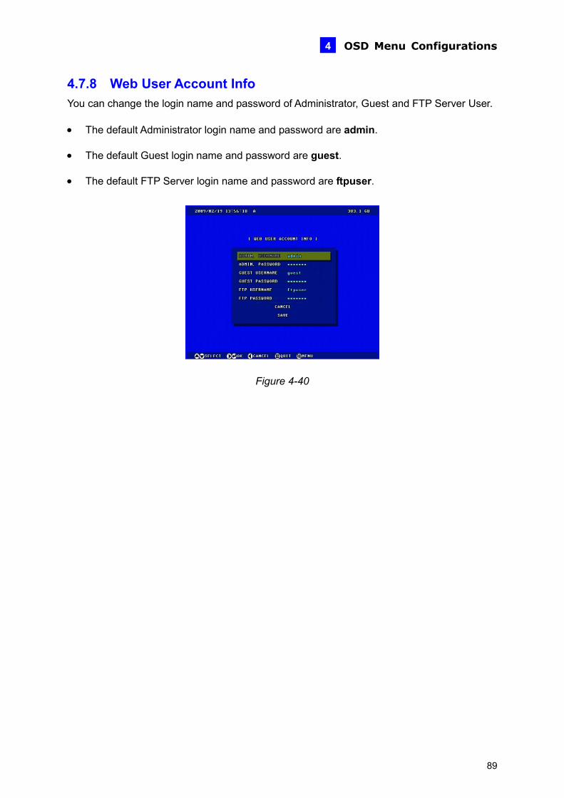
OSD Menu Configurations 4
4.7.8 Web User Account Info You can change the login name and password of Administrator, Guest and FTP Server User.
• The default Administrator login name and password are admin.
• The default Guest login name and password are guest.
• The default FTP Server login name and password are ftpuser.
Figur 40
e 4-
89
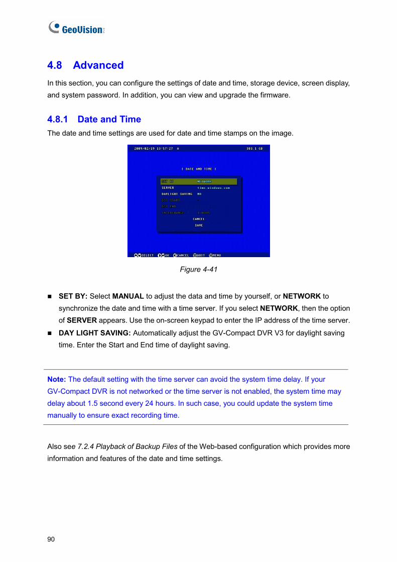
4.8 Advanced In this section, you can configure the settings of date and time, storage device, screen display, and system password. In addition, you can view and upgrade the firmware.
4.8.1 Date and Time The date and time settings are used for date and time stamps on the image.
Figure 4-41
SET BY: Select MANUAL to adjust the data and time by yourself, or NETWORK to synchronize the date and time with a time server. If you select NETWORK, then the option of SERVER appears. Use the on-screen keypad to enter the IP address of the time server.
DAY LIGHT SAVING: Automatically adjust the GV-Compact DVR V3 for daylight saving time. Enter the Start and End time of daylight saving.
Note: The default setting with the time server can avoid the system time delay. If your GV-Compact DVR is not networked or the time server is not enabled, the system time may delay about 1.5 second every 24 hours. In such case, you could update the system time manually to ensure exact recording time.
Also see 7.2.4 Playback of Backup Files of the Web-based configuration which provides more information and features of the date and time settings.
90

OSD Menu Configurations 4
4.8.2 Firmware Settings GeoVision will periodically release the updated firmware on the website. The new firmware can be simply loaded into the GV-Compact DVR V3 by using a USB storage device. For the details on upgrading the unit over the network, see Chapter 8 Advanced Applications.
Figure 4-42
Note: The time for different USB storage devices to be recognized may vary.
91
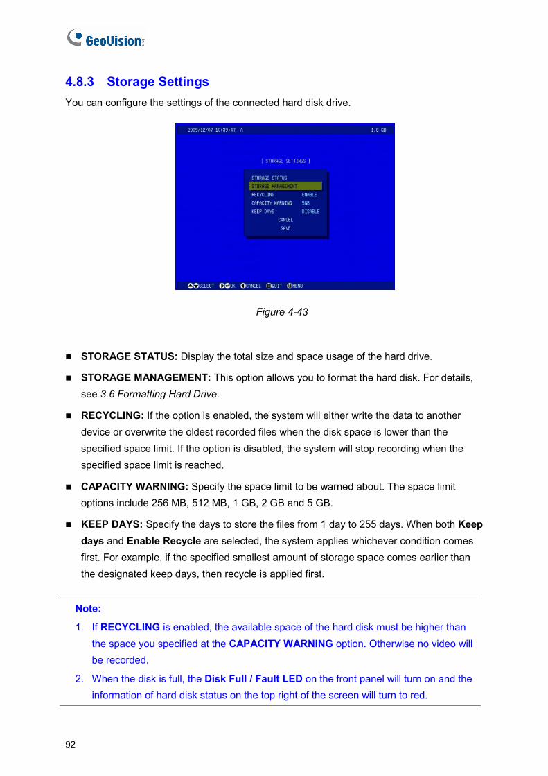
4.8.3 Storage Settings You can configure the settings of the connected hard disk drive.
Figure 4-43
STORAGE STATUS: Display the total size and space usage of the hard drive.
STORAGE MANAGEMENT: This option allows you to format the hard disk. For details, see 3.6 Formatting Hard Drive.
RECYCLING: If the option is enabled, the system will either write the data to another device or overwrite the oldest recorded files when the disk space is lower than the specified space limit. If the option is disabled, the system will stop recording when the specified space limit is reached.
CAPACITY WARNING: Specify the space limit to be warned about. The space limit options include 256 MB, 512 MB, 1 GB, 2 GB and 5 GB.
KEEP DAYS: Specify the days to store the files from 1 day to 255 days. When both Keep days and Enable Recycle are selected, the system applies whichever condition comes first. For example, if the specified smallest amount of storage space comes earlier than the designated keep days, then recycle is applied first.
Note:
1. If RECYCLING is enabled, the available space of the hard disk must be higher than the space you specified at the CAPACITY WARNING option. Otherwise no video will be recorded.
2. When the disk is full, the Disk Full / Fault LED on the front panel will turn on and the information of hard disk status on the top right of the screen will turn to red.
92
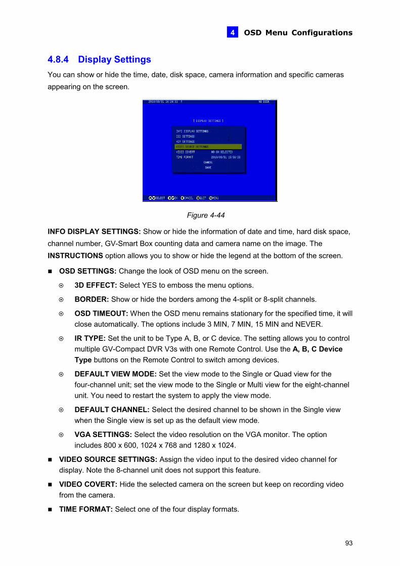
OSD Menu Configurations 4
4.8.4 Display Settings You can show or hide the time, date, disk space, camera information and specific cameras appearing on the screen.
Figure 4-44
INFO DISPLAY SETTINGS: Show or hide the information of date and time, hard disk space, channel number, GV-Smart Box counting data and camera name on the image. The INSTRUCTIONS option allows you to show or hide the legend at the bottom of the screen.
OSD SETTINGS: Change the look of OSD menu on the screen.
3D EFFECT: Select YES to emboss the menu options.
BORDER: Show or hide the borders among the 4-split or 8-split channels.
OSD TIMEOUT: When the OSD menu remains stationary for the specified time, it will close automatically. The options include 3 MIN, 7 MIN, 15 MIN and NEVER.
IR TYPE: Set the unit to be Type A, B, or C device. The setting allows you to control multiple GV-Compact DVR V3s with one Remote Control. Use the A, B, C Device Type buttons on the Remote Control to switch among devices.
DEFAULT VIEW MODE: Set the view mode to the Single or Quad view for the four-channel unit; set the view mode to the Single or Multi view for the eight-channel unit. You need to restart the system to apply the view mode.
DEFAULT CHANNEL: Select the desired channel to be shown in the Single view when the Single view is set up as the default view mode.
VGA SETTINGS: Select the video resolution on the VGA monitor. The option includes 800 x 600, 1024 x 768 and 1280 x 1024.
VIDEO SOURCE SETTINGS: Assign the video input to the desired video channel for display. Note the 8-channel unit does not support this feature.
VIDEO COVERT: Hide the selected camera on the screen but keep on recording video from the camera.
TIME FORMAT: Select one of the four display formats.
93
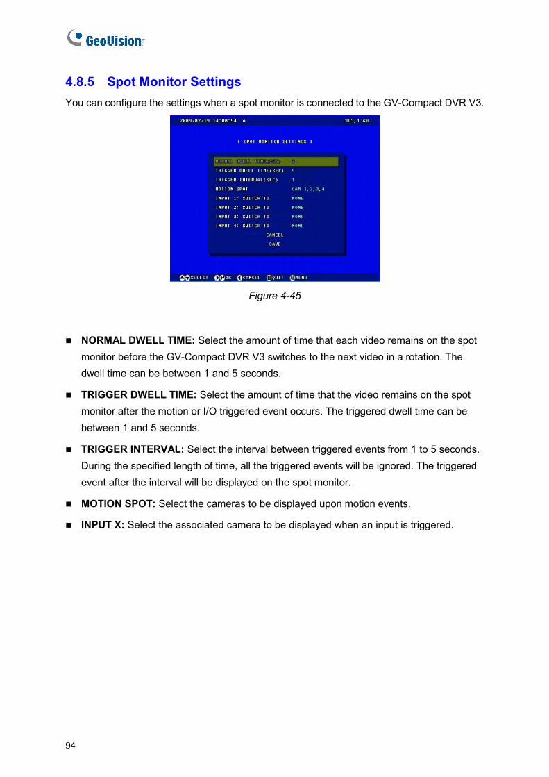
4.8.5 Spot Monitor Settings You can configure the settings when a spot monitor is connected to the GV-Compact DVR V3.
Figure 4-45
NORMAL DWELL TIME: Select the amount of time that each video remains on the spot monitor before the GV-Compact DVR V3 switches to the next video in a rotation. The dwell time can be between 1 and 5 seconds.
TRIGGER DWELL TIME: Select the amount of time that the video remains on the spot monitor after the motion or I/O triggered event occurs. The triggered dwell time can be between 1 and 5 seconds.
TRIGGER INTERVAL: Select the interval between triggered events from 1 to 5 seconds. During the specified length of time, all the triggered events will be ignored. The triggered event after the interval will be displayed on the spot monitor.
MOTION SPOT: Select the cameras to be displayed upon motion events.
INPUT X: Select the associated camera to be displayed when an input is triggered.
94
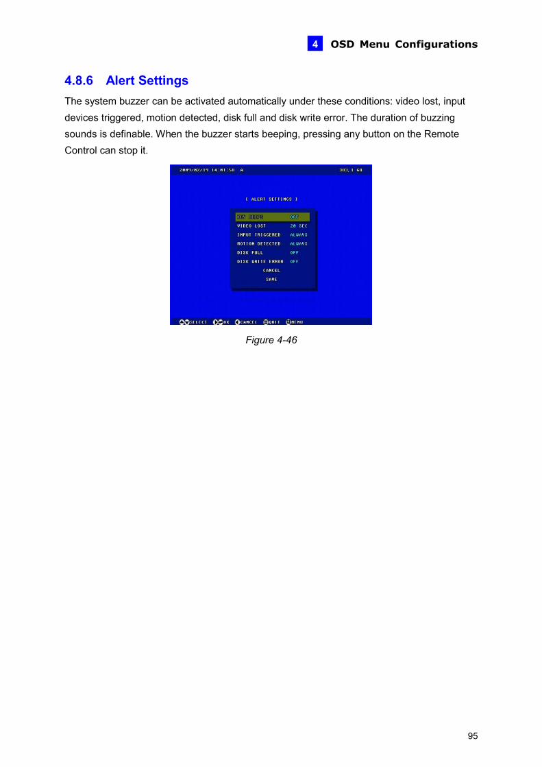
OSD Menu Configurations 4
4.8.6 Alert Settings The system buzzer can be activated automatically under these conditions: video lost, input devices triggered, motion detected, disk full and disk write error. The duration of buzzing sounds is definable. When the buzzer starts beeping, pressing any button on the Remote Control can stop it.
Figure 4-46
95
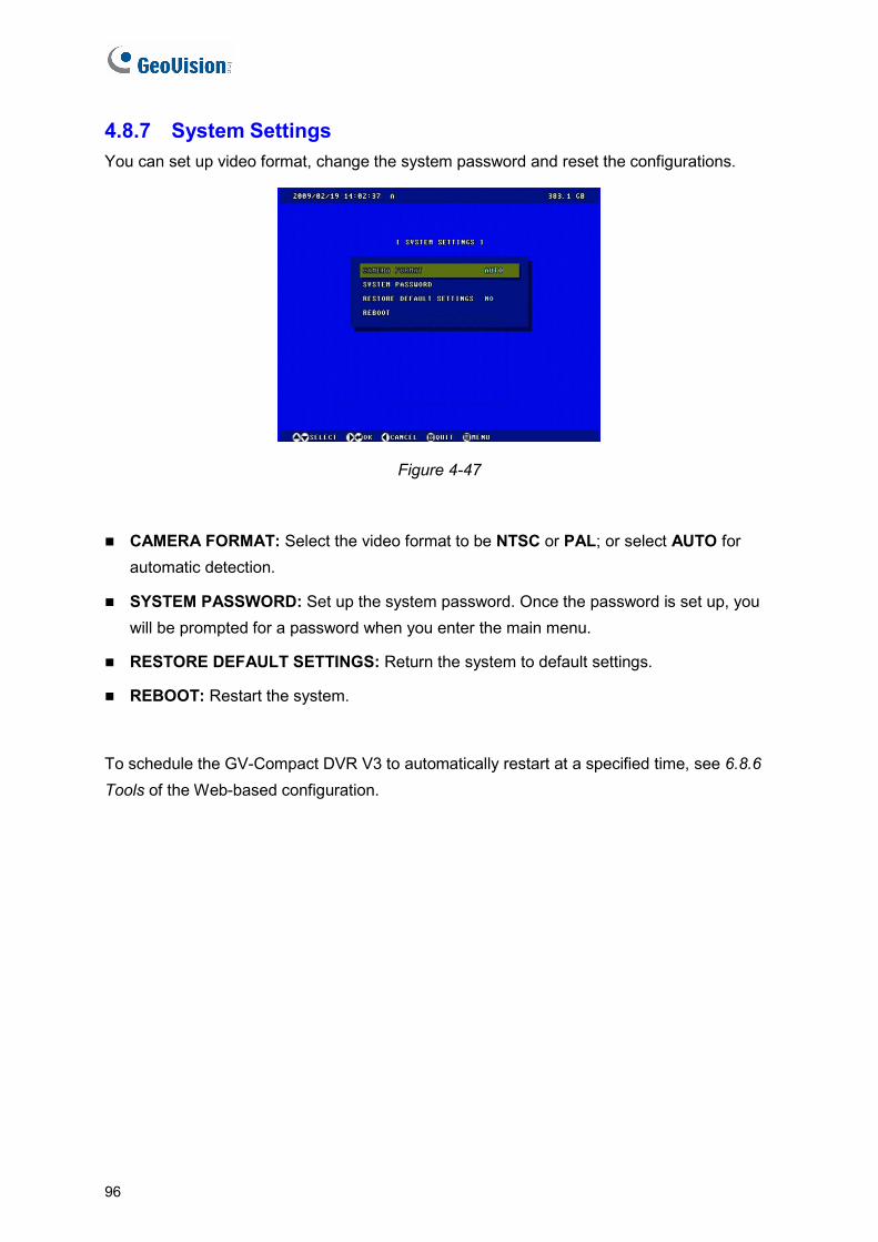
4.8.7 System Settings You can set up video format, change the system password and reset the configurations.
Figure 4-47
CAMERA FORMAT: Select the video format to be NTSC or PAL; or select AUTO for automatic detection.
SYSTEM PASSWORD: Set up the system password. Once the password is set up, you will be prompted for a password when you enter the main menu.
RESTORE DEFAULT SETTINGS: Return the system to default settings.
REBOOT: Restart the system.
To schedule the GV-Compact DVR V3 to automatically restart at a specified time, see 6.8.6 Tools of the Web-based configuration.
96
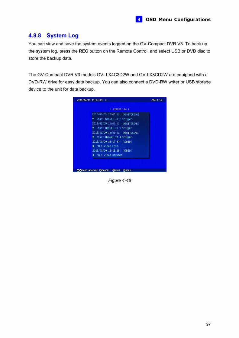
OSD Menu Configurations 4
4.8.8 System Log You can view and save the system events logged on the GV-Compact DVR V3. To back up the system log, press the REC button on the Remote Control, and select USB or DVD disc to store the backup data.
The GV-Compact DVR V3 models GV- LX4C3D2W and GV-LX8CD2W are equipped with a DVD-RW drive for easy data backup. You can also connect a DVD-RW writer or USB storage device to the unit for data backup.
Figure 4-48
97
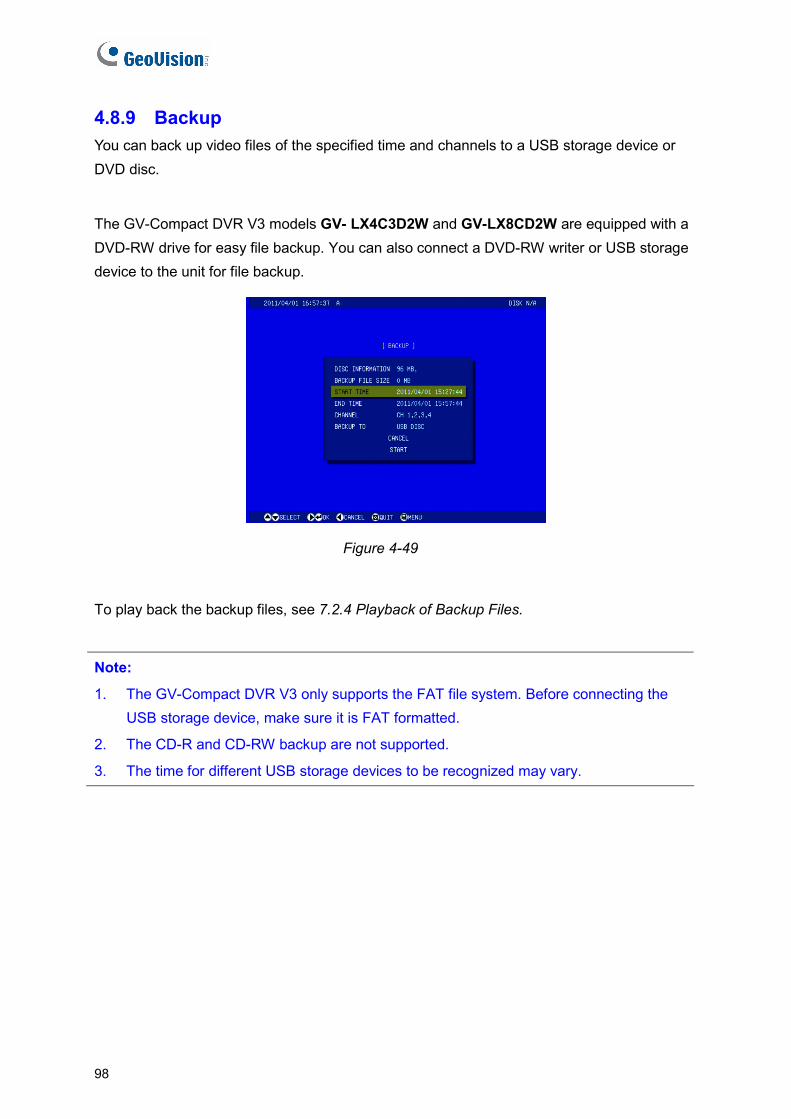
98
4.8.9 Backup You can back up video files of the specified time and channels to a USB storage device or DVD disc.
The GV-Compact DVR V3 models GV- LX4C3D2W and GV-LX8CD2W are equipped with a DVD-RW drive for easy file backup. You can also connect a DVD-RW writer or USB storage device to the unit for file backup.
Figure 4-49
To play back the backup files, see 7.2.4 Playback of Backup Files.
Note:
1. The GV-Compact DVR V3 only supports the FAT file system. Before connecting the USB storage device, make sure it is FAT formatted.
2. The CD-R and CD-RW backup are not supported.
3. The time for different USB storage devices to be recognized may vary.
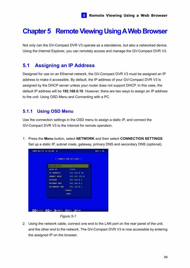
Remote Viewing Using a Web Browser 5
Chapter 5 Remote Viewing Using A Web Browser
rked device. Using the Internet Explorer, you can remotely access and manage the GV-Compact DVR V3.
assigned an IP VR V3 is
r does not support DHCP. In this case, the default IP address will be 192.168.0.10. However, there are two ways to assign an IP address
and Connecting with a PC.
5.1.1 Using OSD Menu
ct the
1. Press the Menu button, select NETWORK and then select CONNECTION SETTINGS. Set up a static IP, subnet mask, gateway, primary DNS and secondary DNS (optional).
Not only can the GV-Compact DVR V3 operate as a standalone, but also a netwo
5.1 Assigning an IP Address Designed for use on an Ethernet network, the GV-Compact DVR V3 must beaddress to make it accessible. By default, the IP address of your GV-Compact Dassigned by the DHCP server unless your route
to the unit: Using OSD Menu
Use the connection settings in the OSD menu to assign a static IP, and conneGV-Compact DVR V3 to the Internet for remote operation.
Figure 5-1
2. Using the network cable, connect one end to the LAN port on the rear panel of the unit, and the other end to the network. The GV-Compact DVR V3 is now accessible by entering the assigned IP on the browser.
99

5.1.2 Connecting with a PC
omputer on the same LAN with the GV-Compact DVR V3 to check and assign the IP address.
eb interface.
VD.
Note: The PC installed with GV-IP Device Utility must be under the same LAN with the
Use a c
5.1.2.1 Checking the IP Address
Follow the steps below to look up the IP address and access the W
1. Install the GV-IP Device Utility program included on the Software CD/D
GV-Compact DVR V3 you wish to configure.
2. On the GV-IP Utility window, click the button to search for the IP devices connected in the same LAN. Click the Name or Mac Address column to sort.
Figure 5-2
3. Find the unit with its Mac Address to see the IP address.
4. To login, type the IP address in your web browser. A login dialog box appears.
5. Type the default username and password admin.
6. Click OK to access the Web interface.
100
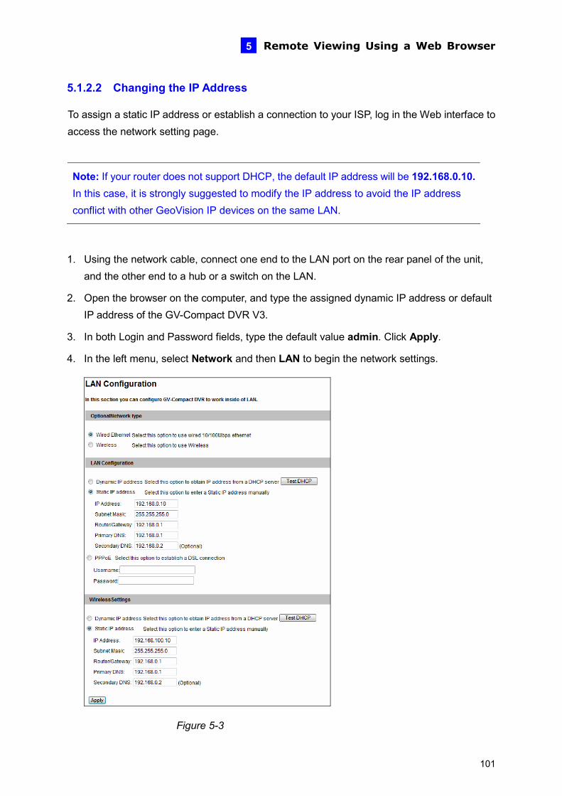
Remote Viewing Using a Web Browser 5
5.1.2.2 Changing the IP Address
s or establish a connection to your ISP, log in the Web interface to access the network setting page.
fault IP address will be 192.168.0.10. In this case, it is strongly suggested to modify the IP address to avoid the IP address conflict with other GeoVision IP devices on the same LAN.
To assign a static IP addres
Note: If your router does not support DHCP, the de
1. Using the network cable, connect one end to the LAN port on the rear paneand the other end to a hub or a sw
l of the unit, itch on the LAN.
ic IP address or default
3. In both Login and Password fields, type the default value admin. Click Apply.
4. In the left menu, select Network and then LAN to begin the network settings.
2. Open the browser on the computer, and type the assigned dynamIP address of the GV-Compact DVR V3.
Figure 5-3
101

5. To assign a static IP address, select Static IP address. Type IP Address, Subnet Mask,
blish a connection to your ISP, select Use PPPoE, and type the username and
V-Compact DVR V3 is now accessible by entering the assigned IP wser.
e 6.7.1 LAN.
-Compact DVR V3 will get from the ISP. Otherwise, you must use the Dynamic DNS service to obtain a
s first. For .7.3 Advanced TCP/IP.
2. If PPPoE is enabled and you cannot access the unit, you may have to reset it to the factory default settings and then perform the network settings again. To restore the factory settings, see the Reset button in 2.1 Front Panel.
Router/Gateway, Primary DNS and Secondary DNS.
6. To estapassword.
7. Click Apply. The Gaddress on the bro
For details, se
IMPORTANT:
1. PPPoE should only be enabled if you know which IP address the GV
domain name linked to the GV-Compact DVR V3’s changing IP addresdetails on Dynamic DNS Server settings, see 6
102
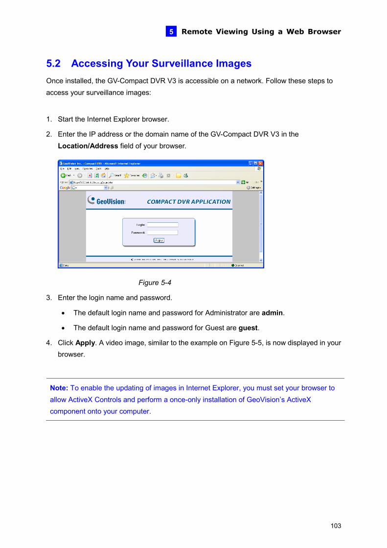
Remote Viewing Using a Web Browser 5
5.2 Accessing Your Surveillance Images pact DVR V3 is accessible on a network. Follow these steps to
access your surveillance images:
2. Enter the IP address or the domain name of the GV-Compact DVR V3 in the Location/Address field of your browser.
Once installed, the GV-Com
1. Start the Internet Explorer browser.
• The default login name and password for Administrator are admin.
• The default login name and password for Guest are guest.
now displayed in your
Note: To enable the updating of images in Internet Explorer, you must set your browser to allow ActiveX Controls and perform a once-only installation of GeoVision’s ActiveX component onto your computer.
Figure 5-4
3. Enter the login name and password.
4. Click Apply. A video image, similar to the example on Figure 5-5, isbrowser.
103
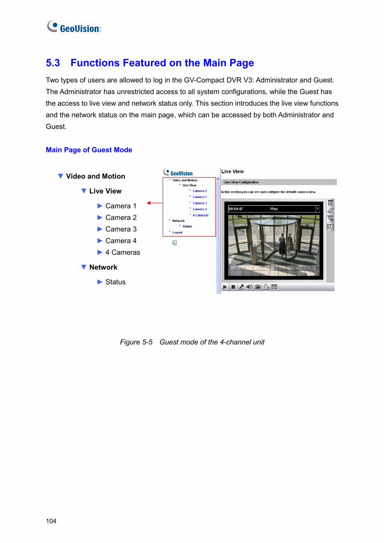
104
5.3 Functions Featured on the Main Page tor and Guest.
Guest has view functions
and the network status on the main page, which can be accessed by both Administrator and
M Mode
▼ Vide
▼
raa 2
Camera 3 mera 4
► 4 Cameras
▼ Network
► Status
Two types of users are allowed to log in the GV-Compact DVR V3: AdministraThe Administrator has unrestricted access to all system configurations, while thethe access to live view and network status only. This section introduces the live
Guest.
ain Page of Guest
o and Motion
Live View
► Came 1 ► Camer► ► Ca
Figure 5-5 Guest mode of the 4-channel unit
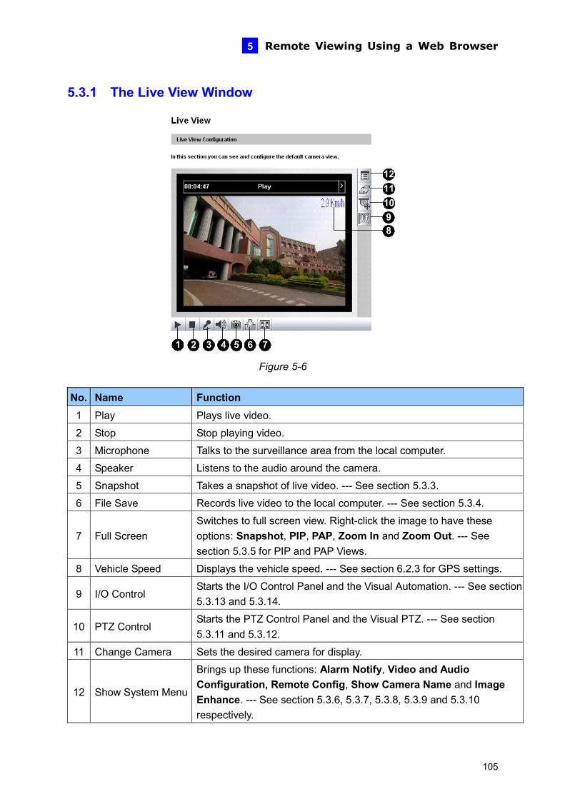
Remote Viewing Using a Web Browser 5
5.3.1 The Live View Window
1110
1 2 3 4 5 6 7
89
12
Figure 5-6
. NameNo Function 1 Play Plays live video.
2 Stop Stop playing video.
3 Microphone ter. Talks to the surveillance area from the local compu
4 Speaker Listens to the audio around the camera.
5 Snapshot Takes a snapshot of live video. --- See section 5.3.3.
6 File Save 5.3.4. Records live video to the local computer. --- See section
7 Full Screen full screen view. Right-click the image to have these
Out. --- See .5 for PIP and PAP Views.
Switches tooptions: Snapshot, PIP, PAP, Zoom In and Zoomsection 5.3
8 .3 for GPS settings. Vehicle Speed Displays the vehicle speed. --- See section 6.2
Starts the I/O Control Panel and the Visual Automation.5.3.13 and 5.3.14.
--- See section 9 I/O Control
10 PTZ Control the PTZ Control Panel and the Visual PTZ. --- See section
5.3.11 and 5.3.12. Starts
11 Change Camera Sets the desired camera for display.
12 Show System Menu
Brings up these functions: Alarm Notify, Video and Audio Configuration, Remote Config, Show Camera Name and Image Enhance. --- See section 5.3.6, 5.3.7, 5.3.8, 5.3.9 and 5.3.10 respectively.
105
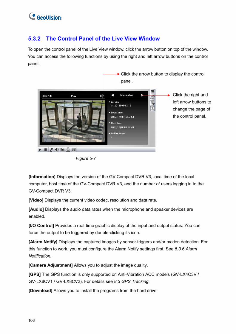
106
5.3.2 The Control Panel of the Live View Window
of the window. can access the following functions by using the right and left arrow buttons on the control
panel.
To open the control panel of the Live View window, click the arrow button on top You
Click the arrow button to display the control panel.
Click tleft
he right and arrow buttons to
change the page of the control panel.
Figure 5-7
Displays the version of the GV-Compact DVR V3, local time of the local s logging in to the
ta rate.
es are
the input and output status. You can force the output to be triggered by double-clicking its icon.
or triggers and/or motion detection. For ttings first. See 5.3.6 Alarm
Notification.
[Camera Adjustment] Allows you to adjust the image quality.
[GPS] The GPS function is only supported on Anti-Vibration ACC models (GV-LX4C3V / GV-LX8CV1 / GV-LX8CV2). For details see 8.3 GPS Tracking.
[Download] Allows you to install the programs from the hard drive.
[Information]computer, host time of the GV-Compact DVR V3, and the number of userGV-Compact DVR V3.
[Video] Displays the current video codec, resolution and da
[Audio] Displays the audio data rates when the microphone and speaker devicenabled.
[I/O Control] Provides a real-time graphic display of
[Alarm Notify] Displays the captured images by sensthis function to work, you must configure the Alarm Notify se

Remote Viewing Using a Web Browser 5
5.3.3 Snapshot of a Live Video
o take a snapshot of live video, follow these steps:
ppears.
2. Specify Save in, type the File name, and select JPEG or BMP as Save as Type. You e stamps on the image.
3. Click the Save button to save the image in the local computer.
.3.4 Video Recording
uter.
gure 5-6). The Save As dialog box appears.
e Time Period scroll bar to specify the time length of the video clip from 1 to 5 minutes.
3. Click the Save button to start recording.
4. To stop recording, click the Stop button (No. 2, Figure 5-6).
T
1. Click the Snapshot button (No. 5, Figure 5-6). The Save As dialog box a
may also choose whether to display the name and dat
5
You can record live video for a certain period of time to your local comp
1. Click the File Save button (No. 6, Fi
2. Specify Save in, type the File name, and move th
107
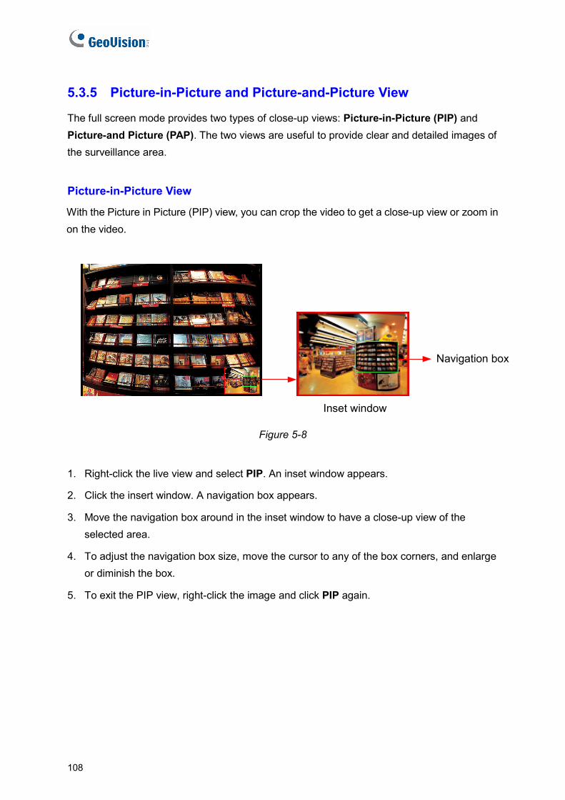
5.3.5 Picture-in-Picture and Picture-and-Picture View
IP) and (PAP). The two views are useful to provide clear and detailed images of
rveillance area.
ith the Picture in Picture (PIP) view, you can crop the video to get a close-up view or zoom in on the video.
The full screen mode provides two types of close-up views: Picture-in-Picture (PPicture-and Picturethe su
Picture-in-Picture View
W
Inset window
Navigation box
re 5-8
2 indow. A navigation box appears.
o have a close-up view of the selected area.
4. To adjust the navigation box size, move the cursor to any of the box corners, and enlarge or diminish the box.
5. To exit the PIP view, right-click the image and click PIP again.
Figu
1. Right-click the live view and select PIP. An inset window appears.
. Click the insert w
3. Move the navigation box around in the inset window t
108
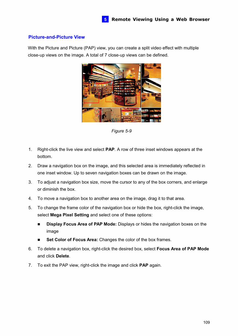
Remote Viewing Using a Web Browser 5
Picture-and-Picture View
video effect with multiple close-up views on the image. A total of 7 close-up views can be defined. With the Picture and Picture (PAP) view, you can create a split
Figure 5-9
1. Right-click the live view and select PAP. A row of three inset windows appears at the
ion box on the image, and this selected area is immediately reflected in n the image.
rs, and enlarge or diminish the box.
e a navigation box to another area on the image, drag it to that area.
box, right-click the image,
Focus Area of PAP Mode: Displays or hides the navigation boxes on the
Set Color of Focus Area: Changes the color of the box frames.
6. To delete a navigation box, right-click the desired box, select Focus Area of PAP Mode and click Delete.
7. To exit the PAP view, right-click the image and click PAP again.
bottom.
2. Draw a navigatone inset window. Up to seven navigation boxes can be drawn o
3. To adjust a navigation box size, move the cursor to any of the box corne
4. To mov
5. To change the frame color of the navigation box or hide the select Mega Pixel Setting and select one of these options:
Displayimage
109
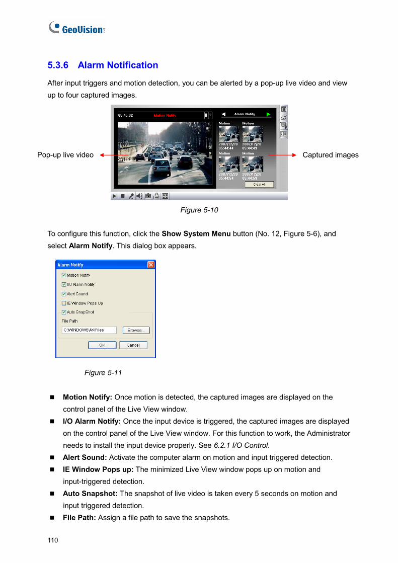
10
5.3.6 Alarm Notification
motion detection, you can be alerted by a pop-up live video and view up to four captured images. After input triggers and
Figure 5-10
To configure this function, click the Show System Menu button (No. 12, Figure 5-6), and select Alarm Notify. This dialog box appears.
Figure 5-11
Motion Notify: Once motion is detected, the captured images are displayed on the
es are displayed f the Live View window. For this function to work, the Administrator
6.2.1 I/O Control. Alert Sound: Activate the computer alarm on motion and input triggered detection. IE Window Pops up: The minimized Live View window pops up on motion and
input-triggered detection. Auto Snapshot: The snapshot of live video is taken every 5 seconds on motion and
input triggered detection. File Path: Assign a file path to save the snapshots.
control panel of the Live View window. I/O Alarm Notify: Once the input device is triggered, the captured imag
on the control panel oneeds to install the input device properly. See
Pop-up live video Captured images
1
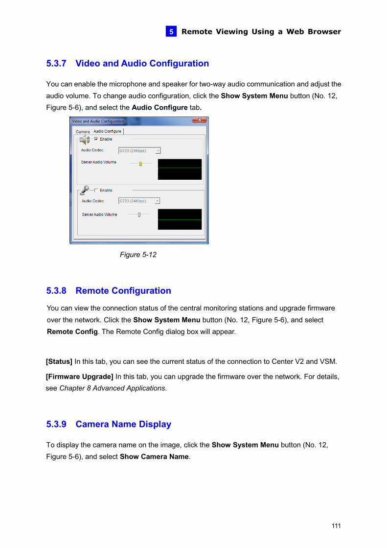
Remote Viewing Using a Web Browser 5
5.3.7 Video and Audio Configuration
and adjust the he Show System Menu button (No. 12,
Figure 5-6), and select the Audio Configure tab.
You can enable the microphone and speaker for two-way audio communicationaudio volume. To change audio configuration, click t
Figure 5-12
ade firmware t
fig dialog box will appear.
e current status of the connection to Center V2 and VSM.
[Firmware Upgrade] In this tab, you can upgrade the firmware over the network. For details,
5.3.9 Camera Name Display
To display the camera name on the image, click the Show System Menu button (No. 12, Figure 5-6), and select Show Camera Name.
5.3.8 Remote Configuration
You can view the connection status of the central monitoring stations and upgrover the network. Click the Show System Menu button (No. 12, Figure 5-6), and selecRemote Config. The Remote Con
[Status] In this tab, you can see th
see Chapter 8 Advanced Applications.
111
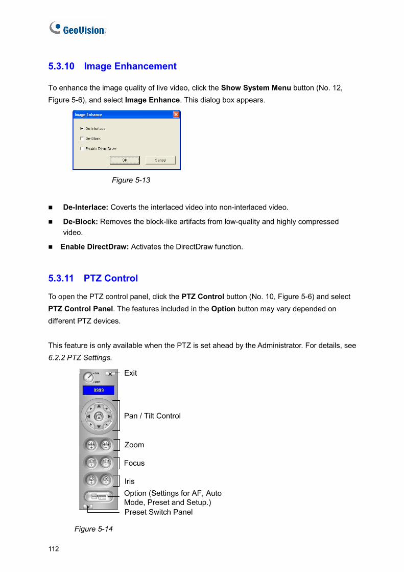
5.3.10 Image Enhancement
w System Menu button (No. 12, Figure 5-6), and select Image Enhance. This dialog box appears. To enhance the image quality of live video, click the Sho
Figure 5-13
o non-interlaced video.
De-Block: Removes the block-like artifacts from low-quality and highly compressed video.
Activates the DirectDraw function.
ntrol
) and select nel. The features included in the Option button may vary depended on
different PTZ devices. This feature is only available when the PTZ is set ahead by the Administrator. For details, see 6.2.2 PTZ Settings.
De-Interlace: Coverts the interlaced video int
Enable DirectDraw:
5.3.11 PTZ Co
To open the PTZ control panel, click the PTZ Control button (No. 10, Figure 5-6PTZ Control Pa
Pan / Tilt Control
Zoom
Focus
Exit
Option (Settings for AF, Auto Mode, Preset and Setup.)Preset Switch Panel
Iris
Figure 5-14
112

Remote Viewing Using a Web Browser 5
5.3.12 Visual PTZ
l on the image. nly available when the PTZ is set ahead by the Administrator. For details, see
6.2.2 PTZ Settings.
In additional to the PTZ control panel, you can display a visual PTZ control paneThis feature is o
Figure 5-15
eature, click the PTZ Control button (No. 10, Figure 5-6) and select
corner. You will
ntrol Type]
irections, i.e. pear. Click and hold
e required level of movement and the camera will move as per the specific
mode with the mouse click, the PTZ control panel will appear. The movement of the camera will depend on the speed of the mouse movement.
[Configure]
Set Color: Changes the color of the panel. Three kinds of colors are available: Red, Green and Blue.
Transparent Degree: Adjusts the transparency level of the panel. Ten levels range from 10% (fully transparent) to 100% (fully opaque).
To access this fVisual PTZ.
To change the panel settings, click the green PTZ button on the top lefthave these options: [PTZ Co
Type 1: In this mode when you place the mouse arrow on the four dnorth, south, east, west, the speed indicator of five levels will apon thspeed.
Type 2: In this
113
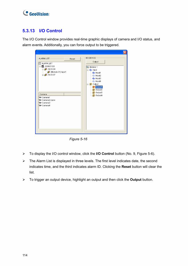
5.3.
provides real-time graphic displays of camera and I/O status, and
13 I/O Control
The I/O Control windowalarm events. Additionally, you can force output to be triggered.
Figure 5-16
ure 5-6).
e Alarm List is displayed in three levels. The first level indicates date, the second ill clear the
list.
To trigger an output device, highlight an output and then click the Output button.
To display the I/O control window, click the I/O Control button (No. 9, Fig
Thindicates time, and the third indicates alarm ID. Clicking the Reset button w
114
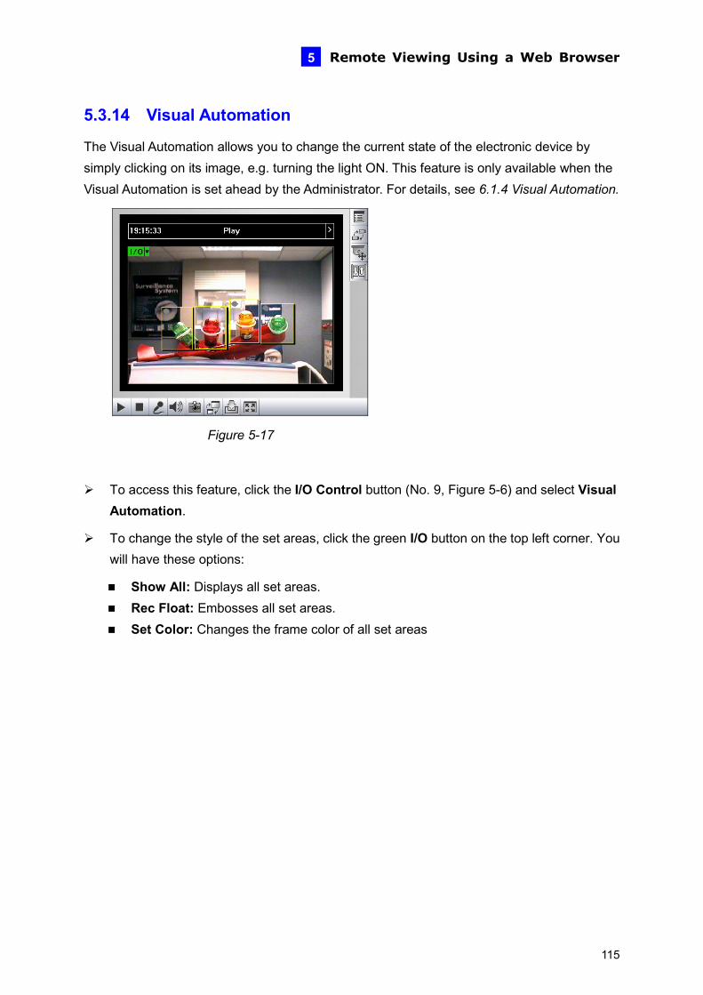
Remote Viewing Using a Web Browser 5
5.3.14 Visual Automation
device by ble when the
Visual Automation is set ahead by the Administrator. For details, see 6.1.4 Visual Automation.
The Visual Automation allows you to change the current state of the electronic simply clicking on its image, e.g. turning the light ON. This feature is only availa
Figure 5-17
ure, click the I/O Control button (No. 9, Figure 5-6) and select Visual
een I/O button on the top left corner. You will have these options:
Show All: Displays all set areas. Rec Float: Embosses all set areas. Set Color: Changes the frame color of all set areas
To access this featAutomation.
To change the style of the set areas, click the gr
115
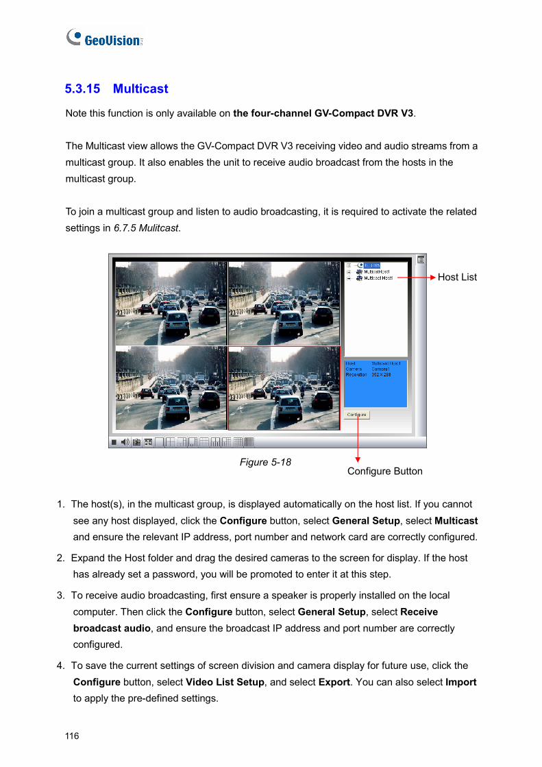
16
5.3.15 Multicast
Note this function is only available on the four-channel GV-Compact DVR V3.
dio streams from a multicast group. It also enables the unit to receive audio broadcast from the hosts in the
To join a multicast group and listen to audio broadcasting, it is required to activate the related settings in 6.7.5 Mulitcast.
The Multicast view allows the GV-Compact DVR V3 receiving video and au
multicast group.
Figure 5-18 Configure Button
Host List
1. The host(s), in the multicast group, is displayed automatically on the host list. If you cannot tup, select Multicast
rrectly configured.
2 he Host folder and drag the desired cameras to the screen for display. If the host
3. he local computer. Then click the Configure button, select General Setup, select Receive broadcast audio, and ensure the broadcast IP address and port number are correctly configured.
4. To save the current settings of screen division and camera display for future use, click the Configure button, select Video List Setup, and select Export. You can also select Import to apply the pre-defined settings.
see any host displayed, click the Configure button, select General Seand ensure the relevant IP address, port number and network card are co
. Expand thas already set a password, you will be promoted to enter it at this step.
To receive audio broadcasting, first ensure a speaker is properly installed on t
1
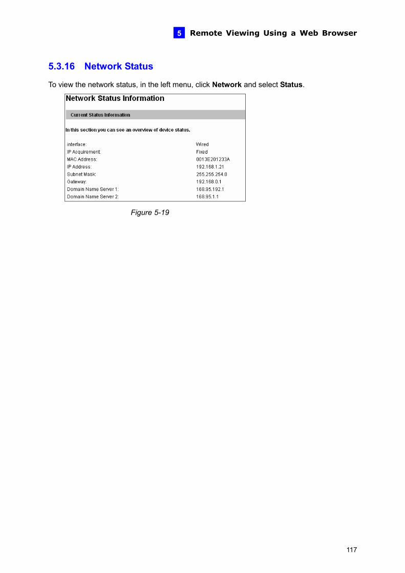
Remote Viewing Using a Web Browser
117
5
5.3.16 Network Status
To view the network status, in the left menu, click Network and select Status.
Figure 5-19
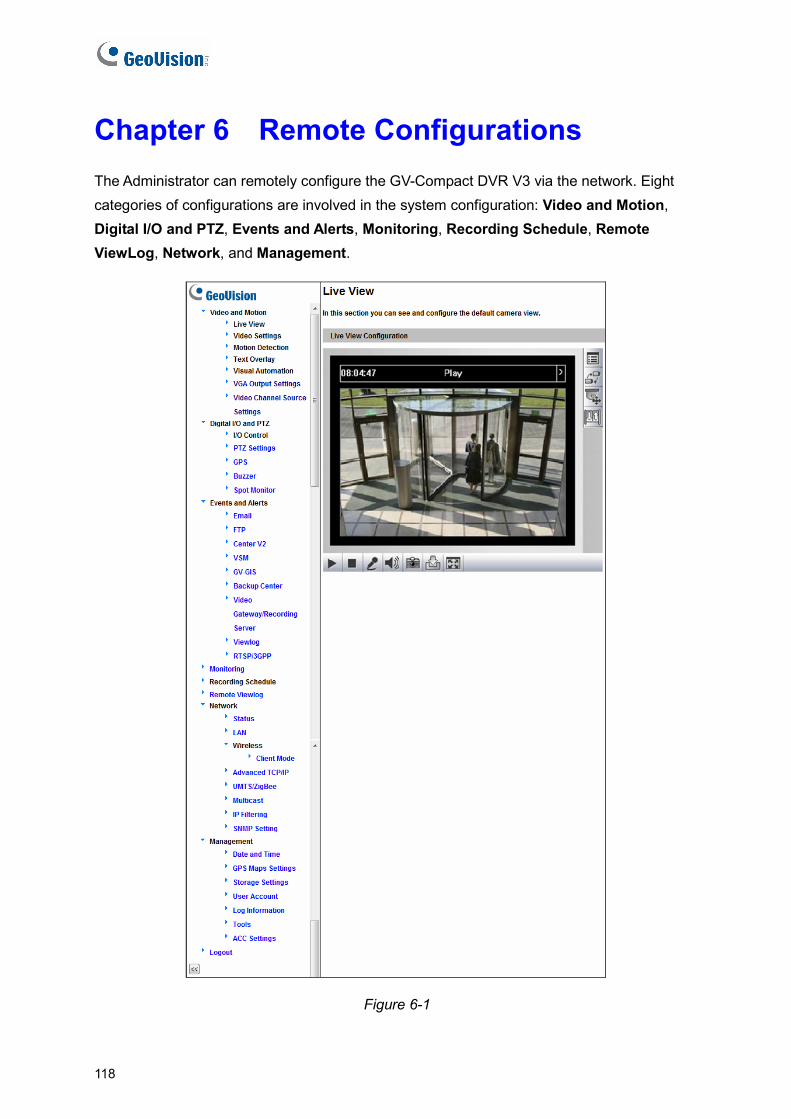
Chapter 6 Remote Configurations The Administrator can remotely configure the GV-Compact DVR V3 via the network. Eight categories of configurations are involved in the system configuration: Video and Motion, Digital I/O and PTZ, Events and Alerts, Monitoring, Recording Schedule, Remote ViewLog, Network, and Management.
Figure 6-1
118

Remote Configurations 6
List of Menu Options Find the topic of interest by referring to the section number prefixed to each option.
6.1 Video and Motion
6.1.1 Video Settings 6.1.2 Motion Detection 6.1.3 Text Overlay 6.1.4 Visual Automation 6.1.5 VGA Output Settings 6.1.6 Video Channel Source Settings
6.2 Digital I/O and PTZ
6.2.1 I/O Control 6.2.2 PTZ Settings 6.2.3 GPS 6.2.4 Buzzer 6.2.5 Spot Monitor
6.3 Events and Alerts
6.3.1 Email 6.3.2 FTP 6.3.3 Center V2 6.3.4 VSM 6.3.5 GV-GIS 6.3.6 Backup Center 6.3.7 Video Gateway / Recording Server 6.3.8 ViewLog 6.3.9 RTSP / 3GPP
6.4 Monitoring
6.5 Recording Schedule 6.5.1 Recording Schedule Settings 6.5.2 I/O Monitoring Settings
6.6 Remote Viewlog
6.7 Network
6.7.1 LAN 6.7.2 Wireless-Client Mode 6.7.3 Advanced TCP/IP 6.7.4 UMTS / ZigBee 6.7.5 Multicast 6.7.6 IP Filtering 6.7.7 SNMP Setting
6.8 Management
6.8.1 Date and Time Settings 6.8.2 GPS Maps Settings 6.8.3 Storage Settings 6.8.4 User Account 6.8.5 Log Information 6.8.6 Tools 6.8.7 ACC Settings
119

6.1 Video & Motion This section includes the video image settings and how the images can be managed by using Video Settings, Motion Detection, Text Overlay, Visual Automation and Video Channel Source Settings.
6.1.1 Video Settings
The Video Settings section allows you to configure the video source, resolution and the related options for the video stream. For each channel, the video stream is set to H.264 codec and can be configured up to 704 x 480 (for both four-channel and eight-channel models) in resolution.
120
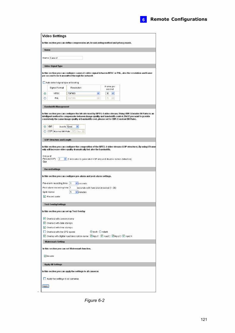
Remote Configurations 6
.
Figure 6-2
121
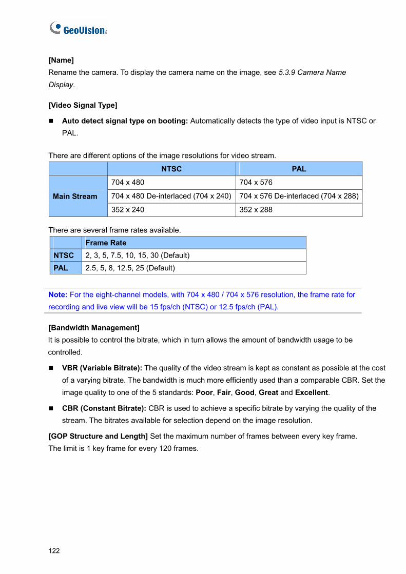
[Name] Rename the camera. To display the camera name on the image, see 5.3.9 Camera Name Display. [Video Signal Type]
Auto detect signal type on booting: Automatically detects the type of video input is NTSC or PAL.
There are different options of the image resolutions for video stream.
NTSC PAL
704 x 480 704 x 576
704 x 480 De-interlaced (704 x 240) 704 x 576 De-interlaced (704 x 288)Main Stream
352 x 240 352 x 288 There are several frame rates available.
Frame Rate NTSC 2, 3, 5, 7.5, 10, 15, 30 (Default)
PAL 2.5, 5, 8, 12.5, 25 (Default) Note: For the eight-channel models, with 704 x 480 / 704 x 576 resolution, the frame rate for recording and live view will be 15 fps/ch (NTSC) or 12.5 fps/ch (PAL). [Bandwidth Management] It is possible to control the bitrate, which in turn allows the amount of bandwidth usage to be controlled.
VBR (Variable Bitrate): The quality of the video stream is kept as constant as possible at the cost of a varying bitrate. The bandwidth is much more efficiently used than a comparable CBR. Set the image quality to one of the 5 standards: Poor, Fair, Good, Great and Excellent.
CBR (Constant Bitrate): CBR is used to achieve a specific bitrate by varying the quality of the stream. The bitrates available for selection depend on the image resolution.
[GOP Structure and Length] Set the maximum number of frames between every key frame. The limit is 1 key frame for every 120 frames.
122
Remote Configurations 6
[Record Settings] The record settings allow you to capture images before and/or after a motion and an I/O event happens.
Pre-alarm recording time: Activates video recording before an event occurs. Set the recording time to 1 or 2 seconds.
Post-alarm recording time: Activates video recording after an event occurs. Set the recording time from 1 to 30 seconds.
Split Interval: Sets the time length between each event file.
Record Audio: Activates audio recording when an event occurs.
[Text Overlay Settings] The settings allow you to display the related names and information on live view and recorded files.
Overlaid with camera name: Includes camera names in live and recorded videos.
Overlaid with date stamps: Includes date stamps in live and recorded videos.
Overlaid with time stamps: Includes time stamps in live and recorded videos.
Overlaid with the GPS data: Includes the vehicle speed in live and recorded videos. This function is only supported on Anti-Vibration ACC models (GV-LX4C3V / GV-LX8CV1 / GV-LX8CV2).
Overlaid with digital input description name: Includes the names of the selected inputs on live and recorded videos.
[Watermark Setting]
Enable: Enable this option to watermark all recordings. The watermark allows you to verify whether the video has been tampered while it was recorded and saved. See 8.5 Verifying Watermark.
[Apply All Settings]
Apply the settings to all cameras: Applies the same settings to other cameras.
123
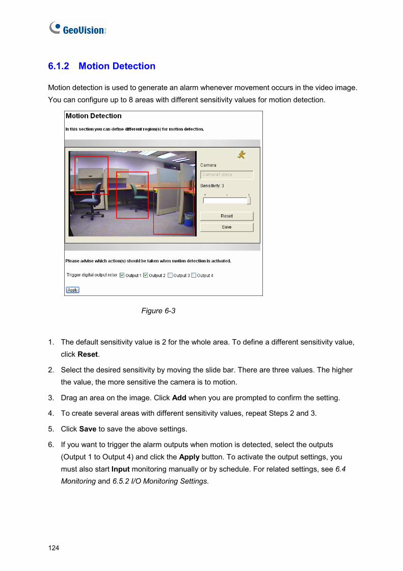
6.1.2 Motion Detection
Motion detection is used to generate an alarm whenever movement occurs in the video image. You can configure up to 8 areas with different sensitivity values for motion detection.
Figure 6-3
1. The default sensitivity value is 2 for the whole area. To define a different sensitivity value, click Reset.
2. Select the desired sensitivity by moving the slide bar. There are three values. The higher the value, the more sensitive the camera is to motion.
3. Drag an area on the image. Click Add when you are prompted to confirm the setting.
4. To create several areas with different sensitivity values, repeat Steps 2 and 3.
5. Click Save to save the above settings.
6. If you want to trigger the alarm outputs when motion is detected, select the outputs (Output 1 to Output 4) and click the Apply button. To activate the output settings, you must also start Input monitoring manually or by schedule. For related settings, see 6.4 Monitoring and 6.5.2 I/O Monitoring Settings.
124

Remote Configurations 6
6.1.3 Text Overlay
The Text Overlay function allows you to type any text in any place on the camera view. Up to 16 text messages can be created. The overlaid text will also be saved in the recorded images.
Figure 6-4
1. Select the Enable option.
2. Click any place on the image. This dialog box appears.
Figure 6-5
3. Type the desired text, and click OK. The text is overlaid on the image.
4. Click on the text and drag it to any place on the image.
5. Click Set Font to modify the font style of the text.
6. Click Save to apply the settings, or click Load (Undo) to revert to a previous setting.
125
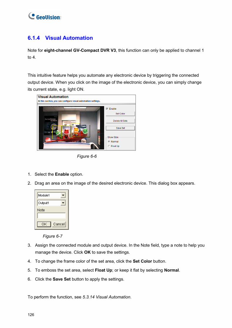
6.1.4 Visual Automation
Note for eight-channel GV-Compact DVR V3, this function can only be applied to channel 1 to 4.
This intuitive feature helps you automate any electronic device by triggering the connected output device. When you click on the image of the electronic device, you can simply change its current state, e.g. light ON.
Figure 6-6
1. Select the Enable option.
2. Drag an area on the image of the desired electronic device. This dialog box appears.
Figure 6-7
3. Assign the connected module and output device. In the Note field, type a note to help you manage the device. Click OK to save the settings.
4. To change the frame color of the set area, click the Set Color button.
5. To emboss the set area, select Float Up; or keep it flat by selecting Normal.
6. Click the Save Set button to apply the settings.
To perform the function, see 5.3.14 Visual Automation.
126

Remote Configurations 6
6.1.5 VGA Output Settings
The GV-Compact DVR V3 is equipped with a VGA connector for computer monitors or high-definition television sets. You can select the screen resolution for the VGA output.
Figure 6-8
6.1.6 Video Channel Source Settings
Note this function is only available for the four-channel GV-Compact DVR V3.
The settings allow you to assign the video input to the desired video channel for display.
Figure 6-9
127
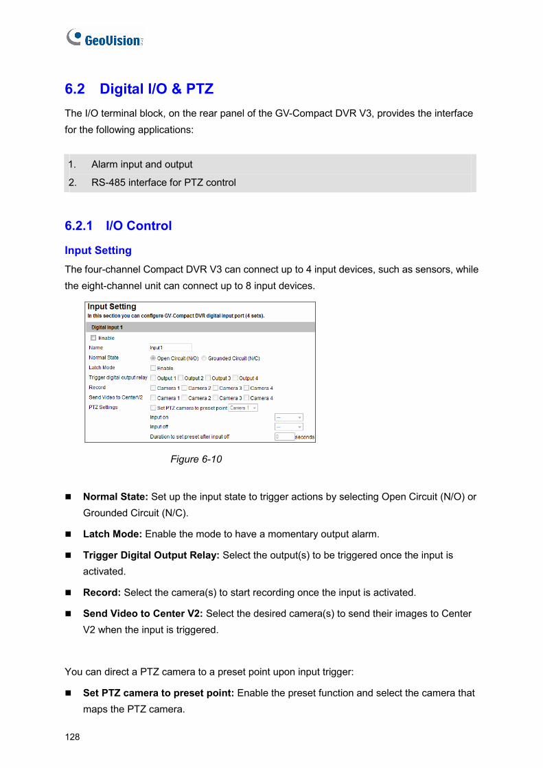
6.2 Digital I/O & PTZ The I/O terminal block, on the rear panel of the GV-Compact DVR V3, provides the interface for the following applications:
1. Alarm input and output
2. RS-485 interface for PTZ control
6.2.1 I/O Control
Input Setting The four-channel Compact DVR V3 can connect up to 4 input devices, such as sensors, while the eight-channel unit can connect up to 8 input devices.
Figure 6-10
Normal State: Set up the input state to trigger actions by selecting Open Circuit (N/O) or Grounded Circuit (N/C).
Latch Mode: Enable the mode to have a momentary output alarm.
Trigger Digital Output Relay: Select the output(s) to be triggered once the input is activated.
Record: Select the camera(s) to start recording once the input is activated.
Send Video to Center V2: Select the desired camera(s) to send their images to Center V2 when the input is triggered.
You can direct a PTZ camera to a preset point upon input trigger:
Set PTZ camera to preset point: Enable the preset function and select the camera that maps the PTZ camera.
128
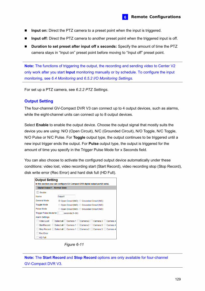
Remote Configurations 6
Input on: Direct the PTZ camera to a preset point when the input is triggered.
Input off: Direct the PTZ camera to another preset point when the triggered input is off.
Duration to set preset after input off x seconds: Specify the amount of time the PTZ camera stays in “Input on” preset point before moving to “Input off” preset point.
Note: The functions of triggering the output, the recording and sending video to Center V2 only work after you start Input monitoring manually or by schedule. To configure the input monitoring, see 6.4 Monitoring and 6.5.2 I/O Monitoring Settings. For set up a PTZ camera, see 6.2.2 PTZ Settings. Output Setting
The four-channel GV-Compact DVR V3 can connect up to 4 output devices, such as alarms, while the eight-channel units can connect up to 8 output devices. Select Enable to enable the output device. Choose the output signal that mostly suits the device you are using: N/O (Open Circuit), N/C (Grounded Circuit), N/O Toggle, N/C Toggle, N/O Pulse or N/C Pulse. For Toggle output type, the output continues to be triggered until a new input trigger ends the output. For Pulse output type, the output is triggered for the amount of time you specify in the Trigger Pulse Mode for x Seconds field. You can also choose to activate the configured output device automatically under these conditions: video lost, video recording start (Start Record), video recording stop (Stop Record), disk write error (Rec Error) and hard disk full (HD Full).
Figure 6-11
Note: The Start Record and Stop Record options are only available for four-channel GV-Compact DVR V3.
129
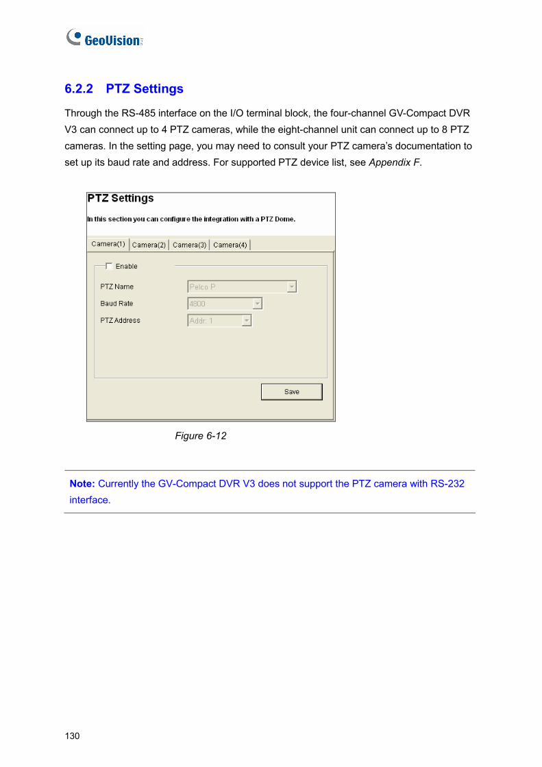
6.2.2 PTZ Settings
Through the RS-485 interface on the I/O terminal block, the four-channel GV-Compact DVR V3 can connect up to 4 PTZ cameras, while the eight-channel unit can connect up to 8 PTZ cameras. In the setting page, you may need to consult your PTZ camera’s documentation to set up its baud rate and address. For supported PTZ device list, see Appendix F.
Figure 6-12
Note: Currently the GV-Compact DVR V3 does not support the PTZ camera with RS-232 interface.
130
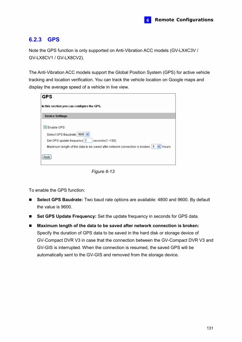
Remote Configurations 6
6.2.3 GPS
Note the GPS function is only supported on Anti-Vibration ACC models (GV-LX4C3V / GV-LX8CV1 / GV-LX8CV2). The Anti-Vibration ACC models support the Global Position System (GPS) for active vehicle tracking and location verification. You can track the vehicle location on Google maps and display the average speed of a vehicle in live view.
Figure 6-13
To enable the GPS function:
Select GPS Baudrate: Two baud rate options are available: 4800 and 9600. By default the value is 9600.
Set GPS Update Frequency: Set the update frequency in seconds for GPS data.
Maximum length of the data to be saved after network connection is broken: Specify the duration of GPS data to be saved in the hard disk or storage device of GV-Compact DVR V3 in case that the connection between the GV-Compact DVR V3 and GV-GIS is interrupted. When the connection is resumed, the saved GPS will be automatically sent to the GV-GIS and removed from the storage device.
131

To display the vehicle speed:
Select Overlaid with the GPS speed on the Video Settings page, and click Apply.
Video Settings page Vehicle speed in live view
Figure 6-14
To track the vehicle location: See 8.3 GPS Tracking.
To play back GPS tracks: If the monitoring is also activated, the GPS tracks will be recorded along with video. This makes it possible to play back video with GPS tracks on maps using the Remote ViewLog player. See 7.2.5 Playback of GPS Tracks.
132
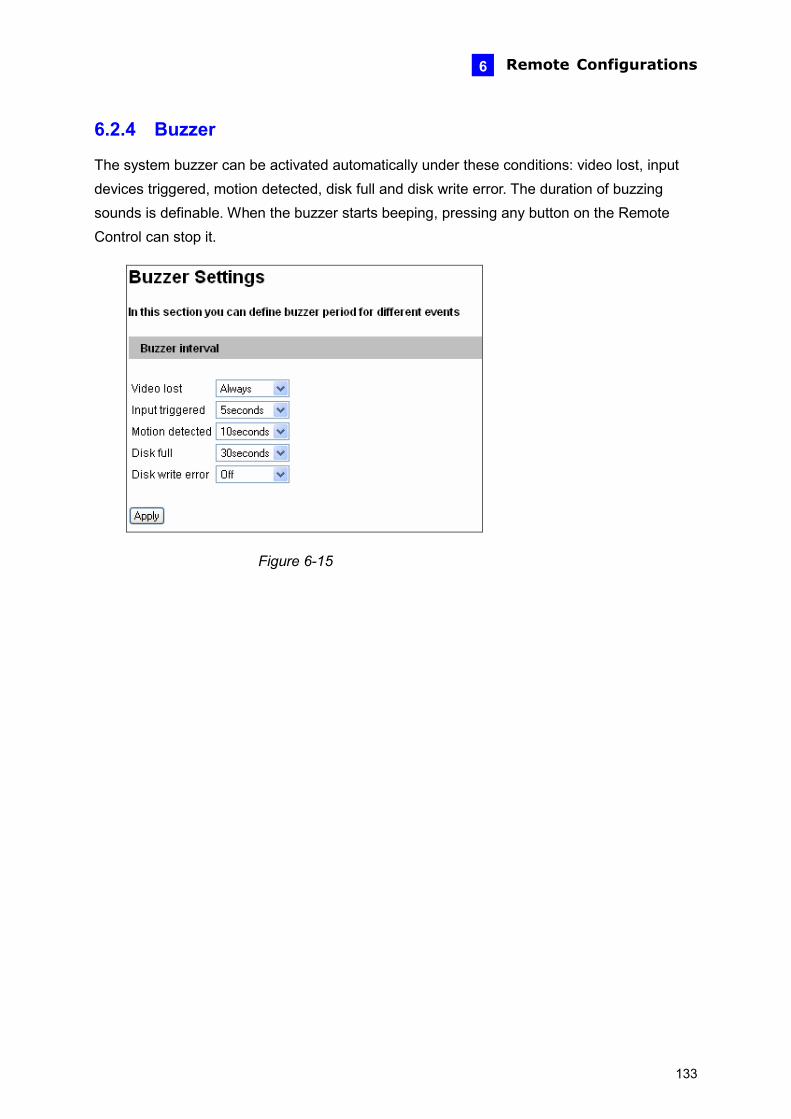
Remote Configurations 6
6.2.4 Buzzer
The system buzzer can be activated automatically under these conditions: video lost, input devices triggered, motion detected, disk full and disk write error. The duration of buzzing sounds is definable. When the buzzer starts beeping, pressing any button on the Remote Control can stop it.
Figure 6-15
133
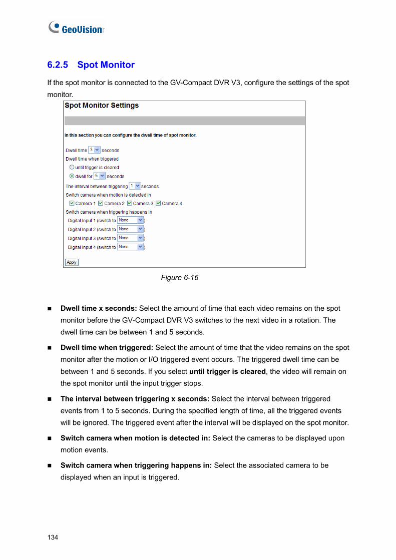
6.2.5 Spot Monitor
If the spot monitor is connected to the GV-Compact DVR V3, configure the settings of the spot monitor.
Figure 6-16
Dwell time x seconds: Select the amount of time that each video remains on the spot monitor before the GV-Compact DVR V3 switches to the next video in a rotation. The dwell time can be between 1 and 5 seconds.
Dwell time when triggered: Select the amount of time that the video remains on the spot monitor after the motion or I/O triggered event occurs. The triggered dwell time can be between 1 and 5 seconds. If you select until trigger is cleared, the video will remain on the spot monitor until the input trigger stops.
The interval between triggering x seconds: Select the interval between triggered events from 1 to 5 seconds. During the specified length of time, all the triggered events will be ignored. The triggered event after the interval will be displayed on the spot monitor.
Switch camera when motion is detected in: Select the cameras to be displayed upon motion events.
Switch camera when triggering happens in: Select the associated camera to be displayed when an input is triggered.
134

Remote Configurations 6
6.3 Events & Alerts When motion is detected or I/O devices are triggered, the Administrator can set up these alert methods:
1. Send a captured still image by e-mail or FTP.
2. Notify Center Monitoring Station, Center V2, VSM or GV-GIS, by video or text alerts.
To have above alert methods, you must also set the following features:
Motion Detection (See 6.1.2 Motion Detection)---optional
Input Setting (See 6.2.1 I/O Control.)
For e-mail and FTP alerts, it is required to start monitoring (See 6.4 Monitoring).
Note: The Motion Detection function is an optional setting and it is activated by default.
135
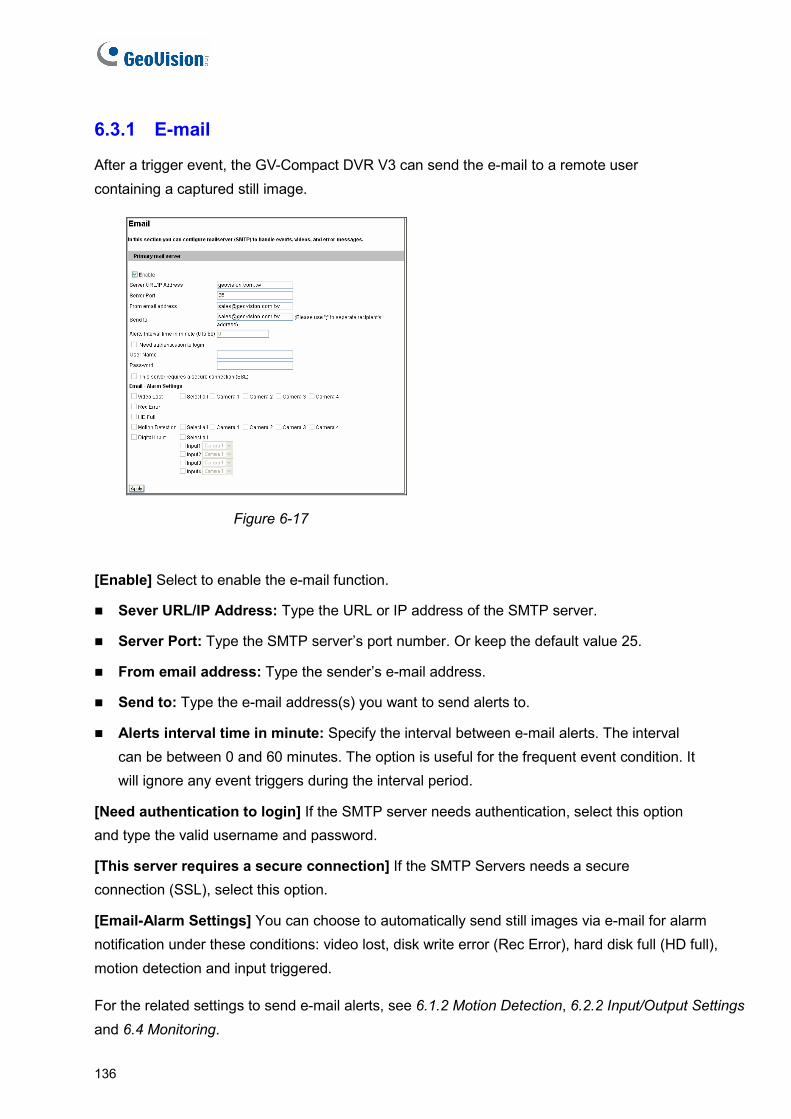
6.3.1 E-mail
After a trigger event, the GV-Compact DVR V3 can send the e-mail to a remote user containing a captured still image.
Figure 6-17
[Enable] Select to enable the e-mail function.
Sever URL/IP Address: Type the URL or IP address of the SMTP server.
Server Port: Type the SMTP server’s port number. Or keep the default value 25.
From email address: Type the sender’s e-mail address.
Send to: Type the e-mail address(s) you want to send alerts to.
Alerts interval time in minute: Specify the interval between e-mail alerts. The interval can be between 0 and 60 minutes. The option is useful for the frequent event condition. It will ignore any event triggers during the interval period.
[Need authentication to login] If the SMTP server needs authentication, select this option and type the valid username and password.
[This server requires a secure connection] If the SMTP Servers needs a secure connection (SSL), select this option.
[Email-Alarm Settings] You can choose to automatically send still images via e-mail for alarm notification under these conditions: video lost, disk write error (Rec Error), hard disk full (HD full), motion detection and input triggered.
For the related settings to send e-mail alerts, see 6.1.2 Motion Detection, 6.2.2 Input/Output Settings and 6.4 Monitoring.
136

Remote Configurations 6
6.3.2 FTP
You can also send the captured still image to a remote FTP server for alerts.
Figure 6-18
[Upload to a FTP Server]
Enable: Select to enable the FTP function.
Server URL/IP Address: Type the URL address or IP address of the FTP Server.
Port Number: Type the port number of the FTP Server. Or keep the default value 21.
User Name: Type a valid user name to log into the FTP Server.
Password: Type a valid password to log into the FTP Server.
Remote Directory: Type the name of the storage folder on the FTP Server.
Alerts Interval time in minute: Specify the interval between FTP alerts. The interval can be between 0 and 60 minutes. The option is useful for the frequent event occurrence by which any event triggers during the interval period will be ignored.
137

[FTP-Alarm Settings]
Motion Detection: Once the motion is detected on the selected camera, a still image will be sent to the FTP Server.
Continuously send images upon trigger events (motion): A sequence of snapshot images are uploaded to the FTP Server when motion is detected on the selected camera.
Digital Input: Once the selected input is triggered, a still image from the assigned camera will be sent to the FTP Server.
Continuously send images upon trigger events (input): A sequence of snapshot images from the corresponding cameras are uploaded to the FTP Server when the selected input is triggered.
[Act as FTP Server]
You can enable the GV-Compact DVR V3 to act as a FTP Server, allowing users to download the AVI files. The default download port is 21.
To access the internal FTP server through a Web browser, enter the IP address or the domain name of the GV-Compact DVR V3 in your browser like this: ftp://192.168.0.10 When you are prompted for Username and Password, enter the default value ftpuser in both fields. Then you should find the AVI files recorded after event triggers.
For the related settings to send FTP alerts, see 6.1.2 Motion Detection, 6.2.1 I/O Control and 6.4 Monitoring. To change the login information of the internal FTP Server, see 6.8.4 User Account.
138

Remote Configurations 6
6.3.3 Center V2
After a motion or an I/O triggered event, the central monitoring station Center V2 can get notified by live videos and text alerts. For the live monitoring through Center V2, you must already have a subscriber account on Center V2. The GV-Compact DVR V3 can connect up to two Center V2 servers simultaneously.
Figure 6-19
To enable the Center V2 connection:
1. Activate Link: Enable the monitoring through Center V2.
2. Host Name or IP Address: Type the host name or IP address of Center V2.
3. Port Number: Type the port matching the Port 2 on Center V2. Or keep the default value 5551. Refer to 11.1 Center V2.
4. User Name: Type a valid user name to log into Center V2.
5. Password: Type a valid password to log into Center V2.
6. Click Apply. The Connection Status should display “Connected” and connected time.
7. To establish connection to the second Center V2 server, click the Connection 2 tab and repeat the steps 1 to 6 settings.
139
These options you can also find on this Center V2 setting page:
Cease motion detection messages from: Stops notifying Center V2 of motion detection from selected camera.
Cease input trigger messages from: Stops notifying Center V2 of input trigger from selected input.
Cease video lost messages from: Stops notifying Center V2 of video lost from selected camera
Enable schedule mode: Starts the monitoring through Center V2 based on the schedule you set in the Select Schedule Time section. Refer to 6.5 Recording Schedule for the same settings.
For related settings to activate the monitoring through Center V2, see 6.1.2 Motion Detection, 6.2.1 I/O Control, and 11.1 Center V2.
140

Remote Configurations 6
6.3.4 VSM
After a motion or an I/O triggered event, the central monitoring station VSM can get notified by text alerts. For the live monitoring through VSM, you must already have a subscriber account on VSM. The GV-Compact DVR V3 can connect up to two VSM simultaneously.
Figure 6-20
To enable the VSM connection:
1. Activate Link: Enable the monitoring through VSM.
2. Host Name or IP Address: Type the host name or IP address of VSM.
3. Port Number: Type the port matching the Port 2 on VSM. Or keep the default value 5609. Refer to 11.2 VSM.
4. User Name: Type a valid user name to log into VSM.
5. Password: Type a valid password to log into VSM.
6. Click Apply. The Connection Status should display “Connected” and connected time.
7. To establish connection to a second VSM, click the Connection 2 tab and repeat steps 1 to 6 for settings.
141

These options you can also find on this VSM setting page:
Cease motion detection messages from: Stops notifying VSM of motion detection from selected camera.
Cease input trigger messages from: Stops notifying VSM of input trigger from selected input.
Cease video lost messages from: Stops notifying VSM of video lost from selected camera
Enable schedule mode: Starts the monitoring through VSM based on the schedule you set in the Select Schedule Time section. Refer to 6.5 Recording Schedule for the same settings.
For related settings to activate the monitoring through VSM, see 6.1.2 Motion Detection, 6.2.1 I/O Control, and 11.2 VSM.
142
Remote Configurations 6
6.3.5 GV-GIS
Note the GV-GIS function is only supported on Anti-Vibration ACC models (GV-LX4C3V, GV-LX8CV1 and GV-LX8CV2). Through the network connection, the Anti-Vibration ACC models equipped with GPS devices can send GPS data and live video to the GV-GIS (Geographic Information System) for the services of vehicle tracking, location verification and live monitoring. The GV-Compact DVR V3 can connect up to two GV-GIS simultaneously. Before you configure the GV-GIS connection on this setting page, the following conditions must be met:
A subscriber account created on the GV-GIS
UMTS connection activated on the GV-Compact DVR V3 (See 6.7.4 UMTS/ZigBee)
GPS function activated on the GV-Compact DVR V3 (See 6.2.3 GPS) For details on the GV-GIS, see GV-CMS Series User’s Manual.
143
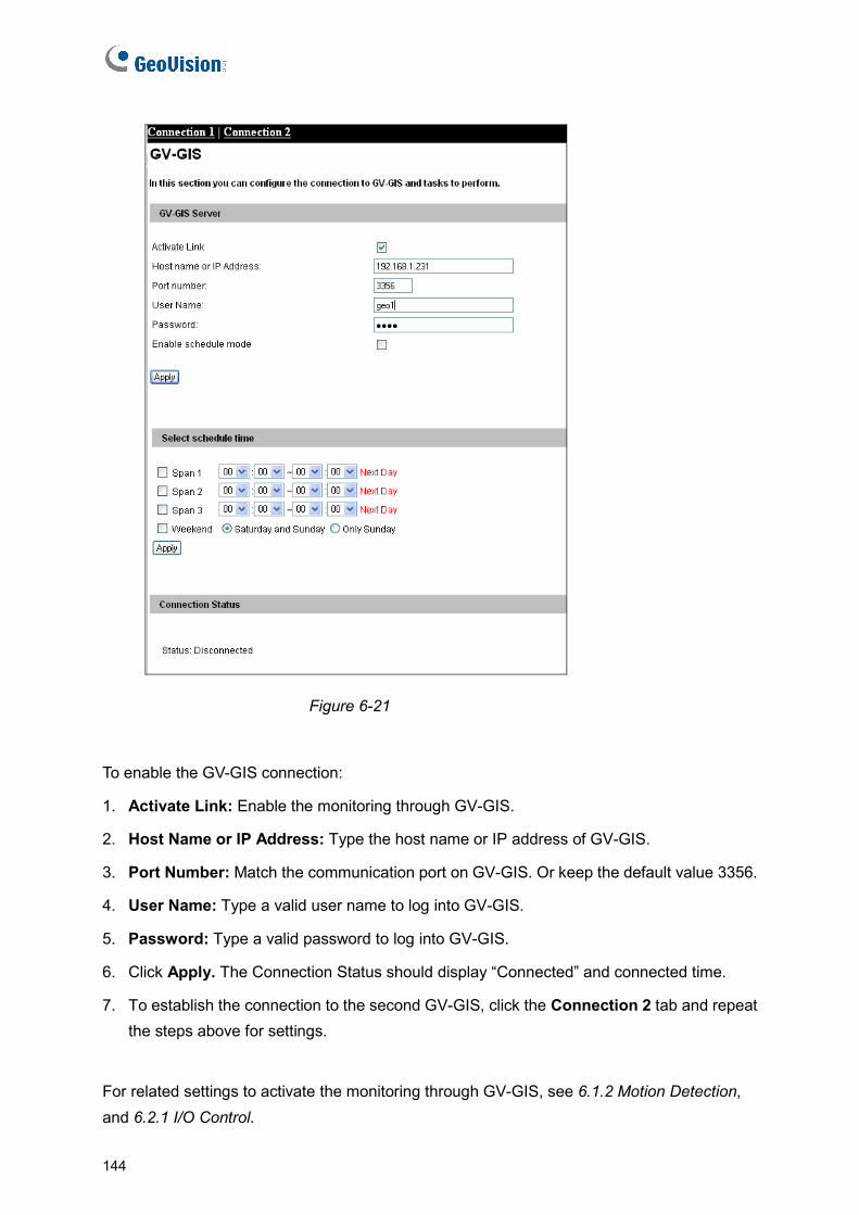
Figure 6-21
To enable the GV-GIS connection:
1. Activate Link: Enable the monitoring through GV-GIS.
2. Host Name or IP Address: Type the host name or IP address of GV-GIS.
3. Port Number: Match the communication port on GV-GIS. Or keep the default value 3356.
4. User Name: Type a valid user name to log into GV-GIS.
5. Password: Type a valid password to log into GV-GIS.
6. Click Apply. The Connection Status should display “Connected” and connected time.
7. To establish the connection to the second GV-GIS, click the Connection 2 tab and repeat the steps above for settings.
For related settings to activate the monitoring through GV-GIS, see 6.1.2 Motion Detection, and 6.2.1 I/O Control.
144

Remote Configurations 6
6.3.6 Backup Center
The GV-Backup Center provides a PC-based storage and backup solution. The connection to the GV-Backup Center allows you to back up another copy of recordings and system log to a pc-based GV-Backup Center while the GV-Compact DVR V3 is saving these data to the attached hard disk. For details on GV-Backup Center, see GV-Backup Center User’s Manual.
Figure 6-22
145

To enable the Backup Center connection:
1. Activate Link: Enable the connection to the Backup Center.
2. Host Name or IP Address: Type the host name or IP address of the Backup Center.
3. Port Number: Match the communication port on the Backup Center. Or keep the default value 30000.
4. User Name: Type a valid user name to log into the Backup Center.
5. Backup Video: Select the cameras that you want to back up their recordings to the Backup Center..
6. Compact Video: Select the cameras that you only want to back up their Key Frames to the Backup Center, instead of full recordings. This option is useful to save the backup time.
7. Resend all files: Select this option to send all the recorded files that have received by the Backup Center again.
8. Password: Type a valid password to log into the Backup Center.
9. Enable Schedule Mode: Enable the Backup Center connection on the schedule you set
in the Select Schedule Time section. Refer to 6.5 Recording Schedule for the same
settings.
10. Click Apply. The Connection Status should display “Connected” and connected time.
If the Backup Center has a failover server providing the uninterrupted backup services in case of the Backup Center failure, you can configure the connection to the failover server.
1. Set Update Frequency: Once the GV-Compact DVR V3 is disconnected from the Backup Center for the specified time, the GV-Compact DVR V3 will be directed to the failover server.
2. Automatic Failover Support: Enable the automatic connection to the failover server once the connection between GV-Compact DVR V3 and Backup Center is interrupted for the specified time.
3. Host Name or IP Address: Type the host name or IP address of the failover center.
4. Port Number: Match the communication port on the failover server. Or keep the default value 30000.
5. User Name: Type a valid user name to log into the failover server.
6. Password: Type a valid password to log into the failover server.
7. Click Apply.
146
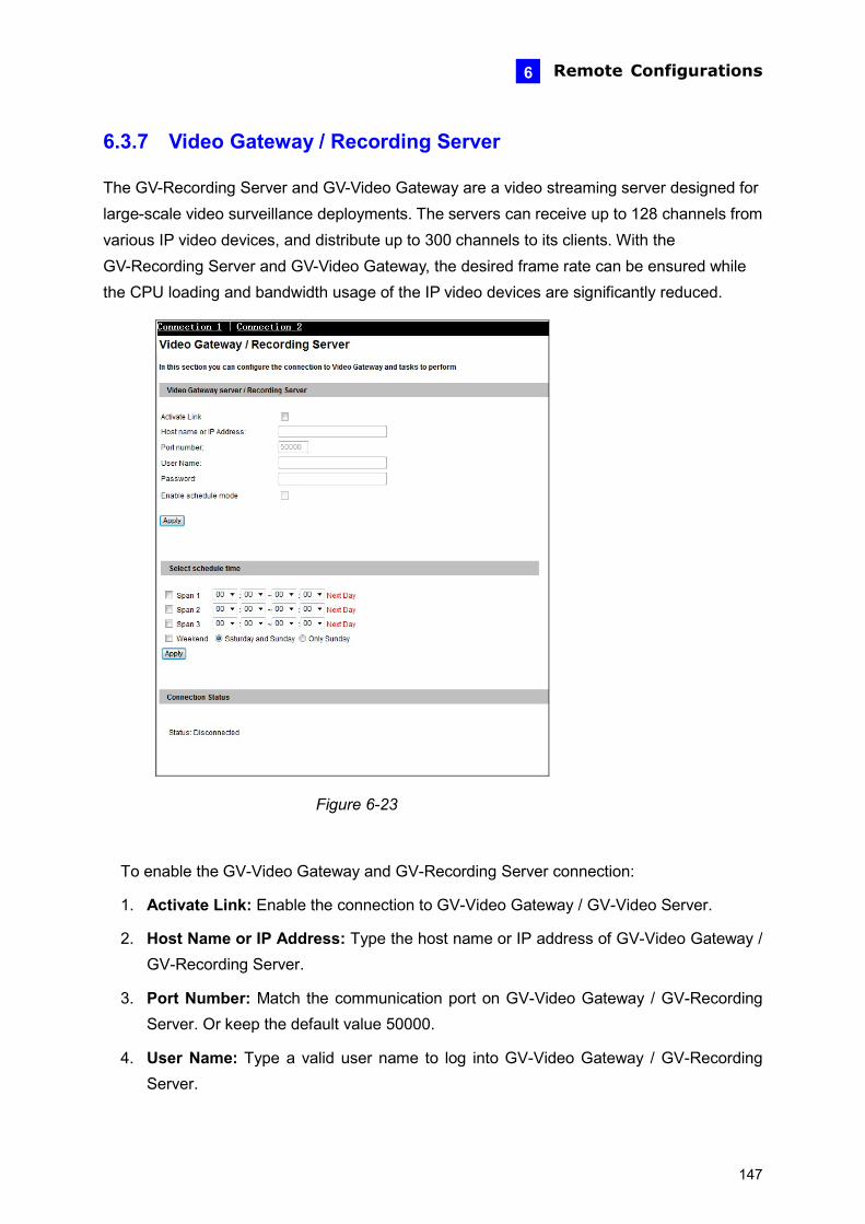
Remote Configurations 6
6.3.7 Video Gateway / Recording Server
The GV-Recording Server and GV-Video Gateway are a video streaming server designed for large-scale video surveillance deployments. The servers can receive up to 128 channels from various IP video devices, and distribute up to 300 channels to its clients. With the GV-Recording Server and GV-Video Gateway, the desired frame rate can be ensured while the CPU loading and bandwidth usage of the IP video devices are significantly reduced.
Figure 6-23
To enable the GV-Video Gateway and GV-Recording Server connection:
1. Activate Link: Enable the connection to GV-Video Gateway / GV-Video Server.
2. Host Name or IP Address: Type the host name or IP address of GV-Video Gateway / GV-Recording Server.
3. Port Number: Match the communication port on GV-Video Gateway / GV-Recording Server. Or keep the default value 50000.
4. User Name: Type a valid user name to log into GV-Video Gateway / GV-Recording Server.
147
5. Password: Type a valid password to log into GV-Video Gateway / GV-Recording Server.
6. Enable schedule mode: Enable the GV-Video Gateway / GV-Recording Server connection on the schedule you set in the Select Schedule Time section. Refer to 6.5 Recording Schedule for the same settings.
7. Click Apply. The Connection Status should display “Connected” and connected time.
8. To establish the connection to the second GV-Video Gateway / GV-Recording Server, click the Connection 2 tab and repeat above steps for setup.
148
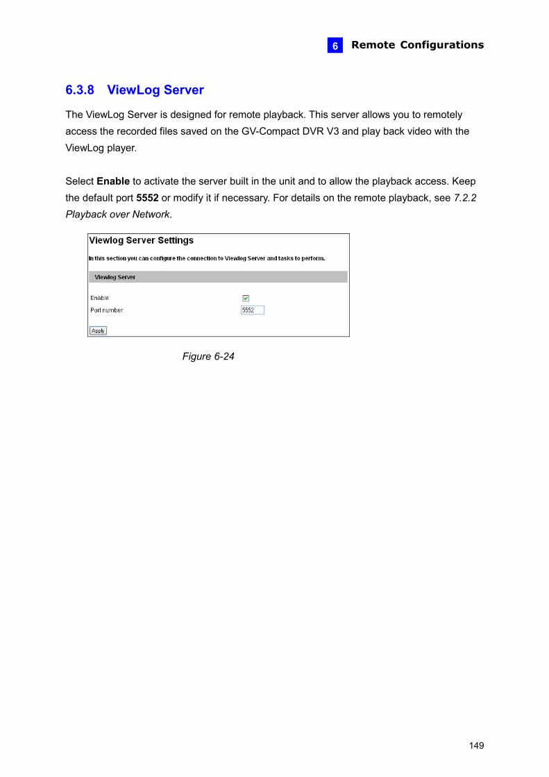
Remote Configurations 6
6.3.8 ViewLog Server
The ViewLog Server is designed for remote playback. This server allows you to remotely access the recorded files saved on the GV-Compact DVR V3 and play back video with the ViewLog player. Select Enable to activate the server built in the unit and to allow the playback access. Keep the default port 5552 or modify it if necessary. For details on the remote playback, see 7.2.2 Playback over Network.
Figure 6-24
149
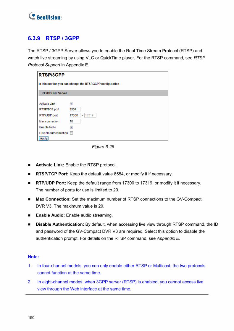
6.3.9 RTSP / 3GPP
The RTSP / 3GPP Server allows you to enable the Real Time Stream Protocol (RTSP) and watch live streaming by using VLC or QuickTime player. For the RTSP command, see RTSP Protocol Support in Appendix E.
Figure 6-25
Activate Link: Enable the RTSP protocol.
RTSP/TCP Port: Keep the default value 8554, or modify it if necessary.
RTP/UDP Port: Keep the default range from 17300 to 17319, or modify it if necessary. The number of ports for use is limited to 20.
Max Connection: Set the maximum number of RTSP connections to the GV-Compact DVR V3. The maximum value is 20.
Enable Audio: Enable audio streaming.
Disable Authentication: By default, when accessing live view through RTSP command, the ID and password of the GV-Compact DVR V3 are required. Select this option to disable the authentication prompt. For details on the RTSP command, see Appendix E.
Note:
1. In four-channel models, you can only enable either RTSP or Multicast; the two protocols cannot function at the same time.
2. In eight-channel modes, when 3GPP server (RTSP) is enabled, you cannot access live view through the Web interface at the same time.
150

Remote Configurations 6
6.4 Monitoring You can start recording manually, by schedule or by input trigger.
Figure 6-26
[Manual] Manually activates recording and I/O monitoring. Select one of the following options and then click the Start button.
Select all: Manually starts recording and I/O monitoring as well.
Camera x: Manually starts recording. Select the desired camera(s) and the recording mode for recording.
Input: Manually starts I/O monitoring. When the input is triggered, its associated camera and output will also be activated for recording and alerting. For input settings, see 6.2.1 I/O Control.
[Schedule] The system starts recording and I/O monitoring based on the schedule you set. For schedule settings, see 6.5 Recording Schedule.
[Start monitoring by Input X] Starts monitoring by the assigned input. When the assigned input is triggered, the system will respond based on your recording or I/O monitoring settings in above Manual or Schedule options.
[Stop monitoring by Input X] Stops monitoring by the assigned input. When the assigned input is triggered, the system will stop monitoring.
Remove HDD: Detaches the hard disk from the system when the unit stops monitoring.
151
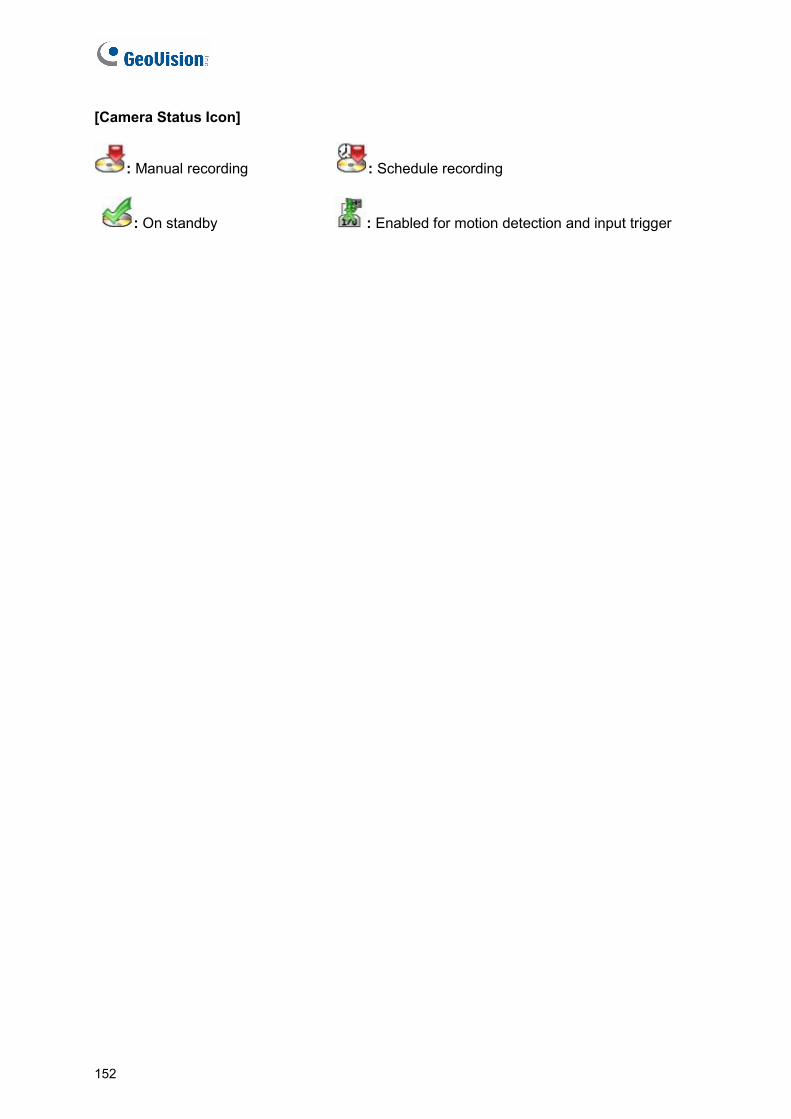
[Camera Status Icon]
: Manual recording : Schedule recording
: On standby : Enabled for motion detection and input trigger
152
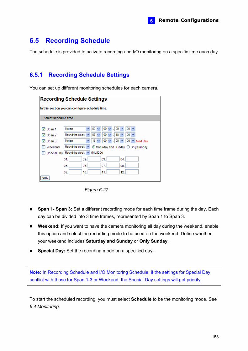
Remote Configurations 6
6.5 Recording Schedule The schedule is provided to activate recording and I/O monitoring on a specific time each day.
6.5.1 Recording Schedule Settings
You can set up different monitoring schedules for each camera.
Figure 6-27
Span 1- Span 3: Set a different recording mode for each time frame during the day. Each day can be divided into 3 time frames, represented by Span 1 to Span 3.
Weekend: If you want to have the camera monitoring all day during the weekend, enable this option and select the recording mode to be used on the weekend. Define whether your weekend includes Saturday and Sunday or Only Sunday.
Special Day: Set the recording mode on a specified day.
Note: In Recording Schedule and I/O Monitoring Schedule, if the settings for Special Day conflict with those for Span 1-3 or Weekend, the Special Day settings will get priority.
To start the scheduled recording, you must select Schedule to be the monitoring mode. See 6.4 Monitoring.
153
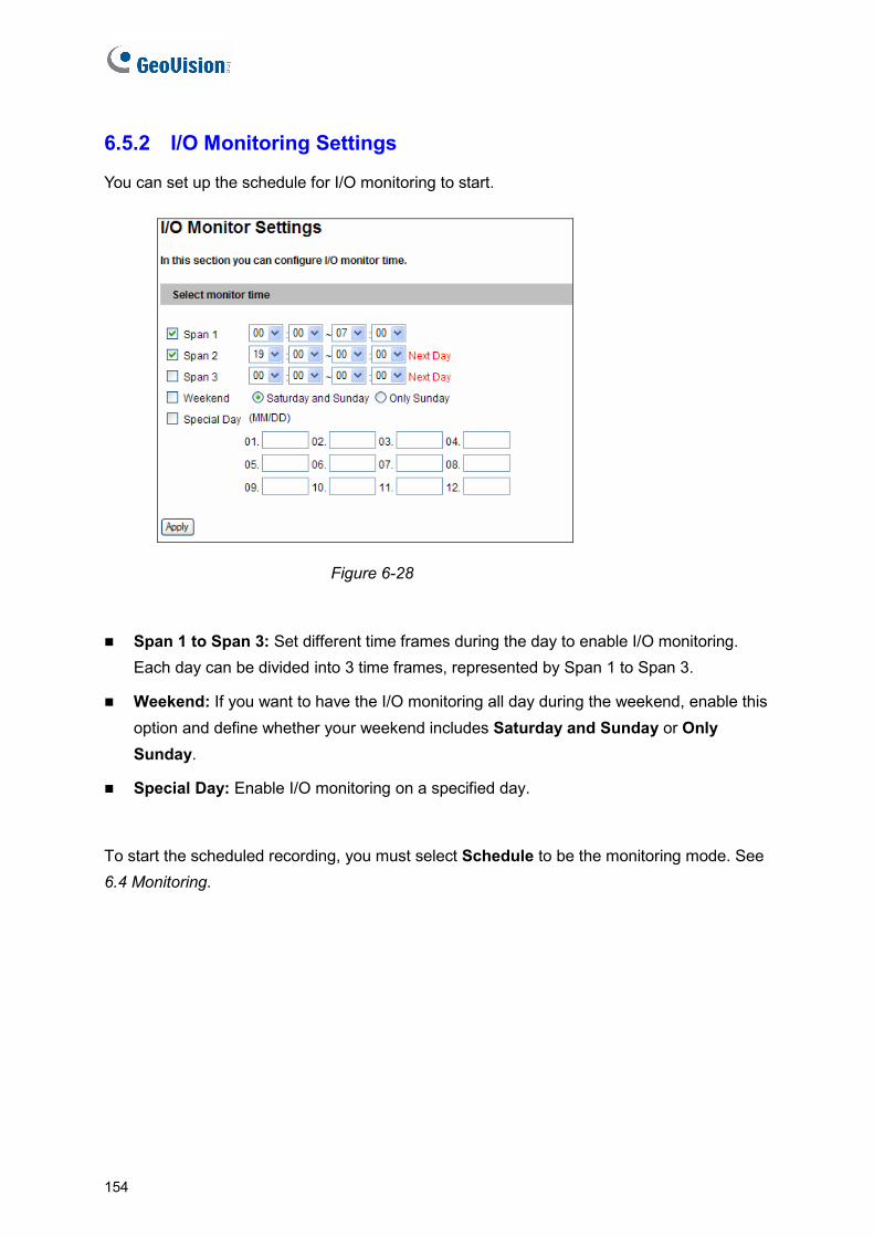
6.5.2 I/O Monitoring Settings
You can set up the schedule for I/O monitoring to start.
Figure 6-28
Span 1 to Span 3: Set different time frames during the day to enable I/O monitoring. Each day can be divided into 3 time frames, represented by Span 1 to Span 3.
Weekend: If you want to have the I/O monitoring all day during the weekend, enable this option and define whether your weekend includes Saturday and Sunday or Only Sunday.
Special Day: Enable I/O monitoring on a specified day.
To start the scheduled recording, you must select Schedule to be the monitoring mode. See 6.4 Monitoring.
154
Remote Configurations 6
6.6 Remote ViewLog With the Remote ViewLog player, you can remotely play back the files recorded at the GV-Compact DVR V3 over TCP/IP network. For the first-time user, you need to install the Remote ViewLog program from the Software CD
to initiate the function. And to allow the playback access, the ViewLog Server built in the unit must be enabled. See 6.3.8 ViewLog Server.
For details on connecting to the GV-Compact DVR V3 for playback, see 7.2.2 Playback over Network.
155

6.7 Network The Network section includes some basic but important network configurations that enable the GV-Compact DVR V3 to be connected to a TCP/IP network.
6.7.1 LAN
According to your network environment, select among Static IP, DHCP and PPPoE to configure an IP address to the GV-Compact DVR V3.
Figure 6-29
156
Remote Configurations 6
[LAN Configuration]
According to the network environment, select Wired or Wireless.
Before enabling Wireless, set up a wireless module first. For details, see 6.7.2 Wireless-Client Mode.
[LAN Configuration]
Dynamic IP address: Assign a dynamic IP by the DHCP server. By default the GV-Compact DVR V3 will be automatically assigned a dynamic IP address by the DHCP server. To check the current IP address, click the Test DHCP button.
Static IP address: Assign a static IP or fixed IP to the GV-Compact DVR V3. Type the GV-Compact DVR V3’s IP address, Subnet Mask, Gateway and DNS Server parameters.
If no DHCP server exists in your network environment, the following default IP address will be assigned to the GV-Compact DVR V3.
Parameters Default
IP address 192.168.0.10 Subnet Mask 255.255.255.0 Router/Gateway 192.168.0.1 Primary DNS server 192.168.0.1 Secondary DNS server 192.168.0.2
PPPoE: Establish the connection to your ISP. Type the username and password provided by the ISP to establish the connection. However, if the IP address provided by your ISP is dynamic, use the DDNS function to obtain a domain name linking to the unit’s changing IP address before enabling the PPPoE function. For details on Dynamic DNS Server Settings, see 6.7.3 Advanced TCP/IP.
Note: To establish connection through a broadband modem, you may refer to this article: ftp://geo-demo-japan.dipmap.com/Technotice/GV_IP_Devices/How to access GV-IP Camera through broadband modem.pdf
157
[Wireless Settings]
Before enabling Wireless, set up a wireless module first. For details, see 6.7.2 Wireless-Client Mode. Then you can select the Dynamic IP Address or Static IP Address in this section for the wireless LAN. By default, the following static IP address will be applied for wireless connection.
Parameters Default
IP address 192.168.100.10 Subnet Mask 255.255.255.0 Router/Gateway 192.168.0.1 Primary DNS server 192.168.0.1 Secondary DNS server 192.168.0.2
158

Remote Configurations 6
6.7.2 Wireless-Client Mode
To use the wireless function, a wireless LAN USB Adaptor is required. For supported wireless LAN adaptors, see Appendix A.
Figure 6-30
Network type: Select the network mode Ad Hoc or Infrastructure.
Infrastructure: Via the Access Point to connect to the Internet. This mode further gives wireless access to the Internet or data sharing under a previously wired environment.
Ad-Hoc: A Peer-to-Peer mode. This mode connects to other computer with the WLAN card, and does not need the Access Point to connect to each other.
Network name (SSID): The SSID (Service Set Identify) is a unique name that identifies a particular wireless network. Type SSID of the Wireless LAN group or Access Point you are going to connect to.
Access Point Survey: Click this button to search all the available Access Points (Infrastructure mode) and wireless stations (AD-Hoc mode) within the range of your WLAN card.
Authentication Type: Select one of these network authentication and data encryption: Disable, WEP, WPAPSK-TKIP, WPAPSK-AES, WPA2PSK-TKIP or WPA2PSK-AES.
Disabled: No authentication is needed within the wireless network.
159
WEP (Wired Equivalent Privacy): A type of data encryption. Type up to four WEP Keys in HEX or ASCII format. Note that if you use HEX format, only digits 0-9 and letters A-F, a-f are valid.
WPAPSK-TKIP and WPA2PSK-TKIP: Type WPA-PSK (Pre-Shared Key) for data encryption.
WPAPSK-AES and WPA2PSK-AES: Type WPA-PSK (Pre-Shared Key) for data encryption.
Note:
1. Your encryption settings must match those used by the Access Points or wireless stations with which you want to associate.
2. When you lose the wireless access, you can still access the unit by connecting it to a LAN and using the default IP address 192.168.0.10.
160

Remote Configurations 6
6.7.3 Advanced TCP/IP
This section introduces the advanced TCP/IP settings, including DDNS server, HTTP port, HTTPS port, streaming port and UPnP.
Figure 6-31
161
[Dynamic DNS Server Settings]
DDNS (Dynamic Domain Name System) provides a convenient way of accessing the GV-Compact DVR V3 when using a dynamic IP. DDNS assigns a domain name to the unit, so that the Administrator does not need to go through the trouble of checking if the IP address assigned by DHCP server or ISP (in xDSL connection) has changed. Before enabling the DDNS function, the Administrator should apply for a Host Name from the DDNS service provider’s website. There are 2 providers listed on the GV-Compact DVR V3: GeoVision DDNS Server and DynDNS.org.
To enable the DDNS function:
1. Enable: Enable the DDNS function.
2. Service Provider: Select the DDNS service provider you have registered with.
3. Host Name: Type the host name used to link to the GV-Compact DVR V3. For the users of GeoVision DDNS Server, it is unnecessary to fill the field because the system will detect the host name automatically.
4. User Name: Type the user name used to enable the service from the DDNS.
5. Password: Type the password used to enable the service from the DDNS.
6. Click Apply.
[HTTP Port Settings]
The HTTP port enables connecting the GV-Compact DVR V3 to the Web. For security integration, the Administrator can hide the server from the general HTTP port by changing the default HTTP port of 80 to a different port number within the range of 1024 thru 65535.
[HTTPS Settings]
By enabling the Hypertext Transfer Protocol Secure (HTTPS) settings, you can access the camera through a secure protocol. You can use self-generated Certificate and Private Key or the ones verified by the SSL authority. Click Browse to locate the Certificate and Private Key files and type the password if the .pem files are protected by password. Click Apply. The Web interface will be restarted and you will need to log in again.
Note: The .pem file format is supported by Certificate and Private Key.
162
Remote Configurations 6
[GV-Compact DVR Streaming Port Settings]
The VSS port enables connecting the GV-Compact DVR V3 to the GV-System. The default setting is 10000.
[UPnP Settings]
UPNP: UPnP (Universal Plug & Play) is a networking architecture that provides compatibility among networking equipment, software and peripherals of the 400+ vendors that are part of the Universal Plug and Play Forum. It means that they are listed in the network devices table for the operating system (such as Windows XP) supported by this function. Enabling this function, you can connect to the GV-Compact DVR V3 directly by clicking on the GV-Compact DVR V3 listed in the network devices table.
DLNA: allows the DLNA certified devices to automatically communicate with each other once connected to the same network. The function is currently supported with Windows Media Player for recording playback.
Note:
1. The DLNA function is only supported with Windows Media Player version 1.1 or later. You must have installed GeoVision codec from the Software CD/DVD or have accessed the GV-Compact DVR V3 Web interface on the computer with Windows Media Player.
2. The DLNA function does not support the connection to TV.
163

6.7.4 UMTS / ZigBee UMTS stands for Universal Mobile Telephone System. UMTS is a third-generation (3G) broadband, packet-based transmission of text, digitized voice, video, and multimedia at data rates up to 2 megabits per second. UMTS offers a consistent set of services to mobile computer and phone users, no matter where they are located in the world. After a mobile broadband device (supporting UMTS, HSDPA, etc.) is attached to the USB port on the front panel and the UMTS function is enabled, the GV-Compact DVR V3 can have wireless Internet connectivity. For supported mobile broadband devices, see Appendix B. The Virtual Private Network (VPN) over a UMTS connection is also configurable in the setting page.
Figure 6-32
164
Remote Configurations 6
[UMTS Settings]
PIN number: Type the PIN number that is provided by your network operator.
Access Point Name (APN): Type Access Point Name that is provided by your network operator.
Username: Type a valid username to enable the UMTS service from your network operator.
Password: Type a valid password to enable the UMTS service from your network operator.
Maximum Transmission Unit: Type the Maximum Transfer Unit (MTU). The default value is 1500.
Retain UMTS Connection: Select this option to check the UMTS connection status and use the drop-down list to specify the time length for check frequency. The GV-Compact DVR V3 will attempt connection if disconnection is detected.
Enable VPN Connection: Select this option to enable the Virtual Private Network (VPN) connection. Enter the IP address of a VPN client in the Check Target IP Address field.
Enable DNS: Optionally type up to two DNS servers of your network operator.
[ZigBee Settings] Enable the ZigBee application.
[3G Connection Status] Indicate the connection status of UMTS or VPN.
165
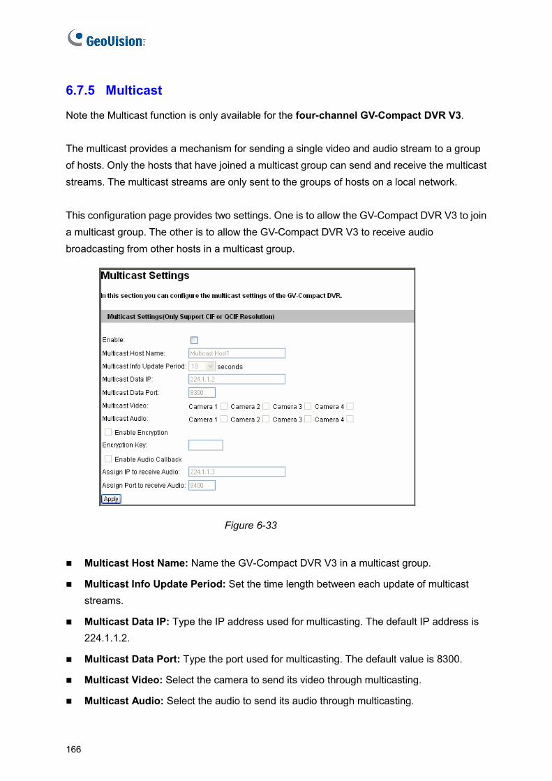
6.7.5 Multicast
Note the Multicast function is only available for the four-channel GV-Compact DVR V3. The multicast provides a mechanism for sending a single video and audio stream to a group of hosts. Only the hosts that have joined a multicast group can send and receive the multicast streams. The multicast streams are only sent to the groups of hosts on a local network. This configuration page provides two settings. One is to allow the GV-Compact DVR V3 to join a multicast group. The other is to allow the GV-Compact DVR V3 to receive audio broadcasting from other hosts in a multicast group.
Figure 6-33
Multicast Host Name: Name the GV-Compact DVR V3 in a multicast group.
Multicast Info Update Period: Set the time length between each update of multicast streams.
Multicast Data IP: Type the IP address used for multicasting. The default IP address is 224.1.1.2.
Multicast Data Port: Type the port used for multicasting. The default value is 8300.
Multicast Video: Select the camera to send its video through multicasting.
Multicast Audio: Select the audio to send its audio through multicasting.
166

Remote Configurations 6
Enable Encryption: Enable this option and type the Encryption Key to secure multicast streams. The hosts in the multicast group will need to enter the Key to access the video and audio streams.
Enable Audio callback: Enable this option to receive audio broadcasting from the hosts in the multicast group. Specify the IP address and port number to receive the audio broadcast. The default IP address is 224.1.1.3 and port number is 8400.
To receive the multicast stream, see 5.3.15 Muliticast.
Note: You can only enable either RTSP or Multicast; the two protocols cannot function at the same time.
167
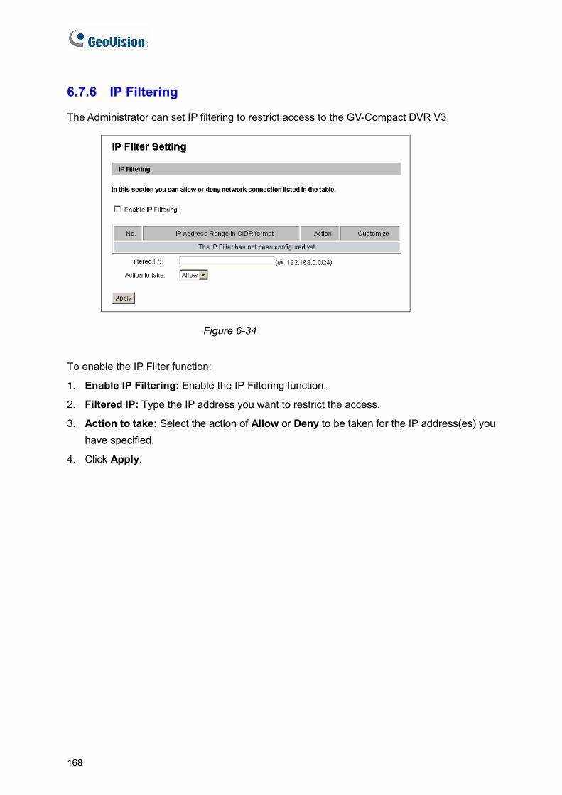
6.7.6 IP Filtering
The Administrator can set IP filtering to restrict access to the GV-Compact DVR V3.
Figure 6-34
To enable the IP Filter function:
1. Enable IP Filtering: Enable the IP Filtering function.
2. Filtered IP: Type the IP address you want to restrict the access.
3. Action to take: Select the action of Allow or Deny to be taken for the IP address(es) you have specified.
4. Click Apply.
168

Remote Configurations 6
6.7.7 SNMP Setting
The Simple Network Management Protocol (SNMP) allows you to monitor the status of the camera through SNMP network management software.
Figure 6-35
1. Select Enable SNMPv1 SNMPv2c to enable the function.
2. To enable access to Read/Write community, type a community string. This will serve as a password to allow read and write access to the camera from the SNMP software.
3. To enable Read only community, type a community string to allow read-only access to the camera from the SNMP software.
4. For a more secured connection, select Enable SNMPv3 to enable SNMP version 3.
5. To enable access to SNMPv3 Read/Write community, type a community string.
6. Select an Authentication Type to use for SNMP requests.
7. Type the Authentication Password and Encryption Password. You will need to type these passwords in the SNMP software to be able to access the camera.
8. To enable access to SNMPv3 Read only community, follow steps 5 to 7.
9. Click Apply to save the settings.
169
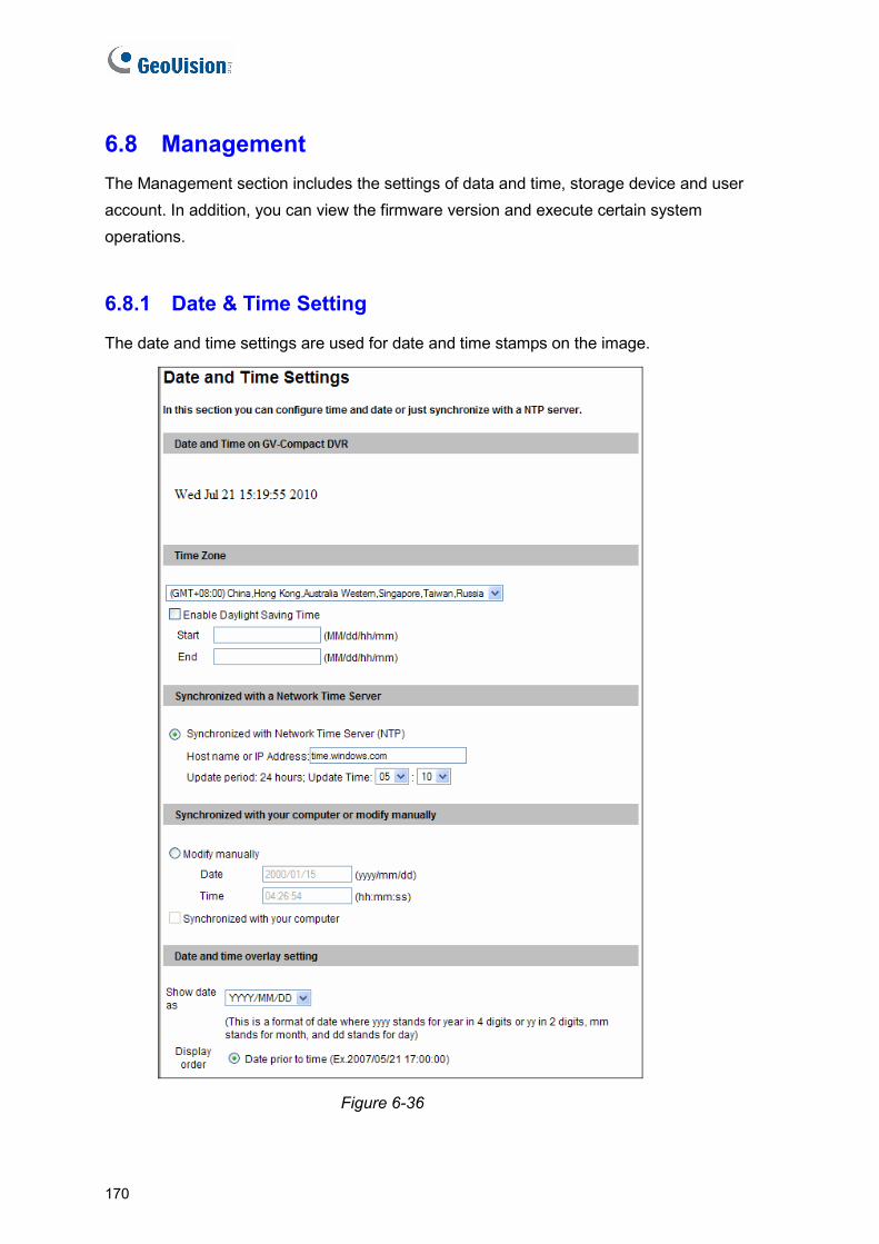
6.8 Management The Management section includes the settings of data and time, storage device and user account. In addition, you can view the firmware version and execute certain system operations.
6.8.1 Date & Time Setting
The date and time settings are used for date and time stamps on the image.
Figure 6-36
170

Remote Configurations 6
[Date & Time on Device] Displays the current date and time on the GV-Compact DVR V3.
[Time Zone] Sets the time zone for local settings. Select Enable Daylight Saving Time to automatically adjust the GV-Compact DVR V3 for daylight saving time. Type the Start Time and End Time to enable the function. To play back, see 7.2.4 Playback of Backup Files. To automatically synchronize the Day Light Saving Time with the GV-System, see Configuring the Compact DVR Settings, 10.1 Setting Up GV-Compact DVR V3.
[Synchronized with a Network Time Server] By default, the GV-Compact DVR V3 uses the timeserver of time.windows.com to automatically update its internal clock every 24 hours. You can define the update time. The host name or IP setting can also be changed to the timeserver of interest.
Note: The default setting with the time server can avoid the system time delay. If your GV-Compact DVR is not networked or the time server is not enabled, the system time may delay about 1.5 second every 24 hours. In such case, you could update the system time manually to ensure exact recording time.
[Synchronized with your computer or modify manually] Manually changes the GV-Compact DVR V3’s date and time. Or, synchronize the GV-Compact DVR V3’s date and time with those of the local computer.
[Date and time overlay setting] Select the display format of date and time stamps on the image. For this function to work, you must also enable the Overlaid with date stamps and Overlaid with time stamps options in Figure 6-2.
171
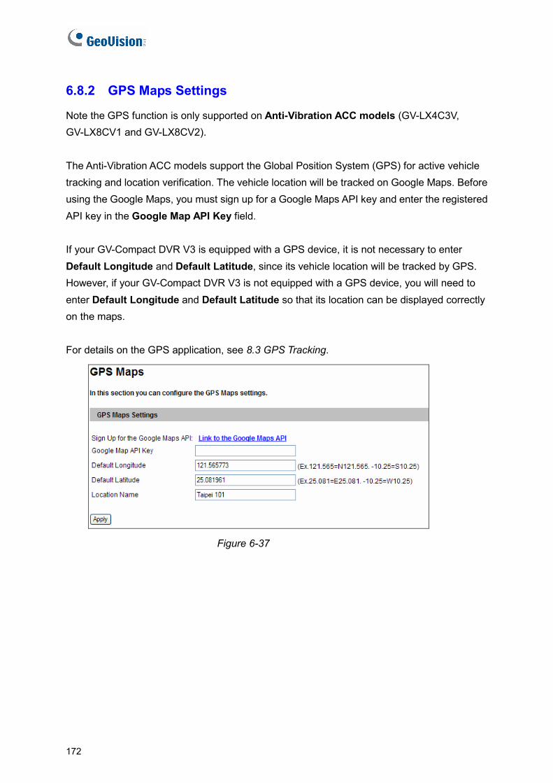
6.8.2 GPS Maps Settings
Note the GPS function is only supported on Anti-Vibration ACC models (GV-LX4C3V, GV-LX8CV1 and GV-LX8CV2). The Anti-Vibration ACC models support the Global Position System (GPS) for active vehicle tracking and location verification. The vehicle location will be tracked on Google Maps. Before using the Google Maps, you must sign up for a Google Maps API key and enter the registered API key in the Google Map API Key field. If your GV-Compact DVR V3 is equipped with a GPS device, it is not necessary to enter Default Longitude and Default Latitude, since its vehicle location will be tracked by GPS. However, if your GV-Compact DVR V3 is not equipped with a GPS device, you will need to enter Default Longitude and Default Latitude so that its location can be displayed correctly on the maps. For details on the GPS application, see 8.3 GPS Tracking.
Figure 6-37
172
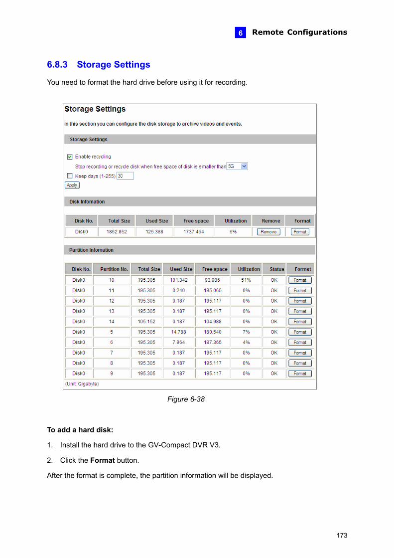
Remote Configurations 6
6.8.3 Storage Settings
You need to format the hard drive before using it for recording.
Figure 6-38
To add a hard disk:
1. Install the hard drive to the GV-Compact DVR V3.
2. Click the Format button.
After the format is complete, the partition information will be displayed.
173
To remove a hard disk:
1. Click the Remove button.
2. When you are prompted to ensure the action, click Yes. The page will be refreshed and the partition information will be cleaned.
3. Remove the hard drive from the GV-Compact DVR V3.
[Storage Settings] If the Enable recycling option is selected, when the space of the hard drive is lower than the specified space, the system will either write the data to another device or overwrite the oldest recorded files. If the Enable recycling option is cancelled, the system will stop recording when the specified space is reached.
Keep days (1-255): Specify the number of days to store the files from 1 day to 255 days. When both Keep days and Enable recycling are selected, the system applies whichever condition comes first. For example, if the specified smallest amount of storage space comes earlier than the designated keep days, then recycle is applied first.
[Disk Information] This section shows the details of the hard drive. [Partition Information] This section shows the partition details of the hard drive.
Note:
1. If Enable Recycle is selected, the available space of the hard drive must be higher than the space you specified at the Stop recording or recycle disk when free space of disk is smaller than x option. Otherwise no video will be recoded.
2. The recording data may be lost if you remove the hard drive during recording.
3. The storage device will be divided into three partitions after being formatted. Each partition has a maximum capacity of 200 GB.
4. Currently 3 TB hard drive is not supported.
174

Remote Configurations 6
6.8.4 User Account
You can change the login name and password of Administrator, Guest and FTP Server User.
[Administrator Account] The default login name and password for Administrator are admin.
[Guest User Account] The default login name and password for Guest are guest.
[Advanced Settings]
Disable authentication for guest account: Allows a Guest user to log in without entering a name and password on the Web interface of the Compact DVR V3.
Disable auto logout when reboot: The option can prevent the automatic logoff of the current user after system restart.
[FTP Server User Account] The default login name and password to access the FTP server are ftpuser.
Figure 6-39
175

6.8.5 Log Information
The Startup time log section contains every start time of the GV-Compact DVR V3. The startup time log is saved on the hard disk, so the log is only available when a hard disk is inserted to the GV-Compact DVR V3.
The Debug Messages section contains the dump data used by service personnel for analyzing problems. The log also records the task of log backup. You can back up the simplified system log by using the OSD menu. See 4.8.8 System Log.
Figure 6-40
176
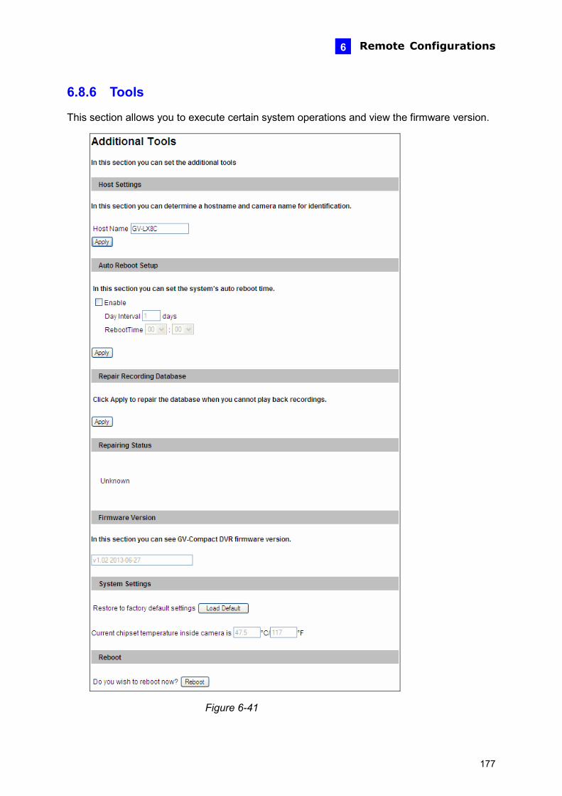
Remote Configurations 6
6.8.6 Tools
This section allows you to execute certain system operations and view the firmware version.
Figure 6-41
177

[Host Settings] Enter a descriptive name for the GV-Compact DVR V3.
[Auto Reboot Setup] Select Enable to activate automatic reboot and specify the time for reboot in the sub fields below.
Day Interval: Type the day interval between reboots.
RebootTime: Use the drop-down list to specify the time for automatic reboot.
[Repair Recording Database] Click Apply to repair the database when errors occur while playing back the recordings with the Remote ViewLog player.
[Repairing Database] This field displays the repairing progress. The field will display “Prepare to Repair”, “Repairing” or “Finish”.
Note: If the video files stored in the hard drives are already damaged, the database can not be successfully repaired.
[Firmware Version] This field displays the firmware version of the GV-Compact DVR V3.
[System Settings] Clicking the Load Default button will make the GV-Compact DVR V3 restore factory default settings. The Ready LED on the front panel will turn off. Wait until the Ready LED turns on and re-log in the unit.
This field also displays the current chipset temperature inside the GV-Compact DVR V3. Note this function is only available for eight-channel GV-Compact DVR V3.
Note: After applying the default function, you will need to configure the GV-Compact DVR V3’s network setting again.
[Reboot]
Clicking the Reboot button will make the GV-Compact DVR V3 perform software reset. The Ready LED on the front panel will turn off. Wait until the Ready LED turns on and re-log in the unit.
178
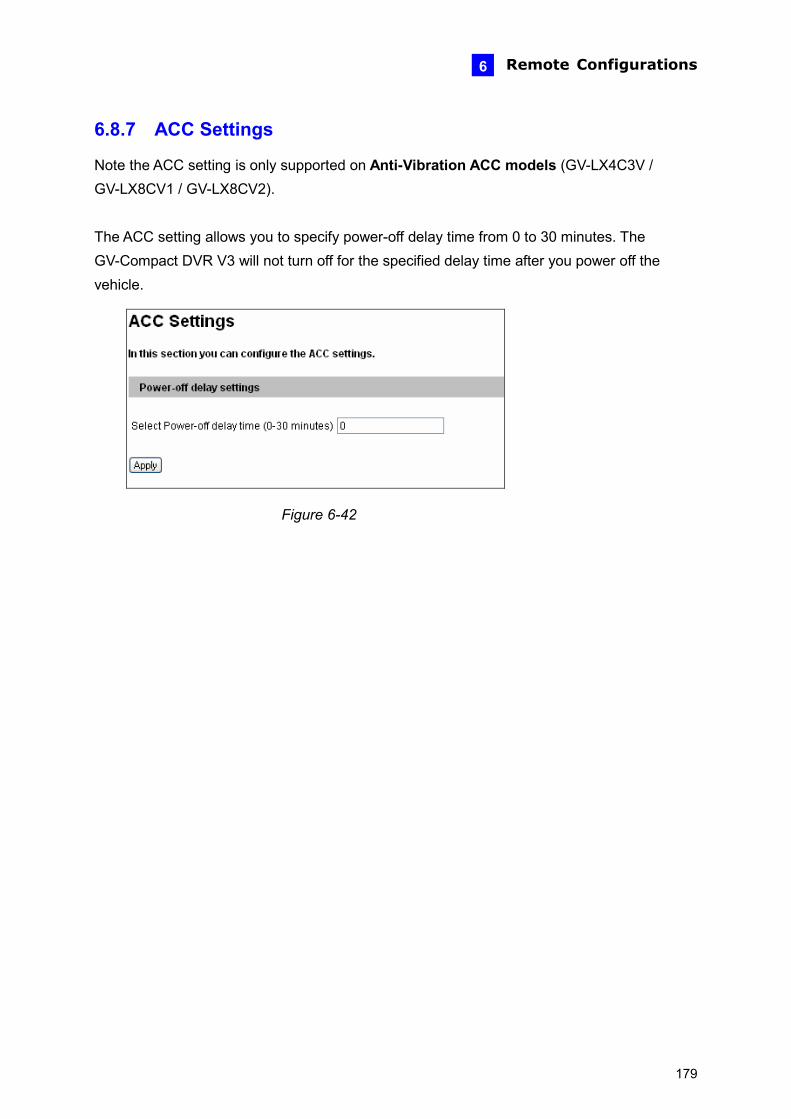
Remote Configurations
179
6
6.8.7 ACC Settings
Note the ACC setting is only supported on Anti-Vibration ACC models (GV-LX4C3V / GV-LX8CV1 / GV-LX8CV2). The ACC setting allows you to specify power-off delay time from 0 to 30 minutes. The GV-Compact DVR V3 will not turn off for the specified delay time after you power off the vehicle.
Figure 6-42
Chapter 7 Remote Recording and Playback The Administrator can remotely start recording to the GV-Compact DVR V3 and play back the recorded files over the TCP/IP network.
7.1 Remote Recording To remotely enable the recording function to the GV-Compact DVR V3:
1. Make sure the hard drive is installed in the unit. See 6.8.3 Storage Settings.
2. If you like to set up the pre-recording, post-recording or audio recording, see 6.1.1 Video Settings.
3. If you like to set up the schedule for video recording or I/O monitoring, see 6.5 Recording Schedule.
4. If you like to configure the areas and sensitivity values for motion detection, see 6.1.2 Motion Detection.
5. If you want the recording to be triggered by an input device, configure the operation of I/O devices. See 6.2.1 I/O Control.
6. To start recording and I/O monitoring, see 6.4 Monitoring.
The GV-Compact DVR V3 will start recording in case of motion detection, I/O trigger, or on the scheduled time.
7.2 Remote Playback
Several methods are available to access and play back the video files recorded on the GV-Compact DVR V3. This section will introduce the following playback methods:
• How to play back the files recorded on the hard drive
• How to play back files over network
• How to access the files through FTP Server
• How to play back the files backed up on a DVD disc or USB storage device
• How to play back the GPS tracks
180
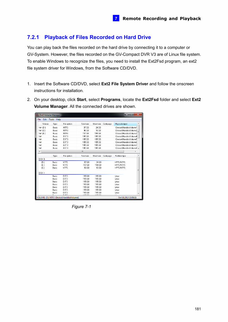
Remote Recording and Playback 7
7.2.1 Playback of Files Recorded on Hard Drive
You can play back the files recorded on the hard drive by connecting it to a computer or GV-System. However, the files recorded on the GV-Compact DVR V3 are of Linux file system. To enable Windows to recognize the files, you need to install the Ext2Fsd program, an ext2 file system driver for Windows, from the Software CD/DVD.
1. Insert the Software CD/DVD, select Ext2 File System Driver and follow the onscreen instructions for installation.
2. On your desktop, click Start, select Programs, locate the Ext2Fsd folder and select Ext2 Volume Manager. All the connected drives are shown.
Figure 7-1
181
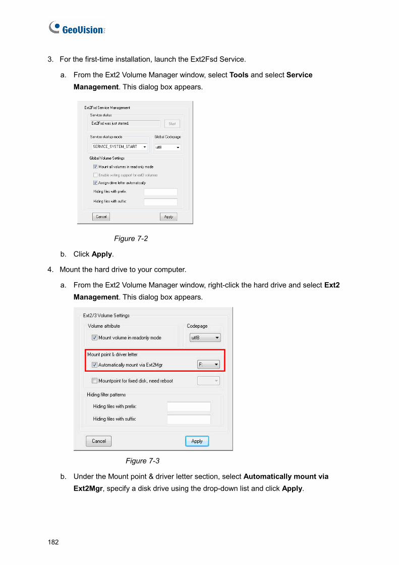
3. For the first-time installation, launch the Ext2Fsd Service.
a. From the Ext2 Volume Manager window, select Tools and select Service Management. This dialog box appears.
Figure 7-2
b. Click Apply.
4. Mount the hard drive to your computer.
a. From the Ext2 Volume Manager window, right-click the hard drive and select Ext2 Management. This dialog box appears.
Figure 7-3
b. Under the Mount point & driver letter section, select Automatically mount via Ext2Mgr, specify a disk drive using the drop-down list and click Apply.
182
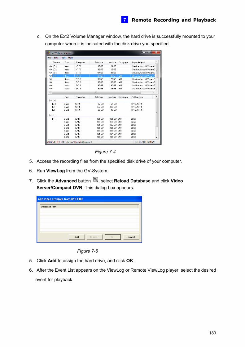
Remote Recording and Playback 7
c. On the Ext2 Volume Manager window, the hard drive is successfully mounted to your computer when it is indicated with the disk drive you specified.
Figure 7-4
5. Access the recording files from the specified disk drive of your computer.
6. Run ViewLog from the GV-System.
7. Click the Advanced button , select Reload Database and click Video Server/Compact DVR. This dialog box appears.
Figure 7-5
5. Click Add to assign the hard drive, and click OK.
6. After the Event List appears on the ViewLog or Remote ViewLog player, select the desired
event for playback.
183
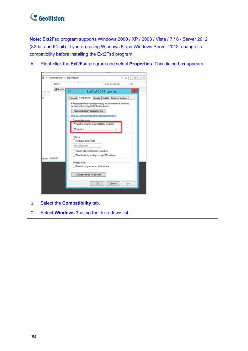
Note: Ext2Fsd program supports Windows 2000 / XP / 2003 / Vista / 7 / 8 / Server 2012 (32-bit and 64-bit). If you are using Windows 8 and Windows Server 2012, change its compatibility before installing the Ext2Fsd program:
A. Right-click the Ext2Fsd program and select Properties. This dialog box appears.
B. Select the Compatibility tab.
C. Select Windows 7 using the drop-down list.
184
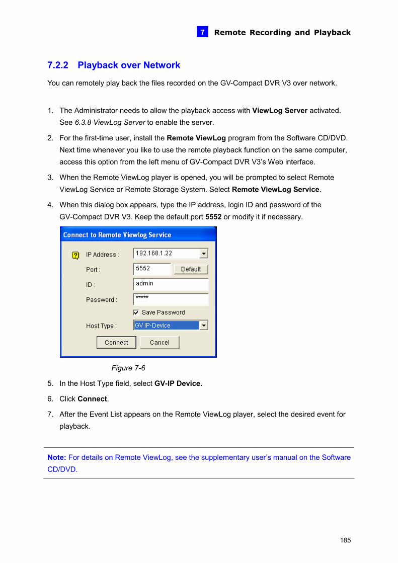
Remote Recording and Playback 7
7.2.2 Playback over Network
You can remotely play back the files recorded on the GV-Compact DVR V3 over network.
1. The Administrator needs to allow the playback access with ViewLog Server activated. See 6.3.8 ViewLog Server to enable the server.
2. For the first-time user, install the Remote ViewLog program from the Software CD/DVD. Next time whenever you like to use the remote playback function on the same computer, access this option from the left menu of GV-Compact DVR V3’s Web interface.
3. When the Remote ViewLog player is opened, you will be prompted to select Remote ViewLog Service or Remote Storage System. Select Remote ViewLog Service.
4. When this dialog box appears, type the IP address, login ID and password of the GV-Compact DVR V3. Keep the default port 5552 or modify it if necessary.
Figure 7-6
5. In the Host Type field, select GV-IP Device.
6. Click Connect.
7. After the Event List appears on the Remote ViewLog player, select the desired event for playback.
Note: For details on Remote ViewLog, see the supplementary user’s manual on the Software CD/DVD.
185
7.2.3 Access to the Recorded Files through FTP Server
The built-in FTP server allows you to download the recorded files saved on the GV-Compact DVR V3.
1. Enable the FTP server. See [Act as FTP Server], 6.3.2 FTP.
2. To access the FTP server through a Web browser, enter the IP address or the domain name of the GV-Compact DVR V3 in your browser like this:
ftp://192.168.0.10
3. When you are prompted for Username and Password, enter the default value ftpuser in both fields. After event triggers, the recorded files will be uploaded to the server.
You can play back the video files using Windows Media Player. You can also install the Remote Playback player from the Software CD/DVD for playback.
Note: To play back video, ensure you have installed GeoVision codec on the computer. The codec is available on the Software CD/DVD. If you have installed the Remote Playback player on the computer, it is not required to install the codec.
7.2.4 Playback of Backup Files
You can play back the video files backed up on a DVD disc or a USB storage device using Windows Media Player. You can also install the Remote Playback player from the Software CD/DVD for playback.
Note:
1. For how to back up the video files, see 4.8.9 Backup.
2. To play back video, ensure you have installed GeoVision codec on the computer. The codec is available on the Software CD/DVD. If you have installed the Remote Playback player on the computer, it is not required to install the codec.
186

Remote Recording and Playback 7
To play back video using the Remote Playback player:
1. Install and run the Remote Playback player from the Software CD/DVD.
2. When the Remote ViewLog player is opened, you will be prompted to select Remote ViewLog Service or Remote Storage System. Select Remote ViewLog Service.
3. Click the Advanced button , select Reload Database and click Video
Server/Compact DVR. This dialog box appears.
Figure 7-7
4. Click Add, and locate the DVD drive or USB storage device. Click OK to read the data.
Figure 7-8
5. This dialog box appears. Click OK.
Figure 7-9
187

6. The Event List appears on the player. Select the desired event for playback.
Note: The AVI file recorded during the Daylight Saving Time (DST) period is named with the prefix “GvDST”, e.g. GvDST20081022xxxxxxxxx.avi, to differentiate from the regular AVI file named with the prefix “Event”, e.g. Event20081022xxxxxxxxx.avi. In the Event List of the Remote ViewLog player, you can also see the separate DST subfolder.
7.2.5 Playback of GPS Tracks
This function is only available for the Anti-Vibration ACC models (GV-LX4C3V / GV-LX8CV1 / GV-LX8CV2). After the GPS function is enabled on the GV-Compact DVR V3, the GPS data will be recorded along with the video files. You can back up the video files on a DVD disc or a USB storage device and play back the GPS tracks on the maps.
Note:
1. For how to back up the video files, see 4.8.9 Backup.
2. You can also remotely access the GV-Compact DVR V3 using a Web browser, and use the Remote Playback function on the left menu of the Web interface for GPS track playback. For how to access the GV-Compact DVR 3 remotely, see 7.2.2 Playback over Network.
To play back the backup GPS tracks:
1. Install and run the Remote Playback player from the Software CD/DVD.
2. When the Remote ViewLog player is opened, you will be prompted to select Remote ViewLog Service or Remote Storage System. Select Remote ViewLog Service.
188
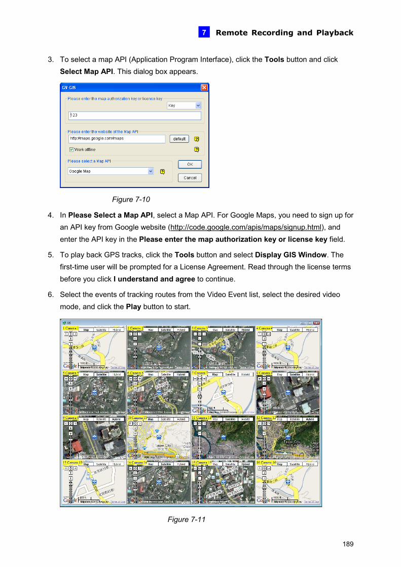
Remote Recording and Playback 7
3. To select a map API (Application Program Interface), click the Tools button and click Select Map API. This dialog box appears.
Figure 7-10
4. In Please Select a Map API, select a Map API. For Google Maps, you need to sign up for an API key from Google website (http://code.google.com/apis/maps/signup.html), and enter the API key in the Please enter the map authorization key or license key field.
5. To play back GPS tracks, click the Tools button and select Display GIS Window. The first-time user will be prompted for a License Agreement. Read through the license terms before you click I understand and agree to continue.
6. Select the events of tracking routes from the Video Event list, select the desired video mode, and click the Play button to start.
Figure 7-11
189
190
Note:
1. The playback function is only compatible with GV-System version 8.3 or later.
2. If you like to use the maps created yourself, overwrite the files at
:\GV folder\GIShtm-User, and select User Defined from the “Please Select a Map API” drop-down list (Figure 7-7).
3. If you are the paid-client of Google Maps, select Client from the “Please enter the map authorization key or license key” drop-down list; otherwise select Key.

Advanced Applications
8
Chapter 8 Advanced Applications This chapter introduces more advanced applications.
8.1 Upgrading System Firmware GeoVision will periodically release the updated firmware on the website. The new firmware can be simply loaded into the GV-Compact DVR V3 over the network or by using the IP Device Utility included in the Software CD/DVD. Important Notes before You Start Before you start updating the firmware, please read these important notes:
1. While the firmware is being updated, the power supply must not be interrupted.
2. Do not turn the power off for 10 minutes after the firmware is updated.
WARNING: The interruption of power supply during updating causes not only update failures but also damages to the device. In this case, please contact your sales representative and send your device back to GeoVision for repair.
IMPORTANT: After upgrading the firmware of GV-Compact DVR V3 to the latest version, it is required to format the storage device for better recording efficiency and stability. To format the storage device, be sure to back up the data first and see 3.7 Formatting Hard Drive for how to format the storage device.
191
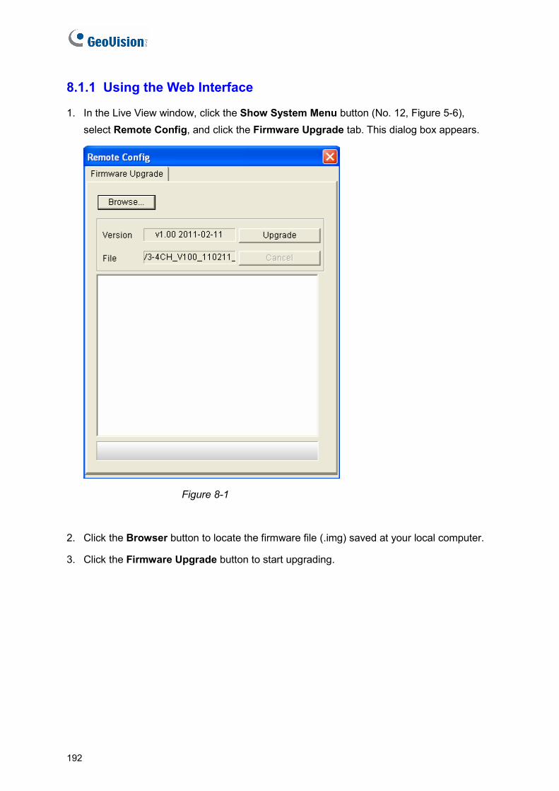
8.1.1 Using the Web Interface
1. In the Live View window, click the Show System Menu button (No. 12, Figure 5-6), select Remote Config, and click the Firmware Upgrade tab. This dialog box appears.
Figure 8-1
2. Click the Browser button to locate the firmware file (.img) saved at your local computer.
3. Click the Firmware Upgrade button to start upgrading.
192
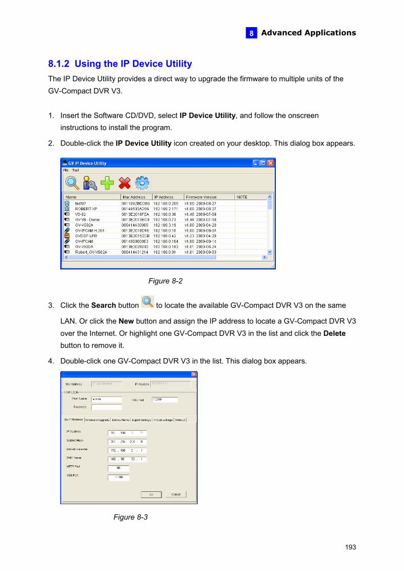
Advanced Applications
8
8.1.2 Using the IP Device Utility The IP Device Utility provides a direct way to upgrade the firmware to multiple units of the GV-Compact DVR V3.
1. Insert the Software CD/DVD, select IP Device Utility, and follow the onscreen instructions to install the program.
2. Double-click the IP Device Utility icon created on your desktop. This dialog box appears.
Figure 8-2
3. Click the Search button to locate the available GV-Compact DVR V3 on the same
LAN. Or click the New button and assign the IP address to locate a GV-Compact DVR V3 over the Internet. Or highlight one GV-Compact DVR V3 in the list and click the Delete button to remove it.
4. Double-click one GV-Compact DVR V3 in the list. This dialog box appears.
Figure 8-3
193

5. Click the Firmware Upgrade tab. This dialog box appears.
Figure 8-4
6. Click the Browse button to locate the firmware file (.img) saved at your local computer.
7. If you like to upgrade all the GV-Compact DVR V3s in the list, select Upgrade all devices.
8. Type Password, and click Upgrade to process the upgrade.
194

Advanced Applications
8
8.2 Backing Up and Restoring Settings With the IP Device Utility included in the Software CD/DVD, you can back up the configurations in the GV-Compact DVR V3 and restore the backup data to the current unit or import it to another unit.
8.2.1 Backing Up the Settings
1. Run IP Device Utility and locate the desired GV-Compact DVR V3. See Steps 1-3 in 8.1.2 Using the IP Device Utility.
2. Double-click the GV-Compact DVR V3 in the list. Figure 8-3 appears.
3. Click the Export Settings button. This dialog box appears.
Figure 8-5
4. Click the Browse button to assign a file path.
5. Type Password, and click Export Settings to save the backup file.
195
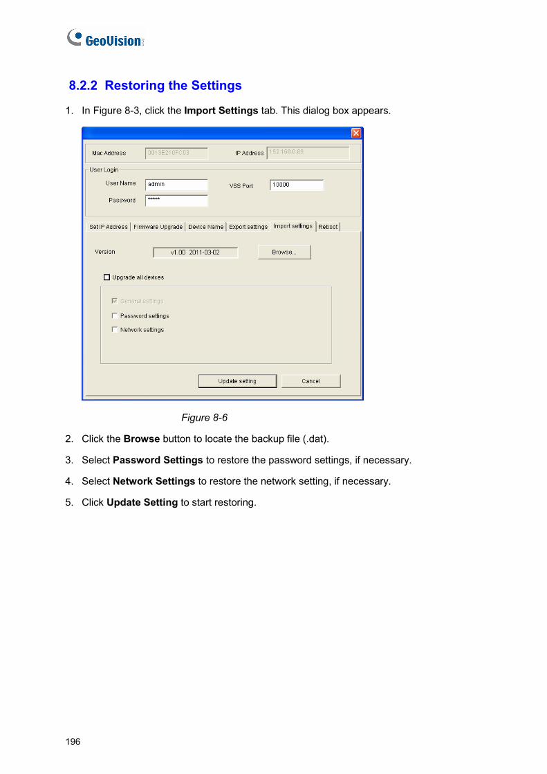
8.2.2 Restoring the Settings
1. In Figure 8-3, click the Import Settings tab. This dialog box appears.
Figure 8-6
2. Click the Browse button to locate the backup file (.dat).
3. Select Password Settings to restore the password settings, if necessary.
4. Select Network Settings to restore the network setting, if necessary.
5. Click Update Setting to start restoring.
196

Advanced Applications
8
8.3 GPS Tracking The Anti-Vibration ACC models of the GV-Compact DVR V3 support the Global Position System (GPS) for active vehicle tracking and location verification. The vehicle location will be tracked by Google Maps. To track the location of your GV-Compact DVR V3:
1. Connect the GV-GPS module with PS/2 connector to the GPS port on the rear panel of the unit.
2. Enable the GPS function. See 4.2.3 GPS Settings for OSD menu configurations, or 6.2.3 GPS for web-based configurations.
3. Sign up for a Google Maps API Key and enable the GPS Maps settings. See 6.8.2 GPS Maps Settings.
4. Open the control panel of the Live View window.
Figure 8-7
Click Start to activate GPS tracking. The longitude, latitude and host time of the GV-Compact DVR V3 will be displayed.
To save the location information to your local computer, select Save message and click […] to assign the storage path.
197
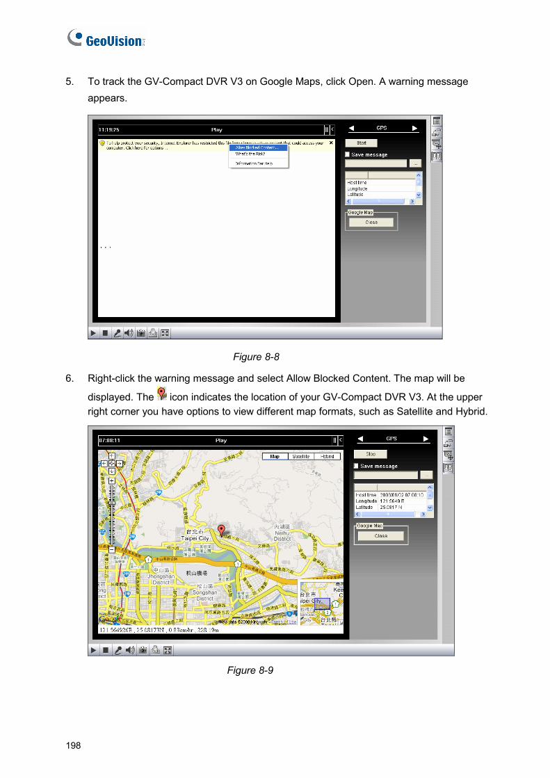
5. To track the GV-Compact DVR V3 on Google Maps, click Open. A warning message appears.
Figure 8-8
6. Right-click the warning message and select Allow Blocked Content. The map will be
displayed. The icon indicates the location of your GV-Compact DVR V3. At the upper right corner you have options to view different map formats, such as Satellite and Hybrid.
Figure 8-9
198

Advanced Applications
8
8.4 Restoring to Factory Default Settings
To restore the GV-Compact DVR V3 to default settings, use the Reset and Default buttons on the front panel. For the location of the two buttons see 2.1 Front Panel.
1. Press and then release the Reset button immediately.
2. Press and hold the Default button until the 2 LEDs (Power and Ready) are on. This may take up to 30 seconds.
3. Release the Default button. The process of loading default values is complete, and the GV-Compact DVR V3 starts rebooting itself with Ready LED turning off.
4. Wait until the Power and Ready LEDs turn on again. After this, all the settings are returned to default values.
Note: Before the Ready LED is on again, do not unplug the power cable; otherwise the loading of default values will fail.
199
8.5 Verifying Watermark
The watermark is an encrypted and digital signature embedded in the video stream during the compression stage, protecting the video from the moment of creation. Watermarking ensures that an image is not edited or damaged after it is recorded. To enable the watermark function, see [Watermark], 6.1.1 Video Settings.
The Watermark Proof is a watermark-checking program. It can verify the authenticity of the recording before you present it in court.
8.5.1 Accessing the Recorded Files
To verify watermark, you must obtain the recorded files by one of these methods first.
1. Use the File Save function on the Live View window (Figure 5-6) to start recording on the local computer.
2. Use the Act as FTP Server function to download the files from the GV-Compact DVR V3. See 6.3.2 FTP.
3. Use the files recorded on the hard drive. Since the files saved on the hard drive are of Linux file system, you need to run Ext2Fsd program to convert the Linux-based files to Windows-based files. For the instructions, see Steps 1 to 5 in 7.2.1 Playback of Files Recorded on Hard Drive.
4. Back up the files to a DVD disc or a USB storage device. For how to back up files, see 4.8.9 Backup.
8.5.2 Running Watermark Proof
1. Install Watermark Proof from the Software CD/DVD. After installment, a WMProof icon is created on your desktop.
2. Double-click the created icon. The Water Mark Proof window appears.
3. Click File from the menu bar, select Open and locate the recorded file (.avi). The selected file is then listed on the window. Alternatively, you can drag the file directly from the storage folder to the window.
4. If the recording is unmodified, a check mark will appear in the Pass column. On the contrary, if the recording is modified or the Watermark function is not enabled, a check mark will appear in the Failed column. To play back the recording, double-click the listed file on the window.
200
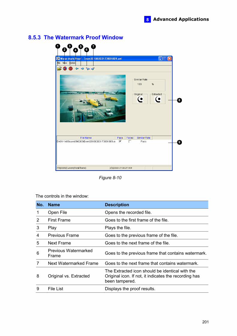
Advanced Applications
201
8
8.5.3 The Watermark Proof Window 1 3 5
67
8
9
2 4
Figure 8-10
The controls in the window:
No. Name Description
1 Open File Opens the recorded file.
2 First Frame Goes to the first frame of the file.
3 Play Plays the file.
4 Previous Frame Goes to the previous frame of the file.
5 Next Frame Goes to the next frame of the file.
6 Previous Watermarked Frame Goes to the previous frame that contains watermark.
7 Next Watermarked Frame Goes to the next frame that contains watermark.
8 Original vs. Extracted The Extracted icon should be identical with the Original icon. If not, it indicates the recording has been tampered.
9 File List Displays the proof results.

Chapter 9 Smart Device Surveillance Using an Android or Apple device you can receive live video streaming from the GV-Compact DVR V3. The chart below lists the available remote viewers for GV-Compact DVR V3.
Handheld Device Viewer
Resolution and Codec Supported
OS SupportedDefault Port
Features
MPEG4 D1 (720 x 480) or
lower
MJPEG 2M (1920x 1080)
or lower GV-Eye / GV-Eye HD
H.264 2M (1920 x 1080)
or lower
- iOS 4.3.3 to 6.0.1 - Android version 2.2 to 4.0.2
VSS Port: 10000
Live view, Snapshots, I/O Trigger, PTZ control & Presets, One-way Audio, Multiple Camera View
Chart 1
Note:
1. GV-Eye / GV-Eye HD does not support remote playback from the GV-Compact DVR V3.
2. The default live view is stream 2 from GV-IP devices with MJPEG codec and VGA (640 x 480) resolution.
3. The GV-Eye / GV-Eye HD for iOS with MJPEG codec, resolution of 704 x 480 is not supported.
202
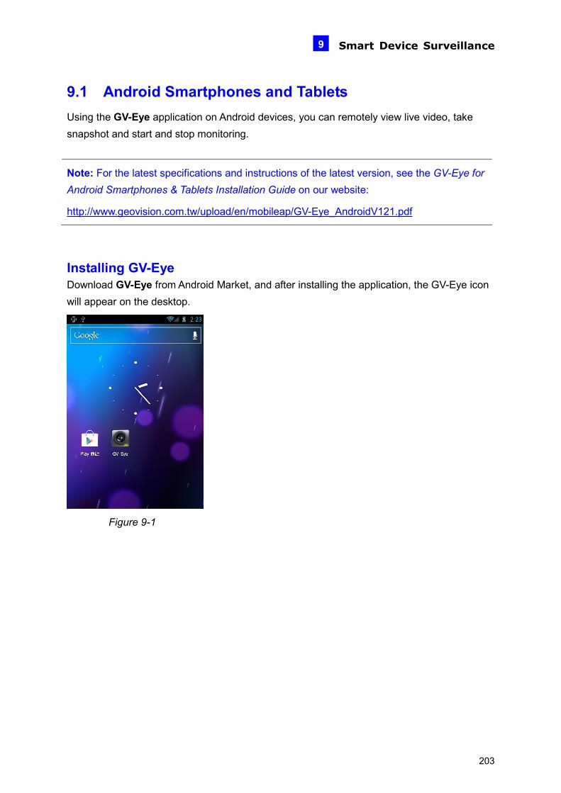
Smart Device Surveillance 9
9.1 Android Smartphones and Tablets Using the GV-Eye application on Android devices, you can remotely view live video, take snapshot and start and stop monitoring.
Note: For the latest specifications and instructions of the latest version, see the GV-Eye for Android Smartphones & Tablets Installation Guide on our website:
http://www.geovision.com.tw/upload/en/mobileap/GV-Eye_AndroidV121.pdf
Installing GV-Eye Download GV-Eye from Android Market, and after installing the application, the GV-Eye icon will appear on the desktop.
Figure 9-1
203
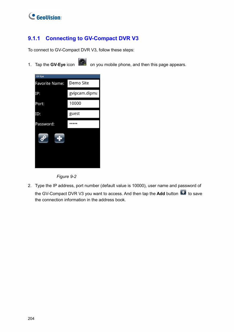
9.1.1 Connecting to GV-Compact DVR V3
To connect to GV-Compact DVR V3, follow these steps:
1. Tap the GV-Eye icon on you mobile phone, and then this page appears.
Figure 9-2
2. Type the IP address, port number (default value is 10000), user name and password of
the GV-Compact DVR V3 you want to access. And then tap the Add button to save the connection information in the address book.
204
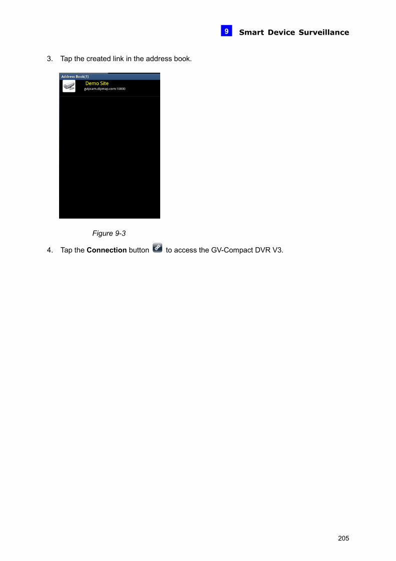
Smart Device Surveillance 9
3. Tap the created link in the address book.
Figure 9-3
4. Tap the Connection button to access the GV-Compact DVR V3.
205
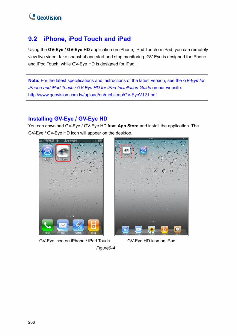
9.2 iPhone, iPod Touch and iPad Using the GV-Eye / GV-Eye HD application on iPhone, iPod Touch or iPad, you can remotely view live video, take snapshot and start and stop monitoring. GV-Eye is designed for iPhone and iPod Touch, while GV-Eye HD is designed for iPad.
Note: For the latest specifications and instructions of the latest version, see the GV-Eye for iPhone and iPod Touch / GV-Eye HD for iPad Installation Guide on our website: http://www.geovision.com.tw/upload/en/mobileap/GV-EyeV121.pdf
Installing GV-Eye / GV-Eye HD You can download GV-Eye / GV-Eye HD from App Store and install the application. The GV-Eye / GV-Eye HD icon will appear on the desktop.
GV-Eye icon on iPhone / iPod Touch GV-Eye HD icon on iPad Figure9-4
206
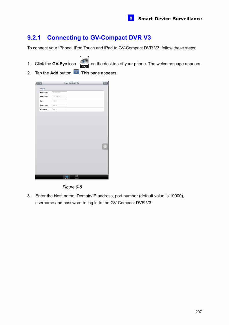
Smart Device Surveillance 9
9.2.1 Connecting to GV-Compact DVR V3 To connect your iPhone, iPod Touch and iPad to GV-Compact DVR V3, follow these steps:
1. Click the GV-Eye icon on the desktop of your phone. The welcome page appears.
2. Tap the Add button . This page appears.
Figure 9-5
3. Enter the Host name, Domain/IP address, port number (default value is 10000), username and password to log in to the GV-Compact DVR V3.
207
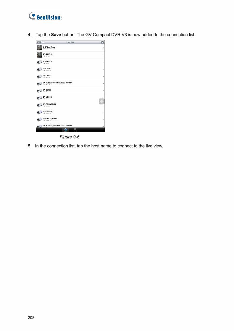
208
4. Tap the Save button. The GV-Compact DVR V3 is now added to the connection list.
Figure 9-6
5. In the connection list, tap the host name to connect to the live view.

DVR Configurations
10
Chapter 10 DVR Configurations
The GV-System provides hybrid solution, integrating the digital videos from GV-Compact DVR V3 with other analog videos. For the digital videos, the GV-System provides the complete video management, such as video viewing, recording, playback, alert settings and almost every feature of the system. Note the following integration specifications:
• GV-System version 8.4 with a patch or later version is required.
• The maximum number of streams that a GV-Compact DVR V3 allows is 8 (4-channel models) / 9 (8-channel models). When a channel of GV-Compact DVR V3 is connected to GV-System, IE browser or any other application, it takes up 1 stream.
Note: When you connect over the maximum number of streams specified above, a warning message “Too many users” will pop up, and no image can be accessed after the threshold.
• The recording resolution of digital videos is set up on the GV-Compact DVR V3 instead of on the GV-System.
• The hardware compression and the “Pre-Recording Using RAM” feature cannot work on the videos from the GV-Compact DVR V3.
GV-Compact DVR V3
TCP/ IP
GV-System with 32-channel Display
GV-Compact DVR V3
X 8 (Max.)
X 8 (Max.)
X 8 (Max.)
X 8 (Max.)
Figure 10-1
209
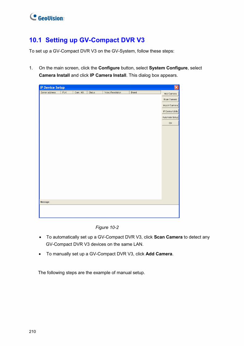
10.1 Setting up GV-Compact DVR V3 To set up a GV-Compact DVR V3 on the GV-System, follow these steps:
1. On the main screen, click the Configure button, select System Configure, select Camera Install and click IP Camera Install. This dialog box appears.
Figure 10-2
• To automatically set up a GV-Compact DVR V3, click Scan Camera to detect any GV-Compact DVR V3 devices on the same LAN.
• To manually set up a GV-Compact DVR V3, click Add Camera.
The following steps are the example of manual setup.
210
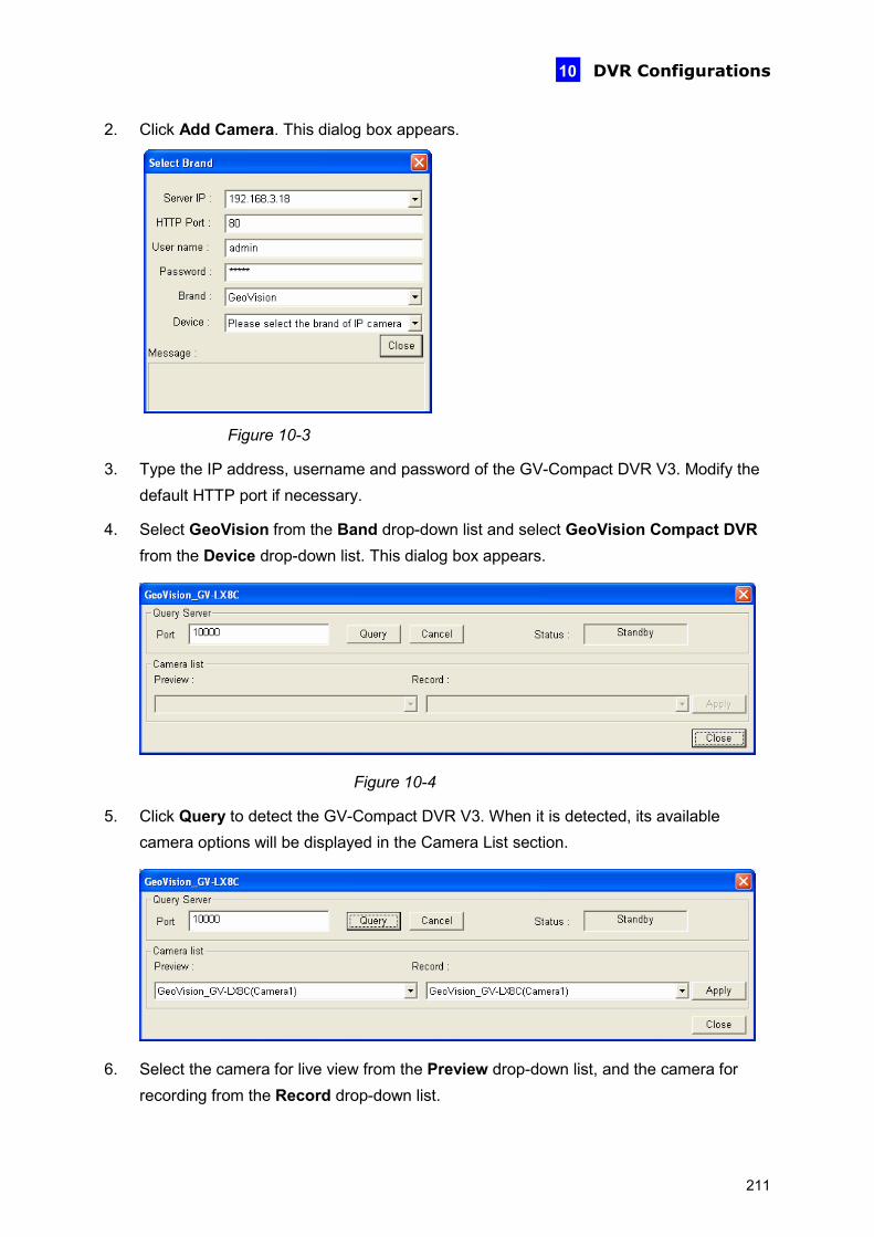
DVR Configurations
10
2. Click Add Camera. This dialog box appears.
Figure 10-3
3. Type the IP address, username and password of the GV-Compact DVR V3. Modify the default HTTP port if necessary.
4. Select GeoVision from the Band drop-down list and select GeoVision Compact DVR from the Device drop-down list. This dialog box appears.
Figure 10-4
5. Click Query to detect the GV-Compact DVR V3. When it is detected, its available camera options will be displayed in the Camera List section.
6. Select the camera for live view from the Preview drop-down list, and the camera for recording from the Record drop-down list.
211

7. Click Apply, and then Close to exit the dialog box. The device information is displayed.
Figure 10-5
8. Right-click the device information and select Display Position to map the IP camera to a channel on the GV-System.
9. The Statue column now should display “Connected”. Click OK.
Configuring the Compact DVR Settings
After the GV-Compact DVR V3 is connected and assigned with a display position, you can configure settings such as frame rate, codec type and resolution. Right-click the GV-Compact DVR V3 on the IP Device Setup dialog box to see the following list of options:
Figure 10-6
Network Time Out: When network disconnection exceeds the specified time period, the camera status will be displayed as Connection Lost.
Frames to keep in live view buffer: Specifies the number of frames to keep in the live view buffer.
GIS Setting: Records the video with the GPS data. To record the GPS data, remember to also enable the GIS function of the GV-System (Configure button < Accessories < Enable Local GIS).
212
DVR Configurations
10
Automatically Adjust DST: If enabled, the time on the GV-Compact DVR V3 Web interface will be synchronized with the time of the GV-System when DST period starts or ends on the GV-System.
213
10.2 Remote Monitoring with Multi View You can use the Multi View to monitor and manage the cameras and I/O devices connected to the GV-Compact DVR V3.
Connecting to GV-Compact DVR V3
The Multi View program is available in the GV-System applications, and also included in the Software CD/DVD as an independent program. The following is an example of running the Multi View through WebCam Server on the GV-System.
1. To enable the remote access to the GV-System, click the Network button, select WebCam Server to display the Server Setup dialog box, and click OK to start the WebCam server.
2. At the local computer, open the Web browser and type the address of the GV-System. The Single View page appears.
3. Select Multi View and the desired viewing resolution. The valid user name and password are required for login. For the first-time user, you will be directed to the Download page. Install the Multi View program before you can run it.
4. On the Multi View window, click the Edit Host button. The Edit Host window appears.
5. To create a host, click the New button. You need to create a group before creating a host.
214

DVR Configurations
10
6. Select Compact DVR from the Device drop-down list. Type the host name, IP address, user name and password of the GV-Compact DVR V3. Modify the default VSS port 10000 if necessary.
Figure 10-7
7. Click Save to establish connection.
For details on the Multi View functions, see “Multi View Viewer”, Chapter 8 Remote Viewing, DVR User’s Manual on the Surveillance System Software CD/DVD.
215
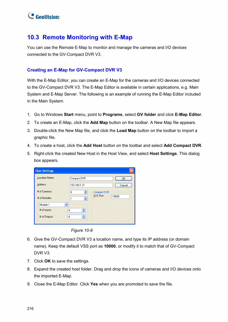
10.3 Remote Monitoring with E-Map You can use the Remote E-Map to monitor and manage the cameras and I/O devices connected to the GV-Compact DVR V3.
Creating an E-Map for GV-Compact DVR V3
With the E-Map Editor, you can create an E-Map for the cameras and I/O devices connected to the GV-Compact DVR V3. The E-Map Editor is available in certain applications, e.g. Main System and E-Map Server. The following is an example of running the E-Map Editor included in the Main System. 1. Go to Windows Start menu, point to Programs, select GV folder and click E-Map Editor.
2. To create an E-Map, click the Add Map button on the toolbar. A New Map file appears.
3. Double-click the New Map file, and click the Load Map button on the toolbar to import a graphic file.
4. To create a host, click the Add Host button on the toolbar and select Add Compact DVR.
5. Right-click the created New Host in the Host View, and select Host Settings. This dialog box appears.
Figure 10-8
6. Give the GV-Compact DVR V3 a location name, and type its IP address (or domain name). Keep the default VSS port as 10000, or modify it to match that of GV-Compact DVR V3.
7. Click OK to save the settings.
8. Expand the created host folder. Drag and drop the icons of cameras and I/O devices onto the imported E-Map.
9. Close the E-Map Editor. Click Yes when you are promoted to save the file.
216
DVR Configurations
217
10
For details on creating an E-Map file on the E-Map Server, see “E-Map Server”, Chapter 9 E-Map Application, DVR User’s Manual on the Surveillance System Software CD/DVD.
Connecting to GV-Compact DVR V3
Depending on where you save the created E-Map file (GV-System, E-Map Server or Control Center), the steps to open the Remote E-Map window for monitoring may vary slightly. The following is the connection example when you store the E-Map file in the GV-System.
1. To enable the remote access to the GV-System, click the Network button, select WebCam Server to display the Server Setup dialog box, and click OK to start the WebCam server.
2. At the local computer, open the Web browser and type the address of the GV-System. The Single View page appears.
3. Select Emap. The valid user name and password are required for login. For the first-time user, you will be directed to the Download page. Install the E-Map program before you can run it.
4. On the Remote E-Map window, click the Login button and select the GV-Compact DVR V3 host to access its videos and I/O devices. The valid user name and password are required to log in the GV-Compact DVR V3.
For details on the Remote E-Map functions, see “The Remote E-Map Window”, Chapter 9 E-Map Application, DVR User’s Manual on the Surveillance System Software CD/DVD.

Chapter 11 CMS Configurations This section introduces the related settings to enable connecting to the GV-Compact DVR V3 in the central monitoring stations Center V2, VSM, Dispatch Server and Control Center.
11.1 Center V2 The Center V2 can monitor and manage the cameras and I/O devices connected to the GV-Compact DVR V3. The following illustration takes the eight-channel GV-Compact DVR V3 as the example.
Figure 11-1
To set the appropriate port connecting to the GV-Compact DVR V3, click the
Preference Settings button, select System Configure, click the Network tab, and select Accept connections from GV-Compact DVR, Video Server & IP Cam. Keep default port 5551, or modify it to match the Center V2 port on the GV-Compact DVR V3.
Figure 11-2
218

CMS Configurations
11
To define he received video on motion detection and input trigger from how to display tthe GV-Compact DVR V3, click the Preference Setting button and select System Configure. This dialog box appears.
Figure 11-3
M nel: Closes the triggered camera view manually.
camera
camera view remaining on the
r: Specify the duration of the camera
n
or details on how to mange the received video from the GV-Compact DVR V3, see GV-
anual close chan
Close the camera view when motion stopped: Closes the triggeredview automatically when motion stops.
Post Motion: Specify the duration of themonitoring window after motion stops.
Camera send by I/O trigger will monitoview remaining on the monitoring window when an I/O device is triggered.
To keep the camera view remaining on the monitoring window even after thealarm is finished, click the right-arrow button, and uncheck Latch Trigger. Thethe camera view will keep remaining on the monitoring window for the specified time. For example, the alarm is triggered for 5 minutes and you set 10 minutes, which means the total display time will be 15 minutes.
FCMS Series User’s manual.
219

11.2 VSM The VSM can monitor and manage the cameras and I/O devices connected to the GV-Compact DVR V3. The following illustration takes the eight-channel GV-Compact DVR V3 as the example.
GV-Compact DVR V3
TCP/ IP
X 8(Max.)
GV-Compact DVR V3
Text Data
VSM
X 8(Max.)
X 8(Max.)
X 8(Max.)
Figure 11-4
ort 2 value of 5609, or modify it to match the VSM port on the GV-Compact DVR V3.
To set the appropriate port connecting to the GV-Compact DVR V3, click Configure on
the window menu, and select System Configure to display this dialog box. Under the Connective Port, keep the default P
Figure 11-5
For details on how to mange the received video from the GV-Compact DVR V3, see GV-CMS Series User’s manual.
220
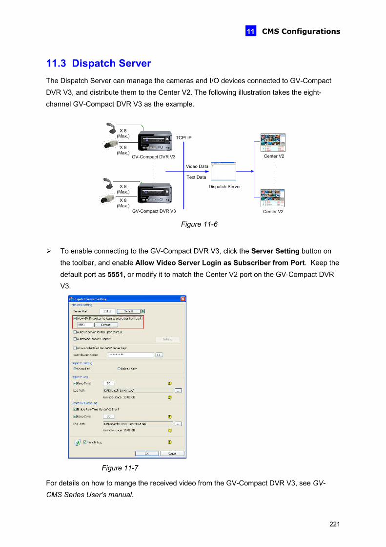
CMS Configurations
11
11.3 Dispatch Server The Dispatch Server can manage the cameras and I/O devices connected to GV-Compact DVR V3, and distribute them to the Center V2. The following illustration takes the eight-channel GV-Compact DVR V3 as the example.
GV-Compact DVR V3
TCP/ IPX 8
(Max.)
GV-Compact DVR V3
Text Data
Center V2
Center V2
Dispatch Server
Video Data
X 8 (Max.)
X 8 (Max.)
X 8 (Max.)
Figure 11-6
To enable connecting to the GV-Compact DVR V3, click the Server Setting button on
the toolbar, and enable Allow Video Server Login as Subscriber from Port. Keep the default port as 5551, or modify it to match the Center V2 port on the GV-Compact DVR V3.
Figure 11-7
For details on how to mange the received video from the GV-Compact DVR V3, see GV-CMS Series User’s manual.
221
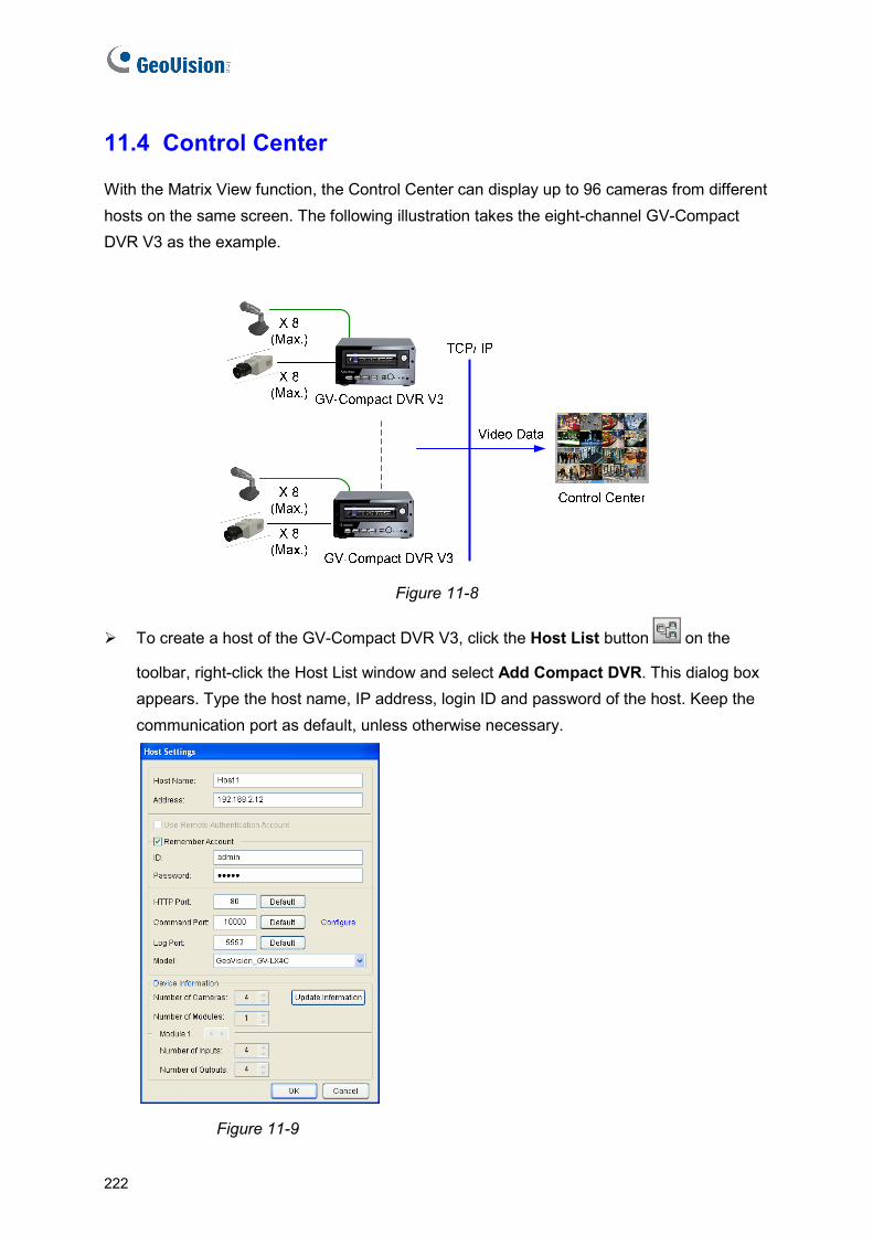
11.4 Control Center
With the Matrix View function, the Control Center can display up to 96 cameras from different hosts on the same screen. The following illustration takes the eight-channel GV-Compact DVR V3 as the example.
Figure 11-8
To create a host of the GV-Compact DVR V3, click the Host List button on the
toolbar, right-click the Host List window and select Add Compact DVR. This dialog box appears. Type the host name, IP address, login ID and password of the host. Keep the communication port as default, unless otherwise necessary.
Figure 11-9
222
CMS Configurations
223
11
To run Matrix View, highlight a Group at the Control Center, and click the Matrix button .
For details on how to mange the received video from the GV-Compact DVR V3, see GV-CMS Series User’s manual.

Chapter 12 The I/O Terminal Block The I/O terminal block, located on the rear panel, can be used to develop applications for alarm input and output, motion detection, PTZ control, GPS tracking or a variety of other functions.
12.1 Pin Assignment
12.1.1 The Four-Channel Unit
Figure 12-1
Pin Function Pin Function
1 Relay Output 1 9 Relay COM
2 Digital Input 1 10 Ground
3 Relay Output 2 11 DC 12V Out for camera power supply
4 Digital Input 2 12 (reserved)
5 Relay Output 3 13 RS-485 + for PTZ control
Standard (reserved) 6 Digital Input 3 14
Anti-Vibration ACC 12V_Standby
7 Relay Output 4 15 RS-485 – for PTZ control
Standard (reserved) 8 Digital Input 4 16
Anti-Vibration ACC ACC wire connection
Note: Currently the standard models (GV-LX4C3D1 / GV- LX4C3D2 / GV- LX4C3D2W /
GV-LX8CD1 / GV-LX8CD2 / GV-LX8CD2W) do not support GPS receiver and
GPS function.
224
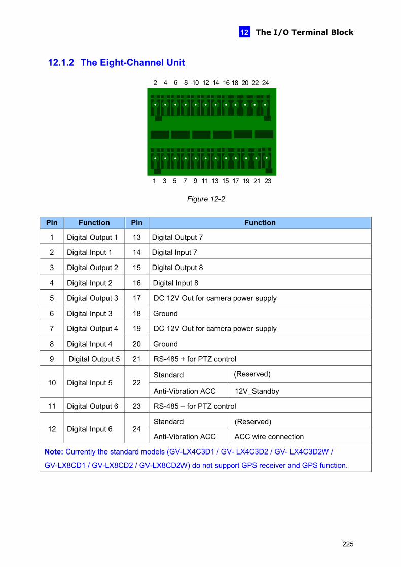
The I/O Terminal Block
12
12.1.2 The Eight-Channel Unit
2 4 6 8 10 12 14 16
1 3 5
18 20 22 24
9 11 13 15 17 19 217 23
Figure 12-2
Pin Function Pin Function
1 Digital Output 1 13 Digital Output 7
2 Digital Input 1 14 Digital Input 7
3 Digital Output 2 15 Digital Output 8
4 Digital Input 2 16 Digital Input 8
5 Digital Output 3 17 DC 12V Out for camera power supply
6 Digital Input 3 18 Ground
7 Digital Output 4 19 DC 12V Out for camera power supply
8 Digital Input 4 20 Ground
9 Digital Output 5 21 RS-485 + for PTZ control
Standard (Reserved) 10 Digital Input 5 22
Anti-Vibration ACC 12V_Standby
11 Digital Output 6 23 RS-485 – for PTZ control
Standard (Reserved) 12 Digital Input 6 24
Anti-Vibration ACC ACC wire connection
Note: Currently the standard models (GV-LX4C3D1 / GV- LX4C3D2 / GV- LX4C3D2W /
GV-LX8CD1 / GV-LX8CD2 / GV-LX8CD2W) do not support GPS receiver and GPS function.
225
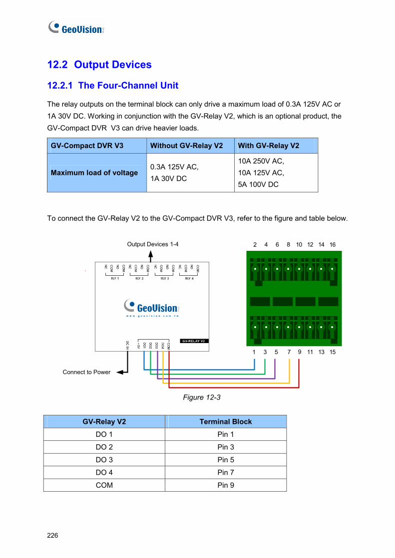
12.2 Output Devices
12.2.1 The Four-Channel Unit
The relay outputs on the terminal block can only drive a maximum load of 0.3A 125V AC or 1A 30V DC. Working in conjunction with the GV-Relay V2, which is an optional product, the GV-Compact DVR V3 can drive heavier loads.
GV-Compact DVR V3 Without GV-Relay V2 With GV-Relay V2
Maximum load of voltage 0.3A 125V AC, 1A 30V DC
10A 250V AC, 10A 125V AC, 5A 100V DC
To connect the GV-Relay V2 to the GV-Compact DVR V3, refer to the figure and table below.
Connect to Power
Output Devices 1-4 2 4 6 8 10 12 14 16
1 3 5 9 11 13 157
Figure 12-3
GV-Relay V2 Terminal Block
DO 1 Pin 1
DO 2 Pin 3
DO 3 Pin 5
DO 4 Pin 7
COM Pin 9
226
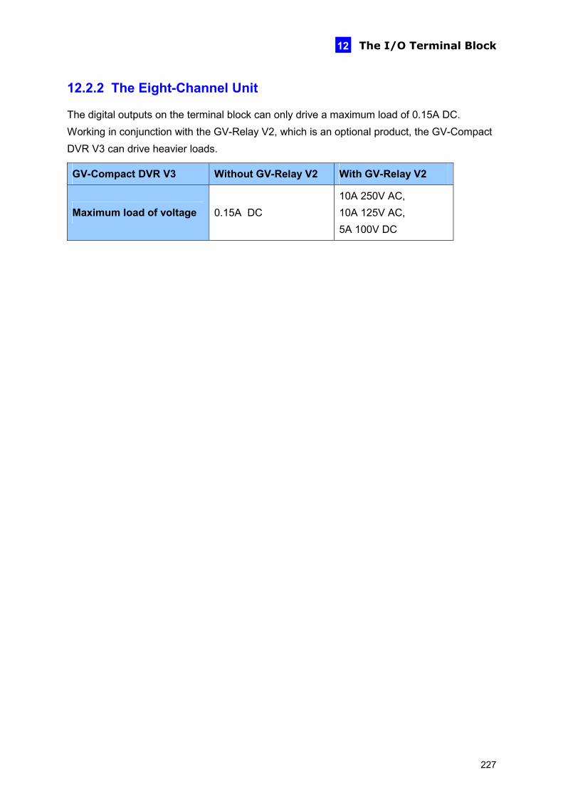
The I/O Terminal Block
12
12.2.2 The Eight-Channel Unit
The digital outputs on the terminal block can only drive a maximum load of 0.15A DC. Working in conjunction with the GV-Relay V2, which is an optional product, the GV-Compact DVR V3 can drive heavier loads.
GV-Compact DVR V3 Without GV-Relay V2 With GV-Relay V2
Maximum load of voltage 0.15A DC 10A 250V AC, 10A 125V AC, 5A 100V DC
227

The eight-channel GV-Compact DVR V3 can connect to up to two GV-Relay V2 modules. To connect the GV-Relay V2 modules to the GV-Compact DVR V3, refer to the figure and table below.
2 4 6 8 10 12 14 16
1 3 5
18 20 22 24
9 11 13 15 17 19 217 2Connect to Power
3
Output Devices 1-4
Connect to Power
Output Devices 5-8
Figure 12-4
GV-Relay V2 with 1 to 4 output devices
Terminal Block GV-Relay V2 with 5 to 8 output devices
Terminal Block
DO 1 Pin 1 DO 1 Pin 9
DO 2 Pin 3 DO 2 Pin 11
DO 3 Pin 5 DO 3 Pin 13
DO 4 Pin 7 DO 4 Pin 15
COM Pin 18 COM Pin 20
228

The I/O Terminal Block
12
12.3 Camera Power Supply
12.3.1 The Four-Channel Unit
The cameras can be powered through GV-Compact DVR V3. Using the supplied Camera Power Cable, connect the black wire to Pin 10 and the red wire to Pin 11.
2 4 6 8 10 12 14 16
1 3 5 9 11 13 157
Figure 12-5
Terminal Block Camera Power Cable
Pin 10 Black Wire
Pin 11 Red Wire
229
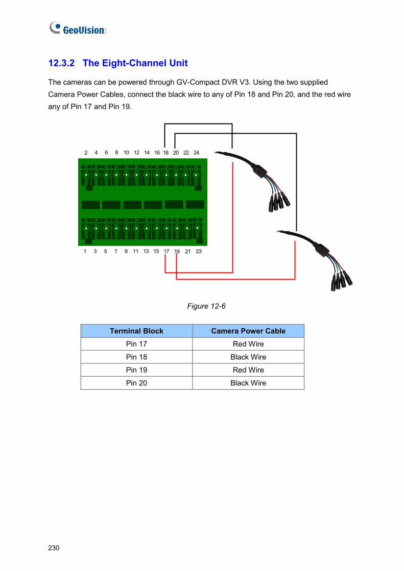
230
12.3.2 The Eight-Channel Unit
The cameras can be powered through GV-Compact DVR V3. Using the two supplied Camera Power Cables, connect the black wire to any of Pin 18 and Pin 20, and the red wire any of Pin 17 and Pin 19.
2 4 6 8 10 12 14 16
1 3 5
18 20 22 24
9 11 13 15 17 19 217 23
Figure 12-6
Terminal Block Camera Power Cable
Pin 17 Red Wire
Pin 18 Black Wire
Pin 19 Red Wire
Pin 20 Black Wire
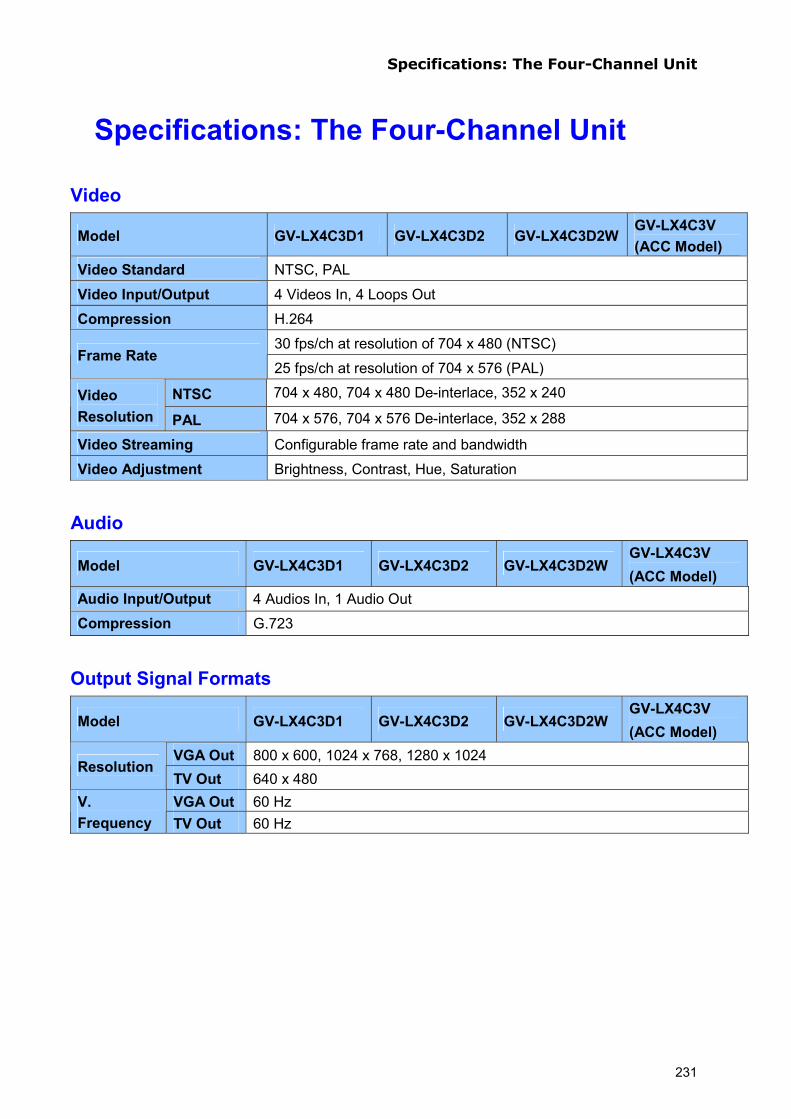
Specifications: The Four-Channel Unit
Specifications: The Four-Channel Unit
Video
Model GV-LX4C3D1 GV-LX4C3D2 GV-LX4C3D2W GV-LX4C3V (ACC Model)
Video Standard NTSC, PAL
Video Input/Output 4 Videos In, 4 Loops Out
Compression H.264
30 fps/ch at resolution of 704 x 480 (NTSC) Frame Rate
25 fps/ch at resolution of 704 x 576 (PAL)
NTSC 704 x 480, 704 x 480 De-interlace, 352 x 240 Video Resolution PAL 704 x 576, 704 x 576 De-interlace, 352 x 288
Video Streaming Configurable frame rate and bandwidth
Video Adjustment Brightness, Contrast, Hue, Saturation
Audio
Model GV-LX4C3D1 GV-LX4C3D2 GV-LX4C3D2W GV-LX4C3V (ACC Model)
Audio Input/Output 4 Audios In, 1 Audio Out Compression G.723
Output Signal Formats
Model GV-LX4C3D1 GV-LX4C3D2 GV-LX4C3D2W GV-LX4C3V (ACC Model)
VGA Out 800 x 600, 1024 x 768, 1280 x 1024 Resolution
TV Out 640 x 480 VGA Out 60 Hz V.
Frequency TV Out 60 Hz
231

Management
Model GV-LX4C3D1 GV-LX4C3D2 GV-LX4C3D2W GV-LX4C3V (ACC Model)
Trigger Time, Sensor Input Triggered, Motion Detected
Event Management Action
Store video to HDD (AVI format) Send e-mails with captured images Upload captured images to FTP Server Monitor through Center V2, VSM and GV-GIS Activate relay outputs to control external devices
Firmware Upgrade Remote upgrade by Web browser Use a USB flash drive Use the upgrade utility included on the Software CD/DVD
Client PC Requirements
Microsoft Internet Explorer 7.x or above running on Windows XP / Vista / 7 / 8 / Server 2008 / Server 2012
Language on Web Interface
Bulgarian / Czech / Danish / Dutch / English / French / German / Greek / Hebrew / Hindi / Hungarian / Italian / Indonesian / Japanese / Norwegian / Lithuanian / Persian / Polish / Portuguese / Romanian / Russian / Serbian / Simplified Chinese / Slovakian / Slovenian / Spanish / Thai / Traditional Chinese / Turkish
Language on OSD Czech / Danish / English / French / German / Hebrew / Hungarian / Italian / Japanese / Polish / Portuguese / Russian / Serbian / Simplified Chinese / Spanish / Traditional Chinese
Note: Internet Explorer 10 is not supported in all the firmware of GV-Compact DVR V3.
Network
Model GV-LX4C3D1 GV-LX4C3D2 GV-LX4C3D2W GV-LX4C3V (ACC Model)
Interface 10/100 Base-T Ethernet 802.11b/g/n Wireless LAN (optional) Mobile broadband: UMTS, EDGE, etc. (optional)
Protocol HTTP, HTTPS, TCP, UDP, SMTP, FTP, DHCP, NTP, UPnP, DynDNS, Mulitcast, 3GPP/ISMA, RTSP, SNMP, QoS (DSCP)
Security IP address filtering
232

Specifications: The Four-Channel Unit
External Interface
Model GV-LX4C3D1 GV-LX4C3D2 GV-LX4C3D2W GV-LX4C3V (ACC Model)
Audio/Video Input D-Type, DB 15 connector (4 Videos In, 4 Audios In)
Audio/Video Output D-Type, DB 15 connector (1 TV Out, 1 Spot Out, 1 VGA Out, 1 Audio Out, 4 Video Loops Out)
Sensor Input 4 inputs on terminal block
Alarm Output 4 outputs on terminal block
PTZ RS-485 +/- outputs on terminal block
ACC Wire Connection None
GPS None
Ethernet RJ-45, 10/100 Mbps
USB 2 ports (USB 2.0)
IR Receiver 1 port for optional External IR Receiver
Power 12V, 5A (60 W Max.)
Alarm
Model GV-LX4C3D1 GV-LX4C3D2 GV-LX4C3D2W GV-LX4C3V (ACC Model)
Sensor Input 4 digital inputs
Alarm Output 4 relay outputs
Environment
Model GV-LX4C3D1 GV-LX4C3D2 GV-LX4C3D2W GV-LX4C3V (ACC Model)
Operation Temp. -20 ~ 50 °C (4 ~ 122 °F)
Humidity 5 ~ 85% RH (non-condensing)
Reliability (for GV-LX4C3V only) Operating Shock 10G, 2 ms Operating Vibration 5 ~ 500 Hz, 1G
233

234
Physical
Model GV-LX4C3D1 GV-LX4C3D2 GV-LX4C3D2W GV-LX4C3V
(ACC Model)
Dimensions (L x W x H) 244 x 176 x 86 mm (9.6 x 6.93 x 3.39 in)
244 x 176 x 130 mm (9.6 x 6.93 x 5.12 in)
244 x 176 x 130 mm (9.6 x 6.93 x 5.12 in)
Weight 2.3 Kg (5 lb) 3.2 Kg (7 lb) 3.3 Kg (7.3 lb) HDD Drive Bay 1 bay 2 bays 1 bay DVD-RW Drive None 1 drive
Optional Storage
Model GV-LX4C3D1 GV-LX4C3D2 GV-LX4C3D2W GV-LX4C3V (ACC Model)
SATA HDD of 2.5" or 3.5"
1 SATA HDD 2 SATA HDD 1 SATA HDD
USB HDDs 2 external USB HDDs
DVD-RW Backup DVD-RW backup
DVD-RW backup N/A (already equipped)
Note: 1. SATA II/III HDD and SSD are supported, but some SATA III HDD and SSD may have
compatibility issues with the device. 2. For the Anti-vibration ACC models (GV-LX4C3V, GV-LX8CV1 and GV-LX8CV2), it is necessary
to use the hard drive especially for notebook, vehicle or surveillance applications, and tightly fasten the unit on the vehicle to prevent vibration and shock hazard.
3. Currently 3 TB HDD is not supported. 4. For 2.5" HDD, the HDD converter is required from GeoVision. 5. The CD-R and CD-RW backup are not supported.
Regulatory Regulatory CE, FCC, C-Tick, RoHS compliant
All specifications are subject to change without notice.

Specifications: The Eight-Channel Unit
Specifications: The Eight-Channel Unit
Video
Model GV-LX8CD1 GV-LX8CD2 GV-LX8CD2W GV-LX8CV1 (ACC Model)
GV-LX8CV2 (ACC Model)
Video Standard NTSC, PAL
Video Input/Output 8 Videos In, 8 Loops Out
Compression H.264 15 fps/ch at resolution of 704 x 480 (NTSC)
Frame Rate 12.5 fps/ch at resolution of 704 x 576 (PAL)
NTSC 704 x 480, 704 x 480 De-interlace, 352 x 240 Video Resolution PAL 704 x 576, 704 x 576 De-interlace, 352 x 288
Video Streaming Configurable frame rate and bandwidth
Video Adjustment Brightness, Contrast, Hue, Saturation Note: When the resolution is set at 704 x 480 / 704 x 576, the frame rate for recording and live view will be 15 fps/ch (NTSC) or 12.5 fps/ch (PAL).
Audio
Model GV-LX8CD1 GV-LX8CD2 GV-LX8CD2W GV-LX8CV1 (ACC Model)
GV-LX8CV2 (ACC Model)
Audio Input/Output 8 Audios In, 1 Audio Out
Compression G.723
Output Signal Formats
Model GV-LX8CD1 GV-LX8CD2 GV-LX8CD2W GV-LX8CV1 (ACC Model)
GV-LX8CV2 (ACC Model)
VGA Out
800 x 600, 1024 x 768, 1280 x 1024 Resolution
TV Out 640 x 480 VGA Out
60 Hz V. Frequency
TV Out 60 Hz
235

Management
Model GV-LX8CD1 GV-LX8CD2 GV-LX8CD2W GV-LX8CV1 (ACC Model)
GV-LX8CV2 (ACC Model)
Trigger Time, Sensor Input Triggered, Motion Detected
Event Management Action
Store video to HDD (AVI format) Send e-mails with captured images Upload captured images to FTP Server Monitor through Center V2, VSM and GV-GIS Activate relay outputs to control external devices
Firmware Upgrade Remote upgrade by Web browser Use a USB flash drive Use the upgrade utility included on the Software CD/DVD
Client PC Requirements
Microsoft Internet Explorer 7.x or above running on Windows XP / Vista / 7 / 8 / Server 2008 / Server 2012
Language on Web Interface
Bulgarian / Czech / Danish / Dutch / English / French / German / Greek / Hebrew / Hindi / Hungarian / Italian / Indonesian / Japanese / Norwegian / Lithuanian / Persian / Polish / Portuguese / Romanian / Russian / Serbian / Simplified Chinese / Slovakian / Slovenian / Spanish / Thai / Traditional Chinese / Turkish
Language on OSD Czech / Danish / English / French / German / Hebrew / Hungarian / Italian / Japanese / Polish / Portuguese / Russian / Serbian / Simplified Chinese / Spanish / Traditional Chinese
Note: Internet Explorer 10 is not supported in all the firmware of GV-Compact DVR V3.
Optional Storage
Model GV-LX8CD1 GV-LX8CD2 GV-LX8CD2W GV-LX8CV1 (ACC Model)
GV-LX8CV2 (ACC Model)
SATA HDD of 2.5" or 3.5"
1 SATA HDD 2 SATA HDD 1 SATA HDD 1 SATA HDD 2 SATA HDD
USB HDDs 4 external USB HDDs
DVD-RW Backup DVD-RW backup
DVD-RW backup
N/A (already equipped)
DVD-RW backup
DVD-RW backup
Note: 1. SATA II/III HDD and SSD are supported, but some SATA III HDD and SSD may have compatibility
issues with the device. 2. For the Anti-vibration ACC models (GV-LX4C3V, GV-LX8CV1 and GV-LX8CV2), it is necessary to use
the hard drive especially for notebook, vehicle or surveillance applications, and tightly fasten the unit on the vehicle to prevent vibration and shock hazard.
3. Currently 3 TB HDD is not supported. 4. For 2.5" HDD, the HDD converter is required from GeoVision. 5. The CD-R and CD-RW backup are not supported.
236

Specifications: The Eight-Channel Unit
Network
Model GV-LX8CD1 GV-LX8CD2 GV-LX8CD2W GV-LX8CV1 (ACC Model)
GV-LX8CV2 (ACC Model)
Interface 10/100/1000 Base-T Ethernet 802.11b/g/n Wireless LAN (optional) Mobile broadband: UMTS, EDGE, etc. (optional)
Protocol HTTP, HTTPS, TCP, UDP, SMTP, FTP, DHCP, NTP, UPnP, DynDNS, 3GPP/ISMA, RTSP, SNMP, QoS (DSCP)
Security IP address filtering
External Interface
Model GV-LX8CD1 GV-LX8CD2 GV-LX8CD2W GV-LX8CV1 (ACC Model)
GV-LX8CV2 (ACC Model)
Audio/Video Input D-Type, DB 15 connector (8 Videos In, 8 Audios In)
Audio/Video Output D-Type, DB 15 connector (1 TV Out, 1 Spot Out, 1 VGA Out, 1 Audio Out, 8 Video Loops Out)
Sensor Input 8 inputs on terminal block
Alarm Output 8 outputs on terminal block
PTZ RS-485 +/- outputs on terminal block
ACC Wire Connection None 1 output on terminal block
GPS None 1 port (PS/2 connector)
Ethernet RJ-45, 10/100/1000 Mbps
USB 4 ports (USB 2.0)
IR Receiver 1 port for optional External IR Receiver
Power 12V, 5A (60 W Max.) 10 ~ 28V, 5A (60 W Max.)
Alarm
Model GV-LX8CD1 GV-LX8CD2 GV-LX8CD2W GV-LX8CV1 (ACC Model)
GV-LX8CV2 (ACC Model)
Sensor Input 8 digital inputs
Alarm Output 8 digital outputs
237
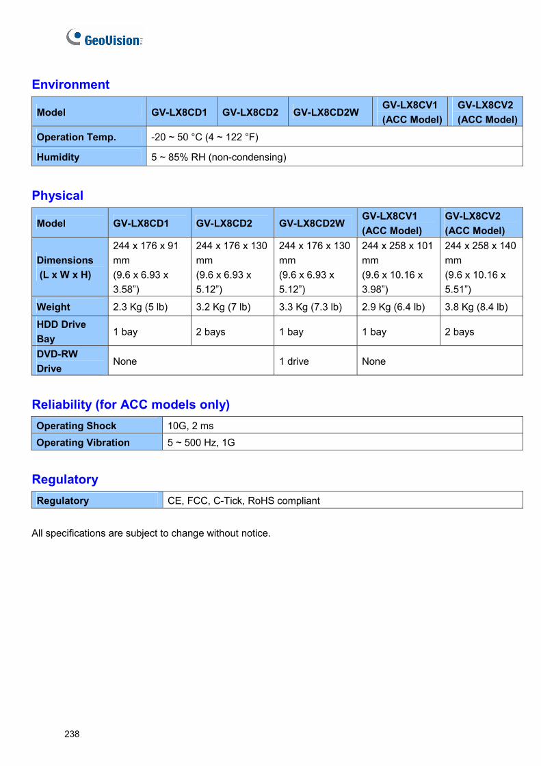
238
Environment
Model GV-LX8CD1 GV-LX8CD2 GV-LX8CD2W GV-LX8CV1 (ACC Model)
GV-LX8CV2 (ACC Model)
Operation Temp. -20 ~ 50 °C (4 ~ 122 °F)
Humidity 5 ~ 85% RH (non-condensing)
Physical
Model GV-LX8CD1 GV-LX8CD2 GV-LX8CD2W GV-LX8CV1 (ACC Model)
GV-LX8CV2 (ACC Model)
Dimensions (L x W x H)
244 x 176 x 91 mm (9.6 x 6.93 x 3.58”)
244 x 176 x 130 mm (9.6 x 6.93 x 5.12”)
244 x 176 x 130 mm (9.6 x 6.93 x 5.12”)
244 x 258 x 101 mm (9.6 x 10.16 x 3.98”)
244 x 258 x 140 mm (9.6 x 10.16 x 5.51”)
Weight 2.3 Kg (5 lb) 3.2 Kg (7 lb) 3.3 Kg (7.3 lb) 2.9 Kg (6.4 lb) 3.8 Kg (8.4 lb)
HDD Drive Bay
1 bay 2 bays 1 bay 1 bay 2 bays
DVD-RW Drive
None 1 drive None
Reliability (for ACC models only) Operating Shock 10G, 2 ms Operating Vibration 5 ~ 500 Hz, 1G
Regulatory Regulatory CE, FCC, C-Tick, RoHS compliant
All specifications are subject to change without notice.
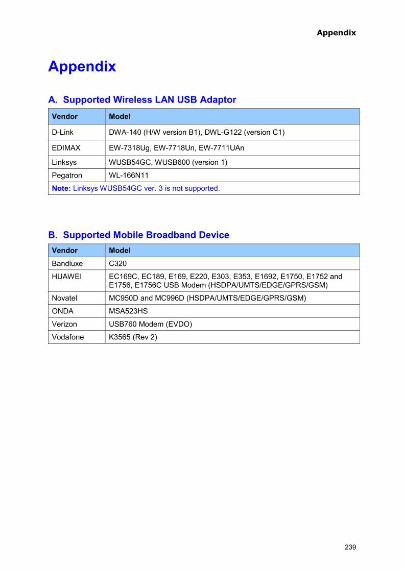
Appendix
Appendix
A. Supported Wireless LAN USB Adaptor Vendor Model
D-Link DWA-140 (H/W version B1), DWL-G122 (version C1)
EDIMAX EW-7318Ug, EW-7718Un, EW-7711UAn
Linksys WUSB54GC, WUSB600 (version 1)
Pegatron WL-166N11
Note: Linksys WUSB54GC ver. 3 is not supported.
B. Supported Mobile Broadband Device Vendor Model
Bandluxe C320
HUAWEI EC169C, EC189, E169, E220, E303, E353, E1692, E1750, E1752 and E1756, E1756C USB Modem (HSDPA/UMTS/EDGE/GPRS/GSM)
Novatel MC950D and MC996D (HSDPA/UMTS/EDGE/GPRS/GSM)
ONDA MSA523HS
Verizon USB760 Modem (EVDO)
Vodafone K3565 (Rev 2)
239
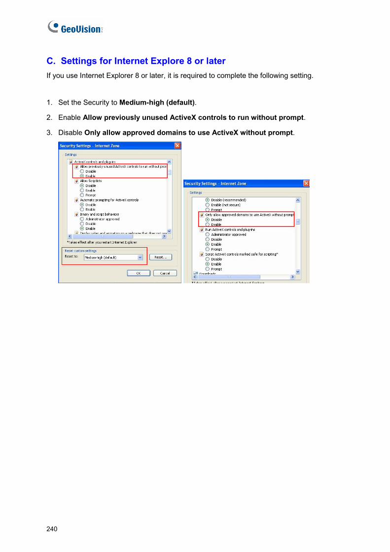
C. Settings for Internet Explore 8 or later If you use Internet Explorer 8 or later, it is required to complete the following setting.
1. Set the Security to Medium-high (default).
2. Enable Allow previously unused ActiveX controls to run without prompt.
3. Disable Only allow approved domains to use ActiveX without prompt.
240

Appendix
D. The CGI Command The GV-Compact DVR V3 supports a CGI command function for obtaining a snapshot of the live view without logging in the Web interface. For a GV-Compact DVR V3 with the following details:
IP address: 192.168.2.109 Username: admin Password: admin Desired Stream: 1
Type the following into your Web browser: http://192.168.2.109/PictureCatch.cgi?username=admin&password=admin&channel=1
241

E. The RTSP Command The GV-Compact DVR V3 can support RTSP protocol for both video and audio streaming. For the RTSP command, enter: rtsp://<IP of the GV-Compact DVR V3:8554/<CH No.>.sdp For example, rtsp://192.168.3.111:8554/CH001.sdp
Note: 1. The RTSP server must be enabled on the Web interface. See 6.3.9 RTSP/ 3GPP. 2. Only VLC and QuickTime players are supported for streaming video via RTSP
protocol.
242
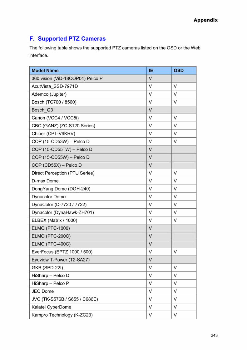
Appendix
F. Supported PTZ Cameras The following table shows the supported PTZ cameras listed on the OSD or the Web interface.
Model Name IE OSD 360 vision (ViD-18COP04) Pelco P V
AcutVista_SSD-7971D V V
Ademco (Jupiter) V V
Bosch (TC700 / 8560) V V
Bosch_G3 V
Canon (VCC4 / VCC5i) V V
CBC (GANZ) (ZC-S120 Series) V V
Chiper (CPT-V9KRV) V V
COP (15-CD53W) – Pelco D V V
COP (15-CD55TW) – Pelco D V
COP (15-CD55W) – Pelco D V
COP (CD55X) – Pelco D V
Direct Perception (PTU Series) V V
D-max Dome V V
DongYang Dome (DOH-240) V V
Dynacolor Dome V V
DynaColor (D-7720 / 7722) V V
Dynacolor (DynaHawk-ZH701) V V
ELBEX (Matrix / 1000) V V
ELMO (PTC-1000) V
ELMO (PTC-200C) V
ELMO (PTC-400C) V
EverFocus (EPTZ 1000 / 500) V V
Eyeview T-Power (T2-SA27) V
GKB (SPD-22I) V V
HiSharp – Pelco D V V
HiSharp – Pelco P V V
JEC Dome V V
JVC (TK-S576B / S655 / C686E) V V
Kalatel CyberDome V V
Kampro Technology (K-ZC23) V V
243

KenKo (DMP23-H1) V V
LG (LPT-OS553HQ) V V
Lilin (PIH) – MLP1 V V
Lilin (PIH-7625) – MLP1 V V
Lilin (PIH-820) – MLP1 V
MESSOA (D-700 series) V V
MESSOA (SDS600 series) V V
Minking Dome V V
Mintron (54G2AHN / P) V
NanWang (NVD 2300PNT) V V
NanWangV4.1 (NVD 2300PNT) V V
Panasonic (WV-CS850) V V
Panasonic (WV-CW960) V V
Pelco (Spectra III) V V
Pelco Dome V V
PelcoSpetra Mini Dome ( SD4-WO) V V
Pishion (22X) V V
PTZ in I/O V V
RX214D V
SAE (DR-E588) V V
Samsung (SCC-641 / 643) V V
Samsung (SPD-1600) V V
Samsung (SPD-3300) V V
Sensormatic (Ultra IV) V V
Sony (EVI-D100) V V
StorVision PTZ V
TOA (CC551) V V
VDI (CT-58SPD) V
VIDO.AT Dome V V
YAAN (YAAN) V V
Total 61 47
244

Appendix
245
G. Default Port Value HTTP Port 80 Video Streaming Port 10000 E-mail Server 25 FTP Server 21 Center V2 5551 VSM 5609 GV-GIS 3356 ViewLog Server 5552 RTSP/TCP Port 8554 RTP/UDP Port 17300-17319
![:_UZR FD e` d`]gV ecRUV UZdafeVd - Daily Pioneer](https://static.fdokumen.com/doc/165x107/63198b3a4cd7b34424091454/uzr-fd-e-dgv-ecruv-uzdafevd-daily-pioneer.jpg)