LOGO! CMR2020, LOGO! CMR2040 - Automation24
186
LOGO! CMR2020, LOGO! CMR2040 SIMATIC NET LOGO! - Industrial Ethernet LOGO! CMR2020, LOGO! CMR2040 Operating Instructions 08/2019 C79000-G8976-C356-06 Preface Application and functions 1 LEDs, connectors, buttons, card slots 2 Installation, connecting up, commissioning 3 Operation: Access to BM 4 Configuration (WBM) 5 Diagnostics and maintenance 6 Dimension drawings 7 Technical specifications 8 Approvals 9 Accessories A Additional information on SMS B Documentation references C
-
Upload
khangminh22 -
Category
Documents
-
view
1 -
download
0
Transcript of LOGO! CMR2020, LOGO! CMR2040 - Automation24

LOGO! CMR2020, LOGO! CMR2040
SIMATIC NET
LOGO! - Industrial Ethernet LOGO! CMR2020, LOGO! CMR2040
Operating Instructions
08/2019 C79000-G8976-C356-06
Preface
Application and functions 1
LEDs, connectors, buttons, card slots
2
Installation, connecting up, commissioning
3
Operation: Access to BM 4
Configuration (WBM) 5
Diagnostics and maintenance
6
Dimension drawings 7
Technical specifications 8
Approvals 9
Accessories A
Additional information on SMS
B
Documentation references C

Siemens AG Digital Industries Postfach 48 48 90026 NÜRNBERG GERMANY
C79000-G8976-C356-06 Ⓟ 08/2019 Subject to change
Copyright © Siemens AG 2014 - 2019. All rights reserved
Legal information Warning notice system
This manual contains notices you have to observe in order to ensure your personal safety, as well as to prevent damage to property. The notices referring to your personal safety are highlighted in the manual by a safety alert symbol, notices referring only to property damage have no safety alert symbol. These notices shown below are graded according to the degree of danger.
DANGER indicates that death or severe personal injury will result if proper precautions are not taken.
WARNING indicates that death or severe personal injury may result if proper precautions are not taken.
CAUTION indicates that minor personal injury can result if proper precautions are not taken.
NOTICE indicates that property damage can result if proper precautions are not taken.
If more than one degree of danger is present, the warning notice representing the highest degree of danger will be used. A notice warning of injury to persons with a safety alert symbol may also include a warning relating to property damage.
Qualified Personnel The product/system described in this documentation may be operated only by personnel qualified for the specific task in accordance with the relevant documentation, in particular its warning notices and safety instructions. Qualified personnel are those who, based on their training and experience, are capable of identifying risks and avoiding potential hazards when working with these products/systems.
Proper use of Siemens products Note the following:
WARNING Siemens products may only be used for the applications described in the catalog and in the relevant technical documentation. If products and components from other manufacturers are used, these must be recommended or approved by Siemens. Proper transport, storage, installation, assembly, commissioning, operation and maintenance are required to ensure that the products operate safely and without any problems. The permissible ambient conditions must be complied with. The information in the relevant documentation must be observed.
Trademarks All names identified by ® are registered trademarks of Siemens AG. The remaining trademarks in this publication may be trademarks whose use by third parties for their own purposes could violate the rights of the owner.
Disclaimer of Liability We have reviewed the contents of this publication to ensure consistency with the hardware and software described. Since variance cannot be precluded entirely, we cannot guarantee full consistency. However, the information in this publication is reviewed regularly and any necessary corrections are included in subsequent editions.

LOGO! CMR2020, LOGO! CMR2040 Operating Instructions, 08/2019, C79000-G8976-C356-06 3
Preface
Validity of this manual This document contains information on the following LOGO! products:
● LOGO! CMR2020 Hardware product version: 1.0 or higher Firmware version: V2.1 Article number: 6GK7 142-7BX00-0AX0
Communications module for connection of LOGO! 8 to the GSM/GPRS network (2G)
● LOGO! CMR2040 Hardware product version: 1.0 or higher Firmware version: V2.1 Article number: 6GK7 142-7EX00-0AX0
Communications module for connection of LOGO! 8 to the LTE network (4G)
Figure 1 LOGO! CMR2020

Preface
LOGO! CMR2020, LOGO! CMR2040 4 Operating Instructions, 08/2019, C79000-G8976-C356-06
The two devices differ in the supported mobile wireless standards. The remaining range of functions of both devices is identical.
Product names and abbreviations ● CMR or device
In this document, the term "CMR" or "device" is also used instead of the full product name LOGO! CMR2020 or LOGO! CMR2040. CMR is the abbreviation for Communication Module Radio.
● BM or LOGO! BM
Basic module: LOGO! 8
● WBM
Web Based Management; Web user interface with which the CMR is configured.
● SD card
Below, the term "SD card" is used instead of micro SD card.
Purpose of the manual This manual supports you during the configuration, installation, commissioning and operation of the communications modules LOGO! CMR2020 and LOGO! CMR2040.
A detailed example (Page 129) supports you during commissioning.
New in this release ● Error detection for e-mails
● Updating wireless approvals:
Link: (www.siemens.com/mobilenetwork-approvals)
Replaced documentation This manual replaces the manual edition 04/2019.
Current manual release on the Internet You will also find the current version of this manual on the Internet pages of Siemens Industry Online Support at the following address:
Link: (https://support.industry.siemens.com/cs/ww/en/view/109477418)
Cross references In this manual there are often cross references to other sections.
To be able to return to the initial page after jumping to a cross reference, some PDF readers support the command <Alt>+<left arrow>.

Preface
LOGO! CMR2020, LOGO! CMR2040 Operating Instructions, 08/2019, C79000-G8976-C356-06 5
Sources of information and other documentation You will find an overview of further reading and references in the Documentation references in this manual.
Use of the device Connection of a LOGO! BM to an LTE, UMTS or GSM/GPRS mobile wireless network and a GPS system.
WARNING
Impairment of medical devices and data media
The device contains a wireless transmitter that could, under certain circumstances, impair the functionality of electronic medical devices such as hearing aids or pacemakers. Do not use the device in places where the operation of wireless devices is prohibited. You can obtain advice from your physician or the manufacturer of such devices.
To prevent data media from being demagnetized, do not keep disks, credit cards or other magnetic data media near the device.
See also System Time (Page 77)
Approvals (Page 155)
License conditions
Note Open source software
Read the license conditions for open source software carefully before using the product.
The license conditions for open source software are stored on the device and can be read out using the WBM: In the header line of the WBM you will find an icon with you can save the OSS license texts on the PC and then extract and open them.
Security information Siemens provides products and solutions with industrial security functions that support the secure operation of plants, systems, machines and networks.
In order to protect plants, systems, machines and networks against cyber threats, it is necessary to implement – and continuously maintain – a holistic, state-of-the-art industrial security concept. Siemens’ products and solutions constitute one element of such a concept.
Customers are responsible for preventing unauthorized access to their plants, systems, machines and networks. Such systems, machines and components should only be connected to an enterprise network or the internet if and to the extent such a connection is

Preface
LOGO! CMR2020, LOGO! CMR2040 6 Operating Instructions, 08/2019, C79000-G8976-C356-06
necessary and only when appropriate security measures (e.g. firewalls and/or network segmentation) are in place.
For additional information on industrial security measures that may be implemented, please visit Link: (http://www.siemens.com/industrialsecurity)
Siemens’ products and solutions undergo continuous development to make them more secure. Siemens strongly recommends that product updates are applied as soon as they are available and that the latest product versions are used. Use of product versions that are no longer supported, and failure to apply the latest updates may increase customers’ exposure to cyber threats.
To stay informed about product updates, subscribe to the Siemens Industrial Security RSS Feed under Link: (http://www.siemens.com/industrialsecurity)
Recycling and disposal The product is low in pollutants, can be recycled and meets the requirements of the WEEE directive 2012/19/EU "Waste Electrical and Electronic Equipment".
Do not dispose of the product at public disposal sites. For environmentally friendly recycling and the disposal of your old device contact a certified disposal company for electronic scrap or your Siemens contact.
Keep to the local regulations.
You will find information on returning the product on the Internet pages of Siemens Industry Online Support: Link: (https://support.industry.siemens.com/cs/ww/en/view/109479891)
Trademarks The following and possibly other names not identified by the registered trademark sign ® are registered trademarks of Siemens AG:
SIMATIC NET
SIMATIC NET glossary Explanations of many of the specialist terms used in this documentation can be found in the SIMATIC NET glossary.
You will find the SIMATIC NET glossary on the Internet at the following address:
Link: (https://support.industry.siemens.com/cs/ww/en/view/50305045)
Service & Support In addition to the product documentation, the comprehensive online information platform of Siemens Automation Customer Support supports at any time and at any location in the world. You will find the Service & Support pages on the Internet at the following address: Link: (https://support.industry.siemens.com/cs/ww/en/)

Preface
LOGO! CMR2020, LOGO! CMR2040 Operating Instructions, 08/2019, C79000-G8976-C356-06 7
Apart from news, you will also find the following information there:
● Product information, Product Support, Applications & Tools
● Technical Forum
● Technical Support - Ask the Siemens experts
● Our service offer:
– Technical Consulting, Engineering support
– Field Service
– Spare parts and repairs
– Maintenance, optimization, modernization and more
You will find contact data on the Internet at the following address: Link: (www.automation.siemens.com/partner)
SITRAIN - Siemens training for automation and industrial solutions With over 300 different courses, SITRAIN covers the entire Siemens product and system spectrum in the field of automation and drive technology. Apart from the classic range of courses, we also offer training tailored for individual needs and a combination of different teaching media and sequences, for example self-learning programs on CD-ROM or on the Internet.
You will find detailed information on the training curriculum and how to contact our customer consultants at the following Internet address:
Link: (www.siemens.com/sitrain)

Preface
LOGO! CMR2020, LOGO! CMR2040 8 Operating Instructions, 08/2019, C79000-G8976-C356-06

LOGO! CMR2020, LOGO! CMR2040 Operating Instructions, 08/2019, C79000-G8976-C356-06 9
Table of contents
Preface ................................................................................................................................................... 3
1 Application and functions ...................................................................................................................... 13
1.1 Application and communications functions ............................................................................. 13
1.2 Further functions ..................................................................................................................... 15
1.3 Requirements for use.............................................................................................................. 18
1.4 Application examples .............................................................................................................. 21 1.4.1 Mobile wireless communication by SMS / e-mail without LOGO! BM .................................... 22 1.4.2 Mobile wireless communication by SMS / e-mail with LOGO! BM ......................................... 23 1.4.3 Access by the PC via the Internet and mobile wireless network ............................................ 24 1.4.4 Position detection (GPS) ........................................................................................................ 26 1.4.5 Time-of-day synchronization ................................................................................................... 27
2 LEDs, connectors, buttons, card slots ................................................................................................... 31
2.1 Appearance of the device ....................................................................................................... 31
2.2 LEDs to display operation ....................................................................................................... 32
2.3 Interfaces ................................................................................................................................ 34
2.4 The "SET" button .................................................................................................................... 35
2.5 Slots for SIM card and SD card .............................................................................................. 35
3 Installation, connecting up, commissioning ............................................................................................ 39
3.1 Important notes on using the device ....................................................................................... 39 3.1.1 Notices on use in hazardous areas ........................................................................................ 39 3.1.2 Notes on use in hazardous areas according to ATEX / IECEx .............................................. 41 3.1.3 Notices on use in hazardous areas according to UL HazLoc ................................................. 41
3.2 Installing the device ................................................................................................................ 42
3.3 Connecting up the device ....................................................................................................... 43 3.3.1 X1P1 (LAN) interface .............................................................................................................. 43 3.3.2 Inputs and outputs .................................................................................................................. 44 3.3.3 Connecting the antenna .......................................................................................................... 45 3.3.4 Power supply .......................................................................................................................... 46
3.4 Commissioning the device ...................................................................................................... 47 3.4.1 Steps in commissioning .......................................................................................................... 47 3.4.2 Insert the SIM card and enter the PIN .................................................................................... 48 3.4.3 Inserting the SD card .............................................................................................................. 50
4 Operation: Access to BM ....................................................................................................................... 51
4.1 Overview ................................................................................................................................. 51
4.2 Reading and writing values ..................................................................................................... 52

Table of contents
LOGO! CMR2020, LOGO! CMR2040 10 Operating Instructions, 08/2019, C79000-G8976-C356-06
5 Configuration (WBM) ............................................................................................................................ 57
5.1 Security recommendations .................................................................................................... 57
5.2 General functions of the WBM ............................................................................................... 60
5.3 Performance data and configuration limits ............................................................................ 63
5.4 Permitted characters and string lengths ................................................................................ 64
5.5 Establishing a connection to the CMR ................................................................................... 68 5.5.1 Establishing the configuration connection ............................................................................. 69
5.6 Start page ............................................................................................................................... 72
5.7 System ................................................................................................................................... 75 5.7.1 General .................................................................................................................................. 75 5.7.2 Device info ............................................................................................................................. 76 5.7.3 SD card .................................................................................................................................. 76 5.7.4 System Time .......................................................................................................................... 77
5.8 Diagnostics ............................................................................................................................. 81 5.8.1 Diagnostics buffer .................................................................................................................. 81 5.8.2 Notifications ............................................................................................................................ 82
5.9 Maintenance ........................................................................................................................... 83 5.9.1 Configuration .......................................................................................................................... 83 5.9.2 Firmware ................................................................................................................................ 85 5.9.3 Operating status ..................................................................................................................... 86 5.9.4 Online support ........................................................................................................................ 88
5.10 LAN ........................................................................................................................................ 90 5.10.1 Configuration .......................................................................................................................... 90
5.11 WAN ....................................................................................................................................... 91 5.11.1 Overview ................................................................................................................................ 91 5.11.2 Mobile wireless settings ......................................................................................................... 93 5.11.3 Wireless cell ........................................................................................................................... 97 5.11.4 SMS ....................................................................................................................................... 98 5.11.5 SMS alias ............................................................................................................................... 99 5.11.6 E-mail ................................................................................................................................... 100 5.11.7 DynDNS ............................................................................................................................... 101
5.12 Security ................................................................................................................................ 103 5.12.1 Overview .............................................................................................................................. 103 5.12.2 OpenVPN-PSK..................................................................................................................... 104 5.12.3 HTTPS ................................................................................................................................. 108
5.13 Users / groups ...................................................................................................................... 111 5.13.1 User ...................................................................................................................................... 111 5.13.2 Recipient groups .................................................................................................................. 113
5.14 Monitoring ............................................................................................................................ 114 5.14.1 Monitoring - What do I need to do?...................................................................................... 115 5.14.2 Monitoring functions ............................................................................................................. 116 5.14.3 Overview .............................................................................................................................. 117 5.14.4 LOGO! BM ........................................................................................................................... 118 5.14.5 Constants ............................................................................................................................. 118 5.14.6 Message texts ...................................................................................................................... 119
Table of contents
LOGO! CMR2020, LOGO! CMR2040 Operating Instructions, 08/2019, C79000-G8976-C356-06 11
5.14.7 Signals .................................................................................................................................. 120 5.14.8 Events ................................................................................................................................... 123 5.14.9 Actions .................................................................................................................................. 124 5.14.10 Assignments ......................................................................................................................... 127 5.14.11 Example of a monitoring configuration ................................................................................. 129
6 Diagnostics and maintenance ............................................................................................................. 139
6.1 Diagnostics options ............................................................................................................... 139
6.2 Diagnostics SMS message ................................................................................................... 140
6.3 Error identifiers for e-mails .................................................................................................... 142
6.4 Disruptions and their possible causes .................................................................................. 143
6.5 Loading firmware .................................................................................................................. 144
6.6 Resetting to factory settings ................................................................................................. 145
6.7 Replacing the CMR ............................................................................................................... 146
7 Dimension drawings ............................................................................................................................ 149
8 Technical specifications ...................................................................................................................... 151
9 Approvals ............................................................................................................................................ 155
A Accessories ........................................................................................................................................ 161
A.1 Antennas ............................................................................................................................... 161
A.2 Antenna cable ....................................................................................................................... 163
A.3 Cabinet feedthrough / antenna coupling ............................................................................... 166
A.4 Overvoltage protection .......................................................................................................... 167
A.5 SD card ................................................................................................................................. 167
B Additional information on SMS ............................................................................................................ 169
B.1 Response of the CMR when receiving an SMS message/replying to SMS message ......... 169
B.2 SMS error messages ............................................................................................................ 171
B.3 Syntax of all SMS commands ............................................................................................... 172
B.4 SMS commands .................................................................................................................... 172
B.5 Reply SMS message to the "MONITOR?" command ........................................................... 177
C Documentation references .................................................................................................................. 183
C.1 /1/ .......................................................................................................................................... 183
C.2 /2/ .......................................................................................................................................... 183
Index................................................................................................................................................... 185

Table of contents
LOGO! CMR2020, LOGO! CMR2040 12 Operating Instructions, 08/2019, C79000-G8976-C356-06

LOGO! CMR2020, LOGO! CMR2040 Operating Instructions, 08/2019, C79000-G8976-C356-06 13
Application and functions 1 1.1 Application and communications functions
Communications functions
Figure 1-1 Overview of the communications functions for the LOGO! CMR
Communication and process data access
Process data access
In a structure with BM you can use the CMR to access the process data: Process image, inputs/outputs, memory bits etc.

Application and functions 1.1 Application and communications functions
LOGO! CMR2020, LOGO! CMR2040 14 Operating Instructions, 08/2019, C79000-G8976-C356-06
In stand-alone operation (see below) you can access the I/O via the inputs and outputs of the CMR
The information can be read out and transferred by SMS message or e-mail. An event-based notification via SMS message or e-mail is possible, see "Mobile wireless".
Mobile wireless
With the CMR, you establish a mobile data connection to a mobile wireless network: The following specifications are supported:
● LOGO! CMR2020
Mobile wireless standards:
– GSM/GPRS
● LOGO! CMR2040
Mobile wireless standards:
– 4G (LTE)
– 3G (UMTS)
– 2G (GSM/GPRS/EDGE)
Fallback strategy: If the establishment of a connection from the CMR2040 to the LTE network fails, the dial-in falls back automatically to the next lower mobile wireless network (LTE > UMTS > GPRS).
You will find the supported frequencies in the section Technical specifications (Page 151).
You will find the country-specific wireless approvals in section Approvals (Page 155) and on the following Internet page; Link: (https://support.industry.siemens.com/cs/ww/en/ps/15383/cert)
GPS
The CMR can receive position data and the time of day of a GPS system.
HTTPS
On a configuration PC / smartphone / tablet you can use HTTPS to access the CMR. HTTPS is supported on both interfaces of the CMR: LAN and WAN (mobile wireless)
Station structure with CMR You can use the CMR with the following structures:
● CMR with BM
The CMR is connected locally to a BM via Ethernet. The CMR establishes the connection to a mobile wireless network.
● Stand-alone operation
You can also operate the CMR in stand-alone mode: in other words without a connected BM. To connect the I/O you use the two digital inputs and outputs of the CMR.

Application and functions 1.2 Further functions
LOGO! CMR2020, LOGO! CMR2040 Operating Instructions, 08/2019, C79000-G8976-C356-06 15
1.2 Further functions
Functions The CMR supports the following functions:
● WBM
A Web user interface (WBM - Web Based Management) for the configuration of the CMR protected by user and password queries, see section "WBM" below.
● OpenVPN
Tunnel technology OpenVPN for secure data transmission via mobile wireless, see section "OpenVPN" below.
● GPS position
– Querying position by SMS
– Forwarding position to the BM
● DynDNS
Use of dynamic DNS on the WAN interface (mobile wireless)
● Messages (SMS / e-mail)
– Sending and receiving SMS messages
– Sending e-mail
For information on the functions, refer to the section "Messages" below.
● Reading the process image
The process image of the BM can be read out by SMS message (command "MONITOR?").
● Writing outputs
The two outputs of the CMR can be written by SMS.
● Reading signals
With e-mail and SMS you can have read access to the process image of the BM, the variable memory of the BM and the process image of the CMR using configurable signals.
● Access to variable memory (VM)
Via the variables memory, you have read and write access to the current values of function blocks of the BM.

Application and functions 1.2 Further functions
LOGO! CMR2020, LOGO! CMR2040 16 Operating Instructions, 08/2019, C79000-G8976-C356-06
● Events / process image
Event configurations and reactions, for example an alarm SMS message if a value changes in the process image.
The process image consists of the following elements that you can use for an event or alarm configuration:
– Digital and analog inputs
– Digital and analog outputs
– Digital and analog bit memory
– Shift register
– Operator keys
– Function keys
● Time-of-day synchronization
– NTP
– GPS
– Mobile wireless network (depending on the mobile wireless provider)
● Forwarding the time of day to the BM
● SD card
As an option you can save the configuration data of the CMR and a copy of the diagnostics buffer on an SD card.
WBM You configure the CMR locally using a Web user interface (WBM) that can be displayed with a Web browser. The WBM provides the following functions:
● Enabling receipt of GPS
● Setting the system time and synchronization of the BM
● Configuration of the CMR for sending and receiving messages
● Configuration of the LAN and WAN interface and their functions
● Configuration of the security functions
● Creation and management of users and groups
● Monitoring the CMR with a wide range of parameters and functions
● Upkeep functions such as firmware updates and restarts
● You will also receive a lot of status and diagnostics information via the WBM.
For more detailed information, refer to section Configuration (WBM) (Page 57).

Application and functions 1.2 Further functions
LOGO! CMR2020, LOGO! CMR2040 Operating Instructions, 08/2019, C79000-G8976-C356-06 17
Messages
Sending SMS messages and e-mails
From internal events and events coming from the process reactions can be generated by the WBM that lead to information, diagnostics and alarm SMS messages or e-mails being sent.
Receiving SMS messages
Using SMS messages, the outputs of the CMR and the BM can be written. The authorization is checked by comparing the phone number of the sender with the configured phone numbers. Password protection is optional.
Example of the SMS text for writing a single bit with the value zero: <Password>;LOGO=VM115.1,0,BIT
Functions for simplifying SMS syntax:
● Alias SMS
Configuration of symbolic names as placeholders for the entire SMS text
● Constants for values that are repeated
Configuration of symbolic constants as placeholders for values to be written that are repeated
● Use of signal names as parameters in SMS messages
Configuration of signals as placeholders for variables of the BM
You will find the relevant information in the following sections:
● Diagnostics > Notifications (Page 82)
● WAN > SMS (Page 98) and the following
● Users / groups > User (Page 111) and > Recipient groups (Page 113)
● Monitoring > Constants (Page 118)
● Monitoring > Message texts (Page 119)
● Monitoring > Signals (Page 120)
and
● Response of the CMR when receiving an SMS message/replying to SMS message (Page 169) and the following
OpenVPN You can use the VPN technology of OpenVPN for the secure transfer of data via the mobile wireless connection of the CMR. A VPN tunnel is established between the CMR and the connection partner (mobile phone/tablet, PC). In this case the CMR is the OpenVPN server, the partner (mobile phone, PC) is the OpenVPN client.
In addition to this you can use OpenVPN for direct communication with the BM if the CMR is entered as a router with the BM.
The CMR RTU uses OpenVPN version V2.3.11.

Application and functions 1.3 Requirements for use
LOGO! CMR2020, LOGO! CMR2040 18 Operating Instructions, 08/2019, C79000-G8976-C356-06
OpenVPN is implemented on the CMR as a TUN device (routing mode). The following security functions are supported:
● Encryption
The data to be transferred is encrypted with the AES-128 CBC method.
● Authentication of the connection partner
SHA-256 is used as hash algorithms for authenticating the user data.
You will find the requirements for the OpenVPN client on the VPN partner in the section Requirements for use (Page 18).
Diagnostics via LAN and WAN Using the WBM you can view a diagnostics buffer for diagnostics purposes. It is also possible to save the diagnostics buffer on the SD card or the PC.
You will find details in the section Diagnostics options (Page 139).
1.3 Requirements for use
Requirements for operation ● Mobile wireless contract with SIM card
To use the mobile wireless communication via the WAN interface of the CMR, you require a contract with a suitable mobile wireless network provider.
For more information on the contract and SIM card see below.
● Mobile wireless network
To be able to use the mobile wireless interface, there must be a mobile wireless network within the reach of the CMR.
● Data contract
For the following data services you require a data contract with your mobile wireless network provider:
E-mail, NTP, DynDNS, OpenVPN, HTTPS via mobile wireless
● NTP
For time-of-day synchronization using NTP, apart from the requirements listed above (SIM card, data contract, mobile wireless network) you also require the address data of an NTP server.

Application and functions 1.3 Requirements for use
LOGO! CMR2020, LOGO! CMR2040 Operating Instructions, 08/2019, C79000-G8976-C356-06 19
● OpenVPN
Apart from the requirements listed above (SIM card, data contract, mobile wireless network) you also require the following to use OpenVPN via the mobile wireless network:
– A public IP address for the CMR
– An OpenVPN client as communications partner (e.g. PC for access to the WBM of the CMR)
– A key compatible with the OpenVPN client (pre-shared key)
The key can be generated in the WBM of the CMR or generated by the communications partner and imported via the WBM of the CMR.
The OpenVPN client in the Open VPN partner must support the following functions:
– OpenVPN V2.3.11 or higher
You can export the information of the Open VPN server of the CMR as a file for the client, see section OpenVPN-PSK (Page 104).
● DynDNS
To use DynDNS, apart from the requirements listed above (SIM card, data contract, mobile wireless network) you also require the following:
– A suitable service provider
– A public IP address
– Note the section "Time of day" below.
● HTTPS
– For HTTPS via mobile wireless you require a public IP address for the CMR.
– Note the section "Time of day" below.
● Time of day
When you use certificates, for example when you use HTTPS, e-mail (secure) or DynDNS, you require the precise time of day and the precise date for checking the certificates.

Application and functions 1.3 Requirements for use
LOGO! CMR2020, LOGO! CMR2040 20 Operating Instructions, 08/2019, C79000-G8976-C356-06
Antennas Only use antennas from the accessories program for the CMR. For more information, refer to the section Antennas (Page 161).
● Mobile wireless
To operate the CMR, you require an antenna that is adapted to the standard of the mobile wireless network you are using.
For the fallback behavior when using an LTE network, refer to section Application and communications functions (Page 13).
You will find the frequency bands supported by the CMR in the section Technical specifications (Page 151).
● GPS
If you want to use GPS, you require a suitable GPS antenna, see section Antennas (Page 161).
Power supply You require a voltage source with a voltage between 12 VDC and 24 VDC that provides adequate voltage or current. For more information, refer to the section Technical specifications (Page 151).
SIM card You require a SIM card of your mobile wireless provider.
Recommendations
Note the following recommendations for the mobile wireless contract or for the SIM card:
● Where possible sign a mobile wireless contract with a provider that makes all required functions available. Should
For example to use DynDNS a public IP address is required.
To send SMS messages, the SIM card must be enabled this function and have a phone number.
● Avoid using a multi SIM card. This can lead to errors in time-of-day synchronization.
● Where possible sign a fixed mobile wireless contract and do not use prepaid cards.
A flat rate for SMS and data can be recommended.
If, however, you want to use a prepaid card note the following:
– If your credit has been used up, the CMR does not send an automatic warning.
– You can query your current credit with your provider.
● With the CMR2040 for faster data traffic a contract (with corresponding SIM card) is recommended that supports the mobile wireless standard LTE.
The CMR2040 however also supports UMTS.
● Where possible, use a standard SIM card without an adapter.

Application and functions 1.4 Application examples
LOGO! CMR2020, LOGO! CMR2040 Operating Instructions, 08/2019, C79000-G8976-C356-06 21
● The provider often assigns a PIN (Personal Identification Number) for the SIM card.
SIM cards that are only used for the data services (see above) can be almost always used without a PIN. You do not need to assign a PIN in the configuration of the CMR.
● The following access data for the mobile wireless network must be present:
– Access Point Name (APN)
– Depending on the service provider also name and password for the APN
– The authentication method
For more information, refer to the section Mobile wireless settings (Page 93).
Compatible cards
The card receptacle of the CMR for the SIM card is compatible with the following card formats:
● Mini SIM card, 25 x 15 mm (ISO/IEC 7810 ID-000)
● Micro SIM card, 15 x 12 mm (ETSI TS 102 221 V9.0.0) if an adapter exists.
● Nano SIM card, 12.3 x 8.8 mm (ETSI TS 102 221, TS 102 221 V11.0.0) if an adapter exists.
Optional accessories: SD card As an optional accessory you can use an SD card that is not supplied with the CMR. For supported SD cards, see the appendix SD card (Page 167).
The SD card makes the following functions available:
● Storing configuration files
If you need to replace the CMR, you can also use the SD card to transfer the configuration data of the CMR stored there to the new device. See section Replacing the CMR (Page 146) for information on this.
● Saving diagnostics buffer entries
● Automatic saving of the entire diagnostics buffer if serious errors occur (can be configured)
1.4 Application examples
Possible applications The CMR has a wide variety of possible uses in various areas of application. Below, you will find several configuration examples for applications of the CMR.
Application and functions 1.4 Application examples
LOGO! CMR2020, LOGO! CMR2040 22 Operating Instructions, 08/2019, C79000-G8976-C356-06
1.4.1 Mobile wireless communication by SMS / e-mail without LOGO! BM
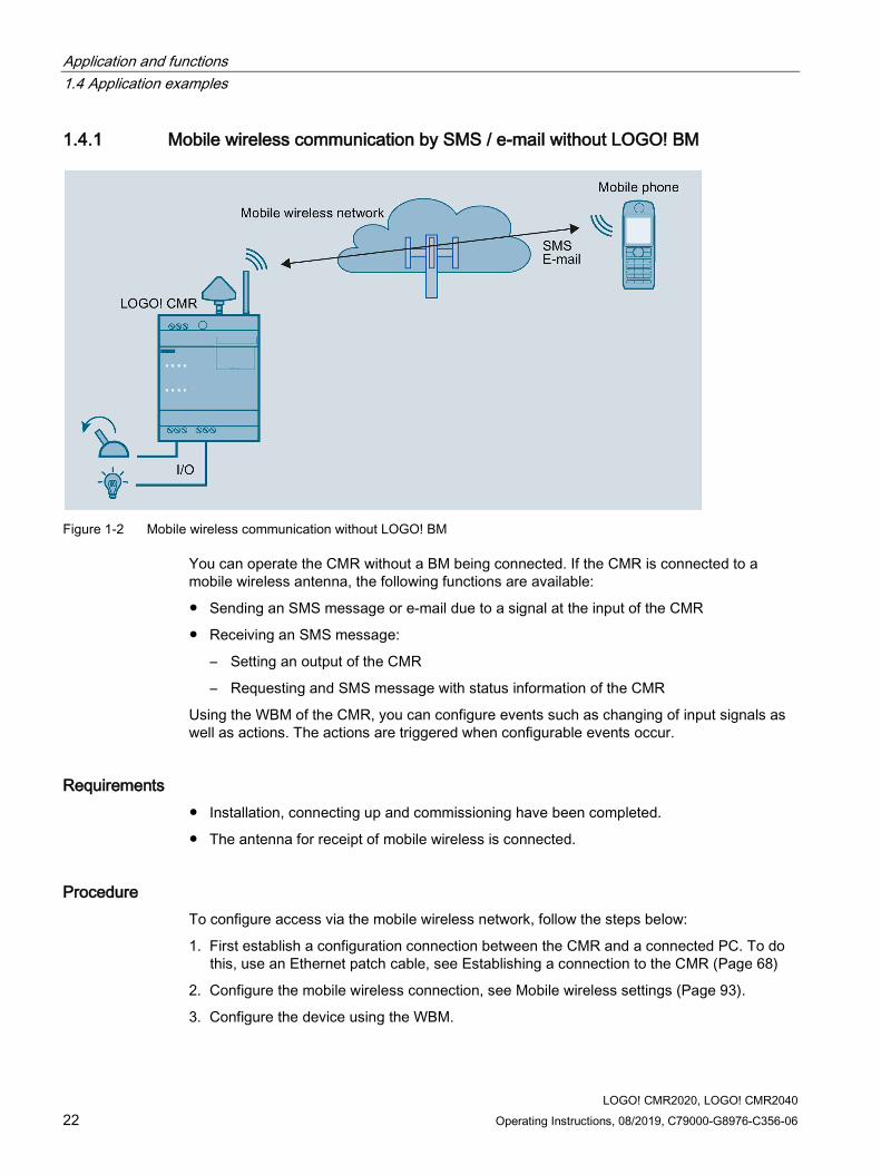
Figure 1-2 Mobile wireless communication without LOGO! BM
You can operate the CMR without a BM being connected. If the CMR is connected to a mobile wireless antenna, the following functions are available:
● Sending an SMS message or e-mail due to a signal at the input of the CMR
● Receiving an SMS message:
– Setting an output of the CMR
– Requesting and SMS message with status information of the CMR
Using the WBM of the CMR, you can configure events such as changing of input signals as well as actions. The actions are triggered when configurable events occur.
Requirements ● Installation, connecting up and commissioning have been completed.
● The antenna for receipt of mobile wireless is connected.
Procedure To configure access via the mobile wireless network, follow the steps below:
1. First establish a configuration connection between the CMR and a connected PC. To do this, use an Ethernet patch cable, see Establishing a connection to the CMR (Page 68)
2. Configure the mobile wireless connection, see Mobile wireless settings (Page 93).
3. Configure the device using the WBM.

Application and functions 1.4 Application examples
LOGO! CMR2020, LOGO! CMR2040 Operating Instructions, 08/2019, C79000-G8976-C356-06 23
1.4.2 Mobile wireless communication by SMS / e-mail with LOGO! BM
Figure 1-3 Mobile wireless communication with LOGO! BM
If the CMR is connected to the BM, and if you have a mobile wireless antenna connected, you can use all the functions available in operation without a connected BM. In addition to this, access to the LOGO! BM is expanded:
● Sending an SMS message or e-mail due to an event in the connected BM
● Receiving an SMS message:
– Triggering an action in the connected BM
– Requesting and SMS message with status information of the CMR
Configuration using the WBM also includes access to the components of the BM.
Requirements ● Installation, connecting up and commissioning have been completed.
● The antenna for receipt of mobile wireless is connected.
Procedure To set up access via the mobile wireless network and to establish a connection to the BM, follow the steps below:
1. First establish a configuration connection between the CMR and a connected PC. To do this, use an Ethernet patch cable, see Establishing a connection to the CMR (Page 68).
2. Configure the mobile wireless connection, see Mobile wireless settings (Page 93).
3. Configure the device using the WBM.

Application and functions 1.4 Application examples
LOGO! CMR2020, LOGO! CMR2040 24 Operating Instructions, 08/2019, C79000-G8976-C356-06
4. When configuration is completed, disconnect the CMR from the PC.
Note
Using a switch
When using a switch, e.g. LOGO! CSM, do not disconnect the connections: BM, CMR and PC can be operated at the same time.
5. If you do not use a switch connect the CMR to the BM.
1.4.3 Access by the PC via the Internet and mobile wireless network If your configuration is connected to the CMR via Internet and the mobile wireless network by using an OpenVPN tunnel you can access the CMR and the BM.
Figure 1-4 Access by the LOGO! via the Internet and mobile wireless network

Application and functions 1.4 Application examples
LOGO! CMR2020, LOGO! CMR2040 Operating Instructions, 08/2019, C79000-G8976-C356-06 25
You have the following options:
● Secure access from the PC to the CMR with OpenVPN
● Secure access from the PC to the BM with OpenVPN
For this application the CMR must be entered as a router in the BM.
In this way, you can for example reload the program of te BM.
● Access from the configuration PC to the CMR via mobile wireless network using HTTPS
For the procedure, refer to the section Establishing a connection to the CMR (Page 68).
● Sending e-mails optionally encrypted via STARTTLS
● Optional: Use of dynamic DNS to simplify the connection via the publicly reachable IP address of the CMR
Requirements ● The services used are activated in the CMR via the WBM.
● You have contracts with suitable service providers.

Application and functions 1.4 Application examples
LOGO! CMR2020, LOGO! CMR2040 26 Operating Instructions, 08/2019, C79000-G8976-C356-06
1.4.4 Position detection (GPS)
Figure 1-5 Position detection (GPS)
The CMR is equipped with a GPS interface via which the position data of the LOGO! station can be determined. If a GPS antenna is connected to the GPS interface, the following functions are available to you:
● Detecting position data:
– Due to an event at an input of the CMR.
– Due to an event from the BM.
– Due to a received SMS message (with the mobile wireless antenna connected)
● Sending detected position data:
– By SMS message or e-mail
– To the BM

Application and functions 1.4 Application examples
LOGO! CMR2020, LOGO! CMR2040 Operating Instructions, 08/2019, C79000-G8976-C356-06 27
To be able to use the functions listed above, you first need to activate (Page 75) the GPS interface in the WBM of the CMR. For correct position detection, the GPS signals need to be received from three satellites.
Requirements ● Installation, connecting up and commissioning have been completed.
● An GPS antenna is connected.
Procedure To set up access via the mobile wireless network and to establish a connection to the BM, follow the steps below:
Note Using the CMR for mobile wireless communication without BM
If you use the CMR in Mobile wireless communication by SMS / e-mail without LOGO! BM (Page 22), the last two steps of the procedure described below can be omitted.
1. First establish a configuration connection between the CMR and a connected PC. To do this, use an Ethernet patch cable. See Establishing a connection to the CMR (Page 68)
2. Configure the mobile wireless connection: See Mobile wireless settings (Page 93)
3. Activate GPS reception (Page 75).
4. When configuration is completed, disconnect the CMR from the PC.
Note
Using a switch
When using a switch, e.g. LOGO! CSM, do not disconnect the connections: BM, CMR and PC can be operated at the same time.
5. If you do not use a switch: Connect the CMR to the BM.
1.4.5 Time-of-day synchronization The time-of-day of the CMR can be synchronized using the following three methods:
● NTP
Synchronization with an external NTP server accessible via the mobile wireless network.
● GPS
● Mobile wireless
The availability of the time of day depends on the mobile wireless provider.

Application and functions 1.4 Application examples
LOGO! CMR2020, LOGO! CMR2040 28 Operating Instructions, 08/2019, C79000-G8976-C356-06
You set the method used for time-of-day synchronization via the WBM in the "System" tab, see section System Time (Page 77).
You can also have the CMR adopt the time of the configuration PC.
Forwarding time to the BM
If you enable the time of day in the WBM, you can also make a setting in the WBM so that the CMR also synchronizes the BM with the time of day (time-of-day forwarding). To do this enable enable "Forward time of day to LOGO! BM".
Even if time-of-day synchronization is disabled, the time of day is forwarded to the LOGO! BM. In this case, only the manual settings are transferred to the LOGO! BM.
Note
If you use time synchronization of the BM via the CMR, activate the standard/daylight saving changeover on the BM to ensure a consistent time.
The following figure provides an overview:

Application and functions 1.4 Application examples
LOGO! CMR2020, LOGO! CMR2040 Operating Instructions, 08/2019, C79000-G8976-C356-06 29
Figure 1-6 Time-of-day synchronization
Time of day when using certificates
If you use certificates for example for the e-mail or DynDNS services you need the precise time of day.
Note Precise time of day for certificates
To check certificates, the precise time of day is required in the CMR. When using certificates enable time-of-day synchronization of the CMR.
Requirements ● The CMR is mounted and connected.
● The antenna for receipt of mobile wireless is connected.

Application and functions 1.4 Application examples
LOGO! CMR2020, LOGO! CMR2040 30 Operating Instructions, 08/2019, C79000-G8976-C356-06
● The CMR is configured.
● Only if the time-of-day synchronization method using the GPS signal was configured: The antenna for receipt of GPS is connected.
Procedure Follow the steps below to configure the time-of-day synchronization:
1. Establish a configuration connection between the CMR and a connected PC. To do this, use an Ethernet patch cable. For details, see section Establishing a connection to the CMR (Page 68).
2. Select the required method.

LOGO! CMR2020, LOGO! CMR2040 Operating Instructions, 08/2019, C79000-G8976-C356-06 31
LEDs, connectors, buttons, card slots 2 2.1 Appearance of the device
Operator control/connector and display elements of the CMR Element Function X10 (L+, M) Power supply connector SET SET button XR01 GPS antenna connector XR02 Mobile wireless antenna connector LED "L" Power supply indicator LED "P1" LAN interface indicator LED "R" Mobile wireless signal strength indicator LED "F" Error/fault indicator X50/X51 Slot for SIM and micro SD card LED I1 Input 1 indicator LED I2 Input 2 indicator LED Q1 Output 1 indicator LED Q2 Output 2 indicator I1 Input 1 connector M Ground I2 Input 2 connector Q1 Output 1 connector M Ground

LEDs, connectors, buttons, card slots 2.2 LEDs to display operation
LOGO! CMR2020, LOGO! CMR2040 32 Operating Instructions, 08/2019, C79000-G8976-C356-06
Element Function Q2 Output 2 connector X1P1 LAN connector
2.2 LEDs to display operation The LEDs on the CMR provide information about the operating status of the device and the two inputs/outputs.

LEDs, connectors, buttons, card slots 2.2 LEDs to display operation
LOGO! CMR2020, LOGO! CMR2040 Operating Instructions, 08/2019, C79000-G8976-C356-06 33
Meaning of the LEDs LED Status Meaning All LEDs Flashing Fatal error
Lit Firmware being updated Not lit • No voltage present or applied
• Device shut down
L Power supply
Off
No external power supply connected
On
Power supply connected
Flashing
Initialization or change to the configuration
P1 LAN
Lit green
Connection to Ethernet is established.
Part flashes yel-low and part lit green
Data
Off
No connection to Ethernet or no cable connected.
R Signal strength (mobile wireless)
Lit green
Very good
Lit yellow
Medium
Off
No or very bad signal
Flashing
Data
F Error
OFF
No error
ON
Error, see also section Disruptions and their possible causes (Page 143).

LEDs, connectors, buttons, card slots 2.3 Interfaces
LOGO! CMR2020, LOGO! CMR2040 34 Operating Instructions, 08/2019, C79000-G8976-C356-06
LED Status Meaning Flashing
Duplicate IP address detected. Ethernet interface unreacha-ble.
I1 Input 1
Off
U < 5 V
Lit green
U > 8.5 V
I2 Input 2
Off
U < 5 V
Lit green
U > 8.5 V
Q1 Output 1
Off
No voltage at output
Lit green
Supply voltage at output
Q2 Output 2
Off
No voltage at output
Lit green
Supply voltage at output
2.3 Interfaces You will find information on connecting the interfaces and connectors in the section Connecting up the device (Page 43).
You will detailed data of the interfaces and connectors in the section Technical specifications (Page 151).
Connecting to the power supply For connecting to the power supply terminal X10 is available.
Connection to the local area network Port X1P1 of the CMR is intended for LAN connection to the local network/PC and to connect to the BM. The IP address of port X1P1 can be configured.

LEDs, connectors, buttons, card slots 2.4 The "SET" button
LOGO! CMR2020, LOGO! CMR2040 Operating Instructions, 08/2019, C79000-G8976-C356-06 35
Connection to the mobile wireless network and GPS For the wireless connection, the CMR has two SMA sockets:
● SMA socket XR02 for the mobile wireless network
● SMA socket XR01 for GPS reception
Inputs and outputs For the connection of I/O elements, the following inputs and outputs are available:
● Digital inputs
I1 + I2
● Digital outputs
Q1 + Q2
2.4 The "SET" button
Operator control/connector and display elements of the CMR The SET button has different functions depending on how long you hold it pressed.
Operator input Function Press briefly (up to 5 s) Restart Keep pressed for 5 to 10 sec-onds
Shutting down the device to a safe status Result: • All LED indicators are off. • The device can be disconnected from the power supply. The CMR can no longer be woken out of the shutdown status. To restart you need to turn the power supply off and on again.
Keep pressed for longer than 10 seconds
Reset to factory settings For information on the effects, refer to the section Resetting to factory settings (Page 145).
2.5 Slots for SIM card and SD card Both slots are on the front of the CMR behind cover.
"X50": Slot for the SIM card X50 is the slot for the SIM card that you receive from the network provider of your mobile wireless contract.

LEDs, connectors, buttons, card slots 2.5 Slots for SIM card and SD card
LOGO! CMR2020, LOGO! CMR2040 36 Operating Instructions, 08/2019, C79000-G8976-C356-06
Compatible cards
For information on compatible SIM card formats, refer to section Requirements for use (Page 18).
Card errors / diagnostics
Card errors are indicated by the "SIM" LED and entries in the diagnostics buffer.
Inserting the card
Inserting the SIM card is described in the section Insert the SIM card and enter the PIN (Page 48).
"X51": Slot for an optional SD card You have the option of using an SD card as an exchangeable storage medium for storing configuration and diagnostics data.
An SD card does not ship with the CMR.
Compatible cards
You will find a list of compatible SD cards in the appendix SD card (Page 167).
Card errors / diagnostics
Card errors are indicated by entries in the diagnostics buffer.
Inserting the card
Inserting the SD is described in the section Inserting the SD card (Page 50).
Retentive storage of important data on the SD card The SD card is an exchangeable storage medium for storing various data safe from power failure.

LEDs, connectors, buttons, card slots 2.5 Slots for SIM card and SD card
LOGO! CMR2020, LOGO! CMR2040 Operating Instructions, 08/2019, C79000-G8976-C356-06 37
The following data can be stored on the SD card.
● Configuration data
The configuration data is backed up on the SD card following every change in a configuration file. Storing configuration data on the SD card serves the following purposes:
– Copying configuration data to other CMRs of the same type
The configuration file can be edited and can be used to copy configuration data to different CMRs via the WBM.
– Device replacement without configuration PC
If a CMRU needs to be replaced for maintenance purposes, by transferring the SD card from the old to the new CMR, the configuration data can be made available to the new CMR. In this case, you do not need a configuration PC.
You will find information on storing the configuration data on the SD card in the section Configuration (Page 83).
For information on device replacement refer to section Replacing the CMR (Page 146).
● Diagnostics buffer entries
In the WBM you can configure that diagnostics buffer entries for serious events are saved on the SD card.
The entire diagnostics buffer of the CMR can be saved manually on the SD card.

LEDs, connectors, buttons, card slots 2.5 Slots for SIM card and SD card
LOGO! CMR2020, LOGO! CMR2040 38 Operating Instructions, 08/2019, C79000-G8976-C356-06

LOGO! CMR2020, LOGO! CMR2040 Operating Instructions, 08/2019, C79000-G8976-C356-06 39
Installation, connecting up, commissioning 3 3.1 Important notes on using the device
Safety notices on the use of the device The following safety notices must be adhered to when setting up and operating the device and during all associated work such as installation, connecting up or replacing devices.
Overvoltage protection
NOTICE
Protection of the external power supply
If power is supplied to the module or station over longer power cables or networks, the coupling in of strong electromagnetic pulses onto the power supply cables is possible. This can be caused, for example by lightning strikes or switching of higher loads.
The connector of the external power supply is not protected from strong electromagnetic pulses. To protect it, an external overvoltage protection module is necessary. The requirements of EN61000-4-5, surge immunity tests on power supply lines, are met only when a suitable protective element is used. A suitable device is, for example, the Dehn Blitzductor BVT AVD 24, article number 918 422 or a comparable protective element.
Manufacturer: DEHN+SOEHNE GmbH+Co.KG Hans Dehn Str.1 Postfach 1640 D-92306 Neumarkt, Germany
3.1.1 Notices on use in hazardous areas
WARNING
EXPLOSION HAZARD
The device must not be opened.
WARNING
The device may only be operated in an environment with pollution degree 1 or 2 (see IEC 60664-1).

Installation, connecting up, commissioning 3.1 Important notes on using the device
LOGO! CMR2020, LOGO! CMR2040 40 Operating Instructions, 08/2019, C79000-G8976-C356-06
External power supply ● Use only an external power supply that complies with EN 60950.
● The output voltage of the external power supply must not exceed 30 VDC.
● The output of the external power supply must be short-circuit proof.
NOTICE
Power supply
The power supply unit to supply the CMR must comply with the requirements for a limited power source according to IEC/EN 60950-1, section 2.5.
The external power supply for the CMR must meet the requirements for NEC class 2 circuits as specified in the National Electrical Code ® (ANSI/NFPA 70).
Note the information in this section and in the installation and operating instructions from the manufacturer of the power supply.
WARNING
The equipment is designed for operation with Safety Extra-Low Voltage (SELV) by a Limited Power Source (LPS).
This means that only SELV / LPS complying with IEC 60950-1 / EN 60950-1 / VDE 0805-1 must be connected to the power supply terminals. The power supply unit for the equipment power supply must comply with NEC Class 2, as described by the National Electrical Code (r) (ANSI / NFPA 70).
If the equipment is connected to a redundant power supply (two separate power supplies), both must meet these requirements.
WARNING
EXPLOSION HAZARD
DO NOT CONNECT OR DISCONNECT EQUIPMENT WHEN A FLAMMABLE OR COMBUSTIBLE ATMOSPHERE IS PRESENT.
WARNING
EXPLOSION HAZARD
SUBSTITUTION OF COMPONENTS MAY IMPAIR SUITABILITY FOR CLASS I, DIVISION 2 OR ZONE 2.

Installation, connecting up, commissioning 3.1 Important notes on using the device
LOGO! CMR2020, LOGO! CMR2040 Operating Instructions, 08/2019, C79000-G8976-C356-06 41
WARNING
When used in hazardous environments corresponding to Class I, Division 2 or Class I, Zone 2, the device must be installed in a cabinet or a suitable enclosure.
3.1.2 Notes on use in hazardous areas according to ATEX / IECEx
WARNING
Requirements for the cabinet/enclosure
To comply with EU Directive 94/9 (ATEX95), the enclosure or cabinet must meet the requirements of at least IP54 in compliance with EN 60529.
WARNING
If the cable or conduit entry point exceeds 70 °C or the branching point of conductors exceeds 80 °C, special precautions must be taken. If the equipment is operated in an air ambient in excess of 50 °C, only use cables with admitted maximum operating temperature of at least 80 °C.
WARNING
Take measures to prevent transient voltage surges of more than 40% of the rated voltage. This is the case if you only operate devices with SELV (safety extra-low voltage).
3.1.3 Notices on use in hazardous areas according to UL HazLoc
WARNING
EXPLOSION HAZARD
DO NOT DISCONNECT WHILE CIRCUIT IS LIVE UNLESS AREA IS KNOWN TO BE NON-HAZARDOUS.
This equipment is suitable for use in Class I, Division 2, Groups A, B, C and D or non-hazardous locations only.

Installation, connecting up, commissioning 3.2 Installing the device
LOGO! CMR2020, LOGO! CMR2040 42 Operating Instructions, 08/2019, C79000-G8976-C356-06
This equipment is suitable for use in Class I, Zone 2, Group IIC or non-hazardous locations only.
Connectors with LAN (Local Area Network) marking
WARNING
Safety notice for connectors with LAN (Local Area Network) marking
A LAN or LAN segment, with all its associated interconnected equipment, shall be entirely contained within a single low-voltage power distribution and within single building. The LAN is considered to be in an "environment A" according IEEE802.3 or "environment 0" according IEC TR 62102, respectively.
Never make direct electrical connection to TNV-circuits (Telephone Network) or WAN (Wide Area Network).
3.2 Installing the device The CMR is suitable for rail mounting on a 35 mm DIN EN 50 022 rail. On the rear of the device there is a locking mechanism with a spring catch.
Installing on a DIN rail / removing from a DIN rail
Figure 3-1 Installing on a DIN rail / removing from a DIN rail

Installation, connecting up, commissioning 3.3 Connecting up the device
LOGO! CMR2020, LOGO! CMR2040 Operating Instructions, 08/2019, C79000-G8976-C356-06 43
Mounting
To mount the CMR on a DIN rail, follow the steps below:
1. Fit the upper part of the locking mechanism ① of the device on to the DIN rail.
2. Press the device down against the DIN rail until the spring catch ② locks in place.
Removal
To remove the CMR from a DIN rail, follow the steps below:
1. Using a screwdriver, pull down the spring catch on the rear of the device ③.
2. Remove the device from the DIN rail.
Wall mounting
To mount the CMR on a wall, follow the steps below:
1. Using a screwdriver, pull the two spring catches ① on the rear of the device towards the outside.
2. Feed the screws through the openings in the catches and secure the device to the wall.
3.3 Connecting up the device
3.3.1 X1P1 (LAN) interface
Connecting the X1P1 (LAN) interface Connect your local area network, the PC or the BM to interface X1P1 (LAN connection) of the CMR.
The interface supports autonegotiation and autocrossing. For the connection, use a patch cable with an RJ-45 plug. For the requirements and for information on grounding see below.
You will find the properties of the X1P1 interface in the technical specifications.

Installation, connecting up, commissioning 3.3 Connecting up the device
LOGO! CMR2020, LOGO! CMR2040 44 Operating Instructions, 08/2019, C79000-G8976-C356-06
Requirements for the cable Requirements for the network cable:
● Use a shielded Ethernet cable for connection to the Ethernet interface.
● To minimize electromagnetic disturbances use a pair of shielded, twisted Ethernet cables (category 5) and a shielded RJ-45 plug at both ends.
● To prevent mechanical movement of the Ethernet cable that can cause contact interruptions, fasten the cables to a cable guide or rail at short intervals.
3.3.2 Inputs and outputs Refer to the technical specifications for the load capabilities of the inputs and outputs.
Ideally, use a debounced switch to connect to a LOGO! CMR input.
Inputs and outputs The CMR has two digital inputs and two digital outputs. The connecting terminals are on the underside of the device.
① Inputs I1 and I2 ② Reference potential inputs ③ Outputs Q1 and Q2 ④ Reference potential outputs
Inputs I1 and I2
The connecting terminals of the inputs are labeled I1 and I2. The reference potential for both inputs is "M".
Using the Web user interface, you can assign any function to each input, for example triggering an alarm SMS message, see section Monitoring (Page 114).
The status of an input can also be read using SMS.
Outputs Q1 and Q2
The connecting terminals of the outputs are labeled Q1 and Q2. The reference potential for both outputs is "M".

Installation, connecting up, commissioning 3.3 Connecting up the device
LOGO! CMR2020, LOGO! CMR2040 Operating Instructions, 08/2019, C79000-G8976-C356-06 45
You can assign any function to each output using the Web user interface see section Monitoring (Page 114). The outputs can be set and reset using SMS messages.
Note
Remember the electrical load capacity of the output.
You will find the electrical values for the inputs and outputs in the section Technical specifications (Page 151).
3.3.3 Connecting the antenna
WARNING
Risk of lightning strikes when installed outdoors
If you install an antenna outside, you need to ground the antenna to protect it from lightning strikes. This work must only be carried out by qualified personnel.
NOTICE
Damage to devices due to incorrect accessories
Select the antenna suitable for your frequency band from the accessories. Other antennas could interfere with product characteristics or lead to defects.
Note Maximum length of the antenna cable
The maximum permitted length of the antenna cable is 15 m.
The CMR has two antenna sockets of the type SMA for connecting the antennas. The antennas must have an impedance of approx. 50 Ω.
Follow the operating instructions of the antennas used. See also section Antennas (Page 161).
You will find configuration images with antenna cables for different structures in the section Antenna cable (Page 163).
Frequency bands in Europe and other regions Select the antenna suitable for your frequency band. See section Antennas (Page 161).
You will find the frequency bands supported by the CMR in the section Technical specifications (Page 151).

Installation, connecting up, commissioning 3.3 Connecting up the device
LOGO! CMR2020, LOGO! CMR2040 46 Operating Instructions, 08/2019, C79000-G8976-C356-06
Signal strength During installation make sure that there is a good signal strength: You will find the meaning of the statuses of the "R" LED in the section LEDs to display operation (Page 32).
If the LED is lit green, the signal strength is very good. Lit yellow signals medium quality.
Large metallic objects in the vicinity of the antennas, for example reinforced concrete, impair the signal strength.
3.3.4 Power supply
Screw terminals for the power supply
① L+ = live wire, positive pole of the DC voltage 12/24 VDC ② M = negative pole/ground of the DC voltage 12/24 VDC ③ Functional ground
• Serves to improve electromagnetic compatibility and to specify a common reference poten-tial for all signals.
• Is achieved efficiently by a connection to the DIN rail.
Note Power supply unit of the CMR is not electrically isolated
No electrical isolation means that the input and output circuits are not galvanically isolated.
The CMR operates with a DC voltage of 12 to 24 VDC, nominally 24 VDC. The nominal current consumption is a maximum of 250 mA at 12 V.
● Connect a suitable power supply to the screw terminals.
● Use copper wires only.
● Use only cables that are approved for at least 70 °C.
Wire: 0.5 to 3 mm² (20 to 18 AWG) Stranded wire: 0.5 to 2.5 mm² Tightening torque for screw terminals: 0.6 to 0.8 Nm

Installation, connecting up, commissioning 3.4 Commissioning the device
LOGO! CMR2020, LOGO! CMR2040 Operating Instructions, 08/2019, C79000-G8976-C356-06 47
Turning off the CMR
NOTICE
Avoidance of sudden disconnection of the power supply
Avoid abrupt disconnection of the CMR from the power supply: In very seldom cases, the CMR can be damaged.
Shut the CMR down to the safe status before turning the power supply off.
1. Hold down the SET button for 5 to 10 seconds.
The CMR shuts down to the safe status: All LED indicators are off.
2. Disconnect the CMR from the power supply.
You can also shut down the CMR to the safe status via the WBM.
The CMR can no longer be woken out of the shutdown status. To restart you need to turn the power supply off and on again.
3.4 Commissioning the device
3.4.1 Steps in commissioning To commission the CMR, follow the steps below:
Overview of commissioning 1. Note the requirements for operating the CMR, refer to the section Requirements for use
(Page 18).
2. SIM card: Before you insert the SIM card, note the information in Insert the SIM card and enter the PIN (Page 48) regarding the two different methods:
– Method 1: For a new device
– Method 2: Replacing the SIM card in a device that has already been in use.
3. Connect a PC with a Web browser to the local interface X1P1 of the CMR, refer to the section Establishing a connection to the CMR (Page 68).
4. Insert the SIM card, see section "Insert the SIM card and enter the PIN (Page 48)".
5. Connect the antennas.
6. Connect the CMR to the power supply.
7. Enter the PIN of the SIM card via the Web user interface of the CMR, refer to the section Mobile wireless settings (Page 93).

Installation, connecting up, commissioning 3.4 Commissioning the device
LOGO! CMR2020, LOGO! CMR2040 48 Operating Instructions, 08/2019, C79000-G8976-C356-06
8. Align the antenna, refer to the section "Wireless cell (Page 97)".
9. Set up the CMR according to your requirements, refer to the section Configuration (WBM) (Page 57).
3.4.2 Insert the SIM card and enter the PIN
NOTICE
Disconnecting the CMR from the power supply before inserting or removing the SIM card
Do not remove the SIM card during operation. 1. Shut the device down to a safe status. 2. Disconnect the CMR from the power supply before inserting or removing the SIM card.
Figure 3-2 Compartment for the SIM card (red rectangle)
The compartment for the SIM card is located on the front of the CMR.
Status of the CMR before inserting/removing the SIM card The CMR is brand new or has been reset to the factory settings:
● A SIM card is inserted for the first time.
The CMR is or has already been in operation:
● Only a different SIM card is inserted.
Inserting/removing the SIM card 1. In the WBM in "WAN", "Mobile wireless settings" tab, deselect the "Activate mobile
wireless interface“ check box: The mobile wireless interface is turned off.
2. Shut the CMR down to the safe status: "Turning off the CMR" (Page 46).
3. Disconnect the CMR from the power supply.
4. Only if the CMR is or was in operation: Remove the SIM card and close the compartment.
To remove the SIM card, press the left-hand sunken ejector button with a sharp object.

Installation, connecting up, commissioning 3.4 Commissioning the device
LOGO! CMR2020, LOGO! CMR2040 Operating Instructions, 08/2019, C79000-G8976-C356-06 49
5. Insert the SIM card into the compartment until you can feel the card lock in place.
6. Restart the CMR by connecting up the power supply.
7. In the WBM, in "WAN", "Mobile wireless settings" tab, select the "Activate mobile wireless interface" check box: The mobile wireless interface is once again ready for operation.
8. Enter the PIN of your SIM card in WBM in the "WAN", Mobile wireless settings" tab.
Note
Entry of an incorrect PIN
The last entered (incorrect) PIN is saved. This means that when changing the configuration (except the PIN) or when restarting the CMR, no further PIN entry attempt is used up.
For this reason, do not change the PIN of the SIM card to the previously stored incorrect PIN outside the CMR.
9. Click the "Apply" button: the PIN of your SIM card is adopted.
10.Make the appropriate settings, see section Configuration (WBM) (Page 57).
Unlocking the SIM card If you enter the PIN incorrectly three times, the SIM card will be locked.
Unblock the SIM card as follows:
1. Shut the CMR down to the safe status: "Turning off the CMR" (Page 46).
2. Disconnect the CMR from the power supply.
3. Remove the SIM card and close the compartment.
To remove the SIM card, press the left-hand sunken ejector button with a sharp object.
4. Insert the removed SIM card in a mobile phone.
5. Unblock the SIM card by entering the PUK or the SuperPIN.
You will have received the PUK or SuperPIN from your mobile wireless provider along with the SIM card.
Result: The SIM card is unblocked and can be used again.

Installation, connecting up, commissioning 3.4 Commissioning the device
LOGO! CMR2020, LOGO! CMR2040 50 Operating Instructions, 08/2019, C79000-G8976-C356-06
3.4.3 Inserting the SD card
Figure 3-3 Slot for the micro SD card (yellow rectangle)
You will find the SD cards supported by the CMR in the appendix SD card (Page 167).
NOTICE
Do not remove/insert an SD card during operation
You can only remove or insert the SD card when the CMR is turned off/shut down.
If you remove or insert the SD card during operation, data on the card can be damaged.
Inserting the micro SD card
1. Insert the SD card into the compartment until you can feel the card lock in place.
Removing the micro SD card
1. By pressing, unlock the card.
2. After unlocking it takes the card out of the slot.

LOGO! CMR2020, LOGO! CMR2040 Operating Instructions, 08/2019, C79000-G8976-C356-06 51
Operation: Access to BM 4 4.1 Overview
Read and write access From a mobile phone or tablet, you have read and write access to the CMR or the BM by SMS.
For an overview of the functions, refer to the section Further functions (Page 15).
Monitoring the LOGO! BM
Functions
To monitor the CMR and a connected BM various functions are available that are configured in the WBM.
The section Monitoring (Page 114) describes the following functions:
● Monitoring of the values of the BM.
● Creating an action depending on the value change of an event
This can, for example, be the sending of an SMS message to the configured phone number due to an alarm.
● Creating recipients and recipient groups for messages of the CMR
● Notification of a recipient group with freely writable SMS and e-mail texts when events occur
Example
You will find out how to configure monitoring quickly in the section Example of a monitoring configuration (Page 129).
There based on an example you will read how to configure events, actions and recipients.
Following this you will see how to link events, actions and recipients in a list.

Operation: Access to BM 4.2 Reading and writing values
LOGO! CMR2020, LOGO! CMR2040 52 Operating Instructions, 08/2019, C79000-G8976-C356-06
4.2 Reading and writing values
Reading / writing "current values" via the BM variables memory (VM) "Current values" (e.g. flags, counters) are read and written only via the BM variables memory (VM).
For reasons of security, setting or reading of current values of the function blocks of the BM (e.g. counters) is possible only via their address in the BM variables memory.
All components of the LOGO! switching program must therefore initially be transferred to the BM-internal variables memory using the "LOGO! Soft Comfort" program. Only then are the components visible with their start addresses and length (type) for the CMR in the BM variables memory.
Data types and range of values when reading and writing To set individual bits, the data types available must be used.
LOGO! CMR and LOGO! BM interpret all values of the data types BYTE, WORD and DWORD as being signed.
Remember this when transferring values using SMS messages. Data type Length in the variables
memory: Range of values
BIT 1 bit 0, 1 BYTE 1 byte -128 ... 127 WORD 2 bytes -32 768 ... 32 767 DWORD 4 bytes -2 147 483 648 ... 2 147 483 647
Reading and writing values in the variables memory (VM) of the LOGO!! BM using SMS messages With the LOGO! CMR, values can be written to and read from the variables memory (VM) of a LOGO! BM using SMS messages.
The parameters to be specified in SMS commands are the address and type (<address>, <data type>, refer to the section SMS commands (Page 172).
In the WBM of the LOGO! CMR, a limit this or a threshold value for a value from the LOGO! 8 can be specified on the "Monitoring" > "Events" page. If the threshold of the value in the LOGO! 8 is exceeded or fallen below, the sending of an SMS message to one or more recipients can, for example, be configured.
Note the signed interpretation of the values also in the following applications:
● Setting threshold/limit values for values in the LOGO! BM via the WBM of the LOGO! CMR
● Display of values in the LOGO! BM via the WBM of the LOGO! CMR
● Reading/writing values in the LOGO! BM using SMS messages with the LOGO! CMR

Operation: Access to BM 4.2 Reading and writing values
LOGO! CMR2020, LOGO! CMR2040 Operating Instructions, 08/2019, C79000-G8976-C356-06 53
Reading and writing directly using LOGO!Soft Comfort (without CMR)
Note Access only to the first 128 bytes of the VM (Variable Memory)
In LOGO!Soft Comfort the VM goes to address 850. Via the CMR, however, only the first 128 bytes can be accessed.
For security reasons the address in the VM can only be read or written using SMS if the address was created earlier as a signal using the WBM.
Table 4- 1 Overview of the options for accessing the LOGO! BM
Value of the LOGO! BM
Read access Write access with action Write access using SMS
Digital inputs (I) x - - Digital flags (M) x - - Digital outputs (Q) x - - Analog inputs (AI) x - - Analog flags (AM) x - - Analog outputs (AQ) x - - Cursor keys (C) x - - Function keys (F) x - - Shift register bits (S) x - - Variables memory (VM)
x x 1) x
Program status (PS) x x x Communication status (CS)
x - -
1) You can have write access the variable memory of the LOGO! BM using the action "Forward GPS position":

Operation: Access to BM 4.2 Reading and writing values
LOGO! CMR2020, LOGO! CMR2040 54 Operating Instructions, 08/2019, C79000-G8976-C356-06
Example of writing a value using LOGO!Soft Comfort
Below you will find an example of the procedure for writing a value using LOGO!Soft Comfort. You can then access the written value by SMS via the CMR.
1. In the program "LOGO! Soft Comfort" click "Tools" > "Parameter VM Mapping":
Figure 4-1 LOGO! Soft Comfort - tools
2. Select a block from your control program that you want to transfer to the VM memory.
In the following figure, select the block B007 from your control program with the stopwatch function.

Operation: Access to BM 4.2 Reading and writing values
LOGO! CMR2020, LOGO! CMR2040 Operating Instructions, 08/2019, C79000-G8976-C356-06 55
Figure 4-2 Variable Memory Configuration
3. Within the B007 block then select a variable to be monitored.
4. By clicking the "OK" button, you confirm your selection.
The selected variable is transferred to the VM.
The "Type" and "Address" of the selected variable are displayed in the VM.
For further details, refer to the LOGO! Soft Comfort description.
Reading variables from the CMR by SMS
With the keywords "Address", "Value" and "Data type" you can read and write the value of a variable by SMS, see also section SMS commands (Page 172).

Operation: Access to BM 4.2 Reading and writing values
LOGO! CMR2020, LOGO! CMR2040 56 Operating Instructions, 08/2019, C79000-G8976-C356-06

LOGO! CMR2020, LOGO! CMR2040 Operating Instructions, 08/2019, C79000-G8976-C356-06 57
Configuration (WBM) 5 5.1 Security recommendations
Keep to the following Security recommendations to prevent unauthorized access to the system.
General ● You should make regular checks to make sure that the device meets these
recommendations and other internal security guidelines if applicable.
● Evaluate your plant as a whole in terms of security. Use a cell protection concept with suitable products.
● Do not connect the device directly to the Internet. Operate the device within a protected network area.
● Keep the firmware up to date. Check regularly for security updates of the firmware and use them.
● Check regularly for new features on the Siemens Internet pages.
– Here you will find information on network security:
Link: (http://www.siemens.com/industrialsecurity)
– Here you will find information on Industrial Ethernet security:
Link: (http://w3.siemens.com/mcms/industrial-communication/en/ie/industrial-ethernet-security/Seiten/industrial-security.aspx)
– You will find an introduction to the topic of industrial security in the following publication:
Link: (http://w3app.siemens.com/mcms/infocenter/dokumentencenter/sc/ic/InfocenterLanguagePacks/Netzwerksicherheit/6ZB5530-1AP01-0BA4_BR_Netzwerksicherheit_en_112015.pdf)
Physical access Restrict physical access to the device to qualified personnel.

Configuration (WBM) 5.1 Security recommendations
LOGO! CMR2020, LOGO! CMR2040 58 Operating Instructions, 08/2019, C79000-G8976-C356-06
Security functions of the product Use the options for security settings in the configuration of the product. These include among others the following Security function of the communication:
● Enable the Security functions of the device.
Think about the services you want to allow access to the station via public networks.
● Use secure protocol variants such as HTTPS or STARTTLS.
● Use the secure communication via OpenVPN.
Passwords ● Define rules for the use of devices and assignment of passwords.
● Regularly update the passwords to increase security.
● Only use passwords with a high password strength. Avoid weak passwords for example "password1", "123456789" or similar.
● Make sure that all passwords are protected and inaccessible to unauthorized personnel.
● Do not use one password for different users and systems.
Protocols
Secure and non-secure protocols
● Only activate protocols that you require to use the system.
● Use secure protocols when access to the device is not prevented by physical protection measures.
The HTTP protocol provides a secure alternative with HTTPS.
Port tables The following tables provide you with an overview of the open ports on this device.
● Protocol / function
Protocols that the device supports.
● Port number (protocol)
Port number assigned to the protocol.
● Default of the port
– Open
The port is open at the start of the configuration.
– Closed
The port is closed at the start of the configuration.

Configuration (WBM) 5.1 Security recommendations
LOGO! CMR2020, LOGO! CMR2040 Operating Instructions, 08/2019, C79000-G8976-C356-06 59
● Port status
– Open
The port is always open and cannot be closed.
– Open according to configuration
The port is open if it has been configured.
– Open (login, when configured)
As default the port is open. After configuring the port, the communications partner needs to log in.
– Closed after configuration
The port is closed because the device is always client for this service.
● Authentication
Specifies whether or not the protocol authenticates the communications partner during access.
Table 5- 1 Ports of the LAN interface
Protocol / function Port number (pro-tocol)
Default of the port Port status Authentication
HTTP 80 (TCP) Open Open (login, when configured) Yes HTTPS 443 (TCP) Open Open (login, when configured) Yes LOGO! Dynamic (TCP) Closed Open (outgoing) after configuration No
Table 5- 2 Ports of the WAN interface
Protocol / function Port number (pro-tocol)
Default of the port Port status Authentication
HTTPS 443 (TCP) Closed Open after configuration Yes OpenVPN 1194 (UDP)
can be set Closed Open after configuration Yes
NTP 123 (UDP) Closed Open (outgoing) after configuration No SMTP Dynamic (TCP) Closed Open (outgoing) after configuration Yes DynDNS Dynamic (TCP) Closed Open (outgoing) after configuration Yes DNS Dynamic (UDP) Closed Open (outgoing) after configuration No

Configuration (WBM) 5.2 General functions of the WBM
LOGO! CMR2020, LOGO! CMR2040 60 Operating Instructions, 08/2019, C79000-G8976-C356-06
5.2 General functions of the WBM To configure the CMR, a Web-based administration user interface (WBM - Web Based Management) is available to you.
● At the left-hand page you will find a navigation panel.
● By clicking on a main entry (group) in the navigation the tabs belonging to this group will be displayed on the right of the title bar.
● The display and input boxes of the parameters are available on the individual pages of the tabs.
Symbols of the title bar The symbols in the title bar have the following function: Symbol Function
Date and time of the last page update of the WBM in the local time of the CMR (yyyy-mm-dd hh:mm:ss)
Drop-down list for setting the WBM language
Name of the currently logged in user
Logout of the user
Number of connections to configuration PCs
The automatic update of the WBM display is enabled. The data is called up at 5 second intervals.
The automatic update of the WBM display is disabled.

Configuration (WBM) 5.2 General functions of the WBM
LOGO! CMR2020, LOGO! CMR2040 Operating Instructions, 08/2019, C79000-G8976-C356-06 61
Symbol Function
Switches on the automatic update of the WBM display.
Switches off the automatic update of the WBM display.
Updates the current WBM display on the "Configuration" pages.
Prints out the current WBM page
Opens the Internet page of the CMR in the Siemens Industry Online Portal. Here, you will find all entries for the product.
Open / save Open Source software license conditions of the CMR
Language selection The WBM of the CMR is available in German and English.
Default
If, for example, the Web browser is set to the English language, the WBM of the CMR is automatically displayed in English.
If the language setting of the Web browser is not supported, the WBM of the CMR is displayed in English.
Changing the language setting
At the top right you will see a drop-down list for the language selection. You can change the language setting at any time.
● From the drop-down list at the right top select the required language.
The language setting is saved for the next access.
● If the language is not changed immediately, update the display in your Web browser, generally using the function key F5.
Configuring You configure the individual parameters on the pages of the various tabs. The following are available:
● Input boxes for entering numbers and texts
● Drop-down lists for selecting parameters
● Check boxes for enabling and disabling functions
● Buttons for executing page-specific actions and for saving the entries ("Apply")
● Notifications and information

Configuration (WBM) 5.2 General functions of the WBM
LOGO! CMR2020, LOGO! CMR2040 62 Operating Instructions, 08/2019, C79000-G8976-C356-06
Incorrect entries in the configuration In many input boxes of the WBM, the content is checked for missing content or consistency when you save. Boxes with detected errors or illegal characters are marked with a red border.
Figure 5-1 Example of an input box with a detected incorrect entry
With some incorrect entries an additional message is also displayed. The settings are only applied after the error has been corrected.
Adding, changing and deleting ("Users / groups", "Monitoring") On the pages of these two parameter groups, you can create new elements and delete existing ones. Elements are:
Users, recipient groups, message texts, signals, events, actions, assignments
The already configured elements are shown at the top of the page in a table.
● Add
To create a new element click the "Add" button.
An empty input box id displayed where you enter the name of the new element.
Then configure the parameters of the element.
● Change
Select an element in the table on the relevant page and make your changes in the parameter boxes at the bottom.
● Delete
You can only delete elements that are not used. If for example a text for a message, a user in a recipient group or a signal in an event, is used you cannot delete the element.
In the table, select the row with the element you want to delete and click the "Delete" button.
A prompt for confirmation appears.
If you confirm this by clicking the "Delete" button the selected element is deleted and removed from the list.
Saving Confirm all your entries by clicking the "Apply" button. Your settings are then adopted by the device. With some parameters this can take a few seconds. If you make changes to the mobile wireless configuration this can also take several minutes.

Configuration (WBM) 5.3 Performance data and configuration limits
LOGO! CMR2020, LOGO! CMR2040 Operating Instructions, 08/2019, C79000-G8976-C356-06 63
Grayed out boxes are preset by the system and cannot be changed.
Note Data loss when changing the WBM page without saving
If you do not save your input with the "Apply" button, your input will be discarded without a prompt for confirmation when you change WBM pages.
Saving configuration files You can save your settings i for configuring a device in a configuration file. This file can, when necessary, then be reloaded or transferred to other devices of the same type. For information on this, refer to section Configuration (Page 83).
5.3 Performance data and configuration limits You can define... Maximum number / Comment User 20 Recipient groups 10; each recipient group can be assigned a maximum of 10 users. Password 1 Phone numbers 20 E-mail addresses 20 Message texts 20; maximum of 160 characters per message. Message text can be used for text messages
(SMS) and email. Signals 32 Events 32 Actions 32 Alias SMS commands 20 Constants 10 Connections
• to the LOGO! BM 1
• via HTTP 1
• via HTTPS 2; HTTP and HTTPS can be combined (maximum of two connections cannot be exceeded). A maximum of 1 connection via HTTPS is possible at the mobile wireless interface.
• as e-mail client 1
• as VPN server 1

Configuration (WBM) 5.4 Permitted characters and string lengths
LOGO! CMR2020, LOGO! CMR2040 64 Operating Instructions, 08/2019, C79000-G8976-C356-06
5.4 Permitted characters and string lengths
Note Correct reception of SMS messages
SMS messages can only be correctly received if the messages correspond to the character sets GSM 03.38 or UCS-2.
Note Leading and following spaces
Leading and following spaces are not permitted in names. These result in an error message in the WBM indicating an incorrect entry. Exception: Descriptions and SMS message texts. Use of special characters
When using special characters, the maximum character length cannot be guaranteed.
Below you will find the characters and string lengths permitted for configuring user names, passwords, parameters and texts. ASCII character sets are often specified. Below you will find ASCII character sets with their hexadecimal code and the corresponding character.
Standard characters
● 0x30 .. 0x39
0 1 2 3 4 5 6 7 8 9
● 0x41 .. 0x5A
A B C D E F G H I J KL M N O P Q R S T U V W X Y Z
● 0x61 .. 0x7A
a b c d e f g h i j k l m n o p q r s t u v w x y z
Special characters
● 0x21 .. 0x2F
! " # $ % & ' ( ) * + , - . /
● 0x3A .. 0x40
: ; < = > ? @
● 0x5B .. 0x60
[ \ ] ^ _ `
● 0x7B .. 0x7E
{ | } ~

Configuration (WBM) 5.4 Permitted characters and string lengths
LOGO! CMR2020, LOGO! CMR2040 Operating Instructions, 08/2019, C79000-G8976-C356-06 65
Special characters ≥ 0x80
● 0x80, 0xA3, 0x8A, 0x9A, 0x8E, 0x9E, 0xB5
€ £ Š š Ž ž µ
● 0xC0 .. 0xFF
À Á Â Ã Ä Å Æ Ç È É Ê Ë Ì Í Î Ï Ð Ñ Ò Ó Ô Õ Ö × Ø Ù Ú Û Ü Ý Þ ß à á â ã ä å æ ç è é ê ë ì í î ï ð ñ ò ó ô õ ö ÷ ø ù ú û ü ý þ ÿ
Table 5- 3 Characters and string lengths permitted and not permitted
Input box Minimum string length
Maximum string length
Permitted characters Non permitted characters
General
• Names except for modules and server names (NTP, e-mail, DynDNS)
1 20 All characters
• Description except for Plant descrip-tion
0 50
System
• Module name • NTP server name
1 1
20 63
DNS name according to RFC 1035 and RFC 1123: • Standard characters 0x30 .. 0x39,
0x41 .. 0x5A, 0x61 .. 0x7A • Special characters: dash (0x2D), period
(0x2E)
• Plant description 0 20 All characters
WAN
• SIM PIN 1) 4 8 0 ... 9 a ... z, A ... Z
• APN 1 63 DNS name according to RFC 1035 and RFC 1123: • Standard characters 0x30 .. 0x39,
0x41 .. 0x5A, 0x61 .. 0x7A • Special characters: dash (0x2D), period
(0x2E)
• Name • Password
0 0
20 20
• Standard characters 0x30 .. 0x39, 0x41 .. 0x5A, 0x61 .. 0x7A
• Special characters 0x21 .. 0x2F, 3A .. 40, 0x5B .. 0x60, 0x7B .. 0x7E

Configuration (WBM) 5.4 Permitted characters and string lengths
LOGO! CMR2020, LOGO! CMR2040 66 Operating Instructions, 08/2019, C79000-G8976-C356-06
Input box Minimum string length
Maximum string length
Permitted characters Non permitted characters
• SMS password 1 8 • 0x21 .. 0x2F • 0x30 .. 0x39 • 0x41 .. 0x5A • 0x61 .. 0x7A • 0x3A • 0x3C .. 0x40
; [ \ ] ^ ` { | } ~ ° ´ €
• Mail server 1 63 DNS name according to RFC 1035 and RFC 1123: • Standard characters 0x30 .. 0x39,
0x41 .. 0x5A, 0x61 .. 0x7A • Special characters: dash (0x2D), period
(0x2E)
• E-mail address 1 127 • Standard characters 0x30 .. 0x39, 0x41 .. 0x5A, 0x61 .. 0x7A
• Special characters 0x21 .. 0x2F, 0x3D, 0x3F .. 0x40, 0x5B .. 0x60, 0x7B .. 0x7E: – ! " # $ % & ' ( ) * + , - . / – = ? @ – [ \ ] ^ _ ` { | } ~
• Name of the e-mail user 1 127 All characters
• Password 1 32 • Standard characters 0x30 .. 0x39, 0x41 .. 0x5A, 0x61 .. 0x7A
• Special characters 0x21 .. 0x2F, 3A .. 40, 0x5B .. 0x60, 0x7B .. 0x7E
ß ä ö ü Ä Ö Ü § ´ € é è
DynDNS
• Host name 1 63 DNS name according to RFC 1035 and RFC 1123: • Standard characters 0x30 .. 0x39,
0x41 .. 0x5A, 0x61 .. 0x7A • Special characters: dash (0x2D), period
(0x2E)
• Name of the DynDNS user
1 127 All characters
• Password 1 32 • Standard characters 0x30 .. 0x39, 0x41 .. 0x5A, 0x61 .. 0x7A
• Special characters 0x21 .. 0x2F, 3A .. 40, 0x5B .. 0x60, 0x7B .. 0x7E
ß ä ö ü Ä Ö Ü § ´ € é è

Configuration (WBM) 5.4 Permitted characters and string lengths
LOGO! CMR2020, LOGO! CMR2040 Operating Instructions, 08/2019, C79000-G8976-C356-06 67
Input box Minimum string length
Maximum string length
Permitted characters Non permitted characters
Users / groups
• Phone numbers 0 20 Format: +<country code><target phone num-ber> Digits and the following special characters: • 0x22 ... 0x7E • 0x2B (Plus character: Placeholder for the
trunk prefix before the country code) • 0x2A (asterisk at the end: Placeholder for
extension numbers) • 0x2F, 0x28, 0x29 ( / ( ) as the delimiter) • 0x32 (Space)
• User name 1 20 0 ... 9, a ... z, A ... Z , - @ _ .
ß ä ö ü Ä Ö Ü § ´ € é è
• Password Note: If the option "Do not use password rules" is enabled no password rules are used and the minimum length is reduced to zero.
8 20 • Standard characters 0x30 .. 0x39, 0x41 .. 0x5A, 0x61 .. 0x7A 0 ... 9, a ... z, A ... Z
• Special characters 0x21 .. 0x2F, 3A .. 40, 0x5B .. 0x60, 0x7B .. 0x7E ! “ # $ % & ' ( ) * + , - . / : ; < = > ? @ [ \ ] ^ _ ` { | } ~
ß ä ö ü Ä Ö Ü § ´ € é è

Configuration (WBM) 5.5 Establishing a connection to the CMR
LOGO! CMR2020, LOGO! CMR2040 68 Operating Instructions, 08/2019, C79000-G8976-C356-06
Input box Minimum string length
Maximum string length
Permitted characters Non permitted characters
Monitoring SMS message texts includ-ing up to 16 placeholders for process values with format-ting instructions. Note: The placeholders are re-placed with real values prior to sending. The text length can then exceed the limit of 160 characters. If the maxi-mum number of characters is exceeded, up to 2 SMS messages are generated and sent.
0 160 • Standard characters 0x30 .. 0x39, 0x41 .. 0x5A, 0x61 .. 0x7A 0 ... 9, a ... z, A ... Z
• Space 0x32 • Special characters 0x21 .. 0x2F,
0x3A .. 0x40, 0x5F, 0xA7 ! " # $ % & ' ( ) * + , - . / : ; < = > ? @ _ §
• Umlauts (ä, ü etc) and ß: 0xC4, 0xE4, 0xD6, 0xF6, 0xDC, 0xFC, 0xDF, 0xE8, 0xE9 Ä ä Ö ö Ü ü ß è é
The square brackets [ and ] (0x1B and 0x1D)are reserved for placeholders. The following formats are permitted for the placeholders of the process values; V stands for a configured signal name. The signal names must not include the characters [ and ]: • [V] decimal value of the signal Other placeholders: • [DATE] current date
Format: yyyy-mm-dd • [GPS] value is GPS position
Format: ddd:mm:ss.hs N/S
ddd:mm:ss.hs W/E Alt m • [TIME] current time
Format: hh:mm:ss • [DEVNAME]Module name
[ \ ] ^ ` { | } ~
1) No PIN is also permitted.
5.5 Establishing a connection to the CMR For the configuration of the CMR, you require a PC with the following web browser:
● Internet Explorer: V 11.0 or higher
● Firefox: V 28.0 or higher
● Google Chrome: V 33.0 or higher
● Apple Safari: iOS V 9.0 or higher
You configure using the Web user interface (WBM) of the CMR.

Configuration (WBM) 5.5 Establishing a connection to the CMR
LOGO! CMR2020, LOGO! CMR2040 Operating Instructions, 08/2019, C79000-G8976-C356-06 69
At the same time a maximum of 2 sessions are possible (2 users logged in). Both sessions have full write access.
Note
Via mobile wireless / HTTPS only one session is possible.
A second session can be established via the local LAN interface.
Configuration via the local interface The following requirements for configuration via the local interface X1P1 must be met:
● The PC must be connected to the Ethernet socket X1P1 of the CMR or have direct access to the CMR via the local network.
● The network adapter of the PC must have the following IP configuration:
– Same subnet: 255.255.255.0
The address of the PC must be located in the subnet of the LAN interface of the CMR.
– IP address (as an example): 192.168.0.4
5.5.1 Establishing the configuration connection To configure the CMR, you must first establish a connection to the device with a Web browser. Follow the steps outlined below:
Setting up the Web browser 1. Start the Web browser on the PC.
2. Set the browser so that it does not automatically select a connection when it is started.
For example in Microsoft Internet Explorer, make the settings as follows:
– Select the "Tools" > "Internet Options" menu command.
– Select the "Connections" tab.
– To delete the entries in "Dial-up and Virtual Private Network settings", click the "Remove" button.
– Click the "Never dial a connection" radio button.
Calling up the start page of the CMR In the address line of the browser, enter the IP address of the CMR in full.
In the factory setting, the IP address is http://192.168.0.3 or http://192.168.0.3

Configuration (WBM) 5.5 Establishing a connection to the CMR
LOGO! CMR2020, LOGO! CMR2040 70 Operating Instructions, 08/2019, C79000-G8976-C356-06
Press the Enter key.
Note Warning about the certificate (HTTPS)
When you establish the connection via HTTPS when you log in a warning message is displayed indicating that the Web page is unsafe or that the certificate is not trustworthy. If you are sure that you have entered the correct address, ignore the message. Also add the connection to the exceptions in your Web browser (depending on the browser).
Entering the user name and password You will be prompted to enter the user name and the password. The factory settings are as follows: User data Default values set in the factory User name admin Password admin
After you log in the first time, you will be prompted to change your password. Keep to the basic rules for a secure password (refer to the notes in the WBM)
Note Changing standard user data
For security reasons, it is recommended that you create another user after the first login. You will find the description in the section Users / groups (Page 111).
Note Loss of changed standard user data
Note changed or newly assigned user names and passwords.
If you change user data of the standard user, lose the changed user data and have not created a second user, you no longer have access to the WBM of the CMR. In this case, you can only access the WBM of the CMR after resetting to the factory settings. When you reset the configuration data is lost.
The start page is displayed After entering the user name and password, the start page of the CMR opens in the Web browser. The start page provides an overview of the operating status of the device.
The start page is not displayed If, after several attempts, the browser still reports that the page cannot be displayed, try the following:

Configuration (WBM) 5.5 Establishing a connection to the CMR
LOGO! CMR2020, LOGO! CMR2040 Operating Instructions, 08/2019, C79000-G8976-C356-06 71
Checking the hardware connection
1. Open the DOS command prompt by selecting the menu command "Start" > "Programs" > "Accessories" > "Command Prompt".
Result: The "Command Prompt" window appears.
2. Enter the command "ping 192.168.0.3".
When operating correctly, you will receive four replies within a few seconds.
If you do not receive four feedback messages within a few seconds, check whether the network cable, the connectors and the network adapter are correctly connected.
Do not use a proxy server
Follow the steps outlined below depending on the operating system:
1. Select the "Tools" > "Internet Options" menu command.
2. Select the "Connections" tab.
3. Click the "LAN settings" button.
The "Local Area Network Settings" dialog opens.
4. Under the "Proxy server" entry, disable the "Use a proxy server for your LAN" check box.
Disable other LAN connections
If other LAN connections are active on the PC, disable these LAN connections while you are setting the configuration.
Follow the steps below if working with Windows 7:
1. In the Start menu, select the command "Start" > "Control Panel" > "Network and Internet" > "Network and Sharing Center"
2. In "View your active networks" you will see the current LAN connections.
3. In "Access type: Connections", left-click on the relevant connection names.
The dialog box associated with the connection opens.
4. Click the "Disconnect" button.
The dialog closes, you have deactivated the required LAN connection.
Changing the interface of the CMR after configuration It is possible that after configuring the CMR, you may need to adapt the LAN interface of the CMR for the connected computer or adapt the local network.
Follow the steps outlined below:
1. Select the page "LAN > Configuration" in the navigation panel.
2. Make the address changes there.
3. Click the "Apply" button.
Result: Your settings are then adopted by the CMR.

Configuration (WBM) 5.6 Start page
LOGO! CMR2020, LOGO! CMR2040 72 Operating Instructions, 08/2019, C79000-G8976-C356-06
5.6 Start page After successfully logging in, the start page of the CMR appears.
Figure 5-2 Start page – "Overview" tab
The start page shows an overview of the current operating status of the CMR.
By clicking on the bold and underlined main entries you jump directly to the relevant WBM configuration page.
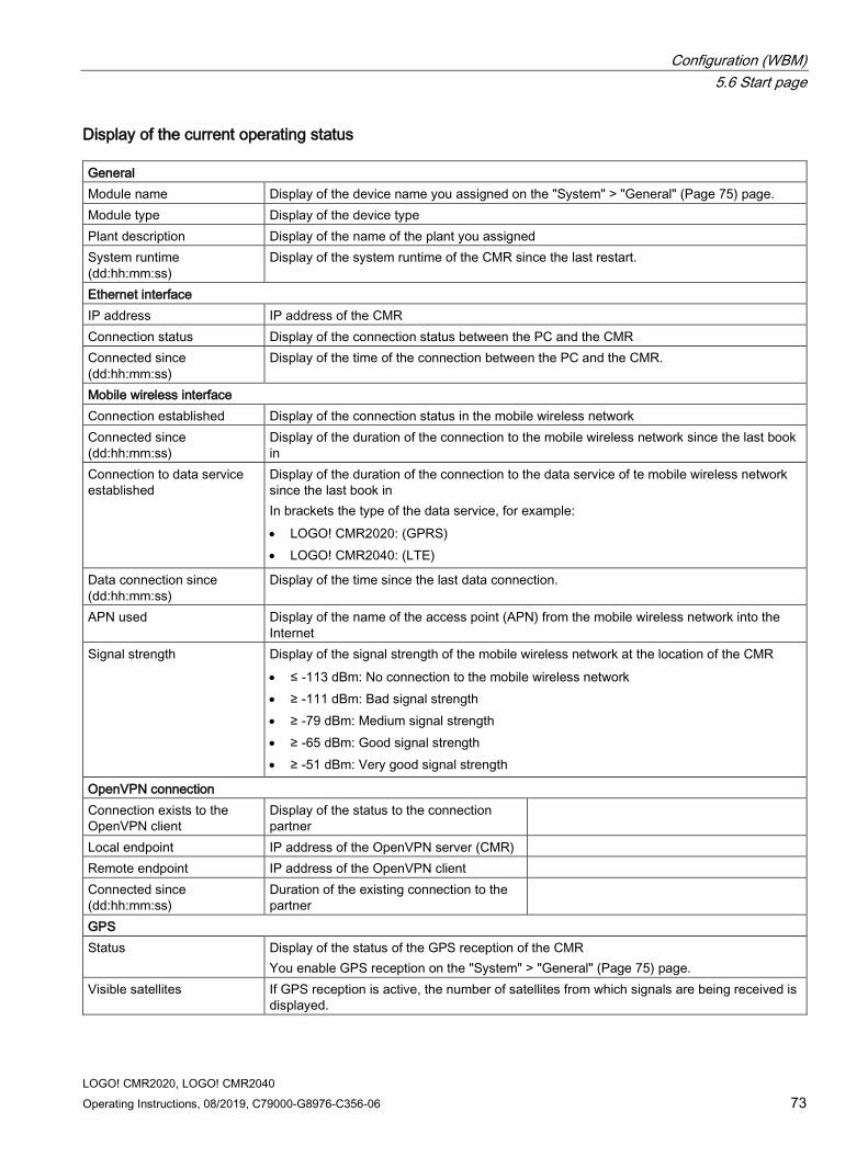
Configuration (WBM) 5.6 Start page
LOGO! CMR2020, LOGO! CMR2040 Operating Instructions, 08/2019, C79000-G8976-C356-06 73
Display of the current operating status General Module name Display of the device name you assigned on the "System" > "General" (Page 75) page. Module type Display of the device type Plant description Display of the name of the plant you assigned System runtime (dd:hh:mm:ss)
Display of the system runtime of the CMR since the last restart.
Ethernet interface IP address IP address of the CMR Connection status Display of the connection status between the PC and the CMR Connected since (dd:hh:mm:ss)
Display of the time of the connection between the PC and the CMR.
Mobile wireless interface Connection established Display of the connection status in the mobile wireless network Connected since (dd:hh:mm:ss)
Display of the duration of the connection to the mobile wireless network since the last book in
Connection to data service established
Display of the duration of the connection to the data service of te mobile wireless network since the last book in In brackets the type of the data service, for example: • LOGO! CMR2020: (GPRS) • LOGO! CMR2040: (LTE)
Data connection since (dd:hh:mm:ss)
Display of the time since the last data connection.
APN used Display of the name of the access point (APN) from the mobile wireless network into the Internet
Signal strength Display of the signal strength of the mobile wireless network at the location of the CMR • ≤ -113 dBm: No connection to the mobile wireless network • ≥ -111 dBm: Bad signal strength • ≥ -79 dBm: Medium signal strength • ≥ -65 dBm: Good signal strength • ≥ -51 dBm: Very good signal strength
OpenVPN connection Connection exists to the OpenVPN client
Display of the status to the connection partner
Local endpoint IP address of the OpenVPN server (CMR) Remote endpoint IP address of the OpenVPN client Connected since (dd:hh:mm:ss)
Duration of the existing connection to the partner
GPS Status Display of the status of the GPS reception of the CMR
You enable GPS reception on the "System" > "General" (Page 75) page. Visible satellites If GPS reception is active, the number of satellites from which signals are being received is
displayed.

Configuration (WBM) 5.6 Start page
LOGO! CMR2020, LOGO! CMR2040 74 Operating Instructions, 08/2019, C79000-G8976-C356-06
GPS position Current position: <latitude>, <longitude> Conversion o sexagesmal coordinates: • Places before the point Degree • 1. + 2. Decimal place: Minutes • 3. + 4. Decimal place: seconds • 5. + 6. Decimal place: Hundredths of seconds Display of the hemisphere and the position to the Meridien: • Latitude: Positive values for north, negative values for south • Longitude: Positive values for east, negative values for west
Altitude Height (m above sea level)
Note Update of the displayed GPS satellites with the CMR2040
If GPS reception deteriorates, for example due to position change or removing the antenna, with the CMR2040 the satellites are displayed with a delay of up to 10 minutes.
Updating the displayed values If you enable automatic updating of the display at the top right on the start page, the displayed values are updated every 5 seconds.
For manual updating, with some Web browsers you can use the F5 key.

Configuration (WBM) 5.7 System
LOGO! CMR2020, LOGO! CMR2040 Operating Instructions, 08/2019, C79000-G8976-C356-06 75
5.7 System
5.7.1 General
Figure 5-3 System – "General" tab
Module name Enter any name for your module.
Only use a DNS-compliant name as the module name. DNS-compliant names are, for example, used for diagnostics.
Plant description Enter any text for your plant.
End session after inactive period (minutes) Period without input after a session is ended.
You then need to log in again with a user name and password.

Configuration (WBM) 5.7 System
LOGO! CMR2020, LOGO! CMR2040 76 Operating Instructions, 08/2019, C79000-G8976-C356-06
Activate GPS Activate/deactivate GPS reception.
Make sure that an antenna is connected to the GPS input:
● To activate GPS, select the entry "Yes" from the "Activate GPS" drop-down list.
● To deactivate GPS, select the entry "No" from the "Activate GPS" drop-down list.
With the CMR2040 note the information on updating the displayed GPS satellites in the section Start page (Page 72).
"Apply" button If you click the "Apply" button, all the settings you made in the "General" tab are adopted.
5.7.2 Device info
System Display of the following parameters:
● System runtime since the last restart.
● Article number of the CMR
● Serial number of the CMR
● Hardware product version of the CMR
5.7.3 SD card
SD card
Displayed data
● SD card inserted
● Total free memory space (kB)
Here the free (still available) and the entire memory on the SD card that can be used by the user are displayed.
Savable files below the parameter area
Below the parameter area, the names of the files saved on the SD card are displayed. By clicking on the file name, you can open the file from the SD card and save it to the file system of your PC.

Configuration (WBM) 5.7 System
LOGO! CMR2020, LOGO! CMR2040 Operating Instructions, 08/2019, C79000-G8976-C356-06 77
Naming conventions for the file names ad file system
File system
Files written from the CMR to the SD card meet the DOS or 8.3 format. File names are structured according to the following pattern: <1...8 characters>.<1...3 characters>
Directories are also displayed in the DOS format (up to 8 characters). Note that when saving files with more than 8 letters that the name is truncated after 8 characters.
Naming conventions for the file names
The file names are structured according to the following scheme:
● Configuration files
Files with configuration data of the CMR:
*.CFG
– The file "default.cfg" is created automatically by the CMR and updated with every change to the configuration.
– The file "user.cfG" is a configuration data file that you saved manually.
For information on saving and the meaning of the files refer to the section Configuration (Page 83).
● Diagnostics buffer file
File with diagnostics buffer entries of the CMR:
diagbuf.txt
● Other files
Files that you yourself save on the SD card:
*.*
5.7.4 System Time In this tab, you make the basic setting for the time of day and specify the following:
● The time-of-day synchronization method and the intervals at which the time of day is synchronized.
● The automatic daylight saving time switchover
● The forwarding of the CMR time of day to the BM

Configuration (WBM) 5.7 System
LOGO! CMR2020, LOGO! CMR2040 78 Operating Instructions, 08/2019, C79000-G8976-C356-06
Note
The time of day is reset during a restart. To have the current time, you always need to use a time-of-day synchronization method.
When using certificates, note the information on the time-of-day in the section Requirements for use (Page 18).
Methods and requirements The following requirements must be met for the various methods of time-of-day synchronization:
● NTP
– The CMR is connected to the mobile wireless network and the mobile wireless interface is enabled.
The connection to the NTP server can only be established via the mobile wireless interface and not via the Ethernet interface.
– The option "Enable data service in the mobile wireless network" n the tab WAN > Mobile wireless settings (Page 93) is enabled.
– An antenna is connected.
– Reception is adequate.
● GPS
– GPS is enabled: System > General (Page 75)
– An antenna is connected.
– Reception is adequate.
● By mobile wireless network
– The service is supported by your mobile wireless provider. Check this with your mobile wireless provider.
– An antenna is connected.
– Reception is adequate.
With this method note that the time when the time of day is synchronized can be very variable. The first time the device books into the mobile wireless network, the time of day is transferred by the mobile wireless provider. After booking in, the intervals of the next time-of-day synchronization points can deviate considerably depending on the mobile wireless provider. Under certain circumstances the intervals may be several days.
Local time zone ● Select the time zone to match your location from the drop-down list.
You can also set the local time zone manually.

Configuration (WBM) 5.7 System
LOGO! CMR2020, LOGO! CMR2040 Operating Instructions, 08/2019, C79000-G8976-C356-06 79
If you click the "Applyy" button, the settings you have made for the local time zone are adopted.
● Automatic daylight saving time switchover
If you select the "Automatic daylight saving time switch" check box, the daylight saving time switchover is performed automatically.
You can only change the date and time for the time-of-day switchover manually. In the drop-down lists, you select the valid dates and times for the time switchover.
The settings are fixed for the UTC time zones and cannot be changed.
● Enable time-of-day synchronization
With this option you enable time-of-day synchronization of the CMR.
● Time-of-day synchronization method
Select a time-of-day synchronization method.
● Last time-of-day synchronization (dd:hh:mm:ss) ago
Shows when the last time-of-day synchronization was performed.
● Now synchronize
If you have selected "NTP" or "GPS" as the time-of-day synchronization method if you have an existing mobile wireless connection of thee CMR, you can synchronize the time of day spontaneously.
● Accept time of day from non-synchronized NTP servers
If the option is enabled, the CMR also accepts the time-of-day from non-synchronized NTP servers with stratum 16.
● IP address or DNS of the NTP server
In this box enter the FQDN (URL format) or the IP address of the SNTP server.

Configuration (WBM) 5.7 System
LOGO! CMR2020, LOGO! CMR2040 80 Operating Instructions, 08/2019, C79000-G8976-C356-06
● Update interval
Using the drop-down list, you specify the intervals at which the time is synchronized.
With the "Via mobile wireless" method you can specify the update interval because the time-of-day is sent actively by the provider.
● Forward time of day to LOGO! BM
With this option you enable forwarding of the time of day of the CMR to LOGO! BM. The time of day is forwarded to the BM at the intervals you have set.
If the time of day is synchronized via a mobile wireless network, the time of day is forwarded as soon as a new time of day is received by the CMR. The time of day is also transferred when establishing the connection to the BM.
Note
Avoid having different settings on the BM and CMR
If you have different settings on the BM and CMR and want to avoid time deviations resulting from this, you need to enable time-of-day forwarding to the BM:
Enable the automatic daylight saving time switchover in the BM This ensures that blocks such as the astronomic clock work correctly.
Note
Second-precise time-of-day synchronization with LOGO! BM
When synchronizing the time of day of LOGO! BM by the CMR time-of-day synchronization to the second is possible with the following firmware versions: • LOGO! BM: V1.81.01 (FS:04) or higher • LOGO! CMR: As of V2.0
With older firmware versions there may be small deviations between the CMR and BM.
If you click the "Apply" button, time-of-day synchronization is started if the parameters have been changed.
Set system time manually You can get the system time for the CMR from your PC or enter it manually.
● New system time
To set the time manually, entered the required system time manually in the input box.
● Adopt new system time
By clicking the button, the time is written to the CMR.
● Adopt PC time
By clicking the button, the system time of the PC is read and written to the CMR.
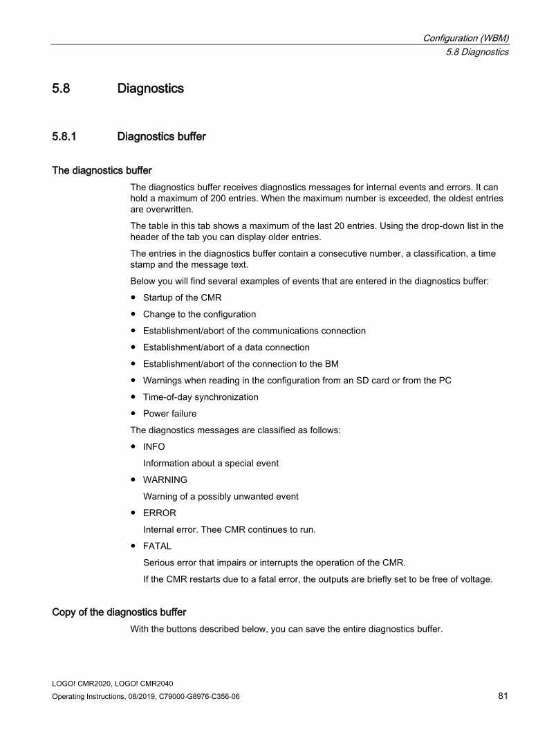
Configuration (WBM) 5.8 Diagnostics
LOGO! CMR2020, LOGO! CMR2040 Operating Instructions, 08/2019, C79000-G8976-C356-06 81
5.8 Diagnostics
5.8.1 Diagnostics buffer
The diagnostics buffer The diagnostics buffer receives diagnostics messages for internal events and errors. It can hold a maximum of 200 entries. When the maximum number is exceeded, the oldest entries are overwritten.
The table in this tab shows a maximum of the last 20 entries. Using the drop-down list in the header of the tab you can display older entries.
The entries in the diagnostics buffer contain a consecutive number, a classification, a time stamp and the message text.
Below you will find several examples of events that are entered in the diagnostics buffer:
● Startup of the CMR
● Change to the configuration
● Establishment/abort of the communications connection
● Establishment/abort of a data connection
● Establishment/abort of the connection to the BM
● Warnings when reading in the configuration from an SD card or from the PC
● Time-of-day synchronization
● Power failure
The diagnostics messages are classified as follows:
● INFO
Information about a special event
● WARNING
Warning of a possibly unwanted event
● ERROR
Internal error. Thee CMR continues to run.
● FATAL
Serious error that impairs or interrupts the operation of the CMR.
If the CMR restarts due to a fatal error, the outputs are briefly set to be free of voltage.
Copy of the diagnostics buffer With the buttons described below, you can save the entire diagnostics buffer.

Configuration (WBM) 5.8 Diagnostics
LOGO! CMR2020, LOGO! CMR2040 82 Operating Instructions, 08/2019, C79000-G8976-C356-06
The file name for the diagnostics messages of the diagnostics buffer is fixed: diagbuf.txt
● Save on SD card
Manual saving on the SD card
● Save to PC
Manual saving in the file system of the configuration PC
● Save a copy of the diagnostics buffer automatically on SD card if serious errors occur
By activating the option you can ensure that if errors of the class FATAL occur, the diagnostics buffer is automatically backed up on the SD card.
Sending the diagnostics buffer In the "Notifications" tab you can configure that the diagnostics buffer is sent by e-mail depending on the class of the entries occurring.
5.8.2 Notifications
Note
To send SMS messages and e-mails you require configured users and groups.
● Send notifications
Here, you set whether the CMR RTU sends a notification by SMS message or e-mail if an event (message) occurs.
In the message, the plain text of the message, the class and time stamp are sent.
The subject in e-mails is "Diag Notification From: <module name>"
● Message class
Here, you set the message class.
The message is sent depending on the class of the entries occurring.
● Recipient group
Here you specify configured groups as recipients of the notification in "Users / groups".
If no recipient group has been configured yet, the notifications cannot be activated.
Only with when sending e-mails:
● Attachment
Here, select the attachment that will be sent with the e-mail. You have the following options:
– Current process image
– Entire diagnostics buffer

Configuration (WBM) 5.9 Maintenance
LOGO! CMR2020, LOGO! CMR2040 Operating Instructions, 08/2019, C79000-G8976-C356-06 83
5.9 Maintenance
5.9.1 Configuration
Load Configuration
Load configuration from PC
With this function a configuration created previously and saved on the PC is loaded on the CMR.
Configuration files have the file extension ".cfg".
1. To search for configurations on the PC, click the "Browse" button.
2. Double-click on the required configuration file.
3. To load the configuration on the CMR, click the "Load on device" button.
Result: The configuration loaded from the PC is now used.
Load configuration from SD card
With this function a configuration created previously and saved on the SD card is loaded on the CMR.
The name of the stored configuration file is "user.cfg".
1. To load the configuration on the CMR, click the "Load from SD card" button.
Result: The configuration loaded from the SD card is now used.
Save configuration
Saving a configuration on PC
You can save the currently used configuration of the CMR as a file "user.cfg" on the PC. To do this, click the "Save to PC" button. Select the relevant storage location.
A saved configuration file can, when necessary, be transferred to other devices of the same type, see the next section.
Save configuration on SD card
Note Only one configuration file of a type
You can only save a single configuration file with the name "user.cfg" or "default.cfg" on the SD card.
You can save the currently used configuration of the CMR as a file "user.cfg" on the SD card. To do this, click the "Save on SD card" button.

Configuration (WBM) 5.9 Maintenance
LOGO! CMR2020, LOGO! CMR2040 84 Operating Instructions, 08/2019, C79000-G8976-C356-06
Configuration files for device replacement and further CMRs If an SD card is inserted, the configuration file "default.cfg" is automatically saved on the SD card during startup of the device. If there are changes to the configuration, the file is automatically updated when you click the "Apply" button.
The configuration files saved with the functions described above can be used for device replacement as well as a template for other devices of the same type.
● Device replacement
With the aid of the configuration files you can continue to use a configuration if you replace a device without needing to create the configuration of the new device.
If the SD card with the "default.cfg" file is inserted in a brand-new CMR or in a CMR that has been reset to the factory settings, the "default.cfg" file will be loaded. The new device can be used immediately with the configuration data of the old device.
● Transfer of the configuration to other devices
With the aid of a configuration file "user.cfg"you can use a configuration as the template for other CMRs of the same time.
If you use several CMRs with a similar configuration, you can save the configuration of the first configured device as a configuration file "user.cfg" on the PC.
You can now make copies of the stored configuration file and adapt the special parameters such as IP address, plant name etc. for each device to be used using an editor (see below). If you save the adapted configuration files on SD cards and insert them in the relevant devices, after device start-up the file will be loaded on the device from the SD card. This saves you time for the full configuration of each individual device.
Editing configuration files The configuration files "*.cfg" can be edited with the usual text editors.
Note Editing configurations with a text editor
Note the following when editing configuration files with a text editor: • Do not change the structure of the file. • Only enter correct parameters. • Sensitive data must not be changed since this is stored encrypted.
This includes passwords and keys, e.g. for HTTPS and OpenVPN. • Save the file either in UTF-8 format or do not use any special characters, in other words
only ASCII characters from the number range (decimal) 32 .. 126.

Configuration (WBM) 5.9 Maintenance
LOGO! CMR2020, LOGO! CMR2040 Operating Instructions, 08/2019, C79000-G8976-C356-06 85
5.9.2 Firmware
Firmware status The following information is shown:
● Module name that you configured on the "System" Web page
● Activated firmware version
● Activated on (date)
● Bootstrap version
● IfMobile wireless module version
Firmware update
NOTICE
Digitally signed and encrypted firmware prevents manipulation by third parties
To be able to check the authenticity of the firmware, the firmware is digitally signed by Siemens. This allows manipulation by third parties to be detected and prevented. The encryption of the firmware is intended to prevent re-engineering.
Note
During the time between unpacking the firmware and the actual update through to the restarting the CMR, the administration user interface is not blocked. • During this time, do not make any settings in the Web user interface otherwise you
cannot be certain that these settings will be adopted correctly.
Do not turn off the CMR during the update.
To load a new firmware version on the CMR, follow the steps below:
1. Before you start the update: Read the notes in “Firmware update".
2. Click the "Browse" button.
3. Select the relevant firmware file, for example "LOGO!CMR_v2.0-v2.1.sfw".
4. Click the "Load" button.
5. After successful transfer, the updated firmware version is displayed.
6. Then click the "Activate and restart" button.
7. The CMR restarts.
8. Following the restart, the firmware is updated. During this time all the LEDs light up for several seconds before the CMR starts.

Configuration (WBM) 5.9 Maintenance
LOGO! CMR2020, LOGO! CMR2040 86 Operating Instructions, 08/2019, C79000-G8976-C356-06
Display boxes with additional information on the firmware
● Status
Indicates errors while loading the firmware: For example format error if you load a file different from the required firmware.
● Signature status
Shows you the result of the signature check.
● Description
Shows you the name of the firmware.
● Version
Shows you the version of the loaded firmware.
5.9.3 Operating status In the "System" tab, you can do the following:
● Change the device to the safe status
● Run a restart
● Reset to factory defaults
Change to the safe status There are two ways in which you can change the CMR to the safe status:
● Using the WBM
● With the SET button on the front of the device
If you change the CMR down to the safe status the CMR books out of the mobile wireless network.
Then you can disconnect the device from the power supply.
Change to the safe status using the WBM
In the "Maintenance" > "System" tab, click the "Change to the safe status" button to change the CMR to the safe status.
Change to the safe status using the SET button
Press the SET button with a suitable object. Hold down the button for between 5 and 10 seconds.

Configuration (WBM) 5.9 Maintenance
LOGO! CMR2020, LOGO! CMR2040 Operating Instructions, 08/2019, C79000-G8976-C356-06 87
Run restart There are two ways of running a restart with the CMR:
● Using the WBM
In the "Maintenance" > "System" tab, click the "Run a restart".
● Using the SET button of the CMR
Press the SET button with a suitable object briefly (< 5 seconds).
Effects:
● The CMR restarts.
● The settings of the current configuration do not change.
The CMR continues to work using these settings after the restarting.
● When restarting, existing connections are interrupted.
● When restarting the outputs of the CMR are briefly reset.
You should therefore only run a restart when this is necessary.
Reset to factory settings There are two ways in of resetting the device to the factory settings:
● Using the WBM
● With theSET button on the front of the device
Note the following instructions before you reset the CMR to the factory settings:
NOTICE
Deleting data
If you reset to factory settings, all the configuration data of the CMR will be deleted. Deleting involves the following data: • User names and passwords • Configured PIN • Diagnostics buffer • If an SD card is inserted:
– The automatically backed up configuration (default.cfg) – The manually backed up configuration (user.cfg)
Following this, the CMR is restarted. After the restart, the CMR can be reached via the Ethernet interface using the default IP address 192.168.0.3.

Configuration (WBM) 5.9 Maintenance
LOGO! CMR2020, LOGO! CMR2040 88 Operating Instructions, 08/2019, C79000-G8976-C356-06
Note Backing up configuration data on PC or SD card
If you do not want to discard the configuration data you have entered, you can back up the data externally and load it again after resetting to factory settings.
For information on this, refer to section Configuration (Page 83)
After saving the configuration data on an SD card, note the following: • Before resetting to factory settings, remove the SD card: see "Reusing a configuration of
a CMR". • Remove the SD card only when the power supply is disconnected.
Resetting using the WBM
In the "Maintenance" > "System" tab, click the "Reset to factory settings" button to reset the CMR.
After the reset to factory settings, the CMR will perform a restart.
Put the device back into operation as described in Steps in commissioning (Page 47) and Configuration (WBM) (Page 57).
Resetting using the SET button
Press the SET button with a suitable object. Hold down the button for longer than 10 seconds.
After the reset to factory settings, the CMR will perform a restart.
Put the device back into operation as described in Steps in commissioning (Page 47) and Configuration (WBM) (Page 57).
Reusing a configuration of a CMR You can transfer the configuration of a CMR any number of times to other CMRs:
Requirement: The CMR is brand-new or was reset to the factory settings (without SD card).
If the SD card of another CMR is inserted before starting the CMR, the automatically backed up configuration (default.cfg) of the other CMR is used.
5.9.4 Online support Here you can call up the Internet pages of Siemens Industry Online Support.
Online support
Link to the Internet portal of Siemens Industry Online Support
Click on "Siemens Industry Online Support" to connect to the Internet pages of Siemens Online Support.
Configuration (WBM) 5.9 Maintenance
LOGO! CMR2020, LOGO! CMR2040 Operating Instructions, 08/2019, C79000-G8976-C356-06 89
There, you can search for information on the product or send a query to product support.
Configuration of the logging
In some cases, product support can send you a logging file of the type *.sup to log events. You save this logging file in the file system of the configuration PC. On this WBM page you download the file to the CMR.
For logging you require an SD card with at least 8 MB free space.
● File
After selecting a logging file stored on the configuration PC with the "Search" button, the file name is displayed here.
● Search
Searches the file system of the configuration PC for a log file saved there that is intended to be downloaded to the CMR.
● Load on device
By clicking the button you download the selected log file to the CMR.
● Standard settings
Loads the default logging file preset in the factory instead of a file for logging made available by Product Support.
● Delete
Deletes a no longer required log file from the CMR.
After deleting the logging file, logging is disabled again.
Enable logging
After loading the logging file, logging must be actively enabled.
● Enable logging and save the file on the SD card
By enabling the option logging is started as soon as you click the "Apply" button.
The log file is saved on the SD card and updated during operation if relevant events occur.
Use of the logging You should only use logging of events. If you have problems with the CMR that you cannot solve yourself.
Note Protecting the SD card by disabling logging
To avoid shortening the working life of the SD card too much, logging should be disabled during normal operation of the CMR.

Configuration (WBM) 5.10 LAN
LOGO! CMR2020, LOGO! CMR2040 90 Operating Instructions, 08/2019, C79000-G8976-C356-06
When logging is enabled, during runtime the CMR continuously saves information about important events that have occurred. The saved data contains information on the configuration, active procedures and error situations.
The data is saved on the SD card in a log file with the name "support.bin". The information in this file is encrypted and can only be read by Siemens Industry Online Support. On completion of logging sent the log file back to your contact at Siemens Industry Online Support.
5.10 LAN
5.10.1 Configuration
Function of the LAN interface X1P1 ● The X1P1 interface (Ethernet RJ-45) of the CMR is used to connect a local PC for the
configuration.
● After completed configuration, the X1P1 interface serves to connect to the BM if the CMR is not being operated in standalone mode.
For information on the operating options, refer to the section Mobile wireless communication by SMS / e-mail without LOGO! BM (Page 22).
You will find the properties of the X1P1 interface in the section Technical specifications (Page 151).
By using autonegotiation and autocrossing, the transmission properties of the interface are detected automatically and set.
Configuration of the Ethernet interface
Note IP address and subnet mask according to RFC 1918
The factory-set IP addresses and subnet masks can be changed as required, but must keep to the specification RFC 1918. The CMR does not run any strict checks of the address bands.
Do not set an IP address that is already assigned in your LAN, for example for other BMs.
If a duplicate IP address is detected, the red error LED starts to flash. The CMR is no longer reachable via the Ethernet interface. No other functions are affected: e.g. sending an SMS message due to events.

Configuration (WBM) 5.11 WAN
LOGO! CMR2020, LOGO! CMR2040 Operating Instructions, 08/2019, C79000-G8976-C356-06 91
Fixed parameters
● MAC address
● Connection status
● Transmission properties (options: 10/100 Mbps; half/full duplex)
● Connected since (dd:hh:mm:ss)
Changeable parameters
● IP address
● Subnet mask
● Default router
The default router is intended for direct connection of the CMR to the Internet via the LAN interface.
5.11 WAN
5.11.1 Overview
Mobile wireless connection The following information on the mobile wireless interface is displayed in the Overview:
● Connection established
Connection status to the mobile wireless network
● Connected since (dd:hh:mm:ss)
Duration of the existing mobile wireless connection
● Connection to data service established
Status of the connection to the data service GPRS / UMTS / LTE
● Data connection since (dd:hh:mm:ss)
Duration of the existing connection to the data service
● Signal strength CSQ (dbm)
– CSQ = 0 .. 8 (-112 .. ≤ -97 dBm): No reception possible
– CSQ = 9 .. 16 (-95 .. -81 dBm): Medium signal quality
– CSQ = 17 .. 31 (≥ -79 dBm): Good signal quality
– CSQ = 99 (≤ -113 dBm): No signal detectable
● APN used

Configuration (WBM) 5.11 WAN
LOGO! CMR2020, LOGO! CMR2040 92 Operating Instructions, 08/2019, C79000-G8976-C356-06
● IMEI
International Mobile Equipment Identity of the mobile wireless network provider
● IMSI
International Mobile Subscriber Identity of the mobile wireless network provider
● IP address
IP address of the CMR assigned by the mobile wireless network provider.
To be able to reach the CMR via mobile wireless, the CMR requires a public IP address.
● DNS server
IP address of the DNS server assigned by the mobile wireless network provider
Statistics The figures apply to the period since the CMR was last restarted.
● SMS sent
Number of SMS messages sent successfully by the CMR
● Sending the SMS failed
Number of SMS messages that the CMR could not send (with diagnostics buffer entry).
● SMS received
Number of SMS messages received and processed by the CMR
● SMS discarded
Number of SMS messages received that the CMR discarded.
In the following situations SMS messages are discarded:
– The option "SMS received" in the "SMS" tab is disabled.
– The phone number of the sending partner is not configured among the users.
● Data sent (kB)
Number of data (kilobytes) sent by the CMR.
● Data received (kB)
Number of data (kilobytes) received by the CMR.
● E-mails sent
Number of e-mails sent successfully by the CMR

Configuration (WBM) 5.11 WAN
LOGO! CMR2020, LOGO! CMR2040 Operating Instructions, 08/2019, C79000-G8976-C356-06 93
● E-mails sent unsuccessfully
Number of e-mails that could not sent successfully by the CMR.
Note Number of attempts to send
If the CMR cannot send an e-mail, it attempts twice more to send the e-mail. Following this, the e-mail is deleted
● Reset statistics
With the button, you reset all counters for statistics in the CMR to zero.
5.11.2 Mobile wireless settings The mobile wireless interface of the CMR connects the device to the mobile wireless network.
Note Costs of a mobile data connection
Remember that both when establishing or when attempting to establish a mobile data connection and to maintain a mobile data connection, frames are exchanged that are subject to charges.
Access parameters You configure your mobile wireless connection in the "Mobile wireless settings" tab.
For access to the GSM mobile wireless network and to the HSPA, UMTS, GPRS or LTE services, you require the following parameters:
● The PIN protects the SIM card against unauthorized use.
● APN is the name of the transition point from the mobile wireless network to other connected IP networks, with the CMR to the Internet.
“Name" and "password" are used to keep APN access secure.
You will receive these access parameters from your mobile wireless provider.

Configuration (WBM) 5.11 WAN
LOGO! CMR2020, LOGO! CMR2040 94 Operating Instructions, 08/2019, C79000-G8976-C356-06
The mobile wireless network is selected automatically.
Note Dial-in in mobile wireless networks with LOGO! CMR2020
LOGO! CMR2020 only dials into a GSM/GPRS network. Dial-in in mobile wireless network with LOGO! CMR2040
As first choice, LOGO! CMR2040 attempts to establish a connection to an LTE network.
If the connection to the LTE network fails, the CMR attempts to establish a connection to a UMTS network.
If the connection to the UMTS network fails, the CMR attempts to establish a connection to a GSM/GPRS network.
By selecting the “Activate mobile wireless interface" check box, you make the mobile wireless interface operational.
If the check box is not selected, the mobile wireless interface cannot be used. The mobile wireless interface is turned off.
PIN of the SIM card
Note SIM card without PIN
The CMR also works with SIM cards without a PIN. In this case, do not make an entry in the "PIN of the SIM card" input box. Entry of an incorrect PIN
The last entered (incorrect) PIN is saved. This means that when changing the configuration (except the PIN) or when restarting the CMR, no further PIN entry attempt is used up.
For this reason, do not change the PIN of the SIM card to the previously stored incorrect PIN outside the CMR. Locking if the PIN is entered correctly
Enter the PIN correctly. If you enter the PIN incorrectly three times, the SIM card will be locked. You should also refer to the information in the section Insert the SIM card and enter the PIN (Page 48). Unlocking the SIM card
Unlocking the SIM card is described in the section Insert the SIM card and enter the PIN (Page 48).

Configuration (WBM) 5.11 WAN
LOGO! CMR2020, LOGO! CMR2040 Operating Instructions, 08/2019, C79000-G8976-C356-06 95
You have received a PIN for your SIM card from your mobile wireless provider.
1. Enter the PIN for your SIM card in the input box.
If you use a SIM card without a PIN, do not make an entry in the box.
2. By clicking the "Apply" button, you save the PIN with the other settings.
– A green check mark below the input box indicates that the PIN was saved successfully on the device.
– A red dot with a white cross below the input box indicates that the configuration is not correct and an error message to this effect is displayed.
No mobile wireless connection is established.
Allow roaming Roaming means that the mobile wireless network of your mobile wireless provider is no longer reachable and another mobile wireless provider takes over the CMR in its mobile wireless network.
If the specified mobile wireless network is no longer reachable, specify whether or not the CMR should log in to another mobile wireless network.
● Select the "Allow roaming" check box.
If the specified mobile wireless network is not available, the device logs in to an available mobile wireless network.
Logging in to another mobile wireless provider can lead to higher connection costs.
● Disable the "Allow roaming" check box.
If the specified mobile wireless network is not available, no connection is established to other mobile wireless networks.
SMSC number The phone number of the SMSC of the mobile wireless provider cannot be changed via the CMR. If you want to change the number, take the SIM card out of the CMR, insert the SIM card in a mobile phone and change the number of the SMSC with the functions of the mobile phone.
Enable data service in the mobile wireless network
Note Enabling mobile data connections
Arrange for the required mobile data connections to be enabled by your mobile wireless provider.

Configuration (WBM) 5.11 WAN
LOGO! CMR2020, LOGO! CMR2040 96 Operating Instructions, 08/2019, C79000-G8976-C356-06
You can turn the mobile data connection on or off for your device.
● "Activate data connection via the mobile wireless network" check box enabled:
If you also want to use IP-based data services of your mobile wireless provider in addition to sending and receiving SMS messages, for example time-of-day synchronization using NTP.
● "Activate data connection via the mobile wireless network" check box is disabled:
The CMR can only send and receive SMS messages.
APN / User name / Password ● APN
Enter the APN of your mobile wireless provider in the input box.
The APN (Access Point Name) is the DNS host name of the access point from a mobile wireless network to an external packet data network (LTE/UMTS/GPRS)..
You can obtain information about this access data from your mobile wireless provider or from the Internet.
● Authentication method
From the "Authentication method" drop-down list, select a method with which the name and the password for the APN will be transferred to the communications partner:
CHAP has the higher priority. If the communications partner does not support CHAP, the name and password are transferred using PAP.
– None
no authentication
– CHAP
Encrypted transfer of name and password using the Challenge Handshake Authentication Protocol.
– PAP
Unencrypted transfer of name and password using the Password Authentication Protocol.
The two following parameters are only required when authentication is enabled.
● Name
In the input box, enter the name given to you by your mobile wireless provider. Some mobile wireless providers do without the access check with a name. In this case, leave the input box empty.
● Password
In the input box, enter the password of the relevant provider. Some mobile wireless providers do without the access check with a password. In this case, leave the input box empty.

Configuration (WBM) 5.11 WAN
LOGO! CMR2020, LOGO! CMR2040 Operating Instructions, 08/2019, C79000-G8976-C356-06 97
5.11.3 Wireless cell
Optimum antenna alignment To allow you to find the optimum alignment of the antenna connected to the SMA socket, you can use the "Wireless cell" tab. The "Wireless cell" tab allows you to test the signal strength at various antenna positions.
The information is updated at intervals of a few seconds. To be able to find the optimum position, you receive immediate information about the signal strength at the test positions.
Status of the wireless cells Display of parameters of the mobile wireless cell where the CMR is currently booked in:
● Wireless cell identifier (CI)
● Signal strength (CSQ / dBm)
Signal strength of the mobile wireless network as CSQ (Cell Signal Quality) and as received signal strength RSSI [dBm]
CSQ and RSSI correspond as follows:
– CSQ = 0 .. 8 (-112 .. ≤ -97 dBm): No reception possible
– CSQ = 9 .. 16 (-95 .. -81 dBm): Medium signal quality
– CSQ = 17 .. 31 (≥ -79 dBm): Good signal quality
– CSQ = 99 (≤ -113 dBm): No signal detectable
● Signal quality
Signal quality as a percentage
● Location Area Code
Location identifier
● Mobile wireless standard of the wireless cell
● Network type
● Network name
● PLMN
Public Land Mobile Network
Worldwide unique identifier of mobile wireless networks consisting of:
– MCC (Mobile Country Code)
– MNC (Mobile Network Code) of the network provider
Example: PLMN 26276 is made up of MCC = 262 and MNC = 76.

Configuration (WBM) 5.11 WAN
LOGO! CMR2020, LOGO! CMR2040 98 Operating Instructions, 08/2019, C79000-G8976-C356-06
5.11.4 SMS In this tab you can allow or block receipt of SMS messages by the CMR.
You will find information on writing data in the appendix Additional information on SMS (Page 169).
● Allow receipt of SMS messages
– If the option is enabled the CMR can receive SMS messages and evaluates them.
– If the option is disabled the CMR can receive SMS messages but does not evaluate them.
The CMR does not evaluate received SMS messages regardless of the SMS rights you have assigned for the users on the Users / groups (Page 111) page.
Note
Roaming cost with the option disabled
Even if the option is disabled the CMR receives SMS messages. For this reason roaming costs can also result in even if receipt of SMS messages is blocked.
● Enable SMS password
With this option you optionally assign a password for write commands transferred by SMS. By assigning a password write access to the CMR is better protected.
If the option is enabled, the CMR only evaluates SMS messages that contain the configured password.
Note that if the options is disabled, SMS messages must not contain a password.
● Password for writing commands
Here, enter the password that needs to be transferred with writing SMS meesages.
● Send positive acknowledgments
After receiving an SMS message with which an error occurs, the CMR always sends an acknowledgment with the relevant error message to the sender. This may be the result of invalid parameters or an incomplete SMS configuration.
After receiving an SMS message with writing data that could be transferred to the destination module, the behavior is as follows:
– If the option is enabled, the CMR always sends a positive acknowledgment to the sender of the SMS message when the job has been handled.
– If the option is disabled the CMR reacts as follows:
After receiving an SMS message with writing data that could be transferred to the destination module, the CMR does not send an acknowledgment to the sender of the SMS message.
After receiving an SMS message with read commands (for example "STATUS?") the CMR always sends a reply.

Configuration (WBM) 5.11 WAN
LOGO! CMR2020, LOGO! CMR2040 Operating Instructions, 08/2019, C79000-G8976-C356-06 99
Test SMS To check the selected settings and the connection, you can have the CMR send a test SMS message to a configured recipient module.
● Recipient group
User group that is to receive the test SMS message.
● Text
Configured text that will be sent in the test SMS message.
● Send test SMS
The button triggers the sending of the test SMS with selected text block (previously configured in "Message texts").
5.11.5 SMS alias
SMS alias configuration In the table configure up to 20 values for the alias texts of SMS that the CMR is to receive. These are SMS messages with writing access or SMS messages with a read command, for example "DIAG?" to request a diagnostics SMS message.
You configure symbolic names as placeholders for the entire SMS text.
● Name
Symbolic name of the text
● Content
Suitable text of the alias SMS message with the correct syntax.
Example:
● The alias name is as follows: Lamp3ON
(This text will be transferred as the SMS message text.)
● The configured content is <password>;LOGO=VM125,1,WORD
(The variable VM125 of the type WORD is linked to the output for Lamp 3.)
When it receives an SMS message with the text "Lamp3ON", the CMR first checks the configured password.
Then according to the configuration in the table the CMR translates remaining text in "LOGO=VM125,1,WORD" and sets the variable VM125 of the type WORD to 1.

Configuration (WBM) 5.11 WAN
LOGO! CMR2020, LOGO! CMR2040 100 Operating Instructions, 08/2019, C79000-G8976-C356-06
5.11.6 E-mail In this tab you can configure the data for the sending of e-mails by the CMR.
If you do not want the CMR to send e-mails, leave this page unedited.
● SMTP server name
Name of the SMTP server. You will receive the data from your service provider.
● Port number
Port number of the SMTP server. You will receive the data from your service provider.
● Connection security
Here, select from the following options:
– Only STARTTLS
With this setting, e-mails are only sent when STARTTLS is supported by the service provider.
For this option a CA certificate from the service provider needs to be imported, see below.
– STARTTLS, if possible
With this setting, e-mails are also sent when STARTTLS is not supported by the service provider.
● Own e-mail address
E-mail address of the CMR. You will receive the data from your service provider.
● Name
Name required by the SMTP server. You will receive the data from your service provider.
● Password
Password required by the SMTP server. You will receive the data from your service provider.
CA certificate
Here, you have the option of importing the CA certificate of the service provider for sending e-mail with STARTTLS.
● Currently used file
Display of the file name of the currently used file
● Delete
With the button, you delete the currently used file.
The file is deleted only after you click "Apply" button.
● File used after applying
After loading the certificate, the name of the loaded file is displayed here.

Configuration (WBM) 5.11 WAN
LOGO! CMR2020, LOGO! CMR2040 Operating Instructions, 08/2019, C79000-G8976-C356-06 101
● Load new file
After selecting a file stored on the configuration PC using the "Search" button, the file name is displayed here.
● Search
Searches the file system of the configuration PC for a certificate file saved there that is intended to be loaded on the CMR.
● Load on device
With the button "Load on device" load the selected file on the CMR.
Test e-mail
Here you can check the settings and the connection establishment by sending a test e-mail.
The requirements for this are that the following parameters (Recipient, Subject, Text) are configured in "Users / groups" or "Monitoring" and that the configuration PC is connected to the Internet.
● Recipient group
● Subject
● Text
● Send test e-mail
By clicking the button, the test e-mail is sent.
5.11.7 DynDNS In this tab you can enable the use of address assignment by dynamic DNS (DynDNS) on the mobile wireless interface. To do this you require one of the service providers that can be selected below and the corresponding access data.
DynDNS is recommended when using OpenVPN and HTTPS.
Note DynDNS only with a public IP address
DynDNS can be used only with a public IP address. Check this with your network provider.
If you log the CMR on to a DynDNS service, the device can be reached from the Internet under a host name, for example "myName.dyndns.org".
Generally the CMR will not have a fixed IP address on the mobile wireless interface and will not be registered under a host name. By using a dynamic domain name system (DynDNS) it can however be reachable on the Internet. The public IP address is then made known by the DynDNS service.
With each dial in to the data network and if the IP address is changed on the mobile wireless interface, the DynDNS server is informed of the received IP address via HTTPS. An entry with the IP address is written to the diagnostics buffer.

Configuration (WBM) 5.11 WAN
LOGO! CMR2020, LOGO! CMR2040 102 Operating Instructions, 08/2019, C79000-G8976-C356-06
The reachability of the IP address from the Internet must be enabled by the service provider.
● Active
– If the option is enabled, the use of DynDNS is enabled.
– If the option is disabled, the use of DynDNS is not enabled.
● DynDNS provider
You can select the following service providers:
– DynDNS
Address: http://www.dyndns.org/
– No-IP
Address: http://www.noip.com/
● Host
Host name of the CMR that you agreed with your service provider (DynDNS) or that you select yourself (No-IP).
● User name
User name assigned by the service provider (DynDNS) or that you select yourself (No-IP).
● Password
Password assigned by the service provider (DynDNS) or that you select yourself (No-IP).
CA certificate
Here you import the file of the CA certificate of the DynDNS service provider. The certificate serves to authenticate the service provider with the CMR.
Certificates are not absolutely necessary for oeration.
Depending on the service provider, the following certificate is required:
● DynDNS
DigiCert CA
● No-IP
Geo Trust Global CA
Request the relevant valid certificate from your provider.
Parameter
● Currently used file
Display of the file name of the currently used file
● Delete
With the button, you delete the currently used file.
The file is deleted only after you click "Apply" button.

Configuration (WBM) 5.12 Security
LOGO! CMR2020, LOGO! CMR2040 Operating Instructions, 08/2019, C79000-G8976-C356-06 103
● File used after applying
After loading the certificate, the name of the loaded file is displayed here.
● Load new file
After selecting a file stored on the configuration PC using the "Search" button, the file name is displayed here.
● Search
Searches the file system of the configuration PC for a certificate file saved there that is intended to be loaded on the CMR.
● Load on device
With the button "Load on device" load the selected file on the CMR.
5.12 Security
5.12.1 Overview
OpenVPN connection
● Connection to the OpenVPN partner exists
Connection status to the OpenVPN client
● IP address of the OpenVPN partner
Shows the public IP address of the OpenVPN client.
● Local endpoint
Shows the IP address of the OpenVPN server (CMR).
The IP address of the OpenVPN server within the VPN tunnel is fixed at 10.8.0.2.
Note Network settings when using OpenVPN
If you use OpenVPN, make sure that the LAN subnet of the CMR and the OpenVPN subnet do not overlap otherwise no connection can be established to the CMR via OpenVPN.
For information on the LAN settings, refer to the section LAN (Page 90).
● Remote endpoint
Shows the IP address of the OpenVPN client.
The IP address of the OpenVPN client within the VPN tunnel is fixed at 10.8.0.1.
● Connected since (dd:hh:mm:ss)
Duration of the existing connection to the OpenVPN client

Configuration (WBM) 5.12 Security
LOGO! CMR2020, LOGO! CMR2040 104 Operating Instructions, 08/2019, C79000-G8976-C356-06
Statistics of the current connection
The numbers apply to the currently established connection.
For the meaning of the parameters, see below.
Statistics since restart
The numbers apply to all connections that were established since the last restart of the CMR.
● Bytes received
Number of bytes received by the CMR.
● Frames received
Number of frames received by the CMR.
● Received frames lost
Number of frames received by the CMR that it could not process..
● Bytes sent
Number of bytes sent by the CMR.
● Frames sent
Number of frames sent by the CMR.
● Frames to be sent lost
Number of frames, which were ready to send on the CMR that could, however, not be sent.
5.12.2 OpenVPN-PSK For information on the functions and requirements, refer to the following sections:
Further functions (Page 15)
Requirements for use (Page 18)
Note DynDNS when using OpenVPN
To simplify connection establishment when using OpenVPN, the use of DynDNS is recommended.

Configuration (WBM) 5.12 Security
LOGO! CMR2020, LOGO! CMR2040 Operating Instructions, 08/2019, C79000-G8976-C356-06 105
Application examples You can use the OpenVPN tunnel for the following purposes:
● Connection from the mobile phone or configuration PC to the CMR via HTTP
You can reach the CMR via the mobile wireless interface using HTTP (not HTTPS). To do this, use the following tunnel IP address of the CMR: http://10.8.0.2
● Connection with BM via the tunnel
You can reach LOGO! BM directly via the configured IP address. e.g. 192.168.0.1. In this case, the CMR serves as a router for the data exchange. To do this enter the CMR in the BM as a router.
After checking the connection establishment you can monitor the BM (via the Web or a mobile app) and configure it using LOGO!Soft Comfort.
Setting up an OpenVPN connection Below you will find an overview of the steps for setting up an OpenVPN connection.
1. Configure and check the mobile wireless connection
2. Optional: Configure and check DynDNS
3. Generate the pre-shared key on the CMR or OpenVPN client.
If you generate the pre-shared key on the OpenVPN client, load it on the CMR (see below).
4. On the CMR adapt the port and the inactivity monitoring time.
Make sure that the port on the partner (OpenVPN client) is enabled or that port forwarding is enabled on the router to which the partner is connected.
5. Load the standard server configuration ("vpnpeer.conf") on the configuration PC. Rename the file "vpnpeer.conf" to "vpnpeer.ovpn" and place it on the OpenVPN client. If necessary, adapt the file: IP address, DNS address, PSK in unified format
6. Enable OpenVPN o the CMR
7. Enable the OpenVPN client and check the connection status in the WBM: "Security > Overview", if applicable diagnostics buffer
OpenVPN-PSK ● Active
Select the option to enable secure communication via OpenVPN.
● Port number
Here you configure the number of the OpenVPN port of the CMR. As default the port is preset with the number 1194.

Configuration (WBM) 5.12 Security
LOGO! CMR2020, LOGO! CMR2040 106 Operating Instructions, 08/2019, C79000-G8976-C356-06
● Inactivity monitoring time (s)
Time without frame traffic after which the CMR sends a keepalive frame to the OpenVPN client.
This parameter is, for example, useful when the partner has a dynamic IP address and a DNS name is used for it.
Range of values (seconds): 60...65535
● Save standard server configuration
The CMR provides the option of exporting its own standard settings (OpenVPN server) for the OpenVPN client to the file system of the connected PC using the file "vpnpeer.conf". The file contains settings that ensure that a connection from the CMR to the OpenVPN client is established. The file can be imported into the OpenVPN client (mobile phone or PC). Rename the file "vpnpeer.conf" to "vpnpeer.ovpn".
The way the file is handled depends on the method of address assignment of the CMR:
– If you use DynDNS, you can use the file directly for the OpenVPN client.
– If you do not use DynDNS, you need to adapt the address data in the file. To do this, the file can be edited with a text editor, see section below,
Pre-shared key In this block, you can generate a new key or you can load a key file from the file system of the connected configuration PC. This can, for example, be a pre-shared key generated by the OpenVPN client.
The following functions are available:
● Generate new key
With the button, you generate a new pre-shared key on the CMR.
(The function corresponds to the "genkey" function of an OpenVPN client.)
For information on saving the key refer to the entry "Save standard server configuration for client" below.
● Currently used file
Display of the file name of the currently used key file
● File used after applying
After loading a key file from the file system, the name of the loaded file is displayed here.
● Load new file
After selecting a file stored on the configuration PC using the "Search button, the file name is displayed here.
● Search
Searches the file system of the configuration PC for a key file saved there that is intended to be loaded on the CMR.

Configuration (WBM) 5.12 Security
LOGO! CMR2020, LOGO! CMR2040 Operating Instructions, 08/2019, C79000-G8976-C356-06 107
● Load on device
With the buttons load the selected file on the CMR.
● Save standard server configuration for client
With this entry you can save the configuration file of the CMR in the file system of your configuration PC. The file has the name "vpnpeer.conf" and among other things contains the pre-shared key generated by the CMR.
File "vpnpeer.conf" Below you will find the content of the configuration file exported from the CMR for the OpenVPN client (communications partner of the CMR).
Note Unencrypted configuration file: Encrypted transfer
The configuration file for the OpenVPN client is not encrypted. The pre-shared key is located unencrypted in the file.
Only transfer the file encrypted to the partner, e.g. using HTTPS.

Configuration (WBM) 5.12 Security
LOGO! CMR2020, LOGO! CMR2040 108 Operating Instructions, 08/2019, C79000-G8976-C356-06
Table 5- 4 Content of the configuration file "vpnpeer.conf"
Original file Adapted file dev tun0 disable-occ # Please update your OpenVPN peer's address on the next line remote vpn.example.com 1194 ifconfig 10.8.0.1 10.8.0.2 nobind keepalive 15 60 route 192.168.0.0 255.255.255.0 tun-mtu 1500 fragment 1371 mssfix 1282 persist-key replay-window 512 15 cipher AES-128-CBC auth SHA256 comp-lzo verb 4 #key-direction 1 #<secret> # Please insert your key here and uncomment these lines #</secret>
dev tun0 disable-occ remote 192.168.229.29 1196 ifconfig 10.8.0.1 10.8.0.2 nobind keepalive 15 60 route 192.168.0.0 255.255.255.0 tun-mtu 1500 fragment 1371 mssfix 1282 persist-key replay-window 512 15 cipher AES-128-CBC auth SHA256 comp-lzo verb 4 key-direction 1 <secret> # # 2048 bit OpenVPN static key # -----BEGIN OpenVPN Static key V1-----1a17c9b9737c0fd0b33eb540ba845340e2dad229b8d6fd9b82f934563d8169843021d0bc1fcec0862d560b0917685cbe03157aa9cb952de7566dd43f120d7278c1d672dad724457eaed3c6412a14434d9da2f97158465e95b711e68f1b80d681 ca4e3f3f6d7cdac38cc6dddfb74f23b175becbb6125093d41a3af1456824760db3e46e0bc8d20539c7fc1a4111c7cdb571552c1a7bfd707848bbe3eca036e9a2092eea5d9041001bd07a3dc0a8b6636fce42fc94b1446c283c24daa458460ef9ab8a18ebb9c4791f45d87f11e0918f002bfbdbc955d74d7ffc7fa4bacd6f15f10137ebde93b8219ae38ebae9b029e97cd79d204255f30a048865ffbb3eabb6b9-----END OpenVPN Static key V1----- </secret>
Notes: • This is the unchanged content of the file exported from
the CMR.
When using DynDNS, in this form, the file can be im-ported into the OpenVPN client.
• When exporting the file in this form, the pre-shared key is still missing on the CMR. You still need to import the pre-shared key at the client end (partner) and at the server end (CMR).
Notes: The content was adapted for the use of OpenVPN without DynDNS: • The third commented line of the original file was deleted
and the address adapted in the next line. • The second last commented out line of the original file
and the comments were deleted and the pre-shared key added.
5.12.3 HTTPS The requirement for using HTTPS for secure communication via the Internet and mobile wireless network with the CMR is a SIM card for the CMR with a publically accessible IP address.
For information on the functions and requirements, refer to the following sections:
Further functions (Page 15)
Requirements for use (Page 18)

Configuration (WBM) 5.12 Security
LOGO! CMR2020, LOGO! CMR2040 Operating Instructions, 08/2019, C79000-G8976-C356-06 109
HTTPS ● Enable HTTPS on the mobile wireless interface
Select the option to enable secure communication with the CMR via the internet and the mobile wireless network using HTTPS. To achieve this port 443 on the WAN interface is opened.
Note: HTTPS is always enabled on the LAN interface.
Note Connections with HTTPS access via the mobile wireless interface
The CMR makes precisely one connection available on the mobile wireless interface. You should therefore use browsers that also only operate with one connection (Mozilla Firefox, Apple Safari). With browsers that require at least two connections (e.g. Internet Explorer 11, Edge, Chrome) no functioning connection will be established or the Web pages will not be displayed correctly.
Note Updating pages with HTTPS access
Use the following options to update and reload a Web page: • The WBM button "Update" • Click on the link of the required page in the navigation on the left in the browser window • Repeat the entry in the address line
Avoid updating pages using the standard browser mechanisms ("Reload page" or F5).
Depending on the device and the mobile wireless network, the setup of the pages can take several seconds and with a bad connection or cell change be interrupted.
Own certificate
In the factory settings the CMR uses a self-issued server certificate for authentication with the communications partner (client). In the browser of the PC from which you want to connect with the CMR, in this case a message is displayed when establishing the connection.
Note Warning message regarding the certificate (HTTPS)
When you establish the connection via HTTPS when you log in a warning message is displayed indicating that the Web page is unsafe or that the certificate is not trustworthy. If you are sure that you have entered the correct address, ignore the message. Also add the connection to the exceptions in your Web browser (depending on the browser).

Configuration (WBM) 5.12 Security
LOGO! CMR2020, LOGO! CMR2040 110 Operating Instructions, 08/2019, C79000-G8976-C356-06
As an alternative you can import a third-party certificate, for example a certificate issued by the client application.
● Currently used file
Display of the file name of the currently used file
● Delete
With the button, you delete the currently used file. The file is deleted only after you click "Apply" button.
After deleting an imported certificate, the CMR once again uses the self-issued certificate from the factory settings.
● File used after applying
After loading the certificate, the name of the loaded file is displayed here.
● Load new file
After selecting a file stored on the configuration PC using the "Search button, the file name is displayed here.
● Search
Searches the file system of the configuration PC for a certificate file saved there that is intended to be loaded on the CMR.
● Load on device
With the button "Load on device" load the selected file on the CMR.
Own key
In the factory settings the CMR uses a self-generated private key for encryption of the data to be transferred via SSL/TLS.
As an alternative you can import a third-party key, for example a private key. A private key without password must be used.
● Currently used file
Display of the file name of the currently used file
● Delete
With the button, you delete the currently used file.
The file is deleted only after you click "Apply" button.
● File used after applying
After loading the key file, the name of the loaded file is displayed here.
● Load new file
After selecting a key file stored on the configuration PC using the "Search" button, the file name is displayed here.

Configuration (WBM) 5.13 Users / groups
LOGO! CMR2020, LOGO! CMR2040 Operating Instructions, 08/2019, C79000-G8976-C356-06 111
● Search
Searches the file system of the configuration PC for a key file saved there that is intended to be loaded on the CMR.
● Load on device
With the button "Load on device" load the selected file on the CMR.
5.13 Users / groups You can create and configure a maximum of 20 users in the CMR:
You can then create up to 10 recipient groups. Assign one to 10 users to the individual recipient groups.
You will find a description of creating, changing and deleting users and groups in the section General functions of the WBM (Page 60).
5.13.1 User You can enter a maximum of 20 users in the tab. You assign attributes and rights to these users.
If you click the "Apply" button, all the settings you made in the "User" tab are adopted.
Note Permitted characters and lengths of passwords
You will find the conditions for passwords in the section Permitted characters and string lengths (Page 64).
Add a new user / Change user ● To add a new user, click the "Add" button.
The parameter group "Add a new user" is opened where you configure the parameters in even put boxes and drop-down lists.
● To change the data of an existing user, select the user in the list at the top.
In the parameter group "Change user" you can change all the data of the user except the user name and password.
To change the user name and password of the user as well, click the "Change login data" button. After this, the input boxes for the user name and password are enabled.

Configuration (WBM) 5.13 Users / groups
LOGO! CMR2020, LOGO! CMR2040 112 Operating Instructions, 08/2019, C79000-G8976-C356-06
Configuration
● Name
Freely selectable name, for example first name and surname. This name is not used as a login to the WBM and may contain special characters.
● Description
Freely selectable text for a more detailed description of the user, e.g. "Service technician".
● Phone number
Phone number at which the user can be reached.
You can also create phone number groups by using the * (asterisk) character. For example, with the entry "+49172*", all phone numbers that start with "+49172" are authorized to send SMS messages to the CMR.
Note
Note the following when using phone number groups
When using phone number groups, remember that the users of these groups cannot receive SMS messages. The users of these groups are only authorized to send SMS messages to the CMR.
● Allow receipt of SMS messages
“Allow receipt of SMS messages" means that the created user can send SMS commands to the CMR.
– An SMS message of the user with the specified phone number is received and evaluated (allow receipt)
– An SMS message of the user with the specified phone number discarded: the SMS message is not evaluated (do not allow receipt).
● Phone number of this user can be changed using SMS
You can change the phone number of this user with the "CHANGEUSER" with an SMS message.
Changing the phone number using an SMS message can be useful in the following situations:
– If you want to set up a substitute for a period of vacation.
– If a phone number has changed and you cannot or do not want to make this change locally or using the WBM.
● E-mail address
Email address of the user for receiving e-mails
If no e-mail address is entered, the user cannot receive any e-mails from the CMR.
● Change login data
Click the button if you want to change the user name and password of the user.

Configuration (WBM) 5.13 Users / groups
LOGO! CMR2020, LOGO! CMR2040 Operating Instructions, 08/2019, C79000-G8976-C356-06 113
● User name
This is the User name with which the user logs in to the WBM of the CMR.
● Password
Password of the user for logging in to the WBM of the CMR
The password must be in keeping with the displayed password rules.
● Repeat password
● Do not use password rules
If you enable this option, the default password rules are turned off and you can use a freely selected password. The length remains restricted to a maximum of 20 characters.
With the "Apply" button all changes are adopted and the list is updated.
5.13.2 Recipient groups In this tab, you set up your recipient groups or make changes to recipient groups that have already been set up.
You can set up a maximum of 10 groups each with 10 users per group.
Add new group / Change group data ● To add a new group, click the "Add new group" button.
In the parameter group "Add new group" configure the input boxes and drop down lists of the parameters.
● To change the data of an existing group, select the group in the list at the top.
In the parameter group "Change group data" change the input boxes and drop down lists of the parameters.
In the lower part of the page you will find all the configured uses with phone number and e-mail address.
If you select a group in the list at the top of the page, the users that are assigned to this group are marked with a check.
Configuration
● Name
Freely selectable user group name. This name must not contain any special characters.
● Description
Freely selectable text for a more detailed description of the group.
● Group type
Here you specify whether this group is intended to receive SMS messages or e-mails.
With the "Apply" button all changes are adopted and the list is updated.

Configuration (WBM) 5.14 Monitoring
LOGO! CMR2020, LOGO! CMR2040 114 Operating Instructions, 08/2019, C79000-G8976-C356-06
5.14 Monitoring Before you begin to configure the monitoring of the BM or the CMR in standalone mode, we recommend that you get an overview of the principle of monitoring and its functions in the following section.
You will find a detailed description of the function in the relevant sections relating to the WBM tabs.
You will find a description of creating, changing and deleting elements in the individual tabs (texts, signals, actions etc.) in the section General functions of the WBM (Page 60).
You will find an example of configuring monitoring at the end in the section Example of a monitoring configuration (Page 129).
Note High data volume due to monitoring the BM
Note that monitoring the BM involves a high data volume.

Configuration (WBM) 5.14 Monitoring
LOGO! CMR2020, LOGO! CMR2040 Operating Instructions, 08/2019, C79000-G8976-C356-06 115
5.14.1 Monitoring - What do I need to do? To allow better orientation, you will find a graphic overview of the individual applications/tasks and the steps required here:

Configuration (WBM) 5.14 Monitoring
LOGO! CMR2020, LOGO! CMR2040 116 Operating Instructions, 08/2019, C79000-G8976-C356-06
5.14.2 Monitoring functions
The monitoring functions
Figure 5-4 Monitoring - procedure for configuration
Tabs of the group "Monitoring" - Overview. ● "Overview tab"
The "Overview" tab shows all configured signals and their current status.
When shipped, the inputs and outputs of the CMR have already been created as signals.
Signals of the signal source LOGO! BM are displayed in red if there is no connection between the CMR and BM.
● "LOGO! BM" tab
A connection between the CMR and BM is only established if you have selected the "Active" option.
If the option is disabled, no connection to the BM is established.
– Enter the IP address of your BM.
– Check whether the entered IP address can be reached by the CMR.
– Query interval for process image: Specify the intervals at which the process image of the BM is read by the CMR.

Configuration (WBM) 5.14 Monitoring
LOGO! CMR2020, LOGO! CMR2040 Operating Instructions, 08/2019, C79000-G8976-C356-06 117
● "Constants tab"
For writing access to the BM by SMS, here you specify fixed values for the variables to be written.
● "Message texts tab"
You create texts you want to send using SMS or e-mail. You assign symbolic names to the message texts.
You configure the sending of these texts to a recipient or recipient group as an action in the "Actions" tab. You assign this action to an event in the "Assignments" tab.
● "Signals tab"
You first specify which signals from the BM or the CMR you want to monitor; e.g. the digital input 1 (I1) of the BM.
You can give all signals symbolic names.
● "Events tab"
For the selected signal, you configure an event, for example I1 “Changes to 0".
● "Actions tab"
You specify one or more actions, initially not associated with an event:
– Send an SMS message or e-mail to a recipient group
– Set an output in the CMR
– Send an SMS message with the process image
– Forward a GPS position to LOGO! BM
– Change the program status of the LOGO! BM.
You can give all actions symbolic names.
● "Assignments tab"
You assign certain actions to the configured events, for example sending an SMS message to a particular recipient group if an output of the BM changes.
In the lower part of the page under “If:" and "Then:" you will see which action will be executed along with all the set parameters.
5.14.3 Overview All configured signals of the BM and the CMR are displayed with symbolic names and their current status.
After resetting to factory settings, the inputs and outputs of the CMR are displayed as when shipped.
Display if the connection between the CMR and BM is interrupted ● In the "LOGO! BM" tab, you have configured a connection between the CMR and BM.
● You have configured LOGO!-BM signal types in the “Signals" tab .

Configuration (WBM) 5.14 Monitoring
LOGO! CMR2020, LOGO! CMR2040 118 Operating Instructions, 08/2019, C79000-G8976-C356-06
The connection between the CMR and BM is interrupted, for example by removing the Ethernet cable:
● The error LED of the CMR is lit red.
● The "Overview" tab shows all configured signal types of the BM in red characters.
● If the "LOGO! BM" signal was configured with the signal types "CS - communications status", the signal changes to the status "Off".
Note
Delayed display of the interrupted connection
The interrupted connection is detected by the CMR after a delay of several seconds.
5.14.4 LOGO! BM
Establishing communication between IBM and CMR 1. Enter the IP address of your BM in the “IP address of the LOGO! BM" input box.
2. Select the "Active" check box. This establishes a connection between the CMR and BM.
If the check box is disabled, there is no connection between the CMR and BM.
3. With "Update interval for process image" you specify the intervals (selection: "1 second" and "10 seconds") at which the process image of the BM will be read by the CMR.
The CMR keeps a copy of the current process image and on request sends it as a reply SMS message or e-mail see sections SMS commands (Page 172) and Reply SMS message to the "MONITOR?" command (Page 177).
4. Then click the "Apply" button. The settings you have made are applied.
5. Click the “Ping LOGO! BM" button:
You test whether the entered IP address can be reached by the CMR. A message is displayed indicating whether or not the IP address can be reached.
5.14.5 Constants
Configuration of the constants In the table, configure the values for the constants for writing SMS messages. This is useful when you often send the same values in SMS messages. You then do not need to write the scalar value in the SMS text, instead you write the name of the constant.

Configuration (WBM) 5.14 Monitoring
LOGO! CMR2020, LOGO! CMR2040 Operating Instructions, 08/2019, C79000-G8976-C356-06 119
You configure symbolic names as placeholders for the value to be written.
● Name
Name of the constant
● Value
Value to be written that replaces the name of the constant on receipt.
Example 1
● The name of the constant is: OFF
The name of the constant is transferred in the SMS text instead of the actual value.
● The configured value of the constant is: 0
● The SMS text is as follows: <Password>;LOGO=VM125,OFF,BYTE
When it receives an SMS message with the text "<Password>;LOGO=VM125,OFF,BYTE", the CMR first checks the configured password.
Then according to the configuration in the table the CMR translates remaining text into "LOGO=VM125,0,BYTE" and writes this to the variable memory of the BM.
Example 2
In this example instead of the address in the variable memory a configured signal is used, for more information, see section Signals (Page 120).
● The name of the constant is: OFF
The name of the constant is transferred in the SMS text instead of the actual value.
● The configured value of the constant is: 0
● The signal "Light" is configured as VM125,BYTE
● The SMS text is as follows: <Password>;LOGO=Light,OFF
Please note: When using a configured signal, you must not send the data type (here: BYTE) in the SMS text.
When it receives an SMS message with the text "<Password>;LOGO=Light,OFF", the CMR first checks the configured password.
Then according to the configuration of the constant and the signal the CMR translates the remaining text into "LOGO=VM125,0,BYTE" and writes this to the variable memory of the BM.
5.14.6 Message texts
Adding a new message text You can create various SMS message and e-mail texts.

Configuration (WBM) 5.14 Monitoring
LOGO! CMR2020, LOGO! CMR2040 120 Operating Instructions, 08/2019, C79000-G8976-C356-06
You can assign a symbolic name to every message text. You can create the text freely with a maximum of 160 characters per message text.
● You configure which texts are sent to which recipient groups in the Actions (Page 124) tab.
● If you click the "Apply" button, all the settings you made in the "Message texts" tab are adopted.
Sending process values and parameters along with the message In the SMS and e-mail message texts and in the e-mail subject, you can also send process values and parameters such as time, date and GPS position.
If placeholders are used, 2 SMS messages will be sent under some circumstances.
You will find the formats permitted for the placeholders of the process values in Permitted characters and string lengths (Page 64).
5.14.7 Signals In this tab you configure individual signals for further use.
A maximum of 32 signals can be configured.
Signals for the monitoring
Here you specify which process data or changes, statuses, triggers or other internal data that you want to use as signals for further monitoring. You then use these signals to configure the events.
Signals for SMS and e-mail texts.
Signals of the data source BM with the signal type "variable memory" and signals of the CMR can also be used as placeholders for variables in the text of SMS messages and e-mails.
Please note: When using a configured signal, you must not send the data type in the SMS text.

Configuration (WBM) 5.14 Monitoring
LOGO! CMR2020, LOGO! CMR2040 Operating Instructions, 08/2019, C79000-G8976-C356-06 121
Examples
● Example 1
You configure:
– Signal name = Motor_2
– Signal source = LOGO! CMR
– Signal type = I/O
– I/O type = Output
– Number = 1
Receipt of SMS messages
When it receives an SMS with the text "OUTPUT=Motor_2,0" the CMR interprets the SMS text as "OUTPUT=O1,0".
The command sets the signal "Motor_2" in other words output 1 of the CMR to the value zero.
● Example 2
As a result of the SMS, a value from the variable memory of the BM will be written to a different variable of the BM. To do this use two signals.
You configure:
– Signal name 1 = Basin_1
– Signal source = LOGO! BM
– Signal type = VM - variable memory
– Data type = WORD
– Address = 107
and
– Signal name 2 = Volume_3
– Signal source = LOGO! BM
– Signal type = VM - variable memory
– Data type = WORD
– Address = 50
Receipt of SMS messages
When it receives an SMS with the text "LOGO=Basin_1,Volume_3" the CMR copies the value of "Volume_3" to the signal "Basin_1".

Configuration (WBM) 5.14 Monitoring
LOGO! CMR2020, LOGO! CMR2040 122 Operating Instructions, 08/2019, C79000-G8976-C356-06
Signal sources and Signal types
As the signal source the BM or the CMR can each be configured with their own signal types. The following signal types can be selected:
● Signal types BM
With "LOGO! BM" these are all the components of the BM process image, the areas of the variable memory, the program status and the connection status with the CMR.
– Digital input
– Digital output
– Digital bit memory
– Analog input
– Analog output
– Analog memory bit
– Function key
– Cursor key
– Digital shift register
– Program status
– Communication status (status of the communication with the CMR)
– Variable memory
● Signal types CMR
With "LOGO! CMR" these are the inputs and outputs, triggers or the connection status of the mobile wireless interface.
– I/O (input/output)
– Trigger
As an alternative you can create the following trigger types: - Periodic trigger that fires cyclically. - Time trigger that fires once a day.
– Connection status wireless mobile network
– Connection status data service

Configuration (WBM) 5.14 Monitoring
LOGO! CMR2020, LOGO! CMR2040 Operating Instructions, 08/2019, C79000-G8976-C356-06 123
Change signal / Add new signal ● Name
Symbolic name of the signal
Following this the signal name is used for the event and assignment configuration and can be used in SMS commands.
● Signal source
"LOGO! BM" for the BM or "LOGO! CMR" for the CMR
● Signal type
(see list above)
Depending on the signal type further drop down lists are displayed:
● Trigger type
● Number
● Address
● Bit
5.14.8 Events For a selected signal, you configure an event, for example I1 “Changes to 0".
In the upper part of the page, you will see a list with the currently configured events.
A maximum of 32 events can be configured.
Add event / Change event An input box and two drop-down lists are then available for the configuration:
● Name
Freely selectable symbolic name for the event.
Following this the event name will be used for the assignment configuration.
● Signal name
Select the relevant signal from the drop-down list. All the signals you have configured along with their symbolic names are available.
● Event
You configure the event. Examples: The digital input changes from "1" to "0". The analog flag falls below or exceeds the value you specify this point.
Depending on the selection you have made in "Signal name" and "Event", further buttons will become available with which you can complete your event.

Configuration (WBM) 5.14 Monitoring
LOGO! CMR2020, LOGO! CMR2040 124 Operating Instructions, 08/2019, C79000-G8976-C356-06
5.14.9 Actions Configure one or more actions that you can later link to events in the "Assignments" tab.
In the upper part of the page, you will see a list with the currently configured actions.
A maximum of 32 actions can be configured.
Add new action / Change action
Add action
In the lower part of the page, click the "Add" button.
An input box and three drop-down lists are then available for the configuration:
Change action
To change an action, follow the steps below.
1. In the list, select the row with the action you want to modify.
2. Change the action with "Change action" in the lower part of the page.
3. Then click "Apply".

Configuration (WBM) 5.14 Monitoring
LOGO! CMR2020, LOGO! CMR2040 Operating Instructions, 08/2019, C79000-G8976-C356-06 125
Parameter
● Name
Freely selectable symbolic name for this action.
Following this the action name will be used for the assignment configuration.
● Target system
Target system of the action:
– LOGO! CMR
If you select the CMR, you can use the two outputs of the CMR as the target element of an action, e.g. opening an output.
– LOGO! BM
If you select the BM as the target system of your action you can change the status of the BM program or forward the GPS position to the BM.
– Send e-mail
With this selection you configure the recipient group (see below), the subject, the message text and possibly an attachment.
– Send SMS
With this selection you configure the recipient group (see below) and the message text.
– Send PA-SMS (send SMS of the process image)
With this selection you configure the recipient group (see below).
● Target element
Only with selection of the target systems "CMR" and "BM". Here, select the required element.
– CMR: Output
– BM: Program status, GPS position
Depending on the selection you have made further drop-down lists will become available with which you specify your action.

Configuration (WBM) 5.14 Monitoring
LOGO! CMR2020, LOGO! CMR2040 126 Operating Instructions, 08/2019, C79000-G8976-C356-06
Other parameters
● Recipient group
When selecting a target element for sending an SMS or e-mail, you select a recipient group, however no individual users or phone numbers.
If you select the target system "Send e-mail" the options "Subject" and "Text" are available for which you need to select configured message texts and the option of sending an attachment with the-e-mail.
If you select "Send SMS message" or "Send PI SMS message" as the target system, you can choose from the SMS recipient groups you have configured.
● Subject / message text
Depending on the type of message to be sent (e-mail / SMS) you configure a subject and a message text. You need to have configured the texts earlier in the "Message texts" tab.
You can select the transfer of the current GPS position data to LOGO! BM as an action. Triggering events can, for example be the expiry of a timer or the status change of a BM or CMR input.
The basic sequence for configuration remains unchanged:
1. Configure LOGO! BM settings
2. Configure signal
3. Configure event
4. Configure action with the destination "LOGO! BM"" and the target element "GPS position"
5. Configure assignment
The start address at which the GPS position data is stored in the VM of the LOGO! BM must be in the range 0 to 112.
Data structure of the GPS position data
The block of data transferred to the BM is written byte by byte and has a length of 16 bytes. The data block is structured as follows:
Note Representation of the letters
Letters are represented as decimal ASCII characters: E.g. "78" for "N" and "83" for "S" and "69" for "E" and "87" for "W".

Configuration (WBM) 5.14 Monitoring
LOGO! CMR2020, LOGO! CMR2040 Operating Instructions, 08/2019, C79000-G8976-C356-06 127
Note Evaluate application on the BM: “state“ and “count“
To ensure data consistency, the BM application needs to evaluate the "state" and "count" bytes: 1. If "state" = "invalid": Data is currently being written by the CMR.
Access is possible only if "state" = "valid" is set. 2. If "state" = "valid": Next, you read the Write Counter and store the value read in. 3. After you have completely read the data structure, check whether or not the
Write Counter has changed its value. – If the value has not changed, you can continue to use the data structure. – If the value has changed, repeat the read cycle and start at "1.".
Byte number Parameter Meaning 0 latNS North / South (N/S) 1 latD Degrees (0 ... 179) 2 latM Minutes (0 ... 59) 3 latS Seconds (0 ... 59) 4 latSF Seconds Fraction (0 ... 99) 5 lngEW East / West (E/W) 6 lngD Degrees (0 ... 179) 7 lngM Minutes (0 ... 59) 8 lngS Seconds (0 ... 59) 9 lngSF Seconds Fraction (0 ... 99) 10 11
alt Altitude meters (-32767 ... +32767)
12 satNum Number of satellites in use 13 state GPS signal state (0,1,2)
• 0: invalid
“invalid = 0" is set by the CMR during a write procedure. • 1: current position • 2: not current position
14 count Write Counter: This is incremented each time the GPS data is written by the CMR.
15 res1 reserved for later use
5.14.10 Assignments You assign an action to an event you have configured.

Configuration (WBM) 5.14 Monitoring
LOGO! CMR2020, LOGO! CMR2040 128 Operating Instructions, 08/2019, C79000-G8976-C356-06
In the upper part of the page, you will see a list with the assignments configured up to now:
● A maximum of 32 assignments are possible.
If you have not yet specified an assignment, the list is empty.
In the lower part of the page, under "Change assignment", you will find the area required for specifying an assignment.
Note The monitoring of the event only becomes active with the assignment event → action 1. You have configured message texts, signals, events and actions. 2. Assign the event to an action. 3. Select the "Activate assignment" check box.
With this, you activate the assignment for monitoring. With the assignment of an action to an event, the relevant event is only monitored when this assignment is active.
Note Actions from events of LOGO! BM
The following requirements apply to the monitoring of events from BM and configuring them as an assignment: • The connection between the CMR and BM is established. • The program status of LOGO! BM is 1 (RUN)
Add new assignment 1. In the lower part of the page, click the "Add" button.
2. Following this, you will see three blocks with input boxes, drop-down lists, check boxes and grayed out text boxes for the configuration.
Name
● Freely selectable symbolic name for this assignment.
● Activate/deactivate the assignment in the "Activate assignment" check box.

Configuration (WBM) 5.14 Monitoring
LOGO! CMR2020, LOGO! CMR2040 Operating Instructions, 08/2019, C79000-G8976-C356-06 129
If:
Event
● From the drop-down list, select the entry of the event you have created.
The entry is displayed with the symbolic name you assigned.
The grayed out boxes "Signal name", "Signal" and "Event" show you which event with the information shown will be used as the "If condition":
– Signal name
You have already made the setting in the Signals (Page 120) tab:
Display of the symbolic name you assigned for a signal.
– Signal definition
You have already made the setting in the Signals (Page 120) tab:
Display of the signal (signal source, signal type) that you are using under the symbolic name you selected.
– Event definition
You have already made the setting in the Events (Page 123) tab:
Display of the event that you configured. The name originates from the "Event configuration" column.
Then:
Action
● From the drop-down list, select the entry of the action you have created.
The entry is displayed with the symbolic name you assigned.
The grayed out "Action configuration" allows you to check the configured action. The content corresponds to the corresponding column in the "Actions" tab.
5.14.11 Example of a monitoring configuration The following simple example is intended to illustrate the steps for a monitoring configuration as explained above.
Assumptions ● A container's fill level is monitored. If the maximum fill level is exceeded, and alarm
message will be sent to the maintenance staff in the form of an SMS message.
● The maintenance staff consists of two employees, "User-1" and "User-2".
● The fill level sensor is connected to input no. 1 of the LOGO! BM:
If the limit value is exceeded, the fill level sensor sets digital input no. 1 to "1".

Configuration (WBM) 5.14 Monitoring
LOGO! CMR2020, LOGO! CMR2040 130 Operating Instructions, 08/2019, C79000-G8976-C356-06
Procedure Requirement: The CMR and BM must be connected via an Ethernet cable.
1. In the "LOGO! BM" tab, enter the IP address of the BM in the "IP address of the LOGO! BM" input box.
2. Select the "Active" check box so that the CMR establishes a connection to the BM.
Figure 5-5 Monitoring - "LOGO! BM" tab: Establishing a connection to the BM

Configuration (WBM) 5.14 Monitoring
LOGO! CMR2020, LOGO! CMR2040 Operating Instructions, 08/2019, C79000-G8976-C356-06 131
3. Enter the two users User 1 and User 2 in the "User" tab with the following properties:
Figure 5-6 Users / groups - "User" tab: Configuring users
User 1
– User 1 is the fitter with the user name "SK".
– User 1 has the right to receive SMS messages from the CMR with his phone number 0721-12345678-1.
– The phone number of User 1 can be changed using the SMS command "CHANGEUSER": For example if there is a colleague with a different phone number substituting during the user's vacation.
User 2
– User 2 is the foreman with the user name "JS".
– User 2 has the right to receive SMS messages from the CMR with his phone number 0721-12345678-2.
– The phone number of User 2 can also be changed using the SMS command "CHANGEUSER".

Configuration (WBM) 5.14 Monitoring
LOGO! CMR2020, LOGO! CMR2040 132 Operating Instructions, 08/2019, C79000-G8976-C356-06
Figure 5-7 Users / groups - "User" tab: Configuring users

Configuration (WBM) 5.14 Monitoring
LOGO! CMR2020, LOGO! CMR2040 Operating Instructions, 08/2019, C79000-G8976-C356-06 133
4. Assign the two employees to the recipient group "Maintenance". The group belongs to the organizational unit "Service" (parameter "Description"):
Figure 5-8 Users / groups - "Recipient groups" tab: Assigning a recipient group

Configuration (WBM) 5.14 Monitoring
LOGO! CMR2020, LOGO! CMR2040 134 Operating Instructions, 08/2019, C79000-G8976-C356-06
5. In the "Message texts" tab enter the text "Overflow 1" for the text "Alarm1" in the "Content" input box.
Figure 5-9 Monitoring – "Message texts" tab: Configure the text of the alarm SMS message

Configuration (WBM) 5.14 Monitoring
LOGO! CMR2020, LOGO! CMR2040 Operating Instructions, 08/2019, C79000-G8976-C356-06 135
6. Create the signal by assigning the signal name "LOGO_DI1" to digital input 1 of the BM as the signal source:
Figure 5-10 Monitoring – "Signals" tab: Creating a signal

Configuration (WBM) 5.14 Monitoring
LOGO! CMR2020, LOGO! CMR2040 136 Operating Instructions, 08/2019, C79000-G8976-C356-06
7. Create the event to be linked to the signal:
Figure 5-11 Monitoring – "Events" tab: Creating an event

Configuration (WBM) 5.14 Monitoring
LOGO! CMR2020, LOGO! CMR2040 Operating Instructions, 08/2019, C79000-G8976-C356-06 137
8. Configure an action that will be performed when the created event occurs. The action should be to send an alarm SMS message:
Figure 5-12 Monitoring – "Actions" tab: Configuring the action
9. Finally link the event with the intended action.

Configuration (WBM) 5.14 Monitoring
LOGO! CMR2020, LOGO! CMR2040 138 Operating Instructions, 08/2019, C79000-G8976-C356-06
Figure 5-13 Monitoring – "Assignments" tab: Specifying the assignment
Result The result of the monitoring is as follows:
When the limit value encoder of the fill level sensor sets the digital input "1" of LOGO! BM to 1, the CMR sends an SMS message with the text "Overflow 1" to the two maintenance employees "User 1" and "User 2".

LOGO! CMR2020, LOGO! CMR2040 Operating Instructions, 08/2019, C79000-G8976-C356-06 139
Diagnostics and maintenance 6 6.1 Diagnostics options
The following diagnostics options are available:
LEDs of the module For information on the LED displays, refer to the section LEDs to display operation (Page 32).
You will find selected error patterns in the section Disruptions and their possible causes (Page 143).
Web Based Management (WBM) To do this, you need to connect your PC to the CMR locally or via the mobile wireless network.
In the WBM area Diagnostics", you will find the diagnostics messages and the setting options for sending messages if errors occur (see below).
On the following WBM pages you obtain information on the status of the CMR:
● You will find general information on the status of the CMR on the start page of the WBM.
● You will find the diagnostics messages on the diagnostics page of the WBM, refer to the section Diagnostics buffer (Page 81).
Diagnostics messages in the diagnostics buffer When important events occur, the CMR writes diagnostics messages to its diagnostics buffer.
The following are logged, for example:
● Operating messages such as startup, change to the configuration
● Establishment/interruption of the connection to the BM
● Establishment/interruption of the connection to the mobile wireless network
● Establishment/interruption of the mobile data connection
● Warnings when reading in the configuration from an SD card or from the PC.
● Time synchronization
The diagnostics messages are divided into 4 classes, see section Diagnostics buffer (Page 81).

Diagnostics and maintenance 6.2 Diagnostics SMS message
LOGO! CMR2020, LOGO! CMR2040 140 Operating Instructions, 08/2019, C79000-G8976-C356-06
You can read out or transfer diagnostics messages using the following mechanisms:
● Reading out the diagnostics buffer using the WBM
● Transferring diagnostics messages relating to errors by SMS message or e-mail
Errors can be sent as a message (SMS or e-mail). You will find the description in the section Notifications (Page 82).
Diagnostics SMS message Apart from the configurable sending of the diagnostics buffer, the CMR can send standardized diagnostics SMS messages on request. A diagnostics SMS message is sent to a telephone with an unauthorized phone number the when the receives an SMS message with the following text from this phone:
DIAG?
For information on the content of the diagnostics SMS of the CMR see section Diagnostics SMS message (Page 140).
6.2 Diagnostics SMS message
SMS command “DIAG?“ The reply SMS to a diagnostics request (SMS command "DIAG?") returns information with the following structure:
Information SMS content Module name of the CMR From: DEVICE-Name Date and time of the module <YYYY-MM-DD> <hh:mm:ss> Type and firmware version <CMR name> <firmware version> Mobile wireless network status • not registered (booked out of the network / not connected)
• registered (booked into the network / connected) • not configured (not configured) • searching network (Network search) • denied (Booking in denied) • unknown (unknown) • roaming (searching) • invalid (invalid access data)
Connected since (only with registered / roaming)
Attached for (ddd:hh:mm:ss) <ddd>:<hh>:<mm>:<ss>
Data service status For the possible entries see "Mobile wireless network status" above. Connected for Attached for (ddd:hh:mm:ss) <ddd>:<hh>:<mm>:<ss> Name of the network /provider Network: <Network name> IP address IP: xxx.xxx.xxx.xxx
If no IP address exists: IP: -

Diagnostics and maintenance 6.2 Diagnostics SMS message
LOGO! CMR2020, LOGO! CMR2040 Operating Instructions, 08/2019, C79000-G8976-C356-06 141
Information SMS content Signal strength Signal Quality:
• invalid • good • medium • weak • no signal
Signal field strength (CSQ /dBm) (CSQ:xx / -xxdBm) For the significance of the values, refer to the section WAN (Page 91).
SMS command “DIAG? Response“ If the information cannot be sent with an SMS message, there is a 2nd SMS that starts with "DIAG? Response".
Such a reply SMS message can appear as follows:
Example of the two reply SMS messages
1st SMS
● From: logo.cmr
● 2016-10-05 14:14:45
● LOGO! CMR2020 V2
● GSM: registered
● Attached for (ddd:hh:mm:ss): 000:00:03:36
2nd SMS
● DIAG? Response
● GPRS: registered
● Attached for (ddd:hh:mm:ss): 000:00:03:36
● Network: <provider>.com
● IP: 77.25.26.11
● Signal Quality: good (CSQ:29/-55dBm)

Diagnostics and maintenance 6.3 Error identifiers for e-mails
LOGO! CMR2020, LOGO! CMR2040 142 Operating Instructions, 08/2019, C79000-G8976-C356-06
6.3 Error identifiers for e-mails
Information in diagnostics buffer entries about e-mails A diagnostics buffer entry is created if e-mails are transferred incorrectly.
The diagnostics buffer entry can contain the following information:
● Internal error detection; the corresponding error codes are explained on the following page: Link: (https://curl.haxx.se/libcurl/c/libcurl-errors.html)
● Last response of the server
● Number of attempts
Last response of the server The error codes of the e-mail server have the following meaning:
Table 6- 1 SMTP (e-mail)
Code Meaning 421 Service not available. Connection is terminated
(often lack of resources of the service provider) 450 Action not executed: Mailbox not available / unreachable.
Try again later. 451 Action aborted - error in execution 452 Action aborted - not enough system memory 500 Syntax error: Command unknown. 501 Syntax error
Check the configuration data. 502 Command not implemented 503 Wrong order of the commands 504 Parameter unknown or not implemented 521 The domain does not accept the e-mail. 530 Access denied
For access using STARTTLS encryption is necessary. 535 SMTP authentication incomplete
Check "Services" > "E-mail" in the configuration: • "User name" and "Password" • "Connection security"
550 Syntax error - recipient e-mail address or domain unknown. Check "Users / groups" > "Groups" in the configuration: • E-mail address of the recipient
551 Mailbox not local Try forwarding

Diagnostics and maintenance 6.4 Disruptions and their possible causes
LOGO! CMR2020, LOGO! CMR2040 Operating Instructions, 08/2019, C79000-G8976-C356-06 143
Code Meaning 552 Action aborted - error in memory assignment
The e-mail could not be transferred because the size of the e-mail exceeds the maximum set by the administrator.
553 Action not executed - mailbox name not allowed (syntax incorrect) See error 535.
554 Transfer failed - no SMTP service available. 5xx Other error message from the e-mail server
The status corresponds to the three-digit error number of the SMTP protocol.
6.4 Disruptions and their possible causes Disruption Meaning Solution Error LED lit red • No connection to the BM
• Wrong PIN • No SIM card but the mobile wireless
interface is activated To obtain information on other possible causes of error, it is best to check the log events in the diagnostics buffer.
• Check the connections/run the PING test
• Unlocking the SIM card • Inserting the SIM card
Error LED flashes red • Duplicate IP address • Correct the IP address
No LED display • Power supply too weak • The CMR is in the shut down status
• Correct the power supply according to the Technical specifications (Page 151)
No positioning possible • Bad GPS reception • Antenna not or not correctly
plugged in
• GPS reception is normally only possible outdoors: GPS reception is not possible in enclosed spaces.
• Check the connector
Bad or no time-of-day synchronization using NTP
• Bad mobile wireless reception • Wrong configuration in the WBM • Mobile wireless interface deactivat-
ed • Incorrect NTP server name or incor-
rect IP address
• Correct the alignment of the anten-na
• Activate the mobile wireless inter-face in the WBM
• Check the configuration of the mo-bile data connection in the WBM
No SMS reception • SMS reception deactivated • Bad mobile wireless reception • User not registered or authorized
• Enable SMS reception in the WBM • Check user rights in the WBM and if
necessary correct • Check the antenna position of the
mobile wireless antenna

Diagnostics and maintenance 6.5 Loading firmware
LOGO! CMR2020, LOGO! CMR2040 144 Operating Instructions, 08/2019, C79000-G8976-C356-06
Disruption Meaning Solution No dial-in to the mobile wireless net-work
• PIN entered incorrectly three times • Mobile wireless interface deactivat-
ed in the WBM
• See section Insert the SIM card and enter the PIN (Page 48), unlocking the SIM card
• Activating the mobile wireless inter-face in the WBM
Monitoring not working • Expected SMS messages config-ured in the WBM are not received
Check in the WBM: • Are the assignments active? • Are the inputs/outputs connected
correctly? • Only if objects of the BM are moni-
tored:
Is the BM connected? SMS message received in which there are placeholders between 2 exclama-tion points
• A signal name specified in the WBM does not exist or has been written incorrectly. The incorrect or non-existent signal name is then shown in the message texts as follows: [CMR_I1] becomes !CMR_I1!
• Correct placeholders in the WBM
6.5 Loading firmware
New firmware versions If a new firmware version is available for the module, you will find this on the Internet pages of Siemens Industry Online Support at:
Link: (https://support.industry.siemens.com/cs/ww/en/ps/15383/dl)
Save the firmware file on the configuration PC.
Downloading new firmware files You load a new firmware file from the configuration PC on the CMR via the WBM.
You will find a description of establishing the connection to the CMR from the configuration PC in the section Establishing a connection to the CMR (Page 68).
You will find a description of loading a firmware file via the WBM of the CMR in the section Firmware (Page 85).

Diagnostics and maintenance 6.6 Resetting to factory settings
LOGO! CMR2020, LOGO! CMR2040 Operating Instructions, 08/2019, C79000-G8976-C356-06 145
6.6 Resetting to factory settings
Resetting to factory settings: Effect
Note Data on the CMR will be deleted
With the functions for resetting to factory settings described here, all configuration data on the CMR is deleted!
Note CMR no longer reachable via VPN
When you reset to factory settings, the VPN configuration is deleted and the CMR is no longer reachable via OpenVPN.
● Deleted data
The following data is deleted by resetting to factory settings:
– IP address of the LAN interface configured by the user
It is reset to the default factory set IP address 192.168.0.3.
– All other configuration data in the memory of the CMR
– Configuration data on a plugged in SD card. The files "default.cfg" and "user.cfg" on the SD card will be deleted.
● Data not deleted
The following data is not deleted by resetting to factory settings:
– MAC address of the LAN interface:
Executing the "Reset to factory settings" function Two methods are available for resetting to factory settings:
● Resetting using the WBM
For a description of the procedure, refer to the section Operating status (Page 86).
● Resetting using the "SET" button
For the number of times and duration of pressing the button, refer to the section The "SET" button (Page 35).
For the LED reactions during resetting and restarting, refer to the section LEDs to display operation (Page 32).

Diagnostics and maintenance 6.7 Replacing the CMR
LOGO! CMR2020, LOGO! CMR2040 146 Operating Instructions, 08/2019, C79000-G8976-C356-06
Reaction after resetting to factory settings After the reset, the RTU starts up again automatically. The remaining behavior depends on the use of an optional SD card:
● Startup without SD card
– If you do not use an SD card, the CMR remains stopped without configuration data.
– The CMR is reachable locally via the following default IP address set in the factory 192.168.0.3.
– The CMR starts up without configuration data.
Generally, the defaults apply during the first commissioning, refer to the section Establishing the configuration connection (Page 69).
● Startup with SD card
If an SD card is plugged in, the CMR searches the SD card for the configuration file "default.cfg" which was deleted during the reset.
A configuration file "user.cfg" saved on the SD card by the user is not used.
If you turn off the CMR after the reset, and then start it up with an SD card plugged in with a configuration file "default.cfg", the CMR uses the configuration file "default.cfg". See also section Configuration (Page 83).
6.7 Replacing the CMR
Replacing the CMR If you need to replace the CMR, you can also use the SD card to transfer the configuration data of the CMR stored there to the new device. Every change to the configuration data is saved on a plugged in SD card.
WARNING
Read the safety notices
Before changing the CMR, read the safety notices in the section Important notes on using the device (Page 39).
While working on the device make sure that the power supply is turned off.
When replacing the CMR follow the steps described in the section Installing the device (Page 42).
When replacing the CMR, remember to take the SIM card from the old device and insert it in the new one.

Diagnostics and maintenance 6.7 Replacing the CMR
LOGO! CMR2020, LOGO! CMR2040 Operating Instructions, 08/2019, C79000-G8976-C356-06 147
Transfer of the configuration data to the new CMR The procedure for transferring the configuration data to the CMR depends on whether you use an SD card in the CMR:
● Device replacement without SD card
If you do not use an SD card, transfer the configuration data from the configuration PC to the new CMR before replacing the device.
When you create the configuration data using the WBM of the CMR, you have the option of saving the configuration data on the configuration PC.
● Device replacement with SD card
If you have used an SD card in the old CMR, after turning off the power supply remove the card from the old CMR and insert it in the new CMR before connecting up and installing it.
When it restarts, the CMR reads the configuration data from the SD card.
For information on saving, loading and editing configuration files, see section Configuration (Page 83).

Diagnostics and maintenance 6.7 Replacing the CMR
LOGO! CMR2020, LOGO! CMR2040 148 Operating Instructions, 08/2019, C79000-G8976-C356-06

LOGO! CMR2020, LOGO! CMR2040 Operating Instructions, 08/2019, C79000-G8976-C356-06 149
Dimension drawings 7
Figure 7-1 All dimensions in millimeters

Dimension drawings
LOGO! CMR2020, LOGO! CMR2040 150 Operating Instructions, 08/2019, C79000-G8976-C356-06

LOGO! CMR2020, LOGO! CMR2040 Operating Instructions, 08/2019, C79000-G8976-C356-06 151
Technical specifications 8
Technical specifications - LOGO! CMR2020 / LOGO! CMR2040 Article numbers LOGO! CMR2020 6GK7 142-7BX00-0AX0 LOGO! CMR2040 6GK7 142-7EX00-0AX0 Attachment to Industrial Ethernet Interface X1P1 for local applications
• Quantity • Design • Properties
• Transmission speed
• 1 • RJ-45 jack • 10/100-Base-T, Ethernet IEEE 802,
autocrossover, autonegotiation • 10 / 100 Mbps
Permitted cable lengths (Ethernet) (Alternative combinations per length range) * 0 ... 55 m • Max. 55 m IE TP Torsion Cable with IE FC RJ45 Plug 180
• Max. 45 m IE TP Torsion Cable with IE FC RJ45 + 10 m TP Cord via IE FC RJ45 Outlet
0 ... 85 m • Max. 85 m IE FC TP Ma-rine/Trailing/Flexible/FRNC/Festoon/Food Cable with IE FC RJ45 Plug 180
• Max. 75 m IE FC TP Ma-rine/Trailing/Flexible/FRNC/Festoon/Food Cable + 10 m TP Cord via IE FC RJ45 Outlet
0 ... 100 m • Max. 100 m IE FC TP Standard Cable with IE FC RJ45 Plug 180
• Max. 90 m IE FC TP Standard Cable + 10 m TP Cord via IE FC RJ45 Outlet
Electrical data Power supply • Power supply • Tolerance • Design
• 12 to 24 VDC nominal • -15 ... +20 % • 3-pin terminal strip, not floating
Current consumption • At 12 V • At 24 V • I burst
• Max.. 850 mA (including 2 x 300 mA for digital outputs) • Max.. 725 mA (including 2 x 300 mA for digital outputs) • 1050 mA (including 2 x 300 mA for digital outputs)
Effective power loss Maximum 3 W

Technical specifications
LOGO! CMR2020, LOGO! CMR2040 152 Operating Instructions, 08/2019, C79000-G8976-C356-06
Technical specifications - LOGO! CMR2020 / LOGO! CMR2040 Digital inputs (I1, I2)
• Quantity • Design
• Permitted voltage range • Voltage in status ON • Voltage in status OFF • Current consumption
• 2 • 3-pin terminal strip,
not floating • 12 to 24 V (nominal) • > 8.5 V • < 5 V • I = 5.5 mA (maximum)
Digital outputs (Q1, Q2)
• Quantity • Design
• Output voltage • Load capability
• 2 • 3-pin terminal strip, transistor,
not floating • Supply voltage • Max. 0.3 A
Mobile wireless interface (XR02) Antenna connector • Quantity • Design • Nominal impedance
• 1 • SMA socket • 50 Ω
Frequency bands
• LOGO! CMR2020 • GSM
GSM 850 MHz, EGSM 900 MHz, DCS 1800 MHz, PCS 1900 MHz
• LOGO! CMR2040 • GSM
EGSM 900 MHz, DCS 1800 MHz • UMTS
Band I (2100 MHz), band V (850 MHz), band VIII (900 MHz) • LTE
Band III (1800 MHz), band VII (2600 MHz), band XX (800 MHz)
Properties and transmission speeds (maximum)
• LOGO! CMR2020 • GPRS – Multislot class 10 – Terminal device class B – Coding scheme: 1 … 4 – Downlink: 80 kbps – Uplink: 40 kbps

Technical specifications
LOGO! CMR2020, LOGO! CMR2040 Operating Instructions, 08/2019, C79000-G8976-C356-06 153
Technical specifications - LOGO! CMR2020 / LOGO! CMR2040
• LOGO! CMR2040 • LTE – Downlink: 100 Mbps – Uplink: 50 Mbps
• HSPA+ – Downlink: 42 Mbps – Uplink: 5.76 Mbps
• EDGE – Multislot class 33 – Terminal device class B – Coding scheme: 1 ... 9 – Downlink: 296 kbps – Uplink: 236.8 kbps
GPS interface (XR01)
• Quantity • Design • Nominal impedance
• 1 • SMA socket • 50 Ω
Power supply • 3.8 V (nominal) • At 5 mA: 3.575 V • At 10 mA: 3.35 V • At 15 mA: 3.125 V
Current consumption Max. 15 mA Design 32-channel GPS standard Frequency bands • L1 (GPS)
• L1, FDMA (Glonass)
Permitted ambient conditions Ambient temperature • During operation • During storage
• -20 °C to +70 °C • -40 °C ... +85 °C
Relative humidity at 25 °C 0 to 95 %, non-condensing Design, dimensions and weight Design Compact design, for DIN rail mounting Degree of protection IP20 Weight 160 g Dimensions (W x H x D) 71.5 x 90 x 58.2 mm (without antenna sockets) Materials Plastic
* For details, refer to the IK PI catalog, cabling technology
You will find additional functions and performance data in the section Application and functions (Page 13).

Technical specifications
LOGO! CMR2020, LOGO! CMR2040 154 Operating Instructions, 08/2019, C79000-G8976-C356-06

LOGO! CMR2020, LOGO! CMR2040 Operating Instructions, 08/2019, C79000-G8976-C356-06 155
Approvals 9
Approvals issued
Note Issued approvals on the type plate of the device
The specified approvals apply only when the corresponding mark is printed on the product. You can check which of the following approvals have been granted for your product by the markings on the type plate.
EC declaration of conformity The product meets the requirements and safety objectives of the following EC directives and it complies with the harmonized European standards (EN) for programmable logic controllers which are published in the official documentation of the European Union.
● 2014/34/EU (ATEX explosion protection directive)
Directive of the European Parliament and the Council of 26 February 2014 on the approximation of the laws of the member states concerning equipment and protective systems intended for use in potentially explosive atmospheres, official journal of the EU L96, 29/03/2014, pages. 309-356
● 2014/53/EU (Radio equipment directive)
Directive of the European Parliament and of the Council of April 16, 2014 on the harmonization of the laws of the member states relating to placing radio equipment on the market and to cancel the directive 1999/5/EU
● 2011/65/EU (RoHS directive)
Directive of the European Parliament and of the Council of 8 June 2011 on the restriction of the use of certain hazardous substances in electrical and electronic equipment
The EC Declaration of Conformity is available for all responsible authorities at:
Siemens Aktiengesellschaft Process Industries and Drives Process Automation DE-76181 Karlsruhe Germany
You will find the EC Declaration of Conformity for these products on the Internet at the following address:
Link: (https://support.industry.siemens.com/cs/ww/en/ps/15383) > Certificate type: “EU Declaration of Conformity"

Approvals
LOGO! CMR2020, LOGO! CMR2040 156 Operating Instructions, 08/2019, C79000-G8976-C356-06
Below you will find the product relevant harmonized standards according to the directives named above. Standard LOGO! CMR2020 LOGO! CMR2040 EN 60079-0 x x EN 60079-15 x x EN 50581 x x EN 60950-1 x x EN 62311 x x EN 301 489-1 x x EN 301 489-3 x x EN 301 489-7 x x EN 301 489-24 - x EN 61000-6-1 x x EN 61000-6-2 x x EN 61000-6-3 x x EN 61000-6-4 x x EN 300 440-2 x x EN 301 511 x x EN 301 908-1 - x EN 301 908-2 - x EN 301 908-13 - x
The current versions of the standards can be seen in the currently valid version of the EC Declaration of Conformity.
IECEx The product meets the requirements of explosion protection according to IECEx.
IECEx classification:
● Ex nA IIC T4 Gc
Certificate: IECEx DEK 14.0025X
Applied standards:
– EN 60079-0 - Hazardous areas - Part 0: Equipment - General requirements
– EN 60079-15 - Hazardous areas - Part 15: Equipment protection by type of protection "n"
● Ex ec IIC T4 Gc
Certificate: IECEx DEK 18.0018X
Applied standards:
– EN 60079-0 - Hazardous areas - Part 0: Equipment - General requirements
– EN 60079-7 - Hazardous areas - Part 7: Equipment protection by increased safety "e"

Approvals
LOGO! CMR2020, LOGO! CMR2040 Operating Instructions, 08/2019, C79000-G8976-C356-06 157
You can see the current versions of the standards in the IECEx certificate that you can find on the Internet at the following address: Link: (https://support.industry.siemens.com/cs/us/en/ps/15383/cert)
The conditions must be met for the safe deployment of the product according to the section Notes on use in hazardous areas according to ATEX / IECEx (Page 41).
You should also note the information in the document "Use of subassemblies/modules in a Zone 2 Hazardous Area" that you can find on the Internet at the following address: Link: (https://support.industry.siemens.com/cs/ww/en/view/78381013)
ATEX The product meets the requirements of the EC directive:2014/34/EC "Equipment and Protective Devices for Use in Potentially Explosive Atmospheres".
ATEX approval:
● II 3 G Ex nA IIC T4 Gc
Type Examination Certificate: KEMA 07 ATEX 0145X
Applied standards:
– EN 60079-0 - Hazardous areas - Part 0: Equipment - General requirements
– EN 60079-15 - Hazardous areas - Part 15: Equipment protection by type of protection "n"
● II 3 G Ex ec IIC T4 Gc
Type Examination Certificate: DEKRA 18 ATEX 0026X
Applied standards:
– EN 60079-0 - Hazardous areas - Part 0: Equipment - General requirements
– EN 60079-7 - Hazardous areas - Part 7: Equipment protection by increased safety "e"
The current versions of the standards can be seen in the EC Declaration of Conformity, see above.
The conditions must be met for the safe deployment of the product according to the section Notes on use in hazardous areas according to ATEX / IECEx (Page 41).
You should also note the information in the document "Use of subassemblies/modules in a Zone 2 Hazardous Area" that you will find here:
● In the SIMATIC NET Manual Collection in "All documents" > "Use of subassemblies/modules in a Zone 2 Hazardous Area"
● On the Internet at the following address: Link: (https://support.industry.siemens.com/cs/ww/en/view/78381013)
Radio equipment directive The CM meets the requirements of the EC directive 2014/53/EU (Radio equipment) according to the requirements of article 3 (1) a, 3 (1) b and 3 (2).

Approvals
LOGO! CMR2020, LOGO! CMR2040 158 Operating Instructions, 08/2019, C79000-G8976-C356-06
Article 3 (1) a - Health and Safety
Harmonized standards:
● EN 60950-1+A1+A2+A11+A12
Information technology equipment - Safety - Part 1: General requirements
● EN 62311
Assessment of electronic and electrical equipment related to human exposure restrictions for electromagnetic fields (0 Hz ... 300 GHz)
Art. 3 (1) b - EMC
Harmonized standards:
● ETSI EN 301 489-1
Electromagnetic compatibility and radio spectrum matters (ERM) - Electromagnetic compatibility for radio equipment and services - Part 1: Common technical requirements
● ETSI EN 301 489-3
Electromagnetic compatibility and radio spectrum matters (ERM) - Electromagnetic compatibility (EMC) for radio equipment and services - Part 3: Specific conditions for wireless devices with a low range (SRD) for use on frequencies between 9 kHz and 246 GHz
● ETSI EN 301 489-7
Electromagnetic compatibility and radio spectrum matters (ERM) - Electromagnetic compatibility for radio equipment and services - Part 7: Specific conditions for mobile and portable radio and ancillary equipment of digital cellular radio telecommunications systems (GSM and DCS)
● ETSI EN 301 489-24
Electromagnetic compatibility and radio spectrum matters (ERM) - Electromagnetic compatibility for radio equipment and services - Part 24: Specific conditions for mobile and portable IMT-2000 CDMA Direct Spread (UTRA) radio and ancillary equipment
● EN 61000-6-1
Electromagnetic compatibility (EMC) - Part 6-1: Generic standards - Immunity for residential, commercial and light-industrial environments
● EN 61000-6-2+AC
Electromagnetic compatibility (EMC) - Part 6-2: Generic standards - Immunity for industrial environments
● EN 61000-6-3+A1+AC
Electromagnetic compatibility (EMC) - Part 6-3: Generic standards - Emission standard for residential, commercial and light-industrial environments
● EN 61000-6-4+A1
Electromagnetic compatibility (EMC) - Part 6-4: Generic standards - Emission standard for industrial environments
Approvals
LOGO! CMR2020, LOGO! CMR2040 Operating Instructions, 08/2019, C79000-G8976-C356-06 159
Article 3 (2) Measures of efficient use of the frequency spectrum
Harmonized standards:
● ETSI EN 300 440-2
Electromagnetic compatibility and radio spectrum matters (ERM) - short range devices - radio equipment to be used in the 1 GHz to 40 GHz frequency range. Part 2: Harmonized standard covering the essential requirements of article 3.2 of the R&TTE directive.
● ETSI EN 301 511
Global system for mobile communication (GSM). Harmonized standard for mobile phones in the GSM 900 and GSM 1800 bands covering essential requirements of article 3.2 of the R&TTE directive.
● ETSI EN 301 908-1
IMT cellular networks - Harmonized standard covering the essential requirements of article 3.2 of the R&TTE directive. Part 1: Introduction and common requirements
● ETSI EN 301 908-2
IMT cellular networks. Harmonized standard covering the essential requirements of article 3.2 of the R&TTE directive. Part 2: CDMA Direct Spread (UTRA FDD) User Equipment (UE)
● ETSI EN 301 908-13
IMT cellular networks. Harmonized standard covering the essential requirements of article 3.2 of the R&TTE directive. Part 13: Evolved Universal Terrestrial Radio Access (E-UTRA) User Equipment (UE)
Maximum antenna gain
Users and installers must be provided with antenna installation instructions and transmitter operating conditions that must be followed to avoid exceeding the permitted RF exposure.
Note the technical specifications of the antenna, refer to Appendix Antennas (Page 161).
RoHS directive The product meets the requirements of the EU directive 2011/65/EC on the restriction of the use of certain hazardous substances in electrical and electronic equipment.
Applied standard:
● EN 50581
cULus ● UL 60950-1 (Information Technology Equipment - Safety - Part 1: General Requirements)
● CSA C22.2 No. 60950-1-07 (Information Technology Equipment - Safety - Part 1: General Requirements)
● UL 61010-1 (Safety Requirements for Electrical Equipment for Measurement, Control, and Laboratory Use - Part 1: General Requirements)
● UL 61010-2-201 (Part 2-201: Particular Requirements for Control Equipment)

Approvals
LOGO! CMR2020, LOGO! CMR2040 160 Operating Instructions, 08/2019, C79000-G8976-C356-06
● CAN/CSA C22.2 No. 61010-1-12 (Safety Requirements for Electrical Equipment for Measurement, Control, and Laboratory Use - Part 1: General Requirements)
● CAN/CSA-IEC 61010-2-201 (Part 2-201: Particular Requirements for Control Equipment)
cULus HAZ.LOC. Underwriters Laboratories, Inc., Certificate / Report No. E240480
● ISA 12.12.01 (Nonincendive Electrical Equipment for Use in Class I and II, Division 2 and Class III, Divisions 1 and 2 Hazardous (Classified) Locations)
● CSA C22.2 No. 213 (Hazardous Location)
APPROVED for Use in:
● Cl. 1, Div. 2, GP. A, B, C, D T4; Ta = -20 °C...+70 °C
● Cl. 1, Zone 2, GP. IIC T4; Ta = -20 °C...+70 °C
FM certification Factory Mutual Research (FM): Approval Standard Class number 3600 and 3611 Approved for use in: Class I, Division 2, Group A, B, C, D, Temperature Class T4A, Ta = 70 °C Class I, Zone 2, Group IIC, Temperature Class T4, Ta = 70 °C
National wireless approvals To operate the device in certain countries approvals for wireless operation must exist, the agreed marking must be present on the type plate and special instructions for the particular country must be adhered to.
Country-specific mobile wireless approvals of SIMATIC NET devices You will find an overview of the mobile wireless approvals of the SIMATIC NET devices for specific countries here: Link: (www.siemens.com/mobilenetwork-approvals)
You can obtain further information on mobile wireless approvals of SIMATIC NET devices from Siemens Industry Online Support: Link: (http://www.siemens.de/automation/support-request)
Current approvals SIMATIC NET products are regularly submitted to the relevant authorities and approval centers for approvals relating to specific markets and applications.
If you require a list of the current approvals for individual devices, consult your Siemens contact or check the Internet pages of Siemens Industry Online Support:
Link: (https://support.industry.siemens.com/cs/ww/en/ps/15383/cert)

LOGO! CMR2020, LOGO! CMR2040 Operating Instructions, 08/2019, C79000-G8976-C356-06 161
Accessories A A.1 Antennas
The following antennas are available and can be installed both indoors and outdoors:
Antennas
Figure A-1 GPRS/LTE antenna, ANT794-4MR rod antenna
Article number Explanation 6NH9 860-1AA00 Omnidirectional antenna for GSM (2G), UMTS (3G) and LTE (4G); weatherproof for
indoor and outdoor areas; 5 m connecting cable connected permanently to the an-tenna, SMA connector, including installation bracket, screws, wall plugs.
You will find detailed information in the device manual. You will find this on the Internet on the pages of Siemens Industry Online Support at the following address:
Link: (https://support.industry.siemens.com/cs/ww/en/view/23119005)

Accessories A.1 Antennas
LOGO! CMR2020, LOGO! CMR2040 162 Operating Instructions, 08/2019, C79000-G8976-C356-06
Figure A-2 LTE antenna, ANT896-4MA, rod antenna
Article number Explanation 6GK5896-4MA00-0AA3 IRC antenna ANT 896-4MA for GSM (2G), UMTS (3G) and LTE (4G),
omnidirectional, radial swiveling, with additional joint, antenna gain: 2 dBi, incl. SMA connector, IP54, -40 ... +85 °C, for direct mounting with SMA connector; package contains: 1 x ANT896-4MA
Figure A-3 LTE antenna, ANT896-4ME, cylinder shaped antenna
Article number Explanation 6GK5896-4ME00-0AA0 Cylinder shaped antenna ANT 896-4ME for GSM (2G), UMTS (3G) and LTE (4G),
omnidirectional, incl. N female connector: 3 dBi, IP66, -40 ... +70 °C, for mounting on cabinet; package contains: 1 x ANT896-4ME

Accessories A.2 Antenna cable
LOGO! CMR2020, LOGO! CMR2040 Operating Instructions, 08/2019, C79000-G8976-C356-06 163
Figure A-4 GPS antenna, ANT895-6ML, flat antenna
Article number Explanation 6GK5895-6ML00-0AA0 Antenna ANT 895-6ML, active GPS antenna including connecting cable (0.3 m) and
N female connector; 3 dBic; @ 90°; IP67, -40 ... +85 °C, mounting using magnets or screws
A.2 Antenna cable
Antenna cable
Note Maximum length of the antenna cable
The maximum permitted length of the antenna cable is 15 m.

Accessories A.2 Antenna cable
LOGO! CMR2020, LOGO! CMR2040 164 Operating Instructions, 08/2019, C79000-G8976-C356-06
Table A- 1 Antenna connecting cables
Article number Cable lengths Explanation 6XV1875-5LE30 0.3 m
Flexible connecting cable preassembled SIMATIC NET N-Connect/SM male/male
6XV1875-5LH10 1 m 6XV1875-5LH20 2 m 6XV1875-5LH50 5 m
6XV1875-5AH10 1 m
Flexible connecting cable preassembled SIMATIC NET N-Connect/N-Connect male/male
6XV1875-5AH20 2 m 6XV1875-5AH50 5 m 6XV1875-5AN10 10 m
Below you will find suggestions for the antenna connection of the CMR with different assembly variants.

Accessories A.2 Antenna cable
LOGO! CMR2020, LOGO! CMR2040 Operating Instructions, 08/2019, C79000-G8976-C356-06 165

Accessories A.3 Cabinet feedthrough / antenna coupling
LOGO! CMR2020, LOGO! CMR2040 166 Operating Instructions, 08/2019, C79000-G8976-C356-06
A.3 Cabinet feedthrough / antenna coupling
Cabinet feedthrough
Cabinet feedthrough / coupling piece
Article number Explanation 6GK5798-2PP00-2AA6 Cabinet feedthrough for wall thicknesses up to a maximum 4.5 mm, can also be used
as a coupling device between two antenna connecting cables, N-Connect/N-Connect female/female connector, suitable for 0 … 11 GHz, IP68

Accessories A.4 Overvoltage protection
LOGO! CMR2020, LOGO! CMR2040 Operating Instructions, 08/2019, C79000-G8976-C356-06 167
A.4 Overvoltage protection
Overvoltage protection
Lightning protector
Article number Explanation 6GK5798-2LP00-2AA6 Lightning protector LP798-1N, for the antennas ANT790 and ANT890, for N-Connect
connectors, N-Connect/N-Connect female/female connector, suitable for 0 ... 6 GHz, IP68, also suitable for DC feed-in via the antenna cable
A.5 SD card
Compatible SD cards To store configuration files you have the option of using an SD card.
The card slot and the CMR are compatible with the following card formats:
● MicroSD card
Format 15 x 11 mm
Specifications:
– SD 1.0, 1 GB, FAT32
– SD 1.1, 2 GB, FAT32
– SDHC, to 32 GB, FAT32
You will find information on using the SD card in the section SD card (Page 76).
Note Temperature range of the SD card
When using an SD card, make sure that this is suitable for the temperature range in which the CMR is used.

Accessories A.5 SD card
LOGO! CMR2020, LOGO! CMR2040 168 Operating Instructions, 08/2019, C79000-G8976-C356-06

LOGO! CMR2020, LOGO! CMR2040 Operating Instructions, 08/2019, C79000-G8976-C356-06 169
Additional information on SMS B B.1 Response of the CMR when receiving an SMS message/replying to
SMS message
List of all permitted and non-permitted characters You will find a list of all permitted and non-permitted characters in the section Permitted characters and string lengths (Page 64).
Checking sender numbers When it receives an SMS message, the CMR first checks whether the sender and the sender's phone number are registered in the CMR and whether the sender has the rights to send an SMS message to the CMR (see settings in the section User (Page 111)):
● Only messages with authorized sender numbers are accepted by the CMR.
● You can also configure phone number groups by using the * (asterisk) character.
Checking SMS text for keywords and password
Note • The password must be separated from the keyword with a semicolon ";". • Read access must not include a password. • Write access can include a password (password entry can be disabled).
Requirements:
● The sender number of the SMS message was checked against the configured phone numbers of the authorized users.
● All messages originating from unauthorized phone numbers were discarded.
The following conventions apply to queries and write access:
● The keywords must always be in uppercase letters.
● With write access, the "?" character is omitted after the keyword. You need to start with a password:
– Write access: <password>;<key word>=<parameter>
– Read access:<key word>?<possibly Parameter>

Additional information on SMS B.1 Response of the CMR when receiving an SMS message/replying to SMS message
LOGO! CMR2020, LOGO! CMR2040 170 Operating Instructions, 08/2019, C79000-G8976-C356-06
The CMR checks the text of the SMS message for keywords or with write SMS commands first for the password specified in the configuration:
● If the SMS message does not contain any keywords or no or an incorrect password an entry is made in the diagnostics buffer.
– If the SMS message comes from an authorized phone number, a reply SMS message is always sent.
– Exception: If the SMS message comes from an unauthorized phone number or “Allow receipt of SMS messages" is deactivated, the SMS message is discarded.
Password configuration for SMS messages with write access
Note No semicolon in the password • The password must not contain a semicolon ";". • The password must be separated from the keyword with a semicolon.
SMS messages with write access can be preceded by a password: You configure this password using the WBM.
The password counts as the authorization of the user and prevents manipulation of LOGO! BM or LOGO! CMR values.
Replying to SMS messages SMS messages from authorized users can be replied to by the CMR (configurable). With write access, this reply consists of a positive or negative acknowledgement of the write procedure.
Note Preventing an SMS message loop with linked CMRs
To avoid several CMRs connected by mobile wireless forming an SMS loop, acknowledgement frames are received but are not replied to.
The number of SMS jobs/time is limited The CMR stores a limited number of SMS send jobs in a job queue.
Sending an SMS message may take several seconds due to the delayed transfer in the mobile wireless network.

Additional information on SMS B.2 SMS error messages
LOGO! CMR2020, LOGO! CMR2040 Operating Instructions, 08/2019, C79000-G8976-C356-06 171
Follow the points below to make sure that all SMS messages are sent within the required time:
● Adapt the length of the interval for large amounts of data to be sent cyclically, e.g. PI-SMS messages (monitor SMS) accordingly.
● Make sure that there is enough time between different actions sending PI-SMS messages.
If, for example, a PI-SMS message requested using SMS was sent incompletely, repeat your request SMS message.
SMS error messages You will find a list of all possible error messages in SMS error messages (Page 171).
B.2 SMS error messages Message Possible causes OK The SMS command was executed successfully. Invalid Command SMS keyword could not be recognized.
Check the uppercase/lower case characters and syntax. Invalid Parameter Transfer parameter not correct; password not correct. No Success Values could not be set or read. Try Again The CMR is currently being reconfigured. The request can-
not be processed. No connection to LOGO! BM • LOGO! BM not activated or wrong IP address set.
• Cable between LOGO! BM and LOGO! CMR discon-nected
No GPS Signal • GPS not configured • GPS signal cannot be received because there is no line
of sight to the GPS satellite.
Not supported by LOGO! BM The setting of bits in the VM of the LOGO! BM is not sup-ported by this device version. To use a VM variable of the type BIT, you need a LOGO! BM with at least a hardware product version FS:04 and the firmware version V1.81.01.

Additional information on SMS B.3 Syntax of all SMS commands
LOGO! CMR2020, LOGO! CMR2040 172 Operating Instructions, 08/2019, C79000-G8976-C356-06
B.3 Syntax of all SMS commands
Syntax of the SMS commands and possible responses What information would I like to have? Example Read diagnostics data from the CMR DIAG? Read GPS position from the CMR GPSPOSITION? Read process image (PI) MONITOR? Read status of the BM STATUS? Read current value LOGO?VM125,WORD
What do I want to influence? Example Set the status of the BM Password;STATUS=RUN Write current value Password;LOGO=VM125,1,WORD Set digital output of the CMR Password;OUTPUT=O1,1 Change phone number of a user Password;CHANGEUSER="Joe","01721234567" Configure address of an NTP server Password;NTPSERVER="217.13.75.19" Query mobile wireless provider using a service code
Password;SERVICECODE="*100#"
B.4 SMS commands The following tables describe all the possible SMS structures of the SMS commands and these are illustrated with examples.
Note
Only 1 SMS command is possible per SMS message to the CMR.
Note Use of prepaid SIM cards
If you use a prepaid SIM card, you can query the current credit using the appropriate service code of your provider.
If your credit has been used up, the CMR does not send an automatic warning.
Read diagnostics data from the CMR Function Requesting diagnostics data from the CMR Access Reading, no password necessary Structure and key-word
DIAG?

Additional information on SMS B.4 SMS commands
LOGO! CMR2020, LOGO! CMR2040 Operating Instructions, 08/2019, C79000-G8976-C356-06 173
Read diagnostics data from the CMR Return values Diagnostics data or error message: SMS error messages (Page 171)
Structure of diagnostics data:Diagnostics SMS message (Page 140) Example Send SMS message: DIAG?
Reply SMS message: Diagnostics SMS message (Page 140)
Read GPS position from the CMR Function Request current GPS position.
The current GPS position is read out and returned to the sender. Access Reading, no password necessary Structure and key-word
GPSPOSITION?
Return values GPS coordinates or error message: SMS error messages (Page 171) Structure of the SMS message: GPS position: ddd:mm:ss.hs N/S ddd:mm:ss.hs W/E Alt mmmm
Example Send SMS message: GPSPOSITION? Reply SMS message: GPS position: 49:0:50.4 N 8:24:15.48 E Alt 0350
Explanation of read-ing the transfer data
ddd degree Degree mm minutes Minutes ss.hs seconds Seconds N/S North/South Degree of longitude W/E West/East Degree of latitude Alt mmmm Altitude Height above sea level in meters
Read process image Function Reading out the BM process image and the status of the two inputs and outputs of the CMR. Access Reading, no password necessary Structure and key-word
MONITOR?
Return values Process image or error message: SMS error messages (Page 171) Structure of the process image: Reply SMS message to the "MONITOR?" command (Page 177)
Example Send SMS message: MONITOR? Reply SMS message: Reply SMS message to the "MONITOR?" command (Page 177)
Read BM status Function Query the BM status Access Reading, no password necessary Structure and key-word
STATUS?
Return values RUN, STOP or error message: SMS error messages (Page 171) Example Send SMS message: STATUS?
Reply SMS message: STATUS:RUN

Additional information on SMS B.4 SMS commands
LOGO! CMR2020, LOGO! CMR2040 174 Operating Instructions, 08/2019, C79000-G8976-C356-06
Set BM status Function Setting the BM status to RUN or STOP Access Writing, password (when configured) Structure and key-word
<password>;STATUS=<LOGO status>
Return values OK (optional) or error message: SMS error messages (Page 171) Example Send SMS message: Password;STATUS=RUN
Reply SMS message: STATUS=RUN:OK
Configure address of an NTP server Function Configuring address of an NTP server.
You can configure the address of an NTP server only if NTP was selected as the time-of-day syn-chronization method. <address> can either be the IP address in the format 123.123.123.123 or the name of the NTP server in URL format, e.g. http://www.ntpservername.de.
Access Writing, password (when configured) Structure and key-word
<password>;NTPSERVER="<address>"
Return values OK (optional) or error message: SMS error messages (Page 171) Example 1st example:
Send SMS message: Password;NTPSERVER="http://www.ntpservername.de" Reply SMS message: NTPSERVER=http://www.ntpservername.de:OK 2nd example: Send SMS message: Password;NTPSERVER="217.13.75.19" Reply SMS message: NTPSERVER=217.13.75.19:OK
Note Direct access to BM variables memory
For security reasons the address in theVM memory can only be read or written using SMS if the address was created earlier as a signal using the WBM.
The commands "Set or read value in the BM variable memory" access the variable memory of the BM directly.
When using these commands, remember the points made in the section Overview (Page 51).

Additional information on SMS B.4 SMS commands
LOGO! CMR2020, LOGO! CMR2040 Operating Instructions, 08/2019, C79000-G8976-C356-06 175
Reading the current value from the BM variables memory: Read "current values" Function Reading the current value from the BM variables memory.
You obtain the address from the BM variables memory. The value <data type> corresponds to BIT, BYTE, WORD or DWORD. Only the first 128 bytes of the BM variable memory can be read and written to. Start addresses of the data types: • BIT / BYTE: 0 ... 127 • WORD: 0 ... 126 • DWORD: 0 ... 124 You can read any value from the BM variables memory. If you know the LOGO! control program precisely, this can, for example, be useful for diagnostics purposes.
Access Reading, no password necessary Structure and key-word
• LOGO?VM<address>,<data type> • LOGO?<Signal name>
Return values Current value or error message: SMS error messages (Page 171) • Structure of the returned value from the variable memory:VM<address>:<value>(<data type>) • Structure of the returned value from a signal:<signal name>:<value> Output: Decimal output of the returned value
Example Send SMS message: LOGO?VM125,WORD Reply SMS message: VM125:1(WORD)
Setting value in the BM variables memory: Write "current values" Function Setting values of a component in the BM variables memory, e.g. inputs, outputs, flags.
You obtain the address of the component from the BM variables memory. Only the first 128 bytes of the BM variables memory can be read and written to. • BIT, BYTE: 0 ... 127 • WORD: 0 ... 126 • DWORD: 0 ... 124 By setting a value in the BM variables memory, you can change the running of a LOGO! control program. Only use this command if you have precise knowledge of the control program! All values are processed by the CMR as signed values.
Access Writing, password (when configured) Structure and key-word
• <password>;LOGO=VM<address>,<value>,<data type> • <Password>;LOGO=VM<Address>,<Constant name> • <Password>;LOGO=<signal name>,<value> • <Password>;LOGO=<signal name>,<constant name>
Return values Confirmation (optional) or error message: SMS error messages (Page 171) Example Send SMS message: Password;LOGO=VM125,1,WORD
Reply SMS message: LOGO=VM125,1,WORD: OK

Additional information on SMS B.4 SMS commands
LOGO! CMR2020, LOGO! CMR2040 176 Operating Instructions, 08/2019, C79000-G8976-C356-06
Set digital output of the CMR Function Setting the digital output 1 or 2 of the CMR to a value: 1 or 0. Access Writing, password (when configured) Structure and key-word
• <password>;OUTPUT=O<1/2>,<1/0> • <Password>;OUTPUT=<signal name>,<1/0> • <Password>;OUTPUT=<signal name>,<constant name>
Return values OK (optional) or error message: SMS error messages (Page 171) Example Send SMS message: Password;OUTPUT=O1,1
Reply SMS message: OUTPUT=O1,1:OK
Changing the phone number of a user Function Changing the phone number of a user uniquely specified by the user name.
For the selected user, in the WBM in Users / groups in the User tab the corresponding release must be entered see section User (Page 111).
Access Writing, password (when configured), right must be configured in the WBM Structure and key-word
<Password>;CHANGEUSER="User name","phone number" With this command use the User name you need to enter when logging in to the WBM.
Return values OK (optional) or error message: SMS error messages (Page 171) Example Send SMS message: Password;CHANGEUSER="Joe","01751234567"
Reply SMS message: CHANGEUSER=Joe01751234567:OK
Querying the mobile wireless provider about the service code Function Querying a service code with the mobile wireless provider, e.g. "*100#".
The text transferred by the mobile wireless provider is returned unchanged as the reply in an SMS message. If you use a prepaid SIM card, and want to query the current credit, the service can be used to que-ry your credit. You cannot, however, use all possible service codes for queries.
Access Writing, password (when configured) Structure and key-word
<password>;SERVICECODE="code"
Return values Original reply of the mobile wireless provider or error message Example Send SMS message: Password;SERVICECODE="*100#"
Reply SMS message: *100# Original text of the mobile wireless provider or error message

Additional information on SMS B.5 Reply SMS message to the "MONITOR?" command
LOGO! CMR2020, LOGO! CMR2040 Operating Instructions, 08/2019, C79000-G8976-C356-06 177
B.5 Reply SMS message to the "MONITOR?" command
Process image The process image shows the current statuses and values of the CMR and the BM with its expansion modules.
The number of I/O elements actually in the system depends on the expansion modules being used. SMS header Value blocks Module name of the CMR From: logo.cmr Date and time of the module <YYYY-MM-DD> <hh:mm:ss>
CMR Value blocks Digital inputs Inputs I1, I2 Digital outputs Outputs Q1, Q2
BM Value blocks Program status Status program PS Communication status Connection status BM-CMR CS Digital inputs Inputs I1 ... I24 Digital outputs Outputs Q1 ... Q20 Digital flags M1 ... M64 Shift register inputs S1.1 ... S4.8 Arrow keys
Function keys F1 ... F4 Analog inputs AI1 ... AI8 Analog outputs AQ1 ... AQ8 Analog flags AM1 ... AM64
Structure of the reply SMS message of the process image (PI-SMS)
Note A maximum of 7 SMS messages
The reply SMS includes a maximum total of 7 SMS messages. The number of SMS messages depends on the monitored signals. Meaning of "*" in the tables
"*" correspond to spaces in the structure of the reply SMS message.

Additional information on SMS B.5 Reply SMS message to the "MONITOR?" command
LOGO! CMR2020, LOGO! CMR2040 178 Operating Instructions, 08/2019, C79000-G8976-C356-06
Representation of digital values, shift registers
● One digit with the logical state (0 or 1).
● Eight values per line counting from right to left.
Representation of analog values
● Analog values according to the internal representation (max. 6 characters) of the analog values of the LOGO! BM.
● The representation of the values is 6 digits with leading zeros. One analog value is output per line.
Representation of unused values and value blocks
● Unused values are represented by "x".
● If there are no used values in the remaining lines of a value block, these lines are not shown. Refer to "Example of a reply SMS message" below in the value block "BM I:".
● An unused values block is not displayed nor is the name.
Representation of control keys
● 4 values per line

Additional information on SMS B.5 Reply SMS message to the "MONITOR?" command
LOGO! CMR2020, LOGO! CMR2040 Operating Instructions, 08/2019, C79000-G8976-C356-06 179
The reply SMS message of the CMR to a process image query has the following prepared structure:
Table B- 1 Reply SMS message: Structure
SMS content Information SMS header From: logo.cmr
Module name of the CMR
2016-10-05 14:14:45
Date and time of the module
CMR I: Name of the values block for CMR inputs ******xx CMR input 1 and 2, values from right (I1) to left (I2) CMR Q: Name of the values block for CMR outputs ******xx CMR output 1 and 2, values from right (Q1) to left (Q2) BM PS/CS: Program and communications status of the BM ******11 PS CS
PS=1 BM in RUN PS=0 BM in STOP CS=1 connection to CMR CS=0 no connection to CMR
BM I: Name of the values block for LOGO! BM - digital inputs xxxxxxxx Inputs 8 ... 1, values from right (I1) to left (I8) xxxxxxxx Inputs 16 ... 9 xxxxxxxx Inputs 24 ... 17 BM Q: Name of the values block for LOGO! BM - digital outputs xxxxxxxx Outputs 8 ... 1, values from right (Q1) to left (Q8) xxxxxxxx Outputs 16 ... 9 ****xxxx Outputs 20 ... 17 BM M: Name of the values block for LOGO! BM - digital memory bits xxxxxxxx Memory bits 8 ... 1, values from right (M1) to left (M8) xxxxxxxx Memory bits 16 ... 9 xxxxxxxx Memory bits 24 ... 17 xxxxxxxx Memory bits 32 ... 25 xxxxxxxx Memory bits 40 ... 33 xxxxxxxx Memory bits 48 ... 41 xxxxxxxx Memory bits 56 ... 49 xxxxxxxx Memory bits 64 ... 57 BM S: Name of the values block for LOGO! BM - shift register xxxxxxxx Shift register inputs S1.8 ... S1.1 xxxxxxxx Shift register inputs S2.8 ... S2.1 xxxxxxxx Shift register inputs S3.8 ... S3.1 xxxxxxxx Shift register inputs S4.8 ... S4.1 BM C: Name of the values block for LOGO! BM - arrow keys

Additional information on SMS B.5 Reply SMS message to the "MONITOR?" command
LOGO! CMR2020, LOGO! CMR2040 180 Operating Instructions, 08/2019, C79000-G8976-C356-06
SMS content Information xxxx Keys 4 ... 1 in the symbols
BM F: Name of the values block for LOGO! BM - function keys xxxx Function keys F4 ... F1, F1 right justified BM AI: Name of the values block for LOGO! BM - analog inputs xxxxxx Analog input 1 xxxxxx Analog input 2 xxxxxx Analog input 3 xxxxxx Analog input 4 xxxxxx Analog input 5 xxxxxx Analog input 6 xxxxxx Analog input 7 xxxxxx Analog input 8 BM AQ: Name of the values block for LOGO! BM - analog outputs xxxxxx Analog output 1 xxxxxx ... xxxxxx ... xxxxxx Analog output 8 BM AM: Name of the values block for LOGO! BM - analog memory bits xxxxxx Analog flag 1 xxxxxx ... xxxxxx ... xxxxxx Analog flag 64
Example of a reply SMS message ● In the CMR, input 1 and output 2 are used.
● In the BM control program I1, I2 and I6, as well as Q1, Q3, Q9 and Q17 and analog input 2 are monitored.
Assumption
● BM in RUN, CMR connection to BM
● CMR: I1=1, Q2=1
● BM: I1 = 0, I2 = 1, I6 = 0, Q1 = 1, Q3 = 0, Q9 = 1, Q17 = 0, AI2 = 3.5 V
Table B- 2 Reply SMS message
Content Description SMS header From: DEVICE-Name
Module name of the CMR

Additional information on SMS B.5 Reply SMS message to the "MONITOR?" command
LOGO! CMR2020, LOGO! CMR2040 Operating Instructions, 08/2019, C79000-G8976-C356-06 181
Content Description 2016-10-05 14:14:45
Date and time of the module
CMR I: ******x1 * = 6 leading spaces CMR Q: ******1x * = 6 leading spaces BM PS/CS: ******11 BM in RUN, CMR connected to BM BM I: xx0xxx10 Input 9 ... 24 in the values block not used and not displayed BM Q: xxxxx0x1 xxxxxxx1 ****xxx0 * = 4 leading spaces BM AI: Values blocks BM M, BM S, BM C and BM F not used and not displayed xxxxxx 00350 No further values in this and the following values blocks, therefore not shown in the
SMS message.
Example with LOGO! BM
● The input voltage range of the analog input is 0 to 10 V:
This range is represented by values in 1 000 steps.
● A voltage at the analog input of 3.5 V has a value of 350 [00350]:
Input voltage in V * 100 = internal value of the LOGO!
● The representation of the values is 6 digits with leading zeros. One analog value is output per line.
● Unused values are represented by x.
Values that cannot be read out are represented by "e".
● Remaining lines in a values block are omitted completely if there are no further used values in these lines.

Additional information on SMS B.5 Reply SMS message to the "MONITOR?" command
LOGO! CMR2020, LOGO! CMR2040 182 Operating Instructions, 08/2019, C79000-G8976-C356-06

LOGO! CMR2020, LOGO! CMR2040 Operating Instructions, 08/2019, C79000-G8976-C356-06 183
Documentation references C
Where to find Siemens documentation ● Article numbers / Catalogs
You will find the article numbers for the Siemens products of relevance here in the following catalogs:
– SIMATIC NET - Industrial Communication / Industrial Identification, catalog IK PI
– SIMATIC - Products for Totally Integrated Automation and Micro Automation, catalog ST 70
You will find the catalogs via the Internet page of Siemens Industry Mall:
Link: (https://mall.industry.siemens.com)
You can request catalogs and additional information from your Siemens representative.
● Manuals on the Internet
You will find SIMATIC NET manuals on the Internet pages of Siemens Industry Online Support:
Link: (https://support.industry.siemens.com/cs/ww/en/ps/15247/man)
Go to the required product in the product tree and select "Manual" as the entry type.
C.1 /1/ SIMATIC NET LOGO! CMR2020 / CMR2040 Operating Instructions Siemens AG Link: (https://support.industry.siemens.com/cs/ww/en/ps/15383/man)
C.2 /2/ LOGO! System Manual Siemens AG Current version on the following Internet page: Link: (https://support.industry.siemens.com/cs/ww/en/ps/13617/man)

Documentation references C.2 /2/
LOGO! CMR2020, LOGO! CMR2040 184 Operating Instructions, 08/2019, C79000-G8976-C356-06

LOGO! CMR2020, LOGO! CMR2040 Operating Instructions, 08/2019, C79000-G8976-C356-06 185
Index
A Abbreviation/acronym, 4 Access parameters, 93 Access to LOGO! BM, 53 Antennas
Optimum alignment, 97 Article number, 3
C Cause of the error, 143 Configuration
Reusing with another CMR, 88 via local interface, 69
Configuration file - editing, 84 Connection to BM, 116 Contact, 7 Cross references (PDF), 4
D Device replacement, 37, 84 Diagnostics buffer, 139 Diagnostics messages, 139 Disposal, 6
E E-mail - attempts to send, 93
F Fallback strategy LTE, 14 File names, 77 Files - formats, 77 Firmware version, 3 Frequency bands, 45
G Glossary, 6
H Hardware product version, 3
I Inputs, 44 Installation on a DIN rail, 42 Internet - direct connection, 91
L Loading the BM program, 25 Logging, 88
M Memory space, 76 Mobile wireless contract - recommendations, 20
O Open Source software license conditions, 60 OpenVPN
Version, 17 Outputs, 44
P Password
For SMS messages, 170 Power supply, 20
External, 40 Process image, 177
R Recycling, 6 Reset to factory settings, 87 Restart, 87 Router, 91

Index
LOGO! CMR2020, LOGO! CMR2040 186 Operating Instructions, 08/2019, C79000-G8976-C356-06
S Safety notices on the use of the device, 39 Saving the configuration, 63 Screw-type terminals
Power supply, 46 Sending process values (SMS/e-mail), 120 SET button
Functions, 35 Setting up the Web browser, 69 Signal strength, 46, 73 SIM card
Unlocking, 94 SIM card - recommendations, 20 SIMATIC NET glossary, 6 SMSC
Changing the number, 95 Start page
Calling, 69 Display, 70 No display, 70
Support, 6 Supported web browsers, 68
T Time-of-day synchronization, 78 Training, 7
U Unlocking the SIM card, 49 Update of the displayed values, 74
W Wall mounting, 43 WBM - Web Based Management, 60 Web browser, 68 Wireless approvals, 160
X X1P1 interface, 43

