SD2E-A2 - Altan Hidrolik Logo
72
1 Functional Description HA 4040 1/2005 2/2 Way Solenoid Operated Directional Control Valves Spool Type SD2E-A2 The directly operated 2/2-Way solenoid actuated spool valve controls in the first line the start and stop function of the oil flow. The valve consists of the valve body (1), control spool (2), return spring (3), cartridge with actuating system (4) and of the solenoid coil (7) that is mounted on the actuating system. The valve bushing is screwed into the cartridge part (4). The valve bushing is fixed in the cartridge by a wire ring (5) and sealed with the seal ring (6). Separation of the valve bushing and the cartridge prevent transmitting the stresses, which could be caused by too high tightening torques. The DC solenoid coils can be delivered for 12 V and 24 V supply voltages. For AC applications 120 V/ 60 Hz or 230 V/ 50 Hz, the suitable rectifiers for the standard solenoid coils are available, with them being mounted in an additional terminal box. With the high power solenoid coils in AC variants, the rectifiers are integrated directly in the connector. By loosening the fixing nut (8), the solenoid coil can be replaced or turned in the range of 360°. The valve body is zinc coated. Note: The valves are supplied without solenoids coils. The solenoid coil, the terminal box and the housing body for line mounting have to be ordered separately. Cartridge Valve 3/4-16 UNF • p max 350 bar (5076 PSI) • Q max 30 L/min (7,9 GPM) Standard performance High performance q 2/2 Way cartridge valves solenoid operated with spool direction q Manual override q No spool sticking by too a high tightening torque q High transmitted power
-
Upload
khangminh22 -
Category
Documents
-
view
0 -
download
0
Transcript of SD2E-A2 - Altan Hidrolik Logo

1
Functional Description
HA 40401/2005
2/2 Way Solenoid OperatedDirectional Control Valves SpoolType
SD2E-A2
The directly operated 2/2-Way solenoid actuated spoolvalve controls in the first line the start and stop function ofthe oil flow. The valve consists of the valve body (1), controlspool (2), return spring (3), cartridge with actuating system(4) and of the solenoid coil (7) that is mounted on theactuating system. The valve bushing is screwed into thecartridge part (4).The valve bushing is fixed in the cartridge by a wire ring (5)and sealed with the seal ring (6). Separation of the valvebushing and the cartridge prevent transmitting the stresses,which could be caused by too high tightening torques. TheDC solenoid coils can be delivered for 12 V and 24 V supplyvoltages. For AC applications 120 V/ 60 Hz or 230 V/ 50 Hz,
the suitable rectifiers for the standard solenoid coils areavailable, with them being mounted in an additionalterminal box. With the high power solenoid coils in ACvariants, the rectifiers are integrated directly in theconnector. By loosening the fixing nut (8), the solenoid coilcan be replaced or turned in the range of 360°. The valvebody is zinc coated.
Note:The valves are supplied without solenoids coils. Thesolenoid coil, the terminal box and the housing body for linemounting have to be ordered separately.
Cartridge Valve
3/4-16 UNF • pmax 350 bar (5076 PSI) • Qmax 30 L/min (7,9 GPM)
� ��
������
� ��
���� ��
Standard performance High performance
2/2 Way cartridge valves solenoid operated withspool direction
Manual override
No spool sticking by too a high tightening torque
High transmitted power

2
HA 4040
Ordering Code
manual override by pushingN1- N2- manual override with socket headscrew 2,5 (0,098)
Standard valve ~71,5(2,815)
High performance valve ~77,5(3,051)
Solenoid coil, terminal box and body for line mounting have to be ordered separately.
Manual Override Dimensions in inches (millimeters)
Standard High performanceCartridge thread 3/4-16 UNF-2BMaximum flow L/min (GPM) 20 (5,3) 30 (7,9)Max. operating pressure bar (PSI) 250 (3626) 350 (5076)Pressure drop bar (PSI) see �p-Q characteristics
Hydraulic fluidHydraulic oils of power classes HM, HV to CETOP - RP 91H
in viscosity classes ISO VG 32, 46 and 68Coil gronps (see the datasheet of coils) C 51-26 C 04-20Fluid temperature range °C (°F) -20 ... 60 (-4 ... 140) -20 ... 80 (-4 ...176)Ambient temperature, max. °C (°F) -20 ... 50 (-4 ...122) -20 ... 80 (-4 ... 176)Viscosity range mm2/s (SUS) 10 ... 500 (49 ... 2450)Maximum degree of fluid contamination Class 21/18/15 according to ISO 4406 (1999).Permissible rated voltage variation % AC,DC ±10 AC,DC ±15Max. switching frequency 1/h 15 000Duty cycle % 100Service life cycles 107
Weight kg(Ibs) 0,10 (0,22) 0,20 (0,44)Maximum valve tightening torque 30 +2NmMaximum plastic nut tightening torque 3 +1Nm 5 +1NmMounting position optional
Technical Data
SD2E-A2 /
2/2 Way Solenoid OperatedDirectional Control Valves
Standard SHigh performance H
Polyurethan, Viton VPolyurethan, NBR No designation
DescriptionRefer to the table with functional symbols
Manual overridePush button N1Socket head screw N2Without manual override No designation
Designation Symbol InterpositionDesignation Symbol Interposition
Functional Symbols
Standard valve ~75,5(2,972)
High performance valve ~81,5(3,209)
3
HA 4040
Standard valve + High performance valve
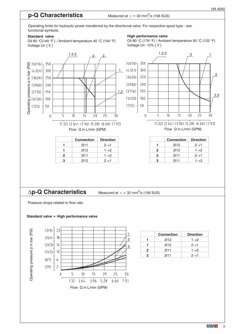
�p-Q Characteristics Measured at � = 32 mm2/s (156 SUS)
Pressure drops related to flow rate.
Connection Direction1 2I12 2�12 2I12 1�22 2I11 2�13 2I11 1�2
Connection Direction1 2I11 2�11 2I12 1�22 2I11 1�23 2I12 2�1
Standard valveOil 60 �C(140 �F ) / Ambient temperature 40 �C (104 �F)Voltage Un [ V ]
High performance valveOil 80 �C (176 �F) / Ambient temperature 50 �C (122 �F)Voltage Un -10% [ V ]
p-Q Characteristics Measured at � = 32 mm2/s (156 SUS)
Operating limits for hydraulic power transferred by the directional valve. For respective spool type - seefunctional symbols.
Flow Q in L/min (GPM)Flow Q in L/min (GPM)
1,2,3
1,2
1
12
3
Connection Direction1 2I12 1�21 2I12 2�12 2I11 1�23 2I11 2�1
Ope
ratin
gpr
essu
rep
inba
r(P
SI)
Flow Q in L/min (GPM)
2
1
2,3
1,2,3 3
Ope
ratin
gpr
essu
rep
inba
r(P
SI)
2 3

4
HA 4040
Note:- For other voltages, connector variants, quenching diodes or rectifiers refer to Coil data sheet HA 8007- Coil size for Standard valve: C51-26- Coil size for High performance valve: C04-20
Coil for Standard valveC51-26
Standard valve High performance valve
Solenoid Connector SD2E-A2 / S... SD2E-A2 / H...Type code Type code
12 VDC EN 175301-803-A (DIN 43 650) with quenching diode C51-26-012DC-E2 C04-20-012DC-E224 VDC EN 175301-803-A (DIN 43 650) with quenching diode C51-26-024DC-E2 C04-20-024DC-E212 VDC AMP (with quenching diode) C51-26-012DC-E4 C04-20-012DC-E424 VDC AMP (with quenching diode) C51-26-024DC-E4 C04-20-024DC-E4120 VAC EN 175301-803-A (DIN 43 650) with rectifier - C04-20-120AC-E5230 VAC EN 175301-803-A (DIN 43 650) with rectifier - C04-20-230AC-E5120 VAC EN 175301-803-A (DIN 43 650) C51-26-105DC-E1* C04-20-105DC-E1*230 VAC EN 175301-803-A (DIN 43 650) C51-26-205DC-E1* C04-20-205DC-E1*
Type of the Solenoid Coils Dimensions in inches (millimeters)
Coil for High performance valveC04-20
*Use the terminal box with rectifier!
Valve Body Dimensions in inches (millimeters)
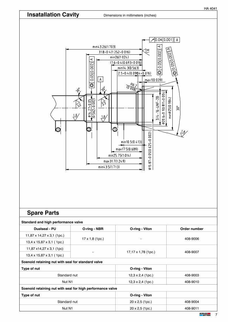
Note:- For detailed valve body ordering code refer to data sheet HA 0018
Body material Connecting size Type code Operating pressuresSteel G3/8 SB-A2-0103ST 420 bar (6091 PSI)Steel SAE 6 SB-A2-0102ST 420 bar (6091 PSI)
Aluminium G3/8 SB-A2-0103AL 250 bar (3626 PSI)Aluminium SAE 6 SB-A2-0102AL 250 bar (3626 PSI)
Form boring A2

5
HA 4040
Standard valve High performance valve
Valve Dimensions Dimensions in inches (millimeters)
Insatallation Cavity Dimensions in inches (millimeters)
hexagon 24 A/F hexagon 24 A/F
hexagon 30 A/Fhexagon 24 A/F

6
HA 4040
Standard and high performance valve
Dualseal - PU O-ring - NBR O-ring - Viton Order number
10,3 x 12,7 x 3,1 (1pc.) 17 x 1,8 (1pc.) - 408-9001
10,3 x 12,7 x 3,1 (1pc.) - 17,17 x 1,78 (1pc.) 408-9002
Soenoid retaining nut with seal for standard valve
Type of nut O-ring - Viton
Standard nut 12,3 x 2,4 (1pc.) 408-9003
Nut N1 12,3 x 2,4 (1pc.) 408-9010
Solenoid retaining nut with seal for high performance valve
Type of nut O-ring - Viton
Standard nut 20 x 2,5 (1pc.) 408-9004
Nut N1 20 x 2,5 (1pc.) 408-9011
Spare Parts
Caution!
Subject to alteration without notice!
ARGO-HYTOS a. s. CZ - 543 15 VrchlabíTel.: +420-499-403111, Fax: +420-499-403421E-mail: [email protected]
The packing foil is recyclable. The technical information regarding the product presented in this catalogue is for descriptive purposes only. It should
not be construed in any case as a guaranteed representation of the product properties in the sense of the law.

1
Functional Description
The directly operated 3/2-Way solenoid actuated spoolvalve controls in the first line the start and stop function ofthe oil flow. The valve consists of the valve body (1), controlspool (2), return spring (3), cartridge with actuating system(4) and of the solenoid coil (7) that is mounted on theactuating system. The valve bushing is screwed into thecartridge part (4).The valve bushing is fixed in the cartridge by a wire ring (5)and sealed with the seal ring (6). Separation of the valvebushing and the cartridge prevent transmitting the stresses,which could be caused by too high tightening torques. TheDC solenoid coils can be delivered for 12 V and 24 V supplyvoltages. For AC applications 120 V/ 60 Hz or 230 V/ 50 Hz,
the suitable rectifiers for the standard solenoid coils areavailable, with them being mounted in an additionalterminal box. With the high power solenoid coils in ACvariants, the rectifiers are integrated directly in theconnector. By loosening the fixing nut (8), the solenoid coilcan be replaced or turned in the range of 360°. The valvebody is zinc coated.
Note:The valves are supplied without solenoids coils. Thesolenoid coil, the terminal box and the housing body for linemounting have to be ordered separately.
� 3/2 Way cartridge valves solenoid operated withspool direction
� Manual override
� No spool sticking by too a high tightening torque
� High transmitted power
� ��
������ �� ���
� ��
Standard performance High performance
Cartridge Valve
HA 40412/2005
3/4-16 UNF • pmax 350 bar (5076 PSI) • Qmax 30 L/min (7,9 GPM)
3/2 Way Solenoid OperatedDirectional Control Valves SpoolType
SD2E-A3
2
HA 4041
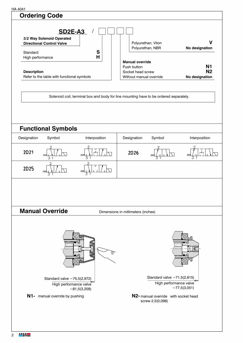
Ordering Code
Manual Override Dimensions in millimeters (inches)
Designation Symbol InterpositionDesignation Symbol Interposition
Functional Symbols
Solenoid coil, terminal box and body for line mounting have to be ordered separately.
SD2E-A3 /3/2 Way Solenoid OperatedDirectional Control Valve
Standard SHigh performance H
Manual overridePush button N1Socket head screw N2Without manual override No designation
Polyurethan, Viton VPolyurethan, NBR No designation
DescriptionRefer to the table with functional symbols
Standard valve ~75,5(2,972)
High performance valve~81,5(3,209)
manual override by pushingN1- N2-manual override with socket headscrew 2,5(0,098)
Standard valve ~71,5(2,815)
High performance valve~77,5(3,051)

3
HA 4041
12 2
High performance valveÖl 80 °C (176 °F) / Ambient temperature 50 °C (122 °F)Voltage Un -10% [ V ]
Standard valveOil 60 °C (140 °F) / Ambient temperature 40 °C (104 °F)Voltage Un [ V ]
Connection1 2D211 2D252 2D26
Connection1 2D211 2D252 2D26
Standard High performance
Cartridge thread 3/4-16 UNF- 2B
Maximum flow L/min (GPM) 20 (5,3) 30 (7,9)
Max. operating pressure bar (PSI) 250 (3626 ) 350 (5076)
Pressure drop bar (PSI) see Dp-Q characteristics
Hydraulic fluidHydraulic oils of power classes HM, HV to CETOP - RP 91H
in viscosity classes ISO VG 32, 46 and 68
Coil groups (see the datasheet of coils) C 51-26 C 04-20
Fluid temperature range °C (°F) -20 ... 60 (-4 ... 140) -20 ... 80 (-4 ...176)
Ambient temperature, max. °C (°F) -20 ... 50 (-4 ... 122) -20 ... 80 (-4 ...176)
Viscosity range mm2/s (SUS) 10 ... 500 (149 ... 2450)
Maximum degree of fluid contamination Class 21/18/15 according to ISO 4406 (1999).
Permissible rated voltage variation % AC,DC ±10 AC,DC ±15
Max. switching frequency 1/h 15 000
Duty cycle % 100
Service life cycles 107
Weight kg (Ibs) 0,15 (0,33) 0,20 (0,44)
Maximum valve tightening torque 30 +2Nm
Maximum plastic nut tightening torque 3 +1Nm 5 +1Nm
Mounting position optional
Technical Data
Flow Q in L/min (GPM)
Operatingpressurepinbar(PSI)
Flow Q in L/min (GPM)
p-Q Characteristics Measured at n = 32 mm2/s (156 SUS)
Operating limits for hydraulic power transferred by the directional valve. For respective spool type - seefunctional symbols.
1

4
HA 4041
�p-Q Characteristics Measured at � = 32 mm2/s (156 SUS)
Pressure drops related to flow rate.
2
1
4
3Connection Direction
1 2D21 3�21 2D25 3�22 2D21 2�13 2D26 3�24 2D25 2�14 2D26 2�1
Standard valve + High performance valve
Note:- For other voltages, connector variants, quenching diodes or rectifiers refer to Coil data sheet HA 8007- Coil size for Standard valve: C51-26- Coil size for High performance valve: C04-20
Standard valve High performance valve
Solenoid ConnectorSD2E-A3 / S... SD2E-A3 / H...
Type code Type code
12 VDC EN 175301-803-A (DIN 43 650) with quenching diode C51-26-012DC-E2 C04-20-012DC-E2
24 VDC EN 175301-803-A (DIN 43 650) with quenching diode C51-26-024DC-E2 C04-20-024DC-E2
12 VDC AMP (with quenching diode) C51-26-012DC-E4 C04-20-012DC-E4
24 VDC AMP (with quenching diode) C51-26-024DC-E4 C04-20-024DC-E4
120 VAC EN 175301-803-A (DIN 43 650) with rectifier - C04-20-120AC-E5
230 VAC EN 175301-803-A (DIN 43 650) with rectifier - C04-20-230AC-E5
120 VAC EN 175301-803-A (DIN 43 650) C51-26-105DC-E1* C04-20-105DC-E1*
230 VAC EN 175301-803-A (DIN 43 650) C51-26-205DC-E1* C04-20-205DC-E1*
*Use the terminal box with rectifier!
Coil for Standard valveC51-26
Type of the Solenoid Coils Dimensions in millimeters (inches)
Coil for High performance valveC04-20
Ope
ratin
gpr
essu
rep
inba
r(P
SI)
Flow Q in L/min (GPM)

5
HA 4041
Valve Body Dimensions in millimeters (inches)
Form boring A3
Note:- For detailed valve body ordering code refer to data sheet HA 0018
Body material Connecting size Type code Operating pressures
Steel G3/8 SB-A3-0103ST 420 bar (6091 PSI)
Steel SAE 6 SB-A3-0102ST 420 bar (6091 PSI)
Aluminium G3/8 SB-A3-0103AL 250 bar (3626 PSI)
Aluminium SAE 6 SB-A3-0102AL 250 bar (3626 PSI)

6
HA 4041
Valve Dimensions Dimensions in millimeters (inches)
Standard valve
High performance valve
hexagon 24 A/F hexagon 30 A/F
hexagon 24 A/F hexagon 24 A/F
7
HA 4041
Spare PartsStandard and high performance valve
Dualseal - PU O-ring - NBR O-ring - Viton Order number
11,87 x 14,27 x 3,1 (1pc.)17 x 1,8 (1pc.) - 408-9006
13,4 x 15,87 x 3,1 ( 1pc.)
11,87 x14,27 x 3,1 (1pc)- 17,17 x 1,78 (1pc.) 408-9007
13,4 x 15,87 x 3,1 ( 1pc.)
Soenoid retaining nut with seal for standard valve
Type of nut O-ring - Viton
Standard nut 12,3 x 2,4 (1pc.) 408-9003
Nut N1 12,3 x 2,4 (1pc.) 408-9010
Soenoid retaining nut with seal for high performance valve
Type of nut O-ring - Viton
Standard nut 20 x 2,5 (1pc.) 408-9004
Nut N1 20 x 2,5 (1pc.) 408-9011
Insatallation Cavity Dimensions in millimeters (inches)

8
HA 4041
Caution!
� The packing foil is recyclable.� The technical information regarding the product presented in this catalogue is for descriptive purposes only. It should
not be construed in any case as a guaranteed representation of the product properties in the sense of the law.
Subject to alteration without notice!
ARGO-HYTOS a. s. CZ - 543 15 VrchlabíTel.: +420-499-403111, Fax: +420-499-403421E-mail: [email protected]

1
HA 404201/2005
4/2 Way Solenoid OperatedDirectional Control Valves SpoolType
SD2E-A4
3/4-16 UNF • pmax 350 bar (5076PSI) • Qmax 30 L/min (7,9 GPM)
Functional Description
The directly operated 4/2-Way solenoid actuated spoolvalve controls in the first line the start and stop function ofthe oil flow. The valve consists of the valve body (1), controlspool (2), return spring (3), cartridge with actuating system(4) and of the solenoid coil (7) that is mounted on theactuating system. The valve bushing is screwed into thecartridge part (4).The valve bushing is fixed in the cartridge by a wire ring (5)and sealed with the seal ring (6). Separation of the valvebushing and the cartridge prevent transmitting the stresses,which could be caused by too high tightening torques. TheDC solenoid coils can be delivered for 12 V and 24 V supplyvoltages. For AC applications 120 V/ 60 Hz or 230 V/ 50 Hz,
the suitable rectifiers for the standard solenoid coils areavailable, with them being mounted in an additionalterminal box. With the high power solenoid coils in ACvariants, the rectifiers are integrated directly in theconnector. By loosening the fixing nut (8), the solenoid coilcan be replaced or turned in the range of 3600. The valvebody is zinc coated.
Note:The valves are supplied without solenoids coils. Thesolenoid coil, the terminal box and the housing body for linemounting have to be ordered separately.
����� �� �������
� �� � ��
Cartridge Valve
Standard performance High performance
4/2 Way cartridge valves solenoid operated spooldirected
Manual override
No spool sticking by too a high tightening torque
High transmitted power

2
HA 4042
Ordering Code
Designation Symbol InterpositionDesignation Symbol Interposition
Functional Symbols
SD2E-A4 /4/2 Way Solenoid OperatedDirectional Control Valve
Standard SHigh Performance H
Polyurethan, Viton VPolyurethan, NBR No designation
DescriptionRefer to the table with functional symbols
Manual overridePush button N1Socket head screw N2Without manual override No designation
Solenoid coil, terminal box and body for line mounting have to be ordered separately.
Manual Override Dimensions in millimeters (inches)
Standard valve ~75,5(2,972)
High performance valve~81,5(3,209)
manual override by pushingN1- N2-manual override with socket headscrew 2,5(0,098)
Standard valve ~71,5(2,815)
High performance valve~77,5(3,051)

3
HA 4042
Connection Direction1 2Z11 3®21 2Z11 4®11 2Z51 2®11 2Z51 3®41 2R21 3-4®2-11 2X21 3-4®2-11 2X21 3-2®4-12 2R21 3-2®4-1
Technical DataStandard High performance
Cartridge thread 3/4-16 UNF- 2B
Maximum flow L/min (GPM) 20 (5,3) 30 (7,9)
Max. operating pressure bar (PSI) 250 (3625) 350 (5076)
Pressure drop bar (PSI) see Dp-Q characteristics
Hydraulic fluidHydraulic oils of power classes HM, HV to CETOP - RP 91H
in viscosity classes ISO VG 32, 46 and 68
Coil groups (see the datasheet of coils) C 51-26 C 04-20
Fluid temperature range °C (°F) -20 ... 60 (-4 ... 140) -20 ... 80 (-4 ... 176)
Ambient temperature, max. °C (°F) -20 ... 50 (-4 ...122) -20 ... 80 (-4 ... 176)
Viscosity range mm2/s (SUS) 10 ... 500 (49 ... 2450)
Maximum degree of fluid contamination Class 21/18/15 according to ISO 4406 (1999).
Permissible rated voltage variation % AC,DC ±10 AC,DC ±15
Max. switching frequency 1/h 15 000
Duty cycle % 100
Service life cycles 107
Weight kg (lbs) 0,18 (0,40) 0,23 (0,51)
Maximum valve tightening torque 30 +2Nm
Maximum plastic nut tightening torque 3 +1Nm 5 +1Nm
Mounting position optional
12
3
4
5
1,2 12
Technical Data
Flow Q in L/min L/min(GPM)
Ope
ratin
gpr
essu
rep
inba
r(P
SI)
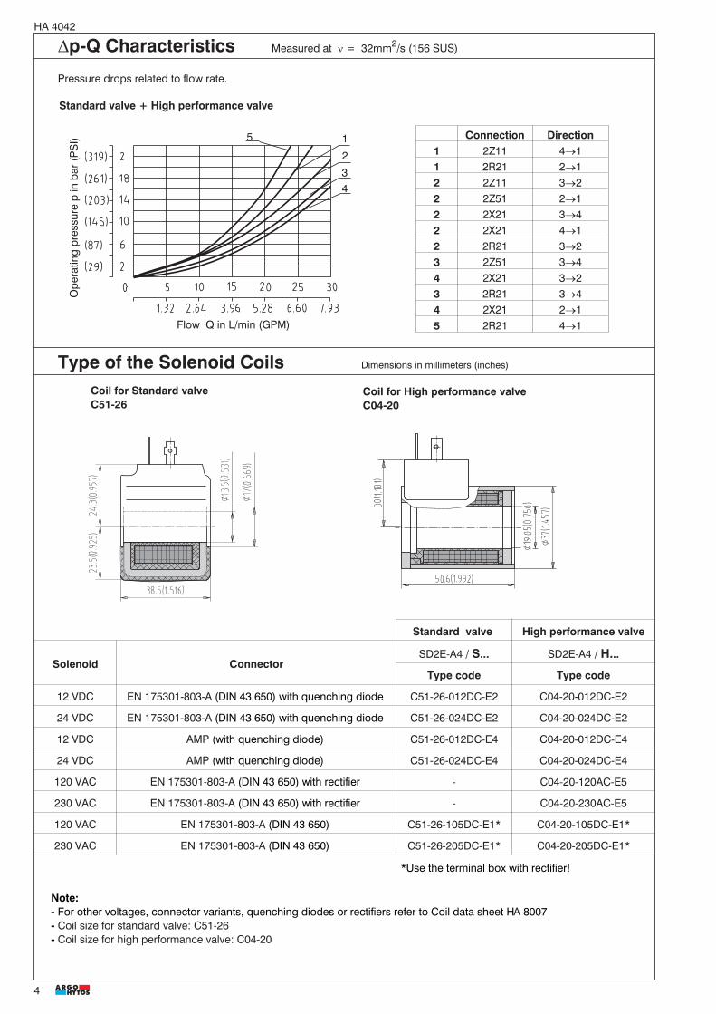
Standard valveOil 140 °F (60 °C) / Ambient temperature 104 °F (40 °C)Voltage Un [ V ]
High performance valveÖl 176 °F (80 °C) / Ambient temperature 122 °F (50 °C)Voltage Un -10% [ V ]
Flow Q in L/min L/min(GPM)
Connection Direction1 2Z51 3®41 2Z51 2®12 2Z11 3®22 2Z11 4®13 2R21 3-2®4-14 2X21 3-4®2-15 2X21 3-2®4-16 2R21 3-4®2-1
6
p-Q Characteristics Measured at n = 32mm2/s (156 SUS)Operating limits for maximum hydraulic power transferred by the directional valve. For respective spool type - seefunctional symbols.
4
HA 4042
Note:- For other voltages, connector variants, quenching diodes or rectifiers refer to Coil data sheet HA 8007- Coil size for standard valve: C51-26- Coil size for high performance valve: C04-20
Standard valve High performance valve
Solenoid ConnectorSD2E-A4 / S... SD2E-A4 / H...
Type code Type code
12 VDC EN 175301-803-A (DIN 43 650) with quenching diode C51-26-012DC-E2 C04-20-012DC-E2
24 VDC EN 175301-803-A (DIN 43 650) with quenching diode C51-26-024DC-E2 C04-20-024DC-E2
12 VDC AMP (with quenching diode) C51-26-012DC-E4 C04-20-012DC-E4
24 VDC AMP (with quenching diode) C51-26-024DC-E4 C04-20-024DC-E4
120 VAC EN 175301-803-A (DIN 43 650) with rectifier - C04-20-120AC-E5
230 VAC EN 175301-803-A (DIN 43 650) with rectifier - C04-20-230AC-E5
120 VAC EN 175301-803-A (DIN 43 650) C51-26-105DC-E1* C04-20-105DC-E1*
230 VAC EN 175301-803-A (DIN 43 650) C51-26-205DC-E1* C04-20-205DC-E1*
*Use the terminal box with rectifier!
�p-Q Characteristics Measured at � = 32mm2/s (156 SUS)
Pressure drops related to flow rate.
Standard valve + High performance valve
Coil for Standard valveC51-26
Type of the Solenoid Coils Dimensions in millimeters (inches)
Coil for High performance valveC04-20
1
2
3
Connection Direction1 2Z11 4�11 2R21 2�12 2Z11 3�22 2Z51 2�12 2X21 3�42 2X21 4�12 2R21 3�23 2Z51 3�44 2X21 3�23 2R21 3�44 2X21 2�15 2R21 4�1
4
5
Flow Q in L/min (GPM)
Ope
ratin
gpr
essu
rep
inba
r(P
SI)

5
HA 4042
Valve Body Dimensions in millimeters (inches)
Form boring A4
Note:- For detailed valve body ordering code refer to data sheet HA 0018
Body material Connecting size Type code Operating pressures
Steel G3/8 SB-A4-0103ST 420 bar (6091 PSI)
Steel SAE 6 SB-A4-0102ST 420 bar (6091 PSI)
Aluminium G3/8 SB-A4-0103AL 250 bar (3626 PSI)
Aluminium SAE 6 SB-A4-0102AL 250 bar (3626 PSI)

6
HA 4042
Standard valve
High performance valve
Valve Dimensions Dimensions in millimeters (inches)
hexagon 24 A/F
hexagon 24 A/Fhexagon 24 A/F
hexagon 30 A/F

7
HA 4042
Spare parts
Insatallation Cavity Dimensions in millimeters (inches)
Standard and high performance valve
Dualseal - PU O-ring - NBR O-ring - Viton Order number
10,3 x 12,7 x 3,1 (1pc.)
17 x 1,8 (1pc.) - 408-900811,87 x 14,27 x 3,1 (1pc.)
13,4 x 15,87 x 3,1 (1pc.)
10,3 x 12,7 x 3,1 (1pc.)
- 17,17 x 1,78 (1pc.) 408-900911,87 x 14,27 x 3,1 (1pc.)
13,4 x 15,87 x 3,1 (1pc.)
Solenoid retaining nut with seal for standard valve
Type of nut O-ring - Viton
Standard nut 12,3 x 2,4 (1pc.) 408-9003
Nut N1 12,3 x 2,4 (1pc.) 408-9010
Solenoid retaining nut with seal for high performance valve
Mutterausführung O-ring - Viton
Standard nut 20 x 2,5 (1pc.) 408-9004
Nut N1 20 x 2,5 (1pc.) 408-9011

8
HA 4042
Caution!
Subject to alteration without notice!
ARGO-HYTOS a. s. CZ - 543 15 VrchlabíTel.: +420-499-403111, Fax: +420-499-403421E-mail: [email protected]
� The packing foil is recyclable.� The technical information regarding the product presented in this catalogue is for descriptive purposes only. It should
not be construed in any case as a guaranteed representation of the product properties in the sense of the law.

1
HA 404301/2005
2/2 Way Solenoid OperatedDirectional Control Valves PoppetType
SD3E-A2
Cartridge Valve
The pilot operated 2/2-Way solenoid actuated poppetvalves control in the first line the start and stop function ofthe oil flow. The valve consists of the valve bushing (1), maincontrol spool (2), return spring (3), cartridge with actuatingsystem (4) and of the solenoid coil (5) that is mounted on theactuating system. The valve bushing is screwed into thecartridge part (4).In the variant normally closed and normally opened, thevalve is securely held in the respective basic position by aspring. By energizing the solenoid coil the spring force isovercome and the pilot valve is pressed onto the seat orlifted. Opening and closing of the main control spool ishydraulically supported through the orifice boring createdin the main control spool.
The DC solenoid coils can be delivered for 12 V and 24 Vsupply voltages. For AC applications 120 V/ 60 Hz or230 V/ 50 Hz, the suitable rectifiers for the standard solenoidcoils are available, with them being mounted in anadditional terminal box. With the AC high power solenoidcoils, the rectifiers are integrated directly in the connector.By loosening the fixing nut (6), the solenoid coil can bereplaced or turned in the range of 360°.
Notice.The valves are supplied without solenoids coils. Thesolenoid coil, the terminal box and the body for linemounting have to be ordered separately.
Functional Description
3/4-16 UNF • pmax 420 bar (6091 PSI) • Qmax 30 L/min (7,9 GPM)
Absence of current opened 2O2 Absence of current closed 2L2
�
�����������
Cartridge and module design as well ashousing for pipeline mounting
Poppet design – no internal oil leakage
High switching reliability also after long standtimes
High transmitted power

2
HA 4043
Ordering Code
SD3E-A2 /
2/2 Way Solenoid OperatedDirectional Control Valves
Standard SHigh Performance H
Polyurethan, Viton VPolyurethan, NBR No designation
DescriptionRefer to the table with functional symbols
Manual overridePush button N1Socket head screw N2Without manual override No designation
Designation Symbol Designation Symbol
N1- manual override by pushingonly for symbols 2O2
N2- manual override by screwingin of the socket head screw2,5(0,098) for symbols 2O2
N2- manual override by screwingin of the socket head screw2,5(0,098) for symbols 2L2
Solenoid coil, terminal box and body for line mounting have to be ordered separately.
Functional Symbols
Manual Override Dimensions in millimeters (inches)
Standard valve ~71(2,759)
High performance valve~81,5(3,209)
Standard valve ~67(2,638)
High performance valve~77,5(3,051)
Standard valve ~71,5(2,815)
High performance valve~89(3,504)
3
HA 4043
Connection1 2L21 2O2
Connection1 2L21 2O2
11
Operatingpressurepinbar(PSI)
Flow Q in L/min (GPM)
Standard valveOil 60 °C (140 °F) / Ambient temperature 40 °C (104 °F)Voltage Un [ V ]
High performance valveOil 80 °C (176 °F) / Ambient temperature 50 °C (122 °F)Voltage Un -10% [ V ]
Flow Q in L/min (GPM)
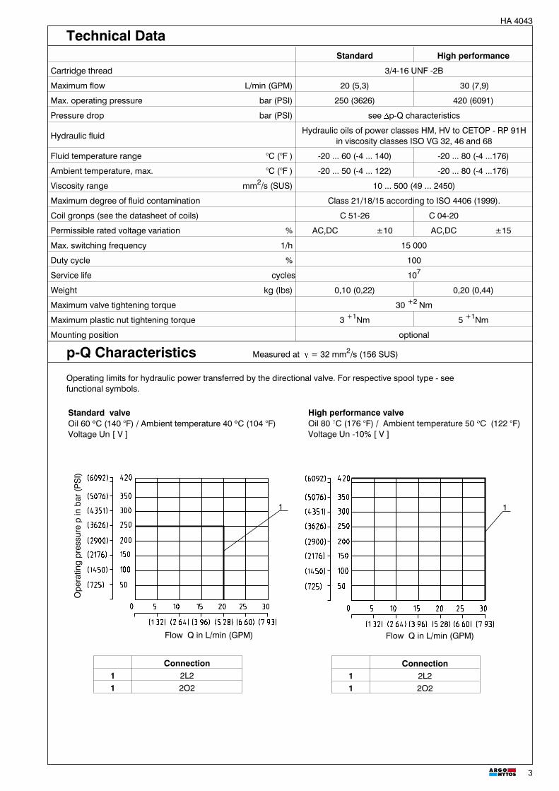
Standard High performance
Cartridge thread 3/4-16 UNF -2B
Maximum flow L/min (GPM) 20 (5,3) 30 (7,9)
Max. operating pressure bar (PSI) 250 (3626) 420 (6091)
Pressure drop bar (PSI) see Dp-Q characteristics
Hydraulic fluidHydraulic oils of power classes HM, HV to CETOP - RP 91H
in viscosity classes ISO VG 32, 46 and 68
Fluid temperature range °C (°F ) -20 ... 60 (-4 ... 140) -20 ... 80 (-4 ...176)
Ambient temperature, max. °C (°F ) -20 ... 50 (-4 ... 122) -20 ... 80 (-4 ...176)
Viscosity range mm2/s (SUS) 10 ... 500 (49 ... 2450)
Maximum degree of fluid contamination Class 21/18/15 according to ISO 4406 (1999).
Coil gronps (see the datasheet of coils) C 51-26 C 04-20
Permissible rated voltage variation % AC,DC ±10 AC,DC ±15
Max. switching frequency 1/h 15 000
Duty cycle % 100
Service life cycles 107
Weight kg (Ibs) 0,10 (0,22) 0,20 (0,44)
Maximum valve tightening torque 30 +2 Nm
Maximum plastic nut tightening torque 3 +1Nm 5 +1Nm
Mounting position optional
Technical Data
p-Q Characteristics Measured at n = 32 mm2/s (156 SUS)
Operating limits for hydraulic power transferred by the directional valve. For respective spool type - seefunctional symbols.

4
HA 4043
Note:- For other voltages, connector variants, quenching diodes or rectifiers refer to Coil data sheet HA 8007- Coil size for standard valve: C51-26- Coil size for high performance valve: C04-20
Standard High performance
Solenoid Connector SD3E-A2 / S... SD3E-A2 / H...Type code Type code
12 VDC EN 175301-803-A (DIN 43 650) with quenching diode C51-26-012DC-E2 C04-20-012DC-E224 VDC EN 175301-803-A (DIN 43 650) with quenching diode C51-26-024DC-E2 C04-20-024DC-E212 VDC AMP (with quenching diode) C51-26-012DC-E4 C04-20-012DC-E424 VDC AMP (with quenching diode) C51-26-024DC-E4 C04-20-024DC-E4120 VAC EN 175301-803-A (DIN 43 650) with rectifier - C04-20-120AC-E5230 VAC EN 175301-803-A (DIN 43 650) with rectifier - C04-20-230AC-E5120 VAC EN 175301-803-A (DIN 43 650) C51-26-105DC-E1* C04-20-105DC-E1*230 VAC EN 175301-803-A (DIN 43 650) C51-26-205DC-E1* C04-20-205DC-E1*
*Use the terminal box with rectifier!
Coil for Standard valveC51-26
Type of the Solenoid Coils Dimensions in millimeters (inches)
Coil for High performance valveC04-20
1
2
3
Standard valve + High performance valve
�p-Q Characteristics Measured at � = 32 mm2/s (156 SUS)
Pressure drops related to flow rate.
Flow Q in L/min (GPM)
Ope
ratin
gpr
essu
rep
inba
r(P
SI)
1
2
3
4
Flow Q in L/min (GPM)
Connection Dirrection1 2L2 1� 21 2L2 2�12 2O2 1� 2*2 2O2 2�1
*Solenoid switched off
Connection Dirrection1 2L2 1� 21 2L2 2� 12 2O2 1� 2*2 2O2 2� 1
*Solenoid switched off

5
HA 4043
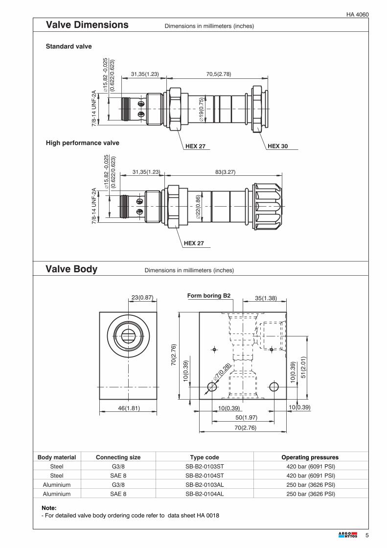
Note:- For detailed valve body ordering code refer to data sheet HA 0018
Form boring A2
Standard valve High performance valve
hexagon 30 A/Fhexagon 24 A/F
Valve Body Dimensions in millimeters (inches)
Valve Dimensions Dimensions in millimeters (inches)
hexagon 30 A/Fhexagon 24 A/F
Body material Connecting size Type code Operating pressuresSteel G3/8 SB-A2-0103ST 420 bar (6091 PSI)Steel SAE 6 SB-A2-0102ST 420 bar (6091 PSI)
Aluminium G3/8 SB-A2-0103AL 250 bar (3626 PSI)Aluminium SAE 6 SB-A2-0102AL 250 bar (3626 PSI)

6
HA 4043
Insatallation Cavity Dimensions in millimeters (inches)
Spare PartsStandard and high performance valve
Dualseal - PU O-ring - NBR O-ring - Viton Order number
10,3 x 12,7 x 3,1 (1pc.) 17 x 1,8 (1pc.) - 408-9001
10,3 x 12,7 x 3,1 (1pc.) - 17,17 x 1,78 (1pc.) 408-9002
Soenoid retaining nut with seal for standard valve
Type of nut O-ring - Viton
Standard nut 12,3 x 2,4 (1pc.) 408-9003
Nut N1 12,3 x 2,4 (1pc.) 408-9010
Solenoid retaining nut with seal for high performance valve
Type of nut O-ring - Viton
Standard nut 20 x 2,5 (1pc.) 408-9004
Nut N1 20 x 2,5 (1pc.) 408-9011
Subject to alteration without notice!
ARGO-HYTOS a. s. CZ - 543 15 VrchlabíTel.: +420-499-403111, Fax: +420-499-403421E-mail: [email protected]
Caution!
� The packing foil is recyclable.� The technical information regarding the product presented in this catalogue is for descriptive purposes only. It should
not be construed in any case as a guaranteed representation of the product properties in the sense of the law.

1
HA 40609/2010
2/2 Way Solenoid OperatedDirectional Control Valves SpoolType
SD2E-B2
The directly operated 2/2 way solenoid actuated spoolvalve controls in the first line the start and stop function ofthe oil flow. The valve consists of the valve body (1),control spool (2), return spring (3), cartridge withactuating system (4) and of the solenoid coil (7) that ismounted on the actuating system. The valve bushing isscrewed into the cartridge part (4).The valve bushing is fixed in the cartridge by a wire ring(5) and sealed with the seal ring (6). Separation of thevalve bushing and the cartridge prevent transmitting thestresses, which could be caused by too high tighteningtorques. The DC solenoid coils can be delivered for 12 Vand 24 V supply voltages.
For the alternating current supply, either of 120V/60Hz or230V/50Hz voltage, the relevant rectifiers for the C19 coiltypes are available in the auxiliary connector. For theC22 coil types and AC voltage design, the rectifiers areintegrated directly into the connector base. Byloosening the fixing nut (8), the solenoid coil can bereplaced or turned in the range of 360°. The valve body iszinc coated.
Note:The valves are supplied without solenoids coils. Thesolenoid coil, the terminal box and the housing body forline mounting have to be ordered separately.
7/8-14 UNF • pmax 350 bar (5076 PSI) • Qmax L/min (15.85 GPM)
Standard performance High performance
Functional Description
� ��
��������� ���
� ��
ReplacesHA 4060 9/2007
2/2 way cartridge valves solenoid operated withspool direction
Manual override
No spool sticking by too high tightening torque
High transmitted power

2
HA 4060
Ordering Code
SD2E-B2 /
2/2 Way Solenoid OperatedDirectional Control Valve Spool
Standard SHigh performance H
DescriptionRefer to the table with functional symbols
Designation Symbol InterpositionDesignation Symbol Interposition
Functional Symbols
Manual Override Dimensions in millimeters (inches)
No designation - standard Designation M9 - without manual override
Designation M2 - covered with rubber boot Designation M5 - with socket head screw 2.5 (0.098)
Standard valve ~78,0(3.071)
High performance valve ~84,8(3.339)
Standard valve ~82,0(3.228)
High performance valve ~100,0(3.937)
Standard valve~70,5 (2.776)
High performance valve~83,0 (3.268)
Standard valve~70,5 (2.776)
High performance valve~83,0 (3.268)
SealsNo designation NBRV FPM (Viton)
Manual overrideNo designation standardM2 covered with rubber bootnM5 socket head screwM9 without manual override
Solenoid coil, terminal box and body for line mounting have to be ordered separately. For selection of solenoid coiland terminal box type use catalogue HA 8007. For selection of valve body for in-line mounting use catalogue HA 0018.

3
HA 4060
Connection Direction1 2I11 2�1
2 2I12 2�1
Connection Direction1 2I11 2�1
2 2I12 2�1
Standard valveOil 80 °C (176 °F) / Ambient temperature 50 °C (122 °F)Voltage Un -10% [V], 24V
High performance valveOil 80 �C (176 �F) / Ambient temperature 50 �C (122 �F)Voltage Un -10% [V], 24V
p-Q Characteristics Measured at � = 32 mm2/s (156 SUS)
Operating limits for hydraulic power transferred by the directional valve. For respective spool type - seefunctional symbols.
Flow Q ( )[ ]L/min GPM
(1450)
(2176)
(725)
(4351)
(5076)
(2901)
(3626)
(1450)
(2176)
(725)
(4351)
(5076)
(2901)
(3626)
0 (2.6) (5.3) (8.0) (13.2) (15.9)(10.6)(2.6) (5.3) (8.0) (13.2)(10.6)Flow Q ( )[ ]L/min GPM
1,2 1,2
0 10 20 30 40 50 60
100
150
50
300
350
200
250
0 10 20 30 40 50
100
150
50
300
350
200
250
12 2 1
Ope
ratin
g pr
essu
re p
bar
PS
I[
](
)Standard High performance
Cartridge thread 7/8-14 UNF-2B
Maximum flow L/min (GPM) 50 (13.21 ) 60 (15.85)
Max. operating pressure bar (PSI) 250 (3626) 350 (5076)
Pressure drop bar (PSI) see �p-Q characteristics
Hydraulic fluid Hydraulic oils of power classes (HL, HLP) to DIN 51524
Coil groups 1) C19B C22B
Fluid temperature range °C (°F) -20 ... +80 (-4 ...+176) -20 ... +80 (-4 ...+176)
Ambient temperature, max. °C (°F) -20 ... +50 (-4 .. +122) -20 ... +80 (-4 ... +176)
Viscosity range mm2/s (SUS) 10 ... 500 (49 ... 2450)
Maximum degree of fluid contamination Class 21/18/15 according to ISO 4406 (2006)
Permissible rated voltage variation % AC,DC �10 AC,DC �15
Max. switching frequency 1/ h 15 000
Duty cycle % 100
Enclosure type to EN 60529 1) IP 67 (IP 65 )
Service life cycles 107
Valve tightening torque Nm (lbf.ft) 35+5 (25.81+3.68)
Plastic nut tightening torque Nm (Ibf.ft) 3+1 (2.21+0.74) 3+1 (2.21+0.74 )
Weight kg(Ibs) 0,22 (0.49) 0,29 (0.64)
Mounting position optional
Technical Data
Flow Q [L/min(GPM)] Flow Q [L/min(GPM)]
1) see data sheet coils HA 8007

4
HA 4060
Type of the Solenoid Coils Dimensions in millimeters (inches)
Coil for High performance valveC22B
Standard valve High performance valve
Solenoid ConnectorSD2E-B2 / S... SD2E-B2 / H...
Type code Type code12 VDC EN 175301-803-A C19B-01200E1-6NA C22B-01200E1-6,55NA24 VDC EN 175301-803-A C19B-02400E1-25,75NA C22B-02400E1-25,3NA12 VDC AMP-Junior-Timer ( 2-pins) C19B-01200E3-6NA C22B-01200E3A-6,55NA24 VDC AMP-Junior-Timer ( 2-pins) C19B-02400E3-25,75NA C22B-02400E3A-25,3NA12 VDC Flying leads** C19B-01200E8N300-6NA C22B-01200E8N300-6,55NA24 VDC Flying leads** C19B-02400E8N300-25,75NA C22B-02400E8N300-25,3NA12 VDC Deutsch DT04-2P --- C22B-01200E12-6,55NA24 VDC Deutsch DT04-2P --- C22B-02400E12-25,3NA120 VAC EN 175301-803-A C19B-10600E1-494NA* C22B-10600E1-545NA*230 VAC EN 175301-803-A C19B-20500E1-1653NA* C22B-20500E1-2353NA*120 VAC EN 175301-803-A (with rectifier) C19B-12060E5-494NA C22B-12060E5-545NA230 VAC EN 175301-803-A (with rectifier) C19B-23050E5-1653NA C22B-23050E5-2353NA
Coil for Standard valveC19B
Standard valve + High performance valve
�p-Q Characteristics Measured at � = 32 mm2/ s (156 SUS)
Pressure drops �p related to flow rate
10 20 30 40 50 60
10
20
0
50
30
40
Flow Q ( )[ ]L/min GPM
(145)
(290)
(725)
(435)
(580)
(2.6) (5.3) (8.0) (13.2) (15.9)(10.6)
2
1
Pre
ssur
e dr
opp
()
[]
�ba
rP
SI
Connection Direction1 2I11 1�21 2I11 2�12 2I12 1�22 2I12 2�1
*Use the terminal box with rectifier!**Standard length of connecting wire is 300 mm, other lengths on request.
Note:Example of most frequent coil types.For complete range of SD2E-B2 valve coils with technical informatik about voltage, enclosure type, terminal box pleaseafer to coil data sheet HA 8007.
49,4(1.945)
19(0
.748
)
37(1
.457
)
29(1
.142
)
22(0
.866
)
45(1
.772
)
32,5
(1.2
79)
52(2.047)
Flow Q [L/min(GPM)]
7/8-
14 U
NF-
2A
70,5(2.78)31,35(1.23)
�15
,82
-0,0
25(0
.622
/0.6
23)
�15
,82
-0,0
25(0
.622
/0.6
23)
7/8-
14 U
NF-
2A
83(3.27)31,35(1.23)
�19
(0.7
5)�
22(0
.86)
5
HA 4060
Standard valve
High performance valve
Valve Dimensions Dimensions in millimeters (inches)
HEX 27 HEX 30
HEX 27
23(0.87) 35(1.38)
70(2.76)
70(2
.76)
51(2
.01)
�7(0
.28)
46(1.81)50(1.97)
10(0
.39)
10(0.39) 10(0.39)
10(0
.39)
Valve Body Dimensions in millimeters (inches)
Body material Connecting size Type code Operating pressuresSteel G3/8 SB-B2-0103ST 420 bar (6091 PSI)
Steel SAE 8 SB-B2-0104ST 420 bar (6091 PSI)
Aluminium G3/8 SB-B2-0103AL 250 bar (3626 PSI)
Aluminium SAE 8 SB-B2-0104AL 250 bar (3626 PSI)
Form boring B2
Note:- For detailed valve body ordering code refer to data sheet HA 0018

6
HA 4060
Caution!
Subject to alteration without notice!
ARGO-HYTOS s.r.o. CZ - 543 15 VrchlabíTel.: +420-499-403111, Fax: +420-499-403421E-mail: [email protected]
The packing foil is recyclable. The technical information regarding the product presented in this catalogue is for descriptive purposes only. It should
not be construed in any case as a guaranteed representation of the product properties in the sense of the law.
25,3+0,4(0.99+0.016)
33,3+0,4(1.31+0.016)
min 31,4(1.24)
max 23,6(0.93)
min14(0.55)�
24±
0,05
(0.9
4/0.
95)
min
34(1
.34)
�
max 1(0.04)
min 16(0.63)
(0.6
24/0
.627
)
2,5 (0.1+0.016)+0,4
7/8-
14 U
NF-2
B30°
R 0,2R 0,2
�15
,87 +
0,05
A
3,2
1,61
A0,05
A0,05
A0,04
3,2
((,
90°
10°
±
1,6
302°
�±
Cavity Dimensions in millimeters (inches)
Standard and high performance valve
Dualseal - PU O-ring - NBR O-ring - Viton Order number
13,47 x 15,87 x 3,1 (1pc.) 19,4 x 2,1 (1pc.) - 18960400
13,47 x 15,87 x 3,1 (1pc.) - 19,4 x 2,1 (1pc.) 18960500
Solenoid retaining nut with seal for standard valve
Type of nut O-ring - Viton Order number
Standard nut 18 x1,5 (1pc.) 20777000
Nut M2 18 x1,5 (1pc.) 20777600
Solenoid retaining nut with seal for high performance valve
Type of nut O-ring - Viton Order number
Standard nut 22 x 2 (1pc.) 15844600
Nut M2 22 x 2 (1pc.) 18961700
Spare Parts Dimensions in millimeters
1
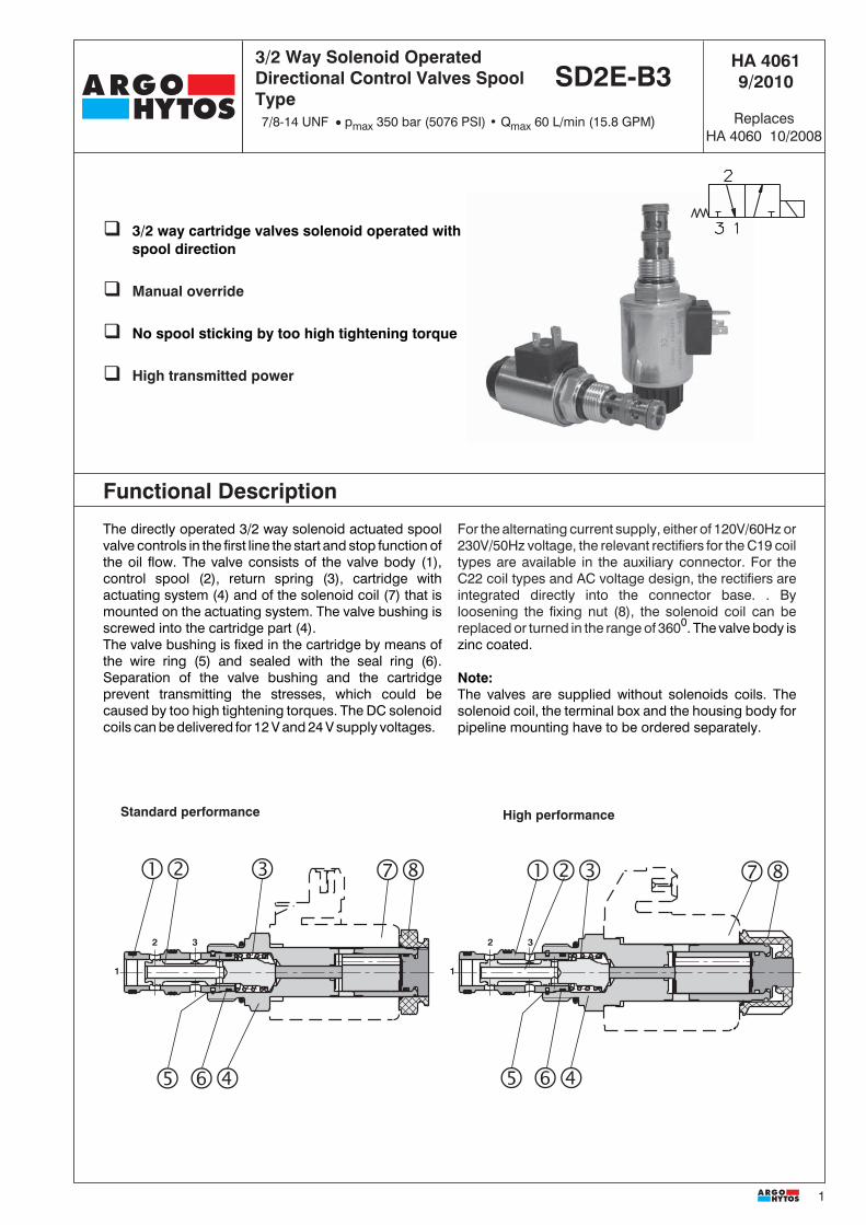
Functional Description
The directly operated 3/2 way solenoid actuated spoolvalve controls in the first line the start and stop function ofthe oil flow. The valve consists of the valve body (1),control spool (2), return spring (3), cartridge withactuating system (4) and of the solenoid coil (7) that ismounted on the actuating system. The valve bushing isscrewed into the cartridge part (4).The valve bushing is fixed in the cartridge by means ofthe wire ring (5) and sealed with the seal ring (6).Separation of the valve bushing and the cartridgeprevent transmitting the stresses, which could becaused by too high tightening torques. The DC solenoidcoils can be delivered for 12 V and 24 V supply voltages.
For the alternating current supply, either of 120V/60Hz or230V/50Hz voltage, the relevant rectifiers for the C19 coiltypes are available in the auxiliary connector. For theC22 coil types and AC voltage design, the rectifiers areintegrated directly into the connector base. . Byloosening the fixing nut (8), the solenoid coil can bereplaced or turned in the range of 3600. The valve body iszinc coated.
Note:The valves are supplied without solenoids coils. Thesolenoid coil, the terminal box and the housing body forpipeline mounting have to be ordered separately.
SD2E-A3
Standard performance High performance
3/2 Way Solenoid OperatedDirectional Control Valves SpoolType
SD2E-B3
1
2 3
1
2 3
� ��
������� �� ���
� ��
HA 40619/2010
ReplacesHA 4060 10/2008
7/8-14 UNF � pmax 350 bar (5076 PSI) • Qmax 60 L/min (15.8 GPM)
3/2 way cartridge valves solenoid operated withspool direction
Manual override
No spool sticking by too high tightening torque
High transmitted power

2
HA 4061
Ordering Code
Manual Override
SD2E-B3 /
DescriptionRefer to the table with functional symbols
Designation Symbol InterpositionDesignation Symbol Interposition
Functional Symbols
SealsNo designation NBRV FPM (Viton)
Manual overrideNo designation standardM2 covered with rubber bootnM5 socket head screwM9 without manual override
No designation - standard Designation M9 - without manual override
Designation M2 - covered with rubber boot Designation M5 - with socket head screw 2.5 (0.098)
Standard valve ~78,0(3.071)
High performance valve ~84,8(3.339)
Standard valve ~82,0(3.228)
High performance valve ~100,0(3.937)
Standard valve~70,5 (2.776)
High performance valve~83,0 (3.268)
Standard valve~70,5 (2.776)
High performance valve~83,0 (3.268)
3/2 Way Solenoid OperatedDirectional Control Valve Spool
Standard SHigh performance H
Solenoid coil, terminal box and body for line mounting have to be ordered separately. For selection of solenoid coiland terminal box type use catalogue HA 8007. For selection of valve body for in-line mounting use catalogue HA0018.

3
HA 4061
High performance valveOil 80 °C (176 °F) / Ambient temperature 50 °C (122 °F)Voltage Un -10% [V], 24V
Standard valveOil 80 °C (176 °F) / Ambient temperature 50 °C (122 °F)Voltage Un -10% [V], 24V
Standard High performance
Cartridge thread 7/8-14 UNF- 2B
Maximum flow L/min (GPM) 50 (13.2) 60 (15.8)
Max. operating pressure bar (PSI) 250 (3626 ) 350 (5076)
Pressure drop bar (PSI) see �p-Q characteristics
Hydraulic fluid Hydraulic oils of power classes (HL, HLP) to DIN 51524
Coil groups1) C19B C22B
Fluid temperature range °C (°F) -20 ... +80 (-4 ...+176) -20 ... +80 (-4 ...+176)
Ambient temperature, max. °C (°F) -20 ... +50 (-4 ... +122) -20 ... +80 (-4 ...+176)
Viscosity range mm2 /s (SUS) 10 ... 500 (49 ... 2450)
Maximum degree of fluid contamination Class 21/18/15 according to ISO 4406 (2006).
Permissible rated voltage variation % AC, DC �10 AC, DC �15
Max. switching frequency 1/ h 15 000
Duty cycle % 100
Enclosure type to EN 60529 1) IP 67 (IP 65 )
Service life cycles 107
Valve tightening torque Nm (lbf.ft) 35+5 (25.81+3.68)
Plastic nut tightening torque Nm (lbf.ft) 3+1 (2.213+0.738) 3+1 (2.21+0.738 )
Weight kg (Ibs) 0,24 (0.53) 0,31 (0.68)
Mounting position optional
Technical Data
p-Q Characteristics Measured at � = 32 mm2/s (156 SUS)
Operating limits for hydraulic power transferred by the directional valve. For respective spool type - seefunctional symbols.
Flow Q L/min (GPM)[ ]
0 10 20 30 40 50 600 10 20 30 40 50
100
150
50
300
350
200
250
(1450)
(2176)
(725)
(4351)
(5076)
(2901)
(3626)
Flow Q ( )[ ]L/min GPM(2.6) (5.3) (8.0) (13.2)(10.6)
100
150
50
300
350
200
250
(1450)
(2176)
(725)
(4351)
(5076)
(2901)
(3626)
(2.6) (5.3) (8.0) (13.2) (15.9)(10.6)
1,2,3,4,5
1 43
5
2
1,2,3,4,5
31
5
4
Ope
ratin
g pr
essu
re p
bar
PS
I[
](
)
2
Connection Direction
1 2D21 3�2
2 2D21 2�1
3 2D25 3�2
4 2D25 2�1
5 2D26 3�2
2 2D26 2�1
Connection Direction
1 2D21 3�2
2 2D21 2�1
3 2D25 3�2
5 2D25 2�1
4 2D26 3�2
5 2D26 2�1
Flow Q [L/min (GPM)] Flow Q [L/min (GPM)]
1) see data sheet coils HA 8007

4
HA 4061
�p-Q Characteristics Measured at � = 32 mm2/s (156 SUS)
Pressure drops �p related to flow rate
Standard valve + High performance valve
Coil for Standard valveC19B
Type of the Solenoid Coils Dimensions in millimeters (inches)
49,4(1.945)
19(0
.748
)
37(1
.457
)
29(1
.142
)
22(0
.866
)
45(1
.772
)
32,5
(1.2
79)
52(2.047)
Connection Direction1 2D21 2�11 2D21 3�23 2D25 3�24 2D25 2�11 2D26 3�21 2D26 2�1
10 20 30 40 50 60
(2.6) (5.3) (8.0) (13.2) (15.9)(10.6)Flow Q ( )[ ]L/min GPM
(145)
(290)
(725)
(435)
(580)
10 20 30 40 50 60
10
20
0
50
30
40
1
4
2
3
Pre
ssur
e dr
opp
()
�[
]ba
rP
SI
Coil for High performance valveC22B
*Use the terminal box with rectifier!**Standard length of connecting wire is 300 mm, other lengths on request.
Standard valve High performance valveSolenoid Connector SD2E-B3 / S... SD2E-B3 / H...
Type code Type code12 VDC EN 175301-803-A C19B-01200E1-6NA C22B-01200E1-6,55NA24 VDC EN 175301-803-A C19B-02400E1-25,75NA C22B-02400E1-25,3NA12 VDC AMP-Junior-Timer ( 2-pins) C19B-01200E3-6NA C22B-01200E3A-6,55NA24 VDC AMP-Junior-Timer ( 2-pins) C19B-02400E3-25,75NA C22B-02400E3A-25,3NA12 VDC Flying leads** C19B-01200E8N300-6NA C22B-01200E8N300-6,55NA24 VDC Flying leads** C19B-02400E8N300-25,75NA C22B-02400E8N300-25,3NA12 VDC Deutsch DT04-2P --- C22B-01200E12-6,55NA24 VDC Deutsch DT04-2P --- C22B-02400E12-25,3NA120 VAC EN 175301-803-A C19B-10600E1-494NA* C22B-10600E1-545NA*230 VAC EN 175301-803-A C19B-20500E1-1653NA* C22B-20500E1-2353NA*120 VAC EN 175301-803-A (with rectifier) C19B-12060E5-494NA C22B-12060E5-545NA230 VAC EN 175301-803-A (with rectifier) C19B-23050E5-1653NA C22B-23050E5-2353NA
Note:Example of most frequent coil types.For complete range of SD2E-B3 valve coils with technical informatik about voltage, enclosure type, terminal box pleaseafer to coil data sheet HA 8007.
Flow Q [L/min (GPM)]

5
HA 4061
Valve Dimensions Dimensions in millimeters (inches)
83(3.27)
7/8-
14 U
NF-
2A
45,85(1.81)
�17
,42
-0,0
25(0
.685
/0.6
86)
�15
,82
-0,0
25(0
.622
/0.6
23)
�22
(0.8
6)
7/8-
14 U
NF-
2A
70,5(2.78)
�17
,42
-0,0
25(0
.685
/0.6
86)
45,85(1.81)
�15
,82
-0,0
25(0
.622
/0.6
23)
�19
(0.7
5)
HEX 27
Standard valve
High performance valve HEX 30
HEX 27
80(3
.15)
44,(1
.76)
23(0.87) 35(1.38)
61(2
.40)
70(2.76)
46(1.81)50(1.97)
10(0
.39)
10(0
.39)
10(0.39)
�7(0
.28)
Valve Body Dimensions in millimeters (inches)
Body material Connecting size Type code Operating pressuresSteel G3/8 SB-B3-0103ST 420 bar (6091 PSI)
Steel SAE 8 SB-B3-0104ST 420 bar (6091 PSI)
Aluminium G3/8 SB-B3-0103AL 250 bar (3626 PSI)
Aluminium SAE 8 SB-B3-0104AL 250 bar (3626 PSI)
Form boring B3

6
HA 4061
Subject to alteration without notice!
ARGO-HYTOS s.r.o. CZ - 543 15 VrchlabíTel.: +420-499-403111, Fax: +420-499-403421E-mail: [email protected]
Caution! The packing foil is recyclable. The technical information regarding the product presented in this catalogue is for descriptive purposes only. It should
not be construed in any case as a guaranteed representation of the product properties in the sense of the law.
min.30(1.18)
48+0,4(1.88+0.016)
min.45,9(1.81)
37,8+0,4(1.49+0.016)
(0.6
24/0
.627
)
(0.6
87/0
.689
)
max.22(0.87)
min.14(0.55)
max.37,8(1.49)
�24
±0,
05(0
.94/
0.95
)
min
.34
(1.3
4)�
22 (0.87+0.016)+0,4
34,8(1.37+0.016)
max 1(0.04)
min.16(0.63)
90°
10°
±
7/8-
14 U
NF-2
B
�15
,87+
0,05 3,2
A0,04
A0,05
A0,
05
1,6 1,6
30°
3,2
�17
,47+
0,05
A
1,6
3,2
R 0,2 R 0,2
3
((,
30°
A0,
05
30°
2°±
2,5 0.1+0.016)+0,4(
Cavity Dimensions in millimeters (inches)
Spare Parts Dimensions in millimeters (inches)
Standard and high performance valve
Dualseal - PU O-ring - NBR O-ring - Viton Order number
13,47 x 15,87 x 3,1 (1pc.)19,4 x 2,1 ( (1pc.) - 18960700
17,47 x 15,07 x 3,1 ( 1pc.)
13,47 x 15,87 x 3,1 (1pc)- 19,4 x 2,1 (1pc.) 18960600
17,47 x 15,07 x 3,1 ( 1pc.)
Solenoid retaining nut with seal for standard valve
Type of nut O-ring - Viton Order number
Standard nut 18 x 1,5 (1pc.) 20777000
Nut M2 18 x 1,5 (1pc.) 20777600
Solenoid retaining nut with seal for high performance valve
Type of nut O-ring - Viton Order number
Standard nut 22 x 2 (1pc.) 15844600
Nut M2 22 x 2 (1pc.) 18961700

1
HA 406210/2010
4/2 Way Solenoid OperatedDirectional Control Valves SpoolType
SD2E-B4
7/8-14 UNF � pmax 350 bar (5076 PSI) • Qmax 60 L/min (15.8 GPM)
Functional DescriptionThe directly operated 4/2 way solenoid actuated spoolvalve controls in the first line the start and stop function ofthe oil flow. The valve consists of the valve body (1),control spool (2), return spring (3), cartridge withactuating system (4) and of the solenoid coil (7) that ismounted on the actuating system. The valve bushing isscrewed into the cartridge part.The valve bushing is fixed in the cartridge by a wire ring(5) and sealed with the seal ring (6). Separation of thevalve bushing and the cartridge prevent transmitting thestresses, which could be caused by too high tighteningtorques. The DC solenoid coils can be delivered for 12 Vand 24 V supply voltages.
For the alternating current supply, either of 120V/60Hz or230V/50Hz voltage, the relevant rectifiers for the C19 coiltypes are available in the auxiliary connector. For theC22 coil types and AC voltage design, the rectifiers areintegrated directly into the connector base. By looseningthe fixing nut (8), the solenoid coil can be replaced orturned in the range of 1800. The valve body is zinccoated.
Note:The valves are supplied without solenoids coils. Thesolenoid coil, the terminal box and the housing body forline mounting have to be ordered separately.
Standard performance High performance
������ ��
� ��
������ ��
� ��
4/2 way cartridge valves solenoid operated withspool direction
Manual override
No spool sticking by too high tightening torque
High transmitted power
ReplacesHA 4062 4/2008

2
HA 4062
SD2E-B4 /
4/2 Way Solenoid OperatedDirectional Control Valve
Standard SHigh Performance H
DescriptionRefer to the table with functional symbols
Manual Override
Designation Symbol InterpositionDesignation Symbol Interposition
Functional Symbols
No designation - standard Designation M9 - without manual override
Designation M2 - covered with rubber boot Designation M5 - with socket head screw 2.5 (0.098)
Standard valve~70,5 (2.776)High performance valve~83,0 (3.268)
Standard valve~70,5 (2.776)High performance valve~83,0 (3.268)
Standard valve ~78,0(3.071)High performance valve ~84,8(3.339)
Standard valve ~82,0(3.228)High performance valve ~100,0(3.937)
Manual overrideNo designation standardM2 covered with rubber bootnM5 socket head screwM9 without manual override
SealsNo designation NBRV FPM (Viton)
Ordering Code
Solenoid coil, terminal box and body for line mounting have to be ordered separately. For selection of solenoid coiland terminal box type use catalogue HA 8007. For selection of valve body for in-line mounting use catalogue HA0018.

3
HA 4062
Technical DataStandard High performance
Cartridge thread 7/8-14 UNF- 2B
Maximum flow L/min (GPM) 50 (13.21) 60 (15.85)
Max. operating pressure bar (PSI) 250 (3625) 350 (5076)
Pressure drop bar (PSI) see �p-Q characteristics
Hydraulic fluid Hydraulic oils of power classes (HL, HLP) to DIN 51524
Coil groups 1) C19B C22B
Fluid temperature range °C (°F) -20 ... +80 (-4... +176) -20 ... +80 (-4 ... +176)
Ambient temperature, max. °C (°F) -20 ... +50 (-4 ...+122) -20 ... +80 (-4 ... +176)
Viscosity range mm2 /s (SUS) 10 ... 500 (49 ... 2450)
Maximum degree of fluid contamination Class 21/18/15 according to ISO 4406 (2006).
Permissible rated voltage variation % AC,DC �10 AC,DC �15
Max. switching frequency 1/h 15 000
Duty cycle % 100
Enclosure type to EN 60529 1) IP 65
Service life cycles 107
Valve tightening torque Nm ( lbf.ft) 35+5 (25.81+3.68)
Plastic nut tightening torque Nm ( lbf.ft) 3+1 (2.213+0.738) 3+1 (2.21+0.738 )
Weight kg (lbs) 0,25 (0.55) 0,32 (0.71)
Mounting position optional
(1450)
(2176)
(725)
(4351)
(5076)
(2901)
(3626)
Flow Q ( )[ ]L/min GPM
(1450)
(2176)
(725)
(4351)
(5076)
(2901)
(3626)
0 10 20 30 40 50
100
150
50
300
350
200
250
0 10 20 30 40 50
100
150
50
300
350
200
250
1,2,3
1
2
2
1
Flow Q L/min (GPM)[ ](2.6) (5.3) (8.0) (13.2)(10.6) (2.6) (5.3) (8.0) (13.2)(10.6)
3
1,2,3
3
Ope
ratin
g pr
essu
re p
bar
PS
I[
](
)
Standard valveOil 80 °C (176 °F) / Ambient temperature 50 °C (122 °F)Voltage Un -10% [V], 24V
High performance valveOil 80 �C (176 �F) / Ambient temperature 50 �C (122 �F)Voltage Un -10% [V], 24V
Operating limits for maximum hydraulic power transferred by the directional valve. For respective spool type - seefunctional symbols.
p-Q Characteristics Measured at � = 32 mm2/s (156 SUS)
Connection Direction1 2Z11 3-2 � 4-12 2Z51 3-4 � 2-12 2X21 3-4 � 2-13 2X21 3-2 � 4-1
Connection Direction1 2Z11 3-2 � 4-12 2Z51 3-4 � 2-13 2X21 3-2 � 4-12 2X21 3-4 � 2-1
Flow Q [L/min (GPM)] Flow Q [L/min (GPM)]
1) see data sheet coils HA 8007

4
HA 4062
�p-Q Characteristics Measured at � = 32 mm2/s (156 SUS)
Pressure drops �p related to flow rate.
Standard valve + High performance valve
Coil for Standard valveC19B
Coil for High performance valveC22B
Flow Q ( )[ ]L/min GPM(2.6) (5.3) (8.0) (13.2) (15.9)(10.6)
(145)
(290)
(435)
(580)
10 20 30 40 50 60
10
20
0
30
40
3
1
2
Pre
ssur
e dr
opp
()
�[
]ba
rP
SI
4(725) 50
Connection Direction1 2Z11 3�21 2Z11 4�13 S2Z51 3�43 S2Z51 2�12 H2Z51 3�43 H2Z51 2�13 2X21 3�24 2X21 4�13 2X21Qmax 50 l/min 3�42 2X21Qmax 40 l/min 2�1
*Use the terminal box with rectifier!**Standard length of connecting wire is 300 mm, other lengths on request.
Note:Example of most frequent coil types.For complete range of SD2E-B4 valve coils with technical informatik about voltage, enclosure type, terminal box pleaseafer to coil data sheet HA 8007.
49,4(1.945)
19(0
.748
)
37(1
.457
)
29(1
.142
)
22(0
.866
)
45(1
.772
)
32,5
(1.2
79)
52(2.047)
Standard High performanceVoltage Connector SD2E-B4 / S... SD2E-B4 / H...
Type code Type code12 VDC EN 175301-803-A C19B-01200E1-6NA C22B-01200E1-6,55NA24 VDC EN 175301-803-A C19B-02400E1-25,75NA C22B-02400E1-25,3NA12 VDC AMP-Junior-Timer C19B-01200E3-6NA C22B-01200E3A-6,55NA24 VDC AMP-Junior-Timer C19B-02400E3-25,75NA C22B-02400E3A-25,3NA12 VDC free cables** C19B-01200E8N300-6NA C22B-01200E8N300-6,55NA24 VDC free cables** C19B-02400E8N300-25,75NA C22B-02400E8N300-25,3NA12 VDC Deutsch DT04-2P --- C22B-01200E12-6,55NA24 VDC Deutsch DT04-2P --- C22B-02400E12-25,3NA120 VAC EN 175301-803-A C19B-10600E1-494NA* C22B-10600E1-545NA*230 VAC EN 175301-803-A C19B-20500E1-1653NA* C22B-20500E1-2353NA*120 VAC EN 175301-803-A (with rectifier) C19B-12060E5-494NA C22B-12060E5-545NA230 VAC EN 175301-803-A (with rectifier) C19B-23050E5-1653NA C22B-23050E5-2353NA
Flow Q [L/min (GPM)]
Type of the Solenoid Coils Dimensions in millimeters (inches)

5
HA 4062
70,5(2.78)7/
8-14
UN
F-2A
�17
,42
-0,0
25(0
.685
/0.6
86)
60,45(2.38)
�15
,82
-0,0
25(0
.622
/0.6
23)
�1 9
-0,0
25(0
.747
/0.7
48)
83(3.27)
7/8-
14 U
NF-
2A
�17
,42
-0,0
25(0
.685
/0.6
86)
60,45(2.38)
�15
,82
-0,0
25(0
.622
/0.6
23)
�19
-0,0
25(0
.747
/0.7
48)
�19
(0.7
5)�
22(0
.86)
Standard valve
High performance valve
Valve Dimensions Dimensions in millimeters (inches)
HEX 27 HEX 30
HEX 27
37,5(1.48)
90(3
.54)
72(2
.83)
75(2.95)
55(2.16)
55,3
(2.1
78)
29(1
.14)
10(0
.39)
10(0
.39)
23(0.87)
46(1.81) 10(0.39)
�7
Form boring B4
Body material Connecting size Type code Operating pressures
Steel G 3/8 SB-B4-0103ST 420 bar (6091 PSI)
Steel SAE 8 SB-B4-0104ST 420 bar (6091 PSI)
Aluminium G 3/8 SB-B4-0103AL 250 bar (3626 PSI)
Aluminium SAE 8 SB-B4-0104AL 250 bar (3626 PSI)
Valve Body Dimensions in millimeters (inches)

6
HA 4062
Caution!
Subject to alteration without notice!
ARGO-HYTOS s.r.o. CZ - 543 15 VrchlabíTel.: +420-499-403111, Fax: +420-499-403421E-mail: [email protected]
The packing foil is recyclable. The technical information regarding the product presented in this catalogue is for descriptive purposes only. It should
not be construed in any case as a guaranteed representation of the product properties in the sense of the law.
37,8 (1.49+0,016)+0,4
(0.6
24/0
.627
)
(0.6
87/0
.689
)
(0.7
50/0
.751
)
min.28,8(1.13)max.22(0.87)
min.14(0.55)
max.37,8(1.49)min.44,8(1.76)
�24
±0.
05(0
.94/
0.95
)
min
34(1
.34)
�
22 0.87+0,016)+0,4(34,8+0,4(1.37+0,016)
min.16(0.63)
50,6+0,4(1.99+0.016)53,6 (2.11+0.016)+0,4
60,5 (2.38+0.016)
max.53,6(2.11)min.60,5(2.38)
�15
,87 +
0,05
�17
,47+
0,05
1,6
3,2
A0,
05
A0,05
A0,
05
7/8-
14 U
NF-2
B
A0,04
A0,
05
30°
3,2
30°
3,2 3,2
30°
1,6 1,6 1,6 �19
,05 +
0,05
A
R 0,2 R 0,2
4
((,
90°
10°
±
30°
2°±
2,5 (0.1/0.11)+0.4max.1(0.04)
Cavity Dimensions in millimeters (inches)
Spare Parts Dimensions in millimeters
Standard and high performance valve
Dualseal - PU O-ring - NBR O-ring - Viton Order number13,47 x 15,87 x 3,1 (1pc.)
19,4 x 2,1 (1pc.) - 1896080017,47 x 15,07 x 3,1 (1pc.)
19,05 x 16,65 x 3,1 (1pc.)
13,47 x 15,87 x 3,1 (1pc.)
- 19,4 x 2,1 (1pc.) 1896090017,47 x 15,07 x 3,1 (1pc.)
19,05 x 16,65 x 3,1 (1pc.)
Solenoid retaining nut with seal for standard valve
Type of nut O-ring - Viton Order numberStandard nut 18 x 1,5 (1pc.) 20777000
Nut M2 18 x 1,5 (1pc.) 20777600
Solenoid retaining nut with seal for high performance valve
Type of nut O-ring - Viton Order numberStandard nut 22 x 2 (1pc.) 15844600
Nut M2 22 x 2 (1pc.) 18961700

1
2
1 2 3 5 64
1
2
1 2 3 5 64
1
HA 406310/2010
2/2 Way Solenoid OperatedDirectional Control Valves PoppetType
SD3E-B2
The pilot operated 2/2 way solenoid actuated poppetvalves control in the first line the start and stop function ofthe oil flow. The valve consists of the valve bushing (1),main control spool (2), return spring (3), cartridge withactuating system (4) and of the solenoid coil (5) that ismounted on the actuating system. The valve bushing isscrewed into the cartridge part.In the variant normally closed / normally open, the valveis securely held in the respective basic position by aspring. By energizing the solenoid coil the spring force isovercome and the pilot valve is pressed onto the seat orlifted. Opening and closing of the main control spool ishydraulically supported through the orifice boringcreated in the main control spool.
The DC solenoid coils can be delivered for 12 V and 24 Vsupply voltages.For the alternating current supply, either of 120V/60Hz or230V/50Hz voltage, the relevant rectifiers for the C19 coiltypes are available in the auxiliary connector. For theC22 coil types and AC voltage design, the rectifiers areintegrated directly into the connector base. . Byloosening the fixing nut (6), the solenoid coil can bereplaced or turned in the range of 360°.
Notice.The valves are supplied without solenoids coils. Thesolenoid coil, the terminal box and the body for linemounting have to be ordered separately.
7/8-14 UNF •pmax 420 bar (6091 PSI)• max 75 L/min (19.81 GPM)
Absence of current opened 2O2 Absence of current closed 2L2
Functional Description
ReplacesHA 4063 12/2009
� 2/2 way cartridge valves solenoid operatedwith spool direction
� Manual override
� High transmitted power

2
HA 4063
Ordering Code
SD3E-B2 /
Standard SHigh Performance H
DescriptionRefer to the table with functional symbols
Functional Symbols
Manual Override Dimensions in millimeters (inches)
Manual overrideNo designation standard for 2O2M2 covered with rubber bootn only for 2O2M5 socket head screwM9 without manual override
SealsNo designation NBRV FPM (Viton)
Standard valve ~82,0(3.228)
High performance valve~100,0(3.937)
Standard valve ~78,0(3.071)
High performance valve~84,8(3.339)
Standard valve ~78,0(3.071)
No designation - Standard for 2O2
Designation M2 - for 2O2covered with rubber bootn
Designation M5 - for 2L2by screwing in of the sockethead screw 2,5(0.098)
High performance valve~90,0(3.543)
Designation M5 - for 2O2by screwing in of the socket headscrew 2,5(0.098)
Standard valve~70,5 (2.776)
High performance valve~83,0 (3.268)
Standard valve~71,0 (2.795)
High performance valve~83,0 (3.268)
Standard valve~70,5 (2.776)
High performance valve~83,0 (3.268)
Designation M9 - for 2L2without manual override
Designation M9 - for 2O2without manual override
Designation Symbol Designation Symbol
2/2 Way Solenoid OperatedDirectional Control ValvePoppet Type
Solenoid coil, terminal box and body for line mounting have to be ordered separately. For selection of solenoid coiland terminal box type use catalogue HA 8007. For selection of valve body for in-line mounting use catalogue HA0018.

3
HA 4063
Connection1 2L21 2O2
Connection1 2L21 2O2
Flow Q ( )[ ]L/min GPM
(2030)
(3046)
(1015)
(6092)
(7107)
(4061)
(5076)
0 15 30 45 60 75
100
150
50
300
350
200
250
Flow Q ( )[L/min GPM
(1450)
(2176)
(725)
(4351)
(5076)
(2901)
(3626)
0 (4.0) (7.9) (11.9) (19.8)(15.8)
1
0 15 30 45 60 75
140
210
70
420
490
280
350
0 (4.0) (7.9) (11.9) (19.8)(15.8)
1
Ope
ratin
g pr
essu
re p
bar
PS
I[
](
)
Ope
ratin
g pr
essu
re p
bar
PS
I[
](
)
Standard valveOil 80 °C (176 °F) / Ambient temperature 50 °C (122 °F)Voltage Un -10% [V], 24V
High performance valveOil 80 �C (176 °F) / Ambient temperature 50 �C (122 °F)Voltage Un -10% [V], 24V
Standard High performance
Cartridge thread 7/8-14 UNF -2B
Maximum flow L/min(GPM) 60 (15.85) 75 (19.81)
Max. operating pressure bar (PSI) 250 (3626) 420 (6091)
Pressure drop bar (PSI) see �p-Q characteristics
Hydraulic fluid Hydraulic oils of power classes (HL, HLP) to DIN 51524
Fluid temperature range °C (°F ) -20 ... +80 (-4 ...+176) -20 ... +80 (-4 ...+176)
Ambient temperature, max. °C (°F ) -20 ... +50 (-4 ...+122) -20 ...+ 80 (-4 ...+176)
Viscosity range mm2/s (SUS) 10 ... 500 (49 ... 2450)
Maximum degree of fluid contamination Class 21/18/15 according to ISO 4406 (2006)
Coil groups 1) C19B C22B
Permissible rated voltage variation % AC,DC �10 AC,DC �15
Max. switching frequency 1/h 15 000
Duty cycle % 100
Service life cycles 107
Enclosure type to EN 60529 1) P 67 (IP 65)
Valve tightening torque Nm ( lbf.ft) 35+5 (25.81+3.68)
Plastic nut tightening torque Nm ( lbf.ft) 3+1 (2.213+0.738) 3+1 (2.213+0.738)
Weight kg (Ibs) 0.23 (0.51) 0.30 (0.66)
Mounting position optional
Technical Data
p-Q Characteristics Measured at � = 32 mm2/s (156 SUS)
Operating limits for hydraulic power transferred by the directional valve. For respective spool type - seefunctional symbols.
Flow Q [L/min (GPM)] Flow Q [L/min (GPM)]
1) see data sheet coils HA 8007

HA 4063
Coil for Standard valveC19B
Type of the Solenoid Coils Dimensions in millimeters (inches)
Coil for High performance valveC22B
�p-Q Characteristics Measured at � = 32 mm2/s (156 SUS)
Pressure drop �p related to flow rate.
Standard valve + High performance valve
4
*Use the terminal box with rectifier!**Standard length of connecting wire is 300 mm, other lengths on request.
Note:Example of most frequent coil types.For complete range of SD3E-B2 valve coils with technical informatik about voltage, enclosure type, terminal box pleaseafer to coil data sheet HA 8007.
2
4
0
12
6
8
10
15 30 45 60 75
2
1
3
(14.5)
(29.0)
(72.5)
(43.5)
(58.0)
(87.0)
(3.96) (7.93) (11.89) (15.85) (19.81)
Connection Dirrection Solenoid1 2L2 1� 2 switched off2 2L2 2� 1 switched on2 2L2 1� 2 switched on2 2O2 1� 2 switched off3 2O2 2� 1 switched off
Flow Q [L/min (GPM)]
Pre
ssur
edr
ops
�p
[bar
(PS
I)]
49,4(1.945)
19(0
.748
)
37(1
.457
)
29(1
.142
)
22(0
.866
)
45(1
.772
)
32,5
(1.2
79)
52(2.047)
Standard valve High performance valveSolenoid Connector SD3E-B2 / S... SD3E-B2 / H...
Type code Type code12 VDC EN 175301-803-A C19B-01200E1-6NA C22B-01200E1-6,55NA24 VDC EN 175301-803-A C19B-02400E1-25,75NA C22B-02400E1-25,3NA12 VDC AMP-Junior-Timer ( 2-pins) C19B-01200E3-6NA C22B-01200E3A-6,55NA24 VDC AMP-Junior-Timer (2-pins) C19B-02400E3-25,75NA C22B-02400E3A-25,3NA12 VDC Flying leads** C19B-01200E8N300-6NA C22B-01200E8N300-6,55NA24 VDC Flying leads** C19B-02400E8N300-25,75NA C22B-02400E8N300-25,3NA12 VDC Deutsch DT04-2P --- C22B-01200E12-6,55NA24 VDC Deutsch DT04-2P --- C22B-02400E12-25,3NA120 VAC EN 175301-803-A C19B-10600E1-494NA* C22B-10600E1-545NA*230 VAC EN 175301-803-A C19B-20500E1-1653NA* C22B-20500E1-2353NA*120 VAC EN 175301-803-A (with rectifier) C19B-12060E5-494NA C22B-12060E5-545NA230 VAC EN 175301-803-A (with rectifier) C19B-23050E5-1653NA C22B-23050E5-2353NA

5
HA 4063
Standard valve High performance valve
HEX 27
Valve Dimensions Dimensions in millimeters (inches)
70,8(2.79)
7/8-
14 U
NF-
2A
30,5(1.20) 82,6(3.25)
7/8-
14 U
NF-
2A
�15
,82
-0,0
25(0
.622
/0.6
23)
30,5(1.20)
�15
,82
-0,0
25(0
.622
/0.6
23)
�19
(0.7
5)
�22
(0.8
7)
HEX 30HEX 27
Form boring A223(0.87) 35(1.38)
70(2.76)
70(2
.76)
51(2
.01)
�7(0
.28)
46(1.81)50(1.97)
10(0
.39)
10(0.39) 10(0.39)
10(0
.39)
Valve Body Dimensions in millimeters (inches)
Body material Connecting size Type code Operating pressures
Steel G3/8 SB-B2-0103ST 420 bar (6091 PSI)
Steel SAE 8 SB-B2-0104ST 420 bar (6091 PSI)
Aluminium G3/8 SB-B2-0103AL 250 bar (3626 PSI)
Aluminium SAE 8 SB-B2-0104AL 250 bar (3626 PSI)
Form boring B2
Note:- For detailed valve body ordering code refer to data sheet HA 0018

6
HA 4063
25,3+0,4(0.99+0.016)
33,3+0,4(1.31+0.016)
min 31,4(1.24)
max 23,6(0.93)
min14(0.55)�
24±
0,05
(0.9
4/0.
95)
min
34(1
.34)
�
max 1(0.04)
min 16(0.63)
(0.6
24/0
.627
)
2,5 (0.1+0.016)+0,4
7/8-
14 U
NF-2
B30°
R 0,2R 0,2
�15
,87 +
0,05
A
3,2
1,61
A0,05
A0,05
A0,04
3,2
((,
90°
10°
±
1,6
302°
�±
Cavity Dimensions in millimeters (inches)
Subject to alteration without notice!
ARGO-HYTOS s.r.o. CZ - 543 15 VrchlabíTel.: +420-499-403111, Fax: +420-499-403421E-mail: [email protected]
Caution!
� The packing foil is recyclable.� The technical information regarding the product presented in this catalogue is for descriptive purposes only. It should
not be construed in any case as a guaranteed representation of the product properties in the sense of the law.
Standard and high performance valve
Dualseal - PU O-ring - NBR O-ring - Viton Order number
13,47 x 15,87 x 3,1 (1pc.) 19,4 x 2,1 (1pc.) - 18960400
13,47 x 15,87 x 3,1 (1pc.) - 19,4 x 2,1 (1pc.) 18960500
Solenoid retaining nut with seal for standard valve
Type of nut O-ring - Viton Order number
Standard nut 18 x1,5 (1pc.) 20777000
Nut M2 18 x1,5 (1pc.) 20777600
Solenoid retaining nut with seal for high performance valve
Type of nut O-ring - Viton Order number
Standard nut 22 x 2 (1pc.) 15844600
Nut M2 22 x 2 (1pc.) 18961700
Spare Parts Dimensions in millimeters

1
Functional Description2-way directional poppet valves with solenoid operationare designed to check and open the flow of the hydraulicfluid. The opening and closing of the valve is ensured byan electro-hydraulically controlled poppet (4) which sitson the seat (3) and guarantees in its closed positionpractically leak-free sealing.The operating solenoid (1) is a DC solenoid. For AC
supply the solenoid is provided with a rectifier which isintegrated in the DIN connector socket as part of thesolenoid. The electrical connector can be turned by 90°.By loosening the retaining nut (2), the solenoid (1) can beturned arbitrarily in the range of 360°, or replaced.The valve body is zinc coated, blocks M and R arephosphate coated.
� Screw-in cartridge, modular and in-line design
� Poppet valve - leak-free closing
� High switching reliability after long idling time
� Short switching times
� Installation dimensions size 04 to ISO 4401,CETOP - RP 121H
� Installation dimensions size 06 to ISO 4401,DIN 24 340-A6
�����
S2 S1
S6 S5
HA 40221/2003
ReplacesHA 4022 3/2002
Size 04, 06 · pmax up to 250 bar · Qmax up to 25 L/min / 63 L/min
2-way directional poppet valves,solenoid operated ROE3

2
HA 4022
Recommended solenoid coils used with electrical connector with rectifiers - type designation K3, K4Rated supply source voltage
(permissible rated voltage variation �10 %)Type designation of the solenoid voltage
24 V AC / 1.44 A / 50 (60) Hz 02100115 V AC / 0.26 A / 50 (60) Hz 10200230 V AC / 0.14 A / 50 (60) Hz 20500
ROE3 - 2 /
Nominal size04 0406 06
Number of operating positions
2-way directional poppnetvalves with solenoid operation
Rated supply voltage of solenoids01200 12 V DC / 2.41 A01400 14 V DC / 1.66 A02100 21 V DC / 1.14 A02400 24 V DC / 1.16 A04200 42 V DC / 0.59 A04800 48 V DC / 0.56 A06000 60 V DC / 0.41 A10200 102 V DC / 0.24 A20500 205 V DC / 0.12 A02450 24 V AC / 1.44 A / 50 (60) Hz11550 115 V AC / 0.26 A / 50 (60) Hz23050 230 V AC / 0.14 A / 50 (60) Hz
The AC coils correspond with E5 type.
Type of the solenoid coilE1E2E3E4E5
with DIN connectorwith DIN connector and quenching diode
with AMP connectorwith AMP connector and quenching diodewith integrated rectifier and DIN connector
Modelscrew-in cartridge no designationmodular valve, connection of A2 - A1 MA04modular valve, connection of B2 - B1 MB04modular valve, connection of A - B MX04modular valve, connection of A - T MD04modular valve, connection of B - T ME04modular valve, connection of B2 - B1, A2 - A1 MC04modular valve, connection of B - T, A - Tmodular valve, connection of P - T
MF04MG04
modular valve, connection of A2 - A1 MA06modular valve, connection of B2 - B1 MB06modular valve, connection of A - B MX06modular valve, connection of A - T MD06modular valve, connection of B - T ME06modular valve, connection of B2 - B1, A2 - A1 MC06modular valve, connection of B - T, A - Tmodular valve, connection of P - Tmodular valve, connection of P1 -P2
MF06MG06MP06
tube-mounting valve, thread G3/8 R1tube-mounting valve, thread G1/2 R2
Sealsno designation NBRV FPM (Viton)
Model and functional symbols
screw-in cartridge S1
screw-in cartridge S2
screw-in cartridge S5*
screw-in cartridge S6*
* only for nominal size 04
Ordering Code
FOR PREFERRED TYPES SEE BOLD TYPING IN ORDERING CODE,AND TABLE OF PREFERRED TYPES ON PAGE 14
**Electrical connector, DIN 43 650no designation without connectorK1 connector without rectifierK2 connector without rectifier with LED
and quenching diodeK3 connector with rectifierK4 connector with rectifier with LED
and quenching diodeK5 connector without rectifier
**other information on pages 12 and 14

3
HA 4022
Functional Symbols
Model MA Model MB Model MX Model MD
Model ME Model MC Model MF
�
�
� Valve side
� Subplate side
Model R1, R2
OrderingNumbers of Sandwich / Valve Bodies (without screw-in cartridge)Modular valve - sealing NBR Ordering number Modular valve - sealing Viton Ordering number
MA04-ROE3 405-6000 MA04-ROE3/V 405-6007
MB04-ROE3 405-6001 MB04-ROE3/V 405-6008
MX04-ROE3 405-6002 MX04-ROE3/V 405-6009
MD04-ROE3 405-6003 MD04-ROE3/V 405-6010
ME04-ROE3 405-6004 ME04-ROE3/V 405-6011
MC04-ROE3 405-6005 MC04-ROE3/V 405-6012
MF04-ROE3 405-6006 MF04-ROE3/V 405-6013
MG04-ROE3 405-6018 MG04-ROE3/V 405-6019
MA06-ROE3 404-6000 MA06-ROE3/V 404-6007
MB06-ROE3 404-6001 MB06-ROE3/V 404-6008
MX06-ROE3 404-6002 MX06-ROE3/V 404-6009
MD06-ROE3 404-6003 MD06-ROE3/V 404-6010
ME06-ROE3 404-6004 ME06-ROE3/V 404-6011
MC06-ROE3 404-6005 MC06-ROE3/V 404-6012
MF06-ROE3 404-6006 MF06-ROE3/V 404-6013
MG06-ROE3 404-6015 MG06-ROE3/V 404-6016
MP06-ROE3 404-6017 MP06-ROE3/V 404-6018
Tube-mounting valve Ordering number
R1-ROE3 405-6014
R2-ROE3 405-6015
Model MG Model MP

4
HA 4022
Technical DataNominal size mm 04 06
Maximal flow L/min 25 63
Maximal operating pressure bar 250 250
Pressure drop bar see �p-Q characteristics
Hydraulic fluidHydraulic oils of power classes HM, HV to CETOP - RP
91H in viscosity classes ISO VG 32, 46 and 68.
Fluid temperature range °C-30 ... +80 for NBR seals-20 ... +80 for FPM seals
Ambient temperature, max. °C 50
Viscosity range mm2/s 20 ... 400
Maximum degree of fluid contamination Class 21/18/15 according to ISO 4406 (1999).
Permissible rated voltage variation %DCAC
±10±10
DCAC
±10±10
Maximal switching frequency 1/h 15 000 10 000
Switching time, ON; at rated voltage and � = 32 mm2/s msDCAC
25 ... 3525 ... 35
DCAC
30 ... 5030 ... 110
Switching time, OFF; at � = 32 mm2/s msDCAC
15 ... 2550 ... 100
DCAC
80 ... 130100 ... 150
Duty cycle % 100
Service life 107
Enclosure type to DIN 40 050 IP 65
Weight - screw-in cartridge- model MA, MB, MX, MD, ME, MG, MP- model MC, MF- model R1, R2
kg
0.51.151.651.6
0.51.451.951.6
Mounting position optional
Flow Q in L/min Flow Q in L/min
Pre
ssur
edr
op�
pin
bar
Pre
ssur
edr
op�
pin
bar
1 7 6 5 4 3 2 1 2 3
�p-Q Characteristics Measured at � = 32 mm2/s and t = 40 °C
For the screw-in cartridge without valve body
In connection with a valve body, the additional pressure loss of the valve body is to be considered.
1 - S1, S2 (B - A) Solenoid OFF2 - S1, S2 (A - B) Solenoid ON3 - S2 (B - A) Solenoid ON4 - S5 (A - B)5 - S5 (B - A)
6 - S6 (A - B)7 - S6 (B - A)
flow up to15 L/min
1 - S1, S2 (B - A) Solenoid OFF2 - S1, S2 (A - B) Solenoid ON3 - S2 (B - A) Solenoid ON
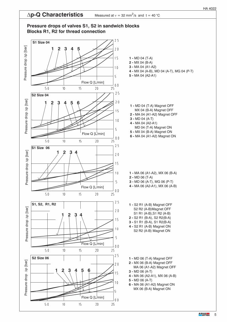
5
HA 4022
�p-Q Characteristics Measured at � = 32 mm2/s and t = 40 °C
Pressure drops of valves S1, S2 in sandwich blocksBlocks R1, R2 for thread connection
1 2 3 4
S2 Size 04
S2 Size 06
S1, S2, R1, R2
S1 Size 04
S1 Size 06
Pre
ssur
edr
op�
p[b
ar]
Flow Q [L/min]
Pre
ssur
edr
op�
p[b
ar]
Flow Q [L/min]
Flow Q [L/min]
Flow Q [L/min]
Flow Q [L/min]
Pre
ssur
edr
op�
p[b
ar]
Pre
ssur
edr
op�
p[b
ar]
Pre
ssur
edr
op�
p[b
ar]
1 2 3 4
1 2 3 4 5 6
1 2 3 4 5
1 2 3 4 5 6
1 - MD 06 (T-A) Magnet OFF2 - MX 06 (B-A) Magnet OFF
MA 06 (A1-A2) Magnet OFF3 - MD 06 (A-T)4 - MA 06 (A2-A1), MX 06 (A-B)5 - MD 06 (A-T)6 - MA 06 (A1-A2) Magnet ON
MX 06 (B-A) Magnet ON
1 - MA 06 (A1-A2), MX 06 (B-A)2 - MD 06 (T-A)3 - MD 06 (A-T), MG 06 (P-T)4 - MA 06 (A2-A1), MX 06 (A-B)
1 - MD 04 (T-A) Magnet OFFMX 04 (B-A) Magnet OFF
2 - MA 04 (A1-A2) Magnet OFF3 - MD 04 (A-T)4 - MA 04 (A2-A1)
MD 04 (T-A) Magnet ON5 - MX 04 (B-A) Magnet ON6 - MA 04 (A1-A2) Magnet ON
1 - MD 04 (T-A)2 - MX 04 (B-A)3 - MA 04 (A1-A2)4 - MX 04 (A-B), MD 04 (A-T), MG 04 (P-T)5 - MA 04 (A2-A1)
1 - S2 R1 (A-B) Magnet OFFS2 R2 (A-B)Magnet OFFS1 R1 (A-B),S1 R2 (A-B)
2 - S2 R1 (B-A), S2 R2(B-A)3 - S1 R1 (B-A), S1 R2(B-A)4 - S2 R1 (A-B) Magnet ON
S2 R2 (A-B) Magnet ON

6
HA 4022
�p-Q Characteristics Measured at � = 32 mm2/s and t = 40 °C
Pressure drops for valves S5, S6 in modular blocksBlocks R1, R2 for thread connection
S5 Size 06
1 2 3
S6 Size 06
S5 Size 04
S6 Size 04
S5,S6 R1,R2
1 2 3
1 2 3
1 2 3
1 2
Pre
ssur
edr
op�
p[b
ar]
Flow Q [L/min]
Flow Q [L/min]
Flow Q [L/min]
Flow Q [L/min]
Flow Q [L/min]
Pre
ssur
edr
op�
p[b
ar]
Pre
ssur
edr
op�
p[b
ar]
Pre
ssur
edr
op�
p[b
ar]
Pre
ssur
edr
op�
p[b
ar]
1 - MD 06 (A-T, T-A), ME 06 (B-T, T-B)MF 06 v(A-T, B-T / T-A, T-B)
2 - MA 06 (A1-A2), MB 06 v(B1-B2),MC 06 (A1-A2 / B1-B2), MX (B-A )
3 - MA 06 (A2-A1), MB 06 (B1-B2)MC 06 (A2-A1/B2-B1), MX 06 (A-B)
1- MD (T-A), ME (T-B), MF (T-A, T-B)2 - MD (A-T), ME (B-T), MF (A-T, B-T)3 - MA (A1-A2, A2-A1), MB (B1 -B2, B2-B1)
MC (A1-A2, A2-A1/ B1 -B2, B2-B1)
1 - MD 04 (A-T, T-A), ME 04 (B-T, T-B)MF 04 (A-T, T-A)
2 - MX 04 (A-B, B-A)3 - MA 04 (A1-A2, A2-A1), MB 04 (B1-B2, B2-B1)
1 - MD 04 (A-T, T-A), ME 04 (T-B, B-T)MF 04 (A-T, B-T / T-A, T-B)
2 - MX 04 (A-B, B-A)3 - MA 04 (A1-A2, A2-A1 ),MB (B1-B2, B2-B1)
MC 04 (A1-A2, A2-A1 / B1-B2, B2-B1)
S5 1 - R1 (A-B, B-A)2 - R2 (A-B, B-A)
S6 1 - R1 (A-B, B-A)2 - R2 (A-B, B-A)

7
HA 4022
Valve Dimensions Dimensions in millimetres
Size 04, 06 - Screw-in cartridge
Mounting cavity
456
1 Solenoid turnable in the range of 360°2 Electrical connector, DIN 43 6503 Retaining nut of the solenoid4 Outside hexagon s = 27 mmTightening torque 25 Nm
5 O-ring 19.4 x 2.1 NBR 80 (1 pc.)supplied with valve
6 Combined sealing:O-ring 14 x 1.78 (1 pc.)Back-up ring 14.73 x 17.43 x 1.14 (1 pc.)supplied with valve
7 Space required to remove connector
1 2 3 4
1 - S5 (A-B)2 - S5 (B-A)3 - S6 (A-B)4 - S6 (B-A)5 - S1 size 04 (A-B)S2 size 04 (A-B, B-A)
6 - S1 size 06 (A-B)S2 size 06 (A-B, B-A)
5 6
Pressurep[bar]
Flow Q [L/min]
p-Q Characteristics Measured at n = 32 mm2/s and t = 40 °C
Operating limits for maximum hydraulic power for valves S1, S2, S5, S6
1 2 7
3

8
HA 4022
Required surface finish ofinterface
Valve Dimensions Dimensions in millimetres
Size 04 (Installation dimensions to ISO 4401, CETOP - RP 121H)
Model MA, MX, MD, MG
Model MB, ME
1 Name plate2 4 through mounting holes3 Square rings 7.65 x 1.68(4 pcs. supplied with valve)
2
1
2
1
3
3

9
HA 4022
Model MC, MF
Valve Dimensions Dimensions in millimetres
Model MA, MX, MD, MG, MP
Valve Dimensions Dimensions in millimetres
Size 06 (Installation dimensions to ISO 4401, DIN 24 340)
2
1
2
1
1 Name plate2 4 through mounting holes3 Square rings 7.65 x 1.68(4 pcs. supplied with valve)
1 Name plate2 4 through mounting holes3 Square rings 9.25 x 1.68(4 pcs. supplied with valve)
Required surface finish ofinterface
3
3

10
HA 4022
Valve Dimensions Dimensions in millimetres
Model MB, ME
Model MC, MF
2
1
2
1
1 Name plate2 4 through mounting holes3 Square rings 9.25 x 1.68(4 pcs. supplied with valve)
Required surface finish ofinterface
3
3

11
HA 4022
Valve Dimensions Dimensions in millimetres
Model R1
Model R2
2
1
2
1
1 Name plate2 2 through mounting holes
1 Name plate2 2 through mounting holes
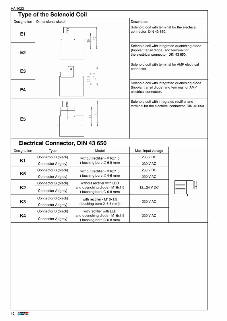
12
HA 4022
Type of the Solenoid CoilDesignation Dimensional sketch Description
E1Solenoid coil with terminal for the electricalconnector, DIN 43 650.
E2Solenoid coil with integrated quenching diode(bipolar transil diode) and terminal forthe electrical connector, DIN 43 650.
E3Solenoid coil with terminal for AMP electricalconnector.
E4Solenoid coil with integrated quenching diode(bipolar transil diode) and terminal for AMPelectrical connector.
E5
Solenoid coil with integrated rectifier andterminal for the electrical connector, DIN 43 650.
Electrical Connector, DIN 43 650Designation Type Model Max. input voltage
K1Connector B (black) without rectifier - M16x1.5
( bushing bore Æ 6-8 mm)
230 V DC
Connector A (grey) 230 V AC
K5Connector B (black) without rectifier - M16x1.5
( bushing bore Æ 4-6 mm)
230 V DC
Connector A (grey) 230 V AC
K2Connector B (black) without rectifier with LED
and quenching diode - M16x1.5( bushing bore Æ 6-8 mm)
12...24 V DCConnector A (grey)
K3Connector B (black) with rectifier - M16x1.5
( bushing bore Æ 6-8 mm)r230 V AC
Connector A (grey)
K4Connector B (black) with rectifier with LED
and quenching diode - M16x1.5( bushing bore Æ 6-8 mm)
230 V ACConnector A (grey)

13
HA 4022
Spare Parts
1 2
3
4
1 Solenoid coil2 Retaining nut with seal3 Electrical connector4 Seal kit
Solenoid coil
Type designationof the coil voltage
Type of the coil
E1 E2 E3 E4 E5
Ordering number
01200 936-0022 936-0690 936-0670 936-0680
01400 936-0650 936-0691 936-0673 936-0681
02100 936-0651 936-0692 936-0674 936-0682
02400 936-0026 936-0693 936-0672 936-0683
04200 936-0653 936-0695 936-0676 936-0685
04800 936-0031 936-0696 936-0677 936-0686
06000 936-0654 - - -
10200 936-0655 - - -
20500 936-0036 - - -
02450 936-2125
11550 936-2175
23050 936-2185

14
HA 4022
Solenoid retaining nut with seal
Type of the nut Seal ring Ordering number
Standart nut for S1, S2 18 x 1,5 403-1001
Standard nut for S5, S6 18 x 1.5 486-9010
Electrical connector, DIN 43 650
Type designationConnector A
greyConnector B
black
Ordering number
K1 936-9902 936-9901
K5 936-9906 936-9905
K2 936-9908 936-9907
K3 936-9904 936-9903
K4 936-9910 936-9909
Seal kit
Type Model Dimensions, number Ordering number
Screw-in cartridge ROE3
O-ring - NBR 80 19.4 x 2.1 (1 pc.)
405-9001O-ring - NBR 80 14 x 1.78 (1 pc.)
Back-up ring 14.73 x 17.43 x 1.14 (1 pc.)
Screw-in cartridge ROE3
O-ring - Viton 19.4 x 2.1 (1 pc.)
404-9002O-ring - Viton 14 x 1.78 (1 pc.)
Back-up ring 14.73 x 17.43 x 1.14 (1 pc.)
Subplate size 04 Square ring - NBR 70 7.65 x 1.68 (4 pcs.) 405-9004
Subplate size 06 Square ring - NBR 70 9.25 x 1.68 (4 pcs.) 404-9003
Subplate size 04 O-ring - Viton 7.65 x 1.68 (4 pcs.) 405-9005
Caution!
� The packing foil is recyclable.� The protecting plate can be returned to the manufacturer.� Mounting studs must be ordered separately. Tightening torques are 5 Nm (size 04) and 8.9 Nm (size 06).� The technical information regarding the product presented in this catalogue is for descriptive purposes only. It shouldnot be construed in any case as a guaranteed representation of the product properties in the sense of the law.
Preferred Types of ValvesType Ordering Number Type Ordering Number
ROE3-042S2/01200E1 405-0526 ROE3-042S5/01200E1 406-0020
ROE3-042S2/02400E1 405-0506 ROE3-042S5/02400E1 406-0021
ROE3-042S2/23050E5 405-0544 ROE-042S5/23050E5 406-0012
ROE3-062S2/01200E1 404-1042 ROE3-042S6/01200E1 406-0040
ROE3-062S2/02400E1 404-1043 ROE3-042S6/02400E1 406-0041
ROE3-062S2/23050E5 404-1118 ROE3-042S6/23050E5 406-0121
R2-ROE3 405-6015
Subject to alteration without notice!
ARGO-HYTOS a. s. CZ - 543 15 VrchlabíTel.: +420-499-403111, Fax: +420-499-403421E-mail: [email protected]

1
HA 40509/2010
Size to 04 (3/16) � ..80 bar (1160 PS) � ..30 L/min (7.93 US GPM )
Directional Valves SolenoidOperated Slip-In PD2E
� 3/2 way valves construction
� Reducing valves suitable for mobileapplications
� Compact design
� Economical Slip-In
� Two cavities sizes
3 1
23 1
2
Functional Description
3 1
21
2 3
2 3
1
� � � � � �
PD2E1-Y
PD2E1-X PD2E1-W
ReplacesHA 4050 2/2009
This directly-controlled electromagnetic distributor, inthe 3/2 arrangement, is used mostly for opening,blocking and direction controlling of the flow of liquids.The distributor consists of the housing (1), control gatevalve (2), counter-spring (3) and magnet coil (4). Theelectromagnet coil is pressed on (and thus fixed to) thevalve control system. The direct current electromagnetcoils are supplied for 12 V and 24 V voltage levels.
Once the fixing screw is released, it is possible to turn thedistributor around its axis by 360� and change thus theconnector socket position (6).The fixing screw (5) and fork (fastening member) (7)form also a part of the supply.In basic variant a part of the valve is exhibited to influenceof the environmental atmosphere and the coil zincplated.

2
HA 4050
Ordering Code
Functional SymbolsDesignation Symbol Interposition Designation Symbol Interposition
Valve cavityD17 (mm) YD20 (mm) WD20 (mm) X
3/2 Way cartridge DirectionalValve Solenoid OperatedSlip-In
Type of construction 1
Number of operating positions 2
Functional Symbols
D21D26
Number of connections 3
-
Sealsno designation NBRV FPM (Viton)
Nominal supply voltage12 12 V DC / 1,67 A24 24 V DC / 0,84 A
PD2E / -
E4
Electronics
with AMP-Junior-Timer-connectorwith integrated quenching diode and
terminal for AMP-Junior-Timerconnector with DEUTSCH DT 04-2P
with integrated quenching diodeand terminal for DEUTSCH DT 04-2P
E12AE13A
E3
Standard
Mounting mode mm (US) D17 D20
Maximum flow L/min (GPM) 30
Max.operating pressure in Canals Y, X -2, 3, W-3 bar 80
Max.operating pressure in Canals Y, X -1, W-2 bar 30
Pressure drop bar see �p-Q characteristisc
Hydraulic fluid Hydraulic oils of power classes (HL, HLP) to DIN 51524
Fluid temperature range °C (°F ) -30 ...90 (-22 ...194), +100 °C (212 °F for a short term)
Ambient temperature, max. °C (°F ) -30 ...90 (-22 ...194), +100 °C (212 °F for a short term)
Viscosity range mm2/s (SUS) 10 ... 500
Supply voltage V 12 DC 24DC
Quenching (E4, E13A) BZW06-19B BZW06-33B
Maximum degree of fluid contamination Class 21/18/15 according to ISO 4406 (1999)
Supply voltage % � 10
Quenching (E4, E13A) hod-1 15 000
Duty cycle % 100
Enclosure type to EN 60529 IP 67
Service life 107
Weight Directional Control Valves kg(Ibs) 0.2 (0.44)
Maximum fixing bolt tightening torque Nm ( lbf.ft) 9+2 ( 6.64+1.48)
Mounting positiion any
Technical Data

3
HA 4050
p-Q Characteristics Measured at � = 32 mm2/s (156 SUS)
0 5 10 15 20 25 30
20
40
60
80
90
1
3
2
Pres
sure
[bar
PSI]
()
(290)
(1305)
Flow Q ( )[ ]GPM L/min(2.64) (3.96) (5.28) (6.60) (7.93)(1.32)
(870)
(1160)
(580)
�p-Q Characteristics Measured at � = 32 mm2/s (156 SUS)
243
1, 6
5
2
4
6
8
10
Pres
sure
[bar
PSI]
()
(29)
(58)
(87)
(116)
(145)
0 5 10 15 20 25 30
Flow Q ( )[ ]GPM L/min(2.64) (3.96) (5.28) (6.60) (7.93)(1.32)
31
24
Oil 90 �C / Ambient temperature 90 �C� Voltage rating Un � 10�
Valve body70(2
.756)
55(2
.165
)
35(1.378)
50(1.968)
70(2.759)
10(0.394)
10(0
.394
)
39(1
.535
)
20(0.787)
40(1.5745)
Dimensions in mm (inches)
Form boringY3, X3, W3
Design Connecting size Type code Body material Operating pressures
Y G3/8 SB-Y3-0103AL Aluminium 250 bar (3625 PSI)
W, X G3/8 SB-W3-0103AL Aluminium 250 bar (3625 PSI)
Y3 Connection Dirrection1
2D2121
2 324
2D2621
2 32X3 Connection Dirrection4
2D2132
5 21W3 Connection Dirrection1
2D2121
6 32
Y3 Connection Dirrection1
2D2121
1 321
2D2632
1 21X3 Connection Dirrection1
2D2121
2 32W3 Connection Dirrection3
2D2121
1 32

4
HA 4050
Valve dimensions Dimensions in mm (inches)
34,5(1.358)
66,2(2.606)M
8
16
,90,
02(0
.665
0.00
1)�
�
15
,90,
02(0
.626
0.00
1)�
�
14
,90,
02(0
.587
0.00
1)�
� 84(3.307)
34
,2(1
.346
)
24(0
.945
)
5,4(0.213)
23(0
.905
)
11(0.433)
1
4
23
5
Within delivered1 O-ring 11,2x1,8 NBR 70 (1pc.)2 O-ring 12,42x1,78 NBR 70 (1pc.)3 O-ring 14x1,78-NBR 70 (1 pc.)4 Fork Slip-In M85 Bolt M8x16 ČSN 021143
PD2E1- Y
PD2E1- X, W
Electronics with terminal E12A, E13AIP 67
Electronics with terminal E3, E4IP 67
19
,90,
02(0
.783
0.00
1)�
�
18
,90,
02(0
.744
0.00
1)�
�
16
,90,
02(0
.665
0.00
1)�
�
23(0
.905
)
5,4(0.213)
39,5(1.555)
11(0.433)
M8
66,2(2.606) 84(3.307)
34
,2(1
.346
)
24(0
.945
)
1
4
23
5
Electronics with terminal E3, E4IP 67
Within delivered1 O-ring 14x1,78 NBR 70 (1pc.)2 O-ring 16x1,8 NBR 70 (1pc.)3 O-ring 17x1,8 NBR 70 (1 pc.)4 Fork Slip-In M85 Bolt M8x16 ČSN 021143
Electronics with terminal E12A, E13AIP 67

5
HA 4050
20H
9m
in. h
l.12
,5
1,5
5
A
A
A
A
0,05
0,025
0,025
M8
3 1
2
X
2 3W
1
17H
9m
in. h
l.45
19H
9m
in. h
l.27
,5
47 min.
37,4± 0,1
32 – 0,2
20,5 ± 0,1
15,2 – 0,2
8max. 6max.
30°
30°
20°
24
23,6
+0,
1
1,61,61,6
15
11
15,2 -0,2
29,7 -0,2
33,5±0,1
44 min.
7,5 max. 9 max.
5
11
15
15
H9
min
HL.
401,61,6
16
H9
min
HL.
26,5
23
,6+
0,1
2430
°
3,2 3,2 3,2
1
30° 30°
M8
20±0,1
17
H9
min
HL.
11,5
0,05 A
0,025 A
1,6
1
3
A
2
A0,025
A0,05
1
2 3
Y
0,05 A
X, W - � D20
Y - � D17
Cavity Dimensions in mm (inches)
M1:2
M1:2

6
HA 4050
The plastic packaging is recyclable. Certified documentation is available per request.
Caution!
Subject to alteration without notice!
ARGO-HYTOS s.r.o. CZ - 543 15 VrchlabíTel.: +420-499-403111, Fax: +420-499-403421E-mail: [email protected]
Seal set
Design -Standard (NBR70) Size, umber Order number
Y 11,2x1,8 (1pc.) 12,42x1,78 (1pc.) 14x1,78 (1pc.) 17938600
X, W 14x1,78 (1pc.) 16x1,8 (1pc.) 17x1,8 (1pc.) 16961300
Fork+Bolt M8 Fork SLIP-IN M8 (1pc.) Bolt M8x16 021143 Zn PO-A (1pc.) 16961500
Spare parts