hit-run fugitive begs for help, fearing he'll die in aussie jail
Upload
khangminh22Category
view
5download
0
AUSSIE BLASTER
Service
Fundamentals
Triplex Pump Technology Explained
NOV 2020 Australian Pump Industries

Australian Pump Industries
Aussie Pumps’ Service Fundamentals Nov 2020 2
This manual was developed as a
basic guide to understanding the
operation and requirements,
installation and servicing of Aussie
Pump’s ‘Big Berty’ Bertolini
positive displacement pumps.
High pressure cleaning equipment
is a potentially hazardous if not
used correctly and can cause injury
and property damage.
Recommended OH&S safety
practices must be observed at all
times.
Australian Pump Industries does
not assume liability or
responsibility for the design or
operation of a customer’s high
pressure system.
INTRODUCTION
CONTENTS
Introduction ................................................................ 2
Australian Safety Standards ...................................... 3
Bertolini & Aussie ...................................................... 3
How a Triplex Pump Works ........................................ 4
Hot water/steam systems ........................................... 4
System Design
Pump selection ...................................................... 5
Motor/engine selection ......................................... 5
Drive System .......................................................... 6
Chemical Injection ................................................. 5
Nozzle selection guide ........................................... 6
Determining spray tip size ..................................... 6
Other components
Inlet side components ........................................... 7
Outlet side components ........................................ 7
Installation of components ......................................... 8
Bertolini Pumps & Components
used on Aussie Blasters ............................................. 9
Troubleshooting Triplex Pumps ............................... 10
Troubleshooting Blasters ........................................ 11
Direct Drive Bertolini Pump Kits .............................. 12
Heavy Duty Bertolini Pump Kits .............................. 13
Triplex Pump Service Guidelines
Valve assemblies .................................................. 14
Removing manifold head ..................................... 14
Replacing plungers ............................................... 15
Replacing V-packings ............................................ 16
Recommended oils .............................................. 17
Test Set ............................................................... 17
Pressure Setting Instructions
- engine drive ....................................................... 18
- electric drive ...................................................... 19
Preventative Maintenance ...................................... 20
Check out our latest Blaster Blitz
online for all our Bertolini pumps,
kits & high pressure accessories.
Change up to a Big Berty … the quality change out!
Refer to the Australian Safety
Standard AS/NZS 4233.01 for
guidelines for the Operation and
Maintenance of High Pressure Water
Jetters.
Nov 2020 Aussie Pumps’ Service Fundamentals 3
Australian Pump Industries
AUSTRALIA SAFETY STANDARDS
In 2013 Australian Safety Standards were introduced
for High Pressure Water Jetting Systems (AS/NZS 4233).
There are two parts to the standard, one covers safe
operation and maintenance, the other covers the
construction and performance.
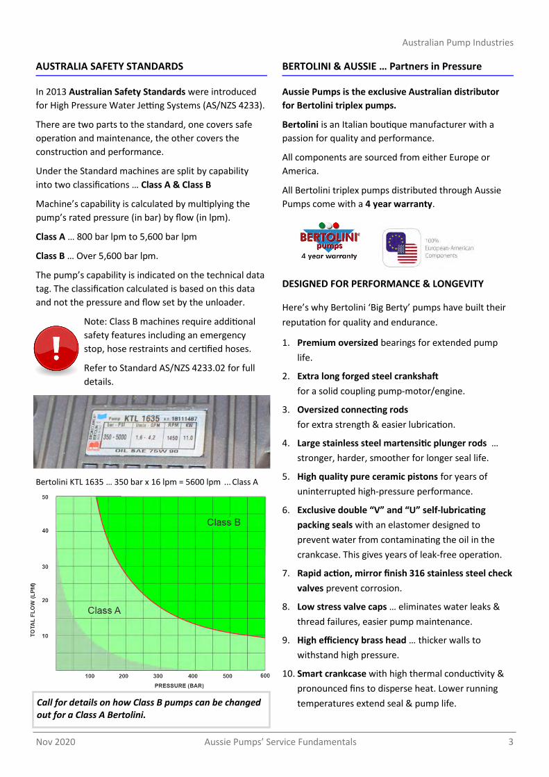
Under the Standard machines are split by capability
into two classifications … Class A & Class B
Machine’s capability is calculated by multiplying the
pump’s rated pressure (in bar) by flow (in lpm).
Class A … 800 bar lpm to 5,600 bar lpm
Class B … Over 5,600 bar lpm.
The pump’s capability is indicated on the technical data
tag. The classification calculated is based on this data
and not the pressure and flow set by the unloader.
Note: Class B machines require additional
safety features including an emergency
stop, hose restraints and certified hoses.
Refer to Standard AS/NZS 4233.02 for full
details.
Bertolini KTL 1635 … 350 bar x 16 lpm = 5600 lpm ... Class A
BERTOLINI & AUSSIE … Partners in Pressure
Aussie Pumps is the exclusive Australian distributor
for Bertolini triplex pumps.
Bertolini is an Italian boutique manufacturer with a
passion for quality and performance.
All components are sourced from either Europe or
America.
All Bertolini triplex pumps distributed through Aussie
Pumps come with a 4 year warranty.
DESIGNED FOR PERFORMANCE & LONGEVITY
Here’s why Bertolini ‘Big Berty’ pumps have built their
reputation for quality and endurance.
1. Premium oversized bearings for extended pump
life.
2. Extra long forged steel crankshaft
for a solid coupling pump-motor/engine.
3. Oversized connecting rods
for extra strength & easier lubrication.
4. Large stainless steel martensitic plunger rods …
stronger, harder, smoother for longer seal life.
5. High quality pure ceramic pistons for years of
uninterrupted high-pressure performance.
6. Exclusive double “V” and “U” self-lubricating
packing seals with an elastomer designed to
prevent water from contaminating the oil in the
crankcase. This gives years of leak-free operation.
7. Rapid action, mirror finish 316 stainless steel check
valves prevent corrosion.
8. Low stress valve caps … eliminates water leaks &
thread failures, easier pump maintenance.
9. High efficiency brass head … thicker walls to
withstand high pressure.
10. Smart crankcase with high thermal conductivity &
pronounced fins to disperse heat. Lower running
temperatures extend seal & pump life. Call for details on how Class B pumps can be changed out for a Class A Bertolini.

Australian Pump Industries
Aussie Pumps’ Service Fundamentals Nov 2020 4
HOW HIGH PRESSURE TRIPLEX PUMPS WORK
Pressure
The pressure produced in a pressure washer system is
the result of forcing a known volume of water through a
restricted orifice (spray tip). This pressure is measured
in bar or pounds per square inch (psi).
Flow
The flow is determined by the speed that the pump
shaft is rotated (rpm). The faster the shaft is rotated
the higher the output volume. This water flow is
measured in litres per minute.
Operation
The pump draws water in through a series of inlet check
valves as the plungers move back. As the plungers
move forward the inlet valves close, forcing the water
to travel through a series of outlet check valves and to
the pump outlet.
When the water exits the pump, the direction of flow is
controlled by means of an unloader or regulating valve.
A positive displacement pump always delivers a certain
volume of water regardless of whether the gun trigger
is open or closed.
The unloader controls the direction of flow, either to
the gun or redirecting (by-passing) the flow back to the
inlet of the pump if the gun trigger is closed.
At least one pressure relief valve must be installed in
the outbound side of the pump to protect against
unloader failure leading to a pressure spike.
Note: Failure to install correct unloader valve or
regulator device could result in serious injury and
property damage.
Nozzle Orifice
Setting unloader valves for the required pressure of the
machine depends entirely on the correct nozzle
selection. The correct nozzle orifice can be selected to
suit any specific pressure/flow combination using the
chart on page 6.
Operators should be conscious that nozzle wear will
create a drop in pressure and an apparent malfunction
of the machine. The abrasive nature of water and the
subsequent wear enlarges the orifice in the nozzle. The
larger the orifice, the less pressure and the more danger
of subsequent machine malfunction through unloader
failure.
Further information on this subject is covered in the
Nozzle Selection Guide section.
Change nozzles regularly to
maintain system pressure
Hot Water/Steam Cleaners
Heated pressure washers and steam cleaners increase
the ability of high pressure water flow to break down
dirt and grease.
The cleaning action of most detergents is also increased.
Units incorporating a boiler are complex and potentially
more hazardous than cold water systems.
These systems should be designed by qualified
professionals with a through knowledge of fuels, heat
transfers, etc.
Pump outlet
Pump inlet
Safety valve Unloader
Downstream Detergent injector
Inlet strainer
Thermal dump

Nov 2020 Aussie Pumps’ Service Fundamentals 5
Australian Pump Industries
Pump Selection
The heart of an Aussie pressure washer is a ‘Big Berty’
Bertolini pump. The pump has been specially chosen to suit
the motor/engine on the blaster.
Choose a pump that’s right for your application. Higher
pressure is not necessarily best. To much pressure and flow
will cause unnecessary wear on your pressure system and
could damage surfaces to be cleaned.
Never exceed the maximum pressures or rotation speed
stated in the pump technical data. Refer to the pump
technical data for the correct rpm required.
Motor/Engine Selection
The size of the motor required is determined by the flow
(litres/minute) and the pressure (bar/psi) desired.
Ensure that a petrol engine runs fast enough to supply the
required horsepower but do not exceed the engine
manufacturer’s specifications. Consult pump and engine
manufacturer’s technical guidelines.
Drive System
There are three common methods of driving or connecting
the pump and motor/engine.
1. Direct drive
2. Gear reduction drive
3. Belt drive is considered inefficient (belt slip) and can have
negative OH&S ramifications.
Chemical injection
Cleaning chemicals or detergents may be introduced into
either the inbound or outbound flow of water.
An inbound chemical injector uses the pump’s ability to draw
fluid in to introduce a chemical into the water flow. This
‘upstream’ injector means chemicals are applied to the
surface to be cleaned at normal high water pressures.
As any detergents or cleaning agents introduced upstream
pass through the pump body, care must be taken to ensure
the liquids are compatible with the pumps construction
materials and seals.
An outbound or downstream chemical injector uses a venturi
system to draw chemical into the water stream.
This type of injector requires low pressure to activate
chemical flow. Low pressure is achieved by enlarging the
outlet orifice by changing to a larger spray tip or by an
adjustable nozzle.
There are advantages to using a downstream injector:
1. Fewer pump component parts are exposed to the cleaning
chemicals which may extend system life.
2. The operator can control the flow of chemicals by
changing the system pressure at the nozzle.
3. Applying the chemical at lower pressure is more
economical as less chemical bounces off the work surface.
SYSTEM DESIGN

Australian Pump Industries
Aussie Pumps’ Service Fundamentals Nov 2020 6
DETERMINING SPRAY TIP SIZE
NOZZLE SELECTION GUIDE
MEG
Sizing for vario & grit-blast heads
Flow in l/min at the indicated pressures 20 BAR
30 BAR
40 BAR
50 BAR
60 BAR
70 BAR
80 BAR
90 BAR
100 BAR
110 BAR
120 BAR
130 BAR
140 BAR
150 BAR
160 BAR
180 BAR
200 BAR
220 BAR
250 BAR
280 BAR
310 BAR
340 BAR
370 BAR
400 BAR
450 BAR
500 BAR
290 psi
435 psi
580 psi
725 psi
870 psi
1015 psi
1160 psi
1305 psi
1450 psi
1595 psi
1740 psi
1885 psi
2030 psi
2175 psi
2320 psi
2610 psi
2900 psi
3190 psi
3625 psi
4060 psi
4560 psi
5000 psi
5440 psi
5880 psi
6525 psi
7250 psi
020 0,99 2 2,5 2,8 3,2 3,5 3,7 4 4,2 4,5 4,7 4,9 5,1 5,3 5,5 5,7 6 6,4 6,7 7,6 7.7 8.1 8.2 8.8 9.2 9.8 10.3
025 1,00 2,5 3.1 3.5 4 4.3 4.7 5 5.3 5.6 5.9 6.1 6.4 6.6 6.9 7.1 7.5 7.9 8.3 8.9 9.4 9.9 10.3 10.8 11.2 11.9 12.5
030 1,09 3,1 3,7 4,3 4,8 5,3 5,7 6,1 6,3 6,8 7,2 7,4 7,7 8 8,3 8,7 9,2 9,6 10 10.8 11.4 12 12.5 13.1 13.6 14.4 15.2
035 1,15 3,6 4,4 5,1 5,6 6,2 6,7 7,3 7,7 8,1 8,4 8,8 9,2 9,6 9,9 10,4 10,9 11,4 12 12.6 13.4 14.1 14.8 15.4 16.0 17.0 17.9
040 1,19 4,2 5,2 5,9 6,6 7,3 7,8 8,4 8,9 9,4 9,8 10,3 10,7 11,1 11,5 11,9 12,4 13,2 14,1 14.1 14.7 16.0 16.9 17.5 18.2 19.3 20.3
045 1,27 4,5 5,5 6,4 7,1 7,8 8,4 9 9,6 10,2 10,6 11,2 11,6 11,8 12,5 12,6 13,2 14,4 15 16.3 17.2 18.1 19.0 19.5 20.6 21.8 23.0
050 1,35 5 6,2 7,1 8 8,7 9,4 10 10,7 11,3 11,7 12,1 12,9 13,4 13,8 14,3 15,1 15,9 16,9 17.9 18.9 19.9 20.9 21.8 22.7 24.2 25.5
055 1,4 5,6 6,8 7,8 8,7 9,6 10,3 11,1 11,8 12,4 13 13,5 14,1 14,7 15,2 15,7 16,4 17,5 18,6 19.8 20.9 22.0 23.0 24.0 25.0 26.5 28.0
060 1,47 6 7,4 8,6 9,6 10,4 11,3 12,1 12,8 13,6 14,2 14,9 15,5 16 16,6 17,2 18 19,2 20,4 21.5 22.9 24.1 25.3 26.4 27.4 29.1 30.6
065 1,52 6,6 8 9,3 10,4 11,3 12,3 13,2 14 14,7 15,5 16,1 16,7 17,4 18 18,6 19,4 20,7 22 22.9 24.8 26.1 27.3 28.5 29.6 31.4 33.1
070 1,6 7,1 8,6 10 11,2 12,2 13,2 14,1 15 15,8 16,6 17,3 18 18,7 19,3 20,1 21,3 22,3 23,7 25.3 26.8 28.2 29.5 30.8 32.0 33.9 35.8
075 1,65 7,6 9,3 10,7 12 13,1 14,2 15,2 16,1 16,9 17,7 18,5 19,2 20 20,7 21,4 22,6 23,8 25,3 27.0 28.6 30.1 31.5 32.9 34.2 36.2 38.2
080 1,7 8 9,8 11,3 12,7 14 11,1 16,1 17,1 18 18,9 19,7 20,5 21,3 22 22,8 23,8 25,4 27 28.8 30.5 32.0 33.6 35.0 36.4 36.8 40.7
085 1,75 8,5 10,4 12,1 13,5 14,8 16 17,1 18,1 19,1 20 20,9 21,7 22,5 23,4 24 25,5 27 28,2 30.7 32.5 34.2 35.8 37.3 38.8 41.2 43.4
090 1,8 9.8 11.5 13.3 14.8 16.3 17.6 18.8 19.9 21.0 22.0 23.0 23.9 24.8 25.7 26.6 28.2 29.7 31.1 33.2 33.5 37.0 38.7 40.4 42.0 44.5 47.0
095 1,85 9.7 11.9 13.4 15.4 16.8 18.1 19.4 20.0 21.7 22.7 23.8 24.7 25.9 26.9 27.8 29.5 31.1 32.6 34.8 36.8 38.7 40.6 42.3 44.0 46.7 49.2
100 1,9 10 12.3 14.2 16.0 17.8 19.2 20.6 21.8 23.0 24.1 25.2 26.2 27.2 28.2 29.1 30.9 32.5 34.1 35.4 38.5 40.5 42.4 44.2 46.0 48.8 51.4
110 1,98 11.1 13.6 15.7 17.6 19.3 20.8 22.2 23.6 24.9 26.2 27.4 28.5 29.6 30.6 31.6 33.5 35.4 37.1 39.5 41.8 44.0 46.1 48.1 50.0 53.0 55.9
120 2,08 12.1 14.8 17.2 19.2 21.0 22.7 24.3 25.8 27.1 28.1 29.4 36.0 31.8 32.9 34.0 36.0 38.0 39.8 42.4 45.0 47.6 50.2 51.9 54.0 57.3 60.4
125 2,13 12.7 15.6 18.0 20.1 22.0 23.8 25.5 27.0 28.5 29.5 30.8 32.1 33.3 34.5 35.6 37.8 39.8 41.8 44.5 46.9 49.3 51.6 53.9 56.0 59.4 62.6
130 2,16 13.2 16.1 18.6 20.8 22.8 24.6 26.3 27.9 29.4 30.8 32.2 33.5 34.8 36.0 37.2 38.9 42.5 44.5 47.4 50.2 52.8 55.3 57.7 60.0 63.6 67.1
140 2,26 14.2 17.4 20.0 22.4 24.5 26.5 28.4 30.1 31.7 33.2 34.7 36.1 37.5 38.8 40.1 42.5 44.8 47.0 50.1 53.2 56.3 59.4 61.7 64.4 67.9 71.6
150 2,34 15.1 18.5 21.3 23.9 26.1 28.3 30.2 32.1 33.8 35.6 37.2 38.7 40.2 41.6 43.0 45.6 48.0 50.4 53.7 57.0 59.9 62.7 65.4 68.0 72.1 76.0
160 2,41 16.2 19.8 22.9 25.6 28.0 30.3 32.4 34.4 36.2 37.8 39.5 41.1 42.7 44.2 45.6 48.4 51.0 53.5 57.0 60.2 63.4 66.4 69.2 72.0 76.4 80.5
180 2,54 18.2 22.3 25.7 29.0 31.8 34.3 36.7 38.6 41.0 43.0 44.9 46.7 48.5 50.2 51.9 55.0 58.0 60.8 64.8 68.6 72.2 75.6 78.9 82.0 87.0 91.7
200 2,69 20.1 24.7 28.5 32.5 35.6 38.5 41.1 43.6 46.0 48.2 50.4 52.4 54.4 56.3 58.2 61.7 65.1 68.2 72.7 77.0 81.0 84.8 88.5 92.0 97.6 102.9
250 2,99 25.2 30.9 35.7 39.8 43.6 47.1 50.4 53.4 56.4 59.1 61.8 64.3 67.0 69.1 71.3 75.1 79.8 84.0 89.3 94.6 99.9 105.2 109.8 114.1 120.9 127.5
The outlet pressure is determined by ejecting a known
volume of water through a spray tip.
The size of this tip is an important factor of efficient
pressure cleaner performance. A tip that is too large
may produce insufficient pressure. A tip that is too
small may cause the pump to be over pressurized
causing damage to the pump and system components.
Refer to the above chart to select the correct nozzle
size for your application.
Check the output pressure and flow on the pump’s
technical data tag.
Select the pump pressure (psi) in the table above and
read down the column until you reach the closest flow
that matches the pumps performance.
Read off the MEG size in the row heading. Drop down
one size because the calculation should always be made
using 90% of the flow.
Example: 2030 psi at 11 litres per minute, calculate 90%
of flow value = 035 nozzle.
Aussie Laser Tip Nozzles are available in various sizes
and spray angles. It is advisable to keep a selection of
different sized and angled spray tips handy for different
cleaning applications.
Adjustable nozzles, like the Aussie ‘Vario-Zoom’ lance,
allow the user to change both the spray angle and
switch between high and low pressure.
Dual lance fitted with 15° (left) & detergent nozzles
Nov 2020 Aussie Pumps’ Service Fundamentals 7
Australian Pump Industries
OTHER SYSTEM COMPONENTS
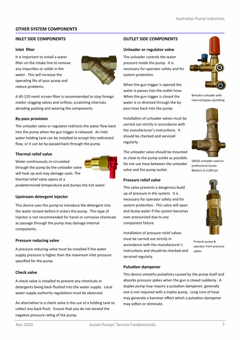
Inlet filter
It is important to install a water
filter on the intake line to remove
any impurities or solids in the
water. This will increase the
operating life of your pump and
reduce problems.
A 60-120 mesh screen filter is recommended to stop foreign
matter clogging valves and orifices, scratching internals,
abrading packing and wearing the components.
By-pass provision
The unloader valve or regulator redirects the water flow back
into the pump when the gun trigger is released. An inlet
water holding tank can be installed to accept this redirected
flow, or it can be by-passed back through the pump.
Thermal relief valve
Water continuously re-circulated
through the pump by the unloader valve
will heat up and may damage seals. The
thermal relief valve opens at a
predetermined temperature and dumps the hot water.
Upstream detergent injector
This device uses the pump to introduce the detergent into
the water stream before it enters the pump. This type of
injector is not recommended for harsh or corrosive chemicals
as passage through the pump may damage internal
components.
Pressure reducing valve
A pressure reducing valve must be installed if the water
supply pressure is higher than the maximum inlet pressure
specified for the pump.
Check valve
A check valve is installed to prevent any chemicals or
detergents being back-flushed into the water supply. Local
water supply authority regulations must be observed.
An alternative to a check valve is the use of a holding tank to
collect any back flush. Ensure that you do not exceed the
negative pressure rating of the pump.
Unloader or regulator valve
The unloader controls the water
pressure inside the pump. It is
necessary for operator safety and for
system protection.
When the gun trigger is opened the
water is passes into the outlet hose.
When the gun trigger is closed the
water is re-directed through the by-
pass hose back into the pump.
Installation of unloader valves must be
carried out strictly in accordance with
the manufacturer’s instructions. It
should be checked and serviced
regularly.
The unloader valve should be mounted
as close to the pump outlet as possible.
Do not use hose between the unloader
valve and the pump outlet.
Pressure relief valve
This valve prevents a dangerous build
up of pressure in the system. It is
necessary for operator safety and for
system protection. This valve will open
and dump water if the system becomes
over pressurized due to any
component failure.
Installation of pressure relief valves
must be carried out strictly in
accordance with the manufacturer’s
instructions and should be checked and
serviced regularly.
Pulsation dampener
This device smooths pulsations caused by the pump itself and
absorbs pressure spikes when the gun is closed suddenly. A
duplex pump may require a pulsation dampener, generally
one is not required with a triplex pump. Long runs of hose
may generate a hammer effect which a pulsation dampener
may soften or eliminate.
OUTLET SIDE COMPONENTS INLET SIDE COMPONENTS
Bertolini unloader with
internal bypass plumbing
VB350 unloader used on
professional Aussie
Blasters to 5,000 psi
Protects pump &
operator from pressure
spikes
Australian Pump Industries
Aussie Pumps’ Service Fundamentals Nov 2020 8
OTHER SYSTEM COMPONENTS
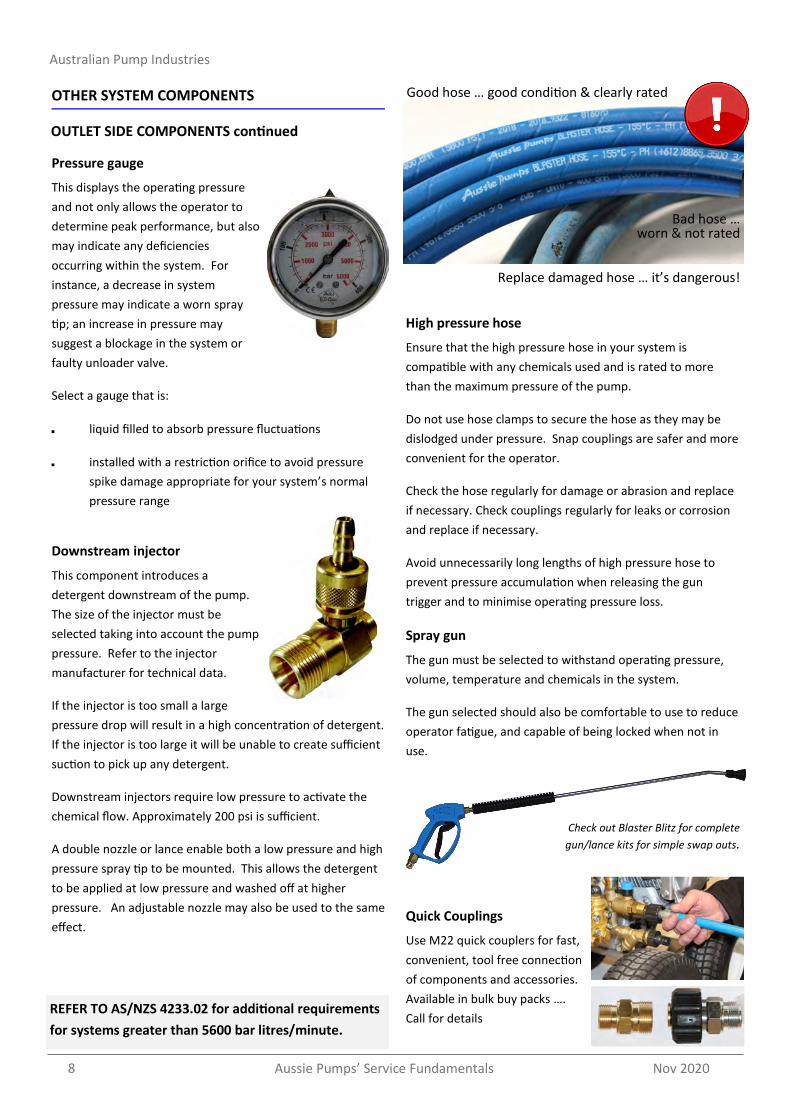
Pressure gauge
This displays the operating pressure
and not only allows the operator to
determine peak performance, but also
may indicate any deficiencies
occurring within the system. For
instance, a decrease in system
pressure may indicate a worn spray
tip; an increase in pressure may
suggest a blockage in the system or
faulty unloader valve.
Select a gauge that is:
liquid filled to absorb pressure fluctuations
installed with a restriction orifice to avoid pressure
spike damage appropriate for your system’s normal
pressure range
Downstream injector
This component introduces a
detergent downstream of the pump.
The size of the injector must be
selected taking into account the pump
pressure. Refer to the injector
manufacturer for technical data.
If the injector is too small a large
pressure drop will result in a high concentration of detergent.
If the injector is too large it will be unable to create sufficient
suction to pick up any detergent.
Downstream injectors require low pressure to activate the
chemical flow. Approximately 200 psi is sufficient.
A double nozzle or lance enable both a low pressure and high
pressure spray tip to be mounted. This allows the detergent
to be applied at low pressure and washed off at higher
pressure. An adjustable nozzle may also be used to the same
effect.
High pressure hose
Ensure that the high pressure hose in your system is
compatible with any chemicals used and is rated to more
than the maximum pressure of the pump.
Do not use hose clamps to secure the hose as they may be
dislodged under pressure. Snap couplings are safer and more
convenient for the operator.
Check the hose regularly for damage or abrasion and replace
if necessary. Check couplings regularly for leaks or corrosion
and replace if necessary.
Avoid unnecessarily long lengths of high pressure hose to
prevent pressure accumulation when releasing the gun
trigger and to minimise operating pressure loss.
Spray gun
The gun must be selected to withstand operating pressure,
volume, temperature and chemicals in the system.
The gun selected should also be comfortable to use to reduce
operator fatigue, and capable of being locked when not in
use.
Quick Couplings
Use M22 quick couplers for fast,
convenient, tool free connection
of components and accessories.
Available in bulk buy packs ….
Call for details
OUTLET SIDE COMPONENTS continued
REFER TO AS/NZS 4233.02 for additional requirements
for systems greater than 5600 bar litres/minute.
Check out Blaster Blitz for complete
gun/lance kits for simple swap outs.
Replace damaged hose … it’s dangerous!
Good hose … good condition & clearly rated
Bad hose … worn & not rated

Nov 2020 Aussie Pumps’ Service Fundamentals 9
Australian Pump Industries
Pump Model Unloader valve Safety valve Thermal Dump Valve Pressure Gauge Gearbox Nozzle size Safety
Classification Aussie Blaster
WBL917 BAPRI20ADJ - MPA60063050 AGCDR0102 - 035 Class A Monsoon 140
WBXG3025 BAPR-I-25ADJ MG1000 MPA60063050 - - 035 Class A AB30
TMG4035 BAPRI 40ADJ VS240 MPA60063070 - - 030 Class A AB40
WBL1114 BAPRI20ADJ MG1000 MPA60063050 - B318699973 035 Class A BB100
TTL1520 VRT3 MG1000 MPA60063070 AGCDR0102 B318870973 045 Class A Scud 350/ Monsoon 200
TTL2120 VRT3 MG1000 MPA60063070 AGCDR0102 B318870973 060 Class A Scud 351/ Monsoon 300
TTL1330 BVB350 VS240 MPA60063070 AGCDR0102 B318870973 050 Class A Scud 400/ Monsoon 400
TTL2028 BVB350 VS240 MPA60063070 AGCDR0102 B318870973 050 Class A Ultra A/Cobra A/Monsoon 400 Maxi
TTK3021 VRT3 VS240 MPA60063070 AGCDR0102 B319110973 (GX630) 055 Class A Monsoon 300
TTK2130 BVB350 VS240 MPA60063070 AGCDR0102 B319110973 (GX630) 055 Class B Ultra/Cobra
KTL1635 BVB350 VS350 MPA60063070 AGCDR0102 B319110973 (GX630) 035 Class A
King Cobra A/Predator A/Hurricane
KTL2035 BVB350 VS350 MPA60063070 AGCDR0102 B319111973 (1 1/8 engine shaft) 045 Class B King Cobra Stubbie
RAL2035 BVB350 VS350 MPA60063070 AGCDR0102 B318880973 (B319219973) 045 Class B King Cobra
RAL2535 BVB350 VS350 MPA60063070 AGCDR0102 B318880973 (B319219973) 055 Class B Predator/
King Cobra
RAS4482 BVB350 VS350 MPA60063070 AGCDR0102 B318880973 (B319219973) 070 Class B Python
RA1650 BVB53 MPA60520000 MPA60063070 AGAUGE600BAR B318880973 (B319219973) 025 Class B Raptor 16
RA1850 BVB53 MPA60520000 MPA60063070 AGAUGE600BAR B318880973 (B319219973) 030 Class B Raptor 18
BERTOLINI PUMPS & COMPONENTS USED ON AUSSIE BLASTERS
Install all components according to
manufacturer’s recommendations to ensure
operator safety, to avoid property damage and
to ensure efficient system operation.
Any plumbing and component parts must be the same size or larger
than the inlet and outlet of the pump. The thread sizes are a guide
to the required sizes of plumbing for correct water flow.
Minimise bends and other restrictions in hoses and other plumbing.
This will ensure maximum efficiency of the motor or engine and
reduce turbulence and cavitation which may damage system
components.
It is important to eliminate all air leaks. These will cause a
reduction in pressure, excessive noise and increased pump wear.
It is recommended that a thread sealant be used on all connections
before tightening securely. Hose clamps are not acceptable as they
are susceptible to leaks and fail under pressure.
Mount the motor/engine so that the rotation of the pump
crankshaft is counterclockwise as you face the pump crankshaft.
The rotation of a petrol engine varies according to manufacturer.
Check the specifications before assembling. In most cases electric
motors may be operated in either direction according to the wiring.
Check the manufacturer’s specifications before connection.
Caution - Electrical components should only be installed by a
qualified professional. Water and electricity are a dangerous
combination. All electrical components must be watertight. Never
allow the spray or leak to contact any electrical component. This
could cause serious injury.
Never introduce acids, caustic substances or abrasive liquids into to
pressure system. Such substances entering the system will damage
the pump and other components and will void any guarantee.
If necessary, the pump and system must be protected from freezing.
INSTALLING COMPONENTS

Australian Pump Industries
Aussie Pumps’ Service Fundamentals Nov 2020 10
TRIPLEX PUMP TROUBLESHOOTING
PROBLEM CAUSE REMEDY
Pulsation Faulty pulsation damper Check pre-charge, if low recharge or replace
Low pressure
Worn nozzle Replace nozzle
Belt slippage Tighten or replace
Air leak in inlet plumbing Disassemble, reseal and reassemble
Unloader stuck, partially blocked or improperly adjusted, valve seat worn
Clean, adjust unloader, check for worn and dirty valve seats. Replace if required
Inlet suction strainer clogged or improperly sized
Clean. Check more frequently
Worn packing. Abrasives in pumped fluid or severe cavitation. Inadequate water
Install proper filter. Suction at inlet manifold must be limited to less than 6m lift or 8.5psi
Fouled or dirty inlet or discharge valves Clean inlet and discharge valve assemblies
Worn inlet, discharge valve blocked or dirty Replace worn valves, valve seats.
Cracked pistons due to dry running Replace pistons
Leaky discharge hose or connectors Replace worn valves, valve seats and/or discharge hose
Pump runs extremely rough, pressure very low
Restricted inlet or air entering the inlet plumbing
Check inlet plumbing size. Check seals are air tight
Inlet restrictions and/or air leaks. Stuck inlet or discharge valve
Replace worn cup or cups, clean out foreign material, replace worn valves.
Water leakage from under manifold, slight leakage
Worn packing Install new packing
Oil leak between crankcase and pumping section
Worn crankcase piston rod seals, O-rings on plunger retainer worn
Replace crankcase piston rod seals. Replace o-rings.
Oil leaking in the area of crankshaft
Worn crankshaft seal or improperly installed oil seal o-ring
Remove oil seal retainer and replace damaged o-ring and/or seals
Faulty bearing Replace bearing
Excessive play in the end of the crankshaft pulley
Worn main bearing from excessive tension on drive belt
Replace crankcase bearing and/or tension drive belt
Water in crankcase (pump oil is milky)
Humid air condensing into water inside the crankcase
Change oil more frequently. Use high grade automotive 30 weight nondetergent oil
Worn packing and/or piston rod sleeve. O-rings on plunger retainer worn
Replace packing. Replace o-rings
Oil leaking from underside of crankcase Worn crankcase piston rod seals Replace seals
Oil leaking at rear portion of the crankcase
Damaged crankcase, rear cover o-ring, drain plug o-ring or sight glass o-ring
Replace cover o-ring, drain plug o-ring, or sight glass o-ring
Loud knocking noise in pump Pulley loose on crankshaft Check key and tighten set screw
Broken or worn bearing Replace bearing
Frequent or premature failure of the packing
Scored, damaged or worn plunger Replace plungers
Overpressure to inlet manifold Reduce inlet pressure
Abrasive material in fluid being pumped Install proper filtration on pump inlet plumbing
Excessive pressure and/or temperature of fluid being pumped
Check pressures and fluid inlet temperature, ensure they are within specified range
Over pressure of pump Reduce pressure
Running pump dry Do not run pump without water

Nov 2020 Aussie Pumps’ Service Fundamentals 11
Australian Pump Industries
Symptoms Cause Action User check
Service Agent only
Electric drive pressure cleaners
Machine does not start
Power not connected Check plug, cable and switch
Wrong voltage Check mains voltage
Power cable damaged Replace cable
Motor hums but does
not run
Voltage supply is too low Check power supply for correct voltage
Pump is stuck Manually turn motor
Spray gun not activated Activate spray gun when switching on
Cross section of extension lead too small Use correct dimension extension lead
Motor stops suddenly Cut out switch activated due to overheating Check power supply is correct. Disconnect machine and allow to cool off for a few minutes.
Motor trips out
Unit run on excessive extension lead Remove lead
Power lead or plug damaged Fix or replace
Excessive pressure build up Check pressure, nozzle size, unloader setting
Motor down to earth e.g. water ingress Electrician to test, fix or replace
Suction amperage cut-out set too low Reset to correct setting
Engine drive pressure cleaners …. For further assistance with engine trouble shooting consult the manufacturers handbook
Machine does not start
Battery dead Recharge or replace battery
Battery cables disconnected Clean connections and reconnect cables
Engine, pump or gearbox is seized Replace or repair seized part
Low oil shutdown is activated Add oil to engine, consult user guide
Low on fuel Add fuel
Engine slows down under load, whenever gun trigger is pressed
Engine needs service Consult engine service centre
Hot water & Steam cleaners
Burner is smoking
Water in the fuel tank Empty fuel tank, clean and refill with clean fuel
Fuel pressure incorrect Adjust fuel pressure
Air throttle adjusted incorrectly Adjust air intake on fan
Electrodes positioned incorrectly Clean, adjust or replace as required
Fuel nozzle dirty Clean fuel nozzle
Fuel nozzle worn or damaged Change fuel nozzle
Heating coil blocked by soot Remove & clean heating coil
Fuel pump dirty Replace fuel pump
Fuel solenoid valve not working Replace fuel solenoid
Burner will not fire
Burner switch not on Turn switch on burner
Diesel fuel level low Add diesel
Trigger on spray gun not pulled Squeeze trigger to fire burner
Fuel filter blocked Clean and replace if necessary
Overload on burner motor tripped Consult service manual
Low water pump pressure Trouble shoot pump (see page 105)
Fuel blockage Check fuel system for flow, clear blockage
Electrode gap incorrect Reset
No power to electrodes Trace power & replace faulty parts
Burner cuts out during operation
Fuel tank is empty (burner will produce white smoke)
Refill the fuel tank
Suction filter is dirty Remove filter and clean using fuel and a brush
Water in fuel Empty fuel tank, clean and refill with clean fuel
Pressure switch not functioning Replace pressure switch
Ignition transformer faulty Replace transformer
Rotation of electrodes Adjust electrodes
Fuel nozzle is dirty Clean fuel nozzle
Fuel nozzle is worn Fuel pump is faulty Replace fuel pump
Fuel solenoid valve not working Replace solenoid valve
Fuse burnt out Check & replace
Water does not reach working temperature
Thermostat adjusted too low Adjust thermostat
Thermostat is faulty Replace thermostat
Scale build up in water circuit De-scale inside of coil
Burner sooted Remove & clean outside of coil & inside of cove
BLASTER TROUBLESHOOTING (other than pump)

Australian Pump Industries
Aussie Pumps’ Service Fundamentals Nov 2020 12
DIRECT DRIVE & SMALL SLOW SPEED BERTOLINI PUMP SERVICE KITS
PUMP MODEL
Part No. Description WEL 744 WEL 733 WBL 1114
WBL 917 WBL 1111 WS 899G WBG 2030 WHY 1520
TWSG 3013 TWSG 3016 WBXG 3025 TMG 4035
Valve Kit
BKIT1 (15 pieces)
BKIT123 (15 pieces)
BKIT141 (15 pieces)
Valve cap kit
BKIT166 (12 pieces)
BKIT3 (12 pieces)
BKIT18 (12 pieces)
BKIT67 (12 pieces)
Minor Seal Kit
BKIT12 (15 pieces)
BKIT60 (12 pieces)
BKIT21 (15 pieces)
BKIT73 (15 pieces)
BKIT74 (15 pieces)
Major Seal Kit
BKIT10 (18 pieces)
BKIT70 (21 pieces)
BKIT61 (18 pieces)
BKIT20 (21 pieces)
BKIT68 (21 pieces)
BKIT69 (21 pieces)
Oil Seal Kit BKIT14 (3 pieces)
BKIT64 (3 pieces)
BKIT65 (3 pieces)
Full oil seal &
sight glass kit
BKIT78 (9 pieces)
BKIT82 (8 pieces)
BKIT83 (8 pieces)
BKIT169 (8 pieces)
Piston
B050010182 18mm
B040010182 15mm
B070007182 15mm
Sight Glass B853505002 ⅜” threaded
B040120322 Clip On
Breather Plugs B852570002 ⅜” Yellow
B049832973 ¼” Orange
Gearbox B318699973 Ø 24mm/ 3/4” Shaft
Minor seal kit Major seal kit Valve kit Full oil seal & sight glass kit
Oil seal kit Valve cap kit
Example Bertolini Pump Breakdown
TMG series
Bertolini pump breakdowns
available online …
aussiepumps.com.au

Nov 2020 Aussie Pumps’ Service Fundamentals 13
Australian Pump Industries
HEAVY DUTY SLOW SPEED BERTOLINI PUMP SERVICE PARTS
PUMP MODEL
Part No. TTV 2015 TTV 2021
KTV 3015 KTV 4040
KKV 2028
HDS 5057
TTL 1520 TTL 2120
TTL 1330 TTL 1530
TTL 2030 TTL 2028
TTK 3021
TTK 2130)
KTL 1635 KTL 2035
RAL 2035
RAL 2035-P 2535-P
RAS 4482
RAS 4482 Premium RA 316
Valve Kit
BKIT123 BKIT249 - HW
12 pieces
BKIT40 12 pieces BKIT93 12 pieces BKIT148 BKIT253 - HW 12 pieces
BKIT209 18 pieces
Valve cap kit
BKIT67 12 pieces
BKIT99 12 pieces
BKIT132 12 pieces
BKIT211 18 pieces
Minor Seal Kit
BKIT89 18 pieces (BKIT311 s/no 15070568 up) BKIT200 - HW
BKIT90 BKIT201 - HW 18 pieces
BKIT95 18 pieces(BKIT309 s/no 15070568 up) BKIT199 - HW
BKIT309 18 pieces
BKIT153 19 pieces
BKIT283 19 pieces
BKIT164 19 pieces BKIT271 BKIT219 - HW 19 pieces
BKIT227 13 pieces
Major Seal Kit
BKIT86 24 pieces (BKIT312 s/no 15070568 up) BKIT87 24 pieces BKIT96 24 pieces (BKIT310 s/no 15070568 up)
BKIT310 24 pieces BKIT152 25 pieces BKIT282 25 pieces
BKIT165 25 pieces BKIT270 25 pieces BKIT228 19 pieces
Oil Seal Kit
BKIT37 3 pieces BKIT146 3 pieces
Full oil seal & sight glass kit
BKIT127 10 pieces BKIT98 9 pieces BKIT147 11 pieces
BKIT210 10 pieces
Piston
B060009182 20mm B060010182 22mm B060055182 18mm B080070182 20mm
Sight Glass & o-ring
B853515502 ¾ threaded (with o-ring)
B060059322 Clip On Oil Breather B060020322
Gearbox
B318870973 Ø 24mm/1” B319110973 Ø 24mm/ 1” B319111973 Ø 24mm/ 1 1/8” B318855973 Ø 30mm/1” B318880973 Ø 30mm/ 1 1/8”
Bertolini pump breakdowns available online … aussiepumps.com.au
Minor seal kit HW = hot water seals up to 85°
Major seal kit
Valve kit Full oil seal & sight glass kit
Oil seal kit
Valve cap kit
Example Bertolini Pump Breakdown
TTL 300 series

Australian Pump Industries
Aussie Pumps’ Service Fundamentals Nov 2020 14
TRIPLEX PUMP SERVICE GUIDELINES
VALVE ASSEMBLIES
All inlet and discharge valves can be serviced
without disconnecting the inlet or discharge
plumbing.
The inlet and discharge valves are identical in all
models.
To service any valve remove valve cap and extract
valve assembly.
Examine o-rings and replace if there is any evidence
of cuts, abrasions or distortion.
Remove valve assembly (retainer, spring, valve,
valve seat) from valve cavity.
Only one Aussie Pumps valve kit is required to
repair all valves in the pump. The kit contains o-
rings, valve seats, poppets, springs and retainers.
Install new o-ring in valve cavity.
insert assembly into valve cavity.
Replace valve cap and torque to specifications.
REMOVING MANIFOLD HEAD
Remove the fasteners retaining head
Separate head from crankcase. It may be necessary
to tap head lightly with soft mallet to loosen.
Care should be taken not to damage plungers when
sliding head from crankcase.
The V-packing assemblies may come off with the
head. Examine plungers. The surface should be
smooth and free from scoring and pitting. If not,
replace.
Replace manifold head and torque to specifications
using the sequence shown below:
TORQUE SEQUENCE FOR TIGHTENING HEAD
Install all head bolts finger tight. Torque to 14 Nm in
sequence as shown, then re-torque to specifications
following the same sequence
NOTE:
Hot water seal & check valve kits available,
for selected slow speed models, to handle
water up to 85°C.
Call for details.
Nov 2020 Aussie Pumps’ Service Fundamentals 15
Australian Pump Industries
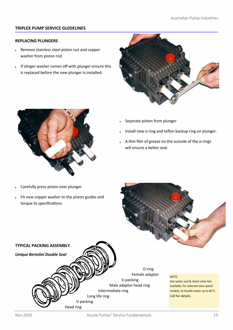
Separate piston from plunger
Install new o-ring and teflon backup ring on plunger.
A thin film of grease on the outside of the o-rings
will ensure a better seal.
REPLACING PLUNGERS
Remove stainless steel piston nut and copper
washer from piston rod
If slinger washer comes off with plunger ensure this
is replaced before the new plunger is installed.
TRIPLEX PUMP SERVICE GUIDELINES
Carefully press piston over plunger
Fit new copper washer to the piston guides and
torque to specifications
TYPICAL PACKING ASSEMBLY
Unique Bertolini Double Seal
O-ring
Female adaptor
V-packing
Male adaptor head ring
Intermediate ring
Long life ring
V-packing
Head ring
NOTE:
Hot water seal & check valve kits
available, for selected slow speed
models, to handle water up to 85°C.
Call for details.

Australian Pump Industries
Aussie Pumps’ Service Fundamentals Nov 2020 16
TRIPLEX PUMP SERVICE GUIDELINES
REPLACING V-PACKINGS
Remove manifold from crankcase
Insert proper extractor collet through main seal
retainer. Tighten collet and extract retainers,
v-packings and head rings.
Insert intermediate seal retainer pressing it
firmly into cylinder until it will go no further using
proper insertion tool.
Install rear head ring v-packing and main seal
retainer into cylinder in order shown and press
firmly into cylinder
Place correct insertion tool in cylinder and install
front head ring, v-packing and long life ring and
press firmly into cylinder until they will go no
further.
Repeat this sequence for each cylinder
Coat each plunger with grease and carefully
remount manifold. Torque head to specifications.

Nov 2020 Aussie Pumps’ Service Fundamentals 17
Australian Pump Industries
RECOMMENDED PUMP OILS
APPLICATION
AUSSIE BLASTER
RECOMMENDED OIL
Axial style wobble-plate pumps
H101 H110 H120 H130 F140 F150 F180 Panther Cougar Tiger MkII
Renolin 100B non-foaming oil
Triplex style crankshaft/piston pumps
Monsoon Series Scud Series BB Series Super Indy Series Sizzler Series Admiral Terminator Predator
SAE 75W/90 gear oil
Pressure cleaner gearbox Slow speed machines
SAE 75W/90 gear oil
AUSSIE PRESSURE CLEANER TEST SET
Professional pressure cleaners occasionally need to have their pressure tested and sometimes reset.
A drop in pressure could indicate nozzles are worn, the pressure regulator is worn, there are leaks in the system, the valves are sticking or signal other problems.
If your system does not include a pressure gauge an Aussie Test Set (p/n ATESTSET) can be supplied.
The kit consisting of a convenient brass T piece, with M22 quick coupler and 6,000 psi pressure gauge.
Simple and quick to fit, you can make sure everything is operating as it should.
Note: Gearbox has a separate oil
chamber and filling cap
FREE SAFETY DECALS
Let us know what Aussie
safety decals you need
and we’ll send them out
FREE of charge.

Australian Pump Industries
Aussie Pumps’ Service Fundamentals Nov 2020 18
AUSSIE BLASTER PRESSURE SETTING INSTRUCTIONS …. ENGINE DRIVE
A pressure spike will cause the safety valve to ‘blow’ to
prevent damage to the pump seals.
A pressure spike is generally caused by the unloader
for the following reasons.
1. Worn nozzles
Worn nozzles, fitted in the end of the lance, result in
less water bypassing back through the unloader to
cool & lubricate it. Without sufficient flow the
unloader will overheat and wear.
Pressure cleaner nozzles need to be changed
regularly to maintain pump performance. A drop in
pressure on the gauge indicates nozzle wear.
Replace worn nozzles.
2. Dirt in the unloader may cause it to jam.
Clean out unloader & check inlet filter fitted and
clean.
3. Leaks in the system can cause unloader ‘chatter’.
This will lead to the unloader wearing prematurely.
All leaks must be fixed before using the machine.
Once the unloader has been serviced or replaced,
resetting the safety valve is simple. This video shows
how to adjust the unloader and the safety valve.
For models purposely designed without a pressure
gauge (AB30, AB40, hire spec machines) an Aussie Test
Set needs to be fitted during this process.
NOTE: These instructions are intended for
the use of Authorised Aussie Eco-Clean
service centres only
The following steps should be taken to reset the safety
valve, with the unit running.
1. Unscrew the lock nut (C) on the safety valve and
the adjusting screw (D), should be screwed in all
the way.
2. Using an allen key, loosen the lock nut (B) on the
unloader and wind the unloader knob (A) in
gradually until the required pressure is obtained
whilst the trigger is pulled and water is running
through the pump. Do not exceed the maximum
rated pressure of the pump.
3. The lock nut (B) should then be wound down until
it grounds out at the bottom (do not over tighten
as this will further adjust the pressure) and locked
with use of the allen key. Paint mark across the nut
and knob to identify any tampering with the
setting.
4. With the pump running at the required pressure,
the adjusting screw (D) on the safety valve should
be wound out until there is a slight drip. Screw it in
one quarter of a turn, or until the drip stops, this
will set the safety valve 10% over the required
pressure. The lock nut (C) should then be locked
off. Paint mark to identify any tampering.
5. Repeat running with the trigger open and then
closed two or three times to ensure safety valve
doesn’t blow off pressure.
6. If safety valve continues to trip contact your
nearest Aussie Eco-clean service centre..
C D
A B
UNLOADER
SAFETY VALVE

Nov 2020 Aussie Pumps’ Service Fundamentals 19
Australian Pump Industries
A pressure spike will cause the safety valve to ‘blow’ to
prevent damage to the pump seals.
A pressure spike is generally caused by the unloader
for the following reasons.
1. Worn nozzles
Worn nozzles, fitted in the end of the lance, result in
less water bypassing back through the unloader to
cool & lubricate it. Without sufficient flow the
unloader will overheat and wear.
Pressure cleaner nozzles need to be changed
regularly to maintain pump performance. A drop in
pressure on the gauge indicates nozzle wear.
Replace worn nozzles.
2. Dirt in the unloader may cause it to jam.
Clean out unloader & check inlet filter fitted and
clean.
3. Leaks in the system can cause unloader ‘chatter’.
This will lead to the unloader wearing prematurely.
All leaks must be fixed before using the machine.
Once the unloader has been serviced or replaced,
resetting the safety valve is simple.
For models purposely designed without a pressure
gauge (AB30, AB40, hire spec machines) an Aussie Test
Set needs to be fitted during this process.
NOTE: These instructions are intended for the use of
Authorised Aussie Eco-Clean service centres only
1. Connect the machine to mains pressure water
supply, ensuring that water is passing freely through
the pump at the correct flow rate for the specified
pump by holding the gun trigger open.
2. Check gun nozzle size with gauge to ensure correct
nozzle size (page 6). Replace nozzle if worn.
3. Ensure machine is set up correctly for testing with
two gauges, as shown below. Pressure gauge ‘A’ to
be installed on top central valve cap. This gauge will
measure the pump pressure. Pressure gauge ‘B’ is to
be installed at the pump outlet on the delivery hose.
This gauge will measure the in-line pressure when
gun is shut off. This pressure must not exceed 20%
increase on operating pump pressure. Example:
2000psi pump pressure on gauge ‘A’ with gun open:
when gun is shut off gauge ‘B’ must not exceed
2400psi.
Measure amps on power supply cable to make sure
amps are running at acceptable levels when desired
pump performance is obtained.
4. To obtain correct pressure at pre-determined rpm:
i. Remove grub screw in unloader lock ring
ii. Wind down unloader until required pressure
is achieved. Check amp meter to ensure
electrical characteristics are within
acceptable parameters.
5. Release trigger on gun to shut off water flow and
read gauge ‘B’ to determine the increase in line
pressure (20% increase limit).
6. If test proves OK, repeat procedure for final check.
7. Unwind unloader by half a turn to ensure no
pressure loss is indicated on gauge ‘A’ in pump.
8. Apply Loctite 243 Super Thread to grub screw in
unloader lock ring and tighten with 1.5mm allen key.
9. Apply paint seal to grub screw head and thread
below unloader lock ring.
AUSSIE BLASTER PRESSURE SETTING INSTRUCTIONS …. ELECTRIC DRIVE

OVERSPEEDING
Do not operate pump over rated rpm. Over speeding can cause serious pump damage.
HIGH PRESSURE SETTING
The unloader valve is factory set to operate at the pumps rated pressure.
Tampering with the pressure regulator will void warranty and can be DANGEROUS.
EXCESSIVE BYPASS
Do not run on excessive by-pass.
Switch machine off within five minutes of ceasing operation as excessive by-pass can cause heat build up in the pump and subsequent damage.
Excessive bypass running voids warranty.
CHECK NOZZLE MONTHLY
If pressure drops off check nozzle for wear.
Nozzles should be replaced on a regular basis (every month for machines in regular use, every three months for machines used intermittently).
Using the machine with the incorrect nozzle size or worn nozzle will void warranty and can be DANGEROUS to the operator.
PRESSURE CLEANER DAILY CHECKLIST
Check the pump oil level
Check engine & gearbox oil level
Check nozzle for wear
Check all high pressure components for leaks:
gun/lance
HP hose
all fittings
Check water filter and clean regularly
Check unloader, safety valve and thermal dump
for leaks
BEWARE of abrasions on hose and replace if
damaged … STAY SAFE
THREE MONTHLY REGULAR SERVICE
All professional machines need to be thoroughly
serviced every three months. Use an approved and
qualified Aussie service agent. The service should
include the engine manufacturer’s
recommendations (see separate Engine Manual)
and the following:
Change the pump & gearbox oil
Check filter for foreign debris
Check unloader, safety valve and thermal dump
for leaks
Check all HP components for leaks: Gun/lance,
HP hose and all fittings
Replace nozzles
Check gearbox to engine key for wear, and
replace as required. NB Damage generated by
worn keys is not covered by warranty.
PREVENTATIVE MAINTENANCE
Australian Pump Industries Pty Ltd
7 Gladstone Road, Castle Hill NSW 2154
Ph: (02) 8865 3500 Fax: (02) 9894 4240
www.aussiepumps.com.au [email protected]
Copyright © 2022 FDOKUMEN