TYPE – i-HT - Kirloskar Pumps
50
INSTRUCTIONS ON INSTALLATION OPERATION AND MAINTENANCE FOR KIRLOSKAR PUMP TYPE – i-HT
-
Upload
khangminh22 -
Category
Documents
-
view
1 -
download
0
Transcript of TYPE – i-HT - Kirloskar Pumps

INSTRUCTIONS
ON
INSTALLATION OPERATION
AND
MAINTENANCE
FOR
KIRLOSKAR PUMP
TYPE – i-HT


CONTENTS
1. GENERAL
2 SAFETY INSTRUCTIONS
3. INSTALLATION
4. OPERATION
5. TECHNICAL DATA
6. MAINTENANCE
7. OVERHAULING
8. SPARE PART LIST AND CROSS-SECTIONAL DRAWINGS
9. GENERAL OUTLINE DIMENSIONS
Please ensure these instructions are read fully before installation and operation of the
pump.
Please furnish complete name plate details, part description, part nos, material construction
and quantity while ordering spare parts.

IOM/i_HT Issue Date: 26/06/2009
Page 4 of 50 Last Revision:26/10/2009
1. GENERAL
1.1 The booklet covers instructions for following types of i-HT pumps.
Single Stage
i-HT06BA i-HT12BA i-HT12EA
i-HT08BA i-HT12BD i-HT15BA
i-HT08BD i-HT12BE i-HT15BE
i-HT08BE i-HT12BF i-HT15DA
i-HT10BA i-HT12CA i-HT15DF
i-HT10BD i-HT12CF i-HT15DF
i-HT10BE i-HT12CG i-HT20DD
i-HT10DE i-HT12DA i-HT20DE
i-HT10ED i-HT12DF i-HT20ED
Double Stage
i-HT05AA i-HT06AA i-HT12XD
i-HT15XE i-HT15XF
1.2 These are horizontal split casing type pumps with suction and discharge nozzles and
their supporting feet integrally cast in the lower half casing. This construction enables to
remove the rotating unit for inspection and repairs by just removing upper half casing,
and without disturbing alignment, pipe connection or prime mover.
1.3 Pumps when properly installed and given due care in operation and maintenance
should operate satisfactorily for a long period.
1.4 When the pump is received, sometime before the actual use of pump, it should be
inspected and located in dry place. The coupling should be rotated periodically (once in a
month) to prevent pitting of bearing surfaces.
1.5 Generally all the i-HT pumps mentioned above are similar in construction with minor
changes of some parts.
1.6 Pump identification: All pumps are designated by serial number, model number, size
and type. This information is stamped on an identification plate which is fixed on the
pump.

IOM/i_HT Issue Date: 26/06/2009
Page 5 of 50 Last Revision:26/10/2009
2. SAFETY INSTRUCTIONS:
2.1: General Information Before performing any actions detailed within this instruction, the Site Health and Safety
instructions must read and fully understood. The instructions in this document also must
be read and fully understood.
Whenever the equipment is operated, maintained or used in any way, the procedures
detailed within the Health and Safety Dossier (DHS) and any procedures detailed within
these instructions shall be followed. The pump supplied by Kirloskar Brothers Limited
(KBL) has been designed with safety in mind, where hazards cannot be eliminated; the
risk has been minimized by the use of guards and other design features. Some hazards
cannot be guarded against and the instructions below MUST BE COMPLIED WITH for
safe operation. These instructions cannot cover all circumstances. It is the responsibility
of the user of the equipment for maintaining safe working practices at all times.
2.1.1 KBL products are designed for installation in designated areas, which are to be
kept clean and free of obstructions that may restrict safe access to the controls and
maintenance access points.
2.1.2 Pump nameplate is fitted to each unit and must not be removed. Loss of this plate
could make identification impossible. This in turn could affect safety and cause difficulty
in obtaining spare parts. Should accidental loss or damage occur, contact KBL
immediately.
2.1.3 Access to the equipment should be restricted to the personnel responsible for
installation, operation and maintenance and they must be trained, adequately qualified
and supplied with the appropriate tools for their respective tasks.
2.1.4 KBL firmly insists that all personnel responsible for installation, operation and
maintenance of the equipment must read safety instructions mentioned in the manual
before any work is done.
2.1.5 Ear defenders should be worn where the specified equipment noise level exceeds
locally defined safe levels. Safety glasses or goggles should be worn where working with

IOM/i_HT Issue Date: 26/06/2009
Page 6 of 50 Last Revision:26/10/2009
pressurized systems and hazardous substances. Other personal protection equipment
must be worn where local rules apply.
2.2 DO NOT wear loose or frayed clothing or jewellery, which could catch on the
controls or becomes trapped in the equipment.
2.3 Operation of the equipment for the application other than for which it is supplied
can increase the risk from hazards. Please consult KBL before making such change in the
application of the equipment.
2.4 Improper installation, operation and maintenance of the product supplied by KBL
could result in injury or death.
2.5 Within the manual, safety instructions are marked with safety symbols.
Hazard
This symbol refers to general mechanical aspects of safety.
Hazard
This symbol refers to electrical safety.
2.6: Transport handling and storage instructions:
2.6.1: Transport.
Pumps are dispatched in duly assembled condition. Pumps are protected against
corrosion and packed for transport by normal road, rail and sea carriers.
2.6.2: Handling
Crushing hazard.
When lifting the pump or pump set, use lifting equipment having a safe working load
rating suitable for the weight specified. Use suitable slings for lifting any pump not
provided with lifting points.
The use of suitable forklift truck and four chain crane sling equipment is recommended
but locally approved equipment rating may be used.
Pump should be slung as shown.

IOM/i_HT Issue Date: 26/06/2009
Page 7 of 50 Last Revision:26/10/2009
Pump set must be lifted from the lifting holes provided on the pump by using suitable
four chain lifting equipment.
2.6.3: Storage.
2.6.3.1: Temporary storage for up to six weeks.
If the pump unit is not be used immediately it should be stored carefully in a horizontal
position, in a sheltered, dry location. Additional rust preventive should be applied to all
unpainted carbon steel or cast iron parts, and should not be removed until final
installation.
2.6.3.2: Long Term Storage.
If the pump is not to be installed and operated soon after arrival, store it in a clean,
dry place, having slow, moderate changes in ambient temperature. Step should be taken
to protect the pump from moisture, dust, dirt, and foreign bodies. It is recommended that
the following procedure is taken:-
a) Ensure that the bearings are packed with the recommended grease, to prevent
moisture from entering around the shaft.

IOM/i_HT Issue Date: 26/06/2009
Page 8 of 50 Last Revision:26/10/2009
b) Remove the glands, packings and lantern rings from the stuffing box if the pump is
equipped in this manner. If the pump is equipped with mechanical seal, dismantle and
coat the seal with light oil.
c) Ensure that suction and discharge branches of the pump and all other openings are
covered with cardboard, wood or masking tape to prevent foreign objects entering the
pump.
d) If the pump is to be stored where there is no protective covering, it is advisable to
cover the unit with a tarpaulin or other suitable covering.
e) The shaft should be manually rotated periodically to prevent pitting of the bearing
surfaces by moisture.
Shearing Hazard.
Do NOT place fingers or hands etc. into the suction or discharge pipe outlets and do
NOT touch the impeller, if rotated this may cause severe injury. To prevent ingress of any
objects, retain the protection covers or packaging in place until removal is necessary for
installation. If the packaging or suction and discharge covers are removed for inspection
purposes, replace afterwards to protect the pump and maintain the safety.
Fill the bearing housing with recommended grease to ensure that the shaft and bearings
remain rust free.
2.6.3.3: Exposed or Extreme Conditions Storage.
For exposed storage or extreme variants in atmospheric or environmental conditions,
please refer to KBL for special storage instructions to suit the conditions acceptable.
3 INSTALLATIONS
3.1 Receiving pump
Upon receipt of the pump, a visual check should be made to determine if any damage
occurred during transit or handling. The main items to look for are:-
a) Broken or cracked equipment, including base, motor or pump feet and flanges.
b) Bent shaft
c) Broken motor end bells, bent eyebolts or damaged boxes of motor

IOM/i_HT Issue Date: 26/06/2009
Page 9 of 50 Last Revision:26/10/2009
d) Missing parts.
e) Pump shaft rotates freely.
Parts or accessories are some times wrapped individually or fastened to the equipment. If
any damage or losses have been incurred; promptly notify your KBL representative, KBL
Dealer and the transport company who delivered the pump.
When unloading pump units, lift equally at four or more points from the base. DO NOT
LIFT ONLY THE DRIVER OR PUMP.
3.2 Preparation
Before installing the pump, clean the suction and discharge flanges thoroughly.
Remove the protective coating from the pump shaft.
If the pump has been in storage and prepared for storage in the manner outlined
previously, remove all the grease from the bearings. The bearings should then be flushed
with carbon tetrachloride or kerosene and relubricated.
3.3 Location
The pump should be installed as near the liquid source as possible, with the shortest and
most direct suction pipe practically.
The pump should be installed with sufficient accessibility for inspection and maintenance.
Ample space and head room should be allowed for the use of an overhead crane or hoist
sufficiently strong to lift the unit.
Make sure there is a suitable power source available for the pump driver. If motor driven,
electrical characteristics should be identical to those shown on motor data/ name plate.
3.4 Foundation
The foundation should be strong enough to reduce vibrations and rigid enough to avoid
any twisting or misalignment.
The foundation should be poured without interruptions to within 20 to 40 mm of the
finished height. The top surface of the foundation should be well scored and glued before
the concrete sets. This provides a bonding surface for the grout. Foundation bolts should
be set in concrete as shown in Fig. 1. Allow enough bolt length for grout, shims, lower

IOM/i_HT Issue Date: 26/06/2009
Page 10 of 50 Last Revision:26/10/2009
base plate flange, nuts and washers. The foundation should be allowed to cure for
several days before the base plate is shimmed and grouted.
3.5 Base plate setting
Use blocks and shims under base for support at foundation bolts and midway between
bolts, to position base approximately 25 mm above the concrete foundation with studs
extending through hole in the baseplate.
By adding or removing shims under the base, level the pump shaft and flanges. The
baseplate does not have to be leveled. Draw foundation bolt nuts tight against baseplate
and observe pump and motor shafts or coupling hubs for alignment.
Check to make sure the piping can be aligned to pump flanges without placing pipe strain
on either flange.
Grout baseplate in completely and allow grout to dry thoroughly before attaching piping
to pump (24 hours is sufficient time with approved grouting procedure).
3.6 Grouting procedure
Grout compensates for uneven foundation, distributes weight of unit and prevents
shifting. Use an approved, non-shrinking grout as follows, after setting and leveling unit
See Fig. 2.
a) Build strong form around foundation to content grout.
b) Soak top of concrete foundation thoroughly, then remove surface water.
c) Baseplate should be completely filled with grout and, if necessary, drill vent holes to
remove trapped air.
d) After grout has thoroughly hardened, check the foundation bolts and tighten if
necessary.
e) Check the alignment after the foundation bolts are tightened.
f) Approximately 14 days after the grout has been poured or when the Grout has
thoroughly dried, apply an oil base paint to the exposed edges of the grout to prevent air
and moisture from coming in contact with the grout.
3.7 Alignment procedure
The pump driver, if supplied, is correctly aligned on its base plate at the factory. A
certain amount of deformation of the base plate is possible during transit and it is
therefore essential to check alignment, prior to final grouting.

IOM/i_HT Issue Date: 26/06/2009
Page 11 of 50 Last Revision:26/10/2009
A flexible coupling will only compensate for small amount of misalignment and should not
be used to compensate for excessive misalignment of the pump and driver shafts.
Inaccurate alignment results in vibration and excessive wear on the bearings, sleeve or
shaft and wear rings.
Coupling alignment can be checked with dial gauge Indicator also. Alignment should be
performed after the base plate has been properly set and grout has dried thoroughly
according to instructions. Final alignment should be made by shimming driver only.
Alignment should be made at operating temperatures.
After final alignment, it is necessary to dowel pump and driver feet to the baseplate.
FACTORS THAT MAY DISTURB ALIGNMENT
The unit should be periodically checked for alignment. If the unit does not stay in line
after being properly installed, the following are possible reasons:
a) Setting, Seasoning of the foundation.
b) Pipe strains, distorting or shifting of the machines.
c) Wear of the bearings.
3.8 Suction and Discharge Piping
When installing the pump piping, make sure to observe the following precautions:-
Piping should always run to the pump. Do not move pump to pipe. This could make final
alignment impossible.
Both suction and discharge piping should be supported independently and close to pump
so that no strain is transmitted to the pump when the flange bolts are tightened.
Use pipe hangers or other supports at necessary intervals to provide support. When
expansion joints are used in the piping system, they must be installed beyond the piping
supports close to the pump.
It is advisable to increase the size of both suction and discharge pipes at the pump
connection to decrease the loss of head from friction.
Install piping as straight as possible, avoiding unnecessary bends. Where necessary, use
45 degree or long sweep 90 degree fitting to decrease friction losses.
Make sure that all piping joints are air tight. Provide pipe expansions bellows when hot
fluids are to be pumped. Where reducers are used, eccentric reducers are to be fitted in
suction lines and straight taper reducers in discharge and vertical lines (See Fig.5).

IOM/i_HT Issue Date: 26/06/2009
Page 12 of 50 Last Revision:26/10/2009

IOM/i_HT Issue Date: 26/06/2009
Page 13 of 50 Last Revision:26/10/2009
Make sure that all piping joints are air tight. Provide pipe expansions bellows when hot
fluids are to be pumped. Where reducers are used, eccentric reducers are to be fitted in
suction lines and straight taper reducers in discharge and vertical lines (See Fig.5).
Misuse of reducers may cause the formation of air pockets in the pipe and thus
preventing the correct operation of the pump.
The suction pipe should be as short & direct as possible. Where suction lift is not very
high, it is advisable to use a foot valve. Horizontal suction line must have a gradual rise
to the pump.
The discharge pipe is usually preceded by a non-return valve or check valve and a
discharge gate valve (See Fig. 5). The check valve is to protect the pump from excessive
back pressure and reverse rotation of the unit and to prevent back flow into the pump in
case of stoppage or failure of the driver. The discharge valve is used in priming, starting
and when shutting down the pump.
4 OPERATION
4.1 Before Starting
Before initial starting of the pump, make the following inspection:
4.1.1 The unit baseplate is grouted and bolted to the foundation.
4.1.2 Alignment between pump and motor.
4.1.3 Motor is correctly wired to starting device, check voltage, phase and frequency on
motor nameplate with line circuit.
Ensure correct direction of rotation prior to coupling to pump. Check by starting motor
and switching off immediately. Observe rotation is the same as the arrow direction on
the pump casing.
4.1.4 Bearing lubrication is provided (see lubrication section), also check driver
lubrication.
4.1.5 Mechanical seal has been fitted or stuffing box has been packed.
4.1.6 All rotating parts are found to be free when turned by hand.

IOM/i_HT Issue Date: 26/06/2009
Page 14 of 50 Last Revision:26/10/2009
4.1.7 Pump is primed. Never run the unit dry. The liquid in the pump serves as a lubricant
for close running fits within the pump and the pump may be damaged if operated dry.
The pump may be primed by using an ejector, exhauster or vacuum pump. If a foot valve
is used in the suction line, the pump may be primed by venting and filling the casing with
liquid.
4.2 Starting
4.2.1 Close valve in discharge line.
4.2.2 Open fully all valves in the suction line.
4.2.3 Turn on seal water to the stuffing box where external pipe supplied.
4.2.4 Prime the pump.
4.2.5 Start the pump driver.
4.2.6 When the pump is operating at full speed, open the discharge valve slowly.
Do not operate pump for prolonged periods with closed discharge valve, so as to avoid
overheating.
The pump should be shut down at once and the trouble corrected if the pump is running
at its rated speed and found to have any of the following defects:
a) No liquid delivered.
b) Not enough liquid delivered.
c) Not enough pressure.
d) Loss of liquid after starting.
e) Excess vibration.
f) Motor runs hot.
g) Pump bearing overheating.
4.3 Running
While the pump is running, a periodic inspection should be made of:
a) Stuffing box (soft packed pumps only). Ensure there is sufficient leakage to lubricate
the packing.
b) Bearings. Check the bearings for temperature, which should not exceed pumped liquid
temperature or 80 Deg. C whichever is the lower.

IOM/i_HT Issue Date: 26/06/2009
Page 15 of 50 Last Revision:26/10/2009
c) With mechanical seal fitted pumps, check that there is no leakage from the stuffing
box.
d) Suction and discharge gauge readings.
4.4 Stopping
a) Slowly close delivery valve and shut down driving unit in accordance with
manufacturer’s instructions.
b) Shut off external sealing liquid supply, if supplied, to relieve stuffing box pressure.
c) Successful operation of the pump depends on accurate alignment. It is recommended
to re-check the alignment after preliminary run.

IOM/i_HT Issue Date: 26/06/2009
Page 16 of 50 Last Revision:26/10/2009
5 TECHNICAL DATA
5.1 Direction of Rotation
Pumps are supplied with clockwise direction of rotation when viewed from coupling end.
The direction of rotation can be reversed easily without changing any part
5.2 BEARING DETAILS:
Pump Model Bearing Module
Bearing DE
Deep Groove Ball
Bearing
Bearing NDE
Angular Contact
Paired Bearing
(Face to Face)
i-HT 06 BA
1
6306
7306(BECB)
i-HT 08 BA
i-HT 12 CA
i-HT 08 BD
i-HT 08 BE
i-HT 10 DE
i-HT 12 CF
i-HT 12 CG
i-HT 12 DA
2
6309
7309(BECB)
i-HT 12 BA
i-HT 15 BA
i-HT 12 EA
i-HT 15 DA
i-HT 10 BA
i-HT 10 BD
i-HT 10 BE
i-HT 12 BD
i-HT 12 BE
i-HT 12 BF
i-HT 12 DF
i-HT 15 BE
i-HT 15 DF
i-HT 10 ED
i-HT 20 DD 3 6312 7312(BECB) i-HT 20 DE
i-HT 20 ED
Note: Thrust bearing is at non driving end and radial bearing is at driving end.
Two Stage

IOM/i_HT Issue Date: 26/06/2009
Page 17 of 50 Last Revision:26/10/2009
5.3 Special care for Bearings
These instructions do not supersede any information issued by the bearing
manufacturers, to whom application should be made for more comprehensive literature
by personnel responsible for bearing care, who with it to make a detailed study.
Care and maintenance of bearings is a matter of ensuring that they are:
a) Correctly lubricated at intervals as laid down in routine maintenance chart.
b) Removed, cleaned and refitted with care.
c) Tools used and work areas should be cleaned.
To remove a bearing, use correctly suited withdrawal equipment.
CAUTION: Damage can be caused by exerting force against the outer ring of a ball
bearing.
Ball bearings should not be dismantled.
Clean bearings thoroughly with an approved fluid.
Dry the bearings by spinning with dry compressed air or by hand. Do not spin a clean dry
bearing.
Inspect the bearing for wear, fractures, cracks, corrosion or other damage which may
necessitate bearing replacement.
Pack both sides of bearing with grease.
Check that the bearing, shaft and housing are cleaned and undamaged.
Recharge with grease to a maximum of two thirds full.
Refit the bearing onto the shaft and press for tap into position.
Pump Model Bearing Module
Bearing DE
Deep Groove
Ball Bearing
Bearing NDE
i-HT 12 XD
3T 6411 6411 i-HT 15 XE
i-HT 15 XF
i-HT 05 AA 1T 6307 6307
i-HT 06 AA 2T 6309 6408

IOM/i_HT Issue Date: 26/06/2009
Page 18 of 50 Last Revision:26/10/2009
5.4 Lubrication Details
Initially bearings are lubricated during assembly. In the regreasing period these bearings
should be repacked with a high quality, lithium soap base, ball and roller bearing grease
free from resin and acid, not liable to harden or crumble and possessing rust preventive
properties. Re-greasing interval depends upon the operating speed of the unit.
Operating speed Regressing Interval
1450 RPM 4000 hours
2900 RPM 3000 hours
To recharge the bearings with fresh grease, use a grease gun and feed through the two
grease nipples provided.
DO NOT APPLY LUBRICANT WHEN PUMP IS RUNNING.
After 10,000 hours or two years whichever is earlier remove bearings from pumps,
degrease, thoroughly clean, recharge with fresh grease and refit in accordance with
reassembly instructions.
Recommended Grease specifications
Speed Lubricant recommended
1450 rpm. IOCL SERVOGEM-3 or equivalent.
2900 rpm. IOCL SERVOGEM-2 or equivalent.
Drop point: 180° C min
5.5 Wearing ring Details
Pumps are supplied with casing wear rings. The Diametrical clearances between
Impeller and casing rings should be minimum 0.18 mm and maximum 0.6 mm depending
up on pump model.

IOM/i_HT Issue Date: 26/06/2009
Page 19 of 50 Last Revision:26/10/2009
Pump
Type
Fig.
No.
D1 Tol.H7.
Min. Max
D2 Tol.c9.
Min. Max
DiametralClearances
Min Max
i-HT06BA 1 115.000 115.035 114.733 114.820 0.180 0.302
i-HT08BA 1 115.000 115.035 114.733 114.820 0.180 0.302
i-HT08BD 1 120.000 120.035 119.733 119.820 0.180 0.302
i-HT08BE 1 120.000 120.035 119.733 119.820 0.180 0.302
i-HT10BA 1 150.000 150.040 149.690 149.790 0.210 0.350
i-HT10BD 1 150.000 150.040 149.690 149.790 0.210 0.350
i-HT10BE 1 150.000 150.040 149.690 149.790 0.210 0.350
i-HT10DE 1 145.000 145.040 144.690 144.790 0.210 0.350
i-HT10ED 1 150.000 150.040 149.690 149.790 0.210 0.350
i-HT12BA 1 175.000 175.040 174.670 174.770 0.230 0.370
i-HT12BD 1 175.000 175.040 174.670 174.770 0.230 0.370
i-HT12BE 1 175.000 175.040 174.670 174.770 0.230 0.370
i-HT12BF 1 175.000 175.040 174.670 174.770 0.230 0.370
i-HT12CA 1 145.000 145.040 144.690 144.790 0.210 0.350
i-HT12CF 1 145.000 145.040 144.690 144.790 0.210 0.350
i-HT12CG 1 145.000 145.040 144.690 144.790 0.210 0.350
i-HT12DA 1 175.000 175.040 174.670 174.770 0.230 0.370
i-HT12DF 1 175.000 175.040 174.670 174.770 0.230 0.370
i-HT12EA 1 185.000 185.046 184.645 184.760 0.240 0.401
i-HT15BA 1 175.000 175.040 174.670 174.770 0.230 0.370
i-HT15BE 1 180.000 180.040 179.670 179.770 0.230 0.370
i-HT15DA 1 185.000 185.046 184.645 184.760 0.240 0.401
i-HT15DF 1 185.000 185.046 184.645 184.760 0.240 0.401
i-HT20DD 1 224.000 224.046 223.625 223.740 0.260 0.421
i-HT20DE 1 224.000 224.046 223.625 223.740 0.260 0.421
i-HT20ED 1 245.000 245.046 244.605 244.720 0.280 0.441
TWO STAGE
i-HT12XD 2 240.000 240.072 239.465 239.580 0.420 0.607
i-HT15XE 2 240.000 240.072 239.465 239.580 0.420 0.607
i-HT15XF 2 240.000 240.072 239.465 239.580 0.420 0.607
i-HT05AA 2 115.035 115.000 114.630 114.543 0.492 0.370
i-HT06AA 2 150.040 150.000 149.605 149.505 0.535 0.395
• For HT12XD, HT15XE, HT15XF Tolerance is H8b9

IOM/i_HT Issue Date: 26/06/2009
Page 20 of 50 Last Revision:26/10/2009
5.6 Impeller Details
Sr.
No. Pump Type
Full. Impeller
Dia. In mm.
Min. Impeller
Dia. In mm. Impeller Type
1 i-HT06BA 240 180 Double Entry
2 i-HT08BA 235 175 Double Entry
3 i-HT08BD 235 190 Double Entry
4 i-HT08BE 210 160 Double Entry
5 i-HT10BA 245 190 Double Entry
6 i-HT10BD 245 210 Double Entry
7 i-HT10BE 210 184 Double Entry
8 i-HT10DE 303 225 Double Entry
9 i-HT10ED 370 270 Double Entry
10 i-HT12BA 245 185 Double Entry
11 i-HT12BD 245 210 Double Entry
12 i-HT12BE 210 180 Double Entry
13 i-HT12BF 245 205 Double Entry
14 i-HT12CA 286 210 Double Entry
15 i-HT12CF 286 210 Double Entry
16 i-HT12CG 286 255 Double Entry
17 i-HT12DA 303 230 Double Entry
18 i-HT12DF 308 230 Double Entry
19 i-HT12EA 348 280 Double Entry
20 i-HT15BA 252 205 Double Entry
21 i-HT15BE 252 215 Double Entry
22 i-HT15DA 325 240 Double Entry
23 i-HT15DF 325 240 Double Entry
24 i-HT20DD 340 240 Double Entry
25 i-HT20DE 340 240 Double Entry
26 i-HT20ED 378 320 Double Entry
TWO STAGE
27 i-HT12XD 310 275 Single Entry
28 i-HT15XE 326 295 Single Entry
29 i-HT15XF 326 295 Single Entry
30 i-HT05AA 220 195 Single Entry
31 i-HT06AA 240 180 Single Entry
All models have double entry impellers.

IOM/i_HT Issue Date: 26/06/2009
Page 21 of 50 Last Revision:26/10/2009
5.7 Stuffing Box Details
Sr.No. i-HT Model Mech
seal
1 i-HT06BA, i-HT08BA, i-HT12CA, i-HT08BD
i-HT08BE, i-HT10DE, i-HT12CF, i-HT12CG 35
2
i-HT12BA, i-HT12DA, i-HT15BA, i-HT12EA,
i-HT15DA,i-HT10BA, i-HT10BD, i-HT10BE,
i-HT12BD, i-HT12BE,i-HT12BF, i-HT12DF,
i-HT15BE, i-HT15DF, i-HT10ED
50
3 i-HT20DE, i-HT20DD, i-HT20ED 65

IOM/i_HT Issue Date: 26/06/2009
Page 22 of 50 Last Revision:26/10/2009
5.9 Interchangeability of Components
Two Stage

IOM/i_HT Issue Date: 26/06/2009
Page 23 of 50 Last Revision:26/10/2009
6. MAINTENANCE.
6.1 Maintenance EHS (Environmental Hazard Safety) Instructions
Following hazards may arise during maintenance work.
Fluid Pressure Jet Hazards
Check and ensure that the pump operates at below the maximum Working Pressure
specified.
Hazardous materials:
Wear a suitable mask or respirator when working with chemical material handling.
Hazardous Gases, Mists, Sprays and Leaks.
Be aware of the hazards relating to the pumped fluid, especially the danger from
inhalation from noxious and toxic gases, skin and eye contact or penetration. Obtain
and understand the hazardous substance data sheets relating to the pumped fluid and
note the recommended emergency and first aid procedures.
Before attempting any maintenance on a pump, particularly if it has been handling any
form of hazardous liquid; ensure that the unit is safe to work on. The pump must be
flushed thoroughly with suitable cleanser to purge away any of the product left in the
pump components. The plant operator should carry this out and a certificate of
cleanliness obtained before starting work. To avoid any risk to health it is also
advisable to wear protective clothing as recommended by the site safety officer,
especially when removing old packing that may be contaminated.
Electric shock and accidental starting hazard:

IOM/i_HT Issue Date: 26/06/2009
Page 24 of 50 Last Revision:26/10/2009
Isolate the equipment before any maintenance work is done. Switch off the mains
supply, remove fuses, apply lockouts where applicable and affix suitable isolation
warning signs to prevent inadvertent re-connection.
In order to avoid the possibility of maintenance personnel inhaling dangerous fumes or
vapours, it is recommended that maintenance work be carried out away from the
pump location by removal of the rotating unit assembly to a suitable maintenance
area.
6.2 Routine Maintenance Chart
Preventive maintenance schedule is a periodical checks and precautions by which
possibilities of failure and breakdown will be rare.
EVERY WEEK
Visually check for leaks
Check for vibration.
Adjust gland as necessary to maintain slight leakage.
Hand test bearing housing for any sign of temperature.
Voltage and current.
EVERY MONTH Check bearing temperature with thermometer.
EVERY 3 MONTHS Check grease lubricated bearings for saponification.
EVERY 6 MONTHS
Check the packing and replace if necessary.
Check shaft or shaft sleeve for scoring.
Check alignment of pump and motor.
Check holding down bolts for tightness.
Check coupling bush/rubber star.
EVERY YEAR
Check rotating element for wear.
Check wear ring clearances.
Clean and regrease bearings.
Measure total suction and discharge Head as a test of pipe connection
7 OVERHAULING
With normal daily operating spell, the pump will be due for overhaul after about 5000
working hours. This work should be done by skilled personnel. Please refer to the cross
sectional drawing while dismantling and reassembling the pump. Please also refer to
chart given at end of this booklet.
Single Stage Pump
7.1 Dismantling Procedure:
1. Remove drain plug (60100) and drain the pump by opening air vent valve
(45000).

IOM/i_HT Issue Date: 26/06/2009
Page 25 of 50 Last Revision:26/10/2009
2. Remove all casing main joint nuts (58001) and dowel pins (61100). Remove
flushing piping.
3. Insert a screw driver or peg bar into the slots between the Upper and Lower
half casing and separate the halves, lifting off the upper half casing.
4. Tap the stuffing box inserts (97900) with a soft headed hammer to break the
seal between the stuffing box insert and lower half casing and lift the rotating
element out of the lower half.
5. Remove four hex. Head screws (57100) from each bearing housing (24001 &
24002) and remove the bearing housings from the bearings.
6. Remove bearing retaining nut (33600) and lock washer (41500) from the
outboard end of the shaft and using a puller remove the bearing [260] from the
shaft. Remove the drive end bearing [260] in the same manner. NOTE:
Retaining nut and lock washer are not used on the drive end bearing.
7. Remove shoulder rings [19900] from the shaft. Remove oil seals [50000] from
the supporting frame [22000].
8. Slide stuffing box inserts [97900] off the shaft. Mark the mechanical seal
position correctly before removing mechanical seal.It is very important to
assemble the pump. Remove mechanical seal from each stuffing box insert.
9. Remove casing rings [19000] from the impeller [15900].
10. a. Clockwise rotation :
Unscrew impeller nut [33000] from the non-drive end and slide it off the shaft.
b. Anti-clockwise rotation:
Unscrew impeller nut [33000] from the drive end and slide it off the shaft.
11. Remove impeller [15900], slide back impeller key [32000] and remove the
other impeller nut .Remove impeller key.
NOTE: For the overhauling of bearings, bearing hosing can be removed without
removing top casing. Pull the bearing housing by means of grip provided on the
bearing housing. There is slot on the insert face. By locating the puller in that
slot bearing can be easily removed.

IOM/i_HT Issue Date: 26/06/2009
Page 26 of 50 Last Revision:26/10/2009
7.2 ASSEMBLY PROCEDURE
For clockwise rotation
1. Wipe shaft [18000] with clean light oil. Screw impeller nut [33000] onto
shaft at drive end as per dimension “A” given on page34.
2. Place impeller key [32000] into key way and tap milled-down end right
home under sleeve.
3. Check the impeller for correct rotation [page 31] and slide onto shaft from
non-drive end.
4. Screw second impeller nut [33000] onto shaft at non-drive end and lock up
tight against impeller hub and first impeller nut.
5. Slide the casing rings [19000] onto the impeller.
6. Fix the mechanical seal to the correct location where the marking is done
before dismantling.
7. Check “O” rings for cuts or flaws, discard if faulty. Lubricate and roll “O”
ring into the groove in each insert [97900].
8. Slide inset [97900] over shaft with guide vane at top position.
9. Fit shoulder ring [19900] onto shaft, then press oil seal [50000] into insert.
10. Heat the ball bearing [26000] to approximately 100°C [212°FC] using
bearing hot plate or oil and water solution [10 to 15% soluble]. NOTE: Do
not exceed temperature 120°C [250°F].
11. Slide the heated bearing onto the shaft up to shoulder ring [19900] [non-
drive end]. Place locking washer [41500] onto shaft and screw bearing
retaining nut [36000] using hook spanner. Lock up tight against bearings.
12. Cool the bearing to room temperature and coat both sides with
recommended grease.
13. Coat the inside of the bearing housing [24002] with grease and slide into
place over bearing. Secure bearing housing [24002] to the support frame
[220] with four hex.head screws [57100].
14. At coupling end: heat the bearing [28000] to approximately 100° C [212° F]
using bearing hot plate or oil and water solution. NOTE: Do not exceed 120°
C [250° F].

IOM/i_HT Issue Date: 26/06/2009
Page 27 of 50 Last Revision:26/10/2009
15. Slide the heated bearing onto the shaft to about shoulder ring [19900]
[coupling end].
16. Cool the bearing to room temperature and coat both sides with
recommended grease.
17. Coat the inside of the bearing housing [24001] with grease and slide into
place over bearing. Secure bearing housing [24001] to the support frame
[22000] with four hex.head screws [57100].
18. Set the rotating element in the pump casing bottom half [12300]. Locate
both insert tongues in their respective casing grooves. Locate pin 61002 and
61003 in their respective horizontal slots on the face of bottom casing.
Correct any excessive “O” ring buckling. Check that the impeller is
centralized in the casing ±2.5 mm and that there I no rubbing.
19. Install casing gasket [51900] with a light coat of commercial cup grease on
both gasket surfaces. Carefully align the inner edge of the gasket with the
insert “O” rings.
20. Lower the upper half casing [12200] into place and install casing joint nuts.
NOTE: When installing upper half casing make sure that the “O” rings are
not cut or pinched and that the gasket is hard against the “O” rings.
21. Insert casing joint dowels [61100] and drive them home. Tighten the joint
nuts [500.1] per instructions on page 33.
22. Install stuffing box flushing piping [56000].
23. Rotate the shaft by hand to assure smooth turning and that it is free from
rubbing or binding.
7.3 REVERSING ROTATION OF PUMPS:
Reversing rotation of pumps puts suction and discharge opening on opposite sides
with respect to the coupling end.
Changes in assembly procedure –
1. Screw impeller locking nut [33000] onto shaft [18000] at non-drive end per
dimension “Z” given on page34.
2. Place impeller key [32000] into key way and tap milled-down end right
home under non-drive end impeller locking nut [mechanical seal] or shaft
sleeves [soft packed].

IOM/i_HT Issue Date: 26/06/2009
Page 28 of 50 Last Revision:26/10/2009
3. Check impeller for correct rotation page 31 and slide onto shaft from drive
end.
4. Screw second impeller locking nut [33000] or shaft sleeve onto shaft at
drive end and using hook spanner, lock up tight against the impeller hub.
From step 5 the assembly procedure is the same as for clockwise rotation
pumps.
Two Stage Pump
7.4 Dismantling Procedure
1. Drain the pump by opening air vent valve
2. Remove all the screws of bearing housing (240) tightened with casing,
insert (979) & bearing cover (271) and dismantle the bearing cartridge.
3. Remove all the nuts and bolts (577, 581) and locating pin (611) of the upper
and lower casing flange.
4. Insert a screw driver or peg bar into the slot between the two halves and
separate two halves, lifting of the upper half casing.
5. Tap the inserts (979) with a soft hammer to break the seat between the
insert and lower half casing and lift the rotating unit out of the lower half
casing.
6. Remove the bearing lock nut (336) and lock washer (415) from the NDE side
of the shaft. By using bearing puller remove the bearings from the shaft.
Remove the driving end bearing in the same manner.
7. Remove bearing cover (271) in the same manner. Remove the liquid
deflectors (236).
8. While removing cartridge mechanical seal.
9. Lock the seal with 4 clamps provided with on seal.
10. Release the allen screws provided to clamp the seal with shaft sleeve
11. Remove fasteners used for tightening gland plate with insert.
12. Remove the impeller nut & insert from DE.
13. Remove impellers with impeller ring from shaft. Impellers at DE and NDE are
with different bores 70 and 72 respectively. So they can’t be interchanged
with there positions.
14. Remove the impeller key (320). Take out interstage ring (204) along with
the interstage bush (313).

IOM/i_HT Issue Date: 26/06/2009
Page 29 of 50 Last Revision:26/10/2009
7.5 Assembly Procedure
1. Check the “O” rings (522) for cut or flows, discard if faulty, lubricate and roll
the “O” ring in groove.
2. Wipe over the shaft (180) with clean light oil.
3. Place the impeller key (320) into the keyway and interstage ring (204) along
with interstage bush (313).
4. Check the 1st & 2nd stage impeller for correct rotation and slide onto the shaft
from DE and NDE.
5. Place the impeller nut (330) onto the shaft DE and NDE and the DE impeller nut
against the impeller hub. After fixing the DE Impeller nut at a distance “A”
509mm. (See pate34) locate the NDE impeller nut. Slide the casing rings (190)
onto the impellers.
6. Check the “O” rings (522) for cuts or flaws, discard if faulty. Lubricate and roll
the “O” ring (522) into the groove in each insert (979.1 and 979.2).
7. Slide insert (979) tightened with cartridge mechanical seal with gland nuts,
liquid deflectors (236) & bearing cover (271) simultaneously over the shaft.
8. Ensure that no foreign particle should enter in bearing assembly. See the
cross-sectional drawing.
9. Heat the bearing (260) to approximately 100 deg. C. (212 deg. F) using
bearing oil bath.
10. Slide the heated bearing onto the shaft. Place the locking washer (415) onto
the shaft and screw the bearing lock nut (336) using spanner* Lock up tightly
against the bearing. Bend the washer in slot of bearing lock nut.
11. Cool the bearing to room temperature and coat both the slides with 200
grams of recommended grease.
12. Place the bearing cartridge over the bearings and tighten up with the insert.
13. Tighten the bearing cover (271) with bearing cartridge.
14. Apply same procedure to the DE end side.
15. Lift the rotating unit by means of crane. Place it in lower half casing such
that DE insert takes guide on lower half casing, casing rings should takes guide
in groove provided in lower half casing.

IOM/i_HT Issue Date: 26/06/2009
Page 30 of 50 Last Revision:26/10/2009
16. Check whether both Impellers are centrally placed in volute. If it did not,
adjust NDE sleeve.
17. Place the cylindrical pins (used to locate the wear ring) in their respective
holes. Install casing gasket (519) with a light coat grease on both gasket
surfaces. Carefully align the inner edge of the gasket with the insert “O” rings.
Lower the casing half upper (122) onto place and engage casing joint nuts
loosely.
NOTE- WHEN INSTALLING CASING HALF UPPER MAKE SURE THAT THE “O” RINGS (522.1) ARE
NOT CUT OR PUNCHED AND THE GASKET IS HARD AGAINST THE “O” RINGS.
18. Insert the locating pin (611) and drive them home.
19. Tighten the bearing cartridge with both upper and lowers half casing.
20. Loose the Cartridge seal clamps & tighten the cartridge seal allen screws
with the shaft.
21. Install the stuffing box flushing piping.
22. Rotate the shaft by hand to assure smooth turning and that is free from
rubbing or binding.
With normal daily operating spell, the pump will be due for overhaul after about 5000
working hours. This work should be done by skilled personnel. Please refer to the cross
sectional drawing while dismantling and reassembling the pump. Please also refer to
chart given at end of this booklet.

IOM/i_HT Issue Date: 26/06/2009
Page 31 of 50 Last Revision:26/10/2009

IOM/i_HT Issue Date: 26/06/2009
Page 32 of 50 Last Revision:26/10/2009
JOINT FLANGE
TIGHTENING TORQUES AND SEQUENCE
Stud and Nut use in this main joint flange of SCT pumps should be tightened to the
torques stated in table 1 and in the sequence stated in Fig.
STUD SIZE TIGHTENING TORQUES
M16
M20
M24
160 N.meters
360 N.meters
600 N.meters
2. Tightening sequence.
2.1 Tighten the four corner stud marked ‘X’ 1, 2, 3, and 4
2.2 Work outward along shaft axis towards the stuffing boxes in opposite quarters
tightening nut in regions 5, 6, 7 and 8.
2.3 Work outwards along the branch and in opposite quarters tightening nuts in regions
9, 10, 11, and 12.
2.4 Repeat the whole sequence.

IOM/i_HT Issue Date: 26/06/2009
Page 33 of 50 Last Revision:26/10/2009

IOM/i_HT Issue Date: 26/06/2009
Page 34 of 50 Last Revision:26/10/2009
ZA
Sr.
No.
Pump Type Clockwise Pump
“A”
CCW pump
“Z”
1 i-HT06BA
198
202 2 i-HT08BA
3 i-HT08BD
4 i-HT08BE
5 i-HT10BA
256
260
6 i-HT10BD
7 i-HT10BE
8 i-HT10DE 198 202
9 i-HT10ED 256 260
10 i-HT12BA
256
260 11 i-HT12BD
12 i-HT12BE
13 i-HT12BF
14 i-HT12CA
198
202 15 i-HT12CF
16 i-HT12CG
17 i-HT12DA 256
260 18 i-HT12DF
19 i-HT12EA 256 260
20 i-HT15BA 256
260 21 i-HT15BE
22 i-HT15DA 256
260 23 i-HT15DF
24 i-HT20DD 330
334 25 i-HT20DE
26 i-HT20ED 330 334
27 i-HT12XD
509
513 28 i-HT15XE
29 i-HT15XF
30 i-HT05AA 313 317
31 i-HT06AA 338 342

IOM/i_HT Issue Date: 26/06/2009
Page 35 of 50 Last Revision:26/10/2009
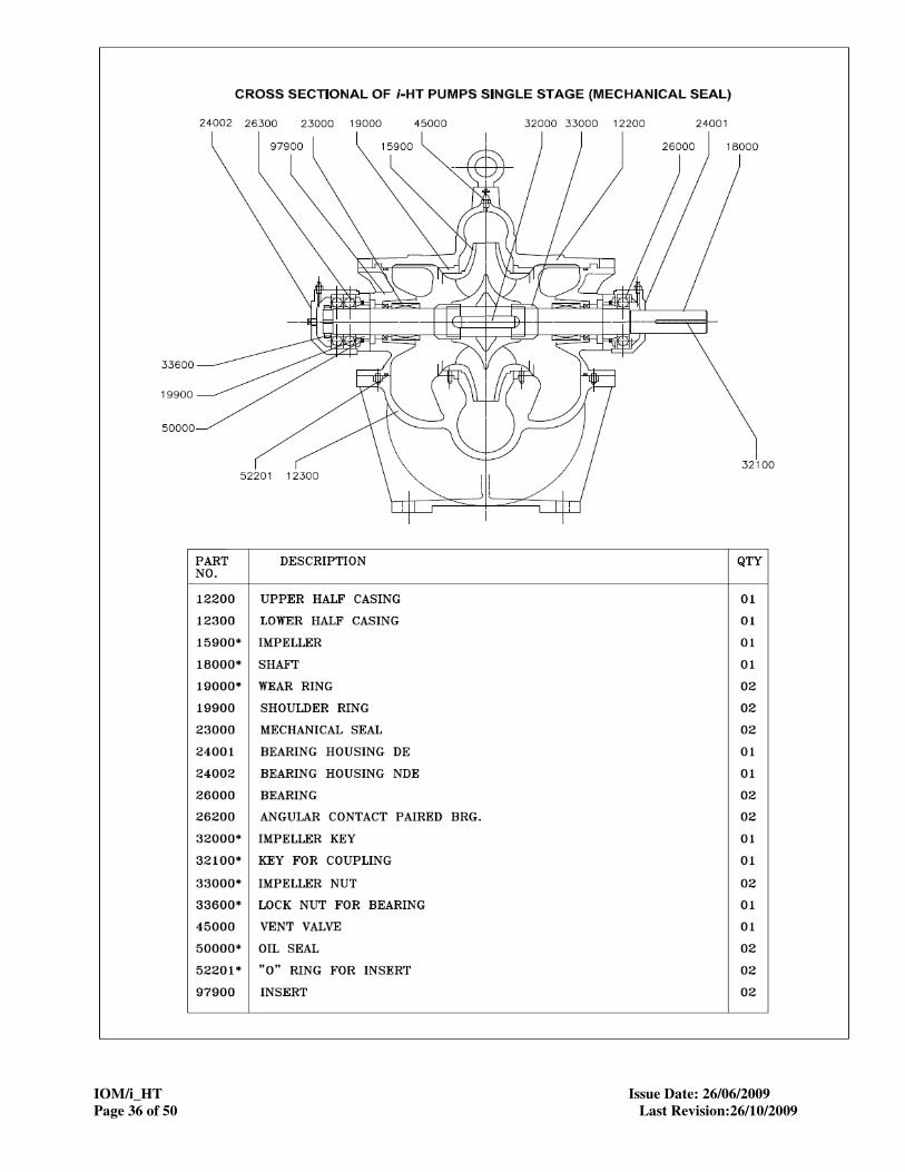
8.0 SPARE PART LIST AND CROSS SECTIONAL DRAWINGS
* marked part code nos. are recommended spares.
Part code no. Part description
12200
12300
15900*
19000*
19900
24001
24002
26000*
27000
27101
27102
32000*
32100
33600
41500
44101
45000
47101
47102
50000
51900
52200*
52202*
57100
57101
57102
58001
58002
59001
59002
60500
60600
61000
61100
64000
67000
69100
84901
84902
84903
60000
60100
CASING HALF UPPER
CASING HALF LOWER
IMPELLER
WEARING RING
SHOULDER RING
BEARINF HOUSING DE
BEARING HOUSING NDE
BALL BEARING
BEARING COVER DE
BEARING COVER NDE
BEARING COVER DE & NDE
KEY (IMPELLER)
KEY (COUPLING)
LOCK NUT (BEARING)
LOCK WASHER (BEARING)
GREASE NIPPLE
VENT VALVE
PROTECTION COVER (SUC)
PROTECTION COVER (DEL)
OIL SEAL
GASKET (CASING)
O RING (INSERT)
ORING (SLEEVE)
SCREW (BRG.HOUSING)
SCREW (BRG. HSG & CASING)
SCREW (BRG. HSG & INSERT)
NUT (CASING)
NUT (INSERT)
STUD (CASING)
STUD (INSERT)
PIPE PLUG (BEARING HOUSING NDE)
PIPE PLUG (PRIMING)
LOCKING PIN (CASING RING)
LOCATING PIN (CASING)
RIVET (NAME PLATE)
DUTY NAME PLATE
NUT (LOCATING PIN)
WASHER (LOCATING PIN)
WASHER (INSERT)
WASHER (BEARING HOUSING)
GAUGE PLUG
DRAIN PLUG
IOM/i_HT Issue Date: 26/06/2009
Page 36 of 50 Last Revision:26/10/2009

IOM/i_HT Issue Date: 26/06/2009
Page 37 of 50 Last Revision:26/10/2009

IOM/i_HT Issue Date: 26/06/2009
Page 38 of 50 Last Revision:26/10/2009

IOM/i_HT Issue Date: 26/06/2009
Page 39 of 50 Last Revision:26/10/2009
9. GENERAL OUTLINE DIMENSIONS

IOM/i_HT Issue Date: 26/06/2009
Page 40 of 50 Last Revision:26/10/2009

IOM/i_HT Issue Date: 26/06/2009
Page 41 of 50 Last Revision:26/10/2009

IOM/i_HT Issue Date: 26/06/2009
Page 42 of 50 Last Revision:26/10/2009

IOM/i_HT Issue Date: 26/06/2009
Page 43 of 50 Last Revision:26/10/2009

IOM/i_HT Issue Date: 26/06/2009
Page 44 of 50 Last Revision:26/10/2009

IOM/i_HT Issue Date: 26/06/2009
Page 45 of 50 Last Revision:26/10/2009

IOM/i_HT Issue Date: 26/06/2009
Page 46 of 50 Last Revision:26/10/2009

IOM/i_HT Issue Date: 26/06/2009
Page 47 of 50 Last Revision:26/10/2009

IOM/i_HT Issue Date: 26/06/2009
Page 48 of 50 Last Revision:26/10/2009
GENERAL INFORMATION & SAFETY INSTRUCTIONS
1. The products supplied by KBL have been designed with safety in mind. Where hazards cannot be
eliminated, the risk has been minimized by the use of guards and other design features. Some hazards
cannot be guarded against and the instructions below MUST BE COMPLIED WITH for safe operation. These
instructions cannot cover all circumstances. Installation, operation and maintenance personnel must use
safe working practices at all the times.
1.1 KBL products are designed for installation in designated areas, which are to be kept clean and free of
obstructions that may restrict safe access to the controls and maintenance access points.
A pump duty nameplate is fitted to each unit and must not be removed. Loss of this plate could make
identification impossible. This in turn could affect safety and cause difficulty in obtaining spare parts. If
accidental loss or damage occur, contact KBL immediately.
1.2 Access to the equipment should be restricted to the person net responsible for installation, operation
and maintenance and they must be trained, adequately qualified and supplied with appropriate tools for
their respective tasks.
1.3 Most accidents involving product operation, maintenance and repair are caused by failure to observe
safety rules or precautions. An accident can often be avoided by recognizing potentially situations
before an accident occurs. A person must be aware of potential hazard associated in activities of
installation, operation and maintenance of equipments.
1.4 KBL requires that, all personnel that are responsible for installation, operation or maintenance of the
equipment, have access to and study the product instruction manual BEFORE any work is done and
that they will comply with all local and industry based safety instructions and regulations.
1.5 Ear defenders should be worn where the specified equipment noise level exceeds locally defined safe
levels. Safety glasses or goggles or face shield should be worn where working with pressurized
systems and hazardous substances. Other personal protection equipment must be worn where local
rules apply. Wear safety shoes, helmets and cotton overall [Apron] when you enter pump house. Noise
level should not exceed 90 dbA and 110 dbA for motor driven and engine driven pumps, respectively.
1.6 Do not wear loose clothing or jewelry, which could catch on the controls or become trapped in the
equipment.
1.7 Read the instruction manual before installation, operation or maintenance of the equipment. Check and
confirm that you are referring relevant copy of the manual by comparing pump type on the nameplate
and with that on the manual.
1.8 Note the “Limits of product application permissible use” specified in the manual. Operation of the
equipment beyond these limits will increase the rist from hazards noted below and may lead to
premature and hazardous pump failure.
1.9 Clear and easy access to all controls, gauges and dials etc must be maintained at all times. Hazardous
or flammable materials must not be stored in pump rooms unless safe areas or racking and suitable
container have been provided.
1.10 Use suitable earthing and tripping devices for electrical equipments.
2. IMPROPER INSTALLATION, OPERATION, MAINTENANCE,
LUBRICATION, REPAIR OF THIS KBL PRODUCT COULD
RESULT IN INJURY OR DEATH.
If any tool, procedure, work method and operation technique is not recommended by KIRLOSKAR
BROTHERS LIMITED is used or followed, it should be ensured that it is a safe for personnel around and
others. It should also be ensured that the product will not be damaged or made unsafe by the operation,
lubrication and maintenance or repair procedures you choose.
3. SAFETY INSTRUCTIONS WHILE HANDLING AND STORAGE
When lifting the pump, use the lifting points specified on general arrangement drawing, if provided. Use
lifting equipment having a safe working load rating suitable for the weight specified. Use suitable slings for
lifting pump, which is not provided, with lifting points. The use of forklift truck and chain crane sling

IOM/i_HT Issue Date: 26/06/2009
Page 49 of 50 Last Revision:26/10/2009
equipment is recommended but locally approved equipment of suitable rating may be used. While lifting,
the equipment adjusts the center of gravity, so that it is balanced properly.
Do not place fingers or hands etc into the suction or discharge pipe outlets and do not touch the impeller, if
rotated this may cause severe injury. To prevent ingress of any objects, retain the protection covers or
packaging in place until removal is necessary for installation. If the packaging or suction and discharge
covers are removed for inspection purposes, replace afterwards to protect the pump and maintain safety.
4. SAFETY INSTRUCTIONS WHILE ASSEMBLY & INSTALLATION
Shaft alignment must be checked again after the final positioning of the pump unit and connection to
pipework as this may have disturbed the pump or motor mounting positions. If hot liquids [above 80°C] are
being pumped, alignment should be checked and reset with the pump and motor at their normal operating
temperature. If this is not possible, KBL can supply estimated initial offset figures to suit extreme operating
temperatures. Failure to support suction and delivery pipework may result in distortion of the pump casing,
with the possibility of early pump failure.
5. SAFETY INSTRUCTIONS WHILE COMMISSIONING & OPERATION
Never attempt adjustments while the pump is running, unless otherwise specified in the operation,
maintenance manual.
Do not touch any moving or rotating parts. Guards are provided to prevent access to these parts, where
they have been removed for maintenance they must be replaced before operating the equipment.
Check that pump is primed. Pump should never be run dry as the pumped liquid acts as lubricant for the
close running fits surrounding impeller and damage will be incurred.
Failure to supply the stuffing box or mechanical seal with cooling of flush water may result in damage and
premature failure of the pump.
Do not touch surfaces, which during normal running will be sufficiently hot to cause injury. Note that these
surfaces remain hot after the pump has stopped, allow sufficient time for cooling before maintenance. Be
cautious and note that other parts of the pump may become hot if a fault is developing.
Do not operate water pumps in temperatures below freezing point, without first checking that the pumped
fluid is not frozen and the pump is free to turn. Pumps in these environments should be drained down
during inactivity and re-primed before starting.
In addition to local or site regulations for noise protection, KBL recommend the use of personal ear
protection equipment in all enclosed pump rooms and particularly those containing diesel engines. Care
must be taken to ensure that any audible alarm or warning signal can be heard with car defenders worn.
Be aware of the hazards relating to the pump fluid, especially the danger from inhalation of noxious and
toxic gases, skin and eye contact or penetration. Obtain and understand the hazardous substance data
sheets relating to the pumped fluid and note the recommended emergency and first aid procedures.
6. SAFETY INSTRUCTIONS WHILE MAINTENANCE & SERVICING
Do not attempt repairs of the pump or its accessories which you do not know. Use proper tools.
Before attempting any maintenance on a pump particularly if it has been handling any form of hazardous
liquid, it should be ensured that the unit is safe to work on. The pump must be flushed thoroughly with
suitable cleaner to purge away any of the product left in the pump components.
This should be carried out by the plant operator and a certificate of cleanliness obtained before starting
work. To avoid any risk to health it is also advisable to wear protective clothing as recommended by the
site safety officer especially when removing old packing, which may be contaminated.

IOM/i_HT Issue Date: 26/06/2009
Page 50 of 50 Last Revision:26/10/2009
Isolate the equipment before any maintenance work is done. Switch off the main supply, remove fuses,
apply lockouts where applicable and affix suitable isolation warning signs to prevent inadvertent
reconnection. In order to avoid the possibility of maintenance personnel inhaling dangerous fumes or
vapours locations by removal of bearing housing and shaft assembly to a suitable maintenance area.
Check and ensure that the pump operates at below the maximum working pressure specified in the manual
or on the pump namepate and before maintenance, ensure that the pump is drained down.
Wear a suitable mask or respirator when working with packing and gasket contain fibrous material, as
these can be hazardous when the fibrous dust is inhaled. Be cautious, if other supplier’s components have
been substituted for genuine KBL parts, these may then contain hazardous materials.
Store all oily rags or other flammable material in a protective container in a safe place. Do not weld or
flame cut on pipes/tubes that contents flammable fluids. Clean them thoroughly with nonflammable solvent
before welding or flame cutting on them. Use solvent/chemical resistant gloves for hand protection.
Dispose of all wastes like gaskets, gland packing, oil, batteries, packing material etc in accordance with
local regulation.
Adequacy of suitable crane should be checked before lifting the pump/pump components. Also condition of
pulleys, chain and lifting shackles should be checked before use.