type dsm (standard) - Kirloskar Brothers Limited
101
INSTRUCTIONS ON INSTALLATION OPERATION AND MAINTENANCE FOR KIRLOSKAR PUMP TYPE DSM (STANDARD) KIRLOSKAR BROTHERS LIMITED UDYOG BHAVAN, TILAK ROAD, PUNE - 411 002
-
Upload
khangminh22 -
Category
Documents
-
view
4 -
download
0
Transcript of type dsm (standard) - Kirloskar Brothers Limited

INSTRUCTIONS ON INSTALLATIONOPERATION ANDMAINTENANCE FORKIRLOSKAR PUMPTYPE DSM (STANDARD)
KIRLOSKAR BROTHERS LIMITEDUDYOG BHAVAN, TILAK ROAD, PUNE - 411 002

IOM/DB/005/01 Issue Date: 25/09/2000 Page: 1/12 Last revision date:
KIRLOSKAR BROTHERS LIMITED Udyog Bhavan, Tilak Road, Pune 411 002 (India)
WARRANTY
We warrant that the pump supplied by us is free from defective material and faulty workmanship. This warranty holds good for a period of 12 months from the date of commissioning of the equipment or 18 months from the date of despatch from our factory, whichever is earlier. Our liability in respect of any complaint is limited to replacing part/parts free of charge ex-works or repairs of the defective part/parts only to the extent that such replacement / repairs are attributable to or arise solely from faulty workmanship or defective material. The warranty holds good only for the products manufactured by us.
KIRLOSKAR BROTHERS LIMITED

- 2 -
CONTENTS 1. GENERAL 2. INSTALLATION 3. OPERATION 4. TECHNICAL DATA
5. MAINTENANCE 6. OVERHAULING 7. SPARE PARTS LIST AND CROSS-SECTIONAL DRAWINGS PLEASE FURNISH COMPLETE NAMEPLATE DETAILS, NAME OF THE PARTS, PART
NOS. AND MATERIAL OF CONSTRUCTION WHILE ORDERING SPARE PARTS FOR THE PUMPS.

- 3 -
1. GENERAL:
1.1 The booklet covers instructions for following models of DSM pumps. Type of pump: DSM-1E DSM-2E 65-DSM, 315M DSM-3 DSM-3ME DSM-4RM, RSM-4RN, DSM-4RR DSM-5B DSM6-15°, DSM6-30° DSM-150-45
1.2 These are Horizontal split Casing type, two stage pumps. This
construction enables to remove the rotating unit without disturbing pipe connections and alignment.
1.3 Pumps when properly installed and given due attention in operation and
maintenance should operate satisfactorily for a long period. 1.4 When the pump is received, sometime before the actual use of pump, it
should be inspected and stored in dry place. The coupling should be rotated once in a month to prevent pitting of bearing surfaces.
2 INSTALLATION :
For location, preparing foundation, installation, alignment, general maintenance, trouble shooting etc., the instructions given in our publication “General Instructions for Installation, Operation & Maintenance of Kirloskar Centrifugal Pumps.” which is also printed alongwith this booklet must be followed carefully.
2.1 The sealing connection piping to the pump stuffing box must be made
after installing and before commissioning the pump. This piping is supplied only for 65DSM 315M, DSM-4RM, DSM-4RN, DSM-4RR, DSM-5B, DSM-6 and DSM 150-45 pumps. For other pumps, sealing connection is integral.
2.2 Put gland packing and lantern ring, if it is sent separately along with the
pump. For DSM-3, 65 DSM 315M also DSM 1E, DSM 2E, DSM 3ME and DSM-4RM, DSM-4RN, DSM-4RR pumps, stuffing boxes are packed with packing before despatch. For balance pumps gland packings and lantern rings are sent separately along with the pumps.
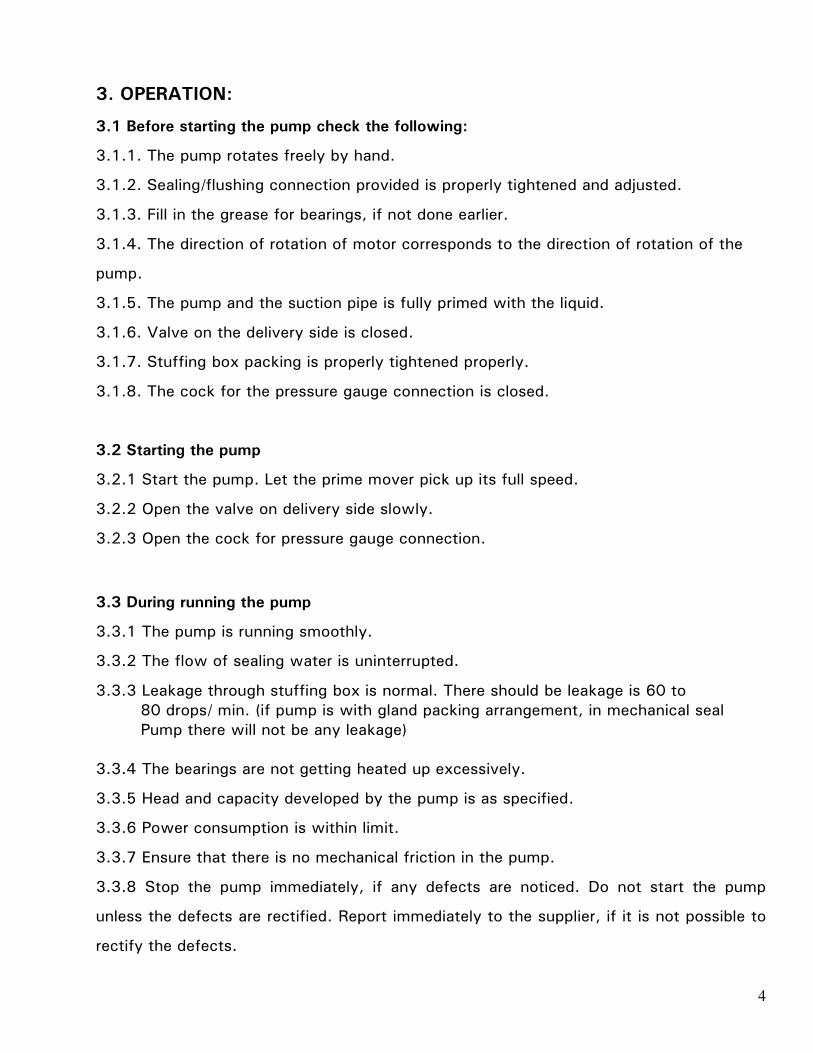
3. OPERATION:
3.1 Before starting the pump. Check the following:
3.1.1. The pump rotates freely by hand. 3.1.2. Sealing connection provided is properly tightened and adjusted.
3.1.3. Fill in the grease for bearings, if not done earlier. 3.1.4. The direction of rotation of motor corresponds to the direction of rotation
of the pump. 3.1.5. The pump and the suction pipe is fully primed with the liquid.

- 4 -
3.1.6. Valve on the delivery side is closed. 3.1.7. Stuffing box packing is properly tightened. 3.1.8. The cock for the pressure gauge connection is closed. 3.2 Starting the pump 3.2.1 Start the pump. Let the prime mover pick up its full speed. 3.2.2 Open the valve on delivery side slowly. 3.2.3 Open the cock for pressure gauge connection. 3.3 During running the pump 3.3.1 The pump is running smooth. 3.3.2 The flow of sealing liquid water is uninterrupted. 3.3.3 Leakage through stuffing box is normal. There should be leakage is 60 to
80 drops/ min. 3.3.4 The bearings are not getting heated up excessively. 3.3.5 Head and capacity developed by the pump is as specified. 3.3.6 Power consumption is within the limit. 3.3.7 Ensure that there is no mechanical friction in the pump. 3.3.8 Stop the pump immediately, if any defects are noticed. Do not start the
pump unless the defects are rectified. Report immediately to the supplier if it is not possible to rectify the defects.
3.4 During stopping the pump: 3.4.1 Close the valve on delivery side. 3.4.2 Stop the motor. 3.4.3 If the pump is not required to be operated for a long time, then drain the
casing completely. 4. TECHNICAL DATA:
4.1 Direction of rotation
The standard direction of rotation is anticlockwise when viewed from driving end. The pump suitable for clockwise rotation can also be supplied against specific requirements.
4.2 Rotational speed
Normally the pumps are supplied suitable for speed of 1450 rpm. Please contact supplier if the pump is to be used for higher speeds.
4.3 Bearings
The shaft is supplied with antifriction ball bearings at driving end and non- driving end. The details of the bearings are given in the technical data chart. The designations of bearings are as per SKF catalogue. However, equivalent bearings in type, capacity and dimensions are also used.

- 5 -
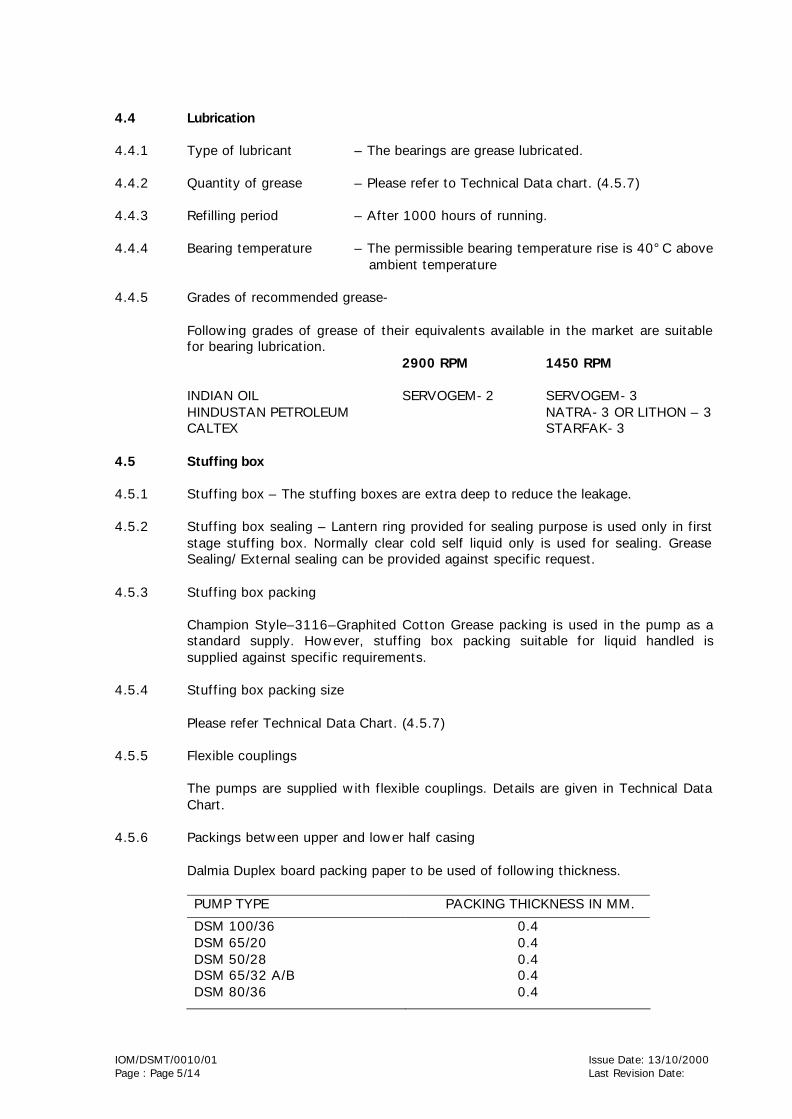
4.4 Lubrication
4.4.1 Type of lubricant – The bearings are grease lubricated. 4.4.2 Quantity of grease – Please refer to Technical Data chart.
4.4.3 Refilling period – After 1000 hours of running.
4.4.4 Bearing temperature – The permissible bearing temperature rise is 40°C
above ambient temperature.
4.4.5 Grades of recommended grease Following grades of grease of their equivalents available in the market are suitable for bearing lubrication. INDIAN OIL - SERVOGEM - 3 CALTEX - STARFAK - 3 HINDUSTAN PETROLEUM NATRA- 3 OR LITHON - 3
4.5 Stuffing box
4.5.1 Stuffing box – The stuffing boxes are extra deep to reduce the leakage. 4.5.2 Stuffing box sealing – Lantern ring provided for sealing purpose is used
only in first stage stuffing box. Normally clear cold self liquid only is used for sealing. Grease Sealing/ External sealing can be provided against specific request.
4.5.3 Stuffing box packing
Champion Style–3316–Graphited Cotton Grease packing is used in the pump as a standard supply. However, stuffing box packing suitable for liquid handled is supplied against specific requirements. For DSM-3, 65 DSM-315 M, DSM 1E, DSM 2E, DSM 3ME, DSM-4RM, DSM-4RN, DSM-4RR pumps the stuffing box packing is sent duly packed in the pump. For other pumps the packing and lantern ring are sent separately alongwith the pump.
4.5.4 Stuffing box packing size – Please refer Technical Data Chart. 4.5.5 Flexible couplings – The pumps are supplied with LOVE-JOY type & pin
bush type flexible couplings. Details (of rubber bushes) are given in Technical Data Chart.
4.5.6 Packing between upper and lower half casing- Dalmia Duplex board packing paper to be used of following thickness. Pump Type Packing thickness
in mm DSM-1 DSM-1E DSM-2 DSM-2E DSM-3 DSM-3M DSM-3ME 65 DSM-315M DSM-4RM, DSM-4RN, DSM-4RR DSM-5 DSM-5B DSM6-15°, DSM6-30° DSM 150-45
0.8 mm

- 6 -
4.5.7 TECHNICAL DATA CHART
Ball bearing No. SKF or equiv.
St. box packing Size in mm
No. of Packing Rings
Pump type
Flange Size In mm Del. X Suc.
Driving end
Non driving End
Qty. of Grease Per Brg. Gms.
Size x length
Position of Lantern ring (L) from Impeller side (NDE side)
DE NDE
Coupling Type
DSM-1E DSM-2E 65 DSM 315M DSM-3 DSM-3ME DSM-4RM DSM-4RN DSM-4RR DSM-5B DSM-6, DSM6-15 DSM6-30° DSM150-45
50 X 65 65 X 80 65 X 80 80 X 100
” 100 X 125 100 X 125 100 X 125 125 X 150 150 X 200 150 X 175
6305
6306
6306
6307
”
6309
”
”
21309cc
6315
N310
6305
6306
6306
6307
”
3309
”
”
”
6413
2 x 7310 BG
100
100
100
100
”
150
150
150
150
150
150
6 Sq. x 1525 10 Sq. x 2135 10 Sq. x 2300 10 Sq. x 1650 ” ” 12 Sq. x 2290 ” ” ” ” 12 Sq. x 3180 16 Sq. x 6250 12 Sq. x 2820
3+L+2
4+L+2
3+L+2 5
”
2+L+3
”
”
3+L+3
4+L+4
2+L+3
7 7 7 5 ” 7 ” ”
10 6
5 6 5 5
” 5
”
” 8 5
Love-Joy Type – SW -110 Love-Joy Type – SW -110 Love-Joy Type – SW -190 Love-Joy Type – CW-226
” Pin Bush Type – CW-226
”
” Love-Joy Type – CW -276 Pin Bush Type – 360φ Pin Bush Type – 310φ
- 7 -
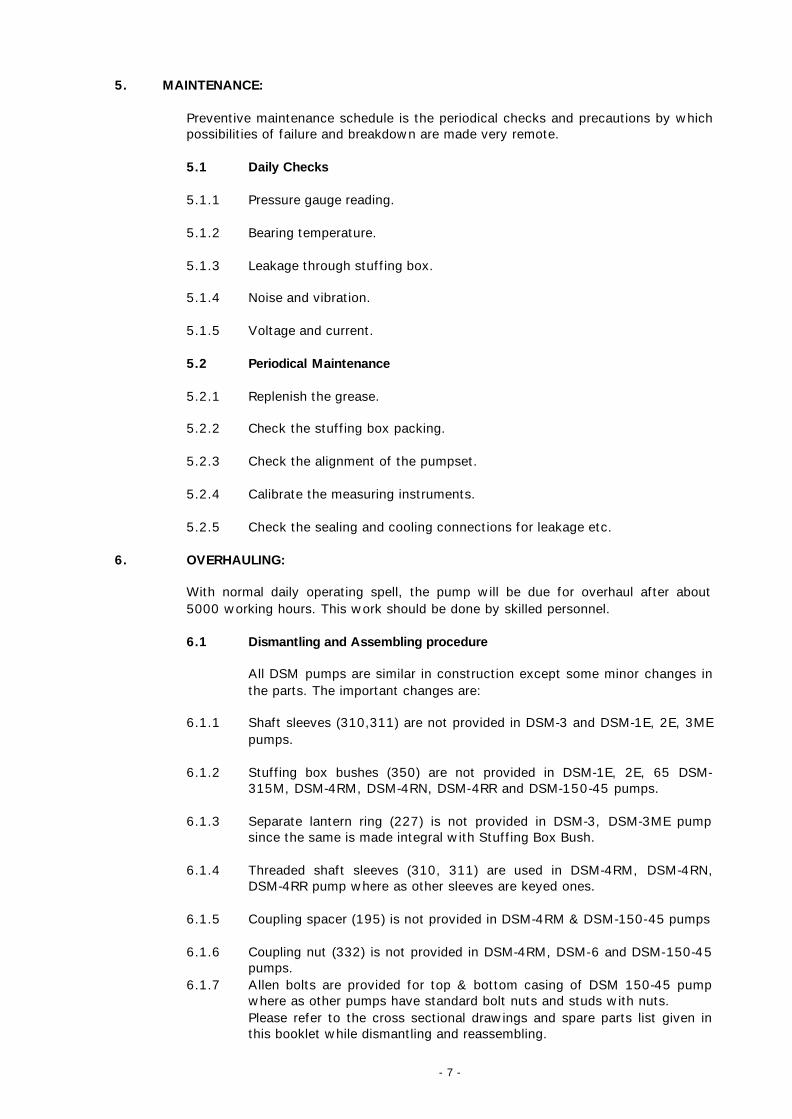
5. MAINTENANCE: Preventive maintenance schedule is the periodical checks and precautions by which possibilities of failure and breakdown are made very remote.
5.1 Daily Checks 5.1.1 Pressure gauge reading. 5.1.2 Bearing temperature. 5.1.3 Leakage through stuffing box. 5.1.4 Noise and vibration. 5.1.5 Voltage and current.
5.2 Periodical Maintenance 5.2.1 Replenish the grease. 5.2.2 Check the stuffing box packing. 5.2.3 Check the alignment of the pumpset. 5.2.4 Calibrate the measuring instruments. 5.2.5 Check the sealing and cooling connections for leakage etc.
6. OVERHAULING: With normal daily operating spell, the pump will be due for overhaul after about
5000 working hours. This work should be done by skilled personnel.
6.1 Dismantling and Assembling procedure All DSM pumps are similar in construction except some minor changes in the parts. The important changes are:
6.1.1 Shaft sleeves (310,311) are not provided in DSM-3 and DSM-1E, 2E, 3ME
pumps.
6.1.2 Stuffing box bushes (350) are not provided in DSM-1E, 2E, 65 DSM-315M, DSM-4RM, DSM-4RN, DSM-4RR and DSM-150-45 pumps.
6.1.3 Separate lantern ring (227) is not provided in DSM-3, DSM-3ME pump
since the same is made integral with Stuffing Box Bush.
6.1.4 Threaded shaft sleeves (310, 311) are used in DSM-4RM, DSM-4RN, DSM-4RR pump where as other sleeves are keyed ones.
6.1.5 Coupling spacer (195) is not provided in DSM-4RM & DSM-150-45 pumps
6.1.6 Coupling nut (332) is not provided in DSM-4RM, DSM-6 and DSM-150-45
pumps. 6.1.7 Allen bolts are provided for top & bottom casing of DSM 150-45 pump
where as other pumps have standard bolt nuts and studs with nuts. Please refer to the cross sectional drawings and spare parts list given in this booklet while dismantling and reassembling.

- 8 -
6.2 Dismantling 6.2.1 Uncouple the pump from the prime mover by removing coupling bolts,
nuts and rubber bushes. 6.2.2 Remove –
- Sealing Connections - Priming funnel, air vent - Grease cup/ nipples and other fittings.
6.2.3 Remove all the bolts and nuts (572, 581) holding the upper half casing &
lower half casing. Take out upper half casing (122) slowly by tightening the release bolts and after removing taper pins.
Upper half casing should be removed slowly so that impellers and other parts are not damaged. By removing upper half casing, the complete rotating unit is exposed for inspection and repairs.
6.2.4 Loosen the bolts and nuts (573) holding the bearing cap to the lower half
casing (122). Remove the bearing caps. 6.2.5 Lift the rotating unit slowly after slinging it in correct fashion so that none
of the parts are damaged. Keep the rotating unit in clean dry place for further dismantling.
6.2.6 Now start dismantling from driving end side. Loosen the coupling nut
(332) if provided.
6.2.7 Take out flexible coupling, pump half (390) with help of a puller. Remove the coupling key (321).
6.2.8 Take out coupling spacer (195) if provided.
6.2.9 Loosen the bolts (631) holding bearing cover (270) to the bearing
cartridge (241).
6.2.10 Remove the bearing cartridge driving end (241) pull out the bearing driving end (260.1) with the help of puller.
6.2.11 Remove bearing cover (270) and water deflector (236).
6.2.12 Take out gland (223). Remove the st. box packing.
6.2.13 Remove the st. box bush (350) if provided. Also take out casing ring
(190).
6.2.14 Take out the shaft sleeve DE (317.1) (only for 65 DSM-315 M, DSM-5, DSM-6 and DSM 150-45 pumps). Remove the ‘O’ ring (522).
6.2.15 Remove the shaft sleeve under st. box (310).
6.3 Start dismantling from non-driving end 6.3.1 Remove the bearing cartridge (253) NDE.
6.3.2 Loosen the bearing lock nut (336) bearing nut (335).
6.3.3 Remove bolts (631) for bearing cover (271) and take out the ver.

- 9 -
6.3.4 Remove the casing ring NDE (191). Water deflector (236), Glands (229) and lantern ring (227).
6.3.5 Take out open shaft sleeve (317.2) and ‘O’ ring in case of 65 DSM 315M,
DSM-5, DSM-6 & DSM 150-45 unscrew or remove the shaft sleeve NDE side (311).
6.3.6 Take out impellers (157) and (158). Before removing the impellers put the
mark of first stage and second stage impellers so that while re-assembling the impellers may not be interchanged.
6.3.7 Remove the impeller key (320). Take out the interstage rin (204). In case
of (DSM-5B, DSM-6 & DSM 150-45, remove interstage diaphragm (462) alongwith interstage bush).
6.4 Reassembling
Before reassembling, all parts are to be cleaned including upper half & lower half casings. Bearings are to be cleaned with Kerosene. Change packing and ‘O’ rings, if any.
6.4.1 Put the impeller key (320) in the keyways provided on the shaft. Fix the
impellers on the shaft with interstage ring (204/462) in between them. First stage impeller should come towards non-driving end.
6.4.2 Put the shaft sleeves (310, 311) and (317.1 & 317.2) with ‘O’ rings for
65 DSM-315M, DSM-5B, DSM-6 and DSM 150-45.
6.4.3 Start the reassembly for non-driving end. Insert the casing ring, NDE (191).
Insert the gland NDE (223) if non-split type (in case of DSM-4RM).
Put the water deflector, NDE (236).
Insert the bearing cover, NDE (271).
Press the NDE bearing on the shaft.
Tighten the bearing nuts. Put appropriate quantity of grease to the
bearings.
Fix the cartridge NDE (Except DSM 150-45). The bearing should touch the shoulder provided on the cartridge.
Fix the bearing cover to the cartridge by tightening the screws (631).
6.4.4 Now start assembling from driving end.
Insert the casing ring DE (190). Insert the gland DE (223) if non-split type (DSM-4RM)
Fit the water deflector (236).
Insert the bearing cover (270).
Press fit the DE bearing on the shaft.

- 10 -
Fix the bearing cartridge DE (241). The outer face of the bearing
should touch the shoulder provided in the cartridge.
Fix the bearing cover DE to the cartridge by tightening the bolts (631).
Insert coupling spacer in case of DSM-3, DSM-1E, 2E, 3ME, 65 DSM-315-M, DSM-5B and DSM-6.
Fit coupling key (321) on the shaft.
Fix pump coupling half (390) on the shaft and tighten the same by
coupling nut (332) in case of DSM-3, DSM-1E, 2E, 3ME, 65 DSM-315-M, DSM-5 and DSM-6 pumps.
In case of DSM 150-45 pump, bearing cartridges are put on the shaft prior to mounting of bearings. This completes the assembly of rotating unit.
6.4.5 Now lift the above rotating unit and fit it properly in the lower half casing
so that pins (611, 610.1) take their proper seating. 6.4.6 Fit the two bearing caps by means of bolts. Rotate the whole unit and see
that there is no friction between rotating and stationery parts.
6.4.7 Cut the paper packing to match the profile at the upper and lower half casing. Put the paper packing (dipped in linseed oil) on the lower half casing. Keep the upper half casing gently and neatly without disturbing the impellers or packing etc. Insert the taper pins so that the two halves of the casings will take their proper seat.
6.4.8 Now insert the bolts and nuts for upper half and lower half casing and
tighten them. While tightening the nuts, take care to tighten the diagonally opposite bolts. Rotate the impeller by rotating coupling and see that there is no friction between the rotating unit and stationery parts.
6.4.9 Insert the eye bolts in their positions and fix them by tightening the bolts
(593, 581). Insert the stuffing box packing staggering the joints in 180 and push each ring inside as far as possible.
6.4.10 Insert the lantern ring at non-driving end side at a position indictaed in
technical data (e.g. 2+L+3).
6.4.11 Fix gland (split type) (223) on the shaft. Tighten the stuffing box packing by tightening the gland nuts (300).
While tightening the glands, please see that the unit can be rotated by hand.
6.4.12 Connect the copper pipes for sealing connection (562). Fix air vents, priming funnel and grease cups. Fix the nameplate (670) on NDE cartridge.
This completes the re-assembly.
While ordering spares, specify nameplate details, particularly machine numbers given in enclosed spare parts list. Also specify quantity required.

- 11 -
7. SPARE PART LIST
Old Part Nos.
New Part Nos.
Description pieces reqd. per
No. of pump
1D
1E
2D*
2E*
3A*
4A*
4E*
8A
8B
9A*
9B*
10A1
10B1
10E
12A*
12B*
12C/
12D
13A*
13B*
14B*
17B*
18A
19A
19B
20A*
24A* &
24B*
25
34A
34B
122
123
157*
158*
180*
190*
204*
241
253
260.1*
260.2*
270
271
274
310*
311*
317.1/
317.2
223*
229*
227*
350*
195
390
391
400*
236*
450
320
321
Casing half upper
Casing half lower
Impeller, 1st stage
Impeller, 2nd stage
Pump shaft direct drive
Wear ring
Interstage ring
Cartridge for bearing, DE
Cartridge for bearing, NDE
Ball bearing, DE
Ball bearing, NDE
Bearing cover, DE
Bearing cover, NDE
Bearing COP
Shaft sleeve, DE
Shaft sleeve, non-driving end
Shaft sleeve open DE/NDE
For DSM-5B & DSM-6 only
Gland (Non-split) for DSM-1E & DSM-2E
Split gland, DE/NDE
Lantern ring (except DSM-3, DSM-3ME)
St. box bush for DSM-3, DSM-3ME, DSM-
5B and DSM-6 only
Coupling spacer (except DSM-4M)
Flexible coupling (pump half)
Flexible coupling (motor half)
Rubber bushes
Water deflector, DE/NDE
Air vent
Impeller key
Coupling key
1
1
1
1
2
1
1
1
1
1
1
1
1
2
1
1
2
2
2
2
2
2
1
1
1
N
1
2
2
1

- 12 -
Old Part Nos.
New Part Nos.
Description pieces reqd. per
No. of pump
35B
35F
37G
37H
37S
37K
38AP
41A
41B
41D
41E
41K
42A
42H
42P
43A*
44C
45A*
47C
47P1
51A
54C1
54C2
62B
67A
332
335
586
572
581
582
574
631
611
610.1**
610.2**
610
610.3
601
600
602
604
430*
519
522*
410
622
441
559.1
559.2
560
670
224
228
263*
Coupling nut (except DSM-4RM & 6 &
DSM-150-45)
Bearing nut
Bolts with nuts for 274
Bolts with nuts for upper and
Lower half casing
Eye bolts with nuts & washer for gland
Hex screw for 300
Hex screw for bearing cover
Taper pin with washes * & nuts for lower
and upper half casing
Pin for casing ring
Pin for st. box bush
Pin for cartridge
Pin for interstage diaphragm
Drain plug for casing
Plug for Suc. & Del. Pressure gauge
connections
Plug for sealing
Plug for st. box leakage water
St. box packing
Paper packing between 122 & 123
‘O’ ring for shaft sleeve only for DSM-4RM
DSM-5B & DSM-6
Lock washer for impeller nut
Washer for 332 only for DSM
Grease nipple for lubrication
Adapter for copper tube
Adapter for copper tube connection
Copper tube for sealing connection
with nuts
Duty name plate
Clamping plate
Collar for st. box only for DSM 150-45
Ball bearing, SKF 7310 BG or equiv.
1
1
4
-
4
4
8
2
2
2
2
1
2
2
1
2
1set
1
2
1
2
1
1
1
1
2
2
2

- 13 -
Old Part Nos.
New Part Nos.
Description pieces reqd. per
No. of pump
263*
264*
263*
261
336
404*
408*
409
462
515*
518*
530
534
540
550
557
558
Roller bearing, SKF N 310 or equiv.
Double row angular contact ball bearing
SKF 3309 or equivalent (For DSM-5B only)
Spherical roller bearing SKF 21309 cc
Brg. lock nut, DE/NDE
Coupling pin
Nut for coupling pin
Washer for coupling pin
Interstage diaphragm
Gasket for shaft sleeve & impeller
Gasket for adaptor piece
Pipe for sealing
Pipe for priming only for DSM-6 & DSM-
150-45
Socket for sealing connection only for
DSM-150-45
Wheel cock
Three way piece for sealing only for DSM-
150-45
Sealing nut
1
1
1
2
N
N
N
1
3
-
1
1
2
1
1
2
* Parts for two years normal working of the pumps. ** These parts should be included in the order, while ordering top and bottom
casing. N Quantity depends upon pump type.

- 14 -
CROSS SECTION ASSEMBLY OF DSM 1E (CCW) CROSS SECTION ASSEMBLY OF DSM 2E (CCW)

- 15 -
CROSS SECTION ASSEMBLY OF DSM 4 RM NOTE : ALSO FOR DSM 4 RN, DSM 4 RR (CCW) CROSS SECTION ASSEMBLY OF DSM 5 B (CCW) DSM 5 B (F). DSM 5 B (MODIFIED)

- 16 -

- 17 -
CROSS SECTIONAL ASSEMBLY OF DSM 3ME (CCW) NOTE ALSO FOR DSM 3/3 ME

GENERAL INFORMATION & SAFETY REQUIREMENTS
1.0 The products supplied by KBL have been designed with safety in mind. Where hazards cannot be eliminated, the risk has been minimised by the use of guards and other design features. Some hazards cannot be guarded against and the instructions below MUST BE COMPLIED WITH for safe operation. These instructions cannot cover all circumstances; YOU are responsible for using safe working practices at all times.
1.1 KBL products are designed for installation in designated area, which are to be kept clean
and free of obstructions that may restrict safe access to the controls and maintenance access points.
A Pump Duty Nameplate is fitted to each unit and must not be removed. Loss of this plate could make identification impossible. This in turn could affect safety and cause difficulty in obtaining spare parts. If accidental loss or damage occur, contact KBL immediately.
1.2 Access to the equipment should be restricted to the personnel responsible for
installation, operation and maintenance and they must be trained, adequately qualified and supplied with appropriate tools for their respective tasks.
1.3 KBL requires that, all personnel that are responsible for installation, operation or
maintenance of the equipment, have access to and study the product instruction manual BEFORE any work is done and that they will comply with all local and industry based safety instructions and regulations.
1.4 Ear defenders should be worn where the specified equipment noise level exceeds locally
defined safe levels. Safety glasses or goggles should be worn where working with pressurised systems and hazardous substances. Other personnel protection equipment must be worn where local rules apply.
1.5 Do not wear loose clothing or jewellery which could catch on the controls or become
trapped in the equipment. 1.6 Read the instruction manual before installation, operation and maintenance of the
equipment. Check and confirm that the manual is relevant copy by comparing pump type on the nameplate and with that on the manual.
1.7 Note the ‘Limits of product application – permissible use’ specified in the manual.
Operation of the equipment beyond these limits will increase the risk from hazards noted below and may lead to premature and hazardous pump failure.
1.8 Clear and easy access to all controls, gauges and dials etc. must be maintained at all
times. Hazardous or flammable materials must not be stored in pump rooms unless safe areas or racking and suitable containers have been provided.
1.9 IMPROPER INSTALLATION, OPERATION OR MAINTENANCE OF THIS KBL PRODUCT
COULD RESULT IN INJURY OR DEATH. 2.0 SAFETY INSTRUCTIONS WHILE HANDLING AND STORAGE When lifting the pump, use the lifting points specified on general arrangement drawing.
Use lifting equipment having a safe working load rating suitable for the weight specified. Use suitable slings for lifting pump which is not provided with lifting points. The use of fork-lift truck and chain crane sling equipment is recommended but locally approved equipment of suitable rating may be used.
-i-

Do not place fingers or hands etc. into the suction or discharge pipe outlets and do not touch the impeller, if rotated this may cause severe injury. To prevent ingress of any objects, retain the protection covers or packaging in place until removal is necessary for installation. If the packaging or suction and discharge covers are removed for inspection purposes, replace afterwards to protect the pump and maintain safety.
3.0 SAFETY INSTRUCTIONS WHILE ASSEMBLY & INSTALLATION
Do not place fingers or hands etc. into the suction or discharge pipe outlets and do not touch the impeller, if rotated this may cause severe injury. To prevent ingress of any objects, retain the protection covers or packaging in place until removal is necessary for installation. Do not touch any moving or rotating parts. Guards are provided to prevent access to these parts, where they have been removed for maintenance they must be replaced before operating the equipment. Shaft alignment must be checked again after the final positioning of the pump unit and connection to pipework as this may have disturbed the pump or motor mounting positions. If hot liquids (above 80°C) are being pumped, alignment should be checked and reset with the pump and motor at their normal operating temperature. If this is not possible, KBL can supply estimated initial offset figures to suit extreme operating temperatures. Failure to support suction and delivery pipework may result in distortion of the pump casing, with the possibility of early pump failure.
4.0 SAFETY INSTRUCTIONS WHILE COMMISSIONING & OPERATION.
Do not touch any moving or rotating parts. Guards are provided to prevent access to these parts, where they have been removed for maintenance they must be replaced before operating the equipment. Check that the pump is primed. Pump should never be run dry as the pumped liquid acts, as lubricant for the close running fits surrounding impeller and damage will be incurred. Failure to supply the stuffing box or mechanical seal with cooling of flush water may result in damage and premature failure of the pump. Do not touch surfaces which during normal running will be sufficiently hot to cause injury. Note that these surfaces will remain hot after the pump has stopped, allow sufficient time for cooling before maintenance. Be cautious and note that other parts of the pump may become hot if a fault is developing. Do not operate water pumps in temperatures below freezing point, without first checking that the pumped fluid is not frozen and the pump is free to turn. Pumps in these environments should be drained down during inactivity and re-primed before starting. In addition to local or site regulations for noise protection, KBL recommend the use of personal ear protection equipment in all enclosed pump rooms and particularly those containing diesel engines. Care must be taken to ensure that any audible alarm or warning signal can be heard with ear defenders worn. Be aware of the hazards relating to the pumped fluid, especially the danger from inhalation of noxious and toxic gases, skin and eye contact or penetration. Obtain and understand the hazardous substance data sheets relating to the pumped fluid and note the recommended emergency and first aid procedures.
-ii-

5.0 SAFETY INSTRUCTIONS WHILE MAINTENANCE & SERVICING
Before attempting any maintenance on a pump particularly if it has been handling any form of hazardous liquid, it should be ensured that the unit is safe to work on. The pump must be flushed thoroughly with suitable cleaner to purge away any of the product left in the pump components. This should be carried out by the plant operator and a certificate of cleanliness obtained before starting work. To avoid any risk to health it is also advisable to wear protective clothing as recommended by the site safety officer especially when removing old packing which may be contaminated. Check and ensure that the pump operates at below the maximum working pressure specified in the manual or on the pump nameplate and before maintenance, ensure that the pump is drained down. Wear a suitable mask or respirator when working with packing and gasket components which contain fibrous material, as these can be hazardous when the fibrous dust is inhaled. Be cautious, if other supplier’s components have been substituted for genuine KBL parts, these may then contain hazardous materials. Be aware of the hazards relating to the pumped fluid, especially the danger from inhalation of noxious and toxic gases, skin and eye contact or penetration. Obtain and understand the hazardous substance data sheets relating to the pumped fluid and note the recommended emergency and first aid procedures. Isolate the equipment before any maintenance work is done. Switch off the mains supply, remove fuses, apply lock-outs where applicable and affix suitable isolation warning signs to prevent inadvertent reconnection. In order to avoid the possibility of maintenance personnel inhaling dangerous fumes or vapours, it is recommended that the maintenance work be carried out away from the pump locations by removal of bearing housing and shaft assembly to a suitable to a suitable maintenance area.
_____________ Ref: Proposed draft standard prEN 800: Pumps and pump units for liquids;
General safety requirements
-iii-

INCORRECT CORRECT
DD
SPACE AROUNDFOOT VALVE
INSUFFICIENT
SHORT BEND
REDUCED SUCTION PIPE
D
D SUFFICIENT
FOOT VALVESPACE AROUND
LONG BEND
INCREASED SUCTION PIPE
CONCENTRIC TAPER PIECE
INCORRECT LAYOUT OF SUCTION PIPE
ECCENTRIC TAPER PIECE
CORRECT LAYOUT OF SUCTION PIPE
FOR RECOMMENDATIONS OF SUITABLE SUCTION AND DELIVERY PIPE SIZE PLEASE CONTACT OUR AUTHORISED DEALER OR NEAREST REGIONAL OFFICE
GENERAL INSTRUCTIONS FOR INSTALLATION OPERATION & MAINTENANCE OF
KIRLOSKAR CENTRIFUGAL PUMPS
® Registered users – Kirloskar Brothers Ltd.

GENERAL INSTRUCTIONS FOR INSTALLATION, OPERATION & MAINTENANCE OF KIRLOSKAR CENTRIFUGAL PUMPS WARNING The equipment supplied is designed for specific capacity, speed, pressure and temperature. Do not use the equipment beyond the capacities for which it is manufactured. The equipment manufactured is also shop tested for the satisfactory performance and if it is operated is excess of the conditions for which it is manufactured, the equipment will be subject to excessive stresses and strains. LOCATION The pump should be located as near the liquid source as possible. This will minimise the suction lift and pump will give better performance. Ample space should be provided on all sides so that the pump can be inspected while in operation and can be serviced conveniently whenever required. FOUNDATION The foundation should be sufficiently substantial to absorb any vibration and to form a permanent rigid support for the base plate. This is important in maintaining the alignment of a direct connected unit. A concrete foundation on a solid base is advisable. Foundation bolts of the proper size should be embedded in the concrete located by a drawing or template. A pipe sleeve about two and one-half diameter larger that the bolt should be used to allow movement for the final position of the foundation bolts. ALIGNMENT Pumps and drivers that are supplied by the manufacturers, mounted on a common base plate are accurately aligned before despatch. However as the alignments are likely to be disturbed during transit to some extent and therefore must not be relied upon to maintain the factory alignment. Re-alignment is necessary after the complete unit has been levelled on the foundation and again after the grout has been set and foundation bolts have been tightened. The alignment must be checked after the unit is piped up and re-checked periodically. FLEXIBLE COUPLING A flexible coupling will not compensate for misalignment of the pump and driver shafts. The purpose of the flexible coupling is to compensate for temperature changes and to permit the movement of the shafts without interference with each other while transmitting power from the driver to the pump. TYPE OF MISALIGNMENT (SEE FIGURE 1) There are two types of misalignment between the pump shaft and the driver shaft.
(a) Angular misalignment : Shafts with axis concentric but not parallel. (b) Parallel misalignment : Shafts with axis Parallel but not concentric.
LEVELLING THE UNIT When the unit is received with the pump and driver mounted on the base plate, it should be placed on the foundation and the coupling halves disconnected. The coupling should not be reconnected until all alignment operations have been completed. The base plate must be supported evenly on wedges inserted under the four corners so that it will not be distorted or sprung by the uneven distribution of the weight. Adjust the wedges until the shafts of the pump and driver are in level. Check the coupling faces, suction and discharge flanges for the horizontal or vertical position by means of spirit level. FLEXIBLE COUPLING ALIGNMENT (SEE FIGURE2) The two halves of the coupling should be at least 4 mm apart so that they cannot touch each other when the driver shaft is rotated. Necessary tools for approximately checking are straight-edge and on an outside caliper.
Figure 1
PARALLEL MISALIGNMENTANGULAR MISALIGNMENT

4 Line supplying the
2 Vacuum equalizing line1 Tank under Vacuum
4
5
6 Connecting line
seeling liquid5 Valve
7 Valve
3 Valve
7
6
3
2
1
A check for parallel alignment is made by placing a straight-edge across both coupling periphery at the top, bottom and both the sides. The unit will be in parallel alignment when the straight-edge rests evenly on the coupling periphery at all positions. Care must be taken to have the straight-edge parallel to the axis of the shafts. A check for angular alignment is made by using an outside caliper across the width of the coupling faces at various points. Coupling alignment can be checked with dial gauge indicator as shown in Fig. 2. GROUTING When the alignment is correct, the foundation bolts should be tightened evenly but not too firmly. The unit can then be grouted by working soft concrete under the edges. Foundation bolts should not be fully tightened until the grout is hardened, usually 48 hours after poring. FACTORS THAT MAY DISTURB ALIGNMENT The unit should be periodically checked for alignment. If the unit does not stay in line after being properly installed, the following are possible causes:
(a) Setting, seasoning of the foundation (b) Pipe strains distorting of shifting the machines (c) Wear of the bearings
PIPING Both suction and delivery pipes and accessories should be independently supported near the pump so that when the flanges bolts are tightened no strain will be transmitted to the pump casing. It is usually advisable to increase the size of both suction and delivery pipes at the pump nozzles in order to decrease the loss of head from friction and for the same reason piping should be arranged with as minimum bends as possible, as these should be made with along radius wherever possible. The pipe lines should be free from scales, welding residuals etc., and have to be mounted in such a way that they can be connected to suction and delivery flanges without any stress on the pump. Adequate supports should be given to pipe lines to that weight of the pipe lines does not fall on the pump. The use of minimum number of the bends and other fittings will minimise the frictional losses. SUCTION PIPE The suction pipe should be as short as possible. This can be achieved by placing the pump near the liquid to be pumped. The suction pipe must be kept free from air leaks. This is particularly important when the suction lift is high. A horizontal suction line must have a gradual rise to the pump. Any high point in the pipe will be filled with air and thus prevent proper operation of the pump. A concentric taper piece should not be used in a horizontal suction line as it forms an air pocket in the top of the reducer and the pipe. Use an eccentric piece instead. The end of the suction pipe must be well submerged to avoid whirlpools and ingress of air but must be kept clear of nay deposits of mud, silt, grit etc. The pipe must be clear from any side of wall by at least 450 mm. The end of the suction pipe should be provided with a strainer of sufficient open area. DELIVERY PIPE A check (non-return) valve and a gate of sluice valve (regulating valve) should be installed in the discharge line. The check valve placed between the pump and the gate valve is to protect the pump from excessive pressure and to prevent water running back through the pump in case of failure of the driving machine. Discharge piping should be provided with a sluice valve adjacent to the delivery flange to control the discharge, if required. VACUUM EQUALISING LINE (AND LIQUID LINE) (SEE FIGURE 3) If the pump draws from a system under vacuum an equalising pipe must be carried from the highest point of the suction line, however, as close to the suction flange of the pump as possible, to the top of the feed tank to keep gas bubbles that might have been entrapped in the flow from entering the pump. The line should be fitted with an isolating valve which should be closed only for maintenance work on the pumpset. Apply sealing liquid (external sealing) to the shaft seal cage to prevent entry of air in the case of pumps with packed stuffing box. It is convenient to tap the sealing liquid from the delivery line above the non-return valve.
STRAIGHT EDGE
Figure 2
MEASURINGWEDGE

FOOT VALVE It is advisable to install a foot valve to facilitate priming. The foot valve should have sufficient clear passage for water. Care must be taken to prevent foreign matter from being drawn into the pump or choking the foot valve and for this purpose an efficient strainer should be provided. STUFFING BOXES AND PACKING Stuffing boxes should be carefully cleaned and the packing placed in them. Be sure that sufficient packing is placed at the back of the water seal cage. If the water to be pumped is dirty or gritty, sealing water should be piped to the stuffing boxes from clean outside source of supply in order to prevent damage to the packing and shaft. In placing the packing, each packing ring should be cut to the proper length so that ends come together but do not overlap. The succeeding rings of packing should not be pressed too tight as it may result in burning the packing and cutting the shaft. If stuffing box is not properly packed, friction in stuffing box prevents turning the rotor by hand. On starting the pump it is well to have the packing slightly loose without causing an air leak, and if it seems to leak, instead of putting too much pressure on the gland, put some heavy oil in the stuffing box until the pump works properly and then gradually tighten up the gland. The packing should be occasionally changed. BALL BEARINGS Correct maintenance of ball bearings is essential. The bearing manufacturers give the following as a guide to relubrication periods under normal conditions. Three monthly when on continuous duty. Six monthly when on eight-hour per duty. The bearings and housings should be completely cleaned and recharged with fresh grease after 2500 hours or the nearest pump overhaul time. PRIMING No pumping action occurs unless the pump casing is filled with liquid. Pump casing and suction pipe must therefore be completely filled with the liquid and thus all air removed before the pump is started. Several different priming methods can be used depending on the kind of installation and service involved. (1) Liquid level above pump level Pump is set below liquid level of source of supply so that liquid always flows to pump under positive
head. (2) Priming with foot valve
(a) When pump is installed on suction lift with foot valve at the end of suction line, fill pump with water from some outside source till all air is expelled and water flows through air vent.
(b) When there is liquid under some pressure in the discharge pipe, priming can be effected by byepassing the pressure liquid around the check and gate valve. Of course, the initial priming must be effected from some outside source. NOTE: in this case, the foot valve must be capable of withstanding pump pressure and possible surge.
(3) Priming by ejector: An ejector operated by steam, compressed air or water under pressure and connected to air vent on top of casing can be used to remove air from and prime the pump on suction lift installations.
(4) Priming by dry vacuum pump : a hand or power pump sucks in all the air from the casing and the suction pipe, and thus primes the system.
STARTING The pump must not be started without being primed. Be sure that the driver rotates in the proper direction as indicated by a direction arrow on the pump casing. RUNNING On account of its simple construction, the centrifugal pump requires practically no attention while running. Lubrication of the bearings and manipulation of the glands are the only things that need attention from the operator. STOPPING Before stopping the pump, close the gate valve. This will prevent water hammer on check valve. STUFFING BOXES Do not tighten the glands excessively. A slight dripping of water from the stuffing boxes when pump is running keeps packing in good condition. CASING RINGS Casing rings are fitted in the casing to reduce the quantity of water leaking back from the high pressure side to the suction side. These casing rings are fitted to maintain a small clearance and depend on the water in the pump for lubrication. When they are worn out, the clearance becomes greater and more water passes back into the suction. They must be replaced from time to time to restore the pump efficiency to its normal value.

SPARE PARTS A set of ball bearings, a set of casing rings, and a set of gland packing rings must always be kept at hand to ensure uninterrupted service from the pump. While ordering for spare parts, always give type, size and serial number of the pumps as stamped on the name plate. PUMP TROUBLE When investigating trouble with Kirloskar pumps, always remember that pumps have been tested at the factory and are mechanically correct when sent out. Discounting the possibility of damage during transit, most of the trouble in the field is due to faulty installation. Investigation shows that the majority of troubles with centrifugal pumps result from faulty conditions on the suction side. BREAK DOWN-CAUSE-CHECK POINTS In case of breakdown we recommend the location of the fault by using the following table.
BREAKDOWN CHECK POINTS
Pump does not deliver 1 7 8 9 10 11 12 14 15 17 18 19 23 25 26 56 57 58
Pump delivers at reduced capacity 1 2 3 4 5 6 7 8 9 10 11 12 13 14 15 17 18 19 20 21 22 56 57 58
Delivery performance deteriorates 1 3 7 9 10 11 12 13 14 19 20 21 22 23 24 53 57 62
Pump delivers too much 16 56 57 58
Delivery is interrupted 1 3 6 7 8 9 10 11 12 13 14 15 16 19 22 23 25 26 56 57 58 62
After stopping pump runs in reverse direction 52
Very noisy 1 2 5 6 7 8 11 12 13 15 19 20 22 54 55 56 57 62
Unsteady running of pump 19 20 22 31 32 33 35 36 37 38 39 40 43 44 47 48 49 50 51 54 55 58
Stuffing box leaks excessively 24 27 28 29 30 31 47 48 49 53
Fumes from stuffing box 22 23 24 25 26 27 28 29 30 41 42 43
Pump rotor locked in standstill position 22 45 46 50
Pump is heating up and seizing 23 24 25 26 27 28 29 30 40 41 42 45 47 48 49 50 54
Bearing temperature increases 19 20 21 22 31 32 33 34 35 36 37 38 39 40 41 42 43 44 45 46 47 48 49 51 54 55 58
Motor will not start 14 22 60
Motor gets hot or burns out 14 22 27 28 40 43 50 55 56 57 58 59 60 61
Motor is difficult to start 14 22 27 28 45 46 50 58 59 60

CHECK POINTS
1. Suction pipe, foot valve choked. 2. Nominal diameter of suction line too small. 3. Suction pipe not sufficiently submerged. 4. Too many bends in the suction line. 5. Clearance around suction inlet not sufficient. 6. Shut off valve in the suction line in
unfavourable position. 7. Incorrect layout of suction line (formation of air
pockets). 8. Valve in the suction line not fully open. 9. Joints in the suction line not leak-proof. 10. Air leaking through the suction line and stuffing
box etc. 11. Suction lift too high. 12. Suction head too low (difference between
pressure at suction connection and vapour pressure too low).
13. Delivery liquid contains too much gas and/or air.
14. Delivery liquid too viscous. 15. Insufficient venting. 16. Number of revolutions too high. 17. Number of revolutions too low. 18. Incorrect direction of rotation (electric motor
incorrectly connected, leads of phases on the terminal block interchanged).
19. Impeller clogged. 20. Impeller damaged. 21. Casing rings worn out. 22. Separation of crystals from the flow of
pumping liquid (falling below the temperature limit/equilibrium temp).
23. Sealing liquid line obstructed. 24. Sealing liquid contaminated. 25. Lantern ring in the stuffing box is not
positioned below the sealing liquid inlet. 26. Sealing liquid omitted. 27. Packing incorrectly fitted. 28. Gland tightened too much/slanted.
29. Packing not suitable for operating conditions. 30. Shaft sleeve worn in the region of the packing. 31. Bearing worn out. 32. Specified oil level not maintained. 33. Insufficient lubrication of bearings. 34. Ball bearings over-lubricated. 35. Oil/Grease quality unsuitable. 36. Ball bearing incorrectly fitted. 37. Axial stress on ball bearings (no axial clearance
for rotor). 38. Bearings dirty. 39. Bearings rusty (corroded). 40. Axial thrust too great because of worn casing
rings, relief holes obstructed. 41. Insufficient cooling water supply to stuffing box
cooling. 42. Sediment in the cooling water chamber of the
stuffing box cooling. 43. Alignment of coupling faulty or coupling loose. 44. Elastic element of coupling worn. 45. Pump casing under stress. 46. Pipeline under stress. 47. Shaft runs untrue. 48. Shaft bent. 49. Rotor parts insufficiently balanced. 50. Rotor parts touching the casing. 51. Vibration of pipe work. 52. Non-return valve gets caught. 53. Contaminated delivery liquid. 54. Obstruction in delivery line. 55. Delivery flow too great. 56. Pump unsuitable for parallel operation. 57. Type of pump unsuitable. 58. Incorrect choice of pump for existing operating
conditions. 59. Voltage too low/power supply overloaded. 60. Short circuit in the motor. 61. Setting of starter of motor too high. 62. Temperature delivery liquid too high.

INSTRUCTION ON
INSTALLATION OPERATION
AND
MAINTAINANCE
FOR
KIRLOSKAR SPLIT CASE PUMP
DSM 100/36 & DSM125/40
(NON THRU BORE)

1

2

3
1. GENERAL
1.1 The booklet covers instructions for the Non Thru Bore Pump.
1.2 It is Horizontal split Casing type, two stage pump. This construction enables to
remove the rotating unit without disturbing pipe connections and alignment.
1.3 Pump when properly installed and given due care in operation and maintenance
should operate satisfactorily for a long period.
1.4 When the pump is received, sometime before the actual use of pump, it should be
inspected and stored in a dry place. The coupling should be rotated at least once in a
month to prevent pitting of bearing surfaces.
2 . INSTALLATIONS:
For location, preparing foundation, installation, alignment, piping, general maintenance,
trouble shooting etc., the instructions given in our publication
“GENERAL INSTRUCTIONS FOR INSTALLATION, OPERATION AND MAINTENANCE OF
KIRLOSKAR CENTRIFUGAL PUMPS.” which is also printed along with this booklet -must
be followed carefully.
2.1 The sealing connection piping to the pump stuffing box must be made after installing
and before commissioning the pump.
2.2 Put gland packing and lantern ring, if it is sent separately along with the pump.
4
3. OPERATION:
3.1 Before starting the pump check the following:
3.1.1. The pump rotates freely by hand.
3.1.2. Sealing/flushing connection provided is properly tightened and adjusted.
3.1.3. Fill in the grease for bearings, if not done earlier.
3.1.4. The direction of rotation of motor corresponds to the direction of rotation of the
pump.
3.1.5. The pump and the suction pipe is fully primed with the liquid.
3.1.6. Valve on the delivery side is closed.
3.1.7. Stuffing box packing is properly tightened properly.
3.1.8. The cock for the pressure gauge connection is closed.
3.2 Starting the pump
3.2.1 Start the pump. Let the prime mover pick up its full speed.
3.2.2 Open the valve on delivery side slowly.
3.2.3 Open the cock for pressure gauge connection.
3.3 During running the pump
3.3.1 The pump is running smoothly.
3.3.2 The flow of sealing water is uninterrupted.
3.3.3 Leakage through stuffing box is normal. There should be leakage is 60 to
80 drops/ min. (if pump is with gland packing arrangement, in mechanical seal
Pump there will not be any leakage)
3.3.4 The bearings are not getting heated up excessively.
3.3.5 Head and capacity developed by the pump is as specified.
3.3.6 Power consumption is within limit.
3.3.7 Ensure that there is no mechanical friction in the pump.
3.3.8 Stop the pump immediately, if any defects are noticed. Do not start the pump
unless the defects are rectified. Report immediately to the supplier, if it is not possible to
rectify the defects.

5
3.4 During stopping the pump:
3.4.1 Close the valve on delivery side.
3.4.2 Stop the motor.
3.4.3 If the pump is not required to be operated for a long time, then drain the casing
completely.
4. TECHNICAL DATA:
4.1 Direction of rotation
The standard direction of rotation is clockwise when viewed from driving end. The pump
suitable for anticlockwise rotation can also be supplied against specific requirements.
4.2 pumps are supplied suitable for speed of 1450 rpm. Please contact supplier if the
pump is to be used for higher speeds.
4.3 Bearings
The shaft is supplied with below bearings
6.2 BEARING DETAILS :
BEARING No.
(SKF OR EQUIVALENT)
Sr.
No.
PUMP TYPE
DE NDE
01
02
DSM 100-36
DSM 125-40
6307
6309
3307
3309
Designations of bearings are as per SKF catalogue. However, equivalent bearings in type,
capacity and dimensions are also used.
4.4 Lubrication
4.4.1 Type of lubricant – The bearings is grease lubricated.
4.4.2 Quantity of grease – 200 gm
4.4.3 Refilling period – After 1000 hours of running.
4.4.4 Bearing temperature – The permissible bearing temperature rise is 40°C above
ambient temperature
4.4.5 Grades of recommended grease-

6
Following grades of grease of their equivalents available in the market are suitable for
bearing lubrication.
INDIAN OIL SERVOGEM- 3
HINDUSTAN PETROLEUM NATRA- 3 OR LITHON – 3
CALTEX STARFAK- 3
4.5 Stuffing box
4.5.1 Stuffing box – The stuffing boxes are extra deep to reduce the leakage.
4.5.2 Stuffing box sealing – Lantern ring provided for sealing purpose is used only in first
stage stuffing box. Normally clear cold self liquid only is used for sealing. Grease Sealing/
External sealing can be provided against specific request.
4.5.3 Stuffing box packing (for gland packed pumps)
Champion Style–3116–Non-asbestos packing is used in the pump as a standard
supply. However, stuffing box packing suitable for liquid handled is supplied against
specific requirements. The packing and lantern ring are sent separately alongwith the
pump.
4.5.4 Stuffing box packing size – Please refer Technical Data Chart.
4.5.5 Flexible couplings – The pumps are supplied with LOVE-JOY type & pin bush type
flexible couplings.
4.5.6 packing between upper and lower half casing-Dalmia Duplex board packing paper
to be used of 1 mm thickness

7
4.5.7 Technical data chart.
• Position of lantern ring from Impeller side(NDE side): 2+L+3 (for gland packing
pumps)

8
5. MAINTENANCE:
Preventive maintenance schedule is the periodical checks and precautions by which
failures and breakdowns are made very remote.
5.1 Daily Checks
5.1.1 Pressure gauge reading.
5.1.2 Bearing temperature.
5.1.3 Leakage through stuffing box
5.1.4 Noise and vibration.
5.1.5 Voltage and current.
5.2 Periodical Maintenance
5.2.1 Replenish the grease.
5.2.2 Check the alignment of the pumpset.
5.2.3 Calibrate the measuring instruments.
5.2.4 Check the sealing and cooling connections for leakage etc.
6. OVERHAULING:
With normal daily operating spell, the pump will be due for overhaul after about
5000 working hours. This work should be done by skilled personnel.
6.1 Dismantling Procedure for gland packed pumps.
6.1.1 Drain the pump by opening air vent valve & drain plugs.
6.1.2 Remove all the screws of bearing cap (274) tightened with lowers half casing.
6.1.3 Remove all the nuts and bolts (577, 581) and locating pin (611) of the upper and
lower casing flange.
6.1.4 Insert a screw driver or peg bar into the slot between the two halves and separate
two halves, lifting of the upper half casing
6.1.5 Lift the rotating unit out of the lower half casing.
6.1.6 Remove all the screws of bearing cartridge (241,253) tightened with casing &
bearing cover (271) and dismantle the bearing cartridge.

9
6.1.7 Remove the bearing lock nut (336) and lock washer (415) from the NDE side of the
shaft. By using bearing puller remove the bearings from the shaft. Remove the driving
end bearing in the same manner.
6.1.8 Remove shoulder rings & bearing cover (271) in the same manner. Remove the
liquid deflectors (236).
6.1.9 Take out gland (229) and remove the stuffing box packing. Remove fasteners used
for tightening gland with pump casing.
6.1.10 Remove the sleeve lock nut, sleeve.
6.1.11 Remove impellers with impeller ring from shaft. Before removing impellers, put
the marks of the first & second stage on the impellers.
6.1.12 Remove the impeller key (320). Take out interstage ring (204)
6.2 Assembly Procedure for gland packed pumps
6.2.1 Check the “O” rings of impellers for cut or flows, discard if faulty, lubricate and
roll the “O” ring in groove.
6.2.2 Wipe over the shaft (180) with clean light oil.
6.2.3 Place the impeller key (320) into the keyway and interstage ring (204).
6.2.4 Check the 1st & 2nd stage impeller for correct rotation and slide onto the shaft
from DE and NDE.
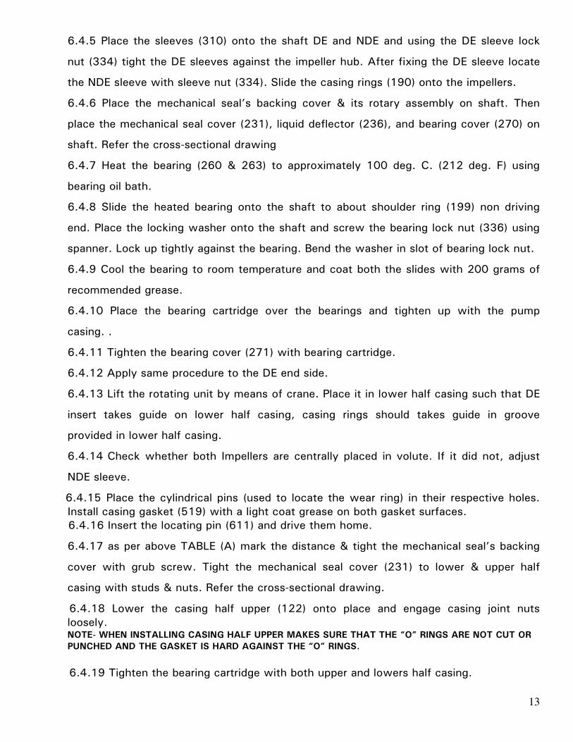
6.2.5 Place the sleeves (310) onto the shaft DE and NDE and using the DE sleeve lock
nut (334) tight the DE sleeves against the impeller hub.After fixing the DE sleeve locate
the NDE sleeve with sleeve nut. Slide the casing rings (190) onto the impellers. Insert the
gland (229) from DE & NDE side of shaft.
6.2.6 Heat the bearing (260 & 263) to approximately 100 deg. C. (212 deg. F) using
bearing oil bath.
6.2.7 Slide the heated bearing onto the shaft to about shoulder ring (199) non driving
end. Place the locking washer (415) onto the shaft and screw the bearing lock nut (336)
using spanner Lock up tightly against the bearing. Bend the washer in slot of bearing lock
nut.
6.2.8 Cool the bearing to room temperature and coat both the slides with 200 grams of
recommended grease. Tighten the bearing cover (271) with bearing cartridge.

10
6.2.9 Place the bearing cartridge over the bearings and tighten up with the lower half
casing (123).Apply same procedure to the DE end side.
6.2.10 Place the cylindrical pins (used to locate the wear ring) in their respective holes.
Install casing gasket (519) with a light coat grease on both gasket surfaces. Carefully
align the inner edge of the gasket with the insert “O” rings. Lower the casing half upper
(122) onto place and engage casing joint nuts loosely.
6.2.11 Lift the rotating unit by means of crane. Place it in lower half casing such that DE
insert takes guide on lower half casing, casing rings should takes guide in groove
provided in lower half casing.
6.2.12 Place gland packing (430), lantern ring (227) in insert as per Cross sectional
drawing.
6.2.13 Fit the shoulder ring (199) onto shaft. Ensure that no foreign particle should enter
in bearing assembly. See the cross-sectional drawing.
6.2.14 Check whether both Impellers are centrally placed in volute. If it did not, adjust
NDE sleeve.
NOTE- WHEN INSTALLING CASING HALF UPPER MAKES SURE THAT THE “O” RINGS ARE NOT CUT OR
PUNCHED AND THE GASKET IS HARD AGAINST THE “O” RINGS.
6.2.15 Insert the locating pin (610) and drive them home.
6.2.16 tightens the bearing cartridge with both upper and lowers half casing.
6.2.17 Loose the Cartridge seal clamps & tighten the cartridge seal allen screws with the
shaft sleeve.
6.2.18 Install the stuffing box flushing piping.
6.2.19 Rotate the shaft by hand to assure smooth turning and that is free from rubbing
or binding.

11
6.3 Dismantling Procedure for mechanical seal pumps.
6.3.1 Drain the pump by opening air vent valve & drain plugs.
6.3.2 Remove all the screws of bearing cap (274) tightened with lower half casing (123).
6.3.3 Loose the DE & NDE side mechanical seal cover (204) which are tightened with
Lower & upper half casing with studs & nuts.
6.3.4 Remove all the nuts and bolts and locating pin of the upper and lower casing
flange.
6.3.5 Insert a screw driver or peg bar into the slot between the two halves and separate
two halves, lifting of the upper half casing (122).
6.3.6 Remove the rotating unit assembly from lower half casing (123) in such a way that
impeller should not be damage.
6.1.7 Remove all the screws of bearing cartridge (241,253) tightened with casing &
bearing cover (271) and dismantle the bearing cartridge.
6.1.8 Remove the bearing lock nut (336) and lock washer (415) from the NDE side of the
shaft. By using bearing puller remove the bearings from the shaft. Remove the driving
end bearing in the same manner.
6.1.9 Remove shoulder rings (199) & bearing cover (271) in the same manner. Remove
the liquid deflectors (236). Then remove shaft sleeve nut (334), wear ring (190), shaft
sleeve (310).
6.3.10 Remove mechanical seal cover (231) & its spring & rotary face very carefully.
Loose the grub screws of backing collar of mechanical seal & remove it from shaft sleeve
(310).
6.3.11 Remove the 1st stage & 2nd stage impeller (158), impeller key (320) & interstage
(204) ring.

12
6.4 Assembly Procedure for mechanical seal pumps
6.4.1 Check the “O” rings of impeller’s for cut or flows, discard if faulty, lubricate and
roll the “O” ring in groove.
6.4.2 Wipe over the shaft (180) with clean light oil.
6.4.3 Place the impeller key (320) into the keyway and interstage ring (204).
6.4.4 Check the 1st & 2nd stage impeller for correct rotation and slide onto the shaft
from DE and NDE.
TABLE A - STUFFING BOX DETAILS: (FOR MECHANICAL SEAL)
Diameters in mm SR
NO
Pump
Type D D1 D2 D3 D4 D5
SEAL
LENGTH
‘L’ mm
M mm H
mm
G
mm
1 DSM
100/36
40 80 67.4 70 50 95 57.5 52.5 62 10
2 DSM
125/40
50 95 85.7 92 70 110 60 53 77 10
13
6.4.5 Place the sleeves (310) onto the shaft DE and NDE and using the DE sleeve lock
nut (334) tight the DE sleeves against the impeller hub. After fixing the DE sleeve locate
the NDE sleeve with sleeve nut (334). Slide the casing rings (190) onto the impellers.
6.4.6 Place the mechanical seal’s backing cover & its rotary assembly on shaft. Then
place the mechanical seal cover (231), liquid deflector (236), and bearing cover (270) on
shaft. Refer the cross-sectional drawing
6.4.7 Heat the bearing (260 & 263) to approximately 100 deg. C. (212 deg. F) using
bearing oil bath.
6.4.8 Slide the heated bearing onto the shaft to about shoulder ring (199) non driving
end. Place the locking washer onto the shaft and screw the bearing lock nut (336) using
spanner. Lock up tightly against the bearing. Bend the washer in slot of bearing lock nut.
6.4.9 Cool the bearing to room temperature and coat both the slides with 200 grams of
recommended grease.
6.4.10 Place the bearing cartridge over the bearings and tighten up with the pump
casing. .
6.4.11 Tighten the bearing cover (271) with bearing cartridge.
6.4.12 Apply same procedure to the DE end side.
6.4.13 Lift the rotating unit by means of crane. Place it in lower half casing such that DE
insert takes guide on lower half casing, casing rings should takes guide in groove
provided in lower half casing.
6.4.14 Check whether both Impellers are centrally placed in volute. If it did not, adjust
NDE sleeve.
6.4.15 Place the cylindrical pins (used to locate the wear ring) in their respective holes.
Install casing gasket (519) with a light coat grease on both gasket surfaces.
6.4.16 Insert the locating pin (611) and drive them home.
6.4.17 as per above TABLE (A) mark the distance & tight the mechanical seal’s backing
cover with grub screw. Tight the mechanical seal cover (231) to lower & upper half
casing with studs & nuts. Refer the cross-sectional drawing.
6.4.18 Lower the casing half upper (122) onto place and engage casing joint nuts
loosely. NOTE- WHEN INSTALLING CASING HALF UPPER MAKES SURE THAT THE “O” RINGS ARE NOT CUT OR
PUNCHED AND THE GASKET IS HARD AGAINST THE “O” RINGS.
6.4.19 Tighten the bearing cartridge with both upper and lowers half casing.

14
6.4.20 Rotate the shaft by hand to assure smooth turning and that is free from rubbing
or binding.
7 CROSS SECTIONAL DRAWINGS :
7.2.1 NON THRU BORE TYPE PUMP (Gland packing type):
7.2.2 THRU NON-THRU BORE TYPE PUMP:

15
7.1.2 NON THRU BORE TYPE PUMP (Mechanical seal type):
16
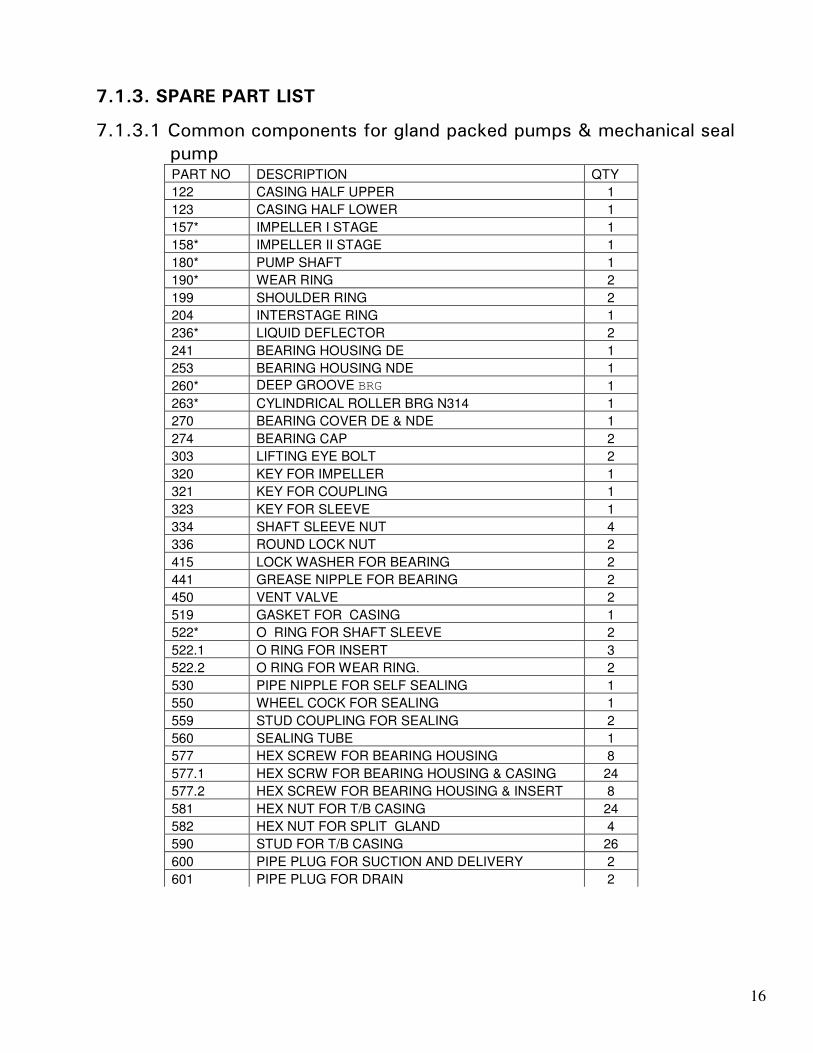
7.1.3. SPARE PART LIST
7.1.3.1 Common components for gland packed pumps & mechanical seal
pump PART NO DESCRIPTION QTY
122 CASING HALF UPPER 1
123 CASING HALF LOWER 1
157* IMPELLER I STAGE 1
158* IMPELLER II STAGE 1
180* PUMP SHAFT 1
190* WEAR RING 2
199 SHOULDER RING 2
204 INTERSTAGE RING 1
236* LIQUID DEFLECTOR 2
241 BEARING HOUSING DE 1
253 BEARING HOUSING NDE 1
260* DEEP GROOVE BRG 1
263* CYLINDRICAL ROLLER BRG N314 1
270 BEARING COVER DE & NDE 1
274 BEARING CAP 2
303 LIFTING EYE BOLT 2
320 KEY FOR IMPELLER 1
321 KEY FOR COUPLING 1
323 KEY FOR SLEEVE 1
334 SHAFT SLEEVE NUT 4
336 ROUND LOCK NUT 2
415 LOCK WASHER FOR BEARING 2
441 GREASE NIPPLE FOR BEARING 2
450 VENT VALVE 2
519 GASKET FOR CASING 1
522* O RING FOR SHAFT SLEEVE 2
522.1 O RING FOR INSERT 3
522.2 O RING FOR WEAR RING. 2
530 PIPE NIPPLE FOR SELF SEALING 1
550 WHEEL COCK FOR SEALING 1
559 STUD COUPLING FOR SEALING 2
560 SEALING TUBE 1
577 HEX SCREW FOR BEARING HOUSING 8
577.1 HEX SCRW FOR BEARING HOUSING & CASING 24
577.2 HEX SCREW FOR BEARING HOUSING & INSERT 8
581 HEX NUT FOR T/B CASING 24
582 HEX NUT FOR SPLIT GLAND 4
590 STUD FOR T/B CASING 26
600 PIPE PLUG FOR SUCTION AND DELIVERY 2
601 PIPE PLUG FOR DRAIN 2

17
PART NO DESCRIPTION QTY
602 PIPE PLUG FOR SEALING 1
604 PIPE PLUG FOR STUFFING BOX 2
610.2* CYLINDRICAL PIN FOR INTER STG DIAPHRAGM 1
610.1* CYLINDRICAL PIN FOR WEARING RING. 2
611 TAPER PIN FOR T/B CASING 2
640 RIVET TB NAME PLATE. 4
668 HEX.SOCKET GRUB SCREW 1
670 DUTY NAME PLATE 1
731 STUD FOR SPLIT OR NON-SPLIT GLAND 4
7.1.3.2 Component for Gland packed pumps
PART NO DESCRIPTION QTY
229* GLAND 2
224* CLAMPING PLATE FOR SPLIT GLAND 2
227.1* SPLIT LANTEN RING 1
228 STUFFING BOX BUSH 2
310* SHAFT SLEEVE 2
430* GLAND PACKING 2 Set
7.1.3.2 Component for Mechanical seal pump
PART NO DESCRIPTION QTY
310* SHAFT SLEEVE FOR MECHANICAL SEAL 2
230* MECHANICAL SEAL 2
231* MECHANICAL SEAL COVER 2
* Parts for two years normal working of the pumps.
** These parts should be included in the order, while ordering top and bottom casing.
N Quantity depends upon pump type.

18

19

20

21

22

23

24

25

26

INSTRUCTIONS ON INSTALLATIONOPERATION ANDMAINTENANCE FOR
KIRLOSKAR MULTISTAGE PUMPTYPE DSM (THRU BORE)DSM 50/20DSM 65/20DSM 50/28DSM 65/32 A/BDSM 80/36
KIRLOSKAR BROTHERS LIMITEDUDYOG BHAVAN, TILAK ROAD, PUNE - 411 002

IOM/DB/005/01 Issue Date: 25/09/2000 Page: 1/12 Last revision date:
KIRLOSKAR BROTHERS LIMITED Udyog Bhavan, Tilak Road, Pune 411 002 (India)
WARRANTY
We warrant that the pump supplied by us is free from defective material and faulty workmanship. This warranty holds good for a period of 12 months from the date of commissioning of the equipment or 18 months from the date of despatch from our factory, whichever is earlier. Our liability in respect of any complaint is limited to replacing part/parts free of charge ex-works or repairs of the defective part/parts only to the extent that such replacement / repairs are attributable to or arise solely from faulty workmanship or defective material. The warranty holds good only for the products manufactured by us.
KIRLOSKAR BROTHERS LIMITED

IOM/DSMT/0010/01 Issue Date: 13/10/2000 Page : Page 2/14 Last Revision Date:
CONTENTS 1. GENERAL 2. INSTALLATION 3. OPERATION 4. TECHNICAL DATA
5. MAINTENANCE 6. OVERHAULING 7. SPARE PARTS LIST AND CROSS-SECTIONAL DRAWINGS Please furnish complete nameplate details, name of the parts, part nos. And material
of construction while ordering spare parts for the pumps. CAUTION THIS INSTRUCTION MANUAL COVERS THE GENERAL REQUIREMENT OF INSTALLATION, OPERATION AND MAINTENANCE. HOWEVER, THE END USER SHOULD ALSO REFER TO THE DRAWINGS AND DOCUMENTS IF SUPPLIED AGAINST SPECIFIC ORDERS.

IOM/DSMT/0010/01 Issue Date: 13/10/2000 Page : Page 3/14 Last Revision Date:
1. GENERAL: 1.1 The booklet covers instructions for the following type of “DSM” pumps. DSM 50/20 DSM 65/20 DSM 50/28 DSM 65/32 A/B DSM 80/36 1.2 These are Horizontal split Casing type, two stage pumps. This construction enables
to remove the rotating unit without disturbing pipe connections and alignment. 1.3 Pumps when properly installed and given due care in operation and maintenance
should operate satisfactorily for a long period. 1.4 When the pump is received, sometime before the actual use of pump, it should be
inspected and stored in a dry place. The coupling should be rotated at least once in a month to prevent pitting of bearing surfaces.
2 INSTALLATION :
For location, preparing foundation, installation, alignment, piping, general maintenance, trouble shooting etc., the instructions given in our publication “GENERAL INSTRUCTIONS FOR INSTALLATION, OPERATION AND MAINTENANCE OF KIRLOSKAR CENTRIFUGAL PUMPS.” which is also printed along with this booklet -must be followed carefully.
2.1 The sealing connection piping to the pump stuffing box must be made after
installing and before commissioning the pump. 2.2 Put the gland packing and lantern ring, if it is sent separately along with the pump
as per given procedure. 3. OPERATION: 3.1 Before starting the pump check the following: 3.1.1. The pump rotates freely by hand. 3.1.2. Sealing connection provided is properly tightened and adjusted. 3.1.3. Fill in the grease for bearings, if not done earlier. 3.1.4. The direction of rotation of motor corresponds to the direction of rotation of the
pump. 3.1.5. The pump and the suction pipe is fully primed with the liquid. 3.1.6. Valve on the delivery side is closed. 3.1.7. Stuffing box packing is properly tightened. 3.1.8. The cock for the pressure gauge connection is closed.

IOM/DSMT/0010/01 Issue Date: 13/10/2000 Page : Page 4/14 Last Revision Date:
3.2 Starting the pump 3.2.1 Start the pump. Let the prime mover pick up its full speed. 3.2.2 Open the valve on delivery side slowly. 3.2.3 Open the cock for pressure gauge connection. 3.3 During running the pump 3.3.1 The pump is running smoothly. 3.3.2 The flow of sealing water is uninterrupted. 3.3.3 Leakage through stuffing box is normal. This is required for cooling of Stuffing box/
Gland packing. 3.3.4 The bearings are not getting heated up excessively. 3.3.5 Head and capacity developed by the pump is as specified. 3.3.6 Power consumption is within limit. 3.3.7 Ensure that there is no mechanical friction in the pump. 3.3.8 Stop the pump immediately, if any defects are noticed. Do not start the pump
unless the defects are rectified. Report immediately to the supplier, if it is not possible to rectify the defects.
3.4 During stopping the pump: 3.4.1 Close the valve on delivery side. 3.4.2 Stop the motor. 3.4.3 If the pump is not required to be operated for a long time, then drain the casing
completely. 4. TECHNICAL DATA: 4.1 Direction of rotation The standard direction of rotation is clockwise when viewed from driving end. The
pump suitable for anticlockwise rotation can also be supplied against specific requirements.
4.2 Normally the pumps are supplied suitable for speed of 1450 rpm. Please contact
supplier if the pump is to be used for higher speeds. 4.3 Bearings The shaft is supplied with antifriction bearings at driving end and non- driving end.
The details of the bearings are given in the technical data chart (4.5.7). The designations of bearings are as per SKF catalogue. However, equivalent bearings in type, capacity and dimensions are also used.
IOM/DSMT/0010/01 Issue Date: 13/10/2000 Page : Page 5/14 Last Revision Date:
4.4 Lubrication 4.4.1 Type of lubricant – The bearings are grease lubricated. 4.4.2 Quantity of grease – Please refer to Technical Data chart. (4.5.7) 4.4.3 Refilling period – After 1000 hours of running. 4.4.4 Bearing temperature – The permissible bearing temperature rise is 40°C above
ambient temperature 4.4.5 Grades of recommended grease-
Following grades of grease of their equivalents available in the market are suitable
for bearing lubrication. 2900 RPM 1450 RPM INDIAN OIL SERVOGEM- 2 SERVOGEM- 3 HINDUSTAN PETROLEUM NATRA- 3 OR LITHON – 3 CALTEX STARFAK- 3 4.5 Stuffing box 4.5.1 Stuffing box – The stuffing boxes are extra deep to reduce the leakage. 4.5.2 Stuffing box sealing – Lantern ring provided for sealing purpose is used only in first
stage stuffing box. Normally clear cold self liquid only is used for sealing. Grease Sealing/ External sealing can be provided against specific request.
4.5.3 Stuffing box packing Champion Style–3116–Graphited Cotton Grease packing is used in the pump as a
standard supply. However, stuffing box packing suitable for liquid handled is supplied against specific requirements.
4.5.4 Stuffing box packing size
Please refer Technical Data Chart. (4.5.7)
4.5.5 Flexible couplings
The pumps are supplied with flexible couplings. Details are given in Technical Data Chart.
4.5.6 Packings between upper and lower half casing
Dalmia Duplex board packing paper to be used of following thickness.
PUMP TYPE PACKING THICKNESS IN MM.
DSM 100/36 DSM 65/20 DSM 50/28 DSM 65/32 A/B DSM 80/36
0.4 0.4 0.4 0.4 0.4
IOM/DSMT/0010/01 Issue Date: 13/10/2000 Page : Page 6/14 Last Revision Date:
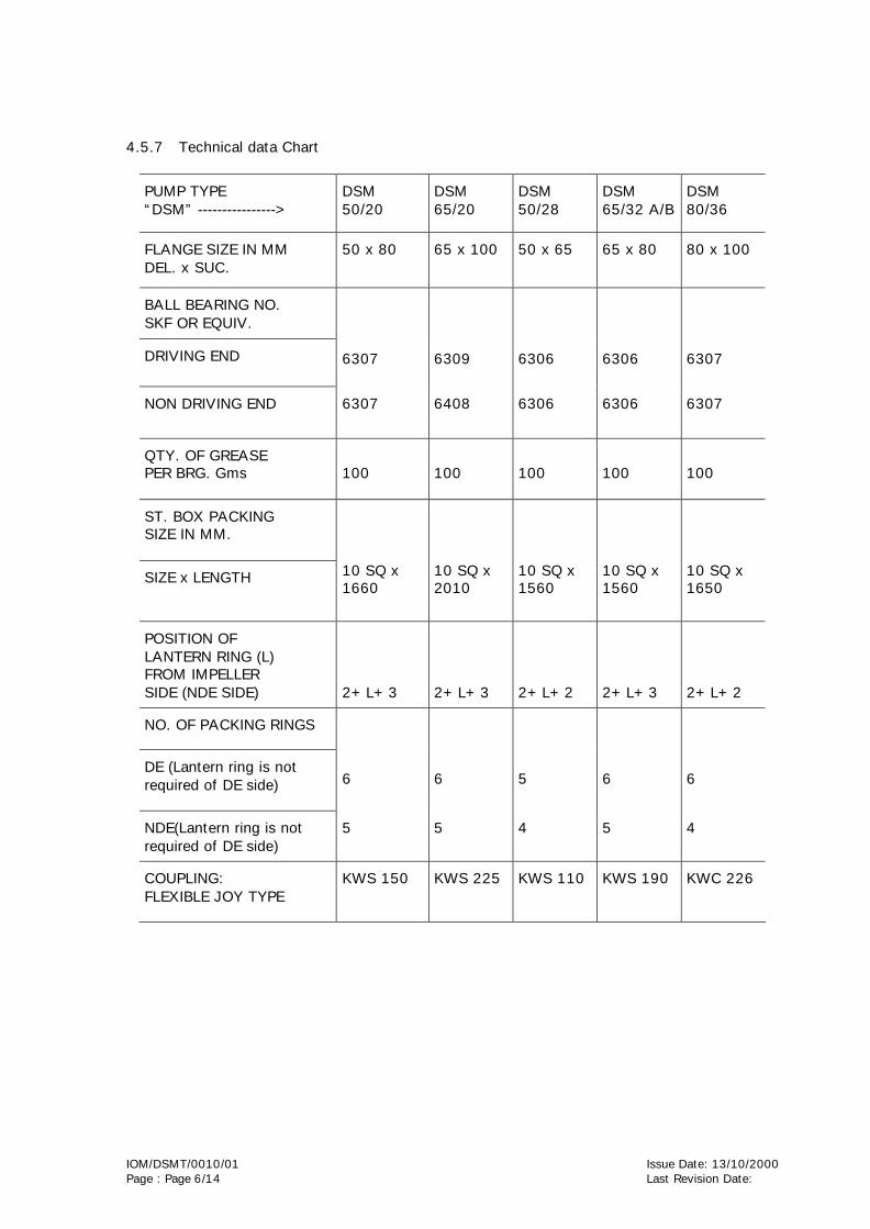
4.5.7 Technical data Chart
PUMP TYPE “DSM” ---------------->
DSM 50/20
DSM 65/20
DSM 50/28
DSM 65/32 A/B
DSM 80/36
FLANGE SIZE IN MM DEL. x SUC.
50 x 80 65 x 100 50 x 65 65 x 80 80 x 100
BALL BEARING NO. SKF OR EQUIV.
DRIVING END
6307
6309
6306
6306
6307
NON DRIVING END 6307 6408 6306 6306 6307
QTY. OF GREASE PER BRG. Gms
100
100
100
100
100
ST. BOX PACKING SIZE IN MM.
SIZE x LENGTH
10 SQ x 1660
10 SQ x 2010
10 SQ x 1560
10 SQ x 1560
10 SQ x 1650
POSITION OF LANTERN RING (L) FROM IMPELLER SIDE (NDE SIDE)
2+L+3
2+L+3
2+L+2
2+L+3
2+L+2
NO. OF PACKING RINGS
DE (Lantern ring is not required of DE side)
6
6
5
6
6
NDE(Lantern ring is not required of DE side)
5 5 4 5 4
COUPLING: FLEXIBLE JOY TYPE
KWS 150 KWS 225 KWS 110 KWS 190 KWC 226

IOM/DSMT/0010/01 Issue Date: 13/10/2000 Page : Page 7/14 Last Revision Date:
5. MAINTENANCE:
Preventive maintenance schedule is the periodical checks and precautions by which failures and breakdowns are made very remote.
5.1 Daily Checks 5.1.1 Pressure gauge reading. 5.1.2 Bearing temperature. 5.1.3 Leakage through stuffing box. 5.1.4 Noise and vibration. 5.1.5 Voltage and current. 5.2 Periodical Maintenance 5.2.1 Replenish the grease. 5.2.2 Check the stuffing box packing. 5.2.3 Check the alignment of the pumpset. 5.2.4 Calibrate the measuring instruments. 5.2.5 Check the sealing and cooling connections for leakage etc. 6. OVERHAULING: With normal daily operating spell, the pump will be due for overhaul after about
5000 working hours. This work should be done by skilled personnel.
6.1 Dismantling Procedure 6.1.1 Drain the pump by opening air vent valve (450). 6.1.2 Remove all the nuts and bolts (572, 581)and locating pin (611) of the upper and
lower casing flange. 6.1.3 Loosen all the insert joint nuts (586) at both the ends.
6.1.4 Insert a screw driver or peg bar into the slot between the two halves and separate two halves, lifting of the upper half casing
6.1.5 Tap the inserts (979.1 and 979.2) with a soft hammer to break the seat between
the insert and lower half casing and lift the rotating unit out of the lower half casing.
6.1.6 Remove four hex. nuts (586) from each bearing housing (240.1 and 240.2) and remove the bearing housing from bearings.
6.1.7 Remove the bearing lock nut (335) and lock washer (415) from the NDE side of the
shaft and using by bearing puller. Remove the bearing (260) from the shaft. Remove the driving end bearing in the same manner.
6.1.8 Remove the oil seals (500) from the insert. Remove shoulder rings (199) from the
shaft by using puller. Remove the liquid deflectors (236).

IOM/DSMT/0010/01 Issue Date: 13/10/2000 Page : Page 8/14 Last Revision Date:
6.1.9 Remove gland nuts (582) and washers (624) from each gland, slide the inserts (979.1 and 979.2) off the shaft.
6.1.10 Remove the gland packings (430) and the lantern ring 9227) from the NDE side
insert.
6.1.11 Remove the two casing rings (190) from the impellers (157 and 158).
6.1.12 First unscrew the impeller nuts (586). Remove the lock washers (410) and distance sleeves (201).
6.1.13 Take out the impellers (157 and 158). Before removing the impellers put the mark of
first stage and second stage impellers so that while reassembling, the impellers may not be interchanged.
6.1.14 Remove the impeller key (320). Take out interstage ring (227) alongwith the
interstage diaphragm (462).
6.2 Assembly Procedure
6.2.1 Check the “O” rings (522.2) for cut or flows, discard if faulty, lubricate and roll the “O” ring in groove.
6.2.2 Wipe over the shaft (180) with clean light oil.
6.2.3 Place the impeller key (320) into the keyway and interstage ring (204) alongwith interstage diaphragm (462).
6.2.4 Check the 1st & 2nd stage impeller for correct rotation and slide onto the shaft from
DE and NDE.
6.2.5 Place the distance sleeves (201) onto the shaft DE and NDE and using the impeller nut (300) and lock washer (410) tight against the impeller hub. Slide the casing rings (199) onto the impellers.
6.2.6 Check the “O” rings (522.1) for cuts or flaws, discard if faulty. Lubricate and roll
the “O” ring (522.1) into the groove in each insert (979.1 and 979.2).
6.2.7 Slide insert (979.1 and 979.2), glands (223) and liquid deflectors (236) simutaneously over the shaft with guide vane at proper position.
6.2.8 Fit the shoulder ring (227) onto shaft then press oil seal (500) into the insert. Ensure
that no foreign particle should enter in bearing assembly. See the cross-sectional drawing.
6.2.9 Heat the ball bearing (260) to approximately 100 deg. C. (212 deg. F) using bearing
oil bath.
NOTE: DO NOT EXCEED 120 DEG.C (250 DEG. F)
6.2.10 Slide the heated bearing onto the shaft to abut shoulder ring (227) nondriving end. Place the locking washer (415) onto the shaft and screw the bearing lock nut (335) using spanner* Lock up tightly against the bearing. Bend the washer in slot of bearing lock nut.
6.2.11 Cool the bearing to room temperature and coat both the slides with 40 grams of
recommended grease. 6.2.12 Apply grease on bearing housing (240.2) OD and slide into the place over bearing.
Secure bearing housings to insert with four hex. nuts (586) and studs (593).
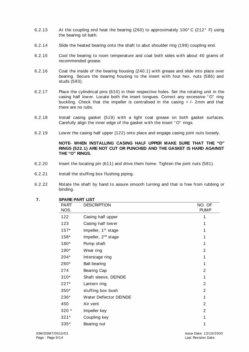
IOM/DSMT/0010/01 Issue Date: 13/10/2000 Page : Page 9/14 Last Revision Date:
6.2.13 At the coupling end heat the bearing (260) to approximately 100°C (212° F) using
the bearing oil bath.
6.2.14 Slide the heated bearing onto the shaft to abut shoulder ring (199) coupling end.
6.2.15 Cool the bearing to room temperature and coat both sides with about 40 grams of recommended grease.
6.2.16 Coat the inside of the bearing housing (240.1) with grease and slide into place over
bearing. Secure the bearing housing to the insert with four hex. nuts (586) and studs (593).
6.2.17 Place the cylindrical pins (610) in their respective holes. Set the rotating unit in the
casing half lower. Locate both the insert tongues. Correct any excessive “O” ring buckling. Check that the impeller is centralised in the casing +/- 2mm and that there are no rubs.
6.2.18 Install casing gasket (519) with a light coat grease on both gasket surfaces.
Carefully align the inner edge of the gasket with the insert “O” rings.
6.2.19 Lower the casing half upper (122) onto place and engage casing joint nuts loosely.
NOTE- WHEN INSTALLING CASING HALF UPPER MAKE SURE THAT THE “O” RINGS (522.1) ARE NOT CUT OR PUNCHED AND THE GASKET IS HARD AGAINST THE “O” RINGS.
6.2.20 Insert the locating pin (611) and drive them home. Tighten the joint nuts (581). 6.2.21 Install the stuffing box flushing piping.
6.2.22 Rotate the shaft by hand to assure smooth turning and that is free from rubbing or binding.
7. SPARE PART LIST
PART NOS.
DESCRIPTION
NO. OF PUMP
122 123
157* 158* 180*
190* 204* 260*
274 310* 227*
350* 236* 450
320 * 321* 335*
Casing half upper Casing half lower
Impeller, 1st stage Impeller, 2nd stage Pump shaft
Wear ring Interstage ring Ball bearing
Bearing Cap Shaft sleeve, DE/NDE Lantern ring
stuffing box bush Water Deflector DE/NDE Air vent
Impeller key Coupling key Bearing nut
1 1
1 1 1
2 1 1
2 1 2
2 1 2
2 1 1

IOM/DSMT/0010/01 Issue Date: 13/10/2000 Page : Page 10/14 Last Revision Date:
PART NOS.
DESCRIPTION
NO. OF PUMP
586
572
581
631
611*
610*
601
600
602
604
430
519*
522*
441
560
670
264*
263*
336*
550
223*
979.1
979.2
240.1
240.2
415*
500*
199*
582
624
223*
330*
410*
201*
204*
Bolts with nuts for 274
Bolts for upper and lower half casing
Nuts for Lower half casing
Hex screw for bearing cover
Taper pin with washes and nuts for lower and upper
half casing
Cylindrical pin
Drain plug for casing
Plug for Suc. & Del. Pressure gauge connections
Plug for sealing
Plug for st. box leakage water
Gland packing
Paper packing between 122 & 123
‘O’ ring for shaft sleeve
Grease nipple for lubrication
Nylon tube for sealing
Duty name plate
Cylindrical roller bearing SKF N 311 or equivalent
Double row angular contact ball
Bearing SKF:7310 BG or equivalent
Bearing lock nut ND/NDE
Wheel cock
Gland (non split)
Insert DE
Insert NDE
Bearing Housing DE
Bearing housing NDE
Lock Washer
Oil Seal
Shoulder Ring
Gland Nut
Washer
Gland
Impeller nut
Lock washer
Distance Sleeve
Inter stage ring
4
1 set
1 set
8
2
2
2
2
1
2
1set
1
2
2
1
1
1
1
2
1
2
1
1
1
1
2
2
2
4
4
2
2
2
2
1
* Recommended spares.

IOM/DSMT/0010/01 Issue Date: 13/10/2000 Page : Page 11/14 Last Revision Date:
CROSS SECTIONAL ASSEMBLY OF DSM 50-28 PUMP CW (THRU BORE TYPE PUMP) DSM 65 32A/B DRG.NO. TC 172-90-003-0

IOM/DSMT/0010/01 Issue Date: 13/10/2000 Page : Page 12/14 Last Revision Date:
CROSS SECTIONAL ASSEMBLY OF DSM 80-36 PUMP CW (THRU BORE TYPE PUMP) DRG.NO. TC 172-90005.0

IOM/DSMT/0010/01 Issue Date: 13/10/2000 Page : Page 13/14 Last Revision Date:
CROSS SECTIONAL ASSEMBLY OF DSM 50-20 PUMP CW (THRU BORE TYPE PUMP) DRG.NO. TC 172-86 024 0

IOM/DSMT/0010/01 Issue Date: 13/10/2000 Page : Page 14/14 Last Revision Date:
CROSS SECTIONAL ASSEMBLY OF DSM 65-20 PUMP CW DRG.NO. TC 172-86-025-1

GENERAL INFORMATION & SAFETY REQUIREMENTS
1.0 The products supplied by KBL have been designed with safety in mind. Where hazards cannot be eliminated, the risk has been minimised by the use of guards and other design features. Some hazards cannot be guarded against and the instructions below MUST BE COMPLIED WITH for safe operation. These instructions cannot cover all circumstances; YOU are responsible for using safe working practices at all times.
1.1 KBL products are designed for installation in designated area, which are to be kept clean
and free of obstructions that may restrict safe access to the controls and maintenance access points.
A Pump Duty Nameplate is fitted to each unit and must not be removed. Loss of this plate could make identification impossible. This in turn could affect safety and cause difficulty in obtaining spare parts. If accidental loss or damage occur, contact KBL immediately.
1.2 Access to the equipment should be restricted to the personnel responsible for
installation, operation and maintenance and they must be trained, adequately qualified and supplied with appropriate tools for their respective tasks.
1.3 KBL requires that, all personnel that are responsible for installation, operation or
maintenance of the equipment, have access to and study the product instruction manual BEFORE any work is done and that they will comply with all local and industry based safety instructions and regulations.
1.4 Ear defenders should be worn where the specified equipment noise level exceeds locally
defined safe levels. Safety glasses or goggles should be worn where working with pressurised systems and hazardous substances. Other personnel protection equipment must be worn where local rules apply.
1.5 Do not wear loose clothing or jewellery which could catch on the controls or become
trapped in the equipment. 1.6 Read the instruction manual before installation, operation and maintenance of the
equipment. Check and confirm that the manual is relevant copy by comparing pump type on the nameplate and with that on the manual.
1.7 Note the ‘Limits of product application – permissible use’ specified in the manual.
Operation of the equipment beyond these limits will increase the risk from hazards noted below and may lead to premature and hazardous pump failure.
1.8 Clear and easy access to all controls, gauges and dials etc. must be maintained at all
times. Hazardous or flammable materials must not be stored in pump rooms unless safe areas or racking and suitable containers have been provided.
1.9 IMPROPER INSTALLATION, OPERATION OR MAINTENANCE OF THIS KBL PRODUCT
COULD RESULT IN INJURY OR DEATH. 2.0 SAFETY INSTRUCTIONS WHILE HANDLING AND STORAGE When lifting the pump, use the lifting points specified on general arrangement drawing.
Use lifting equipment having a safe working load rating suitable for the weight specified. Use suitable slings for lifting pump which is not provided with lifting points. The use of fork-lift truck and chain crane sling equipment is recommended but locally approved equipment of suitable rating may be used.
-i-

Do not place fingers or hands etc. into the suction or discharge pipe outlets and do not touch the impeller, if rotated this may cause severe injury. To prevent ingress of any objects, retain the protection covers or packaging in place until removal is necessary for installation. If the packaging or suction and discharge covers are removed for inspection purposes, replace afterwards to protect the pump and maintain safety.
3.0 SAFETY INSTRUCTIONS WHILE ASSEMBLY & INSTALLATION
Do not place fingers or hands etc. into the suction or discharge pipe outlets and do not touch the impeller, if rotated this may cause severe injury. To prevent ingress of any objects, retain the protection covers or packaging in place until removal is necessary for installation. Do not touch any moving or rotating parts. Guards are provided to prevent access to these parts, where they have been removed for maintenance they must be replaced before operating the equipment. Shaft alignment must be checked again after the final positioning of the pump unit and connection to pipework as this may have disturbed the pump or motor mounting positions. If hot liquids (above 80°C) are being pumped, alignment should be checked and reset with the pump and motor at their normal operating temperature. If this is not possible, KBL can supply estimated initial offset figures to suit extreme operating temperatures. Failure to support suction and delivery pipework may result in distortion of the pump casing, with the possibility of early pump failure.
4.0 SAFETY INSTRUCTIONS WHILE COMMISSIONING & OPERATION.
Do not touch any moving or rotating parts. Guards are provided to prevent access to these parts, where they have been removed for maintenance they must be replaced before operating the equipment. Check that the pump is primed. Pump should never be run dry as the pumped liquid acts, as lubricant for the close running fits surrounding impeller and damage will be incurred. Failure to supply the stuffing box or mechanical seal with cooling of flush water may result in damage and premature failure of the pump. Do not touch surfaces which during normal running will be sufficiently hot to cause injury. Note that these surfaces will remain hot after the pump has stopped, allow sufficient time for cooling before maintenance. Be cautious and note that other parts of the pump may become hot if a fault is developing. Do not operate water pumps in temperatures below freezing point, without first checking that the pumped fluid is not frozen and the pump is free to turn. Pumps in these environments should be drained down during inactivity and re-primed before starting. In addition to local or site regulations for noise protection, KBL recommend the use of personal ear protection equipment in all enclosed pump rooms and particularly those containing diesel engines. Care must be taken to ensure that any audible alarm or warning signal can be heard with ear defenders worn. Be aware of the hazards relating to the pumped fluid, especially the danger from inhalation of noxious and toxic gases, skin and eye contact or penetration. Obtain and understand the hazardous substance data sheets relating to the pumped fluid and note the recommended emergency and first aid procedures.
-ii-

5.0 SAFETY INSTRUCTIONS WHILE MAINTENANCE & SERVICING
Before attempting any maintenance on a pump particularly if it has been handling any form of hazardous liquid, it should be ensured that the unit is safe to work on. The pump must be flushed thoroughly with suitable cleaner to purge away any of the product left in the pump components. This should be carried out by the plant operator and a certificate of cleanliness obtained before starting work. To avoid any risk to health it is also advisable to wear protective clothing as recommended by the site safety officer especially when removing old packing which may be contaminated. Check and ensure that the pump operates at below the maximum working pressure specified in the manual or on the pump nameplate and before maintenance, ensure that the pump is drained down. Wear a suitable mask or respirator when working with packing and gasket components which contain fibrous material, as these can be hazardous when the fibrous dust is inhaled. Be cautious, if other supplier’s components have been substituted for genuine KBL parts, these may then contain hazardous materials. Be aware of the hazards relating to the pumped fluid, especially the danger from inhalation of noxious and toxic gases, skin and eye contact or penetration. Obtain and understand the hazardous substance data sheets relating to the pumped fluid and note the recommended emergency and first aid procedures. Isolate the equipment before any maintenance work is done. Switch off the mains supply, remove fuses, apply lock-outs where applicable and affix suitable isolation warning signs to prevent inadvertent reconnection. In order to avoid the possibility of maintenance personnel inhaling dangerous fumes or vapours, it is recommended that the maintenance work be carried out away from the pump locations by removal of bearing housing and shaft assembly to a suitable to a suitable maintenance area.
_____________ Ref: Proposed draft standard prEN 800: Pumps and pump units for liquids;
General safety requirements
-iii-

INCORRECT CORRECT
DD
SPACE AROUNDFOOT VALVE
INSUFFICIENT
SHORT BEND
REDUCED SUCTION PIPE
D
D SUFFICIENT
FOOT VALVESPACE AROUND
LONG BEND
INCREASED SUCTION PIPE
CONCENTRIC TAPER PIECE
INCORRECT LAYOUT OF SUCTION PIPE
ECCENTRIC TAPER PIECE
CORRECT LAYOUT OF SUCTION PIPE
FOR RECOMMENDATIONS OF SUITABLE SUCTION AND DELIVERY PIPE SIZE PLEASE CONTACT OUR AUTHORISED DEALER OR NEAREST REGIONAL OFFICE
GENERAL INSTRUCTIONS FOR INSTALLATION OPERATION & MAINTENANCE OF
KIRLOSKAR CENTRIFUGAL PUMPS
® Registered users – Kirloskar Brothers Ltd.

GENERAL INSTRUCTIONS FOR INSTALLATION, OPERATION & MAINTENANCE OF KIRLOSKAR CENTRIFUGAL PUMPS WARNING The equipment supplied is designed for specific capacity, speed, pressure and temperature. Do not use the equipment beyond the capacities for which it is manufactured. The equipment manufactured is also shop tested for the satisfactory performance and if it is operated is excess of the conditions for which it is manufactured, the equipment will be subject to excessive stresses and strains. LOCATION The pump should be located as near the liquid source as possible. This will minimise the suction lift and pump will give better performance. Ample space should be provided on all sides so that the pump can be inspected while in operation and can be serviced conveniently whenever required. FOUNDATION The foundation should be sufficiently substantial to absorb any vibration and to form a permanent rigid support for the base plate. This is important in maintaining the alignment of a direct connected unit. A concrete foundation on a solid base is advisable. Foundation bolts of the proper size should be embedded in the concrete located by a drawing or template. A pipe sleeve about two and one-half diameter larger that the bolt should be used to allow movement for the final position of the foundation bolts. ALIGNMENT Pumps and drivers that are supplied by the manufacturers, mounted on a common base plate are accurately aligned before despatch. However as the alignments are likely to be disturbed during transit to some extent and therefore must not be relied upon to maintain the factory alignment. Re-alignment is necessary after the complete unit has been levelled on the foundation and again after the grout has been set and foundation bolts have been tightened. The alignment must be checked after the unit is piped up and re-checked periodically. FLEXIBLE COUPLING A flexible coupling will not compensate for misalignment of the pump and driver shafts. The purpose of the flexible coupling is to compensate for temperature changes and to permit the movement of the shafts without interference with each other while transmitting power from the driver to the pump. TYPE OF MISALIGNMENT (SEE FIGURE 1) There are two types of misalignment between the pump shaft and the driver shaft.
(a) Angular misalignment : Shafts with axis concentric but not parallel. (b) Parallel misalignment : Shafts with axis Parallel but not concentric.
LEVELLING THE UNIT When the unit is received with the pump and driver mounted on the base plate, it should be placed on the foundation and the coupling halves disconnected. The coupling should not be reconnected until all alignment operations have been completed. The base plate must be supported evenly on wedges inserted under the four corners so that it will not be distorted or sprung by the uneven distribution of the weight. Adjust the wedges until the shafts of the pump and driver are in level. Check the coupling faces, suction and discharge flanges for the horizontal or vertical position by means of spirit level. FLEXIBLE COUPLING ALIGNMENT (SEE FIGURE2) The two halves of the coupling should be at least 4 mm apart so that they cannot touch each other when the driver shaft is rotated. Necessary tools for approximately checking are straight-edge and on an outside caliper.
Figure 1
PARALLEL MISALIGNMENTANGULAR MISALIGNMENT

4 Line supplying the
2 Vacuum equalizing line1 Tank under Vacuum
4
5
6 Connecting line
seeling liquid5 Valve
7 Valve
3 Valve
7
6
3
2
1
A check for parallel alignment is made by placing a straight-edge across both coupling periphery at the top, bottom and both the sides. The unit will be in parallel alignment when the straight-edge rests evenly on the coupling periphery at all positions. Care must be taken to have the straight-edge parallel to the axis of the shafts. A check for angular alignment is made by using an outside caliper across the width of the coupling faces at various points. Coupling alignment can be checked with dial gauge indicator as shown in Fig. 2. GROUTING When the alignment is correct, the foundation bolts should be tightened evenly but not too firmly. The unit can then be grouted by working soft concrete under the edges. Foundation bolts should not be fully tightened until the grout is hardened, usually 48 hours after poring. FACTORS THAT MAY DISTURB ALIGNMENT The unit should be periodically checked for alignment. If the unit does not stay in line after being properly installed, the following are possible causes:
(a) Setting, seasoning of the foundation (b) Pipe strains distorting of shifting the machines (c) Wear of the bearings
PIPING Both suction and delivery pipes and accessories should be independently supported near the pump so that when the flanges bolts are tightened no strain will be transmitted to the pump casing. It is usually advisable to increase the size of both suction and delivery pipes at the pump nozzles in order to decrease the loss of head from friction and for the same reason piping should be arranged with as minimum bends as possible, as these should be made with along radius wherever possible. The pipe lines should be free from scales, welding residuals etc., and have to be mounted in such a way that they can be connected to suction and delivery flanges without any stress on the pump. Adequate supports should be given to pipe lines to that weight of the pipe lines does not fall on the pump. The use of minimum number of the bends and other fittings will minimise the frictional losses. SUCTION PIPE The suction pipe should be as short as possible. This can be achieved by placing the pump near the liquid to be pumped. The suction pipe must be kept free from air leaks. This is particularly important when the suction lift is high. A horizontal suction line must have a gradual rise to the pump. Any high point in the pipe will be filled with air and thus prevent proper operation of the pump. A concentric taper piece should not be used in a horizontal suction line as it forms an air pocket in the top of the reducer and the pipe. Use an eccentric piece instead. The end of the suction pipe must be well submerged to avoid whirlpools and ingress of air but must be kept clear of nay deposits of mud, silt, grit etc. The pipe must be clear from any side of wall by at least 450 mm. The end of the suction pipe should be provided with a strainer of sufficient open area. DELIVERY PIPE A check (non-return) valve and a gate of sluice valve (regulating valve) should be installed in the discharge line. The check valve placed between the pump and the gate valve is to protect the pump from excessive pressure and to prevent water running back through the pump in case of failure of the driving machine. Discharge piping should be provided with a sluice valve adjacent to the delivery flange to control the discharge, if required. VACUUM EQUALISING LINE (AND LIQUID LINE) (SEE FIGURE 3) If the pump draws from a system under vacuum an equalising pipe must be carried from the highest point of the suction line, however, as close to the suction flange of the pump as possible, to the top of the feed tank to keep gas bubbles that might have been entrapped in the flow from entering the pump. The line should be fitted with an isolating valve which should be closed only for maintenance work on the pumpset. Apply sealing liquid (external sealing) to the shaft seal cage to prevent entry of air in the case of pumps with packed stuffing box. It is convenient to tap the sealing liquid from the delivery line above the non-return valve.
STRAIGHT EDGE
Figure 2
MEASURINGWEDGE

FOOT VALVE It is advisable to install a foot valve to facilitate priming. The foot valve should have sufficient clear passage for water. Care must be taken to prevent foreign matter from being drawn into the pump or choking the foot valve and for this purpose an efficient strainer should be provided. STUFFING BOXES AND PACKING Stuffing boxes should be carefully cleaned and the packing placed in them. Be sure that sufficient packing is placed at the back of the water seal cage. If the water to be pumped is dirty or gritty, sealing water should be piped to the stuffing boxes from clean outside source of supply in order to prevent damage to the packing and shaft. In placing the packing, each packing ring should be cut to the proper length so that ends come together but do not overlap. The succeeding rings of packing should not be pressed too tight as it may result in burning the packing and cutting the shaft. If stuffing box is not properly packed, friction in stuffing box prevents turning the rotor by hand. On starting the pump it is well to have the packing slightly loose without causing an air leak, and if it seems to leak, instead of putting too much pressure on the gland, put some heavy oil in the stuffing box until the pump works properly and then gradually tighten up the gland. The packing should be occasionally changed. BALL BEARINGS Correct maintenance of ball bearings is essential. The bearing manufacturers give the following as a guide to relubrication periods under normal conditions. Three monthly when on continuous duty. Six monthly when on eight-hour per duty. The bearings and housings should be completely cleaned and recharged with fresh grease after 2500 hours or the nearest pump overhaul time. PRIMING No pumping action occurs unless the pump casing is filled with liquid. Pump casing and suction pipe must therefore be completely filled with the liquid and thus all air removed before the pump is started. Several different priming methods can be used depending on the kind of installation and service involved. (1) Liquid level above pump level Pump is set below liquid level of source of supply so that liquid always flows to pump under positive
head. (2) Priming with foot valve
(a) When pump is installed on suction lift with foot valve at the end of suction line, fill pump with water from some outside source till all air is expelled and water flows through air vent.
(b) When there is liquid under some pressure in the discharge pipe, priming can be effected by byepassing the pressure liquid around the check and gate valve. Of course, the initial priming must be effected from some outside source. NOTE: in this case, the foot valve must be capable of withstanding pump pressure and possible surge.
(3) Priming by ejector: An ejector operated by steam, compressed air or water under pressure and connected to air vent on top of casing can be used to remove air from and prime the pump on suction lift installations.
(4) Priming by dry vacuum pump : a hand or power pump sucks in all the air from the casing and the suction pipe, and thus primes the system.
STARTING The pump must not be started without being primed. Be sure that the driver rotates in the proper direction as indicated by a direction arrow on the pump casing. RUNNING On account of its simple construction, the centrifugal pump requires practically no attention while running. Lubrication of the bearings and manipulation of the glands are the only things that need attention from the operator. STOPPING Before stopping the pump, close the gate valve. This will prevent water hammer on check valve. STUFFING BOXES Do not tighten the glands excessively. A slight dripping of water from the stuffing boxes when pump is running keeps packing in good condition. CASING RINGS Casing rings are fitted in the casing to reduce the quantity of water leaking back from the high pressure side to the suction side. These casing rings are fitted to maintain a small clearance and depend on the water in the pump for lubrication. When they are worn out, the clearance becomes greater and more water passes back into the suction. They must be replaced from time to time to restore the pump efficiency to its normal value.

SPARE PARTS A set of ball bearings, a set of casing rings, and a set of gland packing rings must always be kept at hand to ensure uninterrupted service from the pump. While ordering for spare parts, always give type, size and serial number of the pumps as stamped on the name plate. PUMP TROUBLE When investigating trouble with Kirloskar pumps, always remember that pumps have been tested at the factory and are mechanically correct when sent out. Discounting the possibility of damage during transit, most of the trouble in the field is due to faulty installation. Investigation shows that the majority of troubles with centrifugal pumps result from faulty conditions on the suction side. BREAK DOWN-CAUSE-CHECK POINTS In case of breakdown we recommend the location of the fault by using the following table.
BREAKDOWN CHECK POINTS
Pump does not deliver 1 7 8 9 10 11 12 14 15 17 18 19 23 25 26 56 57 58
Pump delivers at reduced capacity 1 2 3 4 5 6 7 8 9 10 11 12 13 14 15 17 18 19 20 21 22 56 57 58
Delivery performance deteriorates 1 3 7 9 10 11 12 13 14 19 20 21 22 23 24 53 57 62
Pump delivers too much 16 56 57 58
Delivery is interrupted 1 3 6 7 8 9 10 11 12 13 14 15 16 19 22 23 25 26 56 57 58 62
After stopping pump runs in reverse direction 52
Very noisy 1 2 5 6 7 8 11 12 13 15 19 20 22 54 55 56 57 62
Unsteady running of pump 19 20 22 31 32 33 35 36 37 38 39 40 43 44 47 48 49 50 51 54 55 58
Stuffing box leaks excessively 24 27 28 29 30 31 47 48 49 53
Fumes from stuffing box 22 23 24 25 26 27 28 29 30 41 42 43
Pump rotor locked in standstill position 22 45 46 50
Pump is heating up and seizing 23 24 25 26 27 28 29 30 40 41 42 45 47 48 49 50 54
Bearing temperature increases 19 20 21 22 31 32 33 34 35 36 37 38 39 40 41 42 43 44 45 46 47 48 49 51 54 55 58
Motor will not start 14 22 60
Motor gets hot or burns out 14 22 27 28 40 43 50 55 56 57 58 59 60 61
Motor is difficult to start 14 22 27 28 45 46 50 58 59 60

CHECK POINTS
1. Suction pipe, foot valve choked. 2. Nominal diameter of suction line too small. 3. Suction pipe not sufficiently submerged. 4. Too many bends in the suction line. 5. Clearance around suction inlet not sufficient. 6. Shut off valve in the suction line in
unfavourable position. 7. Incorrect layout of suction line (formation of air
pockets). 8. Valve in the suction line not fully open. 9. Joints in the suction line not leak-proof. 10. Air leaking through the suction line and stuffing
box etc. 11. Suction lift too high. 12. Suction head too low (difference between
pressure at suction connection and vapour pressure too low).
13. Delivery liquid contains too much gas and/or air.
14. Delivery liquid too viscous. 15. Insufficient venting. 16. Number of revolutions too high. 17. Number of revolutions too low. 18. Incorrect direction of rotation (electric motor
incorrectly connected, leads of phases on the terminal block interchanged).
19. Impeller clogged. 20. Impeller damaged. 21. Casing rings worn out. 22. Separation of crystals from the flow of
pumping liquid (falling below the temperature limit/equilibrium temp).
23. Sealing liquid line obstructed. 24. Sealing liquid contaminated. 25. Lantern ring in the stuffing box is not
positioned below the sealing liquid inlet. 26. Sealing liquid omitted. 27. Packing incorrectly fitted. 28. Gland tightened too much/slanted.
29. Packing not suitable for operating conditions. 30. Shaft sleeve worn in the region of the packing. 31. Bearing worn out. 32. Specified oil level not maintained. 33. Insufficient lubrication of bearings. 34. Ball bearings over-lubricated. 35. Oil/Grease quality unsuitable. 36. Ball bearing incorrectly fitted. 37. Axial stress on ball bearings (no axial clearance
for rotor). 38. Bearings dirty. 39. Bearings rusty (corroded). 40. Axial thrust too great because of worn casing
rings, relief holes obstructed. 41. Insufficient cooling water supply to stuffing box
cooling. 42. Sediment in the cooling water chamber of the
stuffing box cooling. 43. Alignment of coupling faulty or coupling loose. 44. Elastic element of coupling worn. 45. Pump casing under stress. 46. Pipeline under stress. 47. Shaft runs untrue. 48. Shaft bent. 49. Rotor parts insufficiently balanced. 50. Rotor parts touching the casing. 51. Vibration of pipe work. 52. Non-return valve gets caught. 53. Contaminated delivery liquid. 54. Obstruction in delivery line. 55. Delivery flow too great. 56. Pump unsuitable for parallel operation. 57. Type of pump unsuitable. 58. Incorrect choice of pump for existing operating
conditions. 59. Voltage too low/power supply overloaded. 60. Short circuit in the motor. 61. Setting of starter of motor too high. 62. Temperature delivery liquid too high.

INSTRUCTIONS ON INSTALLATIONOPERATION ANDMAINTENANCE FORKIRLOSKAR PUMPTYPE DSM (THRU BORE)DSM 100-36/DSM 125-40/DSM 150-46
KIRLOSKAR BROTHERS LIMITEDUDYOG BHAVAN, TILAK ROAD, PUNE - 411 002

IOM/DB/005/01 Issue Date: 25/09/2000 Page: 1/12 Last revision date:
KIRLOSKAR BROTHERS LIMITED Udyog Bhavan, Tilak Road, Pune 411 002 (India)
WARRANTY
We warrant that the pump supplied by us is free from defective material and faulty workmanship. This warranty holds good for a period of 12 months from the date of commissioning of the equipment or 18 months from the date of despatch from our factory, whichever is earlier. Our liability in respect of any complaint is limited to replacing part/parts free of charge ex-works or repairs of the defective part/parts only to the extent that such replacement / repairs are attributable to or arise solely from faulty workmanship or defective material. The warranty holds good only for the products manufactured by us.
KIRLOSKAR BROTHERS LIMITED

IOM/DSMT/001/01 Issue Date: 13/10/2000 Page : Page 2/12 Last Revision Date:
CONTENTS 1. GENERAL 2. INSTALLATION 3. OPERATION 4. TECHNICAL DATA
5. MAINTENANCE 6. OVERHAULING 7. SPARE PARTS LIST AND CROSS-SECTIONAL DRAWINGS Please furnish complete nameplate details, name of the parts, part nos. And material
of construction while ordering spare parts for the pumps. CAUTION
THIS INSTRUCTION MANUAL COVERS THE GENERAL REQUIREMENT OF INSTALLATION; END USER SHOULD ALSO REFER TO THE DRAWINGS AND DOCUMENTS IF SUPPLIED AGAINST SPECIFIC ORDERS.

IOM/DSMT/001/01 Issue Date: 13/10/2000 Page : Page 3/12 Last Revision Date:
1. GENERAL: 1.1 The booklet covers instructions for following type of “DSM” pumps. DSM 100/36 DSM 125/40 DSM 150/46 1.2 These are Horizontal split Casing type, two stage pumps. This construction enables
to remove the rotating unit without disturbing pipe connections and alignment. 1.3 Pumps when properly installed and given due care in operation and maintenance
should operate satisfactorily for a long period. 1.4 When the pump is received, sometime before the actual use of pump, it should be
inspected and stored in a dry place. The coupling should be rotated at least once in a month to prevent pitting of bearing surfaces.
2 INSTALLATION :
For location, preparing foundation, installation, alignment, piping, general maintenance, trouble shooting etc., the instructions given in our publication “GENERAL INSTRUCTIONS FOR INSTALLATION, OPERATION AND MAINTENANCE OF KIRLOSKAR CENTRIFUGAL PUMPS.” which is also printed alongwith this booklet must be followed carefully.
2.1 The sealing connection piping to the pump stuffing box must be made after
installing and before commissioning the pump. 2.2 Put gland packing and lantern ring, if it is sent separately alongwith the pump. 3. OPERATION: 3.1 Before starting the pump check the following: 3.1.1. The pump rotates freely by hand. 3.1.2. Sealing connection provided is properly tightened and adjusted. 3.1.3. Fill in the grease for bearings, if not done earlier. 3.1.4. The direction of rotation of motor corresponds to the direction of rotation of the
pump. 3.1.5. The pump and the suction pipe is fully primed with the liquid. 3.1.6. Valve on the delivery side is closed. 3.1.7. Stuffing box packing is properly tightened. 3.1.8. The cock for the pressure gauge connection is closed. 3.2 Starting the pump 3.2.1 Start the pump. Let the prime mover pick up its full speed. 3.2.2 Open the valve on delivery side slowly. 3.2.3 Open the cock for pressure gauge connection.

IOM/DSMT/001/01 Issue Date: 13/10/2000 Page : Page 4/12 Last Revision Date:
3.3 During running the pump 3.3.1 The pump is running smoothly. 3.3.2 The flow of sealing water is uninterrupted. 3.3.3 Leakage through stuffing box is normal. This is required for cooling of Stuffing box/
Gland packing. 3.3.4 The bearings are not getting heated up excessively. 3.3.5 Head and capacity developed by the pump is as specified. 3.3.6 Power consumption is within limit. 3.3.7 Ensure that there is no mechanical friction in the pump. 3.3.8 Stop the pump immediately, if any defects are noticed. Do not start the pump
unless the defects are rectified. Report immediately to the supplier, if it is not possible to rectify the defects.
3.4 During stopping the pump: 3.4.1 Close the valve on delivery side. 3.4.2 Stop the motor. 3.4.3 If the pump is not required to be operated for a long time, then drain the casing
completely. 4. TECHNICAL DATA: 4.1 Direction of rotation The standard direction of rotation is clockwise when viewed from driving end. The
pump suitable for anticlockwise rotation can also be supplied against specific requirements.
4.2 Rotational speed Normally the pumps are supplied suitable for speed of 1450 rpm. Please contact
supplier if the pump is to be used for higher speeds. 4.3 Bearings The shaft is supplied with antifriction bearings at driving end and non- driving end.
The details of the bearings are given in the technical data chart (4.5.7). The designations of bearings are as per SKF catalogue. However, equivalent bearings in type, capacity and dimensions are also used.
4.4 Lubrication 4.4.1 Type of lubricant – The bearings are grease lubricated. 4.4.2 Quantity of grease – Please refer to Technical Data chart. (4.5.7) 4.4.3 Refilling period – After 1000 hours of running. 4.4.4 Bearing temperature – The permissible bearing temperature rise is 40°C above
ambient temperature

IOM/DSMT/001/01 Issue Date: 13/10/2000 Page : Page 5/12 Last Revision Date:
4.4.5 Grades of recommended grease-
Following grades of grease of their equivalents available in the market are suitable for bearing lubrication.
INDIAN OIL - SERVOGEM- 3 HINDUSTAN PETROLEUM - NATRA- 3 OR LITHON – 3 CALTEX - STARFAK- 3 4.5 Stuffing box 4.5.1 Stuffing box – The stuffing boxes are extra deep to reduce the leakage. 4.5.2 Stuffing box sealing – Lantern ring provided for sealing purpose is used only in first
stage stuffing box. Normally clear cold self liquid only is used for sealing. Grease Sealing/ External sealing can be provided against specific request.
4.5.3 Stuffing box packing Champion Style–3116–Graphited Cotton Grease packing is used in the pump as a
standard supply. However, stuffing box packing suitable for liquid handled is supplied against specific requirements.
4.5.4 Stuffing box packing size
Please refer Technical Data Chart. (4.5.7)
4.5.5 Flexible couplings
The pumps are supplied with flexible couplings. Details are given in Technical Data Chart. (4.5.7)
4.5.6 Packings between upper and lower half casing
Dalmia Duplex board packing paper to be used of following thickness.
PUMP TYPE
PACKING THICKNESS IN MM.
DSM 100/36
0.8
DSM 125/40
0.8
DSM 150/46
0.8

IOM/DSMT/001/01 Issue Date: 13/10/2000 Page : Page 6/12 Last Revision Date:
4.5.7 Technical data Chart
PUMP TYPE “DSM” ---------------->
100/36 125/40 150/46
FLANGE SIZE IN MM DEL. x SUC.
100 x 125 125 x 150 150 x 200
BALL BEARING NO. SKF OR EQUIV.
DRIVING END
6307
6309
N311
NON DRIVING END 3307 3309 2 x 7310 BG
QTY. OF GREASE PER BRG. Cms
100
100
200
ST. BOX PACKING SIZE IN MM.
SIZE x LENGTH 10 SQ x 2250 12 SQ x 2850 12 SQ x 3200
POSITION OF LANTERN RING (L) FROM IMPELLER SIDE (NDE SIDE)
2+L+3
2+L+3
2+L+3
NO. OF PACKING RINGS
DE (Lantern ring is not required of DE side)
6
6
6
NDE 5 5 5
COUPLING TYPE FLEXIBLE JOY TYPE KC 276
PIN BUSH TYPE S 260
PIN BUSH TYPE S 290

IOM/DSMT/001/01 Issue Date: 13/10/2000 Page : Page 7/12 Last Revision Date:
5. MAINTENANCE:
Preventive maintenance schedule is the periodical checks and precautions by which possibilities of failures and breakdowns are made very remote.
5.1 Daily Checks 5.1.1 Pressure gauge reading. 5.1.2 Bearing temperature. 5.1.3 Leakage through stuffing box. 5.1.4 Noise and vibration. 5.1.5 Voltage and current. 5.2 Periodical Maintenance 5.2.1 Replenish the grease. 5.2.2 Check the stuffing box packing. 5.2.3 Check the alignment of the pumpset. 5.2.4 Calibrate the measuring instruments. 5.2.5 Check the sealing and cooling connections for leakage etc. 6. OVERHAULING: With normal daily operating spell, the pump will be due for overhaul after about
5000 working hours. This work should be done by skilled personnel.
6.1 Dismantling and Assembling procedure All DSM pumps are similar in construction (except some minor changes in the parts).
Please refer to the cross sectional drawings and spare parts list given in this booklet while dismantling and dismantling.
6.2 Dismantling 6.2.1 Uncouple the pump from the prime mover by removing coupling bolts, nuts and
rubber bushes. 6.2.2 Remove –
- Sealing Connections - Air vent
- Grease nipples and other fittings.
6.2.3 Remove all the bolts and nuts (572, 581) holding the upper half casing and
lower half casing. Take out upper half casing (122) slowly by tightening the release bolts and after removing taper pins.

IOM/DSMT/001/01 Issue Date: 13/10/2000 Page : Page 8/12 Last Revision Date:
Upper half casing should be removed slowly so that impellers and other parts are not damaged. By removing upper half casing, the complete rotating unit is exposed for inspection and repairs.
6.2.4 Loosen the bolts and nuts (573) holding the bearing cap to the lower half casing
(122). Remove the bearing caps. 6.2.5 Lift the rotating unit slowly after slinging it in correct fashion so that none of the
parts are damaged. Keep the rotating unit in clean dry place for further dismantling. 6.2.6 Now start dismantling from driving end side.
6.2.7 Take out flexible coupling, (pump half) with help of a puller. Remove the coupling key (321).
6.2.8 Loosen the bolts (631) holding bearing cover (270) to the bearing cartridge (241). 6.2.9 Remove the bearing cartridge driving end (241) pull out the bearing driving end
(260) with the help of puller. 6.2.10 Remove bearing cover (270) and water deflector (236). 6.2.11 Take out gland (229). Remove the stuffing box packing. 6.2.12 Remove the stuffing box bush (360. Also take out casing ring (190). 6.2.13 Take out the shaft sleeve DE (310). Remove the ‘O’ ring (522).
6.3 Start dismantling from non-driving end 6.3.1 Remove the bearing cartridge (253) NDE. 6.3.2 Loosen the bearing lock nut (336) bearing nut (335). 6.3.3 Remove bolts (631) for bearing cover (271) and take out the cover. 6.3.4 Remove the casing ring NDE side (190). Water deflector (236), Gland (229) and
lantern ring (227). 6.3.5 Take out shaft sleeve (310) and “O” ring. 6.3.6 Take out impellers (157) and (158). Before removing the impellers put the mark of
first stage and second stage impellers so that while re-assembling the impellers may not be interchanged.
6.3.7 Remove the impeller key (320). Take out the interstage ring (204).
6.4 Re-assembling Before reassembling, all parts are to be cleaned including upper half and lower half
casings. Bearings are to be cleaned with Kerosene. Change packing and “O” rings, if any.
6.4.1 Put the impeller key (320) in the keyways provided on the shaft. Fix the impellers on
the shaft with interstage ring (204) in between them. First stage impeller should come towards non-driving end.

IOM/DSMT/001/01 Issue Date: 13/10/2000 Page : Page 9/12 Last Revision Date:
6.4.2 Start the reassembly for non-driving end.
Insert the casing ring, NDE (190). Insert the shaft sleeve (310).
Insert the bearing cover, NDE (271). Press the NDE bearing on the shaft. Tighten the bearing nuts. Put appropriate quantity of grease to the bearings. Fix the cartridge NDE. The bearing should touch the shoulder provided on
the cartridge. Fix the bearing cover to the cartridge by tightening the screws (631).
6.4.3 Now start assembling from driving end.
Insert the casing ring DE (190). Insert the shaft sleeve (310) Fit the water deflector (236). Insert the bearing cover (270). Press fit the DE bearing on the shaft. Fix the bearing cartridge DE (241). The outer face of the bearing should
touch the shoulder provided in the cartridge. Fix the bearing cover DE to the cartridge by tightening the bolts (631). Fit coupling key (321) on the shaft.
This completes the assembly of rotating unit. 6.4.4 Now lift the above rotating unit and fit it properly in the lower half casing so that
pins (610.1, 610.2) take their proper seating. 6.4.5 Fit the two bearing caps by means of bolts. Rotate the whole unit and see that there
is no friction between rotating and stationery parts. 6.4.6 Cut the paper packing to match the profile at the upper and lower half casing. Put
the paper packing (dipped in linseed oil) on the lower half casing. Keep the upper half casing gently and neatly without disturbing the impellers or packing etc. Insert the taper pins so that the two halves of the casings will take their proper seat.
6.4.7 Now insert the bolts and nuts for upper half and lower half casing and tighten them.
While tightening the nuts, take care to tighten the diagonally opposite bolts. Rotate the impeller by rotating driving end of shaft and see that there is no friction between the rotating unit and stationery parts.
6.4.8 Insert the stuffing box packing staggering the joints in 180° and push each ring
inside as far as possible.

IOM/DSMT/001/01 Issue Date: 13/10/2000 Page : Page 10/12 Last Revision Date:
6.4.9 Insert the lantern ring at non-driving end side at a position indicated in technical data chart (e.g. 2+L+3).
6.4.10 Fix gland (229) on the shaft. Tighten the stuffing box packing by tightening the
gland nuts (300). While tightening the glands, please see that the unit can be rotated by hand. 6.4.11 Connect the Nylon pipes for sealing connection. Fix air vents, priming funnel and
grease nipples. Fix the nameplate (670) on NDE cartridge. This completes the re-assembly.
While ordering spares, specify nameplate details, particularly machine numbers given in enclosed spare parts list. Also specify quantity required.
7. SPARE PART LIST
PART NOS.
DESCRIPTION
NO. OF PUMP
122
123
157*
158*
180*
190*
204*
241
253
260*
270
271
274
310*
229*
227*
350*
236
450
320 *
321*
335*
Casing half upper
Casing half lower
Impeller, 1st stage
Impeller, 2nd stage
Pump shaft
Wear ring
Interstage ring
Cartridge for bearing, DE
Cartridge for bearing, NDE
Ball bearing, DE
Bearing cover, DE
Bearing cover, NDE
Bearing Cap
Shaft sleeve, DE/NDE
Gland, DE/NDE
Lantern ring
stuffing box bush
Water Deflector DE/NDE
Air vent
Impeller key
Coupling key
Bearing nut
1
1
1
1
1
2
1
1
1
1
1
1
2
1
2
2
2
1
2
1
1
1

IOM/DSMT/001/01 Issue Date: 13/10/2000 Page : Page 11/12 Last Revision Date:
PART NOS.
DESCRIPTION
NO. OF PUMP
586
572
&581
631
611
610
601
600
602
604
430*
519*
522*
441
560
670
264*
263*
336*
550
573
300
610.1
610.2
Bolts with nuts for 274
Bolts with nuts for upper and
Lower half casing
Hex screw for bearing cover
Taper pin with washes and nuts for lower
and upper half casing
Cylindrical pin
Drain plug for casing
Plug for Suc. & Del. Pressure gauge
connections
Plug for sealing
Plug for st. box leakage water
St. box packing
Paper packing between 122 & 123
‘O’ ring for shaft sleeve
Grease nipple for lubrication
Nylon tube for sealing
Duty name plate
Cylindrical roller bearing
SKF N 311 or equivalent
Double row angular contact ball
Bearing SKF:7310 BG or equivalent
Bearing lock nut ND/NDE
Wheel cock
Hex bolt for Bearing cap
Eye bolt for gland
Cylindrical Pin for wear ring
Cylindrical Pin for interstage diaphragm
4
-
8
2
2
2
2
1
2
1set
1
2
1
1
1
1
2
1
* Recommended spares.

IOM/DSMT/001/01 Issue Date: 13/10/2000 Page : Page 12/12 Last Revision Date:
Drg. No. TC 172890060
CROSS SECTION ASSEMBLY OF NEW DSM (CW)
NON THRU BORE PUMP DSM 100-36, DSM 125-40, DSM 150-46

GENERAL INFORMATION & SAFETY REQUIREMENTS
1.0 The products supplied by KBL have been designed with safety in mind. Where hazards cannot be eliminated, the risk has been minimised by the use of guards and other design features. Some hazards cannot be guarded against and the instructions below MUST BE COMPLIED WITH for safe operation. These instructions cannot cover all circumstances; YOU are responsible for using safe working practices at all times.
1.1 KBL products are designed for installation in designated area, which are to be kept clean
and free of obstructions that may restrict safe access to the controls and maintenance access points.
A Pump Duty Nameplate is fitted to each unit and must not be removed. Loss of this plate could make identification impossible. This in turn could affect safety and cause difficulty in obtaining spare parts. If accidental loss or damage occur, contact KBL immediately.
1.2 Access to the equipment should be restricted to the personnel responsible for
installation, operation and maintenance and they must be trained, adequately qualified and supplied with appropriate tools for their respective tasks.
1.3 KBL requires that, all personnel that are responsible for installation, operation or
maintenance of the equipment, have access to and study the product instruction manual BEFORE any work is done and that they will comply with all local and industry based safety instructions and regulations.
1.4 Ear defenders should be worn where the specified equipment noise level exceeds locally
defined safe levels. Safety glasses or goggles should be worn where working with pressurised systems and hazardous substances. Other personnel protection equipment must be worn where local rules apply.
1.5 Do not wear loose clothing or jewellery which could catch on the controls or become
trapped in the equipment. 1.6 Read the instruction manual before installation, operation and maintenance of the
equipment. Check and confirm that the manual is relevant copy by comparing pump type on the nameplate and with that on the manual.
1.7 Note the ‘Limits of product application – permissible use’ specified in the manual.
Operation of the equipment beyond these limits will increase the risk from hazards noted below and may lead to premature and hazardous pump failure.
1.8 Clear and easy access to all controls, gauges and dials etc. must be maintained at all
times. Hazardous or flammable materials must not be stored in pump rooms unless safe areas or racking and suitable containers have been provided.
1.9 IMPROPER INSTALLATION, OPERATION OR MAINTENANCE OF THIS KBL PRODUCT
COULD RESULT IN INJURY OR DEATH. 2.0 SAFETY INSTRUCTIONS WHILE HANDLING AND STORAGE When lifting the pump, use the lifting points specified on general arrangement drawing.
Use lifting equipment having a safe working load rating suitable for the weight specified. Use suitable slings for lifting pump which is not provided with lifting points. The use of fork-lift truck and chain crane sling equipment is recommended but locally approved equipment of suitable rating may be used.
-i-

Do not place fingers or hands etc. into the suction or discharge pipe outlets and do not touch the impeller, if rotated this may cause severe injury. To prevent ingress of any objects, retain the protection covers or packaging in place until removal is necessary for installation. If the packaging or suction and discharge covers are removed for inspection purposes, replace afterwards to protect the pump and maintain safety.
3.0 SAFETY INSTRUCTIONS WHILE ASSEMBLY & INSTALLATION
Do not place fingers or hands etc. into the suction or discharge pipe outlets and do not touch the impeller, if rotated this may cause severe injury. To prevent ingress of any objects, retain the protection covers or packaging in place until removal is necessary for installation. Do not touch any moving or rotating parts. Guards are provided to prevent access to these parts, where they have been removed for maintenance they must be replaced before operating the equipment. Shaft alignment must be checked again after the final positioning of the pump unit and connection to pipework as this may have disturbed the pump or motor mounting positions. If hot liquids (above 80°C) are being pumped, alignment should be checked and reset with the pump and motor at their normal operating temperature. If this is not possible, KBL can supply estimated initial offset figures to suit extreme operating temperatures. Failure to support suction and delivery pipework may result in distortion of the pump casing, with the possibility of early pump failure.
4.0 SAFETY INSTRUCTIONS WHILE COMMISSIONING & OPERATION.
Do not touch any moving or rotating parts. Guards are provided to prevent access to these parts, where they have been removed for maintenance they must be replaced before operating the equipment. Check that the pump is primed. Pump should never be run dry as the pumped liquid acts, as lubricant for the close running fits surrounding impeller and damage will be incurred. Failure to supply the stuffing box or mechanical seal with cooling of flush water may result in damage and premature failure of the pump. Do not touch surfaces which during normal running will be sufficiently hot to cause injury. Note that these surfaces will remain hot after the pump has stopped, allow sufficient time for cooling before maintenance. Be cautious and note that other parts of the pump may become hot if a fault is developing. Do not operate water pumps in temperatures below freezing point, without first checking that the pumped fluid is not frozen and the pump is free to turn. Pumps in these environments should be drained down during inactivity and re-primed before starting. In addition to local or site regulations for noise protection, KBL recommend the use of personal ear protection equipment in all enclosed pump rooms and particularly those containing diesel engines. Care must be taken to ensure that any audible alarm or warning signal can be heard with ear defenders worn. Be aware of the hazards relating to the pumped fluid, especially the danger from inhalation of noxious and toxic gases, skin and eye contact or penetration. Obtain and understand the hazardous substance data sheets relating to the pumped fluid and note the recommended emergency and first aid procedures.
-ii-

5.0 SAFETY INSTRUCTIONS WHILE MAINTENANCE & SERVICING
Before attempting any maintenance on a pump particularly if it has been handling any form of hazardous liquid, it should be ensured that the unit is safe to work on. The pump must be flushed thoroughly with suitable cleaner to purge away any of the product left in the pump components. This should be carried out by the plant operator and a certificate of cleanliness obtained before starting work. To avoid any risk to health it is also advisable to wear protective clothing as recommended by the site safety officer especially when removing old packing which may be contaminated. Check and ensure that the pump operates at below the maximum working pressure specified in the manual or on the pump nameplate and before maintenance, ensure that the pump is drained down. Wear a suitable mask or respirator when working with packing and gasket components which contain fibrous material, as these can be hazardous when the fibrous dust is inhaled. Be cautious, if other supplier’s components have been substituted for genuine KBL parts, these may then contain hazardous materials. Be aware of the hazards relating to the pumped fluid, especially the danger from inhalation of noxious and toxic gases, skin and eye contact or penetration. Obtain and understand the hazardous substance data sheets relating to the pumped fluid and note the recommended emergency and first aid procedures. Isolate the equipment before any maintenance work is done. Switch off the mains supply, remove fuses, apply lock-outs where applicable and affix suitable isolation warning signs to prevent inadvertent reconnection. In order to avoid the possibility of maintenance personnel inhaling dangerous fumes or vapours, it is recommended that the maintenance work be carried out away from the pump locations by removal of bearing housing and shaft assembly to a suitable to a suitable maintenance area.
_____________ Ref: Proposed draft standard prEN 800: Pumps and pump units for liquids;
General safety requirements
-iii-

INCORRECT CORRECT
DD
SPACE AROUNDFOOT VALVE
INSUFFICIENT
SHORT BEND
REDUCED SUCTION PIPE
D
D SUFFICIENT
FOOT VALVESPACE AROUND
LONG BEND
INCREASED SUCTION PIPE
CONCENTRIC TAPER PIECE
INCORRECT LAYOUT OF SUCTION PIPE
ECCENTRIC TAPER PIECE
CORRECT LAYOUT OF SUCTION PIPE
FOR RECOMMENDATIONS OF SUITABLE SUCTION AND DELIVERY PIPE SIZE PLEASE CONTACT OUR AUTHORISED DEALER OR NEAREST REGIONAL OFFICE
GENERAL INSTRUCTIONS FOR INSTALLATION OPERATION & MAINTENANCE OF
KIRLOSKAR CENTRIFUGAL PUMPS
® Registered users – Kirloskar Brothers Ltd.

GENERAL INSTRUCTIONS FOR INSTALLATION, OPERATION & MAINTENANCE OF KIRLOSKAR CENTRIFUGAL PUMPS WARNING The equipment supplied is designed for specific capacity, speed, pressure and temperature. Do not use the equipment beyond the capacities for which it is manufactured. The equipment manufactured is also shop tested for the satisfactory performance and if it is operated is excess of the conditions for which it is manufactured, the equipment will be subject to excessive stresses and strains. LOCATION The pump should be located as near the liquid source as possible. This will minimise the suction lift and pump will give better performance. Ample space should be provided on all sides so that the pump can be inspected while in operation and can be serviced conveniently whenever required. FOUNDATION The foundation should be sufficiently substantial to absorb any vibration and to form a permanent rigid support for the base plate. This is important in maintaining the alignment of a direct connected unit. A concrete foundation on a solid base is advisable. Foundation bolts of the proper size should be embedded in the concrete located by a drawing or template. A pipe sleeve about two and one-half diameter larger that the bolt should be used to allow movement for the final position of the foundation bolts. ALIGNMENT Pumps and drivers that are supplied by the manufacturers, mounted on a common base plate are accurately aligned before despatch. However as the alignments are likely to be disturbed during transit to some extent and therefore must not be relied upon to maintain the factory alignment. Re-alignment is necessary after the complete unit has been levelled on the foundation and again after the grout has been set and foundation bolts have been tightened. The alignment must be checked after the unit is piped up and re-checked periodically. FLEXIBLE COUPLING A flexible coupling will not compensate for misalignment of the pump and driver shafts. The purpose of the flexible coupling is to compensate for temperature changes and to permit the movement of the shafts without interference with each other while transmitting power from the driver to the pump. TYPE OF MISALIGNMENT (SEE FIGURE 1) There are two types of misalignment between the pump shaft and the driver shaft.
(a) Angular misalignment : Shafts with axis concentric but not parallel. (b) Parallel misalignment : Shafts with axis Parallel but not concentric.
LEVELLING THE UNIT When the unit is received with the pump and driver mounted on the base plate, it should be placed on the foundation and the coupling halves disconnected. The coupling should not be reconnected until all alignment operations have been completed. The base plate must be supported evenly on wedges inserted under the four corners so that it will not be distorted or sprung by the uneven distribution of the weight. Adjust the wedges until the shafts of the pump and driver are in level. Check the coupling faces, suction and discharge flanges for the horizontal or vertical position by means of spirit level. FLEXIBLE COUPLING ALIGNMENT (SEE FIGURE2) The two halves of the coupling should be at least 4 mm apart so that they cannot touch each other when the driver shaft is rotated. Necessary tools for approximately checking are straight-edge and on an outside caliper.
Figure 1
PARALLEL MISALIGNMENTANGULAR MISALIGNMENT

4 Line supplying the
2 Vacuum equalizing line1 Tank under Vacuum
4
5
6 Connecting line
seeling liquid5 Valve
7 Valve
3 Valve
7
6
3
2
1
A check for parallel alignment is made by placing a straight-edge across both coupling periphery at the top, bottom and both the sides. The unit will be in parallel alignment when the straight-edge rests evenly on the coupling periphery at all positions. Care must be taken to have the straight-edge parallel to the axis of the shafts. A check for angular alignment is made by using an outside caliper across the width of the coupling faces at various points. Coupling alignment can be checked with dial gauge indicator as shown in Fig. 2. GROUTING When the alignment is correct, the foundation bolts should be tightened evenly but not too firmly. The unit can then be grouted by working soft concrete under the edges. Foundation bolts should not be fully tightened until the grout is hardened, usually 48 hours after poring. FACTORS THAT MAY DISTURB ALIGNMENT The unit should be periodically checked for alignment. If the unit does not stay in line after being properly installed, the following are possible causes:
(a) Setting, seasoning of the foundation (b) Pipe strains distorting of shifting the machines (c) Wear of the bearings
PIPING Both suction and delivery pipes and accessories should be independently supported near the pump so that when the flanges bolts are tightened no strain will be transmitted to the pump casing. It is usually advisable to increase the size of both suction and delivery pipes at the pump nozzles in order to decrease the loss of head from friction and for the same reason piping should be arranged with as minimum bends as possible, as these should be made with along radius wherever possible. The pipe lines should be free from scales, welding residuals etc., and have to be mounted in such a way that they can be connected to suction and delivery flanges without any stress on the pump. Adequate supports should be given to pipe lines to that weight of the pipe lines does not fall on the pump. The use of minimum number of the bends and other fittings will minimise the frictional losses. SUCTION PIPE The suction pipe should be as short as possible. This can be achieved by placing the pump near the liquid to be pumped. The suction pipe must be kept free from air leaks. This is particularly important when the suction lift is high. A horizontal suction line must have a gradual rise to the pump. Any high point in the pipe will be filled with air and thus prevent proper operation of the pump. A concentric taper piece should not be used in a horizontal suction line as it forms an air pocket in the top of the reducer and the pipe. Use an eccentric piece instead. The end of the suction pipe must be well submerged to avoid whirlpools and ingress of air but must be kept clear of nay deposits of mud, silt, grit etc. The pipe must be clear from any side of wall by at least 450 mm. The end of the suction pipe should be provided with a strainer of sufficient open area. DELIVERY PIPE A check (non-return) valve and a gate of sluice valve (regulating valve) should be installed in the discharge line. The check valve placed between the pump and the gate valve is to protect the pump from excessive pressure and to prevent water running back through the pump in case of failure of the driving machine. Discharge piping should be provided with a sluice valve adjacent to the delivery flange to control the discharge, if required. VACUUM EQUALISING LINE (AND LIQUID LINE) (SEE FIGURE 3) If the pump draws from a system under vacuum an equalising pipe must be carried from the highest point of the suction line, however, as close to the suction flange of the pump as possible, to the top of the feed tank to keep gas bubbles that might have been entrapped in the flow from entering the pump. The line should be fitted with an isolating valve which should be closed only for maintenance work on the pumpset. Apply sealing liquid (external sealing) to the shaft seal cage to prevent entry of air in the case of pumps with packed stuffing box. It is convenient to tap the sealing liquid from the delivery line above the non-return valve.
STRAIGHT EDGE
Figure 2
MEASURINGWEDGE

FOOT VALVE It is advisable to install a foot valve to facilitate priming. The foot valve should have sufficient clear passage for water. Care must be taken to prevent foreign matter from being drawn into the pump or choking the foot valve and for this purpose an efficient strainer should be provided. STUFFING BOXES AND PACKING Stuffing boxes should be carefully cleaned and the packing placed in them. Be sure that sufficient packing is placed at the back of the water seal cage. If the water to be pumped is dirty or gritty, sealing water should be piped to the stuffing boxes from clean outside source of supply in order to prevent damage to the packing and shaft. In placing the packing, each packing ring should be cut to the proper length so that ends come together but do not overlap. The succeeding rings of packing should not be pressed too tight as it may result in burning the packing and cutting the shaft. If stuffing box is not properly packed, friction in stuffing box prevents turning the rotor by hand. On starting the pump it is well to have the packing slightly loose without causing an air leak, and if it seems to leak, instead of putting too much pressure on the gland, put some heavy oil in the stuffing box until the pump works properly and then gradually tighten up the gland. The packing should be occasionally changed. BALL BEARINGS Correct maintenance of ball bearings is essential. The bearing manufacturers give the following as a guide to relubrication periods under normal conditions. Three monthly when on continuous duty. Six monthly when on eight-hour per duty. The bearings and housings should be completely cleaned and recharged with fresh grease after 2500 hours or the nearest pump overhaul time. PRIMING No pumping action occurs unless the pump casing is filled with liquid. Pump casing and suction pipe must therefore be completely filled with the liquid and thus all air removed before the pump is started. Several different priming methods can be used depending on the kind of installation and service involved. (1) Liquid level above pump level Pump is set below liquid level of source of supply so that liquid always flows to pump under positive
head. (2) Priming with foot valve
(a) When pump is installed on suction lift with foot valve at the end of suction line, fill pump with water from some outside source till all air is expelled and water flows through air vent.
(b) When there is liquid under some pressure in the discharge pipe, priming can be effected by byepassing the pressure liquid around the check and gate valve. Of course, the initial priming must be effected from some outside source. NOTE: in this case, the foot valve must be capable of withstanding pump pressure and possible surge.
(3) Priming by ejector: An ejector operated by steam, compressed air or water under pressure and connected to air vent on top of casing can be used to remove air from and prime the pump on suction lift installations.
(4) Priming by dry vacuum pump : a hand or power pump sucks in all the air from the casing and the suction pipe, and thus primes the system.
STARTING The pump must not be started without being primed. Be sure that the driver rotates in the proper direction as indicated by a direction arrow on the pump casing. RUNNING On account of its simple construction, the centrifugal pump requires practically no attention while running. Lubrication of the bearings and manipulation of the glands are the only things that need attention from the operator. STOPPING Before stopping the pump, close the gate valve. This will prevent water hammer on check valve. STUFFING BOXES Do not tighten the glands excessively. A slight dripping of water from the stuffing boxes when pump is running keeps packing in good condition. CASING RINGS Casing rings are fitted in the casing to reduce the quantity of water leaking back from the high pressure side to the suction side. These casing rings are fitted to maintain a small clearance and depend on the water in the pump for lubrication. When they are worn out, the clearance becomes greater and more water passes back into the suction. They must be replaced from time to time to restore the pump efficiency to its normal value.

SPARE PARTS A set of ball bearings, a set of casing rings, and a set of gland packing rings must always be kept at hand to ensure uninterrupted service from the pump. While ordering for spare parts, always give type, size and serial number of the pumps as stamped on the name plate. PUMP TROUBLE When investigating trouble with Kirloskar pumps, always remember that pumps have been tested at the factory and are mechanically correct when sent out. Discounting the possibility of damage during transit, most of the trouble in the field is due to faulty installation. Investigation shows that the majority of troubles with centrifugal pumps result from faulty conditions on the suction side. BREAK DOWN-CAUSE-CHECK POINTS In case of breakdown we recommend the location of the fault by using the following table.
BREAKDOWN CHECK POINTS
Pump does not deliver 1 7 8 9 10 11 12 14 15 17 18 19 23 25 26 56 57 58
Pump delivers at reduced capacity 1 2 3 4 5 6 7 8 9 10 11 12 13 14 15 17 18 19 20 21 22 56 57 58
Delivery performance deteriorates 1 3 7 9 10 11 12 13 14 19 20 21 22 23 24 53 57 62
Pump delivers too much 16 56 57 58
Delivery is interrupted 1 3 6 7 8 9 10 11 12 13 14 15 16 19 22 23 25 26 56 57 58 62
After stopping pump runs in reverse direction 52
Very noisy 1 2 5 6 7 8 11 12 13 15 19 20 22 54 55 56 57 62
Unsteady running of pump 19 20 22 31 32 33 35 36 37 38 39 40 43 44 47 48 49 50 51 54 55 58
Stuffing box leaks excessively 24 27 28 29 30 31 47 48 49 53
Fumes from stuffing box 22 23 24 25 26 27 28 29 30 41 42 43
Pump rotor locked in standstill position 22 45 46 50
Pump is heating up and seizing 23 24 25 26 27 28 29 30 40 41 42 45 47 48 49 50 54
Bearing temperature increases 19 20 21 22 31 32 33 34 35 36 37 38 39 40 41 42 43 44 45 46 47 48 49 51 54 55 58
Motor will not start 14 22 60
Motor gets hot or burns out 14 22 27 28 40 43 50 55 56 57 58 59 60 61
Motor is difficult to start 14 22 27 28 45 46 50 58 59 60

CHECK POINTS
1. Suction pipe, foot valve choked. 2. Nominal diameter of suction line too small. 3. Suction pipe not sufficiently submerged. 4. Too many bends in the suction line. 5. Clearance around suction inlet not sufficient. 6. Shut off valve in the suction line in
unfavourable position. 7. Incorrect layout of suction line (formation of air
pockets). 8. Valve in the suction line not fully open. 9. Joints in the suction line not leak-proof. 10. Air leaking through the suction line and stuffing
box etc. 11. Suction lift too high. 12. Suction head too low (difference between
pressure at suction connection and vapour pressure too low).
13. Delivery liquid contains too much gas and/or air.
14. Delivery liquid too viscous. 15. Insufficient venting. 16. Number of revolutions too high. 17. Number of revolutions too low. 18. Incorrect direction of rotation (electric motor
incorrectly connected, leads of phases on the terminal block interchanged).
19. Impeller clogged. 20. Impeller damaged. 21. Casing rings worn out. 22. Separation of crystals from the flow of
pumping liquid (falling below the temperature limit/equilibrium temp).
23. Sealing liquid line obstructed. 24. Sealing liquid contaminated. 25. Lantern ring in the stuffing box is not
positioned below the sealing liquid inlet. 26. Sealing liquid omitted. 27. Packing incorrectly fitted. 28. Gland tightened too much/slanted.
29. Packing not suitable for operating conditions. 30. Shaft sleeve worn in the region of the packing. 31. Bearing worn out. 32. Specified oil level not maintained. 33. Insufficient lubrication of bearings. 34. Ball bearings over-lubricated. 35. Oil/Grease quality unsuitable. 36. Ball bearing incorrectly fitted. 37. Axial stress on ball bearings (no axial clearance
for rotor). 38. Bearings dirty. 39. Bearings rusty (corroded). 40. Axial thrust too great because of worn casing
rings, relief holes obstructed. 41. Insufficient cooling water supply to stuffing box
cooling. 42. Sediment in the cooling water chamber of the
stuffing box cooling. 43. Alignment of coupling faulty or coupling loose. 44. Elastic element of coupling worn. 45. Pump casing under stress. 46. Pipeline under stress. 47. Shaft runs untrue. 48. Shaft bent. 49. Rotor parts insufficiently balanced. 50. Rotor parts touching the casing. 51. Vibration of pipe work. 52. Non-return valve gets caught. 53. Contaminated delivery liquid. 54. Obstruction in delivery line. 55. Delivery flow too great. 56. Pump unsuitable for parallel operation. 57. Type of pump unsuitable. 58. Incorrect choice of pump for existing operating
conditions. 59. Voltage too low/power supply overloaded. 60. Short circuit in the motor. 61. Setting of starter of motor too high. 62. Temperature delivery liquid too high.

KIRLOSKAR BROTHERS LIMITEDA Kirloskar Group Company
Established 1888
GLOBAL HEADQUARTERS“Yamuna”, S. No. 98/3 to 7, Baner, Pune – 411045, India
Phone:+91-20-27214444 Email: [email protected]
REGISTERED OFFICEUdyog Bhavan, Tilak Road, Pune – 411002, India
Phone: +91-20-24440156 Fax: +91-24440156
GLOBAL PRESENCECambodia │ Egypt │ India │ Lao PDR │ Senegal │ South Africa │ Thailand │ The Netherlands
│ United Arab Emirates │ United Kingdom │ United States of America │ Vietnam
www.kirloskarpumps.com
The NetherlandsIndiaSouth AfricaU.S.A.United Kingdom
OUR COMPANIES