
Hardfacing Technical Welding Guide - Hobart Brothers
28
Hardfacing Technical Welding Guide
-
Upload
khangminh22 -
Category
Documents
-
view
4 -
download
0
Transcript of Hardfacing Technical Welding Guide - Hobart Brothers
Hardfacing Technical Welding Guide
Safety
ii •
Prepared by the Hobart Filler Metals Application Department
©2020 Hobart Filler Metals
The contents of this publication may not be reproduced without permission of Hobart Brothers LLC, Troy, OH USA.
WARNING
This document contains general information about the topics discussed herein. This document is not an application manual and does not contain a complete statement of all factors pertaining to those topics.
The installation, operation, and maintenance of arc welding equipment and the employment of procedures described in this document should be conducted only by qualified persons in accordance with applicable codes, safe practices, and manufacturer’s instructions.
Always be certain that work areas are clean and safe and that proper ventilation is used. Misuse of equipment and failure to observe applicable codes and safe practices can result in serious personal injury and property damage.
ArcWelding
and CuttingtheSafe Way!
As in all occupations, safety is paramount. Because there are numerous safety codes and regulations in place, we recommend that you always read all labels and the Owner’s Manual carefully before installing, operating, or servicing the unit. Read the safety information at the beginning of the manual and in each section. Also read and follow all applicable safety standards, especially ANSI Z49.1, Safety in Welding, Cutting, and Allied Processes.
ANSI Z49.1:, Safety in Welding, Cutting, and Allied Processes is available as a free download from the American Welding Society at: http://www.aws.org.
Here is a list of additional safety standards and where to get them:
Safe Practices for the Preparation of Containers and Piping for Welding and Cutting, American Welding Society Standard AWS F4.1, from Global Engineering Documents (Phone: 1-877-413-5184, website: www.global.ihs.com)
National Electrical Code, NFPA Standard 70, from National Fire Protection Association, Quincy, MA 02269 (Phone: 1-800-344-3555, website: www.nfpa.org and www.sparky.org)
Safe Handling of Compressed Gases in Cylinders, CGA Pamphlet P-1, from Compressed Gas Association, 4221 Walney Road, 5th Floor, Chantilly, VA 20151 (Phone: 1-703-788-2700, website: www.cganet.com)
Safety in Welding, Cutting, and Allied Processes, CSA Standard W117.2, from Canadian Standards Association, Standards Sales, 5060 Spectrum Way, Suite 100, Ontario, Canada L4W 5NS (Phone: 1-800-463-6727, website: www.csa-international.org)
Safe Practice For Occupational And Educational Eye And Face Protection, ANSI Standard Z87.1, from American National Standards Institute, 25 West 43rd Street, New York, NY 10036 (Phone: 1-212-642-4900, website: www.ansi.org)
Standard for Fire Prevention During Welding, Cutting, and Other Hot Work, NFPA Standard 51B, from National Fire Protection Association, Quincy, MA 02269 (Phone: 1-800-344-3555, website: www.nfpa.org)
OSHA, Occupational Safety and Health Standards for General Industry, Title 29, Code of Federal Regulations (CFR), Part 1910, Subpart Q, and Part 1926, Subpart J, from U.S. Government Printing Office, Superintendent of Documents, P.O. Box 371954, Pittsburgh, PA 15250-7954 (Phone: 1-866-512-1800) (There are 10 OSHA Regional Offices—phone for Region 5, Chicago, is 1-312-353-2220, website: www.osha.gov)
Booklet, TLVs, Threshold Limit Values, from American Conference of Governmental Industrial Hygienists (ACGIH), 1330 Kemper Meadow Drive, Cincinnati, OH 45240 (Phone: 1-513−742−3355, website: www.acgih.org)
Towing a Trailer − Being Equipped for Safety, Publication from U.S. Department of Transportation, National Highway Traffic Safety Administration, 400 Seventh Street, SW, Washington, D.C. 20590
U.S. Consumer Product Safety Commission (CPSC), 4330 East West Highway, Bethesda, MD 20814 (Phone: 1-301-504-7923, website: www.cpsc.gov)
Applications Manual for the Revised NIOSH Lifting Equation, The National Institute for Occupational Safety and Health (NIOSH), 1600 Clifton Rd, Atlanta, GA 30333 (Phone: 1-800-232-4636, website: www.cdc.gov/NIOSH)

Table of Con-
HobartBrothers.com • 1
A Guide for Selection and Use of Hardfacing Welding Alloys .......... 1
Hardfacing Definition ..................................................................... 1
Reasons for Hardfacing .................................................................. 2
Uses for Hardfacing ....................................................................... 2
Choosing Hardfacing Alloy .............................................................. 2
Hardfacing Welding Processes ........................................................ 3
Hardfacing Base Metals ................................................................. 5
Wear Factors .................................................................................. 6
Surface Finish ................................................................................ 9
Hardfacing Alloy Classifications .................................................... 10
Hardfacing Misconception ............................................................ 12
Hard Surface Alloys ..................................................................... 13
Applications ................................................................................ 14
Appendix ..................................................................................... 21
Table of Contents
This manual is designed to help in the understanding, selection and use of hardfacing welding alloys for wear-resistant applications. It includes definitions, welding process descriptions, classifications of hardfacing alloys, and the metallurgical and wear characteristics of hardfacing deposits. Among the subjects covered are basic wear factors which can
be controlled by hardfacing as well as major industries and applications which can benefit economically by using hardfacing. It also contains information on all Hobart surfacing electrodes and wires including chemistries, parameters and deposit characteristics.
Hobart Brothers is a company with a rich and diverse history. It was incorporated in 1917 by Charles Clarence (C.C.) Hobart, along with his wife Lou Ella, and their three sons, Edward, Charles and William.
The company began its manufacturing endeavors with a variety of products including generators (Dynamos), metal office furniture and air compressors. In 1925, it produced its first welder, which started Hobart Brothers on the path to becoming a prominent company in the welding industry. It also became a prominent supporter of welding education with the establishment of the Hobart Institute of Welding Technology in 1930. The school became a separate non-profit entity in 1940 and has since trained more than 100,000 welders.
In 1937, Hobart Brothers turned to the production of stick electrodes and shortly thereafter, began serving an active role in manufacturing for World War II. It produced more than 100,000 welders and approximately 45,000 generators to support the war effort, and received the Army/Navy E Award for excellence for its contribution.
In the mid–1940s, Hobart Brothers launched what is now known as Hobart Ground Power after being approached by American Airlines to design a generator specifically to start large aircraft engines.
By 1958, Hobart Brothers turned to the manufacturing of solid wires and then to the development and production of tubular wires in the mid–1960s–both under the Hobart® brand.
Hobart Brothers purchased Tri-Mark® and Corex® in 1986, adding metal-cored wire development to its capabilities. The acquisition of Mckay in 1993 provided hard surfacing and stainless steel filler metal options and the addition of MAXAL in 2011 allowed the company to offer aluminum filler metals.
Hobart Brothers was family-owned and operated until its acquisition by Illinois Tool Works (ITW) in 1996. ITW is a multinational manufacturer of a diversified range of value-adding and short-lead-time industrial products and equipment, and is also the parent company of Miller Electric Mfg. Co., Bernard, Tregaskiss and Jetline.
In May 2013, the company consolidated all of its brands under a single Hobart® brand in order to simplify its filler metal offering and provide a full product line to distributors and end users. The Hobart brand signifies collaboration, innovation and expertise, and is a recognized leader in the industry.
Today, Hobart Brothers continues to develop and manufacture Hobart® tubular wires (metal-cored and flux-cored), solid wires and stick electrodes for distribution across the globe. Each of the products has been carefully formulated to offer the highest quality results, improve productivity for end users and help reduce operation costs.
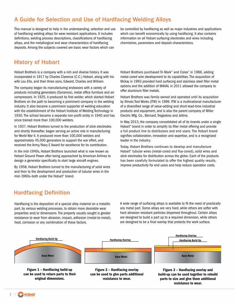
Hardfacing Build Up
Base Metal
Figure 1 – Hardfacing build-up can be used to return parts to their
original dimensions.
Hardfacing Overlay
Base Metal
Figure 2 – Hardfacing overlay can be used to give parts additional
resistance to wear.
Hardfacing Build Up
Hardfacing Overlay
Base Metal
Figure 3 – Hardfacing overlay and build-up can be used together to rebuild parts to size and give them additional
resistance to wear.
A Guide for Selection and Use of Hardfacing Welding Alloys
History of Hobart
Hardfacing is the deposition of a special alloy material on a metallic part, by various welding processes, to obtain more desirable wear properties and/or dimensions. The property usually sought is greater resistance to wear from abrasion, impact, adhesion (metal-to-metal), heat, corrosion or any combination of these factors.
A wide range of surfacing alloys is available to fit the need of practically any metal part. Some alloys are very hard, while others are softer with hard abrasion resistant particles dispersed throughout. Certain alloys are designed to build a part up to a required dimension, while others are designed to be a final overlay that protects the work surface.
Hardfacing Definition
1 •
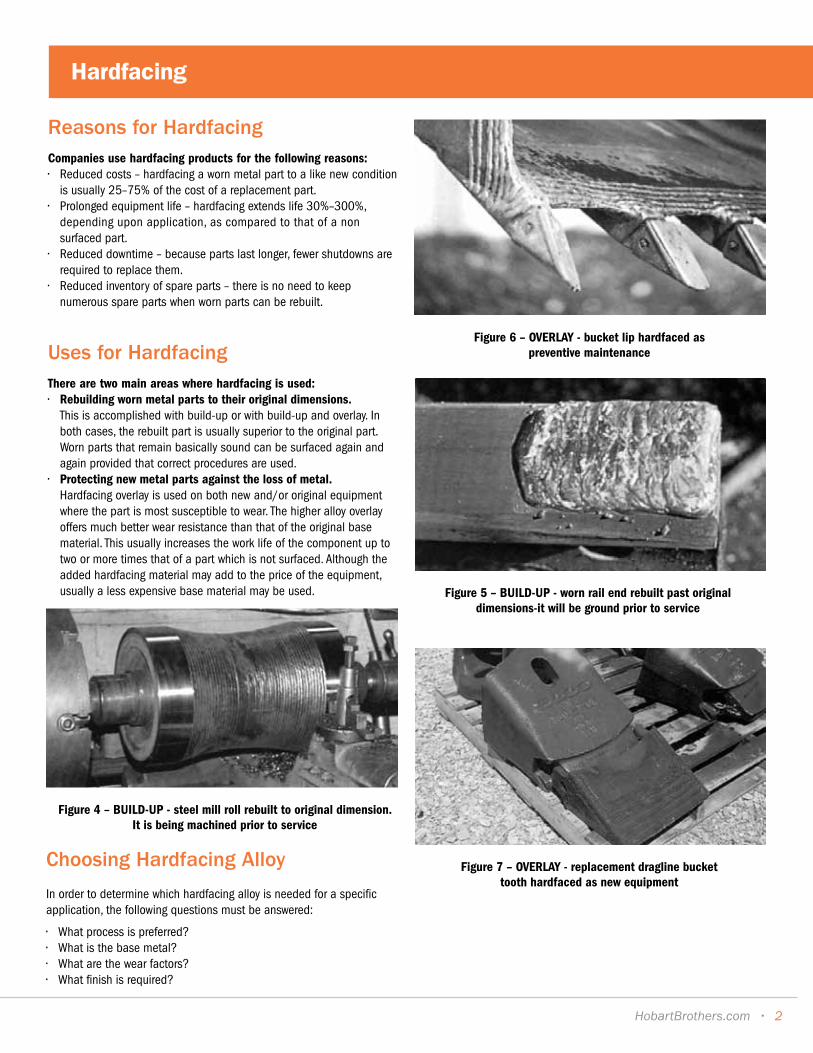
Reasons for HardfacingCompanies use hardfacing products for the following reasons:• Reduced costs – hardfacing a worn metal part to a like new condition
is usually 25–75% of the cost of a replacement part.• Prolonged equipment life – hardfacing extends life 30%–300%,
depending upon application, as compared to that of a non surfaced part.
• Reduced downtime – because parts last longer, fewer shutdowns are required to replace them.
• Reduced inventory of spare parts – there is no need to keep numerous spare parts when worn parts can be rebuilt.
Uses for HardfacingThere are two main areas where hardfacing is used:• Rebuilding worn metal parts to their original dimensions.
This is accomplished with build-up or with build-up and overlay. In both cases, the rebuilt part is usually superior to the original part. Worn parts that remain basically sound can be surfaced again and again provided that correct procedures are used.
• Protecting new metal parts against the loss of metal. Hardfacing overlay is used on both new and/or original equipment where the part is most susceptible to wear. The higher alloy overlay offers much better wear resistance than that of the original base material. This usually increases the work life of the component up to two or more times that of a part which is not surfaced. Although the added hardfacing material may add to the price of the equipment, usually a less expensive base material may be used.
Figure 4 – BUILD-UP - steel mill roll rebuilt to original dimension. It is being machined prior to service
Figure 5 – BUILD-UP - worn rail end rebuilt past original dimensions-it will be ground prior to service
Figure 6 – OVERLAY - bucket lip hardfaced as preventive maintenance
Figure 7 – OVERLAY - replacement dragline bucket tooth hardfaced as new equipment
Choosing Hardfacing Alloy
In order to determine which hardfacing alloy is needed for a specific application, the following questions must be answered:
• What process is preferred?• What is the base metal?• What are the wear factors?• What finish is required?
Hardfacing
HobartBrothers.com • 2
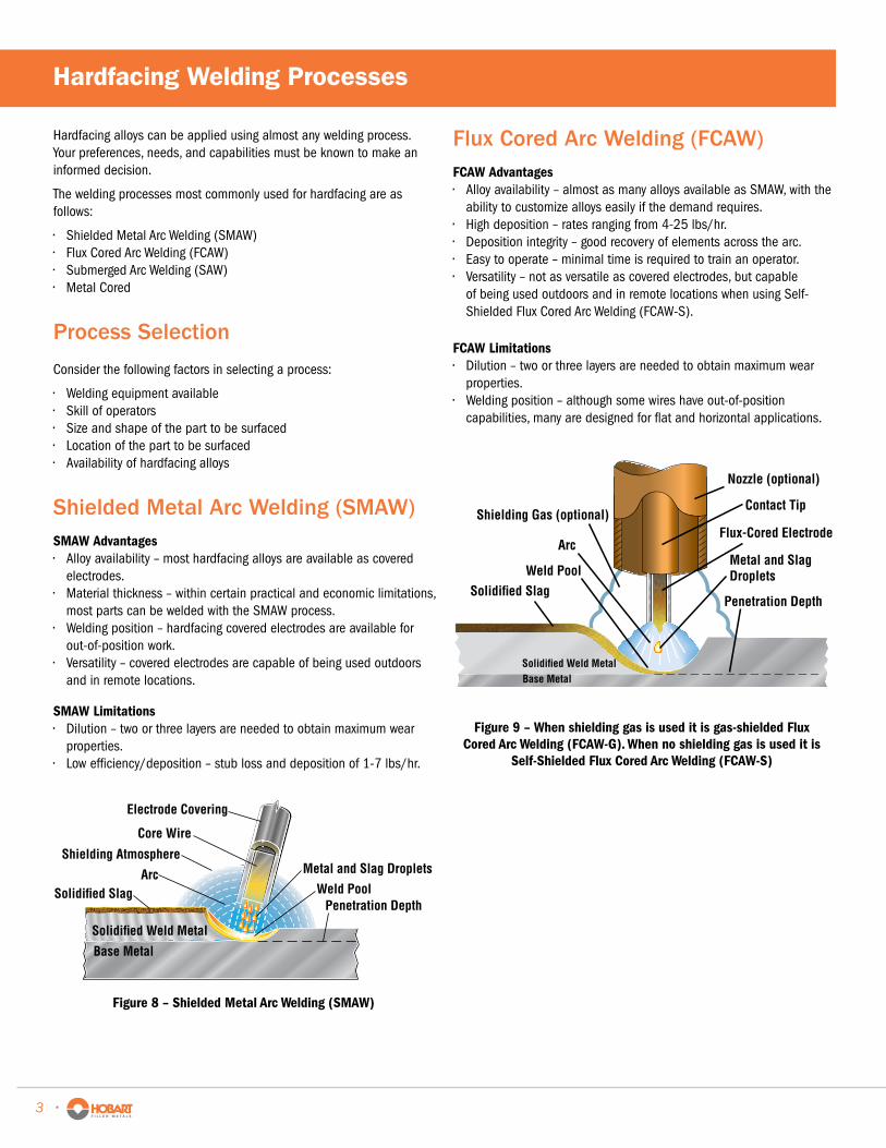
Hardfacing alloys can be applied using almost any welding process. Your preferences, needs, and capabilities must be known to make an informed decision.
The welding processes most commonly used for hardfacing are as follows:
• Shielded Metal Arc Welding (SMAW)• Flux Cored Arc Welding (FCAW)• Submerged Arc Welding (SAW)• Metal Cored
Process Selection
Consider the following factors in selecting a process:
• Welding equipment available• Skill of operators• Size and shape of the part to be surfaced• Location of the part to be surfaced• Availability of hardfacing alloys
Shielded Metal Arc Welding (SMAW)SMAW Advantages• Alloy availability – most hardfacing alloys are available as covered
electrodes.• Material thickness – within certain practical and economic limitations,
most parts can be welded with the SMAW process.• Welding position – hardfacing covered electrodes are available for
out-of-position work.• Versatility – covered electrodes are capable of being used outdoors
and in remote locations.
SMAW Limitations• Dilution – two or three layers are needed to obtain maximum wear
properties.• Low efficiency/deposition – stub loss and deposition of 1-7 lbs/hr.
Flux Cored Arc Welding (FCAW)FCAW Advantages• Alloy availability – almost as many alloys available as SMAW, with the
ability to customize alloys easily if the demand requires.• High deposition – rates ranging from 4-25 lbs/hr.• Deposition integrity – good recovery of elements across the arc.• Easy to operate – minimal time is required to train an operator.• Versatility – not as versatile as covered electrodes, but capable
of being used outdoors and in remote locations when using Self-Shielded Flux Cored Arc Welding (FCAW-S).
FCAW Limitations• Dilution – two or three layers are needed to obtain maximum wear
properties.• Welding position – although some wires have out-of-position
capabilities, many are designed for flat and horizontal applications.
Shielding Atmosphere
Weld PoolSolidified Slag
Base Metal
Solidified Weld Metal
Arc Metal and Slag Droplets
Penetration Depth
Electrode Covering
Core Wire
Figure 8 – Shielded Metal Arc Welding (SMAW)
Shielding Gas (optional)
Weld PoolSolidified Slag
Nozzle (optional)
Contact Tip
Base MetalSolidified Weld Metal
Flux-Cored ElectrodeArc
Penetration Depth
Metal and Slag Droplets
Figure 9 – When shielding gas is used it is gas-shielded Flux Cored Arc Welding (FCAW-G). When no shielding gas is used it is
Self-Shielded Flux Cored Arc Welding (FCAW-S)
Hardfacing Welding Processes
3 •
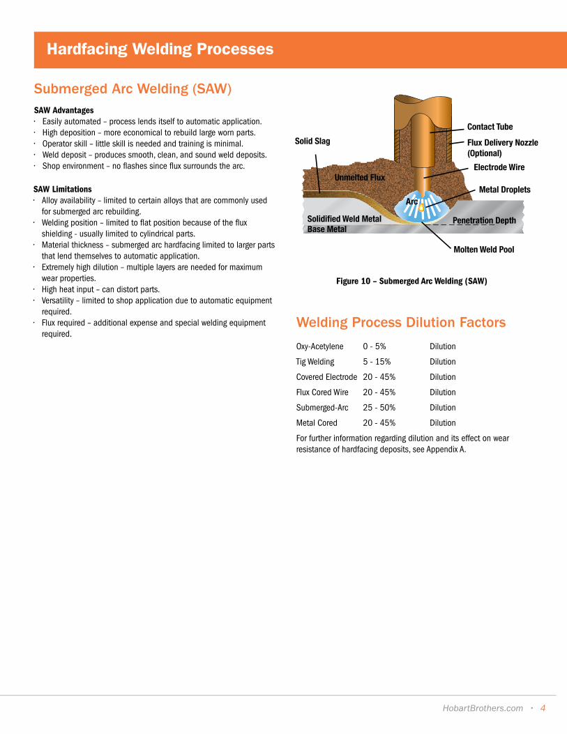
Submerged Arc Welding (SAW)SAW Advantages• Easily automated – process lends itself to automatic application.• High deposition – more economical to rebuild large worn parts.• Operator skill – little skill is needed and training is minimal.• Weld deposit – produces smooth, clean, and sound weld deposits.• Shop environment – no flashes since flux surrounds the arc.
SAW Limitations• Alloy availability – limited to certain alloys that are commonly used
for submerged arc rebuilding.• Welding position – limited to flat position because of the flux
shielding - usually limited to cylindrical parts.• Material thickness – submerged arc hardfacing limited to larger parts
that lend themselves to automatic application.• Extremely high dilution – multiple layers are needed for maximum
wear properties.• High heat input – can distort parts. • Versatility – limited to shop application due to automatic equipment
required.• Flux required – additional expense and special welding equipment
required.
Figure 10 – Submerged Arc Welding (SAW)
Base MetalSolidified Weld Metal
Contact Tube
Molten Weld Pool
Solid Slag
Electrode Wire
Flux Delivery Nozzle(Optional)
Metal DropletsArc
Unmelted Flux
Penetration Depth
Welding Process Dilution Factors
Oxy-Acetylene 0 - 5% Dilution
Tig Welding 5 - 15% Dilution
Covered Electrode 20 - 45% Dilution
Flux Cored Wire 20 - 45% Dilution
Submerged-Arc 25 - 50% Dilution
Metal Cored 20 - 45% Dilution
For further information regarding dilution and its effect on wear resistance of hardfacing deposits, see Appendix A.
HobartBrothers.com • 4
Hardfacing Welding Processes
Base Metal Preparation
Regardless of base metal, certain preparations must be made for successful hardfacing. Grease, oil, rust, dirt and other foreign materials should be removed prior to welding. Grinding or arc gouging should be used to remove old hardfacing deposits, cracks, or any work-hardened areas. If good surface preparation isn’t practiced before hardfacing, chances of cracking and/or spalling can occur before or after the part is put back into service.
Knowing the base material is essential in deciding which alloy to use for hardfacing as welding procedures differ according to the metal. Primarily, base materials for hardfacing fall into two broad classes:
• Carbon or low alloy steels• Austenitic manganese steels
The use of a magnet will generally distinguish the two classes. Carbon and low-alloy steels are strongly magnetic, while austenitic manganese steels are non-magnetic.
Carbon or Low Alloy Steels
There are so many grades of carbon and low alloy steels that no general recommendation for welding procedures can be given. As the carbon and/or alloy content within the base material increases, so do the necessary welding precautions. Preheating, post-heating, slow cooling or stress relieving may be needed. Particular caution should be used when depositing iron-base hardfacing alloys containing extensive carbides on carbon or low alloy steels; a brittle, crack sensitive interface can result.
Austenitic Manganese Steels
This tough, strong and ductile alloy steel has been utilized as a universal wear resistant component because it hardens under impact. Under its hardened, protective surface, the material retains its toughness, strength, and ductility. It also provides an excellent base for brittle, high chrome-carbide alloys. Although generally non-magnetic, work-hardened austenitic manganese shows some magnetism.
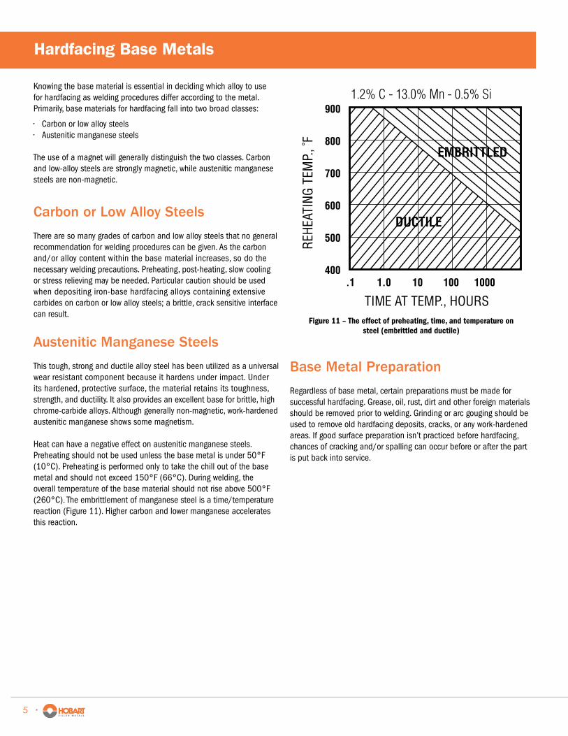
Heat can have a negative effect on austenitic manganese steels. Preheating should not be used unless the base metal is under 50°F (10°C). Preheating is performed only to take the chill out of the base metal and should not exceed 150°F (66°C). During welding, the overall temperature of the base material should not rise above 500°F (260°C). The embrittlement of manganese steel is a time/temperature reaction (Figure 11). Higher carbon and lower manganese accelerates this reaction.
EMBRITTLED
DUCTILE
TIME AT TEMP., HOURS
1.2% C - 13.0% Mn - 0.5% Si
REHE
ATIN
G TE
MP.
, ˚F
.1400
500
600
700
800
900
1.0 10 100 1000
Figure 11 – The effect of preheating, time, and temperature on steel (embrittled and ductile)
Hardfacing Base Metals
5 •

The wearing of metal parts might be defined as a gradual decay or breakdown of the metal. When a part becomes so deformed that it cannot perform adequately, it must be replaced or rebuilt. While the end results of wear are similar, the causes of wear are different. It is essential to understand the wear factors involved before making a hardfacing product selection.
It would be easy to select a surfacing alloy if all metal components were subjected to only one type of wear. However, a metal part is usually subjected to combinations of two or more types of wear. This makes an alloy selection considerably more complicated.
A hardfacing alloy should be chosen as a compromise between each wear factor. The initial focus should center on the primary wear factor and then the secondary wear factor(s) should be examined. For example; upon examining a worn metal part it is determined the primary wear factor is abrasion and the secondary wear factor is light impact. The surfacing alloy chosen should have very good abrasion resistance but also have a fair amount of impact resistance.
5 Major Wear Types
There are five major types of wear:
• Abrasive (3 categories)• Impact• Adhesive
Abrasive wear – Abrasive wear is caused by foreign materials rubbing against a metal part. It accounts for 55-60% of all wear on industrial metal components.
Abrasive wear is really a group of wear problems. It can be broken down into three main categories:
Low-stress scratching abrasion – Normally the least severe type of abrasion, metal parts are worn away through the repeated scouring action of hard, sharp particles moving across a metal surface at varying velocities (Figure 12 and Figure 13). The velocity, hardness, edge sharpness, angle of introduction and size of the abrasive particles all combine to affect the amount of abrasion.
Carbide containing alloys (particularly chrome-carbide) are used successfully to resist low-stress abrasive wear. Due to the absence of impact, the relatively brittle high carbon-chromium steel alloys are well suited for low-stress abrasive applications.
Typical components subjected to low-stress scratching abrasion include: agriculture implements, classifiers, screens, slurry pump nozzles, sand slingers, and chutes.
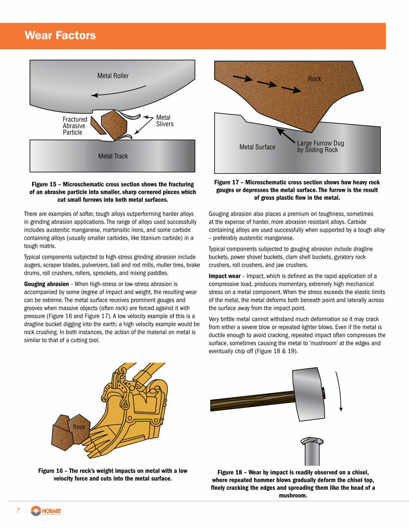
High-stress grinding abrasion – More intense than simple scratching, it results when small, hard, abrasive particles are forced against a metal surface with enough force that the particle is crushed in a grinding mode. Most often the compressive force is supplied by two metal components with the abrasive sandwiched between the two – sometimes referred to as three-body abrasion (Figure 14 and Figure 15). The surface becomes scored and surface cracking can occur.
Abrasive Material
Metal Chute
Figure 12 – Sliding abrasive material gently scratches the metal surface, gradually wearing it down.
Conventional Metal
Abrasive Particle
Metal Sliver
Figure 13 – Microschematic cross section shows how a moving abrasive grain scratches out a tiny sliver of metal.
Abrasive Debris or Dirt
Metal Roller or Wheel
Metal Track
Figure 14 – Two metal components squeeze abrasive material between them, breaking down the original particle size.
• High Temperature• Corrosive
Wear Factors
HobartBrothers.com • 6
Fractured Abrasive Particle
Metal Slivers
Metal Roller
Metal Track
Figure 15 – Microschematic cross section shows the fracturing of an abrasive particle into smaller, sharp cornered pieces which
cut small furrows into both metal surfaces.
Rock
Figure 16 – The rock’s weight impacts on metal with a low velocity force and cuts into the metal surface.
Rock
Metal Surface Large Furrow Dug by Sliding Rock
Figure 17 – Microschematic cross section shows how heavy rock gouges or depresses the metal surface. The furrow is the result
of gross plastic flow in the metal.
Figure 18 – Wear by impact is readily observed on a chisel, where repeated hammer blows gradually deform the chisel top, finely cracking the edges and spreading them like the head of a
mushroom.
There are examples of softer, tough alloys outperforming harder alloys in grinding abrasion applications. The range of alloys used successfully includes austenitic manganese, martensitic irons, and some carbide containing alloys (usually smaller carbides, like titanium carbide) in a tough matrix.
Typical components subjected to high-stress grinding abrasion include augers, scraper blades, pulverizers, ball and rod mills, muller tires, brake drums, roll crushers, rollers, sprockets, and mixing paddles.
Gouging abrasion – When high-stress or low-stress abrasion is accompanied by some degree of impact and weight, the resulting wear can be extreme. The metal surface receives prominent gouges and grooves when massive objects (often rock) are forced against it with pressure (Figure 16 and Figure 17). A low velocity example of this is a dragline bucket digging into the earth; a high velocity example would be rock crushing. In both instances, the action of the material on metal is similar to that of a cutting tool.
Gouging abrasion also places a premium on toughness, sometimes at the expense of harder, more abrasion resistant alloys. Carbide containing alloys are used successfully when supported by a tough alloy – preferably austenitic manganese.
Typical components subjected to gouging abrasion include dragline buckets, power shovel buckets, clam shell buckets, gyratory rock crushers, roll crushers, and jaw crushers.
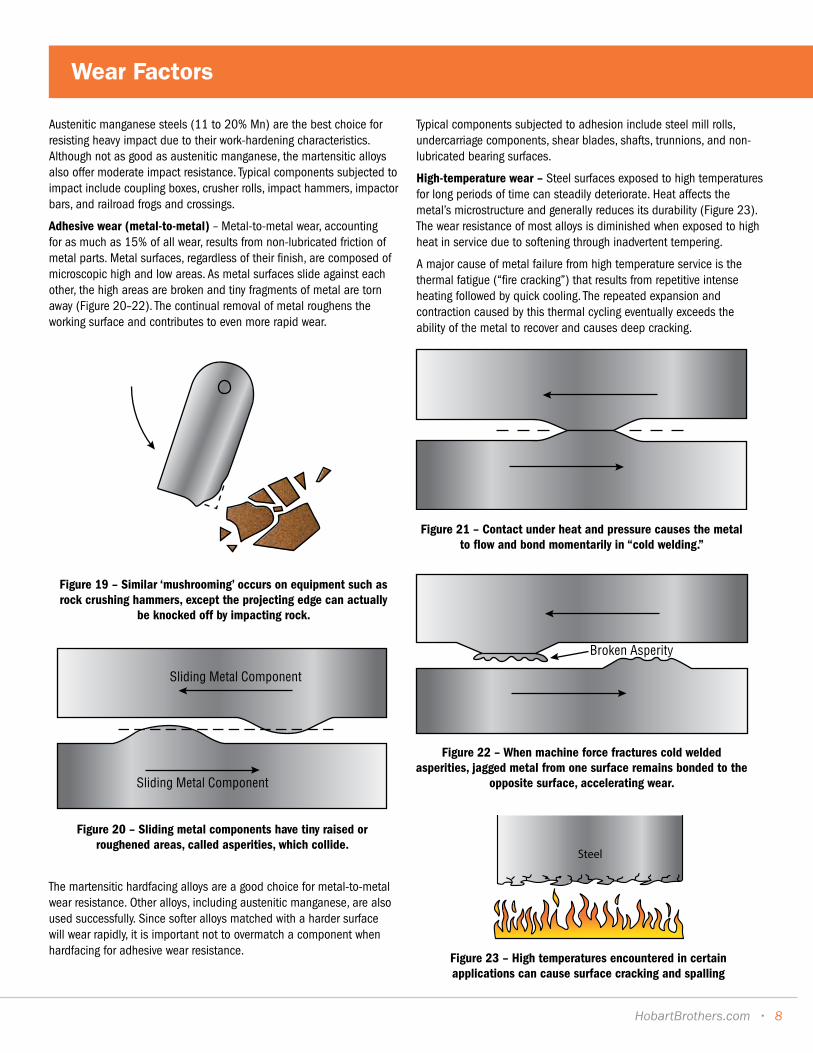
Impact wear – Impact, which is defined as the rapid application of a compressive load, produces momentary, extremely high mechanical stress on a metal component. When the stress exceeds the elastic limits of the metal, the metal deforms both beneath point and laterally across the surface away from the impact point.
Very brittle metal cannot withstand much deformation so it may crack from either a severe blow or repeated lighter blows. Even if the metal is ductile enough to avoid cracking, repeated impact often compresses the surface, sometimes causing the metal to ‘mushroom’ at the edges and eventually chip off (Figure 18 & 19).
Wear Factors
7
Austenitic manganese steels (11 to 20% Mn) are the best choice for resisting heavy impact due to their work-hardening characteristics. Although not as good as austenitic manganese, the martensitic alloys also offer moderate impact resistance. Typical components subjected to impact include coupling boxes, crusher rolls, impact hammers, impactor bars, and railroad frogs and crossings.
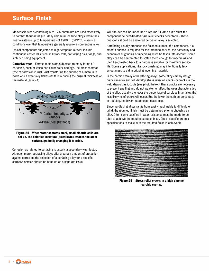
Adhesive wear (metal-to-metal) – Metal-to-metal wear, accounting for as much as 15% of all wear, results from non-lubricated friction of metal parts. Metal surfaces, regardless of their finish, are composed of microscopic high and low areas. As metal surfaces slide against each other, the high areas are broken and tiny fragments of metal are torn away (Figure 20–22). The continual removal of metal roughens the working surface and contributes to even more rapid wear.
Figure 19 – Similar ‘mushrooming’ occurs on equipment such as rock crushing hammers, except the projecting edge can actually
be knocked off by impacting rock.
Sliding Metal Component
Sliding Metal Component
Figure 20 – Sliding metal components have tiny raised or roughened areas, called asperities, which collide.
Figure 21 – Contact under heat and pressure causes the metal to flow and bond momentarily in “cold welding.”
Broken Asperity
Figure 22 – When machine force fractures cold welded asperities, jagged metal from one surface remains bonded to the
opposite surface, accelerating wear.
The martensitic hardfacing alloys are a good choice for metal-to-metal wear resistance. Other alloys, including austenitic manganese, are also used successfully. Since softer alloys matched with a harder surface will wear rapidly, it is important not to overmatch a component when hardfacing for adhesive wear resistance.
Typical components subjected to adhesion include steel mill rolls, undercarriage components, shear blades, shafts, trunnions, and non-lubricated bearing surfaces.
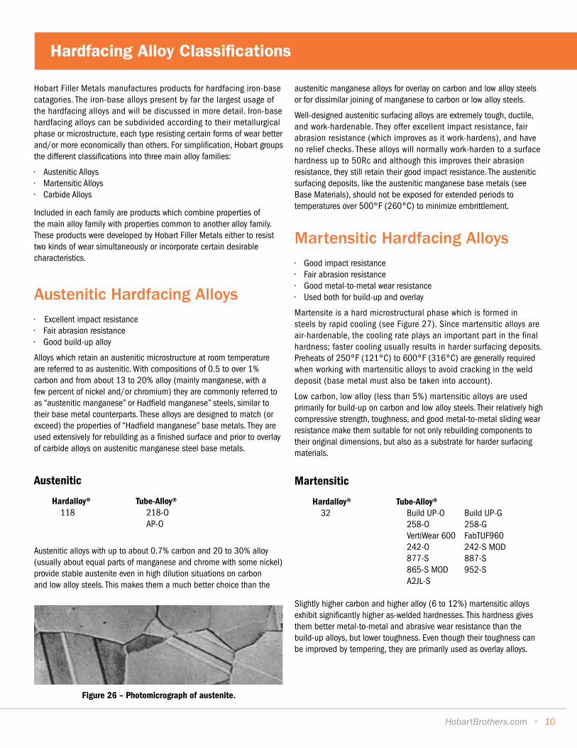
High-temperature wear – Steel surfaces exposed to high temperatures for long periods of time can steadily deteriorate. Heat affects the metal’s microstructure and generally reduces its durability (Figure 23). The wear resistance of most alloys is diminished when exposed to high heat in service due to softening through inadvertent tempering.
A major cause of metal failure from high temperature service is the thermal fatigue (“fire cracking”) that results from repetitive intense heating followed by quick cooling. The repeated expansion and contraction caused by this thermal cycling eventually exceeds the ability of the metal to recover and causes deep cracking.
Steel
Figure 23 – High temperatures encountered in certain applications can cause surface cracking and spalling
Wear Factors
HobartBrothers.com • 8
Martensitic steels containing 5 to 12% chromium are used extensively to combat thermal fatigue. Many chromium-carbide alloys retain their wear resistance up to temperatures of 1200°F (649°C ) – service conditions over that temperature generally require a non-ferrous alloy.
Typical components subjected to high temperature wear include continuous caster rolls, steel mill work rolls, hot forging dies, tongs, and sinter crushing equipment.
Corrosive wear – Ferrous metals are subjected to many forms of corrosion, each of which can cause wear damage. The most common type of corrosion is rust. Rust transforms the surface of a metal into oxide which eventually flakes off, thus reducing the original thickness of the metal (Figure 24).
Acidified Water (Electrolyte)
Rust
Carbon Impurity(Anode)
Plain Steel (Cathode)
Figure 24 – When water contacts steel, small electric cells are set up. The acidified moisture (electrolyte) attacks the steel
surface, gradually changing it to oxide.
Figure 25 – Stress relief cracks in a high chrome carbide overlay.
Corrosion as related to surfacing is usually a secondary wear factor. Although many hardfacing alloys offer a certain amount of protection against corrosion, the selection of a surfacing alloy for a specific corrosive service should be handled as a separate issue.
Will the deposit be machined? Ground? Flame cut? Must the component be heat-treated? Are relief checks acceptable? These questions should be answered before an alloy is selected.
Hardfacing usually produces the finished surface of a component. If a smooth surface is required for the intended service, the possibility and economics of grinding or machining must be taken into account. Some alloys can be heat treated to soften them enough for machining and then heat treated back to a hardness suitable for maximum service life. Some applications, like rock crushing, may intentionally lack smoothness to aid in gripping incoming material.
In the carbide family of hardfacing alloys, some alloys are by design crack sensitive and will develop stress relieving checks or cracks in the weld deposit as it cools (see photo below). These cracks are necessary to prevent spalling and do not weaken or affect the wear characteristics of the alloy. Usually, the lower the percentage of carbides in an alloy, the less likely relief cracks will occur. But the lower the carbide percentage in the alloy, the lower the abrasion resistance.
Since hardfacing alloys range from easily machinable to difficult to grind, the required finish must be determined prior to choosing an alloy. Often some sacrifice in wear resistance must be made to be able to achieve the required surface finish. Check specific product specifications to make sure the required finish is achievable.
Surface Finish
9 •
Hobart Filler Metals manufactures products for hardfacing iron-base catagories. The iron-base alloys present by far the largest usage of the hardfacing alloys and will be discussed in more detail. Iron-base hardfacing alloys can be subdivided according to their metallurgical phase or microstructure, each type resisting certain forms of wear better and/or more economically than others. For simplification, Hobart groups the different classifications into three main alloy families:
• Austenitic Alloys• Martensitic Alloys• Carbide Alloys
Included in each family are products which combine properties of the main alloy family with properties common to another alloy family. These products were developed by Hobart Filler Metals either to resist two kinds of wear simultaneously or incorporate certain desirable characteristics.
Austenitic Hardfacing Alloys • Excellent impact resistance• Fair abrasion resistance• Good build-up alloy
Alloys which retain an austenitic microstructure at room temperature are referred to as austenitic. With compositions of 0.5 to over 1% carbon and from about 13 to 20% alloy (mainly manganese, with a few percent of nickel and/or chromium) they are commonly referred to as “austenitic manganese” or Hadfield manganese” steels, similar to their base metal counterparts. These alloys are designed to match (or exceed) the properties of “Hadfield manganese” base metals. They are used extensively for rebuilding as a finished surface and prior to overlay of carbide alloys on austenitic manganese steel base metals.
Austenitic
Hardalloy® Tube-Alloy® 118 218-O AP-O
Austenitic alloys with up to about 0.7% carbon and 20 to 30% alloy (usually about equal parts of manganese and chrome with some nickel) provide stable austenite even in high dilution situations on carbon and low alloy steels. This makes them a much better choice than the
Figure 26 – Photomicrograph of austenite.
austenitic manganese alloys for overlay on carbon and low alloy steels or for dissimilar joining of manganese to carbon or low alloy steels.
Well-designed austenitic surfacing alloys are extremely tough, ductile, and work-hardenable. They offer excellent impact resistance, fair abrasion resistance (which improves as it work-hardens), and have no relief checks. These alloys will normally work-harden to a surface hardness up to 50Rc and although this improves their abrasion resistance, they still retain their good impact resistance. The austenitic surfacing deposits, like the austenitic manganese base metals (see Base Materials), should not be exposed for extended periods to temperatures over 500°F (260°C) to minimize embrittlement.
Martensitic Hardfacing Alloys • Good impact resistance• Fair abrasion resistance• Good metal-to-metal wear resistance• Used both for build-up and overlay
Martensite is a hard microstructural phase which is formed in steels by rapid cooling (see Figure 27). Since martensitic alloys are air-hardenable, the cooling rate plays an important part in the final hardness; faster cooling usually results in harder surfacing deposits. Preheats of 250°F (121°C) to 600°F (316°C) are generally required when working with martensitic alloys to avoid cracking in the weld deposit (base metal must also be taken into account).
Low carbon, low alloy (less than 5%) martensitic alloys are used primarily for build-up on carbon and low alloy steels. Their relatively high compressive strength, toughness, and good metal-to-metal sliding wear resistance make them suitable for not only rebuilding components to their original dimensions, but also as a substrate for harder surfacing materials.
Martensitic
Hardalloy® Tube-Alloy® 32 Build UP-O Build UP-G 258-O 258-G VertiWear 600 FabTUF960 242-O 242-S MOD 877-S 887-S 865-S MOD 952-S A2JL-S
Slightly higher carbon and higher alloy (6 to 12%) martensitic alloys exhibit significantly higher as-welded hardnesses. This hardness gives them better metal-to-metal and abrasive wear resistance than the build-up alloys, but lower toughness. Even though their toughness can be improved by tempering, they are primarily used as overlay alloys.
Hardfacing Alloy Classifications
HobartBrothers.com • 10
Another group of martensitic alloys common to hardfacing are the martensitic stainless steels. Containing up to about 0.25% carbon and 18% alloy (mainly chromium), this group of alloys exhibits excellent thermal shock resistance. They also offer good metal-to-metal wear resistance and moderate corrosion resistance. They require rigid welding procedures for successful application and are used extensively for steel mill roll (including continuous caster) overlay.
Martensitic hardfacing alloys provide a good balance of impact and abrasion resistance. By choosing the proper carbon-chromium content, it’s possible to choose the best compromise of abrasion, adhesion, and impact resistance. The ability of martensitic alloys to respond to heat treatment also makes it possible to change their hardness/toughness after welding to better suit the service conditions. This alloy family should not be used for joining applications and should not be applied to austenitic base metals.
Carbide Hardfacing Alloys • Excellent abrasion resistance• Good heat resistance• •Fair corrosion resistance• Fair to low impact resistance
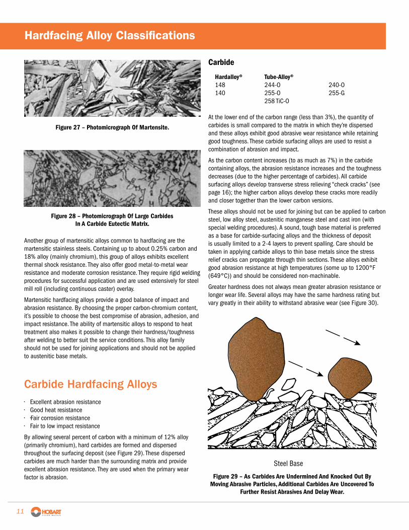
By allowing several percent of carbon with a minimum of 12% alloy (primarily chromium), hard carbides are formed and dispersed throughout the surfacing deposit (see Figure 29). These dispersed carbides are much harder than the surrounding matrix and provide excellent abrasion resistance. They are used when the primary wear factor is abrasion.
Figure 27 – Photomicrograph Of Martensite.
Carbide
Hardalloy® Tube-Alloy® 148 244-O 240-O 140 255-O 255-G 258 TiC-O At the lower end of the carbon range (less than 3%), the quantity of carbides is small compared to the matrix in which they’re dispersed and these alloys exhibit good abrasive wear resistance while retaining good toughness. These carbide surfacing alloys are used to resist a combination of abrasion and impact.
As the carbon content increases (to as much as 7%) in the carbide containing alloys, the abrasion resistance increases and the toughness decreases (due to the higher percentage of carbides). All carbide surfacing alloys develop transverse stress relieving “check cracks” (see page 16); the higher carbon alloys develop these cracks more readily and closer together than the lower carbon versions.
These alloys should not be used for joining but can be applied to carbon steel, low alloy steel, austenitic manganese steel and cast iron (with special welding procedures). A sound, tough base material is preferred as a base for carbide-surfacing alloys and the thickness of deposit is usually limited to a 2-4 layers to prevent spalling. Care should be taken in applying carbide alloys to thin base metals since the stress relief cracks can propagate through thin sections. These alloys exhibit good abrasion resistance at high temperatures (some up to 1200°F (649°C)) and should be considered non-machinable.
Greater hardness does not always mean greater abrasion resistance or longer wear life. Several alloys may have the same hardness rating but vary greatly in their ability to withstand abrasive wear (see Figure 30).
Figure 28 – Photomicrograph Of Large Carbides In A Carbide Eutectic Matrix.
Steel Base
Figure 29 – As Carbides Are Undermined And Knocked Out By Moving Abrasive Particles, Additional Carbides Are Uncovered To
Further Resist Abrasives And Delay Wear.
Hardfacing Alloy Classifications
11
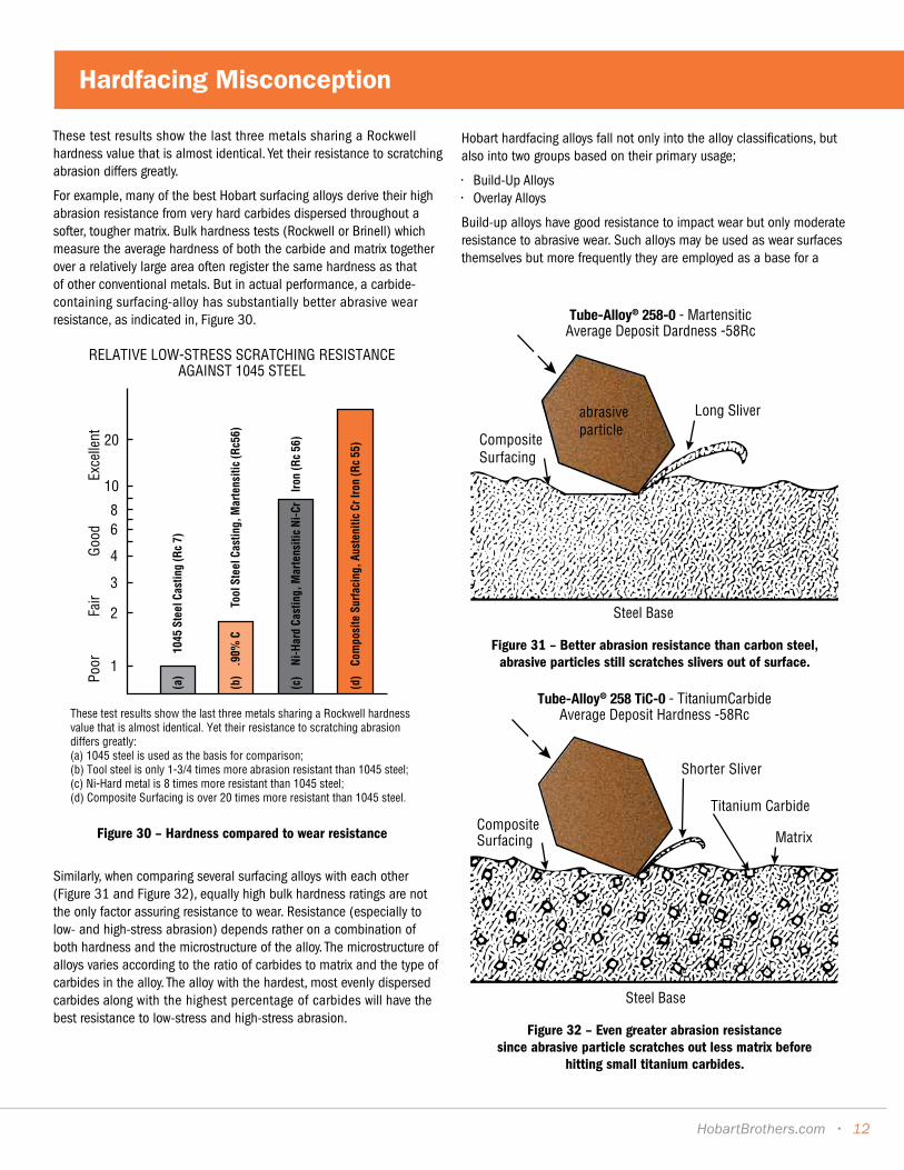
These test results show the last three metals sharing a Rockwell hardness value that is almost identical. Yet their resistance to scratching abrasion differs greatly.
For example, many of the best Hobart surfacing alloys derive their high abrasion resistance from very hard carbides dispersed throughout a softer, tougher matrix. Bulk hardness tests (Rockwell or Brinell) which measure the average hardness of both the carbide and matrix together over a relatively large area often register the same hardness as that of other conventional metals. But in actual performance, a carbide-containing surfacing-alloy has substantially better abrasive wear resistance, as indicated in, Figure 30.
Similarly, when comparing several surfacing alloys with each other (Figure 31 and Figure 32), equally high bulk hardness ratings are not the only factor assuring resistance to wear. Resistance (especially to low- and high-stress abrasion) depends rather on a combination of both hardness and the microstructure of the alloy. The microstructure of alloys varies according to the ratio of carbides to matrix and the type of carbides in the alloy. The alloy with the hardest, most evenly dispersed carbides along with the highest percentage of carbides will have the best resistance to low-stress and high-stress abrasion.
Hobart hardfacing alloys fall not only into the alloy classifications, but also into two groups based on their primary usage;
• Build-Up Alloys• Overlay Alloys
Build-up alloys have good resistance to impact wear but only moderate resistance to abrasive wear. Such alloys may be used as wear surfaces themselves but more frequently they are employed as a base for a
Poor
Fair
Good
Exce
llent
(a)
10
45St
eelC
astin
g(R
c7)
(b)
.90%
C
Tool
Stee
lCas
ting,
Mar
tens
itic
(Rc5
6)
(c)
Ni-H
ard
Cast
ing,
Mar
tens
itic
Ni-C
rIro
n(R
c56
)
(d)
Com
posi
teSu
rfaci
ng,A
uste
nitic
CrIro
n(R
c55
)20
10
86
4
3
2
1
These test results show the last three metals sharing a Rockwell hardness value that is almost identical. Yet their resistance to scratching abrasion differs greatly:(a) 1045 steel is used as the basis for comparison;(b) Tool steel is only 1-3/4 times more abrasion resistant than 1045 steel;(c) Ni-Hard metal is 8 times more resistant than 1045 steel;(d) Composite Surfacing is over 20 times more resistant than 1045 steel.
RELATIVE LOW-STRESS SCRATCHING RESISTANCE AGAINST 1045 STEEL
Figure 30 – Hardness compared to wear resistance
Tube-Alloy® 258-0 - MartensiticAverage Deposit Dardness -58Rc
Steel Base
CompositeSurfacing
Long Sliverabrasiveparticle
Figure 31 – Better abrasion resistance than carbon steel, abrasive particles still scratches slivers out of surface.
CompositeSurfacing
Tube-Alloy® 258 TiC-0 - TitaniumCarbideAverage Deposit Hardness -58Rc
Steel Base
Shorter Sliver
Titanium Carbide
Matrix
Figure 32 – Even greater abrasion resistance since abrasive particle scratches out less matrix before
hitting small titanium carbides.
Hardfacing Misconception
HobartBrothers.com • 12

harder, abrasion-resistant overlay. Both austenitic manganese and low alloy martensitic alloys are used for build-up.
Overlay alloys are hard overlays that have excellent abrasion resistance and fair to poor impact resistance. Due to their hardness, these alloys are usually limited to a specific number of layers. Certain martensitic alloys and all of the carbide alloys are used for overlay.
Welding Procedures For Surfacing Electrodes And Wires Hobart Hardalloy® Covered Surfacing Electrodes
In general, Hardalloy® electrodes have excellent operating characteristics in the flat position; vertical surfaces may be overlayed by building a series of horizontal beads on a “shelf.” As with most welding electrodes, the smaller diameters have better operating characteristics when welding vertical surfaces. For maximum deposition rate use higher amperages and a wide weave technique. For most Hardalloy® electrodes, weaving up to four electrode diameters is satisfactory. To minimize penetration and thus weld metal dilution, use lower amperages. Holding a longer arc (higher voltage) will produce a wider, flatter bead and will increase heat input into base metal. When welding on manganese steel castings, currents as low as possible should be used to prevent overheating of the base metal. The surface to be built up should be ground to remove the work hardened area, cracked or spalled metal, and any other foreign materials. Peening is recommended on heavy build-ups. Hobart Tube-Alloy® Surfacing Wires
Tube-Alloy® open-arc wires require no external shielding gas and have a steady arc with globular transfer. Spatter and noise levels are minimal, with complete slag coverage which removes easily. Increasing amperage will increase deposition rate, penetration (higher base metal dilution), and heat input to the base metal. Increasing voltage will widen and flatten the bead. Excessive voltage will result in porosity. Control of wire extension (stick-out) is important with excessively short stick-out resulting in scattered internal porosity and excessively long stick-out resulting in increased spatter. Tube-Alloy® open-arc wires can be used with either a variable or a constant voltage power source with the latter preferred. Constant and variable-speed wirefeeders both are being used successfully with the proper power source.
General Advantages of .045in. and 1/16in. Tube-Alloy® Wires• Permit marked reduction in welding costs (as much as 2/3 cost
savings) – deposition rate greater than that of manual electrodes or gas-shielded wires.
• Simplicity of operation with lightweight guns and no gas lines for shelf-shielded products.
• With proper procedure can be used to surface in the vertical position.
• More adaptable on small thin parts and edges – holds corners.
It must be emphasized that .045 and 1/16in. Tube-Alloy® wires are not all – position wires in the true sense of the word. They can be used to weld vertical surfaces with a horizontal stringer technique. A shelf may be required on the initial passes and operators should use amperages in the low end of the range (approximately 200 amps), fast travel speeds, and torch angles inclined up to 15 degrees.
Submerged Arc Welding Of Cylindrical Components For cylindrical submerged arc welding the factors which control bead contour are arc voltage, amperage, rotation speed, and lead.
Arc Voltage - Arc voltage should be preset at approximately 26–30 volts. A decrease in arc voltage will shorten the arc and tend to produce a higher, narrower bead. If the voltage is increased, the arc will become longer, penetration will be deeper, and additional dilution with the base metal will result.
Amperage - The rate of wire burnoff and heat input are functions of the welding current. With 1/8in. wire, a good starting point is 425 Amps. 5/32in., 500 Amps. More metal will be deposited with higher amperage but higher heat input will result. As heat builds up, especially in parts of small diameter, the contour of the bead is more difficult to control.
Rotating Surface Speed - A good starting point is approximately 16 in./minute. If the surface speed is increased, a narrower bead will result. When decreased, a wide bead is deposited.
Lead - After the above three parameters have been set, the contour of the bead can be controlled by varying the amount of lead. Lead is the distance ahead of dead center. Position the electrode ahead of dead center sufficiently so the molten pool solidifies as it passes top dead center.
Diameter Inches Ahead of Dead Center
3 in.–18in. 3/4in. to 1in.
18 in.–42in. 1 in. to 1-1/2in.
On small diameters, the correct lead is particularly important since the molten slag tends to run before freezing. When insufficient lead is used, the bead will be convex and undercut at the edges. When too much lead is used, the bead will be flat or concave and tend to have centerline cracks. The correct lead produces a bead having a slight crown and long lines of solidification.
Hobart Hard Surface Alloys
13 •
HARDFACING INDUSTRIES
• Agriculture
Crushing / Quarry
• Dredging
• Heavy Equipment / Mining
• Iron and Steel
• Power Generation
• Railroad
Hardfacing is used in almost every industry… wherever metal meets wear. Listed are the industries and applications where hardfacing is being used successfully; some industries have been consolidated due to similarity of applications. The products shown for each application on the following pages are general recommendations and are only to be used as a guide. For specific application recommendations, contact the technical staff at Hobart Filler Metals.
Applications
HobartBrothers.com • 14
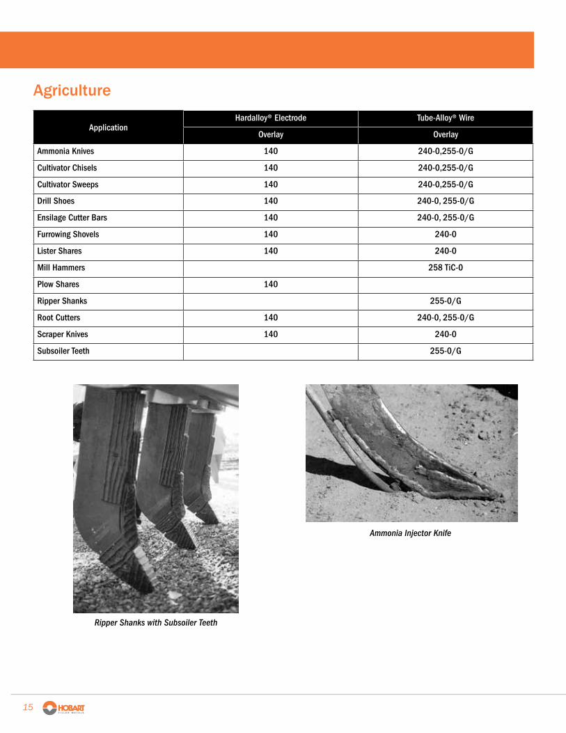
Ripper Shanks with Subsoiler Teeth
Ammonia Injector Knife
Agriculture
ApplicationHardalloy® Electrode Tube-Alloy® Wire
Overlay Overlay
Ammonia Knives 140 240-0,255-0/G
Cultivator Chisels 140 240-0,255-0/G
Cultivator Sweeps 140 240-0,255-0/G
Drill Shoes 140 240-0, 255-0/G
Ensilage Cutter Bars 140 240-0, 255-0/G
Furrowing Shovels 140 240-0
Lister Shares 140 240-0
Mill Hammers 258 TiC-0
Plow Shares 140
Ripper Shanks 255-0/G
Root Cutters 140 240-0, 255-0/G
Scraper Knives 140 240-0
Subsoiler Teeth 255-0/G
15
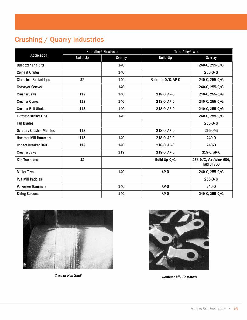
Crushing / Quarry Industries
ApplicationHardalloy® Electrode Tube-Alloy® Wire
Build-Up Overlay Build-Up Overlay
Bulldozer End Bits 140 240-0, 255-0/G
Cement Chutes 140 255-0/G
Clamshell Bucket Lips 32 140 Build Up-O/G, AP-0 240-0, 255-0/G
Conveyor Screws 140 240-0, 255-0/G
Crusher Jaws 118 140 218-0, AP-0 240-0, 255-0/G
Crusher Cones 118 140 218-0, AP-0 240-0, 255-0/G
Crusher Roll Shells 118 140 218-0, AP-0 240-0, 255-0/G
Elevator Bucket Lips 140 240-0, 255-0/G
Fan Blades 255-0/G
Gyratory Crusher Mantles 118 218-0, AP-0 255-0/G
Hammer Mill Hammers 118 140 218-0, AP-0 240-0
Impact Breaker Bars 118 140 218-0, AP-0 240-0
Crusher Jaws 118 218-0, AP-0 218-0, AP-0
Kiln Trunnions 32 Build Up-O/G 258-0/G, VertiWear 600, FabTUF960
Muller Tires 140 AP-0 240-0, 255-0/G
Pug Mill Paddles 255-0/G
Pulverizer Hammers 140 AP-0 240-0
Sizing Screens 140 AP-0 240-0, 255-0/G
Crusher Roll Shell Hammer Mill Hammers
HobartBrothers.com • 16
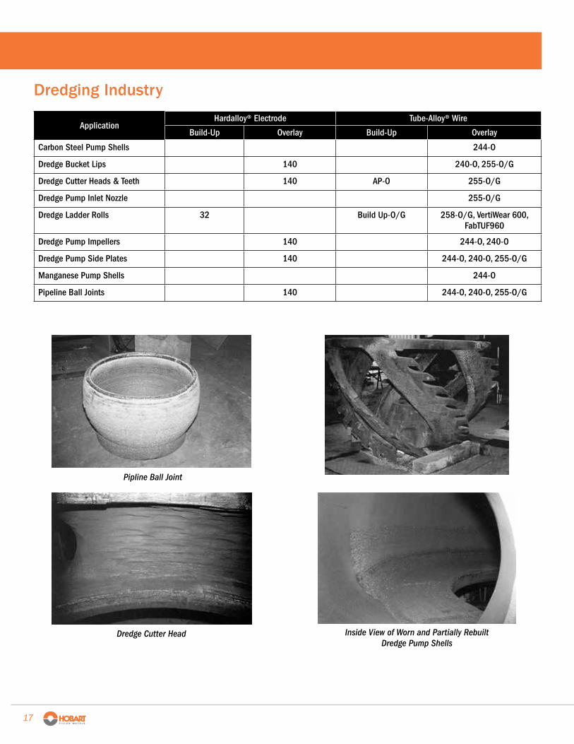
Dredging Industry
ApplicationHardalloy® Electrode Tube-Alloy® Wire
Build-Up Overlay Build-Up Overlay
Carbon Steel Pump Shells 244-O
Dredge Bucket Lips 140 240-O, 255-O/G
Dredge Cutter Heads & Teeth 140 AP-O 255-O/G
Dredge Pump Inlet Nozzle 255-O/G
Dredge Ladder Rolls 32 Build Up-O/G 258-O/G, VertiWear 600, FabTUF960
Dredge Pump Impellers 140 244-O, 240-O
Dredge Pump Side Plates 140 244-O, 240-O, 255-O/G
Manganese Pump Shells 244-O
Pipeline Ball Joints 140 244-O, 240-O, 255-O/G
Pipline Ball Joint
Dredge Cutter Head Inside View of Worn and Partially Rebuilt Dredge Pump Shells
17

Heavy Equipment / Mining Industries
ApplicationHardalloy® Electrode Tube-Alloy® Wire
Build-Up 0verlay Build-Up 0verlay
Bulldozer Blades 140 240-0, 255-0/G
Bulldozer End Bits 140 240-0, 255-0/G
Crane Wheels 32 Build Up-O/G 242-0, 242-S
Dragline Buckets 32 140 Build Up-O/G, AP-0, 240-0, 255-0/G
Dragline Chain 32 140 Build Up-O/G 258-0/G, 240-0, 255-0/G, VertiWear 600, FabTUF960
Drilling Augers 140 240-0, 255-0/G
Mine Car Wheels Build Up-O/G 242-S
Paving Agitator Screws 258TiC-0
Power Shovel Buckets 32 140 Build Up-O/G, AP-0 240-0, 255-0/G, 258-0/G, FabTUF960
Power Shovel Bucket Teeth 140 AP-0 240-0, 255-0/G, 258-0/G
Pug Mill Paddles 255-0/G
Ore/Coal Chutes 255-0/G
Road Rippers 255-0/G
Scraper Blades 140 240-0, 255-0/G
Scoop Lift Buckets 140 240-0, 255-0/G
Sheeps Foot Tampers 140 240-0, 255-0/G, 258-0/G, FabTUF960
Tractor Undercarriage Idlers 242-S
Tractor Undercarriage Rollers 242-S
Dragline Bucket
Tractor Undercarriage Idler
HobartBrothers.com • 18
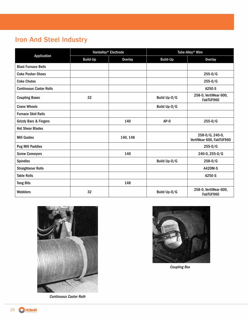
Continuous Caster Rollr
Coupling Box
Iron And Steel Industry
ApplicationHardalloy® Electrode Tube-Alloy® Wire
Build-Up 0verlay Build-Up 0verlay
Blast Furnace Bells
Coke Pusher Shoes 255-0/G
Coke Chutes 255-0/G
Continuous Caster Rolls A250-S
Coupling Boxes 32 Build Up-O/G258-0, VertiWear 600,
FabTUF960
Crane Wheels Build Up-O/G
Furnace Skid Rails
Grizzly Bars & Fingers 140 AP-0 255-0/G
Hot Shear Blades
Mill Guides 140, 148258-0/G, 240-0,
VertiWear 600, FabTUF960
Pug Mill Paddles 255-0/G
Screw Conveyors 140 240-0, 255-0/G
Spindles Build Up-O/G 258-0/G
Straightener Rolls A420M-S
Table Rolls A250-S
Tong Bits 148
Wobblers 32 Build Up-O/G258-0, VertiWear 600,
FabTUF960
19 •
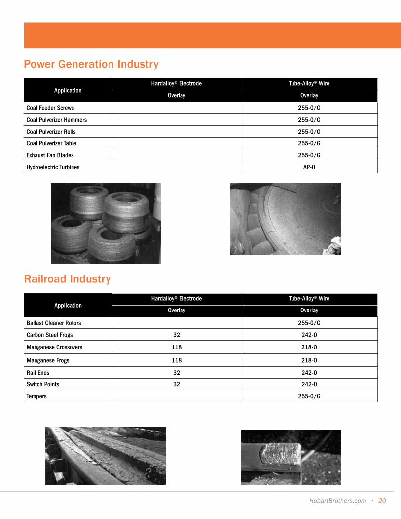
Power Generation Industry
ApplicationHardalloy® Electrode Tube-Alloy® Wire
Overlay Overlay
Coal Feeder Screws 255-0/G
Coal Pulverizer Hammers 255-0/G
Coal Pulverizer Rolls 255-0/G
Coal Pulverizer Table 255-0/G
Exhaust Fan Blades 255-0/G
Hydroelectric Turbines AP-0
Railroad Industry
ApplicationHardalloy® Electrode Tube-Alloy® Wire
Overlay Overlay
Ballast Cleaner Rotors 255-0/G
Carbon Steel Frogs 32 242-0
Manganese Crossovers 118 218-O
Manganese Frogs 118 218-O
Rail Ends 32 242-0
Switch Points 32 242-0
Tempers 255-0/G
HobartBrothers.com • 20
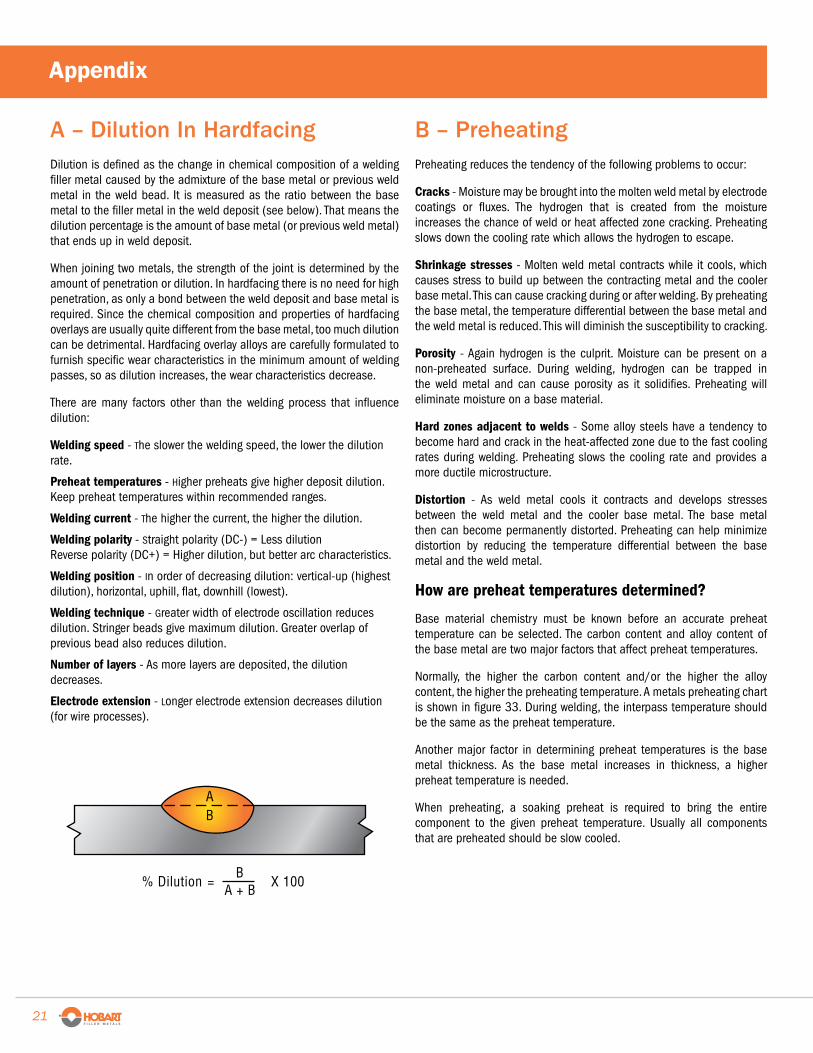
A – Dilution In Hardfacing Dilution is defined as the change in chemical composition of a welding filler metal caused by the admixture of the base metal or previous weld metal in the weld bead. It is measured as the ratio between the base metal to the filler metal in the weld deposit (see below). That means the dilution percentage is the amount of base metal (or previous weld metal) that ends up in weld deposit.
When joining two metals, the strength of the joint is determined by the amount of penetration or dilution. In hardfacing there is no need for high penetration, as only a bond between the weld deposit and base metal is required. Since the chemical composition and properties of hardfacing overlays are usually quite different from the base metal, too much dilution can be detrimental. Hardfacing overlay alloys are carefully formulated to furnish specific wear characteristics in the minimum amount of welding passes, so as dilution increases, the wear characteristics decrease.
There are many factors other than the welding process that influence dilution:
Welding speed - The slower the welding speed, the lower the dilution rate.
Preheat temperatures - Higher preheats give higher deposit dilution. Keep preheat temperatures within recommended ranges.
Welding current - The higher the current, the higher the dilution.
Welding polarity - Straight polarity (DC-) = Less dilution Reverse polarity (DC+) = Higher dilution, but better arc characteristics.
Welding position - In order of decreasing dilution: vertical-up (highest dilution), horizontal, uphill, flat, downhill (lowest).
Welding technique - Greater width of electrode oscillation reduces dilution. Stringer beads give maximum dilution. Greater overlap of previous bead also reduces dilution.
Number of layers - As more layers are deposited, the dilution decreases.
Electrode extension - Longer electrode extension decreases dilution (for wire processes).
= X 100B
A + B
AB
% Dilution
B – Preheating Preheating reduces the tendency of the following problems to occur:
Cracks - Moisture may be brought into the molten weld metal by electrode coatings or fluxes. The hydrogen that is created from the moisture increases the chance of weld or heat affected zone cracking. Preheating slows down the cooling rate which allows the hydrogen to escape.
Shrinkage stresses - Molten weld metal contracts while it cools, which causes stress to build up between the contracting metal and the cooler base metal. This can cause cracking during or after welding. By preheating the base metal, the temperature differential between the base metal and the weld metal is reduced. This will diminish the susceptibility to cracking.
Porosity - Again hydrogen is the culprit. Moisture can be present on a non-preheated surface. During welding, hydrogen can be trapped in the weld metal and can cause porosity as it solidifies. Preheating will eliminate moisture on a base material.
Hard zones adjacent to welds - Some alloy steels have a tendency to become hard and crack in the heat-affected zone due to the fast cooling rates during welding. Preheating slows the cooling rate and provides a more ductile microstructure.
Distortion - As weld metal cools it contracts and develops stresses between the weld metal and the cooler base metal. The base metal then can become permanently distorted. Preheating can help minimize distortion by reducing the temperature differential between the base metal and the weld metal.
How are preheat temperatures determined?
Base material chemistry must be known before an accurate preheat temperature can be selected. The carbon content and alloy content of the base metal are two major factors that affect preheat temperatures.
Normally, the higher the carbon content and/or the higher the alloy content, the higher the preheating temperature. A metals preheating chart is shown in figure 33. During welding, the interpass temperature should be the same as the preheat temperature.
Another major factor in determining preheat temperatures is the base metal thickness. As the base metal increases in thickness, a higher preheat temperature is needed.
When preheating, a soaking preheat is required to bring the entire component to the given preheat temperature. Usually all components that are preheated should be slow cooled.
Appendix
21 •
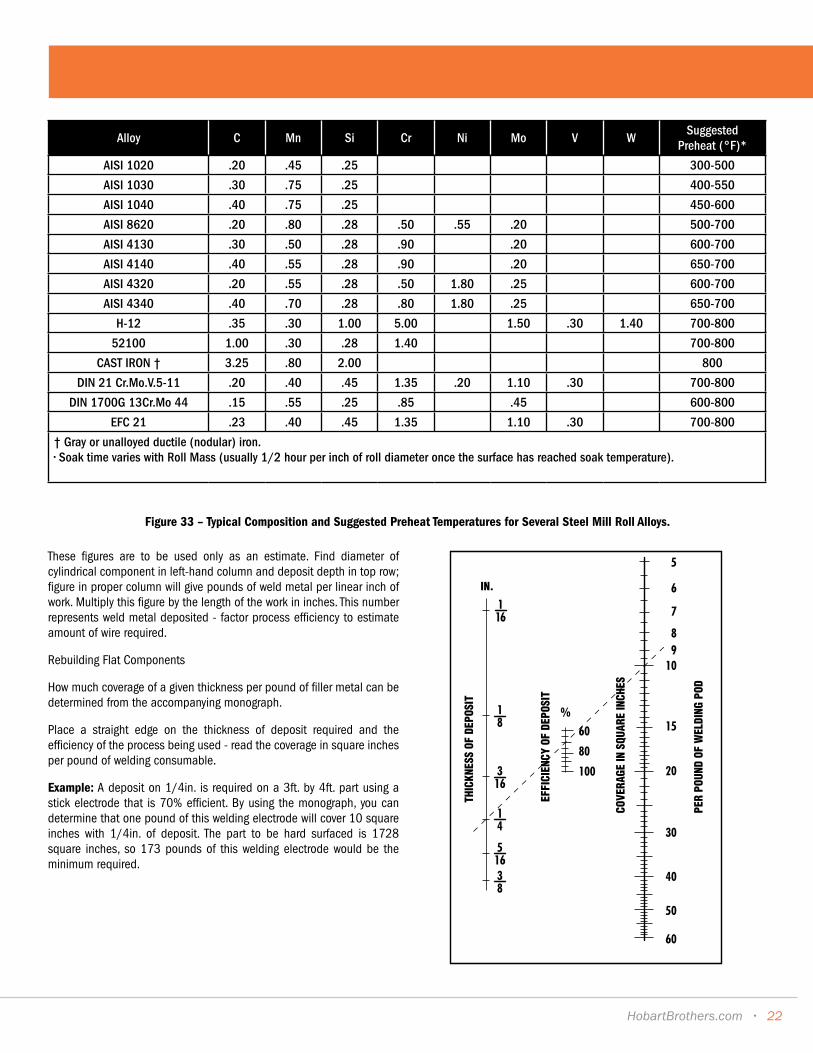
Alloy C Mn Si Cr Ni Mo V WSuggested
Preheat (°F)*
AISI 1020 .20 .45 .25 300-500
AISI 1030 .30 .75 .25 400-550
AISI 1040 .40 .75 .25 450-600
AISI 8620 .20 .80 .28 .50 .55 .20 500-700
AISI 4130 .30 .50 .28 .90 .20 600-700
AISI 4140 .40 .55 .28 .90 .20 650-700
AISI 4320 .20 .55 .28 .50 1.80 .25 600-700
AISI 4340 .40 .70 .28 .80 1.80 .25 650-700
H-12 .35 .30 1.00 5.00 1.50 .30 1.40 700-800
52100 1.00 .30 .28 1.40 700-800
CAST IRON † 3.25 .80 2.00 800
DIN 21 Cr.Mo.V.5-11 .20 .40 .45 1.35 .20 1.10 .30 700-800
DIN 1700G 13Cr.Mo 44 .15 .55 .25 .85 .45 600-800
EFC 21 .23 .40 .45 1.35 1.10 .30 700-800
† Gray or unalloyed ductile (nodular) iron.• Soak time varies with Roll Mass (usually 1/2 hour per inch of roll diameter once the surface has reached soak temperature).
Figure 33 – Typical Composition and Suggested Preheat Temperatures for Several Steel Mill Roll Alloys.
These figures are to be used only as an estimate. Find diameter of cylindrical component in left-hand column and deposit depth in top row; figure in proper column will give pounds of weld metal per linear inch of work. Multiply this figure by the length of the work in inches. This number represents weld metal deposited - factor process efficiency to estimate amount of wire required.
Rebuilding Flat Components
How much coverage of a given thickness per pound of filler metal can be determined from the accompanying monograph.
Place a straight edge on the thickness of deposit required and the efficiency of the process being used - read the coverage in square inches per pound of welding consumable.
Example: A deposit on 1/4in. is required on a 3ft. by 4ft. part using a stick electrode that is 70% efficient. By using the monograph, you can determine that one pound of this welding electrode will cover 10 square inches with 1/4in. of deposit. The part to be hard surfaced is 1728 square inches, so 173 pounds of this welding electrode would be the minimum required.
THIC
KNES
S OF
DEP
OSIT
EFFI
CIEN
CY O
F DE
POSI
T
COVE
RAGE
IN S
QUAR
E IN
CHES
PER
POUN
D OF
WEL
DING
POD
IN.
HobartBrothers.com • 22
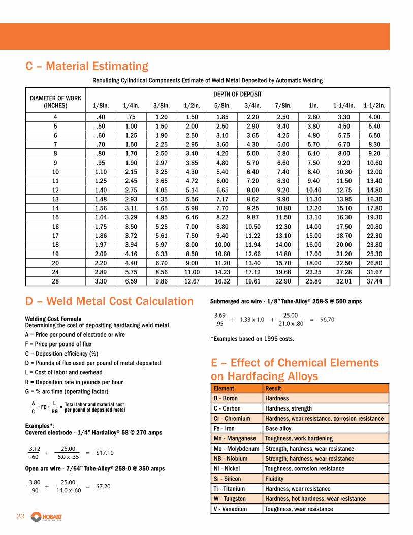
C – Material EstimatingRebuilding Cylindrical Components Estimate of Weld Metal Deposited by Automatic Welding
DIAMETER OF WORKDEPTH OF DEPOSIT
(INCHES) 1/8in. 1/4in. 3/8in. 1/2in. 5/8in. 3/4in. 7/8in. 1in. 1-1/4in. 1-1/2in.
4 .40 .75 1.20 1.50 1.85 2.20 2.50 2.80 3.30 4.005 .50 1.00 1.50 2.00 2.50 2.90 3.40 3.80 4.50 5.406 .60 1.25 1.90 2.50 3.10 3.65 4.25 4.80 5.75 6.507 .70 1.50 2.25 2.95 3.60 4.30 5.00 5.70 6.70 8.308 .80 1.70 2.50 3.40 4.20 5.00 5.80 6.10 8.00 9.209 .95 1.90 2.97 3.85 4.80 5.70 6.60 7.50 9.20 10.60
10 1.10 2.15 3.25 4.30 5.40 6.40 7.40 8.40 10.30 12.0011 1.25 2.45 3.65 4.72 6.00 7.20 8.30 9.40 11.50 13.4012 1.40 2.75 4.05 5.14 6.65 8.00 9.20 10.40 12.75 14.8013 1.48 2.93 4.35 5.56 7.17 8.62 9.90 11.30 13.95 16.3014 1.56 3.11 4.65 5.98 7.70 9.25 10.80 12.20 15.10 17.8015 1.64 3.29 4.95 6.46 8.22 9.87 11.50 13.10 16.30 19.3016 1.75 3.50 5.25 7.00 8.80 10.50 12.30 14.00 17.50 20.8017 1.86 3.72 5.61 7.50 9.40 11.22 13.10 15.00 18.70 22.3018 1.97 3.94 5.97 8.00 10.00 11.94 14.00 16.00 20.00 23.8019 2.09 4.16 6.33 8.50 10.60 12.66 14.80 17.00 21.20 25.3020 2.20 4.40 6.70 9.00 11.20 13.40 15.70 18.00 22.50 26.8024 2.89 5.75 8.56 11.00 14.23 17.12 19.68 22.25 27.28 31.6728 3.30 6.59 9.86 12.67 16.32 19.61 22.90 25.86 32.01 37.44
D – Weld Metal Cost Calculation Welding Cost FormulaDetermining the cost of depositing hardfacing weld metalA = Price per pound of electrode or wireF = Price per pound of fluxC = Deposition efficiency (%)D = Pounds of flux used per pound of metal depositedL = Cost of labor and overheadR = Deposition rate in pounds per hourG = % arc time (operating factor)
Examples*:Covered electrode - 1/4” Hardalloy® 58 @ 270 amps
Open arc wire - 7/64” Tube-Alloy® 258-O @ 350 amps
AFD
LC RG
+ + = Total labor and material cost per pound of deposited metal
E – Effect of Chemical Elements on Hardfacing AlloysElement Result
B - Boron Hardness
C - Carbon Hardness, strength
Cr - Chromium Hardness, wear resistance, corrosion resistance
Fe - Iron Base alloy
Mn - Manganese Toughness, work hardening
Mo - Molybdenum Strength, hardness, wear resistance
NB - Niobium Strength, hardness, wear resistance
Ni - Nickel Toughness, corrosion resistance
Si - Silicon Fluidity
Ti - Titanium Hardness, wear resistance
W - Tungsten Hardness, hot hardness, wear resistance
V - Vanadium Toughness, wear resistance
Submerged arc wire - 1/8” Tube-Alloy® 258-S @ 500 amps
*Examples based on 1995 costs.
23 •

Notes
HobartBrothers.com • 24
HobartBrothers.com©2020 Hobart Brothers CompanyHobart and the Hobart logo are trademarks of Illinois Tool Works Inc. Rev 9/20
Hardfacing Technical Welding Guide
ADMINISTRATIVE OFFICES, RESEARCH FACILITIES AND FACTORY
Hobart Welding Products 101 Trade Square East Troy, OH 45373 U.S.A.
NATIONAL INSIDE SALES SERVICE:
In the U.S.A. Phone: (800) 424-1543 Fax: (800) 541-6607
International Phone: (937) 332-5188 Fax: (937) 332-5898
DISTRIBUTION CENTERS:
Fort Worth, TX Troy, OH Portland, OR
APPLICATIONS ENGINEERING:
Contact: Phone: (800) 532-2618 Email: [email protected]