Laser Welding and Hybrid Welding of Aluminium Alloys
7
Laser Welding and Hybrid Welding of Aluminium Alloys Seiji Katayama, Yousuke Kawahito and Masami Mizutani Joining and Welding Research Institute, Osaka University 11-1 Mihogaoka, Ibaraki, Osaka 567-0047, Japan Laser welding of aluminium alloys was performed with high power YAG, fiber or disk laser. Interaction between laser and plume, laser absorption, welding phenomena and weldability were investigated by using such lasers. The absorption of a focused fiber laser in aluminium alloy was found to be higher at high powers and low welding speeds than that in stainless steel. Hybrid welding of A5052 alloy with YAG, fiber or disk and MIG arc was performed to understand welding phenomena, the mechanisms of weld penetration, porosity formation and prevention, etc. The conditions for the production of sound deep welds were clarified. Furthermore, the addition of the other filler wire during hybrid butt-joint welding was also investigated, and the effect of the increase in gap tolerance was confirmed. Keywords: Laser welding, Hybrid welding, Laser absorption, Welding defects, Welding phenomena 1. Introduction Aluminium alloys have great potential in every industry due to their low densities and good mechanical properties. However, laser welding of aluminium alloys is generally known to be difficult. Many reports and literatures deal with laser welding of aluminium alloys [1-30]. Recently, the physical phenomena and mechanisms concerning penetration and porosity suppression methods have been understood. Therefore, this paper describes our welding results and characteristics concerning fiber laser absorption and weld penetration in aluminium alloy, welding defects and prevention methods in fiber laser welding, laser-arc hybrid welding utilizing an additive filler wire, and so on. 2. Experimental Procedures and Results 2.1 Interaction between laser beam and plume during laser welding Interaction between YAG laser-induced plume and probe laser was visually investigated by using the measuring system, as shown in Fig. 1. Refraction and attenuation of the probe fiber laser beam are also confirmed in Fig. 1. These data of Type 304 and A5083 alloy are summarized in Table 1. The level of attenuation for A5083 alloy is judged to be much smaller than Type 304. It was found that the degrees of attenuation of laser powers were proportional to λ -4 (λ:wavelength of laser beam) by using a fiber laser (λ =1.09 μm), a diode laser (λ =0.83 μm) and a He-Ne laser (λ =0.633 μm) as probe lasers. Therefore, the attenuation of laser power due to laser-induced plume is chiefly attributed to Rayleigh scattering induced by ultrafine particles produced during laser welding. In fact, the interaction of an incident laser beam to the plume and the upper part of low refractive indexes is important rather than the probe laser beam. It was also found that the beam refraction and defocusing Refraction angle ϑ [mrad] Probe laser height 10 mm Probe laser SUS304 Aperture ϑ ϑ ≒ Tanϑ = D spot /L (L≫ D spot ) Probe laser height, h p [mm] 4.4 s 4.1 s 3.9 s 3.8 s 0 s 2 mm 2 mm Refraction angle ϑ [mrad] Probe laser height 10 mm Probe laser SUS304 Aperture L=2.9 m D spot ϑ ϑ ≒ Tanϑ = D spot /L (L≫ D spot ) Probe laser height, h p [mm] 4.4 s 4.1 s 3.9 s 3.8 s 0 s 2 mm 2 mm 4.4 s 4.1 s 3.9 s 3.8 s 0 s 2 mm 2 mm Fig. 1 Visualization results of probe laser beam, showing refraction and attenua- tion as interaction between probe laser and laser-induced plume during welding. 908 Proceedings of the 12th International Conference on Aluminium Alloys, September 5-9, 2010, Yokohama, Japan ©2010 The Japan Institute of Light Metals pp. 908-914
-
Upload
khangminh22 -
Category
Documents
-
view
0 -
download
0
Transcript of Laser Welding and Hybrid Welding of Aluminium Alloys
Proceedings of the 12th International Conference on Aluminium Alloys, September 5-9, 2010, Yokohama, Japan ©2010 The Japan Institute of Light Metals
Laser Welding and Hybrid Welding of Aluminium Alloys
Seiji Katayama, Yousuke Kawahito and Masami Mizutani Joining and Welding Research Institute, Osaka University
11-1 Mihogaoka, Ibaraki, Osaka 567-0047, Japan Laser welding of aluminium alloys was performed with high power YAG, fiber or disk laser. Interaction between laser and plume, laser absorption, welding phenomena and weldability were investigated by using such lasers. The absorption of a focused fiber laser in aluminium alloy was found to be higher at high powers and low welding speeds than that in stainless steel. Hybrid welding of A5052 alloy with YAG, fiber or disk and MIG arc was performed to understand welding phenomena, the mechanisms of weld penetration, porosity formation and prevention, etc. The conditions for the production of sound deep welds were clarified. Furthermore, the addition of the other filler wire during hybrid butt-joint welding was also investigated, and the effect of the increase in gap tolerance was confirmed.
Keywords: Laser welding, Hybrid welding, Laser absorption, Welding defects, Welding phenomena
1. Introduction Aluminium alloys have great potential in every industry due to their low densities and good mechanical properties. However, laser welding of aluminium alloys is generally known to be difficult. Many reports and literatures deal with laser welding of aluminium alloys [1-30]. Recently, the physical phenomena and mechanisms concerning penetration and porosity suppression methods have been understood.
Therefore, this paper describes our welding results and characteristics concerning fiber laser absorption and weld penetration in aluminium alloy, welding defects and prevention methods in fiber laser welding, laser-arc hybrid welding utilizing an additive filler wire, and so on.
2. Experimental Procedures and Results
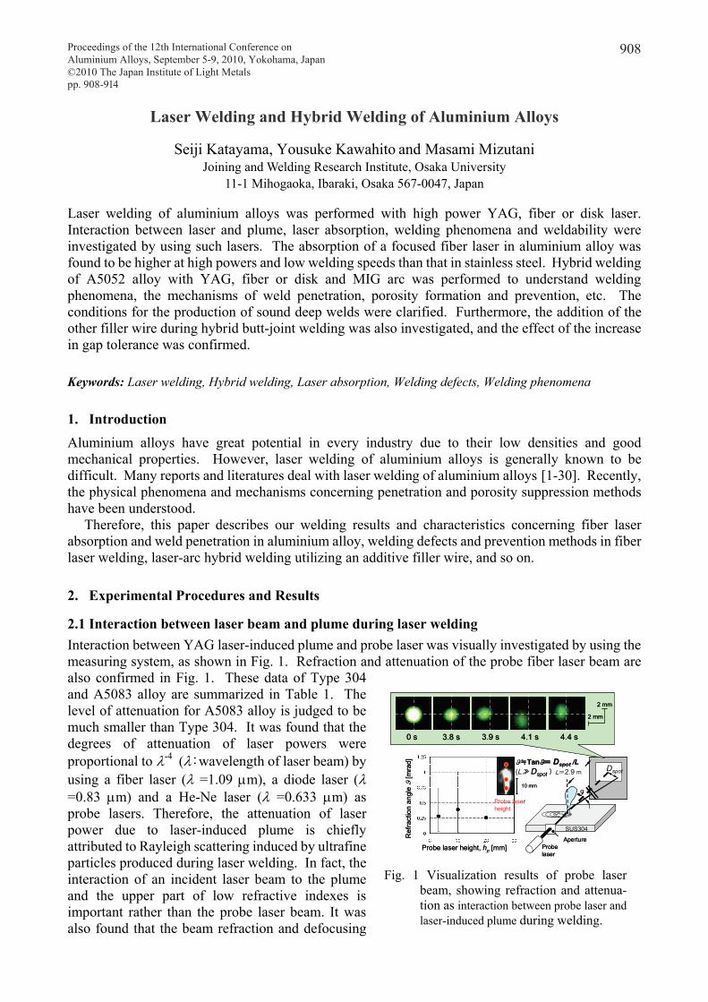
2.1 Interaction between laser beam and plume during laser welding Interaction between YAG laser-induced plume and probe laser was visually investigated by using the measuring system, as shown in Fig. 1. Refraction and attenuation of the probe fiber laser beam are also confirmed in Fig. 1. These data of Type 304 and A5083 alloy are summarized in Table 1. The level of attenuation for A5083 alloy is judged to be much smaller than Type 304. It was found that the degrees of attenuation of laser powers were proportional to λ-4 (λ:wavelength of laser beam) by using a fiber laser (λ =1.09 μm), a diode laser (λ =0.83 μm) and a He-Ne laser (λ =0.633 μm) as probe lasers. Therefore, the attenuation of laser power due to laser-induced plume is chiefly attributed to Rayleigh scattering induced by ultrafine particles produced during laser welding. In fact, the interaction of an incident laser beam to the plume and the upper part of low refractive indexes is important rather than the probe laser beam. It was also found that the beam refraction and defocusing
Ref
ract
ion
angl
e ϑ
[mra
d]
Probe laser height
10 mm
Probe laser
SUS304
Aperture
L=2.9 m Dspot
ϑ
ϑ≒Tanϑ= Dspot /L(L≫ Dspot )
Probe laser height, hp [mm]
4.4 s4.1 s3.9 s3.8 s0 s
2 mm
2 mm
Ref
ract
ion
angl
e ϑ
[mra
d]
Probe laser height
10 mm
Probe laser
SUS304
Aperture
L=2.9 m Dspot
ϑ
ϑ≒Tanϑ= Dspot /L(L≫ Dspot )
Probe laser height, hp [mm]
4.4 s4.1 s3.9 s3.8 s0 s
2 mm
2 mm
4.4 s4.1 s3.9 s3.8 s0 s
2 mm
2 mm
Fig. 1 Visualization results of probe laser beam, showing refraction and attenua- tion as interaction between probe laser and laser-induced plume during welding.
908Proceedings of the 12th International Conference on Aluminium Alloys, September 5-9, 2010, Yokohama, Japan©2010 The Japan Institute of Light Metals pp. 908-914
should be considered in the case of remote welding utilizing a high quality laser such as fiber laser and disk laser. It was furthermore confirmed that the effect of the plume on weld penetration was small when the plume was suppressed to be short and small.
2.2 Laser absorption during welding of
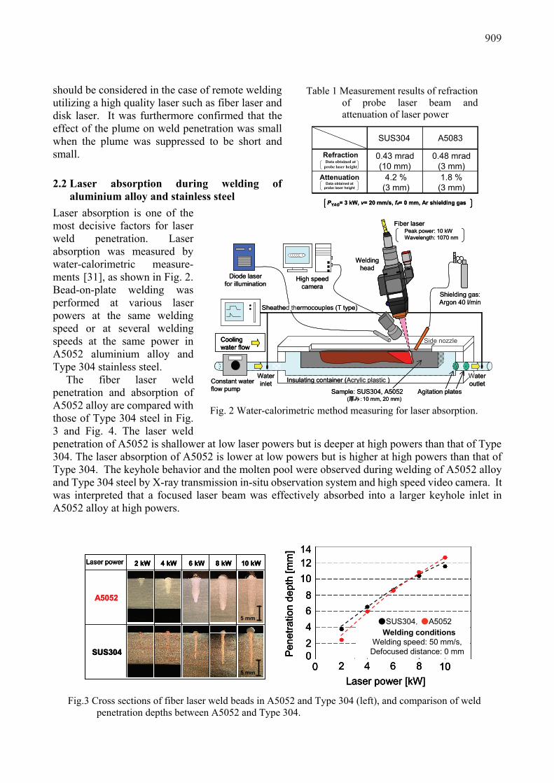
aluminium alloy and stainless steel Laser absorption is one of the most decisive factors for laser weld penetration. Laser absorption was measured by water-calorimetric measure- ments [31], as shown in Fig. 2. Bead-on-plate welding was performed at various laser powers at the same welding speed or at several welding speeds at the same power in A5052 aluminium alloy and Type 304 stainless steel.
The fiber laser weld penetration and absorption of A5052 alloy are compared with those of Type 304 steel in Fig. 3 and Fig. 4. The laser weld penetration of A5052 is shallower at low laser powers but is deeper at high powers than that of Type 304. The laser absorption of A5052 is lower at low powers but is higher at high powers than that of Type 304. The keyhole behavior and the molten pool were observed during welding of A5052 alloy and Type 304 steel by X-ray transmission in-situ observation system and high speed video camera. It was interpreted that a focused laser beam was effectively absorbed into a larger keyhole inlet in A5052 alloy at high powers.
Table 1 Measurement results of refraction of probe laser beam and attenuation of laser power
A5083SUS304
RefractionData obtained at
probe laser height
Attenuation Data obtained at
probe laser height
4.2 %(3 mm)
1.8 %(3 mm)
0.43 mrad(10 mm)
0.48 mrad(3 mm)
PYAG= 3 kW, v= 20 mm/s, fd= 0 mm, Ar shielding gas
A5083SUS304
RefractionData obtained at
probe laser height
Attenuation Data obtained at
probe laser height
4.2 %(3 mm)
1.8 %(3 mm)
0.43 mrad(10 mm)
0.48 mrad(3 mm)
PYAG= 3 kW, v= 20 mm/s, fd= 0 mm, Ar shielding gas
High speed camera
Diode laser for illumination
Constant water flow pump
Side nozzle
Water inlet
Water outlet
Agitation plates
Sheathed thermocouples (T type)
Shielding gas: Argon 40 l/min
Insulating container (Acrylic plastic )
Sample: SUS304, A5052
Fiber laserPeak power: 10 kWWavelength: 1070 nm
Welding head
Cooling water flow
(厚み:10 mm, 20 mm)
High speed camera
Diode laser for illumination
Constant water flow pump
Side nozzle
Water inlet
Water outlet
Agitation plates
Sheathed thermocouples (T type)
Shielding gas: Argon 40 l/min
Insulating container (Acrylic plastic )
Sample: SUS304, A5052
Fiber laserPeak power: 10 kWWavelength: 1070 nm
Welding head
Cooling water flowCooling water flow
(厚み:10 mm, 20 mm)
Fig. 2 Water-calorimetric method measuring for laser absorption.
2 kW 4 kW 6 kW 8 kW 10 kWLaser power
5 mm
SUS304
5 mm
A5052
14
Laser power [kW]
Welding conditionsWelding speed: 50 mm/s, Defocused distance: 0 mmPe
netra
tion
dept
h [m
m]
●SUS304,●A5052
0 10864202468
10122 kW 4 kW 6 kW 8 kW 10 kWLaser power
5 mm
SUS304
5 mm
A5052
2 kW 4 kW 6 kW 8 kW 10 kWLaser power
5 mm
SUS304
5 mm
A5052
14
Laser power [kW]
Welding conditionsWelding speed: 50 mm/s, Defocused distance: 0 mmPe
netra
tion
dept
h [m
m]
●SUS304,●A5052
0 10864202468
1012
Laser power [kW]
Welding conditionsWelding speed: 50 mm/s, Defocused distance: 0 mmPe
netra
tion
dept
h [m
m]
●SUS304,●A5052
0 10864202468
1012
Fig.3 Cross sections of fiber laser weld beads in A5052 and Type 304 (left), and comparison of weld
penetration depths between A5052 and Type 304.
909
Cross section
7.7 mm9.0 mm12.0 mm10.8 mmPenetration depth
X-ray inspection
Bead surface
560 μm360 μm200 μm130 μm
Spot diameter
P1 : 10 kW, α : 6°, v : 6 m/min, @focus, Shielding gas: Ar (15 l/min)
5 mm
5 mm
5 mm
5 mm
Cross section
7.7 mm9.0 mm12.0 mm10.8 mmPenetration depth
X-ray inspection
Bead surface
560 μm360 μm200 μm130 μm
Spot diameter
P1 : 10 kW, α : 6°, v : 6 m/min, @focus, Shielding gas: Ar (15 l/min)
5 mm
5 mm
5 mm
5 mm
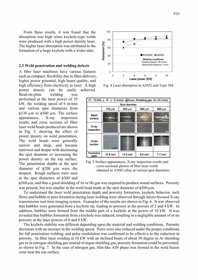
Fig. 5 Surface appearances, X-ray inspection results and
cross-sectional photos of fiber laser welds obtained in A5083 alloy at various spot diameters.
From these results, it was found that the absorption was high when keyhole-type welds were produced with a high power density laser. The higher laser absorption was attributed to the formation of a large keyhole with a wider inlet.
2.3 Weld penetration and welding defects A fiber laser machines have various features such as compact, flexibility due to fiber-delivery, higher power potential, high beam quality, and high efficiency from electricity to laser. A high power density can be easily achieved. Bead-on-plate welding was performed at the laser power of 10 kW, the welding speed of 6 m/min and various spot diameters from φ130 μm to φ560 μm. The surface appearances, X-ray inspection results and cross sections of fiber laser weld beads produced are shown in Fig. 5, showing the effect of power density on weld penetration. The weld beads were generally narrow and deep, and became narrower and deeper with decreasing the spot diameter or increasing the power density on the top surface. The penetration depths at the spot diameter of φ200 μm were the deepest. Rough surfaces were seen at the spot diameters of φ360 and φ560 μm, and thus a good shielding of Ar or He gas was required to produce sound surfaces. Porosity was present, but was smaller in the weld bead made at the spot diameter of φ200 μm.
To understand the laser weld penetration depth and porosity formation, keyhole behavior, melt flows and bubble or pore formation during laser welding were observed through micro-focused X-ray transmission real-time imaging system. Examples of the results are shown in Fig. 6. It was observed that bubbles were generated from a keyhole tip, leading to porosity at the powers of 2 and 4 kW. In addition, bubbles were formed from the middle part of a keyhole at the power of 10 kW. It was revealed that bubbles formation from a keyhole was reduced, resulting in a negligible amount of or no porosity at the laser powers of 6 and 8 kW.
The keyhole stability was different depending upon the material and welding conditions. Porosity decreases with an increase in the welding speed. Pores were also reduced under the proper conditions for full penetration welding, and pulse modulation was confirmed to be effective to the reduction in porosity. In fiber laser welding at 10 kW with an inclined beam of about 50 degree in Ar shielding gas or in nitrogen shielding gas instead of argon shielding gas, porosity formation could be prevented, as shown in Fig. 7. In the case of nitrogen gas, film-like AlN phase was formed in the weld fusion zone near the top surface.
Welding conditionsWelding speed:50 mm/s, Defocused distance:0 mm
Laser power [kW]
Abso
rptio
n [%
]
●SUS304,●A5052Welding conditions
Welding speed: 50 mm/s, Defocused distance: 0 mm
Welding conditionsWelding speed:50 mm/s, Defocused distance:0 mm
Laser power [kW]
Abso
rptio
n [%
]
●SUS304,●A5052Welding conditions
Welding speed: 50 mm/s, Defocused distance: 0 mm
Fig. 4 Laser absorption in A5052 and Type 304.
910

2.4 Laser-MIG hybrid welding results YAG-MIG and MIG-YAG hybrid welding were carried out on A5052 alloy. Slightly easier melting or higher speed for full penetration welding was achieved in MIG-YAG welding. However, better surface appearances of weld beads were observed in YAG-MIG hybrid welding. Therefore, YAG-MIG and MIG-YAG hybrid welding can be recommended from the better weld bead surface appearances and from the deeper penetration, respectively.
YAG-MIG hybrid welding was performed at various MIG currents. The surface appearances, cross sections and X-ray inspection results of weld beads are shown in Fig. 8. The weld beads were wider and deeper with an increase in the MIG arc current, and porosity was also reduced. Porosity
X-Ray transmission
images
Schematic illustration
2 kW 4 kW 6 kW 8 kW 10 kWLaser power
KeyholeKeyholeKeyhole
BubbleWelding direction
Keyhole
Bubble
Porosity
Keyhole
Bubble
X-Ray transmission
images
Schematic illustration
2 kW 4 kW 6 kW 8 kW 10 kWLaser power
KeyholeKeyholeKeyhole
BubbleWelding direction
Keyhole
Bubble
Porosity
Keyhole
Bubble
Fig. 6 X-ray transmission observation results and schematic representation of keyhole during
laser welding of A5052 with inclined beam of 10 degree at various laser powers.
N2 Shielding gas
12 mm
Incident angle, α: 10°
Incident angle, 50°
Shielding gas, Ar (φ16 mm, 50 l/min)
10 mm
N2 Shielding gas
12 mm12 mm
Incident angle, α: 10°
Incident angle, 50°
Shielding gas, Ar (φ16 mm, 50 l/min)
10 mm10 mm
Fig. 7 Surfaces and cross sections of fiber laser weld beads of A5083 alloy produced by inclined laser beam (left) and in nitrogen shielding gas (right).
Arc
current[A]
Surface Crosssection
X-ray inspection
0YAG single
welding
60
120
180
Porosity
Undercut
5mm240 5mm 3mm
Arccurrent
[A]Surface Cross
sectionX-ray inspection
0YAG single
welding
60
120
180
Porosity
Undercut
5mm240 5mm 3mm
Fig. 8 Surface appearances, cross sections and X-ray inspection results of YAG laser and YAG-MIG hybrid weld beads.
911
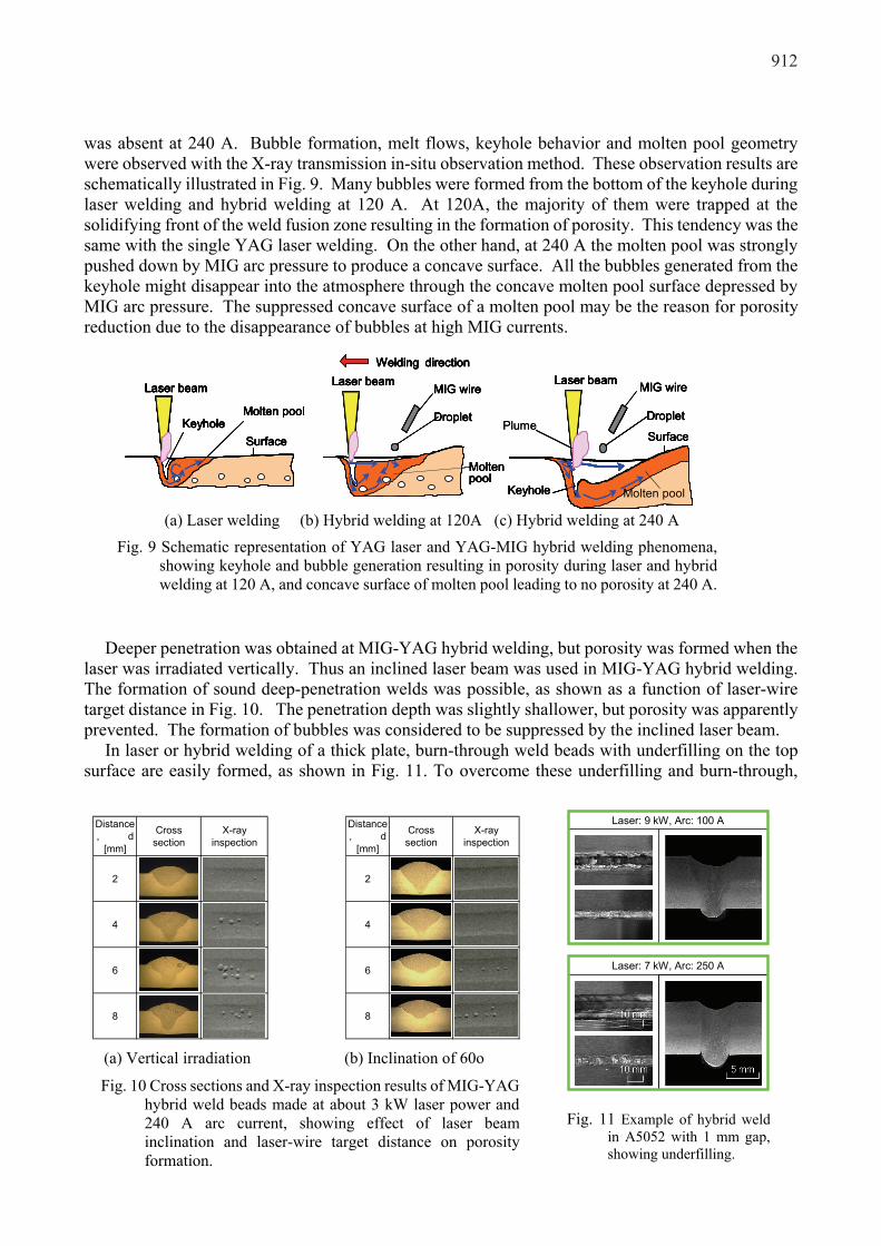
was absent at 240 A. Bubble formation, melt flows, keyhole behavior and molten pool geometry were observed with the X-ray transmission in-situ observation method. These observation results are schematically illustrated in Fig. 9. Many bubbles were formed from the bottom of the keyhole during laser welding and hybrid welding at 120 A. At 120A, the majority of them were trapped at the solidifying front of the weld fusion zone resulting in the formation of porosity. This tendency was the same with the single YAG laser welding. On the other hand, at 240 A the molten pool was strongly pushed down by MIG arc pressure to produce a concave surface. All the bubbles generated from the keyhole might disappear into the atmosphere through the concave molten pool surface depressed by MIG arc pressure. The suppressed concave surface of a molten pool may be the reason for porosity reduction due to the disappearance of bubbles at high MIG currents.
Deeper penetration was obtained at MIG-YAG hybrid welding, but porosity was formed when the laser was irradiated vertically. Thus an inclined laser beam was used in MIG-YAG hybrid welding. The formation of sound deep-penetration welds was possible, as shown as a function of laser-wire target distance in Fig. 10. The penetration depth was slightly shallower, but porosity was apparently prevented. The formation of bubbles was considered to be suppressed by the inclined laser beam.
In laser or hybrid welding of a thick plate, burn-through weld beads with underfilling on the top surface are easily formed, as shown in Fig. 11. To overcome these underfilling and burn-through,
MIG wire
Droplet
Surface
Laser beam
Keyhole Molten pool
KeyholeMolten pool
Surface
Laser beam
Welding direction
MIG wire
Droplet
Laser beam
Molten pool
Plume
MIG wire
Droplet
Surface
Laser beam
Keyhole Molten pool
KeyholeMolten pool
Surface
Laser beam
Welding direction
MIG wire
Droplet
Laser beam
Molten pool
MIG wire
Droplet
Surface
Laser beam
Keyhole Molten pool
MIG wire
Droplet
Surface
Laser beamLaser beam
Keyhole Molten pool
KeyholeMolten pool
Surface
Laser beam
KeyholeMolten pool
Surface
Laser beam
KeyholeMolten pool
Surface
Laser beamLaser beam
Welding direction
MIG wire
Droplet
Laser beam
Molten pool
Welding directionWelding direction
MIG wire
Droplet
Laser beamLaser beam
Molten pool
Plume
(a) Laser welding (b) Hybrid welding at 120A (c) Hybrid welding at 240 A
Fig. 9 Schematic representation of YAG laser and YAG-MIG hybrid welding phenomena, showing keyhole and bubble generation resulting in porosity during laser and hybrid welding at 120 A, and concave surface of molten pool leading to no porosity at 240 A.
Distance, d
[mm]
Crosssection
X-rayinspection
Distance, d
[mm]
Crosssection
X-rayinspection
2 2
4 4
6 6
8 8
(a) Vertical irradiation (b) Inclination of 60o
Fig. 10 Cross sections and X-ray inspection results of MIG-YAG hybrid weld beads made at about 3 kW laser power and 240 A arc current, showing effect of laser beam inclination and laser-wire target distance on porosity formation.
Laser: 9 kW, Arc: 100 A
Laser: 7 kW, Arc: 250 A
Fig. 11 Example of hybrid weld
in A5052 with 1 mm gap, showing underfilling.
912
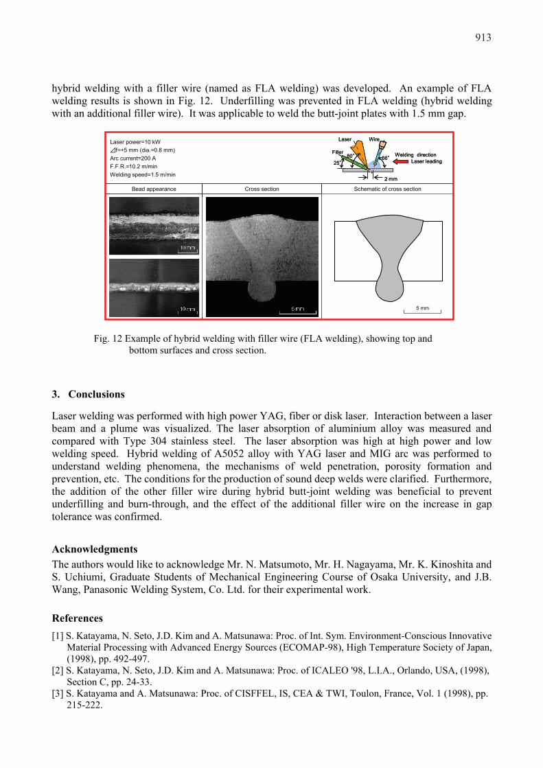
hybrid welding with a filler wire (named as FLA welding) was developed. An example of FLA welding results is shown in Fig. 12. Underfilling was prevented in FLA welding (hybrid welding with an additional filler wire). It was applicable to weld the butt-joint plates with 1.5 mm gap.
3. Conclusions
Laser welding was performed with high power YAG, fiber or disk laser. Interaction between a laser beam and a plume was visualized. The laser absorption of aluminium alloy was measured and compared with Type 304 stainless steel. The laser absorption was high at high power and low welding speed. Hybrid welding of A5052 alloy with YAG laser and MIG arc was performed to understand welding phenomena, the mechanisms of weld penetration, porosity formation and prevention, etc. The conditions for the production of sound deep welds were clarified. Furthermore, the addition of the other filler wire during hybrid butt-joint welding was beneficial to prevent underfilling and burn-through, and the effect of the additional filler wire on the increase in gap tolerance was confirmed. Acknowledgments The authors would like to acknowledge Mr. N. Matsumoto, Mr. H. Nagayama, Mr. K. Kinoshita and S. Uchiumi, Graduate Students of Mechanical Engineering Course of Osaka University, and J.B. Wang, Panasonic Welding System, Co. Ltd. for their experimental work.
References [1] S. Katayama, N. Seto, J.D. Kim and A. Matsunawa: Proc. of Int. Sym. Environment-Conscious Innovative
Material Processing with Advanced Energy Sources (ECOMAP-98), High Temperature Society of Japan, (1998), pp. 492-497.
[2] S. Katayama, N. Seto, J.D. Kim and A. Matsunawa: Proc. of ICALEO '98, L.I.A., Orlando, USA, (1998), Section C, pp. 24-33.
[3] S. Katayama and A. Matsunawa: Proc. of CISFFEL, IS, CEA & TWI, Toulon, France, Vol. 1 (1998), pp. 215-222.
Laser power=10 kW⊿f=+5 mm (dia.=0.8 mm)Arc current=200 AF.F.R.=10.2 m/minWelding speed=1.5 m/min
Bead appearance Cross section
Laser leadingWelding direction66°
Wire
2 mm
Laser
80°25°
Filler
Laser leadingWelding direction66°
Wire
2 mm
Laser
80°25°
Filler
Schematic of cross section
5 mm
Fig. 12 Example of hybrid welding with filler wire (FLA welding), showing top and
bottom surfaces and cross section.
913
[4] A. Matsunawa, S. Katayama and Y. Fujita: Proc. INALCO ’98 (7th Int. Conf. on Joints in Aluminium), Vol.1, Cambridge, UK, (1998), pp. 67-78.
[5] N. Seto, S. Katayama and A. Matsunawa: Proc. of ICALEO ‘99 –Laser Materials Processing-, LIA, San Diego, (1999), Vol.87-Section E (1999), pp. 19-27.
[6] S. Katayama, K. Tanaka, M. Mizutani and A. Matsunawa: Proc. of ICALEO ‘99 –Laser Materials Processing-, LIA, San Diego, (1999, Nov.), Vol.87 -Section D (1999), pp. 157-166.
[7] S. Katayama, N. Seto, J.D. Kim and A. Matsunawa: International Institute of Welding (IIW), Lisbon, (1999), IX-1949-99, pp. 1-10.
[8] S. Katayama, N. Seto, M. Mizutani and A. Matsunawa: International Institute of Welding (IIW), Lisbon, (1999, IV-753-99, pp. 1-6.
[9] S. Katayama, D. Yoshida and A. Matsunawa: Proc. of Laser Materials Processing Conference ICALEO 2000, LIA, 89 (2000) Section C, pp. 42-51.
[10] S. Katayama, N. Seto, M. Mizutani and A. Matsunawa: Proc. of Laser Materials Processing Conference ICALEO 2000, LIA, USA, 89-Section C (2000), pp. 16-25.
[11] S. Katayama, D. Yoshida, S. Yokoya and A. Matsunawa: IIW Annual Assembly, Florence, 2000, IIW Doc. IV-767-2000, pp. 1-7.
[12] N. Seto, S. Katayama and A. Matsunawa: J. of Laser Applications, 12-6(2000), pp.245-250. [13] S. Katayama and A. Matsunawa: Proc. of 7 International Aachen Welding Conference –High Productivity
Joining Processes, Fundamentals, Applications, Equipment-, ed. by U. Dilthey, Aachen, Germany, Vol. 1 (2001,5), pp. 133-143.
[14] S. Katayama, N. Seto, M. Mizutani and A. Matsunawa: Proc. of the 7th Int. Welding Symposium, JWS, Kobe, 2001, pp. 555-560.
[15] S. Katayama, D. Yoshida, S Yokoya and A. Matsunwa: Congress Proc. of ICALEO 2001 (Laser Materials Processing Conference), Jacksonville, FL, (2001), Session C: Welding, 1701.
[16] S. Katayama, N. Seto, M. Mizutani and A. Matsunawa: Congress Proc. of ICALEO 2001 (Laser Materials Processing Conference), Jacksonville, FL, (2001), Session C: Welding, 804.
[17] S. Katayama, Y. Kobayashi, M. Mizutani and A. Matsunawa: J. of Laser Applications, 13-5 (2001), pp.187-192.
[18] S. Katayama, M. Mizutani and A. Matsunawa: Proc. of SPIE, High Power Laser Macroprocessing, Vol. 4831 (LAMP 2002), (2002), pp.281-288.
[19] M. Mizutani, S. Katayama and A. Matsunawa: Proc. of SPIE, High Power Laser Macroprocessing, Vol. 4831 (LAMP 2002), (2002), pp.208-213.
[20] S. Katayama and M. Mizutani: Trans. JWRI, 31-2(2002), pp.147-155. [21] S. Katayama and M. Mizutani: Proc. 30th Anniversary International Symposium 'Joining & Welding
Solution to Industrial Innovation', JWRI, Osaka, 2003, pp.167-170. [22] S. Uchiumi, J.B. Wang, S. Katayama, M. Muzutani, T. Hongu, K. Fujii: Congress Proc. of ICALEO
2004(CD), USA, (2004), Oct.4-7, 530 [23] Y. Kawahito, S. Katayama: Journal of Laser Applications, Vol. 17, No. 1 (2005), pp. 30-37. [24] Y. Kawahito and S. Katayama: The Online Proceedings of LPM2005-The 6th International Symposium
on Laser Precision Microfabrication, Paper #27. [25] Y. Kawahito, K. Kinoshita, S. Katayama, S. Tsubota, T. Ishide: ICALEO 2005 Congress Proceedings,
LIA (Laser Institute of America), (CD), (2005), pp. 920-928. [26] Y. Kawahito and S. Katayama: ICALEO 2005 Congress Proceedings, LIA (Laser Institute of America),
(CD), (2005), pp. 905-914. [27] S. Katayama, S. Uchiumi and F. Briand: Congress Proceedings of ICALEO 2006, LIA Pub#599, 99,
Paper #1903, pp. 953-959. [28] S. Katayama, Y. Kawahito and M. Mizutani: Proc. of the Fourth Int. WLT-Conference on Lasers in
Manufacturing 2007, (2007), 265-271. [29] Y. Kawahito and S. Katayama: Journal of Laser Applications, 18, 2 (2006), 93-100. [30] Y. Kawahito and S. Katayama: JLMN-Journal of Laser Micro/Nanoengineering, 1, 1 (2006), pp. 5-28. [31] T. Shida, T. Wakasa, S. Tsukamoto and K. Hiraoka: Q. J. Jpn. Weld. Soc. 17(1999) pp.493-50.
914