The formation of surface segregates during twin roll casting of aluminium alloys
9
Materials Science and Engineering A 415 (2006) 12–20 The formation of surface segregates during twin roll casting of aluminium alloys B. Forbord a,∗ , B. Andersson b , F. Ingvaldsen c , O. Austevik c , J.A. Horst b , I. Skauvik d a SINTEF Materials Technology, N-7465 Trondheim, Norway b SINTEF Materials Technology, N-0314 Oslo, Norway c Hydro Aluminium, Karmøy Rolling Mill, N-4265 H˚ avik, Norway d Hydro Aluminium, R&D Materials Technology, N-4265 H˚ avik, Norway Received in revised form 1 May 2005; accepted 1 August 2005 Abstract When a certain productivity/casting speed is exceeded during twin roll casting, surface segregations form in a number of aluminium alloys with wide freezing ranges. Such segregations limit the productivity as mechanical properties and surface quality suffer during and after subsequent rolling and forming. Simulation results obtained by a 2-D thermo-mechanical model for twin roll casting, AlStrip, have been combined with studies in scanning electron microscope SEM/microprobe to assess the responsible mechanisms for the formation of segregates. The proposed mechanism consists of a sequence of events, where the initial source for the segregation is the progressive enrichment of alloying elements in the interdendritic liquid during solidification (microsegregation). Under certain conditions, i.e. when the critical productivity/casting speed is exceeded, low-pressure zones develop in the surface regions. Due to this pressure distribution, the enriched liquid flows through the coherent solid network to the surface, where solidification and the subsequent formation of segregations take place. © 2005 Elsevier B.V. All rights reserved. Keywords: Twin roll casting; Aluminium; Segregation; Solidification 1. Introduction Aluminium alloys with wide solidification intervals, like for instance the corrosion resistant and ductile AA5052, can be produced successfully by twin roll casting (TRC) at Hydro Alu- minium’s plant at Karmøy, Norway. However, when a critical productivity/casting speed, V cr , is exceeded, segregations appear with a certain periodicity in the surface of the strip (see for instance ref. [1]). These defects may lead to cracking during subsequent rolling and forming, and may also reduce the corro- sion resistance of the material. An obvious industrial challenge is to avoid the formation of surface segregates, or at least postpone their appearance to higher (and more profitable) productivities. The aim of this work has been to identify the responsible mech- anisms behind their formation. ∗ Corresponding author. Tel.: +47 98230463; fax: +47 73597040. E-mail address: [email protected] (B. Forbord). The experimental investigations were mainly conducted on so-called stop-samples, which are produced by abruptly inter- rupting casting. Such samples allow for a more accurate study of the different solidification phenomena, as also un-deformed material in the early stages of solidification becomes available for studies. However, care must be taken when analysing stop- samples as some material solidify under “abnormal” conditions, i.e. the rolls decelerate over a small distance after the power is switched off and neighbouring regions may be affected with respect to solidification contraction and heat transfer. Experi- mental results have therefore been complemented with the use of a thermo-mechanical model for twin roll casting, AlStrip [2], which is able to predict temperature, stress, velocity and pressure distributions under various steady state process conditions. 2. Experimental Three AA5052-variants, which were cast at productivi- ties/speeds > V cr and display surface segregations consisting of Mg-containing particles and AlFeSi-phases, have been 0921-5093/$ – see front matter © 2005 Elsevier B.V. All rights reserved. doi:10.1016/j.msea.2005.08.224
-
Upload
independent -
Category
Documents
-
view
2 -
download
0
Transcript of The formation of surface segregates during twin roll casting of aluminium alloys

Materials Science and Engineering A 415 (2006) 12–20
The formation of surface segregates during twinroll casting of aluminium alloys
B. Forborda,∗, B. Anderssonb, F. Ingvaldsenc,O. Austevikc, J.A. Horstb, I. Skauvikd
a SINTEF Materials Technology, N-7465 Trondheim, Norwayb SINTEF Materials Technology, N-0314 Oslo, Norway
c Hydro Aluminium, Karmøy Rolling Mill, N-4265 Havik, Norwayd Hydro Aluminium, R&D Materials Technology, N-4265 Havik, Norway
Received in revised form 1 May 2005; accepted 1 August 2005
Abstract
When a certain productivity/casting speed is exceeded during twin roll casting, surface segregations form in a number of aluminium alloys withwide freezing ranges. Such segregations limit the productivity as mechanical properties and surface quality suffer during and after subsequentr th studiesi d mechanismc nterdendritl -pz the surface,w©
K
1
ipmpwissttTa
d oninter-studymedlablestop-ions,er is
withperi-e use
ssure.
tivi-tingeen
0d
olling and forming. Simulation results obtained by a 2-D thermo-mechanical model for twin roll casting, AlStrip, have been combined win scanning electron microscope SEM/microprobe to assess the responsible mechanisms for the formation of segregates. The proposeonsists of a sequence of events, where the initial source for the segregation is the progressive enrichment of alloying elements in the iic
iquid during solidification (microsegregation). Under certain conditions, i.e. when the critical productivity/casting speed is exceeded, lowressureones develop in the surface regions. Due to this pressure distribution, the enriched liquid flows through the coherent solid network tohere solidification and the subsequent formation of segregations take place.2005 Elsevier B.V. All rights reserved.
eywords: Twin roll casting; Aluminium; Segregation; Solidification
. Introduction
Aluminium alloys with wide solidification intervals, like fornstance the corrosion resistant and ductile AA5052, can beroduced successfully by twin roll casting (TRC) at Hydro Alu-inium’s plant at Karmøy, Norway. However, when a criticalroductivity/casting speed,Vcr, is exceeded, segregations appearith a certain periodicity in the surface of the strip (see for
nstance ref.[1]). These defects may lead to cracking duringubsequent rolling and forming, and may also reduce the corro-ion resistance of the material. An obvious industrial challenge iso avoid the formation of surface segregates, or at least postponeheir appearance to higher (and more profitable) productivities.he aim of this work has been to identify the responsible mech-nisms behind their formation.
∗ Corresponding author. Tel.: +47 98230463; fax: +47 73597040.E-mail address: [email protected] (B. Forbord).
The experimental investigations were mainly conducteso-called stop-samples, which are produced by abruptlyrupting casting. Such samples allow for a more accurateof the different solidification phenomena, as also un-deformaterial in the early stages of solidification becomes avaifor studies. However, care must be taken when analysingsamples as some material solidify under “abnormal” conditi.e. the rolls decelerate over a small distance after the powswitched off and neighbouring regions may be affectedrespect to solidification contraction and heat transfer. Exmental results have therefore been complemented with thof a thermo-mechanical model for twin roll casting, AlStrip[2],which is able to predict temperature, stress, velocity and predistributions under various steady state process conditions
2. Experimental
Three AA5052-variants, which were cast at producties/speeds >Vcr and display surface segregations consisof Mg-containing particles and AlFeSi-phases, have b
921-5093/$ – see front matter © 2005 Elsevier B.V. All rights reserved.oi:10.1016/j.msea.2005.08.224
B. Forbord et al. / Materials Science and Engineering A 415 (2006) 12–20 13
Table 1Casting parameters for the three investigated AA5052-variants
A (stop-sample) B (stop-sample) C
Strip width (mm) 250 250 1350Strip thickness (mm) 4.1 2.0 3.8Casting speed (m/min) 1.50 5.58 1.84Productivity (t/m/h) 1.00 1.81 1.13Setback (mm) 42 50 55Separating force (kN) 1488 2088 9315
examined (seeTable 1for casting parameters). Two of thesewere stop-samples (A and B) cast on a pilot caster with a rolldiameter of 540 mm, while the last variant (C) was cast on afull scale Pechiney machine with a roll diameter of 960 mm.
Optical microscopy was carried out in a Carl Zeiss JenaNeophot 32, where bright field imaging was used for normalapplications. In the examinations of grain structures polarisedlight was applied on anodised material. The distributions of ele-ments were investigated by wavelength dispersive spectroscopy(WDS) in a CAMECA SX100 microprobe. When the purposeis to reveal segregation patterns, the resolution should be bet-ter than 1�m. This means that individual pictures with 256or 512 pixels cannot cover more than 200�m, and since areasneed to span about 1 mm to reveal the long-range segregationpatterns, areas have been stitched together (after correcting foruneven intensity distributions due to the positioning of the crys-tal detectors). The microprobe is equipped with a programmabletest table, which allows stepping in two perpendicular directionsand enables large areas to be studied.
In order to obtain topographic views of the surfaces, a JeoJSM-LV5900 scanning electron microscope (SEM) equippedwith a programmable tilting unit and test table was used. Forsuch investigations backscattered electrons are applied. Analysby energy dispersive spectroscopy (EDS) was also performed iorder to analyse the particles in the surface segregations.
3
ngo dist bys assa AP.T etc.n thea eter,t ick-n ck au haveb l, thec ifiedi -t reva
fromF
and by only considering a longitudinal 2-D section, studies ofvariations along the sheet width as well as edge effects cannotbe performed.
The material in the roll gap is treated as a fluid where theviscosity depends on the temperature and the strain rate. Thisimplies that the different material phases (liquid, mushy zone,solid) are treated similarly and the material flow in the wholeregion can be reproduced. However, elastic strains and strainhardening cannot be handled properly, but this is of minor impor-tance due to the high temperatures involved during twin rollcasting. The predictions of the model conforms well with theexperience gained in the plant and has contributed to the gen-eral understanding of the effects of casting parameters on thestructure of twin roll cast materials[1].
Another useful model, which is fairly similar to AlStrip in itsbuild-up, has been developed by Cruchaga et al.[3]. However,this model addresses the typical steel problem of whether thematerial is solid or not at the exit, and needs to be extendedwith data on the liquid/solid region to model gap-entrancephenomena like surface segregation formation in aluminiumalloys.
4. Results
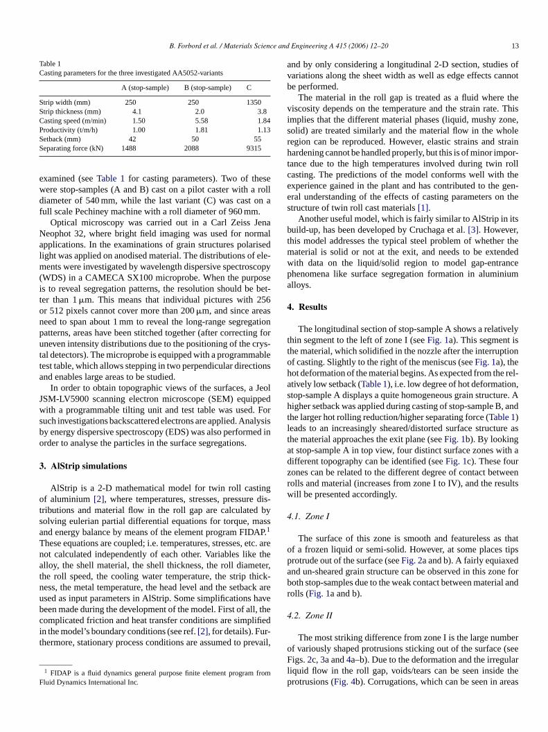
The longitudinal section of stop-sample A shows a relativelythin segment to the left of zone I (seeFig. 1a). This segment ist tionoh rel-a n,s re. Ah , andtl re asta ith ad rz tweenr sultsw
4
s thato tipsp da ne forb al andr
4
bero (seeF larl thep eas
. AlStrip simulations
AlStrip is a 2-D mathematical model for twin roll castif aluminium [2], where temperatures, stresses, pressure
ributions and material flow in the roll gap are calculatedolving eulerian partial differential equations for torque, mnd energy balance by means of the element program FID1
hese equations are coupled; i.e. temperatures, stresses,ot calculated independently of each other. Variables likelloy, the shell material, the shell thickness, the roll diam
he roll speed, the cooling water temperature, the strip thess, the metal temperature, the head level and the setbased as input parameters in AlStrip. Some simplificationseen made during the development of the model. First of alomplicated friction and heat transfer conditions are simpln the model’s boundary conditions (see ref.[2], for details). Furhermore, stationary process conditions are assumed to p
1 FIDAP is a fluid dynamics general purpose finite element programluid Dynamics International Inc.
l
isn
-
are
re
il,
he material, which solidified in the nozzle after the interrupf casting. Slightly to the right of the meniscus (seeFig. 1a), theot deformation of the material begins. As expected from thetively low setback (Table 1), i.e. low degree of hot deformatiotop-sample A displays a quite homogeneous grain structuigher setback was applied during casting of stop-sample B
he larger hot rolling reduction/higher separating force (Table 1)eads to an increasingly sheared/distorted surface structuhe material approaches the exit plane (seeFig. 1b). By lookingt stop-sample A in top view, four distinct surface zones wifferent topography can be identified (seeFig. 1c). These fouones can be related to the different degree of contact beolls and material (increases from zone I to IV), and the reill be presented accordingly.
.1. Zone I
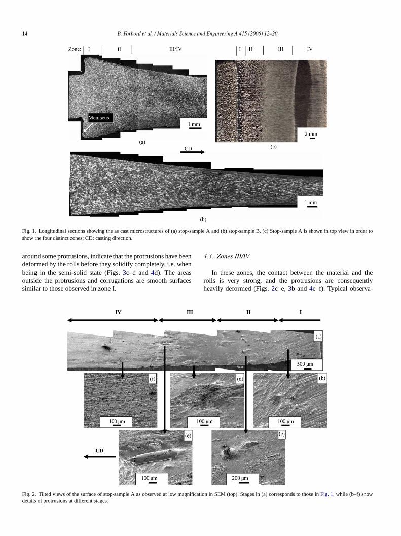
The surface of this zone is smooth and featureless af a frozen liquid or semi-solid. However, at some placesrotrude out of the surface (seeFig. 2a and b). A fairly equiaxend un-sheared grain structure can be observed in this zooth stop-samples due to the weak contact between materiolls (Fig. 1a and b).
.2. Zone II
The most striking difference from zone I is the large numf variously shaped protrusions sticking out of the surfaceigs.2c, 3a and4a–b). Due to the deformation and the irregu
iquid flow in the roll gap, voids/tears can be seen insiderotrusions (Fig. 4b). Corrugations, which can be seen in ar
14 B. Forbord et al. / Materials Science and Engineering A 415 (2006) 12–20
Fig. 1. Longitudinal sections showing the as cast microstructures of (a) stop-sample A and (b) stop-sample B. (c) Stop-sample A is shown in top view in order toshow the four distinct zones; CD: casting direction.
around some protrusions, indicate that the protrusions have beendeformed by the rolls before they solidify completely, i.e. whenbeing in the semi-solid state (Figs.3c–d and4d). The areasoutside the protrusions and corrugations are smooth surfacessimilar to those observed in zone I.
4.3. Zones III/IV
In these zones, the contact between the material and therolls is very strong, and the protrusions are consequentlyheavily deformed (Figs.2c–e,3b and4e–f). Typical observa-
F agnd
ig. 2. Tilted views of the surface of stop-sample A as observed at low m
etails of protrusions at different stages.ification in SEM (top). Stages in (a) corresponds to those inFig. 1, while (b–f) show

B. Forbord et al. / Materials Science and Engineering A 415 (2006) 12–20 15
Fig. 3. Tilted views of (a) newly formed protrusions in zone II and (b) deformed ones in zones II/III of stop-sample A. (c and d) Top views of corrugationsoriginatingfrom protrusions in zone II.
tions are: (i) as the material enters zone III the protrusionsseem to fracture or bend towards the casting direction, CD(Fig. 4c). (ii) Further into the roll gap (zone IV) the increas-ing (shear) deformation leads to a complete flattening of theprotrusion and a subsequent merging with the underlying sur-face (Fig. 4e–f). The surrounding surface is of the same typeas in the earlier zones but the pattern of corrugations is morepronounced.
4.4. Characterisation of individual segregations
EDS-analysis has revealed that the segregation coloniesconsist of�-AlFeSi, Mg-rich and occasionally Al–Mg-particles(see Fig. 4b). The morphology indicates that a substantialvolume of eutectics has solidified in the protrusion, i.e. the seg-regations most likely solidify at high solid volume fractionsfs,i.e. after dendritic coherency has been established. Boundaries
F tingt protru
ig. 4. Protrusions in stop-sample A with high concentrations of segregahe top of protrusion in (a). (c) and (d) show cross section and top view ofnderlying surface in zones III–IV, repsectively.
elements (Mg, Fe, Si) at different levels of contact. (a) Zone I/II and (b) detail fromusion in zone II, respectively. (e) and (f) show protrusions flattened and merged with

16 B. Forbord et al. / Materials Science and Engineering A 415 (2006) 12–20
Fig. 5. Examples from the longitudinal section (ND: normal direction) of the commercially cast sample C showing (a) a boundary and (b) no boundary between thesurface segregation and the matrix.
were often seen between the segregations and the surroundingmatrix in the commercially cast sample C (Fig. 5a), but equallyfrequent the structure changes gradually from the matrixand into the segregation without displaying such boundaries(Fig. 5b). In order to clarify whether these, apparently dissim-ilar, segregations form by different mechanisms, a number ofdeformed protrusions/segregations in zones III and IV havebeen studied in detail. An example is given for stop-sampleA in Fig. 6 , which shows a deformed segregation in top view(Fig. 6a) as well as three longitudinal sections in order to coverthe regions from the centre to the outer edge of the segregation
(Fig. 6b–d). The observations can be summarised as follows:(i) the section closest to the edge (Fig. 6b) displays a distinctboundary between the segregation and the matrix. (ii) In thesection between the centre and the edge of the segregation(Fig. 6c), a distinct boundary can be seen between the leftpart of the segregation and the matrix. To the right, howeverthe microstructure changes gradually from the matrix and intothe segregation. (iii) The centre of the segregation (Fig. 6d) ischaracterised by large intermetallics and a high Mg-content. Nodistinct boundary can be seen between the segregation and thematrix.
Fcabo
ig. 6. (a) Segregation in zone III of stop-sample A characterised in top view. Tentre of the segregation are shown in (b–d). The sections are marked on the tnd the underlying structure can only be seen in (b) and (c), which show heaoundaries is a result of these bent/fractured parts being deformed and eventf the segregation which remains in its original position during the passage thr
hree longitudinal sections were made to cover the regions from the outer edge to theop view image and the endpoints indicated. Boundaries between the surfacesegregationvily bent/fractured parts of the originally protruding segregation. The appearance ofually placed “on top” of the nearby surface. (d) on the other hand, which shows a partough the roll gap (i.e. the root of the protrusion), no boundary was detected.
B. Forbord et al. / Materials Science and Engineering A 415 (2006) 12–20 17
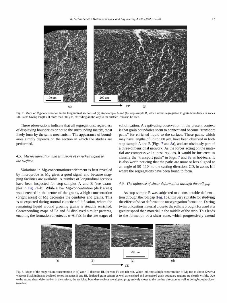
Fig. 7. Maps of Mg-concentration in the longitudinal sections of (a) stop-sample A and (b) stop-sample B, which reveal segregation to grain boundaries in zonesI/II. Paths having lengths of more than 500�m, extending all the way to the surface, can also be seen.
These observations indicate that all segregations, regardlessof displaying boundaries or not to the surrounding matrix, mostlikely form by the same mechanism. The appearance of bound-aries simply depends on the section in which the studies areperformed.
4.5. Microsegregation and transport of enriched liquid tothe surface
Variations in Mg-concentration/enrichment is best revealedby microprobe as Mg gives a good signal and because map-ping facilities are available. A number of longitudinal sectionshave been inspected for stop-samples A and B (see exam-ples inFig. 7a–b). While a low Mg-concentration (dark areas)was detected in the centre of the grains, a high concentration(bright areas) of Mg decorates the dendrites and grains. Thisis as expected during normal eutectic solidification, where theremaining liquid around growing grains is steadily enriched.Corresponding maps of Fe and Si displayed similar patterns,enabling the formation of eutectic�-AlFeSi in the late stages of
solidification. A captivating observation in the present contextis that grain boundaries seem to connect and become “transportpaths” for enriched liquid to the surface. These paths, whichmay have lengths of up to 500�m, have been observed in bothstop-sample A and B (Figs.7 and8a), and are obviously part ofa three-dimensional network. As the forces acting on the mate-rial are compressive in these regions, it would be incorrect toclassify the “transport paths” in Figs.7 and8a as hot-tears. Itis also worth noticing that the paths are more or less aligned atan angle of 90–110◦ to the casting direction, CD, in zones I/IIwhere the segregations have been found to form.
4.6. The influence of shear deformation through the roll gap
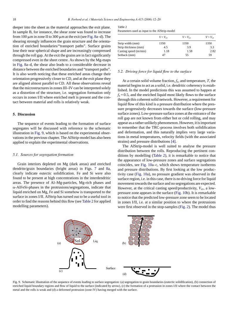
As stop-sample B was subjected to a considerable deforma-tion through the roll gap (Fig. 1b), it is very suitable for studyingthe effect of shear deformation on segregation formation. Duringtwin roll casting material close to the rolls is brought forward at agreater speed than material in the middle of the strip. This leadsto the formation of a shear zone, which progressively extend
F c) zo ut 1w in cen rt ions rt
ig. 8. Maps of the magnesium concentration in (a) zone II, (b) zone III, (hereas black indicates depleted zones. In zones II and III, depleted gra
o the strong shear deformation in the surface, the enriched boundary regogether.
ne IV and (d) exit. White indicates a high concentration of Mg (up to abo2 wt%)ters as well as enriched and connected grain boundary regions are clealy visible. Dueare aligned progressively closer to the casting direction as well as being brought close
18 B. Forbord et al. / Materials Science and Engineering A 415 (2006) 12–20
deeper into the sheet as the material approaches the exit plane.In sample B, for instance, the shear zone was found to increasefrom 100�m in zone II to 300�m at the exit (seeFig. 8a–d). Theshearing strongly influences the grain structure and the orienta-tion of enriched boundaries/“transport paths”. Surface grainslose their near spherical shape and are increasingly compressedthrough the roll gap. At the exit the grains are in fact significantlycompressed even in the sheet centre. As shown by the Mg-mapsin Fig. 8a–d, the shear also leads to a considerable decrease indistance between the enriched boundaries and “transport paths”.It is also worth noticing that these enriched areas change theirorientation progressively closer to CD, and at the exit plane theyare aligned almost parallel to CD. All these observations revealthat the microstructures in zones III–IV can be interpreted solelyas a distortion of the structure, i.e. segregation formation onlyoccurs in zones I/II where enriched melt is present and the con-tact between material and rolls is relatively weak.
5. Discussion
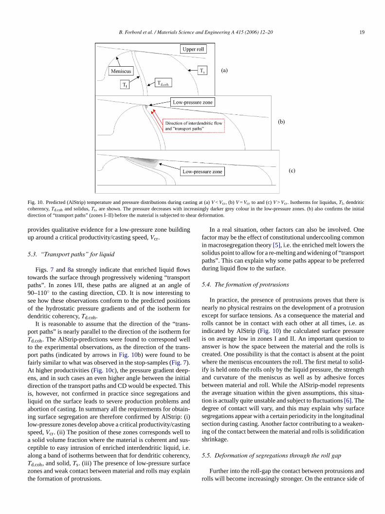
The sequence of events leading to the formation of surfacesegregates will be discussed with reference to the schematicillustration inFig. 9, which is based on the experimental obser-vations in the previous chapter. The AlStrip-model has also beenapplied to explain the experimental observations.
5
cheddc alsof dritica and� thatl o thes ol inom
Table 2Parameters used as input to the AlStrip-model
V < Vcr V = Vcr V > Vcr
Strip width (mm) 1350 1350 1350Strip thickness (mm) 4.5 3.9 3.3Casting speed (m/min) 1.18 1.58 2.82Setback (mm) 47 55 59
5.2. Driving force for liquid flow to the surface
At a certain solid volume fraction,fs, and temperature,T, thematerial begins to act as a solid, i.e. dendritic coherency is estab-lished. In the model predictions this was assumed to happen atfs = 0.5, and the enriched liquid most likely flows to the surfacethrough this coherent solid network. However, a requirement forliquid flow of this kind is a pressure distribution where the pres-sure progressively decreases towards the surface (low-pressuresurface zones). Low-pressure surface zones at the entrance of theroll gap are not known from either hot or cold rolling, and mayappear as a rather unlikely phenomenon. However, it is importantto remember that the TRC-process involves both solidificationand deformation, and this naturally implies very large varia-tions in metal temperatures, velocity fields (with the associatedstrains) and pressure distributions[4].
The AlStrip-model is well suited to analyse the pressuredistribution between the rolls. Reproducing the pertinent con-ditions by modelling (Table 2), it is remarkable to notice thatthe appearance of low-pressure zones and surface segregationscoincides, seeFig. 10a–c, which shows temperature isothermsand pressure distributions. By first looking at the low produc-tivity case (Fig. 10a), no pressure gradient was observed in thesurface region, i.e. in this case, there is no driving force for liquidmovement towards the surface and no segregations are expected.However, at the critical casting speed/productivity,V , a low-p et catedi ionsw s
F seg fe ed by em g me
.1. Sources for segregation formation
Grain interiors depleted on Mg (dark areas) and enriendrite/grain boundaries (bright areas) in Figs.7 and 8a,learly indicate eutectic solidification. Fe and Si wereound to be present at high concentrations in the interdenreas. The presence of Al–Mg-particles, Mg-rich phases-AlFeSi-phases in the protrusions/segregations, indicate
iquid enriched on Mg, Fe and Si somehow is transported turface in zones I/II. AlStrip has turned out to be a useful torder to find the reasons behind this flow (seeTable 2for appliedodelling parameters).
ig. 9. Schematic illustration of the sequence of events leading to surfacenriched liquid boundary regions and flow of liquid to the surface (indicatetal and the rolls is weak and (d) a deformed protrusion (zone IV) havin
crressure zone appears in the surface (Fig. 10b). It is remarkabl
o notice that the predicted low-pressure zone seem to be lon zones I/II, i.e. at a similar position to where the protrusere first observed in the stop-samples (Fig. 2). The model thu
regation: (a) segregation to grain boundaries (eutectic solidification), (b) connection oarrow), (c) the formation of a protrusion in zones I/II where the contact between thrged with the surface.
B. Forbord et al. / Materials Science and Engineering A 415 (2006) 12–20 19
Fig. 10. Predicted (AlStrip) temperature and pressure distributions during casting at (a)V < Vcr, (b) V = Vcr to and (c)V > Vcr. Isotherms for liquidus,Tl , dendriticcoherency,Td.coh and solidus,Ts, are shown. The pressure decreases with increasingly darker grey colour in the low-pressure zones. (b) also confirms the initialdirection of “transport paths” (zones I–II) before the material is subjected to shear deformation.
provides qualitative evidence for a low-pressure zone buildingup around a critical productivity/casting speed,Vcr.
5.3. “Transport paths” for liquid
Figs. 7 and 8a strongly indicate that enriched liquid flowstowards the surface through progressively widening “transportpaths”. In zones I/II, these paths are aligned at an angle of90–110◦ to the casting direction, CD. It is now interesting tosee how these observations conform to the predicted positionsof the hydrostatic pressure gradients and of the isotherm fordendritic coherency,Td.coh.
It is reasonable to assume that the direction of the “trans-port paths” is nearly parallel to the direction of the isotherm forTd.coh. The AlStrip-predictions were found to correspond wellto the experimental observations, as the direction of the trans-port paths (indicated by arrows inFig. 10b) were found to befairly similar to what was observed in the stop-samples (Fig. 7).At higher productivities (Fig. 10c), the pressure gradient deep-ens, and in such cases an even higher angle between the initialdirection of the transport paths and CD would be expected. Thisis, however, not confirmed in practice since segregations andliquid on the surface leads to severe production problems andabortion of casting. In summary all the requirements for obtain-ing surface segregation are therefore confirmed by AlStrip: (i)l stings ll toa susc i.e.a encyT cez plait
In a real situation, other factors can also be involved. Onefactor may be the effect of constitutional undercooling commonin macrosegregation theory[5], i.e. the enriched melt lowers thesolidus point to allow for a re-melting and widening of “transportpaths”. This can explain why some paths appear to be preferredduring liquid flow to the surface.
5.4. The formation of protrusions
In practice, the presence of protrusions proves that there isnearly no physical restrains on the development of a protrusionexcept for surface tensions. As a consequence the material androlls cannot be in contact with each other at all times, i.e. asindicated by AlStrip (Fig. 10) the calculated surface pressureis on average low in zones I and II. An important question toanswer is how the space between the material and the rolls iscreated. One possibility is that the contact is absent at the pointwhere the meniscus encounters the roll. The first metal to solid-ify is held onto the rolls only by the liquid pressure, the strengthand curvature of the meniscus as well as by adhesive forcesbetween material and roll. While the AlStrip-model representsthe average situation within the given assumptions, this situa-tion is actually quite unstable and subject to fluctuations[6]. Thedegree of contact will vary, and this may explain why surfacesegregations appear with a certain periodicity in the longitudinalsection during casting. Another factor contributing to a weaken-i tions
5
andr e of
ow-pressure zones develop above a critical productivity/capeed,Vcr. (ii) The position of these zones corresponds wesolid volume fraction where the material is coherent and
eptible to easy intrusion of enriched interdendritic liquid,long a band of isotherms between that for dendritic coherd.coh, and solid,Ts. (iii) The presence of low-pressure surfaones and weak contact between material and rolls may exhe formation of protrusions.
-
,
n
ng of the contact between the material and rolls is solidificahrinkage.
.5. Deformation of segregations through the roll gap
Further into the roll-gap the contact between protrusionsolls will become increasingly stronger. On the entrance sid

20 B. Forbord et al. / Materials Science and Engineering A 415 (2006) 12–20
the neutral plane, where the rolls travel faster than the mate-rial, the tips of the protrusions will be dragged with the rolls,fold over/fracture and eventually merge with the nearby surface.Other parts of the protrusions will only be flattened before beingsqueezed onto the surrounding material. In both cases, the resultis the appearance of boundaries between segregations and theunderlying structure. The parts of the protrusions, which remaincloser to their original positions, like for instance the “roots”,will not form boundaries to the matrix. This is clearly shownin Fig. 6, and explains why the appearance of such boundariesdepends on the section the studies are performed in. The appar-ent compression of the surface regions is therefore a result ofprotrusions being squeezed into it, and not as a result of a sur-face buckling due to velocity differences as proposed by refs.[7–12]. Such buckling would require opposing shearing forces,but in this work only a gradual shearing in accordance with thesticking to the rolls has been observed (Fig. 7).
6. Conclusions
Mechanisms behind the formation of surface segregates inAA5052 have been investigated. The initial source for the forma-tion of surface segregation is the enrichment of alloying elementsat the dendrite/grain boundaries (microsegregation). Under cer-tain conditions, i.e. when a certain productivity/casting speed,V ons,c surf athd zonh theo ppeaa mater thed s the
casting direction and are eventually squeezed into the underlyingsurface.
Acknowledgements
This work was carried out at Hydro Aluminium, Karmøy,where the main author previously has been employed at the R&DCentre. Thanks are due to Karmøy Rolling Mill (KRM) andHydro Aluminium for giving permission to publish this paper.
References
[1] O. Daaland, A.B. Espedal, M.L. Nedreberg, I. Alvestad, in: R. Huglen(Ed.), Light Metals 1997, TMS, Warrendale, PA, 1997, pp. 745–752.
[2] A. Mo, S.H. Høydal, Modeling of Casting Welding and advanced Solid-ification Processes VI, 1993, pp. 671–677.
[3] M.A. Cruchaga, D.J. Celentano, R.W. Lewis, Comm. Numer. Meth. Eng.19 (2003) 623–635.
[4] B. Andersson, J. Tibballs, in: H.D. Merchant, J.G. Morris (Eds.), TMS-Fall Meeting: Continuous Casting of Non-Ferrous Metals and Alloy, TheMetallurgical Society, Chicago, September 26/29, 1988.
[5] M.C. Flemings, in: B.J. Clark, M. Gardner (Eds.), Solidification Pro-cessing, McGraw-Hill Inc., 1974.
[6] J. Strid, T. Furu, R. Ørsund, E. Nes, in: H.D. Merchant, J.G. Morris(Eds.), TMS-Fall Meeting: Continuous Casting of Non-Ferrous Metalsand Alloy, The Metallurgical Society, Chicago, 1988, September 26–29,1988, pp. 119–152.
[7] D.J. Monaghan, M.B. Henderson, J.D. Hunt, D.V. Edmonds, Mats. Sci.
um
iza-
[ 01)
[ rum
[ 005)
cr, is exceeded, the enriched liquid in interdendritic regionnects and eventually become “transport paths” to theace. The liquid flows towards the surface through these pue to the presence of low-pressure surface zones. Theseave been predicted by the AlStrip-model and coincide withnset of segregation formation. The segregations first as protrusions in the surface when the contact betweenial and rolls are weak and periodically absent, but due toeformation through the roll gap, they fracture/bend toward
-ses
r-
Eng. A173 (1993) 251–254.[8] S.A. Lockyer, M. Yun, J.D. Hunt, D.V. Edmonds, Mater. Sci. For
217–222 (1996) 367–372.[9] S.A. Lockyer, M. Yun, J.D. Hunt, D.V. Edmonds, Mater. Character
tion 37 (1996) 301–310.10] M. Yun, S.A. Lockyer, J.D. Hunt, Int. J. Cast Met. Res. 13 (20
255–261.11] C. Gras, M. Meredith, K. Gatenby, J.D. Hunt, Mater. Sci. Fo
396–402 (2002) 89–94.12] Ch. Gras, M. Meredith, J.D. Hunt, J. Mater. Proc. Tech. 167 (1) (2
62–72.