Discontinuous Seam-Carving for Video Retargeting - Google ...
Upload
independentCategory
view
1download
0
Variable Carving Volume Casting
A Method for Mass-Customized Mold Making
Brandon Clifford, Nazareth Ekmekjian, Patrick Littleand Andrew Manto
Abstract The digital era fosters variability and change, though this desire losestraction when applied to methods falsely assumed to be repeatable—casting. Thiscollision has produced a plethora of expensive, wasteful, and time-intensivemethods. This chapter presents a method for rapidly carving variable molds to castunique volumetric elements, without material waste. This method employs a multi-axis robotic arm fitted with a hot-knife to carve foam into mass-customizednegatives. In doing so, it re-engages a gothic craft tradition of producing uniquevolumetric architectural elements. The act of rapidly carving volumetric materialmines knowledge from the past in an effort to create novel forms that are notpossible in the aggregation of standard building components. This chapter advo-cates for, prototypes, and analyses this variable, sympathetic, and reciprocalapproach that carving once offered the built environment. We found the method tobe effective and promising, when informed by limitations and constraintsembedded in the process.
Keywords Robotic fabrication � Multi-axis � Formwork � Mass customization �Digital craft � Free-form geometry
B. Clifford (&) � N. Ekmekjian � P. Little � A. MantoMassachusetts Institute of Technology, Cambridge, MA, USAe-mail: [email protected]
N. Ekmekjiane-mail: [email protected]
P. Littlee-mail: [email protected]
A. Mantoe-mail: [email protected]
W. McGee and M. Ponce de Leon (eds.), Robotic Fabrication in Architecture,Art and Design 2014, DOI: 10.1007/978-3-319-04663-1_1,� Springer International Publishing Switzerland 2014
3

1 Introduction
Architecture has a long history of working with volumetric materials in a variableway. Only recently, as a result of the Industrial Revolution, has the buildingindustry advocated for sheet materials and standardized building components(Clifford 2012). With greater attention paid to robotic fabrication in architecture,there has been a resurgence surrounding the topic of volumetric materials and theircapacity to engage computational, algorithmic, free-form, or otherwise complexgeometries that are not capable of being described through the Albertian ortho-graphic representations of architectural intent (Carpo 2011).
In recent years, designers have transferred Philibert de L’Orme’s method anddefinition of art du trait géométrique (currently known as stereotomy) into thecarving of large volumetric positives in expanded polystyrene (EPS) foam(Fallacara 2006; Feringa and Sondergaard 2014; Rippmann and Block 2011).Their projects, though working as an analog for stone construction, argued for theadvantages of EPS for its regenerative abilities, lightweight, and machinability(Clifford and McGee 2011). A paper (Stavric and Kaftan 2012) expanded thecarving of foam beyond the use of traditional linear cutting geometries into customprofiles. The use of custom profiles is not a new idea either, as it has been usedhistorically for mold profiles in the method of plaster scraping as well as moldingshapers for wood moldings and ornamental columns. A project (archolab.com/archives/40) recently applied the use of plaster scraping to robotic processes.
Recently, attention has been paid to the problem of creating complex molds tocast free-form geometries. Many projects have applied subtractive computernumerically controlled (CNC) technology to create custom formwork with highprecision. This approach assumes the waste and non-repeatability of the molds infavor of further freedom in geometric creation. Another approach is to approxi-mate subtle curvature through the bending of sheet material against a super-structure (www.designtoproduction.ch/content/view/17/26/). This approach limitsthe global figure of the geometry to the maximum bending of the material inresponse to the Gaussian curvature. In a similar method, the use of a variable moldthrough pneumatics and actuators has been used to articulate a geometry via pointsacross a malleable material in papers such as (Pronk et al. 2009; Raun et al. 2010).Gramazio and Kohler (dfab.arch.ethz.ch/web/e/forschung/164.html) have alsodemonstrated the advantage of re-usable materials to create serially variablemolds. This method is not dissimilar to the use of earthwork as formwork foron-site or tilt-up concrete construction.
This chapter proposes a precise and rapid method for carving negative moldswith a custom robotic hot-knife for highly variable free-form geometries withoutthe material waste of typical subtractive machining approaches. It uses the columnas an exercise to prototype this method and EPS foam as the carved material.
4 B. Clifford et al.
2 Digital Gothic
This chapter assumes a digital gothic approach as described by Ruskin (1960) inhis text ‘The Nature of Gothic’. Ruskin describes the qualities of gothic as beingdetermined by the maker and (his) methods of making. This approach can beconversely opposed to the classic approach of assuming the identical copies of astyle that has been pre-determined by one ‘thinker’. In establishing this dichotomy,one comprehends the history of division between thinker and maker, as well as theoccasional alignment. With the advent of digital technologies in design and fab-rication, our profession has found a reciprocal and harmonious relationshipbetween the two. This chapter exercises one development in this reciprocity bygenerating sympathetic architecture (Carpo 2011; Spuybroek 2011).
3 Fluting and Bundling
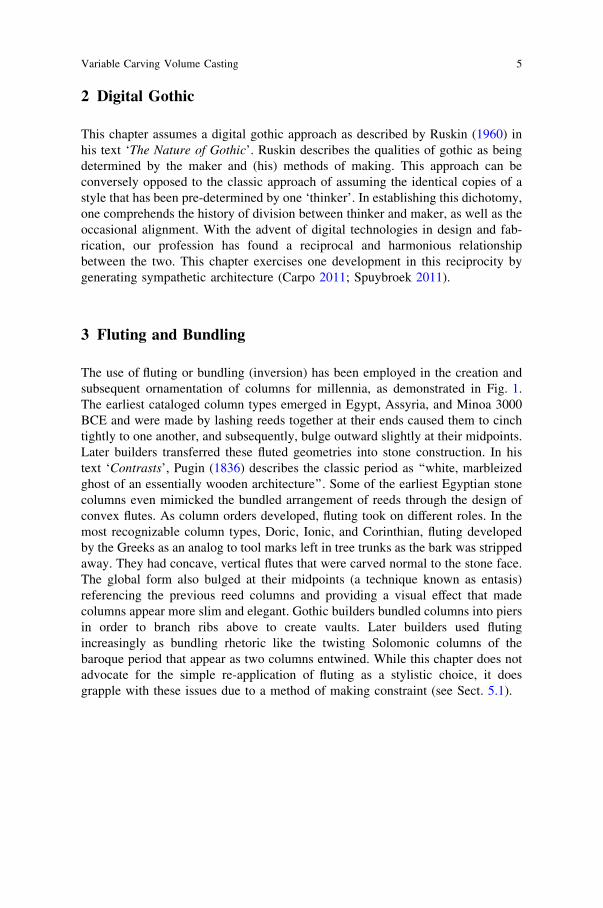
The use of fluting or bundling (inversion) has been employed in the creation andsubsequent ornamentation of columns for millennia, as demonstrated in Fig. 1.The earliest cataloged column types emerged in Egypt, Assyria, and Minoa 3000BCE and were made by lashing reeds together at their ends caused them to cinchtightly to one another, and subsequently, bulge outward slightly at their midpoints.Later builders transferred these fluted geometries into stone construction. In histext ‘Contrasts’, Pugin (1836) describes the classic period as ‘‘white, marbleizedghost of an essentially wooden architecture’’. Some of the earliest Egyptian stonecolumns even mimicked the bundled arrangement of reeds through the design ofconvex flutes. As column orders developed, fluting took on different roles. In themost recognizable column types, Doric, Ionic, and Corinthian, fluting developedby the Greeks as an analog to tool marks left in tree trunks as the bark was strippedaway. They had concave, vertical flutes that were carved normal to the stone face.The global form also bulged at their midpoints (a technique known as entasis)referencing the previous reed columns and providing a visual effect that madecolumns appear more slim and elegant. Gothic builders bundled columns into piersin order to branch ribs above to create vaults. Later builders used flutingincreasingly as bundling rhetoric like the twisting Solomonic columns of thebaroque period that appear as two columns entwined. While this chapter does notadvocate for the simple re-application of fluting as a stylistic choice, it doesgrapple with these issues due to a method of making constraint (see Sect. 5.1).
Variable Carving Volume Casting 5
4 Tooling
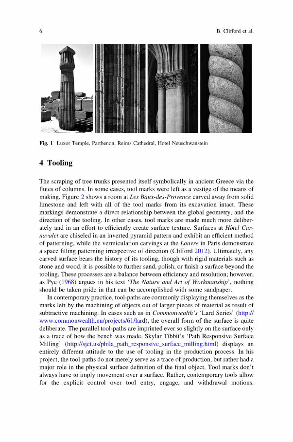
The scraping of tree trunks presented itself symbolically in ancient Greece via theflutes of columns. In some cases, tool marks were left as a vestige of the means ofmaking. Figure 2 shows a room at Les Baux-des-Provence carved away from solidlimestone and left with all of the tool marks from its excavation intact. Thesemarkings demonstrate a direct relationship between the global geometry, and thedirection of the tooling. In other cases, tool marks are made much more deliber-ately and in an effort to efficiently create surface texture. Surfaces at Hotel Car-navalet are chiseled in an inverted pyramid pattern and exhibit an efficient methodof patterning, while the vermiculation carvings at the Louvre in Paris demonstratea space filling patterning irrespective of direction (Clifford 2012). Ultimately, anycarved surface bears the history of its tooling, though with rigid materials such asstone and wood, it is possible to further sand, polish, or finish a surface beyond thetooling. These processes are a balance between efficiency and resolution; however,as Pye (1968) argues in his text ‘The Nature and Art of Workmanship’, nothingshould be taken pride in that can be accomplished with some sandpaper.
In contemporary practice, tool-paths are commonly displaying themselves as themarks left by the machining of objects out of larger pieces of material as result ofsubtractive machining. In cases such as in Commonwealth’s ‘Lard Series’ (http://www.commonwealth.nu/projects/61/lard), the overall form of the surface is quitedeliberate. The parallel tool-paths are imprinted ever so slightly on the surface onlyas a trace of how the bench was made. Skylar Tibbit’s ‘Path Responsive SurfaceMilling’ (http://sjet.us/phila_path_responsive_surface_milling.html) displays anentirely different attitude to the use of tooling in the production process. In hisproject, the tool-paths do not merely serve as a trace of production, but rather had amajor role in the physical surface definition of the final object. Tool marks don’talways have to imply movement over a surface. Rather, contemporary tools allowfor the explicit control over tool entry, engage, and withdrawal motions.
Fig. 1 Luxor Temple, Parthenon, Reims Cathedral, Hotel Neuschwanstein
6 B. Clifford et al.
Avi Forman’s work (http://www.flickr.com/photos/69844849@N00/5175767950)at the Yale School of Architecture shows an artifact formed through the use ofthousands of individual drill points. The resulting surface emerges as a highlystippled combination of holistic form and nuanced individual tool-marking similarto the surface at Hotel Carnavalet.
5 Methodology
The column prototype described in this chapter is fabricated with a roboticallycontrolled hot-knife to carve negative geometries from EPS foam. These moldnegatives are then sealed with a vacuum bag and used to cast unique Glass FiberReinforced Gypsum (GFRG) positives. This process involves the computing of thetool-paths, the rapid prototyping of potential forms, and the development of fab-rication techniques used to make finished artifacts.
5.1 Hot-Knife Tooling and Geometric Constraints
Two hot-knifes were tested in the prototyping of this method. The first mounts anoff-the-shelf hot-knife that is originally designed to be used by a human hand. Ithas a long bent handle that works well for a manual operation, but creates collisionobstacles during robotic operations. The second version is a custom mounting thatminimizes the handle and accommodates a larger blade. While this developmentdoes resolve the collision obstacle, both employed a semi-circular or ‘J’ blade
Fig. 2 Les-Baux-des-Provence Bouches-du-Rhone, France (left). Hotel Carnavalet Paris, France(middle). Louvre Paris, France (right)
Variable Carving Volume Casting 7
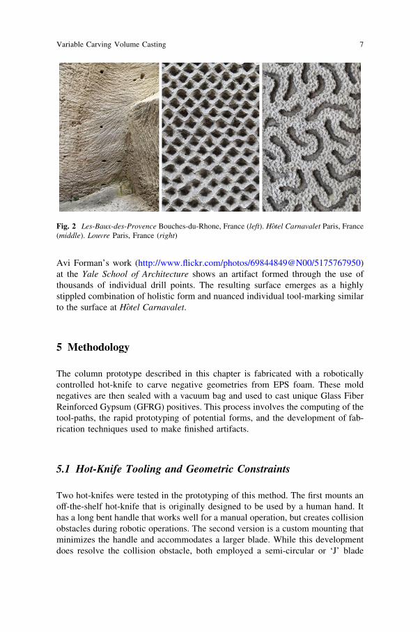
profile. The first is 1 in. in diameter and the second is 3.25 in. in diameter asshown in Fig. 3.
The hot-knife cuts through EPS foam by melting it at high temperature, creatingboth a minimum and a maximum step-over for the tool-path. Figure 4 demon-strates the maximum step over is a function of tool width; while minimum stepover attempts to limit areas of re-melting from previous tool-paths. Typical CNCsubtractive (milling) machining assumes there is a maximum, but no minimum.For this reason, milling can either express the tooling and enjoy the benefits ofminimum passes, or increase the resolution of the step-over to greater approximatea smooth surface. This approach is dedicated to resolution, allowing the tool pathto pass any way they are prescribed by the machinist.
While similarities can exist in appearance between these two methods, it isimportant to note that not all geometries can be translated from one to the other.Beyond the requirement of a minimum step-over, another major differencebetween milling and this proposal is that of direction. A milling tool-path has nodirection because the blade is spinning. This also means a mill can turn a cornerwith zero radius, but the proposed method has a blade with a direction andtherefore can only turn with a wide sweeping radius. The advantage this methodhas over milling is the ability to generate non-symmetric custom profiles.
Due to the constraints of the method, the approach demonstrated in this chapteris dedicated to the conscious decision of tooling location. This chapter does notadvocate for the universal use of tool-path visibility, though this method of the hot-knife carving requires attention to this issue. Figure 5 shows a few of the tool-pathstrategies prototyped.
Fig. 3 A comparison of the two prototyped knives. Off-the-shelf craftsman hot-knife with a 10 0
diameter ‘J’ blade (left). Custom hot-knife mounting with a 3.250 0 diameter blade (right)
8 B. Clifford et al.
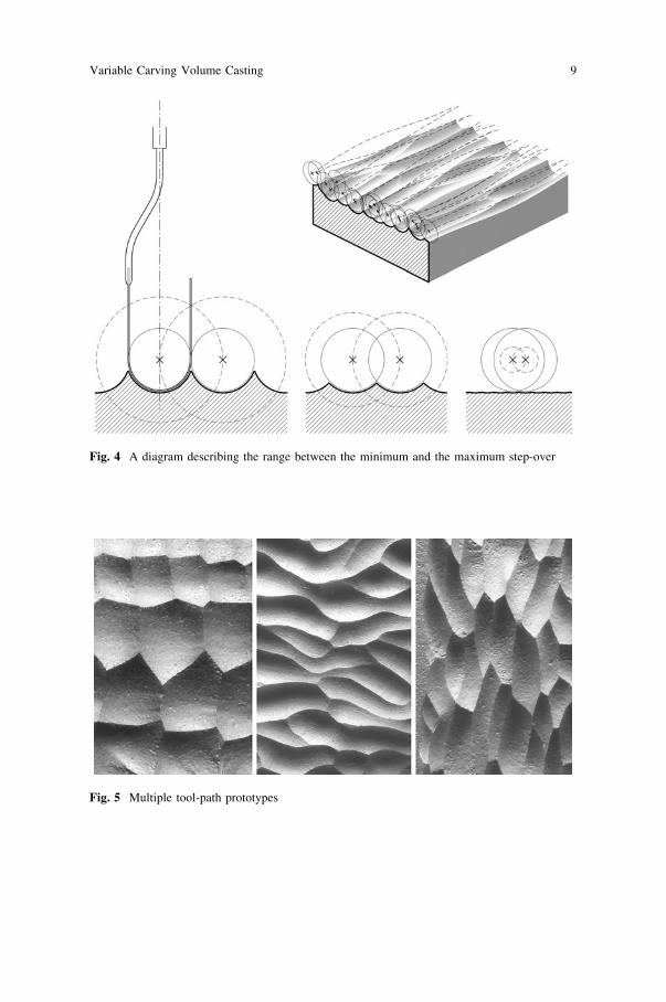
Fig. 4 A diagram describing the range between the minimum and the maximum step-over
Fig. 5 Multiple tool-path prototypes
Variable Carving Volume Casting 9
5.2 Digital Modeling and Computed Simulation
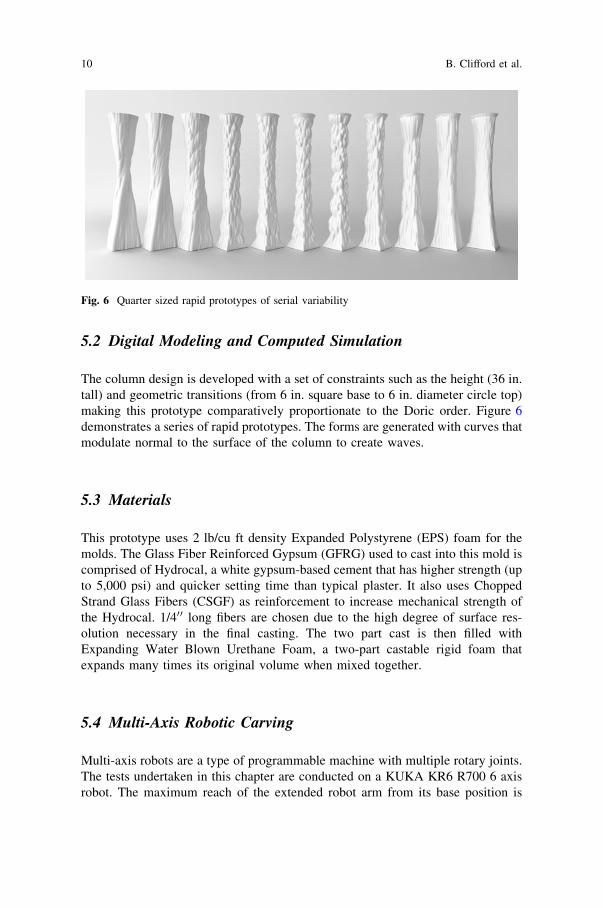
The column design is developed with a set of constraints such as the height (36 in.tall) and geometric transitions (from 6 in. square base to 6 in. diameter circle top)making this prototype comparatively proportionate to the Doric order. Figure 6demonstrates a series of rapid prototypes. The forms are generated with curves thatmodulate normal to the surface of the column to create waves.
5.3 Materials
This prototype uses 2 lb/cu ft density Expanded Polystyrene (EPS) foam for themolds. The Glass Fiber Reinforced Gypsum (GFRG) used to cast into this mold iscomprised of Hydrocal, a white gypsum-based cement that has higher strength (upto 5,000 psi) and quicker setting time than typical plaster. It also uses ChoppedStrand Glass Fibers (CSGF) as reinforcement to increase mechanical strength ofthe Hydrocal. 1/400 long fibers are chosen due to the high degree of surface res-olution necessary in the final casting. The two part cast is then filled withExpanding Water Blown Urethane Foam, a two-part castable rigid foam thatexpands many times its original volume when mixed together.
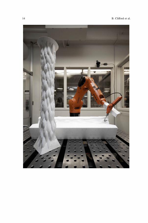
5.4 Multi-Axis Robotic Carving
Multi-axis robots are a type of programmable machine with multiple rotary joints.The tests undertaken in this chapter are conducted on a KUKA KR6 R700 6 axisrobot. The maximum reach of the extended robot arm from its base position is
Fig. 6 Quarter sized rapid prototypes of serial variability
10 B. Clifford et al.
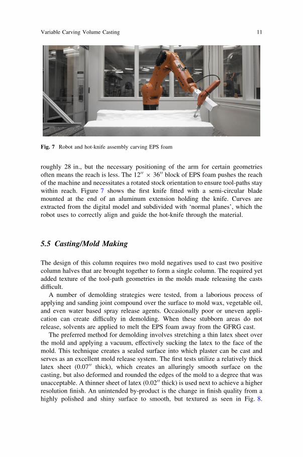
roughly 28 in., but the necessary positioning of the arm for certain geometriesoften means the reach is less. The 1200 9 3600 block of EPS foam pushes the reachof the machine and necessitates a rotated stock orientation to ensure tool-paths staywithin reach. Figure 7 shows the first knife fitted with a semi-circular blademounted at the end of an aluminum extension holding the knife. Curves areextracted from the digital model and subdivided with ‘normal planes’, which therobot uses to correctly align and guide the hot-knife through the material.
5.5 Casting/Mold Making
The design of this column requires two mold negatives used to cast two positivecolumn halves that are brought together to form a single column. The required yetadded texture of the tool-path geometries in the molds made releasing the castsdifficult.
A number of demolding strategies were tested, from a laborious process ofapplying and sanding joint compound over the surface to mold wax, vegetable oil,and even water based spray release agents. Occasionally poor or uneven appli-cation can create difficulty in demolding. When these stubborn areas do notrelease, solvents are applied to melt the EPS foam away from the GFRG cast.
The preferred method for demolding involves stretching a thin latex sheet overthe mold and applying a vacuum, effectively sucking the latex to the face of themold. This technique creates a sealed surface into which plaster can be cast andserves as an excellent mold release system. The first tests utilize a relatively thicklatex sheet (0.0700 thick), which creates an alluringly smooth surface on thecasting, but also deformed and rounded the edges of the mold to a degree that wasunacceptable. A thinner sheet of latex (0.0200 thick) is used next to achieve a higherresolution finish. An unintended by-product is the change in finish quality from ahighly polished and shiny surface to smooth, but textured as seen in Fig. 8.
Fig. 7 Robot and hot-knife assembly carving EPS foam
Variable Carving Volume Casting 11
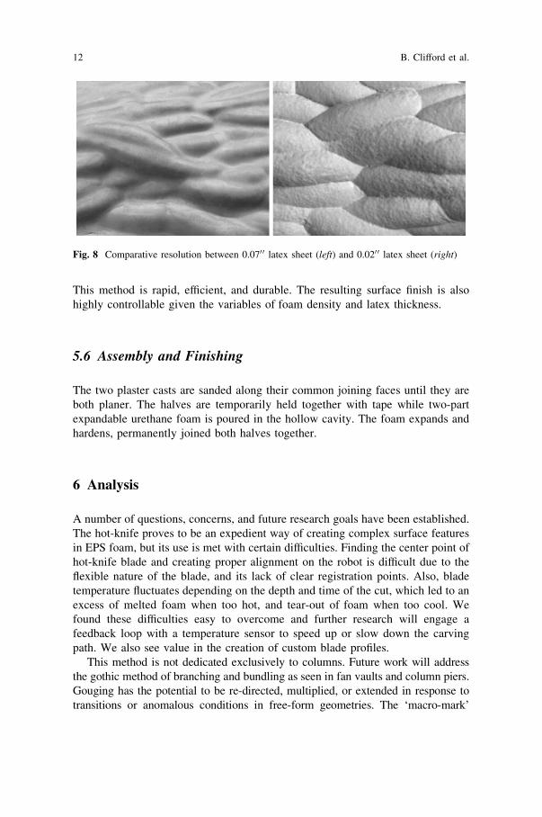
This method is rapid, efficient, and durable. The resulting surface finish is alsohighly controllable given the variables of foam density and latex thickness.
5.6 Assembly and Finishing
The two plaster casts are sanded along their common joining faces until they areboth planer. The halves are temporarily held together with tape while two-partexpandable urethane foam is poured in the hollow cavity. The foam expands andhardens, permanently joined both halves together.
6 Analysis
A number of questions, concerns, and future research goals have been established.The hot-knife proves to be an expedient way of creating complex surface featuresin EPS foam, but its use is met with certain difficulties. Finding the center point ofhot-knife blade and creating proper alignment on the robot is difficult due to theflexible nature of the blade, and its lack of clear registration points. Also, bladetemperature fluctuates depending on the depth and time of the cut, which led to anexcess of melted foam when too hot, and tear-out of foam when too cool. Wefound these difficulties easy to overcome and further research will engage afeedback loop with a temperature sensor to speed up or slow down the carvingpath. We also see value in the creation of custom blade profiles.
This method is not dedicated exclusively to columns. Future work will addressthe gothic method of branching and bundling as seen in fan vaults and column piers.Gouging has the potential to be re-directed, multiplied, or extended in response totransitions or anomalous conditions in free-form geometries. The ‘macro-mark’
Fig. 8 Comparative resolution between 0.070 0 latex sheet (left) and 0.020 0 latex sheet (right)
12 B. Clifford et al.
contains another advantage particularly aligned with robotics. These large gougesare not aligned to resolution, and therefore the possibility of translating largematerial within the reach of the arm can be accomplished without the requirement ofperfect indexing. This strategy is akin to the feathering of hair, where it is not clearwhere one set of paths start and the others begin.
Though this prototype employed GFRG and expanding urethane foam, there isnothing about this method that is strictly dedicated to these materials. Future workwill expand this material pallet with the similar mold creation method.
7 Conclusion
This chapter presents a process for producing mass-customizable formwork forfree-form geometries without material waste. It successfully demonstrates thepracticality and potential by rapidly carving variable molds to cast unique volu-metric architectural elements. The foam molds as well as the releasing processused to cast these elements are 100 % recyclable.
While this chapter presents a column as prototype, the method is in no waydedicated to this element typology. We understand the column as a placeholder fora variety of architectural forms to come. For this reason, we do not test the columnfor its structural capacity; rather, we test it against precision, ability to cast, andease of fabrication. This process produces a form that is highly unique to itsmethods of making. We learned the limitations and constraints of the method aredirectly aligned with a long history of volumetric carving. This re-insertion of pastknowledge into contemporary methods results in a new language that has roots inancient traditions.
We see robotics as translating gothic craft traditions into a digital environment,full of feedback and variability. While this method could be produced roughly witha number of non-robotic controllable devices, we see it uniquely aligned withrobotics for their inclination toward volumetric processes and system feedback.This method is also inherently lightweight and lacks the precision one wouldexpect from CNC subtractive machining. Where it lacks in this precision, it makesup for in efficiency of scale. One must keep this false assumption of precision inconsideration when developing a design strategy as the method is embedded with afew potentials for aligning units we are excited to test in future work. In proto-typing this hypothesis, we learned a number of ‘‘fuzzy’’ variables that could bebetter informed by sensing and system feedback, for instance, the over-melt ofprevious passes and the variation in knife temperature versus the feed.
We see no limit to the forms or elements this method can produce, as it is notdedicated to a scale, material, or style. It is dedicated to an efficiency of scale, alimitation of waste, and the digital desire for variation. This chapter opens thedoors of variation to methods previously relegated to the re-production of identicalforms.
Variable Carving Volume Casting 13
14 B. Clifford et al.
Acknowledgments This chapter is part of a research workshop at the Massachusetts Institute ofTechnology titled ‘Volumetric Robotics’ and led by Brandon Clifford. This course is dedicated totranslating volumetric methods of making into contemporary digital culture. Teaching assistanceby Trygve Wastvedt and Bobby White. Fabrication and facility support by Justin Lavallee andLarry Sass. Geometries were generated in Grasshopper (grasshopper3d.com), a parametric plugindeveloped by David Rutten for Rhinoceros (rhino3d.com), a program developed by RobertMcNeil. Robotic control was generated via Hal (hal.thibaultschwartz.com), a program developedby Thibault Schwartz and SuperMatterTools, a program developed by Wes McGee of MatterDesign (matterdesignstudio.com) and Dave Pigram of Supermanoeuvre (supermanoeuvre.com).
References
Carpo M (2011) The alphabet and the algorithm (writing architecture). The MIT Press,Cambridge
Clifford B (2012) Volume: bringing surface into question. SOM Foundation final reportClifford B, McGee W (2011) Matter and making: periscope foam tower. In: Glynn R, Sheil B
(eds) Fabricate: making digital architecture. Riverside Architectural Press, London, pp 76–79Fallacara G (2006) Digital stereotomy and topological transformations: reasoning about shape
building. In: Proceedings of the second international congress on construction history, vol 1,pp 1075–1092
Feringa J, Sondergaard A (2014) Fabricating architectural volume: stereotomic investigations inrobotic craft. In: Gramazio F, Kohler M, Langenberg S (eds) Fabricate: negotiating design &making. gta Verlag, ETH Zurich, pp 76–83
Pronk A, Rooy I, Schinkel P (2009) Double-curved surfaces using a membrane mould. In:Proceedings of the international association for shell and spatial structures (IASS) symposium2009, Valencia, Spain
Pugin A (1836) Contrasts: or, a parallel between the noble edifices of the fourteenth and fifteenthcenturies and similar buildings of the present day. Shewing the present decay of taste.Accompanied by appropriate text, Salisbury
Pye D (1968) The nature and art of workmanship. Cambridge University Press, LondonRaun C, Kristensen M, Kirkegaard P (2010) Flexible mould for precast concrete elements. In:
Proceedings of the international association for shell and spatial structures (IASS) symposium2010, Shanghai, China
Rippmann M, Block P (2011) Digital stereotomy: voussoir geometry for freeform masonry-likevaults informed by structural and fabrication constraints. In: Proceedings of the IABSE-IASSsymposium 2011, London, UK
Ruskin J (1960) The nature of Gothic. In: Links JG (ed) The stones of Venice. Da Capo Press,New York
Spuybroek L (2011) The sympathy of things: ruskin and the ecology of design. V2_Publishing,Rotterdam
Stavric M, Kaftan M (2012) Robotic fabrication of modular formwork for non-standard concretestructures. In: Achten H, Pavlicek J, Hulin J, Matejdan D (eds) Digital physicality—Proceedings of the 30th eCAADe conference, vol 2 12(14), pp 431–437
Variable Carving Volume Casting 15
Copyright © 2022 FDOKUMEN