
Lecture 1 Metal Casting Introduction
194
ME8351 MANUFACTURING TECHNOLOGY – I Lecture 1 Metal Casting Introduction Virtually nothing moves, turns, rolls, or flies without the benefit of cast metal products. The metal casting industry plays a key role in all the major sectors of our economy. There are castings in locomotives, cars trucks, aircraft, office buildings, factories, schools, and homes. Figure some metal cast parts. net Metal Casting is one of the oldest materials shaping methods known. Casting means pouring molten me al in o a mold with a cavity of the shape to be made, and allowing it to solidify. When solidified, the desir d m tal obj ct is aken out from the mold either by breaking the mold or taking the mold apart. The solidified object is call d he cas ing. By his process, intricate parts can be given strength and rigidity frequently not obtainable by a y oth r ma ufacturing . used as it process. The mold, into which the metal is poured, is made of some heat resisting material Sa d is most oft resists the high temperature of the molten metal. Permanent molds of metal can also be used to cast products. Figure : Metal Cast parts Advantages The metal casting process is extensively used in manufacturing because of its many advantages. 1. Molten material can flow into very small sections so that intricate shapes can be made by this process. As a result, many other operations, such as machining, forging, and welding, can be minimized or eliminated. 2. It is possible to cast practically any material that is ferrous or non-ferrous. 3. As the metal can be placed exactly where it is required, large saving in weight can be achieved. 4. The necessary tools required for casting molds are very simple and inexpensive. As a result, for production of a small lot, it is the ideal process. 5. There are certain parts made from metals and alloys that can only be processed this way. 6. Size and weight of the product is not a limitation for the casting process. ME8351 MANUFACTURING TECHNOLOGY – I
-
Upload
khangminh22 -
Category
Documents
-
view
4 -
download
0
Transcript of Lecture 1 Metal Casting Introduction

ME8351
MANUFACTURING TECHNOLOGY – I
Lecture 1
Metal Casting
Introduction
Virtually nothing moves, turns, rolls, or flies without the benefit of cast metal products. The metal casting industry plays akey role in all the major sectors of our economy. There are castings in locomotives, cars trucks, aircraft, office buildings,factories, schools, and homes. Figure some metal cast parts.
netMetal Casting is one of the oldest materials shaping methods known. Casting means pouring molten me al in o a moldwith a cavity of the shape to be made, and allowing it to solidify. When solidified, the desir d m tal obj ct is aken outfrom the mold either by breaking the mold or taking the mold apart. The solidified object is call d he cas ing. By hisprocess, intricate parts can be given strength and rigidity frequently not obtainable by a y oth r ma ufacturing
.
used as itprocess. The mold, into which the metal is poured, is made of some heat resisting material Sa d is most oftresists the high temperature of the molten metal. Permanent molds of metal can also be used to cast products.
Figure : Metal Cast parts
Advantages
The metal casting process is extensively used in manufacturing because of its many advantages.
1. Molten material can flow into very small sections so that intricate shapes can be made by this process. As a result,many other operations, such as machining, forging, and welding, can be minimized or eliminated.
2. It is possible to cast practically any material that is ferrous or non-ferrous.3. As the metal can be placed exactly where it is required, large saving in weight can be achieved.4. The necessary tools required for casting molds are very simple and inexpensive. As a result, for production of
a small lot, it is the ideal process.5. There are certain parts made from metals and alloys that can only be processed this way.6. Size and weight of the product is not a limitation for the casting process.
ME8351
MANUFACTURING TECHNOLOGY – I

ME8351
MANUFACTURING TECHNOLOGY – I
Limitations
1. Dimensional accuracy and surface finish of the castings made by sand casting processes are a limitation to this technique. Many new casting processes have been developed which can take into consideration the aspects of dimensional accuracy and surface finish. Some of these processes are die casting process, investment casting process, vacuum-sealed molding process, and shell molding process.
2. The metal casting process is a labor intensive process
History
Casting technology, according to biblical records, reaches back almost 5,000 years BC. Gold, pure in na ur , most likely caught Prehistoric man's fancy…as he probably hammered gold ornaments out of the gold nugg ts he found. Silver wouldhave been treated similarly. Mankind next found copper, because it appeared in the ash of his camp fir s from copper-bearing ore that he lined his fire pits with. Man soon found that copper was harder than gold or silv r. Copp r did notbend up when used. So copper, found a ‘nitch' in man's early tools, and then marched it's way i to W aponry. But, long before all this…man found clay. So he made pottery – something to eat from. Then he thought, " ow…what else can I dowith this mud…" . Early man thought about it, "they used this pottery stuff, ( the first patter s ), to shape metal into bowlsreached a molten state. padeepz
".
3200 B.C. A copper frog, the oldest known casting in existence, is cast in Meso otamia.
233 B.C. Cast iron plowshares are poured in China.
500 A.D. Cast crucible steel is first produced in India, but the proc ss is lost until 1750, when Benjamin Huntsmanreinvents it in England.
1455 Dillenburg Castle in Germany is the first to use cast iron pipe to transport water.
1480 Birth of Vannoccio Biringuccio (1480-1539), the "father of the foundry industry," in Italy. He is the first man todocument the foundry process in writing.
1709 Englishman Abraham Darby cre tes the first true foundry flask for sand and loam molding.
1750 Benjamin Huntsman reinvents the rocess of cast crucible steel in England. This process is the first in which thesteel is completely melted, roducing uniform composition within the melt. Since the metal is completely molten,it also allows for alloy steel production, as the additional elements in the alloy can be added to the crucible duringmelting. Prior steel production as accomplished by a combination of forging and tempering, and the metal never
1809 Centrifugal casting is developed by A. G. Eckhardt of Soho, England.
1896 American Foundrymen's Association (renamed American Foundrymen's Society in 1948 and now called theAmerican Foundry Society) is formed.
1897 Investment casting is rediscovered by B.F. Philbrook of Iowa. He uses it to cast dental inlays.
1947 The Shell process, invented by J. Croning of Germany during WWII, is discovered by U.S. officials and madepublic.
1953 The Hotbox system of making and curing cores in one operation is developed, eliminating the need for dielectricdrying ovens.
ME8351
MANUFACTURING TECHNOLOGY – I

ME8351
MANUFACTURING TECHNOLOGY – I
1958 H.F. Shroyer is granted a patent for the full mold process, the forerunner of the expendable pattern (lost foam)casting process.
1968 The Coldbox process is introduced by L. Toriello and J. Robins for high production core making.
1971 The Japanese develop V-Process molding. This method uses unbonded sand and a vacuum.
1971 Rheocasting is developed at Massachusetts Institute of Technology.
1996 Cast metal matrix composites are first used in a production model automobile in the brake rotors for the Lotus Elise.
Metal Casting History (India)
3000 BC Earliest castings include the 11 cm high bronze dancing girl found at Mohen-jo-daro.
2000 BC Iron pillars, arrows, hooks, nails, bowls and daggers or earlier have been fou d in D lhi, Roopar, Nashik and other places.
500 BC Large scale state-owned mints and jewelry units, and processes of metal extraction a d alloyi g have beenmentioned in Kautilya's Arthashastra
500 A.D. Cast crucible steel is first produced in India, but the process is lost until 1750, when Benjamin Huntsman reinvents it in England
ME8351
MANUFACTURING TECHNOLOGY – I

ME8351
MANUFACTURING TECHNOLOGY – I
Lecture 2
Casting Terms
1. Flask: A metal or wood frame, without fixed top or bottom, in which the mold is formed. Depending upon theposition of the flask in the molding structure, it is referred to by various names such as drag – lower moldingflask, cope – upper molding flask, cheek – intermediate molding flask used in three piece molding.
2. Pattern: It is the replica of the final object to be made. The mold cavity is made with the help of pattern.3. Parting line: This is the dividing line between the two molding flasks that makes up the mold.4. Molding sand: Sand, which binds strongly without losing its permeability to air or gases. It is a mixture of silica
sand, clay, and moisture in appropriate proportions.5. Facing sand: The small amount of carbonaceous material sprinkled on the inner surface of he mold cavi y to give
a better surface finish to the castings.6. Core: A separate part of the mold, made of sand and generally baked, which is used to cr a op nings and various
shaped cavities in the castings.7. Pouring basin: A small funnel shaped cavity at the top of the mold into which the molt m tal is poured.
8. Sprue: The passage through which the molten metal, from the pouring basin, reaches the mold cavity. In many cases it controls the flow of metal into the mold.
9. Runner: The channel through which the molten metal is carried from the sprue to the gate.10. Gate: A channel through which the molten metal enters the mold cavity11. Chaplets: Chaplets are used to support the cores inside the mold cavity to take care of its own weight and
overcome the metallostatic force.12. Riser: A column of molten metal placed in the mold to feed the castings as it shrinks and solidifies. Also known as
“feed head”.13. Vent: Small opening in the mold to facilitate escape of air and gas s.
ME8351
MANUFACTURING TECHNOLOGY – I

ME8351
MANUFACTURING TECHNOLOGY – I
Steps in Making Sand Castings
There are six basic steps in making sand castings:
1. Patternmaking2. Core making3. Molding4. Melting and pouring5. Cleaning
Pattern making
The pattern is a physical model of the casting used to make the mold. The mold is made by packing some r adily formedaggregate material, such as molding sand, around the pattern. When the pattern is withdrawn, its imprint provid s the moldcavity, which is ultimately filled with metal to become the casting. If the casting is to be hollow, as in the case of pipefittings, additional patterns, referred to as cores, are used to form these cavities.
Melting and Pouring
Core making

Cores are forms, usually made of sand,padeepzwhichareplacedintoamoldcavitytoformtheinterior surfaces of castings.
Thus the void space between the core and mold-cavity surface is what eventually becomes the casting.
Molding
Molding consists of all operations necessary to prepare a mold for r c iving molt n metal. Molding usually involvesplacing a molding aggregate around a pattern held with a supporting fram , withdrawing the pattern to leave the moldcavity, setting the cores in the mold cavity and finishing and closing the mold.
The preparation of molten metal for c sting is referred to simply as melting. Melting is usually done in a specificallydesignated area of the foundry, and the molten met l is tr nsferred to the pouring area where the molds are filled.
Cleaning
Cleaning refers to all operations necessary to the removal of sand, scale, and excess metal from the casting. Burned-on sandand scale are removed to improved the surface earance of the casting. Excess metal, in the form of fins, wires, partingline fins, and gates, is removed Inspection of the casting for defects and general quality is performed.
ME8351
MANUFACTURING TECHNOLOGY – I

ME8351
MANUFACTURING TECHNOLOGY – I
Lecture 3
Pattern
The pattern is the principal tool during the casting process. It is the replica of the object to be made by the casting process, with some modifications. The main modifications are the addition of pattern allowances, and the provision of core prints. If the casting is to be hollow, additional patterns called cores are used to create these cavities in the finished product. The quality of the casting produced depends upon the material of the pattern, its design, and construction. The costs of the pattern and the related equipment are reflected in the cost of the casting. The use of an expensive pattern is justified when the quantity of castings required is substantial.
Functions of the Pattern
1. A pattern prepares a mold cavity for the purpose of making a casting.2. A pattern may contain projections known as core prints if the casting requires a core a d d to be made hollow.3. Runner, gates, and risers used for feeding molten metal in the mold cavity may form a part of the pattern.4. Patterns properly made and having finished and smooth surfaces reduce casti g defects5.
padeepz
A properly constructed pattern minimizes the overall cost of the castings
1.2.3.4.5.6.7.
Pattern Material

Patterns may be constructed from the following materials. Each material has its own advantages, limitations, and field ofapplication. Some materials used for making patterns are: wood, m tals and alloys, lastic, plaster of Paris, plastic and rubbers, wax, and resins. To be suitable for use, the pattern mat rial should b :
Easily worked, shaped and joined Light in weightStrong, hard and durable Resistant to wear and abrasionResistant to corrosion, and to chemic l re ctionsDimensionally stable and unaffected by v ri tions in temperature and humidity Available at low cost
The usual pattern materials are wood, metal, and lastics. The most commonly used pattern material is wood, since it is readily available and of low weight Also, it can be easily shaped and is relatively cheap. The main disadvantage of wood is its absorption of moisture, which can cause distortion and dimensional changes. Hence, proper seasoning and upkeep ofwood is almost a pre-requisite for large-scale use of wood as pattern material.
ME8351
MANUFACTURING TECHNOLOGY – I

ME8351
MANUFACTURING TECHNOLOGY – I
Pattern Allowances
Pattern allowance is a vital feature as it affects the dim nsional charact ristics of the casting. Thus, when the pattern is produced, certain allowances must be given on the siz s sp cifi in the finished component drawing so that a casting with the particular specification can be made. The s l ction of corr ct allowances greatly helps to reduce machining costs and avoid rejections. The allowances usually consi ered on patterns and core boxes are as follows:
1. Shrinkage or contraction allow nce2. Draft or taper allowance3. Machining or finish allowance4. Distortion or camber allowance5. Rapping allowance
Figure 2:padeepzAtypicalpatternattachedwithgatingandriser system
Shrinkage or Contraction Allowance ( click on Table 1 to view various rate of contraction of various materials)

All most all cast metals shrink or contract volumetrically on cooling. The metal shrinkage is of two types:
i. Liquid Shrinkage: it refers to the reduction in volume when the metal changes from liquid state to solid state atthe solidus temperature. To account for this shrinkage; riser, which feed the liquid metal to the casting, are provided in the mold.
ii. Solid Shrinkage: it refers to the reduction in volume caused when metal loses temperature in solid state. Toaccount for this, shrinkage allowance is provided on the patterns.
The rate of contraction with temperature is dependent on the material. For example steel contracts to a higher degree compared to aluminum. To compensate the solid shrinkage, a shrink rule must be used in laying out the measurements forthe pattern. A shrink rule for cast iron is 1/8 inch longer per foot than a standard rule. If a gear blank of 4 inch in diameterwas planned to produce out of cast iron, the shrink rule in measuring it 4 inch would actually measure 4 -1/24 inch, thus compensating for the shrinkage. The various rate of contraction of various materials are given in Table 1.
ME8351
MANUFACTURING TECHNOLOGY – I

ME8351
MANUFACTURING TECHNOLOGY – I
Table 1 : Rate of Contraction of Various Metals
Material Dimension Shrinkage allowance(inch/ft)
Grey Cast Iron Up to 2 feet 0.1252 feet to 4 feet 0.105over 4 feet 0.083
Cast Steel Up to 2 feet 0.2512 feet to 6 feet 0.191over 6 feet 0.155
Aluminum Up to 4 feet 0.1554 feet to 6 feet 0.143over 6 feet 0.125
Magnesium Up to 4 feet 0.173Over 4 feet 0.155
Exercise 1
The casting shown is to be made in cast iron using wooden pattern. Assuming only shrinkage allowance, calculate the dimension of the pattern. All Dimensions are in Inches
Solution 1
The shrinkage allowance for cast iron for size up to 2 feet is o.125 inch per feet (as per Table 1)
For dimension 18 inch, allowance = 18 X 0.125 / 12 = 0.1875 inch » 0.2 inch
For dimension 14 inch, allowance = 14 X 0.125 / 12 = 0.146 inch » 0.15 inch
For dimension 8 inch, allo ance =padeepz8 X 0.125 / 12 = 0.0833 inch » 0. 09 inch
For dimension 6 inch, allo ance = 6X 0.125 / 12 = 0.0625 inch » 0. 07 inch
The pattern dra ing ith required dimension is shown below:
ME8351
MANUFACTURING TECHNOLOGY – I

ME8351
MANUFACTURING TECHNOLOGY – I
Lecture 4
Draft or Taper Allowance
By draft is meant the taper provided by the pattern maker on all vertical surfaces of the pattern so that it can be removed from the sand without tearing away the sides of the sand mold and without excessive rapping by the molder. Figure 3 (a) shows a pattern having no draft allowance being removed from the pattern. In this case, till the pattern is completely lifted out, its sides will remain in contact with the walls of the mold, thus tending to break it. Figure 3 (b) is an illustrationof a pattern having proper draft allowance. Here, the moment the pattern lifting commences, all of its surfaces are well away from the sand surface. Thus the pattern can be removed without damaging the mold cavity.
Figure 3 ( ) P ttern H ving No Draft on Vertical Edges
Figure 3 (b) Pattern Having Draft on Vertical Edges
ME8351
MANUFACTURING TECHNOLOGY – I
ME8351
MANUFACTURING TECHNOLOGY – I
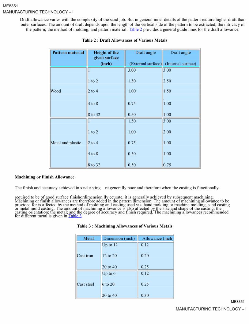
Draft allowance varies with the complexity of the sand job. But in general inner details of the pattern require higher draft thanouter surfaces. The amount of draft depends upon the length of the vertical side of the pattern to be extracted; the intricacy of
the pattern; the method of molding; and pattern material. Table 2 provides a general guide lines for the draft allowance.
Table 2 : Draft Allowances of Various Metals
Pattern material Height of the Draft angle Draft anglegiven surface
(inch) (External surface) (Internal surface)
1 3.00 3.00
1 to 2 1.50 2.50
Wood 2 to 4 1.00 1.50
4 to 8 0.75.1 00
8 to 32 0.50 1 00
1 1.50 3 00
1 to 2 1.00 2.00
Metal and plastic 2 to 4 0.75 1.00
4 to 8 0.50 1.00
8 to 32 0.50 0.75
Machining or Finish Allowance
The finish and accuracy achieved in s nd c sting re generally poor and therefore when the casting is functionally
required to be of good surface.finishordimension lly ccurate, it is generally achieved by subsequent machining. Machining or finish allowances are therefore added in the pattern dimension. The amount of machining allowance to beprovided for is affected by the method of molding and casting used viz. hand molding or machine molding, sand castingor metal mold casting. The amount of machining allowance is also affected by the size and shape of the casting; the casting orientation; the metal; and the degree of accuracy and finish required. The machining allowances recommended for different metal is given in Table 3
Table 3 : Machining Allowances of Various Metals
Metal Dimension (inch) Allowance (inch)
Up to 12 0.12
Cast iron 12 to 20 0.20
20 to 40 0.25
Up to 6 0.12
Cast steel 6 to 20 0.25
20 to 40 0.30ME8351
MANUFACTURING TECHNOLOGY – I

ME8351
MANUFACTURING TECHNOLOGY – I
Up to 8 0.09
Non ferrous 8 to 12 0.12
12 to 40 0.16
Exercise 2
The casting shown is to be made in cast iron using a wooden pattern. Assuming only machining allowance, calculate thedimension of the pattern. All Dimensions are in Inches
Solution 2
The machining allowance for cast iron for size, up to 12 inch is o.12 inch and from 12 inch to 20 inch is 0.20 inch ( (Table3)
For dimension 18 inch, allowance = 0.20 inch
For dimension 14 inch, allowance = 0.20 inch
For dimension 8 inch, allowance = 0.12 inch
For dimension 6 inch, allowance = 0.12 inch
The pattern drawing with required dimension is shown in Figure below
Distortion or Camber Allowance
Sometimes castings get distorted, during solidification, due to their typical shape. For example, if the casting has the formof the letter U, V, T, or L etc. it will tend to contract at the closed end causing the vertical legs to look slightly inclined. This can be prevented by making the legs of the U, V, T, or L shaped pattern converge slightly (inward) so that the castingafter distortion will have its sides vertical ( (Figure 4).
The distortion in casting may occur due to internal stresses. These internal stresses are caused on account of unequal cooling of different section of the casting and hindered contraction. Measure taken to prevent the distortion in castinginclude:
ME8351
MANUFACTURING TECHNOLOGY – I

ME8351
MANUFACTURING TECHNOLOGY – I
i. Modification of casting designii. Providing sufficient machining allowance to cover the distortion affect
iii. Providing suitable allowance on the pattern, called camber or distortion allowance (inverse reflection)
Figure 4: Distortions in Casting
Rapping Allowance
Before the withdrawal from the sand mold, the pattern is rapp all around the vertical faces to enlarge the mold cavity slightly, which facilitate its removal. Since it enlarg s the final casting mad , it is desirable that the original pattern dimension should be reduced to account for this incr ase. Th re is no sure way of quantifying this allowance, since it is highly dependent on the foundry personnel practice involv . It is a n gative allowance and is to be applied only to those dimensions that are parallel to the parting plane.
Core and Core Prints
Castings are often required to have holes, recesses, etc. of various sizes and shapes. These impressions can be obtained byusing cores. So where coring is required, rovision should be made to support the core inside the mold cavity. Core printsare used to serve this purpose The core rint is an added projection on the pattern and it forms a seat in the mold on which the sand core rests during ouring of the mold. The core print must be of adequate size and shape so that it can support the weight of the core during the casting operation. Depending upon the requirement a core can be placedhorizontal, vertical and can be hanged inside the mold cavity. A typical job, its pattern and the mold cavity with core andcore print is sho n in Figure 5. padeepz
Figure 5: A Typical Job, its Pattern and the Mold CavityME8351
MANUFACTURING TECHNOLOGY – I

ME8351
MANUFACTURING TECHNOLOGY – I
Lecture 5
Types of Pattern
Patterns are of various types, each satisfying certain casting requirements.
1. Single piece pattern
2. Split or two piece pattern
3. Match plate pattern
The one piece or single pattern is thepadeepzmostinexpensiveofalltypsofattrns.Thistype of pattern is used only in cases
where the job is very simple and does not create any withdrawal probl ms. It is also used for application in very small-scale production or in prototype development. This type of patt rn is xp ct to be entirely in the drag and one of the surfaceis is expected to be flat which is used as the parting plane. A gating system is made in the mold by cutting sand with the help of sand tools. If no such flat surface exists, the molding becomes complicated. A typical one-piece pattern is shown in Figure 6.
Single Piece Pattern

Figure 6: A Typical One Piece Pattern
Split or T o Piece Pattern
Split or t o piece pattern is most widely used type of pattern for intricate castings. It is split along the parting surface, the position of hich is determined by the shape of the casting. One half of the pattern is molded in drag and the other half in cope. The t o halves of the pattern must be aligned properly by making use of the dowel pins, which are fitted, to the cope half of the pattern. These dowel pins match with the precisely made holes in the drag half of the pattern. A typical split pattern of a cast iron wheel Figure 7 (a) is shown in Figure 7 (b).
ME8351
MANUFACTURING TECHNOLOGY – I

ME8351
MANUFACTURING TECHNOLOGY – I
padeepzFigure7(a):TheDetailsofaCastIronWheel
Figure 7 (b): The Split Piece or Two Piece Pattern of Cast Iron Wheel
Classification of casting Processes
Casting processes can be classified into following FOUR categories:
1. Conventional Molding Processes
a. Green Sand Moldingb. Dry Sand Moldingc. Flask less Molding
2. Chemical Sand Molding Processes
a. Shell Moldingb. Sodium Silicate Moldingc. No-Bake Molding
3. Permanent Mold Processes
a. Gravity Die castingb. Low and High Pressure Die Casting
ME8351
MANUFACTURING TECHNOLOGY – I

ME8351
MANUFACTURING TECHNOLOGY – I
4. Special Casting Processes
a. Lost Waxb. Ceramics Shell Moldingc. Evaporative Pattern Castingd. Vacuum Sealed Moldinge. Centrifugal Casting
Green Sand Molding
Green sand is the most diversified molding method used in metal casting operations. The process u ilizes a mold made ofcompressed or compacted moist sand. The term "green" denotes the presence of moisture in the molding sand. The moldmaterial consists of silica sand mixed with a suitable bonding agent (usually clay) and moisture.
Advantages
1. Most metals can be cast by this method.2. Pattern costs and material costs are relatively low.3. No Limitation with respect to size of casting and type of metal or alloy used
Disadvantages
Surface Finish of the castings obtained by this process is not good and machining is often required to achieve the finished product.
Sand Mold Making Procedure
The procedure for making mold of a cast iron wheel is shown in (Figure 8(a),(b),(c)).
The first step in making mold is to place the patt rn on the molding board. The drag is placed on the board ((Figure 8(a)). Dry facing sand is sprinkled over the bo rd nd pattern to provide a non sticky layer. Molding sand is then riddled in to cover the ttern with the fingers; then the drag is completely filled. The sand is then firmly acked in the dr g by means of hand rammers. The ramming must be proper i.e. it
must neither be too hard or soft After the ramming is over, the excess sand is leveled off with a straight bar known as a strike rod. With the help of vent rod, vent holes are made in the drag to the full depth of the flask as well as to the pattern
to facilitate the removal of gases during ouring and solidification. The finished drag flask is now rolled over to the bottom board exposing the pattern. .
Cope half of the pattern is then placed over the drag pattern with the help of locating pins. The cope flask onpadeepz
the drag is located aligning again with the help of pins ( (Figure 8 (b)). The dry parting sand is sprinkled all over the drag and on the pattern. A sprue pin for making the sprue passage is located at a small distance from the pattern. Also, riser pin, if
required, is placed at an appropriate place. The operation of filling, ramming and venting of the cope proceed in the same manner as performed in the drag. The sprue and riser pins are removed first and a pouring basin is scooped out at the top to pour the liquid metal. Then pattern from the cope and drag is removed and facing sand in the form of paste is applied all over the mold
cavity and runners which would give the finished casting a good surface finish. The mold is now assembled. The mold now is ready for pouring (see ((Figure 8 (c) )
ME8351
MANUFACTURING TECHNOLOGY – I

ME8351
MANUFACTURING TECHNOLOGY – I
Figure 8 (a)
Figure 8 (b)
Figure 8 (c)
Figure 8 (a, b, c): Sand Mold Making Procedure
ME8351
MANUFACTURING TECHNOLOGY – I

ME8351
MANUFACTURING TECHNOLOGY – I
Lecture 6
Molding Material and Properties
A large variety of molding materials is used in foundries for manufacturing molds and cores. They include molding sand,system sand or backing sand, facing sand, parting sand, and core sand. The choice of molding materials is based on theirprocessing properties. The properties that are generally required in molding materials are:
It is the ability of the molding material to resist the temperature of the liquid metal to be poured so that it does not get fused with the metal. The refractoriness of the silica sand is highest.
Hot Strength
Dry Strength

PermeabilityDuring pouring and subsequent solidification of a casting, a large amount of gases and steam is ge erated. These gases are those that have been absorbed by the metal during melting, air absorbed from the atmosphere a d the steam generated by
each other to impart sufficient strength to the mold. The green sand must have nough strength so that the constructed
mold retains its shape.
the molding and core sand. If these gases are not allowed to escape from the mold, they wouldnetbetrappedinsidethe
casting and cause casting defects. To overcome this problem the molding material must be porous Proper venting of the
mold also helps in escaping the gases that are generated inside the mold cavity. Green Strength
When the molten metal is poured in the mold, the sand around the mold cavity is quickly converted into dry sand as themoisture in the sand evaporates due to the he t of the molten metal. At this stage the molding sand must posses the sufficient strength to retain the exact sh pe of the mold c vity and at the same time it must be able to withstand the metallostatic pressure of the liquid materi l.
As soon as the moisture is eliminated, the sand would reach at high temperature when the metal in the mold is still in
liquid state. The strength of the sand that is required to hold the shape of the cavity is called hot strength.

Collapsibility
The molding sand should also have collapsibility so that during the contraction of the solidified casting it does notprovide any resistance, hich may result in cracks in the castings.Besides these specific properties the molding materialshould be cheap, reusable and should have good thermal conductivity.
Molding Sand Composition
The main ingredients of any molding sand are:
Base sand, Binder, and Moisture
ME8351MANUFACTURING TECHNOLOGY – I

ME8351
MANUFACTURING TECHNOLOGY – I
Base Sand
Silica sand is most commonly used base sand. Other base sands that are also used for making mold are zircon sand,Chromite sand, and olivine sand. Silica sand is cheapest among all types of base sand and it is easily available.
Binder
Binders are of many types such as:
1. Clay binders,2. Organic binders and3. Inorganic binders
Clay binders are most commonly used binding agents mixed with the molding sands to provide the str ngth. The mostpopular clay types are:
Kaolinite or fire clay (Al2O3 2 SiO2 2 H2O) and Bentonite (Al2O3 4 SiO2 nH2O)
Of the two the Bentonite can absorb more water which increases its bonding power
Moisture
Clay acquires its bonding action only in the presence of the requir d amount of moisture. When water is added to clay, it penetrates the mixture and forms a microfilm, which coats the surface of ach flake of the clay. The amount of water used should be properly controlled. This is because part of the wat r, which coats the surface of the clay flakes, helps in bonding, while the remainder helps in improving the plasticity. A typical composition of molding sand is given in (Table 4).
Table 4 : A Typical Composition of Molding Sandpadeepz
Molding S nd Constituent Weight Percent
Silica s nd 92
Cl y (Sodium Bentonite) 8
Water 4

ME8351
MANUFACTURING TECHNOLOGY – I

ME8351
MANUFACTURING TECHNOLOGY – I
Lecture 7
Dry Sand Molding
When it is desired that the gas forming materials are lowered in the molds, air-dried molds are sometimes preferred togreen sand molds. Two types of drying of molds are often required.
1. Skin drying and2. Complete mold drying.
In skin drying a firm mold face is produced. Shakeout of the mold is almost as good as that obtained wi h green sand molding. The most common method of drying the refractory mold coating uses hot air, gas or oil flame. Skin drying of themold can be accomplished with the aid of torches, directed at the mold surface.
Shell Molding Process
It is a process in which, the sand mixed with a thermosetting resin is allowed to come in contact with a heated pattern plate(200 oC), this causes a skin (Shell) of about 3.5 mm of sand/plastic mixture to adhere to the pattern.. Then the shell isremoved from the pattern. The cope and drag shells are kept in a flask with necessary backup material and the molten metal is poured into the mold.
This process can produce complex parts with good surface finish 1.25 µm to 3.75 µm, and dimensional tolerance of 0.5% A good surface finish and good size tolerance reduce the need for machining. The process overall is quite cost ff ctive due to reduced machining and cleanup costs. The mat rials that can be used with this process are cast irons, and aluminum and copper alloys.
Molding Sand in Shell Molding Process
The molding sand is a mixture.offinegr ined qu rtz s nd and powdered bakelite. There are two methods of coating the
sand grains with bakelite. First method is Cold coating method and another one is the hot method of coating.
In the method of cold coating, quartz sand is poured into the mixer and then the solution of powdered bakelite in acetoneand ethyl aldehyde are added The typical mixture is 92% quartz sand, 5% bakelite, 3% ethyl aldehyde. During mixing ofthe ingredients, the resin envelops the sand grains and the solvent evaporates, leaving a thin film that uniformly coats thesurface of sand grains, thereby imparting fluidity to the sand mixtures.
In the method of hot coating, the mixture is heated to 150-180 o C prior to loading the sand. In the course of sand mixing,the soluble phenol formaldehyde resin is added. The mixer is allowed to cool up to 80 – 90 o C. This method gives betterproperties to the mixtures than cold method.
Sodium Silicate Molding Process
In this process, the refractory material is coated with a sodium silicate-based binder. For molds, the sand mixture can be compacted manually, jolted or squeezed around the pattern in the flask. After compaction, CO 2 gas is passed through thecore or mold. The CO 2 chemically reacts with the sodium silicate to cure, or harden, the binder. This cured binder then holds the refractory in place around the pattern. After curing, the pattern is withdrawn from the mold.
The sodium silicate process is one of the most environmentally acceptable of the chemical processes available. The major disadvantage of the process is that the binder is very hygroscopic and readily absorbs water, which causes a porosity in the
ME8351
MANUFACTURING TECHNOLOGY – I

ME8351
MANUFACTURING TECHNOLOGY – I
castings.. Also, because the binder creates such a hard, rigid mold wall, shakeout and collapsibility characteristics canslow down production. Some of the advantages of the process are:
A hard, rigid core and mold are typical of the process, which gives the casting good dimensional tolerances; good casting surface finishes are readily obtainable;
Permanent Mold Process
In al the above processes, a mold need to be prepared for each of the casting produced. For large-scale production, making a mold, for every casting to be produced, may be difficult and expensive. Therefore, a permanent mold, called he die may be made from which a large number of castings can be produced. , the molds are usually made of cast iron or s eel, although graphite, copper and aluminum have been used as mold materials. The process in which we use a die o makehe castings is called permanent mold casting or gravity die casting, since the metal enters the mold und r gravi y. Some ime in die-casting we inject the molten metal with a high pressure. When we apply pressure in injecting the m tal it is called pressure die casting process.
Advantages Permanent Molding producespadeepzasounddensecastingwithsuperiormechanicalproperties
The castings produced are quite uniform in shape have a higher degree of dimensional accuracy than castingsproduced in sand
The permanent mold process is also capable of producing a consistent quality of finish on castings
Disadvantages
Centrifugal Casting

The cost of tooling is usually higher than for sand castings The process is generally limited to the production of small castings of simple exterior design, although complex
castings such as aluminum engine blocks and h ads are now commonplace.
In this process, the mold is rotated rapidly bout its centr l axis as the metal is poured into it. Because of the centrifugal force, a continuous pressure will be acting on the met l s it solidifies. The slag, oxides and other inclusions being lighter, get separated from the metal and segreg te tow rds the center. This process is normally used for the making of hollow pipes, tubes, hollow bushes,.etc,which re xisymmetric with concentric hole. Since the metal is always pushed outward because of the centrifugal force, no core needs to be used for making the concentric hole. The mold can be rotated about avertical, horizontal or an inclined axis or about its horizontal and vertical axes simultaneously. The length and outside diameter are fixed by the mold cavity dimensions while the inside diameter is determined by the amount of molten metal poured into the mold Figure 9(Vertical Centrifugal Casting), Figure 10 ( Horizontal Centrifugal Casting)
Figure 9: (Vertical Centrifugal Casting)ME8351
MANUFACTURING TECHNOLOGY – I

ME8351
MANUFACTURING TECHNOLOGY – I
Figure 10: (Horizontal Centrifugal Casting)
Advantages
Formation of hollow interiors in cylinders without cores Less material required for gate Fine grained structure at the outer surface of the casting fr of gas and shrinkage cavities and porosity
Disadvantages
More segregation of alloy component during pouring und r the forces of rotation Contamination of internal surface of castings with non-m tallic inclusions Inaccurate internal diameter
ME8351
MANUFACTURING TECHNOLOGY – I

ME8351
MANUFACTURING TECHNOLOGY – I
Lecture 8
Investment Casting Process
The root of the investment casting process, the cire perdue or “lost wax” method dates back to at least the fourth millennium B.C. The artists and sculptors of ancient Egypt and Mesopotamia used the rudiments of the investment casting process to create intricately detailed jewelry, pectorals and idols. The investment casting process alos called lost wax process begins with the production of wax replicas or patterns of the desired shape of the castings. A pattern is needed for every casting to be produced. The patterns are prepared by injecting wax or polystyrene in a metal dies. A number of patterns are attached to a central wax sprue to form a assembly. The mold is prepared by surrounding the pattern with refractory slurry that can set at room temperature. The mold is then heated so that pattern melts and flows ou , leaving a clean cavity behind. The mould is further hardened by heating and the molten metal is poured while it is s ill hot. When the casting is solidified, the mold is broken and the casting taken out.
The basic steps of the investment casting process are ( Figure 11 ) :
1. Production of heat-disposable wax, plastic, or polystyrene patterns2. Assembly of these patterns onto a gating system3. “Investing,” or covering the pattern assembly with refractory slurry4. Melting the pattern assembly to remove the pattern material5. Firing the mold to remove the last traces of the pattern material6. Pouring7. Knockout, cutoff and finishing.
Figure 11: The Basic Steps of the Investment Casting Process
Advantages
Formation of hollow interiors in cylinders without cores Less material required for gate Fine grained structure at the outer surface of the casting free of gas and shrinkage cavities and porosity
ME8351MANUFACTURING TECHNOLOGY – I

ME8351
MANUFACTURING TECHNOLOGY – I
Disadvantages
More segregation of alloy component during pouring under the forces of rotation Contamination of internal surface of castings with non-metallic inclusions Inaccurate internal diameter
Ceramic Shell Investment Casting Process
The basic difference in investment casting is that in the investment casting the wax pattern netisimmersedinarefractory aggregate before dewaxing whereas, in ceramic shell investment casting a ceramic shell is built around a ree assembly by repeatedly dipping a pattern into a slurry (refractory material such as zircon with binder). After each dipping and stuccoing is completed, the assembly is allowed to thoroughly dry before the next coating is appli d. Thus, a sh ll is built up around the assembly. The thickness of this shell is dependent on the size of the castings and mp ra ure of he me al to bepoured.
After the ceramic shell is completed, the entire assembly is placed into an autoclave or flash fire fur ace at a high temperature. The shell is heated to about 982 o C to burn out any residual wax and to develop a high-temperature bond inthe shell. The shell molds can then be stored for future use or molten metal can be poured i to them immediately. If the shell molds are stored, they have to be preheated before molten metal is poured into them
Advantages
excellent surface finish tight dimensional tolerances machining can be reduced or completely eliminated
ME8351
MANUFACTURING TECHNOLOGY – I
ME8351
MANUFACTURING TECHNOLOGY – I
Lecture 9
Full Mold Process / Lost Foam Process / Evaporative Pattern Casting Process
The use of foam patterns for metal casting was patented by H.F. Shroyer on April 15, 1958. In Shroyer's patent, a pattern was machined from a block of expanded polystyrene (EPS) and supported by bonded sand during pouring. This process is known as the full mold process. With the full mold process, the pattern is usually machined from an EPS block and is used to make primarily large, one-of-a kind castings. The full mold process was originally known as the lost foam process. However, current patents have required that the generic term for the process be full mold.heat of the metal is sufficient to gasify the pattern and progressive displacement of patternnetmaterialbythemolten metal takes place.In 1964, M.C. Flemmings used unbounded sand with the process. This is known today as lost foam cas ing (LFC). WithLFC, the foam pattern is molded from polystyrene beads. LFC is differentiated from full mold by the use of unboundedsand (LFC) as opposed to bonded sand (full mold process).
Foam casting techniques have been referred to by a variety of generic and proprietary names. Among th se are lost foam,evaporative pattern casting, cavity less casting, evaporative foam casting, and full mold casti g.
In this method, the pattern, complete with gates and risers, is prepared from expanded polystyre . This pattern is embedded in a no bake type of sand. While the pattern is inside the mold, molten metal is poured through the sprue. The
The EPC process is an economical method for producing complex, close-tolerance castings using an expandable polystyrene pattern and unbonded sand. Expandable polystyrene is a thermo lastic material that can be molded into a variety of complex, rigid shapes. The EPC process involves attaching x andable olystyrene patterns to an expandable polystyrene gating system and applying a refractory coating to the ntire ass mbly. After the coating has dried, the foam pattern assembly is positioned on loose dry sand in a v nt d flask. Additional sand is then added while the flask is vibrated until the pattern assembly is completely emb dd d in sand. Molt n metal is poured into the sprue, vaporizing the foam polystyrene, perfectly reproducing the pattern.
In this process, a pattern refers to the expandable polystyrene or foamed polystyrene part that is vaporized by the moltenmetal. A pattern is required for each c sting.
Process Description ((Figure 12)
1. The EPC procedure starts with the re-expansion of beads, usually polystyrene. After the pre-expanded beads arestabilized, they are blown into mold to form pattern sections. When the beads are in the mold, a steam cyclecauses them to fully ex and and fuse together.
2. The pattern sections are assembled with glue, forming a cluster. The gating system is also attached in a similarmanner. padeepz
3. The foam cluster is covered ith a ceramic coating. The coating forms a barrier so that the molten metal does notpenetrate or cause sand erosion during pouring.
4. After the coating dries, the cluster is placed into a flask and backed up with bonded sand.5. Mold compaction is then achieved by using a vibration table to ensure uniform and proper compaction. Once this
procedure is complete, the cluster is packed in the flask and the mold is ready to be poured .
ME8351
MANUFACTURING TECHNOLOGY – I

ME8351
MANUFACTURING TECHNOLOGY – I
Figure 12: The Basic Steps of the Evaporative Patt rn Casting Process
Advantages
The most important advantage of EPC process is that no cores are required. No binders or other additives are required for the sand, which is reusable. Shakeout of the castings in unbon ed sand is simplified. There are no parting lines or corefins.
ME8351
MANUFACTURING TECHNOLOGY – I

ME8351
MANUFACTURING TECHNOLOGY – I
Lecture 10
Vacuum Sealed Molding Process
It is a process of making molds utilizing dry sand, plastic film and a physical means of binding using negative pressure orvacuum. V-process was developed in Japan in 1971. Since then it has gained considerable importance due to its capabilityto produce dimensionally accurate and smooth castings. The basic difference between the V-process and other sand molding processes is the manner in which sand is bounded to form the mold cavity. In V-process vacuum, of the order of 250 – 450 mm Hg, is imposed to bind the dry free flowing sand encapsulated in between two plastic films. The technique involves the formation of a mold cavity by vacuum forming of a plastic film over the pattern, backed by unbounded sand,which is compacted by vibration and held rigidly in place by applying vacuum. When the metal is poured in o he molds, the plastic film first melts and then gets sucked just inside the sand voids due to imposed vacuum where it condenses and forms a shell-like layer. The vacuum must be maintained until the metal solidifies, after which the vacuum is released allowing the sand to drop away leaving a casting with a smooth surface. No shakeout equipm nt is r quir d and he same sand can be cooled and reused without further treatment.
Sequence of Producing V-Process Molds
The Pattern is set on the Pattern Plate of Pattern Box. The Pattern as well as the Pattern Plate has Numerous Small
Holes.padeepz
These Holes Help the Plastic Film to Adhere Closely on Pattern When Vacuum is Applied. A Heater is used to Soften the Plastic Film The Softened Plastic Film Drapes over the Pattern. The Vacuum Suction Acts through the Vents (Pattern and
Pattern Plate) to draw it so that it adheres closely to the Pattern. The Molding Box is Set on the Film Coated Pattern The Molding Box is filled with Dry Sand. Slight Vibration Com acts the Sand Level the Mold. Cover the Top of Molding Box with Plastic Film. Vacuum Suction Stiffens the Mold. Release the Vacuum on the Pattern Box and Mold Strips Easily. Cope and Drag are assembled and Metal is pour . During Pouring the Mold is Kept under Vacuum After Cooling, the Vacuum is released. Free Flowing Sand Drops Away, Leaving a Clean Casting
Advantages
Exceptionally Good Dimension l Accur cy Good Surface Finish Longer Pattern Life Consistent Reproducibility Low Cleaning / Finishing Cost
Click to view the sequence of producing V - Process Mode.
Lecture 11
Melting Practices
Melting is an equally important parameter for obtaining a quality castings. A number of furnaces can be used for meltingthe metal, to be used, to make a metal casting. The choice of furnace depends on the type of metal to be melted. Some ofthe furnaces used in metal casting are as following:.
Crucible furnaces Cupola Induction furnace Reverberatory furnace
Crucible Furnace.
ME8351
MANUFACTURING TECHNOLOGY – I

ME8351
MANUFACTURING TECHNOLOGY – I
Crucible furnaces are small capacity typically used for small melting applications. Crucible furnace is suitable for the batch type foundries where the metal requirement is intermittent. The metal is placed in a crucible which is made of clayand graphite. The energy is applied indirectly to the metal by heating the crucible by coke, oil or gas.The heating of crucible is done by coke, oil or gas. .
Coke-Fired Furnace(Figure 13) .
Primarily used for non-ferrous metals Furnace is of a cylindrical shape Also known as pit furnace Preparation involves: first to make a deep bed of coke in the furnace Burn the coke till it attains the state of maximum combustion Insert the crucible in the coke bed Remove the crucible when the melt reaches to desired temperature
Figure 13: Coke Fired Crucible Furnace
Oil-Fired Furnace.
Primarily used for non-ferrous metals Furnace is of a cylindrical shape Advantages include: no astage of fuel Less contamination of the metal Absorption of ater vapor is least as the metal melts inside the closed metallic furnace
Cupola
Cupola furnaces are tall, cylindrical furnaces used to melt iron and ferrous alloys in foundry operations. Alternating layersof metal and ferrous alloys, coke, and limestone are fed into the furnace from the top. A schematic diagram of a cupola is sho n in Figure14 . This diagram of a cupola illustrates the furnace's cylindrical shaft lined with refractory and the alternating layers of coke and metal scrap. The molten metal flows out of a spout at the bottom of the cupola. .
Description of Cupola
The cupola consists of a vertical cylindrical steel sheet and lined inside with acid refractory bricks. The lining isgenerally thicker in the lower portion of the cupola as the temperature are higher than in upper portion
ME8351MANUFACTURING TECHNOLOGY – I

ME8351
MANUFACTURING TECHNOLOGY – I
There is a charging door through which coke, pig iron, steel scrap and flux is charged The blast is blown through the tuyeres These tuyeres are arranged in one or more row around the periphery of cupola Hot gases which ascends from the bottom (combustion zone) preheats the iron in the preheating zone Cupolas are provided with a drop bottom door through which debris, consisting of coke, slag etc. can be
discharged at the end of the melt A slag hole is provided to remove the slag from the melt Through the tap hole molten metal is poured into the ladle At the top conical cap called the spark arrest is provided to prevent the spark emerging to outside
Operation of Cupola
The cupola is charged with wood at the bottom. On the top of the wood a bed of coke is built. Alterna ing layers of metaland ferrous alloys, coke, and limestone are fed into the furnace from the top. The purpose of adding flux is o liminate theimpurities and to protect the metal from oxidation. Air blast is opened for the complete combustion of coke. When sufficient metal has been melted that slag hole is first opened to remove the slag. Tap hole is th op d to collect the metal in the ladle.
.Figure 14: Schematic of a Cupola
ME8351
MANUFACTURING TECHNOLOGY – I

ME8351
MANUFACTURING TECHNOLOGY – I
Lecture 12
Reverberatory furnace
A furnace or kiln in which the material under treatment is heated indirectly by means of a flame deflected downward fromthe roof. Reverberatory furnaces are used in opper, tin, and nickel production, in the production of certain concretes and cements, and in aluminum. Reverberatory furnaces heat the metal to melting temperatures with direct fired wall-mounted burners. The primary mode of heat transfer is through radiation from the refractory brick walls to the metal, but convective heat transfer also provides additional heating from the burner to the metal. The advantages provided by reverberatory melters is the high volume processing rate, and low operating and maintenance costs. The disadvantages of the reverberatory melters are the high metal oxidation rates, low efficiencies, and large floor space requiremen s. A schematic of Reverberatory furnace is shown in Figure 15
Figurepadeepz15:SchematicofReverberatoryFurnace
Induction furnace
Induction heating is a heating method. The heating by the induction method occurs when an electrically conductive material is placed in a varying magnetic field. Induction heating is a rapid form of heating in which a current is induced directly into the part being heated. Induction heating is a non-contact form of heating.
The heating system in an induction furnace includes:
1. Induction heating power supply,2. Induction heating coil,3. Water-cooling source, which cools the coil and several internal components inside the power supply.
The induction heating power supply sends alternating current through the induction coil, which generates a magnetic field. Induction furnaces work on the principle of a transformer. An alternative electromagnetic field induces eddy currents in the metal which converts the electric energy to heat without any physical contact between the induction coil and the work piece.A schematic diagram of induction furnace is shown in Figure 16. The furnace contains a crucible
ME8351MANUFACTURING TECHNOLOGY – I

ME8351
MANUFACTURING TECHNOLOGY – I
surrounded by a water cooled copper coil. The coil is called primary coil to which a high frequency current is supplied. Byinduction secondary currents, called eddy currents are produced in the crucible. High temperature can be obtained by this method. Induction furnaces are of two types: cored furnace and coreless furnace. Cored furnaces are used almost exclusively as holding furnaces. In cored furnace the electromagnetic field heats the metal between two coils. Coreless furnaces heat the metal via an external primary coil.
Advantages of Induction Furnace padeepzFigure16:SchematicofInductionFurnace

Induction heating is a clean form of he tingHigh rate of melting or high melting efficiencyAlloyed steels can be melted without ny loss of lloying elementsControllable and localized heating
Disadvantages of Induction Furnace
High capital cost of the equipment High operating cost
ME8351
MANUFACTURING TECHNOLOGY – I
ME8351
MANUFACTURING TECHNOLOGY – I
Lecture 13 & 14
Gating System
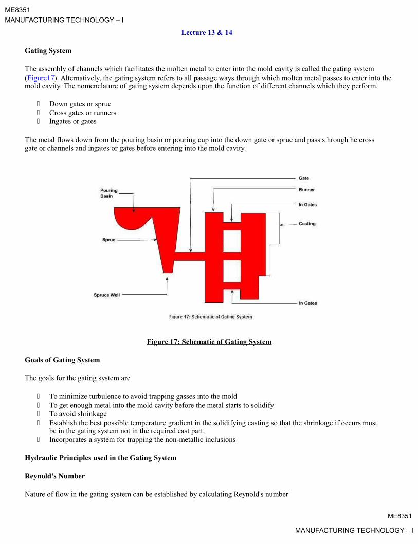
The assembly of channels which facilitates the molten metal to enter into the mold cavity is called the gating system(Figure17). Alternatively, the gating system refers to all passage ways through which molten metal passes to enter into themold cavity. The nomenclature of gating system depends upon the function of different channels which they perform.
Down gates or sprue Cross gates or runners Ingates or gates
The metal flows down from the pouring basin or pouring cup into the down gate or sprue and pass s hrough he cross gate or channels and ingates or gates before entering into the mold cavity.
Figure 17: Schematic of Gating System
Goals of Gating System
The goals for the gating system are
To minimize turbulence to avoid trapping gasses into the mold To get enough metal into the mold cavity before the metal starts to solidify To avoid shrinkage Establish the best possible temperature gradient in the solidifying casting so that the shrinkage if occurs must
be in the gating system not in the required cast part. Incorporates a system for trapping the non-metallic inclusions
Hydraulic Principles used in the Gating System
Reynold's Number
Nature of flow in the gating system can be established by calculating Reynold's number
ME8351
MANUFACTURING TECHNOLOGY – I

ME8351
MANUFACTURING TECHNOLOGY – I
RN = Reynold's number
V = Mean Velocity of flow
D = diameter of tubular flow
= Kinematics Viscosity = Dynamic viscosity / Density
= Fluid density
When the Reynold's number is less than 2000 stream line flow results and when the number is more han 2000 urbulent flow prevails. As far as possible the turbulent flow must be avoided in the sand mold as because of the turbul nce sand particles gets dislodged from the mold or the gating system and may enter into the mould cavity l adi g to the production of defective casting. Excess turbulence causes
Inclusion of dross or slag Air aspiration into the mold Erosion of the mold walls
Bernoulli's Equation
h = height of liquid
P = Static Pressure
= metal velocity
g = Acceleration due to gravity
= Fluid density
Turbulence can be avoided by incorporating small changes in the design of gating system. The sharp changes in the flow should be avoided to smooth changes. The gating system must be designed in such a way that the system always runs fullwith the liquid metal. The most important things to remember in designing runners and gates are to avoid sharp corners. Any changes in direction or cross sectional area should make use of rounded corners.
To avoid the aspiration the tapered sprues are designed in the gating systems. A sprue tapered to a smaller size at itsbottom ill create a choke which will help keep the sprue full of molten metal.
Types of Gating Systems (Figure18a, 18b)
The gating systems are of two types:
Pressurized gating system Un-pressurized gating system
Pressurized Gating SystemME8351
MANUFACTURING TECHNOLOGY – I

ME8351
MANUFACTURING TECHNOLOGY – I
The total cross sectional area decreases towards the mold cavity Back pressure is maintained by the restrictions in the metal flow Flow of liquid (volume) is almost equal from all gates Back pressure helps in reducing the aspiration as the sprue always runs full Because of the restrictions the metal flows at high velocity leading to more turbulence and chances of
mold erosion
Un-Pressurized Gating System
The total cross sectional area increases towards the mold cavity Restriction only at the bottom of sprue Flow of liquid (volume) is different from all gates aspiration in the gating system as the system never runs full Less turbulence
Fig 18a : Pressurized Gating System
Fig 18b : Un-Pressurized Gating SystemME8351
MANUFACTURING TECHNOLOGY – I

ME8351
MANUFACTURING TECHNOLOGY – I
Riser
Riser is a source of extra metal which flows from riser to mold cavity to compensate for shrinkage which takes place in the casting when it starts solidifying. Without a riser heavier parts of the casting will have shrinkage defects, either on thesurface or internally.
Risers are known by different names as metal reservoir, feeders, or headers.
Shrinkage in a mold, from the time of pouring to final casting, occurs in three stages.
1. during the liquid state2. during the transformation from liquid to solid3. during the solid state
First type of shrinkage is being compensated by the feeders or the gating system. For the seco d type of shrinkage risers are required. Risers are normally placed at that portion of the casting which is last to freeze A riser must stay in liquid state at least as long as the casting and must be able to feed the casting during this time
Functions of Risers
Provide extra metal to compensate for the volumetric shrinkage Allow mold gases to escape Provide extra metal pressure on the solidifying mold to reproduce mold details more exact
Design Requirements of Risers
1. Riser size: For a sound casting riser must be last to fr ze. The ratio of (volume / surface area)2 of the riser mustbe greater than that of the casting. However, wh n this condition does not meet the metal in the riser can be keptin liquid state by heating it externally or using xoth rmic mat rials in the risers.
2. Riser placement: the spacing of risers in the casting must be considered by effectively calculating the feedingdistance of the risers.
3. Riser shape: cylindrical risers re recommen ed for most of the castings as spherical risers, although considers asbest, are difficult to cast. To incre se volume/surface area ratio the bottom of the riser can be shaped ashemisphere.
ME8351
MANUFACTURING TECHNOLOGY – I

ME8351
MANUFACTURING TECHNOLOGY – I
Lecture 15
Casting Defects (Figure19)
The following are the major defects, which are likely to occur in sand castings
Gas defects Shrinkage cavities Molding material defects Pouring metal defects Mold shift
Gas Defects
A condition existing in a casting caused by the trapping of gas in the molten metal or by mold gas s volv d during thepouring of the casting. The defects in this category can be classified into blowholes a d pi hole porosity. Blowholes are
Molding Material Defects
Shrinkage Cavities

spherical or elongated cavities present in the casting on the surface or inside the casti g Pi hole porosity occurs due tothe dissolution of hydrogen gas, which gets entrapped during heating of molten metal
Causes
The lower gas-passing tendency of the mold, which may be due to lower venting, lower permeability of the mold or improper design of the casting. The lower permeability is caused by finer grain si of the sand, high percentage of clay in mold mixture, and excessive moisture present in the mold.
Metal contains gas Mold is too hot Poor mold burnout
These are caused by liquid shrinkagepadeepzoccurringuringthesoliificationofthecasting. To compensate for this, proper feeding of liquid metal is required. For this re son risers
are placed at the appropriate places in the mold. Sprues may be
too thin, too long or not attached in the ro er loc tion, causing shrinkage cavities. It is recommended to use thick sprues to avoid shrinkage cavities.
The defects in this category are cuts and washes, metal penetration, fusion, and swell.
Cut and washes
These appear as rough spots and areas of excess metal, and are caused by erosion of molding sand by the flowing metal. This is caused by the molding sand not having enough strength and the molten metal flowing at high velocity. The formercan be taken care of by the proper choice of molding sand and the latter can be overcome by the proper design of the gating system.
Metal penetration
When molten metal enters into the gaps between sand grains, the result is a rough casting surface. This occurs because thesand is coarse or no mold wash was applied on the surface of the mold. The coarser the sand grains more the metal penetration.
FusionME8351
MANUFACTURING TECHNOLOGY – I

ME8351
MANUFACTURING TECHNOLOGY – I
This is caused by the fusion of the sand grains with the molten metal, giving a brittle, glassy appearance on the castingsurface. The main reason for this is that the clay or the sand particles are of lower refractoriness or that the pouring temperature is too high.
Swell
Under the influence of metallostatic forces, the mold wall may move back causing a swell in the dimension of the casting.A proper ramming of the mold will correct this defect.
Inclusions
Particles of slag, refractory materials, sand or deoxidation products are trapped in the casting during pouring solidification. The provision of choke in the gating system and the pouring basin at the top of the mold can pr v nt his defect.
Pouring Metal Defects
The likely defects in this category are
Mis-runs and Cold shuts.
A mis-run is caused when the metal padeepzisunabletofillthemoldcavitycomltlyandthusleaves unfilled cavities. A mis-
run results when the metal is too cold to flow to the extremiti s of the mold cavity before freezing. Long, thin sections are subject to this defect and should be avoided in casting design.
A cold shut is caused when two streams while meeting in the mold cavity, do not fuse together properly thus forming a discontinuity in the casting. When the molten metal is pour d into the mold cavity through more-than-one gate, multiple liquid fronts will have to flow together and become one solid. If the flowing metal fronts are too cool, they may not flow together, but will leave a seam in the part. Such seam is called a cold shut, and can be prevented by assuring sufficient superheat in the poured metal and thick enough w lls in the casting design.
The mis-run and cold shut defects are c used either by lower fluidity of the mold or when the section thickness of thecasting is very small. Fluidity can be im roved by ch nging the composition of the metal and by increasing the pouringtemperature of the metal.
Mold Shift
The mold shift defect occurs hen cope and drag or molding boxes have not been properly aligned.
Figure 19 : Casting DefectsME8351
MANUFACTURING TECHNOLOGY – I

ME8351
MANUFACTURING TECHNOLOGY – I
Lecture 1
Introduction:
Welding which is the process of joining two metallic components for the desired purpose, can be defined as the process ofjoining two similar or dissimilar metallic components with the application of heat, with or without the application of pressure and with or without the use of filler metal. Heat may be obtained by chemical reaction, electric arc, electrical resistance, frictional heat, sound and light energy. If no filter metal is used during welding then it is termed as ‘Autogenous Welding Process'.
During ‘Bronze Age' parts were joined by forge welding to produce tools, weapons and ornaments etc, how v r, pr s nt day welding processes have been developed within a period of about a century.
First application of welding with carbon electrode was developed in 1885 while metal arc welding with bare electrode waspatented in 1890. However, these developments were more of experimental value and applicable o ly for repair welding but proved to be the important base for present day manual metal arc (MMAW) welding and other arc welding processes.
In the mean time resistance butt welding was invented in USA in the year 1886. Other resistance welding processes such as spot and flash welding with manual application of load were developed around 1905.
With the production of cheap oxygen in 1902, oxy – acetylene welding became feasible in Europe in 1903.
When the coated electrodes were developed in 1907, the manual m tal arc w lding rocess become viable for production/fabrication of components and assemblies in the industri s on large scale.
Subsequently other developments are as follows:
• Thermit Welding (1903)
• Cellulosic Electrodes (1918)
• Arc Stud Welding (1918)
• Seam Welding of Tubes (1922)
• Mechanical Flash Welder for Joining Rails (1924)
• Extruded Coating for MMAW Electrodes (1926)
• Submerged Arc Welding (1935)
• Air Arc Gouging (1939)
• Inert Gas Tungsten Arc (TIG) Welding (1941)
• Iron Powder Electrodes ith High Recovery (1944)
• Inert Gas Metal Arc (MIG) Welding (1948)
• Electro Slag Welding (1951)
• Flux Cored Wire ith CO 2 Shielding (1954)
• Electron Beam Welding (1954)
• Constricted Arc (Plasma) for Cutting (1955)
• Friction Welding (1956)
• Plasma Arc Welding (1957)
• Electro Gas Welding (1957)ME8351
MANUFACTURING TECHNOLOGY – I
ME8351
MANUFACTURING TECHNOLOGY – I
• Short Circuit Transfer for Low Current, Low Voltage Welding with CO 2 Shielding (1957)
• Vacuum Diffusion Welding (1959)
• Explosive Welding (1960)
• Laser Beam Welding (1961)
• High Power CO 2 Laser Beam Welding (1964)
All welded ‘ Liberty ' ships failure in 1942, gave a big jolt to application of welding. However, it had drawn attention tofracture problem in welded structures.
Applications:
Although most of the welding processes at the time of their developments could not get their place in the production except for repair welding, however, at the later stage these found proper place in ma ufacturi g/production. Presently welding is widely being used in fabrication of pressure vessels, bridges, building structures, aircraft a d space crafts, railway coaches and general applications. It is also being used in shipbuilding, automobile, electrical, electronic and defense industries, laying of pipe lines and railway tracks and nuclear installations etc
General Applications:
Welding is vastly being used for construction of transport tankers for trans orting oil, water, milk and fabrication of welded tubes and pipes, chains, LPG cylinders and other items. Steel furniture, gates, doors and door frames, body and other parts of white goods items such as refrigerators, washing machin s, microwave ovens and many other items of general applications are fabricated by welding.
Pressure Vessels:
One of the first major use of welding was in the fabrication of pr ssure vessels. Welding made considerable increases inthe operating temperatures and pressures possible as compared to riveted pressure vessels.
Bridges:
Early use of welding in bridge construction took l ce in Australia . This was due to problems in transporting complete riveted spans or heavy riveting machines necessary for fabrication on site to remote areas. The first all welded bridge was erected in UK in 1934. Since then all welded bridges are erected very commonly and successfully.
Ship Building :
Ships were produced earlier by riveting. Over ten million rivets were used in ‘Queen Mary' ship which required skills and massive organization for riveting but elding would have allowed the semiskilled/ unskilled labor and the principle of pre-fabrication. Welding found its place in ship building around 1920 and presently all welded ships are widely used. Similarly submarines are also produced by welding.
Building Structures:
Arc elding is used for construction of steel building leading to considerable savings in steel and money. In addition to building, huge structures such as steel towers etc also require welding for fabrication.
Aircraft and Spacecraft:
Similar to ships, aircrafts were produced by riveting in early days but with the introduction of jet engines welding is widely used for aircraft structure and for joining of skin sheet to body.
ME8351
MANUFACTURING TECHNOLOGY – I

ME8351
MANUFACTURING TECHNOLOGY – I
Space vehicles which have to encounter frictional heat as well as low temperatures require outer skin and other parts of special materials. These materials are welded with full success achieving safety and reliability.
Railways:
Railways use welding extensively for fabrication of coaches and wagons, wheel tyres laying of new railway tracks by mobile flash butt welding machines and repair of cracked/damaged tracks by thermit welding.
Automobiles:
Production of automobile components like chassis, body and its structure, fuel tanks and joining of door hinges require welding.
Micro-Joining:
Defence Industry:
Nuclear Installations:

printed circuit boards. Robotic soldering is very common for joining of parts to printed circuit boards of computers,
television, communication equipment and other control quipm nt tc.
Electrical Industry:Starting from generation to distribution and utilization of electrical energy, welding plays importa role. Components ofboth hydro and steam power generation system, such as penstocks, water control gates, co de sers, electrical transmissiontowers and distribution system equipment are fabricated by welding. Turbine blades and cooli g fi s are also joined bywelding.
netElectronic Industry:
Electronic industry uses welding to limited extent such as for joining l ads of s ecial transistors but other joiningprocesses such as brazing and soldering are widely being used. Sold ring is us for joining electronic components to
padeepzSpheres for nuclear reactor, pipe line bends joining two pipes carrying heavy water and other components require weldingfor safe and reliable operations.
Defence industry requires welding for joining of many components of war equipment. Tank bodies fabrication, joining of turret mounting to main body of tanks are ty ical examples of applications of welding.
It employs the processes such as micro-plasma, ultrasonic, laser and electron beam welding, for joining of thin wire to wire, foil to foil and foil to ire, such as producing junctions of thermocouples, strain gauges to wire leads etc.
Apart from above applications welding is also used for joining of pipes, during laying of crude oil and gas pipelines, construction of tankers for their storage and transportation. Offshore structures, dockyards, loading and unloading cranesare also produced by elding.
ME8351
MANUFACTURING TECHNOLOGY – I

ME8351
MANUFACTURING TECHNOLOGY – I
Lecture 2
Classification of Welding Processes:
1. Welding with or without filler material.2. Source of energy of welding.3. Arc and Non-arc welding.4. Fusion and Pressure welding.
1. Welding can be carried out with or without the application of filler material. Earlier only gas welding was hefusion process in which joining could be achieved with or without filler material. Wh w lding was donewithout filler material it was called ‘autogenous welding'. However, with the developm nt of TIG, l c ron beamand other welding processes such classification created confusion as many processes shall be falling in both thecategories.
2. Various sources of energies are used such as chemical, electrical, light, sound, mecha ical rgi s, but except forchemical energy all other forms of energies are generated from electrical energy for weldi g. So this criteriondoes not justify proper classification.
3.padeepz
Arc and Non-arc welding processes classification embraces all the arc welding processes in one class and all other
processes in other class. In such classification it is difficult to assign either of thenetclasstoprocessessuch aselectroslag welding and flash butt welding, as in electroslag welding the rocess starts with arcing and with themelting of sufficient flux the arc extinguishes while in flash butt welding tiny arcs i.e. sparks are establishedduring the process and then components are pressed against each other. Therefore, such classification is also notperfect.
4. Fusion welding and pressure welding is most widely us classification as it covers all processes in both thecategories irrespective of heat source and w lding with or without filler material. In fusion welding all thoseprocesses are included where molten metal solidifi s fr ly while in pressure welding molten metal if any isretained in confined space under pressure (as may be in case of resistance spot welding or arc stud welding)solidifies under pressure or semisolid metal cools un r pr ssure. This type of classification poses no problems so itis considered as the best criterion.
Processes falling under the categories of fusion nd pressure welding are shown in Figures 2.1 and 2.2.
Welding processes can be classified based on following criteria;

ME8351
MANUFACTURING TECHNOLOGY – I

ME8351
MANUFACTURING TECHNOLOGY – I
Figure 2.1: Classification of Fusion W lding Processes
Figure 2.2: Classification of Pressure Welding Processes
ME8351
MANUFACTURING TECHNOLOGY – I

ME8351
MANUFACTURING TECHNOLOGY – I
Lecture 3
Brazing and Soldering:
Both brazing and soldering are the metal joining processes in which parent metal does not melt but only filler metal meltsfilling the joint with capillary action. If the filler metal is having melting temperature more than 450°C but lower than the melting temperature of components then it is termed as process of brazing or hard soldering. However, if the melting temperature of filler metal is lower than 450°C and also lower than the melting point of the material of components then it is know as soldering or soft soldering.
During brazing or soldering flux is also used which performs the following functions:
• Dissolve oxides from the surfaces to be joined.
• Reduce surface tension of molten filler metal i.e. increasing its wetting action or spreadability.
• Protect the surface from oxidation during joining operation.
The strength of brazed joint is higher than soldered joint but lower than welded joint However, in between welding andbrazing there is another process termed as ‘braze welding'.
Braze Welding:
Unlike brazing, in braze welding capillary action plays no role but the fill r metal which has liquidus above 450 ° C but below the melting point of parent metal, fills the joint like w lding without the melting of edges of parent metal. During the operation, the edges of the parent metal are heated by oxy-ac tyl ne flame or some other suitable heat source to that temperature so that parent metal may not melt but m lting t mp rature of fill r metal is reached. When filler rod is brought in contact with heated edges of parent metal, the fill r rod starts m lting, filling the joint. If edges temperature falls down then again heat source is brought for melting fill r rod. The molten filler metal and parent metal edges produce adhesion on cooling resulting into strong braze weld.
The braze welding filler material is normally brass with 60% Cu and remaining Zn with small additions of tin, manganese and silicon. The small additions of elements improve the deoxidizing and fluidity characteristics of filler metal.
Brazing:
The most commonly used filler metal is copper base zinc alloy consisting of normally 50-60% Cu, approximately 40% Zn, 1% Ni, 0.7 % Fe and traces of Si and Mn, which is brass and termed as 'spelter'. In some cases around 10% Ni may also be added to filler alloys. Copper base alloys may be available in the form of rod, strip and wire. Silver brazing filler metal may consists of 30-55% Ag, 15-35% Cu, 15-28% Zn, 18-24% Cd and sometimes 2-3% Ni or 5% Sn. Silver brazingalloys are available in form of wire, strip, rods and powders.
Borax and boric acid are commonly used fluxes for brazing with copper base filler metals. Many other commercialfluxes may be available in the form of paste or liquid solution leading to ease of application and adherence to the surfacein any position.
ME8351
MANUFACTURING TECHNOLOGY – I

ME8351
MANUFACTURING TECHNOLOGY – I
Various commonly used method of brazing are followings:
• Torch Brazing
Torch brazing utilizes the heat of oxy-acetylene flame with neutral or reducing flame. Filler metal may be either preplacedin form of washers, rings, formed strips, powders or may be fed manually in form of rod.
• Dip Brazing
In dip brazing components with filler metal in proper form is preplaced at the joint and assembly is dipped in ba hof molten salt which acts as heat source as well as flux for brazing. Preplaced preform melts and fills the joint. Anoher variant is to dip assembled parts in metallic bath and metal of bath fills the joint.
• Furnace Brazing
Self fixturing assembly with preplaced filler metal is placed inside electrically heated fur ace with temperature control forheating and cooling. These furnaces may also be using protective atmosphere with inert gases like argon a d helium or vacuum for brazing of reactive metal components.
• Infra-red Brazing
The heat for brazing is obtained from infra-red lamps. Heat rays can be concentrated at desired area or spot with concavereflectors. Such method of brazing requires automation and parts to be join d should be self fixturing. Filler metal is to bepreplaced in the joint. The operation can be performed in air or in in rt atmos h re or in vacuum.
• Induction Brazing
The heat is generated by induced current into the workpi ce from wat r cooled coil which surrounds the workpieces to be brazed. High frequencies employed vary from 5 to 400 kHz. High r the frequency of current, shallow is the heating effect while lower frequencies of current lead to eeper heating and so it can be employed for thicker sections. Fluxes may or may not be used during brazing.
• Resistance BrazingIn resistance brazing the heat is generatedpadeepzattheinterfacestobebrazedbyresistiveheating. The components are
connected to high current and low voltage ower supply through two electrodes under pressure. Only those fluxes are
used which are electrically conductive and filler metal is preplaced.
Fig 3.2: Typical Self Fixturing Brazing Assembly
ME8351
MANUFACTURING TECHNOLOGY – I

ME8351
MANUFACTURING TECHNOLOGY – I
Fig 3.3: Preplaced Brazing Material and filling of joint duri g Brazi g.
Flux Residue Treatment:

Soldering:.
The soldering filler metal is called solderpadeepz.Themostcommonlyusedsolderisleadandtin alloy containing tin ranging
from 5 to 70% and lead 95 to 30%. Higher the contents of tin, lower the melting point of alloy Other filler metal are tin-antimony solder (95% tin and 5% antimony), tin-silver solder (tin 96% and silver 4%), lead-silver solder (97% lead, 1.5 tin and 1.5 silver), tin-zinc solder (91 to 30% tin and 9 to 70% zinc), cadmium-silver solder (95% cadmium and 5% silver). These are available in the form of bars, solid and flux cored wires, reforms, sheet, foil, ribbon and paste or cream.
Fluxes used in soldering are ammonium chloride, zinc chlorid , rosin and rosin dissolved in alcohol.
Various soldering methods are soldering with soldering irons, dip sold ring, torch soldering, oven soldering, resistancesoldering, induction soldering, infra-red and ultrasonic sold ring.
Soldering iron being used for manual soldering, consists of insulated handle and end is fitted with copper tip whichmay be heated electrically or in coke or oil/g s fired furn ce. Sol er is brought to molten state by touching it to the tip ofthe soldering iron so that molten solder can spre to the joint surface.
Ultrasonic soldering uses ultrasonics i. . high frequency vibrations which break the oxides on the surface of workpiecesand heat shall be generated due to rubbing between surfaces. This heat melts the solder and fills the joint by capillary action.
When brazing or soldering is completed then the flux residues are to be removed because without removal the residues may lead to corrosion of assemblies.
Brazing flux residues can be removed by rinsing with hot water followed by drying. If the residue is sticky then it can be removed by thermal shock i.e. heating and quenching. Sometimes steam jet may be applied followed by wire brushing.
Soldering flux residues of rosin flux can be left on the surface of joint, however, activated rosin flux and other flux residues require proper treatment. If rosin residues removal is required then alcohol, acetone or carbon tetrachloride can be used. Organic flux residues are soluble in hot water so double rising in warm water shall remove it. Residue removal of zinc chloride base fluxes can be achieved by washing first in 2% hydrochloric acid mixed in hot water followed by simple hot ater rinsing.

ME8351
MANUFACTURING TECHNOLOGY – I
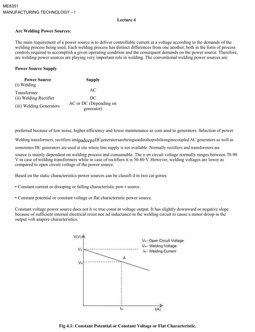
ME8351
MANUFACTURING TECHNOLOGY – I
Lecture 4
Arc Welding Power Sources:
The main requirement of a power source is to deliver controllable current at a voltage according to the demands of the welding process being used. Each welding process has distinct differences from one another, both in the form of process controls required to accomplish a given operating condition and the consequent demands on the power source. Therefore,arc welding power sources are playing very important role in welding. The conventional welding power sources are:
Power Source Supply
Power Source Supply(i) Welding
ACTransformer(ii) Welding Rectifier DC
(iii) Welding GeneratorsAC or DC (Depending on
generator)
preferred because of low noise, higher efficiency and lower maintenance as com ared to generators. Selection of power
Welding transformers, rectifiers andpadeepzDCgeneratorsarebeingusedinshopwhileenginecoupled AC generators as well as
sometimes DC generators are used at site where line supply is not available. Normally rectifiers and transformers are
source is mainly dependent on welding process and consumable. The o en circuit voltage normally ranges between 70-90 V in case of welding transformers while in case of rectifiers it is 50-80 V. However, welding voltages are lower as compared to open circuit voltage of the power source.
Based on the static characteristics power sources can be classifi d in two cat gories
• Constant current or drooping or falling characteristic pow r source.
• Constant potential or constant voltage or flat characteristic power source.
Constant voltage power source does not h ve true const nt voltage output. It has slightly downward or negative slope because of sufficient internal electrical resist nce nd inductance in the welding circuit to cause a minor droop in the output volt ampere characteristics.
Fig 4.1: Constant Potential or Constant Voltage or Flat Characteristic.

ME8351
MANUFACTURING TECHNOLOGY – I

ME8351
MANUFACTURING TECHNOLOGY – I
With constant voltage power supply the arc voltage is established by setting the output voltage on the source. The power source shall supply necessary current to melt the electrode at the rate required to maintain the preset voltage or relative arclength. The speed of electrode drive is used to control the average welding current. The use of such power source in conjunction with a constant electrode wire feed results in a self regulating or self adjusting arc length system. Due to some internal or external fluctuation if the change in welding current occurs, it will automatically increase or decrease the electrode melting rate to regain the desired arc length.
Fig 4.2: Drooping or Const nt current or Falling Characteristic.
The volt ampere output curves for constant current power source are called ‘drooper' because of substantial downward or negative slope of the curves The ower source may have open circuit voltage adjustment in addition to output current control. A change in either control will change the slope of the volt ampere curve. With a change in arc voltage, the change in current is small and, therefore, with consumable electrode welding process, electrode melting rate wouldremain fairly constant ith a change in arc length. These power sources are required for processes using relatively thicker
consumable electrodespadeepz
hich may sometimes get stubbed to workpiece or with nonconsumable tungsten electrode whereduring touching of electrode for starting of arc may lead to damage of electrode if current is unlimited. Under these conditions the short circuiting current shall be limited leading to safety of power source and the electrode.
Some po er sources need high frequency unit to start the arc, which may be requirement of processes like TIG and plasma arc. High frequency unit is introduced in the welding circuit but in between the control circuit and HF unit, filtersare required so that high frequency may not flow through control circuit and damage it. High frequency unit is a device
hich supplies high voltage of the order of few KV along with high frequency of few KHz with low current. This high voltage ionizes the medium between electrode and workpiece/nozzle starting pilot arc which ultimately leads to the start of main arc. Although high voltage may be fatal for the operator but when it is associated with high frequencies then current does not enter body but it causes only skin effect i.e. current passes through the skin of operator causing nodamage to the operator.
ME8351
MANUFACTURING TECHNOLOGY – I
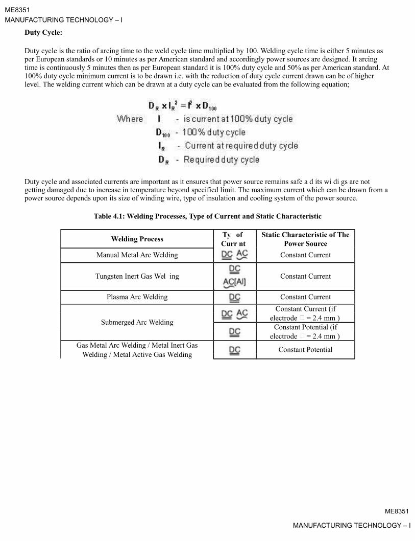
ME8351
MANUFACTURING TECHNOLOGY – I
Duty Cycle:
Duty cycle is the ratio of arcing time to the weld cycle time multiplied by 100. Welding cycle time is either 5 minutes as per European standards or 10 minutes as per American standard and accordingly power sources are designed. It arcing time is continuously 5 minutes then as per European standard it is 100% duty cycle and 50% as per American standard. At100% duty cycle minimum current is to be drawn i.e. with the reduction of duty cycle current drawn can be of higher level. The welding current which can be drawn at a duty cycle can be evaluated from the following equation;
Duty cycle and associated currents are important as it ensures that power source remains safe a d its wi di gs are not getting damaged due to increase in temperature beyond specified limit. The maximum current which can be drawn from apower source depends upon its size of winding wire, type of insulation and cooling system of the power source.
Table 4.1: Welding Processes, Type of Current and Static Characteristic
Welding ProcessTy of Static Characteristic of TheCurr nt Power Source
Manual Metal Arc Welding Constant Current
Tungsten Inert Gas Wel ing Constant Current
Plasma Arc Welding Constant Current
Constant Current (if
Submerged Arc Weldingelectrode = 2.4 mm )
Constant Potential (ifelectrode = 2.4 mm )
Gas Metal Arc Welding / Metal Inert GasConstant Potential
Welding / Metal Active Gas Welding
ME8351
MANUFACTURING TECHNOLOGY – I

ME8351
MANUFACTURING TECHNOLOGY – I
Lecture 5 & 6
Manual Metal Arc Welding:
Manual metal arc welding (MMAW) or shielded metal arc welding (SMAW) is the oldest and most widely used process being used for fabrication. The arc is struck between a flux covered stick electrode and the workpieces. The workpieces are made part of an electric circuit, known as welding circuit. It includes welding power source, welding cables, electrodeholder, earth clamp and the consumable coated electrode. Figure 5.1 Shows details of welding circuit.
Fig 5.1: Manual M tal Arc W lding Circuit
Fig 5.2: Molten Metal and Flux Transfer to Weld Pool
Figure 5.2 shows the fine molten droplets of metal and molten flux coming from the tip of the coated electrode. The flux melts along with the metallic core wire and goes to weld pool where it reacts with molten metal forming slag which floats on the top of molten weld pool and solidifies after solidification of molten metal and can be removed by chipping and brushing.
ME8351
MANUFACTURING TECHNOLOGY – I

ME8351
MANUFACTURING TECHNOLOGY – I
Welding power sources used may be transformer or rectifier for AC or DC supply. The requirement depends on the typeof electrode coating and sometimes on the material to be welded.
The constant-current or drooping type of power source is preferred for manual metal arc welding since it is difficult to hold a constant arc length. The changing arc length causes arc voltage to increase or decrease, which in turn produces achange in welding current. The steeper the slope of the volt-ampere curve within the welding range, the smaller the current change for a given change in arc voltage. This results into stable arc, uniform penetration and better weld seam inspite of fluctuations of arc length.
The welding voltages range from 20 to 30 V depending upon welding current i.e. higher the current, higher the voltage.Welding current depends on the size of the electrode i.e. core diameter. The approximate average welding current for structural steel electrodes is 35.d (where d is electrode diameter in mm) with some variations with he ype of coa ing of electrode. Table 5.1 shows influence of welding parameters on weld characteristics.
Table 5.1: Welding Variables and Their Influence
Welding Condition Main EffectsCurrent in excess of optimum Excess spatter. Flat wide deposit. Deep crater Deep pe etration. Electrode overheats.Current less than optimum Slag difficult to control. Metal piles up. Poor dead shape Poor pe etration.Voltage in excess of optimum Deposit irregular and flat. Arc wander. Porosity SpatterVoltage less than optimum Irregular piling of weld metal. Arc extinctions. Little penetration.Travel speed in excess of Narrow thin weld bead. Undercut.optimumTravel speed less than optimum Wide thick deposit. Difficulty in slag control.Optimum Welding conditions Smooth even weld deposit. Stable arc condition. Easily controlled slag. Little spatter
produced.
The output voltage of the power source on ‘no load' or ‘op n circuit' must be high enough to enable the arc to be started.A value of 80 V is sufficient for most electro es but c rtain typ s may require more or less than this value.
A manual welding power source is never lo ed continuously because of operations such as, electrode changing, slagremoval etc. Most MMA welding equipment h suty cycle of around 40% at maximum welding current.
Coated Electrodes are specified based on core wire di meter. Commonly used electrode diameters are 2, 2.5, 3.18, 4, 5and 6 mm. Length of electrodes may end on diameter of core wire ranging from 250 to 450 mm i.e. larger the corediameter larger the length However, s ecial electrodes may be of 8-10 mm diameter. Table 5.2 gives the details ofelectrode sizes and currents
Table.52:Size and Welding Current for Stick Mild Steel Electrodes
padeepzDiameter d 2.0 2.5 3.18(1/8") 4.0 5.0 6.0
mmLength L 250/300 350 350/450 450 450 450
mmWelding 50-80 70-100 90-130 120-160 160-200 190-240ICurrent
A
The electrodes are also specified based on ratio of diameter of coated portion of electrode to core wire diameter. If thisratio is lesser than 1.2 then electrodes are thin coated, if ratio ranges between 1.2 to 1.5 then medium coated and ifratio exceeds 1.5 then electrodes are heavy coated or thick coated. This ratio may vary slightly in different codes.
Thin coated electrodes have very good bridgeability at the joint gap but weld bead has coarse ripples and penetration isalso poor. Medium coated electrodes lead to reasonably good bridgeability, medium ripples in weld bead and modest
ME8351
MANUFACTURING TECHNOLOGY – I

ME8351
MANUFACTURING TECHNOLOGY – I
penetration. Thick coated electrodes have poor bridgeability, however, bead appearance is excellent with fine ripples andalso excellent penetration.
The ingress of oxygen and nitrogen from the atmosphere to the weld pool and arc environment would cause embrittlementand porosity in the weld metal and this must be prevented. The Actual method of arc shielding from atmospheric nitrogenand oxygen attack varies with different type of electrodes which are in two main categories.
1. Bulk of covering material converts to a gas by the heat of the arc, only a small amount of slag is produced. Protection depends largely upon a gaseous shield to prevent atmospheric contamination as in case of cellulosic electrode.
2. Bulk of covering material converts to a slag, only a small volume of shielding gas produced as in he case of ru ile andbasic coated electrodes.
Electrode coating performs many functions depending upon coating constituents, during welding to improve weld metalproperties. The important functions are as follows:
1. Improve the electric conductivity in the arc region to improve the arc ignition and stabilization of the arc.
2. Formation of slag, which;
(a) Influences size of droplet.
(b) Protects the droplet during transfer and molten weld pool from atmos heric gases.
(c) Protects solidified hot metal from atmospheric gases.
(d) Reduces the cooling rate of weld seam.
3.Formation of shielding gas to protect molten metal.
4.Provide deoxidizers like Si and Mn in form of FeSi nd FeMn.
5.Alloying with certain elements such s Cr, Ni, Mo to improve weld metal properties.
6.Improve deposition rate with addition of iron owder in coating.
Various constituents of electrode coating are cellulose, calcium fluoride, calcium carbonate, titanium dioxide, clay, talc,iron oxide, asbestos, potassium / sodium silicate, iron powder, ferro-maganese, powdered alloys, silica etc. Each constituent performs either one or more than one functions.
Electrode metallic core ire is the same but the coating constituents give the different characteristics to the welds. Based on the coating constituents, structural steel electrodes can be classified in the following classes;
1. Cellulosic Electrodes
Coating consists of high cellulosic content more than 30% and TiO2 up to 20%. These are all position electrodesand produce deep penetration because of extra heat generated during burning of cellulosic materials. However, high spatter losses are associated with these electrodes.
2. Rutile Electrodes
Coating consists of TiO 2 up to 45% and SiO2 around 20%. These electrodes are widely used for general workand are called general purpose electrodes.
ME8351
MANUFACTURING TECHNOLOGY – I

ME8351
MANUFACTURING TECHNOLOGY – I
3. Acidic Electrodes
Coating consists of iron oxide more than 20%. Sometimes it may be up to 40%, other constituents may be TiO2 10% and CaCO3 10%. Such electrodes produce self detaching slag and smooth weld finish and are used normally in flat position.
4. Basic Electrodes
Coating consist of CaCO3 around 40% and CaF2 15-20%. These electrodes normally require baking at temperature of approximately 250 ° C for 1-2 hrs or as per manufacturer's instructions. Such electrodes produce high quality weld deposits which has high resistance to cracking. This is because hydrogen is removed from weldmetal by the action of fluorine i.e. forming HF acid as CaF2generates fluorine on dissociation in he heat of arc.
Classification of Electrodes as per Indian Standard:

Table 5.3: Coating Constituents and Their Functions
Coating Constituent FunctionsMain Functions Other Functions
Cellulose Gas former Coating Stre gth a dReduci g age
Calcium Fluoride (CaF2) Slag basicity and metal Slag former
fluidity, H2removal net
Clay (Aluminum Silicate) Slag former Coating strengthTalc (Magnesium Slag former Arc stabilizer
Silicate)Rutile (TiO2 ) Arc stabiliz r, Slag Slag removal and bead
form r, Fluidity appearanceIron Oxides Fluidity, Slag form r Arc Stabilizer, improved
metal transfer,Calcium Carbonate Gas form r, Arc stabilizer Slag basicity, Slag former
Asbestos Coating strength Slag formerQuartz (SiO2 ) Sl g flui ity, Slag former Increase in current
carrying capacity.Sodium Silic te / Binder, Arc stabilizer Slag formerPotassium Silic te
FeMn / FeSi Deoxidizer -Iron Powder Deposition Rate -
Powdered Alloys Alloying -
Structural steel electrodes ere classified as per IS 814:1974 and this code was revised and the revised code is IS 814:1991.
The corresponding code is given on each packet of electrode.
IS 815:1974
As per IS 815 electrodes are designated with letters and digits.
P X X X X X X S
ME8351
MANUFACTURING TECHNOLOGY – I

ME8351
MANUFACTURING TECHNOLOGY – I
Prefix (P) is either E or R which indicates solid extruded (E) or reinforced extruded (R) Electrode.
1 st digit – Indicates type of coating.
2 nd digit – Indicates weld positions in which electrode can be used.
3 rd digit – Indicates welding current conditions.
4 th and 5 th digit – Indicate UTS and YS of all weld metal.
6 th digit – Requirement of minimum % elongation and absorbed energy in charpy V- notch impact est of weld metal.
Suffix (s) – P – Deep penetration electrode
H – Hydrogen controlled electrode
Weld Bead Geometry

J, K and L – Amount of metal recovery in case of iron powder electrode
Suffix (s) are optional and may or may not be given if not applicable.
IS 814:1991
As per IS 814 electrodes are designated with letters and digits as given below:
E L X X X X S
Suffix(s) are optional and indicate speci l ch r cteristics of electrode such as H1, H2, and H3 indicate hydrogen controlled
electrodes with different amount of diffusible hydrogen J, K, L indicate different amount of metal recovery in weld pool
in case of iron powder electrodes and X me ns r diogr phic weld quality.
In this code E indicates extruded solid electrode, L is l tt r to d signate type of coating, first digit indicates UTS and YSof deposited weld metal, second digit gives percentage longation and impact values of weld metal deposited, third digitgives welding positions in which electrode can be us and fourth digit gives the current conditions for the use ofelectrode.
padeepzNote: For details see the above codes ublished by Bureau of Indian Standards (BIS), Manak Bhawan, Bahadur Shah Jafar Marg, New Delhi .
Figure 5.3 sho s the important parameters of the weld bead geometry for a butt weld.
FIg 5.3: Weld Bead Geometry
ME8351
MANUFACTURING TECHNOLOGY – I

ME8351
MANUFACTURING TECHNOLOGY – I
Lecture 7 & 8
Submerged Arc Welding:
Submerged arc welding is an arc welding process in which heat is generated by an arc which is produced between bareconsumable electrode wire and the workpiece. The arc and the weld zone are completely covered under a blanket of granular, fusible flux which melts and provides protection to the weld pool from the atmospheric gases.
The molten flux surrounds the arc thus protecting arc from the atmospheric gases. The molten flux flows down continuously and fresh flux melts around the arc. The molten flux reacts with the molten metal forming slag and improvesits properties and later floats on the molten/solidifying metal to protect it from atmospheric gas con amina ion and retards cooling rate. Process of submerged arc welding is illustrated in Figure 7.1.
economically obtained through.addingpadeepzalloyingelementsinthefluxandusingrelatively unalloyed wire as
compared with welding with alloyed wire and ordinary flux.
Fig 7.1: Process of Submerged Arc Welding
Extremely high welding currents can be used without the danger of spatter and atmospheric contamination giving deep penetration with high welding s eeds A ro er selection of flux-wire combination can produce welds of very high quality. This makes the process very suitable for the welding of high strength steel at welding speeds much higher thanconventional manual metal arc welding It is found that the desired composition of the weld metal can be more
A continuous consumable ire electrode is fed from a coil through contact tube which is connected to one terminal of power source. Wires in the range 1 – 5 mm diameters are usually employed and with wires at the lower end of this range(upto 2.4 mm) constant-potential DC power source can be used allowing arc length control by the self-adjusting effect. For higher diameter electrodes constant current DC source is used.
Submerged arc elding head may be mounted on self-propelled tractors carrying a flux hopper and the coiled electrode. A suction device may also be carried to recover the unused flux for reuse.
Since the end of the electrode and the welding zone are completely covered at all times during the actual welding operation, the eld is made without the sparks, spatter, smoke or flash commonly observed in other arc welding processes.
Power source requirement may be DC or AC. Normally electrode is connected to positive terminal of DC power source.Sometime depending on the nature of flux AC can be used with single electrode wire or with multiple electrodes whereone electrode may be connected to DC and other to AC if independent power sources are to be used.
ME8351
MANUFACTURING TECHNOLOGY – I

ME8351
MANUFACTURING TECHNOLOGY – I
Electrode wires and fluxes are two major consumables. Wires of structural steel are coated with copper to protect it fromatmospheric corrosion and increasing its current carrying capacity while stainless steel wires are not coated with copper.
Flux in submerged arc welding performs more or less the similar functions as the electrode coating in the case of MMA welding, except from generation of shielding gas. However, these fluxes perform additional function of pickup or loss of alloying elements through gas metal and slag metal reactions as the molten flux gets sufficient time to react with molten metal and performs above reactions and then forming slag. Some fluxes require baking before use, to remove moisture which might have been absorbed during storage. Such fluxes should be baked as per manufacturer's recommendations or at 250–300 ° C for 1 - 2 hours duration before use.
Fluxes are fused or agglomerated consisting of MnO, SiO2, CaO, MgO, Al2O3, TiO2, FeO, and CaF2 and sodium/potassium silicate. Particular flux may consist of some of these constituents and other may not be present. Depending upon the flux constituents the base of flux is decided. Also the basicity index of flux is decided on he flux constituents. The ratio of contents of all basic oxides to all acidic oxides in some proportion is call d basici y index of a flux. CaO, MgO, BaO, CaF2, Na2O, K2O, MnO are basic constituents while SiO2, TiO2, Al2O3 are consid r d to be acidic constituents.
When welding with low basicity index fluxes, better current carrying capacity, slag detachability a d bead appearance are achieved while mechanical properties and crack resistance of the weld metal are poor High basicity fluxes produce weld metal with excellent mechanical propertiespadeepzandresistancetocracking,however,beadappearance and current carryingcapacity are poor.
Electrode wire size, welding voltage, current and speed are four most im ortant welding variables apart from flux. Welding current is the most influential variable as it controls electrode melting rate, depth of penetration and the amountof base metal fused. However, very high current shall lead to too much n tration resulting into burn through in the metal being joined, excessive reinforcement and increased w ld shrinkage and, therefore, large amount of distortion. On the other hand low current shall lead to insufficient n tration, lack of fusion and unstable arc.
Welding voltage has nominal effect on the electrode wire m lting rate but high voltage leads to flatter and wider bead, increased flux consumption and resistance to porosity caus by rust or scale and helps bridge gap when fitup is poor. Lower voltage produces resistance to arc blow but high narrow bead with poor slag removal. Welding voltages employedvary from 22 to 35 V.
If the welding speed is increased, power or he t input per unit length of weld is decreased, less welding material is appliedper unit length of weld, and consequently less weld reinforcement results and penetration decreases. Travel speed is used primarily to control bead size and enetration. It is interdependent with current.
Excessive high travel speed decreases wetting action, increases tendency for undercut, arc blow, porosity and uneven beadshapes while slower travel speed reduces the tendency to porosity and slag inclusion.
The electrode size principally affects the depth of penetration for fixed current. Small wires are generally used in semiautomatic equipment to provide flexibility to the welding gun. The small wires are also used in multiple electrodes, parallel ire setups.
The larger electrodes are generally used to take advantage of higher currents and consequently higher deposition rates.Where poor fitup is countered a larger electrode is capable of bridging gaps better than smaller ones.
Variations in submerged arc welding may be single electrode wire and multiple electrode wires i.e. multiple arcs.
Multiple arcs are used to increase deposition rates and to direct the arc blow in order to provide an increase in weldingspeed. Multiple arcs may also reduce the solidification rate and porosity in the weld metal. Multiple arcs may be usedeither with a single power source or with separate power sources for each electrode.
ME8351
MANUFACTURING TECHNOLOGY – I

ME8351
MANUFACTURING TECHNOLOGY – I
Fig 7.2: Influence of W l ing Param t rs on Bead Shape.
Fig 7.3: Influence of Electrode Size on Weld Bead.
ME8351
MANUFACTURING TECHNOLOGY – I

ME8351
MANUFACTURING TECHNOLOGY – I
Submerged arc welding process padeepzhashighositionratewithhighdepthofpenetration. This is continuous welding process
with no interruptions as electrode wire is supplied through coil on a spool. Welding is carried out without sparks,
smoke or spatter. Weld bead is very clean and smooth. Welds produced are of high quality with good mechanical andmetallurgical characteristics.
As the arc is not visible, being covered with the layer of slag, so it necessitates accurate guidance of the welding head on the weld groove, failing hich an improper fusion will result. Further, process can be used only in flat or HV positions.Plates of lesser thickness (less than 5 mm) can not be welded because of danger of burn through which may occur. Circumferential elds cannot be made in small diameter components because the flux falls away.
Submerged arc elding is mainly being used for different grades of steels. It is widely being used in shipbuilding, offshore, structural and pressure vessel industries. General fabrication such as fabrication of pipes, penstocks, LPG cylinders, bridge girders and other structures are produced by SA welding. Surfacing for reclamation of worn out parts orfor deposition of wear or corrosion resistant layers or for hardfacing layers also employ submerged arc process.
ME8351
MANUFACTURING TECHNOLOGY – I

ME8351
MANUFACTURING TECHNOLOGY – I
Lecture 9
Gas Metal Arc Welding
Gas metal arc welding (GMAW) is the process in which arc is struck between bare wire electrode and workpiece. The arcis shielded by a shielding gas and if this is inert gas such as argon or helium then it is termed as metal inert gas (MIG) andif shielding gas is active gas such as CO2 or mixture of inert and active gases then process is termed as metal active gas (MAG) welding. Figure 9.1 illustrates the process of GMA welding.
Fig 9.1 Schematic Diagram of GMA Welding
Direct current flat characteristic power source is the requirement of GMAW process. The electrode wire passing through the contact tube is to be connected to positive termin l of power source so that stable arc is achieved. If the electrode wireis connected to negative terminal then it sh ll result into unstable spattery arc leading to poor weld bead. Flat characteristic leads to self adjusting or self regul ting rc leading to constant arc length due to relatively thinner electrode wires.
GMA welding requires consumables such as filler wire electrode and shielding gas. Solid filler electrode wires are normally employed and are available in sizes 0.8, 1.0, 1.2 and 1.6 mm diameter. Similar to submerged arc welding electrode wires of mild steel and low alloyed steel, are coated with copper to avoid atmospheric corrosion, increase current carrying capacity and for smooth movement through contact tube. The electrode wire feeding system is shown in Figure 9.2.
ME8351
MANUFACTURING TECHNOLOGY – I

ME8351
MANUFACTURING TECHNOLOGY – I
Fig 9.2: Electrode Wire Feeding System
Pressure adjusting screw is used to apply required pressure on the l ctrode wire during its feeding to avoid any slip. Depending on the size and material of the wire, different pr ssur s are r quir d for the smooth feeding of wire with minimum deformation of the wire. Further, wire feeding rolls have groov s of different sizes and are to be changed for aparticular wire size.
The range of welding current and voltage vary and is p n nt on material to be welded, electrode size and mode ofmetal transfer i.e. mode of molten drop formed at the tip of electrode and its transfer to the weld pool. This processexhibits most of the metal transfer modes depen ing on wel ing parameters.
The range of current and voltage for rticul r size of electrode wire, shall change if material of electrode wire ischanged. With lower currents normally lower volt ges re employed while higher voltages are associated with highercurrents during welding. Thin sheets andlates in all positions or root runs in medium plates are welded with low currents
while medium and heavy plates in flat osition are welded with high currents and high voltages. Welding of mediumthickness plates in horizontal and vertical positions are welded with medium current and voltage levels.
padeepzTable 9.1 gives the total range of currents and voltages for different sizes of structural steel i.e. mild steel electrodes of
different sizes.
Electrode Current Range (A) Voltage Range (V)Wire Diameter (mm)
0.8 50-180 14-241.0 70-250 16-261.2 120-320 17-301.6 150-380 18-34
Table 9.1: Welding Current and Voltage Ranges for Mild Steel Electrodes
Both inert gases like argon and helium and active gases like CO2 and N2 are being used for shielding depending upon themetal to be welded. Mixtures of inert and active gases like CO2 and O2 are also being used in GMA welding process. Formild steel carbon dioxide is normally used which gives high quality, low current out of position welding i.e. also in
ME8351
MANUFACTURING TECHNOLOGY – I

ME8351
MANUFACTURING TECHNOLOGY – I
welding positions other than flat position. Low alloyed and stainless steels require argon plus oxygen mixtures for better fluidity of molten metal and improved arc stability. The percentage of oxygen varies from 1-5% and remaining is argon inargon and oxygen mixtures. However, low alloy steels are also welded with 80% argon and 20% CO2 mixture.
Nickel, monel, inconel, aluminum alloys, magnesium, titanium, aluminum bronze and silicon bronze are welded with pure argon. Nickel and nickel alloys may sometimes be welded with mixture of argon and hydrogen (upto 5%). Copper and aluminum are also welded with 75% helium and 25% argon mixture to encounter their thermal conductivity. Nitrogenmay be used for welding of copper and some of its alloys, but nitrogen and argon mixtures are preferred over pure nitrogen for relatively improved arc stability.
The process is extremely versatile over a wide range of thicknesses and all welding positions for both ferrous and nonferrous metals, provided suitable welding parameters and shielding gases are selected. High quality w lds are produced without the problem of slag removal. The process can be easily mechanized / automat d as con inuous w lding is possible.
However, process is costly and less portable than manual metal arc welding. Further, arc shall be disturbed and poorquality of weld shall be produced if air draught exists in working area.
GMA welding has high deposition rate and is indispensable for welding of ferrous and specially for nonferrous metals likealuminum and copper based alloys in shipbuilding, chemical plants, automobile and electrical industries. It is also used forbuilding structures.
ME8351
MANUFACTURING TECHNOLOGY – I

ME8351
MANUFACTURING TECHNOLOGY – I
Lecture 10
TIG Welding
Tungsten Inert Gas (TIG) or Gas Tungsten Arc (GTA) welding is the arc welding process in which arc is generated between non consumable tungsten electrode and workpiece. The tungsten electrode and the weld pool are shielded by aninert gas normally argon and helium. Figures 10.1 & 10.2 show the principle of tungsten inert gas welding process.
Fig 10.1: Principle of TIG Welding.
.Fig102: Schem tic Diagram of TIG Welding System.
The tungsten arc process is being em loyed widely for the precision joining of critical components which require controlled heat input. The small intense heat source provided by the tungsten arc is ideally suited to the controlled meltingof the material. Since the electrode is not consumed during the process, as with the MIG or MMA welding processes, welding without filler material can be done without the need for continual compromise between the heat input from the arc and the melting of the filler metal. As the filler metal, when required, can be added directly to the weld pool from a separate wire feed system or manually, all aspects of the process can be precisely and independently controlled i.e. the degree of melting of the parent metal is determined by the welding current with respect to the welding speed, whilst the degree of eld bead reinforcement is determined by the rate at which the filler wire is added to the weld pool.
In TIG torch the electrode is extended beyond the shielding gas nozzle. The arc is ignited by high voltage, high frequency(HF) pulses, or by touching the electrode to the workpiece and withdrawing to initiate the arc at a preset level of current.
Selection of electrode composition and size is not completely independent and must be considered in relation to the operating mode and the current level. Electrodes for DC welding are pure tungsten or tungsten with 1 or 2% thoria, the thoria being added to improve electron emission which facilitates easy arc ignition. In AC welding, where the electrodemust operate at a higher temperature, a pure tungsten or tungsten-zirconia electrode is preferred as the rate of tungsten loss is somewhat lesser than with thoriated electrodes and the zirconia aids retention of the ‘balled' tip.
Table 10.1 gives chemical composition of tungsten electrodes as per American Welding Society (AWS) classification.ME8351
MANUFACTURING TECHNOLOGY – I

ME8351MANUFACTURING TECHNOLOGY – I
AWS Tungsten, Thoria, Zirconia, Total othermin. percent percent percent elements,
Classification max. percentEWP 99.5 - - 0.5
EWTh-1 98.5 0.8 to 1.2 - 0.5EWTh-2 97.5 1.7 to 2.2 - 0.5
EWZr 99.2 - 0.15 to 0.40 0.5
Table 10.1: Chemical Composition of TIG Electrodes.
Tungsten electrodes are commonly available from 0.5 mm to 6.4 mm diameter and 150 - 200 mm leng h. The current carrying capacity of each size of electrode depends on whether it is connected to negative or positive erminal of DC power source. AC is used only in case of welding of aluminum and magnesium and their alloys. Table 10.2 gives ypical current ranges for TIG electrodes when electrode is connected to negative terminal (DCEN) or to posi ive rminal (DCEP).
Electrode DCEN DCEPpadeepz
Pure d Thoriated Tu gstenDia. (mm)
Pure and Thoriated Tungsten
0.5 5-20 -1.0 15-80 -1.6 70-150 10-202.4 150-250 15-303.2 250-400 25-404.0 400-500 40-554.8 500-750 55-806.4 750-1000 80-125
Table 10.2: Typical Current Ranges for TIG Electrodes
The power source required to maintain the TIG rc h s rooping or constant current characteristic which provides an essentially constant current output when the rc length is varied over several millimeters. Hence, the natural variations in the arc length which occur in manual welding h ve little effect on welding current. The capacity to limit the current to theset value is equally crucial when the electrode is short circuited to the workpiece, otherwise excessively high current shall flow, damaging the electrode O en circuit voltage of power source ranges from 60 to 80 V.
Argon or helium may be used successfully for most applications, with the possible exception of the welding of extremely thin material for hich argon is essential. Argon generally provides an arc which operates more smoothly and quietly, is handled more easily and is less penetrating than the arc obtained by the use of helium. For these reasons argon is usually preferred for most applications, except where the higher heat and penetration characteristic of helium is required for welding metals of high heat conductivity in larger thicknesses. Aluminum and copper are metals of high heat conductivity and are examples of the typeof material for which helium is advantageous in welding relatively thick sections.
Pure argon can be used for welding of structural steels, low alloyed steels, stainless steels, aluminum, copper, titanium andmagnesium. Argon hydrogen mixture is used for welding of some grades of stainless steels and nickel alloys. Pure heliummay be used for aluminum and copper. Helium argon mixtures may be used for low alloy steels, aluminum and copper.
TIG elding can be used in all positions. It is normally used for root pass(es) during welding of thick pipes but is widely being used for welding of thin walled pipes and tubes. This process can be easily mechanised i.e. movement of torch and feeding of filler wire, so it can be used for precision welding in nuclear, aircraft, chemical, petroleum, automobile and space craft industries. Aircraft frames and its skin, rocket body and engine casing are few examples where TIG welding isvery popular.
ME8351
MANUFACTURING TECHNOLOGY – I

ME8351
MANUFACTURING TECHNOLOGY – I
Lecture 11 & 12
Resistance Welding
Resistance welding processes are pressure welding processes in which heavy current is passed for short time through the area of interface of metals to be joined. These processes differ from other welding processes in the respect that no fluxes are used, and filler metal rarely used. All resistance welding operations are automatic and, therefore, all process variablesare preset and maintained constant. Heat is generated in localized area which is enough to heat the metal to sufficient temperature, so that the parts can be joined with the application of pressure. Pressure is applied through the electrodes.
The heat generated during resistance welding is given by following expression:
H = I 2 R T
Where, H is heat generated
I is current in amperes
R is resistance of area being welded
T is time for the flow of current.
The process employs currents of the order of few KA, voltages range from 2 to 12 volts and times vary from few ms to few seconds. Force is normally applied before, during and aft r the flow of current to avoid arcing between the surfaces and to forge the weld metal during post heating. The necessary pr ssure shall vary from 30 to 60 N mm-2 depending uponmaterial to be welded and other welding conditions. For good quality w lds these parameters may be properly selected which shall depend mainly on material of components, th ir thickn ss s, type and size of electrodes.
Apart from proper setting of welding parameters, compon nt should be properly cleaned so that surfaces to be welded arefree from rust, dust, oil and grease. For this purpose compon nts may be given pickling treatment i.e. dipping in diluted acid bath and then washing in hot water bath and then in the cold water bath. After that components may be dried throughthe jet of compressed air. If surfaces re rust free then pickling is not required but surface cleaning can be done through some solvent such as acetone to remove oil nd gre se.
The current may be obtained from a single h se step down transformer supplying alternating current. However, whenhigh amperage is required then three hase rectifier may be used to obtain DC supply and to balance the load on threephase power lines.
The material of electrode should have higher electrical and thermal conductivities with sufficient strength to sustain high pressure at elevated temperatures. Commonly used electrode materials are pure copper and copper base alloys. Copper base alloys may consist of copper as base and alloying elements such as cadmium or silver or chromium or nickel or beryllium or cobalt or zirconium or tungsten. Pure tungsten or tungsten-silver or tungsten-copper or pure molybdenum may also be used as electrode material. To reduce wear, tear and deformation of electrodes, cooling through water circulation is required. Figure 11.1 shows the water cooling system of electrodes.
ME8351
MANUFACTURING TECHNOLOGY – I

ME8351
MANUFACTURING TECHNOLOGY – I
Fig 11.1: Water Cooling of Electrodes (a) Spot Welding (b) Seam Welding.
Commonly used resistance welding processes are spot, seam and rojection welding which produce lap joints except in case of production of welded tubes by seam welding where edges are in butting osition. In butt and flash welding, components are in butting position and butt joints are produced.
1. Spot Welding
In resistance spot welding, two or more sheets of m tal are h ld b tw n l ctrodes through which welding current is supplied for a definite time and also force is exerted on work pi c s. The principle is illustrated in Figure 11.2.
Fig 11.2: Principle of Resistance spot Welding
The elding cycle starts with the upper electrode moving and contacting the work pieces resting on lower electrode which is stationary. The work pieces are held under pressure and only then heavy current is passed between the electrodes for preset time. The area of metals in contact shall be rapidly raised to welding temperature, due to the flow of current through the contacting surfaces of work pieces. The pressure between electrodes, squeezes the hot metal together thus completing the weld. The weld nugget formed is allowed to cool under pressure and then pressure is released. This total cycle is known as resistance spot welding cycle and illustrated in Figure 11.3
ME8351
MANUFACTURING TECHNOLOGY – I

ME8351
MANUFACTURING TECHNOLOGY – I
padeepzFig11.3:ResistanceSpotWeldingCycle
Spot welding electrodes of different shapes are used. Point tip or truncat d cones with an angle of 120° - 140° are used for ferrous metal but with continuous use they may w ar at the tip. Dom d l ctrodes are capable of withstanding heavier loads and severe heating without damage and are normally us ful for w lding of nonferrous metals. The radius of dome generally varies from 50-100 mm. A flat tip electrode is us d wh re minimum indentation or invisible welds are desired.
Fig 11.4: Electrode Shapes for Spot Welding
Most of the industrial metal can be welded by spot welding, however, it is applicable only for limited thickness of components. Ease of mechanism, high speed of operation and dissimilar metal combination welding, has made is widelyapplicable and acceptable process. It is widely being used in electronic, electrical, aircraft, automobile and home appliances industries.
2. Seam Welding:
In seam welding overlapping sheets are gripped between two wheels or roller disc electrodes and current is passed to obtain either the continuous seam i.e. overlapping weld nuggets or intermittent seam i.e. weld nuggets are equally spaced.Welding current may be continuous or in pulses. The process of welding is illustrated in Figure 11.5.
ME8351
MANUFACTURING TECHNOLOGY – I

ME8351
MANUFACTURING TECHNOLOGY – I
Fig 11.5: Process of Seam welding
Fig 11.6: Type of S am W lds
Fig 11.7: Electrode Shapes of Seam Welding
Overlapping of eld nuggets may vary from 10 to 50 %. When it is approaching around 50 % then it is termed as continuous eld. Overlap elds are used for air or water tightness.
It is the method of elding which is completely mechanized and used for making petrol tanks for automobiles, seam elded tubes, drums and other components of domestic applications.
Seam elding is relatively fast method of welding producing quality welds. However, equipment is costly and maintenance is expensive. Further, the process is limited to components of thickness less than 3 mm.
ME8351
MANUFACTURING TECHNOLOGY – I
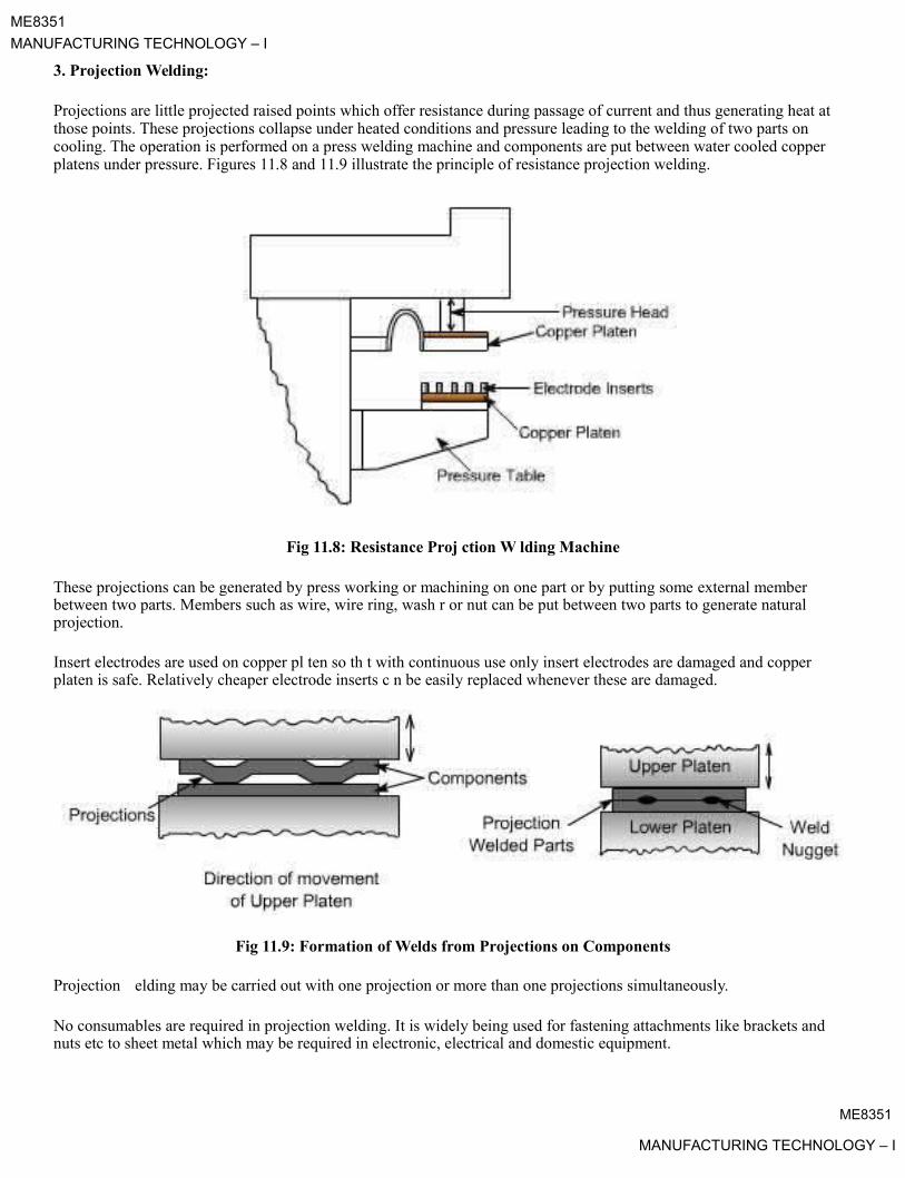
ME8351
MANUFACTURING TECHNOLOGY – I
3. Projection Welding:
Projections are little projected raised points which offer resistance during passage of current and thus generating heat atthose points. These projections collapse under heated conditions and pressure leading to the welding of two parts on cooling. The operation is performed on a press welding machine and components are put between water cooled copper platens under pressure. Figures 11.8 and 11.9 illustrate the principle of resistance projection welding.
Fig 11.8: Resistance Proj ction W lding Machine
These projections can be generated by press working or machining on one part or by putting some external memberbetween two parts. Members such as wire, wire ring, wash r or nut can be put between two parts to generate naturalprojection.
Insert electrodes are used on copper pl ten so th t with continuous use only insert electrodes are damaged and copper platen is safe. Relatively cheaper electrode inserts c n be easily replaced whenever these are damaged.
Fig 11.9: Formation of Welds from Projections on Components
Projection elding may be carried out with one projection or more than one projections simultaneously.
No consumables are required in projection welding. It is widely being used for fastening attachments like brackets andnuts etc to sheet metal which may be required in electronic, electrical and domestic equipment.
ME8351
MANUFACTURING TECHNOLOGY – I

ME8351
MANUFACTURING TECHNOLOGY – I
Production of seam welded Tubes:
Welded tubes are produced by resistance seam welding. Tubes are produced from strips which are wrapped on spool withtrimmed edges. The width of strip should be slightly bigger than the periphery of the tube to be produced to take care forthe loss of metal in flashout. The strip is fed through set of forming rollers to form first the shape of the tube and then it ispassed under the seam welding rolls. Under seam welding rolls the edges are butt welded with some flash out on thejoint. This flash out is trimmed and then tubes are cut to required size. The process is shown in Figures 11.10 & 11.11.
Fig 11.10: Forming of Tube from Strip
Fig 11.11: Seam Welding of Tube
ME8351
MANUFACTURING TECHNOLOGY – I

ME8351
MANUFACTURING TECHNOLOGY – I
Lecture 13
Welding Defects
The defects in the weld can be defined as irregularities in the weld metal produced due to incorrect welding parameters orwrong welding procedures or wrong combination of filler metal and parent metal.
Weld defect may be in the form of variations from the intended weld bead shape, size and desired quality. Defects may beon the surface or inside the weld metal. Certain defects such as cracks are never tolerated but other defects may be acceptable within permissible limits. Welding defects may result into the failure of components under service condition, leading to serious accidents and causing the loss of property and sometimes also life.
Various welding defects can be classified into groups such as cracks, porosity, solid inclusions, lack of fusion andinadequate penetration, imperfect shape and miscellaneous defects.
1. Cracks
Cracks may be of micro or macro size and may appear in the weld metal or base metal or base metal a d weld metal boundary. Different categories of cracks are longitudinal cracks, transverse cracks or radiati g/star cracks and cracks in the weld crater. Cracks occur when localized stresses exceed the ultimate tensile strength of material. These stresses aredeveloped due to shrinkage during solidification of weld metal.
Fig 13.1: Various Types of Cracks in Welds
Cracks may be developed due to oor ductility of base metal, high sulpher and carbon contents, high arc travel speeds i.e.fast cooling rates, too concave or convex weld bead and high hydrogen contents in the weld metal.
2. Porosity
Porosity results hen the gases are entrapped in the solidifying weld metal. These gases are generated from the flux or coating constituents of the electrode or shielding gases used during welding or from absorbed moisture in the coating. Rust, dust, oil and grease present on the surface of work pieces or on electrodes are also source of gases during welding. Porosity may be easily prevented if work pieces are properly cleaned from rust, dust, oil and grease.Futher, porosity can also be controlled if excessively high welding currents, faster welding speeds and long arc lengths are avoided flux and coated electrodes are properly baked.
ME8351
MANUFACTURING TECHNOLOGY – I

ME8351
MANUFACTURING TECHNOLOGY – I
Fig 13.2: Different Forms of Porosities
3. Solid InclusionSolid inclusions may be in the form of slag or any other nonmetallic material entrapped in the weld metal as these may not able
to float on the surface of the solidifyingpadeepzweldmetal.Duringarcweldingfluxeither in the form of granules or coating after
melting, reacts with the molten weld metal removing oxides and other impurities in the form of slag and it floats onthe surface of weld metal due to its low density. However, if the molten weld metal has high viscosity or too lowtemperature or cools rapidly then the slag may not be released from the weld ool and may cause inclusion.
Slag inclusion can be prevented if proper groove is selected, all the slag from the reviously deposited bead is removed, too high or too low welding currents and long arcs are avoid .
Fig 13.3: Sl g Inclusion in Weldments
4. Lack of Fusion and Inadequate or incom lete penetration:
Lack of fusion is the failure to fuse together either the base metal and weld metal or subsequent beads in multipass welding because of failure to raise the temperature of base metal or previously deposited weld layer to melting point during welding. Lack of fusion can be avoided by properly cleaning of surfaces to be welded, selecting proper current, proper welding technique and correct size of electrode.
Fig 13.4: Types of Lack of Fusion
Incomplete penetration means that the weld depth is not upto the desired level or root faces have not reached to melting point in a groove joint. If either low currents or larger arc lengths or large root face or small root gap or too narrow grooveangles are used then it results into poor penetration.
ME8351
MANUFACTURING TECHNOLOGY – I

During undercutting a notch is formed either on one side of the weld bead or both sides in netwhichstrsssnd to concentrate and it can result in the early failure of the joint. Main reasons for undercutti g are the xc ssive w lding currents, long arc lengths and fast travel speeds.
Underfilling may be due to low currents, fast travel speeds and small size of electrodes Overlap may occur due to lowcurrents, longer arc lengths and slower welding speeds.
Imperfect shape means the variation from the desired shape and size of the weld bead.
5. Imperfect Shape
Fig 13.5: Examples of Inadequate Penetration
ME8351MANUFACTURING TECHNOLOGY – I

ME8351MANUFACTURING TECHNOLOGY – I

ME8351
MANUFACTURING TECHNOLOGY – I
Fig 13.6: Various Imp rf ct Shapes of Welds
Excessive reinforcement is formed if high currents, low voltages, slow travel speeds and large size electrodes are used. Excessive root penetration and sag occur if excessive high currents and slow travel speeds are used for relatively thinner members.
Distortion is caused because of shrinkage occurring due to large heat input during welding.
6. Miscellaneous Defects
Various miscellaneous defects may be multiple arc strikes i.e. several arc strikes are one behind the other, spatter, grinding and chipping marks, tack eld defects, oxidized surface in the region of weld, unremoved slag and misalignment of weld beads if elded from both sides in butt welds.
ME8351
MANUFACTURING TECHNOLOGY – I

ME8351MANUFACTURING TECHNOLOGY – I
Lecture 1
FUNDAMENTALS OF METAL FORMING
There are four basic production processes for producing desired shape of a product. These are casting, machining, joining (welding, mechanical fastners, epoxy, etc.), and deformation processes. Casting process exploit the fluidity of a metal in liquid state as it takes shape and solidifies in a mold. Machining processes provide desired shape with good accuracy and precision but tend to waste material in the genera ion of removed portions. Joining processes permit complex shapes to be constructed from simpler componen s and have a wide domain of applications.
Deformation processes exploit a remarkable property of metals, which is their ability to flow plastically inthe solid state without deterioration of their properties. With the application of suitable pr ssur s, the material ismoved to obtain the desired shape with almost no wastage. The required pressures are g rally high and the tools and equipment needed are quite expensive. Large production quantities are often ecessary to justify the process.
Fig 1.1 State of the stresses metal undergo during deformation.
As a metal is deformed (or formed, as often called) into useful shape, it experiences stresses such as tension, compression, shear, or various combinations there of Fig 1.1 illustrates these states of stresses. Somecommon metal forming processes are schematically given in Fig 1.2 along with the state of stress(es) experienced by the metal during the process.
ME8351
MANUFACTURING TECHNOLOGY – I

ME8351MANUFACTURING TECHNOLOGY – I
State of Stress
Number Processin Main Part
DuringForming
Rolling
1Bi-axial
compression
Forging
2Tri-axial
compression
Extrusion
3Tri-axial
compression
ME8351
MANUFACTURING TECHNOLOGY – I

ME8351
MANUFACTURING TECHNOLOGY – I
swaging
Bi-axial4 compression
Deep drawing
In flange ofblank, bi-axial
tension and5 compression. In
wall of cup,simple uni-axial
tension.
Wire nd tube rawing
Bi-axial6 compression,
tension.
Straight bending
At bend, bi-axial
7 compression and bi-axial
tension
Fig 1.2 Common metal forming processes. State of stress experienced by metal is also givenME8351
MANUFACTURING TECHNOLOGY – I

ME8351
MANUFACTURING TECHNOLOGY – I
To understand the forming of metal, it is important to know the structure of metals. Metals are crystalline in nature and consist of irregularly shaped grains of various sizes. Each grain is made up of atoms in an orderly arrangement, known as a lattice. The orientation of the atoms in a grain is uniform but differs in adjacent grains. When a force is applied to deform it or change its shape, a lot of changes occur in the grain structure. These include grain fragmentation, movement of atoms, and lattice distortion. Slip planes develop through the lattice structure at points where the atom bonds of attraction are the weakest and whole blocks of atoms are displaced. The orientation of atoms, however, does not change when slip occurs.
To deform the metal permanently, the stress must exceed the elastic limit. At room temperature, the metalis in a more rigid state than when at higher temperature. Thus, to deform the metal greater pressures are neededwhen it is in cold state than when in hot state.
When metal is formed in cold state, there is no recrystallization of grains and thus r cov ry from grain distortion or fragmentation does not take place. As grain deformation proceeds, great r r sistance to this action results in increased hardness and strength. The metal is said to be strain harde ed. Th re are s v ral theories to explain this occurrence. In general, these refer to resistance build up in the grai s by atomic dislocation, fragmentation, or lattice distortion, or a combination of the three phenomena
Cold Working:

The amount of deformationpadeepzthatametalcanundergoatroomtemperature depends on its ductility. The
higher the ductility of a metal, the more the deformation it can undergo. Pure metals can withstand greater
amount of deformation than metals having alloying elements, since alloying increases the tendency and rapidityof strain hardening. Metals having large grains are more ductile than those having smaller grains.
When metal is deformed in cold state, severe str ss s known as residual stresses are set up in the material. These stresses are often undesirable, and to r move th m the metal is heated to some temperature below the recrystalline range temperature. In this t mp rature rang , the stresses are rendered ineffective without appreciable change in physical properti s or grain structure.
COLD AND HOT WORKING OF METALS
Plastic deformation of metals below the recryst lliz tion temperature is known as cold working. It is generally performed at room temperature In some cases, slightly elevated temperatures may be used to provide increasedductility and reduced strength Cold working offers number of distinct advantages, and for this reason various cold-working processes have become extremely important. Significant advances in recent years have extended the use of cold forming, and the trend appears likely to continue.
In comparison ith hot orking, the advantages of cold working are
1. No heating is required
2. Bettter surface finish is obtained
3. Better dimensional control is achieved; therefore no secondary machining is generally needed.
4. Products possess better reproducibility and interchangeablity.
5. Better strength, fatigue, and wear properties of material.
6. Directional properties can be imparted.ME8351
MANUFACTURING TECHNOLOGY – I

ME8351
MANUFACTURING TECHNOLOGY – I
7. Contamination problems are almost negligible.
Some disadvantages associated with cold-working processes are:
1. Higher forces are required for deformation.
2. Heavier and more powerful equipment is required.
3. Less ductility is available.
4. Metal surfaces must be clean and scale-free.
5. Strain hardening occurs ( may require intermediate annealing ).
6. Undesirable residual stresses may be produced
Cold forming processes, in general, are better suited to large-scale production of parts because of the cost of the required equipment and tooling.
Warm Working:
Metal deformation carried out at temperatures interm diate to hot and cold forming is called Warm Forming . Compared to cold forming, warm forming off rs s v ral advantages. These include:
• Lesser loads on tooling and equipment
• Greater metal ductility
• Fewer number of annealing operation ( because of less strain hardening )
Compared to hot forming, warm forming offers the following advantages.
• Lesser amount of heat energy requirement
• Better precision of components
• Lesser scaling on parts
• Lesser decarburization of parts
• Better dimensional control
• Better surface finish
• Lesser thermal shock on tooling
• Lesser thermal fatigue to tooling, and so greater life of tooling.
ME8351
MANUFACTURING TECHNOLOGY – I
ME8351
MANUFACTURING TECHNOLOGY – I
Hot Working:
Plastic deformation of metal carried out at temperature above the recrystallization temperature, is calledhot working. Under the action of heat and force, when the atoms of metal reach a certain higher energy level, the new crystals start forming. This is called recrystallization. When this happens, the old grain structure deformed by previously carried out mechanical working no longer exist, instead new crystals which are strain-free are formed.
In hot working, the temperature at which the working is completed is critical since any extra heat left in the material after working will promote grain growth, leading to poor mechanical properties of material.
In comparison with cold working, the advantages of hot working are
1. No strain hardening2. Lesser forces are required for deformation3. Greater ductility of material is available, and therefore more deformation is possible.4. Favorable grain size is obtained leading to better mechanical properties of material5. Equipment of lesser power is needed6. No residual stresses in the material.
Some disadvantages associated in the hot-working of metals are:
1. Heat energy is needed2. Poor surface finish of material due to scaling of surface3. Poor accuracy and dimensional control of parts4. Poor reproducibility and interchangeability of parts5. Handling and maintaining of hot metal is difficult and troublesome6. Lower life of tooling and equipment.
ME8351
MANUFACTURING TECHNOLOGY – I
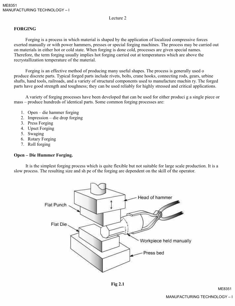
ME8351MANUFACTURING TECHNOLOGY – I
Lecture 2
FORGING
Forging is a process in which material is shaped by the application of localized compressive forces exerted manually or with power hammers, presses or special forging machines. The process may be carried outon materials in either hot or cold state. When forging is done cold, processes are given special names. Therefore, the term forging usually implies hot forging carried out at temperatures which are above the recrystallization temperature of the material.
Forging is an effective method of producing many useful shapes. The process is generally used o produce discrete parts. Typical forged parts include rivets, bolts, crane hooks, connecting rods, gears, urbine shafts, hand tools, railroads, and a variety of structural components used to manufacture machin ry. The forged parts have good strength and toughness; they can be used reliably for highly stressed and critical applications.
A variety of forging processes have been developed that can be used for either produci g a single piece or mass – produce hundreds of identical parts. Some common forging processes are:
1. Open – die hammer forging2. Impression – die drop forging3. Press Forging4. Upset Forging5. Swaging6. Rotary Forging7. Roll forging
Open – Die Hummer Forging.
It is the simplest forging process which is quite flexible but not suitable for large scale production. It is aslow process. The resulting size and sh pe of the forging are dependent on the skill of the operator.
Fig 2.1ME8351
MANUFACTURING TECHNOLOGY – I

ME8351
MANUFACTURING TECHNOLOGY – I
Open die forging does not confine the flow of metal, Fig 2.1. The operator obtains the desired shape of forging by manipulating the work material between blows. Use may be made of some specially shaped tools or a simple shaped die between the work piece and the hammer or anvil to assist in shaping the required sections (round, concave, or convex), making holes, or performing cut – off operations. This process is most often used to make near – final shape of the part so that some further operation done on the job produces the final shape.
Forging Force. In open die forging operation, the forging force F, to be applied on a solid cylindricalcomponent can be determined from the relation.
Where s f is the flow stress of the material, µ is the coefficient of friction, and d andnetharehediam r and
height of the work piece, respectively.
Example. Using open-die forging operation, a solid cylindrical piece of 304 stai less st l havi g 100 mm dia x 72 mm height is reduced in the height to 60 mm at room temperature. Assumi g the coefficie of friction as 0.22 and the flow stress for this material at the required true strain as 1000 MPa, calculate the forging force at
i.e. d =110 mm
= 60 mmFinal height
= 72 mmInitial height

the end of stroke. padeepzSolution . Initial diameter = 100 mm
If final diameter is d, (100)2 x 72 =2 x 60
Impression – Die Drop Forging (Closed – Die Forging)
The process uses shaped dies to control the flow of metal. The heated metal is positioned in the lower cavity and on it one or more blo s are struck by the upper die. This hammering makes the metal to flow and fill the die cavity completely. Excess metal is squeezed out around the periphery of the cavity to form flash. On completion of forging, the flash is trimmed off with the help of a trimming die.
Most impression – die sets contain several cavities. The work material is given final desired shape in stages as it is deformed in successive cavities in the die set. The shape of the cavities cause the metal to flow in desired direction, thereby imparting desired fibre structure to the component.
Auto – Forging:
This is a modified form of impression – die forging, used mainly for non – ferrous metals.
In this a cast preform, as removed from the mold while hot, is finish – forged in a die. The flash formed during die forging is trimmed later in the usual manner. As the four steps of the process – casting, transfer from
ME8351
MANUFACTURING TECHNOLOGY – I
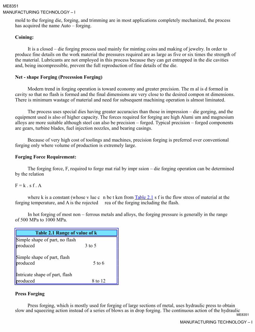
ME8351
MANUFACTURING TECHNOLOGY – I
mold to the forging die, forging, and trimming are in most applications completely mechanized, the process has acquired the name Auto – forging.
Coining:
It is a closed – die forging process used mainly for minting coins and making of jewelry. In order to produce fine details on the work material the pressures required are as large as five or six times the strength of the material. Lubricants are not employed in this process because they can get entrapped in the die cavities and, being incompressible, prevent the full reproduction of fine details of the die.
Net - shape Forging (Precession Forging)
Modern trend in forging operation is toward economy and greater precision. The m al is d formed in cavity so that no flash is formed and the final dimensions are very close to the desired compon nt dimensions.There is minimum wastage of material and need for subsequent machining operation is almost liminated.
The process uses special dies having greater accuracies than those in impression – die gorging, and the equipment used is also of higher capacity. The forces required for forging are high Alumi um and magnesium alloys are more suitable although steel can also be precision – forged. Typical precision – forged components are gears, turbine blades, fuel injection nozzles, and bearing casings.
Because of very high cost of toolings and machines, precision forging is preferred over conventionalforging only where volume of production is extremely large.
Forging Force Requirement:
The forging force, F, required to forge mat rial by impr ssion – die forging operation can be determined by the relation
F = k . s f . A
where k is a constant (whose v lue c forging temperature, and A is the rojected
n be t ken from Table 2.1 s f is the flow stress of material at the rea of the forging including the flash.
In hot forging of most non – ferrous metals and alloys, the forging pressure is generally in the range of 500 MPa to 1000 MPa.
Table 2.1 Range of value of kSimple shape of part, no flashproduced 3 to 5
Simple shape of part, flashproduced 5 to 6
Intricate shape of part, flashproduced 8 to 12
Press Forging
Press forging, which is mostly used for forging of large sections of metal, uses hydraulic press to obtain slow and squeezing action instead of a series of blows as in drop forging. The continuous action of the hydraulic
ME8351
MANUFACTURING TECHNOLOGY – I

ME8351
MANUFACTURING TECHNOLOGY – I
press helps to obtain uniform deformation throughout the entire depth of the workpiece. Therefore, the impressions obtained in press forging are more clean.
Press forgings generally need smaller draft than drop forgings and have greater dimensional accuracy.Dies are generally heated during press forging to reduce heat loss, promote more uniform metal flow and production of finer details.
Hydraulic presses are available in the capacity range of 5 MN to 500 MN but 10 MN to 100MN capacitypresses are more common.
Upset Forging
Upset forging involves increasing the cross – section of a material at the expense of i s corr sponding length. Upset – forging was initially developed for making bolt heads in a continuous mann r, but pr sently it is
Roll Forging
3.
2.

the most widely used of all forging processes. Parts can be upset – forged from bars or rods upto 200 mm in diameter in both hot and cold condition. Examples of upset forged parts are faste ers, valv s, ails, and couplings.
The process uses split dies with one or several cavities in the die. Upon separation of split die, the heated bar is moved from one cavity to the next. The split dies are then forced together to grip the and a heading tool (or ram) advances axially against the bar, upsetting it to com letely fill the die cavity. Upon completion of upsetting process the heading tool comes back and the movable s lit die releases the stock.
Upsetting machines, called upsetters, are generally horizontal acting.
When designing parts for upset – forging, the following thr rul s must be followed.
1. The length of unsupported bar that can be ups t in one blow of heading tool should not exceed 3times the diameter of bar. Otherwise bucking will occur.For upsetting length of stock gre ter than 3 times the diameter the cavity diameter must notexceed 1.5 times the dia of b r.For upsetting length of stock gre ter than 3 times the diameter and when the diameter of the upset is less.than15times the di meter of the bar, the length of un – supported stock beyond the face of die must not exceed diameter of the stock.
This process is used to reduce the thickness of round or flat bar with the corresponding increase in length.Examples of products produced by this process include leaf springs, axles, and levers.
The process is carried out on a rolling mill that has two semi – cylindrical rolls that are slightly eccentric to the axis of rotation. Each roll has a series of shaped grooves on it. When the rolls are in open position, the heated bar stock is placed between the rolls. With the rotation of rolls through half a revolution, the bar is progressively squeezed and shaped. The bar is then inserted between the next set of smaller grooves and the process is repeated till the desired shape and size are achieved.
ME8351
MANUFACTURING TECHNOLOGY – I

ME8351MANUFACTURING TECHNOLOGY – I
Lecture 3
SWAGING
In this process, the diameter of a rod or a tube is reduced by forcing it into a confining die. A set of reciprocation dies provides radial blows to cause the metal to flow inward and acquire the form of the die cavity. The die movements may be of in – and – out type or rotary. The latter type is obtained with the help of aset of rollers in a cage, in a similar action as in a roller bearing. The workpiece is held stationary and the dies rotate, the dies strike the workpiece at a rate as high as 10 - 20 strokes per second.
Screwdriver blades and soldering iron tips are typical examples of swaged products. Fig 3.1 shows theseand other products made by swaging.
Fig 3.1 Typical parts made by swaging.
In tube s aging, the tube thickness and / or internal dia of tube can be controlled with the use of internalmandrels. For small – diameter tubing, a thin rod can be used as a mandrel; even internally shaped tubes canbe s aged by using shaped mandrels. Fig 3.2 shows the process.
ME8351
MANUFACTURING TECHNOLOGY – I
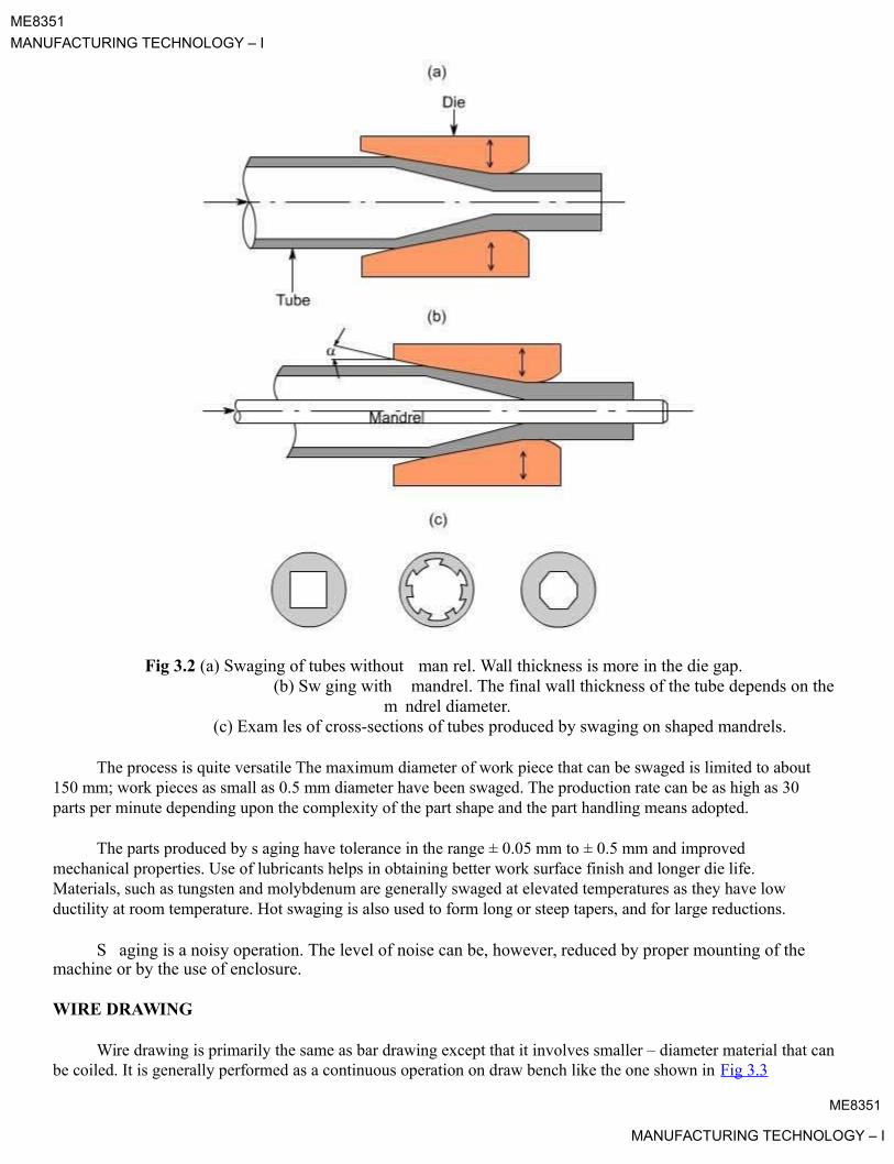
ME8351
MANUFACTURING TECHNOLOGY – I
Fig 3.2 (a) Swaging of tubes without man rel. Wall thickness is more in the die gap.(b) Sw ging with mandrel. The final wall thickness of the tube depends on the
m ndrel diameter.(c) Exam les of cross-sections of tubes produced by swaging on shaped mandrels.
The process is quite versatile The maximum diameter of work piece that can be swaged is limited to about 150 mm; work pieces as small as 0.5 mm diameter have been swaged. The production rate can be as high as 30 parts per minute depending upon the complexity of the part shape and the part handling means adopted.
The parts produced by s aging have tolerance in the range ± 0.05 mm to ± 0.5 mm and improved mechanical properties. Use of lubricants helps in obtaining better work surface finish and longer die life. Materials, such as tungsten and molybdenum are generally swaged at elevated temperatures as they have low ductility at room temperature. Hot swaging is also used to form long or steep tapers, and for large reductions.
S aging is a noisy operation. The level of noise can be, however, reduced by proper mounting of themachine or by the use of enclosure.
WIRE DRAWING
Wire drawing is primarily the same as bar drawing except that it involves smaller – diameter material that canbe coiled. It is generally performed as a continuous operation on draw bench like the one shown in Fig 3.3
ME8351
MANUFACTURING TECHNOLOGY – I

ME8351
MANUFACTURING TECHNOLOGY – I
Large coil of hot rolled material of nearly 10 mm diameter is taken and subjected to preparation treatment before the actual drawing process. The preparation treatment for steel wire consists of :
Cleaning. This may be done by acid pickling, rinsing, and drying. Or, it may be done by mechanicalflexing.
Neutralization. Any remaining acid on the raw mat rial is neutralized by immersing it in a lime bath.The corrosion protected material is also giv n thin lay r of lubricant.
To begin the drawing process, one end of coil is re uced in cross section upto some length and fed through the
drawing die, and gripped. A wire dr wing ie is generally made of tungsten carbide and has the configuration
shown in Fig 3.4 for drawing very fine wire, di mond die is preferred.
Fig 3.3 Wire drawing on a continuous draw block. The rotating draw block provides a co ti uous pull on the
padeepzincomingwire.
Fig 3.4 Cross section through a typical carbide wire drawing die.
ME8351
MANUFACTURING TECHNOLOGY – I

ME8351
MANUFACTURING TECHNOLOGY – I
Small diameter wire is generally drawn on tandom machines which consists of a series of dies, each held in a water – cooled die block. Each die reduces the cross section by a small amount so as to avoid excessive strain in the wire. Intermediate annealing of material between different states of wire may also be done, if required.
Wire drawing terms :
Where Do , Df , Lo and Lf are the original and final diameter and length. Ao and Af are origi al a d final cross sectional area.
For a single cold – drawing pass,padeepzthepercentareareductionthatcanbedonedepends upon many factors. These include the type
of material, its size, initial metallurgical condition, the final si and mechanical properties
Die pull

desired, die design and lubrication efficiency. The percent of area reduction er ass can range from near zero to50%.
The force required to pull the stock through the die (und r frictionl ss conditions) can be computed as follows.
Where F = die pull, i.e. the force required to ull the stock through the die
Yavg = average true stress of the material in the die gap
Ao , Af = original and final areas of cross section of material.
Alternatively, the follo ing expression can be used
F = c st (Ao - Af )
where c is a constant hose value is in the range 1.5 to 3.0 depending upon the % area reduction, (lower value for higher % reduction), and st is tensile strength of material before drawing.
The pull force determines the machine capacity needed.
ME8351
MANUFACTURING TECHNOLOGY – I

ME8351
MANUFACTURING TECHNOLOGY – I
TUBE DRAWING
The diameter and wall thickness of tubes that have been produced by extrusion or other processes can be reduced by tube drawing process. The process of tube drawing (Fig 3.5) is similar to wire or rod drawing exceptthat it usually requires a mandrel of the requisite diameter to form the internal hole.
Tubes as large as 0.3 m in diameter can be drawn.
Drawing Equipment
padeepzFig3.5
Drawing equipment can be of several esigns. These designs can be classified into two basic types; Draw bench, and Bull block. A draw bench (Fig 3.5) uses single die and the pulling force is supplied by a chain drive or by hydraulic means. Draw bench is used for single length drawing of rod or tube with diameter greater than 20mm. Length can be as much s 30 m. The drawing speed attainable on a draw bench ranges from 5 m/min to 50 m/min. Draw benches re v il ble h ving capacities to provide pull force of upto 1 MN.
Bull block or rotating drum (Fig 3.3) is used for drawing rods or wires of very long length.
ME8351
MANUFACTURING TECHNOLOGY – I

ME8351MANUFACTURING TECHNOLOGY – I
Lecture 4
FORMABILITY OF SHEET METAL
Formability may be defined as the ease with which material may be forced into a permanent change of shape. The formability of a material depends on several factors. The important one concerns the properties of material like yield strength, strain hardening rate, and ductility. These are greatly temperature - dependent. As the temperature of material is increased, the yield strength and rate of strain hardening progressively reduce andductility increases. The hot working of metal, therefore, permits relatively very large amount of deformation before cracking.
There are several methods of predicting formability. A brief description of some impor ant me hodsfollows.
Cup or Radial Drawing:
Cup drawing test uses a circular blank from the metal to be tested. It is i serted in a die, and the severityof the draw it is able to withstand without tearing called the drawing ratio, is oted The drawi g ratio is the ratioof the cup diameter to the blank diameter.
Where Rd = drawing ratio
D = blank diameter
d = punch diameter
ME8351
MANUFACTURING TECHNOLOGY – I

ME8351
MANUFACTURING TECHNOLOGY – I
A drawing ratio of 50 % is considered excellent. As shown in Fig 4.1(a), either a flat bottom punch with lubricated blank may be used to draw the cup, or as shown in Fig 4.1(b) a blank may be drawn by a lubricated hemi – spherical punch. In the first case, the action is principally that of drawing in which cylindrical stretchingof material takes place. In the second case, there will be bi – axial stretching of the material. For drawing, the clamping force is just sufficient to prevent buckling of the material at the draw radius as it enters the die. The deformation takes place in the flange and over the draw radius.
Fukui Conical – Cup Test:
It utilizes a hemispherical, smoothly polished punch. No blank holder is required. In each test, a drawing ratio which will result in a broken cup is determined. Formation of wrinkles is avoided by using a fixed ratio between the thickness of the sheet, the size of the blank, and the punch and die diameters. Under hese conditions, the test produces a known amount of stretching, drawing, and bending und r t nsion.
The material is subjected to uni-axial tensile test. The anisotropy coefficie is derived from the ratio ofthe plastic width strain eW to the thickness strain et . A material with a high plastic a isotropy also has a greater
padeepz
“thinning resistance.” In general, the higher the anisotropy coefficient the better the material deforms in
drawing operations. netStrain-Hardening Coefficient:
Strain hardening refers to the fact that as metal d forms in some area, dislocations occur in themicrostructure. As these dislocations pile up, th y t nd to str ngth n the metal against further deformation in that area. Thus the strain is spread throughout the sh t. How v r, at some point in the deformations, the strain suddenly localizes and necking, or localized thinning, d v lops. When this occurs, little further overall deformation of the sheet can be obtained without it fracturing in the necked region.
The strain – hardening coefficient therefore reflects how well the metal distributes the strain throughout the sheet, avoiding or delaying loc lized necking. The higher the strain – hardening coefficient, the move the material will harden as it is being stretched nd the greater will be the resistance to localized necking. Necks in the metal harm surface appearance nd ffect structural integrity.
For many stamping o erations, stretching of the metal is the critical factor and is dependent on the strain– hardening coefficient. Therefore, stampings that need much drawing should be made from metal having highaverage strain – hardening coefficients. Yield strength should be low to avoid wrinkles or buckling.
Normal Anisotropy Coefficient:

Forming Limit Curve:
The forming – limit curve is a good index of determining the formability of sheet metal. Essentially, it requires to draw a curve that shows a boundary line between acceptable strain levels in forming and those that may cause failure, Fig 4.2.
ME8351
MANUFACTURING TECHNOLOGY – I

ME8351
MANUFACTURING TECHNOLOGY – I
Fig 4.2 The relationship of major, e1 , and minor, e2 , strains is established by measurement after forming.
The curve indicates the relation between major and minor strains that are perpendicular to the plane of thesheet. To determine these strains, a grid of circles is marked on the sheet metal, say by an electrolytic stencil – etching process. After the metal is deformed, the circles are measured to obtain the major strain e1 and the minor strain e2 , as shown in Fig 4.2 Typically, ten to fifteen data points are obtained from a test specimen in theregion of fracture. Ellipses lying both in the failed region and just outside of it are measured. The forming – limit curve is then drawn to fall below the strains in the necked and fractured zones, and above the strains foundjust outside these zones (Fig 4.3)
With controlled variation in specimen size it is possible to plot an entire forming – limit curve from onetest setup. A reasonably accurate forming limit curve may be obtained with four specimens while a precision curve may be obtained with eight specimens.
In may be noted that “local” ductility varies for different metals, so no u iversal formi g – limit curve can be developed. For example, two metals may have peak local ductilities of 20% a d 50% at a giv n minor strain. The metal with the 20 % local ductility (high strain – hardening coefficie t) may turn out to be the best choice because the strain will then have a better distribution throughout, allowi g the tire sheet to be stretched20%. If the other sheet showed little strain hardening, it might stretch by 50% in local area, but leave the rest ofthe sheet relatively unstrained. net
Through the use of formability – prediction techniques. Designers and fabricators are able to make awiser choice of metals and obtain date quickly on new r m tals. The ssential data can be obtained before thedie is designed. Also metal suppliers will be able to establish wh th r material possesses required formabilitybefore it is shipped from the plant.
padeepz
Fig. 4.3
ME8351
MANUFACTURING TECHNOLOGY – I
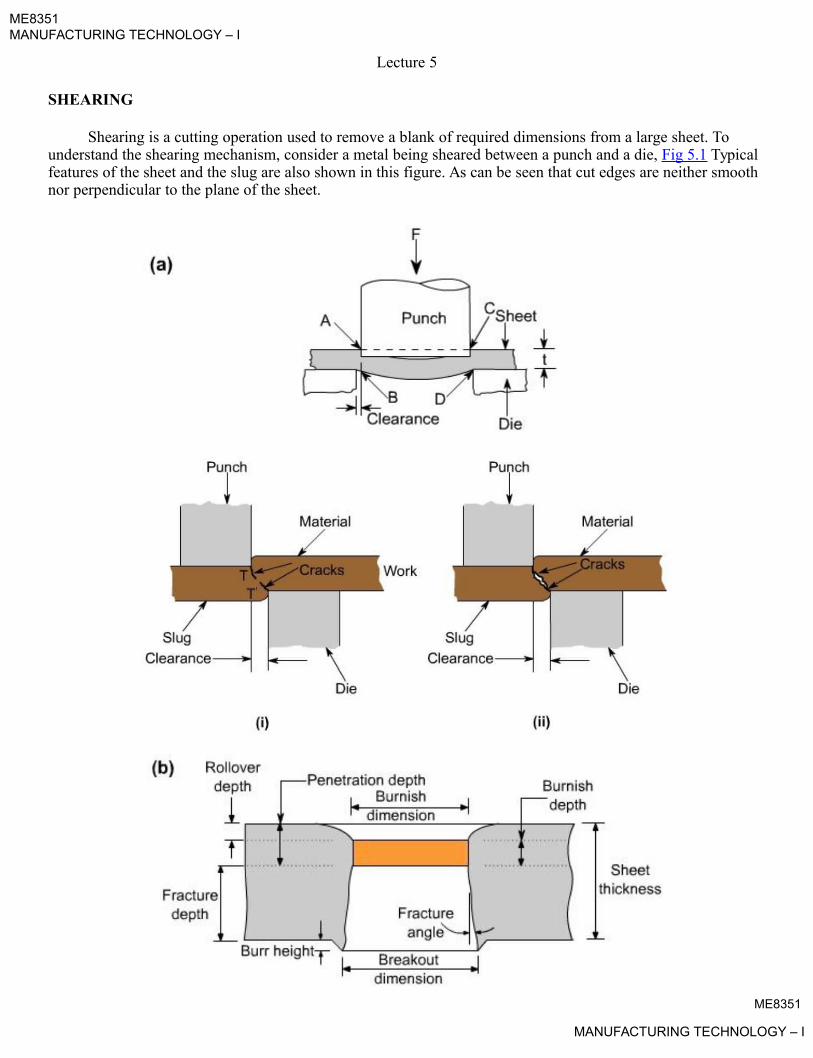
ME8351MANUFACTURING TECHNOLOGY – I
Lecture 5
SHEARING
Shearing is a cutting operation used to remove a blank of required dimensions from a large sheet. To understand the shearing mechanism, consider a metal being sheared between a punch and a die, Fig 5.1 Typicalfeatures of the sheet and the slug are also shown in this figure. As can be seen that cut edges are neither smoothnor perpendicular to the plane of the sheet.
ME8351
MANUFACTURING TECHNOLOGY – I
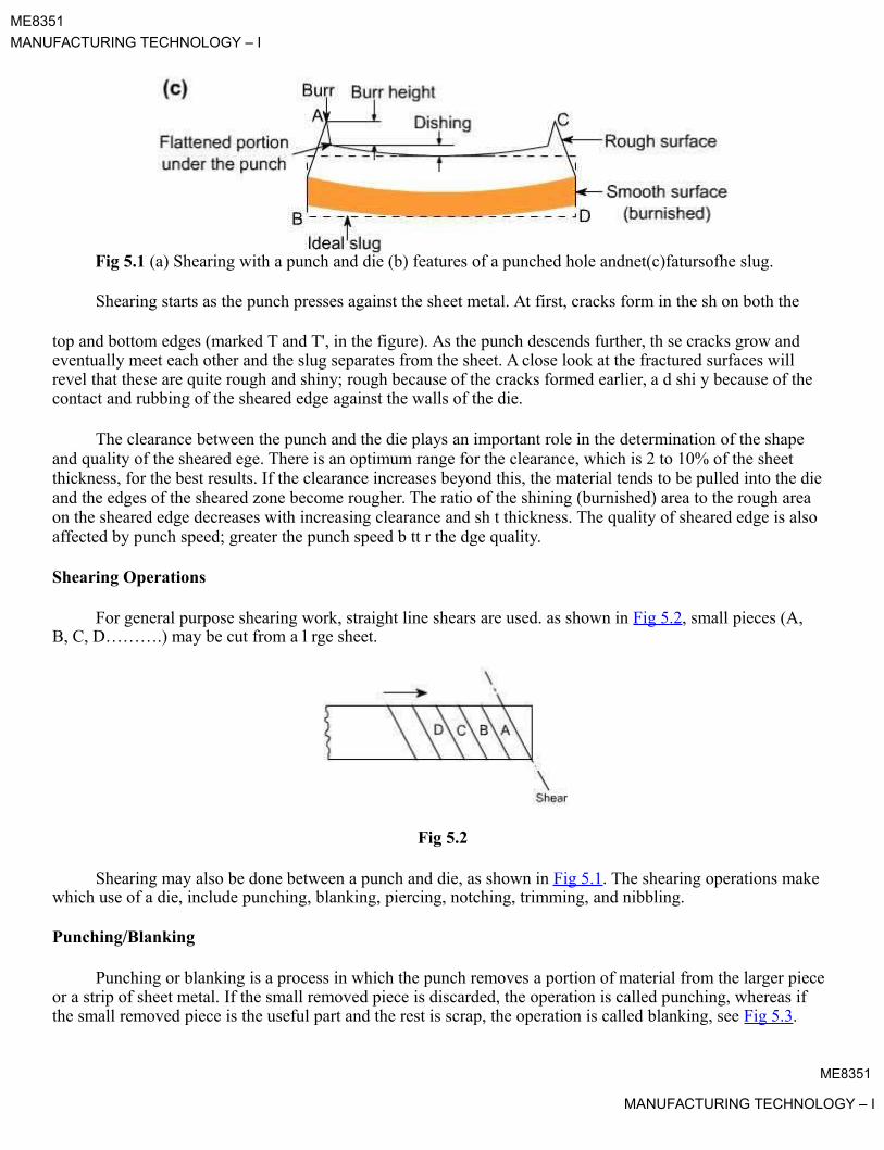
ME8351
MANUFACTURING TECHNOLOGY – I
Fig 5.1 (a) Shearing with a punch and die (b) features of a punched hole andnet(c)fatursofhe slug.
Shearing starts as the punch presses against the sheet metal. At first, cracks form in the sh on both the
top and bottom edges (marked T and T', in the figure). As the punch descends further, th se cracks grow and eventually meet each other and the slug separates from the sheet. A close look at the fractured surfaces will revel that these are quite rough and shiny; rough because of the cracks formed earlier, a d shi y because of the contact and rubbing of the sheared edge against the walls of the die.
The clearance between the punch and the die plays an important role in the determination of the shape and quality of the sheared ege. There is an optimum range for the clearance, which is 2 to 10% of the sheet thickness, for the best results. If the clearance increases beyond this, the material tends to be pulled into the die and the edges of the sheared zone become rougher. The ratio of the shining (burnished) area to the rough area on the sheared edge decreases with increasing clearance and sh t thickness. The quality of sheared edge is also affected by punch speed; greater the punch speed b tt r the dge quality.
Shearing Operations
For general purpose shearing work, straight line shears are used. as shown in Fig 5.2, small pieces (A, B, C, D……….) may be cut from a l rge sheet.
Fig 5.2
Shearing may also be done between a punch and die, as shown in Fig 5.1. The shearing operations makewhich use of a die, include punching, blanking, piercing, notching, trimming, and nibbling.
Punching/Blanking
Punching or blanking is a process in which the punch removes a portion of material from the larger piece or a strip of sheet metal. If the small removed piece is discarded, the operation is called punching, whereas if the small removed piece is the useful part and the rest is scrap, the operation is called blanking, see Fig 5.3.
ME8351
MANUFACTURING TECHNOLOGY – I

ME8351
MANUFACTURING TECHNOLOGY – I
Fig 5.3 Comparison of basic stam ing o erations.In punching, the metal inside the part is removed; in blanking, the metal around the part is removed.
A typical setup used for blanking is shown in Fig 5.4.
Fig 5.4 Blanking punch and die.
The clearance between the die and punch can be determined as c = 0.003 t. t where t is the sheetthickness and t is the shear strength of sheet material. For blanking operation, die size = blank size, and thepunch is made smaller, by considering the clearance.
ME8351
MANUFACTURING TECHNOLOGY – I

ME8351
MANUFACTURING TECHNOLOGY – I
The maximum force, P required to be exerted by the punch to shear out a blank from the sheet can beestimated as
P = t. L. t
where t is the sheet thickness, L is the total length sheared (such as the perimeter of hole), and t is theshear strength of the sheet material.
Stripping force. Two actions take place in the punching process – punching and stripping. Stripping means extracting the punch. A stripping force develops due to the spring back (or resiliency) of the punched ma erialthat grips the punch. This force is generally expressed as a percentage of the force required o punch he hole, although it varies with the type of material being punched and the amount of clearance between he cu ing edges. The following simple empirical relation can be used to find this force
SF = 0.02 L.t
where SF = stripping force, kN
L = length of cut, mm
t = thickness of material, mm
Example: A circular blank of 30 mm diameter is to be cut from 2 mm thick 0.1 C steel sheet. Determine the dieand punch sizes. Also estimate the punch force and the strip ing force needed. You may assume the following for the steel : Tensile strength: 410 MPa ; shear str ngth : 310 MPa
Solution:- For cutting a blank, die size = blank size
\ Die size = 30mm
Clearance = 0.003 x t x t = 0.003 x 2 x 310
= 1.86 mm
Punch size = blank size – 2 clearance
= 30 – 2 x 1.86 = 26.28 mm
Punch force needed = L. t. p = p x 30 x 2 x 310
= 58.5 kN
Stripping force needed = 0.02 L.t
= 0.02 x p x 30 x 2
= 3.77 kN
Piercing:
ME8351
MANUFACTURING TECHNOLOGY – I

ME8351
MANUFACTURING TECHNOLOGY – I
It is a process by which a hole is cut (or torn) in metal. It is different from punching in that piercing does not generate a slug. Instead, the metal is pushed back to form a jagged flange on the back side of the hole.
A pierced hole looks somewhat like a bullet hole in a sheet of metal.
Trimming:
When parts are produced by die casting or drop forging, a small amount of extra metal gets spread out atthe parting plane. This extra metal, called flash, is cut – off before the part is used, by an operation called trimming. The operation is very similar to blanking and the dies used are also similar to blanking dies. Thepresses used for trimming have, however, relatively larger table. net
Notching:
It is an operation in which a specified small amount of metal is cut from a bla k. It is diff r nt frompunching in the sense that in notching cutting line of the slug formed must touch o dge of the blank or strip.A notch can be made in any shape. The purpose of notching is generally to release metal for fitting up.
Nibbling: padeepz
Nibbling is variation of notching, with overlapping notches being cut into the metal. The operation maybe resorted to produce any desired shape, for example flanges, collars, etc.
Perforating:
Perforating is an operation is which numb r of uniformly spac d holes are punched in a sheet of metal.The holes may be of any size or shape. They usually cov r the ntire sheet of metal.
ME8351
MANUFACTURING TECHNOLOGY – I

ME8351MANUFACTURING TECHNOLOGY – I
Lecture 6
SHEET METAL PROCESSES
BENDING
Bending is one very common sheet metal forming operation used not only to form shapes like seams, corrugations, and flanges but also to provide stiffness to the part (by increasing its moment of inertia).
As a sheet metal is bent (Fig 6.1), its fibres experience a distortion such that those nearer i s ou side, convex surface are forced to stretch and come in tension, while the inner fibres come in compression. Somewhere, in the cross section, there is a plane which separates the tension and compression zones. This planeis parallel to the surface around which the sheet is bending, and is called neutral axis. The posi ion of neu ral axis depends on the radius and angle of bend. Further, because of the Poisson's ratio, the width of the part L in the outer region is smaller, and in the inner region it is larger, than the initial origi al width.
Fig 6.1 Sheet metal bending. It m y be noted th t the bend radius is measured to the inner surface of the bent part.
BEND ALLOWANCE
It is the length of the neutral axis in the bend, Fig 6.1. This determines the blank length needed for a bentpart. It can be approximately estimated from the relation
Lb = a ( R + kt )
where, Lb = bend allo ance (mm)
a = bend angle (radian)
R = bend radius (mm)
t = thickness of sheet (mm), and
k = constant, whose value may be taken as 1/3 when R < 2t, and as 1/2 when R ³ 2t.
ExampleME8351
MANUFACTURING TECHNOLOGY – I
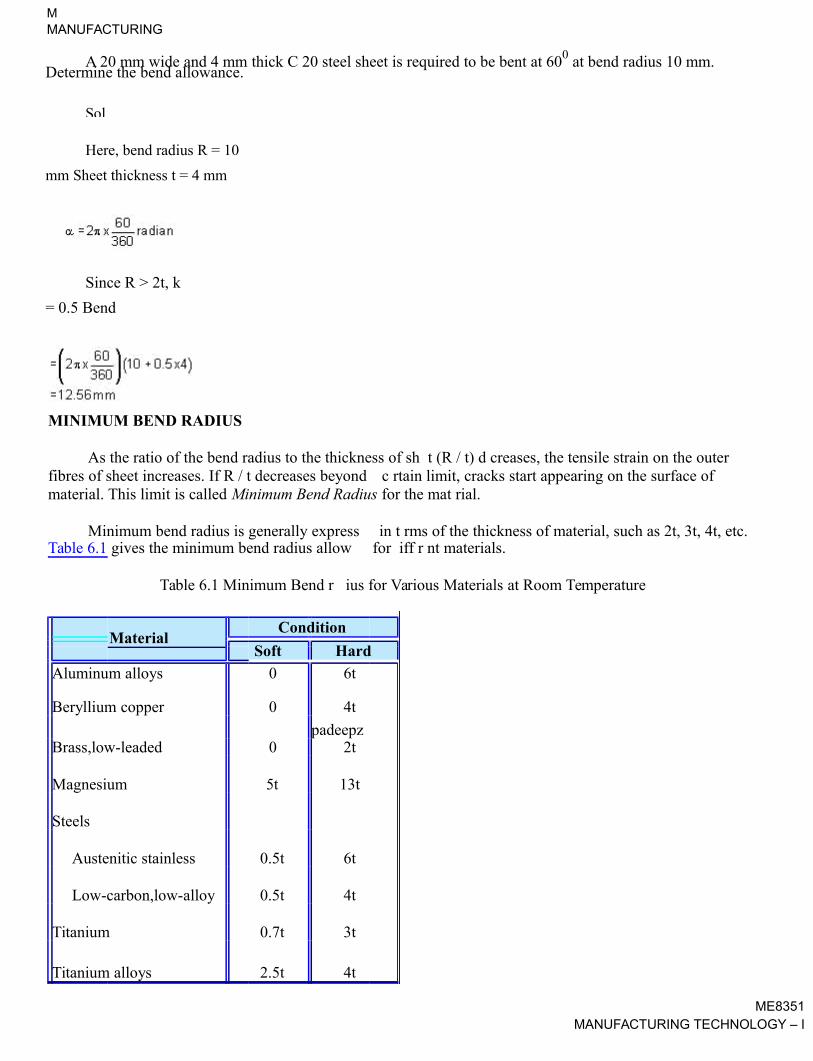
MINIMUM BEND RADIUS
As the ratio of the bend radius to the thickness of sh t (R / t) d creases, the tensile strain on the outerfibres of sheet increases. If R / t decreases beyond c rtain limit, cracks start appearing on the surface ofmaterial. This limit is called Minimum Bend Radius for the mat rial.
Minimum bend radius is generally express in t rms of the thickness of material, such as 2t, 3t, 4t, etc.Table 6.1 gives the minimum bend radius allow for iff r nt materials.
Table 6.1 Minimum Bend r ius for Various Materials at Room Temperature
MaterialCondition
Soft Hard
Aluminum alloys 0 6t
Beryllium copper 0 4t
padeepzBrass,low-leaded 0 2t
Magnesium 5t 13t
Steels
Austenitic stainless 0.5t 6t
Low-carbon,low-alloy 0.5t 4t
Titanium 0.7t 3t
Titanium alloys 2.5t 4t
ME8351MANUFACTURING TECHNOLOGY – I
A 20 mm wide and 4 mm thick C 20 steel sheet is required to be bent at 600 at bend radius 10 mm. Determine the bend allowance.
Solution.
Here, bend radius R = 10
mm Sheet thickness t = 4 mm
Since R > 2t, k
= 0.5 Bend
allowance
MMANUFACTURING
TECHNOLOGY – I

ME8351
MANUFACTURING TECHNOLOGY – I
Bending Force :
There are two general types of die bending : V – die bending and wiping die bending. V – die bending isused expensively in brake die operations and stamping die operations. The bending force can be estimated fromthe following simple relation.
P = k.Y.L.t2 / D
where P is bending force, g is the yield stress of the material, L is the bend length ( bend allowance ), t is the sheet thickness, D is the die opening and k is a constant whose value can be taken as 1.3 for a V-die and 0.3 fora wiping die. Fig 6.2 shows various types of bending dies.
Fig 6.2 Die-bending operations.
Bending force varies as the punch progresses through the bending operation. The force is zero in the beginning. It rises and reaches the maximum value as the punch progresses and reaches the bottom of the stroke.
Example:
A 400 mm long and 2.5 mm thick piece of carbon steel sheet is required to be bent at 900 using a V – die.You may assume the yield stress of the material as 500 MPa and the die opening as 10 times the material thickness. Estimate the force required for the operation.
Solution : Here, Y = 500 MPa
L = 400 mmME8351
MANUFACTURING TECHNOLOGY – I

ME8351
MANUFACTURING TECHNOLOGY – I
t = 2.5 mm
k = 1.3 (for V – die)
D = 25 mm
Bending force P = k.Y.L.t2 / D
= 1.3 x 500 x 400 x (2.5)2 / 25
= 65 KN
Example :
If the material as mentioned in the above example is to be bent at 900 usi g wipi g die with radius = 3.75 mm, what is the force requirement?
Solution : Here,Y = 500 MPa
L = 400 mm
t = 2.5 mm
k = 0.3
D = 2.5 + 3.75 + 3.75 = 10mm (see Fig 6.3)
Fig 6.3
Bending force P = k.Y.L.t2 / D
= 0.3 x 500 x 400 x (2.5)2 / 10
= 37.5 KN
DRAWING
It is a process of cold forming a flat blank of sheet metal into a hollow vessel without much wrinkling, trimming, or fracturing. The process involves forcing the sheet metal blank into a die cavity with a punch. The punch exerts sufficient force and the metal is drawn over the edge of the die opening and into the die, Fig 6.4. In forming a cup, however, the metal goes completely into the die, Fig 6.5.
ME8351
MANUFACTURING TECHNOLOGY – I

ME8351MANUFACTURING TECHNOLOGY – I
Fig 6.4 Drawing operation.
Fig 6.5 Drawing operation.
The metal being dra n must possess a combination of ductility and strength so that it does not rupture inthe critical area ( here the metal blends from the punch face to the vertical portion of the punch). The metal inthis area is subjected to stress that occurs when the metal is pulled from the flat blank into the die.
OPERATION . A setup similar to that used for blanking is used for drawing with the difference that the punch and die are given necessary rounding at the corners to permit smooth flow of metal during drawing. The blank of appropriate dimensions is place within the guides on the die plate. The punch descends slowly on the blank and metal is drawn into the die and the blank is formed into the shape of cup as punch reaches the bottom of thedie. When the cup reaches the counter – bored portion of the die, the top edge of the cup formed around the punch expands a bit due to the spring back . On the return stroke of the punch, the cup is stripped off the punch by this counter – bored portion.
ME8351
MANUFACTURING TECHNOLOGY – I

ME8351
MANUFACTURING TECHNOLOGY – I
The term shallow drawing is used when the height of cup formed is less than half its diameter. When drawing deeper cup (height greater that ½ diameter) the chances of excessive wrinkle formation at the edges of blank increases. To prevent this, a blank holder is normally provided, see Fig 6.4. As the drawing process proceeds the blank holder stops the blank from increasing in thickness beyond a limit and allows the metal to flow radially. The limiting thickness is controlled by the gap between the die and the blank holder, or by the spring pressure in the case of a spring loaded blank holder.
Some lubricant is generally used over the face of the blank to reduce friction and hence drawing load.
Blank Size
It is generally difficult to find the exact size of the blank needed for drawing a given cup, because of thinning and thickening of the metal sheet during the drawing operation. The following simple r la ions can beused for determine the blank diameter D:
where d = outside diameter of cup
h = height of cup
r = corner radius on punch.
Drawing Force.
For drawing cylindrical shells having circular cross section, the maximum drawing force P can be determined from the relation
P = k.t.d.t.Y
where d = outside diameter of cup
t = thickness of material
Y = yield strength of material
k = factor hose value is approx. equal to [D/d – 0.6]
D = blank diameter
EMBOSSING
Embossing is an operation in which sheet metal is drawn to shallow depths with male and female matching dies, Fig 6.6. The operation is carried out mostly for the purpose of stiffening flat panels.The operation is also sometimes used for making decoration items like number plates or name plates, jewelry, etc.
ME8351
MANUFACTURING TECHNOLOGY – I
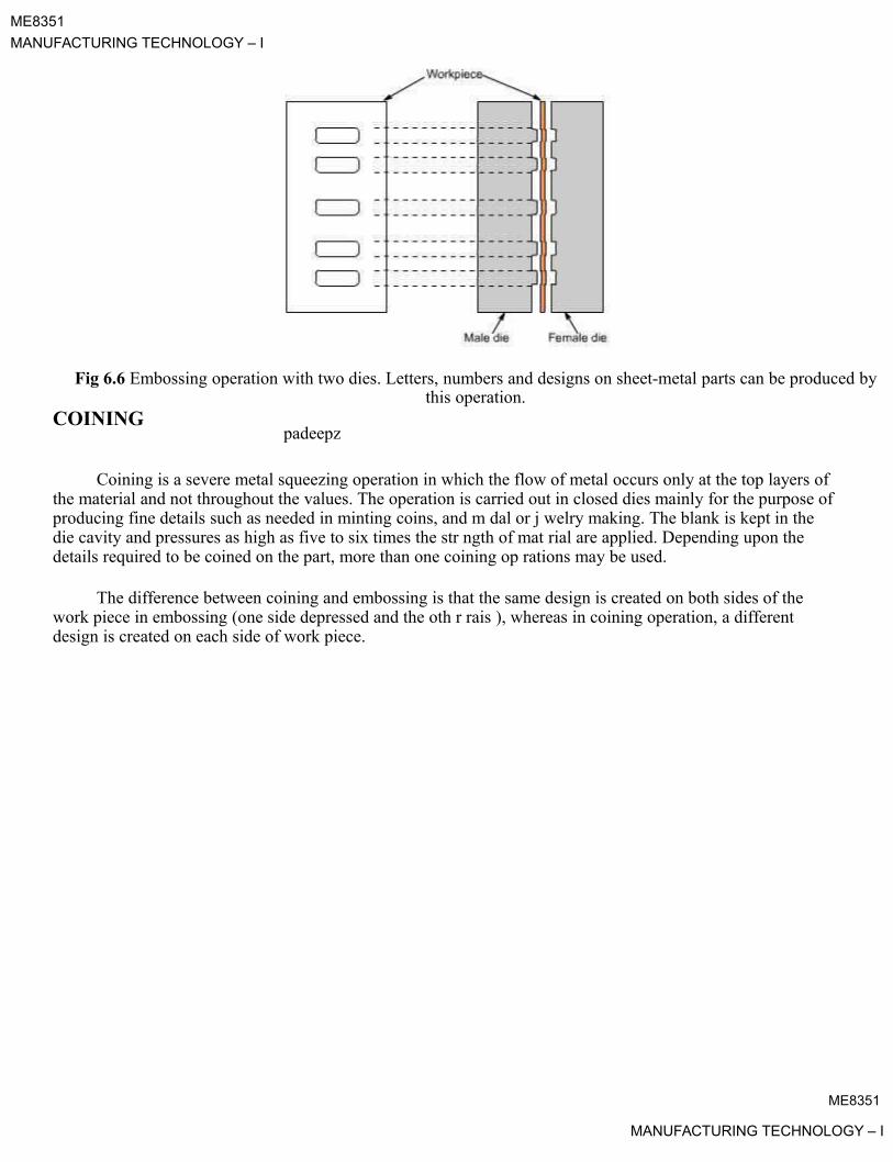
ME8351
MANUFACTURING TECHNOLOGY – I
Fig 6.6 Embossing operation with two dies. Letters, numbers and designs on sheet-metal parts can be produced bythis operation.
COININGpadeepz
Coining is a severe metal squeezing operation in which the flow of metal occurs only at the top layers of the material and not throughout the values. The operation is carried out in closed dies mainly for the purpose ofproducing fine details such as needed in minting coins, and m dal or j welry making. The blank is kept in the die cavity and pressures as high as five to six times the str ngth of mat rial are applied. Depending upon the details required to be coined on the part, more than one coining op rations may be used.
The difference between coining and embossing is that the same design is created on both sides of the work piece in embossing (one side depressed and the oth r rais ), whereas in coining operation, a different design is created on each side of work piece.
ME8351
MANUFACTURING TECHNOLOGY – I

ME8351MANUFACTURING TECHNOLOGY – I
Lecture 7
PRESSES FOR SHEET METAL WORKING
Classification of presses.
Types of presses for sheet metal working can be classified by one or a combination of characteristics,such as source of power, number of slides, type of frame and construction, type of drive, and intended applications.
Classification on the basis of source of power.
Manual Presses. These are either hand or foot operated through levers, screws or g ars. A common press of this type is the arbor press used for assembly operations.
Mechanical presses.These presses utilize flywheel energy which is tra sferred to the work pi ce by gears, cranks, eccentrics, or levers.
Hydraulic Presses. These presses provide working force through the application of fluid pressure on apiston by means of pumps, valves, intensifiers, and accumulators. These presses have better performance and reliability than mechanical presses.
end of its stroke, before thepadeepzunchmountedontheinnerslidetouchesthe workpiece. In this way, practically the complete ca acity of the press is available for drawing operation.
Pneumatic Presses. These presses utilize air cylinders to exert the required force. These are generallysmaller in size and capacity than hydraulic or mechanical resses, and therefore find use for light duty operations only.
Classification on the basis of number of slides.
Single Action Presses. A single action pr ss has one r ciprocation slide that carries the tool for the metalforming operation. The press has a fixed b d. It is the most widely used press for operations likeblanking, coining, embossing, and rawing.
Double Action Presses. A double action press has two slides moving in the same direction against afixed bed. It is more suitable for r wing operations, especially drawing, than single action press.For this reason, its two slides re gener lly referred to as outer blank holder slide and the inner draw slide.The blank holder slide is hollow rectangle, while the inner slide is a solid rectangle that reciprocates within the blank holder. The bl nk holder slide has a shorter stroke and dwells at the bottom
Another advantage of double action press is that the four corners of the blank holder are individually adjustable.This permits the application of non uniform forces on the work if needed.
A double action press is idely used for deep drawing operations and irregular shaped stampings.
Triple Action Presses. A triple action press has three moving slides. Two slides (the blank holder and the inner slide) move in the same direction as in a double – action press and the third or lower slide movesup ard through the fixed bed in a direction opposite to that of the other two slides. This action allowsreverse – drawing, forming or bending operations against the inner slide while both upper actions ared elling.
Cycle time for a triple – action press is longer than for a double – action press because of the time required for the third action.
Classification on the basis of frame and construction.ME8351
MANUFACTURING TECHNOLOGY – I
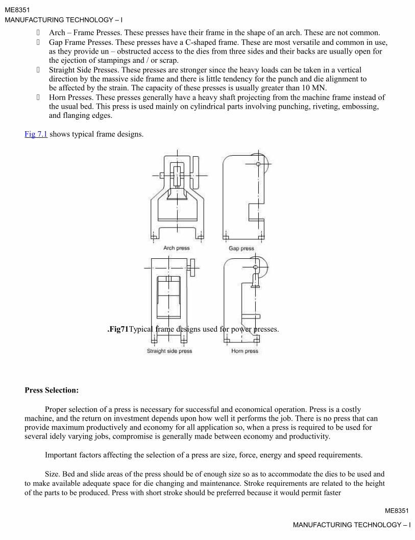
ME8351
MANUFACTURING TECHNOLOGY – I
Arch – Frame Presses. These presses have their frame in the shape of an arch. These are not common. Gap Frame Presses. These presses have a C-shaped frame. These are most versatile and common in use,
as they provide un – obstructed access to the dies from three sides and their backs are usually open for the ejection of stampings and / or scrap.
Straight Side Presses. These presses are stronger since the heavy loads can be taken in a vertical direction by the massive side frame and there is little tendency for the punch and die alignment to be affected by the strain. The capacity of these presses is usually greater than 10 MN.
Horn Presses. These presses generally have a heavy shaft projecting from the machine frame instead ofthe usual bed. This press is used mainly on cylindrical parts involving punching, riveting, embossing, and flanging edges.
Fig 7.1 shows typical frame designs.
.Fig71Typical frame designs used for power presses.
Press Selection:
Proper selection of a press is necessary for successful and economical operation. Press is a costly machine, and the return on investment depends upon how well it performs the job. There is no press that canprovide maximum productively and economy for all application so, when a press is required to be used for several idely varying jobs, compromise is generally made between economy and productivity.
Important factors affecting the selection of a press are size, force, energy and speed requirements.
Size. Bed and slide areas of the press should be of enough size so as to accommodate the dies to be used andto make available adequate space for die changing and maintenance. Stroke requirements are related to the heightof the parts to be produced. Press with short stroke should be preferred because it would permit faster
ME8351
MANUFACTURING TECHNOLOGY – I

ME8351
MANUFACTURING TECHNOLOGY – I
operation, thus increasing productivity. Size and type of press to be selected also depends upon the method andnature of part feeding, the type of operation, and the material being formed.
Force and Energy. Press selected should have the capacity to provide the force and energy necessary forcarrying out the operation. The major source of energy in mechanical presses is the flywheel, and the energy available is a function of mass of flywheel and square of its speed.
Press Speed. Fast speeds are generally desirable, but they are limited by the operations performed. High speed may not, however, be most productive or efficient. Size, shape and material of workpiece, die life, maintenance costs, and other factors should be considered while attemping to achicve the highest production rate at the lowest cost per piece.
Mechanical versus Hydraulic Presses:
Mechanical presses are very widely used for blanking, forming and drawi g op ratio s r quir d to be done on sheet metal. For certain operations which require very high force, for exampl , hydraulic pr sses aremore advantageous. Table 7.1 gives a comparison of characteristics and preferred application of the two typesof press.
padeepzTable 7.1 Comparison of Mechanical and Hydraulic Presses
Characteristic Mechanical Presses Hydraulic Presses
Force Depends upon slide position.Dose not nd u on slideposition. R lativ ly constant.
Stroke length Short strokesLong strok s, v n as muchas 3 m.
High. Highest at mid-stroke. CanSlow. Rapid advance and
Slide speed retraction. Variable speedsbe variable
uniform throughout stroke.
Capacity About 50 MN (m ximum)About 500 MN, or evenmore.
ControlFull stroke generally required Adjustable, slide reversalbefore reversel possible from any position.
Operations requiring maximumOperations requiring steadypressure through-out stoke.
pressure near bottom of stroke.Deep drawing. Drawing
Cutting operations(blanking,Application irregular shaped parts.
shearing, piercing, Forming andStraightening. Operations
dra ing to depths of about 100requiring variable forces and
mm./or strokes.
Press Feeding Devices:
Safety is an important consideration in press operation and every precaution must be taken to protect the operator. Material must be tried to be fed to the press that eliminates any chance of the operator having hisor her hands near the dies. The use of feeding device allows faster and uniform press feeding in addition to thesafety features.
• Blank and Stamping Feeds.ME8351
MANUFACTURING TECHNOLOGY – I
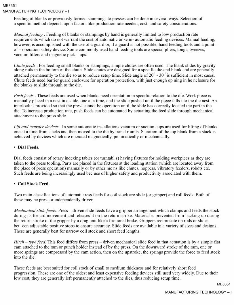
ME8351
MANUFACTURING TECHNOLOGY – I
Feeding of blanks or previously formed stampings to presses can be done in several ways. Selection of a specific method depends upon factors like production rate needed, cost, and safety considerations.
Manual feeding . Feeding of blanks or stampings by hand is generally limited to low production rate requirements which do not warrant the cost of automatic or semi- automatic feeding devices. Manual feeding, however, is accomplished with the use of a guard or, if a guard is not possible, hand feeding tools and a point –of – operation safety device. Some commonly used hand feeding tools are special pliers, tongs, tweezes, vacuum lifters and magnetic pick – ups.
Chute feeds . For feeding small blanks or stampings, simple chutes are often used. The blank slides by gravityalong rails in the bottom of the chute. Slide chutes are designed for a specific die and blank and are generally attached permanently to the die so as to reduce setup time. Slide angle of 200 - 300 is sufficient in most cases.Chute feeds need barrier guard enclosure for operation protection, with just enough op ning in he nclosure for the blanks to slide through to the die.
Push feeds . These feeds are used when blanks need orientation in specific relation to the die. Work piece is manually placed in a nest in a slide, one at a time, and the slide pushed until the piece falls i to the die nest. An interlock is provided so that the press cannot be operation until the slide has correctly located the part in the die. To increase production rate, push feeds can be automated by actuating the feed slide through mechanical attachment to the press slide.
Lift and transfer devices . In some automatic installations vacuum or suction cups are used for lifting of blanks one at a time from stacks and then moved to the die by transf r units. S aration of the top blank from a stack is achieved by devices which are operated magnetically, pn umatically or mechanically.
• Dial Feeds.
Dial feeds consist of rotary indexing tables (or turntabl s) having fixtures for holding workpiecs as they are taken to the press tooling. Parts are placed in the fixtures at the loading station (which are located away from the place of press operation) manually or by other me ns like chutes, hoppers, vibratory feeders, robots etc. Such feeds are being increasingly used bec use of higher safety and productivity associated with them.
• Coil Stock Feed.
Two main classifications of automatic ress feeds for coil stock are slide (or gripper) and roll feeds. Both of these may be press or independently driven.
Mechanical slide feeds. Press – driven slide feeds have a gripper arrangement which clamps and feeds the stockduring its for ard movement and releases it on the return stroke. Material is prevented from backing up duringthe return stroke of the gripper by a drag unit like a frictional brake. Grippers reciprocate on rods or slidesbet een adjustable positive stops to ensure accuracy. Slide feeds are available in a variety of sizes and designs.These are generally best for narrow coil stock and short feed lengths.
Hitch – type feed. This feed differs from press – driven mechanical slide feed in that actuation is by a simple flatcam attached to the ram or punch holder instead of by the press. On the downward stroke of the ram, one or more springs are compressed by the cam action, then on the upstroke, the springs provide the force to feed stockinto the die.
These feeds are best suited for coil stock of small to medium thickness and for relatively short feed progression. These are one of the oldest and least expensive feeding devices still used very widely. Due to their low cost, they are generally left permanently attached to the dies, thus reducing setup time.
ME8351
MANUFACTURING TECHNOLOGY – I

ME8351
MANUFACTURING TECHNOLOGY – I
Pneumatic slide feeds. These feeds are similar to mechanical slide feeds in that they have grippers or clamps that reciprocate on guide rails or slides between adjustable positive stops to push and / or pull stock into a die. However, these differ in that they are powered by an air cylinder, with actuation and timing of valves by cam –operated limit switches.
These feeds are best for short progression, and find wide applications in job shops because of their low cost andversatility.
Roll feeds. In these feeds, coil stock is advanced by pressure exerted between intermittently driven, opposed rolls which allow the stock to dwell during the working part of the press cycle. Intermittent rotation (or indexing) of the feed rolls, with the rolls rotating in only one direction, is accomplished in many ways. In onecommon design, the rolls are indexed through a one – way clutch by a rack – and – pinion mechanism hat is actuated by an adjustable eccentric on the press – crankshaft.
These feeds are available in several types and sizes to suit almost any width a d thick ss of stock. Thoughtheir initial cost is slightly higher, their greater durability and lower maintena ce cost accou for th irextensive use.
net
ME8351
MANUFACTURING TECHNOLOGY – I

ME8351MANUFACTURING TECHNOLOGY – I
Lecture 8
DIE AND PUNCH
A typical die and punch set used for blanking operation is shown in Fig 8.1. The sheet metal used is called strip or stock. The punch which is held in the punch holder is bolted to the press ram while die is bolted on the press table. During the working stroke, the punch penetrates the strip, and on the return stroke of the press ram the strip is lifted with the punch, but it is removed from the punch by the stripper plate. The stop pin is a gage and it sets the advance of the strip stock within the punch and die. The strip stock is butted against theback stop acting as a datum location for the centre of the blank.
Fig 8.1.
The die opening is given angular clearance to permit escape of good part (blank). The waste skelton of stock strip, from which blanks have been cut, is recovered as salvaged material.
The clearance angle provided on the die (Fig 8.1) depends on the material of stock, as well as its thickness. For thicker and softer materials generally higher angular clearance is given. In most cases, 2 degree of angular clearance is sufficient. The height of cutting land of about 3 mm is generally sufficient.
Clearance
In blanking operation , the die size is taken as the blank size and the punch is made smaller giving thenecessary clearance between the die and the punch.
Die size = blank size
Punch size = blank size – 2 x clearance
Clearance = k . t . t
ME8351
MANUFACTURING TECHNOLOGY – I
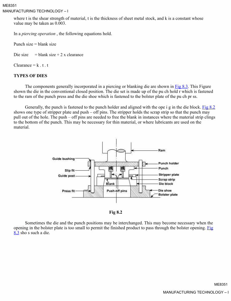
ME8351
MANUFACTURING TECHNOLOGY – I
where t is the shear strength of material, t is the thickness of sheet metal stock, and k is a constant whose value may be taken as 0.003.
In a piercing operation , the following equations hold.
Punch size = blank size
Die size = blank size + 2 x clearance
Clearance = k . t . t
TYPES OF DIES
The components generally incorporated in a piercing or blanking die are shown in Fig 8.3. This Figure shown the die in the conventional closed position. The die set is made up of the pu ch hold r which is fastened to the ram of the punch press and the die shoe which is fastened to the bolster plate of the pu ch pr ss.
Generally, the punch is fastened to the punch holder and aligned with the ope i g in the die block. Fig 8.2 shows one type of stripper plate and push – off pins. The stripper holds the scrap strip so that the punch may pull out of the hole. The push – off pins are needed to free the blank in instances where the material strip clings to the bottom of the punch. This may be necessary for thin material, or where lubricants are used on the material.
Fig 8.2
Sometimes the die and the punch positions may be interchanged. This may become necessary when theopening in the bolster plate is too small to permit the finished product to pass through the bolster opening. Fig8.3 sho s such a die.
ME8351
MANUFACTURING TECHNOLOGY – I
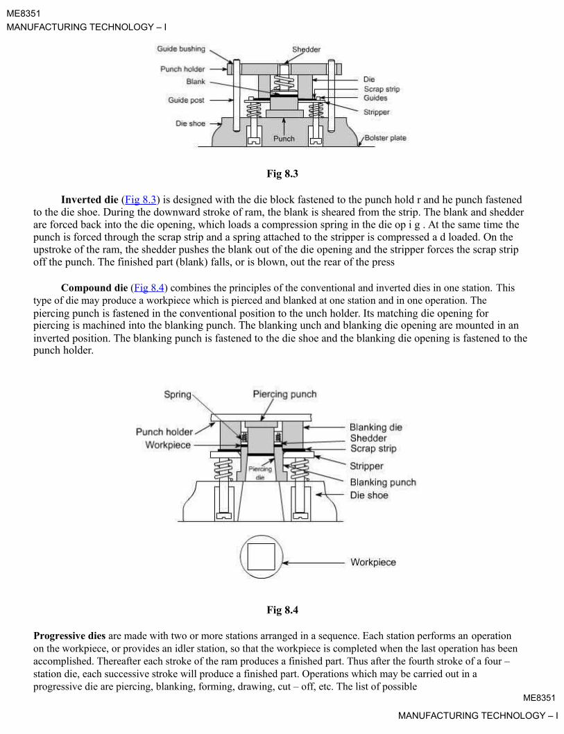
ME8351
MANUFACTURING TECHNOLOGY – I
Fig 8.3
Inverted die (Fig 8.3) is designed with the die block fastened to the punch hold r and he punch fastened to the die shoe. During the downward stroke of ram, the blank is sheared from the strip. The blank and shedder are forced back into the die opening, which loads a compression spring in the die op i g . At the same time the punch is forced through the scrap strip and a spring attached to the stripper is compressed a d loaded. On the upstroke of the ram, the shedder pushes the blank out of the die opening and the stripper forces the scrap strip off the punch. The finished part (blank) falls, or is blown, out the rear of the press
Compound die (Fig 8.4) combines the principles of the conventional and inverted dies in one station. This type of die may produce a workpiece which is pierced and blanked at one station and in one operation. Thepiercing punch is fastened in the conventional position to the unch holder. Its matching die opening for piercing is machined into the blanking punch. The blanking unch and blanking die opening are mounted in aninverted position. The blanking punch is fastened to the die shoe and the blanking die opening is fastened to thepunch holder.
Fig 8.4
Progressive dies are made with two or more stations arranged in a sequence. Each station performs an operation on the workpiece, or provides an idler station, so that the workpiece is completed when the last operation has been accomplished. Thereafter each stroke of the ram produces a finished part. Thus after the fourth stroke of a four – station die, each successive stroke will produce a finished part. Operations which may be carried out in a progressive die are piercing, blanking, forming, drawing, cut – off, etc. The list of possible
ME8351
MANUFACTURING TECHNOLOGY – I

ME8351
MANUFACTURING TECHNOLOGY – I
operations is long. The number and types of operations which may be performed in a progressive die depends upon the ingenuity of the designer.
Fig 8.5 shows a four – station progressive die. The die block is made up of four pieces and fastened to the die shoe. This permits easy replacement of broken or worn die blocks. The stock is fed from the right and registers against a finger strop (not shown). The first stroke of the press Fig 8.5(a) produces a square hole and two notches. These notches form the left end of the first piece.
During the upstroke of ram, the stock is moved to the next station against a finger stop (not shown). Thestock is positioned for the second stroke. The second station is an idler, Fig 8.5(b). The right end of the first piece, the left end of the second piece, and a second square hole are pierced.
padeepzFig8.5
The ram retracts and the scr strip is moved to the third station against an automatic stop, Fig 8.5(c). This stop picks up the notched V and ositions the scrap strip. The third stroke of the ram pierces the four holes as shown in Fig 8.5(c). The fourth stroke, Fig 8.5(d), cuts off and forms the radii at the ends of the finished piece. Thereafter every stroke roduces finished part, Fig 8.5(e).
Progressive dies generally have the cut – off or blanking operation as the last operation. It is preferred to have piercing operation as the first operation so that the pierced hole can be advantageously used as a pilot hole. Alternatively, special pilot holes are pierced in the scrapped part of the stock. In certain special cases, blankingis done at the first station, and the blank returned to the die by using spring plates and then moved to the subsequent station by mechanical means or manually.
Progressive dies are used where higher production rates are desired and the material is neither too thicknor too thin. Their use helps in cutting down the material handling costs.
ME8351
MANUFACTURING TECHNOLOGY – I

ME8351MANUFACTURING TECHNOLOGY – I
Lecture 9
HIGH ENERGY RATE FORMING PROCESSES
In these forming processes large amount of energy is applied for a very short interval of time. Many metals tend to deform more readily under extra – fast application of load which make these processes useful to form large size parts out of most metals including those which are otherwise difficult – to – form.
The parts are formed at a rapid rate, and thus these processes are also called high – velocity forming processes. There are several advantages of using these forming processes, like die costs are low, easy maintenance of tolerances, possibility of forming most metals, and material does not show spring-back effect.The production cost of components by such processes is low. The limitation of these processes is he need for skilled personnel.
There are three main high energy rate forming processes: explosive formi g, mag tic forming, and electro hydraulic forming. We shall discuss these processes.Explosive Formingpressure pulse impinges against thepadeepzworkpiece,themetalisdeformedintothedie with as high velocity as 120 m/s.
Explosive forming, is distinguished from conventional forming in that the punch or diaphragm is replacedby an explosive charge. The explosives used are generally high – ex losive chemicals, gaseous mixtures, or propellants. There are two techniques of high – explosive forming: stand – off technique and the contact technique.
Standoff Technique . The sheet metal work piece blank is clamp d ov r a die and the assembly is lowered into atank filled with water. The air in the die is pump out. The xplosive charge is placed at some predetermineddistance from the work piece, see Fig 9.1. On d tonation of the xplosive, a pressure pulse of very highintensity is produced. A gas bubble is also pro uc which xpands spherically and then collapses. When the
ME8351
MANUFACTURING TECHNOLOGY – I
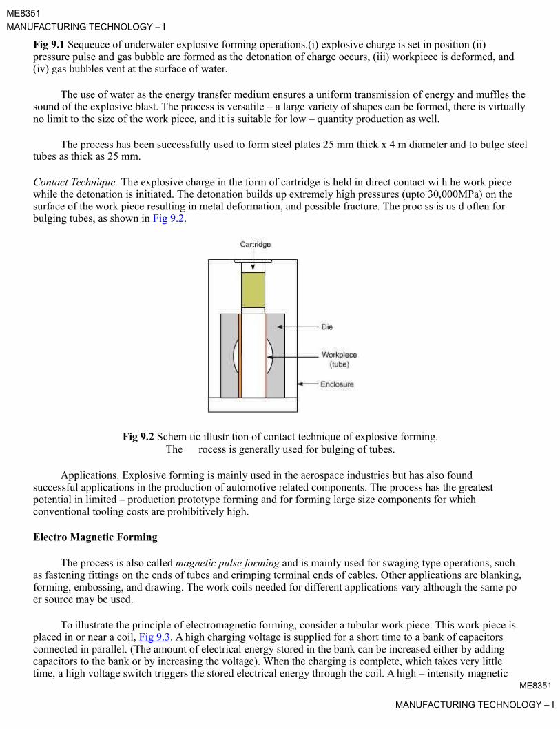
ME8351
MANUFACTURING TECHNOLOGY – I
Fig 9.1 Sequeuce of underwater explosive forming operations.(i) explosive charge is set in position (ii) pressure pulse and gas bubble are formed as the detonation of charge occurs, (iii) workpiece is deformed, and (iv) gas bubbles vent at the surface of water.
The use of water as the energy transfer medium ensures a uniform transmission of energy and muffles thesound of the explosive blast. The process is versatile – a large variety of shapes can be formed, there is virtuallyno limit to the size of the work piece, and it is suitable for low – quantity production as well.
The process has been successfully used to form steel plates 25 mm thick x 4 m diameter and to bulge steeltubes as thick as 25 mm.
Contact Technique. The explosive charge in the form of cartridge is held in direct contact wi h he work piece while the detonation is initiated. The detonation builds up extremely high pressures (upto 30,000MPa) on the surface of the work piece resulting in metal deformation, and possible fracture. The proc ss is us d often for bulging tubes, as shown in Fig 9.2.
Fig 9.2 Schem tic illustr tion of contact technique of explosive forming.The rocess is generally used for bulging of tubes.
Applications. Explosive forming is mainly used in the aerospace industries but has also found successful applications in the production of automotive related components. The process has the greatest potential in limited – production prototype forming and for forming large size components for which conventional tooling costs are prohibitively high.
Electro Magnetic Forming
The process is also called magnetic pulse forming and is mainly used for swaging type operations, such as fastening fittings on the ends of tubes and crimping terminal ends of cables. Other applications are blanking, forming, embossing, and drawing. The work coils needed for different applications vary although the same po er source may be used.
To illustrate the principle of electromagnetic forming, consider a tubular work piece. This work piece isplaced in or near a coil, Fig 9.3. A high charging voltage is supplied for a short time to a bank of capacitors connected in parallel. (The amount of electrical energy stored in the bank can be increased either by adding capacitors to the bank or by increasing the voltage). When the charging is complete, which takes very little time, a high voltage switch triggers the stored electrical energy through the coil. A high – intensity magnetic
ME8351
MANUFACTURING TECHNOLOGY – I

ME8351
MANUFACTURING TECHNOLOGY – I
field is established which induces eddy currents into the conductive work piece, resulting in the establishment of another magnetic field. The forces produced by the two magnetic fields oppose each other with the consequence that there is a repelling force between the coil and the tubular work piece that causes permanent deformation of the work piece.
Fig 9.3 Various applications of m gnetic forming process. (i) Swaging, (ii) Expanding, and (iii) Embossing orblanking.
Either permanent or ex andable coils may be used. Since the repelling force acts on the coil as well the work, the coil itself and the insulation on it must be capable of withstanding the force, or else they will be destroyed. The expandable coils are less costly and are also preferred when high energy level is needed.
Magnetic forming can be accomplished in any of the following three ways, depending upon the requirements.
Coil surrounding work piece. When a tube – like part x is to fit over another part y (shown as insert inFig 9.3(i)), coil is designed to surround x so that when energized, would force the material of xtightly around y to obtain necessary fit.
Coil inside work piece. Consider fixing of a collar on a tube – like part, as shown in Fig 9.3(ii). The magnetic coil is placed inside the tube – like part, so that when energized would expand the material ofthe part into the collar.
Coil on flat surface. Flat coil having spiral shaped winding can also be designed to be placed either above or below a flat work piece, see Fig 9.3(iii).These coils are used in conjunction with a die to form, emboss, blank, or dimple the work piece.
ME8351MANUFACTURING TECHNOLOGY – I

ME8351
MANUFACTURING TECHNOLOGY – I
In electromagnetic forming, the initial gap between the work piece and the die surface, called the fly distance, must be sufficient to permit the material to deform plastically. From energy considerations, the ideal pressure pulseshould be of just enough magnitude that accelerates the part material to some maximum velocity and then let the part come to zero velocity by the time it covers the full fly distance. All forming coils fail, expendable coils fail sooner than durable coils, and because extremely high voltages and currents are involved, it is essential that proper safety precautions are observed by the production and maintenance personnel.
Applications
together. Flat coils have been used on flat sheets to produce stretch (internal) andnetshrink(xtrnal)flanges on ring and disc – shaped work pieces.
Electromagnetic forming process is capable of a wide variety of forming and assembly operations. It hasfound extensive applications in the fabrication of hollow, non – circular, or asymmetrical shapes from ubular stock. The compression applications involve swaging to produce compression, tensile, and orque join s or sealed pressure joints, and swaging to apply compression bands or shrink rings for fast ning compon s
Electromagnetic forming has also been used to perform shearing, piercing, and rivettti g.
Electro Hydraulic Forming
energy is converted into mechanicalpadeepzenergyfortheformingofmetallicarts.A bank of capacitors is first
charged to a high voltage and then discharged across a gap b tw n two electrodes, causing explosions inside
Electro hydraulic forming (EHF), also known as electro s ark forming, is a process in which electrical
the hollow work piece, which is filled with some suitable m dium, g n rally water. These explosions produce shock waves that travel radially in all directions at high v locity until they meet some obstruction. If the discharge energy is sufficiently high, the hollow work pi ce is form d. The deformation can be controlled by applying external restraints in the form of die or by varying the amount of energy released, Fig 9.4.
Fig 9.4 Unrestrained and restrained electro-hydraulic forming process.
Advantages
1. EHF can form hollow shapes with much ease and at less cost compared to other forming techniques.2. EHF is more adaptable to automatic production compared to other high energy rate forming techniques.3. EHF can produce small – to intermediate sized parts that don't have excessive energy requirements.
ME8351

MANUFACTURING TECHNOLOGY – I

ME8351
MANUFACTURING TECHNOLOGY – I
Accuracy of parts produced
Accuracy of electro hydraulically formed parts depends on the control of both the magnitude and location of energy discharges and on the dimensional accuracy of the dies used. With the modern equipment, it is now possible to precisely control the energy within specified limits, therefore the primary factor is the dimensional accuracy of the die. External dimensions on tubular parts are possible to achieve within ± 0.05 mmwith the current state of technology.
Materials formed
Materials having low ductility or having critical impact velocity less than 30 m/s are generally not considered to be good candidate for EHF. All materials that can be formed by conventional forming processescan be formed by EHF also. These materials are aluminum alloys, nickel alloys, stainl ss s ls, i anium, and Inconel 718.
ME8351
MANUFACTURING TECHNOLOGY – I

ME8351MANUFACTURING TECHNOLOGY – I
Lecture 10
POWDER METALLURGY
Powder metallurgy (PM) is a metal working process for forming precision metal components from metalpowders. The metal powder is first pressed into product shape at room temperature. This is followed by
heating (sintering) that causes the powder particles to fuse together without melting.
The parts produced by PM have adequate physical and mechanical properties while completely meeting the functional performance characteristics. The cost of producing a component of given shape and he required dimensional tolerances by PM is generally lower than the cost of casting or making it as a wrought product, because of extremely low scrap and the fewer processing steps. The cost advantage is the main reason for selecting PM as a process of production for high – volume component which needs to be produc d xac ly to, or close to, final dimensions. Parts can be produced which are impregnated with oil or plastic, or infiltrated with lower melting point metal. They can be electroplated, heat treated, and machi ed if c ssary.
The rate of production of parts is quite high, a few hundreds to several thousa ds per hour.
Industrial applications of PMpadeepzpartsareseveral.Theseincludeself–lubricating bearings, porous metal
filters and a wide range of engineered shapes, such as gears, cams, brackets, sprockets, etc.
In the PM process the following three steps are follow d in s qu nce: mixing (or blending), compacting, and sintering.
Mixing: A homogeneous mixture of elem ntal m tal powders or alloy powders is prepared. Depending upon the need, powders of other alloys or lubricants may be add d.
Compacting: A controlled amount of the mixed powder is introduced into a precision die and then it ispressed or compacted at a pressure in the r nge 100 MPa to 1000 MPa. The compacting pressure requireddepends on the characteristics and sh of the p rticles, the method of mixing, and on the lubricant used. This
Process Details:

is generally done at room tem erature. In doing so, the loose powder is consolidated and densified into a shapedmodel. The model is generally called “green compact.” As is comes out of the die, the compact has the size and shape of the finished product The strength of the compact is just sufficient for in – process handling and transportation to the sintering furnace
ME8351
MANUFACTURING TECHNOLOGY – I

ME8351
MANUFACTURING TECHNOLOGY – I
Figpadeepz10.1Typicalsetofpowdermetallurgytools
To illustrate the process, let us take straight cylindrical part such as a sleeve bearing. Fig 10.1 shows a typical set of tools used for producing this part. The compacting cycle for this art (Fig 10.2) follows the following steps.
Fig 10.2 Powder metallurgy compacting cycle.
1. With the upper punch in the withdrawn position, the empty die cavity is filled with mixed powder.2. The metal powder in the die is pressed by simultaneous movement of upper and lower punches.3. The upper punch is withdrawn, and the green compact is ejected from the die by the lower punch.4. The green compact is pushed out of the pressing area so that the next operating cycle can start.
ME8351
MANUFACTURING TECHNOLOGY – I

ME8351
MANUFACTURING TECHNOLOGY – I
This compacting cycle is almost the same for all parts.
Sintering: During this step, the green compact is heated in a protective atmosphere furnace to a suitable temperature, which is below the melting point of the metal. Typical sintering atmospheres are endothermic gas, exothermic gas, dissociated ammonia, hydrogen, and nitrogen. Sintering temperature varies from metal to metal; typically these are within 70 to 90% of the melting point of the metal or alloy. Table 10.1 gives the sintering temperatures used for various metals. Sintering time varies with size and metal of part. Table 10.1 alsogives typical range of sintering time needed for various metals.
Table 10.1 Sintering temperature and time for various metal powders
Material Temperature Time
( 0C)
Copper, brass,760-900 10-40
bronze
Nickel1000-1150 30-40
Stainless steels1100-1290 30-60
Ferrites1200-1500 10-600
Tungsten carbide1430-1500 20-30
Molybdenum2050 120
Tungsten2350 480
Tantalum2400 480
Sintering is a solid state rocess which is responsible for producing physical and mechanical properties in the PM part by developing metallurgical bond among the powder particles. It also serves to remove the lubricant from the powder, revents oxidation, and controls carbon content in the part. The structure and porosityobtained in a sintered compact depend on the temperature, time, and processing details. It is not possible to completely eliminate the porosity because voids cannot be completely closed by compaction and because gasesevolve during sintering. Porosity is an important characteristic for making PM bearings and filters.
SECONDARY AND FINISHING OPERATIONS
Sometimes additional operations are carried out on sintered PM parts in order to further improve theirproperties or to impart special characteristics. Some important operations are as under.
1. Coining and sizing. These are high pressure compacting operations. Their main function is to impart (a)greater dimensional accuracy to the sintered part, and (b) greater strength and better surface finish by further densification.
2. Forging. The sintered PM parts may be hot or cold forged to obtain exact shape, good surface finish, good dimensional tolerances, and a uniform and fine grain size. Forged PM parts are being increasinglyused for such applications as highly stressed automotive, jet – engine and turbine components.
ME8351
MANUFACTURING TECHNOLOGY – I

ME8351
MANUFACTURING TECHNOLOGY – I
3. Impregnation. The inherent porosity of PM parts is utilized by impregnating them with a fluid like oil or grease. A typical application of this operation is for sintered bearings and bushings that are internally lubricated with upto 30% oil by volume by simply immersing them in heated oil. Such components havea continuous supply of lubricant by capillary action, during their use. Universal joint is a typical grease –impregnated PM part.
4. Infiltration. The pores of sintered part are filled with some low melting point metal with the result that part's hardness and tensile strength are improved. A slug of metal to be impregnated is kept in close contact with the sintered component and together they are heated to the melting point of the slug. The molten metal infiltrates the pores by capillary action. When the process is complete, the component hasgreater density, hardness, and strength. Copper is often used for the infiltration of iron – base PM components. Lead has also been used for infiltration of components like bushes for which lower frictional characteristics are needed.
5. Heat Treatment. Sintered PM components may be heat treated for obtaining gr at r hardn ss or s rength in them.
6. Machining. The sintered component may be machined by turning, milli g, drilli g, thr ading, grinding, etc. to obtain various geometric features.
7. Finishing. Almost all the commonly used finishing method are applicable to PM parts. Some of suchmethods are plating, burnishing, coating, and colouring.
Plating. For improved appearance and resistance to wear and corrosion, the sintered compacts may be plated byelectroplating or other plating processes. To avoid penetration and entra ment of plating solution in the pores of the part, an impregnation or infiltration treatment is often necessary before lating. Copper, zinc, nickel, chromium, and cadmium plating can be applied.
Burnishing. To work harden the surface or to improve the surface finish and dimensional accuracy, burnishingmay be done on PM parts. It is relatively easy to displace m tal on PM parts than on wrought parts because ofsurface porosity in PM parts.
Coating. PM sintered parts are more susceptible to environmental degradation than cast and machined parts. This is because of inter – connected porosity in PM parts. Coatings fill in the pores and seal the entire reactivesurface.
Colouring. Ferrous PM parts can be lied colour for protection against corrosion. Several methods are in use for colouring. One common method to blacken ferrous PM parts is to do it chemically, using a salt bath.
8. Joining. PM parts can be welded by several conventional methods. Electric resistance welding is bettersuited than oxy- acetylene elding and arc welding because of oxidation of the interior porosity. Argonarc welding is suitable for stainless steel PM parts.
ME8351
MANUFACTURING TECHNOLOGY – I

ME8351
MANUFACTURING TECHNOLOGY – I
Lecture 11METAL POWDERS FOR PM
Metal powders play an extremely important role in powder metallurgy. These are highly engineered materials. The particle size, shape and size distribution of metal powder affect the characteristics and properties of the compacted product. A large number of types and grades of powders available which makes possible the production of a wide variety of components for meeting numerous performance requirements. All metals can beproduced in powder form but not all have the desired properties which are necessary for economical production.Some widely used metal powders for manufacturing PM parts are listed in Table 11.1. The characteristic of powders given in this Table are significant from the viewpoint of application feasibility for PM parts
9. Table 11.1 Widely used Metal Powders
Pure Metals: Alloys:
Aluminum Aluminium-iron
Antimony Brass
Berylium Copper-zinc-nickel
Bismuth Nickel-chromium
Cadmium Nickel-chromium-iron
Chromium Nickel-copp r
Cobalt Nickel-iron
Copper Silicon-iron
Iron Solder
Lead Stainless steel
Manganese
Molybdenum Compounds:
Nickel Borides(chromium, tungsten, etc.)
Precious metals(gold, silver, Carbides (molybdenum, tungsten,platinum) etc.)
Rhenium Molybdenum disilicide
Silicon Nitrides (siliconn titanium, etc.)
Tantalum Zirconium hydride
ME8351
MANUFACTURING TECHNOLOGY – I

ME8351
MANUFACTURING TECHNOLOGY – I
Tin
Titanium
Tungsten
Vanadium
Zinc
10. Powder Production11. All metal powders, because of their individual physical and chemical charac ris ics, cannot be
produced in the same way.12. There are several methods for producing metal powders each giving diff r nt size and structure of the
particles. Table 11.2 gives important characteristics of powders produced by some comm rcialmethods. Also given in this Table are advantages and disadvantages of these methods. A brief
Apparent Density
The apparent density or specific gravity of powder is xpr ss d in kg/m 3 .It should be kept constant. This means that the same amount of owdershould be fed into the die each time.
Chemical Properties
These are the properties like the purity of the pow er, amount of oxides permitted, and the percentage of other elements llowed.
Compressibility
Compressibility is the ratio of the volume of intial powder to the volume
of the compressed piece It varies considerably and is affected by the
particle-size distribution and shape Compressibility affects the green
strength of a compact.
description of some of these methods follows.
padeepz13.Table11.2MetalPowderCharacteristics
Fineness
Fineness refers to the particle size and is determined by passing thepo der through a standard sieve or by microscopic measurement.
Flo ablity
Flo ablity is the characteristic of a powder that permits it to flow readily

and conform to the mold cavity. It can be described as the rate of flowthrough a fixed orifice.
Particle-Size Distribution
ME8351
MANUFACTURING TECHNOLOGY – I

ME8351
MANUFACTURING TECHNOLOGY – I
Particle-Size Distribution refers to the amount of each standardparticle size in the powder. It influences the flowablity and apparentdensity as well as porosity of the product.
Sintering Ability
Sintering ability is the suitability of a powder for bonding of particles bythe application of heat.
14. Atomization: It is as excellent and very widely used method of producingnetmetalpowders.Incase of low melting point metals, the molten metal is kept in a tank. It is raised by the suction produced by hot air, through a pipe to the atomizing nozzle. A fine stream of molten metal is brok into small drople s, which solidify into metal powder particles. The size of particles can be controll d but he shape of particles remains irregular. However, the technique used for high melting point m tals is slightly different. A stream of molten metal coming from an orifice at the bottom of a r s rvoir is broken up by a jet of atomizing fluid (which may be inert gas, air , water or steam) into metal powder particles. It is possible to control the powder characteristics (average particle size, particle shapes, particle size
distribution, particle chemistry,padeepzandparticlestructure)bychangingtheprocess variables (such as temperature, stream velocity, etc.) in the atomizing process.
15. Electrolysis: Electrolytic deposition or electrolysis is a widely used method of producing powders of iron, coppers, silver, and several other metals. For producing iron, for example, a tank containing a suitable electrolyte is taken. In it steel plates are placed as anode and stainless steel plates are placed as cathode. The two electrodes are connected to a pow rful de source. In about 50 hours, a 2 mm thick deposit of is obtained on the cathode plates. This posit of l ctrolytic iron is stripped, washed, screened, and sized. The iron powder may be ann al d if its brittleness is to be reduced.
16. Reduction: In this process, metal oxide is r duc d to m tal powder through contact with a reducing gas at temperature below the melting point. For xampl , in case of iron the iron oxide is crushed and passed through a furnace. The hydrogen atmosph re in the furnace reacts with the oxygen of iron oxide at a temperature of nearly 1050 0 C nd pure iron with sponge – like structure is obtained. In addition to iron, other commonly produced commerci lly by this method include nickel, cobalt, molybdenum, and tungsten.
17. Machining and Grinding.Mchining h s been used to produce coarse magnesium powder. Milling and grinding processes utilize various ty es of rotary mills, stamping mills, crushers, and grinders, break down brittle metals into owders of almost any fineness but of irregular shaped particles.
18. There are several other methods involving precipitation, condensation and other chemical processes, that are employed for producing metal powders.
19. Powder Mixing20. Mixing of po ders precedes compacting.21. The process of mixing includes mixing of various metal powders with lubricants as a result of
hich the po ders are thoroughly intermingled. This is carried out in batch mixers. The surface friction properties of the powders to be mixed significantly affect the properties of the mixtures. If the powders differ to much in density, segregation of the heavier powder may occur because gravitational forces maybe stronger than the frictional forces.
22. The temperature during mixing affects the friction between powder particles. With increasing temperature, the friction coefficient between most materials increases and the flow of powders is impaired. It is therefore desirable to maintain lower mixing temperature.
23. When parts are pressed in rigid dies, the use of lubricant becomes essential in order to reduce friction between powder particles and between the compact being pressed and the die wall and core rod. The lubricant also reduces the pressure required to eject compacts from the die. The lubricant, which is generally ½ to 1% by weight, is introduced as a fine powder mixing time and the intensity of mixing powder and lubricant affect flow and apparent density of the powder mixture.
ME8351
MANUFACTURING TECHNOLOGY – I
ME8351MANUFACTURING TECHNOLOGY – I
Lecture 12
POWDER METALLURGY
Advantages: Metal in powder form is costlier than in solid form. Further, expensive dies and equipment neededto adapt this process implies that the process is justified by the unusual properties obtained in the products. Powder metallurgy offers the following specific advantages.
i. Parts can be produced from high melting point refractory metals with respectivelynetlessdifficulyand
at less cost.
2. Production rates are high even for complex parts. This is primarily because of the use of au oma d equipment in the process.
iii. Near net shape components are produced. The dimensional tolerances on compo ts are mostly such that no further machining is needed. Scrap is almost negligible.
iv. Parts can be made from a padeepzgreatvarietyofcompositions.Itisthereforemuch easy to have partsof desired mechanical and physical properties like density, hardness toughness, stiffness, damping, and specific electrical or magnetic properties.
v. Parts can be produced with impregnation and infiltration of oth r materials to obtain specialcharacteristics needed for specific applications.
vi. Skilled machinists are not needed, so labour cost is low
vii. Parts with controlled porosity can be pro uc
viii. Bi-metallic products, sintered carbi es and porous bearings can be produced only by this process.
Limitations: Powder metallurgy has the following limitations.
i. High cost of metal powders com ared to the cost of raw material used for casting or forging a component. A few powders are even difficult to store without some deterioration.
ii. High cost of tooling and equipment. This is particularly limitation when production volumes are small.
iii. Large or complex shaped parts are difficult to produce by PM process.
iv. Parts have lo er ductility and strength than those produced by forging.
v. Uniformly high – density products are difficult to produce.
vi. Some powders (such as aluminum, magnesium, titanium and zirconium) in a finally divided statepresent fire hazard and risk of explosion.
vii. Low melting point metal powders (such as of zinc, tin, cadmium) give thermal difficulties during sintering operation, as most oxides of these metals cannot be reduced at temperatures below the meltingpoint.
ME8351
MANUFACTURING TECHNOLOGY – I

ME8351
MANUFACTURING TECHNOLOGY – I
Applications of Powder Metallurgy:
There is a great variety of machine components that are produced from metal powders, many of these are put to use without any machining operation carried out on them. Following are some of the prominent PM Products.
Filters: Permanent metal powder filters have greater strength and shock resistance than ceramic filters. Fibermetal filters, having porosity upto 95% and more, are used for filtering air and fluids. Such filters find usein dehydration for filtering air and fluids. Such filters find use in dehydrators for diffusing moisture – ladenair around some drying agent such as silica gel, Fig 12.1.
Fig 12.1 Applications of powder met llurgy parts. Filiers can be used for diffusing or for separating.
These filters find wide usage also in etrol / diesel engines for separating dirt and moisture from fuel system. Metal powder filters are also used for arresting flame and attenuating sound.
Cutting Tools and Dies. Cemented carbide cutting tool inserts find extensive applications in machine shops.These are produced by PM from tungsten carbide powder mixed with cobalt binder.
Machinery Parts. Several machinery parts including gears, bushes and bearings, sprockets, rotors are made from metal po ders mixed ith sufficient graphite to give to product the desired carbon content. The parts have nearly 20 percent porosity. The pores of the parts which are to rub against another surface in their use, are impregnated ith oil to promote quiet operation.
Bearing and Bushes. Bearing and bushes to be used with rotating parts are made from copper powder mixed ith graphite.In small quantities, lead or tin may also be added for obtaining better wear resistance. After sintering, the bearings aresized and then impregnated with oil by vacuum treatment. Porosity in the bearings may be as high as 40 percent of the
volume. Other machinery parts made by PM include clutch plates, brakedrums, ball retainers and welding rods.
Magnets. Small magnets produced from different compositions of powders of iron, aluminum, nickel and cobalthave shown excellent performance, far superior to those cast.
ME8351
MANUFACTURING TECHNOLOGY – I
ME8351
MANUFACTURING TECHNOLOGY – I
Electrical Parts. The possibility of combining several metal powders and maintaining some characteristics ofeach has promoted PM for production of electric contact parts. These parts are required to have excellent electrical conductively, be wear resistant, and somewhat refractory. Several combinations such as copper – tungsten, cobalt – tungsten, silver – tungsten, copper-nickel, and silver – molybdenum have been used for production of these parts.
Economics of Powder Metallurgy:
Since it is possible to produce near net shape parts by PM, there is usually very little scrap and also no need for secondary manufacturing and assembly operations. PM is therefore becoming increasingly compe i ivewith conventional manufacturing processes like forging, casting, and machining. The high initial cost of dies, punches, and equipment for PM processing, however, requires sufficiently high production volume to make thisprocess cost – effective.
Design Considerations for PM Parts
The following recommendations should be kept in mind while designing parts to be made by PM
1. The shape of the part must permit ejection from the die.2. The shape of the part must not require the powder to flow into thin walls, narrow passages, or
sharp corners.3. The shape of the part should permit construction of strong and rigid tooling.4. The shape of the part should make allowance for the length to which thin – walled portion of the part
can be compacted.5. The shape of the part should have the fewest possible change in section.6. The special capabilities afforded by PM to produce c rtain part forms, should be utilized.
ME8351
MANUFACTURING TECHNOLOGY – I

ME8351
MANUFACTURING TECHNOLOGY – I
Lecture 4.1: Thermoplastics and Thermosets
The word plastic comes from the Greek word Plastikos, meaning “able to be shaped and
molded”. Plastics can be broadly classified into two major groups on the basis of th ir ch mical
structure i.e. thermoplastics and thermosetting plastics.
Thermoplastics
The material that softens when heated above the glass transition temperature or melti gresistance, durability, selfpadeepzlubrication,transparencyandwaterproofing.temperature and becomes hard after cooling is called thermoplastics Thermoplastics can be
reversibly melted by heating and solidified by cooling in limited number of cycles without
affecting the mechanical properties. On increasing the number of recycling of thermoplastics
may result in color degradation, thereby affecting th ir a arance and ro erties. In the molten
state, they are liquids, and in the mushy state th y are glassy or artially crystalline. The
molecules are joined end-to-end into a seri s of long chains, ach chain being independent of the
other. Above the melting temperature, all crystalline structure disappears and the long chain
becomes randomly scattered.
The molecular structure of thermoplastic (figure 1) has an influence on the chemical resistance
and resistance against environment l effects lik UV radiation. The properties may also vary from
optical transparency to op que, depending on the molecular structure. The important properties of
the thermo l stics re high strength and toughness, better hardness, chemical
With the application of heat, thermo lastic softens and it can be molded into desired shapes.
Some thermoplastics can be joined with the application of heat and pressure. There are several
techniques available for the joining of thermoplastics such as mechanical fastening, fusion
bonding, hot gas elding, solvent bonding, ultrasonic welding, induction welding, and dielectric
elding.
The different types of thermoplastic are: Acrylonitrile Butadiene Styrene (ABS), Acetals,
Acrylics, Cellulosics, Fluorocarbons, Polyamides, Polycarbonates, Polyethylene (PE),
Polypropylenes (PP), Polystyrenes, Polyetheretherketone, Polyvinyl Chloride (PVC), Liquid
Crystal Polymers (LCP), Polyphenylene Sulphide (PPS) and Vinyls.
ME8351
MANUFACTURING TECHNOLOGY – I

ME8351
MANUFACTURING TECHNOLOGY – I
Figure 1 Molecular structure of thermoplasticsApplications padeepz
Thermoplastics can be used to manufacture the dashboards and car trims, toys, phones, handles,
electrical products, bearings, gears, rope, hinges and catch s, glass frames, cables, hoses, sheet,
and windows, etc.
Thermosets
The property of material becoming perman ntly hard and rigid after cooling when heated above
the melting temperature is called thermosets. The solidification process of plastics is known as
curing. The transformation from the liquid st te to the solid state is irreversible process, further
heating of thermosets result only in the chemical decomposition. It means that the thermosets
can’t be recycled During curing, the sm ll molecules are chemically linked together to form
complex inter-connected network structures (figur 2). This cross-linking prevents the slippage of
individual chains Therefore, the mechanical properties (tensile strength, compressive strength,
and hardness) are not temperature dependent, as compared to thermoplastics. Hence, thermosets
are generally stronger than the thermoplastics.
ME8351
MANUFACTURING TECHNOLOGY – I

ME8351MANUFACTURING TECHNOLOGY – I
Figue2 Molecular structure of thermosets
The joining of thermosets by thermal processes like ultrasonic welding, laser welding, and gas
welding is not possible, but mechanical fastening and adh sive bonding may be used for low
strength applications.
The different types of thermosets are Alkyds, Allylics, Amin , Bak lite, Epoxy, Phenolic (PF),
Polyester, Silicone, Polyurethane (PUR), and Vinyl Est r.
Applications
Thermosets are commonly used for high temperature applications. Some of the common
products are electrical equi ments, motor brush holders, printed circuit boards, circuit breakers,
encapsulation, kitchen utensils, h ndles nd knobs, and spectacle lenses.
Processing Techniques for Plastics
Plastic materials are synthetic and semi-synthetic organic solids and it can be easily processed.
The processing stages of plastics may be heating, forming and cooling in continuous or repeated
cycles. The processing of plastic product depends on the shape of the final product and types of
plastic material (thermoplastics or thermosets) being used. The complex plastic product can be
produced in a single operation. The processing of plastic may be automated and suitable for mass
production.
Thermoplastics can be processed by heating up to the glass transition temperature and formed
into the desired shape with the application of pressure, for examples, thermoforming,
compression molding, and blown film extrusion.
ME8351
MANUFACTURING TECHNOLOGY – I
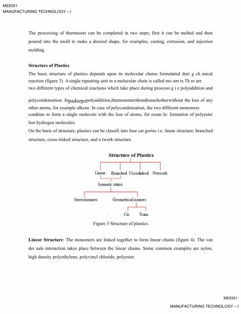
ME8351
MANUFACTURING TECHNOLOGY – I
The processing of thermosets can be completed in two steps; first it can be melted and then
poured into the mold to make a desired shape, for examples, casting, extrusion, and injection
molding.
Structure of Plastics
The basic structure of plastics depends upon its molecular chains formulated duri g ch mical
reaction (figure 3). A single repeating unit in a molecular chain is called mo om rs Th re are
two different types of chemical reactions which take place during processi g i e polyaddition and
polycondensation. Inpadeepzpolyaddition,themonomersbondtoeachotherwithout the loss of any
other atoms, for example alkene. In case of polycondensation, the two different monomers
combine to form a single molecule with the loss of atoms, for exam le: formation of polyester
lost hydrogen molecules.
On the basis of structure, plastics can be classifi into four cat gories i.e. linear structure, branched
structure, cross-linked structure, and n twork structure.
Figure 3 Structure of plastics
Linear Structure: The monomers are linked together to form linear chains (figure 4). The van
der aals interaction takes place between the linear chains. Some common examples are nylon,
high density polyethylene, polyvinyl chloride, polyester.
ME8351
MANUFACTURING TECHNOLOGY – I

ME8351MANUFACTURING TECHNOLOGY – I
Branched Structure: The monomers are joined to form long chains with bra chnetsofdiffr
lengths (figure 5). For examples: low density polyethylene, glycogen and starch
padeepzFigure5Branchdstructure
Cross-linked Structure: The monomers are combin tog ther to form cross-linked chains
(figure 6). Chains are connected by covalent bon s. For example: rubber, bakelite.
Figure 6 Cross-linked structure
Figure 4 Linear structure

Net ork Structure: The monomers are joined together to form a large three dimensional
net ork, for example: epoxy, phenol formaldehyde.
ME8351
MANUFACTURING TECHNOLOGY – I

ME8351
MANUFACTURING TECHNOLOGY – I
Figure 7 Network structure net
Isomers are molecules that have the same molecular formula, but have a differe t arra geme ofThe monomers are organicpadeepzcarbonbasedmolecules.Covalentbondshold the atoms in the molecules together and secondary bonds hold groups of chains together. For example,
the atoms in space. Isomers may be in two form i.e. stereoisomers and geometrical isomers.
Further, geometrical isomers can be divided into the trans and cis isomer depending upon atoms
in space, for example: 1, 2 dichloroethene (figure 8). Two chlorine atoms are joined on opposite
side of the double bond is called trans isomer. If th chlorine atoms are joined on the same side is
called cis isomer.
Tr ns Cis
Figure 8 1, 2 dichloroethene
polyethylene is made from ethylene monomers (figure 9). The two mers are joined together with
the application of heat, pressure and catalyst which is called polymerization to form polyethylene
chains.
Figure 9 Polymerization of polyethlene
ME8351
MANUFACTURING TECHNOLOGY – I

ME8351
MANUFACTURING TECHNOLOGY – I
The polyethylene chains are elongated thousands times greater than its crystalline structures
when stretched. The mechanical properties of plastics depend upon the number of carbon atom
present into the polymeric chain. Some of the common plastic monomers are shown in table 1.
Table 1 Chemical formula of plastic monomers
Polyethylene (PE) Polyvinyl chloride
(PVC)
Polypropylene (PP) Polystyrene (PS)
padeepzPolytetrafluoroethylene Polymethyl
(PTFE) m thacrylate
(PMMA)
Mechanical Properties of Plastics
The mechanical properties of th plastics are giv n b low:
(a) Hardness: Plastics are not very h r , their har ness being comparable to that of brass and
aluminum. Generally, thermosets re h r er th n thermoplastics. The temperature of the material
substantially affects its ro erties. The h rdness of commonly used plastics is in the range of 5-50
BHN.
(b) Stress-Strain Behavior: When the plastic is subjected to uni-axial load, it deforms
permanently and ultimately fails as shown in figure 10. Tensile strengths of plastics may be in
the range of 10 to 100 MPa. The modulus of elasticity for plastic is in the range of 10 MPa to
4000 MPa. Tensile strength decreases with increasing temperature. Some of the plastics are
brittle in nature. The mechanical properties of the plastics depend upon the strain rate,
temperature, and environmental conditions.
ME8351
MANUFACTURING TECHNOLOGY – I
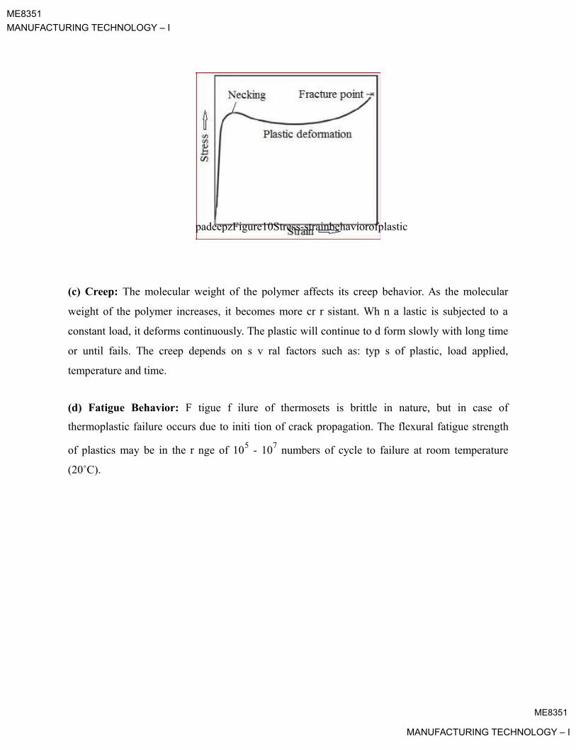
ME8351
MANUFACTURING TECHNOLOGY – I
padeepzFigure10Stress-strainbehaviorofplastic
(c) Creep: The molecular weight of the polymer affects its creep behavior. As the molecular
weight of the polymer increases, it becomes more cr r sistant. Wh n a lastic is subjected to a
constant load, it deforms continuously. The plastic will continue to d form slowly with long time
or until fails. The creep depends on s v ral factors such as: typ s of plastic, load applied,
temperature and time.
(d) Fatigue Behavior: F tigue f ilure of thermosets is brittle in nature, but in case of
thermoplastic failure occurs due to initi tion of crack propagation. The flexural fatigue strength
of plastics may be in the r nge of 105 - 107 numbers of cycle to failure at room temperature
(20˚C).
ME8351
MANUFACTURING TECHNOLOGY – I

ME8351MANUFACTURING TECHNOLOGY – I
Lecture 4.2: Processing of Plastics
General Behavior of Polymer Melts:
The research and development in the areas of polymer melts has increased due to its nonlin ar
behavior. The rheological behavior of polymer melts depends on the three factors:
(a) Structure of the molecules
.(b) Development of a realistic fluid dynamics
(c) Molecular orientation formed during polymerization
The polymer melts are highlypadeepzviscousliquids,anditsviscousflowisoftenconnected with large,
rubberlike elastic deformations. Polymer melts can be elongated without rupture The viscosity of
polymer melts is much higher than the molecular weight. Polymers have the long chain
molecules with high molecular weights. The mol cul s are ntangled together, increasing its
effective molecular weights. The high viscosity of olym r m lts comes from molecular
entanglements. As shear rate increases, the mol cul s ori nt more along the flow direction and the
degree of molecular entanglements d cr as s. Thus, the lasticity increases and the viscosity
decreases with increasing shear rate.
Polymer Melt Viscosity s Function of Shear Rate
The viscosity of polymer melt t const nt temperature is a function of shear rate. The viscosity
behavior can be understood in terms of molecular mechanism. The viscosity of a polymer melt is
constant and it does not end on shear rate and at very low shear rate, it follows Newtonian
behavior. Molecular entanglements are constantly dissipated as the molecules slide each other by
flow and are reformed at the same time by the kinetic motions of molecular segments. At very
low shear rates, the rates of dissipation and reformation of entanglement are the same, and the
degree of entanglements remain constant.
Crystallization, Melting, and Glass Transition Phenomena
Crystallization rates are governed by the nucleation and crystal growth. Nucleation becomes slo
er at higher temperatures. The melting behavior of semi crystalline polymers is intermediate bet
een that of crystalline materials (sharp density change at a melting temperature) and that of a
pure amorphous material (slight change in slope of density at the glass-transition temperature).
ME8351
MANUFACTURING TECHNOLOGY – I

ME8351
MANUFACTURING TECHNOLOGY – I
The melting temperature increases with the rate of heating, thickness of the lamellae, and
depends on the temperature at which the polymer was crystallized. Rigid chains have higher
melting temperatures. Melting involves breaking of the inter-chain bonds, so the glass and
melting temperatures depend on:
Chain stiffness
Size and shape of side groups
Size of molecule
Side branches Cross-linking
preferred. A mold releasepadeepzsayisusedonthemoldsurfacepriortocasting.The process cycle for
casting is very short
Casting
Casting involves processing plastic material into a r quir d sha . Plastic material is melted and it
is poured in to the mold cavity. The molded part is cool d and solidifies in the mold cavity and
molded part is ejected.
Working Principle
A mixture of plastic material, catalyst, and various additives is heated into oven above the
melting temperature and poured into the mold cavity until the mold is filled. The molten plastic
is gravity filled into the mold c vity. The pplication of heat accelerates the polymerization
process into the mold c vity nd hence it is cured. The molded part is allowed to cool and
solidify, allowing the lastic roduct to be ejected from the mold cavity. Generally, air cooling is
There are t o types of mold i. . rigid and flexible. Rigid mold can be made of metals, plaster, and
epoxy to produce soft and flexible parts or rigid parts. Flexible mold is made of silicone, latex,
and urethane to produce hard plastic parts.
Material Used
Thermosets (such as polyesters, urethanes, phenolics, and epoxy) and thermoplastics (acrylics
and nylons) can be used for casting.
ME8351

MANUFACTURING TECHNOLOGY – I

ME8351
MANUFACTURING TECHNOLOGY – I
Process Parameters
The main process parameters which affect the casting process are:
Melting temperature of plastic
Pouring temperature
Cooling rates
Applications
It is used to produce variety of toys like designer toys, garage kits, ball-joi ted dolls, sheet,
wheels, either individual parts or entire models of objects like trains, aircraft, boat and ships.
Advantages
Low initial investment cost
Dimensional stability
High production rate
Flexible parts can be made
Disadvantages
This is more labor intensive th n injection mol ing
Complex sha e cannot be roduced
ME8351
MANUFACTURING TECHNOLOGY – I
ME8351
MANUFACTURING TECHNOLOGY – I
Lecture 4.3: Extrusion of Plastics
Extrusion
Extrusion is a high volume manufacturing process. The plastic material is melted wi h he
application of heat and extruded through die into a desired shape. A cylindrical rotating scr w is
placed inside the barrel which forces out molten plastic material through a die. The x rud d
material takes shape according to the cross-section of die. The schematic of extrusion proc ss is
shown in figure 1.
In this process, plastic padeepzmaterialintheformofpelletsorgranulesisgravity fed from a top
mounted hopper into the barrel. Additives such as colorants and ultraviolet inhibitors (liquid or
pellet form) can be mixed in the hopper. The plastic mat rial nt rs through the feed throat and
comes into contact with the rotating screw. The rotating scr w ush s the lastic beads forward into
the barrel. The barrel is heated using the h ating l m nts up to the melting temperature of the
plastic. The heating elements are used in such ways that gradually increase the temperature of the
barrel from the rear to the front.
There are three possible zones in a rotating screw i. . feed zone, melting zone, and metering zone.
In the feed zone, the pl stic be s melt gr ually as they are pushed through the barrel. The plastic
material is completely melted in the melting zone. A thermostat is used to maintain the inside
temperature of the b rrel. The overheating of plastics should be minimized which may cause
degradation in the material ro erties. A cooling fan or water cooling system is used to maintain
the temperature of the barrel during the process.
Working Principle

At the front of the barrel, the molten plastic leaves the screw and travels through a screen pack to
remove any contaminants in the molten plastic. The screens are reinforced by a breaker plate.
The breaker plate assembly also serves to create back pressure in the barrel. The back pressure
gives uniform melting and proper mixing of the molten plastic material into the barrel. After
passing through the breaker plate, molten plastic enters into die. The die gives the desired shape
of plastic product. An uneven flow of molten plastic would produce unwanted stresses in the
plastic product. These stresses can cause warping after solidification of molten plastic. Plastics
are very good thermal insulators and therefore it is very difficult to cool quickly. The plastic
product is cooled by pulling through a set of cooling rolls.
ME8351
MANUFACTURING TECHNOLOGY – I

ME8351
MANUFACTURING TECHNOLOGY – I
Extrusion Process Parameters
Screw Design:

padeepzFigure1Extrusionprocess
There are five important process parameters to be consid r b fore xtrusion process:
Melting temperature of plastic
Speed of the screw
Extrusion pressure required
Types of die used
Cooling medium
The design of screw is im ortant for lastic processing. It has mainly three different functions:
namely, feeding mechanism; uniform melting and mixing of plastic and finally it generates the
pressure to push the molten material through die. A screw length (L) is referenced to its diameter
(D) as L/D ratio. Generally, L/D ratio is used as 24:1, but for more mixing and output, it may
increase up to 32:1. There are three possible zones in a screw length i.e. feed zone, melting zone,
and metering zone.
(a) Feed zone: In this zone, the resin is inserted from hopper into the barrel, and the channel
depth is constant.
(b) Melting zone: The plastic material is melted and the channel depth gets progressively
smaller. It is also called the transition or compression zone.
ME8351
MANUFACTURING TECHNOLOGY – I

ME8351
MANUFACTURING TECHNOLOGY – I
(c) Metering zone: The molten plastic is mixed at uniform temperature and pressure and
forwarded through the die. The channel depth is constant throughout this zone.
Types of Extrusion Process
The extrusion process is broadly classified into seven different types depending upon the sp cific
applications.
(a) Sheet/Film ExtrusionIn this extrusion process, the molten plastic material is extruded through a flat die The cooli g rolls
are used to determinepadeepzthethicknessofsheet/filmanditssurfacetexture The thickness of
sheet can be obtained in the range of 0.2 to 15 mm. The thin flat sheet or film of plastic material
can be made. Generally, polystyrene plastic is used as a raw material in the sheet extrusion
process.
(b) Blown Film Extrusion
In the blown film process, the die is like a v rtical cylind r with a circular profile. The molten
plastic is pulled upwards from the ie by a pair of nip roll rs. The compressed air is used to
inflating the tube. Around the die, an air-ring is fitted. The purpose of an air-ring is to cool the
film as it travel upwards. In the center of the ie, there is an air inlet from which compressed air
can be forced into the centre of the circul r profile, and creating bubble. The extruded circular
cross section may be incre sed 2-3 times of the die diameter. The bubbles are collapsed with the
help of collapsing late The nip rolls flatten the bubble into double layer of film which is called
layflat. The wall thickness of the film can be controlled by changing the speed of the nip rollers.
The layflat can be spooled in the form of roll or cut into desired shapes. Bottom side of the
layflat is sealed ith the application of heat, and cut across further up to form opening; hence it
can be used to make a plastic bag. The die diameter may vary from 1 to 300 centimeters.
Generally, polyurethane plastic is used in this process. The schematic of blown film extrusion is
sho n in figure 2.
ME8351
MANUFACTURING TECHNOLOGY – I
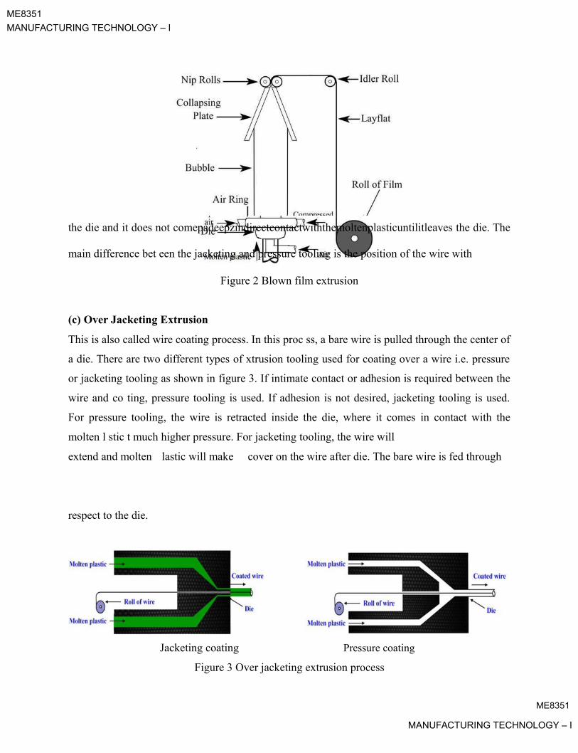
ME8351
MANUFACTURING TECHNOLOGY – I
the die and it does not comepadeepzindirectcontactwiththemoltenplasticuntilitleaves the die. The
main difference bet een the jacketing and pressure tooling is the position of the wire with
Figure 2 Blown film extrusion
(c) Over Jacketing Extrusion
This is also called wire coating process. In this proc ss, a bare wire is pulled through the center of
a die. There are two different types of xtrusion tooling used for coating over a wire i.e. pressure
or jacketing tooling as shown in figure 3. If intimate contact or adhesion is required between the
wire and co ting, pressure tooling is used. If adhesion is not desired, jacketing tooling is used.
For pressure tooling, the wire is retracted inside the die, where it comes in contact with the
molten l stic t much higher pressure. For jacketing tooling, the wire will
extend and molten lastic will make cover on the wire after die. The bare wire is fed through
respect to the die.
Jacketing coating Pressure coating
Figure 3 Over jacketing extrusion process
ME8351
MANUFACTURING TECHNOLOGY – I

ME8351
MANUFACTURING TECHNOLOGY – I
(d) Tubing Extrusion
In this process, the molten plastic is extruded through a die and hollow cross sections are formed
by placing a mandrel inside the die. Tube with multiple holes can also be made for specific
applications, by placing a number of mandrels in the center of the die.
(e) Coextrusionsuitable for other applications, e.g. impact resistance and structural performance.Itmay be usedCoextrusion is the extrusion process of making multiple layers of material simulta ously. It is
used to apply one or more layers on top of base material to obtain specific properties such aspolypropylene are used padeepzultraviolet absorption, grip, matte surface, and energy reflection, while base material is more
on any of the processes such as blown film, overjacketing, tubing, sheet/film extrusion. In this
process, two or more extruders are used to deliver mat rials which are combined into a single die
that extrudes the materials in the desired shape. The lay r thickn ss is controlled by the speed and
size of the individual extruders deliv ring the mat rials.
(f) Extrusion Coating
Extrusion coating is used to make an a itional layer onto an existing rollstock of paper, foil or
film. For example, to improve the w ter resistant of paper polyethylene coating is used. The
applications of extrusion co ting re liquid ckaging, photographic paper, envelopes, sacks
lining for fertilizers ck ging nd medical packaging. Generally, polyethylene and
Materials Used
The different types of plastic materials that can be used in extrusion process are Polyethylene,
Polypropylene (PP), Acetal, Acrylic, Nylon (Polyamides), Polystyrene, Polyvinyl Chloride
(PVC), Acrylonitrile Butadiene Styrene (ABS) and Polycarbonate.
Applications
The extrusion process is used for manufacturing rods, plates and tubes, wire and cable coating,
hose liners, hose mandrels, filaments, sheet, multilayer film, medical packaging and food
packaging, etc.
ME8351
MANUFACTURING TECHNOLOGY – I

ME8351
MANUFACTURING TECHNOLOGY – I
Advantages
High production volumes
Relatively low cost as compared with other molding process
Design flexibility
Short lead times
Coating of wire can be done to achieves desired properties
Continuous part can be produced
Disadvantages:
Limited complexity of parts
Uniform cross section can only be produced
ME8351
MANUFACTURING TECHNOLOGY – I

ME8351MANUFACTURING TECHNOLOGY – I
Lecture 4.4: Transfer Molding and Compression Molding
Transfer Molding netTransfer molding process combines the principle of compression and transfer of the polymer
charge. In the transfer molding, polymer charge is transferred from the transfer pot to the mold.
The mold is cooled and molded part is ejected. The schematic of transfer molding proc ss is
shown in figure1.
In this process, the required amount of polymer charge is weighted and inserted i to th tra sf r
pot before the molding process. The transfer pot is heated by the heati g eleme above thepadeepz
melting temperature of the polymer charge. The liquid charge is gravity filled through the sprue
to the mold cavity. A “piston and cylinder” arrangement is built in the transfer pot so that the
resin is squirted into the mold cavity through a sprue. The lunger is also preheated in the
transfer pot. The plunger is used to push the liquid polym r charge from the transfer pot into the
mold cavity under pressure. The mold cavity remains clos d as the olymer charge is inserted.
The mold cavity is held closed until the r sin g ts cur d. The mold cavity is opened and the
molded part can be removed once it has hard n with the h lp of j ctor pin. The sprue and gate
attached to the molded part have to be trimm aft r the proc ss has been completed.
ME8351
MANUFACTURING TECHNOLOGY – I

ME8351MANUFACTURING TECHNOLOGY – I
Figure 1 Transfer molding process
This is used for mass production. It has short production cycle and smaller tolerances and more
intricate parts can be achieved. It produces more waste material; therefore it is the more
expensive process. The mold cavity can be made from metals such as aluminum or st l for larger
production.
Process Parameters
Heating time
Melting temperature of the charge
Applied pressure
Cooling time
Materials Used
Generally, thermoset plastics (such as poxy, poly st r, phenol-formaldehyde, vinyl ester, silicone)
are processed by transfer mol ing proc ss, but c rtain thermoplastic materials can also be
processed.
Applications
This process is widely used to enc sul te items such as integrated circuits, plugs, connectors, pins,
coils, and studs It is suitable for molding with ceramic or metallic inserts which are placed in the
mold cavity When the heated polymer fills the mold it forms bonding with the insert surface.
Transfer molding is also used for manufacturing radio and television cabinets and car body
shells.
Advantages
Fast setup time and lower setup costs
Low maintenance cost
Plastic parts with metal inserts can be made
Design flexibility
Dimensionally stable
ME8351MANUFACTURING TECHNOLOGY – I
ME8351
MANUFACTURING TECHNOLOGY – I
Uniform thickness of parts
Large production rate
Disadvantage:
Wastage of material
Production rate lower than injection molding
Air can be trapped in the moldCompression Molding padeepz
Compression molding process is one of the low cost molding m thods as compared to injection
molding and transfer molding. It is high pressure forming roc ss in which the molten plastic
material is squeezed directly into a mould cavity by the application of heat and pressure to
conform to the shape of the mold. The sch matic of compr ssion molding process is shown in
figure 2.
Working Principle
In this process, the predetermined mount of charge of plastic material is placed in the lower half
of a heated mold.cavityThe l stic m teri l is preheated before inserting into the mold cavity to
reduce the temperature difference between the material and the mold cavity. The mold cavity is
closed with upper movable half mold and pressure is applied to compress the material in to the
mold cavity. This causes the raw material to be squeezed out to take the shape of the mold cavity.
The application of the heat and pressure increases the polymerization process. Hence, plastic
material is cured. The temperature of the mold cavity is usually in the range of 130-200°C.
Generally, the hydraulic pressure is required in the range of 7-25 MPa to squeeze the plastic
material. The mold cavity is then cooled for sometimes so that molded plastic part gets solidified.
The mould cavity is then opened and the final product is taken out with the help of ejector pin.
The molded part may require the finishing operation.
In compression molding, the charge of plastic material may be inserted into the mold cavity
either as a powder, granules or as a preformed. The manufacturing cycle time (heating, cooling,
ME8351MANUFACTURING TECHNOLOGY – I

ME8351
MANUFACTURING TECHNOLOGY – I
and part ejection) may be long (about 1-6 minutes). For high production rate, it is desirable to
have multi cavity molds. Compression mold cavity can also be available in a wide variety of
shapes and sizes; therefore plastic products can be manufactured into different shapes and sizes.
There are four important factors to be considered before compression molding proc ss:
Amount of plastic material (charge)
Heating time and melting temperature of plastic material
Pressure required to squeeze the material in to the mold cavity
Cooling timeTwo different types of padeepzmoldingcompoundsi.e.bulkmoldingcompound (BMC) and sheet
molding compound (SMC) are commonly used in compression molding rocess.
In bulk molding compound, the plastic materials ar bl nd d with fillers and short fibers and
placed into the mold cavity. In SMC, the long fib r sh t is usually cut according to the mold
cavity and placed into the mold surface. The r sin is plac d on the fiber sheet. It is a layer by layer
making process. The process is compl t until d sir d thickness is obtained. The long fiber sheet
results in better mechanical prop rti s as compar d with the bulk molding compound products. In
both the molding compoun s (BMC and SMC), the plastic materials are conformed to the mold
cavity, with the pplic tion of he t and pressure.
Figure 2 Compression molding setup
ME8351
MANUFACTURING TECHNOLOGY – I

ME8351
MANUFACTURING TECHNOLOGY – I
Materials Used
Different types of thermosets and thermoplastics materials can be used for compression molding
process. For example: Epoxies, Urea formaldehyde (UF), Melamine formaldehyde (MF),
Phenolics (PF), Polyester, Polyamide (PI), Polyamide-imide (PAI), Polyphenylene sulfide (PPS),
Polyetheretherketone (PEEK), Torlon, and Vespel.
Applications
Compression molding process is used for manufacturing electrical and electro ic equipme ts
(electrical wall receptacles, circuit breakers, television cabinets, radio cases, electric plugs and
sockets, electrical switch, fuse box, electricity meter housing), brush and mirror handles, trays,
cookware knobs, clothes dryer blower fan blade, cooking utensils, milling machine adjustment
wheel, water testing equipment buttons, dinnerwar , liance housings, aircraft main power
terminal housing, pot handles, dinnerware plat s, automotive arts (such as hoods, fenders, scoops,
spoilers, gears), flatware, buttons, buckl s, and large contain r. Compression molding is also
suitable for heavy molding applications.
Advantages
The advantages of the compression mol ing process are as following:
Low initial setup costs nd f st setup time
Heavy lastic rts c n be molded
Com lex intricate arts can be made
Good surface finish of the molded parts
Wastes relatively little material as compared with other methods
padeepzThe molding process is cheaper as compared to injection molding
Disadvantages
The disadvantages of the compression molding process are as following:
Low production rate
Limited largely to flat or moderately curved parts with no undercuts
ME8351
MANUFACTURING TECHNOLOGY – I
ME8351MANUFACTURING TECHNOLOGY – I
Lecture 4.5: Injection Molding
netInjection molding is the one of the most commonly used manufacturing process for the plas iccomponents. It is used to manufacture thin walled plastic parts for a wide variety of shap s and
sizes. In this process, the plastic material is melted in the injection chamber and th inj c d
into the mold, where it cools and finally the finished plastic part is ejected.
In this process, the plasticpadeepzmaterialsusuallyintheformofpowderorpelletsare fed from hopperinto the injection chamber. The “piston and cylinder” arrangement is used to forward the material
inserted from the hopper in to the injection chamber. The lastic material is heated in the injection
chamber with the application of heating l m nts. The cooling system is also used to maintain the
temperature of the injection chamb r. The molt n lastic material is then injected into the mold
cavity through nozzl . The mold d part is cool d quickly in the mold. Thereafter, the final plastic
part is removed from the mold cavity. The proc ss cycle for injection molding is very short,
typically between 2 to 60 secon s. Th compl te injection molding process is divided into four
stages: clamping, injection, cooling and ejection.
Clamping: The two halves of the mold must be tightly closed, before the molten plastic material
is injected into .themoldOne h lf of the mold is attached to the injection unit (nozzle) and other
half is allowed to slide on the guide ways. The clamping of mold is operated hydraulically which
it pushes the moving half art of the mold towards the fixed part to make an air tight chamber. The
force and the time required to close and open the mold depends upon the machine capability.
Injection: During this process, the plastic material is melted by the application of heat and for
arded through the piston towards the nozzle and finally into the mold. The function of torpedo in
the heating zone is to spread the molten plastic into the thin film. The molten plastic is then
injected into the mold cavity quickly. The amount of material that is injected into the mold is
referred to as the shot volume. The injection time can be estimated by the shot volume, injection
power and pressure. The schematic of injection molding process is shown in figure 1.
Working Principle

ME8351
MANUFACTURING TECHNOLOGY – I
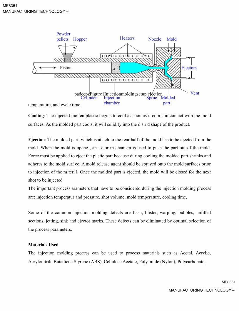
ME8351
MANUFACTURING TECHNOLOGY – I
padeepzFigure1Injectionmoldingsetup ejection
temperature, and cycle time.
Cooling: The injected molten plastic begins to cool as soon as it com s in contact with the mold
surfaces. As the molded part cools, it will solidify into the d sir d shape of the product.
Ejection: The molded part, which is attach to the rear half of the mold has to be ejected from the
mold. When the mold is opene , an j ctor m chanism is used to push the part out of the mold.
Force must be applied to eject the pl stic part because during cooling the molded part shrinks and
adheres to the mold surf ce. A mold release agent should be sprayed onto the mold surfaces prior
to injection of the m teri l. Once the molded part is ejected, the mold will be closed for the next
shot to be injected.
The important process arameters that have to be considered during the injection molding process
are: injection temperatur and pressure, shot volume, mold temperature, cooling time,
Some of the common injection molding defects are flash, blister, warping, bubbles, unfilled
sections, jetting, sink and ejector marks. These defects can be eliminated by optimal selection of
the process parameters.
Materials Used
The injection molding process can be used to process materials such as Acetal, Acrylic,
Acrylonitrile Butadiene Styrene (ABS), Cellulose Acetate, Polyamide (Nylon), Polycarbonate,
ME8351
MANUFACTURING TECHNOLOGY – I
ME8351
MANUFACTURING TECHNOLOGY – I
Polyester, Polyether Sulphone (PS), Polyetheretherketone (PEEK), Polyetherimide,
Polyethylene, Polyphenylene Oxide, Polyphenylene Sulphide (PPS), Polypropylene (PP),
Polyvinyl Chloride (PVC), and Elastomers.
Applications
This process can be used to manufacture thin walled plastic housing products which r quire many
ribs and bosses on the interior surfaces. These housings are used in a variety of products
including household appliances, electronics, and automotive dashboards Other common thin
walled products include different types of open containers, such as buckets It is also used to
produce several daily use items such as toothbrushes or small plastic toys, many medical devices,
including valves and syringes.
The advantages and disadvantages of the injection molding roc ss are given below:
Advantages
Higher production rate
Close tolerances on small intricate parts
Minimum wastage of mat rial
Complex geometry can be easily pro uced
Disadvantages
Tooling cost higher
High setup cost
Large undercuts can’t be formed
ME8351
MANUFACTURING TECHNOLOGY – I

ME8351MANUFACTURING TECHNOLOGY – I
Lecture 4.6: Thermoforming
Introduction netThermoforming is a plastic manufacturing process in which the thermoplastic sheets are formed
with the application of heat and pressure in a mold. The thermoplastic sheet is held horizon ally
over a mold surface and clamped with a holding device. The sheet is heated up to pr d rmin d
temperature using a heating element called heater. The thermostat is used to mai tain the
temperature of the heater. When the temperature becomes substantially high in the mold, the
temperature is controlled by adjusting the heater and providing the cooling air The thermoplastic
sheet softens with the application of heat and is pressed into or stretched over the mold surface
by application of air pressure or by any other means. The softened sheet conforms to the mold
shape and it is held in place until it cools. The mold cavity is o ened and the thermoformed part
is released. Some of the plastic materials require air cooling in ord r to make those rigid quickly,
because plastic materials have low thermal conductivity. The xc ss material is then trimmed out
from the formed part. Excess material can be r ground, mix d with unused plastic, and again
reformed into thermoplastic sheets. Thin sh t (up to 1.5 mm) nd thick sheet (about 3 mm) can
be formed easily.
Thermoforming set-up usually consists of the clamping unit, heaters, mold, and air cooling
system. The molds should be cle ned fter every cycle, as materials in the mold can cause the
change in the shape of the finished goods.
There are mainly three different ty es of thermoforming process depending upon the pressurerequired i.e., vacuum forming, ressure forming and matched die forming.
(a) Vacuum padeepzForming
In this process, the vacuum pressure is used to form the heated thermoplastic sheet into
the desired shape. The thermoplastic sheet is placed on the mold surface and fixed with
the help of clamping unit. The sheet is heated until it is softens and thereafter vacuum
needs to be applied quickly. A surge tank is used to quickly pull the air out between the
mold cavity and the sheet. When the vacuum is created, the sheet conforms to the shape
of the mold cavity. The formed part is cooled and then ejected from the mold cavity. The
schematic of vacuum forming process is shown in figure 1.
ME8351
MANUFACTURING TECHNOLOGY – I

ME8351
MANUFACTURING TECHNOLOGY – I
(b) Pressure Forming The pressure forming process is closely related to vacuum
forming. In this process, the air pressure required is much higher as compared to the
vacuum forming. The preheated plastic sheet is placed on the mold surface, and then air
pressure is applied quickly above the sheet as shown in figure 2. The high pr ssure is
developed in between the softened sheet and the pressure box. Due to high pr ssur , he
preheated plastic sheet can be deformed into the mold cavity in a fraction of a s co d. The
formed sheet is held in the mold cavity for cooling for a few seco ds The form d part
thereby solidifies and is ejected from mold cavity. Prototype parts can also be made using
pressure forming process.
Figure 1 V cuum forming process
Figure 2 Pressure forming
ME8351
MANUFACTURING TECHNOLOGY – I

ME8351
MANUFACTURING TECHNOLOGY – I
(c) Matched die Forming Matched die forming is also called mechanical forming. In
this process, mold consists of two parts i.e. die and punch as shown in figure 3. The
thermoplastic sheet is heated with the application of heat until it softenes. The prehea ed
sheet is placed into the mold surface (that is called die) and through punch pr ssure is
applied on the hot sheet. The air in between the die and softened sheet is vacua d by using
vacuum pump, and therefore the thermoplastic sheet conforms to the mold shape. The
formed part is cooled and ejected from the mold cavity.
Figure 3 M tch die forming
The important process arameters that are considered during the thermoforming process are
heating temperature, heating time, vacuum pressure, air pressure, mechanical pressure, cooling
time and ejection mechanism
Materials Used
The different types of thermoplastic materials which can be processed using thermoforming
process are: Acrylic (PMMA), Acrylonitrile butadiene styrene (ABS), Cellulose acetate, Low
density polyethylene (LDPE), High density polyethylene (HDPE), Polypropylene (PP),
Polystyrene (PS), Polyvinyl chloride (PVC)
Applications
ME8351
MANUFACTURING TECHNOLOGY – I

ME8351
MANUFACTURING TECHNOLOGY – I
Thermoforming process is used for variety of applications, for example, food packaging,
automotive parts, trays, building products and aircraft windscreens. Thick gauge parts are used as
cosmetic surfaces on permanent structures such as trucks, medical equipment, material handling
equipment, electrical and electronic equipment, spas and shower enclosures, vehicle door and
dash panels, refrigerator liners, utility vehicle beds, and plastic pallets. Thin gauge par s are
primarily used to package or contain a food item, disposable cups, contai ers, lids, blist rs a d
clamshells.
The advantages and disadvantages of the thermoforming process are given below:
Advantages:
Extremely adaptive to design requirement
Rapid prototype development
Low initial setup costs
Low production costs
Less thermal stresses than inj ction molding and compression molding
Good dimensional stability
Disadvantages:
Poor surface finish
Parts may h ve non-uniform w ll thickness.
All arts need to be trimmed
Ribs and bosses cannot be molded easily
Limited number of materials can be used
Very thick plastic sheets can’t be formed
ME8351
MANUFACTURING TECHNOLOGY – I

ME8351
MANUFACTURING TECHNOLOGY – I
Lecture 4.7: Rotational Molding and Blow Molding
Rotational Molding
The rotational molding is a high temperature and low pressure plastic forming proc ss. The
powder is inserted into the closed split mold and rotated in biaxial to produce a hollow part. The
schematic of rotational molding process is shown in figure 1.
oven and rotated biaxial until the powder has melted. The molten powder is adhered to the mold walland makes a thin layer. The mold is opened and finished art is removed.
The plastic material in thepadeepzformofpowderisinsertedintothemold.Themold is heated in an
The mold is rotated at different speeds in order to avoid the accumulation of molten powder. The
amount of time required to heat the powder at molt n t m rature in to the oven is important. If the
oven is heated for long time, powder will d grade and it will aff ct the mechanical properties. If
the mold is heated short time, the powd r may not be compl t ly melted, resulting in large bubbles
in the powder. The formed part must be cool through the air so that it solidifies slowly. The
formed part will shrink on cooling, and facilitating easy removal of part. The cooling rate must
be kept within cert in r nge. The water cooling should be avoided, because formed part may
shrink and warped fter cooling.
Working Principle

ME8351
MANUFACTURING TECHNOLOGY – I

ME8351MANUFACTURING TECHNOLOGY – I
Figure 1 Rotational molding
A mold release agent should be used to quickly remove the formed part. Mold release can reduce
cycle times and defects of finished product. Three different types of mold release ag nt may be
used i.e. sacrificial coating (silicones), semi-permanent coating, (polysiloxane), and p rman nt
coating (polytetrafluoroethylene).
Process Parameters
The amount of powder
Heating temperature and time
Rotational speeds
Cooling rates
Material Used
Thermosets and thermoplastic material can be us d, for xampl : low density polyethylene
(LDPE), high density polyethylene (HDPE), polypropyl n , and polyvinyl chloride (PVC).
Applications
Additives for weather resist nce, fl me ret rdation can be incorporated. Products that can be
manufactured include stor ge t nks, bins nd refuse containers, airplane parts, road cones,
footballs, helmets, and rowing boats.
Advantages
Allo s complex mold split lines.
Allo s molded threads and mold-in inserts.
Allows a wide range of surface finishes (textured, smooth, or polished).
Very little waste.
Low residual stresses
Tooling is less expensive
Suitable for both low-volume prototypes and high-volume production runs
ME8351
MANUFACTURING TECHNOLOGY – I

ME8351
MANUFACTURING TECHNOLOGY – I
Disadvantages
Slow production speed. It usually takes about one hour to complete the process
Lower precision
Blow Molding
Blow molding is a manufacturing process that is used to produce hollow plastic parts by i flati g
a heated plastic until it fills a mold and formed the desired shape The schematic of blow molding
process is shown in figure 2.
both preform manufacturingpadeepzndbottleblowingareperformedinthsamemachine. The formedpart solidified as it is cooled inside the mold. The mold halves are separated and the final productWorking Principle
In this process, the thermoplastic in the form of small pellets or granules is first heated above the
melting temperature and molded into a preform using inj ction molding rocess. These preforms
are used to feed into the blow mold. The preform is h at d above the glass transition temperature
and formed into a hollow tube which is call d parison. The parison is then clamped between two
mold halves and inflated by high air pr ssure until it conforms to the inner shape of the mold. The
air pressure is required as 60 to 140 psi p n ing upon the material used. The preform is
always stretched from the center of the part uring the process. This is single stage process, as
is removed. Final art may be trimmed.
Figure 2 Blow molding
ME8351
MANUFACTURING TECHNOLOGY – I

ME8351
MANUFACTURING TECHNOLOGY – I
Generally, mold can be made of metal. Cycle time depends upon the finished part wall thickness.
If the part wall thickness is 1.5 mm, the cycle time will be 40 to 50 seconds.
Process Parameters
Amount of plastic material
Melting temperature of plastic material
Air pressure required
Cooling time
Materials Used
Different types of thermoplastic material are used, for exam le: High Density Polyethylene
(HDPE), Low Density Polyethylene (LDPE), Polypropyl ne (PP), Polyvinyl Chloride (PVC),
Polyethylene Terephtalate (PET), and Polycarbonate (PC).
Applications
Different types of plastic products can be manufactur by this process such as bottles in
different shape and size, jars, and containers, ucting, fluid oil tanks, mugs, and toys.
Advantages
Low tooling cost
Fast roduction rates
Ability to mold com lex part with uniform thickness
Little scrap generatedpadeepz
Large hollow shape can be producedProduced parts can be recycle
Disadvantages
Limited to hollow parts
Thick parts can’t be manufactured
Machining of Plastics
ME8351
MANUFACTURING TECHNOLOGY – I
ME8351
MANUFACTURING TECHNOLOGY – I
Most of the finished plastic products are produced directly by molding processes. But some of
the complex plastic products that can’t be directly manufactured by the molding process and
require finishing operations to give final shape, to improve dimensional accuracy and final
finish. The life cycle of plastic products are very short, and if limited numbers of plastic product
are molded for specific application then machining becomes more economical. All plas ic
materials (thermosets and thermoplastic) can’t be machined, because some of the plastic
materials are soft and flexible in nature. The machining of plastic material depe ds on the twofactors i.e. cutting tool material and rigidity of the material being cut. The machi i g of plastics
is different from metal duepadeepztoitsrigidity.Therigidplasticmaterialscanbemachined easier; but
more flexible and softer plastic materials are very difficult to machine. The softer and flexible
plastic materials can also be machined with the application of s ecially designed jigs and fixtures.
It is well known that the plastics have lower thermal conductivity th r fore heat generated during
machining can’t dissipate quickly. At high r machining sp d, plastic may soften due to heat
induced during machining and the machin d surfac s may g t smeared. Therefore, cooling
medium (air or lubricant) is required uring the machining. G nerally, compressed air is used for
machining of plastics. Because lubricant or liquid coolant may react with the plastic material
during machining and it c n degr e the mech nical properties or surface quality. A strong jet of
compressed air or coolant serves three purposes i.e. it cools the workpiece as well as cutting tool,
it helps to remove chi s quickly nd improves the surface finish of machined surface.
An important point is to be noted that while the machining of thermoplastics produces
continuous swarf, but thermosets roduce chips form. The chips are always removed rapidly in
order to carry a ay as much heat from the surface as possible.
The high speed steel (HSS), carbon steel, and carbi tool materials are commonly used for
machining of plastic materials. Machining with carbide tool may improve the surface finish of
plastic product. A large number of machining methods (such as turning, drilling, milling,
threading and tapping, sawing, and grinding) can be used for plastics which have been discussed
as follo :
Drilling: All types of hard plastic material can be drilled. Generally, standard twist drill is used
for drilling of plastics. During drilling of thermosets, cracking around inlet and exit hole edges
ME8351
MANUFACTURING TECHNOLOGY – I

ME8351
MANUFACTURING TECHNOLOGY – I
are common. Moreover, higher drill point angle induces more stress along thickness direction as
compared with lower drill point angle. Therefore, especially designed twist drill (drill point angle
may be varies from 60˚ to 90˚, and rake angle 0˚) should be used for drilling of plastics. The heat
generated by the drill causes the thermoplastic to expand and shrink up on cooling. H nc , o
maintain the drilled hole sizes, allowance has to be made in drill sizes (0.002 to 0.16 mm
depending upon the drill size). The operating variables (feed rate and cutti g spe d) should be
high so that the material can be easily drilled and chips are removed quickly Drilli g forc s
(thrust force and torque) slightly decrease as the cutting speed increases At higher cutti g speed, surface
finish will improvepadeepz.Drillingwithcarbidetoolmaterialsgivesbettersurface finish. While
drilling with thick sheet (thickness 3 times greater than drill diameter), cooling air or lubricant
should be used.
Reaming: It can be carried out after drilling or boring o ration to rovide both accuracy and good
surface finish. Generally, spiral-flut d r am rs are us d. The r aming can be done dry, but use of
water coolants will improve the surface finish. Standard cooling oils or lubricants should be
avoided.
Threading and Tapping: Thre ing should be one using singl point with carbide insert. The
coarse series of threads should be used bec use less frictional heat will be generated. Tapping is
the process of cutting intern l thre ds. The t pping speed should be low. It is also recommended
that oversized tapes should be used because of elastic recovery of plastic materials. Coolant may
be used for both threading and ta ing operations.
Sa ing: Band saw and circular saw with buttress thread or widely spaced thread should be used
in order to easy removal of chips. The speed of the saw blade should be used in the range of 300
to 900 m/min for better cut. Feed rate should be high. It should also minimize the friction bet een
the saw blade and the work, and even blocking of the saw. A clamping fixture should be used in
order to avoid vibrations and consequent rough cutting or even rupture. Tungsten carbide saw
blades provide an optimum surface finish.
ME8351
MANUFACTURING TECHNOLOGY – I
ME8351
MANUFACTURING TECHNOLOGY – I
Turning: Turning speed should be in the range of 90 to 180 m/min and low feed rate should be
preferred. Fine grained C-2 carbide tool is generally used for turning operations. Sharp tool bits
with 10 to 15˚ clearance angles and 10 to 20˚ positive rake angles should be used for be er
operations.
Milling: Two flute end mills, face mills and shell mills with inserts as well as fly cutt rs can be
used. Down-milling is normally recommended to reduce heat by dissipating it i to the chip. Fast
table travel and high spindle speed will improve the surface finish, but low travel speed will
generate excessive heat that can cause melting. Fixtures should be used for providing adequate
support to the workpiece. Mist type water cooling is recommended.
Grinding: It is rather difficult to grind the thermoplastics due to high amount of heat generated
and it results in the clogging of the abrasive whe l. A low grade grinding wheel with open grain
spacing with the application of coolant should be us d. G n rally, hard materials are better ground
with finer grit size wheels and soft mat rials are b tt r suit for grinding with coarse grit wheels.
The wheel specification, 54 and 46 grits are r commended for thermosets and thermoplastics,
respectively.
Advantages
Plastic roduct c n be m nuf ctured with short lead times
Ability to manufacture low volumes economically
Thicker wall sections can be machined
Heavy molded plastic can be machined
The popadeepz
er required to machine plastics are lowChips can be recycled
Disadvantages
Soft and flexible plastic can’t be machined easily
Relative high cost of block plastic material
High volume of chips to be removed
For increase in production by machining will require robust jigs and fixtures
ME8351MANUFACTURING TECHNOLOGY – I

ME8351
MANUFACTURING TECHNOLOGY – I
Heat generated in the machining process can’t dissipated quickly
Dust producing plastics require an effective dust collection system
ME8351
MANUFACTURING TECHNOLOGY – I