METAL CASTING AND WELDING 15ME35A
40
METAL CASTING AND WELDING 15ME35A MODULE-1 INTRODUCTION & BASIC MATERIALS USED IN FOUNDRY Introduction Manufacturing is a process of converting raw materials into finished product. It includes design and manufacturing of goods using various production methods and techniques. The above figure illustrates the manufacturing process. Eve p oduct requires material from which the product is made and also requires a method to conve t aw material into desired product. We need machines to convert the materials to get desi e shape and size. To convert the raw material into the product using m chine nd methods we require men to operate the machines and to apply the methods. Money is the essential input required for purchasing raw materials, machines and m n power. Classification of manufacturing process: a. Casting b. Forming c. Machining d. Joining a. Casting: In casting process, the molten metal is poured into a mould cavity and is allowed to solidify after solidification, the casting is removed from the mould and cleaned, finally machined to the required shape and size and inspected before use. They are further classified into 2 types 1. Expandable mould 2. Permanent mould 1. Expandable mould Here, the mould is prepared from sand, plaster or any other similar material which can break easily to remove the solidified part, in other words a new mould has to be prepared for each new casting. Eg: Green sand, dry sand, plaster, etc. 2. Permanent mould Here, the mould is fabricated out of steel and can be used repeatedly to produce many castings. Eg: Gravity die casting, continuous casting, pressure die casting, centrifugal casting. b. Forming In forming process, the desired shape and size are obtained through the plastic deformation of material. The type of loading may be tensile, compressive, shearing or combination of these loads, unlike machining technique. In this process no material is removed and wasted. ARUN.R, Assistant Professor, Dept., of Mech Engg., SVIT, Bengaluru-64. Page 1
-
Upload
khangminh22 -
Category
Documents
-
view
3 -
download
0
Transcript of METAL CASTING AND WELDING 15ME35A

METAL CASTING AND WELDING 15ME35A
MODULE-1INTRODUCTION & BASIC MATERIALS USED IN FOUNDRY
Introduction
Manufacturing is a process of converting raw materials into finished product. Itincludes design and manufacturing of goods using various production methods andtechniques. The above figure illustrates the manufacturing process. Eve p oduct requiresmaterial from which the product is made and also requires a method to conve t aw materialinto desired product. We need machines to convert the materials to get desi e shape and size.To convert the raw material into the product using m chine nd methods we require men tooperate the machines and to apply the methods. Money is the essential input required forpurchasing raw materials, machines and m n power.
Classification of manufacturing process:
a. Castingb. Formingc. Machiningd. Joining
a. Casting:In casting process, the molten metal is poured into a mould cavity and is allowed to
solidify after solidification, the casting is removed from the mould and cleaned, finallymachined to the required shape and size and inspected before use. They are furtherclassified into 2 types
1. Expandable mould2. Permanent mould
1. Expandable mouldHere, the mould is prepared from sand, plaster or any other similar material which can breakeasily to remove the solidified part, in other words a new mould has to be prepared for eachnew casting. Eg: Green sand, dry sand, plaster, etc.2. Permanent mouldHere, the mould is fabricated out of steel and can be used repeatedly to produce manycastings. Eg: Gravity die casting, continuous casting, pressure die casting, centrifugalcasting.
b. FormingIn forming process, the desired shape and size are obtained through the plastic
deformation of material. The type of loading may be tensile, compressive, shearing orcombination of these loads, unlike machining technique. In this process no material isremoved and wasted.
ARUN.R, Assistant Professor, Dept., of Mech Engg., SVIT, Bengaluru-64. Page 1

METAL CASTING AND WELDING 15ME35A
1. Hot workingIn this process deformation of metal takes place above its re-crystallization temperature.Eg: Forging, rolling, extrusion, etc.
2. Cold workingIn this process deformation of metal takes place below its re-crystallization temperature.Eg: Bending, wire drawing, etc.
c. Machining processThe process of removing the unwanted material from a given wo k piece to give it to a
required shape and size is known as machining. The unw nted m teri l is removed in the form of chips from the blank material by a harder tool, so s to obt in fin l desired shape.
1. Traditional or conventional machineIn this process a cutting tool is used to remove excess mate ial f om the work piece. Thetool is rigidly mounted on the machine. Eg: Turning, milling, d illing, grinding, etc.
2. Non-Traditional or non-convent onal machineIn this process, a layer of electron beam, chem cal erosion, electric discharge and electrochemical energy is used instead of trad t onal cutting tool.
d. JoiningIn this process, two or more pieces are joined together to produce the required shape
and size of the product. The joint can be either permanent or temporary.
1. Permanent jointIn this joining, it can be done by pouring metals together i.e. welding, gas welding, etc.
2. Temporary jointIn this, it can be done by nuts, bolts, screws, adhesive (gum) bonding, soldering, brazing,etc.
ARUN.R, Assistant Professor, Dept., of Mech Engg., SVIT, Bengaluru-64. Page 2

METAL CASTING AND WELDING 15ME35A
Schematic representation of the classification of manufacturing process.
Expandable mould a. Sand casting (green sand, dry sand)b. Shell casting
a) CASTING c. Foam castingd. Investment casting
Permanent mould a. Gravity die castingb. Pressure Die castingc. Centrifugal casting
Hot working a. Forging
b. Rollingb) FORMING c. Extrusion
Cold working a. Wi e d wingb. Bendingc. Swagingd. Roll fo ming
Convent onal a. Turning
c) MACHNNG Mach n ng . Millingc. Grindingd. Tapinge. Drilling
Non-Conventional a. Laser beamMachining b. Electro polishing
c. Ultrasonic machiningd. Water jet machininge. Electro dischargef. Electro chemical
Permanent a. Welding
Joining b. Gas weldingd) JOINING c. Friction
Temporary a. SolderingJoining b. Brazing
c. Adhesive bonding
Selection of a process for productionSelection of a particular process for manufacturing to produce a given component depends on several factors. Some of the important factors to be considered are:
1. Shape to be produced2. Quantity to be produced3. Type of material4. Surface finish and dimensional tolerance5. Technical viability of the process6. Economic consideration
ARUN.R, Assistant Professor, Dept., of Mech Engg., SVIT, Bengaluru-64. Page 3

METAL CASTING AND WELDING 15ME35A1. Shape to be produced
The shape of the component place a very important role in selection of the process if theshape is simple it can be machined from raw material or it can be forged or extrudedhowever, when the shape is highly complex and intricate, casting is best suited.
2. Quantity to be producedThe quantity required is also an important factor for small quantities. Casting may not berequired or economical, while for large quantities it is best suited.
3. Type of materialThe type of material and its properties such as ductile, h rdness, toughness, brittleness, arethe contributing factor. Very hard materials cannot be m chined e sily. Brittle materialscannot be mechanically worked.
4. Surface finish and dimensional toleranceThe surface finish and dimensional tolerance limits the selection of process considerably.Eg: Commercial sand casting processes cannot e used for high degree of surface finish andtolerance are required, if they are used. Mach n ng may ecome mandatory otherwise one hasto use die casting or investment cast ng to overcome this problem. Similarly hot workingmay not give good surface f n sh and d mensional tolerance. It should be definitely befollowed by cold working finishing operation.
5. Quality and property requirement
A defect free product with a specific property serves its purpose for long life. Properties ofcast materials are generally used when compare to that of mechanically worked materials,also castings gives a lot of defects, hence a process that gives better property and quantityshould be selected.
6. Technical viability of the process
he process selected must be technically viable i.e. we should be in a position tomanufacture the components using this process without much difficulty.
7. Economic considerationCustomers often demands for product with more features and performance at reduced price,hence a low cast production process should be selected, but at the same time see that nocompromise is made in terms of quality.
ARUN.R, Asstistant Professor, Dept., of Mech Engg., SVIT, Bengaluru-64. Page 4

METAL CASTING AND WELDING 15ME35AINTRODUCTION TO CASTING
In this process, components are produced by pouring molten metal into a contoured cavityfollowed by cooling to a solid mass.1. The cold solid mass represents the configuration of the cavity and is the required shape
of the component.
2. The components thus produced are called as casting.3. The cavity compound to shape of the component is called mould.4. The mould can be made of refractory material or metal.5. The mould made out of refractory material is called sand moulds and that of made out
of metal is called metal moulds or dies.6. Cooling of liquid metal to solid metal is termed as ph se tr nsform tion. The place
where this activity is carried out is referred to as foundry.
7. In short, casting process involves shaping of the met l by using mould cavity and hot metal.
8. In this process, the final shape is realized without using any other mechanism unlike inother processes, except the conversion of liquid metal to solid metal.
Steps involved in making a cast ng1. Pattern2. Mould preparation3. Core making4. Melting and pouring5. Cleaning and Inspection
1. PatternA pattern is a replica of the object is to be cast. It is used to prepare a cavity into which themolten metal is poured. A skilled pattern maker prepares the pattern using wood, metal,plastic or any other material. Many factors like durability, allowance for shrinkage andmachining, etc., are considered when making a pattern.
2. Mould preparationIt involves for making a cavity by packing sand around a pattern enclosed in a supportingmetallic frame. When the pattern is removed from the mould an exact shaped cavity remainsinto which the molten metal is poured. Gating and risering are provided at suitable locationsin the mould.
3. Core makingIn some cases a hole or a cavity is required in the casting. This is obtained by placing a corein the mould cavity. The shape of the core corresponds to the shape of the hole required.The mould is cleaned & finished before metal pouring.
ARUN.R, Asstistant Professor, Dept., of Mech Engg., SVIT, Bengaluru-64. Page 5

METAL CASTING AND WELDING 15ME35A
4. Melting and pouringMetals or alloys of the required composition are melted in a furnace and poured in to themould cavity. Many factors like temperature of molten metal, pouring time, turbulence, etcshould be considered while making & pouring.
5. Cleaning and Inspection
After the molten metal is solidified and cooled, the rough casting is emoved from the mould,cleaned and dressed (removing cores, adhered sand pa ticles, gating, risering system, fins,blisters, etc from the casting surface) and then sent for inspection to check for dimensions ordefects like blow holes, crakes, etc.
Procedure for making a casting
a. Mould boxIt is usually a metallic frame used for making for holding a sand mould. The mould box hastwo parts. The upper part is called “Cope” and the lower part is called “Drag”.b. Parting lineIt is the zone of separation between a cope & drag position of the mould in sand casting.c. Sprue/RunnerIt is a vertical passage through wh ch the molten metal will enter the gate.d. Pouring basinThe enlarge position of the sprue with its top into which the molten metal is poured.e. GateIt is a short passage way which carries the molten metal from the runner sprue in to themould cavity.f. RiserA riser or a feed head is a vertical passage that stores the molten metal ands supplies thesame to the casting as it solidifies.g. Mould cavity
he space in a mould that is filled with molten metal to form the casting upon solidification.h. CoreA core is performed by using a mass of sand placed in the mould cavity to form hollowcavity in the castings.i. Core printIt is a projection attached to the pattern to help for support and correct location of core inthe mould cavity.
ARUN.R, Asstistant Professor, Dept., of Mech Engg., SVIT, Bengaluru-64. Page 6
METAL CASTING AND WELDING 15ME35A
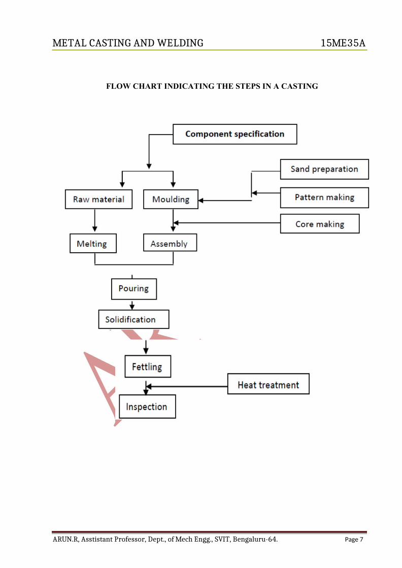
FLOW CHART INDICATING THE STEPS IN A CASTING
ARUN.R, Asstistant Professor, Dept., of Mech Engg., SVIT, Bengaluru-64. Page 7

METAL CASTING AND WELDING 15ME35A
Varieties of Components produced by casting process
Casting is the 1st step and the primary process for shaping any material. All materials have to be cast before it is put in use.
The ingots produced by casting process are used as raw material for secondary processeslike machining, forging, rolling, etc.
To list the components produced by casting is an endless process, a few majorcomponents produce by casting are given below:
a. Automotive sector: A few parts like brake drum, cylinder, cylinder linings, pistons,engine blocks, universal joints, rocker arms, brackets, etc.
b. Aircraft: Turbine blades, casting, etc.c. Marine: Propeller bladesd. Machining: Cutting tools, machine beds, wheels and pulleys, blocks, t ble for supports,
etc.e. Agriculture & rail road equipments: Pumps and comp esso , frames, valves, pipes
and fittings for construction.f. Camera frame, parts in washing machine, refrigerator & air-conditionersg. Steel utensil & a wide variety of products.Advantages and limitations of cast ng process
Following are a few advantages and l m tat ons of casting process.
Advantages:
Casting is the basic and versatile (flexible) manufacturing process.
Difficult shapes can be easily cast.
Large, hollow & intricate shapes can be easily cast.
Casting provides freedom of design with respect to shape, size and quality of theproduct.
Some metals that cannot be machined can be produced by casting to the required shape.
Heavy objects can be produced only by casting process.
Controlled mechanical & metallurgical properties can be obtained.
Casting process is most suitable for mass production.
A large variety of alloying composition & properties can be obtained.
Directional properties can be obtained in certain cases by controlled cooling.
Parts with close dimensional tolerance & ready to use can be produced by specialcasting methods.

ARUN.R, Assistant Professor, Dept., of Mech Engg., SVIT, Bengaluru-64. Page 8

METAL CASTING AND WELDING 15ME35A
Disadvantages OR Limitations Casting process is an elaborate process and involves operations. It requires large infrastructure like casting section, melting, pattern, core section,
cleaning, finishing, and inspection. Very high investment is required. Casting process is not economical & viable for small scale operations. The man power requirement is large. High care is required in handling chemicals and molten metal. The actual casting operation cannot be automated. Generally most operations may be casting or one of type i.e. mould has to be p epared for
each casting. Great care is required in controlling the cooling rate to obt in defect free casting. Very difficult to cast thin sections.
PATTERNS:
Definition: Pattern is a tool used to produce the mould cavity. It is a mould making tool.The shape of the pattern is the same as that of the component or casting, but the size will beslightly larger than the casting. Pattern s also referred to as the positive replica of thecasting. A number or castings can be made us ng a single pattern.
Functions of a pattern: The basic functions of a pattern are;
To produce the mould cavity faithfully.
To establish parting line.
To promote production of quality casting
To incorporate gating system and riser.
To bring economy to the process.
To have provision for core prints.
Materials used for Patterns: Before selecting a particular material, a few factors are to beconsidered, they are:
a) Number of castings to be produced.b) Degree of accuracy and surface finish of casting required.c) Shape and size of the casting.d) Re-usability of pattern, so that they will provide a repeatable dimensionally
acceptable.e) Type of mould material used- clay or resin.f) Type of moulding selected – green sand moulding, investment process etc.
ARUN.R, Assistant Professor, Dept., of Mech Engg., SVIT, Bengaluru-64. Page 8

METAL CASTING AND WELDING 15ME35A
The following materials are used for making patterns:-
a) Wood – Well seasoned teak wood is used for the pattern. Wood is soft, light and easy towork and takes the shape easily. Used for producing smaller number of castings. Largeand small patterns can be made. It wears out faster, cannot withstand rough handling andcan absorb moisture.
b) Metal – Is stronger than wood, but heavier than wood. Can maintain dimensionsaccurately for a very long time. Does not absorb moisture. Used to produce largenumber of castings. Has longer life. It is difficult to repair. Bigger sized patterns cannotbe made using this.
c) Wax – Is a low melting point material. Imparts good surface to the mould. Can berecovered and used again and again. Used in investment casting moulding. Acombination of paraffin, wax, bees wax, etc. is used for m king the p ttern.
d) Plastics – Plastic material is a compromise between wood nd met l. Thermosettingresins like phenolic resin, epoxy resin, foam plastic etc. e used s m terials for makingpattern. It is strong and light in weight. Does not abso b moisture during its use andstorage. Gives good surface finish to castings. Thin sections are difficult to cast usingplastics. Initially plastic patterns have to e cast and finished to desired shape and size.This leads to the increase in cost of the final cast product.
e) Plaster – Gypsum or plaster of Par s s another pattern material capable of producingintricate castings to close dimens onal tolerances. They are strong, light in weight, easilyshaped, gives good surface f n sh. However, they used for small castings only. Plasterreadily mixes with water and when allowed sets and becomes hard. Normally plaster isused for producing master dies and moulds.
Various Pattern allowances and their importance:
Pattern has the same shape as that of the casting but the dimensions will be generally morethan that of the casting. This extra dimension from the required value, given on the pattern iscalled as “allowances”. These allowances need to be given on the pattern due tometallurgical and mechanical reasons. The different types of allowances are;
a) Shrinkage allowanceb) Draft allowancec) Machining allowanced) Scale & Grinding allowancee) Distortion allowance
a) Shrinkage allowance: All metals and alloys undergo decrease in volume when cooledfrom liquid temperature to room temperature. This change in volume of metal or alloy iscalled as “shrinkage”. Fig. 1 shows the variation of shrinkage as a function oftemperature. As the molten metal is cooled from its superheat temperature, the volumestarts decreasing continuously till it reaches room temperature. This is a naturalphenomenon. Shrinkage of metal or alloy takes place in three stages viz. liquid to liquid,liquid to solid and solid to solid. The first two are taken care of by providing risers in thecastings. The last one is taken care of by providing shrinkage allowance on the pattern.
ARUN.R, Assistant Professor, Dept., of Mech Engg., SVIT, Bengaluru-64. Page 9

METAL CASTING AND WELDING 15ME35A
This is also referred to as pattern shrinkage allowance. The value of this depends on thenature of the metal or alloy. This allowance when given on to the pattern, will increase its size.
Pattern maker‟s scale is available to facilitate easy and direct measurement. Pattern shrinkage
for some metals is:
Ex. Cast steel AluminiumCast iron
3-5 mm per 100mm length3-4 mm per 100mm length2-3 mm per 100mm length
b) Draft allowance: It is the allowance g ven to the vertical surface of the pattern tofacilitate easy removal of the pattern from the mould cavity, without causing anydamage to the mould. This allowance depends on the type of moulding. Fig. 2 and 2a, 2b& 2c shows the method of draft allowance given in patterns. Damage is caused to thevertical pattern portions of the mold, when there is no draft. Hence by giving taper ordraft on the vertical portions of the pattern there is no damage caused to the mould whenthe pattern is lifted upwards.
ARUN.R, Assistant Professor, Dept., of Mech Engg., SVIT, Bengaluru-64. Page 10

METAL CASTING AND WELDING 15ME35A
c) Machining allowance: Most of the castings will have more than one surface that needsmachining. The dimensions get reduced after machining. Hence, the size of the patternis made larger than required. During machining, this extra material on the casting isremoved. This allowance depends on the nature of the metal and the dimensions of thecastings. Typical machining allowances are:
Ex. Cast Iron 1-10 mmCast steel 3-12 mmAluminium 1.5-4.5 mmAlloys 1.5-4.5 mmBrass, Bronze, etc 1.5-5 mm
d) Scale & Grinding allowance: Most of the castings unde go he t tre tment and due tohigher temperatures scales are formed on the su f ce. This needs to be removed bygrinding operation. In addition, sometimes su face oughness or imperfection needs to beremoved by grinding operation. Hence, the size of the casting is made slightly biggerthan the required to accommodate this. The magnitude of this extra allowance is0.2 -3 mm.
e) Distortion allowance: Casting hav ng shapes such as C, U and large plate, loose theirshapes during solidification. The loss of shape is referred to as distortion. This is due tothe shrinkage stresses present during solidification. To take care of this, the pattern isgiven an allowance in the direction opposite to the expected distortion. This is referred toas distortion allowance. More or experience is essential is addition to the design knowledge inarriving to this allowance. Fig. shows the distortion allowance.
Classification of patterns: Patterns are of various types. But the selection of a particular typeof pattern depends upon the type of moulding process employed, shape and size of the castingrequired. Some of the commonly sued patterns are discussed.
ARUN.R, Assistant Professor, Dept., of Mech Engg., SVIT, Bengaluru-64. Page 11

METAL CASTING AND WELDING 15ME35A
a) Single piece pattern: Single piece pattern also called, solid pattern the simplest typemade in one piece without any joints or loose pieces. Used for simple shape and largesize castings. It can be made easily. Fig. Shows the single piece pattern.
b) Split pattern: Consists of pattern in two halves joined by a pin. It is used to preparemoulds using hand. It is used popularly in hand moulding. The split can be at two ormore planes. The split in the pattern facilitates e sy moulding. Fig. shows the splitpattern.
c) Loose piece pattern : Pattern consists of a main body to which small projection piecesare attached. These pieces can be removed from the mould after removing the mainbody. This type of pattern is used to get undercut portions in the castings. Fig. shows theloose piece pattern.
d) Cope & Drag pattern: It is basically a two part pattern (split type). Each half is fixed toa metal plate separately with gates, runners and risers. These two plates with patterns areused to make moulds in a moulding machine, separately to get bottom and top mouldcavities. The bottom portion is called as the drag portion and the top portion is called asthe cope portion. Hence the names cope and drag pattern. The two moulds are preparedseparately using separate machines and assembled. This type of pattern is used toproduce large number of castings. Fig. Shows the cope & drag pattern.
ARUN.R, Assistant Professor, Dept., of Mech Engg., SVIT, Bengaluru-64. Page 12

METAL CASTING AND WELDING 15ME35A
e) Gated pattern: This consists of a number of patterns attached with runner, ingate, sprueand risers. A cope & drag pattern may be used for this purpose. A machine is used formaking the moulds. More number of castings can be produced per mould. Size of thecasting is small. Fig shows the gated pattern.
f) Match plate pattern: This consists of two parts of the p ttern mounted on eithersurfaces of a metal plate. It is basically a split p tte n. The two p rts are perfectly aligned.It is used in a moulding machine. Both cope and d ag boxes are made in the samemachine one after the other. When the two boxes a e closed, the desired mould isobtained. Fig. shows the match plate pattern.
g) Follow board pattern : When the shape of the pattern is such that it cannot be heldstable in its position, a wooden board conforming to the contour of the pattern is used torest the same in correct position and moulding is carried out. Such a pattern which needsa follow board is referred to as follow board pattern. Follow board holds the pattern tillthe moulding is over. Even for moulding thin sections follow board is used. Fig. showsthe follow board pattern.
h) Skeleton pattern: It consists of a number of wooden pieces assembled together to formthe desired shape. The assembly resembles a skeleton. The skeleton portion is then coveredwith thin boards. This type of arrangement is used for heavy and big castings and the numbers
ARUN.R, Assistant Professor, Dept., of Mech Engg., SVIT, Bengaluru-64. Page 13

METAL CASTING AND WELDING 15ME35A
required is only a few. Material saving for the pattern is achieved and the cost of pattern is reduced. Used for simple shapes. Ex. Water pipe bends, frames, calve bodies can be cast. Fig.shows the Skeleton pattern.
i) Sweep pattern: Makes use of a thin board of wood conforming to the outer contour ofthe casting. It is used when the casting has a surface of evolution contour such as cylindrical,bell shape, etc. Can be used for small or big castings and the number of castings is not aproblem. Saves pattern material. It is easy to handle and sto e. It can be used for makingcores. Fig. shows the sweep pattern.
BIS color coding of Patterns: For easy recognition of different portions of the pattern,standard colour codes have been recommended for the finished wooden pattern. Thestandard colour code adopted by the American Foundry men s Society (AFS) is being used‟s Society (AFS) is being usedall over the world. Each colour conveys how the castings will be.
Sl. Colour Casting positionNo.
1 Black Casting surface to be left unfinished2 Red Surface of casting to be machined3 Red stripes on yellow Loose pieces & seats
background
4 Yellow Core prints and seats for loose core prints5 Diagonal black stripes on a Stop offs (portions of a pattern that form a cavity which are
yellow base filled with sand before pouring). They are reinforcements toprevent delicate portions of the pattern.
Due to extensive use of metal and plastic patterns, the colour code is used less now a days.
ARUN.R, Assistant Professor, Dept., of Mech Engg., SVIT, Bengaluru-64. Page 14

METAL CASTING AND WELDING 15ME35A
BINDER: The sand used for preparing moulds is a mixture of silica sand ( of all the varioussand like zircon, olivine, magnesite etc., silica sand is the widely used), binder andadditives.Moulding sand = Silica sand + Binder + Additives
A hard mould is the primary requirement is making any castings, and binders serve thepurpose. A binder is a material used to produce cohesion or bind the sand particles (silicasand) together thereby imparting strength to the sand. Clay binde s (Bentonites) are the mostwidely used for bonding moulding sands. But, clay activates or tends to bind sand particlesonly in the presence of water (moisture). The amount of water added to clay should be basedon experimental trials because, if too little w ter is dded, the sand will lack strength as thebond between the sand is low. On the other h nd, too much water causes sand to reach semiliquid state thereby making it unsuit ble for moulding. In other words, for a givenpercentage of clay, there is an optimum pe cent ge of w ter th t gives favorable properties tothe moulding sand. For good moulding sand, clay may vary in the range 6-12% andmoisture from 3-5%.
Types of binders used in mould ng sand: B nders are classified into two types:a) Organic binders andb) Inorganic binders.
Organic group of binders include:Dextrin – made from starch
Molasses – a byproduct of sugar industry
Cereal binders – gelatinized starch and gelatinized flour
Linseed oil – a vegetable oil
Resins – urea formaldehyde, phenol formaldehyde etc.Inorganic group of binders include:
Clay binders – bentonite, fire clay, etcPortland cement
Sodium silicate etc.
ADDITIVES:
Additives are generally added to develop certain new properties, or to enhance the existingproperties of the moulding sand. They do not form a compulsory constituent to themoulding sand. However, its addition improves the quality of the moulding sand and hencethe casting obtained.
Note: Additives do not impart any binding qualities.
ARUN.R, Assistant Professor, Dept., of Mech Engg., SVIT, Bengaluru-64. Page 15

METAL CASTING AND WELDING 15ME35A
A few commonly used additives used and their properties are mentioned below:(a) Sea Coal
It is a finely powdered bituminous coal.
Its addition ranges from 2-8% by weight of sand.
Enhances peeling property of castings. Improves surface finish of castings
Prevents sand burn out.
(b) Silica Flour It is pulverized silica added in ranges of 5-10% based on sand weight.
Resists metal penetration in the mould walls. Improves surface finish.
(c) Wood Flour (Cellulose material)
It is a pulverized soft wood (fibrous mate ial)
Added in ranges of 1-2% y weight of sand.
Controls sand expans on created y temper water.
Absorbs excess water and mproves flowa ility of sand during mouldingprocess.
Improves collapsibility of moulds/cores.
(d) Iron Oxide Develops hot strength to moulding sand.
Aid in the thermal transfer of heat from the mould-metal interface and provides stability to the moulds dimensional properties
ARUN.R, Assistant Professor, Dept., of Mech Engg., SVIT, Bengaluru-64. Page 16

METAL CASTING AND WELDING 15ME35A
SAND MOULDING
Sand Moulding: A mould is a cavity created using metal or refractory sand. The shape ofthe cavity corresponds to the shape of casting except the dimensions. A mould is referred toas the negative replica of the casting. Mould made of metal is called as metal or metallicmoulds and the ones made by using sand is called sand moulds.
Sand moulds or non metallic moulds:
Sand moulds are made using a mixture of refractory sand along with a binde , additiveand water.
This mixture is referred to as moulding sand.
A mould cavity is prepared using this moulding sand.
They are also referred to as non-metallic moulds or refr ctory moulds.
Moulding sands may be:
Natural sand:Occur readily in nature and contains all the ingredients in the right proportion.
The sand can be directly used to prepare the mould.
Synthetic sand:Are prepared by making different ngred ents (sand, inder, water, etc.) in the correct proportion and then used for prepar ng the moulds.
Properties of moulding sand: An important property of a moulding sand is that, it shouldproduce a sound casting, i.e. a good casting.To achieve this, the moulding sand should posses the following desired properties:
1. Flowability: It is the ability of the sand to flow easily and cover all the contours on the pattern,
thus take the desired shape. he sand with good flowability gets compacted to a uniform density. Energy during ramming gets easily transmitted through the sand if the flowability is
good. Clay and water additions influence flowability.
Good moulding sand should have good flowability property.
2. Green Strength: It is the strength of the sand when in moist condition or green condition (after
compaction). A mould with adequate green strength will retain its shape, does not distort and will not
collapse while handling it. A mould with adequate green strength resists metallostatic pressure and sand erosion
while molten metal is flowing in the mould.
Good moulding sand should have good green strength property.
ARUN.R, Assistant Professor, Dept., of Mech Engg., SVIT, Bengaluru-64. Page 17
METAL CASTING AND WELDING 15ME35A
3. Dry strength: It is the strength of the sand when there is no moisture in the sand i.e. in the dry
condition. Hence, a good moulding should be able to develop good dry strength. By heating the mould to approximately 200oC, all the moisture in the sand can be
removed, the strength of such dried sand represents dry strength. Dry sand enhances strength of the mould. Resistance to erosion is improved considerably. Shape of the mould is retained easily in the dry condition.
4. Hot Strength: It is the strength of the sand mould at high temper ture bove 100oC i.e. if the hot
strength of sand is good at 200oC, it means that the s nd h s the necessary strengthwhen sand is heated and held at 200oC.
When molten metal is poured into the cavity, the mould gets heated up. If the sand does not have sufficient strength at this tempe ature it will induce casting
defects.
Hence, sand should have adequate strength at elevated temperature.
5. Permeability:
It is the ability of the sand/mould to allow easy escape of gases/vapour through it.
When molten metal comes in contact with the mould and core surface, moisture, binders and additives present in them produce gases and vapour.
These tend to go through vents and also pass through the mould surface.
The sand surface should allow the gases/vapour to escape.
If these are entrapped in the casting, defects will appear in the casting as pores.
Hence, good moulding sand should have good permeability.
6. Collapsibility:
It is the ability of the moulding sand to collapse after the casting solidifies. It should break down into pieces at the knock out and cleaning stages, easily.
Easier the mould breaks, higher is the collapsibility property of the sand.
If the mould or core sand does not collapse easily, it may obstruct/restrict the contraction of the solidifying casting and result in cracks/tear in the casting.
Hence, the collapsibility of the sand should be good.
7. Bench line:
It is the ability of the moulding sand to retain its properties during its storage.
The sand should posses fairly good bench life.
A good moulding sand should have good bench life.
ARUN.R, Assistant Professor, Dept., of Mech Engg., SVIT, Bengaluru-64. Page 18

METAL CASTING AND WELDING 15ME35A
8. Coefficient of expansion: Moulding sand should have very low expansion characteristics otherwise sand
expansion will occur. Lower the value of expansion, lesser is the problem of expansion defects in the
mold. Lesser is the cracking tendency of the mold.
9. Adhesiveness: It is the property of the moulding sand owing to which the su faces of the mould are
held together. It is because of this property that the sand sticks to the walls of the boxes.
A good moulding sand should have good adhesiveness.
10. Durability:
It is the ability of the sand to withstand repeated cycles of he ting nd cooling and
still retain its properties.
The sand should be reusable i.e. should be able to eclaim the sand.
Requirements of base sand: For produc ng good casting the sand has to fulfill thefollowing:-
Base Sand:
Should be sub angular (grain size)
Should be good grain distribution
Should have high refractoriness
Should have low impurities
Should have low expansion characteristics
Should be thermally stable.
BASE SAND:It is a mass of refractory grains. Grains are formed due to the withering action of rocks. It isavailable in plenty in nature along se beaches, deserts, etc. Bas sand refers to sand grainswithout any other ingredients. They are normally oxides of elements.
Types of base sand:1) Silica Sand2) Olivine Sand3) Chromite Sand4) Zircone Sand
ARUN.R, Assistant Professor, Dept., of Mech Engg., SVIT, Bengaluru-64. Page 19

METAL CASTING AND WELDING 15ME35A
1. Silica Sand: Silica sand is essentially silicon dioxide (SiO2) found in nature on thebottom and banks of the rivers, lake and seashore. Silica deposits tend to have varyingdegree of organic and mineral contaminants like limestone, magnesia, soda and potashthat must be removed prior to its use, otherwise which affects castings in numerousways.
Silica sand is available in plenty, less expensive and possess favorable properties.But its high thermal expansion leads to certain casting defects; the reason for which notbeing used in steel foundries. However, silica sand when mixed with certain additiveslike wood flour, cereals, (corn flour) saw dust, etc., defects can be eliminated. Theseadditives burn by the heat of the molten metal thereby c eating voids that can beaccommodated the sand expansion.
2. Olivine sand: Olivine sand is typically used in non-ferrous foundries. With its thermalexpansion about half of that of silica sand makes it suit ble for production of steelcastings also. But the high cost restricts its wide use.
3. Chromite sand: This is African sand with cost being much higher compared to othersands. Due to its superior thermal characteristics, it is generally used in steel foundriesfor both mould and core mak ng.
4. Zircon sand: Zircon or zircon um s l cate possesses most stable thermal properties of allthe above discussed sand. The cho ce for this type of sand arises when very hightemperatures are encountered and refractoriness becomes a consideration. But the majordisadvantage is that, zircon has trace elements of uranium & thorium which is hazardousin nature, thereby restricting its use in foundries.
TYPES OF SAND MOULDS: Moulds prepared with sand are called “sand moulds” or“temporary moulds”, (when moulds are with metal, it is called metallic moulds orpermanent moulds) as they are broken for removing the casting. The different types of sandmoulds are:-
Green sand mould
Dry sand mould
No bake sand mould
Green Sand mould: The moulding sand is in the moist state at the time of metal pouring.The main ingredients of green sand are silica sand, clay and moisture (water). Additivesmay be added in small quantity to obtain the desired properties of mould/casting. Nearly60% of the total castings are prepared from green sand moulds.
Advantages:Prepared for simple, small and medium castings
Suitable for mass production
Least expensive
Sand can be reused many times after reconditioning with clay & moisture.
ARUN.R, Assistant Professor, Dept., of Mech Engg., SVIT, Bengaluru-64. Page 20

METAL CASTING AND WELDING 15ME35A
Disadvantages:
Moulds/cores prepared by this process lack in permeability, strength and stability.
They give rise to many defects like porosity, blow holes, etc.
Moulds/cores cannot be stored for long time.
Not suitable for large castings.
Difficult to cast thin and intricate shapes.
Dry sand mould: The dry sand mould is prepared in the normal manner as that of greensand mould, i.e., by mixing base sand, clay, water and other additives. St ength is realizedafter baking the mould in the oven, to remove moisture present in them. Baking is carried
out for 6-12 hours at 200-300oC, depending on the size of the mould and type of metal beingpoured.
Advantages:Moulds are stronger than green sand moulds.
Surface finish of the casting is better.
Defects related to moisture are eliminated.
Disadvantages: Production is slower, labour and cost due to aking process.
Under baked or over baked moulds s another disadvantage.
Not suitable for large & heavy cast ngs as they are difficult to bake.
No Bake sand moulds: A no bake or self setting sand mould is one that does not requirebaking. The main ingredients are base sand, binder (resin type), hardener and a catalyst oraccelerator. The bonding strength developed in moulds by means of a self-setting chemicalreaction between binder and hardener. In some cases, a catalyst or an accelerator is added tospeed up the chemical reaction.
Advantages:Higher strength about 50 to 100 times that of green sand moulds.
Patterns can be stripped within a few minutes after ramming, which is not possible ingreen and dry sand mould.
Moulds can be stored for longer periods.
Highly simplified moulding.
Better dimensional accuracy & stability.
Improve casting quality.
Surface finish is excellent.
ARUN.R, Assistant Professor, Dept., of Mech Engg., SVIT, Bengaluru-64. Page 21

METAL CASTING AND WELDING 15ME35A
Disadvantages:
Use of resin and catalyst causes lot of environmental problem both within (i.e. duringmixing & pouring) and outside (dumping of sand).
Resins and catalysts are expensive.
Unsafe for human operators.
Due to high strength & hardness, reuse of sand is slightly difficult.
MOULDING SAND MIXTURE INGREDIENTS FOR DIFFERENT SAND MIXTURES
A moulding sand is a mixture of base sand, binder and additives. Ing edients for dry sandmixture are similar to that of green sand.
a. Ingredients for Green Sand MixtureGreen sand mixture is composed of base sand, binde , moistu e nd dditives.Base Sand: Silica sand is used as the base sand. It possesses f vourable properties,inexpensive and can be reused many number of times. The amount of silica sand addedmay vary depending on the requirements.
Binder: Bentonite (clay binder) is the widely used inder for bonding sand particles. It isactivated in the presence of water. A est ond etween the sand can be obtained withbentonite varying from 6-12% and water 3-5%.
Additives: Additives are added n small quantities to develop certain new properties orto enhance the existing properties of moulding sand. Sea coal, silica flour, wood flourand iron oxide are commonly used additives.
b. Ingredients for No-bake sand mixture:Of all the various no -bake sand mixture, viz., Furan system, Phenolic urethane system,Alkyd system, sodium silicate binder system, etc. Ingredients of Alkyd binder systemwhich is one of the most widely used binder system is discussed below.Base sand: Silica sand is used as the base sand.
Binder: he alkyd binder system consists of three parts: Part – A (binder)Part – B (hardener)Part – C (catalyst)
Part – A (binder): The binder is alkyd resin which is obtained by reacting linseed oilwith a polybase acid like iso-pathalic and solvents like turpentine, kerosene or mineralspirit to improve flowability. Its addition ranges from 2-5% based on weight of sand.Part – B (hardener): The hardener is a reacted product between cobalt/lead salts and napthanic acid. Its addition ranges from 5-10% based on weight of binder.Part – C (catalyst): Methylene-diphenyl-Di-isocyanate commonly known as MDI isused as catalyst to speed up the chemical reaction. It addition ranges from 20-25% basedon weight of binder.
ARUN.R, Assistant Professor, Dept., of Mech Engg., SVIT, Bengaluru-64. Page 22

METAL CASTING AND WELDING 15ME35A
METHODS USED FOR SAND MOULDING
The various sand moulding methods are:-
Bench moulding
Floor moulding
Pit moulding &
Machine moulding
Bench Moulding: Bench moulding is preferred for small jobs and is ca ied out on a benchof convenient height. The bench moulder (mould maker) prepa es the mould manually whilestanding.Floor Moulding: Floor moulding is preferred for large size moulds th t c nnot be carried outon benches. In most of the foundries, moulding is c ied out on floors irrespective of the sizeof jobs.
Pit moulding: Large castings that cannot be accommodated in mould box (flasks) are madein pits dug on the floor. The pits form the drag part of mould and a separate cope box isplaced above the pit. The mould maker enters the pit and prepares the mould. The cope boxis rammed using dry sand with r sers placed at su ta le location.
The walls of the pit are lined w th r ck and the ottom is covered with moulding sandwith connecting vent pipes to the floor level for easy escape of hot gases. A crane is usedfor handling the cope box and other operations.
Machine moulding: In bench, floor and pit moulding, all the operations viz., ramming,withdrawing pattern, rolling flasks, etc., are done manually by mould makers. But whenlarge number of castings are to be produced manual operations consumes more time andalso accuracy and uniformity of moulding varies. To overcome this difficulty, machinemoulding is used. The operations perform by machines includes:
Ramming moulding sand: By jolt operations or Jolt squeeze machines.
Rapping the pattern: Patterns are rapped in the sand with vibrators that are operatedelectrically or by compressed air.
Removal of pattern: By raising or lowering the mould, or by raising or lowering the pattern.
ARUN.R, Assistant Professor, Dept., of Mech Engg., SVIT, Bengaluru-64. Page 23

METAL CASTING AND WELDING 15ME35A
CORES
Cores are used in the mould to produce mainly hollow castings. It is the only methodthrough which cavities can be produced in the casting without machining.Core sand is used to prepare the core. A core consists of base sand, a binder and water ifrequired. Special types of binders are used for the purpose. Core sand is filled in a metal orwooden die then rammed to get the desired geometry of the die. The shaped sand representsgreen core. This core gains strength after suitable treatments, depending on the t pe ofbinder used.
TYPES OF CORESCores are classified based on:a) Condition of core:
b) Binder used
i. Green sand coreii. Dry sand core
i. Resin bonded co e
- cont ins moisture- Co es does not cont in moisture,co e in the dried form
- contains esin as binder
ii. Sodium silicate core - contains sodium silicate as the binderiii. O l onded core - contains oil as binderiv. Shell core - contains urea/phenol formaldehyde
resin as binderc) Hardening process i. CO2 process - uses co2 gas to harden the sand
used ii. No bake oil - uses air to harden the sandiii Furan no bake - uses heating to harden the sandiv. Nishiyama - uses chemical reaction to harden the
sandv. Fluid sand - uses chemical reaction to harden
the sandd) Shape & position i. Horizontal core - core placed in horizontal
position of the core ii. Vertical core - core placed in vertical positioniii. Balanced core - core hanging on one sideiv. Hanging core - core suspended from the top.
ARUN.R, Assistant Professor, Dept., of Mech Engg., SVIT, Bengaluru-64. Page 24

METAL CASTING AND WELDING 15ME35A
Green sand core: A green sand core is composed of a mixture of silica sand, binder(bentonite), moisture and additives. The preparation of green sand core is similar to thatused for green sand mould.Dry sand core: The sand used for preparing a dry sand core is different from that used fordry sand moulds. A dry sand core is composed of a mixture of silica sand and binder. Thebinder may be sodium silicate, Portland cement, linseed oil, mineral oil, natural resins, etc.Binder used : explained above.Hardening process used : explained above
Shape and position of the core:
a. Horizontal core: The core is placed horizont lly in the mould, it is known ashorizontal core. The core prints are provided at both ends of the core to rest in the seats initiallyprovided by the pattern. These core prints helps the co e to be secu ely nd correctly positioned inthe mould cavity.
b. Vertical core: When the axis of the core is vertical, it is known as vertical core.
c. Balanced core: A balanced core is one that is supported from its one end only. Suchcores are used when the cavity required is only to a certain depth.
d. Hanging core: The core is supported from the top, the core hangs vertically from the mould and the core may be provided with a hole for molten metal to flow.
ARUN.R, Assistant Professor, Dept., of Mech Engg., SVIT, Bengaluru-64. Page 25

METAL CASTING AND WELDING 15ME35A
e. Drop core: Drop core is used when the axis of the desired hole does not co inside withthe parting line of the mould, i.e., the core is required to be placed either above or belowthe parting line.
f. Kiss core: In some cases, pattern cannot be provided with core prints nd hence no seatwill be available as a rest for the core. In such cases, the core is held in position betweenthe cope and the drag by the pressure exerted f om the cope on the dr g. Such a core iscalled a kiss core and is shown in fig.
g. Ram-up core: When a core is to be placed in an inaccessible position, it is difficult toplace it after ramming the mould. The core used in this case is called a ram-up core andis placed in the mould along with the pattern before ramming fig.
ME HOD OF MAKING CORESCore making consists of the following four steps:
1. Core sand preparation2. Core making3. Core baking4. Core finishing
1. Core sand preparation: The core sand of desired type (dry sand) and compositionalong with additives is mixed manually or using muller of suitable type.
2. Core making: Cores are prepared manually or using machines depending on the needs.Machine like jolt machine, sand slinger, core blower, etc., are used to for large scalecontinuous production, while small sized cores for limited production are manuallymade.
ARUN.R, Assistant Professor, Dept., of Mech Engg., SVIT, Bengaluru-64. Page 26

METAL CASTING AND WELDING 15ME35A
A core box is similar to a pattern that gives a suitable shape to the core fig. shows a core boxused to produce rectangular shaped cores. The procedure involved for preparing core is asfollows:
The prepared core sand mixture is rammed manually into the core box.
The core box is inverted over a core plate and rapped in all direction using wooden
mallet.
The box is lifted vertically to leave the core on the core plate.
The core along with the core plate is sent for baking.
3. Core baking: Cores are baked in ovens in order to drive away the moisture in them andalso to harden the binder thereby imparting strength to the core. The temperature and
duration for baking may vary from 93-232oC and from a few minutes to hoursrespectively depending on the size of the core and type of binder used.
4. Core finishing: The baked cores are finished by rubbing or filing with special tools toremove any fins, bumps, loose sand or other sand projection from its surface. The coresare also checked for dimensions and cleanliness. Finally, if cores are made in parts, they areassembled by using suitable pastes, pressed and dried in air before placing them in mould andcavity.
BINDERS USED FOR CORESBinders used for core making are of various types: each type used to provide some desiredproperty to a core for particular use or set of conditions. The core binders commonly usedare discussed below:a) Binders that become firm at room temperature. The binders that come under this group include:
Sodium silicate
Sodium silicate is mixed with silica sand to prepare a core of desired shape and size.Vent holes are made in the core after which carbon-dioxide gas is passed through it. Thecore hardens rapidly within a few seconds after gassing is stopped.
Port Land Cement
Port land cement is mixed with silica sand and water to prepare a core of desired shape
ARUN.R, Assistant Professor, Dept., of Mech Engg., SVIT, Bengaluru-64. Page 27

METAL CASTING AND WELDING 15ME35A
after which it is made to set (dry) in a room for about 72 hours. The strength develop with this binder is very high and hence, preferred for heavy steel and gray iron castings.
Rubber Cement (Rubber latex)
Bonding of cores with this binder is a patented process. Silica sand is mixed with water,and then the rubber latex (obtained from plant) is added. The core is rammed andallowed to harden at room temperature.
Synthetic resins (No bake binders)
Synthetic resins like phenol and urea formaldehyde are used as binders. They are mixedwith hardeners and/or catalyst to bring about a chemical reaction. St ength developmentin cores takes place within a few minutes after mixing.
b) Binder that become firm on baking
This group of binders does not develop their strength by chemic l or physic l changes,
rather they become hard on heating (baking). Binde s m te i ls of this group include: Vegetable oils ex. Linseed oil
Marine animal oil ex. Whale oil
Cereal binder
Dextrin made from starch
Molasses (by product of sugar ndustry)
Pitch (a coal tar product)
Protein binders ex. Gelatin & glues.
c) Binder that harden on cooling after being heatedA binder that softens on heating and hardens on cooling includes natural resins like:
Gum resins – obtained by tapping the living tree and distilling the gum.
Wood resins – obtained from pine stump wood.
Limed wood resins – these are wood resins treated with lime
Coal tar resins – a product of coal tar industry.
d) Other bindersClay binders – bentonite mixed with water.
Saw dust and wood floor – although not pure binders (they provide little adhesivestrength), they serve to improve the collapsibility of the core.
GATING
The concept of gating is very important, as it helps one to learn the controlled flow ofmolten metal from the crucible or ladle into the mould cavity.
The term gating or gating system refers to all the channels or cavities through which themolten metal flows to reach and fill the mould cavity. Fig shows a simple gating systemwhich consists of the following components.
ARUN.R, Assistant Professor, Dept., of Mech Engg., SVIT, Bengaluru-64. Page 28

METAL CASTING AND WELDING 15ME35A
a. Spruec. Runner
b. Pouring cupd. Ingates or Gate
a) SprueA sprue is a vertical passage way through wh ch the molten metal will enter the runner. It isalso called „down gate or „down sprue . The sprue is tapered in cross-section with its‟s Society (AFS) is being used ‟s Society (AFS) is being usedbigger end at the top connected to the pouring cup while its smaller end connected to therunner.b) Pouring cup
The enlarged portion (usually funnel shaped) of the sprue at its top into which the moltenmetal is poured is called pouring cup. (Fig. 15 a & b). In some cases, pouring basin is usedinstead of cup. The pouring basin has a larger opening as shown in fig 15(a). It makespouring easier, eliminates aspiration (air pick-up) and reduces the momentum of the liquidflowing into the mould settling first into it.c) Runner
he runner is a horizontal passage way through which the molten metal flows into the gates.he cross section of the runner runner may be square or trapezoid and its length is very
large compared to its width.
d) Runner extensionIt is a small portion of the runner that extends beyond the last gate. It is used to trap the slagin the initial molten metal.
e) IngatesThe ingates or gate is a short passageway which carries the molten metal from the runner tothe mould cavity. The gates used may vary in number and depends on the size of the castingand rate of solidification of molten metal. A gate may be built as a part of the pattern or itmay be cut in the mould using gate cutter tool. The combination of sprue base, runner andingates completes the total pouring system of any casting.
ARUN.R, Assistant Professor, Dept., of Mech Engg., SVIT, Bengaluru-64. Page 29

METAL CASTING AND WELDING 15ME35A
RISERINGWhen the molten metal solidifies, it shrinks in volume. At this stage, if it does not have asource of more molten metal to feed as it shrinks, voids appear leading to defects incastings. This problem is overcome with the use of risers.
A riser or feed head is a vertical passage that stores the liquid metal and supplies (feed) thesame to the casting as it solidifies. This means that the metal in the riser must stay liquidlonger than the metal in the part being cast.
Requirement of a riser
a) A riser must be large enough that the casting detail it is intended to feed. This helpscontinuous feeding of liquid metal to the solidifying c sting so th t shrinkage cavitiesare eliminated.
b) The riser must be kept open to the atmosphe e and pl ced in such location that itmaintains a positive pressure of liquid metal on all po tions of the casting it is intendedto feed.
c) A riser should be located in a position that will cause directional solidification from thecasting towards it.
PRINCIPLE OF GATING SYSTEM
1. A good gating system should help easy and complete filling of the mould cavity.2. It should fill the mould cavity with molten metal with least amount of turbulence.3. It should prevent mould erosion and gas pickup.4. It should establish proper temperature gradient in the casting.5. It should promote directional solidification.6. It should regulate the rate of flow of metal into the mould cavity.
TYPES OF GATES
he common types of gate are:1. op Gate2. Bottom Gate3. Parting line Gate4. Step Gate
1. Top GateThe top are used for simple casting. Molten metal flows into the mould cavity directly fromthe top. They are the most efficient type of gating. Simple to mould.
ARUN.R, Assistant Professor, Dept., of Mech Engg., SVIT, Bengaluru-64. Page 30

METAL CASTING AND WELDING 15ME35A
2. Bottom GateThe bottom gates are used for denser metals such as steel. Molten metal flows into themould cavity from the bottom and slowly rises up. It avoids e osion of mold taken moretime in moulding. Bottom gate is shown in fig.
3. Parting line gateThe gates located at the junction of cope and the drag boxes. They can be easily prepared.Molten metal flows into the cavity from a certain height. These are used for most of thenon-ferrous alloys and steel castings Fig.
4. Horn Gate
ARUN.R, Assistant Professor, Dept., of Mech Engg., SVIT, Bengaluru-64. Page 31

METAL CASTING AND WELDING 15ME35A
TYPES OF RISERS
Basically riser can be classified as open riser and blind riser. The open riser is kept open tothe atmosphere at the top whereas the blind riser is close to the atmosphere.
Open RiserAn open riser is a riser provided in the mould cavity when the top portion is open to
the atmosphere. It is easy to mould. Further, an open riser can be classified as Top riser –when the riser is placed above the casting. Side riser - when the riser is placed by the side ofthe casting. Top risers are extensively used since its efficiency is ve y high. In open risermolten metal is subjected to atmospheric pressure directly.
Blind riserA blind riser as shown in f g. s one wh ch is completely enclosed in the mould and not
exposed to the atmosphere. Due to this, the metal in the riser cools slower and thus stayliquid longer promoting directional solidification.
FETTLING AND CLEANING OF CASTINGS
Castings are to be separated from sand mould box before the gates and risers are removed.This is referred to as fettling and cleaning of casting. The steps involved are:
ARUN.R, Assistant Professor, Dept., of Mech Engg., SVIT, Bengaluru-64. Page 32

METAL CASTING AND WELDING 15ME35AFettling
Shake out sand, Casting and mould boxes are separatedSand lumps are broken Returned to the moulding section
Cleared of nails, wires, etc to be used againCleaning operation of castings
Returned to sand MullerFor reuse for moulding Involves
Removing sand by shot bl sting Removing core sand Removing moulding s nd on the c sting surface Removing gates and ise s Removing fins, excess metal, sand, etc., Leveling the su face by g inding Rectifying the casting from defects
Cleaning operation depends on the cast ng shape, size, metal and the process used. Sand cores are removed by shak ng, ch pp ng, poking or dissolving, etc., Gates, risers, fins are removed by oxy-acetylene flame cutting, hammering, abrasive
grinding wheel, etc., Sand sticking on the casting surface removed by shot blasting or sand blasting.
MOULDING MACHINES
Moulding machines are used to maintain mold quality, reduce allowances, havereproducibility in molding, casting and to enhance productivity.
he following are moulding machines, classified based on the method of ramming.a. Jolt machineb. Squeeze machinec. Jolt-squeeze machined. Sand slinger
a. Jolt Machine
The machine consists of a cylinder with two passages on for permitting compressed air atthe bottom and another for air to go out. A piston is located in the cylinder and can move upand down. The piston carries a table at the top. One the top of the table a pattern can befixed and mould box can be placed around it. A control panel is located near the machine tooperate it. The machine is located on a firm and rigid concrete base. A hopper carrying sandmixture is located above the machine. By operating the lever compressed air can be made toflow through the bottom of the piston.
ARUN.R, Assistant Professor, Dept., of Mech Engg., SVIT, Bengaluru-64. Page 33

METAL CASTING AND WELDING 15ME35A
Working operation: First the moulding sand is filled into the box to cover the p ttern.
The pattern is placed on the table. Moulding box is pl ced on to the t ble. Compressed air let into the cylinder.
Now the table starts moving upwards till the bottom of the piston reaches the topportion.
At top portion the air escapes out causing a drop in the pressure inside the cylinder. Due to its own weight the table along w th the ox drops down.
Again the compressed air lifts the p ston up t ll top point and the box is dropped downwards.A jolting action is created.
The process is repeated several times to achieve a desired hardness in the mould.
Sand is compacted more at the bottom due to jolting action.
Cope and drag boxes are prepared this way.
b. Squeeze MachineIt consists of a cylinder and piston assembly as in jolting machine. It has only one
opening in the cylinder connected by a two way valve. Through this valve compressed aircan be let inside the cylinder or let out. Thus the piston can be lifted or lowered inside thecylinder. he piston head carries a table on which the platen/board corresponding to theinside cross section of the mould box is fixed. This board when positioned above the boxwill squeeze the sand in it when the piston moves upwards. The platen can be swung to oneside for placing the mold box and filling the sand.
Working operation:
ARUN.R, Assistant Professor, Dept., of Mech Engg., SVIT, Bengaluru-64. Page 34
METAL CASTING AND WELDING 15ME35A
First the mould box is kept on the table fixed with the pattern.
Moulding sand is filled in the box at least 25% in excess of the box volume.
The platen/board is brought in position above the box.
Compressed air is then allowed inside the cylinder through the value.
Now the piston will move upwards along with the box.
The platen will squeeze the sand in the box during this period.
Compacted sand will have more compaction on the top and less at the bottom due tosqueezing action.
The air pressure is released now. The piston and box move down wa ds.
The box is ejected out using ejector pins.
One half of the mould is ready now.
Similarly next half is done and assembled.
Two machines placed side by side are used to prepare cope nd dr g molds.
Suitable for small works and shallow boxes.
c. Jolt and Squeeze Machine
Here both jolt and squeeze act on are mparted to the sand. Constructional features
It consists of a piston (P) carry ng a table (T)
Piston is housed in a sleeve (S)
Sleeve has an opening O 1 at the top and another opening (O3) at the bottom
Sleeve is housed in an outer casing (C) which has a firm base (B)
The casing has 3 openings O2, O4 and O5
Opening O4 is connected to the valve 1 referred to as Jolt valve
Opening O5 is connected to valve 2 referred to as squeeze valve
Opening O2 is the exhaust part and connects the opening O1 Valves 1 and 2 are
connected to a pipe which in turn is connected to compressed air supply.
he pattern for moulding can be mounted on the table and the moulding box can beplaced in position by using locating pins.
A squeeze head at the top of the machine is used to squeeze the sand in the mouldbox.

ARUN.R, Assistant Professor, Dept., of Mech Engg., SVIT, Bengaluru-64. Page 35

METAL CASTING AND WELDING 15ME35A
Working Operations:
To start with the piston and sleeve are in the bottom position. O1, O2 nd O3, O4 areconnected and are in line. By opening the valve 1, comp essed air is made to pass throughthe opening O4, O3. Now the piston carrying the mould box with sand mixture movesupwards till the bottom of the piston just move a ove the opening O1. Suddenly thecompressed air below the piston escapes out through O1, O2, opening. This results in drop inthe pressure inside the sleeve below the p ston. Due to this the piston drops downwardscausing jolting action. The sand gets compacted. Now the connection between O1, and thesleeve chamber is cut off. Since the valve 1 connects O4, and O3, this will again increase thepressure inside the sleeve. This once again lifts the piston upwards. When the bottom of thepiston crosses the opening O 1 , the pressure drops once again causing jolting. This can berepeated several times. Now for bringing about squeezing action, valve 1 is closed and valve2 is opened. This results in establishing connection between valve 2 and opening O5. Thiscauses increase in the pressure at the bottom of the sleeve. Now the piston and the sleevenow get lifted upwards. The squeeze head is brought in line with the mould box containingsand. This results in the squeezing action of the sand against the squeeze head. Squeezingaction can be repeated. By this mechanism both jolting squeezing can be imparted to thesand in the mould. The hardness of the mould will be uniform throughout from top tobottom.
d. Sand Slingers:
Sand slinger is used for large boxes for preparing large molds.
Large amounts of sand is handled.
Uniform ramming is obtained.
Ramming is fast.
Initial cost is high.
A number of moulds can be prepared one after the other, around the slinger.
ARUN.R, Assistant Professor, Dept., of Mech Engg., SVIT, Bengaluru-64. Page 36
METAL CASTING AND WELDING 15ME35A
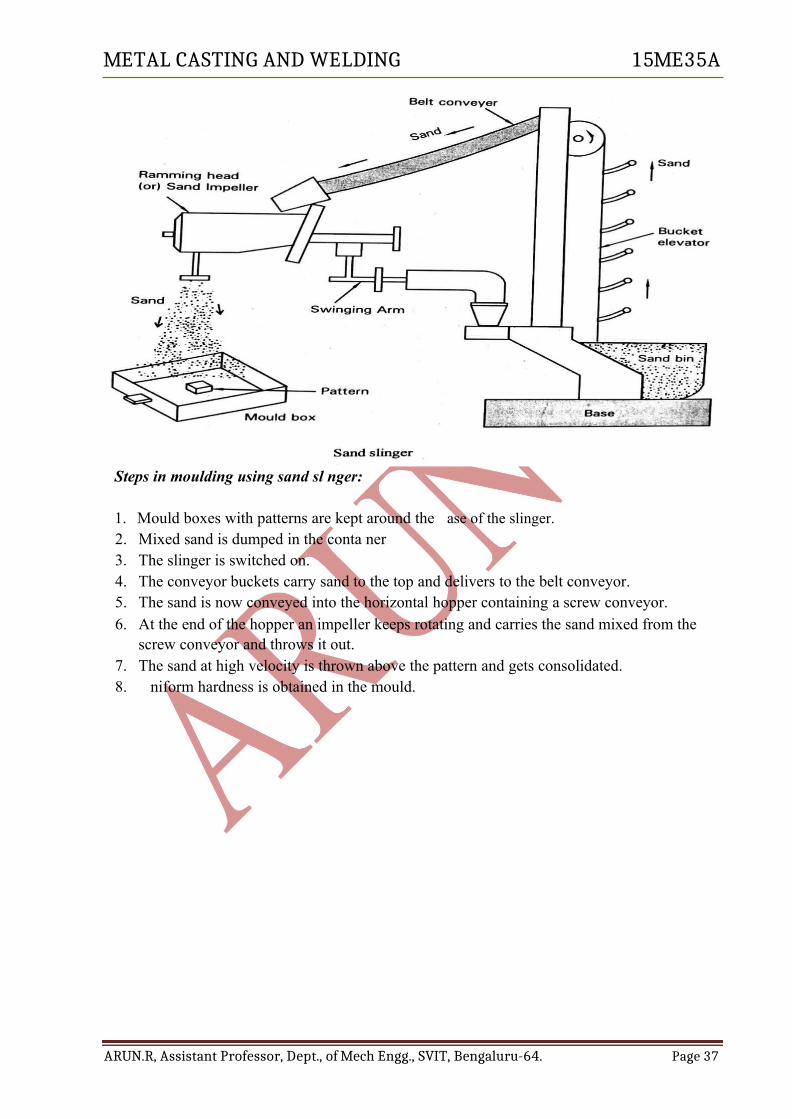
Steps in moulding using sand sl nger:
1. Mould boxes with patterns are kept around the ase of the slinger.2. Mixed sand is dumped in the conta ner3. The slinger is switched on.4. The conveyor buckets carry sand to the top and delivers to the belt conveyor.5. The sand is now conveyed into the horizontal hopper containing a screw conveyor.6. At the end of the hopper an impeller keeps rotating and carries the sand mixed from the
screw conveyor and throws it out.7. The sand at high velocity is thrown above the pattern and gets consolidated.8. niform hardness is obtained in the mould.
ARUN.R, Assistant Professor, Dept., of Mech Engg., SVIT, Bengaluru-64. Page 37