DEFECT FORMATION OF GRAY IRON CASTING Abstract
10
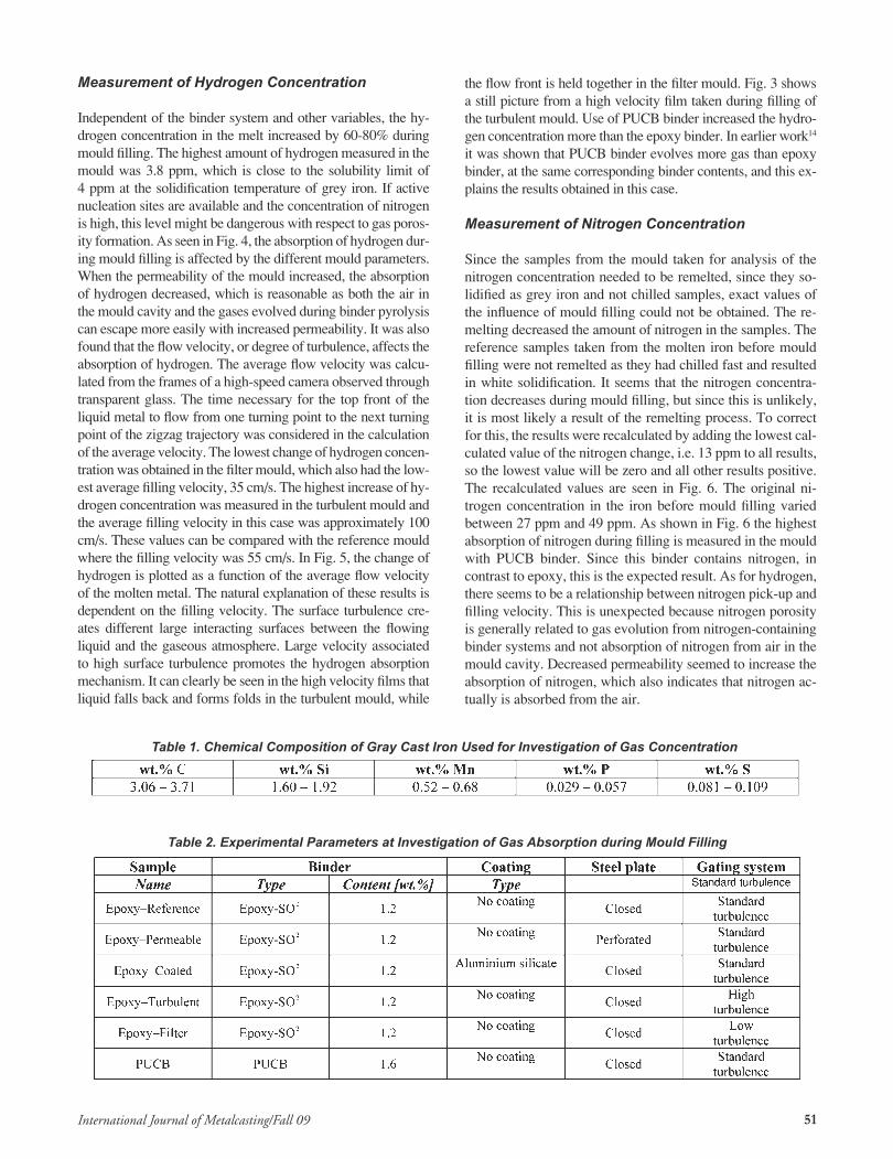
49 International Journal of Metalcasting/Fall 09 DEFECT FORMATION OF GRAY IRON CASTING A. Diószegi, L. Elmquist, J. Orlenius and I. Dugic Jönköping University, Jönköping, Sweden Copyright © 2009 American Foundry Society Abstract Cast iron is one of the oldest technical alloys (engineered cast materials) used for creating objects. From the very beginning of casting, foundrymen were fighting to avoid casting defects. In the beginning a successfully produced casting was associated with witchcraft. Cast component producers suffer substantial yearly expenses due to rejecting or repairing castings. This present work will summarize research efforts to understand the formation mechanisms of defects, performed in collaboration with Swedish foundries during the last few years. It will focus on defects specific to the casting of gray iron components and the studied defects: gas porosity, shrinkage porosity and metal expansion penetration. Novell experimental set up has been developed or existing methods have been improved to study defect formation mechanisms. Today we can realize that casting without defects is possible only by approaching the defect formation mechanism with multidisciplinary science. Keywords: cast iron, defects, gas porosity, shrinkage, metal expansion penetration, pinholes Introduction The research in this report has been performed within a collaborative project between Swedish foundries under the umbrella of Casting Innovation Center and a Swedish ini- tiative to promote the cast metal research. The performed work focused on understanding the formation mechanism of common casting defects such as gas porosity, shrinkage porosity and metal expansion penetration in gray cast iron components appearing at the collaborating foundries and taking action to eliminate or minimize their impact on the produced cast quality. Results from the research work have been reported in journals and conferences ending up with two PhD theses 1,3 and a Licentiate thesis 2 . The Licentiate thesis is a Swedish academic degree corresponding roughly 60 % of a PhD degree. Gas Porosity Gas porosity defects characterized in the literature as pin- holes, 4,5,6 are not only aesthetic problems but also counter- act the functionality of complex shaped cast components. These types of defects are revealed for the first time during the machining, process thus causing additional expenses. Two types of pinhole defects (hydrogen and nitrogen) are similar in appearance but different in formation mechanisms and have been reported in literature. In addition, pinholes are also linked to carbon monoxide. 4,5,7 The formation mecha- nism of pinholes have been linked to bubble formation from gases dissolved in liquid iron. Hydrogen and nitrogen are soluble in liquid iron and are dependent upon the raw mate- rials used, the melting method or the exposure of the metal to a gaseous environment during mold filling. The solubility of hydrogen in gray iron 8,9 is approximately 8 ppm in liquid state and drops to 4 ppm during solidification. The solubility levels of nitrogen are reported below 150 ppm, 9,10,11 but po- rosity defect formation has been reported when the nitrogen content is 110 – 150 ppm. 12,13 Gas Concentration in Gray Cast Iron Melted in Cupola And Induction Furnaces The influence of the melting process on the hydrogen and ni- trogen content in grey cast iron was investigated at two dif- ferent foundries. Both foundries produce iron using induc- tion furnaces, one also uses a cupola furnace. Measurements of gas concentrations were performed at different places in the process chain. In Foundry 1 the measurements were per- formed directly in the induction furnace, while in Foundry 2, the liquid iron both from the induction furnace and the cupola furnace, was transferred in a transport ladle of 3 tones before performing the measurement. Accordingly, the chemical composition varied somewhat, but the lower and upper limits are shown in Table 1. The hydrogen concen- tration was determined by an online sensing system based on thermal conductivity measurement of nitrogen gas cir- culated between the measuring unit and the liquid iron until equilibrium is achieved between the circulated nitrogen and the hydrogen dissolved in the liquid. The average concentra- tion of hydrogen in iron from induction furnaces were 2.1 and 2.7 ppm, while iron from cupola furnace has a concen- tration of 1.4 ppm. The differences between the induction furnaces are explained by the preheating of the charge when the lower value is obtained. When preheating the charge ma- terial, the amount of moisture is reduced contributing to a lower hydrogen concentration. The cupola furnace produces
-
Upload
khangminh22 -
Category
Documents
-
view
1 -
download
0
Transcript of DEFECT FORMATION OF GRAY IRON CASTING Abstract

49International Journal of Metalcasting/Fall 09
DEFECT FORMATION OF GRAY IRON CASTING
A. Diószegi, L. Elmquist, J. Orlenius and I. Dugic
Jönköping University, Jönköping, Sweden
Copyright © 2009 American Foundry Society
Abstract
Cast iron is one of the oldest technical alloys (engineered
cast materials) used for creating objects. From the very
beginning of casting, foundrymen were fighting to avoid
casting defects. In the beginning a successfully produced
casting was associated with witchcraft. Cast component
producers suffer substantial yearly expenses due to
rejecting or repairing castings. This present work will
summarize research efforts to understand the formation
mechanisms of defects, performed in collaboration with
Swedish foundries during the last few years. It will focus
on defects specific to the casting of gray iron components
and the studied defects: gas porosity, shrinkage porosity
and metal expansion penetration. Novell experimental
set up has been developed or existing methods have been
improved to study defect formation mechanisms. Today
we can realize that casting without defects is possible
only by approaching the defect formation mechanism with
multidisciplinary science.
Keywords: cast iron, defects, gas porosity, shrinkage, metal
expansion penetration, pinholes
Introduction
The research in this report has been performed within a
collaborative project between Swedish foundries under the
umbrella of Casting Innovation Center and a Swedish ini-
tiative to promote the cast metal research. The performed
work focused on understanding the formation mechanism
of common casting defects such as gas porosity, shrinkage
porosity and metal expansion penetration in gray cast iron
components appearing at the collaborating foundries and
taking action to eliminate or minimize their impact on the
produced cast quality. Results from the research work have
been reported in journals and conferences ending up with
two PhD theses1,3 and a Licentiate thesis2. The Licentiate
thesis is a Swedish academic degree corresponding roughly
60 % of a PhD degree.
Gas Porosity
Gas porosity defects characterized in the literature as pin-
holes,4,5,6 are not only aesthetic problems but also counter-
act the functionality of complex shaped cast components.
These types of defects are revealed for the first time during
the machining, process thus causing additional expenses.
Two types of pinhole defects (hydrogen and nitrogen) are
similar in appearance but different in formation mechanisms
and have been reported in literature. In addition, pinholes are
also linked to carbon monoxide.4,5,7 The formation mecha-
nism of pinholes have been linked to bubble formation from
gases dissolved in liquid iron. Hydrogen and nitrogen are
soluble in liquid iron and are dependent upon the raw mate-
rials used, the melting method or the exposure of the metal
to a gaseous environment during mold filling. The solubility
of hydrogen in gray iron8,9 is approximately 8 ppm in liquid
state and drops to 4 ppm during solidification. The solubility
levels of nitrogen are reported below 150 ppm,9,10,11 but po-
rosity defect formation has been reported when the nitrogen
content is 110 – 150 ppm.12,13
Gas Concentration in Gray Cast Iron Melted in
Cupola And Induction Furnaces
The influence of the melting process on the hydrogen and ni-
trogen content in grey cast iron was investigated at two dif-
ferent foundries. Both foundries produce iron using induc-
tion furnaces, one also uses a cupola furnace. Measurements
of gas concentrations were performed at different places in
the process chain. In Foundry 1 the measurements were per-
formed directly in the induction furnace, while in Foundry
2, the liquid iron both from the induction furnace and the
cupola furnace, was transferred in a transport ladle of 3
tones before performing the measurement. Accordingly, the
chemical composition varied somewhat, but the lower and
upper limits are shown in Table 1. The hydrogen concen-
tration was determined by an online sensing system based
on thermal conductivity measurement of nitrogen gas cir-
culated between the measuring unit and the liquid iron until
equilibrium is achieved between the circulated nitrogen and
the hydrogen dissolved in the liquid. The average concentra-
tion of hydrogen in iron from induction furnaces were 2.1
and 2.7 ppm, while iron from cupola furnace has a concen-
tration of 1.4 ppm. The differences between the induction
furnaces are explained by the preheating of the charge when
the lower value is obtained. When preheating the charge ma-
terial, the amount of moisture is reduced contributing to a
lower hydrogen concentration. The cupola furnace produces

50 International Journal of Metalcasting/Fall 09
iron with an even lower concentration of hydrogen based
on the same principal of effective preheating of the charge
material. The nitrogen concentration was determined with
optical emission spectroscopy together with the chemical
composition from coin shaped samples collected in resin
bounded sample molds. The measured concentration of ni-
trogen by this method includes both dissolved and bounded
nitrogen. Cupola iron contains the highest concentration of
nitrogen, 105 ppm. Differences between the induction melt-
ing methods are also observed, 75 and 95 ppm respectively.
The highest nitrogen concentration from the cupola furnace
is attributed to the high amount of steel scrap the coke used
as fuel and the air blown in to the cupola. Under the investi-
gated conditions, neither the induction nor the cupola melt-
ing method results in hydrogen or nitrogen concentrations
close to the solubility limit reported in the literature except
for the nitrogen in cupola iron.
Gas Absorption in Gray Cast Iron
During Mould Filling
A special mould was developed to investigate the absorp-
tion of hydrogen and nitrogen in the liquid iron during the
mould filling. The scope of the investigation was to measure
the gas concentration in a pouring ladle before casting, then
cast the liquid into a special deigned gating system allow-
ing a large but controlled interaction between the liquid and
the surrounding mould components, and finally collect the
liquid in an open feeder where the hydrogen and nitrogen
concentration can be measured again. The moulds were con-
structed in such a way that different parameters influencing
the absorption process can be tested. The first parameter var-
ied was the gating procedure in order to create a different
level of turbulence in the gating system. The standard filling
concept is shown in Fig 1. The liquid metal is poured in the
mould through a pouring cup placed over a downsprue fol-
lowed by an ascending flow in a zigzag shaped channel up to
the open feeder. To provoke a more turbulent flow compared
to the standard filling concept, the liquid was poured into the
mould through the open feeder allowing for an uncontrolled
flow through the zigzag channel and finally ascending back-
ward up in the downsprue and finally filling the pouring cup.
The third variation of the filling sequence (Fig. 2) was ar-
ranged by introducing two pressed ceramic filters with the
intention to reduce the flow velocity. For the visual obser-
vation of the mould filling, the front side of the mould was
covered with thermal resistant transparent glass. The second
parameter targeted to influence gas absorption was the gas
permeability from the sand mould out to the surroundings.
The front side of the mould was in every case impermeable
due to usage of the glass. To provoke a low permeability, the
back side of the lower mould was covered by a steel plate.
The variation in the permeability was obtained by perforat-
ing the steel plate with an open area of 40%. The mould ma-
terial was made in sand using two different binders, Epoxy-
SO2 and PUCB (Phenolic Urethane Coldbox). The influence
of coating the inner surface of the mould was investigated
by coating with an aluminium silicate based coating. The
chemical composition of the melt was held in the middle of
the variation range reported in Table 1. The average pouring
temperature was 1445°C (2633°F). The measuring methods
of hydrogen concentrations were identical with those used
for measurement in the previous section. The measurement
method of nitrogen concentration for samples taken before
pouring were identical with the previously described meth-
od. The samples aimed for investigation of the nitrogen con-
tent after mould filling were cut out from the open feeder.
Due to the slow solidification rate, the samples was remelted
and cast into a die to obtain white solidification structure
necessary for the optical emission spectroscopy investiga-
tion. The experimental setup is summarized in Table 2.
Figure 1. Mould layout for
measuring gas absorption
Figure 2. Mould layout
surface turbulence.
51International Journal of Metalcasting/Fall 09
Measurement of Hydrogen Concentration
Independent of the binder system and other variables, the hy-
drogen concentration in the melt increased by 60-80% during
mould filling. The highest amount of hydrogen measured in the
mould was 3.8 ppm, which is close to the solubility limit of
4 ppm at the solidification temperature of grey iron. If active
nucleation sites are available and the concentration of nitrogen
is high, this level might be dangerous with respect to gas poros-
ity formation. As seen in Fig. 4, the absorption of hydrogen dur-
ing mould filling is affected by the different mould parameters.
When the permeability of the mould increased, the absorption
of hydrogen decreased, which is reasonable as both the air in
the mould cavity and the gases evolved during binder pyrolysis
can escape more easily with increased permeability. It was also
found that the flow velocity, or degree of turbulence, affects the
absorption of hydrogen. The average flow velocity was calcu-
lated from the frames of a high-speed camera observed through
transparent glass. The time necessary for the top front of the
liquid metal to flow from one turning point to the next turning
point of the zigzag trajectory was considered in the calculation
of the average velocity. The lowest change of hydrogen concen-
tration was obtained in the filter mould, which also had the low-
est average filling velocity, 35 cm/s. The highest increase of hy-
drogen concentration was measured in the turbulent mould and
the average filling velocity in this case was approximately 100
cm/s. These values can be compared with the reference mould
where the filling velocity was 55 cm/s. In Fig. 5, the change of
hydrogen is plotted as a function of the average flow velocity
of the molten metal. The natural explanation of these results is
dependent on the filling velocity. The surface turbulence cre-
ates different large interacting surfaces between the flowing
liquid and the gaseous atmosphere. Large velocity associated
to high surface turbulence promotes the hydrogen absorption
mechanism. It can clearly be seen in the high velocity films that
liquid falls back and forms folds in the turbulent mould, while
the flow front is held together in the filter mould. Fig. 3 shows
a still picture from a high velocity film taken during filling of
the turbulent mould. Use of PUCB binder increased the hydro-
gen concentration more than the epoxy binder. In earlier work14
it was shown that PUCB binder evolves more gas than epoxy
binder, at the same corresponding binder contents, and this ex-
plains the results obtained in this case.
Measurement of Nitrogen Concentration
Since the samples from the mould taken for analysis of the
nitrogen concentration needed to be remelted, since they so-
lidified as grey iron and not chilled samples, exact values of
the influence of mould filling could not be obtained. The re-
melting decreased the amount of nitrogen in the samples. The
reference samples taken from the molten iron before mould
filling were not remelted as they had chilled fast and resulted
in white solidification. It seems that the nitrogen concentra-
tion decreases during mould filling, but since this is unlikely,
it is most likely a result of the remelting process. To correct
for this, the results were recalculated by adding the lowest cal-
culated value of the nitrogen change, i.e. 13 ppm to all results,
so the lowest value will be zero and all other results positive.
The recalculated values are seen in Fig. 6. The original ni-
trogen concentration in the iron before mould filling varied
between 27 ppm and 49 ppm. As shown in Fig. 6 the highest
absorption of nitrogen during filling is measured in the mould
with PUCB binder. Since this binder contains nitrogen, in
contrast to epoxy, this is the expected result. As for hydrogen,
there seems to be a relationship between nitrogen pick-up and
filling velocity. This is unexpected because nitrogen porosity
is generally related to gas evolution from nitrogen-containing
binder systems and not absorption of nitrogen from air in the
mould cavity. Decreased permeability seemed to increase the
absorption of nitrogen, which also indicates that nitrogen ac-
tually is absorbed from the air.

52 International Journal of Metalcasting/Fall 09
Shrinkage Porosity
Shrinkage Porosity in Gray Iron Cast Components
Shrinkage porosity in complex shaped cast iron components,
particularly in cylinder heads, are defects that compromise
the functionality of an engine during the operation. The main
cause for reduced functionality is due to leakage between the
different sections of the cylinder head designed for trans-
porting fuel, cooling media, intake or exhausting gases. A
standard measure to avoid leakage is to apply a Tellurium
based coating on surfaces where leakage is observed. Tel-
lurium, a strong carbide promoter, contributes to the creation
of a thin carbide layer on the casting surface and impedes
the leakage through this surface. The drawback of this appli-
cation is the brittle properties of the carbide with increased
risk for crack initiation. A less active element, Bismuth, is
another element added to coatings to prevent leakage. The
reason for the positive effect of Bismuth is not well under-
stood. The possible influence of Bismuth on the austenite
dendrite growth could affect the dendrite shape.15 From this
observation, the authors conclude that Bismuth influences
the path length between the austenite dendrite arms.
Cylinder heads from two different foundries has been ex-
amined. Both castings, with and without leakage defects,
were included. The scope of the examination was to identify
to all results.
possible factors influencing the shrinkage porosity forma-
tion mechanisms. Both foundries use induction furnaces for
melting the iron with compositions included in the range
presented in Table 1. The castings are molded in green sand
at both foundries, but the internal cores were processed us-

53International Journal of Metalcasting/Fall 09
ing different core bounding systems. A basic observation is
that on the surface of the casting identified as an area for
leakage is the ragged surface, in comparison to surfaces
where no leakage was observed. On the surfaces where no
leakage is present, the surface is smooth. Ragged surfaces
include craters (Fig. 7.) with a configuration similar to a na-
ked primary austenite dendrite. The cross section of the cast-
ing in the area with leakage is presented in a color etched mi-
crograph on Fig. 8. In many cases the porosities are clearly
seen to be connected to the casting surface. Fig. 9 indicates
an internal porosity where the cavity is bordered between
primary austenite dendrites and the surface of the dendrite is
covered with thin oxide layers. The oxide layers are believed
to form at elevated temperatures due to contact with oxy-
gen from the atmosphere, outside of the casting. The color
etched picture indicates the distribution of the porosities in
the microstructure exclusively in the neighborhood of the
eutectic cells. In single cases a eutectic cell is surrounded by
porosity, but most often several eutectic cells are engulfed
by porosities. The observations presented clearly note that
the observed leakage was caused by porosities enmeshing
the metallic matrix but it gives no indication on when the po-
rosities are formed during the solidification interval. General
indications in the literature for shrinkage porosity formed at
the end of solidification cannot be confirmed from this ob-
servation due to the larger number of eutectic cells engulfed
by a coherent porosity area.
Studying Shrinkage Porosity Formation
Earlier investigation by the authors16 indicates that macro-
structure of gray cast iron, including austenite grains, contains
several eutectic cells between the primary austenite dendrites.
This observation, in context with coherent shrinkage porosity
engulfing several eutectic cells, may raise the question wheth-
er this type of shrinkage porosity is not formed earlier during
the solidification, being influenced by the macrostructure and
the primary austenite dendrite network.
The complex shaped cast component is not satisfactory to
perform structured investigation including macrostructure
investigation. A heat treatment called DAAS17 is neces-
sary to retain the grain structure of cast iron, otherwise the
austenite will transform to pearlite. For this purpose a spe-
cial sample with a less complex shape than a cylinder head
but including combinations of cylindrical and plate shaped
geometrical components, was designed. (Fig. 10.). The test
samples were molded in furan bounded sand and cast from
the same alloy as was used for the cylinder head investiga-
tion. The samples were DAAS treated and the cross sec-
tion in the bottom of the middle cylindrical bar has been
identified as containing shrinkage porosities of the same
type and at the same extent as was found in cylinder heads.
Fig. 11 shows the grain boundaries of the primary austenite
dendrites. There is a clear distinction between the shape
and the perpendicular position of the columnar austenite
dendrite in relation to the mould wall. There is a layer of
primary columnar dendrites on each surface and between

54 International Journal of Metalcasting/Fall 09
these layers there is an area containing the equiaxed aus-
tenite dendrites. The shrinkage porosities are found in the
lower right side of the cross section of the sample. At a
higher magnification (Fig 12.) it is clearly visible the posi-
tion of the porosities concentrated in the border between
the columnar austenite grains. The thermal behavior of this
sample is comparable with the thermal distribution of a
cylinder head. An important observation, after solidifica-
tion simulation of the sample, is that the local hot spot of
the sample in the cross section of the middle cylindrical
bar is migrating during solidification. The position of the
hot spot as a function of time and temperature is indicated
in Fig. 13. The simulation software used to perform the so-
lidification simulation was MAGMAsoft. Another impor-
tant observation is the coincidence between the moving hot
spot and the shape and extent of the austenite grains in the
layer to right, which incorporates even the shrinkage po-
rosities. The austenite grains look out to be smaller than on
the opposite wall, but the transition between the columnar
to equiaxed grains is situated at the same distance from the
respective surfaces. A possible explanation is the very slow
and distorted grain growth direction due to the moving hot
spot where the grain boundaries have been changed similar
to a recrystallization process.
The conclusion from the present investigation is that the
time for this type of shrinkage porosity formation is early
in the solidification process, and probably coincides dur-
ing the columnar to equiaxed transition when the need
for feeding the austenite growth leads to transport phe-
nomena between the primary austenite grains. Gases from
the surrounding atmosphere are sucked into the border
grains.
function of space and time.
treatment. Columnar austenite grains

55International Journal of Metalcasting/Fall 09
between the columnar austenite dendrite. The distorted
austenite grains, due to the hot spot migration, are be-
lieved to be extremely permeable thus facilitating the
transport phenomena. Once the porosities formed in the
border of the austenite grains, the solidification continues
with the coarsening of the austenite dendrite followed by
the growth of the eutectic phase. In this case, the eutec-
tic phase is developing after the porosities were formed
and the surplus of liquid due to graphite expansion is not
enough to compensate for the existing pores. The pro-
posed mechanism for porosity formation is useful to ex-
plain how the tellurium-based coating was successful in
preventing shrinkage porosity formation.
Gray Cast Iron Cast Components
Collaborating research partner foundries have reported
that metal expansion penetration appears on surfaces
where leakage due to shrinkage porosity occurs. In cyl-
inder heads the most affected surfaces are between the
casting and complex shaped cores forming an internal
cavity for transport of the cooling media (Fig. 14). These
surfaces are often not accessible and only be examined
with difficulty. Non-cleaned surfaces, from the mixture
of a metallic-sand grain matrix, may reduce the cooling
effectiveness and disturb the optimal engine operation.
Examination of cylinder heads and the metallic–sand
grain matrix reveal that the metallic fraction of the pen-
etrated mixture has different microstructure. In minor
cases the matrix includes a mixture of metallic phases
and graphite where the metallic phase contains both pri-
mary and eutectic austenite, which corresponds with the
hypo-eutectic composition used for produce this cast-
ings (Fig. 15). The dominant case is when the metallic
matrix contains pure eutectic phase (Fig. 16), which is
deduced from the appearance of the colour etched mi-
crographs completely missing the primary phase. The
observations indicate that the penetration moment could
happen at different stages of the solidification, such as
during the primary solidification indicated by the hypo-
eutectic composition of the penetrated metal and during
the eutectic solidification indicated by the pure eutectic
composition in the penetrated matrix.
austenite.

56 International Journal of Metalcasting/Fall 09
For the same reason, as indicated in the case of shrink-
age porosity, to improve the ease of examination, a spe-
cial designed casting sample has been created to investi-
gate the mechanism of expansion penetration formation.
The simulation indicated similarities to the shrinkage
porosity casting samples in that the hot spot of the cast-
ing is migrating from an initial position corresponding
to the mass center of the casting to the surface between
the concave metal surface and the mould wall (Fig. 17).
The test mould has been formed in bonded sand using
Epoxy-SO2 method and DAAS treated. The coincidence
is obvious with the case of samples used to study shrink-
age porosity; the columnar austenite dendrite zone on
the concave casting surface is shorter than in connec-
tion to the other surfaces (Fig. 18). In this case we can
conclude that the migrating hot spot has an influence on
the development of the columnar austenite dendrite in
the area where metal expansion penetration is expected.
Two mainly different mechanisms have been observed
from these experiments. One mechanism is the complete
distortion of the columnar zone (Fig. 19). The area be-
hind the distorted dendrite zone contains small primary
austenite dendrites surrounded by a metallic phase con-
taining carbides (Fig. 20). The conclusion from this ob-
servation is that an internal pressure of the liquid has de-
formed the columnar zone. The concave surface swelled
backward and the area behind was filled up with a liquid
of hypoeutectic composition. The time for this type of
penetration is believed to coincide with the primary so-
lidification. The second observed mechanism indicates
a metal strip, squeezed behind the sand grains forming
the mould surface (Fig. 21). The observed color etched
micrograph indicates this strip being of a pure eutectic
composition without any primary phase (Fig. 22). The
time for this type of penetration is suggested to be dur-
ing the eutectic solidification in the bulk metal when the
surplus of liquid from the interspaces of austenite den-
drite is squeezed between the sand grains.
radius is 15 mm.

57International Journal of Metalcasting/Fall 09
Conclusion
A strong comprehensive collaboration between Swedish
foundries including new investigation methods and novel
experimental setup has pointed out some basic understand-
ing on the formation mechanisms of gas porosity, shrink-
age porosity and metal expansion penetration in gray cast
iron components.
New investigation methods used to obtain the results report-
ed in this paper are:
in liquid iron
including the primary austenite phase
-
crostructure on the same micrograph
Novel experimental setups used to obtain the results report-
ed in this paper:
surface for observing the liquid flow
during mould filling
-
rosity and metal expansion penetration
The variety of the tools including methods and experimental
setups, necessary to obtain the presented complex mecha-
nisms are considered to make the difference between witch-
craft and multidisciplinary science.
REFERENCES
1. Dugic, I., “The Mechanism of Metal Expansion
Penetration During Solidification of Gray Cast Iron,”
Linköping Studies in Science and Technology,
Dissertation No. 1007, (2006).
2. Orlenius, J., “Factors Related to the Formation of Gas
Porosity in Gray Cast Iron,” Research Series from
Chalmers University of Technology, ISSN 1653-8891,
Licentiate Theses. (2008).
3. Elmquist, L., “Defect Formation during Solidification
in Gray Cast Iron,” Research Series from Chalmers
University of Technology, PhD Theses. (2009).
4. Dawson, J.V., Kilshaw, J.A., Morgan, A.D., “The
Nature and Origin of Gas Holes in Iron Castings,” AFS
Transactions, vol 73, pp 224-240 (1965).
5. Hernandez, B., Wallace, J.F., “Mechanisms of Pinhole
Formation in Gray Iron,” AFS Transactions, vol 87, pp
335-348 (1979).
6. Dawson, J.V., “Pinhole Defects,” BCIRA, Report 653,
pp 433-437 (1962).
7. Svoboda, J.M., “Fundamentals of Physical Chemistry
Relating to Gases in Cast Metals,” Gases in Cast
Metals; Williamsburg; VA; 24-26 Mar. 1976, 46 pp
(1976).

58 International Journal of Metalcasting/Fall 09
8. Svensson, I., “Influence of Deoxidation Practice on
Hydrogen Pick-up in Steel Melts,” Solidification
Technology in the Foundry and Cast House; Coventry;
England; 15-17 Sept. 1980, pp 253-262 (1983).
9. Svensson, I., Fredriksson, H.S., “Effect of Hydrogen and
Nitrogen on Formation of Pores in Iron,” Solidification
Technology in the Foundry and Cast House; Coventry;
England; 15-17 Sept. 1980, pp 376-380 (1983).
10. Fruehan, R.J., “Gases in Metals,” ASM Handbook, vol
15, pp 82-87 (1988).
11. Shusen, W., Libiao, W., “The Variation of Hydrogen,
Oxygen, and Nitrogen Levels in Cast Iron with
Varying Blast-Air Moisture,” Cast Metals, vol 5, no 2,
pp 87-91 (1992).
12. Carter, S.F., Evans, W.J., Harkness, J.C., Wallace, J.F.,
“Factors Influencing the Formation of Pinholes in Gray
and Ductile Iron,” AFS Transactions, vol 88, pp 245-
268 (1980).
13. Caspers, K.-H., “Influence of Steel Scrap and Burden
Additives in Induction Furnaces on the Tendency for
Defect Formation in Cast Iron,” AFS International Cast
Metals Journal, vol 2, No 29, pp 29-32 (1977).
14. Orlenius, J., Gotthardsson, U., and Diószeg, A.,
Submitted to International Journal of Cast Metals
Research. (2008).
15. Winardi, L., Loper, C.R., “Influence of Bismuth
Addition on Primary Austenite Dendrite in Gray Cast
Iron”, AFS Transactions, vol 112, pp 723-742 (2004).
16. Diószegi, A., Liu, K.Z., and Svensson, I.L.,
“Inoculation of Primary Austenite in Grey Cast Iron,”
International Journal of Cast Metals Research. Vol. 20,
no. 2, pp. 68-72 (2007).
17. Rivera, J.L., Boeri, R.E., Sikora, J.A., “Solidification
of Gray Cast Iron,” Scripta Materialia, vol.50, pp.331-
335, (2004).