Swage casting of A380 alloy
8
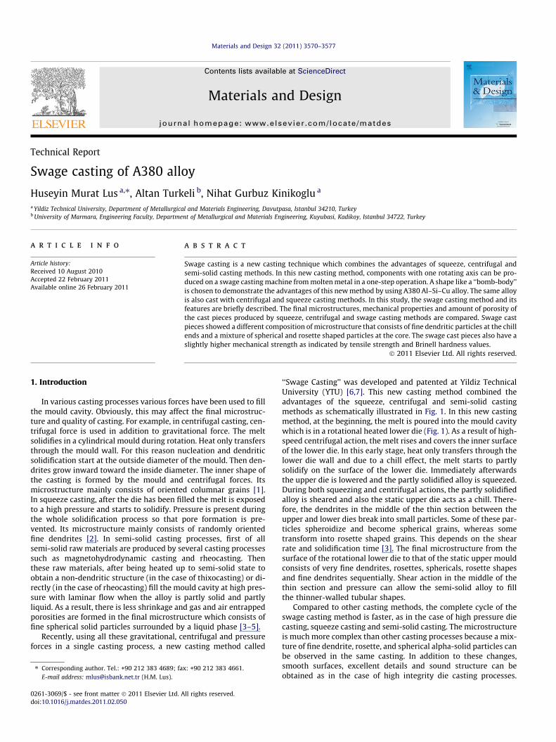
Technical Report Swage casting of A380 alloy Huseyin Murat Lus a,⇑ , Altan Turkeli b , Nihat Gurbuz Kinikoglu a a Yildiz Technical University, Department of Metallurgical and Materials Engineering, Davutpasa, Istanbul 34210, Turkey b University of Marmara, Engineering Faculty, Department of Metallurgical and Materials Engineering, Kuyubasi, Kadikoy, Istanbul 34722, Turkey article info Article history: Received 10 August 2010 Accepted 22 February 2011 Available online 26 February 2011 abstract Swage casting is a new casting technique which combines the advantages of squeeze, centrifugal and semi-solid casting methods. In this new casting method, components with one rotating axis can be pro- duced on a swage casting machine from molten metal in a one-step operation. A shape like a ‘‘bomb-body’’ is chosen to demonstrate the advantages of this new method by using A380 Al–Si–Cu alloy. The same alloy is also cast with centrifugal and squeeze casting methods. In this study, the swage casting method and its features are briefly described. The final microstructures, mechanical properties and amount of porosity of the cast pieces produced by squeeze, centrifugal and swage casting methods are compared. Swage cast pieces showed a different composition of microstructure that consists of fine dendritic particles at the chill ends and a mixture of spherical and rosette shaped particles at the core. The swage cast pieces also have a slightly higher mechanical strength as indicated by tensile strength and Brinell hardness values. Ó 2011 Elsevier Ltd. All rights reserved. 1. Introduction In various casting processes various forces have been used to fill the mould cavity. Obviously, this may affect the final microstruc- ture and quality of casting. For example, in centrifugal casting, cen- trifugal force is used in addition to gravitational force. The melt solidifies in a cylindrical mould during rotation. Heat only transfers through the mould wall. For this reason nucleation and dendritic solidification start at the outside diameter of the mould. Then den- drites grow inward toward the inside diameter. The inner shape of the casting is formed by the mould and centrifugal forces. Its microstructure mainly consists of oriented columnar grains [1]. In squeeze casting, after the die has been filled the melt is exposed to a high pressure and starts to solidify. Pressure is present during the whole solidification process so that pore formation is pre- vented. Its microstructure mainly consists of randomly oriented fine dendrites [2]. In semi-solid casting processes, first of all semi-solid raw materials are produced by several casting processes such as magnetohydrodynamic casting and rheocasting. Then these raw materials, after being heated up to semi-solid state to obtain a non-dendritic structure (in the case of thixocasting) or di- rectly (in the case of rheocasting) fill the mould cavity at high pres- sure with laminar flow when the alloy is partly solid and partly liquid. As a result, there is less shrinkage and gas and air entrapped porosities are formed in the final microstructure which consists of fine spherical solid particles surrounded by a liquid phase [3–5]. Recently, using all these gravitational, centrifugal and pressure forces in a single casting process, a new casting method called ‘‘Swage Casting’’ was developed and patented at Yildiz Technical University (YTU) [6,7]. This new casting method combined the advantages of the squeeze, centrifugal and semi-solid casting methods as schematically illustrated in Fig. 1. In this new casting method, at the beginning, the melt is poured into the mould cavity which is in a rotational heated lower die (Fig. 1). As a result of high- speed centrifugal action, the melt rises and covers the inner surface of the lower die. In this early stage, heat only transfers through the lower die wall and due to a chill effect, the melt starts to partly solidify on the surface of the lower die. Immediately afterwards the upper die is lowered and the partly solidified alloy is squeezed. During both squeezing and centrifugal actions, the partly solidified alloy is sheared and also the static upper die acts as a chill. There- fore, the dendrites in the middle of the thin section between the upper and lower dies break into small particles. Some of these par- ticles spheroidize and become spherical grains, whereas some transform into rosette shaped grains. This depends on the shear rate and solidification time [3]. The final microstructure from the surface of the rotational lower die to that of the static upper mould consists of very fine dendrites, rosettes, sphericals, rosette shapes and fine dendrites sequentially. Shear action in the middle of the thin section and pressure can allow the semi-solid alloy to fill the thinner-walled tubular shapes. Compared to other casting methods, the complete cycle of the swage casting method is faster, as in the case of high pressure die casting, squeeze casting and semi-solid casting. The microstructure is much more complex than other casting processes because a mix- ture of fine dendrite, rosette, and spherical alpha-solid particles can be observed in the same casting. In addition to these changes, smooth surfaces, excellent details and sound structure can be obtained as in the case of high integrity die casting processes. 0261-3069/$ - see front matter Ó 2011 Elsevier Ltd. All rights reserved. doi:10.1016/j.matdes.2011.02.050 ⇑ Corresponding author. Tel.: +90 212 383 4689; fax: +90 212 383 4661. E-mail address: [email protected] (H.M. Lus). Materials and Design 32 (2011) 3570–3577 Contents lists available at ScienceDirect Materials and Design journal homepage: www.elsevier.com/locate/matdes
-
Upload
independent -
Category
Documents
-
view
0 -
download
0
Transcript of Swage casting of A380 alloy
Materials and Design 32 (2011) 3570–3577
Contents lists available at ScienceDirect
Materials and Design
journal homepage: www.elsevier .com/locate /matdes
Technical Report
Swage casting of A380 alloy
Huseyin Murat Lus a,⇑, Altan Turkeli b, Nihat Gurbuz Kinikoglu a
a Yildiz Technical University, Department of Metallurgical and Materials Engineering, Davutpasa, Istanbul 34210, Turkeyb University of Marmara, Engineering Faculty, Department of Metallurgical and Materials Engineering, Kuyubasi, Kadikoy, Istanbul 34722, Turkey
a r t i c l e i n f o
Article history:Received 10 August 2010Accepted 22 February 2011Available online 26 February 2011
0261-3069/$ - see front matter � 2011 Elsevier Ltd. Adoi:10.1016/j.matdes.2011.02.050
⇑ Corresponding author. Tel.: +90 212 383 4689; faE-mail address: [email protected] (H.M. Lus).
a b s t r a c t
Swage casting is a new casting technique which combines the advantages of squeeze, centrifugal andsemi-solid casting methods. In this new casting method, components with one rotating axis can be pro-duced on a swage casting machine from molten metal in a one-step operation. A shape like a ‘‘bomb-body’’is chosen to demonstrate the advantages of this new method by using A380 Al–Si–Cu alloy. The same alloyis also cast with centrifugal and squeeze casting methods. In this study, the swage casting method and itsfeatures are briefly described. The final microstructures, mechanical properties and amount of porosity ofthe cast pieces produced by squeeze, centrifugal and swage casting methods are compared. Swage castpieces showed a different composition of microstructure that consists of fine dendritic particles at the chillends and a mixture of spherical and rosette shaped particles at the core. The swage cast pieces also have aslightly higher mechanical strength as indicated by tensile strength and Brinell hardness values.
� 2011 Elsevier Ltd. All rights reserved.
1. Introduction
In various casting processes various forces have been used to fillthe mould cavity. Obviously, this may affect the final microstruc-ture and quality of casting. For example, in centrifugal casting, cen-trifugal force is used in addition to gravitational force. The meltsolidifies in a cylindrical mould during rotation. Heat only transfersthrough the mould wall. For this reason nucleation and dendriticsolidification start at the outside diameter of the mould. Then den-drites grow inward toward the inside diameter. The inner shape ofthe casting is formed by the mould and centrifugal forces. Itsmicrostructure mainly consists of oriented columnar grains [1].In squeeze casting, after the die has been filled the melt is exposedto a high pressure and starts to solidify. Pressure is present duringthe whole solidification process so that pore formation is pre-vented. Its microstructure mainly consists of randomly orientedfine dendrites [2]. In semi-solid casting processes, first of allsemi-solid raw materials are produced by several casting processessuch as magnetohydrodynamic casting and rheocasting. Thenthese raw materials, after being heated up to semi-solid state toobtain a non-dendritic structure (in the case of thixocasting) or di-rectly (in the case of rheocasting) fill the mould cavity at high pres-sure with laminar flow when the alloy is partly solid and partlyliquid. As a result, there is less shrinkage and gas and air entrappedporosities are formed in the final microstructure which consists offine spherical solid particles surrounded by a liquid phase [3–5].
Recently, using all these gravitational, centrifugal and pressureforces in a single casting process, a new casting method called
ll rights reserved.
x: +90 212 383 4661.
‘‘Swage Casting’’ was developed and patented at Yildiz TechnicalUniversity (YTU) [6,7]. This new casting method combined theadvantages of the squeeze, centrifugal and semi-solid castingmethods as schematically illustrated in Fig. 1. In this new castingmethod, at the beginning, the melt is poured into the mould cavitywhich is in a rotational heated lower die (Fig. 1). As a result of high-speed centrifugal action, the melt rises and covers the inner surfaceof the lower die. In this early stage, heat only transfers through thelower die wall and due to a chill effect, the melt starts to partlysolidify on the surface of the lower die. Immediately afterwardsthe upper die is lowered and the partly solidified alloy is squeezed.During both squeezing and centrifugal actions, the partly solidifiedalloy is sheared and also the static upper die acts as a chill. There-fore, the dendrites in the middle of the thin section between theupper and lower dies break into small particles. Some of these par-ticles spheroidize and become spherical grains, whereas sometransform into rosette shaped grains. This depends on the shearrate and solidification time [3]. The final microstructure from thesurface of the rotational lower die to that of the static upper mouldconsists of very fine dendrites, rosettes, sphericals, rosette shapesand fine dendrites sequentially. Shear action in the middle of thethin section and pressure can allow the semi-solid alloy to fillthe thinner-walled tubular shapes.
Compared to other casting methods, the complete cycle of theswage casting method is faster, as in the case of high pressure diecasting, squeeze casting and semi-solid casting. The microstructureis much more complex than other casting processes because a mix-ture of fine dendrite, rosette, and spherical alpha-solid particles canbe observed in the same casting. In addition to these changes,smooth surfaces, excellent details and sound structure can beobtained as in the case of high integrity die casting processes.

Fig. 1. (a) Swage casting machine and die assembly. (b) Schematic illustration of swage casting process and solid shape of cast piece.
Table 1Chemical composition of A380 alloy used in this study and nominal solidificationrange.
Element Si Fe Cu Mg Zn Al
Content (wt.%) 8.73 0.603 3.09 0.216 0.453 Rest.SolidificationRange [1] 537–593 �C
H.M. Lus et al. / Materials and Design 32 (2011) 3570–3577 3571
However, swage casting demands an exact determination of theamount of melt needed. Cores cannot be used to produce complexparts. Only cylindrical shapes can be produced [6,7].
In this study, a multifunctional swage cast machine is designedto cast a shape like a bomb-body shape with A380 die cast alumi-num alloy. This multifunctional swage casting machine is also usedwith squeeze and centrifugal castings for the same shape with thesame amount of melt and the same alloy. Microstructures of thesecasting components are characterized by using an optic microscopeand a scanning electron microscope whereas hardness and tensilestrength are measured with hardness and uniaxial tensile equip-ment, respectively. The amount of porosity is also measured withthe Archimedes’ principle. Results obtained from these three differ-ent casting methods are compared to each other and discussed.
2. Experimental procedure
2.1. Material selection
A380 alloy aluminum contains high silicon and copper. Siliconin the range of 7.5–9.5 wt.% provides good castability and fluiditywhereas copper in the range of 3.0–4.0 wt. contributes to moder-ately high strength and good machinability [8]. In this alloy, theiron content can be higher than other aluminum casting alloys.This good combination of alloying elements is suitable for a widerange of application fields, e.g. automotive components, enginebrackets, transmission and gear cases. Therefore, it is by far themost widely cast aluminum die cast alloy [9]. For this reasonA380 Al–Si–Cu alloy was chosen in this study to investigate theprinciples of swage casting, and also to compare microstructuresobtained from this new method with squeeze and centrifugal cast-ings. The chemical composition was analyzed using an opticalspectrometer system (Hilger analytical). Its composition and solid-ification range are given in Table 1.
2.2. Die assembly
The swage casting machine designed and used in this studyconsists of three parts which are the turnable lower die, staticupper die, and bottom-holed cylindrical seal cover. The static
upper die is in the shape of a bomb-body and its function is to pro-vide high pressure and also create the mould cavity. During swageand squeeze castings, the static upper die is attached to a ram of100 ton hydraulic press. The lower die is in the form of a cylindricalshape having a bomb-body die cavity and can also rotate through-out a large range of rotational speed. During vertical centrifugalcasting and swage casting, the lower die is mounted to a verticalcentrifugal casting machine installed in the bed of the hydraulicpress. The diameters of the lower and upper dies were chosen as48 mm and 67 mm, respectively. Therefore, when the upper dieis inserted into the lower die the thickness between them remainsapproximately 10 mm in most parts of the casting piece. Theheight of the cavity is 200 mm. It is also necessary to use the bot-tom-holed cylindrical seal cover and put it on the lower die in or-der to keep the melt in the mould cavity during all three castingprocesses. The diameter of the hole in the bottom is chosen assame as the diameter of the upper die (48 mm). The all-steel diesused in these processes are made of DIN 1.2344 Hot Work ToolSteel because of a very good heat resistance alloy. The surfaces ofboth upper and lower dies were coated with ZYP Coatings BoronNitride Aerosol Lubricoat� at room temperature to improve easeof removal.
2.3. Casting methods
In swage casting, first of all, both the upper and lower dies wereheated to 200 �C to increase the fluidity of the alloy and for uni-form solidification, then the lower one was rotated at 600 rpm. A15 KW, 9600 Hz Lepel Induction Furnace was used for meltingthe alloy in a SiC crucible. Whenever the temperature of the de-gassed liquid alloy decreased to around 830 �C, it was poured into

Table 2Process parameters for each casting method.
Casting No. Squeezing pressure (Mpa) Squeezing time (s) Die temperature (�C) Pouring temperature (�C) Lower die speed (rpm)
1 Centrifugal – – 203 835 6002 Squeeze 10 10 203 830 –3 Swage 10 10 202 825 600
3572 H.M. Lus et al. / Materials and Design 32 (2011) 3570–3577
the lower die, and then immediately the melt was squeezed un-der 10 MPa for approximately 10 s. For the squeeze casting, thecentrifugal casting machine was removed and replaced with asupporting unit for the lower die. Similar to the swage castingprocess, the dies were heated with an electrical heater andcoated with the same lubricant (ZYP Coatings Boron Nitride
Fig. 2. Comparison of typical microstructures of centrifugal (a1, a2, a3), squeeze (b1, b2,and the inner surface of the die respectively.
Aerosol Lubricoat�). After pouring the degassed, superheatedmelt into the die cavity, 10 MPa pressure was applied forapproximately the same time delay. The same amount of liquidmetal was used for squeeze casting without centrifuging andfor centrifugal casting without pressing. The casting conditionsused in this study are given in Table 2.
b3) and swage (c1, c2, c3) taken from the outer surface, the middle of a thin section

Table 3Average secondary dendrite arm spacing (SDAS) and spherical particle diameter (SPD)values for each casting method.
Casting method SDAS or SPD (lm)
Outer surface Center Inner surface
Centrifugal casting 15–20 20–30 25–35Squeeze casting 8 15 10Swage casting 10 25–40 (SPD) 10
H.M. Lus et al. / Materials and Design 32 (2011) 3570–3577 3573
2.4. Microstructural analysis
For systematic metallographic examination, eight specimenswere taken from the bottom to the top in the swage cast piece,to investigate the variation of microstructure with distance. Tocompare the variation of microstructures across the thickness,three specimens were taken from each of the cast pieces (swagecasting, centrifugal casting, and squeeze casting). The transversalsections of the samples were polished and then etched with Kel-ler’s reagent for a period of 30 s at room temperature. Secondarydendrite arm spacing (SDAS) measurements were carried out usinga LEICA image analyzer. Scanning electron micrographs were takenwith SEM JEOL JSM 6335F under 20 kV.
Fig. 3. Microstructure variations with the distance from the bottom to the top in the swa150 mm, and (h) 175 mm, from the bottom. (a) Dendritic, (b, c) rosette, (d–h) spherical
2.5. Porosity measurement
Several methods such as direct method, optical method, andArchimedes’s method can be employed to measure porosity incasting samples. In this study the amount of porosity was mea-sured by using 3 cm3 specimens for each casting method withthe Archimedes’ principle as described by Taylor et al. [10]. Fivespecimens were taken from different regions in the middle of thecasting pieces for all casting methods so that the effects of otherparameters were eliminated.
2.6. Hardness and tensile tests
In this study, in order to observe the localized mechanical prop-erties of this new process and also to compare it with other castmethods, standard Brinell hardness testing equipment with62.5 kg load was employed to measure hardness on the final micro-structures as a function of distance from the bottom to the top foreach casting piece. In addition, in order to evaluate the mechanicalproperties of ultimate tensile strength, yield strength and elonga-tion of the cast samples, three specimens were taken from the mid-dle of each casting for a tensile test, which was performed in a
ge casting (a) 1 mm, (b) 25 mm, (c) 50 mm, (d) 75 mm, (e) 100 mm, (f) 125 mm, (g).

3574 H.M. Lus et al. / Materials and Design 32 (2011) 3570–3577
Mohr–Federhaff machine with 5000 kg maximum load and a ten-sile rate of 10 MPa s�1. The size of the test specimens correspondedto the EN 10002-1 standard for 6 � 10 mm test specimens.
3. Results and discussion
3.1. Microstructure
It is well known that mechanical properties depend on micro-structure. In order to compare the microstructures of the differentcasting processes used in this study, the microstructures taken
Fig. 4. Variation of microstructures across the thickness from the outer to the inner surfa–partly spherical, and (f) dendritic.
from the outer surface, the middle of the thin section and fromthe inner surface of the die for each casting process, are shownin Fig. 2. It can be observed that the castings produced from thecentrifugal Fig. 2 (a1, a2, a3) and the squeeze casting Fig. 2 (b1,b2, b3) processes present a dendritic type morphology across thecast section because there is no shear rate occurred during solidi-fication. The average secondary dendrite arm spacing in squeezecasting is much smaller than that in centrifugal casting as shownin Table 3 and in Fig. 2. These fine secondary arms can be explaineddue to the high pressure and chill effect on both surfaces duringthe solidification of squeeze casting.
ce of the swage cast piece. (a) Dendritic, (b)rosette, (c, d) spherical, (e) partly rosette

Fig. 5. Comparison of the amount of porosity for each casting method.
Fig. 6. Change of hardness from the bottom to the top in each cast piece.
H.M. Lus et al. / Materials and Design 32 (2011) 3570–3577 3575
Secondary arm spacing plays a significant role in the solidifica-tion of metals because it determines the spacing of microsegrega-tion, precipitates or micro-porosity [1]. In the earliestinvestigation, Horwart and Mondolfo studied the secondary armin Al–Cu alloys [11]. They reported that the secondary dendritearm spacings decrease with increasing cooling rate, i.e. k2 = BW�n
where B and n are constant and n is around 0.33. Later, Bower,Brody and Flemings investigated the secondary arm spacing inAl–Cu alloys in the solidified ingots under known thermal condi-tions and by unidirectional solidification [12]. They comparedthese measurements with several previous studies. All the pointsfitted this empirical equation k2 = 7:5t0:39
f , where tf is solidificationtime, i.e. secondary arm spacing increases with increasing solidifi-cation time. Under the light of this fundamental relationship be-tween secondary arm spacing and cooling rate or solidificationtime, Table 3 indicates that the cooling rate decreases from outersurface to inner surface in the centrifugal casting whereas in thesqueeze casting the cooling rate decreases upon approaching thecenter of the thickness of the cast piece because the solidificationof alloy started at both surfaces. It can be also said due to compar-isons of Fig. 2 (a1, a2, a3) with Fig. 2 (b1, b2, b3) and Table 3 thatthe variation in arm spacing in the squeeze casting is much smallerthan that in the centrifugal casting. This is also an indication thatthe average cooling rate for this thin casting does not change verymuch from the outer surface to the core of the cast piece in thesqueeze casting process.
On the other hand, it can be observed in Fig. 2 (c1, c2, c3) that inswage casting, the final microstructure consists of fine dendritesonly, at both surfaces of the casting pieces. However, microstruc-ture changes on approaching towards the center of the cast piecefrom fine dendrites to spherical particles. This can be explainedas being the result of the action of the shearing forces imposedon the semi-solid melt during the rotary motion of the mould inthe casting process. Firstly, the melt solidifies as dendrites at bothsurfaces due to the chill effect. Then the growing dendrites fromboth surfaces break into small particles in the middle of the thinsection because of the high rotational speed of the lower mouldand are dispersed throughout the cast piece. While a portion solid-ifies into spherical particles, the remaining portions transform torosette shapes. Both intimate contact between the melt and thedie wall and the high shear rate, which causes dispersion of thefragmented dendrites, increase the effective nucleation rate. Thecombination of phases would therefore be expected to depend onthe shear rate and solidification time.
The microstructures taken from the center of the thickness ofthe swage cast piece from the bottom to the top are shown inFig. 3. The microstructure at the bottom of the specimen is fullydendritic because of very low shear rate in this region due to thesmall radius of the casting piece, whereas alpha-solid particles inthe other microstructures toward to the top are mainly sphericalbecause of the high shear rate which occurred during solidificationof the swage casting in the center regions. Typical microstructurevariation across the thickness of the specimen from the outer sur-face of the specimen to the inner surface of the specimen is shownin Fig. 4. The microstructure at the outer surface of the specimen isfully dendritic. With increasing shear rate, the microstructureschange to rosette, spherical, partly spherical and partly rosetteshapes and again dendritic sequentially in swage casting. Thisobservation is in good agreement with the result of Spencer–Flem-ings [13].
In literature the formation of non-dendritic particles observedin the semi-solid casting has been explained by three differentmechanisms. The first one is based on the remelting of secondarydendrite arms from their roots [14,15]. Due to negative curvatureeffect at the root of secondary dendrite arms, solute elements dif-fuse back from tips to roots and therefore this decreases melting
point in this region and secondary arms remelt. In the secondmechanism, under dynamic agitating conditions secondary den-drite arms bend and this creates a high angle grain boundary.When the liquid alloy wetted this grain boundary, dendrite armsdetache from the primary arm [16]. Recently Das et al. [17] andLi and Fan [18] suggested another mechanism for the formationof non-dendritic particles. According to this relatively new theory,with increasing shear rate and intensity of turbulence, the growthmorphology changes from dendrites to spheres via rosettes due tothe change in the diffusion geometry in the liquid around thegrowing solid phase. It is believed that the second and third mech-anisms are mainly responsible for the formation of microstructurein the swage casting because of high shear occurrence.
3.2. Porosity
The amount of average porosity is calculated and compared toeach other as shown in Fig. 5. It can be seen that the amount ofaverage porosity is lowest in the swage casting and highest inthe case of centrifugal casting. Porosity values were found to bein the range of 0.027–0.21% for swage casting, 2.05–3.21% for cen-trifugal casting, and 0.17–0.63% for squeeze casting. This low valuecan be attributed to both the high pressure and the shearing actionapplied during solidification of the swage casting.
3.3. Mechanical properties
Hardness was measured from the bottom to the top in the centerof the thickness of the cast piece for each casting method. As can be
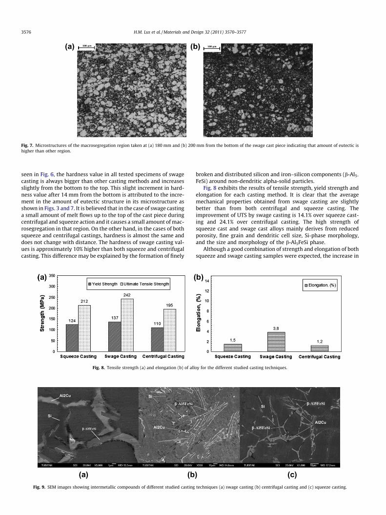
Fig. 7. Microstructures of the macrosegregation region taken at (a) 180 mm and (b) 200 mm from the bottom of the swage cast piece indicating that amount of eutectic ishigher than other region.
3576 H.M. Lus et al. / Materials and Design 32 (2011) 3570–3577
seen in Fig. 6, the hardness value in all tested specimens of swagecasting is always bigger than other casting methods and increasesslightly from the bottom to the top. This slight increment in hard-ness value after 14 mm from the bottom is attributed to the incre-ment in the amount of eutectic structure in its microstructure asshown in Figs. 3 and 7. It is believed that in the case of swage castinga small amount of melt flows up to the top of the cast piece duringcentrifugal and squeeze action and it causes a small amount of mac-rosegregation in that region. On the other hand, in the cases of bothsqueeze and centrifugal castings, hardness is almost the same anddoes not change with distance. The hardness of swage casting val-ues is approximately 10% higher than both squeeze and centrifugalcasting. This difference may be explained by the formation of finely
Fig. 8. Tensile strength (a) and elongation (b) of all
Fig. 9. SEM images showing intermetallic compounds of different studied casting
broken and distributed silicon and iron–silicon components (b-Al5-
FeSi) around non-dendritic alpha-solid particles.Fig. 8 exhibits the results of tensile strength, yield strength and
elongation for each casting method. It is clear that the averagemechanical properties obtained from swage casting are slightlybetter than from both centrifugal and squeeze casting. Theimprovement of UTS by swage casting is 14.1% over squeeze cast-ing and 24.1% over centrifugal casting. The high strength ofsqueeze cast and swage cast alloys mainly derives from reducedporosity, fine grain and dendritic cell size, Si-phase morphology,and the size and morphology of the b-Al5FeSi phase.
Although a good combination of strength and elongation of bothsqueeze and swage casting samples were expected, the increase in
oy for the different studied casting techniques.
techniques (a) swage casting (b) centrifugal casting and (c) squeeze casting.

H.M. Lus et al. / Materials and Design 32 (2011) 3570–3577 3577
elongations is more remarkable. Generally, the low ductility of theas-cast 380 alloy is attributed to the presence of the sharp tips ofthe needle-shaped silicon phases and the massive plate-like formsof iron–aluminide crystals [19]. This needle-shaped-Fe particles actas stress raiser.
With increasing shear rate and high pressure, the growth mor-phology changes from dendritic to globular shape and this processbrings about the formation of rounded silicon phases and fine uni-formly dispersed iron–aluminide intermetallics which conse-quently improve ductility. Fig. 9 shows the shape of Si-phasesand Fe-containing intermetallic (b-Al5FeSi) compounds in eachcasting method. It was observed that high shear rate during solid-ification had significant effects in reducing long-needle morphol-ogy into lath shape for the b-Al5FeSi intermetallic phase in theswage cast alloy.
Morphologies of intermetallic components in aluminum basealloys and their effects on mechanical properties have long beeninvestigated by several researchers [20,21]. Recently, Jorstad etal. [22] and Fang et al. [23] studied relationship between micro-structure and ductility in semi-solid alloys. They reported thatdue to high cooling rate in semi-solid processes (SSM), SSM cast-ings usually contain smaller and more uniformly distributed Fecontaining phases than permanent mold or conventional die cast-ings. As a result, the detrimental effect of Fe containing phases onductility of SSM castings has been greatly diminished. This obser-vation is good agreement with the results of this study. It is be-lieved that high shear rate breaks the beta-Fe particles and asresult this increases ductility in the swage casting.
4. Conclusion
A multifunctional swage cast machine is designed to cast ashape like a bomb-body with A380 die cast aluminum alloy. Thismultifunctional swage casting machine is also used for squeezeand centrifugal castings for the same shape with the same amountof melt and with the same alloy. Their mechanical properties andmicrostructures are characterized as follows:
[1] Metallographic examination indicates that the microstruc-ture in the squeeze and centrifugal casting is fully dendriticwhereas the microstructure of swage casting consists of finedendrite (in the chill regions), rosette and spherical particles(in the core of the thickness of the cast piece) resulting fromhigh shear rate.
[2] The amount of porosity in this swage casting is found to beless than centrifugal and squeeze casting.
[3] Measurements of hardness indicate that in the swage cast-ing Brinell hardness values are higher than other castingtechniques due to different microstructures. It is also foundin this study that swage casting improves the mechanicalproperties, particularly elongation of at least 14% compared
to other casting methods due to extremely low porosity, fineand non-dendritic morphology. Comparing swage castmicrostructures with squeeze and centrifugal pieces it isobserved that the needles-like morphology of b-Al5FeSi isbroken due to high shear rate during solidification. It isbelieved that this can be one of the reasons for the bettermechanical properties of the new casting process.
Acknowledgements
The authors wish to thank the Yildiz Technical University Re-search Fund and State Planning Organization for the financial sup-port for this research and BCACT (Balkan Centre for AdvancedCasting Technologies) for their help in experiments.
References
[1] ASM Handbook. Casting, vol. 15, 9th ed. Ohio, USA: Metals Park; 1992.[2] Ghomashchi MR, Vikhrov A. Squeeze casting: an overview. J Mater Process
Technol 2000;101(1/2):1–9.[3] Flemings MC. Behavior of Metal Alloys in the Semisolid State. Metal Trans
1991;22B:269–93.[4] Kirkwood DH. Semi-solid metal processing. Int Mater Rev 1994;39(5):173–89.[5] Vinarcik EJ. High integrity die casting processes. USA: John Wiley and Sons;
2003.[6] Kinikoglu NG. Swage casting. TR-Patent, Tr-1997-00568; 2003.[7] Lus HM. Ph.D. Thesis. Production of bomb body by swage casting. Yildiz
Technical University; 2007.[8] American Foundrymens Society. Aluminum casting technology, 2nd ed.; 1993.[9] NADCA product specification standards for die castings produced by the semi-
solid and squeeze cast processes. 1st ed.; 1997.[10] Taylor RP, McClain ST, Berry JT. Uncertainty analysis of metal-casting porosity
measurements using Archimedes’ principle. Int J Cast Met 1999;11:247–57.[11] Horwart JA, Mondolfo LF. Dendritic growth. Acta Met 1962;10:1037–42.[12] Bower TF, Brody HD, Flemings MC. Measurements of solute redistribution in
dendritic solidification. Trans AIME 1966;236:624–34.[13] Spencer DB, Mehrabian R, Flemings MC. Rheological behavior of Sn–15%Pb in
the crystallization range. Metall Trans 1972;3:1925–32.[14] Flemings MC, Behavior of metal alloys in the semi-solid state. Metall Trans
1991;22A:957–81.[15] Kattamis TZ, Coughlin J, Flemings MC. Influence of coarsening on dendrite arm
spacing of aluminum–copper alloys. Trans Met Soc AIME1967; 239 (1504):1604-1511.
[16] Doherty RD, Lee HI, Feest EA. Microstructure of stir-cast metals. Mater Sci Eng1984;65:181–9.
[17] Das A, Ji S, Fan Z. Morphological development of solidification structures underforced fluid flow: a monte carlo simulation. Acta Meter 2002;50:4571–85.
[18] Li S, Fan Z. Microstructural evolution of Sn–15Pb alloy under high shear rateand high intensity of turbulence. Met Mater Trans 2002;33A:3511–20.
[19] Wang Y. Ph.D Thesis. Solution treatment of vacuum high pressure die castaluminum alloy A380. University of Windsor; 2004.
[20] Mondolfo LF. Aluminum alloys: structure and properties, 1th ed. London:Butterworths; 1976.
[21] Triveño Rios C, Caram R, Bolfarini C, Botta F WJ, Kiminami CS. Intermetalliccompounds in the Al–Si–Cu system. Acta Microscopica 2003;12(1):77–82.
[22] Jorstad L, Pan QY, Apelian D. solidification microstructure affecting ductility insemisolid cast products. Mater Sci Eng A 2005;413–414:186–91.
[23] Fang X, Shao G, Liu YQ, Fan Z. Effects of intensive forced melt convection on themechanical properties of Fe-containing Al–Si based alloys. Mater Sci Eng A2007;445–446:65–72.