Nd2O3 doped low silica calcium aluminosilicate glasses: Thermomechanical properties
Upload
khangminh22Category
view
1download
0
HAL Id: hal-00574301https://hal-mines-paristech.archives-ouvertes.fr/hal-00574301
Submitted on 9 Mar 2012
HAL is a multi-disciplinary open accessarchive for the deposit and dissemination of sci-entific research documents, whether they are pub-lished or not. The documents may come fromteaching and research institutions in France orabroad, or from public or private research centers.
L’archive ouverte pluridisciplinaire HAL, estdestinée au dépôt et à la diffusion de documentsscientifiques de niveau recherche, publiés ou non,émanant des établissements d’enseignement et derecherche français ou étrangers, des laboratoirespublics ou privés.
A thermomechanical modelling of continuous casting tomaster steel slabs internal soundness and surface quality
Nicolas Triolet, Manuel Bobadilla, Michel Bellet, Laure Avedian, PierreMabelly
To cite this version:Nicolas Triolet, Manuel Bobadilla, Michel Bellet, Laure Avedian, Pierre Mabelly. A thermomechanicalmodelling of continuous casting to master steel slabs internal soundness and surface quality. Revuede Métallurgie, 2005, pp.Pages 343-353. �10.1051/metal:2005129�. �hal-00574301�

The development of high tensile strength steels
with higher levels of alloying elements needs the
implementation of operating means in the
continuous casting machine to master slabs
internal soundness and surface quality. In order
to define optimal process parameters, according
to the characteristics of the different continuous
casting machines, and to optimize the revamping
of older equipment, thermomechanical modelling
of the steel slab behaviour during casting has
been carried out. This paper presents the results
of simulations performed to check the potential of
this modelling.
■ INTRODUCTION
High tensile strength steels are currently being developedfor automotive applications. These steels contain a largeamount of alloying elements, which lead to both increasedsegregation and cracking sensitivity.
During casting, the bulging of the slab along the supportrolls induces cyclic strains and stresses both in the mushyzone and in the solid shell. These deformations could beresponsible for surface quality issues like corner cracks,and internal defects like hot tearing and macrosegregation(1). Indeed, if the slab bulging induces tension into themushy zone close to the end of solidification, the last-resi-dual-enriched liquid is sucked and flows across the dendri-tic solid network (2, 3). The solidification of this segrega-ted liquid in the centre of the product leads to a detrimentalaxial macrosegregation, as outlined for instance by NipponSteel (4), which indicates that axial macrosegregationintensifies when the amount of bulging exceeds 200 µm.Moreover, if the dendritic network is unable to sustain thetensile stresses, cracks may be observed. This means thatwe need to know slab strains and stresses during casting,and to get mechanical and metallurgical criteria in order tobe able to predict the damage of the solid phase into themushy zone (5), and also in the critical interval for ductility,which is typically between 700 and 1,000°C (6).
In order to define optimum casting conditions allowingmaximum casting speed with suitable internal soundnessand surface quality, a macroscopic thermomechanical modelof steel slab continuous casting has been developed byCEMEF. This is a useful tool to help the manufacturers tomodify the design of their machines (curvature of bendingand unbending zones, roll dimensions and pitch…) and tohelp the steelmakers to adapt their casting conditions (cas-ting velocity, cooling strategy…) according to the cast steelgrade properties. We will see hereafter the influence ofthese parameters on the slab bulging.
First, the original global, non steady-state approach and themodel used for the calculations are presented. The interes-ted reader can refer to previous publications, where it waslargely detailed (7, 8, 9). In a second part, we focus on thecalculations carried out by Arcelor Research to assess thepotential of this modelling, as well as on the operationalresults. The effects of roll arrangement, casting speed andheat transfer on the slab bulging were investigated.
La Revue de Métallurgie-CIT Mai 2005 343
A thermomechanical modelling ofcontinuous casting to master steel slabsinternal soundness and surface quality*
N. Triolet, M. Bobadilla (Arcelor Research) M. Bellet (École des Mines de Paris, Cemef) L. Avedian (Arcelor, Sollac Atlantique) P. Mabelly (Arcelor, Sollac Méditerranée)
* Subject of a presentation at the 2004 ATS International Steelmaking
Conference (Paris, December 9-10, 2004, Session 14).
© La Revue de Métallurgie 2005.

344 La Revue de Métallurgie-CIT Mai 2005
Les aciers à très haute résistance développés pour desapplications automobiles peuvent être très chargés enéléments d’alliage, ce qui les rend sensibles à la ségré-gation et à l’endommagement au cours de l’opération decoulée. Ces problèmes de santé interne résultent du gon-flement de la brame entre les rouleaux du système desoutien. Ce gonflement induit en effet des contraintes etdes déformations périodiques dans la zone pâteuse etdans la coque solide. Pour être en mesure de définir lesconditions de coulée optimales permettant d’assurer uneproductivité maximale et d’obtenir des produits de qua-lité, une modélisation thermomécanique 2D et 3D de lacoulée continue de brames d’acier, à l’échelle macro-scopique, a été développée. L’originalité de cette simu-lation repose sur le calcul du gonflement sur toute lalongueur de la machine de coulée, en fonction :
– des propriétés de l’acier coulé ;
– des paramètres process (vitesse de coulée, stratégiede refroidissement…) ;
– des spécificités de la machine de coulée : profils decintrage / décintrage, diamètre et pas des rouleaux,réduction douce mécanique, position des sprays dusystème de refroidissement, etc.
Les potentialités de cette approche ont été démontréesdans des configurations de coulée industrielles. Lesrésultats obtenus montrent que :
– la modélisation permet de décrire le fluage de lacoque solide entre les rouleaux du système de soutien,sous l’action de la pression ferrostatique exercée parle cœur liquide ;
– la confrontation des résultats avec des mesures degonflement et d’autres résultats de simulation estsatisfaisante ;
– la modélisation reproduit correctement l’influencedes paramètres process sur le gonflement de la brame.
La validation quantitative du modèle sera établie parcomparaison des résultats numériques à des mesuresréalisées sur le pilote de coulée continue de bramettesd’Arcelor Research. Notre objectif final est d’êtrecapable de prévoir la formation de la macroségrégationaxiale en fonction des propriétés de l’acier coulé et desparamètres process. Ceci doit nous aider à définir lesconditions optimales pour mettre en place une réductiondouce mécanique sur une ligne de coulée industrielle.Pour atteindre cet objectif, il est nécessaire de décrirecorrectement le comportement de la zone semi-solide.Pour cela, une approche diphasique est en cours dedéveloppement dans notre modèle 2D. Les échangesd’énergie, de masse, de quantité de mouvement et desoluté entre la phase liquide et la phase solide sont prisen compte. Nous simulerons ainsi les écoulements de laphase liquide ségrégée en éléments d’alliage à travers laphase solide de la zone pâteuse sous l’effet du gonfle-ment périodique de la brame entre les rouleaux du sys-tème de soutien.
Le modèle 3D sera exploité pour traiter des problèmesde qualité de surface. Cette approche est nécessairepour prévoir, par exemple, la formation de criquesd’angle. De plus, nous avons commencé à développerune modélisation 3D du comportement thermoméca-nique de la peau qui se solidifie en lingotière de couléecontinue. Elle traite de façon couplée les écoulementsturbulents de métal liquide surchauffé, le comportementthermomécanique de la peau qui se solidifie et la dilata-tion de la lingotière.
Une modélisation thermomécanique de la coulée continue pour maîtriser la santé interne et la qualité de surfacedes brames d’acier
N. Triolet, M. Bobadilla (Arcelor Research) M. Bellet (École des Mines de Paris, Cemef) L. Avedian (Arcelor, Sollac Atlantique) P. Mabelly (Arcelor, Sollac Méditerranée)

■ AN ORIGINAL GLOBAL, NONSTEADY-STATE APPROACH
The global, non steady-state approach is illustrated infigure 1. Starting from an initial mesh representing a smallamount of steel at the top of the machine, the advancing ofthe product is simulated by imposing to the lower surfacea condition of bilateral contact with a rigid extraction tool,which moves at the nominal casting speed. On the contrary,the upper surface remains fixed : this means that the meshvolume enlarges continuously at each time step. This methodrequires solving a transient thermomechanical problem,which is assumed to converge towards the steady-stateregime. It was implemented in R2SOL® and TherCast®softwares, which are, respectively, 2D and 3D finite ele-ment modelling tools.
The mesh management is a key point of the method. Thenodes belonging to the upper surface remain fixed, while allother nodes move with the same speed as the product.Consequently, the first row of elements near the top surfaceundergoes continuous elongation. To prevent mesh degene-racy, a periodic remeshing operation is carried out, in whichmost nodes are untouched, except those located near the topsurface. During remeshing, some new nodes are added inthis region. It is also possible with the same software tocarry out a classical non-steady slice modelling as it hasbeen achieved by Thomas et al. (10), or Pascon (11) : theupper surface may become a free surface, which is the uppersurface of the slice, allowed to move down.
At this stage, it is important to detail some assumptions :
• First, the model is focused on the thermomechanicalstress-strain analysis, while the fluid flow occurring inthe liquid pool is ignored. This is a rough approximationin the mould region, but we assume that it has no majorimpact on the thermomechanical state in the secondarycooling, which is the effective aim of this work.
• For the moment, the mushy zone is considered as onehomogeneous phase. Some work is in progress in orderto model the mushy zone as a two-phase continuum, withan effective distinction between the motion of the liquidphase and of the solid phase (12). In this modelling, theexchange of solute, mass, energy and momentum aretaken into account between both phases.
■ THE THERMOMECHANICALMODELLING
Heat transfer problem
The thermal problem is based on the resolution of the heattransfer equation, which is the general energy conservationequation :
λ (W/m/°C) denotes the thermal conductivity, ρ (kg/m3) thedensity and H (J/kg) the specific enthalpy which can bedefined as :
T0 (°C) is an arbitrary reference temperature, Cp(J/kg/°C) the specific heat, gs the volume fractionof solid and L (J/kg) the specific latent heat offusion. In the one-phase modelling, gs(T) is pre-viously calculated using the microsegregationmodel PTIMEC_CEQCSI (13).
The temperature is prescribed onto the top surfaceof the mesh : T = Timp. We assume an adiabaticcondition on the extraction tool : -λ∇T.n = 0. Onthe lateral surface of the mesh, the thermal boun-dary conditions are averaged on successive zones :
• In the mould, heat flux is imposed uniformly : -λ∇T.n = Φimp. n denotes the outward normal unitvector. We do not take into account a possible airgap at slab/mould interface on heat release. Thishypothesis is justified by the fact that we focusthis work on the secondary cooling.
COULÉE CONTINUE
La Revue de Métallurgie-CIT Mai 2005 345
Fig. 1 – Schematic representation of mesh growth in the global, non steady-state approach.
Fig. 1 – Représentation schématique de la croissance du maillage dans l’approche globale instationnaire.

• In the secondary cooling, we have the possibility toimpose two kinds of averaged boundary conditions on suc-cessive zones defined between two metallurgical lengths :
– Average convection : -λ∇T.n = hzone(T – Text), wherehzone (W/m2/°C) is the heat transfer coefficient, and Textis the external temperature. hzone is uniform and constanton each zone ;
– Radiation : -λ∇T.n = εrσr(T4 – Text4) where εr is the steel
emissivity and σr the Stephan – Boltzmann constant.
In order to simulate accurately the thermomechanical beha-viour of the slab shell in the secondary cooling, we alsohave the possibility to account for local heat release due toroll contact and spray cooling. Hardin et al (14) have everused this for instance, which is interesting for the study oftransverse corner cracking.
Constitutive equations
As suggested by Bellet (15), we make a clear distinctionbetween the constitutive equations used for the liquid andmushy state, and those for the solid state. In the one-phasemodelling, the liquid and mushy states are modelled usinga pure thermo-viscoplastic law, without any elastic contri-bution. Depending on the solid fraction, the model is eitherpurely Newtonian, or non-linear viscoplastic. A thermo-elastic-viscoplastic constitutive law is used to describe thesteel behaviour below a coherency temperature (fig. 2). It is more representative of solid-like behaviour. Usually, weassume that the coherency temperature is equal to the tem-perature of the end of solidification.
Mechanical problem
At any time, the mechanical equilibrium is governed by themomentum equation : ∇.σ + ρg – ργ = 0, where σ is theCauchy stress tensor, g the gravity vector and γ the accele-
ration vector. Concerning boundary conditions, the kineticsof the extraction tool is imposed equal to the casting speed.We impose a uniform pressure on the injection tool, whichis representative of the local ferrostatic pressure. The freelateral surface is submitted to contact with the support rolls,which are supposed motionless and non-deformable. Forthe moment, we assume that the slab slides on the rolls.This unilateral contact is modelled by a penalty method.For any boundary point M of the product, and for any rollof centre C and radius R, we must have : CM ≥ R, which isthe non-penetration condition (fig. 3). We accept a shortpenetration of the slab into the rolls of about 0.05 mm. It isof the same order as roll eccentricity.
■ THERMOMECHANICAL BEHAVIOUROF THE SLAB IN THE SECONDARYCOOLING
Stress distribution calculated into the solid shell
Some simulations were carried out on SollacAtlantique No. 23 continuous caster. It is acurved machine, with a radius of 10.5 m. Thedomain of calculation is a mid-width slice : itsthickness is 250 mm. We assume that thedeflection of the solid shell at the centreregion of the wide face is independent of theslab width. This is the case as soon as the ratiobetween the slab width and the roll pitch issufficiently large. The composition of the caststeel grade is indicated in table I. The castingspeed is 0.9 m/min. All the results presentedhere were obtained for a metallurgical lengthbetween 8 and 14 m.
346 La Revue de Métallurgie-CIT Mai 2005
Fig. 2 – Schematic representation of the rheological behaviour of the different phases.
Fig. 2 – Représentation schématique des comportements rhéologiques des différentes phases.
Fig. 3 – Schematic representation of contact penalization totreat the non-penetration of the solidified shell into the rolls.
Fig. 3 – Représentation schématique du contact pénalisé entre la brame et les rouleaux pour contrôler la pénétration
de la brame dans les rouleaux.

Figure 4 illustrates schematically the longitudinal compo-nent of the stress tensor σYY into the solid shell. Weobserve a double periodic alternation of compressive andtensile longitudinal stresses. The quantitative results areindicated in figure 5. On the surface, the slab is in a com-pressive state at roll contact in the longitudinal direction(σYY ≈ -20 MPa). Conversely, it is in a tensile state on thefree surface between rolls (σYY ≈ 10 MPa). If we look at thelongitudinal stresses in the solid phase close to the solidifi-cation front, we can see that there is also an alternation, butin the opposite sense : it is in a tensile state when passingby a roll (σYY ≈ 6 MPa), while it is in a compressive statebetween two successive rolls (σYY ≈ -6 MPa).
Concerning the transverse stresses, we observe a large com-pressive state at roll contact (σXX ≈ -20 MPa), and a negli-gible tensile state into the solid shell between rolls (σXX ≤1 MPa). The tensile stresses calculated in the transversedirection are clearly smaller than the tensile stresses calcu-lated in the longitudinal direction. This alternation of ten-sile / compressive stresses in the solid phase results fromthe bulging of the solid shell between the support rolls. Thisalternation is also revealed by the symmetric distribution ofthe shear stresses at roll contact : (σXY ≈ ± 8 MPa) (fig. 6).The shear stresses are plotted a few millimetres before andafter the roll contact. We observe that rolls induce an inver-sion of the shear stress orientation into the solid shell.
Consequently, the simulation describes successfully thatthe solidified shell behaves like a beam resting on the sup-port rolls, which creeps due to ferrostatic pressure loading.Until now, we have assumed that the rolls are perfectly ali-gned. But if one roll is removed, the bulging and slabstrains-stresses are enhanced. Figure 7 shows the large bul-ging of the slab when one roll was removed at 11 m ofmetallurgical length, and the equivalent strain calculated on
COULÉE CONTINUE
La Revue de Métallurgie-CIT Mai 2005 347
TABLE I : Composition of the steel grade used for the simulations.
TABLEAU I : Composition de l’acier utilisé pour les simulations.
C Si Mn S P
10-3 % 180 420 1,370 9 18
Fig. 4 – The longitudinal stress distribution revealscompressive and tensile zones due to the slab bulging
between rolls.
Fig. 4 – La carte des contraintes longitudinales montre une sollicitation périodique en traction - compression
de la coque solide due au gonflement.
Fig. 5 – Stresses calculated in the slab thickness at roll contact and on the free surface between rolls. (a) Longitudinal stresses. (b) Transverse stresses.
Fig. 5 – Contraintes calculées dans l’épaisseur de la brame dans l’emprise d’une paire de rouleaux et entre deux paires de rouleaux. (a) Contraintes longitudinales. (b) Contraintes transverses.
a) b)

a slab section. The results indicate a clear distinction bet-ween the thermomechanical behaviour of the solid shell onboth sides. The equivalent strain calculated in the solidshell close to the solidification front, and on the slab sur-face, is roughly four times more important on the upperside than on the lower side due to the roll removal. Thissimulation proves the necessity to maintain the caster in anoptimal state with few misalignments, and few roll eccen-tricities, to master a convenient product internal soundnessand surface quality with enough productivity. The couplingof this simulation with metallurgical or mechanical criteriawill help us to define the critical tolerance for roll mis-alignment.
Slab bulging between rolls
As previously mentioned, we use a non-steady approach tocarry out the simulation. Figure 8 represents the bulgingcalculated at 12.3 m for two casting speeds : 0.9 m/min and1.2 m/min. It confirms that the bulging converges effecti-
348 La Revue de Métallurgie-CIT Mai 2005
Fig. 6 – Shear stresses calculated in the slab thickness at roll contact and on the free surface between rolls.
Fig. 6 – Contraintes de cisaillement calculées dans l’épaisseur de la brame dans l’emprise d’une paire de rouleaux et entre deux paires de rouleaux.
Fig. 7 – Roll removal
induces a largeincrease of the
strain on the slabsurface and close to the
solidification front.
Fig. 7 – La suppression d’unrouleau induit uneforte augmentationde la déformation
à la surface de la brame et à
proximité du front de solidification.
Fig. 8 – The calculated slab bulging converges quickly to a steady state value. It proves the accuracy of the global,
non-steady state approach.
Fig. 8 – Le gonflement calculé converge rapidement vers un régime permanent. Ceci prouve la validité de cette approche
globale instationnaire.
vely until a steady state value, and proves the accuracy ofthis approach. A stabilized value is obtained typically after100 s, corresponding to a casting distance of about 2 m.
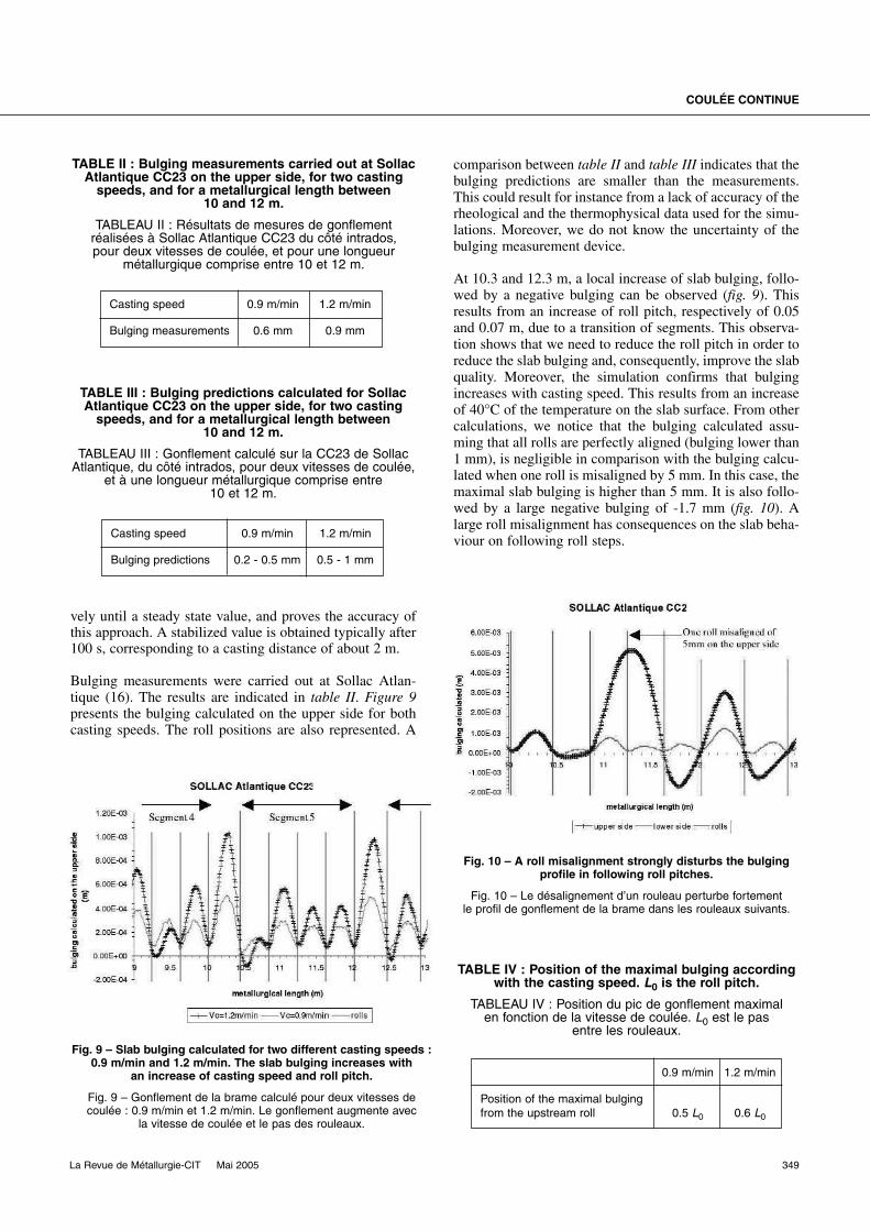
Bulging measurements were carried out at Sollac Atlan-tique (16). The results are indicated in table II. Figure 9presents the bulging calculated on the upper side for bothcasting speeds. The roll positions are also represented. A
comparison between table II and table III indicates that thebulging predictions are smaller than the measurements.This could result for instance from a lack of accuracy of therheological and the thermophysical data used for the simu-lations. Moreover, we do not know the uncertainty of thebulging measurement device.
At 10.3 and 12.3 m, a local increase of slab bulging, follo-wed by a negative bulging can be observed (fig. 9). Thisresults from an increase of roll pitch, respectively of 0.05and 0.07 m, due to a transition of segments. This observa-tion shows that we need to reduce the roll pitch in order toreduce the slab bulging and, consequently, improve the slabquality. Moreover, the simulation confirms that bulgingincreases with casting speed. This results from an increaseof 40°C of the temperature on the slab surface. From othercalculations, we notice that the bulging calculated assu-ming that all rolls are perfectly aligned (bulging lower than1 mm), is negligible in comparison with the bulging calcu-lated when one roll is misaligned by 5 mm. In this case, themaximal slab bulging is higher than 5 mm. It is also follo-wed by a large negative bulging of -1.7 mm (fig. 10). Alarge roll misalignment has consequences on the slab beha-viour on following roll steps.
COULÉE CONTINUE
La Revue de Métallurgie-CIT Mai 2005 349
TABLE III : Bulging predictions calculated for SollacAtlantique CC23 on the upper side, for two casting
speeds, and for a metallurgical length between 10 and 12 m.
TABLEAU III : Gonflement calculé sur la CC23 de SollacAtlantique, du côté intrados, pour deux vitesses de coulée,
et à une longueur métallurgique comprise entre 10 et 12 m.
Casting speed 0.9 m/min 1.2 m/min
Bulging predictions 0.2 - 0.5 mm 0.5 - 1 mm
TABLE II : Bulging measurements carried out at SollacAtlantique CC23 on the upper side, for two casting
speeds, and for a metallurgical length between 10 and 12 m.
TABLEAU II : Résultats de mesures de gonflementréalisées à Sollac Atlantique CC23 du côté intrados, pour deux vitesses de coulée, et pour une longueur
métallurgique comprise entre 10 et 12 m.
Casting speed 0.9 m/min 1.2 m/min
Bulging measurements 0.6 mm 0.9 mm
Fig. 9 – Slab bulging calculated for two different casting speeds :0.9 m/min and 1.2 m/min. The slab bulging increases with
an increase of casting speed and roll pitch.
Fig. 9 – Gonflement de la brame calculé pour deux vitesses decoulée : 0.9 m/min et 1.2 m/min. Le gonflement augmente avec
la vitesse de coulée et le pas des rouleaux.
TABLE IV : Position of the maximal bulging accordingwith the casting speed. L0 is the roll pitch.
TABLEAU IV : Position du pic de gonflement maximal en fonction de la vitesse de coulée. L0 est le pas
entre les rouleaux.
0.9 m/min 1.2 m/min
Position of the maximal bulging from the upstream roll 0.5 L0 0.6 L0
Fig. 10 – A roll misalignment strongly disturbs the bulgingprofile in following roll pitches.
Fig. 10 – Le désalignement d’un rouleau perturbe fortement le profil de gonflement de la brame dans les rouleaux suivants.

Finally, we focus on the slab bulging calculated between 12and 12.5 m with a perfect roll alignment (fig. 11). We cannotice that the maximum bulging is shifted towards thedownstream roll when the casting speed increases. Table IVpresents the position of the maximum bulging, calculatedaccording to the casting speed. It confirms the observationsof Wunnenberg (17) and Lamant (18). This bulging profileduring steady state casting conditions results from both thedownward extraction of the product, and the creep mecha-nism involved.
■ INFLUENCE OF PROCESSPARAMETERS ON SLAB BULGING
Some simulations were carried out on Sollac MéditerranéeNo. 2 continuous caster. It is a vertical - bending machinewith split rolls. The composition of the cast steel grade is thesame as the one indicated in table I. We studied the influence
of process parameters like molten steel superheat, rolldiameter and pitch, cooling strategy, casting speed, onthe slab bulging between 8 and 15 m of metallurgicallength.
Benefit of split rolls to reduce slab bulging
We know that using split rolls reduces slab bulging. Itis justified by the fact that a decrease of roll diameterallows a decrease of roll pitch (L0). This favourabletrend is reinforced by the associated decrease of thepitch creep time (∆tcreep) : ∆tcreep = L0/Vc. This wasverified with the model by simulations carried out onboth configurations of Sollac Méditerranée CC2,before and after the revamping (19). This revampinghas consisted in replacing the big rolls in the low partof the caster by split rolls : the roll diameter was redu-ced by 100 mm. Only the caster geometry was chan-ged in these simulations. The casting speed is 1 m/min.Table V points out that the use of split rolls reduces, byabout 50 %, the bulging at the mid-width of the slab.
Influence of casting speed and coolingstrategy on slab bulging
For a given cooling strategy, we carried out three simula-tions on the revamped geometry with different castingspeeds : 1 m/min, 1.25 m/min and 1.5 m/min. The resultsindicate that an increase of casting speed induces anincrease of slab bulging (fig. 12), despite the reduction of thepitch creep time. Actually this is explained by the fact thatan increase of casting speed induces an increase of the slabsurface temperature, and a reduction of the thickness solidi-fied : the end of solidification is delayed when we cast fas-ter. For this reason, the solid shell offers less resistance tothe ferrostatic pressure loading and creeps more. This wasconfirmed by the following results where we checked theinfluence of cooling strategy on slab bulging. Actually, wesimulated the casting of the same steel grade at 1.25 m/minon Sollac Méditerranée CC2 for two different cooling stra-tegies : one hard and one soft. We notice a reduction of slab bulging when the cooling is intensified (table VI).
350 La Revue de Métallurgie-CIT Mai 2005
TABLE VI : Average bulging calculated on SollacMediterranée CC2 between 8 and 15 m of metallurgical
length, for one casting speed of 1.25 m/min and fortwo cooling strategies, one soft and one hard.
TABLEAU VI : Gonflement moyen calculé entre 8 et 15 m de longueur métallurgique, sur la CC2 de Sollac
Méditerranée, pour une vitesse de coulée de 1,25 m/min, et pour deux conditions de refroidissement,
une faible et une forte.
Hard cooling Soft cooling
Upper side 0.161 mm 0.220 mm
Lower side 0.187 mm 0.231 mm
TABLE V : Average bulging calculated on SollacMediterranée CC2, before and after revamping,
between 8 and 15 m of metallurgical length. The use of split rolls reduces by about 50 %
the bulging at the mid-width of the slab.
TABLEAU V : Gonflement moyen calculé entre 8 et 15 m de longueur métallurgique, sur la CC2 de Sollac
Méditerranée, avant et après la rénovation effectuée en2002. L’utilisation de rouleaux divisés permet de réduire
de moitié le gonflement au milieu des grandes faces.
Before revamping After revamping
Upper side 0.322 mm 0.182 mm
Lower side 0.327 mm 0.195 mm
Fig. 11 – When the casting speed increases from 0.9 m/min to 1.2 m/min, the position of the maximal bulging is shifted towards
the downstream roll.
Fig. 11 – Quand la vitesse de coulée augmente de 0.9 m/min à 1.2 m/min, la position du pic de gonflement maximal
est décalée vers le rouleau aval.

Consequently, a more intensive cooling could offset theincrease of bulging induced by an increase of casting speed.
For the soft cooling strategy, and for a casting speed of 1 m/min, we checked also the influence of molten steelsuperheat on slab bulging. We observed that an increase ofthe average slab bulging induced by an increase of thesuperheat is negligible between 8 and 15 m of metallurgi-cal length (table VII). This is not the case just below mouldexit, where superheat has more influence on the slab sur-face temperature and the thickness solidified.
This parametric study confirms the results of Lamant (18)who showed that the two main important parameterscontrolling the intensity of bulging are the roll pitch and the solid shell thickness. The results are also coherent withthose of Wunnenberg (17), Miyazawa (20) and Ha (21). Forinstance, Ha (21) simulated the bulging of a 0.08 % C gradeslab, cast at 1.4 m/min. The slab thickness is 250 mm. Theycalculated a bulging of 0.22 mm at 15 m of metallurgicallength. If we look at figure 12, we predict a bulging bet-ween 0.18 and 0.20 mm for the same casting speed. Thisslight difference could be justified :
– we did not use the same rheological models to describethe solid shell behaviour. For instance, they did not takeinto account strain hardening, which is probably notnegligible at 900°C ;
– the slab thickness is 30 mm more important in their case ;
– at 15 m of metallurgical length, the roll pitch is 40 mmlower in Sollac Méditerranée CC2.
This study allowed us to check that the simulation is able to describe accurately the influence of process parameterson slab bulging. The results are very encouraging. Never-theless, slab bulging is also strongly influenced by the rheo-logical properties of steel. We know that bulging is morepronounced for steels with large Si contents and for ferriticstainless steels. Since steel properties are not well knownfor the specific conditions existing in the solid shell, it maybe difficult to predict absolute values of bulging. Quali-tative predictions on the influence of various parametersare, however, possible. The rheological data usually used inthis kind of simulation generally come from tensile creeptests under a constant loading (22, 23). Such experimentaldata could be applied directly to calculate the solid shellstrain and stress at rest. The case of a moving slab is morecomplicated because the stress in each moving volumechanges with time. The solid phase behaviour under conti-nuously changing loads has not been investigated experi-mentally according to our knowledge. However, furtherwork will be carried out in order to compare temperatureand bulging predictions with measurements performed onthe Arcelor Research small slab pilot caster.
■ CONCLUSION
An original macroscopic approach to the thermomechani-cal stress-strain analysis of steel continuous casting hasbeen developed and was implemented in 2D and 3D finiteelement software in order to calculate the strains and
stresses affecting the slab. The actual caster shape andsteel grade properties are accounted for. The accuracy ofthis approach was qualitatively demonstrated on indus-trial cases. We showed that the simulation describes suc-cessfully the fact that the solidified shell behaves like abeam resting on the support rolls, and creeps due to fer-rostatic pressure loading. In addition, we proved the qua-litative accuracy of the model to simulate the thermome-chanical behaviour of the slab during casting in secondarycooling. It is a useful tool to help manufacturers modifytheir design of machines and steelmakers adapt their ope-rating conditions according to the cast steel grade pro-perties. In particular, it will be used to :
– predict the adequate operating point for the diffe-rent continuous casters of Arcelor,
– compare their potentialities to define the optimalmetallurgical routes,
– give recommendations for the revamping of theoldest machines.
COULÉE CONTINUE
La Revue de Métallurgie-CIT Mai 2005 351
TABLE VII : Average bulging calculated on SollacMediterranée CC2 between 8 and 15 m of metallurgical
length for two superheats, 10 and 30°C. The effect of superheat on bulging is negligible in the lower part
of the caster.
TABLEAU VII : Gonflement moyen calculé entre 8 et 15 m de longueur métallurgique sur la CC2 de Sollac
Méditerranée, pour deux surchauffes : 10 et 30°C.L’influence de la surchauffe sur le gonflement estnégligeable dans la partie basse de la machine.
Superheat = 10°C Superheat = 30°C
Upper side 0.182 mm 0.192 mm
Lower side 0.195 mm 0.202 mm
Fig. 12 – The average bulging calculated on Sollac MéditerranéeCC2 between 8 and 15 m of metallurgical length increases
with the casting speed.
Fig.12 – Le gonflement moyen calculé entre 8 et 15 m de longueurmétallurgique, sur la CC2 de Sollac Méditerranée, augmente
avec la vitesse de coulée.

Following Kajitani (24), our final objective consists inbeing able to predict the formation of axial macrosegrega-tion and hot tears according with the steel grade propertiesand the operating conditions. It will be useful, for instance,to define the adequate mechanical soft reduction. Toachieve this goal, the one-phase approach to describe themushy zone is very rough. A more accurate description isdeveloped and will be coupled to the present 2D modelling(12). We account for heat, mass, momentum and soluteexchange between the solid phase and the liquid phase intothe mushy zone. We make a clear distinction between themotion of the liquid phase and of the solid phase. Thisapproach needs also accurate data to describe the deforma-tion of the compressible semi-solid domain. Many experi-mental investigations have been carried out to study mushyzone rheology, but they were mainly focused on Sn-Pb (25)and Al alloys (26).
On the contrary, the 3D modelling is dedicated to solve surface quality issues. We have the possibility to calculatelocal heat release in the secondary cooling due to rollcontact and spray cooling. It is interesting to simulate thethermomechanical behaviour of the slab corners in order toreduce corner crack ratios. Moreover, we have begun todevelop a non-steady 3D numerical modelling of the ther-momechanical behaviour of the shell solidified in a slabcontinuous casting mould. This model will fully couple theturbulent, transient molten steel flow in the inlet nozzle andthe strand liquid pool, with the thermomechanical beha-viour of the shell that solidifies, and the distortion of themould copper plates.
■ ACKNOWLEDGEMENT
The authors would like to acknowledge the financial sup-port of the Ministère de l’Économie, des Finances et del’Industrie, in the frame of the OSC - Continuous Castingproject, and all their partners : Transvalor, Sciences &Computer Consultants and Ascometal-Lucchini. We arealso grateful to Professor Gérard Lesoult from École desMines de Nancy for his valuable advices.
■ REFERENCES
(1) BOBADILLA (M.), JOLIVET (J.-M.), LAMANT (J.-Y.),LARRECQ (M.) – Continuous casting of steel : A closeconnection between solidification studies and industrialprocess development. Materials Sciences and Engineering,A173 (1993), p. 275-285.
(2) MIYAZAWA (K.), SCHWERDTFEGER (K.) – Macro-segregation in continuously cast steel : Preliminary theore-tical investigation on the effect of steady state bulging.Arch. Eisenhüttenwes., 52 (1981), p. 415-422.
(3) LESOULT (G.), SELLA (S.) – Analysis and prevention ofcentreline segregation during continuous casting of steelrelated to deformation of the solid phase. Proceedings of the6th International Iron and Steel Congress, Nagoya, ISIJ,vol. 1 (1990), p. 681-688.
(4) SAEKI (T.), IMURA (H.), OONISHI (Y.), NIIMI (H.),MIWA (E.), YOSHIDA (T.), IGARI (S.), KITAMINE (S.)– Effect of bulging and solidification structure on segrega-tion in continuously cast slab. Transactions ISIJ, 24, No. 11(1984), p. 907-916.
(5) WON (Y.-M.), YEO (T.-J.), SEOL (D.-J.), OH (K.-H.) – A new criterion for internal crack formation in continuouslycast steels. Metallurgical and Materials Transactions B, vol. 31B (2000), p. 779-794.
(6) CASTAGNE (S.), HABRAKEN (A.-M.) – Investigation oftransverse cracks initiation in continuous steel casting usinga finite element approach. Intern. Conference on “Computa-tional and experimental engineering and sciences”, Corfu,Greece (2003).
(7) HEINRICH (A.) – Modélisation thermomécanique de lacoulée continue d’acier en deux dimensions. PhD thesis,École des Mines de Paris (2003).
(8) COSTES (F.) – Modélisation thermomécanique tridimen-sionnelle par éléments finis de la coulée continue d’aciers.PhD Thesis, École des Mines de Paris (2004).
(9) BELLET (M.), HEINRICH (A) – A two-dimensional finiteelement thermomechanical approach to a global stress-strain analysis of steel continuous casting. ISIJ Inter-national, 44, No. 10 (2004), p. 1686-1695.
352 La Revue de Métallurgie-CIT Mai 2005
T °C Temperature εr Steel emissivity
Text °C External temperature σr W/m2/K4 Stephan-Boltzmann constant
TC °C Coherency temperature VC m/s Casting speed
H J/kg Enthalpy σXX Pa Transverse stresses
ρ Kg/m3 Density σYY Pa Longitudinal stresses
λ W/m/°C Thermal conductivity σXY Pa Shear stresses
Cp J/kg/°C Specific heat L0 m Roll pitch
gs Volume fraction of solid ∆tcreep s Pitch creep time
L J/kg Specific latent heat of fusion n Outward normal unit vector
Φimp W/m2 Imposed density of heat flux g Gravity vector
hzone W/m2/°C Average heat transfer coefficient . σ Cauchy stress tensoron one zone
Liste of symboles / Liste des symboles

(10) THOMAS (B.-G.), STORKMAN (W.-R.), MOITRA (A.) –6th International Iron and Steel Congress, ISIJ, Tokyo(1990), p. 348.
(11) PASCON (F.) – 2D1/2 thermal-mechanical model of conti-nuous casting of steel using finite element method. PhDThesis, University of Liège, Belgium (2003).
(12) BELLET (M.), LE CORRE (S.), FACHINOTTI (V.-D.) – A 2-phase finite element model to study concurrent fluidflow and solid deformation occurring in mushy zonesduring the solidification of metallic alloys, Intern.Conference on “Semi-solid processing of alloys and com-posites”, Limassol, Cyprus (2004).
(13) WINTZ (M.), BOBADILLA (M.), LEHMANN (J.), GAYE(H.) – Experimental study and modelling of the precipita-tion of non-metallic inclusions during solidification of steel.ISIJ International, 35, No. 6 (1995), p. 715-722.
(14) HARDIN (R.-A.), LIU (K.), KAPOOR (A.), BECKER-MANN (C.) – A transient simulation and dynamic spraycooling control model for continuous steel casting.Metallurgical and Materials Transactions B, 34B (2003), p. 297-306.
(15) BELLET (M.), JAOUEN (O.) – Finite Element approach tothermomechanics of solidification processes. Intern. confe-rence on “Cutting edge of computer simulation of solidifi-cation and casting”, Osaka, The Iron and Steel Institute ofJapan (1999), p. 173-190.
(16) RAHIER (P.), KRAEMER (R.), LAMANT (J.-Y.), LAR-RECQ (M.) – Comportement mécanique de la brame dansla zone de refroidissement secondaire d’une machine decoulée continue d’acier. ECSC research project No. 7210CA/315 (November 1990).
(17) WUNNENBERG (K.) – Strangausbauchung zwischenStützvollen beim Stransggiessen von Brammen. Stahl undEisen, Nr. 6 (1978).
(18) LAMANT (J.-Y.), LARRECQ (M.), BIRAT (J.-P.), HENS-GEN (J.-L.), WEBER (J.-D.), DHUYVETTER (J.-C.) –Study of slab bulging in continuous caster. Conference ofthe Metals Society, London (1985).
(19) HOSY (P.), MABELLY (P.), PERASSE (T.) – Augmen-tation de la productivité à la coulée continue n° 2 de SollacFos. 25es Journées Sidérurgiques Internationales ATS (2004),Session 10, p. 160-161.
(20) MIYAZAWA (K.), SCHWERDTFEGER (K.) – Compu-tation of bulging of continuously cast slabs with simplebending theory. Ironmaking and Steelmaking, No. 2 (1979),p. 68-74.
(21) HA (J.-S.), CHO (J.-R.), LEE (B.-Y.), HA (M.-Y.) – Nume-rical analysis of secondary cooling and bulging in the conti-nuous casting of slabs. J. of Materials Processing Techno-logy, 113 (2001), p. 257-261.
(22) WRAY (P.-J.) – Effect of carbon content on the plastic flowof plain carbon steels at elevated temperatures. Metallur-gical Transactions A, 13A (1982), p. 125-134.
(23) SUZUKI (T.), TACKE (K.-H.), WUNNENBERG (K.),SCHWERDTFEGER (K.) – Creep properties of steel atcontinuous casting temperatures. Ironmaking and Steel-making, 15, No. 2 (1988), p. 90-100.
(24) KAJITANI (T.), DREZET (J.-M.), RAPPAZ (M.) – Nume-rical simulation of deformation-induced segregation incontinuous casting of steel. Metallurgical and MaterialsTransactions A, 32A (2001), p. 1479-1491.
(25) MARTIN (C.-L.), FAVIER (D.), SUERY (M.), BOBA-DILLA (M.) – Isothermal constitutive behaviour of thesolid-liquid mushy zone, theoretical treatment and experi-mental identification. Proceedings of Process VIII confe-rence on “Modelling of casting, welding and advanced soli-dification”, TMS edition (1988), p. 875.
(26) LUDWIG (O), COMMET (B.), DREZET (J.-M.), MAR-TIN (C.), SUERY (M.) – Rheological behaviour of partiallysolidified Al-Cu alloys : Experimental and numerical study.Proceedings of Process X conference on “Modelling of cas-ting, welding and advanced solidification”, TMS edition(2003), p. 183-190.
COULÉE CONTINUE
La Revue de Métallurgie-CIT Mai 2005 353
Copyright © 2022 FDOKUMEN