Progress in Thermomechanical Analysis of Friction Stir Welding
33
Meyghani and Wu Chin. J. Mech. Eng. (2020) 33:12 https://doi.org/10.1186/s10033-020-0434-7 REVIEW Progress in Thermomechanical Analysis of Friction Stir Welding Bahman Meyghani and Chuansong Wu * Abstract This article reviews the status of thermomechanical analysis of the friction stir welding (FSW) process for establishing guidelines for further investigation, filling the available research gaps, and expanding FSW applications. Firstly, the advantages and applications of FSW process are introduced, and the significance and key issues for thermomechani- cal analysis in FSW are pointed out. Then, solid mechanic and fluid dynamic methods in modeling FSW process are described, and the key issues in modeling FSW are discussed. Different available mesh modeling techniques including the applications, benefits and shortcomings are explained. After that, at different subsections, the thermomechanical analysis in FSW of aluminum alloys and steels are examined and summarized in depth. Finally, the conclusions and summary are presented in order to investigate the lack of knowledge and the possibilities for future study of each method and each material. Keywords: Thermomechanical analysis, Friction stir welding, Solid mechanic, Fluid dynamic, Mesh modeling techniques, Aluminum alloys and Steels © The Author(s) 2020. This article is licensed under a Creative Commons Attribution 4.0 International License, which permits use, sharing, adaptation, distribution and reproduction in any medium or format, as long as you give appropriate credit to the original author(s) and the source, provide a link to the Creative Commons licence, and indicate if changes were made. The images or other third party material in this article are included in the article’s Creative Commons licence, unless indicated otherwise in a credit line to the material. If material is not included in the article’s Creative Commons licence and your intended use is not permitted by statutory regulation or exceeds the permitted use, you will need to obtain permission directly from the copyright holder. To view a copy of this licence, visit http://creativeco mmons.org/licenses/by/4.0/. 1 Introduction Friction stir welding (FSW) is a solid-state joining pro- cess that requires no melting of the materials during the process. As shown in Figure 1, a non-consumable rotat- ing tool with a specially designed pin and shoulder is inserted into the abutting edges of plates to be joined and traversed along the joint line [1]. e heat generated by the rotational and transverse movements of the tool sof- tens the materials and stirs it due to the friction and the plastic deformation. From the operational viewpoint, a FSW run contains four phases including plunging, dwell- ing, welding and retracting stages. During FSW process, the material undergoes intense plastic deformation at elevated temperature, result- ing in the generation of fine and equiaxed recrystallized grains [1]. e fine microstructure in friction stir welds produces good mechanical properties. Due to the solid- state nature, FSW has some advantages over other fusion welding methods. Without melting and solidification of base metals, FSW joints are with the absence of crack- ing and porosity and no loss of alloying elements. ere are much less residual stresses and distortions due to the lower heat input. It is environmentally friendly (a green process) because there are no toxic fumes and radiation. erefore, FSW has been widely used in joining high- strength aluminum alloys and other difficult welding metals in aerospace, shipbuilding, automobile and rail- way industries [2–4]. Due to the remarkable success of FSW, the friction stir concept has been further modified, improved and refurbished to develop various novel mate- rial joining and processing technologies for other sophis- ticated applications [5]. During FSW process, the heat generated due to fric- tion and plastic deformation at the tool-workpiece interface and due to plastic deformation in the ther- momechanically-affected zone softens the metal adja- cent to the tool, and the softened metal flows around the pin, resulting in joining of the weld seam [4]. Fun- damentally, heat generation and material flow are two key issues in FSW [6]. It needs to be mention that, the localized temperature variations and large plastic Open Access Chinese Journal of Mechanical Engineering *Correspondence: [email protected] Institute of Materials Joining, Shandong University, Jinan 250061, China
-
Upload
khangminh22 -
Category
Documents
-
view
0 -
download
0
Transcript of Progress in Thermomechanical Analysis of Friction Stir Welding

Meyghani and Wu Chin. J. Mech. Eng. (2020) 33:12 https://doi.org/10.1186/s10033-020-0434-7
REVIEW
Progress in Thermomechanical Analysis of Friction Stir WeldingBahman Meyghani and Chuansong Wu*
Abstract
This article reviews the status of thermomechanical analysis of the friction stir welding (FSW) process for establishing guidelines for further investigation, filling the available research gaps, and expanding FSW applications. Firstly, the advantages and applications of FSW process are introduced, and the significance and key issues for thermomechani-cal analysis in FSW are pointed out. Then, solid mechanic and fluid dynamic methods in modeling FSW process are described, and the key issues in modeling FSW are discussed. Different available mesh modeling techniques including the applications, benefits and shortcomings are explained. After that, at different subsections, the thermomechanical analysis in FSW of aluminum alloys and steels are examined and summarized in depth. Finally, the conclusions and summary are presented in order to investigate the lack of knowledge and the possibilities for future study of each method and each material.
Keywords: Thermomechanical analysis, Friction stir welding, Solid mechanic, Fluid dynamic, Mesh modeling techniques, Aluminum alloys and Steels
© The Author(s) 2020. This article is licensed under a Creative Commons Attribution 4.0 International License, which permits use, sharing, adaptation, distribution and reproduction in any medium or format, as long as you give appropriate credit to the original author(s) and the source, provide a link to the Creative Commons licence, and indicate if changes were made. The images or other third party material in this article are included in the article’s Creative Commons licence, unless indicated otherwise in a credit line to the material. If material is not included in the article’s Creative Commons licence and your intended use is not permitted by statutory regulation or exceeds the permitted use, you will need to obtain permission directly from the copyright holder. To view a copy of this licence, visit http://creat iveco mmons .org/licen ses/by/4.0/.
1 IntroductionFriction stir welding (FSW) is a solid-state joining pro-cess that requires no melting of the materials during the process. As shown in Figure 1, a non-consumable rotat-ing tool with a specially designed pin and shoulder is inserted into the abutting edges of plates to be joined and traversed along the joint line [1]. The heat generated by the rotational and transverse movements of the tool sof-tens the materials and stirs it due to the friction and the plastic deformation. From the operational viewpoint, a FSW run contains four phases including plunging, dwell-ing, welding and retracting stages.
During FSW process, the material undergoes intense plastic deformation at elevated temperature, result-ing in the generation of fine and equiaxed recrystallized grains [1]. The fine microstructure in friction stir welds produces good mechanical properties. Due to the solid-state nature, FSW has some advantages over other fusion welding methods. Without melting and solidification of
base metals, FSW joints are with the absence of crack-ing and porosity and no loss of alloying elements. There are much less residual stresses and distortions due to the lower heat input. It is environmentally friendly (a green process) because there are no toxic fumes and radiation. Therefore, FSW has been widely used in joining high-strength aluminum alloys and other difficult welding metals in aerospace, shipbuilding, automobile and rail-way industries [2–4]. Due to the remarkable success of FSW, the friction stir concept has been further modified, improved and refurbished to develop various novel mate-rial joining and processing technologies for other sophis-ticated applications [5].
During FSW process, the heat generated due to fric-tion and plastic deformation at the tool-workpiece interface and due to plastic deformation in the ther-momechanically-affected zone softens the metal adja-cent to the tool, and the softened metal flows around the pin, resulting in joining of the weld seam [4]. Fun-damentally, heat generation and material flow are two key issues in FSW [6]. It needs to be mention that, the localized temperature variations and large plastic
Open Access
Chinese Journal of Mechanical Engineering
*Correspondence: [email protected] of Materials Joining, Shandong University, Jinan 250061, China

Page 2 of 33Meyghani and Wu Chin. J. Mech. Eng. (2020) 33:12
deformation cause a microstructural change in weld joints. The material flow also affects the formation of the defects like void and the bonding of the material. Thus, it is of critical significance to conduct thermome-chanical analysis of FSW process [7].
On the other hand, thermomechanical analysis of FSW should be considered as a complicated coupled temperature–displacement nonlinear problem. Numer-ical simulation methods like finite element method (FEM) should be employed to conduct such analysis. Nowadays, the characterization of FSW principles and modeling of the heat generation and material flow have been investigated by using different methods including computational solid mechanics (CSM) and computa-tional fluid dynamics (CFD) methods [8].
According to the solid-state behavior of FSW, the application of CSM approaches for simulating FSW is increasing sharply. Though lots of work has been done in this aspect, great efforts are still required to under-stand the highly complex underlying physics in FSW. To this end, it is necessary to classify the efficient mod-eling method considerations. Reviewing the existing literature about the thermal and mechanical behaviors of different materials and also different available mod-eling methods can assist researchers to recognize the potential research gaps and define novel and appropri-ate research objectives.
This review article presents an overview of the rel-evant literature in the thermomechanical analysis of FSW. In the first part, solid mechanical approaches and key issues for thermomechanical analysis of FSW are introduced in detail. Various aspects are addressed, including assumptions and simplifications, governing equations, boundary conditions, contact conditions, heat generation, constitutive equations, mesh gen-eration techniques and existing solutions. Then, the specifications and adaptations of the abovementioned issues for aluminum and steel materials are summa-rized and categorized. Finally, the results are concluded
and the possible future work and recommendations are proposed.
2 Modeling MethodsAs mentioned above, computational solid mechanics (CSM) and computational fluid dynamics (CFD) meth-ods have been used for modeling the thermomechanical behaviors in FSW. For CSM method, the tool is treated as a rigid body without deformation, and the workpiece material is treated as a deformable body. Then finite ele-ment method (Lagrange mesh) employs to analyze the FSW process. By specifying the friction model between the tool and the workpiece, the movement of the tool and the material flow on the contact interface can be calcu-lated according to the principles of plastic mechanics. It should be noted that, when the tool geometry is simple, CSM method has higher accuracy, especially in predict-ing the temperature, stress and strain. Moreover, CSM method is suitable for plastic deformation with low strain rate. Due to the limitation of mesh deformation, it is dif-ficult to deal with the tool with complex geometry.
For CFD method, the workpiece is treated as a non-Newtonian, incompressible, visco-plastic material, and Euler method can be used to describe the physical quan-tities such as flow velocity and temperature of materi-als. The grid is fixed in the whole domain, which avoids grid distortion caused by large plastic deformation. Thus, it has outstanding advantages in dealing with the tool with complex geometry. However, CFD method cannot give the stress/strain information directly. In summary, CSM and CFD methods have their own advantages and shortcomings.
2.1 CSM MethodThe issues of interest in CSM based methods for FSW are some technical approaches, like achieving better qualities for the mesh, because it undergoes large plastic deforma-tion. Thus, a three-dimensional mesh that can symbolize the complex geometry is required to carry out the com-putational approach for the thermomechanical analysis of the process. It needs to be noted that, the quality of the mesh is highly influenced by the forecast thermo-mechanical state variable values and the distributions, because the mesh quality has a significant effect on the convergence of the simulation and the computational robustness. In a typical thermomechanical analysis which is performed and based on CSM, the movement of the mesh is associated with the material, therefore the mate-rial deformation can be depicted by the mesh deforma-tion. During FSW, the extreme mesh distortion would cause the crashing of the calculation if the typical Lagran-gian domain employs. Hence, it is crucial to choose the right technology/approach to manage the extreme mesh
Figure 1 Schematic diagram of FSW

Page 3 of 33Meyghani and Wu Chin. J. Mech. Eng. (2020) 33:12
distortion formed by the severe plastic deformation to carry out a thermomechanical analysis of FSW based on CSM [9–11]. The present literature demonstrates a few favorable approaches to manage distortion of the mesh. One of these methods is the employment of arbitrary Lagrangian Eulerian (ALE) method [12–15]. Fixation or the attachment of the mesh to the material is done in the ALE approach, therefore the material is permitted to eas-ily move across the mesh. On the other hand, another suitable alternative for thermomechanical analysis of FSW was described by some researchers [16–18] which was adopted Lagrangian domain with intermittent re-meshing in three dimensions. Due to the material move-ment across the mesh in the Lagrangian technique, the re-meshing approaches can form a novel mesh method with a better quality of the conservation for the evalu-ated thermo-mechanical state along with the computa-tion. Recently, Ref. [19] gave a proposal to employ the coupled Eulerian–Lagrangian (CEL) or pure Eulerian methods to study the thermomechanical behavior. In the CEL method, the workpiece governing equations were discretized using the Eulerian formulation, while the welding tool was considered as a Lagrangian domain. It should be noted that, on the basis of the immersed boundary method, the implementation of the tool/workpiece interaction is done in the CEL approach [20]. Recently, the studies have described more about the FSW analysis based on the CEL method, which were employed for analogous processes [21–23]. In the pure Eulerian method, the workpiece mesh was maintained constant and the movement of the material across the mesh can be done freely (without distorting the mesh) [24]. Thus, it is suitable for modeling thermomechanical behavior and material flow.
2.2 CFD MethodBased on CFD method, Refs. [25–28] conclusively proved the established of the thermomechanical analy-sis for FSW, in which the analysis of the 3-D heat trans-fer and flow of the material were done by resolving mass conservation, momentum, and energy equations. During the calculations of the CFD method and the Eulerian technique, with the flow or the deformation of the material, the computational mesh will not deform. Hence, the material movement does not depend on the mesh movement. In the initial steps of the analy-sis, for spatial discretization, a constant mesh should be employed. Then, a moving mesh method for the process analysis or a dynamic mesh needs to be used. In the abovementioned method of the simulation, a dynamic geometric model allows the acquire transient behavior.
A CFD-based analysis was proposed by Yu et al. [29] for examining the attributes of the heat transient flow and the mass equations. In the research, the material could move across the mesh including the geometric model variation, the transitional and the tool rotating movements. Ref. [30] permitted the mesh revolution in examining the impact of the pin profile during the ther-momechanical analysis of FSW. A CFD-based analysis was also recommended for inspecting the generation of the heat, temperature distribution, and material move-ment [31]. Ref. [32] used a moving mesh technique for finding the pin thread impact on the flow of the mate-rial. In the paper, the material which is located in the pin thread channels is considered as an extra fluid vol-ume moving mesh and as a transient phenomenon, moving mesh approaches for the CFD-based FSW anal-ysis were considered.
2.3 Comparison of Governing Equations for CSM and CFD Methods
A category of computational mechanics that use the computational methods for examining the situation under the control of the solid mechanics materials called computational solid mechanical (CSM) based methods in which high-temperature severe plas-tic deformation, model forming, and simulating the thermo-mechanical condition in material manufactur-ing processes can be widely done [33, 34]. During the use of CSM for FSW analysis, the elasto-viscoplastic body will be employed. In general, the governing equa-tions are solved on the basis of the CSM approach to obtain thermal and mechanical responses. The differ-ential form of the motion-equation can be employed to resolve the displacement vector (u) which is the governing equation in the CSM based approach for the mechanical response.
On the other hand, a non-Newtonian fluid should be considered for the workpiece in CFD models. The analysis of the thermo-mechanical attributes in FSW employs the conservation equations of mass, momen-tum, and energy. It should be mention that, in the CFD-based analysis, the simple form of the governing equations for the material movement without consid-ering the elastic term is the momentum conservation equation.
In order to understand and investigate the governing equations for different situations and calculations, the following equations are described for the CSM (Lagran-gian) and CFD (Eulerian) methods [35].

Page 4 of 33Meyghani and Wu Chin. J. Mech. Eng. (2020) 33:12
Conservation of energy
Equations for CSM Equations for CFD
ρcpT =(
kT,i)
,i+ ηSij ε
plij ρcpT =
(
kT,i)
,i+ ηSij ε
plij − ui
(
ρcpT)
,i(1)
where ρ is density (kg/m3), cp is the specific heat (J/(kg·K)), T is tem-perature derivative taken with respect to time,
(
kT,i)
,i is the thermal
conductivity along the direction, Sij is the interfacial heat generation rate, εplij is the strain rate tensor, η is mechanical efficiency and u is velocity vector components.
Momentum equations
Equations for CSM Equations for CFD
ρui = σji,j + pi ∂(pui )∂t = σji,j + pi − ρ
(
uj ui)
,j(2)
where stress tensor is σ and p is pressure.
Mass equations
Equations for CSM Equations for CFD
There is no equation for explicit analysis ρ = −(ρui),i (3)
Thermal models (Energy with source term)
Equations for CSM Equations for CFD
ρcpT =(
kT,i)
,i+ Qm 0 =
(
kT,i)
,i+ Qm − ui
(
ρcpT)
,i(4)
where Qm is the heat source.
Energy equation without source term (The surface prescribed heat)
Equations for CSM Equations for CFD
ρcpT =(
kT,i)
,i0 =
(
kT,i)
,i− ui
(
ρcpT)
,i(5)
Flow and residual stresses equations
Equations for CSM Equations for CFD
(Dynamic equilibrium, using ALE)
ρui = σji,j + pi
The equation of dynamic equilibrium is not relevant
(6)
Statical equilibrium for implicit flow formulation
σji,j + pi = 0
Statical equilibrium for a quasi-static thermomechanical analysis
σji,j + pi = 0
(7)
Strain and displacements
The theory of the large strains The theory of the small strains
εtotij = 12
(
ui,j + uj,i + uk,iuk,j)
εtotij = 12
(
ui,j + uj,i)
(8)
Total strain
Rigid viscoplastic behavior The independent plasticity rate
εtotij = εvpij
Explicit ALEεtotij = εelij + ε
plij + ε
vpij + εthij
εtotij = εelij + εplij + εthij
(9)
Thermal strain
εthij = δij
T2∫
T1
a(T )dT(10)
Constitutive law
Equivalent stress
σ =(
32σijσij
)12
σ =(
32σijσij
)12 (11)
The equivalent of the total strain rate for the rigid viscoplastic law
˙σ total =(
23εtotalij εtotalij
)12
The plastic strain rate equivalent
ǫpl =(
23εplij ε
plij
)12
(12)
General formulation for yield stress
σy = σy(
T , ˙σ pl)
σy → 0
T → Tcut−off ∼ Tsol
σy = σy(
T , ˙σ pl)
σy → 0
T → Tcut−off ∼ Tsol
(13)
Norton power lawσy = K ˙εm
The hardening law (Ramberg–Osgood)
εtotal = σE + α
σyE
(
σσy
)n
(14)
Inverse hyperbolic sine
σy = 1αsinh
−1(
ZA
)1n
Z = εeQRT
m = ∂ lnσ∂ lnε
… (15)
Johnson–Cookσy = (A+ Bεn)
(
1+ Cln εε0
)
(
1−(
T−TrefTsol−Tref
)m)
Elasticity Hooke’s generalized law
σij = E1+v
(
εelij +v
1−v δijεelij
)
(16)
Fluid mechanics equations for flow
Momentum
Steady-state Steady-state and Stokes flow (17)
0 = σji,j + pi − ρ(
uj ui)
,j0 = σji,j + pi
Strain rates and the displacement rates
εtotij12
(
ui,j + uj,i)
(18)
Constitutive law
Incompressible Newto-nian law
σij = −δij P + 2µεij
Incompressible Non-Newtonian lawσij = −δij P + µeff 2εij
(19)
The equivalent for stress and strain rate
σy = K ˙εm (m = 1)
The equivalent for stress and strain rateσy = K ˙εm
(20)
… General effective viscosity
µeff = σ
3 ˙ε => µeff = µ√3m−1 ˙εm−1
(21)
… The power law for the effective viscosity
µeff = 13K ˙εm−1
(22)
Page 5 of 33Meyghani and Wu Chin. J. Mech. Eng. (2020) 33:12
… The effective viscosity for hyperbolic sine
µeff=
1αsinh−1
{
1A εe
− QRT
}1n
3ε
(23)
Cut off temperatureσy → 0
T → Tcut−off ∼ Tsol
Cut off temperatureµeff → 0
T → Tcut−off ∼ Tsol
(24)
2.4 Computational ApproachesIt is anticipated to find and calculate thermomechanical variables distributions with a suitable spatial determina-tion. In the computational examination, spatial deter-mination relies on the mesh size. It can be summarized that in the CSM-based analyses, the region near the tool has more attention and the mesh size near the tool area was found to be in the range of 0.2 to 1.0 mm [17, 36–39]. For CFD based analyses the values of 0.1 to 0.2 mm were reported [40, 41]. Based on the recent publications, it can be seen that there is a significant change for the microstructure almost 0.1 mm away from the stirring zone [9, 42]. Therefore the mesh size should be equal or less than 0.1 mm. Even though a lot of methods were proposed for FSW analysis, however the bulk mesh end-ing up in deficient spatial resolution remains as an exist-ing issue. Moving forward, more analysis on the basis of CSM model is needed to use smaller sizes for the mesh which leads to the enhancement of the accuracy. Thus, the level of the computation needs to be enhanced to permit an improved spatial resolution for developing thermomechanical analysis of FSW. At the same time, the computation of the equivalent strategies is needed for a tremendous increase in the computation efficiency and shorten the computational costs. A note is made that the presently accessible computational capacity per-mits the employment of smaller size for the mesh dur-ing CFD-based simulations compared to the CSM based modeling. This issue happens in the CFD-based models due to the simplification of the governing equation which has neglected the terms of the elasticity. Furthermore, the stress calculations are only dependent on the velocity gradient, therefore in a large extent, the computational costs for the CFD models are less than CSM models [43]. Presented CFD-based FSW analysis permits the improvement of the spatial resolution, hence much com-plicated geometrical features can be simulated by CFD based models [32]. Whereas, the mean stress also called the forecast pressure has more ambiguity in the CFD based analyses, due to the negligence of elasticity [9].
It is obvious that, rising the element numbers rises the time taken to perform the calculations. Moreover, the use of the explicit algorithm in solving governing equations makes the analysis slower due to the conditional stability
nature of the algorithm. To avoid this and decreasing the simulation time, the mass of the elements should be arti-ficially increased. There is a specific activation called the ‘scaling procedure’ in which the time increment is below a certain limit. In CSM, the explicit central difference approach is employed to integrate the equations in time. It should be noted that, in this method, the mass matrix which is employed in the equilibrium equations plays a significant role in both computational efficiency and the model accuracy. As mentioned earlier, the process has a dynamic nature, assumed that the workpiece material should have rate-dependent properties, so the natural time scale needs to be considered in the computational analysis. Besides, it should be mention that, in the ini-tial trial runs the stable time increments substantially is less than the average values, because the pin contains few small elements. This issue leads to a very small-time increment for the entire structure.
2.5 Finite Element Modeling Boundary Conditions2.5.1 Thermal Boundary ConditionsDuring the FSW, both the frictional force and the plas-tic deformation generate heat which propagates quickly into the whole of the workpiece. It needs to be mentioned that, on the workpiece upper and bottom surfaces, the radiation and the convection account for the heat loss into the ambient should be considered. Moreover, on the bottom surface, the backing plate or the clamp the con-duction losses occur. The available data in the previous studies [44–47] suggested that the film condition for dif-ferent sides of the workpiece should be presumed, except for the bottom surface which can be assumed to have an adiabatic behavior. In addition, the room temperature of 25 °C can be considered in the model as the initial temperature. It should be noted that, the friction coef-ficient highly influences the results of the temperature. The higher coefficient rises the final temperature values because at higher coefficients the lower percentage of the heat will be lost by the radiation.
2.5.2 Mechanical Boundary ConditionsFor the mechanical boundary condition side, the work-piece is clamped like a fixture. During the beginning steps of the welding, every node in the tool must be strained in the right angle direction and in all directions the workpiece clamp portions should be constrained, and all workpiece bottom nodes should be fixed in the per-pendicular direction. The next step is the model assem-bly and the specification of the starting point for the midpoint of the source of heat. Basically, the FSW pro-cess contains four different phases and the process loads consist of three initial periods. Plunging step in which the tool plunges gradually into the workpiece at a very
Page 6 of 33Meyghani and Wu Chin. J. Mech. Eng. (2020) 33:12
shallow depth while it is rotating in order to generate heat. The dwelling step is available in some cases for the better stirring of the material. In the dwelling step, the tool/workpiece friction results in the generation of the heat. This step can be defined as the initial tool position that should be continued until the workpiece tempera-ture gives the value needed for the transverse velocity, where the rotating tool moves across the welding line. In the transverse period, the temperature of the welding line would increase, however the highest temperature values did not cross the melting temperature of the workpiece. Finally, the tool plunges out and withdrawn from the workpiece. As mentioned earlier, although, in the trav-erse step, the welding seam temperature increases, how-ever the welding maximum temperature will not surpass to the workpiece material melting temperature. When the temperature declines and the workpiece cools down, a solid continuous joint will appear in the welding seam. It should be mention that, the depth and rotating speeds are two critical parameters for reaching the required welding temperatures. Moreover, the analysis type should be dynamic temperature-displacement explicit and the mass scaling type can be considered as the semi-auto-matic target time increment. Consequently, each step should be considered as a separate load, while in some cases, for simplifying the loads the tool defines as a rigid constraint surface.
2.6 Sliding and Sticking Conditions at the Contact Interface
Friction between solid objectives involves a complicated behavior, thus to achieve a high accuracy modeling of the process during complex welding conditions the imple-mentation of an accurate contact condition is required [48–51]. The first important point in implementing an appropriate contact condition during FSW process is the selection of the contact model. Different studies have pos-ited that the employment of the Coulomb friction model could result in achieving accurate and excellent predic-tion of the temperature distributions. This is because, the friction coefficient in the model should be considered as a function of the temperature and the strain rate. It makes this law suitable for solving problems encountered dur-ing couple temperature displacement problems. Conse-quently, as discussed above due to the Coulomb friction law capabilities, an excellent agreement was found and many researchers have chosen the classical Coulomb fric-tion law [12, 14, 52] in coupled thermomechanical FE models for defining the interaction between interfaces.
Zhang et al. [53] adopted two different contact condi-tions to study the material flow and heat generation dur-ing the process. In the research, a comparison between the conventional and the modified Coulomb friction
models was done and it was found that the contact pres-sure directly controls the friction force and the tempera-ture pattern. Furthermore, it was investigated that unlike the Coulomb contact model, the friction coefficient in the Norton friction law is affected by the welding forces and the tool temperatures. The study also showed that in Nor-ton law there is a need to incorporate the temperature pro-file, rendering and accurate measurements of the forces into the computed values and also there is a need to calcu-late the temperature changes at the surface. It is also nota-ble that, the slight friction variation is the primary cause of these changes, hence, the lack of the data when the Norton law is using leads to achieve unrealistic results [54].
In a FE model, Chao and Qi et al. [55–57] employed a moving heat source for modeling the residual stresses, the transient evolution of temperature and the residual distortions during the FSW process. In the model, it was presumed that, the heat comes from the sliding friction between the tool and the workpiece. Moreover, Coulomb friction model was used to estimate the friction force. In addition, at the tool surface interface, the pressure was set constant and it was observed that a radially depend-ent surface heat flux distribution produced by the shoul-der. However, the effect of the pin in the heat generation was neglected. Comparisons between the experimen-tal and the numerical observations of temperatures and shear stress in global and local scales were established for investigating the strain and the stress during the welding of post-buckled stiffened panels. Moreover, in the mod-els, the evaluation of the failure criteria during the FSW was studied.
A similar method was used to find the fracture mechan-ics-based methods for predicting the skin-stiffener sepa-ration using a 3-D model in commercial ABAQUS/Explicit® software. In the model, ALE, Johnson–Cook material model, and Coulomb friction model were used to find the influence of the friction force in the generated heat. Moreover, the slip rate in relative to the workpiece was related to the generated heat by the friction, while the generated heat by the plastic deformation was related to the material velocity [58]. In a FE model, the surface of the rigid back-plate was modeled separately to predict friction forces by using Coulomb frictional law. Besides, the heat which is produced by both the frictional force and the plastic deformation during the process were con-sidered. The steps of the dwelling and the welding phases have been modeled using a constant contact conduct-ance. In addition, sticking and sliding conditions were used in the model to investigate the generated heat in the pin side, the shoulder bottom and the pin bottom. The model could also successfully predict the velocity of the material, the plastic strains and the temperature. A main limitation in the model was the long processing time

Page 7 of 33Meyghani and Wu Chin. J. Mech. Eng. (2020) 33:12
for reaching the steady-state condition. In fully coupled thermomechanical models, the classical and the modi-fied Coulomb laws were used for modeling the FSW pro-cess [51, 59]. The gap between numerical models was not wide at lower rotational velocities. However, at higher rotational velocities the classical model failed, because of the shear stress limitations at the welding interfaces, while the modified model in a semi-analytical thermal condition could successfully simulate the process [60].
By using average values of the consistency and the strain rate in Norton–Hoff visco-plastic constitutive equation, the FSW process was modeled. The calculated streamlines were compared with the visualization of the material flow experi-mentally (a marker inserted in the along the welding center line). The correlation between the results was developed by modeling of the effective sheet thickness and defining the realistic material properties in which the material properties were defined as a function of temperature. Moreover, more accurate prescription of the velocity boundary conditions and refining the mesh in the HAZ zone aided to increase the model accuracy. Furthermore, for achieving high accuracy results, the influence of the pin thread and shoulder thread were considered. Finally, the outcomes were found in a good correlation when the results compared with experimental measurements. Based on the friction model calibrations, a three-dimensional model was used by employing both Eulerian and ALE formulations. In the paper, Norton and Coulomb friction laws were employed for modeling the inter-actions at the welding interfaces of aluminum 6061-T6. It was determined that, the coefficient of the friction in Norton fric-tion model is influenced by the welding forces and the weld-ing temperatures. It was also reported that, there is a need to incorporate into computed values such as accurate calibra-tions of forces, proper rendering of the temperature profile and considering the changes (caused by slight friction varia-tions) of the contact interfaces. Finally, a good correlation was found between the simulation and experimental tests [54].
Moreover, there are two important input parameters in the contact condition definition i.e., the values of the friction coefficient and the slip rate. Basically, in the procedure of the FSW, the material must be stirred and deformed by the friction force. To accomplish this, the friction force has to overcome the force keeping the inter-faces held together. The friction coefficient as a dimen-sionless value is defined as the relationship between the above-mentioned forces (the friction force and the forces held interfaces together). Therefore, one of the most important input parameters of the contact condition is the coefficient of friction.
Several research [45, 61–66] have documented various values ranging from 0.3 to 0.5. It should be noted that in the previous studies, the experimental measurements of the normal pressure and the tool torque have been
used to estimate the values [64, 65]. Levenberg–Mar-quardt (LM) model was also used for simulating nonflat estimation of the friction coefficient and the material adhesion amount in the heat transfer and the fluid flow models [67]. It should be noted that, for simplifications, the coefficient of the heat transfer in the bottom side of the weld and the viscous dissipation amount converted into heat. Additionally, in a considerable amount of lit-erature [68–70], the researchers have assumed the con-ditions of full sticking, full sliding and partial sticking/sliding for simulating the FSW process.
The material under the condition of full sliding is not moving close to the tool. Moreover, in this condition, the extrusion of the material will be only done by the pin. This condition (sliding) occurs when the material yield stress is more than the material shear stress. Besides, in the sliding condition, the intensity of the shear stress on the workpiece segments trends to follow a regular rate of the deformation which has a flat pattern. The condi-tion of full sliding during FSW process was considered in some FE models, while the influence of the pin depth was neglected [45, 62, 68]. As a result, the contact area was not realistic in these studies. Thus, the gap between the experiments and the finite element model in the temper-ature profile was extensive.
To investigate the distribution of the temperature under the sliding condition at the workpiece/tool inter-face, the literature [69] presumed that the shear stress has a uniform pattern. Furthermore, for correlating the meas-ured torque amounts with the heat flux, the input param-eters of the power of the FSW machine were employed. In order to find the mechanical behavior, kinematics and thermal profile in the sliding condition, contact behavior of the process was developed by Lorrain et al. [71]. FSW thermal modeling was done by Hamilton et al. [70, 72], however, to simplify the finite element model, conditions of full sliding for the contact area were used.
In the research which has been done by Colegrove, Ulysse [73] and Shercliff [27] the deformation of the work-piece during FSW was measured under the assumption of the unique heat source. The model contact condition and the sliding condition were studied successfully in the abovementioned papers. Heurtier et al. [74] considered two techniques for the heat generation methods under the conditions of full sticking and full sliding, however because of the process complexity and the diverse local phenomena both models were uncoupled. It was claimed that, under the condition of full sticking, the material cir-cumferential velocity at the interfaces of the tool is the same as the velocity of the tool. In addition, when the workpiece yield stress is less than the shear stress of the contact area, the surface of the workpiece would stick to the tool segments. The rate of the acceleration of the

Page 8 of 33Meyghani and Wu Chin. J. Mech. Eng. (2020) 33:12
workpiece under this condition will remain equal to the velocity of the tool until the condition of equilibrium between the shear stress of the contact area and the inter-nal shear stress of the workpiece achieves.
Transient and fully coupled thermo-fluid finite differ-ence models were used to minimize the calibration of parameters by Nikiforakis [75]. In the model, an overlap-ping grid method was employed to handle the tool rota-tional movement. Moreover, a rigid-visco-plastic material model in a sticking contact condition at the interface between the tool and the workpiece was presumed for simplifying the model. Additionally, due to the limita-tions of sticking condition only the generated heat by the plastic deformation was calculated. In a full sticking con-dition, a 3-D heat flow model was employed for predict-ing the temperature field during the FSW by the literature [76–78]. Stick and slip settings at the interface between the tool and the workpiece in two and three-dimensional models were created in FLUENT® software to study the influence of the pin shapes in the material flow and the welding forces. The results related to pressure and related to forces indicated that the gap between the stick and slip conditions is small. However, because the isothermal conditions have been assumed and only the tool pin was modeled, the model accuracy was limited.
Parametric studies of variations in material properties and temperature profiles were simulated in thermal mod-eling by Reynolds et al. [79]. In the model, the total torque was separated to the shoulder, the pin bottom and the pin side surfaces. Input parameters of the model were total input power, thermo-physical properties of the welding material, welding speeds, boundary conditions and tool geometry. Moreover, the Zener-Hollomon parameter was used for defining the deviatoric flow stress and a non-slip boundary condition at the contact interfaces was consid-ered. In the model, the effect of the material properties in the weldability, potential mechanisms of defect for-mation, hardness and microstructure distributions were studied. It was explained that, basically when the veloc-ity of the segments of the workpiece is smaller than the rotational velocity of the tool, a mixed state of sticking and sliding conditions will be appeared. To more clearly, when the workpiece internal yield stress is equal to the shear stress of the contact area, the equilibrium condi-tion will be achieved. Therefore, the plastic deformation generates heat under the condition of full sliding, while in the condition of full sticking, the friction between inter-faces produces the heat.
As cited earlier, during FSW, the plastic deformation and the friction is present. Thus, a condition of partial sticking sliding needs to be considered in the model. In this light, Schmidt et al. [80] proposed a contact condi-tion that represents the slip rate variable ( δ ) at the tool/
workpiece interface. In this model, δ = 1 represents the full sticking conditions, δ = 0 represents the full slid-ing conditions and 0 < δ < 1 represents a partial sliding/sticking condition. Other studies that modeled the FSW procedure include the research done by Gerlish et al. [81] and Schmidt et al. [82]. Cho et al. [83] and DebRoy et al. [84, 85] presented finite element models (3D mod-els) for measuring the plastic deformation. In the models, the slip rate and the friction coefficient were determined using the assumptions of the cross-wedge rolling process. The following formulations are proposed for calculating the friction coefficient and the slip rate by Refs. [30, 86].
In the full sliding ( δ = 0) and full sticking ( δ = 1) condi-tions, the shear stress can be calculated as follows:
where µ is the friction coefficient, τ is the shear stress and P0 is the axial pressure at the shoulder bottom and the pin bottom area which can be written as,
where FN is the normal force and RS is the radius of the shoulder.
For a partial sliding/sticking condition the contact shear stress at the shoulder bottom and the pin bottom surfaces can be written as [30, 86],
For the pin side region, the shear stress can be calculated as,
where α is the tool pin angle.And in the partial sliding/sticking condition the shear
stress for the pin side region can be explained as,
By employing Eqs. (28) and (31) and resolving a linear system of two equations and two variables the values of the friction coefficient can be measured as,
By incorporating Eq. (32) into Eq. (28) or (31) the values of the slip rate can be calculated as below,
(25)τfric = µP0 when δ = 0,
(26)τshear = τy when δ = 1,
(27)P0 =FN
πR2S
,
(28)τ0 = δτy + (1− δ)µP0.
(29)τ1 = µP0sinα when δ = 0,
(30)τ1 = τy when δ = 1,
(31)τ1 = δτy + (1− δ)µP0sinα.
(32)µ =τ0 − τ1
(1− δ)P0(1− sinα).

Page 9 of 33Meyghani and Wu Chin. J. Mech. Eng. (2020) 33:12
Thus, the final equation for measuring the values of the friction coefficient can be calculated as below,
2.7 Heat GenerationsFirst of all, there is a need for analytical estimating of the heat generation. As can be observed in Figure 2 and con-firmed by Refs. [56, 80, 87], the heat generation has a very complicated behavior.
To illustrate, the tool geometry, the rotational speed, the transverse speed, etc., are some initial parameters that have a significant influence on the heat generation. As the welding continues, some other factors will affect the heat generation, like the temperature, the friction coefficient, the contact pressure, the shear stress.
The presented flowchart in Figure 3 confirms that, the main reasons for the heat generation are the frictional force and the plastic deformation. These sources produce shear
(33)δ =τ1 − τ0sinα
(1− sinα)τy.
(34)µ =τ0 − τ1
(
1− τ1−τ0sinα(1−sinα)τy
)
P0(1− sinα).
stress at the welding area, the shear stress causes the weld-ing forces, the forces produce torque and finally, the torque will generate the heat.
In the Coulomb friction model, the frictional shear stress ( τfric ) can be calculated as [88],
where μ is the friction coefficient, P0 is the axial contact pressure and δ is the slip rate.
As the welding temperature increases, von Mises shear stress criterion ( τy ) should be applied for the plastic deformation as follows [80],
where σy is the yield stress.As mentioned earlier, for estimating the generation
of the heat during the process in a partial sliding/stick-ing condition the shear stress at the shoulder and the pin bottom areas can be calculated as,
(35)τfric = µP0 when δ = 0,
(36)τy =σy√3
when δ = 1,
(37)τ0 = δτy + (1− δ)µP0.
Welding tool
geometryMechanism of
heat
Friction
coefficient
Contact pressure
Generated heat
Shear at the
contact
Temperature
Rotational
Transfer speed
Load
Figure 2 Flowchart of the coupled temperature displacement behavior during FSW

Page 10 of 33Meyghani and Wu Chin. J. Mech. Eng. (2020) 33:12
And the shear stress at the pin side area can be written as,
Due to the different values of the shear stress at the shoulder and the pin bottom areas and the pin side area, a ratio for the shear stress ( τ ) can be written,
According to Ref. [89], this ratio has a relationship with the pin angle as follows:
The values of the torque can be indicated by Ttotal , con-taining 3 sections including torque of the shoulder ( TS ), the torque of the pin bottom ( TPb ) and the torque of the pin side ( TPS ) as follows:
(38)τ1 = δτy + (1− δ)µP0sinα.
(39)τ =τ0
τ1,
(40)τ =δτy + (1− δ)µP0
δτy + (1− δ)µP0sinα.
(41)1 < τ <1
sinα, α > 0.
(42)Ttotal = TS + TPb + TPS ,
where the shoulder area is AS , the pin bottom area is APb and the pin side area is APS.
Hence, the summarization of the aforementioned val-ues is the overall quantity of heat generated during FSW. It can be finalized that the contact area geometry, speed of rotation, the force and the shear stress will impact the heat generated.
2.8 Plasticity ModelingIn this process, the influence of the strain rate and the temperature have to be considered in terms of plasticity modeling. In order to avoid large plastic deformation problems and distortion of mesh an elas-tic-plastic Johnson–Cook material law which was pro-posed by G. R. Johnson and H. Cook [90] can be used as follows:
where σy depends on the equivalent plastic strain rate ( εP ), the ratio ( εP
ε0 ), the ratio of hydrostatic pressure to
equivalent stress (
Pσ
)
and the FSW temperature. The val-ues of damage constants ( Di where 1 ≤ i ≥ 5) are given from the literature as listed in Table 1.
2.9 Mesh ModelingThere are different methods for modeling the mesh (Fig-ure 4) which each of them has its own application, in this part comparisons between these methods are done in order to find the best method for different types of mod-eling of the process.
2.9.1 Lagrangian MethodThis method is significantly used in solid and structural combination elements. Ref. [24] took into considerations
(43)Ttotal =∮
AS
τ0dAS +∮
APb
τ0dAPb +∮
APS
τ1dAPS ,
(44)σy =
[
D1 + D2 exp
(
D3P
σ
)][
1+ D4ln
[
εP
ε0
]]
×[
1+ D5
(
TFSW − Troom
Tmelt − Troom
)]
,
Table 1 Different parameters for the Johnson-Cook material [91–96]
Property Parameter
Initial failure strain D1
Exponential factor D2
Triaxiality factor D3
Strain fate factor D4
Temperature factor D5
Friction
Shear
stress
Shear stress × Area =
Force
Torque (N.m) = Force × disp
Plastic
deformation
Rotational speed × Torque (N.m) = Heat
Figure 3 The procedure of the generation of the heat during FSW

Page 11 of 33Meyghani and Wu Chin. J. Mech. Eng. (2020) 33:12
that this method can give results with higher accuracy at the global level. As aforementioned, the nodes travel with the material and can trace the deformation of the mate-rial. Hence, there is no material pass between elements making the method appropriate to investigate the pro-cess during small mesh distributions (outside the welding zone). Concluding, it was seen that this method permits smooth interface and surface motion into the materials. In addition, it facilitates the treatment of materials with history-dependent constitutive relations. However, the limitation is the inability of the following large deforma-tions of the computational domain without an alternative frequent remeshing (Figure 5).
2.9.2 Eulerian MethodAs alleged by the research workers [24, 97], this method was not often employed for analysis of the thermal pro-cess as it has an immovable mesh (unlike the Lagrangian
method). Hence, this method was mostly employed in the fluid mechanic process in which the material moves through the mesh (Figure 6). In addition, the range of the application is limited for the large plastic deformation modeling, due to the requirement of proper explanation of the convection term, properties of the materials, and the geometry of the components in this formulation [98]. Overall, this technique has been mostly used for the fluid dynamics issues, due to the fixed mesh and easy move-ment of the fluid through the mesh. Additionally, the large movements of the fluids are handled in this method, however there are few limitations at the flow detail reso-lution and the precise interface definition.
2.9.3 Arbitrary Lagrangian–Eulerian (ALE)The Lagrangian and the Eulerian methods are not advan-tageous for local-level analysis, because the divergence occurs inside the HAZ due to high material deformation and large mesh deformations, thus there is a necessity for continuously remeshing [99, 100]. A suitable method for local-level analysis is the Arbitrary Lagrangian–Eule-rian (ALE) as the mesh inside the domains are enabled to move promptly in order to optimize the shapes of the elements (Figure 7) [101]. To demonstrate this, in this method the mesh on the domain boundaries and
Figure 4 Description of each mesh modeling method [24]
Figure 5 Comparison between the main domain and the Lagrangian formulation
Figure 6 Comparison between the main domain and the Eulerian formulation
Figure 7 Comparison between the main domain and the ALE
Page 12 of 33Meyghani and Wu Chin. J. Mech. Eng. (2020) 33:12
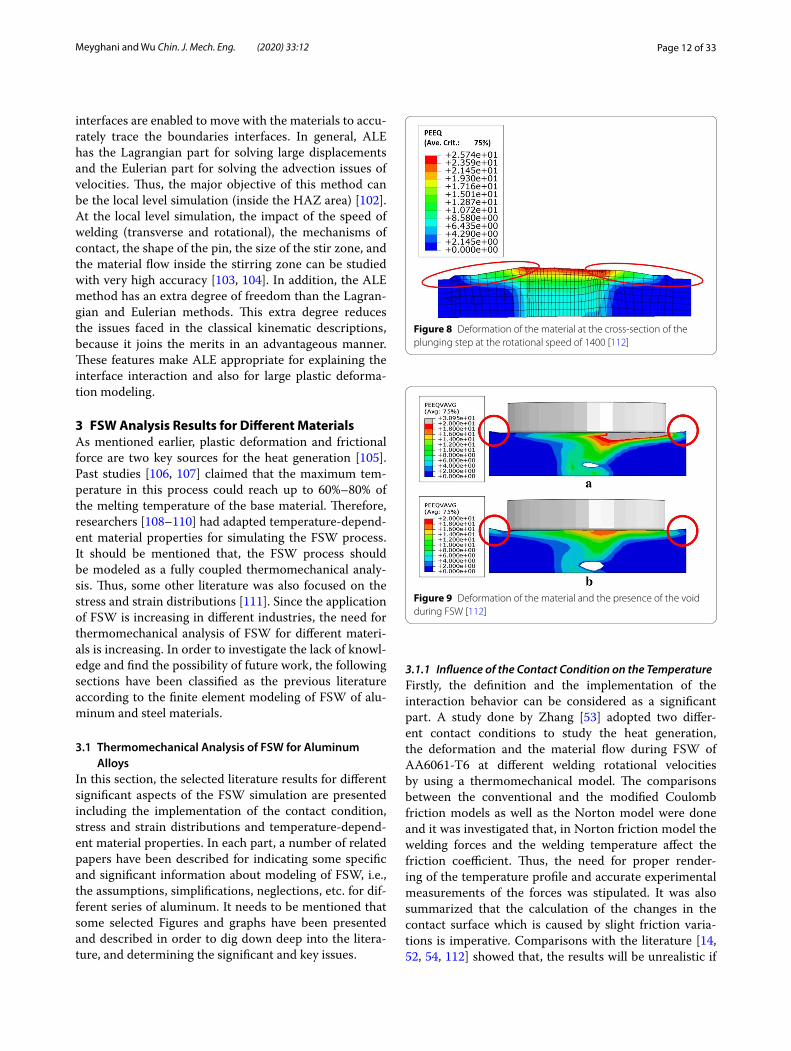
interfaces are enabled to move with the materials to accu-rately trace the boundaries interfaces. In general, ALE has the Lagrangian part for solving large displacements and the Eulerian part for solving the advection issues of velocities. Thus, the major objective of this method can be the local level simulation (inside the HAZ area) [102]. At the local level simulation, the impact of the speed of welding (transverse and rotational), the mechanisms of contact, the shape of the pin, the size of the stir zone, and the material flow inside the stirring zone can be studied with very high accuracy [103, 104]. In addition, the ALE method has an extra degree of freedom than the Lagran-gian and Eulerian methods. This extra degree reduces the issues faced in the classical kinematic descriptions, because it joins the merits in an advantageous manner. These features make ALE appropriate for explaining the interface interaction and also for large plastic deforma-tion modeling.
3 FSW Analysis Results for Different MaterialsAs mentioned earlier, plastic deformation and frictional force are two key sources for the heat generation [105]. Past studies [106, 107] claimed that the maximum tem-perature in this process could reach up to 60%–80% of the melting temperature of the base material. Therefore, researchers [108–110] had adapted temperature-depend-ent material properties for simulating the FSW process. It should be mentioned that, the FSW process should be modeled as a fully coupled thermomechanical analy-sis. Thus, some other literature was also focused on the stress and strain distributions [111]. Since the application of FSW is increasing in different industries, the need for thermomechanical analysis of FSW for different materi-als is increasing. In order to investigate the lack of knowl-edge and find the possibility of future work, the following sections have been classified as the previous literature according to the finite element modeling of FSW of alu-minum and steel materials.
3.1 Thermomechanical Analysis of FSW for Aluminum Alloys
In this section, the selected literature results for different significant aspects of the FSW simulation are presented including the implementation of the contact condition, stress and strain distributions and temperature-depend-ent material properties. In each part, a number of related papers have been described for indicating some specific and significant information about modeling of FSW, i.e., the assumptions, simplifications, neglections, etc. for dif-ferent series of aluminum. It needs to be mentioned that some selected Figures and graphs have been presented and described in order to dig down deep into the litera-ture, and determining the significant and key issues.
3.1.1 Influence of the Contact Condition on the TemperatureFirstly, the definition and the implementation of the interaction behavior can be considered as a significant part. A study done by Zhang [53] adopted two differ-ent contact conditions to study the heat generation, the deformation and the material flow during FSW of AA6061-T6 at different welding rotational velocities by using a thermomechanical model. The comparisons between the conventional and the modified Coulomb friction models as well as the Norton model were done and it was investigated that, in Norton friction model the welding forces and the welding temperature affect the friction coefficient. Thus, the need for proper render-ing of the temperature profile and accurate experimental measurements of the forces was stipulated. It was also summarized that the calculation of the changes in the contact surface which is caused by slight friction varia-tions is imperative. Comparisons with the literature [14, 52, 54, 112] showed that, the results will be unrealistic if
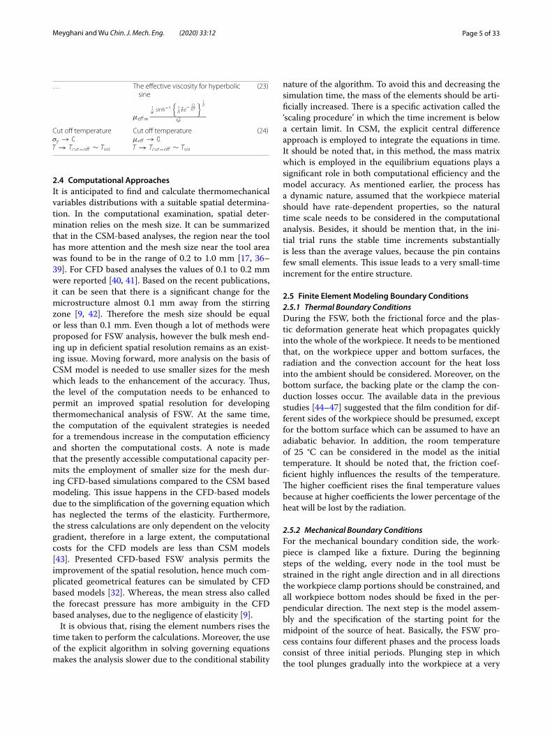
Figure 8 Deformation of the material at the cross-section of the plunging step at the rotational speed of 1400 [112]
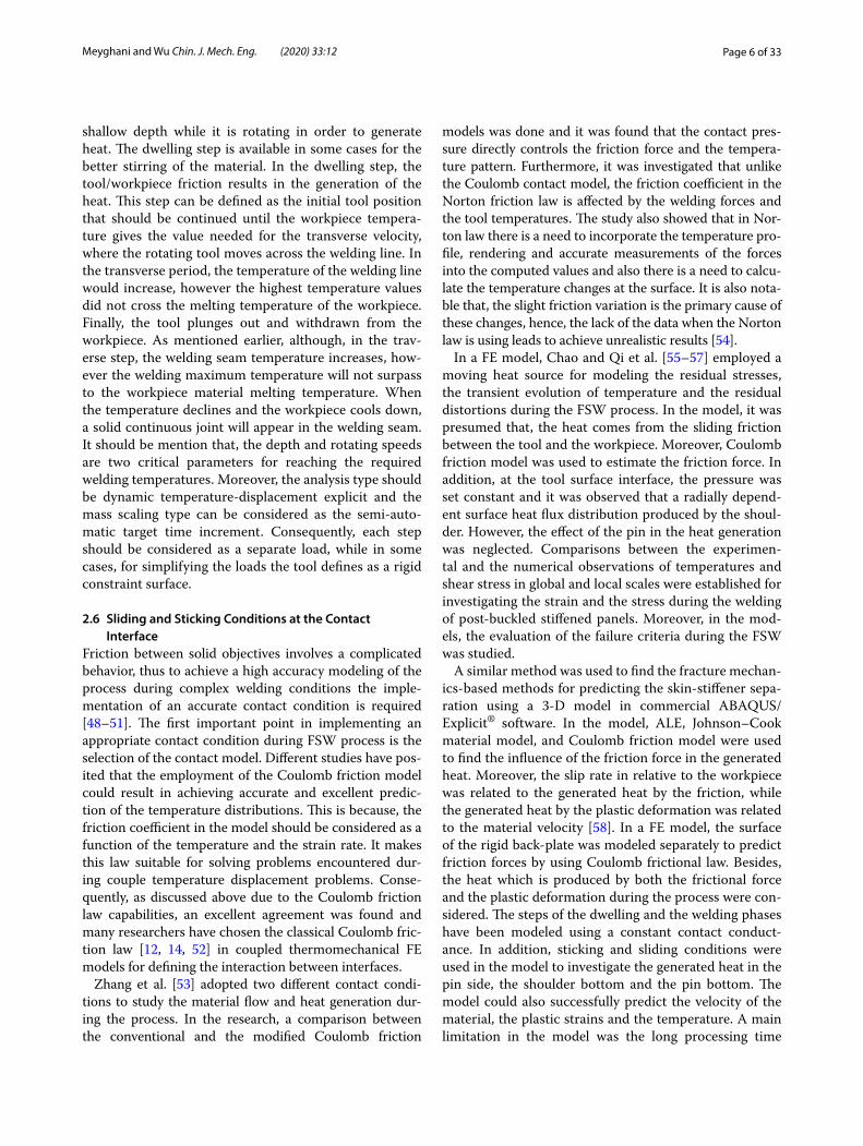
Figure 9 Deformation of the material and the presence of the void during FSW [112]

Page 13 of 33Meyghani and Wu Chin. J. Mech. Eng. (2020) 33:12
a lack of data happens during the implementation of the contact condition in a fully coupled thermomechanical. Finally, Coulomb friction law could provide more realis-tic and better results in the investigation of the thermo-mechanical behavior for AA6061-T6, because the law considers the variable on the temperature and the strain rate and deformations (Figures 8 and 9), which makes this law suitable for solving couple temperature dis-placement problems. To illustrate, in the literature it was mentioned that the tool pushes the material upward and deforms the tool side sections. This issue can be observed in Figures 8 and 9 (the highlighted sections). Therefore, due to the accurate employment of the contact area, a good and accurate prediction of the deformation behav-ior is done. In order to describe the relationship between the accurate implementation of the contact condition and the temperature distribution Figure 10 has been pre-sented. As can be seen, the welding temperature has an asymmetrical pattern and the temperature of 400 °C is achieved as the peak temperature (below the shoulder). Moreover, it was observed that the backside of the pin has higher temperature and a “V” shape pattern for the temperature is observed which shows the implementa-tion of accurate applying contact condition and the inter-action parameters.
Studies by Ulysse et al. [73] and Colegrove and Shercliff [27] investigated the contact condition to measure the workpiece plastic deformation in a unique heat source condition for AA 7050-T7451 while Heurtier et al. [74] considered two heat generation methods in full sliding and full sticking conditions for AA2024-T351. Hamil-ton et al. [72] proposed a FSW thermal model in which a
full sliding contact was used, because of the assumptions of the finite element model. Different rotational speeds including 225, 250, 300 and 400 r/min and constant val-ues of the transverse speed have been considered for the model. In addition, the relationship between the yield strength and the temperature was obtained (Figure 11) and as can be seen with the increase of the temperature the yield strength is decreased. It should be noted that the Johnson–Cook material law (the values are high-lighted in Figure 11) was employed for welding material modeling. The welding contour including the plates and the back plate also is available in Figure 12 which con-firms that most of the heat is generated by the shoulder and the maximum temperature of 388 °C was obtained during the process. It was investigated that due to the use of accurate sliding condition, the welding energy also decreased when the temperature of the welding is increased.
Gerlich et al. [81] investigated two different types of aluminum (Al 5754 and Al 6061) separately and Schmidt et al. [82] model showed that the contact condition in the FSW process has a partial sliding/sticking condi-tion, especially for high strength aluminum alloys like AA2024-T3. Figure 13 shows the welding thermal cycle at the rotational velocity of 3000 r/min which indicates the highest values of the temperature (814 °C).
Some studies [45, 68] presented FE models for mode-ling the heat during FSW of AA2195 at the cold condition during high welding velocity and the normal condition in which the welding velocity was considered to be low (Fig-ure 14). Authors considered the full sliding condition for the interaction behavior between the tool and the work-piece, however due to the simplifications, in these studies
Figure 10 The contour of the peak temperature during the welding: (a) the 3D view point, (b) the longitudinal direction, and (c) the transverse direction [53]
Figure 11 Relationship between the temperature and the yield strength [72]

Page 14 of 33Meyghani and Wu Chin. J. Mech. Eng. (2020) 33:12
the contact area was unrealistic and there was a wide gap between the experimental measurements and the numer-ical model. Finally, it was seen that the higher values of the welding speed create higher temperature gradients.
In a fully coupled thermomechanical model, the classi-cal and the modified Coulomb laws were employed [59] for modeling the FSW process during different weld-ing rotational velocities. Additionally, the gap between the results of different numerical models was not wide at lower rotational velocities. However, at higher rota-tional velocities the classical model failed, because of the shear stress limitations at the welding interfaces, while the modified model in a semi-analytical thermomechani-cal condition could successfully simulate the process [60]. After applying the modified model it was observed that during higher values of the rotational velocities the
Figure 12 The contour plot of the welding including the welding and the backplate: (a) 5 s after the welding and (b) 30 s after the welding [72]
Figure 13 Relationship between the temperature and the welding time [81]
Figure 14 Distribution of the temperature: (a) the normal welding condition and (b) the cold welding conditions [45]
Page 15 of 33Meyghani and Wu Chin. J. Mech. Eng. (2020) 33:12
deformation of the welding material at the top and the bottom surfaces becomes almost similar.
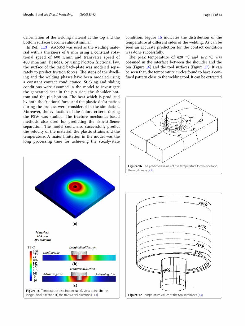
In Ref. [113], AA6063 was used as the welding mate-rial with a thickness of 8 mm using a constant rota-tional speed of 600 r/min and transverse speed of 400 mm/min. Besides, by using Norton frictional law, the surface of the rigid back-plate was modeled sepa-rately to predict friction forces. The steps of the dwell-ing and the welding phases have been modeled using a constant contact conductance. Sticking and sliding conditions were assumed in the model to investigate the generated heat in the pin side, the shoulder bot-tom and the pin bottom. The heat which is produced by both the frictional force and the plastic deformation during the process were considered in the simulation. Moreover, the evaluation of the failure criteria during the FSW was studied. The fracture mechanics-based methods also used for predicting the skin-stiffener separation. The model could also successfully predict the velocity of the material, the plastic strains and the temperature. A major limitation in the model was the long processing time for achieving the steady-state
condition. Figure 15 indicates the distribution of the temperature at different sides of the welding. As can be seen an accurate prediction for the contact condition was done successfully.
The peak temperature of 428 °C and 472 °C was obtained in the interface between the shoulder and the pin (Figure 16) and the tool surfaces (Figure 17). It can be seen that, the temperature circles found to have a con-fined pattern close to the welding tool. It can be extracted
Figure 15 Temperature distribution: (a) 3D view point, (b) the longitudinal direction (c) the transversal direction [113]
Figure 16 The predicted values of the temperature for the tool and the workpiece [73]
Figure 17 Temperature values at the tool interfaces [73]

Page 16 of 33Meyghani and Wu Chin. J. Mech. Eng. (2020) 33:12
that, far from the welding zone the circle line distance increases [73].
3.1.2 Stress and Strain DistributionsChen et al. and Hamilton et al. [62, 72, 114] thermome-chanically studied the influence of the rotational (225 r/min, 250 r/min, 300 r/min, 400 r/min and 1000 r/min) and transverse speeds on the temperature and the stress–strain distributions during the FSW process on AA 6061-T6. It was investigated that the sliding con-dition happens when the contact shear stress is less than the yield stress of the workpiece material. The presented results indicated that the temperature has a significant influence on the strain–stress curve and as the welding temperature increases the increasing rate of the curve increases as well. The results for the resid-ual stress distribution was also presented (Figure 18) at different values of the transverse velocities (150 and 350 mm/min).
Riahi and Nazari [115] introduced material charac-teristics into a FE model for the welding of aluminum 6061-T6. The influence of the tool moving speed which is linked to the residual stress and the heat distribu-tion was simulated accurately. Figure 19 indicates that the impact of the heat was also analyzed to predict the stress and residual stress during the rotational speed of 1250 r/min and the transverse velocity of 280 mm/min. The results obtained showed that the stress asym-metrically distributed across the thickness. Figure 20 also indicates the longitudinal and the transverse values of the residual stress at 280, 530 and 787 mm/min at the cross-section. The outcomes of the residual stress showed that the distribution of the heat across the thickness varies and has an almost irregular pattern. It was shown that, the stress across the cross-section direction increases with the increase of the welding
speed and the tool movement and the form of the stress behavior at the pin area changes significantly (as high-lighted in Figure 20). This happens because the heat could cause minor differences in the result of the simu-lation and the outcome of an actual experiment.
For the welding of AA6061-T6, the stress and strain distributions inside the string zone was reported to be around 533 °C (Figures 21 and 22) [116]. It was described that the welding stress at the pin bottom area is around 200 MPa, while inside the heat-affected zone it was recorded to be around 130 MPa and in the base of the material it was measured that the stress is around 50 MPa. As can be seen in Figure 22, the strain distri-butions at the cross-section of the welding (advancing side and the retreating side) are not symmetrical. To illustrate, in the advancing side the material pushed upward due to the influence of the shoulder on the movement of the material.
Figure 23 was presented to explain the measured val-ues of the strain rate at different rotational speeds and it was concluded that as the rotational speed increases the values of the strain rate increases as well, how-ever the rate of the increase is getting slower after applying the rotational speed of 1500 r/min [82]. To explain the issue, after the rotational speed of 1500 r/min, an almost constant pattern for the strain rate was
Figure 18 Stress distribution during the transverse speed of 20 mm/s and rotational speed of 1000 min−1 [114]
Figure 19 Distribution of the stress across the workpiece: (a) S11 Stress in 1 direction, (b) stress in 2 direction [115]

Page 17 of 33Meyghani and Wu Chin. J. Mech. Eng. (2020) 33:12
achieved, while a sharp increase between the rotational speed of 700 r/min to 1300 r/min has been obtained.
3.1.3 Material Flow InvestigationThe values of the strain rate, the magnitude and vec-tors of the velocity were described during the friction
stir welding with different tool pin geometries (Fig-ure 24). It can be seen that near the pin/shoulder inter-face area, the maximum values for the material velocity are found (in the bonding area). Moreover, the relation-ship between the temperature values and the history of the particles was investigated and plotted in the paper
Figure 20 Values of the residual stress across the welding cross-section: (a) the transverse velocity of 280 mm/min and the rotational speed of 1250 r/min, (b) the transverse velocity of 530 mm/min and the rotational speed of 1250 r/min, (c) the transverse velocity of 787 mm/min and the rotational speed of 1250 r/min [115]
Figure 21 Stress distributions at the tool and the workpiece interface [111]
Figure 22 Strain distribution across the workpiece cross-section rotational speed of 1000 and 60 mm/s [116]
Figure 23 Relationship between the strain rate and the rotational speed [82]

Page 18 of 33Meyghani and Wu Chin. J. Mech. Eng. (2020) 33:12
in order to find and predict the maximum values of the temperature and also the final position of the mate-rial (Figure 25). As can be seen, the maximum values of the temperature (501 °C) are achieved between the values of 0.5 s to 1 s and after 1 s the values decreased gradually.
Comparisons between the experimental and the numerical observations of the temperatures and the shear stress in global and local scales were established for investigating the material movement, the strain, and the stress during the welding of post-buckled stiffened panels [117]. The thickness of the plate was consid-ered to be 1.8 mm at the constant welding parameter of 500 r/min and 5 mm/s. As can be seen in Figure 26, the flow of the material in the initial configuration and the welding step is compared with the experiments. Figure 27 also shows that, the particle locations at the mid-height of the pin for different welding time were also plotted in the research. The particle positions in a three-dimensional viewpoint can be seen in Figure 28 and it was observed that the material final position is located behind the tool and the movement of the material in the pin bottom section is higher than the pin side, thus an asymmetrical behavior for the mate-rial movement is achieved. This issue happens because during higher rotational speeds, at the pin, the dis-placements of the particles in the Z-axis are smaller than X and Y axes. In addition, an upward pattern for
Figure 24 Simulation results for the model: (a) contours of velocity magnitude (m/s); (b) velocity vectors; (c) strain rate; (d) temperature contours [27]
Figure 25 Temperature history for the particles of the material near the pin [27]
Figure 26 Comparison between the material flow in the initial and the welding steps [117]

Page 19 of 33Meyghani and Wu Chin. J. Mech. Eng. (2020) 33:12
the material is observed at the pin side area. It can be also shown that, there is a good agreement between the results and the experiments.
3.1.4 Temperature‑Dependent Material PropertiesFor finding and investigating the influence of the mate-rial temperature on the mechanical behavior during FSW modeling of 6061 aluminum alloy [108, 118–121] tem-perature-dependent material properties were adopted. These studies found that firstly the temperature increases smoothly (during heating), then decreases sharply (dur-ing cooling). It was mentioned that applying temper-ature-dependent material mechanical and thermal properties like density, Poisson ratio, Young’s modulus,
thermal conductivity, the coefficient of thermal expan-sion, specific heat capacity, friction coefficient and slip rate will highly increase the accuracy of the model [100, 122].
Lastly, it should be noted that, specific properties of aluminum like high thermal conductivity or the wide-ranging of melting temperatures which cause the poros-ity, highly affect the quality of the welding. As a summary, the fluctuations of the heat input, the investigation of the presence of the voids and cracks, the study of the tem-perature, stress and strain distributions have been some significant objectives for thermomechanical analysis of FSW.
3.2 Thermomechanical Analysis of FSW for SteelsOne of the main challenges for FSW of steels is the high melting temperature. Moreover, FSW of steel requires high values of force, because its resistance is much higher than aluminum, thus the numerical investigation of the FSW tool should be considered as a critical aspect. To illustrate, high expenses of the tool coating methods encourage researchers to use finite element methods for simulating the FSW of steel. In this regard, numerical investigation of the process parameters, temperature and material flow behaviors assists researchers to control the process temperature, improve the material flow, optimize the welding condition, decrease the welding forces and also enhance the welding quality.
3.2.1 Material FlowFor investigating the heat and the material flow through FSW of different types of steel, Cho et al. [83] (ferritic stainless steel) and Nandan et al. [84] (mild steel) pre-sented three-dimensional numerical models that were used to examine the material movement, the plastic deformation and the temperature of the workpiece. Fig-ure 29 indicates the stream trace of the flow near the pin. It needs to be mention that, the backside was considered to be as the inlet and the front side was selected to be the outlet. As can be seen, the streamlines are almost straight
Figure 27 Locations of velocity particles at the middle side of the pin [117]
Figure 28 Three-dimensional view of the material flow [117]
Figure 29 Stream trace for the flow of the material at the 3-D viewpoint [83]

Page 20 of 33Meyghani and Wu Chin. J. Mech. Eng. (2020) 33:12
far from the welding region, while near the tool a circu-lar confined closed pattern was seen. Additionally, recir-culate plastic flow also was observed near the pin and the streamlines occupied bigger regions at the shoulder surface.
Figure 30 shows the plot of the temperature and the velocity vectors at different welding planes [84]. It can be seen that the velocity values near the pin area (upper surfaces) are higher compared to the places far from the welding centerline (lower surfaces). It needs to be men-tioned that the rotational speed of 450 r/min and the transverse velocity of 0.42 mm/s have been applied in the model.
Figure 31 shows the movement of the material in dif-ferent 0.25 rd/mm and 2 rd/mm ration conditions (the ratio between the radius of the shoulder and the trans-verse velocity). As can be seen, the width of 16 mm is considered for the workpiece. It was found that at lower ratio (0.25), the material moves below the shoulder, while at higher ratio (0.5), the material has a spare form across the welding seam [74]. It can be seen that in the weld-ing retreating side a confined pattern for the material movement is seen, while the gap between the lines in the advancing side is getting wider.
Previous studies [123, 124] have used a poly-crystal plasticity model to investigate texture evolution through the FSW of stainless steel. By specifically monitoring of the evolving crystallographic texture at different points, different welding parameters and different thread geome-tries (Figure 32), the measurements have done accurately. These studies also examined the impact of the frictional conditions at the tool pin and the shoulder on the flow of the material across the thickness direction. The texture strengthening and weakening trends relative to the rate
of the deformation and spin were also highlighted. Fur-thermore, the authors compared the computed textures with the measurement of the electron backscatter dif-fraction based on their distribution as well as the primary texture components along the fiber orientation.
Meanwhile, another study [15] used a rate-dependent constitutive model to simulate the 3D material flows of the FSW process of 1018 steel under different welding conditions. The outcomes of the model demonstrated that the flow of the material near the shoulder-plate interface is affected by the shoulder border. In this light, increasing the angular velocity or reducing the welding speed could improve the combination of the material in the lower half of the weld. However, it was observed that the error could happen when a relatively high angular velocity or low translational velocity is available.
Meanwhile, other previous studies [125, 126] modeled the FSW of stainless steel employing a steady-state Eule-rian formula. The formula could be used for solving the 3D coupled viscoplastic flow and the heat transfer. The method was also employed to determine the distribution of the temperature and the velocity field to resolve the model equations while the improved Petrov–Galerkin formulation was applied to stabilize the temperature.
Figure 33 indicates the flow of the material around the tool. It should be noted that, the tool backside is assumed to be as the inlet, while the front side is defined to be as
Figure 30 Plot of the temperature and the velocity for mild steel [84]
Figure 31 Flow of the material across the workpiece [74]

Page 21 of 33Meyghani and Wu Chin. J. Mech. Eng. (2020) 33:12
the outlet. It can be observed that at the retreating side of the weld the largest values of the strain rate and material flow are happening [125, 126]. It can be seen that, TMAZ can be considered as the second affected part because of the tool movement. Furthermore, far from the weld-ing side at the base material, a slight movement has been achieved.
3.2.2 Friction BehaviorThe influence of the slip rate and the friction coefficient on the radial distance was studied in a model (Figure 34) [83]. It can be observed that, there is an increasing rate for the values of the slip rate with the increase of the
Figure 32 Texture across the workpiece at the tool interface [123]
Figure 33 Flow of the material at the workpiece interface [124]
Figure 34 The relationship between (a) the frictional slip and (b) the friction coefficient with the radial distance [83]

Page 22 of 33Meyghani and Wu Chin. J. Mech. Eng. (2020) 33:12
radial distance from the axis. It was detected that, the area below the curve during lower values of the slip rate (0.3) is larger. As can be seen in Figure 34b, the values of the friction coefficient decreases as the distance from the radial axis increases. Unlike the behavior of the slip rate, the area below the curve during higher friction coeffi-cient values is larger.
Heurtier et al. [74] considered two techniques for the heat generation under the conditions of full sticking and full sliding for welding of AISI 1018 steel, however because of the process complexity and the diverse local phenomena both models were uncoupled. It should be noted that the tilt angle is applied in order to increase the quality of the weld; however, a complete contact condi-tion was assumed for the interface between the work-piece and the tool. Furthermore, the friction at the pin side was neglected and only the shoulder contact inter-face was assumed, because it was claimed that the major-ity of the heat during the process is produced by the tool shoulder surface.
3.2.3 Temperature DistributionThe results of the literature from a solid mechanic model [83] for the temperature field in the advancing side and the retreating side is reported in Figure 35. As can be seen, the shoulder produces the highest temperature and a confined pattern for the temperature were obtained. It can be obtained that, an almost symmetric pattern for the temperature across the cross-section and the top surface
has been achieved. Additionally, the peak temperature of 1030 K is reached in the workpiece for stainless steel.
In the meantime, Ref. [127] adopted a simplified heat input model to study the distribution of the transient temperature and thermal cycle curve feature points for a 4 mm Q235A steel FSW butt joints. The study veri-fied the heat input model and the simulation technique by making a comparison between the results of the feature point temperature curve which was measured by thermocouples and the calculated outcomes of the simulations. As the constitutive law, the Johnson-Cook material model was used because it is dependent on the strain rate and the temperature values. Here, the model heat comes from the friction between the mate-rial, the pin and the shoulder of the tool, as well as the heat which is produced by the plastic deformation. It was observed that the peak temperature of 550 °C is achieved in the welding (below the shoulder) [74].
One study presented a FE model using WELDSIM code which was specifically established to create 3D nonlinear thermal and thermo-mechanical simulations for FSW of 304L stainless steel material [44, 128]. The distribution of the temperature at the interface of the
Figure 35 Temperature distribution in the workpiece during the welding: (a) the three dimensional view point, (b) the top view of the workpiece [83]
Figure 36 Temperature distribution at the tool and workpiece interface: (a) the top view, (b) the transverse direction [125, 126]

Page 23 of 33Meyghani and Wu Chin. J. Mech. Eng. (2020) 33:12
tool and the workpiece in the top viewpoint and the transverse direction (including the tool) of the work-piece is shown in Figure 36. As can be seen, the peak temperature of 900 °C is obtained at the tool. The study also analyzed two cases with the rotation velocities of 300 and 500 r/min. Subsequently, the transient tem-perature found at different positions during the FSW process and used to develop as an inverse analysis tech-nique for thermal modeling. Afterward, for determin-ing the temperature field, and identifying the residual stresses on the FSW plate, a 3D elastic-plastic thermo-mechanical simulation was employed.
Ref. [129] found a good agreement between the experi-ments and the simulated model by ABAQUS® for FSW of L80 steel. Figure 37 indicates the measured maximum temperature of 1050 °C that was obtained for the thermal model and 920 °C which was recorded for the simulated model. Contour for the temperature distribution can be seen in Figure 38. It can be concluded that in the warm-ing up step the source of the heat has been fixed and the
heat conduction was obtained to be the same at the heat source, while after moving the tool, the source of the heat regularly expands.
Nandan et al. [84] experimentally and theoretically investigated the 3D viscoplastic flow and the heat trans-fer through the FSW of mild steel during different weld-ing conditions (350, 450, 550 and 650 r/min and 0.02, 0.06, 0.1 and 0.14 mm/s). Figure 39 indicates the tem-perature values across the shoulder diameter at differ-ent sides of the welding. It was reported that a “V” shape form for the temperature is shaped across the cross-sec-tion and the transverse direction, while at the top side near the shoulder confined circles were obtained. Spa-tially variable thermo-physical properties, as well as the method adapted from another well-established work in fusion welding, were used to provide a 3D solution for solving governing equations that include mass conserva-tion, momentum, and energy. Besides, the study calcu-lated Non-Newtonian viscosity for measuring the flow of the material. The temperature and flow stress were also determined by measuring the strain rate. Susceptible vis-coplastic flow near the tool surface was calculated, and it was obtained that the convection is the main heat trans-fer mechanism in this region.
Ref. [130] presented a continuum-based FE model for FSW of steels that was utilized to predict temperature, strain, strain rate distribution as well as the thermal and the mechanical loads on the welding tool at differ-ent primary process parameters. The maximum tem-perature of the FSW at the tool interfaces (460 °C) was measured in the numerical simulation (Figure 40) and the maximum values of 940 °C at the shoulder interface was obtained. As can be seen, the highest values of the temperature were obtained in the shoulder region. It can be seen that the uniform pattern for the tempera-ture below the shoulder is obtained, thus a regular pat-tern for the behavior of the temperature across the tool is observed.
Figure 37 Distribution of the temperature across the workpiece: (a) thermal model, (b) the simulated model [129]
Figure 38 Contours of temperature (K) for FSW of stainless steel alloy [129]

Page 24 of 33Meyghani and Wu Chin. J. Mech. Eng. (2020) 33:12
A reference model [130] presented a 3D Lagrangian implicit, coupled and rigid viscoplastic simulation (Figure 41) for studying the temperature and strength simulations. It needs to be noted that, a regular pattern for the temperature is achieved for different sides of the welding. As can be seen, the influence of the pin was neglected, therefore no temperature pattern for the pin area was reported. The peak values of the temperature for the shoulder side area was observed (1400 K). How-ever, from section b of Figure 41, it was observed that, the strength only happened across the welding seam and some limited areas nearby. It is clear that for the strength the pin effect is abandoned, hence no report for the pin area was described.
Figure 39 Temperature distributions at different sides of the welding: (a) at the X direction, (b) at the Y direction, (c) at the top section [84]
Figure 40 Plot of the temperature at the welding tool [130]
Figure 41 Distribution of the temperature and the strength during the welding: (a) temperature distribution, (b) strength distribution [125, 126]

Page 25 of 33Meyghani and Wu Chin. J. Mech. Eng. (2020) 33:12
3.2.4 Stress and StrainAs can be seen in Figures 42 and 43 the variation of the viscosity with the strain (Figure 44) and the temperature and the strain rate at different locations of the workpiece were investigated. It was reported that, the maximum strain rate of 400 s−1 was obtained for different ranging of the temperature from 800 K to 1300 K for the mild steel. It needs to be mention that, these values are almost similar to the maximum temperature for the stainless steel that was presented in Ref. [83]. It was observed that the values of the strain rate across the welding line are reduced, however, the pattern for 5.72 s−1 is com-pletely different from others. The comparisons between the velocity contours also were obtained in the paper and it was concluded that the computed morphology of the
viscosity is almost similar to the welding region. From the highlighted section of Figure 44, it can be seen that, the advancing side has an almost regular pattern, while for the retreating side the pattern is different, therefore an almost irregular pattern has been achieved.
It was reported that, the main sources of the heat are located near the welding tool-workpiece interface and the maximum flow of the material is located in the retreating side of the welding. Refs. [131, 132] were focused on the prediction of thermomechanical histories, temperature profile and residual stresses distortion during the FSW of different types of steel material. However, there are still some challenges in simulating complicated problems in which three-dimensional components are available. Figure 45 indicates the residual stress values across the transverse direction of the workpiece and it can be con-cluded that the advancing side has higher values.
Residual stress values after releasing were calculated at different parts of the plate at the rotational speed of 300 r/min (Figure 46). From the plot, it can be seen that
Figure 42 Relationship between the temperature and the strain rate [84]
Figure 43 Strain rate values across the X direction [84]
Figure 44 Strain rate distribution and the comparison with the experiments: (a) the experimental results, (b) the simulation results [83]
Figure 45 Residual stress values at the transverse direction of the workpiece [132]

Page 26 of 33Meyghani and Wu Chin. J. Mech. Eng. (2020) 33:12
the distance between the upper surface and the lower surface after and before releasing the fixture is not very wide. In some points (highlighted sections by the red mark) the values after and before releasing the fix-ture are almost the same. Moreover, experimental test data have been reported in order to verify the model. It can be seen that a good correlation between the pre-dicted values by the model and the experimental tests is obtained.
The results for the strain and strain rate distributions can be seen in Figure 47 [130]. As can be seen, the maximum values were found at the shoulder region due to the higher influence of the shoulder for deforming the material. It is observed from the results that an unbalanced behavior for the deformation is obtained between the advancing side and the retreating side. The outcomes were observed to be appropriate because of the accurate applying of the mate-rial property and suitable mesh modeling technique and mesh size (smaller mesh size inside the welding seam) for the welding (Figure 48). The results for the tunnel defect across the cross-sectional of the welding was also reported for indicating the quality of the welding and investigating the formation of the defect in the welding seam (Figure 49).
The distribution of the equivalent plastic strain for dif-ferent welding speeds (transverse speed of 1.279, 2.363 and 3.316 mm/s and rotational speed of 240, 290 and 390 r/min) is shown in Figure 50 [15]. As can be seen, the rotational speed variations have a significant influence on the material mechanical deformation inside the weld-ing zone. Increasing the transverse speed also observed to have an effect on the deformation of the material which is located far from the welding region. To explain more, during the transverse speed of 2.363 mm/s and 3.316 mm/s the highest influence on the behavior of the shape (production of an unbalanced shape) and the size of the welding zone was obtained. Figure 51 indicates the equivalent plastic strain distribution across the cross-section of the weld and it was concluded that there is a severe deformation of the material inside the nugget zone compared to the stirring zone which this issue makes the grain size of the stirring zone smaller.
Figure 52 [74] shows the plot of the predicted values of the strain rate at the cross-section (a) and the trans-verse direction (b) respectively. It can be concluded that there is an asymmetrical pattern for the strain distribu-tion between the advancing and the retreating sides of the weld (as highlighted in Figure 52). As a drawback for the model, it needs to be mention that a uniform pat-tern for the mesh was considered which this issue affects the accuracy of the results. To illustrate, smaller sizes of
Figure 46 Relationship between the yield stress across the workpiece [132]
Figure 47 (a) Strain and (b) stress rate distribution across the workpiece interface [130]
Figure 48 Mesh inside the domain which shows smaller mesh size in the welding zone [130]
Figure 49 Tunnel defect across the cross section of the welding [130]

Page 27 of 33Meyghani and Wu Chin. J. Mech. Eng. (2020) 33:12
the mesh increase the computational time, while coarse mesh sizes decrease the accuracy of the model, thus for an accurate and appropriate simulation, optimized mesh size should be considered. Furthermore, the maxi-mum value of the equivalent strain rate is reported to be around 6.
Figure 50 Contour plot of the equivalent plastic strain at different welding rotational and transverse speeds: (a) the transverse speed of 2.363 mm/s and the rotational speed of 240 r/min, (b) the transverse speed of 2.363 mm/s and the rotational speed of 290 r/min, (c) the transverse speed of 2.363 mm/s and the rotational speed of 340 r/min, (d) the transverse speed of 1.279 mm/s and the rotational speed of 390 r/min, (e) the transverse speed of 2.363 mm/s and the rotational speed of 390 r/min, (f) the transverse speed of 3.316 mm/s and the rotational speed of 390 r/min [15]
Figure 51 The equivalent strain rate distribution at the tool-workpiece interface [15]
Figure 52 Distribution of the temperature: (a) the cross-section, (b) the transverse movement direction [74]
◂

Page 28 of 33Meyghani and Wu Chin. J. Mech. Eng. (2020) 33:12
Figure 53 indicates the computed values of the flow stress which shows that FSW process induces both the large strain and higher values of the temperature [125, 126]. As can be seen, at all different conditions a regu-lar and uniform increasing rate is obtained and the high-est value of 170 MPa is achieved during the lowest value of the parameter (1 s−1). It needs to be mention that, a scalar state variable strain hardening was incorporated to demonstrate the isotropic strength caused by the defor-mation as the material travels along the flow field stream-lines [125, 126]. The study also modeled the influence of the pin threads on the frictional behavior at the tool/workpiece interface using the axial tractions to supple-ment the tangential tractions along the interface of the pin and the pitch threads.
Predicted streamlines in an Eulerian domain of the flow and the effective (a) and mean (arithmetic meaning for the maximum and minimum values) stress (b) distribu-tions can be seen in Figure 54 [125, 126]. As can be seen, the majority of the concentration for the stress is around the pin area. For the effective stress distribution, an almost regular pattern is obtained, however in the case of mean stress a scattered shape was achieved. It needs to be mention that, the distribution of the temperature (peak temperature of 1400 K) and the strength during the welding were also obtained successfully.
4 ConclusionsCompared to the conventional metal joining process, FSW has many effective advantages, thus it has been widely used in industries like aerospace, automotive, maritime engineering, etc. This article reviews the recent
publications on the thermomechanical analysis of FSW for aluminum and steel materials. The main findings are summarized as follows.
• The governing equation for mechanical problems is the momentum balance equation and assuming the quasi-static mechanical analysis can be done for solv-ing this equation.
• The frictional contact conditions including frictional model (Coulomb friction model, Norton thermo-frictional contact model, etc.), the governing equa-tions and different modeling methods (penalty-based methods direct elimination or Lagrange multipliers methods) for transferring the heat due to the thermal contact at the interface and the thermal impenetra-bility are considered as significant issues in thermo-mechanical analysis of FSW.
Figure 53 Relationship between the stress and the strain [124]
Figure 54 Effective stress and mean stress distributions over the Eulerian domain: (a) effective stress, and (b) mean stress [124]

Page 29 of 33Meyghani and Wu Chin. J. Mech. Eng. (2020) 33:12
• In CSM, the optimization of the mesh size, its shape, and its distortion are some serious challenges.
• Conservation of momentum energy and mass are explained to be appropriate for the Lagrangian and Eulerian frameworks.
• The radiation and the convection, the conduction losses and the film condition are significant issues that need to be considered for the FSW thermal boundary condition.
• Mechanical boundary conditions are clamping the workpiece for explicit dynamic temperature-dis-placement. Moreover, the tool can be considered as a rigid body in order to simplify the model.
• The mass scaling technique can be used to decrease the computation time, but it is significant to note that the quality of the results can be corrupted when there is extreme mass scaling.
• The Lagrangian technique is seen to be suitable for modeling the global level simulation as in this method, the position of the material points is linked to the nodes.
• In contrast, the Eulerian technique is found to be appropriate for modeling the material flow, because the nodes are fixed and the material can move inside the mesh. Thus, scholars used the Eulerian technique to model the material flow, evaluate the temperature, density, and material mixing inside the welding zone.
• Furthermore, coupling models assist researchers in reducing or avoiding remeshing; thus a kinematic setting which can combine the Eulerian and the Lagrangian frameworks (called arbitrary Eulerian-Lagrangian (ALE)) can be used as an appropriate method.
• Although ALE permits to account for the arbitrary and complicated behavior of the material, however it does not necessarily prevent remeshing. Conse-quently, ALE is appropriate to perform local-level analysis (inside the stirring zone).
• The microstructure, temperature and stress compari-sons with the experimental tests assist to verify and validate the model.
5 Future WorkFor the future work, the following items are suggested:
• As FSW is an economical and environment-friendly welding process with huge industrial potential, there is a growing interest in expanding the applications of FSW in different engineering materials, hence more advanced control techniques for continuous welding
and the development of FSW process parameters is needed.
• Because of the complexity of the material modeling for aluminum metal matrix composites (MMC), these materials also have the possibility to be stud-ied more by researchers since the researchers have mostly focused on homogeneous materials. It should be noted that user-defined subroutines can help in this issue to solve complicated material behavior problems.
• Because of the high expenses of the tool coating methods for welding of steel alloys and aluminum metal matrix composites, numerical modeling can help to investigate the welding more in detail, there-fore there will be an opportunity for further research on the tool behavior and tool life analysis.
• It should be noted that, in recent years, welding mate-rials with high melting temperatures, high strength and hardening are becoming more in demand; there-fore the tool design and the tool itself become one of the main features.
• There is a need to find a proper mathematical or theoretical model regarding the FSW process param-eters performance such as the tool shape, tool speed, feed rate, and axial force.
• Choosing suitable input parameters to obtain the desired output for different welding materials is required.
• It will be proposed that the distribution of the resid-ual stresses could affect the weld quality, because it is the main reason for the formation of cracks, propa-gation, and failure of the material due to fatigue crack propagation (FCP), thus for increasing the weld qual-ity further study on the residual stress can be done.
• FSW of curved plates is done for similar materials with low penetration of the pin inside the workpiece. Hence, for both similar and dissimilar materials, the thermomechanical analysis and the study of the material flow of the curved plates with an appropri-ate penetration of the tool can be studied.
• There is a lack of knowledge in modeling high-speed FSW, due to the difficulty and the high chance of the divergence problem caused by the mesh distortion during finite element modeling.
• There is a need to classify and categorize the previous studies and the literature for FSW of different similar (like copper, magnesium, titanium, etc.) and dissimi-lar materials (steel to aluminum, aluminum to mag-nesium, etc.).
AcknowledgementsThe authors would like to acknowledge the Postdoctoral Fellowship of China Postdocral Council and Shandong University.

Page 30 of 33Meyghani and Wu Chin. J. Mech. Eng. (2020) 33:12
Authors’ ContributionsBM wrote the manuscript; CW proposed the outlines and modified the manu-script. Both authors read and approved the final manuscript.
Authors’ InformationBahman Meyghani was born in 1988. He obtained his PhD degree in mechani-cal engineering from Universiti Teknologi PETRONAS (UTP), Malaysia. He is cur-rently working at Institute of Materials Joining, Shandong University, China. He is doing research in Materials Welding and Joining. His current research field is “Experimental and Numerical Investigation of Friction Stir Welding for Similar and Dissimilar Materials”.Chuansong Wu currently works at Institute of Materials Joining, Shandong University, China. Prof. Wu does research in Materials Welding and Joining. He is the Fellow of American Welding Society, and Humboldtian Scholar in Germany. His research interests include the physics of welding, numerical simulation and experimental sensing & control of various welding processes. He is the member of Editorial Board of Science and Technology of Welding and Joining (Taylor & Francis), and the Vice Chair of the Editorial Board of Chinese Journal of Mechanical Engineering (Springer).
FundingSupported by National Natural Science Foundation of China (Grant Nos. 51475272, 51842507) and Key R&D Program of Shandong Province in China (Grant No. 2018GGX103001).
Competing interestsThe authors declare that they have no competing interests.
Received: 31 October 2019 Revised: 14 January 2020 Accepted: 22 Janu-ary 2020
References [1] R S Mishra, Z Ma. Friction stir welding and processing. Materials Science
and Engineering: R: Reports, 2005, 50: 1-78. [2] X C Liu, Y F Sun, T Nagira, et al. Experimental evaluation of strain and
strain rate during rapid cooling friction stir welding of pure copper. Science and Technology of Welding and Joining, 2019, 24: 352-359, 2019/05/19.
[3] X C Liu, Y F Sun, T Nagira, et al. Evaluation of dynamic development of grain structure during friction stir welding of pure copper using a quasi in situ method. Journal of Materials Science & Technology, 2019, 35: 1412-1421, 2019/07/01.
[4] R Nandan, T DebRoy, H Bhadeshia. Recent advances in friction-stir weld-ing–process, weldment structure and properties. Progress in Materials Science, 2008, 53: 980-1023.
[5] G Padhy, C Wu, S Gao. Friction stir based welding and processing technologies-processes, parameters, microstructures and applica-tions: A review. Journal of Materials Science & Technology, 2018, 34: 1-38.
[6] R S Mishra, P S De, N Kumar. Friction stir welding and processing: science and engineering. Springer, 2014.
[7] Y Zhu, G Chen, Q Chen, et al. Simulation of material plastic flow driven by non-uniform friction force during friction stir welding and related defect prediction. Materials & Design, 2016, 108: 400-410, 2016/10/15.
[8] A Simar, Y Bréchet, B De Meester, et al. Integrated modeling of friction stir welding of 6xxx series Al alloys: process, microstructure and proper-ties. Progress in Materials Science, 2012, 57: 95-183.
[9] G Chen, S Zhang, Y Zhu, et al. Thermo-mechanical analysis of friction stir welding: A review on recent advances. Acta Metallurgica Sinica (English Letters), 2019: doi:10.1007/s40195-019-00942-y.
[10] B Meyghani. Thermomechanical analysis of friction stir welding (FSW) on curved plates by adapting calculated temperature dependent properties. Malaysia: Universiti Teknologi PETRONAS, 2018.
[11] B Meyghani, M Awang, C Wu. Thermal analysis of friction stir welding with a complex curved welding seam (technical note). International Journal of Engineering, 2019, 32: 1480-1484.
[12] H Schmidt, J Hattel. A local model for the thermomechanical conditions in friction stir welding. Modelling and Simulation in Materials Science and Engineering, 2004, 13: 77.
[13] Z Zhang, Q Wu. Numerical studies of tool diameter on strain rates, temperature rises and grain sizes in friction stir welding. Journal of Mechanical Science and Technology, 2015, 29: 4121-4128.
[14] Z Zhang, Y Liu, J Chen. Effect of shoulder size on the temperature rise and the material deformation in friction stir welding. The International Journal of Advanced Manufacturing Technology, 2009, 45: 889.
[15] Z Zhang, J Chen. The simulation of material behaviors in friction stir welding process by using rate-dependent constitutive model. Journal of Materials Science, 2008, 43: 222-232.
[16] G Buffa, J Hua, R Shivpuri, et al. A continuum based fem model for fric-tion stir welding—model development. Materials Science and Engineer-ing: A, 2006, 419: 389-396.
[17] Z Wan, Z Zhang, X Zhou. Finite element modeling of grain growth by point tracking method in friction stir welding of AA6082-T6. The International Journal of Advanced Manufacturing Technology, 2017, 90: 3567-3574.
[18] L Long, G Chen, S Zhang, et al. Finite-element analysis of the tool tilt angle effect on the formation of friction stir welds. Journal of Manufac-turing Processes, 2017, 30: 562-569.
[19] F Al-Badour, N Merah, A Shuaib, et al. Coupled Eulerian Lagrangian finite element modeling of friction stir welding processes. Journal of Materials Processing Technology, 2013, 213: 1433-1439.
[20] L Zhu, C S Peskin. Simulation of a flapping flexible filament in a flowing soap film by the immersed boundary method. Journal of Computational Physics, 2002, 179: 452-468.
[21] K Li, F Jarrar, J Sheikh-Ahmad, et al. Using coupled Eulerian Lagrangian formulation for accurate modeling of the friction stir welding process. Procedia Engineering, 2017, 207: 574-579.
[22] V Shokri, A Sadeghi, M Sadeghi. Thermomechanical modeling of fric-tion stir welding in a Cu-DSS dissimilar joint. Journal of Manufacturing Processes, 2018, 31: 46-55.
[23] X Liu, S Lan, J Ni. Thermal mechanical modeling of the plunge stage during friction-stir welding of dissimilar Al 6061 to TRIP 780 steel. Jour-nal of Manufacturing Science and Engineering, 2015, 137: 051017.
[24] B Meyghani, M B Awang, S S Emamian, et al. A comparison of different finite element methods in the thermal analysis of friction stir welding (FSW). Metals, 2017, 7: 450.
[25] G Chen, Q Shi, Y Li, et al. Computational fluid dynamics studies on heat generation during friction stir welding of aluminum alloy. Computa-tional Materials Science, 2013, 79: 540-546, 2013/11/01.
[26] P A Colegrove, H R Shercliff. 3-Dimensional CFD modelling of flow round a threaded friction stir welding tool profile. Journal of Materials Processing Technology, 2005, 169: 320-327.
[27] P Colegrove, H Shercliff. CFD modelling of friction stir welding of thick plate 7449 aluminium alloy. Science and Technology of Welding and Join-ing, 2006, 11: 429-441.
[28] R Nandan, G Roy, T Lienert, et al. Numerical modelling of 3D plastic flow and heat transfer during friction stir welding of stainless steel. Science and Technology of Welding and Joining, 2006, 11: 526-537.
[29] Z Yu, W Zhang, H Choo, et al. Transient heat and material flow modeling of friction stir processing of magnesium alloy using threaded tool. Metallurgical and Materials Transactions A, 2012, 43: 724-737.
[30] H Su, C S Wu, M Bachmann, et al. Numerical modeling for the effect of pin profiles on thermal and material flow characteristics in friction stir welding. Materials & Design, 2015, 77: 114-125.
[31] L Shi, C Wu. Transient model of heat transfer and material flow at dif-ferent stages of friction stir welding process. Journal of Manufacturing Processes, 2017, 25: 323-339.
[32] G Chen, H Li, G Wang, et al. Effects of pin thread on the in-process material flow behavior during friction stir welding: A computational fluid dynamics study. International Journal of Machine Tools and Manu-facture, 2018, 124: 12-21.
[33] A E Tekkaya. State-of-the-art of simulation of sheet metal forming. Journal of Materials Processing Technology, 2000, 103: 14-22.
[34] J Zhou, L Li, J Duszczyk. Computer simulated and experimentally veri-fied isothermal extrusion of 7075 aluminium through continuous ram speed variation. Journal of Materials Processing Technology, 2004, 146: 203-212.

Page 31 of 33Meyghani and Wu Chin. J. Mech. Eng. (2020) 33:12
[35] J H Hattel, H N B Schmidt, C Tutum. Thermomechanical modelling of friction stir welding. ASM Proceeding of International Conference: Trends in Welding Researches, 2009: 1-10.
[36] X Yang, W Feng, W Li, et al. Numerical modelling and experimental investigation of thermal and material flow in probeless friction stir spot welding process of Al 2198-T8. Science and Technology of Welding and Joining, 2018, 23: 704-714.
[37] P Chauhan, R Jain, S K Pal, et al. Modeling of defects in friction stir welding using coupled Eulerian and Lagrangian method. Journal of Manufacturing Processes, 2018, 34: 158-166.
[38] Z Zhang, Q Wu, M Grujicic, et al. Monte Carlo simulation of grain growth and welding zones in friction stir welding of AA6082-T6. Journal of Materials Science, 2016, 51: 1882-1895.
[39] Z Sun, C Wu. A numerical model of pin thread effect on material flow and heat generation in shear layer during friction stir welding. Journal of Manufacturing Processes, 2018, 36: 10-21.
[40] G Chen, Q Ma, S Zhang, et al. Computational fluid dynamics simulation of friction stir welding: A comparative study on different frictional boundary conditions. Journal of Materials Science & Technology, 2018, 34: 128-134.
[41] H Su, C S Wu, A Pittner, et al. Thermal energy generation and distribu-tion in friction stir welding of aluminum alloys. Energy, 2014, 77: 720-731.
[42] Y Zhong, C Wu, G Padhy. Effect of ultrasonic vibration on welding load, temperature and material flow in friction stir welding. Journal of Materi-als Processing Technology, 2017, 239: 273-283.
[43] P Bussetta, É Feulvarch, A Tongne, et al. Two 3D thermomechanical numerical models of friction stir welding processes with a trigonal pin. Numerical Heat Transfer, Part A: Applications, 2016, 70: 995-1008.
[44] X Zhu, Y Chao. Numerical simulation of transient temperature and residual stresses in friction stir welding of 304L stainless steel. Journal of Materials Processing Technology, 2004, 146: 263-272.
[45] Y J Chao, X Qi, W Tang. Heat transfer in friction stir welding—experi-mental and numerical studies. Journal of Manufacturing Science and Engineering, 2003, 125: 138-145.
[46] Z Sun, C Wu. Influence of tool thread pitch on material flow and thermal process in friction stir welding. Journal of Materials Processing Technology, 2020, 275: 116281.
[47] G Chen, Z Feng, Y Zhu, et al. An alternative frictional boundary condi-tion for computational fluid dynamics simulation of friction stir welding. Journal of Materials Engineering and Performance, 2016, 25: 4016-4023, 2016/09/01.
[48] F Lu, H-P Wang, A B Murphy, et al. Analysis of energy flow in gas metal arc welding processes through self-consistent three-dimensional process simulation. International Journal of Heat and Mass Transfer, 2014, 68: 215-223.
[49] N Dialami, M Chiumenti, M Cervera, et al. Numerical simulation and visualization of material flow in friction stir welding via particle tracing. Numerical Simulations of Coupled Problems in Engineering, Springer, 2014: 157-169.
[50] Z Saldi, A Kidess, S Kenjereš, et al. Effect of enhanced heat and mass transport and flow reversal during cool down on weld pool shapes in laser spot welding of steel. International Journal of Heat and Mass Transfer, 2013, 66: 879-888.
[51] B Meyghani, M Awang, S Emamian. A mathematical formulation for calculating temperature dependent friction coefficient values: application in Friction Stir Welding (FSW). Defect and Diffusion Forum, 2017: 73-82.
[52] Z Zhang, H Zhang. A fully coupled thermo-mechanical model of friction stir welding. The International Journal of Advanced Manufacturing Technology, 2008, 37: 279-293.
[53] Z Zhang. Comparison of two contact models in the simulation of friction stir welding process. Journal of Materials Science, 2008, 43: 5867-5877.
[54] X He, F Gu, A Ball. A review of numerical analysis of friction stir welding. Progress in Materials Science, 2014, 65: 1-66.
[55] S Zhang, G Chen, Q Liu, et al. Numerical analysis and analytical mode-ling of the spatial distribution of heat flux during friction stir welding. Journal of Manufacturing Processes, 2018, 33: 245-255, 2018/06/01.
[56] Y J Chao, X Qi. Thermal and thermo-mechanical modeling of friction stir welding of aluminum alloy 6061-T6. Journal of Materials Process-ing and Manufacturing Science, 1998, 7: 215-233.
[57] Y Chao, X Qi. Heat transfer and thermo-mechanical analysis of fric-tion stir joining of AA6061-T6 plates. 1st International Symposium on Friction Stir Welding, 1999: 14-16.
[58] M V Darko, M P Rakin, M M Perovi, et al. Heat generation during plunge stage in friction stir welding. Thermal Science, 2013, 17: 489-496.
[59] Z Zhang, H Zhang. Effect of contact model on numerical simulation of friction stir welding. Acta Metallurgica Sinica-Chinese Edition-, 2008, 44: 85. (in Chinese)
[60] P Ferro, F Bonollo. A semianalytical thermal model for fiction stir weld-ing. Metallurgical and Materials Transactions A, 2010, 41: 440-449.
[61] H B Schmidt, J H Hattel. Thermal modelling of friction stir welding. Scripta Materialia, 2008, 58: 332-337.
[62] C Chen, R Kovacevic. Finite element modeling of friction stir weld-ing—thermal and thermomechanical analysis. International Journal of Machine Tools and Manufacture, 2003, 43: 1319-1326.
[63] M Song, R Kovacevic. Thermal modeling of friction stir welding in a moving coordinate system and its validation. International Journal of Machine Tools and Manufacture, 2003, 43: 605-615.
[64] K J Colligan, R S Mishra. A conceptual model for the process variables related to heat generation in friction stir welding of aluminum. Scripta Materialia, 2008, 58: 327-331.
[65] K Kumar, C Kalyan, S V Kailas, et al. An investigation of friction during friction stir welding of metallic materials. Materials and Manufacturing Processes, 2009, 24: 438-445.
[66] M Awang, V Mucino, Z Feng, et al. Thermo-mechanical modeling of friction stir spot welding (FSSW) process: use of an explicit adaptive meshing scheme. SAE Technical Paper 0148-7191, 2005.
[67] S Pereyra, G Lombera, S Urquiza. Modelado numérico del proceso de soldadura FSW incorporando una técnica de estimación de parámet-ros. Revista Internacional de Métodos Numéricos para Cálculo y Diseño en Ingeniería, 2014, 30: 173-177.
[68] M Song, R Kovacevic. Numerical and experimental study of the heat transfer process in friction stir welding. Proceedings of the Institution of Mechanical Engineers, Part B: Journal of Engineering Manufacture, 2003, 217: 73-85.
[69] M Khandkar, J A Khan, A P Reynolds. Prediction of temperature distribu-tion and thermal history during friction stir welding: input torque based model. Science and Technology of Welding & Joining, 2003, 8: 165-174.
[70] C Hamilton, S Dymek, A Sommers. A thermal model of friction stir welding in aluminum alloys. International Journal of Machine Tools and Manufacture, 2008, 48: 1120-1130.
[71] O Lorrain, J Serri, V Favier, et al. A contribution to a critical review of fric-tion stir welding numerical simulation. Journal of Mechanics of Materials and Structures, 2009, 4: 351-369.
[72] C Hamilton, A Sommers, S Dymek. A thermal model of friction stir weld-ing applied to Sc-modified Al–Zn–Mg–Cu alloy extrusions. International Journal of Machine Tools and Manufacture, 2009, 49: 230-238.
[73] P Ulysse. Three-dimensional modeling of the friction stir-welding process. International Journal of Machine Tools and Manufacture, 2002, 42: 1549-1557.
[74] P Heurtier, M Jones, C Desrayaud, et al. Mechanical and thermal model-ling of friction stir welding. Journal of Materials Processing Technology, 2006, 171: 348-357.
[75] N Nikiforakis. Towards a whole system simulation of FSW. Proceedings of the 2nd FSW Modelling and Flow Visualisation Seminar, GKSS Forschung-szentrum, Geesthacht, Germany, January, 2005.
[76] P Colegrove. Three dimensional ow and thermal modelling of thermo-mechanical performance of Friction Stir Welding. The 2nd International Symposium on Friction Stir Welding, 2000.
[77] P Colegrove, H Shercliff. Modelling the friction stir welding of aerospace alloys. Proceedings of the 5th International Friction Stir Welding Sympo-sium, 2004.
[78] Frigaard, Grong, O Midling. A process model for friction stir welding of age hardening aluminum alloys. Metallurgical and Materials Transactions A, 2001, 32: 1189-1200.

Page 32 of 33Meyghani and Wu Chin. J. Mech. Eng. (2020) 33:12
[79] A P Reynolds, Z Khandkar, T Long, et al. Utility of relatively simple models for understanding process parameter effects on FSW. Materials Science Forum, 2003: 2959-2964.
[80] H Schmidt, J Hattel, J Wert. An analytical model for the heat generation in friction stir welding. Modelling and Simulation in Materials Science and Engineering, 2003, 12: 143.
[81] A Gerlich, M Yamamoto, T North. Strain rates and grain growth in Al 5754 and Al 6061 friction stir spot welds. Metallurgical and Materials Transactions A, 2007, 38: 1291-1302.
[82] H N B Schmidt, T Dickerson, J H Hattel. Material flow in butt friction stir welds in AA2024-T3. Acta Materialia, 2006, 54: 1199-1209.
[83] H-H Cho, S-T Hong, J-H Roh, et al. Three-dimensional numerical and experimental investigation on friction stir welding processes of ferritic stainless steel. Acta Materialia, 2013, 61: 2649-2661.
[84] R Nandan, G Roy, T Lienert, et al. Three-dimensional heat and material flow during friction stir welding of mild steel. Acta Materialia, 2007, 55: 883-895.
[85] A Arora, R Nandan, A P Reynolds, et al. Torque, power requirement and stir zone geometry in friction stir welding through modeling and experiments. Scripta Materialia, 2009, 60: 13-16.
[86] S Sulaiman, S Emamian. 6.13 - Optimum speed of friction stir welding on 304L stainless steel by finite element method A2 - Hashmi, Saleem. Comprehensive Materials Processing, G F Batalha, C J V Tyne, B Yilbas, eds. Oxford: Elsevier, 2014: 227-236.
[87] J E Gould, Z Feng. Heat flow model for friction stir welding of aluminum alloys. Journal of Materials Processing and Manufacturing Science, 1998, 7: 185-194.
[88] W Li, S Shi, F Wang, et al. Numerical simulation of friction welding pro-cesses based on ABAQUS environment. Journal of Engineering Science and Technology Review, 2012, 5: 10-19.
[89] B Meyghani, M Awang, S Emamian, et al. Developing a finite element model for thermal analysis of friction stir welding by calculating tem-perature dependent friction coefficient. 2nd International Conference on Mechanical, Manufacturing and Process Plant Engineering, 2017: 107-126.
[90] G R Johnson, W H Cook. A constitutive model and data for metals subjected to large strains, high strain rates and high temperatures. Pro-ceedings of the 7th International Symposium on Ballistics, 1983: 541-547.
[91] M Agmell, A Ahadi, J-E Ståhl. A fully coupled thermomechanical two-dimensional simulation model for orthogonal cutting: formulation and simulation. Proceedings of the Institution of Mechanical Engineers, Part B: Journal of Engineering Manufacture, 2011, 225: 1735-1745.
[92] O Pantalé, J-L Bacaria, O Dalverny, et al. 2D and 3D numerical models of metal cutting with damage effects. Computer Methods in Applied Mechanics and Engineering, 2004, 193: 4383-4399.
[93] D R Lesuer, G Kay, M LeBlanc. Modeling large strain, high rate deforma-tion in metals. Engineering Research, Development and Technology, 1999.
[94] M Agmell, A Ahadi, J E Ståhl. A numerical and experimental investiga-tion of the deformation zones and the corresponding cutting forces in orthogonal cutting. Advanced Materials Research, 2011: 152-161.
[95] E-G Ng, D K Aspinwall. Modelling of hard part machining. Journal of Materials Processing Technology, 2002, 127: 222-229.
[96] L E Schwer, C Windsor. Aluminum plate perforation: a comparative case study using Lagrange with erosion, multi-material ALE, and smooth particle hydrodynamics. 7th European LS-DYNA Conference, 2009.
[97] B Meyghani, M Awang, S Emamian, et al. Thermal modelling of fric-tion stir welding (FSW) using calculated Young’s modulus values. The Advances in Joining Technology, Springer, 2019: 1-13.
[98] B Meyghani, M Awang, S Emamian, et al. A comparison between temperature dependent and constant Young’s modulus values in inves-tigating the effect of the process parameters on thermal behaviour during friction stir welding: Vergleich zwischen den temperaturabhän-gigen und konstanten Elastizitätsmodulwerten in der Untersuchung der Prozessparameter auf die Wärmewirkung beim Rührreibschweißen,” Materialwissenschaft und Werkstofftechnik, 2018, 49: 427-434.
[99] B Meyghani, M Awang. Developing a finite element model for thermal analysis of friction stir welding (FSW) using hyperworks. Advances in Material Sciences and Engineering, Springer, 2020: 619-628.
[100] B Meyghani, M B Awang. Prediction of the temperature distribution during friction stir welding (FSW) with a complex curved welding seam: Application in the automotive industry. MATEC Web of Confer-ences, 2018: 01001.
[101] M Awang. The advances in joining technology. Springer, 2019. [102] B Meyghani, M Awang. A comparison between the flat and the curved
friction stir welding (FSW) thermomechanical behavior. Archives of Computational Methods in Engineering, 2019: 1-14.
[103] B Meyghani, M B Awang, M Momeni, et al. Development of a finite element model for thermal analysis of friction stir welding (FSW). IOP Conference Series: Materials Science and Engineering, 2019: 012101.
[104] B Meyghani, M B Awang, R G M Poshteh, et al. The effect of friction coefficient in thermal analysis of friction stir welding (FSW). IOP Confer-ence Series: Materials Science and Engineering, 2019: 012102.
[105] J A Roubidoux, P F Mendez. Modeling friction stir welding through advanced scaling techniques. Proceedings of 2006 NSF Design, Service, and Manufacturing Grantees and Research Conference, St. Louis, Missouri, 2006.
[106] M Awang, S R Khan, B Ghazanfar, et al. Design, fabrication and testing of fixture for implementation of a new approach to incorporate tool tilting in friction stir welding. MATEC Web of Conferences, 2014: 04020.
[107] B Meyghani, M B Awang. Prediction of the temperature distribution during friction stir welding (FSW) with a complex curved welding seam: Application in the automotive industry. MATEC Web Conferences, 2018, 225: 01001.
[108] D Maisonnette, D Bardel, V Robin, et al. Mechanical behaviour at high temperature as induced during welding of a 6xxx series aluminium alloy. International Journal of Pressure Vessels and Piping, 2017, 149: 55-65.
[109] B Meyghani, M Awang, S Emamian. A comparative study of finite element analysis for friction stir welding application. ARPN Journal of Engineering and Applied Sciences, 2016, 11: 12984-12989.
[110] Y Su, W Li, V Patel, et al. Formability of an AA5083 aluminum alloy T-joint using SSFSW on both corners. Materials and Manufacturing Processes, 2019: 1-8.
[111] T Nakamura, T Obikawa, I Nishizaki, et al. Friction stir welding of non-heat-treatable high-strength alloy 5083-O. Metals, 2018, 8: 208.
[112] Z Zhu, M Wang, H Zhang, et al. A finite element model to simulate defect formation during friction stir welding. Metals, 2017, 7: 256.
[113] D Andrade, C Leitão, N Dialami, et al. Thermomechanical analysis of the friction stir welding process. AIP Conference Proceedings, 2019: 050003.
[114] T Nakamura, T Obikawa, E Yukutake, et al. Tool temperature and process modeling of friction stir welding. Modern Mechanical Engineering, 2018, 8: 78.
[115] M Riahi, H Nazari. Analysis of transient temperature and residual thermal stresses in friction stir welding of aluminum alloy 6061-T6 via numerical simulation. The International Journal of Advanced Manufactur-ing Technology, 2011, 55: 143-152.
[116] R Jain, S Pal, S Singh. Finite element simulation of temperature and strain distribution in Al2024 aluminum alloy by friction stir welding. 5th Int. 26th All India Manuf. Technol. Des. Res. Conf.(AIMTDR 2014), 2014: 3-7.
[117] N Dialami, M Chiumenti, M Cervera, et al. Material flow visualization in friction stir welding via particle tracing. International Journal of Material Forming, 2015, 8: 167-181.
[118] P Threadgill, A Leonard, H Shercliff, et al. Friction stir welding of alu-minium alloys. International Materials Reviews, 2009, 54: 49-93.
[119] P F Mendez, K ETello, T J Lienert. Scaling of coupled heat transfer and plastic deformation around the pin in friction stir welding. Acta Mate-rialia, 2010, 58: 6012-6026.
[120] B Meyghani, M Awang. Developing a finite element model for thermal analysis of friction stir welding (FSW) using hyperworks. Advances in Material Sciences and Engineering, Singapore, 2020: 619-628.
[121] S Kumar. Ultrasonic assisted friction stir processing of 6063 aluminum alloy. Archives of Civil and Mechanical Engineering, 2016, 16: 473-484.
[122] B Meyghani, M B Awang, S Emamian, et al. A comparison between temperature dependent and constant Young’s modulus values in inves-tigating the effect of the process parameters on thermal behaviour during friction stir welding. Materialwissenschaft und Werkstofftechnik, 2017, 49: 427-434.
[123] J-H Cho, P R Dawson. Modeling texture evolution during friction stir welding of stainless steel with comparison to experiments. Journal of Engineering Materials and Technology, 2008, 130: 011007.
[124] J-H Cho, D E Boyce, P R Dawson. Modeling strain hardening and texture evolution in friction stir welding of stainless steel. Materials Science and Engineering: A, 2005, 398: 146-163.

Page 33 of 33Meyghani and Wu Chin. J. Mech. Eng. (2020) 33:12
[125] J Cho, D Boyce, P Dawson. Modelling of strain hardening during friction stir welding of stainless steel. Modelling and Simulation in Materials Sci-ence and Engineering, 2007, 15: 469.
[126] J-H Cho, P R Dawson. Investigation on texture evolution during friction stir welding of stainless steel. Metallurgical and Materials Transactions A, 2006, 37: 1147-1164.
[127] X J Wang, Y X Lu, Z K Zhang, et al. The temperature field test and numerical simulation of steel’s friction stir welding process. Advanced Materials Research, 2013: 370-374.
[128] M P Miles, T W Nelson, C Gunter, et al. Predicting recrystallized grain size in friction stir processed 304L stainless steel. Journal of Materials Science & Technology, 2019, 35: 491-498, 2019/04/01.
[129] W Gan, Z Li, S Khurana. Tool materials selection for friction stir welding of L80 steel. Science and Technology of Welding and Joining, 2007, 12: 610-613.
[130] G Buffa, L Fratini. Friction stir welding of steels: process design through continuum based FEM model. Science and Technology of Welding and Joining, 2009, 14: 239-246.
[131] D Berglund. Simulation of welding and stress relief heat treating in the development of aerospace components. Luleå tekniska universitet, 2001.
[132] P Bouchard. The NeT bead-on-plate benchmark for weld residual stress simulation. International Journal of Pressure Vessels and Piping, 2009, 86: 31-42.