Mehta, Kush Ultra-thin friction stir welding on Aluminum alloy
11
This is an electronic reprint of the original article. This reprint may differ from the original in pagination and typographic detail. Powered by TCPDF (www.tcpdf.org) This material is protected by copyright and other intellectual property rights, and duplication or sale of all or part of any of the repository collections is not permitted, except that material may be duplicated by you for your research use or educational purposes in electronic or print form. You must obtain permission for any other use. Electronic or print copies may not be offered, whether for sale or otherwise to anyone who is not an authorised user. Panchal, Mrunal ; Patel, Devax; Vyas, Hardik; Mehta, Kush Ultra-thin friction stir welding on Aluminum alloy Published in: Materials Today: Proceedings DOI: 10.1016/j.matpr.2020.02.597 Published: 01/01/2020 Document Version Peer reviewed version Published under the following license: CC BY-NC-ND Please cite the original version: Panchal, M., Patel, D., Vyas, H., & Mehta, K. (2020). Ultra-thin friction stir welding on Aluminum alloy. Materials Today: Proceedings, 26, 2888-2894. https://doi.org/10.1016/j.matpr.2020.02.597
-
Upload
khangminh22 -
Category
Documents
-
view
3 -
download
0
Transcript of Mehta, Kush Ultra-thin friction stir welding on Aluminum alloy

This is an electronic reprint of the original article.This reprint may differ from the original in pagination and typographic detail.
Powered by TCPDF (www.tcpdf.org)
This material is protected by copyright and other intellectual property rights, and duplication or sale of all or part of any of the repository collections is not permitted, except that material may be duplicated by you for your research use or educational purposes in electronic or print form. You must obtain permission for any other use. Electronic or print copies may not be offered, whether for sale or otherwise to anyone who is not an authorised user.
Panchal, Mrunal ; Patel, Devax; Vyas, Hardik; Mehta, KushUltra-thin friction stir welding on Aluminum alloy
Published in:Materials Today: Proceedings
DOI:10.1016/j.matpr.2020.02.597
Published: 01/01/2020
Document VersionPeer reviewed version
Published under the following license:CC BY-NC-ND
Please cite the original version:Panchal, M., Patel, D., Vyas, H., & Mehta, K. (2020). Ultra-thin friction stir welding on Aluminum alloy. MaterialsToday: Proceedings, 26, 2888-2894. https://doi.org/10.1016/j.matpr.2020.02.597

Available online at www.sciencedirect.com
ScienceDirect
[ICMPC-2020]
Ultra-thin Friction stir welding on Aluminum alloy
Mrunal Panchal1 , Devax Patel1, Hardik Vyas1, Kush Mehta1,2
1Department of Mechanical Engineering, School of Technology (SOT), Pandit Deendayal Petroleum University (PDPU), Raisan, Gandhinagar
382355, Gujarat, INDIA 2Advanced Manufacturing and Materials group, Department of Mechanical Engineering, School of Engineering, Aalto University, Finland
Abstract
Ultra-thin sheets’ welding is an intricate process either by conventional or advanced techniques. In the present investigation, Micro
friction stir welding (FSW) was successfully performed to join the ultra-thin (0.5 mm thick) commercial aluminum. Suitable fixture
and tool were developed for the ultra-thin sheets to perform experiments. Velocity ratio of rotational speed to transvers speed was
varied to obtain ultra-thin friction stir welding. The welded samples were investigated by visual examination, macrographs,
microstructure, tensile testing with fracture surface analysis and micro hardness distribution. The results revealed that, the sound
joint was achieved at the velocity ratio of 13.71. The tensile strength of 100.877 N/mm2 and elongation of 23.12% were obtained,
which were 90.77% and 51.377% of the parent material respectively. Fracture surfaces after tensile testing was observed with
elongated dimples indicating ductile fracture. The maximum micro hardness of 94 HV was observed in the weld zone.
[copyright information to be updated in production process]
Keywords: Aluminum alloy, Mechanical Properties, Micro friction stir welding, Microstructure, Ultra-thin
1. Introduction
Friction stir welding (FSW) was developed in 1991 by Wayne Thomas and his colleagues in The Welding Institute
(TWI) [1, 2]. FSW is a solid-state welding process that works on visco plastic material mixing caused by thermo-
mechanical processing [3]–[6]. FSW has least impact on the environment due to solid state green welding that does
not partake in any fumes, red-hot glowing materials, spattering or a loud noise during operation [7]. In FSW, a non-
consumable tool made up of suitable features and dimensions of shoulder and pin is plunged into the area to be joined.
Due to plastic deformation and friction between surfaces of tool and workpiece produces heat [8]-[10]. The material
mixing with fine and recrystallized grains is established by stirring that deformed material with a favorable
combination between rotational and transverse velocities of non-consumable tool.
FSW is invented for Al and its alloys that is further expanded for high temperature materials, dissimilar materials,
composites, and plastics [11]. FSW is under development with its novel variants for different size of workpieces for
aforementioned materials. Micro FSW is one of such variant to obtain weld having thickness less than 1 mm. Micro
FSW offers advantages such as I) It significantly increases the possibility of joining wider range of similar and
dissimilar material (plasticisable materials), II) Joints are free of any contamination as there is no use of filler materials
and fluxes, III) Difficult to weld Aluminum alloys can be welded without using any shielding gas [1, 2]. Sithole and
Rao [12] presented a review on recent developments in micro FSW with its importance and process details.
In 2004, Nishihara and Nagasaka [13] revolutionized FSW by introducing welding of thin-plate structural material of
sub 1 mm materials and named that as micro FSW. Micro FSW is further investigated by Taylor et al. [14] in 2008
with successful welds of 0.8 mm Aluminum (Al) alloy. Baskoro et al. [15] studied the effect of welding parameters
for micro FSW in order to better understand the process-parameters influence on weld formation for Aluminum alloy

in lap configuration with 0.4 mm thickness. The same group of Baskoro et al. [16] in 2015 performed micro FSW
with experimental studies to provide understanding on friction stir spot welding for parameters-process influence on
joint formation. Wanshon and Binti [17] developed understanding on heat dissipation in case of micro FSW using
different backing plates namely a ceramic anvil backing plate and a conventional stainless steel anvil backing plate.
Papaefhyimo and Goulase [18] performed the feasibility test of micro FSW for titan zinc plates (ZnTiCu) having a
thickness of 700 µm, wherein a low velocity ratio with tool rotation speed of 1000 rpm along with feed rate of 318
mm/min were observed as favorable. Ahmed [2] in 2015, successfully welded 0.44 mm 6xxx Al sheets with butt and
lap joint configurations. They calculated the tensile strength in both transverse and longitudinal direction. In 2017,
Ahmed [19] published an article on developing a fixture for ultra-thin FSW. Huang[20] in 2018, developed tri-flat pin
of tool for 0.5 mm 6061-T4 Al alloy. Zhang [21] in 2019, successfully welded 0.8 mm 1060-H24 Al alloy using a
shoulder less tool. Wang [22] in 2019, joined 0.254 mm thick workpiece with micro FSW. Sagher-Abbasi [23] in
2019, formulated an investigation of parametric optimization in case of micro FSW.
Despite of aforementioned studies in the area of micro FSW, there is a need to develop micro FSW for 0.5 mm thick
commercial aluminum considering limited investigations on commercial Al with such low thickness. Commercial Al
alloy is more challenging as it consists of highest thermal conductivity among all other Al alloys. This in turn leads
problems of distortion during weld especially when the thickness is such small of 0.5 mm. It is worth to perform
investigation on ultra-thin FSW on commercial Al alloy. In the present investigation, micro FSW was developed to
join 0.5 mm commercial Al alloy considering velocity ratios of rotational speed to travel speed.
2. Materials and Method
The micro FSW of commercial Al with thickness of 0.5 mm was performed. Different velocity ratios of 8.91, 12.50.
13.70, 15.30 and 17.30 were varied using combinations of rotational speed and travel speed as shown in Table 1. All
the experiments were performed with tilt angle of 1 degree. Baskaro in 2013 suggested that optimal the tilt angle is 1°
[15]. The workpiece sheets were clamped on the fixture using copper backing plate, in order to conduct heat using
higher conductivity of Cu compare to Al. Ceramic and Copper backing plates showed best result thus copper backing
plate was taken into consideration to hinder in the process of heat dissipation [4]. The experimental set-up and tool
design (of HSS M-2) are shown in Figure 1 (a) and Figure 1 (b) respectively.
Table1. Numbers of trials with different parameters
Trials Rotational speed(RPM) Travel Feed (mm/min) Speed Ratio
1 1070 120 8.91
2 1500 120 12.50
3 1070 78 13.70
4 765 50 15.30
5 545 315 17.30
Tensile test coupon was generated for sample by cutting it into required dimension with the help of EDM, according
to the ASTM standard as shown in figure1. Fracture surface analysis of the tensile specimen from the weld was carried
out using scanning electron microscopy (SEM). Macrostructure and microstructure examination was performed on
the welded sample. For that weld specimen was cut transverse to welding with the help of EDM machine, hot mounted
followed by grinding and mirror polishing. Macrostructure examination was carried out according to the ASTM-E-
381-01, E-340-15 with the utilization of digital camera/stereo microscope. Micro hardness test was performed on the
generated weld specimen according to ASTM E-384-17 standards at load of 50gms. The base plate chemical
composition along with the mechanical properties were highlighted in table 2 and table 3 respectively.

Dimensions:
A = 11 mm, B = 12
mm, C = 25 mm, D
= 15 mm, E = 6.4
mm, F = 20 mm, G
= 2.3 mm, H = 2
mm, I = 0.35mm
(a) (b)
Figure 1. (a) Welding setup of 0.5mm thick plate (b) tool design
After welding, the obtained welds were initially inspected with visual examination. Macroscopic analysis,
microstructural pattern and mechanical testing were carried out after visual examination for the successfully welded
sample. The tensile test coupon was generated by cutting it into required dimensions with the help of wire cut-electro
discharge machining (EDM), according to the ASTM standard as shown in Figure 2. Fracture surface analysis for the
fractured specimens of tensile testing was carried out using scanning electron microscopy (SEM). Macrostructure and
microstructure examination was performed on the cross sectioned sample for the successfully obtained weld. Wire cut
EDM machine was used for the same, which was subsequently hot mounted followed by grinding and mirror polishing.
Macrostructure examination was carried out according to the ASTM-E-381-01, E-340-15 with the utilization of digital
camera/stereo microscope. Micro hardness test was performed on the generated cross sectional weld specimen
according to ASTM E-384-17 standards at load of 50 grams (from the middle of the cross section).
3. Result and Discussion
3.1 Joint formation/ Visual Inspection
Table 2 depicts the weld formation scenario with respect to different velocity ratios. Better surface appearance is
obtained with velocity ratio of 13.71 having feed rate of 78 mm/min and tool rotation speed of 1070 rpm, whereas
difficulties in weld formation were encountered for rest of the combinations. The successful obtained weld with
velocity ratio of 13.71 was consists of small defects caused by improper material mixing at the beginning for around
15 mm. The reason of this is non uniform heat distribution across the length of the weld. In the beginning of the weld
the heat is subjected to the start position and later same is conducted by the bulk of material across the length and
width. Later after 15 mm in the length, excellent material mixing resulted in defect free surface. Besides, the workpiece
lift effect was observed in other combinations velocity ratios. This effect was caused due to distortion experienced
Figure 2. Standard tensile coupon
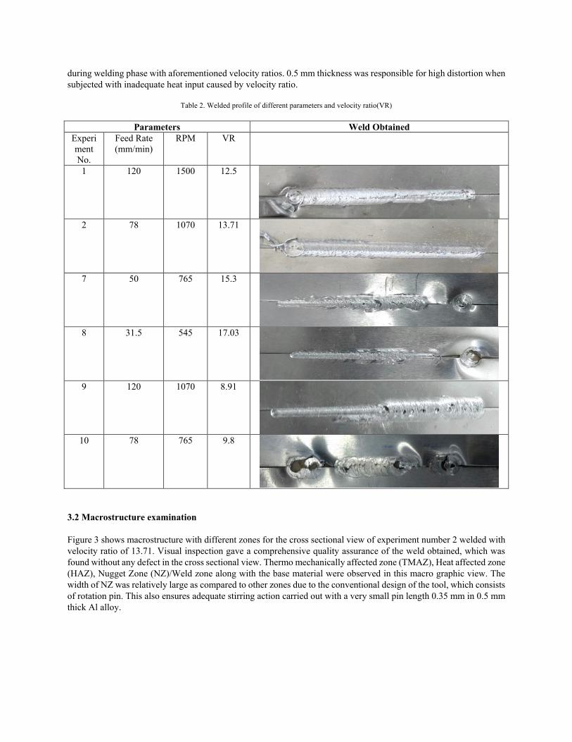
during welding phase with aforementioned velocity ratios. 0.5 mm thickness was responsible for high distortion when
subjected with inadequate heat input caused by velocity ratio.
Table 2. Welded profile of different parameters and velocity ratio(VR)
Parameters Weld Obtained
Experi
ment
No.
Feed Rate
(mm/min)
RPM VR
1 120 1500 12.5
2 78 1070
13.71
7 50 765 15.3
8 31.5 545 17.03
9 120 1070 8.91
10 78 765 9.8
3.2 Macrostructure examination
Figure 3 shows macrostructure with different zones for the cross sectional view of experiment number 2 welded with
velocity ratio of 13.71. Visual inspection gave a comprehensive quality assurance of the weld obtained, which was
found without any defect in the cross sectional view. Thermo mechanically affected zone (TMAZ), Heat affected zone
(HAZ), Nugget Zone (NZ)/Weld zone along with the base material were observed in this macro graphic view. The
width of NZ was relatively large as compared to other zones due to the conventional design of the tool, which consists
of rotation pin. This also ensures adequate stirring action carried out with a very small pin length 0.35 mm in 0.5 mm
thick Al alloy.

Figure 3. Macrostructure image with different zone
3.3 Microstructure examination
It can be cross verified from Figure 4 that the discussion presented in previous section with macrostructure of TMAZ,
HAZ and NZ was in line with these consisted images. Intense stirring process in NZ resulted in equi-axed fine grain
microstructure in stir zone as can be seen from Figure 4 (a)-(c) with different magnification. Dynamic recrystallization
of the grain structure was experienced by this NZ. There were no defects presented even at higher magnification in
microstructure of the stir zone. HAZ-base material and HAZ-TMAZ can be observed in Figure 4 (d) and (e)
respectively. There was a clear distinction between stir zone and HAZ and TMAZ that can be seen comparing internal
figures. There were no stirring action presented in the HAZ and TMAZ regions and hence Similar results were
obtained in the literature of [20]. TMAZ was formed due to heat and deformation experiences, whereas HAZ was
formed due to heat experiences. Relatively larger grains were observed in HAZ compare to TMAZ and NZ because
of large experiences of heat dissipation without any stirring effects.
(a) (b)
AS RS
100X
400X

(c)
3.4 Mechanical properties
3.4.1 Tensile property
The transverse tension test, where the applied load was orthogonal to the weld direction investigates the joint’s
efficiency. Figure 5 exhibits the tensile properties of weld produced with velocity ratio of 13.71. The tensile strength
of 115 MPa was obtained, which was noted as more than that of the base metal, wherein the elongation of 34.8% was
obtained. Therefore, it can be said that the joint efficiency (i.e. ratio of tensile strength of weld to base material) was
107% of the base metal while the maximum elongation was 80% of the base metal. 80 % elongation shows excellent
ductility of welds that increases potential applications in the area of bending and forming industries. In addition, an
excellent yield strength of 43.5 MPa was 96% of the base metal obtained. Defect free welding noticed in figure 3 and
figure 4 at macro and micro levels respectively supports these excellent strengths. The equi-axed fine grains noticed
in the stir zone was responsible for an outstanding ductility. Similar trend was seen in the literature [19], [24], and
[20].
Figure 6 shows the comparison between the joint efficiency of the current literature to the other literature as mentioned
in the graph. The highest joint efficiency is obtained in the present work that was around 107% whereas the literature
of [4] and [20] have 106% and 92% joint efficiency respectively, which shows similar trend. Further, it was observed
that in all literatures, represented the yield strength of the weld was decreased than the parent metal. In the present
work, the yield strength of 43.5 MPa that was 96% of the base metal was obtained as highest relative to published
literature of micro FSW. However, in this work commercial Al alloy was used.
(d) (e)
Figure 4. Microstructural patterns of ultra-thin FSW sample under the condition of 13.71 velocity ratio, (a)-(c) NZ/Weld zone with different
magnifications, (d) HAZ-Base material boundary and (e) TMAZ-HAZ boundary at retreating side
1000X
BASE MATERIAL HAZ
200X
TMAZ HAZ
400X

Figure 5. Tensile properties of welded sample under the condition of 13.71 velocity ratio
Figure 6. Comparison chart between previous and current work of Joint Efficiency and Tensile Strength
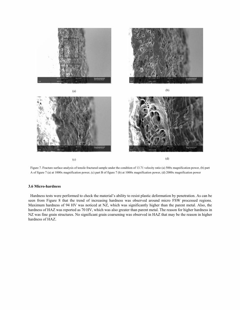
3.4.2 Morphology of tensile fracture surface
The tensile fracture surface morphology was investigated by SEM analysis using Pemtron Make SS-100. Figure 7
shows the fracture surface morphologies analysis of tensile fractured sample under the condition of 13.71-velocity
ratio at different magnifications. It can be seen that the fracture was occurred in ductile condition with large amount
of dimples on a fractured surfaces. This is in a support of obtained higher elongation from tensile testing.
0
50
100
150
200
250
300
0
20
40
60
80
100
120
140
Ten
sile
Str
engt
h (
MP
a)
Join
t Ef
fici
ency
(%
)
Literature [JE] [TS]
Current [19] [24] [20][2] [21]
(a) (b)
(c) (d)
Figure 7. Fracture surface analysis of tensile fractured sample under the condition of 13.71 velocity ratio (a) 500x magnification power, (b) part
A of figure 7 (a) at 1000x magnification power, (c) part B of figure 7 (b) at 1000x magnification power, (d) 2000x magnification power
3.6 Micro-hardness
Hardness tests were performed to check the material’s ability to resist plastic deformation by penetration. As can be
seen from Figure 8 that the trend of increasing hardness was observed around micro FSW processed regions.
Maximum hardness of 94 HV was noticed at NZ, which was significantly higher than the parent metal. Also, the
hardness of HAZ was reported as 70 HV, which was also greater than parent metal. The reason for higher hardness in
NZ was fine grain structures. No significant grain coarsening was observed in HAZ that may be the reason in higher
hardness of HAZ.

4. Conclusion
In the present work, 0.5 mm thin sheets of commercially pure Al were welded successfully with the help of micro
friction stir welding. Following conclusions can be inferred.
The sound joint of micro FSW on commercially pure Al was achieved at the velocity ratio of 13.71.
The tensile strength of 100.877 N/mm2 and elongation of 23.12% were obtained, which were 90.77%
and 51.377% of the parent material respectively.
Fracture surfaces after tensile testing was observed with elongated dimples indicating ductile fracture.
The maximum micro hardness of 94 HV was observed in the weld zone.
5. Acknowledgement
The authors of this research work would like to thank Aditya High Vacuum Pvt. Ltd. Ahmedabad, India for providing
aluminum material.
6. References
[1] S. Walden, G. Michael, and P. Temple-smith, “United States Patent ( 19,” no. 54, 1995).
[2] S. Ahmed, A. Shubhrant, A. Deep, and P. Saha, “Development and Analysis of Butt and Lap Welds in Micro-
friction Stir Welding ( µ FSW ),” doi: 10.1007/978-81-322-2355-9.
[3] K. P. Mehta and V. J. Badheka, “A review on dissimilar friction stir welding of copper to aluminum: Process,
properties, and variants,” Mater. Manuf. Process., vol. 31, no. 3, pp. 233–254, 2016, doi:
10.1080/10426914.2015.1025971.
[4] K. P. Mehta and V. J. Badheka, “Hybrid approaches of assisted heating and cooling for friction stir welding of
copper to aluminum joints,” J. Mater. Process. Technol., vol. 239, pp. 336–345, 2017, doi:
10.1016/j.jmatprotec.2016.08.037.
[5] K. P. Mehta, P. Carlone, A. Astarita, F. Scherillo, and F. Rubino, “Conventional and cooling assisted friction stir
welding of AA6061 and AZ31B alloys,” Mater. Sci. Eng. A, vol. 759, no. April, pp. 252–261, 2019, doi:
10.1016/j.msea.2019.04.120.
[6] K. P. Mehta, “A review on friction-based joining of dissimilar aluminum – steel joints,” J. Mater. Res., vol. 34,
no. 1, pp. 78–96, 2019, doi: 10.1557/jmr.2018.332.
[7] K. Mehta, “Advanced Joining and Welding Techniques: An overview,” in Advanced Manufacturing Technologies.
Materials Forming, Machining and Tribology., K. Gupta, Ed. 2017, pp. 101–136.
Figure 8. Micro-hardness measured across the weld at different locations

[8] K. P. Mehta and V. J. Badheka, “Influence of tool design and process parameters on dissimilar friction stir welding
of copper to AA6061-T651 joints,” Int. J. Adv. Manuf. Technol., vol. 80, pp. 2073–2082, 2015, doi: 10.1007/s00170-
015-7176-1.
[9] K. P. Mehta and V. J. Badheka, “Influence of tool pin design on properties of dissimilar copper to aluminum
friction stir welding,” Trans. Nonferrous Met. Soc. China, vol. 27, no. 1, pp. 36–54, 2017, doi: 10.1016/S1003-
6326(17)60005-0.
[10] K. P. Mehta, V. J. Badheka, K. P. Mehta, and V. J. Badheka, “Effects of Tilt Angle on the Properties of Dissimilar
Friction Stir Welding Copper to Aluminum Effects of Tilt Angle on the Properties of Dissimilar Friction Stir Welding
Copper to Aluminum,” Mater. Manuf. Process., vol. 31, no. 3, pp. 255–263, 2016, doi:
10.1080/10426914.2014.994754.
[11] A. Mishra, “Micro Friction Stir Welding Process : State of the Art Micro Friction Stir Welding Process : State of
the Art,” no. April, 2018, doi: 10.14741/ijcet/v.8.2.15.
[12] H. Search, C. Journals, A. Contact, M. Iopscience, I. O. P. Conf, and I. P. Address, “Recent developments in
Micro Friction Stir Welding : A review,” vol. 012036, pp. 0–11, doi: 10.1088/1757-899X/114/1/012036.
[13] S. Tokyo and T. Nisihara, “Development of Micro-FSW.”
[14] P. Taylor, A. Scialpi, L. A. C. De Filippis, P. Cuomo, and P. Di Summa, “Micro friction stir welding of 2024 –
6082 aluminium alloys Micro friction stir welding of 2024-6082 aluminum alloys,” no. December 2012, pp. 37–41,
doi: 10.1080/09507110801936069.
[15] A. S. Baskoro, A. A. D. Nugroho, D. Rahayu, and G. Kiswanto, “Effects of Welding Parameters in Micro Friction
Stir Lap Welding of Aluminum A1100,” vol. 789, pp. 356–359, 2013, doi: 10.4028/www.scientific.net/AMR.789.356.
[16] A. S. Baskoro, M. D. Habibullah, Z. Arvay, and G. Kiswanto, “Effects of Dwell-Time and Plunge Speed during
Micro Friction Stir Spot Welding on Mechanical Properties of Thin Aluminum A1100 Welds,” vol. 758, pp. 29–34,
2015, doi: 10.4028/www.scientific.net/AMM.758.29.
[17] C. H. U. Wanshun and F. B. Yusof, “Influence of Different Anvil Back Plates on Heat Dissipation Velocity of
the Micro-Friction Stir Welding Process,” vol. 786, pp. 415–420, 2015, doi:
10.4028/www.scientific.net/AMM.786.415.
[18] S. Papaefthymiou, C. Goulas, and E. Gavalas, “Journal of Materials Processing Technology Micro-friction stir
welding of titan zinc sheets,” J. Mater. Process. Tech., vol. 216, pp. 133–139, 2015, doi:
10.1016/j.jmatprotec.2014.08.029.
[19] S. Ahmed and P. Saha, “Development and testing of fixtures for friction stir welding of thin aluminum sheets,”
J. Mater. Process. Tech., vol. 252, no. September 2017, pp. 242–248, 2018, doi: 10.1016/j.jmatprotec.2017.09.034.
[20] Y. Huang, X. Meng, Z. Lv, T. Huang, and Y. Zhang, “Microstructures and mechanical properties of micro friction
stir welding ( FSW ) of 6061-T4 aluminum alloy,” Integr. Med. Res., no. x x, pp. 1–8, doi:
10.1016/j.jmrt.2017.10.010.
[21] C. Zhang, W. Wang, X. Jin, C. Rong, and Z. Qin, “A Study on Microstructure and Mechanical Properties of
Micro Friction Stir Welded Ultra-Thin Al-1060 Sheets by the Shoulderless Tool,” 2019.
[22] K. Wang, H. Khan, Z. Li, S. Lyu, and J. Li, “SC,” J. Mater. Process. Tech., 2018, doi:
10.1016/j.jmatprotec.2018.05.029.
[23] Y. Sagheer-abbasi, “Optimization of parameters for micro friction stir welding of aluminum 5052 using Taguchi
technique,” 2019.
[24] S. Sattari, H. Bisadi, and M. Sajed, “Mechanical Properties and Temperature Distributions of Thin Friction Stir
Welded Sheets of AA5083,” vol. 2, no. 1, pp. 1–6, 2012, doi: 10.5923/j.mechanics.20120201.01.