On Novel Copper Based Alloys Development via Friction Stir ...
12
crystals Article On Novel Copper Based Alloys Development via Friction Stir Alloying Khaja Moiduddin 1, * , Arshad Noor Siddiquee 2, *, Mustufa Haider Abidi 1 , Syed Hammad Mian 1 and Muneer Khan Mohammed 1 Citation: Moiduddin, K.; Siddiquee, A.N.; Abidi, M.H.; Mian, S.H.; Mohammed, M.K. On Novel Copper Based Alloys Development via Friction Stir Alloying. Crystals 2021, 11, 498. https://doi.org/10.3390/ cryst11050498 Academic Editors: Jiangtao Xiong and Hongbin Bei Received: 5 April 2021 Accepted: 23 April 2021 Published: 1 May 2021 Publisher’s Note: MDPI stays neutral with regard to jurisdictional claims in published maps and institutional affil- iations. Copyright: © 2021 by the authors. Licensee MDPI, Basel, Switzerland. This article is an open access article distributed under the terms and conditions of the Creative Commons Attribution (CC BY) license (https:// creativecommons.org/licenses/by/ 4.0/). 1 Advanced Manufacturing Institute, King Saud University, Riyadh-11421, Saudi Arabia; [email protected] (M.H.A.); [email protected] (S.H.M.); [email protected] (M.K.M.) 2 Department of Mechanical Engineering, Faculty of Engineering and Technology, Jamia Millia Islamia, New Delhi-110025, India * Correspondence: [email protected] (K.M.); [email protected] (A.N.S.) Abstract: Friction stir alloying (FSA) of commercially pure Cu with Ni, Zn, and Mg is implemented in the current study. Mechanical and microstructural aspects of the successfully fabricated alloy struc- ture have been examined. Energy dispersive X-ray spectroscopy revealed a uniform distribution of alloying elements and coalescence at the atomic level. The compositional and grain size heterogeneity is managed in the stir zone, allowing for microstructural control with FSA. Thus, the present study is essential for the development of novel materials whose fabrication requires temperature well below the melting point of base metals. The alloying process is found to be accompanied by ultra-refined grains, with the smallest grain size being ~0.44 μm. The fabricated alloy managed to retain the FCC phase, and no brittle intermetallic compounds formed, according to X-ray diffraction. The fabricated alloy exhibits maximum and average microhardness enhancements of 18.4% and 6%, respectively. Tensile properties have also been investigated and correlated with microstructural morphology. A shift toward grain bimodality has also been documented, which is a highly sought-after property nowadays, especially to overcome the strength-ductility trade-off. Keywords: copper alloy; friction stir alloying; macrostructure; material properties 1. Introduction Copper (Cu) and its alloys are widely used due to their excellent thermal and electrical conductivity. Cu alloys, which are the optimal option for today’s energy and environ- mental problems, are extensively employed in nuclear fusion reactors at locations with exceedingly high heat flux [1–3]. Cu-based shape memory alloys (SMAs) and high entropy alloys (HEAs) form a group of functional materials that expand beyond Cu-based alloy’s traditional electro-mechanical applications. Cu-containing HEAs have been discovered to possess antibacterial properties, as well as being corrosion resistant to marine biofilms [4]. Micro-electromechanical, electrical, and biomedical sciences are also investigating the use of Cu with varying microstructural morphology [5–7]. Friction stir alloying (FSA) is a relatively new development of the remarkable friction stir processing (FSP) technology, in which the matrix and reinforcement are both ductile metallic phases. The ideation of FSA also arises from the work of Shiri et al. [8], who performed friction stir welding by inserting the foils of Cu, Zn, Brass, and Cu-Zn-Ni between the abutting surfaces of Al plates and found the secondary materials to be diffused into the base metal. Chemical complexities and related mechanical adversaries that occur in fusion alloying processes can be easily avoided in FSA because alloying takes place at approximately half the melting point of the matrix material. Furthermore, FSA’s ability to accommodate a wide variety of material heterogeneity allows it the modern-day alchemy for developing new alloy systems and libraries. Crystals 2021, 11, 498. https://doi.org/10.3390/cryst11050498 https://www.mdpi.com/journal/crystals
-
Upload
khangminh22 -
Category
Documents
-
view
1 -
download
0
Transcript of On Novel Copper Based Alloys Development via Friction Stir ...

crystals
Article
On Novel Copper Based Alloys Development via Friction StirAlloying
Khaja Moiduddin 1,* , Arshad Noor Siddiquee 2,*, Mustufa Haider Abidi 1 , Syed Hammad Mian 1
and Muneer Khan Mohammed 1
�����������������
Citation: Moiduddin, K.; Siddiquee,
A.N.; Abidi, M.H.; Mian, S.H.;
Mohammed, M.K. On Novel Copper
Based Alloys Development via
Friction Stir Alloying. Crystals 2021,
11, 498. https://doi.org/10.3390/
cryst11050498
Academic Editors: Jiangtao Xiong
and Hongbin Bei
Received: 5 April 2021
Accepted: 23 April 2021
Published: 1 May 2021
Publisher’s Note: MDPI stays neutral
with regard to jurisdictional claims in
published maps and institutional affil-
iations.
Copyright: © 2021 by the authors.
Licensee MDPI, Basel, Switzerland.
This article is an open access article
distributed under the terms and
conditions of the Creative Commons
Attribution (CC BY) license (https://
creativecommons.org/licenses/by/
4.0/).
1 Advanced Manufacturing Institute, King Saud University, Riyadh-11421, Saudi Arabia;[email protected] (M.H.A.); [email protected] (S.H.M.); [email protected] (M.K.M.)
2 Department of Mechanical Engineering, Faculty of Engineering and Technology, Jamia Millia Islamia,New Delhi-110025, India
* Correspondence: [email protected] (K.M.); [email protected] (A.N.S.)
Abstract: Friction stir alloying (FSA) of commercially pure Cu with Ni, Zn, and Mg is implementedin the current study. Mechanical and microstructural aspects of the successfully fabricated alloy struc-ture have been examined. Energy dispersive X-ray spectroscopy revealed a uniform distribution ofalloying elements and coalescence at the atomic level. The compositional and grain size heterogeneityis managed in the stir zone, allowing for microstructural control with FSA. Thus, the present study isessential for the development of novel materials whose fabrication requires temperature well belowthe melting point of base metals. The alloying process is found to be accompanied by ultra-refinedgrains, with the smallest grain size being ~0.44 µm. The fabricated alloy managed to retain the FCCphase, and no brittle intermetallic compounds formed, according to X-ray diffraction. The fabricatedalloy exhibits maximum and average microhardness enhancements of 18.4% and 6%, respectively.Tensile properties have also been investigated and correlated with microstructural morphology. Ashift toward grain bimodality has also been documented, which is a highly sought-after propertynowadays, especially to overcome the strength-ductility trade-off.
Keywords: copper alloy; friction stir alloying; macrostructure; material properties
1. Introduction
Copper (Cu) and its alloys are widely used due to their excellent thermal and electricalconductivity. Cu alloys, which are the optimal option for today’s energy and environ-mental problems, are extensively employed in nuclear fusion reactors at locations withexceedingly high heat flux [1–3]. Cu-based shape memory alloys (SMAs) and high entropyalloys (HEAs) form a group of functional materials that expand beyond Cu-based alloy’straditional electro-mechanical applications. Cu-containing HEAs have been discovered topossess antibacterial properties, as well as being corrosion resistant to marine biofilms [4].Micro-electromechanical, electrical, and biomedical sciences are also investigating the useof Cu with varying microstructural morphology [5–7].
Friction stir alloying (FSA) is a relatively new development of the remarkable frictionstir processing (FSP) technology, in which the matrix and reinforcement are both ductilemetallic phases. The ideation of FSA also arises from the work of Shiri et al. [8], whoperformed friction stir welding by inserting the foils of Cu, Zn, Brass, and Cu-Zn-Nibetween the abutting surfaces of Al plates and found the secondary materials to be diffusedinto the base metal. Chemical complexities and related mechanical adversaries that occurin fusion alloying processes can be easily avoided in FSA because alloying takes place atapproximately half the melting point of the matrix material. Furthermore, FSA’s ability toaccommodate a wide variety of material heterogeneity allows it the modern-day alchemyfor developing new alloy systems and libraries.
Crystals 2021, 11, 498. https://doi.org/10.3390/cryst11050498 https://www.mdpi.com/journal/crystals

Crystals 2021, 11, 498 2 of 12
Shukla et al. [9] utilized FSA to scrutinize the phase transformations in Fe40Mn20Co20Cr15Si5(at. %) HEA after gradient Cu addition. In another study by Karthik et al. [10], the frictionstir selectively alloyed Al stir zone with ∼2 wt. % Cu responded well to aging treatment,which emboldened the foundations of FSA. The HCP to BCC transformation due to theintroduction of V in γ -FCC-based HEA via FSA has lately been investigated by Agarwalet al. [11]. AZ31 Mg alloy’s mechanical capabilities have also been improved by varyingAl additions using FSA [12]. In this case, the groove width was varied to modify thecomposition of Al in the stir zone. Several FSP studies consisting of metals, as both thematrix and reinforcement materials have also reported the formation of intermetallic com-pounds [13,14]. The discussed process has also been fruitful in stimulating transformation-induced plasticity (TRIP) and precipitates hardening by the addition of Ti in a twinninginduced plasticity (TWIP) HEA [15]. Furthermore, FSA’s ability to simultaneously produceultra-refined grains while alloying is largely unmatched by other alloying processes. Inanother study, Li et al. [16] analyzed the consequences of Yttrium (Y) and Zirconium (Zr)co-alloying on microstructural transformation and the mechanical characteristics of theas-casted and the FSPed Mg–6Zn alloys. The yield strength, ultimate tensile strength,and elongation of the FSPed Mg–6Zn–1Y-0.5Zr alloys were significantly increased due tograin refinement, dispersion enhancement, and the customized composition. Mg-CuOand Mg-Cu-based surface nanocomposites were accomplished by Farghadani et al. [17]through FSP on the surface of AZ91 Mg casting alloy. The hardness of AZ91/Cu andAZ91/CuO nanocomposites was substantially enhanced, as well as AZ91/CuO nanocom-posite displayed leading tensile strength and wear resistance. Similarly, FSP strengthenedthe hardness of the fabricated composite (Zirconia dispersed in Cu Matrix) as compared toCu alone [18]. The primary reason for the increased hardness was the reduction in grainsize and consistent distribution of zirconia.
Earlier research has demonstrated that FSP can be used to enhance the mechanicalproperties of an alloy by altering its microstructural characteristics. The grain size has amajor impact on the strength of the alloy [19]. According to the Hall-Petch equation, there isan inverse relationship between the strength of the alloy and the grain size [20]. In FSP, thematerial is heated up due to friction and extreme plastic deformation, thus transforming thecoarse-grained alloy into a fine-grained crystalline material. Naik et al. [21] implementedFSP to upgrade the mechanical and wear properties of Cu–Zr (Cu–0.18 wt.%Zr) alloywithout compromising the electrical conductivity. They noticed a reduction in the averagegrain size from 40.5 to 4.6 µm and an improvement in hardness from 70 to 99 HV with ahigher tool traverse speed. Among the different zones, the stir zone (SZ) has a massiveinfluence on the microstructure and the base material’s properties [22]. The volume of thebase material processed during single-pass FSP is determined by the size and shape ofthe SZ. During FSP, two types of SZ shapes are commonly developed: basin and elliptical.According to Ma et al. [23], the shape of SZ is primarily governed by the heat input, whichcan be modified in FSP by changing the combination of tool rotation and travel speeds.Hsu et al. [24] used FSP to refine the SZ grains to 1–2 µm, resulting in an ultrafine-grainedAl–Al2Cu with a high Young’s modulus and strong compressive properties. Similarly, afine equiaxed re-crystallized grain structure with an average size of 2.1 µm was formedin the SZ after FSP while dispersing graphene nano-platelets [25]. As a consequence, thenanocomposite’s hardness, elastic modulus, and yield strength all increased dramatically.The FSP of Cu-Ni (70/30) by Mukherjee and Ghosh [26] resulted in reduced porosity,refined grains, higher hardness, minimized ductility, and increased corrosion, in contrastto laser-assisted direct metal deposition (DMD). Xie et al. [27] used a novel FSP aided lasercladding process to eliminate metallurgical defects. The coarse networks of laser claddingcoating were converted into scattered nanoparticles, and the crack in laser cladding Ni-Cr-Fe coating was removed. The top surface grain size approached 300 nm, and hardnessincreased to over 400 HV. The investigation by Sabbaghian et al. [28] who fabricated aCu-based composite by dispersing TiC through FSP demonstrated the many advantagesof FSP yet again. They concluded that FSP formed a fine grain microstructure with a

Crystals 2021, 11, 498 3 of 12
uniform particle distribution on the surface. They also illustrated that FSP strengthenedthe specimen’s microhardness and wear resistance as a result of grain refinement andthe presence of TiC particles in the FSP region. Priyadharshini et al. [29] explored theimpact of tool traverse speed (of FSP) on the microstructural evolution, microhardness,tensile behavior, and tribological characteristics of CuNi/B4C surface composite. FSPof specimens at speeds greater than 30 mm/min resulted in undesirable microhardness,tensile strength, and wear resistance, according to the microstructural study. They founda maximum microhardness of 190 HV, a maximum ultimate tensile strength of 295 MPa,and a minimum wear rate of 210 × 10−5 mm3/min at a traverse speed of 30 mm/min.According to Zangabad et al. [30], the experimental outcome on the fatigue propertiesof Al-matrix nanocomposites prepared by the FSP resulted in an increase in the fatiguestrength. FSP is capable of preventing several defects, porosities, as well as improvingthe ductility and tensile strength of numerous alloys [31]. As a result, FSA which is amodern development of the, FSP must have the same characteristics, but further researchis required.
Although FSA’s success has firmly been manifested in the above literature, the vastmulti-dimensional elemental compositional space that is accessible through FSA remainschiefly unexplored. Studies concerned with the FSA of several extensively used metals,such as Cu, Zn, Fe, Ti, Mg, Ni, etc., are either very rare or utterly absent in the publishedworks. As a result, the aim of this work is to use FSP to alloy four of the most commonlyused metals, namely Cu, Zn, Mg, and Ni. This research will also look into the effect of thematerial’s melting point on FSA. Hence, the alloying elements are chosen to cover a widerange of melting points, such as Zn melts at 420 ◦C, Mg melts at 650 ◦C, Cu melts at 1085 ◦C,and Ni melts at 1455 ◦C. To prevent the development of brittle intermetallic compounds,no more than four elements are considered for FSA. Cu and Ni would have been softenedinadequately if Zn or Mg had been used as base materials. Ni as a base material, on the otherhand, would lead to high softening temperature, that would provide formation enthalpyfor intermetallic compounds. Thus, Cu is selected as the base material in the currentresearch. Furthermore, surface alloying through FSA advances the current emphasis onsurface behaviors and modeling [32]. The nature of FSA allows for microstructural control,both from the elemental and morphological perspectives. The alloying of Cu with Niaids its corrosion resistance, solidus, and liquidus temperature, whereas the addition ofMg enhances ductility and workability. Further, Cu alloyed with Zn results in bettercreep strength and wear resistance. Therefore, alloying of Cu simultaneously with Mg,Ni and Zn is attempted in the present work through FSA. The simultaneous alloyingwith multiple metals using FSA is also the novelty of the present work. The characteristiczones, namely the SZ, thermo-mechanically affected zone (TMAZ) and the heat affectedzone (HAZ) are examined in light of alloying for the first time. The ultra-refinement andtransformed morphology of grains due to severe plastic deformation are scrutinized. Thepresent research thus holds the potential to aid the development of meta-materials andunprecedented alloy systems through the FSA process.
2. Materials and Methods
Rolled commercially pure Cu plate (obtained from Tremor Alloys, Mumbai, India) ofdimensions 180 mm × 60 mm × 4 mm was used for alloying. The chemical composition ofthe base metal is presented in Table 1. A robust vertical milling machine was utilized toperform FSA with the assistance of an in-house designed tool adapter and work fixture.A square slot with a side of 3 mm was milled on the Cu plate and filled with a mixtureof pure Ni (50 wt. %), Zn (20 wt. %), and Mg (30 wt. %) powders. The higher weightproportion of elements with a relatively low melting point created voids/defects in the stirregion during the trial experiments. Therefore, Ni (highest melting point) was used in thehighest proportion, and Zinc (lowest melting point) was used in the smallest proportionamong the alloying elements. Friction stir alloying also benefits from the fact that it isa solid-state process. As a result, keeping the foremost melting element in the smallest

Crystals 2021, 11, 498 4 of 12
proportion ensures minimal melting during the alloying process. The average particle sizeof Ni, Zn, and Mg powders was ~60 µm, ~44 µm, and ~100 µm, respectively.
Table 1. Chemical composition of Cu base metal (wt. %).
Element Cu Sn Fe P Zn Pb S
Content(wt%) >99.92 0.04 0.001 0.02 0.012 0.003 0.002
The slot was first covered by a pin-less tool having 20 mm shoulder diameter andthen processed with a tool having shoulder, pin bottom, and pin root diameters of 23 mm,10 mm, and 9.3 mm, respectively. A tapered cam-tri-flute profile was machined on the pin,having a length of 3.15 mm. High-speed steel (HSS) was used for tool material. Figure 1shows a schematic diagram of the FSA experimental setup. The parameters indicated inthe Figure 1, i.e., the tool rotational speed and tool traverse speed were set at 710 rpm and50 mm/min, respectively. These parameters were established via optimized design usingrigorous experimentation.
Crystals 2021, 11, x FOR PEER REVIEW 4 of 12
smallest proportion ensures minimal melting during the alloying process. The average particle size of Ni, Zn, and Mg powders was ~60 μm, ~44 μm, and ~100 μm, respectively.
Table 1. Chemical composition of Cu base metal (wt. %).
Element Cu Sn Fe P Zn Pb S Content (wt%) >99.92 0.04 0.001 0.02 0.012 0.003 0.002
The slot was first covered by a pin-less tool having 20 mm shoulder diameter and then processed with a tool having shoulder, pin bottom, and pin root diameters of 23 mm, 10 mm, and 9.3 mm, respectively. A tapered cam-tri-flute profile was machined on the pin, having a length of 3.15 mm. High-speed steel (HSS) was used for tool material. Figure 1 shows a schematic diagram of the FSA experimental setup. The parameters indicated in the Figure 1, i.e., the tool rotational speed and tool traverse speed were set at 710 rpm and 50 mm/min, respectively. These parameters were established via optimized design using rigorous experimentation.
Figure 1. Schematic diagram of FSA.
The most difficult aspect of FSP is achieving a uniform distribution of added materi-als, while simultaneously preventing agglomeration, voids, and surface craters. The tool traverse and rotational speed have the greatest impact on the above results. As a result, the above parameter setting was preceded by over 20 experiments in which one or more of the aforementioned issues were encountered. A standard metallographic sample prep-aration procedure was followed to examine the transverse cross-sections of the fabricated alloy. Before the examination, the samples were etched with a 1:1 mixture of HNO3 and H2O for 30 s, followed by rinsing with distilled water. Optical microscopy (OM) (QS Me-trology, Delhi, India), Scanning Electron Microscopy (SEM) (Zeiss, Germany) and Energy Dispersive X-ray Spectroscopy (EDS) (Zeiss, Germany) were utilized to observe the mor-phology and composition of the developed microstructure. X-ray diffraction (XRD) (Rigaku, Tokyo, Japan) was utilized to scrutinize the crystal structure of the alloyed sam-ple. Wire electric discharge machining was used to cut tensile samples, which were tested with a Tensometer (Kudale Instruments Pvt Ltd, Pune, India) of 20 kN capacity. Vickers microhardness was measured by a tester (Mitutoyo, Kanagawa, Japan) at a test force of 100 gm and a dwell time of 15 s, with an indentation separation of 0.5 mm. The micro-hardness of the base metal was 110 HV.
Figure 1. Schematic diagram of FSA.
The most difficult aspect of FSP is achieving a uniform distribution of added materials,while simultaneously preventing agglomeration, voids, and surface craters. The tooltraverse and rotational speed have the greatest impact on the above results. As a result, theabove parameter setting was preceded by over 20 experiments in which one or more of theaforementioned issues were encountered. A standard metallographic sample preparationprocedure was followed to examine the transverse cross-sections of the fabricated alloy.Before the examination, the samples were etched with a 1:1 mixture of HNO3 and H2O for30 s, followed by rinsing with distilled water. Optical microscopy (OM) (QS Metrology,Delhi, India), Scanning Electron Microscopy (SEM) (Zeiss, Germany) and Energy DispersiveX-ray Spectroscopy (EDS) (Zeiss, Germany) were utilized to observe the morphology andcomposition of the developed microstructure. X-ray diffraction (XRD) (Rigaku, Tokyo,Japan) was utilized to scrutinize the crystal structure of the alloyed sample. Wire electricdischarge machining was used to cut tensile samples, which were tested with a Tensometer(Kudale Instruments Pvt Ltd, Pune, India) of 20 kN capacity. Vickers microhardness wasmeasured by a tester (Mitutoyo, Kanagawa, Japan) at a test force of 100 gm and a dwell
Crystals 2021, 11, 498 5 of 12
time of 15 s, with an indentation separation of 0.5 mm. The microhardness of the basemetal was 110 HV.
3. Results and Discussion3.1. Macrostructure
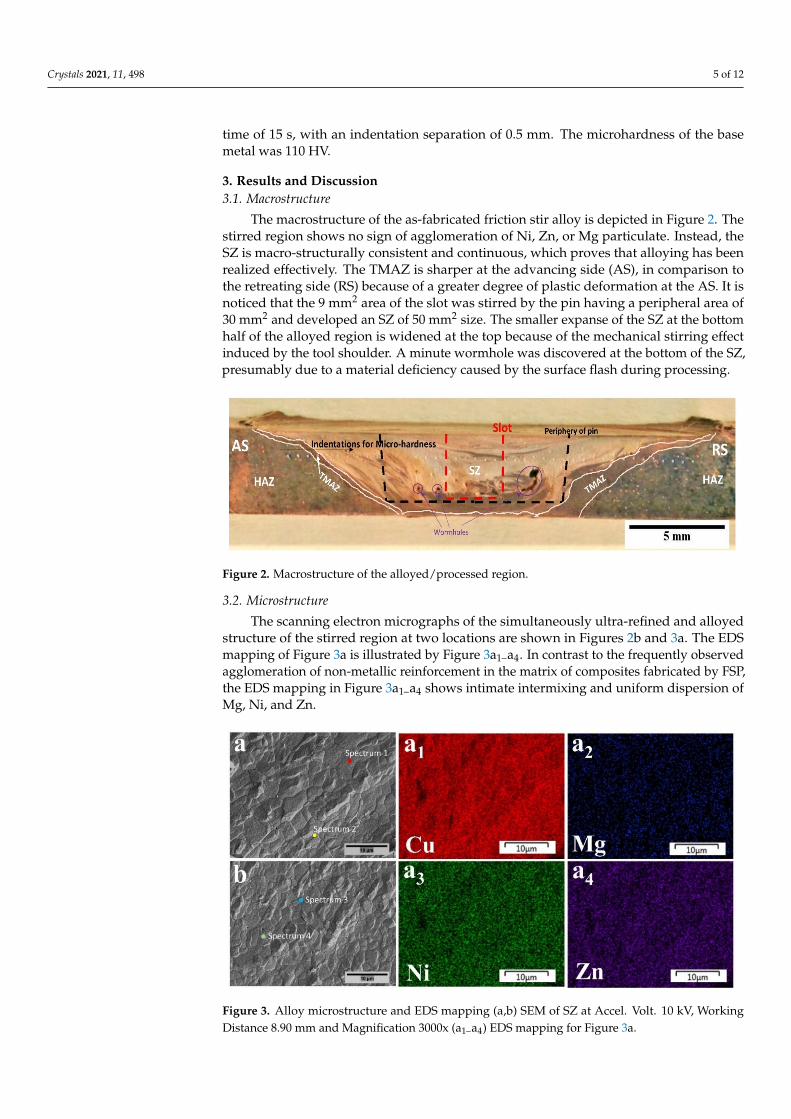
The macrostructure of the as-fabricated friction stir alloy is depicted in Figure 2. Thestirred region shows no sign of agglomeration of Ni, Zn, or Mg particulate. Instead, theSZ is macro-structurally consistent and continuous, which proves that alloying has beenrealized effectively. The TMAZ is sharper at the advancing side (AS), in comparison tothe retreating side (RS) because of a greater degree of plastic deformation at the AS. It isnoticed that the 9 mm2 area of the slot was stirred by the pin having a peripheral area of30 mm2 and developed an SZ of 50 mm2 size. The smaller expanse of the SZ at the bottomhalf of the alloyed region is widened at the top because of the mechanical stirring effectinduced by the tool shoulder. A minute wormhole was discovered at the bottom of the SZ,presumably due to a material deficiency caused by the surface flash during processing.
Crystals 2021, 11, x FOR PEER REVIEW 5 of 12
3. Results and Discussion 3.1. Macrostructure
The macrostructure of the as-fabricated friction stir alloy is depicted in Figure 2. The stirred region shows no sign of agglomeration of Ni, Zn, or Mg particulate. Instead, the SZ is macro-structurally consistent and continuous, which proves that alloying has been realized effectively. The TMAZ is sharper at the advancing side (AS), in comparison to the retreating side (RS) because of a greater degree of plastic deformation at the AS. It is no-ticed that the 9 mm2 area of the slot was stirred by the pin having a peripheral area of 30 mm2 and developed an SZ of 50 mm2 size. The smaller expanse of the SZ at the bottom half of the alloyed region is widened at the top because of the mechanical stirring effect induced by the tool shoulder. A minute wormhole was discovered at the bottom of the SZ, presumably due to a material deficiency caused by the surface flash during pro-cessing.
Figure 2. Macrostructure of the alloyed/processed region.
3.2. Microstructure The scanning electron micrographs of the simultaneously ultra-refined and alloyed
structure of the stirred region at two locations are shown in Figures 3a and 2b. The EDS mapping of Figure 3a is illustrated by Figure 3a1–a4. In contrast to the frequently observed agglomeration of non-metallic reinforcement in the matrix of composites fabricated by FSP, the EDS mapping in Figure 3a1–a4 shows intimate intermixing and uniform dispersion of Mg, Ni, and Zn.
Figure 2. Macrostructure of the alloyed/processed region.
3.2. Microstructure
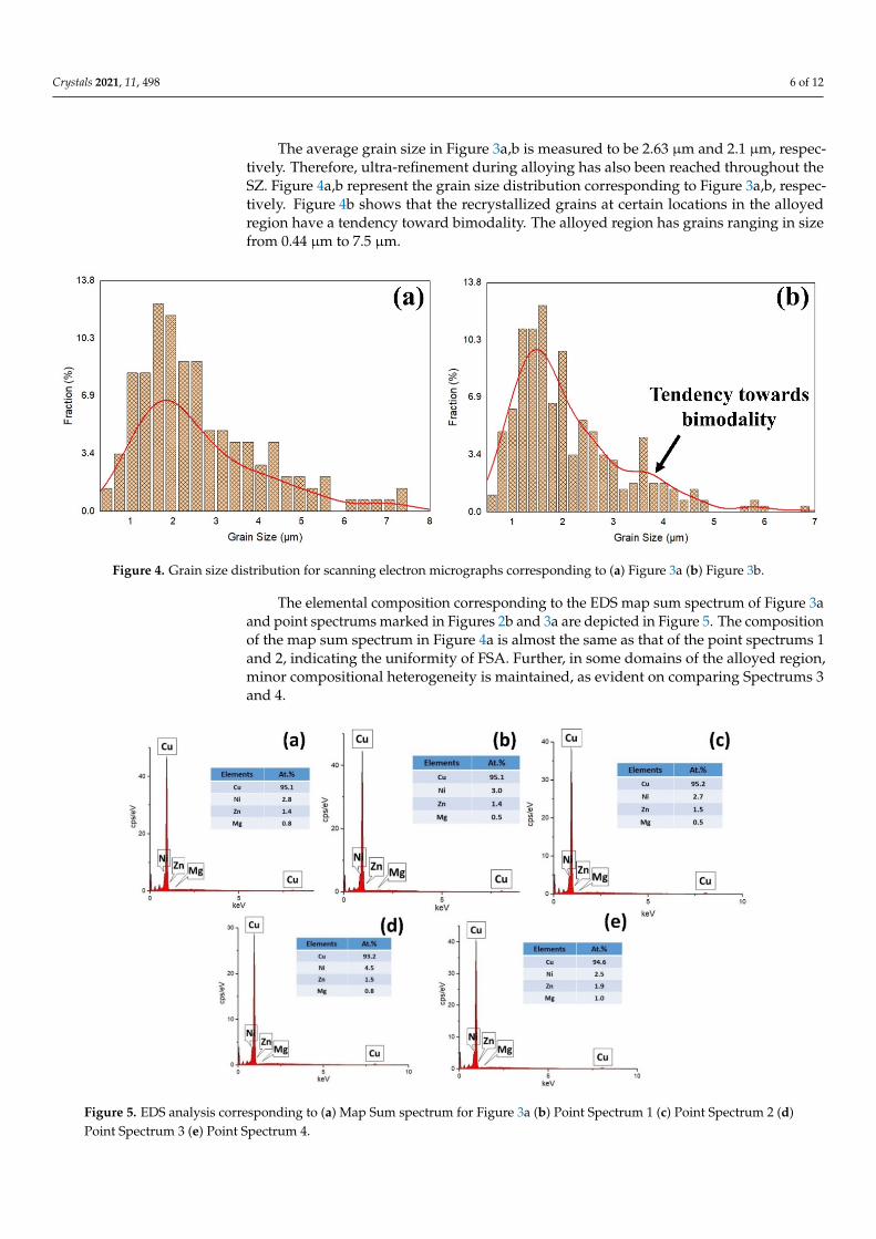
The scanning electron micrographs of the simultaneously ultra-refined and alloyedstructure of the stirred region at two locations are shown in Figures 2b and 3a. The EDSmapping of Figure 3a is illustrated by Figure 3a1–a4. In contrast to the frequently observedagglomeration of non-metallic reinforcement in the matrix of composites fabricated by FSP,the EDS mapping in Figure 3a1–a4 shows intimate intermixing and uniform dispersion ofMg, Ni, and Zn.
Crystals 2021, 11, x FOR PEER REVIEW 5 of 12
3. Results and Discussion 3.1. Macrostructure
The macrostructure of the as-fabricated friction stir alloy is depicted in Figure 2. The stirred region shows no sign of agglomeration of Ni, Zn, or Mg particulate. Instead, the SZ is macro-structurally consistent and continuous, which proves that alloying has been realized effectively. The TMAZ is sharper at the advancing side (AS), in comparison to the retreating side (RS) because of a greater degree of plastic deformation at the AS. It is no-ticed that the 9 mm2 area of the slot was stirred by the pin having a peripheral area of 30 mm2 and developed an SZ of 50 mm2 size. The smaller expanse of the SZ at the bottom half of the alloyed region is widened at the top because of the mechanical stirring effect induced by the tool shoulder. A minute wormhole was discovered at the bottom of the SZ, presumably due to a material deficiency caused by the surface flash during pro-cessing.
Figure 2. Macrostructure of the alloyed/processed region.
3.2. Microstructure The scanning electron micrographs of the simultaneously ultra-refined and alloyed
structure of the stirred region at two locations are shown in Figures 3a and 2b. The EDS mapping of Figure 3a is illustrated by Figure 3a1–a4. In contrast to the frequently observed agglomeration of non-metallic reinforcement in the matrix of composites fabricated by FSP, the EDS mapping in Figure 3a1–a4 shows intimate intermixing and uniform dispersion of Mg, Ni, and Zn.
Figure 3. Alloy microstructure and EDS mapping (a,b) SEM of SZ at Accel. Volt. 10 kV, WorkingDistance 8.90 mm and Magnification 3000x (a1–a4) EDS mapping for Figure 3a.
Crystals 2021, 11, 498 6 of 12
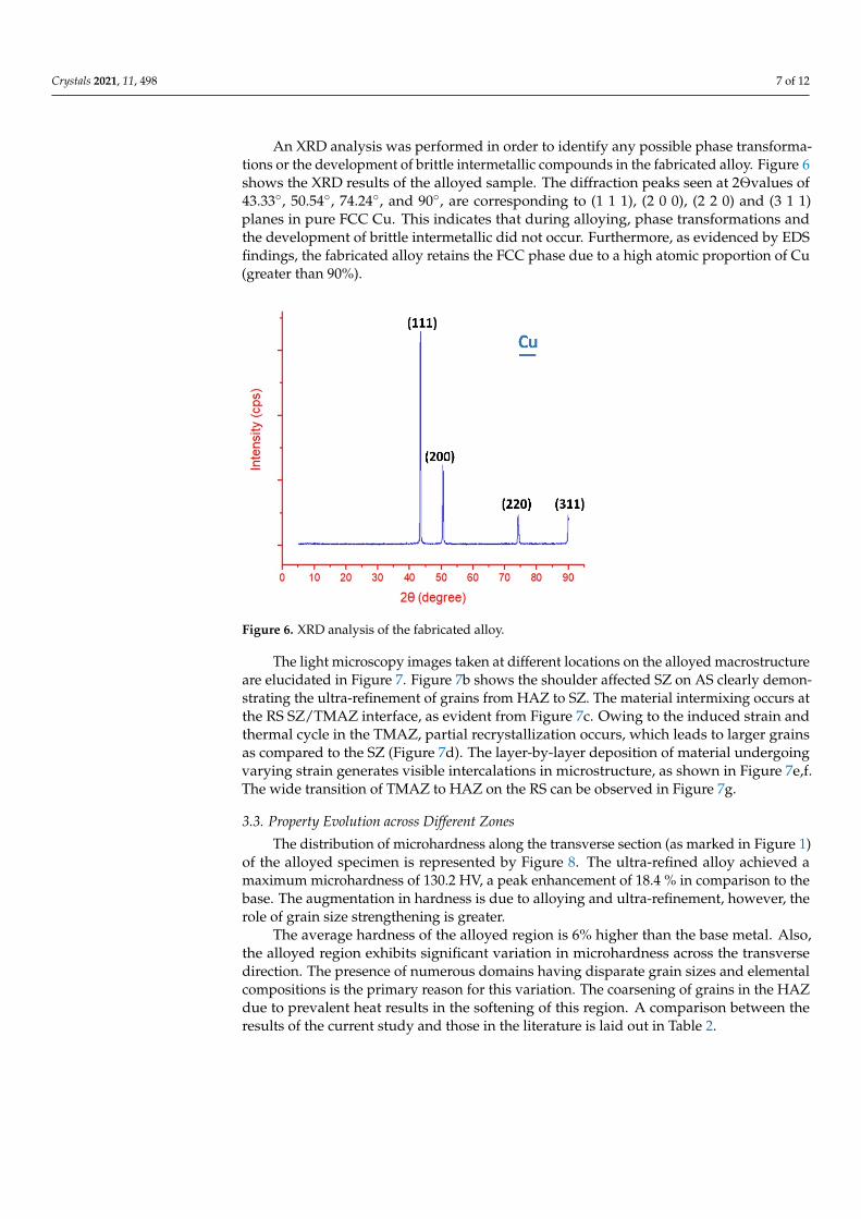
The average grain size in Figure 3a,b is measured to be 2.63 µm and 2.1 µm, respec-tively. Therefore, ultra-refinement during alloying has also been reached throughout theSZ. Figure 4a,b represent the grain size distribution corresponding to Figure 3a,b, respec-tively. Figure 4b shows that the recrystallized grains at certain locations in the alloyedregion have a tendency toward bimodality. The alloyed region has grains ranging in sizefrom 0.44 µm to 7.5 µm.
Crystals 2021, 11, x FOR PEER REVIEW 6 of 12
Figure 3. Alloy microstructure and EDS mapping (a,b) SEM of SZ at Accel. Volt. 10 kV, Working Distance 8.90 mm and Magnification 3000x (a1–a4) EDS mapping for Figure 3a.
The average grain size in Figure 3a,b is measured to be 2.63 μm and 2.1 μm, respec-tively. Therefore, ultra-refinement during alloying has also been reached throughout the SZ. Figure 4a,b represent the grain size distribution corresponding to Figure 3a,b, respec-tively. Figure 4b shows that the recrystallized grains at certain locations in the alloyed region have a tendency toward bimodality. The alloyed region has grains ranging in size from 0.44 μm to 7.5 μm.
Figure 4. Grain size distribution for scanning electron micrographs corresponding to (a) Figure 3a (b) Figure 3b.
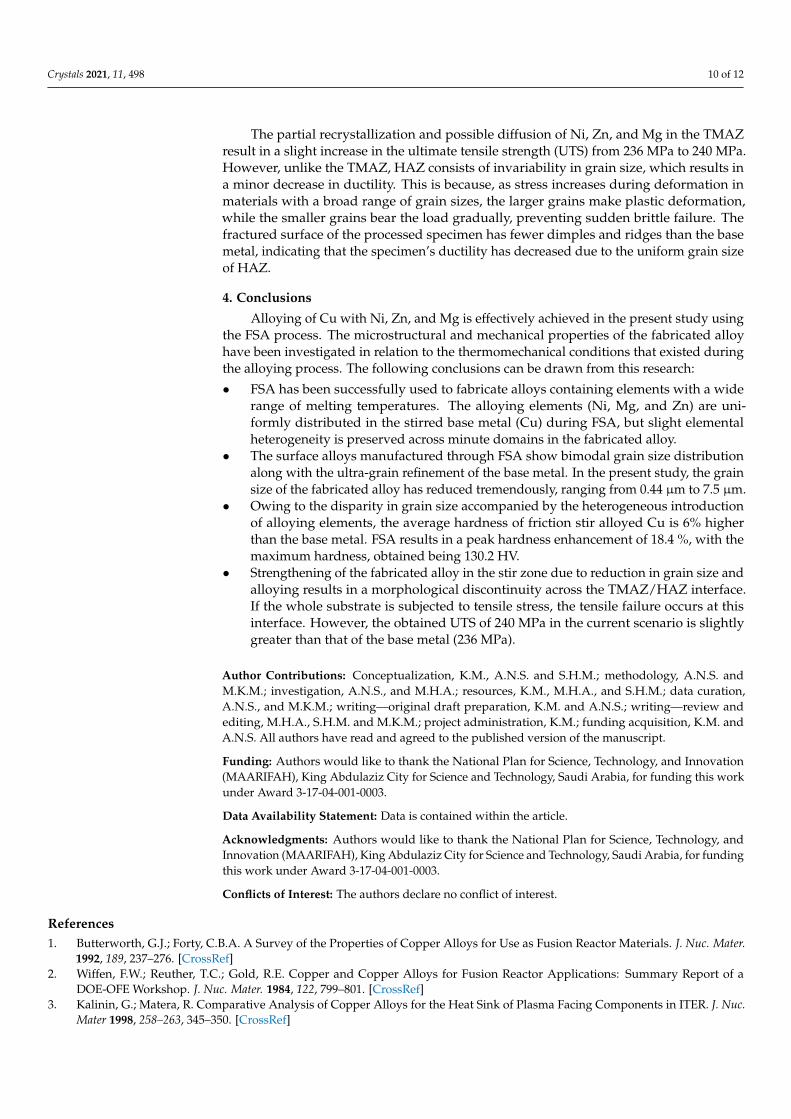
The elemental composition corresponding to the EDS map sum spectrum of Figure 3a and point spectrums marked in Figures 3a and 2b are depicted in Figure 5. The com-position of the map sum spectrum in Figure 4a is almost the same as that of the point spectrums 1 and 2, indicating the uniformity of FSA. Further, in some domains of the al-loyed region, minor compositional heterogeneity is maintained, as evident on comparing Spectrums 3 and 4.
Figure 4. Grain size distribution for scanning electron micrographs corresponding to (a) Figure 3a (b) Figure 3b.
The elemental composition corresponding to the EDS map sum spectrum of Figure 3aand point spectrums marked in Figures 2b and 3a are depicted in Figure 5. The compositionof the map sum spectrum in Figure 4a is almost the same as that of the point spectrums 1and 2, indicating the uniformity of FSA. Further, in some domains of the alloyed region,minor compositional heterogeneity is maintained, as evident on comparing Spectrums 3and 4.
Crystals 2021, 11, x FOR PEER REVIEW 7 of 12
Figure 5. EDS analysis corresponding to (a) Map Sum spectrum for Figure 3a (b) Point Spectrum 1 (c) Point Spectrum 2 (d) Point Spectrum 3 (e) Point Spectrum 4.
An XRD analysis was performed in order to identify any possible phase transfor-mations or the development of brittle intermetallic compounds in the fabricated alloy. Figure 6 shows the XRD results of the alloyed sample. The diffraction peaks seen at 2Ө values of 43.33°, 50.54°, 74.24°, and 90°, are corresponding to (1 1 1), (2 0 0), (2 2 0) and (3 1 1) planes in pure FCC Cu. This indicates that during alloying, phase transformations and the development of brittle intermetallic did not occur. Furthermore, as evidenced by EDS findings, the fabricated alloy retains the FCC phase due to a high atomic proportion of Cu (greater than 90%).
Figure 6. XRD analysis of the fabricated alloy.
The light microscopy images taken at different locations on the alloyed macrostruc-ture are elucidated in Figure 7. Figure 7b shows the shoulder affected SZ on AS clearly demonstrating the ultra-refinement of grains from HAZ to SZ. The material intermixing
Figure 5. EDS analysis corresponding to (a) Map Sum spectrum for Figure 3a (b) Point Spectrum 1 (c) Point Spectrum 2 (d)Point Spectrum 3 (e) Point Spectrum 4.
Crystals 2021, 11, 498 7 of 12
An XRD analysis was performed in order to identify any possible phase transforma-tions or the development of brittle intermetallic compounds in the fabricated alloy. Figure 6shows the XRD results of the alloyed sample. The diffraction peaks seen at 2Өvalues of43.33◦, 50.54◦, 74.24◦, and 90◦, are corresponding to (1 1 1), (2 0 0), (2 2 0) and (3 1 1)planes in pure FCC Cu. This indicates that during alloying, phase transformations andthe development of brittle intermetallic did not occur. Furthermore, as evidenced by EDSfindings, the fabricated alloy retains the FCC phase due to a high atomic proportion of Cu(greater than 90%).
Crystals 2021, 11, x FOR PEER REVIEW 7 of 12
Figure 5. EDS analysis corresponding to (a) Map Sum spectrum for Figure 3a (b) Point Spectrum 1 (c) Point Spectrum 2 (d) Point Spectrum 3 (e) Point Spectrum 4.
An XRD analysis was performed in order to identify any possible phase transfor-mations or the development of brittle intermetallic compounds in the fabricated alloy. Figure 6 shows the XRD results of the alloyed sample. The diffraction peaks seen at 2Ө values of 43.33°, 50.54°, 74.24°, and 90°, are corresponding to (1 1 1), (2 0 0), (2 2 0) and (3 1 1) planes in pure FCC Cu. This indicates that during alloying, phase transformations and the development of brittle intermetallic did not occur. Furthermore, as evidenced by EDS findings, the fabricated alloy retains the FCC phase due to a high atomic proportion of Cu (greater than 90%).
Figure 6. XRD analysis of the fabricated alloy.
The light microscopy images taken at different locations on the alloyed macrostruc-ture are elucidated in Figure 7. Figure 7b shows the shoulder affected SZ on AS clearly demonstrating the ultra-refinement of grains from HAZ to SZ. The material intermixing
Figure 6. XRD analysis of the fabricated alloy.
The light microscopy images taken at different locations on the alloyed macrostructureare elucidated in Figure 7. Figure 7b shows the shoulder affected SZ on AS clearly demon-strating the ultra-refinement of grains from HAZ to SZ. The material intermixing occurs atthe RS SZ/TMAZ interface, as evident from Figure 7c. Owing to the induced strain andthermal cycle in the TMAZ, partial recrystallization occurs, which leads to larger grainsas compared to the SZ (Figure 7d). The layer-by-layer deposition of material undergoingvarying strain generates visible intercalations in microstructure, as shown in Figure 7e,f.The wide transition of TMAZ to HAZ on the RS can be observed in Figure 7g.
3.3. Property Evolution across Different Zones
The distribution of microhardness along the transverse section (as marked in Figure 1)of the alloyed specimen is represented by Figure 8. The ultra-refined alloy achieved amaximum microhardness of 130.2 HV, a peak enhancement of 18.4 % in comparison to thebase. The augmentation in hardness is due to alloying and ultra-refinement, however, therole of grain size strengthening is greater.
The average hardness of the alloyed region is 6% higher than the base metal. Also,the alloyed region exhibits significant variation in microhardness across the transversedirection. The presence of numerous domains having disparate grain sizes and elementalcompositions is the primary reason for this variation. The coarsening of grains in the HAZdue to prevalent heat results in the softening of this region. A comparison between theresults of the current study and those in the literature is laid out in Table 2.

Crystals 2021, 11, 498 8 of 12
Crystals 2021, 11, x FOR PEER REVIEW 8 of 12
occurs at the RS SZ/TMAZ interface, as evident from Figure 7c. Owing to the induced strain and thermal cycle in the TMAZ, partial recrystallization occurs, which leads to larger grains as compared to the SZ (Figure 7d). The layer-by-layer deposition of material undergoing varying strain generates visible intercalations in microstructure, as shown in figures 7e and 7f. The wide transition of TMAZ to HAZ on the RS can be observed in Figure 7g.
Figure 7. (a) Macrostructure of the alloyed region (b) SZ/TMAZ/HAZ Interface on shoulder af-fected AS (c) SZ/TMAZ Interface at RS (d) TMAZ at RS (e) Layered intercalations at AS (f) Layered intercalations at AS (g) TMAZ/HAZ Interface.
3.3. Property Evolution Across Different Zones The distribution of microhardness along the transverse section (as marked in Figure
1) of the alloyed specimen is represented by Figure 8. The ultra-refined alloy achieved a maximum microhardness of 130.2 HV, a peak enhancement of 18.4 % in comparison to the base. The augmentation in hardness is due to alloying and ultra-refinement, however, the role of grain size strengthening is greater.
Figure 7. (a) Macrostructure of the alloyed region (b) SZ/TMAZ/HAZ Interface on shoulder affectedAS (c) SZ/TMAZ Interface at RS (d) TMAZ at RS (e) Layered intercalations at AS (f) Layeredintercalations at AS (g) TMAZ/HAZ Interface.
Crystals 2021, 11, x FOR PEER REVIEW 8 of 12
occurs at the RS SZ/TMAZ interface, as evident from Figure 7c. Owing to the induced strain and thermal cycle in the TMAZ, partial recrystallization occurs, which leads to larger grains as compared to the SZ (Figure 7d). The layer-by-layer deposition of material undergoing varying strain generates visible intercalations in microstructure, as shown in figures 7e and 7f. The wide transition of TMAZ to HAZ on the RS can be observed in Figure 7g.
Figure 7. (a) Macrostructure of the alloyed region (b) SZ/TMAZ/HAZ Interface on shoulder af-fected AS (c) SZ/TMAZ Interface at RS (d) TMAZ at RS (e) Layered intercalations at AS (f) Layered intercalations at AS (g) TMAZ/HAZ Interface.
3.3. Property Evolution Across Different Zones The distribution of microhardness along the transverse section (as marked in Figure
1) of the alloyed specimen is represented by Figure 8. The ultra-refined alloy achieved a maximum microhardness of 130.2 HV, a peak enhancement of 18.4 % in comparison to the base. The augmentation in hardness is due to alloying and ultra-refinement, however, the role of grain size strengthening is greater.
Figure 8. Microhardness distribution across the transverse section of the alloyed region
The tensile properties of base metal and test sample cut from the processed plateare given in Table 3. The wormholes in the SZ were machined out to measure the actualstrength of the processed specimen. The fractographic SEM images corresponding tothe failed Cu base metal and processed Cu tensile specimen are shown in Figure 9a–f,respectively. Since the SZ has been strengthened more than the base metal and the HAZ isweakened, morphological discontinuity exists at the TMAZ/HAZ interface. Therefore, thefailure occurs from this location.

Crystals 2021, 11, 498 9 of 12
Table 2. Comparison of results with previous work related to FSA.
Related Study Objective Base Material Mechanical PropertyChange
Effect onMicrostructure
Current studyFriction stir alloying of
Cu with Ni, Zn,and Mg
Commercially pure Cu Increased hardness ofthe fabricated alloy
Ultrafine grained alloyfabricated having a
uniform distribution ofalloying elements
without the formationof hard intermetallic
compounds
Shiri et al. [8]
To study diffusionphenomenon in FSW
joints by inserting foilsof Cu, Zn, brass, and
Cu-Zn-Ni alloy
Pure Al Increase in jointstrength
Diffusion of foilmaterial in Al to formsolid solution suggests
successful alloying
Shukla et al. [9]
To study the effect ofgradient Cu addition
on phases andmechanical properties
Fe40Mn20Co20Cr15Si5(at.%) HEA
Young’s modulusincreased from ∼153
GPa to ∼224 GPa
Formation andstabilization of γ-fcc
phase occurs due to theaddition of Cu
Karthik et al. [10] Selective alloying of Alwith Cu via FSP Pure Al Higher strength of stir
zone
Al-Cu alloyed stir zoneresponds well to aging/
heat treatment
Sahu et al. [12]Friction stir selectivealloying of AZ31 Mg
alloy with AlRolled AZ31 Mg alloy Enhancement of
ductility
Hard intermetalliccompounds formed
in SZ
Table 3. Tensile properties of base metal and test sample cut from processed plate.
S. No. Specimen UTS (MPa) Elongation (%) Failure Location
1 Cu base metal 236 22 —————
2 Processed Cu 240 18 TMAZ/HAZInterface
Crystals 2021, 11, x FOR PEER REVIEW 10 of 12
Figure 9. Fractographic analysis of tensile specimen corresponding to (a)–(c) Cu base metal (d)–(f) Processed Cu.
The partial recrystallization and possible diffusion of Ni, Zn, and Mg in the TMAZ result in a slight increase in the ultimate tensile strength (UTS) from 236 MPa to 240 MPa. However, unlike the TMAZ, HAZ consists of invariability in grain size, which results in a minor decrease in ductility. This is because, as stress increases during deformation in materials with a broad range of grain sizes, the larger grains make plastic deformation, while the smaller grains bear the load gradually, preventing sudden brittle failure. The fractured surface of the processed specimen has fewer dimples and ridges than the base metal, indicating that the specimen’s ductility has decreased due to the uniform grain size of HAZ.
4. Conclusions Alloying of Cu with Ni, Zn, and Mg is effectively achieved in the present study using
the FSA process. The microstructural and mechanical properties of the fabricated alloy have been investigated in relation to the thermomechanical conditions that existed during the alloying process. The following conclusions can be drawn from this research: • FSA has been successfully used to fabricate alloys containing elements with a wide
range of melting temperatures. The alloying elements (Ni, Mg, and Zn) are uniformly distributed in the stirred base metal (Cu) during FSA, but slight elemental heteroge-neity is preserved across minute domains in the fabricated alloy.
• The surface alloys manufactured through FSA show bimodal grain size distribution along with the ultra-grain refinement of the base metal. In the present study, the grain size of the fabricated alloy has reduced tremendously, ranging from 0.44 μm to 7.5 μm.
• Owing to the disparity in grain size accompanied by the heterogeneous introduction of alloying elements, the average hardness of friction stir alloyed Cu is 6% higher than the base metal. FSA results in a peak hardness enhancement of 18.4 %, with the maximum hardness, obtained being 130.2 HV.
• Strengthening of the fabricated alloy in the stir zone due to reduction in grain size and alloying results in a morphological discontinuity across the TMAZ/HAZ inter-face. If the whole substrate is subjected to tensile stress, the tensile failure occurs at
Figure 9. Fractographic analysis of tensile specimen corresponding to (a)–(c) Cu base metal (d)–(f) Processed Cu.
Crystals 2021, 11, 498 10 of 12
The partial recrystallization and possible diffusion of Ni, Zn, and Mg in the TMAZresult in a slight increase in the ultimate tensile strength (UTS) from 236 MPa to 240 MPa.However, unlike the TMAZ, HAZ consists of invariability in grain size, which results ina minor decrease in ductility. This is because, as stress increases during deformation inmaterials with a broad range of grain sizes, the larger grains make plastic deformation,while the smaller grains bear the load gradually, preventing sudden brittle failure. Thefractured surface of the processed specimen has fewer dimples and ridges than the basemetal, indicating that the specimen’s ductility has decreased due to the uniform grain sizeof HAZ.
4. Conclusions
Alloying of Cu with Ni, Zn, and Mg is effectively achieved in the present study usingthe FSA process. The microstructural and mechanical properties of the fabricated alloyhave been investigated in relation to the thermomechanical conditions that existed duringthe alloying process. The following conclusions can be drawn from this research:
• FSA has been successfully used to fabricate alloys containing elements with a widerange of melting temperatures. The alloying elements (Ni, Mg, and Zn) are uni-formly distributed in the stirred base metal (Cu) during FSA, but slight elementalheterogeneity is preserved across minute domains in the fabricated alloy.
• The surface alloys manufactured through FSA show bimodal grain size distributionalong with the ultra-grain refinement of the base metal. In the present study, the grainsize of the fabricated alloy has reduced tremendously, ranging from 0.44 µm to 7.5 µm.
• Owing to the disparity in grain size accompanied by the heterogeneous introductionof alloying elements, the average hardness of friction stir alloyed Cu is 6% higherthan the base metal. FSA results in a peak hardness enhancement of 18.4 %, with themaximum hardness, obtained being 130.2 HV.
• Strengthening of the fabricated alloy in the stir zone due to reduction in grain size andalloying results in a morphological discontinuity across the TMAZ/HAZ interface.If the whole substrate is subjected to tensile stress, the tensile failure occurs at thisinterface. However, the obtained UTS of 240 MPa in the current scenario is slightlygreater than that of the base metal (236 MPa).
Author Contributions: Conceptualization, K.M., A.N.S. and S.H.M.; methodology, A.N.S. andM.K.M.; investigation, A.N.S., and M.H.A.; resources, K.M., M.H.A., and S.H.M.; data curation,A.N.S., and M.K.M.; writing—original draft preparation, K.M. and A.N.S.; writing—review andediting, M.H.A., S.H.M. and M.K.M.; project administration, K.M.; funding acquisition, K.M. andA.N.S. All authors have read and agreed to the published version of the manuscript.
Funding: Authors would like to thank the National Plan for Science, Technology, and Innovation(MAARIFAH), King Abdulaziz City for Science and Technology, Saudi Arabia, for funding this workunder Award 3-17-04-001-0003.
Data Availability Statement: Data is contained within the article.
Acknowledgments: Authors would like to thank the National Plan for Science, Technology, andInnovation (MAARIFAH), King Abdulaziz City for Science and Technology, Saudi Arabia, for fundingthis work under Award 3-17-04-001-0003.
Conflicts of Interest: The authors declare no conflict of interest.
References1. Butterworth, G.J.; Forty, C.B.A. A Survey of the Properties of Copper Alloys for Use as Fusion Reactor Materials. J. Nuc. Mater.
1992, 189, 237–276. [CrossRef]2. Wiffen, F.W.; Reuther, T.C.; Gold, R.E. Copper and Copper Alloys for Fusion Reactor Applications: Summary Report of a
DOE-OFE Workshop. J. Nuc. Mater. 1984, 122, 799–801. [CrossRef]3. Kalinin, G.; Matera, R. Comparative Analysis of Copper Alloys for the Heat Sink of Plasma Facing Components in ITER. J. Nuc.
Mater 1998, 258–263, 345–350. [CrossRef]
Crystals 2021, 11, 498 11 of 12
4. Zhou, E.; Qiao, D.; Yang, Y.; Xu, D.; Lu, Y.; Wang, J.; Smith, J.A.; Li, H.; Zhao, H.; Liaw, P.K.; et al. A Novel Cu-BearingHigh-Entropy Alloy with Significant Antibacterial Behavior against Corrosive Marine Biofilms. J. Mater. Sci. Technol. 2020, 46,201–210. [CrossRef]
5. Wang, Y.; Chen, M.; Zhou, F.; Ma, E. High Tensile Ductility in a Nanostructured Metal. Nature 2002, 419, 912–915. [CrossRef][PubMed]
6. Vu Quoc, T.; Duong, L.T.; Quoc, V.D.; Tran Quoc, T.; Nguyen Trong, D.; Talu, S. Effect of doped H, Br, Cu, Kr, Ge, As and Feon structural features and bandgap of poly C13H8OS-X: A DFT calculation. Des Monomers Polym. 2021, 24, 53–62. [CrossRef][PubMed]
7. Tuan, T.Q.; Dung, N.T. Effect of heating rate, impurity concentration of Cu, atomic number, temperatures, time annealingtemperature on the structure, crystallization temperature and crystallization process of Ni 1− x Cu x bulk; x= 0.1, 0.3, 0.5, 0.7. Int.J. Mod. Phys. B 2018, 32, 1830009. [CrossRef]
8. Shiri, S.G.; Sarani, A.; Hosseini, S.R.E.; Roudini, G. Diffusion in FSW Joints by Inserting the Metallic Foils. J. Mater. Sci. Tech. 2013,29, 1091–1095. [CrossRef]
9. Shukla, S.; Wang, T.; Frank, M.; Agrawal, P.; Sinha, S.; Mirshams, R.A.; Mishra, R.S. Friction Stir Gradient Alloying: A NovelSolid-State High Throughput Screening Technique for High Entropy Alloys. Mater. Tod. Commun. 2020, 23, 100869. [CrossRef]
10. Karthik, G.M.; Ram, G.D.J.; Kottada, R.S. Friction Stir Selective Alloying. Mater. Sci. Eng. A 2017, 684, 186–190. [CrossRef]11. Agrawal, P.; Shukla, S.; Gupta, S.; Agrawal, P.; Mishra, R.S. Friction Stir Gradient Alloying: A High-Throughput Method to
Explore the Influence of V in Enabling HCP to BCC Transformation in a γ-FCC Dominated High Entropy Alloy. App. Mater. Tod.2020, 21, 100853. [CrossRef]
12. Sahu, P.K.; Das, J.; Chen, G.; Liu, Q.; Pal, S.; Zeng, S.; Shi, Q. Friction Stir Selective Alloying of Different Al% Particulate Reinforcedto AZ31 Mg for Enhanced Mechanical and Metallurgical Properties. Mater. Sci. Eng. A 2020, 774, 138889. [CrossRef]
13. Ke, L.; Huang, C.; Xing, L.; Huang, K. Al–Ni Intermetallic Composites Produced in Situ by Friction Stir Processing. J. Alloy.Compd. 2010, 503, 494–499. [CrossRef]
14. Chuang, C.H.; Huang, J.C.; Hsieh, P.J. Using Friction Stir Processing to Fabricate MgAlZn Intermetallic Alloys. Scrip. Mater. 2005,53, 1455–1460. [CrossRef]
15. Wang, T.; Shukla, S.; Gwalani, B.; Sinha, S.; Thapliyal, S.; Frank, M.; Mishra, R.S. Co-Introduction of Precipitate Hardening andTRIP in a TWIP High-Entropy Alloy Using Friction Stir Alloying. Sci. Rep. 2021, 11, 1579. [CrossRef]
16. Li, J.; Huang, Y.; Wang, F.; Meng, X.; Wan, L.; Dong, Z. Enhanced Strength and Ductility of Friction-Stir-Processed Mg–6Zn Alloysvia Y and Zr Co-Alloying. Mater. Sci. Eng. A 2020, 773, 138877. [CrossRef]
17. Farghadani, M.; Karimzadeh, F.; Enayati, M.H.; Naghshehkesh, N.; Moghaddam, A.O. Fabrication of AZ91D/Cu/Mg2Cu andAZ91D/Mg2Cu/MgCu2/MgO in-Situ Hybrid Surface Nanocomposites via Friction Stir Processing. Surf. Topogr. Metrol. Prop.2020, 8, 045002. [CrossRef]
18. Kumar, H.; Khan, M.Z.; Vashista, M. Microstructure, Mechanical and Electrical Characterization of Zirconia Reinforced CopperBased Surface Composite by Friction Stir Processing. Mater. Res. Exp. 2018, 5, 086505. [CrossRef]
19. Zykova, A.P.; Tarasov, S.Y.; Chumaevskiy, A.V.; Kolubaev, E.A. A Review of Friction Stir Processing of Structural MetallicMaterials: Process, Properties, and Methods. Metals 2020, 10, 772. [CrossRef]
20. Luo, P.; McDonald, D.T.; Xu, W.; Palanisamy, S.; Dargusch, M.S.; Xia, K. A Modified Hall–Petch Relationship in Ultrafine-GrainedTitanium Recycled from Chips by Equal Channel Angular Pressing. Scrip. Mater. 2012, 66, 785–788. [CrossRef]
21. Naik, R.B.; Reddy, K.V.; Reddy, G.M.; Kumar, R.A. Development of High-Strength and High-Electrical Conductivity Cu–Zr AlloyThrough Friction Stir Processing. Trans. Indian. Inst. Met. 2019, 72, 1431–1435. [CrossRef]
22. Patel, V.; Li, W.; Vairis, A.; Badheka, V. Recent Development in Friction Stir Processing as a Solid-State Grain RefinementTechnique: Microstructural Evolution and Property Enhancement. Crit. Rev. Soild State Mater. Sci. 2019, 44, 378–426. [CrossRef]
23. Ma, Z.Y.; Mishra, R.S.; Mahoney, M.W. In Friction stir welding and processing II, K.V. In Friction Stir Processing for MicrostructuralModification of an Aluminum Casting; Jata, K.V., Mahoney, M.W., Mishra, R.S., Semiatin, S.L., Lienert, T., Eds.; TMS (The Minerals,Metals & Materials Society): Warrendale, PA, USA, 2003; pp. 221–230.
24. Hsu, C.J.; Kao, P.W.; Ho, N.J. Ultrafine-Grained Al–Al2Cu Composite Produced in Situ by Friction Stir Processing. Scrip. Mater.2005, 53, 341–345. [CrossRef]
25. Khodabakhshi, F.; Arab, S.M.; Švec, P.; Gerlich, A.P. Fabrication of a New Al-Mg/Graphene Nanocomposite by Multi-PassFriction-Stir Processing: Dispersion, Microstructure, Stability, and Strengthening. Mater. Charact. 2017, 132, 92–107. [CrossRef]
26. Mukherjee, S.; Ghosh, A.K. Friction Stir Processing of Direct Metal Deposited Copper–Nickel 70/30. Mater. Sci. Eng. A 2011, 528,3289–3294. [CrossRef]
27. Xie, S.; Li, R.; Yuan, T.; Chen, C.; Zhou, K.; Song, B.; Shi, Y. Laser Cladding Assisted by Friction Stir Processing for Preparation ofDeformed Crack-Free Ni-Cr-Fe Coating with Nanostructure. Opt. Laser. Technol. 2018, 99, 374–381. [CrossRef]
28. Sabbaghian, M.; Shamanian, M.; Akramifard, H.R.; Esmailzadeh, M. Effect of Friction Stir Processing on the Microstructure andMechanical Properties of Cu–TiC Composite. Ceram. Int. 2014, 40, 12969–12976. [CrossRef]
29. Priyadharshini, G.S.; Kumar, T.S.; Anbuchezhian, N.; Vignesh, R.V.; Subramanian, R.; Velmurugan, T.; Basha, K.K. Influence ofTool Traverse Speed on Microstructure and Mechanical Properties of CuNi/B4C Surface Composites. Trans. IMF 2021, 99, 38–45.[CrossRef]

Crystals 2021, 11, 498 12 of 12
30. Sahandi Zangabad, P.; Khodabakhshi, F.; Simchi, A.; Kokabi, A.H. Fatigue Fracture of Friction-Stir Processed Al–Al3Ti–MgOHybrid Nanocomposites. Int. J. Fatigue 2016, 87, 266–278. [CrossRef]
31. Mehdi, H.; Mishra, R.S. Effect of Friction Stir Processing on Mechanical Properties and Heat Transfer of TIG Welded Joint ofAA6061 and AA7075. Def. Technol. 2020. [CrossRef]
32. Tălu, S. Micro and Nanoscale Characterization of Three Dimensional Surfaces: Basics and Applications, 2015 ed.; Napoca Star PublishingHouse: Cluj-Napoca, Romania, 2015; ISBN 978-606-690-349-3.