Improving the Quality of Friction Stir Welds in Aluminium Alloys
20
Improving the Quality of Friction Stir Welds in Aluminium Alloys EHIASARIAN, Arutiun <http://orcid.org/0000-0001-6080-3946>, PURANDARE, Yashodhan <http://orcid.org/0000-0002-7544-9027>, SUGUMARAN, Arunprabhu <http://orcid.org/0000-0002-5087-4297>, HOVSEPIAN, Papken <http://orcid.org/0000-0002-1047-0407>, HATTO, Peter and DEBACKER, Jeroen Available from Sheffield Hallam University Research Archive (SHURA) at: http://shura.shu.ac.uk/28602/ This document is the author deposited version. You are advised to consult the publisher's version if you wish to cite from it. Published version EHIASARIAN, Arutiun, PURANDARE, Yashodhan, SUGUMARAN, Arunprabhu, HOVSEPIAN, Papken, HATTO, Peter and DEBACKER, Jeroen (2021). Improving the Quality of Friction Stir Welds in Aluminium Alloys. Coatings, 11 (5). Copyright and re-use policy See http://shura.shu.ac.uk/information.html Sheffield Hallam University Research Archive http://shura.shu.ac.uk
-
Upload
khangminh22 -
Category
Documents
-
view
0 -
download
0
Transcript of Improving the Quality of Friction Stir Welds in Aluminium Alloys

Improving the Quality of Friction Stir Welds in Aluminium Alloys
EHIASARIAN, Arutiun <http://orcid.org/0000-0001-6080-3946>, PURANDARE, Yashodhan <http://orcid.org/0000-0002-7544-9027>, SUGUMARAN, Arunprabhu <http://orcid.org/0000-0002-5087-4297>, HOVSEPIAN, Papken <http://orcid.org/0000-0002-1047-0407>, HATTO, Peter and DEBACKER, Jeroen
Available from Sheffield Hallam University Research Archive (SHURA) at:
http://shura.shu.ac.uk/28602/
This document is the author deposited version. You are advised to consult the publisher's version if you wish to cite from it.
Published version
EHIASARIAN, Arutiun, PURANDARE, Yashodhan, SUGUMARAN, Arunprabhu, HOVSEPIAN, Papken, HATTO, Peter and DEBACKER, Jeroen (2021). Improving the Quality of Friction Stir Welds in Aluminium Alloys. Coatings, 11 (5).
Copyright and re-use policy
See http://shura.shu.ac.uk/information.html
Sheffield Hallam University Research Archivehttp://shura.shu.ac.uk
coatings
Article
Improving the Quality of Friction Stir Welds in Aluminium Alloys
Arutiun Ehiasarian 1,*, Yashodhan Purandare 1, Arunprabhu Sugumaran 1 , Papken Hovsepian 1, Peter Hatto 2
and Jeroen DeBacker 3
�����������������
Citation: Ehiasarian, A.; Purandare,
Y.; Sugumaran, A.; Hovsepian, P.;
Hatto, P.; DeBacker, J. Improving the
Quality of Friction Stir Welds in
Aluminium Alloys. Coatings 2021, 11,
539. https://doi.org/10.3390/
coatings11050539
Academic Editors: Joerg Vetter and
Kyong Yop Rhee
Received: 29 March 2021
Accepted: 29 April 2021
Published: 2 May 2021
Publisher’s Note: MDPI stays neutral
with regard to jurisdictional claims in
published maps and institutional affil-
iations.
Copyright: © 2021 by the authors.
Licensee MDPI, Basel, Switzerland.
This article is an open access article
distributed under the terms and
conditions of the Creative Commons
Attribution (CC BY) license (https://
creativecommons.org/licenses/by/
4.0/).
1 National HIPIMS Technology Centre, Materials and Engineering Research Institute,Sheffield Hallam University, Howard Street, Harmer Building, Sheffield S1 1WB, UK;[email protected] (Y.P.); [email protected] (A.S.); [email protected] (P.H.)
2 Ionbond UK Limited, Unit 36, No. 1 Ind. Est., Consett DH8 6TS, UK; [email protected] Friction & Forge Processes, TWI Ltd., Granta Park, Great Abington, Cambridge CB21 6AL, UK;
[email protected]* Correspondence: [email protected]; Tel.: +44-114-225-3646; Fax: +44-114-225-3501
Abstract: The Stationary Shoulder Friction Stir Welding (SS-FSW) technique benefits from reducedheat input, improved mechanical properties and surface finish of the weld, avoiding the need for postweld processing. Coatings on the tool probe and the shoulder for welding of aggressive Aluminiumalloys have rarely been successful. Such coatings must be well adherent and inert. In this study,coated tools were used for SS-FSW of AA6082-T6 alloy. Performance of a nanoscale multilayerTiAlN/VN coating deposited by High Power Impulse Magnetron Sputtering (HIPIMS) technologywas compared with amorphous Diamond Like Carbon (a-C:H) by Plasma Assisted Chemical VapourDeposition (PACVD), AlTiN deposited by arc evaporation and TiBCN along with TiB2 produced byChemical Vapour Deposition (CVD) methods. The TiAlN/VN coating was found to have low affinityto aluminium, acceptable coefficient of friction and provided excellent weld quality by inhibitingintermixing between the tool and workpiece materials resulting in a significant reduction in tool wear.
Keywords: Stationary Shoulder Friction Stir Welding (SS-FSW); High Power Impulse MagnetronSputtering (HIPIMS); nanoscale multilayer coating; TiAlN/VN; superior weld
1. Introduction
Friction Stir Welding (FSW) is a joining method where a rotating tool is traversedalong the interface of two work pieces, mechanically intermixing them without causingmelting. The combination of frictional heat and severe plastic deformation leaves a highquality fine-grained joint, leading to excellent joint properties, achieved with relativelylow energy consumption and low distortion. The joints are porosity-free, have highmechanical strength and thus are impermeable to gases and fluids. Recently a variant ofFSW designated as Stationary Shoulder Friction Stir Welding (SS-FSW) has been developedwhich further improves the mechanical properties and surface finish of the joint [1]. Despitea superior quality of the end-product, industrial adoption of FSW and SS-FSW for highmelting point materials, such as steel and titanium, is restricted primarily by severelylimited tool life due to the extreme environments to which tools are exposed. For lowermelting point materials, such as aluminium, SS-FSW technology currently has difficultieswith material sticking to the stationary shoulder producing a weld with a rough surfacefinish, especially at high welding speeds [2]. FSW tools require protection from hightemperature, severe abrasion and the corroding influence of the freshly exposed, highlyreactive surfaces of the metals being joined. Although these conditions are not too differentfrom those experienced by cutting tools, FSW has some additional demands; the whole ofthe “tool probe” is in contact with the material(s) being welded, often for many minutes,and, because of the nature of the FSW process there is no way of applying an effectivecooling and/or lubrication regime, hence the thermal and material environment to whichFSW tooling is exposed is substantially more demanding. In welding aluminium alloys
Coatings 2021, 11, 539. https://doi.org/10.3390/coatings11050539 https://www.mdpi.com/journal/coatings

Coatings 2021, 11, 539 2 of 19
for example, the shoulder experiences oxidising environments and temperatures in excessof 350 ◦C whereas the conditions at the rotating probe resemble those at a temperature of550 ◦C in vacuum with an added aggressive metallurgical reaction with the semi-moltenaluminium [3]. Peak temperatures up to 605 ◦C have been reported for conventionalFSW [4]. Furthermore, the probe rotates at a high rotational speed (typically 2000 to4000 rpm) within the stationary shoulder, with less than 0.2 mm clearance between theprobe and the bore. This makes the probe-shoulder interface particularly prone to wear,especially for welding alloys with abrasive particles such as high pressure die casting(HPDC) aluminium alloys which typically contain 10% silicon.
The simultaneous requirements for toughness and chemical inertness of the probe andshoulder are typically met by combining a steel body to address the former and a coatingto address the latter. Unlike traditional welding processes, FSW does not use shieldinggases or fluxes. The heat generated by the rotating tool due to the friction forces and plasticdeformation (pushing action of the traversing tool shoulder) is utilised to join the piecestogether. Thus, the choice of a coating for the FSW tool depends on the fact that it shouldhave a moderately high friction coefficient, a high wear resistance and that it can be utilisedfor both the shoulder and the probe. Also, in order to achieve a smooth surface finish,chemical compatibility between the coating and the weld material should be a minimumto avoid any build-up of material on the shoulder. In the case of SS-FSW tooling, becausethe requirements of probe and shoulder are somewhat different, it would be feasible to usedifferent, optimised, coating materials on the probe and shoulder.
The coating technology considered most appropriate for developing solutions to theissues highlighted is Physical Vapour Deposition (PVD). PVD has been used since the early1980′s to reduce wear and increase the productivity of cutting and forming tools throughthe deposition of binary compounds, such as titanium and chromium nitrides, and, morerecently, ternary materials such as aluminium titanium and titanium silicon nitrides, whichprovide protection under more demanding operating conditions where the simple binarycoatings fail rapidly [5].
In order to prolong the life of SS-FSW tooling, potential coatings must be characterizedby high adhesion, appropriate friction coefficient, low roughness, high wear and oxidationresistance, and low affinity to the work piece material both at high temperature and undervacuum. There are few materials and technologies that can offer all the advantages. Whilstthe interaction of the coating with the workpiece material is poorly understood, it is crucialfor the improvement of SS-FSW process.
This work compares the performance of a range of coatings and coating technologiesin SS-FSW of aluminium AA6082-T6 alloy. Firstly, two PVD technologies were evaluated;arc evaporation and HIPIMS (High Power Impulse Magnetron Sputtering), both of whichare characterized by high ionization and deposition energy of the coating flux [6,7]. Arcevaporation is a well-established technology used for commercial coating of a wide varietyof tools and components since the early 1980′s [7,8], which in this study was used todeposit AlTiN—a hard abrasion- and oxidation- resistant coating material. HIPIMS is arecently developed variant of magnetron sputtering, providing significantly enhancedcompositional, structural and morphological control of the deposited film [9–11], as wellas very high levels of coating adhesion [12]. HIPIMS was used to produce TiAlN/VNnanoscale multilayer coating with high hardness and lubricious wear surface which pre-vents material build-up [13]. An alternative, though related technology, Chemical VapourDeposition (CVD), which provides coatings of the same general type as PVD but depositedat temperatures of ≥800 ◦C [14] was also evaluated for the deposition of TiB2 and TiBCNcoating materials which have high hardness and which are not currently available by PVD.Finally, a third coating variant, Plasma Assisted Chemical Vapour Deposition (PACVD),which combines aspects of both PVD and CVD [15], was also used for the preparationof amorphous diamond-like carbon coatings (a-C:H) henceforth referred as DLC, whichdisplay a very low affinity for aluminium and have very low coefficients of friction [16].

Coatings 2021, 11, 539 3 of 19
Detailed characterization of these coating variants and their performance in the extremeoperating conditions of SS-FSW are presented below.
2. Experimental2.1. Coating Deposition
For this study, five different coatings were evaluated: nanoscale multilayer TiAlN/VN,deposited by HIPIMS; AlTiN deposited by arc evaporation; DLC deposited by PACVD;and TiB2 and TiBCN deposited by CVD. These were selected based on their excellent wearresistance and anticipated low affinity for aluminium. Coatings were deposited onto flatmirror-polished high speed steel (M2) coupons to facilitate coating characterization andonto FSW probes and shoulders manufactured from hot work tool steel (H13) for use inwelding trials.
The nanoscale multilayer TiAlN/VN coatings were deposited in an industrial sizedcoating deposition equipment- HTC 1000-4, Hauzer Techno Coatings, Europe B.V., Venlo,The Netherlands, enabled with HIPIMS technology, based at the National HIPIMS Tech-nology Centre in Sheffield Hallam University, Sheffield, UK. Figure 1 shows a schematiccross section of this coating chamber. It consists of a centrally placed substrate holdersurrounded by 4 evenly spaced planar magnetron sputtering plasma sources which canoperate rectangular sputtering targets 600 mm × 200 mm in size. These sources can beoperated in an unbalanced dc magnetron (UBM) sputtering or HIPIMS mode allowingto set different sputtering combinations as required. The system is also equipped with adedicated bias power supply (Hüttinger Elektronik Sp. z o.o., Warsaw, Poland), whichmaintains a constant dc voltage during HIPIMS pulses [17].
Coatings 2021, 11, x FOR PEER REVIEW 4 of 21
Figure 1. Schematic cross section of the deposition chamber- HTC 1000-4 PVD coater.
Single-layer AlTiN coatings were deposited by random-arc reactive evaporation
from alloy targets in an eight-evaporator Multi-Arc coating system at Ionbond, Ionbond
UK Ltd, Consett, UK using commercially established and widely proven coating deposi-
tion conditions.
The DLC coatings were produced at Ionbond, UK Ltd, Consett, UK using a proprie-
tary process in an Ionbond PACVD coating system using an underlayer of sputter depos-
ited CrN. Finally, the TiB2 and TiBCN coatings were at IHI Ionbond AG’s coating centre,
(now IHI Bernex, Olten, Switzerland) using proprietary CVD processes.
All parts were tested in the as-coated condition except those coated by CVD, which,
because of the high deposition temperatures used, were re-heat treated under vacuum to
recover the original substrate hardness and metallurgical properties.
2.2. Coating Characterisation and Tribological Studies
All the coatings were thoroughly characterised using a number of analytical tech-
niques. The microstructural features and morphology of the coatings and sliding wear
tracks were investigated with a Scanning Electron Microscope (SEM) (FEI NOVA-NANO-
SEM 200, (Eindhoven, The Netherlands). A Phillips CM20 (Eindhoven, The Netherlands)
transmission electron microscope (TEM) was operated in bright field imaging mode to
obtain cross-sectional images of the TiAlN/VN coating. The texture of the coatings was
investigated by XRD, using glancing angle (2° incidence) and Bragg-Brentano (2θ, 20°–
100° (step size = 0.026 (°2θ), step time = 198.64 s)) geometries. The bi-layer period of the
multilayer TiAlN/VN coating was investigated by the low-angle (2θ, 1°–10° (step size =
0.03 (°2θ) and time of 148.92 s)) Bragg-Brentano geometry XRD technique.
The friction coefficient values and dry sliding wear coefficients (KC) of the coatings
were studied using a high-temperature CSM-Anton Paar pin-on-disk apparatus adhering
to the general principles of ASTM G99-17 standard [19]. In these tests, coated M2 High
Speed Steel (HSS) samples were slid against a static partner at a linear speed of 0.1 ms−1
under a static normal load of 5 N. To approximate the conditions of the FSW process, tests
were carried out at room temperature (25 °C) and at temperatures of 350 and 550 °C, the
second of which corresponded to the peak temperatures at the shoulder, the latter to that
of the probe. The environment of the probe, where it is immersed into the workpiece ma-
terial without contact to oxygen was further simulated in dry sliding wear tests in vacuum
Figure 1. Schematic cross section of the deposition chamber- HTC 1000-4 PVD coater.
In this study, TiAlN/VN nanoscale multilayer coatings were deposited by sputteringin an Ar + N2 (flow ratio of 1:1) atmosphere (total working pressure of 10−3 mbar) whileoperating a set of TiAl and V targets each in HIPIMS mode and a second set in DC sputteringmode. Targets were sputtered with an average power of 8 kW irrespective of the technique.In the case of HIPIMS, rectangular voltage pulses with a duration of 200 µs, frequency of100 Hz and duty cycle of 1% were employed. The temperature of deposition was 400 ◦Cwith a substrate bias voltage of Ub = −65 V. Before the actual coating synthesis, all thesamples were subjected to an adhesion-improving HIPIMS etching pre-treatment [12,18],wherein the samples were sputter-cleaned and implanted with V+ ions extracted from aHIPIMS discharge sustained on a V target.
Coatings 2021, 11, 539 4 of 19
Single-layer AlTiN coatings were deposited by random-arc reactive evaporationfrom alloy targets in an eight-evaporator Multi-Arc coating system at Ionbond, Ion-bond UK Ltd, Consett, UK using commercially established and widely proven coatingdeposition conditions.
The DLC coatings were produced at Ionbond, UK Ltd, Consett, UK using a proprietaryprocess in an Ionbond PACVD coating system using an underlayer of sputter depositedCrN. Finally, the TiB2 and TiBCN coatings were at IHI Ionbond AG’s coating centre, (nowIHI Bernex, Olten, Switzerland) using proprietary CVD processes.
All parts were tested in the as-coated condition except those coated by CVD, which,because of the high deposition temperatures used, were re-heat treated under vacuum torecover the original substrate hardness and metallurgical properties.
2.2. Coating Characterisation and Tribological Studies
All the coatings were thoroughly characterised using a number of analytical techniques.The microstructural features and morphology of the coatings and sliding wear trackswere investigated with a Scanning Electron Microscope (SEM) (FEI NOVA-NANOSEM200, (Eindhoven, The Netherlands). A Phillips CM20 (Eindhoven, The Netherlands)transmission electron microscope (TEM) was operated in bright field imaging mode toobtain cross-sectional images of the TiAlN/VN coating. The texture of the coatings wasinvestigated by XRD, using glancing angle (2◦ incidence) and Bragg-Brentano (2θ, 20–100◦
(step size = 0.026 (◦2θ), step time = 198.64 s)) geometries. The bi-layer period of themultilayer TiAlN/VN coating was investigated by the low-angle (2θ, 1–10◦ (step size = 0.03(◦2θ) and time of 148.92 s)) Bragg-Brentano geometry XRD technique.
The friction coefficient values and dry sliding wear coefficients (KC) of the coatingswere studied using a high-temperature CSM-Anton Paar pin-on-disk apparatus adheringto the general principles of ASTM G99-17 standard [19]. In these tests, coated M2 HighSpeed Steel (HSS) samples were slid against a static partner at a linear speed of 0.1 ms−1
under a static normal load of 5 N. To approximate the conditions of the FSW process, testswere carried out at room temperature (25 ◦C) and at temperatures of 350 and 550 ◦C, thesecond of which corresponded to the peak temperatures at the shoulder, the latter to that ofthe probe. The environment of the probe, where it is immersed into the workpiece materialwithout contact to oxygen was further simulated in dry sliding wear tests in vacuum atambient temperature (approximately 22 ◦C), 350 and 550 ◦C which were conducted usinga high-temperature vacuum tribometer from CSM-Anton Paar [Peuseux, Switzerland].Since several tests were planned at high temperature, both in air and vacuum, these testparameters demanded a counterpart which would behave consistently in all the conditionswithout adding complexity to the already intricate tribological phenomenon. Hence, forthese tests, a compositionally inert Al2O3 ball (6 mm diameter) was chosen as the staticpartner. The sliding distance in these tests depended on the performance of each coating,i.e., the total sliding distance was set to restrict the resulting volume loss to within thecoating thickness in order to calculate the dry sliding wear coefficient (KC). A Horiba-Jobin-Yvon Raman spectrometer (LabRam HR800, Palaiseau, France) fitted with a green laser(wavelength λ = 532 nm, 5 mW output power) was used to analyse the oxidation productsformed in the wear tracks. The spectra were collected by averaging over 3 acquisitions inthe wavelength range of 100–2000 cm−1. Lab-Spec software (version V5 embedded intothe spectrometer system) was used to correct for the background, de-spike and smooth thedata and a multi-peak Gaussian-fitting function was used to de-convolute the spectra andidentify the Raman peaks.
A Dektak 150 (Veeco Instruments, New York, NY, USA) stylus profilometer was usedto measure surface roughness and calculate volume loss after the pin-on-disk tests. ACSM-Anton Paar nano-hardness (Peuseux, Switzerland) tester was used to determine thenano-hardness of the coatings where the maximum load applied was 10 mN. Coatingadhesion was measured by Rockwell C intentation (ISO 26,443 standard) adhesion testsas well as progressive loading scratch tests (ISO 20502) conducted on CSEM-Anton Paar

Coatings 2021, 11, 539 5 of 19
REVETEST (Peuseux, Switzerland). The normal load was progressively increased from5 to 100 N at the rate of 0.01 Nm−1 (10 N/mm) with an indenter moving at a velocity of1.6 × 10−4 ms−1 (10 mm/min). The critical load of coating adhesion failure (Lc2 value) wasidentified with the help of an attached optical microscope along with the correspondingrise in the acoustic emissions displayed by the instrument.
2.3. FSW Experiments
Welding trials were carried out at the TWI Technology Centre, Yorkshire, UK on theFlexiFab FSW robot system shown in Figure 2.
Coatings 2021, 11, x FOR PEER REVIEW 5 of 21
at ambient temperature (approximately 22 °C), 350 and 550 °C which were conducted us-
ing a high-temperature vacuum tribometer from CSM-Anton Paar [Peuseux, Switzer-
land]. Since several tests were planned at high temperature, both in air and vacuum, these
test parameters demanded a counterpart which would behave consistently in all the con-
ditions without adding complexity to the already intricate tribological phenomenon.
Hence, for these tests, a compositionally inert Al2O3 ball (6 mm diameter) was chosen as
the static partner. The sliding distance in these tests depended on the performance of each
coating, i.e., the total sliding distance was set to restrict the resulting volume loss to within
the coating thickness in order to calculate the dry sliding wear coefficient (KC). A Horiba-
Jobin-Yvon Raman spectrometer (LabRam HR800, Palaiseau, France) fitted with a green
laser (wavelength λ = 532 nm, 5 mW output power) was used to analyse the oxidation
products formed in the wear tracks. The spectra were collected by averaging over 3 acqui-
sitions in the wavelength range of 100–2000 cm−1. Lab-Spec software (version V5 embed-
ded into the spectrometer system) was used to correct for the background, de-spike and
smooth the data and a multi-peak Gaussian-fitting function was used to de-convolute the
spectra and identify the Raman peaks.
A Dektak 150 (Veeco Instruments, New York, NY, USA) stylus profilometer was used
to measure surface roughness and calculate volume loss after the pin-on-disk tests. A
CSM-Anton Paar nano-hardness (Peuseux, Switzerland) tester was used to determine the
nano-hardness of the coatings where the maximum load applied was 10 mN. Coating ad-
hesion was measured by Rockwell C intentation (ISO 26,443 standard) adhesion tests as
well as progressive loading scratch tests (ISO 20502) conducted on CSEM-Anton Paar RE-
VETEST (Peuseux, Switzerland). The normal load was progressively increased from 5 to
100 N at the rate of 0.01 Nm−1 (10 N/mm) with an indenter moving at a velocity of 1.6 ×
10−4 ms−1 (10 mm/min). The critical load of coating adhesion failure (Lc2 value) was iden-
tified with the help of an attached optical microscope along with the corresponding rise
in the acoustic emissions displayed by the instrument.
2.3. FSW Experiments
Welding trials were carried out at the TWI Technology Centre, Yorkshire, UK on the
FlexiFab FSW robot system shown in Figure 2.
Figure 2. FlexiFab robotic FSW system at TWI (a) and SS-FSW tool setup (b).
In the tests the coated tools were employed to friction stir weld a 6 mm thick alumin-
ium alloy (AA6082-T6) plate with a weld penetration depth of 3 mm. A cylindrical
threaded probe with a nominal diameter of 5 mm. The probe shank diameter was 8 mm
with g6 tolerance. The shoulder had an inner diameter between 8.1 and 8.15 mm. Note
that due to the different thicknesses of the coatings subsequently applied, the probe-shoul-
der clearance varied for different coatings.
Figure 2. FlexiFab robotic FSW system at TWI (a) and SS-FSW tool setup (b).
In the tests the coated tools were employed to friction stir weld a 6 mm thick alu-minium alloy (AA6082-T6) plate with a weld penetration depth of 3 mm. A cylindricalthreaded probe with a nominal diameter of 5 mm. The probe shank diameter was 8 mmwith g6 tolerance. The shoulder had an inner diameter between 8.1 and 8.15 mm. Note thatdue to the different thicknesses of the coatings subsequently applied, the probe-shoulderclearance varied for different coatings.
The tool was plunged in force control mode, whereby a constant force of 5 kN wasapplied to the tool while the probe was rotating at 2800 rpm. Once plunging was completed,i.e., the shoulder was in firm contact with the material to be welded at the desired peaktemperature of 600 ◦C, the traverse motion was initiated over a weld distance of 0.1 m ata speed of 0.01 m·s−1 with a constant load of 7 kN. The exact load distribution betweenprobe and shoulder could not be assessed but it is estimated that 60% to 90% of the forceapplied to the workpiece material is borne by the shoulder. The rotation speed of the probewas maintained at 2800 rpm. In order to obtain a fully consolidated weld with a goodsurface appearance, the tool was tilted to an angle of 1.5◦ towards its trailing edge. Thefinish of the weld was qualitatively analysed and deemed acceptable if it had no morethan minor surface breaking voids with a general appearance similar to the weld shownin Figure 3. All the coated tools and shoulders were subjected to weld trials with similarparameters and conditions.
Coatings 2021, 11, x FOR PEER REVIEW 6 of 21
The tool was plunged in force control mode, whereby a constant force of 5 kN was
applied to the tool while the probe was rotating at 2800 rpm. Once plunging was com-
pleted, i.e., the shoulder was in firm contact with the material to be welded at the desired
peak temperature of 600 °C, the traverse motion was initiated over a weld distance of 0.1
m at a speed of 0.01 m·s−1 with a constant load of 7 kN. The exact load distribution between
probe and shoulder could not be assessed but it is estimated that 60% to 90% of the force
applied to the workpiece material is borne by the shoulder. The rotation speed of the
probe was maintained at 2800 rpm. In order to obtain a fully consolidated weld with a
good surface appearance, the tool was tilted to an angle of 1.5° towards its trailing edge.
The finish of the weld was qualitatively analysed and deemed acceptable if it had no more
than minor surface breaking voids with a general appearance similar to the weld shown
in Figure 3. All the coated tools and shoulders were subjected to weld trials with similar
parameters and conditions.
Figure 3. General appearance of the aluminium weld surface using an uncoated and unpolished
steel shoulder.
3. Results and Discussion
3.1. Coating Microstructure, Morphology and Crystallographic Texture
Figure 4a–e shows SEM images (secondary electron imaging mode) of the coating
surface revealing their morphology in detail. The arc-deposited monolithic AlTiN coating
(Figure 4a) had the densest microstructure consisting of closely packed nano-sized colum-
nar grains which are punctuated by micron-size droplet defects and voids. The arc depo-
sition process is well known for producing highly ionised plasmas and thus the extreme
densification and the nano size of the grains can be attributed to the intense bombardment
of the depositing flux during the coating growth stage [19]. Despite being dense, the coat-
ing had a high roughness (Ra = 0.164 µm) which could be a result of deposition of micron-
size macro-droplets of the depositing material [20] and craters associated with their ex-
pulsion post-deposition.
The PECVD-synthesised DLC coatings (Figure 4b) and HIPIMS-deposited nanoscale
multilayer TiAlN/VN coatings (Figure 4c) consisted of pronounced globular grains. In the
case of DLC coatings, the grains appeared coarser in size with well-defined inter-colum-
nar boundaries. The finer columnar grains in the TiAlN/VN coating appeared to be
densely packed with narrow, in some cases indistinguishable, intercolumnar boundaries.
The absence of large-scale defects in the DLC and TiAlN/VN coatings rendered a smooth
surface with roughness values (Ra) of 0.04 and 0.06 µm respectively. The CVD-grown
TiBCN coating microstructure (Figure 4d) consisted of macroscopic grains (around 8–12
µm in size) formed due to the clustering of smaller grains. Though very densely packed,
the conglomerated macroscopic grains had deep grain boundaries that ultimately resulted
Figure 3. General appearance of the aluminium weld surface using an uncoated and unpolishedsteel shoulder.

Coatings 2021, 11, 539 6 of 19
3. Results and Discussion3.1. Coating Microstructure, Morphology and Crystallographic Texture
Figure 4a–e shows SEM images (secondary electron imaging mode) of the coatingsurface revealing their morphology in detail. The arc-deposited monolithic AlTiN coat-ing (Figure 4a) had the densest microstructure consisting of closely packed nano-sizedcolumnar grains which are punctuated by micron-size droplet defects and voids. Thearc deposition process is well known for producing highly ionised plasmas and thus theextreme densification and the nano size of the grains can be attributed to the intense bom-bardment of the depositing flux during the coating growth stage [19]. Despite being dense,the coating had a high roughness (Ra = 0.164 µm) which could be a result of depositionof micron-size macro-droplets of the depositing material [20] and craters associated withtheir expulsion post-deposition.
Coatings 2021, 11, x FOR PEER REVIEW 7 of 21
in the surface texture being non-uniform and rough with Ra = 0.63 µm. Of all the coatings
analysed in this study, the TiB2 coating, Figure 4e, had the most under-dense microstruc-
ture. It consisted of clusters of randomly oriented irregular shaped nanosize grains
(around 200–300 nm) to form globular grains of around 1 to 3 micrometers in diameter.
Even though these globular grains appeared widely spaced with huge gaps in between
them, their orderly stacking rendered them smoother (Ra = 0.20 µm) as compared to
TiBCN coatings.
Figure 4. SEM images showing the microstructure of the coatings in detail (a) AlTiN (b) DLC (c)
TiAlN/VN (d) TiBCN (e) TiB2.
Figure 5 shows a bright field cross-sectional TEM (CTEM) image of the HIPIMS de-
posited TiAlN/VN coating consisting of a TiAlN base layer followed by an uninterrupted
deposition of alternating TiAlN and VN nanolayers. The TiAlN base layer was found to
be very dense and free of defects (macroparticles). The transition from the base layer to
the multilayer structure was found to be seamless with several columnar grains showing
Figure 4. SEM images showing the microstructure of the coatings in detail (a) AlTiN (b) DLC(c) TiAlN/VN (d) TiBCN (e) TiB2.
The PECVD-synthesised DLC coatings (Figure 4b) and HIPIMS-deposited nanoscalemultilayer TiAlN/VN coatings (Figure 4c) consisted of pronounced globular grains. In thecase of DLC coatings, the grains appeared coarser in size with well-defined inter-columnarboundaries. The finer columnar grains in the TiAlN/VN coating appeared to be denselypacked with narrow, in some cases indistinguishable, intercolumnar boundaries. Theabsence of large-scale defects in the DLC and TiAlN/VN coatings rendered a smoothsurface with roughness values (Ra) of 0.04 and 0.06 µm respectively. The CVD-grownTiBCN coating microstructure (Figure 4d) consisted of macroscopic grains (around 8–12 µmin size) formed due to the clustering of smaller grains. Though very densely packed, theconglomerated macroscopic grains had deep grain boundaries that ultimately resulted inthe surface texture being non-uniform and rough with Ra = 0.63 µm. Of all the coatingsanalysed in this study, the TiB2 coating, Figure 4e, had the most under-dense microstructure.It consisted of clusters of randomly oriented irregular shaped nanosize grains (around

Coatings 2021, 11, 539 7 of 19
200–300 nm) to form globular grains of around 1 to 3 micrometers in diameter. Even thoughthese globular grains appeared widely spaced with huge gaps in between them, theirorderly stacking rendered them smoother (Ra = 0.20 µm) as compared to TiBCN coatings.
Figure 5 shows a bright field cross-sectional TEM (CTEM) image of the HIPIMSdeposited TiAlN/VN coating consisting of a TiAlN base layer followed by an uninterrupteddeposition of alternating TiAlN and VN nanolayers. The TiAlN base layer was found tobe very dense and free of defects (macroparticles). The transition from the base layer tothe multilayer structure was found to be seamless with several columnar grains showingevidence of epitaxy extending from the bottom of the base layer into the column as growthprogressed. These individual densely packed columnar grains consisted of alternatingnanoscale TiAlN (bright contrast) and VN (dark contrast) sublayers stacked in an orderlyfashion. The nanoscale layers were found to be very flat, well defined and with sharpinterfaces. XRD results indicated the bi-layer thickness to be in the range of 4.7 nm. Theseengineered interfaces generated by modulation of the layered structure act as planes forenergy deflection, stress relaxation or crack deflection and hence impart high toughness tothe coating [21] and an unique layer by layer wear debris generation when subjected toharsh wear conditions [22]. As a result, the coating inherits high hardness, high toughnessand a high wear resistance.
Coatings 2021, 11, x FOR PEER REVIEW 8 of 21
evidence of epitaxy extending from the bottom of the base layer into the column as growth
progressed. These individual densely packed columnar grains consisted of alternating na-
noscale TiAlN (bright contrast) and VN (dark contrast) sublayers stacked in an orderly
fashion. The nanoscale layers were found to be very flat, well defined and with sharp
interfaces. XRD results indicated the bi-layer thickness to be in the range of 4.7 nm. These
engineered interfaces generated by modulation of the layered structure act as planes for
energy deflection, stress relaxation or crack deflection and hence impart high toughness
to the coating [21] and an unique layer by layer wear debris generation when subjected to
harsh wear conditions [22]. As a result, the coating inherits high hardness, high toughness
and a high wear resistance.
Figure 5. Bright field CTEM image of the nanoscale multilayer structure TiAlN/VN coating.
Table 1 summarises the characterisation results of all the coatings. The CVD-depos-
ited TiBCN coating was the thickest of all with a thickness value of 8.5 microns whereas
the arc deposited AlTiN coating was the thinnest around 1.5 micrometers. All the coatings
exhibited good adhesion as the Lc2 values were in the range of 52–58 N and the Rockwell
indentations resembled Class 1 classification. Barring the DLC coating (hardness around
11 GPa) all other coatings could be categorised as hard coatings with their hardness values
in the range of 28–35 GPa. Owing to the under-dense microstructure, the nanohardness of
TiB2 coating could not be reliably determined. XRD analyses revealed the AlTiN and
TiAlN/VN to have a F.C.C. NaCl type crystal structure with a preferred (200) orientation
characteristic of highly ionised deposition processes. In the case of TiB2 coating, the crys-
tals had a H.C.P structure with a preferred (001) orientation.
Table 1. Mechanical and crystallographic characterisation results.
Coating DLC AlTiN TiAlN/VN TiBCN TiB2
Technology PECVD Arc HIPIMS CVD CVD
Thickness (μm) 3.0 ± 0.09 1.5 ± 0.04 3.5 ± 0.02 8.5 ± 0.2 9.8 ± 0.3
Nanohardness (GPa) 11 ± 0.7 35 ± 1.7 28 ± 2.8 30 ± 2.6 NA
Roughness (μm) 0.04 ± 0.01 0.164 ± 0.03 0.060 ± 0.01 0.633 ± 0.14 0.205 ± 0.02
Crystal structure NA F.C.C. NaCl F.C.C. NaCl F.C.C. NaCl H.C.P.
Crystallographic Texture NA (200) dominated (200) dominated randomly oriented (001) dominated
The coatings were thoroughly investigated to find the right combination of friction
coefficient and wear resistance for the FSW application. Pin on disk experiments were
conducted at room temperature, 350 and 550 °C using an Al2O3 ball as counterpart.
3.2. Room Temperature Sliding Wear Tests
Figure 6a–e shows the friction coefficient values recorded for each coating under dry
sliding wear conditions at room temperature (approximately 22 °C). Results showed that
the DLC coatings had the lowest friction coefficient with a mean friction coefficient value
Figure 5. Bright field CTEM image of the nanoscale multilayer structure TiAlN/VN coating.
Table 1 summarises the characterisation results of all the coatings. The CVD-depositedTiBCN coating was the thickest of all with a thickness value of 8.5 microns whereas thearc deposited AlTiN coating was the thinnest around 1.5 micrometers. All the coatingsexhibited good adhesion as the Lc2 values were in the range of 52–58 N and the Rockwellindentations resembled Class 1 classification. Barring the DLC coating (hardness around11 GPa) all other coatings could be categorised as hard coatings with their hardness valuesin the range of 28–35 GPa. Owing to the under-dense microstructure, the nanohardnessof TiB2 coating could not be reliably determined. XRD analyses revealed the AlTiN andTiAlN/VN to have a F.C.C. NaCl type crystal structure with a preferred (200) orientationcharacteristic of highly ionised deposition processes. In the case of TiB2 coating, the crystalshad a H.C.P structure with a preferred (001) orientation.
Table 1. Mechanical and crystallographic characterisation results.
Coating DLC AlTiN TiAlN/VN TiBCN TiB2
Technology PECVD Arc HIPIMS CVD CVDThickness (µm) 3.0 ± 0.09 1.5 ± 0.04 3.5 ± 0.02 8.5 ± 0.2 9.8 ± 0.3
Nanohardness (GPa) 11 ± 0.7 35 ± 1.7 28 ± 2.8 30 ± 2.6 NARoughness (µm) 0.04 ± 0.01 0.164 ± 0.03 0.060 ± 0.01 0.633 ± 0.14 0.205 ± 0.02Crystal structure NA F.C.C. NaCl F.C.C. NaCl F.C.C. NaCl H.C.P.
Crystallographic Texture NA (200) dominated (200) dominated randomly oriented (001) dominated

Coatings 2021, 11, 539 8 of 19
The coatings were thoroughly investigated to find the right combination of frictioncoefficient and wear resistance for the FSW application. Pin on disk experiments wereconducted at room temperature, 350 and 550 ◦C using an Al2O3 ball as counterpart.
3.2. Room Temperature Sliding Wear Tests
Figure 6a–e shows the friction coefficient values recorded for each coating underdry sliding wear conditions at room temperature (approximately 22 ◦C). Results showedthat the DLC coatings had the lowest friction coefficient with a mean friction coefficientvalue of µ = 0.039. Even though it had the lowest hardness value of 11 GPa, it showedthe highest wear resistance (KC = 2.46 × 10⁻¹⁶ m3·N−1·m−1). The wear track appearedsmooth with shallow grooving resulting from a 3 body contact abrasion mechanism. Incomparison, other monolithic coatings such as the AlTiN, TiBCN and TiB2 showed a trendof increasing friction coefficient values with increasing number of laps. The friction curvefor AlTiN became noiser as the number of laps increased which indicated that as thetest progressed coarser wear debris was generated and led to a 3 body contact abrasionmechanism. It is well known that under sliding wear conditions, the columnar grain topsof monolithic PVD coatings can break and generate wear debris which can be around50–75 nm in size [22]. SEM images (not included) confirmed the presence of coarser weardebris in the wear track. Consequently, the AlTiN coating displayed a high wear rate(KC = 8.42 × 10⁻¹⁴ m3·N−1·m−1) despite being very hard in nature.
Coatings 2021, 11, x FOR PEER REVIEW 9 of 21
of µ = 0.039. Even though it had the lowest hardness value of 11 GPa, it showed the highest
wear resistance (KC = 2.46 × 10⁻¹⁶ m3·N−1·m−1). The wear track appeared smooth with shal-
low grooving resulting from a 3 body contact abrasion mechanism. In comparison, other
monolithic coatings such as the AlTiN, TiBCN and TiB2 showed a trend of increasing fric-
tion coefficient values with increasing number of laps. The friction curve for AlTiN be-
came noiser as the number of laps increased which indicated that as the test progressed
coarser wear debris was generated and led to a 3 body contact abrasion mechanism. It is
well known that under sliding wear conditions, the columnar grain tops of monolithic
PVD coatings can break and generate wear debris which can be around 50–75 nm in size
[22]. SEM images (not included) confirmed the presence of coarser wear debris in the wear
track. Consequently, the AlTiN coating displayed a high wear rate (KC = 8.42 × 10⁻¹⁴
m3·N−1·m−1) despite being very hard in nature.
Figure 6. Friction coefficients recorded under 5 N normal load when sliding against Al2O3 ball at
room temperature: (a) AlTiN (b) DLC (c) TiAlN/VN (d) TiBCN (e) TiB2.
In contrast, the friction curve for nanoscale multilayer TiAlN/VN coating had a
smooth appearance in the steady state conditions and attained a mean value of µ = 0.70.
SEM images (not included) showed shallow grooving and evidence of oxide formation in
the wear track due to tribo-oxidation wear mechanism [23]. In areas where the oxide lay-
ers were removed due to the sliding action of the counterpart, dome shaped columnar
Figure 6. Friction coefficients recorded under 5 N normal load when sliding against Al2O3 ball atroom temperature: (a) AlTiN (b) DLC (c) TiAlN/VN (d) TiBCN (e) TiB2.
In contrast, the friction curve for nanoscale multilayer TiAlN/VN coating had asmooth appearance in the steady state conditions and attained a mean value of µ = 0.70.SEM images (not included) showed shallow grooving and evidence of oxide formation in

Coatings 2021, 11, 539 9 of 19
the wear track due to tribo-oxidation wear mechanism [23]. In areas where the oxide layerswere removed due to the sliding action of the counterpart, dome shaped columnar tops ofthe coating were visible which indicated that the coating was not perforated. Literaturesuggests that due to the high temperatures at asperity contacts (temperatures can reacharound 800 ◦C when sliding in dry conditions), the elements Ti and V form lubricious Mag-neli phase structured oxides [24,25]. Previous work of sliding wear studies on TiAlN/VNsuggested the presence of a tribofilm on the surface of the coating. This 20–50 nm thick film,which is formed due to dense packing of wear debris, plastically deformed nanolayersfrom the top of the coating and oxides is strongly adherent to the surface of the coating andconfines the resulting wear debris to particles which are 8–10 nm in size [26]. Thus, thestable friction characteristic of TiAlN/VN coating was the result of a combination of factors:lubricious oxides, presence of a tribofim and the unique nanosize layer by layer removalwear mechanism of the HIPIMS deposited hard layers of TiAlN and VN. Consequently, theTiAlN/VN coating exhibited a high wear resistance (of KC = 5.94 × 10⁻¹⁶ m3·N−1·m−1)which was comparable to that of DLC coatings. In the case of AlTiN coating, any lubriciouseffect of Ti-based oxides appeared to be completely outweighed by the breaking of thecolumnar grains leading to a high wear rate of the coating.
The TiBCN and TiB2 coatings show high friction coeficient values and high wear rates(KC in the range of 4 × 10⁻¹⁵ m3·N−1·m−1) along with the high wear of the Al2O3 ballcounterpart. For both the coatings, the wear mechanism consisted of plastic deformationof the globular grains followed by their cracking and shearing. This led to the generationof coarser (macrosized) wear debris and consequently to higher friction coefficent valuesand higher wear rates. In most of the room temperature tests, the static Al2O3 counterpartexhibited negligible wear (not quantifyable). However, in the case of tests against TiBCNcoatings, the Al2O3 ball exhibited a high wear rate of KC = 2.4 × 10⁻¹⁵ m3·N−1·m−1.
3.3. Sliding Wear Tests at Temperature of 350 ◦C
Figure 7a–e shows the friction curves recorded for each coating when tested at 350 ◦C.As anticipated, in comparison to the room temperature tests, barring DLC, all the coatingsshowed a slight increase in the steady state friction coefficient values due to the loss ofcondensed water vapour film lubrication usually present at room temperatures. The natureof the curves for all the coatings resembled that at room temperature.
However, the rise in test temperature also led to a decrease in the wear resistanceoffered by some of the coatings. As at room temperature, TiAlN/VN and DLC showedbetter wear resistance at this test temperature (Table 2) as compared to AlTiN, TiBCN andTiB2 coatings. The beneficial effect of the formation of lubricious oxides and the superiornanolayered structure of the TiAlN/VN coating was also evident at this temperature. Thefriction curve appeared very smooth (Figure 7c) with a mean value µ = 0.88 until thecoating was perforated at around 4000 laps. Even though the DLC coating showed a verylow friction coefficient value, which further reduced during the test, visual inspection andRaman spectroscopy results (not shown) indicated the beginning of graphitisation of thecoatings which probably contributed to the reduced friction coefficient but also led to adecrease in the wear resistance offered by the coating. However, unlike the other coatingsthe DLC appeared to remain intact and survive to the end of the test at 10,000 laps. TheTiBCN coating exhibited a high friction coefficient value of 0.94. Due to the uneven wearof the coating columnar tops, profiling of the TiBCN wear track and thus calculation ofthe dry sliding wear coefficient (KC) was not possible. Similar to the room temperatureperformance it was estimated to be in the same range as that of the TiB2 coating. Eventhough the TiB2 coating had a lower friction coefficient value it had a lower wear resistanceas comared to the TiAlN/VN. Thus, with a combination of attributes of moderate andnear steady friction behaviour, structural integrity and wear resistance, the multilayerTiAlN/VN coating fared better than those analysed in this study in these test conditions.Similar to the results of the room temperature tests, noticiable wear of the Al2O3 counterpart

Coatings 2021, 11, 539 10 of 19
was only observed in the case of TiBCN coatings (KC = 7.37 × 10⁻¹⁴ m3·N−1·m−1). For allother tests at 350 ◦C, the static exhibited negligible wear.
Coatings 2021, 11, x FOR PEER REVIEW 11 of 21
Figure 7. Friction coefficients recorded under 5 N normal load when sliding against Al2O3 ball at
350 °C: (a) AlTiN (b) DLC (c) TiAlN/VN (d) TiBCN (e) TiB2.
Table 2. Mean friction coefficients and dry sliding wear coefficients for different coatings accord-
ing to test temperatures.
Test Temperature AlTiN DLC TiAlN/VN TiBCN TiB2
Ambient
Mean friction co-
efficient (µ ) 0.70 ± 0.04 0.04 ± 0.002 0.65 ± 0.05 0.93 ± 0.13 0.64 ± 0.11
Dry Sliding
wear coefficient
(KC)
(m3·N−1·m−1)
8.42 ± 0.32
(×10−14)
2.46 ± 0.03
(×10−16)
5.94 ± 0.2
(×10−16)
4.10 ± 0.37
(×10−15)
4.22 ± 0.53
(×10−15)
350 °C
Mean friction co-
efficient (µ ) 0.74 ± 0.06 0.02 ± 0.002 0.88 ± 0.04 0.94 ± 0.05 0.77 ± 0.09
Dry Sliding
wear coefficient
(KC)
(m3·N−1·m−1)
1.23 ± 0.22
(×10−14)
9.49 ± 0.41
(×10−16)
1.26 ± 0.08
(×10−15)
not measura-
ble
2.38 ± 0.33
(×10−14)
550 °C
Mean friction co-
efficient (µ ) 0.72 ± 0.04 0.72 ± 0.12 0.74 ± 0.08 0.65 ± 0.14 0.77± 0.99
Dry Sliding
wear coefficient
(KC)
5.41 ± 0.47
(×10−14)
2.79 ± 0.34
(×10−14)
not measur-
able
5.08 ± 0.86
(×10−14)
2.08 ± 0.27
(×10−14)
Figure 7. Friction coefficients recorded under 5 N normal load when sliding against Al2O3 ball at350 ◦C: (a) AlTiN (b) DLC (c) TiAlN/VN (d) TiBCN (e) TiB2.
Table 2. Mean friction coefficients and dry sliding wear coefficients for different coatings according to test temperatures.
Test Temperature AlTiN DLC TiAlN/VN TiBCN TiB2
Ambient
Mean frictioncoefficient (µ) 0.70 ± 0.04 0.04 ± 0.002 0.65 ± 0.05 0.93 ± 0.13 0.64 ± 0.11
Dry Sliding wearcoefficient (KC)(m3·N−1·m−1)
8.42 ± 0.32(×10−14)
2.46 ± 0.03(×10−16)
5.94 ± 0.2(×10−16)
4.10 ± 0.37(×10−15)
4.22 ± 0.53(×10−15)
350 ◦C
Mean frictioncoefficient (µ) 0.74 ± 0.06 0.02 ± 0.002 0.88 ± 0.04 0.94 ± 0.05 0.77 ± 0.09
Dry Sliding wearcoefficient (KC)(m3·N−1·m−1)
1.23 ± 0.22(×10−14)
9.49 ± 0.41(×10−16)
1.26 ± 0.08(×10−15) not measurable 2.38 ± 0.33
(×10−14)
550 ◦C
Mean frictioncoefficient (µ) 0.72 ± 0.04 0.72 ± 0.12 0.74 ± 0.08 0.65 ± 0.14 0.77± 0.99
Dry Sliding wearcoefficient (KC)(m3·N−1·m−1)
5.41 ± 0.47(×10−14)
2.79 ± 0.34(×10−14) not measurable 5.08 ± 0.86
(×10−14)2.08 ± 0.27(×10−14)
Coatings 2021, 11, 539 11 of 19
3.4. Sliding Wear Tests at Temperature of 550 ◦C
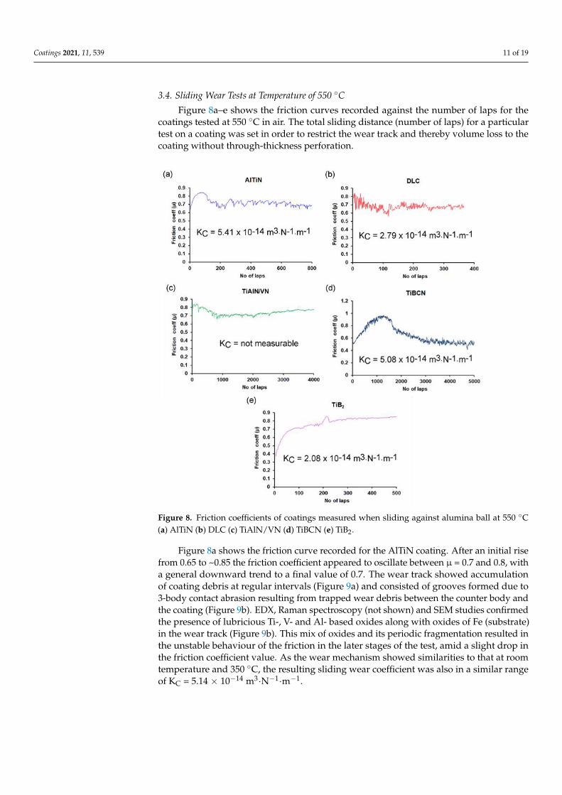
Figure 8a–e shows the friction curves recorded against the number of laps for thecoatings tested at 550 ◦C in air. The total sliding distance (number of laps) for a particulartest on a coating was set in order to restrict the wear track and thereby volume loss to thecoating without through-thickness perforation.
Coatings 2021, 11, x FOR PEER REVIEW 13 of 21
Figure 8. Friction coefficients of coatings measured when sliding against alumina ball at 550 °C (a)
AlTiN (b) DLC (c) TiAlN/VN (d) TiBCN (e) TiB2.
Figure 8. Friction coefficients of coatings measured when sliding against alumina ball at 550 ◦C(a) AlTiN (b) DLC (c) TiAlN/VN (d) TiBCN (e) TiB2.
Figure 8a shows the friction curve recorded for the AlTiN coating. After an initial risefrom 0.65 to ~0.85 the friction coefficient appeared to oscillate between µ = 0.7 and 0.8, witha general downward trend to a final value of 0.7. The wear track showed accumulationof coating debris at regular intervals (Figure 9a) and consisted of grooves formed due to3-body contact abrasion resulting from trapped wear debris between the counter body andthe coating (Figure 9b). EDX, Raman spectroscopy (not shown) and SEM studies confirmedthe presence of lubricious Ti-, V- and Al- based oxides along with oxides of Fe (substrate)in the wear track (Figure 9b). This mix of oxides and its periodic fragmentation resulted inthe unstable behaviour of the friction in the later stages of the test, amid a slight drop inthe friction coefficient value. As the wear mechanism showed similarities to that at roomtemperature and 350 ◦C, the resulting sliding wear coefficient was also in a similar rangeof KC = 5.14 × 10⁻¹⁴ m3·N−1·m−1.

Coatings 2021, 11, 539 12 of 19
Coatings 2021, 11, x FOR PEER REVIEW 14 of 21
Figure 9. SEM images (secondary electron imaging mode) of the wear track generated at 550 °C.
Images on the left are at low magnification; on the right are at high magnification (a,b) AlTiN (c,d)
DLC (e,f) TiBCN (g,h) TiB2.
As the friction curve in Figure 8c indicates, the nanoscale multilayer TiAlN/VN coat-
ing displayed the lowest variation in friction coefficient, with the friction stabilising to a
steady value of around µ = 0.77 at the end of the test at 4000 laps. SEM images (Figure
10a,b), EDX results and Raman spectroscopy results indicated that the wear track had not
Figure 9. SEM images (secondary electron imaging mode) of the wear track generated at 550 ◦C.Images on the left are at low magnification; on the right are at high magnification (a,b) AlTiN(c,d) DLC (e,f) TiBCN (g,h) TiB2.
Amongst all the coatings analysed, the performance of DLC coating, Figure 8b, deteri-orated the most when the test temperature was increased. The friction coefficient valueshowed a steep increase from 0.02 at 350 ◦C to 0.72 at 550 ◦C. SEM images, Figure 9c,d,EDX analysis and Raman spectroscopy results (not shown) confirmed that at this tempera-ture the coating underwent rapid decomposition (graphitisation). The wear track mainlyconsisted of oxidised substrate (within 400 laps) with no trace of any intact coating. Conse-quently, the dry sliding wear coefficient showed an increase of two orders of magnitude ascompared to the room temperature, though interestingly it was still only half that of theAlTiN film (Table 2).
The TiBCN and TiB2 coatings (Figures 9e–f and 9g–h respectively) showed almost noformation of oxides or build-up of wear debris. In the case of TiBCN coating the frictioncoefficient reached µ = 1 (around 1500 laps) followed by a gradual drop to stabilise ataround µ = 0.5 until the end of the test. The wear mechanism mainly consisted of wear of
Coatings 2021, 11, 539 13 of 19
the columnar tops of the coating (Figure 4d) which generated finer wear debris (Figure 9f).Even though noticeable wear of the Al2O3 counterpart (KC = 9.3 × 10⁻¹⁶ m3·N−1·m−1)was observed, it was comparatively less than observed for tests at room temperature and350 ◦C and could be attributed to the finer debris generated. The coatings exhibited a drysliding wear coefficient of KC = 5.08 × 10⁻¹⁴ m3·N−1·m−1. Similarly, the wear track of theTiB2 coatings (Figure 9g–h) consisted of worn and flattened globular grains (Figure 4e).The friction coefficient showed a steady increase in value with the increase in number oflaps to reach a value of µ = 0.84 at the end of the test (Figure 8e). The coatings exhibited adry sliding wear coefficient of KC = 2.08 × 10⁻¹⁴ m3·N−1·m−1.
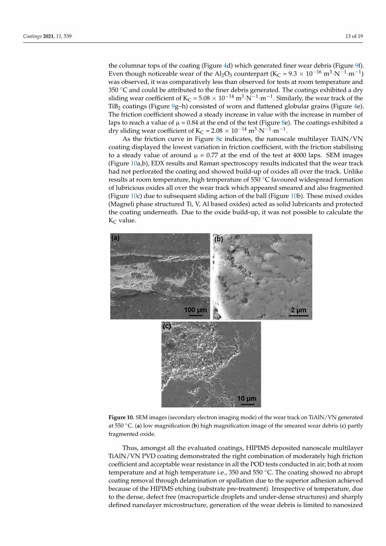
As the friction curve in Figure 8c indicates, the nanoscale multilayer TiAlN/VNcoating displayed the lowest variation in friction coefficient, with the friction stabilisingto a steady value of around µ = 0.77 at the end of the test at 4000 laps. SEM images(Figure 10a,b), EDX results and Raman spectroscopy results indicated that the wear trackhad not perforated the coating and showed build-up of oxides all over the track. Unlikeresults at room temperature, high temperature of 550 ◦C favoured widespread formationof lubricious oxides all over the wear track which appeared smeared and also fragmented(Figure 10c) due to subsequent sliding action of the ball (Figure 10b). These mixed oxides(Magneli phase structured Ti, V, Al based oxides) acted as solid lubricants and protectedthe coating underneath. Due to the oxide build-up, it was not possible to calculate theKC value.
Coatings 2021, 11, x FOR PEER REVIEW 15 of 21
perforated the coating and showed build-up of oxides all over the track. Unlike results at
room temperature, high temperature of 550 °C favoured widespread formation of lubri-
cious oxides all over the wear track which appeared smeared and also fragmented (Figure
10c) due to subsequent sliding action of the ball (Figure 10b). These mixed oxides (Magneli
phase structured Ti, V, Al based oxides) acted as solid lubricants and protected the coating
underneath. Due to the oxide build-up, it was not possible to calculate the KC value.
Figure 10. SEM images (secondary electron imaging mode) of the wear track on TiAlN/VN gener-
ated at 550 °C. (a) low magnification (b) high magnification image of the smeared wear debris (c)
partly fragmented oxide.
Thus, amongst all the evaluated coatings, HIPIMS deposited nanoscale multilayer
TiAlN/VN PVD coating demonstrated the right combination of moderately high friction
coefficient and acceptable wear resistance in all the POD tests conducted in air; both at
room temperature and at high temperature i.e., 350 and 550 °C. The coating showed no
abrupt coating removal through delamination or spallation due to the superior adhesion
achieved because of the HIPIMS etching (substrate pre-treatment). Irrespective of temper-
ature, due to the dense, defect free (macroparticle droplets and under-dense structures)
and sharply defined nanolayer microstructure, generation of the wear debris is limited to
nanosized particles through a layer-by-layer removal mechanism. This is in stark contrast
to the wear mechanism of breaking of columnar grains often observed for monolithic PVD
coatings, such as that observed for the AlTiN coating in this study. At high temperature,
the superior wear mechanism of TiAlN/VN coating is assisted by the formation of lubri-
cious Magneli phase structured oxides, which reduced the friction coefficient and wear
rate of the coating.
3.5. Tests in Vacuum
Because of its superior performance in tests in air, the HIPIMS-deposited TiAlN/VN
coating was chosen for its evaluation in conditions which represent the probe of the FSW
Figure 10. SEM images (secondary electron imaging mode) of the wear track on TiAlN/VN generatedat 550 ◦C. (a) low magnification (b) high magnification image of the smeared wear debris (c) partlyfragmented oxide.
Thus, amongst all the evaluated coatings, HIPIMS deposited nanoscale multilayerTiAlN/VN PVD coating demonstrated the right combination of moderately high frictioncoefficient and acceptable wear resistance in all the POD tests conducted in air; both at roomtemperature and at high temperature i.e., 350 and 550 ◦C. The coating showed no abruptcoating removal through delamination or spallation due to the superior adhesion achievedbecause of the HIPIMS etching (substrate pre-treatment). Irrespective of temperature, dueto the dense, defect free (macroparticle droplets and under-dense structures) and sharplydefined nanolayer microstructure, generation of the wear debris is limited to nanosized

Coatings 2021, 11, 539 14 of 19
particles through a layer-by-layer removal mechanism. This is in stark contrast to the wearmechanism of breaking of columnar grains often observed for monolithic PVD coatings,such as that observed for the AlTiN coating in this study. At high temperature, the superiorwear mechanism of TiAlN/VN coating is assisted by the formation of lubricious Magneliphase structured oxides, which reduced the friction coefficient and wear rate of the coating.
3.5. Tests in Vacuum
Because of its superior performance in tests in air, the HIPIMS-deposited TiAlN/VNcoating was chosen for its evaluation in conditions which represent the probe of the FSWtool, i.e., friction at high temperature in vacuum. To evaluate performance, tests wereconducted in vacuum (×10−7 mbar) and at ambient temperature (approximately 22 ◦C), 350,and 550 ◦C. As anticipated, the coatings exhibited a very stable friction behaviour (µ = 0.73)at ambient temperature (Figure 11a) mainly due to the superior nanolayer microstructureand the nanoscale layer-by-layer wear mechanism. The wear track (Figure 12a showedwear of selected areas (appear darker in contrast) of the coating (limited to the dome shapedcolumnar tops of the coating which came in contact with the counterpart). The coatingexhibited a very high wear resistance (KC = 3.56 ± 0.13 × 10⁻¹⁶ m3·N−1·m−1). As thetemperature was increased to 350 and 550 ◦C respectively, the friction curves became noisier(Figure 11b,c). The fluctuation in friction coefficient can be attributed to the generationof coarser wear debris caused by the disintegration of the tribofilm. This film which isadherent to the coating top at room temperature, is speculated to crack and disintegrateat higher temperatures (mainly due to the difference in thermal coefficient of expansion).Wear debris in the range of 10–20 nm in size led to an enhanced 3 body contact abrasionwear mechanism. SEM investigation confirmed the presence of shallow grooving in thewear tracks (Figure 12b,c) thus supporting the rationale of this proposed wear mechanism.Even though lack of oxygen prevented the generation of lubricious oxides, the superiornanolayer wear mechanism imparted a high wear resistance to the coating, with valuesof KC = 3.3 ± 0.28 × 10⁻¹⁵ and KC = 6.62 ± 0.73 × 10⁻¹⁵ m3·N−1·m−1 at 350 and 550 ◦Crespectively. Thus, the TiAlN/VN coating exhibited favourable attributes of a moderatelyhigh friction coefficient and a high wear resistance in vacuum necessary for the FSWprocess. In all these vacuum tests, the static Al2O3 counterpart exhibited negligible wear.
Coatings 2021, 11, x FOR PEER REVIEW 16 of 21
tool, i.e., friction at high temperature in vacuum. To evaluate performance, tests were con-
ducted in vacuum (×10−7 mbar) and at ambient temperature (approximately 22 °C), 350,
and 550 °C. As anticipated, the coatings exhibited a very stable friction behaviour (µ =
0.73) at ambient temperature (Figure 11a) mainly due to the superior nanolayer micro-
structure and the nanoscale layer-by-layer wear mechanism. The wear track (Figure 12a
showed wear of selected areas (appear darker in contrast) of the coating (limited to the
dome shaped columnar tops of the coating which came in contact with the counterpart).
The coating exhibited a very high wear resistance (KC = 3.56 ± 0.13 × 10⁻¹⁶ m3·N−1·m−1). As
the temperature was increased to 350 and 550 °C respectively, the friction curves became
noisier (Figure 11b,c). The fluctuation in friction coefficient can be attributed to the gener-
ation of coarser wear debris caused by the disintegration of the tribofilm. This film which
is adherent to the coating top at room temperature, is speculated to crack and disintegrate
at higher temperatures (mainly due to the difference in thermal coefficient of expansion).
Wear debris in the range of 10–20 nm in size led to an enhanced 3 body contact abrasion
wear mechanism. SEM investigation confirmed the presence of shallow grooving in the
wear tracks (Figure 12b,c) thus supporting the rationale of this proposed wear mechanism.
Even though lack of oxygen prevented the generation of lubricious oxides, the superior
nanolayer wear mechanism imparted a high wear resistance to the coating, with values of
KC = 3.3 ± 0.28 × 10⁻¹⁵ and KC = 6.62 ± 0.73 × 10⁻¹⁵ m3·N−1·m−1 at 350 and 550 °C respectively.
Thus, the TiAlN/VN coating exhibited favourable attributes of a moderately high friction
coefficient and a high wear resistance in vacuum necessary for the FSW process. In all
these vacuum tests, the static Al2O3 counterpart exhibited negligible wear.
Figure 11. Friction coefficient of the TiAlN/VN coating measured when sliding against
an alumina ball in vacuum (a) ambient temperature (b) 350 °C (c) 550 °C.
Figure 11. Friction coefficient of the TiAlN/VN coating measured when sliding against an aluminaball in vacuum (a) ambient temperature (b) 350 ◦C (c) 550 ◦C.

Coatings 2021, 11, 539 15 of 19Coatings 2021, 11, x FOR PEER REVIEW 17 of 21
Figure 12. Wear tracks generated on TiAlN/VN coating when sliding against alumina ball in vac-
uum (a) ambient temperature (b) 350 °C (c) 550 °C.
3.6. SS-FSW Results
The surface finish for all coatings was superior to the uncoated tool. Particularly
TiAlN/VN and DLC provided an exceptionally smooth surface finish. Following the stir
weld tests, the trailing surfaces of the shoulders were covered with a buildup of alloy
material as shown in Figure 13a–e. The buildup was smallest for the TiAlN/VN and the
DLC coatings (Figure 13a,b) and the majority of the material could be removed without
tools indicating limited and dynamic buildup with the sliding and shearing interface close
to the coating surface.
Figure 12. Wear tracks generated on TiAlN/VN coating when sliding against alumina ball in vacuum(a) ambient temperature (b) 350 ◦C (c) 550 ◦C.
3.6. SS-FSW Results
The surface finish for all coatings was superior to the uncoated tool. ParticularlyTiAlN/VN and DLC provided an exceptionally smooth surface finish. Following the stirweld tests, the trailing surfaces of the shoulders were covered with a buildup of alloymaterial as shown in Figure 13a–e. The buildup was smallest for the TiAlN/VN and theDLC coatings (Figure 13a,b) and the majority of the material could be removed withouttools indicating limited and dynamic buildup with the sliding and shearing interface closeto the coating surface.
To assess the coating surface under the buildup, the shoulders and probes werechemically etched using sodium hydroxide solution (NaOH) to remove the Aluminiumbuild-up. SEM micrographs (Figure 13f) and EDX analysis (not shown) confirmed thatthe TiAlN/VN coating was present, and the underlying substrate was not exposed. Theappearance of the coating was the same inside and outside the direct contact area betweenthe shoulder and workpiece material indicating no significant changes to the coatingsurface. Compositional EDX analysis detected the presence of workpiece alloy constituents(Mg, Si) on the TiAlN/VN coating surface. This buildup was not allowed to accrue due tothe lubricious nature of the Magneli oxide phases formed by the coating during slidingas seen in the wear tests at intermediate temperature (Section 3.3). These phases severedthe bond between the bulk of the coating and the buildup material, rendering the lattermechanically unstable.
The surface of the DLC coating showed clear evidence of the location of the directcontact area on the trailing edge of the shoulder—see bright area in Figure 13g. Thecoating in contact area contained cracks transverse to the welding direction and its surfaceremained covered with workpiece material (Al, Mg, and Si) even after the chemical etchingas confirmed by EDX analysis. Outside the direct contact area (dark area of Figure 13g)there was no detectable buildup. As the carbon coating is not expected to form compoundswith Al, the mechanism of buildup accrual may have proceeded through the formationof carbides with the Si and Mg alloying constituents favoured by the high temperaturesand subsequent build-up. Additionally, coating cracking under the high stresses of thewelding process may have resulted in the workpiece material bonding with the exposedshoulder bulk. In contrast, outside the contact area, where temperature and loading werelow, cracking and buildup were not present.

Coatings 2021, 11, 539 16 of 19Coatings 2021, 11, x FOR PEER REVIEW 18 of 21
Figure 13. Post-welding analysis. Photographs of the shoulders after welding for tools coated with
(a) TiAlN/VN, (b) DLC, (c) AlTiN, (d) TiBCN, and (e) uncoated tools. SEM micrographs of the trail-
ing edge of the shoulders near the contact area after welding and chemical etching with NaOH, for
tools coated with (f) TiAlN/VN, (g) DLC, (h) AlTiN, and (i) TiBCN showing surface adjacent to the
contact area (left) and inside the contact area (right). Micrographs of the probes coated with (j)
TiAlN/VN, (k) DLC, (l) AlTiN, and (m) TiBCN. Weld surfaces produced by tools coated with (n)
TiAlN/VN, (o) DLC, (p) AlTiN, and (q) TiBCN and (r) uncoated tools.
To assess the coating surface under the buildup, the shoulders and probes were
chemically etched using sodium hydroxide solution (NaOH) to remove the Aluminium
build-up. SEM micrographs (Figure 13f) and EDX analysis (not shown) confirmed that the
TiAlN/VN coating was present, and the underlying substrate was not exposed. The ap-
pearance of the coating was the same inside and outside the direct contact area between
the shoulder and workpiece material indicating no significant changes to the coating sur-
face. Compositional EDX analysis detected the presence of workpiece alloy constituents
(Mg, Si) on the TiAlN/VN coating surface. This buildup was not allowed to accrue due to
the lubricious nature of the Magneli oxide phases formed by the coating during sliding as
seen in the wear tests at intermediate temperature (Section 3.3). These phases severed the
bond between the bulk of the coating and the buildup material, rendering the latter me-
chanically unstable.
The surface of the DLC coating showed clear evidence of the location of the direct
contact area on the trailing edge of the shoulder—see bright area in Figure 13g. The coat-
ing in contact area contained cracks transverse to the welding direction and its surface
remained covered with workpiece material (Al, Mg, and Si) even after the chemical etch-
ing as confirmed by EDX analysis. Outside the direct contact area (dark area of Figure
Figure 13. Post-welding analysis. Photographs of the shoulders after welding for tools coated with(a) TiAlN/VN, (b) DLC, (c) AlTiN, (d) TiBCN, and (e) uncoated tools. SEM micrographs of thetrailing edge of the shoulders near the contact area after welding and chemical etching with NaOH,for tools coated with (f) TiAlN/VN, (g) DLC, (h) AlTiN, and (i) TiBCN showing surface adjacentto the contact area (left) and inside the contact area (right). Micrographs of the probes coated with(j) TiAlN/VN, (k) DLC, (l) AlTiN, and (m) TiBCN. Weld surfaces produced by tools coated with(n) TiAlN/VN, (o) DLC, (p) AlTiN, and (q) TiBCN and (r) uncoated tools.
The AlTiN, TiBCN and uncoated shoulder picked up a thick well-adherent depositindicating that the sliding and shear occurred within the buildup itself. The surface ofAlTiN coatings contained buildup in the direct contact area, making its surface appearrough (right-bottom half of Figure 13h). In TiBCN, the buildup appeared to ingress intothe intercolumnar voids of the coating in the contact area (right side of Figure 13i) and wasnot detected outside the coating area (left side of Figure 13i).
All probes contained traces of the coating. The lowest damage was sustained bythe AlTiN coating with no cracking or spallation at the thread edge or the tip of thetool (Figure 13l) due to the high temperature of rapid oxidation of the coating of 800 ◦C.TiAlN/VN ranked second with no damage at the tip and coating worn out from anarea spanning 10 µm on either side of the thread edge (Figure 13j). DLC-coated probesexhibited delamination span of 300 µm along the circumference of the thread (Figure 13k).TiBCN exhibited cohesive cracking (within the coating) at the tip and coating delaminationexposing the bright substrate at the thread (Figure 13m left and right respectively).
The surface appearance of the welds with TiAlN/VN coated shoulder (Figure 13n)and DLC coated shoulder (Figure 13o) exhibited no surface breaking voids and repre-

Coatings 2021, 11, 539 17 of 19
sented an excellent surface finish. This was superior to the AlTiN, TiBCN and uncoatedprobe/shoulder combinations (Figure 13p–r respectively).
One of the objectives of using low friction coatings on stationary shoulders is to reducethe contact forces between the weld material and the tool. This would be advantageousfor three reasons. Firstly, the loads on the FSW machine would reduce, requiring lesspowerful machines or robots. Secondly, the fixturing requirements and thereby associatedcosts could reduce. Finally, for SS-FSW of thin section material (typically below 1 mm),the un-welded material tends to buckle or deform due to the high drag forces of the tool.Table 3 below compares the traverse forces (x direction) and side forces (y direction) forSS-FSW tools comprising uncoated (H13) probes and the shoulders listed. As indicated, inaddition to the coatings discussed above, these included both polished and unpolished H13as well as a shoulder manufactured in silicon nitride (a high temperature ceramic underconsideration for use in FSW for high temperature materials). The combined Fxy forcecalculated from the average traverse and side forces was identified as most representativeof the performance of the tool. The TiAlN/VN and DLC coating resulted in the lowestcombined forces and provided the best surface quality (confirmed by visual assessment),however the surface texture and roughness values were not quantified. The H13 tools withpolished shoulder surface performed significantly better than those with an unpolishedsurface. Note that it was not possible to test a probe coated with TiB2 because the coatingthickness made the outer diameter of the probe larger than the tool holder causing theprobe to rub against the shoulder as soon as loads were applied.
Table 3. Traverse (x) and side (y) forces associated with SS-FSW of 6 mm thick AA6082-T6 plate using SS-FSW toolscomprising an H13 probe with the shoulders listed.
Shoulder Material Fx Min [N] Fx Max [N] Fy Min [N] Fy Max [N] Fxy Average [N]
Uncoated unpolished H13 1400 1600 1000 1100 1831Uncoated polished H13 1200 1300 200 200 1266
AlTiN (arc) 1200 1400 250 400 1340TiBCN 1100 1400 200 250 1270
TiAlN-VN 1100 1400 160 220 1264DLC 1050 1150 320 400 1157
uncoated SiN 1200 2000 100 400 1619
The high weld performance and quality correspond well with the observations as-sociated with the TiAlN/VN coating’s thin shoulder buildup, high temperature stabilityand moderate friction coefficient. The advantages for the DLC coatings come about fromits low friction however deterioration is observed due to the limited high temperaturestability. Although AlTiN and TiBCN have a good temperature stability, the reactivity ofthe former and high roughness/high friction coefficients of the latter result in the strongbuildup and poor weld surface quality observed in tests. The TiB2 coating, although nottested in SS-FSW, has a high friction coefficient, high roughness and propensity for buildupsimilar to those of the TiBCN and is therefore expected to perform in a similar way.
4. Conclusions
Of the coating materials tested, only the TiAlN/VN nanostructure multilayer, de-posited by the HIPIMS process, displayed excellent performance under conditions whichexist at both probes and shoulders used for SS-FSW of aluminium alloys. DLC coatingsdeposited by PACVD were unable to match the harsh conditions experienced by probes,however their low friction and medium temperature capability enabled them to producean excellent weld surface finish when applied to SS-FSW shoulders. Of the other coatingstested, of the two CVD coatings—TiBCN and TiB2—TiBCN showed the highest friction ofall coatings tested at both room temperature and 350 ◦C and the lowest value at 550 ◦Cand both had similar wear performance. How much these results were due to the roughmorphology and relatively low density of the CVD coatings is not clear although it is

Coatings 2021, 11, 539 18 of 19
possible that both might have performed better had they been polished prior to testing.The remaining coating—AlTiN deposited by arc evaporative PVD displayed a superior per-formance (marginally better than nanoscale multilayer TiAlN/VN) at the probe howevershowed considerable buildup on the shoulder. It displayed the most consistent frictioncoefficient over the three test temperatures, whilst its wear resistance displayed a peakat 350 ◦C, being 7 times higher than at room temperature and over 4 times higher thanat 550 ◦C. Whilst not being part of the original testing regime, the testing of polished un-coated tools for comparison with unpolished uncoated tools was the result of the observedrough surface condition of the uncoated tools during their preparation for coating and theassumption, proved correct, that this might have a negative impact on their performance.
This research demonstrated the superior high temperature performance of the TiAlN/VNnanostructure multilayer. Further improvements may be achievable through careful pre-and post-coating polishing to ensure optimal surface condition of tooling.
Author Contributions: A.E.: Conceptualization, funding acquisition, methodology, validation ofresults, draft reviewing. Y.P.: Investigation, validation and preparation of manuscript draft. A.S.:Investigation and validation. P.H. (Papken Hovsepian): Conceptualization, Supervision, validationof results, draft reviewing. P.H. (Peter Hatto) and J.D.: Conceptualization, funding acquisition,investigation, validation of results, draft reviewing. All authors have read and agreed to the publishedversion of the manuscript.
Funding: This work was supported by Innovate UK under grant 132366—StirCoat.
Institutional Review Board Statement: Not applicable.
Informed Consent Statement: Not applicable.
Data Availability Statement: The data presented in this study are available on request from the cor-responding author. The data are not publicly available due to issues related to the proprietary rights.
Conflicts of Interest: The authors declare no conflict of interest.
References1. Andrews, D.; Russell, M.; Martin, J. Recent developments in FSW at TWI. In Proceedings of the 9th International Symposium on
Friction Stir Welding, Huntsville, AL, USA, 15–17 May 2012.2. Wu, H.; Chen, Y.-C.; Strong, D.; Prangnell, P. Stationary shoulder FSW for joining high strength aluminum alloys. J. Mater. Process.
Technol. 2015, 221, 187–196. [CrossRef]3. Silva, A.C.F.; De Backer, J.; Bolmsjö, G. Temperature measurements during friction stir welding. Int. J. Adv. Manuf. Technol. 2017,
88, 2899–2908. [CrossRef]4. Silva-Magalhães, A.; De Backer, J.; Martin, J.; Bolmsjö, G. In-situ temperature measurement in friction stir welding of thick section
aluminium alloys. J. Manuf. Process. 2019, 39, 12–17. [CrossRef]5. Bouzakis, K.-D.; Skordaris, G.; Gerardis, S.; Katirtzoglou, G.; Makrimallakis, S.; Pappa, M.; LilI, E.; M’Saoubi, R. Ambient and
elevated temperature properties of TiN, TiAlN and TiSiN PVD films and their impact on the cutting performance of coatedcarbide tools. Surf. Coat. Technol. 2009, 204, 1061–1065. [CrossRef]
6. Helmersson, U.; Lattemann, M.; Bohlmark, J.; Ehiasarian, A.P.; Gudmundsson, J.T. Ionized physical vapor deposition (IPVD): Areview of technology and applications. Thin Solid Films 2006, 513, 1–24. [CrossRef]
7. Anders, A. A review comparing cathodic arcs and high power impulse magnetron sputtering (HiPIMS). Surf. Coat. Technol. 2014,257, 308–325. [CrossRef]
8. Hatto, P.; Teer, D. Ion plating with an arc source. Vacuum 1986, 36, 67–69. [CrossRef]9. Kouznetsov, V.; Macák, K.; Schneider, J.M.; Helmersson, U.; Petrov, I. A novel pulsed magnetron sputter technique utilizing very
high target power densities. Surf. Coat. Technol. 1999, 122, 290–293. [CrossRef]10. Ehiasarian, A.P.; Münz, W.-; Hultman, L.; Helmersson, U.; Petrov, I. High power pulsed magnetron sputtered CrNx films.
Surf. Coat. Technol. 2003, 163–164, 267–272. [CrossRef]11. Ehiasarian, A.P. Fundamentals and Applications of HIPIMS. Plasma Surface Engineering Research and Its Practical Applications; Research
Signpost: Kerala, India, 2007.12. Ehiasarian, A.P.; Wen, J.G.; Petrov, I. Interface microstructure engineering by high power impulse magnetron sputtering for the
enhancement of adhesion. J. Appl. Phys. 2007, 101, 054301. [CrossRef]13. Hovsepian, P.; Lewis, D.; Münz, W.-D. Recent progress in large scale manufacturing of multilayer/superlattice hard coatings.
Surf. Coat. Technol. 2000, 133, 166–175. [CrossRef]

Coatings 2021, 11, 539 19 of 19
14. Kafizas, A.; Carmalt, C.J.; Parkin, I.P. CVD and precursor chemistry of transition metal nitrides. Coord. Chem. Rev. 2013,257, 2073–2119. [CrossRef]
15. Rie, K.; Gebauer, A.; Wöhle, J. Plasma assisted CVD for low temperature coatings to improve the wear and corrosion resistance.Surf. Coat. Technol. 1996, 86–87, 498–506. [CrossRef]
16. Bewilogua, K.; Hofmann, D. History of diamond-like carbon films—From first experiments to worldwide applications.Surf. Coat. Technol. 2014, 242, 214–225. [CrossRef]
17. Ehiasarian, A.P.; Tietema, R.; Bugyi, R.; Klimczak, A.; Hovsepian, P.E.; Doerwald, D. A Vacuum Treatment Apparatus, a Bi-asPower Supply and a Method of Operating a Vacuum Treatment Apparatus. U.S. Patent 20,100,025,230 A1, 4 February 2010.
18. Ehiasarian, A.P.; Hovsepian, P.E.; Munz, W.-D. A Combined Process Comprising Magnetic Field-Assisted, High-Power, PulsedCathode Sputtering and an Unbalanced Magnetron. U.S. Patent 10,718,435, 25 July 2006.
19. Lugscheider, E.; Barimani, C.; Wolff, C.; Guerreiro, S.; Doepper, G. Comparison of the structure of PVD-thin films deposited withdifferent deposition energies. Surf. Coat. Technol. 1996, 86, 177–183. [CrossRef]
20. Ali, M.; Hamzah, E.; Qazi, I.A.; Toff, M.R.M. Growth defects and surface roughness in TiN-coated tool steel at various N2 gasflow rates using cathodic arc PVD technique. Mater. Sci. Forum 2010, 636, 965–970. [CrossRef]
21. Holleck, H.; Schier, V. Multilayer PVD coatings for wear protection. Surf. Coat. Technol. 1995, 76, 328–336. [CrossRef]22. Hovsepian, P.E.; Münz, W.-D. Nanostructured Coatings. Synthesis, Structure, and Applications of Nanoscale Multi-Layer/Superlattice
Structured PVD Coatings; Springer: New York, NY, USA, 2006.23. Vancoille, E.; Celis, J.; Roos, J. Dry sliding wear of TiN based ternary PVD coatings. Wear 1993, 165, 41–49. [CrossRef]24. Woydt, M.; Skopp, A.; Dörfel, I.; Witke, K. Wear engineering oxides/anti-wear oxides. Wear 1998, 218, 84–95. [CrossRef]25. Hovsepian, P.; Lewis, D.; Luo, Q.; Münz, W.-D.; Mayrhofer, P.; Mitterer, C.; Zhou, Z.; Rainforth, W. TiAlN based nanoscale
multilayer coatings designed to adapt their tribological properties at elevated temperatures. Thin Solid Films 2005, 485, 160–168.[CrossRef]
26. Zhou, Z.; Rainforth, W.; Luo, Q.; Hovsepian, P.; Ojeda, J.; Romero-Gonzalez, M. Wear and friction of TiAlN/VN coatings againstAl2O3 in air at room and elevated temperatures. Acta Mater. 2010, 58, 2912–2925. [CrossRef]