On the coupling between precipitation and plastic deformation in relation with friction stir welding...
10
Materials Science and Engineering A 441 (2006) 39–48 On the coupling between precipitation and plastic deformation in relation with friction stir welding of AA2024 T3 aluminium alloy C´ ecile Genevois a , Damien Fabr` egue a , Alexis Deschamps a,∗ , Warren J. Poole b a LTPCM, CNRS UMR 5614, Institut National Polytechnique de Grenoble, BP 75, 38 402 St. Martin d’H` eres Cedex, France b Department of Metals and Materials Engineering, University of British Columbia, Vancouver, Canada Received 1 November 2005; received in revised form 1 March 2006; accepted 1 July 2006 Abstract We have investigated the influence of plastic deformation on the precipitation kinetics of the S (S) phase in the AA2024 aluminium alloy, with the objective of understanding the microstructures found in friction stir welds of the same alloy. Different types of thermo-mechanical treatments have been investigated, where plastic deformation has been carried out either before heating in a salt bath, or concurrently with the thermal treatment in a Gleeble compression apparatus. The volume fraction of precipitates has been measured by differential scanning calorimetry and the precipitate morphology has been observed by transmission electron microscopy. It is observed that plastic deformation increases the precipitation kinetics in the temperature range below 300 ◦ C. This can be attributed both to the increase in the number of nucleation sites and to the increase in the effective diffusion coefficient. At higher temperatures the influence of plasticity on the volume fraction is negligible, however, in the presence of deformation during the heat treatment, the precipitate morphology is profoundly modified. The effect of plastic deformation is observed to be similar, whether plastic deformation is carried out before or during the heat treatment. These results are shown to be valuable tools in understanding the microstructures of friction stir welds of the same material. It is shown that taking into account the effect of plastic deformation is not absolutely necessary in the thermo-mechanically affected zone. However, we show that the precipitate microstructure in some parts of the heat-affected zone is strongly influenced by a small amount of plasticity. © 2006 Elsevier B.V. All rights reserved. Keywords: Precipitation; Plastic deformation; Friction stir welding; Aluminium alloys 1. Introduction Friction stir welding is rapidly developing in the transporta- tion industry owing to the remarkable mechanical properties achievable on high strength precipitation hardening materials [1]. In particular, welding of AA2024 T3 alloy, one of the most widely used aerospace alloys, has received considerable attention in the recent past [2–12]. The microstructure present in the different zones has been studied in detail, as well as the resulting mechanical properties (hardness distribution [4,7], tendency to localisation of plastic flow [7–9], fatigue [10], ...). However, the impact of the thermo-mechanical path on the microstructure formation in each location of the weld is still unclear. Notably, although most authors claim that the precip- ∗ Corresponding author. Tel.: +33 476 826607; fax: +33 476 826644. E-mail address: [email protected] (A. Deschamps). itate microstructure results from a combination of temperature and plastic flow [13–17], there is very little evidence regarding the importance of the coupling between these two features. This is particularly true in the thermo-mechanically affected zones (TMAZ), where the state of precipitation results in minimum strength and thus determines the overall properties of the welded joint. Understanding in which conditions plasticity influences the evolution of precipitates is, however, of prime importance for the future development of predictive models for microstructural evolution, which in the present state of the art [18–20] are not capable of integrating the presence of plastic flow in their pre- dictions. During welding, the thermo-mechanical conditions can induce interaction between the phenomena of deformation, pre- cipitation, recovery and recrystallisation. A number of authors have studied the different interactions on precipitation harden- ing aluminium alloys [21–29]. Dislocations act both as preferred 0921-5093/$ – see front matter © 2006 Elsevier B.V. All rights reserved. doi:10.1016/j.msea.2006.07.151
-
Upload
grenoble-inp -
Category
Documents
-
view
1 -
download
0
Transcript of On the coupling between precipitation and plastic deformation in relation with friction stir welding...
A
obam
tpph
tt©
K
1
ta[mairtHmu
0d
Materials Science and Engineering A 441 (2006) 39–48
On the coupling between precipitation and plastic deformation inrelation with friction stir welding of AA2024 T3 aluminium alloy
Cecile Genevois a, Damien Fabregue a, Alexis Deschamps a,∗, Warren J. Poole b
a LTPCM, CNRS UMR 5614, Institut National Polytechnique de Grenoble, BP 75, 38 402 St. Martin d’Heres Cedex, Franceb Department of Metals and Materials Engineering, University of British Columbia, Vancouver, Canada
Received 1 November 2005; received in revised form 1 March 2006; accepted 1 July 2006
bstract
We have investigated the influence of plastic deformation on the precipitation kinetics of the S′(S) phase in the AA2024 aluminium alloy, with thebjective of understanding the microstructures found in friction stir welds of the same alloy. Different types of thermo-mechanical treatments haveeen investigated, where plastic deformation has been carried out either before heating in a salt bath, or concurrently with the thermal treatment inGleeble compression apparatus. The volume fraction of precipitates has been measured by differential scanning calorimetry and the precipitateorphology has been observed by transmission electron microscopy.It is observed that plastic deformation increases the precipitation kinetics in the temperature range below 300 ◦C. This can be attributed both
o the increase in the number of nucleation sites and to the increase in the effective diffusion coefficient. At higher temperatures the influence oflasticity on the volume fraction is negligible, however, in the presence of deformation during the heat treatment, the precipitate morphology isrofoundly modified. The effect of plastic deformation is observed to be similar, whether plastic deformation is carried out before or during theeat treatment.
These results are shown to be valuable tools in understanding the microstructures of friction stir welds of the same material. It is shown thataking into account the effect of plastic deformation is not absolutely necessary in the thermo-mechanically affected zone. However, we show thathe precipitate microstructure in some parts of the heat-affected zone is strongly influenced by a small amount of plasticity.
2006 Elsevier B.V. All rights reserved.
alloy
iati(sj
ete
eywords: Precipitation; Plastic deformation; Friction stir welding; Aluminium
. Introduction
Friction stir welding is rapidly developing in the transporta-ion industry owing to the remarkable mechanical propertieschievable on high strength precipitation hardening materials1]. In particular, welding of AA2024 T3 alloy, one of theost widely used aerospace alloys, has received considerable
ttention in the recent past [2–12]. The microstructure presentn the different zones has been studied in detail, as well as theesulting mechanical properties (hardness distribution [4,7],endency to localisation of plastic flow [7–9], fatigue [10], . . .).
owever, the impact of the thermo-mechanical path on theicrostructure formation in each location of the weld is stillnclear. Notably, although most authors claim that the precip-
∗ Corresponding author. Tel.: +33 476 826607; fax: +33 476 826644.E-mail address: [email protected] (A. Deschamps).
cd
ichi
921-5093/$ – see front matter © 2006 Elsevier B.V. All rights reserved.oi:10.1016/j.msea.2006.07.151
s
tate microstructure results from a combination of temperaturend plastic flow [13–17], there is very little evidence regardinghe importance of the coupling between these two features. Thiss particularly true in the thermo-mechanically affected zonesTMAZ), where the state of precipitation results in minimumtrength and thus determines the overall properties of the weldedoint.
Understanding in which conditions plasticity influences thevolution of precipitates is, however, of prime importance forhe future development of predictive models for microstructuralvolution, which in the present state of the art [18–20] are notapable of integrating the presence of plastic flow in their pre-ictions.
During welding, the thermo-mechanical conditions can
nduce interaction between the phenomena of deformation, pre-ipitation, recovery and recrystallisation. A number of authorsave studied the different interactions on precipitation harden-ng aluminium alloys [21–29]. Dislocations act both as preferred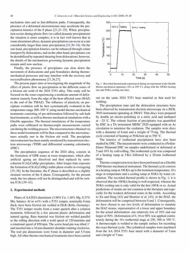
4 ce and Engineering A 441 (2006) 39–48
npcttscotbtr
mmr
eafmtctthGpottmt(
tact[sst
2
MtTtntaaTh
Ftr
ow
b3babcwc
sE5os
3isco5pctdwtflu
0 C. Genevois et al. / Materials Scien
ucleation sites and as fast-diffusion paths. Consequently, theresence of a deformed microstructure may accelerate the pre-ipitation kinetics of the S phase [21,23–25]. When, precipita-ion occurs during plastic flow (so-called dynamic precipitation)he situation is more complex; it is in fact well known that inome aluminium alloys, dynamic precipitation can occur at a rateonsiderably larger than static precipitation [23,30–34]. On thene hand, precipitation kinetics can be enhanced through soluteransport by dislocations; and on the other hand, precipitates cane destabilized by repeated shearing from dislocations; however,he details of the mechanisms governing dynamic precipitationemain until now unclear.
Finally, the presence of precipitates can slow down theovement of dislocations and gain boundaries during thermo-echanical processes and may interfere with the recovery and
ecrystallisation phenomena [21,26,27].The present paper aims at investigating the magnitude of the
ffect of plastic flow on precipitation in the different zones offriction stir weld of the 2024 T351 alloy. This study will be
ocused on the zones experiencing a moderate amount of defor-ation (namely from the edge of the heat-affected zone (HAZ)
o the end of the TMAZ). The influence of plasticity on pre-ipitate evolution will be first systematically evaluated in theemperature range 200–350 ◦C using model thermo-mechanicalreatments consisting of pre-deformation followed by salt batheat treatments, as well as thermo-mechanical simulations with aleeble apparatus. The thermal simulations of the temperatureaths were calibrated on thermocouple measurements carriedut during the welding process. The microstructures obtained viahese model treatments will be then compared to the microstruc-ures actually met in the friction stir weld. The precipitate
icrostructure has been mainly monitored by transmission elec-ron microscopy (TEM) and differential scanning calorimetryDSC).
The precipitation sequence of the 2024 alloy, consists inhe formation of GPB zones at room temperature, which afterrtificial ageing are dissolved and then replaced by semi-oherent S′(Al2CuMg) precipitates. After longer time exposurehe formation of S(Al2CuMg) stable phase results in overageing35–38]. In the literature, the S′ phase is described as a slightlytrained version of the S phase. Consequently, for the presenttudy the two phases will not be distinguished and will be writ-en S′(S) [39–41].
. Experimental methods
Plates of AA2024 aluminium (3.98% Cu, 1.48% Mg, 0.37%n, balance Al in wt%) with a T351 temper, nominally 6 mm
hick, have been friction stir welded at DLR (Koln, Germany).he T351 temper results from a water quench after a solution
reatment, followed by a few percent plastic deformation andatural ageing. Base material was friction stir welded parallelo the rolling direction with a weld speed of 120 mm/min and
rotational speed of 850 rpm. The screw head pin was tilted 1◦nd inserted into a 16 mm diameter shoulder rotating clockwise.he tool pin dimensions were 6 mm in diameter and 5.5 mmigh. All other thermo-mechanical treatments have been carriedAtfa
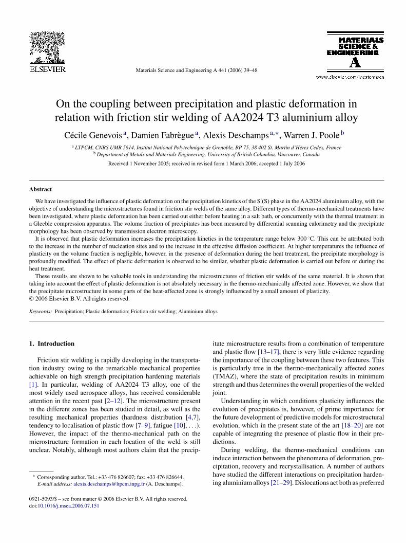
ig. 1. Recorded thermal path experienced during an experiment in the Gleeblehermo-mechanical apparatus (10 s at 250 ◦C), along with the 100 K/s heatingate and 50 K/s cooling rate lines.
ut on the same 2024 T351 base material as that used forelding.The precipitation state and the dislocation structures have
een observed by transmission electron microscopy on a JEOL010 instrument operating at 300 kV. Thin discs were preparedy double jet electro-polishing in a nitric acid and methanolt −25 ◦C. The volume fraction of precipitates was quantifiedy DSC in a TA instrument MDSC 2920 equipped with an Arirculation to minimise the oxidation. The samples were discsith a diameter of 6 mm and a weight of 75 mg. The thermal
ycle consisted of heating at 50 K/min up to 550 ◦C.The kinetics of isothermal precipitation have also been
tudied by DSC. The measurements were conducted in a Perkin-lmer Diamond DSC on samples undeformed or deformed atand 10% by cold rolling. The isothermal cycle was composedf a heating ramp at 5 K/s followed by a 20 min isothermaltage.
Thermo-compression tests have been performed on a Gleeble500 thermo-mechanical instrument. The thermal cycle consistsn a heating ramp at 100 K/s up to the treatment temperature, 10 stage at temperature and a cooling ramp at 50 K/s by water cir-ulation. The recorded thermal profile is shown in Fig. 1; it isbserved that the 100 K/s heating is well respected, whereas the0 K/s cooling rate is only valid for the first 100 K or so. Actualredictions of strains are not common in the literature and espe-ially for the weakest deformed zones in the welds. Accordingo Xu and Deng [42] and Heurtier et al. [43], in the HAZ, theeformation will be comprised between 0 and 1. Consequently,e have chosen to use two levels of deformation to simulate
he HAZ strains, representative of a lower and upper boundaryor the actual deformation: one relatively low of 10% and onearger of 50%. Deformation of 0, 10 or 50% was applied contin-ously during the 10 s isothermal stage at 250, 300 or 350 ◦C.
thermocouple is welded to the sample surface for recordinghe exact thermal cycle. The cylindrical samples were machinedrom the AA 2024 T351 base metal with a diameter of 5 mmnd a height of 7 mm.
C. Genevois et al. / Materials Science and Engineering A 441 (2006) 39–48 41
Fig. 2. Evolution of the hardness accross the retreating side of a friction stir weldcarried out on 2024 T351 material, along with the volume fraction of GPB zonesand S′(S) precipitates. Different zones are delimited, namely the nugget, thetd
3o
ttawwtrs
(
(
(
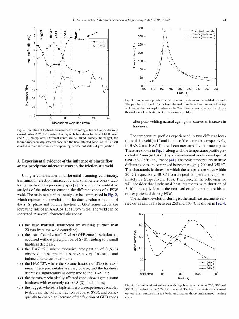
Fig. 3. Temperature profiles met at different locations in the welded material.Twt
tiTdOdT2iw5–10 s are equivalent to the non-isothermal temperature histo-ries experienced during FSW.
The hardness evolution during isothermal heat treatments car-ried out in salt baths between 250 and 350 ◦C is shown in Fig. 4.
hermo-mechanically-affected zone and the heat-affected zone, which is itselfivided in three sub-zones, corresponding to different states of precipitation.
. Experimental evidence of the influence of plastic flown the precipitate microstructure in the friction stir weld
Using a combination of differential scanning calorimetry,ransmission electron microscopy and small-angle X-ray scat-ering, we have in a previous paper [7] carried out a quantitativenalysis of the microstructure in the different zones of a FSWeld. The main result of this study can be summarised in Fig. 2,hich represents the evolution of hardness, volume fraction of
he S′(S) phase and volume fraction of GPB zones across theetreating side of an AA2024 T351 FSW weld. The weld can beeparated in several characteristic zones:
(i) the base material, unaffected by welding (further than20 mm from the weld centreline);
(ii) the heat-affected zone “1”, where GPB zone dissolution hasoccurred without precipitation of S′(S), leading to a smallhardness decrease;
iii) the HAZ “2”, where extensive precipitation of S′(S) isobserved; these precipitates have a very fine scale andinduce a hardness maximum;
iv) the HAZ “3”, where the volume fraction of S′(S) is maxi-mum; these precipitates are very coarse, and the hardnessdecreases significantly as compared to the HAZ “2”;
(v) the thermo-mechanically affected zone, showing minimum′
hardness with extremely coarse S (S) precipitates;vi) the nugget, where the high temperature experienced enablesto decrease the volume fraction of coarse S′(S), and conse-quently to enable an increase of the fraction of GPB zones
F3os
he profiles at 10 and 14 mm from the weld line have been measured duringelding by thermocouples, whereas the 7 mm profile has been calculated by a
hermal model calibrated on the two former profiles.
after post-welding natural ageing that causes an increase inhardness.
The temperature profiles experienced in two different loca-ions of the weld (at 10 and 14 mm of the centreline, respectively,n HAZ 2 and HAZ 1) have been measured by thermocouples.hese are shown in Fig. 3, along with the temperature profile pre-icted at 7 mm (in HAZ 3) by a finite element model developed atNERA, Chatillon, France [44]. The peak temperatures in theseifferent zones are comprised between roughly 200 and 350 ◦C.he characteristic times for which the temperature stays within0 ◦C (respectively, 40 ◦C) from the peak temperature is approx-mately 5 s (respectively, 10 s). Therefore, in the following weill consider that isothermal heat treatments with duration of
ig. 4. Evolution of microhardness during heat treatments at 250, 300 and50 ◦C carried out on the 2024 T351 material. The heat treatments are all carriedut on small samples in a salt bath, ensuring an almost instantaneous heatingtage.
4 ce and Engineering A 441 (2006) 39–48
Tf
Tfiai
aapdrah5sp
atbfne
tTdtmoci1s
wbctotiTiic(
aTsosm
Ft(
4i
iFjopTSIezmitt
2 C. Genevois et al. / Materials Scien
he initial state of the samples is the 2024 T351 material, unde-ormed.
At 250 ◦C, a drop in hardness is observed as early as 5 s.his hardness decrease continues until approximately 50 s, and is
ollowed by a large hardness increase up to 150 HV. This increases undoubtedly due to the formation of fine S′(S) precipitates,nd therefore the main phenomenon occurring in the first 5–10 ss only the GPB zone dissolution.
At 300 ◦C, the drop in hardness is much larger in magnitudend also much shorter. A hardness increase is observed as earlys 20 s, however, the maximum hardness achieved at this tem-erature is quite lower as compared to 250 ◦C. At 300 ◦C, theriving force for nucleation of S′(S) is lower and the diffusionates are much faster, consequently the S′(S) precipitates formedfter the dissolution of GPB zones are much coarser and thusave a smaller contribution to hardening than at 250 ◦C. In the–10 s time scale, the main feature is an almost complete dis-olution of GPB zones and the beginning of formation of S′(S)recipitates.
At 350 ◦C, a continuous decrease of hardness is observed, atmuch slower rate than as compared to 300 ◦C. This indicates
hat the formation of S′(S) precipitates is almost instantaneous,ut that these precipitates undergo coarsening as soon as they areormed, leading to continuous softening from the initial hard-ess. The main feature in the 5–10 s time scale is, therefore, anxtensive presence of coarse S′(S) precipitates.
We can now compare the microstructures observed in the fric-ion stir weld to that interpreted from the salt bath experiments.he HAZ 1 (at 14 mm from the centreline) is dominated by theissolution of GPB zones (Fig. 2). It is not possible to estimatehe amount of dissolution occurring during welding, since the
easurements were performed several months after the weldingperation. However, one important feature is that no S′(S) pre-ipitates are observed. On the other hand, the peak temperatures between 200 and 250 ◦C. Thus, the microstructure in the HAZcorresponds well to that observed after 5–10 s at 250 ◦C in the
alt bath experiments.The HAZ 2 experiences a peak temperature around 270 ◦C. If
e consider the salt bath experiments, the microstructure shoulde still dominated by the dissolution of GPB zones, and the pre-ipitation of S′(S) should hardly be visible. However, this is nothe case, since the fraction of S′(S) measured in HAZ 2 is halff the maximum value (Fig. 2). Thus, it appears that the precipi-ation of S′(S) in this zone is much faster than expected fromsothermal experiments carried out on undeformed samples.his is potentially an effect of deformation that would occur dur-
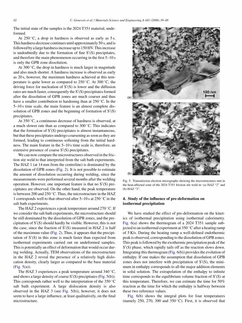
ng welding. Actually, TEM observations of the microstructuren the HAZ 2 reveal the presence of a relatively high dislo-ation density, clearly larger as compared to the base materialFig. 5(a)).
The HAZ 3 experiences a peak temperature around 340 ◦C,nd shows a large density of coarse S′(S) precipitates (Fig. 5(b)).his corresponds rather well to the interpretation of the 350 ◦C
alt bath experiment. A large dislocation density is alsobserved in the HAZ 3 (see Fig. 5(b)), however, it does noteem to have a large influence, at least qualitatively, on the finalicrostructure.rt
(
ig. 5. Transmission electron micrographs showing the microstructures met inhe heat-affected zone of the 2024 T351 friction stir weld in: (a) HAZ “2” andb) HAZ “3”.
. Study of the influence of pre-deformation onsothermal precipitation
We have studied the effect of pre-deformation on the kinet-cs of isothermal precipitation using isothermal calorimetry.ig. 6(a) shows the thermogram of a 2024 T351 sample sub-
ected to an isothermal experiment at 350 ◦C after a heating rampf 5 K/s. During the heating ramp a well-defined endothermiceak is observed, corresponding to the dissolution of GPB zones.his peak is followed by the exothermic precipitation peak of the′(S) phase, which rapidly tails off as the reaction slows down.ntegrating this thermogram (Fig. 6(b)) provides the evolution ofnthalpy. If one makes the assumption that dissolution of GPBones does not interfere with precipitation of S′(S), the mini-um in enthalpy corresponds to all the major addition elements
n solid solution. The extrapolation of the enthalpy to infiniteime corresponds to the equilibrium volume fraction of S′(S) athis temperature. Therefore, we can estimate the time for 50%
eaction as the time for which the enthalpy is halfway betweenhese two reference values.Fig. 6(b) shows the integral plots for four temperaturesnamely 250, 270, 300 and 350 ◦C). First, it is observed that
C. Genevois et al. / Materials Science and Engineering A 441 (2006) 39–48 43
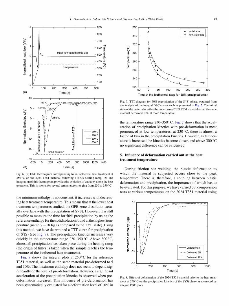
Fig. 6. (a) DSC thermogram corresponding to an isothermal heat treatment at350 ◦C on the 2024 T351 material following a 5 K/s heating ramp. (b) Theit
titaprptoqa(p
Tanadb
Fig. 7. TTT diagram for 50% precipitation of the S′(S) phase, obtained fromtsm
tepfan
5t
wtemperature. There is, therefore, a coupling between plasticdeformation and precipitation, the importance of which has tobe evaluated. For this purpose, we have carried out compressiontests at various temperatures on the 2024 T351 material using
ntegration of this thermogram provides the evolution of enthalpy along the heatreatment. This is shown for several temperatures ranging from 250 to 350 ◦C.
he minimum enthalpy is not constant: it increases with decreas-ng heat treatment temperature. This means that at the lower heatreatment temperatures studied, the GPB zone dissolution actu-lly overlaps with the precipitation of S′(S). However, it is stillossible to measure the time for 50% precipitation by using theeference enthalpy for the solid solution found at the highest tem-erature (namely −18 J/g as compared to the T351 state). Usinghis method, we have determined a TTT curve for precipitationf S′(S) (see Fig. 7). The precipitation kinetics increases veryuickly in the temperature range 230–350 ◦C. Above 300 ◦C,lmost all precipitation has taken place during the heating rampthe origin of times is taken when the sample reaches the tem-erature of the isothermal heat treatment).
Fig. 8 shows the integral plots at 250 ◦C for the reference351 material, as well as the same material pre-deformed to 5nd 10%. The maximum enthalpy does not seem to depend sig-
ificantly on the level of pre-deformation. However, a significantcceleration of the precipitation kinetics is observed when pre-eformation increases. This influence of pre-deformation haseen systematically evaluated for a deformation level of 10% inFmi
he analysis of the integral DSC curves such as presented in Fig. 5. The initialtate of the material is either the undeformed 2024 T351 material either the sameaterial deformed 10% at room temperature.
he temperature range 230–350 ◦C. Fig. 7 shows that the accel-ration of precipitation kinetics with pre-deformation is mostronounced at low temperatures: at 230 ◦C, there is almost aactor of two in the precipitation kinetics. However, as temper-ture is increased the kinetics become closer, and above 300 ◦Co significant difference can be evidenced.
. Influence of deformation carried out at the heatreatment temperature
During friction stir welding, the plastic deformation tohich the material is subjected occurs close to the peak
ig. 8. Effect of deformation of the 2024 T351 material prior to the heat treat-ent at 250 ◦C on the precipitation kinetics of the S′(S) phase as measured by
ntegral DSC plots.
4 ce an
a1to(dcs
dtscGt(tDmb
tiad3
tsttommtdh
Fatf
4 C. Genevois et al. / Materials Scien
Gleeble thermo-mechanical simulator. These consist in a00 K/s heating ramp to the heat treatment temperature, 10 s atemperature, and a 50 K/s cooling stage. Compression of 0, 10r 50% is performed continuously during the 10 s at temperaturethus the deformation rate is five times lower for the 10%eformation as compared to the 50% deformation). After theompression tests, samples have been studied by differentialcanning calorimetry with a ramp speed of 50 K/min.
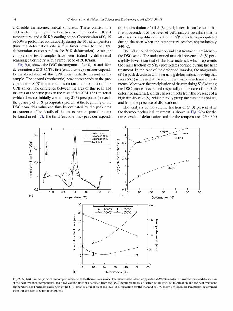
Fig. 9(a) shows the DSC thermograms after 0, 10 and 50%eformation at 250 ◦C. The first (endothermic) peak correspondso the dissolution of the GPB zones initially present in theample. The second (exothermic) peak corresponds to the pre-ipitation of S′(S) from the solid solution after dissolution of thePB zones. The difference between the area of this peak and
he area of the same peak in the case of the 2024 T351 materialwhich does not initially contain any S′(S) precipitates) reveals
he quantity of S′(S) precipitates present at the beginning of theSC scan, this value can thus be evaluated by the peak areaeasurement. The details of this measurement procedure cane found in ref. [7]. The third (endothermic) peak corresponds
a
tt
ig. 9. (a) DSC thermograms of the samples subjected to the thermo-mechanical treatmt the heat treatment temperature. (b) S′(S) volume fractions deduced from the DSCemperature. (c) Thickness and length of the S′(S) laths as a function of the level of drom transmission electron micrographs.
d Engineering A 441 (2006) 39–48
o the dissolution of all S′(S) precipitates; it can be seen thatt is independent of the level of deformation, revealing that inll cases the equilibrium fraction of S′(S) has been precipitateduring the scan when the temperature reaches approximately40 ◦C.
The influence of deformation and heat treatment is evident onhe DSC scans. The undeformed material presents a S′(S) peaklightly lower than that of the base material, which representshe small fraction of S′(S) precipitates formed during the heatreatment. In the case of the deformed samples, the magnitudef the peak decreases with increasing deformation, showing thatore S′(S) is present at the end of the thermo-mechanical treat-ents. Moreover, the precipitation of the remaining S′(S) during
he DSC scan is accelerated (especially in the case of the 50%eformed material), which can result both from the presence of aigh density of S′(S), which rapidly pump the remaining solute,
nd from the presence of dislocations.The analysis of the volume fraction of S′(S) present afterhe thermo-mechanical treatment is shown in Fig. 9(b) for thehree levels of deformation and for the temperatures 250, 300
ents in the Gleeble apparatus at 250 ◦C, as a function of the level of deformationthermograms as a function of the level of deformation and the heat treatmenteformation for the 300 and 350 ◦C thermo-mechanical treatments, determined
C. Genevois et al. / Materials Science and Engineering A 441 (2006) 39–48 45
F the th(
a2asidn
soittonodTtia
ifeiima
bipwpsaiaf
bs
cbeamirtd3
In the case of the higher amount of deformation, the volumefraction of precipitates formed at all temperatures is almost iden-tical in the static and dynamic experiments. It can be assumedthat in this situation the stored dislocation density is similar in
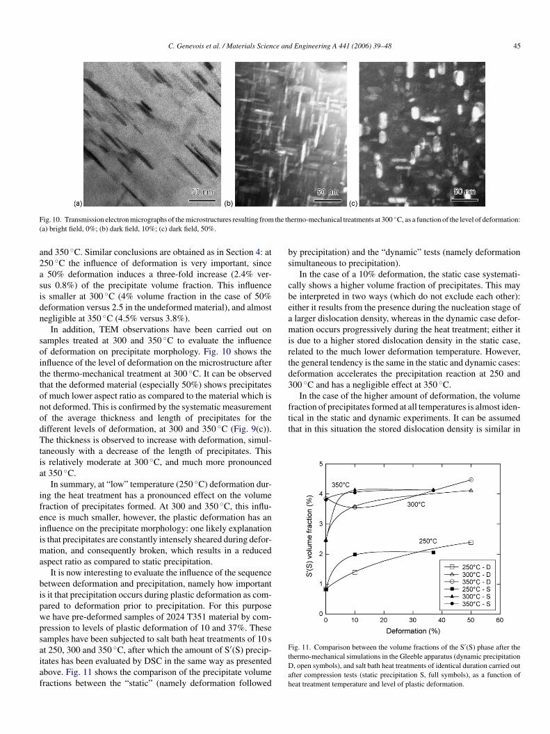
ig. 10. Transmission electron micrographs of the microstructures resulting froma) bright field, 0%; (b) dark field, 10%; (c) dark field, 50%.
nd 350 ◦C. Similar conclusions are obtained as in Section 4: at50 ◦C the influence of deformation is very important, since50% deformation induces a three-fold increase (2.4% ver-
us 0.8%) of the precipitate volume fraction. This influences smaller at 300 ◦C (4% volume fraction in the case of 50%eformation versus 2.5 in the undeformed material), and almostegligible at 350 ◦C (4.5% versus 3.8%).
In addition, TEM observations have been carried out onamples treated at 300 and 350 ◦C to evaluate the influencef deformation on precipitate morphology. Fig. 10 shows thenfluence of the level of deformation on the microstructure afterhe thermo-mechanical treatment at 300 ◦C. It can be observedhat the deformed material (especially 50%) shows precipitatesf much lower aspect ratio as compared to the material which isot deformed. This is confirmed by the systematic measurementf the average thickness and length of precipitates for theifferent levels of deformation, at 300 and 350 ◦C (Fig. 9(c)).he thickness is observed to increase with deformation, simul-
aneously with a decrease of the length of precipitates. Thiss relatively moderate at 300 ◦C, and much more pronouncedt 350 ◦C.
In summary, at “low” temperature (250 ◦C) deformation dur-ng the heat treatment has a pronounced effect on the volumeraction of precipitates formed. At 300 and 350 ◦C, this influ-nce is much smaller, however, the plastic deformation has annfluence on the precipitate morphology: one likely explanations that precipitates are constantly intensely sheared during defor-
ation, and consequently broken, which results in a reducedspect ratio as compared to static precipitation.
It is now interesting to evaluate the influence of the sequenceetween deformation and precipitation, namely how importants it that precipitation occurs during plastic deformation as com-ared to deformation prior to precipitation. For this purposee have pre-deformed samples of 2024 T351 material by com-ression to levels of plastic deformation of 10 and 37%. Theseamples have been subjected to salt bath heat treatments of 10 s
t 250, 300 and 350 ◦C, after which the amount of S′(S) precip-tates has been evaluated by DSC in the same way as presentedbove. Fig. 11 shows the comparison of the precipitate volumeractions between the “static” (namely deformation followedFtDah
ermo-mechanical treatments at 300 ◦C, as a function of the level of deformation:
y precipitation) and the “dynamic” tests (namely deformationimultaneous to precipitation).
In the case of a 10% deformation, the static case systemati-ally shows a higher volume fraction of precipitates. This maye interpreted in two ways (which do not exclude each other):ither it results from the presence during the nucleation stage oflarger dislocation density, whereas in the dynamic case defor-ation occurs progressively during the heat treatment; either it
s due to a higher stored dislocation density in the static case,elated to the much lower deformation temperature. However,he general tendency is the same in the static and dynamic cases:eformation accelerates the precipitation reaction at 250 and00 ◦C and has a negligible effect at 350 ◦C.
ig. 11. Comparison between the volume fractions of the S′(S) phase after thehermo-mechanical simulations in the Gleeble apparatus (dynamic precipitation, open symbols), and salt bath heat treatments of identical duration carried out
fter compression tests (static precipitation S, full symbols), as a function ofeat treatment temperature and level of plastic deformation.

46 C. Genevois et al. / Materials Science an
Ff
bd
6t
ttwccbeii
Fhse
Ttp
(ptnhTntiWtXf2teitawr
pftbd
ig. 12. Dark field transmission electron micrograph in the HAZ “2” of theriction stir weld of 2024 T351 material.
oth cases, due to recovery of the dislocations initially presenturing the heating stage in the static experiment.
. Discussion: comparison of microstructures betweenhe thermo-mechanical tests and the FSW joint
We can now compare the microstructures resulting from thehermo-mechanical treatments (compression tests at the heatreatment temperature) to the various zones of the friction stireld as defined in Section 3. We will first turn to what we have
alled HAZ 2, which corresponds to a high density of moderatelyoarse S′(S) precipitates (see Fig. 12) that induce a significant,ut not maximum, hardness drop (Fig. 2). This zone has experi-
nced a temperature peak at almost 300 ◦C. This microstructures well reproduced by a thermo-mechanical treatment combin-ng 10 s at 300 ◦C with 10% plastic deformation (Fig. 10(b)).ig. 13. Precipitation kinetics of the S′(S) phase during a 200 ◦C isothermaleat treatment with a 5 K/s heating ramp measured by in situ small-angle X-raycattering. The initial state of the material is either 2024 T351 (undeformed),ither the same material cold rolled to a deformation of 200%.
tebdtdai
uc5Tgcuisd
istbao
d Engineering A 441 (2006) 39–48
his confirms that the HAZ 2, whose grain structure is identicalo that of the base material, is subjected to a small amount oflastic deformation, which influences the state of precipitation.
The fact that the range of moderate temperatures250–300 ◦C) is the one where plastic deformation has the mostronounced effect on the formation of the S′(S) phase is not par-icularly surprising. In this temperature range the homogeneousucleation of S′(S) is particularly difficult, due to the relativelyigh interfacial energy of this phase with the aluminium matrix.he presence of dislocations in the material provides a largeumber of nucleation sites, and also fast-diffusion paths for theransport of solute, which is quite slow at these temperatures. Thenfluence of deformation is apparent even at lower temperatures.
e have had the opportunity to measure in situ the initial stage ofhe precipitation kinetics at 200 ◦C by synchrotron small-angle-ray scattering (for experimental details, see, e.g. [20]), starting
rom the 2024 T351 material, either undeformed or deformed00% by cold rolling. The heating rate is 5 K/s. Fig. 13 showshat at this relatively low temperature, pre-deformation has anven more pronounced effect as compared to 250 ◦C: the precip-tation kinetics is accelerated by almost a decade as comparedo the undeformed material. Of course, the effect of deformationt such low temperatures is not directly of interest in friction stirelding, since the material subject to a peak temperature in this
ange is not plastically deformed by the welding process.An important point arising from the present study is that
oints of what appears to be simply the heat-affected zones in theriction stir welds are subject to small levels of plastic deforma-ion. Usually the thermo-mechanically affected zone (which isy definition the zone where the material is subjected to plasticeformation) is defined by the zone where visible grain rota-ion has occurred. However, a strict definition of the TMAZ isvidently more complex, since small levels of deformation cane found without significant evolution of the grain shape, eitherue to very small rotations, or simply to plastic deformation dueo thermal constraints. We have shown that such small levels ofeformation (of the order of a few percent) had to be taken intoccount if one wants to understand the microstructure formationn the welds.
The microstructure of the TMAZ, consisting of a large vol-me fraction of coarse precipitates, is shown in Fig. 14(a). Itorresponds very well to the microstructure resulting from a0% deformation carried out during 10 s at 350 ◦C (Fig. 14(b)).he only difference is that the precipitates tend to be more elon-ated in the TMAZ. This can result from the fact that in ourompression experiments, plastic deformation occurred contin-ously during the heat treatment. The situation is more complexn the case of friction stir welding, where the material stays aignificant amount of time at high temperature after the plasticeformation, which can promote the lengthening of precipitates.
Thus, both the thermo-mechanical treatments that we havenvestigated, and the observations in the TMAZ of the frictiontir weld, converge to tell that the influence of deformation in
his temperature range simply consists in a morphology change,ut not in a drastic change on the precipitated volume fractions observed at lower temperatures. In fact, the required numberf nucleation sites for precipitation of the S′(S) phase is much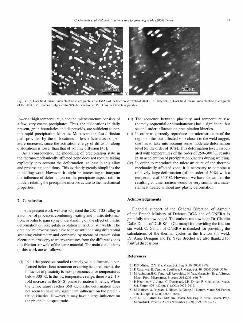
C. Genevois et al. / Materials Science and Engineering A 441 (2006) 39–48 47
F tion so le app
lapmpad
teamtmp
7
atdoseoo
(
(
A
ogDscDf
R
ig. 14. (a) Dark field transmission electron micrograph in the TMAZ of the fricf the 2024 T351 material subjected to 50% deformation at 350 ◦C in the Gleeb
ower at high temperature, since the microstructure consists offew, very coarse precipitates. Thus, the dislocations initially
resent, grain boundaries and dispersoids, are sufficient to per-it rapid precipitation kinetics. Moreover, the fast-diffusion
ath provided by the dislocations is less efficient as temper-ture increases, since the activation energy of diffusion alongislocations is lower than that of volume diffusion [45].
As a consequence, the modelling of precipitation state inhe thermo-mechanically affected zone does not require takingxplicitly into account the deformation, at least in this alloynd processing conditions. This evidently greatly simplifies theodelling work. However, it might be interesting to integrate
he influence of deformation on the precipitate aspect ratio inodels relating the precipitate microstructure to the mechanical
roperties.
. Conclusion
In the present work we have subjected the 2024 T351 alloy tonumber of processes combining heating and plastic deforma-
ion, in order to gain some understanding on the effect of plasticeformation on precipitate evolution in friction stir welds. Thebtained microstructures have been quantified using differentialcanning calorimetry and compared by means of transmissionlectron microscopy to microstructures from the different zonesf a friction stir weld of the same material. The main conclusionsf this work are as follows:
(i) In all the processes studied (namely with deformation per-formed before heat treatment or during heat treatment), theinfluence of plasticity is most pronounced for temperaturesbelow 300 ◦C. In the low temperature range, there is a 2–10-fold increase in the S′(S) phase formation kinetics. When
the temperature reaches 350 ◦C, plastic deformation doesnot seem to have any significant influence on the precipi-tation kinetics. However, it may have a large influence onthe precipitate aspect ratio.tir weld of 2024 T351 material. (b) Dark field transmission electron micrographaratus.
(ii) The sequence between plasticity and temperature rise(namely sequential or simultaneous) has a significant, butsecond-order influence on precipitation kinetics.
iii) In order to correctly reproduce the microstructure of theregion of the heat-affected zone closest to the weld nugget,one has to take into account some moderate deformationlevel (of the order of 10%). This deformation level, associ-ated with temperatures of the order of 250–300 ◦C, resultsin an acceleration of precipitation kinetics during welding.
iv) In order to reproduce the microstructure of the thermo-mechanically affected zone, it is necessary to combine arelatively large deformation (of the order of 50%) with atemperature of 350 ◦C. However, we have shown that theresulting volume fraction would be very similar in a mate-rial heat treated without any plastic deformation.
cknowledgements
Financial support of the General Direction of Armourf the French Ministry of Defence DGA and of ONERA isratefully acknowledged. The authors acknowledge Dr. Claudioalle-Donne of DLR Koln (Germany) for providing the friction
tir weld. C. Gallais of ONERA is thanked for providing thealculations of the thermal cycles in the friction stir weld.r. Anne Denquin and Pr. Yves Brechet are also thanked for
ruitful discussions.
eferences
[1] R.S. Mishra, Z.Y. Ma, Mater. Sci. Eng. R 50 (2005) 1–78.[2] P. Cavaliere, E. Cerri, A. Squillace, J. Mater. Sci. 40 (2005) 3669–3676.[3] M.A. Sutton, B.C. Yang, A.P. Reynolds, J.H. Yan, Mater. Sci. Eng. A Struct.
Mater. Prop. Microstruct. Process. 364 (2004) 66–74.[4] P. Heurtier, M.J. Jones, C. Desrayaud, J.H. Driver, F. Montheillet, Mater.
Sci. Forum 426–432 (pt. 4) (2003) 2927–2932.[5] M. Karlsen, O. Frigaard, J. Hjelen, O. Grong, H. Norum, Mater. Sci. Forum
426–432 (pt. 4) (2003) 2861–2866.[6] Y. Li, L.E. Murr, J.C. McClure, Mater. Sci. Eng. A Struct. Mater. Prop.
Microstruct. Process. A271 (November (1–2)) (1999) 213–223.
4 ce an
[[
[
[[
[
[
[
[
[[[
[
[
[
[
[[[
[
[
[
[
[[[
[
[
[
[
[
[
[
[
8 C. Genevois et al. / Materials Scien
[7] C. Genevois, A. Deschamps, A. Denquin, B.D. Cottignies, Acta Mater. 53(2005) 2447–2458.
[8] W.D. Lockwood, A.P. Reynolds, Mater. Sci. Eng. A Struct. Mater. Prop.Microstruct. Process. 339 (2003) 35–42.
[9] W.D. Lockwood, B. Tomaz, A.P. Reynolds, Mater. Sci. Eng. A Struct.Mater. Prop. Microstruct. Process. 323 (2002) 348–353.
10] G. Bussu, P.E. Irving, Int. J. Fatigue 25 (2003) 77–88.11] M.J. Starink, S.C. Wang, I. Sinclair, Proceedings of a Symposia Sponsored
by the Shaping and Forming Committee of the Materials Processing andManufacturing Division of TMS, vol. 233–240, 2005.
12] M.J. Jones, P. Heurtier, C. Desrayaud, F. Montheillet, D. Allehaux, J.H.Driver, Scripta Mater. 52 (2005) 693–697.
13] L.E. Murr, G. Liu, J.C. McClure, J. Mater. Sci. 33 (1998) 1243–1251.14] Y.S. Sato, H. Kokawa, Metall. Mater. Trans. A Phys. Metall. Mater. Sci. 32
(2001) 3023–3031.15] Y.S. Sato, H. Kokawa, M. Enomoto, S. Jogan, T. Hashimoto, Metall. Mater.
Trans. A Phys. Metall. Mater. Sci. 30 (1999) 3125–3130.16] J.Q. Su, T.W. Nelson, R. Mishra, M. Mahoney, Acta Mater. 51 (2003)
713–729.17] L. Litynska, R. Braun, G. Staniek, C. Dalle Donne, J. Dutkiewicz, Mater.
Chem. Phys. 81 (2003) 293–295.18] O.R. Myhr, O. Grong, H.G. Fjaer, C.D. Marioara, Acta Mater. 52 (2004)
4997–5008.19] J.D. Robson, Acta Mater. 52 (2004) 1409–1421.20] M. Nicolas, A. Deschamps, Acta Mater. 51 (2003) 6077–6094.21] F. Bardi, M. Cabibbo, S. Spigarelli, Mater. Sci. Eng. A Struct. Mater. Prop.
Microstruct. Process. 334 (2002) 87–95.22] L. Blaz, E. Evangelista, Mater. Sci. Eng. A Struct. Mater. Prop. Microstruct.
Process. A207 (1996) 195–201.23] E. Cerri, S. Spigarelli, E. Evangelista, P. Cavaliere, Mater. Sci. Eng. A
Struct. Materials Prop. Microstruct. Process. A324 (February (1–2)) (2002)
157–161.24] K.K. Chawla, A.H. Esmaeili, A.K. Datye, A.K. Vasudevan, Scripta Metall.Mater. 25 (1991) 1315–1319.
25] R. Ferragut, A. Somoza, Phys. Status Solidi A: Appl. Res. 175 (1999)R1–R2.
[
[
d Engineering A 441 (2006) 39–48
26] M.J. Jones, F.J. Humphreys, Acta Mater. 51 (2003) 2149–2159.27] V. Ocenasek, M. Slamova, Mater. Charact. 47 (2001) 157–162.28] J.H. Ryu, D.N. Lee, Mater. Sci. Eng. A Struct. Mater. Prop. Microstruct.
Process. 336 (2002) 225–232.29] M. Cabibbo, E. Evangelista, M. Vedani, Metall. Mater. Trans. A Phys.
Metall. Mater. Sci. 36A (2005) 1353–1364.30] M. Cabibbo, E. Evangelista, S. Spigarelli, Mater. Sci. Forum 396–402 (pt.
2) (2002) 807–813.31] E. Cerri, E. Evangelista, A. Forcellese, H. McQueen, Proceedings of the
10th International Conference, 1994, pp. 799–802.32] E. Cerri, E. Evangelista, N. Ryum, Metall. Mater. Trans. A Phys. Metall.
Mater. Sci. 28A (February (2)) (1997) 257–263.33] E. Pink, Acta Metall. 37 (July (7)) (1989) 1773–1781.34] P. Cavaliere, J. Light Met. 2 (2002) 247–252.35] A. Charai, T. Walther, C. Alfonso, A.M. Zahra, C.Y. Zahra, Acta Mater. 48
(2000) 2751–2764.36] V. Radmilovic, R. Kilaas, U. Dahmen, G.J. Shiflet, Acta Mater. 47 (1999)
3987–3997.37] S.P. Ringer, S.K. Caraher, I.J. Polmear, Scripta Mater. 39 (1998)
1559–1567.38] A.M. Zahra, C.Y. Zahra, C. Alfonso, A. Charai, Scripta Mater. 39 (1998)
1553–1558.39] A.K. Gupta, P. Gaunt, M.C. Chaturvedi, Philos. Mag. A: Phys. Condens.
Matter: Struct. Defects Mech. Prop. 55 (1987) 375–387.40] A.K. Jena, A.K. Gupta, M.C. Chaturvedi, Acta Metall. 37 (1989) 885–
895.41] H.-C. Shih, N.-J. Ho, J.C. Huang, Metall. Mater. Trans. A Phys. Metall.
Mater. Sci. 27A (1996) 2479–2494.42] S. Xu, X. Deng, 4th International Symposium on FSW, Park City, Utah,
USA, 2003.43] P. Heurtier, M.J. Jones, C. Desrayaud, J.H. Driver, F. Montheillet, D. Alle-
haux, J. Mater. Process. Technol. 171 (2006) 348–357.44] C. Gallais, Ph.D. Thesis, Institut National Polytechnique de Grenoble,
France, 2005.45] M.A. Krishtal, M.A. Vyboyschchik, V.A. Sudnik, Fiz. Met. Metalloved. 36
(1973) 1103.