Low cost aluminium closures
165
UNIVERSITY OF SOUTHAMPTON FACULTY OF ENGINEERING, SCIENCE AND MATHEMATICS School of Civil Engineering and the Environment Low Cost Aluminium Closures by Lisa Young Thesis for the degree of Engineering Doctorate November 2005
-
Upload
khangminh22 -
Category
Documents
-
view
0 -
download
0
Transcript of Low cost aluminium closures

UNIVERSITY OF SOUTHAMPTON
FACULTY OF ENGINEERING, SCIENCE AND MATHEMATICS
School of Civil Engineering and the Environment
Low Cost Aluminium Closures
by
Lisa Young
Thesis for the degree of Engineering Doctorate
November 2005

UNIVERSITY OF SOUTHAMPTON
ABSRTACT FACULTY OF ENGINEERING, SCIENCE AND MATHEMATICS SCHOOL OF CIVIL ENGINEERING AND THE ENVIRONMENT
Engineering Doctorate
LOW COST ALUMINIUM CLOSURES
by Lisa Young
Low cost aluminium closures are a new design of closure (hood, door or
tailgate) for automotive vehicles. A closure is made from an outer and
inner panel and other components such as: hinges, latches, strikers and
reinforcements. A low cost aluminium closure has a pre-coated aluminium
outer panel joined to a zinc coated steel inner panel with additional
components made of zinc coated steel. Low cost aluminium closures offer
the potential to reduce weight, manufacturing complexity and improve
corrosion resistance. The purpose of this research is to demonstrate that
low cost aluminium closures can at least equal the performance of the
existing all zinc coated steel closure architecture in terms of corrosion
resistance, structural durability, manufacturing feasibility and part cost.
Low cost aluminium closures have been shown to be at least as corrosion
resistant as the existing all zinc coated closure and the structural durability
of low cost aluminium closures meets the specified performance level. The
existing hem flange adhesive is suitable low cost aluminium closures and an
optimised two part epoxy has been evaluated and would be recommended
for use on large closures where increased handling strength is required.
Manufacturing feasibility has been investigated and low cost aluminium
closures can be manufactured in Ford of Europe production plants with
minimal changes to existing production lines. The part cost of low cost
aluminium closures has established and taking into account the cost
reduction associated with weight saving low cost aluminium closures can be
manufactured for significantly less than the existing closure.

Contents
1.0 Introduction
1.1 The Automotive Industry
1.2 Low Cost Aluminium Closures
1.3 Hypothesis
1.4 Aims and Objectives
1.5 Overview of Dissertation
2.0 Business Case
1
2
9
12
12
13
2.1 Performance of Aluminium Closures 14
2.2 Manufacturing Considerations for Aluminium Closures 17
2.3 Low Cost Aluminium Closures 21
2.4. Manufacturing Considerations for Low Cost Aluminium Closures 22
2.5 Cost Model 27
2.6 Business Case Conclusion 29
3.0 Review of literature 31
3.1 Corrosion 32
3.2 Structural Performance of Closures 59
3.3 Implications of Reviewed Literature on Low Cost Aluminium
Closures 68
4.0 Materials and Methods 72
4.1 Corrosion Properties of Low Cost Aluminium Closures 72
4.2 Structural Performance and Durability of Low Cost Aluminium
Closures 83

5.0 Corrosion Properties of low Cost Aluminium Closures 88
5.1 Introduction 88
5.2 Galvanic Series of Metals found in Hem Flanges 91
5.3 Corrosion Resistance of Hem Flange Metals 94
5.4 Galvanic Coupling of Hem Flange Metals 100
5.5 Corrosion Resistance of Hem Flange Sections 104
5.6 Galvanic Coupling of Hem Flange Sections 109
5.7 Cut Edge Corrosion Performance of Hem Flange Metals 113
5.8 Corrosion Performance of Low Cost Aluminium Closure 114
6.0 Structural Performance and Durability of low Cost
Aluminium Closures 117
6.1 Introduction 117
6.2 Structural Specification Requirements for Hem Flange Adhesives 118
6.3 Initial Adhesive Selection Screening 119
6.4 Adhesive Mix Ratio Optimisation 120
6.5 PASCAR 1 + 2 Structural Durability 130
7.0 low Cost Aluminium Closure Demonstrator Manufacture 131
7.1 Stamping Pre-coated Aluminium 131
7.2 Closure Assembly 136
7.3 Painting 137
8.0 Discussion and Conclusions 139
8.1 Business Case 139
8.2 Corrosion Properties of Low Cost Aluminium Closures 140
8.3 Structural Performance and Durability of Low Cost Aluminium
Closures 142
8.4 Conclusions 144
8.5 Further Work 144
References 146

Figures
Figure 1.1
Figure 1.2
Figure 1.3
Figure 1.4
Figure 1.5
Figure 2.1
Figure 2.2
Figure 2.3
Figure 2.4
Figure 2.4
Figure 3.1.
Figure 3.2
Figure 3.3
Figure 3.4
Figure 3.5
Figure 3.6
Figure 3.7
Figure 3.8
Figure 3.9
Figure 4.1
Figure 4.2
Figure 4.3
List of Figures, Charts and Tables
Over Engineering
Robustness Failure
Pre-coated Aluminium
Low Cost Aluminium Closure Concept (Hood)
Low Cost Aluminium Hem Flange
Flat{ Rope and Compressed Radius Hems
Ford Focus CMax Hood
Cross Section of a Hem Flange with Over Hem Sealer
Outer Panel Cost Summary
Weight Reduction and Cost Summary for All steel{ All
Aluminium and Low Cost Aluminium Hoods
Factors Affecting the Corrosion Resistance of a Metal
(Fontana [1986])
Basic Wet Corrosion Cell (Rowe [1977])
SchematiC of an All Steel Hem Showing Inner and Outer
Gaps
Corrosion Path in a Hem Flange
Specimen Set Up for Lapped Panels used by Nakazawa
et al [1993]
Spot Welded Lap Joint Specimen used by Almeida and
Morcilo [2000 a and b] with Corrosion Mechanism
Single Lap Shear and Modified Peel Joints
Shear and Peel Stress Components of the Stress
Distribution in a Single Lap Shear Joint
The Effect of Adhesive Thickness on Shear Strength and
Peel Strength
Pre-coated Aluminium
Masking Pattern for Specimens
Experimental Set up for Open Circuit Potential
Measurements of Sheet Specimens

Figure 4.4
Figure 4.5
Figure 4.6
Figure 4.7
Figure 4.8
Figure 4.9
Figure 5.1
Figure 5.2
Figure 5.3
Figure 5.4
Figure 5.5
Figure 5.6
Figure 5.7
Figure 5.8
Figure 5.9
Figure 5.10
Figure 5.11
Figure 6.1
Figure 7.1
Figure 7.2
Figure 7.3
Experimental Set Up for Tafel and Potentiodynamic
Scans for Sheet Specimens
Experimental Set of Galvanic Coupling of Sheet
Specimens
Experimental Set Up for Tafel and Potentiodynamic
Scans of Hem Section Specimens
Experimental Set Up for Hem Section Galvanic Couple
Scribe Lines to Assess Corrosion Creep
Single Lap Shear and Modified Peel Specimens
All Steel Hem Flange
Low Cost Aluminium Hem Flange
Galvanic series for hem flange metals in four electrolytes
with the Molar chloride concentrations of the electrolytes
shown
Stone chipped pre-coated aluminium showing areas of
perforation through pre-coating to bare aluminium
Area of Pitting and Zinc Consumption on Low Cost
Aluminium Hem Section
Void in Adhesive Fill of All Hot Dip Galvanised Steel Hem
Zinc Coating Pull Out by Hem Flange Adhesive
Cut Edge Corrosion on Hem Sections Exposed to 480
Hours Neutral Salt Spray
Assessment of Corrosion Creep on PASCAR 1 + 2 Low
Cost Aluminium Hood
PASCAR 1+ 2 Low Cost Aluminium Hood Cowl Edge Red
Rust Bleed Out
30 APGE Low Cost Aluminium Hood
Failure Mode Types and Locations in a Low Cost
Aluminium Closure Adhesive Joint
Cowl Corner Flange Reduction
Mesh Drawing of Low Cost Aluminium Hood Outer
Surface
Profile Differenced Between Low Cost Aluminium and All
Zinc Coated Steel Hood Outer Surfaces

Figure 7.4
Charts
Chart 1.1
Chart 5.1
Chart 5.2
Chart 5.3
Chart 5.4
Chart 5.5
Chart 5.6
Chart 5.7
Chart 5.8
Chart 6.1
Chart 6.2
Chart 6.3
Chart 6.4
Chart 6.5
Chart 6.6
Chart 6.7
Chart 6.8
The Effect of Springback on the Fit of the Closure to a
Vehicle
Passenger Car Mass Distribution (Reproduced from
Kelkar et al [2001])
Linear polarisation behaviour of hot dip galvanised steel
Linear scale polarisation behaviour of hot dip galvanised
steel
Potentiodynamic scan of hot dip galvanised steel
Linear polarisation behaviour of pre-coated aluminium
Logarithmic scale Tafel Plot for pre-coated aluminium
Potentiodynamic scan for pre-coated aluminium
Linear Polarisation Plot for Unexposed Hem Sections
Linear Polarisation Plot for Hem Sections Exposed to 480
Hours Neutral Salt Spray
Effect of Bake Cycle on the Shear Strength of Control
Specimens
Effect of Environmental Exposure on Shear Strength of
Maximum Bake Specimens
Effect of Environmental Exposure on the Shear Strength
of Minimum Bake Specimens
Effect of Maximum and Minimum Bake Cycles on the
Peel Performance of Control Specimens
Effect of Maximum and Minimum Bake Cycles on the
Initial Peak Peel Performance of Control Specimens
Effect of Environmental Exposure on the Plateau Peel
Strength of Maximum Bake Specimens
Effect of Environmental Exposure on the Plateau Peel
Strength of Minimum Bake Specimens
Shear Strength and Peel Plateau Resistance for Control
Specimens with Specification Requirements

Chart 6.9
Tables
Table 1.1
Table 2.1
Table 2.2
Table 2.3
Table 3.1
Table 3.2
Table 3.3
Table 4.1
Table 4.2
Table 4.3
Table 4.4
Table 5.1
Table 5.2
Table 5.3
Table 5.4
Table 6.1
Table 6.2
Table 6.3
Bake Cycle Effects on Shear Strength and Peel Plateau
Resistance for 30 APGE Specimens
Inner and Outer Noise Types
Mechanical and Functional Properties of AA6016 and
AA6111 (Layahe et al. [2000])
Production Materials for a Typical All Zinc Coated Steel
Closure
Cost Model Summary for Focus CMax Demonstrator
Critical Relative Humidity Required for Deliquescence
Approximate Corrosion Rates of Zinc Coatings
Galvanic series for some automotive metals in sea water
(summarised from Trethewey and Chamberlain [1995])
Compositions of AA6016
Test summary for Corrosion Resistance Testing and
Galvanic Coupling of Hem Sections
Automatic Cabinet APGE Cycling Procedure
Test Summary for Single Lap Shear and Peel Specimens
Mean coupled potentials of pre-coated aluminium and
hot dip galvanised steel galvanic couples and the effect
of area ratio on galvanic coupling currents
Corrosion Resistance of Unexposed Hem Sections
Corrosion Resistance of Hem Sections Exposed to 480
Hours Neutral Salt Spray
Corrosion Rates and Mean Coupled Potentials of Galvanic
Coupled Hem Sections
Shear Strength and Peel Resistance Specification
Requirements
Failure Modes and Mean Shear Strength of Low Cost
Aluminium Adhesive Joints
Failure Modes and Mean Plateau Peel Strength of Low
Cost Aluminium Adhesive Joints

Acknowledgements
I would like to thank Ford Motor Company Limited and EPSRC for funding
my Engineering Doctorate and the EngD Centre for administering my EngD
(Thanks to Anne and Pat). Many thanks to everyone at Ford for their
support, help and advice during my research. Thank you also to 3M
(Bernard Sikkel and Graham Preedy) for their assistance with
manufacturing and testing the lap shear and peel specimens reported in this
thesis. Thanks also go to everyone at Alcan (now Novelis) for supplying me
with pre-coated aluminium to make this project possible. Thank you to my
academic supervisor's Prof. Stuart Moy and Prof. Marcus Lee for their
assistance throughout my EngD. Thank you also to Dr Julian Wharton and
Prof. Frank Walsh for their help with the corrosion section of this thesis.
Finally, a very big thank you to my partner David and my parents for
supporting me thorough this research (it's been tough but I got there in the
end!).

Company Confidential
1.0 Introduction
Low cost aluminium closures are a new type of body closure architecture for
automotive vehicles. Body closures are hoods, doors and tailgates and are
termed closures because they enclose the vehicle body and are attached
mechanically to the main vehicle body by hinges. Closures are assembled
from sheet metal stampings, castings, fasteners and other components such
as crash reinforcements, hinges, locks and electrical systems. Low cost
aluminium closures use organically pre-coated aluminium and zinc coated
steel sheet to form a reduced weight closure with the potential to improve
corrosion resistance and reduce manufacturing complexity.
The automotive industry is a challenging business and manufacturing
environment. The business and economic constraints the automotive
industry operates under will be discussed briefly in this section along with
the challenges of mass production. The operating environment for
automotive vehicles will be described and the importance of robust design
and manufacturing techniques on manufacturing and in service performance
will be highlighted. Current use of aluminium for the manufacture of
automotive vehicles will be examined and as well as the reasons why
aluminium has not been more widely adopted discussed.
The architecture of low cost aluminium closures will be described and the
economic advantages of the low cost aluminium closure concept examined
with reference to current all steel vehicle manufacturing processes. The
weight reduction potential and corrosion considerations surrounding a mixed
material system will be introduced. The hypothesis and aims and objectives
of this research will be stated together with an overview of the structure of
this dissertation.
© Copyright 2005 by Lisa Young. All Rights Reserved.
1

Company Confidential
1.1 The Automotive Industry
Today's automotive industry is a fiercely competitive environment and
automotive manufacturers must produce high volumes of high quality
vehicles that meet (and hopefully exceed) customer expectations to
maintain and increase their market share. They must do this cost
effectively and also meet a myriad of legislative requirements for safety!
fuel economy! exhaust emissions and end of life disposal of vehicles
(amongst many other requirements).
1.1.1 Mass Manufacture
Most automotive manufacturers are in the business of mass manufacture.
Vehicles are very complex mechanical and electrical systems and the
economics of mass manufacturing allow the cost of such complex systems
to be kept within the reach of consumers. Organisations such as Ford Motor
Company Limited! produce multiple vehicle lines at volumes of
approximately one hundred thousand vehicles per line per year! this
equates to one vehicle coming off the end of the production line every five
minutes. The processes! materials and resources required to manufacture
one vehicle every five minutes make mass manufacturing environments
extremely challenging. Materials must arrive correct and on time at the
start of the production line and all the plant and assembly processes must
function together to ensure the smooth flow of parts and material to all
parts of the line. Quality control procedures are essential to ensure that
parts made at different times and by different processes fit together and
function correctly.
Closures are made up of an inner and outer panel and a number of other
components. The inner and outer panels are stamped from sheet material
in the press shop using high load press installations to conform a sheet
metal blank (trimmed metal sheet) to the required contour of the main
draw die by a combination of drawing and stretching. Subsequent passes
through the press consolidate the features through restrike! trim the part
and pierce holes where required.
© Copyright 2005 by Lisa Young. All Rights Reserved.
2

Company Confidential
The stamped panels are moved to a sub-assembly line where the inner and
outer panels are joined together using a combination of adhesive bonding
and mechanical clinching. The adhesive bond is sometimes given an
induction curing process to give the closure handling. Depending on the
closure architecture other components may have been fixed to either the
inner or the outer panel before they were joined together and after
assembly further components will be joined to the closure, such as strikers,
welded fasteners and hinge reinforcements. The fully assembled body in
white closure will join the vehicle body, termed body in white (a traditional
term for a vehicle body structure) before the vehicle is painted. Closures
are removed from the painted vehicle for electrical fit out and trim and then
rejoin the vehicle in final assembly.
Quality control of raw materials and manufacturing processes ensure that
closures are dimensionally accurate and meet the strength and stiffness
requirements specified by the vehicle designers. In-plant inspection
procedures (and quality requirements placed on suppliers) ensure that most
deviations from specified quality levels are detected before the vehicle
leaves the plant but unfortunately not all faults can be or are detected.
Some faults will escape into the field and these may be serious enough for a
vehicle to be recalled to a dealership for repair or rectification of the fault
may be carried out at the next routine service interval. Robust material
selection procedures and manufacturing techniques minimise the risk of
faults occurring in the plant and escaping into the field and are an essential
method of controlling the variability of manufacturing inputs and processes.
1.1.2 Robustness in Manufacture and Use
Every manufacturing process increases the variability of a raw material as it
is made into the final component and mass manufacturing industries use
robust design to produce high quality products economically. Taguchi
defines robustness as a product or process that can function well against
background noise (Grove and Davis (1992)). Noise refers to any cause of
variation whether it originates in the manufacturing process, the customer's
method of use or the environment.
© Copyright 2005 by Lisa Young. All Rights Reserved.
3

Company Confidential
Demand Capacity
Figure 1.1 Over Engineering
Figure 1.2 Robustness Failure
Figure 1.1 shows graphically an over engineered situation. In an over
engineered situation the variation due to inner noises is controlled to a
statistical distribution that will never overlap the expected outer noise
distribution (Davies (1997)).
Demand Function I Capacity Function
Inner Noise I Outer Noise
Piece to Piece Dimensions Customer Usage
Variation Change in Operating Environments (Climactic or
Dimensions (Wear Road Conditions)
Out)
Change in Internal system and component
Mechanical interactions
Properties
(Fatigue)
Table 1.1 Inner and Outer Noise Types
© Copyright 2005 by Lisa Young. All Rights Reserved.
4

Company Confidential
Robust design aims to bring the demand and capacity functions as close
together as possible without robustness failures occurring when the curves
overlap as in figure 1.2. Consider a door assembly that is at the upper end
of its dimensional specification, when this component is exposed to noises
in service, for example high temperatures on a hot summers day the door
may expand and jam shut, this would be a failure. Vehicle manufacturers
use robust design to optimise costs and minimise failures. However, the
effective use of robust design relies on a thorough understanding of the
outer noises affecting a system and being able to control the statistical
distribution of inner noises to an appropriate level.
One method of controlling inner noises is to reduce the number of
manufacturing processes needed to produce a component or assembly.
Pre-coated aluminium allows manufacturing complexity to be reduced by
eliminating at least one highly variable process (over hem sealing see
section 2.4.2) and the manufacturing method used to pre-coat the
aluminium sheet is highly repeatable and robust (pre-coating is applied
continuously on line at the sheet rolling mill).
1.1.3 Operating Environment for Automotive Vehicles
Automotive vehicles operate in a demanding environment. They are driven
by customers of different sizes and driving styles in every type of climate.
The same vehicle may have to withstand the arid environment of North
Africa, the marine environment of the west coast of the USA or the cold
climates of Northern Europe. Each of these different environments places
different demands on the vehicle and in the case of this research, closures.
The primary issue associated with closures experiencing different climates is
corrosion. In marine and cold climates salt (sodium chloride) from sea
water and de-icing salts used in icy and snowy regions (sodium chloride and
calcium chloride) act together with moisture from the air and rain fall to
form an aggressive corrosion environment.
© Copyright 2005 by Lisa Young. All Rights Reserved.
5

Company Confidential
In arid climates salt and moisture are not an issue but the abrasive nature
of sand and possible high winds may be problematic for paint appearance.
All environments are challenging to closures with respect to stone chipping
and after paintwork has been chipped marine and cold climates exploit any
damage to paint work and corrosion often initiates at the site of the stone
chip.
Vehicle owners vary greatly in the way they treat their vehicles when they
drive them and also in general use. For example when a door is closed the
force exerted on the door by one owner may be much greater than by
another. As such, doors must be designed to withstand all reasonable "door
slams" and should not need large forces to close them fully. Some vehicle
owners may take great care of their vehicles regularly washing and waxing
the body work which can help protect the vehicle from corrosion by
reducing salt build up on the body work. The vehicle manufacturers cannot
rely on all vehicle owners being so attentive and so vehicles must be
designed to withstand reasonable salt loadings and resist corrosion for the
warranty period of the vehicle to fall in line with customer expectations.
Customer expectations are a very important consideration. Although a
small amount of visible red rust may be acceptable without compromising
the structural performance of the vehicle it is unlikely to be acceptable to
the customer. Therefore it is often the customer requirements that dictate
design specifications and these specifications are used in robust engineering
design to meet customer expectations throughout the life of the vehicle.
1.1.4 Aluminium Vehicles
Steel has been the metal of choice for mass production of automotive
vehicles and relatively small amounts of aluminium have been used in the
manufacture of vehicles. The aluminium content of vehicles has increased
from approximately 64 kg to 130 kg per vehicle in the past 10 years
(Osborn (2005)), in approximately the same time period (1987 to 2000)
vehicle curb weight has increased by 12% (German (2002)). Usage of
aluminium has increased by 103 %, so the increase in aluminium could not
© Copyright 2005 by Lisa Young. All Rights Reserved.
6

Company Confidential
be accounted for by overall curb weight increases. Aluminium has been
used successfully in powertrain applications to manufacture engine blocks
and can give considerable weight savings over equivalent cast iron blocks.
The use of aluminium for alloy wheels and heat exchangers has also
increased the aluminium content of vehicles.
Aluminium vehicle bodies are less well developed and only a few vehicles
bodies are produced entirely of aluminium. Audi was one of the first
companies to produce an aluminium vehicle body (the A8 and later the A2)
using a space frame design that utilises two and three-dimensional
extrusions and cast nodes. Jaguar has produced a conventional unibody
(sheet metal construction) vehicle, the Jaguar XJ and the XK Coupe is about
to be produced from aluminium using a combination of space frame and
unibody architecture. Kelkar et al (2001) have suggested that a complete
redesign of the steel automobile body is necessary for aluminium to make
significant inroads into the vehicle body material market. They concluded
that space frame technology has greater potential to produce an
economically competitive aluminium vehicle and that significant challenges
still exist for aluminium to be widely incorporated into mass production
vehicles. The main areas of concern were joining parts togetherr stamping
body panels and the base material cost of aluminium compared to steel.
Chart 1.1 shows the incentives vehicle manufacturers and aluminium
producers have to increase the aluminium body content in vehicles. Body in
White accounts for 28% of the mass of the vehicle and it would give
aluminium producers an extensive new market. Vehicle manufacturers
would have the opportunity to reduce weight in order to meet ever more
stringent fuel economy and emission targets. For aluminium to be used in
large quantities to manufacture vehicle bodies a number of events must
take place:
1. The price per kilogram of aluminium must converge on the price of
steel.
2. Manufacturers must make a strategic decision to make vehicle bodies
from aluminium (like Audi and Jaguar) and employ suitable design
techniques to make the design economically viable.
© Copyright 2005 by Lisa Young. All Rights Reserved.
7

Company Confidential
3. Aluminium producers and manufacturers must work together to solve
the technical challenges of joining and stamping aluminium in mass
production volumes.
Mason (2003) conducted a study into manufacturing hoods from aluminium
for Ford of Europe and found that due to the material cost of aluminium it
was not economically feasible to manufacture even one component (on an
otherwise entirely steel vehicle) entirely from aluminium. The current
difficulties associated with producing all aluminium components or vehicles
on grounds of cost and technical challenges have led to a novel design of
closure to selectively utilise aluminium and produce a low cost aluminium
closure.
Passenger Car Mass Distribution
IOChassis
III Body in White
o Interior
o Glass
• Powertrain
o Other
Chart 1.1 Passenger Car Mass Distribution (Reproduced from Kelkar et al
(2001)
© Copyright 2005 by Lisa Young . All Rights Reserved.
8

Company Confidential
1.2 Low Cost Aluminium Closures
LandRover has used steel and aluminium together for many years by
combining a steel chassis with an aluminium body. In cases where the steel
chassis is not electrically isolated from the aluminium body, galvanic
corrosion can occur and the aluminium will corrode preferentially to the
steel. If a robust method of electrically isolating steel from aluminium was
available and the part design allows for joining to be carried out without
welding or fasteners i.e. adhesive bonding, then there would be minimal
risk of galvanic corrosion occurring and steel could be used alongside
aluminium successfully in a vehicle body.
Alcan (now Novelis) presented a new type of automotive aluminium sheet to
Ford of Europe in 2001. Pre-coated aluminium sheet (shown schematically
in figure 1.3), then termed electrocoat replacement (ECR) was marketed to
Ford as a way of removing the need for electrocoat (one of the initial paint
layers applied to a vehicle).
Figure 1.3 Pre-coated Aluminium
Electrocoat paint systems are expensive to install and run, as prior to
electrocoat the vehicle body is cleaned, rinsed, given a phosphate pre
treatment (to increase zinc coating weight and improve electrocoat paint
adhesion), electrocoated and then the electrocoat paint is baked before final
paint layers are applied. This process takes approximately 1 hour for a
vehicle to complete and a paint system without electrocoat would
undoubtedly be more efficient. ECR aluminium sheet would have been an
excellent opportunity if Ford of Europe were making all aluminium vehicles.
© Copyright 2005 by Lisa Young. All Rights Reserved.
9

Company Confidential
Jaguar were starting to produce the XJ in aluminium but the development
process had not been conducted with ECR aluminium sheet and the paint
line for the XJ is common to the XJ and the S Type (which is an all steel
construction), so there would have been no advantage in using ECR sheet
for the XJ.
Despite the initial application being unsuitable, ECR sheet was considered to
have advantages for other body applications. The organic pre-coating gives
increased formability and the electrical isolation provided by the coating
meant it was suitable for direct substitution for a steel stamped outer panel
in a closure. A hood was the most suitable closure to trial the concept as
the outer panel of a hood is adhesively bonded to the inner panel. An
additional advantage of pre-coated aluminium is that it forms durable
adhesive bonds, unlike untreated aluminium sheet.
1.2.1 Component Architecture
A pre-coated aluminium outer panel would be stamped in existing tooling
designed for stamping steel and assembled with the existing zinc coated
steel inner panel, steel hinges, reinforcements and other steel components.
Figure 1.4 shows the low cost aluminium hood concept on a hood. The pre
coating would be used on the inside of the outer panel to ensure electrical
isolation from the inner panel in conjunction with the hem flange adhesive
as shown in figure 1.5. A hem flange is the jOint that is formed when an
inner panel is joined to an outer panel during the assembly of a closure.
It is not thought that any significant changes would be needed in either the
stamping, assembly or paint processes. The initial work conducted by Alcan
(Carr et al (1997)) showed compatibility with automotive adhesive systems
and paint processes. Their work also showed improved formability of pre
coated aluminium sheet when compared to uncoated aluminium sheet of
the same alloy grade.
© Copyright 2005 by Lisa Young. All Rights Reserved.
10

Company Confidential
Pre-coated Aluminium
Figure 1.4 Low Cost Aluminium Closure Concept (Hood)
steel inner panel
Hem Flange Adhesive
Organically pre-coated aluminium outer panel
Organic precoating
Figure 1.5 Low Cost Aluminium Hem Flange
1.2.2 Economics, Weight Reduction and Corrosion Considerations
As with all businesses the economic feasibility of any new product must be
demonstrated. Mass production environments are especially challenging for
new products as even a small increase in part cost has serious implications
for a vehicle production line manufacturing one hundred thousand vehicles a
year.
© Copyright 2005 by Lisa Young. All Rights Reserved.
11

Company Confidential
Low cost aluminium closures aim to address the economics of using a
premium material (aluminium) by making the most efficient use of this
premium material and by reducing manufacturing complexity. Further long
term economic advantages may be gained by the potential to improve
corrosion resistance and competitive advantages may be gained from the
reduction in vehicle weight.
1.3 Hypothesis
The hypothesis to be tested in this thesis is:
Low cost aluminium closures can at least meet the performance of the
existing all zinc coated steel closure in terms of corrosion resistance,
structural durability and economic and manufacturing feasibility, so that the
opportunity for weight reduction and decreased manufacturing complexity
can be realised.
1.4 Aims and Objectives
The aims of this research are to test the hypothesis stated above by
assessing corrosion performance and structural durability of a low cost
aluminium closure. A business case will be formulated to investigate the
economic and manufacturing implications of low cost aluminium closures.
The objectives of this research are to manufacture a number of low cost
aluminium closures in a mass production environment and to test the
corrosion resistance of these closures using accelerated laboratory and
accelerated proving ground tests. The structural durability of the closure
will also be assessed using an accelerated proving ground test. The
corrosion resistance of small sections of assembled closures will be
investigated using electrochemical techniques and where possible
electrochemical results will be correlated with the corrosion performance of
the full size demonstrators. The structural durability of the metal substrates
used to form a hem flange will be assessed using single lap shear joints
© Copyright 2005 by Lisa Young. All Rights Reserved.
12

Company Confidential
adhesively bonded together with automotive hem flange adhesives. The
jOints will be tested in tension to assess the effects of environmental
degradation. The overall objective will be to produce a corrosion resistant
closure that performs equivalently to all zinc coated steel closure with an
optimised adhesive system for bonding steel to aluminium.
1.5 Overview of Dissertation
This dissertation will first address the economic and manufacturing
implications of producing a low cost aluminium hood within a Ford of Europe
production plant on an existing vehicle. The literature covering all aspects
of low cost aluminium closures will be reviewed and discussed. From the
environments they will operate in to the corrosion mechanisms seen on zinc
coated steel and the stress distributions of single lap shear joints.
Conclusions drawn from the literature will be summarised, an experimental
design described and the materials and methods used in this research will
be detailed. Results and discussions will be divided into to two sections:
• Structural Durability of Low Cost Aluminium Closures
• Corrosion Performance of Low Cost Aluminium Closures
An overall discussion and conclusions will draw together the important
observations and discoveries and relate them back to the business case
(presented in section 2). Finally recommendations will be made as to the
suitability of low cost aluminium closures for use on future Ford of Europe
vehicles and what further work is required to allow this new technology to
be implemented.
© Copyright 2005 by Lisa Young. All Rights Reserved.
13

Company Confidential
2.0 The Business Case for Low Cost Aluminium Closures
Low cost aluminium closures have the potential to offer weight reduction
and improved corrosion resistance when used to replace conventional all
steel closures. The technical demands of manufacturing an all aluminium
car body are considerable and these demands increase when aluminium is
used in conjunction with other metals, however Jaguar and Audi are
currently manufacturing all aluminium vehicle bodies successfully.
The business implications of producing mixed material closures needs
careful consideration to ensure that the performance of closures meets the
standard required and that the component can be economically and
successfu lIy ma n ufactu red.
The risk of producing an entirely new component in a mass production
environment should not be underestimated and the manufacture of a low
cost aluminium closure must fit into current manufacturing processes with
minimal disruption and the need for only minor changes. This business case
aims to address some of the performance and manufacturing issues that
producing low cost aluminium closures may present. In a business case of
this scope it would be impossible to address all possible processes affected
by producing an entirely new component, but it should serve as a good
starting point for a more in depth study into the overall implications of
producing a low cost aluminium closure.
2.1 Performance of Aluminium Closures
Aluminium has been used by a number of manufacturers to produce vehicle
bodies effectively and with the application of the correct design practices it
is possible to meet the functional demands of a closure. Closure is a
general term for doors, hoods and tailgates and closures have specific
functional demands as summarised by Lahaye et al (2000):
© Copyright 2005 by Lisa Young. All Rights Reserved.
14

Company Confidential
.. Dent resistance: High strength after paint baking for high dent
resistance if maximum weight saving is required.
.. Stiffness: Combination of inner and outer panel should give a
component with high torsional rigidity.
.. Design aspects: High formability for stamping and flat hem
capability.
.. Paint appearance: High standard of paint finish required for
exterior body panels ("A" Class Finish).
.. Corrosion: For aluminium good corrosion resistance is focused
on low filiform corrosion (FFC) susceptibility.
This list above is not exhaustive, but gives a number of points to consider
when selecting aluminium for use in a closure. Dent resistance can be
classified in two ways, static and dynamic and is an important functional
demand as it can influence customer perception of body panel quality. It is
also important for a body panel (outer panel) to have good dent resistance
during manufacture as it minimises the risk of in plant damage and in
service dents and dings. Aluminium alloys selected for outer panel
applications have a bake hardening response to give adequate dent
resistance, the heat input required to bake harden the sheet comes from
one of the paint oven bake cycles and is specific to each manufacturer. The
bake cycle for electrocoat paint used by Ford of Europe is approximately
180°C and on average vehicles will see that temperature for 30 minutes.
Automotive aluminium alloys (and bake hardenable steel grades) are
developed to bake harden at temperatures commonly seen by vehicles on
production paint lines. Gauge selection of the aluminium sheet must
compensate for the reduced strength of aluminium when compared to an
equivalent steel sheet and the strength criterion used in this business case:
YS alu min X t alu min 2
;::: YS steel X t steel 2 [2.1]
(YS = Yield Strength (MPa), t = Thickness (mm))
© Copyright 2005 by Lisa Young. All Rights Reserved.
15

Company Confidential
The two most common aluminium alloys selected for outer panels in Europe
are AA6016 (AIMgOASi1.2) and AA6111 (AIMgO. 7SiO. 9CuO. 7) and both of
these alloys have a bake hardening response giving them appropriate
mechanical properties after bake to meet the functional demands of
closures. Typical mechanical and functional properties are shown in table
2.1. The up-gauge required to meet the strength criterion in equation [2.1]
(for example a 0.65 mm steel outer panel with YS = 235 MPa would require
an aluminium panel of AA6016 to be a minimum of 0.81 mm thick (YSAA6016
= 150 MPa)) means that the stiffness of an equivalent strength aluminium
outer panel is usually superior to the steel panel.
Property Alloy
AA6016 AA6111
Yield Strength T4 (MPa) < 130 < 170
Yield Strength T6 (MPa) > 150 > 200
(185°C for 20 minutes)
Flat Hemming Capability Mild roughen ing Severe cracking
Spring back Less More
Copper Content (wt %) 0.1 0.7
Filiform Corrosion 0.5 - 0.9 1.4 - 5.2
Susceptibility on Two Different
Pa i nt Systems
(Length of filament
delamination (mm))
Table 2.1 Mechanical and Functional Properties of AA6016 and AA6111
(Layahe et al. (2000))
Part Substrate Coating Gauge (mm)
Hood Outer BHZ 260 ZC 55A55AHD 0.65
Hood Inner DX54D 60G60GHD 0.65
Table 2.2 Production Materials for a Typical All Zinc Coated Steel Closure
© Copyright 2005 by Lisa Young . All Rights Reserved.
16

Company Confidential
The grades of steel used in a typical Ford of Europe closure are given in
table 2.2 and the yield strength of the outer panel material is 235 MPa, as
used in the calculation above. AA6111 can allow for further down gauging
enabling more weight to be saved, as the higher T6 yield strength gives
improved dent resistance due to the increased copper content giving an
improved bake hardening response.
2.2 Manufacturing Considerations for Aluminium Closures
2.2.1 Stamping Aluminium
Automotive aluminium alloys used for forming outer panels are generally
less formable than their steel counterparts and this is due to the mechanical
properties of aluminium allowing lower strain to failure and increased spring
back on equivalent forming operations used for stamping steel. Spring back
occurs when a panel is stamped to shape and then on withdrawal from the
die the elastic portion of the total deformation is recovered by the stamped
part. Unfortunately spring back in automotive panels is unpredictable due to
the three dimensional nature of the stresses and strains applied to the
panels during stamping and it is often only truly understood when a die set
is tried out for the first time. As die sets are made from hard tool steels or
cast iron any modifications required to produce a part to the correct
dimensions by minimizing spring back are costly and time consuming.
When designing a part (outer panel) and the corresponding stamping tool
(die set) with aluminium in mind the problems with formability can be
minimized with intelligent contouring of dies and optimizing the strain
imparted at each stage of stamping. Due to the complex nature of
stamping operations computer aided modeling is still of limited use and this
is especially true of aluminium where spring back is an important factor.
Often the skill and experience of the stamping engineers is required to
manufacture a die set to overcome spring back. Complex stamped parts
such as the hood (bonnet) of the Jaguar XJ have been successfully stamped
in aluminium but often require more passes (than the same part made of
© Copyright 2005 by Lisa Young. All Rights Reserved.
17

Company Confidential
steel) to achieve the correct profile and more die development time is
needed. When designing a part to be stamped from aluminium an
appropriate design that is possible in aluminium is needed. The overstrike
required (to minimize spring back) to produce a part of the correct
dimensions first time must be accounted for by the stamping engineer in
the die design.
2.2.2 Hemming Aluminium
Formability of the base alloy in closures also plays an important part in the
hemming (clinching) performance. Poor formability will result in cracking of
the sheet at the hem radius and lead to unacceptable visual appearance of
the hem. Also, spring back after clinching can mean that hems are more
open making subsequent sealing operations more difficult. As such
aluminium is not suitable for the primary hemming technique (flat
hemming, shown in figure 2.1) used by automotive manufacturers. During
flat hemming the outer panel is clinched flat around the inner panel, also
known as a 180 0 hem because the metal has been formed around 180 o.
Aluminium cannot withstand the deformation required to produce a flat hem
and so alternative hemming techniques are required.
Rope hemming and compressed radius hemming are two techniques used in
manufacturing aluminium closures. Rope hemming requires less
deformation than flat hemming but does not give a good visual appearance
to the customer due to the large radius of the hem. Compressed radius
hemming presents the customer with a sharp edge as with flat hemming
but is less demanding on the total deformation required, figure 2.1 shows
flat, rope and compressed radius hems schematically. Flat hemming
AA6016 results in mild roughening that after painting results in a
satisfactory paint appearance, however in areas of three dimensional
deformation such as cowl edge corners flat hemming may still be too much
of a challenge for AA6016. AA6111 is likely to crack during even a simple
flat hemming operation, after paint this would lead to an unacceptable
cosmetic result.
© Copyright 2005 by Lisa Young. All Rights Reserved.
18

Company Confidential
I Flat Hem
~'----~ I Rope Hem I
I Compressed Radius Hem
Figure 2.1 Flat, Rope and Compressed Radius Hems
2.2.3 Paint Appearance and Processing of Aluminium
Paint appearance is critical to customer satisfaction and 6xxx series
aluminium alloys allow an "A" Class paint appearance to be achieved. Other
more formable aluminium alloys, such as 5xxx series used for inner panel
applications show surface defects called stretcher strain markings or LOders
bands that show through after painting giving an unacceptable paint
appearance. 6xxx series alloys do not exhibit these "Type A" defects and so
are preferable to 5xxx series alloys from a paint appearance as well as a
structural performance. When 6xxx series alloys are roll textured they can
achieve similar paint appearances to steel outer panels. Roll texturing can
be created by two different techniques as described by Benati et al. (2002):
Electron beam texturing (EBT), where a controlled beam strikes the roll in a
deterministic manner, creating highly repetitive textures and electro
discharge texturing (EDT) where the electro discharge machine randomly
erodes small areas on the roll surface. Glossy paint appearance is achieved
and problem paint appearance issues such as "orange peel" are minimized.
Surface texture can also improve the formability of the material, Lahaye et
al. (2000) reported a significant reduction in galling (loss of surface metal
oxides during stamping, resulting in die contamination and defects on the
stamped surface) when surface texture had been applied.
© Copyright 2005 by Lisa Young. All Rights Reserved.
19

Company Confidential
2.2.4 Corrosion Properties of Aluminium
The corrosion properties of aluminium present different concerns to those
seen on steel. Aluminium does not corrode in the same way as steel due to
its tenacious oxide layer that will repassivate the surface if it is damaged
and will act to protect the underlying metal. As such/ aluminium will not
corrode at cut edges and no red rust corrosion products will be observed.
Cosmetic corrosion of aluminium under paint films with thread like
morphology is known as filiform corrosion and although superficial results in
poor customer satisfaction. It is well known that copper content in
aluminium alloys increases the risk of filiform corrosion and therefore
AA6016 is a better choice of material if corrosion resistance is considered
important. It is also well known that rework of aluminium panels with
abrasive media can also increase the risk of filiform corrosion.
Other functional demands lead from those listed above; in Europe crash
resistance and pedestrian protection are very important attributes for any
new vehicle. A study was conducted by Mason (2003) on the feasibility of
all aluminium hoods in response to an increase in head impact criterion
(part of the assessment of pedestrian protection of new vehicles) and in
that report aluminium hoods (with inner/ outer panel and all hinges and
strikers) were found not to be economically feasible at that time.
Aluminium can meet the functional demands for closures/ as demonstrated
by many manufacturers including Jaguar and Audi. However/ in general
aluminium has not been used for closures on high volume production
vehicles in Europe. As a result of the work done by Mason (2003) a new
concept was required to meet both the functional and economic demands of
using aluminium in high volume production vehicle closures/ low cost
aluminium closures.
© Copyright 2005 by Lisa Young. All Rights Reserved.
20

Company Confidential
2.3 Low Cost Aluminium Closures
The low cost aluminium closure concept (as described in section 1.2 and
illustrated in figure 1.4) selectively uses pre-coated aluminium in the outer
panel. The pre-coating is applied to the inner side of the outer panel. The
demonstrator selected for this work was a Ford Focus CMax Hood. The Ford
Focus CMax has recently come through product development and is now in
full production at Ford's Saarlouis Plant in Germany. The CMax was
selected as a demonstrator vehicle as opportunities for proving ground
testing were still available and more easily accessible as the vehicle has
completed its initial product launch development. During product launch it
is unlikely that new types of components would be trailed on a vehicle and
it is only after launch that new types of products that may provide cost and
weight reductions are tried out on vehicles during proving ground tests.
Hoods are the simplest closures as they have a small number of parts, no
welds or mechanical fastenings between the inner and the outer and
reduced structural requirements (when compared with side doors). These
attributes make a hood most suitable for manufacturing a low cost
aluminium closure as there will be no electrical contact between the steel
inner panel and the aluminium outer panel from either weld or mechanical
fasteners that would put the component at risk of galvanic corrosion. The
large outer panel makes best use of a premium material as there will be
little material wasted as scrap during stamping and the weight of a hood out
panel made of steel contributes a significant proportion of total weight of all
closures on a vehicle. It has also been already proven by Mason (2003)
that aluminium closures can meet pedestrian head impact requirements and
as aluminium closures have been used on other vehicles they can also be
designed to meet other crash and pedestrian safety requirement.
The CMax hood is currently an all steel construction, table 2.2 summarises
the materials used and figure 2.2 shows the dimensions of the production
part. The plan view is the surface area of the hood outer panel including
subtraction of the cowl cut outs, headlamp cut outs and the addition of the
© Copyright 2005 by Lisa Young. All Rights Reserved.
21

Company Confidential
part curvature. The dimensions shown in figure 2.2 will be used to calculate
the cost of the closure in this business case.
Figure 2.2 Ford Focus CMax Hood
2.4. Manufacturing Considerations for Low Cost Aluminium Closures
The ability of aluminium to meet the functional demands of closures has
been discussed and aluminium is suitable for use as a body closure
material. Low cost aluminium closure concept selectively uses pre-coated
aluminium as the outer panel for a CMax hood demonstrator and it is the
production issues associated with manufacturing a low cost aluminium hood
for a Focus CMax that will be discussed here.
2.4.1 Stamping Pre-coated Aluminium
Aluminium can be stamped with the same capital equipment as steel but
some modifications to existing plant would be needed to process aluminium
alongside steel. Currently steel is handled magnetically from blanking to
the final press and assembly operations and magnetic sensors activate
some presses and robotic stations. Aluminium would need to be handled by
a vacuum system and alternative sensor technology would be required.
Jaguar has used this method of handling successfully in manufacturing the
XJ. All other body in white assembly processes for simple closures (such as
hoods) are compatible with aluminium.
© Copyright 2005 by Lisa Young. All Rights Reserved.
22

Company Confidential
Pre-coated aluminium has a number of advantages over bare aluminium.
Alcan started work on pre-coated aluminium in 1995 and their initial
investigations are summarised by Carr et al. (1997). Alcan originally
intended pre-coated aluminium to be a replacement for electrocoat paint (e
coat) in an all aluminium vehicle. However, as previously discussed all
aluminium vehicle bodies are currently only produced by premium
manufacturers and it is not economically feasible to produce a vehicle like a
Focus CMax entirely from aluminium. As a result an alternative use for pre
coated aluminium was found by combining it with steel to create a cost
effective closure. The low cost aluminium closure concept utilises the
unique properties of pre-coated aluminium to successfully produce a mixed
material closure.
Pre-coated aluminium has improved formability compared to bare
aluminium. Carr et al. (1997) carried out press forming trials and found
under deep drawing conditions that the pre-coating allowed for a 35%
increased depth to failure. In some cases this may allow pre-coated
aluminium parts to be stamped in dies originally designed to stamp steel.
Pre-coating the aluminium also improves the flanging (flat hemming)
performance.
Aluminium is sensitive to strain rate and as a result must be formed more
slowly then steel, Mason (2003) noted that a 35% increase in cycle time is
needed to stamp aluminium. Pre-coating the aluminium improves its
overall formability but cannot reduce the increased cycle time. The outer
panel of a low cost aluminium closure is directly joined to the hot dip
galvanised (HDG) steel inner panel with an adhesive bond. The adhesive
bonding performance of pre-coated aluminium has been proved by Carr et
al (1997) to be excellent both in initial bond strength and durability. The
pre-coating is a poly-amide poly-urethane based polymer and it should be
compatible with most automotive adhesive systems and application
techniques.
Carr et al. (1997) described a number of other benefits of using pre-coated
aluminium, including: Reduced tendency for pickup/galling, reduced die
© Copyright 2005 by Lisa Young. All Rights Reserved.
23

Company Confidential
wear in volume production, reduced contamination of the automotive paint
line and reduced emphasis on cleaning prior to painting.
2.4.2 Corrosion Resistance of Low Cost Aluminium Closures
In order to prevent galvanic corrosion occurring between the dissimilar
metals it is necessary to have an electrically insulating layer between the
two metallic parts and the organic pre-coating can provide an effective
barrier against galvanic corrosion. If the metals were to come in direct
contact with each other the zinc from the zinc-coated steel would corrode
preferentially to the aluminium and then when the zinc had been consumed
the aluminium would corrode preferentially to the steel.
Carr et al (1997) amongst others noted the increased cut edge corrosion
resistance after painting of aluminium compared to hot dip galvanised steel.
Current all zinc coated steel closures have a sealant applied to the exposed
cut edge of the outer panel to prevent cut edge corrosion, figure 2.3. This
is a difficult, time consuming and costly process but is necessary on steel
closures due to the possibility of red rust bleed out from the cut edge onto
visible parts of the closure. Red rust bleed out is unacceptable to customers
even if it is only a cosmetic corrosion issue. The sealant also prevents fluid
such as water from road splash from entering the hemmed area and
accumulating in the gaps between the inner and outer panels.
Cavity Wax
Figure 2.3 Cross Section of a Hem Flange with Over Hem Sealer
© Copyright 2005 by Lisa Young. All Rights Reserved.
24

Company Confidential
The increased stability of aluminium cut edges removes the need for over
hem sealer and consequently manufacturing cost and process complexity
are reduced.
2.4.3 Painting Pre-coated A.luminium
Aluminium can be painted successfully on conventional automotive paint
lines designed to process aluminium. However, only a sma" amount of
aluminium on a predominantly steel vehicle can be tolerated on a steel
paint line. A steel automotive paint line consists of many stages but
generally includes (as shown by Courval and Shores (1999)): Alkali
cleaning, rinse, phosphate, rinse, electrocoat, cure, primer/surfacer, cure,
basecoatjclearcoat and a final cure. When processing aluminium through
the paint line outlined above a number of problems are encountered:
81 The alkali cleaner must have a pH lower than 11.5 to ensure the
aluminium surface is not etched during cleaning resulting in dusty
phosphate coatings and poor electrocoat adhesion, Osman (2002a).
Cleaner concentration may have to increase to effectively remove
pre-lubes and dry film lubricants Osman (2002b). Ford alkaline
cleaners currently operate at pH 12 .
., Aluminium must not be allowed to dry out during rinsing after
alkaline cleaning in order to prevent inter-stage drying that leads to
patterning in the subsequent painted body, Simpson and Sudour
(2004) .
., Osman (2002a) and Simpson and Sudour (2004) have reported the
requirement for increased zinc phosphate solution flow and increased
free fluoride content. This ensures complete phosphate coverage of
the aluminium body panel and allows conventional automotive
materials (zinc coated steel and cold rolled steel) to phosphate
normally.
© Copyright 2005 by Lisa Young. All Rights Reserved.
25

Company Confidential
III Processing aluminium through a zinc phosphate bath generates an
increased amount of sludge compared to processing conventional
substrates through the same bath. This sludge must be effectively
removed from the bath to ensure the sludge does not deposit on
horizontal surfaces leading to poor electrocoat appearance and
adhesion, Osman (2002a).
Pre-coating aluminium reduces the amount of bare aluminium exposed to
cleaning and phosphating processes and this improves the compatibility of
the aluminium part with a conventional paint line. Osman (2002a) found
that with the modifications listed above up to 30% aluminium by surface
area of the vehicle could be processed in a conventional paint line. This
would still represent a significant capital investment but as pre-coated
aluminium reduces the amount of bare aluminium it becomes more
economically viable to manufacture mixed metal closures for vehicles.
The concept demonstrator will be painted on a standard production paint
line, so the surface area of the hood was calculated from the approximate
size of the vehicle and the plan view area of the hood. The percentage area
of exposed aluminium (based on a one side pre-coated outer panel) is
1. 7%. In the small trial of 5 hoods, especially considering the exposed area
was so small it was considered acceptable by the production paint engineers
to process the hoods through the existing paint line.
One or two side coated aluminium could be used for a low cost aluminium
CMax hood and the cost for one or two side coated material is the same per
kilo. Some uncertainty surrounds the use of two side coated material
because of its possible response to a production paint system. It has been
suggested that any defect on the surface of a two side coated panel
exposing bare metal and the exposed cut edges would accumulate
excessive amounts of electrocoat paint leading to unacceptable paint
appearance. This hypothesis has not been tested and as such a
conservative approach would suggest the use of one side coated material to
minimise the risk of paint appearance problems. However, in the course of
this research a two side coated material will be examined to assess the
© Copyright 2005 by Lisa Young. All Rights Reserved.
26

Company Confidential
effects of automotive paint processes on two side coated pre-coated
aluminium.
2.5 Cost Model
The low cost aluminium closure concept is based on a pre-coated aluminium
outer panel with the pre-coating on the inside of the outer panel, joined to
the existing standard production HDG steel inner. All other hood
components including hinges, strikers and reinforcements are carried over
from the current production CMax hood. The manufacturing process for the
hood demonstrator is outlined in section 6.5. The current outer panel
material is 0.65 mm thick and in order to meet the same dent resistance
requirements the aluminium outer panel must be a minimum of 0.81 mm
thick AA6016 (calculation shown above), in order to maintain a margin of
safety a 0.9 mm gauge sheet would be recommended to account for the
variations in bake response in the paint ovens.
Materials and Processes Low Cost Aluminium CMax
Hood (e)
Outer Panel 9.61
(Cost reduction opportunity from
replacing Laser Blanking with
conventional shear blanking)
Coating 1.61
Carry Over Steel Parts 21.79
Scrap Reclaim (0.07)
Over-hem Sealer (2 .75)
Forming (35% Increase in Cycle Time at 1.95
€0.83/minute)
Sub Total 32.14
Current Cost of All Steel Hood 30.42
Cost Difference 1.72
Cost of Low Cost Aluminium Hood 25.54
including 3.3 kg Weight Saving (€2/kg)
Cost Difference (4.88)
Table 2.3 Cost Model Summary for Focus CMax Demonstrator
© Copyright 2005 by Lisa Young. All Rights Reserved .
27

Company Confidential
Mass of Outer Panel Blank is: 3.1 kg
Cost AA6016 Aluminium (0.9 mm): C 3.1/kg
Hood Outer Panel Blank Size: 1470 mm x 870 mm x 0.9 mm
Cost of Steel Outer Panel: €s.18
Hot Dip Galvanised Steel is €0.91/kg and Scrap Reclaim value is €O.l/kg
Figure 2.4 Outer Panel Cost Summary
All Steel 11.2 30.42
~r
Cost of Cut Outer Panel Material is: C9.65
Cost of Two S Coating: €D.s
~r
Cost of Cut and Two Side Coated Outer Panel is: C11.22
ided l/kg
All Aluminium 5.9 5.3 46.54 + 16.12 34.88 + 4.46
Low Cost
Aluminium
7.9 3.3 32.14 + 1.72 25.54 - 4.88
Figure 2.4 Weight Reduction and Cost Summary for All steel, All Aluminium
and Low Cost Aluminium Hoods
© Copyright 2005 by Lisa Young. All Rights Reserved.
28

Company Confidential
2.6 Business Case Conclusion
The business case detailed above has shown that it is feasible to produce a
low cost aluminium CMax hood in a Ford production plant with minimal
disruption to current processes. It is necessary to modify the material
handling systems used in the press shop and subsequent assembly
operations for processing a non-ferromagnetic material. The capital cost of
installing new material handling systems and scrap reclaim systems to
optimise the price received for scrap would only make low cost aluminium
hoods a realistic proposition for a new vehicle line as the in plant
modifications would be made when preparing a new vehicle line.
Low cost aluminium closures could be applied on an existing vehicle with an
alternative manufacturing process. Jaguar has a press shop designed to
stamp aluminium and capacity permitting the outer panel for a low cost
aluminium closure could be stamped at Jaguar and then shipped to the
appropriate plant for assembly. During assembly it may be possible to
make only minor alterations to assembly systems as half the closure is
made of steel and ferromagnetic handling systems may be able to cope with
the aluminium outer panel.
The business implications of low cost aluminium closures have been
investigated and it is possible to produce a low cost aluminium closure
economically. The structural and corrosion performance of this closure
must now be assessed to prove the closure can meet the performance of
the existing all steel closure.
Low cost aluminium closures offer the potential to save €4.85 over the
existing closure when taken into account the cost saving associated with
weight reduction. The closure demonstrator will save 3.3 kg per vehicle
offering the potential to improve fuel economy. As consumers increasingly
demand vehicles with additional luxury items such as in car media systems
and climate control weight saved from the vehicle body allows additional
feature content to be added to the vehicle without reducing performance or
© Copyright 2005 by Lisa Young. All Rights Reserved.
29

Company Confidential
fuel economy. The weight reduction may also allow increased safety
features to be added to the vehicle without increasing curb weight. The
overall benefits of low cost aluminium closures, including improved
corrosion resistance provide a good incentive to incorporate aluminium
selectively on mass production vehicles.
© Copyright 2005 by Lisa Young. All Rights Reserved.
30

Company Confidential
3.0 Review of Literatu re
The main body of this research into low cost aluminium closures can be
divided into two sections:
• Corrosion
• Structural Performance of Closures
The cost of corrosion to vehicle consumers in the United States of America
is estimated by Johnson (2000) to be $23.4 billion per year. This annual
cost can be divided into three components:
1. Increased manufacturing cost due to corrosion resistant materials
and engineering ($2.5 billion)
2. Repairs and maintenance necessitated by corrosion ($6.5 billion)
3. Corrosion related depreciation ($14.4 billion)
Vehicle manufacturers are primarily concerned with issues one and two as
these costs directly affect the manufacturer. Part of the cost associated with
the repairs and maintenance resulting from corrosion will be paid for by the
manufacturer under the terms of a corrosion warranty offered by most
manufacturers with the sale of new vehicles. Corrosion related depreciation
is also important to manufacturers as it can have a deleterious impact on
the brand image of the vehicle maker.
Automotive engineers must have a good understanding of the causes and
mechanisms of corrosion in order to minimise the costs incurred from
manufacturing corrosion resistant vehicles and warranty payments, when
the measures taken are not sufficient to prevent corrosion in service.
The mechanisms and factors affecting corrosion will be summarised and the
operating environment for vehicles outlined. The corrosion properties of
common automotive materials and component geometries will be described
© Copyright 2005 by Lisa Young. All Rights Reserved.
31

Company Confidential
with special emphasis on galvanic and crevice corrosion. Finally, a review
of current testing procedures will be conducted including the differences
between real time and accelerated testing and the difficulties of
extrapolating between the two types of tests. Typical car corrosion
problems will be described with specific references to corrosion occurring in
hem flanges.
The joining method used between the inner and outer panel of the hood to
form the hem flange in the demonstrator component is adhesive bonding.
The effects of static loading on joint properties will be described in addition
to the importance of joint geometry. The durability of adhesive bonds
between common automotive materials will be reviewed with emphasis
placed on surface treatment and environmental exposure.
3.1 Corrosion
3.1.1 Mechanisms and Factors affecting Corrosion
A comprehensive review of the types of corrosion affecting steel automotive
vehicles is given by the Auto/Steel Partnership Light Truck Frame Project
Team (2000). The five main types of corrosion that affect automobiles are:
• Uniform or general corrosion is the uniform loss of metal across the
whole surface of the component.
• Crevice corrosion occurs in confined spaces where an autocatalytic
reaction takes place accelerating the corrosion rate in the crevice.
Hospaduk (1981) defined a crevice as having a width of 0.1 mm or
less.
• Pitting corrosion involves the breakdown of passive films on metals
exposed to chloride ions in solutions. During pitting attack corrosion
is highly localised to the pit leaving the rest of the metal surface
unaffected.
© Copyright 2005 by Lisa Young. All Rights Reserved.
32

Company Confidential
• Galvanic corrosion takes place between two dissimilar metals, where
the most electrochemically active metal becomes the anode and
metal dissolves from this surface in preference to the more noble
metal. The more widely separated the metals are in the galvanic
series the higher the rate of metal dissolution will be on the more
anodic metal.
• Cosmetic corrosion is an automotive concept as manufacturers are
concerned with corrosion that the customer can see, in addition to
corrosion that may affect the structure of the vehicle. Cosmetic
corrosion under paint films my take the form of blistering or filiform
corrosion (threadlike corrosion trails starting from a defect, such as a
stone-chip in a paint film) and will not generally affect the
performance of the vehicle, it is however unacceptable to most
customers. Bautista (1996) gives a comprehensive review of filiform
corrosion.
Fontana (1986a) summarised the factors affecting the corrosion resistance
of a metal in a diagram reproduced in figure 3.1. Fontana (1986b) also
discusses the importance of environmental effects on corrosion. Electrolyte
chemistry affects corrosion due to the power of the oxidising species
present, such as hydrogen ions and the presence of other aggressive ions
such as chlorides. Aeration of the electrolyte also has an effect on corrosion
as oxygen is required in most cathodic reactions, as such velocity of the
electrolyte (in systems with flowing electrolytes) is also important if
corrosion is under cathodic diffusion control. Any increase in temperature
increases the power of the oxidiser and galvanic coupling can also have the
effect of increasing the power of the oxidiser as the area for cathodic
reactions is increased and in addition some metals will allow easier
evolution of cathodic reaction products.
© Copyright 2005 by Lisa Young. All Rights Reserved.
33

Surface conditions Mechanisms of corrosion reactions
. -.- . - . - . - .~ - . - . - . - . - .
I
Physical and Chemical
._._._._._._._.- ._._._._._' ,
Company Confidential
1 ' - ' - ' - ' - ' - ' - ' - ' - ' - ' - ' - '
Electrochemical _______ ~ Kinetics of corrosion
, reactions
Metallurgical
I
I
,. _. _. _. _. _.Y. _. _. _. _. _._. ;_ ~1I~y_ c~e_m~s:~ _. _. _.;
Spontaneous direction , of reaction ; Th",et'ca' p",'blilty of t" .~modYn'0 reaction occurring ;
Figure 3.1 Factors Affecting the Corrosion Resistance of a Metal (Fontana
(1986))
Although corrosion is conventionally viewed as occurring in bulk electrolyte,
atmospheriC corrosion occurs under thin films of electrolyte. Trethewey and
Chamberlain (1995a) state that temperature can affect atmospheriC
corrosion in two ways. Firstly an increase in temperature increases the
reaction rate and approximately a 10 °C rise in temperature doubles the
rate of reaction. Secondly, changes in temperature affect relative humidity
and can cause dew point condensation.
Condensation can form on all surfaces that are cool enough, both internally
and externally causing water droplets to form and collect in water traps
within components. This produces pools of free electrolyte where none
might be expected and so relative humidity also has an effect on corrosion.
The effect of road salt on the relative humidity level required for
deliquescence to occur on a metal surface was recorded by Baboian (1981)
and is shown in table 3.1. The importance of calcium chloride being present
in road salt should not be underestimated as it has a significant effect of
lowering both the temperature and relative humidity required for a film of
electrolyte to form on a metal.
© Copyright 2005 by Lisa Young. All Rights Reserved.
34

Company Confidential
Temperature (OC)
~ 25 76 30
10 76 41
0 45
Table 3.1 Critical Relative Humidity Required for Deliquescence
Road salt has been used extensively since it replaced abrasives as the
primary method of de-icing in the 1950's. Baboian (1981) reported that
usually 20 to 25% calcium chloride is added to sodium chloride to increase
melting action. Hydrated calcium chloride is more effective for de-icing due
to its lower eutectic temperature (-55°C at 29.8 weight percent), hydrated
sodium chloride (NaCl.2H 20) has a higher eutectic temperature of -21.2 °C
at 23.2 weight %. Hydrated calcium chloride (CaC/z.6H 20) is stable up to
29.8 °C and NaCI.2H20 is only stable up to 0.15 0c. The lower eutectic
temperature is important as this is the point in the phase diagram that the
system is liquid, hence why hydrated calcium chloride is a more effective
de-icing salt then hydrated sodium chloride. Time of wetness (Le. the time
there is electrolyte present on the metal surface) was found to increase in
significantly where calcium chloride is used, since solutions of calcium
chloride are readily formed by deliquescence. Hospaduk (1981) observed
that time of wetness can influence the adhesion and compactness of the
corrosion product film and long time of wetness can lead to loose, porous
depOSits.
Van de Streek (1985) also noted that road salts are deliquescent and can
hold moisture in contact with steel with as little as 30% relative humidity in
the presence of calcium chloride . Baboian (1995) revised his initial
composition estimate of road salt and stated that that US road salt was
approximately 5% calcium chloride in the 1990's. Chlorides are important
in corrosion as they increase electrolyte conductivity and act as oxide film
disruptors.
© Copyright 2005 by Lisa Young . All Rights Reserved.
35

Company Confidential
In addition to humidity allowing moisture films to form, precipitation has an
important role to play in corrosion. Modern vehicles are designed to help
prevent water entrapment; however debris such as mud or vegetation can
block drain holes and allow water to accumulate. This water arises mostly
from precipitation, car washing and road surface spray. Wang et al (2001)
found positive correlation between roof top time of wetness and time of
wetness inside the door with the inside of the door generally experiencing a
higher time of wetness than the roof top. They also observed strong
positive correlation between ambient (measured on the roof top) relative
humidity and the relative humidity within the door, inside door and ambient
relative humidity were broadly the same. A very strong positive correlation
was also noted between roof top temperature and temperature within the
door, with inside door temperatures being very similar to ambient
temperatures. The one year average microenvironment for inside the door
was calculated by Wang et al (2000) as an air temperature of 17 0(,
relative humidity of 59% and time of wetness of 0.28.
The demonstrator under consideration in this research is a hood, but in
general more severe corrosion environments are encountered in other
closures with a vertical orientation such as doors and tailgates. The same
study by Wang et al (2000) also evaluated under hood microenvironments.
Under hood time of wetness was not strongly correlated to roof top time of
wetness and the relative humidity under the hood was positively correlated
with roof top relative humidity with under hood relative humidity being
significantly less than ambient. Under hood time of wetness was not
correlated with roof top time of wetness, probably due to most under hood
wetness arising from road splash as opposed to precipitation or humidity.
The one-year average microenvironment for inside the door was calculated
as an air temperature of 35 0(, relative humidity of 27% and time of
wetness of 0.17.
As mentioned above the chemistry of the electrolyte is an important factor
in the corrosion of metals. In addition to road salt and salt available from
coastal environments the chemistry of rain must also be taken into
consideration. Baboian (1995) reported that sulphurous and nitrous oxides
© Copyright 2005 by Lisa Young. All Rights Reserved.
36

Company Confidential
present in the atmosphere (both from natural sources and made-made
emissions) undergo hydrolysis and oxidation reactions yielding nitric and
sulphuric acid. Acid rain can be distributed over large areas and the
synergistic effect of acid deposition and road salt on the corrosion rate was
summarised. The combined effect of film disrupting chlorides and the
reducible hydrogen ions from acids is more severe than the added separate
effects.
Humidity and precipitation are the main sources of electrolytes for
automotive vehicles and another possible source comes from the paint
process. An automotive paint line consists of many stages nearly all of
which are water based in Europe. The vehicle is sprayed or dipped in
aqueous solutions to clean, rinse and prepare the surface for paint. A
general overview of the automotive paint line is given by Gehmecker
(1997).
The first stage of the paint process is degreasing the vehicle body to
remove stamping lubricants and handling marks. Ford of Europe uses an
alkaline based cleaning solution for this degreasing step. It is
approximately pH 12. Trethewey and Chamberlain (1995b) have produced
the E/pH (Pourbaix) diagram for zinc in water and it shows that the zinc
corrosion product produced in solutions with a pH greater than pH 10 is
soluble. Unlike the corrosion product produced at solutions of between pH 8
and 10 that is insoluble and adherent and therefore acts as a passive layer,
preventing any further corrosion from taking place. It is possible that some
residues may be left in areas of the vehicle after painting has been
completed leading to electrolytes with an unfavourable pH. It should be
noted that Pourbaix diagrams should be used cautiously as they do not take
into account the kinetics of the corrosion reactions.
Rowe (1977) describes the corrosion of metals as essentially an
electrochemical phenomenon and corrosion occurs because of an electrical
current passing between two metal Sites. In order for this to happen there
must be a metallic conduction path and a conductive liquid. He goes on to
say that the two metal sites must be at different potentials to produce a
© Copyright 2005 by Lisa Young. All Rights Reserved.
37

Company Confidential
driving force for current (electron) flow. The site at which metal dissolves
(oxidation) is referred to as the anode and the site where the electrons are
consumed (reduced) is the cathode. Both oxidation and reduction reactions
must take place for corrosion to occur. This condition can be satisfied either
between two sites on the same metal or between separate pieces of metal
connected through external contacts. Figure 3.2 shows a basic wet
corrosion cell adapted from Rowe (1977). The most common reaction
occurring at the anode is metal dissolution as shown in reaction [3.1]:
[3.1]
Where z is the valence of the metal atom, z = 1, 2, 3.
The most common reaction occurring at the cathode in acidic solutions is
the reduction of hydrogen ions to hydrogen as shown in reaction [3.2]:
In neutral and alkaline solutions dissolved oxygen is reduced to form
hydroxide ions as in reaction [3.3]:
[3.2]
[3.3]
An important pOint to draw from figure 3.2 is the current flow from the
anode to the cathode. In this thesis the direction of current and electron
flow will be considered to be the same.
© Copyright 2005 by Lisa Young. All Rights Reserved.
38

Company Confidential
,--------------------------------------------I
Environment
I I Oxidation Reduction I I
Reaction Reaction I I I I IL ~IL I I
Conducting Liquid
I Anode I I Cathode I "'-- .---/
~ Current and Electron Flow
Figure 3.2 Basic Wet Corrosion Cell (Rowe (1977))
Paint is one of the methods automotive manufactures protect vehicle bodies
from corrosion. Mattssonn (1996) provides a good summary of other
measure used to prevent and reduce corrosion on automobiles. Firstly
manufacturers select zinc coated steel for the vehicle body panels as a
metal coating which is less noble than the substrate (such as zinc) provides
cathodic and barrier protection for the base metal. Cathodic protection is
most effective in electrolytes of high conductivity. In atmospheric
conditions zinc is seldom effective over distances greater than 1 mm. It
should be noted that zinc provides cathodic protection for steel at
temperatures below 50 °C because at temperatures exceeding 50°C the
standard electrode potentials of steel and zinc reverse i.e. steel becomes
cathodic to zinc. Three types of zinc coated steels are commonly used by
auto manufacturers:
© Copyright 2005 by Lisa Young. All Rights Reserved .
39

Company Confidential
1. Electrolytic zinc coated steel (EZ) - Thin zinc coating (less than 20
!-1m/ typically 10 !-Im)/ 1 or 2 side coated with low porosity/ good
formability and weldability. Current distribution issues can mean
plating complex parts and edges is difficult.
2. Hot dip galvanised steel (HDG) - Thick zinc coating (20 - 25 !-1m per
side). Only two side coating available as steel sheet is run
continuously off the coil into a molten zinc bath and the coating is
trimmed to the correct thickness with gas knives. HD generally has
lower base steel formability than EZ and HD as the steel is
submerged in molten zinc at 450°C and on removal from the zinc
bath the steel substrate can suffer from quench aging (Townsend and
Allegra (1981))
3. Glavannaelled zinc coated steel (GA) - Heat treated EZ to form an
intermediate Fe-Zn alloy between the zinc layer and the steel
substrate. GA has improved formability and weldability over EZ due
to heat treatment stage.
The next stage of corrosion protection is applied on the automotive paint
line. After cleaning the vehicle body in an alkaline bath the metal is
submerged in a zinc phosphate bath. Zinc phosphate crystals form on the
metal surface and in addition to adding more zinc to the zinc coated steel
the phosphate coating provides an excellent base for subsequent paints to
adhere to.
After phosphate/ cathodic electro paint is applied by submerging the vehicle
body in a tank of electrocoat (e coat). E coat penetrates hollow sections
and parts of the body that would be difficult to paint electrostatically.
Following e coat/ sealers and cavity waxes are applied to selected cut edges
and hollow sections. Electrostatic primer and top coat are then applied to
the vehicle as the final layer of corrosion protection.
© Copyright 2005 by Lisa Young. All Rights Reserved.
40

Company Confidential
3.1.2 Corrosion Properties of Common Automotive Materials
Zinc coated steel
Vehicle bodies are still primarily metallic. Tiburcio and Yergin (2003)
reported that prior to 1977 cold rolled steel was mostly used for vehicle
bodies. In the mid 1980's coated steel was introduced and by the mid
1990's nearly all vehicle bodies were made from coated steel. Automotive
manufacturers have extensively used zinc coated steel to reduce the impact
of corrosion on vehicles. In 1998 three hundred and eighty six vehicles
were evaluated for corrosion defects (blistering, perforation and red rust) of
those 204 were manufactured between 1991 and 1992. 64% of vehicles
made 1991-92 had a corrosion imperfection, compared to the survey
undertaken in 1993 of vehicles made between 1986 and 1987 where 91%
of vehicles had an imperfection. Most significantly the percentage of
vehicles observed with a perforation halved from 16% to 8% between the
1993 and 1998 study. The authors attribute this performance improvement
to the extensive use of zinc coated steel.
Automotive manufacturers use many different types of zinc coatings on
steel. European manufacturers use mostly hot dip galvanised zinc coated
steel (HDG) in conjunction with smaller amounts of electroplated zinc
coated steel (EZ) and galvannealed steel (GA) and American manufacturers
tend to prefer EZ and GA as it has improved formability, weldability and
historically EZ and GA products have been lower cost in the US than in
Europe.
An extensive survey of corrosion rate data presented in the literature is
given by Zhang (1999) for zinc, steel and zinc coated steel. The corrosion
rate of steel in atmospheric conditions is approximately a factor of ten
higher than the corrosion rate of zinc under the same conditions. The
analysis also examined the corrosion rates of zinc in soils and seawater and
the author concluded that it was most beneficial to use zinc coatings for the
corrosion protection of steel in atmospheric environments. Mattsson (1996)
reported the corrosion rates of zinc coatings in various environments,
© Copyright 2005 by Lisa Young. All Rights Reserved.
41

Company Confidential
reproduced in table 3.2. The values reported in table 3.2 concur with the
conclusions drawn by Zhang (1999) as the corrosion rates seen in rural and
marine environments are significantly lower than those seen in submerged
conditions.
Environment I Approximate Corrosion Rate (IJm/year)
Rural 0.5-1
Urban or Marine 1-10
Marine 0.5-2
Indoor <0.15
Fresh Water 2-20
Sea Water 10-25
Soil 5
(Sometimes higher depending on soil chemistry)
Table 3.2 Approximate Corrosion Rates of Zinc Coatings
The corrosion mechanism for zinc exposed to the atmosphere is described
by Falk et al (1998) for open specimens of electrolytic grade zinc. The
authors found that CO2 slowed down the corrosion rate of zinc in the
presence of NaCI by a factor of three to six. This was explained by the
neutralisation of the surface electrolyte resulting in the precipitation of the
chloride ions in solution in the form of simonkolleite (Zns(OH)aCIz.H20).
Simonkolleite forms by the reaction of chloride with ZnO, releasing
hydroxide ions:
5ZnO (s) + 2CI- (aq) + 6H20 B Zns(OH)aCI2.H20 (s) + 20W (aq) [3.4]
As carbon dioxide dissolves the electrolyte pH will decrease and therefore
reaction [3.4] will be forced to the right and simonkolleite will be formed
consuming chloride ions. Simonkolleite was not found to be protective
under atmospheric conditions containing sulphur dioxide. In a NaCI
electrolyte but in the absence of CO2 ZnO is formed along with some
simonkolleite precipitating close to the anodic sites.
© Copyright 2005 by Lisa Young. All Rights Reserved.
42

Company Confidential
The mechanism noted by Falk et al (1998) was concurred by Zhu et al
(2000) on open specimens. Zhu et al (2000) and Zhu et al (2001) also
investigated the corrosion products formed on confined zinc and
electrogalvanised steel substrates.
Zhu et al (2000) examined the effect of periodic wet dry conditions on the
corrosion products formed on confined and open zinc surfaces. The
specimens were dipped in 1 wt% NaCI solution for one hour followed by
either 0, 5 or 23 hours of drying time at 25°C and 50% RH. The authors
discovered as drying time increased on open specimens more simonkolleite
was formed on the substrate surface. This observation can be explained by
the thinning of the electrolyte film with increasing drying time and the rate
of dissolution of CO2 increasing with the reduction in electrolyte film
thickness. Also, as the film thins the chloride concentration will increase
allowing equation [3.4] to progress to form simonkolleite. The effects of
drying time on confined zinc surfaces with varying crevice width were also
observed.
Crevice corrosion is a severe localised corrosion phenomenon and a general
definition of crevice corrosion is given by Trethewey and Chamberlain
(1995c): as the attack, which occurs because part of the metal surface is in
a shielded or restricted environment, compared to the rest of the metal
which is exposed to a large volume of electrolyte. Dissolved oxygen
required for the cathodic reaction to take place [3.5] is in short supply in
the crevice. Aggressive chloride ions are drawn from the bulk electrolyte
(available from de-iCing salts and coastal atmospheres) to balance positive
metal ions from the anodic reaction [3.6]. Metal and chloride ions react
with water as in [3.7] and the hydrogen ions generated then accelerate
metal dissolution further. Hospaduk (1981) reported pH values a low as 3
in crevices and noted that low pH and high concentrations of chloride ions
would destroy any passive film normally present on the metal surface.
2H 20 + O2 + 4e- -+ 40H
M -+ MZ+ + ze-
MZ+ + H20 -+ MOH(z - 1) + H+
© Copyright 2005 by Lisa Young. All Rights Reserved.
[3.5]
[3.6]
[3.7]
43

Company Confidential
The confined surfaces examined by Zhu et al (2000) can be considered to
be crevices. The authors proposed a three stage drying mechanism for a
crevice:
Stage 1:
Stage 2:
Stage 3:
The first phase lasts for the first several hours of the drying
stage, during which the zinc surface is completely covered by
chloride containing electrolyte. The electrolyte film was thick
leading to a situation similar to complete immersion.
The electrolyte layer reduces in thickness and becomes
saturated with C02. This together with the high chloride
concentrations inside the crevice (as noted by Trethewey and
Chamberlain (1995c) above) provided favourable conditions
inside the crevice for high corrosion rates.
With extended drying times it is likely that the thin electrolyte
film allowed oxygen to diffuse into to the crevice and into the
electrolyte. The high corrosion rate would mean a high rate of
oxygen reduction at the cathodic sites, generating large
amounts of hydroxide ions and in the presence of CO2 the ZnO
would form zinc hydroxycarbonate (hydrozincite) as in reaction
[3.8]. Small amounts of simonkolleite were formed at the
anodic (pits) sites but generally the pH was too high (at
approximately pH 10) for simonkolleite to be stable.
A crevice width of 0.25 mm was found to have the highest corrosion rate of
the confined zinc specimens, more hyrdozincite was formed on the 0.25 mm
crevice specimens than simonkolleite compared to crevices larger than 0.25
mm where the result was reversed. This is due to the increased drying rate
favouring simonkolleite formation on the wider crevice specimens. As the
crevice width decreased from 0.25 mm to 0.05 mm the authors observed
more simonkolleite forming on the zinc surface. In a narrow 0.05 mm
crevice the drying time is high and the diffusion of oxygen into the crevice is
© Copyright 2005 by Lisa Young. All Rights Reserved.
44

Company Confidential
slow, limiting the cathodic reaction that releases OH- ions. As a result
reaction [3.4] favours the formation of simonkolleite.
The effect of increasing chloride concentration was investigated and the
quantity of simonkolleite increased with increasing chloride content. More
simonkolleite formed on the confined specimens than the equivalent open
specimens.
Zhu et al (2001) extended their investigations to electrogalvanised steel for
open and confined specimens. The corrosion products formed on
electrogalvanised steel surfaces in confined specimens were different to
those formed on pure zinc surfaces of confined specimens. In general more
zinc oxide and less simonkolleite were formed on the electrogalvanised
steel. This can be explained by the high corrosion rate present in the
crevice completely dissolving some sites of the zinc layer exposing bare
steel. The exposed bare steel sites then acted as cathodes and the oxygen
reduction reaction given in equation [3.5] occurred at a high rate
generating a high pH. The high pH favoured the formation of zinc oxide as
simonkolleite is not stable at high pH levels.
Following on from the work by Falk et al (1998) and Zhu et al (2000 and
2001), the next step in the corrosion mechanism shown by zinc coated steel
substrates once red rust has started to form was investigated by Jordan et
al (1996). They examined the contributions of several cathodic reactions to
the anodic dissolution of electrogalvanised steel. The authors showed that
the dominant cathodic reaction occurring on electrogalvanised steel with
some red rust was the reduction of y-FeOOH to Fe3 04 by the Evans reaction
shown in reaction [3.9].
This reaction [3.9] does not require oxygen to progress, once the iron
oxyhydroxide has formed. Therefore, corrosion can continue in limited
oxygen electrolytes. Reaction [3.9] is reversible as shown in reaction
© Copyright 2005 by Lisa Young. All Rights Reserved.
[3.9]
45

Company Confidential
[3.10] and upon drying Fe304 converted to FeOOH which provides a fresh
supply of FeOOH to act as a cathode during subsequent wet cycles.
[3.10]
Aluminium
Aluminium is generally regarded to be a corrosion resistant material in
automotive environments, as observed by Brown et al (1998) on an
extensive field study of vehicles up to 42 years in age. They reported that
the corrosion performance of steel was clearly superior to that of steel.
Automotive manufacturers are currently using 6xxx and 5xxx series alloys
for closures. 6xxx series alloys are alloyed with magnesium and silicon and
5xxx series alloys are alloyed with magnesium. Both 6xxx and 5xxx series
alloys contain small amounts of other alloying elements, such as copper and
manganese (Davies (2003)). 6xxx series alloys are favoured for outer
panels as they do not show signs of U.iders bands (as 5xxx series alloys do
at low elongations) on the surface of the panels that would show through
paint and give a cosmetic appearance issue. 5xxx series alloys are used for
inner panels and non-visible parts where high formability is required. It is
well known that copper alloying additions can cause corrosion issues on
aluminium alloys, copper additions increase the susceptibility of an alloy to
filiform corrosion.
Ramamurthy et al (2005) analysed the corrosion products of aluminium
closure panels a number of laboratory salt spray tests. The aluminium
closure panels were treated with zinc phosphate, e coat, primer, basecoat
and topcoat and scribed through to base metal prior to testing. The authors
observed that no zinc remained on the surface of the aluminium at the
scribe marks, however phosphorous was detected. This indicated that the
zinc had preferentially dissolved leaving the phosphate ions behind.
Chlorine was also detected in the scribes showing the importance of chloride
ions in the mechanism of filiform corrosion. It was also noted that filiform
corrosion was intergranular in nature and when filament cracks coalesced
© Copyright 2005 by Lisa Young. All Rights Reserved.
46

Company Confidential
the grain surrounded by the filaments lifted off embedding in the corrosion
product.
Colvin et al (1997) examined the importance of surface preparation on the
prevention of filiform corrosion. Dry sanding with 150 grit aluminium oxide
sand paper was found to greatly increase the susceptibility of the substrate
to filiform corrosion especially in alloys containing copper. The effect of
climatic parameters on filiform corrosion were examined by LeBozec et al
(2004). Filiform corrosion was found to be highest in the range 75% to
95% RH but was observed propagating at relative humidity's as low as 40-
50% RH. Titanium-zirconium pre-treatments were found to have very poor
filiform corrosion resistance compared to conventional chromate or
phosphate based systems in cyclic tests. Filiform corrosion (FFC) has been
found by Zhou et al (2003) to be controlled by the near surface
microstructure. They found that heavy deformation, fine grains and
dispersed particles promote FFC. Removal of these surface features
provides significant resistance to FFC.
Leth-Olsen and Nisancioglu (1998) observed the effects of an annealed
surface on FFC on a painted aluminium sheet. They found the annealed
surface to be reactive and this increased susceptibility to FFC. Increasing
the iron content in the alloy also increased susceptibility to FFC. Removal of
1 Ilm of the surface resulted in improved resistance. They found that
directionality of the filaments could be attributed to the rolling topography.
FFC often initiates at free edges and then growth continues under the paint
film or coating in characteristic pattern. Hunter and Barlow (2002)
investigated cut edge effects on the Ti/Zr electrocoat replacement pre
treatment; they observed no edge or filiform corrosion, showing the coating
has excellent adhesion to the substrate.
© Copyright 2005 by Lisa Young. All Rights Reserved.
47

Company Confidential
3.1.3 Hem Flange Corrosion
The geometry of the hem flange is represented schematically in Figure 3.3.
The gaps between the inner and outer panel can be very small and result in
a crevice geometry. Many authors have observed that decreasing the
crevice width increases the rate and severity of corrosion. Nakazawa et al
(1993) investigated the corrosion performance of a hem taken from a 7.5
year old vehicle which had been in service in North America. The door was
sectioned and the sections ranked in order of the severity of corrosion. The
authors identified the path of corrosion in a conventional all zinc coated
steel hem.
Typically outer panels and inner panels are between 0.6 and 1.5 mm thick
depending on the material and application. Hem flange joints in all steel
closures are termed flat hems as they are formed around 180 degrees so
the gaps between the inner and out panel are typically small (less than 0.25
mm). The adhesive should fill the hem flange joint and can be either a one
or two part adhesive, most adhesive formulations are suitable for use as
hem flange adhesives.
Inner Panel (Two side
coated hot dip galvanised
steel)
Inside Gap
Outer Panel
(Hot Dip Galvanised
Steel)
Figure 3.3 Schematic of an All Steel Hem Showing Inner and Outer Gaps
© Copyright 2005 by Lisa Young. All Rights Reserved.
48

Company Confidential
Nakazawa et al (1993) found that corrosion initiated at the inner panel [1]
of the inside gap (figure 3.4) and then jumped to the outer panel of the
inside gap [2] . Then, passing through the bottom of the two gaps the
corrosion propagated to the outer gap. In the case of the hem examined in
this study no adhesive was applied in the inside gap, but adhesive was
applied to the outside gap.
Figure 3.4 Corrosion Path in a Hem Flange
The corrosion process proposed was the zinc coating first becoming
damaged and then transformed to oxide. Iron oxide was also detected and
the corrosion products were partially chlorinated. These corrosion products
correlate well with the corrosion products observed by Zhu et al (2000 and
2001) and Falk et al (1998). In the crevice of the hem it is likely that the
pH was too high for simonkolleite to form during the many wet and dry
cycles the hem would have experienced during its service life. When bare
steel was exposed at the anodic sites red rust would have formed changing
the cathodic reaction to the Evans reaction shown in reaction [3.9], this
would account for the iron oxide found by the authors and finally the
chlorinated oxides could have formed at a later stage when the pH had
fallen during a wet cycle. The authors noted that the presence of chloride
ions changed the corrosion path and that corrosion was heavier under a
drain hole. They attributed the increase in corrosion by the drain hole to the
water path that was formed to the drain. It is more likely that the drain
© Copyright 2005 by Lisa Young. All Rights Reserved.
49

Company Confidential
hole allowed for a faster drying time and as previously noted a faster
corrosion rate due to electrolyte thinning.
Panels clamped together with HD Clamps
Figure 3.5 Specimen Set Up for Lapped Panels used by Nakazawa et al
(1993)
Lapped panels can be used to form simulated hem specimens and are very
effective at forming crevices. Lapped panels of electrogalvanised steel were
used by Nakazawa et al (1993) to determine the effects of drain hole and
crevice width, specimen set up is shown in figure 3.5. It was observed that
the corrosion products on specimens with a wider crevice and a drain were
"spot-like", indicating more localized corrosion. On specimens with a
narrower crevice and specimens with a wider crevice and no drain resulted
in uniform corrosion.
Spot welded lap joint specimens were made from electrogalvanised steel
and galvannealed steel and exposed to salt spray by Almeida and Morcillo
(2000 a and b), specimen shown in figure 3.6. The authors found that
initially corrosion products formed at the upper entrance of the lap joint,
with a tendency to fill the entrance. Humidification of the entrance lead to
the motion of chloride ions into the crevice, then the specimens behaves as
a conventional crevice with the oxygen and air at the entrance allowing
relatively protective zinc corrosion products such as hydroxycarbonates and
oxyhydroxides to form. The acidification of the inner part of the lap joint as
a result of anodic dissolution producing H+ ions draws chloride rich media
into the crevice. The chloride ions react with the zinc coating to form
© Copyright 2005 by Lisa Young. All Rights Reserved.
50

Company Confidential
simonkolleite. At the center of the joint very severe corrosive attack was
observed, shown on figure 3.6 by the area of high chloride concentration.
Galvannealed steel proved to be more resistant to crevice corrosion than
electrogalvanised steel and this was thought to be due to the less
amphoteric nature of the Fe-Zn coating providing buffering capacity in the
alkaline regions adjacent to cathodic sites. Although the corrosion
propagation step was slower for galvannealed steel the corrosion products
formed were found to be the same as those on electrogalvanised steel.
The corrosion products formed in this study are slightly different to those
previously reported on confined specimens because there was no drying
time and therefore the pH did not significantly increase allowing
simonkolleite to remain stable in the crevice. Townsend (1996) found that
electrogalvanised steel had increased crevice corrosion performance
compared to aluminium .
1------- _._--
o 0
Figure 3.6. Spot Welded Lap Joint Specimen used by Almeida and Morcilo
(2000 a and b) with Corrosion Mechanism.
The corrosion path noted by Almeida and Morcilo (2000 a and b) was
partially concurred by Miki et al (1989). They found the peak corrosion
depth was located at the top of the lapped panel. The samples were
exposed to a salt spray solution of 5% NaCI once a week for two years.
Compared to the continuous salt spray exposure experienced by the spot
© Copyright 2005 by Lisa Young. All Rights Reserved.
51

Company Confidential
welded lapped specimens the peak corrosion depth measured would really
only correlate with the initiation stage on the spot welded lapped
specimens.
3.1.4 Galvanic Corrosion
Bimetallic corrosion (also known as galvanic corrosion or dissimilar metal
corrosion) occurs when two metals with different potentials, are in electrical
contact while immersed in an electrically conducting corrosive liquid. When
a metal is immersed in a conducting liquid it takes up an electrode potential
(also know as the corrosion potential or the open circuit potential). This is
determined by the equilibrium between the anodic and cathodic reactions
and is usually measured with reference to a standard electrode such as the
standard calomel electrode (SCE). As the two metals have different natural
potentials in the liquid, a current will flow from the anode (more
electronegative) to the cathode (more electropositive) and will increase the
corrosion on the anode.
A galvanic series of metal can be drawn up when the potentials of the
metals of interest are measured in the same known solution. Commonly
sea water is used as an electrolyte for drawing up a galvanic series. Table
3.3 gives a summarized galvanic series for automotive metals from
Trethewey and Chamberlain (1995d). The ranges given illustrate how
different alloy compositions, heat treatments and processing characteristics
can affect the free corrosion of a metal.
Metal Free Corrosion Potential vs Standard
Calomel Electrode (SCE) (V)
Magnesium -1.6 to -1.64
Zinc -1.0
Aluminium Alloys -0.75 to -1.0
Low Alloy Steel -0.575 to -0.625
Stainless Steel -0.15 to -0.35
Table 3.3 Galvanic series for some automotive metals in sea water
(summarized from Trethewey and Chamberlain (1995d))
© Copyright 2005 by Lisa Young. All Rights Reserved.
52

Company Confidential
Galvanic corrosion can be prevented as the system is essentially a basic wet
corrosion cell. Except, in galvanic corrosion the anodic and cathodic
reactions occur on different metals. National Physical Laboratory (2000)
states methods of prevention as breaking the electrical path in the metallic
or electrolyte parts of the system, by excluding oxygen from the electrolyte,
adding corrosion inhibitors to the electrolyte or by sacrificial protection.
A bimetallic system in an automotive vehicle body could consist of a number
of different material combinations: cold rolled steel coupled to zinc coated
steel, cold rolled steel coupled to aluminium and zinc coated steel coupled
to aluminium. Vincent and Coon (1986) gave the galvanic series of various
metals and alloys exposed to sea water. From that series zinc is anodic to
electrogalvanised steel and electrogalvanised steel is anodic to aluminium.
Cold rolled steel is the least active of common automotive materials in a
bimetallic couple.
Area ratios (total exposed area of anode: total exposed area of cathode)
between the anodic and cathodic metals have an important effect on
galvanic corrosion. Mansfeld (1971) examined the effect of area ratios on
three theoretical cases. He concluded that in metals that are widely
separated in the galvanic series the only significant process occurring on the
active (more electronegative) metal is anodic dissolution and the only
process occurring on the more noble metal is reduction of the oxidser. In
this case the galvanic current density will give an exact value for the
dissolution rate of the metal. The galvanic current or the galvanic current
density depends upon the area of the anode, or the cathode or the area
fraction given in equation [3.11].
AA = AA / A C + AA
[3.11]
Where AA is the anodic area fraction, AA is the anodic area and AC is the
cathodic area.
© Copyright 2005 by Lisa Young. All Rights Reserved.
53

Company Confidential
The second case examined concerns metals separated only by a small
potential. Tafel behavior is not observed in these cases and the galvanic
current density is always smaller than the dissolution current density of the
anode. However, a correlation between both quantities does exist.
The third case assumes that the corrosion rate of the anodic metal is
controlled by the diffusion rate of the oxidizer (normally oxygen) to the
surface of the anodic metal. For this case the catchment principle is derived
according to which the dissolution rate of the anode in the galvanic couple is
directly proportional to the area of the cathode. The measurement of
galvanic current density will also result in a value which is smaller than the
dissolution current density of the anode.
Mansfeld and Kenkel (1975) went on to study the effect of solution
composition on the galvanic corrosion of aluminium alloys. They reported
that electrochemical studies of galvanic corrosion initiated in 3.5% NaCl
solution could be extended to electrolytes of lower conductivity such as tap
water or distilled water without experimental difficulties. Chloride ions can
act on aluminium alloys to maintain the potential of the aluminium alloy at
the pitting potential which is only slightly more noble than the corrosion
potential. In the absence of chlorides or at low chloride levels the
aluminium potential can move in the more noble direction. An experimental
study of the area ratio effects on aluminium alloys was completed by
Mansfeld and Kenkel (1975) and the experimental results confirmed the
mixed potential theory results from Mansfeld (1971).
Gao et al (2002) measured the galvanic corrosion rates on two galvanic
couples and found that zinc/cold rolled steel couples corroded three to four
times faster than aluminium/cold rolled steel couples. It is well known
electrochemical theory that galvanic corrosion rates between metals closer
in the galvanic series would not be as great as those with greater
differences in potentials. In a previous publication (Gao (1999)) examined
the effect of sodium chloride concentration on the galvanic current between
a steel and aluminium couple. Increasing the chloride concentration
increased the galvanic corrosion current of the aluminium/cold rolled steel
© Copyright 2005 by Lisa Young. All Rights Reserved.
54

Company Confidential
couple. Temperature increases also increased the galvanic corrosion
current.
The galvanic corrosion resistance of aluminium alloys coupled to
electrogalvanised steel was found to be superior to aluminium/cold rolled
steel couples by Townsend (1996). The effect of increased chloride
concentration on the galvanic current was also noted to increase. Jordan
(1990) found that the galvanic corrosion rate of zinc was higher when
coupled to iron corrosion products than when coupled to bare steel.
Isaac and John (1990) observed an additional feature of zinc coated
steel/cold rolled steel couples. They noted that during paint pre-treatment
with zinc phosphate solution the zinc phosphate deposited preferentially on
the zinc coated steel leaving the cold rolled steel less protected by
phosphate. As phosphate is used to improve paint adhesion the bimetallic
couples induced premature failure of the paint systems on the cold rolled
steel side of the couple. They proposed that pre-phosphating the zinc
surface could reduce this problem.
The performance of aluminium in bimetallic assemblies was evaluated by
King et al (1975). The authors noted the importance of area ratio effects
and the type of environment, they were especially concerned with chloride
containing road splash. They did propose a number of solutions to galvanic
corrosion in automotive bodies and found that sealant tapes, gaskets,
transition materials (good reviews of using transition materials to join
dissimilar metals are given by Baboian and Haynes (1976 and 1993)) and
zinc chromate primers (significant amounts of zinc chromate primers are no
longer permitted in European vehicles due to the End of Life Vehicle
Directive). Most of all the authors observed that proper design and
selection of insulating materials could prevent galvanic corrosion from
occurring in automotive bodies.
© Copyright 2005 by Lisa Young. All Rights Reserved.
55

Company Confidential
3.1.5 Accelerated Corrosion Testing
The purpose of accelerated corrosion testing is to subject materials,
components and even whole vehicles to a corrosion environment that allows
a life time of normal exposure to be experienced in a much shorter time.
Manufacturers are caught between two conflicting demands: the need for
reliable in service corrosion data and the program production requirement
that means you cannot run a vehicle in the field for twelve years to see if it
corrodes before you build it. As a result many accelerated corrosion tests
have been developed to assess the corrosion resistance of automotive
materials and vehicles in a relatively short space of time. Wang et al
(2000) discussed the continuing search for a predictive computer program
that could take into account vehicle materials, designs, operating
environments and corrosion mechanisms and give an accurate estimate of
corrosion initiation times and metal loss over the vehicle life time.
Currently such a program is still the "Holy Grail" of vehicle corrosion
engineering and so accelerated tests are still very much required to give an
estimate of material, component and vehicle corrosion resistance.
It is not the purpose of this literature review to describe in detail the many
accelerated tests available or to evaluate the effectiveness of each of the
individual tests. General conclusions will be drawn on the benefits of
accelerated testing and the issues accelerated testing can raise.
Many groups have worked on developing accelerated tests that correlate
well with in service environments and a review of the development of
accelerated test methods for pre-coated sheet materials is given by Boelen
et al (2003) based on environments encountered in the building industry.
Although not directly relevant to the environments encountered by
automotive vehicles the authors note that it is imperative that the corrosion
mechanisms of materials are understood in natural conditions so that
similar corrosion mechanisms can be replicated in accelerated tests.
© Copyright 2005 by Lisa Young. All Rights Reserved.
56

Company Confidential
Townsend and McCune (1997) and Townsend et al (1999) have made
significant contributions to the development of an improved accelerated test
for cosmetic corrosion; this test became SAE J 2334. During the
development of SAE J 2334 good correlation between on vehicle specimens
in Canada and accelerated test specimens was observed. Townsend et al
(1999) extended this work to US on vehicle tests and found the US
corrosion environment in Pennsylvania, Michigan and Ohio were found to be
half as severe as the Canadian corrosion environment. In conclusion SAE J
2334 correlates well with Canadian on vehicle environments but not North
American Snow Belt environments. This highlights the difficulty of
assessing the corrosion performance of materials from accelerated test
results.
It should be noted that accelerated testing when performed correctly can
give valuable information about the ranking of materials in terms of their
corrosion performance. Davidson et al (2003) documented the effect of a
number of accelerated tests on a confined specimen. The authors observed
that SAE J 2334, GM9540P and Ford APGE (Arizona Proving Ground
Equivalent) gave results that were reasonably consistent with on vehicle
behavior of autobody steel sheet.
A similar body of work is under way in the aluminium industry with
collaboration from many automotive manufacturers by Courval et al (2003)
and Bovard et al (2005). Initial tests are showing some signs of correlation
between on vehicle tests and the accelerated tests. Most of the accelerated
tests being examined were originally designed to assess the corrosion
resistance of coated steel products and as such their suitability to assessing
aluminium is limited. This point was noted by Corval and Allin (2000) in a
precursor paper to those mentioned above.
© Copyright 2005 by Lisa Young. All Rights Reserved.
57

Company Confidential
The main factors used to accelerate corrosion in accelerated laboratory
corrosion tests are:
.. Concentration of NaCI
• Temperature
• Humidity
• Surface preparation
.. Other aggressive chemicals such as 502 , HCI and N02
• Wet/dry cycling
From previous discussions above the importance of chloride concentration in
corrosion mechanisms has been seen especially in the formation of
simonkolleite in preference of the more protective zinc oxyhydroxides and
hydroxycaronates. Temperature increases the rate of reaction by increasing
the solubility of aggressive ions and their mobility in the electrolyte.
Increased humidity allows a film of electrolyte to form on surfaces that
would not necessarily be susceptible to corrosion in the field. Surface
preparation of test specimens can accelerate corrosion, for example it has
been reported above that sanding aluminium increases susceptibility to
filiform corrosion. Introducing other aggressive chemicals into the
accelerated corrosion environment such as inorganic acids may result in
unrepresentative film disruption. In addition sulphur and nitrous oxides
may not react in an accelerated test the way they would in the atmosphere.
In conclusion, great care should be taken when assessing accelerated test
results. As discussed by many authors the factors accelerating the tests
may exploit a different corrosion mechanism to those occurring in the field.
However, in some situations accelerated testing can provide valuable
information on corrosion rate in the field.
© Copyright 2005 by Lisa Young. All Rights Reserved.
58

Company Confidential
3.2 Structural Performance of Closures
3.2.1 Single lap Shear Joints
Closures are made from inner and outer panels adhesively bonded together
at the hem flange as shown in Figure 2.3. The inner and outer panel are
made from sheet material which is usually less than 1 mm thick. Many
automotive manufacturers choose to test the performance of their
substrates, adhesives and surface preparations on single lap shear joints.
The thin substrates and the shear and peel loading that may be seen in
service make this joint geometry particularly suitable. In addition, single
lap shear jOints are quick, simple and cheap to assemble and test in large
numbers, allowing many test variables to be assessed efficiently. Figure 3.7
shows the geometry of single lap shear and modified peel joints using
dissimilar substrates. Peel tests are also performed in the automotive
industry to discriminate between surface conditions and assess surface
degradation after environmental exposure. It is thought that during crash
the jOints within closures are subjected to high peel loadings.
The initial work done by Volkerson (1938) and Goland and Reissner (1944)
has been extended by many authors in recent years. With the advent of
cheap and readily available computing power finite element methods (FE)
have been used extensively to further the understanding of the stress
distributions in adhesive jOints. Goncalves et al. (2002) used interface
elements in conjunction with brick elements to calculate the stresses at the
interfaces between the adherend and adhesive. They considered the
interface between the adherend and the interface to be a critical region in
the structure. Their analysis showed the three-dimensional nature of the
stresses within a single lap shear joint and that stresses at the interface
were much higher than in the middle of the jOint. By considering the plastic
deformation of materials in the joint they demonstrated that the stress
concentrations in the critical regions were reduced. Perhaps the most
important contribution from this work is the need to consider the three-
© Copyright 2005 by Lisa Young. All Rights Reserved.
59

Company Confidential
dimensionality of the stresses in the joint and hence use strength
predictions from bi-dimensional models with care.
A schematic representation of the peel and shear stresses within a single
lap shear jOint were presented by Ciba-Geigy (1989) and reproduced here
in figure 3.8. As discussed above a single lap shear joint experiences a
combination of shear and peel stresses and the peak stresses operate at the
ends of the overlap. The peel stresses act at right angles to the joint and
are at a maximum at the ends. The shear stress varies along the length of
the joint and also reaches a peak at the ends of the overlap.
I !---__ __+_1 __ [] "mm
i· 100 mm ~i ! '-Pre- .c-oa- te- d- a-Ium- i-niu- m- --' 12.5 mm i
• ~i 1 mm
t······· · · ···················· ·· · · ······· ·· ······· · ·· ······ ·· ·· ···~·~:··~~nge adhesive
Hem flange adhesive
1mm +. ....................... ~~~~ f ...................... c== ~'
i 30 mm
'. ~!
II---' _100m_m _I]"~
Figure 3.7 Single Lap Shear and Modified Peel Joints
Single Lap Shear Joint
Modified Peel Joint
When low modulus adherends are used in a single lap shear joint the
adherends will bend as shown in figure 3.8 as a result of eccentricity of the
load path i.e. the joint will align along the axis of loading. Eccentricity in
single lap shear joints can be avoided during testing by using spaces (tabs)
© Copyright 2005 by Lisa Young . All Rights Reserved.
60

Company Confidential
of equal thickness to the adherend plus the adhesive bond gap. This is not
always feasible as tabs can slip under high loads and tabbing specimens is
very time consuming. If tabs are not used the peel stresses at the ends of
the overlaps will be higher than in equivalent tabbed specimens due to load
path eccentricity and this may give unrepresentative test data.
VI....,~ VI C Q) Q) I.... C ...., 0 lila. QiE Q) 0 CLU
VI VI...., Q) C I.... Q) ...., c lIlo I.... a. ~ E
.r:: 0 lIlU
Distance along Overlap •
Adhesive
Leading to Bend in Adherends
Figure 3.8 Shear and Peel Stress Components of the Stress Distribution in a
Single Lap Shear Joint
Lees (1981) found that for a toughened epoxy/steel single lap shear joint
the peel strength increased with increased bond line thickness and the
shear strength decreased with increasing adhesive thickness. The joints
tested had adhesive bond lines between 0.050 and 0.5 mm and a schematic
graph of the results is shown in figure 3.9.
Chiu and Jones (1992) examined the effect of adherend thickness and
adhesive layer thickness on the stress distribution in a thin adhesive layer.
They confirmed the original findings that high normal stresses exist close to
the ends of the overlap and that the stress concentrations at the end of the
© Copyright 2005 by Lisa Young. All Rights Reserved.
61

Company Confidential
overlap can be reduced by increasing the thickness of the adherend or
increasing the thickness of the adhesive.
48
46
44 .. 0..
~ 42 .c ;;, C
~ 40 (I)
~ m ~ 38 0.. ~ -' -& 36 c iii
34
32
Single Lap Shear Shear Strength and T Peel Strength for Toughened Epoxy and Steel Joints
140
130
120 E E
on N
~ .c --Single Lap Shear Shear Strength (MPa)
110 ~ c - T Peel Stmgth (Nl25mm) e Iii ~ m
100 ~
90
30 -I<--------r-----.----.----,-----------,---.--.--------r--+ 80
0.05 0.1 0.15 0.2 0.25 0.3 0.35 0.4 0.45 0.5
Adhesive Thickness (mm)
Figure 3.9 The Effect of Adhesive Thickness on Shear Strength and Peel
Strength
Lang and Mallick (1998) investigated the effects of spew geometry on the
stresses in a single lap joint using linear two-dimensional plane strain FE
analysis. Although a standard single lap shear specimen is far from being in
plane strain the research did support observed results. Their study showed
that the presence of the spew significantly reduces the stress concentrations
and peel stresses at the ends of the overlap. They also found that the
larger the spew and the smoother the transition in the joint geometry the
greater the reduction in the peak stresses .
It is now a well accepted fact that some of the highest stresses in an
adhesive joint exist at the ends of the overlap. A study by Pires et al
(2003) investigated the effects of applying adhesives of different stiffnesses
along the length of the overlap. They applied a stiff adhesive in the middle
portion of the overlap, while a low modulus adhesive was applied at the
ends of the overlap. The low modulus adhesive was applied to overcome
the high peel stresses and resulting stress concentrations encountered at
© Copyright 2005 by Lisa Young. All Rights Reserved.
62

Company Confidential
the ends of the overlap. Results showed an increase in strength of the bi
adhesive joint compared to joints with a single adhesive applied over the
whole overlap length.
Fracture mechanics can be used as a complimentary approach to the more
traditional stress analysis methods. Chow and Woo (1985) have used FE
methods to gain an understanding of the localised stress distributions
arising from internal flaws along the bonded layer. It was observed that a
flaw in the central portion of the bonding length would not reduce the
fracture strength significantly. However, a flaw located near the lap ends
can cause a marked reduction in the fracture strength. As it is at the ends
of the overlap that the stresses are highest this is an anticipated
observation.
Kafkalidis and Thouless (2002) used a fracture mechanics approach to
investigate the effects of geometry and material properties on the fracture
of single lap shear joints. They found that plasticity of the adherends was
important when the adherends were thin, the yield strength of the
adherends was low or the toughness of the interface was high.
The maximum stability of any system is achieved when its free energy is at
a minimum, in accordance with the second law of thermodynamics.
Considering an adhesive bond as a thermodynamic system Gutowski (1987)
proposed that the minimum interfacial energy corresponded to maximum
strength and durability. He calculated an energy ratio from the surface
energy of the substrate compared to that of the cured adhesive. If this
ratio has a specific value the energy is minimised. However, he also found
that systems with ratios greater than his specific value still had engineering
applications.
© Copyright 2005 by Lisa Young. All Rights Reserved.
63

Company Confidential
3.2.2 Durability
The importance of durability in automotive environments should not be
underestimated and Gledhill and Kinloch (1974) were some of the first
workers to look at the issues of durability in adhesive systems. They
concluded that immersion in water considerably reduces the strength of
adhesive jOints. The observed mechanism of failure was the displacement
of adhesive on the metal oxide surface by water. They also noted that in
addition to interfacial failure the adhesive may also degrade in the presence
of water and at temperatures above the glass transition temperature of the
adhesive the rate of migration through the adhesive will be greatly
accelerated. They suggested that using accelerated hot-wet tests to deduce
durability may be misleading as other mechanisms other than those
operative at room temperature might occur.
Ong et al (1992) also noted the problems of testing for durability; they
suggested that the commonly used Boeing Wedge Test was not suitable for
assessing joint durability of different surface treatments for the same
reasons mentioned above. They considered long term immersion tests
more suitable for this role as the operative failure mechanisms would be
similar to those encountered in service.
The search for a more realistic technique for comparing the durability of
different adhesive and substrate systems led Briskham and Smith (2000) to
investigate cyclic stress durability testing. They found that cyclic stress
durability testing was very effective at discriminating between different
surface treatments in a short time scale. In this type of testing PAA out
performed titanium/zirconium (Ti/Zr) based pre-treatments and amino
silane coupling agents (which perform well in unstressed testing) responded
very poorly to cyclic stress testing.
Kinloch (1987b) used a fracture mechanics approach to predict service life.
After environmental exposure a joint will often debond, Kinloch
hypothesised that this debond length was equivalent to an environmental
crack length. The environmental crack length could then be used to
© Copyright 2005 by Lisa Young. All Rights Reserved.
64

Company Confidential
calculate a critical water concentration at which this debond or crack would
occur and therefore the service life of the bond could be predicted.
The durability of adhesively bonded steel under salt spray and hydrothermal
stress conditions was assessed by Fay and Madison (1990). The authors
observed that bonds made directly to "oilylf steel (which was representative
of steel received in plant) performed poorly compared to steel prepared with
a good pre-treatment after environmental exposure. It was also noted that
simply removing the oil had little or no effect on the performance of the
jOint. Stress durability testing of joints was found to be very discriminating
between different surface pre-treatments, but for jOints that survived
exposure there was little difference between as made and exposed joint
strengths.
It is not only the environment that can affect bond durability. Alloy
composition can also be detrimental to durability. Minford and Vader
(1974) and Moulds (1984) noted that alloys with a significant magnesium
content had the lowest initial bond strength and retained strength after
exposure. Lunder et al (2002) also observed the effect of magnesium
content on durability in their work on sulphuric acid anodising.
3.2.3 Surface Preparation and Pre-treatment
Surface preparation and pre-treatment are necessary to improve the
durability of an adhesively bonded system. A clean, contaminant free
surface and a stable oxide layer ensure excellent initial adhesion and long
term joint durability.
There are very few cases where mechanical interlocking contributes
significantly to adhesion. Uehara and Sakurai (2002) proposed that the
bonding strength of adhesives is influenced by the surface roughness of the
substrates. They found that an optimum value of surface roughness exists
with respect to the tensile strength of adhesion; this optimum value was a
surface roughness (RA) of 3 Ilm to 6 Ilm. Similar relationships were not
observed for the shear and peel strength of adhesion. As peel and shear
© Copyright 2005 by Lisa Young. All Rights Reserved.
65

Company Confidential
stresses dominate in single lap joints the surface roughness of the substrate
would not play an important role in the strength of adhesion in the jOint.
Grit blasting is one of the most reliable and repeatable methods of
mechanically roughening a surface. Harris and Beevers (1999) conducted a
detailed study on the effects of grit blasting with different alumina grits on
the surface characteristics of mild steel and aluminium substrates. They
found that the roughness of the surface was directly linked to the surface
energy, the rougher the surface the lower the surface energy. Grit blasting
was found to introduce chemical changes onto the surface, with smaller grit
sizes introducing more contamination (in the form of sodium ions) that
would cause the surface energy to increase.
Bockenheimer et al (2002) confirmed the findings of Harris and Beevers
(1999) demonstrating that mechanical pre-treatment by blasting with
alumina grit or glass beads changes the topography and chemical state of
an aluminium adherend. They found that non-stoichiometric compounds of
aluminium i.e. other that AI 20 3 occur on the blasted surface. In this state
the aluminium atoms will be highly reactive as they do not possess their
maximum degree of oxidation and hence have an electron density
deficiency. The chemical state of the surface influences the curing of the
adhesive and a network structure in the epoxy adhesive is formed because
of the preferential adsorption of the hardener onto the aluminium surface.
Anodising is one of the only surface pre-treatments that results in
mechanical interlocking on a micro scale and as such anodised surfaces
tend to give good initial bond strengths and good durability. Brockmann et
al (1982) recognised anodised surfaces allow for micro mechanical linking to
take place with adhesives of low molecular weight and that anodising gives
a reactive surface allowing chemical bonds to form with adhesives. These
authors also recognised that adhesion between a metal and a polymer can
only be explained by chemical interactions and micro mechanical linking and
any investigation into adhesion must consider the whole system.
© Copyright 2005 by Lisa Young. All Rights Reserved.
66

Company Confidential
Phosphoric acid anodising (PAA) consistently out performs any other
anodising process in durability testing. Critchlow and Brewis (1996)
conducted an extensive review of 41 mechanical, chemical and
electrochemical pre-treatments specifically designed to modify the surface
of aluminium and enhance bond durability. They found that in comparative
trials PAA produced the best durability. They were also able to define two
factors that contribute to bond durability: stability of the oxide layer and
topography (increased surface area allows for more beneficial interactions
to take place). Ong et al (1992) evaluated non-tank surface pre-treatments
for aluminium bonding repairs. Once again the non-tank phosphoric
anodising process out performed the other techniques under investigation.
Although PAA is a very effective procedure it is not very environmentally
friendly. Lunder et al (2002) found alternating current anodising in hot
sulphuric acid (more environmentally sympathetic) to be a very effective
alternative process on AA6060.
As has been shown above anodising is a very effective way of improving
durability. However, due to the economic and environmental implications of
anodising many other types of surface pre-treatments and coatings are
being researched. Conversion coatings are a potential alternative to
anodising. Rivera et al (2003) are evaluating rare earth oxide based
conversion coatings. They propose a cerium oxide based coating as a
potential replacement for chromate based systems. A conversion layer built
up in fifteen minutes can withstand 1000 hours of salt fog exposure.
Conversion coatings are susceptible to alloy composition. Brown et al
(1993) found that on the heterogeneous surface of an alloy the grain
boundaries and intermetallics provide a preferential path for electronic
conduction. This leads to the coating growing on grain boundaries and
other flaws preferentially, as such the coating on the bulk of the grain will
be thinner than at the surface heterogeneities.
Chromium free surface pre-treatments are also of great interest to industry
because of limitations imposed by the End of Life Vehicle Directive,
European Parliament (2000). Kresse and Nowak (1995) found that
chromium free systems had only a slight corrosion inhibiting effect on bare
© Copyright 2005 by Lisa Young. All Rights Reserved.
67

Company Confidential
aluminium-magnesium-silicon alloys in their unpainted form. When painted
the chromium free conversion treatments provided adequate protection. As
would be expected it was observed that anodising provided the most stable
surface. Ti/Zr pre-treatment performed as well as the traditional yellow
chromating pre-treatment (Alodine 4840). Organic corrosion inhibitors
were found to be an effective surface pre-treatment by Schulte et al (1995)
when used in conjunction with zinc phosphates.
Ti/Zr conversion coatings have been examined by Carr et al (1997), the
conversion coating was shown to have good initial bond strength and good
durability in double lap shear specimens. Hunter and Barlow (2002)
conducted further research into Ti/Zr conversion coatings and their
application as an electrocoat replacement in automotive painting process.
They also found that the coating gave good bond strengths before and after
exposure.
Hard coatings can crack in service when applied to a soft compliant material
such as aluminium. This is an area of concern for most coated material as
many coatings are brittle. Wanstrand et al (2002) evaluated the influence
of coating stiffness, hardness and thickness on the load carrying capacity of
coated aluminium. Wanstrand proposed that the presence of an
intermediate layer could increase the load carrying capacity of the coated
material. The load carrying capacity of the system increased with the
thickness and elastic modulus of the intermediate layer.
3.3 Implications of Reviewed Literature on Low Cost Aluminium
Closures
Corrosion costs consumers and manufacturers large amounts of money
every year in terms of manufacture, repair and depreciation. Any new
technology such as a low cost aluminium closure that can reduce
susceptibility to corrosion will have a positive impact on consumers and
manufacturers. Vehicles are complex corrosion systems and operate in
aggressive corrosion environments due to marine or de-icing salts and
moisture from rainfall or humidity. Although the mechanisms of corrosion
© Copyright 2005 by Lisa Young. All Rights Reserved.
68

Company Confidential
on metals are generally well understood applying these mechanisms to the
complex geometries and multi-material systems of automotive components
is challenging.
Many researchers have investigated the corrosion characteristics of
automotive materials and the bulk of the work has concentrated on zinc
coated steel in all its forms (HD, EZ and GA). There is no doubt that the
extensive use of zinc coated steel on modern vehicles has reduced the
incidences and extent corrosion. Aluminium sheet has been found to be
more resistant to corrosion than zinc coated steel in automotive operating
environments, but is at risk of a specific type of cosmetic corrosion called
fil iform corrosion.
The specific geometry of interest in this research is the hem flange and a
small number of studies have been produced on this type of joint
configuration. The path of corrosion in hem flanges has been identified and
some possible corrosion mechanisms have been proposed. The importance
of drying time within the hem flange as a result of periodic rain fall or an
accelerated test environment was noted by some authors and this is of
special interest as Ford of Europe uses cyclic wet/dry accelerated testing of
vehicles and components to assess corrosion performance. Accelerated
corrosion testing can be problematic as accelerating factors do not always
allow similar in field failure modes to be repeated under accelerated
conditions in the laboratory. Great care should be taken when interpreting
accelerated corrosion test data to ensure that representative failures are
being seen.
A low cost aluminium closure is made from steel and aluminium and in the
absence of the pre-coating would be at risk of galvanic corrosion. The are
ratio effects in galvanic corrosion are well understood and need to be
carefully considered in relation to the corrosion system of a low cost
aluminium closure. Published data on galvanic currents measured in-situ in
a hem flange was not available at the time of writing this review. This area
of research will help further understanding of the corrosion mechanisms
© Copyright 2005 by Lisa Young. All Rights Reserved.
69

Company Confidential
operating in a hem flange and is of even greater performance in mixed
material systems like low cost aluminium closures.
The structural performance of the joints present in closures is generally
assessed using single lap shear and T peel jOints. The stress distributions
within these joint geometries are well understood/ although it is still a
matter for debate which of these types of joints best represent the stress
state seen in a hem flange. It is the opinion of the author that a single lap
shear joint better represents a hem flange because of the length of overlap
in a hem flange. Also/ the constraint provided by the hem flange geometry
(effectively a double lap joint) is unlikely to allow a hem flange to peel/ as a
T peel specimen would during test. It would not however/ be appropriate to
use double lap joints for routine automotive testing as they are more
difficult and time consuming to make in the quantities required to optimise
automotive adhesive bonding systems.
Surface treatment has an important effect on the durability of an adhesive
joint but unfortunately the treatments that give the best durability
performance are either no longer available (due to legislative changes) or
too costly and time consuming to apply in a mass production environment.
As such/ automotive manufacturers must look for intermediate solutions.
Roll applied pre-treatments/coatings like that used for pre-coated
aluminium allow robust surface pre-treatments to be carried out quickly and
cost efficiently at the supplier.
The review of literature here has shown that in the realm of published
information the low cost aluminium closure is a new concept. The published
data examined for this review has shown that the hem flange has not been
extensively studied and knowledge of the corrosion mechanisms operating
are still in the early stages of development. Studies on mixed material hem
flanges have not been conducted and are needed to understand the
corrosion performance of a low cost aluminium closure. The validity of
using single lap shear joints as the primary method of assessing the
structural performance of hem flange joints has been discussed and is
deemed appropriate by the author as a suitable joint geometry for
© Copyright 2005 by Lisa Young. All Rights Reserved.
70

Company Confidential
assessing the adhesive joint properties of low cost aluminium closures. T
peel joints should also be assessed as they can be more discriminating on
differences in surface preparation. Accelerated corrosion and environmental
testing are considered a valid approach to aging materials and joints but
data should be interpreted carefully to ensure representative failure modes
are experienced.
© Copyright 2005 by Lisa Young. All Rights Reserved.
71

Company Confidential
4.0 Materials and Methods
The experimental work carried out to test the hypothesis was the
investigation of the corrosion properties, structural performance and
durability of low cost aluminium closures . The corrosion properties of low
cost aluminium closures were assessed using electrochemical techniques
and accelerated testing of components. The structural durability
performance of low cost aluminium closures were assessed using single lap
shear joints and modified peels jOints. The performance of the component
was evaluated with an accelerated proving ground test at the Ford proving
ground in Lommel, Germany.
4.1 Corrosion Properties of Low Cost Aluminium Closures
4.1.1 Substrates
• Hot dip galvanised steel sheet 0.65 mm thick (60G60GHD) with 60
g/m 2 zinc on each side.
• Aluminium alloy 6016 sheet 1.2 mm thick.
• Pre-coated aluminium alloy 6016 T4 0.7 mm thick, the pre-coating
and conversion coating shown in Figure 4.1. The composition of AA6016
is shown in Table 4.1.
Table 4.1 Compositions of AA6016
© Copyright 2005 by Lisa Young . All Rights Reserved .
72

Company Confidential
Black PE134
NR 1453 Titanium/Zirconium Conversion Coatinq (20 nm)
Figure 4.1 Pre-coated Aluminium
4.1.2 Specimen Preparation
Aluminium Alloy 6016 T4 Substrate (0.7 mm)
1642-80 Green Epoxy Primer (5 IJm)
The specimens were degreased using lint free cloths and acetone to ensure
all lubricants and contaminants were removed from the surface.
Degreasing also ensures good adhesion of the masking tape to the surface
of the substrate. The specimens were laser cut from the sheet materials
using a Bystar 3015 3 Kilowatt Turbo machine. Two specimen sizes were
used:
• 120 mm x 200 mm
• 60 mm x 100 mm
The specimens were masked as shown in Figure 4.2. The 60 x 100 mm
specimen shown with 100 mm 2 of exposed substrate and the 120 x 200 mm
specimen is shown with 100 mm 2 of exposed substrate. The cut edge of the
exposed area is left unmasked to simulate in service conditions. In order to
expose 10000 mm 2 of substrate the 120 x 200 mm substrate was used and
an area of 100 x 100 mm left exposed. The black pre-coating shown in
Figure 4.1 was always used as the exposed surface.
Three 120 x 200 mm specimens of pre-coated AA6016 (PAl) were stone
chipped in accordance with FLTM BI 157-06. Stone chipping was used to
© Copyright 2005 by Lisa Young. All Rights Reserved.
73

Company Confidential
initiate random damage to the coating. A small area of the pre-coating and
epoxy primer from were removed from the pre-coated aluminium to ensure
good electrical connection. 60 x 100 mm sheet specimens were tested in
600 ml Pyrex glass beakers and 120 x 200 mm specimens were tested in
5000 ml Pyrex glass beakers.
60 x 100 mm Specimen
;&:.;.~.s..~...;...::s: IZ:_~
~~ -_'-.....-__ --=----:..--==-
Cut Edge
3M 851 PCB Electroplaters Tape
120 x 200 mm Specimen
Figure 4.2 Masking Pattern for Specimens
Hem Section Specimens
Hem sections were cut from an assembled and painted all zinc coated steel
closure and low cost aluminium closure. Hem sections were nominally 100
mm wide and 200 mm long and the exposed metal edges were masked with
3M 851 PCB electroplaters tape to prevent exposure to the electrolyte.
Low Cost Aluminium Hood
The low cost aluminium hood and benchmarked all zinc coated steel hoods
were manufactured in plant in Saarlouis on a standard production line.
They were assembled using a one-part heat curable hem flange epoxy
(Henkel Terosen 5811) and painted on a standard steel paint production
© Copyright 2005 by Lisa Young. All Rights Reserved.
74

Company Confidential
line. Manufacturing the demonstrator components (hoods) was a significant
achievement as production lines must meet daily targets and production
engineers are reluctant to conduct any trials on their lines that may
jeopardize normal production.
4.1.3 Experimental Design for Small Specimens
Open circuit potential, also known as free corrosion is measured to allow
metals to be ranked into a galvanic series. A galvanic series is specific to
the conditions it is measured under and as such the conditions of
measurement, such as, electrolyte composition, aeration and temperature
must be quoted when stating a galvanic series.
Each test was completed in triplicate on 60 x 100 mm specimens with 100
mm 2 of substrate exposed. All electrolytes were aerated and the current
and potential were measured for a minimum of 3 days at a sampling rate of
l/minute. The current and potential was measured using an ACM
Instruments 6 channel Zero Resistance Ammeter (ZRA), Silver/Silver
Chloride reference electrodes were used. The experimental set is shown in
figure 4.3.
The open circuit potential of sheet specimens of hot dip galvanized steel,
uncoated AA6016 and pre-coated AA6016 were measured in 4 different
electrolytes:
1. Tap Water
2. 1% NaCi
3. 3% NaCi
4. 5% NaCi
Tap water used was from Southern Water and was specified to have 30 ppm
chloride ions (minimum annual value recorded was 23 ppm, mean 30 ppm
and maximum was 34 ppm (Southern Water [2004])). Sodium chloride
solutions were prepared by weight and with deionised water. The
electrolytes were aerated during the test period
© Copyright 2005 by Lisa Young. All Rights Reserved.
75

Zero Resistance Ammeter
Sheet Specimen
Company Confidential
WEI RE WE2
•
5% NaCI in De-ionised Water
Figure 4.3 Experimental Set up for Open Circuit Potential Measurements of
Sheet Specimens
Corrosion Resistance of Sheet Specimens
Linear polarisation resistance (LPR) is used to analyse the corrosion
resistance and passivation behaviour of metals by applying an over or under
potential (voltage) to the specimen from its measured open circuit potential.
This allows the cathodic and anodic behaviour of the metal to be studied.
The linear polarisation resistance was measured using a Gamry Instruments
Potentiostat. A silver/silver chloride reference electrode and graphite
counter electrode were used to complete the cell. Each cell was prepared
with the specimen, reference electrode, counter electrode and electrolyte
and left for at least 1 hour to stabilise before testing commenced, as shown
in figure 4.4.
A Tafel and Potentiodynamic scan of the specimen was conducted. These
tests apply a potential to the specimen and measure the current. A Tafel
scan is done by applying potentials from -0.02 V from the open circuit
potential to +0.02 V from the open circuit potential at a scan rate of 1 mV
every 2 seconds. A Potentiodynamic scan is conducted immediately after a
Tafel scan and potentials are applied from -0.2 V from the open circuit
© Copyright 2005 by Lisa Young. All Rights Reserved.
76
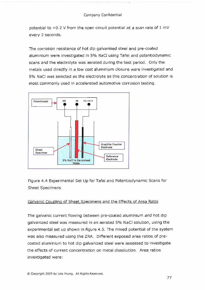
Company Confidential
potential to +0.2 V from the open circuit potential at a scan rate of 1 mV
every 2 seconds.
The corrosion resistance of hot dip galvanised steel and pre-coated
aluminium were investigated in 5% NaCi using Tafel and potentiodynamic
scans and the electrolyte was aerated during the test period. Only the
metals used directly in a low cost aluminium closure were investigated and
5% NaCi was selected as the electrolyte as this concentration of solution is
most commonly used in accelerated automotive corrosion testing.
Potentiostat
Sheet Specimen
WE RE Counter E
5% NaCI in De-ionised Water
Graphite Counter Electrode
Figure 4.4 Experimental Set Up for Tafel and Potentiodynamic Scans for
Sheet Specimens
Galvanic Coupling of Sheet Specimens and the Effects of Area Ratio
The galvanic current flowing between pre-coated aluminium and hot dip
galvanized steel was measured in an aerated 5% NaCi solution, using the
experimental set up shown in figure 4.5. The mixed potential of the system
was also measured using the 2RA. Different exposed area ratios of pre
coated aluminium to hot dip galvanized steel were assessed to investigate
the effects of current concentration on metal dissolution . Area ratios
investigated were:
© Copyright 2005 by Lisa Young. All Rights Reserved.
77

Company Confidential
1. Pre-coated Alum inium 1: 1 Hot Dip Galvanised Steel
2. Pre-coated Aluminium 1: 10 Hot Dip Galvanised Steel
3. Pre-coated Aluminium 1: 100 Hot Dip Galvanised Steel
4 . Pre-coated Aluminium Stone chipped: 10 Hot Dip Galvanised Steel
Pre-coated aluminium sheets (200 mm x 120 mm) were stone chipped in
accordance with FLTM BI 157-06 to damage the pre-coating and simulate in
plant handling damage.
Zero Resistance Ammeter
Pre-coated Alumin ium
5% NaCI in De-ionised Water
Hot Dip Galvan ised
Figure 4.5 Experimental Set of Galvanic Coupling of Sheet Specimens
Corrosion Resistance of Hem Sections
The corrosion resistance of hem sections was measured using the Tafel and
potentiodynamic parameters described above for sheet specimens and the
experimental set up is shown in figure 4.6 .
Three types of hem section specimen were tested and some were exposed
to 480 hours neutral salt spray as specified in WSS-M2P180-A, paragraph
3.6.4 was carried out in accordance with ASTM Bl17, whilst others were
tested in an unexposed condition. A summary of the test schedule is shown
© Copyright 2005 by Lisa Young. All Rights Reserved.
78

Company Confidential
in table 4.2. A 5% NaCi electrolyte solution was used and the electrolyte
was aerated during the test.
Potentiostat WEi
Outer Panel
Inner Pa nel
Masking Tape
WE2 RE
Counter Electrode
Reference Electrode
Figure 4 .6 Experimental Set Up for Tafel and Potentiodynamic Scans of Hem
Section Specimens
Galvanic Coupling of Hem Sections
The outer and inner panels of hem sections were galvanically coupled
together as shown in figure 4.7. A 5% NaCi aerated electrolyte was used
and the galvanic current and mixed potential was measured for a minimum
period of three days. The same experimental design was used as for the
determination of corrosion resistance, shown in table 4.2 and specimens
were tested in triplicate.
© Copyright 2005 by Lisa Young . All Rights Reserved.
79

Company Confidential
Inner Outer Over Hem Exposure Panel Panel Sealer Hot dip Hot dip Yes None galvanised galvanised steel steel
480 Hours Neutral Salt Spray
No None (Insufficient specimens available to assess the effects of Salt Spray)
Pre-coated No None aluminium
480 Hours Neutral Salt Spray
Table 4.2 Test summary for Corrosion Resistance Testing and Galvanic
Coupling of Hem Sections
Zero Resistance Ammeter
Outer Panel
Inner Panel
Masking Tape
WEi WE2 RE
Reference ====4--1 Electrode
5% NaCI in deionised water
Figure 4.7 Experimental Set Up for Hem Section Galvanic Couple
© Copyright 2005 by Lisa Young. All Rights Reserved.
80

Company Confidential
4.1.4 Experimental Design for Hood
Two low cost aluminium hoods were assessed for corrosion resistance using
30 APGE cycles (accelerated laboratory corrosion test) and PASCAR 1 + 2,
summarised in the sections below. PASCAR 1 + 2 is a structural durability
test which all Ford of Europe vehicles must pass before commencing full
scale production. The test uses salt loading and structural inputs to initiate
and propagate any structural defects in the vehicle. It is an arduous test
and is used here as a way of assessing corrosion resistance of a low cost
aluminium closure on a vehicle.
As the CMax (the demonstrator component vehicle) was already well into
production al l the vehicle corrosion testing was complete and a PASCAR 1 + 2 test was available because some post launch modifications were being
made to the vehicle . Vehicle accelerated tests such as PASCAR 1 + 2 and
the vehicle accelerated corrosion test (both carried out at Ford's Lommel
Proving Ground) are very expensive to conduct and it was extremely
fortunate that a test vehicle was available in the duration of this research
project. Scribe lines were applied (one vertical and one horizontal, figure
4.8) to both hoods to allow scribe corrosion creep to be measured during
and on completion of both accelerated tests.
100 mm
Scribed Lines to assess
Figure 4.8 Scribe Lines to Assess Corrosion Creep
© Copyright 2005 by Lisa Young. All Rights Reserved .
81

Company Confidential
Accelerated Laboratory Test (APGE)
APGE (Arizona Proving Ground Equivalent) is an accelerated environmental
cycle designed to be equivalent to conditions experienced at the Ford
proving ground in Arizona. The cycle includes spraying specimens with a
5% neutral salt solution followed by a low humidity drying cycle and a high
humidity conditioning cycle. The procedure for an automated cabinet is
shown in Table 4 .3.
An automated procedure was used to condition the adhesively bonded
specimens. The cycle was run continuously seven days a week until 30
cycles had been completed i.e. 30 days required to complete 30 cycles. A
C&W SFj1000jCCT cabinet was used for the automated APGE cycling.
Table 4.3 Automatic Cabinet APGE Cycling Procedure
Accelerated Proving Ground Structural Durability Test (PASCAR 1 + 2)
PASCAR 1+2 is a vehicle system durability test for passenger cars:
1. A basic cycle at speeds between 35 and 60 kph.
2. A cycle on a gravel road at speeds between 20 and 50 kph.
3. A higher speed cycle at speeds between 20 and 130 kph .
4. A cycle containing gradients and hills.
© Copyright 2005 by Lisa Young. All Rights Reserved.
82

Company Confidential
5. A drive through a dust tunnel.
6. A drive through a mud solution bath.
7. A drive through a salt solution bath.
8. The basic cycle repeated at speeds between 45 and 75 kph.
9. A high speed cycle on a "comfort road" at speeds between 10 and 90
kph.
10. A high speed cycle at close to the vehicles maximum speed.
The vehicle completes 300 basic cycles (steps 1 to 8) and 100 high
speed cycles (steps 9 to 10).The vehicle will complete 42667 km
during the test, the test duration is approximately 6 months.
4.2 Structural Performance and Durability of Low Cost Aluminium
Closures
A low cost aluminium closure requires that hot dip galvanized steel be
bonded to pre-coated aluminium. A suitable adhesive for this purpose is 3M
7036 as it can be formulated to bond steel to steel (4: 1) and aluminium to
aluminium (2:1). It would be reasonable to assume that an intermediate
mix ratio would provide the best bond properties for a steel to aluminium
jOint.
Initial screening work was conducted by 3M using 3M 7036 at a number of
mix ratios and the mix ratios found to perform best under shear and peel
conditions were 4: 1, 4.5: 1 and 5: 1 (on uncoated AA6111 and hot dip
galvanised steel joints). It was decided to limit further investigations to
these mix ratios.
4.2.1 Substrates and Adhesives
Hot dip galvanised steel and pre-coated aluminium (AA6016) were used to
assess the structural durability of low cost aluminium closures and are
described in section 4.1.1. Henkel Terosen 5811 is the current PVC Epoxy
production hem flange adhesive in Ford of Europe and it is used in this
© Copyright 2005 by Lisa Young. All Rights Reserved.
83

Company Confidential
study as a bench mark. 3M 7036 is a two part epoxy system that can be
mixed to bond steel to steel or aluminium to aluminium. The mix ratios are
modified to optimize the amine to epoxy ratio for the substrate system
being bonded. High amine to epoxy ratios are preferable for aluminium as
they enhance durability, where as high epoxy to amine ratios are preferable
on steel substrates (Sikkel, [2005]).
4.2.2 Specimen Preparation
Single lap shear specimens were made in accordance with SAE ]1523. Peel
resistance (T Peel Test) specimens were prepared in accordance with ASTM
D 1876-01. The coupons were laser cut from the sheet materials using a
Bystar 3015 3 Kilowatt Turbo machine. They were nominally 25.4 mm wide
by 101.6 mm long. Single lap shear and modified peel specimens are
shown in figure 4.9.
The coupons were degreased n heptane solvent and then re-oiled according
to a 3M Specification. Hot dip galvanised steel coupons were re-oiled with
of 6g/m 2 Quaker stamping lubricant. Bond line thickness was controlled
with glass bead spacers in the adhesive. The bond line thickness was 1
mm. No lubricant was applied to the pre-coated aluminium as it is expected
that no lubricant will be required during stamping because of the pre
coating. A closure adhesive jOint (hem flange) usually receives an induction
cure to promote initial adhesion, aid lubricant dispersion and adsorption and
give improved handling strength. No induction cure was given to either the
single lap shear or the peel specimens. Assembled specimens were
conditioned at room temperature and humidity (23°C ± 2 °C and 55% RH
± 5%) prior to curing. Three curing cycles were used:
1. Control, 30 minutes at 180°C.
2. Minimum Bake, 10 minute ramp from room temperature to 170°C
with a dwell at 170 °C for 10 minutes.
3. Maximum Bake, 10 minute ramp from room temperature to 205°C
with a dwell of 30 minutes at 205 dc.
© Copyright 2005 by Lisa Young. All Rights Reserved.
84

Company Confidential
North American minimum and maximum bake cycles were used, as they are
a more severe test than equivalent European bake cycles . The cycles are
described in WSB-M2G373-A and WSS-M2G373-A2/B paragraph 5.6.3.
. Pre-coated aluminium 12.5 mm i 411 .~
1 mm f ...................... · .............................. , .... -.... -.... -.... - .L.-------.
Hem flange adhesive
Pre-coated aluminium Hem flange adhesive
t. ..................... ~~~~ lmm r-- -r=
Hot dip galvanised steel
~i4ll~-----10-0-m-m----~·1
25 mm
Figure 4.9 Single Lap Shear and Modified Peel Specimens
4 .2.3 Experimenta l Design
An automotive adhesive joint (hem flange) is affected by many variables
(noises) both in plant and in service and two of these variable were
assessed in this research:
1. The effect of heat input from the production paint bake ovens
2. The effect of environmental exposure
Production paint bake ovens do not have an even temperature distribution
and as such all parts of the vehicle do not see the same heat inputs. The
minimum and maximum bake cycles described in section 4.2.2 are designed
to replicate the worst expected lower and upper bake cycles experienced in
a production paint oven. The control bake cycle would be the ideal heat
input seen by a hem f lange jOint.
© Copyright 2005 by Lisa Young. All Rights Reserved .
85

Company Confidential
Three environmental exposure regimes are used in this study:
1. Humidity aging, conducted at 60°C and 95 0/0 RH for 7 days in a C&W
SF/l000/CCT cabinet.
2. 30 APGE cycles, as summarised in section 4.1.4.
3. Custom environmental cycle based on Wang et al [2000]. The
average environmental conditions seen by a door hem flange were
59% relative humidity (RH), 17°C and 0.28 time of wetness. It was
not possible to meet 17 °C and 59% RH in the environmental
chamber available. It was therefore necessary to compromise on one
of these requirements. A cycle of 6 hours immersion in tap water
followed by 18 hours at room temperature and humidity was chosen.
The ambient environment is controlled to 50 0/0 RH ± 5 and
temperature is controlled at 23°C ± 2. It was not antiCipated that
the increase in temperature would be a sign ificant accelerating factor
over temperatures seen in service.
30 cycles of the custom environmental cycle were completed. One cycle per
weekday was completed with the specimens held at room temperature and
humidity during the weekend.
3M 70364:1 3M 70364.5: 3M 7036 5:1 Henkel 5811
3M 70364:1 3M 70364.5:1 Henkel 5811 3M 70364:1 3M 70364.5: Henkel 5811
3M 70364:1 3M 70364.5: Henkel 5811 3M 70364:1 3M 70364.5:1 Henkel 5811 3M 70364:1 3M 70364.5:1 Henkel 5811
3M 70364:1 3M 70364.5: Henkel 5811 3M 70364:1 3M 70364.5:1 Henkel 5811
3M 70364: 1 3M 70364.5: 1 Henkel 5811 3M 70364: 1 3M 70364.5: 1 Henkel 5811
Table 4.4 Test Summary for Single Lap Shear and Peel Specimens
© Copyright 2005 by Lisa Young. All Rights Reserved .
86

Company Confidential
The experimental design used to assess the structural durability of low cost
aluminium joints is summarised in table 4.4. Each specimen was replicated
at least three times.
4.2.4 Experimental Design for Hood
One low cost aluminium hood was fitted to a CMax undergoing PASCAR 1 + 2 and assessed for structural durability as in section 4.1.4.
© Copyright 2005 by Lisa Young. All Rights Reserved.
87

Company Confidential
5.0 Corrosion Properties of Low Cost Aluminium Closures
5.1 Introduction
A low cost aluminium closure is made of dissimilar metals and is therefore
at risk of galvanic corrosion. The geometry of hem flanges allow a fluid trap
to form that can accumulate electrolyte and the dimensions of the gap
(between the inner and outer panels) leads to the possibility of crevice
corrosion occurring. As closure panels are stamped from coils of sheet
material, cut edges are always present in hem flanges and therefore
corrosion of the cut edges can also occur. Automotive vehicles operate in
aggressive environments, where high humidity, precipitation and chloride
ions (from road salt and coastal atmospheres) provide the ingredients for
highly corrosive electrolytes to form.
It is clear that hem flanges are complex corrosion environments requiring a
number of different experimental techniques to assess the corrosion
properties and performance of low cost aluminium closures and more
specifically hem flanges. The metals that make up the closure were ranked
in a galvanic series to establish their relative electrochemical activities and
the corrosion resistance of the metals was measured using linear
polarisation resistance (Tafel). Linear polarisation resistance
(potentiodynamic scan) was also used to investigate any passive behaviour.
The different metals found in a hem flange were coupled together and the
galvanic current and mixed potential measured to investigate the effects of
galvanic coupling. The galvanic current of galvanic couples with
unfavourable area ratios was also measured to examine the effects of
possible current concentration. Similar measurements were made on
sections of low cost aluminium closure to test the corrosion resistance of
hem flanges and the galvanic currents flowing between the inner and outer
panels. In addition to the small specimen laboratory tests full size
demonstrator components were tested for corrosion resistance using an
© Copyright 2005 by Lisa Young. All Rights Reserved.
88

Company Confidential
accelerated proving ground test and an accelerated laboratory test. Where
possible sections were taken from non-corroded and corroded test
specimens for metallographic examination and these observations were
used in conjunction with the measured test results to understand the
corrosion behaviour exhibited by low cost aluminium closures and hem
flanges.
The electrochemical corrosion properties of automotive hem flanges have
not been extensively studied and as such no data is available about the
corrosion rates of hem flange metals in-situ. This information would be
very valuable to automotive manufacturers as it would allow them to
effectively predict the life of this complex geometry component. The
current method for evaluating the performance of a hem flange is either
testing a component in an environmental chamber using an accelerated
corrosion test or testing a component on a vehicle in an accelerated proving
ground test. Accelerated laboratory testing can take upwards of six weeks
and the minimum time period for an accelerated proving ground test at
present is also six weeks. Both of these tests rely upon having
representative production parts in order to conduct the tests. They are also
limited by the accelerating factors used in the tests and how they correlate
with real life exposure experienced by vehicles in use by customers.
Electrochemical corrosion testing of hem flanges would allow manufacturers
to establish the corrosion rates of new materials systems (such as a new
type of zinc coating or a reduced weight zinc coating) without having to
build a component or a whole vehicle. This would reduce the need for
expensive proving ground tests and allow any changes needed to corrosion
protection systems to be made well before a new vehicle goes into
production. The later in the new vehicle design and production process
changes are made the more expensive they become to implement. In the
case of a proving ground corrosion failure this may mean the need for
additional cavity wax in an area which is difficult to access using current
facilities and require the wax to be applied by hand. Such changes
observed earlier in the design process can allow production planners to get
the correct facilities in place at a lower cost.
© Copyright 2005 by Lisa Young. All Rights Reserved.
89

Company Confidential
Ultimately a full understanding of the electrochemical performance of
automotive sheet materials in their natural environments would allow
manufacturers to reduce costs associated with accelerated laboratory and
proving ground testing. It would also allow them to better plan the
production line as late changes to corrosion protection measures would not
be needed. It would also permit the use of new types of corrosion
resistance coatings to be tested in a low risk environment and be able to
compare them with the existing materials in a fair and constructive manner.
The electrochemical tests conducted in this research are an initial
investigation into this field of testing.
The corrosion performance of low cost aluminium closures was
benchmarked against the corrosion performance of all steel closures in the
small specimen laboratory tests and the accelerated laboratory test on the
full size demonstrator. However, due to the limitations of proving ground
testing direct benchmarking against an all steel closure was not possible.
For clarity it should be noted that an all steel closure has a zinc coated steel
inner and outer panels (figure 5.1) and a low cost aluminium closure has a
zinc coated steel inner panel and a pre-coated aluminium (with the pre
coating on the inside of the outer panel, not shown to scale on diagram)
outer panel (figure 5.2).
Zinc coated steel inner
panel
sealer
Cavity wax
Zinc coated steel outer
panel
Hem flange adhesive
Figure 5.1 All Steel Hem Flange
© Copyright 2005 by Lisa Young. All Rights Reserved.
Zinc coated steel inner
panel
Organically pre-coated aluminium outer panel
Organic pre-coating
Figure 5.2 Low Cost Aluminium
Hem Flange
90

Company Confidential
5.2 Galvanic Series of Metals found in Hem Flanges
All steel hem flanges are made from two panels of zinc coated steel and low
cost aluminium hem flanges have a zinc coated steel inner panel and a pre
coated aluminium outer panel. Therefore there are two metals in an all
steel hem flange: steel and zinc and three metals in a low cost aluminium
hem flange: aluminium (AA6016), steel and zinc. The open circuit
potentials (free corrosion potential) of uncoated AA6016, pre-coated
AA6016 and zinc coated steel were measured using a zero resistance
ammeter (ZRA) as a potentiostat (just using the logged vales of potential)
in order to establish the galvanic series of these metals in four electrolytes:
tap water, 1% NaCl, 3% NaCi and 5% NaCI.
The open circuit potentials (OCP) of pure zinc or zinc-coated steel with the
zinc removed were not measured. The corrosion properties of metals are
highly influenced by processing routes, alloy composition and surface
condition. If a zinc plate had been used to measure the open circuit
potential of zinc, the results may not have been representative of the open
circuit potential of hot dip galvanised zinc coating on zinc coated steel
sheet. As an inner panel in a hem flange has a cut edge exposing a small
strip of steel it was considered more representative to measure the
potential of the whole zinc coated steel system. Similarly, the electrode
potential of the steel substrate was not measured, although it is possible to
remove a zinc coating by chemical (etching) and/or physical (abrasion)
methods the resulting surface condition would not have been representative
of a standard mill finished steel. Unfortunately it is very difficult to obtain
small quantities of steel sheet used in mass production and even more
difficult to obtain material that is not commonly used, for example uncoated
steel grade that is usually sold as zinc coated steel. A comparison between
the electrode potentials of uncoated and pre-coated aluminium was possible
as currently AA6016 is the most favoured aluminium alloy in Europe for
vehicle closure outer panels and as such is readily available.
© Copyright 2005 by Lisa Young. All Rights Reserved.
91

Company Confidential
The galvanic series found for the four electrolytes listed above is shown in
figure 5.3. It is important to note that a galvanic series is only valid if all
the measurements are taken under the same conditions i.e. the same
temperature, humidity, electrolyte composition, electrolyte aeration etc.
The potentials shown are averages of three replicate specimens and the
potential of each specimen was obtained by averaging all the potentials
over a minimum period of three days.
Electrolyte
-292 mV Uncoated AA6016
-459 mV Pre-coated AA6016
-827 mV Hot Dip Galvanised Steel
-664 mV Pre-coated -672 mV
AA6016 Pre-coated AA6016 -710 mV
-721 mV Uncoated Uncoated AA6016 AA6016
-1024 mV -1033 mV Hot Dip Hot Dip Galvanised Galvanised Steel Steel
Open Circuit Potential (Free Corrosion
Potential)
-200 mV
-709 mV Pre-coated AA6016 -713 mV Uncoated AA6016
-1022 mV Hot Dip Galvan ised Steel
-1100 mV
Tap I~~~ Water .~~~
Chloride Concentration
0.0005 M II 0.171 M II 0.513 M II 0.856 M
Figure 5.3 Galvanic series for hem flange metals in four electrolytes with
the Molar chloride concentrations of the electrolytes shown
Tap water has a very low chloride concentration and as expected the open
circuit potentials of all the metals are substantially lower in tap water than
in electrolytes with higher chloride concentrations. Also, tap water has
other dissolved ions such as carbonates that aid passive film formation
reducing the rate of metal dissolution.
© Copyright 2005 by Lisa Young. All Rights Reserved.
92

Company Confidential
Chlorides increase the rate of dissolution of metals (the anodic reaction) as
they are film disruptors and in crevices they act to help lower pH. pH is a
measure of hydrogen ion concentration in a solution and the increase in
hydrogen ions further accelerates metal dissolution. This is because
hydrogen ions are reduced at the cathode (consuming electrons) and
therefore driving the anodic reaction to produce more electrons. The
highest potentials are observed in the electrolytes with the highest chloride
concentrations and importantly it should be noted that the order of the
metals does not change in electrolytes with significant chloride
concentrations.
Pre-coated AA6016 and uncoated AA6016 have different free corrosion
potentials and as they have the same alloy composition there must be
another explanation for the differences in their OCPs. The pre-coated
aluminium specimens only have a small area of base metal exposed at the
cut edge, where as the uncoated aluminium specimens have base metal and
a cut edge exposed to the substrate. It is likely that the small exposed cut
edge of the pre-coated aluminium specimen is in some way restricting the
anodic reaction. The surface condition of a cut edge is likely to be different
to the surface of the uncoated aluminium and this may also have an effect
on the corrosion rate. Laser cutting was used to prepare the specimens and
so the cut edge may also have a heat affected zone and tenacious oxides
present that may limit metal dissolution.
The order of metals in the galvanic series is important because it governs
which metal will sacrifice itself when the metals are electrically coupled
together. In the electrolytes with 1%, 3% and 5% NaCi the hot dip
galvanised steel will sacrifice itself in preference to the aluminium. So it is
the zinc of the hot dip galvanised steel that would sacrifice itself in
preference to the aluminium, once a significant amount of zinc has been
consumed then the aluminium would be anodic to the steel. Mattssonn
(1996) discussed that the effectiveness of zinc protecting steel in
atmospheric conditions is limited to distances of approximately 1 mm. So,
in an automotive hem flange the effectiveness of zinc in protecting
© Copyright 2005 by Lisa Young. All Rights Reserved.
93

Company Confidential
aluminium in the galvanic series is limited by the distance of remaining zinc
from the corroding aluminium.
It is interesting to note that the OCPs of the metals under consideration do
not vary greatly with increasing NaCi concentration. This is an important
consideration from an automotive viewpoint as much debate has taken
place about the actual NaCi loadings seen in service by vehicles.
Automotive accelerated corrosion tests usually use a 5% NaCI solution (by
weight) but it is thought that a much lower concentration is seen in service,
a value of between 0.5 and 1% is proposed by Townsend (1996). Although
chloride concentration it not the only factor that affects the corrosion rates
and mechanisms seen by automotive vehicles it is an interesting
observation that chloride concentration in the range studied i.e. 1, 3 and
5% does not affect the galvanic series of metals found in low cost
aluminium and all steel hem flanges.
Hot dip galvanised steel developed a gelatinous oxide on the surface of the
zinc during exposure to NaCI solutions. This oxide appeared to protect the
surface of the zinc from further dissolution in the areas it covered. The
composition of the gelatinous material was not investigated but is very
likely that it could be a form of insoluble zinc hydroxychloride termed
simonkoellite, observed by authors such as Falk (1998) and Zhu (2000).
This compound forms in the presence of hydroxide ions and chloride ions.
Investigation of the stoichiometry of this oxide could be conducted using X
ray diffraction against a simonkoellite benchmark specimen. Authors in this
field have noted that it is very difficult to remove and isolate enough
simonkoellite to get a definitive result from x ray diffraction techniques.
5.3 Corrosion Resistance of Hem Flange Metals
Polarisation of metals is one of the most common methods of examining
corrosion behaviour. A potential is applied to a metal sample and the
current response of the sample is measured. Two types of polarisation tests
are normally conducted: Linear polarisation technique (leading to a Tafel
© Copyright 2005 by Lisa Young. All Rights Reserved.
94

Company Confidential
plot and the calculation of linear polarisation resistance (LPR)) and
Potentiodynamic polarisation. LPR data can be taken from a
potentiodynamic plot but is more usual to conduct a linear polarisation test
first as the small polarisations from the free corrosion potential do not affect
the condition of the metal surface. Once a potentiodynamic scan has been
completed the metal has been forced through such a large potential range
that it would give invalid results if a linear polarisation plot were taken from
this data. Potentiodynamic scans are used to investigate cathodic and
anodic reactions separately on the same metal and also to examine any
passive behaviour that may occur at potentials away from the free corrosion
potential of the metal. This can be of particular interest as knowledge of
the passivation behaviour of a metal can be used to prevent corrosion in
certain situations where an over potential can be applied to a system.
Two hem flange metals were investigated for their potentiodynamic
polarisation behaviour: Hot dip galvanised steel and pre-coated aluminium.
The linear polarisation plots for hot dip galvanised steel specimens are
shown in chart 5.1. The free corrosion potential of the three hot dip
galvanised steel specimens are not identical and this is due to variations in
the cut edges and surfaces of the samples. Although the samples were
cleaned and prepared in the same way differences in surface condition for
the hot dip galvanising process and subsequent in plant handing would
account for the 3 mV difference between the three replicate specimens. Icorr
ranges between 1. 96 x 10-8 A and 6.99 x 10⁻⁸ A for the three hot dip
galvanised steel specimens. The curves show that the linear polarisation
behaviour of the three specimens is very similar. In order to calculate the
linear polarisation resistance of the samples it is necessary to re-plot the
data on a linear scale as shown in Chart 5.2.
© Copyright 2005 by Lisa Young. All Rights Reserved.
95

-0 .97
-0.98
-0.99
~ ~ c "
Company Confidential
Logarithmic Scale Tafel Plot for Hot Dip Galvanised Steel Small Sheet Specimens
Ecorr (Free Corrosion Potential)
- Hot Dip Galvanised steel 1
~ -1.00 - Hot Dip Galvanised steel 2
."
.!! Q. 0. «
- Hot Dip Galvanised steel 3
-1 .01
-1 .02
-1.03 +---~--~--~--~--~--~--~--~--~
1.00E-09 1.00E-08 1.00E-07 1.00E-06 t OOE-OS 1.00E-04 1.00E-03 tOOE-02 1.00E-01 1.00E+00
Current (A)
Chart 5.1 Linear polarisation behaviour of hot dip galvanised steel
Linear Scale Tafel Plot for Hot Dip Galvanised Steel Small Sheet Specimens in 5% NaCI
~ 0.03
~ c: .. '0 Q.
li 0.02 > 0
- Hot Dip Galvanised steel 1
- Hot Dip Galvainsed steel 2
- Hot Dip Galvanised steel 3
-1 .00E-04 -S.OOE-OS 0.0 +00 S.OOE-OS 1.00E-04 1.S0E-04 2.00E-04 2.50E-04 3.00E-04 3 .S0E-04
Current (A)
-0.03
Chart 5.2 Linear scale polarisation behaviour of hot dip galvanised steel
The data is shown plotted over a range of ± 30 mV and over this range the
data should be linear for a calculation of linear polarisation resistance to be
valid. There are many reasons why a metal may not show linear behaviour
© Copyright 2005 by Lisa Young. All Rights Reserved.
96

Company Confidential
on a Tafel plot. Trethewey and Chamberlain (1995e) give three possible
explanations for non-linear Tafel behaviour:
1. If there is more than one electrode reaction and any corrosion
products that form on the surface of the specimens, reducing the
conductivity of the anode. This results in lower current densities than
would be predicted by the Tafel equation and a deviation upwards on
the potential/current plot.
2. If the scan rate is too fast and the specimens cannot react to each
potential step before the next one is imposed then linearity cannot be
expected.
3. If corrosion is controlled by transport of charge through the
electrolyte and not by the kinetics of the electrode reactions then the
corrosion reactions are under diffusion polarisation and the Tafel
relationship will not apply.
As the linearised polarisation data is not linear over the plotted range it is
not possible to calculate the linear polarisation resistance for hot dip
galvanised steel under these experimental conditions. The data plotted
does not deviate upwards so it is unlikely that more than more than one
electrode reaction was occurring on the metal surface. However, more than
one electrode reaction is possible as there are two metals in the electrolyte,
but as we have already seen zinc is anodic to steel in the electrolytes under
examination in this study (5% NaCl). The scan rate used for the test was
one potential step change every two seconds, so it is therefore unlikely that
the scan rate was too fast to prevent the specimen from reacting to the
imposed potential step before the next potential increment was applied.
The non-linearity observed in chart 5.2 is due to the rate at which oxygen
can diffuse to the cathode surface and the corrosion rate of zinc is known to
be diffusion controlled.
The potentiodynamic scan for hot dip galvanised steel is shown in chart 5.3.
Ecorr for the three specimens varies by 10 mV and again this variation is due
© Copyright 2005 by Lisa Young. All Rights Reserved.
97

Company Confidential
to differences in the metal surfaces being exploited by the applied
potentials. The decrease in corrosion current seen at -0.85 V passivation
behaviour of the hot dip galvanised steel commences. At potentials greater
than -0.85 V a passive film forms and the anodic current decreases. The
passive film does not begin to break down in the range measured during
this potentiodynamic scan .
Logarithmic Scale Potentiodynamic Scan for Hot Dip Galvanised Steel Small Sheet Specimens in 5% NaCI
-0.40
-0.50
-0.60
-0.70
-0.80 ~
- Hot Dip Gaillanised steel 1 .. 'E -0 .90
- Hot Dip Gaillanised steel 2 - Hot Dip Gaillanised steel 3
.. (;
Q. -1.00
-1 .10
-1 .20
-1 .30
-1 .40 +----.-----.---------,-------,---.---------,------, 1.00E-07 1.00E-06 1.00E-05 1.00E-04 1.00E-03 1.00E-02 1.00E-01 1.00E+00
Current (A)
Chart 5.3 Potentiodynamic scan of hot dip galvanised steel
Pre-coated aluminium showed very complex current response behaviour
under applied potentials. Chart 5.4 shows the logarithmic scale Tafel plot
for pre-coated aluminium. Only one specimen is plotted as obtaining
meaningful data from pre-coated aluminium was very difficult. This was
due to the small area of bare exposed metal possibly limiting
electrochemical reactions occurring on the exposed metal. The Tafel plot
shows Ecorr for pre-coated aluminium is -0.701 V and Icorr is 4.65 X 10⁻¹⁰ A.
The linear plot (chart 5.5) of the Tafel data shows non-linearity over the
measured range and Tafel behaviour is not obeyed. It is likely that the
corrosion rate of aluminium is also under oxygen diffusion control.
However, as the plotted line is tending to the vertical it may also be
© Copyright 2005 by Lisa Young. All Rights Reserved .
98

Company Confidential
possible that more than one reaction is occurring on the electrode. No
stable passive behaviour is shown by pre-coated aluminium but an unstable
passive region forms at -0.5 V as seen in chart 5.6.
-0.67
-0.67
-0.68
-0.68
5" :::- -0 .69 .!! 'E
Logarithmic Scale Tafel Plot for Pre-coated Aluminium Steel Small Sheet Specimen in 5% NaCI
" ~ -0.69 1 - Pre-coated Aluminium 1
."
.!! 8: -0.70 «
-0 .70
-0.71
-0.71
-0.72 +--~--~--~--~-~--~--~--~-~--~
1.00E-10 1.00E-09 1.00E-08 1.00E-07 1.00E-06 1.00E-05 1.00E-04 1.00E-03 1.00E-02 1.00E-01 1.00E+00
Current (A)
Chart 5.4 Linear polarisation behaviour of pre-coated aluminium
Linear Scale Tafel Plot for Pre-coated Aluminium Small Sheet Specimen in 5% NaCI
~ 0.04
li 'E ii Q.
i; 0.03 > 0
1- Pre-coated Aluminium 1
-2.00E-07 -1 .00E-07 0 0 +00 1.00E-07 2.00E-07 3.00E-07 4.00E-07 5.00E-07 6.00E-07 7.00E-07 Current (A)
-0.01
Chart 5.5 Logarithmic scale Tafel Plot for pre-coated aluminium
© Copyright 2005 by Lisa Young. All Rights Reserved.
99

0.00
-0.20
-0.40
?:
Company Confidential
Logarithmic Scale Potentiodynamic Scan for Pre-coated Aluminium Small Sheet Specimens in5% NaCI
~) ~---~ 1- Pre-coaled Aluminium 1 iii 'E -0 .50
II
o a..
-0.80
-1 .00
-1.20 -l---~-----'---.---~-~---.----.----r---.------'
1.00E-1 0 1.00E-09 1.00E-08 1.00E-07 1.00E-05 1.00E-05 1.00E-04 1.00E-03 1.00E-02 1.00E-01 1.00E+00
Current (A)
Chart 5.6 Potentiodynamic scan for pre-coated aluminium
5.4 Galvanic Coupling of Hem Flange Metals
Pre-coated aluminium and hot dip galvanised steel sheets were coupled
together and immersed in 5% NaCi solution . The current flowing between
metals and the coupled potential was measured using a ZRA. As the data
was recorded over many days (at least three) an average of the coupled
potential and current was taken when the specimens had reached a steady
state and as the currents and potentials fluctuate over time the averages
were taken from one hour after coupling to the end of the exposure period.
The mean coupled potential and mean current are shown in table 5.1. The
corrosion rate is also shown and this was using current density to give a
corrosion rate:
Assuming: Zn -+ Zn2+ + 2e- [5 .1]
is the anodic reaction and using Faraday's Law:
w/M =q/zF [5.2]
© Copyright 2005 by Lisa Young. All Rights Reserved.
100

Where:
w =
M =
q =
z =
F =
Company Confidential
mass of material lost during anodic dissolution
Molar mass of material lost
Electrical charge
Number of electrons used in reaction 5.1 (z = 2)
Faraday's constant (96485 A s morl)
Substitute q = A t equation [5.2]:
w/M=It/zF
Rearrange to get mass loss per unit time:
w/t=IM/zF
Substitute density into equation 5.4 (p = w / V = w / A x, where V =
volume, A = area and x = thickness lost):
PAx/t=IM/zF
Rearrange to get thickness lost per unit time:
x/t=IM/pAzF
I/ A is current density = j, so substitute into equation [5.6]:
x/t=jM/pzF
[5.3]
[5.4]
[5.5]
[5.6]
[5.7]
Equation [5.7] was used to calculate the corrosion rate shown in table 5.1.
The anodic reaction is occurring on the hot dip galvanised steel, so the area
taken to calculate current density is the area of exposed hot dip galvanised
steel. This is because of the ranking of the galvanic series discussed above
in section 5.2, that zinc will sacrifice itself for aluminium in 5% NaC!. The
stone chipped areas exposed approximately 6.5 mm 2 of bare aluminium on
a 284 mm 2 sheet of pre-coated aluminium. A photograph showing the type
of damage inflicted by stone chipping is given in figure 5.4.
The mean coupled potential for all the area ratios is between that of
aluminium and zinc. The mixed potential does not vary greatly with area
ratio, as the dominant reaction influencing the potential is the dissolution of
© Copyright 2005 by Lisa Young. All Rights Reserved.
101

Company Confidential
zinc. Recall from figure 5.3 that the mean measured potentials for hot dip
galvanised steel and pre-coated aluminium were -709 and -1022 mV
respectively. The mixed potentials shown in table 5.1 range between -
1007 and -1066 mV and as the measured coupled potential is closer to the
open circuit potential of hot dip galvanised steel then the predominant
anodic reaction occurring in the couple is the dissolution of zinc.
Area Ratio (Pre-coated Mean Potential Mean Current Corrosion Rate AA6016 : Hot dip (mV) (IJA) (!-1m/year) galvanised steel)
1:1 -1022 -0.51 7.6 -1007 -1.1 16.5 -1012 -1.2 lS.0
1: 10 -1033 -4S.3 72.4 -1007 -44.2 66.2 -1027 -1.1 1.7
1:100 -1029 -1.9 0.3 -1019 -O.S 0.1 -1024 -1.S 0.3
Stone-chip: 10 -1014 -2.1 3.1 -1011 -54 SO.l -1066 -0.9 1.3
Table 5.1 Mean coupled potentials of pre-coated aluminium and hot dip
galvanised steel galvanic couples and the effect of area ratio on galvanic
coupling currents
Figure 5.4 Stone chipped pre-coated aluminium showing areas of
perforation through pre-coating to bare aluminium
© Copyright 2005 by Lisa Young. All Rights Reserved.
102

Company Confidential
The actual area ratios are much smaller than those recorded above as
although the area masked off on the specimen exposed 1 cm 2 of the pre
coated aluminium! the area of exposed metal was only that of the cut edge
(0.7 mm x 10 mm). As discussed previously zinc is anodic to aluminium in
the test electrolyte of 5% NaCi and so in these tests the dominant anodic
reaction is the dissolution of zinc. This can be seen by the negative polarity
of the current in table 5.1; referring back to figure 4.5 a current flowing
from WE2 (working electrode two) to WEl (working electrode one) is
recorded by the ZRA as a negative current.
Higher corrosion rates are observed on 1: 10 couples than on 1: 1 couples
because more zinc is available to provide electrons for the cathodic
reduction reaction on the aluminium. The corrosion rate decreases on the
1: 100 couples because the zinc now has significant amounts of cathodic
sites on its own surface as well as the reduction reaction occurring on the
aluminium cathode (it is not possible to measure the corrosion rate of an
uncoupled metal directly and so the current being measured between the
two metals is reduced by the electron consuming reactions occurring on the
zinc itself). The stone chip to 10 couple sees a slight increase in corrosion
rate as the aluminium surface available may be more active due to the
stone chipping procedure! giving a larger effective area to support the
cathodic reaction.
The variation in the results illustrates a very important feature of
electrochemical corrosion testing; results are very susceptible to local
surface conditions and local variations in electrolyte aeration and
composition. As such! definitive conclusions cannot be drawn on small data
sets! as in table 5.1. It is still valid to highlight trends and use the data for
comparative assessments of the corrosion performance of specimens tested
under equivalent test regimes.
The corrosion rate shown in table 5.1 is calculated from a current measured
over a short time period (only a few days)! if the current was measured
over a much longer time period i.e. years the current would be much lower
and the corrosion rate would then much better represent the corrosion rate
© Copyright 2005 by Lisa Young. All Rights Reserved.
103

Company Confidential
seen by in service materials. The results given in table 5.1 do allow for
useful comparison between the different areas of exposure and how these
areas of exposure might relate to conditions in a hem flange.
The purpose of this work on the effect of area ratios was to determine what
would happen if a small amount of aluminium was exposed in a hem flange.
In a bare aluminium and steel couple this would result in the aluminium
being consumed rapidly leading to perforation of the aluminium sheet. In a
zinc coated steel pre-coated aluminium couple this does not happen in the
time period studied as zinc is sacrificed in preference to the aluminium. The
most unfavourable area ratio tested here was 1: 100 (1: 1500 on actual
exposed aluminium area) and this resulted in the lowest corrosion rates,
because the zinc corrodes within itself and in preference to the aluminium.
The coupled system studied using two open-faced specimens is not
representative of the system seen in a hem flange and so the galvanic
coupling of a hem flange will be discussed in section 5.6.
5.5 Corrosion Resistance of Hem Flange Sections
Sections of hem flange were taken from a low cost aluminium closure and a
conventional all steel closure. The conventional all steel closure was
partially over hem sealed on the leading edge of the hood and the headlamp
cutouts, this allowed hot dip galvanised steel hems to be tested both with
(HD#OH) and without (HD#NoOH) over hem sealer. The low cost
aluminium hood (PAI#) did not have any over hem sealer applied to the
hem flanges. The corrosion resistance of the hem flange sections was
assessed using linear polarisation (Tafel). A potentiodynamic scan was not
possible on the hem sections as the total exposed area of metal within the
hem was too large for the potentiostat to polarise, as most laboratory
potentiostats are limited to 1 amp and this therefore limits the amount of
exposed metal that can be polarised. Hem sections were either tested in an
as made condition or were exposed to 480 hours neutral salt spray to
accelerate the corrosion process.
© Copyright 2005 by Lisa Young. All Rights Reserved.
104

Company Confidential
Chart 5.7 shows the linear scale Tafel plot for unexposed hem sections
tested in 5% NaCi solution. Three of each type of specimen were tested
and as can be seen from the data on chart 5.7 not all specimens gave a
result for linear polarisation resistance. This was due to the complex
geometry of the hem flange and despite allowing the system to settle for at
least one hour in the electrolyte the specimens not shown here, did not
respond as expected to the applied potential. As potential was applied the
current response was random and inconsistent and was not representative
of the other specimens tested.
The polarisation resistance of the hems tested is shown in table 5.2. A
simple measure of polarisation resistance is used in this analysis, as the
corrosion rates of hem sections will be calculated in section 5.6 from the
galvanic current flowing between the inner and outer panels. A material
with perfect corrosion resistance would have a Tafel plot showing no change
in current response with applied voltage i.e. a vertical line on chart 5.7. So,
the closer to vertical the plotted lines are the better the corrosion resistance
of the hem system. Corrosion resistance (LPR) is measured in Ohms, as the
gradient of the line (Tafel slope) is simply applied voltage (V) divided by
current response (A). Differences between specimens are assessed using
changes in orders of magnitude of resistance. So, HD1NoOH has superior
corrosion resistance compared to the rest of the specimens, with the
remaining hot dip galvanised he sections showing similar corrosion
resistance and the low cost aluminium hem sections have the least
resistance to corrosion in an unexposed condition.
The free corrosion potential of the hem system is slightly lower than the
equivalent measurements made on the galvanic couples in section 5.4 and
shown in table 5.1. This is probably due to the effects of the hem flange
geometry on the corrosion system. Recall from figure 5.1 that hem flange
adhesive is present in a hem and this will limit the penetration of electrolyte
into the hem and may shield the zinc coating from the electrolyte. As the
OCP is closer to that of steel it is probable that the cut edge is the
predominant metal present in the electrolyte as hem flange adhesive fill
around the cut edge of the inner panel is difficult to achieve. The OCP
© Copyright 2005 by Lisa Young. All Rights Reserved.
105

Company Confidential
measured for the low cost aluminium hems is not significantly different to
the hot dip galvanized steel hems, so the aluminium is not having an
participating in the corrosion process after short periods of immersion in the
electrolyte.
Linear Scale Tafel Plot for Hem Slice Specimens with No Exposure in 5% NaCI
~0.80
-1.05
-0.00015 -0.0001 -0.00005 0 0.00005 0.0001
Current (A)
Chart 5.7 Linear Polarisation Plot for Unexposed Hem Sections
Specimen Linear Ecorr (V) Polarisation
Resistance (.0) HD10H 1880.5 -0.9467 HD30H 514.92 -0.8888 HD1NoOH 19955 -0.9824 HD2NoOH 2284.8 -0.9998 HD3NoOH 1957.3 -0.9964 PAI2 741.96 -0.9939 PAI3 463.42 -1.0124
Table 5.2 Corrosion Resistance of Unexposed Hem Sections
© Copyright 2005 by Lisa Young . All Rights Reserved .
- HD10H - HD30H
HD1NoOH - HD2NoOH - HD3NoOH - PAI2 --+- PAI3
106

Company Confidential
The Tafel data from hem sections exposed to 480 hours neutral salt spray is
shown in Chart 5.8 and the corrosion resistance of these specimens is given
in table 5.3. In general the corrosion resistance of the hem specimens after
salt spray exposure was equivalent to the performance of the unexposed
hem specimens. Zhu (2000) examined the effect of wet/dry cycling on
open and confined zinc surfaces and concluded that environments with
extended drying times were more aggressive corrosion environments than
those with extended periods of wetness. This was thought to be because as
the drying time increases the electrolyte film thins concentrating corrosion
aggressive ions (such as chlorides) and altering the composition of corrosion
products formed. The specimens exposed to 480 hours of neutral salt spray
would have effectively seen the equivalent of 480 hours immersion in 5%
NaCl, as they were oriented vertically in the salt spray chamber and
prepared with masked edges to allow electrolyte to accumulate in the hem.
The effect of the salt spray exposure is more easily seen in the slight
reduction of the free corrosion potential to bring it slightly closer to bare
steel. With increasing exposure times it would be reasonable to assume
that the zinc present on the steel is consumed reducing the amount of zinc
present and therefore adjusting the ratio of exposed zinc to steel cut edge
and this consequently would account for the slight shift in OCP. There is no
evidence to suggest that aluminium is participating in the corrosion system
from the data shown in table 5.3 and the corrosion resistance of the low
cost aluminium hem is equivalent to the hot dip galvanized steel hems with
increasing exposure time. It is noted that the number of specimens
available for analysis here is small and as such only cautious conclusions
will be drawn in chapter 7.
© Copyright 2005 by Lisa Young. All Rights Reserved.
107

Company Confidential
Linear Scale Tafel Plot for Hem Flange Specimens Pre-exposed to 500 Hours Neutral Salt Spray in 5% NaCI
-1.05
-0.00015 -0.0001 -0.00005 o Current (A)
0.00005 0 .0001
--HD10HSS - HD30HSS
HD1NoOHSS
- HD2NoOHSS - HD3NoOHSS - PAI1SS
Chart 5.8 Linear Polarisation Plot for Hem Sections Exposed to 480 Hours
Neutral Salt Spray
Specimen Linear Ecorr (V) Polarisation
Resistance (0.) HD10HSS 4933.9 -0.8376 HD30HSS 367.89 -0.9239 HD1NoOHSS 1703.9 -0.9815 HD2NoOHSS 1623.8 -0.9714 HD3NoOHSS 1207.8 -0.9807 PAllSS 1709.6 -0.9816
Table 5.3 Corrosion Resistance of Hem Sections Exposed to 480 Hours
Neutral Salt Spray
© Copyright 2005 by Lisa Young. All Rights Reserved.
108

Company Confidential
5.6 Galvanic Coupli ng of Hem Flange Sections
The galvanic current measured between the outer and inner panel as shown
in figure 4.7 was used to calculate the corrosion rate for the hem slice
specimens. The area inside the hem flange joint was measured to allow a
current density to be calculated and the exposed area inside the joint was
estimated by subtracting the area of adhesive coverage in the opened joint
from the total measured area. The corrosion rate measured from the
exposed area current density (mean current divided by exposed area) gives
a better representation of corrosion rate as it takes into account the actual
area of metal available in the hem joint for corrosion reactions to take
place. Corrosion rates for the total hem area and actual exposed area are
shown in table 5.4.
Q) Q)
.j.J
lfl "0 Q) UJ C ro > ro (9
0. (5 .j.J
0 I
"0 Q) UJ c ro >--Q) ro Q) (9.j.J
o.lfl {5 .j.J
0 I
"0 E Q) .j.J ::J ro .-o .~ u E I Q) ::J 1...-0..«
No
No
480 Hours Neutra l Salt Spray ~------~------~------1-----~
None
None
480 Hours Neutral Salt Spray
~--~~~--~~~--~~-r--~~~
Table 5.4 Corrosion Rates and Mean Coupled Potentials of Galvanic Coupled
Hem Sections
The large variation in the corrosion rates of the specimens shown in table
5.4 is due to local differences in the specimens affecting the corrosion rates.
The corrosion rates are calculated from a mean current taken over a short
© Copyright 2005 by Lisa Young . All Rights Reserved.
109

Company Confidential
period of time (minimum of three days) and so are not representative of the
corrosion rates calculated from a galvanic current taken over the whole life
of the vehicle. As such, they cannot be used as absolute values and are
only suitable for comparing specimens with similar exposure periods.
The data shows that there is not much differences in corrosion rates for the
all zinc coated steel hem slices, either after exposure or with or without
over hem sealer. An important point to note on the all zinc coated steel
hem slice samples is the changing polarity of the mean current. This is
normal in a system when both WEl and WE2 are made of the same metal,
as the current is able to flow in either direction as the anodic reaction can
take place on WEl or WE2. For example the zinc could be dissolving from
outer panel and the current would be positive or zinc dissolving from the
inner panel would give a negative current.
The effect of the initial exposure on the outer panels has not affected the
corrosion rate of the hem slices. As 480 hours of salt spray is a
continuously wet environment with no drying cycle the effect of the
exposure is limited in the area of the hem flange. This is because the hem
flange will fill with electrolyte from the salt fog and be constantly
replenished during the 480 hours (3 weeks) of exposure. The inner and
outer panel were not electrically connected externally (i.e. with a wire)
during the salt spray test and therefore unless an internal connection was
present within the hem galvanic corrosion would not have been able to take
place. Only on immersion in the laboratory and connection through the ZRA
was galvanic corrosion being assessed. So, the only real effect 480 hours of
salt spray could have had on the hem specimens was to create a crevice
and allow accelerated corrosion of the zinc coating during the period of
exposure. This suggestion is supported by the reduction in the mean
potential in the salt spray exposed hems towards a value closer to the free
corrosion potential of steel. No differences could be seen between the
micrographs of exposed and unexposed hem sections.
The low cost aluminium hems had (with one exception) considerably lower
corrosion rates than the all zinc coated steel hems. The one exception had
© Copyright 2005 by Lisa Young. All Rights Reserved.
110

Company Confidential
pitting on the inner panel, showing that the zinc coating and then the steel
had been dissolved and this observation is supported by the measured high
negative current (which means current is flowing from the inner panel to
the outer panel). This again shows the importance of local variations in
surfaces in giving high corrosion rates. In the case of this sample the high
corrosion rate was directed towards the inner panel and therefore no
perforation would have resulted for the high corrosion rate. Figure 5.5
shows one of the areas of pitting observed on the zinc coated steel inner
panel of the low cost aluminium hem with high corrosion rate.
I 60 ~m h . ' . . \
. . . t
. l ~ · . ' . '
. ' . '~ . . ~ . '
Hot Dip Galvanised
Zinc Layer
Mounting Material
Steel Inner Panel
Figure 5.5 Area of Pitting and Zinc Consumption on Low Cost Aluminium
Hem Section
Some of the low cost aluminium hems have a positive current flowing from
the outer panel to the inner panel and the reasons for this may be poor
paint coverage over the aluminium cut edge allowing current to flow from
the aluminium to the zinc coated steel. As the currents were small and no
significant metal loss was observed from the aluminium outer panel cut
edge.
© Copyright 2005 by Lisa Young. All Rights Reserved.
111

Company Confidential
Adhesive fill is an important consideration in the prevention of corrosion in
the hem flange. One hundred percent adhesive fill and good adhesion to
the hot dip galvanised steel would make mean that no exposed area was
seen and therefore a very low corrosion rate would be measured. If a large
area of the joint is not covered by adhesive then a large area of zinc coating
can protect the steel. Conversely if there is near perfect adhesive fill the
corrosion situation could be worse as there is less zinc available to protect
the underlying steel and the cut edge corrosion mechanism comes into
effect as described previously (the same effect is seen at paint defects).
Figure 5.6 shows a void in adhesive fill on an all hot dip galvanised steel
hem. The type of void shown in figure 5.6 was typical of the type of defect
observed in most of the hem specimens analysed.
0.5 mm
Paint Layers
Void in adhesive fill
Hot Dip Galvanised _-~t4-----;"'1 Steel Outer Panel
Hem Flange Adhesive
Figure 5.6 Void in Adhesive Fill of All Hot Dip Galvanised Steel Hem
The void defect shown above is of particular concern as the zinc coating on
the inside radius of the outer panel appears to loose adhesion and come
away for the steel substrate when the adhesive void forms. Figure 5.7
shows the zinc coating delaminating from the steel; the contrast and
brightness of this micrograph have been modified to highlight the removal
of the zinc layer. This removal of zinc from the substrate leaves the
underlying steel unprotected and with the presence of a void this may allow
corrosion of the steel to initiate. No corrosion on the steel was observed in
the areas with any remaining zinc coating, but as exposure times were
© Copyright 2005 by Lisa Young. All Rights Reserved.
112

Company Confidential
short in the test programme studied here, it would be difficult to predict the
longer-term consequences of the absence of zinc on the inner hem radius of
an outer panel.
Figure 5.7 Zinc Coating Pull Out by Hem Flange Adhesive
5.7 Cut Edge Corrosion Performance of Hem Flange Metals
The cut edge performance of the inner and outer panel materials was
assessed after the 480 hours of salt spray exposure. The effects of salt
spray on the cut edge corrosion of both a low cost aluminium and all zinc
coated steel hem are shown in figure 5.8. The painted zinc coated steel
was severely affected by the salt fog and large amounts of blistering and
red rust were observed on the cut edge. The pre-coated aluminium
experienced no cut edge corrosion at all and was very resistant to the
effects of salt spray.
© Copyright 2005 by Lisa Young. All Rights Reserved.
113

Pre-coated Aluminium Outer
Panel
Company Confidential
Hot Dip Galvanised Steel Outer Panel
Hot Dip Galvanised Steel Inner Panel
Hot Dip Galvanised Steel Inner Panel
No Cut Edge Corrosion on Pre-coated Aluminium
Low Cost Aluminium
Hem
All Zinc Coated
Steel Hem
Figure 5.8 Cut Edge Corrosion on Hem Sections Exposed to 480 Hours
Neutral Salt Spray
5.8 Corrosion Performance of Low Cost Aluminium Closure
5.8.1 Accelerated Proving Ground Corrosion Testing (PASCAR 1+ 2)
100 mm
Scribed Lines
Figure 5.9 Assessment of Corrosion Creep on PASCAR 1 + 2 Low Cost
Aluminium Hood
© Copyright 2005 by Lisa Young. All Rights Reserved.
114

Company Confidential
The low cost aluminium hood that completed PASCAR 1+ 2 structural
durability testing was assessed for corrosion performance. There is a
significant amount of salt loading used in PASCAR 1 + 2 testing and
although this test is not considered as severe as the whole vehicle
accelerated corrosion test used by Ford of Europe, in the absence of an
opportunity to put a low cost aluminium hood through the corrosion test
PASCAR 1+ 2 was the next best alternative. It also allowed the
component's structural durability to be tested and this is discussed in the
chapter 6. The low cost aluminium closure suffered from no scribe
corrosion creep (figure 5.9) and the small amounts of red rust bleed out
seen in figure 5.10 are not in an area readily seem by an owner and
therefore are not considered as a cosmetic corrosion concern. As with the
30 APGE hood described below Ford Corrosion Engineering considered this
level of corrosion to be acceptable.
Figure 5.10 PASCAR 1+ 2 Low Cost Aluminium Hood Cowl Edge Red Rust
Bleed Out
© Copyright 2005 by Lisa Young. All Rights Reserved.
115

Company Confidential
5.8.2 Accelerated Laboratory Corrosion Assessment (30 APGE)
The low cost aluminium and all zinc coated steel hood exposed to 30 APGE
cycles were assessed for scribe corrosion creep and visually inspected for
cosmetic corrosion appearance. The all zinc coated steel hood showed zero
millimetres of corrosion creep and no visible signs of corrosion on the hem
flanges. The low cost aluminium hood also showed no scribe corrosion
creep and small amounts of red rust bleed out (as shown in figure 5.11)
were observed at the cowl edge hem; this is likely to be due to inadequate
adhesive fill, as seen in figure 5.6. Both hoods were inspected by corrosion
engineering and were classified as being acceptable for customer cosmetic
corrosion appearance.
Cowl Edge Hem Flange
-VIl r --(, . 11 .-( -1 -' . -."- L 1
~~,~~
OS-O()ft-fir-'/I
Figure 5.11 30 APGE Low Cost Aluminium Hood
© Copyright 2005 by Lisa Young. All Rights Reserved.
116

Company Confidential
6.0 Structural Performance and Durability of Low Cost Aluminium Closures
6.1 Introduction
A closure has many parts and is subjected to a number of manufacturing
processes and the combination of materials, processing and design give the
closure strength and stiffness. Adhesives perform a number of important
roles in the manufacture and in service performance of a vehicle. In plant
adhesives are used to give handling strength to assembled parts and
provide a first line of defence from corrosion, by filling voids inaccessible at
later stages of manufacture. In service adhesives improve the static
strength of joints by giving increased bond areas (compared to the
discontinuous joints formed by spot welding) and give resistance to dynamic
loads in a crash situation. Adhesives also improve the long-term ride and
handling of a vehicle by giving good fatigue resistance.
The two important characteristics of an adhesive joint in an automotive
application investigated in this research are:
1& Static strength
1& Dynamic load resistance
In order to evaluate the static strength of a joint found in a low cost
aluminium closure single lap shear specimens were tested in tension to give
a measure of shear strength. The dynamic load resistance of an adhesive
joint was evaluated on a modified peel test specimen, it was not thought
necessary to conduct high strain rate testing. Single lap shear specimens
are simple to manufacture and provide a reasonable approximation of the
joints seen in a vehicle. They are not being used in this study to give true
measures of pure stress states, instead they are intended to give a measure
of structural performance that would be seen in the complex stress states
encountered in a vehicle adhesive jOint.
© Copyright 2005 by Lisa Young. All Rights Reserved.
117

Company Confidential
As a low cost aluminium closure is made from a pre-coated aluminium outer
panel and a hot dip galvanised inner panel the adhesive used to join the two
panels together in the hem flange joint must be able to bond effectively to
both surfaces and retain sufficient strength after environmental exposure.
Two adhesives were evaluated in this study. The current one part PVC
epoxy hem flange adhesive (Henkel 5811) and a two part epoxy adhesive
(3M 7036) with adjustable mix ratio for bonding steel to steel of aluminium
to aluminium. Prior to assembly the components of the closure must be
stamped to form the inner and outer panels. The results of stamping the
pre-coated aluminium outer panel will be discussed and the results of
structural durability of a low cost aluminium closure evaluated in an on
vehicle test assessed. The PASCAR 1 + 2 was described in section 4.1.4.
Error bars on all charts are absolute maximum and minimum recorded
values for the specimens tested from the calculated mean of replicated
specimens. At least three replicates were used for each test with four
replicated tested for APGE exposure and five replicates tested for Custom
exposure.
6.2 Structural Specification Requirements for Hem Flange Adhesives
The minimum structural performance expected from hem flange adhesives is
specified by Ford Engineering Material Specifications: WSB-M2G373-A, A2 and
B for two part epoxy adhesive for bonding aluminium (A and A2) and steel (B)
and WSK-M2G330-A, A2 and A3 for one part epoxy (A), low viscosity
epoxy/PVC blend (A2) and high viscosity epoxy/PVC blend (A3). The shear and
peel strength minimum performance levels are shown in Table 6.1.
A low cost aluminium closure has a pre-coated aluminium outer panel and a
hot dip galvanised steel inner panel. Adhesives are usually formulated to
bond to a particular substrate so bonding steel to pre-coated aluminium
presents an interesting challenge. The selected adhesive must be able to
bond well to both the inner and the outer panel. Henkel 5811 and a two
part 3M (3M 7036) adhesive were assessed for their structural durability
© Copyright 2005 by Lisa Young. All Rights Reserved.
118

Company Confidential
performance on jOints made from pre-coated aluminium and steel
substrates.
Shear Strength
Adhesive Substrate Oven Cured Adhesion Strength (MPa)
Henkel5811 Steel 7.5
Aluminium
3M 7036
Aged Adhesion Strength, 30 APGE (MPa)
No specification for strength retained after 30 APGE. 20-40% allowable loss for other environmental exposures (humidity, cataplasma and 500 hours salt s
Table 6.1 Shear Strength and Peel Resistance Specification Requirements
6.3 Initial Adhesive Selection Screening
3M 7036 was tested at a number of mix ratios as described in section 4.2.3.
The optimal mix ratios for combined shear strength and peel resistance
were 4:1,4.5:1 and 5:1 and these ratios were assessed further as
described in section 6.4.
© Copyright 2005 by Lisa Young. All Rights Reserved.
119

Company Confidential
6.4 Adhesive Mix Ratio Optimisation
6.4.1 Shear Strength
The shear strengths of single lap shear joints without environmental
exposure (control) and after different bake cycles are shown in Chart 6.1.
3M 7036 meets specification requirements for strength, with the exception
of 4.5: 1 minimum bake at 9.52 MPa all mean strengths exceed 10 MPa.
Henkel 5811 is a one part heat curable adhesive and is therefore sensitive
to under bake, this can be clearly seen by the poor performance of the
minimum bake specimens in Chart 6.1.
The effects of different environmental exposures on minimum and
maximum bake cycle specimens are shown in charts 6.2 and 6.3. Minimum
and maximum bake cycle conditions described in section 4.x. There is a
general trend to reduction in strengths from control specimens with
environmental exposures. The one exception to this trend is the
performance of the specimens after exposure to 30 Custom environmental
cycles. This exposure consisted of submersion of specimens in tap water
for 6 hours a day with 18 hours drying at room temperature and humidity.
This was repeated daily during weekdays and the specimens were held at
room temperature and humidity over weekends and holidays. Tap water
appears not to be an aggressive environment for the system under
consideration here and the hydration of the adhesive in some cases (Max
Bake 3M7036 4:1,4.5:1 and Min Bake 4.5:1) causes the mean specimen
shear strength to increase slightly. This increase is not considered to be
significant due to the variability in the specimens tested.
© Copyright 2005 by Lisa Young. All Rights Reserved.
120

7036 (4:1)
Company Confidential
Effect ot Maximum and Minimum Bake Cycle on Shear Strength ot Control Environmental Exposure Specimens
7036 (4.5:1)
Adhesive (Mix Rat io)
5811
[J Maximum Bake Cycle
• Control Bake Cycle
• Minimum Bake Cycle
Chart 6.1 Effect of Bake Cycle on the Shear Strength of Control Specimens
16
14
12 -;-Q. :E ::; 10 C, c: 4) ... - 8 !J) ... I'll 4)
..c:: !J) 6 c: I'll 4)
:E 4
2
0
Effects of Environmental Cycling on Maximum Bake Shear Strength
7036 (4:1) 7036 (4.5:1)
Adhesive (Mix Ratio)
5811
Control
• Humidity Aged
OAPGE
o Custom
Chart 6.2 Effect of Environmental Exposure on Shear Strength of Maximum
Bake Specimens
© Copyright 2005 by Lisa Young. All Rights Reserved. 121

Company Confidential
The low cost aluminium closure joints were most susceptible to joint
strength degradation after 30 APGE cycles and this was most significant for
Henkel 5811. 3M 7036 exceeds specification requirements after all
environmental exposure regimes and Henkel 5811 meets the specification
performance levels required of a one part epoxy. It should be noted that
there is no specification performance level set for Henkel 5811 after 30
APGE cycles and this is entirely unsatisfactory as APGE accelerated testing
is the most used environmental cycle within Ford of Europe for assessing
the performance of adhesive jOints.
12
10
2
o ¥-----'-
Effects of Environmental Cycling on Minimum Bake Shear strength
7036 (4:1) 7036 (4.5:1)
Adhesive (Mix Ratio)
5811
Chart 6.3 Effect of Environmental Exposure on the Shear Strength of
Minimum Bake Specimens
Control
II Humidity
DAPGE
o Custom
The percentage failure mode occurring on each of the specimens was
estimated by eye and the mean predominate failure modes are shown in the
colour coded table 6.2. The adhesive joint system under consideration is
complex and figure 6.1 shows the types of failure modes and where they
© Copyright 2005 by Lisa Young. All Rights Reserved.
122

Company Confidential
occur in the specimen. The joint geometry shown in figure 6.1 shows it is
possible for many other failure modes could occur in this type of system,
but in the experience of the author the failure modes shown are those most
likely to occur. The most commonly observed failure mode was a cohesive
failure of the pre-coating. This shows that the formed bond between the
adhesive and the pre-coating is stronger than the internal (cohesive)
strength of the pre-coating. The failure mode of some specimens shifts
from cohesive in the pre-coating to cohesive in the adhesive (shown in pink
in table 6.2). Now the cohesive strength of the adhesive is weaker than the
cohesive strength of the pre-coating for a particular specimen and a change
in predominant failure mode is observed. A cohesive failure mode is
generally regarded to be a stable high energy failure mode and when
comparing the mean shear strengths of cohesive and interfacial failure
modes in table 6.1 there is a trend to lower shear strengths in specimens
with a predominant interfacial failure mode.
• 11.~ ~i. ~ ... ~.. ... .-. . ,
Interfacial Failure between Pre-coating and Adhesive
Cohesive Failure in Adhesive ~ +--.1 -----i L-________________ ~ ,
Interfacial Failure between
Pre-coating and Pre-treatment
Cohesive Failure in Pre-coating
Interfacial Failure between Adhesive and Zinc Coating
r-------~==============~
Aluminium Substrate
Adhesive
Hot Dip Galvanised Zinc Coating
Steel Substrate
Figure 6.1 Failure Mode Types and Locations in a Low Cost Aluminium
Closure Adhesive Join
© Copyright 2005 by Lisa Young. All Rights Reserved.
123

Humidity
30 APGE
Custom
Company Confidential
Interfacial between Adhesive and Hot Di Galvanised Steel 50% Cohesive in Adhesive 50% Cohesive in Coatin 50% Cohesive in Adhesive 50% Interfacial between Adhesive and Hot Di Galvanised Steel
Table 6.2 Failure Modes and Mean Shear Strength of Low Cost Aluminium
Adhesive Joints
Henkel 5811 did not generally adhere well to the hot dip galvanised steel
substrate and this was probably due to the high coating weights of lubricant
used on the steel substrate. A coating weight of 6g/m 2 of Quaker 6130
lubricant is high and would not be seen regularly in plant. However, when
changes are made in the press shop often Stamping Engineers need to
apply more lubricant to parts of a blank to ensure the part is stamped
successfully. Also, during storage of pressed parts lubricant can pool along
edges of component (stamped panels are stored vertically in racks until
needed in assembly, sometimes for a period of a days) and these edges are
where the hem flange will be formed. To overcome the high coating
weights of lubricant, promote initial adhesion and give handling strength,
Henkel 5811 (the current production hem flange adhesive) receives an
induction cure at the closure assembly stage. The single lap shear
specimens tested here were not induction cured and this may be one of the
causes of the poor adhesion seen to the hot dip galvanised steel. Although
© Copyright 2005 by Lisa Young. All Rights Reserved.
124

Company Confidential
the interfacial mode is undesirable because it can rapidly propagate and is
consequently a lower energy process the Henkel 5811 specimens met their
specification requirements. There is not a significant difference between
mix rations of 4: 1 and 4.5: 1 with respect to shear strength.
6.4.2. Peel Strength
The peel resistance of control jOints is shown in Chart 6.4 for mean plateau
load and Chart 6.5 for initial peak load. The initial peak load is an indication
of the resistance of the adhesive to shear and so the results given in Chart
6.5 are ranked in a similar way to the shear strength results in Chart 6.1.
Effect of Maximum and Minimum Bake Cycle on Peel Resistance (Mean Plateau) of Control Environmental Exposure Specimens
III Maximum Bake Cycle
II Control Bake Cycle
II Minimum Bake Cycle
7036 (4:1) 7036 (4 .5:1)
Adhesive (Mix Ratio)
5811
Chart 6.4 Effect of Maximum and Minimum Bake Cycles on the Peel
Performance of Control Specimens
The mean plateau load measured after the initial peak gives a better
measure of the peel resistance and generally an adhesive that performs well
in shear will not perform as well in peel. This is shown clearly by the softer
lower modulus Henkel 5811 outperforming 3M 7036. Charts 6.4 and 6.5
are shown because of the discrepancy between the adhesive performance
specifications given in Table 6.1. Henkel 5811 is a one-part heat curable
adhesive and its performance is measured against the initial peak peel load
© Copyright 2005 by Lisa Young. All Rights Reserved.
125

Company Confidential
of 12Njmm and it does not meet the specification requirements. 3M 7036
is a two part adhesive and is measured against a mean plateau peel load of
100 N for steel substrates and 50 N for aluminium. 3M 7036 is on the
borderline of meeting the specification requirements of aluminium under
control conditions and after environmental conditioning the specification
requirements are easily met due to the softening of the adhesive. Henkel
5811 generally performs better in peel that 3M 7036 and the failure mode is
cohesive in the adhesive for all the Henkel 5811 joints (table 6.3). The 3M
7036 joints fail cohesively in the coating and there is not a significant
difference between the two mix ratios in peel performance.
Humidity
30 APGE
Custom
Table 6.3 Failure Modes and Mean Plateau Peel Strength of Low Cost
Aluminium Adhesive Joints (For Colour Coding see Table 6.2)
The plateau peel performance of the adhesive joints after environmental
exposure for minimum and maximum bake cycles are shown in charts 6.6
and 6.7. 3M 7036 had improved plateau peel strength with environmental
exposure and this was probably due to the adhesive softening with moisture
uptake during exposure to either high humidity, salt fog or tap water
immersion. The exceptional result of 148 N mean plateau peel strength of
maximum bake 3M 7036 4.5: 1 specimens after 30 APGE should be noted.
It is not known why this type of environmental exposure has produced such
high peel resistance. The adhesive manufacturers are very interested in the
chemistry of the mechanism operating in this special case and will be
investigating the mechanism further.
© Copyright 2005 by Lisa Young. All Rights Reserved.
126

Company Confidential
Effect of Maximum and Minimum Bake Cycle on Peel Resistance (Initial Peak/Specimen Width) of Control Environmental Exposure Specimens
7036 (4:1) 7036 (4.5:1)
Adhesive (Mix Ratio)
5811
[J Maximum Bake Cycle
II Control Bake Cycle
Iil Minimum Bake Cycle
Chart 6.5 Effect of Maximum and Minimum Bake Cycles on the Initial Peak
Peel Performance of Control Specimens
180
160
140
120 .... ill """ ~ 1)0 • ~ ., • ;:
80 • • ~ :E
60
40
20
0
Bfect of Environmental Cycling on Maximum Bake Peel Strength
7036 (4 :1) 7036 (4.5:1)
Adhesive (M ix Ratio)
5811
[JCantral
II l-iJrridity
[JAPGE
[J Custam
Chart 6.6 Effect of Environmental Exposure on the Plateau Peel Strength of
Maximum Bake Specimens
© Copyright 2005 by Lisa Young. All Rights Reserved.
127

Company Confidential
Henkel 5811 was less sensitive to environmental exposure and remained at
approximately the same level of plateau peel strength. All minimum bake
cycle joints responded well to 30 APGE cycles in comparison to the control
jOints and this is due to the significant heat input seen by the joints during
the APGE cycling. Joints are exposed to 55 0 for extended periods of time
as described in section 4.1.4 and this in conjunction with the moisture
uptake helps to promote good peel resistance.
80
70
~ 60
~ 1< 50 ii:
~ 40
30
20
10
Effect of Environmental Cycling on Minimum Bake Peel Strength
7036 (4:1) 7036 (4.5:1)
Adhesive (Mix Ra1lo)
5811
a Control
II Humidity
CAPGE
CCustom
Chart 6.7 Effect of Environmental Exposure on the Plateau Peel Strength of
Minimum Bake Specimens
6.4.3 Combined Shear and Peel Performance
The competing demands of shear strength and peel resistance can make
adhesive selection difficult. Chart 6.8 shows peel resistance plotted against
shear strength together with the appropriate specification limits. An
adhesive with adequate shear and peel performance will lie in the upper
right quadrant of the chart. Henkel 5811 exceeds the specification limit of
7.5 MPa in control and maximum bake conditionsr it should be noted from
© Copyright 2005 by Lisa Young. All Rights Reserved.
128

Company Confidential
table 6.21 however that the mostly interfacial failure modes seen are not
satisfactory. 3M 7036 exceeds both the peel and shear specification limits
at 4: 1 minimum bake cycle l all other 3M 7036 mix ratio and bake cycles are
close to meeting their specification limits and the failure modes for the two
part epoxy are of the more stable cohesive type.
Control Environmental Exposure - Shear and Plateau Peel Strength Specification Requirements
120 Henkel5811 3M 7036 Shear .. 3M 70364:1 Minimum Bake Cycle Shear strength • strength .. 3M 7036 4:1 Control Bake Cycle Spec~ication • Spec~ication
lim~ (7.5 MPa) • lim~ (10 MPa) .. 3M 7036 4:1 Maximum Bake Cycle 100 + 3M 70364.5:1 Minimum Bake Cycle
+ 3M 70364.5:1 Control Bake Cycle
• • 3M 70364.5 :1 Maximum Bake Cycle
• • Henkel 5811 Minimum Bake Cycle ~ 80
.s= • Henkel5811 Control Bake Cycle OJ • Henkel 5811 Maximum Bake Cycle e ~ • Uj
60 .. ~ ti
" ll. • • ::J co ;- . .. 3M 7036 Plateau Peel strength on " ;;; , • # Alum inium Spec~ication lim it (50 N) 0: 40 • • ~
• No Plateau Peel Strength Spec~ication given for Henkel 5811
20
0
0 2 4 6 8 10 12 14
Shear Strength (MPa)
Chart 6.8 Shear Strength and Peel Plateau Resistance for Control Specimens
with Specification Requirements
Environmental aging using 30 APGE cycles is a useful way of discriminating
between adhesive in a bonded system. The combination of salt spraYI high
temperature and humidity cycling is thought to replicate the conditions seen
at the Arizona proving ground in the United States. Chart 6.9 shows the
effect of minimum and maximum bake cycles on the shear and peel
performance of Henkel 5811 and 3M 7036 at 4: 1 and 4.5: 1 after 30 APGE
cycles. This chart shows two very interesting featuresl the peak in both
peel and shear performance of 3M 7036 at a mix ratio of 4.5: 1 (maximum
bake) and the effect of adhesive type on the shear and peel performance.
As previously discussed Henkel 5811 performs much better in peel than in
© Copyright 2005 by Lisa Young. All Rights Reserved.
129

Company Confidential
shear and 3M 7036 performs much better in shear then in peel, this effect is
shown clearly on Chart 6.9.
30 APGE Environmental Exposure - Bake Cycle Effects on Shear and Plateau Peel Strength
12 160
• /.-4 , 140
10 +-- / , / ,
/ , 120
/ , -. 8 Z ti ... ,
100 ;: D. / , ~ e.
rf e: ---+- Shear Streng1h Maxim um Bake Cycle .r:: --'II f e. - - Iii ---+- Shear Streng1h Minimum Bake Cycle e: 6 - 80 f - -- Ii - .. - Plateau Peel Strength Maximum Bake Cycle Iii -- . . - " _ . , - _. - . -_ . .- - II
D. - .. - Plateau Peel Strength Minimum Bake Cycle tv :;J
II '" .r:: 60 .. II) ;;
4 0::
40
2 20
0 0
3M 70364:1 3M 70364.5: 1 Henkel 58 11
Adhesive and Mix Ratio
Chart 6.9 Bake Cycle Effects on Shear Strength and Peel Plateau Resistance
for 30 APGE Specimens
6.5 PASCAR 1 + 2 Structural Durability
The low cost aluminium hood subjected to PASCAR 1 + 2 did not exhibit any
structural durability issues. The usual failure mode encountered on hoods
during PASCAR 1 + 2 is the failure of the striker and latch assembly. As the
low cost aluminium closure weighs 3.3 kg less than the all zinc coated steel
closure and the latch and striker assembly is a carry over part from the
current closure system, failure of the latch and striker assembly should not
have occurred. The test engineers did not report any issues with noise and
vibration from the hood, with the exception of wind noise from the gaps
around the closure due to dimensional problems caused by spring back.
The low cost aluminium closure successfully completed PASCAR 1 + 2
structural durability assessment.
© Copyright 2005 by Lisa Young. All Rights Reserved.
130

Company Confidential
7.0 Low Cost Aluminium Closure Demonstrator Manufacture
Low cost aluminium closures are a new manufacturing concept and as such
have never been produced in a mass production environment. As discussed
in section 1.1.1 mass manufacture is very challenging and making changes
in such a high volume production system can be risky as the implications of
such changes may not be fully understood. In order to manufacture a
production representative low cost aluminium closure it was necessary to
use in plant equipment and this meant interrupting the normal production
processes to do so. To make a closure the sheet metal must be stamped,
assembled and clinched and finally painted. In plant these different
manufacturing processes are controlled by different engineering functions
and it was important to work effectively with all the engineering groups to
make the closure.
7.1 Stamping Pre-coated Aluminium
The hood demonstrator components were manufactured at the Ford
production plant in Saarlouis in Germany. The outer panels were stamped
in existing production dies and the die set consisted of four dies. Production
die sets represent a significant capital investment and a typical die set for a
single stamped panel can cost in the region of one million dollars. So, as
would be expected stamping engineers are reluctant to risk damaging a die
set and potentially hold up production. Die sets are used in rotation every
few days to ensure there is a constant supply of parts to the assembly line.
If a die set needs repair then it can cause significant problems for the rest
of the production line. In order to minimise the risk of damage to the die
set advice was sought form the stamping engineers at Jaguar, as they have
recent and extensive experience of the issues of stamping aluminium. The
Jaguar stamping engineers recommended decreasing the flange depth to
prevent cracking at the highly three dimensionally stressed cowl corners.
The stamping engineers in Saarlouis took a number of attempts to produce
five good outer panels that were used in this research. As only limited
access to the die set was available due to normal production continuing it
© Copyright 2005 by Lisa Young. All Rights Reserved.
131

Company Confidential
took a three months to produce the required number of outer panels. It
was necessary to visit plant to optimise the stamping parameters to get the
most out of the die set and it was very helpful to be present when the parts
were coming off the transfer press and be able to make changes to the
stamping set up to improve the appearance of the parts.
The stamping was done on a transfer press, which uses magnetic sensors
and electromagnets to move the outer panel from one die to the next. As
aluminium is not ferromagnetic the panel had to be moved from one die to
the next by hand. Aluminium alloys do not form in the same way as steel
and as such a number of modifications had to be made:
Step 1:
Step 2:
Step 3:
Step 4:
Step 5:
Step6:
The flat sheet (1300 x 2000 mm) was blanked.
The blanked panel was deep drawn in the draw die.
The panel was removed from the press and the cowl corners
were trimmed to give a flange depth of 3 mm on the
completed aluminium outer compared to a steel flange depth
of 6 mm, as shown in Figure 7.1.
The panel was returned to the transfer press and trimmed.
The flanging steels were retracted by 1 mm and lubricant was
applied to the cowl corners.
The outer was flanged to 90°.
Five outer panels were manufactured in total. These hood outer panels
were assembled as shown in Figure 1.4 using the existing steel inner panel,
steel hinges and strikers. The current PVC epoxy hem flange adhesive,
Henkel Terosen 5811 was used in the hemming operation to join the pre
coated aluminium outer panel to the steel inner. Production hem tooling
was used to create a flat hem as shown in Figure 3.1. The assembled
hoods were fixed to a sacrificial vehicle and painted in plant at Saarlouis.
© Copyright 2005 by Lisa Young. All Rights Reserved.
132

Company Confidential
3 mm
Flanging Line
Figure 7.1 Cowl Corner Flange Reduction
Despite the modifications made to the flanging steels and blanks some
cracking (not full sheet thickness) still occurred during stamping. The
shape of the assembled low cost aluminium hood and assembled a" zinc
coated steel hood were analysed using a laser digitiser coordinate
measuring machine (CMM). The machine uses a combination of projected
laser points and image processing software to capture the surface contours
of the part. The software allowed the low cost aluminium hood to be
compared to the a" zinc coated steel hood.
Figure 7.2 shows the mesh representation of the low cost aluminium hood
outer surface and figure 7.3 shows the differences in profile between the
two different hood constructions. Figures 7.4 shows the on vehicle effect of
spring back in the aluminium outer panel.
© Copyright 2005 by Lisa Young. All Rights Reserved.
133

Company Confidential
Figure 7.2 Mesh Drawing of Low Cost Aluminium Hood Outer Surface
Low Cost Aluminium Hood Outer Surface
All Zinc Coated Steel Hood Outer Surface
I
Figure 7.3 Profile Differenced Between Low Cost Aluminium and All Zinc
Coated Steel Hood Outer Surfaces
© Copyright 2005 by Lisa Young. All Rights Reserved.
134

Company Confidential
Figure 7.4 The Effect of Spring back on the Fit of the Closure to a Vehicle
As the die set used in stamping was designed to stamp sheet steel it does
not have the correct contours to allow the effects of spring back to
minimised i.e. to "over strike" the aluminium panel and allow it to recover
to a part of the correct geometry. The difference in contour along the red
line shown in figure 6.3 is approximately 5.4 mm between the low cost
aluminium and all zinc coated steel hoods and this equates to a large overall
dimensional difference for the whole component assembly. This
dimensional difference due to spring back is unacceptable when the closure
is assembled onto the vehicle and figure 6.5 shows this problem very
clearly. Modifications to the die profile could be made to allow aluminium
outer panels to be stamped successfully to the correct contours and
dimensions.
Modification of the existing die set would be an economically efficient
method of producing aluminium outer panels to the correct geometry if the
low cost aluminium closure was to be substitutes onto an existing vehicle.
Jaguar have extensive experience of producing die sets for stamping
aluminium and would be able to advise on the changes needed. The
primary issue with the CMax Hood outer panel is the flatness or lack of
profile on the part. To remedy this situation the curvature of the die would
need to be increased.
© Copyright 2005 by Lisa Young. All Rights Reserved.
135

Company Confidential
Modifying a die set is not a trivial task as hardened steels are conventionally
used and removing significant amounts of material from the die face
together with subsequent finishing operation would require experienced
operators and capital investment. However, the cost of producing a new die
set would far exceed the cost of modifications.
The spring back of aluminium after stamping is not a well understood
phenomenon and the complex nature of the three dimensional stresses
experienced during stamping make it vary difficult to predict. Research
programmes (under the guidance of Carl Johnson) are underway at Ford in
the US to better understand spring back of aluminium and to model the
responses of stamped panels. It is hoped that this research programme will
result in a predictive tool that can be used to more efficiently produce die
sets for aluminium.
7.2 Closure Assembly
The five pre-coated aluminium outer panels were assembled using standard
production processes and parts to form low cost aluminium closures. The
first stage of assembly involves the all zinc coated steel inner panel. During
this initial stage the hinges, reinforcements and strikers are fixed to the
inner panel using spot welds. The second stage of the closure assembly
involves spray application of the PVC epoxy hem flange adhesive onto the
periphery of the inside surface of the outer panel. Once the adhesive had
been applied the reinforced inner panel is positioned above the inside
surface of the outer panel. The panels are brought into contact in a fixture
and the outer panel flanges are progressively formed to produce a flat hem.
A flat hem is formed using a die which first folds the outer panel flange from
90 degrees (the 90 degree flange is formed during the stamping operations)
to 45 degrees and then finally to flat, zero degrees. This type of hem is
known as a flat hem or 180 degree hem. Curved regions of the component,
for example the cowl edge present the greatest challenge to the material to
form the hem without splitting or cracking.
© Copyright 2005 by Lisa Young. All Rights Reserved.
136

Company Confidential
During the hem flanging operation cracks formed splits at the cowl edge
corners, because as previously discussed in the business case the preferred
method of hemming for aluminium is either rope or compressed radius
hemming as this is a less demanding forming operation. Even though pre
coated aluminium has improved formability it could not withstand
production flat hemming without cracking in highly stressed areas.
Compressed radius hemming could be performed using the same fixture
arrangement as is currently used in production, with the only changes to
the hemming tooling needed. Rope hemming requires a different hemming
technique as the outer panel flange is rolled to meet the inner panel. This
procedure could be done by an operator or by a robotic arm. In addition to
compressed radius hemming being more compatible with current
manufacturing processes; it also allows higher levels of craftsmanship to be
achieved. A compressed radius hem appears much "sharper" than a rope
hem and gives a similar appearance to a flat hem with less demands made
of the material being formed.
Once the flat hem was formed the hem area of the assembled closure is
induction cured whilst still in its fixture. The induction cure promotes
adhesion by increasing the amount of stamping lubricant the adhesive can
tolerate. It also gels the adhesive to give it handling strength until it
receives the final cure during the e coat paint bake cycle. The assembled
closure then joins the vehicle body in white before it is painted.
7.3 Painting
The issues associated with painting low cost aluminium closures have been
discussed in the business case in section 2.4.3. The Saarlouis plant paint
engineers were very reluctant to paint the low cost aluminium hood on the
production paint line as they were concerned the aluminium would
contaminate the phosphate bath. The section from the business case was
presented to them to reassure them that a small amount of aluminium
going through the paint line would not cause contamination. The
approximate surface area of the vehicle was calculated and the area of
© Copyright 2005 by Lisa Young. All Rights Reserved.
137

Company Confidential
exposed aluminium on a one side coated pre-coated aluminium outer panel
was less than 3% of the total vehicle body surface area. This exposed
area was well within the guidelines set out by Paul Osman (a Ford Paint
Engineering Manager) in 2002. On further examination of the material
supplied to Ford by Novelis for the trial a green epoxy primer was present
on the outside surface of the one side coated pre-coated aluminium. This
primer was non conductive and so in reality although the black PE134
coating was present only on one side the material used to make the
demonstrator components was in fact two side coated with respect to
painting.
A two side coated material is preferable from a paint line contamination
perspective but previously it had been thought that the two side coating
would lead to paint defects. As a two side coated sheet is stamped,
hemmed and handled in plant the "A" class surface i.e. the outside of the
outer panel can be scratched and scuffed. If these scratches and scuffs
penetrate to the base metal it was thought that this could cause excessive e
coat build up at the defects. Electrocoat is a conductive paint and deposits
via an electric field in the e coat paint bath, so any defects in an other wise
insulting coating would be susceptible to preferential e coat deposition.
This phenomenon has been observed by Novelis when painting parts in
isolation of the vehicle body in white at another vehicle manufacturer.
Although defects were present in the green epoxy primer no excessive e
coat build up or subsequent paint defects were observed on the finished
demonstrator components. It is thought that this is due to the very small
area of these defects in relation to the rest of the highly conducting steel
vehicle body. This implies that a number of low cost aluminium closures
(using two side coated pre-coated aluminium) could be incorporated onto a
steel vehicle body without excessive e coat build up occurring leading to
potential "A" class surface failures that would require rework. As has been
previously discussed reworking aluminium body panels increases the risk of
filiform corrosion and would be entirely impractical is large numbers of
closures required rework.
© Copyright 2005 by Lisa Young. All Rights Reserved.
138

Company Confidential
8.0 Discussion and Conclusions
The low cost aluminium closure concept was designed to produce a reduced
weight and corrosion resistant closure for mass produced vehicles. Pre
coated aluminium allows aluminium and steel to be used together in a
closure assembly. The organic pre-coating reduces the risk of galvanic
corrosion occurring and gives a stable surface for adhesive bonding. The
aim of this research was to prove that: a low cost aluminium closure could
at least meet the performance of the existing all zinc coated steel closure in
terms of corrosion resistance, structural durability, economic and
manufacturing feasibility, so that the opportunity for weight reduction and
decreased manufacturing complexity can be realised.
8.1 Business Case
The business case showed that it is practically possible to produce a low
cost aluminium closure in a Ford of Europe production plant with minimal
changes to the current production processes. It would be necessary to
draw on experience within other parts of the organisation, specifically
Jaguar to ensure that stamping and handling aluminium in plant is done
efficiently. Changes to the hemming process from flat hemming to
compressed radius hemming would be required to prevent splitting of the
hem. The current steel production paint lines can effectively (without
contamination) paint low cost aluminium closures and the paint appearance
of a low cost aluminium closures can meet 'A' Class paint appearance
requirements.
The economics of producing a low cost aluminium closure were assessed
and when the cost implications of weight saving are taken into account, a
low cost aluminium closure offers the potential to save €4.85 over the
existing closure. This cost save does not take into account the capital
investment required to modify die sets to stamp aluminium outer panels or
the sheet handling equipment needed to handle a non-ferromagnetic
© Copyright 2005 by Lisa Young. All Rights Reserved.
139

Company Confidential
material. Low cost aluminium closures give a weight reduction of 3.3 kg per
vehicle when used on a hood only. This allows vehicle designers to use the
weight saved to increase the feature content of the vehicle, improve safety
measures or reduce fuel consumption.
8.2 Corrosion Properties of Low Cost Aluminium Closures
The corrosion properties of low cost aluminium closures were benchmarked
against the current all zinc coated steel closure. Hem flanges are complex
corrosion environments and production hem flanges have not been
previously studied using electrochemical techniques. The materials that
make up a low cost aluminium and all zinc coated steel hem flanges were
studied using electrochemical techniques to determine their galvanic series
and corrosion resistance. Hem sections taken from production hoods were
also studied using electrochemical techniques to assess the effects of
geometry on corrosion properties. Full size components were tested using
accelerated laboratory and proving ground tests to ensure the component
could meet corrosion re'sistance levels required by Ford of Europe Corrosion
Engineers.
The galvanic series established that in the environments commonly seen by
hem flanges (electrolytes containing significant levels of chloride ions); hot
dip galvanised steel was the most anodic material and therefore would
sacrifice itself in preference to aluminium. The effect of anode to cathode
area ratio was found not to cause rapid dissolution of the pre-coated
aluminium outer panel, even in the presence of defects. This finding was
very significant as within Ford of Europe, galvanic current concentration
leading to perforation is an issue of great concern. The data generated in
this research shows that under the conditions tested pre-coated aluminium
is not likely to perforate as zinc will sacrifice itself in order to protect the
aluminium. Significant amounts of zinc would need to be consumed before
the aluminium would start to dissolve and this dissolution would only take
place if there was a flaw in the pre-coating.
© Copyright 2005 by Lisa Young. All Rights Reserved.
140

Company Confidential
The corrosion resistance of hem metals was not determined as Tafel
behaviour was not obeyed due to the corrosion of zinc being oxygen
diffusion controlled. The corrosion resistance of hem sections was
determined using linear polarisation resistance and the resistance of low
cost aluminium closures was found to be equivalent to all zinc coated steel
closures. The corrosion rates calculated from the galvanic current flowing
between the hem sections was similar for all specimens and overall low cost
aluminium hems had reduced corrosion rates. The demonstrator hoods
exposed to accelerated laboratory and proving ground tests were assessed
by Corrosion Engineering and were deemed to have acceptable corrosion
resistance properties. The proving ground test and accelerated laboratory
test gave very similar results and this is important to note as an accelerated
laboratory test takes less time to conduct and is far less costly than a
vehicle test.
Limited numbers of specimens were available for corrosion testing in this
research and all testing was conducted over short time periods or under
accelerated conditions; as such! conclusions must be drawn with caution.
The corrosion rate and resistance data are not representative of the life
time performance of a low cost aluminium closure, however the data does
allow comparisons to be made between specimens tested under the same
conditions. Conventional all zinc coated steel closures have been in
production for many years and corrosion failures on modern vehicles are not
frequent occurrences. By benchmarking the performance of low cost
aluminium closures and materials against the current closure technology
some extrapolation is possible. As the corrosion resistance and corrosion
rates (calculated from galvanic coupling current) showed that despite
experimental variation the performance of low cost aluminium closures was
at least equivalent and in some cases superior to the current closure. It is
therefore reasonable to conclude that a low cost aluminium closure will have
equivalent lifetime corrosion performance to an all zinc coated steel closure.
Low cost aluminium closures were shown to have improved cut edge
corrosion resistance compared to all zinc coated steel closures after 480
hours salt spray. Excellent scribe corrosion creep resistance was seen on
© Copyright 2005 by Lisa Young. All Rights Reserved.
141

Company Confidential
the low cost aluminium closures and this is especially important as often
filiform corrosion can be an issue on aluminium body panels.
The low cost aluminium closure and hem sections tested did not have over
hem sealer and still reached an equivalent performance level to all zinc
coated steel closures and hem sections with over hem sealer. This is
important as it allows for the deletion of over hem sealer, which as
previously discussed is difficult, time consuming and expensive to apply.
This meets one of the hypothesis requirements that manufacturing
complexity can be reduced.
8.3 Structural Performance and Durability of Low Cost Aluminium
Closures
The structural performance of low cost aluminium closures was investigated
using an on vehicle structural durability test. The static strength and
dynamic load resistance of single lap shear and peel specimens were
evaluated to determine the structural properties of a hem flange joint in a
low cost aluminium closure. An optimised adhesive system (3M 7036) was
benchmarked against the current hem flange adhesive (Henkel Terosen
5811) in unexposed and environmentally degraded adhesive joints.
Required performance level discrepancies were found between the Ford
Engineering Material Specification for one part epoxy based systems
(Henkel 5811) and two part epoxy systems (3M 7036). This made
assessing the performance of each of the adhesive systems difficult as they
cannot be directly compared to each other.
In general 3M 7036 at 4: 1 and 4.5: 1 was found to have superior shear
strength and Henkel 5811 was found to have superior peel resistance. 3M
7036 met the performance levels required by its specification and despite
having superior peel resistance Henkel 5811 did not meet its own
specification. Single lap shear strength is considered by the author to be a
better representation of hem flange geometry and is therefore shear
© Copyright 2005 by Lisa Young. All Rights Reserved.
142

Company Confidential
strength is used as primary assessment factor for adhesive joint
performance.
3M 7036 had excellent peel resistance at 4.5: 1 mix ratio after 30 APGE
cycles and as 30 APGE cycles are generally regarded to be representative of
vehicle proving ground tests conducted in the us this result is of particular
significance. The excellent peel performance at 4.5: 1 3M 7036 (after 30
APGE cycles) would mean this mix ratio would be preferred over 4: 1 for use
in a low cost aluminium closure.
Both adhesives evaluated would be suitable for use in a low cost aluminium
closure and the suitability of both adhesive allows production engineers to
select the most appropriate adhesive for the closure being assembled. One
part adhesives are generally less costly and easier to apply as they do not
require mixing at prescribed mix ratios. However, for larger parts such as a
Mondeo hood it may be necessary to use a two part adhesive to give
increase handling strength. There is a cost implication of using two part
epoxies, but in the case of large components this would be offset by the
reduction in additional fixtures needed to support the component as it
moves down the assembly line.
Stamping pre-coated aluminium in plant designed to stamp steel is possible
but would require optimisation and modification to meet component
geometry successfully. Dies can be modified to allow aluminium to spring
back to the correct contour and hemming techniques can be altered to
prevent spitting at highly stressed areas.
The low cost aluminium closure successfully completed PASCAR 1 + 2
without any structural concerns or reports of noise and vibration issues.
PASCAR 1 + 2 is a harsh test and is designed to exploit any structural
weakness in a vehicle or component. The reduced weight of the low cost
aluminium closure reduced the possibility of striker and latch failure, which
are the most common fault seen in the hood area during PASCAR 1 + 2
testing.
© Copyright 2005 by Lisa Young. All Rights Reserved.
143

Company Confidential
8.4 Conclusions
The business implications, corrosion performance and structural
performance and durability of low cost aluminium closures have been
investigated. Within the scope of this study and the limitations of the
number of specimens tested, low cost aluminium closures are considered to
be a viable alternative to the current closure architecture.
Low cost aluminium closures at least equal the corrosion performance of all
zinc coated steel closures and allow manufacturing complexity to be
reduced. The structural durability of low cost aluminium closures has
validated by the successful completion of PASCAR 1 + 2. Low cost
aluminium closures can be successfully produced with two hem flange
adhesives, a one part PVC epoxy (Henkel 5811) or a two part epoxy (3M
7036, 4.5: 1 mix ratio). Joints made with either adhesive meet shear
strength level specifications and perform to acceptable levels after
environmental degradation.
Low cost aluminium closures can be manufactured in Ford of Europe
production plants with minimal changes. The part cost and performance
advantages of replacing current closure architecture with low cost
aluminium closures have been demonstrated in this research.
8.5 Further Work
Low cost aluminium closures have been shown to be viable replacements for
current closures in Ford of Europe mass production vehicles within the
scope of this research. However, due to the limitations of specimen
numbers it is necessary for further work to be done before this new closure
architecture is implemented on a production vehicle.
A larger sample of low cost aluminium closures should be tested under
accelerated laboratory conditions with full tear down of the hem flange
areas to assess the extent of any corrosion present. Long term
© Copyright 2005 by Lisa Young. All Rights Reserved.
144

Company Confidential
assessments of electrochemical corrosion performance should be made to
ensure no changes in corrosion mechanism occur as exposure times
increase. A vehicle corrosion test of the low cost aluminium closure would
validate the accelerated laboratory tests and should be conducted.
The structural durability of low cost aluminium closures has been
investigated using the current one part PVC epoxy. If production is to go
ahead using the two part epoxy in plant trials would be required to
investigate the structural performance of this adhesive and assembly and to
ensure the manufacturing feasibility.
FinallYt only part costs have been considered in the business case presented
here. It would be necessary to make a full assessment of the capital costs
of die modification and tryout; non-ferromagnetic handling systems and
designated scrap reclaim systems.
© Copyright 2005 by Lisa Young. All Rights Reserved.
145

References
ALMEIDA, E. and MORCIllO, M. (2000a) lap-Joint Corrosion of
Automotive Coated Materials in Chloride Media. Part 1 - Electrogalvanised
Steel. Surface Coatings and Technology, 124 (2000), 169-179.
ALMEIDA, E. and MORCIllO, M. (2000b) lap-Joint Corrosion of
Automotive Coated Materials in Chloride Media. Part 2 -Galvannealed
Steel. Surface Coatings and Technology, 124 (2000), 180-189.
AUTO/STEEL PARTNERSHIP LIGHT TRUCK FRAME PROJECT TEAM (2000).
Auto Steel Partnership, Michigan. Available from: http://www.a
sp.org/database/custom/cprotection/CorrosionProtection.pdf [Accessed on
30/06/2005]
BABOIAN, R. (1981) Introduction - The Automotive Environment.
Automotive Corrosion by Deicing Salts ed BABOIAN, R. NACE, 1981, 7.
BABOIAN, R. (1995) Automotive Body Corrosion Tests and Standards. In:
NASIM UDDIN, M, ed. Proceedings of the International Body Engineering
Conference IBEC '95, Detroit October 31st - November 2nd 1995. IBEC,
ltd. Publications, 143-150.
BABOIAN, R. and HAYNES, G. (1975) Joining dissimilar metals with
transition materials. Society of Automotive Engineers Technical Paper
Series, 750714, 1-14.
BABOIAN, R. and HAYNES, G. (1993) Transition materials for automotive
applications. Society of Automotive Engineers Technical Paper Series,
930707, 1-5.
BAUTISTA, A. (1996) Filiform corrosion in polymer-coated metals.
Progress in Organic Coatings, 28 (1996), 49-58.

BENATI, F. et al (2002) Correlation between surface topography and
lubricant migration in steel sheets for the autobody manufacturing
process. Measurement Science and Technology, 13 (2002), 785-791.
BOCKENHEIMER, C. et al. (2002) Network structure in epoxy aluminium
bonds after mechanical treatment. International Journal of Adhesion and
Adhesives, 22, 349-356.
BOELEN, B et al. (1993) A Literature Survey on the Development of an
Accelerated Laboratory Test Method for Atmospheric Corrosion of Pre
coated Steel Products. Corrosion Science, 34 (11), 1923-1931.
BOVARD, F. (2005) Development of an Improved Cosmetic Corrosion Test
for Finished Aluminium Autobody Panels. Society of Automotive Engineers
Technical Paper Series, 2005-01-0542.
BRISKHAM, P. and SMITH, G. (2000) Cyclic stress durability testing of lap
shear joints exposed to hot-wet conditions. International Journal of
Adhesion and Adhesives, 20, 33-38.
BROCKMANN, W. et al. (1982) Surface proerties and adhesion in bonding
aluminium alloys by adhesives. International Journal of Adhesion and
AdheSives, January, 33-40.
BROWN, K.R. (1998) The Corrosion Performance of Aluminium Automotive
Body Panels in Service. Society of Automotive Engineers Technical Paper
Series, 980460.
CARR, A. et al. (1997) Pre-coated aluminium sheet development for
automotive applications, particularly outer skin body panels. IN: KELKAR,
S.G. ed. International Body Engineering Conference IBEC '97, Stuttgart 30
September - 2 October 1997. Michigan Automotive Technology Group
Incorporated, 39-47.

CHIU, W.K. and JONES, R. (1992) A numerical study of adhesively bonded
lap jOints. International Journal of Adhesion and Adhesives, 12 (4), 219-
225.
CHOW, C.L. and WOO, C.W. (1985) On flaw size and distribution in lap
jOints. Theoretical and Applied Fracture Mechanics, 4, 75-82.
CIBA-GEIGY (1989) User's Guide to Adhesives. CIBA-GEIGY Plastics
Publication No.A17F, September 1989.
COLVIN, E.L. (1997) Filiform corrosion of aluminium autobody sheet in
accelerated and outdoor environments. Society of Automotive Engineers
Technical Paper Series, 970735.
COURVAL, G.J. and ALLIN, J. (2000) Cosmetic Corrosion of Aluminium
Closure Panels: Laboratory Testing versus Field Performance. Society of
Automotive Engineers Technical Paper Series, 2000-01-0064, 1-9.
COURVAL, G.J. et al. (2003) Development of an Improved Cosmetic
Corrosion Test by the Automotive and Aluminium Industries for Finished
Aluminium Autobody Panels. Society of Automotive Engineers Technical
Paper Series, 2003-01-1235, 17-20.
COURVEL, G. and SHORES, S. (1999) Elimination of Electrocoating on
Aluminium Intensive Vehicles. Society of Automotive Engineers Technical
Paper Series, 1999-01-0352.
CRITCHLOW, G.W. and BREWIS, D.M. (1996) Review of surface pre
treatments for aluminium alloys. International Journal of Adhesion and
Adhesives, 16 (4), 255-275.
DAVIDSON, D. et al (2003) Perforation Corrosion Performance of
Autobody Steel Sheet in On Vehicle and Accelerated Tests. Society of
Automotive Engineers Technical Paper Series, 2003-01-1238, 45-63.

DAVIES, J.R. (2003) Corrosion or Aluminium and Aluminium Alloys, ed
DAVIES, J.R. ASM International, 2003, 58.
DAVIS, T.P. (1997) Robustness Thinking and Robust Engineering Design.
IMechE, April 1997.
EUROPEAN PARLIAMENT (2000) Directive 2000j53jEC of the European
Parliament and the Council of 18 September 2000 on End of Life Vehicles,
Annex 2.
FALK et al. (1998) The Influence of CO2 and NaCi on the Atmospheric
Corrosion of Zinc: A Laboratory Study. Journal of the Electrochemical
Society, 145 (9), 2993-2999.
FAY, P.A. and MADISON, A. (1990) Durability of adhesively bonded steel
under salt spray and hydrothermal stress conditions. International Journal
of Adhesion and Adhesives, 10 (3), 179-186.
FONTANA, M.G. (1986a) Corrosion Engineering McGraw-Hili 1986, 13.
FONTANA, M.G. (1986b) Corrosion Engineering McGraw-Hili 1986, 23-28.
FONTANA, M.G. and GREENE, N.D. (1967) Corrosion Engineering 2nd ed.
McGraw-Hili New York, 39-44.
GAO, G. et al. (2002) Corrosion rates of steel, zinc and bi metal couples in
field and laboratory environments. Society of Automotive Engineers
Technical Paper Series, 2002-01-0206.
GEHMECKER, H. (1997) Automotive Corrosion Protection and Practices in
Europe. Society of Automotive Engineers Technical Paper Series, 970733,
45-52.
GERMAN, J. (2002) Statement John German, American Honda Motor Co.,
Inc Before the Committee on Commerce, Science and Transportation
(United States Senate). Available from:

www.commerce.senate.gov/hearings/012402/german2.pdf [Accessed
14/11/05]
GLEDHILL, R.A. and KINLOCH, A.J . (1974) Environmental failure of
structural adhesive jOints. Journal of Adhesion, 6, 315-330.
GOLAND, M. and REISSNER, E. (1944) The stresses in cemented joints.
Journal of Applied Mechanics, 2 (March) (A), 17-27.
GONCLAVES, J.P.M. et al. (2002) A three-dimensional finite element
method for stress analysis of adhesive jOints. International Journal of
Adhesion and Adhesives, 22, 357-365 .
GUTOWSKI, W. (1987) The relationship between the strength of an
adhesive bond and the thermodynamic properties of its components.
International Journal of Adhesion and Adhesives, 7 (4) 189-198.
HARRIS, A.F. and BEEVERS, A. (1999) The effects of grit blasting on
surface properties for adhesion. International Journal of Adhesion and
Adhesives, 19, 445-452.
HOSPADUK, V. (1981) Corrosion Fundamentals and their Applications to
Automobiles. Automotive Corrosion by Deicing Salts ed BABOIAN, R.
NACE, 1981.
http://www.corrosioncost.com/pdf /tra nsportation. pdf [Accessed
06/01/2005]
HUNTER, J. and BARLOW, E. (2002) Pre-primed aluminium autosheet:
Electrocoat replacement (ECR) applications. IN: Vorlackiete Werkstoffe im
Automobilbau, Bad Nauheim 24 - 24 October 2002.
ISAAC, J. and JOHN, V. (1990) Automobile Corrosion and Corrosion
Control at Bimetallic Couples . Society of Automotive Engineers Technical
Paper Series, 900191, 1- 16.

JOHNSON, J.T (2000) Corrosion Cost Appendix N Motor Vehicles. Cost of
Corrosion. Available from:
http://www.corrosioncost.com/pdf Itra nsportation. pdf [Accessed
06/01/2005]
JORDAN, D.L. (1990) Influence of Iron Corrosion Products on the
Underfilm Corrosion of Painted Steel and Galvanised Steel. IN: KRAUSS,
G. and MATLOCK, D.K. ed. Zinc-Based Steel Coating Systems: Metallurgy
and Performance. The Minerals, Metals and Materials Society, 1990, 195-
205.
JORDAN, D.L. et al (1996) Relative Contributions of Several Cathodic
Reactions to the Anodic Dissolution of Electrogalvanised Steel. Corrosion,
52 (3), 187-193.
KAFKALIDIS, M.S. and THOULESS, M.D. (2002) The Effects of Geometry
and Material Properties on the Fracture of Single Lap Shear Joints.
International Journal of Solids and Structures, 39 (2002) 4367-4383.
KELKAR, A. et al (2001) Automobile Bodies: Can Aluminium be an
economical alternative to steel? Journal of Materials, 53 (8), 28-32.
KING, W. et al. (1975) Performance of Aluminium Bimetallic Assemblies.
Society of Automotive Engineers Technical Paper Series, 750464.
KINLOCH, A.J. (1987b) Polymer Surfaces and Interfaces: Chapter 4
Environmental Attack at Metal Adhesive Interfaces. Chichester: John Wiley
and Sons Limited.
KRESSE, J. and NOWAK, A. (1995) Alternatives to chromating of
aluminium and its alloys. IN: DFO/DGO - Tagung, Dusseldorf 14-15
February 1995.
KUROKAWA et al. (1997) Evaluation of the Corrosion Rate of Zinc Coated
Steel Sheets for Automotive Body Use. SOCiety of Automotive Engineers
Technical Paper Series, 971003, 143-150.

LAHAYE, C. et al (2000) Aluminium alloy selection for closures with
respect to functional demands. Society of Automotive Engineers Technical
Paper Series, 2000-01-2696.
LANG, T.P. and MALLICK, P.K. (1998) Effect of spew geometry on stresses
in single lap adhesive joints. International Journal of Adhesion and
Adhesives, 18, 167-177.
LeBOZEC, N. et al (2004) Effect of Climactic Parameters on Filiform
Corrosion of Coated Aluminium Alloys. Corrosion, 60 (6), 584-593.
LEES, W.A. (1981) Toughened Epoxy on Steel. International Journal of
Adhesion and Adhesives, July 1981.
LETH-OLSEN, H. AND NISANCIOGLU, K. (1998) Filiform Corrosion
aluminium sheet I. Corrosion behaviour of painted material. Corrosion
Science, 40 (7), 1179-1194.
LUNDER, O. et al. (2002) Pre-treatment of AA6060 aluminium alloy for
adhesive bonding. International Journal of Adhesion and Adhesives, 22,
143-150.
MANSFELD, F. and KENKEL, J.V. (1971) Area Relationships in Galvanic
Corrosion. Corrosion, 27 (10), 436-442.
MANSFELD, F. and KENKEL, J.V. (1975) Galvanic Corrosion of Aluminium
Alloys - II. Effect of Solution Composition. Corrosion Science, 15, 183-
198.
MANSFELD, F. and KENKEL, J.V. (1975) Galvanic Corrosion of Aluminium
Alloys - III. The Effect of Area Ratio. Corrosion Science, 15, 239-249.
MATTSSON, E. (1996) Basic Corrosion Technology for SCientists, 2nd ed.
Institute of Materials, 1996, 107.

MIKI et al. (1989) Weathering Test of Hem Model Set Inside Automotive
Door. Society of Automotive Engineers Technical Paper Series, 892568,
127-131.
MINFORD, J.D. and VADER, E.M. (1974) Adhesive bonding of aluminium
automotive body sheet. IN: Automotive Engineering Congress, Detroit 25
February to 1 March 1974. New York: Society of Automotive Engineering
Incorporated.
MOULDS, R.J. (1984) Some effects of alloying elements on the
performance of bonded aluminium jOints. International Journal of
Adhesion and Adhesives, 4 (1), 23-25.
NAKAZAWA et al. (1993) Perforation Corrosion of Automotbiles - Field Car
and Laboratory Investigation. Society of Automotive Engineers Technical
Paper Series, 932367, 415-425.
NATIONAL PHYSICAL LABORATORY (2000) Guides to Good Practice in
Corrosion Control: Bimetallic Corrosion. National Physical Laboratory
Available from: www.npl.co.uk/ncs/docs/bimeta llic.pdf [Accessed
ONG, c.L. et al. (1992) The evaluation of non-tank surface treatments for
aluminium bonding repairs. International Journal of Adhesion and
Adhesives, 12 (2), 79-84.
OSMAN, P. (2002a) Private Communication between Paul Osman and
Henkel Surface Technologies.
OSMAN, P. (2002b) Ford of Europe Internal Report: Pro's and Con's for
the use of Aluminium in European Ford Products.
PIRES,!. et al. (2003) Performance of bi-adhesive bonded aluminium lap
joints. International Journal of Adhesion and Adhesives, 23, 215-223.
RAMAMURTHY, S. et al (2005) Corrosion Product Analysis of Aluminium
Closure Panels. Society of Automotive Engineers Technical Paper Series,
2005-01-0541.

RIVERA, B.F. et al. (2003) Deposition and characterisation of cerium oxide
conversion coatings on aluminium alloy 7075-T6. Surface Coatings
Technology, 176 (3), 349-356.
ROWE, L.C. (1977) The Application of Corrosion Principles to Automotive
Engineering Design. Society of Automotive Engineers Technical Paper
Series, 770292.
SCHULTE, G. et al. (1995) Corrosion control with organic corrosion
inhibitors (abridged version of article). Welt der Farben, 17 (2/95)
SIKKEL, B. (2005) Private Communication between Lisa Young and
Bernard Sikkel (3M Co).
SIMPSON, M. and SURDOUR, M. (2004) Advances in Aluminium Pre
treatment. Society of Automotive Engineers Technical Paper Series, 2004-
01-1669.
TIBURCIO, A.C. and YERGIN, M.J. (2003) U.S. Automotive Corrosion
Trends: 1998 SAE (ACAP) Automotive Body Survey Results. Society of
Automotive Engineers Technical Paper Series, 2003-01-1244.
TOWNSEND, H.E. (1996) Behaviour of Painted Steel and Aluminium Sheet
in Laboratory Automotive Corrosion Tests. Corrosion, 52 (i), 66-71.
TOWNSEND, H.E. (1999) Licence Plate Cosmetic Corrosion Test of
Automotive Coated Steel Sheet. Corrosion, 55 (4), 406-411.
TOWNSEND, H.E. and ALLEGRA, L. (1981) Pre-coated Steel Sheet for
Automotive Applications. Automotive Corrosion by Deicing Salts ed
BABOIAN, R. NACE, 1981, 337-351.

TOWNSEND, H.E. and McCUNE, D.C. (1997) Round Robin Evaluation of a
New Standard Laboratory Test for Cosmetic Corrosion. Society of
Automotive Engineers Technical Paper Series, 970734, 53-68.
TRETHEWEY, K.R. and CHAMBERLAIN, J. (1995a) Corrosion for Science
and Engineering 2nd ed. Longman Scientific and Technical, 75-77.
TRETHEWEY, K.R. and CHAMBERLAIN, J. (1995b) Corrosion for Science
and Engineering 2nd ed. Longman Scientific and Technical, 108.
TRETHEWEY, K.R. and CHAMBERLAIN, J. (1995c) Corrosion for Science
and Engineering 2nd ed. Longman Scientific and Technical, 165-168.
TRETHEWEY, K.R. and CHAMBERLAIN, J. (1995c) Corrosion for Science
and Engineering 2nd ed. Longman Scientific and Technical, 137.
TRETHEWEY, K.R. and CHAMBERLAIN, J. (1995d) Corrosion for Science
and Engineering 2nd ed. Longman Scientific and Technical, 137.
TRETHEWEY, K.R. and CHAMBERLAIN, J. (1995e) Corrosion for Science
and Engineering 2nd ed. Longman Scientific and Technical, 120.
UEHARA, K. and SAKURAI, M. (2002) Bonding strength of adhesives and
the roughness of joined parts. Journal of Materials Processing Technology,
127, 178-181.
VAN DE STREEK, G. (1985) Hem Flange Evaluation of Corrosion
Performance. Society of Automotive Engineers Technical Paper Series,
85-05-65.
VINCENT, J.J. and COON, c.L. (1986) The relative effect of paint film
thickness on bimetallic and crevice corrosion. Society of Automotive
Engineers Technical Paper Series, 860109, 7-21.

VOLKERSON, 0 (1938) Die Neitkraftveteilung in zugeanspruchten
Nietverbindingen mit konstanten Laschenquerschnitten. Luftfahrtforsch,
15, 41-47.
WANG, T. et al (2000) A Vehicle Micro Corrosion Environment Study.
Society of Automotive Engineers Technical Paper Series, 2000-01-1194.
WANG, T. et al (2001) A Vehicle Micro Corrosion Environment Study of
Field and Proving Ground Tests. Society of Automotive Engineers
Technical Paper Series, 2001-01-0646.
WANSTRAND, O. et a!. (2000) An experimental method for the evaluation
of the load carrying capacity of coated aluminium: the influence of coating
stiffness, hardness and thickness. Surface Coatings and Technology, 127,
107-113.
ZHANG, X.G. (1999) Corrosion Ratios of Steel to Zinc in Natural Corrosion
Environments. Corrosion, 55 (8), 787-794.
ZHOU, X. et a!. (2003) The influence of surface treatment on filiform
corrosion resistance of painted aluminium alloy sheet. Corrosion Science,
45, 1767-1777.
ZHU et a!. (2000) Formation of Corrosion Products on Open and Confined
Zinc Surfaces Exposed to Wet/Dry Conditions. Corrosion, 56 (12), 1256-
1265.
ZHU et a!. (2001) Formation of Corrosion Products on Open and Confined
Metal Surfaces Exposed to Periodic Wet/Dry Conditions - A Comparison
between Zinc and Electrogalvanised Steel. Corrosion, 57 (7), 582-590.