MANUFACTURING OF NANO/MICRO COMPOSITES USING FRICTION STIR PROCESSING
20
www.iaset.us [email protected] MANUFACTURING OF NANO/MICRO COMPOSITES USING FRICTION STIR PROCESSING M. EL-SHENNAWY 1 & ADEL A. OMAR 2 1,2 Taif University, Engineering College, Department of Mechanical Engineering, Taif, KSA 1 On Leave from Helwan University, Faculty of Engineering, Department of Mechanical Engineering, Helwan, Egypt 2 On Leave from Benha University, Faculty of Engineering, Department of Mechanical Engineering Department, Benha, Egypt ABSTRACT Compared with unreinforced metals, metal-matrix composites reinforced with ceramic phases exhibit high strength, high elastic modulus, and improved resistance to wear, creep and fatigue, which make them promising structural materials for aerospace and automobile industries. This article reviews various researches concerning the fabrication of nano and micro metal-matrix composites using the novel technique of friction stir processing, FSP. KEYWORDS: Nano Composite, Metal-Matrix Composite, Aluminum-Matrix Composite, Friction Stir Process, Ceramic Particles, Novel Technique INTRODUCTION Aluminum and its alloys are used extensively in aerospace and automotive industries because of its low density and high strength to weight ratio [1]. However, a poor resistance to wear and erosion is of serious concern for prolonged use [2]. Metal matrix composites are most promising new class of materials that exhibit good wear and erosion resistance properties, higher stiffness and hardness at a lower density as compared to the matrix [3]. This is due to the presence of nano and micro-sized reinforcement particles into the matrix. Aluminum matrix composites (AMCs) reinforced with particles and whiskers are widely used for high performance applications such as in automotive, military, aerospace and electricity industries because of their improved physical and mechanical properties [4]. In the composites relatively soft alloy like aluminum can be made highly resistant by introducing predominantly hard but brittle particles such as Al 2 O 3 . Hard particles such as Al 2 O 3 [5-15], SiC [16-26], TiC [27-31], TiO 2 [32-34], Cr 2 O 3 [35,36], or mixture of them [37-40], and others [41-46] are commonly used as reinforcement in the composites. The application of Al 2 O 3 particle reinforced aluminum alloy matrix composites in the automotive and aircraft industries is gradually increasing for pistons, cylinder heads, connecting rods etc. where the tribological properties of the materials are very important [47-49]. However, the presence of the ceramic particles in the metallic matrix result in higher strength and hardness, often at the expense of some ductility [47] which makes the matrix brittle [50]. In this regard, it may however be noted that wear is a surface dependent degradation mode, which may be improved by a suitable modification of surface microstructure and/or composition [51]. Hence, instead of bulk reinforcement, if the ceramic particles would be added to the surface, it could improve the wear and erosion resistance without sacrificing the bulk properties [51]. The enhancement of mechanical properties in the novel nano-particle reinforced MMCs has been reviewed recently [4]. International Journal of Mechanical Engineering (IJME) ISSN(P): 2319-2240; ISSN(E): 2319-2259 Vol. 4, Issue 3, Apr - May 2015, 29-48 © IASET
-
Upload
helwanuniversity -
Category
Documents
-
view
1 -
download
0
Transcript of MANUFACTURING OF NANO/MICRO COMPOSITES USING FRICTION STIR PROCESSING
www.iaset.us [email protected]
MANUFACTURING OF NANO/MICRO COMPOSITES USING FRICTI ON STIR
PROCESSING
M. EL-SHENNAWY 1 & ADEL A. OMAR 2 1,2Taif University, Engineering College, Department of Mechanical Engineering, Taif, KSA
1On Leave from Helwan University, Faculty of Engineering, Department of Mechanical Engineering,
Helwan, Egypt 2On Leave from Benha University, Faculty of Engineering, Department of Mechanical Engineering Department,
Benha, Egypt
ABSTRACT
Compared with unreinforced metals, metal-matrix composites reinforced with ceramic phases exhibit high
strength, high elastic modulus, and improved resistance to wear, creep and fatigue, which make them promising structural
materials for aerospace and automobile industries. This article reviews various researches concerning the fabrication of
nano and micro metal-matrix composites using the novel technique of friction stir processing, FSP.
KEYWORDS: Nano Composite, Metal-Matrix Composite, Aluminum-Matrix Composite, Friction Stir Process, Ceramic
Particles, Novel Technique
INTRODUCTION
Aluminum and its alloys are used extensively in aerospace and automotive industries because of its low density
and high strength to weight ratio [1]. However, a poor resistance to wear and erosion is of serious concern for prolonged
use [2]. Metal matrix composites are most promising new class of materials that exhibit good wear and erosion resistance
properties, higher stiffness and hardness at a lower density as compared to the matrix [3]. This is due to the presence of
nano and micro-sized reinforcement particles into the matrix. Aluminum matrix composites (AMCs) reinforced with
particles and whiskers are widely used for high performance applications such as in automotive, military, aerospace and
electricity industries because of their improved physical and mechanical properties [4]. In the composites relatively soft
alloy like aluminum can be made highly resistant by introducing predominantly hard but brittle particles such as Al2O3.
Hard particles such as Al2O3 [5-15], SiC [16-26], TiC [27-31], TiO2 [32-34], Cr2O3 [35,36], or mixture of them [37-40],
and others [41-46] are commonly used as reinforcement in the composites. The application of Al2O3 particle reinforced
aluminum alloy matrix composites in the automotive and aircraft industries is gradually increasing for pistons, cylinder
heads, connecting rods etc. where the tribological properties of the materials are very important [47-49]. However, the
presence of the ceramic particles in the metallic matrix result in higher strength and hardness, often at the expense of some
ductility [47] which makes the matrix brittle [50]. In this regard, it may however be noted that wear is a surface dependent
degradation mode, which may be improved by a suitable modification of surface microstructure and/or composition [51].
Hence, instead of bulk reinforcement, if the ceramic particles would be added to the surface, it could improve the wear and
erosion resistance without sacrificing the bulk properties [51]. The enhancement of mechanical properties in the novel
nano-particle reinforced MMCs has been reviewed recently [4].
International Journal of Mechanical Engineering (IJME) ISSN(P): 2319-2240; ISSN(E): 2319-2259 Vol. 4, Issue 3, Apr - May 2015, 29-48 © IASET
30 M. El-Shennawy & Adel A. Omar
Impact Factor (JCC): 3.6234 NAAS Rating: 2.02
Dispersion of the nano-reinforcements particles on metallic substrate surface and the control of its distribution in a
uniform manner is a critical and difficult to achieve by conventional surface treatments [52].
FABRICATION OF METAL MATRIX COMPOSITES
Conventional Methods
Fabrication of MMCs had been carried out using various methods. Those methods are based on surface
modification techniques which include casting [53], cast sinter [54, 55], high-energy electron beam irradiation [56, 57],
high-energy laser melt treatment [58-65], plasma spraying [66]. In Laser technique, metal-matrix composites using either
carbide powder (SiC, TiC, or WC), or combination of carbide powders and a binding material (Co, Al, or Ni) could be
obtained [59-63].
In the above mentioned techniques, it is hard to avoid the interfacial reaction between reinforcement and metal-
matrix and the formation of some detrimental phases because these processing techniques are based on liquid phase
processing at high temperatures. Furthermore, critical control of processing parameters is necessary to obtain ideal
solidified microstructure in surface layer. Moreover, using conventional surface modification techniques makes it difficult
to achieve successful dispersion of fine ceramic particles in a surface layer. Obviously, if processing of surface composite
is carried out at temperatures below melting point of substrate, the problems mentioned above can be avoided.
Friction Stir Processing Method
Recently, much attention has been paid to a new surface modification technique named friction stir processing
(FSP) [67-70]. FSP is a solid state processing technique to obtain a fine-grained microstructure. It has been developed for
microstructural modification by Mishra et al. [71, 72] based on the basic principles of friction stir welding (FSW).
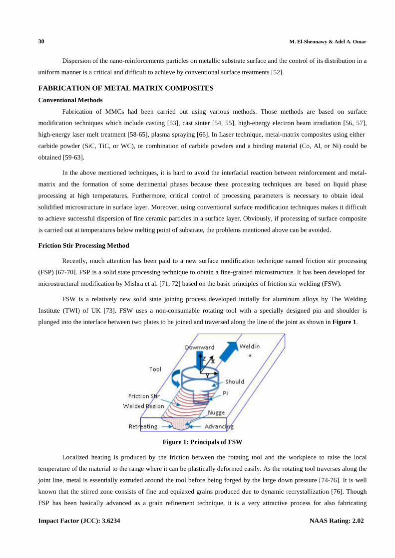
FSW is a relatively new solid state joining process developed initially for aluminum alloys by The Welding
Institute (TWI) of UK [73]. FSW uses a non-consumable rotating tool with a specially designed pin and shoulder is
plunged into the interface between two plates to be joined and traversed along the line of the joint as shown in Figure 1.
Figure 1: Principals of FSW
Localized heating is produced by the friction between the rotating tool and the workpiece to raise the local
temperature of the material to the range where it can be plastically deformed easily. As the rotating tool traverses along the
joint line, metal is essentially extruded around the tool before being forged by the large down pressure [74-76]. It is well
known that the stirred zone consists of fine and equiaxed grains produced due to dynamic recrystallization [76]. Though
FSP has been basically advanced as a grain refinement technique, it is a very attractive process for also fabricating
Manufacturing of Nano/Micro Composites using Friction Stir Processing 31
www.iaset.us [email protected]
composites. Mishra et al. [77] fabricated the Al/SiC surface composites by FSP, and indicated that SiC particles were well
distributed in the Al matrix, and good bonding with the Al matrix was generated.
Nano/Micro Metal Matrix Composites
Metal matrix composites containing nano-sized reinforcement particles inserted into the matrix are promising
materials due to the enhancement in mechanical properties. Friction stir processing technique is used in manufacturing
nano composites. Various reinforcement particles materials were applied in the metals matrices (metallic substrates) which
were also varied from aluminum alloys to copper alloys and other easy friction stir processed metal alloy.
Metallic Substrate
Aluminum Alloys
Aluminum alloys are the most widely applied metallic substrate for producing nano composites [6, 8-10, 12, 16,
18, 19, 21, 22, 33-36, 41, 78, 79, 80-84]. There also applied in case of micro composites [5, 7, 11, 17, 20, 27, 28, 32, 37-39,
42, 85-87]. Aluminum alloy AA5083 [5, 17, 32, 38, 41, 85], AA1000 [6, 8, 10], AA6061 [18, 22, 36, 37, 39, 42, 81, 87],
AA7075 [16, 19, 21, 35], AA6082 [9, 27, 28], A356 [11, 20, 78], and other aluminum alloys such as AA2618 [7], AA5052
[12] and aluminum magnesium alloy [33, 34, 82] were the most aluminum alloys received attention from researchers in the
recent years concerning metal matrix composites.
Other Metals and Alloys
Copper was used as a metal substrate in manufacturing metal matrix composites [13, 88]. Magnesium [14],
Titanium [23] and other alloys [43, 89] were also used as a metal substrate in producing metal matrix composites.
Reinforcement Particle
Alumina (Al2O3) was the main reinforcement particle used with metal substrate regardless its type [5, 7-11, 13,
14, 78, 88]. Silicon carbide (SiC) was used extensively also as reinforcement particles with different metal matrices [16-23,
35, 84, 85]. Mixture of both Al2O3 and SiC was also used [37-39]. Other carbides such as TiC [27, 28, 32], or oxides such
as TiO2 [32-34] or Cr2O3 [81] or compound such as Al-Cr-O [36] were applied as a reinforcement particles.
Process and Joint Design
There are various designs for the process followed for producing matrix metal composites MMCs using friction
stir process, FSP and different designs for the joint or specimen used in this process. There are mainly two types of joint
design followed in producing MMCs, first using flat plate [5, 8, 9, 12-15, 18, 20, 22-24, 26-28, 30-32, 34, 37-46, 90, 91],
second using two plates to form a joint to be welded [16, 19, 21, 29]. In case of flat plate there were two main methods for
inserting the reinforcement; first making groove(s) all through the plate length [8, 9, 12-15, 18, 20, 22-24, 27, 28, 32, 34,
37, 39-41, 43-46, 90, 91], second making holes in the substrate in two parallel line having specific distance apart between
each line or each hole wall [26, 30, 31, 38, 42]. In case of the joint with two separate plates, groove was made at one edge
of one plate and then been joined to the other plate [16, 19, 21, 29].
Tool used for FSP was mainly from hard steel alloy or tool steel such as H-13, or WC-Co alloy, … etc. The tool
design including shoulder diameter, pin shape and diameter(s) and length were varied to have columnar or conical shape
which either threaded or un-threaded pin/probe.
32 M. El-Shennawy & Adel A. Omar
Impact Factor (JCC): 3.6234 NAAS Rating: 2.02
Friction stir process parameters were chosen according to the plate thickness, substrate material and tool used.
Values varied in the range from 600 up to 1600 rpm for aluminum alloys, while traversing speed were in the range of 30 up
to 180 mm/min [5, 8, 9, 37, 16, 36, 27, 18, 19, 20, 28, 39, 41, 21]. Special case was recorded using 3000 rpm and 348
mm/min for cylindrical specimen with holes [38]. For cupper, it was 900-1000 rpm and 40-50 mm/min. In case of Mg and
Mg alloys, it was 800-1500 rpm and 20-45 mm/min.
Material of substrate was mainly from aluminum and its alloys, copper, magnesium and its alloys. Some cases
dealt with mild and stainless steel [29, 40] and titanium alloy [30, 43, 46].
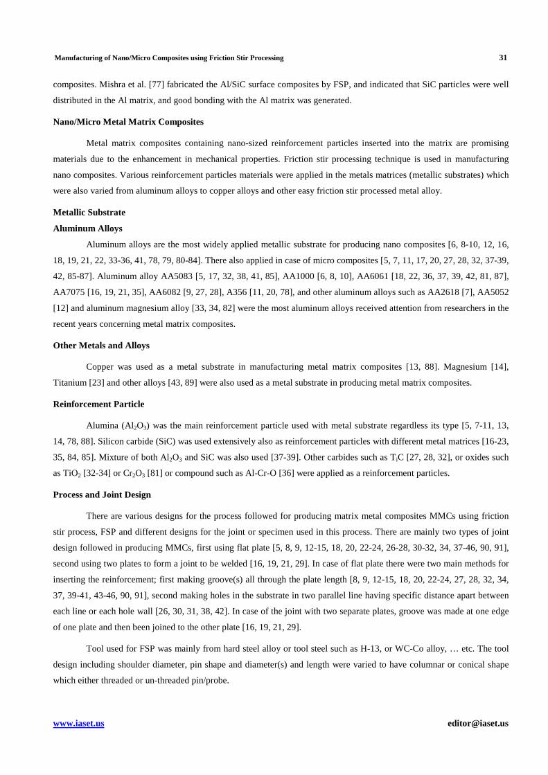
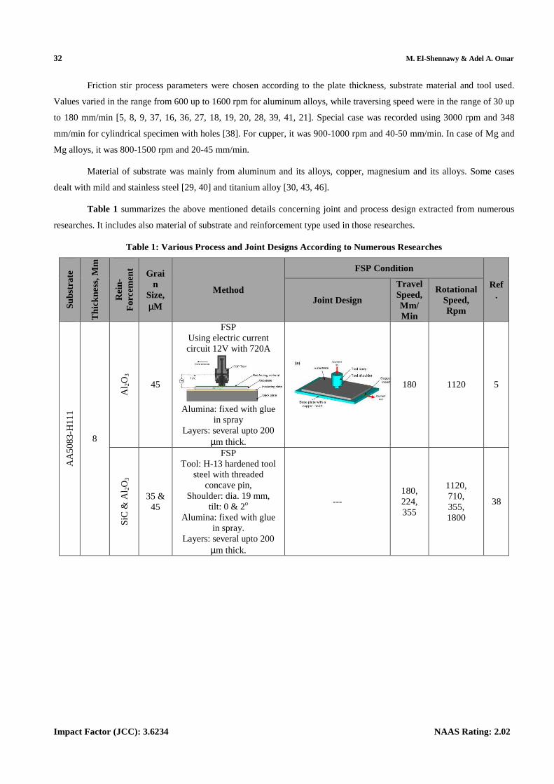
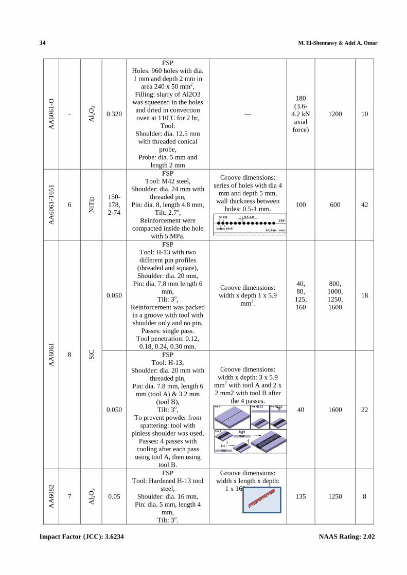
Table 1 summarizes the above mentioned details concerning joint and process design extracted from numerous
researches. It includes also material of substrate and reinforcement type used in those researches.
Table 1: Various Process and Joint Designs According to Numerous Researches
Sub
stra
te
Thi
ckne
ss, M
m
Rei
n-F
orce
men
t
Grain
Size, µM
Method
FSP Condition
Ref. Joint Design
Travel Speed, Mm/ Min
Rotational Speed, Rpm
AA
50
83
-H11
1
8
Al 2
O3
45
FSP Using electric current circuit 12V with 720A
Alumina: fixed with glue
in spray Layers: several upto 200
µm thick.
180 1120 5
SiC
& A
l 2O
3
35 & 45
FSP Tool: H-13 hardened tool
steel with threaded concave pin,
Shoulder: dia. 19 mm, tilt: 0 & 2o
Alumina: fixed with glue in spray.
Layers: several upto 200 µm thick.
--- 180, 224, 355
1120, 710, 355, 1800
38
Manufacturing of Nano/Micro Composites using Friction Stir Processing 33
www.iaset.us [email protected]
AA
50
83
-O
5
Cer
ium
Oxi
de
and
MW
CN
Ts
30 and 0 respe
ct.
FSP Tool: H-13 hot working
tool steel and heat treated, Shoulder: cylindrical
concave dia. 18 mm with threaded pin,
Pin: dia. 6 mm, length 4.5 mm,
Tilt: 5o, To prevent powder from
spattering: tool with pinless shoulder was first
used, Passes: 3 passes.
Goove dimensions: width x depth: 1.2 x 2
mm2.
35 (first 2 passes)
, 45 (last pass)
800 (first 2 passes), 600 (last
pass)
41
AA
60
61
-T6
4
SiC
, G
r (g
rap
hite
) &
A
l 2O
3
20
FSP Tool: H-13 tool steel with
screwed taper pin, Pin: dia. 8 mm, length 3.5
mm, Shoulder: dia. 24 mm,
tilt: 2.5o Initial pass: shoulder
without pin.
Groove dimensions: Square 3 x 3 mm2.
40 (5kN axial force)
900, 1120, 1400
37
SiC
+G
r,
SiC
+A
l 2O3
FSP Tool: H-13,
Shoulder: dia. 24 mm with screwed taper profile pin, Pin: dia. 8 mm, length 3.5
mm, Tilt: 2.5 o.
To prevent reinforcement escape: tool with shoulder
without pin was used.
Groove dimensions: width x depth: 3 x 3
mm2. Tangential to the pin in the advancing side and 2 mm far away from the center line of the tool
rotation on plate.
40 900 39
13
Cr 2
O3
-
FSP Tool: H-13,
Shoulder: dia. 18 mm with threaded taper pin,
Tilt: 3o, Pin: dia. 6 mm, length 4
mm, Reinforcement: placed by atmospheric plasma spray,
Passes: 6.
---
100 630
36
20-40
FSP Tool: H-13,
Shoulder: dia. 18 mm with threaded conical pin,
Pin: dia. 6 mm (upper), 4 mm (lower), length 4 mm,
Tilt: 3o, Coating:150 µm layer of Cr2O3 was first coated by APS plasma system on
substrate, Passes: 1-6 passes.
No groove 81
34 M. El-Shennawy & Adel A. Omar
Impact Factor (JCC): 3.6234 NAAS Rating: 2.02
AA
60
61
-O
-
Al 2
O3
0.320
FSP Holes: 960 holes with dia. 1 mm and depth 2 mm in
area 240 x 50 mm2, Filling: slurry of Al2O3
was squeezed in the holes and dried in convection oven at 110oC for 2 hr,
Tool: Shoulder: dia. 12.5 mm with threaded conical
probe, Probe: dia. 5 mm and
length 2 mm
---
180 (3.6-
4.2 kN axial force)
1200 10
AA
60
61
-T6
51
6
NiT
ip 150-
178, 2-74
FSP Tool: M42 steel,
Shoulder: dia. 24 mm with threaded pin,
Pin: dia. 8, length 4.8 mm, Tilt: 2.7o,
Reinforcement were compacted inside the hole
with 5 MPa.
Groove dimensions: series of holes with dia 4
mm and depth 5 mm, wall thickness between
holes: 0.5-1 mm. 100 600 42
AA
60
61
8 SiC
0.050
FSP Tool: H-13 with two different pin profiles
(threaded and square), Shoulder: dia. 20 mm,
Pin: dia. 7.8 mm length 6 mm,
Tilt: 3o, Reinforcement was packed in a groove with tool with shoulder only and no pin,
Passes: single pass. Tool penetration: 0.12, 0.18, 0.24, 0.30 mm.
Groove dimensions: width x depth 1 x 5.9
mm2.
40, 80, 125, 160
800, 1000, 1250, 1600
18
0.050
FSP Tool: H-13,
Shoulder: dia. 20 mm with threaded pin,
Pin: dia. 7.8 mm, length 6 mm (tool A) & 3.2 mm
(tool B), Tilt: 3o,
To prevent powder from spattering: tool with
pinless shoulder was used, Passes: 4 passes with
cooling after each pass using tool A, then using
tool B.
Groove dimensions: width x depth: 3 x 5.9
mm2 with tool A and 2 x 2 mm2 with tool B after
the 4 passes. 40 1600 22
AA
60
82
7
Al 2
O3
0.05
FSP Tool: Hardened H-13 tool
steel, Shoulder: dia. 16 mm,
Pin: dia. 5 mm, length 4 mm,
Tilt: 3o.
Groove dimensions: width x length x depth:
1 x 160 x 4 mm3
135 1250 8
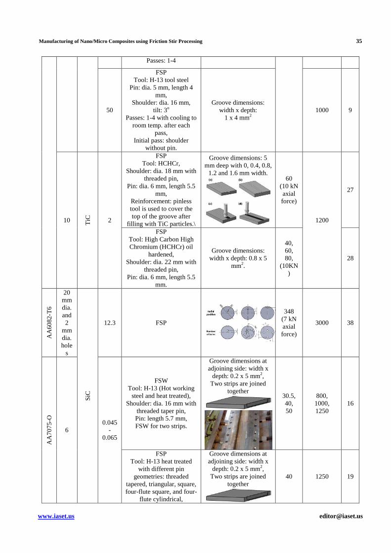
Manufacturing of Nano/Micro Composites using Friction Stir Processing 35
www.iaset.us [email protected]
Passes: 1-4
50
FSP Tool: H-13 tool steel
Pin: dia. 5 mm, length 4 mm,
Shoulder: dia. 16 mm, tilt: 3o
Passes: 1-4 with cooling to room temp. after each
pass, Initial pass: shoulder
without pin.
Groove dimensions: width x depth:
1 x 4 mm2 1000 9
10 TiC
2
FSP Tool: HCHCr,
Shoulder: dia. 18 mm with threaded pin,
Pin: dia. 6 mm, length 5.5 mm,
Reinforcement: pinless tool is used to cover the top of the groove after
filling with TiC particles.\
Groove dimensions: 5 mm deep with 0, 0.4, 0.8,
1.2 and 1.6 mm width.
60 (10 kN axial force)
1200
27
FSP Tool: High Carbon High Chromium (HCHCr) oil
hardened, Shoulder: dia. 22 mm with
threaded pin, Pin: dia. 6 mm, length 5.5
mm.
Groove dimensions: width x depth: 0.8 x 5
mm2.
40, 60, 80,
(10KN)
28
AA
60
82
-T6
20 mm dia. and 2
mm dia. hole
s
SiC
12.3 FSP
348 (7 kN axial force)
3000 38
AA
70
75
-O
6 0.045
-0.065
FSW Tool: H-13 (Hot working
steel and heat treated), Shoulder: dia. 16 mm with
threaded taper pin, Pin: length 5.7 mm, FSW for two strips.
Groove dimensions at adjoining side: width x
depth: 0.2 x 5 mm2, Two strips are joined
together
30.5, 40, 50
800, 1000, 1250
16
FSP Tool: H-13 heat treated
with different pin geometries: threaded
tapered, triangular, square, four-flute square, and four-
flute cylindrical,
Groove dimensions at adjoining side: width x
depth: 0.2 x 5 mm2, Two strips are joined
together
40 1250 19
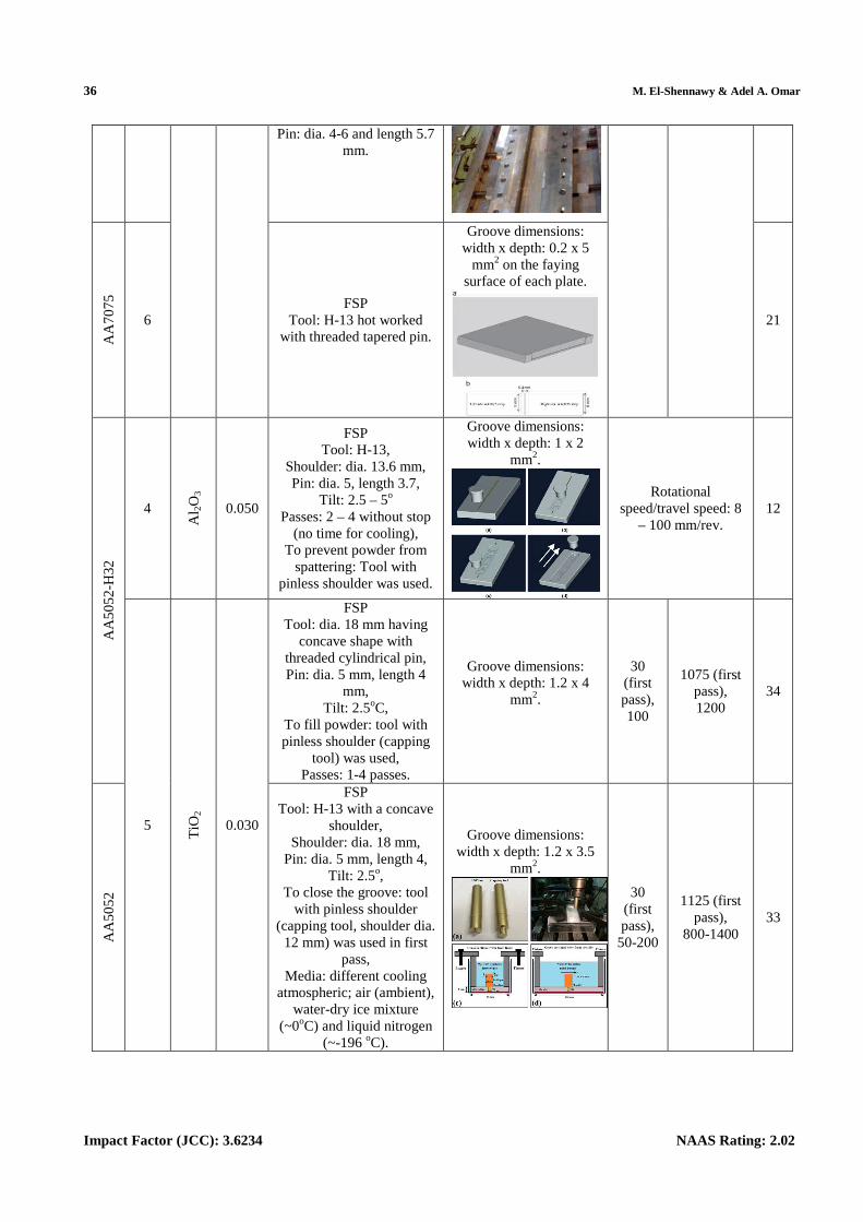
36 M. El-Shennawy & Adel A. Omar
Impact Factor (JCC): 3.6234 NAAS Rating: 2.02
Pin: dia. 4-6 and length 5.7 mm.
AA
70
75
6 FSP
Tool: H-13 hot worked with threaded tapered pin.
Groove dimensions: width x depth: 0.2 x 5
mm2 on the faying surface of each plate.
21
AA
50
52
-H32
4
Al 2
O3
0.050
FSP Tool: H-13,
Shoulder: dia. 13.6 mm, Pin: dia. 5, length 3.7,
Tilt: 2.5 – 5o Passes: 2 – 4 without stop
(no time for cooling), To prevent powder from
spattering: Tool with pinless shoulder was used.
Groove dimensions: width x depth: 1 x 2
mm2.
Rotational speed/travel speed: 8
– 100 mm/rev. 12
5
TiO
2
0.030
FSP Tool: dia. 18 mm having
concave shape with threaded cylindrical pin, Pin: dia. 5 mm, length 4
mm, Tilt: 2.5oC,
To fill powder: tool with pinless shoulder (capping
tool) was used, Passes: 1-4 passes.
Groove dimensions: width x depth: 1.2 x 4
mm2.
30 (first pass), 100
1075 (first pass), 1200
34
AA
50
52
FSP Tool: H-13 with a concave
shoulder, Shoulder: dia. 18 mm,
Pin: dia. 5 mm, length 4, Tilt: 2.5o,
To close the groove: tool with pinless shoulder
(capping tool, shoulder dia. 12 mm) was used in first
pass, Media: different cooling
atmospheric; air (ambient), water-dry ice mixture
(~0oC) and liquid nitrogen (~-196 oC).
Groove dimensions: width x depth: 1.2 x 3.5
mm2.
30 (first pass), 50-200
1125 (first pass),
800-1400 33
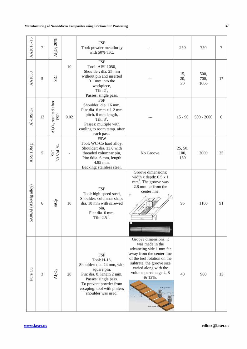
Manufacturing of Nano/Micro Composites using Friction Stir Processing 37
www.iaset.us [email protected]
AA
26
18
-T6
7
Al 2
O3
20
%
10
FSP Tool: powder metallurgy
with 50% TiC. --- 250 750 7
AA
10
50
5 SiC
FSP Tool: AISI 1050,
Shoulder: dia. 25 mm without pin and inserted
0.1 mm into the workpiece,
Tilt: 2o, Passes: single pass.
--- 15, 20, 30
500, 700, 1000
17
Al-
10
SiO
2
12
Al 2
O3
resu
lted
aft
er
FS
P
0.02
FSP Shoulder: dia. 16 mm,
Pin: dia. 6 mm x 1.2 mm pitch, 6 mm length,
Tilt: 3o, Passes: multiple with
cooling to room temp. after each pass.
--- 15 - 90 500 - 2000 6
Al-
Si1
0M
g
5 SiC
3
0 V
ol.
%
-
FSW Tool: WC-Co hard alloy, Shoulder: dia. 13.6 with threaded columnar pin, Pin: 6dia. 6 mm, length
4.85 mm, Backing: stainless steel.
No Groove. 25, 50, 100, 150
2000 25
5A
06
Al (
Al-
Mg
allo
y)
6
SiC
p
10
FSP Tool: high-speed steel,
Shoulder: columnar shape dia. 18 mm with screwed
pin, Pin: dia. 6 mm,
Tilt: 2.5 o.
Groove dimensions: width x depth: 0.5 x 1 mm2. The groove was 2.8 mm far from the
center line.
95 1180 91
Pu
re C
u
3
Al 2
O3
20
FSP Tool: H-13,
Shoulder: dia. 24 mm, with square pin,
Pin: dia. 8, length 2 mm, Passes: single pass.
To prevent powder from escaping: tool with pinless
shoulder was used.
Groove dimensions: it was made in the
advancing side 1 mm far away from the center line of the tool rotation on the subtrate, the groove size
varied along with the volume percentage 4, 8
& 12%. 40 900 13
38 M. El-Shennawy & Adel A. Omar
Impact Factor (JCC): 3.6234 NAAS Rating: 2.02
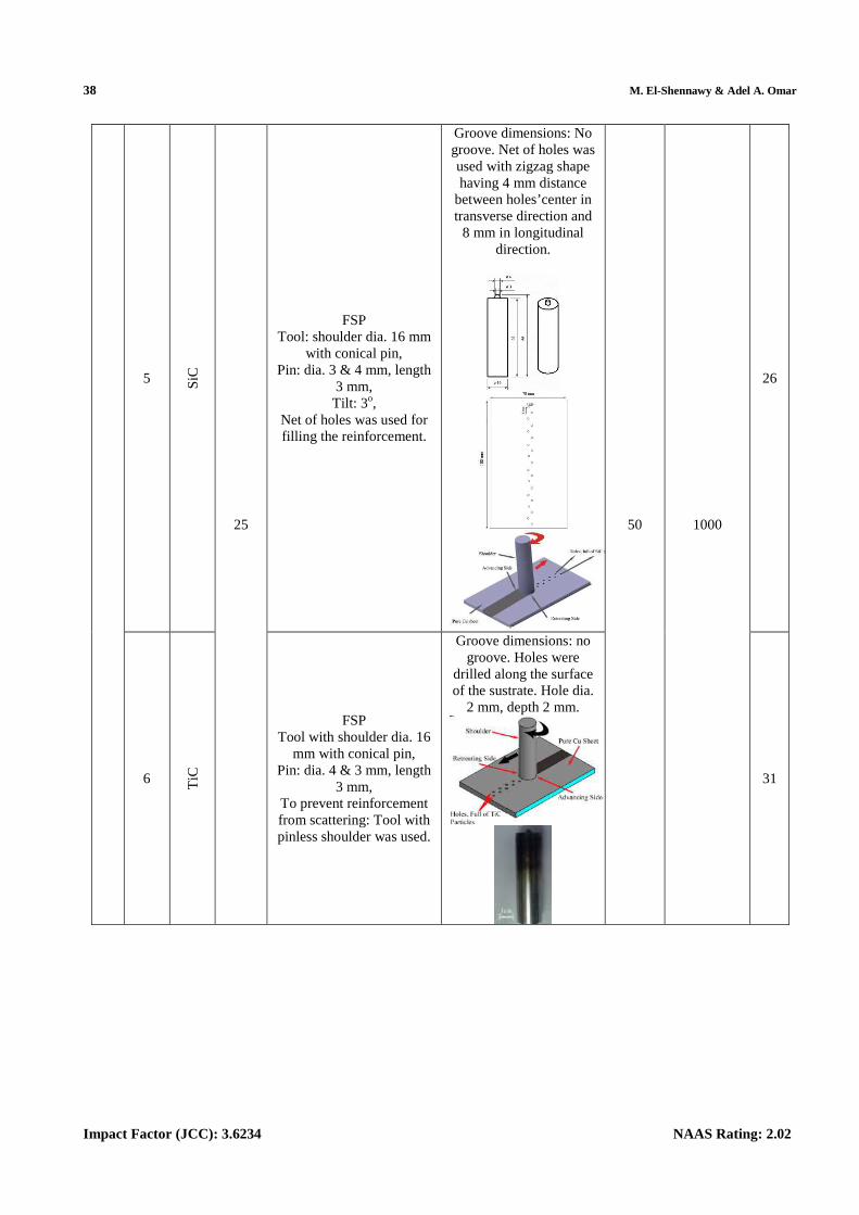
5 SiC
25
FSP Tool: shoulder dia. 16 mm
with conical pin, Pin: dia. 3 & 4 mm, length
3 mm, Tilt: 3o,
Net of holes was used for filling the reinforcement.
Groove dimensions: No groove. Net of holes was used with zigzag shape having 4 mm distance
between holes’center in transverse direction and
8 mm in longitudinal direction.
50 1000
26
6 TiC
FSP Tool with shoulder dia. 16
mm with conical pin, Pin: dia. 4 & 3 mm, length
3 mm, To prevent reinforcement from scattering: Tool with pinless shoulder was used.
Groove dimensions: no groove. Holes were
drilled along the surface of the sustrate. Hole dia.
2 mm, depth 2 mm.
31
Manufacturing of Nano/Micro Composites using Friction Stir Processing 39
www.iaset.us [email protected]
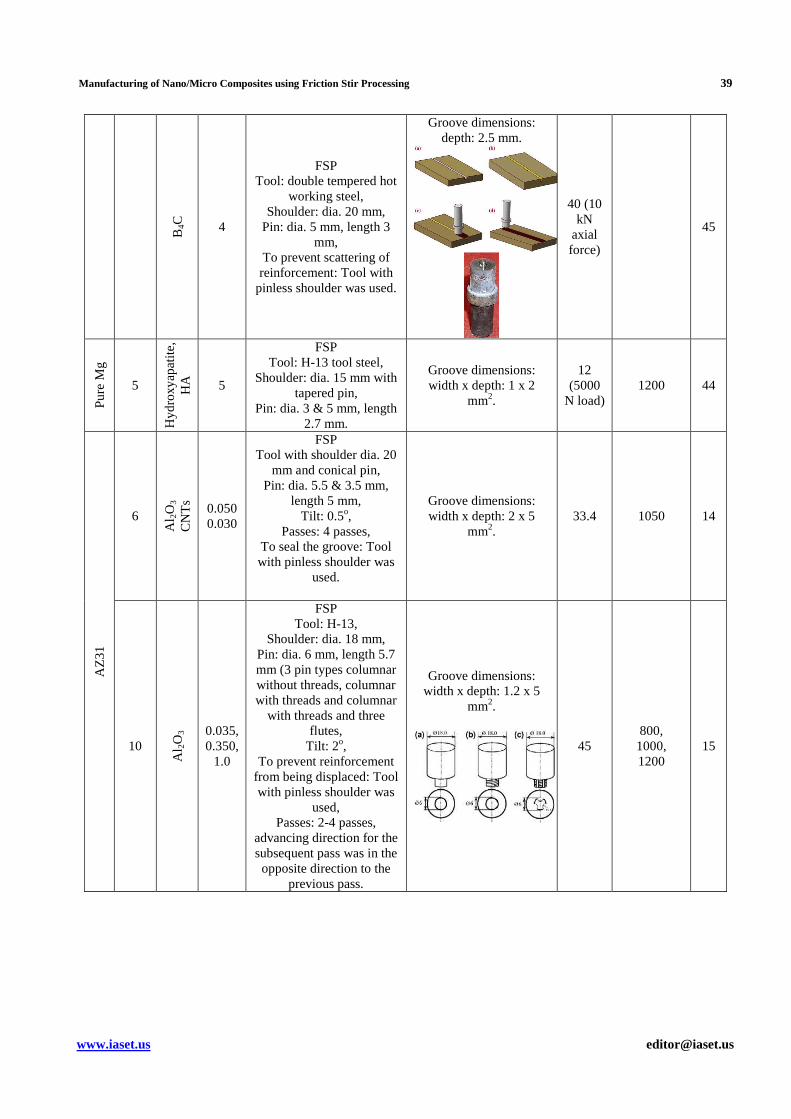
B4C
4
FSP Tool: double tempered hot
working steel, Shoulder: dia. 20 mm,
Pin: dia. 5 mm, length 3 mm,
To prevent scattering of reinforcement: Tool with
pinless shoulder was used.
Groove dimensions: depth: 2.5 mm.
40 (10 kN
axial force)
45
Pu
re M
g
5
Hyd
roxy
apat
ite,
HA
5
FSP Tool: H-13 tool steel,
Shoulder: dia. 15 mm with tapered pin,
Pin: dia. 3 & 5 mm, length 2.7 mm.
Groove dimensions: width x depth: 1 x 2
mm2.
12 (5000
N load) 1200 44
AZ
31
6
Al 2
O3
CN
Ts
0.050 0.030
FSP Tool with shoulder dia. 20
mm and conical pin, Pin: dia. 5.5 & 3.5 mm,
length 5 mm, Tilt: 0.5o,
Passes: 4 passes, To seal the groove: Tool with pinless shoulder was
used.
Groove dimensions: width x depth: 2 x 5
mm2. 33.4 1050 14
10
Al 2
O3 0.035,
0.350, 1.0
FSP Tool: H-13,
Shoulder: dia. 18 mm, Pin: dia. 6 mm, length 5.7 mm (3 pin types columnar without threads, columnar with threads and columnar
with threads and three flutes,
Tilt: 2o, To prevent reinforcement
from being displaced: Tool with pinless shoulder was
used, Passes: 2-4 passes,
advancing direction for the subsequent pass was in the opposite direction to the
previous pass.
Groove dimensions: width x depth: 1.2 x 5
mm2.
45 800, 1000, 1200
15
40 M. El-Shennawy & Adel A. Omar
Impact Factor (JCC): 3.6234 NAAS Rating: 2.02
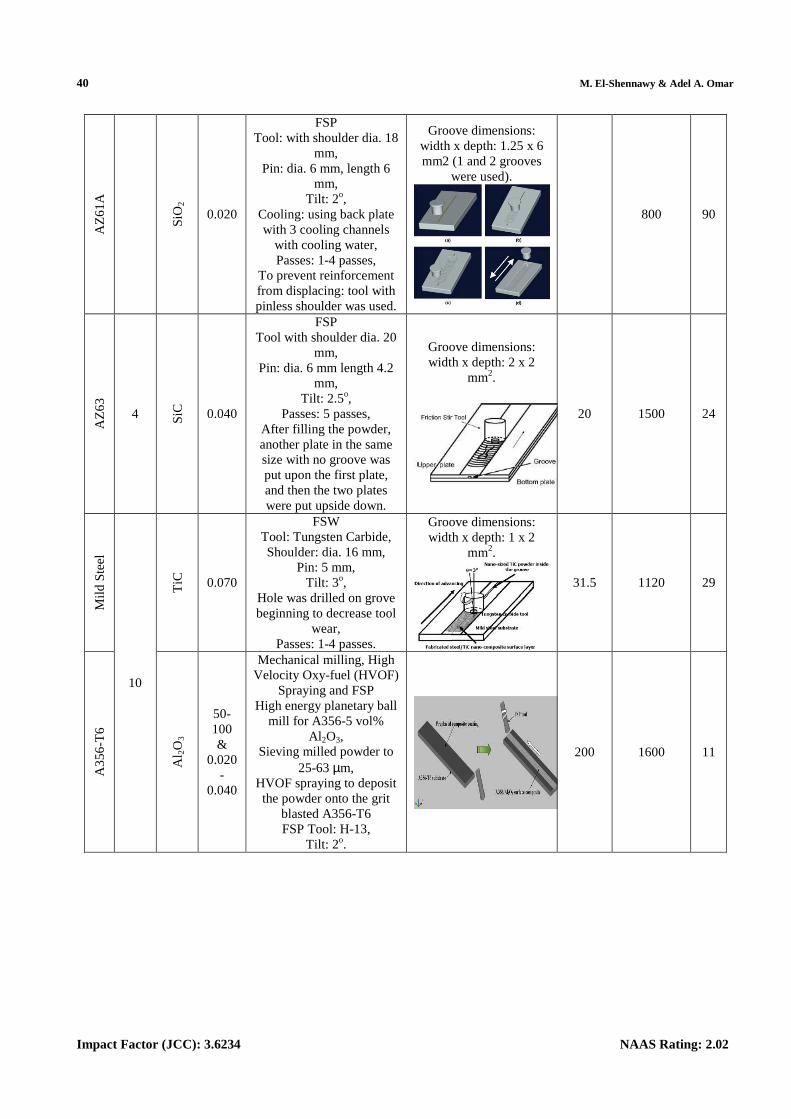
AZ
61
A
SiO
2
0.020
FSP Tool: with shoulder dia. 18
mm, Pin: dia. 6 mm, length 6
mm, Tilt: 2o,
Cooling: using back plate with 3 cooling channels
with cooling water, Passes: 1-4 passes,
To prevent reinforcement from displacing: tool with pinless shoulder was used.
Groove dimensions: width x depth: 1.25 x 6 mm2 (1 and 2 grooves
were used).
800 90
AZ
63
4 SiC
0.040
FSP Tool with shoulder dia. 20
mm, Pin: dia. 6 mm length 4.2
mm, Tilt: 2.5o,
Passes: 5 passes, After filling the powder, another plate in the same size with no groove was put upon the first plate, and then the two plates were put upside down.
Groove dimensions: width x depth: 2 x 2
mm2.
20 1500 24
Mild
Ste
el
10
TiC
0.070
FSW Tool: Tungsten Carbide, Shoulder: dia. 16 mm,
Pin: 5 mm, Tilt: 3o,
Hole was drilled on grove beginning to decrease tool
wear, Passes: 1-4 passes.
Groove dimensions: width x depth: 1 x 2
mm2.
31.5 1120 29
A3
56
-T6
Al 2
O3
50-100 &
0.020-
0.040
Mechanical milling, High Velocity Oxy-fuel (HVOF)
Spraying and FSP High energy planetary ball
mill for A356-5 vol% Al 2O3,
Sieving milled powder to 25-63 µm,
HVOF spraying to deposit the powder onto the grit
blasted A356-T6 FSP Tool: H-13,
Tilt: 2o.
200 1600 11
Manufacturing of Nano/Micro Composites using Friction Stir Processing 41
www.iaset.us [email protected]
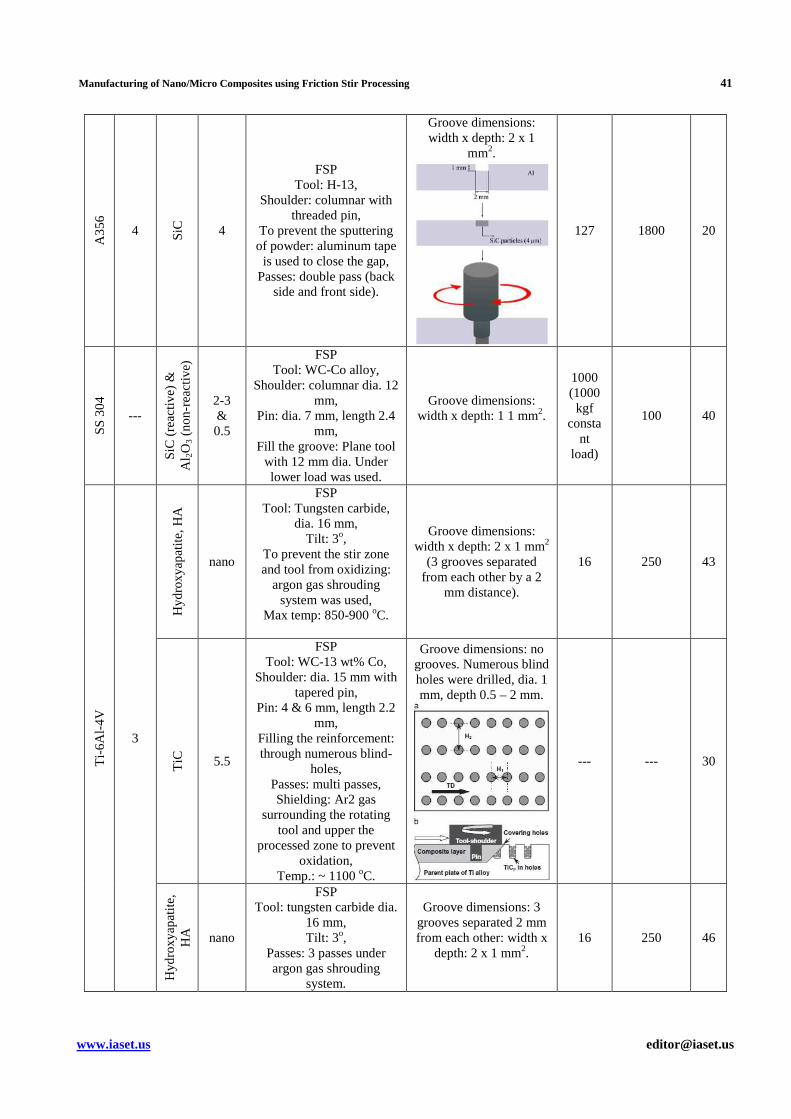
A3
56
4 SiC
4
FSP Tool: H-13,
Shoulder: columnar with threaded pin,
To prevent the sputtering of powder: aluminum tape is used to close the gap,
Passes: double pass (back side and front side).
Groove dimensions: width x depth: 2 x 1
mm2.
127 1800 20
SS
30
4
---
SiC
(re
activ
e) &
A
l 2O
3 (n
on
-rea
ctiv
e)
2-3 & 0.5
FSP Tool: WC-Co alloy,
Shoulder: columnar dia. 12 mm,
Pin: dia. 7 mm, length 2.4 mm,
Fill the groove: Plane tool with 12 mm dia. Under lower load was used.
Groove dimensions: width x depth: 1 1 mm2.
1000 (1000 kgf
constant
load)
100 40
Ti-
6A
l-4
V
3
Hyd
roxy
apat
ite,
HA
nano
FSP Tool: Tungsten carbide,
dia. 16 mm, Tilt: 3o,
To prevent the stir zone and tool from oxidizing:
argon gas shrouding system was used,
Max temp: 850-900 oC.
Groove dimensions: width x depth: 2 x 1 mm2
(3 grooves separated from each other by a 2
mm distance).
16 250 43
TiC
5.5
FSP Tool: WC-13 wt% Co,
Shoulder: dia. 15 mm with tapered pin,
Pin: 4 & 6 mm, length 2.2 mm,
Filling the reinforcement: through numerous blind-
holes, Passes: multi passes, Shielding: Ar2 gas
surrounding the rotating tool and upper the
processed zone to prevent oxidation,
Temp.: ~ 1100 oC.
Groove dimensions: no grooves. Numerous blind holes were drilled, dia. 1 mm, depth 0.5 – 2 mm.
--- --- 30
Hyd
roxy
apat
ite,
HA
nano
FSP Tool: tungsten carbide dia.
16 mm, Tilt: 3o,
Passes: 3 passes under argon gas shrouding
system.
Groove dimensions: 3 grooves separated 2 mm from each other: width x
depth: 2 x 1 mm2.
16 250 46
42 M. El-Shennawy & Adel A. Omar
Impact Factor (JCC): 3.6234 NAAS Rating: 2.02
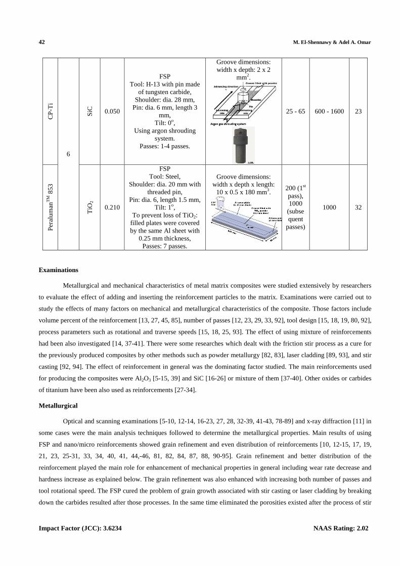
CP
-Ti
6
SiC
0.050
FSP Tool: H-13 with pin made
of tungsten carbide, Shoulder: dia. 28 mm,
Pin: dia. 6 mm, length 3 mm,
Tilt: 0o, Using argon shrouding
system. Passes: 1-4 passes.
Groove dimensions: width x depth: 2 x 2
mm2.
25 - 65 600 - 1600 23
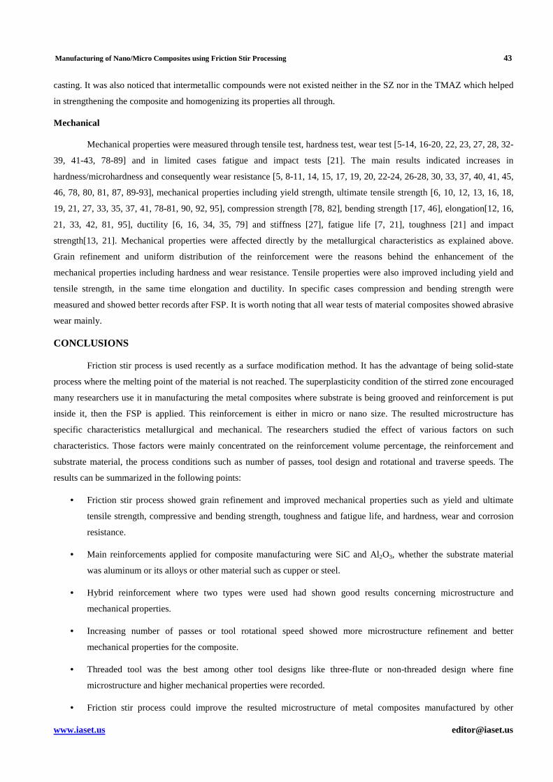
Per
alu
man
TM
853
TiO
2
0.210
FSP Tool: Steel,
Shoulder: dia. 20 mm with threaded pin,
Pin: dia. 6, length 1.5 mm, Tilt: 1o,
To prevent loss of TiO2: filled plates were covered by the same Al sheet with
0.25 mm thickness, Passes: 7 passes.
Groove dimensions: width x depth x length:
10 x 0.5 x 180 mm3. 200 (1st pass), 1000 (subsequent
passes)
1000 32
Examinations
Metallurgical and mechanical characteristics of metal matrix composites were studied extensively by researchers
to evaluate the effect of adding and inserting the reinforcement particles to the matrix. Examinations were carried out to
study the effects of many factors on mechanical and metallurgical characteristics of the composite. Those factors include
volume percent of the reinforcement [13, 27, 45, 85], number of passes [12, 23, 29, 33, 92], tool design [15, 18, 19, 80, 92],
process parameters such as rotational and traverse speeds [15, 18, 25, 93]. The effect of using mixture of reinforcements
had been also investigated [14, 37-41]. There were some researches which dealt with the friction stir process as a cure for
the previously produced composites by other methods such as powder metallurgy [82, 83], laser cladding [89, 93], and stir
casting [92, 94]. The effect of reinforcement in general was the dominating factor studied. The main reinforcements used
for producing the composites were Al2O3 [5-15, 39] and SiC [16-26] or mixture of them [37-40]. Other oxides or carbides
of titanium have been also used as reinforcements [27-34].
Metallurgical
Optical and scanning examinations [5-10, 12-14, 16-23, 27, 28, 32-39, 41-43, 78-89] and x-ray diffraction [11] in
some cases were the main analysis techniques followed to determine the metallurgical properties. Main results of using
FSP and nano/micro reinforcements showed grain refinement and even distribution of reinforcements [10, 12-15, 17, 19,
21, 23, 25-31, 33, 34, 40, 41, 44,-46, 81, 82, 84, 87, 88, 90-95]. Grain refinement and better distribution of the
reinforcement played the main role for enhancement of mechanical properties in general including wear rate decrease and
hardness increase as explained below. The grain refinement was also enhanced with increasing both number of passes and
tool rotational speed. The FSP cured the problem of grain growth associated with stir casting or laser cladding by breaking
down the carbides resulted after those processes. In the same time eliminated the porosities existed after the process of stir
Manufacturing of Nano/Micro Composites using Friction Stir Processing 43
www.iaset.us [email protected]
casting. It was also noticed that intermetallic compounds were not existed neither in the SZ nor in the TMAZ which helped
in strengthening the composite and homogenizing its properties all through.
Mechanical
Mechanical properties were measured through tensile test, hardness test, wear test [5-14, 16-20, 22, 23, 27, 28, 32-
39, 41-43, 78-89] and in limited cases fatigue and impact tests [21]. The main results indicated increases in
hardness/microhardness and consequently wear resistance [5, 8-11, 14, 15, 17, 19, 20, 22-24, 26-28, 30, 33, 37, 40, 41, 45,
46, 78, 80, 81, 87, 89-93], mechanical properties including yield strength, ultimate tensile strength [6, 10, 12, 13, 16, 18,
19, 21, 27, 33, 35, 37, 41, 78-81, 90, 92, 95], compression strength [78, 82], bending strength [17, 46], elongation[12, 16,
21, 33, 42, 81, 95], ductility [6, 16, 34, 35, 79] and stiffness [27], fatigue life [7, 21], toughness [21] and impact
strength[13, 21]. Mechanical properties were affected directly by the metallurgical characteristics as explained above.
Grain refinement and uniform distribution of the reinforcement were the reasons behind the enhancement of the
mechanical properties including hardness and wear resistance. Tensile properties were also improved including yield and
tensile strength, in the same time elongation and ductility. In specific cases compression and bending strength were
measured and showed better records after FSP. It is worth noting that all wear tests of material composites showed abrasive
wear mainly.
CONCLUSIONS
Friction stir process is used recently as a surface modification method. It has the advantage of being solid-state
process where the melting point of the material is not reached. The superplasticity condition of the stirred zone encouraged
many researchers use it in manufacturing the metal composites where substrate is being grooved and reinforcement is put
inside it, then the FSP is applied. This reinforcement is either in micro or nano size. The resulted microstructure has
specific characteristics metallurgical and mechanical. The researchers studied the effect of various factors on such
characteristics. Those factors were mainly concentrated on the reinforcement volume percentage, the reinforcement and
substrate material, the process conditions such as number of passes, tool design and rotational and traverse speeds. The
results can be summarized in the following points:
• Friction stir process showed grain refinement and improved mechanical properties such as yield and ultimate
tensile strength, compressive and bending strength, toughness and fatigue life, and hardness, wear and corrosion
resistance.
• Main reinforcements applied for composite manufacturing were SiC and Al2O3, whether the substrate material
was aluminum or its alloys or other material such as cupper or steel.
• Hybrid reinforcement where two types were used had shown good results concerning microstructure and
mechanical properties.
• Increasing number of passes or tool rotational speed showed more microstructure refinement and better
mechanical properties for the composite.
• Threaded tool was the best among other tool designs like three-flute or non-threaded design where fine
microstructure and higher mechanical properties were recorded.
• Friction stir process could improve the resulted microstructure of metal composites manufactured by other
44 M. El-Shennawy & Adel A. Omar
Impact Factor (JCC): 3.6234 NAAS Rating: 2.02
methods like stir casting or laser cladding where large grains have been broken into fine grains and porosities
were limited after FSP application.
REFERENCES
1. H. Bakes, D. Benjamin, C. W. Kirkpatrick (Eds.), Metals Handbook, vol. 2, ASM, Metals Park, OH, 1979, pp. 3–
23.
2. Y. Wan, Q. J. Xue, Tribol. Lett. 2 (1996) 37–45.
3. M. E. Smagorinski, P. G. Tsantrizos, S. Grenier, J. Min. Met. Mater. 48 (1996) 56–59.
4. Sajjadi SA, Ezatpour HR, Beygi H., Proceedings of 14th national conference on Materials Science and
Engineering, Tehran, Iran; 2010. pp. 325–32.
5. Telmo G. Santos, N. Lopes, Miguel Machado, Pedro Vilaca, R. M Miranda, J Mat. Proc. Tech. 216 (2015), pp.
375-380.
6. You, G. L., Ho, N. J., Kao, P. W., Mat. Charact. 80 (2013), pp. 1-8.
7. Cavaliere, P, Composites, Part A 36 (2005), pp. 1657-1665.
8. Shafiei-Zarghani, A, Kashani-Bozorg, S. F., Zarei-Hanzaki, A, Wear 270 (2011), pp. 403-412.
9. Shafiei-Zarghani, A, Kashani-Bozorg, S. F., Zarei-Hanzaki, A, Mater. Sci. Engg. A 500 (2009), pp. 84-91.
10. Guo, J. F., Liu, J, Sun, C. N., Maleksaeedi, S., Bi, G., Tan, M. J., Wei, J., Mater. Sci. Engg. A 602 (2014), pp.
143-149.
11. Mazaheri, Y., Karimzadeh, F., Enayati, M. H., J. Mater. Proc. Tech. 211 (2011), pp. 1614-1619.
12. Sharifitabar, M. Sarani, A. Khorshahian, S. Shafiee Afarani, M., Materials and Design 32 (2011), pp. 4164–4172.
13. Suvarna Raju, L., Kumar, A., Proc. Mater. Sci. 5 (2014, pp. 434-443.
14. Dehong Lu, Yehua Jiang, Rong Zhou, Wear 305 (2013), pp. 286–290.\
15. Azizieh, M., Kokabi, A. H., Abachi, P., Materials and Design 32 (2011), pp. 2034–2041.
16. Mohsen Bahrami, Kamran Dehghani, Mohammad Kazem Besharati Givi, Materials and Design 53 (2014), pp.
217–225.
17. Adem Kurta, Ilyas Uygurb, Eren Cete, Jl. Mater. Proc. Tech. 211 (2011), pp. 313–317.
18. Salehi, M., Saadatmand, M., Aghazadeh mohandesi, J., Trans. Nonferrous Met. Soc. China 22 (2012), 1055-1063.
19. Mohsen Bahrami, Mohammad Kazem Besharati Givi, Kamran Dehghani, Nader Parvin, Materials and Design 53
(2014), 519–527.
20. Don-Hyun Choi, Yong-Hwan Kim, Byung-Wook Ahn, Yong-Il Kim, Seung-Boo Jung, Trans. Nonferrous Met.
Soc. China 23 (2013), pp. 335−340.
21. Mohsen Bahrami, Nader Helmi, Kamran Dehghani, Mohammad Kazem Besharati Givi, Mat. Sci. & Engg. A595
(2014), pp. 173–178.
Manufacturing of Nano/Micro Composites using Friction Stir Processing 45
www.iaset.us [email protected]
22. Mojtaba Salehi, Hamidreza Farnoush, Jamshid Aghazadeh Mohandesi, Materials and Design 63 (2014), pp. 419–
426.
23. Ali Shamsipur, Seyed Farshid Kashani-Bozorg, Abbas Zarei-Hanzaki, Surface & Coatings Technology 206
(2011), pp. 1372–1381.
24. Sun, K., Shi, Q. Y., Sun, Y. J., Chen, G. Q., Mat. Sci. and Engg. A 547 (2012), pp. 32– 37.
25. Huijie Liu, Yanying Hu, Yunqiang Zhao, Hidetoshi Fujii, Materials and Design 65 (2015), pp. 395–400.
26. Akramifard, H. R., Shamanian, M., Sabbaghian, M., Esmailzadeh, M., Materials and Design 54 (2014), pp. 838–
844.
27. Thangarasu, A., Murugan, N., Dinaharan, I., Vijay, S. J., Archives of Civil and Mechanical Engineering 15
(2015), pp. 324–334.
28. Thangarasu, A., Murugan, N., Dinaharan, I., Vijay, S. J., Procedia Mat. Sci. 5 (2014), pp. 2115-2121.
29. Ahmad Ghasemi-Kahrizsangi, Seyed Farshid Kashani-Bozorg, Surface & Coatings Technology 209 (2012), pp.
15–22.
30. Bo Li, Yifu Shen, Lei Luo, Weiye Hu, Mat. Sci. & Engg. A574 (2013), pp. 75–85.
31. Sabbaghiana, M., Shamaniana, M., Akramifarda, H. R., Esmailzadeh, M., Ceramics International 40 (2014), pp.
12969–12976.
32. Visweswara Chakravarthy Gudla, Flemming Jensen, Aude Simar, Rajashekhara Shabadi, Rajan Ambat, Applied
Surface Science 324 (2015), pp. 554–562.
33. Khodabakhshi, F., Gerlich, A. P., Simchi, A., H. Kokabi, A., Mat. Sci. & Engg A620 (2014), 471–482.
34. Khodabakhshi, F., Simchi, A., Kokabi, A. H., Gerlich, A. P., Nosko, M., Materials and Design 63 (2014), pp. 30–
41.
35. Mohsen Bahrami, Kamran Dehghani, Mohammad Kazem Besharati Givi, Materials and Design 53 (2014), pp.
217–225.
36. Anvari, S. R., Karimzadeh, F., Enayati, M. H., Wear 304 (2013), pp. 144–151.
37. Devaraju Aruria, Kumar Adepua, Kumaraswamy Adepub, Kotiveerachari Bazavada, j. Mat. Res. Tech. 2 (2013),
pp. 362–369.
38. Miranda, R. M., Santosa, Telmo G., Gandrab, J., Lopesa, N., Silva, R. J. C., Jl. Mat. Proc. Tech. 213 (2013), pp.
1609– 1615.
39. Devaraju, A., Kumar, A., Kotiveerachari, B., Trans. Nonferrous Met. Soc. China 23 (2013), pp. 1275−1280.
40. Kimoto, Y., Nagaoka, T., Watanabe, H., Fukusumi, M., Osaka Municipal Technical Research Institute, Japan, pp.
389-393.
41. Hossieni, S. A., Khalil Ranjbar, Dehmolaei, R., Amirani, A. R., Jl. Alloys and Compounds 622 (2015), pp 725–
733.
46 M. El-Shennawy & Adel A. Omar
Impact Factor (JCC): 3.6234 NAAS Rating: 2.02
42. Ni, D. R., Wanga, J. J., Zhou, Z. N., Ma, Z. Y., Jl. of Alloys and Compounds 586 (2014), pp. 368–374.
43. Hamidreza Farnousha, Ashkan Abdi Bastamia, Ali Sadeghib, Jamshid Aghazadeh Mohandesia, Fathollah
Moztarzadeh, Jl. Mech. Behavior of Biomedical Materials 20 (2013), pp. 90–97.
44. Sunil, B. Ratna, Kumar, T. S. Sampath, Uday Chakkingal, Nandakumar, V., Mukesh Doble, Mat. Sci. and Engg.
C39 (2014), pp. 315–324.
45. Sathiskumara, R., Murugana, N., Dinaharanb, I., Vijay, S. J., Mat. Characterization 84 (2013), pp. 16–27.
46. Hamidreza Farnoush, Ali Sadeghi, Ashkan Abdi Bastami, Fathollah Moztarzadeh, Jamshid Aghazadeh
Mohandesi, Ceramics International 39 (2013), pp. 1477–1483.
47. Vencl A, Bobic I, Arostegui S, Bobic B. Structural, mechanical and tribological properties of A356 aluminum
alloy reinforced with Al2O3, SiC and SiC + graphite particles. J. Alloys Compd. 506 (2010), pp. 631–639.
48. Sajjadi SA, Torabi Parizi M, Ezatpour HR, Sedghi A. Fabrication of A356 composites reinforced with micro and
nano Al2O3 particles by a developed compocasting method and study of their properties. J, Alloys Compd. 511
(2012), pp. 226-231.
49. Mazahery A, Abdizadeh H, Baharvandi HR. Development of high-performance A356/nano-Al2O3 composites.
Mater Sci Eng A 518 (2009), pp. 61–64.
50. T. W. Clyne, P. J. Withers, An Introduction to Metal Matrix Composites, Cambridge University Press,
Cambridge, 1993.
51. E. Rabinowicz, Friction and Wear of Materials, John Wiley and Sons, New York, 1965.
52. K. G. Budinski, Surface Engineering for Wear Resistance, Prentice-Hall, New Jersey, 1988.
53. A. N. Attia, Mater. Des. 22 (2001), 451.
54. Y. Wang, X. Zhang, G. Zeng, F. Li, Mater. Des. 21 (2000), 447.
55. Y. S. Wang, X. Y. Zhang, G. T. Zeng, F. C. Li, Composites Part A 32 (2001), 281.
56. S.-H. Choo, S. Lee, S.-J. Kwon, Metall. Mater. Trans. A 30A (1999), 1211.
57. S.-H. Choo, S. Lee, S.-J. Kwon, Metall. Mater. Trans. A 30A (1999), 3131.
58. G. Ricciardi, M. Cantello, G. Mollino, W. Varani, E. Garlet, Proceedings of 2nd International Seminar on Surface
Engineering with High Energy Beam, Science and Technology, CEMUL-IST, Lisbon, Portugal, 1989, pp. 415-
423.
59. D. Pantelis, A. Tissandier, P. Manolatos, P. Ponthiaux, Mater. Sci. Technol. 11 (1995), 299.
60. C. Hu, T. N. Baker, J. Mater. Sci. 30 (1995), 891.
61. C. Hu, H. Xin, T. N. Baker, J. Mater. Sci. 30 (1995), 5985.
62. C. Hu, H. Xin, T. N. Baker, Mater. Sci. Technol. 12 (1996), 227.
63. C. Hu, T. N. Baker, J. Mater. Sci. 32 (1997), 5047.
Manufacturing of Nano/Micro Composites using Friction Stir Processing 47
www.iaset.us [email protected]
64. T. C. Lei, J. H. Ouyan, Y. T. Pei, Y. Zhou, Mater. Sci. Technol. 11 (1995), 520.
65. L. R. Katipelli, N. B. Dahotre, Mater. Sci. Technol. 17 (2001), 1061.
66. M. C. Gui, S. B. Kang, Mater. Lett. 46 (2000), 296.
67. H. J. Liu, H. Fujii, K. Nogi, Mater. Sci. Technol. 20 (2004), pp. 399–402.
68. K. Ohishi, T. R. Mcnelley, Metall. Trans. A 35A (2004), pp. 2951–2961.
69. J. Q. Su, T. W. Nelson, C. J. Sterling, Scripta Mater. 52 (2005), pp. 135–140.
70. D. C. Hofmann, K. S. Vecchio, Mater. Sci. Eng. A 402 (2005), pp. 234–241.
71. R. S. Mishra, M. W. Mahoney, S. X. McFadden, N. A. Mara, A. K. Mukherjee, Scripta Mater. 42 (2000), 163.
72. R. S. Mishra, M. W. Mahoney, Mater. Sci. Forum 507 (2001), pp. 357-359.
73. W. M. Thomas, E. D. Nicholas, J. C. Needham, M. G. Murch, P. Templesmith, C. J. Dawes, G. B. Patent
Application No. 9125978.8, December 1991.
74. K. Colligan, Weld. J. 78 (1999), pp. 229S–234S.
75. T. U. Seidel, A. P. Reynolds, Metall. Mater. Trans. A 32A (2001), pp. 2879–2887.
76. R. S. Mishra, Z. Y. Ma, Mater. Sci. Eng. R 50 (2005), pp. 1–78.
77. R. S. Mishra, Z. Y. Ma, I. Charit, Mater. Sci. Eng. A 341 (2003), pp. 307–310.
78. Sajjadi, S. A., Ezatpour, H. R., Torabi Parizi, M., Materials and Design 34 (2012), pp. 106–111.
79. Patrick B. Berbon, William H. Bingel, Rajiv S. Mishra, Scripta Mater. 44 (2001), pp. 61–66.
80. Qiang Liu, Liming Ke, Fencheng Liu, Chunping Huang, Li Xing, Materials and Design 45 (2013), pp. 343–348.
81. S. R. Anvari, F. Karimzadeh, M. H. Enayati, J. Alloys and Compd 562 (2013), pp. 48–55.
82. You, G. L., Ho, N. J., Kao, P. W., Materials Letters 100 (2013), pp. 219–222.
83. Wang, D., Xiao, B. L., Wang, Q. Z., Ma, Z. Y., J. Mater. Sci. Technol. 30 (2014), pp. 54-60.
84. Arash Heydarian, Kamran Dehghani, Taymor Slamkish, Metall. And Mat. Trans. B 45 (2014), pp. 821-826.
85. Izadi, H., Noltingb, A., Munrob, C., Bishopc, D. P., Plucknettc, K. P., Gerlich, A. P., Jl. of Mat. Proc. Tech. 213
(2013), pp. 1900–1907.
86. Ma, Z Y., Liu, Z Y., Zhang, Q., Ni, D R., Xiao, B L., Proc. of the 1st Int. Joint Symp.on Joining and
Welding (2013), pp. 395-399.
87. Dinaharan, I., Ashok Kumar, G., Vijay, S. J., Murugan, N., Materials and Design 63 (2014), pp. 213–222.
88. Suvarna Raju, L., Kumar, A., Defence Technology 10 (2014), pp. 375-383.
89. Ruidi Li, Tiechui Yuan, Zili Qiua, Kechao Zhou, Jinglong Li, Surface & Coatings Technology 258 (2014), pp.
415–425.

48 M. El-Shennawy & Adel A. Omar
Impact Factor (JCC): 3.6234 NAAS Rating: 2.02
90. Lee, C. J., Huang, J. C., Hsieh, P. J., Scripta Materialia 54 (2006), pp. 1415–1420.
91. Wei Wang, Qing-yu Shi, Peng Liu, Hong-ke Li, Ting Li, Jl. of Mat. Proc. Tech. 209 (2009), pp. 2099–2103.
92. Vijayavel, P., Balasubramanian, V., Sundaram, S., Materials and Design 57 (2014), pp. 1–9.
93. Ruidi Li, Tiechui Yuan, Zili Qiu, Applied Surface Science 308 (2014), pp. 176–183.
94. Ni, D. R., Xiao, B. L., Ma, Z. Y., Qiao, Y. X., Zheng, Y. G., Corrosion Science 52 (2010), pp. 1610–1617.
95. Zhu, S J., Jin, J., Wang, J., Sun, Y F., Chen, J., Wang, L G., Fujii, H., Guan, S K., Proc. of the 1st Int. Joint Symp.
on Joining and Welding (2013), pp. 411-415.